FACTS & FIGURES - KPI-JCI
236
FACTS & FIGURES
-
Upload
khangminh22 -
Category
Documents
-
view
0 -
download
0
Transcript of FACTS & FIGURES - KPI-JCI

FACTS & FIGURES


SEVENTH EDITION
Aggregate production is based on mathematical relationships, volumes, lengths, widths, heights and speeds. Because of widely-varying field conditions and characteristics of material processed, infomation herein relating to machine capacities and gradations produced are estimates only. Much of this data of specivst to producers and their employees has been included in this valuable booklet. We at Astec hope you find this resource a valuable tool in your organization and operations.

RELA
TIVE W
ORLD
PROD
UCTIO
N
BY VA
LUE
Sand
and
gra
vel,
and
crus
hed
stone
, are
the
num
ber o
ne a
nd tw
o ra
nked
min
eral
reso
urce
s
(exc
lusiv
e of
ene
rgy
reso
urce
s) w
orld
wid
e in
term
s of b
oth
amou
nt a
nd
valu
e.
Mod
ified
afte
r Law
atsc
heck
, 199
0
Cou
rtesy
of
USG
S
6
5
4
3
2
1
FIG
URE
NO
. 1

3
INDEXAngle of Repose/Surcharge............................................................131Autogenous Crushing.....................................................................68-69Belt Speed..........................................................................128-129, 133Blademills .....................................................................................155-156Classifying Controls (Spec-Select I, II and III).................................174-175 Fine Material Washing and Classifying Introduction........157 Pipes, Velocity Flow and Friction Loss................170, 197-204 Tanks.....................................................................................169-173 Weir Flow...........................................................................173, 199 Coarse Material Washing.......................................................150Crushers Cones Kodiak® Plus Series.....................................................30-50 LS Series..........................................................................51-56 Horizontal Shaft Impactors (HSI) Andreas style..........................................................24, 28-29 New Holland style.......................................................24-25 Hybrid HSI.....................................................................26-27 Jaws............................................................................................19-23 Rolls.............................................................................................57-64 Vertical Shaft Impactors (VSI)...............................................65-72Data Angle of repose/surcharge.....................................................131 Belt carrying capacity................................................................128 Belt speeds...............................................................128-129, 133 Elevation, conveyors.........................................................123-124 Horsepower requirements..............................................131-132 Idler classification........................................................................122 Allowable incline for bulk materials........................................120 Stockpile Circular................................................................................126 Conical................................................................................125 Extendable stacker capacity..........................................139 Volume.................................................................................127 Weights, common materials...........................................209-211 Weir flow............................................................................173, 199

4
Industry Terms..............................................................................227-232 Dredge pump..................................................................................196 Electric motors and wiring..................................................191-195
Generator sizing ............................................................................195Pipes, velocity flow and friction loss .....................170, 197-204Railroad ballast ..............................................................................189Riprap ...............................................................................................190Spray nozzles.......................................................................200-204Weights and measures ......................................................205-211
FM (Fineness Modulus) ................................................................... 149RAP ................................................................................................107-119General Information on the Aggregate Industry .......................6-9Gradations
Aggregates ............................................................11-13, 144-145ASTM C-33, C-144 ........................................................ 146-148
Hoppers and Feeders ................................................................15, 140Horizontal Shaft Impactors (HSI)
Andreas style ............................................................................ 28-29New Holland style .................................................................. 24-25Hybrid HSI ................................................................................ 26-27
Material Handling ..............................................................................120Belt speeds .................................................................128-129, 133Elevation ................................................................................123-124Horsepower requirements ................................................131-132Idler classification ..........................................................................122Allowable incline for bulk materials ..........................................120Conveyor models sizes and selections..........................134-139
Pugmills ...................................................................................................141Screening and Washing Plants ............................................176-177Screens, Calculating Area VSMA ................................................... 80Screening Theory .................................................................................. 74
Horizontal Screens ............................................74-78, 81, 92-95Incline Screens ....................................................76-78, 81, 84-90Combo Screens ................................................................ 79, 96-99High Frequency Screens ...................................................100-106Sieve sizes ..............................................................10-11, 144-150
SE (Sand Equivalent test) ...................................................... 149-150Spray Nozzles ...........................................................................200-204Stockpile
Angle of repose/surcharge .......................................................131Circular .............................................................................................126Conical.............................................................................................125Extendable stacker capacity ......................................................139

5
Volume .............................................................................................127Track Mounted Plants
Jaw plants ...................................................................................... 181Kodiak® Plus cone plants ......................................................... 182Impactor plants ............................................................................ 183Screen plants ................................................................................ 184High Frequency screen plants.................................................. 185Track screen plants ..................................................................... 186Track direct feed plants .............................................................. 187Global track conveyor ............................................................... 188
Typical Gradation CurveGravel deposit ................................................................................. 12Limestone Quarry Run .................................................................... 13
Washing Introduction ............................................................ 142-143ASTM C-33, C-144 ........................................................ 146-148Blademills ............................................................................ 155-156Fine Material Washing and Classifying........................157-162Coarse material washing ................................................ 150-154Controls ..................................................................................174-175Dredge pump .................................................................................196Fineness modulus (FM) .............................................................. 149Log washers ........................................................................ 151-152Sand equivalent test (SE) ................................................. 149-150Series 9000 dewatering screen ................................... 178-179Series 9000 plants ...................................................................... 180Screening and washing plants.........................................176-177
Weights and Measures ...........................................................205-211World Production .................................................................................... 2

6
GENERAL INFORMATION ON THE AGGREGATE INDUSTRY
Modern civilization is based on the use of inert minerals for concrete and asphaltic products. Aggregate production is the largest single extractive industry in the United States, with more than 2.8 billion tons of sand, gravel and crushed rock are produced annually. Because aggregates play such a vital role in the continuing growth of the nation and the world, demand for all types can be expected to increase substantially in the years ahead.
The earth sciences tell us a compelling story of the evolution of the earth’s mantle and its minerals, which man has found so valuable to the civilizing processes on his planet. Since the earliest Ice Age, erosion of the continental rock by earth, wind, rain and fire has resulted in fractions being carried down the mountains by wind and water, the grains settling in an almost natural grading process. Other natural events such as floods and upheavals caused rivers and streams to change courses, burying river beds that have become high production sand and gravel operations in our time. Evaporation, condensation, precipitation and chemical actions, percolation and fusions have formed other rock materials that have become valuable aggregates in modern times. Advancements in geology and technology aid the industry in its progress to greater knowledge about these building blocks of all ages and civilizations.
Locating these minerals has become much easier, too—and just in time, as recently the nation has acknowledged the state of neglect of hundreds of thousands of miles of state and county roads. The massive interstate program has dominated the expenditure of roadbuilding funds at the expense of these rural highways, so that today there are vast amounts of repair, reclamation and replacement of roads to be done. And, of course, locating nearby sources of roadbed materials wherever possible will affect the economy of construction, and in some cases, even the kind of construction as well.

7
Rapid field investigations for possible sources of minerals have been made very simple and relatively inexpensive by the use of portable seismic instruments and earth resistivity meters. The latter are especially effective in locating sand, gravel and ground water by measuring the inherent electrical characteristics of each. Briefly, an alternating current is applied across electrodes implanted at known spacings in the surface soil; the potential drop of the current between the electrodes indicates whether the subsurface geology includes any high-resistance areas, indicating sand, gravel or water. Another tool, the portable seismic instrument, is used to measure the velocity of energy transmitted into the earth as deep as 1,000 feet. The velocity of the energy waves travels through the subsurface geologic structure to indicates the density or hardness of each layer or strata. For example, the velocity of topsoil may be 3,000 feet-per-second, while limestone, granite and other potentially useful inert materials may have velocities beyond 12,000 feet-per-second. Thus, where the occurrence of aggregate material is not always convenient to the shortest haul routes or major population centers, locating and utilizing them have benefitted greatly by modern technology.
CLASSES OF AGGREGATESThere are two main classes of aggregates. 1. Natural aggregates, in which forces of nature have produced formations of sand and gravel deposits, may
include silts, clays or other foreign materials that can be difficult to reject. Further, gradations may be quite different than those required for commercial sales. To meet such requirements, it becomes necessary to process or beneficiate natural aggregate deposits.
2. Manufactured aggregates are obtained from deposits or ledges of sedimentary rock (formed by sediments) or from masses of igneous rock (formed by volcanic action or intense heat). These are blasted, ripped or excavated and then crushed and ground to specified gradations. These deposits, too, may include undesirable materials such as shales, slates or bodies of metamorphic or igneous rock. Such deleterious materials must be removed in the processing operations.

8
PROCESSING OF AGGREGATESMuch of the equipment used in the processing of raw aggregates has been adapted from other mineral processing techniques and modified to meet the specific requirements of the crushed stone, sand and gravel industry. Other types of equipment have been introduced to improve efficiency and final product. The equipment is classified in four groups.
1. Reduction equipment: jaw, cone, roll, gyratory, impact crushers and mills; these reduce materials to required sizes or fractions
2. Sizing equipment: vibratory and grizzly screens to separate the fractions in varying sizes
3. Dewatering equipment: sand sorters, log washers, sand and aggregate preparation and fine and coarse material washers
4. Sorting equipment: various kinds of feeder traps and conveyor arrangements to transfer, stockpile or hold processed aggregates
As to method, there are two types of operations at most sand and gravel pits and quarry operations. They include:
1. Dry process: material is excavated by machines or blasted loose and is hauled to a processing plant without the use of water
2. Wet process: involves pumping (dredge pumps) or excavation (draglines) of the aggregate material from a pit filled with water, material enters the processing operation with varying quantities of water
The ideal gradation is seldom, if ever, met in naturally occurring sand or gravel. Yet the quality and control of these gradations is absolutely essential to the workability and durability of the end use.
The aggregate has three principal functions:
1. To provide a relatively cheap filler for cementing or asphaltic materials
2. To provide a mass of particles that will resist the action of applied loads, abrasion, percolation of moisture and water
3. To reduce the volume changes resulting from the setting and hardening process and from moisture changes

9
The influence of the aggregate on the resulting product depends on the following characteristics:
1. The mineral character of the aggregate as related to strength, elasticity and durability
2. The surface characteristics of the particles, particularly as related to workability and bonding within a hardened mass
3. Aggregate with rough surfaces or angular shapes does not place or flow as easily into the forms as smooth or rounded grains
4. The gradation of the aggregates, particularly as related to the workability, density and economy of the mix
Of these characteristics, the first two are self-explanatory and inherent to a particular deposit. In some cases, an aggregate can be upgraded to an acceptable product by removing unsound or deleterious material, using benefication processes.
Gradation, however, is a characteristic that can be changed or improved with simple processes and is the usual objective of aggregate preparation plants.

10
SIEVE ANALYSIS ENVELOPEPERCENT PASSING BY WEIGHT
Standard sizes of square-mesh sievesCurves indicate the limits specified in ASTM for fine and coarse aggregate
FIGURE NO. 2
EXAMPLE OF ALLOWABLE GRADATION ZONE IMPORTANCE OF GRADATION—
CONCRETETo improve workability of concrete, either the amount of water or the amount of fine particles must be increased. Since the water-to-cement ratio is governed by the strength required in the final cured concrete, any increase in the amount of water would increase the amount of cement in the mix. Since cement costs are much greater than aggregate, it is evident that varying the gradation is more economical. Most of the formula used for proportioning the components of the concrete have been worked out as the results of actual experimentation. They are based on two fundamentals.
1. To obtain a sound concrete, all voids must be filled either with fine aggregates or cement paste
2. To obtain a sound concrete, the surface of each aggregate particle should be covered with cement paste
An ideal mix is a balance between saving on cement paste by using fine aggregates to fill the voids, and the added paste required to cover the surfaces of these additional aggregate particles.
100
80Nos
100-4
siev
es
Nos 10
0-4 si
eves
Nos 4
-1.5
in. s
ieves
Nos 4
-1.5
in. s
ieves
60
40
20
0100 50 30 16 8 4 13/4
3/81/2 11/2
Nos 10
0-4 si
eves
Nos 4
-1.5
in. s
ieves

11
ACTUAL GRADATIONThe ideal gradation is seldom, if ever, met in naturally-occurring sand or gravel. The quality of the gradation of the aggregate, the workability of the concrete, cement and asphalt requirements must be balanced to achieve strength and other qualities desired, at minimum total cost.
Sizing of material larger than No. 8 sieve is best and most economically done by the use of mechanical screens of various types, either dry or wet. In actual practice, however, the division between coarse aggregates, which require different equipment for sizing, is set at No. 4 sieve (Figure 3).
Tables have been published to facilitate these calculations, and are based on the maximum size of the coarse aggregate, which can be used for the specific type of construction planned.
FIGURE 3
Sieve No.
Percent Weight Retained
Allowable Sample Tested
CumulativeIndividual Cumulative
Min. Max.
³⁄₈” 0 0 0 0
4 0 10 4 4
8 10 35 11 15
16 30 55 27 42
30 55 75 28 70
50 80 90 18 88
100 92 98 8 96
Pan 100 100 4 100

12
SIEVE ANALYSIS
SIEV
E SI
ZE
% RETAINED
% PASSING
inches mm
654
3
21-1/21-1/4
1
3/4
1/2
3/4
1/4#4
#8#10
#16
#20
#30
#40#50#60
#80#100
#200020406080100
0 20 40 60 80 100152127102
76.2
50.838.131.825.4
19.0
12.7
9.53
6.35
KEY:35/65 Heavy Gravel 50/50 Deposit 65/35 Heavy Sand
Lorem ipsum
TYPICAL GRADATION CURVESFOR GRAVEL DEPOSITS
Sieve Analysis% Retained

13
TYPICAL GRADATION CURVESFOR LIMESTONE QUARRY RUN
Sieve Analysis% Retained
% PASSING
SIEV
E SI
ZE
14
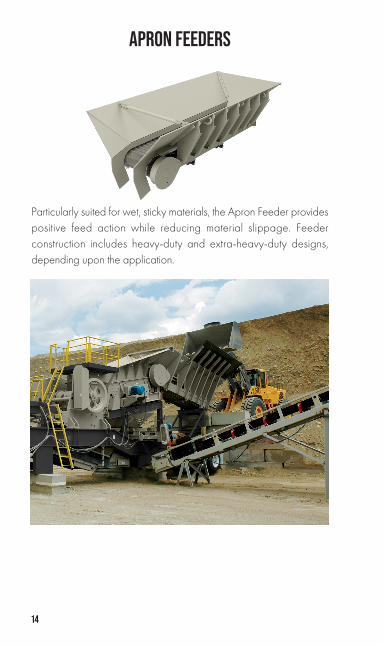
APRON FEEDERS
Particularly suited for wet, sticky materials, the Apron Feeder provides positive feed action while reducing material slippage. Feeder construction includes heavy-duty and extra-heavy-duty designs, depending upon the application.

15
STAN
DARD
HOP
PER
APPR
OXIM
ATE C
APAC
ITIES
—APR
ON FE
EDER
S
RECI
PROC
ATIN
G PLA
TE FE
EDER
S
NO
TE: *
Rang
e va
ries d
epen
ding
on
the
appl
icat
ion.
6ft
1.83
m8f
t2.
44m
10ft
3.05
m12
ft3.
66m
14ft
4.27
Wid
thyd
3m
3yd
3m
3yd
3m
3yd
3m
3yd
3m
3
30”
(762
mm
) Apr
on F
eede
r w/
o Ex
tens
ion
2.1
1.6
3.2
2.4
4.3
3.3
5.4
4.1
--
30”
(762
mm
) Apr
on F
eede
r w/
Ext
ensio
n3.
32.
55.
84.
48.
36.
410
.88.
2-
-
36”
(914
mm
) Apr
on F
eede
r w/
o Ex
tens
ion
2.4
1.8
3.6
2.8
4.8
3.7
6.0
4.6
7.2
5.5
36”
(914
mm
) Apr
on F
eede
r w
/ E
xten
sion
3.6
2.8
6.3
4.8
9.0
6.9
11.7
8.9
14.5
11.1
42”
(106
7 m
m) A
pron
Fee
der w
/o
Exte
nsio
n2.
62.
03.
93.
05.
34.
06.
65.
07.
96.
0
42”
(1,0
67 m
m) A
pron
Fee
der
w/
Ext
ensio
n3.
93.
06.
85.
29.
77.
412
.69.
615
.611
.8
48”
(1,2
19 m
m) A
pron
Fee
der w
/o
Exte
nsio
n-
-4.
43.
45.
84.
47.
35.
68.
86.
7
48”
(1,2
19 m
m) A
pron
Fee
der
w/
Ext
ensio
n-
-7.
45.
610
.58.
013
.610
.416
.712
.8
Mod
el N
umbe
rSi
zeTy
pe o
f Ser
vice
App
rox.
Cap
acity
* at
60
RPM
Hop
per S
ize
Hop
per C
apac
ityW
eigh
t (w
ith H
oppe
r)in
mm
ft2m
2yd
3m
3
25 R
P24
610
Stan
dard
100
-20
0 T
PH (
90
.7 -
181
mt/
h)6
1.8
31.
71.
32
,05
0lb
s93
1kg
31 R
P3
076
2St
anda
rd15
0-3
00
TPH
( 13
6-2
72 (m
t/h)
61.
83
1.7
1.3
2,1
65
lbs
983
kg
30
RP
30
762
Hea
vy D
uty
150
-30
0 T
PH (
136
-272
mt/
h)6
1.8
31.
71.
32
,55
0lb
s1,
158
kg
37 R
P3
691
4St
anda
rd21
5-4
30
TPH
( 19
5-3
90
mt/
h)7
2.14
2.6
1.9
93,
175
lbs
1,4
41kg
36
RP
36
914
Hea
vy D
uty
215
-43
0 T
PH (
195
-39
0 m
t/h)
72
.142
.61.
99
3,95
0lb
s1,
793
kg
42 R
P42
1,0
67H
eavy
Dut
y3
00
-60
0 T
PH (
272
-54
4 m
t/h)
72
.142
.61.
99
4,7
10lb
s2
,136
kg

16
NO
TE: C
onsid
erab
le v
aria
nce
will
alw
ays b
e en
coun
tere
d w
hen
calc
ulat
ing
the
capa
citie
s of f
eede
rs. U
sual
ly, e
xper
ienc
e is
the
best
guid
e to
wha
t a fe
eder
will
hand
le u
nder
give
n co
nditio
ns o
f mat
eria
l, ra
te o
f tra
vel o
f the
feed
er p
ans,
ande
pth
of lo
adin
g. T
he ta
ble
abov
e is
base
d on
a d
epth
of m
ater
ial e
qual
to h
alf t
he fe
eder
wid
th, a
nd to
ns a
re b
ased
on
mat
eria
l wei
ghin
g 2,
700
poun
ds p
er c
u. y
d. A
feed
ing
fact
or o
f .8
has b
een
intro
duce
d to
com
pens
ate
for v
oids
, res
istan
ceto
flow
, etc
. Thi
s fac
tor,
too,
will
vary
with
the
type
of m
ater
ial a
nd it
s con
ditio
n w
hen
fed.
The
follo
win
g fo
rmul
a ca
n be
use
d to
cal
cula
te th
e ap
prox
imat
e ca
paci
ty in
cub
ic y
ards
of a
feed
er o
f give
n w
idth
whe
re th
e fe
edin
g fa
ctor
is d
eter
min
ed to
be
othe
r tha
n .8
:C
u. Y
ds p
er H
r. =
2.22
(d x
w x
s x
f); w
here
d
= d
epth
of l
oad
on fe
eder
, in
feet
: s =
rate
of p
an tr
avel
, in
feet
per
min
ute;
w
= w
idth
of f
eede
r, in
feet
; f =
feed
ing
fact
or.
To c
onve
rt cu
. yds
. to
tons
; mul
tiply
cu.
yds
. by
1.35
.
APPR
OXIM
ATE P
ER H
OUR
CAPA
CITIE
S OF A
PRON
FEED
ERS A
CCOR
DING
TO W
IDTH
Pa
n Tr
avel
(ft
per m
in)
30”
Wid
e36
” W
ide
42”
Wid
e48
” W
ide
60”
Wid
e72
” W
ide
yds3
Tons
yds3
Tons
yds3
Tons
yds3
Tons
yds3
Tons
yds3
Tons
1055
7480
108
109
147
143
192
222
300
320
432
1583
112
120
162
164
222
214
289
333
450
480
648
2011
014
816
021
621
829
428
438
444
460
065
086
425
138
186
200
270
273
369
357
482
555
750
800
1,08
030
165
223
240
324
327
442
427
577
667
900
960
1,29
635
193
260
280
378
382
516
500
673
778
1,05
01,1
201,
,512
4022
029
632
043
243
658
857
276
888
81,
200
1,28
017
28
Pan
Trav
el
(met
ers
per
min
ute)
.762
m W
ide
.914
m W
ide
1.07
m W
ide
1.22
m W
ide
1.52
m W
ide
1.83
m W
ide
m3
mt
m3
mt
m3
mt
m3
mt
m3
mt
m3
mt
3.05
4267
6198
8313
310
917
417
027
224
539
24.
5763
102
9214
712
520
116
426
225
440
836
758
86.
1084
134
122
196
167
267
217
348
339
544
489
784
7.62
105
169
153
245
209
335
273
437
424
680
611
908
9.14
126
202
183
293
250
401
326
523
510
816
734
1,176
10.6
714
723
621
434
329
246
838
261
059
495
385
61,
372
12.19
168
269
245
392
333
533
437
697
679
1089
978
1,56
8

17
VIBRATING FEEDERS
Designed to convey material while separating fines, Vibrating Feeders provide smooth, controlled feed rates to maximize capacity. Grizzly bars are tapered to self-relieve with adjustable spacing for bypass sizing. Feeder construction includes heavy-duty deck plate with optional AR plate liners. Heavy-duty spring suspension withstands loading impact and assists vibration.
CAPACITY MULTIPLIERS FOR VARIOUS FEEDER PAN MOUNTING ANGLES FROM 0° TO 10° DOWN HILL—ALL VIBRATING FEEDERS
NOTE: *Capacity can vary ±25% for average quarry installations—capacity will usually be greater for dry or clean gravel. Capacity will be affected by the methods of loading, characteristics and gradation of material handled, and other factors.
(4° and more consult with Factory)
VIBRATING FEEDERS—APPROXIMATE CAPACITY*30” (.76m)
Wide36” (.91m)
Wide42” (1.07m)
Wide50” (1.27m)
Wide60” (1.5m)
WideRPM tph mtph tph mtph tph mtph tph mtph tph mtph600 828 754650 623 568 898 818700 315 287 473 431 671 611 967 881750 270 246 337 307 507 462 720 656 1,035 943800 290 264 360 328 541 493 767 698850 305 278 382 348 575 524900 325 296 404 368 609 555950 345 314 427 389 642 585
1,000 365 332
Angle Down Hill 0° 2° 4° 6° 8° 10°Multiplier 1.0 1.15 1.35 1.6 1.9 2.25

18
BELT FEEDER CAPACITY (TPH)
NOTE: Capacities based on 100 lb./cu. ft. material
TPH = 3 x H (in.) x W (in.) x FPM
144
24”
BELT
FEE
DER
(W =
18”
) H (in)Belt Speed feet per minute
10 20 30 40 50 60
8 30 60 90 120 150 180
9 34 68 101 135 169 203
10 38 75 113 150 188 225
11 41 83 124 168 206 248
12 45 90 135 180 225 270
13 49 98 146 195 244 293
14 53 105 158 210 262 315
30”
BELT
FEE
DER
(W =
24”
)
8 40 80 120 160 200 240
9 45 90 135 180 225 270
10 50 100 150 200 250 300
11 55 110 165 220 275 330
12 60 120 180 240 300 360
13 65 130 195 260 325 390
14 70 140 210 280 350 420
36”
BELT
FEE
DER
(W
= 3
0”)
8 50 100 150 200 250 300
9 56 113 169 225 281 338
10 62 125 187 250 312 375
11 69 137 206 275 344 412
12 75 150 225 300 375 450
13 81 162 244 325 406 487
14 87 175 262 350 437 525
42”
BELT
FEE
DER
(W
= 3
6”)
8 60 120 180 240 300 360
9 68 135 203 270 338 405
10 75 150 225 300 375 450
11 83 165 248 330 413 495
12 90 180 270 360 450 540
13 98 195 293 390 488 585
14 105 210 315 420 525 630
CRUSHING

19
JAW CRUSHER
For almost a century, jaw crushers have been processing materials without objection. Used most commonly as a primary crusher, but also as a secondary in some applications, these compression crushers are designed to accept all manner of materials including hard rock, gravels and recycle pavements, as well as construction and demolition debris.
CRUSHING

20
Test Sieve Sizes (in)
APPROXIMATE GRADATIONS AT PEAK TO PEAK CLOSED SIDE SETTINGS Test
Sieve Sizes (mm)
¾” 1” 1 ¼” 1 ½” 2” 2 ½” 3” 3 ½” 4” 5” 6” 7” 8”
19mm
25.4mm
31.8mm
38.1mm
50.8mm
63.5mm
76.2mm
89.1mm
102mm
127mm
152mm
178 mm
203mm
12’ 100 98 95 305
10” 100 97 95 90 254
8” 100 96 92 85 75 203
7” 100 97 92 85 76 65 178
6” 100 98 93 85 74 65 53 152
5” 100 97 95 85 73 62 52 40 127
4” 100 96 90 85 70 56 45 38 28 102
3” 100 93 85 75 65 50 38 32 27 23 76.2
2 ½” 100 95 85 73 62 52 38 31 24 22 17 63.5
2” 100 96 85 70 55 47 39 28 24 20 17 13 50.8
1 ½” 100 93 85 67 49 39 33 27 21 18 15 13 10 31.8
1 ¼” 96 85 73 55 39 31 27 23 17 15 13 10 8 38.1
1” 85 69 55 40 29 24 20 17 14 12 10 8 6 25.4
¾” 66 49 39 28 21 18 15 13 11 9 8 6 5 19.0
½” 41 29 24 19 14 12 10 9 7 6 6 5 4 12.7
³⁄₈” 28 21 18 14 11 9 8 7 5 5 5 4 3 9.53
¼” 18 14 12 10 7 7 6 5 4 4 4 3 2 6.35
#4 12 10 9 7 5 5 4 4 3 3 3 2 1 #4
#8 6 6 5 5 4 4 3 3 2 2 2 1 0.5 #8
The chart on this page is particularly useful in determining the percentages of various
sized particles to be obtained when two or more crushers are used in the same setup. It
is also helpful in determining necessary screening facilities for making size separations.
Here is an example designed to help show you how to use the percentage charts:
To determine the amount of material passing 1¼” (31.8 mm) when the crusher is set at
2” (50.8 mm) closed side setting, find 2” (50.8 mm) at the top, and follow down the
vertical line to 1¼” (31.8 mm). The horizontal line shows 39% passing, or 61% retained.
Values Are Percent Passing
JAW CRUSHERS APPROXIMATE JAW CRUSHERSGRADATION OPEN CIRCUIT
CRUSHING

21
LEGE
NDAR
Y JAW
CRUS
HERS
—HOR
SEPO
WER
REQU
IRED
AND
APPR
OXIM
ATE C
APAC
ITIES
IN TP
H
NO
TE:
*Bas
ed o
n m
ater
ial w
eigh
ing
2,70
0 lb
s. pe
r cub
ic y
ard.
Cap
acity
may
var
y as
muc
h as
±25
%.
**
Larg
er se
tting
s may
be
obta
ined
with
oth
er th
an st
anda
rd to
ggle
pla
te. C
onsu
lt fa
ctor
y.
***I
ndic
ates
jaw
size
s tha
t are
no
long
er st
anda
rd p
rodu
ctio
n m
odel
s.
CRUSHING
SIZE
HP
REQ
UIR
ED
(MIN
IMU
M)
APP
ROXI
MA
TE C
APA
CIT
IES
AT
PEA
K TO
PEA
K C
LOSE
D S
IDE
SETT
ING
S (IN
TPH
)*¾
”1”
1 ¼
”1
½”
2”2
½”
3”3
½”
4”5”
6”7”
8”9”
10”
11”
12”
Elec
t.D
iese
lRP
M19
mm
25m
m32
mm
38m
m51
mm
64m
m76
mm
89m
m10
2mm
127m
m15
2mm
178m
m20
3mm
228m
m25
4mm
279m
m30
4mm
***1
016
1525
1012
1419
2428
***1
024
2540
290
1518
2229
3644
***1
036
4060
290
2227
3344
5567
1047
110
2936
4459
7389
1524
4060
290
3645
5463
7215
3675
110
290
5468
8195
109
136
1654
125
175
290
8110
212
214
216
320
4**
*183
060
9027
561
7486
9812
320
3610
014
027
510
912
413
915
618
7**
2436
100
150
260
123
136
153
171
205
239
273
2148
125
170
260
145
165
186
207
248
***2
649
150
190
165
188
211
235
282
2854
200
250
260
213
241
268
323
378
433
**30
4215
019
026
020
022
326
831
335
731
6320
025
029
033
037
045
053
061
069
0**
3350
200
250
275
302
350
407
465
522
**35
4620
025
023
527
530
235
040
746
552
2**
4248
250
310
225
324
376
438
500
562
625
688
752
875

22
PIONEER® JAW CRUSHER
Today’s hard rock producer requires massive crushing energy and hydraulic closed-side-setting adjustment to increase productivity and reduce downtime. Used most commonly as a primary crusher, but also as a secondary in some applications, these compression crushers are designed to accept a variety of materials including hard rock, gravels and recycle pavements, as well as construction and demolition debris.
CRUSHING

23
PION
EER®
JAW
CRUS
HERS
HO
RSEP
OWER
REQ
UIRE
D AN
D AP
PROX
IMAT
E CAP
ACITI
ES IN
TPH
NO
TE:
*Bas
ed o
n m
ater
ial w
eigh
ing
2,70
0 lb
s. pe
r cub
ic y
ard.
Cap
acity
may
var
y w
ith th
e m
ater
ial c
hara
cter
istic
s.
*
*Lar
ger s
ettin
gs m
ay b
e ob
tain
ed w
ith o
ther
than
stan
dard
togg
le p
late
. Con
sult
Fact
ory.
CRUSHING
SIZE
HP
REQ
UIR
ED
(MIN
IMU
M)
APP
ROXI
MA
TE C
APA
CIT
IES
AT
PEA
K TO
PEA
K C
LOSE
D S
IDE
SETT
ING
S (IN
TPH
)*
¾”
1”1
¼”
1 ½
”2”
2 ½
”3”
3 ½
”4”
5”6”
7”8”
9”10
”11
”12
”
Elec
t.D
iese
lRP
M19
mm
25m
m32
mm
38m
m51
mm
64m
m76
mm
89m
m10
2mm
127m
m15
2mm
178m
m20
3mm
228m
m25
4mm
279m
m30
4mm
2056
125
160
285
128-
170
150-
195
170-
225
190-
250
212-
280
255-
335
2742
150
190
275
133-
175
150-
200
171-
225
190-
250
228-
300
2650
150
190
260
157-
206
179-
235
200-
264
223-
294
268-
353
3055
200
250
250
252-
331
285-
375
317-
418
382-
503
447-
589
502-
660
3144
150
190
260
201-
265
228-
300
254-
334
304-
400
354-
466
405-
533
**31
6520
025
025
025
2-33
129
0-38
135
3-46
543
6-57
450
4-66
358
0-76
465
7-86
5
3365
200
265
250
260-
341
300-
393
364-
480
450-
595
520-
685
595-
790
680-
892
**35
5220
025
022
530
2-39
834
2-45
039
5-52
046
0-60
552
5-69
1
4450
250
310
225
402-
529
467-
615
545-
718
621-
818
698-
919
775-
1,02
0

24
PRIMARY IMPACT CRUSHERS(NEW HOLLAND STYLE)
Making a cubical product necessary for asphalt and concrete specifications poses many equipment problems for the aggregate producer. Among these problems are abrasive wear, accessibility for hammer maintenance or breaker bar changes and bridging in the crushing chamber.
Impact crusher units are designed to help overcome problems faced by producers and at the same time to provide maximum productivity for existing conditions.
CRUSHING

25
PRIMARY IMPACT CRUSHERS(NEW HOLLAND STYLE)—APPROXIMATE
PRODUCT GRADATION—OPEN CIRCUIT
NOTE:*Capacity depends on feed size and gradation, type of material, etc. Approximate product gradation can be expected as shown on chart. The product will vary from that shown depending on the size and type of feed, adjustment of lower breaker bar, etc.
Test Sieve Sizes (in)
3850 4654 6064 Test Sieve Sizes (mm)Normal
SettingClose
SettingNormal Setting
Close Setting
Normal Setting
Close Setting
6” 100 152
5” 100 97 100 127
4” 100 98 100 90 98 102
3” 96 100 89 96 75 89 76.2
2½” 90 97 80 90 66 80 63.5
2” 77 89 67 77 56 67 50.8
1½” 64 75 56 64 48 56 38.1
1¼” 57 67 50 57 43 50 31.8
1” 50 58 44 50 38 44 25.4
¾” 41 47 37 41 31 37 19.1
½” 32 37 28 32 24 28 12.7
³⁄₈” 26 30 23 26 19 23 9.53
¼” 20 23 17 20 14 17 6.35
#4 17 19 15 17 12 15 #4
#8 12 14 10 12 8 10 #8
#16 8 9 6 8 5 6 #16
#30 5 6 4 5 3 4 #30
#50 3 4 3 3 2 3 #50
#100 2 3 2 2 1 2 #100
Recommended HP Approx. Capacities Maximum Feed Size
Model Electric Diesel TPH MTPH
3850 250-300 350-450 250-450 227-409 24”
4654 300-400 450-600 400-750 364-682 30”
6064 400-600 600-900 600-1,200 545-1,091 40”
Values are percent passing
CRUSHING

26
5054 HYBRID HORIZONTAL SHAFT IMPACT CRUSHER
The 5054 hybrid HSI combines the large feed opening and expansion chamber of the primary New Holland style HSI with the precise top-size control of the Andreas HSI to provide the best of both crushers. The hybrid 5054 comes standard with hydraulic apron adjustment and apron position monitoring, as well as the convenience of Andreas HSI style replaceable blow bars and bolt-in liners. This crusher is well-suited for primary crushing applications in limestone and other large, non-abrasive feed materials and features an optional feed lip "bridge breaker" to help alleviate internal bridging from oversized feed material.
CRUSHING

27
5054 HYBRID HSI —APPROXIMATE PRODUCT GRADATION—OPEN CIRCUIT
NOTE:*Capacity depends on feed size and gradation, type of material, etc. Approximate product gradation may vary depending on material characteristics.
Test Sieve Sizes (in)
CSS (apron to blow bar clearance) Test Sieve Sizes (mm)8" 6" 5" 4"
15” 100 100 100 100 381
12" 100 100 100 100 304.8
10" 96 100 100 100 254
8" 88 97 100 100 203.2
6" 77 90 98 100 152.4
5" 65 78 91 99 127
4" 54 66 79 92 101.6
3" 42 56 67 80 76.2
2" 25 43 58 67 50.8
1" 13 24 44 57 25.4
½” 10 14 23 43 12.7
³⁄₈” 9 11 17 22 9.53
¼” 7 8 13 18 6.35
#4 6 7 9 16 #4
#8 5 6 7 10 #8
#16 4 5 6 8 #16
#30 3 4 5 6 #30
#50 2 3 3 5 #50
#100 1 2 2 3 #100
#200 1 1 1 2 #200
Recommended HP Approx. Capacities*Maximum Feed SizeHybrid
Model Electric Diesel TPH MTPH
5054 300-400 450-600 400-800 364-728 40"
CRUSHING

28
ANDREAS-STYLE IMPACT CRUSHERS
Andreas-Style impact crushers are designed for recycling concrete and asphalt, as well as traditional aggregate crushing applications. The Maximum Performance Rotor (MPR) offers the mass of a solid design with the clearances of an open configuration.
CRUSHING

29
ANDREAS IMPACT CRUSHERSHORIZONTAL SHAFT IMPACT CRUSHER
NOTE:*Capacity depends on feed size and gradation, type of material, etc. ** Limestone and hard rock feed sizes are based on secondary applications.
100%
90%
80%
70%
60%
50%
40%
30%
20%
50 mesh 8 mesh 1" 3" 10"12"
10%
0%
APRONS:Upper @ 4"Lower @ 2"
% C
umul
ativ
e Pa
ssin
g
Approximate Output Gradations-Open Circuit
8000 fpm
6500 fpm
5250 fpm
FEED
Recommended HP Approx. Capacities
Size Electric Diesel TPH MTPH
4233 100 165 up to 200 up to 181
4240 150 190 up to 250 up to 227
4250 200 265 up to 300 up to 272
5260 - 3 bar 300 390 up to 450 up to 408
5260 - 4 bar 300 390 up to 450 up to 408
Maximum Feed Size** Min Lower/Upper Appron
SettingSize Recycle Limestone Hard Rock
4233 24”x24”x12” up to 18” up to 16” 1” / 2”
4240 27”x27”x12” up to 21” up to 18” 1” / 2”
4250 30”x30”x12” up to 21” up to 21” 1” / 2”
5260 - 3 bar 36”x36”x12” up to 24” up to 21” 1” / 2”
5260 - 4 bar 36”x36”x12” up to 21” up to 18” 1” / 2”
CRUSHING

30
KODIAK® PLUS AND LS CONE CRUSHER NOTES1. Capacities and product gradations produced by cone crushers
will be effected by the method of feeding, characteristics of the material, speed of the machine, power applied and other factors. Hardness, compressive strength, mineral content, grain structure, plasticity, size and shape of feed particles, moisture content and other characteristics of the material also affect production capacities and gradations.
2. Gradations and capacities shown are based on a typical well-graded choke feed to the crusher. Well-graded feed is considered to be 90-100% passing the closed side feed opening, 40-60% passing the midpoint of the crushing chamber on the closed side (average of the closed side feed opening and closed side setting) and 0-10% passing the closed side setting. Choke feed is considered to be material located 360 degrees around the crushing head and approximately 6” above the mantle nut.
3. Maximum feed size is the average of the open side feed opening and closed side feed opening.
4. A general rule of thumb for applying cone crushers is the reduction ratio. A crusher with coarse-style liners would typically have a 6:1 reduction ratio. Thus, with a ¾” closed side setting, the maximum feed would be 6 x ¾ or 4.5 inches. Reduction ratios of 8:1 may be possible in certain coarse crushing applications. Fine liner configurations typically have reduction ratios of 4:1 to 6:1.
5. Minimum closed side setting may be greater than published settings since it is not a fixed dimension. It will vary depending on crushing conditions, the compressive strength of the material being crushed and the stage of reduction. The actual minimum closed side setting is that setting just before the bowl assembly lifts minutely against the factory recommended pressurized hydraulic relief system. Operating the crusher above the factory recommended relief pressure will void the warranty, as will operating the crusher in a relief mode (bowl float).
CRUSHING
31
KODIAK® PLUS OPERATING PARAMETERSThe following list outlines successful operating parameters for the Kodiak® Plus line of crushers. These are not prioritized in any order of importance.
Material1. Material with a compressive strength greater than 40,000
pounds per square inch should be reviewed in advance by the factory.
2. No more than 10% of the total volume of feed material is sized less than the crusher closed side setting.
3. The crusher feed material conforms to the recommended feed size on at least two sides.
4. Moisture content of material is below 5%.5. Feed gradation remains uniform.6. Clay or plastic material in crusher feed is limited to prevent the
formation of compacted material.
Mechanical1. Crusher operates at factory recommended tramp iron relief
pressures without bowl float.2. Crusher support structure is level and evenly supported across
all four corners. In addition, the support structure provides adequate strength to resist static and dynamic loads.
3. Crusher is operated only when all electrical, lubrication and hydraulic systems are correctly adjusted and functioning properly.
4. Lubrication low flow warning system functions correctly.5. Lubrication oil filter functions properly and shows adequate
filtering capacity on its indicator.6. Crusher drive belt(s) are in good condition and tensioned to
factory specifications.7. Crusher lubrication reservoir is full of lubricant that meets
factory required specifications.8. Any welding on the crusher or support structure is grounded
directly at the weld location.9. Crusher input shaft rotates in the correct direction.10. Manganese wear liners are replaced at the end of their
expected life.
CRUSHING

32
11. Crusher cone head is properly blocked prior to transport. 12. Only authorized OEM parts or factory-approved wear parts
are used.
Application1. Reduction ratio limited to 6:1 below 1” closed side setting
and 8:1 above 1” closed side setting provided no bowl float occurs.
2. Manganese chamber configuration conforms to the factory recommended application guidelines.
3. Crusher is operated at the factory recommended RPM for the application.
4. Crusher feed is consistent with an even flow of material, centered in the feed opening and covering the mantle nut at all times.
5. Crusher input horsepower does not exceed factory specifications.
6. Crusher discharge chamber is kept clear of material buildup.7. If the crusher cannot be totally isolated from metal in the feed
material, a magnet should be used over the crusher feed belt.8. Crusher is never operated at zero closed side setting.
K200+
K300+
K350+
K400+
K500+
CRUSHING

33
KODIAK® CONE CRUSHERS GRADATION CHART
Estimated product gradation percentages at setting shown.
ProductSize
Crusher Closed Side Setting
5/16” 3⁄₈” 7/16” ½” ₅⁄₈” ¾” ₇⁄₈” 1” 1 ¼” 1 ½” 1 ¾” 2”
7.94mm
9.52mm
11.11mm
12.7mm
15.87mm
19.05mm
22.22mm
25.4mm
32mm
38.1mm
44.5mm
50.8mm
4” 100
3 ½” 100 96
3” 100 95 90
2 ¾” 98 92 86
2 ½” 100 95 88 81
2 ¼” 97 91 83 74
2” 100 94 86 76 65
1 ¾” 100 99 89 79 66 55
1 ½” 100 99 97 82 68 56 45
1 ¼” 100 99 95 90 72 56 46 38
1” 100 99 95 87 79 60 45 36 29
₇⁄₈” 100 99 95 88 80 70 49 38 30 25
¾” 100 97 95 91 83 71 61 41 32 26 21
₅⁄₈” 100 98 94 90 85 73 58 49 34 28 22 18
½” 99 95 89 85 75 63 50 42 28 23 19 16
3⁄₈” 91 85 75 69 63 51 42 33 21 17 14 12
5/16” 85 75 65 61 56 43 35 27 19 15 13 10
¼” 74 63 52 50 45 37 29 23 16 13 11 9
4M 58 51 42 36 33 28 21 18 14 11 9 7
5/32” 50 42 36 30 28 23 18 15 12 10 8 6
8M 40 35 30 26 24 20 16 12 9 7 5 4
10M 35 31 26 22 20 17 14 10 8 6 4 3
16M 28 24 21 17 15 13 10 8 6 4 3 2
30M 21 18 15 11 9 8 6 5 4 3 2 1.5
40M 18 15 13 10 8 7 5 4 3 2 1.5 1
50M 14 12 11 8 7 6 4 3 2 1.5 1 0.8
100M 11 9 8 7 6 5 4 3 1.5 1 0.5 0.5
200M 8 7 6 6 5 4 3 2 1 0.5 0.5 0.3
CRUSHING

34
K200+ MANGANESE CONFIGURATION
K200+COARSE
CHAMBER
A B C
8 ¾” (222.2mm) 7 ¾” (196.9mm) ₇⁄₈” (22.2mm)
9” (228.6mm) 8” (203.2mm) 1” (25.4mm)
9 ¼” (234.9mm) 8 ¼” (209.6mm) 1 ¼” (31.8mm)
9 ½” (241.3mm) 8 ½” (215.9mm) 1 ½” (38.1mm)
10” (254mm) 9” (228.6mm) 2” (50.8mm)
K200+ MEDIUM CHAMBER WITH FEED SLOTS
A B C
7 ¾” (196.8mm) 6 ¾” (171.5mm) ₅⁄₈” (15.9mm)
7 ₇⁄₈” (200mm) 6 ₇⁄₈” (174.6mm) ¾” (19mm)
8” (203.2mm) 7” (177.8mm) ₇⁄₈” (22.2mm)
8 ¼” (209.5mm) 7 ¼” (184.2mm) 1 ¹⁄₈” (28.6mm)
8 ½” (215.9mm) 7 ½” (190.5mm) 1 ¼” (31.8mm)
A = Open-side feed opening | B = Closed-side feed opening | C = Closed-side setting
A
A
B
B
C
C
CRUSHING

35
K200+ FINE
CHAMBER
A B C
4 ½” (114.3mm) 2 ¾” (69.9mm) ³⁄₈” (9.5mm)
4 ½” (114.3mm) 2 ₇⁄₈” (73mm) ½” (12.7mm)
4 ½” (114.3mm) 3” (76.2mm) ₅⁄₈” (15.9mm)
4¾” (120.7mm) 3 ¹⁄₈” (79.4mm) ₇⁄₈” (22.2mm)
K200+MEDIUM
CHAMBER
A B C
6 ¼” (158.8mm) 5” (127mm) ₅⁄₈” (15.9mm)
6 ³⁄₈” (161.9mm) 5 ³⁄₁₆” (131.8mm) ¾” (19mm)
6 ½” (165.1mm) 5 ¼” (133.4mm) ₇⁄₈” (22.2mm)
6 ¾” (171.5mm) 5 ¾” (146mm) 1 ¹⁄₈” (28.6mm)
7” (177.8mm) 5 ¾” (146mm) 1 ¼” (31.8mm)
A = Open-side feed opening | B = Closed-side feed opening | C = Closed-side setting
A
B
C
C
BA
CRUSHING

36
K300+COARSE CHAMBER
K300+MEDIUM COARSE
CHAMBER
A B C
10 ¹⁄₈” (257.2mm) 9 ¼” (235mm) ¾” (19mm)10 ¼” (260.4mm) 9 ³⁄₈” (238.1mm) ₇⁄₈” (22.2mm)10 ³⁄₈” (263.5mm) 9 ½” (241.3mm) 1” (25.4mm)10 ½” (266.7mm) 9 ₅⁄₈” (244.5mm) 1 ¼” (31.8mm)10 ¾” (273mm) 9 ¾” (247.7mm) 1 ½” (38.1mm)11” (279.4mm) 10” (254mm) 1 ¾” (44.5mm)
11 ¼” (285.8mm) 10 ¼” (260.4mm) 2” (50.8mm)
A B C
8 ¾” (222.3mm) 7 ¾” (196.9mm) ¾” (19mm)9” (228.6mm) 7 ¾” (196.9mm) ₇⁄₈” (22.2mm)9” (228.6mm) 8” (203.2mm) 1” (25.4mm)
9 ³⁄₈” (238.1mm) 8 ¼” (209.6mm) 1 ¼” (31.8mm)9 ₅⁄₈” (244.5mm) 8 ½” (215.9mm) 1 ½” (38.1mm)9 ₇⁄₈” (250.8mm) 8 ¾” (222.3mm) 1 ¾” (44.5mm)
A = Open-side feed opening | B = Closed-side feed opening | C = Closed-side setting
A
A
B
B
C
C
K300+ MANGANESE CONFIGURATION
CRUSHING

37
K300+ MEDIUM
CHAMBER
K300+ MEDIUM CHAMBER
WITH FEED SLOTSA B C
8 ₇⁄₈” (225.4mm) 7 ₇⁄₈” (200mm) ₅⁄₈” (15.9mm)
9” (228.6mm) 8” (203.2mm) ¾” (19mm)
9 ¹⁄₈” (231.8mm) 8 ¹⁄₈” (206.4mm) ₇⁄₈” (22.2mm)
9 ¼” (234.9mm) 8 ¼” (209.6mm) 1” (25.4mm)
9 ½” (241.3mm) 8 ½” (215.9mm) 2” (50.8mm)
A B C
7 ₅⁄₈” (193.7mm) 6 ½” (165.1mm) ₅⁄₈” (15.9mm)
7 ¾” (196.9mm) 6 ₅⁄₈” (168.3mm) ¾” (19mm)
7 ₇⁄₈” (200mm) 6 ¾” (171.5mm) ₇⁄₈” (22.2mm)
8” (203.2mm) 6 ₇⁄₈” (174.6mm) 1” (25.4mm)
8 ¼” (209.6mm) 7 ¹⁄₈” (180.9mm) 1 ¾” (44.5mm)
A = Open-side feed opening | B = Closed-side feed opening | C = Closed-side setting
C
C
B
B
A
A
CRUSHING

38
KODIAK 300+ FINE CHAMBER
K300+MEDIUM
FINE CHAMBER
A B C
5 ¹⁄₈” (130.2mm) 3 ₅⁄₈” (92mm) ½” (12.7mm)5 ¼” (133.4mm) 3 ¾” (95.3mm) ₅⁄₈” (15.9mm)5 ³⁄₈” (136.5mm) 3 ₇⁄₈” (98.4mm) ¾” (19mm)5 ½” (139.7mm) 4” (101.6mm) ₇⁄₈” (22.2mm)5 ₅⁄₈” (142.9mm) 4 ¹⁄₈” (104.8mm) 1” (25.4mm)
A B C
4 ³⁄₈” (111.1mm) 2 ¾” (69.9mm) ¼” (6.4mm)4 ½” (114.3mm) 2 ₇⁄₈” (73mm) ³⁄₈” (9.5mm)4 ₅⁄₈” (117.5mm) 3” (76.2mm) ½” (12.7mm)4 ¾” (120.7mm) 3 ¹⁄₈” (79.4mm) ₅⁄₈” (15.9mm)4 ₇⁄₈” (123.8mm) 3 ¼” (82.6mm) ¾” (19mm)
5” (127mm) 3 ³⁄₈” (85.7mm) ₇⁄₈” (22.2mm)
A = Open-side feed opening | B = Closed-side feed opening | C = Closed-side setting
B
B
C
C
A
A
CRUSHING

39
K350+COARSE CHAMBER
K350+MEDIUM COARSE
CHAMBER
A B C
10 ₇⁄₈” (276.2mm) 9 1³⁄₁₆” (249.2mm) ¾” (19.1mm)11” (279.4mm) 10” (254mm) ₇⁄₈” (22.2mm)
11 ¹⁄₈” (282.6mm) 10 ¹⁄₈” (257.2mm) 1” (25.4mm)11 7/16” (290.5mm) 10 7/16” (265.1mm) 1 ¼” (31.8mm)
11 ¾” (298.5mm) 10 ¾” (273.1mm) 1 ½” (38.1mm)12” (304.8mm) 11” (279.4mm) 1 ¾” (44.5mm)
12 ¼” (311.2mm) 11 5/16” (287.3mm) 2” (50.8mm)
A B C
9 ¼” (235mm) 8 ¼” (209.6mm) ¾” (19mm)9 ³⁄₈” (238.1mm) 8 ³⁄₈” (212.7mm) ₇⁄₈” (22.2mm)9 ½” (241.3mm) 8 ½” (215.9mm) 1” (25.4mm)9 ¾” (247.7mm) 8 ¾” (222.3mm) 1 ¼” (31.8mm)
10” (254mm) 9” (228.6mm) 1 ½” (38.1mm)10 ¼” (260.4mm) 9 5/16” (236.5mm) 1 ¾” (44.5mm)10 ½" (266.7mm) 9 ₅⁄₈" (244.5mm) 2” (50.8mm)
A = Open-side feed opening | B = Closed-side feed opening | C = Closed-side setting
A
A
B
B
C
C
CRUSHING

40
K350+MEDIUM
CHAMBER
K350+MEDIUM
CHAMBER
A B C
8” (203.2mm) 6 ¾” (171.5mm) ₅⁄₈” (15.9mm)8 ¹⁄₈” (206.4mm) 6 ₁₅⁄₁₆” (176.2mm) ¾” (19.1mm)8 ½” (215.9mm) 7” (177.8mm) ₇⁄₈” (22.2mm)8 ¾” (222.3mm) 7 ¼” (184.2mm) 1” (25.4mm)8 ₁₅⁄₁₆” (227mm) 7 ½” (190.5mm) 1 ¼” (31.8mm)
A B C
6 ¾” (171.5mm) 5 ½” (139.7mm) ₅⁄₈” (15.9mm)6 ₇⁄₈” (174.6mm) 5 ₅⁄₈” (142.9mm) ¾” (19.1mm)
7” (177.8mm) 5 ¾” (146.1mm) ₇⁄₈” (22.2mm)7 ¹⁄₈” (181mm) 5 ₇⁄₈” (149.2mm) 1” (25.4mm)
7 ³⁄₈” (187.3mm) 6 ¹⁄₈” (155.6mm) 1 ¼” (31.6mm)
A = Open-side feed opening | B = Closed-side feed opening | C = Closed-side setting
A
A
B
B
C
C
CRUSHING

41
K350+MEDIUM FINE
CHAMBER
K350+MEDIUM FINE
MEDIUM CHAMBER
A B C
4 ¾” (120.7mm) 3 ¹⁄₈” (79.4mm) ³⁄₈" (9.5mm)4 ₇⁄₈” (123.8mm) 3 ¼” (82.6mm) ½" (12.7mm)
5” (127mm) 3 ³⁄₈” (85.7mm) ₅⁄₈" (15.6mm)5 ¹⁄₈” (130.2mm) 3 ½” (88.9mm) ¾” (19.1mm)5 ¼” (133.4mm) 3 11/16” (93.7mm) ₇⁄₈” (22.2mm)5 ½” (139.7mm) 4” (101.6mm) 1” (25.4mm)
A B C
4” (101.6mm) 2 ³⁄₈” (60.3mm) ³⁄₈" (9.5mm)4 ³⁄₁₆” (106.4mm) 2 ½” (63.5mm) ½" (12.7mm)
4 5/16” (109.5mm) 2 11/16” (68.3mm) ₅⁄₈" (15.9mm)4 7/16” (112.7mm) 2 ¾” (69.9mm) ¾” (19.1mm)
4 ½” (114.3mm) 2 ₁₅⁄₁₆” (74.6mm) ₇⁄₈” (22.2mm)4 ₅⁄₈” (117.5mm) 3 ¹⁄₈” (79.4mm) 1” (25.4mm)
A = Open-side feed opening | B = Closed-side feed opening | C = Closed-side setting
A
A
B
B
C
C
CRUSHING

42
K350+FINE
CHAMBER
K350+EXTRA FINE CHAMBER
A B C
3 11/16” (93.7mm) 2” (50.8mm) ³⁄₈" (9.5mm)3 1³⁄₁₆” (96.8mm) 2¹⁄₁₆” (52.4mm) ½" (12.7mm)3 ₇⁄₈” (98.4mm) 2 ³⁄₁₆” (55.6mm) ₅⁄₈" (15.9mm)4” (101.6mm) 2 ¼” (57.2mm) ¾” (19.1mm)
4 ¹⁄₈” (104.8mm) 2 ³⁄₈” (59.1mm) ₇⁄₈” (22.2mm)4 ³⁄₁₆” (106.4mm) 2 ½” (63.5mm) 1” (25.4mm)
A B C
3” (76.2mm) 1 ¼” (31.8mm) ¼” (6.4mm)3¹⁄₁₆” (77.8mm) 2 ³⁄₈” (60.3mm) ³⁄₈” (9.5mm)3 ³⁄₁₆” (81mm) 2 7/16” (61.9mm) ½” (12.7mm)3 ¼” (82.6mm) 2 ½” (63.5mm) ₅⁄₈” (15.9mm)3 ³⁄₈” (85.7mm) 2 ₅⁄₈” (66.7mm) ¾” (19.1mm)
A = Open-side feed opening | B = Closed-side feed opening | C = Closed-side setting
A B
C
CRUSHING

43
K400+ MANGANESE CONFIGURATION
K400+ COARSE
CHAMBER
K400+ MEDIUM CHAMBER
WITH FEED SLOTS
A B C
11 ½” (292.1mm) 10 ¼” (260.4mm) ¾” (19.1mm)11 ₅⁄₈” (295.3mm) 10 ³⁄₈” (263.5mm) ₇⁄₈” (22.2mm)11 ¾” (298.5mm) 10 ½” (266.7mm) 1” (25.4mm)12” (304.8mm) 10 ¾” (273.1mm) 1 ¼” (31.8mm)
12 ¼” (311.2mm) 11 ¹⁄₈” (282.6mm) 1 ½” (38.1mm)12 ½” (317.5mm) 11 ³⁄₈” (288.9mm) 1 ¾” (44.5mm)12 ¾” (323.9mm) 11 ½” (292.1mm) 2” (50.8mm)
A B C
9 ½” (241.3mm) 8 ¹⁄₈” (206.4mm) ₅⁄₈” (15.9mm)9 ₅⁄₈” (244.5mm) 8 ¼” (209.6mm) ¾” (19.1mm)9 ¾” (247.7mm) 8 ³⁄₈” (212.7mm) ₇⁄₈” (22.2mm)9 ₇⁄₈” (250.8mm) 8 ½” (215.9mm) 1” (25.4mm)
10 ¼” (260.4mm) 8 ¾” (222.3mm) 1 ¼” (31.8mm)
A = Open-side feed opening | B = Closed-side feed opening | C = Closed-side setting
A
A
B
B
C
C
CRUSHING

44
K400+ MEDIUM
CHAMBER
K400+ MEDIUM FINE
CHAMBER
A B C
8 ¹⁄₈” (206.4mm) 6 ₅⁄₈” (168.3mm) ₅⁄₈” (15.9mm)8 ¼” (209.6mm) 6 ¾” (171.5mm) ¾” (19.1mm)8 ³⁄₈” (212.7mm) 6 ₇⁄₈” (174.6mm) ₇⁄₈” (22.2mm)8 ½” (215.9mm) 7 (177.8mm) 1” (25.4mm)8 ¾” (2223mm) 7 ³⁄₈” (187.3mm) 1 ¼” (31.8mm)
A B C
5 ¼” (133.4mm) 3 ½” (88.9mm) ½” (12.7mm)5 ³⁄₈” (136.5mm) 3 ¾” (95.3mm) ₅⁄₈” (15.9mm)5 ½” (139.7mm) 3 ₇⁄₈” (98.4mm) ¾” (19.1mm)5 ¾” (146.1mm) 4" (101.6mm) ₇⁄₈” (22.2mm)5 ₇⁄₈” (149.2mm) 4 ¹⁄₈” (104.8mm) 1 (25.4mm)
A = Open-side feed opening | B = Closed-side feed opening | C = Closed-side setting
A
A
B
B
C
C
CRUSHING

45
K400+ FINE
CHAMBER
K400+ EXTRA FINE CHAMBER
A B C
3 ₇⁄₈” (98.4mm) 2 ¹⁄₈” (54mm) ¼” (6.4mm)4” (101.6mm) 2 ¼” (57.2mm) ³⁄₈” (9.5mm)
4 ¹⁄₈” (104.8mm) 2 ³⁄₈” (60.3mm) ½” (12.7mm)4 ¼” (108mm) 2 ½” (63.5mm) ₅⁄₈” (15.9mm)
4 ³⁄₈” (111.1mm) 2 ₅⁄₈” (66.7mm) ¾” (19.1mm)
A B C
3 ½” (88.9mm) 1 ¾” (44.5mm) ¼” (6.4mm)3 ₅⁄₈” (92.1mm) 1 ₇⁄₈” (47.6mm) ³⁄₈” (9.5mm)3 ¾” (95.3mm) 2” (50.8mm) ½” (12.7mm)3 ₇⁄₈” (98.4mm) 2 ¹⁄₈” (54mm) ₅⁄₈” (15.9mm)4” (101.6mm) 2 ¼” (57.2mm) ¾” (19.1mm)
A = Open-side feed opening | B = Closed-side feed opening | C = Closed-side setting
A B
C
CRUSHING

46
K500+ EXTRA COARSE
CHAMBER
K500+ COARSE
CHAMBER
A B C
14” (355.6mm) 13” (330.2mm) 1 ¼” (31.8mm)14 ¼” (362mm) 13¹⁄₁₆” (331.8mm) 1 ½” (38.1mm)
14 ³⁄₈” (365.1mm) 13 ³⁄₈” (339.7mm) 2” (50.8mm)14 ¾” (374.7mm) 13 ₇⁄₈” (352.4mm) 2 ½” (63.5mm)15 ¹⁄₁₆” (382.6mm) 14¹⁄₁₆” (357.2mm) 3” (76.2mm)
A B C
12 ½” (317.5mm) 11 ¹⁄₈” (282.6mm) ¾” (19.1mm)12 ₅⁄₈” (320.7mm) 11 ½” (292.1mm) 1" (25.4mm)
12 ₁₅⁄₁₆” (328.6mm) 11 ¾” (298.5mm) 1¼” (31.8mm)13 ¼” (336.6mm) 12 ¹⁄₈” (308mm) 1½” (38.1mm)13 ¾” (349.3mm) 12 ¾” (323.9mm) 2” (50.8mm)
K500+ MANGANESE CONFIGURATION
A = Open-side feed opening | B = Closed-side feed opening | C = Closed-side setting
A
A
B
B
C
C
CRUSHING

47
K500+ MEDIUM
CHAMBER
K500+ MEDIUM FINE
CHAMBER
A B C
11 ¾” (298.5mm) 10 ½” (266.7mm) ₅⁄₈” (15.9mm)11₇⁄₈” (301.6mm) 10 ₅⁄₈” (269.9mm) ¾” (19.1mm)12” (304.8mm) 10 ¾” (273.1mm) ₇⁄₈” (22.2mm)12 ¹⁄₈” (308mm) 10 ₇⁄₈” (276.2mm) 1” (25.4mm)
12 ³⁄₈” (314.3mm) 11 ¹⁄₈” (282.6mm) 1¼” (31.8mm)
A B C
6 ³⁄₈” (161.9mm) 4 ₅⁄₈” (117.5mm) ½” (12.7mm)6 ½” (165.1mm) 4 ¾” (120.7mm) ₅⁄₈” (15.9mm)6 ₅⁄₈” (168.3mm) 4 ₇⁄₈” (123.8mm) ¾” (19.1mm)6 ¾” (171.5mm) 5¹⁄₁₆” (128.6mm) ₇⁄₈” (22.2mm)6 ₇⁄₈” (174.6mm) 5 ¼” (133.4mm) 1” (25.4mm)
A
A
B
B
C
C
K500+ EXTRA FINECHAMBER
A B C
4 ½” (114.3mm) 2 ₅⁄₈” (66.7mm) ¼” (6.4mm)4 ₅⁄₈” (117.5mm) 2 ¾” (69.9mm) ³⁄₈” (9.5mm)4 ¾” (120.7mm) 3” (76.2mm) ½” (12.7mm)4 ₇⁄₈” (123.8mm) 3 ¹⁄₈” (79.4mm) ₅⁄₈” (15.9mm)
5” (127mm) 3 ¼” (82.6mm) ¾” (19.1mm)
A = Open-side feed opening | B = Closed-side feed opening | C = Closed-side setting
A B
C
CRUSHING

48
KODI
AK®
PLUS
SERI
ES CO
NE CR
USHE
R PR
OJEC
TED
CAPA
CITY
AND
GRAD
ATIO
N CH
ARTS
Ope
n C
ircui
t Cap
acitie
s
Clo
sed-
side
Setti
ng (C
SS)
½”
(13m
m)
₅ ⁄₈” (1
6mm
)¾
” (1
9mm
)₇ ⁄₈”
(22m
m)
1” (2
5mm
)1
¼”
(32m
m)
1 ½
” (3
8mm
)1
¾”
(44m
m)
2” (5
1mm
)
K200
+12
5-16
5 tp
h(1
13-1
50 m
tph)
140-
195
tph
(127
-177
mtp
h)16
5-22
0 tp
h(1
50-2
00 m
tph)
180-
245
tph
(163
-222
mtp
h)22
0-32
0 tp
h(2
00-2
90 m
tph)
240-
345
tph
(218
-313
mtp
h)26
0-36
5 tp
h(2
36-3
31 m
tph
285-
365
tph
(259
-331
mtp
h)30
0-38
5 tp
h(2
72-3
50 m
tph)
K300
+ 17
0-21
0 tp
h(1
54-1
91 m
tph)
190-
240
tph
(172
-218
mtp
h)21
5-27
0 tp
h(1
95-2
45 m
tph)
240-
300
tph
(218
-272
mtp
h)27
0-33
0 tp
h(2
45-2
99 m
tph)
310-
385
tph
(281
-350
mtp
h)33
0-41
5 tp
h(2
99-3
76 m
tph)
350-
440
tph
(318
-399
mtp
h)37
0-46
0 tp
h(3
35-4
17 m
tph)
K350
+ 18
7-23
1 tp
h(1
70-2
10 m
tph)
209-
264
tph
(190
-240
mtp
h)23
7-29
7 tp
h(2
15-2
69 m
tph)
264-
330
tph
(240
-299
mtp
h)29
7-36
3 tp
h (2
69-3
29 m
tph)
341-
424
tph
(309
-385
mtp
h)36
3-45
7 tp
h(3
29-4
15 m
tph)
385-
484
tph
(349
-439
mtp
h)40
7-50
6 tp
h(3
69-4
59 m
tph)
K400
+ 21
0-26
0 tp
h(1
91-2
36 m
tph)
250-
315
tph
(227
-286
mtp
h)29
0-36
5 tp
h(2
63-3
31 m
tph)
315-
395
tph
(286
-358
mtp
h)34
0-42
5 tp
h(3
08-3
86 m
tph)
405-
505
tph
(367
-458
mpt
h)44
0-55
0 tp
h(3
99-4
99 m
tph)
475-
595
tph
(431
-540
mtp
h)50
0-62
5 tp
h(4
54-5
67 m
tph)
K500
+ 27
0-33
0 tp
h(2
45-2
99 m
tph)
320-
395
tph
(290
-358
mtp
h)37
5-44
5 tp
h(3
40-4
04 m
tph)
390-
495
tph
(354
-449
mtp
h)42
5-52
0 tp
h(3
86-4
72 m
tph)
485-
585
tph
(440
-531
mtp
h)54
5-67
0 tp
h(4
94-6
08 m
tph)
595-
735
tph
(540
-667
mtp
h)65
0-83
0 tp
h(5
90-7
53 m
tph)
Rec
omm
ende
d Pi
nion
RPM
ran
ges:
Coa
rse
crus
hing
: 750
-850
RPM
Med
ium
cru
shin
g: 8
00-9
00RP
MFi
ne c
rush
ing:
850
-950
RPM
Con
sult
fact
ory
for s
peci
fic a
pplic
atio
n re
com
men
datio
ns
CRUSHING

49
KODI
AK®
PLUS
SERI
ES CO
NE CR
USHE
R PR
OJEC
TED
CAPA
CITY
AND
GRAD
ATIO
N CH
ARTS
Clo
sed
Circ
uit C
apac
ities
Clo
sed
Side
Se
tting
(CSS
)½
” (1
3mm
)₅ ⁄₈”
(16m
m)
¾”
(19m
m)
₇ ⁄₈” (2
2mm
)1”
(25m
m)
1 ¼
” (3
2mm
)1
½”
(38m
m)
1 ¾
” (4
4mm
)2”
(51m
m)
K200
+ 10
6-14
0 tp
h(9
5-12
7 m
tph)
119-
166
tph
(108
-150
mtp
h)13
7-18
3 tp
h(1
24-1
66 m
tph)
144-
196
tph
(131
-178
mtp
h)17
4-25
3 tp
h(1
58-2
29 m
tph)
174-
248
tph
(158
-225
mtp
h)17
6-24
8 tp
h(1
58-2
23 m
pth)
188-
241
tph
(169
-217
mtp
h)19
5-25
0 tp
h(1
75-2
25 m
tph)
K300
+ 14
5-17
9 tp
h(1
31-1
62 m
tph)
162-
224
tph
(147
-185
mtp
h)17
8-22
4 tp
h(1
62-2
03 m
tph)
192-
240
tph
(174
-218
mtp
h)21
3-26
1 tp
h(1
94-2
37 m
tph)
223-
277
tph
(202
-251
mtp
h)22
4-28
2 tp
h(2
02-2
54 m
tph)
231-
290
tph
(208
-261
mtp
h)24
0-29
9 tp
h(2
16-2
69 m
tph)
K350
+ 15
9-19
6 tp
h(1
44-1
78 m
pth)
178-
224
tph
(162
-203
mtp
h)19
7-24
7 tp
h(1
79-2
24 m
tph)
211-
264
tph
(191
-240
mtp
h)23
5-28
7 tp
h(2
13-2
60 m
tph)
246-
305
tph
(223
-277
mtp
h)24
7-31
1 tp
h(2
22-2
80 m
tph)
254-
319
tph
(228
-287
mtp
h)26
4-32
9 tp
h(2
37-2
96 m
tph)
K400
+ 17
9-22
1 tp
h(1
62-2
00 m
tph)
213-
268
tph
(193
-243
mtp
h)24
1-30
3 tp
h(2
18-2
75 m
tph)
269-
336
tph
(229
-287
mtp
h)26
9-33
6 tp
h(2
44-3
05 m
tph)
292-
364
tph
(265
-330
mtp
h)29
9-37
4 tp
h(2
69-3
36 m
tph)
313-
393
tph
(282
-354
mtp
h)32
5-40
6 tp
h(2
92-3
65 m
tph)
K500
+ 23
0-28
1 tp
h(2
08-2
54 m
tph)
272-
336
tph
(247
-305
mtp
h)31
1-36
9 tp
h(2
82-3
35 m
tph)
312-
396
tph
(283
-359
mtp
h)33
6-41
1 tp
h(3
05-3
73 m
tph)
349-
421
tph
(317
-382
mtp
h)37
0-45
5 tp
h(3
33-4
09 m
tph)
393-
485
tph
(354
-436
mtp
h)42
2-53
9 tp
h(3
80-4
85 m
tph)
Rec
omm
ende
d Pi
nion
RPM
ran
ges:
Coa
rse
crus
hing
: 750
-850
RPM
Med
ium
cru
shin
g: 8
00-9
00RP
MFi
ne c
rush
ing:
850
-950
RPM
Con
sult
fact
ory
for s
peci
fic a
pplic
atio
n re
com
men
datio
ns
CRUSHING

50
Min
imum
clo
sed
side
setti
ng is
the
clos
est s
ettin
g po
ssib
le th
at d
oes n
ot in
duce
bow
l flo
at.
Act
ual m
inim
um c
lose
d sid
e se
tting
and
pro
duct
ion
num
bers
will
var
y an
d ar
e in
fluen
ced
by fa
ctor
s lik
e na
ture
of f
eed
mat
eria
l, ab
ility
to s
cree
n ou
t fin
es,
man
gane
se
cond
ition
, etc
.
IMPO
RTA
NT:
Est
imat
ed r
esul
ts m
ay d
iffer
fro
m p
ublis
hed
data
due
to
vari
atio
ns in
ope
ratin
g co
nditi
ons
and
appl
icat
ion
of c
rush
ing
and
scre
enin
g eq
uipm
ent.
Thi
s in
form
atio
n do
es n
ot c
onst
itute
an
expr
esse
d or
impl
ied
war
rant
y bu
t sh
ows
estim
ated
per
form
ance
bas
ed o
n m
achi
ne o
pera
tion
with
in r
ecom
men
ded
desi
gn p
aram
eter
s. U
se th
is in
form
atio
n fo
r es
timat
ing
purp
oses
onl
y.
KODI
AK®
PLUS
SERI
ES CO
NE CR
USHE
R PR
OJEC
TED
CAPA
CITY
AND
GRAD
ATIO
N CH
ARTS
Reci
rcul
atin
g Lo
ad
Clo
sed-
Side
Setti
ng (C
SS)
3⁄₈”
(10m
m)
½”
(13m
m)
₅ ⁄₈”(1
6mm
)¾
”(1
9mm
)
₇ ⁄₈”(2
2mm
)1”
(25m
m)
1¼”
(32m
m)
1½”
(38m
m)
1¾”
(44m
m)
2”(5
1mm
)
Reci
rcul
atin
g Lo
ad15
%15
%15
%17
%20
%21
%28
%32
%34
%35
%
CRUSHING

51
1200
/ 14
00 LS
CON
E CRU
SHER
PROJ
ECTE
D CA
PACI
TY AN
D GR
ADAT
ION
CHAR
TSO
pen
Circ
uit C
apac
ities i
n To
ns-P
er-H
our
Clo
sed
Circ
uit C
apac
ities i
n To
ns-P
er-H
our
Min
imum
clo
sed
side
settin
g is
the
clos
est s
ettin
g po
ssib
le th
at d
oes n
ot in
duce
bow
l flo
at.
Act
ual m
inim
um c
lose
d sid
e se
tting
and
prod
uctio
n nu
mbe
rs w
ill va
ry a
nd a
re in
fluen
ced
by fa
ctor
s lik
e na
ture
of f
eed
mat
eria
l, ab
ility
to s
cree
n ou
t fin
es, m
anga
nese
co
nditio
n, lo
w re
lief s
yste
m p
ress
ure,
etc
.
CRUSHING
Clo
sed-
side
Setti
ng (C
SS)
½”
(13m
m)
₅ ⁄₈”
(16m
m)
¾”
(19m
m)
₇ ⁄₈”
(22m
m)
1” (2
5mm
)1
¼”
(32m
m)
1 ½
” (3
8mm
)1
¾”
(44m
m)
2” (5
1mm
)
1200
LS G
ross
Th
roug
hput
125-
165
tph
(113
-150
mtp
h)14
0-19
5 tp
h(1
27-1
77 m
tph)
165-
220
tph
(150
-200
mtp
h)18
0-24
5 tp
h(1
63-2
22 m
tph)
200-
270
tph
(181
-245
mtp
h)22
0-32
0 tp
h(2
00-2
90 m
tph)
240-
345
tph
(218
-313
mtp
h)26
0-36
5 tp
h(2
36-3
31 m
tph)
270-
385
tph
(245
-349
mtp
h)
1400
LS G
ross
Th
roug
hput
170-
215
tph
(154
-195
mtp
h)20
0-25
5 tp
h(1
81-2
31 m
tph)
225-
285
tph
(204
-259
mtp
h)23
0-30
5 tp
h(2
09-2
77 m
tph)
240-
350
tph
(218
-318
mtp
h)26
5-39
0 tp
h(2
40-3
54 m
tph)
295-
405
tph
(268
-367
mtp
h)31
5-45
0 tp
h(2
86-4
08 m
tph)
330-
480
tph
(299
-435
mtp
h)
Clo
sed-
side
Setti
ng (C
SS)
¼”
(6m
m)
5/16
” (8
mm
)3⁄₈
” (1
0mm
)½
” (1
3mm
)₅ ⁄₈
” (1
6mm
)¾
” (1
9mm
)₇ ⁄₈
” (2
2mm
)1”
(25m
m)
Reci
rcul
atin
g Lo
ad15
%15
%16
%20
%20
%20
%26
%28
%
1200
LS G
ross
Th
roug
hput
75-9
0 tp
h(6
8-82
mtp
h)90
-105
tph
(82-
95 m
tph)
115-
145
tph
(104
-132
mpt
h)14
5-19
0 tp
h (1
32-1
72 m
tph)
165-
220
tph
(150
-200
mpt
h)18
5-25
0 tp
h(1
68-2
27 m
tph)
205-
275
tph
(186
-250
mtp
h)22
5-30
0 tp
h(2
04-2
72 m
tph)
1200
LS N
et
Thro
ughp
ut64
-77
tph
(58-
70 m
tph)
77-9
0 tp
h(7
0-82
mtp
h)97
-122
tph
(88-
111
mtp
h)11
6-15
2 tp
h(1
05-1
38 m
tph)
132-
176
tph
(120
-160
mtp
h)14
8-20
0 tp
h(1
34-1
81 m
tph)
152-
204
tph
(138
-185
mtp
h)16
2-21
6 tp
h(1
47-1
96 m
tph)
1400
LS G
ross
Th
roug
hput
-11
5-14
5 tp
h(1
04-1
32 m
tph)
145-
190
tph
(132
-172
mtp
h)19
0-23
5 tp
h(1
72-2
13 m
tph)
225-
280
tph
(204
-254
mtp
h)24
0-31
5 tp
h(2
18-2
86 m
tph)
245-
335
tph
(222
-304
mtp
h)26
5-37
5 tp
h(2
40-3
40 m
tph)
1400
LS N
et
Thro
ughp
ut-
98-1
23 tp
h(8
9-11
2 m
tph)
122-
160
tph
(111
-145
mtp
h)15
2-18
8 tp
h(1
38-1
71 m
tph)
180-
224
tph
(163
-203
mpt
h)19
2-25
2 tp
h(1
74-2
29 m
tph)
181-
248
tph
(164
-225
mtp
h)19
1-27
0 tp
h(1
73-2
45 m
tph)

52
1200/1400 LS CONE CRUSHERGRADATION CHART
Estimated product gradation percentages at setting shown.
CRUSHING
ProductSize
Crusher Closed Side Setting
⁵⁄₁₆” 3⁄₈” ⁷⁄₁₆” ½” ₅⁄₈” ¾” ₇⁄₈” 1” 1 ¼” 1 ½” 1 ¾” 2”
7.94mm
9.52mm
11.11mm
12.7mm
15.87mm
19.05mm
22.22mm
25.4mm
32mm
38.1mm
44.5mm
50.8mm
4” 100
3½” 100 96
3” 100 95 90
2¾” 98 92 86
2½” 100 95 88 81
2¼” 97 91 83 74
2” 100 94 86 76 65
1¾” 100 97 88 79 66 55
1½” 100 96 91 80 68 56 45
1¼” 100 97 90 83 70 56 46 38
1” 100 99 90 82 72 58 45 36 29
7⁄8” 100 99 93 86 74 64 48 38 30 25
¾” 100 97 94 87 80 65 54 40 32 26 21
5⁄8” 98 94 87 80 69 55 46 34 28 22 18
½” 100 95 88 80 69 58 47 39 28 23 19 16
3⁄₈” 91 84 73 63 52 44 37 28 21 17 14 12
5⁄16” 85 74 63 54 46 37 31 25 19 15 13 10
¼” 74 61 50 44 36 32 26 21 16 13 11 9
4M 58 48 42 35 32 26 21 18 14 11 9 7
5⁄32” 50 41 36 30 28 23 18 15 12 10 8 6
8M 40 35 30 26 24 20 16 12 9 7 5 4
10M 35 31 26 22 20 18 14 10 8 6 4 3
16M 28 24 21 17 15 13 10 8 6 4 3 2
30M 20 18 15 11 9 8 6 5 4 3 2 1.5
40M 18 15 14 10 8 7 5 4 3 2 1.5 1
50M 14 12 12 8 7 6 4 3 2 1.5 1 0.8
100M 11 9 9 7 6 5 4 3 1.5 1 0.5 0.5
200M 8 7 6 6 5 4 3 2 1 0.5 0.5 0.3

53
LS SERIES CRUSHER MANGANESE CONFIGURATIONS
1200LS ENLARGED FEED
COARSE CHAMBER
1200LS COARSE
CHAMBER
CRUSHING
A B C
10” (254mm) 8¾” (222mm) 2” (51mm)
9½” (239mm) 8³⁄₈” (213mm) 1½” (38mm)
9¼” (235mm) 8¹⁄₈” (206mm) 1¼” (32mm)
9” (229mm) 7₇⁄₈” (200mm) 1” (25mm)
A B C
9¾” (248mm) 9” (229mm) 2” (51mm)
9½” (241.3mm) 8½” (216mm) 1½” (38mm)
9¼” (235mm) 8¼” (210mm) 1¼” (32mm)
9” (229mm) 8” (203mm) 1” (25mm)
A = Open-side feed opening | B = Closed-side feed opening | C = Closed-side setting
A
A
B
B
C
C

54
1200LS MEDIUM-FINE
CHAMBER
1200LS FINE
CHAMBER
CRUSHINGA B C
3" (76 mm) 1³⁄₈" (35mm) ³⁄₈" (10mm)
3¼" (83mm) 1₅⁄₈" (41mm) ₅⁄₈" (16mm)
3½" (89mm) 1₇⁄₈" (48mm) ₇⁄₈" (22mm)
3₅⁄₈" (92mm) 2" (51mm) 1¹⁄₈" (29mm)
4³⁄₈" (111mm) 2¾" (70mm) 2" (51mm)
A B C
5¼" (133mm) 4" (102mm) 1" (25mm)
5¹⁄₈"(130mm) 3₇⁄₈" (98mm) 7⁄8" (22mm)
5" (127mm) 3¾" (95mm) ¾" (19mm)
4¾" (121mm) 3¾" (95mm) ½" (13mm)
A B
C
A B
C
A = Open-side feed opening | B = Closed-side feed opening | C = Closed-side setting

55
1400LS COARSE
CHAMBER
1400LS MEDIUM
CHAMBER
A B C
12" (305mm) 11¼" (286mm) 2" (51mm)
11 ¼" (286mm) 10¾" (273mm) 1½" (38mm)
11" (279mm) 10½" (267mm) 1¼" (32mm)
10 ¾" (273mm) 10¼"(260mm) 1" (25mm)
A B C
9½" (241mm) 8¾" (222mm) 1¼" (32mm)
9¼" (235mm) 8½" (216mm) 1" (25mm)
9¹⁄₈" (232mm) 8³⁄₈"(213mm) ₇⁄₈" (22mm)
9" (229mm) 8¼" (210mm) ¾" (19mm)
CRUSHING
A B
C
A B
C
A = Open-side feed opening | B = Closed-side feed opening | C = Closed-side setting

56
1400LS MEDIUM-FINE
CHAMBER
1400LS FINE
CHAMBER
A B C
5½" (140mm) 4" (102mm) 1" (25mm)
5¼" (133mm) 3¾" (95mm) ₇⁄₈" (22mm)
5¹⁄₈" (130mm) 3₅⁄₈" (92mm) ¾" (19mm)
5" (127mm) 3½" (89mm) 5⁄8" (16mm)
A B C
5½" (140mm) 4" (102mm) 1" (25mm)
5¼" (133mm) 3¾" (95mm) ₇⁄₈" (22mm)
5¹⁄₈" (130mm) 3₅⁄₈" (92mm) ¾" (19mm)
5" (127mm) 3½" (89mm) ₅⁄₈" (16mm)
CRUSHING
A B
C
A B
C
A = Open-side feed opening | B = Closed-side feed opening | C = Closed-side setting

57
ROLL CRUSHERS APPROXIMATE TWIN AND TRIPLE ROLL CRUSHER GRADATION—OPEN
CIRCUIT
Gradation result may be varied to greater fines content by increasing feed and corresponding horsepower.
CRUSHING
TestSieveSizes(in.)
Roll Crusher SettingsTest
SieveSizes(in.)
¼” 3⁄₈” ½” ¾” 1” 1¼” 1½” 2” 2½” 3” 4”
6.35 mm
9.53 mm
12.7 mm 19 mm 25.4
mm31.8 mm
38.1 mm
50.8 mm
63.5 mm
76.2 mm
102 mm
8” 203
6” 152
5” 127
4” 85 102
3” 85 63 75.2
2½” 85 70 50 63.5
2” 85 69 54 36 50.8
1½” 85 62 50 37 26 38.1
1¼” 85 70 50 40 31 22 31.8
1” 85 70 52 38 31 25 17 25.4
¾” 85 65 50 36 27 24 19 14 19
½” 85 60 40 29 24 20 16 14 10 12.7
3⁄₈” 85 65 40 27 22 19 15 13 11 8 9.53
¼” 85 58 41 24 19 16 14 11 9 8 5 6.35
#4 61 39 26 18 15 13 11 9 7 6 4 #4
#8 31 20 16 12 10 8 7 6 5 4 3 #8
#16 16 12 9 7 6 5 4 3 2 2 2 #16
#30 9 7 5 4 3 3 3 2 1 1 1 #30
#50 6 4 3 3 2 2 2 1 0.5 0.5 0.5 #50
#100 4 3 2 2 1 1 1 0.5 0 0 0 #100
Values Shown are
Percent Passing

58
ROLL CRUSHERS APPROXIMATE TWIN AND TRIPLE ROLL CRUSHER GRADATION
CLOSED CIRCUIT WITH SCREEN
Gradation result may be varied to greater fines content by increasing feed and corresponding horsepower.
CRUSHING
TestSieveSizes(in.)
Roll Crusher SettingsTest
SieveSizes(in.)
¼” 3⁄₈” ½” ¾” 1” 1¼” 1½” 2” 2½” 3” 4”
6.35 mm
9.53 mm
12.7 mm
19 mm
25.4 mm
31.8 mm
38.1 mm
50.8 mm
63.5 mm
76.2 mm
102 mm
4” 100 102
3” 100 79 76.2
2½” 100 91 64 63.5
2” 100 85 75 48 50.8
1½” 100 79 63 55 35 38.1
1¼” 100 90 63 50 44 29 31.8
1” 100 85 75 46 39 34 23 25.4
¾” 100 80 66 55 33 28 25 18 19
½” 100 75 55 41 33 22 20 18 13 12.7
3⁄₈” 100 80 55 36 28 24 18 16 14 10 9.53
¼” 100 75 53 33 23 19 18 13 11 10 7 6.35
#4 80 55 35 22 17 15 14 10 9 8 5 #4
#8 40 25 19 14 12 10 9 7 6 5 3 #8
#16 18 14 11 8 7 6 5 4 3 3 2 #16
#30 11 8 6 5 4 4 3 3 2 2 1 #30
#50 7 5 4 3 3 3 2 2 1 1 .5 #50
#100 4 3 3 2 2 2 1 1 .5 .5 0 #100
Values Shown are
Percent Passing

59
TWIN ROLL CRUSHERS RECOMMENDED HP
APPROXIMATE CAPACITIES IN TPH FOR OPEN CIRCUIT(Use 85 percent of these values in closed circuit)
*With smooth shells No beads Bead one shell Bead two shells** Not current production models
*Based on 50% of theoretical ribbon of material of 100# / ft.3 Bulk Density–capacity may vary as much as ± 25%. The capacity at a given setting is dependent on HP, slippage, type of shells and feed size. To find Yd.3 /Hr., multiply by .74. For larger settings, consult factory.
CRUSHING
Size Electric Diesel (Continuous)
**2416 50 75
**3018 100 150
3024 125 175
**3030 200 300
**4022 150 200
4030 250 325
4240 300 400
**5424 250 325
**5536 350 475
Roll Settings
Size ¼” ½” ¾” 1” 1¼” 1½” 2” 2½” 3”
**2416 16 31 47 63 79 94
**3018 25 50 75 100 125 150 200
3024 33 66 100 133 166 200 266
**3030 41 82 125 166 207 276 344 414
**4022 34 69 103 138 172 207 276 344 414
4030 53 106 160 213 266 320 426 532 640
4240 70 141 213 284 354 426 568 709 853
**5424 44 87 131 175 228 262 350 437 525
**5536 65 130 195 261 326 390 522 652 782
Roll Setting 24" Dia. Rolls 30" Dia. Rolls 40" or 42" Dia. Rolls 54" or 55" Dia. Rolls
¼ ½ ½ ₅⁄₈ ¾
³⁄₈ ¾ ¾ 1 1¹⁄₈
½ 1 1 1¼ 1½
¾ 1½ 1½ 1₇⁄₈ 2¼
1 2 2 2½ 3
1¼ 2³⁄₈ 2³⁄₈ 2₇⁄₈ 3³⁄₈
1½ 2¾ 2¾ 3¹⁄₈ 3¾
2 3½ 3¾ 4½
2½ 4³⁄₈ 5¼
3 5 6
MAXIMUM FEED SIZE VS. ROLL SETTING* (INCHES)

60
TWIN ROLL CRUSHERS RECOMMENDED HP
APPROXIMATE CAPACITIES IN MT/H* FOR OPEN CIRCUIT(Use 85 percent of these values in closed circuit)
*Based on 50% of theoretical ribbon of material of 1600 kg / m3 Bulk Density–capacity may vary as much as ± 25%. The capacity at a given setting is dependent on HP, slippage, type of shells and feed size. To find cubic meters per hour, multiply by 1.6. For larger settings, consult factory.
CRUSHING
Size Electric Diesel (Continuous)
**2416 50 75
**3018 100 150
3024 125 175
**3030 200 300
**4022 150 200
4030 250 325
4240 300 400
**5424 250 325
**5536 350 475
Size
Roll Settings
6.35mm 12.7mm 19mm 25.4mm 31.7mm 38.1mm 50.8mm 63.5mm 76.2mm
**2416 14 28 43 57 72 85
**3018 23 45 68 91 113 136 181
3024 30 60 91 121 150 181 241
**3030 37 74 113 150 188 227 301
**4022 31 62 93 125 156 188 250 312 375
4030 48 96 145 193 241 290 386 483 580
4240 64 128 193 257 321 386 514 644 773
**5424 40 79 119 159 207 238 317 396 476
**5536 59 118 177 237 296 354 473 591 709
MAXIMUM FEED SIZE VS. ROLL SETTING* (MM)Roll Setting 610mm
Dia. Rolls762mm
Dia. Rolls1,016 or 1,066 mm
Dia. Rolls1,372 or 1,397mm
Dia. Rolls
6.35 12.7 12.7 15.9 19
9.52 19 19 25.4 28.8
12.7 25.4 25.4 31.7 38.1
19 38.1 38.1 47.6 57.1
25.4 50.8 50.8 63.5 76.2
31.7 60.3 60.3 73 85.7
38.1 69.8 69.8 79.4 95.2
50.8 88.9 95.2 114
63.5 111 133
76.2 127 152
*With smooth shells No beads Bead one shell Bead two shells** Not current production models

61
TRIPLE ROLL CRUSHERS RECOMMENDED HP
APPROXIMATE CAPACITIES IN TPH* FOR OPEN CIRCUIT—SINGLE FEED
(Use 85 percent of these values in closed circuit single feed only)
*Based on 75% of theoretical ribbon of material of 100# / ft.3 Bulk Density–capacity may vary as much as ± 25%. The capacity at a given setting is dependent on HP, slippage, type of shells and feed size. To find Yd.3 / Hr., multiply by .74. For larger settings, consult factory.
CRUSHING
Size Electric Diesel (Continuous)
**3018 125 175
3024 150 200
**3030 250 375
**4022 200 275
4030 300 400
4240 400 525
**5424 300 400
**5536 450 600
Roll Settings
Size ¼” ½” ¾” 1” 1¼” 1½” 2” 2½”
**3018 37 75 112 150 187 225
3024 52 104 156 208 260 312
**3030 65 130 195 260 325 390
**4022 58 117 176 234 292 350 468 584
4030 79 159 238 318 398 476 636 796
4240 105 212 317 424 530 634 848 1,061
**5424 65 131 198 262 328 392 524 655
**5536 97 195 293 391 489 586 782 977
MAXIMUM FEED SIZE VS. ROLL SETTING* (IN)
Smaller Setting30" Dia. Rolls 40" or 42" Dia. Rolls 54" or 55"
Dia. RollsLarger Setting Max. Feed Larger
Setting Max. Feed Larger Setting Max. Feed
¼ ½ 1 ₉⁄₁₅ 1¼ ₅⁄₈ 1½
³⁄₈ ¾ 1½ 1³⁄₁₆ 1₇⁄₈ ₁₅⁄₁₆ 2¼
½ 1 2 1¹⁄₈ 1₇⁄₈ ₁₅⁄₁₆ 2¼
¾ 1½ 3 1₁₁⁄₁₆ 3¾ 11³⁄₁₆ 4½
1 1₇⁄₈ 3½ 2¼ 5 ₂₇⁄₁₆ 6
1¼ 2 3½ 2½ 5 ₂₇⁄₁₆ 6
1½ 2 3½ 2¾ 5 3 6
2 3 5 3 6
2½ 3 5 3 6
*With smooth shells No beads Bead one shell Bead two shells** Not current production models

62
TRIPLE ROLL CRUSHERS RECOMMENDED HP
APPROXIMATE CAPACITIES IN MT/H*FOR OPEN CIRCUIT—SINGLE FEED
(Use 85 percent of these values in closed circuit single feed only)
CRUSHING
Size Electric Diesel (Continuous)
**3018 125 1753024 150 200
**3030 250 375**4022 200 275
4030 300 4004240 400 525
**5424 300 400**5536 450 600
Roll Settings
Size 6.35mm 12.7mm 19mm 25.4mm 31.7mm 38.1mm 50.8mm 63.5mm
**3018 33 68 102 136 170 204
3024 47 94 141 189 236 283
**3030 59 118 177 236 295 354
**4022 53 106 160 212 265 317 424 530
4030 72 144 216 288 361 432 577 722
4240 96 192 288 384 481 576 769 962
**5424 59 119 180 238 297 356 475 594
**5536 88 177 266 355 444 532 709 886
MAXIMUM FEED SIZE VS. ROLL SETTING* (MM)
Smaller Setting762mm Dia. Rolls 1,016mm or
1,066mm Dia. Rolls
1,372mm or 1,397mm Dia. Rolls
Larger Setting Max. Feed Larger
Setting Max. Feed Larger Setting Max. Feed
6.35 12.7 25.4 14.3 31.7 15.9 38.1
9.52 19 38.1 20.6 47.6 23.8 57.1
12.7 25.4 50.8 28.6 63.5 31.7 76.2
19 38.1 76.2 42.9 95.2 46 114
25.4 47.6 88.9 57.1 127 61.9 152
31.7 50.8 88.9 63.5 127 69.8 152
38.1 50.8 88.9 69.8 127 76.2 152
50.8 76.2 127 76.2 152
63.5 76.2 127 76.2 152
*With smooth shells No beads Bead one shell Bead two shells** Not current production models
*Based on 75% of theoretical ribbon of material of 1600 kg/m3 Bulk Density–capacity may vary as much as ± 25%. The capacity at a given setting is dependent on HP, slippage, type of shells and feed size. To find cu. meters per hour, multiply by 1.6. For larger settings, consult factory.

63
CAPACITY MULTIPLIERS FOR OPEN CIRCUIT TWIN FEED VS. SINGLE FEED TRIPLE ROLLS
Triple roll twin feed capacities are obtained by selecting a multiplier from the chart (depending on coarse/fine feed ratio) and applying the same to the single feed triple roll capacity. Roll crusher capacities at given settings will vary depending on horse-power available, slippage of feed on shells in crushing chamber, type of shells and size of feed. Based on a reduction ratio of 2:1 in each stage.
(12.7 mm)
(25.4 mm)1”
½”
EXAMPLE: (4030 Triple Roll)(1) Single feed capacity for ½”—(12.7 mm—) Product = 159 TPH (144 t/h).(2) Twin feed capacity with “feed split ratio coarse/fine” 67/33 is 159 x 2 =
318 TPH (144 x 2 = 288 mt/h).(3) Single feed open circuit product 159 x .85 = 135 TPH
(144 x .85 = 122 mt/h).(4) Twin feed open circuit product is 159 x .85 x 1.3 = 175 TPH (144 x .85 x
1.3 = 159 mt/h).
CRUSHING
Feed Split Ratio Coarse/Fine Capacity Through Crusher Capacity That is Product Size
20/80 0.83 0.73
30/70 0.97 0.77
40/60 1.13 0.85
50/50 1.35 0.95
60/40 1.66 1.12
67/33 2 1.3
70/30 1.95 1.24
80/20 1.75 1.04
90/10 1.55 0.82

64
DETAIL DATA FOR ROLL CRUSHER PERFORMANCE(TWIN ROLLS)
DETAIL DATA FOR ROLL CRUSHER PERFORMANCE (TRIPLE ROLLS)
** Out-of-production models
CRUSHING UnitNo. of Teeth Counter-
shaftRPM
ShellFPM
Rubber Tires
Working Centers, In.
Star Gears Working Centers, Inches
No. of Springs Per
RollPinion Gear
2416 15 68 270 346 — 22¼-25¾ 2
3018 17 82 325 530 — 28¼-33 2
3024 17 82 325 530 30-32 (7 x 18) 28¼-33 2
3030 19 73 300 623 30-32(7 x 18) — 8
4022 18 103 325 60039-42
(10 x 22)40-43
(11 x 22)37½-42½ 8
4030 19 91 310 68039-42
(10 x 22)40-43
(11 x 22)37½-42½ 8
4240 17 88 320 680 41-45 — 8
5424 19 118 310 700 53-58 (12 x 36) 53-57
888
5536 17 88 250 700 53-58 (12 x 36) — 12
UnitNo. of Teeth Counter-
shaftRPM
ShellFPM
Rubber Tires
Working Centers, In.
Star Gears Working Centers, Inches
No. of Springs Per RollPinion Gear
**3018 17 82 325 530 — 28 ¼ - 33222
3024 18 82 325 555 30-32( 7 x 18 ) 28¼ - 33 2
**3030 19 73 300 623 30-32 ( 7 x 18 ) — 8
**4022 19 91 310 680
39-42 (10 x 22)
40-43 (11 x 22)
37½ - 42½
888
4030 19 91 310 680
39-42(10 x 22)
40-43 (11 x 22)
37½ - 42½
88
5536 17 88 250 700 53-58 (12 x 36) — 8
12

65
These vertical shaft impact crushers are best applied in tertiary and quaternary applications and various secondary applications. Rock fed to the crusher’s accelerator mechanism (table or rotor) is flung outwards by centrifugal force against the stationary anvils or hybrid rock shelf for free-body impacting. The proper chamber configuration is application dependent.
VERTICAL SHAFT IMPACT CRUSHER OPERATION
CRUSHING

66
VERT
ICAL
SHAF
T IMP
ACT C
RUSH
ER—S
PECI
FICAT
IONS
AND
PROD
UCTIO
N CH
ARAC
TERI
STIC
S
NO
TE:
(H) i
n th
e m
odel
num
ber d
enot
es h
ardp
arts
conf
igur
atio
n al
so re
ferre
d to
as “
stand
ard
conf
igur
atio
n.”
(A) i
n th
e m
odel
num
ber d
enot
es a
utog
enou
s con
figur
atio
n. T
he sp
ecifi
catio
n an
d pr
oduc
tion
rate
s sho
wn
appl
y to
sem
i- an
d fu
lly-a
utog
enou
s con
figur
atio
ns. (
1) M
ax fe
ed si
ze re
stric
tion
can
vary
with
rega
rds t
o m
ater
ial d
ensit
y, c
rush
abili
ty, e
long
atio
n an
d im
pelle
r tab
le
spee
d or
con
figur
atio
n. (2
) Fee
d siz
e an
d th
roug
hput
tonn
age
base
d on
mat
eria
l wei
ghin
g 10
0 lb
s. pe
r cub
ic fo
ot.
Mod
el
Max
imum
Fe
ed S
ize
(1)
Min
imum
Re
com
med
C
lose
d C
ircui
t
Feed
Tub
eD
iam
eter
Cap
acity
Effe
ctiv
e C
rush
ing
Rang
e (2
)
Stan
dard
Im
pelle
r Ta
ble
Spee
d Ra
nge
Reco
mm
ende
d El
ectri
c H
orse
pow
er
Tabl
e/A
nvil
Cle
aran
ce
Expl
osio
n C
ham
ber
Volu
me
EV-
Mod
els
WK2
App
roxi
mat
e W
eigh
t (El
ectic
Sh
own)
in.
mm
Mes
hin
.tp
hm
tph
RPM
HP
in.
mm
in.
lb/
ftlb
kg
1500
(H)
250
#16
8½75
-125
67-1
1272
0-2,
000
75-1
5010
.426
04,
635
1,10
013
,200
6,00
0
1500
(A)
250
#4
8½75
-150
67-1
3572
0-2,
000
150
——
4,63
51,
100
13,7
006,
000
2500
(H)
375
#16
11³⁄₈
150-
250
135-
223
700-
1,40
025
08.
822
010
,120
2,40
018
,000
8,18
2
2500
(A)
250
#4
11³⁄₈
150-
300
135-
267
700-
1,40
030
0—
—10
,120
2,40
019
,000
8,18
2
823
75#
1614
250-
400
227-
356
800-
1,20
040
0-50
08.
721
810
,940
3,20
024
,000
11,0
00
3500
(H)
375
#16
1425
0-40
022
7-35
680
0-1,
200
400-
500
8.7
218
10,9
403,
200
24,0
0011
,000
3500
(A)
250
#4
1425
0-40
022
7-35
680
0-1,
200
400-
500
8.7
218
10,9
403,
200
24,0
0011
,000
4500
(H)
375
#4
1630
0-45
026
7-40
180
0-1,
200
400-
500
10.2
525
617
,360
3,83
029
,600
13,3
20
4500
(H)
512
5³⁄₈
”16
300-
450
267-
401
800-
1,20
040
0-50
011
.75
294
17,3
603,
830
29,6
0013
,320
4500
(A)
2 ½
63#
416
300-
500
267-
445
800-
1,20
040
0-50
0—
—17
,360
3,50
029
,100
13,3
20
120
615
0³⁄₈
”18
300-
500
267-
445
800-
1,08
040
0-60
014
.75
369
26,0
205,
600
32,1
0014
,595
CRUSHING

67
SECO
NDAR
Y CRU
SHIN
G AVE
RAGE
MAT
ERIAL
S (BA
SALT
, HAR
D LIM
ESTO
NE, G
RAVE
L/DO
LOMI
TE) W
/STA
NDAR
D CON
FIGUR
ATION
NO
TE:
(1)
Fee
ds s
how
n ar
e ty
pica
l fee
d gr
adat
ions
whe
n fo
llow
ing
a pr
imar
y ja
w
set a
t 3”
to 4
” or
a p
rimar
y im
pact
or s
et a
t 2”
to 3
” w
ith p
rodu
ct-s
ized
m
ater
ial r
emov
ed.
(2)
Cru
sher
out
puts
show
ave
rage
val
ues
base
d on
fiel
d ex
perie
ncea
nd a
re
take
n be
fore
scre
enin
g pr
oduc
t-siz
ed m
ater
ial o
ut. T
he fig
ures
are
pro
vided
fo
r esti
mat
ing
requ
ired
scre
en a
reas
and
terti
ary
crus
hing
equ
ipm
ent w
hen
used
with
the
expe
cted
tonn
age
of c
rush
er th
roug
hput
. Val
ues
will
diffe
r w
ith e
ach
spec
ific c
rush
ing
appl
icat
ion;
thes
e fig
ures
are
not
gua
rant
ees.
Fact
ors
that
can
affe
ct o
utpu
t gra
datio
n in
clud
e: fe
ed g
rada
tion,
feed
to
nnag
e, f
eed
friab
ility
, im
pelle
r ta
ble
conf
igur
atio
n, i
mpe
ller
spee
d,
moi
sture
con
tent
, clo
sed
circ
uit s
cree
n cl
oth
open
ing,
ava
ilabl
e sc
reen
ar
ea, h
orse
pow
er, e
tc.
M
odel
450
0 M
odel
120
Max
Fee
d Si
ze R
ange
“C
ubed
” 4-
5” (1
00-1
25 m
m)
5-6”
(125
-150
mm
)C
rush
er T
hrou
ghpu
t 30
0-45
0 TP
H
300-
500
TPH
Seco
ndar
y
AVE
RAG
E M
ATE
RIA
LS C
RUSH
ER O
UTP
UT,
(2)
USI
NG
3-S
HO
E/4-
SHO
E IM
PELL
ER
Max
. Spe
ed80
% o
f Max
. Sp
eed
Out
put
50%
of M
ax.
Spee
d O
uput
Siev
e Si
ze (i
n)Si
eve
Size
(mm
)Fe
ed S
calp
ed a
t 1½
" (1)
% P
assin
g
6”15
2mm
5”12
5mm
100%
4”10
0mm
100%
993”
75m
m10
0%99
972”
50m
m96
9186
1½”
37.5
mm
9081
701¼
”31
.5m
m86
7763
1”25
.0m
m78
6852
₇ ⁄₈”
22.4
mm
7464
48¾
”19
.0m
m68
5640
₅ ⁄₈”
16.0
mm
6251
36½
”12
.5m
m53
4230
³⁄₈”
9.5m
m44
3424
¼”
6.3m
m35
2719
#4M
4.75
mm
2924
16#
8M2.
36m
m17
1511
#16
M1.
18m
m14
138
#30
M60
0um
109
6#
50M
300u
m7
64
#10
0M15
0uM
54
3#
200M
75uM
32
2
CRUSHING

68
TYPI
CAL L
IMES
TONE
IN
STAN
DARD
CONF
IGUR
ATIO
NPR
ODUC
ING A
COAR
SE GR
ADED
MAT
ERIA
L, EM
PHAS
IS O
N CH
IPS,
POPC
ORN
AND
DI
MENS
IONA
L PRO
DUCT
S
Max
imum
Cr
ushe
r
Feed
Siz
e:
Thro
ughp
ut
“Cub
ed”
Capa
city
Mod
el 1
500H
2”
(50m
m)
75-1
25 T
PHM
odel
250
0H
3” (7
5mm
) 15
0-25
0 TP
HM
odel
82
3” (7
5mm
) 25
0-40
0 TP
HM
odel
350
0H
3” (7
5mm
) 25
0-40
0 TP
H
Ty
pica
l coa
rse g
rada
tions
requ
ire 5
0-80
% m
axim
um sp
eed
and
3- o
r 4 -s
hoe
tabl
e.
Typi
cally
den
se g
rada
tions
requ
ire 7
0-10
0% m
axim
um sp
eed,
4-
or 5
-shoe
tabl
e.
Terti
ary
Mod
els 1
500H
, 250
0H, 8
2H
Siev
e Si
ze (i
n)Si
eve
Size
(mm
)3”
Fee
d2"
Fee
d1"
Fee
d
Feed
Typi
cal
Out
put
Feed
Typi
cal
Out
put
Feed
Typi
cal
Out
put
3”75
mm
100%
2”50
mm
9810
0%1½
”37
.5m
m94
981”
25m
m83
9010
0%¾
”19
mm
6978
95½
”12
.5m
m52
6080
³⁄₈”
9.5m
m40
4662
¼”
6.3m
m28
3340
#4M
4.75
mm
2024
30#
8M2m
m14
1515
#16
M1.
18m
m9
1010
#30
M60
0uM
67
7#
50M
300u
M4
55
#10
0M15
0uM
34
4#
200M
75uM
23
3
CRUSHING

69
TYPI
CAL L
IMES
TONE
IN
STAN
DARD
CONF
IGUR
ATIO
NPR
ODUC
ING A
DEN
SE GR
ADED
MAT
ERIA
L, EM
PHAS
IS O
N FIN
ES FO
R BA
SE, A
SPHA
LT
MATE
RIAL
, SAN
D SU
PPLE
MENT
, ETC
.Fe
eds:
Typ
ical
feed
s sh
own
have
bee
n sc
reen
ed to
take
out
pro
duct
-siz
ed
mat
eria
l and
are
initia
l fee
d pl
us re
circ
ulat
ing
load
.
Out
puts
: Th
ese
outp
uts
show
ave
rage
val
ues
base
d on
fie
ld e
xper
ienc
e cr
ushi
ng to
ugh
mat
eria
l and
indi
cate
cru
sher
out
put b
efor
e sc
reen
ing
prod
uct-
sized
mat
eria
l out
. Gra
datio
n ch
ange
is d
ue to
incr
ease
d im
pelle
r spe
ed fr
om
50 to
100
% o
f m
axim
um a
nd a
diff
eren
ce o
f im
pelle
r ta
ble
conf
igur
atio
n.
Valu
es w
ill di
ffer f
or e
ach
spec
ific
crus
hing
app
licat
ion.
Fac
tors
that
can
affe
ct
outp
ut g
rada
tion
incl
ude:
feed
gra
datio
n, fe
ed to
nnag
e, fe
ed fr
iabi
lity, i
mpe
ller
tabl
e co
nfig
urat
ion,
impe
ller s
peed
, moi
sture
con
tent
, clo
sed
circ
uit s
cree
n cl
oth
open
ing,
ava
ilabl
e sc
reen
are
a, h
orse
pow
er, e
tc.
Terti
ary
Mod
els 1
500H
, 250
0H, 8
2H
Siev
e Si
ze (i
n)Si
eve
Size
(mm
)3”
Fee
d2"
Fee
d1"
Fee
d
Feed
Typi
cal
Out
put
Feed
Typi
cal
Out
put
Feed
Typi
cal
Out
put
3”75
mm
100%
2”50
mm
981½
”37
.5m
m95
100%
1”25
mm
8794
100%
¾”
19m
m79
8599
½”
12.5
mm
6873
90³⁄₈
”9.
5mm
5762
78¼
”6.
3mm
4649
63#
4M4.
75m
m37
4052
#8M
2mm
2627
33#
16M
1.18
mm
1718
21#
30M
600u
M11
1215
#50
M30
0uM
78
10#
100M
150u
M5
66
#20
0M75
uM4
44
CRUSHING

70
TYPI
CAL L
IMES
TONE
INST
ANDA
RD CO
NFIG
URAT
ION
1” FE
ED SI
ZE AP
PLIC
ATIO
NS
Mode
ls 15
00H,
2500
H, 82
, 350
0HC
rush
ing
1” to
p fe
ed s
ize
for c
hips
, pop
corn
, fra
ctur
e co
unt o
r a m
anuf
actu
red
swee
tene
r.Lo
w R
ange
Resu
lting
from
:•
To
ugh
feed
mat
eria
l•
Im
pelle
r spe
eds 5
0-80
% o
f max
.•
C
rush
er c
hoke
-fed
•
3- o
r 4-s
hoe
tabl
eH
igh
Rang
eRe
sultin
g fro
m:
•
Mod
erat
ely
toug
h to
mod
erat
ely
friab
le fe
ed m
ater
ial
•
Impe
ller s
peed
s 80-
100%
of m
ax•
C
rush
er fe
d 85
% o
f cho
ke-fe
ed ra
te, o
r les
s•
5-
shoe
tabl
e
* Sh
ows
high
ran
ge w
ith t
he e
ffect
of
norm
al f
ield
scr
eeni
ng i
neffi
cien
cies
. A
pr
opor
tiona
l ret
urn
of th
e co
arse
scr
een
thro
ugh
fract
ions
and
hyd
raul
ic c
lass
ifica
tion
to re
mov
e a
porti
on o
f the
#10
0 m
esh
min
us is
usu
ally
requ
ired
to m
eet A
STM
C-3
3 sp
ecifi
catio
ns re
gard
ing
a #
4M m
inus
gra
datio
n.
Qua
tern
ary
Mod
els 1
500H
, 250
0H, 8
2H
Siev
e Si
ze
(in)
Siev
e Si
ze
(mm
)
App
rox.
Cru
sher
Out
put
Feed
Low
Ran
geH
igh
Rang
eA
vera
geH
igh
Rang
e Sc
reen
ed a
t #4
M*
1”25
mm
100%
100%
100%
¾”
19m
m95
9997
½”
12.5
mm
8090
85
³⁄₈”
9.5m
m62
7870
¼”
6.3m
m40
6352
#4
4.75
mm
3052
4110
0%
#8
2.36
mm
1533
2475
#16
1.18
mm
1021
1548
#30
600u
M6
1511
34
#50
300u
M5
107
22
#10
015
0uM
46
513
#20
075
uM3
43
9
CRUSHING

71
TYPI
CAL S
AND
AND
GRAV
EL IN
AUTO
GENO
US AN
D SE
MI-A
UTOG
ENOU
S CO
NFIG
URAT
ION
M
axim
um
Crus
her
Fe
ed S
ize:
Th
roug
hput
“C
ubed
” Ca
paci
ty
Mod
el 1
500A
2”
75
-150
TPH
Mod
el 2
500A
2”
15
0-30
0 TP
HM
odel
350
0A
2”
250-
400
TPH
Mod
el 4
500A
2½
” 30
0-50
0 TP
H
Base
d up
on m
ater
ial w
eigh
ing
2,70
0 lb
s. pe
r cu
bic
yard
(16
00 k
g/m
3 ). C
apac
ities
may
var
y as
muc
h as
±25
% d
epen
dent
upo
n m
etho
ds o
f loa
ding
, ch
arac
teris
tics
and
grad
atio
n of
mat
eria
l, co
nditi
on o
f equ
ipm
ent a
nd o
ther
fa
ctor
s.
Qua
tern
ary
Mod
els 1
500A
, 250
0A, 4
500A
1½"
Feed
Fully
Aut
ogen
ous
100%
Spe
edSe
mi-A
utog
enou
s 10
0% S
peed
2”50
mm
1½”
37.5
mm
100%
1¼”
31m
m99
v1”
25m
m95
96¾
”19
mm
9090
½”
12.5
mm
7076
³⁄₈”
9.5m
m56
58¼
”6.
3mm
3845
#4M
4.75
mm
3137
#8M
2mm
2225
#16
M1.
18m
m15
17#
30M
600u
M11
13#
50M
300u
M8
8#
100M
150u
M6
5#
200M
75uM
43
CRUSHING

72
VERTICAL SHAFT IMPACT CRUSHER CRUSHING CHAMBER TERMINOLOGY
ROTOR & HYBRID ROCK SHELFRock-on-rock crushing; rotor flings rock against rock bed on outer hybrid rock shelf, and exposed portion of anvils lining the hybrid rock shelf for free-body impacting. Variable reduction ratios up to 12:1.
FULLY AUTOGENOUS
ROTOR & ANVILCrushing chamber has autogenous rotor and standard stationary anvils for specialized crushing and materials problems; 1½-2” feed sizes and variable reduction ratios up to 12:1.
SEMI-AUTOGENOUS
SHOE & ANVILImpeller shoes in chamber fling rock at true right angles to stationary anvils; rock gradations controlled by impeller table speed. Variable reduction ratios up to 12:1.
STANDARD CONFIGURATION
CRUSHING

73
STANDARD HOPPER APPROXIMATE CAPACITIES VIBRATING FEEDERSStandard Feeder Size yd3 m3
30” x 12’ (762mm x 3.7m) - 5.5 4.230” x 12’ (762mm x 3.7m) Extension 7.2 5.536” x 14’ (914mm x 4.3m) - 7.2 5.536” x 14’ (914mm x 4.3m) Extension 12.6 9.636” x 16’ (914mm x 4.9m) - 8.2 6.336” x 16’ (914mm x 4.9m) Extension 14.4 11.042” x 15’ (1,067mm x 4.6m) - 9.0 6.942” x 15’ (1,067mm x 4.6m) Extension 18.0 13.842” x 17’ (1,067mm x 5.2m) - 10.2 7.842” x 17’ (1,067mm x 5.2m) Extension 20.4 15.642” x 18’ (1,067mm x 5.5m) - 10.0 8.242” x 18’ (1,067mm x 5.5m) Extension 21.6 16.542” x 20’ (1,067mm x 6.2m) - 12.0 9.242” x 20’ (1,067mm x 6.2m) Extension 24.0 18.450” x 16’ (1,270mm x 4.9m) - 11.0 8.450” x 16’ (1,270mm x 4.9m) Extension 21.6 16.550” x 18’ (1,270mm x 5.5m) - 12.6 9.650” x 18’ (1,270mm x 5.5m) Extension 24.3 18.650” x 20’ (1,270mm x 6.1m) - 14.0 10.750” x 20’ (1,270mm x 6.1m) Extension 27.0 20.660” x 24’ (1,524mm x 7.3m) - 19.6 15.060” x 24’ (1,524mm x 7.3m) Extension 43.0 32.9
SCALPING SCREEN SIZING FORMULA
MODIFYING FACTOR “O” FOR PERCENT OF OVERSIZED MATERIAL IN THE FEED
MODIFYING FACTOR “F” FOR PERCENT PASSING HOLES HALF-SIZE OF OPENING
CAPACITY FACTOR “C” SIZE OF OPENING (IN.)
FACTOR “C”PERFORATED PLATE GRIZZLY BARS
2 4.1 6.13 5.4 8.14 6.7 10.05 8.6 15.06 9.8 17.27 10.9 19.18 11.6 23.29 12.5 25.0
10 13.5 27.0
% FACTOR10 1.0520 1.0130 .9840 .9550 .9060 .8670 .8080 .7085 .6490 .55
% FACTOR10 .5520 .7030 .8040 1.0050 1.2060 1.4070 1.8080 2.2085 2.5090 3.00
Scalping area = Tons / hour of undersized material in the feed
Capacity per square feet (“C”) x modifying factors “O” and “F”
SCREENING

74
SCREENING THEORYScreening is defined as a mechanical process that separates particles on the basis of size. Particles are presented to a multitude of apertures in a screening surface and rejected if larger than the opening, or accepted and passed through if smaller. The feed material is delivered to one end of the screening surface. Assuming that the openings in the screening media are all the same size, movement of the material across the surface will produce two products. The material rejected by the apertures (overs) discharges over the far end, while the material accepted by the apertures (throughs) pass through the openings.
As a single particle approaches the screening media, it could come into contact with the solid wire or plate that makes up the screen media, or pass completely through the open hole. If the size of the particle is relatively small when compared to the openings, there is a high degree of probability that it will pass through one of them before it reaches the end of the screen. Conversely, when the particle is relatively large, or close to the same size as the opening, there is a high degree of probability that it will pass over the entire screen and be rejected to the overs. If the movement of the particle is very rapid, it might bounce from wire to wire and never reach an aperture for sizing. The velocity of the particle, the incline of the screen and the thickness of the wire all tend to reduce the effective dimensions of the openings and make accurate sizing more difficult. It becomes apparent that this simplified screen would perform much better if the following conditions prevailed:
1. Each particle is delivered individually to an aperture.2. The particle arrives at the opening with zero forward velocity.3. The particle traveled normal to the screen surface.4. The smallest dimension of the particle was centered on the
opening.5. Screening surface has little or no thickness.
SCREENING

75
As material flows over a vibrating screening surface, it tends to develop fluid-like characteristics. The larger particles rise to the top, while the smaller particles sift through the voids and find their way to the bottom of the material bed. This phenomenon of differentiation is called stratification. Without stratification of the material, there would be no opportunity for the small particles to get to the bottom of the material bed and pass through the screen apertures causing separation of material by size.
After the material has been stratified to allow the passage of throughs, the apertures are then blocked with oversize particles that were above the fines in the material bed. Before passage of more fines can occur, the bed must be re-stratified so the fines are again at the bottom of the bed and available for passage. Thus, the process must be repeated successively until all fines are passed.
Potential occurrences that can prevent successful screening include:1. Arrival of several particles at an aperture, with the result that
none succeed in passing even though all are undersized2. Oversized particles plugging the openings so that undersized
cannot pass though3. Undersized particles blinding the apertures by sticking to the
screening media, which reduces the opening and prevents undersized particles from passing
4. Oblique impact of near-sized particles bouncing off the sides of the aperture, reducing efficiency
There are two basic styles of vibrating gradation screens manufactured to perform the material separation process. These include inclined screens and horizontal screens. Within these two broad definitions are many different variations, which affect the screening action and mounting systems.
SCREENING

76
Incline Screens are most commonly built with single eccentric shafts that create a circular motion. Dual-shaft incline screens may be considered for heavier-duty applications. Incline screens utilize gravity, as well as the circular eccentric motion, to perform the screening operation. Depending on the application, incline screens run at angles of 10-45 degrees. The high frequency screen, a type of incline screen, typically operates at a very steep angle with fine openings. A primary feature of the incline screen is its low operating cost. It may also have a lower operating cost by using less horsepower and having fewer shafts and bearings.
Facts about Incline Screens:1. Incline screens have an operating angle of typically 10-35
degrees.2. Incline Screens produce a higher material travel speed and a
thinner bed depth than a flat screen, reducing the potential for material spill-over from volumetric surges.
3. Size-for-size, incline screens are more economical in terms of capital expenditure than a flat screen, and requires fewer shaft assemblies and parts to maintain and replace.
4. The increased profile height provides more accessibility for maintenance, screen media changes, etc.
5. The circular stroke pattern produces fewer “G’s” than flat screens, providing more of a “tumbling” motion. The material has a tendency to pick up velocity as it moves down the deck.
6. Incline Screens can be configured to retain material on the decks longer by rotating the screen’s direction, essentially throwing the material backwards.
Based on this data, an Inclined Screen is recommended when the following conditions exist:
• The producer has a relatively consistent feed volume and gradation to the screen.
• The desired results can be achieved with the stroke pattern being produced by a single or dual shaft assembly.
• The material is relatively dry (in dry applications) and does not plug the opening.
INCLINE SCREENS
SCREENING

77
• All of the above are true and the producer does not require a low-profile height.
• Large volumetric surges of material that could potentially spill over the rear and sides of flat screens are frequent.
• A replacement screen is required to fit within existing or fixed screen towers/structures.
• The economics of capital expenditure and maintenance are top priority.
Horizontal Screens are utilized as a low-height, aggressive action screening devices. Horizontal screens are built with a dual shaft, (creating a straight line action at approximately 45 degrees to the horizontal) or triple shaft (creating an oval action with adjustable stroke angle typically between 30 and 60 degrees from horizontal). A primary feature of the horizontal screen is its aggressive action in applications where blinding or plugging of the screen media openings can occur.
Facts about Horizontal Screens:1. Horizontal screens provide a lower profile height for increased
suitability on portable plants.2. Horizontal screens generate more “G” force required to
dislodge particles that might potentially blind incline screens.3. Horizontal screens produce an oval stroke pattern that can be
adjusted to suit the application for increased flexibility through manipulating stroke length and timing angle.
4. The triple-shaft assembly distributes the load over more bearings and larger bearings; extending the life of the shaft assembly components.
5. Horizontal screens produce a consistent material travel speed along the entire length of the deck. The screen can also be configured to enable a slower travel speed than incline screens for higher efficiency.
6. The relationship of the trajectory to the screening media is at a true right angle, where incline screens essentially reduce the amount of open area. Incline screen operators often compensate for this by installing cloth with slightly larger openings than the desired top size.
HORIZONTAL SCREENS
SCREENING

78
Based on this data, a Horizontal Screen is recommended when the following conditions exist:
• The producer requires portability to move between various sites or a lower profile height is required.
• The incoming feed gradation is inconsistent.• When screening efficiency/reduced carryover is a priority.• The screen is to be used in more than one application.• A slow, consistent material travel speed is required on any or all
of the decks.• The material has a tendency to plug or blind the screen cloth.The variations in the stroke patterns of incline and horizontal screens are illustrated in Figure 1.
Screening RevelationsIn 2001, Johnson Crushers International, Inc. (JCI) performed a side-by-side test between flat and incline screens in an effort to better understand the benefits and limitations of both designs. This data has led to the development of the new combo screen design, which was also tested and compared. Listed below is a general recap of the observations that were made.
Figure 1
SCREENING

79
The combo screens utilize both inclined panels and horizontal panels:
1. Inclined panel sections increase material travel speed, thus producing thinner bed depths enabling fines to be introduced to the horizontal bottom deck faster, which increases the bottom deck screening capacity, or bottom deck factor used in the VSMA screen calculation.
2. Increased travel speed produced by incline sections reduces potential for material spillover caused by volumetric surges.
3. Horizontal panels reduce travel speed and provide high screening efficiency and reduced carryover, similar to a flat screen.
4. The combo screen is the only multi-slope design that utilizes a triple-shaft assembly, producing oval screening motion with the ability to adjust stroke length, stroke angle, and RPM speed to best suit the conditions of the application.
5. A hybrid punch-plate in the feed area provides an additional 10% of screening area, thereby removing a percentage of fines before being introduced to the actual deck.
Based on this data, a combo screen is recommended when the following conditions exist:
• A high percentage of fines exists in the feed material that must be separated efficiently.
• Increased screen capacity is required within the same structure of “footprint.”
• An incline screen cannot produce the desired screening efficiency of separation found on horizontal screens.
• Producers need to reduce material “spillover” caused by volumetric surges of feed coupled with a slower travel speed of a flat screen.
• A single “dual purpose” screen is required to separate both coarse and fine particles.
• An incline screen is preferred, but cannot be installed due to height restrictions or limitations.
COMBO SCREENSSCREENING
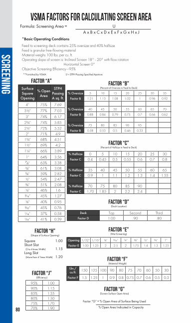
80
VSMA FACTORS FOR CALCULATING SCREEN AREAFormula: Screening Area = U
A x B x C x D x E x F x G x H x J*Basic Operating Conditions
Feed to screening deck contains 25% oversize and 40% halfsizeFeed is granular free-flowing materialMaterial weighs 100 lbs. per cu. ft.Operating slope of screen is: Inclined Screen 18° - 20° with flow rotation Horizontal Screen 0°Objective Screening Efficiency—95%
FACTOR “H”(Shape of Surface Opening)
Square 1.00Short Slot (3 to 4 times Width) 1.15Long Slot (More than 4 Times Width) 1.20
FACTOR “G”(Screen Surface Open Area)
Factor “G” = % Open Area of Surface Being Used
% Open Area Indicated in Capacity
**Furnished by VSMA U = STPH Passing Specified Aperture
SurfaceSquare
Opening
% Open Area
STPH Passing A sq. ft.
4” 75% 7.69
3½” 77% 7.03
3” 74% 6.17
2¾” 74% 5.85
2½” 72% 5.522” 71% 4.9
1¾” 68% 4.511½” 69% 4.2
1¼” 66% 3.89
1” 64% 3.56₇⁄₈” 63% 3.38¾” 61% 3.08₅⁄₈” 59% 2.82½” 54% 2.47³⁄₈” 51% 2.08¼” 46% 1.6³⁄₁₆” 45% 1.27
¹⁄₈” 40% 0.95
³⁄₃₂” 45% 0.76
¹⁄₁₆” 37% 0.58¹⁄₃₂” 41% 0.39
95% 1.0090% 1.1585% 1.3580% 1.5075% 1.7070% 1.90
FACTOR “A”
% Oversize 5 10 15 20 25 30 35
Factor B 1.21 1.13 1.08 1.02 1 0.96 0.92
% Oversize 40 45 50 55 60 65 70
Factor B 0.88 0.84 0.79 0.75 0.7 0.66 0.62
% Oversize 75 80 85 90 95
Factor B 0.58 0.53 0.5 0.46 0.33
% Halfsize 0 5 10 15 20 25 30Factor C 0.4 0.45 0.5 0.55 0.6 0.7 0.8
% Halfsize 35 40 45 50 55 60 65Factor C 0.9 1 1.1 1.2 1.3 1.4 1.55
% Halfsize 70 75 80 85 90Factor C 1.70 1.85 2 2.2 2.4
Opening 1/32” 1/16” ¹⁄₈” ³⁄₁₆” ¼” ³⁄₈” ½” ¾” 1”
Factor E 1.00 1.25 2 2.5 2 1.75 1.4 1.3 1.25
Lbs./cu.ft. 150 125 100 90 80 75 70 60 50 30
Factor F 1.5 1.25 1 0.9 0.8 0.75 0.7 0.6 0.5 0.3
Deck Top Second ThirdFactor D 1.00 .90 .80
FACTOR “B”(Percent of Oversize in Feed to Deck)
FACTOR “C”(Percent of Halfsize in Feed to Deck)
FACTOR “D”(Deck Location)
FACTOR “E”(Wet Screening)
FACTOR “F”(Material Weight)
FACTOR “J”(Efficiency)
SCREENING

81
Smal
l roc
k (0
- ³⁄₁
₆”)
Big
rock
(+ 2
4”)
Smal
l ope
ning
(-8
MES
H)
Larg
e O
pein
g (+
7”)
Hig
h sp
eed
(+ 1
600
RPM
) Sl
ow sp
eed
(- 6
50 R
PM)
Smal
l sto
ke (-
1/
32”)
La
rge
strok
e (+
¾”)
Mor
e slo
pe (+
45°
) Le
ss sl
ope
(0 -
10°)
Stee
per t
imin
g an
gle
Flat
ter t
imin
g an
gle
(mor
e ve
rtica
l) (m
ore
horiz
onta
l)
NO
TE: T
he a
bove
are
gene
ral s
cree
ning
gui
delin
es
only
. App
licat
ion
and
mat
eria
l cha
ract
erist
ics
will
var
y ea
ch o
pera
ting
para
met
er to
ach
ieve
max
imum
scre
enin
g
effic
ienc
y.
INCL
INE
SCR
EEN
HO
RIZ
ON
TAL
SCR
EEN
SCREENING
SCRE
ENIN
G APP
LICAT
ION

82
a - c
ontro
lled
feed
dro
p he
ight
requ
ired,
<24
” dr
op fo
r mat
eria
l siz
e to
12”
, <18
” dr
op fo
r mat
eria
l siz
e to
36”
b
- slo
wer
spee
d m
ust b
e us
ed w
ith m
axim
um st
roke
, stro
ke m
ust b
e le
ss w
ith h
ighe
r spe
eds
c -
griz
zly
bar o
peni
ng c
an b
e w
ider
dep
ende
nt o
n ba
r des
ign
d- 5
” m
ax o
peni
ng o
n 5x
14, 5
x16,
6x1
6 sc
reen
s; 4”
max
ope
ning
on
6x20
, 7x2
0, 8
x20
e -
max
imum
stro
ke is
dep
ende
nt u
pon
vario
us fa
ctor
s suc
h as
med
ia w
eigh
t.
SCRE
EN M
ATRI
XM
odel
Fine
scre
enin
gSt
anda
rd
scre
enin
gLi
ght
scal
ping
Med
ium
sc
alpi
ngH
eavy
Scal
ping
Max
imum
m
ater
ial s
ize
(in.)A
Max
imum
op
enin
g siz
e (in
.)
Spee
d rp
mb
Max
imum
str
oke
(inch
es)g
Slop
e (d
egre
es)
“SI”
Incl
ined
(s
ingl
e sh
aft)
xx
xv
104
800-
1150
³⁄₈b
15-2
5
“DI”
Incl
ined
(d
ual s
haft)
xx
x10
475
0-10
50½
b15
-25
Cas
cade
Incl
ine
xx
104
750-
1000
½b
10-2
5
“XH
” Fl
at E
xtra
H
eavy
Sca
lper
xx
x24
8 gr
izzl
y ba
r57
5-77
5₇ ⁄₈
2 on
top
0 on
bo
ttom
“LP”
Fla
t St
anda
rd S
cree
nx
xx
105f
675-
875
¾0
“CS”
Com
bo
Scre
enx
xx
x10
567
5-87
5¾
mul
tiple
“MS”
Fla
t M
ediu
m S
calp
erx
xx
145
675-
875
¾2
on to
p 0
on
botto
m
“HS”
Fla
t Hea
vy
Scal
per
xx
x18
657
5-77
5₇ ⁄₈
2 on
top
0 on
bo
ttom
“FS”
Fla
t Fin
ishin
g Sc
reen
xx
82
875-
1075
½0
Mes
abi
xx
x36
griz
zly
bar
800
7/16
12SCREENING

83
SCRE
EN M
ATRI
X
a - c
ontro
lled
feed
dro
p he
ight
requ
ired,
<24
” dr
op fo
r mat
eria
l siz
e to
12
”, <1
8” d
rop
for m
ater
ial s
ize
to 3
6”
b - s
low
er s
peed
mus
t be
used
with
max
imum
stro
ke, s
troke
mus
t be
less
with
hig
her s
peed
s c
- gr
izzl
y ba
r ope
ning
can
be
wid
er d
epen
dent
on
bar d
esig
n d
- 8x
20 s
cree
n op
erat
es a
t 15
degr
ees
e -
sing
le s
haft
with
4 b
earin
gs, f
ixed
stro
ke
f - 5
” m
ax o
peni
ng o
n 5x
14, 5
x16
, 6x1
6 sc
reen
s; 4
” m
ax o
peni
ng o
n 6x
20,
7x20
, 8x2
0 g
- m
axim
um s
troke
is ₅ ⁄₈”
to ¾
” de
pend
ing
on s
cree
n sp
eed
SCREENING
Mod
elFi
ne sc
reen
ing
Stan
dard
sc
reen
ing
Ligh
t sc
alpi
ngM
ediu
m
scal
ping
Hea
vySc
alpi
ngM
axim
um
mat
eria
l siz
e (in
.)A
Max
imum
op
enin
g siz
e (in
.)
Spee
d rp
mb
Max
imum
str
oke
(inch
es)g
Slop
e (d
egre
es)
71 S
tand
ard
In
clin
edx
x5
2.5
1,00
0 - 1
,500
¼10
- 15
72 D
esan
der
In
clin
edx
x5
2.5
1,10
0 - 1
,300
³⁄₁₆
25 -
35
72 G
rizzl
y
Incl
ined
x
103c
1,00
0 - 1
,200
₅ ⁄₁₆
10 -
15
H
igh
In
clin
edx
x6
395
0 - 1
,050
³⁄₁₆
2 on
top
0 on
bo
ttom
Stan
dard
In
clin
edx
xx
124
850
- 950
³⁄₈0
Mes
abi
St
anda
rd
Dut
yx
x24
6c95
0 - 1
,000
³⁄₈e
mul
tiple
M
esab
i
Hea
vy
D
uty
xx
367c
900
³⁄₈e
2 on
top
0 on
bo
ttom

84
Series 70 Screens are two bearing inclined screens and include base frame with C spring suspension and electric motor drives. These screens are a medium/light-duty screens and are typically used to size material down to #4 mesh and up to 3” maximum. They are available in a range of sizes from 2’ x 4’ to 5’ x 12’.
Series 71 Screens are “Conventional" screens and are available in single, double- or triple-deck configurations. Each deck has side-tensioned cloth. They operate at an incline of approximately 15°.
INCLINE SCREENS
Model Size Speed (RPM) Motor
71-1D244 24” x 4’ 15-1,700 2 hp71-1D366 36” x 6’ 14-1,600 3 hp71-1D368 36” x 8’ 14-1,600 3 hp71-1D486 48” x 6’ 14-1,600 3 hp71-1D488 48” x 8’ 13-1,500 5 hp
71-1D4810 48” x 10’ 13-1,500 5 hp71-1D4812 48” x 10’ 13-1,500 7½ hp71-1D6010 60” x 10’ 13-1,500 5 hp71-1D6012 60” x 12’ 13-1,500 7½ hp71-1D6014 60” x 14’ 11-1,300 10 hp
Model Size Speed (RPM) Motor
71-2D366 36” x 6’ 14-1,600 3 hp71-2D486 48” x 6’ 13-1,500 5 hp71-2D488 48” x 8’ 13-1,500 7½ hp
71-2D4810 48” x 10’ 11-1,300 10 hp71-2D4812 48” x 12’ 11-1,300 10 hp71-2D6010 60” x 10’ 11-1,300 10 hp71-2D6012 60” x 12’ 11-1,300 10 hp71-2D6014 60” x 14’ 11-1,300 10 hp
SCREENINGSINGLE DECK
DOUBLE DECK

85
Series 72 screens are de-sanders and are available in a double-deck configuration. The top deck cloth is side-tensioned and the bottom deck cloth is end tensioned – harp wire type. They operate at an incline of 15° to 50°.
Series 77 screens are vibrating grizzly screens and are available in single- or double-deck configurations. Grizzly bars are available in fixed or adjustable configurations. Single-deck configurations include grizzly bars only. Double-deck configurations include grizzly bars on the top deck and side-tensioned screen cloth on the bottom deck. Coil impact springs are mounted inside of the C springs. They operate at an incline angle of approximately 15°.
Note: F = Fixed grizzly bars A = Adjustable grizzly bars
Model Size Speed (RPM) Motor
71-3D366 36” x 6’ 13-1,500 5 hp71-3D488 48” x 8’ 11-1,300 10 hp
71-3D4810 48” x 10’ 11-1,300 10 hp
Model Size Speed Motor77-1DG-(F or A) 366 36” x 6’ 13-1,500 7½ hp
77-1DG-(F or A) 488 48” x 8’ 11-1,300 10 hp
Model Size Speed Motor77-2DG-(F or A) 488 48” x 8’ 11-1,300 15 hp
77-2DG-(F or A) 4810 48” x 10’ 11-1,300 15 hp
Model Size Speed Motor
72-2D488 48” x 8’ 11-1,300 7½ HP72-2D4810 48” x 10’ 11-1,300 10 HP72-2D4812 48” x 12’ 11-1,300 10 HP72-2D6010 60” x 10’ 11-1,300 10 HP72-2D6012 60” x 12’ 11-1,300 10 HP
SCREENINGTRIPLE DECK
DOUBLE DECK
SINGLE DECK
DOUBLE DECK

86
Model Size Speed (RPM) Motor
2D4812 48” x 12’ 950-1,050 7½ hp2D6012 60” x 12’ 950-1,050 10 hp2D6014 60” x 14’ 950-1,050 15 hp2D6016 60” x 16’ 950-1,050 15 hp2D7216 72” x 16’ 950-1,050 20 hp
Model Size Speed (RPM) Motor
3D4812 48” x 12’ 950-1,050 10 hp3D6012 60” x 12’ 950-1,050 15 hp3D6014 60” x 14’ 950-1,050 20 hp3D6016 60” x 16’ 950-1,050 20 hp 3D7216 72” x 16’ 950-1,050 30 hp
SCREENING
22° INCLINE SCREENS
SINGLE DECK
DOUBLE DECK

87
10° INCLINE SCREENS
NOTE: *2D9620 and 3D9620 screens operate at 15° incline.
The 10-degree incline screen combines the economy of the single-shaft, two-bearing incline screens with the heavy-duty, aggressive action of the horizontal screens. Perfect for portable applications and in situations where headroom is limited, the screen has a ³⁄₈ inch circular stroke and runs at an RPM around 950. The heavy-duty pan and deck construction make it perfect for applications ranging from standard to heavy-duty.
Model Size Speed (RPM) Motor
2D3610 36” x 10’ 850-950 7½ hp2D4810 48” x 10’ 850-950 10 hp2D4812 48” x 12’ 850-950 15 hp2D6012 60” x 12’ 850-950 20 hp2D6014 60” x 14’ 850-950 25 hp2D6016 60” x 16’ 850-950 30 hp2D7216 72” x 16’ 850-950 30 hp2D7220 72” x 20’ 850-950 30 hp
*2D9620 96” x 20’ 850-950 40 hp
Model Size Speed (RPM) Motor
3D3610 36” x 10’ 850-950 10 hp3D4810 48” x 10’ 850-950 15 hp3D4812 48” x 12’ 850-950 20 hp3D6012 60” x 12’ 850-950 25 hp3D6014 60” x 14’ 850-950 30 hp3D6016 60” x 16’ 850-950 40 hp 3D7216 72” x 16’ 850-950 40 hp3D7220 72” x 20’ 850-950 40 hp
*3D9620 96” x 20’ 850-950 50 hp
SCREENING
DOUBLE DECK
TRIPLE DECK

88
Incline screens feature heavy-duty side and reinforcing plates, a huck bolted construction, an adjustable operating incline from 15-25 degrees, adjustable stroke amplitudes, AR-lined feed boxes and heavy-duty, double-roll bronze cage spherical roller bearings.
Incline screens are available in both single and dual-shaft arrangements, two and three-deck configurations, and are available in sizes ranging from 6’ x 16’ to 8’ x 24.’
INCLINE SCREENS
SINGLE-SHAFT INCLINED SCREENSSingle-shaft incline screens are well-suited for stationary installations, applications where the feed gradation to the screen is constant or when a circular stroke pattern will provide the desired results. Incline screens also enable a lower bed depth of material due to an increased material travel speed that minimizes power consumption while maximizing access for maintenance.
Screen size: 6162 & 6163 6202 & 6203 7202 & 7203 8202 & 8203
SCREENING

89
The Cascade Incline Screen is a field-proven and reliable design featuring an externally-mounted vibrating assembly engineered for efficiency and reduced cost of operation. The screen is available in two- or three-decks and various sizes. Additionally, the screens are available with either oil or grease lubrication and optional speed/stroke combinations, which allow for optimum separation and increased efficiency. As your screen ages, it is not always cost-effective to replace or modify the entire support structure or chassis so Johnson Crushers International is willing to collect data on your aging machine assembly and design and manufacture a replacement “drop-in” unit to minimize any interruption to your production.
CASCADE SCREEN
Screen Size Horsepower Weight Decks
5162-26 SIC 25 hp 12,000 lb 25163-26 SIC 25 hp 15,500 lb 36162-26 SIC 25 hp 13,000 lb 26163-26 SIC 25 hp 16,620 lb 36202-32 SIC 25 hp 15,750 lb 26203-32 SIC 30 hp 19,850 lb 3
SCREENING
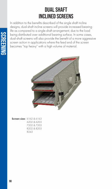
90
In addition to the benefits described of the single shaft incline designs, dual-shaft incline screens will provide increased bearing life as compared to a single-shaft arrangement, due to the load being distributed over additional bearing surface. In some cases, dual-shaft screens will also provide the benefit of a more aggressive screen action in applications where the feed end of the screen becomes “top heavy” with a high volume of material.
DUAL SHAFT INCLINED SCREENS
Screen size: 6162 & 6163 6202 & 6203 7202 & 7203 8202 & 8203 8243
SCREENING

91
SCALPING SCREENS
Model Size Speed (RPM) Motor
2D4810 48” x 10’ 950-1,000 20 hp2D4812 48” x 12’ 950-1,000 25 hp2D6012 60” x 12’ 950-1,000 30 hp2D6014 60” x 14’ 950-1,000 40 hp2D7216 72” x 16’ 950-1,000 50 hp
Model Size Speed (RPM) Motor
2D488 48” x 8’ 900 30 hp2D6014 60” x 14’ 900 40 hp 2D7214 72” x 14’ 900 50 hp
SCREENING
DOUBLE DECK
HEAVY DUTY

92
Horizontal screens are of a triple-shaft design that provides a true oval vibrating motion, and feature a huck-bolted basket assembly, fully-contained lubrication system, and rubber springs to reduce basket stress. Their low profile height makes them ideal for portability, and their adjustment capabilities of speed, stroke length, and stroke angle enable them to be well-suited for both fine and coarse screening applications. Horizontal screens can be retrofitted with either wire cloth or urethane panels, and can be easily converted to wet screen applications.
Horizontal screens are available in several configurations in sizes up to 8' x 24' in two-, three- and four-deck designs.
HORIZONTAL VIBRATING SCREENS
FINISHING SCREENSThe finishing screen maximizes screening efficiency and productivity in fine separation applications by using a reduced stroke and a higher frequency that provides an optimal sifting action.
Adjustable stroke length (Amplitude)(Stroke reduced by removing weight plugs)
min ³⁄₈” to max ½”
Adjustable stroke angle (timing angle) 30 to 60 degrees
Operating speed range 875-1,075 rpm
Maximum feed size 8”
Maximum top deck opening All model screens = 2”
Screen size: 5142-32FS & 5143-32FS 5162-32FS & 5163-32FS 6162-32FS & 6163-32FS 6202-32FS & 6203-32FS 7202-38FS & 7203-38FS 8202-38FS & 8203-38FS
SCREENING

93
LOW-PROFILE SCREENSThe Low-Profile series is best-suited for the widest array of applications ranging from fine to coarse material separation applications.
Adjustable stroke length (Amplitude)(Stroke reduced by removing weight plugs) min 5⁄8” to max ¾”
Adjustable stroke angle (Timing angle) 30 to 60 degrees
Operating speed range 675-875 rpm
Maximum feed size 10”
Maximum top deck opening514, 516 & 616 = 5”
620, 720, 820 & 824 = 4”
Screen size: 5142-32LP & 5143-32LP 5162-32LP & 5163-32LP 6162-32LP & 6163-32LP 6202-32LP & 6203-32LP 7202-38LP & 7203-38LP 8202-38LP & 8203-38LP 8242-38LP & 8243-38LP
*All screen sizes listed above are available in 2 ½ degree slope models
SCREENING

94
MEDIUM SCALPER SCREENSThe medium scalper screen is an excellent machine for coarse screening and light-duty scalping applications. Medium scalper screens also feature thicker side plates and a heavy-duty crowned top deck.
Adjustable stroke length (amplitude) min ₉⁄₁₆” to max ¾”
Adjustable stroke angle (timing angle) 30 to 60 degrees
Operating speed range 675-875 rpm
Maximum feed size* 14”
Maximum top deck opening All model screens = 5”
Screen size: 5142-32MS & 5143-32MS 5162-32MS & 5163-32MS 6162-32MS & 6163-32MS 6202-32MS & 6203-32MS 7202-38MS & 7203-38MS 8202-38MS & 8203-38MS
SCREENING

95
EXTRA-HEAVY SCALPER SCREENSThe extra-heavy scalper screens are also available with a stepped grizzly bar top deck designed to handle up to 24” feed size.
Screen size: 5142-32XH 5162-32XH 6162-38XH 6202-38XH 7202-38XH 8202-38XH
HEAVY SCALPER SCREENSThe heavy scalper screens are designed for heavy-duty scalping applications with the lowest frequency and most aggressive stroke length in the family of horizontal screens. Heavy scalper screens also feature the heaviest-duty construction that can accept up to 18” feed sizes and 24” in the extra-heavy step deck model.
PATENT PENDING
Adjustable stroke length* (Amplitude)(Stroke reduced by removing weight plugs) min ¾” to max 7⁄8”
Adjustable stroke angle (Timing angle) 30 to 60 degrees
Operating speed range* 575-775 rpm
Maximum feed size* 18”
Maximum top deck opening* All model screens = 6”
Screen size: 5142-32HS & 5143-32HS 5162-32HS & 5163-32HS 6162-38HS & 6163-38HS 6202-38HS & 6203-38HS 7202-38HS 8202-38HS
SCREENING

96
Combo screens combine the advantages of both an inclined screen and a horizontal screen. The screen is equipped with inclined panel sections that begin with a 20-degree section, flatten to a 10-degree section, and the remaining deck area is at zero degrees.
By installing sloped sections at the feed end, material bed depth is reduced, since gravity will increase the travel speed of the material. This reduced bed depth minimizes spillover and enables fine particles to stratify through the coarser particles and onto the screening surface much faster, where it can then find more opportunities to be passed through screen openings. This design also enables fines to be introduced to the bottom deck faster, which increases the bottom deck screening capacity, or bottom deck factor used in the VSMA screen calculation.
A punch plate section was designed into the feed plate itself, thereby increasing the total screening area of the top deck by an additional 10%. This punch plate will remove a high percentage of fine particles before they are even introduced to the actual screen deck, thereby increasing production volumes.
The coarse near-sized and oversized particles that are not initially separated on the middle and top decks gradually slow down as the deck panels flatten out to the horizontal section towards the discharge end of the screen. This material’s reduced travel speed, combined with the optimum angle of trajectory in relationship to the screen opening, provides a high screening efficiency upon which oval motion horizontal screens have built their reputation.
MULTI-ANGLE SCREENS
20 °10 °
0 °
0 °
0 °
10 °
10 °
20 °
20 °
SCREENING

97
The combo screen is also the only multi-slope screen that features a triple-shaft design. This design provides an optimal oval screening motion that has proven effective. In addition to the features of the combo design, producers will also benefit by having the ability to adjust stroke length, stroke angle and RPM speed to best suit the conditions of the application.
The end result is a machine that:
1) Provides increased feed production by as much as 20% over standard flat or incline screens
2) Maintains or improves the screening efficiency of separation found on horizontal screens
3) Reduces material spillover at the feed end from high volumes or surges of feed material
4) Improves the bottom screen deck’s utilization, thereby increasing volume and efficiency
Although not as portable as the traditional horizontal screens, the combo design will be an ideal screen for a variety of both scalping and product sizing applications. The design is especially well-suited for accepting large volumetric feed surges, deposits containing a high percentage of fines that must be removed, installations where screening capacity must be increased within the same structural or mounting footprint, or in closed circuit with crushers.
Combo screens are available in both standard and finishing configurations with three or four decks and sizes ranging from 6’ x 20’ to 8’ x 20’. These screens feature a huck-bolt construction, inclined deck panels that slope from 0-20 degrees and adjustable stroke amplitudes. Combo screens also have a hinged tailgate rear section for maintenance access and a perforated feed box for additional screening area. These screens can be installed with either standard wire cloth or urethane/rubber deck panels.
SCREENING

98
COMBO SCREEN
COMBO FINISHING SCREENSThe finishing screen maximizes screening efficiency and productivity in fine separation applications by using a reduced stroke and a higher frequency that provides an optimal sifting action.
Adjustable stroke length* (Amplitude)(Stroke reduced by removing weight plugs) min 5⁄8” to max ¾”
Adjustable stroke angle (timing angle) 30 to 60 degrees
Operating speed range 675-875 RPM
Maximum feed size 10”
Maximum top deck opening 4”
Adjustable stroke length* (Amplitude)(Stroke reduced by removing weight plugs) min ³⁄₈” to max ½”
Adjustable stroke angle (Timing angle) 30 to 60 degrees
Operating speed range 875-1,075 RPM
Maximum feed size 8”
Maximum top deck opening All model screens = 2”
Screen size: 6202-32CS & 6203-32CS 7202-38CS & 7203-38CS 8202-38CS & 8203-38CS
Screen size: 6202-32CF & 6203-32CF 7202-38CF & 7203-38CF 8202-38CF & 8203-38CF
SCREENING

99
GUIDELINES FOR STROKE ADJUSTMENTS
Figu
re 2
Size of Material Plug Configuration RPM of Screen Timing Angle
Coarse 1¼" Plus
3 Plug Each Wheel ¾" Approx.
Very Slow740 RPM 45° - 55°
Medium¾" - 1¼"
2 Plug Each Wheel 11/16"
Approx
Slow ¾" to 1¼" 785 RPM
40° - 50°
Fine¾" - 1¼"
1 Plug Each Wheel ₅⁄₈" Approx.
Fast¾" to 1¼" 830 RPM
35° - 45°
Extra Fine ³⁄₈" Minus
No Plugs Each Wheel 9/16"
Approx. Minimum Stroke
Very Fast875 RPM 30° - 40°
SCREENING
Feed
Additional Capacity with Horizontal Screen Horizontal Deck 6' x 16'
Incline Deck 6' x 16'
Material on Deck
Material on Deck
Additional Capacity
Effective Length of 16' Incline DeckEffective Length of 16' Horizontal Deck
Length of 16' Incline Deck

100
HIGH FREQUENCY SCREENSThe high frequency line includes the Vari Vibe and Duo Vibe screens. There are many advantages a high frequency screen provides, from higher production capabilities to more efficient sizing as compared to conventional screens. The higher production is achieved by an aggressive screen vibration directly applied to the screen media. The high level of vibrating RPMs allows material to stratify and separate at a much faster rate as compared to conventional screens.
Multiple configurations for the screens are available in stationary, portable and track-mounted assemblies. Both screens provide producers with increased production, waste stockpile reduction and more salable product.
SCREENING

101
The Vari Vibe screens are ideal for post-screening applications and offer high frequency vibration on all decks. These screens achieve the highest screen capacity in the market for fines removal, chip sizing, dry manufactured sand and more.
The Duo Vibe screens are ideal for pre-screening applications by offering a scalper top deck with conventional frequency mounted over high frequency bottom deck(s). These screens improve production needs earlier in the circuit by removing fines from coarser materials.
SCREENING

102
1612V CAPACITY(6’ X 12’ SINGLE DECK VARI-VIBE® HIGH FREQUENCY SCREEN)
Basic Capacity Table — 1612V
* Tonnages will vary depending on application, size and type of screens used, weight of product and moisture content.
** This chart is to be used for estimation purposes only. This chart is based on material
weight of 100 lbs/cu. ft. Do not guarantee tonnages without consideration of all possible variables.
Through Deck, Slotted Screen B/C, TPH sq. ft. TPH, 72 sq. ft.
¾” 4.6 331.2 TPH₅⁄₈” 4.2 302.4 TPH
½” 3.81 274.3 TPH
³⁄₈” 3.33 239.8 TPH
¼” 2.91 209.5 TPH
³⁄₁₆” (4M) 2.43 175.0 TPH
¹⁄₈” (6M) 1.6 115.2 TPH
3/32” (8M) 1.18 85.0 TPH
5/64” (10M) 0.9 64.8 TPH
1/16” (12M) 0.7 50.4 TPH
3/64” (16M) 0.55 39.6 TPH
1/32” (20M) 0.43 31.0 TPH
3/128” (30M) 0.33 23.8 TPH
1/64” (40M) 0.22 15.8 TPH
SCREENING

103
2618VM CAPACITY(MODIFIED 6’ X 18’ DOUBLE DECK VARI-VIBE® HIGH FREQUENCY SCREEN)
BASIC CAPACITY TABLE — 2618VM
* Tonnages will vary depending on application, size and type of screens used, weight of product and moisture content.
** This chart is to be used for estimation purposes only. This chart is based on material
weight of 100 lbs/cu. ft. Do not guarantee tonnages without consideration of all possible variables.
Through Deck, Slotted Screen B/C, TPH sq. ft.
Pre-Screen Deck Section A
(TPH, 36 sq. ft.)
Chip Deck Section B
(TPH, 72 sq. ft.))
Post Screen Fine Deck Section C 9TPH, 72 sp. ft.)
¾” 4.6 165.6 TPH 301.5 TPH 265.0 TPH₅⁄₈” 4.2 151.2 TPH 274.5 TPH 241.9 TPH
½” 3.81 137.1 TPH 247.5 TPH 219.5 TPH
³⁄₈” 3.33 119.9 TPH 216.0 TPH 191.8 TPH
¼” 2.91 104.8 TPH 189.0 TPH 167.6 TPH
³⁄₁₆” (4M) 2.43 87.5 TPH 157.5 TPH 140.0 TPH
¹⁄₈” (6M) 1.6 57.6 TPH 103.5 TPH 92.2 TPH
3/32” (8M) 1.18 42.5 TPH 76.5 TPH 68.0 TPH
5/64” (10M) 0.9 32.4 TPH 58.5 TPH 51.8 TPH
1/16” (12M) 0.7 25.2 TPH 45.0 TPH 40.3 TPH
3/64” (16M) 0.55 19.8 TPH 36.0 TPH 31.7 TPH
1/32” (20M) 0.43 15.5 TPH 27.9 TPH 24.8 TPH
3/128” (30M) 0.33 11.9 TPH 21.4 TPH 19.0 TPH
1/64” (40M) 0.22 7.92 TPH 14.3 TPH 12.7 TPH
SCREENING

104
TROUBLESHOOTING GUIDEHIGH FREQUENCY SCREENS
It is a good rule of thumb to ask yourself the following questions if you are seeing a change in the gradation.
1. Has the moisture of the material changed?2. Is the spread of material correct?3. Is the GPM flow rate to vibrators correct?4. Does the angle of screen need to be changed?5. Has the feed gradation changed?6. Is there screen cloth wear?7. Has the feed rate changed?8. If electric vibrators, is the overload protection tripped?
It is Astecs' recommendation to closely monitor the following items as conditions change.
MATERIAL CARRY-OVER OF INEFFICIENT SCREENING
CAUSE SOLUTION
1. Bed of material is too deep 1. Decrease tonnage rate
2. Screen cloth open area too small 2. Increase open area of cloth
3. Screen cloth is blinded 3. Clean screen cloth
4. Screen cloth is blinding on the sides of panels
4. Adjust side seal strips to the same height as tappets
5. Screen angle may need to be steeper 5. Increase angle of screen (not to exceed 43°)
6. Oil flow to vibrators is not set properly 6. Check and adjust vibrators to proper settings
7. Weights in vibrators need to be increased 7. Adjust weights to a higher setting
SCREENING

105
MATERIAL FLOWS DOWN CENTER ORTO ONE SIDE OF SCREEN
TROUBLESHOOTING GUIDEHIGH FREQUENCY SCREENS
CAUSE SOLUTION
1. Material is too wet for the feed rate 1. Reduce feed rate
2. Oil flow to vibrator is not set properly 2. Check and adjust vibrators to proper settings
3. Screen angle may need to be steeper 3. Increase angle of screen (not to exceed 43°)
4. Spread of material is not spread evenly across screen panel
4. Material needs to be across entire screen panel
5. Weights in vibrators need to be increased 5. Adjust weights to a higher setting
CAUSE SOLUTION
1. Material is not centered on feed conveyor 1. Center material on feed conveyor
2. Aggregate spreader needs to be adjusted
2. Adjust position of aggregate spreader in or out to headpulley of feed conveyor
Adjust angle irons on aggregate spreader to achieve proper spread on screen
3. Side seal strips set too high 3. Adjust side seal strips to the same height as the tappets
4. Screening plant may not be level 4. Check level of plant
SCREENING

106
BREAKING SCREEN CLOTH
MATERIAL IS “POPCORNING” ASIT FLOWS DOWN SCREEN
TROUBLESHOOTING GUIDEHIGH FREQUENCY SCREENS (CONT.)
CAUSE SOLUTION
1. Wire diameter of screen cloth is too small for size of material
1. Increase wire diameter or decrease material size
2. Material impact on screen cloth2. Install rubber strips across width of cloth at impact zone to protect screen cloth
3. Improper tension of screen cloth
3. Screen cloth is either too loose or too tight (depending on wire diameter); make sure anchor ends are evenly tensioned
4. Bucker rubber on tappets is worn out 4. Install new bucker rubber on tappets
5. Improper weave or crimp of screen panel 5. Contract screen manufacturer
6. Screen panel is too long and hook end turned over too far 6. Contact screen manufacturer
CAUSE SOLUTION
1. Fines have been removed from material
1. Adjust oil flow on the vibrators where this is occurring
Install dams to knock materials down (contact Astec Mobile Screens)
2. Feed rate to screen is too slow 2. Increase feed rate
SCREENING

107
FRACTIONATING RAPPrice increases in liquid asphalt and virgin aggregates have led the industry to re-evaluate the use of recycled asphalt pavement (RAP) in hot mix asphalt (HMA) designs. Consider that recycled asphalt has rock the same age as the aggregate coming from the rock quarry today and liquid asphalt coming from the refined oil from oil wells. Most RAP processed today is ½" x 0, since it is coming from milled material, which is generally surface mix.
Processing RAP includes crushing and/or screening. The fractionation process typically separates RAP into two or three sizes, ½" x ³⁄₈”, ³⁄₈" x ³⁄₁₆", and -³⁄₁₆”. The coarser material (fractions) will have lower asphalt content and dust content versus the finer material (fractions), which enables the mix designer to have greater control over the amount of RAP being introduced into the mix.
Under the assumption that recycled materials are worth what they replace, producers are realizing extraordinary financial benefits by fractionating RAP material.
SCREENING

108
Asphalt mixes first appeared in the United States in the late 1800s. Natural asphalt from Trinidad Lake was placed in drums and imported into the United States where drums were heated and the asphalt melted to be mixed with combinations of aggregate of various sizes to produce a smooth, quiet road. Professor Alonzo Barber of Harvard College obtained a franchise from the British Government to bring Trinidad Lake asphalt into the United States and distribute it. From these early beginnings, asphalt roads have grown to become the major pavement of choice, with approximately 94% of the roads in America being surfaced with asphalt.
In the early 1900s, due to the high cost of Trinidad Lake material, recycling of old pavements was common. During the 1920s, with more and more automobiles becoming available, the demand for roads increased. Concurrent with this was the need for more fuel, and as oil was discovered in Pennsylvania and California, Trinidad Lake asphalt was replaced by a less expensive product, the residue from the refining process (the bottom of the barrel) and the roads were made from asphalt being derived from the oil refining process. Due to the fact that liquid asphalt was difficult to handle, sticky, and at low temperatures a rubbery-like substance, oil refineries just wanted to be free of the material and basically gave it away initially. Due to the abundance of crude oil in Texas and other areas of the United States, asphalt and oil remained relatively cheap through the ‘50s, ‘60s and
into the early ‘70s.
During the 1950s and ‘60s, liquid asphalt sold for a p p r o x i m a t e l y $20/ton. Since an average of 5% asphalt was used to glue the aggregate together to form
a road, the glue or asphalt only costs approximately $1/ton and aggregate was approximately $1/ton, leading to a virgin material
INTRODUCTION TO RAP
SCREENING

109
costs of the hot mix asphalt of approximately $2/ton. By the early ‘70s, liquid asphalt had increased to approximately $30/ton, with the asphalt or glue at $1.50/ton and aggregate to about $1.50/ton, resulting in material costs of $3/ton. F1 In 1973, crude oil prices escalated due to the first oil embargo in the United States and liquid asphalt prices escalated to $80/ton in a very short time period. Typically, asphalt prices per ton are usually 6 times the price of a barrel of crude oil, i.e. 6 x $30/ barrel equals $180/ton liquid asphalt. This also resulted in higher aggregate prices (due to higher fuel prices) and liquid asphalt prices of approximately $4/ton of mix (5% of $80/ton). And thus resulting in a total virgin material cost of $6-$7/ton.
Again in 1979, F1, crude climbed to $30/barrel and liquid asphalt prices escalated to $180/ton with the second oil embargo.
This resulted in material costs for the asphalt portion of hot mix at $9/ton and aggregate costs had escalated to approximately $4-$5/ton resulting in a total virgin material costs of $13/ton.
In 1975, two things came together that made recycling again economically feasible. First, the prices of liquid asphalt and aggregate had escalated as mentioned above and secondly, a machine called a road planer or milling machine was developed (F2), that would remove as little as a ¼” or as much as 6” of material from
SCREENING

110
the roadway in one pass. This revolutionary new machine allowed numerous benefits to the road building industry. A few of them are as follows:
• Rutted roads could be milled to a level surface, resulting in a more uniform and h igher-qual i ty pavement when placed over a flat surface, F3.
• Drainage could be maintained on city streets by milling the road surface prior to placement of another lift of mix eliminating stacking of layer on layer of resurfacing material, F4.
• Milling eliminated the raising of utilities and manholes and maintained
proper drainage to the curb, F5.
• Milling eliminated the reduction in clearance under overpasses, F6.
• Milling eliminated the increase of weight on bridges caused by adding layer after layer.
While all of these advantages helped the public works designers to establish and maintain elevations, clearances, etc., it also generated
SCREENING

111
an enormous amount of reclaimed pavement that could be recycled.
A second contribution of milling machines to the asphalt industry was the reduction in cost of obtaining recycled material versus complete pavement removal. Early milling costs were in the $4/ton range, but currently milling costs of $2-$3/ton, depending whether on highway or in city work, is normal. With the combination of higher virgin material costs and lower removal costs, hot mix asphalt has become the highest volume recycle product in the United States. The low cost of milling material versus the higher costs of virgin material produces a differential that gives recycle a tremendous economic advantage. Basically, recycling is worth what it replaces. F7 shows the economic benefit of adding recycle based on the various percentages used.
While recycling is often looked at in many industries as an inferior product to new materials, in hot mix asphalt it is often found to be a superior product, since the liquid asphalt available today is often not of the same quality as it was a number of years ago. Current specifications allow the artificial softening of harder asphalts and lead to liquids with high percentages of volatiles and less binding strength than the original liquid. Even where current liquids are used today, the light oils are generally evaporated during mixing and placement and over a period of time resulting in purer asphalt occurring in the recycled product.
In addition, aggregates that tend to be absorptive only absorb the liquid asphalt one time. The recycled product, when combined with new aggregate, often will have a thicker film because absorption occurs only once in the RAP portion of the mix. Perhaps the best description of recycling could be summed up by the words of a Japanese customer (who was the first to recycle in Japan). When asked what he told his customers concerning recycle, he said “it’s all the same age.”
SCREENING

112
AVAILABILITY OF RECYCLEDASPHALT PRODUCTS (RAP)
Due to the benefits of milling in cities and on highways, more recycle is becoming available. Inlays are becoming commonplace in most states where 1-½” to 2” of material is milled and a new surface is installed
in the removed area without increasing the elevation of the road. This type of construction is very beneficial since the inlay area allows containment of the new mix on each side, resulting in superior
joints. Also, it permits construction to be done at night with minimum disruption to the traveling public, F8. This type of construction results in enough material being available to produce 100% recycle mix and although this is not practical, it results in increasing quantities of RAP.
In addition, with rebuilding of sewers, electrical lines, and other utilities below the roadway, numerous amounts of ripped-up material is available. Milling on parking lots is often done rather than complete removal, since material can be milled to an exact elevation and the price of milling is much less than total excavation and re-grading prior to placing a new surface. This also results in a large quantity of material being available. With the passage of each year, it is our opinion that the amount of recycle available will increase steadily and more efforts must be made to increase the quality of recycle placed into hot mix asphalt without sacrificing quality.
SCREENING

113
PROCESSING RAP MATERIALHot mix asphalt producers generally have two types of recycle asphalt that is available: ripped up material being brought in by customers and mill material from highway projects, parking lots, city streets, etc. Typically, mill material is placed in recycle bins and the oversized mill material passes over a single- or multiple-deck screen. The bulk of the material is fed directly to the plant without processing. When RAP is screened over 1-½” to 2” screens, unless the asphalt plant has a long mixing time, the RAP cannot be totally melted and homogeneously mixed with the new virgin aggregate and asphalt.
Some plants are equipped with closed circuit crushing systems that crush the oversized material that does not pass through the screen and returns it to the top of the screen as shown in F9.
Ripped up material has been crushed through various types of crushing plants F9 and F10.
For percentages of RAP of less than 15-20%, feeding one size of material is generally adequate, but as the percentage of recycle increases, and the quality of mix is more scrutinized, it has become more obvious that multiple
SCREENING

114
sizes of RAP will be required. Logic dictates that RAP should be treated like any other aggregate that is sized and fed to the plant in multiple sizes, if the quality of the final product is to be ensured. On most mixes designed in the United States in the last 50 years, a film thickness
of 9 to 10 microns has been commonplace. By sizing the material into specific size ranges, the amount of liquid asphalt in each of these materials is much more consistent. Trying to produce a product using 30, 40 or 50% RAP with one size results in segregation of the material and wide variations in liquid asphalt content, making it very difficult for the plant to produce a high-quality mix.
The most economical way of processing RAP into multiple sizes is to screen it first. Since most of the mill material is surface mix, it is ½ inch or 12.5 mm minus material. With mill material, 70-80% of the
material will pass a ½ inch screen and, if sized into two sizes, a ¼” x 0” F12, and ½” x ¼” F13, the consistency and the percentage of RAP that can be used increases significantly. F14 shows a portable, high-frequency screen. It is self-contained with its own engine and hydraulic drives that allow pre-screening of RAP into three sizes, one oversized and two finished products. Since 70-80% of the material will pass ½” minus opening, only 20-25% of the oversized material
FOLD ‘N GO
SCREENING

115
requires crushing. A highly-mobile unit such as this can be moved quickly between multiple plants sizing the material and reducing the amount of material required to be crushed.
It is estimated that pre-screening the material, as shown here in F15, can be done for $.50 to $.75 per ton, therefore reducing the cost of crushing significantly, since only 20-25% of the material will be required to be crushed. A crusher, as shown in F16, can then be used to feed the material directly into a pre-screening unit, again sizing the material into two different sizes.
SCREENING

116
ECONOMICSBy processing the material into two different sizes, higher percentages of RAP can be accurately blended producing not only additional savings, but also resulting in a higher quality, more consistent mix. With the more restrictive gradation requirements of the Superpave mix
design procedure, producers often find it difficult to insert more than 10% RAP when using only a single size. By separating the RAP into two sizes, producers are successful ly increas ing RAP quantities to as high as 40% while also improving the quality of the mix. F17 shows a 12.5 mm Superpave mix with 15% recycle.
By fractionating the RAP, the percentage of recycle can be increased to 40%. The savings through increased recycle is shown in F18. F19 shows a mix with RAP increased from 10% to 35%. F20
shows the savings by increasing the RAP percentages from 10% to 35% and F21 shows a 9.5 mm mix with RAP increased from 15% to 40%. F22 shows the savings by increasing the RAP percentages from
SCREENING

117
15 to 40%. Innovative operators have used the pre-screening plants for producing a large number of multiple sizes. Where SMA mixes are required, minus-16 mesh RAP can be processed, producing a minus-16 mesh product and feeding it directly into the asphalt plant while also producing two additional sizes of product that can be used in mixes at a later date. By using the minus 16 mesh or minus-4 mesh product to replace mineral filler and a portion of the polymerized asphalt, the cost of mix can be reduced significantly. F23 shows the gradations and asphalt content of the two RAP products. F24 shows the savings that result.
F25 shows how the RAP actually improves the rutting performance. When using minus-16 mesh RAP, the material should be fed directly from the screen to the RAP feeder on the asphalt plant due to its high asphalt
SCREENING

118
content. F26 shows a screening plant feeding directly to a RAP bin. The other two sizes are stockpiled for future use. Since the percentage of liquid varies with the size of RAP, ¼” x 0” RAP may have as high as 7% liquid, while ½” x ¼” may have less than 4% liquid. Some states place limits on the percentage of RAP before the grade of liquid is changed. Using finer RAP allows a significant reduction of new l iquid without exceeding the percentage of RAP required. Most important when considering the use of multiple sizes of RAP is the improvement in
quality. One producer, using ¾” minus RAP, was limited to 20% and continuously experienced penalties for quality. By sizing the RAP, the percentage has increased to 40% and penalties have disappeared.
SCREENING

119
CONCLUSIONWith each passing year, the amount of recycled materials available continually increases. The economic benefits of adding recycle are obvious. An increase of 10% recycle can be shown to reduce the cost (based on the economics in F7). This significant savings certainly justifies processing RAP and treating it like any other material. High-frequency screening plants can reduce the cost of processing RAP significantly. These highly-portable plants make multiple sizes of recycle available to allow the production of high-quality mixes. The savings can result in paybacks in just a few months on the screening plant while improving the quality of the finished product and resulting in better, smoother, higher-quality roads for the traveling public to use.
SCREENING

120
MATERIAL HANDLINGBelt conveyors are designed to carry material the shortest distance between the loading and unloading points. When required, belt conveyors can operate continuously without loss of time and are capable of handling tonnagǝs of bulk materials that would be more costly and often impractical to transport by other means.
Choosing the right conveyor starts with looking at the five basic considerations: material characteristics, conveyor length and/or discharge height, TPH feed, conveyor width and horsepower requirements.
NOTE: *When mass slips due to water lubrication rib type belts permit 3-5 degrees increase.
RECOMMENDED MAXIMUM ALLOWABLE INCLINEFOR BULK MATERIALS
Material Angle Incline % GradeAlumina 10.0-12.0 17.6-21.2
Ashes, Coal, Dry, ½” and Under
20-25 36.4-46.6
Ashes, Coal, Wet, ½” and Under
23-27 42.4-50.4
Ashes, Fly 20-22 36.4-40.4
Bauxite, Ground, Dry 20 36.4
Bauxite, Mine Run 17 30.6Bauxite, Crushed 3”
and Under20 36.4
Borax, Fine 20-25 36.4-46.6
Cement, Portland 23 42.4
Charcoal 20-25 36.4-46.6
Cinders, Blast Furnace 18-20 32.5-36.4
Cinders, Coal 20 36.4
Coal
Bituminous, Run of Mine 18 32.4
Bituminous, Fines Only 20 36.4
Bituminous, Lump Only 16 28.6
Anthracite, Run of Mine 16 28.6
Anthracite, Fines 20 36.4
Anthracite, Lump Only 16 28.6
Anthracite, Briquettes 12 21.3
Coke—Run of Oven 18 32.4
Coke, Breeze 20 36.4
Concrete—Normal 15 26.8
Concrete—Wet (6" Slump) 12 21.3
Chips—Wood 27 50.9
Cullet 20 36.4
Dolomite, Lumpy 22 40.4
Grains—Whole 15 26.8
Gravel—Washed 15 26.8
Gravel and Sand 20 36.4
Gravel and Sand Saturated 12 21.3
Gypsum, Dust Aerated 23 42.4
v Angle Incline % GradeGypsum, ½” Screening 21 38.3
Gypsum, 1-½” to 3” Lumps 15 26.8
Earth—Loose and Dry 20 36.4Lime, Ground, ¹⁄₈”
and Under23 42.4
Lime, Pebble 17 30.6
Limestone, Crushed 18 32.5
Limestone, Dust 20 36.4
Oil Shale 18 32.5Ores—Hard—
Primary Crushed17 30.6
Ores—Hard—Small Crushed Sizes
20 36.4
Ores—Soft—No Crushing Required
20 36.4
Phosphate Triple Super, Ground Fertilizer
30 57.7
Phosphate Rock, Broken, Dry 12-15 21.2-26.8
Phosphate Rock, Pulverized 25 46.6
Rock, Primary Crushed 17 30.6
Rock, Small Crushed Sizes 20 36.4
Sand—Damp 20 36.4
Sand—Dry 15 26.8
Salt 20 36.4
Soda Ash (Trona) 17 30.6
Slate, Dust 20 36.4Slate, Crushed, ½”
and Under15 26.8
Sulphate, Powder 21 38.3Sulphate, Crushed—
½” and Under20 36.4
Sulphate, 3” and Under 18 32.5
Taconite—Pellets 13-15 23.1-26.8
Tar Sands 18 32.5
MATERIAL HANDLING

121
1. Material Characteristicsa. Variables include: particle shape, and size, moisture, angle of repose, lump size and percentage fines and weight. Characteristics typically used as a rule of thumb include: 100 lbs. per cubic foot density, 37° angle of repose and less than 25% of a max. 3” lump.
b. Material characteristics can affect other elements of conveyor selection.
• Heavier material or large lumps may require more horsepower, a heavier belt, closer idler spacing and impact idlers at feed points
• Abrasiveness may require wear liners or special rubber compositions• Moisture may require steeper hopper sides, wider belts, anti-buildup
return idlers and special belt wipers• Dust content may require special discharge hoods and chutes, slower
belt speeds and hood covers• Sharp materials may require impact idlers, wear liners, special belt
and plate feeder• Lightweight materials may require wider belts and less horsepower
c. Conveyor Belt
Conveyor belts consist of three elements: top cover, carcass and bottom cover.
The belt carcass carries the tension forces necessary in starting and moving the loaded belt, absorbs the impact energy of material loading and provides the necessary stability for proper alignment and load support over idlers, under all operating conditions.
Because the primary function of the cover is to protect the carcass, it must resist the wearing effects of abrasion and gouging, which vary according to the type of material conveyed. The top cover will generally be thicker than the bottom cover because the concentration of wear is usually on the top or carrying side.
The belt is rated in terms of “maximum recommended operating tension” pounds per inch of width (PIW). The PIW of the fabric used in the belt is multiplied by the number of plies in the construction of the belt to determine the total PIW rating of the belt.
MATERIAL HANDLING

122
d. Idlers
Idler selection is based on the type of service, operating condition, load carried and belt speed.
CEMA IDLER CLASSIFICATION
2. Length
Length is determined one of three ways:
a. Lift height required: When lift height is the determining factor, as a rule of thumb, an 18-degree incline is used, where 3 x height needed approximates the conveyor length required. Particle size, moisture and other factors affect the maximum incline angle. If the material tends to have a conveyable angle that is less than 18 degrees, a longer conveyor needs to be selected to achieve the desired lift height.
b. Distance to be conveyed
c. Stockpile capacity desired
Classification Former Series No. Roll Diameter (in) Description
A4 I 4 Light Duty
A5 I 5 Light Duty
B4 II 4 Light Duty
B5 II 5 Light Duty
C4 III 4 Medium Duty
C5 III 5 Medium Duty
C6 IV 6 Medium Duty
D5 NA 5 Medium Duty
D6 NA 6 Medium Duty
D7 VI 7 Heavy Duty
E6 V 6 Heavy Duty
MATERIAL HANDLING

123
40’
40’
50’
60’
80’
100’
120’
150’
21° 18
° 15° 12
° 9°
50’
60’
80’
100’
120’
150’
60’
50’
40’
30’
5’10’
20’
ELEVATION IN FEET
CONV
EYOR
ELEV
ATIO
N CH
ART
CON
VEYO
R LE
NG
TH IN
FEE
T
HO
RIZO
NTA
L D
ISTA
NCE
IN F
EET
MATERIAL HANDLING

124
CONVEYOR ELEVATION
L L
2'
H
Head PulleyC
H=L x Sin(θ)+2
Conveyor Legth (ft) Conveyor Angle (degrees) Height (ft)
40
12 10.3
15 12.4
18 14.4
21 16.3
60
12 14.5
15 17.5
18 20.5
21 23.5
80
12 18.6
15 22.7
18 26.7
21 30.7
100
12 22.8
15 27.9
18 32.9
21 37.8
125
12 28
15 34.4
18 40.6
21 46.8
150
12 33.2
15 40.8
18 48.4
21 55.8
MATERIAL HANDLING

125
Live capacity is the part of pile that can be removed with one feed chute at the center of pile. Approximately ¼ of gross capacity of pile.
Gross Volume = 1⁄3 Area Base x Height*Gross Volume, (V1) Cu. Yd. = .066 (Height, Ft. )3*Gross Capacity, Tons = 1.35 x Volume, Cu. Yd. (100#/Cu. Ft.)*Based on an angle of repose of 37.5°
CONICAL STOCKPILE CAPACITY
"D" APPROX
"H"
37.537.5DEADSTORAGE
LIVE STORAGE
o o
H DVolume
H DVolume
Cu. Yds. Tons(100lb/cu. ft.) Cu. Yds. Tons
(100lb/cu. ft.)
6 16 14 19 26 68 1,158 1,563
8 21 34 46 28 73 1,446 1,952
10 26 66 89 30 78 1,779 2,401
12 31 114 154 35 91 2,824 3,813
14 36 181 244 40 104 4,216 5,691
16 42 270 364 45 117 6,003 8,104
18 47 384 519 50 130 8,234 11,116
20 52 527 711 55 143 10,960 14,795
22 57 701 947 60 156 14,228 19,208
24 63 911 1,229
Dead Storage
"D" Approx
"H"
Live Storage
MATERIAL HANDLING

126
APPROXIMATE VOLUME OFCIRCULAR STOCKPILE
V3 = V1 + V2ӨV3 = Total volume of stockpile - in cu. yds.V1 = volume of ends (volume of conical stockpile) - in cu. yds.V2 = Volume of stockpile for 1° Arc - in cu. yds.
V2 = 1,187H
H = Height of stockpile - in feetR = Radius of arc (Centerline Pile to Centerline Pivot) - in feetR = cos 18° x conveyor length L
NOTE: V2 based on 37.5° angle of repose Ө = Angle of arc - in degrees
V1
2
R
VOLUME OF STOCKPILESEGMENT FOR 1o ARC V2
V1
2
H2R
Volume of Stockpile Segment for 1° Arc V2
MATERIAL HANDLING

127
V2 = VOLUME OF STOCKPILE SEGMENT FOR 1 DEGREE ARC (CU. YDS.)
3. TPH FeedSee belt carrying capacity chart. As a rule of thumb, at 350 fpm, 35-degree troughing idlers and 100 lbs/cu. ft. material, a 24” belt carries 300 TPH, a 30” belt carries 600 TPH and a 36” belt carries 900 TPH.
EXAMPLES:
Radius (ft)
Stockpile Height (H) (ft)10 15 20 25 30 35 40 45 50 55
25 2.130 2.535 2.9 6.640 3.4 7.645 3.8 8.550 4.2 9.5 16.855 4.6 10.4 18.560 5.1 11.4 20.2 31.665 5.5 12.3 21.9 34.270 5.9 13.3 23.6 36.975 6.3 14.2 25.3 39.5 56.980 6.7 15.2 27 42.1 60.785 7.2 16.1 28.6 44.8 64.4 87.790 7.6 17.1 30.3 47.4 68.2 92.995 8 18 32 50 72 98
100 8.4 19 33.7 52.7 75.8 103.2 134.8105 8.8 19.9 35.4 55.3 79.6 108.4 141.5110 9.3 20.9 37.1 57.9 83.4 113.5 148.3 187.7115 9.7 21.8 38.8 60.6 87.2 118.7 155 196.2120 10.1 22.7 40.4 63.2 91 123.8 161.8 204.7 252.7125 10.5 23.7 42.1 65.8 94.8 129 168.5 213.2 263.3130 11 24.6 43.8 68.4 98.6 134.2 175.2 221.8 273.8135 11.4 25.6 45.5 71.1 102.4 139.3 182 230.3 284.3 344140 11.8 26.5 47.2 73.7 106.1 144.5 188.7 238.8 294.9 356.8145 12.2 27.5 48.9 76.3 109.9 149.6 195.5 247.4 305.4 369.5150 12.6 28.4 50.5 79 113.7 154.8 202.2 255.9 315.9 382.3
L H R V1 V1 V2 V2 V3 V3
Feet Feet Feed Cu. Yds. Tons Cu. Yds. Tons90°
Stockpile Cu. Yds.
90° Stockpile
Tons
60 20.5 57 567 766 20.2 27.3 2,385 3,223
80 26.7 76 1,254 1,693 45.6 61.6 5,358 7,237
100 32.9 95 2,346 3,167 86.6 116.9 10,140 13,688
120 39.1 114 3,938 5,316 146.8 198.2 17,150 23,154
150 48.4 142.5 7,469 10,083 281.2 379.6 32,777 44,247
MATERIAL HANDLING

128
NO
TE: *
Cap
acity
is b
ased
on
mat
eria
l wei
ghin
g 10
0 lb
./cu
. ft.
with
37.
5 de
gree
ang
le o
f rep
ose,
3-ro
ll, 35
deg
ree
idle
rs a
nd n
o sk
irt b
oard
s.
*
Cap
acity
is th
eore
tical
bas
ed o
n a
full
cros
s sec
tion.
To
use
for c
onve
yor s
izin
g, u
se 7
5%-8
0% o
f the
cap
acity
liste
d ab
ove.
CONV
EYOR
BEL
T CAR
RYIN
G CAP
ACITY
AT VA
RIOU
S SPE
EDS
Belt
Wid
th(in
)
Cap
acity
in T
PH
Belt
Spee
d (fp
m)
100
150
200
250
300
350
400
450
500
550
600
1869
103
138
172
207
241
276
310
345
379
414
2413
219
826
433
039
646
252
859
466
072
679
2
3021
532
243
053
764
575
286
096
71,
075
1,18
21,
290
3631
847
763
679
595
41,
113
1,27
21,
431
1,59
01,
749
1,90
8
4244
166
188
21,
102
1,32
31,
543
1,76
41,
984
2,20
52,
425
2,64
6
4858
587
71,
170
1,46
21,
755
2,04
72,
340
2,63
22,
925
3,21
73,
510
5474
81,
122
1,49
61,
870
2,24
42,
618
2,99
23,
366
3,74
04,
114
4,48
8
6093
21,
398
1,86
42,
330
2,79
63,
262
3,72
84,
194
4,66
05,
126
5,59
2
721,
360
2,04
02,
720
3,40
04,
080
4,76
05,
440
6,12
06,
800
7,48
08,
160
MATERIAL HANDLING

129
4. Conveyor Width
There are a number of factors that affect width. These include TPH feed, future considerations, lump size and the percentage of fines, cross-section of how the material settles on the belt and material weight.
a. Normally, portable conveyors are set up to run at 350 feet per minute, as this is accepted as the best speed for the greatest number of types of material and optimum component life. When it is desirable to run at a different speed, this will usually be a factory decision based on the material and the capabilities requested by the customer. These variations are generally applicable on engineered systems.
RECOMMENDED MAXIMUM BELT SPEEDS
Material Bing Conveyed Belt Speeds (fpm) Belt width (in)
Grain or other free-flowing, nonabrasive material
500 18
700 24-30
800 36-42
1,000 48-96
Coal, damp clay, soft ores, overburden and earth, fine-crushed stone
400 18
600 24-36
800 42-60
1,000 72-96
Heavy, hard, sharp-edged ore, coarse-crushed stone
350 18
500 24-36
600 Over 36
Foundry sand, preared or damp; shakeout sand with small cores, with or without small castings (not hot enough to harm belting)
350 Any width
Prepared foundy sand and similar damp (or dry abrasive) materials dischared from belt by rubber-edged plows
200 Any width
Nonabrasive materials dischared from belt by means of plows
200 except for wood pulp, where 300 to 400 is preferable
Any width
Feeder belts, flat or troughted, for feeding fine, nonabreasive, or midly abrasive materials from hopper and bins
50-100 Any width
MATERIAL HANDLING

130
b. Lump size and the percentage of fines can have a major effect on width selection. As a rule of thumb, for a 20-degree surcharge angle, with 10 percent lumps and 90 percent fines, the recommended maximum lump size is one third of the belt width (BW/3). With all lumps and no fines, the recommended maximum lump size is one fifth of the belt width (BW/5). For a 30-degree surcharge angle, with 10 percent lumps and 90 percent fines, the recommended maximum lump size is one sixth of the belt width (BW/6). With all lumps and no fines, the recommended maximum lump size is one tenth of the belt width (BW/10). Belts must be wide enough so any combination of lumps and fine material does not load the lumps too close to the edge of the belt.
c. The cross section of how the material settles on a moving belt can have a major effect on expected tonnage for a given width conveyor.
FACTORS AFFECTING THE CROSS SECTION:
• The angle of repose of a material is the angle that the surface of a normal, freely formed pile, makes to the horizontal.
• The angle of surcharge of a material is the angle to the horizontal that the surface of the material assumes while the material is at rest on a moving conveyor belt. This angle usually is 5° to 15° less than the angle of repose, though in some materials it may be as much as 20° less.
• The flowability of a material, as measured by its angle of repose and angle of surcharge, determines the cross-section of the material load that can safely be carried on a belt. It is also an index of the safe angle of incline of the belt conveyor. The flowability is determined by such material characteristics as size and shape of the fine particles and lumps, roughness or smoothness of the surface of the material particles, proportion of fines and lumps present and moisture content of material.
MATERIAL HANDLING

131
FLOWABILITY—ANGLE OF SURCHARGE—ANGLE OF REPOSE
d. The material weight affects the volume, which affects the width. Most aggregate weighs between 90-110 lbs. per cubic foot. When the weight varies significantly, it can have a dramatic effect on expected belt width needed to achieve a given tonnage.
Very Free Flowing Free Flowing Average Flowing Sluggish 5° Angle of 10° Angle of 20° Angle of 25° Angle of 30° Angle of surcharge surcharge surcharge surcharge surcharge
0°-19° Angle 20°-29° Angle 30°-34° Angle 35°-39° Angle 40°-up Angle of repose of repose of repose of repose of repose
MATERIAL CHARACTERISTICS Uniform size, Rounded, dry Irregular, granu- Typical common Irregular, very small polished particles, lar or lumpy materials such as stringy, fibrous, rounded particle, of medium weight, materials of bituminous coal, interlocking mate- either very wet or such as whole medium weight, stone, most ores, ial, such as wood very dry, such as grain or beans. such as anthra- etc. chips, bagasse, dry silica sand, cite coal, cotton- tempered foundry cement, wet con- seed meal, clay, sand, etc. crete, etc. etc.
5. Horsepower Requirements
The power required to operate a belt conveyor depends on the maximum tonnage handled, the length of the conveyor, the width of the conveyor and the vertical distance that the material is lifted. Factors X + Y + Z (from tables below) = Total HP Required at Headshaft. The figures shown are based on average conditions with a uniform feed and at a normal operating speed. Additional factors such as pulley friction, skirtboard friction, material acceleration and auxiliary device frictions (mechanical feeder, tripper, etc.) may require an increase in horsepower.
Drive efficiency is taken into consideration to determine the motor horsepower required. This can be an additional 10-15% above the headshaft horsepower. The ability to start a loaded conveyor will also require an additional horsepower consideration.
MATERIAL HANDLING

132
Factor X - Horsepower Required to Operate Empty Conveyor at 350 FPM
Conveyor Width
Center-Center of Pulleys
25’ 50’ 75’ 100’ 150’ 200’ 250’ 300’ 350’ 400'
18” 0.7 0.8 0.9 1.1 1.2 1.3 1.4 1.7 1.8 224” 0.9 1.1 1.2 1.4 1.6 1.8 2 2.1 2.3 2.530” 1.4 1.6 1.8 1.9 2.2 2.5 2.8 3 3.2 3.536” 1.8 2 2.1 2.6 2.9 3.1 3.4 3.8 4.2 4.442” 2.1 2.5 2.7 3 3.5 3.7 4.2 4.6 5.3 648” 2.7 2.8 3.2 3.4 3.7 4.2 5.3 5.6 6.2 6.7
Factor Y - Additional HP Required to Operate Loaded Conveyor on the Level
TPHCenter-Center of Pulleys
25’ 50’ 75’ 100’ 150’ 200’ 250’ 300’ 350’ 400’
100 0.5 0.6 0.7 0.8 0.9 1 1.1 1.3 1.4 1.5150 0.8 0.9 1 1.1 1.3 1.5 1.7 1.9 2.1 2.3200 1 1.2 1.3 1.5 1.7 2 2.2 2.5 2.8 3250 1.3 1.5 1.6 1.9 2.1 2.5 2.8 3.1 3.5 3.8300 1.5 1.8 2 2.3 2.6 3 3.3 3.8 4.2 4.5350 1.8 2.1 2.3 2.6 3 3.5 3.9 4.4 4.9 5.3400 2 2.4 2.6 3 3.4 4 4.4 5 5.6 6500 2.5 3 3.3 3.8 4.3 5 5.5 6.3 7 7.5600 3 3.6 3.9 4.5 5.1 6 6.6 7.5 8.4 9700 3.5 4.2 4.6 5.3 6 7 7.7 8.8 9.8 10.5800 4 4.8 5.2 6 6.8 8 8.8 10 11.2 12900 4.5 5.4 5.9 6.8 7.7 9 9.9 11.3 12.6 13.5
1,000 5 6 6.5 7.5 8.5 10 11 13 14 15
Factor Z - Horsepower Required to Lift Load on Belt Conveyor
TPHLift
10’ 20’ 30’ 40’ 50’ 60’ 70’ 80’ 90’ 100’
100 1 2 3 4 5 6 7 8 9 10150 1.5 3 4.5 6 7.5 9 10.5 12 13.5 15200 2 4 6 8 10 12 14 16 18 20250 2.5 5 7.5 10 12.5 15 17.5 20 22.5 25300 3 6 9 12 15 18 21 24 27 30350 3.5 7 10.5 14 17.5 21 24.5 28 31.5 35400 4 8 12 16 20 24 28 32 36 40500 5 10 15 20 25 30 35 40 45 50600 6 12 18 24 30 36 42 48 54 60700 7 14 21 28 35 42 49 56 63 70800 8 16 24 32 40 48 56 64 72 80900 9 18 27 36 45 54 63 72 81 90
1,000 10 20 30 40 50 60 70 80 90 100
MATERIAL HANDLING

133
HOW TO DETERMINE CONVEYOR BELT SPEEDFive factors are required to determine conveyor belt speed.
A = Motor RPM B = Motor sheave diameter (inches) C = Reducer sheave diameter (inches) D = Reducer ratio E = Diameter of pulley (inches)
A x B ÷ C = Reducer input speed (RPM)
Reducer input speed (RPM) ÷ D = drive pulley RPM
Drive Pulley RPM x 0.2618 x E = conveyor belt speed (FPM)
Example: Determine conveyor belt speed of a 30” x 60’ conveyor with a 15 HP, 1,750 RPM electric motor drive, 16” head pulley, 6.2” diameter motor sheave, 9.4” diameter reducer sheave and a 15:1 reducer.
A = 1,750 RPM B = 6.2 C = 9.4 D = 15 E = 16
1,750 x 6.2 ÷ 9.4 = 1,154 RPM (Reducer input)
1,154 RPM ÷ 15 = 77 RPM (Pulley speed)
77 RPM x 0.2618 x 16 = 322 FPM Conveyor belt speed
Note: 1. To increase conveyor belt speed, a smaller reducer sheave
could be used or a larger motor sheave could be used.2. To decrease conveyor belt speed, a larger reducer sheave
could be used or a smaller motor sheave could be used.
MATERIAL HANDLING

134
Astec manufactures a variety of portable and stationary conveyors designed to meet the customer’s requirements. As a rule of thumb, conveyors are designed with a Class I Drive, 220 PIW 2-ply belt, 5” CEMA B idlers and a belt speed of 350 fpm. At 350 fpm belt speed, basic capacities are: 24” belt width up to 300 TPH; 30” belt width up to 600 TPH; 36” belt width up to 900 TPH.
Conveyor options include: belt cleaners, vertical gravity take-up, horizontal gravity take-up, snub pulley, return belt covers, full hood top belt covers, impact idlers, self-training troughing idlers, self-training return idlers, 220 PIW 2-ply belting with 3⁄16” top covers and 1⁄16” bottom covers, 330 PIW 3-ply belting with 3⁄16” top covers and 1⁄16” bottom covers, CEMA C idlers, walkway with handrail, toeplate and galvanized decking, safety stop switch with cable tripline, discharge hood, wind hoops, balanced driveshaft, backstops, etc.
Portable, standard-duty, lattice frame conveyors are most often used as radial stacking conveyors a top folding option is available for road portability.
RADIAL STACKERS
MATERIAL HANDLING

135
SuperStacker® telescoping stackers are portable, heavy-duty radial stacking conveyors. Because of the stacker’s ability to move in three directions (raise/lower, radial and extend/retract), it is effective in reducing segregation and degradation of material stockpiles.
Its unique axle arrangement allows for quick set-up. Road travel suspension of eight (8) 11:00-22.5 tires on tandem walking beam axle. Gull wing radial stockpiling axle assembly of four (4) 385/65D-19.5 tires. Gull wing is hydraulically actuated to lift travel tires off the ground for radial stockpiling. Two (2) hydraulic planetary power travel drives are included.
Automated stockpiling with PLC controls is available on all models.
SUPERSTACKER® TELESCOPING STACKERMATERIAL HANDLING

136
STOC
KPILE
VOLU
MES
CONV
ENTIO
NAL R
ADIA
L STA
CKER
SUPE
RSTA
CKER
® CO
NVEY
OR
MATERIAL HANDLING

137
MATERIAL HANDLING
CONV
ENTIO
NAL R
ADIA
L STA
CKER
SD
imen
sions
(ft)
Con
ical
Pile
Col
ume
Volu
me
for O
ne
Deg
ree
Arc
90°
Stoc
kpile
Vo
lum
e18
0° S
tock
pile
Vo
lum
e27
0° S
tock
pile
Vo
lum
e
LR
HD
r
O
Cu.
Yd.
Ton
Live
Sto
r.TC
u. Y
d.To
nC
u. Y
d.To
nC
u. Y
d.To
nC
u. Y
d.
Ton
4038
14.4
3719
5719
526
466
79
790
1,06
71,
385
1,87
01,
980
2,67
3
5047
.617
.545
2370
351
474
118
1216
1,44
91,
956
2,54
73,
438
3,64
54,
920
6057
.120
.554
2784
572
772
193
2027
2,39
83,
237
4,22
35,
701
6,04
98,
166
7066
.623
.662
3197
871
1,17
629
431
423,
690
4,98
16,
509
8,78
79,
327
12,5
92
8076
.126
.770
3511
11,
259
1,70
042
546
625,
378
7,26
19,
498
12,8
2213
,617
18,3
82
100
95.1
32.9
8643
138
2,35
13,
173
793
8711
710
,157
13,7
1217
,963
24,2
5025
,769
34,7
88
125
118.
940
.610
653
172
4,42
65,
975
1,49
416
522
319
,304
26,0
6034
,182
46,1
4549
,059
66,2
30
150
142.
748
.412
663
206
7,46
110
,072
2,51
828
137
932
,750
44,2
1258
,039
78,3
5283
,327
112,
492

138
MATERIAL HANDLING
SUPE
RSTA
CKER
® CO
NVEY
ORS —
MAX
IMUM
STOC
KPILE
Dim
ensio
ns (f
eet)
Con
ical
Pile
Vo
lum
eVo
lum
e fo
r One
D
egre
e A
rc90
° St
ockp
ile
Volu
me
180°
Sto
ckpi
le
Volu
me
270°
Sto
ckpi
leVo
lum
e
LR
HD
r
O
Cu.
Yd.
Ton
Cu.
Yd.
Ton
Cu.
Yd.
Ton
Cu.
Yd.
Ton
Cu.
Yd.
Ton
SS13
011
6.7
4412
5.3
62.6
179.
35,
810
7,84
324
232
627
,563
37,2
0149
,316
66,5
5971
,069
95,9
17
SS13
612
2.3
4212
863
.618
5.9
5,60
57,
567
231
312
26,3
8635
,620
47,1
6763
,673
67,9
4891
,726
SS15
013
2.8
5115
275
.720
8.5
9,96
413
,452
380
511
44,1
6459
,442
78,3
6410
5,43
211
2,56
415
1,42
2
SS17
015
8.3
6016
0.3
80.2
238.
514
,064
18,9
8650
267
759
,224
79,9
5210
4,38
914
0,92
514
9,55
420
1,89
8
SS19
017
266
178
8926
120
,000
27,0
0074
11,
000
86,6
6711
7,00
015
3,33
320
7,00
022
0,00
029
7,00
0

139
SUPE
RSTA
CKER
® TE
LESC
OPIN
G STA
CKER
Larg
er S
tock
pile
Cap
acity
: The
tele
scop
ing
actio
n of
the
Supe
rSta
cker
® c
onve
yor c
over
age
mak
es it
cap
able
of c
reat
ing
stock
-pi
les w
ith u
p to
30%
mor
e ca
paci
ty th
an a
stan
dard
radi
al st
acke
r of t
he sa
me
leng
th.
MATERIAL HANDLING

140
• Gravity feed hoppers are used primarily in free- flowing materials and are installed directly over the conveyor tail end. They are used with top loading equipment.
• Feeder hoppers generally provide a more accurate metering of material than a gravity hopper.
• Belt feeders/hoppers are commonly used and recommended for handling sand, gravel and sticky materials, like clay or topsoil that tend to build-up in other types of feeders. A hopper is mounted above the feeder for use with top loading equipment.
• Reciprocating plate feeders/hoppers are used for free-flowing sand and gravel to minimize impact directly to the conveyor belt. A hopper is mounted above the feeder for use with top loading equipment.
• Gravity feed dozer traps are used primarily for free- flowing materials when push loading material with a dozer. Material feeds directly to conveyor belt.
• Belt feeder/dozer traps include a belt feeder as described above with feed coming from a dozer, pushing material into the dozer trap.
• Plate feeder/dozer traps include a plate feeder as described above with the feed coming from a dozer, pushing material into the dozer trap.
HOPPER/FEEDERS
MATERIAL HANDLING

141
PUGMILLS & PUGMILL PLANTS
Astec pugmill plants feature an aggressive mixing action and portability. The continuous mix pugmill includes two counter rotating shafts with paddles, along with timing gears that provide optimum speed to obtain the quality mix desired. Controlled blending and automatic proportioning ensure your end product is the consistency you require. Multiple configurations of ingredient feed systems ensure maximum flexibility and unparalleled ease of operation.
Pugmills can be sold as a bare unit or as a plant.
AVAILABLE MODELS:
(Model 52 shown)
Model Primary Hopper
Top Opening
Secondary Hopper
Top Opening
Pugmill Size Capacity
52 Plant 9 cu. yd. 12'x6' 6.5 cu. yd. 12'x6'48" x6'/
60 hpup to
300 TPH
52S Plant 15 cu. yd. 14'x7 8 cu. yd. 14'x7'48"x8'/100 hp
up to 500 TPH
50-486 - - - -48" x6'/
60 hp-
50-488 - - - -48"x8'/75 hp
-
GT2000P
MATERIAL HANDLING

142
WASHING AND CLASSIFYING
INTRODUCTIONClean aggregates are important to the construction industry, yet producers are frequently hard-pressed to meet all requirements for cleanliness. Materials engineers constantly strive to improve concrete and bituminous mixes and road bases. While hydraulic methods are the most satisfactory for cleaning aggregates to achieve the desired result, they are not always perfect. It is still necessary to accept materials on the basis of some allowable percent of deleterious matter.
In the broadest terms, construction aggregates are washed to meet specifications. However, there is more to processing aggregates than just washing. Among these functions are:
1. Removal of clay and silt 2. Removal of shale, coal, soft stone, roots, twigs and other
deleterious material 3. Sizing 4. Classifying/separating 5. Dewatering
There is no washing method that is perfect and some materials require too much time and money to process. It is important, therefore, to test the source thoroughly beforehand to ensure the desired finished aggregates can be produced at reasonable cost.
The project materials engineer can be of immeasurable help in determining the economic suitability of the material, and generally must approve the source before production begins. Many manufacturers of washing equipment will examine and test samples to determine whether their equipment can do the job satisfactorily.
WASHING & CLASSIFYING

143
The ideal gradation is seldom, if ever, met in naturally occurring deposits, yet the quality and control of these gradations is absolutely essential to the workability and durability of the end use. Gradation is a characteristic that can be changed or improved with simple processes and is the usual objective of aggregate preparation plants.
Crushing, screening and blending are methods used to affect the gradations of aggregates. However, even following these processes, the material may still require washing to meet specification for cleanliness and for separation very small material.
Washing and classifying of aggregates can be considered in two parts, depending on the size range of material.
Coarse material - generally above ³⁄₈” (sometimes split at ¼” or 4 mesh). The washing process typically removes foreign, objectionable material, including the finer particles.
Fine aggregates - from ³⁄₈” down. In this case, washing is used to to remove dirt and silt while retaining sand down to 100-200 mesh.
WASHING & CLASSIFYING

144
Gradation is used to denote the distribution of sizes of the particles of aggregates. It is represented by a series of percentages by weight of particles passing one size of sieve but retained by a smaller size. The distribution is determined by a mechanical analysis performed by shaking the aggregate through a series of nested sieves or screens, in descending order of size of openings. Round openings are used for larger screens, square ones for the smaller sieves. Prescribed methods and prescribed openings of the screens and sieves have been established by the ASTM (American Society for Testing Materials). The normal series of screens and sieves is: 1½”, ¾”, ³⁄₈”, Numbers 4, 8, 16, 30, 50, 100, 200 mesh.
SIEVES FOR TESTING PURPOSES
GRADATION OF AGGREGATES
Screen or SieveDesignation
Nominal Opening Equivalents
mm in microns
4” 101.63” 76.22” 50.8
1½” 38.11” 25.4¾” 19.1½” 12.7³⁄₈” 9.52¼” 6.35
No.4 4.76 0.187 4,7606 3.36 0.132 3,3608 2.38 0.0937 2,380
12 1.68 0.0661 1,68016 1.19 0.0469 1,19020 0.84 0.0331 84030 0.59 0.0232 59040 0.42 0.0165 42050 0.297 0.0117 29770 0.21 0.0083 210
100 0.149 0.0059 149140 0.105 0.0041 105150 0.1 0.0039 100200 0.074 0.0029 74270 0.053 0.0021 53400 0.037 0.0015 37
WASHING & CLASSIFYING

145
GRAD
ING R
EQUI
REME
NTS F
OR CO
ARSE
AGGR
EGAT
ES
Size
N
umbe
rN
orm
al S
ize
(Sie
ves
with
Squ
are
Ope
ning
)
Am
ount
s Fin
er th
an E
ach
Labo
rato
ry S
ieve
(Squ
are-
Ope
ning
s), W
eigh
t Per
cent
4 in
. (1
00m
m)
3½ in
. (9
0mm
)3
in.
(75m
m)
2½ in
(6
3mm
)2
in.
(50m
m)
1½ in
. (3
7.5m
m)
1 in
. (2
5.0m
m)
¾ in
. (1
9.0m
m)
½ in
. (1
2.5m
m)
3⁄₈ in
. (9
.5m
m)
No.
4
(4.7
5mm
)N
o. 8
(2
.36m
m)
No.
16
(1.18
mm
)
13½
- 1½
in.
(90
- 37.
5 m
m)
100
90 -
100
25 -
600
- 15
0 - 5
22½
- 1½
in.
(63
- 37.
5 m
m)
100
90 -
100
35 -
700
- 15
0 - 5
32
- 1 in
. (5
0 - 2
5.0
mm
)10
090
- 10
035
- 70
0 - 1
50
- 5
357
2 in
- N
o. 4
(5
0 - 4
.75
mm
)10
095
- 10
035
- 70
10 -
300
- 5
41½
- ¾
in.
(37.
5 - 1
9.0
mm
)10
090
- 10
020
- 55
0 - 1
50
- 5
467
1½ in
- N
o. 4
(3
7.5
- 4.7
5 m
m)
100
95 -
100
35 -
7010
- 30
0 - 5
51
- ½ in
. (2
5.0
- 12.
5 m
m)
100
90 -
100
20 -
550
- 10
0 - 5
561
- ³⁄₈
in.
(25.
0 - 9
.5 m
m)
100
90 -
100
40 -
8510
- 40
0 - 1
50
- 5
571
in. -
No.
4
(25.
0 - 4
.75
mm
)10
095
- 10
025
- 60
0 - 1
00
- 5
6¾
- ³⁄
₈ in.
(1
9.0
- 9.5
mm
)10
090
- 10
020
- 55
0 - 1
50
- 5
67¾
in. -
No.
4
(19.
0 - 4
.75
mm
)10
090
- 10
020
- 55
0 - 1
00
- 5
7½
in. -
No.
4
(12.
5 - 4
.75
mm
)10
090
- 10
040
- 70
0 - 1
50
- 5
8³⁄₈
in. -
No.
8
(9.5
- 2.
36 m
m)
100
85 -
100
10-3
00
- 10
0 - 5
WASHING & CLASSIFYING

146
Common sand specifications are ASTM C-33 for concrete sand and ASTM C-144 for mason sand. These specifications are often written numerically and also shown graphically.
SAND SPECIFICATIONS
ASTM C-33
ASTM C-144
Sieve Limits% Passing
Center Spec% Passing
³⁄₈” 100 100No. 4 95 - 100 97.5
8 80 - 100 9016 50 - 85 67.530 25 - 60 42.550 5 - 30 17.5
100 0 - 10 5200 0 - 3 1.5
Sieve Limits% Passing
Center Spec% Passing
³⁄₈” 100 100No. 4 100 100
8 95 - 100 97.516 70 - 100 8530 40 - 75 57.550 10 - 35 22.5
100 2 - 15 8.5200 0 - 10 5
WASHING & CLASSIFYING

147
100
3/
81
/4
46
810
12
16
20
30
40
50
70
80
10
014
02
00
9.5
6.3
4.7
53
.35
2.3
62
.01
.71
.18
600
42
53
00
212
18
015
010
675
0.3
75
U.S
.
MM
DEC
IMA
L0
.25
00
.18
70
.13
2.0
93
7.0
78
.06
6.0
46
9.0
331
.02
34
.016
5.0
117
.00
83
.00
70
.00
59
.00
41
.00
29
90
80
70
60
50
40
30
20
100
0
10
20
30
40
50
60
70
80
90
100
PERCENT PASSING
PERCENT PASSING
850
u m
ASTM
C-33
WASHING & CLASSIFYING

148
ASTM
C-14
4
10
04
68
10
12
16
20
30
40
50
70
80
10
014
02
00
4.7
53
.35
2.3
62
.01
.71
.18
85
0
M6
00
42
53
00
212
18
015
010
675
U.S
.
MM
DEC
IMA
L0
.18
70
.13
2.0
93
7.0
78
.06
6.0
46
9.0
331
.02
34
.016
5.0
117
.00
83
.00
70
.00
59
.00
41
.00
29
90
80
70
60
50
40
30
20
100
0
10
20
30
40
50
60
70
80
90
10
0
PERCENT PASSING
PERCENT PASSING
WASHING & CLASSIFYING

149
FM AND SEThe factor called fineness modulus (FM) serves as a quick check for samples to meet specifications without checking each sieve size of material against the standards set for a particular job. FM is determined by adding the cumulative retained percentages of sieve sizes #4, 8, 16, 30, 50 and 100 and dividing the sum by 100.
Sieve % Passing % Retained #4 97 3 #8 81 19 #16 59 41 #30 36 64 #50 15 85 #100 4 96 308 / 100 = 3.08 (FM)
Different agencies will require different limits on the FM. Normally, the FM must be between 2.3 and 3.1 for ASTM C-33 concrete sand with only 0.1 variation for all the material used throughout a certain project.
The sand equivalent test (SE) is more complex than the FM test. The “equivalent” refers to the equivalent quantities of fine versus coarse particles in a given sand sample. The test is performed by selecting a given quantity of a sand sample and mixing it in a special solution. The chemicals in the solution contain excellent wetting agents. These wetting agents will rapidly dissolve any deposits of semi-insoluble clays or plastic clays, which are clinging to the individual sand particles. After a specified period of agitation, either by hand or by machine, the sample is allowed to stand in a graduated tube for a specified time period. A weighted plunger is slowly lowered into the settled sand-solution mixture, and the depth to which the weight descends is noted from the graduations on the tube. A formula is supplied with the testing apparatus and from that formula the “SE” is determined.
WASHING & CLASSIFYING

150
In order to produce aggregate at the most economical cost, it is important to quickly remove any size fraction that can be considered ready for use. The basic process consists of crushing oversized material, scrubbing or washing coatings or entrapped materials, sorting and dewatering. Beneficiation of some coarse aggregate fractions may be necessary. When scrubbing or washing coarse material is required, it is generally a consideration of the material size, the type of dirt, clay or foreign material to be scrubbed and the target tons-per-hour rate that will determine when coarse material washing equipment to use.
In general, the finer the sand, the deeper the weight will penetrate. The wetting agents that dissolve the clay make a seemingly coarse material much finer because the clays are now a separate, very fine product. This extra fine material acts as a lubricant and the weight will descend deeper into the sample. Because of this, it is possible that a sample with an acceptable FM is rejected for failure to pass the SE test.
COARSE MATERIAL WASHING
WASHING & CLASSIFYING

151
Purpose: In the aggregate industry, the log washer is known best for its ability to remove tough, plastic soluble clays from natural and crushed gravel, crushed stone and ore feeds. The log washer will also remove coatings from individual particles, break up agglomerations, and reduce some soft, unsound fractions by a form of differential grinding.
Design: The log washer consists of a trough or tank of all welded construction set at an incline (typically 6-10°) to decrease the transport effect of the paddles and to increase the mass weight against the paddles. Each “log” or shaft (two per unit) is fitted with four rows of paddles that are staggered and timed to allow each shaft to overlap and mesh with the paddles of the other shaft. The paddles are pitched to convey the material up the incline of the trough to the discharge end.
LOG WASHERSWASHING & CLASSIFYING

152
Astec's is unique paddle design is set in a spiral pattern around the shaft; instead of in a straight line. This design feature provides many benefits, including: 1) reduced intermittent shock loading of the log, 2) a portion of the mass is in motion at all times, reducing power peaks and valleys and overall power requirements, 3) reduced wear and 4) more effective scrubbing. Other important features of the log washer include two large tank drain/clean-out ports, rising current inlet, overflow ports on each side of the unit, cast ni-hard paddles with corrugated faces, readily-available, externally-mounted lower end bearings and a custom-designed and manufactured single-input dual-output gear reducer.
Application: The majority of the scrubbing action performed by the log washer is caused by the abrasion of one stone particle on another, rather than paddles on material. With this scrubbing action and feed material characteristics like solubility, the log washer can handle a wide range of capacities. In a typical application, the log washer will be followed by a screen with spray bars to remove fines and clay coatings from the stone.
LOG WASHERS
WASHING & CLASSIFYINGModel Capacity
(TPH)Motor(hp)
WaterRequired(GPM)
Maximum Feed Size(in)
Approx.Dead Load(lb)
Approx.Live Load(lb)
8024-18 25-80 40 25-250 3” 12,500 15,000
8036-30 85-200 100 50-500 4” 34,000 45,000
8048-30 125-300 150 100-800 5” 47,500 70,000
8048-35 125-400 200 100-800 5” 53,000 83,000

153
COARSE MATERIAL WASHERS
Purpose: The coarse material washer is used to remove a limited amount of deleterious material from a coarse aggregate. This deleterious material includes shale, wood, coal, dirt, trash and some very soluble clay. A coarse material washer is often used as final wash for coarse material (typically -2½” x +³⁄₈”) following a wet screen. Both single and double spiral units are available, depending on the capacity required.
Design: The coarse material washer consists of a long, vertical-sided trough or tank of all welded construction set at a 15° incline. The shaft(s) or spiral(s) of a coarse material washer begin with one double-pitch spiral flight with replaceable ni-hard outer wear shoes and AR steel inner wear shoes. Following this single flight is a variable number of bolt-on paddle assemblies. Standard units include four sets of paddle arms with ni-hard tips. Two sets of arms replace one full spiral. The balance of the spiral(s) consists of double-pitch spiral flights with replaceable ni-hard outer wear shoes and AR steel inner wear shoes.
WASHING & CLASSIFYING

154
Other important features of the coarse material washer include a rising current manifold, adjustable full width overflow weirs, readily-available, externally-mounted lower end bearing(s) and upper end bearing(s) and shaft mounted gear reducer with v-belt drive assembly (one drive assembly per spiral).
Application: As previously noted, the number of paddle assemblies vary. The number of paddle assemblies installed on a particular unit is dependent on the amount of water turbulence and scrubbing action required to suitably clean the feed material. As the number of paddles is increased, the operational characteristics of the unit change, including increased scrubbing action, increased retention time, reduced capacity and increased power requirements.
NOTE: Two motors required on twin units. 24” diameter unit offered only in single spiral configuration.
COARSE MATERIAL WASHERS
ModelCapacity
(TPH)Motor(hp)
Water Required(GPM)
MaxFeedSize(in)
Approx.DeadLoad(lb)
Approx.LiveLoad(lb)
SINGLE SPIRAL CONFIGURATIONS
6024-15S6036-19S6048-23S
60-75150-175200-250
152540
300-400400-600500-700
2½”2½”3”
6,20010,40015,600
9,00019,00038,500
TWIN SPIRAL CONFIGURATIONS
6036-19T6048-23T
300-350400-500
2540
700-900800-1,000
2½”3”
17,00028,500
37,00078,000
WASHING & CLASSIFYING

155
BLADEMILLS
Purpose: Similar in design to the coarse material washer, the blademill is used to pre-condition aggregates for more efficient wet screening. Blademills are generally used prior to a screening and washing application to break up small amounts of soluble mud and clay. Typical feed to a blademill is 2½” x 0”. Units are available in both single- and double-spiral designs, depending on the capacity required.
Design: The blademill consists of a long vertical sided trough or tank of all welded construction set at a variable incline (typically 0-4°), depending on the degree of scrubbing or pre-conditioning required. The shaft(s) or spiral(s) of a blademill begin with one double pitch spiral flight with replaceable ni-hard outer wear shoes and AR steel inner wear shoes. Following this single flight is a combination of bolt-on paddle and flight assemblies, which can be varied, depending on the amount of scrubbing required. The flight assemblies include replaceable ni-hard outer wear shoes and AR steel inner wear shoes. The paddle assemblies are fitted with replaceable cast ni-hard paddle tips. Other important features of the blademill include readily-available, externally-mounted lower end bearing(s) and upper end bearing(s) and shaft mounted gear reducer with v-belt drive assembly (one drive assembly per spiral).
WASHING & CLASSIFYING

156
Application: The number of paddle and flight assemblies, as well as the angle of operation, can be varied depending on the amount of scrubbing or pre-conditioning required. As the number of paddles or angle of operation is increased, the operational characteristics of the unit change, including increased scrubbing action, increased retention time, reduced capacity and increased power requirements.
Capacities/specifications: Blademill capacity is indirectly a function of retention time. Each application will indicate a required period of time for effective washing, which actually determines the capacity of the unit. As a rule of thumb, a blademill can be expected to process in the range of a coarse material washer with respect to raking capacity in TPH and requires approximately ¼ to 1⁄3 of the water required in a coarse material washer. If sufficient information is not available with regards to clay content and solubility, the lower end of the coarse material washer range should be used. Blademills are offered in single or twin screw configurations of the same size.
NOTE: Two motors required on twin units. 24” diameter unit offered only in single spiral configuration.
BLADEMILLS
ModelCapacity
(TPH)Motor(hp)
Water Required(GPM)
MaxFeed Size(in)
Approx.DeadLoad(lb)
Approx.LiveLoad(lb)
SINGLE SPIRAL CONFIGURATIONS
6524-15S 60-75 15 75-150 2½” 6,900 7,500
6536-19S 150-175 25 100-200 2½” 9,800 15,800
6548-23S 200-250 40 125-250 3” 17,700 30,700
TWIN SPIRAL CONFIGURATIONS
6536-19T 300-350 25 175-350 2½” 17,200 28,300
6548-23T 400-500 40 200-400 3” 31,100 57,600
WASHING & CLASSIFYING

157
FINE MATERIAL WASHINGAND CLASSIFYING
INTRODUCTIONAside from washing sand to remove dirt and silt, hydraulic methods are employed to size the material and to classify or separate it into the proper particle designation. After these steps, the product is usually dewatered.
Washing aggregates to clean them is not new. However, much closer attention has been given to both the cleanliness and the gradation of the fines in construction aggregates. This has developed new techniques for processing of fine aggregates. These techniques require more technical know-how and methods more precise than those usually associated with washing gravel and rock. At the same time, it has been necessary to advance the procedure in a practical way so as to produce material at a reasonable price.
Screening is the best way to separate coarse aggregates into size ranges. With fine materials, however, screening on less than #8 mesh is usually impractical. This necessitates a split between ³⁄₈” and #4 mesh, putting everything finer into the category of requiring hydraulic separation for best gradation control.
With hydraulic separation, a large amount of water is used. Here, separation depends on the relative buoyancies of the grain particles and on their settling rates under specific conditions of water flow and turbulence. In some cases, separation depends on the relative specific gravity difference between the materials to be separated and the hydraulic medium. In a certain sense, this applies when water is used to separate particle sizes of sands. Perhaps it would be more apt to say this separation of sands is based on relative densities or that the process separates by gravity.
WASHING & CLASSIFYING

158
In its strictest sense, however, classifying means that several sizes of sand products of equal specific gravity can be separated while rejecting slimes, silt and similar deleterious substances. But sand particles are not necessarily always of the same specific gravity, so frequently both specific gravity and particle size affect the rate of settling. Consequently, you cannot always estimate the probable gradation of the final products without preliminary tests on the material. Nor can you be sure of product quality without analysis and tests after processing.
In any hydraulic classification of sand, the amount of fines retained with the final product will be dependent upon:
1. Area of settling basin 2. Amount of water used 3. Extent of turbulence in settling area
The area of the settling basin generally will be fixed. The amount and size of fines to be rejected will be determined by regulating the water quantity and turbulence.
WASHING & CLASSIFYING

159
Purpose: Fine material washers, also frequently called screw classifiers or screw dehydrators, are utilized to clean and dewater fine aggregates (typically –³⁄₈” or -#4 mesh), fine-tune end products to meet specifications and to separate out slimes, dirt and fines (typically -#100 mesh or finer). Available in both single and twin configurations, fine material washers are most often used after a sand classifying/blending tank or after a wet screening operation.
Design: The fine material washer consists of an all-welded tub set at an incline of approximately 18.5° (4:12 slope) and includes a full-length curved bottom with integral rising current manifold designed to control fines retention and the water velocity within the pool. The lower end of the tub or tank is flared to provide a large undisturbed pool, which provides accurate material classification. Long adjustable weirs around the top of the sides and end of the tub’s flared portion are designed to handle large volumes of slurry and to control the pool level for uniform overflow. Also incorporated into the design of the tub is a chase water line to clear the drain trough for better dewatering and an overflow flume.
FINE MATERIAL WASHERSWASHING & CLASSIFYING

160
The shaft(s) or spiral(s) of the fine material washer consist of a double-pitch, solid flight spiral, complete with AR steel inner wear shoes and urethane outer wear shoes, to provide protection of the entire flight (cast ni-hard outer wear shoes are optional). Other important features of the fine material washer include:• Readily-available, externally-mounted lower end bearings and upper end bearings• Shaft-mounted gear reducer with v-belt assembly (one drive assembly per spiral)• Center feed box with internal and external baffles to reduce the velocity of the material entering the fine material washer and to reduce pool turbulence for enhanced fines retention
Application: Two important elements must be considered when sizing a fine material washer for an application: 1) calculation of overflow capacities and 2) calculation of sand raking capacity. Overflow capacity is critical to ensure that the unit has sufficient capacity to handle the water required for proper dilution of the feed material, which allows for proper settling to occur and to produce the desired split point. The requirements for water in a fine material washer are to have approximately 5 GPM of water for every 1 STPH of total sand feed or 50 GPM of water for every 1STPH of silt (-#200 mesh). The larger of these two figures and the desired mesh split to be produced within the fine material washer are then used to assist in sizing of the unit. This process allows for proper dilution of the sand so that the material will correctly settle in the tub.The raking capacity of a fine material washer is governed by the fineness of the material to be dewatered. Generally speaking, the finer the material to be raked, the slower the spiral speed must be, to ensure adequate dewatering and reduced pool turbulence. The following tables are provided to assist in the proper selection of a fine material washer.
PERCENT SCREW SPEED vs. PERCENT FINES(in the product)
% SCREW SPEED (RPM)
% PASSING 50 MESH
% PASSING 100 MESH
% PASSING 200 MESH
100% 15 2 0
75% 20 5 0
50% 30 10 3
25% 50 25 8
WASHING & CLASSIFYING

161
FINE MATERIAL WASHERSRAKING & OVERFLOW CAPACITY TABLE
NOTE: Two motors required on twin units. *24” & 30” dia. units offered only in single spiral configuration.
Model
Capacity Single/
Twin(TPH)
Spiral Speed
%
Spiral Speed(RPM)
Minimum Motor HP
Req. /Spiral
Overflow Capacities (GPM) Single/Twin
100 Mesh 150 Mesh 200 Mesh
*5024-25
50 100% 32 7.5
500 225 12537 75% 24 5
25 50% 16 5
12 25% 8 3
*5030-25
75 100% 25 10
550 275 15055 75% 19 10
38 50% 13 7.5
18 25% 7 5
5036-25
100/200 100% 21 15
700/1,200 325/600 175/30075/150 75% 15 10
50/100 50% 12 7.5
25/50 25% 6 5
5044-32
175/350 100% 17 20
1,500/2,700 750/1,300 400/750130/260 75% 13 15
85/170 50% 9 10
45/90 25% 5 7.5
5048-32
200/400 100% 16 20
1,650/2,900 825/1,450 450/825150/300 75% 12 15
100/200 50% 8 10
50/100 25% 4 7.5
5054-34
250/500 100% 14 30
1,800/3,200 900/1,600 525/900185/370 75% 11 25
125/250 50% 7 15
60/120 25% 4 10
5060-35
325/650 100% 13 30
2,200/3,600 1,000/1,800 550/950250/500 75% 9 25
165/330 50% 5 20
85/170 25% 3 15
5066-35
400/800 100% 11 40
2,400/4,000 1,100/2,000 625/1,000300/600 75% 8 30
200/400 50% 5 25
100/200 25% 3 15
5072-38
475/950 100% 11 60
2,600/4,400 1,250/2,200 700/1,200355/710 75% 8 50
235/475 50% 5 30
120/240 25% 3 15
WASHING & CLASSIFYING

162
WASHING & CLASSIFYING
MO
DEL
WEI
R LE
NG
THA
VERA
GE
DEP
TH O
VER
WEI
R
½”
¾”
1”1¼
”1½
”1¾
”2”
2¼”
2½”
5024
-25S
15’3
”22
5 229
397
500 56
471
7
991
1,20
5 1,
449
1,67
81,
983
5030
-25S
15’9
”23
6275
410
550 58
374
01,
024
1,24
4 1,
496
1,73
32,
048
5036
-25S
16’3
” 24
4325
423
601
700 76
4 1,
056
1,28
4 1,
544
1,78
82,
113
5036
-25T
19’9
”29
6300
51460
073
1 9
281,
200 1,
284
1560
1,87
62,
173
2,56
8
5044
-32S
22’0
” 33
0400
572
750 81
41,
034
1,43
0 1,
500
1738
2,09
02,
420
2,86
0
5044
-32T
26’0
” 39
0 6
76 75
096
21,
2221,
300
1,69
02,
054
2,47
02,
700 2,
860
3,38
0
5048
-32S
22’3
”33
4 45
0 5
7982
3825
1,04
61,
446
1,65
0 1,75
82,
114
2,44
82,
893
5048
-32T
26’9
”40
169
699
01,
2571,
450
1,73
92,
113
2,5
412,
900 2,
943
3,47
8
5054
-34S
26’0
”39
0 52
567
690
0 96
21,
222
1,69
0 2,
054
2,
470
2,86
03,
380
5054
-34T
31’0
”46
580
6 90
01,
147
1,
457
1,60
02,
015
2,4
49
2,94
5 3,
200
3,4
104,
030
5060
-35S
26’6
” 3
9855
068
998
11,00
01,
246
1,72
3 2
,094
2,2
002,
518
2,91
53,
445
5060
-35T
31’6
” 4
7381
9 950
1,16
61,
481
1,8
00 2
,048
2,48
92,
993
3,46
5 3,
600
4,09
5
5066
-35S
27’3
” 4
09
625 7
091,
008
1,10
01,
281
1,77
12,
153
2,40
0 2,
589
2,99
83,
543
5066
-35T
32’9
”49
185
21,00
01,
212
1,53
9 2,
129
2,58
7 3
,111
3,6
034,
000 4,
258
5072
-38S
27’9
”41
670
0 722
1,02
7 1,
250 1,
304
1,80
42,
192
2,60
0 2,63
6 3
,053
3,60
8
5072
-38T
34’3
”51
489
11,
200 1,
267
1,61
0 2,
200 2,
226
2,70
6 3
,254
3,7
684,
400 4,
453
FINE M
ATER
IAL W
ASHE
R WEIR
OVER
FLOW
RATE
S
NO
TE:
All
flow
s sho
wn
are
in g
pm. B
old
italic
ized
flow
s dep
ict o
verfl
ow ra
tes r
equi
red
for 2
00, 1
50 &
100
mes
h sp
lits,
resp
ectiv
ely.

163
CLASSIFICATION METHODS APPLIED TO FINE AGGREGATES
INTRODUCTIONClassification is the sizing of solid particles by means of settling. In classification, the settling is controlled so that the fines, silts and clays will flow away with a stream of water or liquid, while the coarse particles accumulate in a settled mass.
Washing and classifying equipment is manufactured in many different configurations depending on the natural material characteristics and the end product(s) desired. Although the general definition of aggregate classifying can be applied to coarse material (+³⁄₈”), it is most commonly applied to the material passing ³⁄₈”. Included in the fine material classifying equipment are the sand screws, counter-current classifiers, sand drags and rakes, hydro-cyclones, hydro-classifiers, bowl classifiers, hydro-separators, density separators, and scalping/classifying tanks.
All the above-mentioned classifiers, except the scalping/classifying tank, are generally single product machines that can only affect the gradation of the end product on the very fine side (the overflow separation size). This separation size, due to the mechanical means employed, is never a knife-edge separation. However, the aim of modern classification methods is to approach a clean-cut differentiation. Many material specifications today call for multiple sizes of sand with provisions for blending back to obtain the gradations required. It is rare to find the exact blend occurring naturally or to economically manufacture the blend to exact specifications. In either case, the accepted procedure is to screen out the fine material from which the sand specifications will be obtained. This material is processed in a water scalping/classifying tank for multiple separation by grain sizes or particle specific gravity.
There is no mystery connected with classifying tanks. They are merely long settling basins capable of holding large quantities of water. The water and sand mix
WASHING & CLASSIFYING

164
(slurry) is introduced into the tank at the feed end. The slurry, which often comes from dredging or wet screening operations, flows toward the overflow end, and as it does, solids settle to the bottom of the tank. Weight differences between sand particles allow coarser material to settle first while lighter material progressively settles out further along the tank length.
PRINCIPLES OF SETTLINGThe specific gravity of aggregates varies according to the nature of the minerals in the rock. “Bulk” specific gravity is used in aggregate processing and indicates the relative weight of the rock or sand, including the natural pores, voids and cavities, as compared to water (specific gravity = 1.0). In the case of fine aggregates, the specific gravity is about 2.65. As a consequence, the weight of grains of sand will be directly proportional to their volume. All grains of sand of a given size will therefore weigh the same, and the weight can be measured in relation to the opening of the sizing sieve.
A second basic consideration is that of the density or specific gravity of the slurry itself. Dilution is usually expressed in percentages by weight of either the solid or of the water. Since the specific gravity of water is 1.00 and that of sand is assumed to be 2.65, a simple calculation will give the specific gravity, or density, of the slurry mixture.
CALCULATION OF SLURRY OR PULPThe following method of calculating slurry or pulp is quick, accurate and requires no reference tables. It may be used for any liquid-solid mixture.
Basic equation, for a single substance or mixture:
For water: GPM Water = TPH Water x 4
For solids: GPM Solids = TPH Solids x
WASHING & CLASSIFYING
4GPM = TPH x SG
4
SG Solids

165
For solids SG 2.65-2.70 (sand, gravel, quartz, limestone): GPM solids = TPH Solids x 1.5
For slurry: GPM Slurry = TPH Slurry x
To solve for Specific Gravity:
SG slurry =
Example:Given: 10 TPH of sand @ 40% solids (by weight)Find: GPM and SG of slurryUse this matrix to calculate your data
TPH Slurry x 4GPM Slurry
Fill in as follows: 1) Convert % weight to decimel form: 40% = 0.40 2) TPH slurry = TPH solids divided by 0.40 = 25 3) TPH water = TPH slurry - TPH Solids = 15 4) GPM water = TPH water x 4 = 60 5) GPM solids = TPH solids x 1.5 = 15 6) GPM slurry = GPM water + GPM solids = 75 7) SG slurry = TPH slurry x 4/GPM slurry = 1.33
The tablulation can be solved for all unknowns if "SG solids" and two other principal quantities are given.
If "GPM slurry", "% solids" and "SG solids" are given, solve for 1 TPH and divide total GPM slurry by resultant GPM slurry to obtain TPH solids.
Rework tabulation with this figure to check the result.
Percent solids by volume may be calculated directly from GPM column.
% Weight TPH SG GPM
Water 1.0
Solids 40 10 2.67
Slurry 100
% Weight TPH SG GPM
Water 60 15 1.0 60
Solids 40 10 2.67 15
Slurry 100 25 1.33 75
WASHING & CLASSIFYING
4SG Slurry

166
GPM column may also be extended to any other unit desired; e.g., cubic feet per second.
NOTE: 1) The equation is based on U.S. gallon and std. (short) ton of
2,000 lbs. 2) The difference in result by using 2.65 or 2.70 "SG solids" is
negligible compared to the inaccuracy usually inherent in given quantities.
3) For sea water, use SG 1.026. In this case, the difference is appreciable.
CONVERSION FACTORS
The third consideration is that of viscosity. Viscosity can be compared to friction in that it is a resistance to movement between liquid particles and between solid and liquid particles.
In a continuous process, such as in the production of fine aggregates, the slurry flows into and out of the classifying tank at a measurable rate, which determines its velocity of flow through the tank. The solids settle out, due to their weight, at a speed that is expressed as rate of fall or settling. It is the interrelationship between these two movements which governs the path of the falling particle.
In the figure above, directions of the current and of the free fall of the particle are at right angles. The actual path of a falling particle is a parabola; the height of fall (D) and the length of horizontal travel (L) are determined by use of well-known formula. This is called settling from a surface current.
GA
LA LB LC LD LE
B C
OVERFLOW
PATH OF PARTICLE
HORIZONTAL TRAVEL OF FALLING SAND PARTICLES
DIAGRAM OF FORCES
D
Settling From A Surface Current
D
FEED
E
VO
Lorem ipsum
To Obtain Multiply By Based On
TPH Cu. Yd/Hr. 1.35 Sand 100#/cu. ft., dry.
Short TPH Long TPH 1.12 2,240lb ton
Short TPH Metric TPH 1.1023 Kilo = 2.2046lb
US GPM British GPM 1.201
US GPM Cu. Ft./Min. 7.48
US GPM Cu. FT./Sec. 448.5
WASHING & CLASSIFYING

167
While a particle is in suspension, one force acts on it to make it fall, while others act to limit the fall. Gravity acts to move the particle downward, while the viscosity of the liquid may slow the fall. The difference between free settling and hindered settling is relative to the forces acting on the particle. In free settling, the downward component is much greater than those slowing the fall. In a hindered setting, the downward component is only slightly greater than those slowing the fall.
Apart from the multiple sizing, the scalping tank serves to eliminate the surplus water prior to discharging the product to a screw-type classifier. By so doing, the amount of water handled by the screw classifier can be regulated better for the mesh size of fines to be retained. It becomes apparent, then, that a water scalping tank will be followed by as many screw classifiers as there are sizes of sand products to be made.
Adjustable weirs on the scalping tank regulate the rate and velocity of overflow to provide the size separations required. Clays, silt and slime, which are lighter than the finest mesh sand, remain suspended in the water and are washed out over the tank weirs for discharge into a settling pond.
In order to re-blend sand fractions into a specification product, settling stations are located along the bottom length of the tank. The best classifying occurs with more length to the classifying tank. It is recommended to use a minimum of a 28’ tank. Shorter tanks will work when the material is very consistent in gradation and close to the product specification to be made.
Build up or “silting in” of the classifying tank will occur as the specific gravity of the overflow slurry goes beyond 1.065. The ideal slurry is between 1.025 and 1.030. At this point, maximum efficiency occurs. Additional water will carry away more fines unless the tank area is oversized.
WASHING & CLASSIFYING

168
NOTE:1) Most dredge and pump suppliers work with percent solids by weight.2) A few dredge suppliers work with percent solids by volume.3) ALL MACHINES ARE RATED ON PERCENT SOLIDS BY WEIGHT.
DENSITY—SPECIFIC GRAVITY RELATIONSHIPFOR WATER SLURRY OF SAND, GRAVEL,
QUARTZ OR LIMESTONE(SOLID S.G. 2.65-2.70)
0 10 20 30 40 50 60 70 80
0 10 20 30 40 50 60 70 80
1.0
1.1
1.2
1.3
1.4
1.5
1.6
1.7
1.8
1.9
2.0
1.0
1.1
1.2
1.3
1.4
1.5
1.6
1.7
1.8
1.9
2.0
SPEC
IFIC
GRA
VITY
SLU
RRY
OR
PULP
(G)
SPEC
IFIC
GRA
VITY
SLU
RRY
OR
PULP
(G)
DENSITY PERCENT SOLIDS
DENSITY PERCENT SOLIDS
G=
=
1000WT 1 LITER SLURRY IN GRAMS
DENSITY % SOLIDS BY WEIGHT
G160 (G-1)
=DENSITY % SOLIDS BY VOLUME
60 (G-1)
FOR THE ABOVE MATERIALS
FOR G = 1.25
DENSITY = 32% SOLIDS BY WT
OR 15% SOLIDS BY VOL
EXAMPLE
FOR
SOLID
S BY
WEI
GH
T
FOR
SOLID
S BY
VO
LUM
ELorem ipsum
WASHING & CLASSIFYING

169
SAND CLASSIFYING TANKS
Purpose: Classification is the sizing of solid particles (typically –³⁄₈” or -#4 mesh) by means of settling. In classification, the settling is controlled so that the fines, or undersized material, will flow away with a stream of water or liquid, while the coarse, or oversized material, accumulates in a settled mass. By applying the principles of settling and classification in the classifying/water scalping tank, the following functions are performed:
1) Reject undesirables like clay, silt, slime and excess fine particles2) Separate desirable sand particles so that they can be
controlled3) Reblend separated material into correct gradation
specifications4) Production of two different specification products
simultaneously and an excess product5) Remove excess water
Feed to a classifying tank is typically in the form of a sand and water slurry. The slurry feed can come from several sources, but is generally from a dredging or wet screening operation.
CLASSIFYING TANKS ARE NECESSARY WHEN ANY ONE OF THE FOLLOWING CONDITIONS EXISTS:
1) Feed material gradations fail to meet the allowable minimums or maximums when compared to the material specifications to be produced
2) Sand feed gradations vary within a deposit3) More than one specification product is desired4) Excessive water is present, such as from a dredging operation
WASHING & CLASSIFYING

170
Coarse Medium
FEED
A BC
VELOCITY CLASSIFICATION
Fine Very Fine
Water andSlime
Lorem ipsum
Design: A classifying tank consists of an all-welded tank with sizes ranging from 8’ x 20’ to 12’ x 48’. The slurry feed is introduced into the tank through a feed box, which includes an integral curved liner for improved slurry flow control. As the slurry flows toward the discharge end of the tank, weight differences between sand particles allow coarser material to settle first while the lighter material settles progressively further down the tank. Clays, silt and slime, which are lighter than the finest mesh sand, remain suspended in the water and are washed out over the adjustable tank weirs for discharge into a settling pond. Sand fractions are then reblended into two specification products and an excess product, via settling stations (6 to 11, depending on tank length) located along the bottom of the tank. Discharge valves (typically three) at each station serve to “batch” the sand into a collecting/blending flume located below the tank.
WASHING & CLASSIFYING

171
Sand discharge is controlled with a SpecSelect® controller, (see section on SpecSelect® Classifying Tank Controllers) which receives a signal from an adjustable height sensing paddle located at each station. The sensing paddle controls the amount of material that accumulates at each station before a valve opens to discharge the sand and water slurry. The valves consist of self-aligning urethane dart valves and urethane seats, providing uniform flow at the maximum rate, positive sealing and long service life. The urethane dart valve is connected to an adjustable down rod to ensure optimum seating pressure and provide leak resistant operation. The valves are activated by an electric/hydraulic mechanism in response to signals received from the controller and sensing paddle. Once discharged, the slurry flows through product down pipes, which include urethane elbows for improved flow and wear into a collecting/blending flume for transport to the appropriate dewatering screw.
The electric/hydraulic mechanism is mounted within a bridge that runs lengthwise with the tank. This system includes an electric/hydraulic
pump, reservoir, accumulator, individual ball, and check valves at each station. Also included, is a toggle switch box with a 3-position switch for each valve at a station that can be “plugged in” to an individual station, providing maximum flexibility in troubleshooting and servicing. Other important features of the classifying tank include stainless steel hydraulic tubing with O-ring face seal fittings, optional rising current cells to create hindered settling, optional recirculating pump to reduce overall water requirements and complete pre-wiring of the tank to a NEMA 4 junction box/control enclosure located on the bridge.
AB
C
WASHING & CLASSIFYING
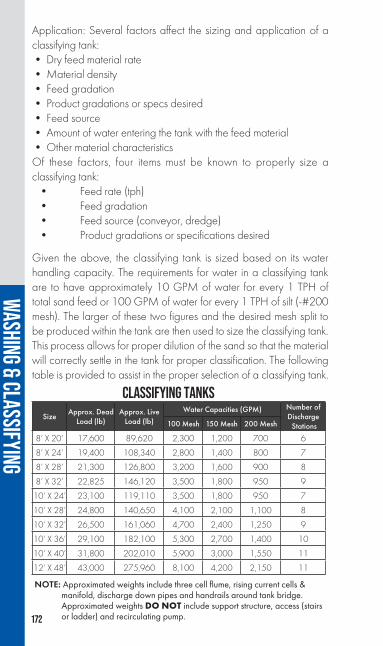
172
Application: Several factors affect the sizing and application of a classifying tank:• Dry feed material rate • Material density• Feed gradation• Product gradations or specs desired• Feed source• Amount of water entering the tank with the feed material• Other material characteristicsOf these factors, four items must be known to properly size a classifying tank: • Feed rate (tph) • Feed gradation • Feed source (conveyor, dredge) • Product gradations or specifications desired
Given the above, the classifying tank is sized based on its water handling capacity. The requirements for water in a classifying tank are to have approximately 10 GPM of water for every 1 TPH of total sand feed or 100 GPM of water for every 1 TPH of silt (-#200 mesh). The larger of these two figures and the desired mesh split to be produced within the tank are then used to size the classifying tank. This process allows for proper dilution of the sand so that the material will correctly settle in the tank for proper classification. The following table is provided to assist in the proper selection of a classifying tank.
NOTE: Approximated weights include three cell flume, rising current cells & manifold, discharge down pipes and handrails around tank bridge. Approximated weights DO NOT include support structure, access (stairs or ladder) and recirculating pump.
CLASSIFYING TANKSSize Approx. Dead
Load (lb)Approx. Live
Load (lb)Water Capacities (GPM) Number of
Discharge Stations100 Mesh 150 Mesh 200 Mesh
8’ X 20’ 17,600 89,620 2,300 1,200 700 6
8’ X 24’ 19,400 108,340 2,800 1,400 800 7
8’ X 28’ 21,300 126,800 3,200 1,600 900 8
8’ X 32’ 22,825 146,120 3,500 1,800 950 9
10’ X 24’ 23,100 119,110 3,500 1,800 950 7
10’ X 28’ 24,800 140,650 4,100 2,100 1,100 8
10’ X 32’ 26,500 161,060 4,700 2,400 1,250 9
10’ X 36’ 29,100 182,100 5,300 2,700 1,400 10
10’ X 40’ 31,800 202,010 5,900 3,000 1,550 11
12’ X 48’ 43,000 275,960 8,100 4,200 2,150 11
WASHING & CLASSIFYING

173
CLAS
SIFY
ING T
ANK
WEIR
OVE
RFLO
W RA
TES
NO
TE:
All
flow
s sho
wn
are
in g
pm. B
old
italic
ized
flow
s dep
ict o
verfl
ow ra
tes r
equi
red
for 2
00, 1
50 &
100
mes
h sp
lits, r
espe
ctive
ly.
WASHING & CLASSIFYING
MO
DEL
WEI
R LE
NG
THA
VERA
GE
DEP
TH O
VER
WEI
R
½”
¾”
1”1¼
”1½
”1¾
”2”
2¼”
2½”
8’ x
20’
32’
225
480
700 80
01,
150
1,20
01,
690
2,22
5 2,
300
2,72
03,
360
4,40
0
8’ x
24’
40’
280
600
800 1,
000
1,40
0 1,44
02,
120
2,80
0 2,
800
3,40
0 4,
200
5,00
0
8’ x
28’
48’
336
720 9
001,
200
1,60
01,
720
2,55
03,
200 3,
350
4,07
0 5,
040
6,00
0
8’ x
32’
56’
392
840
950
1,40
0 1,
800
2,01
02,
960
3,50
03,
920
4,75
0
5,88
0 7
,000
10’ x
24’
42’
295
63095
01,
050
1,52
02,
230
2,94
03,
500 3,
570
4,40
05,
250
10’ x
28’
50’
350
750
1,10
0 1,25
01,
8002,
100
2,65
03,
500
4,10
0 4,25
0 5,
240
6,2
50
10’ x
32’
58’
410
880
1,20
0 1,45
02,
080
2,40
03,
060
4,0
604,
700 4,
930
6,08
07,
250
10’ x
36’
66’
465
990
1,40
0 1,65
02,
3802,
700
3,50
04,
630
5,30
0 5,61
0 6,
920
8,25
0
10’ x
40’
7
4’52
01,
1101,
550
1,85
02,
6603,
000
3,92
05,
180
5,9
006,
290
7,76
09,
250
12’ x
48’
80’
562
1,20
02,
0002,
150
2,87
6 4,
200 4,
238
5,60
06,
800
8,10
0 8,39
010
,000

174
SPECSELECT® CONTROLLERSP u r p o s e : S p e c S e l e c t ® controllers are utilized in conjunction with a classifying tank to control the blending of the various sand fractions into one or two specification products plus an excess product. SpecSelect® controllers are also a valuable source of information when troubleshooting or monitoring the activity occurring within a classifying tank.
Design: SpecSelect® controllers consist of an industrial-quality PLC (programmable logic controller) housed in the NEMA 4 junction box/control enclosure located on the bridge of the classifying tank and a desktop PC HMI. An optional industrial PC HMI with color touchscreen housed in a NEMA 4 enclosure is also available for outdoor installation in lieu of the desktop PC. Easy-to-use Windows-based controls allow operators to proportion the amount of material discharging from each station to the appropriate collecting/blending flume for transport to the dewatering device. EEPROM memory in the PLC and the hard drive of the PC provide permanent storage for PLC logic, operating parameters and recipes.
Application: Two modes of controlling the tank discharge are utilized in conventional classifying tanks. The SpecSelect® I mode of operation is the simplest method to operate a classifying tank and is the same in theory as the manual splitter box type classifying tanks. It is an independent control of each station by a percentage method to determine the amount of material discharged to each of the three product flumes. The system operates on a 10-second cycle that is repeated over and over from product “A” to “B” to “C”. The mode of operation works best in a fairly consistent pit, where the feed gradation does not vary too much. Monitoring the product gradations informs the operator of variances in the feed. Changes to the percentage settings at each station can be made quickly at the controller to maintain the product specification.
WASHING & CLASSIFYING

175
The SpecSelect® II mode of operation is a dependent method of operation utilizing minimum and maximum timer settings at each station to control the material discharge, and ensure that product specifications are met on a consistent basis. This system not only controls the discharge valves at each station, but also controls all of the settling stations relative to each other. The minimum and maximum timer settings are determined by the gradation of the material settling out at each station and relating this to the product specification limits. In effect, the SSII mode of operation is making batches of specification sand continuously. Each “A” or “B” valve at a given station discharges sand on a time basis between its minimum and maximum timer settings. No valve can begin a new batch until every other valve has discharged at least its minimum in the present batch being made. When a valve reaches its maximum timer setting and one or more of the other valves for that product have not yet met their minimum settings, the controller automatically directs the material to one of the other product valves and flumes. It is important to remember, in this mode of operation, the potential to waste or to direct sand to a non-spec product where it is not desired is increased and should be carefully considered when operating a tank by this method. This mode of operation is typically used when the feed gradation and/or feed rate vary widely.
All currently manufactured models of SpecSelect® controllers are capable of operating in either the SpecSelect® I or the SpecSelect® II mode of operation.
WASHING & CLASSIFYING

176
Purpose: Screening/washing plants are used to rinse and size up to three stone products while simultaneously washing, dewatering and fine-tuning a single sand product. Specific stone product gradations can typically be met with the use of blending gates between the screen overs chutes while sand product gradations are adjusted with screw speed and water overflow rates.
Design: Traditional Series 1800 screening/washing plants consist of a heavy-duty, three-deck incline (10°) or horizontal wet screen mounted above a fine material washer on either a semi-portable skid support structure or a heavy-duty portable chassis. Important features of the screening/washing plant include the capability to fit three radial stacking conveyors under the screen overs chutes, complete water plumbing with single inlet connection and wide three-sided screen access platform, as well as all the features of the industry-leading screens and the fine material washers.
Also available, are the model 1822PHB and model 1830PHB portable screening/washing plants, which incorporate a blademill ahead of the horizontal screen, all on a single, heavy-duty, portable chassis. This addition serves to pre-condition the raw feed material for more efficient wet screening.
Application: Review of the feed material gradation, products desired and tph to be processed will determine the screen and screw combination best-suited for the application.
SCREENING/WASHING PLANTS
WASHING & CLASSIFYING

177
1800 SERIESSCREENING/WASHING PLANTS
NOTES: Model 1814, 1822 and 1830 available in both portable and skid-mounted configurations. Additional options exist, consult factory for further details. Skid-mounted plants can be configured to include a number of different screen and screw combinations, consult factory for details. For further capacity or specification information on screens, fine material washers and blademills, see the corresponding sections of this book relating to those pieces of equipment.
Description Model 1814 Model 1822 Model 1830 Model 1822PHB Model 1830PHB
Screen Size5’ x 14’
(incline only)6’ x 16’ 6’ x 20’
6’ x 16’ (horizontal only)
6’ x 20’ (horizontal only)
Fine Material Washer Size
36” x 25’ single
36” x 25’ twin44” x 32’ twin or 36” x 25’
twin36” x 25' twin 44” x 32’ twin
Blademill Size N/A N/A N/A 24” x 12’ twin 36” x 15' twin
Plant CapacityConsult Factory
Consult Factory
Consult Factory Consult Factory Consult Factory
WaterRequirements
Up to 700US-GPM
Up to 1,200US-GPM
Up to 2,700US-GPM
Up to 1,200US-GPM
Up to 2,700US-GPM
Optional Equipment (Portabel and Skid Plants) Wedge Bolts
(for screen cloth retention)
Yes Yes Yes Yes Yes
AR or Urethane Chute & Hopper
Wear LinersYes Yes Yes Yes Yes
Feed/Slurry Box Yes Yes Yes Yes Yes
Wire Mesh Screen Cloth
Yes Yes Yes Yes Yes
Deck Preparation for Urethane
Screen MediaNo Yes Yes Yes Yes
Electrical Pkg. Yes Yes Yes Yes Yes
Blending Gates Yes Yes Yes Yes Yes
Optional Equipment (Skid Plants Only)Stair vs. Ladder
AccessYes Yes Yes N/A N/A
Roll-Away Chutes Yes Yes Yes N/A N/A
Optional Equipment (Portable Plants Only)
Landing Gear No Yes Yes Yes Yes
Hydraulic Run-on Jacks
No Yes Yes Yes Yes
Gas/Hyd. or Elec./Hyd. Power Pk.
No Yes Yes Yes Yes
Hyd. Screen Adjust (incline Screens only)
No Yes Yes N/A N/A
Cross Conveyors
No Yes Yes Yes Yes
Remote Grease Yes Yes Yes Yes YesFlare Mountin in
King Pin AreaN/A N/A Yes N/A Yes
Hinged Folding Flares
N/A N/A Yes N/A Yes
WASHING & CLASSIFYING

178
Purpose: Dewatering screens are utilized to dewater fine aggregates (typically, minus ³⁄₈” or smaller) prior to stockpiling. Feed to a dewatering screen can come from a variety of sources including cyclones, conventional wet screens, density classifiers, classifying tanks and even directly from fine material washers. Depending on the gradation of the product to be produced, dewatering screens will typically produce a finished product with a moisture content as low as 8 – 15 percent by weight.
Design: Dewatering screens are single-deck, adjustable incline (0-5°) linear motion screens available in sizes ranging from 2’ wide x 7’ long to 8’ wide x 16’ long with processing rates up to 400 STPH. The units include a predominately bolted screen frame assembly, integral stiffener tubes with lifting lugs, steel coil springs, a sloped feed section, an adjustable discharge dam to control bed depth, bolt-in UHMW pan side liners, modular urethane screen media available in sizes ranging from #10 - #150 mesh, a stress-relieved fabricated motor bridge, engineered motor mounting studs and two adjustable stroke 1,200 rpm vibrating motors. Dewatering screens can also be configured to produce two different sand products from one unit
SERIES 9000 DEWATERING SCREENS
WASHING & CLASSIFYING

179
POWER REQUIREMENTS & APPROXIMATE CAPACITIES
NOTES: Capacities provided are estimates only. Consult factory for specific applications. **Denotes 900RPM motor.
through the installation of a divider down the length of the unit and dual discharge/blending chutes.
Application: Several important elements must be considered when sizing a dewatering screen: product gradation, feed rate in STPH and the percent solids-by-weight of the slurry feed. Generally speaking, a finer product requires a reduction in the screen stroke and a reduction in the capacity of the unit. Also, a finer product will typically have a higher moisture content than a coarse product.
Model HP
Capacity (STPH)
Feed Size (assumes a 2.67 S.G.)
Fine Sand (-#50 x +#325)
Coarse Sand(-#4 x +#150)
DWS 27 2 @ 2.7 13 43
DWS 38 2 @ 3.9 20 65
DWS 410 2 @ 4.7 43 144
DWS 513 2 @ 8.4 65 216
DWS 613 2 @ 9.4 78 259
DWS 716 2 @ 11.0** 106 353
DWS 816 2 @ 12.7** 121 403
WASHING & CLASSIFYING

180
The Astec Series 9000 and 1892 plants combine all the features of the Series 9000 dewatering screens, cyclones, slurry pumps, the conventional Series 1800 plants and custom-engineered chassis or skid-mounted support structures into one complete, compact aggregate processing package.
• The Model 9400 plants are designed for aggregate producers requiring a fines recovery plant to support their existing operations by reducing the volume of fine material (typically, minus #100 mesh x plus #400 mesh) reporting to the settling pond without the use of flocculants.• The Model 9200 plants are designed to dewater and fine-tune one or two sand products to a level typically not possible with traditional sand dewatering equipment.• The Model 1892 plants are designed for aggregate producers requiring a single plant to rinse and size up to three stone products while simultaneously washing, dewatering and fine-tuning one or two sand products.
Available in portable, semi-portable or stationary configurations, these plants are custom-built to meet application requirements and can be configured with various types and quantities of cyclones, various pump sizes, various dewatering screen sizes and various incline or horizontal screen sizes. Other custom features include dual inlet slurry sumps with bypass and overflow capabilities, electrical packages with variable frequency drives as required, air suspension axle assemblies, hydraulic leveling jacks, hydraulically -folding cyclone support system, electric/hydraulic or gas/hydraulic power packs, roll-away or swing-away screen overs chutes, blending chutes, cross conveyors and multiple liner options.
SERIES 9000 PLANTS
WASHING & CLASSIFYING
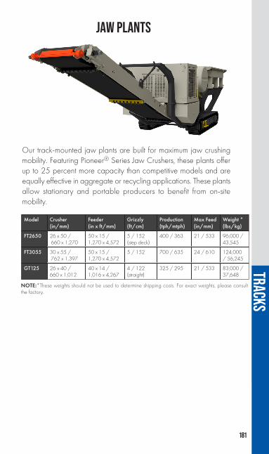
181
Our track-mounted jaw plants are built for maximum jaw crushing mobility. Featuring Pioneer® Series Jaw Crushers, these plants offer up to 25 percent more capacity than competitive models and are equally effective in aggregate or recycling applications. These plants allow stationary and portable producers to benefit from on-site mobility.
JAW PLANTS
Model Crusher(in/mm)
Feeder (in x ft/mm)
Grizzly (ft/cm)
Production (tph/mtph)
Max Feed(in/mm)
Weight *(lbs/kg)
FT2650 26 x 50 / 660 x 1,270
50 x 15 /1,270 x 4,572
5 / 152 (step deck)
400 / 363 21 / 533 96,000 / 43,545
FT3055 30 x 55 / 762 x 1,397
50 x 15 / 1,270 x 4,572
5 / 152 700 / 635 24 / 610 124,000 / 56,245
GT125 26 x 40 / 660 x 1,012
40 x 14 /1,016 x 4,267
4 / 122 (straight)
325 / 295 21 / 533 83,000 / 37,648
NOTE:*These weights should not be used to determine shipping costs. For exact weights, please consult the factory.
TRACKS

182
Astec cone plants are engineered for maximum cone crushing productivity. Each plant features a Kodiak® Plus cone crusher that delivers efficient material sizing, making them perfect for both mobile and stationary producers who need quick, effortless on-site movement.
KODIAK® PLUS CONE PLANTS
NOTE: *These weights should not be used to determine shipping costs. For exact weights, please consult the factory.
Model Crusher ScreenBelt feeder Production Weight
In Mm Tph Mtph Lb Kg
FT200CC K200+ 6' x 12' 2-deck 48 1,219 385 350 111,000 50,350
FT200DF K200+ NA 36 914 385 350 80,000 36,290
FT300DF K300+ NA 48 1,219 460 417 99,000 44,905
FT400DF K400+ NA 60 1,524 625 567 116,000 52,620
TRACKS

183
Astec track-mounted impactor plants are engineered for maximum impact crushing versatility. Featuring Andreas Series impact crushers, these plants come equipped with our standard overload protection system (OPS). Delivering exceptional performance with an easy-to-adjust interface, aggregate producers and recyclers alike will benefit from the availability of open or closed circuit configurations, complete with a screen and recirculating conveyor.
IMPACTOR PLANTS
Model Crusher(in/mm)
Feeder (in x ft/mm)
Grizzly (ft/cm)
Production (tph/mtph)
Weight*(lbs/kg)
GT440CC 42 x 40 / 1,067 x 1,016
40 x 14 / 1,016 x 4,267
4/122 (straight)
325 / 295 94,000 / 42,638
GT440OC 42 x 40 / 1,067 x 1,016
40 x 14 / 1,016 x 4,267
4/122 (straight)
325 / 295 81,000 / 36,741
FT4250CC 42 x 50 / 1,067 x 1,270
50 x 15 / 1,270 x 4,572
5/152 (step deck)
400 / 363 112,500 / 51,029
FT4250OC 42 x 50 / 1,067 x 1,270
50 x 15 / 1,270 x 4,572
5/152 (step deck)
400 / 363 99,000 / 44,906
FT5260 52 x 60 / 1,321 x 1,524
50 x 15 /1,270 x 4,572
5/152 (step deck)
750 / 680 112,500 / 51,029
NOTE: *These weights should not be used to determine shipping costs. For exact weights, please consult the factory.
TRACKS

184
Astec track-mounted screens are engineered to provide higher production capacities and more efficient sizing compared to conventional screens. Featuring triple-shaft, oval motion screens, these plants offer better bearing life, more aggressive screening action for reduced plugging and blinding and a consistent material travel speed that does not accelerate through gravity for a higher probability of separation. As such, these highly-efficient plants are perfect for both portable and stationary producers who need quick, effortless on-site movement and reduced down time.
HORIZONTAL SCREEN PLANTS
Model Screen Size(ft/cm)
Decks Production (tph/mtph)
Weight*(lbs/kg)
FT3620 6 x 20 /183 x 609
3 700 / 635 81,000 / 36,741
FT6203OC 6 x 20 /183 x 609
3 800 / 726 83,000 / 37,648
FT6203CC 6 x 20 /183 x 609
3 800 / 726 86,000 / 39,009
FT710 KDS 7 x 10 / 2,134 x 3,048
2 200 / 181 35,000 / 15,876
NOTE: *These weights should not be used to determine shipping costs. For exact weights, please consult the factory.
TRACKS

185
Astec high frequency screens are engineered to provide higher production capacities and more efficient sizing compared to conventional screens. High frequency screens feature aggressive vibration applied directly to the screen that allows for the highest capacity in the market for removal of fine material, as well as chip sizing, dry manufactured sand and more.
HIGH FREQUENCY SCREEN PLANTS
Model Screen Size(ft/cm)
Production (tph/mtph
Weight*(lbs/kg)
FT2618V 6 x 18 /183 X 547
350 / 318 62,000 / 28,123
FT2618VM 6 x 18 /183 x 547
350 / 318 60,000 / 27,216
NOTE: *These weights should not be used to determine shipping costs. For exact weights, please consult the factory.
TRACKS

186
Mobile screening plants feature double- or triple-deck screens for processing sand and gravel, topsoil, slag, crushed stone and recycled materials. They provide easy-to-reach engine controls and grease points for routine service, simple-to-use hydraulic leveling gears, hydraulic plant controls and screen angle adjustment. Tethered track remote control is standard with an optional wireless remote track control available.
INCLINE SCREEN PLANTS
ModelHopper
Capacity (yd/m)
Screen Size (ft/m)
Power (hp/kw)
GT145 10.5 / 8.03 5 x 14 / 1.52 x 4.27 129 / 96
GT205 10.5 / 8.03 5 x 20 / 1.52 x 6.10 129 / 96
Model Capacity (tph/mtph)
Overs Conveyor(in/mm)
GT145 650 / 540 24 / 610
GT205 650 / 540 30 / 762
TRACKS
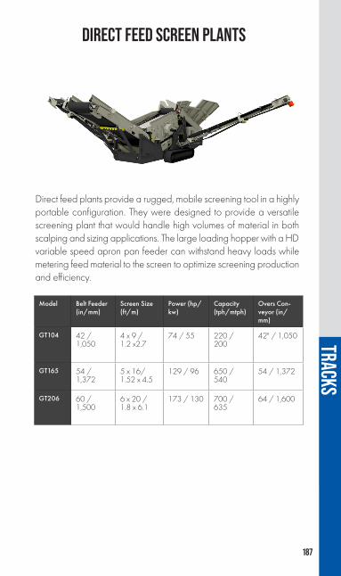
187
Direct feed plants provide a rugged, mobile screening tool in a highly portable configuration. They were designed to provide a versatile screening plant that would handle high volumes of material in both scalping and sizing applications. The large loading hopper with a HD variable speed apron pan feeder can withstand heavy loads while metering feed material to the screen to optimize screening production and efficiency.
DIRECT FEED SCREEN PLANTS
Model Belt Feeder (in/mm)
Screen Size (ft/m)
Power (hp/kw)
Capacity (tph/mtph)
Overs Con-veyor (in/mm)
GT104 42 / 1,050
4 x 9 / 1.2 x2.7
74 / 55 220 / 200
42" / 1,050
GT165 54 / 1,372
5 x 16/ 1.52 x 4.5
129 / 96 650 / 540
54 / 1,372
GT206 60 / 1,500
6 x 20 / 1.8 x 6.1
173 / 130 700 / 635
64 / 1,600
TRACKS

188
These units are a self-contained, track-mounted, mobile conveyors that can be used as a transfer or stacking conveyors with portable or track crushing and screening equipment.
Capable of carrying loads of up to 750TPH with adjustable speed and discharge height, these units are a perfect tool when quick set-up, mobility and flexibility are required.
MOBILE CONVEYOR
Model Belt Width (in / mm)
Belt Length (ft / m) Diesel Power (hp / kw)
GT3660 36 / 900 60 / 18.25 60 / 45
GT3680 36 / 900 80 / 24 75 / 56
GT4260 42 / 1,100 60 / 18.25 136 / 101
Model Capacity (tph / mtph)
Discharge Height (ft/ m)
GT3660 750 / 675 24 / 7.315
GT3680 500 / 454 32 / 9.58
GT4260 700 / 635 29 / 8.8
TRACKS

189
RAILROAD BALLASTBallast is a relatively coarse aggregate that provides a stable load-carrying base for trackage, as well as quick drainage. Ballast normally would be crushed quarry or slag material, free of clay, silt, etc.
Two typical specifications follow, to provide some idea as to general gradations:
1 sack cement = 1 cu. ft.; 4 sacks = 1 bbl.; 1 bbl. = 376 lbs.
QUANTITIES OF CEMENT, FINE AGGREGATE AND COARSE AGGREGATE
REQUIRED FOR ONE CUBIC YARD OF COMPACT MORTAR OR CONCRETE
Sieve Opening Example "A" Percent Passing
Example "B" Percent Passing
3” (76.2 mm) 100 -
2½” (63.5 mm) 90 -100 100
2” (50.8 mm) - 96 -100
1½” (38.1 mm) 25 - 60 35 - 70
1” (25.4 mm) - 0 - 15
¾” (19.0 mm) 0 - 13 -
½” (12.7 mm) 0 - 5 0 - 5
NOTE: The above are typical. However, there are many other ballast sizes dependent on job specifications. Note also that ballast is most usually purchased on a unit volume rather than tonnage basis.
Mixtures
Cement F.A.(Sand
C.A.(gravel or
Stone
1 1.5
1 2
1 2.5
1 3
1 1.5 3
1 2 2
1 2 3
1 2 4
1 2.5 3.5
1 2.5 4
1 2.5 5
1 3 5
Approx. Quantities of Material
Cement in Stacks
Fine Aggregate Coarse Aggregate
cu. ft cu. yd cu. ft cu. yd
15.5 23.2 0.86
12.8 25.6 0.95
11 27.5 1.02
9.6 28.8 1.07
7.6 11.4 0.42 22.8 0.85
8.3 16.6 0.61 16.6 0.61
7 14 0.52 21 0.78
6 12 0.44 24 0.89
5.9 14.7 0.54 20.6 0.76
5.6 14 0.52 22.4 0.83
5 12.5 0.46 25 0.92
4.6 13.8 0.51 23 0.85

190
RIPRAP
WEIGHTS OF RIPRAP—POUNDS
NOTE: The above is given as general information only; each job will carry its individual specification.
Riprap, as used for facing dams, canals and waterways, is normally a coarse, graded material. Typical specifications would call for a minimum 160 lb./ft.3 stone, free of cracks and seams with no sand, clay, dirt, etc. A typical specification will probably give the percent passing by particle weight such as:
Percent Passing 15" Blanket 24" Blanket
100 165 lbs. 670 lbs.
50 - 70 50 lbs. 200 lbs.
30 - 50 35 lbs. 135 lbs.
0 - 15 10 lbs. 40 lbs.
In order to relate the above weights to rock size, refer to the following size/density chart:
Cubical Size(in.)
Solid Rock Density - lb per ft3 (appprox.)
145 150 155 160 165 170 175 180 185
5 10 11 11 12 12 12 13 13 136 18 19 19 20 21 21 22 23 237 29 30 31 32 33 34 35 36 378 43 44 46 47 49 50 52 53 559 61 63 65 68 70 72 74 76 78
10 84 87 90 93 95 98 101 104 10711 112 116 119 123 127 131 135 139 14212 145 150 155 160 165 170 175 180 18513 184 191 197 203 210 216 222 229 23514 230 238 246 254 262 270 278 286 29415 283 293 302 312 322 332 342 351 36116 344 356 367 379 391 403 415 426 43817 412 426 440 454 469 483 497 511 52618 489 506 523 539 556 573 590 607 62419 575 595 615 634 654 674 694 714 73420 671 694 717 740 763 786 810 833 85622 893 925 954 985 1,016 1,047 1,078 1,108 1,13924 1,160 1,200 1,239 1,279 1,319 1,359 1,399 1,439 1,47925 1,475 1,526 1,575 1,626 1,677 1,728 1,779 1,830 1,88128 1,842 1,905 1,967 2,031 2,094 2,158 2,222 2,285 2,34930 2,265 2,343 2,419 2,498 2,576 2,654 2,732 2,811 2,88932 2,749 2,844 2,936 3,031 3,126 3,221 3,316 3,411 3,50634 3,298 3,412 3,522 3,636 3,750 3,864 3,978 4,092 4,20636 3,914 4,050 4,180 4,316 4,451 4,586 4,722 4,857 4,99239 4,978 5,150 5,321 5,493 5,664 5,836 6,008 6,179 6,351

191
MOTOR WIRING AT STANDARD SPEEDSFROM NATIONAL ELECTRICAL CODE
††,** Where high ambient temperature is present, it may, in some cases, be necessary to install next larger size thermal overload relay.
HPFull Load Amp. Per
Phase
††Min. Size wire
AWG Rubber
Covered
Size Conduit
(in)
**Max. Rating of Branch Circuit Fuses
Full Load Amp. Per
Phase
††Min. Size Wire
AWG Rubber
Covered
Size Conduit
(in)
**Max. Rating of Branch Circuit Fuses
Single Phase Induction Motors
120 Volts 230 Volts
½ 7 14 ½ 25 3.5 14 ½ 15
¾ 9.4 14 ½ 30 4.7 14 ½ 15
1 11 14 ½ 35 5.5 14 ½ 20
1½ 15.2 12 ½ 45 7.6 14 ½ 25
2 20 10 ¾ 60 10 14 ½ 30
3 28 8 ¾ 90 14 12 ½ 45
5 46 4 1¼ 150 23 8 ¾ 70
7½ 34 6 1 110
10 43 5 1¼ 125
HPFull Load Amp. Per
Phase
††Min. Size wire
AWG Rubber
Covered
Size Conduit
(in)
**Max. Rating of Branch Circuit Fuses
††Min. Size Wire
AWG Rubber
Covered
Size Conduit
(in)
**Max. Rating of Branch Circuit Fuses
3 Phase Induction Motors
230 Volts 460 Volts
1 3.3 14 ½ * 15 1.7 14 ½ * 15
1½ 4.7 14 ½ * 15 2.4 14 ½ * 15
2 6 14 ½ * 20 3 14 ½ * 15 3 9 14 ½ * 30 4.5 14 ½ * 155 15 12 ½ * 45 7.5 14 ½ * 25
7½ 22 8 ¾ † 60 11 14 ½ † 30
10 27 8 ¾ † 70 14 12 ½ † 3515 38 6 1¼ † 80 19 10 ¾ † 5020 52 4 1¼ †110 26 8 ¾ † 7025 64 3 1¼ †150 32 6 1¼ † 7030 77 1 1½ †175 39 6 1¼ † 8040 101 00 2 †200 51 4 1¼ †10050 125 000 2 †250 63 3 1¼ †125
60 149 200,000 C.M. 2½ †300 75 1 1½ †150
75 180 0000 2½ †300 90 0 2 †200
100 245 ‡ 500 3 †500 123 000 2 †250
125 310 ‡ 750 3½ †500 155 0000 2½ †350
150 360 ‡ 1,000 4 †600 180 300 ‡ 2½ †400
200 480 240 500 ‡ 3 †500
250 580 290300 696 348

192
NEMA FRAME NUMBERS FOR POLYPHASE INDUCTION MOTORS
‡ M.C.M.† In order to avoid excessive voltage drop where long runs are involved, it may be necessary to use conductors and conduit of sizes larger than the minimum sizes listed above.**Branch-circuit fuses must be large enough to carry the starting current, hence they protect against short-circuit only. Additional protection of an approved type must be provided to protect each motor against normal operating overloads.*For full-voltage starting of normal torque, normal starting current motor.†For reduced-voltage starting of normal torque, normal starting current motor, and for full-voltage starting of high-reactance, low starting current squirrel-cage motors.
HPFull Load Amp. Per
Phase
††Min. Size wire
AWG Rubber
Covered
Size Conduit
(in)
**Max. Rating of Branch Circuit Fuses
Full Load Amp. Per
Phase
††Min. Size Wire
AWG Rubber
Covered
Size Conduit
(in)
**Max. Rating of Branch Circuit Fuses
Direct Current Motor
115 Volts 230 Volts
1 8.4 14 ½ 15 4.2 14 ½ 15
1½ 12.5 12 ½ 20 6.3 14 ½ 152 16.1 10 ¾ 25 8.3 14 ½ 15
3 23 8 ¾ 35 12.3 12 ½ 20
5 40 6 1 60 19.8 10 ¾ 307½ 58 3 1¼ 90 28.7 6 1 4510 75 1 1½ 125 38 6 1 6015 112 0 2 175 56 4 1¼ 9020 140 0 2 225 74 1 1½ 12525 184 300 ‡ 2½ 300 92 0 2 15030 220 400 ‡ 3 350 110 00 2 17540 292 700 ‡ 3½ 450 146 0000 2½ 22550 360 1,000 ‡ 4 600 180 300 ‡ 2½ 30060 215 400 ‡ 3 35075 268 600 ‡ 3½ 450
100 355 1,000 ‡ 4 600
Horsepower"T" Frame
1800 RPM 1200 RPM2 145T 184T3 182T 213T5 184T 215T
7½ 213T 254T10 215T 256T15 254T 284T20 256T 286T25 284T 324T30 286T 326T40 324T 364T50 326R 365T60 364T 404T75 365T 405T
MOTOR WIRING AT STANDARD SPEEDS (CONTINUED)FROM NATIONAL ELECTRICAL CODE

193
DIMENSIONS, IN INCHES, OF ELECTRIC MOTORSBY NEMA FRAME NUMBER
M + N D E F U V Keyway
182T 7¾ 4½ 3¾ 2¼ 1¹⁄₈ 2½ ¼ x ¹⁄₈
184T 8¼ 4½ 3¾ 2¾ 1¹⁄₈ 2½ ¼ x ¹⁄₈
213 9¼ 5¼ 4¼ 2¾ 1¹⁄₈ 2¾ ¼ x ¹⁄₈
213T 9₅⁄₈ 5¼ 4¼ 2¾ 1³⁄₈ 3¹⁄₈ 5/16 x 5/32
215 10 5¼ 4¼ 3½ 1¹⁄₈ 2¾ ¼ x ¹⁄₈
215T 10³⁄₈ 5¼ 4¼ 3½ 1³⁄₈ 3¹⁄₈ 5/16 x 5/32
254T 12³⁄₈ 6¼ 5 4¹⁄₈ 1₅⁄₈ 3¾ ³⁄₈ x ³⁄₁₆
254U 12¹⁄₈ 6¼ 5 4¹⁄₈ 1³⁄₈ 3½ 5/16 x 5/32
256T 13¼ 6¼ 5 5 1₅⁄₈ 3¾ ³⁄₈ x ³⁄₁₆
256U 13 6¼ 5 5 1³⁄₈ 3½ 5/16 x 5/32
284T 14¹⁄₈ 7 5½ 4¾ 1₇⁄₈ 4³⁄₈ ½ x ¼
284U 14³⁄₈ 7 5½ 4¾ 1₅⁄₈ 4₅⁄₈ ³⁄₈ x ³⁄₁₆
286T 14₇⁄₈ 7 5½ 5½ 1₇⁄₈ 4³⁄₈ ½ x ¼
286U 15¹⁄₈ 7 5½ 5½ 1₅⁄₈ 4₅⁄₈ ³⁄₈ x ³⁄₁₆
324T 15¾ 8 6¼ 5¼ 2¹⁄₈ 5 ½ x ¼
324U 16¹⁄₈ 8 6¼ 5¼ 1₇⁄₈ 5³⁄₈ ½ x ¼
326T 16½ 8 6¼ 6 2¹⁄₈ 5 ½ x ¼
326U 16₇⁄₈ 8 6¼ 6 1₇⁄₈ 5³⁄₈ ½ x ¼
364T 17³⁄₈ 9 7 5₅⁄₈ 2³⁄₈ 5₅⁄₈ ₅⁄₈ x 5/16
364U 17₇⁄₈ 9 7 5₅⁄₈ 2¹⁄₈ 6¹⁄₈ ½ x ¼
365T 17₇⁄₈ 9 7 6¹⁄₈ 2³⁄₈ 5₅⁄₈ ₅⁄₈ x 5/16
365U 18³⁄₈ 9 7 6¹⁄₈ 2¹⁄₈ 6¹⁄₈ ½ x ¼
404T 20 10 8 6¹⁄₈ 2₇⁄₈ 7 ¾ x ³⁄₈
404U 19₇⁄₈ 10 8 6¹⁄₈ 2³⁄₈ 6₇⁄₈ ₅⁄₈ x 5/16
405T 20¾ 10 8 6₇⁄₈ 2₇⁄₈ 7 ¾ x ³⁄₈
405U 20₅⁄₈ 10 8 6₇⁄₈ 2³⁄₈ 6₇⁄₈ ₅⁄₈ x 5/16
444U 23³⁄₈ 11 9 7¼ 2₇⁄₈ 8³⁄₈ ¾ x ³⁄₈
445U 24³⁄₈ 11 9 8¼ 2₇⁄₈ 8³⁄₈ ¾ x ³⁄₈

194
CURR
ENT C
ARRY
ING C
APAC
ITIES
AND C
ABLE
DIAM
ETER
SIZE
S FOR
THE P
ORTA
BLE C
ABLE
S
Abo
ve D
ata
from
Wes
tern
Insu
late
d W
ire C
o. fr
o Br
onco
66
Cer
tifie
d C
able
*Whe
n us
ing
4 co
nduc
tor t
ype
“W”
cabl
e on
3 p
hase
circ
uit w
ith 4
th c
ondu
ctor
use
d as
gro
und,
use
am
p ca
paci
ty fo
r 3 c
ondu
ctor
type
“G
” ca
ble.
AW
G S
ize
Type
SO
Cor
d3
Con
duct
or T
ype
"G"
4 C
ondu
ctor
Typ
e "W
:
Am
p C
apac
ityD
iam
eter
(in)
Am
p C
apac
ityD
iam
eter
(in)
*Am
p C
apac
ityD
iam
eter
(in)
2 C
ond.
3 C
ond.
4 C
ond.
250
MC
M27
52.
394/
024
52.
0421
02.
263/
022
01.
8919
02.
072/
019
01.
7517
01.
931/
016
01.
6514
51.
791
145
1.51
125
1.68
213
01.
3411
01.
483
110
1.24
951.
344
951.
1785
1.27
675
1.01
601.
18
550.
9150
0.99
1025
0.64
0.69
0.75
1220
0.60
50.
640.
6714
150.
530.
560.
605
1610
0.40
50.
430.
485
187
0.39
0.40
50.
435

195
GENERATOR SIZE TO POWER ELECTRICMOTORS ON CRUSHING AND SCREENING PLANTSThe minimum generator size to power a group of motors should be selected on the basis of the following rules, which allow all motors to operate simultaneously with complete freedom of starting sequence.
A. GENERATOR KW—0.8 x total electric name plate horsepower.B. GENERATOR KW—2 x name plate horsepower of the largest
electric motor with across-the-line starter.C. GENERATOR KW—1.5 x name plate horsepower of the largest
electric motor with reduced voltage starting (with 80 percent starting voltage).
D. GENERATOR KW—2.25 x name plate horsepower of the largest electric motor with part winding starting.
For across-the-line starting, use the larger of the two values determined from A and B.
For reduced voltage starting, use the larger of the two values determined from A and C.
For part winding starting, use the larger of the two values determined from A and D.
For combinations of the above starting types, use the largest value determined from A, B, C, and D as they apply.

196
DREDGE PUMP
Above information can be used as a guide in preliminary selection of material handling components. For plants charged by dredge pumps, proper selection of sand processing components is in part controlled by maximum amount of water in the slurry.
Prior to final selection of machinery, complete information must be assimilated so sound judgement can be exercised.
20% Solids @ 100 lb./cu. ft.
(% Solids by Weight)
NOTE: GPM ÷ 17.6 = TPH TPH X 17.6 = GPM
SIZE SLURRY (GPM) TPH
4 680 38
6 1,500 85
8 2,700 153
10 4,100 233
12 5,900 335
14 7,300 414
16 9,670 550
18 12,280 696
20 15,270 866

197
VELOCITY OF FLOW IN PIPES
NOTE: Based on following ID’s for Std. Wt. W:I or Steel Pipe
1” 1.049” 2½” 2.469” 6” 6.065”1¼” 1.380” 3” 3.068” 8” 7.981”1½” 1.610” 4” 4.026” 10” 10.020”2” 2.067” 5” 5.047” 12” 11.938”
4000
30002500
2000
1500
1000900800700600
500
400
300
200
150
10090807060
50
40
30
25
20
4000
30002500
2000
1500
1000900800700600
500
400
300
200
150
10090807060
50
40
30
25
203 4 5 6 7 8 9 10 11 12 13 14 15 16 17
3 4 5 6 7 8 9 10 11 12 13 14 15 16 17
U.S
. GAL
LON
S PE
R M
INU
TE
U.S
. GAL
LON
S PE
R M
INU
TE
VELOCITY - FEET PER SECOND
VELOCITY - FEET PER SECOND
VELOCITY OF FLOW IN PIPES
STDPIPESIZE
1"
2"
3"
4"
5"
6"
8"
10"
12"
1-1/4"
1-1/2"
2-1/2"

198
FRICTION LOSS IN PIPES
NOTE: Based on new, Standard Weight Wrought Iron or Steel Pipe.
10.1 .2 .3 .4 .5 .6 .8 2 3 4 5 6 8 10 20 30 40 501.0
.1 .2 .3 .4 .5 .6 .8 2 3 4 5 6 8 10 20 30 40 501.0
20
30
4050607080
100
100
200
300
400500600700800
1000
1000
2000
3000
40005000
10
20
30
4050607080
100
100
200
300
400500600700800
1000
1000
2000
3000
40005000
FRICTION LOSS FOR WATER IN FEET OF HEAD PER 100 FT. PIPE
FRICTION LOSS FOR WATER IN FEET OF HEAD PER 100 FT. PIPE
U.S
. GAL
LON
S PE
R M
INU
TE
U.S
. GAL
LON
S PE
R M
INU
TE
12"12"12"
10"10"10"
8"8"8"
6"6"6"
5"5"5"
4"4"4"
3"3"3"
2-1/2"2-1/2"2-1/2"
2"2"2"
1-1/2"1-1/2"1-1/2"
1-1/4"1-1/4"1-1/4"
1"1"1"

199
FLOW OVER WEIRSSETTLING TANKS, CLASSIFIERS, SAND PREPS, FLUMES
GENERALMeasure overflow depth (h) at a distance back of weir at least four times h. Use a flat strip taped to the end of a carpenter’s level.
Multiply figure from curve by length of weir.
FLUME OR LAUNDERUse a bevel-edge steel plate or board with sharp edge upstream.
L(weir length) and D (depth of water behind weir) must each be at least three times h.
Water or slurry must fall free of weir; i.e., with air space underneath. If possible, drill air holes in side of launder on downstream side of weir plate.
Curve does not apply to triangular or notched weirs.
250
1
2
3
4
5
0
1
2
3
4
5
50 75 100 150 200 250 300 400
25 50 75 100 150 200 250 300 400
GPM OVERFLOW PER FOOT OF WEIR
OV
ERFL
OW
DEP
TH (H
) IN
INCH
ES
OV
ERFL
OW
DEP
TH (H
) IN
INCH
ES
GPM OVERFLOW PER FOOT OF WEIR
SETTLING TANK S, CLASSIFIERS, SAND PREPS, FLUMES

200
SPRAY PIPE DESIGN
AMOUNT OF WATER REQUIRED TO WASH ROCKAs a guideline use (5 - 10 gallons/minute) per (yard/hour) or for 100 pund per cubic foot rock. As a guideline use (3.7 - 7.4 gallons/minute) per (ton/hour). Example (200 ton/hour) x (3.7 gallons/minute) per (ton/hour) = 740 gallons/minute
Nozzle Spray Pipe Dual Flat Spray PatternStandard Orifice Size ¼”
STANDARD NOZZLE ORIFICE SIZELess Protector With protector Less nozzles
5ft 516074 pipe 1¼ STD 516510 pipe 1¼ STD 516511 pipe 1¼ STD
6ft 620310 pipe 1¼ STD 616341 pipe 1¼ STD 616476 pipe 1¼ STD
7ft 720141 pipe 1¼ STD 720556 pipe 1¼ STD 720557 pipe 1¼ STD
8ft Not available 820061 pipe 1½ STD 820783 pipe 1½ STD
Less protector w/ ball valve With protector w/ ball valve
617372 pipe 1¼ nozzle ¼ xxxxx
720734 pipe 1¼ nozzle ¼ xxxxx
Not available 821274 pipe 1½ nozzle ¼
821243 pipe 1½ nozzle 5/32
Screen Model
Pipes/Deck Total pipes per screen
Total nozzles
per screen
Gallons per screen at 20 psi ¼" orifice
Gallons per screen at 30 psi
¼" orifiace
Gallons per screen at 40 psi
¼" orifiaceTOP CTR B/C BT
8243-38 7 6 - 5 15 414 2,939 3,602 4,140
8203-38 6 6 - 5 17 391 2,776 3,402 3,910
8202-38 6 - - 5 11 253 1,796 2,201 2,530
7203-38 6 6 - 5 17 340 2,414 2,958 3,400
7202-38 6 - - 5 11 220 1,562 1,914 2,200
6204-32 6 6 5 3 20 320 2,272 2,784 3,200
6203-32 6 6 - 5 17 272 1,931 2,366 2,720
6202-32 6 - - 5 11 176 1,250 1,531 1,760
6163-32 5 5 - 4 14 224 1,590 1,949 2,240
6162-32 5 - - 4 9 144 1,022 1,253 1,440
5163-32 5 5 - 4 14 196 1,392 1,705 1,960
5162-32 5 - - 4 9 126 895 1,096 1,260
5143-24 4 4 - 4 12 168 1,193 1,462 1,680
5142-24 4 - - 4 8 112 795 974 1,120
STANDARD NOZZLE ORIFICE SIZE ¼”

201
SPRAY NOZZLESFOR VIBRATING SCREENS
The introduction of water under pressure over the vibrating screens often improves screening efficiency as well as aids in the removal of deleterious materials on the individual aggregate particles. We utilize type WF flat spray nozzles over the screens to produce a uniform, flat spray pattern without hard edges at pressures of 5 psi and up. Tapered edges of the spray pattern permits pattern overlap with even distribution of the spray. The impact of spray is generally greater with narrower spray angles, assuming the same flow rate.
AVAILABLE SPRAY ANGLESNozzle Size
0°— All sizes
15° — All sizes thru WF 150
25° — All sizes thru WF 150
40° — All sizes thru WF 150
50° — All sizes thru WR 200
65° — All sizes
90° — All sizes thru WF 250
090085 9/64 Orifice ³⁄₈NPT 40° Fan At 20psi nozzle capacity is 2.1 gal/min At 30psi nozzle capacity is 2.6 gal/min At 40psi nozzle capacity is 3.0 gal/min
090327 11/64 Orifice ³⁄₈NPT 40° Fan At 20psi nozzle capacity is 3.5 gal/min At 30psi nozzle capacity is 4.3 gal/min At 40psi nozzle capacity is 5.0 gal/min
090248 ³⁄₁₆ Orifice ³⁄₈NPT 40° Fan At 20psi nozzle capacity is 4.2 gal/min At 30psi nozzle capacity is 5.2 gal/min At 40psi nozzle capacity is 6.0 gal/min
090461 5/32 Orifice ³⁄₈NPT 40° Fan At 20psi nozzle capacity is 2.8 gal/min At 30psi nozzle capacity is 3.5 gal/min At 40psi nozzle capacity is 4.0 gal/min
090328 13/64 Orifice ³⁄₈NPT 40° Fan At 20psi nozzle capacity is 4.9 gal/min At 30psi nozzle capacity is 6.1 gal/min At 40psi nozzle capacity is 7.0 gal/min
Standard 090016 ¼ Orifice ³⁄₈NPT 40° Fan At 20psi nozzle capacity is 7.1 gal/min At 30psi nozzle capacity is 8.7 gal/min At 40psi nozzle capacity is 10 gal/min
Standard 090278 13/64 Orifice ¼NPT 50° Fan At 20psi nozzle capacity is 4.9 gal/min At 30psi nozzle capacity is 6.1 gal/min At 40psi nozzle capacity is 7.0 gal/min
NOZZLES PER PIPE8' spray pipe has 23 nozzles per pipe7' spray pipe has 20 nozzles per pipe6' spray pipe has 16 nozzles per pipe5' spray pipe has 14 nozzles per pipe
NOZZELS SIZES

202
TYPE
WF C
APAC
ITY CH
ART
Noz
zle
Num
ber—
Capa
city
at 4
0 PS
I
Shad
ed c
olum
ns in
dica
te m
ost a
vaila
ble
sizes
.
Noz
zel N
umbe
rEq
uiv.
Orif
.D
ia.
Pipe
Siz
eC
apac
ity -
GPM
at P
SI p
ress
ure
Mal
eN
o.1⁄
8¼
3⁄8
½¾
4060
8010
015
020
030
040
050
060
070
080
010
00
WFM
20.
034
0.2
0.24
0.28
0.32
0.39
0.45
0.55
0.63
0.71
0.77
0.84
0.89
1
WFM
40.
052
0.4
0.49
0.57
0.63
0.77
0.89
1.1
1.3
1.4
1.6
1.7
1.8
2
WFM
4.5
0.05
50.
450.
550.
640.
710.
871
1.2
1.4
1.5
1.7
1.9
22.
2
WFM
50.
057
0.5
0.61
0.71
0.79
0.97
1.1
1.4
1.6
1.8
1.9
2.1
2.2
2.5
WFM
5.5
0.06
0.55
0.67
0.78
0.87
1.1
1.2
1.5
1.7
1.9
2.1
2.3
2.5
2.8
WFM
60.
062
0.6
0.73
0.85
0.95
1.2
1.3
1.6
1.9
2.1
2.3
2.5
2.7
3
WFM
60.
064
0.65
0.8
0.92
11.
31.
51.
82.
12.
32.
52.
72.
93.
3
WFM
70.
067
0.7
0.86
0.99
1.1
1.4
1.6
1.9
2.2
2.5
2.7
2.9
3.1
3.5
WFM
80.
072
0.8
0.98
1.1
1.3
1.5
1.8
2.2
2.5
2.8
3.1
3.4
3.6
4
WFM
8.5
0.07
40.
851.
11.
21.
31.
61.
92.
32.
73
3.3
3.6
3.8
4.2
WFM
90.
076
0.9
1.1
1.3
1.4
1.7
22.
52.
83.
23.
53.
84
4.5
WFM
100.
081
1.2
1.4
1.6
1.9
2.2
2.7
3.2
3.5
3.9
4.2
4.5
5

203
TYPE
WF C
APAC
ITY CH
ART
Noz
zle
Num
ber—
Capa
city
at 4
0 PS
I
Shad
ed c
olum
ns in
dica
te m
ost a
vaila
ble
sizes
.
Noz
zel N
umbe
rEq
uiv.
Orif
.D
ia.
Pipe
Siz
eC
apac
ity -
GPM
at P
SI p
ress
ure
Mal
eN
o.1⁄
8¼
3⁄8
½¾
1015
2030
4060
8010
015
020
030
040
050
0
WFM
*15
3/32
0.75
0.92
1.1
1.3
1.5
1.8
2.1
2.4
2.9
3.4
4.1
4.7
5.3
WFM
207/
641
1.2
1.4
1.7
22.
52.
83.
23.
94.
55.
56.
37.
1
WFM
309/
641.
51.
82.
12.
63
3.7
4.2
4.7
5.8
6.7
8.2
9.5
10.6
WFM
405/
322
2.5
2.8
3.5
44.
95.
76.
37.
79
1112
.714
.2
WFM
5011
/64
2.5
3.1
3.5
4.3
56.
17.
17.
99.
711
.213
.715
.817
.7
WFM
60³⁄₁
₆3
3.7
4.2
5.2
67.
38.
59.
511
.613
.416
.419
21.2
WFM
*70
13/6
43.
54.
34.
96.
17
8.6
9.9
11.1
13.5
15.7
19.2
22.2
24.8
WFM
807/
324
55.
65.
88
9.8
11.4
12.6
15.4
17.9
21.9
25.3
28.3
WFM
100
¼5
6.1
7.1
8.6
1012
.214
.115
.819
.422
.327
.431
.635
.3
WFM
150
19/6
47.
59.
210
.613
1518
.421
.223
.729
33.5
41.1
47.4
53.1
WFM
200
11/3
210
12.2
14.1
17.3
2024
.528
.331
.638
.744
.354
.763
.370
.8
WFM
250
25/6
412
.515
.717
.721
.625
30.5
35.4
39.4
48.4
55.8
68.4
7988
.4
WFM
300
27/6
415
18.4
21.2
2630
36.8
42.4
47.4
5866
.982
.194
.810
6
WFM
400
½20
.224
.428
.234
.640
4956
.663
.277
.489
.511
012
714
1

204
DIMENSIONS AND WEIGHTS FOR TYPE WF
WATER VOLUME REQUIRED FOR WASHING AGGREGATESThe amount of water required for washing aggregates under average conditions is 3 to 5 GPM of water for each TPH of material fed to a washing screen. The finer the feed gradation, the more GPM of water required.
GETTING MAXIMUM WASHED PRODUCT FROM A VIBRATING SCREENScreen efficiency can be greatly increased by applying water directly to the feed box located ahead of the vibrating screen. Water volume applied must be sufficient to form a slurry in the feed box so that effective screening begins immediately when the wet product contacts the screen.
Dimensions (in)
Pipe Size Type A B C Weight (oz)
¹⁄₈ WFM 11/16 7/16 5/16 0.4
¼ WFM 31/32 9/16 ³⁄₈ 0.7
³⁄₈ WFM 1 11/16 7/16 1.1
½ WFM 117/64 ₇⁄₈ ½ 3
¾ WFM 127/64 11/16 ₅⁄₈ 5

205
WEIGHTS AND MEASURES—UNITED STATESLINEAR MEASURE
1 cubic yard = 27 cubic feet1 cord (wood) = 4x4x8 ft. = 128 cu. ft.1 ton (shipping) = 40 cubic ft.
1 cu. ft. = 1,728 cu. in.1 bushel = 2,150.42 cu. in.1 gallon = 231 cu. in.
CUBIC MEASURE
1 long ton = 2,250 lbs.1 short ton = 2,000 lbs.
1 pound = 16 ounces1 ounce = 16 drams
WEIGHTS (COMMERCIAL)
1 link = 7.92 inches1 statute mile = 80 chains
100 links1 chain = 4 rods 66 feet 22 yards
GUNTER’S OR SURVEYOR’S CHAIN MEASURE
{ 36 sections1 township = 36 sq. miles 1 section1 sq. mile = 640 acres 4,840 sq. yards1 acre = 43,560 sq. feet 160 sq. rods
272¼ sq. feet1 sq. rod = 30¼ sq. yards 1,296 sq. inches1 sq. yard = 9 sq. feet1 sq. foot = 144 sq. inches
LAND MEASURE
{
{ {{{
12 ounces1 pound = 5,760 grains
20 pennyweights1 ounce = 480 grains
TROY WEIGHT (FOR GOLD AND SILVER)
1 pennyweight = 24 grains
{{
= 4 gills (gl.)1 pint (pt.) = 28.875 cu. in. = 2 pints1 quart (qt.) = 57.75 cu. in. 4 quarts 8 pints1 gallon (gal.) = 32 gills 231 cu. in. 8½ lbs. @ 62°F
1 hogshead = 63 gallons1 barrel = 31½ gallons1 cu. ft. 7.48 U.S. gals. water = 1,728 cu. in. 62½ lbs. @ 62°F
LIQUID MEASURE
{{
{{
8 furlongs 80 chains1 mile = 320 rods 1,760 yards 5,280 feet 10 chains1 furlough = 220 yards 6.06 rods1 station = 33.3 yards 100 feet
4 rods 22 yards1 chain = 66 feet 100 links 5.5 yards1 rod = 16.5 feet 3 feet1 yard = 36 inches1 foot = 12 inches
{{
{{
{{

206
WEIGHTS AND MEASURES—UNITED STATESDRY MEASURE
2 pints (pt.)1 quart (qt.) = 67.20 cu. in. 8 quarts1 peck (pk.) = 16 pints 537.605 cu. in.
4 pecks1 bushel (bu. ) = 32 quarts 2150.42 cu. in.
(When necessary to distinguish the dry pint or quart from the liquid pint or quart, the word “dry” should be used in combination with the name or abbreviation of the dry unit.)
1 fathom = 6 feet1 cable length = 120 fathoms1 nautical mile = 6,080 feet
1 marine league = 3 marine miles 7½ cable lengths1 statute mile = 5,280 feet
MARINER’S MEASURE
.0236 horsepower 17.6 watts 1 BTU per minute = .0176 kilowatts 778 foot lbs. per min. .0226 watts 1 ft. lb. per minute = .001285 BTU per min. 746 watts .746 kilowatts 1 horsepower = 33,000 ft. lbs. per min. 42.4 BTU per min. .00134 horsepower 1 watt = .001 kilowatts 44.2 ft. lbs. per min. .0568 BTU per min. 1.341 horsepower 1 kilowatt = 1,000 watts 44.250 ft. lbs. per min. 56.8 BTU per min.
MEASURES OF POWER
1 sq. centimeter = 100 sq. milli- (cm2) meters (mm2) 1,000,000 mm2
1 sq. meter (m2) = 10,000 cm2
1 are (a) = 100 m2
10,000 m2
1 hectare (ha) = 100 a1 sq. kilometer = 1,000,000 m2
(km2) 100 ha
WEIGHTS AND MEASURES—METRICAREA MEASURE
1 centimeter (cm) = 10 milli- meters (mm) 100 mm1 decimeter (dm) = 10 cm 1,000 mm1 meter (m) = 10 dm
1 dekameter (dkm) = 10 m 100 m1 hectometer (hm) = 10 dkm 1,000 m1 kilometer (km) = 10 hm
LINEAR MEASURE
1 centigram (cg) = 10 milligrams (mg) 100 mg1 decigram (dg) = 10 cg 1,000 mg1 gram (g) = 10 dg.
100g1 hectogram (hg) = 10 dkg1 dekagram (dkg) = 10 g 1,000 g1 kilogram (kg) = 10 hg1 metric ton (1) = 1,000 kg
WEIGHT
{{{
{
{
{
{{
{{
{{
{{
{
{
{
{{{

207
WEIGHTS AND MEASURES—METRIC (Continued)
CUBIC MEASURE 1 cubic centimeter (cm3) = 1,000 cubic millimeters (mm3) 1,000,000 mm3
1 cubic decimeter (dm3) = 1,000 cm3
1 stere 1,000,000,000 mm3
1 cubic meter (m3) = 1,000,000 cm3
1,000 dm3
METRIC-U.S. CONVERSION FACTORS(BASED ON NATIONAL BUREAU OF STANDARDS)
1 centiliter (cl) = 10 milliliters (ml) 100 ml1 deciliter (dl) = 10 cl 1,000 ml1 liter* (l) = 10 dl
1 dekaliter (dkl) = 10 l 100 l1 hectoliter (hl) = 10 dkl 1,000 l1 kiloliter (kl) = 10 hl
Volume Measure
.986 U.S. horsepower1 metric horsepower = 736 watts 32,550 ft. lbs. per min. .736 kilowatts 41.8 BTU per min.
POWER
*The liter is defined as the volume occupied, under standard conditions, by a quantity of pure water having a mass of 1 kilogram.
Sq. cm. x 0.1550 = sq. ins. Sq. ins. x 6.4516 = sq. cmSq. m. x 10.7639 = sq. ft. Sq. ft. x 0.0929 = sq. mAres x 1076.39 = sq. ft. Sq. ft. x 0.00093 = aresSq. m x 1.1960 = sq. yds. Sq. yds. x 0.8361 = sq. mHectare x 2.4710 = acres Acre x 0.4047 = hectaresSq. km x 0.3861 = sq. miles Sq. miles x 2.5900 = sq. km
AREA
Kgs per sq. cm x 14.223 = lbs. per sq. in. Lbs. per sq. in. x 0.0703 = kgs per sq. cm Kgs per sq. in. x 0.2048 = lbs. per sq. ft. Kgs per sq. m x .204817 = lbs. per sq. ft. Lbs. per sq. ft. x 4.8824 = kgs per sq. m Kgs per sq. m x .00009144 = tons (long) per sq. ft.
PRESSURE
Centimeters x 0.3937 = inches Inches x 2.5400 = centimetersMeters x 3.2808 = feet Feet x 0.3048 = metersMeters x 1.0936 = yards Yards x 0.9144 = metersKilometers x 0.6214 = miles* Miles* x 1.6093 = kilometersKilometers x 0.53959 = miles** Miles** x 1.85325 = kilometers *Statute miles **Nautical miles
LENGTH
Cu. ft. per min. x 0.028314 = cu. m per min.Cu. m per min. x 35.3182 = cu. ft. per min.
FLOW
Metric horsepower x .98632 = U.S. horsepowerU.S. horsepower x 1.01387 = metric horsepower
POWER
{
{
{{ {
{{

208
METRIC-U.S. CONVERSION FACTORS (Continued)
PRESSURE (Continued)
Tons (long) per sq. ft. x 10940.0 = kg per sq. m Kgs per sq. mm x .634973 = tons (long) per sq. in. Tons (long) per sq. in. x 1.57494 = kg per sq. mm Kgs per cu. m x .062428 = lbs. per cu. ft. Lbs. per cu. ft x 16.0184 = kgs per cu. m Kgs per m x .671972 = lbs. per ft. Lbs. per ft. x 1.48816 = kgs per m Kg/m x 7.233 = ft. lbs. Ft. lbs. x .13826 = kg/m Kgs per sq. com x 0.9678 = normal atmosphere Normal atmosphere x 1.0332 = kgs per sq cm
Board feet x 144 sq. in. x 1 in. = cubic inches Board feet x .0833 = cubic feet Cubic feet x 6.22905 = gallons, Br. Imp. Cubic feet x 2.38095 x 10-2 = tons, Br. shipping Cubic feet x 0.025 = tons, U.S. shipping Degrees, angular x 0.0174533 = radians Degrees, F. (less 32°F) x 0.5556 = degrees, Centigrade Degrees, centigrade x 1.8 plus 32 = degrees, F. Gallons, Br. Imp. x 0.160538 = cubic feet Gallons, Br. Imp. x 4.54596 = liters Gallons, U.S. x 0.13368 = cubic feet Gallons, U.S. x 3.78543 = liters Liters x 0.219975 = gallons, Br. Imp. Miles, statute x 0.8684 = miles, nautical Miles, nautical x 1.1516 = miles, statute Radians x 57.29578 = degrees, angular Tons, long x 1.120 = tons, short Tons, short x 0.892857 = tons, long Tons, Br. shipping x 42.00 = cubic feet Tons, Br. shipping x 0.952381 = tons, U.S. shipping Tons, U.S. shipping x 40.00 = cubic feet Tons, U.S. shipping x 1.050 = tons, Br. shipping
Note: Br. Imp = British Imperial
Grams x 15.4324 = grains Grains x 0.0648 = gGrams x 0.0353 = oz. Oz. x 28.3495 = gGrams x 0.0022 = lbs. Lbs. x 453.592 = gKgs x 2.2046 = lbs. Lbs. x 0.4536 = kgKgs x 0.0011 = tons (short) Lbs. x 0.0004536 = tons*Kgs x 0.00098 = tons (long) Tons (short) x 907.1848 = kgTons* x 1.1023 = ton (short) Tons (short) x 0.9072 = tons*Tons* x 2204.62 = lbs. Tons (long) x 1016.05 = kg
WEIGHT
Cu. cm. x 0.0610 = cu. in. Cu. ins. x 16.3872 = cu. cmCu. m x 35.3145 = cu. ft. Cu. ft. x 0.0283 = cu. mCu. m x 1.3079 = cu. yds. Cu. yds. x 0.7646 = cu. mLiters x 61.0250 = cu. in. Cu. ins. x 0.0164 = litersLiters x 0.0353 = cu. ft. Cu. ft. x 27.3162 = litersLiters x 0.2642 = gals. (U.S.) Gallons x 3.7853 = litersLiters x 0.0284 = bushels (U.S.) Bushels x 35.2383 = liters
VOLUME
MISCELLANEOUS CONVERSION FACTORS
1,000.027 = cu. cmLiters x 1.0567 = qt. (liquid) or 0.9081 = qt. (dry) 2.2046 = lb. of pure water at 4°C = 1 kg.{

209
APPROXIMATE WEIGHT OF MATERIALSMaterial Weight (lb/ft3) Weight (lb/yd3) Weight (kg/m3)
Andesite, Solid 173 4,660 2,771Ashes 41 1,100 657Basalt, Broken 122 3,300 1,954 - Solid 188 5,076 3,012Caliche 90 2,430 1,442Cement, Portland 100 2,700 1,602 - Mortar, Portland, 1:2½ 135 3,654 2,162Cinders, Blast Furnace 57 1,539 913 - Coal, Ashes and Clinkers 40 1,080 641Clay, Dry Excavated 68 1,847 1,089 - Wet Excavated 114 3,080 1,826 - Dry Lumps 67 1,822 1,073 - Wet Lumps 100 2,700 1,602 - Compact, Natural Bed 109 2,943 1,746Clay and Gravel, Dry 100 2,700 1,602 - Wet 114 3,085 1,826Concrete, Asphaltic 140 3,780 2,243 - Gravel or Conglomerate 150 4,050 2,403
- Limestone with Portland Cement 148 3,996 2,371
Coal, Anthracite, Natural Bed 94 2,546 1,506 - Broken 69 1,857 1,105 - Bituminous, Natural Bed 84 2,268 1,346 - Broken 52 1,413 833Cullett 80-100 2,160-2,700 1,281-1,602Dolomite, Broken 109 2,940 1,746 - Solid 181 4,887 2,809Earth, Loam, Dry Excavated 78 2,100 1,249 - Moist Excavated 90 2,430 1,442 - Wet Excavated 100 2,700 1,602 - Dense 125 3,375 2,002 - Soft Loose Mud 108 2,196 1,730 - Packed 95 2,565 1,522Gneiss, Broken 116 3,141 1,858 - Solid 179 4,833 2,867Granite, Broken or Crushed 103 2,778 1,650 - Solid 168 4,525 2,691Gravel, Loose, Dry 95 2,565 1,522 - Pit Run, (Gravelled Sand) 120 3,240 1,922 - Dry ¼ - 2” 105 2,835 1,682 - Wet ½ - 2” 125 3,375 2,002Gravel, Sand & Clay, Stabilized, Loose
100 2,700 1,602
- Compacted 150 4,050 2,403Gypsum, Broken 113 3,054 1,810 - Crushed 100 2,700 1,602 - Solid 174 4,698 2,787Halite (Rock Salt) Broken 94 2,545 1,506 - Solid 145 3,915 2,323Hematite, Broken 201 5,430 3,220 - Solid 306 8,262 4,902Limonite, Broken 154 4,159 2,467 - Solid 237 6,399 3,028Limestone, Broken or Crushed 97 2,625 1,554 - Solid 163 4,400 2,611Magnetite, Broken 205 5,528 3,284 - Solid 315 8,505 5,046Marble, Broken 98 2,650 1,570 - Solid 160 4,308 2,563Marble Wet Excavated 140 3,780 2,243Mica, Broken 100 2,700 1,602 - Solid 180 4,860 2,883

210
APPROXIMATE WEIGHT OF MATERIALS
NOTE: The above weights may vary in accordance with moisture content, texture; etc.
MISCELLANEOUS USEFUL INFORMATIONArea of circle: Multiply square of diameter by .7854.Area of rectangle: Multiply length by breadth.Area of triangle: Multiply base by ½ perpendicular height.Area of ellipse: Multiply product of both diameters by .7854.Area of sector of circle: Multiply arc by ½ radius.Area of segment of circle: Subtract area of triangle from area of sector of equal angle.Area of surface of cylinder: Area of both ends plus length by circumference.Area of surface of cone: Add area of base to circumference of base multiplied by ½
slant height.Area of surface of sphere: Multiply diameter2 by 3.1416.Circumference of circle: Multiply diameter by 3.1416.Cubic inches in ball or sphere: Multiply cube of diameter by .5236.Cubic contents of cone or pyramid: Multiply area of base by 1⁄3 the altitude.Cubic contents of cylinder or pipe: Multiply area of one end by length.Cubic contents of wedge: Multiply area of rectangular base by ½ height.Diameter of circle: Multiply circumference by .31831.
Material Weight (lb/ft3) Weight (lb/yd3) Weight (kg/m3)Mud, Fluid 108 2,916 1,730 - Packed 119 3,200 1,906 - Dry Close 80-110 2,160-32,970 1,282-1,762Peat, Dry 25 675 400 - Moist 50 1,350 801 - Wet 70 1,890 1,121Phosphate Rock, Broken 110 2,970 1,762Pitch 71.7 1,936 1,148Plaster 53 1,431 848Porphyry, Broken 103 2,790 1,650 - Solid 159 4,293 2,547Sandstone, Broken 94 2,550 1,506 - Solid 145 3,915 2,323Sand, Dry Loose 100 2,700 1,602 - Slightly Damp 120 3,240 1,922 - Wet 130 3,500 2,082 - Wet Packed 130 3,510 2,082Sand and Gravel, Dry 108 2,916 1,730
- Wet 125 3,375 2,022
Shale, Broken 99 2,665 1,586 - Solid 167 4,500 2,675Slag, Broken 110 2,970 1,762 - Solid 132 3,564 2,114Slag, Screenings 92 2,495 1,474Slag, Crushed (¾”) 74 1,998 1,185Slag, Furnace, Granulated 60 1,620 961Slate, Broken 104 2,800 1,666 - Solid 168 4,535 2,691Stone, Crushed 100 2,700 1,602Taconite 150-200 4,050-5,400 2,403-3,204Talc, Broken 109 2,931 1,746 - Solid 168 4,535 2,691Tar 71.6 1,936 1,148Trap Rock, Broken 109 2,950 1,746 - Solid 180 4,870 2,883

211
APPROXIMATE WEIGHTS IN POUNDS PER CUBIC YARDOF COMMON MINERAL AGGREGATES WITH VARIOUS
PERCENTAGES OF VOIDS(SPECIFIC GRAVITY OF 1 = APPROX. 1685 LBS.)
NOTE: Most limestone, gravel and sand will absorb one percent or more water by weight. Free water in moist sand approximates two percent, moderately wet 4 percent, and very wet seven percent.
DUMPING ANGLESAngles at which different materials will slide on steel
Ashes, Dry ............................ 33°Ashes, Moist ........................38°Ashes, Wet ...........................30°Asphalt ..................................45°Cinders, Dry ......................... 33°Cinders, Moist ..................... 34°Cinders, Wet ........................31°Cinders & Clay ...................30°Clay .......................................45°
Coal, Hard .......................... 24°Coal, Soft .............................30°Coke...................................... 23°Concrete ..............................30°Earth, Loose..........................28°Earth, Compact ...................50°Garbage ..............................30°Gravel ...................................40°Ore, Dry ...............................30°
Ore, Fresh Mined ............... 37°Rubble ...................................45°Sand, Dry ............................. 33°Sand, Moist .........................40°Sand & Crushed Stone .....27°Stone .....................................30°Stone, Broken ......................27°Stone, Crushed ...................30°
Material Specific Gravity
Percentage of Voids
25% 30% 35% 40% 45% 50%
Trap Rock
2.8 3,540 3,300 3,070 2,830 2,600 2,360
2.9 3,660 3,420 3,180 2,930 2,690 2,440
3.0 3,790 3,540 3,290 3,030 2,780 2,530
3.1 3,910 3,650 3,390 3,130 2,870 2,610
Granite and Limestone
2.6 3,280 3,060 2,850 2,630 2,410 2,190
2.7 3,410 3,180 2,960 2,730 2,500 2,270
2.8 3,540 3,300 3,070 2,830 2,600 2,360
Sandstone
2.4 3,030 2,830 2,630 2,420 2,020 2,020
2.5 3,160 2,950 2,740 2,520 2,310 2,100
2.6 3,280 3,060 2,850 2,630 2,410 2,190
2.7 3,410 3,180 2,960 2,730 2,500 2,270
Slag
2.0 2,530 2,360 2,190 2,020 1,850 1,680
2.1 2,650 2,470 2,300 2,120 1,950 1,770
2.2 2,780 2,590 2,410 2,220 2,040 1,850
2.3 2,900 2,710 2,520 2,320 2,120 1,940
2.4 3,030 2,830 2,630 2,420 2,220 2,020
2.5 3,160 2,950 2,740 2,520 2,310 2,100
Granulated Slag 1.5 1,890 1,770 1,640 1,510 1,390 1,260
Gravel Sand 2.65 3,350 3,120 2,900 2,680 2,450 2,230

212
DECIMAL EQUIVALENTS OF FRACTIONS
Inch Millimeter
1/64 0.015625 0.39687
1/32 0.03125 0.79375
3/64 0.046875 1.1906
1/16 0.0625 1.5875
5/64 0.078125 1.9844
3/32 0.09375 2.3812
7/64 0.109375 2.7781
¹⁄₈ 0.125 3.1750
9/64 0.140625 3.5719
5/32 0.15625 3.9687
11/64 0.171875 4.3656
³⁄₁₆ 0.1875 4.7625
13/64 0.203125 5.1594
7/32 0.21875 5.5562
15/64 0.234375 5.9310
¼ 0.25 6.35
17/64 0.265625 6.7469
9/32 0.28125 7.1437
19/64 0.296875 7.5406
5/16 0.3125 7.9375
21/64 0.328125 8.3344
11/32 0.34375 8.7312
23/64 0.359375 9.1281
³⁄₈ 0.375 9.5250
25/64 0.390626 9.9219
13/32 0.40625 10.319
27/64 0.421875 10.716
7/16 0.4375 11.112
29/64 0.453125 11.509
15/32 0.46875 11.906
31/64 0.484375 12.303
½ 0.5 12.7
Inch Millimeter
33/64 0.515625 13.097
17/32 0.53125 13.494
35/64 0.546875 13.891
9/16 0.5625 14.287
37/64 0.578125 14.684
19/32 0.59375 15.081
39/64 0.609375 15.478
₅⁄₈ 0.625 15.875
41/64 0.640625 16.272
21/32 0.65625 16.669
43/64 0.671875 17.066
11/16 0.6875 17.462
45/64 0.703125 17.859
23/32 0.71875 18.256
47/64 0.734375 18.653
¾ 0.75 19.05
49/64 0.765625 19.447
25/32 0.78125 19.844
51/64 0.796875 20.241
1³⁄₁₆ 0.8125 20.637
53/64 0.828125 21.034
27/32 0.84375 21.431
55/64 0.859375 21.828
₇⁄₈ 0.875 22.225
57/64 0.890625 22.622
29/32 0.90625 23.019
59/64 0.921875 23.416
₁₅⁄₁₆ 0.9375 23.812
61/64 0.953125 24.209
31/32 0.96875 24.606
63/64 0.984375 25.003

213
AREA AND CIRCUMFERENCE OF CIRCLES (INCHES)Dia. Area Cir.
¹⁄₈ 0.0123 0.3926
¼ 0.0491 0.7854
³⁄₈ 0.1104 1.178
½ 0.1963 1.57
₅⁄₈ 0.3067 1.963
¾ 0.4417 2.356
₇⁄₈ 0.6013 2.748
1 0.7854 3.141
1¹⁄₈ 0.9940 3.534
1¼ 1.227 3.927
1³⁄₈ 1.484 4.319
1½ 1.767 4.712
1₅⁄₈ 2.073 5.105
1¾ 2.405 5.497
1₇⁄₈ 2.761 5.89
2 3.141 6.283
2¼ 3.976 7.068
2½ 4.908 7.854
2¾ 5.939 8.639
3 7.068 9.424
3¼ 8.295 10.21
3½ 9.621 10.99
3¾ 11.044 11.78
4 12.566 12.56
4½ 15.904 14.13
5 19.635 15.7
5½ 23.758 17.27
6 28.274 18.84
6½ 33.183 20.42
7 38.484 21.99
7½ 44.178 23.56
8 50.265 25.13
8½ 56.745 26.7
9 63.617 28.27
9½ 70.882 29.84
Dia. Area Cir.
30 706.86 94.24
31 754.76 97.38
32 804.24 100.5
33 855.3 103.6
34 907.92 106.8
35 962.11 109.9
36 1,017.8 113
37 1,075.2 116.2
38 1,134.1 119.3
39 1,194.5 122.5
40 1,256.6 125.6
41 1,320.2 128.8
42 1,385.4 131.9
43 1,452.2 135
44 1,520.5 138.2
45 1,590.4 141.3
46 1,661.9 144.5
47 1,734.9 147.6
48 1,809.5 150.7
49 1,885.7 153.9
50 1,963.5 157
51 2,042.8 160.2
52 2,123.7 163.3
53 2,206.1 166.5
54 2,290.2 169.6
55 2,375.8 172.7
56 2,463 175.9
57 2,551.7 179
58 2,642 182.2
59 2,733.9 185.3
60 2,827.4 188.4
61 2,922.4 191.6
62 3,019 194.7
63 3,117.2 197.9
64 3,216.9 201
Dia. Area Cir.
10 78.54 31.41
10½ 86.59 32.98
11 95.03 34.55
11½ 103.86 36.12
12 113.09 37.69
12½ 122.71 39.27
13 132.73 40.84
13½ 143.13 42.41
14 153.93 43.98
14½ 165.13 45.55
14 176.71 47.12
15½ 188.69 48.69
16 201.06 50.26
16½ 213.82 51.83
17 226.98 53.4
17½ 240.52 54.97
18 254.46 56.46
18½ 268.8 58.11
19 283.52 59.69
19½ 298.64 61.26
20 314.16 62.83
20½ 330.06 64.4
21 346.36 65.97
21½ 363.05 67.54
22 380.13 69.11
22½ 397.6 70.68
23 415.47 72.25
23½ 433.73 73.82
24 452.39 75.39
24½ 471.43 76.96
25 490.87 78.54
26 530.93 81.68
27 572.55 84.82
28 615.75 87.96
29 660.52 91.1
Dia. Area Cir.
65 3,318.3 204.2
66 3,421.2 207.3
67 3,525.6 210.4
68 3,631.6 213.6
69 3,739.2 216.7
70 3,848.4 219.9
71 3,959.2 223
72 4,071.5 226.1
73 4,185.3 229.3
74 4,300.8 232.4
75 4,417.8 235.6
76 4,536.4 238.7
77 4,656 241.9
78 4,778.3 245
79 4,901.6 248.1
80 5,026.5 251.3
81 5,153 254.4
82 5,281 257.6
83 5,410.6 260.7
84 5,541.7 263.8
85 5,674.5 257
86 5,808.8 270.1
87 5,944.6 272.3
88 6,082.1 276.4
89 6,221.1 279.6
90 6,361.7 282.7
91 6,503.8 285.8
92 6,647.6 289
93 6,792.9 292.1
94 6,939.7 295.3
95 7,088.2 298.4
96 7,238.2 301.5
97 7,389.8 304.7
98 7,542.9 307.8
99 7,697.7 311

214
TRIGONOMETRIC FUNCTIONSAngle Sin Cos Tan
0 0 1 0
1 0.017 0.999 0.017
2 0.035 0.999 0.035
3 0.052 0.999 0.052
4 0.07 0.998 0.07
5 0.087 0.996 0.087
6 0.105 0.995 0.105
7 0.112 0.993 0.123
8 0.139 0.99 0.141
9 0.156 0.988 0.158
10 0.174 0.985 0.176
11 0.191 0.982 0.194
12 0.208 0.978 0.213
13 0.225 0.974 0.231
14 0.242 0.97 0.249
15 0.259 0.966 0.268
16 0.276 0.961 0.287
17 0.292 0.956 0.306
18 0.309 0.951 0.325
19 0.326 0.946 0.344
20 0.342 0.94 0.364
21 0.358 0.934 0.384
22 0.375 0.927 0.404
23 0.391 0.921 0.424
24 0.407 0.914 0.445
25 0.423 0.906 0.466
26 0.438 0.898 0.488
27 0.454 0.891 0.51
28 0.469 0.883 0.532
29 0.485 0.875 0.554
30 0.5 0.866 0.577
31 0.515 0.857 0.601
32 0.53 0.848 0.625
33 0.545 0.839 0.649
34 0.559 0.829 0.675
35 0.574 0.819 0.7
36 0.588 0.809 0.727
37 0.602 0.799 0.754
38 0.616 0.788 0.781
39 0.629 0.777 0.81
40 0.643 0.766 0.839
41 0.656 0.755 0.869
42 0.669 0.743 0.9
43 0.682 0.731 0.933
44 0.695 0.719 0.966
45 0.707 0.707 1
Angle Sin Cos Tan
46 0.719 0.695 1.04
47 0.731 0.682 1.07
48 0.743 0.699 1.11
49 0.755 0.656 1.15
50 0.766 0.643 1.19
51 0.777 0.629 1.23
52 0.788 0.616 1.28
53 0.799 0.602 1.33
54 0.809 0.588 1.38
55 0.819 0.574 1.43
56 0.829 0.559 1.48
57 0.839 0.545 1.54
58 0.848 0.53 1.6
59 0.857 0.515 1.66
60 0.866 0.5 1.73
61 0.875 0.485 1.8
62 0.883 0.469 1.88
63 0.891 0.454 1.96
64 0.898 0.438 2.05
65 0.906 0.423 2.14
66 0.914 0.407 2.25
67 0.921 0.391 2.36
68 0.927 0.375 2.48
69 0.934 0.358 2.61
70 0.94 0.342 2.75
71 0.946 0.326 2.9
72 0.951 0.309 3.08
73 0.956 0.292 3.27
74 0.961 0.276 3.49
75 0.966 0.259 3.73
76 0.97 0.242 4.01
77 0.974 0.225 4.33
78 0.978 0.208 4.7
79 0.982 0.191 5.14
80 0.985 0.174 5.67
81 0.988 0.156 6.31
82 0.99 0.139 7.12
83 0.993 0.122 8.14
84 0.995 0.105 9.51
85 0.996 0.087 11.43
86 0.998 0.07 14.3
87 0.999 0.035 19.08
88 0.999 0.035 28.64
89 0.999 0.017 57.28
90 1 0 Infinity

215
THEORETICAL WEIGHTS OF STEEL PLATES
STANDARD STEEL SHEET GAUGES & WEIGHTS
NOTE: (¼” Thick and Heavier Are Called Plates.)
To avoid errors, specify decimal part of one inch or mention gauge number and the name of the gauge. Orders for a definite gauge weight or gauge thickness will be subject to standard gauge weight or gauge thickness tolerance, applying equally plus and minus form the ordered gauge weight or gauge thickness.
U.S. Standard Gauge—Iron and steel sheets. Note: U.S. Standard Gauge was established by act of Congress in 1893, in which weights per square foot were indicated by gauge number. The weight, not thickness, is determining factor when the material is ordered to this gauge.
Size (in) Wt. per sq. ft. (lb)
³⁄₁₆ 7.65
¼ 10.2
5/16 12.75
³⁄₈ 15.30
7/16 17.85
½ 20.4
Size (in) Wt. per sq. ft. (lb)
1
2
3 0.2391
4 0.2242
5 0.2092
6 0.1943
7 0.1793
8 0.1644
9 0.1494
10 0.1345
11 0.1196
12 0.1046
13 0.0897
14 0.0747
15 0.0673
Size (in) Wt. per sq. ft. (lb)
11.25 16
10.625 17
10 18
9.375 19
8.75 20
8.125 21
7.5 22
6.875 23
6.25 24
5.625 25
5 26
4.375 27
3.75 28
3.125 29
2.812 30
Size (in) Wt. per sq. ft. (lb)
0.0598 2.5
0.0538 2.25
0.0478 2
0.0418 1.75
0.0359 1.5
0.0329 1.375
0.0299 1.25
0.0269 1.125
0.0239 1
0.0209 0.875
0.0179 0.75
0.0164 0.6875
0.0149 0.625
0.0135 0.5625
0.012 0.5
Size (in) Wt. per sq. ft. (lb)
9/16 22.95
₅⁄₈ 25.5
¾ 30.6
₇⁄₈ 35.70
1 40.8
1 ¹⁄₈ 45.9
Size (in) Wt. per sq. ft. (lb)
1 ¼ 51
1 ³⁄₈ 56.1
1 ½ 61.2
1 ₅⁄₈ 66.3
1 ¾ 71.4
2 81.6

216
APPROXIMATE WEIGHTS PER LINEAL FOOTIN POUNDS OF STANDARD STEEL BARS
APPROXIMATE WEIGHT OF VARIOUS METALSTo find weight of various metals, multiply contents in cubic inches by the number shown; result will be approximate weight in pounds.
WEIGHTS OF FLAT BARS AND PLATESTo find weight per foot of flat steel, multiply width in inches by figure listed below:
1⁄16” ................................0.2125 7⁄8”................................... 2.975 1¾” .................................5.95011⁄8” .............................. 0.4250 15⁄16” ...............................3.188 113⁄16” ........................... 6.1633⁄16” .............................. 0.6375 1” .....................................3.400 17⁄8” ...............................6.375¼” ..................................0.8500 11⁄16” ................................ 3.613 115⁄16” .......................... 6.5885⁄16” ..............................1.0600 11⁄8” ................................ 3.825 2” ................................... 6.800³⁄₈” ...................................1.2750 13⁄16” ..............................4.038 21⁄8” ................................7.2257⁄16” ..............................1.4880 1¼” .................................4.250 2¼” .................................7.650½” .................................. 1.7000 115⁄16” ...........................4.463 2³⁄₈”.................................8.0759⁄16” ................................1.9130 1³⁄₈” ................................. 4.675 2½” ................................ 8.500 5⁄8” .................................. 2.1250 17⁄16” ..............................4.888 25⁄8” ...............................8.92511⁄16” .............................2.3380 1½” ..................................5.100 2¾” .................................9.350¾” ..................................2.5500 19⁄16” ............................... 5.313 27⁄8” ...............................9.77513⁄16” ............................2.7630 15⁄8” ............................... 5.525 3” .................................10.200111⁄16” .............................5.738
Iron . . . . . . . . . 0.27777Steel . . . . . . . . 0.28332Copper . . . . . . 0.32118
Brass. . . . . . . . . 0.31120Lead . . . . . . . . . 0.41015Zinc . . . . . . . . . 0.25318
Tin . . . . . . . . . . 0.26562Aluminum . . . . .0.09375
Dia. (in) Rd. Hex. Sq.
1/16 0.101 0.012 0.013
3/32 0.023 0.026 0.03
¹⁄₈ 0.042 0.046 0.053
5/32 0.065 0.072 0.083
³⁄₁₆ 0.094 0.104 0.12
7/32 0.128 0.141 0.163
¼ 0.167 0.184 0.212
9/32 0.211 0.233 0.269
5/16 0.261 0.288 0.332
11/32 0.316 0.348 0.402
³⁄₈ 0.376 0.414 0.478
13/32 0.441 0.486 0.561
7/16 0.511 0.564 0.651
15/32 0.587 0.647 0.747
½ 0.667 0.736 0.85
17/32 0.754 0.831 0.96
9/16 0.845 0.932 1.08
19/32 0.941 1.03 1.2₅⁄₈ 1.04 1.15 1.33
21/32 1.15 1.27 1.46
11/16 1.26 1.39 1.61
23/32 1.38 1.52 1.76
¾ 1.5 1.66 1.91
25/32 1.63 1.8 2.08
1³⁄₁₆ 1.76 1.94 2.24
Dia. (in) Rd. Hex. Sq.
27/32 0.19 2.1 2.42₇⁄₈ 2.04 2.25 2.6
29/32 2.19 2.42 2.79₁₅⁄₁₆ 2.35 2.59 2.99
31/32 2.51 2.7 3.19
1 2.67 2.95 3.4
11/16 3.01 3.32 3.84
1¹⁄₈ 3.38 3.37 4.3
1³⁄₁₆ 3.77 4.15 4.8
1¼ 4.17 4.6 5.31₁₅⁄₁₆ 4.6 5.07 5.86
1³⁄₈ 5.05 5.57 6.43
17/16 5.52 6.09 7.03
1½ 6.01 6.63 7.65
1₅⁄₈ 7.05 7.78 8.98
1¾ 8.18 9.02 10.41
1₇⁄₈ 9.39 10.36 11.95
2 10.68 11.78 13.6
2¹⁄₈ 12.06 13.3 15.35
2¼ 13.52 14.91 17.21
2³⁄₈ 15.06 16.61 19.18
2½ 16.69 18.4 21.25
2¾ 20.2 22.27 25.71
3 24.03 26.5 30.6
Thickness Thickness Thickness

217
STEEL WIRE GAUGE DATA
NOTE: Birmingham or Stubs Gauge—Cold rolled strip, round edge flat wire, cold roll spring steel, seamless steel and stainless tubing and boiler tubes.
*B.W. Gauge weights per sq. ft. are theoretical and based on steel weight of 40.8 lbs. per sq. ft. of 1” thickness; weight of hot rolled strip is predicted by using this factor.
Steel Wire Gauge—(Washburn & Moen Gauge)—Round steel wire in black annealed, bright basic, galvanized, tinned and copper coated.
Ga. No.
Birmingham Wire Guage or Stubs GuageBrown & Sharpe or
American WireSteel Wire Gauge
(washburn & Moren)Thickness (in) *Wt. per Sq. Ft.
3 0.259 10.567 0.2294 0.2437
4 0.238 9.71 0.2043 0.2253
5 0.22 8.976 0.1819 0.207
6 0.203 8.282 0.162 0.192
7 0.18 7.344 0.1443 0.177
8 0.165 6.732 0.1285 0.162
9 0.148 6.038 0.1144 0.1483
10 0.134 5.467 0.1019 0.135
11 0.12 4.896 0.0907 0.1205
12 0.109 4.447 0.0808 0.1055
13 0.095 3.876 0.072 0.0915
14 0.083 3.386 0.0641 0.08
15 0.072 2.938 0.0571 0.072
16 0.065 2.652 0.0508 0.0625
17 0.058 2.366 0.0453 0.054
18 0.049 1.999 0.0403 0.0475
19 0.042 1.714 0.0359 0.041
20 0.035 1.428 0.032 0.0348
21 0.032 1.306 0.0285 0.0317
22 0.028 1.142 0.0253 0.0286
23 0.025 1.02 0.0226 0.0258
24 0.022 0.898 0.0201 0.023
25 0.020 0.816 0.0179 0.0204
26 0.018 0.734 0.0159 0.0181
27 0.016 0.653 0.0142 0.0173
28 0.014 0.571 0.0126 0.0162
29 0.013 0.53 0.0113 0.015
30 0.012 0.49 0.01 0.014

218
ROCKWELL-BRINELL CONVERSION TABLE
AMERICAN STANDARD COARSEAND FINE THREAD SERIES
Birnell Numbers 10mm ball 3000 kg Load
Rockwell C Scale Brale Penetrator
150 kg load
Birnell Numbers 10mm ball 3000 kg Load
Rockwell C Scale Brale Penetrator
150 kg load
690 65 393 42
673 64 382 41
658 63 372 40
645 62 362 39
628 61 352 38
614 60 342 37
600 59 333 36
587 58 322 35
573 57 313 34
560 56 305 33
547 55 296 32
534 54 290 31
522 53 283 30
509 52 276 29
496 51 272 28
484 50 265 27
472 49 260 26
460 48 255 25
448 47 248 24
437 46 245 23
426 45 240 22
415 44 235 21
404 43 230 20
SizeThreads per inch
Coarse NC Fine NF
0 80
1 64 72
2 56 64
3 48 56
4 40 48
5 40 44
6 32 40
8 32 36
10 24 32
12 24 28
¼ 20 28
5/16 18 24
³⁄₈ 16 24
7/16 14 20
½ 13 20
SizeThreads per inch
Coarse NC Fine NF
9/16 12 18
₅⁄₈ 11 18
¾ 10 16
₇⁄₈ 9 14
1 8 14
1¹⁄₈ 7 12
1¼ 7
1³⁄₈ 6
1½ 6 12
1¾ 5
2 4½
2¼ 4½
2½ 4
2¾ 4
3 4
Over 3

219
SPEED RATIOS
GENERAL INFORMATION ON CHAINSThe chain drive has three elements: the driver sprocket, the driven sprocket, and the endless chain that transmits power from the first to the second. The distance from center to center of adjacent chain pins is the chain pitch and also the sprocket pitch.
Chain speed, except for high speed RC and silent chains, should not exceed 500 ft. per min. Working load should be held under 1/16 the ultimate strength for speeds up to 200 f.p.m., 1/10 where speed is between 200 and 300 f.p.m., and less if speed exceeds 300 f.p.m.
Chain speed, f.p.m. No. of teeth in sprocket x chain pitch (in.) x r.p.m.12
=
H.P. of drive Chain speed in f.p.m. x pull in pounds33,000
=
Speed ratios and groups from which speed change selection can be made.
Ratio of transmission Revolutions per minute of faster shaftRevolutions per minute of slower shaft
=
Num
ber o
f Tee
th in
Driv
en G
ear &
Spr
ocke
t
Number of Teeth in Driver Dear & Sprocket
17 19 21 23 25 27 30 33
19 1.12 1 0.91 0.83 0.76 0.7 0.64 0.58
21 1.23 1.1 1 0.91 0.84 0.78 0.7 0.65
23 1.35 1.21 1.1 1 0.92 0.85 0.78 0.7
25 1.47 1.32 1.19 1.09 1 0.93 0.83 0.76
27 1.59 1.42 1.28 1.17 1.08 1 0.9 0.82
30 1.77 1.58 1.43 1.3 1.2 1.11 1 0.91
33 1.94 1.74 1.57 1.43 1.32 1.22 1.19 1
36 2.12 1.89 1.71 1.56 1.44 1.33 1.2 1.09
40 2.35 2.1 1.9 1.74 1.6 1.48 1.33 1.21
45 2.65 2.37 2.14 1.96 1.8 1.67 1.5 1.36
50 2.94 2.63 2.38 2.18 2 1.85 1.67 1.52
55 3.24 2.89 2.62 2.39 2.2 2.04 1.83 1.67
60 3.53 3.16 2.86 2.61 2.4 2.22 2 1.82
68 4 3.58 3.24 2.96 2.72 2.52 2.27
75 4.41 3.95 3.57 3.26 3 2.78
84 4.94 4.42 4 3.65 3.36
90 5.3 4.74 4.28 3.91
102 6 5.37 4.86
Number of Teeth in Driver Dear & Sprocket
36 40 45 50 55 60 68 75
19 0.53 0.48 0.42 0.38 0.35 0.32 0.28 0.25
21 0.58 0.53 0.47 0.42 0.38 0.35 0.31 0.28
23 0.64 0.58 0.51 0.46 0.42 0.38 0.34 0.31
25 0.7 0.63 0.56 0.5 0.46 0.42 0.37 0.33
27 0.75 0.68 0.6 0.54 0.49 0.45 0.4 0.36
30 0.83 0.75 0.67 0.6 0.55 0.5 0.44
33 0.92 0.83 0.73 0.66 0.6 0.55
36 1 0.9 0.8 0.72 0.65
40 1.11 1 0.89 0.8
45 1.25 1.13 1
50 1.3 1.25
55 1.53

220
CONVERSION OF THERMOMETER SCALE
MISCELLANEOUS USEFUL INFORMATION•To find capacity in U.S. gallons of rectangular tanks, multiply length by width by depth (all in inches) and divide result by 231.•To find number of U.S. gallons in pipe or cylinder, divide cubic contents in inches by 231.•Doubling the diameter of a pipe increases its capacity four times.•To find pressure in pounds per square inch of column of water, multiply height of column in feet by .434; to find height of column of water when pressure in pounds per square inch is known, multiply pressure in pounds by 2.309 (2.309 Feet Water exerts pressure on one pound per square inch.)
Centigrade — Fahrenheit°C = 5/9 (°F -32) °F = 9/5 °C + 32
°C °F °C °F °C °F °C °F °C °F
-80 -112 1 33.8 31 87.8 61 141.8 91 195.8
-70 -94 2 35.6 32 89.6 62 143.6 92 197.6
-60 -76 3 37.4 33 91.4 63 145.4 93 199.4
-50 -58 4 39.2 34 93.2 64 147.2 94 201.2
-45 -49.1 5 41 35 95 65 149 95 203
-40 -40 6 42.8 36 96.8 66 150.8 96 204.8
-35 -31 7 44.6 37 98.6 67 152.6 97 206.6
-30 -22 8 46.4 38 100.4 68 154.4 98 208.4
-25 -13 9 48.2 39 102.2 69 156.2 99 210.2
-20 -4 10 50 40 104 70 158 100 212
-19 -2.2 11 51.8 41 105.8 71 159.8 105 221
-18 -0.4 12 53.6 42 107.6 72 161.6 110 230
-17 1.4 13 55.4 43 109.4 73 163.4 115 239
-16 3.2 14 57.2 44 111.2 74 165.2 120 248
-15 5 15 59 45 113 75 167 130 266
-14 6.8 16 60.8 46 114.8 76 168.8 140 284
-13 8.6 17 62.6 47 116 77 170.6 150 302
-12 10.4 18 64.4 48 118.4 78 172.4 160 320
-11 12.2 19 66.2 49 120.2 79 174.2 170 338
-10 14 20 68 50 122 80 176 180 356
-9 15.8 21 69.8 51 123.8 81 177.8 190 374
-8 17.6 22 71.6 52 125.6 82 179.6 200 392
-7 19.4 23 73.4 53 127.4 83 181.4 250 482
-6 21.2 24 75.2 54 129.2 84 183.2 300 572
-5 23 25 77 55 131 85 185 350 662
-4 24.8 26 78.8 56 132.8 86 186.8 400 752
-3 26.6 27 80.6 57 134.6 87 188.6 500 932
-2 28.4 28 82.4 58 136.4 88 190.4 600 1,112
-1 30.2 29 84.2 59 138.2 89 192.2 700 1,292
0 32 30 86 60 140 90 194 800 1,472
900 1,652
1,000 1,832

221
APPROX. SAFE LOAD FOR CHAINS AND WIRE ROPESUNDER DIFFERENT LOADING CONDITIONS
The above Working Load Limits are based upon using chain having a working load equal to that shown in column for single leg. - Courtesy of The Crosby Group
*Ton = 2,000 lbs. - Courtesy Macwhyte Company
Alloy Sling Chain ASTM A-391 Approx. Working Load Limits
WIRE ROPE
Alloy Chain Size
Single Leg Double Leg
in mm lb kg lb kg lb kg lb kg
¼ 6.35 3,250 1,474 5,660 2,563 4,600 2,086 3,250 1,474
³⁄₈ 9.52 6,600 2,994 11,400 5,171 9,300 4,218 6,600 2,994
½ 12.7 11,250 5,103 19,500 8,845 15,900 7,212 11,250 5,103
₅⁄₈ 15.9 16,500 7,484 28,600 12,973 23,300 10,559 16,500 7,484
¾ 19 23,000 10,433 39,800 18,053 32,500 14,742 23,000 10,433
₇⁄₈ 22.2 28,750 13,041 49,800 22,589 40,700 18,461 28,750 13,041
1 25.4 38,750 17,577 67,100 30,436 54,800 24,857 38,750 17,577
1¼ 31.7 57,500 26,082 99,600 45,178 81,300 36,878 57,500 26,082
Single-PartRope Body Size
Rated Capacity (Approx.)
1 Sling Vertical 2 Legs 60° 2 Legs 45° 2 Legs 30°
Inch mm Tons* mt Tons* mt Tons* mt Tons* mt
½ 12.7 1.8 1.6 3.2 2.9 2.6 2.4 1.8 1.6
9/16 14.3 2.3 2.1 4 3.6 3.2 2.9 2.3 2.1
₅⁄₈ 15.9 2.8 2.5 4.8 4.4 4 3.6 2.8 2.5
¾ 19 3.9 3.5 6.8 6.2 5.5 5 3.9 3.5
₇⁄₈ 22.2 5.1 4.6 8.9 8.1 7.3 6.6 5.1 4.6
1 25.4 6.7 6.1 11 10 9.4 8.5 6.7 6.1
1¹⁄₈ 28.6 8.4 7.6 14 12.7 12 10.9 8.4 7.6
1¼ 31.7 10 9.1 18 16.3 15 13.6 10 9.1
1³⁄₈ 34.9 12 10.9 21 19 17 15.4 12 10.9
1½ 38.1 15 13.6 25 22.7 21 19 15 13.6
1₅⁄₈ 41.3 17 15.4 30 27.2 24 21.8 17 15.4
1¾ 44.4 20 18.1 34 30.8 28 25.4 20 18.1
1₇⁄₈ 47.6 22 20 39 35.4 34 30.8 22 20
2 50.8 26 23.6 44 40 36 32.6 26 23.6

222 Concentrated Load = ½ of uniformly distributed load.
Span
Beam Dimension
Load
Und
er id
eal c
ondi
tions
the
load
can
be
incr
ease
d 1/
3
Width Depth
ft m in mm in mm lb kg
4 1.219 6 152 6 152 2,100 952.6
8 203 8 203 4,970 2,254
8 203 10 254 7,765 3,522
6 1.829 6 152 6 152 1,398 634.1
6 152 8 203 2,490 1,129
8 203 8 203 3,320 1,506
8 203 10 254 5,184 2,351
10 254 10 254 6,480 2,939
10 254 12 305 9,330 4,232
12 305 12 305 11,197 5,097
8 2.438 6 152 6 152 1,050 476.3
6 152 8 203 1,866 846.4
8 203 8 203 2,488 1,128
8 203 10 254 3,888 1,763
10 254 10 254 4,860 2,204
10 254 12 305 7,000 3,175
12 305 12 305 8,400 3,810
AVERAGE SAFE CONCENTRATED LOADS ON WOODEN BEAMS—AVERAGE CONDITIONS

223
TONS
OF M
ATER
IAL R
EQUI
RED
PER
MILE
FOR
VARI
OUS W
IDTH
S AND
POUN
DS PE
R SQ
UARE
YARD
NO
TE: F
orm
ula
used
for c
alcu
latio
n is
as fo
llow
s:W
here
w
=
Wei
ght o
f mat
eria
l in
tons
per
mile
R
= Ra
te o
f app
licat
ion
in lb
s. pe
r sq.
yd.
W
=
Wid
th o
f app
licat
ion
in fe
et
Dat
a Fr
om T
he A
spha
lt In
stitu
tew
=
= 0.
2933
RW
W __ 3()
5280
____
_
3()
R__
__
2000
()
lb p
er sq
. yd
Wid
th (f
t)
12
34
56
78
910
2030
4050
601
0.3
0.6
.91.
21.
51.
82.
12.
32.
62.
95.
98.
811
.714
.717
.62
0.6
1.2
1.8
2.3
2.9
3.5
4.1
4.7
5.3
5.9
11.7
17.6
23.5
29.3
35.2
30.
91.
82.
63.
54.
45.
36.
27
7.9
8.8
17.6
26.4
35.2
4452
.84
1.2
2.3
3.5
4.7
5.9
78.
29.
410
.611
.723
.535
.246
.958
.770
.45
1.5
2.9
4.4
5.9
7.3
8.8
10.3
11.7
13.2
14.7
29.3
4458
.773
.388
61.
83.
55.
37
8.8
10.6
12.3
14.1
15.8
17.6
35.2
52.8
70.4
8810
5.6
72.
14.
16.
28.
210
.312
.314
.416
.418
.520
.541
.161
.582
.110
2.7
123.
28
2.3
4.7
79.
411
.714
.116
.418
.821
.123
.546
.970
.493
.911
7.3
140.
89
2.6
5.3
7.9
10.6
13.2
15.8
18.5
21.1
23.8
26.4
52.8
79.2
105.
613
215
8.4
102.
95.
98.
811
.714
.717
.620
.523
.526
.429
.358
.788
117.
314
6.7
176
205.
911
.717
.623
.529
.335
.241
.146
.952
.858
.711
7.3
176
234.
729
3.3
352
308.
817
.626
.435
.244
52.8
61.6
70.4
79.2
8817
626
435
244
052
7.9
4011
.723
.535
.246
.958
.770
.482
.193
.910
5.6
117.
323
4.7
352
469.
358
6.7
704
5014
.729
.344
58.7
73.3
8810
2.7
117.
313
214
6.7
293.
344
058
6.7
733.
388
060
17.6
35.2
52.8
70.4
8810
5.6
123.
214
0.8
158.
417
635
252
870
488
01,
056
7020
.541
.161
.682
.110
2.7
123.
214
3.7
164.
318
4.8
205.
341
0.7
616
821.
31,
026.
71,
232
8023
.546
.970
.493
.911
7.3
140.
816
4.3
187.
721
1.2
234.
746
9.3
704
938.
71,
173.
31,
408
9026
.452
.879
.210
5.6
132
158.
418
4.8
211.
223
7.6
264
528
792
1,05
61,
320
1,58
410
029
.358
.788
117.
314
6.7
176
205.
323
4.7
264
293.
358
6.7
880
1,17
3.3
1,46
6.7
1,76
020
058
.711
7.3
176
234.
729
3.3
352
410.
746
9.3
528
586.
71,
173.
31,
760
2,34
6.7
2,93
3.3
3,52
030
088
176
264
352
440
528
616
704
792
880
1,76
02,
640
3,52
04,
400
5,28
040
011
7.3
234.
735
246
9.3
586.
770
482
1.3
938.
71,
056
1,17
3.3
2,34
6.7
3,52
04,
693.
35,
866.
77,
040
500
146.
729
3.3
440
586.
773
3.3
880
1,02
6.7
1,17
3.3
1,32
01,
466.
72,
933.
34,
400
5,86
6.7
7,33
3.3
8,80
060
017
635
252
870
488
01,
056
1,23
21,
408
1,58
41,
760
3,52
05,
280
7,04
08,
800
10,5
6070
020
5.3
410.
761
682
1.3
1,02
6.7
1,23
21,
437.
31,
642.
71,
848
2,05
3.3
4,10
6.7
6,16
08,
213.
310
,266
.712
,320
800
234.
746
9.3
704
938.
71,
173.
31,
408
1,64
2.7
1,87
7.3
2,11
22,
346.
74,
693.
37,
040
9,38
6.7
11,7
33.3
14,0
8090
026
452
879
21,
056
1,32
01,
584
1,84
82,
112
2,37
62,
640
5,28
07,
920
10,5
6013
,200
15,8
401,
000
293.
358
6.7
880
1,17
3.3
1,46
6.7
1,76
02,
053.
32,
346.
72,
640
2,93
3.3
5,86
6.7
8,80
011
,733
.314
,666
.717
,600

224
APPR
OXIM
ATE C
UBIC
YARD
S OF A
GGRE
GATE
REQ
UIRE
D FO
R ON
E MILE
OF R
OAD
ATVA
RIOU
S WID
THS A
ND LO
OSE D
EPTH
S—(S
EE N
OTE)
NO
TE: 1
6.30
cub
ic y
ards
—1”
dee
p, 1
’ wid
e an
d 1
mile
long
. To
obta
in th
e am
ount
of m
ater
ial r
equi
red
for d
epth
afte
r com
pact
ion,
incr
ease
the
abov
e fig
ures
15%
to 3
0% d
epen
ding
on
the
type
and
gra
datio
n of
mat
eria
l.
Wid
th o
f R
oad
(ft)
sq. y
d.
Per M
ile
Loos
e D
epth
(in)
12
34
56
78
910
158
716
3349
6581
9811
413
014
716
3
84,
693
130
261
391
521
652
782
913
1,04
31,
173
1,30
4
95,
280
147
293
440
587
733
880
1,02
71,
173
1,32
01,
467
105,
867
163
326
489
652
815
978
1,14
11,
304
1,46
71,
630
127,
040
196
391
587
782
978
1,17
31,
369
1,56
51,
760
1,95
6
148,
213
228
456
685
912
1,14
11,
369
1,59
71,
825
2,05
42,
282
158,
800
244
489
733
977
1,22
21,
467
1,71
11,
955
2,20
02,
445
169,
387
261
521
782
1,04
21,
304
1,56
41,
827
2,08
62,
347
2,60
8
1810
,560
293
587
880
1,17
31,
467
1,76
02,
053
2,34
72,
641
2,93
3
2011
,733
326
652
978
1,30
41,
630
1,95
62,
281
2,60
72,
933
3,25
9
2212
,907
358
717
1,07
61,
434
1,79
32,
152
2,51
02,
868
3,22
83,
586
2414
,080
391
782
1,17
31,
564
1,95
62,
347
2,73
83,
128
3,52
13,
912
2615
,253
424
847
1,27
11,
694
2,11
92,
543
2,96
63,
388
3,81
54,
238
2816
,427
456
913
1,36
91,
824
2,28
22,
738
3,19
43,
684
4,10
84,
564
3017
,600
489
879
1,46
71,
956
2,44
42,
933
3,42
23,
911
4,44
04,
889
4023
,467
652
1,30
41,
956
2,60
73,
259
3,91
14,
563
5,21
55,
867
6,51
9

225
APPR
OXIM
ATE W
EIGHT
IN PO
UNDS
PER
SQUA
RE YA
RD O
F AGG
REGA
TES O
F VA
RYIN
G DEN
SITIE
S AT V
ARIO
US D
EPTH
S
Den
sity
(lb p
er
cu. y
d)D
epth
(in)
12
34
56
78
910
12
1,50
041
.783
.312
516
6.7
208.
325
029
1.7
333.
337
541
6.6
500
1,60
044
.488
.913
3.3
177.
822
2.2
266.
731
135
5.5
400
444.
453
3.3
1,70
047
.294
.514
1.6
188.
923
6.1
283.
333
0.4
377.
842
547
2.2
566.
7
1,80
050
100
150
200
250
300
350
400
450
500
600
1,90
052
.810
5.5
158.
321
1.1
263.
931
6.7
369.
442
2.2
475
527.
863
3.3
2,00
055
.611
1.1
166.
722
2.2
277.
833
3.3
388.
944
4.4
500
555.
666
6.7
2,10
058
.311
6.7
175
233.
329
1.7
350
408.
346
6.7
525.
558
3.4
733.
3
2,20
061
.112
2.2
183.
324
4.4
305.
636
6.7
427.
848
8.9
550
611.
173
3.3
2,30
063
.912
7.8
191.
725
5.5
319.
538
3.3
447.
251
1.1
575
638.
976
6.6
2,40
066
.713
3.3
200
266.
733
3.3
400
466.
753
3.3
600
666.
780
0
2,50
069
.413
8.9
208.
327
7.8
347.
241
6.7
486.
155
5.5
625
694.
483
3.3
2,60
072
.214
4.4
216.
728
8.9
361.
143
3.3
505.
657
7.8
650
722.
286
6.7
2,70
075
150
225
300
375
450
525
600
675
750
900
2,80
077
.815
5.5
233.
331
1.1
388.
946
6.7
544.
462
2.2
700
777.
893
3.3
2,90
080
.616
1.1
241.
732
2.2
402.
848
3.3
563.
964
4.4
725
805.
696
6.7
3,00
083
.316
6.7
250
333.
341
6.7
500
563.
366
6.7
750
833.
31,
000
3,10
086
.117
2.2
258.
334
4.4
430.
651
6.7
602.
868
8.9
775
861.
21,
033.
3
3,20
088
.917
7.8
266.
735
5.5
444.
553
3.3
622.
271
1.1
800
888.
91,
066.
7
3,30
091
.718
3.3
275
366.
745
8.3
550
641.
773
3.3
825
944.
41,
133.
3
3,40
094
.418
8.9
283.
337
7.8
472.
256
6.7
661.
175
5.5
850
944.
41,
133.
3
3,50
097
.219
4.4
291.
738
8.9
486.
158
3.3
680.
677
7.8
875
972.
21,
166.
7
3,60
010
020
030
040
050
060
070
080
090
01,
000
1,20
0
3,70
010
2.8
205.
530
8.3
411.
151
3.9
626.
771
9.4
822.
292
51,
027.
81,
233.
3

226
APPR
OXIM
ATE C
UBIC
YARD
S OF C
ONCR
ETE I
N SL
ABS O
F VAR
IOUS
AREA
S AND
THIC
KNES
S
NO
TE: T
his t
able
may
be
used
to e
stim
ate
the
cubi
c co
nten
t of s
labs
of g
reat
er th
ickn
ess a
nd a
rea
than
thos
e sh
own.
Exa
mpl
es: T
o fin
d th
e cu
bic
cont
ent o
f a sl
ab o
f 100
0 sq
. ft.
area
and
8” t
hick
ness
, add
the
figur
es g
iven
unde
r 6” a
nd 2
” for
1,0
00 sq
. ft.
To fi
nd th
e cu
bic
cont
ent o
f a sl
ab 6
” thi
ckne
ss a
nd 1
,500
sq. f
t. ar
ea, a
dd th
e fig
ures
gi
ven
for 1
,000
and
500
sq. f
t. un
der 6
” thi
ckne
ss.
Are
a (S
q. F
t.)Th
ickn
ess o
f Sla
bs (i
n)
11.
52
2.5
33.
54
4.5
55.
56
100.
030.
050.
060.
080.
090.
110.
130.
140.
150.
170.
1920
0.06
0.09
0.12
0.16
0.19
0.22
0.25
0.28
0.31
0.34
0.37
300.
090.
140.
190.
230.
280.
330.
370.
420.
460.
410.
5640
0.12
0.19
0.25
0.31
0.37
0.43
0.5
0.56
0.62
0.68
0.74
500.
150.
230.
310.
390.
460.
540.
620.
70.
770.
850.
9360
0.19
0.28
0.37
0.46
0.56
0.65
0.74
0.83
0.93
1.02
1.11
700.
220.
320.
430.
540.
650.
760.
870.
971.
081.
191.
380
0.25
0.37
0.49
0.62
0.74
0.87
11.
111.
241.
361.
6790
0.28
0.42
0.56
0.7
0.84
0.97
1.11
1.25
1.39
1.53
1.67
100
0.31
0.46
0.62
0.78
0.93
1.08
1.24
1.39
1.55
1.7
1.85
200
0.62
0.93
1.23
1.54
1.85
2.16
2.47
2.78
3.09
3.4
3.7
300
0.93
1.39
1.85
2.32
2.78
3.24
3.7
4.17
4.63
5.1
5.56
400
1.23
1.83
2.47
3.1
3.7
4.32
4.94
5.56
6.17
6.79
7.41
500
1.54
2.32
3.09
3.86
4.63
5.4
6.17
77.
728.
499.
2660
01.
852.
783.
74.
635.
566.
487.
418.
339.
2610
.19
11.1
170
02.
163.
244.
325.
46.
487.
568.
649.
7210
.811
.88
12.9
680
02.
473.
74.
946.
27.
418.
649.
8811
.11
12.3
513
.58
14.8
290
02.
784.
175.
566.
958.
339.
7211
.11
12.5
13.8
915
.28
16.6
71,
000
3.09
4.63
6.17
7.72
9.26
10.8
12.3
513
.89
15.4
316
.98
18.5
2

227
DEFINITIONS AND TERMSAdmixtures—Substances, not normally a part of paving materials or mixtures, added to them to modify their properties
Agglomeration—Gathering into a ball or mass
Aggregates—In the case of materials for construction, essentially inert materials which when bound together into a conglomerated mass by a matrix form asphalt, concrete, mortar or plaster; crushed rock or gravel screened to size for use on road surfaces
Ballast—Broken stone or gravel used in stabilizing a road bed or making concrete
Bank Gravel—Gravel found in natural deposits, usually more or less intermixed with fine material, such as sand or clay, or combinations thereof; gravelly clay, gravelly sand, clayey gravel, and sandy gravel, indicate the varying proportions of the materials in the mixture
Base—Foundation for pavement
Beneficiation—Improvement of the chemical or physical properties of a material or intermediate product by the removal of undesirable components or impurities
Binder Course—The course, in sheet asphalt and bituminous concrete pavements, placed between base and surface courses
Binder Soil—Material consisting primarily of fine soil particles (fine sand, silt, true clay and colloids); good binding properties; commonly referred to as clay binder
Bleeding—Upward migration of bituminous material, resulting in film of bitumen on surface
Blow-up—Localized buckling or shattering of rigid pavement caused by excessive longitudinal pressure
Bog—Wet spongy ground, sometimes filled with decayed vegetable matter
Boulders—Detrital material greater than about 8” in diameter
Construction Joint—Vertical or notched plane of separation in pavement
Contraction Joint—Joint of either full depth or weakenedplane type, designed to establish position of any crack caused by contraction, while providing no space for expansion of pavement beyond original length

228
DEFINITIONS AND TERMSCorrugations—Regular transverse undulation in surface of pavement consisting of alternate valleys and crests
Cracks—Approximately vertical cleavage due to natural causes or traffic action
Crazing—Pattern cracking extending only through surface layer, a result of more drying shrinkage in surface than interior of plastic concrete
“D” Lines—Disintegration characterized by successive formation of series of fine cracks at rather close intervals paralleling edges, joints and cracks, and usually curving across slab corners. Initial cracks forming very close to slab edge and additional cracks progressively developing, ordinarily filled with calcareous deposit
Dense and Open Graded Aggregates—Dense applies to graded mineral aggregate containing sufficient dust or mineral filler to reduce all void spaces in compacted aggregate to exceedingly small diameters approximating size of voids in filler itself, may be either coarse or fine graded; open applies to graded mineral aggregate containing no mineral filler or so little that void spaces in compacted aggregate are relatively large
Dewater—To remove water by pumping, drainage, evaporation, or a dewatering screw
Disintegration—Deterioration into small fragments from any cause
Distortion—Any deviation of pavement surface from original shape
Expansion Joint—Joint permitting pavement to expand in length
Faulting—Differential vertical displacement of slabs adjacent to joint or crack
Flume—An open conduit of wood, concrete or metal
Gradation—Sieve analysis of aggregates, a general term to describe the aggregate composition of a mix
Gradation Aggregates—Percentages of aggregate in question which fall into specified size limits; purpose of grading aggregates is to have balanced gradation of aggregate so that voids between sizes are progressively filled with smaller particles until voids are negligible. Resulting mix reaches highest mechanical stability without binder
Granites—Crystalline, even-grained rocks consisting essentially of feldspar and quartz with smaller amounts of mica and other ferro-magnesian minerals

229
DEFINITIONS AND TERMSGravel—Granular, pebbly material (usually coarser than ¼” in diameter) resulting from natural disintegration of rock; usually found intermixed with fine sands and clay; can be identified as bank, river or pea gravel; rounded character of some imparted by stream action
Gravity—The force that tends to pull bodies towards the center of mass, to give bodies weight
Grit—A coarse sand formed mostly of angular quartz grains
Gumbo—Soil of finely divided clays of varying capillarity
Hollows—Deficiencies in certain fractions of a pitrun gravel
Igneous—Natural rock composed of solidified molten material
Lime Rock—Natural material essentially calcium carbonate with varying percentages of silica; hardens upon exposure to elements; some varieties provide excellent road material
Limestone—Natural rock of sedimentary origin composed principally of calcium carbonate or calcium and magnesium carbonates in either its original chemical or fragmental, or recrystallized form
Loam—Soil that breaks up easily, usually consisting of sand, clay and organic material
Loess—An unstratified deposit of yellow-brown loam
Manufactured Sand—Not natural occurring sand, -³⁄₈” material made by crushing +³⁄₈” material
Mesh—The number of openings per lineal inch in wire screen
Metamorphic Rock—Pre-existing rock altered to such an extent as to be classed separately. One of the three basic rock formations, including igneous and sedimentary
Micron—A unit of length; one thousandth of a millimeter
Mineral Dust or Filler—Very finely divided mineral product, great bulk of which will pass No. 200 sieve. Pulverized limestone is most commonly manufactured filler; other stone dust, silica, hydrated lime and certain natural deposits of finely divided mineral matter are also used
Muck—Moist or wet decaying vegetable matter or peat

230
DEFINITIONS AND TERMSNatural Cement—Product obtained by finely pulverizing calcined argillaceous limestone, to which not to exceed 5 percent of nondeleterious materials may be added subsequent to calcination. Temperature of calcination shall be no higher than necessary to drive off carbonic acid gas
Ore—Any material containing valuable metallic matter that is mined or worked
Outcropping—A stratum of rock or other material that breaks surface of ground
Overburden—Soil mantle, waste, or similar matter found directly above deposit of rock or sand-gravel
Paving Aggregate—Vary greatly as to grade, quality, type, and composition; general types suitable for bituminous construction can be classified as: crushed stone, gravel, sand, slag, shell, mineral dust
Pebbles—Rock fragments of small or moderate size which have been more or less rounded by erosional processes
Pitrun—Natural gravel deposits; may contain some sand, clay or silt
Portland Cement—Product obtained by pulverizing clinker consisting essentially of hydraulic calcium silicates to which no additions have been made subsequent to calcination other than water or untreated calcium sulfate, except that additions not to exceed 1 percent of other materials may be interground with clinker at option of manufacturer, provided such materials have been shown to be not harmful
Riprap—Riprap as used for facing dams, canals, and waterways is normally a coarse, grade material; typical general specifications would call for a minimum 160 lb./ft3 (2563 kg/m3) stone, free of cracks and seams with no sand, clay, dirt, etc
Sand—Standard classification of soil or granular material passing the ³⁄₈” (9.52mm) sieve and almost entirely passing the No. 4 (4.76mm) sieve and predominantly retained on the No. 200 (74 micron) sieve
Sand Clay (Road Surface)—Surface of sand and clay mixture in which the two materials have been blended so their opposite qualities tend to maintain a condition of stability under varying moisture content
Sand, Manufactured—Not natural occurring sand, -³⁄₈” material made by crushing +³⁄₈” material

231
DEFINITIONS AND TERMSSandstone—Essentially rounded grains of quartz, with or without interstitial cementing materials, with the larger grains tending to be more perfectly rounded than the smaller ones; the fracture takes place usually in the cement, leaving the grains outstanding
Scalp Rock—Rock passed over a screen and rejected—waste rock
Screenings—Broken rock, including dust, or size that will pass through ½” to ¾” screen, depending upon character of stone
Sedimentary—Rocks formed by the deposit of sediment
Settling Rock—An enlargement to permit the settlement of debris carried in suspension, usually provided with means of ejecting the material collected
Shale—Material composed essentially of silica and alumina with a thinly laminated structure imparted by natural stratification of extremely fine sediments together with pressure
Shell Aggregate—Applies to oyster, clam shells, etc., used for road surfacing material; shells are crushed to size but generally must be blended with other fine sands to produce specification gradation
Sieve—Test screens with square openings.
Slag—By-product of blast furnace; usually makes good paving material, can be crushed into most any gradation; most are quite porous
Slates—Rocks, normally clayey in composition, in which pressure has produced very perfect cleavage; readily split into thin, smooth, tough plates
Slope Angle—The angle with the horizontal, at which a particular material will stand indefinitely without movement
Specific Gravity—The ratio of the mass of a unit volume of a material at a stated temperature to the mass of the same volume of a gas-free distilled water at the same temperature
Stone—Any natural rock deposit or formation of igneous, sedimentary and/or metamorphic origin, either in original or altered form
Stone-Sand—Refers to product (usually less than ½” in diameter) produced by crushing of rock; usually highly processed, should not be confused with screenings
Stratum—A sheet-like mass of sedimentary rock or earth of one kind, usually in layers between bed of other kinds

232
DEFINITIONS AND TERMSSub-grade—Native foundation that is placed road material or artificial foundation, in case latter is provided
Sub-soil—Bed or earth immediately beneath surface soil
Tailings—Stones which, after going through crusher, do not pass through the largest openings on the screen
Top-soil (Road Surface)—A variety of surfacing used principally in southeastern states, being stripping of certain top-soils containing natural sand-clay mixture. When placed on road surface, wetted and puddled under traffic, it develops considerable stability
Trap—Includes dark-colored, fine-grained, dense igneous rocks composed of ferro-magnesian minerals, basic feldspars, and little or no quartz; ordinary commercial variety is basalt, diabase, or gabbro
Viscosity—Measure of the ability of a liquid or solid to resist flow; a liquid with high viscosity will resist flow more readily than a liquid with low viscosity
Voids—Spaces between grains of sand, gravel or soil that are occupied by water or air or both
Weir—A structure for diverting or measuring the flow of water

6
5
4
3
2
1

Because Astec Industries may use in their catalog and literature, field photographs of their products which may have been modified by the owners, products furnished by K Astec Industries may not necessarily be as illustrated therein. Also continuous design progress makes it necessary that specifications be subject to change without notice. All sales of the products of Astec Industries are subject to the provisions of their standard warranty. Astec Industries do not warrant or represent that their products meet any federal, state, or local statutes, codes, ordinances, rules, standards or other regulations, including OSHA and MSHA, covering safety, pollution, electrical wiring, etc. Compliance with these statutes and regulations is the responsibility of the user and will be dependent upon the area and the use to which the product is put by the user. In some photographs, guards may have been removed for illustrative purposes only. This equipment should not be operated without all guards attached in their normal position. Placement of guards and other safety equipment is often dependent upon the area and how the product is used. A safety study should be made by the user of the application, and, if required additional guards, warning signs and other safety devices should be installed by the user, wherever appropriate before operating the products.
NOTE: SPECIFICATIONS ARE SUBJECT TO CHANGE WITHOUT NOTICE Rev. 3/22
www.astecindustries.com