Low voltage ride-through enhancement of fixed-speed wind farms using series FACTS controllers
10
Original Research Article Low voltage ride-through enhancement of fixed-speed wind farms using series FACTS controllers Hossein Ali Mohammadpour ⇑ , Amin Ghaderi, Hassan Mohammadpour, Mohd. Hasan Ali Department of Electrical Engineering, University of South Carolina, Columbia, SC 29208, USA article info Article history: Received 25 March 2014 Revised 24 October 2014 Accepted 31 October 2014 Keywords: Series braking resistor (SBR) Flexible AC transmission systems (FACTS) Gate-controlled series capacitor (GCSC) Thyristor-controlled series capacitor (TCSC) Wind power generation abstract This paper studies the application and control of three series flexible AC transmission system (FACTS) devices namely, the gate-controlled series capacitor (GCSC), the thyristor controlled series capacitor (TCSC), and series braking resistor (SBR), in order to enhance the low voltage ride-through (LVRT) in fixed-speed wind turbine generator systems (FSWTGS). Modeling and simulations are carried out in order to investigate and compare the performance of these devices, considering (1) successful reclosing of cir- cuit breakers (CBs), (2) unsuccessful reclosing of CBs, and (3) connection of a dynamic load to the point of common coupling (PCC). Simulation results exhibit significantly enhanced transient stability of FSWTGS due to the employment of the GCSC. Furthermore, the GCSC is competitive with the TCSC and the SBR, and it requires less power rating to stabilize the wind generator system. Therefore, the proposed GCSC can be considered an effective tool to improve the LVRT of FSWTGS. Ó 2014 Elsevier Ltd. All rights reserved. 1. Introduction Environmental pollution and possible shortage of conventional fossil fuels are two of the most important energy-related issues facing the world today. These issues have led to increasing inter- ests in electric power generation by renewable energy sources. Among the variety of renewable energy sources, wind energy is one of the most attractive and is rapidly being adopted around the world [1]. However, increasing interest and use of wind energy will inevitably lead to the connection of large wind turbine gener- ator systems to the existing utility power grids. Although fixed- speed wind turbine generator systems (FSWTGS) are diminishing, they are still a substantial part of the fast-growing wind energy market [2]. The FSWTGS employ squirrel cage induction generators (IGs) and are directly connected to the utility power grid. However, the grid-connected IGs can cause stability problems since the IGs are not equipped with direct electrical control of torque or speed [3]. With increasing wind power penetration, the grid codes demand the wind farms to remain connected to the grid in the case of voltage drop, for a certain period of time. Low-voltage ride- through (LVRT) capability is one of the most important issues among grid codes [4,5]. A common technology employed to stabilize the FSWTGS and enhance the LVRT of FSWTGS is the pitch control system [6]. In addition, flexible ac transmission system (FACTS) devices, such as static synchronous compensator (STATCOM) [3,7], static var com- pensator (SVC) [4], thyristor controlled series capacitor (TCSC) [8], series braking resistor (SBR), and super-conductive magnetic energy storage (SMES) [9–12] systems are investigated as effective tools for stabilization of the FSWTGS. The gate-controlled series capacitor (GCSC) is a series FACTS device, which was initially pro- posed for series compensation of a transmission line to control power flow [13,14]. The benefits presented by the GCSC in the con- trol of power flow in power systems have already been studied in the literature [15,16]. Moreover, the application of the GCSC has been studied for sub-synchronous resonance (SSR) damping in power systems by de Jesus, et al., in [17] and the corresponding author of the current work in [18–21]. This paper proposes application and control of the GCSC for transient stability enhancement of FSWTGS. In order to justify the effectiveness of the proposed GCSC, its performance is com- pared with the TCSC and SBR, in terms of point of common cou- pling (PCC) voltage, the IG real power, and the synchronous generator (SG) load angle. The studied power system in this paper consists of one SG and one fixed-speed wind turbine IG, delivering electrical power to an infinite bus via double-circuit transmission lines. The simulations are carried out using the electromagnetic simulation program EMTDC/PSCAD [22], considering both http://dx.doi.org/10.1016/j.seta.2014.10.007 2213-1388/Ó 2014 Elsevier Ltd. All rights reserved. ⇑ Corresponding author. Tel.: +1 803 569 0156. E-mail address: [email protected] (H.A. Mohammadpour). Sustainable Energy Technologies and Assessments 9 (2015) 12–21 Contents lists available at ScienceDirect Sustainable Energy Technologies and Assessments journal homepage: www.elsevier.com/locate/seta
-
Upload
independent -
Category
Documents
-
view
1 -
download
0
Transcript of Low voltage ride-through enhancement of fixed-speed wind farms using series FACTS controllers
Sustainable Energy Technologies and Assessments 9 (2015) 12–21
Contents lists available at ScienceDirect
Sustainable Energy Technologies and Assessments
journal homepage: www.elsevier .com/locate /seta
Original Research Article
Low voltage ride-through enhancement of fixed-speed wind farms usingseries FACTS controllers
http://dx.doi.org/10.1016/j.seta.2014.10.0072213-1388/� 2014 Elsevier Ltd. All rights reserved.
⇑ Corresponding author. Tel.: +1 803 569 0156.E-mail address: [email protected] (H.A. Mohammadpour).
Hossein Ali Mohammadpour ⇑, Amin Ghaderi, Hassan Mohammadpour, Mohd. Hasan AliDepartment of Electrical Engineering, University of South Carolina, Columbia, SC 29208, USA
a r t i c l e i n f o a b s t r a c t
Article history:Received 25 March 2014Revised 24 October 2014Accepted 31 October 2014
Keywords:Series braking resistor (SBR)Flexible AC transmission systems (FACTS)Gate-controlled series capacitor (GCSC)Thyristor-controlled series capacitor (TCSC)Wind power generation
This paper studies the application and control of three series flexible AC transmission system (FACTS)devices namely, the gate-controlled series capacitor (GCSC), the thyristor controlled series capacitor(TCSC), and series braking resistor (SBR), in order to enhance the low voltage ride-through (LVRT) infixed-speed wind turbine generator systems (FSWTGS). Modeling and simulations are carried out in orderto investigate and compare the performance of these devices, considering (1) successful reclosing of cir-cuit breakers (CBs), (2) unsuccessful reclosing of CBs, and (3) connection of a dynamic load to the point ofcommon coupling (PCC). Simulation results exhibit significantly enhanced transient stability of FSWTGSdue to the employment of the GCSC. Furthermore, the GCSC is competitive with the TCSC and the SBR,and it requires less power rating to stabilize the wind generator system. Therefore, the proposed GCSCcan be considered an effective tool to improve the LVRT of FSWTGS.
� 2014 Elsevier Ltd. All rights reserved.
1. Introduction
Environmental pollution and possible shortage of conventionalfossil fuels are two of the most important energy-related issuesfacing the world today. These issues have led to increasing inter-ests in electric power generation by renewable energy sources.Among the variety of renewable energy sources, wind energy isone of the most attractive and is rapidly being adopted aroundthe world [1]. However, increasing interest and use of wind energywill inevitably lead to the connection of large wind turbine gener-ator systems to the existing utility power grids. Although fixed-speed wind turbine generator systems (FSWTGS) are diminishing,they are still a substantial part of the fast-growing wind energymarket [2].
The FSWTGS employ squirrel cage induction generators (IGs)and are directly connected to the utility power grid. However,the grid-connected IGs can cause stability problems since the IGsare not equipped with direct electrical control of torque or speed[3]. With increasing wind power penetration, the grid codesdemand the wind farms to remain connected to the grid in the caseof voltage drop, for a certain period of time. Low-voltage ride-through (LVRT) capability is one of the most important issuesamong grid codes [4,5].
A common technology employed to stabilize the FSWTGS andenhance the LVRT of FSWTGS is the pitch control system [6]. Inaddition, flexible ac transmission system (FACTS) devices, such asstatic synchronous compensator (STATCOM) [3,7], static var com-pensator (SVC) [4], thyristor controlled series capacitor (TCSC)[8], series braking resistor (SBR), and super-conductive magneticenergy storage (SMES) [9–12] systems are investigated as effectivetools for stabilization of the FSWTGS. The gate-controlled seriescapacitor (GCSC) is a series FACTS device, which was initially pro-posed for series compensation of a transmission line to controlpower flow [13,14]. The benefits presented by the GCSC in the con-trol of power flow in power systems have already been studied inthe literature [15,16]. Moreover, the application of the GCSC hasbeen studied for sub-synchronous resonance (SSR) damping inpower systems by de Jesus, et al., in [17] and the correspondingauthor of the current work in [18–21].
This paper proposes application and control of the GCSC fortransient stability enhancement of FSWTGS. In order to justifythe effectiveness of the proposed GCSC, its performance is com-pared with the TCSC and SBR, in terms of point of common cou-pling (PCC) voltage, the IG real power, and the synchronousgenerator (SG) load angle. The studied power system in this paperconsists of one SG and one fixed-speed wind turbine IG, deliveringelectrical power to an infinite bus via double-circuit transmissionlines. The simulations are carried out using the electromagneticsimulation program EMTDC/PSCAD [22], considering both

H.A. Mohammadpour et al. / Sustainable Energy Technologies and Assessments 9 (2015) 12–21 13
temporary and permanent balanced three-phase-to-ground (3LG)faults on the transmission line [23].
The structure of the paper is as follows: in Section 2, wedescribe the studied power system; in Section B, we present themodeling of the studied power system; in Section 3, we presentthe dynamic performance of the system without any compensa-tion; in Section 4, we briefly present the structure and control sys-tem of the GCSC, the TCSC, and the SBR. In Section 5, we analyzeand discuss the simulation results. In this section, we considerthree events to investigate the effectiveness of each series FACTScontrollers, namely, (1) a 3LG temperately fault, (2) a 3LG perma-nent fault, and (3) a dynamic load connection to the system. In Sec-tion 6, we conclude this work based on the simulation results.
2. Power system description
The power system studied in this paper is shown in Fig. 1. Thissystem consists of a 100 MVA synchronous generator (SG) and a50 MW fixed-speed wind turbine-based wind farm, deliveringpower to an infinite bus through a transmission line with two cir-cuits. The 50 MW wind farm is an aggregated model of 25 windturbine units, where each unit has the power rating of 2 MW. Infact, a 2 MW wind turbine is scaled up to represent a 50 MW windfarm. This assumption of wind farms is supported by several stud-ies [24,25], suggesting that the dynamic behavior of an aggregatedwind farm is sufficient for power system dynamics studies.
As shown in Fig. 1, there exists a local transmission line, whichconnects the wind farm to the main transmission line through atransformer. A fixed-capacitor is connected to the terminal of theinduction generator to compensate demand of the generator’sreactive power at steady state condition, and its value is chosenin a way that the power factor of the wind farm is unity, whenthe rated power and voltage are generated [3]. The system dataand modeling are given in the Appendix A and B, respectively.
Moreover, Fig. 1 shows that the GCSC, TCSC, or SBR are insertedin series at the wind generator terminal bus. In this paper, the per-formance of these three series FACTS devices on transient stabilityimprovement of the system is studied.
3. Simulation of the system without series FACTS
In this section, the simulations are presented, for the case thatno FACTS device is installed in the system. Two different scenariosfor the simulation are considered. In the first scenario (Scenario I),a balanced temporary 3LG fault occurs at point F1 near the syn-chronous generator, as shown in Fig. 1. In this scenario, the faultoccurs at t = 0.2 s, and the CBs on the faulted lines are opened att = 0.3 s, and they are closed again at t = 1.2 s, while the fault iscleared.
Fig. 1. Schematic of power system with a fixed spe
In the second scenario (Scenario II), a permanent 3LG faultoccurs at the same point F1, making an unsuccessful re-closer ofCBs. In this scenario, it is assumed that the reclosing of the CBs isnot successful, because of the permanent fault. The CBs are reo-pened after 0.1 s of the reclosing time.
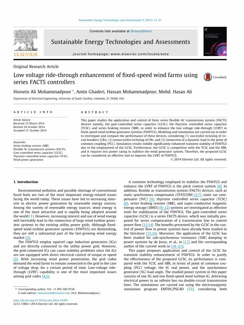
The RMS value of the PCC voltage is depicted for both scenariosin Fig. 2, including the LVRT profile. Note that the LVRT profileshown in Fig. 2 is adopted from the Nordel grid code for the Nordiccountries including Norway, Denmark, and Sweden [4]. As seen inFig. 2, the wind turbine is not capable of maintaining the stabilityafter fault, and the peak of the PCC voltage drops from 1 p.u. toabout 0.5 p.u. in both scenarios.
4. Overview of the series FACTS controllers used in this work
4.1. The gate-controlled series capacitor (GCSC)
The GCSC consists of a fixed capacitor in parallel with a bidirec-tional switch with a pair of gate turn-off (GTO) thyristors (g1 andg2), as shown in Fig. 3. The current and voltage waveforms of theGCSC are shown in Fig. 4. The principle of GCSC operation is basedon the variation of the turn-off angle (b) of the gate-controlledswitches. By controlling the turn-off angle (b), the series compen-sation level of the transmission line can be determined. The turn-off angles of the GTOs are measured from the zero crossing ofthe line current, and the compensation level of the GCSC is deter-mined by the fundamental component of the voltage (vCGðtÞ)across the GCSC. The effective reactance of the GCSC is determinedby the following equation [19]:
XðbÞ ¼ XCG
pð2b� 2p� sinð2bÞÞ ð1Þ
where XCG is the reactance of the GCSC capacitor.Fig. 5 shows typical impedance characteristic of the GCSC as a
function of the turn-off angle. As shown in this figure, as b variesfrom 90 to 180 degrees, XðbÞ varies from �Xmax (�XCG) to 0 [19].
A generic block diagram of the basic control structure of a GCSCdevice is depicted in Fig. 6. This controller is based on a propor-tional-integral (PI) regulator. In this figure, TmG is the time constantof first order low pass filter associated with the measurement ofthe line power. In this controller, the measured line power Pm iscompared to the reference current P�Line, and the error DPe is passedthrough a PI regulator. The output of the PI regulator, XGdes, is theinput signal to the linearization block, which computes border , basedon Eq. (1). The turn-off pulse generator, which is synchronizedwith the transmission line current, produces the GCSC’s inputturn-off pulse.
ed wind turbine for modeling and simulation.
0 0.2 0.45 0.95 1.2 1.45 1.7 1.950
0.25
0.5
0.75
0.951
1.2
Volta
ge (p
.u.)
Time (s)
Scenario I
LVRT profile
Scenario II
Fig. 2. The PCC voltage for Scenario I and Scenario II, and the LVRT profile from theNordel grid code for the Nordic countries Norway, Denmark, and Sweden [4].
Fig. 3. Typical single line configuration of a GCSC.
Fig. 4. The typical waveforms of the GCSC including transmission line and GTOcurrents (iL; igate) as well as capacitor voltage and current (vCG; iCG) and correspond-ing turn-off angle pulses.
90 180-Xmax
0
Effe
ctiv
e re
acta
nce
of G
CSC
Turn-off angle β (deg.)
Fig. 5. GCSC reactance versus turn-off angle.
Fig. 6. Generic block diagram of the basi
14 H.A. Mohammadpour et al. / Sustainable Energy Technologies and Assessments 9 (2015) 12–21
4.2. Thyristor-controlled series capacitor
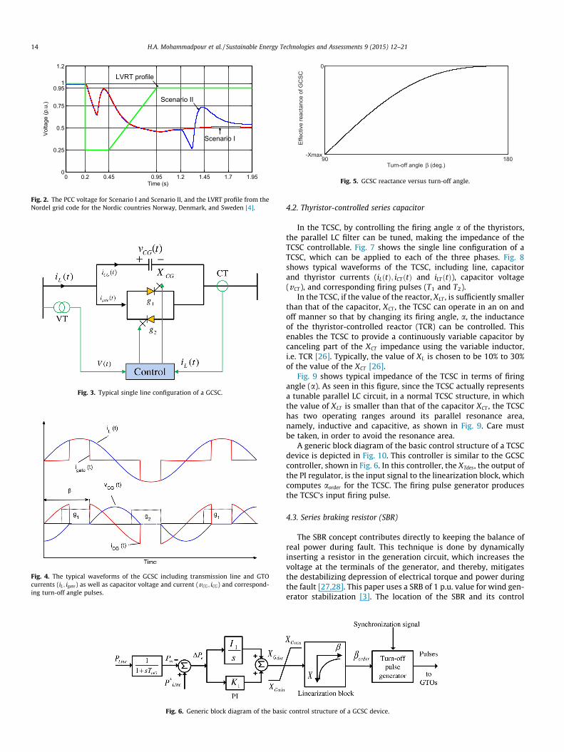
In the TCSC, by controlling the firing angle a of the thyristors,the parallel LC filter can be tuned, making the impedance of theTCSC controllable. Fig. 7 shows the single line configuration of aTCSC, which can be applied to each of the three phases. Fig. 8shows typical waveforms of the TCSC, including line, capacitorand thyristor currents (iLðtÞ; iCTðtÞ and iLTðtÞ), capacitor voltage(vCT ), and corresponding firing pulses (T1 and T2).
In the TCSC, if the value of the reactor, XLT , is sufficiently smallerthan that of the capacitor, XCT , the TCSC can operate in an on andoff manner so that by changing its firing angle, a, the inductanceof the thyristor-controlled reactor (TCR) can be controlled. Thisenables the TCSC to provide a continuously variable capacitor bycanceling part of the XCT impedance using the variable inductor,i.e. TCR [26]. Typically, the value of XL is chosen to be 10% to 30%of the value of the XCT [26].
Fig. 9 shows typical impedance of the TCSC in terms of firingangle (a). As seen in this figure, since the TCSC actually representsa tunable parallel LC circuit, in a normal TCSC structure, in whichthe value of XLT is smaller than that of the capacitor XCT , the TCSChas two operating ranges around its parallel resonance area,namely, inductive and capacitive, as shown in Fig. 9. Care mustbe taken, in order to avoid the resonance area.
A generic block diagram of the basic control structure of a TCSCdevice is depicted in Fig. 10. This controller is similar to the GCSCcontroller, shown in Fig. 6. In this controller, the XTdes, the output ofthe PI regulator, is the input signal to the linearization block, whichcomputes aorder for the TCSC. The firing pulse generator producesthe TCSC’s input firing pulse.
4.3. Series braking resistor (SBR)
The SBR concept contributes directly to keeping the balance ofreal power during fault. This technique is done by dynamicallyinserting a resistor in the generation circuit, which increases thevoltage at the terminals of the generator, and thereby, mitigatesthe destabilizing depression of electrical torque and power duringthe fault [27,28]. This paper uses a SRB of 1 p.u. value for wind gen-erator stabilization [3]. The location of the SBR and its control
c control structure of a GCSC device.
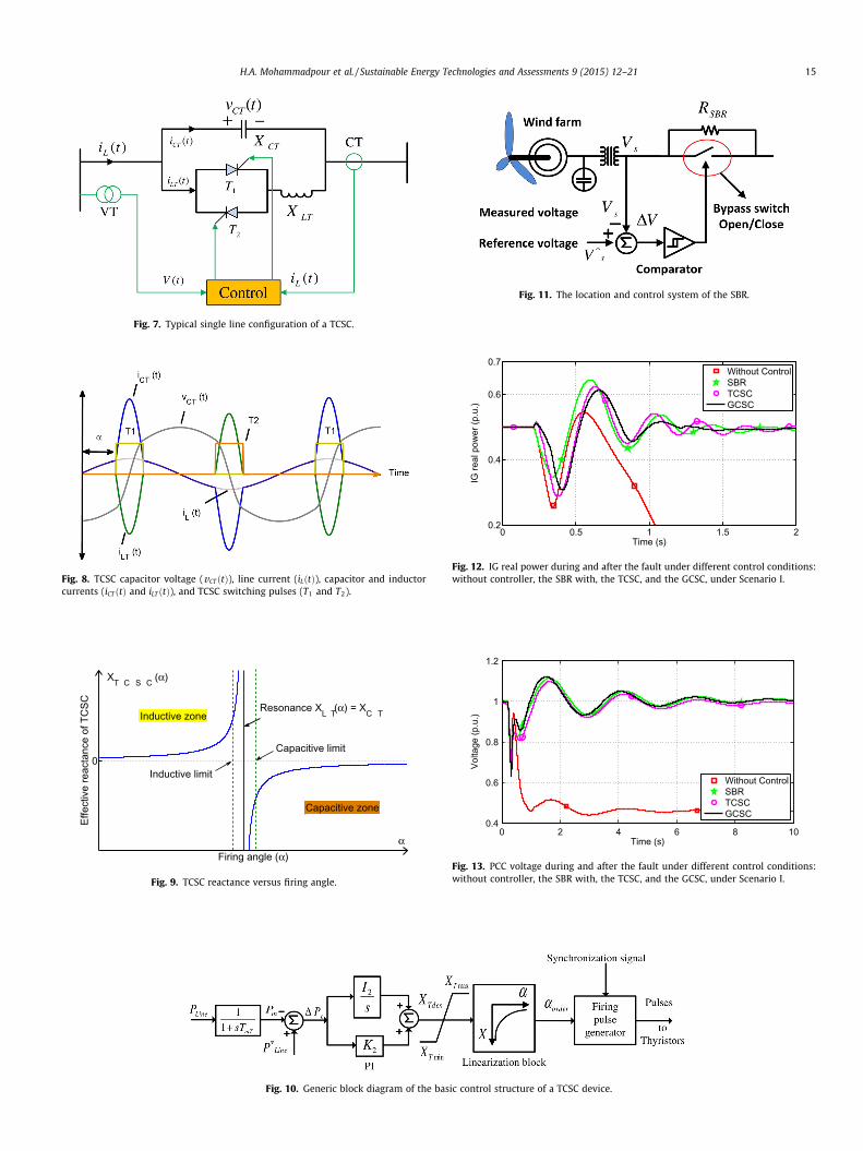
Fig. 7. Typical single line configuration of a TCSC.
Fig. 8. TCSC capacitor voltage (vCT ðtÞ), line current (iLðtÞ), capacitor and inductorcurrents (iCT ðtÞ and iLT ðtÞ), and TCSC switching pulses (T1 and T2).
0
Firing angle (α)
Effe
ctiv
e re
acta
nce
of T
CSC
α
Resonance XL T (α) = XC T
Capacitive limit
Inductive limit
Capacitive zone
Inductive zone
XT C S C (α)
Fig. 9. TCSC reactance versus firing angle.
Fig. 10. Generic block diagram of the basic control structure of a TCSC device.
Fig. 11. The location and control system of the SBR.
0 0.5 1 1.5 20.2
0.4
0.6
0.7
IG re
al p
ower
(p.u
.)
Time (s)
Without ControlSBRTCSCGCSC
Fig. 12. IG real power during and after the fault under different control conditions:without controller, the SBR with, the TCSC, and the GCSC, under Scenario I.
0 2 4 6 8 100.4
0.6
0.8
1
1.2
Volta
ge (p
.u.)
Time (s)
Without ControlSBRTCSCGCSC
Fig. 13. PCC voltage during and after the fault under different control conditions:without controller, the SBR with, the TCSC, and the GCSC, under Scenario I.
H.A. Mohammadpour et al. / Sustainable Energy Technologies and Assessments 9 (2015) 12–21 15
0 2 4 6 8 1020
30
40
50
60
SG lo
ad a
ngle
(deg
.)
Time (s)
Without ControlSBRTCSCGCSC
Fig. 14. SG load angle during and after the fault under different control conditions:without controller, the SBR with, the TCSC, and the GCSC, under Scenario I.
Table 1Assessment of stabilization methods during successful reclosing (Scenario I).
Parameters Values of indices in case of Scenario 1
No Controller SBR TCSC GCSC
Dp (p.u., sec) 0.5726 0.0713 0.0745 0.0609Dv (p.u., sec) 0.8596 0.1965 0.2011 0.1906Dd (deg., sec) 19.2423 16.2812 16.7389 16.2134
0 1 2 3 40.2
0.4
0.6
0.7
IG re
al p
ower
(p.u
.)
Time (s)
Without ControlSBRTCSCGCSC
Fig. 15. IG real power during and after the fault under different control conditions:without controller, the SBR with, the TCSC, and the GCSC, under Scenario II.
0 2 4 6 8 100.2
0.4
0.6
0.8
1
1.2
Volta
ge (p
.u.)
Time (s)
Without ControlSBRTCSCGCSC
Fig. 16. PCC voltage during and after the fault under different control conditions:without controller, the SBR with, the TCSC, and the GCSC, under Scenario II.
0 2 4 6 8 1020
30
40
50
60
SG lo
ad a
ngle
(deg
.)
Time (s)
Without ControlSBRTCSCGCSC
Fig. 17. SG load angle during and after the fault under different control conditions:without controller, the SBR with, the TCSC, and the GCSC, under Scenario II.
Table 2Assessment of stabilization methods during unsuccessful reclosing (Scenario II).
Parameters Values of indices in case of Scenario 1
No controller SBR TCSC GCSC
Dp (p.u., sec) 0.5948 0.1224 0.1190 0.0951Dv (p.u., sec) 1.8568 0.1901 0.2662 0.1556Dd (deg., sec) 25.3290 23.6907 24.5873 23.0532
16 H.A. Mohammadpour et al. / Sustainable Energy Technologies and Assessments 9 (2015) 12–21
methodology are shown in Fig. 11. According to the controlmethod, if DV is positive, then the bypass switch is open, and ifDV is negative or zero, the bypass switch is closed, realizing aclosed loop control of the SBR.
5. Simulation results
5.1. Scenario I (temporary fault)
In this scenario, the fault occurs at t = 0.2 s, the CBs on thefaulted lines are opened at t = 0.3 s, and the CBs are closed againat t = 1.2 s, while the fault is cleared. The wind speed is randomlychanging; however, during the short span of the analysis of tran-sient stability, the variation of wind speed can be neglected. Thewind speed in this paper is assumed to be constant at 12 m/s. Itis noted that the IG real power, the PCC voltage, and the SG loadangle have been taken into consideration, in order to verify theeffectiveness of the GCSC in transient stability enhancement, asthese parameters clearly indicate the power system stability.
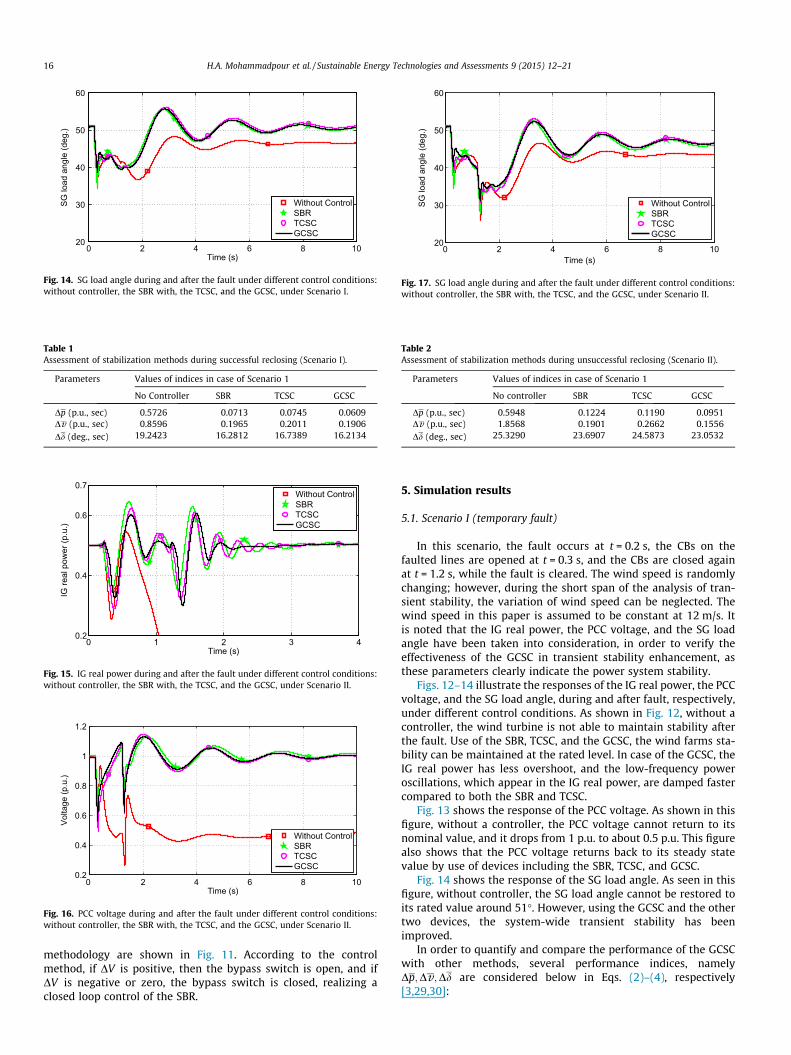
Figs. 12–14 illustrate the responses of the IG real power, the PCCvoltage, and the SG load angle, during and after fault, respectively,under different control conditions. As shown in Fig. 12, without acontroller, the wind turbine is not able to maintain stability afterthe fault. Use of the SBR, TCSC, and the GCSC, the wind farms sta-bility can be maintained at the rated level. In case of the GCSC, theIG real power has less overshoot, and the low-frequency poweroscillations, which appear in the IG real power, are damped fastercompared to both the SBR and TCSC.
Fig. 13 shows the response of the PCC voltage. As shown in thisfigure, without a controller, the PCC voltage cannot return to itsnominal value, and it drops from 1 p.u. to about 0.5 p.u. This figurealso shows that the PCC voltage returns back to its steady statevalue by use of devices including the SBR, TCSC, and GCSC.
Fig. 14 shows the response of the SG load angle. As seen in thisfigure, without controller, the SG load angle cannot be restored toits rated value around 51�. However, using the GCSC and the othertwo devices, the system-wide transient stability has beenimproved.
In order to quantify and compare the performance of the GCSCwith other methods, several performance indices, namelyDp;Dv ;Dd are considered below in Eqs. (2)–(4), respectively[3,29,30]:
0 1 2 3 40.45
0.475
0.5
0.525
0.55
IG re
al p
ower
(p.u
.)
Time (s)
Without ControlSBRTCSCGCSC
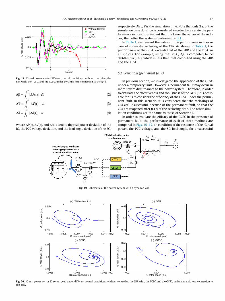
Fig. 18. IG real power under different control conditions: without controller, theSBR with, the TCSC, and the GCSC, under dynamic load connection to the grid.
H.A. Mohammadpour et al. / Sustainable Energy Technologies and Assessments 9 (2015) 12–21 17
Dp ¼Z T
0jDPðtÞj � dt ð2Þ
Dv ¼Z T
0jDVðtÞj � dt ð3Þ
Dd ¼Z T
0jDdðtÞj � dt ð4Þ
where DPðtÞ;DVðtÞ, and DdðtÞ denote the real power deviation of theIG, the PCC voltage deviation, and the load angle deviation of the SG,
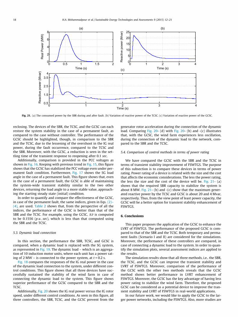
Fig. 19. Schematic of the power s
1.003 1.005 1.007 1.009 1.011 1.0120.45
0.5
0.55
IG rotor speed (p.u.)
IG re
al p
ower
(p.u
.)
(a): Without control
1.0025 1.0045 1.00651.0070.45
0.5
0.55
IG rotor speed (p.u.)
IG re
al p
ower
(p.u
.)
(c): TCSC
Fig. 20. IG real power versus IG rotor speed under different control conditions: withoutthe grid.
respectively. Also, T is the simulation time. Note that only 2 s. of thesimulation time duration is considered in order to calculate the per-formance indices. It is evident that the lower the values of the indi-ces, the better the system’s performance [31].
In Table 1, we present the values of the performance indices incase of successful reclosing of the CBs. As shown in Table 1, theperformance of the GCSC exceeds that of the SBR and the TCSC inall indices. For example, using the GCSC, Dp is computed to be0.0609 (p:u:; sec), which is less than that computed using the SBRand the TCSC.
5.2. Scenario II (permanent fault)
In previous section, we investigated the application of the GCSCunder a temporary fault. However, a permanent fault may occur inmore severe disturbances to the power system. Therefore, in orderto evaluate the effectiveness and robustness of the GCSC, it is desir-able for us to consider the efficiency of the GCSC under the perma-nent fault. In this scenario, it is considered that the reclosings ofCBs are unsuccessful, because of the permanent fault, so that theCBs are reopened after 0.1 s of the reclosing time. The other simu-lation conditions are the same as those of Scenario I.
In order to evaluate the efficacy of the GCSC in the presence ofpermanent fault, the performance of each of three methods arecompared in Figs. 15–17, on condition of the response of the IG realpower, the PCC voltage, and the SG load angle, for unsuccessful
ystem with a dynamic load.
1.002 1.004 1.006 1.008 1.0090.45
0.5
0.55
IG rotor speed (p.u.)
IG re
al p
ower
(p.u
.)
(b): SBR
1.002 1.004 1.006
0.46
0.48
0.5
0.52
IG rotor speed (p.u.)
IG re
al p
ower
(p.u
.)
(d): GCSC
controller, the SBR with, the TCSC, and the GCSC, under dynamic load connection to
0 0.5 1 1.5 20
2
4
6
8
Time (s)
Rea
l Pow
er (M
W)
(a)
0 1 2 3 40
5
10
15
20
25
Time (s)
Rea
ctiv
e po
wer
(Mva
r)
(b)
0 1 2 3 40.5
1.5
2.5
3.54
Time (s)
Rea
ctiv
e po
wer
(Mva
r)
(c)
Fig. 21. (a) The consumed power by the SBR during and after fault. (b) Variation of reactive power of the TCSC. (c) Variation of reactive power of the GCSC.
18 H.A. Mohammadpour et al. / Sustainable Energy Technologies and Assessments 9 (2015) 12–21
reclosing. The devices of the SBR, the TCSC, and the GCSC can eachrestore the system stability in the case of a permanent fault, ascompared to the case without controller. The performance of theGCSC should be highlighted, though, in comparison to the SBRand the TCSC, due to the lessening of the overshoot in the IG realpower, during the fault occurrence, compared to the TCSC andthe SBR. Moreover, with the GCSC, a reduction is seen in the set-tling time of the transient response to reopening after 0.1 sec.
Additionally, comparison is provided in the PCC voltages asshown in Fig. 16. Keeping with previous trend in Fig. 15, this figureshows that the GCSC has stabilized the PCC voltage even under per-manent fault condition. Furthermore, Fig. 17 shows the SG loadangle in the case of a permanent fault. This figure shows that, evenin the case of a permanent fault, the GCSC is able of maintainingthe system-wide transient stability similar to the two otherdevices, returning the load angle to a more stable value, approach-ing the starting steady state (initial) condition.
In order to quantify and compare the effectiveness of the GCSC,in case of the permanent fault, the same indices, given in Eqs. (2)–(4), are used. Table 2 shows that, from the perspective of all theindices, the performance of the GCSC is better than that of theSBR and the TCSC. For example, using the GCSC, Dv is computedto be 0.1556 (p:u:; sec), which is less than that computed usingthe SBR and the TCSC.
5.3. Dynamic load connection
In this section, the performance the SBR, TCSC, and GCSC iscompared, when a dynamic load is replaced with the SG system,as represented in Fig. 19. The dynamic load – which is an aggrega-tion of 10 induction motor units, where each unit has a power rat-ing of 2 MW – is connected to the power system, at t = 0.2 s.
Fig. 18 compares the responses of the IG real power in the caseof the dynamic load connection to the system, under different con-trol conditions. This figure shows that all three devices have suc-cessfully sustained the stability of the wind farm in case ofconnecting the dynamic load to the system. This figure showssuperior performance of the GCSC compared to the SBR and theTCSC.
Additionally, Fig. 20 shows the IG real power versus the IG rotorspeed, under different control conditions. As seen in this figure, allthree controllers, the SBR, TCSC, and the GCSC prevent from the
generator rotor acceleration during the connection of the dynamicload. Comparing Fig. 20- (d) with Fig. 20- (b) and -(c) illustratesthat, with the GCSC, the wind farm experiences less oscillation,during the connection of the dynamic load to the network, com-pared to the SBR and the TCSC.
5.4. Comparison of control methods in terms of power rating
We have compared the GCSC with the SBR and the TCSC interms of transient stability improvement of FSWTGS. The purposeof this subsection is to compare these devices in terms of powerrating. Power rating of a device is related with the size and the costthat affects the economic considerations. The less the power rating,the less the size and the cost of the device will be. Fig. 21- (a)shows that the required SBR capacity to stabilize the system isabout 8 MW. Fig. 21- (b) and -(c) show that the maximum gener-ated reactive power by the TCSC and GCSC is about 20 and 4 Mvar,respectively. Thus, from the view point of least power capacity, theGCSC will be a better option for transient stability enhancement ofFSWTGS.
6. Conclusions
This paper proposes the application of the GCSC to enhance theLVRT of FSWTGS. The performance of the proposed GCSC is com-pared to that of the SBR and the TCSC. Both temporary and perma-nent faults (Scenario I and II) are considered for the simulations.Moreover, the performance of these controllers are compared, incase of connecting a dynamic load to the system. In order to quan-tify the simulation plots, several assessment indices are applied tothe results.
The simulation results show that all three methods, i.e.. the SBR,the TCSC, and the GCSC can improve the transient stability andLVRT of FSWTGS. Moreover, comparison of the performance ofthe GCSC with the other two methods reveals that the GCSCmethod shows better performance in LVRT enhancement ofFSWTGS. Moreover, the GCSC has the key advantage of having lesspower rating to stabilize the wind farm. Therefore, the proposedGCSC can be considered as a potential device to improve the tran-sient stability and LVRT of FSWTGS in real-world applications.
In our future work, we would like to apply the GCSC to the lar-ger power networks, including the FSWTGS. Also, more studies are
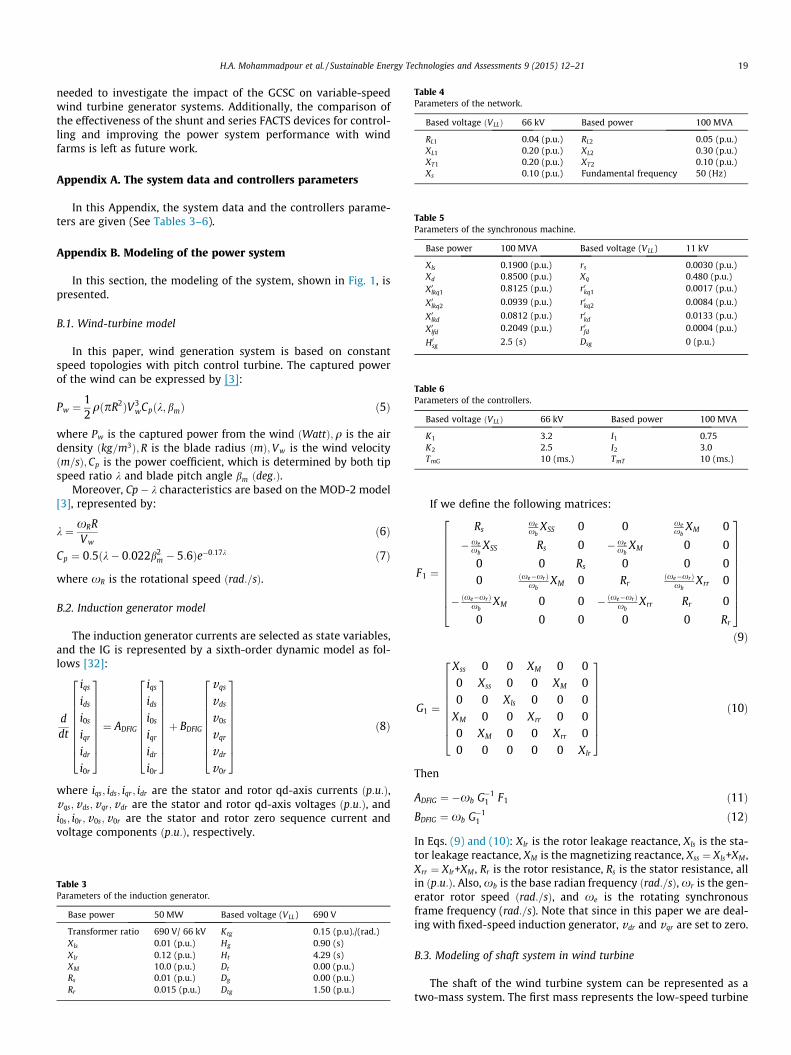
Table 4Parameters of the network.
Based voltage ðVLLÞ 66 kV Based power 100 MVA
RL1 0.04 (p.u.) RL2 0.05 (p.u.)XL1 0.20 (p.u.) XL2 0.30 (p.u.)XT1 0.20 (p.u.) XT2 0.10 (p.u.)Xs 0.10 (p.u.) Fundamental frequency 50 (Hz)
Table 5Parameters of the synchronous machine.
Base power 100 MVA Based voltage (VLL) 11 kV
Xls 0.1900 (p.u.) rs 0.0030 (p.u.)Xd 0.8500 (p.u.) Xq 0.480 (p.u.)X0lkq1 0.8125 (p.u.) r0kq1 0.0017 (p.u.)
X0lkq2 0.0939 (p.u.) r0kq2 0.0084 (p.u.)
X0lkd 0.0812 (p.u.) r0kd 0.0133 (p.u.)
X0lfd 0.2049 (p.u.) r0fd 0.0004 (p.u.)
H0sg 2.5 (s) Dsg 0 (p.u.)
Table 6Parameters of the controllers.
Based voltage ðVLLÞ 66 kV Based power 100 MVA
K1 3.2 I1 0.75K2 2.5 I2 3.0TmG 10 (ms.) TmT 10 (ms.)
H.A. Mohammadpour et al. / Sustainable Energy Technologies and Assessments 9 (2015) 12–21 19
needed to investigate the impact of the GCSC on variable-speedwind turbine generator systems. Additionally, the comparison ofthe effectiveness of the shunt and series FACTS devices for control-ling and improving the power system performance with windfarms is left as future work.
Appendix A. The system data and controllers parameters
In this Appendix, the system data and the controllers parame-ters are given (See Tables 3–6).
Appendix B. Modeling of the power system
In this section, the modeling of the system, shown in Fig. 1, ispresented.
B.1. Wind-turbine model
In this paper, wind generation system is based on constantspeed topologies with pitch control turbine. The captured powerof the wind can be expressed by [3]:
Pw ¼12qðpR2ÞV3
wCpðk;bmÞ ð5Þ
where Pw is the captured power from the wind ðWattÞ;q is the airdensity ðkg=m3Þ;R is the blade radius ðmÞ;Vw is the wind velocityðm=sÞ;Cp is the power coefficient, which is determined by both tipspeed ratio k and blade pitch angle bm ðdeg:Þ.
Moreover, Cp� k characteristics are based on the MOD-2 model[3], represented by:
k ¼ xRRVw
ð6Þ
Cp ¼ 0:5ðk� 0:022b2m � 5:6Þe�0:17k ð7Þ
where xR is the rotational speed ðrad:=sÞ.
B.2. Induction generator model
The induction generator currents are selected as state variables,and the IG is represented by a sixth-order dynamic model as fol-lows [32]:
ddt
iqs
ids
i0s
iqr
idr
i0r
2666666664
3777777775¼ ADFIG
iqs
ids
i0s
iqr
idr
i0r
2666666664
3777777775þ BDFIG
vqs
vds
v0s
vqr
vdr
v0r
2666666664
3777777775
ð8Þ
where iqs; ids; iqr ; idr are the stator and rotor qd-axis currents ðp:u:Þ,vqs;vds;vqr;vdr are the stator and rotor qd-axis voltages ðp:u:Þ, andi0s; i0r ;v0s;v0r are the stator and rotor zero sequence current andvoltage components ðp:u:Þ, respectively.
Table 3Parameters of the induction generator.
Base power 50 MW Based voltage (VLL) 690 V
Transformer ratio 690 V/ 66 kV Ktg 0.15 (p.u)./(rad.)Xls 0.01 (p.u.) Hg 0.90 (s)Xlr 0.12 (p.u.) Ht 4.29 (s)XM 10.0 (p.u.) Dt 0.00 (p.u.)Rs 0.01 (p.u.) Dg 0.00 (p.u.)Rr 0.015 (p.u.) Dtg 1.50 (p.u.)
If we define the following matrices:
F1 ¼
Rsxexb
XSS 0 0 xexb
XM 0
� xexb
XSS Rs 0 � xexb
XM 0 0
0 0 Rs 0 0 00 ðxe�xrÞ
xbXM 0 Rr
ðxe�xrÞxb
Xrr 0
� ðxe�xrÞxb
XM 0 0 � ðxe�xr Þxb
Xrr Rr 0
0 0 0 0 0 Rr
266666666664
377777777775ð9Þ
G1 ¼
Xss 0 0 XM 0 00 Xss 0 0 XM 00 0 Xls 0 0 0
XM 0 0 Xrr 0 00 XM 0 0 Xrr 00 0 0 0 0 Xlr
2666666664
3777777775
ð10Þ
Then
ADFIG ¼ �xb G�11 F1 ð11Þ
BDFIG ¼ xb G�11 ð12Þ
In Eqs. (9) and (10): Xlr is the rotor leakage reactance, Xls is the sta-tor leakage reactance, XM is the magnetizing reactance, Xss ¼ Xls+XM ,Xrr ¼ Xlr+XM , Rr is the rotor resistance, Rs is the stator resistance, allin ðp:u:Þ. Also, xb is the base radian frequency ðrad:=sÞ, xr is the gen-erator rotor speed ðrad:=sÞ, and xe is the rotating synchronousframe frequency (rad:=s). Note that since in this paper we are deal-ing with fixed-speed induction generator, vdr and vqr are set to zero.
B.3. Modeling of shaft system in wind turbine
The shaft of the wind turbine system can be represented as atwo-mass system. The first mass represents the low-speed turbine

20 H.A. Mohammadpour et al. / Sustainable Energy Technologies and Assessments 9 (2015) 12–21
and the second mass represents the high-speed generator, and thetwo mass connections are modeled as a spring and a damper. Themotion equations then can be expressed as a third order linear sys-tem in per unit as follows [33–36]:
ddt
xt1
xr1
Ttg
26664
37775¼
ð�Dt�Dtg Þ2Ht1
Dt g2Ht1
� 12Ht1
Dt g2Hg1
ð�Dg�Dtg Þ2Hg1
12Hg1
Ktg xb �Ktg xb 0
2666664
3777775
xt1
xr1
Ttg
26664
37775þ
12Ht1
0 0
0 12Hg1
0
0 0 1
266664
377775
Tx
Te1
0
26664
37775 ð13Þ
In the shaft equations, Te is the electric torque and is given by0:5XMðiqsidr � idsiqrÞ ðp:u:Þ, �xm is the turbine shaft speed ðp:u:Þ, �xr
is the generator rotor speed ðp:u:Þ, Tx is the wind torque ðp:u:Þ, Dg
and Dt are damping coefficient of generator and turbine ðp:u:Þ, Dtg
is the damping coefficient between the two masses ðp:u:Þ. Also,Ktg is the inertia constant of the turbine and the generatorðp:u=rad:Þ, and Hg and Ht are the inertia constants of the generatorand the turbine ðsÞ.
B.4. Modeling of synchronous machine
A two-pole, three-phase, wye-connected, salient-pole syn-chronous generator (SG) is considered in this paper. Therotor is equipped with a field winding and three damperwindings. In the following, the modeling of the differentparts of the SG is described. The machine data is given inthe Appendix A.
B.4.1. Synchronous generator modelThe synchronous generators equations in qd-frame are
described in this section. If the SG currents are selected as the statevariables, then the SG qd model will be as follows [32]:
ddt
irqs
irds
isg0s
i0rkq1
i0rkq2
i0rfd
i0rkd
26666666666666666664
37777777777777777775
¼ ASG
irqs
irds
i0s
i0rkq1
i0rkq2
i0rfd
i0rkd
26666666666666666664
37777777777777777775
þ BSG
v rqs
v rds
v sg0s
v 0rkq1
v 0rkq2
v 0rxfd
v 0rkd
2666666666666666664
3777777777777777775
ð14Þ
where irqs and ir
ds are the stator qd-axis currents, isg0s and v sg
0s are thestator zero sequence current and voltage components, respectively,i0rkq1; i
0rkq2, and i0rkd are the first, the second, and the third damper wind-
ings currents, respectively, i0rfd is the field winding magnetic current,v r
qs;v rds are the stator qd-axis voltages, v 0rkq1;v 0rkq2, and v 0rkd are the first,
the second, and the third damper windings voltages, respectively,and v 0rxfd is the field magnetic voltage, all in ðp:u:Þ.
If we define the following matrices:
F2 ¼
rsxexb
Xd 0 0 0 xexb
Xmdxexb
Xmd
� xexb
Xq rs 0 � xexb
Xmq � xexb
Xmq 0 0
0 0 rs 0 0 0 0
0 0 0 r0rkq1 0 0 0
0 0 0 0 r0rkq2 0 0
0 0 0 0 Xmd 0
0 0 0 0 0 r0kd
2666666666666666664
3777777777777777775ð15Þ
G2 ¼
Xq
xb0 0 Xmq
xb
Xmq
xb0 0
0 Xdxb
0 0 0 Xmdxb
Xmdxb
0 0 Xlsxb
0 0 0 0
Xmq
xb0 0
X0kq1xb
Xmq
xb0 0
Xmq
xb0 0 Xmq
xb
X0kq2xb
0 0
0 Xmdr0
fd
Xmdxb
0 0 0 Xmdr0
fd
X0fdxb
Xmdr0
fd
Xmdxb
0 Xmdxb
0 0 0 Xmdxb
X0kdxb
26666666666666666666664
37777777777777777777775
ð16Þ
ASG ¼ �xb G�12 F2 ð17Þ
BSG ¼ xb G�12 ð18Þ
where
Xq ¼ Xls þ Xmq ð19ÞXd ¼ Xls þ Xmd ð20ÞX0kq1 ¼ X0lkq1 þ Xmq ð21ÞX0kq2 ¼ X0lkq2 þ Xmq ð22ÞX0fd ¼ X 0lfd þ Xmd ð23ÞX0kd ¼ X 0lkd þ Xmd ð24Þ
In Eqs. (15)–(24): Xls is the stator leakage reactance, rs is the statorresistance ðp:u:Þ, X0lkq1;X
0lkq2, and X0lkd are the first, the second, and the
third damper windings leakage reactances, r0kq1; r0kq2, and r0kd are the
first, the second, and the third damper windings resistances, X0lfd isthe field winding leakage reactance, r0fd is the field winding resis-tance, Xmq is the mutual inductance in q-axis, and Xmd is the mutualinductance in d-axis, all in ðp:u:Þ.
B.4.2. Swing equationThe swing equations in the synchronous machine is defined as
follows [32]:
ddt
xr2
d
� �¼�Dsg 0xb 0
� � xr2
d
� �þ
TL�Te22Hsg
0
" #ð25Þ
where TL is the mechanical torque ðp:u:Þ, Te2 is the electromagnetictorque ðp:u:Þ, xr2 is the angular velocity of the rotor ðp:u:Þ, d is theangular position of the rotor with respect to the synchronouslyrotating frame ðrad:Þ, Dsg is the damping coefficient of the generatorrotor ðp:u:Þ, and Hsg is the inertia constants of the generator rotorðsÞ.
In Eq. (25), Te2 is defined as follows:
Te2 ¼ 1:5ðkrdsi
rqs � kr
qsirdsÞ ð26Þ
where
krds ¼ Xlsi
rds þ Xmdðir
ds þ i0rfd þ i0rkdÞ ð27Þkr
qs ¼ Xlsirqs þ Xmqðir
qs þ i0rkq1 þ i0rkq2Þ ð28Þ
B.4.3. Automatic voltage regulator (AVR) and governorThe automatic voltage regulator (AVR) and the Governor (GOV)
control system models, used in this paper, are shown in Fig. 22. Aand B.
B.5. Modeling of transmission line
The general equations of the transmission line in qd-frame canbe expressed in the matrix form as follows [32]:
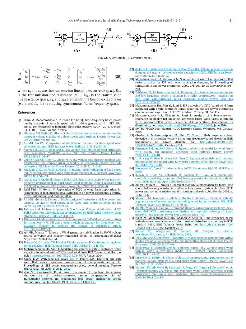
Fig. 22. A. AVR model. B. Governor model.
H.A. Mohammadpour et al. / Sustainable Energy Technologies and Assessments 9 (2015) 12–21 21
ddt
ilq
ild
il0
264
375 ¼ xb
� RlineXline
� �xe 0
�xe � RlineXline
0
0 0 � RlineXline
26664
37775
ilq
ild
il0
264
375þxb
vqs�EBq
Xline
vds�EBdXline
v0s�EB0Xline
26664
37775 ð29Þ
where ilq and ild are the transmission line qd-axis currents ðp:u:Þ, Rline
is the transmission line resistance ðp:u:Þ, Xline is the transmissionline reactance ðp:u:Þ, EBq and EBd are the infinite bus qd-axis voltagesðp:u:Þ, and �xe is the rotating synchronous frame frequency ðp:u:Þ.
References
[1] Islam M, Mohammadpour HA, Stone P, Shin YJ. Time-frequency based powerquality analysis of variable speed wind turbine generators. In: IEEE 39thannual conference of the industrial electronics society (IECON); 2013. p. 6426–6431, 10–13 Nov., Vienna, Austria.
[2] Eltamaly AM, Farh HM. Effects of electrical and mechanical parameters on thetransient voltage stability of a fixed speed wind turbine. Electric Power SystRes 2011;81(7):1308–16.
[3] Ali MH, Bin Wu. Comparison of stabilization methods for fixed-speed windgenerator systems. IEEE Transact Power Deliv 2010;25(1):323–31.
[4] Molinas M, Suul JA, Undeland T. Low voltage ride through of wind farms withcage generators: STATCOM versus SVC. IEEE Transact Power Electron2008;23(3):1104–17.
[5] Chou SF, Lee Ch T, Ko HC, Cheng PT. A low-voltage ride-through method withtransformer flux compensation capability of renewable power grid-sideconverters. IEEE Transact Power Electron 2014;29(3):1710–9.
[6] Rogdakis G, Garcia-Valle R, Arana I. Transient model validation of fixed-speedinduction generator using wind farm measurements. IEEE Transact Power Syst2012;27(1):564–71.
[7] Gaztanaga H, Otadui IE, Ocnasu D, Bacha S. Real-time analysis of the transientresponse improvement of fixed-speed wind farms by using a reduced-scaleSTATCOM prototype. IEEE Transact Power Syst 2007;22(2):658–66.
[8] Joshi Nitin N, Mohan N. Application of TCSC in wind farm application. In:Proceedings of IEEE international symposium on power electronics, electricaldrives, automation and motion; 2006.
[9] Ali MH, Murata T, Tamura J. Minimization of fluctuations of line power andterminal voltage of wind generator by fuzzy logic-controlled SMES. Int RevElectr Eng (IREE) 2006;1(4):559–66.
[10] Pahlavani M, Mohammadpour HA, Shoulaie A. Voltage stabilization of VSISMES capacitors and voltage sag compensation by SMES using novel switchingstrategies. Energy 2010;8(35):3131–42.
[11] Pahlavani M, Mohammadpour HA. An optimized SVPWM switching strategyfor three-level NPC VSI and a novel switching strategy for three-level two-quadrant chopper to stabilize the voltage of capacitors. Energy2010;35(12):4917–31.
[12] Ali MH, Murata T, Tamura J. Wind generator stabilization by PWM voltagesource converter and chopper controlled SMES. In: Proceedings of ICEM,September 2006, CD-ROM.
[13] Karady GG, Ortmeyer TH, Pilvelait BR, Maratukulam D. Continuously regulatedseries capacitor. IEEE Transact Power Deliv 1993;8(3):1348–55.
[14] Mohammadpour HA, Santi E. Modeling and control of gate – controlled seriescapacitor interfaced with a DFIG-based wind farm. IEEE Transact Ind Electron,doi: http://dx.doi.org/10.1109/TIE.2014.2347007; August 2014.
[15] Souza LFW, Watanabe EH, Alves JER, Jr, Pilotto LAS. Thyristor and gatecontrolled series capacitors: comparison of components rating. In:Proceedings of IEEE power engineering society general meeting, Toronto,ON, Canada; Jul. 2003. p. 2542–2547.
[16] Zou SB, Czarkowski D. A novel phase-control topology to improvecharacteristics of thyristor-controlled series compensation in ACtransmission systems. In: Proceedings IEEE power engineering societysummer meeting, Jul. 18–22; 1999, vol. 2. p. 1134–1139.
[17] de Jesus FD, Watanabe EH, de Souza LFW, Alves JER. SSR and power oscillationdamping using gate – controlled series capacitors (GCSC). IEEE Transact PowerDeliv 2007;22(3):1806–12.
[18] Mohammadpour HA, Pahlavani M, Shoulaie A. On control of gate controlledseries capacitor for SSR and power oscillation damping. In: Proceeding ofcompatibility and power electronics, 2009. CPE ’09.; 20–22 May 2009, p.196–203.
[19] Pahlavani M, Mohammadpour HA. Damping of sub-synchronous resonanceand low-frequency power oscillation in a series-compensated transmissionline using gate-controlled series capacitor. Electric Power Syst Res2011;81(2):308–17.
[20] Mohammadpour HA, Shin YJ, Santi E. SSR analysis of a DFIG-based wind farminterfaced with a gate-controlled series capacitor, applied power electronicsconference and exposition, APEC 2014; March 2014. p. 3110–3117.
[21] Mohammadpour HA, Ghaderi A, Santi E. Analysis of sub-synchronousresonance in doubly-fed induction generator-based wind farms interfacedwith gate-controlled series capacitor, IET generation, transmission &distribution, doi: http://dx.doi.org/10.1049/iet-gtd.2013.0643; June 2014.
[22] EMTDC PSCAD User Manual, HVDC Research Center, Winnipeg, MB, Canada;2005.
[23] Ghaderi A, Mohammadpour HA, Shin YJ, Ginn H. High impedance faultdetection in distribution network using time-frequency based algorithm, IEEEtransactions on power delivery, doi: http://dx.doi.org/10.1109/TPWRD.2014.2361207; October 2014.
[24] Fernandez LM, Jurado F, Saenz JR. Aggregated dynamic model for wind farmswith doubly fed induction generator wind turbines. Renew Energy2008;33(1):129–40.
[25] Li H, Yang C, Zhao B, Wang HS, Chen Z. Aggregated models and transientperformances of a mixed wind farm with different wind. Electric Power SystRes 2012;92(2):1–10.
[26] Hingorani NG, Gyugi L. Understanding FACTS. Piscataway, NJ, USA: IEEE Press;2000.
[27] Rubaai A, Ofoli AR, Cobbinah D, Kankam MD. Two-layer supervisorycontroller-based thyristor-controlled braking resistor for transient stabilitycrisis. IEEE Trans Ind Appl 2005;41(6):1539–47.
[28] Ali MH, Murata T, Tamura J. Transient stability augmentation by fuzzy logiccontrolled braking resistor in multi-machine power system. In: Proc. IEEEpower eng. soc. transmission and distribution conf. exhib. Asia Pacific; 2002. p.1332–1337.
[29] Muyeen SM, Takahashi R, Ali MH, Murata T, Tamura J. Transient stabilityaugmentation of power system including wind farms by using ECS. IEEETransact Power Syst 2008;23(3):1179–87.
[30] Ali MH, Murata T, Tamura J. Transient stability enhancement by fuzzy logic-controlled SMES considering coordination with optimal reclosing of circuitbreakers. IEEE Transact Power Syst 2008;23(2):631–40.
[31] Islam M, Mohammadpour HA, Ghaderi A, Shin YJ. Time-frequency basedinstantaneous power components for transient disturbances according to IEEEstandard 1459, IEEE Transact Power Deliv, doi: http://dx.doi.org/10.1109/TPWRD.2014.2361207; October 2014.
[32] Krause PC, Wasynczuk O, Sudhoff SD. Analysis of electricmachinery. Piscataway, NJ: IEEE Press; 1995.
[33] Lei Y, Mullane A, Lightbody G, Yacamini R. Modeling of the wind turbine with adoubly fed induction generator for grid integration studies. IEEE Trans EnergyConversion 2006;21(1):257–64.
[34] Boukhezzar B, Siguerdidjane H. Nonlinear control of a variable-speed windturbine using a two-mass model. IEEE Transact Energy Conversion2001;26(1):149–62.
[35] Dusonchet L, Telaretti E. Effects of electrical and mechanical parameters on thetransient voltage stability of a fixed speed wind turbine. Electric Power SystRes 2001;81(7):1308–16.
[36] Muyeen SM, Ali Mohd H, Takahashi R, Murata T, Tamura J, Tomaki Y, et al.Transient stability analysis of grid connected wind turbine generator systemconsidering multi-mass shaft modeling. Electric Power Components Syst2006;34(10):1121–38.