University of Groningen Pins and Needles, Facts and Feelings ...
Upload
khangminh22Category
view
1download
0
OPTICALLY SENSORIZED TENDONS FOR ARTICULATE ROBOTIC NEEDLES
A Thesis
by
ROHITH KARTHIKEYAN
Submitted to the Office of Graduate and Professional Studies ofTexas A&M University
in partial fulfillment of the requirements for the degree of
MASTER OF SCIENCE
Chair of Committee, Seok Chang RyuCommittee Members, Won-Jong Kim
Michael MorenoHead of Department, Andreas A. Polycarpou
August 2017
Major Subject: Mechanical Engineering
Copyright 2017 Rohith Karthikeyan

ABSTRACT
This study proposes an optically sensorized tendon composed of a 195 µm diame-
ter, high strength, polarization maintaining (PM) fiber Bragg gratings (FBG) optical fiber
which resolves the cross-sensitivity issue of conventional FBGs. The bare fiber tendon
is locally reinforced with a 250 µm diameter Kevlar bundle enhancing the level of force
transmission and enabling high curvature tendon routing.
The performance of the sensorized tendons is explored in terms of strength (higher than
13N for the bare PM-FBG fiber tendon, up to 40N for the Kevlar-reinforced tendon under
tensile loading), strain sensitivity (0.127 percent strain per newton for the bare PM-FBG
fiber tendon, 0.04 percent strain per newton for the Kevlar-reinforced tendon), temperature
stability, and friction-independent sensing behavior.
Subsequently, the tendon is instrumented within an 18 Ga articulate NiTi cannula and
evaluated under static and dynamic loading conditions, and within phantoms of varying
stiffness for tissue-stiffness estimation. The results from this series of experiments serve
to validate the effectiveness of the proposed tendon as a bi-modal sensing and actuation
component for robot-assisted minimally invasive surgical instruments.
ii

DEDICATION
To my parents,
Nithya Kalyani and Karthikeyan
iii

ACKNOWLEDGMENTS
I would like to extend my heartfelt gratitude to my adviser, Dr. Seok Chang Ryu for his
counsel, guidance, and insight through this endeavour. I also thank Dr. Nadhir Kosa, Dr.
Bram Van Hoe, and Dr. Jan Van Roosbroeck of FBGS Technology GmbH, Jena, Germany
for their technical support with the fiber-optics involved.
I thank Dr. Selwan Ibrahim and team at FAZ Technology, Dublin, Ireland for tech-
nical assistance with the interrogation unit. In addition, I express my gratitude to Alex
Betamen, Eddie McCoy, and Richard Swindell at Precision Automated Laser Systems
Inc., San Clemente, CA for their support with fabrication and troubleshooting of in-house
equipment.
Lastly, my friends and fellow Aggies, Ameya R. Paranjpe, Manasa V. Hegde, and
Pranjal M. Dixit for being my family away from home.
iv

CONTRIBUTORS AND FUNDING SOURCES
Contributors
This work was supported by a thesis committee consisting of Dr. Seok Chang Ryu [ad-
visor], Dr. Won-Jong Kim, and Dr. Michael Moreno from the Department of Mechanical
Engineering at Texas A&M University.
The data analyzed for Section 5.1 was experimentally compiled by Kelly Sigmund, Un-
dergraduate Collaborator, Department of Mechanical Engineering, Class of 2017, Texas
A&M University. All other work conducted for the thesis was completed by the student
independently.
Funding Sources
This research study was partially supported by Intuitive Surgical’s Technology Re-
search Grant for the year 2017.
v

TABLE OF CONTENTS
Page
ABSTRACT . . . . . . . . . . . . . . . . . . . . . . . . . . . . . . . . . . . . . . ii
DEDICATION . . . . . . . . . . . . . . . . . . . . . . . . . . . . . . . . . . . . iii
ACKNOWLEDGMENTS . . . . . . . . . . . . . . . . . . . . . . . . . . . . . . . iv
CONTRIBUTORS AND FUNDING SOURCES . . . . . . . . . . . . . . . . . . v
TABLE OF CONTENTS . . . . . . . . . . . . . . . . . . . . . . . . . . . . . . . vi
LIST OF FIGURES . . . . . . . . . . . . . . . . . . . . . . . . . . . . . . . . . . viii
LIST OF TABLES . . . . . . . . . . . . . . . . . . . . . . . . . . . . . . . . . . xi
1. INTRODUCTION . . . . . . . . . . . . . . . . . . . . . . . . . . . . . . . . . 1
2. BACKGROUND . . . . . . . . . . . . . . . . . . . . . . . . . . . . . . . . . 5
2.1 Review of Optical Elements . . . . . . . . . . . . . . . . . . . . . . . . . 52.1.1 Strength of Fiber Bragg Grating Sensors . . . . . . . . . . . . . . 52.1.2 The Draw Tower Grating Process . . . . . . . . . . . . . . . . . . 62.1.3 Principle of Polarization Maintaining FBG Fibers . . . . . . . . . 8
2.2 State of the Art . . . . . . . . . . . . . . . . . . . . . . . . . . . . . . . 92.2.1 Sensing in Robotic Surgery . . . . . . . . . . . . . . . . . . . . . 92.2.2 Tendon Driven Instruments for Robotic Surgery . . . . . . . . . . 102.2.3 Design for Needle Articulation . . . . . . . . . . . . . . . . . . . 10
2.3 Research Objectives . . . . . . . . . . . . . . . . . . . . . . . . . . . . . 11
3. EVALUATION OF SENSORIZED TENDONS . . . . . . . . . . . . . . . . . 13
3.1 Comparison Under Tensile Load . . . . . . . . . . . . . . . . . . . . . . 133.2 PM FBG Strain Response and Sensitivity . . . . . . . . . . . . . . . . . 14
3.2.1 Bare Fiber . . . . . . . . . . . . . . . . . . . . . . . . . . . . . . 163.2.2 Kevlar-reinforced Optical Fiber . . . . . . . . . . . . . . . . . . 17
3.3 Temperature Independence of PM-FBG Fibers . . . . . . . . . . . . . . . 183.4 Friction Effects: Transmission Decay . . . . . . . . . . . . . . . . . . . . 19
vi
4. TOOL DESIGN DESCRIPTION . . . . . . . . . . . . . . . . . . . . . . . . . 23
4.1 Needle Kinematics . . . . . . . . . . . . . . . . . . . . . . . . . . . . . 244.2 Needle Tip Mechanics . . . . . . . . . . . . . . . . . . . . . . . . . . . . 28
5. PROTOTYPE EVALUATION . . . . . . . . . . . . . . . . . . . . . . . . . . 30
5.1 Tissue Phantom . . . . . . . . . . . . . . . . . . . . . . . . . . . . . . . 315.2 Behavior Under Static Loads . . . . . . . . . . . . . . . . . . . . . . . . 325.3 Behavior Under Dynamic Load . . . . . . . . . . . . . . . . . . . . . . . 345.4 Insertion Tests: Two-layered Phantoms . . . . . . . . . . . . . . . . . . . 36
6. CONCLUSIONS . . . . . . . . . . . . . . . . . . . . . . . . . . . . . . . . . 41
REFERENCES . . . . . . . . . . . . . . . . . . . . . . . . . . . . . . . . . . . . 43
vii

LIST OF FIGURES
FIGURE Page
1.1 Example of the use of sensorized tendons, a force sensing steerable needleprototype with circumferential slits that enable bi-directional planar bend-ing. The 18 Ga needle is made of a 120 mm long, 1.27 mm (0.05") diam-eter NiTi tube. The net range of flexion is approximately ± 29◦. SectionAA′ depicts a cross-section with the proposed inner and outer sheaths . . 2
2.1 (a) Typical spectral response of a single PM-FBG fiber. a′ is the peakseparation at time t1 and b′ at time t2. The relative peak shifts are shown forboth P1 and P2. The instantaneous peak separation relates to temperature,while their temporal difference is proportional to fiber strain. (b) Cross-section of the PM-FBG fiber (panda-section). . . . . . . . . . . . . . . . 5
2.2 Draw tower gratings: The manufacture of Bragg grating sensors during theextrusion process. Courtesy of FBGS Technologies GmbH, Jena, Germany. 7
3.1 Performance evaluation of sensorized tendons (a) Tensile load limit andtime-sensitivity as observed for the PM-FBG fibers. (b) Strain and temper-ature response of a bare PM-FBG fiber and Kevlar reinforced fiber undertensile loading. . . . . . . . . . . . . . . . . . . . . . . . . . . . . . . . 14
3.2 Schematic depicts the the PM-FBG fiber reinforced with pre-tensionedKevlar fiber. Equivalently modeled as a composite bar under axial tensionwith Kevlar and optical fiber regions separated by an exaggerated adhesivelayer. . . . . . . . . . . . . . . . . . . . . . . . . . . . . . . . . . . . . . 16
3.3 Temperature independence of the PM-FBG fiber: During Stage I - con-stant temperature and incremental load up to 500 g. Stage II - constantload (strain) increasing temperature from 27◦C (ambient) to approx. 90◦C.Note: temperature axis is to the right. . . . . . . . . . . . . . . . . . . . . 18
3.4 Transmission decay investigation: Force-balance on an infinitesimal ten-don section in frictional contact with the PTFE lumen as observed on theexperimental setup. . . . . . . . . . . . . . . . . . . . . . . . . . . . . . 20
viii

3.5 (a) Strain response with increase in applied load for different anngles ofcurvature. (b) Measured load magnitude against angle of curvature andapplied load, Tin is increased and corresponding Tout is depicted as a func-tion of θ. . . . . . . . . . . . . . . . . . . . . . . . . . . . . . . . . . . . 21
4.1 Joint kinematics for the bi-directional planar flexure: section under bend-ing is as shown, with dimensional attributes of a single recurring sectionand its corresponding geometry under bending load. . . . . . . . . . . . . 24
4.2 Needle kinematic description: (a) Reference frames i to iv and geometricparameters of interest for the recurring section under bending. (b) SectionsAA and BB′ detailed. . . . . . . . . . . . . . . . . . . . . . . . . . . . . 25
4.3 (a) Test setup used in experiments. (b) Proposed simplification throughequivalent beam deflection models. (c) Observed deflection and planarrange of motion for test prototype. . . . . . . . . . . . . . . . . . . . . . 28
5.1 Sensorized tendons as a force sensing modality within a steerable needle.During insertion, the resultant tip reaction force (Rt) opposes needle flex-ion - this is measured as a function of strain given by the PM-FBG fiberusing Eq. (24). . . . . . . . . . . . . . . . . . . . . . . . . . . . . . . . . 30
5.2 (a) Phantom behavior under compressive loading – stress-strain curves todetermine elastic moduli. (b) Phantom specimen in compression test setup. 32
5.3 (a) Static flexion experiment: instrumented prototype actuated within dif-ferent phantom types - strain response and corresponding tip flexion. Ra-tios correspond to proportion of plastic to thinner in plastisol.(b) Needle tipreaction force as a function of observed flexion angle and phantom stiff-ness during static actuation experiments. Ratios correspond to proportionof plastic to thinner in plastisol. . . . . . . . . . . . . . . . . . . . . . . . 33
5.4 (a) Dynamic strain response of the Kevlar-reinforced PM-FBG fiber at afrequency of 1.38 Hz, extension - 1.33 mm and net time - 120 s. Here, AA′
corresponds to an approximation for the peak-averaged input strain ε1 andBB′ corresponds to the peak-averaged measured strain ε2. (b) Compositemodel of optical fiber within an adhesive substrate for input strain corre-spondence in Kevlar-reinforced PM-FBG fiber. . . . . . . . . . . . . . . 34
5.5 An example of the stages of insertion into two phantom layers - from plati-sol 2:1 segment into ballistic gel 3 segment. Steps [1-5]: insertion, [6-10]:retraction. Frame (10) shows tool path through the clear phantom layerwhile Frame (3) shows the beginning of tool-flexion. . . . . . . . . . . . 37
ix

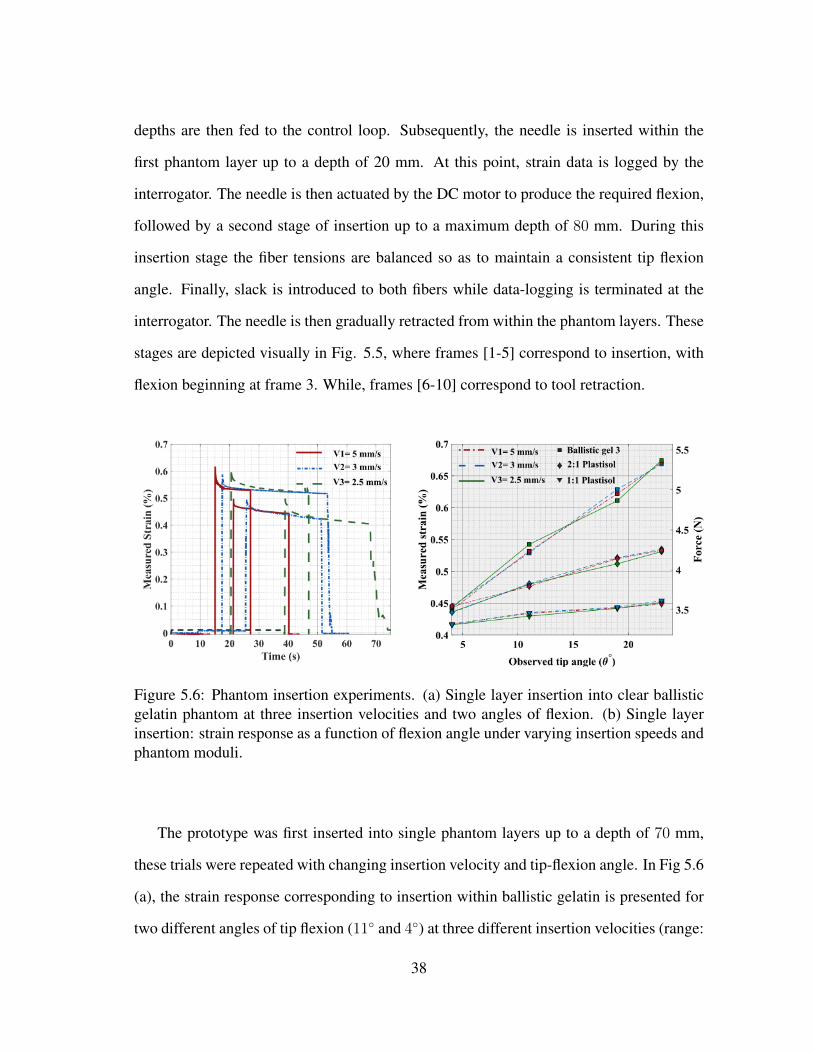
5.6 Phantom insertion experiments. (a) Single layer insertion into clear ballis-tic gelatin phantom at three insertion velocities and two angles of flexion.(b) Single layer insertion: strain response as a function of flexion angleunder varying insertion speeds and phantom moduli. . . . . . . . . . . . . 38
5.7 Insertion into two phantom layers at three insertion velocities and constantflexion angle. . . . . . . . . . . . . . . . . . . . . . . . . . . . . . . . . 39
x

LIST OF TABLES
TABLE Page
3.1 Results from tensile loading experiments on standard tele-communicationfibers and high strength PM-FBG fibers. Where, Nufern 1 - MM-S105/125-22A, Nufern 2 - 1310M-HP-80, and Nufern 3 - 1550B-HP. . . . . . . . . 13
5.1 Averaged elastic moduli for cubic phantom specimen of side 2.5 in ea.from compression loading experiments at 0.1 in/min and strain margins upto 10% . . . . . . . . . . . . . . . . . . . . . . . . . . . . . . . . . . . . 31
5.2 A summary of strain response from dynamic tension-slack tests on theinstrumented prototype for three scenarios: (a) changing oscillation count- time (up to 200s) (b) increasing extension length - amplitude (0.89 −2.25 mm) (c) actuator RPM - frequency (up to 5 Hz). Measured straincorresponds to peak averaged values over multiple cycles. . . . . . . . . . 37
xi

1. INTRODUCTION
It has been two decades since the now ubiquitous surgical robot, da Vinci (Intuitive
Surgical Inc., Sunnyvale, CA) was brought to the medical device market. Due to its clini-
cal and commercial success, surgical robots have been considered to revolutionize clinical
practice [1]. The next stage along this development path demands a push for robot-assisted
minimally invasive surgery (MIS) across therapeutic modalities [2]. The challenge, there-
fore, necessitates functionally augmented surgical instruments and miniaturized robotic
platforms that are smaller and more sophisticated than those currently available [3].
Although robot-assisted procedures using thin, long, and articulate instruments includ-
ing the da Vinci system have profoundly influenced modern surgery, techniques using the
slender tools inserted through small incisions deprive surgeons of cutaneous and kines-
thetic feedback, a perception of depth, and dexterity – attributes which contribute to the
ease of traditional open surgery [4]. Besides, studies suggest that when accurate instru-
ment positioning is required and (or) when the associated structures are fragile such that
trauma may have severe implications, the interaction between the tool and surrounding
tissue may provide for useful sensory primitives to the operator [5] [6]. This necessity
has motivated several academic circles to commit to intensive research on force-feedback
within instruments for robotic surgery.
Literature classifies these studies primarily on the basis of sensor position - proximal
(tool-base), distal (near tip/ joint) and at the end-effector (gripper) [7]. Notably, strain
gauges and push-rod driven load-cells have been extensively investigated and constitute
instruments with sensors nearer to the proximal end (tool-base) of the instrument [8] [9]
[10]. Optical force sensors using fiber-bragg gratings (FBGs), capacitive wrist force sen-
sors and mutli-axis force and torque-sensing strain gauges facilitate examples of distal
1

Figure 1.1: Example of the use of sensorized tendons, a force sensing steerable needleprototype with circumferential slits that enable bi-directional planar bending. The 18 Ganeedle is made of a 120 mm long, 1.27 mm (0.05") diameter NiTi tube. The net rangeof flexion is approximately ± 29◦. Section AA′ depicts a cross-section with the proposedinner and outer sheaths
force-sensing methods [11] [12] [13]. Force-sensing grippers and forceps remain a com-
mon theme, including, capacitive and piezo-resistive sensors. Where, the sensors are in-
strumented within the end-effector [14] [15].
However, many of these alternatives are hindered by several practical limitations. Dis-
tal end sensors such as load cells are affected by mechanical hysteresis, backlash, friction
and disturbance from the driving mechanism. Traditional FBGs are susceptible to tem-
perature variations, while capacitive and piezoresistive sensors raise questions about their
safety and compatibility with some imaging modalities. Grippers and the other similar
end-effectors are limited by size, manufacturability and tool dexterity [16]. Hence, it is
commonly acknowledged that introducing reliable sensing and actuation modalities within
2

such devices remains a complicated proposition, despite the fact that the desire to include
such features have been expressed by an increasing number of surgeons [17].
A viable solution to these challenges would be to integrate multiple robotic functions
such as actuation, sensing and joint motion within a single fundamental element. Based
on this paradigm shift in robot design, we propose a unique, bi-modal approach to imple-
menting actuation and sensing in micro-surgical procedures - Sensorized tendons.
In robot-assisted surgery, with end-effectors working within deep seated tissue struc-
tures and limiting workspace constraints, it is often difficult or impossible to have the
actuators within the patient’s body. Research on developing flexible transmission media
has enabled the possibility of placing joints and actuating elements further apart [18],
therefore, providing a significant advantage to the development of patient-friendly instru-
ments for MIS using bio-compatible, safe and minimalist alternatives. Tendons as trans-
mission elements afford the possibility of optimizing actuator position, weight, and reli-
ability while retaining the simplicity of mechanical design and kinematics. Experiments
have proven their efficiency, with tendons finding favor among robotic hands and paral-
lel robots across research circles [19] [20] [21]. Typically, these tendons are made from
stainless steel [22], polyethylene [23], and NiTi [24] cables. However, there remain a few
underlying drawbacks, including – the non-negligible elasticity of the material, constraints
in routing, friction from channel interaction, need for correct pre-tensioning, mechanical
hysteresis and difficulties in force characterization among a few others. It is our belief that
the proposed Sensorized tendons may offset some of these issues in practice.
A potential problem of the proposed fiber-optic tendon, however, is that the Bragg grat-
ings are sensitive to both mechanical strain and temperature fluctuations. In the past, to
negate such undesired thermal effects, additional fibers have been arranged to enable tem-
perature compensation [25]. However, this increases tool dimensions while design choices
are limited due to assumptions in support of temperature uniformity. Thus, the desired ap-
3
proach is to employ a particular class of fibers which allow for decoupled temperature and
strain measurement from a single FBG sensor.
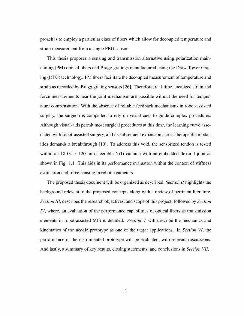
This thesis proposes a sensing and transmission alternative using polarization main-
taining (PM) optical fibers and Bragg gratings manufactured using the Draw Tower Grat-
ing (DTG) technology. PM fibers facilitate the decoupled measurement of temperature and
strain as recorded by Bragg grating sensors [26]. Therefore, real-time, localized strain and
force measurements near the joint mechanism are possible without the need for temper-
ature compensation. With the absence of reliable feedback mechanisms in robot-assisted
surgery, the surgeon is compelled to rely on visual cues to guide complex procedures.
Although visual-aids permit most surgical procedures at this time, the learning curve asso-
ciated with robot-assisted surgery, and its subsequent expansion across therapeutic modal-
ities demands a breakthrough [10]. To address this void, the sensorized tendon is tested
within an 18 Ga x 120 mm steerable NiTi cannula with an embedded flexural joint as
shown in Fig. 1.1. This aids in its performance evaluation within the context of stiffness
estimation and force-sensing in robotic catheters.
The proposed thesis document will be organized as described, Section II highlights the
background relevant to the proposed concepts along with a review of pertinent literature.
Section III, describes the research objectives, and scope of this project, followed by Section
IV, where, an evaluation of the performance capabilities of optical fibers as transmission
elements in robot-assisted MIS is detailed. Section V will describe the mechanics and
kinematics of the needle prototype as one of the target applications. In Section VI, the
performance of the instrumented prototype will be evaluated, with relevant discussions.
And lastly, a summary of key results, closing statements, and conclusions in Section VII.
4

2. BACKGROUND
2.1 Review of Optical Elements
2.1.1 Strength of Fiber Bragg Grating Sensors
Figure 2.1: (a) Typical spectral response of a single PM-FBG fiber. a′ is the peak separa-tion at time t1 and b′ at time t2. The relative peak shifts are shown for both P1 and P2.The instantaneous peak separation relates to temperature, while their temporal differenceis proportional to fiber strain. (b) Cross-section of the PM-FBG fiber (panda-section).
In tendon driven robots, force or torque limitations are a concern owing to the prop-
erties of the material involved. The rudiments of traditional surgery may be classified as
grasping, spreading, sweeping, pushing, and lateral retraction with studies estimating the
required force magnitude at 1.32 N (Gall Bladder) to 3.47 N (Liver) for probing, between
1.49 N (Gall Bladder) to 3.26 N (Liver) for punctures, and up to 7.19 N for suturing (de-
pending on the tightness of knot) [27]. Hence, the load bearing capacity of the tendons
play an important role. In FBGs, strength is contingent on the technique used for fabrica-
tion [28] [29].
5

Traditionally, there are four steps to the FBG fabrication process: (i) removal of the
fiber coating (ii) photo-sensitization (iii) exposure to UV light (irradiation of the fiber) (iv)
annealing (or) re-coating. Each of these steps may progressively contribute to structural
flaws on the glass surface, thereby, weakening the ultimate strength and reducing its long-
term reliability [30]. Sometimes the decrease in strength could be as high as 72% , causing
the fibers to break at strains lesser than 1% [31].
The advantage of an FBG sensing array is realized only if the high inherent strength
and reliability of an optical fiber is not compromised during the manufacturing process
[32]. In this approach the FBGs are inscribed onto the uncoated fiber during the extrusion
process which offers greater fiber strain margins, and hence higher loads in tension [33].
Notably, in [33] the authors provide evidence to suggest that the strain behavior of
fibers with Type-1 gratings and the Organic Modified Ceramic (OrMoCer) coating to be
nearly similar to that of standard (no-grating) fibers. The estimated failure load is at 55−70
N for gratings manufactured in this manner, and at 20 N for Type-2 gratings with a cross-
section of 125 µm. The types here correspond to the ionization threshold of the glass
substrate. Type-2 gratings are favored for their temperature stability.
Therefore, commercial draw tower grating PM-FBG fibers have a projected tensile
load limit of 20 N, i.e. approximately one-third the permissible load on an equivalent
glass fiber rod with an observed elongation grater than 3% at failure [30].
2.1.2 The Draw Tower Grating Process
As described previously, the fabrication technique determines the mechanical capa-
bilities of the optical fiber bragg grating sensors. Research shows that the simultaneous
inscription of the Bragg gratings during the extrusion process preserves the mechanical
strength and enables the manufacture of Type - II gratings with the desired temperature
stability. This is a consequence of the fact that grating inscription is during the window
6

Figure 2.2: Draw tower gratings: The manufacture of Bragg grating sensors during theextrusion process. Courtesy of FBGS Technologies GmbH, Jena, Germany.
of time between preform melting and fiber coating. In doing so, the need for fiber re-
moval is avoided, therefore, increasing it’s performance. Empirical studies indicate that
the achieved mechanical stability of draw tower gratings (DTGs) is similar to fibers with-
out gratings.
Fig. 2.2 describes the fabrication method. The input here is a glass preform.The heated
preform is drawn through molds as shown. Subsequently, the fiber meets the optical axis
of the laser source and interferometer used to create a UV-light based interference pattern
on the glass substrate. A pulse selector takes into account drawing speed and accurately
7

positions the FBGs. Following this step a coating reservoir coats the fiber, this retains the
pristine fiber strength of the optical fiber.
2.1.3 Principle of Polarization Maintaining FBG Fibers
The ability to decouple strain from temperature has been explored using Bragg gratings
written on highly-birefringent fiber in conjunction with accurate interrogation techniques
[26]. The PM-FBGs have double Bragg reflection peaks (Fig. 2.1 (a)), which enable
the decoupled measurement of strain and temperature. They are unique in their ability
to decouple strain data from temperature effects. This combines the sensing attributes of
traditional FBGs with the temperature independence of the PM fibers.
The PM fibers are fabricated by introducing linear birefringence into the glass sub-
strate. The birefringence is stress-induced using stress rods along the cross-section of the
extruded fiber. This preserves the polarization state of the transmitted wavelength provided
the light beam is aligned with either axis of birefringence. In general, a tunable LASER
interrogator platform transmits polarized wavelengths and the reflected spectrum consists
of two peaks, alternatively sampled by the optical interrogator at an optimum frequency,
for loss-less data acquisition.
Interestingly, the response of the dual wavelength spectrums to temperature and strain
is similar to that of the FBGs. However, the sensitivities of individual peaks differ [34]. In
Fig. 2.1, the reflection magnitude and corresponding spectral wavelengths are illustrated
and the two reflected wavelength amplitude peaks are evident. The plots are a result of
consecutive sampling instances at time t1 and t2. Here, a represents peak separation at
time instant t1 while the peak separation is b at time t2. Calibration studies indicate that
the separation between peaks P1 and P2 corresponds to temperature fluctuations while
strain is inferred from the relative change in peak wavelengths i.e the difference between
a and b [35].
8

The cross-coupling between temperature and strain is resolved due to this induced
stress birefringence. The response of individual wavelengths λ1 and λ2 to strain ε and
temperature T is described by the equations that follow.
λ1 − λ10 = A∆T +B∆ε
λ2 − λ20 = C∆T +D∆ε (2.1)
∆T = (A∆λ1 −B∆λ2)/k
∆ε = (C∆λ1 −D∆λ2)/k (2.2)
where ∆λ1 and ∆λ2 are the change in peak wavelengths with respect to a reference
wavelength at known temperature and strain. The sensitivity parameters A, B, C, and D
for ε and T are derived empirically , while k = AD −BC [35] .
2.2 State of the Art
There are three fundamental aspects to this study - sensing, actuation, and needle tip
articulation. The subsequent sections briefly outline some literature relevant to these areas.
2.2.1 Sensing in Robotic Surgery
In robotic surgery, the physicians ability to feel forces acting on the end-effector is
limited during the insertion and manipulation of the instrument as it punctures/ traverses
within tissue layers. Force sensing is particularly advantageous to microsurgery (scaling),
suturing, palpation, and robotic force control [36] [37] [38]. In addition, haptic cues during
membrane puncture, interaction with oclivities, and the presence of tissue inconsistencies
are valuable primitives to the operator. Such information could effectively determine tool
9

path and subsequent corrective strategies necessary for the success of the intervention pro-
cedure. This has motivated research on incorporating sensing modalities within surgical
tools. Several of these tools are classified on the basis of sensor position - at the end-
effector/ gripper, tool shaft or distal section, proximal shaft, and near the tool base [17]. In
this research, the sensorized tendons permit variation in sensor location, contingent on the
objectives of a specific experiment or procedure.
2.2.2 Tendon Driven Instruments for Robotic Surgery
Research on developing flexible transmission media has enabled the possibility of plac-
ing joints and actuating elements further apart [18]. Tubes, tendon sheaths, and pulleys
allow cables to transmit force and position information to remote segments of the instru-
ment. This provides for a significant advantage in the development of patient-friendly,
minimally invasive surgical instruments. Tendon based transmission systems greatly sim-
plify the mechanical design of tools used in robotic surgery. Inspired from biology, ten-
dons as transmission elements have been studied for the development of robotic hands [19]
[21]. In robotic surgery, with end-effectors working within deep seated tissue structures
and limiting workspace constraints, it is often difficult or impossible to have the actuating
elements (motors) within the patient’s body. Tendon driven systems permit the required
diversity in tool dimensions [39] [40] and offer a workaround to allow for miniaturization,
safety and flexibility within a wide range of applications - the da Vinci [41], endoscopes
[42], slave-master systems [43], etc. Therefore, the proposed optically sensorized tendon
could prove a viable extension to existing tendon-driven instruments in robotic surgery.
2.2.3 Design for Needle Articulation
Needle steering in current literature refers to the possibility of actively reconfiguring
the mechanical design of the needle’s structure, enabling directional steering of the in-
strument through layers of tissue [44]. Literature classifies these approaches primarily
10

as active or passive depending on the extent of control available at the operator’s end.
Passive steering techniques include base manipulation [45], and bevel-tip steering [46],
where, the initial orientation and geometry of the needle’s tip together with insertion ve-
locity and medium stiffness determine the path taken. Active steering refers to the con-
trollable change in the needle’s path by altering the structure or manner of interaction with
surrounding media. Techniques include, concentric tubes that can telescope relative each
other [47], pre-curved stylets that incorporate bent structures [48], reconfigurable bevel
tips that alter the needle’s tip [49], and tendon driven compliant cannula among others.
In this study, the steering was achieved with a needle cannula having circumferential slits
near the distal section, these slits reduce the stiffness across the member while enabling
planar bending.
2.3 Research Objectives
The crux of this study deals with verifying the feasibility of high strength PM-FBG
fibers as a bimodal actuation and sensing component in robot-assisted MIS. A series of
experiments were performed to first, evaluate the performance of the sensorized tendon
itself followed by testing within a prototype surgical instrument (steerable cannula - bidi-
rectional planar bending Fig. 1.1). Subsequently, we present evidence to substantiate ten-
don performance in terms of strength, strain independence, and friction decay along with
instrument force and stiffness sensitivity. To this end, we define the following metrics to
justify this proposition.
1. Performance evaluation of sensorized tendons
i Tendon strength: define load thresholds and identify modes of failure.
ii Temperature-strain decomposition: experimentally validate this independent
relationship.
11
iii Friction compensation: quantify transmission decay with friction and draw
parallels with existing theory.
iv Effect of Kevlar reinforcement: characterize the strain behavior in optical fibers
reinforced with synthetic para-aramid fibers (Kevlar).
2. Experimental validation of proposed application
i Kinematics and mechanics - system analysis: estimate tip flexion, range of
motion, workspace, and bending behavior of test prototype.
ii Response to static loads: calibrate for reaction force and stiffness by observing
static strain behavior during flexion within homogeneous phantom tissue.
iii Response to dynamic loads: observe and characterize the behavior of the sen-
sorized tendons and prototype under the influence of dynamic forces.
iv Tissue stiffness estimation during phantom insertion: observe and characterize
strain response during insertion within multi-layered phantom tissue, and real-
time tissue stiffness estimation.
Given the above premise, there are certain limitations to this study. Firstly, the lack
of real-time control using fiber data limits steerability. Phantom behavior is visco-elastic
and the working assumptions for stiffness estimation require further substantiation. The
proposed application comprises of a single PM-FBG fiber which inhibits exact decomposi-
tion of force information and bi-directional tip control. Moreover, the design of the flexure
itself is not optimized toward efficacy in stiffness estimation. Location, geometry, flexi-
bility, and strength should be studied further for its safe use as a steerable medical device.
Therefore, these aspects signal plausible future directions for the proposed concept. The
experimets, results, and subsequent discussion present evidence in support of the defined
objectives within the confines of the stated limitations.
12

3. EVALUATION OF SENSORIZED TENDONS
3.1 Comparison Under Tensile Load
To discern the safe loading conditions for the actuating fibers (PM-FBG fibers, FBGS
International, Brussels, Belgium), standard gauge optical fibers used in tele-communication
(Nufern Inc, CT, USA) were subject to tensile loading. Three fibers were tested with in-
cremental load applied over consistent time intervals and strain rates. The loads at failure
were then recorded.
A bench-top tensile-testing machine (Instron 4411, Instron Corporation, United King-
dom) was used for this experiment with a maximum applied load of 11.8 N over 60 s time
intervals at a strain rate of 0.1 in/min. The fibers varied in cross-section (core, cladding,
and coating diameters) and coating material.
Notably, the failure loads for the Nufern 1550B-HP and MMS-S105/125-22A having
similar glass layer dimensions as the PM-FBG fiber was 11.8 N and 9.81 N respectively.
However, they differ in terms of coating material. Coating separation was observed as a
common mode of failure. The glass core remained intact across trials, i.e. jacket strip-
off was observed prior to core disjunction. In Fig. 3.1 (a), the PM-FBG fiber’s response
Fiber type Nufern 1 Nufern 2 Nufern 3 DTG PM-FBG
Coating Diameter µm 245.0±15.0 165.0±10.0 245.0±15.0 195 ±15.0Cladding Diameter µm 125± 2.0 80±1.0 125.0±1.0 125± 2.0Core Diameter µm 105±3.0 6.0 9.0 6.0Failure Load N 9.81 5.4 11.8 > 13 (3% strain)Coating Material Acrylate Acrylate Acrylate OrMoCer
Table 3.1: Results from tensile loading experiments on standard tele-communication fibersand high strength PM-FBG fibers. Where, Nufern 1 - MM-S105/125-22A, Nufern 2 -1310M-HP-80, and Nufern 3 - 1550B-HP.
13

Figure 3.1: Performance evaluation of sensorized tendons (a) Tensile load limit and time-sensitivity as observed for the PM-FBG fibers. (b) Strain and temperature response of abare PM-FBG fiber and Kevlar reinforced fiber under tensile loading.
to tensile load is documented, the load limit is constrained to approximately 12 N due
to wavelength limitations of the interrogator. The fiber response remained consistent and
error-free after repeated trials beyond the required duration, no fracture was observed up
to this load.
Vendor documentation projects a failure load of 20 N for the PM-FBG fibers. Table 3.1
further details the results from these tests, evidently, the PM-FBG fiber is able to withstand
loads greater than a standard tele-communication fiber (no FBGs) having slightly larger
cross-sectional dimension, this is potentially attributed to the special coating used.
3.2 PM FBG Strain Response and Sensitivity
To calibrate the PM-FBG fibers and to test their strain sensitivity i.e. percent strain
per unit load in tension (%/N), load tests were performed using standard weights and a
bench-top tensile test setup. The optical fiber was connected to the interrogator (FAZ
Technologies Inc., Dublin, Ireland) and the free-end bonded to a 3D printed attachment.
A section of the fiber was taped onto a support structure while loads were suspended from
14

the free end. Considering a 20 N failure load, a factor of safety of four was adopted as
the safe load limit for fibers in subsequent experiments (4.905 N for time intervals < 300
s). Two trials were performed with load increments of 20 g up to 200 g and another with
load steps of 50 g up to 500 g at room temperature (27 ◦C). The peak wavelength shifts
were recorded using the system GUI (Femto-sense, FAZ Technologies, Dublin, Ireland)
and post-processed for strain and temperature information. A plot of load to strain and
temperature was obtained as shown in Fig. 3.1 (b), this served as a reference source for
calibration in future experiments.
The above process was repeated with Kevlar-reinforced PM-FBG fibers. The optical
fiber is bonded using an instant alkoxy-ethyl adhesive (Loctite 403, Henkel Adhesives,
USA) to a strand of pre-tensioned synthetic para-aramid fiber (Kevlar, DuPont, Wilming-
ton, DE) as shown in Fig. 3.2. The bonding length was 10 mm and the cure time 24 hrs.
In doing so, the bonded section can be modeled as a simple composite bar in axial tension.
Here, Tnet is the applied tension that results in an extension, δLb across each layer such
that,
(δLb)Of = (δLb)Ad = (δLb)Kev (3.1)
(TLbAE
)Of
=
(TLbAE
)Ad
=
(TLbAE
)Kev
(3.2)
where, T corresponds to the applied load across the section, Lb - length of the bonded
segment, A - the area of cross-section and E - elastic modulus of the material. Of refers
to the optical fiber, Ad - adhesive and Kev - Kevlar fiber. The elastic modulus for kevlar
(Ekev) is taken as 110 GPa, the optical fiber - EOf as 16.56 GPa and the adhesive - EAd as
3.67 GPa [50] [51].
15

Figure 3.2: Schematic depicts the the PM-FBG fiber reinforced with pre-tensioned Kevlarfiber. Equivalently modeled as a composite bar under axial tension with Kevlar and opticalfiber regions separated by an exaggerated adhesive layer.
Therefore,
Tnet = 2.8123TOf ≈ 3(TOf ) (3.3)
This implies that the effective load experienced by the optical fiber when reinforced
with Kevlar is approximately one-third the magnitude of load applied to the Kevlar fiber
itself. This extends to the possibility that when reinforced, the sensorized tendons can
carry up to three times the permissible load for the bare PM-FBG fiber. This claim is
validated experimentally in the sections to follow.
3.2.1 Bare Fiber
The plot in Fig. 3.1 (b) represents the strain to load relationship (strain-response) for
the bare PM-FBG fibers while under a tensile load. The response is seemingly linear with
a sensitivity of 0.1266 %/N. The temperature stability of the fiber is apparent as evidenced
16

by the simultaneous temperature data plot, with room temperature at 26◦C as determined
using a thermometer. This relationship was consistent over three trials. The applied load
was increased to a maximum of 4.9 N under a strain rate of 0.1 in/min.
In Fig. 3.1 (a), the bare PM-FBG fiber was subject to tensile load increments of 1 N
up to ∼ 12 N with a time interval of 60 s each. The fiber response was unaffected and
remained consistent across trials. This lends support to the idea that the PM-FBG fibers
could function as efficient transmission media in applications that require small loads up
to a cut-off value.
3.2.2 Kevlar-reinforced Optical Fiber
The plot in Fig. 3.1 (b) also depicts the relationship between strain and applied load for
the PM-FBG fibers when reinforced with Kevlar fiber having a nominal diameter of 250
µm. The reinforced fiber bundle has a load sensitivity of 0.03975 %/N. The temperature
stability of the fiber is evidenced by the simultaneous temperature data plot, with room
temperature at 26◦C as measured using a thermometer.
Notably, the observed strain dropped by about 35% during these trials which is ap-
proximately equivalent to the expected difference (Eq. (5)). This can be attributed to the
idea that the bare fiber, the adhesive and the synthetic fiber now function like a composite
with a certain degree of load re-distribution as described theoretically from Fig. 3.2. This
relationship was consistent over three trials. A maximum load of 11.8 N was applied at a
strain rate of 0.25 in/min.
For applications involving large loads, Kevlar can be used as a force carrying tendon
while the PM-FBG fiber is bonded to it. Kevlar fiber has a higher stiffness than the PM-
FBG fiber and hence undergoes lesser strain for the same load, this permits up to three
times the load carrying capacity of bare fiber (approx. 40 N). This tensile load capacity
translates to a lateral force magnitude of approximately 5.08 N (as detailed in Section
17

Figure 3.3: Temperature independence of the PM-FBG fiber: During Stage I - constanttemperature and incremental load up to 500 g. Stage II - constant load (strain) increasingtemperature from 27◦C (ambient) to approx. 90◦C. Note: temperature axis is to the right.
V-B) which is sufficient for most rudiments of modern surgery [27]. Equivalently, for
a device such as the EndoWrist, with a cross-sectional diameter of 8 mm, and gripper
length 10 mm this could be enhanced up to 31 N in terms of grasping force at the end-
effector. Moreover, due to limitations in the bend radius of the glass core in an optical fiber,
reinforcing elements such as Kevlar enable unique tethering configurations advantageous
to the specific application.
3.3 Temperature Independence of PM-FBG Fibers
Fig. 3.3 demonstrates the temperature independence of the sensorized tendons. This
experiment was performed in a controlled environment. During Stage-I, the optical fibers
were placed in a stress-free state at room temperature (26◦C). Loads were then added to
the bare fiber in four steps up to 400 g i.e. steps i to iv. As evidenced by Fig. 3.3, the
temperature readings remain consistent throughout this stage while, strain rises in response
to increasing load.
18

In Stage-II, the optical fibers were under a constant tensile load (400g) while ambient
temperature was increased in four stages using a heat gun and a thermally reflective en-
closure. Temperature was gauged in tandem with wavelength using a thermometer. Step 1
corresponds to a nominal temperature of 32 ◦C, step 2 at 45 ◦C, step 3 at 60 ◦C and step 4
up to 80 ◦C (as measured). Notably, the noise in strain data beyond a certain temperature
step is attributed to the draft induced by the heat gun.
This experiment clearly demonstrates the idea that the temperature response of the
grating is independent of applied load. Moreover, the measured temperature was in agree-
ment with the observed temperature as determined using an external thermometer. This
validates the temperature independence of the wavelength shifts registered by the PM-FBG
fiber. Therefore, undesired thermal effects would not hinder the performance capabilities
of the sensorized tendons.
3.4 Friction Effects: Transmission Decay
This section details the influence of friction on tendon based force transmission and
how fiber-optic sensing provides means to quantify this attribute. Under tendon actuation,
an important concern is force reduction due to friction loss. Research by Palli et. al. [19]
points to a theoretical model that postulates tendon decay as a factor influenced by two
elements inherent to the transmission media: angle of curvature (θ) and the coefficient of
friction (µ) between the contact surfaces (PM-FBG fiber Coating and the polytetrafluo-
roethane (PTFE) Lumen). Hence, higher the angle θ, higher the transmission decay.
Fig. 3.4, presents a schematic of an infinitesimal section of the tendon while under ten-
sion. The tendons are routed within the PTFE tube which is held in contact with the curved
surface. Where, transmission decay is a consequence of the relative motion between the
stationary lumen and moving optical fiber.
19

Figure 3.4: Transmission decay investigation: Force-balance on an infinitesimal tendonsection in frictional contact with the PTFE lumen as observed on the experimental setup.
Ff = µNsgn(ε) (3.4)
∆T = −Ff (3.5)
where, Ff is the friction force,N the normal load due tendon motion and surface curvature,
ε the tendon deformation rate, and ∆T the loss in tension due to friction. Therefore for the
infinitesimal tendon segment,
N = Tdθ = Tdx
R(3.6)
dT = −Ff = −µT dxRsgn(ε) (3.7)
20

Figure 3.5: (a) Strain response with increase in applied load for different anngles of cur-vature. (b) Measured load magnitude against angle of curvature and applied load, Tin isincreased and corresponding Tout is depicted as a function of θ.
where, dθ is the angle subtended by the arc made by the infinitesimal section (dx). dT
is the corresponding decay and R the radius of curvature. Now, Eq. (9) can be integrated
over the tendon length to provide for a relationship between Tin (input tensile load) and
Tout (measured tensile load) as in Eq. (10) - which depends on the direction of loading.
dToutdTin
=
e−ν , ε > 0
eν , ε < 0.
(3.8)
where,
v =µ
RL = µθ (3.9)
Based on the coulomb friction model developed by Kaneko et. al. [52], where, trans-
mission decay is the consequence of frictional contact between the tendon and a fixed sur-
face, a segmented exponential function provides for a quantifiable relationship between
tension output and tension input across the curved section.
21

This is substantiated experimentally, in Fig. 3.5 (a), a schematic of the test setup used
is described. This setup was used to test for change in fiber strain with varying angles of
curvature. The fibers were routed through a PTFE lumen bonded to a surface having the
required angle of curvature. The FBGs were positioned so as to be devoid of contact which
may interfere with the tension readings. Loads were applied at fixed intervals and the
corresponding fiber strain recorded. The process was repeated for three different angles of
curvature. The results so compiled were compared with the load calibration data obtained
in Fig. 3.1 (b).
Due to contact between the curved surface and fibers, the effective tensile load ex-
perienced by the gratings is less than the applied load - this behavior is amplified with
both increase in angle of contact and (or) coefficient of friction for the material pair. Cor-
respondingly, the output strain decreases with increasing angle of curvature. Hence, as
expected, in Fig. 3.1 (b) the fiber strains show a marked decrease with increasing angle of
contact.
As the tension on the input end Tin is increased, the corresponding output load as deter-
mined from fiber strain is shown in Fig. 3.5 (b). Here, the load at θ set to zero corresponds
to the input tension (Tin), and subsequent data-points relate to the measured tension (Tout)
at different angles of curvature. This trend is potentially exponential and supports the seg-
mented exponent idea described in existing literature [19]. This underscores the possibility
that, with the PM-FBG fibers as actuating elements, the control model may circumvent the
need to externally account for friction based decay in tendon driven systems. Besides, the
behavioral attributes of the sensorized tendon mimic that of existing tendons in literature -
a model well-understood. However, in practice, interactions between the tendon and con-
tact channel are complicated and may not subscribe to the assumptions of existing theory
- hence, an inherent sensing modality would prove advantageous. Subsequent sections
discuss tendon performance within the context of the proposed application.
22

4. TOOL DESIGN DESCRIPTION
To better comprehend the underlying kinematics and to describe the force response of
the tendons, a brief discussion of tool design is presented. The sensorized tendons studied
in Section IV, when instrumented within the prototype can estimate stiffness or reaction
forces during tool-tissue interactions. This demands a study of the joint kinematics and
deformation behavior during bending. A prototype was fabricated using NiTi tube with
an outer diameter of 0.05 in and wall thickness of 0.01 in (18 Ga). A flexure joint was
embedded onto the needle by laser machining circumferential slits across a small section.
The pattern so machined, enabled bi-directional flexion (bending) of the needle’s tip along
a plane and is labeled bi-direction flexure.
Two stages of actuation of the prototype are shown in Fig. 4.1. The sample used for
the experiment was 120 mm long. The total length of the patterned joint was 4 mm. A
section of length 6 mm was left un-patterned ahead of the joint. The schematic in Fig. 4.1
also describes tendon routing. Here, the tendons are arranged in an antagonistic manner
and actuated by DC motors placed near the proximal segment of the instrument.
However, the proposed prototype is limited by the fact that there is only one sensorized
tendon actuating the flexure - this hinders effective force decomposition. Besides, the
design of the flexure itself is largely un-optimized and remains beyond the scope of this
investigation. In addition, the approach posits the use of an inner lumen to route the
actuating fibers, under the absence of which the kinematic assumptions may not hold.
The subsequent results examine the performance merits of the proposed sensing modality
within the confines of these limitations.
23

Figure 4.1: Joint kinematics for the bi-directional planar flexure: section under bending isas shown, with dimensional attributes of a single recurring section and its correspondinggeometry under bending load.
4.1 Needle Kinematics
A kinematic model is described for the recurring joint segment, with frame assign-
ments as depicted in Fig. 4.1 (a). Here, the flexure joint is assumed to undergo constant
curvature bending across recurring sections of the joint. A single joint segment consists of
two circumferential slits arranged opposite to one another as shown. Seven such recurring
segments enable up to 29◦ of flexion in a given direction.
Evidence supporting this assumption has been discussed earlier in literature [53]. Fur-
ther, the tendons are modeled as though they remain in contact with the walls of the can-
nula during the flexion process. In addition, the tendon itself is regarded as an inextensible
element made of high strength Kevlar fiber [54] [55]. These assumptions remain reason-
able given the material choice and design constraints.
The objective here is to map tendon extension ∆L to tip flexion θ. This requires
assumptions to locate the neutral axis for the beam, as discussed previously [53]. On a
24

Figure 4.2: Needle kinematic description: (a) Reference frames i to iv and geometricparameters of interest for the recurring section under bending. (b) Sections AA and BB′
detailed.
similar vein, we assume that the neutral axis passes through the centroid of the cross-
section at each segment.
y =y1A1 − y2A2
A1 − A2
(4.1)
Where, y is the distance of the centroid of section BB′ from its center. y1 and y2 are
the the centroids for sections 1 and 2 as shown in Fig. 4.2 (b), while A1 and A2 are their
respective areas. Note, frame assignments remain consistent at each segment, therefore,
depending on the orientation of the slits, the centroid position either takes a positive or a
negative value.
For the joint, the cutting depth is 1.1 mm (d3), slit separation is 0.49 mm (d4) and a
slit width of 0.06 mm (d2). The sections BB′ and AA′ correspond to the slit-section and
25

tube cross-sections respectively. A1 and A2 correspond to the area of circular segments as
indicated in Fig. 4.2 (b) given by Eq. (14), with corresponding centroids at y1 and y2 given
by Eq. (13) [53].
yn =4rnsin
3(1/2φn)
3(φn − sin(φn))(4.2)
An =r2n(φn − sin(φn))
2(4.3)
φn = 2cos−1((g − rn)/rn) (4.4)
The subscript n corresponds to section 1 and 2 for the cross-section. Based on the
deformation geometry of the circumferential slits as shown in Fig. 4.2 (a), we can now map
the tendon pulling length to the curvature k as described in Eq. (16) using arc equations
and trigonometric identities.
∆L = h− 2(1/k − rn)sin
(kh
2(1 + yk)
)(4.5)
where, h is the initial tendon length. Now, this provides equations for curvature k and arc
length s i.e. the length of the actuating fiber within the deformed slit segment (Eq. (17)).
From these expressions we derive a sequence of transformations from frame i to frame iv
(see Fig. 4.2 (b)).
ki =∆L
h(rn + y)−∆Lysi =
h
1 + yki(4.6)
Homogenous transformations, with angular deflection and displacement across slit 1
(i − ii), followed by displacement d across the undeformed region separating the two
26

slits (ii− iii), angular displacement and deflection across slit 2 (iii− iv) and subsequent
translation to the neighboring segment. These rudiments together contribute toward the
net deflection of a single recurring element.
H ivi =
1 0 0 0
0 cos2(k2s2) B22 B33
0 −B22 −sin2(k2s2) C33
0 0 0 1
(4.7)
where,
B33 =−sin(k2s2)(dk1 + sin(k2s2))
k1
B22 = cos(k2s2)sin(k2s2)
D33 =cos(k2s2)(dk1 + sin(k2s2))
k1
Hence, the net transformation for a single segment is
Hj+1j ≡
iv∏k=i
{Hk+1k Tz{d}} (4.8)
Therefore, for n (here, n = 7) such segments i.e. n: the number of segments,
{Hn
0
}net
=n∏j=1
Hj+1j (4.9)
Eq. (20) describes the kinematic model that relates tip flexion to tendon pulling length.
27

Figure 4.3: (a) Test setup used in experiments. (b) Proposed simplification through equiv-alent beam deflection models. (c) Observed deflection and planar range of motion for testprototype.
4.2 Needle Tip Mechanics
A modelling assumption is used to idealize the compliant section of the needle joint as
a cantilever shown in Fig. 4.3 (b). Here, the tubular sections which precede and succeed
the machined region are assumed to be rigid. The tension acting on the tendon is mapped
to a comparable transverse tip load. This can be done by modeling the tensile load as an
end moment acting on the cantilever beam, where, the torque arm is equal to the outer
radius of the NiTi tube. Subsequently, equivalent deflections may be found for a similar
section under a transverse tip load as depicted in Fig. 4.3 (b). The tension force has a
magnitude T , the inner radius of the cross-section is ri. Hence, the effective end moment
Meff is given as: s
Meff = Tri (4.10)
28

For a cantilever beam under an end moment or an equivalent transverse tip load (Ftip)
as previously described, the slope θ is as given by Eq. (22), where E is the elastic modulus
of NiTi (83 GPa - austenite), L the length of the beam, and I the cross-sectional moment
of inertia for the equivalent section.
θ =MeffL
EI≡ FtipL
2
2EI(4.11)
Ftip =2Meff
L(4.12)
Now, Eq. (23) maps applied tension to an equivalent transverse tip-load (Ftip). In our
experiments, the strain from the PM-FBG fiber corresponds to applied tension, which in
turn provides for an equivalent load, Ftip. The magnitude of Ftip in air (Fair) would differ
from that observed within phantom (Fp) due to the contrast in material stiffness and the
commensurate measured strain. This difference is attributed to the reaction component
from the resultant of the tissue interaction force at the tip, Rt - which is in effect a measure
of its compliance. Moreover, the force in air, Fair may be determined from the mechanics
model outlined previously. Therefore,
Rt = Fp − Fair (4.13)
We further investigate this possibility in Section VI with the aid of Fig. 5.1.
29

5. PROTOTYPE EVALUATION
The sensorized tendons provide an estimate of stiffness during needle-tissue interac-
tions. This is better understood with the scenario as shown in Fig. 5.1. During insertion
- for the given configuration, the reaction force from the phantom opposes flexion in the
clockwise direction. Tension on the sensorized tendon is mapped to an equivalent clock-
wise moment at the distal section based on Eq. (15). This enables flexion in a direction
against tissue reaction. The tool design studies described in Section V, further substantiate
this idea.
Figure 5.1: Sensorized tendons as a force sensing modality within a steerable needle. Dur-ing insertion, the resultant tip reaction force (Rt) opposes needle flexion - this is measuredas a function of strain given by the PM-FBG fiber using Eq. (24).
Therefore, borrowing from the concepts previously described, the tangential force on
the distal segment is a function of applied tension. Hence, the tension required to produce
a flexion angle, θ is contingent on phantom compliance. Implicitly, higher the modulus
of elasticity, larger the required tension for equivalent angles of flexion (θ). Hence, in
30

theory, passive instrument bending can be corrected through tendon actuation which in-
turn enables stiffness estimation. To substantiate this concept, the subsequent sections
present evidence from relevant experiments.
5.1 Tissue Phantom
The sensor instrumented needle prototype was tested within tissue phantoms of varying
stiffness. Two materials were used - Plastisol (MF Plastics, Fort Worth, TX) and Medical
grade ballistic gelatin (Clear Ballistics Inc., Fort Smith, AK). The plastisol phantoms were
fabricated in-house. Phantom compliance is varied by changing the proportions of plastic
to thinner in solution. A bench-top compression test apparatus (Instron 5960, Instron
Corporation, United Kingdom) was used to determine the elastic moduli.
Phantom Type Measured Elastic Modulus (kPa)
1-1 Plastisol 6.5432-1 Plastisol 13.5404-1 Plastisol 22.039Ballistic gelatin 3 42.0848-1 Plastisol 57.129Ballistic gelatin 2 57.711Plastic phantom 67.111
Table 5.1: Averaged elastic moduli for cubic phantom specimen of side 2.5 in ea. fromcompression loading experiments at 0.1 in/min and strain margins up to 10%
Phantoms of known dimension were fabricated using standard molds, the specimen
were then subject to compressive loads under a consistent strain rate (0.1 in/min). The
applied load and corresponding strain were recorded. This way, the elastic modulus for
each specimen was determined from the strain-response curves [56]. The averaged strain
response for each phantom is as shown on the graph in Fig. 5.2 (a) and the respective
elastic moduli are as documented in Table 5.1.
31

Figure 5.2: (a) Phantom behavior under compressive loading – stress-strain curves to de-termine elastic moduli. (b) Phantom specimen in compression test setup.
5.2 Behavior Under Static Loads
The PM-FBG fibers are unique in their ability to provide decoupled temperature and
strain information. This feature enables real-time estimation of tissue reaction forces using
principles outlined previously. To evaluate the functionality of the instrumented prototype
in this context, we performed static flexion experiments within different phantom media.
The needle was held in place using a 3D printed clutch, and the fibers were pre-tensioned
and actuated by antagonistic DC motors. A camera was used to record the observed tip-
flexion.
The setup is as shown in FIg. 4.3 (a), the observations show that measured strain is a
function of phantom stiffness. This relationship is reasonably linear and lends credence to
the argument that strain data may be calibrated to provide a measure for tissue stiffness.
Moreover, the difference between observed strain when in air and within phantom provides
an estimate for reaction force from tissue during the static experiments (Eq. (24)). With
32
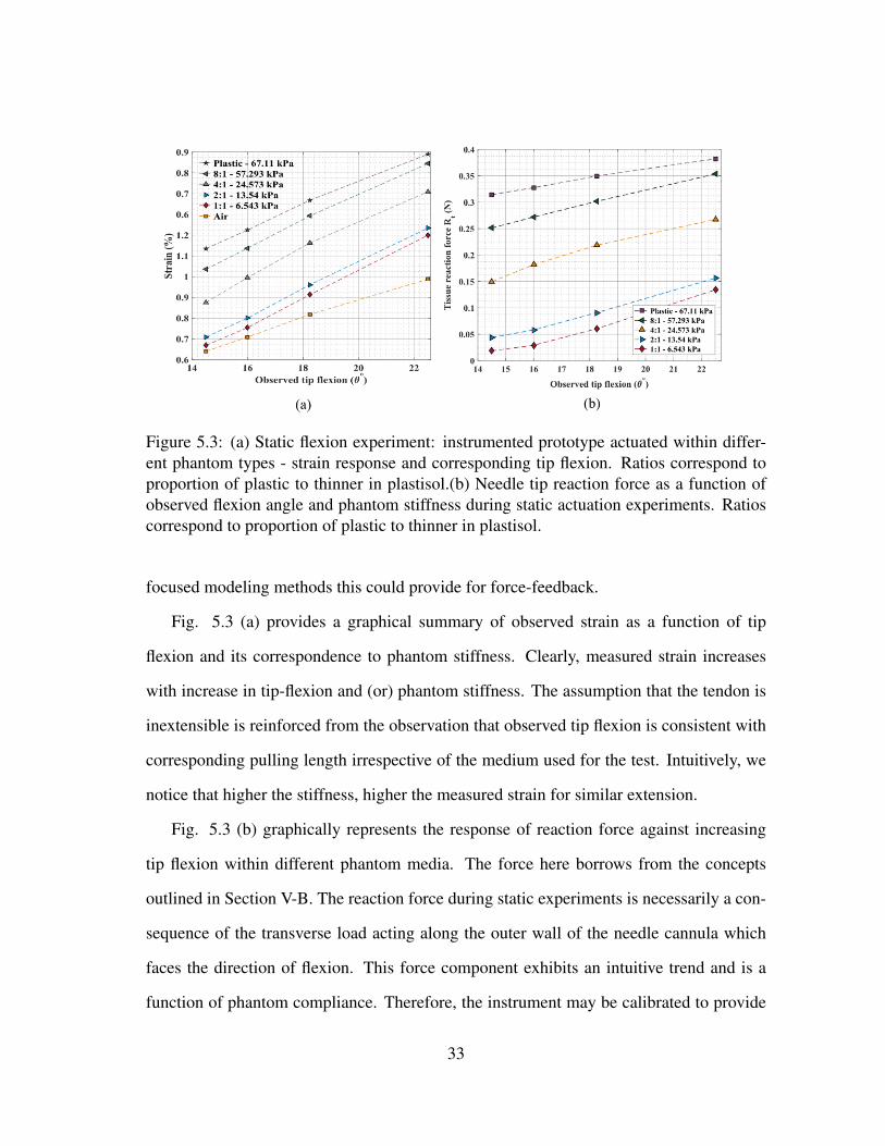
Figure 5.3: (a) Static flexion experiment: instrumented prototype actuated within differ-ent phantom types - strain response and corresponding tip flexion. Ratios correspond toproportion of plastic to thinner in plastisol.(b) Needle tip reaction force as a function ofobserved flexion angle and phantom stiffness during static actuation experiments. Ratioscorrespond to proportion of plastic to thinner in plastisol.
focused modeling methods this could provide for force-feedback.
Fig. 5.3 (a) provides a graphical summary of observed strain as a function of tip
flexion and its correspondence to phantom stiffness. Clearly, measured strain increases
with increase in tip-flexion and (or) phantom stiffness. The assumption that the tendon is
inextensible is reinforced from the observation that observed tip flexion is consistent with
corresponding pulling length irrespective of the medium used for the test. Intuitively, we
notice that higher the stiffness, higher the measured strain for similar extension.
Fig. 5.3 (b) graphically represents the response of reaction force against increasing
tip flexion within different phantom media. The force here borrows from the concepts
outlined in Section V-B. The reaction force during static experiments is necessarily a con-
sequence of the transverse load acting along the outer wall of the needle cannula which
faces the direction of flexion. This force component exhibits an intuitive trend and is a
function of phantom compliance. Therefore, the instrument may be calibrated to provide
33

Figure 5.4: (a) Dynamic strain response of the Kevlar-reinforced PM-FBG fiber at a fre-quency of 1.38 Hz, extension - 1.33 mm and net time - 120 s. Here, AA′ corresponds toan approximation for the peak-averaged input strain ε1 and BB′ corresponds to the peak-averaged measured strain ε2. (b) Composite model of optical fiber within an adhesivesubstrate for input strain correspondence in Kevlar-reinforced PM-FBG fiber.
for the elastic moduli of tissue during insertion.
5.3 Behavior Under Dynamic Load
Needle steering and the insertion of articulate cannulae are dynamic processes, there-
fore, although the functionality of the instrument under static conditions is understood,
the dynamic behavior of the sensorized tendons could further extend its potential applica-
tion. In these experiments, pre-tensioned PM-FBG fiber was subject to oscillatory loading
34

(tension-slack cycles) at different pulling frequencies, length (amplitude), and time ac-
counting for visco-elastic behavior, while their performance was analyzed for consistency
in strain response. Here, the frequency of applied load is contingent on actuator RPM
(motor speed), the time duration of loading relies on the oscillation count and number of
cycles, while the extension is dependent on the angular position of the actuator.
In Fig. 5.4 (a), a section of the strain response corresponding to an extension of 1.33
mm, frequency of 1.38 Hz, and net time interval of 120 s is shown. Evidently, the ob-
served strain as picked up by the Bragg sensors is almost equivalent to the input strain
approximation as measured using the optical encoder on the DC motor. Moreover, this
relationship is consistent across trials for a given medium (air) and a given prototype as
indicated by the amplitude ratio. The observed amplitude ratio is ≈ 0.95. This is better
understood with a simple composite model as shown in Fig. 5.4 (b), where ε1 and ε2 are
the strains across the indicated sections. If the tension applied on Kevlar fiber tethered to
the actuator is Fkev, and assuming linear behavior across layers, it can be shown that,
FOfFKev
=FOfFAd
=EOfEAd
(5.1)
FOf and FAd are the load components borne by the optical fiber and adhesive respec-
tively. EOf and Ead their corresponding moduli of elasticity. For strain compatibility all
layers of the composite section undergo equal extensions.
With optical fiber strain (εOf = ε2) as determined by the PM-FBG fibers and with the
assumption of complete load transfer between the Kevlar and adhesive (i.e. FKev = FAd)
as a consequence of their contrast in stiffness [57], the strain on the Kevlar fiber (εKev =
ε1) may be determined. In doing so, it is observed that the ratio of strain on the optical
fiber to the strain on the Kevlar fiber (i.e. amplitude ratio) is equivalent (using material
35

properties as detailed in Section IV-B). From the experiments, the amplitude ratio is found
to be approx. 0.95, this difference is attributed to the bonding length Lb used during
the said trials. An increase in bonding length Lb would further promote strain transfer
betweeen the two media.
Notably, there is a response delay between input strain and measured strain to the tune
of 20 ms. Table 5.2 provides a complete summary of the observations from the dynamic
tests on the instrumented prototype. Interestingly, the observed strain was consistent ir-
respective of oscillation count (time), RPM (frequency), and varied proportionally with
actuation length (extension). It was observed that the fiber response gradually decreases
during extended oscillation times, possibly due to the visco-elastic nature of the phantom
or fatigue and needs further investigation. However, these intervals are beyond expected
operation periods for the application.
5.4 Insertion Tests: Two-layered Phantoms
The performance of the instrument during insertion within two-layered phantom tis-
sue was experimentally investigated. In these trials, the instrumented needle prototype
was actuated by a pair of opposed DC motors mounted atop the carriage of a linear ball
screw actuator (see Fig. 4.3 (a)). The system allowed for two degrees of freedom - linear
insertion, and distal flexion of the needle tip. The instrument was interfaced with three dif-
ferent phantoms (ballistic gelatin 3 - 42.084 kPa, 2:1 plastisol - 13.54 kPa and 1:1 plastisol
- 6.543 kPa) in pairs of two. At the outset, the immediate concerns were to ensure that
system response was consistent, independent of insertion velocity, phantom arrangement
or flexion, and in agreement with strain estimates observed during the static trials.
The stages of insertion are described as follows - first, the needle is oriented in the
preferred direction and locked in place by the clutch. The tendons are then tethered to the
actuators and provided a fixed (consistent) pre-tension. The required flexion and insertion
36

Changing oscillation count - Time
Trial no. T1 T2 T3 T4
Pulling length (mm) 1.77Motor Speed (RPM) 9.5Measured strain ε2 (%) 0.298 0.292 0.299 0.309Amplitude ratio 0.9426 0.9524 0.9347 0.9834No. of oscillations 20 30 40 50Frequency (Hz) 2.857 2.616 2.761 2.730Response delay (ms) 17.76 18.61 17.88 18.32
Changing pulling length - Extension
Pulling length (mm) 2.22 1.77 1.33 0.8Motor Speed (RPM) 9.5Measured strain ε2 (%) 0.359 0.298 0.239 0.178Amplitude ratio 0.9411 0.9767 0.9336 0.9426No. of oscillations 20Frequency (Hz) 2.857 1.744 1.380 1.092Response delay (ms) 18.92 17.76 19.93 10.21
Changing motor speed - Frequency
Pulling length (mm) 1.77Motor Speed (RPM) 9 11 13.6 16.7Measured strain ε2 (%) 0.308 0.303 0.307 0.306Amplitude ratio 0.9677 0.9720 0.9608 0.9366No. of oscillations 50Frequency (Hz)2.730 3.265 4.075 5.090Response delay (ms)18.32 15.23 19.11 17.16
Table 5.2: A summary of strain response from dynamic tension-slack tests on the instru-mented prototype for three scenarios: (a) changing oscillation count - time (up to 200s) (b)increasing extension length - amplitude (0.89 − 2.25 mm) (c) actuator RPM - frequency(up to 5 Hz). Measured strain corresponds to peak averaged values over multiple cycles.
Figure 5.5: An example of the stages of insertion into two phantom layers - from platisol2:1 segment into ballistic gel 3 segment. Steps [1-5]: insertion, [6-10]: retraction. Frame(10) shows tool path through the clear phantom layer while Frame (3) shows the beginningof tool-flexion.
37
depths are then fed to the control loop. Subsequently, the needle is inserted within the
first phantom layer up to a depth of 20 mm. At this point, strain data is logged by the
interrogator. The needle is then actuated by the DC motor to produce the required flexion,
followed by a second stage of insertion up to a maximum depth of 80 mm. During this
insertion stage the fiber tensions are balanced so as to maintain a consistent tip flexion
angle. Finally, slack is introduced to both fibers while data-logging is terminated at the
interrogator. The needle is then gradually retracted from within the phantom layers. These
stages are depicted visually in Fig. 5.5, where frames [1-5] correspond to insertion, with
flexion beginning at frame 3. While, frames [6-10] correspond to tool retraction.
Figure 5.6: Phantom insertion experiments. (a) Single layer insertion into clear ballisticgelatin phantom at three insertion velocities and two angles of flexion. (b) Single layerinsertion: strain response as a function of flexion angle under varying insertion speeds andphantom moduli.
The prototype was first inserted into single phantom layers up to a depth of 70 mm,
these trials were repeated with changing insertion velocity and tip-flexion angle. In Fig 5.6
(a), the strain response corresponding to insertion within ballistic gelatin is presented for
two different angles of tip flexion (11◦ and 4◦) at three different insertion velocities (range:
38

Figure 5.7: Insertion into two phantom layers at three insertion velocities and constantflexion angle.
2.5 − 5 mm/s). It was observed that the recorded strain was independent of insertion
velocity for the ranges so tested, this is evidenced by the consistent strain peaks depicted
on the graph – an attribute common to over 40 trials that were performed within a single
phantom layer. At an angle of 11◦ the measured strain averaged at 0.559% while at an
angle of 4◦ it was 0.4569%. In Fig. 5.6 (b), the peak-averaged strain value corresponding
to flexion angle for each phantom type is shown. This data is the average of four trials, at
four angles of flexion, within three phantom variants and at three insertion velocities. From
the graph, the response agrees with the linear trend observed during earlier experiments
(see Fig. 3.1).
Subsequently, the instrument was interfaced with two-layered phantom arrangements
starting with insertion into the more compliant region followed by flexion and insertion
39

into a stiffer segment. The results from a set of insertion trials within two phantom layers is
presented in Fig. 5.7, and shows insertion into the 2:1 plastisol segment (Stage-1) followed
by insertion into the ballistic gelatin segment (Stage-2) under a flexion angle of 11◦.
The observed strain is approximately equivalent to values observed under the single
layer phantom experiments. This was reasonably consistent across similar (increasing
stiffness) phantom arrangements. Interestingly, the strain behavior corresponds with the
expected stress-relaxation of the visco-elastic phantom and could potentially result in an
improved tissue modeling strategy. From our observations in Fig. 5.7 it is evident that
the instrumented prototype has a stiffness sensitivity of approximately 0.003%/kPa i.e.
35.65 pm/kPa (standard FBG sensitivity is ∼ 1.18pm/µε) for the given flexion angle.
40

6. CONCLUSIONS
In this study, we explored a bi-modal approach to sensing and actuation in the form of
sensorized tendons using Kevlar-reinforced PM-FBG fibers. Further, a potential applica-
tion in the form of an articulate robotic needle with stiffness estimation capabilities was
discussed to substantiate this proposition. The experiments primarily dwell on the perfor-
mance of the tendon on its own regard followed by trials to validate its function within the
context of the recommended application.
Evidence suggests that the tendons are able to transmit loads up to 40 N, which is sub-
stantively more than previously documented for standard optical fibers (no FBG). Besides,
they provide for temperature independent strain measurements and means for friction com-
pensation.
When instrumented within the prototype needle, their response to static loads is con-
sistent, linear, and a function of phantom compliance, and flexion angle. This attribute
further extends to dynamic loading conditions, where, the documented strain is indepen-
dent of loading frequency, amplitude and time. Together, these factors add to the stiffness
sensing capabilities of the instrument given the nature of tool-tissue interactions during
surgery.
This is experimentally validated using the observations from the phantom tissue inser-
tion experiments. Where, the documented strain agrees with those observed under static
and dynamic loading conditions and is independent of insertion velocity. Moreover, the
response mimics the stress-relaxation behavior of the visco-elastic phantom, and could
therefore enable improved tissue modelling approaches.
Hence, with emphasis on force-modeling techniques, dual sensorized actuating ten-
dons, active closed-loop control with online stiffness estimation to ensure a consistent an-
41

gle of flexure during the insertion stages, and a custom inner PTFE lumen - the proposed
concept could potentially fulfill the force-sensing needs of instruments in robot-assisted
invasive procedures of today.
42

REFERENCES
[1] R. H. Taylor, A. Menciassi, G. Fichtinger, and P. Dario, “Medical robotics and
computer-integrated surgery,” in Springer handbook of robotics, pp. 1199–1222,
Springer Berlin Heidelberg, 2008.
[2] M. Daouadi, A. H. Zureikat, M. S. Zenati, H. Choudry, A. Tsung, D. L. Bartlett, S. J.
Hughes, K. K. Lee, A. J. Moser, and H. J. Zeh, “Robot-assisted minimally invasive
distal pancreatectomy is superior to the laparoscopic technique,” Annals of surgery,
vol. 257, no. 1, pp. 128–132, 2013.
[3] F. Corcione, C. Esposito, D. Cuccurullo, A. Settembre, N. Miranda, F. Amato,
F. Pirozzi, and P. Caiazzo, “Advantages and limits of robot-assisted laparoscopic
surgery: preliminary experience,” Surgical Endoscopy and Other Interventional
Techniques, vol. 19, no. 1, pp. 117–119, 2005.
[4] G. Tholey, J. P. Desai, and A. E. Castellanos, “Force feedback plays a significant
role in minimally invasive surgery: results and analysis,” Annals of surgery, vol. 241,
no. 1, pp. 102–109, 2005.
[5] C. Wagner, N. Stylopoulos, and R. Howe, “Force feedback in surgery: Analysis
of blunt dissection,” in Proceedings of the 10th symposium on haptic interfaces for
virtual environment and teleoperator systems, 2002.
[6] C. E. Reiley, T. Akinbiyi, D. Burschka, D. C. Chang, A. M. Okamura, and D. D. Yuh,
“Effects of visual force feedback on robot-assisted surgical task performance,” The
Journal of thoracic and cardiovascular surgery, vol. 135, no. 1, pp. 196–202, 2008.
[7] D.-H. Lee, U. Kim, T. Gulrez, W. J. Yoon, B. Hannaford, and H. R. Choi, “A la-
paroscopic grasping tool with force sensing capability,” IEEE/ASME Transactions
43

on Mechatronics, vol. 21, no. 1, pp. 130–141, 2016.
[8] A. Trejos, R. Patel, M. Naish, A. Lyle, and C. Schlachta, “A sensorized instrument
for skills assessment and training in minimally invasive surgery,” Journal of Medical
Devices, vol. 3, no. 4, p. 041002, 2009.
[9] C. He, S. Wang, H. Sang, J. Li, and L. Zhang, “Force sensing of multiple-dof cable-
driven instruments for minimally invasive robotic surgery,” The International Journal
of Medical Robotics and Computer Assisted Surgery, vol. 10, no. 3, pp. 314–324,
2014.
[10] J. Rosen, B. Hannaford, C. G. Richards, and M. N. Sinanan, “Markov modeling of
minimally invasive surgery based on tool/tissue interaction and force/torque signa-
tures for evaluating surgical skills,” IEEE transactions on Biomedical Engineering,
vol. 48, no. 5, pp. 579–591, 2001.
[11] S. Elayaperumal, J. H. Bae, B. L. Daniel, and M. R. Cutkosky, “Detection of mem-
brane puncture with haptic feedback using a tip-force sensing needle,” in Intelli-
gent Robots and Systems (IROS 2014), 2014 IEEE/RSJ International Conference on,
pp. 3975–3981, IEEE, 2014.
[12] A. Gijbels, E. B. Vander Poorten, P. Stalmans, and D. Reynaerts, “Development and
experimental validation of a force sensing needle for robotically assisted retinal vein
cannulations,” in 2015 IEEE International Conference on Robotics and Automation.
Proceedings. ICRA ’15, pp. 2270–2276, IEEE, 2015.
[13] U. Seibold, B. Kubler, and G. Hirzinger, “Prototype of instrument for minimally inva-
sive surgery with 6-axis force sensing capability,” in 2005 IEEE International Con-
ference on Robotics and Automation. Proceedings. ICRA ’05, pp. 496–501, IEEE,
2005.
44

[14] M. B. Hong and Y.-H. Jo, “Design and evaluation of 2-dof compliant forceps with
force-sensing capability for minimally invasive robot surgery,” IEEE Transactions
on Robotics, vol. 28, no. 4, pp. 932–941, 2012.
[15] M. A. Qasaimeh, S. Sokhanvar, J. Dargahi, and M. Kahrizi, “Pvdf-based microfabri-
cated tactile sensor for minimally invasive surgery,” Journal of Microelectromechan-
ical Systems, vol. 18, no. 1, pp. 195–207, 2009.
[16] U. Kim, D.-H. Lee, W. J. Yoon, B. Hannaford, and H. R. Choi, “Force sensor inte-
grated surgical forceps for minimally invasive robotic surgery,” IEEE Transactions
on Robotics, vol. 31, no. 5, pp. 1214–1224, 2015.
[17] A. Trejos, R. Patel, and M. Naish, “Force sensing and its application in minimally
invasive surgery and therapy: a survey,” Proceedings of the Institution of Mechani-
cal Engineers, Part C: Journal of Mechanical Engineering Science, vol. 224, no. 7,
pp. 1435–1454, 2010.
[18] H. M. Le, T. N. Do, and S. J. Phee, “A survey on actuators-driven surgical robots,”
Sensors and Actuators A: Physical, vol. 247, pp. 323–354, 2016.
[19] G. Palli, G. Borghesan, and C. Melchiorri, “Tendon-based transmission systems for
robotic devices: Models and control algorithms,” in 2009 IEEE International Con-
ference on Robotics and Automation. Proceedings. ICRA ’09, pp. 4063–4068, IEEE,
2009.
[20] S. Jacobsen, E. Iversen, D. Knutti, R. Johnson, and K. Biggers, “Design of the
utah/mit dextrous hand,” in Proceedings from the IEEE International Conference
on Robotics and Automation, 1986, vol. 3, pp. 1520–1532, IEEE, 1986.
[21] H. Kobayashi, K. Hyodo, and D. Ogane, “On tendon-driven robotic mechanisms with
redundant tendons,” The International Journal of Robotics Research, vol. 17, no. 5,
45

pp. 561–571, 1998.
[22] C. Poon, H. Yang, K. Lau, W. Xu, Y. Yam, J. Lau, and P. Chiu, “A bioinspired flexible
robot with hybrid actuation mechanisms for endoscopic surgery,” in The Hamlyn
Symposium on Medical Robotics, p. 81, 2014.
[23] P. J. Johnson, C. M. R. Serrano, M. Castro, R. Kuenzler, H. Choset, S. Tully, and
U. Duvvuri, “Demonstration of transoral surgery in cadaveric specimens with the
medrobotics flex system,” The Laryngoscope, vol. 123, no. 5, pp. 1168–1172, 2013.
[24] C. Seneci, J. Shang, and G. Yang, “Design of a bimanual end-effector for an endo-
scopic surgical robot,” in The Hamlyn Symposium on Medical Robot, 2014.
[25] Y.-L. Park, S. Elayaperumal, B. Daniel, S. C. Ryu, M. Shin, J. Savall, R. J. Black,
B. Moslehi, and M. R. Cutkosky, “Real-time estimation of 3-d needle shape and de-
flection for mri-guided interventions,” IEEE/ASME Transactions On Mechatronics,
vol. 15, no. 6, pp. 906–915, 2010.
[26] J. Van Roosbroeck, S. Ibrahim, E. Lindner, K. Schuster, and J. Vlekken, “Stretching
the limits for the decoupling of strain and temperature with fbg based sensors,” in
International Conference on Optical Fibre Sensors (OFS24), pp. 96343S–96343S,
International Society for Optics and Photonics, 2015.
[27] D. R. Berg, T. P. Kinney, P. Y. Li, and A. G. Erdman, “Determination of surgical robot
tool force requirements through tissue manipulation and suture force measurement,”
Transactions of the ASME-W-Journal of Medical Devices, vol. 5, no. 2, p. 027517,
2011.
[28] C. Wei, C.-C. Ye, S. W. James, R. P. Tatam, and P. E. Irving, “The influence of
hydrogen loading and the fabrication process on the mechanical strength of optical
fibre bragg gratings,” Optical Materials, vol. 20, no. 4, pp. 241–251, 2002.
46

[29] D.-H. Kang, S.-O. Park, C.-S. Hong, and C.-G. Kim, “Mechanical strength character-
istics of fiber bragg gratings considering fabrication process and reflectivity,” Journal
of intelligent material systems and structures, vol. 18, no. 4, pp. 303–309, 2007.
[30] C. Davis, S. Tejedor, I. Grabovac, J. Kopczyk, and T. Nuyens, “High-strain fiber
bragg gratings for structural fatigue testing of military aircraft,” Photonic Sensors,
vol. 2, no. 3, pp. 215–224, 2012.
[31] S. J. Mihailov, D. Grobnic, C. W. Smelser, P. Lu, R. B. Walker, and H. Ding, “Bragg
grating inscription in various optical fibers with femtosecond infrared lasers and a
phase mask,” Optical Materials Express, vol. 1, no. 4, pp. 754–765, 2011.
[32] Z. Gu, Y. Xu, and K. Gao, “Optical fiber long-period grating with solgel coating for
gas sensor,” Optics letters, vol. 31, no. 16, pp. 2405–2407, 2006.
[33] M. W. Rothhardt, C. Chojetzki, and H. R. Mueller, “High-mechanical-strength
single-pulse draw tower gratings,” in Photonics North, pp. 127–135, International
Society for Optics and Photonics, 2004.
[34] S. K. Ibrahim, M. Farnan, D. M. Karabacak, and J. M. Singer, “Enabling technolo-
gies for fiber optic sensing,” in SPIE Photonics Europe, pp. 98990Z–98990Z, Inter-
national Society for Optics and Photonics, 2016.
[35] S. K. Ibrahim, J. Van Roosbroeck, J. O’Dowd, B. Van Hoe, E. Lindner, J. Vlekken,
M. Farnan, D. M. Karabacak, and J. M. Singer, “Interrogation and mitigation of
polarization effects for standard and birefringent fbgs,” in SPIE Commercial+ Sci-
entific Sensing and Imaging, pp. 98520H–98520H, International Society for Optics
and Photonics, 2016.
[36] P. Puangmali, K. Althoefer, L. D. Seneviratne, D. Murphy, and P. Dasgupta, “State-
of-the-art in force and tactile sensing for minimally invasive surgery,” IEEE Sensors
47

Journal, vol. 8, no. 4, pp. 371–381, 2008.
[37] O. Van der Meijden and M. Schijven, “The value of haptic feedback in conventional
and robot-assisted minimal invasive surgery and virtual reality training: a current
review,” Surgical endoscopy, vol. 23, no. 6, pp. 1180–1190, 2009.
[38] H. Xin, J. Zelek, and H. Carnahan, “Laparoscopic surgery, perceptual limitations and
force: A review,” in First Canadian student conference on biomedical computing,
vol. 144, 2006.
[39] K. Harada, K. Tsubouchi, M. G. Fujie, and T. Chiba, “Micro manipulators for in-
trauterine fetal surgery in an open mri,” in 2005 IEEE International Conference on
Robotics and Automation. Proceedings. ICRA ’05, pp. 502–507, IEEE, 2005.
[40] J. H. Lee, W. H. Shin, and D.-S. Kwon, “A modularized wire-driven overtube using
tube type bending mechanism for robotic notes system,” in Control, Automation and
Systems (ICCAS), 2013 13th International Conference on, pp. 631–634, IEEE, 2013.
[41] G. S. Guthart and J. K. Salisbury, “The intuitive/sup tm/telesurgery system: overview
and application,” in 2000 IEEE International Conference on Robotics and Automa-
tion. Proceedings. ICRA ’00, vol. 1, pp. 618–621, IEEE, 2000.
[42] R. M. Ohline, J. M. Tartaglia, A. Belson, A. T. Roth, W. A. Keller, S. C. Anderson,
and C. A. Julian, “Tendon-driven endoscope and methods of insertion,” Feb. 22 2005.
US Patent 6,858,005.
[43] P. W. Chiu, S. Phee, Z. Wang, Z. Sun, C. C. Poon, T. Yamamoto, I. Penny, J. Y. Wong,
J. Y. Lau, and K. Ho, “Feasibility of full-thickness gastric resection using master and
slave transluminal endoscopic robot and closure by overstitch: a preclinical study,”
Surgical endoscopy, vol. 28, no. 1, pp. 319–324, 2014.
48

[44] N. J. van de Berg, D. J. van Gerwen, J. Dankelman, and J. J. van den Dobbel-
steen, “Design choices in needle steeringâATa review,” IEEE/ASME Transactions
on Mechatronics, vol. 20, no. 5, pp. 2172–2183, 2015.
[45] S. P. DiMaio and S. E. Salcudean, “Needle steering and motion planning in soft
tissues,” IEEE Transactions on Biomedical Engineering, vol. 52, no. 6, pp. 965–974,
2005.
[46] R. J. Webster III, J. S. Kim, N. J. Cowan, G. S. Chirikjian, and A. M. Okamura,
“Nonholonomic modeling of needle steering,” The International Journal of Robotics
Research, vol. 25, no. 5-6, pp. 509–525, 2006.
[47] P. E. Dupont, J. Lock, B. Itkowitz, and E. Butler, “Design and control of concentric-
tube robots,” IEEE Transactions on Robotics, vol. 26, no. 2, pp. 209–225, 2010.
[48] T. R. Wedlick and A. M. Okamura, “Characterization of pre-curved needles for steer-
ing in tissue,” in Engineering in Medicine and Biology Society, 2009. EMBC 2009.
Annual International Conference of the IEEE, pp. 1200–1203, IEEE, 2009.
[49] S. Y. Ko, L. Frasson, and F. R. y Baena, “Closed-loop planar motion control of a
steerable probe with a programmable bevel inspired by nature,” IEEE Transactions
on Robotics, vol. 27, no. 5, pp. 970–983, 2011.
[50] F. Pigeon, S. Pelissier, A. Mure-Ravaud, H. Gagnaire, and C. Veillas, “Optical fibre
young modulus measurement using an optical method,” Electronics Letters, vol. 28,
no. 11, pp. 1034–1035, 1992.
[51] H. Cease, P. Derwent, H. Diehl, J. Fast, and D. Finley, “Measurement of mechanical
properties of three epoxy adhesives at cryogenic temperatures for ccd construction,”
Fermi National Accelerator Laboratory, 2006.
49

[52] M. Kaneko, T. Yamashita, and K. Tanie, “Basic considerations on transmission char-
acteristics for tendon drive robots,” in Advanced Robotics, 1991.’Robots in Unstruc-
tured Environments’, 91 ICAR., Fifth International Conference on, pp. 827–832,
IEEE, 1991.
[53] P. J. Swaney, P. A. York, H. B. Gilbert, J. Burgner-Kahrs, and R. J. Webster, “Design,
fabrication, and testing of a needle-sized wrist for surgical instruments,” Journal of
Medical Devices, vol. 11, no. 1, p. 014501, 2017.
[54] R. Wilfong and J. Zimmerman, “Strength and durability characteristics of kevlar
aramid fiber,” in Journal of Applied Polymer Science: Applied Poymer Symposium,
vol. 31, pp. 1–21, 1977.
[55] D. B. Camarillo, C. F. Milne, C. R. Carlson, M. R. Zinn, and J. K. Salisbury, “Me-
chanics modeling of tendon-driven continuum manipulators,” IEEE Transactions on
Robotics, vol. 24, no. 6, pp. 1262–1273, 2008.
[56] R. Stockwell, “Biological materials: Structure, mechanical properties and modeling
of soft tissues,” Journal of anatomy, vol. 160, p. 234, 1988.
[57] S. C. Ryu, Z. F. Quek, P. Renaud, R. J. Black, B. L. Daniel, and M. R. Cutkosky, “An
optical actuation system and curvature sensor for a mr-compatible active needle,”
in 2012 IEEE International Conference on Robotics and Automation. Proceedings.
ICRA ’12, pp. 1589–1594, IEEE, 2012.
50
Copyright © 2022 FDOKUMEN


!["When Children Articulate Social Order. Surveying Childhood Ranking and Judgment" [with W. Lignier, translation from french, previously published in Politix, 2012]](https://static.fdokumen.com/doc/165x107/631f4f273b43b66d3c0fb539/when-children-articulate-social-order-surveying-childhood-ranking-and-judgment.jpg)