
Operations and Automation - Your.Org
371
IMS Version 15.1.0 Operations and Automation (March 2, 2018 edition) SC27-6793-00 IBM
-
Upload
khangminh22 -
Category
Documents
-
view
2 -
download
0
Transcript of Operations and Automation - Your.Org

IMSVersion 15.1.0
Operations and Automation(March 2, 2018 edition)
SC27-6793-00
IBM

IMSVersion 15.1.0
Operations and Automation(March 2, 2018 edition)
SC27-6793-00
IBM

NoteBefore you use this information and the product it supports, read the information in “Notices” on page 339.
March 2, 2018 edition.
This edition applies to IMS 15 (program number 5635-A06), IMS Database Value Unit Edition, V15.01.00 (programnumber 5655-DS5), IMS Transaction Manager Value Unit Edition, V15.01.00 (program number 5655-TM4), and to allsubsequent releases and modifications until otherwise indicated in new editions.
© Copyright IBM Corporation 1974, 2017.US Government Users Restricted Rights – Use, duplication or disclosure restricted by GSA ADP Schedule Contractwith IBM Corp.
Contents
About this information . . . . . . . . viiPrerequisite knowledge . . . . . . . . . . viiHow new and changed information is identified . . viiHow to read syntax diagrams . . . . . . . . viiAccessibility features for IMS 15 . . . . . . . ixHow to send your comments . . . . . . . . . x
Chapter 1. Controlling IMS. . . . . . . 1Controlling IMS with the TSO SPOC application . . 1
Starting and setting up the TSO SPOC. . . . . 2Type-1 and type-2 command responses from theTSO SPOC . . . . . . . . . . . . . . 5Displaying command status in the TSO SPOC . . 5Command shortcuts in the TSO SPOC . . . . . 6Defining groups of IMS systems in the TSO SPOC 7Reissuing commands in the TSO SPOC . . . . 7Managing IMS resources by using TSO SPOC . . 8Viewing the OM audit trail log by using TSOSPOC . . . . . . . . . . . . . . . . 9
Issuing Batch SPOC commands. . . . . . . . 10Modifying and controlling system resources . . . 12
Modifying system resources online . . . . . 13List of commands with similar functions formultiple resources . . . . . . . . . . . 16Modifying dependent regions . . . . . . . 25Modifying telecommunication lines . . . . . 25How to modify terminals . . . . . . . . . 25Modifying and controlling transactions . . . . 25Database control. . . . . . . . . . . . 26Creating, updating, deleting, and queryingresource definitions dynamically . . . . . . 26Modifying ETO user IDs and assignments of ISCusers . . . . . . . . . . . . . . . 36Modifying Multiple Systems Coupling resources 37Modifying security options . . . . . . . . 37Displaying and terminating conversations . . . 37Modifying and controlling subsystems . . . . 38Controlling OTMA input messages . . . . . 38Recovery during the IMSRSC repository data setupdate process . . . . . . . . . . . . 38
Enabling and disabling IMS functions . . . . . 43Controlling log data set characteristics . . . . . 44
Changing online log data set characteristics . . 44Changing write-ahead data set characteristics . . 47Changing system log data set characteristics . . 48Changing RECON data set characteristics . . . 49
Connecting and disconnecting subsystems . . . . 50Commands for IMS operations tasks . . . . . . 50
Chapter 2. Starting or restarting IMS . . 63Starting an IMSplex . . . . . . . . . . . 63Starting the CSL . . . . . . . . . . . . . 64
Starting the CSL SCI . . . . . . . . . . 65Restarting the CSL SCI . . . . . . . . . 65Starting the CSL ODBM . . . . . . . . . 65
Restarting the CSL ODBM . . . . . . . . 66Starting the CSL OM . . . . . . . . . . 66Restarting the CSL OM . . . . . . . . . 66Starting the CSL RM . . . . . . . . . . 66Restarting the CSL RM . . . . . . . . . 67
Starting and stopping the IMSRSC repository . . . 67Opening the IMSRSC repository . . . . . . 68Starting the IMSRSC repository . . . . . . . 69Stopping the IMSRSC repository . . . . . . 69
Starting and stopping the Repository Server . . . 70Starting the Repository Server . . . . . . . 70Stopping the Repository Server . . . . . . . 71
How to start the IMS control region . . . . . . 72Setting the z/OS TOD clock . . . . . . . . 73Setting or changing local time . . . . . . . 75Cold starting IMS in a non-shared queuesenvironment . . . . . . . . . . . . . 75Cold starting IMS in a shared-queuesenvironment . . . . . . . . . . . . . 75Cold starting IMS with dynamic resourcedefinition . . . . . . . . . . . . . . 75Warm starting IMS (or normal restart) . . . . 79Emergency starting IMS . . . . . . . . . 80Emergency restarts and dynamic resourcedefinition . . . . . . . . . . . . . . 81SLDS input to warm start and emergency restart 82Specifying security options at startup. . . . . 82
Starting the IRLM . . . . . . . . . . . . 83Starting the CQS. . . . . . . . . . . . . 83Starting dependent regions . . . . . . . . . 84
Message processing regions . . . . . . . . 84Batch message processing regions . . . . . . 85Fast Path message-driven regions . . . . . . 85Java dependent regions . . . . . . . . . 85DEDB online utility regions . . . . . . . . 85CCTL regions. . . . . . . . . . . . . 85
Restarting CQS . . . . . . . . . . . . . 85CQS warm start . . . . . . . . . . . . 86CQS cold start . . . . . . . . . . . . 86CQS registration with the z/OS AutomaticRestart Manager . . . . . . . . . . . . 87Restarting CQS after CQS resource cleanupfailures . . . . . . . . . . . . . . . 87
Restarting CQS queue structures . . . . . . . 88CQS structure allocation . . . . . . . . . 88CQS structure warm start. . . . . . . . . 88CQS structure cold start . . . . . . . . . 89Restarting resource structures . . . . . . . 89CQS structure recovery for restarting . . . . . 90
Starting Transaction Manager . . . . . . . . 91Connecting to the VTAM network . . . . . . 91Connecting to devices . . . . . . . . . . 92Connecting to APPC/MVS . . . . . . . . 92Connecting ISC sessions from CICS to IMS . . . 93
Starting IMS systems and global command status . 94Restarting a component of IMS . . . . . . . . 96
© Copyright IBM Corp. 1974, 2017 iii
||

Restarting IMS . . . . . . . . . . . . . 96Cold start . . . . . . . . . . . . . . 97Warm start . . . . . . . . . . . . . 99Emergency restart . . . . . . . . . . . 100Defer of BMP backout programs to speedemergency restart . . . . . . . . . . . 102
IMS restart and global resource status in anIMSplex that uses RM . . . . . . . . . . 102How to perform a subsystem restart with the z/OSAutomatic Restart Manager . . . . . . . . 103BMP restart after system failure . . . . . . . 104Restarting batch jobs . . . . . . . . . . . 105Reconnecting CCTLs or ODBA applicationprograms . . . . . . . . . . . . . . . 105
Chapter 3. Monitoring IMS . . . . . . 107Monitoring the system . . . . . . . . . . 107Candidate subsystem messages for monitoring . . 107Monitoring IMS Connect connections . . . . . 110
Checking port TCP/IP connection status . . . 111Checking client TCP/IP connection status . . . 111Checking remote IMS Connect TCP/IPconnection status . . . . . . . . . . . 112Checking IMSplex member SCI connectionstatus . . . . . . . . . . . . . . . 112Checking XCF data store connection status forIMS TM clients . . . . . . . . . . . . 112
IMS system log utilities . . . . . . . . . . 114File Select and Formatting Print utility(DFSERA10) . . . . . . . . . . . . . 115Log Transaction Analysis utility (DFSILTA0) . . 115Statistical Analysis utility (DFSISTS0) . . . . 116
Gathering performance-related data . . . . . . 116Activating and controlling the DB Monitor . . 116Logging the data from the DB Monitor . . . . 117Data recording and the IMS Monitor . . . . 117
Chapter 4. Shutting down IMS . . . . 121Stopping Transaction Manager . . . . . . . 121
Stopping APPC. . . . . . . . . . . . 122Stopping OTMA . . . . . . . . . . . 122
Stopping dependent regions . . . . . . . . 122Shutting down the IMS control region . . . . . 122
Shutting down IMS by using the/CHECKPOINT commands . . . . . . . 124Shutting down an IMS system that usesdynamic resource definition . . . . . . . 127Session termination . . . . . . . . . . 128Shutting down an IMS network . . . . . . 129Terminating an ISC session from CICS . . . . 129
Stopping the IRLM . . . . . . . . . . . 130Shutting down CQS . . . . . . . . . . . 131Shutting down an IMSplex . . . . . . . . . 131Shutting down the CSL . . . . . . . . . . 132
Shutting down the CSL using z/OS commands 133Shutting down the CSL ODBM . . . . . . 133Shutting down the CSL OM . . . . . . . 134Shutting down the CSL RM . . . . . . . 134Shutting down the CSL SCI . . . . . . . 135
Forced termination of IMS . . . . . . . . . 135
Offline dump formatter . . . . . . . . . . 136Producing a dump using the z/OS MODIFYcommand . . . . . . . . . . . . . 136Producing a dump using the z/OS DUMPcommand . . . . . . . . . . . . . 136Producing a dump using the standalone dump(SADMP) . . . . . . . . . . . . . . 137Keeping dump data sets available . . . . . 137Database resource adapter storage . . . . . 138
Chapter 5. IMS failure recovery . . . . 139z/OS system failures . . . . . . . . . . . 139Control region failures . . . . . . . . . . 140Emergency restart failures . . . . . . . . . 140
Re-establishing database integrity . . . . . 140System data set failures . . . . . . . . . . 141
Message queue data set failures . . . . . . 141Other system data set failures . . . . . . . 142RECON data set recovery . . . . . . . . 142Restoring RECON data sets if both are unusable 142
Log errors . . . . . . . . . . . . . . 143Log error recovery. . . . . . . . . . . . 144
Log Recovery utility (DFSULTR0) . . . . . 144WADS or RDS log recovery . . . . . . . 146
Dependent region failures . . . . . . . . . 146Application program failures . . . . . . . 146Region controller failures . . . . . . . . 147
Database failures . . . . . . . . . . . . 148Database recovery . . . . . . . . . . . . 148Recovering from a network failure when theremote terminal stops responding . . . . . . 149CPI Communications failures . . . . . . . . 150
Session failure . . . . . . . . . . . . 150System failure . . . . . . . . . . . . 151Recovery processing for CPI Communicationsdriven application programs . . . . . . . 151
MSC VTAM message resynchronization andrecovery . . . . . . . . . . . . . . . 151IMSRSC repository recovery . . . . . . . . 152
Backing up the IMSRSC repository . . . . . 152Scratching and repopulating the IMSRSCrepository data sets . . . . . . . . . . 152
CQS failures and structure failures . . . . . . 153CQS log recovery . . . . . . . . . . . 154
CCTL failures . . . . . . . . . . . . . 154CCTL region failure . . . . . . . . . . 154CCTL thread failure . . . . . . . . . . 154CCTL thread looping . . . . . . . . . . 154
DBCTL failures . . . . . . . . . . . . . 155IRLM failures . . . . . . . . . . . . . 155Recovery with data sharing . . . . . . . . 156
DBRC and protecting data . . . . . . . . 156IRLM and protecting data . . . . . . . . 157Fast Database Recovery (FDBR) regions . . . 157
User access problems . . . . . . . . . . . 161IMS recovery using Extended Recovery Facility 162
Planning for operating an XRF complex . . . 163XRF initialization . . . . . . . . . . . 166Actions performed during synchronization . . 169Tracking in the XRF complex . . . . . . . 172Processing during takeover . . . . . . . . 181
iv Operations and Automation
Post-takeover . . . . . . . . . . . . 187Terminating subsystems . . . . . . . . . 189IMS DBCTL capabilities . . . . . . . . . 189
Recovery points . . . . . . . . . . . . 190Creating recovery points . . . . . . . . 191Creating recovery points and keeping thedatabase quiesced . . . . . . . . . . . 192
Executing recovery-related functions . . . . . 193Issuing DBRC commands . . . . . . . . 193Dumping the message queues . . . . . . . 194Recovering the message queues . . . . . . 194Archiving the OLDS . . . . . . . . . . 195Making databases recoverable or nonrecoverable 195Running recovery-related utilities. . . . . . 195
Chapter 6. Developing operatingprocedures . . . . . . . . . . . . 197Operations personnel . . . . . . . . . . . 197Establishing operating procedure documents . . . 200
Establishing operations interactions . . . . . 200Plan for procedure requirements . . . . . . 201Planning the content of procedures . . . . . 202How to set the level of operator control . . . 204
Record-keeping procedures for the MTO . . . . 204Recording IMS control region activity . . . . 206Utility recording forms for IMS utilities . . . 206Application program recording forms . . . . 207Forms for recording problems or unusual events 208Forms for recording startup, shutdown, andsystem log activity . . . . . . . . . . 208OM audit trail . . . . . . . . . . . . 210
Planning availability of IMS service . . . . . . 210Checklist for defining the production cycle . . 211Devices available to the network . . . . . . 212Operations responsibilities for online controlservices . . . . . . . . . . . . . . 212
MTO abilities and operator responsibilities . . . 213Normal operator actions (DB/DC or DCCTL) 214Normal operator actions (DBCTL) . . . . . 215Resources controlled by the MTO . . . . . 216Secondary master terminal and auditingoperational control . . . . . . . . . . 217Operator control of conversational transactions 218MTO and tracing operations . . . . . . . 220Offline dump formatting operations . . . . . 222
Designing operating procedures . . . . . . . 223Operating procedure design using flowchartsand other graphic techniques . . . . . . . 223Operating procedure design using narrative . . 223
IMS-to-IMS TCP/IP connection operations . . . 224Viewing configuration and status informationfor IMS-to-IMS TCP/IP connections in IMSConnect . . . . . . . . . . . . . . 224Stopping a connection to a remote IMS Connectinstance for IMS-to-IMS TCP/IPcommunications . . . . . . . . . . . 228Restarting a connection to a remote IMSConnect instance for IMS-to-IMS TCP/IPcommunications . . . . . . . . . . . 229Stopping IMS Connect send client sockets onIMS-to-IMS TCP/IP connections . . . . . . 230
Stopping IMS Connect communication with anIMSplex when MSC TCP/IP links are supported 231Starting IMS Connect communication with anIMSplex when MSC TCP/IP links are supported 232Cleaning up MSC logical link resources in IMSConnect . . . . . . . . . . . . . . 232Stopping an MSC physical link in IMS Connect 233
Operating ISC TCP/IP connections . . . . . . 234Cleaning up an ISC parallel session in IMSConnect . . . . . . . . . . . . . . 234Stopping an ISC link in IMS Connect . . . . 235Restarting an ISC link in IMS Connect . . . . 235Stopping a connection to a remote CICSsubsystem from IMS Connect . . . . . . . 236Restarting a connection to a remote CICSsubsystem in IMS Connect . . . . . . . . 237
MSC operations . . . . . . . . . . . . 237MSC initialization . . . . . . . . . . . 237MSC termination . . . . . . . . . . . 238Changing logical link assignments . . . . . 239Restarting a logical link . . . . . . . . . 241Switching TCP/IP and VTAM physical linktypes . . . . . . . . . . . . . . . 242MSC TCP/IP link operations . . . . . . . 243Commands that help control resources in anMSC environment . . . . . . . . . . . 245Displaying information about an MSC network 246Logical link path control. . . . . . . . . 248Recovery considerations for multiple systems 249
Establishing maintenance procedures . . . . . 251Setting up standard JCL . . . . . . . . . . 251Operator test procedures . . . . . . . . . 251
Chapter 7. Developing userprocedures . . . . . . . . . . . . 255Procedures for user terminal operators . . . . . 255
User operator tasks . . . . . . . . . . 256Operating instructions for terminal operators 256Potential use of IMS commands . . . . . . 258Problem reporting for a remote terminaloperator . . . . . . . . . . . . . . 260
Connecting to IMS . . . . . . . . . . . 261Communicating with IMS . . . . . . . . . 262
Transactions for communicating with IMS . . . 263Operators-to-operator messages . . . . . . 265IMS commands used to communicate with IMS 266
Administration support for errors . . . . . . 267
Chapter 8. Operations andIMS-supported devices . . . . . . . 2693270 Information Display System . . . . . . . 269
Interacting with IMS . . . . . . . . . . 2693270 terminal components that operate withIMS . . . . . . . . . . . . . . . 270Using programmed symbols for IBM 3270 . . . 283Remote 3270 errors (VTAM) . . . . . . . 286
System console . . . . . . . . . . . . . 287Local card reader . . . . . . . . . . . . 288Local printer . . . . . . . . . . . . . 289Replace the magnetic tape . . . . . . . . . 289
Contents v

Disk data sets . . . . . . . . . . . . . 289Programmable remote systems . . . . . . . 290SLU-1 devices . . . . . . . . . . . . . 290
Connecting to IMS using SLU-1 devices . . . 290Communicating with IMS using SLU-1 devices 291Disconnecting SLU-1 devices from IMS. . . . 292
SLU-2 devices . . . . . . . . . . . . . 293Using SLU-2 devices to connect and disconnectto IMS. . . . . . . . . . . . . . . 2933290 information panel . . . . . . . . . 293
NTO logical units . . . . . . . . . . . . 293Connecting to IMS using NTO devices . . . . 294How to communicate with IMS from an NTOdevice . . . . . . . . . . . . . . . 294Disconnecting NTO devices from IMS . . . . 295Special operational notes and restrictions . . . 295
Master terminal . . . . . . . . . . . . 296
Chapter 9. Automated operations . . . 297Advantages of automation . . . . . . . . . 297Deciding what to automate . . . . . . . . . 298Tools for automated operations . . . . . . . 298
IMS Automated Operator Interface (AOI) . . . 298REXX SPOC API . . . . . . . . . . . 311IMS time-controlled operations . . . . . . 312
Chapter 10. Type-1 automatedoperator (AO) application program(GU, GN, CMD, and GCMD calls) . . . 323About the type-1 AO application program (GU,GN, CMD, and GCMD calls) . . . . . . . . 323Supported application program environments . . 324AO applications for shared-queues . . . . . . 324Commands used with AO applications (CMD) . . 325
Format of commands . . . . . . . . . . 325Responses to commands. . . . . . . . . 325Synchronization point processing . . . . . . 326Format identifiers for the /DISPLAY command 326
Getting messages from an AO exit routine or aterminal . . . . . . . . . . . . . . . 328Cross-reference of commands and commandresponse messages. . . . . . . . . . . . 328Sample AO application (UETRANS) . . . . . . 331
Chapter 11. Type-2 automatedoperator (AO) application program(GMSG, ICMD, and RCMD calls) . . . 333About the type-2 AO application program (GMSG,ICMD, and RCMD calls) . . . . . . . . . 333
Issuing commands and retrieving commandresponses (ICMD and RCMD calls) . . . . . 334
Supported application program environments . . 335AO application security . . . . . . . . . . 335Commands used with AO applications (ICMD) . . 335
Responses to commands. . . . . . . . . 336Format identifiers for the /DISPLAY command 337
Restart and recovery considerations . . . . . . 338Sample AO application (DFSAOPGM) . . . . . 338
Notices . . . . . . . . . . . . . . 339Trademarks . . . . . . . . . . . . . . 341Terms and conditions for product documentation 341IBM Online Privacy Statement. . . . . . . . 342
Bibliography. . . . . . . . . . . . 343
Index . . . . . . . . . . . . . . . .X-1
vi Operations and Automation
About this information
These topics provide guidance information for selecting tools and options foroperating an IMS™ system, for recovering an IMS system, and for automating IMSoperations and recovery tasks. The topics also describe how to develop proceduresfor the master terminal operator and the end user.
This information is available in IBM® Knowledge Center.
Prerequisite knowledgeBefore using this information, operators and system programmers need to havesome foundation understanding of basic z/OS® and IMS concepts, the IMSenvironment, and your installation's IMS system. Additionally, systemprogrammers should understand administration of the IMS system and databases,z/OS control programs, and VSAM Access Service Methods.
You can learn more about z/OS by visiting the “z/OS basic skills” topics in IBMKnowledge Center.
You can gain an understanding of basic IMS concepts by reading An Introduction toIMS, an IBM Press publication.
IBM offers a wide variety of classroom and self-study courses to help you learnIMS. For a complete list of courses available, go to the IBM Skills Gateway andsearch for IMS.
How new and changed information is identifiedNew and changed information in most IMS library PDF publications is denoted bya character (revision marker) in the left margin. The first edition (-00) of ReleasePlanning, as well as the Program Directory and Licensed Program Specifications, do notinclude revision markers.
Revision markers follow these general conventions:v Only technical changes are marked; style and grammatical changes are not
marked.v If part of an element, such as a paragraph, syntax diagram, list item, task step,
or figure is changed, the entire element is marked with revision markers, eventhough only part of the element might have changed.
v If a topic is changed by more than 50%, the entire topic is marked with revisionmarkers (so it might seem to be a new topic, even though it is not).
Revision markers do not necessarily indicate all the changes made to theinformation because deleted text and graphics cannot be marked with revisionmarkers.
How to read syntax diagramsThe following rules apply to the syntax diagrams that are used in this information:
© Copyright IBM Corp. 1974, 2017 vii

v Read the syntax diagrams from left to right, from top to bottom, following thepath of the line. The following conventions are used:– The >>--- symbol indicates the beginning of a syntax diagram.– The ---> symbol indicates that the syntax diagram is continued on the next
line.– The >--- symbol indicates that a syntax diagram is continued from the
previous line.– The --->< symbol indicates the end of a syntax diagram.
v Required items appear on the horizontal line (the main path).
►► required_item ►◄
v Optional items appear below the main path.
►► required_itemoptional_item
►◄
If an optional item appears above the main path, that item has no effect on theexecution of the syntax element and is used only for readability.
►►optional_item
required_item ►◄
v If you can choose from two or more items, they appear vertically, in a stack.If you must choose one of the items, one item of the stack appears on the mainpath.
►► required_item required_choice1required_choice2
►◄
If choosing one of the items is optional, the entire stack appears below the mainpath.
►► required_itemoptional_choice1optional_choice2
►◄
If one of the items is the default, it appears above the main path, and theremaining choices are shown below.
►► required_itemdefault_choice
optional_choiceoptional_choice
►◄
v An arrow returning to the left, above the main line, indicates an item that can berepeated.
►► required_item ▼ repeatable_item ►◄
viii Operations and Automation

If the repeat arrow contains a comma, you must separate repeated items with acomma.
►► required_item ▼
,
repeatable_item ►◄
A repeat arrow above a stack indicates that you can repeat the items in thestack.
v Sometimes a diagram must be split into fragments. The syntax fragment isshown separately from the main syntax diagram, but the contents of thefragment should be read as if they are on the main path of the diagram.
►► required_item fragment-name ►◄
fragment-name:
required_itemoptional_item
v In IMS, a b symbol indicates one blank position.v Keywords, and their minimum abbreviations if applicable, appear in uppercase.
They must be spelled exactly as shown. Variables appear in all lowercase italicletters (for example, column-name). They represent user-supplied names orvalues.
v Separate keywords and parameters by at least one space if no interveningpunctuation is shown in the diagram.
v Enter punctuation marks, parentheses, arithmetic operators, and other symbols,exactly as shown in the diagram.
v Footnotes are shown by a number in parentheses, for example (1).
Accessibility features for IMS 15Accessibility features help a user who has a physical disability, such as restrictedmobility or limited vision, to use information technology products successfully.
Accessibility features
The following list includes the major accessibility features in z/OS products,including IMS 15. These features support:v Keyboard-only operation.v Interfaces that are commonly used by screen readers and screen magnifiers.v Customization of display attributes such as color, contrast, and font size.
Keyboard navigation
You can access IMS 15 ISPF panel functions by using a keyboard or keyboardshortcut keys.
For information about navigating the IMS 15 ISPF panels using TSO/E or ISPF,refer to the z/OS TSO/E Primer, the z/OS TSO/E User's Guide, and the z/OS ISPFUser's Guide Volume 1. These guides describe how to navigate each interface,including the use of keyboard shortcuts or function keys (PF keys). Each guide
About this information ix

includes the default settings for the PF keys and explains how to modify theirfunctions.
Related accessibility information
Online documentation for IMS 15 is available in IBM Knowledge Center.
IBM and accessibility
See the IBM Human Ability and Accessibility Center at www.ibm.com/able for moreinformation about the commitment that IBM has to accessibility.
How to send your commentsYour feedback is important in helping us provide the most accurate and highestquality information. If you have any comments about this or any other IMSinformation, you can take one of the following actions:v Click the Contact Us tab at the bottom of any IBM Knowledge Center topic.v Send an email to [email protected]. Be sure to include the book title and the
publication number.
To help us respond quickly and accurately, please include as much information asyou can about the content you are commenting on, where we can find it, and whatyour suggestions for improvement might be.
x Operations and Automation

Chapter 1. Controlling IMS
You can use the TSO Single Point of Control (TSO SPOC) to issue commands tocontrol IMS and IMS resources.
Controlling IMS with the TSO SPOC applicationYou can use the TSO SPOC to issue operator commands in an IMSplex. The TSOSPOC application uses an ISPF panel interface and communicates with the IMSOperations Manager (OM). OM then communicates with all of the other addressspaces in the IMSplex (for example, IMS) as required for operations.
There can be more than one TSO SPOC in an IMSplex. However, the TSO SPOC isoptional in an IMSplex.
The TSO SPOC provides the following functions to an IMSplex:v Presents a single system image for an IMSplex by allowing the user to issue
commands to all IMS systems in the IMSplex from a single console.v Displays consolidated command responses from multiple IMS address spaces.v Sends a message to an IMS terminal connected to any IMS control region in the
IMSplex by using the IMS /BROADCAST command.v Allows users to create, query, update, and delete various IMS resources online.v Displays the OM audit trail log which records command input, command
responses, and selected system messages from across the IMSplex.v Allows users to define input user exits to modify or reject command parameters,
set return and reason codes, and send text messages to the TSO SPOC session.
There are several ways to issue commands in the IMS TSO SPOC application:v By command linev By retrieving a command
– Using the ISPF RETRIEVE command– Using a command listed in the response area– Using the Command status panel
v By defining and using command shortcuts
You can use these methods in any combination at any time.
Important: TSO SPOC applications issue the CSLOMCMD request. You thereforeneed to be aware of the parameters and return and reason codes of theCSLOMCMD request.
The following screen sample shows the format of the TSO SPOC screen:
© Copyright IBM Corp. 1974, 2017 1

You can issue both IMS type-1 commands and type-2 commands by using the TSOSPOC interface. Enter the command next to the command prompt (Command ==> inthe previous screen sample). Enter the IMSplex name in the Plex field. Enter thelist of IMS systems to which to route the command, if applicable, in the Routefield. If you specify an asterisk (*) in the Route field, the command is routed to allregistered command processing clients in the IMSplex. If you specify a percentsymbol (%) in the Route field, the command is routed to only one commandprocessing client in the IMSplex that is registered for the command and that hasMASTER capability. The Operations Manager chooses the command processingclient. If no route list is specified, the default routing is to all registered commandprocessing clients in the IMSplex.
After you type the command, press Enter. The command issued is shown in theResponse for: field and the actual command response is shown below theResponse for: field.
Tip: If you want to change the default PF key settings on SPOC ISPF panels, usethe KEYS or KEYLIST ISPF command.
For more information about the TSO SPOC application, see the IMS TSO SPOConline tutorial. To see the IMS TSO SPOC online tutorial, select Help > Tutorial inthe application.Related concepts:
A single point of control (SPOC) program in CSL (System Administration)Related reference:
CSLOMCMD: command request (System Programming APIs)
ISPF keylist settings
Starting and setting up the TSO SPOCAfter you start the TSO SPOC through the IMS Application menu, you must addthe IMS distribution libraries to the TSO user's environment.
To start the TSO SPOC, use the IMS Application menu.
Use one of the following methods to set up the TSO SPOC program:v Edit the logon procedure to include the IMS distribution libraries or to issue
ALLOCATE commands to make the data sets available to the TSO user.The TSOLIB command of TSO can be used to make the load module data setavailable to the TSO user. TSOLIB is a command that establishes a STEPLIB-likedata set without having to modify the logon procedure.
File Action Manage resources SPOC View Options Help--------------------------------------------------------------–PLEX1 IMS Single Point of ControlCommand ==> __________________________________________________________________________________________________________________----------------------- Plex . _____ Route . _____ Wait . _____Response for:
CSLM000I (C) Copyright IBM Corp. 2000. All rights reserved.F1=Help f3=Exit F4=Showlog F6=Expand F9=Retrieve F12=Cancel
Figure 1. TSO SPOC screen format
2 Operations and Automation

The data set allocated to ISPTABL is unique to the user. Because of the way ISPFuses tables, the same data set allocated to ISPTABL must also be allocated in theISPTLIB concatenation and ahead of the IMS.SDFSTLIB data set. The data setsare shown in the following table.
Table 1. Data sets for SPOC setup
Usage Data set
TSOLIB command or STEPLIB IMS.SDFSRESL
FILE(ISPPLIB) IMS.SDFSPLIB
FILE(ISPMLIB) IMS.SDFSMLIB
FILE(ISPTLIB) user.ISPTLIB IMS.SDFSTLIB
FILE(ISPTABL) user.ISPTLIB
FILE(SYSPROC) IMS.SDFSEXEC
After the data sets are added to your TSO environment, you can call the TSOSPOC from other applications through a command interface.An example of calling TSO SPOC from a rexx program is:/* rexx */Address ISPEXEC "SELECT CMD(DFSSPOC CMD(qry tran)PLEX(plex1))"
Additionally, you can call the TSO SPOC by entering:– TSO DFSSPOC in any ISPF command line.– DFSSPOC in the ISPF option 6 command line followed by any of the optional
parameters that appear in the DFSSPOC syntax diagram.v Use the TSO ALTLIB command and ISPF's LIBDEF service. The DFSSPSRT exec
provides an example of starting the DFSSPOC program using ALTLIB andLIBDEF.You can invoke DFSSPSRT from ISPF option 6 by entering:EXEC ’imslib.SDFSEXEC(DFSSPSRT)’ ’HLQ(imslib)’
Related concepts:
IMS Application Menu (System Administration)
Syntax of the DFSSPOC commandThe DFSSPOC command supports several parameters. External programs can issueIMS operator commands and display the command response. You can scrollthrough the data, but no other SPOC interactions are allowed.
The DFSSPOC command accepts the following parameters:
►► DFSSPOCCMD(command)OPT(selection)
▼
,
EXITCMD( name )
►
►
▼
,
EXITPGM( name )
TYPE(SPOC)
TYPE(DISPLAY) APPL(newappl)►
Chapter 1. Controlling IMS 3

►PLEX(plexname) ROUTE(ims_names)ROUTE(*)ROUTE(%)
►
►WAIT(wait_time)
►◄
DFSSPOC keywords
DFSSPOCSpecifies the TSO SPOC command name.
CMD(command)Specifies that a command issue immediately. The response displays in the firstSPOC panel. Only commands supported by the OM API can be used.
OPT(selection)Jumps to a specific Manage Resource menu without viewing intermediatemenus where (selection) is a value (1, 2, 3, and so on) for a particular menu.
EXITCMDSpecifies the user exit that TSO SPOC invokes before sending the command toOM. Can be either a single or a list of user exits. Command exits are calledwith a TSO command processor parameter list. All command exits are calledbefore the program exits. On entry to the routine, register 1 points to theCommand Processor Parameter List (CPPL), and is defined by macro IKJCPPL.
EXITPGMSpecifies the user exit that TSO SPOC invokes before sending the command toOM. Can be either a single or a list of user exits. Program exits are called witha z/OS batch program parameter list. Command exits are called before theprogram exits. On entry to the routine, register 1 points to a standardparameter list. Register 1 points to a full word, which points to a half-wordlength followed by the parameter string.
TYPE(DISPLAY)Displays the command response only, with no other SPOC interactions.
TYPE(SPOC)Indicates that the normal TSO SPOC display be used. This is the default ifTYPE is not specified.
APPL(newappl)Indicates a user specified application ID that is used by ISPF to fence offdifferent applications. This is a one to four character value. The first characteris alphabetic and the remaining characters are alphanumeric. If no value isspecified, a default of 'CSLU' is used.
PLEX(plexname)Specifies the name of the IMSplex to which to issue the command. If noIMSplex name is specified, the user's default IMSplex name is used.
ROUTE(ims_names)Specifies which members of the IMSplex to route the command to. Namesmust be separated by commas.
ROUTE(*)Specifies that the command is routed to all registered command processingclients in the IMSplex.
4 Operations and Automation
ROUTE(%)Specifies that the command is routed to only one command processing client inthe IMSplex that is registered for the command and that has MASTERcapability. The Operations Manager chooses the command processing client.
WAIT(wait_time)Specifies, in MM:SS format, how long OM waits for member responses beforereturning a response. The default wait time is 5 minutes.
Related reference:
TSO SPOC user exit routines (Exit Routines)
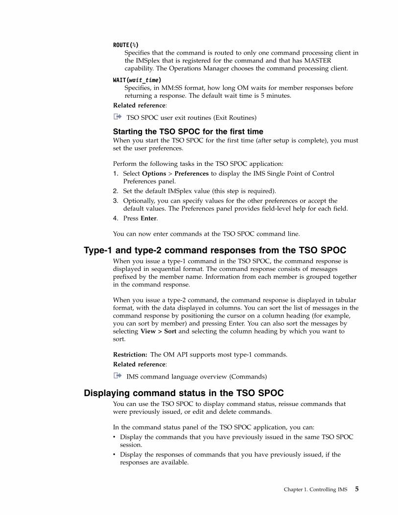
Starting the TSO SPOC for the first timeWhen you start the TSO SPOC for the first time (after setup is complete), you mustset the user preferences.
Perform the following tasks in the TSO SPOC application:1. Select Options > Preferences to display the IMS Single Point of Control
Preferences panel.2. Set the default IMSplex value (this step is required).3. Optionally, you can specify values for the other preferences or accept the
default values. The Preferences panel provides field-level help for each field.4. Press Enter.
You can now enter commands at the TSO SPOC command line.
Type-1 and type-2 command responses from the TSO SPOCWhen you issue a type-1 command in the TSO SPOC, the command response isdisplayed in sequential format. The command response consists of messagesprefixed by the member name. Information from each member is grouped togetherin the command response.
When you issue a type-2 command, the command response is displayed in tabularformat, with the data displayed in columns. You can sort the list of messages in thecommand response by positioning the cursor on a column heading (for example,you can sort by member) and pressing Enter. You can also sort the messages byselecting View > Sort and selecting the column heading by which you want tosort.
Restriction: The OM API supports most type-1 commands.Related reference:
IMS command language overview (Commands)
Displaying command status in the TSO SPOCYou can use the TSO SPOC to display command status, reissue commands thatwere previously issued, or edit and delete commands.
In the command status panel of the TSO SPOC application, you can:v Display the commands that you have previously issued in the same TSO SPOC
session.v Display the responses of commands that you have previously issued, if the
responses are available.
Chapter 1. Controlling IMS 5

v Reissue commands that you have previously issued and view the commandresponses.
v Delete commands.v Edit commands.
To open the command status panel, select SPOC > Command status in the TSOSPOC application.
Related concepts:“Reissuing commands in the TSO SPOC” on page 7
Command shortcuts in the TSO SPOCYou can use the command shortcuts option of the TSO SPOC if you prefer to useshortened versions of commands or nicknames for commands. Define the shortcuts(the short commands or nicknames) in the TSO SPOC.
Use the ampersand (&) character as the first character of the shortcut if you wantto use it as a nickname.
When you issue a short version of a command, the TSO SPOC appends theadditional parameters to the short command. When you issue a nickname for acommand, the TSO SPOC replaces the nickname with the full version of thecommand. The following example shows the SPOC Command Shortcuts panelwith some user-defined command shortcuts.
File Action Manage resources SPOC View Options Help---------------------------------------------------------------------------PLEX1 IMS Single Point of ControlCommand ===> _________________________________________________________________________________________________________________________________________-------------------------------- Plex . _____ Route . _______ Wait . ____Enter ’/’ to view command response, ’i’ to reissue a command, ’d’ to deletea command, and ’e’ to edit a command.
Act Status Command___ Complete DIS STATUS___ Complete QRY TRAN NAME(SKS*) SHOW(ALL)___ Complete QRY IMSPLEX SHOW(TYPE,STATUS,SUBTYPE)___ /NRE CHKPT 0 FMT ALL___ QRY IMSPLEX SHOW(ALL)___ QRY TRAN NAME(CDEBTRN3) SHOW(STATUS)___ START TRAN CDEBTRN3___ QRY TRAN NAME(CDEBTRN3) SHOW(ALL)___ DIS TRAN CDEBTRN3___ DIS TRAN CDEBTRN3 ALL___ DIS ACT
Figure 2. TSO SPOC Command Status panel
6 Operations and Automation
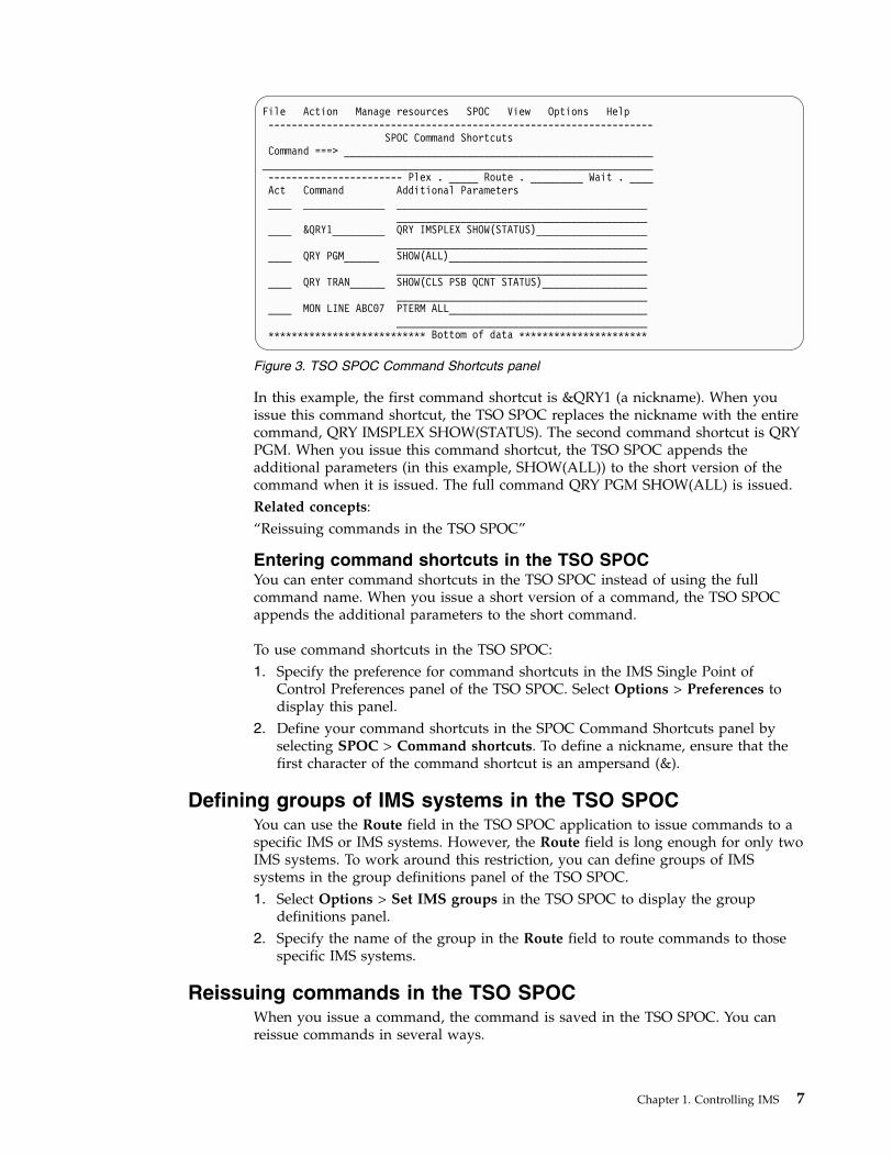
In this example, the first command shortcut is &QRY1 (a nickname). When youissue this command shortcut, the TSO SPOC replaces the nickname with the entirecommand, QRY IMSPLEX SHOW(STATUS). The second command shortcut is QRYPGM. When you issue this command shortcut, the TSO SPOC appends theadditional parameters (in this example, SHOW(ALL)) to the short version of thecommand when it is issued. The full command QRY PGM SHOW(ALL) is issued.Related concepts:“Reissuing commands in the TSO SPOC”
Entering command shortcuts in the TSO SPOCYou can enter command shortcuts in the TSO SPOC instead of using the fullcommand name. When you issue a short version of a command, the TSO SPOCappends the additional parameters to the short command.
To use command shortcuts in the TSO SPOC:1. Specify the preference for command shortcuts in the IMS Single Point of
Control Preferences panel of the TSO SPOC. Select Options > Preferences todisplay this panel.
2. Define your command shortcuts in the SPOC Command Shortcuts panel byselecting SPOC > Command shortcuts. To define a nickname, ensure that thefirst character of the command shortcut is an ampersand (&).
Defining groups of IMS systems in the TSO SPOCYou can use the Route field in the TSO SPOC application to issue commands to aspecific IMS or IMS systems. However, the Route field is long enough for only twoIMS systems. To work around this restriction, you can define groups of IMSsystems in the group definitions panel of the TSO SPOC.1. Select Options > Set IMS groups in the TSO SPOC to display the group
definitions panel.2. Specify the name of the group in the Route field to route commands to those
specific IMS systems.
Reissuing commands in the TSO SPOCWhen you issue a command, the command is saved in the TSO SPOC. You canreissue commands in several ways.
File Action Manage resources SPOC View Options Help------------------------------------------------------------------
SPOC Command ShortcutsCommand ===> _____________________________________________________
___________________________________________________________________----------------------- Plex . _____ Route . _________ Wait . ____Act Command Additional Parameters____ ______________ ___________________________________________
_______________________________________________ &QRY1_________ QRY IMSPLEX SHOW(STATUS)___________________
_______________________________________________ QRY PGM______ SHOW(ALL)__________________________________
_______________________________________________ QRY TRAN______ SHOW(CLS PSB QCNT STATUS)__________________
_______________________________________________ MON LINE ABC07 PTERM ALL__________________________________
___________________________________________*************************** Bottom of data **********************
Figure 3. TSO SPOC Command Shortcuts panel
Chapter 1. Controlling IMS 7

v After entering a command, position the cursor on the entered command andpress Enter. The command is moved into the TSO SPOC command line, and youcan edit the command or press Enter to issue the command again.
v Use the ISPF retrieve key to display commands that were previously entered.Because the ISPF retrieve key is an ISPF function, all commands entered fromother applications are also retrieved.
v Use the ISPF RETP command to list previously entered commands. Because theISPF retrieve key is an ISPF function, all commands entered from otherapplications are also retrieved. Select the number of the command shown in thelist of commands and press Enter.
v Use the TSO SPOC command status panel. Enter “i” in the Act column toreissue the command. If you enter “i” next to several commands and pressEnter, the commands are reissued in the order in which they are listed.
v Use the TSO SPOC command shortcuts panel. Enter “i” in the Act column toreissue the command. If you enter “i” next to several commands and pressEnter, the commands are reissued in the order in which they are listed.
Related concepts:“Displaying command status in the TSO SPOC” on page 5“Command shortcuts in the TSO SPOC” on page 6
Managing IMS resources by using TSO SPOCThe TSO SPOC application provides a set of resource management panels to helpyou manage IMS resources. You can use TSO SPOC to query IMS resources and, ifdynamic resource definition (DRD) is enabled in your IMS systems, you can alsouse the TSO SPOC panels to create, delete, export, import, and update IMSresources.
You can access the panels from the Manage Resources menu in the TSO SPOCapplication or by selecting the Manage Resources option directly from the IMSApplication Menu.
Querying IMS resource information by using TSO SPOC
You can query the attributes and status of IMS resources as maintained in eachIMS system or across the IMSplex. The information returned for IMS resources caninclude:v The status of resources as set by commands and maintained locally by IMS
systemsv The status of resources as set by commands and maintained globally across the
IMSplex by Resource Manager (RM)v The status of resources as set in the DBRC RECON data setv The attributes of various IMS resources as set by system definition macros or by
DRD commandsv The attributes status and attributes information about an IMSRSC repository
Creating, deleting, exporting, importing, and updating IMSresources by using TSO SPOC
Before you can create, delete, export, import, or update IMS resources through TSOSPOC by using the dynamic resource definition commands, you should be awareof the following points:v You must enable DRD in the target IMS systems.
8 Operations and Automation
v Changes made to IMS resources are not saved across an IMS cold start until theyare exported to the resource definition data set (RDDS) or the repository. If acold start or emergency restart with the COLDSYS parameter occurs before anexport is performed, any changes to resource definitions are lost.
v After creating an application program or database by using the CREATEcommand, you must further define the application program or database, as wellas its relationships to other resources, by running the appropriate generationutility, such as the Database Description Generation (DBDGEN) utility or theProgram Specification Block Generation (PSBGEN) utility. You must perform anACBLIB or ACBMBR online change to ensure that the created or modified DBDor PSB resources are available to the IMS system.
The IMS resources and resource descriptors that you can create, delete, export,import, and update in DRD-enabled systems include:v Application programsv Databasesv Fast Path routing codesv Transactionsv Change list (delete only)Related tasks:
Enabling dynamic definition for IMS resource groups (System Definition)
Viewing the OM audit trail log by using TSO SPOCYou can view the OM audit trail log by using the TSO SPOC application if the CSLOperations Manager (OM) is configured to produce an audit trail log. The OMaudit trail log contains log records of commands, command responses, and systemmessages routed through OM.
OM audit trail logging is enabled by the AUDITLOG parameter in the CSL OMinitialization parameters PROCLIB member (CSLOIxxx).
You can filter the records returned by TSO SPOC by specifying in the Preferencespanel one or more IMSplex member names for which you want to see records.Alternately, you can specify the type of IMSplex member, such as IMS systems,automated operator programs, CQS, RM, and so forth.
When you are viewing the OM audit trail in TSO SPOC, a log record for commandinput, command output, or system message appears on a separate line. You canobtain additional information by:v Clicking on a log entry for a system message, which produces a link that you
can follow to a description of the message.v Clicking on a log entry for a command response, which produces information
about that command.
To search for a text string in the TSO SPOC Audit Trail panel, type find on thecommand line or click View > Find from the menu bar. A pop-up panel isdisplayed, prompting you to enter the text string. To find the same text stringagain, press PF5 or type rfind on the command line.
Chapter 1. Controlling IMS 9

When you are using the TSO SPOC ISPF interface, the log entries for systemmessages are color coded in the TSO SPOC display. Error messages are displayedin red. Warning messages are displayed in yellow. All other messages aredisplayed in white.
Enabling the OM audit log displayYou can enable the OM audit log display in order to display the current recordsthat are being logged.
To enable the OM audit log display, follow these steps:1. Optionally define your audit trail preferences in the TSO SPOC Preferences
panel.2. Select Audit Trail from the panel selection screen.3. Enter the z/OS log data set name that contains the OM audit log. This name
must match the z/OS log data set name specified in the AUDITLOGsubparameter of the IMSPLEX parameter in the CSLOIxxx PROCLIB member.
4. Enter the earliest date and time for which you want to see records.5. Enter the latest data and time for which you want to see records. Enter an
asterisk in the end date and end time fields to see the current records beinglogged.
Issuing Batch SPOC commandsYou can use the Batch SPOC utility to submit IMS operator commands to anIMSplex. The Batch SPOC utility accepts any commands that are supported by theOM API.
The Batch SPOC utility uses:v Program parameters to define the IMSplex environment, including IMSplex
name, routing and the wait time.v The SYSIN file as input for IMS operator commands.v The SYSPRINT file to show SPOC-like formatted command response.
You can invoke the Batch SPOC utility using standard JCL statements. Thefollowing example shows a simple invocation, but you can call the utility usingother valid JCL.
File Display View Options Help----------------------------------------------------------------PLEX1 IMSplex Audit TrailCommand ===> ___________________________________________________----------------- Members. . _____________ Type . . _____________MbrName Time MessageIMS1 2006.086 14:04:21.148419 DFSxxxxI message textIMS1 2006.086 14:08:18.898122 DFSxxxxW message textIMS1 2006.086 14:10:08.752387 DFSxxxxE message textOMUSER1 2006.086 14:15:08.752387 Response for: QRY IMSPLEXIMS1 2006.086 15:08:21.148419 DFSxxxxI message textIMS1 2006.086 15:09:18.898122 DFSxxxxW message text
F1=Help F7=Up F8=Down F12=Cancel
Figure 4. TSO SPOC IMSplex Audit Trail panel
10 Operations and Automation

Sample batch job with multiple commands//SPOCJOB JOB ,// MSGCLASS=H,NOTIFY=&SYSUID,USER=&SYSUID//*//SPOC EXEC PGM=CSLUSPOC,// PARM=(’IMSPLEX=PLEX1,ROUTE=IMS3,WAIT=30,F=WRAP’)//STEPLIB DD DISP=SHR,DSN=IMS.SDFSRESL//SYSPRINT DD SYSOUT=*//SYSIN DD *QRY IMSPLEX SHOW(JOB,TYPE, +
STATUS)
QRY TRAN NAME(INV1*) SHOW(ALL) /* inventory appl *//*EOF
The following program parameters define the IMSplex environment:
IMSPLEXRequired parameter that specifies the 1- to 5-character suffix of the IMSplexname.
F Optional parameter that specifies the print format of the SPOC output. You canspecify one of the following values:
WRAPWraps to the next line as needed. This is the default.
BYCOLLines of data are grouped together by the column.
BYRSCLines of data are grouped together by the resource.
ROUTEOptional parameter that specifies the SYSIDs of IMSplex members that are toexecute the command. If ROUTE is not specified, all members of the IMSplexwill execute the command. If more than one member is specified, enclose thelist in parenthesis and separate the names with commas. For example:// PARM=(’IMSPLEX=PLEX1,WAIT=30,ROUTE=(IMSZ,IMSA)’)
If ROUTE=* is specified, the command is routed to all registered commandprocessing clients in the IMSplex. If ROUTE=% is specified, the command isrouted to only one command processing client in the IMSplex that is registeredfor the command and that has MASTER capability. The Operations Managerchooses the command processing client.
WAITOptional parameter that specifies the wait time for individual commands. Thewait value is in minutes and seconds (MMM:SS) or just seconds (SSSSS). OMwill return a single response as soon as a response is received from all of themembers of the IMSplex. If the interval expires, OM will return any responsesfrom IMSplex members, plus an indication that some did not reply. The BatchSPOC utility will wait for each command to complete before issuing the nextcommand. The default wait value is five minutes (5:00). The WAIT timeapplies to every command in the SYSIN file. The user can specify a wait timeof zero seconds; in this case, the batch SPOC issues a command but does notwait for the response.
The SYSIN file is provided by the user and contains the commands that the userwants to execute. The commands are executed serially. When one commandcompletes, the next command is executed until all records from the SYSIN file areprocessed. Continuation of the SYSIN control statements is specified by a plus sign
Chapter 1. Controlling IMS 11

(+) or a minus sign (-) as the last nonblank character of the line. A plus signremoves the leading spaces from the next line; a minus sign keeps leading spaces.Comments can be included within the SYSIN file and are specified with thefollowing format:/* this is a comment */
The SYSPRINT file will have the formatted command response. If more than onecommand is issued, the responses appear in the same order as the commandsappear in the SYSIN file. The default record length is 133. The command responseis formatted in a style specified by the user. The user may specify DCB informationin the JCL or in the data set allocation to allow longer records in the SYSPRINTfile.
System Display and Search Facility (SDSF) can be used to view batch job output.
Sample batch job output
The following example shows sample batch job output:========================================================Log for. . : QRY IMSPLEX SHOW(JOB,TYPE,STATUS)
IMSplex . . . . . : PLEX1Routing . . . . . :Start time. . . . : 2005.132 15:36:28.11Stop time . . . . : 2005.132 15:36:29.17Return code . . . : 00000000Reason code . . . : 00000000Command master. . : SYS3
IMSplex MbrName CC Member JobName Type StatusCSLPLEX1 OM1OM 0 USRT002 USRT002 AOP ACTIVECSLPLEX1 OM1OM 0 OM1OM OM1 OM READY,ACTIVECSLPLEX1 OM1OM 0 RM1RM RM1 RM READY,ACTIVECSLPLEX1 OM1OM 0 SCI1SC SCI1 SCI READY,ACTIVECSLPLEX1 OM1OM 0 IMS1 IMS1 IMS READY,ACTIVECSLPLEX1 OM1OM 0 SYS1 SYS1 IMS READY,ACTIVE=======================================================
Sample batch job output with no response
If no wait time, WAIT=0, is specified, the command response is not available andtherefore will not be printed. The SYSPRINT file will only have short summaryinformation for each command:========================================================Log for. . : QRY IMSPLEX SHOW(JOB,TYPE,STATUS)
IMSplex . . . . . : PLEX1Routing . . . . . :Start time. . . . : 2006.075 15:36:28.11========================================================
Related reference:
Batch SPOC utility (CSLUSPOC) (System Utilities)
Modifying and controlling system resourcesYou establish the initial settings of IMS resources during IMS system definition.
12 Operations and Automation

Modifying system resources onlineIMS supports two separate functions that support modifying IMS resources online:dynamic resource definition (DRD) and the online change function. Authorizedsystem operators and database administrators (DBAs) can change various systemresources using IMS commands.
Dynamic resource definition
With DRD, you can perform the following actions on IMS system resources:v Use commands to create, update, and delete MODBLKS and MSC resources
dynamically.v Use the enhanced Destination Creation exit routine (DFSINSX0), formerly called
the Output Creation exit routine, to create transactions (and, if necessary, theprograms that are associated with the transactions) instead of using the onlinechange process.
v Use the Program Creation user exit routine (PGMCREAT) to dynamically createthe runtime program resourece for a program that is to be scheduled in a BMPor JBP dependent region.
DRD enables you to avoid the online change process for MODBLKS resources. Tochange resources other than MODBLKS and MSC resources online (for example,resources in IMS.ACBLIB), you still need to use the online change process.
DRD is enabled by specifying MODBLKS=DYN in the DFSDFxxx member or theDFSCGxxx member. To enable DRD for MSC resources, you must also specifyMSCRSCS=DYN in the DFSDFxxx member.
When dynamic resource definition (DRD) is enabled in your IMS system, you canuse the following type-2 commands to create, modify, and delete runtime resourceand descriptor definitions for application programs, databases, routing codes andtransactions.v CREATEv UPDATEv DELETEv IMPORT
The CREATE, UPDATE, DELETE, and IMPORT commands in a DRD-enabledsystem are essentially the same as adding, modifying, or deleting the systemdefinition macros for IMS runtime resource definitions.
The EXPORT command is used to export MODBLKS runtime resource anddescriptor definitions from the online IMS system to a resource definition data set(RDDS) or IMSRSC repository. The MODBLKS resource and descriptor definitionscan then be added to IMS dynamically through the IMPORT command. Fordynamically defined MSC resources, use the automatic export function to exportthe resources to the IMSRSC repository. The MSC resource definitions can then beadded to IMS dynamically at IMS cold start by using the automatic importfunction.
By exporting runtime resource and descriptor definitions to a repository, you cancreate resources for another IMS in the IMSplex.
Chapter 1. Controlling IMS 13
|
||
||||
|||
|||

Modifications to IMS resources that are made by use of type-2 commands arerecoverable across a warm or emergency restart. Runtime MODBLKS descriptordefinitions and MSC definitions are lost when an IMS system is cold started unlessyou perform the following actions:v For runtime MODBLKS descriptor definitions, export MODBLKS resource and
descriptor definitions to the RDDS or repository while IMS is running.MODBLKS resource and descriptor definitions can be exported either explicitlyby use of the EXPORT DEFN command, or automatically if AUTOEXPORT isenabled in the DFSDFxxx PROCLIB member.
v For MSC definitions, use the automatic export function to export the definitionsto the IMSRSC repository.
If you want to modify resources, use the QUERY command to view the resourceinformation before making the change.
You must ensure that:v Commands are routed to and executed on the systems where you want the
changes to be applied.v Any changes made dynamically with the DRD commands are recovered across a
cold start. Here are some examples of possible methods:– Using automatic export to export updated resource definitions to an RDDS or
the IMSRSC repository, and then using automatic import during IMS coldstart to retrieve the definitions from the RDDS or the IMSRSC repository.
– Issuing the EXPORT DEFN TARGET(REPO) command while IMS is runningand then using automatic import from the repository.You can periodically issue the EXPORT DEFN TARGET(REPO)OPTION(CHANGESONLY) command to write changes to the repository.
The following IMS resources and resource descriptors can be defined dynamically:v Application programsv Databasesv Fast Path routing codesv Transactionsv MSC resources, including logical links, physical links, logical link paths
(MSNAMEs), and remote logical terminals (LTERMs)
You can enter the CREATE, UPDATE, DELETE, and MODIFY type-2 commandsdirectly through:v TSO SPOCv Batch SPOCv REXX automation (through the REXX SPOC API)v Your own programs that use the OM API
Similarly, you can use the Manage Resource panels to enter DRD commands byselecting an option from the IMS Application Menu. The Manage Resource panelsare a hierarchy of ISPF panels that offer an alternative way to enter commands.From the Manage Resource panels, you can:v Define and control IMS resourcesv Select an action that you want to perform (for example, CREATE)v Manage attributes of a resource
14 Operations and Automation
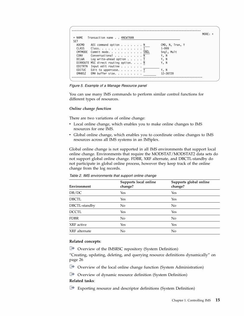
You can use many IMS commands to perform similar control functions fordifferent types of resources.
Online change function
There are two variations of online change:v Local online change, which enables you to make online changes to IMS
resources for one IMS.v Global online change, which enables you to coordinate online changes to IMS
resources across all IMS systems in an IMSplex.
Global online change is not supported in all IMS environments that support localonline change. Environments that require the MODSTAT/MODSTAT2 data sets donot support global online change. FDBR, XRF alternate, and DBCTL-standby donot participate in global online process, however they keep track of the onlinechange from the log records.
Table 2. IMS environments that support online change
EnvironmentSupports local onlinechange?
Supports global onlinechange?
DB/DC Yes Yes
DBCTL Yes Yes
DBCTL-standby No No
DCCTL Yes Yes
FDBR No No
XRF active Yes Yes
XRF alternate No No
Related concepts:
Overview of the IMSRSC repository (System Definition)“Creating, updating, deleting, and querying resource definitions dynamically” onpage 26
Overview of the local online change function (System Administration)
Overview of dynamic resource definition (System Definition)Related tasks:
Exporting resource and descriptor definitions (System Definition)
---------------------------------------------------------------------------------MORE: +
* NAME Transaction name . . 4NEWTRANSET
AOCMD AOI command option . . . . . . . N CMD, N, Tran, YCLASS Class. . . . . . . . . . . . . . 1 1-999CMTMODE Commit mode. . . . . . . . . . . SNGL Sngl, MultCONV Conversational . . . . . . . . . N Y, NDCLWA Log write-ahead option . . . . . Y Y, NDIRROUTE MSC direct routing option. . . . N Y, NEDITRTN Input edit routine . . . . . . .EDITUC Edit to uppercase. . . . . . . . Y Y, NEMHBSZ EMH buffer size. . . . . . . . . 12-30720
----------------------------------------------------------------------------------
Figure 5. Example of a Manage Resource panel
Chapter 1. Controlling IMS 15
Importing resource and descriptor definitions (System Definition)Related reference:“List of commands with similar functions for multiple resources”
List of commands with similar functions for multipleresources
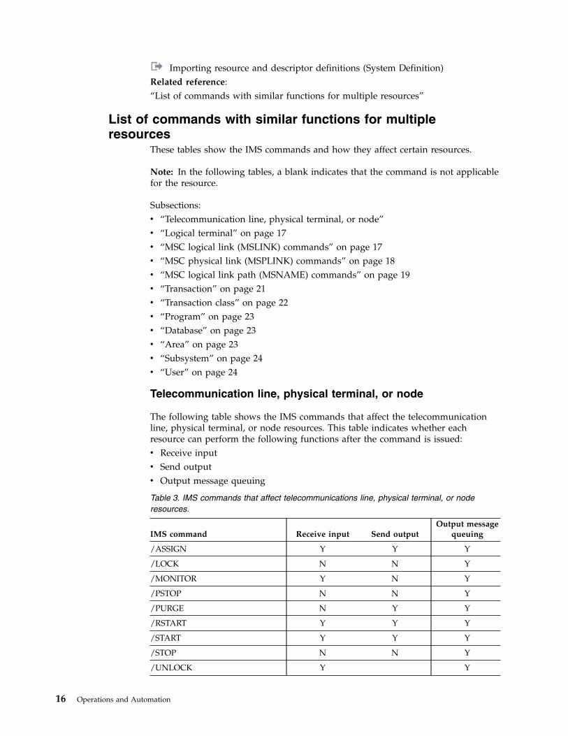
These tables show the IMS commands and how they affect certain resources.
Note: In the following tables, a blank indicates that the command is not applicablefor the resource.
Subsections:v “Telecommunication line, physical terminal, or node”v “Logical terminal” on page 17v “MSC logical link (MSLINK) commands” on page 17v “MSC physical link (MSPLINK) commands” on page 18v “MSC logical link path (MSNAME) commands” on page 19v “Transaction” on page 21v “Transaction class” on page 22v “Program” on page 23v “Database” on page 23v “Area” on page 23v “Subsystem” on page 24v “User” on page 24
Telecommunication line, physical terminal, or node
The following table shows the IMS commands that affect the telecommunicationline, physical terminal, or node resources. This table indicates whether eachresource can perform the following functions after the command is issued:v Receive inputv Send outputv Output message queuing
Table 3. IMS commands that affect telecommunications line, physical terminal, or noderesources.
IMS command Receive input Send outputOutput message
queuing
/ASSIGN Y Y Y
/LOCK N N Y
/MONITOR Y N Y
/PSTOP N N Y
/PURGE N Y Y
/RSTART Y Y Y
/START Y Y Y
/STOP N N Y
/UNLOCK Y Y
16 Operations and Automation
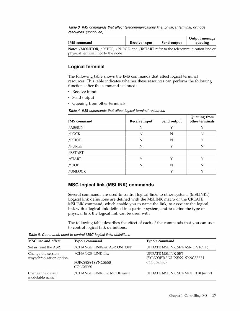
Table 3. IMS commands that affect telecommunications line, physical terminal, or noderesources (continued).
IMS command Receive input Send outputOutput message
queuing
Note: /MONITOR, /PSTOP, /PURGE, and /RSTART refer to the telecommunication line orphysical terminal, not to the node.
Logical terminal
The following table shows the IMS commands that affect logical terminalresources. This table indicates whether these resources can perform the followingfunctions after the command is issued:v Receive inputv Send outputv Queuing from other terminals
Table 4. IMS commands that affect logical terminal resources
IMS command Receive input Send outputQueuing fromother terminals
/ASSIGN Y Y Y
/LOCK N N N
/PSTOP N N Y
/PURGE N Y N
/RSTART
/START Y Y Y
/STOP N N N
/UNLOCK Y Y
MSC logical link (MSLINK) commands
Several commands are used to control logical links to other systems (MSLINKs).Logical link definitions are defined with the MSLINK macro or the CREATEMSLINK command, which enable you to name the link, to associate the logicallink with a logical link defined in a partner system, and to define the type ofphysical link the logical link can be used with.
The following table describes the effect of each of the commands that you can useto control logical link definitions.
Table 5. Commands used to control MSC logical links definitions
MSC use and effect Type-1 command Type-2 command
Set or reset the ASR. /CHANGE LINKlink ASR ON|OFF UPDATE MSLINK SET(ASR(ON|OFF))
Change the sessionresynchronization option.
/CHANGE LINK link
FORCSESS|SYNCSESS|COLDSESS
UPDATE MSLINK SET(SYNCOPT(FORCSESS|SYNCSESS|COLSDESS))
Change the defaultmodetable name.
/CHANGE LINK link MODE name UPDATE MSLINK SET(MODETBL(name)
Chapter 1. Controlling IMS 17

Table 5. Commands used to control MSC logical links definitions (continued)
MSC use and effect Type-1 command Type-2 command
Assign to a new physicallink.
/MSASSIGN LINK link MSPLINK name UPDATE MSLINK SET(MSPLINK(name)
Stop the current link andsending and receiving ofmessages.
/PSTOP LINK link UPDATE MSLINK STOP(COMM)
Force the stoppage of alink.
/PSTOP LINK link PURGE|FORCE UPDATE MSLINK STOP(COMM)OPTION(FORCE)
Start a previously stoppedMSLINK and start thequeuing of or sending ofmessages to logical linkson another system.
/RSTART LINK link UPDATE MSLINK START(COMM)
Start a previously stoppedMSLINK and start thequeuing of or sending ofmessages to logical linkson another system, but usemodetable for this sessiononly.
/RSTART LINK link MODE name UPDATE MSLINK START(COMM)SET(MODETBL(name))
Start or stop an internaltrace.
/TRACE SET ON|OFF LINK link UPDATE MSLINK START(TRACE) orUPDATE MSLINK STOP(TRACE)
Start or stop an XRFtakeover trace.
/TRACE SET ON|OFF LINK linkTAKEOVER
UPDATE MSLINK START(TKOTRC) orUPDATE MSLINK STOP(TKOTRC)
Start or stop thebandwidth mode.
Not applicable UPDATE MSLINKSET(BANDWIDTH(ON|OFF))
Change the send/receivebuffer size.
Not applicable UPDATE MSLINK SET(BUFSIZE(size))
Change the logical linkname.
Not applicable UPDATE MSLINK SET(MSLINK(name))
Change the partner id. Not applicable UPDATE MSLINK SET(PARTNER(id))
MSC physical link (MSPLINK) commands
Several commands are used to control physical links (MSPLINKs). The MSPLINKmacro or the type-2 CREATE MSPLINK command can define the following typesof connections between two systems:v Channel-to-channel (CTC)v Memory-to-memory (MTM)v TCP/IPv VTAM®
The following table describes the effect of each of the commands that you can usewith to control physical link paths to IMS systems.
Table 6. Commands used to control MSC physical links
MSC use and effect Type-1 command Type-2 command
Disable logons to thisphysical link.
/PSTOP MSPLINK UPDATE MSPLINKSTOP(LOGON)
18 Operations and Automation
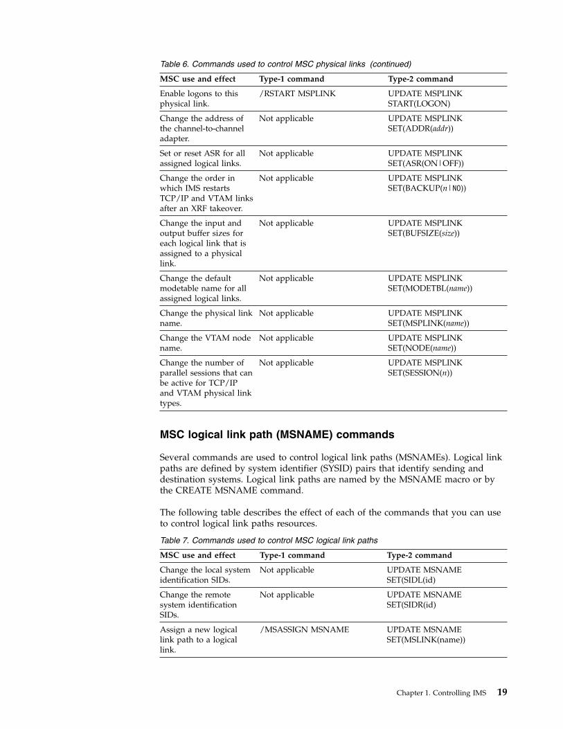
Table 6. Commands used to control MSC physical links (continued)
MSC use and effect Type-1 command Type-2 command
Enable logons to thisphysical link.
/RSTART MSPLINK UPDATE MSPLINKSTART(LOGON)
Change the address ofthe channel-to-channeladapter.
Not applicable UPDATE MSPLINKSET(ADDR(addr))
Set or reset ASR for allassigned logical links.
Not applicable UPDATE MSPLINKSET(ASR(ON|OFF))
Change the order inwhich IMS restartsTCP/IP and VTAM linksafter an XRF takeover.
Not applicable UPDATE MSPLINKSET(BACKUP(n|NO))
Change the input andoutput buffer sizes foreach logical link that isassigned to a physicallink.
Not applicable UPDATE MSPLINKSET(BUFSIZE(size))
Change the defaultmodetable name for allassigned logical links.
Not applicable UPDATE MSPLINKSET(MODETBL(name))
Change the physical linkname.
Not applicable UPDATE MSPLINKSET(MSPLINK(name))
Change the VTAM nodename.
Not applicable UPDATE MSPLINKSET(NODE(name))
Change the number ofparallel sessions that canbe active for TCP/IPand VTAM physical linktypes.
Not applicable UPDATE MSPLINKSET(SESSION(n))
MSC logical link path (MSNAME) commands
Several commands are used to control logical link paths (MSNAMEs). Logical linkpaths are defined by system identifier (SYSID) pairs that identify sending anddestination systems. Logical link paths are named by the MSNAME macro or bythe CREATE MSNAME command.
The following table describes the effect of each of the commands that you can useto control logical link paths resources.
Table 7. Commands used to control MSC logical link paths
MSC use and effect Type-1 command Type-2 command
Change the local systemidentification SIDs.
Not applicable UPDATE MSNAMESET(SIDL(id)
Change the remotesystem identificationSIDs.
Not applicable UPDATE MSNAMESET(SIDR(id)
Assign a new logicallink path to a logicallink.
/MSASSIGN MSNAME UPDATE MSNAMESET(MSLINK(name))
Chapter 1. Controlling IMS 19
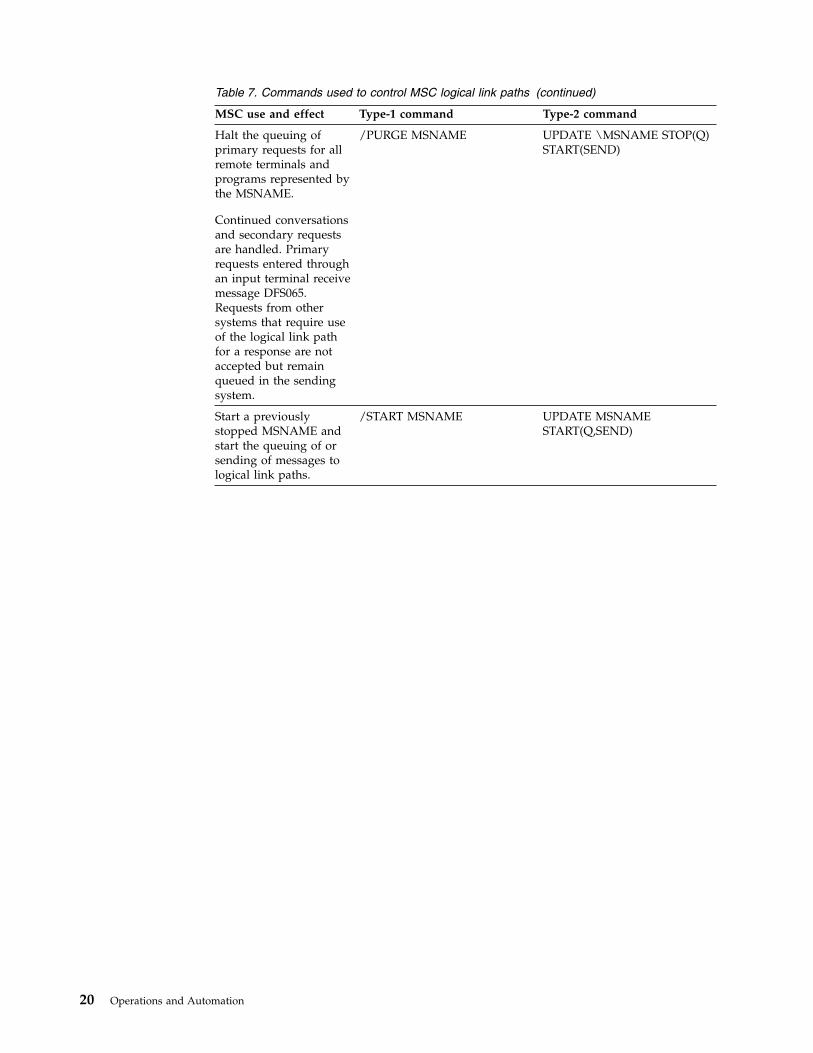
Table 7. Commands used to control MSC logical link paths (continued)
MSC use and effect Type-1 command Type-2 command
Halt the queuing ofprimary requests for allremote terminals andprograms represented bythe MSNAME.
Continued conversationsand secondary requestsare handled. Primaryrequests entered throughan input terminal receivemessage DFS065.Requests from othersystems that require useof the logical link pathfor a response are notaccepted but remainqueued in the sendingsystem.
/PURGE MSNAME UPDATE \MSNAME STOP(Q)START(SEND)
Start a previouslystopped MSNAME andstart the queuing of orsending of messages tological link paths.
/START MSNAME UPDATE MSNAMESTART(Q,SEND)
20 Operations and Automation
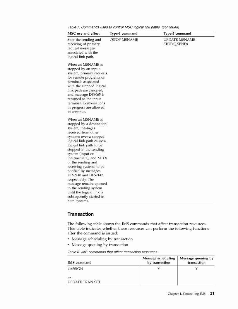
Table 7. Commands used to control MSC logical link paths (continued)
MSC use and effect Type-1 command Type-2 command
Stop the sending andreceiving of primaryrequest messagesassociated with thelogical link path.
When an MSNAME isstopped by an inputsystem, primary requestsfor remote programs orterminals associatedwith the stopped logicallink path are canceled,and message DFS065 isreturned to the inputterminal. Conversationsin progress are allowedto continue.
When an MSNAME isstopped by a destinationsystem, messagesreceived from othersystems over a stoppedlogical link path cause alogical link path to bestopped in the sendingsystem (input orintermediate), and MTOsof the sending andreceiving systems to benotified by messagesDFS2140 and DFS2142,respectively. Themessage remains queuedin the sending systemuntil the logical link issubsequently started inboth systems.
/STOP MSNAME UPDATE MSNAMESTOP(Q,SEND)
Transaction
The following table shows the IMS commands that affect transaction resources.This table indicates whether these resources can perform the following functionsafter the command is issued:v Message scheduling by transactionv Message queuing by transaction
Table 8. IMS commands that affect transaction resources
IMS commandMessage scheduling
by transactionMessage queuing by
transaction
/ASSIGN
orUPDATE TRAN SET
Y Y
Chapter 1. Controlling IMS 21

Table 8. IMS commands that affect transaction resources (continued)
IMS commandMessage scheduling
by transactionMessage queuing by
transaction
/LOCKorUPDATE TRAN SET(LOCK|ON|OFF)
N Y
/MSASSIGN
orUPDATE TRAN SET(MSNAME)
Y Y
/PSTOP
orUPDATE TRAN STOP(SCHD) START(Q)
N Y
/PURGE
orUPDATE TRAN START(SCHD) STOP(Q)
Y N
/START
orUPDATE TRAN START(Q,SCHD)
Y Y
/STOP
orUPDATE TRAN STOP(Q,SCHD)
N N
/UNLOCK
orUPDATE TRAN SET(LOCK|ON|OFF)
Y Y
Transaction class
The following table shows the IMS commands that affect transaction classresources. This table indicates whether these resources can perform transactionscheduling by class after the command is issued.
Table 9. IMS commands that affect transaction class resources.
IMS commandTransaction scheduling by
class
/ASSIGN Y
/MSASSIGN Y
/START Y
/STOP N
UPDATE TRAN Y or N1
UPDATE TRAN SET Y
UPDATE TRAN START (Q) Y
UPDATE TRAN STOP (Q) N1 Whether the transaction class can perform transaction scheduling by class after theUPDATE command is issued depends on the parameters and keywords specified in thiscommand.
22 Operations and Automation
Program
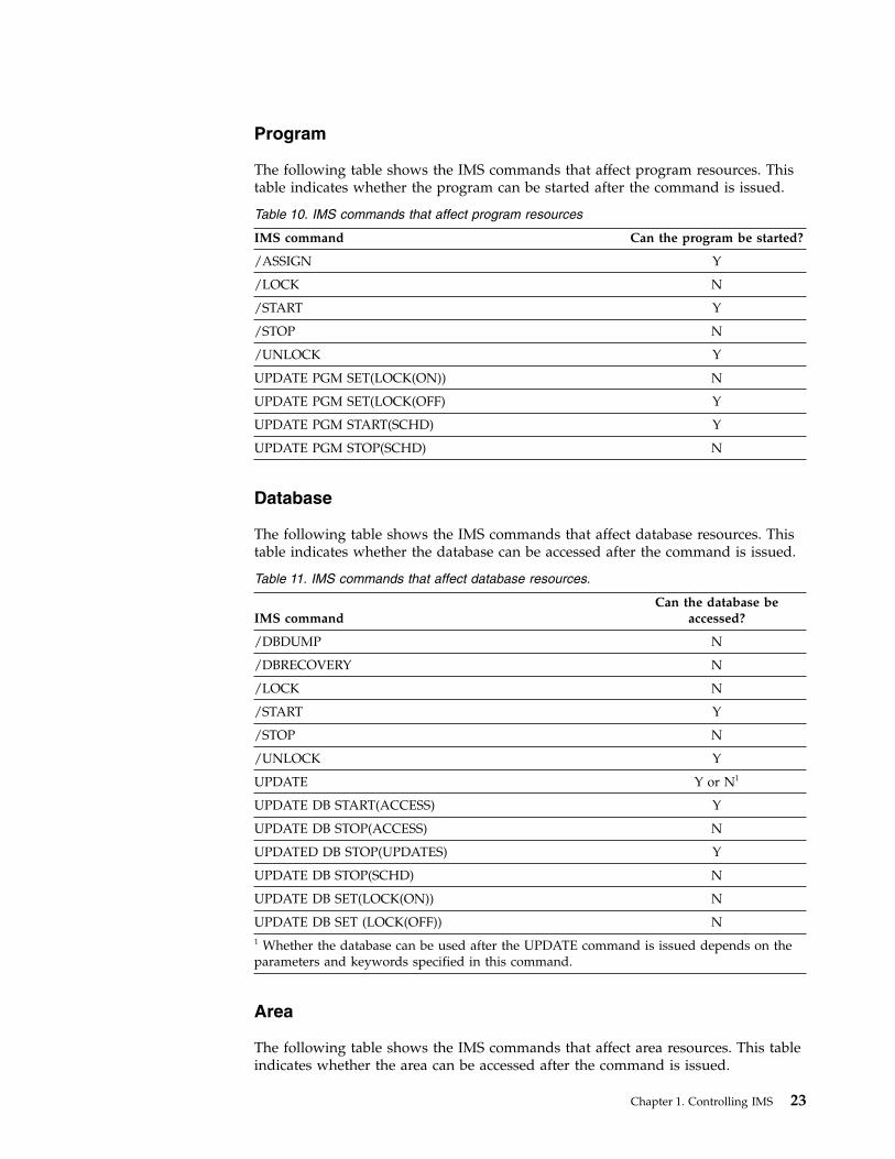
The following table shows the IMS commands that affect program resources. Thistable indicates whether the program can be started after the command is issued.
Table 10. IMS commands that affect program resources
IMS command Can the program be started?
/ASSIGN Y
/LOCK N
/START Y
/STOP N
/UNLOCK Y
UPDATE PGM SET(LOCK(ON)) N
UPDATE PGM SET(LOCK(OFF) Y
UPDATE PGM START(SCHD) Y
UPDATE PGM STOP(SCHD) N
Database
The following table shows the IMS commands that affect database resources. Thistable indicates whether the database can be accessed after the command is issued.
Table 11. IMS commands that affect database resources.
IMS commandCan the database be
accessed?
/DBDUMP N
/DBRECOVERY N
/LOCK N
/START Y
/STOP N
/UNLOCK Y
UPDATE Y or N1
UPDATE DB START(ACCESS) Y
UPDATE DB STOP(ACCESS) N
UPDATED DB STOP(UPDATES) Y
UPDATE DB STOP(SCHD) N
UPDATE DB SET(LOCK(ON)) N
UPDATE DB SET (LOCK(OFF)) N1 Whether the database can be used after the UPDATE command is issued depends on theparameters and keywords specified in this command.
Area
The following table shows the IMS commands that affect area resources. This tableindicates whether the area can be accessed after the command is issued.
Chapter 1. Controlling IMS 23
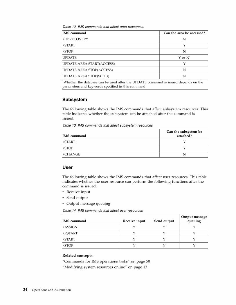
Table 12. IMS commands that affect area resources.
IMS command Can the area be accessed?
/DBRECOVERY N
/START Y
/STOP N
UPDATE Y or N1
UPDATE AREA START(ACCESS) Y
UPDATE AREA STOP(ACCESS) N
UPDATE AREA STOP(SCHD) N1Whether the database can be used after the UPDATE command is issued depends on theparameters and keywords specified in this command.
Subsystem
The following table shows the IMS commands that affect subsystem resources. Thistable indicates whether the subsystem can be attached after the command isissued.
Table 13. IMS commands that affect subsystem resources
IMS commandCan the subsystem be
attached?
/START Y
/STOP Y
/CHANGE N
User
The following table shows the IMS commands that affect user resources. This tableindicates whether the user resource can perform the following functions after thecommand is issued:v Receive inputv Send outputv Output message queuing
Table 14. IMS commands that affect user resources
IMS command Receive input Send outputOutput message
queuing
/ASSIGN Y Y Y
/RSTART Y Y Y
/START Y Y Y
/STOP N N Y
Related concepts:“Commands for IMS operations tasks” on page 50“Modifying system resources online” on page 13
24 Operations and Automation
Modifying dependent regionsTo modify the assignment of classes to regions or to adjust the processing loadamong message regions, you can use the type-1 /ASSIGN command or the type-2UPDATE command.
Use the /ASSIGN TRAN or UPDATE TRAN SET(CLASS(new_class_number))command to modify the assignment of classes to regions.
Modifying telecommunication linesTo discard response-mode output messages, you can use the /DEQUEUEcommand
Use the /DEQUEUE command to discard response-mode output messages beforeyou enter an /RSTART LINE command.
How to modify terminalsTerminals and links to terminals can be modified through various type-1commands. You can use these commands and their variations to manage terminals.
Use the /DISPLAY PTERM and /DISPLAY NODE command to display the statusof terminals and nodes. You can also use the /DISPLAY STATUS command, whichshows all resources that have a status requiring operator intervention, includingterminals and nodes.
Use the /ASSIGN LTERM command to modify the assignment of logical terminalsto physical terminals or nodes. The new assignment remains in effect until the nextcold start or until you issue another /ASSIGN command.
Use the /DEQUEUE command to discard full-function response-mode output sothat the /RSTART command can reset terminal response mode.
You can reset static nodes that are hung in Fast Path input response mode byissuing the /STOP NODE and /START NODE commands in sequence.
Use the /COMPT command for VTAM terminals (nodes) to notify IMS that aterminal component is operable or inoperable.
IMS provides a VTAM I/O Timeout facility to detect VTAM hung nodes anddetermine what action, if any, should be taken. Use the /TRACE command to startand stop the VTAM I/O Timeout facility. Use the /IDLE command to deactivate anode and the /ACTIVATE command to activate a node. Use the /DISPLAYcommand to display all nodes that have I/O outstanding for a time period greaterthan that specified during system definition.
Modifying and controlling transactionsYou can use the /ASSIGN TRAN or UPDATE TRANSET(CPRI(new_current_priority)) command to reassign the scheduling prioritiesestablished for transactions during system definition. The new assignments remainin effect until the next cold start or until you issue another /ASSIGN or UPDATEcommand.
In a shared-queues environment, you can use the /ASSIGN TRAN or UPDATETRAN SET(CLASS(new_class_number)) command to control which IMS subsystemscan run certain types of transactions by assigning transactions to a particular class.
Chapter 1. Controlling IMS 25
For example, you can define TRANA to class 4 on IMSA and to class 255 on IMSBand IMSC, so that only IMSA can run TRANA. If IMSA fails, you can reassignTRANA on either IMSB or IMSC to a class that these IMS subsystems can run.
Attention: Do not use the /STOP TRAN or UPDATE TRAN STOP(Q,SCHD)command to control which IMS subsystems can run certain types of transactions.
Database controlYou can use the type-1 /DBDUMP DB or type-2 UPDATE DB commands to controldatabases and access to databases.
Use the /DBDUMP DB or UPDATE DB STOP(UPDATES) command to stop onlineupdate access to a database so that you can produce an offline dump of thedatabase.
Use the /DBRECOVERY DB or UPDATE DB STOP(ACCESS) command to stop allonline access to a database. Use it to recover a database offline.
Normally, IMS switches to using the next OLDS when you enter the /DBDUMP or/DBRECOVERY command. This switch does not occur if you specify the NOFEOVkeyword on either command. When you enter the UPDATE DB STOP(ACCESS)command to stop online access to the database, IMS does not switch to the nextOLDS. You can specify OPTION(FEOV) if you want IMS to switch to the nextOLDS.
Specify the GLOBAL keyword on the /DBDUMP or /DBRECOVERY command tohave the command apply to all subsystems sharing the database. The IRLM mustbe active if you use this keyword. The default is LOCAL, which specifies that thecommand applies only to the subsystem on which you enter the command.
Creating, updating, deleting, and querying resourcedefinitions dynamically
If dynamic resource definition (DRD) is enabled in your IMS system, you cancreate, update, delete, and query certain IMS resources online through severaltype-2 commands. You can also create runtime descriptor definitions to use astemplates for creating additional resources.
You can use the following type-2 commands:v CREATEv UPDATEv DELETEv QUERYv IMPORT
You can also create runtime descriptor definitions, which are a set of resourcedefinitions that you can use as templates to create additional resources.
The following IMS resources and resource descriptors can be dynamically defined:v Application programsv Databasesv Fast Path routing codesv Transactions
26 Operations and Automation

You can use Fast Path routing codes and transactions as soon as they are correctlydefined by the CREATE command.
After creating an application program or database by using the CREATEcommand, you must further define the application program or database, as well asits relationships to other resources, by running the appropriate generation utility,such as the Database Description Generation (DBDGEN) utility or the ProgramSpecification Block Generation (PSBGEN) utility.
You can also create and modify these resources by using the Managing Resourcesseries of ISPF panels which are invoked through the IMS applications menu.Related concepts:“Modifying system resources online” on page 13
Dynamic resource definition (System Definition)
Creating runtime resource definitions or runtime descriptordefinitions dynamicallyThe CREATE commands can be used to add resources dynamically without havingto go through the online change process. You can use the CREATE command withthe appropriate parameters to define a new runtime resource definition or runtimedescriptor definition.
Runtime resource definitions and runtime descriptor definitions that are created byusing the CREATE command exist until the next IMS cold start, unless they aredeleted by using the DELETE command.
Runtime resource definitions and runtime descriptor definitions createddynamically by using the CREATE command are recoverable across an IMS warmstart or an emergency restart. Resources and runtime descriptor definitions are lostif an IMS system is cold started, unless the resource and descriptor definitionswere previously exported to a resource definition data set while IMS was running.
The CREATE command can only be issued through the Operations Manager API.The CREATE command can be used in all IMS environments, although somekeywords are restricted. For example, you cannot use the CREATE DB commandin an IMS DCCTL environment, and you cannot use the CREATE TRAN commandin IMS DBCTL environment.
The CREATE command is not valid in an XRF alternate IMS system or an FDBRregion.
The CREATE command is only valid if DRD is enabled. To enable DRD, specifyMODBLKS=DYN in either the DFSDFxxx or the DFSCGxxx PROCLIB member.
Creating databases and database descriptors dynamicallyUse the type-2 command CREATE DB to dynamically create a database. Use thetype-2 command CREATE DBDESC to create a database descriptor. Optionally, youcan use the Program Creation user exit routine (PGMCREAT) to dynamically createa database, but only one database can be created.
You can reference existing databases or database descriptors to use as a model byspecifying the LIKE() parameter.
The CREATE DB and CREATE DBDESC commands are valid only in DB/DC andDBCTL systems.
Chapter 1. Controlling IMS 27
|||

The PGMCREAT user exit is valid in DB/DB, DBCTL, and DCCTL systems.Related reference:
CREATE DB command (Commands)
CREATE DBDESC command (Commands)
PGMCREAT user exit routine type (Exit Routines)
Creating application programs and application programdescriptors dynamicallyUse the type-2 command CREATE PGM to dynamically create an applicationprogram. Use the type-2 command CREATE PGMDESC to create an applicationprogram descriptor. Use the Program Creation user exit routine (PGMCREAT) todynamically create an application program that is scheduled in a BMP or JBPdependent region.
You can reference existing application programs or application program descriptorsto use as a model by specifying the LIKE() parameter.
The PGMCREAT user exit routine, the CREATE PGM command, and the CREATEPGMDESC command are valid in DB/DC, DBCTL, and DCCTL systems.
In a shared EMH queues environment, CREATE PGM creates a program even ifthere are messages on the shared EMH queues for the program. If the messageswere placed on the shared EMH queues because the program was defined as FastPath in another IMS system, but the program being created is defined as nonFast-Path, the IMS system in which the new program is being defined will beunable to access the messages on the shared EMH queues.Related reference:
CREATE PGM command (Commands)
CREATE PGMDESC command (Commands)
PGMCREAT user exit routine type (Exit Routines)
Creating Fast Path routing codes and Fast Path routing codedescriptors dynamicallyUse the type-2 command CREATE RTC to dynamically create a Fast Path routingcode. Use the type-2 command CREATE RTCDESC to create a Fast Path routingcode descriptor.
You can reference existing Fast Path routing codes or Fast Path routing codedescriptors to use as a model by specifying the LIKE() parameter.
The CREATE RTC and CREATE RTCDESC commands are valid only in DB/DCand DCCTL systems in which Fast Path is installed.
Creating transactions and transaction descriptors dynamicallyUse the type-2 command CREATE TRAN to dynamically create a transaction. Usethe type-2 command CREATE TRANDESC to create a transaction descriptor.
You can reference an existing transaction or transaction descriptor to use as amodel by specifying the LIKE() parameter.
The CREATE TRAN and CREATE TRANDESC commands are valid only inDB/DC and DCCTL systems.
28 Operations and Automation
|
|||
||

In a shared message queues environment, the CREATE TRAN command creates atransaction, even if there are messages on the shared message queues for thetransaction. If the messages were placed on the shared message queues usingconversation, Fast Path, response, or serial attributes that differ from the attributesdefined for the new transaction, the IMS system in which the new transaction isbeing created will be unable to access the messages on the shared message queues.
Updating runtime resource definitions or runtime descriptordefinitions dynamicallyUse the UPDATE command with the appropriate parameters to dynamicallyupdate a runtime resource definition or resource descriptor. Changes to resourcedefinitions or runtime descriptor definitions made by using the UPDATE commandexist until the next IMS cold start, unless they are modified by another UPDATEcommand or the runtime resource definition or runtime descriptor definition isdeleted by using the DELETE command.
Updates to runtime resource definitions and runtime descriptor definitions arerecoverable across an IMS warm start or an emergency restart. Updates toresources and runtime descriptor definitions are lost if an IMS system is coldstarted, unless the resource and descriptor definitions were previously exported tothe resource definition data set while IMS was running.
The UPDATE command can be used to update runtime descriptor definitionsdynamically without having to go through the online change process. TheUPDATE command can only be issued through the Operations Manager API. Eachresource or descriptor is updated individually. DRD does not work like the onlinechanges where either all resources are created, updated, and deleted, or none ofthe resources are created, updated, or deleted.
You cannot update the attributes of runtime resource definitions that are currentlyin use or that have work in progress. If a resource is in use, the UPDATEcommand fails. To ensure the success of an UPDATE command, stop the resourceand let the work complete before you issue the UPDATE command. In an IMSplexenvironment, the UPDATE command might succeed on some IMS systems and failon others.
To minimize the likelihood that an update of a resource definition will fail,perform the following steps before issuing the UPDATE command:1. Stop the resource2. Query the resource to check for work in progress3. Dequeue transactions with the QUEUE command4. Complete the work (if any)
If all of the attributes specified by an UPDATE command are already defined for aresource, IMS takes no action and returns a completion code of zero.
Except for a few resource-specific exceptions, the UPDATE command is not validwith the SET() parameter or with any of the resource descriptor parameters if DRDis not enabled in either the DFSDFxxx or the DFSCGxxx PROCLIB member.
You cannot modify resource definitions for resources that are delivered with theIMS product. For example, you cannot modify the Fast Path utility programDBF#FPU0. You can, however, use the UPDATE command to change the status ofcertain IMS-delivered resources. For example, you might start or stop DBF#FPU0.
Chapter 1. Controlling IMS 29
You also cannot modify the runtime descriptor definitions that are delivered withthe IMS product, other than to select them as your default resource descriptor for agiven resource. DFSDSDB1, DFSDSPG1, DBFDSRT1, and DFSDSTR1 are examplesof the descriptors delivered with the IMS product.Related reference:
UPDATE PGM command (Commands)
Updating database attributes and database descriptors dynamically:
Use the type-2 command UPDATE DB to update certain attributes of a databasedefinition dynamically. Use the type-2 command UPDATE DBDESC to update adatabase descriptor.
The DB and DBDESC parameters of the UPDATE command are valid only in DB/DCand DBCTL systems.
You cannot specify the UPDATE DB command or the UPDATE DBDESC commandin an XRF alternate IMS system or in an FDBR region.
If you use the UPDATE DB command to change the status of a database that has aMODBLKS definition type, the definition type of the database changes to UPDATE,as displayed by the QUERY DB command.
If DRD is not enabled, you cannot use the UPDATE command to update runtimeresource definition attribute values.
If a database is in use, you cannot update the status of the database definition.
Changing RESIDENT(N) to RESIDENT(Y) takes effect at the next restart.
Updating application programs and application program descriptorsdynamically:
Use the type-2 command UPDATE PGM to update certain attributes of thedefinition of an application program dynamically. Use the type-2 commandUPDATE PGMDESC to update an application program descriptor.
The PGM and PGMDESC parameters of the UPDATE command are valid in DB/DC,DBCTL, and DCCTL systems.
You cannot specify the UPDATE PGM command or the UPDATE PGMDESCcommand in an XRF alternate IMS system or in an FDBR region.
If there is work in progress for the application program, you cannot updateapplication program definitions. In a local queues environment, if there are queuedmessages for transactions associated with the program being updated, the updatefails.
In a shared-queues environment, the UPDATE PGM command updates a programeven if there are messages queued for transactions that reference the program. Ifthere are conflicts within a single IMS between the program attributes beingchanged and the attributes of the transactions and routing codes that reference theprogram, the update fails. However, if there are conflicts between the programattributes being changed and the attributes of messages queued for transactionsthat reference the program, this will not cause the update to fail. You must be
30 Operations and Automation

careful when updating a program in a shared-queues environment to set theattributes consistently between programs, transactions, and routing codes across allIMS systems in the shared queues group. In a sysplex environment with multipleIMS systems, the update might succeed on some IMS systems and fail on others.
Changing RESIDENT(N) to RESIDENT(Y) takes effect at the next restart.
You must stop an application program before issuing an UPDATE PGM commandif you are updating any of the following attributes of the application programdefinition:v DOPTv FPv GPSBv LANGv PGMTYPEv RESIDENTv SCHDTYPE
If DRD is not enabled, the LOCK and TRANSTAT attributes are the onlyapplication program attributes that you can set by using the UPDATE PGMcommand.
For application programs delivered as part of the IMS product, you can issue theUPDATE PGM command with the following parameters:v STARTv STOPv SET(LOCK(ON|OFF))v SET(TRANSTAT(Y|N))
If you use the UPDATE PGM command to change any of the following attributesof an application program that has a MODBLKS definition type, the definition typeof the application program changes to UPDATE, as displayed by the QUERY PGMcommand:v DOPTv FPv GPSBv LANGv PGMTYPEv SCHDTYPEv TRANSTAT
You cannot update any of the following attributes of an application program ifDRD is not enabled:v DOPTv FPv GPSBv LANGv PGMTYPEv RESIDENTv SCHDTYPE
Chapter 1. Controlling IMS 31
By using the UPDATE PGM START(REFRESH) command, you can roll out theapplication program change easily without having to figure out all the regions theprogram is scheduled in and stopping the regions manually.
The UPDATE PGM START(REFRESH) command is supported for programsscheduled in the following region types:v MPP pseudo-wait-for-input (PWFI) regions in which the program is scheduled
and the program is not preloaded by the DFSMPLxx PROCLIB memberv JMP PWFI regions in which the specified program name is scheduledv MPP, JMP, and message-driven BMP regions in which the program is scheduled
and that are running a transaction defined as WFI=YES
The UPDATE PGM START(REFRESH) command is not supported for MPP regionswhere the program is loaded by the DFSMPLxx PROCLIB member, IFP regions,JBP regions, and non-message driven BMP regions.
Updating Fast Path routing codes and Fast Path routing code descriptorsdynamically:
Use the type-2 command UPDATE RTC to dynamically update the definition of aFast Path routing code. Use the type-2 command UPDATE RTCDESC to update aFast Path routing code descriptor.
The RTC and RTCDESC parameters of the CREATE command are valid only inDB/DC and DCCTL systems in which Fast Path is installed.
If the Fast Path routing code is in use, the UPDATE RTC command fails if you aremodifying either the INQ attribute or the PGM attribute of the definition of a FastPath routing code.
You cannot update the following attributes of the definition of a Fast Path routingcode if DRD is not enabled:v INQv PGM
If you use the UPDATE RTC command to change either the INQ attribute or thePGM attribute in the definition of a Fast Path routing code that has a MODBLKSdefinition type, the definition type of the Fast Path routing code changes toUPDATE, as displayed by the QUERY RTC command.
Updating transactions and transaction descriptors dynamically:
Use the type-2 command UPDATE TRAN to dynamically update the definition ofa transaction. Use the type-2 command UPDATE TRANDESC to update atransaction descriptor.
The TRAN and TRANDESC parameters of the UPDATE command are valid only inDB/DC and DCCTL systems.
If DRD is not enabled, you cannot use the UPDATE command to updatedefinitional attributes. You can, however, use the UPDATE command when DRD isnot enabled to control the locking, tracing, queuing, and scheduling of transactions.
In a local queues environment, you cannot update the definitional attributes of atransaction if there are queued messages for the transaction being updated. In a
32 Operations and Automation

shared queues environment, the UPDATE TRAN command updates thedefinitional attributes of a transaction, even if there are messages queued for thetransaction on the shared queue.
You must be careful when updating the definitional attributes of a transaction toset attributes consistently across all IMSs in a shared queues group. Updating atransaction does not remove queued messages that are associated with thetransaction from the queue. Also, queued messages are not automatically updatedto be consistent with the changes made to associated transactions. Inconsistenciesbetween queued messages and updated transactions can cause problems. In asysplex environment with multiple IMS systems, an update might succeed on someIMS systems and fail on others.
If a transaction is in use or has work in progress, the UPDATE TRAN commandfails if you are modifying any of the following attributes of the transactiondefinition:v AOCMDv CMTMODEv CONVv DCLWAv DIRROUTEv EDITRTNv EDITUCv EMHBSZv EXPRTIMEv FPv INQv MSGTYPEv MSNAMEv PGMv PLCTTIMEv RECOVERv REMOTEv RESPv SERIALv SIDLv SIDRv SPASZv SPATRUNCv TRANSTATv WFI
If you use the UPDATE TRAN command to change any of the following attributesin the definition of a transaction that has a MODBLKS definition type, thedefinition type of the transaction changes to UPDATE, as displayed by the QUERYTRAN command:v AOCMDv CMTMODEv CONV
Chapter 1. Controlling IMS 33

v DCLWAv DIRROUTEv EDITRTNv EDITUCv EMHBSZv FPv INQv MSGTYPEv MSNAMEv PGMv RECOVERv RESPv SERIALv SIDLv SIDRv SPASZv SPATRUNCv WFI
Deleting runtime resource definitions or runtime descriptordefinitions dynamicallyUse the DELETE command to dynamically delete runtime resource definitionssuch as databases, application programs, Fast Path routing codes, or transactions.Also use the DELETE command to dynamically delete any runtime resourcedefinition descriptors.
If you delete resource definitions or runtime descriptor definitions from all IMSs inan IMSplex, and the IMSRSC repository is used, you must also issue a DELETEDEFN command to delete the resource definitions or runtime descriptor definitionsfrom the repository.
Recommendation: Delete the resource definitions or runtime descriptor definitionsfrom all IMSs first, and then delete them from the repository.
Deleted runtime resource definitions and runtime descriptor definitions reappear ifan IMS system is cold started, unless all resource and descriptor definitions areexported to a resource definition data set before IMS terminates and are importedfrom the resource definition data set when IMS cold starts. Deleted resources anddescriptors remain deleted across either a warm start or an emergency restart. TheDELETE command is recoverable.
In a shared message queues environment, DELETE TRAN dynamically deletes thetransaction even if there are messages on the shared MSG queues for thetransaction. If the transaction is deleted from all IMS systems, no IMS can accessthe messages on the shared MSG queues. Similarly, in a shared EMH queuesenvironment, DELETE PGM deletes an application program even if there aremessages on the shared EMH queues for the program. If the program is deletedfrom all IMS systems, no IMS system can access the messages on the shared EMHqueues.
The DELETE commands are similar to local online change (/MODIFY) or globalonline change (INITIATE OLC) for IMS resources in the MODBLKS data set, except
34 Operations and Automation

that the DELETE command works without requiring any offline procedures suchas a MODBLKS system definition or the execution of the online change copyutility. Moreover, the DELETE command deletes resources and runtime descriptordefinitions individually, while the /MODIFY and INITIATE OLC commands eitherdelete a list of resources as a group or deletes no resources at all if an error occurs.
You cannot delete resources that are currently in use or that have work in progress.If a resource is in use, the delete fails. In a sysplex environment, the delete mightsucceed on some IMS systems and fail on others.
To minimize the likelihood that a delete of a resource will fail, perform thefollowing steps before issuing the DELETE command:1. Stop the resource2. Query the resource to check for work in progress3. Dequeue transactions with the QUEUE command4. Complete the work (if any)
Examples of resources in use include a database being accessed by an applicationprogram, a /STOP or UPDATE command in progress for the resource, a scheduledapplication program, an active routing code, a transaction with messages queued.
You cannot issue the DELETE command against resources or runtime descriptordefinitions that are identified with a definition type of IMS and delivered with theIMS product. For example, you cannot delete the IMS-defined application programDBF#FPU0 or the IMS-defined runtime descriptor definitions DFSDSDB1,DFSDSPG1, DBFDSRT1, and DFSDSTR1.
In a DB/DC environment, all of the parameters of the DELETE command arevalid.
In a DBCTL environment, only the following forms of the DELETE command arevalid:v DELETE DB
v DELETE DBDESC
v DELETE DEFN TYPE(DB | DBDESC | PGM | PGMDESC)
v DELETE PGM
v DELETE PGMDESC
In a DCCTL environment, only the following forms of the DELETE command arevalid:v DELETE DEFN TYPE(PGM | PGMDESC | RTC | RTCDESC | TRAN | TRANDESC)
v DELETE PGM
v DELETE PGMDESC
v DELETE RTC
v DELETE RTCDESC
v DELETE TRAN
v DELETE TRANDESC
The commands DELETE RTC and DELETE RTCDESC are only valid in DB/DC orDCCTL environments in which Fast Path is installed.
Chapter 1. Controlling IMS 35
Querying runtime resource definitions or runtime descriptordefinitions dynamicallyUse the QUERY command with the appropriate parameter to query database andprogram resources. All of the QUERY commands are type-2 commands that youcan issue from the OM API.
These commands can be issued through the TSO SPOC or the Manage Resourcesoptions in the IMS Applications menu. These commands can also be issued to anIMSplex using the batch SPOC utility.
The QUERY commands return information based on the keyword specified. Forexample, issue the QUERY DB command to view the current database resource ordatabase descriptor settings.
Several type-2 QUERY commands support dynamic resource definition (DRD):v QUERY DBv QUERY DBDESCv QUERY OLCv QUERY PGMv QUERY PGMDESCv QUERY RTCv QUERY RTCDESCv QUERY TRANv QUERY TRANDESC
When the IMSRSC repository is enabled, you can check for and identify whichresource and descriptor definitions have not yet been exported to the IMSRSCrepository by issuing the QUERY rsc_type SHOW(EXPORTNEEDED) command,where rsc_type can be DB, DBDESC, PGM, PGMDESC, RTC, RTCDESC, TRAN, orTRANDESC.
Modifying ETO user IDs and assignments of ISC usersYou can use the /ASSIGN, /DISPLAY USER DEADQ, /DEQUEUE, and the/DISPLAY QCNT MSGAGE commands to modify various aspects of assignmentsof ISC users.
For dynamic users, use the /ASSIGN command to change the assignment of anLTERM to another user (also called a subpool for ISC). The new assignmentremains in effect until the next cold start or until you issue another /ASSIGNcommand. For static terminals that are not ISC, the LTERM can be reassigned toanother terminal or node.
Use the /DISPLAY USER DEADQ command to list all message queues that areeligible for dead letter status. Use the /ASSIGN command to assign a dead letterqueue to another user. Use the /DEQUEUE command to discard a dead letterqueue.
In a shared-queues environment, use the /DISPLAY QCNT MSGAGE command todetermine which messages, if any, are eligible for dead letter status.
36 Operations and Automation

Modifying Multiple Systems Coupling resourcesAfter modifying MSC resources, use the /MSVERIFY command to ensure that theassignment produced a valid configuration. The /MSVERIFY command verifies theconsistency of MSC system identifications (SYSIDs) and logical link paths(MSNAMEs) across two systems.
All changes made by the online commands remain in effect until the next coldstart unless changes are exported to the IMSRSC repository or coded into IMSsystem generation.
If you use the IMSRSC repository to store dynamically defined MSC resources,ensure that automation and operational procedures that issue commands for MSCresources use type-2 commands, which specify link names, instead of type-1commands, which specify link numbers. For example, instead of using the/RSTART LINK 10 command to start a link, use the UPDATE MSLINKNAME(logicallinkname) START(COMM) command. During stage-1 system generation,the IMS system assigns numbers to logical links in the order in which the links aregenerated. However, the numbers for links are not stored in the IMSRSCrepository. If logical links are referenced by using link numbers and areautomatically imported from the IMSRSC repository, the numbers of the links arelikely to change at the next IMS cold start.Related concepts:“MSC operations” on page 237
Modifying security optionsCommands to modify security options for RACF® are described.
Use the /MODIFY PREPARE RACF, /DISPLAY MODIFY, and /MODIFYCOMMIT commands to reinitialize RACF information if you are not using a RACFdata space. If you are using a RACF data space, use the RACF SETROPTSRACLIST command rather than the IMS /MODIFY command.
Use the /SECURE APPC command to control the RACF security level for inputfrom LU 6.2 devices. Use the /DISPLAY APPC command to show the securitylevel that is currently in effect. When IMS starts, the default is full security.
Use the /SECURE OTMA command to control the RACF security level for inputfrom specified OTMA clients or for the entire OTMA z/OS cross-system couplingfacility (XCF) group. Use the /DISPLAY OTMA command to show the securitylevel that is currently in effect. When IMS starts, the default is full security.
Use the /SECURE OTMA REFRESH command to refresh security informationcached in online memory after making a RACF change to a specific user ID.Cached OTMA security information can be refreshed globally by the OTMATMEMBER, or by user ID, without impacting other cached user IDs.
Displaying and terminating conversationsUse the /DISPLAY CONV command to show the status of all conversations, heldor active. You can terminate a conversation if necessary with the /EXIT command,but you should only do this after warning the end user.
Chapter 1. Controlling IMS 37
Modifying and controlling subsystemsUse the /CHANGE command to delete an invalid network identifier (NID). If youneed to disconnect from a specific subsystem, use the /STOP command. If the/STOP command does not work, use the z/OS MODIFY command.
Controlling OTMA input messagesUse the OTMA descriptor, the /START TMEMBER INPUT command, or aclient-bid protocol message from an OTMA member to set the maximumtransaction instance block (TIB) or maximum active input message count for anOTMA member.
The OTMA descriptor can be used to establish the initial maximum active inputmessage count for an OTMA member. The client-bid protocol message canunder-ride the value that is set by the OTMA descriptor, but not override it. The/START TMEMBER INPUT command can always be used to override the valuethat is specified by the OTMA descriptor or client-bid protocol message. If thevalue is not specified by any of these methods, the system default of 5000 TIBs isused.
OTMA monitors the growth of the active input messages from members. Awarning message DFS1988W is sent to the console to indicate that a certainpercentage of the TIB limit for the member has been reached. The message is sentwhen the member reaches 80% of the TIB limit and then for each additional 5%thereafter. When the maximum limit is reached, an error message DFS1989E is sentto the console. Any subsequent OTMA input messages are rejected with a newOTMA sense code X'30'.
Use the /DISPLAY TMEMBER or /DIS OTMA command to display the activeinput message count for an OTMA member.
To activate global flood control to suppress new OTMA input transactions,complete one of the following tasks:v Specify the global flood limit value INPT for the DFSOTMA member in the
OTMA client descriptor for all the OTMA members.v Issue the IMS command /START TMEMBER ALL INPUT ####.
Recovery during the IMSRSC repository data set updateprocess
The Repository Server (RS) uses a duplex pair of data sets for each IMSRSCrepository, so that the RS can always recover data sets to the last completed andverified write activity.
The duplex pair of data sets is the primary repository index data set (RID) andrepository member data set (RMD) (COPY1) and the secondary RID and RMD(COPY2). The RS always requires both the primary and secondary data set pairs tobe available; the repository is otherwise stopped.
The repository can have an optional third defined data set pair, the spare RID andRMD (SPARE), which is used during the SPARE recovery process.
The RS writes to the repository in two phases:
38 Operations and Automation
1. In the first phase, the COPY1 RID and RMD are updated. At the crossoverpoint, the change is considered completed. A successful return code is sent tothe requesting client.
2. In the second phase, the same updates are written to the COPY2 RID andRMD. The request is completed.
The following sequence shows how the RS performs recovery of data sets if an I/Oerror occurs during the first phase of the update process (write to the COPY1 dataset):1. The request in progress fails with an error.2. The repository becomes unavailable. The client is notified through any client
connection exits with the Repository unavailable status.3. If the RS verifies that a spare data set pair is unavailable, the repository is
stopped. The client is notified that the repository is stopped. Administratorintervention is required to delete the data set in error and define a new data setand restart the repository. During repository start processing, data is copiedfrom the valid data set to the newly added data set.
4. If the RS verifies that a valid spare data set pair is available and the otherconditions for recovery are met, then spare recovery processing is started:a. Any client connection exits are driven with the Repository recovery
started status.b. When recovery processing is completed, data is copied from the COPY2
data set to the SPARE data set pair and the status of the SPARE data setpair is changed to COPY1. The repository becomes available, and any clientconnection exits are driven with the Repository recovery endedsuccessfully status.
c. If an error occurs during recovery processing, any client connection exits aredriven with the Repository recovery error status.
If the RS fails during the second phase of the update process (write to the COPY2data set), the RS performs the same tasks, except that data is copied from theCOPY1 data set to the SPARE data set pair and the status of the SPARE data setpair is changed to COPY2. As the first phase of the update process is completed,the request in progress is considered completed. A successful return code isreturned to the caller.
If the automated SPARE recovery process fails, the repository might be in a CLOSEstate.
If a repository remains in CLOSED state at the end of SPARE recovery processing,perform the following steps to make the repository available:1. Re-allocate the discarded repository data sets.2. Issue the LIST FRPBATCH command to check if the repository is in a STOP
state. If it is not, issue the STOP FRPBATCH command to change the state toSTOP.
3. Issue the DSCHANGE FRPBATCH command to change the re-allocateddiscarded data sets back to a SPARE state.
4. Issue the START FRPBATCH command to start the repository.This resumes the data set recovery process.
For automated recovery to take place, either the primary RID and RMD or thesecondary RID and RMD must be valid and a SPARE repository data set pair mustbe available.
Chapter 1. Controlling IMS 39

If a SPARE repository data set pair is not defined when the failure occurs, therepository is stopped. You must define new data sets for the primary or secondarydata sets and start the repository. Perform the following procedure:1. Allocate new repository data sets to take the place of the failed primary or
secondary data sets and to create a SPARE repository data set pair.2. Issue the DSCHANGE FRPBATCH command to discard the repository data sets
in error.3. Issue the UPDATE FRPBATCH command to replace the failed data sets with
the newly allocated data sets for the existing repository.4. Issue the START FRPBATCH command to start the repository.
This resumes the data set recovery process.
You can also use the F reposervername,ADMIN command equivalents to theFRPBATCH commands.
The following topics describe the recovery procedures after the failure of both theprimary and secondary RIDs and RMDs.Related concepts:
Overview of the IMSRSC repository (System Definition)
IMSRSC repository and RS catalog repository data sets (System Definition)
Recovery of changed runtime resource and descriptor definitions (SystemDefinition)
Deleting runtime resource and descriptor definitions (System Definition)
Updating IMSRSC repository specifications in the RS catalog repository(System Administration)Related reference:
F reposervername,ADMIN (Commands)Related information:
Commands for FRPBATCH (System Programming APIs)
Recovering IMSRSC repository data sets when all IMS systemsand an RM system are active in an IMSplexYou can recover IMSRSC repository data sets when all IMS systems and an RMsystem are active in an IMSplex.
Perform the following procedure:1. Define new primary and secondary repository data sets for the repository that
failed, by using the FRPBATCH UPDATE command.2. Start the repository by using the FRPBATCH START command or the F
reposervername,ADMIN START command.3. List the repository by using the FRPBATCH LIST command or the F
reposervername,ADMIN DISPLAY command.4. Write the resource definitions to the repository from each active IMS by using
the IMS EXPORT command.v If your IMS systems are cloned, route the following command to one of the
active IMS systems in the IMSplex and have it write its resource definitionsto the repository for all of the IMS systems in the IMSplex.EXPORT DEFN TARGET(REPO) TYPE(ALL) NAME(*) SET(IMSID(IMSids_of_all_IMSs_sharing_repository))
40 Operations and Automation
v If your IMS systems are not cloned, route the following command to each ofthe IMS systems in the IMSplex so that each IMS writes its own runtimedefinitions to the repository.EXPORT DEFN TARGET(REPO) TYPE(ALL) NAME(*)
This command writes the runtime resource definitions from each IMS to therepository.
IMS can continue processing while the repository data sets are being recovered.Related concepts:
Overview of the IMSRSC repository (System Definition)
Change lists for the IMSRSC repository (System Definition)Related reference:
EXPORT command (Commands)
F reposervername,ADMIN (Commands)
LIST command for FRPBATCH (System Programming APIs)
START command for FRPBATCH (System Programming APIs)
UPDATE command for FRPBATCH (System Programming APIs)
Recovering IMSRSC repository data sets when one or more IMSsystems are down but an RM system is activeYou can recover IMSRSC repository data sets when one or more IMS systems aredown but IMS logs are available and an RM system is active.
Perform the following procedure:1. Define new primary and secondary repository data sets for a repository that
failed, by using the FRPBATCH UPDATE command.2. Start the repository by using the FRPBATCH START command or the F
reposervername,ADMIN START command.3. List the repository information by using the FRPBATCH LIST command or the
F reposervername,ADMIN DISPLAY command.4. Write the resource definitions to the repository by performing one of the
following steps:v If your IMS systems are cloned, route the following command to one of the
active IMS systems in the IMSplex and have it write its resource definitionsto the repository for all of the IMS systems in the IMSplex.EXPORT DEFN TARGET(REPO) TYPE(ALL) NAME(*) SET(IMSID(IMSids_of_all_IMSs_sharing_repository))
v If your IMS systems are not cloned, take one of the following steps:– Issue the EXPORT DEFN TARGET(REPO) TYPE(ALL) NAME(*) command
at each active IMS system to route the command to each active IMSsystem in the IMSplex. This command writes the runtime resourcedefinitions from each active IMS to the repository.
– Generate a resource definition data set (RDDS) for each IMS system that isdown. The RDDS can be generated from the IMS logs by using theDFSURCL0 utility. Then, run the CSLRUP10 utility to write the resourcedefinitions from each generated RDDS to the repository.
If an IMPORT DEFN SOURCE(REPO) SCOPE(ALL) command was issued beforethe data sets were recovered and it resulted in the IMS change lists to be createdfor the IMS systems that are down, no IMS change lists will exist in the IMSRSC
Chapter 1. Controlling IMS 41
repository after the data sets are recovered. You must either reissue the IMPORTDEFN SOURCE(REPO) SCOPE(ALL) command to re-create the IMS change lists,or issue the IMPORT command after the IMS that was down and had a change listcreated is restarted.Related concepts:
Overview of the IMSRSC repository (System Definition)
Change lists for the IMSRSC repository (System Definition)Related reference:
EXPORT command (Commands)
Repository to RDDS utility (CSLURP20) (System Utilities)
Create RDDS from Log Records utility (DFSURCL0) (System Utilities)
F reposervername,ADMIN (Commands)
LIST command for FRPBATCH (System Programming APIs)
START command for FRPBATCH (System Programming APIs)
UPDATE command for FRPBATCH (System Programming APIs)
Recovering IMSRSC repository data sets when no IMS systemsor RM systems are activeYou can recover IMSRSC repository data sets when all IMS systems and RMsystems are down and no IMS log is available but backup copies of the repositorydata sets are available.
Any IMS IDs that were deleted from the IMSRSC repository using the DELETEDEFN TYPE(IMSIDMBR) command after the repository backup was taken willnow be in the IMSRSC repository. If the resource definitions for the IMS ID andthe IMS IDs are no longer needed in the IMSRSC repository you must reissue theDELETE DEFN TYPE(IMSIDMBR) command.1. Define the primary and secondary data sets from the backup copies.2. Start the repository by using the FRPBATCH START command or the F
reposervername,ADMIN START command. The repository is started from thebackup copies of data.
3. List the repository information by using the FRPBATCH LIST command or theF reposervername,ADMIN DISPLAY command.
4. Cold start IMS systems from the repository.5. To bring the repository and IMS systems to the same state as the time of
failure, reissue the commands that you used to create, update, or delete theresource definitions between the time the backup was generated and the IMScold start. The type-1 or type-2 commands that were issued from OM API canbe obtained from the OM audit log or command responses sent to OM API.
Any new IMS change lists in the IMSRSC repository that are created after thebackup time are lost. To re-create these IMS change lists, you must reissue theIMPORT DEFN commands that created them.
Any old IMS change lists in the backup data sets exist in the IMSRSC repository. Ifany of these lists are not needed because IMS was restarted or a DEL DEFNTYPE(CHGLIST) command was issued, you must issue the DEL DEFNTYPE(CHGLIST) command to delete the residual change lists that are no longerneeded.
42 Operations and Automation

Related concepts:
Overview of the IMSRSC repository (System Definition)Related tasks:“Cold starting an IMS system that uses the IMSRSC repository” on page 77Related reference:
F reposervername,ADMIN (Commands)
LIST command for FRPBATCH (System Programming APIs)
START command for FRPBATCH (System Programming APIs)
UPDATE command for FRPBATCH (System Programming APIs)
Enabling and disabling IMS functionsIf an IMS function is not enabled by default, you can enable the functiondynamically while IMS is running by issuing the UPDATE IMSFUNC command.Or, you can enable the function statically by defining the function as enabled in theDFSDFxxx member of the IMS PROCLIB data set, and then cold starting IMS.
To enable IMS functions dynamically, ensure that OM and SCI are enabled.
Changes that you make by using the UPDATE IMSFUNC command are logged inthe x'22' map byte x'31' log record and are recoverable across an IMS restart. Forexample, if a function is enabled in the DFSDFxxx member and later disabled byusing the UPDATE IMSFUNC, the disabled value is recovered if IMS restarts.
If you change a function enablement value by using the UPDATE IMSFUNCcommand and IMS is cold started, one of the following situations occurs:v For local functions, the enablement value is retrieved from the DFSDFxxx
PROCLIB member during cold start. In this case, the UPDATE IMSFUNCcommand might need to be issued following the cold start to return theenablement value to a previous state.
v For global functions, if you use RM, CQS, and a resource structure, theenablement value is retrieved from the resource structure during cold start.
v For catalog functions, the enablement value is retrieved from the catalog duringcold start.
After installing a PTF that includes an IMS function that is not enabled by default,use one or more of the following steps to enable or disable the function:v To enable IMS functions statically, define the enabling parameter for the function
in the DFSDFxxx member, and then cold start IMS.v To enable IMS functions dynamically, perform the following steps.
1. Restart IMS. When IMS restarts, message DFS4878I is issued to display thecurrent IMS function level.
2. Issue the UPDATE IMSFUNC command with the SET(ENABLED(Y)) optionspecified.For IMS catalog functions, the enablement value is stored in the IMS catalogafter you issue the UPDATE IMSFUNC command.For all other global IMS functions, if you use RM, CQS, and a resourcestructure, the enablement value is stored in the resource structure.
3. Optional: For local functions, define the function as enabled in the DFSDFxxxmember so that the function remains enabled at the next IMS cold start. For
Chapter 1. Controlling IMS 43
|
||||
|
||||
||
||||
||
||
||
||
|
||
||
||
||
||

global functions, if you do not use RM, CQS, and a resource structure, definethe function as enabled in the DFSDFxxx member so that the functionremains enabled at the next IMS cold start.
v To disable the function statically, define the function as disabled in theDFSDFxxx member so that the function remains disabled at the next IMS coldstart.
v To disable the function dynamically, perform the following steps:1. Issue the UPDATE IMSFUNC command with the SET(ENABLED(N)) option
specified.For IMS catalog functions, the enablement value is stored in the IMS catalogafter you issue the UPDATE IMSFUNC command.For all other global IMS functions, if you use RM, CQS, and a resourcestructure, the enablement value is stored in the resource structure.
2. Optional: For local functions, define the function as enabled in the DFSDFxxxmember so that the function remains enabled at the next IMS cold start. Forglobal functions, if you do not use RM, CQS, and a resource structure, definethe function as enabled in the DFSDFxxx member so that the functionremains enabled at the next IMS cold start.
Related concepts:
IMS function levels overview (System Administration)Related reference:
QUERY IMSFUNC command (Commands)
UPDATE IMSFUNC command (Commands)
Controlling log data set characteristicsYou might need to tune and modify log data set characteristics after monitoring orafter changing your requirements for system availability, integrity, or operatorhandling. You can change characteristics for the OLDS, WADS, and RECON datasets through the IMS commands.
Changing online log data set characteristicsBecause you can restart IMS (warm start or emergency restart) with all input onSLDS, you can reallocate the OLDSs between a shutdown (or failure) and asubsequent restart. To restart IMS using SLDSs as input, you must delete thePRIOLDS and SECOLDS records from the RECON data sets.
Changing block size for the OLDSYou can change the space, location, or block size of your OLDS or reallocate anOLDS on the same volume and with the same space.1. Shut down IMS.2. Archive all OLDSs.3. Delete PRIOLDS and SECOLDS records from the RECON data sets by using
the DELETE.LOG command of the Data Base Recovery Control utility program(DSPURX00).
4. Either scratch all OLDSs and reallocate them with the BLKSIZE, or change theBLKSIZE= parameter in the LOGGER section of the DFSDFxxx PROCLIBmember to the new block size.
5. Verify WADS space allocation.6. Restart IMS (from SLDS).
44 Operations and Automation
|||
|||
|
||
||
||
|||||
|
|
|
|
|
|||

Changing the OLDS block size can affect the space required for the IMSwrite-ahead data set (WADS) . For example, if you have your WADS sized to holda hundred 22K buffers, and you increase the OLDS block size to 24K, you mightneed to increase the size of the WADS if you want it to be able to hold a hundredof the larger 24K buffers. If you reallocate the WADS, make sure that you restartIMS by using the /NRE FORMAT WA or /NRE FORMAT ALL command.Related tasks:“Changing write-ahead data set characteristics” on page 47Related reference:
Execution data sets (Installation)
Changing the OLDS mode from single to dualYou must change your OLDSDEF specification in the LOGGER section of theDFSDFxxx member in IMS.PROCLIB to change the OLDS mode from single todual. IMS initialization requires that at least three pairs of OLDSs be available. Youmust also reconsider data set placement.
When changing from single to dual OLDS, each data set in a pair of OLDSs musthave the same space allocation (number of blocks).
Changing the mode from single to dual or from dual to single requires changes inthe following operating procedures:v Skeletal JCL for archive (ARCHJCL member)v Skeletal JCL for log recovery (LOGCLJCL member)v Batch JCL for Log Recovery utilityv Batch backout JCL for online transactions and BMPs
If you warm start the IMS subsystem after changing from single to dual OLDSs,the /DISPLAY OLDS command does not show the secondary OLDSs as IN USEuntil they have been archived once. The command does, however, show dualOLDS logging.1. Shut down IMS.2. Archive all OLDSs.3. Allocate dual OLDSs.4. Delete the OLDS records from the RECON data sets, using the DELETE.LOG
command. The primary OLDS records will be deleted.5. Change OLDSDEF specification to dual.6. Change IMS startup procedure (OLDS DD statements), if required.7. Compile DFSMDA macros, if required.8. Modify operating procedures.9. Restart IMS.
Changing the OLDS mode from dual to singleYou must change your OLDSDEF specification in the LOGGER section of theDFSDFxxx member in IMS.PROCLIB to change the OLDS mode from dual tosingle. IMS initialization requires that at least three pairs of OLDSs be available.You must also reconsider data set placement.
Changing the mode from single to dual or from dual to single requires changes inthe following operating procedures:v Skeletal JCL for archive (ARCHJCL member)
Chapter 1. Controlling IMS 45
||||
||||
v Skeletal JCL for log recovery (LOGCLJCL member)v Batch JCL for Log Recovery utilityv Batch backout JCL for online transactions and BMPs
If you warm start the IMS subsystem after changing from single to dual OLDSs,the /DISPLAY OLDS command does not show the secondary OLDSs as IN USEuntil they have been archived once. The command does, however, show dualOLDS logging.1. Shut down IMS.2. Archive all OLDSs.3. Allocate dual OLDSs.4. Delete the OLDS records from the RECON data sets, using the DELETE.LOG
command. The primary OLDS records will be deleted.5. Change OLDSDEF specification to dual.6. Change IMS startup procedure (OLDS DD statements), if required.7. Compile DFSMDA macros, if required.8. Modify operating procedures.9. Restart IMS.
Changing the number of OLDS buffersYou must change BUFNO by changing the OLDSDEF specification for BUFNO inthe LOGGER section of the DFSDFxxx member in IMS.PROCLIB to change thenumber of OLDS buffers.
When you modify BUFNO, you should consider also modifying the region size forthe VSM common storage area (CSA). The amount of storage fixed for OLDSbuffers is [BUFNO x BUFFERSIZE].
WADS space is also affected by BUFNO.
To change the number of OLDS buffers:1. Shut down IMS.2. Change the OLDSDEF specification for BUFNO.3. Verify CSA size.4. Verify WADS space allocation.5. Restart IMS.Related tasks:“Changing write-ahead data set characteristics” on page 47Related reference:
Execution data sets (Installation)
Changing space, location, or allocation of an OLDS withoutshutting down IMSYou can change the space, location, or allocation of an OLDS by change the blocksize for the OLDS. If your IMS is operating in a non-XRF environment, you canmodify space, location, or allocation without shutting down IMS.1. /STOP OLDSnn
2. Archive all OLDSs.3. Delete PRIOLDS and SECOLDS records in the RECON data sets, using the
DELETE.LOG command.
46 Operations and Automation
|||
4. Scratch and reallocate OLDSs.5. /START OLDSnn
Related concepts:
Formatting newly initialized (reinitialized) volumes for an OLDS (SystemDefinition)
Changing write-ahead data set characteristicsThe write-ahead data set (WADS) contains log records that reflect completedoperations and are not yet written to an online log data set. You can change thewrite-ahead data set (WADS) mode, add or remove a WADS, or change the space,location, or allocation of the WADS.Related tasks:“Changing block size for the OLDS” on page 44“Changing the number of OLDS buffers” on page 46
Changing the WADS mode from single to dualYou can change the write-ahead data set (WADS) mode from single to dual. TheWADS can be dynamically allocated and deallocated.
To reflect the new mode for WADSs, you must update the following parameters:v Skeletal JCL for the Log Recovery utility (LOGCLJCL member).v LOGGER section of the DFSDFxxx member of the IMS.PROCLIB data set
(WADSDEF statement).v All recovery procedures implemented to recover WADS errors or to close
unclosed OLDSs using WADS.1. Shut down IMS.2. Allocate new WADS.3. Define a DFSMDA member.4. Add DD statement in IMS JCL, if necessary.5. Update WADSDEF specification in the LOGGER section of the DFSDFxxx
member of IMS.PROCLIB.6. Modify operating procedures.7. Restart IMS with FORMAT WADS keywords.
Changing the WADS mode from dual to singleYou can change the write-ahead data set (WADS) mode from dual to single. TheWADS can be dynamically allocated and deallocated.
To reflect the new mode for WADSs, you must update the following parameters:v Skeletal JCL for the Log Recovery utility (LOGCLJCL member).v LOGGER section of the DFSDFxxx member of the IMS.PROCLIB data set
(WADSDEF statement).v All recovery procedures implemented to recover WADS errors or to close
unclosed OLDSs using WADS.1. Shut down IMS.2. Update WADSDEF specification in the LOGGER section of the DFSDFxxx
member of IMS.PROCLIB.3. Delete DFSMDA member.4. Remove DD statement in IMS JCL, if necessary.
Chapter 1. Controlling IMS 47
||
||
||
||

5. Modify operating procedures.6. Restart IMS.
Adding a spare WADSThe write-ahead data set (WADS) contains log records that reflect completedoperations and are not yet written to an online log data set.1. Allocate a spare WADS.2. Update WADSDEF specification in the LOGGER section of the DFSDFxxx
member of IMS.PROCLIB3. Define DFSMDA member.4. Add DD statement in IMS JCL, if necessary.5. Modify operating procedures.6. /START WADSn (or wait until IMS restart).
Removing a spare WADSYou might need to remove a spare write-ahead data set (WADS). WADS containslog records that reflect completed operations and are not yet written to an onlinelog data set.1. Issue the /STOP WADSn command (and wait for dynamic deallocation).2. Scratch the spare WADS.3. Update WADSDEF statement in the LOGGER section of the DFSDFxxx member
of IMS.PROCLIB.4. Remove DD statement in IMS JCL.5. Modify operating procedures.
Changing space, location, or allocation of a WADSAll write-ahead data sets (WADS) must have the same space allocation (number oftracks) and be on the same type of device.1. Shut down IMS.2. Scratch and reallocate WADSs.3. Restart IMS with FORMAT WADS keywords.
Changes in the WADS block size after IMS initialization are accomplished bychanging the OLDS block size. If you are changing the OLDS block size from beinga multiple of 2048 (running in non-z/Architecture mode) to being a multiple of4096 (running in z/Architecture® mode), make sure that you run the /NREFORMAT WA or /NRE FORMAT ALL command after changing the OLDS blocksize.
Changing system log data set characteristicsConverting from single to dual SLDSs requires modification in the skeletal JCL(ARCHJCL member) and in all your operational procedures using SLDSs. In theoperational procedures, consider using the secondary SLDS when you experienceerrors in the primary one. No modification is required for online processingbecause IMS dynamically allocates SLDSs.
Changing the BLKSIZE requires modification in the skeletal JCL (ARCHJCLmember). All SLDSs required for online processing must have the same BLKSIZE.
48 Operations and Automation
||
||

Changing RECON data set characteristicsYou can change many aspects of the RECON data set by adding or removingspares, replacing the active data set, or changing it from single to dual mode.
Adding a spare RECON data setIMS normally works with two active RECON data sets. If one RECON data setbecomes unavailable, a spare RECON data set will be activated, if a spare isavailable.
Recommendation: For both online and batch, use dynamic allocation for RECONdata sets, and run with at least three RECON data sets.
Note: The spare data set must be in VSAM CREATE mode.1. Delete the cluster.2. Compile DFSMDA macro for the spare data set or add DD statement in IMS
JCL and batch JCL if you do not use dynamic allocation.
Removing a spare RECON data setThere may be certain instances where you need to remove a RECON data set (forinstance testing in a nonproduction system or maybe a damaged DASD).
Recommendation: For both online and batch, use dynamic allocation for RECONdata sets, and run with at least three RECON data sets.1. Delete the cluster.2. Delete DFSMDA member in IMS.SDFSRESL or remove DD statement from IMS
JCL and batch JCL if you do not use dynamic allocation.
Replacing an active RECON data setThere might be circumstances for which you need to replace an active RECONdata set, for instance on a test system.
Recommendations: Stop all IMS subsystems and batch jobs accessing the RECONdata sets.
For both online and batch, use dynamic allocation for RECON data sets, and runwith at least three RECON data sets.1. Define a spare data set with new space or allocate a spare data set at a new
location.2. Issue the CHANGE.RECON REPLACE (RECONn) command.3. Define a new spare data set.4. Continue normal processing.
Changing the RECON data set mode from single to dualIMS normally works with two active RECON data sets. If one RECON data setbecomes unavailable, a spare will be activated if a spare is available.
Recommendations: Stop all IMS subsystems and batch jobs accessing the RECONdata sets.
For both online and batch, use dynamic allocation for RECON data sets, and runwith at least three RECON data sets.1. Define a spare RECON data set.2. Issue the CHANGE.RECON DUAL command.
Chapter 1. Controlling IMS 49

3. Define a new spare data set.4. Continue normal processing.
Connecting and disconnecting subsystemsIMS can only connect to another subsystem if that subsystem is identified in thesubsystem member in IMS.PROCLIB. You must specify the subsystem membername in the SSM EXEC parameter before an IMS subsystem can access databasesin an external subsystem (another program executing in a z/OS address space).
When specified to and accessed by IMS, the subsystem member name cannot bechanged without stopping IMS.
Connections between an IMS subsystem and another subsystem can occur with orwithout operator intervention, and without regard to which subsystem is availablefirst.v Automatic connection: When the SSM EXEC parameter is specified, IMS
automatically establishes the connection when it processes the parameter.v Operator-controlled connection: When the SSM EXEC parameter is not specified,
the connection is established when the /START SUBSYS SSM command isentered. The /START SUBSYS SSM command specifies the subsystem member inIMS.PROCLIB that IMS uses in connecting to subsystems.
Disconnecting IMS from another subsystem is initiated with the /STOP SUBSYScommand, and normally completes without operator intervention. IMS will quiesceall dependent region external subsystem activity prior to stopping the subsystem.
If an external subsystem fails, IMS might not be able to disconnect properly fromthe failed subsystem. In this case, IMS might appear to hang in the disconnectprocess and the external subsystem might not be able to reconnect to IMS until thethreads that were open at the time of the failure are properly closed.
To prevent this problem, issue the /STOP SUBSYS command before the failingexternal subsystem is shut down. After the external subsystem is brought back up,reconnecting to IMS is automatic.
If it is not possible to issue the /STOP SUBSYS command before the externalsubsystem is shut down, issue the /DISPLAY ACTIVE or /DISPLAY ALLcommand. These commands enable you to display the external subsystem threadsthat are still connected to IMS. Each thread has to be canceled individually. Afterall threads are cancelled and the external subsystem is brought back up,reconnecting to IMS is automatic.Related concepts:
Specifying the SSM= EXEC parameter (System Definition)
Commands for IMS operations tasksYou can use various commands to complete IMS operation tasks.
The following table describes commands for IMS operation tasks.
Table 15. Commands for IMS operations tasks
Operations task Command
Activating VTAM nodes /ACTIVATE
50 Operations and Automation
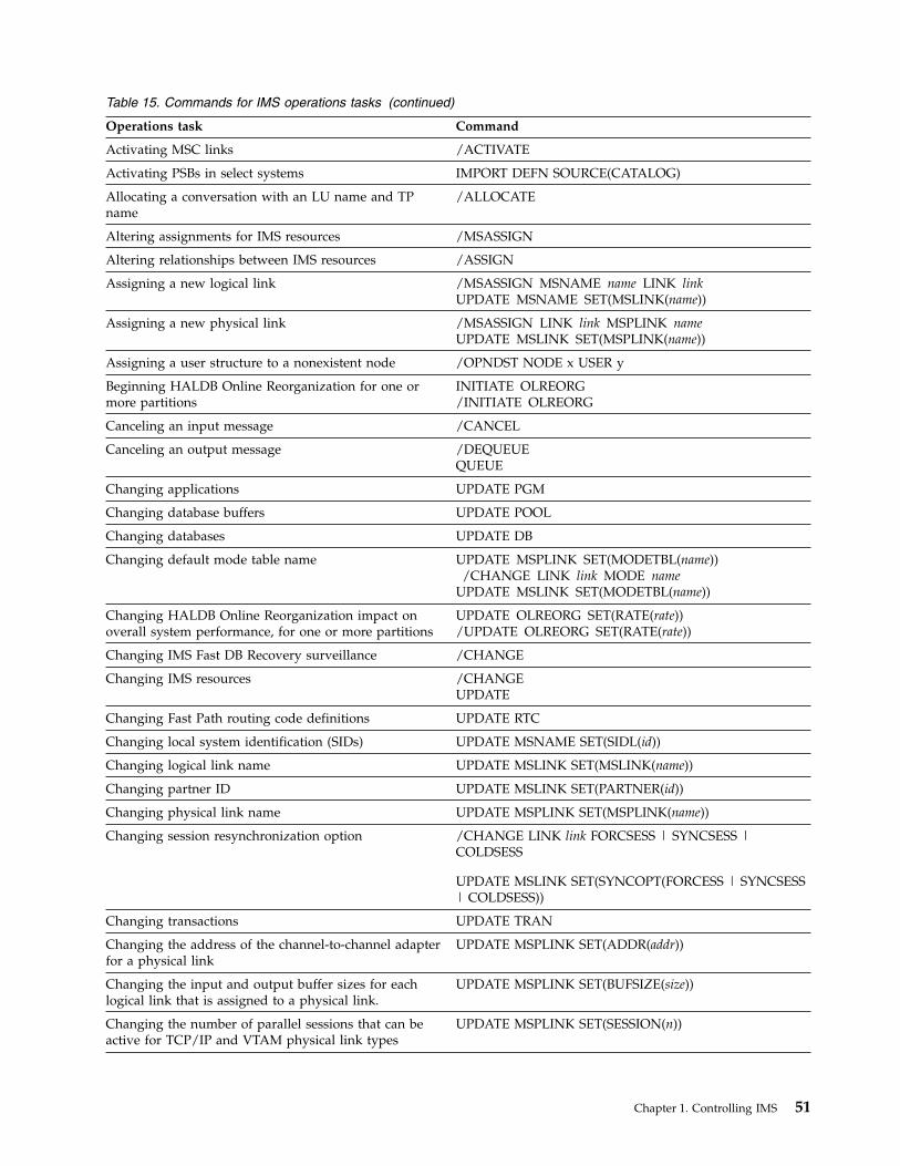
Table 15. Commands for IMS operations tasks (continued)
Operations task Command
Activating MSC links /ACTIVATE
Activating PSBs in select systems IMPORT DEFN SOURCE(CATALOG)
Allocating a conversation with an LU name and TPname
/ALLOCATE
Altering assignments for IMS resources /MSASSIGN
Altering relationships between IMS resources /ASSIGN
Assigning a new logical link /MSASSIGN MSNAME name LINK linkUPDATE MSNAME SET(MSLINK(name))
Assigning a new physical link /MSASSIGN LINK link MSPLINK nameUPDATE MSLINK SET(MSPLINK(name))
Assigning a user structure to a nonexistent node /OPNDST NODE x USER y
Beginning HALDB Online Reorganization for one ormore partitions
INITIATE OLREORG/INITIATE OLREORG
Canceling an input message /CANCEL
Canceling an output message /DEQUEUEQUEUE
Changing applications UPDATE PGM
Changing database buffers UPDATE POOL
Changing databases UPDATE DB
Changing default mode table name UPDATE MSPLINK SET(MODETBL(name))/CHANGE LINK link MODE name
UPDATE MSLINK SET(MODETBL(name))
Changing HALDB Online Reorganization impact onoverall system performance, for one or more partitions
UPDATE OLREORG SET(RATE(rate))/UPDATE OLREORG SET(RATE(rate))
Changing IMS Fast DB Recovery surveillance /CHANGE
Changing IMS resources /CHANGEUPDATE
Changing Fast Path routing code definitions UPDATE RTC
Changing local system identification (SIDs) UPDATE MSNAME SET(SIDL(id))
Changing logical link name UPDATE MSLINK SET(MSLINK(name))
Changing partner ID UPDATE MSLINK SET(PARTNER(id))
Changing physical link name UPDATE MSPLINK SET(MSPLINK(name))
Changing session resynchronization option /CHANGE LINK link FORCSESS | SYNCSESS |COLDSESS
UPDATE MSLINK SET(SYNCOPT(FORCESS | SYNCSESS| COLDSESS))
Changing transactions UPDATE TRAN
Changing the address of the channel-to-channel adapterfor a physical link
UPDATE MSPLINK SET(ADDR(addr))
Changing the input and output buffer sizes for eachlogical link that is assigned to a physical link.
UPDATE MSPLINK SET(BUFSIZE(size))
Changing the number of parallel sessions that can beactive for TCP/IP and VTAM physical link types
UPDATE MSPLINK SET(SESSION(n))
Chapter 1. Controlling IMS 51
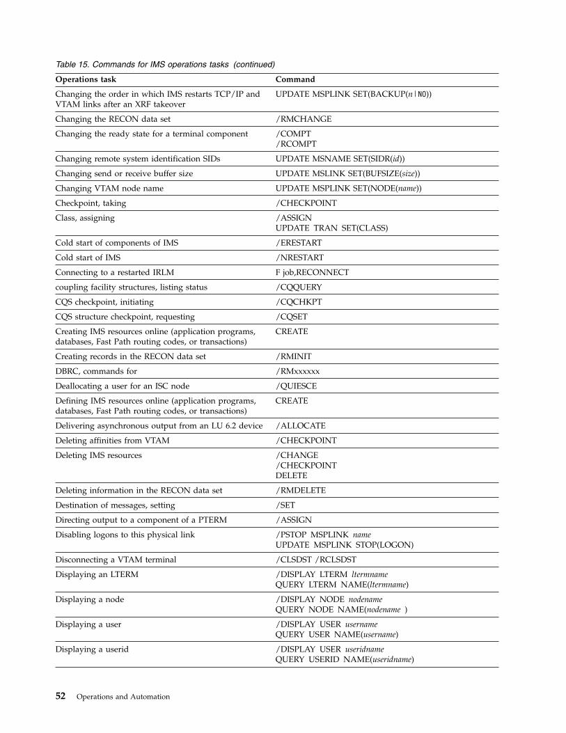
Table 15. Commands for IMS operations tasks (continued)
Operations task Command
Changing the order in which IMS restarts TCP/IP andVTAM links after an XRF takeover
UPDATE MSPLINK SET(BACKUP(n|NO))
Changing the RECON data set /RMCHANGE
Changing the ready state for a terminal component /COMPT/RCOMPT
Changing remote system identification SIDs UPDATE MSNAME SET(SIDR(id))
Changing send or receive buffer size UPDATE MSLINK SET(BUFSIZE(size))
Changing VTAM node name UPDATE MSPLINK SET(NODE(name))
Checkpoint, taking /CHECKPOINT
Class, assigning /ASSIGNUPDATE TRAN SET(CLASS)
Cold start of components of IMS /ERESTART
Cold start of IMS /NRESTART
Connecting to a restarted IRLM F job,RECONNECT
coupling facility structures, listing status /CQQUERY
CQS checkpoint, initiating /CQCHKPT
CQS structure checkpoint, requesting /CQSET
Creating IMS resources online (application programs,databases, Fast Path routing codes, or transactions)
CREATE
Creating records in the RECON data set /RMINIT
DBRC, commands for /RMxxxxxx
Deallocating a user for an ISC node /QUIESCE
Defining IMS resources online (application programs,databases, Fast Path routing codes, or transactions)
CREATE
Delivering asynchronous output from an LU 6.2 device /ALLOCATE
Deleting affinities from VTAM /CHECKPOINT
Deleting IMS resources /CHANGE/CHECKPOINTDELETE
Deleting information in the RECON data set /RMDELETE
Destination of messages, setting /SET
Directing output to a component of a PTERM /ASSIGN
Disabling logons to this physical link /PSTOP MSPLINK nameUPDATE MSPLINK STOP(LOGON)
Disconnecting a VTAM terminal /CLSDST /RCLSDST
Displaying an LTERM /DISPLAY LTERM ltermnameQUERY LTERM NAME(ltermname)
Displaying a node /DISPLAY NODE nodenameQUERY NODE NAME(nodename )
Displaying a user /DISPLAY USER usernameQUERY USER NAME(username)
Displaying a userid /DISPLAY USER useridnameQUERY USERID NAME(useridname)
52 Operations and Automation

Table 15. Commands for IMS operations tasks (continued)
Operations task Command
Displaying assigned MSLINKS /DISPLAY ASMT MSPLINK nameQUERY MSPLINK SHOW(MSLINK)QUERY MSNAME SHOW(MSLINK)
Displaying assigned MSPLINKs /DISPLAY ASMT LINK link MODEQUERY MSLINK SHOW(MSPLINK)QUERY MSNAME SHOW(MSPLINK)
Displaying assigned MSNAMEs /DISPLAY ASMT LINK linkQUERY MSLINK SHOW(MSNAME)QUERY MSPLINK SHOW(MSNAME)
Displaying bandwidth mode /DISPLAY LINK OPTION BUFSIZEQUERY MSLINK SHOW(BANDWIDTH)
Displaying buffer size /DISPLAY LINK OPTION BUFSIZEQUERY MSLINK SHOW(BUFSIZE)
Displaying CTC address /DISPLAY ASMT MSPLINK nameQUERY MSPLINK SHOW(ADDR)
Displaying database buffer pool usage statistics QUERY POOL/DISPLAY POOL DBAS
Displaying usage statistics about storage pools managedby the IMS 64-bit storage manager
QUERY POOL TYPE(STG64) NAME(name)
Displaying global queue counts /DISPLAY LINK link QCNTQUERY MSNAME SHOW(QCNT)
Displaying HALDB Online Reorganization status QUERY DB STATUS(OLR)/DISPLAY DB OLR
Displaying IMS Fast DB Recovery status F fdbrproc,STATUS
Displaying IMS resources and status /DISPLAY QUERY
Displaying IMSplex member status or attributeinformation
QUERY MEMBER
Displaying IRLM status F irlmproc,STATUS ,ALLD,ALLI ,MAINT ,STOR ,TRACE
Displaying links with specified status QUERY MSNAME STATUS(status)
Displaying MSNAMEs (logical link paths) QUERY MSNAME QCNT(condition,count)QUERY MSLINK STATUS(status)
Displaying local queue counts /DISPLAY LINK linkQUERY MSNAME SHOW(QCNT)
Displaying local and remote system IDs /DISPLAY ASMT MSNAME msnameQUERY MSNAME SHOW(SYSID)
Displaying the LTERM name of the MTO /RDISPLAYQUERY LTERM STATUS(MTO,SMTO)
Displaying maximum session count /DISPLAY ASMT MSPLINK nameQUERY MSPLINK SHOW(MSLINK)
Displaying members of the IMSplex QUERY IMSPLEX
Displaying mode table name /DISPLAY LINK link MODE [for MSC]
/DISPLAY NODE nodename MODE [for non-MSC]
QUERY MSLINK SHOW(MODETBL)
QUERY NODE SHOW(MODETBL)
Displaying MSPLINKs with specified status QUERY MSPLINK SHOW(MSNAME)
Chapter 1. Controlling IMS 53
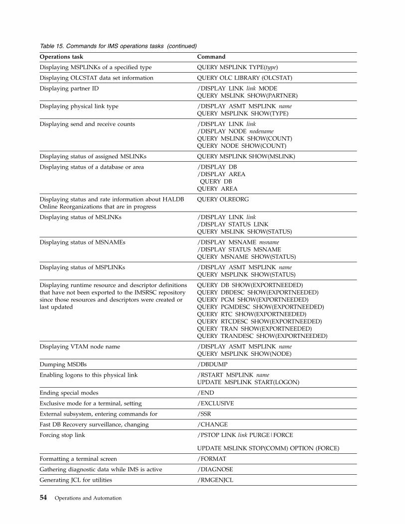
Table 15. Commands for IMS operations tasks (continued)
Operations task Command
Displaying MSPLINKs of a specified type QUERY MSPLINK TYPE(type)
Displaying OLCSTAT data set information QUERY OLC LIBRARY (OLCSTAT)
Displaying partner ID /DISPLAY LINK link MODEQUERY MSLINK SHOW(PARTNER)
Displaying physical link type /DISPLAY ASMT MSPLINK nameQUERY MSPLINK SHOW(TYPE)
Displaying send and receive counts /DISPLAY LINK link/DISPLAY NODE nodenameQUERY MSLINK SHOW(COUNT)QUERY NODE SHOW(COUNT)
Displaying status of assigned MSLINKs QUERY MSPLINK SHOW(MSLINK)
Displaying status of a database or area /DISPLAY DB/DISPLAY AREAQUERY DB
QUERY AREA
Displaying status and rate information about HALDBOnline Reorganizations that are in progress
QUERY OLREORG
Displaying status of MSLINKs /DISPLAY LINK link/DISPLAY STATUS LINKQUERY MSLINK SHOW(STATUS)
Displaying status of MSNAMEs /DISPLAY MSNAME msname/DISPLAY STATUS MSNAMEQUERY MSNAME SHOW(STATUS)
Displaying status of MSPLINKs /DISPLAY ASMT MSPLINK nameQUERY MSPLINK SHOW(STATUS)
Displaying runtime resource and descriptor definitionsthat have not been exported to the IMSRSC repositorysince those resources and descriptors were created orlast updated
QUERY DB SHOW(EXPORTNEEDED)QUERY DBDESC SHOW(EXPORTNEEDED)QUERY PGM SHOW(EXPORTNEEDED)QUERY PGMDESC SHOW(EXPORTNEEDED)QUERY RTC SHOW(EXPORTNEEDED)QUERY RTCDESC SHOW(EXPORTNEEDED)QUERY TRAN SHOW(EXPORTNEEDED)QUERY TRANDESC SHOW(EXPORTNEEDED)
Displaying VTAM node name /DISPLAY ASMT MSPLINK nameQUERY MSPLINK SHOW(NODE)
Dumping MSDBs /DBDUMP
Enabling logons to this physical link /RSTART MSPLINK nameUPDATE MSPLINK START(LOGON)
Ending special modes /END
Exclusive mode for a terminal, setting /EXCLUSIVE
External subsystem, entering commands for /SSR
Fast DB Recovery surveillance, changing /CHANGE
Forcing stop link /PSTOP LINK link PURGE|FORCE
UPDATE MSLINK STOP(COMM) OPTION (FORCE)
Formatting a terminal screen /FORMAT
Gathering diagnostic data while IMS is active /DIAGNOSE
Generating JCL for utilities /RMGENJCL
54 Operations and Automation

Table 15. Commands for IMS operations tasks (continued)
Operations task Command
IMS monitor, starting or stopping /TRACE
Initiating IMS Fast DB Recovery of tracked databases F fdbrproc,RECOVER
Initiating a session with a terminal /OPNDST
IRLM, abending F irlmproc,ABEND
IRLM, changing MAXCSA (for IRLM Version 2.1) F irlmproc,SET,CSA=nnn,TRACE=nnn
IRLM, displaying status F irlmproc,STATUS ,ALLD,ALLI ,MAINT ,STOR ,TRACE
IRLM, reconnecting to F proc, RECONNECT
IRLM, releasing locks F irlmproc,PURGE,imsname
IRLM, setting timeout value F irlmproc,START,TMOUT=nF irlmproc,STOP,TMOUT
IRLM, starting S irlmproc
IRLM, stopping P irlmproc
IRLM, tracing S irlmproc,TRACE=YES TRACE CT
ISC node shutdown /QUIESCE
ISC session cold start /ASSIGN
Language Environment® (LE) attributes and parameters,changing
UPDATE LEDELETE LE
Limiting count for a transaction, setting /ASSIGN UPDATE TRAN SET(LCT)
Listing all of the databases for which HALDB OnlineReorganizations are in progress
QUERY DB STATUS(OLR)
Listing information in the RECON data set /RMLIST
Logging off from a terminal /RCLSDST
Logging on to IMS from a VTAM terminal /OPNDST
LTERM, enqueuing messages to or dequeuing messagesfrom
QUEUE LTERM
LTERM to node, assigning /ASSIGN
LTERM to PTERM, assigning /ASSIGN
LTERM to user or ISC half session, assigning /ASSIGN
Message control error exit routine, activating /DEQUEUE
Message Format Service (MFS) format, using on aterminal
/FORMAT
MFS test mode for terminals, setting /TEST
Modifying applications /MODIFYINITIATEUPDATE PGM
Modifying databases /MODIFYINITIATEUPDATE DB
Modifying IMS resources INITIATE/MODIFYUPDATE
Modifying IMS resources globally for an IMSplex INITIATE OLC
Chapter 1. Controlling IMS 55
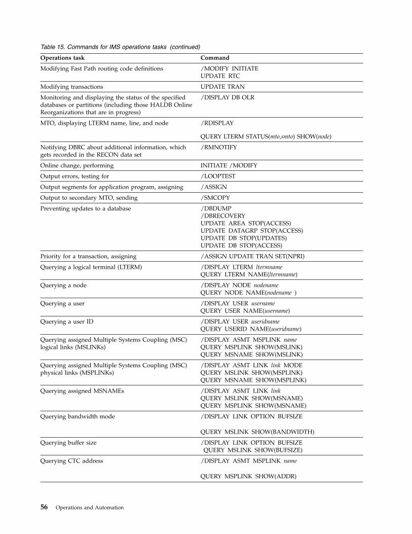
Table 15. Commands for IMS operations tasks (continued)
Operations task Command
Modifying Fast Path routing code definitions /MODIFY INITIATEUPDATE RTC
Modifying transactions UPDATE TRAN
Monitoring and displaying the status of the specifieddatabases or partitions (including those HALDB OnlineReorganizations that are in progress)
/DISPLAY DB OLR
MTO, displaying LTERM name, line, and node /RDISPLAY
QUERY LTERM STATUS(mto,smto) SHOW(node)
Notifying DBRC about additional information, whichgets recorded in the RECON data set
/RMNOTIFY
Online change, performing INITIATE /MODIFY
Output errors, testing for /LOOPTEST
Output segments for application program, assigning /ASSIGN
Output to secondary MTO, sending /SMCOPY
Preventing updates to a database /DBDUMP/DBRECOVERYUPDATE AREA STOP(ACCESS)UPDATE DATAGRP STOP(ACCESS)UPDATE DB STOP(UPDATES)UPDATE DB STOP(ACCESS)
Priority for a transaction, assigning /ASSIGN UPDATE TRAN SET(NPRI)
Querying a logical terminal (LTERM) /DISPLAY LTERM ltermnameQUERY LTERM NAME(ltermname)
Querying a node /DISPLAY NODE nodenameQUERY NODE NAME(nodename )
Querying a user /DISPLAY USER usernameQUERY USER NAME(username)
Querying a user ID /DISPLAY USER useridnameQUERY USERID NAME(useridname)
Querying assigned Multiple Systems Coupling (MSC)logical links (MSLINKs)
/DISPLAY ASMT MSPLINK nameQUERY MSPLINK SHOW(MSLINK)QUERY MSNAME SHOW(MSLINK)
Querying assigned Multiple Systems Coupling (MSC)physical links (MSPLINKs)
/DISPLAY ASMT LINK link MODEQUERY MSLINK SHOW(MSPLINK)QUERY MSNAME SHOW(MSPLINK)
Querying assigned MSNAMEs /DISPLAY ASMT LINK linkQUERY MSLINK SHOW(MSNAME)QUERY MSPLINK SHOW(MSNAME)
Querying bandwidth mode /DISPLAY LINK OPTION BUFSIZE
QUERY MSLINK SHOW(BANDWIDTH)
Querying buffer size /DISPLAY LINK OPTION BUFSIZEQUERY MSLINK SHOW(BUFSIZE)
Querying CTC address /DISPLAY ASMT MSPLINK name
QUERY MSPLINK SHOW(ADDR)
56 Operations and Automation

Table 15. Commands for IMS operations tasks (continued)
Operations task Command
Querying global queue counts /DISPLAY LINK link QCNTQUERY MSNAME SHOW(QCNT)
Querying HALDB Online Reorganization status QUERY DB STATUS(OLR)/DISPLAY DB OLR
Querying IMS Fast DB Recovery status F fdbrproc,STATUS
Querying IMS resources and status /DISPLAY QUERY
Querying IMSplex member status or attributeinformation
QUERY MEMBER
Querying IRLM status F irlmproc,STATUS ,ALLD ,ALLI ,MAINT ,STOR ,TRACE
Querying links with specified status QUERY MSNAME STATUS(status)
Querying MSNAMEs (logical link paths) QUERY MSNAME QCNT(condition,count)QUERY MSLINK STATUS(status)
Querying local queue counts /DISPLAY LINK link
QUERY MSNAME SHOW(QCNT)
Querying local and remote system IDs /DISPLAY ASMT MSNAME msnameQUERY MSNAME SHOW(SYSID)
Querying the LTERM name of the MTO /RDISPLAY
QUERY LTERM STATUS(MTO,SMTO)
Querying maximum session count /DISPLAY ASMT MSPLINK name
QUERY MSPLINK SHOW(MSLINK)
Querying members of the IMSplex QUERY IMSPLEX
Querying mode table name /DISPLAY LINK link MODE [for MSC]
/DISPLAY NODE nodename MODE [for non-MSC]
QUERY MSLINK SHOW(MODETBL)
QUERY NODE SHOW(MODETBL)
Querying MSPLINKs with specified status QUERY MSPLINK SHOW(MSNAME)
Querying MSPLINKs of a specified type QUERY MSPLINK TYPE(type)
Querying OLCSTAT data set information QUERY OLC LIBRARY (OLCSTAT)
Querying partner ID /DISPLAY LINK link MODEQUERY MSLINK SHOW(PARTNER)
Querying physical link type /DISPLAY ASMT MSPLINK name
QUERY MSPLINK SHOW(TYPE)
Querying send and receive counts /DISPLAY LINK link/DISPLAY NODE nodenameQUERY MSLINK SHOW(COUNT)QUERY NODE SHOW(COUNT)
Querying status of assigned MSLINKs QUERY MSPLINK SHOW(MSLINK)
Chapter 1. Controlling IMS 57
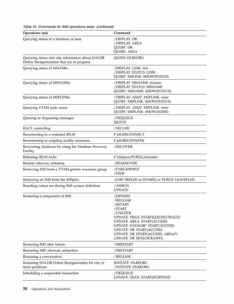
Table 15. Commands for IMS operations tasks (continued)
Operations task Command
Querying status of a database or area /DISPLAY DB/DISPLAY AREAQUERY DBQUERY AREA
Querying status and rate information about HALDBOnline Reorganizations that are in progress
QUERY OLREORG
Querying status of MSLINKs /DISPLAY LINK link/DISPLAY STATUS LINKQUERY MSLINK SHOW(STATUS)
Querying status of MSNAMEs /DISPLAY MSNAME msname/DISPLAY STATUS MSNAMEQUERY MSNAME SHOW(STATUS)
Querying status of MSPLINKs /DISPLAY ASMT MSPLINK nameQUERY MSPLINK SHOW(STATUS)
Querying VTAM node name /DISPLAY ASMT MSPLINK nameQUERY MSPLINK SHOW(NODE)
Queuing or dequeuing messages /DEQUEUEQUEUE
RACF, controlling /SECURE
Reconnecting to a restarted IRLM F job,RECONNECT
Reconnecting to coupling facility structures F job,RECONNSTR
Recovering databases by using the Database RecoveryFacility
/RECOVER
Releasing IRLM locks F irlmproc,PURGE,imsname
Remote takeover, initiating /RTAKEOVER
Removing IMS from a VTAM generic resources group /CHECKPOINT/STOP
Removing an IMS from the IMSplex /CHE FREEZE or DUMPQ or PURGE LEAVEPLEX
Resetting values set during IMS system definition /ASSIGNUPDATE
Restarting a component of IMS /OPNDST/RELEASE/RSTART/START/UNLOCKUPDATE TRAN START(Q,SCHD,TRACE)UPDATE AREA START(ACCESS)UPDATE DATAGRP START(ACCESS)UPDATE DB START(ACCESS)UPDATE DB START(ACCESS) AREA(*)UPDATE DB SET(LOCK(OFF))
Restarting IMS after failure /ERESTART
Restarting XRF alternate subsystem /ERESTART
Resuming a conversation /RELEASE
Resuming HALDB Online Reorganization for one ormore partitions
INITIATE OLREORG/INITIATE OLREORG
Scheduling a suspended transaction /DEQUEUEUPDATE TRAN START(SUSPEND)
58 Operations and Automation

Table 15. Commands for IMS operations tasks (continued)
Operations task Command
Secondary MTO, sending output to /SMCOPY
Security, controlling /SECURE
Sending messages to terminals or other IMS subsystems /BROADCAST LTERMQUEUE LTERM
Setting the RATE for a HALDB Online Reorganization INITIATE OLREORG SET(RATE(rate))/INITIATE OLREORG SET(RATE(rate))UPDATE OLREORG SET(RATE(rate))/UPDATE OLREORG SET(RATE(rate))
Setting or resetting ASR /CHANGE LINK link ASR ON|OFFUPDATE MSLINK SET(ASR(ON|OFF))UPDATE MSPLINK SET(ASR(ON|OFF))
Setting timeout value for IRLM F irlmproc,START,TMOUT=nF irlmproc,STOP,TMOUT
Sharing startup JCL between IMS dependent regions /START
Shutting down Common Queue Server (CQS) P cqsproc
Shutting down the Common Service Layer (CSL) F sciproc, SHUTDOWN CSLLCL/CSLPLEX
Shutting down IMS /CHECKPOINT
Shutting down an ISC node /QUIESCE
Shutting down Operations Manager (OM) P omjob
Shutting down Resource Manager (RM) P rmjob
Shutting down Structured Call Interface (SCI) P scijob
Signing on or off IMS terminals /SIGN
Specifying that a HALDB master is capable of beingreorganized online
INIT.DB OLRCAPCHANGE.DB OLRCAP
Specifying whether to delete the inactive data sets afterthe copying phase of a HALDB online reorganizationcompletes
UPDATE OLREORG OPTION(DEL | NODEL)
/UPDATE OLREORG OPTION(DEL | NODEL)
Specifying whether to release ownership of OLR atnormal or abnormal shutdown of IMS
UPDATE OLREORG OPTION(REL | NOREL)
/UPDATE OLREORG OPTION(REL | NOREL)
Starting bandwidth mode UPDATE MSLINK SET(BANDWIDTH(ON|OFF))
Starting Common Queue Server (CQS) S cqsproc
Starting HALDB Online Reorganization for one or morepartitions
INITIATE OLREORG/INITIATE OLREORG
Starting IMS /NRESTART/ERESTART
Starting IMS Fast DB Recovery S fdbrproc
Starting IMS resources /STARTUPDATE TRAN START(Q,SCHD,TRACE)UPDATE AREA START(ACCESS)UPDATE DATAGRP START(ACCESS)UPDATE DB START(ACCESS)UPDATE DB START(ACCESS) AREA(*)
Starting an internal trace /TRACE SET ON|OFF LINK linkUPDATE MSLINK START(TRACE)
Starting IRLM S irlmproc
Chapter 1. Controlling IMS 59
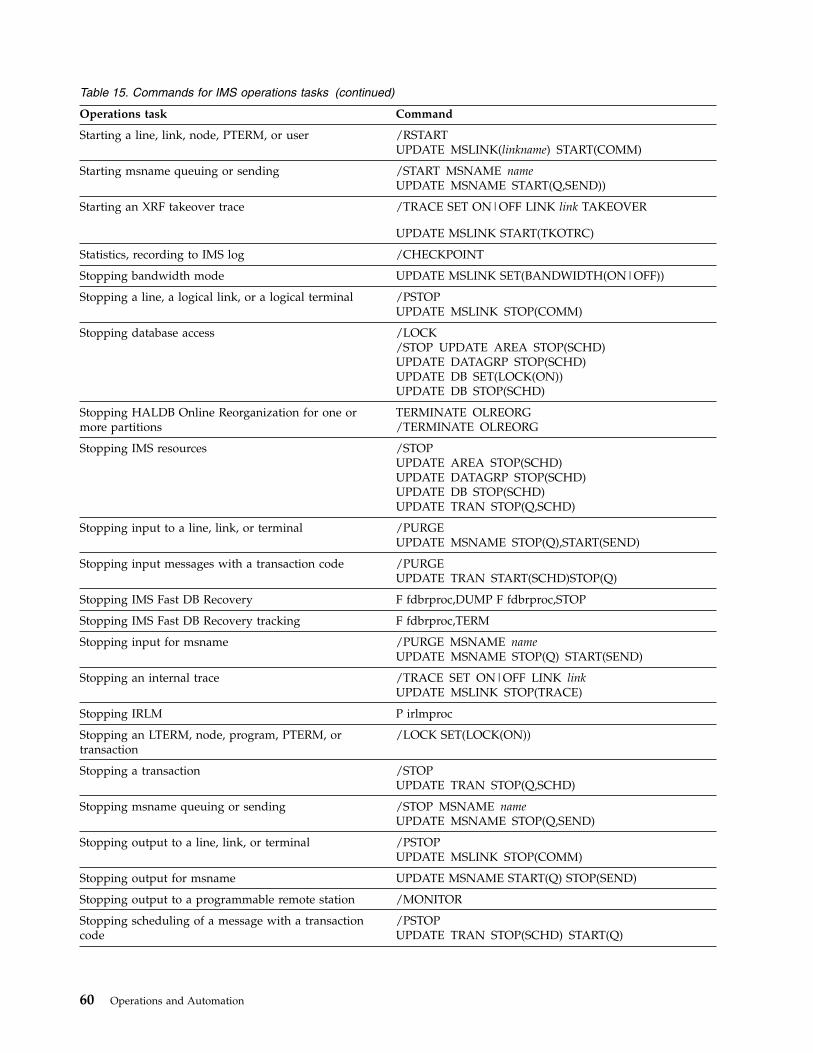
Table 15. Commands for IMS operations tasks (continued)
Operations task Command
Starting a line, link, node, PTERM, or user /RSTARTUPDATE MSLINK(linkname) START(COMM)
Starting msname queuing or sending /START MSNAME nameUPDATE MSNAME START(Q,SEND))
Starting an XRF takeover trace /TRACE SET ON|OFF LINK link TAKEOVER
UPDATE MSLINK START(TKOTRC)
Statistics, recording to IMS log /CHECKPOINT
Stopping bandwidth mode UPDATE MSLINK SET(BANDWIDTH(ON|OFF))
Stopping a line, a logical link, or a logical terminal /PSTOPUPDATE MSLINK STOP(COMM)
Stopping database access /LOCK/STOP UPDATE AREA STOP(SCHD)UPDATE DATAGRP STOP(SCHD)UPDATE DB SET(LOCK(ON))UPDATE DB STOP(SCHD)
Stopping HALDB Online Reorganization for one ormore partitions
TERMINATE OLREORG/TERMINATE OLREORG
Stopping IMS resources /STOPUPDATE AREA STOP(SCHD)UPDATE DATAGRP STOP(SCHD)UPDATE DB STOP(SCHD)UPDATE TRAN STOP(Q,SCHD)
Stopping input to a line, link, or terminal /PURGEUPDATE MSNAME STOP(Q),START(SEND)
Stopping input messages with a transaction code /PURGEUPDATE TRAN START(SCHD)STOP(Q)
Stopping IMS Fast DB Recovery F fdbrproc,DUMP F fdbrproc,STOP
Stopping IMS Fast DB Recovery tracking F fdbrproc,TERM
Stopping input for msname /PURGE MSNAME nameUPDATE MSNAME STOP(Q) START(SEND)
Stopping an internal trace /TRACE SET ON|OFF LINK linkUPDATE MSLINK STOP(TRACE)
Stopping IRLM P irlmproc
Stopping an LTERM, node, program, PTERM, ortransaction
/LOCK SET(LOCK(ON))
Stopping a transaction /STOPUPDATE TRAN STOP(Q,SCHD)
Stopping msname queuing or sending /STOP MSNAME nameUPDATE MSNAME STOP(Q,SEND)
Stopping output to a line, link, or terminal /PSTOPUPDATE MSLINK STOP(COMM)
Stopping output for msname UPDATE MSNAME START(Q) STOP(SEND)
Stopping output to a programmable remote station /MONITOR
Stopping scheduling of a message with a transactioncode
/PSTOPUPDATE TRAN STOP(SCHD) START(Q)
60 Operations and Automation

Table 15. Commands for IMS operations tasks (continued)
Operations task Command
Stopping an XRF takeover trace /TRACE SET ON|OFF LINK link TAKEOVER
UPDATE MSLINK STOP(TKOTRC)
Subsystem, external, entering commands for /SSR
Suspending a conversation /HOLD
Switching data sets for XRF /SWITCH
Terminating a conversation /EXIT
Terminating global online change on all IMS systems inan IMSplex
TERMINATE OLC
Terminating IMS without a dump F job,STOPF job,STOPxxxF job,FORCExxx
Terminating IMS with a dump F job,DUMPF job,DUMPxxx
Terminating IRLM abnormally F irlmproc,ABEND
Terminating I/O for terminals /IDLE
Terminating preset mode /RESET
Terminating special modes /END
Test mode for terminals, setting /TEST
Testing for output errors /LOOPTEST
Tracing IMS resources /TRACEUPDATE TRAN START(TRACE)UPDATE MSLINK START(TRACE)
Tracing IRLM S irlmproc,TRACE=YES TRACE CT
Transactions, enqueuing messages to or dequeuingmessages from
QUEUE TRAN
Undoing /ASSIGN /ASSIGN/NRE CHECKPOINT 0UPDATE TRAN
Undoing /EXCLUSIVE /END/START
Undoing /HOLD /RELEASE/EXIT
Undoing /IDLE /ACTIVATE
Undoing /LOCK /UNLOCKUPDATE DB SET(LOCK(OFF))
Undoing /LOOPTEST /END
Undoing /MSASSIGN /MSASSIGN/NRE CHECKPOINT 0
UPDATE MSLINK NAME(linkname)SET(MSPLINK(plinkname)
UPDATE MSNAME NAME(msname)SET(MSLINK(linkname)
Undoing /SET /RESET
Chapter 1. Controlling IMS 61

Table 15. Commands for IMS operations tasks (continued)
Operations task Command
Undoing /START, /RSTART, /PSTART, /PURGE, or/MONITOR
/STOPUPDATE
Undoing /START, /STOP, /COMPT, /RCOMPT,/PSTART, /PURGE, or /MONITOR
/RSTARTUPDATE
Undoing /START, /MONITOR, /RSTART, /STOP, or/PSTART
/PURGEUPDATE
Undoing /START, /MONITOR, /RSTART, /STOP, or/PURGE
/PSTOPUPDATE
Undoing /START, /RSTART, /STOP, /PSTOP, or/PURGE
/MONITORUPDATE
Undoing /TEST /END/START
Unloading an area from a data space /VUNLOAD
Verifying local transactions and LTERMs with remotetransactions and LTERMs
/MSVERIFY
Verifying /MSASSIGN /MSVERIFY
Warm start of IMS /NRESTART
Writing a message to the IMS log /LOG
XRF, switching data sets /SWITCH
Important: In an IMSplex, type-2 commands are issued to the OperationsManager, which then routes the commands to the subsystem IMSplex members.When commands are issued globally in an IMSplex, they can behave differentlyfrom commands that are issued to single IMS systems.Related concepts:
Restrictions for HALDB Online Reorganization (Database Administration)Related reference:
Equivalent IMS type-1 and type-2 commands (Commands)“List of commands with similar functions for multiple resources” on page 16
62 Operations and Automation
Chapter 2. Starting or restarting IMS
Starting or restarting an IMS subsystem means initializing the IMS control region.You must first restore the operating environment and the master terminal operatormust insure that critical applications, such as any dependent regions, areinitialized.
To restore the operating environment, the MTO must ensure the following are alsoinitialized:v All IRLMsv All CQSsv Any dependent regions (including utilities)v All CSL address spaces (ODBM, OM, RM, and SCI), if operating as an IMSplex
using CSLv Any connections to VTAMv All communication lines and terminals
The term MTO used in this information refers to the IMS master terminal operatorfor the DB/DC and DCCTL environments, and to the operator for the DBCTLenvironment. All commands shown assume that the command-recognitioncharacter is the forward slash (/).
Starting an IMSplexStarting an IMSplex involves starting required CSL components, such as SCI andOM, starting the IMS control regions, and starting any other optional IMSplexcomponents, such as CSL RM, CSL ODBM, IMS Connect, and so on.
The following briefly summarizes starting an IMSplex:1. Start all SCIs.2. Start all OMs.3. If using a resource structure, start CQS.4. If using RM, start all RMs.5. Start all IMS control regions with the following parameters:v CSLG= parameter specified on the control region execution or the DFSPBxxx
member of the IMS PROCLIB data set.v Parameters specified in the DFSDCxxx member of the IMS PROCLIB data set
if you do not want to use the defaults:– RCVYSTSN– RCVYFP– SRMDEF
v OCMD and CSLT parameters specified in the DFSVSMxx member of the IMSPROCLIB data set.
v Parameters specified in the DFSCGxxx member of the IMS PROCLIB dataset:– CMDSEC– IMSPLEX
© Copyright IBM Corp. 1974, 2017 63
– NORSCCC– OLC– OLCSTAT
v Appropriate parameters specified in the BPE and CQS PROCLIB memberdata sets.
6. Start any other optional IMSplex components, such as ODBM and IMSConnect.
7. If you use a SPOC, you can log on to TSO, allocate the appropriate files to theTSO user ID, and issue the DFSSPOC command from ISPF option 6.
Starting the CSLThe Common Service Layer (CSL) is consisted of multiple address spaces. The CSLis considered “started” after each of the CSL manager address spaces you requireis started.
If you are running IMS™ as an IMSplex with CSL, start the SCI, OM, and RMaddress spaces before starting the IMS control region. Start ODBM after the SCIstartup procedure is completed. You can start the CSL manager address spaces byusing the z/OS START command from a z/OS system console or by using JCL.
Initialization parameters must be defined for each address space before CSL can bestarted. To customize the parameters of a specific CSL manager address space, usethe following members of the PROCLIB data set:v CSLDIxxx, which initializes the Open Database Managerv CSLOIxxx, which initializes the Operations Managerv CSLRIxxx, which initializes the Resource Managerv CSLSIxxx, which initializes the Structured Call Interface
The parameters that are defined in the PROCLIB data set vary on the addressspace that you are customizing, but can include the IMSplex name, the addressspace name, the use of Automatic Restart Manager (ARM), and more.
For ODBM, IMS also provides a CSLDCxxx member of the IMS.PROCLIB data set,which contains parameters that define the IMS data store connections to ODBM.
ODBM, OM, RM, and SCI are initially started by running their respective startupprocedures. To run an ODBM, OM, RM, or SCI procedure, you can either issue az/OS START command or code and run JCL. ODBM, OM, RM, and SCI can berestarted using the z/OS Automatic Restart Manager (ARM). You can specify theparameter ARMRST either in the startup procedures or in the execution parametersof ODBM, OM, RM, and SCI. The default is ARMRST=Y, so if you do not specifythe parameter, all of the CSL managers try to register with ARM.
Before you can start any of the CSL components, they must be defined to the IMSsystem.
The IMS PROCLIB data set members DFSCGxxx and DFSDFxxx define how theIMS control region interacts with the CSL.Related concepts:
CSL definition and tailoring (System Definition)Related reference:
64 Operations and Automation
||||

DFSDFxxx member of the IMS PROCLIB data set (System Definition)
DFSCGxxx member of the IMS PROCLIB data set (System Definition)
Starting the CSL SCIThe system operator can start the CSL SCI in one of three ways: as a z/OS startedprocedure, as JCL, or as a started procedure in an IMS control region.
You can start SCI in the following ways:v The system operator can use a z/OS started procedure. CSLSC000, a sample
started procedure that is shipped with IMS, can be modified for yourinstallation, or you can identify your own started procedure. To start an SCIaddress space with a started procedure, issue the z/OS START command asfollows: S scijobname.scijobname is the job name of the SCI address space to bestarted.
v The system operator can submit JCL that starts the started procedure.v The IMS control region can use a started procedure in an RMENV=N
environment by using the SCIPROC parameter in the DFSCGxxx or DFSDFxxxPROCLIB member data sets. If RMENV=N is specified and there is no SCIaddress space active in the IMSplex, IMS will start the specified procedure.
Restarting the CSL SCIAfter the Structured Call Interface (SCI) is started, if it is abnormally terminated, itcan be restarted by using the z/OS Automatic Restart Manager (ARM). SCI mustcomplete initialization for ARM to restart the address space if an abend occurs. Useof ARM to restart SCI is the default.
Starting the CSL ODBMYou can start ODBM either before or after starting IMS, IMS Connect, or z/OSResource Recovery Services (RRS).
If ODBM and an IMS system are not members of the same IMSplex, ODBMautomatically connects to the IMS system only if the IMS system is started beforeODBM.
To enable ODBM to connect to the IMS system automatically regardless of theorder in which ODBM and IMS are started, use either the DFSCGxxx member ofthe IMS.PROCLIB data set or the Common Service Layer section of the DFSDFxxxPROCLIB member to define the IMS system as a member of the same IMSplex asODBM.
The options for starting ODBM include:v The system operator can use a z/OS started procedure. For example, CSLODBM,
a sample started procedure that is shipped with IMS, can be modified for yourinstallation, or you can identify your own started procedure. To start an ODBMaddress space with a started procedure, issue the z/OS START command asfollows:S odbmjobname
odbmjobname is the job name of the ODBM address space to be started.v The system operator can submit JCL that starts the started procedure.
Chapter 2. Starting or restarting IMS 65

Restarting the CSL ODBMIn the event that ODBM terminates abnormally, it can be restarted by using thez/OS Automatic Restart Manager (ARM).
ODBM must complete initialization for ARM to restart the address space if anabend occurs. Use of ARM to restart ODBM is the default.
Starting the CSL OMThe system operator can start the CSL OM three ways: using a z/OS startedprocedure, or by submitting JCL, or by using a started procedure in an IMS controlregion.
You can start OM in the following ways:v The system operator can use a z/OS started procedure. For example,
CSLOM000, a sample started procedure that is shipped with IMS, can bemodified for your installation, or you can identify your own started procedure.To start an OM address space with a started procedure, issue the z/OS STARTcommand as follows: S omjobname omjobname is the job name of the OMaddress space to be started.
v The system operator can submit JCL that starts the started procedure.v The IMS control region can use a started procedure in an RMENV=N
environment by using the OMPROC parameter in the DFSCGxxx or DFSDFxxxmember of the IMS PROCLIB data sets. If RMENV=N is specified and there isno OM address space active in the IMSplex, IMS will start the specifiedprocedure.
Restarting the CSL OMIf, after OM is started, if it is abnormally terminated, it can be restarted using thez/OS Automatic Restart Manager (ARM). OM must complete initialization forARM to restart the address space if an abend occurs. Use of ARM to restart OM isthe default.
Starting the CSL RMThe system operator can use a z/OS started procedure. CSLRM000, a samplestarted procedure that is shipped with IMS, can be modified for your installation,or you can identify your own started procedure.
You can start RM in the following ways:v To start an RM address space with a started procedure, issue the z/OS START
command as follows:S rmjobname
rmjobname is the job name of the RM address space to be started.v The system operator can submit JCL that starts the started procedure.
You can also add a resource structure to your CFRM policy.Related tasks:
Defining the CFRM policy (System Administration)
66 Operations and Automation
Restarting the CSL RMIf the resource manager (RM) terminates abnormally, it can be restarted using thez/OS Automatic Restart Manager (ARM). RM must complete initialization forARM to restart the address space if an abend occurs. Use of ARM to restart RM isthe default.
Starting and stopping the IMSRSC repositoryAn IMSRSC repository can have a status of closed, opening, open, stopping, orstopped. Start or stop a repository to make it available or unavailable for clientconnections.
CLOSEDThe repository is defined to the Repository Server (RS) and it is started, but itsassociated data sets are closed. The RS accepts client connections to therepository, but because the repository has not yet been opened and itsassociated data sets have not been allocated by the RS, you cannot write orread from the repository in this state.
If a repository remains in CLOSED state at the end of SPARE recoveryprocessing, perform the following steps to make the repository available:1. Re-allocate the discarded repository data sets.2. Issue the LIST FRPBATCH command to check if the repository is in a STOP
state. If it is not, issue the STOP FRPBATCH command to change the stateto STOP.
3. Issue the DSCHANGE FRPBATCH command to change the re-allocateddiscarded data sets back to a SPARE state.
4. Issue the START FRPBATCH command to start the repository.This resumes the data set recovery process.
OPENINGThe repository is in the process of being opened.
OPENStarted and opened. The repository is available for client connections and readand update requests.
Starting a repository makes it possible for connections to be made to it. Thefollowing functions are performed when a repository is started:v The repository becomes available for client connections.v If the repository is set with the ADD or UPDATE FRPBATCH commands to
AUTOOPEN=Y, or the repository was started with the OPEN=YES option inthe START FRPBATCH command, the RS opens the repository, readying itfor client function requests.
v If the repository is not set to open either explicitly or automatically, therepository and RS catalog repository data sets are allocated when a clientfirst connects to the repository.
STOPPINGThe repository is in the process of being stopped.
Stopping a repository has the following results:v The repository can no longer accept new client connections.v If the repository data sets are allocated, the RS tries to close and deallocate
them. The RS waits until all active client request threads are completedbefore closing and deallocating the data sets.
Chapter 2. Starting or restarting IMS 67
STOPPEDStopped and closed. The RS does not accept client connections to therepository. The repository data sets are closed and deallocated.
The start and stop state of a repository is persistent. For example, a repository thatis stopped remains stopped after the RS is restarted, regardless of the setting forthe AUTOOPEN option. The AUTOOPEN option only determines when data setsare allocated and opened if the repository is started.Related concepts:
Overview of the IMSRSC repository (System Definition)
IMSRSC repository and RS catalog repository data sets (System Definition)Related information:
Commands for FRPBATCH (System Programming APIs)
Opening the IMSRSC repositoryYou can control when an IMSRSC repository is opened with the AUTOOPENoption for the ADD or UPDATE FRPBATCH commands, or with the OPEN optionfor the START FRPBATCH command.v If the repository is set to AUTOOPEN=Y, its data sets are allocated and opened
when it starts. If the repository was in the started state when the RepositoryServer (RS) last shut down, the data sets are allocated and opened when the RSis restarted.
v If the repository is set to AUTOOPEN=N and it is started with OPEN=YES, it isopened immediately.
v If the repository is set with AUTOOPEN= N and it is not started withOPEN=YES, it is opened at the time of the first client connection.
The RS performs basic validation of IMSRSC repository data sets at open time. Arepository cannot be opened unless there is both a valid COPY1 and COPY2 of theIMSRSC repository data set.
If there is one valid copy and a valid SPARE IMSRSC repository data set,automated SPARE recovery occurs. In the SPARE recovery process, the SPAREIMSRSC repository data set is reassigned to take the place of the missing COPY1or COPY2, and its data sets are populated from the valid copy.
At the conclusion of data set validation:v The available IMSRSC repository data sets are allocated and open.v Empty data sets are identified.v All data sets have valid characteristics for their identified function as either a
repository member data set (RMD) or repository index data set (RID).v Populated data sets (with resource definitions) are considered to be valid
repository data sets.v The repository's set of data sets is known to be consistent.
If any data set fails to meet these basic requirements, an error message is issuedand the repository open process terminates.
During repository open processing, either with the AUTOOPEN option or duringthe first access, all of the repository data sets are opened using VSAM local sharedresources (LSR). As the data sets are opened using VSAM LSR, if the repository
68 Operations and Automation

data sets are empty, informational messages are issued that indicate that the datasets are empty. An informational messages received for the spare data set pairrequires no user action. The spare data set is opened to ensure that it is empty, sothat there are no errors during SPARE recovery process.
The RS closes the IMSRSC repository data sets when the repository is stopped,during the SPARE recovery process and during RS shutdown.Related concepts:
Overview of the IMSRSC repository (System Definition)
IMSRSC repository and RS catalog repository data sets (System Definition)
Recovery in an IMSplex (System Administration)Related information:
Commands for FRPBATCH (System Programming APIs)
Starting the IMSRSC repositoryTo start the IMSRSC repository, you can either use a START command issued fromthe z/OS MODIFY (F) interface or issue START FRPBATCH command.
To start the repository, do one of the following:v Issue the following command from the z/OS MODIFY (F) interface:
F reposervername,ADMIN START repositoryname
v Issue the START FRPBATCH command.Related concepts:
Overview of the IMSRSC repository (System Definition)Related reference:
F reposervername,ADMIN (Commands)
START command for FRPBATCH (System Programming APIs)
Stopping the IMSRSC repositoryTo stop the IMSRSC repository, you can either use a STOP command issued fromthe z/OS MODIFY (F) interface or issue STOP FRPBATCH command.
To stop the repository, do one of the following:v Issue the following command from the z/OS MODIFY (F) interface:
F reposervername,ADMIN STOP repositoryname
v Issue the STOP FRPBATCH command.Related concepts:
Overview of the IMSRSC repository (System Definition)Related reference:
F reposervername,ADMIN (Commands)
STOP command for FRPBATCH (System Programming APIs)
Chapter 2. Starting or restarting IMS 69
Starting and stopping the Repository ServerTo start the Repository Server (RS), submit a customized RS startup procedure. Tostop the RS, use an RS command issued from the z/OS MODIFY (F) interface.Related concepts:
Overview of the IMSRSC repository (System Definition)Related reference:
F reposervername,ADMIN (Commands)
Starting the Repository ServerTo start the Repository Server (RS), submit a customized RS startup procedure.
Perform the following procedure:1. Make sure that you have performed system definition for the IMSRSC
repository.2. Customize the following startup procedure:
//FRP12A PROC RGN=0M,SOUT=A,//*//IEFPROC EXEC PGM=BPEINI00,REGION=0M,// PARM=’BPEINIT=FRPINI00,BPECFG=BPECONFG,FRPCFG=FRPCONFG’//*//STEPLIB DD DSN=RESLIB_dataset_name,DISP=SHR//*//PROCLIB DD DSN=PROCLIB_dataset_name,DISP=SHR//*//FRPPRINT DD SYSOUT=&SOUT//SYSPRINT DD SYSOUT=&SOUT//SYSUDUMP DD SYSOUT=&SOUT//*
Make sure that the values specified in this JCL for the BPECFG= and FRPCFG=parameters match the values specified in the FRP and BPE configurationmembers of the IMS PROCLIB data set.
3. Submit the RS startup procedure.
If the RS is started successfully as the active RS, then the FRP2002I message isissued.
If another RS is already started in the same z/OS cross-system coupling facilitygroup, a FRP2001I message is issued, indicating that the subordinate RS is started.
During startup of both the active and subordinate RS, the FRP2006I message isissued.
When the RS has started successfully and is ready to accept client connections, theFRP2025I message is issued.Related concepts:
Overview of the IMSRSC repository (System Definition)Related tasks:“Starting the Repository Server”
Defining the IMSRSC repository (System Definition)“Cold starting an IMS system that uses the IMSRSC repository” on page 77Related reference:
70 Operations and Automation

FRPCFG member of the IMS PROCLIB data set (System Definition)
BPE configuration parameter member of the IMS PROCLIB data set (System
Definition)
FRP messages (Repository Server) (Messages and Codes)Related information:
FRP2002I (Messages and Codes)
FRP2001I (Messages and Codes)
FRP2006I (Messages and Codes)
FRP2025I (Messages and Codes)
Starting subordinate Repository ServersTo start a Repository Server (RS) as a subordinate, you only need to define it withthe same z/OS cross-system coupling facility group as an RS that is alreadyrunning.
However, all parameters in the FRPCFG member for both the master RS and itssubordinates should be the same, except for the RSNAME= parameter. RSNAME=should be unique for each RS, including the master RS and its subordinates.RSNAME= is used to register to the Structured Call Interface (SCI) if IMSPLEX() isspecified. SCI requires unique names for the clients.
Make sure that the subordinate RSs use the same RS catalog repository data sets asthe master RS.Related concepts:
Overview of the IMSRSC repository (System Definition)
Recovery in an IMSplex (System Administration)
Stopping the Repository ServerTo stop the Repository Server (RS), you can use an RS command issued from thez/OS MODIFY (F) interface.
To stop the RS, issue the following command from the z/OS MODIFY (F) interface:F reposervername,SHUTDOWN
To stop all the RS address spaces, issue the following command from the z/OSMODIFY (F) interface. The command can be directed to a master RS or subordinateRS:F reposervername,SHUTDOWN ALL
You can also stop the RS by issuing the z/OS STOP (P) command.Related concepts:
Overview of the IMSRSC repository (System Definition)Related tasks:“Starting the Repository Server” on page 70Related reference:
F reposervername,SHUTDOWN (Commands)
Chapter 2. Starting or restarting IMS 71
How to start the IMS control regionYou usually start the IMS control region with a z/OS START command from az/OS system console.
If, depending on the size of your installation, you have an alternate system consolefor the IMS MTO, be sure the z/OS system operator relays all IMS messages (thatis, those beginning with BPE, CQS, DFS, DSP, and DXR) to the IMS MTO.
If the z/OS system console is physically separate from the IMS MTO, you shouldhave a local telephone or paging line to enable communication between the z/OSoperator and the IMS MTO. The MTO should also have easy access to theoperators responsible for DASD and tape units.
When the IMS control region is started, IMS issues two DFS1929I messages.Message DFS1929I lists the system parameters and their values defined for the IMSsystem. This information will help you understand the configuration of a particularsystem. Understanding the configuration will be helpful in diagnosing problems.The system parameters are also listed in the job log.
IMS issues message DFS1929I once during initialization and again when restartcompletes. The first DFS1929I message reflects the system parameter values that aredefined in the DFSPBxxx PROCLIB member. The second DFS1929I message reflectsthe system parameter values that are actually in effect for the current execution ofIMS.
For online IMS systems, the control region automatically starts the DBRC addressspace. If you are running an IMS DB/DC or DBCTL environment, you can specifyLSO=S as an EXEC parameter for the control region to start the DL/I address space.The following rules apply:v IMS initialization waits until there is a separate address space available for
DBRC.v You can start DBRC manually (if, for example, a JCL error prevented DBRC from
starting).v When you restart IMS, you can change the specification of LSO=; IMS does not
use any prior specifications.
After the control region has started, the MTO enters an IMS command to start thesystem. Select one of three ways of starting IMS:1. Cold start2. Warm start (also referred to as normal restart)3. Emergency restart
Your operating procedures should include guidelines for the MTO in selecting theright type of startup.
You can alternatively use automatic restart instead of having the MTO enter anIMS command to restart the system. Specify AUTO=Y in the control region JCL torequest automatic restart. IMS selects a suitable checkpoint for restart and notifiesthe MTO. You cannot use automatic restart if you:v Want to perform a cold startv Need to specify any options on the restart command (such as formatting system
data sets, changing security options, or restarting only one portion of a DB/DCsystem)
72 Operations and Automation

v Need to override DBRC after a failure in which DBRC is unable to mark thesubsystem record in the RECON data set as abnormally terminated, such as inthe case of a power, CPC, z/OS, or DBRC failure
Setting the z/OS TOD clockThe z/OS time-of-day (TOD) clock setting is critical to the integrity of the IMS log.The TOD clock is also critical to the proper functioning of IMS restart, data sharingand XRF tracking and takeover.
Recommendations: Use one of the following procedures:v Use an External Time Reference (ETR) device. Be sure to set it to use Universal
Coordinated Time (also known as Greenwich Mean Time) with the appropriateoffset for your local time zone.
v Set the z/OS TOD clock during IPL using Universal Coordinated Time, then setthe local time.
Attention: During IPL, do not set the TOD clock to a time and date earlier thanthe immediate prior shutdown or failure. Setting the TOD clock back has severeIMS database integrity and recovery implications. If you do set the TOD clockback, you must reallocate the OLDSs using a different block size, reinitialize theDBRC RECON data sets, take image copies of all DBDSs, and cold start IMS.
Considerations for setting local time
Set your system's time zone offset (the difference between local time and UniversalCoordinated Time (UTC)) to an integer multiple of 15 minutes. This is consistentwith world time zone definitions and ensures that the local time reported by IMSmatches the local time reported by the operating system.
IMS will function properly even if the time zone offset is not a multiple of 15minutes. However, due to the way IMS stores time values internally, not followingthis recommendation might result in IMS reporting a local time that is inconsistentwith the local time reported by the operating system.
More about IMS time stamps and setting the time zone offset
IMS stores all date/time stamps internally as 12 bytes in the followingpacked-decimal format:YYYYDDDF HHMMSSth mijuAQQ$
The date and time fields (YYYYDDDF and HHMSSthmiju) are in Universal CoordinatedTime (UTC). The A field consists of 4 bits of flags used internally by IMS. The QQ$field contains the signed packed-decimal local time zone offset for when the timestamp was created. To get the local time, IMS adds the time zone offset—stored inquarter hours (fifteen-minute intervals)—to the UTC stamp. For example, the timestamp:2000353F 06420588 4242032D
represents the UTC date and time of:06:42:05.884242 on day 353 of 2000 (December 18th)
The QQ$ field of this time stamp is 32D, which represents a local time zone offset ofminus 32 quarter hours (or minus 8 hours west of Greenwich). Thus, the local timerepresented by this time stamp is:
Chapter 2. Starting or restarting IMS 73

22:42:05.884242 on day 352 of 2000 (December 17th)
This format allows IMS internal time stamps to encode both the UTC time (toprovide an always-incrementing time that is not subject to daylight savings timechanges), and local time (to determine the “wall-clock” time for when the timestamp was generated). If your time zone offset is set to a multiple of fifteenminutes, IMS can accurately use the offset to convert from the UTC stored in the12-byte time stamp into the local time.
In this example, the local time will be consistent with the time reported by theoperating system. However, if your time zone offset is not set to a multiple offifteen minutes, the local time derived from this conversion will not be consistentwith the time reported by the operating system.
In the following example, the time zone offset is set to +01:55 (one hour andfifty-five minutes east of Greenwich). A time stamp is generated at 15:00:00.000000UTC time (16:55:00.000000 local time, using the current time zone offset setting).IMS will construct an internal time stamp of:2001240F 15000000 0000008C
The encoded time zone offset is 8C, or +8 quarter hours (2 hours). Because IMScannot store a time zone offset with a precision greater than fifteen minutes, itrounds to the nearest fifteen minute boundary.
When this time stamp is converted back into local time, IMS reports a time of17:00:00.000000, not 16:55:00.000000. This does not cause problems for IMS, whichuses the more accurate UTC form of the time stamp internally. However, you willnotice this rounding effect when you compare IMS-generated local times to thecurrent operating system time. For example, if you issue an IMS checkpointcommand on the system described above, the DFS058I message will indicate twodifferent times, as shown below:16:55:00 DFS058I 17:00:00 CHECKPOINT COMMAND IN PROGRESS
The first time value (16:55) is returned by the operating system; this value isgenerated by using the z/OS time zone offset of +01:55. The second time value(17:00) is returned by IMS; this value is generated from an internal IMS time stampthat uses a time zone offset of +08 quarter hours (2 hours).
This behavior may also be encountered by application programs that compare thelocal time stamp in the I/O PCB with the value returned from the z/OS TIMEmacro. The I/O PCB local time represents the time when the message was receivedby IMS. The data in this time field is derived from an internal IMS 12-byte timestamp stored with the message.
In the following example, a message is received by IMS at 12:42 UTC on thesystem described above. The local time is 14:37, based on the z/OS time zoneoffset of +01:55. However, the time presented to the application by IMS in the I/OPCB local time field is 14:42, due to the rounding of the time zone offset.
Now, suppose the message is scheduled at 12:43 UTC, one minute after it arrived.If the application program issues a z/OS TIME macro request, it will receive backa local time of 14:38. If the application were to compare this time to the I/O PCBtime, it would appear as if the message was being processed before it wasenqueued (enqueue time = 14:42; process time = 14:38). This is only a problem foran application program if it compares the I/O PCB time to a time generated froman operating system time service.
74 Operations and Automation

Related tasks:“Setting or changing local time”Related reference:
z/OS: External time reference (ETR)
Setting or changing local timeYou can reset local time whenever necessary, for example when changing fromstandard time to daylight savings (or summer) time.1. To set or change the local time, edit the CLOCKxx member (the TIMEZONE
keyword) of the SYS1.PARMLIB data set to set the current offset for local time.2. If you have an ETR device, use it to set and change the time zone offset. If you
do not have an ETR device, complete one of the following steps to set orchange the local time:
Option Description
Use the SET CLOCK command to set thetime zone offset.
Using the SET CLOCK command does notallow you to set a precise value for yoursystem's time zone offset. Consequently,using this method might cause IMS to reporta local time that is inconsistent with the localtime reported by the operating system.
Re-IPL your system with the updatedCLOCKxx member.
Your time zone offset is set to the precisevalue specified in the member.
Related concepts:“Setting the z/OS TOD clock” on page 73
Cold starting IMS in a non-shared queues environmentYou perform a cold start when starting IMS for the first time, or after changing thenucleus in a system definition. IMS never uses information from a previousshutdown as input to a cold start.
In a nonshared-queues environment, a cold start assumes empty message queues,so IMS discards any messages that exist. You must close the last OLDS used by theonline system before you attempt a cold start. You should also archive the lastOLDS before a cold start, so the OLDS is available if a database recovery isrequired.
Cold starting IMS in a shared-queues environmentYou perform a cold start when starting IMS for the first time, or after changing thenucleus in a system definition. IMS never uses information from a previousshutdown as input to a cold start.
In a shared-queues environment, IMS does not discard messages on shared queues.If you want to discard messages on shared queues, you must scratch theshared-queue structures on the coupling facility, and scratch and reallocate theCQS structure recovery data sets.
Cold starting IMS with dynamic resource definitionYou perform a cold start when starting IMS for the first time, or after changing thenucleus in a system definition. IMS never uses information from a previousshutdown as input to a cold start.
Chapter 2. Starting or restarting IMS 75

During a cold start, resource and descriptor definitions are automatically importedfrom the IMSRSC repository, resource definition data set (RDDS), or the MODBLKSdata set, or IMS comes up with no resources.
During a cold start, the partition status or access state will be copied from theHALDB master. If you export the HALDB master status to the RDDS or therepository, the status of the master and its partitions will be obtained from theRDDS or the repository.
Automatic import of resource and descriptor definitions is defined through theAUTOIMPORT parameter in the DYNAMIC_RESOURCES section of theDFSDFxxx member of the IMS PROCLIB data set
If AUTOIMPORT=AUTO is specified, these conditions determine the source of theimported resource and descriptor definitions:
If all of the following conditions are true, automatic import from the IMSRSCrepository is enabled:v For MODBLKS resources, MODBLKS=DYN is specified to enable MODBLKS
DRD in IMS.v For MSC resources, the MSC section of the DFSDFxxx member of the IMS
PROCLIB data set is defined with MSCRSCS=DYN to enable MSC DRD in IMS.v For MSC resources, the MSC section of the DFSDFxxx member is defined with
MSCREPO=Y to enable MSC resources to be stored in the IMSRSC repository.v The REPOSITORY section of the DFSDFxxx member is defined with
TYPE=IMSRSC.v IMS is enabled with RM services (RMENV=N is not specified in the DFSCGxxx
member of the IMS PROCLIB data set or in the CSL section of the DFSDFxxxmember of the IMS PROCLIB data set)
v The CSLRIxxx member of the IMS PROCLIB data set is defined for therepository with TYPE=IMSRSC.
v The repository contains stored resource definitions for the IMS system.v RM is started with the repository enabled.v The RS address space is started and available.
If all of the following conditions are true, automatic import from an RDDS isenabled:v MODBLKS=DYN is specified to enable DRD in IMS.v The REPOSITORY section of the DFSDFxxx member of the IMS PROCLIB data
set is not present.v Two or more system RDDSs are defined in the RDDSDSN() parameter of the
DFSDFxxx member of the IMS PROCLIB data set.v All of the defined RDDSs can be allocated and read.v At least one of the RDDSs contains valid resource and descriptor definitions.Related concepts:
Overview of the IMSRSC repository (System Definition)Related reference:
DFSDFxxx member of the IMS PROCLIB data set (System Definition)
76 Operations and Automation
Cold starting an IMS system that uses an RDDSIMS systems that use dynamic resource definition to manage application programs,databases, Fast Path routing codes, and transactions can save resource definitionsto a resource definition data set. During a cold start, IMS can use the definitionsfrom the MODBLKS data set or the resource definition data set (RDDS) to createruntime resource definitions.
If your IMS system is not configured to import the resource definitionsautomatically at cold start, you can issue the IMPORT command after the restartprocess is complete. The IMPORT command, as well as all of the other type-2dynamic resource definition commands, requires that the SCI and OM CSLcomponents be started.
You can successfully start an IMS for the first time with DRD enabled and noresources defined yet. After the restart process completes, you can define resourcesdynamically by using the appropriate CREATE commands.
Before you shut down a running IMS system that uses dynamic resource definitionfor a cold start, you must export the resource and descriptor definitions that arecurrently defined in your online system to the RDDS. If you do not, any changesmade to the resource definitions in the online system will be lost at the next coldstart or emergency restart with the COLDSYS parameter.
During a cold start, the partition status or access state will be copied from theHALDB master. If you export the HALDB master status to the RDDS or therepository, the status of the master and its partitions will be obtained from theRDDS or the repository.
If an error occurs while trying to access an RDDS during the automatic importprocess, automatic import terminates abnormally. IMS either continues with thecold start process without any runtime resource definitions defined, or IMS stopsthe cold start process. If an error occurs during automatic import processingbecause of an invalid resource or descriptor definition, one of the followingsituations occurs:v Automatic import processing terminates abnormally, and IMS cold start
terminates abnormally with a U3397 abend.v Automatic import processing continues, and the resource in error is marked and
given a not-initiated status (NOTINIT).
The action IMS takes depends on the values specified for the RDDSERR and theIMPORTERR parameters in the DFSDFxxx member of the IMS PROCLIB data set.Related concepts:
Overview of the IMSRSC repository (System Definition)Related tasks:
Backing out DRD command-related changes made to your online system(System Definition)
Cold starting an IMS system that uses the IMSRSC repositoryIf IMS is using the IMSRSC repository, and AUTOIMPORT=AUTO or REPO isdefined in the DYNAMIC_RESOURCES section of the DFSDFxxx member of theIMS PROCLIB data set, the stored resource definitions are read from the repositoryduring IMS cold start if the repository contains the resource definitions for the IMSthat is cold starting.
Chapter 2. Starting or restarting IMS 77
During a cold start, the partition status or access state will be copied from theHALDB master. If you export the HALDB master status to the RDDS or therepository, the status of the master and its partitions will be obtained from theRDDS or the repository.
The stored resource definitions from the repository are used to create the runtimeresource definitions in the IMS system that is cold starting.
An IMS resource list in the repository is used during an IMS cold start to identifyall the resource and descriptor definitions that are to be imported during the coldstart.
The DFS3395I message is issued, indicating that the stored resource definitions areautomatically imported from the repository. The DFS3396I message with a returncode is issued when the automatic import from the repository is completed.
An RM error trying to read the stored resource definitions from repository resultsin the DFS4401E message with the RM return and reason code.
If REPOERR=ABORT is specified in the DFSDFxxx member, IMS terminates with a3368 abend. The DFS3397E message with a return code of 16 is issued before theabend.
If REPOERR=NOIMPORT is specified in the DFSDFxxx member, IMS continuesprocessing with no resources imported.
If there are no resource definitions in the repository for the IMS, the storedresource definitions from the resource definition data set (RDDS), MODBLKS dataset, or the DFSCLL3x member of the IMS.SDFSRESL data set are read ifAUTOIMPORT=AUTO is specified. If the RDDS, MODBLKS data set, or theIMS.SDFSRESL DFSCLL3x member is not defined or is empty, orAUTOIMPORT=REPO is specified, IMS will come up with no resources.
If there are no resources for the IMS in the repository, IMS issues the DFS4405Wmessage, which indicates that the repository is empty.
If an RDDS was created by the Create RDDS from Log Records utility (DFSURCL0)to hold any new or modified resources that were not exported to the IMSRSCrepository before IMS was shut down, you can either specify that RDDS on theIMPORT command after IMS cold starts from the IMSRSC repository, or use thatRDDS as input to the CSLURP10 utility.
At the end of cold start processing, if IMS is not defined withAUTOEXPORT=AUTO or REPO, you must issue the EXPORT DEFNTARGET(REPO) command to export the runtime MODBLKS resource definitionsimported from the RDDS or MODBLKS data set to the IMSRSC repository. If IMShas AUTOEXPORT=AUTO or REPO specified, it automatically exports anyruntime resource definition imported from the RDDS, MODBLKS data set, or theIMS.SDFSRESL DFSCLL3x member to the repository at the end of the restartcheckpoint.
If one exists, the change list in the repository for the IMS that is cold starting isdeleted at the end of IMS cold start.Related concepts:
Overview of the IMSRSC repository (System Definition)
78 Operations and Automation

Resource lists for the IMSRSC repository (System Definition)
Related tasks:“Recovering IMSRSC repository data sets when no IMS systems or RM systems areactive” on page 42Related reference:
DFSDFxxx member of the IMS PROCLIB data set (System Definition)
Create RDDS from Log Records utility (DFSURCL0) (System Utilities)
EXPORT command (Commands)Related information:
DFS4404I (Messages and Codes)
DFS3395I (Messages and Codes)
DFS3396I (Messages and Codes)
DFS4401E (Messages and Codes)
DFS3397E (Messages and Codes)
DFS4405W (Messages and Codes)
DFS3374W (Messages and Codes)
Warm starting IMS (or normal restart)A warm start (or normal restart) is the most common way of initializing IMS, andis also the recommended way of restarting IMS after a controlled shutdown.
Use the /NRESTART command to perform a warm start or a normal restart. You canuse the FORMAT parameter to format various system data sets (something youmight want to do if you have reallocated any of the data sets). If you are runningan IMS DB/DC or DCCTL environment, and you request reformatting of any ofthe message queue data sets, you must specify BLDQ on the /NRESTARTcommand if IMS was previously shut down with either the DUMPQ or PURGEkeyword specified.
If the MTO needs to dequeue transactions after a warm start, use the /DEQUEUESUSPEND command.
If you want to reload MSDBs during restart, use the MSDBLOAD keyword on the/NRESTART command.
If IMS is enabled to use the IMSRSC repository, IMS calls Resource Manager (RM)during warm start to read the change list, if one exists, for the IMS. The IMSchange list is maintained by RM and is built if the IMPORT command with theSCOPE(ALL) keyword is issued while the IMS is down.
If a change list exists for the IMS that is being restarted, the database, program,transaction, and routing code resources and descriptors in the IMS change list andthat apply to the IMS environment are quiesced and are not available for use untilthe stored resource definitions are imported from the repository.
After the IMS log is processed, IMS imports the stored resource definitions fromthe repository for the database, program, transaction, and routing code resources
Chapter 2. Starting or restarting IMS 79
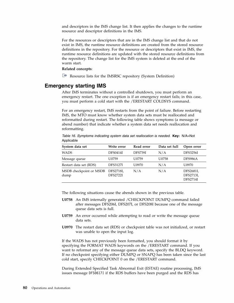
and descriptors in the IMS change list. It then applies the changes to the runtimeresource and descriptor definitions in the IMS.
For the resources or descriptors that are in the IMS change list and that do notexist in IMS, the runtime resource definitions are created from the stored resourcedefinitions in the repository. For the resource or descriptors that exist in IMS, theruntime resource definitions are updated with the stored resource definitions fromthe repository. The change list for the IMS system is deleted at the end of thewarm start.Related concepts:
Resource lists for the IMSRSC repository (System Definition)
Emergency starting IMSAfter IMS terminates without a controlled shutdown, you must perform anemergency restart. The one exception is if an emergency restart fails; in this case,you must perform a cold start with the /ERESTART COLDSYS command.
For an emergency restart, IMS restarts from the point of failure. Before restartingIMS, the MTO must know whether system data sets must be reallocated andreformatted during restart. The following table shows symptoms (a message orabend number) that indicate whether a system data set needs reallocation andreformatting.
Table 16. Symptoms indicating system data set reallocation is needed. Key: N/A=NotApplicable
System data set Write error Read error Data set full Open error
WADS DFS0414I DFS739I N/A DFS3256I
Message queue U0759 U0759 U0758 DFS986A
Restart data set (RDS) DFS3127I U0970 N/A U0970
MSDB checkpoint or MSDBdump
DFS2718I,DFS2722I
N/A N/A DFS2681I,DFS2713I,DFS2714I
The following situations cause the abends shown in the previous table.
U0758 An IMS internally generated /CHECKPOINT DUMPQ command failedafter messages DFS206I, DFS207I, or DFS208I because one of the messagequeue data sets is full.
U0759 An error occurred while attempting to read or write the message queuedata sets.
U0970 The restart data set (RDS) or checkpoint table was not initialized, or restartwas unable to open the input log.
If the WADS has not previously been formatted, you should format it byspecifying the FORMAT WADS keywords on the /ERESTART command. If youwant to reformat any of the message queue data sets, specify the BLDQ keyword.If no checkpoint specifying either DUMPQ or SNAPQ has been taken since the lastcold start, specify CHECKPOINT 0 on the /ERESTART command.
During Extended Specified Task Abnormal Exit (ESTAE) routine processing, IMSissues message DFS0617I if the RDS buffers have been purged and the RDS has
80 Operations and Automation
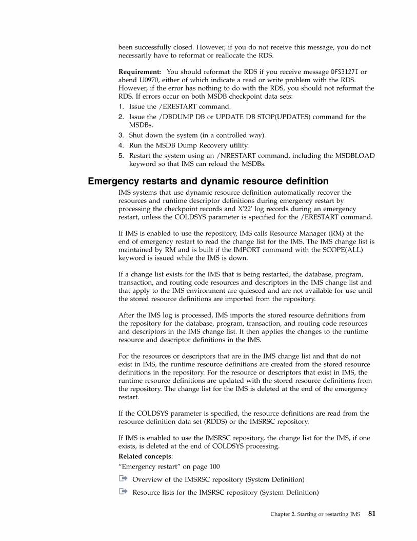
been successfully closed. However, if you do not receive this message, you do notnecessarily have to reformat or reallocate the RDS.
Requirement: You should reformat the RDS if you receive message DFS3127I orabend U0970, either of which indicate a read or write problem with the RDS.However, if the error has nothing to do with the RDS, you should not reformat theRDS. If errors occur on both MSDB checkpoint data sets:1. Issue the /ERESTART command.2. Issue the /DBDUMP DB or UPDATE DB STOP(UPDATES) command for the
MSDBs.3. Shut down the system (in a controlled way).4. Run the MSDB Dump Recovery utility.5. Restart the system using an /NRESTART command, including the MSDBLOAD
keyword so that IMS can reload the MSDBs.
Emergency restarts and dynamic resource definitionIMS systems that use dynamic resource definition automatically recover theresources and runtime descriptor definitions during emergency restart byprocessing the checkpoint records and X'22' log records during an emergencyrestart, unless the COLDSYS parameter is specified for the /ERESTART command.
If IMS is enabled to use the repository, IMS calls Resource Manager (RM) at theend of emergency restart to read the change list for the IMS. The IMS change list ismaintained by RM and is built if the IMPORT command with the SCOPE(ALL)keyword is issued while the IMS is down.
If a change list exists for the IMS that is being restarted, the database, program,transaction, and routing code resources and descriptors in the IMS change list andthat apply to the IMS environment are quiesced and are not available for use untilthe stored resource definitions are imported from the repository.
After the IMS log is processed, IMS imports the stored resource definitions fromthe repository for the database, program, transaction, and routing code resourcesand descriptors in the IMS change list. It then applies the changes to the runtimeresource and descriptor definitions in the IMS.
For the resources or descriptors that are in the IMS change list and that do notexist in IMS, the runtime resource definitions are created from the stored resourcedefinitions in the repository. For the resource or descriptors that exist in IMS, theruntime resource definitions are updated with the stored resource definitions fromthe repository. The change list for the IMS is deleted at the end of the emergencyrestart.
If the COLDSYS parameter is specified, the resource definitions are read from theresource definition data set (RDDS) or the IMSRSC repository.
If IMS is enabled to use the IMSRSC repository, the change list for the IMS, if oneexists, is deleted at the end of COLDSYS processing.Related concepts:“Emergency restart” on page 100
Overview of the IMSRSC repository (System Definition)
Resource lists for the IMSRSC repository (System Definition)
Chapter 2. Starting or restarting IMS 81
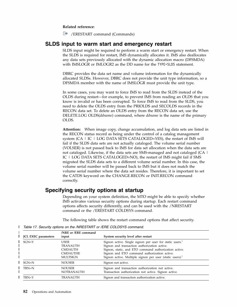
Related reference:
/ERESTART command (Commands)
SLDS input to warm start and emergency restartSLDS input might be required to perform a warm start or emergency restart. Whenthe SLDS is required for restart, IMS dynamically allocates it. IMS also deallocatesany data sets previously allocated with the dynamic allocation macro (DFSMDA)with IMSLOGR or IMLOGR2 as the DD name for the TYPE=SLDS statement.
DBRC provides the data set name and volume information for the dynamicallyallocated SLDSs. However, DBRC does not provide the unit type information, so aDFSMDA member with the name of IMSLOGR must provide the unit type.
In some cases, you may want to force IMS to read from the SLDS instead of theOLDS during restart—for example, to prevent IMS from reading an OLDS that youknow is invalid or has been corrupted. To force IMS to read from the SLDS, youneed to delete the OLDS entry from the PRIOLDS and SECOLDS records in theRECON data set. To delete an OLDS entry from the RECON data set, use theDELETE.LOG OLDS(ddname) command, where ddname is the name of the primaryOLDS.
Attention: When image copy, change accumulation, and log data sets are listed inthe RECON status record as being under the control of a catalog managementsystem (CA | IC | LOG DATA SETS CATALOGED=YES), the restart of IMS willfail if the SLDS data sets are not actually cataloged. The volume serial number(VOLSER) is not passed back to IMS for data set allocation when the data sets arenot cataloged. Likewise, if the data sets are SMS-managed and not cataloged (CA |IC | LOG DATA SETS CATALOGED=NO), the restart of IMS might fail if SMSmigrated the SLDS data sets to a different volume serial number. In this case, thevolume serial number will be passed back to IMS but it does not match thevolume serial number where the data set resides. Therefore, it is important to setthe CATDS keyword on the CHANGE.RECON or INIT.RECON commandcorrectly.
Specifying security options at startupDepending on your system definition, the MTO might be able to specify whetherIMS activates various security options during startup. Each restart commandoptions affects security differently, and can be used with the /NRESTARTcommand or the /ERESTART COLDSYS command.
The following table shows the restart command options that affect security.
Table 17. Security options on the /NRESTART or /ERE COLDSYS command.
JCL EXEC parameters/NRE or /ERE commandinput System security level after restart
SGN=Y USERTRANAUTHCMDAUTHCMDAUTHEMULTSIGN
Signon active. Single signon per user for static users.1
Signon and transaction authorization active.Signon, static, and ETO command authorization active.Signon and ETO command authorization active.Signon active. Multiple signon per user (static users).1
SGN=N NOUSER Signon not active.
TRN=N NOUSERNOTRANAUTH
Signon and transaction authorization not active.Transaction authorization not active. Signon active.
TRN=Y TRANAUTH Signon and transaction authorization active.
82 Operations and Automation
||
||||
||||||
|||||
|||
|||||
|||
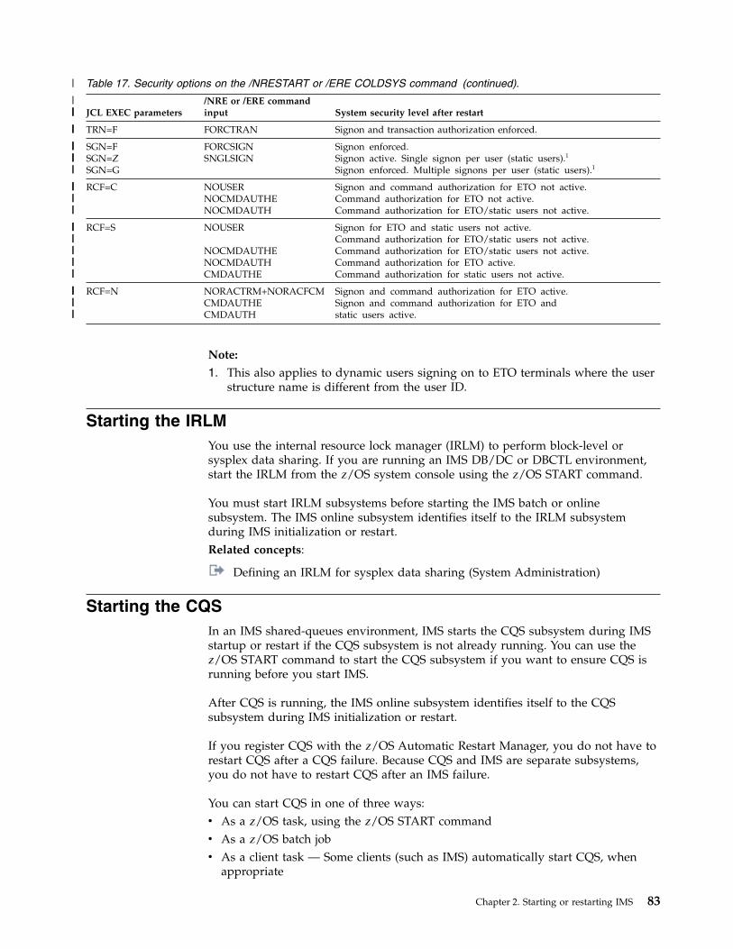
Table 17. Security options on the /NRESTART or /ERE COLDSYS command (continued).
JCL EXEC parameters/NRE or /ERE commandinput System security level after restart
TRN=F FORCTRAN Signon and transaction authorization enforced.
SGN=FSGN=ZSGN=G
FORCSIGNSNGLSIGN
Signon enforced.Signon active. Single signon per user (static users).1
Signon enforced. Multiple signons per user (static users).1
RCF=C NOUSERNOCMDAUTHENOCMDAUTH
Signon and command authorization for ETO not active.Command authorization for ETO not active.Command authorization for ETO/static users not active.
RCF=S NOUSER
NOCMDAUTHENOCMDAUTHCMDAUTHE
Signon for ETO and static users not active.Command authorization for ETO/static users not active.Command authorization for ETO/static users not active.Command authorization for ETO active.Command authorization for static users not active.
RCF=N NORACTRM+NORACFCMCMDAUTHECMDAUTH
Signon and command authorization for ETO active.Signon and command authorization for ETO andstatic users active.
Note:
1. This also applies to dynamic users signing on to ETO terminals where the userstructure name is different from the user ID.
Starting the IRLMYou use the internal resource lock manager (IRLM) to perform block-level orsysplex data sharing. If you are running an IMS DB/DC or DBCTL environment,start the IRLM from the z/OS system console using the z/OS START command.
You must start IRLM subsystems before starting the IMS batch or onlinesubsystem. The IMS online subsystem identifies itself to the IRLM subsystemduring IMS initialization or restart.Related concepts:
Defining an IRLM for sysplex data sharing (System Administration)
Starting the CQSIn an IMS shared-queues environment, IMS starts the CQS subsystem during IMSstartup or restart if the CQS subsystem is not already running. You can use thez/OS START command to start the CQS subsystem if you want to ensure CQS isrunning before you start IMS.
After CQS is running, the IMS online subsystem identifies itself to the CQSsubsystem during IMS initialization or restart.
If you register CQS with the z/OS Automatic Restart Manager, you do not have torestart CQS after a CQS failure. Because CQS and IMS are separate subsystems,you do not have to restart CQS after an IMS failure.
You can start CQS in one of three ways:v As a z/OS task, using the z/OS START commandv As a z/OS batch jobv As a client task — Some clients (such as IMS) automatically start CQS, when
appropriate
Chapter 2. Starting or restarting IMS 83
|
||||
|||
|||
|||||
||||
|||
||||||
|||||
||||
|||
Example: If IMS is the client, define the CQS name in the DFSSQxxx or theDFSDFxxx member in the IMS PROCLIB data set and specify the CQS name onthe SHAREDQ parameter of the IMS procedure. IMS does not start CQS if theCQS is needed only to manage a resource structure.
A CQS that supports only a resource structure must be started manually becauseIMS does not start this CQS.Related tasks:
Preparing to start the CQS address space (System Definition)Related reference:
DCC procedure (System Definition)
DFSSQxxx member of the IMS PROCLIB data set (System Definition)
z/OS: Defining Sysplex policies
Starting dependent regionsIMS dependent regions are z/OS regions that are separate from the IMS controlregion, and that are logically dependent upon the IMS control region.
The following types of programs execute in dependent regions:v IMS batch message programs (BMPs) and message processing programs (MPPs)v IMS Fast Path (IFP) message-driven application programsv Fast Path DEDB online utility programsv Java™ batch processing (JBP) and Java message processing (JMP) applicationsv Coordinator controller (CCTL) application programs (in the IMS DBCTL
environment)
You can start IMS dependent regions from the z/OS system console or the IMSmaster terminal. From the z/OS system console, use the z/OS START command tostart a reader procedure (usually IMSRDR) to read the JCL for the region. From theIMS master terminal, use the IMS /START REGION command to start a region. Ifyou do not specify a procedure name on the START or /START REGIONcommand, IMS uses the IMSMSG procedure.
You should not start IMS message regions and Fast Path regions with automaticpriority group (APG) initiators because IMS cannot control the dispatching priorityof an APG-initiated job or uniquely identify such jobs. You might need to start andstop z/OS initiators for IMS message regions and Fast Path regions that have APGinitiators.
IMS can dynamically allocate up to 255 regions. The total number of regionsincludes the number of regions allocated during IMS system definition plus thenumber of dynamically allocated regions or CCTL threads.
Message processing regionsOne of the jobs in the IMS.JOBS data set contains the message region JCL.Parameters on the JCL EXEC statement define the transaction classes that areeligible for processing in the region. You can define more than one set of JCL ifnecessary.
84 Operations and Automation
The default job name is IMSMSG. After you start a message region, transactionsassociated with the transaction classes supported by the region can be scheduled.You can change these classes using the /ASSIGN TRAN or UPDATE TRANSET(CLASS(new_class_number)) command after you have started the region.
Batch message processing regionsYou can start BMP regions from the z/OS console or the IMS master terminal.Generally, you use the z/OS console and a z/OS reader procedure to start a BMP,unless the JCL for the job (using procedure IMSBATCH) is in the IMS.JOBS dataset.
A JCL EXEC parameter indicates that the job is a BMP.
Fast Path message-driven regionsYou can start IMS Fast Path message-driven regions from the z/OS console or theIMS master terminal. Generally, you use the z/OS console and a z/OS readerprocedure to start a Fast Path message-driven region, unless the JCL for the job(using procedure IMSFP) is in the IMS.JOBS data set.
A JCL EXEC parameter indicates that the job is a Fast Path message-drivenapplication program.
Java dependent regionsYou can start two types of Java message-driven dependent regions, either a JMP ora JBP region.
The JMP region is similar to an MPP region and is started in the same manner asan MPP region. The default job name is IMSJMP.
The JBP region is similar to a BMP region and is started in the same manner as aBMP region. The default job name is IMSJBP.
DEDB online utility regionsYou can start all DEDB online utilities using procedure FPUTIL. Specify the utilityin the TYPE operand in the control data set.
CCTL regionsThe CCTL region is not part of an IMS subsystem. See your CCTL documentationfor information on how to start the CCTL.
Restarting CQSAfter CQS completes the structure initialization, it continues with the restart. CQScan do either a cold restart or a warm restart. Restarting CQS affects only the unitsof work that this CQS manages. Restarting does not back out or restore any unitsof work owned by another CQS.
When you have completed restarting all structure pairs for a particular CQS, theCQS ready message is issued (CQS0020I).
Since changes to resource structures are not check pointed or logged, restartingCQS does not affect units of work for resource structures.
Chapter 2. Starting or restarting IMS 85

The frequency of system checkpoints affects restart. CQS must read more logrecords when checkpoints are infrequent than when checkpoints occur more often.Also, the amount of logging that one CQS performs can affect another CQS duringrestart. All CQSs write to the same log, so a CQS restarting must read all logrecords written by all CQSs.
CQS takes an initial system checkpoint at the end of a restart.
CQS warm startDuring a warm start, CQS reads the log records from the last system checkpoint,restores the environment for committed data objects, and backs out uncommitteddata objects to prepare CQS to regain synchronization with the client and resumeprocessing. Normally, a CQS warm start is automatic and you do not need to takeany action.
When CQS warm starts, it reads the checkpoint data set to find the log tokenrepresenting the last system checkpoint. When CQS finds this log token, it initiatesa warm start. If CQS fails to find this log token in the checkpoint data set, it readsthe log token from the structure. If CQS finds the log token, CQS issues WTORCQS0031A to allow you to confirm the use of this token. At this point, you can doone of the following:v Confirm the log tokenv Cold start CQSv Cancel CQSv Specify a new log token
If you specify a new log token and CQS fails to find this log token, CQS issuesWTOR CQS0032A. At this point, you can take one of the following actions:v Cold start CQSv Cancel CQSv Specify a new log token
Sometimes, CQS purges log records that are required for restart. CQS purges logrecords in the following situations:v During a structure checkpointv When the log becomes full and no more data sets are available for logging
Important: CQS might not have any log records if it is only managing resourcestructures.
Recommendation: If a CQS does not accept a log token during CQS restart, coldstart the CQS. In cases where multiple CQSs are running, it is possible that logrecords for a CQS that previously failed and was not restarted are purged whileanother CQS performs a structure checkpoint.Related concepts:
Using CQS structure checkpoint (System Administration)
CQS cold startWhen CQS restarts after a structure cold start, CQS cold start processing isautomatic. You do not need to take any action. CQS takes a system checkpoint andthen CQS restart is complete.
86 Operations and Automation

When CQS cold starts after a structure warm start or a structure recovery, CQSreads the structure to find unresolved work. CQS backs out requests to move databut completes requests to delete data. CQS performs a system checkpoint andrestart is complete.
No log records are read or processed when CQS is cold started.
To cold start CQS, you must:1. Scratch the CQS system checkpoint data set for the structure.2. Reply COLD to the CQS0031A WTOR.
CQS registration with the z/OS Automatic Restart ManagerCQS, if requested, can register with the z/OS Automatic Restart Manager (ARM).The ARM is a z/OS recovery function that can improve the availability of startedtasks. When a task fails or the system on which it is running fails, the ARM canrestart the task without operator intervention.
Recommendation: Register with the z/OS ARM regardless of the types ofstructures that CQS is using.
To enable the ARM, you can specify ARMRST=Y in one of two ways:v In the CQSIPxxx member of the IMS PROCLIB data setv As an execution parameter
An abend table exists in module CQSARM10. The table lists the CQS endsabnormally for which the ARM does not restart CQS after the abend occurs. Youcan modify this table.
IBM provides policy defaults for automatic restart management. You can use thesedefaults or define an ARM policy to specify how CQS should be restarted. Thepolicy can specify different actions to be taken when the system fails and whenCQS fails. When ARM is enabled, CQS registers to ARM with an ARM elementname of CQS + cqsssn + CQS. Use this ARM element name in the ARM policy todefine the ARM policy for CQS.
cqsssn is the CQS name that can be defined either as a CQS execute parameter, orwith the SSN= parameter in the CQSIPxxx member of the IMS PROCLIB data set.For example, if SSN=CQSA, then the ARM element name is CQSCQSACQS.Related reference:
z/OS: Using automatic restart management
Restarting CQS after CQS resource cleanup failuresIf CQS abends and you receive message CQS0102E with module CQSRSM00, logrecords might be missing from the CQS log. Message CQS0102E indicates that afailure occurred during CQS resource cleanup. This failure might prevent CQS logrecords in internal buffers from being externalized to the CQS log.
If this situation occurs, perform one of the following actions:v If the terminating CQS is the only CQS running for its set of structures, restart
the CQS immediately.v If other CQSs are running, either immediately restart the terminated CQS or
initiate a structure checkpoint on one of the surviving CQSs.
Chapter 2. Starting or restarting IMS 87
Successfully restarting the failed CQS or taking a structure checkpoint is necessaryto preserve the state of the data on the shared queues in the event that a structurerebuild is needed.
Restarting CQS queue structuresRestarting queue structures involves restarting a structure pair. The structurerestart function ensures that the data in the structure is correct. Structure restartdeals only with the status of data in a specific coupling facility structure, not unitsof work specific to a given CQS.
Before CQS can restart, CQS must recover each queue structure defined to CQS, ifneeded. CQS connects to both the primary and the overflow queue structures foreach structure pair defined. CQS determines whether the structures need to bewarm or cold started and performs the necessary recovery functions. If more thanone structure pair is defined to CQS, one structure pair can be warm started andanother can be cold started.
CQS structure allocationA structure is allocated the first time a CQS connects to it and remains allocateduntil you explicitly delete it using the z/OS SETXCF command.
When a CQS connects to a structure, the structure might be empty; that is, it mightcontain no data, might contain only CQS control information, or it might containclient data. The structure can be empty if:v This is the first time a CQS is accessing the structure.v You scratched the structure to perform a structure cold start.v A structure failure occurred and the structure must be recovered.
CQS structure warm startCQS warm starts both a primary structure and its overflow structure if either theprimary structure contains data, or one SRDS contains valid structure checkpointdata and the CQS log contains valid data.
During a structure warm start, CQS determines the status of the structure andinitiates a structure recovery if necessary. If a structure recovery is needed, CQSallocates the structure and repopulates it from either the CQS log and the SRDS,which contains valid client data from a previous checkpoint, or from the CQS logby itself.
After a structure warm start has completed, CQS determines whether a futurerecovery is possible based on the status of the structure recovery data sets and thelog stream. If the primary structure contains client data, but neither the SRDS northe log can be used for future recovery, CQS issues a CQS0009W message.
Recommendation: If CQS issues a CQS0009W message, initiate a structurecheckpoint as soon as possible. If a structure checkpoint does not completesuccessfully and the structure fails, CQS cannot recover the structure.
After a structure warm start, CQS can be cold started or warm started. If the logrecords needed for the CQS restart have been deleted, you might have to cold startthe CQS.
88 Operations and Automation
CQS structure cold startCommon Queue Server (CQS) cold starts both a primary structure and its overflowstructure if the primary structure is empty and both of the structure recovery datasets are empty.
During a structure cold start, CQS deletes:v The overflow structurev All the log records in the log stream for the structure
To cold start a structure, you must:1. Shut down any CQS systems that are connected to the structure. For example,
issue the following command, where cqs_name is the CQS subsystem name.P cqs_name
The response will be shown as follows:CQS0021I CQS SHUTDOWN COMPLETECQS0101I CQS CLEANUP SUCCESSFUL
2. Delete the primary and overflow structures on the coupling facility. Forexample, issue the following command, where structure_name is the structurename.SETXCF FORCE,STRUCTURE,STRNAME=structure_name
The response will be shown as follows:IXC353I THE SETXCF FORCE REQUEST FOR STRUCTUREstructure_name WAS COMPLETED:STRUCTURE WAS DELETED
3. Scratch both structure recovery data sets (SRDS 1 and 2). For example, use theAccess Method Services program IDCAMS to scratch the data sets.
4. Reallocate both structure recovery data sets (SRDS 1 and 2). For example, usethe Access Method Services program IDCAMS to reallocate the data sets.
5. Restart a CQS. CQS initialization will reallocate the structure. For example, usethe CQS startup procedure.
6. Verify that the structure is empty. For example,v Issue the following z/OS command, where structure_name is the structure
name.D XCF,STR,STRNAME=structure_name
The response for the z/OS command will be shown as follows:...STORAGE INCREMENT SIZE: 256 KENTRIES: IN-USE: 3 TOTAL: 4238, 0% FULLELEMENTS: IN-USE: 3 TOTAL: 4238, 0% FULLEMCS: IN-USE: 0 TOTAL: 6634, 0% FULL...
When structure cold start completes, CQS automatically performs cold start restartprocessing.
Restarting resource structuresYou can cold start a resource structure by shutting down any CQS systems thatconnect to the resource structure, deleting the resource structure on the couplingfacility, and restarting a CQS to reallocate the resource structure.
To cold start a resource structure, you must:
Chapter 2. Starting or restarting IMS 89

1. Shut down any CQS systems that connect to the resource structure. Forexample, issue the following command, where cqs_name is the CQS subsystemname.P cqs_name
The response will be shown as follows:CQS0021I CQS SHUTDOWN COMPLETECQS0101I CQS CLEANUP SUCCESSFUL
2. Delete the resource structure on the coupling facility. For example, issue thefollowing command, where structure_name is the resource structure name.SETXCF FORCE,STRUCTURE,STRNAME=structure_name
The response will be shown as follows:IXC353I THE SETXCF FORCE REQUEST FOR STRUCTUREstructure_name WAS COMPLETED:STRUCTURE WAS DELETED
3. Restart a CQS. CQS initialization will reallocate the resource structure. Forexample, use the CQS startup procedure.
4. Verify that the resource structure is empty. For example, issue the followingcommand, where structure_name is the resource structure name.D XCF,STR,STRNAME=structure_name
The response will be shown as follows:...STORAGE INCREMENT SIZE: 256 KENTRIES: IN-USE: 3 TOTAL: 4238, 0% FULLELEMENTS: IN-USE: 3 TOTAL: 4238, 0% FULLEMCS: IN-USE: 0 TOTAL: 6634, 0% FULL...
When structure cold start completes, CQS automatically performs cold start restartprocessing.
CQS structure recovery for restartingA structure might need to be recovered if the structure is empty or if it containsonly Common Queue Server (CQS) control information. Data from the laststructure checkpoint and the z/OS log stream are used to recover a structure.
The structure is first repopulated with data objects from the structure recovery datasets. CQS then reads the log, starting at the time of the structure checkpoint, andupdates the structure with changes that occurred after the structure checkpoint.
If the primary structure is empty and neither SRDS contains valid structurecheckpoint data, CQS determines whether it can use just the CQS log for recovery.If the first log record in the log stream is the “Beginning of Log” record, the logstream contains all the log records required for recovery, and CQS can use the logrecords to complete the structure recovery.
If CQS finds that a previous structure rebuild did not complete successfully, itinitiates another rebuild.
If the primary structure contains only CQS control information and the first CQSthat connected to the structure (the one that allocated the structure) cannotdetermine whether a rebuild is needed, CQS initiates a rebuild if either SRDS isvalid or if all the log records are available.
90 Operations and Automation

If neither SRDS is valid and the log records have been deleted by a previousstructure checkpoint, CQS cannot rebuild the structure. When this happens and arebuild is necessary, CQS issues write-to-operator-with-reply (WTOR) CQS0034Amessage asking what you want to do. You can cold start the structure or cancelthis CQS.Related concepts:
CQS structure recovery (System Administration)
Starting Transaction ManagerFor remote terminal operators to enter transactions, you must initialize the IMSTransaction Manager (for the IMS DB/DC and DCCTL environments).
The procedures are different for the different access methods and protocols:v Virtual Telecommunications Access Method (VTAM)v Communications with devicesv Advanced Program-to-Program Communications (APPC/MVS™)v Intersystem Communication (ISC)
Connecting to the VTAM networkYou use the /START DC command to establish communications between IMS andVTAM. The /START DC command tells VTAM to pass queued logon requests toIMS for all terminals defined to VTAM as belonging to IMS.
Before establishing a session with IMS for any terminal, verify that the followingconditions exist:v VTAM and the Network Control Program (NCP) are active.v Controllers and logical units are active. If they are not automatically activated by
VTAM, the VTAM network operator can use the VTAM VARY command toactivate them.
v Controllers are powered on, appropriately configured, initialized, and activatedfor VTAM and NCP.
Recommendation: Start VTAM before starting the IMS control region.
You also need to use the /START DC command in either of the followingsituations:v If VTAM is stopped and restarted while the IMS control region is runningv If you terminate communications between IMS and VTAM using the /STOP DC
command
The /START DC command activates the following processes:Initiating IMS Transaction Manager processingOpening the VTAM access method control block (ACB)Enabling the IMS VTAM logon exit routineOpening the primary and secondary VTAM master terminals if these terminalswere not opened during IMS initialization (due to the specification ofVACBOPN=DELAY in the DFSDCxxx IMS.PROCLIB member)
If VTAM is active when IMS starts, the IMS VTAM ACB is opened; otherwise, theACB is opened by the /START DC command. Any logon requests received by
Chapter 2. Starting or restarting IMS 91
VTAM before the IMS /START DC command, but after the IMS VTAM ACB hasbeen opened, are enqueued by VTAM until the /START DC command completes.If the queuing of logon requests by VTAM causes operational problems, thespecification of VACOPN=DELAY in the DFSDCxxx PROCLIB member can beused to delay the opening of the VTAM ACB. When the master terminals aregenerated to use VTAM, the master terminal operator will be unable to enter eitherthe /NRE or /ERE commands (including /ERE BACKUP) or the /START DCcommand. These commands can be issued using automatic restart (AUTO=Y) orautomated operations.
Before you can establish a session between IMS and a logical unit or node, thelogical unit or node must be active, connected, enabled, and available to VTAMand started in IMS. You can activate logical units or nodes when VTAM startsusing VTAM start options, or a VTAM operator can activate them using the VTAMVARY command.
Normally after you start IMS, all VTAM terminals have a started status. If you stopa VTAM terminal with an IMS /STOP command, the terminal remains stoppedafter an IMS warm start or emergency restart. You must use the /START NODEcommand before issuing the /OPNDST (open destination) command to reactivatethe terminal.
You must establish sessions between terminals and IMS before anyone can usethem to transmit data. You can initiate sessions in several ways:v VTAM can automatically log them on (based on the VTAM terminal definition).v The end user can log on.v You can issue an IMS /OPNDST command (if they are not automatically logged
on).v You can issue a VTAM VARY command.
Connecting to devicesWhen you start IMS, IMS automatically starts communications between IMS anddevices such as spools, readers, printers, punches, tapes, and disks. After you startIMS, the telecommunication lines have a stopped status.
You can start the telecommunication lines, and devices if necessary, using the/START or /RSTART commands. Normally, you use the /START command afteran IMS cold start and the /RSTART command after a warm start. The /RSTARTcommand starts the devices so that they have the same mode they had when theywere stopped at the previous system shutdown.
If you stop a device using the /STOP command, the device remains stopped afteran IMS warm start or emergency restart.
Connecting to APPC/MVSBefore an LU 6.2 conversation can be established with IMS, the following must beactive: APPC/MVS, VTAM, and NCP.
Recommendation: Start APPC/MVS and VTAM before starting IMS.
When you specify APPC=Y in the IMS procedure, IMS automatically startscommunication between IMS and APPC/MVS. If you specify APPC=N in the IMSprocedure, you can use the /START APPC command to establish communications.
92 Operations and Automation
You also need to use the /START APPC command in either of the followingsituations:v If APPC/MVS is stopped and restarted while IMS is runningv If you terminate communication between IMS and APPC/MVS by using a
/STOP APPC command
Connecting ISC sessions from CICS to IMSYou can connect CICS® ISC sessions to IMS in two distinct ways. You can initiatethe session explicitly or the CICS operator can initiate the session through acommand.
You can connect CICS ISC sessions to IMS in one of the following ways:v You can initiate the session explicitly by specifying AUTOCONNECT YES on the
DEFINE CONNECTION command in the CICS system definition (CSD) utility,or by specifying CONNECT=AUTO in the DFHTCT TYPE=TERMINAL program.When CICS is started, it attempts to establish all sessions for whichAUTOCONNECT is specified.In order for session to be initiated, IMS must be active when CICS is started.
v The CICS operator can initiate a session by entering the following command:CEMT SET TERMINAL(termid) [ACQUIRED | COLDACQ | RELEASED]where termid is the four-character session name (defined on the DEFINESESSIONS command in the CSD utility), or the TRMIDNT in the DFHTCTTYPE=TERMINAL program. The following describes the effects of the keywordsfor the CEMT SET TERMINAL command:
ACQUIREDSpecifies normal resynchronization with the IMS half-session. CICS is insession with the logical unit represented by the terminal.
COLDACQSpecifies that no resynchronization is done.
COLDACQ is a special form of ACQUIRED, in which noresynchronization is required. If the previous session ended abnormally,using COLDACQ overrides CICS integrity control, which can lead tointegrity problems. Also, check the CSMT log for an activity keypoint(similar to an IMS checkpoint) after the restart of a session following aCICS failure. If there is no activity keypoint, reissue the CEMT SETTERMINAL(termid) COLDACQ command after the next emergencyrestart.
RELEASEDSpecifies that CICS is not in session with the logical unit represented bythe terminal.
Specifying RELEASED for a terminal that has an active session causesthe session to be terminated. Running transactions are allowed to finishunless you also specify PURGE or FORCEPURGE.
The display area of the CEMT [INQUIRE | SET] TERMINAL command showsthe status of the CICS half-session. If the session initiates successfully, the statuschanges from REL (released) to ACQ (acquired). If the session does not initiatesuccessfully, CICS writes an error message to the transient data destinationCSMT.
v An application program can initiate a session implicitly by using theALLOCATE command. A program can use the ALLOCATE command only forthe SEND/RECEIVE interface.
Chapter 2. Starting or restarting IMS 93

Recommendation: Use the ALLOCATE SYSID form of the command because itallows CICS to select an available session.If a session is not immediately available, control is returned to the applicationprogram if either of the following occur:– The program issues a HANDLE CONDITION command.– The program specifies NOQUEUE on the ALLOCATE command.
Otherwise, the command is queued until a session becomes available.Each of the following conditions causes a session to be “not immediatelyavailable”.– All sessions to the specified system (or the specified session) are in use.– The only available sessions are not bound.– The only available sessions are contention losers.
v CICS automatic task initiation (ATI) can initiate a session.
To determine the primary and secondary RU sizes, CICS uses the values for theRECEIVESIZE and SENDSIZE parameters on the DEFINE CONNECTION |SESSION command in the CSD utility or the values for the RUSIZE and BUFFERparameters on the DFHTCT TYPE=TERMINAL | SYSTEM program.Related concepts:“Terminating an ISC session from CICS” on page 129Related reference:
CICS Transaction Server for z/OS
Starting IMS systems and global command statusGlobal command status is the status of a shared IMS resource as set by onlinecommands and as seen by all IMSplex members that have the resource defined.
If you are operating in an IMSplex environment that specifiesPLEXPARM(GSTSTRAN(Y), GSTSDB(Y) or GSTSAREA(Y)), you must understandhow the status of IMS resources as set by online commands is maintained at boththe global and the local level, as well as how resource status is recognized byIMSplex members as individual IMS systems are started and stopped across theIMSplex.
For example, if the Resource Manager (RM) maintains global command statusinformation for a database and the database is stopped by a command, allmembers of the IMSplex, whether they were running at the time the command wasissued or not, see that the database is stopped. That same database can have alocal status in an IMS system that is different than the global command statusmaintained in RM. Stopping a database globally while allowing access locally canbe useful for preventing updates to the database from other IMSplex memberswhile a local batch program processes the database.
RM maintains global command status for IMS resources by resource type. Themaintenance of global command status is enabled for a resource type by specifyingthe PLEXPARM= parameter in the DFSDFxxx or DFSCGxxx PROCLIB memberduring IMS initialization.
You can assign global status to a resource dynamically by using one of thefollowing commands:
94 Operations and Automation

v UPDATE IMS SET(PLEXPARM(GSTSDB(Y)) identifies that global database statusis to be maintained on database commands.
v UPDATE IMS SET(PLEXPARM(GSTSAREA(Y)) identifies that global area statusis to be maintained on area commands.
v UPDATE IMS SET(PLEXPARM(GSTSTRAN(Y)) identifies that global transactionstatus is to be maintained on transaction commands.
If global status is not explicitly specified for a resource type, RM does not maintainglobal status.
When RM maintains global status for a resource type, any commands issuedagainst specific instances of the resource change the global status of the resourceinstance in RM. You can limit the affect of commands on the global status of aresources by using the SCOPE() parameter with the appropriate type-2 command:v The SCOPE(ACTIVE) parameter limits the scope of commands to the active IMS
systems that the command is routed to, and no global information is changed.v The SCOPE(ALL) parameter specifies the scope of commands to the active IMS
systems that the command is routed to and updates the RM status if applicable.
If a command is issued against a resource with global status before an IMS systemis started, the starting IMS system can read the global status of resources in RMand apply them locally to the IMS system if the resources are valid.
The first IMS system to start in an IMSplex sets the PLEXPARM values that itknows about. IMS systems that start in the IMSplex subsequent to the first, use thePLEXPARM status definitions already in RM.
When an IMS system restarts and global status exists for the resource type in RM,the type of start determines which status takes precedence:v For cold starts, the global status of databases, partitions, areas, and transactions
takes precedence.v For warm starts, the restarting IMS system first applies the local status saved in
the log records and then applies the global status stored in RM only if itchanged while the IMS system was down.
Before attempting to restart IMS again, complete one of the following actions:1. Cancel IMS or shutdown IMS after restart completes. After the error condition
reported in the DFS3308 message is fixed, restart IMS. IMS will besynchronized with RM status, and no additional action is required.
2. Allow the IMS restart to complete, then take the following actions:v Issue the appropriate UPDATE IMS SET(PLEXPARM) command to enable
global status at this IMS.v Issue the appropriate QRY TRAN|DB|AREA SHOW(GLOBAL) commands
to see the resources with global status.v Issue appropriate command with the SCOPE(ACTIVE) parameter to ensure
that the IMS is synchronized with RM status.
RM stores global status information in its resource structure. If the resourcestructure should fail, RM repopulates the resource structure by having each activeIMS system in the IMSplex update the resource structure with its local resourcesthat have global status. Any global status for resources owned by an IMS systemthat is not active is not restored to the resource structure.Related concepts:
Chapter 2. Starting or restarting IMS 95
“IMS restart and global resource status in an IMSplex that uses RM” on page 102
Restarting a component of IMSAfter performing the necessary recovery, you can reactivate the particularcomponent that you shut down or detached. For example, if you take a databaseoffline because of an I/O error and then recover it, you can again make it availableto applications.
Use the appropriate IMS command to restart the component. Most often, thiscommand is some form of the /START or UPDATE command. For example, use/START DATABASE or UPDATE DB START(ACCESS) to restart a database or/START PROGRAM to restart an application program.
A list of restart commands and their corresponding shutdown commands is shownin the following table:
Table 18. Commands for restarting components of IMS
Restart commandCorresponding shutdowncommand Affected components
/OPNDST /CLSDST VTAM session
/START /STOP /IDLE /DBDUMP/DBRECOVERY
Areas, databases, VTAMlogons, lines, logicalterminals, VTAM nodes,OLDS, programs, regions,external subsystemconnection, transactions,users
/RSTART /IDLE Lines, physical terminals,logical links, VTAM nodes
/RELEASE /HOLD Conversations
/UNLOCK /LOCK Databases, logical terminals,nodes, programs, physicalterminals, transactions
UPDATE UPDATE Areas, data groups,databases, MSC resources,and transactions.
Restarting IMSYou can restart IMS after you have completed any necessary recovery. You canperform a normal, emergency, or emergency with OVERRIDE restart.v Normal restart initializes the IMS subsystem without reference to any previous
execution of IMS (a cold start), or restarts a system that was terminated using acheckpoint command (a warm start).
v Emergency restart initializes an IMS subsystem after a system failure. During anemergency restart, IMS does the following:– Closes the OLDS from the WADS– Resets each active transaction to its last sync point– Resets each active region (BMPs, and CCTL or ODBA threads) to its last sync
point
96 Operations and Automation
You do not need to restart connected ODBA application programs or CCTLs.An IMS shutdown or failure simply disconnects from the ODBA applicationor CCTL and generally does not affect it.
– Restores the databases to the last sync point– Restores local message queues to their condition at the time of failure
An IMS failure does not generally affect shared message queues.– If dynamic resource definition is enabled in the IMS system, the runtime
resource definitions are restored by processing the checkpoint and X'22' logsYou must manually restart regions and BMPs. However, when restarting a batchmessage processing region, IMS automatically determines the last BMP syncpoint if you specified LAST as an EXEC parameter. Otherwise, IMS indicateswhat the last BMP sync point was so that you can specify it during restart.If you have an IMS DBCTL standby environment, you can send the /ERESTARTcommand to the pre-initialized DBCTL subsystem. Doing this is faster thanstarting the IMS job and waiting for the DBCTL-ready message before sendingthe /ERESTART command.
v Emergency restart with OVERRIDE is necessary after a failure in which DBRC isunable to mark the SSYS record in the RECON data set as abnormallyterminated, such as a power, CPC, z/OS, or DBRC failure.
Automatic restart reduces MTO intervention and makes restart faster. Withautomatic restart, IMS automatically chooses the appropriate restart command(either /NRESTART or /ERESTART). If restart processing abnormally terminatesbefore initial checkpoint, the appropriate automatic restart command is the sametype (either /NRE or /ERE) as the aborted restart. The operator does not enter arestart command. Specify automatic restart by including AUTO=Y in the JCL.
When AUTO=Y is specified in the startup procedure, you cannot cold start IMS ormodify any restart options before IMS restarts.
You can implement normal restart procedures easily, and generally do not need toworry about it. However, an operator error could adversely affect system integrityin the following situations:v Specifying cold start after a /CHECKPOINT FREEZE | DUMPQ | PURGE
command when some messages are not completely processedv Failing to supply the proper security options
Restriction: Do not change the IMS operating environment between shutdownand normal or emergency restart. For example, if you change from anonshared-queues environment to a shared-queues environment, or changecoupling facility structure names, IMS abends during normal or emergency restart.If you change the operating environment, you should cold start the IMSsubsystem; or you can use IMS online change (/MODIFY command) to makechanges while IMS is running.
Cold startA cold start is required only when you first initialize IMS or after changing thenucleus during a system definition. You must also cold start IMS after scratchingand reallocating shared-message-queue structures if these structures containedmessages.
Chapter 2. Starting or restarting IMS 97

Request a cold start using the /NRESTART CHECKPOINT 0 or /ERESTARTCOLDSYS command. When you specify the COLDSYS keyword, the /ERESTARTcommand initiates a cold start, not an emergency restart.
Note that if AUTO=Y is specified in the startup procedure, you cannot cold startIMS or modify any restart options before IMS automatically executes either anemergency restart or warm restart, as determined by the circumstances of the priortermination.
In a non-shared-queues environment, a cold start assumes empty message queues:if any messages exist, IMS discards them. In a shared-queues environment, IMSdoes not discard messages on shared queues during a cold start. If any affinitiesexist for VTAM generic resource groups, IMS deletes them. IMS never usesinformation from a previous shutdown as input to a cold start.
Optionally, you can format the IMS message queue data sets, WADS, and restartdata set (RDS) during a cold restart. During a cold start, IMS loads all controlblocks from the system libraries.
In a shared-queues environment, any locked messages remain locked after the IMScold start until IMS (or other Common Queue Server client) unlocks or deletesthem.
IMS systems that use dynamic resource definition (DRD) can store resourcedefinitions for application programs, databases, Fast Path routing codes, andtransactions in a resource definition data set (RDDS) or the IMSRSC repository.During a cold start, IMS can be set up to automatically import the stored resourceand descriptor definitions. If your IMS system is not configured to automaticallyimport the resource definitions, you can issue the IMPORT command after therestart process is complete. The IMPORT command, as well as all of the othertype-2 dynamic resource definition commands, require that the SCI and OM CSLcomponents are started.
In order to recover changes to the runtime resource definitions across a cold start,you must export the resource definitions to an RDDS or the IMSRSC repositorywhile IMS is up. If you do not, any changes made to resources and descriptors inthe online system might be lost.
If the IMS resource definitions were not exported to the IMSRSC repository andIMS had to perform a cold start, you can create a non-system from RDDS from theIMS log using the DFSURCL0 utility with EXPORTNEEDED parameter. If such anRDDS was created then you can specify that RDDS on the IMPORT command afterthe cold start is complete.
During a cold start, the partition status or access state will be copied from theHALDB master. If you export the HALDB master status to the RDDS or therepository, the status of the master and its partitions will be obtained from theRDDS or the repository.
If an error occurs while trying to access an RDDS during the automatic importprocess, automatic import terminates abnormally. IMS either continues with thecold start process without any runtime resource definitions defined, or IMS stopsthe cold start process. If an error occurs during automatic import processingbecause of an invalid resource or descriptor definition, one of the followingsituations occurs:
98 Operations and Automation
v Automatic import processing terminates abnormally, and IMS cold startterminates abnormally with a U3397 abend.
v Automatic import processing continues, and the resource in error is marked andgiven a not-initiated status (NOTINIT).
The action IMS takes depends on the values specified for the RDDSERR and theIMPORTERR parameters in the DFSDFxxx member.Related reference:
Create RDDS from Log Records utility (DFSURCL0) (System Utilities)
Warm startA warm start is the most common way to reinitialize IMS, and is therecommended way of restarting after a controlled shutdown of IMS. You shouldattempt a warm start only if IMS terminated in an orderly manner. You can specifya warm start by using the /NRESTART command.
Before starting IMS and entering the restart command, you must determinewhether IMS should:v Reload MSDBsv Format specific system data sets during restartv Activate specific security functions during restart
The following situations require you to reallocate and reformat specific system datasets after a controlled IMS shutdown:v When a message queue data set is full (indicated by messages DFS206, DFS207,
or DFS208) and IMS was shut down by an internally-generated /CHECKPOINTDUMPQ command.
v When a write error occurred on the restart data set (RDS) during checkpoint orrestart (indicated by message DFS3127I).
v When you need to change the amount of space allocated to the WADS or a writeerror occurs on the WADS during normal operation. You should change theamount of space allocated to the WADS only after a controlled IMS shutdown.You can replace a WADS that encountered a write error during normal restart(/NRE) or emergency restart (/ERE). In any case, when IMS uses a new WADS,you must format it during restart.
v When read or write errors occur on one of the MSDB data sets during normaloperation (indicated by messages DFS2718I or DFS2722I).
For other error situations that require reallocation and formatting of some or all ofthe system data sets, you must use the /ERE command.
During a warm start, IMS:v Reestablishes the status of the control region using control blocks that were
logged at terminationv Optionally restores local message queues if IMS logged them (you issued a
/CHE DUMPQ | PURGE command)v Restores in-doubt units of work so they can later be resolved
Unlike emergency restart, you might have to manually release any transactions onthe suspend queue by:v Re-executing the transaction by issuing a /START TRAN tranname command.
This command releases a specific transaction.
Chapter 2. Starting or restarting IMS 99

v Issuing a /DEQUEUE SUSPEND command. This command releases alltransactions on the suspend queue.
When using XRF with VTAM Multinode Persistent Session (MNPS), IMS operatesin an XRF environment and must use two ACBs: the APPLID ACB and the MNPSACB. During a controlled shutdown, IMS closes the MNPS ACB and the APPLIDACB. Closing the MNPS ACB terminates MNPS tracking.
After a normal restart that follows this controlled shutdown, VTAM no longermaintains persistent sessions. Therefore, when IMS opens the MNPS ACB, it doesnot need to recover any previous sessions.Related concepts:
XRF and VTAM generic resources (System Administration)
Emergency restartIMS requires an emergency restart whenever it terminates without a controlledshutdown. When restarted, IMS restarts from the point of failure. You can initiatean emergency restart using the /ERESTART command.
With an emergency restart, IMS:v Backs out DL/I in-flight units of workv Applies committed but unwritten DEDB changes to the databasev Retains any in-doubt units of work for IMS subsystems connected to a CCTL or
to Recoverable Resource Management Services (RRMS), the z/OS syncpointmanager.
v Resolves any unfinished External Subsystem Attach Facility (ESAF) units ofwork with external subsystems
v Releases locked messages in a shared-queues environmentv Uses checkpoint and X'22' log records to recover MODLBKS resources
Before starting IMS and entering the emergency restart command, you need toknow the following:v Whether system data sets must be reallocated and formatted during restart.v Whether IMS has cleaned up its resources. You can check for message DFS627I
or DFS627W to determine the previous ending status of the IMS resourcetermination manager. These messages tell you if IMS successfully completedresource cleanup processing. Successful resource cleanup guarantees IMS restartwithout requiring a z/OS restart.
After an IMS failure, you can use the ESAF In-Doubt Notification exit routine(DFSFIDN0) to determine in-doubt units of work during restart of the failed IMS.You can resolve the work outside of IMS.
During an emergency restart, IMS restores the system to the status it had at thelast system checkpoint. Databases and areas reflect their content at the last syncpoint for each dependent region. The local message queues reflect their content atthe time of the failure. And the system has just taken a new checkpoint. When yourestart the dependent regions, IMS reschedules the previously processingprograms. IMS also releases any transactions on the suspend queue.
If the backout of any database fails during an emergency restart, IMS identifies thedatabase by issuing DFS981I and the database remains stopped after restartcompletes. After IMS is running again, you might able to complete the backout by
100 Operations and Automation

entering a /START DB or UPDATE DB START(ACCESS) command; however,depending on the root cause of the backout failure, you might need to takeadditional steps to correct the problem.
After an IMS failure when XRF is used with VTAM MNPS, VTAM continues tomaintain persistent sessions until the timer specified by the PSTIMER= keyword(specified in DFSDCxxx IMS.PROCLIB member) expires. If there is no XRFtakeover, then VTAM might continue to maintain active persistent sessions whenthe MNPS ACB is opened after emergency restart. If this occurs, IMS issues thecommand SETLOGON OPTCD=NPERSIST, which tells VTAM to drop allpersistent sessions being maintained. This is consistent with emergency restartprocessing when the XRF USERVAR= keyword is used, which also has no sessionrecovery. IMS then issues the command SETLOGON OPTCD=PERSIST to start thenormal session persistence for all new sessions on the MNPS ACB.
If an emergency restart fails, you do not have to cold start the entire IMSsubsystem. The following table shows the various emergency restart cold startcommands and how they affect an IMS system.
Table 19. Effects of emergency restart commands on an IMS subsystem
Emergency restart commandEffect on the IMS DB orDBCTL subsystem
Effect on the IMS TM orDCCTL subsystem
/ERESTART COLDBASE Cold restart Emergency restart
/ERESTART COLDCOMM Emergency restart Cold restart
/ERESTART COLDSYS Cold restart Cold restart
v The /ERE COLDBASE command performs a cold start of the DB portion of anIMS DB/DC subsystem.If you use this command, you are responsible for the recovery of the databases.IMS does not redo committed DEDB updates, and does not back out in-flightupdates for DL/I databases. IMS identifies and stops databases that havein-doubt data or that need backout or recovery. You can backout in-flight DL/Idata by running the Database Batch Backout utility, for which you should close(and, optionally, archive) the OLDS.
v The /ERE COLDCOMM command performs a cold start of the TM portion of anIMS DB/DC subsystem.This command initializes the message queues, recovers DEDBs, reloads MSDBs,and backs out in-flight changes to DL/I databases. At the same time, IMSmaintains all existing in-doubt data.
v The /ERE COLDSYS command allows you to cold start both DB and TM.This command is essentially a combination of both /ERE COLDBASE and /ERECOLDCOMM, but it does not read the OLDS. Therefore, closing the OLDS isessential. The processing described for both the/ERE COLDBASE and /ERECOLDCOMM commands also pertains to /ERE COLDSYS.
Of the three forms of emergency restart command, you will likely use/ERECOLDCOMM most often.
If an emergency restart (/ERE) fails and a subsequent emergency restart (/ERECOLDBASE or /ERE COLDCOMM) also fails, you must issue the /ERE COLDSYScommand to restart IMS. You must also close (and optionally, archive) the lastOLDS that was used online before performing this /ERE COLDSYS restart becausethe log must be available in case database recovery is necessary.
Chapter 2. Starting or restarting IMS 101
Restriction: Do not add a Fast Path DBD to the active ACBLIB between anabnormal termination and an emergency restart. If you add a Fast Path DBD to theactive ACBLIB after abnormal termination of IMS, it is not accessible after theemergency restart. If you make changes to a Fast Path DBD in the active ACBLIBafter the last warm start or online change (/MODIFY), an emergency restart mayfail with abend U0168.
If an IMS database encounters an I/O error and the Extended Specified TaskAbnormal Exit (ESTAE) routine is not able to execute, then IMS does not create anEEQE and does not lock the error block. Consequently, an IMS emergency restartdoes not detect the bad block. In this situation, you might need to use theOVERRIDE keyword on the /ERE command or set the abnormal termination flagin the RECON data set for the failing subsystem.Related concepts:“Emergency restarts and dynamic resource definition” on page 81Related reference:
ESAF In-Doubt Notification exit routine (DFSFIDN0) (Exit Routines)
Defer of BMP backout programs to speed emergency restartAfter a system-wide failure, IMS backs out the interrupted online programs as itrestarts. This backout must be complete before regular work can continue. You canrequest postponement of BMPs by specifying the NOBMP keyword on the/ERESTART command.
This backout hastens restart if either of the following conditions is true:v A BMP had run a long time since its last commit point and needs large
quantities of data backed outv The program has a low priority and could have its restart postponed with no
trouble
If you postpone BMP backout, you must run the Database Batch Backout utilitysome time before you rerun the BMP, or before you put the affected database backonline (in case other programs need it).
If you register the affected database with DBRC, DBRC prevents programs fromusing that database before a backout is performed.
IMS restart and global resource status in an IMSplex that uses RMIf you are operating in an IMSplex environment that uses the Resource Manager(RM) component of the Common Service Layer, you need to understand howrestarting an IMS system affects both the global and local status information of theIMS resources that the restarting IMS system shares with the rest of the IMSplex.
The first IMS system to start in an IMSplex sets the PLEXPARM values that theIMS system knows about in RM. Subsequent IMS systems that start in the IMSplexobtain the PLEXPARM values by reading the PLEXPARM entry in RM. SubsequentIMS systems either use the PLEXPARM entry in RM if it has a value or update thePLEXPARM value in RM if they introduce a PLEXPARM variable.
When an IMS system restarts, if global status is maintained for a resource type, thetype of restart determines how the global status is applied at the restarting IMS.For example:
102 Operations and Automation
v For cold starts, the global status of databases, areas, and transactions takesprecedence.
v For warm starts, the restarting IMS system first applies the local status saved inthe log records and then applies the global status stored in RM only if itchanged while the IMS system was down.
v For emergency restarts, the restarting IMS system first applies the local statussaved in the log records and then applies the global status stored in RM only ifit changed while the IMS system was down.
v For COLDSYS emergency restarts, the global status of databases, partitions,areas, and transactions takes precedence.
v For COLDBASE emergency restarts, the global status of databases, partitions,and areas take precedence.
v For COLDCOMM emergency restarts, the global status of transactions takesprecedence.
Any error reading the global status of resources in RM during IMS initializationresults in a message DFS3500W that states that the maintenance in RM of theglobal resource status is disabled for the specified resource type.
Before attempting to restart IMS again, take one of the following actions:1. Cancel IMS or shutdown IMS after restart completes. After the error condition
reported in the DFS3308W message is fixed, restart IMS. IMS will besynchronized with RM status, and no additional action is required.
2. Allow the IMS restart to complete, then take the following actions:v Issue the appropriate UPDATE IMS SET(PLEXPARM) command to enable
global status at this IMS.v Issue the appropriate QRY TRAN|DB|AREA SHOW(GLOBAL) commands
to see the resources with global status.v Issue appropriate command with the SCOPE(ACTIVE) parameter to ensure
that the IMS is synchronized with RM status.Related concepts:“Starting IMS systems and global command status” on page 94
How to perform a subsystem restart with the z/OS Automatic RestartManager
You can use the z/OS Automatic Restart Manager (ARM) to restart a subsystem ora job after a failure of the subsystem or environment in which it is running. IMSsupports the z/OS Automatic Restart Manager in the DB/DC, DBCTL, DCCTL,and XRF environments.
The following subsystems also use the z/OS Automatic Restart Manager:v The IRLM subsystemv The CQS subsystemv The CSL Open Database Manager (ODBM)v The CSL Operations Manager (OM)v The CSL Resource Manager (RM)v The CSL Structured Call Interface (SCI)
IMS batch environments and IMS utilities do not support the z/OS AutomaticRestart Manager.
Chapter 2. Starting or restarting IMS 103

After a failure, the z/OS Automatic Restart Manager will restart only the IMScontrol region and the CQS subsystem (each independently of the other). Otherregions (such as DLISAS and DBRC) are in turn restarted by the IMS controlregion, and IMS dependent regions are typically restarted using automation.
In an XRF environment, the active IMS subsystem is automatically de-registeredfrom the z/OS Automatic Restart Manager while the alternate IMS subsystem is inits tracking phase. Thus, the active subsystem is not be restarted after a failure;instead, the XRF alternate takes over as expected.
The z/OS Automatic Restart Manager ignores AUTO=N in the IMS startupparameters.
If an IMS or CQS subsystem abends before it completes restart, it is de-registeredfrom the z/OS Automatic Restart Manager so that the abend can be fixed beforeattempting restart again.
If an IMS or CQS subsystem that is registered with the z/OS Automatic RestartManager is canceled by the z/OS operator (using the CANCEL command), thatIMS subsystem is not restarted by the z/OS Automatic Restart Manager unless theoperator includes the ARMRESTART keyword on the command.Related concepts:
The z/OS Automatic Restart Manager (ARM) (System Administration)
BMP restart after system failureIMS does not automatically restart BMPs after a system failure. You must startthem yourself after IMS has completed its restart processing. The way in whichyou restart a BMP depends on whether its last checkpoint records exist in theOLDS.
When the last checkpoint records are in the OLDS, you can specify one of fourvalues during restart:v The 8-byte checkpoint IDv The 14-byte time stamp ID IIIIDDDHHMMSSTHMIJU+0000 from message
DFS0540I, where:– IIII is the region ID– DDD is the day of the year– HHMMSSTHMIJU+0000 is the time in hours, minutes, seconds, and tenths,
hundredths, thousandths, ten-thousandths, hundred-thousandths, andmillionths of a second, plus the local time zone offset
v The value LAST
Specify this value as an EXEC parameter. When you specify LAST, you must notchange the BMP's job name, PSB name, or program name; IMS uses these names tolocate checkpoint information for the BMP.
Restarting a BMP using XRST
If CKPTID=LAST is coded, IMS can automatically locate the last checkpoint takenby the BMP under most conditions if all of the following requirements are met:v The BMP is restarted with the same job name, the same PSB, and the same
program name used when it ended abnormally.
104 Operations and Automation

v The BMP restarts on the same IMS system that it ended abnormally on, and thissystem was not cold-started after the BMP abend occurred.
v If the restart checkpoint is no longer available on an OLDS data set, theSLDSREAD Logger function must be available . In this case, the checkpoint is onan archived SLDS data set.
If these requirements are met, an IMSLOGR DD statement that points to the logdata set is not required. Coding an IMSLOGR DD statement and using IMSautomatic checkpoint location are mutually exclusive processes. If an IMSLOGRDD statement is specified, IMS does not use the automated process to locate thecheckpoint, but only searches the IMSLOGR concatenation. If the requiredcheckpoint is not found in the concatenation, the BMP ends abnormally withabend code U0102.
If these requirements are not met, an IMSLOGR DD statement that points to thecorrect log data set is required. Automatic checkpoint location is restricted toCKPTID=LAST. If you use a checkpoint value, you must code the appropriateIMSLOGR DD statement.
Important: If you do not specify CKPTID=LAST, the data updated between thespecified checkpoint and the actual last checkpoint taken has been committed byIMS.
If the program issued XRST and CHKP calls, you can restart it from the lastcheckpoint by specifying the checkpoint ID in the JCL and supplying, as input, theSLDS created in the program's previous execution.
Restarting batch jobsBefore you restart a DL/I batch job, ensure all database changes have been backedout. IMS might have backed out the database changes dynamically if apseudo-abend occurred and you specified BKO=Y in the JCL and the data setresides on DASD. Otherwise, run the Database Batch Backout utility.
To restart a batch job, specify the ID of its last checkpoint in the JCL and supply, asinput, the SLDS created in the program's previous execution. The input is specifiedon the IMSLOGR DD statement.
The batch job that is performing the restart must have the same job name as theoriginal. If you do not use the same job name for the restart, IMS cannot find thecheckpoint and the job fails with a U0102 error.
Reconnecting CCTLs or ODBA application programsIMS DB system shutdown or failure generally does not cause the termination of aCCTL or ODBA application program, but it does disconnect the CCTL or ODBAapplication program. The CCTL or ODBA application program can automaticallyreconnect after an IMS system termination, or a CCTL operator can manuallyreconnect it.Related reference:
CCTL exit routines (Exit Routines)
Chapter 2. Starting or restarting IMS 105

106 Operations and Automation
Chapter 3. Monitoring IMS
You can monitor IMS by using various IMS commands, utilities, tools, and userexits.Related concepts:
Tools for detailed monitoring (System Administration)
Monitoring the systemIn order to gather problem determination and performance information, you needto monitor the status of the system on a regular schedule. For example, todetermine if you should start an extra message region, you might monitor thestatus of the queues during peak load.
You can determine the current status of the system by issuing /DISPLAY STATUSor QUERY commands, specifying the appropriate keywords. You can monitor thestatus of the IRLM by using the z/OS command MODIFYirlmproc,STATUS.
You can use traces enabled by commands such as /TRACE, UPDATE TRACE(type-2 trace tables), UPDATE TRAN, and UPDATE MSLINK to help diagnosesystem operation problems. These commands turn on or off various IMS traces,which record use of IMS control blocks, message queue and I/O line buffers, savearea sets, and MSC links.
IMS records trace information on the IMS log unless you request that the traces berecorded on an external trace data set. You can also use the /TRACE command totrace locking activities and to start and stop the IMS monitor.
You can use the IMS Monitor user exit (IMSMON) to access IMS Monitor data foryour own performance monitoring tool or utility.
You can use the Operations Manager (OM) audit trail log to see the commands, thecommand responses, and the selected system messages that are routed throughOM. When OM audit trail logging is enabled, the OM audit trail log is saved tolog stream in the z/OS System Logger, as specified on the AUDITLOG= keywordof the IMSPLEX parameter in the OM initialization parameters PROCLIB member(CSLOIxxx). You can use TSO SPOC to view the OM audit trail log.Related concepts:“User access problems” on page 161
IMS Trace Facility (System Administration)
IMS Monitor (System Administration)
Collecting and interpreting IMS monitoring data (System Administration)Related reference:
IMS Monitor user exit (IMSMON) (Exit Routines)
Candidate subsystem messages for monitoringCertain messages that are issued by IMS and its component subsystems can becritical to detecting problems early and identifying their root cause.
© Copyright IBM Corp. 1974, 2017 107
The following sections contain example lists of subsystem messages that arecandidates for monitoring in the IMS environment.
Important: Use the lists only as an example when determining which messages tomonitor in your own IMS environment. The lists contain only a small subset of allof the messages your installation might need to monitor. The lists also mightcontain messages that your installation does not need to monitor.
The lists are organized into the following sections:v Messages that are issued in all IMS environments. These are typically messages
that are issued by the IMS control region or system components.v Messages that are issued by IMS DB components. These messages can be issued
only in DB/TM and DBCTL environments.v Messages that are issued by IMS TM components. These messages can be issued
only in DB/TM and DCCTL environments.
Some sections contain separate lists for optional components that run in a givenenvironment.
Messages to monitor in all IMS environments
The following messages are related to IMS system components and processing, socan be issued in all IMS environments.v DFS0414I CONTINUING WITH ALTERNATE LOGv DFS629I IMS ttt TCB <action> IMS|SYS sss|uuuuvvvvIMS ttt TCB <action>
IMS|SYS sss|uuuuvvvv or IMS BATCH REGION ABEND - IMS|SYS uuuu orPSW AT ERROR = hhhhhhhh hhhhhhhh or MODID = cccccccc EPA = aaaaaaaaor IMS DBC REGION ABEND
v DFS0738X ERROR TERMINATING OLDS RC=xx dddddddd nnnnnnnv DFS2867A EXTERNAL TRACE NOT USABLE, REPLY "Y" TO USE OLDS, "N"
TO TRACE INCOREv DFS3258A LAST ONLINE LOG DATA SET IS BEING USED - NEED ARCHIVE
or SYSTEM WAITING FOR AN ONLINE LOG DATA SET - NEED ARCHIVEv DFS3262E NO DATA SET AVAILABLE FOR LOG WRITE AHEADv DFS3306A CTL REGION WAITING FOR csltypev DFS3785E DIAGNOSE AWE INITIALIZATION FAILED – reason_textv DFS3786E DIAGNOSE AWE PROCESSING ERROR – reason_textv DFS3787E DIAGNOSE SYSOUT PROCESSING ERROR – reason_textv DFS555I RAN tttttttt ABEND (SYSID sss); REASON=reason; MSG IN PROCESS:
xxxx (up to 78 bytes of data) time-stampv DSP0014I DYNAMIC ALLOCATION FAILED FOR RECONn RETURN
CODE=xx REASON CODE=xxxxv DSP0027I ddname DATA SET IS FULLv DSP0256I NO SPARE RECON DATA SET AVAILABLEv DSP1135A SCI REGISTRATION FAILED, IMSPLEX NAME=nnnnn,
RC=xxxxxxxx, RSN=yyyyyyyy, JOB=jjjjjjjjv DSP1141I RECON LOSS NOTIFICATION RECEIVED, JOB=jjjjjjjjv DSP1145I RECON LOSS NOTIFICATION NOT SENT, JOB=jjjjjjjjv DSP1147I DBRC REGION WAITING FOR SCI, IMSPLEX NAME=ppppp
108 Operations and Automation

v DSP2002E DBRC INITIALIZATION ERROR IN modulename servicename RC=rcdetail
IMSRSC repository messages:v DFS4409A REPOSITORY CHANGE LIST IS NOT ACCESSIBLE - IMS
RESOURCES MAY BE OUT OF SYNCv DFS4411E REPOSITORY CHANGE LIST PROCESSING FAILED RC=rc RSN=rsnv DFS4413E REPOSITORY CHANGE LIST PROCESSING FAILED FOR
RSCNAME=rscname RSCTYPE=rsctype CC=cc
Messages to monitor in DB/TM and DBCTL environments
The following messages are related to IMS DB components and processing, so canbe issued only in DB/TM and DBCTL environments.v DFS047A UNABLE TO OBTAIN AUTHORIZATION FOR DATA BASE xxxxxxxx.
REASON CODE = zz. PSB= psbname.v DFS0565I cccc COMMAND NOT PROCESSED DB=xxxxxxxx IN USE BY
PSB=psbname, REG=region-numberv DFS691I WAITING FOR CTL xxxx - yyyyyyyyv DFS0730I UNABLE TO OPEN OR CLOSE DATASET WITH DDNAME ddname
FOR REASON x, yy, z DATABASE dbdname programidv DFS0811A UNABLE TO OBTAIN GGG GIGABYTES OF 64-BIT STORAGE FOR
THE ACB POOL. REASON=xxxxv DFS0844I modulename dbname DATASET FULL, DDNAME=ddnamev DFS0845I dbname DATASET LIMIT REACHED, DDNAME=ddnamev DFS981I DBD=dbdname WITHIN PSB=psbname STOPPED DUE TO (BACKOUT
FAILURE|ERE NOBMP START|COLDBASE START|REMOTE TAKEOVER)v DFS2011I IRLM FAILURE - IMS QUIESCINGv DFS2012I GLOBALLY SHARED DATA BASE|AREA - dbdname|areaname
STOPPED or SHARING DATA BASE(S) STOPPED BECAUSE DATA SHARINGDISCONTINUED
v DFS2503W DYNAMIC ALLOCATION|DEALLOCATION| CREATION|DELETION FAILED FOR DATA SET NAME xxxxxxxx.xxxxxxxx.xxxxxxxxDATABASE NAME dbdname REASON CODE yyyyy
v DFS3867A NOTIFY REQUEST TO SET AN ADS TO AVAILABLE STATUSFAILED FOR AREA=xxxxxxxx DD=yyyyyyyy
v DFS4164W FDR FOR (imsid) TIMEOUT DETECTED DURING LOG AND XCFSURVEILLANCE
Messages to monitor in DB/TM and DCCTL environments
The following messages are related to IMS TM components and processing, so canbe issued only in DB/TM and DCCTL environments.v DFS271 UNABLE TO LOAD ERROR MESSAGE OUTPUT DESCRIPTIONv DFS2013 NUMBER OF RECORDS IN QBLKS DATA SET HAS EXCEEDED
UPPER THRESHOLDv DFS2014 NUMBER OF RECORDS IN SMSGQ DATA SET HAS EXCEEDED
UPPER THRESHOLDv DFS2015 NUMBER OF RECORDS IN LMSGQ DATA SET HAS EXCEEDED
UPPER THRESHOLDv DFS2088I APPC/OTMA SMQ ENABLEMENT INACTIVE. REASON = xxx.
Chapter 3. Monitoring IMS 109

v DFS3492W APPC/IMS TIMEOUT LIMIT REACHED FOR LU luname, TP-IDtp-id, variable text
v DFS554A TRAN tttttttt ABEND (SYSID sss); REASON=reason; MSG INPROCESS: xxxx (up to 78 bytes of data) time-stamp
OTMA messages:v DFS1988W OTMA input messages from member yyyyyyyy have reached xx% of
the maximum active input message limit zzzzv DFS1989E OTMA input messages from member yyyyyyyy have reached the
maximum active input message limit zzzzv DFS2088I APPC/OTMA SMQ ENABLEMENT INACTIVE. REASON = xxx.v DFS3428W THE TOTAL OTMA INPUT MESSAGES(TIB) HAVE REACHED xx%
OF THE GLOBAL LIMIT zzzzv DFS3429E THE TOTAL OTMA INPUT MESSAGES(TIB) HAVE REACHED THE
GLOBAL LIMIT zzzzv DFS3492W APPC/IMS TIMEOUT LIMIT REACHED FOR LU luname, TP-ID
tp-id, variable textv DFS3494E OTMA HAS TIMED OUT FOR TMEMBER/TPIPE xxxx/yyyy variable
textv DFS3495W OTMA HAS BEEN WAITING FOR AN ACK FROM
TMEMBER/TPIPE xxxx/yyyy FOR OVER zzzz SECONDS.v DFS4382W THE TOTAL OTMA TPIPE COUNT nnnnn HAS REACHED 80% OF
mmmmm for MEMBER namev DFS4383E THE TOTAL OTMA TPIPE COUNT nnnnn HAS REACHED 100% OF
mmmmm for MEMBER namev DFS4385W THE GLOBAL OTMA TPIPE COUNNT nnnnn HAS REACHED
100% OF kkkkkRelated concepts:“Processing of messages, commands, and command responses” on page 301
IMS messages overview (Messages and Codes)
DFS messages (Messages and Codes)
Non-DFS messages (Messages and Codes)
Monitoring IMS Connect connectionsIMS manages TCP/IP connections through IMS Connect, which serves as theTCP/IP gateway to IMS. The IMS Connect function can also be viewed as aTCP/IP socket server.
TCP/IP connections to IMS Connect can be classified into the following types:v IMS DB client connections, where the client is accessing IMS DB.v IMS TM client connections, where the client is accessing IMS TM.v IMS-to-IMS TCP/IP connections, where one IMS Connect instance connects to
another IMS Connect instance for communications between two geographicallyremote IMS systems.
In addition to the TCP/IP connections that can be made to IMS Connect, you mustalso consider the connections between IMS Connect and the IMS server. IMSConnect runs in a separate address space from IMS and connects with certaincomponents of IMS by using different communications methods.
110 Operations and Automation
For IMS DB client support, IMS Connect uses the Structured Call Interface (SCI)component of the IMS Common Service Layer (CSL) to connect to the IMS OpenDatabase Manager (ODBM) component of CSL. ODBM communicates directly withIMS DB through the IMS Open Database Access (ODBA) interface.
IMS Connect also uses SCI for direct communications with IMS when IMS-to-IMSTCP/IP connections are used to support Multiple Systems Coupling (MSC)TCP/IP links.
For IMS TM client support, IMS Connect uses the z/OS cross-system couplingfacility to connect to the Open Transaction Manager (OTMA) component of IMS.
To monitor and verify the status of each type of the connection managed by IMSConnect, you might need to use different commands or facilities.
The following subsections describe only some of the commands that you can useto check the status of IMS Connect connections.Related concepts:“MSC TCP/IP link operations” on page 243
Checking port TCP/IP connection statusYou can check the status of all of the TCP/IP connections on a port.
To see the status of all of the TCP/IP connections on a port:
Issue any one of the following IMS Connect commands:v In the IMS type-2 command format, QUERY IMSCON TYPE(PORT)v In the WTOR command format, VIEWPORTv In the z/OS MODIFY command format,QUERY PORTRelated reference:
QUERY IMSCON commands (Commands)
IMS Connect WTOR commands (Commands)
IMS Connect z/OS commands (Commands)
Checking client TCP/IP connection statusYou can check the status of the TCP/IP connections for one or more IMS Connectclients.
To check the status of TCP/IP connections for specific clients:
Issue the command QUERY IMSCON TYPE(CLIENT) in the IMS type-2 commandformat. No equivalent WTOR or z/OS MODIFY command exists for QUERYIMSCON TYPE(CLIENT); however, the WTOR VIEWPORT command and thez/OS MODIFY QUERY PORT command provide some client-related connectioninformation.Related reference:
QUERY IMSCON commands (Commands)
IMS Connect WTOR commands (Commands)
IMS Connect z/OS commands (Commands)
Chapter 3. Monitoring IMS 111

Checking remote IMS Connect TCP/IP connection statusYou can check the status of TCP/IP connections with a remote IMS Connectinstance.
To check the status of a TCP/IP connection to another instance of IMS Connect:
Issue any of the following IMS Connect commands:v In the IMS type-2 command format, QUERY IMSCON TYPE(RMTIMSCON) or
QUERY IMSCON TYPE(SENDCLNT)v In the WTOR command format, VIEWRMTv In the z/OS MODIFY command format, QUERY RMTIMSCONRelated reference:
QUERY IMSCON commands (Commands)
IMS Connect WTOR commands (Commands)
IMS Connect z/OS commands (Commands)
Checking IMSplex member SCI connection statusYou can check the status of connections between IMS Connect and SCI within anIMSplex.
IMS Connect uses SCI to communicate a number of different IMSplex members fora number of different purposes. IMS Connect provides different commands tocheck the status of an IMSplex and the status of the IMSplex members.v For IMSplex status, issue any of the following IMS Connect commands:
– In the IMS type-2 command format, QUERY IMSCON TYPE(IMSPLEX)– In the WTOR command format, VIEWIP– In the z/OS MODIFY command format, QUERY IMSPLEX
v For IMS connection status for MSC TCP/IP link support, issue any of thefollowing IMS Connect commands:– In the IMS type-2 command format, QUERY IMSCON TYPE(MSC)– In the WTOR command format, VIEWMSC– In the z/OS MODIFY command format, QUERY MSC
v For ODBM connection status for IMS DB access, issue any of the following IMSConnect commands:– In the IMS type-2 command format, QUERY IMSCON TYPE(ODBM)– In the WTOR command format, VIEWIA– In the z/OS MODIFY command format, QUERY ALIAS
Related reference:
QUERY IMSCON commands (Commands)
IMS Connect WTOR commands (Commands)
IMS Connect z/OS commands (Commands)
Checking XCF data store connection status for IMS TM clientsYou can issue variations of the IMS and IMS Connect commands to determine thestatus of XCF data store connections for IMS TM clients.
112 Operations and Automation
In the following examples, the XCF connection between IMS Connect and OTMAis defined by the following DATASTORE configuration statement:
DATASTORE=(ID=DSNAME,MEMBER=ICONNAME,TMEMBER=IMSNAME,GROUP=GRPNAME...)
v From IMS, use the following commands to check the status of IMS Connect:– /DIS OTMA
When IMS Connect is ready for use, the output of the /DIS OTMA commandappears as shown in the following example:GROUP/MEMBER XCF-STATUS USER-STATUS SECURITY TIB INPT SMEM DRUEXIT T/O ACEEAGEGRPNAME-IMSNAME ACTIVE SERVER FULL*-ICONNAME ACTIVE ACCEPT TRAFFIC
* CHECK, FULL, NONE or PROFILE depending on the OTMA Securitysetting (for example, enter /SEC OTMA NONE on the MVS systemconsole to turn off RACF security for IMS OTMA clients). FULLis the default setting for OTMA security at IMS startup.
– /DISPLAY TMEMBER tmembername TPIPEFor example, the command input /DISPLAY TMEMBER CLIENT1 TPIPE ALL mightproduce the following output:MEMBER/TPIPE ENQCT DEQCT QCT STATUSCLIENT1 TRA-TPIPE1 0 0 0 TRA,STO-TPIPE2 2 2 0 TRA,STO-TPIPE3 1 0 1 TRA,STO*94165/170756*
v From IMS Connect, you can use the following WTOR-format commands todisplay status:
VIEWHWSDisplays information about data stores, ports, and IMSplex.
Tip: If you use the SUMMARY option for the VIEWHWS command, youcan display IMS Connect information without the detailed output foreach socket.
VIEWDSDisplays information about data stores.
Alternatively, you can issue the following IMS type-2-format commands throughthe OM API to display the status:
QUERY IMSCON TYPE(CONFIG)Displays the status and activities of IMS Connect. Unlike the VIEWHWScommand, individual resources such as port and data store are notdisplayed.
QUERY IMSCON TYPE(PORT)Displays the status and activities of one or more ports defined to IMSConnect.
If you specify the SHOW(CLIENT) keyword, an additional line isdisplayed for each client associated with the specified port.
QUERY IMSCON TYPE(DATASTORE)Displays the status and activities of one or more data stores defined toIMS Connect.
v Enter the following IMS commands if you fail to receive a response to a requestmessage sent from an IMS TM client (or to check the readiness of the host datastore):
Chapter 3. Monitoring IMS 113

/DIS A REGYou can use this command to verify that the dependent region whereyour host application runs is properly configured and ready to acceptmessages:REGID JOBNAME TYPE TRAN/STEP PROGRAM STATUS CLASS
1 Job1 TP WAITING 1, 2, 3, 4
/DIS TRAN TranNameYou can use this command to verify the class and status of a transactionand whether or not a transaction is currently queued for processing:TRAN CLS ENQCT QCT LCT PLCT CP NP LP SEGSZ SEGNO PARLM RCTRANNAME 2 1 1 65535 65535 8 8 8 0 0 NONE 0
QCT is the number of transactions that are currently queued. ENQCTincludes transactions that have been dequeued (processed), as well asthose that are currently on the queue.
v If you receive an IMS Connect error message on either the z/OS system consoleor in the response message at the client when you issue IMS or IMS Connectcommands, the format of IMS Connect message numbers is HWSxnnnn, wherethe x represents an alphabetic character and nnnn represents a 4-digit number.
v IMS Connect requires that all active clients have unique client names. IMS TMResource Adapter creates a unique CLIENTID, which identifies each request thatan application makes to execute an IMS transaction. If you are using TCP/IPclients that access IMS TM other than IMS TM Resource Adapter, you mustensure that those clients each use a unique client name. This client name value isdisplayed for a client in the “CLIENT=” or “ORIGIN=” fields. When IMSConnect receives an initial request from IMS TM Resource Adapter with a blankClient ID, IMS Connect generates a unique Client ID to be used for that TCP/IPpersistent socket. IMS Connect returns this Client ID to IMS TM ResourceAdapter on any reply message.
Important: There are OTMA restrictions on IMS commands.Related reference:
OTMA restrictions and requirements (Communications and Connections)
/DISPLAY OTMA command (Commands)
/DISPLAY TMEMBER command (Commands)
QUERY IMSCON commands (Commands)
IMS Connect WTOR commands (Commands)
IMS Connect z/OS commands (Commands)
IMS system log utilitiesThe system log data sets are a basic source for statistics about the processingperformed by the online system. Individual log record types contain data that canbe analyzed in many ways. For example, you can select and format all activitypertaining to a specified user ID, or about IMS pools.
IMS provides several utilities to assist with extracting log records from the systemlog. These utilities also assist with reducing and merging data that is spread acrossseveral log data sets.
114 Operations and Automation
In addition to the following utilities, IMS Performance Analyzer for z/OS providesa comprehensive suite of reports to help you manage the performance andresource utilization of your IMS systems.Related concepts:
IMS Performance Analyzer for z/OS overview
File Select and Formatting Print utility (DFSERA10)You use this utility to examine message segments or database change activity indetail. This utility prints the contents of log records contained in the OLDS, SLDS,or the CQS log stream. Each log record is presented as one or more segments of 32bytes. The printed output gives each segment in both character and hexadecimalformats.
You can specify selection criteria for a subset of the records rather than printing allrecords. You can also specify a starting record number and the number of recordsto process. You can use an exit routine to customize the selection and formatting ofthe log records.
Although you can use the File Select and Formatting Print Program to copy entireinput logs, you can more conveniently use the Log Archive utility (DFSUARC0).You use one or more SLDSs as input and specify a user data set as output. Also,you need to specify DBRC=NO in the EXEC statement to prevent DBRC from makingentries in the RECON data set about your backup log. Making backup copies ofthe system log data sets can be useful to obtain an alternative input source forstatistics and other monitoring activities occurring in parallel with production useof the system log.Related reference:
File Select and Formatting Print utility (DFSERA10) (System Utilities)
Log Transaction Analysis utility (DFSILTA0)In an IMS DB/DC or DCCTL environment, you can use this utility to collectinformation about individual transactions, based on records on the system log.Many events are tabulated in the Log Analysis report produced by this utility,including total response time, time on the input queue, processing time, and timeon the output queue.
You can select a start time for the report tabulation; analysis begins at the firstcheckpoint after the start time. To control how much transaction activity istabulated, you can specify an interval (in minutes) of elapsed time from the starttime before the utility ends the tabulation, or you can relate the activity reported toa number of IMS checkpoints.
You can retitle a Log Analysis report or change the sequence in which the detailedtransaction lines are printed. You can sort by transaction code or by any of thefields in the report. You can also suppress printing so that the output is stored on aDASD data set.
Using this utility, you can create an output data set, in system log format, that is acopy of all or part of the input system logs. By having a copy of the system log,you can monitor system activity without impacting the use of the OLDS forrecovery.Related reference:
Chapter 3. Monitoring IMS 115
Log Transaction Analysis utility (DFSILTA0) (System Utilities)
Statistical Analysis utility (DFSISTS0)In an IMS DB/DC or DCCTL environment, you can use this utility to produceseveral summary reports. You can use these reports to obtain actual transactionloads and response times for the system. The statistics produced are dependent onthe input system log data sets.
The following set of reports is produced:v Telecommunication line and terminal (distributed traffic over 24-hour day)v Transaction (distributed activity over 24-hour day)v Transaction responsev Messages queued but not sent (listing by destination and by transaction code)v Program-to-program messages (listing by destination and by transaction code)v Application accountingv IMS accountingRelated reference:
Statistical Analysis utility (DFSISTS0) (System Utilities)
Gathering performance-related dataIMS provides the DB Monitor and the IMS Monitor that gather and format IMSperformance-related data and record this data on a statistics log.
The DB Monitor is available to IMS batch systems; it can monitor the activitybetween application programs and databases. The IMS Monitor is available to IMSonline systems. In addition to performing all of the functions of the DB Monitor,the IMS Monitor can track and record information about activities occurring in theIMS control region and data communication activities.
IMS uses the statistics produced by each Monitor to generate reports. The reportprograms run offline and print reports that summarize and categorize IMSactivities.
The DB Monitor records performance data during execution of an IMS DB batchsystem. The DB Monitor can be active during the entire execution of an IMS batchjob, or you can stop and restart it from the system console.Related concepts:
DB Monitor reports (System Administration)
IMS Monitor reports (System Administration)
Activating and controlling the DB MonitorTo activate the DB Monitor, specify MON=Y in the PROC statement of the batchjob. When you submit the job, IMS uses parameter substitution to update thePARM field of the EXEC statement with a Y in the appropriate position.
To stop the DB Monitor, the system console operator can use theMODIFYjobname,STOP command. Message DFS2215A displays on the systemconsole when the Monitor is inactive.
116 Operations and Automation

To reactivate the DB Monitor, the console operator can use theMODIFYjobname,START command.
Message DFS2216A displays on the console when the Monitor is active again.
Logging the data from the DB MonitorIMS records the data produced by the DB Monitor on either the batch log or aseparate DB Monitor log defined by the //IMSMON DD statement. You use the//IMSMON DD statement in the batch procedure to control where data is logged.v To store the Monitor records on the batch log, either include a //IMSMON DD
DUMMY statement or omit the //IMSMON DD statement entirely.v To store the Monitor records on a separate DB Monitor log, include a valid
//IMSMON DD statement.
If, for any reason, IMS cannot open the DB Monitor log data set specified on the//IMSMON DD statement, IMS displays message DFS2217I on the system console.Batch execution continues, but the Monitor is inactive.
If the DB Monitor log device encounters I/O errors, IMS displays messageDFS2219I on the system console. Batch execution continues, but the Monitor isinactive.
If you want to stop the Monitor and force an end-of-volume for the DB Monitorlog, use the MODIFYjobname,STOPEOV command. When you use the STOPEOVkeyword, the batch region does not continue executing until the z/OS mountrequest for a new data set is satisfied.
Note: If you enter an incorrect job name on the MODIFY command, z/OS issuesan error message. If you make some other error while entering the MODIFYcommand, IMS issues message DFS2218I, followed by either message DFS2215A ormessage DFS2216A.
Data recording and the IMS MonitorThe IMS Monitor records performance-related data during execution of the IMSonline subsystem. When a significant event occurs within IMS, IMS passes relevantdata to the IMS Monitor when activated. The IMS Monitor formats a recorddescribing the event, including the time stamps, and logs the event.
Activating and controlling the IMS MonitorIf you create a DFSDCMON member in the IMS.SDFSRESL data set, you do notneed a DD statement in the IMS, DBC, or DCC procedures for the IMS Monitorbecause IMS dynamically allocates and deallocates the IMS Monitor data set. Youstart and stop the IMS Monitor with the /TRACE command.
Otherwise, to activate the IMS Monitor, you must include a DD statement (usingIMSMON as the data set name) in the IMS, DBC, or DCC procedures to specify theIMS Monitor log data set. When you include this DD statement, the IMS Monitorbecomes available. If the IMS Monitor is available but inactive, processor usage isunaffected.
Monitoring using the /TRACE commandIn addition to starting and stopping the IMS Monitor, you can specify the types ofevents to be monitored using the /TRACE command. You can use the /TRACEcommand to monitor various activities.
Chapter 3. Monitoring IMS 117

Some of the activities that you can monitor with the /TRACE command include:v Telecommunication line and logical link activityv Scheduling and termination eventsv Activity between application programs and message queuesv Activity between application programs and databases (full function and Fast
Path)
You can also use the /TRACE command to limit the monitoring to:v Particular databases, partitions, or areasv Particular dependent regionsv A particular interval of time
Log data from the IMS MonitorDue to how your IMS Monitor log data set is stored, you should process the logafter you stop the IMS Monitor and before restarting it again.
If the IMS Monitor log data set is on tape, IMS issues a tape mount request eachtime you start the IMS Monitor, and IMS rewinds the tape each time you stop theIMS Monitor. If the IMS Monitor log data set is on DASD, IMS uses the same dataset each time you start the IMS Monitor.
Recommendation: Start the IMS Monitor and allow it to run for a period of time,and then stop it to write a “snapshot” of current activity on the IMS Monitor log.You must stop the IMS Monitor before you take a shutdown checkpoint in orderfor the report program to produce usable output.
I/O errors on the IMS Monitor log data setIf a permanent I/O error occurs on the IMS Monitor log data set, IMS stops theIMS Monitor and issues message DFS2202. In this situation, you cannot restart theIMS Monitor until you restart IMS because IMS does not close the IMS Monitor logdata set until you shut down IMS.
If the problem that caused the error has not been corrected when you restart IMS,you should specify a different volume or unit for the new execution.
Monitoring IRLMYou can use the MODIFYirlmproc,STATUS command to obtain information aboutIRLM activity.
This command provides:v The IMS IDs of IMS subsystems using this IRLMv The number of locks that are held and waiting for each subsystem on this IRLMv Identification of this IRLM: its subsystem name and IRLM number
Tracing IRLM activityThe IMS Monitor does not collect IRLM trace activity. IRLM uses the z/OScomponent trace (CTRACE) facility. You can use the TRACE CT command to runvarious types of sublevel traces.
DBM Trace interactions with the identified DBMS.
EXP Trace any exception condition.
INT Trace member and group events other than normal locking activity.
SLM Trace interactions with the z/OS locking component.
118 Operations and Automation

XCF Trace all interactions with the z/OS cross-system coupling facility services.
XIT Trace only asynchronous interactions with the z/OS locking component.
Chapter 3. Monitoring IMS 119

120 Operations and Automation
Chapter 4. Shutting down IMS
This approach is a common sequence for shutting down the entire online system.1. Stop communications based on your IMS environment.
Option Description
Stop data communications For an IMS DB/DC or DCCTL environment
Disconnect from the CCTL For an IMS DBCTL environment
2. Stop dependent regions.3. Stop MSC links.4. Stop OTMA.5. Stop the control region.6. For an IMS DB/DC or DBCTL environment, stop the IRLM.7. For a shared-queues environment, if CQS has not shut down, shut it down.8. For an IMSplex system using CSL, shut down the CSL manager address spaces
(OM, RM, repository server and SCI).
The command used to shut down the control region also forces termination of datacommunications and the dependent regions if they have not already beenterminated in an orderly way, and can also tell the CQS subsystem to shut down.
Stopping Transaction ManagerYou can use the /STOP DC command to prevent new users from logging on toVTAM terminals. This command does not terminate existing sessions.
You can use the /STOP LINE and IDLE LINE commands to disable devices suchas printers, spools, punches, disks, readers, and tapes. You can use the /PURGETRAN or UPDATE TRAN START(SCHD) STOP(Q) command to prevent existingVTAM terminal users from entering new transactions.
To terminate a VTAM session, you can use one of the following commands, or youcan wait for the end user to terminate the session.v /STOP NODEv /CLSDST NODEv VTAM VARYv /IDLE NODE
You can use this command if you already entered a /STOP DC or/CHECKPOINT command or you can wait for the end user to terminate thesession.
Recommendation: Use the /CLSDST NODE command to terminate a VTAMsession instead of the /STOP NODE command. The /STOP command requires thatyou subsequently issue a /START command before you or a user can initiate asession. You can initiate a session using the /OPNDST command.
To shut down VTAM, use the HALT NET command (abbreviated as Z NET). If youissue a Z NET command with no keywords, you terminate VTAM, and IMS
© Copyright IBM Corp. 1974, 2017 121
||
permits no new logons, but existing sessions continue. The existing VTAM sessionsmust be ended by the terminal user, the VTAM operator, or the MTO. If you issuethe Z NET,QUICK command, VTAM does not allow new sessions to be establishedor any additional input or output operations to take place, and IMS terminatesexisting sessions.
Stopping APPCYou use the /STOP APPC command to prevent new users or programs fromallocating APPC conversations with the IMS APPC BASE LU.
The /STOP APPC CANCEL command prevents new users or programs fromallocating APPC conversations with any IMS APPC LU. In both cases, theconversation is rejected with a TP_Not_Available_No_Retry return code byAPPC/MVS.
Stopping OTMAYou use the /STOP TMEMBER command to suspend input from one or morespecified OTMA client transaction members (tmembers).
The connection remains active, transactions already being processed are unaffected,conversational transactions already in progress can complete normally, and all ofthe OTMA protocol commands can still be processed by OTMA.
If you want to shut down OTMA completely, use the /STOP OTMA command.
Stopping dependent regionsYou can use the /STOP REGION command to terminate dependent regions. Youalso terminate dependent regions when you shut down the control region using a/CHECKPOINT command.
Shutting down the IMS control regionUse the /CHECKPOINT FREEZE|DUMPQ|PURGE command to shut down theIMS control region. You should provide guidelines for the MTO on selecting theright kind of shutdown, either specifying the FREEZE or PURGE keyword.
Using the FREEZE keyword causes the quickest shutdown, and the PURGEkeyword causes the slowest shutdown.v /CHECKPOINT FREEZE|DUMPQ|PURGE immediately terminates sessions for
all logical units as follows:
FREEZEImmediately after current input/output message
DUMPQAfter blocks have been written to the log
PURGEAfter all queues are empty
v /CHECKPOINT [FREEZE|DUMPQ|PURGE] QUIESCE allows all networknodes to complete normal processing before IMS shuts down.
If dynamic resource definition (DRD) is enabled for your IMS system, you mustensure that changes to your runtime resource and descriptor definitions are savedto the resource definition data set or an IMSRSC repository. If AUTOEXPORT is
122 Operations and Automation

enabled in the DFSDFxxx PROCLIB member, the definitions will be exportedautomatically to the repository, the RDDS, or both, depending on theAUTOEXPORT specification and your DRD configuration, during the IMSshutdown checkpoint processing. If IMSRSC repository is enabled andAUTOEXPORT is not enabled, use the QUERY command with theSHOW(EXPORTNEEDED) filter to identify any unexported resources, and exportthem. If IMS shuts down before dynamically defined resources can be exported,you can use the DFSURCL0 utility to create a non-system RDDS data set thatcontains only the resource definitions that have not been exported to therepository.
The following table illustrates what IMS does in response to each type ofcheckpoint command.
Table 20. System actions during checkpoint.
System action FREEZE DUMPQ1 PURGE
Stop terminal input X X X
Process transactions X2 X
Free message regions X X X
Purge real storage message queueto disk
X X
Log checkpoint data X X X
Notify the CCTL X X
Wait for the CCTLs to disconnectfrom their resource managers
X X
Write MSDBs to checkpoint dataset
X X X
Write CHKPT ID to masterterminal
X X X
Purge database buffer pool X X X
Terminate message regions X X X
Send queued output X X X
Wait for BMP's sync point X X
Wait for BMP's completion X
Send shutdown message toterminals
X X
Dump message queues to log X
Close databases X X X
Close queues X X X
Close log X X X
Terminate IMS control region X X X
Notes:
1. The /CHECKPOINT DUMPQ command is not valid for an IMS DBCTL environment.
2. Applies to Fast Path messages only.
Recommendations:
Chapter 4. Shutting down IMS 123

v Have the MTO broadcast a message to all users about 10 minutes beforeentering the IMS shutdown command. This lets end users, except those involvedin conversations, terminate their work in an orderly way.
v If you use the IMS monitor, stop it with the /TRACE SET OFF MON commandbefore using the /CHECKPOINT command.
v Allow active VTAM terminals to complete processing before the IMS shutdownbegins.
After the shutdown process has begun, you can use the /DISPLAY SHUTDOWNSTATUS command to list the following information:v Communication lines and terminals that still contain active messagesv BMPs and CCTL threads that are still active
To speed up the shutdown process, you can use the /IDLE command to stop I/Ooperations on specified lines.
In the IMS DBCTL environment, IMS notifies the CCTL that IMS is shutting down.In response, the CCTL must disconnect from the IMS DBCTL subsystem. TheCCTL can control how long its threads process before it disconnects, for example,it could let all threads reach a sync point first.
If IMS fails to shut down, and if logging resources are available, you must forceIMS to terminate.
Exceptions:
v If no logging resources are available, the OLDS must be archived before you canforce shutdown.
v IMS does not shut down if the CQS subsystem is unavailable while you arerunning in a shared-queues environment.
Related concepts:“Forced termination of IMS” on page 135Related reference:
Create RDDS from Log Records utility (DFSURCL0) (System Utilities)
Shutting down IMS by using the /CHECKPOINT commandsThe way that IMS shuts down depends on which form of the /CHECKPOINTcommand you use. You can choose to specify the FREEZE, DUMPQ, or PURGEkeyword, and each keyword shuts down IMS differently.
The forms of the /CHECKPOINT command are:v /CHECKPOINT FREEZEv /CHECKPOINT DUMPQv /CHECKPOINT PURGE
Subsections:v “Shutting down IMS by using /CHECKPOINT FREEZE” on page 125v “Shutting down IMS by using /CHECKPOINT DUMPQ” on page 126v “Shutting down IMS by using /CHECKPOINT PURGE” on page 126v “Forcing an acceleration of the shutdown process” on page 126v “IMS shutdown considerations” on page 127
124 Operations and Automation

Shutting down IMS by using /CHECKPOINT FREEZE
The fastest way to terminate IMS in an orderly way is to use the /CHECKPOINTFREEZE command. Using the /CHECKPOINT FREEZE command, you allow IMSto complete input and output messages that are in transit. Then IMS:v Stops each communication linev Terminates VTAM sessionsv Terminates message regions as soon as the messages currently being processed
have completedv Returns status code XD to batch message regions when they next issue a DL/I
checkpoint call
In a DBCTL environment, IMS notifies the CCTL of the /CHECKPOINT FREEZEcommand so the CCTL can disconnect from its connected resource managers. TheCCTL controls how long its CCTL threads can continue processing before thedisconnect occurs. For example, the CCTL might let all its threads reach a syncpoint.
During shutdown, IMS also closes message queue data sets and databases, andwrites checkpoint data to the OLDS, just as for a simple checkpoint. IMS issuesmessage DFS994, which contains the last checkpoint ID, and closes the OLDS. IMSupdates the checkpoint ID table to reflect the shutdown, and writes it to the restartdata set (RDS). Then IMS closes the RDS and terminates the IMS control region.
During normal shutdown, IMS tells CQS to shut down. If you do not want CQS toshut down, specify the NOCQSSHUT keyword on the /CHECKPOINT command.If you are shutting down a single IMS subsystem in a sysplex in order to activate asystem definition, change a parameter specification, or for reasons that are notrelated to the CQS subsystem, you do not need to shut down the CQS addressspace. By leaving the CQS address space active after IMS has shut down, CQS cancontinue to participate in structure checkpoint, overflow, and rebuild events.
Recommendations:
v Ensure that the CQS address space is active during structure checkpointprocessing. During a structure checkpoint, z/OS deletes log records that are nolonger needed for structure recovery, thus reclaiming log space. If CQS is notactive during the structure checkpoint, it is possible that the CQS restart logrecords will be deleted. In this case, the next restart for the CQS address spacemust be a cold start. You must respond COLD to WTOR message CQS0032A. Ifyou choose to leave CQS up, you can reduce the number of times that CQSneeds to cold start due to log record deletion.If CQS is active when IMS is started, IMS reconnects to the existing CQS anddoes not need to wait for CQS initialization and restart to complete.
v Although using the /CHECKPOINT FREEZE command is the fastest way toaccomplish an orderly shutdown, you should not use it regularly for normalsystem termination. When you use the /CHECKPOINT FREEZE command, endusers might not receive responses for extended periods of time (until you restartIMS). IMS also rejects Fast Path input messages during shutdown. If duringrestart, IMS must load the message queues from the log to the message queuedata sets (a BUILDQ), you might need to access previously archived OLDSs (toisolate the last DUMPQ or SNAPQ checkpoint).
Chapter 4. Shutting down IMS 125

Shutting down IMS by using /CHECKPOINT DUMPQ
The /CHECKPOINT DUMPQ command requests an immediate shutdown. Usingthe /CHECKPOINT DUMPQ command, you allow IMS DB/DC or IMS DCCTL tocomplete input and output messages that are in transit. Then IMS:v Stops each communication linev Terminates VTAM sessionsv Terminates message regions as soon as the messages currently being processed
have completedv Allows Fast Path message-driven regions to process all received messages before
terminatingv Returns status code XD to batch message regions when they next issue a DL/I
checkpoint call
In a non-shared-queues environment, IMS writes the contents of the messagequeues to the system log along with checkpoint data. In a shared-queuesenvironment, IMS does not dump the shared queues during shutdown.
The cost of executing a /CHECKPOINT DUMPQ command over a/CHECKPOINT FREEZE command is the time it takes to dump the queues; thistime varies depending on the system design, transaction volumes, and activity at aspecific time of day.
Shutting down IMS by using /CHECKPOINT PURGE
Using the /CHECKPOINT PURGE command is the most time-consuming methodof terminating IMS. As the result of the /CHECKPOINT PURGE command, IMSstops each input communication line as soon as it receives any messages that arein transit. IMS then:v Processes all messages in the input queue, if possible (if the transaction and
program are not stopped)v Transmits all output, if possible (if the line and terminal are not stopped)v Stops output communication lines after it has terminated all active regions and
has sent all possible output messagesv Terminates VTAM sessions
IMS writes any unprocessed input messages and any untransmitted outputmessages to the system log along with checkpoint data.
For an IMS DBCTL environment, the /CHECKPOINT PURGE command operatesexactly like the /CHECKPOINT FREEZE command, except that the IMS DBCTLsystem waits for BMPs to complete their processing.
Forcing an acceleration of the shutdown process
All three variations of full shutdown (/CHECKPOINT FREEZE | DUMPQ |PURGE) allow transactions that had already been started to complete, and allowBMP programs to run to their next checkpoint. These commands might also allowCCTL threads that had already been started to complete. In some cases, you mighthave to wait a long time before IMS finally shuts down. For example, aconversational transaction or CCTL might be waiting for an end user to enter aresponse; or a long BMP program might not take any checkpoints.
126 Operations and Automation
If necessary, you can force shutdown (although some work might be lost). You canuse various forms of the /DISPLAY or QUERY command to discover what work isstill running. Then, you can use other commands to force shutdown (for example,the /EXIT, /IDLE LINE, or /STOP REGION commands).
If all else fails, you can bring down IMS by issuing a z/OS MODIFY IMS,DUMPcommand or MODIFY IMS,STOP command.
Attention: Only use the z/OS MODIFY IMS commands as a last resort, becauseyou must immediately enter an emergency restart (/ERESTART) command andshut down again before you can run batch jobs.
IMS shutdown considerations
If automatic export to the IMSRSC repository during IMS shutdown fails, IMS isnot allowed to shut down. A DFS4391E message is issued to indicate that IMScannot shut down because automatic export failed. The error must be resolved andshutdown reissued so that automatic export can complete and IMS can shut down.Or, you can issue the UPDATE IMS command to set AUTOEXPORT(N) and retrythe shutdown to allow IMS to shut down. If you need to cold start IMS whenautomatic export has not been done, see the procedures for retrieving the resourcesto be exported from the IMS log by using the Create RDDS from Log Recordsutility (DFSURCL0) and the EXPORTNEEDED parameter.
When an IMS shutdown command is issued in an IMS that has autoexport torepository enabled, the DFS4370I message is issued before the autoexport to theIMSRSC repository is started by IMS. The DFS4370I message indicates that IMSshutdown is checking for resource and descriptor definitions that have beencreated or updated and should be autoexported to the repository. The messageindicates that IMS shutdown processing has not yet started.Related reference:
/CHECKPOINT command (Commands)
Shutting down an IMS system that uses dynamic resourcedefinition
If dynamic resource definition (DRD) is enabled and you configured your systemto automatically import resource and descriptor definitions from a resourcedefinition data set (RDDS) or an IMSRSC repository during a cold start, ensurethat any online changes to the runtime resource and descriptor definitions arereflected in a system RDDS or repository.
Any changes made to online resources and descriptors that are not saved to asystem RDDS or a repository are lost when you perform a cold start or when youuse the /ERESTART command with the COLDSYS parameter to perform anemergency restart.
If AUTOEXPORT is enabled in the DFSDFxxx PROCLIB member, resources anddescriptor definitions are exported automatically to the repository, the RDDS, orboth, depending on the AUTOEXPORT specification and your DRD configuration,before the IMS shutdown checkpoint.
If AUTOEXPORT is not enabled, export resource and descriptor definitions to arepository or an RDDS by issuing the EXPORT DEFN command before shuttingdown IMS. You can check for and identify which resource and descriptor
Chapter 4. Shutting down IMS 127
definitions have not yet been exported to the IMSRSC repository by issuing theQUERY rsc_type SHOW(EXPORTNEEDED) command, where rsc_type can be DB,DBDESC, PGM, PGMDESC, RTC, RTCDESC, TRAN, or TRANDESC.
If IMS is shut down with one or more resource definitions not exported to theIMSRSC repository, a DFS4419I message is issued during IMS shutdown to indicatethat the IMS log and the IMSRSC repository are not in synchronization. If IMSmust cold start after DFS4419I is issued, use the DFSURCL0 utility with theEXPORTNEEDED parameter after IMS is cold started.Related concepts:
Overview of the IMSRSC repository (System Definition)
Exporting MODBLKS resource and descriptor definitions to an RDDS (SystemDefinition)
Exporting MODBLKS resource and descriptor definitions to an IMSRSCrepository (System Definition)Related reference:
/ERESTART command (Commands)
/CHECKPOINT command (Commands)
Create RDDS from Log Records utility (DFSURCL0) (System Utilities)Related information:
DFS4419I (Messages and Codes)
Session terminationTerminating a session releases the terminal from its current logical connection toIMS (the VTAM application program). Terminating a session also makes theterminal available for sessions with other VTAM application programs, or you canterminate communications altogether.
Sessions can be terminated by the IMS MTO, the VTAM network operator, or theuser at the terminal. There are two types of session termination:
Orderly terminationThe terminal is allowed to complete normal processing before the sessionis terminated.
Immediate terminationForces the terminal to terminate the session unconditionally.
Because these two session termination methods have different consequences, youmust develop specific procedures for different situations.
Orderly termination
To initiate an orderly termination of the network, use the IMS /CHECKPOINT[FREEZE | PURGE | DUMPQ] QUIESCE command. When you specify theQUIESCE keyword, IMS sends a VTAM shutdown command to all terminals andwaits until they all complete normal processing.
After all terminals indicate that shutdown is complete, IMS issues VTAM CLSDSTmacro instruction to cause VTAM to send the UNBIND command to all terminals.This command releases the terminals from their sessions with IMS, and prohibitsadditional data transmission.
128 Operations and Automation

During an orderly termination, the IMS MTO can terminate the networkunconditionally, rather than wait for the orderly termination to complete, byinitiating an immediate termination.
Immediate termination
To initiate an immediate termination of the network, use the IMS /CHECKPOINTFREEZE | PURGE | DUMPQ command. When you enter this command, withoutthe QUIESCE keyword, IMS issues the VTAM CLSDST macro instruction to causeVTAM to send the UNBIND command to all terminals. This command releases theterminals from their sessions with IMS, and prohibits additional data transmission.
You can use the /CLSDST or /STOP commands to terminate stations or portionsof a network selectively. These commands cause IMS to issue the VTAM CLSDSTmacro instruction for the specified stations. The /STOP command also preventsadditional sessions from being established until you issue a /START command forthe terminal.
The VTAM network operator can use the VARY command to terminate a sessionimmediately. It is sometimes necessary for the VTAM network operator to use thiscommand to terminate sessions that have an error preventing an I/O operationfrom completing.
The terminal user can use VTAM session control commands to terminate a sessionwith IMS. For normal processing, when the user decides to terminate a sessionwith IMS, the terminal should send the VTAM request-shutdown command. IMScompletes any input or output currently in progress for that terminal and thenissues the VTAM CLSDST macro instruction.
If the terminal detects an error condition from which it cannot recover, it can sendthe VTAM terminate-session command. VTAM releases the terminal from thesession and notifies IMS.
Shutting down an IMS networkYou can shut down the IMS network while shutting down IMS or without shuttingdown IMS. Use the /CHECKPOINT command to terminate the network and shutdown IMS. Use the /STOP DC command to terminate the network only.
You can also use the VTAM HALT NET command to shut down the VTAMnetwork.
If your network includes APPC, be aware of the following conditions:v Allocated LU 6.2 conversations might prolong the shutdown process.v Network shutdown does not prevent the application programs from establishing
LU 6.2 conversations.v LU 6.2-originated transactions, not scheduled but on the IMS queue, terminate
with message DFS1970.
Terminating an ISC session from CICSYou can only use CICS control operator commands to terminate ISC sessions.
The CICS operator can release a session by using the CEMT SETTERMINAL(termid) RELEASED | OUTSERVICE command, where termid is thefour-character session name (defined on the DEFINE SESSIONS command in the
Chapter 4. Shutting down IMS 129

CSD utility), or the TRMIDNT in the DFHTCT TYPE=TERMINAL program. Thefollowing list describes the effects of the keywords for the CEMT SET TERMINALcommand:
RELEASEDThe session terminates when active transactions complete (unless you alsospecify the PURGE or FORCEPURGE keywords) and the session is left in aVTAM between-brackets state.
When you specify RELEASED, CICS initiates an orderly terminationbetween IMS and CICS. Although, from the CICS point of view, the sessionmay appear to be in warm-start state, it is actually in cold-start state as aresult of the VTAM SBI/BIS (Stop Bracket Initiation / Bracket InitiationStopped) command flow.
OUTSERVICEThe session terminates when active transactions complete (unless you alsospecify the PURGE or FORCEPURGE keywords), the session is left in aVTAM between-brackets state, and no additional transactions can use theterminal. For a VTAM terminal, using this keyword also causes it to bereleased and the operator to be signed off, either immediately or when thecurrent transaction has completed.
When you specify OUTSERVICE, CICS requests resynchronization whenthe session is re-initiated, that is, the session is left in a warm-start state. Toinitiate a session in cold-start mode, the CICS operator must use the CEMTSET TERMINAL (termid) COLDACQ command.
You can specify both RELEASED and OUTSERVICE together on the samecommand.
Restriction: The OUTSERVICE keyword is not applicable for LU 6.2devices.
Recommendation: Although a CICS application program can issue an EXEC CICSDISCONNECT call to initiate orderly session termination, this approach is notrecommended in a normal application. However, you can write an “operatorcontrol” application to issue this call.
Any messages about the session's termination are sent to transient data destinationCSMT.Related tasks:“Connecting ISC sessions from CICS to IMS” on page 93
Stopping the IRLMYou can stop the IRLM from the system console through a version of the MODIFYor STOP commands.
MODIFYirlmproc,ABEND,NODUMPSTOPirlmproc
Recommendation: Terminate the IRLM subsystem only after all IMS subsystemsconnected to the IRLM have completed their processing.
130 Operations and Automation

Shutting down CQSDuring normal shutdown in a shared-queues environment, IMS tells CommonQueue Server (CQS) to shut down, but if it does not, you can use the z/OS STOPcommand to shut down the CQS subsystem. To shut down CQS, IMS can issue theCQSSHUT request, the CQSDISC request with the CQSSHUT=YES parametercommand.
The IMS subsystem does not have access to the shared queues as long as CQS isdown, and messages that are locked by that IMS subsystem are unavailable to allother IMS subsystems in the sysplex.
Normally, when a client disconnects from CQS by using the CQSDISC request andspecifying the CQSSHUT=YES parameter, CQS shuts down after no clients areconnected to it. In some cases, however, the CQS address space remains active,even when no clients are connected to it. This can happen under any of thefollowing conditions:v No client is connected to CQS when CQS is started.v A client that was connected to CQS terminates abnormally, without issuing a
CQSDISC request to disconnect from CQS, or issues a CQSDISC request withthe CQSSHUT=NO parameter specified.
You can shut down a CQS address space that has no clients connected to it byissuing the z/OS STOP command and specifying the job name of the CQS addressspace.P cqsjobname
cqsjobname is the job name of the CQS address space that you want to stop. If noclients are connected to a CQS, that CQS shuts down. If clients are connected tothe CQS, the STOP command is rejected, and message CQS0300I is issued.Related concepts:
CQS clients and handling special events (System Programming APIs)
Shutting down an IMSplexIf you are running IMS as an IMSplex with CSL, and you are shutting down theentire IMSplex, you should stop the CSL manager address spaces (ODBM, OM,RM, and SCI) after you shut down the IMS control region.
If you are planning to restart the IMS control region, you do not need to stop theCSL address spaces. The new IMS control region will connect to the existing CSLaddress spaces when it initializes.
The following briefly summarizes shutting down the IMSplex:1. Shut down the IMSplex components that participate in that IMSplex by issuing
a /CHE FREEZE or similar command to the individual IMS components.2. Shut down CSL by using one of the following methods:v A z/OS MODIFY commandv A z/OS STOP command for each componentv A CSLZSHUT request to an SCI in the IMSplex
3. Shut down CQS by issuing a z/OS MODIFY command.
Chapter 4. Shutting down IMS 131

If automatic export to the IMSRSC repository during IMS shutdown fails, IMS isnot allowed to shut down. A DFS4391E message is issued to indicate that IMScannot shut down because automatic export failed. The error must be resolved andshutdown reissued so that automatic export can complete and IMS can shut down.Or, you can issue the UPDATE IMS command to set AUTOEXPORT(N) and retrythe shutdown to allow IMS to shut down. If you need to cold start IMS whenautomatic export has not been done, see the procedures for retrieving the resourcesto be exported from the IMS log by using the Create RDDS from Log Recordsutility (DFSURCL0) and the EXPORTNEEDED parameter.
Shutting down the CSLA Common Service Layer (CSL) is comprised of multiple address spaces. As such,you can shut down either an entire CSL or individual CSL manager addressspaces.
You can shut down:v A single CSL component, such as an instance of ODBM, OM, RM, or SCIv A CSL, including all of its components, on a single z/OS imagev A CSL, including all of its components, that spans an IMSplex across multiple
z/OS images
The entire CSL should be shut down only if no IMSplex components are connectedto any CSL managers. You should first issue an IMS /CHE FREEZE or similarcommand to terminate all the IMSplex components that might be connected to CSLprior to shutting down CSL. If a CQS address space has more than one client, itmight not shut down, and you might need to shut it down after all the clientshave terminated.
If you shut down an instance of ODBM, OM, or RM and there are other instancesof ODBM, OM, or RM active in the IMSplex, IMSplex members can still participatein IMSplex activities; however, an IMSplex member can communicate only withthe SCI with which it is registered. If that SCI is shut down, any IMSplex memberson the same z/OS image as that SCI cannot communicate with other IMSplexmembers until that SCI is restarted.
Attention: If you are running Automatic RECON Loss Notification (ARLN), youmust keep SCI active (even after IMS is shut down) until all jobs that need accessto the RECON data sets have completed.
If you are shutting down only some of the CSL managers to, for example, applymaintenance, you can shut down the individual CSL managers using the STOPcommand. You do not have to shut down the other IMSplex components if you areonly shutting down a CSL manager to apply maintenance.
To shut down the entire CSL on one z/OS image, a program can issue aCSLZSHUT request to SCI that specifies the entire CSL to shut down. Or, you canissue a MODIFY command for one CSL. The MODIFY command shuts down theCSL on the z/OS image that is associated with the SCI that receives the command.The CSL managers quiesce work and then terminate. This command is used toterminate the CSL on a single z/OS image in an orderly manner.
If you shut down the whole IMSplex, a CSLZSHUT request can be issued to SCIthat specifies that the entire CSL is to be shut down. Or you can issue the MODIFY
132 Operations and Automation
command for the entire CSL. The MODIFY command shuts down the CSLs on allz/OS images in a single IMSplex that is associated with the SCI.
Recommendation: Use the CSL SHUTDOWN command with the z/OS MODIFYcommand interface to shut down the CSL, rather than stopping individualcomponents.
You can shut down the CSL by either:v Issuing the z/OS STOP command to individual CSL manager address spaces.v Issuing the CSL SHUTDOWN command using the z/OS MODIFY command
interface.v Using the CSLZSHUT request in a CSL application programming interface (API).Related reference:
CSLZSHUT: shutdown request (System Programming APIs)
Shutting down the CSL using z/OS commandsYou can shut down the CSL as one unit by issuing the CSL SHUTDOWNcommand to any SCI in the IMSplex with the z/OS MODIFY command interface.You can stop individual modular units in the IMSplex by issuing the z/OS STOPcommand to the address space you want to stop.
To shut down a CSL on one z/OS image, issue the z/OS MODIFY command asfollows:F scijobname,SHUTDOWN CSLLCL
This command shuts down the CSL on the z/OS image associated with the SCIthat receives the command. Use this version of the command to shut down theCSL on a single z/OS image.
To shut down an entire IMSplex, issue the z/OS MODIFY command as follows:F scijobname,SHUTDOWN CSLPLEX
This command shuts down the CSL managers on all z/OS images in a singleIMSplex associated with the SCI that receives the command.
Note: To shut down the CSL managers using the SHUTDOWN CSLPLEXcommand, a local SCI is required. If you issue the SHUTDOWN CSLPLEXcommand on a system without an active SCI, the CSL managers will not shutdown.
In each of these examples, scijobname is the name of the SCI in the CSL. After itreceives the command, SCI notifies other CSL managers (ODBMs, OMs, and RMs)to stop, and then SCI stops. If clients are currently connected to any CSL managerand were not first stopped with a /CHE FREEZE or other command, messageCSL0300I is issued, work is quiesced, and then the CSL manager stops.
Shutting down the CSL ODBMYou can shut down ODBM by using one of several methods.
The options to shut down ODBM include:v The system operator can use a z/OS STOP command:
P odbmjobname
Chapter 4. Shutting down IMS 133

odbmjobname is the job name of the ODBM address space to stop.v Issue the CSL SHUTDOWN command, which can shut down either a CSL on
one z/OS image or an entire IMSplex.v Issue the CSLZSHUT request. CSLZSHUT is a programming interface that an
assembler program can issue to shut down one or more CSL address spaces.
If no clients are connected to ODBM, ODBM shuts down. If clients are connectedto ODBM, message CSL0300I is issued, and ODBM quiesces in-flight work. Afterall work is quiesced, the ODBM address space terminates.
Before shutting down an ODBM, consider the reasons for shutting down and howshutting down ODBM can impact other IMSplex members.Related reference:
CSLZSHUT: shutdown request (System Programming APIs)
Shutting down the CSL OMBefore shutting down an OM, consider the reasons for shutting down and howshutting down OM can impact other IMSplex members.
Recommendation: Although you can shut down OM by itself, you should shutdown OM by shutting down the CSL as one unit.
To shut down the OM, do one of the following:v The system operator can use a z/OS STOP command:
P omjobname
omjobname is the job name of the OM address space to stop.v Issue the CSL SHUTDOWN command.v Issue the CSLZSHUT request.
If no clients are connected to OM, the OM shuts down. If clients are connected toOM, message CSL0300I is issued, and OM quiesces in-flight work. After all work isquiesced, the OM address space terminates.Related reference:
CSLZSHUT: shutdown request (System Programming APIs)
Shutting down the CSL RMBefore shutting down a Resource Manager (RM), consider the reasons for shuttingdown and how shutting down RM can impact other IMSplex members. There aremultiple ways to shut down RM.
Recommendation: Shut down RM by shutting down the CSL as one unit.
To shut down the RM, do one of the following:v The system operator can use a z/OS STOP command: P rmjobname rmjobname is
the job name of the RM address space to stop.v Issue the CSL SHUTDOWN command.v Issue the CSLZSHUT request.
If no clients are connected to RM and no IMSplex-wide process steps are inprogress (or no IMSplex-wide processes are in progress for an RM with noresource structure defined), RM shuts down. If clients are connected to RM,
134 Operations and Automation

message CSL0300I is issued, and RM quiesces in-flight work. RM waits for processsteps to timeout and returns the process step responses to RM clients.
For an IMSplex defined with no resource structure, RM terminates anyIMSplex-wide process that is in progress and issues message CSL2210I for eachterminated process. To avoid this premature termination of the process, completeall IMSplex-wide processes before RM shutdown is attempted.
If the IMSRSC repository is enabled, RM termination disconnects from anyrepository RM is managing and deregisters from the Repository Server (RS)address space.Related concepts:
Overview of the IMSRSC repository (System Definition)
CSL RM, IMS, and Repository Server termination (System Administration)Related reference:
CSL SHUTDOWN command (Commands)
CSLZSHUT: shutdown request (System Programming APIs)Related information:
CSL0300I (Messages and Codes)
CSL2210I (Messages and Codes)
Shutting down the CSL SCIBefore shutting down the Structured Call Interface (SCI), consider the reasons forshutting down and how shutting down the SCI can impact other IMSplexmembers. There are multiple ways of shutting down SCI.
Recommendation: Shut down SCI by shutting down the CSL as one unit.
To shut down the SCI, do one of the following:v The system operator can use a z/OS STOP command:
P scijobname
scijobname is the job name of the SCI address space to stop.v Issue the CSL SHUTDOWN command.v Issue the CSLZSHUT request.
If no clients are connected to SCI, the SCI shuts down. However, if there areregistered members on the local z/OS image, message CSL0300I is issued, and SCIdoes not process any new requests or messages from local members. After allin-flight requests have completed or timed out, the SCI address space terminates.Related reference:
CSLZSHUT: shutdown request (System Programming APIs)
Forced termination of IMSYou normally use the /CHECKPOINT command to shut down IMS. However, incertain error situations such as a control region loop, you might need to forcetermination of IMS. In this case, use the z/OS MODIFY command, and be sure torequest a dump of the IMS control region.
Chapter 4. Shutting down IMS 135

You can also use the z/OS CANCEL command, specifying the DUMP keyword, toterminate IMS. If you need to enter this command more than once, give eachCANCEL time to complete before entering it again.
Attention: Using the z/OS CANCEL command more than once might stop IMSfrom completing termination tasks in the proper order and from releasing z/OSsystem resources. If IMS does not complete termination, you might need to IPLyour system before restarting IMS.Related concepts:“Shutting down the IMS control region” on page 122“Control region failures” on page 140Related reference:
z/OS: MODIFY commandRelated information:
z/OS: CANCEL command
Offline dump formatterOffline dump formatting can reduce the duration of IMS outages by increasing thetime required for an online IMS subsystem to terminate. You should be able torestart online subsystems faster as long as z/OS remains operational.
Any DL/I batch job can also use offline dump formatting after calling for aSYSMDUMP.
IMS can produce a machine-readable dump for later offline formatting. This can bean SDUMP, SYSMDUMP, standalone dump, a dump produced using the DUMPcommand, or any other machine-readable dump, such as a z/OS SVC dump.
Producing a dump using the z/OS MODIFY commandUse the z/OS MODIFY command to create a machine-readable dump rather than az/OS or JES CANCEL command.
The CANCEL command often produces undesirable online IMS dump formattingfor canceled address spaces in addition to the requested dump for offlineformatting.
Producing a dump using the z/OS DUMP commandThe z/OS operator can request a console dump at any time, whether or not IMS isterminating, by entering the DUMP COMM=description command.
z/OS responds with the following message:xx IEE094D SPECIFY OPERAND(S) FOR DUMP COMMAND
To which the z/OS operator must then reply with the following command:xx,JOBNAME=(imsname,dbrcname,dliname,irlmname),
SDATA=(PSA,NUC,SQA,RGN,CSA,TRT)
Unless you dump all specified areas, the IMS Offline Dump Formatter might notbe able to format all desired IMS subsets of the dump.
136 Operations and Automation
Producing a dump using the standalone dump (SADMP)The z/OS operator can take a standalone dump of the entire system if z/OS fails.The operator receives a message when the SADMP completes.
This includes:v Suspending operation of the system.v Setting the address of the device containing your high-speed SADMP program,
which you have generated to dump real and virtual areas.To dump virtual areas, code PROMPT on the AMDSADMP macro.
v Performing a STORE STATUS.v Initiating the IPL of the standalone dump program. This program prompts you
for:AMD001A TAPE=____AMD011A TITLE=______...______
v Answering the prompts for dumping virtual storage areas:AMDO59D ENTER DUMP OPTIONS, ’LIST’, OR ’END’.> dump CSA,ASID(’IMSjobname’,’DL/Iname’,’DBRCname’,’IRLMname’)AMDO59D ENTER DUMP OPTIONS, ’LIST’, OR ’END’.> endAMD010I PROCESSING ASID= ASCB= JOBNAME=*MASTER*
v Waiting until the standalone dump program completes. The following messagessignal completion:AMD005I REAL DUMP DONEAMD025I VIRTUAL DUMPING COMPLETE FOR CSAAMD010I PROCESSING ASID=0001...AMD023I VIRTUAL DUMP COMPLETE - 00
Recommendation: Do not press the EXTERNAL INTERRUPT key before the dumpcompletes because this could prevent the IMS Offline Dump Formatter fromproducing a formatted dump later.
Keeping dump data sets availablez/OS console and IMS master terminal operators must keep the system dump datasets available to avoid losing dumps of the IMS subsystem. z/OS operators shouldtransfer and process IMS-produced SDUMPs using the IEBGENER programaccording to your installation procedures.
If you produce IMS dumps using SYSMDUMP DD statements, the MTO shouldtransfer and process the dump data sets according to your installation procedures.
The z/OS operators should be aware of the following IMS messages that relate tothe offline dump process:DFS3906I DFSDUMP FAILED BECAUSE ALL SYSTEM DUMP DATA SETS ARE FULLDFS3906A REPLY "S" TO SKIP, OR "U" TO RETRY AFTER CLEARING
A DUMP DATASET.
In this case, if a dump is required, reply U after clearing one or more dump datasets. If a dump is not required, reply S.DFS3907I DFSSUMP FAILED BECAUSE A DUMP IS IN PROGRESSDFS3907A REPLY "S" TO SKIP, OR "U" TO RETRY AFTER THE CURRENT
DUMP COMPLETES.
Chapter 4. Shutting down IMS 137
In this case, if the dump is required, reply U after you receive the followingmessage:IEA911E COMPLETE/PARTIAL DUMP ON SYS1.DUMPxx.
If a dump is not required, reply S.IEA793A NO DUMP data sets AVAILABLE FOR DUMP=nnn BY JOB (imsproc).USE THE DUMPPDS COMMAND OR REPLAY D TO DELELTE THE DUMP
In this case, the dump is written to the dump data set after clearing one or moredump data sets. If a dump is not required, reply D.
Database resource adapter storageYou can use the database resource adapter (DRA) to access an IMS DB subsystem.In this instance, the DRA code actually runs in the CCTL region or z/OSapplication region, not in any of the IMS DB regions.
A shutdown of the IMS DB subsystem with a dump does not produce anyinformation about the DRA.
138 Operations and Automation
Chapter 5. IMS failure recovery
When a failure occurs, you must perform the correct recovery and restartprocedures to ensure system integrity. You can use the IMS control regionExtended Specified Task Abnormal Exit (ESTAE) routines to clean up resourcesafter an IMS abend.
The reason for the abnormal termination and the results of cleanup processinghave a great effect on the subsequent restart process. The processing sequence ofthese routines is as follows:v The storage management task ESTAE routine writes recovery data to the restart
data set (RDS) and then closes the RDS.v The IMS control task ESTAE routine terminates all dependent regions and issues
message DFS629I.v All ESTAE routines attempt to purge the OLDS log buffer and to write a
termination log record.v The ESTAE routines tell DBRC to sign off abnormally.v The ESTAE routines tell IRLM to quit, and either retain or release locks, based
on whether DBRC indicates that databases have been updated.v The ESTAE routines disconnect XRF alternate subsystems from the z/OS
availability manager to perform I/O prevention.
In addition, the IMS resource cleanup module cleans up resources whenever IMSterminates. It releases the common storage area (CSA), closes DBDSs, deletes thesubsystem interface control block, closes the VTAM Access-method Control Block(ACB), and issues message DFS627I.
If you use the DL/I address space (you specified LSO=S in the IMS procedure),IMS issues message DFS603I to indicate that cleanup is successful.
z/OS system failuresIf IMS terminates because of a z/OS failure or a hardware or power failure, youmust IPL z/OS and then restart IMS using an /ERESTART command.
Database I/O errors, occurring as a result of, or at the same time as, a hardwarefailure, can leave damaged data on DASD. If IMS terminates abnormally after thiskind of an I/O error before IMS can record the I/O error on the IMS log and inDBRC, IMS does not know that there is damaged data. And if IMS does not knowthat there is damaged data, your data integrity is compromised.
If you experience or suspect I/O errors that lead to these kinds of failures so that itis necessary to use the /ERE OVERRIDE command, check and, if necessary,recover all databases allocated for dynamic backout or DEDB Redo duringemergency restart.
If APPC/MVS fails, restart APPC/MVS and issue the IMS /START APPCcommand to establish the interface between IMS and APPC/MVS.
© Copyright IBM Corp. 1974, 2017 139

Control region failuresSoftware errors that cause an abend or a loop, or failures that are related to systemdata sets (including the log data sets) can cause control region failures. After youdetermine and correct the cause of the failure, you can restart the system by usingthe /ERESTART command.
If the failure results in a loop in the control region, you might need to forcetermination of the region with the z/OS MODIFY command.
When the IMS control region fails, APPC/MVS terminates LU 6.2 conversationswith the DEALLOCATE abend.
When the IMS control region fails, the CQS subsystem to which it is connecteddoes not shut down. If you need to shut down the CQS subsystem, use the z/OSSTOP or CANCEL command.Related concepts:“Forced termination of IMS” on page 135
Emergency restart failuresEmergency restart backs out incomplete changes from programs that were active atthe time of failure. However, damaged logs or message queues might preventemergency restart from completing. If this occurs, you might be able to perform anemergency restart from a previous checkpoint or by specifying FORMAT ALL onthe /ERESTART command.
If you are running an IMS DB/DC system, and an emergency restart fails, you donot have to cold start the entire system. You can use the commands /ERECOLDCOMM and /ERE COLDBASE. These commands cold start part of thesystem while restarting the other part: /ERE COLDCOMM cold starts the DC partand restarts the rest, while /ERE COLDBASE cold starts the DB part and restartsthe rest.
If you are running an IMS DBCTL or DCCTL system, and an emergency restartfails, you must cold start the entire system using the /ERE COLDSYS command.
Re-establishing database integrityIf no emergency restart succeeds, an appropriate response depends on yourunderstanding the reason for the failure. Although it might not work exactly aswritten for your installation, use the following procedure to reestablish databaseintegrity.1. Run the Log Recovery utility (DFSULTR0) to close the OLDS (CLS mode). If the
utility needs additional logs, concatenate them in your JCL, oldest first, andrerun the utility.
2. Be sure that your log is correct and that your databases are consistent with thelog.
3. Produce an SLDS using the Log Archive utility (DFSUARC0).4. Forward recover all updated DEDBs to make them consistent with the log
using the Database Recovery utility (DFSURDB0).
Recommendation: If the recovered area utilized the shared VSO option, ensurethat there are no failed-persistent XES connections to the CF structure used by
140 Operations and Automation

the area. If necessary, use the z/OS SETXCF command to delete the connectionsprior to cold start of the systems involved.
5. For full-function databases, run the Batch Backout utility (DFSBBO00) to backout programs (PSBs) that were active at the time of failure. Determine thesefrom the output of the Log Recovery utility.
6. Update the RECON data set, if necessary, to reflect the current status of thesystem.
7. If you use MSDBs, rebuild the MSDBINIT data set from the last usedMSDBCP1 and MSDBCP2 data sets and the last SLDS.
At this point, database integrity should be reestablished. If you are using DBRC ordata sharing, additional actions might be required before you perform a cold start.
System data set failuresIf an IMS system data set fails because of an unrecoverable I/O error, you mustscratch, reallocate, and reformat the data set before you restart the system usingthe /ERESTART command.
Message queue data set failuresTwo types of problems can occur with message queue data sets: they can run outof space, or an I/O error can occur. In either case, you need to scratch andreallocate the problem data set, and increase its size if necessary.
Note: This topic does not apply to a DBCTL environment or to a shared-queuesenvironment.
IMS automatically reconstructs the contents of the message queues when yourestart IMS and specify the BUILDQ and FORMAT keywords on the restartcommand.
Restriction: IMS can only reconstruct the message queue data sets from the initialcold start or from a SNAPQ or DUMPQ checkpoint.
To recover message queues during IMS restart, use the /NRE BUILDQ or /EREBUILDQ command. If you also want to reinitialize the message queue data sets(that is, reformat them with null records), use the FORMAT keyword on the restartcommand.
To use the /NRE BUILDQ command, you must have previously shut down IMSusing a /CHECKPOINT DUMPQ | PURGE command. You can use the/EREBUILDQ command to recover messages from a prior SNAPQ checkpoint(/CHECKPOINT SNAPQ).
If an emergency restart fails, you must initiate an emergency cold start using the/ERE COLDSYS command. An emergency cold start does not perform anydatabase recovery, so you must close and archive the last OLDS.
If an IMS restart fails, you can use the IBM IMS Queue Control Facility for z/OS(QCF) to recover the message queues if you use one of the following cold startcommands after the failed restart: /ERE CHECKPOINT 0, /ERE COLDCOMM, or/ERE COLDSYS. With QCF, you can select messages from the OLDS or an SLDSand requeue them to the message queues after IMS restarts (cold start). QCFprovides recovery modes that analyze and select the messages to be requeued.
Chapter 5. IMS failure recovery 141
Related reference:
IMS Queue Control Facility overview
Other system data set failuresYou should make periodic backup copies of IMS system data sets so that if anerror occurs, you can recover your data or recreate it from a backed up copy.
If an error occurs on an IMS data set, such as IMS.ACBLIBx or IMS.FORMATx,you need to recover it. If you have made periodic backup copies of the data set,you can use the latest copy. If you have not changed the content of the data setsince making the copy, you can use it as is. If you have changed the content of thedata set since making the copy, for example, you have added ACB generationssince copying the ACBLIB data set, you need to redo the changes before thebackup copy can be considered up-to-date.
If you have not made backup copies of the data set, you need to recreate it. Forexample, if you lose the active format library (IMS.FORMATx) and you have nobackup copy of it, you need to rerun Message Format Services and redo all yourformat definitions.
If you have inactive data sets from an online change, you can recover those datasets involved with online change (MODBLKS, ACBLIB, and FORMAT). In thiscase, you must reapply any changes made to the system data sets.
IMS does not offer any specific utilities or commands to recover system data sets.
RECON data set recoveryIf an I/O error occurs on a RECON data set, DBRC tries to use an available sparedata set. DBRC then copies the healthy RECON data set to the spare data set, andthen activates the spare data set.
When other subsystems using the failed RECON data set complete theirprocessing, you can delete and redefine the error data set so it can be used as aspare. If, however, you want to analyze the RECON error, you should allocate newspace for the RECON data set, rather than deleting and redefining it.
If DBRC cannot locate a spare data set, all currently executing jobs continue toprocess using the RECON data set in single mode. DBRC allows new jobs to startwith only one RECON data set if you specify the STARTNEW keyword on theINIT.RECON or CHANGE.RECON command (or the DSPAPI FUNC=COMMANDCOMMAND=INIT.RECON or DSPAPI FUNC=COMMANDCOMMAND=CHANGE.RECON API requests).
Attention: Do not allow jobs to start with only one RECON data set because itjeopardizes the integrity of the system.
Restoring RECON data sets if both are unusableIt is unlikely that both RECON data sets would be unusable. However, if thissituation occurs, you must back up, delete, and redefine your RECON data sets,make an image copy of all applicable DBDSs, and close any open, out-of-dateOLDSs.
To restore and resynchronize the RECON data sets with the databases:1. Stop all jobs that require access to the RECON data set.
142 Operations and Automation
2. Optional: If you can access both RECON data sets, use the VSAM accessmethod services REPRO command to back them up. This step is optional, butrecommended.
3. Use the VSAM access method services utility to delete and redefine yourRECON data sets.
4. Issue the access method services REPRO command to restore one of theRECON data sets.
5. Issue the REPRO command to restore the other RECON data set from thefirst.
6. Issue the DBRC LIST.RECON command or the DSPAPI FUNC=QUERY APIrequest to list one of the RECON data sets. Based on the list, determine whichDBDSs IMS updated since you made the backup in Step 2. If you cannotdetermine which DBDSs have been updated, assume that all have beenupdated.
7. Issue the DBRC CHANGE.IC command (or the DSPAPI FUNC=COMMANDCOMMAND=CHANGE.IC API request) with the INVALID keyword to markall image copy records in error for all applicable DBDSs in Step 6.
8. Make an image copy of all applicable DBDSs from Step 6.9. Issue the DBRC BACKUP.RECON command (or DSPAPI FUNC=COMMAND
COMMAND=BACKUP.RECON API request) to make a backup copy of theRECON data sets.
10. Close any open, out-of-date OLDSs using the NOTIFY.PRILOG command (orDSPAPI FUNC=COMMAND COMMAND=NOTIFY.PRILOG API request) toclean up the new RECON data set.
The RECON data sets are now restored and resynchronized with the databases.
Note: If DBRC does not manage a large number of databases, it might be easier touse the following procedure:1. Stop all jobs that require access to the RECON data set.2. Define new RECON data sets.3. Initialize these RECON data sets.4. Register the environment (always keep a backup copy of the most recently
initialized, but not yet used, RECON data set available).5. Take image copies of all databases.
Log errorsYou can experience three types of errors during logging. A write error on theOLDS, a read error on the OLDS or SLDS, and a read or write error on the WADScan occur.
OLDS write errorWhen an OLDS has a write error, IMS stops the OLDS (or a pair ofOLDSs) in error. No specific MTO interaction is required. When an OLDSis no longer needed for dynamic backout, IMS dynamically deallocates astopped OLDS.
If you are using single logging, IMS switches to the next OLDS. If the errorcauses only two OLDSs to remain available, IMS terminates. If an erroroccurs and no other OLDS is available, IMS abends with code U0616.
If you are using dual logging and an error occurs (either to one or bothvolumes in the pair), IMS switches to the next OLDS pair and continues.
Chapter 5. IMS failure recovery 143

What happens next depends on what is specified on the DEGRADE controlstatement of the LOGGER section of the DFSDFxxx member.
DEGRADE=YESSpecifies that IMS will continue to use all good pairs of OLDSsuntil only two pairs remain. At this point, IMS switches (degrades)to single-logging mode, using whatever good data sets are leftfrom each pair of OLDSs. When only two good OLDSs remain,IMS terminates (as it does in normal single-logging mode).DEGRADE=YES is the default.
DEGRADE=NOSpecifies that IMS will terminate when only two good pair ofOLDSs remain.
Recommendation: Use the /START OLDS command to allocate new pairsof OLDSs.
OLDS or SLDS read errorWhen read errors occur on the OLDS or the SLDS during emergencyrestart, IMS abends. When read errors occur on the OLDS during dynamicbackout, backout fails.
WADS errorWhen a WADS has an I/O error, IMS switches to another WADS if one isavailable. If none is available, processing continues without a WADS. IMSmaintains log-write-ahead protocols by truncating log buffers. As withOLDS errors, no specific MTO interaction is required. You should scratchand reallocate any WADS with a write error after you shut down IMS.
Log error recoveryProblems can occur with any of the log data sets (OLDS, SLDS, WADS, restart dataset (RDS), and RLDS). Your actions depend on the log, the type of error, whethersingle or dual logging was in effect when the error occurred, and what processingwas being performed when the error occurred.
Log Recovery utility (DFSULTR0)The Log Recovery utility produces a usable log data set from an OLDS or SLDSthat contains read errors or was not properly closed.
The Log Recovery utility has four modes of operation:v CLS mode, to close an OLDSv DUP mode, to create:
Create an interim log containing error recordsCreate a closed batch SLDS containing an end-of-file mark
v REP mode, to:– Read the interim log– Replace the error records with data that you specify– Create a new log
v PSB mode, to produce a report of active PSBs from the input log
When IMS opens the input logs, DBRC validates them, ensuring that the data setname and volume serial numbers agree with those in the RECON data set. For logrecovery, DBRC requires that the entire log data set be specified as input to the
144 Operations and Automation
|
IMS Log Recovery utility, not just selected volumes. For a closed SLDS, DBRCrequires only the last volume as input to the Log Recovery utility.
When IMS opens the output logs, it calls DBRC to do the following:v Create an IPRIOLDS record (and ISECOLDS record if you are using dual
logging) using the time stamp of the input log and the data set name from thejob file control block of the output log. Applies to DUP mode.
v Create new OLDSs from interim OLDSs. Applies to REP mode.
DBRC issues the GENJCL.CLOSE command to generate a job to run the LogRecovery utility. When you issue this command, specify the subsystem ID of theIMS subsystem that created the OLDS to be closed. You can also specify the OLDSto be closed. If you do not specify an OLDS, DBRC closes the most recent, openOLDS. You can issue the GENJCL.CLOSE command using the Recovery Controlutility or as an IMS command.
When IMS reads the write-ahead data sets (WADS), the Log Recovery utility mightissue the DFS3253W warning message to explain the MVS messages that VSAMissues in the job log.Related reference:
Log Recovery utility (DFSULTR0) (System Utilities)Related information:
DFS3253W (Messages and Codes)
OLDS recoveryIMS automatically closes the OLDS during normal shutdown or during emergencyrestart. You must close an OLDS before you can archive it or use it as input to anyutility.
You must close the OLDS using the Log Recovery utility in either of the followingcircumstances:v When an emergency restart fails and, rather than performing another emergency
restart, you perform a cold startv When IMS does not close the OLDS because IMS detected a write error (single
logging only)
The Log Recovery utility recovers the OLDS from the following types of errors:v An I/O error while reading the input log data setv An error in the log recordv A sequence error in the log record, the log block, or the OLDS write time stamp
To recover the OLDS, the Log Recovery utility does the following:v In CLS mode, the utility closes an input OLDS from information in the WADS if
IMS cannot close it because of a system failure. Otherwise, the utility closes theOLDS from the OLDS used immediately after the OLDS in error. The utility usesthe immediately prior OLDS, if any, to establish a base point for closeprocessing, using the last block sequence number.If dual logging is in effect, IMS must close both OLDSs. If IMS successfullycloses the logs, you do not need to use the Log Recovery utility.
v In DUP mode, the utility reads an OLDS and duplicates all readable records ona log.
Chapter 5. IMS failure recovery 145
|||

v In REP mode, the utility reads the interim log created in DUP mode, copiesgood log blocks, and replaces error blocks with good ones based on informationthat you specify in control statements. The output log data set is a usable OLDS.
If the OLDS being recovered has not been closed (DBRC shows a stop time ofzero), you must use the output from REP mode as input to CLS mode.
SLDS recoveryThe Log Recovery utility closes a system log data set (SLDS) created by an IMSbatch job. You must close an SLDS before you can use it as input to any utilities orto an IMS restart.
The Log Recovery utility recovers the SLDS from the following types of errors:v An I/O error while reading the input log data setv An error in the log recordv A log record sequence error
To recover an SLDS, the Log Recovery utility reads the SLDS based on the modethat it is in:v In DUP mode, the utility reads an SLDS and duplicates all readable log records
onto an interim log. When the utility encounters the first error or end of file(EOF), it stops copying and closes the SLDS. When you specify a nonzero errorcount, DUP mode writes error blocks and error ID records on the interim loguntil either the error count reaches the number you specify or EOF is reached.The utility uses the interim log containing these error blocks and error IDrecords as input to REP mode.You can close an SLDS by using DUP mode and specifying the error count aszero. REP mode is not required.
v In REP mode, the utility reads the interim log created by DUP mode, copiesgood log blocks, and replaces error blocks with good ones based on informationthat you specify in control statements. The output log data set is a usable SLDS.
WADS or RDS log recoveryYou cannot recover a write-ahead data set (WADS) or a restart data set (RDS). If aproblem occurs with either type of data set, you must scratch, reallocate, andformat it during an IMS restart.
Dependent region failuresTwo types of dependent region failures can occur: an application program failureor a region controller failure. In each case, if an LU 6.2 conversation established bythe application program is running in the failing dependent region, APPC/MVSterminates the conversation with the DEALLOCATE abend.v Application program failures, in which the application program abends but the
region is still active.v Region controller failures, in which the region fails. This kind of failure can
occur, for example, when the program loops.
Application program failuresWhen an IMS application program abends, IMS issues message DFS554I (and insome cases message DFS555I) and then backs out all database changes made bythe failing program to the last checkpoint, or to last point at which the program
146 Operations and Automation

was scheduled. You must use the /START PROGRAM and /STARTTRANSACTION commands to restart the program and transaction after correctingthe cause of the failure.
If an error occurs during database backout and restartable backout does not correctthe problem, follow the procedures for database recovery before reactivating theprogram and transaction.
Region controller failuresOne symptom of a dependent region failure is an increase in the number oftransactions on the message queue. If the region appears to be looping, stop theregion with the /STOP REGION ABDUMP command. If the region does not stop,enter the /STOP REGION CANCEL command.
You can monitor the status of your regions with the /DISPLAY ACTIVE,/DISPLAY Q TRANSACTION, and /DISPLAY Q BALGRP commands.
z/OS issues messages IEF450I and IEF404I to indicate an abend in a BMP, MPP, orIFP region. If these messages are not followed by a DFS554I message, issue the/STOP REGION ABDUMP command so that IMS recognizes that the region hasterminated and backs out any database updates.
After you determine and correct the problem that caused the region to loop or thatcaused the abend, use the /START command to start the transaction andapplication program again.
Restart of BMP regionsIf the application program uses the IMS restart call (XRST), you can restart theprogram from its latest checkpoint. You can identify this checkpoint from theDFS681I, DFS395A, or DFS682I messages.
DFS681IThis message lists the checkpoint ID and the PSB name, and is issuedwhen the program takes a checkpoint.
DFS395AThe Database Batch Backout utility issues this message when it cannotrestart.
DFS682IThis message lists the checkpoint ID and the program name, and is issuedafter emergency restart or after dynamic backout following an abend.
Specify the checkpoint ID value or LAST in the PARM field of the JCL used forrestarting the BMP.
To restart a BMP after a cold start of IMS, use the IMS Log Analysis utility to scanfor X'37' log records that contain BMP restart information for the desired BMP (jobname, PSB name, program name). The last X'37' log record printed contains theinformation needed to restart the BMP region.
Restart of Fast Path regionsIf a Fast Path message-driven application program or DEDB online utility programabends, you can restart the Fast Path region immediately. You can restart theregion with the /START REGION command.
Chapter 5. IMS failure recovery 147

You should provide the MTO with documentation of the names of the proceduresthat are started using the /START REGION command because the procedure namemust be given with this command. You should keep this documentation currentbecause these regions require system resources, such as virtual storage anddatabase buffers.
Database failuresIMS issues message DFS0451I or DFS0451A when there is an error in an IMSdatabase. Every time IMS encounters a DL/I I/O error, IMS creates an extendederror queue element (EEQE) that identifies the block or VSAM control interval inerror.
When IMS closes a database, it automatically retries read and write errors on DL/Idatabases. If successful, forward recovery of the database is not required.Otherwise, forward recovery is eventually required. It might be possible to deferrecovery to a more convenient time. Deferring recovery does not inhibit schedulingaccess or updating.
Using DEDB multiple area data sets also allows application programs to continuewhen I/O errors exist. For DEDB I/O errors, IMS issues messages DFS2571,DFS2572, DFS3712, and DFS3713. If a DEDB area is not available, the applicationreceives an FH status code.
IMS maintains I/O information and buffer images across restarts. IMS does this byrecording the EEQEs in DBRC, notifying all systems that are using the IRLM, and,during initialization and checkpoint, logging EEQEs and virtual buffers to theOLDS.Related concepts:
Database failures (Database Administration)
Database recoveryThe primary methods for recovering a database after a failure are forward recoveryand backward recovery or backout. Two methods of database recovery are possiblefor each type of recovery.
Forward recovery involves reconstructing the database from a copy of the databasemade prior to the database failure. Forward recovery uses the information youhave been keeping, such as image copies, logs, and so forth, and reapplies it to thedatabase copy. It is based on the notion that if you knew what the data was like atone time and you know what you have done to it since then, you can process thedata to return the database to the state it was in just before it was lost.
IMS supplies two methods for the forward recovery of databases:v The Database Recovery utility (DFSURDB0).v If you have the Database Recovery Facility or Online Recovery Service products
installed, you can use the /RECOVER command.
Backout allows you to remove incorrect or unwanted changes from existinginformation or work without rebuilding from a prior copy of the database.
There are two types of database backout:
148 Operations and Automation

v Dynamic backout, in which IMS automatically backs out changes to a database,usually after an application program error.
v Database batch backout, in which the Batch Backout utility (DFSBBO00) removesdatabase changes made by IMS batch jobs and online programs.
Related concepts:
Recovery of databases (Database Administration)
Database backout (Database Administration)Related reference:
Database Recovery utility (DFSURDB0) (Database Utilities)
Recovering from a network failure when the remote terminal stopsresponding
If IMS stops responding to a remote terminal, you might be able to recover thesession if the IMS master terminal is still active. The MTO receives a message thatindicates why the terminals are not operational if they have not been stopped bythe /CLSDST, /STOP, or /PSTOP commands. Correct the error and issue a/START or /RSTART command to restore operation for the terminals.
You can use the various forms of the /DISPLAY command to list the status forcommunication lines, terminals, nodes, and ETO dynamic users.v Use the /DISPLAY LINE command for communication linesv Use the /DISPLAY LINE PTERM command for terminalsv Use the /DISPLAY NODE command for nodesv Use the /DISPLAY USER command for ETO dynamic users
For a VTAM terminal session, you might only need to use the /OPNDST NODEcommand to restart it.
If you have a hung node, you can free it with a /CLSDST FORCE command, if thefollowing conditions exist:v A VTAM display indicates that no session exists.v The output from a /DISPLAY NODE command indicates that a CID exists, the
node is connected, and the node is not idle.If a session does exist, terminate it with the VTAM command VARYINACT,FORCE, but use caution, because this command terminates all parallelsessions.
If a static node or ETO dynamic user is hung in Fast Path input response mode, asindicated by a “RESP-INP-FP” status in the output of the /DISPLAY NODE or/DISPLAY USER commands, you can reset the node or user with the appropriate/STOP and /START command sequence. For static nodes, issue /STOP NODE and/START NODE. For ETO dynamic users, issue/STOP USER and /START USER.
If a static node or ETO dynamic user is hung in full-function input response mode,as indicated by a “RESP-INP” status in the output of the /DISPLAY NODE or/DISPLAY USER commands, you can reset the node or user with the /DEQUEUEcommand to discard response-mode output so that the /RSTART command canreset terminal response mode.
Chapter 5. IMS failure recovery 149
If all terminals are operational and appear to function, then it is likely that anapplication program has terminated abnormally, or is in a loop, or has a resourceconflict that prevents its scheduling. To find the cause of the problem, use one ofthe following commands: /DISPLAY ACTIVE, /DISPLAY PROGRAM, /DISPLAYTRAN, or QUERY TRAN.
If you use /DISPLAY ACTIVE and continually see a program listed as active in aMPP or BMP region, that program is probably in a loop. For a program that iscontinually active, check that its PROCLIM value (specified in the PSB) is correct.Use the /STOP REGION ABDUMP command to terminate the region, or use the/STOP command to stop programs and transactions. You should be careful whenusing the /STOP REGION CANCEL command because in certain instances it cancause an abend of the IMS control region.
CPI Communications failuresFor a CPI Communications driven LU 6.2 conversation, IMS TM is not involvedand places no restrictions on your choice of either committing or backing outupdates.
Session failureIn the event of a session failure, a CPI Communications driven applicationprogram can provide full integrity by issuing commit (SRRCMIT) or a backout(SRRBACK) calls. If an LU 6.2 session fails during an LU 6.2 conversation, you canend the conversation or continue processing.
If the session fails before the transaction completes phase one of the two-phasecommit sync-point protocol, IMS takes action as follows:v For both standard and modified standard DL/I application programs, if the
original conversation is asynchronous, IMS commits all database changes, sendsall output messages asynchronously, and deallocates any establishedconversations.
v For standard DL/I application programs:– If the conversation is synchronous and a user destination exit routine is
provided, the routine determines whether to abort or commit. If it commits,IMS sends all output messages asynchronously and commits all databasechanges. If it aborts, or if no user destination exit routine is provided, IMSaborts the transaction and backs out all changes.
v For modified standard DL/I application programs:– If the user destination exit routine commits, IMS commits database changes
and inserts all messages to the IMS message queue asynchronously.– If the original conversation is synchronous and the user destination exit
routine aborts, IMS aborts the transaction, backs out all database changes, anddiscards all messages inserted to the IMS message queue (unless the insertused an express PCB).
If the session fails after the transaction starts phase two of the two-phase commit,IMS sync-point processing continues for both standard and modified DL/Iapplication programs, despite a session failure.
150 Operations and Automation

System failureWhen the IMS system fails during a CPI Communications driven LU 6.2conversation, IMS determines whether to resolve in-doubts for IMS-protectedresources. Examples of IMS-protected resources are IMS DB databases, Db2 forz/OS databases, and IMS TM messages.
For standard and modified standard DL/I application programs, if the IMS systemfails before the transaction completes phase one of the two-phase commitsync-point protocol, IMS backs out changed data during IMS restart. This backoutincludes all discardable transactions that were processing at the time of the systemfailure. IMS requeues non-discardable transactions so they can be processed.
If the transaction completes phase one of the two-phase commit, IMS resolvesin-doubts during IMS restart. If only IMS resources are affected, IMS commitschanges. If Db2 for z/OS resources are affected, IMS tells Db2 for z/OS to commitor abort the changed data, as appropriate.
Recovery processing for CPI Communications drivenapplication programs
If your application programs require recovery assistance, they should use theimplicit API provided by IMS rather than the CPI API. Implicit support allowsapplication programs that do not normally use LU 6.2 protocols to use LU 6.2devices.
The implicit API support is the original IMS DL/I API (using xxxTDLI calls, wherexxx represents the programming language used).
IMS provides no recovery processing for application programs that use the explicitCPI application programming interface (API). IMS discards all messages for andfrom CPI Communications driven application programs at IMS restart, regardlessof their state at the time of failure. Application program designers should use theSAA resource recovery resynchronization functions for explicit CPI applicationprograms.Related reference:
DL/I calls for IMS and CICS (Application Programming)
MSC VTAM message resynchronization and recoveryFor IMS systems linked by VTAM, IMS maintains the integrity of messages andcontrol blocks during system and session failures. IMS recovers sessionsautomatically if both half-sessions save resynchronization information.
Because a logical link is broken after an abend caused by a system failure, useraction is required for recovery. Performing a normal cold start destroys sessionresynchronization information, so you should use the /ERESTART command torestart IMS.
During emergency restart, IMS restores the message queues. After the link isreestablished, IMS resynchronizes messages between half-sessions.
In contrast, the message queues are lost during a cold start because IMS cannotrestart the link at the point at which the system failed. Messages that were lostmust be resubmitted.
Chapter 5. IMS failure recovery 151

After you reestablish a VTAM link after a session fails, you must reassign asprimary the half-session originally assigned as primary (the one from which youissue the /RSTART command or the type-2 UPDATE MSLINK(linkname) START(COMM)command).
A z/OS system can run more than one IMS subsystem at a time. One IMSsubsystem communicates with the other subsystem using real-storage-to-real-storage communication. z/OS provides the real-storage-to-real-storage connectionprimarily for system protection and testing purposes.
If a physical link between systems fails, the MTO should reestablishcommunication through an alternate physical link:1. Use the /MSASSIGN LINK command or the type-2 UPDATE MSLINK(linkname)
SET(MSPLINK(msplinkname)) to reassign the logical link to an alternate physicallink. This command must be entered on both systems.
2. Use the /RSTART LINK command or the type-2 UPDATE MSLINK NAME(linkname)START(COMM) command to start the logical link.
IMSRSC repository recoveryYou can restore the IMSRSC repository with backup IMSRSC repository or byscratching the IMSRSC repository data sets and repopulating.
Backing up the IMSRSC repositoryConsider backing up the IMSRSC repository data sets, so that the IMSRSCrepository can be restored.
By backing up the IMSRSC repository data sets, IMSRSC repository can be restoredin the following conditions:v IMSRSC repository errorv Falling back from a new IMS release that changed the IMSRSC repository formatv Backing off maintenance that changed the IMSRSC repository format
The IMSRSC repository consists of a minimum of 4 data sets:v Primary repository index data set (RID)v Primary repository member data set (RMD)v Secondary repository index data set (RID)v Secondary repository member data set (RMD)
Use IDCAMS to back up either the primary RID and RMD pair, or the secondaryRID and RMD pair. Consider using a naming convention for the IMSRSCrepository backup data sets to help tie them together to indicate that they belongto one IMSRSC repository.
Scratching and repopulating the IMSRSC repository data setsIf an IMSRSC repository error occurs with no backup IMSRSC repository, you needto scratch and repopulate your IMSRSC repository data sets.
In different conditions, perform the following steps to scratch only the IMSRSCrepository data sets, not the IMSRSC repository catalog data sets, and repopulatethe IMSRSC data sets from IMSs or RDDSs.
152 Operations and Automation
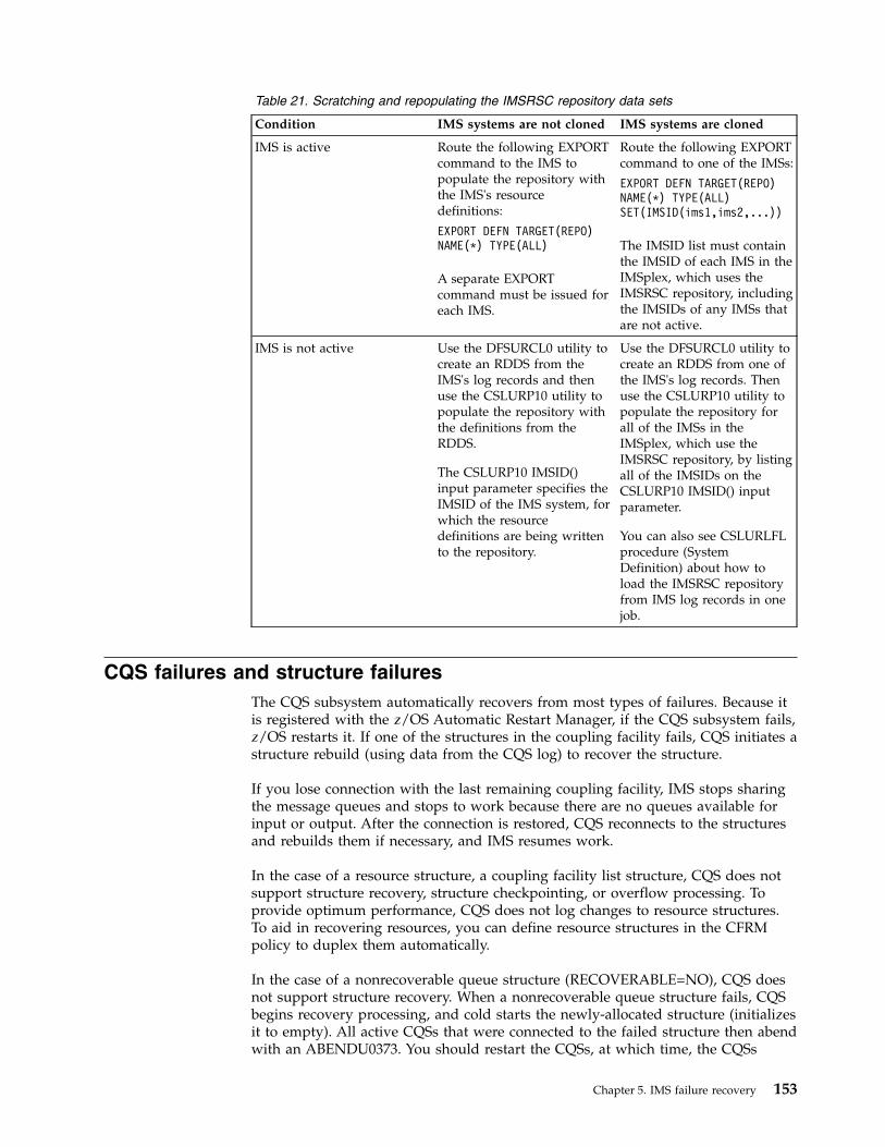
Table 21. Scratching and repopulating the IMSRSC repository data sets
Condition IMS systems are not cloned IMS systems are cloned
IMS is active Route the following EXPORTcommand to the IMS topopulate the repository withthe IMS's resourcedefinitions:
EXPORT DEFN TARGET(REPO)NAME(*) TYPE(ALL)
A separate EXPORTcommand must be issued foreach IMS.
Route the following EXPORTcommand to one of the IMSs:
EXPORT DEFN TARGET(REPO)NAME(*) TYPE(ALL)SET(IMSID(ims1,ims2,...))
The IMSID list must containthe IMSID of each IMS in theIMSplex, which uses theIMSRSC repository, includingthe IMSIDs of any IMSs thatare not active.
IMS is not active Use the DFSURCL0 utility tocreate an RDDS from theIMS's log records and thenuse the CSLURP10 utility topopulate the repository withthe definitions from theRDDS.
The CSLURP10 IMSID()input parameter specifies theIMSID of the IMS system, forwhich the resourcedefinitions are being writtento the repository.
Use the DFSURCL0 utility tocreate an RDDS from one ofthe IMS's log records. Thenuse the CSLURP10 utility topopulate the repository forall of the IMSs in theIMSplex, which use theIMSRSC repository, by listingall of the IMSIDs on theCSLURP10 IMSID() inputparameter.
You can also see CSLURLFLprocedure (SystemDefinition) about how toload the IMSRSC repositoryfrom IMS log records in onejob.
CQS failures and structure failuresThe CQS subsystem automatically recovers from most types of failures. Because itis registered with the z/OS Automatic Restart Manager, if the CQS subsystem fails,z/OS restarts it. If one of the structures in the coupling facility fails, CQS initiates astructure rebuild (using data from the CQS log) to recover the structure.
If you lose connection with the last remaining coupling facility, IMS stops sharingthe message queues and stops to work because there are no queues available forinput or output. After the connection is restored, CQS reconnects to the structuresand rebuilds them if necessary, and IMS resumes work.
In the case of a resource structure, a coupling facility list structure, CQS does notsupport structure recovery, structure checkpointing, or overflow processing. Toprovide optimum performance, CQS does not log changes to resource structures.To aid in recovering resources, you can define resource structures in the CFRMpolicy to duplex them automatically.
In the case of a nonrecoverable queue structure (RECOVERABLE=NO), CQS doesnot support structure recovery. When a nonrecoverable queue structure fails, CQSbegins recovery processing, and cold starts the newly-allocated structure (initializesit to empty). All active CQSs that were connected to the failed structure then abendwith an ABENDU0373. You should restart the CQSs, at which time, the CQSs
Chapter 5. IMS failure recovery 153
performs resync processing with any connected clients. You can manually restartCQS, use the z/OS ARM feature (ARMRST=Y), or use your own automation.When CQS restarts after the failure of a nonrecoverable queue structure, all data inthe previous (failed) structure is lost.
CQS log recoveryCQS uses a z/OS log stream for its recovery log. You cannot recover if the lastoffload data set in the z/OS log stream is full and CQS fails. Be sure to scheduleCQS system checkpoints frequently enough to prevent your offload data sets fromfilling. You can define groups of offload data sets for the system log, and z/OSuses each group in turn so that you do not run out of data sets. CQS can recoveryour system by using these data sets.
CCTL failuresCCTL failures commonly include CCTL region failures, in which a program is notstopped, and when a program is stopped
CCTL region failureIf a CCTL fails, it normally disconnects from the IMS DBCTL system and has noeffect on the IMS DBCTL system itself. The CCTL threads are terminatedimmediately or after they complete their current DBCTL request. These threadterminations appear as DFS554I messages. The programs are not stopped.
What action IMS takes for database changes made (units of recovery), depend onthe sync-point state of the thread. If a CCTL fails, a U113 abend of the DBCTLcontrol region can occur.Related reference:
CCTL exit routines (Exit Routines)
CCTL thread failureA CCTL thread failure can occur if the CCTL thread makes a database resourceadapter (DRA) request, and IMS ends abnormally during that request.
When this happens, IMS issues a DFS554I message, and the CCTL indicates thefailure to its operator. The program is stopped; you can start it again using the/START command after the problem is resolved. If a CCTL thread fails within theCCTL itself, IMS takes no action.
A thread can also fail because of an abend while the thread is within IMS or theDRA. For example, when the IMS DBCTL system fails, all CCTL threads endsabnormally in the DRA with a U002 abend. What happens to the UOR associatedwith the CCTL thread is determined by its sync-point state. If the failure occurswhile UOR is in-flight, IMS backs the UOR out; if the UOR is in-doubt (in themiddle of the sync-point process), the UOR remains in-doubt.Related concepts:
Unit of recovery (Application Programming)
CCTL thread loopingUse CCTL commands to determine if the CCTL is looping or if it has issued aDBCTL request and is waiting for a response. Refer to your CCTL documentationif the CCTL is looping. Otherwise, issue the /DISPLAY command to find the region
154 Operations and Automation

with the recovery token that corresponds to the CCTL task that is waiting for aresponse from DBCTL. Then use the /STOP REGION command to force that thread toend.
DBCTL failuresA termination of a IMS DBCTL system does not cause connected subsystems toterminate; the subsystems are simply left without DBCTL services. If any of theDBCTL address spaces (DBC, DBRC, or DLISAS) fails, all of its address spaces areterminated.
The state of the DRA is determined by how the CCTL responds to notification ofthe IMS DBCTL system failure.
Normally, you terminate the IMS DBCTL system using a /CHECKPOINT FREEZEcommand, but you can also use the z/OS MODIFY command to force termination,particularly if an IMS shutdown or failure results in a loop. If you use theMODIFY command and want a dump of the address space, use the DUMPkeyword; otherwise use the STOP keyword. The DBCTL control region terminateswith a U0020 abend, and IMS issues the following messages: DFS628I andDFS629I. These messages tell you that an abend is scheduled and what the jobname is.
After determining the cause of the failure and correcting it, restart the IMS DBCTLsystem using the /ERESTART command. The CCTL cannot reconnect to the IMSDBCTL system until the /ERE command completes. The CCTL has several optionson how to respond to a DBCTL failure.
When a CCTL connects to an IMS DBCTL system after a restart, theyresynchronize in-doubt UORs automatically. Resynchronization means that theCCTL requests an action (commit, abort, or forget) and the IMS DBCTL systemprocesses that request. If the commit or abort process fails, IMS takes the sameactions as in the DB/DC environment. If the commit process fails for systems withDEDBs, IMS sends message DFS2282I to the DBCTL operator. For all failures, IMSremoves the EEQEs because the UOR is no longer in-doubt.
If a CCTL requests resynchronization of an in-doubt UOR, and the DBCTLsubsystem has no knowledge of that UOR, IMS returns code 218 to the CCTL, andsends message DFS2283I to the DBCTL operator. The DBCTL operator can use the/DISPLAY command to display the in-doubt UORs known to the IMS DBCTLsubsystem.Related concepts:
Recovery in an IMS DBCTL environment (System Administration)Related reference:
CCTL exit routines (Exit Routines)
IRLM failuresWhen an IRLM fails, IMS subsystems using the IRLM cannot continue normaloperation. IMS terminates active programs using the IRLM with abend 3303 andputs their messages on a suspend queue.
Chapter 5. IMS failure recovery 155
For wait-for-input programs using the IRLM, IMS either terminates them withabend 3303 on their next database call or gives them a QC status code. IMS inhibitssubsequent program scheduling until IMS reconnects with the IRLM.
Before IMS can back out the IRLM failure, every dependent region with an intentto use a database must terminate its threads. IMS cannot terminate or reconnect tothe IRLM until all dependent regions disconnect from the IRLM. Therefore, youmust abnormally terminate any region that has not terminated (such as thoseprograms that are waiting in an for a timer expiration or a for a reply to aWrite-to-Operator with Reply (WTOR) message.
Restart the IRLM using the z/OS START command. Then, reconnect IMSsubsystems to the restarted IRLM using the z/OS MODIFYjobnameRECONNECTcommand. IMS automatically dequeues messages on the suspend queue.
Recovery with data sharingIn a data-sharing environment, you must extend IMS recovery procedures byprotecting surviving subsystems from database records that contain incompletechanges left by a failing subsystem. IMS recovers a shared database by restoringthe database from the latest image copy.
You can use the merge function provided with the IMS Database ChangeAccumulation utility (DFSUCUM0) to merge the log data sets from the subsystemsthat updated the database.
Apply the records from the utility (in the output data sets) for a forward recovery.If only one subsystem in a data-sharing environment updated the database, IMSdoes not need to use the sequence numbers and the Database ChangeAccumulation utility, because it has only one set of log data sets to manage.
IMS data sharing also introduces other challenges. Two IMS Internal Resource LockManagers (IRLMs) might lose communication with each other because:v An z/OS cross-system coupling facility (XCF) might fail.v An IRLM might fail, leaving its IMS subsystems running.v A z/OS system might fail, bringing down the IRLM, VTAM, DBRC, and IMS
subsystems running under it.
In a data-sharing environment, IMS must ensure data integrity after failure of oneor more components of data sharing.
The IRLM and DBRC work together with IMS to protect shared databases beforeand after a failure leaves incomplete changes in these databases. This protectionremains after a failure until failed subsystems complete backout of incompletechanges.Related reference:
Database Change Accumulation utility (DFSUCUM0) (Database Utilities)
DBRC and protecting dataDBRC provides database-level (level 1) data sharing and database-level protectionafter a failure occurs. DBRC prevents conflicts in database allocation that couldcompromise database integrity. DBRC uses the RECON data set to recordinformation about each database authorization it grants to IMS subsystems, and toindicate whether a subsystem is updating a database.
156 Operations and Automation
DBRC removes this indication when any of the following occur:v The subsystem terminates normally.v Dynamic backout completes after a failure.
If an IMS subsystem fails during an update, the RECON data set still indicates thisincomplete update. DBRC does not grant additional database authorizations unlessthe IRLM retains locks that protect the incomplete changes.
IRLM and protecting dataThe internal resource lock manager (IRLM) can protect your data if an IMSsubsystem fails.
If the IRLM is present and remains running, it retains locks on incomplete changesat the database record level after an IMS subsystem fails. The IRLM removes theselocks when dynamic backout completes.
If the IRLM fails while its IMS subsystems continue to run, the subsystems stop allwork in progress, dynamically back out all incomplete database changes, and callDBRC to relinquish their authorizations to shared databases. After you restart theIRLM, the subsystems resume processing.
If two or more IRLMs are active during block-level data sharing, and one IRLMfails with or without the z/OS system that it runs under, the surviving IRLMs andtheir IMS subsystems reauthorize with DBRC the use of all shared databases.
In this case, because the surviving IRLMs know about the block-level locks (thatprotect the incomplete changes made by the failed subsystem), they permit theirIMS subsystems to continue block-level sharing of the affected databases.
Fast Database Recovery (FDBR) regionsIn a sysplex data-sharing environment, if one IMS subsystem fails while it holdslocks on data in shared databases or while waiting for work on an externalsubsystem, the other sharing IMS subsystems must wait for the failed subsystem torestart and release its locks. To reduce the amount of time that the sharingsubsystems must wait, you can use IMS Fast Database Recovery (FDBR) regions.
FDBR regions monitor an IMS subsystem and can automatically recover databaseresources (shared databases and areas) if the monitored subsystem fails. Inaddition, in-doubt work on an attached external subsystem can be identified bycalling the External Subsystem Attach Facility (ESAF) In-Doubt Notification exitroutine (DFSFIDN0), which passes an informational message that you can use toautomate in-doubt work handling during recovery.
An FDBR region tracks a single subsystem, so you must set up a separate FDBRregion for each subsystem that you want FDBR to track.
An FDBR region does not have to run in the same z/OS system as the IMSsubsystem it tracks, but both the FDBR region and the IMS subsystem must be inthe same z/OS cross-system coupling facility (XCF) group. The FDBR region alsomust have access to the following IMS data sets:v ACBLIBxv MODBLKSxv MODSTATx
Chapter 5. IMS failure recovery 157
v OLDSv Restart data set (RDS)v RECONxv SDFSRESLxv WADS
FDBR is similar to XRF in that it operates in distinct phases:v Surveillancev Recovery processv Post-recovery
Restrictions:
v You cannot use an FDBR region with the following types of subsystems: DCCTL,Extended Recovery Facility (XRF), or DBCTL standby.
v While using a tracking system such as FDBR, you must not use a buffermanager that is different from that of the active system.
You do not have to register a CSL with an FDBR region. If you do register a CSLwith an FDBR region, it gives you the following benefits:v a more complete picture of the IMSplex when looking at it from the QUERY
IMSPLEX commandv a monitor program can watch the status of FDBR using the notifications that SCI
sends when an IMSplex member joins and leaves the IMSplex
FDBR surveillanceDuring the surveillance phase, the FDBR region monitors database activity byreading the IMS log. It monitors all activity for shared databases and areas, andcan monitor activity for nonshared areas.
Restriction: An FDBR region does not track MSDB activity.
If the IMS subsystem that the FDBR region is tracking fails, the FDBR regionautomatically begins recovery for all tracked databases and areas. If the IRLM forthe tracked IMS subsystem fails, or if there is no log activity from the tracked IMSsubsystem for a specified length of time, the FDBR region issues a message tellingthe operator to begin FDBR recovery.
FDBR recovery processIf the tracked IMS subsystem fails, the FDBR region automatically begins recovery.During automatic recovery, the FDBR region uses the MVS Availability Manager todetermine when I/O is complete for the databases and areas it will recover.
During recovery, the FDBR region does the following for all tracked databases andareas:v Allocates and opens database data setsv Backs out updates for full-function databasesv Performs REDO processing for DEDB areas
After recovery is complete, the FDBR region tells IRLM to release retained locks forthe recovered databases and areas. The FDBR region then issues a message thatrecovery is complete.
158 Operations and Automation
If the tracked IMS subsystem's z/OS cross-system coupling facility (XCF) fails, theFDBR region stops tracking and issues a message. If the FDBR region's XCF fails,the region abnormally terminates.
To begin recovery manually, issue the z/OS MODIFYfdbrproc, RECOVERcommand. For manual recovery, the FDBR does not wait for I/O to completebecause it assumes the I/O is already complete.
Online change and FDBRFDBR tracks online changes through the x'70' log records.
To avoid problems if FDBR is shut down or restarted after an online change isperformed, or to avoid problems under other circumstances after online change,take one or more IMS system checkpoints after the online change is complete andbefore FDBR is shut down or restarted. Doing so ensures that FDBR restarts from acheckpoint that was taken after the last online change.
For example, before you restart FDBR after an online change, issue the/CHECKPOINT command on the active system to take a simple checkpoint andverify from the DFS3804I message that the latest restart checkpoint time stamp isafter the online change.
FDBR post-recoveryWhen recovery is complete, all shared databases and areas are available to othersharing IMS subsystems in the sysplex. You can restart the failed IMS subsystem atany time.
During IMS restart, IMS does the following to complete recovery:v Writes updates for shared VSO areas to DASDv Recovers nonshared DEDB areas that were not tracked by the FDBR regionv Recovers MSDBs
After the IMS subsystem is running, you can reestablish tracking by the FDBRregion by issuing the z/OS STARTfdbrproc command.
Commands for using FDBRUse the commands for Fast Database Recovery (FDBR) to start and terminatetracking, obtain status, and initiate recovery. For each command, fdrprocrepresents the FDBR procedure name.
Starting tracking:
Normally, you start FDBR with a JCL job, submitted during system start, after thetracked IMS is started.
You can also issue the z/OS START command to start FDBR tracking of an IMSsubsystem, as follows:
S fdrproc
Obtaining status:
You use the z/OS MODIFY command to obtain Fast database recovery (FDBR)status.F FDR1,STATUS
Chapter 5. IMS failure recovery 159
This command returns the following information:DFS000I: PHASE: TRACKING LOG-TIME: 17:48:41 FDR1DFS000I: ACT-ID: SYS3 GROUPNAME: FDRSYS3 FDR1DFS000I: TIMEOUT: 060 SEC AREA01: NORECOV FDR1DFS000I: SVSOOPEN: SERIAL FPBUFF: LOCAL FDR1
The returned information includes:
PHASEThis field indicates the phase of the FDBR region. You can display thefollowing phases:
INIT (initialization phase)TRACKING (tracking phase)RECOVERY (recovery phase)
ACT-IDThe IMS ID that FDBR is tracking. If the FDBR region is in initializationphase, N/A is shown.
GROUPNAMEz/OS cross-system coupling facility group name used for XCF monitoring.If the FDBR region is in initialization phase, N/A is shown.
TIMEOUTXCF timeout value. If the FDBR region is in initialization phase, N/A isshown.
LOG-TIMETime associated with the log record currently being processed by FDBRregion. The length of time the FDBR lags behind the IMS in reading the logis the difference between the current time, as shown by the time stamp andthe log time. If the FDBR region is in initialization phase, N/A is shown.
AREA01=This field shows the share level 0|1 DEDB area recovery option as follows:
NORECOVNORECOV option is specified in DFSFDRxx IMS.PROCLIBmember.
RECOVRECOV option is specified in DFSFDRxx IMS.PROCLIB member.
Initiating recovery:
Use the z/OS MODIFY command to initiate FDBR.
You can use this command if FDBR determines a time out status during z/OScross-system coupling facility (XCF) or log surveillance. The command is notaccepted if FDBR is being initialized or is already in a recovery process.
The following command starts FDBR immediately: F fdrproc,RECOVER
Terminating tracking:
Use the z/OS MODIFY command to terminate FDBR.
The following command stops FDBR tracking activity:F fdrproc,TERM
160 Operations and Automation

The command is not accepted if FDBR is being initialized or is in a recoveryprocess.
Stopping the FDBR region:
You can use z/OS MODIFY commands to stop the FDBR region functions.1. The following command ends FDBR functions without producing a dump:
a. F fdrproc,STOP
FDBR ends with a return code of 0200.2. The following command ends FDBR functions and produces a dump:
a. F fdrproc,DUMP
FDBR ends with return code of 0020.
User access problemsThe task of determining and responding to user access problems can be done bythe IMS MTO, the network support group, or a user liaison group.
If your installation has a user liaison group that helps end users with problemdetermination, you need to explain what information that group should obtainfrom the end user before they contact the IMS MTO. This information includes adescription of the problem's symptoms (such as poor response time or no responseat all), details of any system or application program error messages received,terminal status lights, and so forth. Be sure to give the user liaison groupguidelines on whether to call the network support group, application supportgroup, or IMS MTO.
After they have gathered all information from the end user, they should develop aplan for determining the cause of the problem and, if possible, correcting it.Typically, user problems can be classified as:v Poor system responsev No response, or terminal keyboard lockedv Unexpected output (system or application program error messages)
If the general system response is poor, the MTO should follow the proceduresdescribed in “Monitoring the system” on page 107.
If the end user is getting no response at all or has a locked keyboard, the problemmight be in the network or in the status of the application program resourcesrequired by the transaction. For example, an OLDS might need to be archived tofree additional logging resources. Use one of the following commands to determineif any of the required resources are unavailable:v /DISPLAY STATUSv /DISPLAY OLDSv QUERY DB SHOW(STATUS)
If the end user is receiving application program error messages or invalid output,the MTO should follow your procedures for contacting the appropriate applicationsupport group. You should define the documentation that MTO need to provide tothe support groups, including a dump of the message region (if one was
Chapter 5. IMS failure recovery 161
produced), or exact details of the original transaction the user entered. For IMS orVTAM system messages, the MTO should follow the appropriate error recoveryprocedures.Related concepts:“Monitoring the system” on page 107
IMS recovery using Extended Recovery FacilityTo operate IMS in an Extended Recovery Facility (XRF) complex, you mustunderstand what tasks to perform during each XRF phase, from initializationthrough termination.v Initialization:
– How to bring up the active IMS subsystem– How and when to bring up the alternate IMS subsystem
v Synchronization:– Whether or not to enter the /CHECKPOINT SNAPQ command
v Tracking:– How to use the /DISPLAY command and read the status line of the master
terminal– How to use online change– How to change surveillance dynamically– How to use other XRF-related commands– How to use XRF in an IMS DBCTL environment– How to use XRF in a data-sharing environment
v Takeover:– How does automatic takeover differ from manual takeover– How to work with the operator of the other subsystem and the operator of
the network– How to initiate a takeover– How to ensure I/O prevention on the failed active subsystem– When to end I/O toleration on the alternate subsystem– How to switch DASD and class-3 terminals
v Post-takeover:– How to ease the workload on the new active subsystem– How and when to restore service to class-3 and class-2 terminals that failed to
switch– How to complete dynamic DL/I backouts– How to perform diagnostics on the failed subsystem– How to bring up a third subsystem as an alternate or to restore the original
active as the alternate subsystemv Termination:
– How to terminate an XRF complex– How to stop surveillance
XRF requires the following resources:v z/OS, IMS, and VTAM, running on each central processor complex (CPC).v If USERVAR is used, Network Control Program (NCP) running on a 3725
Communication Controller for full terminal switching.
162 Operations and Automation
v IMS system logs— online data sets (OLDSs) and write-ahead data sets(WADSs)—and certain other system data sets must be on DASD shared by bothIMS subsystems.
Related concepts:
Overview of XRF (System Administration)
Planning for operating an XRF complexWhen operating with XRF, it is important that the staff understand the“single-system image” and have an awareness of what physically belongs to activeor alternate subsystems, what is shared, and generally where system and databasedata sets are located.
The operator preparation is mostly knowing the division of responsibility whenprocessing moves to an a different processor as a result of a takeover.
Regardless of whether master terminal operations staff have master terminals closeto one another, close communication is required.
There are several considerations when you plan changes to your operationalcontrol for XRF. These considerations are:v Whether additional staff should be responsible for an alternate subsystem and
assume full control when that subsystem becomes the activev Whether a relocation of the IMS master terminal and z/OS alternate subsystem
console is necessaryv How additional takeover activities and other procedure changes are to be
incorporated into “run books”v Whether a takeover should proceed automatically or by means of operator
intervention when the alternate subsystem makes a takeover decision
Communication and console configuration among operatorsTo promote good communication among the operators of an XRF complex, placeall consoles in a central location. The speed with which the takeover proceedsdepends on operators confirming that a takeover is in progress and that I/Oprevention is complete. This confirmation is easiest when operators are located inthe same physical area.
With the operators in two separate physical locations, the chance formisunderstanding or lack of communication is great. The success of the takeoverand the integrity of the databases lies with your operators and their awareness ofwhat is going on in the entire complex.
The following figure shows a recommended configuration for the consoles that areresponsible for managing XRF:v A group of four logical consoles:
– IMS master terminal for the active subsystem– IMS master terminal for the alternate subsystem– Multiple console support (MCS) console that receives messages from z/OS for
the active subsystem– Multiple console support (MCS) console that receives messages from z/OS for
the alternate subsystemv IMS secondary master terminal with attached printer for the active subsystemv IMS secondary master terminal with attached printer for the alternate subsystem
Chapter 5. IMS failure recovery 163

v Network terminal for VTAM and Tivoli® NetView® for z/OSv Optionally, two additional consoles for JES3 in the two systems (not shown in
the figure)
It is important that the active and alternate IMS subsystems each have their ownIMS master terminals. IMS limits the commands that the MTO can issue on thealternate subsystem.
On this set of terminals, your operators have a collective view of z/OS, IMS, andnetwork events. Your operators cannot issue the z/OS SYSTEM RESET command onthe processor consoles, but they can receive all the availability manager (AVM)messages and can issue monitoring commands.
MCS MTO SecondaryMTO
Printer
Operating system
Active
IMS
CPC
Operating system
Alternate
IMS
CPC
MCS MTO SecondaryMTO
Printer
Figure 6. Recommended console configuration for XRF
164 Operations and Automation

To understand how important it is to have the operators' consoles together,consider the implications of having separate centers for the active subsystem andthe alternate subsystem operations. Operators at each center must have someunderstanding of the entire XRF complex. The state of the alternate subsystem isimportant to the operators for the active subsystem, and vice versa. For example:v The operators for the active subsystem should know when the initialization of
the alternate subsystem is complete.v The operators for the active subsystem must know of a failure of the alternate
subsystem.v The operators for the alternate subsystem must know of the completion of I/O
prevention in the failing active subsystem.
At changes of shifts, the operators on one shift must let the operators on thefollowing shift know the current state of the complex.
Normal IMS operations in an XRF complexDuring takeover, operators must be aware of response time, availability ofterminals, data set access problems, and database access. You start the failed activesubsystem as a new active subsystem in parallel with the alternate subsystem,providing interim end-user service.
In terms of command usage, the operator needs to know the following:v When and how to initiate a takeover manuallyv When and how to terminate an IMS alternate subsystemv What terminal switching needs to be donev What database control might be requiredv How to interpret /DISPLAY output when operating in an XRF complexv How to make changes to the takeover criteria and surveillance methodsv How to respond to a failure of the takeover process
Those terminals considered critical for continuous service should be defined asclass-1 terminals. However, a certain number of these terminals might have to beswitched manually. A convenient way of connecting these terminals to the newactive IMS is to use an automated operator program. This program could issue aset of IMS /START or UPDATE commands. Another use of automated operatorprograms could be to modify surveillance intervals and takeover criteria.Related concepts:“Processing during takeover” on page 181
Online changes in an XRF complexIn addition to preparing the staging libraries, you need to prepare the inactivelibraries.Related concepts:
Making local online changes in an XRF complex (System Administration)
XRF in a data sharing environmentIf you are using IRLM in a sysplex data sharing environment and the alternatesubsystem is available, there are no required tasks to maintain continued dataavailability.
Chapter 5. IMS failure recovery 165
XRF with a data propagation managerTo propagate changed data from IMS DL/I databases in an XRF complex to Db2for z/OS tables, be sure IMS and Db2 for z/OS are available to both the active andalternate subsystems.
If Db2 for z/OS is not available on one of the systems, the data propagation fromIMS to Db2 for z/OS fails until Db2 for z/OS is made available.
XRF initializationDuring the initialization phase, in addition to standard IMS initialization tasks, theactive subsystem and the alternate subsystems in an XRF complex perform tasksspecifically related to XRF.
You need to know about the following:v What IMS parameters are in effect for XRF.v How to initialize MODSTAT, restart data set (RDS), and the message-queue data
sets.v Whether or not IMS joins the availability manager.v How to successfully start the XRF complex.v How to use VTAM USERVAR or VTAM Multinode Persistent Sessions (MNPS)
to manage terminal sessions for XRF.
XRF parameter determinationThe active subsystem uses the recoverable service element name (RSE name), notthe z/OS SSID, when signing on to DBRC and identifying to IRLM.
Using the RSE name allows the alternate subsystem to inherit databases and theirauthorizations from the active subsystem during takeover.
Both subsystems read IMS.PROCLIB member DFSHSBxx for their RSEname,surveillance options, and takeover conditions.Related reference:
DFSHSBxx member of the IMS PROCLIB data set (System Definition)
Data set initializationDuring initialization, the active subsystem can start but it is not XRF-capable if itdoes not find two MODSTAT data sets (unless global online change is enabled, inwhich case the MODSTAT data sets are not needed), two restart data sets (RDSs),and, if you used IMS Fast Path, four MSDBCPn data sets.
The alternate subsystem, however, cannot be started unless it finds these data setson shared DASD.
Both the active subsystem and the alternate subsystem allocate the latestMODSTAT and RDS, but the alternate subsystem switches to the unused pairduring startup. The active subsystem uses the last active MSDBCPn pair, and thealternate subsystem uses the other two.
In a shared-queues environment, the active IMS subsystem does not need themessage-queue data sets, but the alternate subsystem IMS subsystem does usethese data sets because the alternate subsystem does not participate in sharing theIMS message queues until it takes over the active IMS subsystem workload.
166 Operations and Automation

How to join IMS with the availability managerThe availability manager (AVM) has its own address space. You can start the AVMwith the z/OS START command or let z/OS start it automatically when you issuethe IMS /NRESTART or /ERESTART command. To start the availability manager,issue the z/OS START AVM command. When the AVM is initialized, you receivethe AVM001I message.
Recommendation: Use the z/OS START AVM,SUB=MSTR command to start theAVM. If you omit the SUB=MSTR keywords, z/OS starts the AVM from the JESaddress space, and the resulting dependency on JES means you cannot stop JESwithout also stopping the AVM.
Both the active subsystem and the alternate subsystem notify the z/OS availabilitymanager of their participation in an RSE during initialization. When IMSsuccessfully joins the AVM and RSE, you receive messages DFS3871I and DFS3873I.
If IMS fails to connect to the AVM, you receive message DFS3872I. If the connectionfails, the operator must initiate I/O prevention during XRF takeover.
You must have a procedure established in case the connection fails duringinitialization of either the active subsystem or the alternate subsystem. You mightwant to determine the cause of the failure and restart the initialization to ensurethat the connection is successful.
How to start the subsystems in an XRF complexStart the active subsystem first. Use the /ERE BACKUP command to start thealternate subsystem only after the active subsystem startup completes with theDFS994I message.
Recommendation: If the active subsystem begins processing before you start thealternate subsystem, issue the /CHECKPOINT command on the active subsystemto take a simple checkpoint. If you establish a checkpoint before starting thealternate subsystem, the alternate subsystem needs to read only the activesubsystem's log from this checkpoint.
After an XRF takeover, restart the alternate subsystem first if it issued a simplecheckpoint, even if you had not yet released it from I/O toleration (by issuing the/UNLOCK SYSTEM command or replying to an AVM message). Otherwise, restartthe active subsystem first.
When you start an XRF alternate subsystem (using the /ERE BACKUP command),IMS establishes VTAM backup sessions (if USERVAR is used with XRF), an AVMnode, and an ISC link to facilitate communications with the active subsystem. Ifthe alternate subsystem fails and is restarted by the z/OS Automatic ResourceManager (ARM), the VTAM ACB and the VTAM master terminals will be openedtowards the end of the alternate subsystem's initialization.
Startup procedures for subsystems:
You must have two distinct procedures to start an XRF complex because there aretwo separate IMSsubsystems that perform different functions.v One of these procedures must specify HSBID=1 in the IMS procedure and, in a
non-shared-queues environment, contain DD statements for its set of uniquemessage-queue data sets (LGMSG, SHMSG, QBLKS, LGMSGL, SHMSGL, andQBLKSL).
Chapter 5. IMS failure recovery 167

v The other procedure must specify HSBID=2 in the IMS procedure and contain DDstatements for its set of message-queue data sets, which must be distinct fromthe data sets listed above.
In an XRF complex, the OLDS definition (OLDSDEF) for the active subsystem mustmatch the OLDSDEF for the alternate subsystem. Also, all OLDSs used by theactive subsystem must be accessible to the alternate subsystem, regardless ofwhether they are in the OLDS definition.
IMS identifier:
The IMS identifier (ID) identifies a particular IMS subsystem. When an IMS BMPjob tries to link to an IMS subsystem, it attempts to link first to the subsystemspecified by the IMSID= parameter, and next to any subsystem specified by theALTID= parameter.
Specify the subsystem name in the IMSCTRL macro during system definition, andyou can overwrite the subsystem name in JCL procedures.
If the active and alternate subsystems in an XRF complex are on the same centralprocessor complex (CPC), their IMSIDs or ALTIDs must be different. If thesubsystems are on different CPCs, you can specify either the same or differentIMSIDs or ALTIDs.
If you specify different IMSIDs or ALTIDs, you must specify the correct IMSID orALTID in all dependent region JCL procedures.Related reference:
Parameter descriptions for IMS procedures (System Definition)
Terminal session management for XRFYou can use VTAM USERVAR or VTAM Multinode Persistent Sessions (MNPS) tomanage terminal sessions for XRF. The differences between each method aretransparent to the end user.
In an XRF system with USERVAR, the alternate subsystem continuously maintainsan open backup session for class-1 terminals and switches the terminals to thatsession during a takeover.
In an XRF system with MNPS, the alternate subsystem does not maintain backupsessions. Instead, the alternate subsystem opens a new instance of the MNPS ACBduring a takeover. Sessions for class-1 terminals are then rerouted through the newMNPS ACB on the alternate IMS.
Recommendation: Because of performance limitations of MNPS, use theCommunication Controller for Linux on System z® (CCL) to support XRF.Related concepts:
Using MNPS or USERVAR in XRF complexes (Communications andConnections)
Initializing the USERVAR to manage terminal sessions for XRF:
VTAM uses a variable called USERVAR to associate a user's logon message withthe application name of the currently active IMS subsystem.
168 Operations and Automation
The two subsystems in an Extended Recovery Facility (XRF) complex havedifferent application names.
During IMS initialization (and later, during XRF takeover), to allow terminals tolog on to the correct subsystem, IMS or network operators must initialize theVTAM USERVAR tables.
If you are not using the VTAM USERVAR Management Enhancement in yournetwork, the network operator must enter the MODIFYprocname, USERVARcommand for the alternate subsystem VTAM if it owns terminals. You might alsohave to tell operators for other VTAMs that communicate with the XRF complex toenter the z/OS MODIFY command to change the application name in theirUSERVAR tables.
The active IMS subsystem issues a MODIFY command to tell its own VTAM toinitialize the application name in its USERVAR table.
If you are using the VTAM USERVAR Management Enhancement in your network,the network operator should not initialize the VTAM USERVAR table nor use aTivoli NetView for z/OS program (CLIST) to propagate the table to other VTAMnodes. It is also not necessary for the operator to enter the z/OS MODIFYprocname,USERVAR command to change the application name in the USERVAR tables. TheVTAM USERVAR Management Enhancement does all of this for IMS.
Specifying MNPS to manage terminal sessions for XRF:
To have IMS use Multinode Persistent Sessions (MNPS) for Extended RecoveryFacility (XRF) terminal switching, specify the MNPS=name optional keyword on theDFSPBxxx or DFSHSBxx IMS.PROCLIB members.
The name specifies the name of the MNPS ACB, which is used for terminalrecovery. The MNPS ACB name must be the same for the active IMS and thealternate IMS, and only one MNPS ACB can exist at a time. If the MNPS= keywordis specified, the USERVAR= keyword is ignored.
Actions performed during synchronizationActions that the operator may need to take during synchronization include issuingthe /CHECKPOINT SNAPQ command, responding to inconsistent definitions, orresponding to improperly allocated system data sets.
The alternate subsystem system automatically performs the following actions:v Preopening backup sessions for class-1 terminals, if using USERVARv Pre-allocating and preopening DBDSs
Simple checkpoint request (/CHECKPOINT SNAPQ)After you start the alternate subsystem with the /ERESTART BACKUP command,the active subsystem sends an “OKTOSYNC” message to the alternate subsystemover the ISC link when checkpoint processing is in progress. If you do not have anISC link, the alternate subsystem monitors the restart data set (RDS) to determinewhen the checkpoint is taken.
After you start the alternate subsystem with the /ERESTART BACKUP command:v If you do not have an intersystem communication (ISC) link, and you receive
message DFS3801I on the alternate subsystem (saying that a checkpoint SNAPQis required on the active subsystem):
Chapter 5. IMS failure recovery 169
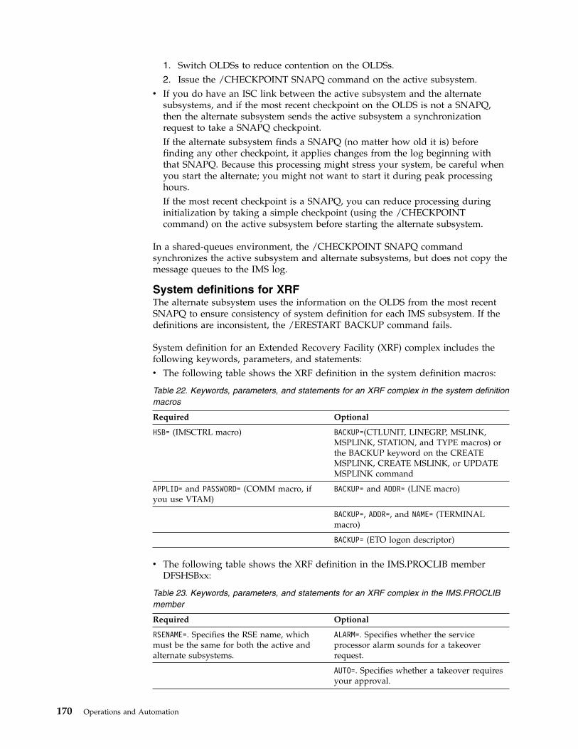
1. Switch OLDSs to reduce contention on the OLDSs.2. Issue the /CHECKPOINT SNAPQ command on the active subsystem.
v If you do have an ISC link between the active subsystem and the alternatesubsystems, and if the most recent checkpoint on the OLDS is not a SNAPQ,then the alternate subsystem sends the active subsystem a synchronizationrequest to take a SNAPQ checkpoint.If the alternate subsystem finds a SNAPQ (no matter how old it is) beforefinding any other checkpoint, it applies changes from the log beginning withthat SNAPQ. Because this processing might stress your system, be careful whenyou start the alternate; you might not want to start it during peak processinghours.If the most recent checkpoint is a SNAPQ, you can reduce processing duringinitialization by taking a simple checkpoint (using the /CHECKPOINTcommand) on the active subsystem before starting the alternate subsystem.
In a shared-queues environment, the /CHECKPOINT SNAPQ commandsynchronizes the active subsystem and alternate subsystems, but does not copy themessage queues to the IMS log.
System definitions for XRFThe alternate subsystem uses the information on the OLDS from the most recentSNAPQ to ensure consistency of system definition for each IMS subsystem. If thedefinitions are inconsistent, the /ERESTART BACKUP command fails.
System definition for an Extended Recovery Facility (XRF) complex includes thefollowing keywords, parameters, and statements:v The following table shows the XRF definition in the system definition macros:
Table 22. Keywords, parameters, and statements for an XRF complex in the system definitionmacros
Required Optional
HSB= (IMSCTRL macro) BACKUP=(CTLUNIT, LINEGRP, MSLINK,MSPLINK, STATION, and TYPE macros) orthe BACKUP keyword on the CREATEMSPLINK, CREATE MSLINK, or UPDATEMSPLINK command
APPLID= and PASSWORD= (COMM macro, ifyou use VTAM)
BACKUP= and ADDR= (LINE macro)
BACKUP=, ADDR=, and NAME= (TERMINALmacro)
BACKUP= (ETO logon descriptor)
v The following table shows the XRF definition in the IMS.PROCLIB memberDFSHSBxx:
Table 23. Keywords, parameters, and statements for an XRF complex in the IMS.PROCLIBmember
Required Optional
RSENAME=. Specifies the RSE name, whichmust be the same for both the active andalternate subsystems.
ALARM=. Specifies whether the serviceprocessor alarm sounds for a takeoverrequest.
AUTO=. Specifies whether a takeover requiresyour approval.
170 Operations and Automation

Table 23. Keywords, parameters, and statements for an XRF complex in the IMS.PROCLIBmember (continued)
Required Optional
DEFERFIX=. Identifies the IMS.PROCLIBmember DFSFIXnn.
USERVAR=. Specifies the USERVAR (if you useVTAM)
SURV=. Specifies the surveillance mechanisms.
LNK=. Specifies interval and timeout valuesfor links.
LOG=. Specifies interval and timeout valuesfor the log.
RDS=. Specifies interval and timeout valuesfor the restart data set (RDS).
SWITCH=. Controls whether absences ofsurveillance signals or failures of VTAM or ofthe IRLM cause the alternate subsystem torequest or initiate a takeover.
The IMS.PROCLIB member DFSHSBxx controls the following aspects of the XRFcomplex:– Surveillance mechanisms– Takeover conditions– Display of optional messages– VTAM USERVAR name or MNPS ACB name (depending on whether
USERVAR or MNPS is used)– Name of the IMS.PROCLIB member that determines non-Fast Path control
region page-fixing values for the alternate subsystem after a takeover– Name by which the complex is known to z/OS, DBRC, and the IRLMs
v In the IMS.PROCLIB member DFSFIXnn:This member specifies page-fixing options for the alternate subsystem after atakeover. You can move non-Fast Path related options of an existing DFSFIXnnmember to this additional page-fix member to reduce the real storagerequirements of the alternate subsystem during initialization and tracking. Usethis member to fix buffer pool pages that you do not want fixed duringinitialization and tracking.
v In the IMS.PROCLIB member DFSVSMxx:If the active and the alternate subsystems are on the same CPC, you mustchange the VSAMPLS keyword on the OPTIONS control statement to specify LOCL(local) instead of GLBL (global) for at least one of the subsystems. Only onecontrol region on a processor can request a VSAM Shared Resource Pool. If youspecify LSO=Y or LSO=S for the IMS control region, the default for VSAMPLS is LOCL.The OLDSDEF and WADSDEF control statements must be identical.
v In the EXEC statement for each control region:– HSBMBR=, which gives the suffix for the DFSHSBxx member of IMS.PROCLIB.– HSBID=, which identifies the message queues. Setting HSBID= to null
deactivates XRF capability.If you do not set HSBID= to null, you must specify either 1 or 2. The procedurefor IMSA must specify a different value than you specify for IMSB.
Chapter 5. IMS failure recovery 171
If after a takeover, you bring up a third subsystem as an alternate subsystem,specify the same HSBID= as on the failing active subsystem.
v If the XRF subsystems participate in block-level data sharing, you need JCLstatements for the IRLMs.
v DD statements for system data sets.Related tasks:
Guidelines for IMS system data set placement (System Administration)
System data sets for XRFIf the restart data set (RDS), MODSTAT , and MSDBCPn data sets are not properlyallocated on the active and alternate subsystems, the alternate subsystemterminates. The alternate subsystem loads MSDBs from the SNAPQ records ratherthan from the MSDBCPn data set containing the last image.
Because IMS allocates data sets and pre-loads programs during initialization ofdependent regions, you should exercise care if you make any changes in theseareas after this time. Specifically:v If programs running on the active subsystem modify data set allocation
information, you might have to rewrite these programs to use dynamicallocation. Also note that IMS does not perform I/O prevention for any userdata set.
v If you rebind preloaded programs on the active subsystem and subsequentlyactivate them using the z/OS START command, you must also restart theassociated regions on the alternate subsystem. The alternate subsystem does notautomatically start or stop its dependent regions based on actions on the activesubsystem.
Backup sessions for class-1 terminalsIf USERVAR is used, the alternate subsystem establishes backup sessions forterminals that have the BACKUP=(, YES) option specified and that have opensessions (as recorded in the SNAPQ log records).
Tracking in the XRF complexDuring normal operations, the operators do not have any tasks specifically for XRF,nor do they receive messages about XRF. During the tracking phase, your tasks areto monitor, maintain, and modify the XRF complex.
Because these tasks involve IMS commands that are also useful during otherprocessing phases, these topics review all XRF-related IMS commands.
During the tracking phase, operators can issue the following commands to monitorthe system:v IMS /DISPLAY HSB commandv VTAM DISPLAY NET,ID and DISPLAY NET,USERVAR commands (if USERVAR
is used)
These commands display the status of the XRF complex and monitor the status ofsessions on class-1 terminals.
Operator commands on an XRF alternate subsystemBecause the XRF alternate subsystem does not process transactions, the operatorfor the alternate subsystem does not need some of the commands that the operatorfor the active subsystem needs.
172 Operations and Automation
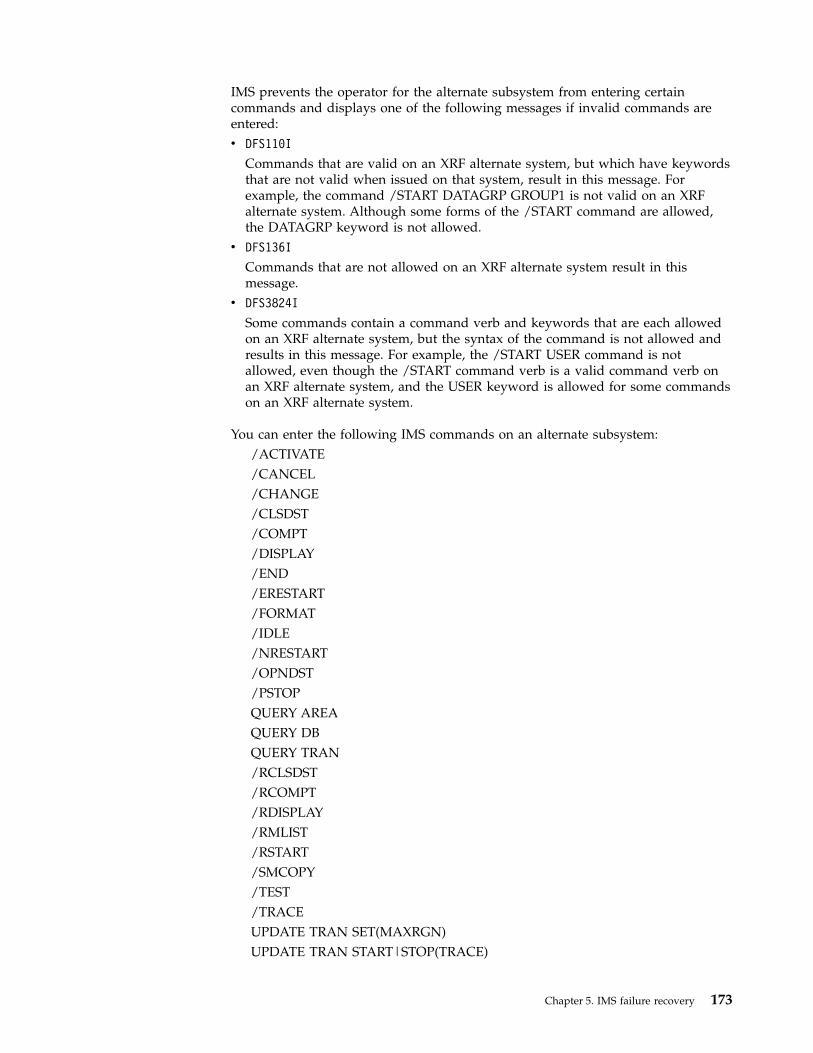
IMS prevents the operator for the alternate subsystem from entering certaincommands and displays one of the following messages if invalid commands areentered:v DFS110I
Commands that are valid on an XRF alternate system, but which have keywordsthat are not valid when issued on that system, result in this message. Forexample, the command /START DATAGRP GROUP1 is not valid on an XRFalternate system. Although some forms of the /START command are allowed,the DATAGRP keyword is not allowed.
v DFS136I
Commands that are not allowed on an XRF alternate system result in thismessage.
v DFS3824I
Some commands contain a command verb and keywords that are each allowedon an XRF alternate system, but the syntax of the command is not allowed andresults in this message. For example, the /START USER command is notallowed, even though the /START command verb is a valid command verb onan XRF alternate system, and the USER keyword is allowed for some commandson an XRF alternate system.
You can enter the following IMS commands on an alternate subsystem:/ACTIVATE/CANCEL/CHANGE/CLSDST/COMPT/DISPLAY/END/ERESTART/FORMAT/IDLE/NRESTART/OPNDST/PSTOPQUERY AREAQUERY DBQUERY TRAN/RCLSDST/RCOMPT/RDISPLAY/RMLIST/RSTART/SMCOPY/TEST/TRACEUPDATE TRAN SET(MAXRGN)UPDATE TRAN START|STOP(TRACE)
Chapter 5. IMS failure recovery 173
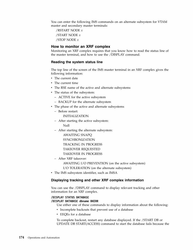
You can enter the following IMS commands on an alternate subsystem for VTAMmaster and secondary master terminals:
/RSTART NODE x/START NODE x/STOP NODE x
How to monitor an XRF complexMonitoring an XRF complex requires that you know how to read the status line ofthe master terminal, and how to use the /DISPLAY command.
Reading the system status line
The top line of the screen of the IMS master terminal in an XRF complex gives thefollowing information:v The current datev The current timev The RSE name of the active and alternate subsystemsv The status of the subsystem:
– ACTIVE for the active subsystem– BACKUP for the alternate subsystem
v The phase of the active and alternate subsystems– Before restart:
INITIALIZATION– After starting the active subsystem:
Null– After starting the alternate subsystem:
AWAITING SNAPQSYNCHRONIZATIONTRACKING IN PROGRESSTAKEOVER REQUESTEDTAKEOVER IN PROGRESS
– After XRF takeover:AWAITING I/O PREVENTION (on the active subsystem)I/O TOLERATION (on the alternate subsystem)
v The IMS subsystem identifier, such as IMSA
Displaying tracking and other XRF complex information
You can use the /DISPLAY command to display relevant tracking and otherinformation for an XRF complex.
/DISPLAY STATUS DATABASE/DISPLAY DATABASE dbname BKERR
Use either one of these commands to display information about the following:v Incomplete backouts that prevent use of a databasev EEQEs for a database
To complete backout, restart any database displayed. If the /START DB orUPDATE DB START(ACCESS) command to start the database fails because the
174 Operations and Automation
required OLDS have been archived and reused, use the date and time shownin the display to determine which SLDS to use and then perform batchbackout.
/DISPLAY ACTIVEUse this command on either the active or the alternate subsystem in an XRFcomplex to display information about active regions and, after the time stamp,the RSE name, the status of the subsystem (ACTIVE or BACKUP), and thephase of the XRF complex. The status can be one of the following:
AWAITING SNAPQSYNCHRONIZATIONTRACKINGTAKEOVER REQUESTEDTAKEOVER IN PROGRESSI/O TOLERATION
/DISPLAY HSBUse this command on either the active or the alternate subsystem to display:v The RSE namev The status of the subsystem (ACTIVE or BACKUP)v The mode (whether the alternate subsystem is in I/O toleration after a
takeover)v The processing phase of the alternate subsystem (if entered on the alternate
subsystem), which is one of the following:AWAITING SNAPQSYNCHRONIZATIONTRACKING IN PROGRESSTAKEOVER REQUESTEDTAKEOVER IN PROGRESS
v The IMSIDs of the active subsystem and the subsystem used to enter thecommand
v The VTAM USERVAR, if USERVAR is usedv The MNPS ACB name, if MNPS is usedv The time associated with the log record currently being read by the alternate
system as it tracks the active subsystemv The surveillance mechanisms in effect for the complexv The takeover conditions specified on the SWITCH= keyword of the DFSHSBxx
member of IMS.PROCLIBRelated concepts:“Unplanned takeover” on page 181“Maintaining the XRF complex during tracking” on page 178
Monitoring the status of the networkSome VTAM messages have a STATUS field that appears in response to the VTAMDISPLAY command. Examples in these topics describe the XRF-related keywordsfor the DISPLAY command and the STATUS fields that appear in the resultingmessages.
The following graphic shows example system configuration for monitoring an XRFcomplex. The complex contains a primary and a backup session; IMSNAME1 is in
Chapter 5. IMS failure recovery 175

the primary session and IMSNAME2 is in the backup session.
Displaying the status of specific terminals:
The VTAM DISPLAY NET,ID command allows the network operator to see thestatus of the primary and backup sessions for a specific class-1 terminal.
For example, to display the status of both sessions for the class-1 terminal withlogical unit name TERM1, the network operator issues the following command:DISPLAY NET,ID=TERM1,SCOPE=ALL
The response to this command is the following message:IST634I NAME STATUS SESSION ID SEND RECV VRN TP . . .IST635I IMSNAME1 APRIM-PRIIST635I IMSNAME2 ABKUP-PRIIST8351 END
Except for the STATUS field, the two IST635I messages should be familiar to yournetwork operators. The NAME and STATUS fields in the two messages indicatethe following:v The following is the first IST635I message:
IST635I IMSNAME1 APRIM-PRI
In this message:– IMSNAME1 indicates that terminal TERM1 is in session with IMSNAME1.– A indicates that the session is active, that is, not pending.– PRIM indicates that the session with IMSNAME1 is the primary session.– PRI indicates that IMSNAME1 is a primary LU.
v The following is the second IST635I message:
Communication
controllerNCP
Operating system 1
VTAM1Active
IMS 1
CPC
LUname=TERM1
Operating system 2
VTAM2Alternate
IMS 2
CPC
Figure 7. Monitoring status
176 Operations and Automation

IST635I IMSNAME2 ABKUP-PRI
In this message:– IMSNAME2 indicates that terminal TERM1 is in session with IMSNAME2.– A indicates that the session is active, that is, not pending.– BKUP indicates that the session with IMSNAME2 is the backup session.– PRI indicates that IMSNAME1 is a primary LU.
Displaying the status of sessions connected to specific subsystems:
The VTAM DISPLAY NET,ID command allows the network operator to see thestatus of all sessions on class-1 terminals connected to a specific subsystem in theXRF complex.
For example, to see the status of all class-1 terminals that have sessions with thesubsystem IMS1, the network operator issues the following command:DISPLAY NET,ID=IMS1,SCOPE=ALL
The following message (IST635I) appears for every session that is communicatingwith IMS1.IST635I NAME STATUS SESSION ID SEND RECV VRN TP . . .IST635I TERM1 APRIM-SEC
In this message:TERM1 indicates that terminal TERM1 is in session with IMSNAME1.A indicates that the session is active, that is, not pending.PRIM indicates that the session is a primary XRF session. All sessions withIMSNAME1 will be primary XRF sessionsSEC indicates that TERM1 is a secondary LU.
Recommendation: If you have many class-1 terminals, do not display all sessions.
Displaying the number of primary and backup sessions in XRF withUSERVAR:
The VTAM DISPLAY NET,ID command allows the network operator to see thenumber of primary and backup sessions on class-1 terminals communicating withXRF subsystems.
For example, to display the number of primary sessions in the XRF complex, thenetwork operator issues the following command:DISPLAY NET,ID=IMSNAME1,SCOPE=ALL
VTAM responds with this message:IST809I XRF SESSIONS - PRIMARY = nnnn BACKUP = 0000.
To display the number of backup sessions in the XRF complex, the networkoperator issues the following command:DISPLAY NET,ID=IMSNAME2,SCOPE=ALL
VTAM responds with this message:IST809I XRF SESSIONS - PRIMARY = 0000 BACKUP = mmmm.
Chapter 5. IMS failure recovery 177
Messages IST634I and IST635I follow with information about each session that iscommunicating with the IMS XRF complex.
An important use of this command is to determine if all the class-1 terminals havebackup sessions established (if USERVAR is used). For example, before initiating aplanned XRF takeover, an operator should make sure that all the users of class-1terminals have backup sessions in place. In this case, the operator issues bothDISPLAY commands discussed in these topics, compares the number of primaryand backup sessions, and does not initiate a takeover unless the two numbers areidentical.
Displaying the current application name in XRF with USERVAR:
The VTAM DISPLAY NET,USERVAR command allows the operator to see theapplication name that corresponds to a USERVAR in the USERVAR table.
For example, the operator issues the following command:DISPLAY NET,USERVAR,ID=IMS
The response to this command is:IST811I USERVAR(S):IST810I NAME = IMS, VALUE = IMSNAME1IST8351 END
If your installation has defined more than one USERVAR, the network operator canissue the following command to display all the USERVARs and the correspondingapplication names:DISPLAY NET,USERVAR
Maintaining the XRF complex during trackingMaintaining an Extended Recovery Facility (XRF) complex requires that you knowhow to change surveillance dynamically, how to update system data sets, and howto suspend operations on the active or the alternate subsystem.
Although an end user cannot log on to the alternate subsystem during the trackingphase, the master terminal, secondary master terminal, optional ISC link betweentwo subsystems, and the system console can communicate with the alternate.
You can enter the following commands on the alternate subsystem during tracking:
/DISPLAYUse the /DISPLAY command to display relevant tracking and otherinformation for an XRF complex.
/OPNDST NODE/CLSDST NODE
Use these commands to open and close VTAM sessions for the master terminaland the ISC link. These commands can reestablish backup sessions for class-1terminals that have active sessions, if USERVAR is used. Backup sessions arenot maintained in XRF systems with MNPS.
If the active IMS has a session that is XRF capable, enter /OPNDST commandon the alternate subsystem to establish a backup session, if it does not alreadyhave one.
178 Operations and Automation

In order to use the /OPNDST command successfully for a class-1 ETOterminal, the control blocks must exist and be coupled together, and an activesession must exist on the active system. If not, IMS rejects the /OPNDSTcommand, and issues message DFS3862.
/START LINE x PTERM y/STOP LINE x PTERM y/RSTART LINE x PTERM y
Use these commands to start, stop, and restart non-VTAM master andsecondary master terminals.
/START NODE x/STOP NODE x/RSTART NODE x
Use these commands to start, stop, and restart VTAM master and secondarymaster terminals.
/START REGION/STOP REGION
Use these commands to start and stop regions.
/START SURV/STOP SURV/CHANGE SURV
Use these commands to dynamically stop and start surveillance and todynamically change surveillance values.
Related reference:“How to monitor an XRF complex” on page 174
Controlling surveillance:
You can issue commands to start and stop surveillance for ISC link, the system log,and the restart data set. You can also change the mechanism, interval value, ortimeout value that you established during initialization.
Use the following command to dynamically stop and start surveillance, anddynamically change surveillance values:
/START SURVEILLANCE LNK | LOG | RDS | ALL/STOP SURVEILLANCE LNK | LOG | RDS | ALL
Use these commands to start and stop the operation of any (or all) of the threesurveillance mechanisms:v The ISC linkv The system logv The restart data set
If you operate with all three surveillance mechanisms, IMS can detect aproblem as soon as possible and is more likely to initiate a takeover only whenit is appropriate. However, you can stop and start surveillance for a briefperiod to perform a system change, such as to restart a DASD control unit, thatmight trigger an unwanted takeover.
/CHANGE SURVEILLANCE [LNK | RDS | LOG | ALL] TIMEOUT | INTERVALUse this command to change the mechanism, interval value, or timeout valuethat you established during initialization. If you enter this command on theactive subsystem, it affects both the active and the alternate subsystems; if youenter it on the alternate subsystem, it affects only the alternate subsystem.
Chapter 5. IMS failure recovery 179

Recommendation: Enter /CHANGE SURVEILLANCE on the activesubsystem. However, if you enter it on the alternate subsystem, do not specifyan interval or timeout value for the alternate subsystem that is less than theinterval or timeout value on the active.
Updating system data sets during tracking:
Before you make a system change to an XRF-capable IMS subsystem, you mustidentically update the equivalent data set on the other subsystem in the XRFcomplex.
Update the following system data sets:v IMS.ACBLIBA and IMS.ACBLIBBv IMS.FORMATA and IMS.FORMATBv IMS.MODBLKA and IMS.MODBLKBv IMS.TFORMATA and IMS.TFORMATB
You can perform identical updates on both subsystems using an IMS restart or theOnline Change Copy utility (DFSUOCU0). Use one set of staging libraries for bothsubsystems; a staging library is not a single point of failure because the onlinesubsystem does not use it. After you have ensured that the inactive data sets onboth subsystems are identical in content, use the /MODIFY PREPARE, /DISPLAYMODIFY, and /MODIFY COMMIT commands on the active subsystem. Afterthese changes are committed on the active subsystem, the alternate subsystemautomatically reprocesses the online change sequence.
Suspending operations on the active or alternate subsystem:
Do not suspend operations on or stop the z/OS system on which the activesubsystem is running without first disabling surveillance, unless you want toinitiate an XRF takeover.
Recommendation: Do not suspend operations on or stop the z/OS system onwhich the alternate subsystem is running without first disabling surveillance andstopping the active subsystem. If you do, the alternate subsystem could interferewith the performance of the active subsystem when you restart the alternatesubsystem because it tries to reflect the changes that occurred on the activesubsystem in the meantime.
IMS control region dump during tracking:
To prevent an unwanted takeover while processing an SDUMP, ensure that theXRF takeover interval is sufficient to allow the SDUMP to complete, and ensurethat the system data set contains adequate space for capturing information for thedump.
If you specify QUIESCE=YES on the z/OS CHANGEDUMP command, any SVCdump, depending on the timeout values assigned to the LNK and RDS keywordsin DFSHSBxx, might trigger a takeover request. If you specify QUIESCE=NO, onlya dump of the IMS control region can trigger a takeover. If you are troubled bySVC dumps that cause unwanted takeovers, stop surveillance or specifyQUIESCE=NO.
Recommendation: To prevent an unwanted takeover while processing an SDUMP:
180 Operations and Automation
How commands on the active subsystem affect the alternate subsystem:
Commands that make resources unavailable to the active subsystem also makethese resources unavailable to the alternate subsystem after a takeover. Thisincludes, for example, a /STOP PROGRAM command to stop the scheduling oftransactions and any command to reassign terminals or stop physical terminals.
Processing during takeoverMost of the processing during takeover takes place in the alternate subsystem. Thealternate subsystem detects the normal or abnormal termination of the activesubsystem and takes control of its resources and workload.Related concepts:“Normal IMS operations in an XRF complex” on page 165
Planned takeoverYou can apply hardware or software maintenance to either subsystem in an XRFcomplex as long as you do not change the log record format, make systemdefinition changes (and bring up an alternate subsystem with those changes), orapply maintenance that requires an IMS cold start in a non-XRF environment.
To apply maintenance to the alternate subsystem: terminate it, leaving the activesubsystem without an alternate subsystem for the time that you take to apply themaintenance. Then bring that subsystem back up as the alternate subsystem.
To apply maintenance to the active subsystem: initiate a planned takeover to shiftits workload to the alternate subsystem. After you apply maintenance, bring upthat subsystem as a new alternate subsystem. Initiate another takeover to returnthe subsystem to its role as the active subsystem.
Unplanned takeoverThe alternate subsystem can take over the workload of the active subsystemwithout operator intervention.
In an XRF complex, the alternate subsystem uses log records and surveillance todetect events on the active subsystem that suggest the need for a takeover:v It reads the log for evidence of an IMS abend.v It reads the log for evidence of an IRLM failure.v It detects an absence of signals across the ISC link, absence of new records on
the OLDS, or absence of a new time stamp on the restart data set (RDS).
You can display the surveillance mechanisms and takeover conditions in effect byusing the /DISPLAY HSB command.
The following conditions can trigger a takeover request:v A surveillance-detectable failure of the IMS control regionv A total failure of z/OSv A single central processor complex (CPC) failurev An IRLM failure that causes IMS to call the IMS STATUS exit routinev A VTAM failure that causes IMS to call the IMS TPEND exit routine
If you set the SWITCH= parameter of the DFSHSBxx member in IMS.PROCLIB toSWITCH=(LNK,LOG,RDS),(IRLM),(TPEND) (the default), the alternate subsystemrequests or initiates a takeover for any one of the following events:
Chapter 5. IMS failure recovery 181

v Both the ISC link and the RDS fail to send signals, and new log records fail toappear after the timeout periods that you specify.
v The IRLM fails and calls the STATUS exit routine.v VTAM fails and causes IMS to call the TPEND exit routine.
XRF does not take over for the following types of failures:v A channel or link failure that causes a break in communication between the CPC
and the communication controllersv A failure in the telecommunication network, such as communication controllers,
the network control program (NCP), telecommunication lines, or terminalsv An intersystem failure, such as those caused by JES3 or CTC linksv Loss of or damage to an IMS databasev A power failure that affects both CPCs in the XRF complexv A failure of user catalogs that point to data sets, such as databases
You can establish your own procedures to detect more subtle causes of failures ofthe active to process transactions. If a failure situation occurs that the alternatesubsystem does not detect, you can force a takeover by entering the /SWITCHSYSTEM command from either the active subsystem or the alternate subsystem.Related reference:“How to monitor an XRF complex” on page 174
The takeover flowYou can determine if you want a takeover to proceed automatically or for it toproceed only with your approval.
If you want a takeover to proceed automatically, specify AUTO=YES in the DFSHSBxxmember of IMS.PROCLIB. When IMS detects a takeover condition, it does not giveyou the option of deciding whether a takeover is needed. You receive messageDFS3890I saying that a takeover was requested, and the alternate subsystem takesover the workload from the active subsystem.
If you want a takeover to proceed only with your approval, specify AUTO=NO (thedefault) in the DFSHSBxx member of IMS.PROCLIB. When IMS detects a takeovercondition, you receive message DFS3869 saying that the active subsystem mighthave failed. You must decide whether to proceed with a takeover. To initiate atakeover, issue the /SWITCH SYSTEM ACTIVE [FORCE] command from the activesubsystem if you can. Otherwise, issue the /SWITCH SYSTEM FORCE commandfrom the alternate subsystem.
Good communication between operators for the active and alternate subsystems isessential.
How to ensure I/O prevention:
After an XRF takeover, you must ensure that the failing active subsystem cannotupdate data sets used by the new active subsystem. If the new active subsystemcan write to the databases before the failing active subsystem is prevented fromchanging this data, data integrity is compromised.
That is, you must ensure that the new active subsystem is in a state known as I/Oprevention. I/O prevention can occur in one of the following ways, depending onthe cause of the takeover:
182 Operations and Automation
v I/O prevention occurs automatically:– If IMS fails and z/OS continues running– If you enter the /SWITCH SYSTEM command on the active subsystem and
IMS issues abend U0604v If z/OS or the CPC fails, ensure I/O prevention by resetting the active CPC.v For all other causes of takeover, terminate the active IMS subsystem with the
z/OS MODIFY command.
Because there is no communication between the z/OS for the active subsystem andthe z/OS for the alternate subsystem, the operator for the active subsystem mustinform the operator for the alternate subsystem when I/O prevention is complete.
I/O prevention is completed in one of the following ways:v By receiving the following message from the z/OS availability manager:
AVM006E TELL OPERATOR AT BACKUP TO REPLY "UNLOCK" TO MESSAGE AVM005A.I/O PREVENTION IS COMPLETE FORSUBSYSTEM ssid,FAILING ACTIVE ELEMENT OF RSE rsename.
v By ensuring that the failed IMS control region and DL/I address space haveterminated execution
v By ensuring that the CPC has failedv By ensuring that the CPC has been resetv By canceling IMS and waiting until all of the address spaces terminatev By physically switching the DASD that contains the data sets that the active
subsystem might access
If the availability manager's address space fails, IMS continues processing normallybut takeover processing is degraded. You can choose to continue without theavailability manager, however, you cannot reconnect IMS to the availabilitymanager unless you terminate and restart IMS.
How to end I/O toleration:
Until the failed active subsystem has completed I/O prevention, the new activesubsystem is in a state known as I/O toleration. You must be sure that I/Oprevention is complete before you end I/O toleration. No message appears on thenew active subsystem console to tell you that I/O prevention is complete.
The only way you can learn that I/O prevention is complete is from the operatorof the failed active.
Recommendation: Because the new active subsystem is executing transactionswhile the failed active subsystem is in I/O prevention, it is better to wait until youare sure that the IMS control region and the DL/I address space on the failedactive subsystem are fully terminated than to get out of I/O toleration prematurely.You can end I/O toleration in one of the following ways:v By responding UNLOCK to the following message:
AVM005A REPLY UNLOCK WHEN I/O PREVENTIONCOMPLETES FOR RSE rsename
v By entering the /UNLOCK SYSTEM command
Chapter 5. IMS failure recovery 183

Manual control at takeoverWhen IMS issues message DFS3890I to initiate the takeover request, the IMSoperators must have specific procedures to follow. The IMS operator for the activesubsystem first verifies that a takeover is necessary.
The message might indicate a condition that does not call for a takeover, such as alink failure or the active subsystem starting a dump. The message appears every 30seconds as long as surveillance or the system log identifies the error condition tothe alternate subsystem. If the active subsystem resumes normal processing, themessage no longer appears.
You give an operator control during an extended recovery facility (XRF) takeoverfor one or more of the following reasons:v To perform certain tasksv To make the takeover smootherv To make sure the takeover is necessaryv To try to correct the problem that caused the takeover request
If a takeover is necessary, before allowing the takeover to proceed, an IMS operatormight:v Switch telecommunications linesv Suspend operations for certain workloads on the alternate subsystem, such as
stopping a batch jobv Force TSO terminal users off the alternate subsystemv Switch a 3274 terminal controller to allow recovery on local terminalsv Switch the databases connected to the active subsystem to the alternate
subsystem
To attempt to fix the problem that caused the takeover request, the IMS operatorfor the failing active subsystem might:v Restart the CPCv Terminate the active IMS subsystemv Respond to a missing interrupt handler (MIH) message on one of the z/OS
consoles
To proceed with the takeover, the operator for the active subsystem issues the/SWITCH SYSTEM ACTIVE command from the IMS console. This commandcauses the active subsystem to terminate abnormally with a U0604 abend.
The operator for the alternate subsystem can request that the takeover proceed byissuing the /SWITCH SYSTEM FORCE command. The operator then terminatesIMS in the active subsystem. When address spaces in the active subsystem are allterminated, the operator for the active subsystem can assume that I/O preventionis complete.
Recommendation: The operator for the alternate subsystem should initiate atakeover only when the active subsystem cannot receive commands.
At this point, procedures for the operators are the same as if the takeoverproceeded automatically rather than manually.
184 Operations and Automation
Failure during takeoverIf a failure of the alternate subsystem occurs during takeover (regardless ofwhether it is sharing data), use the /ERE to restart the subsystem that took thelatest checkpoint valid for restart.
Network and user considerationsBecause the purpose of an XRF complex is to diminish the disruption from failuresand planned changes to end users, you must be aware of how an XRF takeoveralters your network and terminal configuration.
XRF support of terminals:
XRF provides different service after takeover for the three different classes ofterminals, depending on their characteristics.
The support that XRF provides to a particular terminal depends on several factors:v Whether the terminal uses the SNA protocolv Whether the terminal uses the logical unit type 6.2 (LU 6.2) protocolv How you define the terminal on the UNITYPE keyword of the TYPE or
LINEGRP macros during system definition or ETO logon descriptionv What priority you establish for the terminal on the BACKUP= keyword of a
system definition macro or ETO logon descriptorv Whether the terminal is controlled by a VTAM instance and an NCP that
support XRF, if USERVAR is usedv Whether the terminal is connected to a 37x5 Communication Controllerv Whether the terminal is channel-attached to the active subsystem or the alternate
subsystemv Whether you specified BACKUP=(, YES) keyword for class-1 terminals or
BACKUP=(, NO) keyword for class-2 terminalsv Whether the VTAM instance that owns the terminal is in the z/OS of the active
subsystem, the z/OS of the alternate subsystem, or in a CommunicationManagement Configuration (CMC)
Related concepts:
Terminals in an XRF complex (System Administration)
XRF terminal class support:
During takeover, an XRF-capable IMS subsystem manages its three terminal classesin different ways.
Class-1 terminals
Class-1 terminals are managed differently depending on whether XRF withUSERVAR or XRF with MNPS is used.
If XRF with USERVAR is used, IMS asks the Network Control Program (NCP) toswitch VTAM sessions for class-1 terminals from their active sessions to theirpre-initialized backup sessions and to terminate their active sessions.
If XRF with MNPS is used, VTAM holds the class-1 terminals' sessions open aspersistent sessions when XRF takeover begins. The original MNPS ACB closes andthe alternate IMS opens its own MNPS ACB. VTAM then reconnects the class-1terminals' sessions to the new MNPS ACB on the new active IMS.
Chapter 5. IMS failure recovery 185

Class-2 and class-3 terminals
If XRF with USERVAR or XRF with MNPS is used, class-2 and class-3 terminals aremanaged as follows:v IMS tries to reestablish sessions for class-2 terminals.v IMS terminates sessions for class-3 terminals, as it would if XRF were not
present. Logical unit type 6.2 (LU 6.2) devices are class 3.
Sessions for class-2 terminals terminate at the time of failure, but the alternatesubsystem tries to reestablish sessions if:v Paths between the alternate subsystem and the terminals exist.
Paths exist for channel-attached terminals connected to other hosts in thenetwork. Paths do not exist for channel-attached terminals connected to thefailing active.
v The alternate subsystem can find the host that owns the terminals.It does this by specific definition in the Cross-Domain Resource Definitions orby using the VTAM facilities that try to locate the owning system servicescontrol program (SSCP) by referring to a default list of SSCPs.
v The owning SSCP is available.The alternate subsystem cannot reestablish a session with a class-2 VTAMterminal if the failing active subsystem owns it.
XRF and TSO, batch, CICS, or another IMS:
During XRF takeover, z/OS might swap out swappable work, such as TSO andbatch applications, until the new active subsystem is stable.
When z/OS swaps the work back in, it might run with degraded performance,depending on the demands of the IMS workload.
If you want to cancel these jobs on the new active subsystem, wait until takeoveris complete, and cancel one job at a time. Processing for the CANCEL commandtakes priority over takeover processing, and could slow takeover.
Nonswappable work during takeover, such as CICS or another IMS, competes withtakeover processing, and experiences some degree of degraded performance. z/OStries to give IMS in the new active subsystem priority during takeover, but thenonswappable work might still interfere and prolong the takeover.
Nonswappable work after takeover competes with the IMS interactive workload.Response times for both sets of users might be affected, depending on how heavilysystem resources are used, and their relative priorities.
Change the USERVAR:
During a takeover, as during initialization, to allow terminals to log on to thecurrently active subsystem, IMS and network operators must initialize the VTAMUSERVAR tables.
Changing the USERVAR follows this pattern:v The alternate subsystem automatically issues a MODIFY USERVAR command to
tell its own VTAM instance to initialize the application name in its USERVARtable.
186 Operations and Automation
v If you are using VTAM Release 3.1 or an earlier release, the network operatormust enter a MODIFY procname,USERVAR command for any other VTAMinstance that owns terminals that log on to the currently active subsystem in theXRF complex.This might mean that you must tell operators for VTAM instances thatcommunicate with the XRF complex to enter the MODIFYprocname,USERVARcommand to change the application name in their USERVAR tables.If you use Tivoli NetView for z/OS, a command list (CLIST) is available thatautomatically propagates this change in application name to other VTAM nodes.
Dynamic DL/I backoutsDuring takeover, the alternate subsystem in an XRF complex backs out transactionsthat were in process when takeover was initiated. The alternate subsystem recordsinformation necessary for the backout and notifies DBRC. DBRC flags the DBDSrecord with “Backout required”. You can retry the backout as long as the OLDScontaining the pertinent information is available.
For DEDBs on shared DASD, the alternate subsystem performs forward recovery.For DL/I databases on shared DASD, the alternate subsystem reads the databaseblock to which the change log record refers, and then it backs out the change. IfI/O toleration has completed, it writes the block back. If I/O toleration is stillactive, the alternate subsystem creates EEQEs for these blocks and places them invirtual buffers residing above the 16-megabyte line.
Transactions (running on the new active IMS) that access these blocks prior to theend of I/O toleration use these virtual buffers instead of the blocks on DASD.DBRC records the presence of the EEQEs and the IRLM propagates thisinformation to all sharing subsystems. Thus, until I/O toleration ends, thesedatabases can continue to be shared, but the presence of the EEQE prevents asharing subsystem from accessing these particular blocks.
For DL/I databases on nonshared DASD, the alternate subsystem allows you todefer backout until you switch the DASD and restart the databases. The alternatesubsystem schedules the appropriate PSBs for backout. It backs out all databasesfor each PSB that can access them and stops only the databases that it cannotaccess.
Post-takeoverAfter you receive message DFS994I (takeover is complete) on the alternatesubsystem, you can finish other tasks related to the takeover.
Easing the workload after takeoverAfter you receive message DFS994I on the alternate subsystem after takeover, youmight want to ease the workload on the new active subsystem.
You can perform the following tasks to help the new active subsystem adapt to itschanged workload:v Stop batch or TSO work that had been running on the alternate subsystem
before the takeover.v Ease the workload of the new active CPC to improve its performance for online
users by stopping certain transactions or applications.v Inform users of restricted operations (if any).
Chapter 5. IMS failure recovery 187

Recovering terminal sessionsIn an XRF system with USERVAR, the alternate subsystem continuously maintainsan open backup session for class-1 terminals and switches the terminals to thatsession during a takeover. If the alternate subsystem fails to reestablish a sessionwith a class-2 terminal, use existing procedures to correct the cause of the failureand reestablish service. Use existing procedures to establish new sessions forclass-3 terminals.
If class-1 terminals switch to the alternate subsystem (the new active subsystem),you receive the following messages for them on the master terminal or systemconsole: DFS3859I and DFS3860I saying that all terminal sessions have beenswitched. If you do not receive these messages, identify the unswitched terminalsand issue /CLSDST and /OPNDST commands for them.
If you need to switch many terminals manually, you can use an automatedoperator program. This program can invoke a set of /DISPLAY NODE, /CLSDSTNODE, and /OPNDST NODE commands.Related concepts:Chapter 9, “Automated operations,” on page 297
Completing dynamic backouts and starting databasesUse the /DISPLAY DB BKERR command to determine whether dynamic DL/Ibackout has failed for any database on nonshared DASD. If it has, switch theDASD to make the database available to the alternate subsystem (using, forexample, an IBM 3814 switching unit), and issue a /START DB or UPDATE DBSTART(ACCESS) command for the affected database to perform the incompletebackout. For shared databases, include the GLOBAL keyword on the /START orroute the UPDATE command to all IMS systems in the IMSplex.
The /DISPLAY DB BKERR command does not show databases and VSAM KSDSsstopped because of extents by the failing active subsystem in progress duringtakeover. The following messages inform you of these: DFS2012I, DFS0772I, andDFS0773I. These messages list stopped databases, stopped shared databases, andKSDSs that were not backed out.
Notifying other VTAMs of the takeover in XRF with USERVARDuring takeover, if Extended Recovery Facility (XRF) with USERVAR is used, thealternate subsystem issues a MODIFY USERVAR command to change the VTAMapplication name in its USERVAR table. If you are using VTAM Release 3.1 or anearlier release, network operators in all VTAM domains except the one for thealternate subsystem, including the failed active, must change these entries. Thenetwork operators for each of these VTAM instances issue the same command.
When an entry in the USERVAR table changes, VTAM responds with this message:IST813I USERVAR IMS CHANGED FROM name1 TO name2
Until the USERVAR is changed for these VTAM nodes, terminals owned by thoseVTAM instances cannot log on to the new active subsystem.
You might want your operator to delay issuing this command after a takeoveruntil processing on the new active subsystem stabilizes. In fact, if the processingenvironment for the new active subsystem is inferior to that at the failed activesubsystem, you might not want any more terminals to connect to the new activesubsystem.
188 Operations and Automation
If your installation has installed Tivoli NetView for z/OS, you can use TivoliNetView for z/OS to communicate the new application name.
Performing diagnostics after unplanned takeoversIf the takeover was unplanned, use existing procedures to determine the cause ofthe takeover on the failed active subsystem.
You might, for example:v Request service aid information using a z/OS MODIFY IMS,DUMP command.v Perform problem determination.v Identify the component that caused the subsystem to fail.v If the subsystem is dumping, let it continue.
Establishing a new alternate subsystemFollowing a takeover, the new active subsystem runs without an alternatesubsystem. You must establish a new alternate subsystem, and you can reestablishyour original configuration.
Establish a new alternate subsystem by doing one of the following:v Establish a new alternate subsystem in the CPC that had the failed active
subsystem.v Establish a new alternate subsystem in a different CPC without waiting for
problem determination for the failed active subsystem to complete. Given asuitable configuration, this is the faster way to regain XRF capability.
Restriction: If the XRF complex is sharing databases with another system, donot establish an alternate on a different CPC.
If you want to reestablish your original configuration (active and alternatesubsystems in their original CPCs), do so in stages:1. Bring up the former active subsystem as the new alternate subsystem.2. Perform a planned takeover.
Terminating subsystemsThe termination phase separates the two subsystems in the XRF complex intoindependent IMS environments
To terminate the alternate subsystem and cancel backup sessions for class-1terminals, issue the /STOP BACKUP command from the alternate subsystem.
To terminate both the active and the alternate subsystems, issue the enter the/CHECKPOINT FREEZE command from the active subsystem. When the activesubsystem terminates, it writes a type X'06' record to the IMS log. The alternatesubsystem reads this record and terminates
IMS DBCTL capabilitiesIn an IMS DBCTL environment, you can back up your system by using a secondDBCTL subsystem as a standby alternate subsystem, or using XRF.
DBCTL standbyWhile one DBCTL subsystem is active, you can start another DBCTL subsystem asa standby alternate. This alternate subsystem does not track the active subsystem(as it would in a true XRF complex), but is a fully initialized IMS DBCTL
Chapter 5. IMS failure recovery 189
subsystem that is waiting for a restart command (for example, the /EREcommand). This alternate subsystem is a preinitialized DBCTL environment.
The preinitialized DBCTL and active subsystem startup procedures must specifythe DBRSE= keyword with the same string so that after restart the preinitializedDBCTL environment can assume the identity of the failed active. In addition, theactive and preinitialized DBCTL subsystems must both specify unique IMSID= (orALTID=) and CRC= parameters. Otherwise, the second region to start will fail duringinitialization.
Until you issue the restart command for the preinitialized IMS DBCTL subsystem,it cannot process any other commands. After restart is complete, everything is thesame as if you had restarted the failed active system. Issuing a restart commandfor the preinitialized DBCTL subsystem before the active subsystem has shut downcauses the restart command to fail and could cause a failure of the preinitializedDBCTL environment.
DBCTL and XRFAn IMS DB/DC XRF subsystem can provide DBCTL service. There are no changesto the XRF functions or to the DBCTL functions in this case.
For an XRF takeover to complete in this environment, the CCTL must be able tobroadcast a /SWITCH command to the XRF active subsystem. The CRC must beunique to each IMS region that specifies it.
Recovery pointsIf you use either full-function or Fast Path DEDB databases, you can createrecovery points in the database without having to take IMS offline. By creatingrecovery points you will improve the recovery of the database when an outageoccurs.
When you quiesce the database you establish a point of consistency, which is whenthere are no updates pending for the database and the information stored on adirect access storage device (DASD) accurately reflects the current informationstored in the database. When this point of consistency is reached, you create animage copy that you can use to provide a quick method of recovering the databaseto this point.
Important: This process must occur on every IMS in an IMSplex that is activelyusing the database.
You can create this point of consistency without making the database unavailableto applications. When the quiesce command is invoked, all updates that are inprogress are committed and stored on DASD. However, the next DL/I call thatattempts to access the database results in a wait until the quiesce on the databaseis released. Once the quiesce is released, these applications can access the databaseagain.
There are two ways to quiesce the database using the UPDATE DB command withthe START(QUIESCE) keyword:
START(QUIESCE)This command causes the database to become quiesced and then releasesthe quiesce, thereby creating the new recovery point for the database. Thisis the default form of the quiesce command.
190 Operations and Automation

START(QUIESCE) OPTION(HOLD)This command causes the database to become quiesced and keeps thedatabase quiesced until an UPDATE DB STOP(QUIESCE) command isissued that releases the quiesce. While the database is quiesced, you cancreate image copies of the database data sets.
Creating recovery pointsYou use the IMS single point of control (SPOC) OM API to enter the UPDATE DBcommand with the START(QUIESCE) keyword to establish a recovery point. Youcan also enter an UPDATE DB START(QUIESCE) OPTION(HOLD) command tohave a recovery point established, and keep the database quiesced.
The UPDATE START(QUIESCE) command stops all updates in progress and savesthem to a direct access storage device (DASD). When this command is issued, allopen ALLOC records on any sharing systems are closed. When the commandcompletes, you have a recovery point, and applications can continue to makeupdates to the database.
To create recovery points for high-activity databases:1. Enter one of the following commands from IMS SPOC:
Option Description
UPDATE AREA NAME(area_name)START(QUIESCE)
To quiesce a Fast Path area and establish anew recovery point.
UPDATE DB NAME(db_name)START(QUIESCE)
To quiesce a full-function database andestablish a new recovery point.
UPDATE DB NAME(HALDBmaster_name)START(QUIESCE)
To quiesce a full-function HALDB.Note: When the quiesce function is invokedon a full-function HALDB, it affects all of thepartitions of the HALDB. The command doesnot set on the quiesce in progress flag on inthe RECON data sets for the HALDB master.Instead it sets the quiesce in progress flag onin each HALDB partition.
UPDATE DB NAME(DEDB_name)START(QUIESCE)
To quiesce a Fast Path DEDB and establish anew recovery point.
UPDATE DATAGRP NAME(dbgrp_name)START(QUIESCE)
To quiesce a database group and establish anew recovery point.
IMS SPOC returns the following output:DBName MbrName CCDBXYZ IM02 0DBXYZ IM01 0DBXYZ IM03 0
2. Verify that the command has processed successfully. Enter the followingcommand from IMS SPOC: QRY DB NAME(DBXYZ) SHOW(STATUS)
IMS SPOC returns the following output:DBName MbrName CC TYPE LclStatDBXYZ IM03 0 DLI ALLOCS,OPENDBXYZ IM01 0 DLI ALLOCS,OPENDBXYZ IM02 0 DLI ALLOCS,OPEN
3. Create a concurrent image copy of the database. Verify that the image copycompletes successfully.
Chapter 5. IMS failure recovery 191
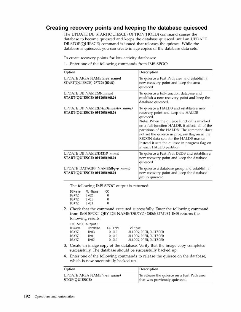
Creating recovery points and keeping the database quiescedThe UPDATE DB START(QUIESCE) OPTION(HOLD) command causes thedatabase to become quiesced and keeps the database quiesced until an UPDATEDB STOP(QUIESCE) command is issued that releases the quiesce. While thedatabase is quiesced, you can create image copies of the database data sets.
To create recovery points for low-activity databases:1. Enter one of the following commands from IMS SPOC:
Option Description
UPDATE AREA NAME(area_name)START(QUIESCE) OPTION(HOLD)
To quiesce a Fast Path area and establish anew recovery point and keep the areaquiesced.
UPDATE DB NAME(db_name)START(QUIESCE) OPTION(HOLD)
To quiesce a full-function database andestablish a new recovery point and keep thedatabase quiesced.
UPDATE DB NAME(HALDBmaster_name)START(QUIESCE) OPTION(HOLD)
To quiesce a HALDB and establish a newrecovery point and keep the HALDBquiesced.Note: When the quiesce function is invokedon a full-function HALDB, it affects all of thepartitions of the HALDB. The command doesnot set the quiesce in progress flag on in theRECON data sets for the HALDB master.Instead it sets the quiesce in progress flag onin each HALDB partition.
UPDATE DB NAME(DEDB_name)START(QUIESCE) OPTION(HOLD)
To quiesce a Fast Path DEDB and establish anew recovery point and keep the databasequiesced.
UPDATE DATAGRP NAME(dbgrp_name)START(QUIESCE) OPTION(HOLD)
To quiesce a database group and establish anew recovery point and keep the databasegroup quiesced.
The following IMS SPOC output is returned:DBName MbrName CCDBXYZ IM02 0DBXYZ IM01 0DBXYZ IM03 0
2. Check that the command executed successfully. Enter the following commandfrom IMS SPOC: QRY DB NAME(DBXYZ) SHOW(STATUS) IMS returns thefollowing results:IMS SPOC output:DBName MbrName CC TYPE LclStatDBXYZ IM03 0 DLI ALLOCS,OPEN,QUIESCEDDBXYZ IM01 0 DLI ALLOCS,OPEN,QUIESCEDDBXYZ IM02 0 DLI ALLOCS,OPEN,QUIESCED
3. Create an image copy of the database. Verify that the image copy completessuccessfully. The database should be successfully backed up.
4. Enter one of the following commands to release the quiesce on the database,which is now successfully backed up.
Option Description
UPDATE AREA NAME(area_name)STOP(QUIESCE)
To release the quiesce on a Fast Path areathat was previously quiesced.
192 Operations and Automation
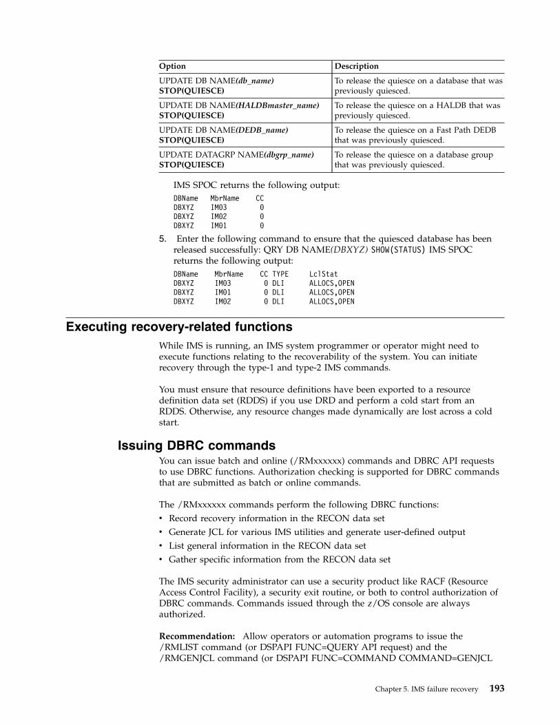
Option Description
UPDATE DB NAME(db_name)STOP(QUIESCE)
To release the quiesce on a database that waspreviously quiesced.
UPDATE DB NAME(HALDBmaster_name)STOP(QUIESCE)
To release the quiesce on a HALDB that waspreviously quiesced.
UPDATE DB NAME(DEDB_name)STOP(QUIESCE)
To release the quiesce on a Fast Path DEDBthat was previously quiesced.
UPDATE DATAGRP NAME(dbgrp_name)STOP(QUIESCE)
To release the quiesce on a database groupthat was previously quiesced.
IMS SPOC returns the following output:DBName MbrName CCDBXYZ IM03 0DBXYZ IM02 0DBXYZ IM01 0
5. Enter the following command to ensure that the quiesced database has beenreleased successfully: QRY DB NAME(DBXYZ) SHOW(STATUS) IMS SPOCreturns the following output:DBName MbrName CC TYPE LclStatDBXYZ IM03 0 DLI ALLOCS,OPENDBXYZ IM01 0 DLI ALLOCS,OPENDBXYZ IM02 0 DLI ALLOCS,OPEN
Executing recovery-related functionsWhile IMS is running, an IMS system programmer or operator might need toexecute functions relating to the recoverability of the system. You can initiaterecovery through the type-1 and type-2 IMS commands.
You must ensure that resource definitions have been exported to a resourcedefinition data set (RDDS) if you use DRD and perform a cold start from anRDDS. Otherwise, any resource changes made dynamically are lost across a coldstart.
Issuing DBRC commandsYou can issue batch and online (/RMxxxxxx) commands and DBRC API requeststo use DBRC functions. Authorization checking is supported for DBRC commandsthat are submitted as batch or online commands.
The /RMxxxxxx commands perform the following DBRC functions:v Record recovery information in the RECON data setv Generate JCL for various IMS utilities and generate user-defined outputv List general information in the RECON data setv Gather specific information from the RECON data set
The IMS security administrator can use a security product like RACF (ResourceAccess Control Facility), a security exit routine, or both to control authorization ofDBRC commands. Commands issued through the z/OS console are alwaysauthorized.
Recommendation: Allow operators or automation programs to issue the/RMLIST command (or DSPAPI FUNC=QUERY API request) and the/RMGENJCL command (or DSPAPI FUNC=COMMAND COMMAND=GENJCL
Chapter 5. IMS failure recovery 193
API request). Restrict the use of /RMCHANGE, /RMDELETE, and /RMNOTIFYcommands (or equivalent API requests), because they update the RECON data sets.
Attention: When the /RMLIST command is issued from the OM API (such asTSO SPOC), the amount of output that is generated can be large. Because theRECON data set is reserved during command processing, if the generated outputis large, do not issue the command during peak times. To prevent the commandfrom being issued with the DBRC='RECON' option inadvertently, considerprotecting the command with a security product.Related concepts:
DBRC and data sharing support (System Administration)
Supporting data sharing (System Administration)
DBRC API (System Programming APIs)
Dumping the message queuesYou use the /CHECKPOINT SNAPQ command to save the message queues in anonshared-queues environment. This command dumps the message queues to thelog without terminating the online system.
Recommendation: Schedule the /CHECKPOINT SNAPQ regularly because itshortens the time required for emergency restart if a problem occurs on themessage queue data sets. Consider the following intervals:v Whenever the OLDS is switchedv Once each hourv Once each shiftv Twice each day (midnight and noon)v Once each day
For a shared-queues environment, use the /CQCHKPT SHAREDQ command todump the shared queues.
Recovering the message queuesIn a non-shared-queues environment, you can recover the message queues duringan IMS restart if the previous shutdown included the DUMPQ or the SNAPQkeyword.
Specify the BUILDQ keyword on the /NRESTART or /ERESTART command torestore the messages to the message queue data sets from the IMS log. Specify theFORMAT keyword on the /NRE or /ERE command if you also want to reinitializethe message queue data sets.
In order to use the /NRE BUILDQ command, the system must be shut down usinga /CHECKPOINT DUMPQ | PURGE command. To use the /ERE BUILDQcommand, you need only a prior /CHECKPOINT SNAPQ command.
Restriction: If a /NRE BUILDQ or /ERE BUILDQ command fails and you coldstart IMS or cold start DC, messages are lost and are not processed.
You can use the IBM IMS Queue Control Facility for z/OS to select messages fromthe OLDS (or SLDS) and reinsert them into the IMS message queues after an IMScold start.
194 Operations and Automation
For a shared-queues environment, CQS automatically rebuilds the message queuesif the coupling facility fails. You can also use the SETXCF START,REBUILDcommand to rebuild the queues manually.Related reference:
IMS Queue Control Facility overview
IBM IMS Queue Control Facility for z/OS interface (Diagnosis)
Archiving the OLDSYou should archive the OLDS to an SLDS at regular intervals. If you are not usingautomatic archiving, the MTO or automation program should issue the DBRCGENJCL command (or DSPAPI FUNC=COMMAND COMMAND=GENJCL APIrequest) at regular intervals to generate the JCL for the Log Archive utility, andshould execute the utility.
Making databases recoverable or nonrecoverableYou can change recoverable full-function DBs to nonrecoverable (after deletingrecovery-related records from the RECON data set) by using the CHANGE.DBNONRECOV command.
You can change to recoverable again by using the CHANGE.DB RECOVABLcommand.
Use the LIST.DB command or the DBRC QUERY TYPE DB API request to displaywhether a database is recoverable.
Running recovery-related utilitiesDepending on your recovery strategy, the MTO might be responsible for runningvarious recovery-related utilities at regular intervals.
These could include:v Database Image Copy utilityv Database Image Copy 2 utilityv Online Database Image Copy utilityv Database Change Accumulation utility
The MTO should also run these utilities when a database changes fromnonrecoverable to recoverable.Related reference:
Database Image Copy utility (DFSUDMP0) (Database Utilities)
Database Image Copy 2 utility (DFSUDMT0) (Database Utilities)
Online Database Image Copy utility (DFSUICP0) (Database Utilities)
Database Change Accumulation utility (DFSUCUM0) (Database Utilities)
Chapter 5. IMS failure recovery 195

196 Operations and Automation

Chapter 6. Developing operating procedures
After you have made basic design decisions about operations and recovery, youare ready to implement these decisions. Primarily, implementation takes the formof developing procedures for operating IMS.
The importance of developing good procedures cannot be over emphasized. Theinstallations with the most success are those with well-written, well-maintained,well-tested, and well-understood procedures.
Establishing procedures for operating IMS is not a simple task. Because eachinstallation has unique requirements and resources, no single approach tooperations is possible. These topics provide some basic guidelines for establishingprocedures.
Operations personnelIt is important that you identify the operational requirements for IMS, and identifythe people responsible for performing the various operations tasks. After assigningresponsibilities, you are ready to set up the procedures necessary to coordinate theoperations task.
Many people are involved, directly or indirectly, in the operation of a successfulIMS system. To help you understand who needs operating procedures and what itis they are responsible for operating, these topics look briefly at the variousfunctions performed by these people. This topic also gives you an understandingof the context in which MTOs operate the system, and users or remote terminaloperators use it. A fundamental understanding of the MTO is important becausethe subsequent topics describe the procedures you develop for the MTO and user.
An IMS DBCTL environment includes no IMS terminals, so the DBCTL operatormust use a z/OS console. Throughout these topics, this DBCTL operator is calledthe IMS MTO.
The following groups of people represent functions often defined at an installation:v z/OS and JES system operators. This group is responsible for operating z/OS
and JES.If the IMS MTO does not have access to a z/OS console, you need to establishprocedures so the MTO can communicate with the z/OS operator in case of afailure. This is particularly important when the MTO is physically distant fromthe z/OS console.
v Network support group. This group is responsible for operation of the network,including: VTAM, physical telecommunications lines, and modems.You must establish procedures for communication between the MTO andnetwork support personnel for initializing the online system and isolating andcorrecting errors related to the IMS network.
v DASD and tape pool operators. This group is responsible for managing tapeand disk media.
© Copyright IBM Corp. 1974, 2017 197

The MTO must communicate with DASD and tape operators when mountingarchive tapes, and when creating image copies, change accumulations, and soforth. Communication is also required when the MTO is analyzing andcorrecting I/O errors.
v User liaison group. This group is the primary interface for the end user.The user liaison group needs procedures for answering user questions relating toboth IMS and individual application programs. The user liaison group alsoneeds procedures for problem determination and correction, and forcommunicating with the MTO when unable to solve a problem. The user liaisongroup might also need to communicate with application support groups when auser problem relates to a specific application program rather than to the IMSsubsystem.
v Application support groups. This group develops and maintains IMSapplication programs.You need to identify representatives for the support of each application runningon the IMS subsystem. You should give the user liaison group and the IMS MTOprocedures for contacting this group in case of application problems.
v IMS system administrator, system programmer, or recovery specialist. Thisperson (or group) is responsible for installing IMS and designing the systemconfiguration.There are certain error conditions the MTO cannot correct. For such errors, theMTO needs instructions on how to contact the IMS system administrator, systemprogrammer, or recovery specialist. This person (or group) will help resolve themore complex recovery problems.
The following figure provides an overview of the relationships between thesefunctional groups.
198 Operations and Automation

Depending on the size of your installation, some of these functions might beperformed by the same person or group. In large installations, the same functionmight be performed by many different people. The IMS MTO, for example, mighthave access to a z/OS system console. This access would allow the MTO to enterz/OS START commands.
In this book, operations procedures are classified into two types:v Those for operating IMS, which are generally performed primarily by the MTO
and secondarily by the system administrator or recovery specialistv Those for use by an end user
Developing procedures for an end user is not applicable in an IMS DBCTLenvironment, which has no DBCTL terminal end users. References to end users fora DBCTL environment actually refer to the CCTL end users.Related concepts:Chapter 7, “Developing user procedures,” on page 255
End user
Networkcontrol or
CCTL
Applicationsupport
Userliaison
MTO
Systemadministrator
Tape/DASDoperator
MVS/JESoperator
Figure 8. Relationships among operations groups
Chapter 6. Developing operating procedures 199
Establishing operating procedure documentsYou need to establish operating procedure documents as part of your overallstrategy for controlling an IMS system. This will help you to ensure that operatorswill handle various situations in a consistent manner.
Establishing operations interactionsThe online IMS environment should be transparent to general business procedures.It is probably only part of the data processing services. Your procedures, to somedegree, reflect your installation's organization.
Definitions of support groupsSupport groups provide specific functions for different groups of users, differentenvironments, and even for different operations.
An IMS operations group must implement procedures and use tools, often specifiedby system programmers, that originate from requirements for database and datacommunication administration. The requirements for scheduling jobs, handlingtapes and direct access devices, and producing printed output are developed inconjunction with general system operations procedures.
The system operations group provides z/OS support, and also often supports thehardware. The software support group provides support for the operating systemand the language compilers. The applications support group provides support for theapplication programs, and is represented by user liaison and developmentmaintenance groups.
The user liaison group is of special importance. Most of the problems that end usersexperience are application-program dependent. The user liaison group, acting asfirst point of contact, can answer such questions, but operations cannot. The userliaison group can also be the channel for problem resolution. They can initiateproblem tracking, and their interpretation of error events can help all end users.The user liaison group analyzes problems to determine if they areapplication-program related, procedural, hardware, or system software. They cancontact the master terminal control group regarding network or operationsproblems, or interact with application-program development support forprogramming errors. Very often, they are key personnel in any decisions affectingrecovery, because they must interpret the actions taken on behalf of end users.
Operations contacts and responsibilitiesEvery organization needs to have layers of support and advice for controlresponsibilities for day-to-day operations. You need to plan for casual support andexpert support.
Some suggestions for assigning control responsibilities are:v Have a user liaison group answer day-to-day application-program questions,
track problems, and monitor service.Make the user liaison group the primary contact for the end user and for IMSoperations. Encourage the user liaison group to be part of recovery decisions.
v Have a database-administration contact for recovery, design change evaluation,and database monitoring and analysis.
v Shield the MTO from most end-user inquiries so that the MTO can concentrateon availability, system status, and production statistics. Use other supervisoryterminals to distribute the workload. Take advantage of automated operatorprograms to initiate MTO commands and reduce operator tedium.
200 Operations and Automation
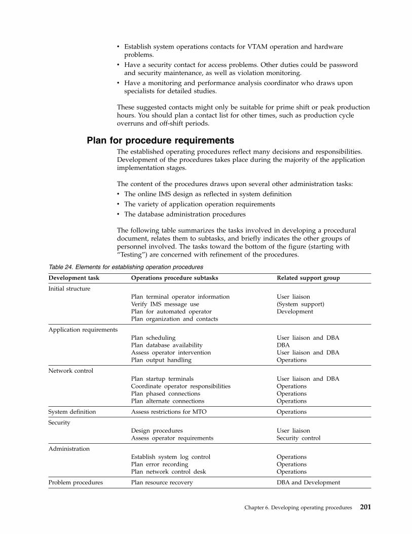
v Establish system operations contacts for VTAM operation and hardwareproblems.
v Have a security contact for access problems. Other duties could be passwordand security maintenance, as well as violation monitoring.
v Have a monitoring and performance analysis coordinator who draws uponspecialists for detailed studies.
These suggested contacts might only be suitable for prime shift or peak productionhours. You should plan a contact list for other times, such as production cycleoverruns and off-shift periods.
Plan for procedure requirementsThe established operating procedures reflect many decisions and responsibilities.Development of the procedures takes place during the majority of the applicationimplementation stages.
The content of the procedures draws upon several other administration tasks:v The online IMS design as reflected in system definitionv The variety of application operation requirementsv The database administration procedures
The following table summarizes the tasks involved in developing a proceduraldocument, relates them to subtasks, and briefly indicates the other groups ofpersonnel involved. The tasks toward the bottom of the figure (starting with“Testing”) are concerned with refinement of the procedures.
Table 24. Elements for establishing operation procedures
Development task Operations procedure subtasks Related support group
Initial structurePlan terminal operator informationVerify IMS message usePlan for automated operatorPlan organization and contacts
User liaison(System support)Development
Application requirementsPlan schedulingPlan database availabilityAssess operator interventionPlan output handling
User liaison and DBADBAUser liaison and DBAOperations
Network controlPlan startup terminalsCoordinate operator responsibilitiesPlan phased connectionsPlan alternate connections
User liaison and DBAOperationsOperationsOperations
System definition Assess restrictions for MTO Operations
SecurityDesign proceduresAssess operator requirements
User liaisonSecurity control
AdministrationEstablish system log controlPlan error recordingPlan network control desk
OperationsOperationsOperations
Problem procedures Plan resource recovery DBA and Development
Chapter 6. Developing operating procedures 201
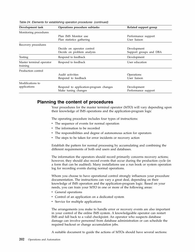
Table 24. Elements for establishing operation procedures (continued)
Development task Operations procedure subtasks Related support group
Monitoring proceduresPlan IMS Monitor usePlan statistics gathering
Performance supportUser liaison
Recovery proceduresDecide on operator controlDecide on problem analysis
DevelopmentSupport groups and DBA
Testing Respond to feedback Development
Master terminal operatortraining
Respond to feedback User education
Production controlAudit activitiesRespond to feedback
OperationsUser liaison
Modifications toapplications Respond to application-program changes
Make tuning changesDevelopmentPerformance support
Planning the content of proceduresYour procedures for the master terminal operator (MTO) will vary depending upontheir knowledge of IMS operations and the application-program logic
The operating procedure includes four types of instructions:v The sequence of events for normal operationv The information to be recordedv The responsibilities and degree of autonomous action for operatorsv The steps to be taken for error incidents or recovery action
Establish the pattern for normal processing by accumulating and combining thedifferent requirements of both end users and databases.
The information the operators should record primarily concerns recovery actions;however, they should also record events that occur during the production cycle (ina form that can be audited). Many installations use a run book or system operationlog for recording events during normal operations.
Whom you choose to have operational control strongly influences your proceduredocumentation. The instructions can vary a great deal, depending on theirknowledge of IMS operation and the application-program logic. Based on yourneeds, you can train your MTO in one or more of the following areas:v General operationsv Control of an application on a dedicated systemv Service for multiple applications
The arrangements you make to handle error or recovery events are also importantin your control of the online IMS system. A knowledgeable operator can restartIMS and fall back to a valid checkpoint. An operator who suspects databasedamage can involve personnel from database administration or can schedule therequired backout or change accumulation jobs.
A suitable document to guide the actions of MTOs should have several sections:
202 Operations and Automation

v An introductionThis section gives an overview of IMS operation (both generally and specificallyfor your installation), how the network is controlled, and how the masterterminal is used. The intended audience is new or substitute operators.
v Operating proceduresThis section shows the normal progression of events, but also providessupplementary instructions for error conditions. You can organize this section asa series of flowcharts.
v Commands reference sectionThis section shows syntax and recommendations for using IMS commands andother commands as appropriate. Include only those command keywords andparameters that you consider necessary for situations the MTO should handlewithout assistance from other groups. You might also want to includecustomized explanations of selected IMS messages to guide the MTO's actions.
v Configuration tablesThis section contains descriptions of the IMS and system configuration. Thesedescriptions help the operators to visualize the resources under their control. Forexample, you can include a chart of terminal connections related toapplication-program use, or representations of the databases that are online(together with the logical dependencies). You could also display larger copies inthe operations area.
v Supplementary proceduresThis section contains procedures not covered in earlier sections. With any largesystem, you can make alternative configurations available. This section can alsocontain recovery procedures indexed by symptom.
v A chronological record of eventsThis section lists the various events an MTO is likely to encounter duringnormal operations. This section could also list the types of events an MTOshould record in an operations log or run book. Because an online IMS operationis likely to span several operator shifts, some type of record of the MTO's actionsis desirable.
v A problem-reporting procedureThis section describes how to report problems or unusual events. An incidentreport is a useful tool to help you control the integrity of the system and servicefor the end user. Any of the following personnel or groups could fill in thisreport form: the end user or user liaison group, the IMS MTO or networkadministrator, the database administrator, or the system programmer.
Recommendation: Regardless of who fills in the form, you should require that itbe completed, even though the person competing the form contacts otheroperating personnel. This form can become a controlling document in the case ofa recovery action, but can also be used for minor complaints. To fostercooperation, you should return a copy of the report, showing actions taken, tothe originator. You should also periodically review these reports to discoverrecurring problems and make valuable procedural changes.
Related concepts:“Procedures for user terminal operators” on page 255Related tasks:“Planning availability of IMS service” on page 210
Chapter 6. Developing operating procedures 203

How to set the level of operator controlIMS is designed so processing is controlled by message traffic, which places controlof the operation primarily in the hands of the master terminal operator. From anadministration point of view, control of operations is far more than a structureduse of IMS commands.
For a complex system such as IMS, you need to carefully match operational controlto operator capability. You must decide whether an operator or an applicationadministrator should have primary control.
The MTO can have a wide range of responsibilities. At one end of the spectrum,you have an operator using a standard set of instructions, designed using acook-book approach: “if such-and-such happens, perform procedure X”. At theother end of the spectrum, you have a system programmer who understands theflexibility of IMS control as well as the application program and databaserequirements. The first approach requires good symptom-based instructions; thesecond requires clear guidelines and periodic auditing.
If an operator handles your operations, the two areas for which they needinstructions, detailed to a level appropriate for their knowledge andresponsibilities, are:v Normal operations
You need to document instructions for making specific resources available forcommitted end-user service. The instructions must be especially clear aboutwhen and how to shut down and restart IMS. If alternative network connectionsare part of the system design, the instructions should have a set of additionalprocedures for them.Operators who understand the end-user priorities should be allowed to changethe scheduling algorithm by making reassignment of message priorities or evenof message region classes.
v Error and recovery operations (triggered by symptoms or user feedback)These events range from temporary transaction processing problems to problemsthat have serious database implications. Your recovery procedures shouldinclude carefully documented and tested actions for your operators to take.
Recommendation: Design your procedures so the operator initiates recoveryactions in cooperation with your user-liaison group and your system-supportpersonnel. Structure your operations to take advantage of as much consultationas possible. Insist that your operators record all recovery actions in a run log,including justification for decisions made.An important part of the operations strategy is the recovery procedures used torestart the online IMS subsystem after a failure of the operating system or theIMS control region.
Record-keeping procedures for the MTOThe master terminal operator (MTO) needs to keep various types of informationthat document system activity. Consider designing standard forms or online panelsfor recording this information.
The MTO needs to record the following general types of information:v IMS control region activityv Utility executions
204 Operations and Automation

v Application program activityv Problems or unusual eventsv Startup, shutdown, and system log activity
Some of this information can be recorded automatically. DBRC records all OLDSand archive activity, and can also record the execution of batch jobs andrecovery-related utilities.
By default, the master secondary terminal provides a hardcopy log of IMS systemactivity, including checkpoint information and IMS messages. The logging of IMSsystem messages to the secondary master terminal can be disabled by using the/SMCOPY MSG OFF command.
You can also have the secondary master terminal provide a hardcopy loggingoption for certain IMS commands and command responses by specifying theCOPYLOG keyword in the COMM system definition macro or by issuing the/SMCOPY command with the appropriate keyword.
The information logged to the secondary master terminal can be helpful whentracking a series of events affecting the operation of IMS, or when verifying that anoperations task was performed. Information useful for analyzing an IMS errorsituation is often in the z/OS hardcopy log.
You can select whether IMS logs commands issued from the master terminal orcommands entered from other terminals, or both. In either case, IMS only logscertain commands. When you issue a command from a terminal other than themaster terminal, IMS logs output and identifies its node, or line and physicalterminal number.
The /SMCOPY command starts and stops the hardcopy logging facility forcommands, system messages, or both.
IMS logs the following commands to the secondary master terminal:/ACTIVATE/ALLOCATE/ASSIGN/CHECKPOINT/CLSDST/COMPT/DBDUMP/DBRECOVERY/DELETE/DEQUEUE/DISPLAY/IDLE/MODIFY/MONITOR/MSASSIGN/OPNDST/PSTOP/PURGE
Chapter 6. Developing operating procedures 205
/QUIESCE/RCLSDST/RCOMPT/RMCHANGE/RMDELETE/RMGENJCL/RMINIT/RMLIST/RMNOTIFY/RSTART/START/STOP/SWITCH/TRACE/UNLOCKSYSTEM
Recording IMS control region activityYou should design a form on which the master terminal operator (MTO) candocument executions of the control region. Details to be recorded on the forminclude: the time when the system is started or shut down, the type of restart, andthe reason for shutdown. You should make provisions on the form for recordingerror situations, such as DASD I/O errors, and actions taken to recover from sucherrors.
The operator can file the output of the DBRC LIST.LOG command (or DSPAPIFUNC=QUERY API request) with this form to provide a record of log archive activity.
Utility recording forms for IMS utilitiesHow much manual record keeping is necessary for IMS utilities depends on youruse of DBRC. If you have registered all your databases with DBRC, DBRC recordsthe execution of the recovery-related utilities in the RECON data set. By listing theRECON data set (LIST.RECON command or DSPAPI FUNC=QUERY API request)at regular intervals, you can easily maintain records of utility executions.
If you have not registered all your databases with DBRC, you should design formsfor recording execution of the following utilities:v Database Image Copyv Database Image Copy 2v Online Database Image Copyv Database Change Accumulationv Database Recoveryv Those utilities involved in database reorganizations
You also need to record the execution of batch database reorganizations. Adatabase cannot be backed out to a point earlier than its latest batchreorganization. Nor can a forward recovery be done from an image copy precedingthe latest batch reorganization. Thus, a knowledge of recent reorganizations isimportant when recovering a database.
206 Operations and Automation
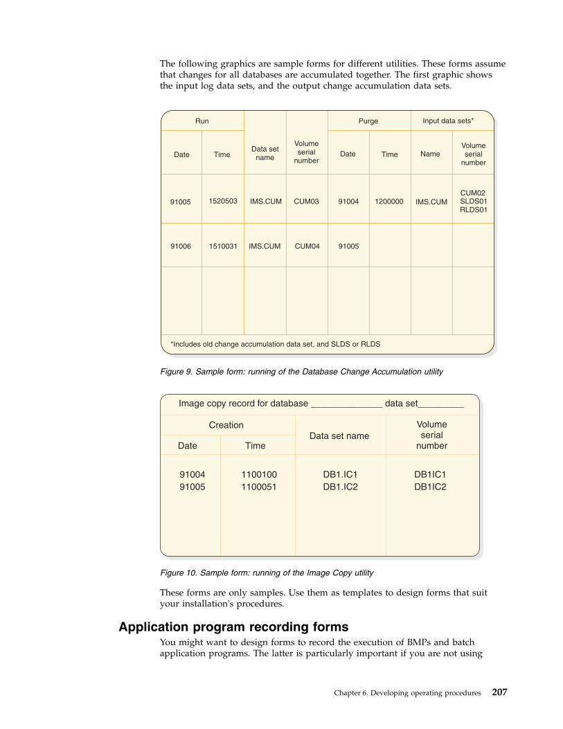
The following graphics are sample forms for different utilities. These forms assumethat changes for all databases are accumulated together. The first graphic showsthe input log data sets, and the output change accumulation data sets.
These forms are only samples. Use them as templates to design forms that suityour installation's procedures.
Application program recording formsYou might want to design forms to record the execution of BMPs and batchapplication programs. The latter is particularly important if you are not using
Date
CUM02
IMS.CUM120000091004CUM03IMS.CUM152050391005
91005CUM04IMS.CUM151003191006
SLDS01RLDS01
Run Purge Input data sets*
*Includes old change accumulation data set, and SLDS or RLDS
DateTime TimeData set
nameName
Volumeserial
number
Volumeserial
number
Figure 9. Sample form: running of the Database Change Accumulation utility
Date
91004 1100100 DB1.IC1 DB1IC1
91005 1100051 DB1.IC2 DB1IC2
Image copy record for database ______________ data set_________
TimeData set name
Creation Volumeserial
number
Figure 10. Sample form: running of the Image Copy utility
Chapter 6. Developing operating procedures 207

DBRC to record logs produced by batch programs. Other information you mightwant to record includes checkpoint IDs and any error messages produced by theprograms.
Forms for recording problems or unusual eventsYou might want to design an incident report form for recording any systemproblems or unusual events. Incident reports help you control the integrity of thesystem and services for end-users. This form might be filled in by the user liaisongroup, the MTO, or the recovery specialist.
Recommendation: Regardless of who fills in the form, you should require that itbe completed, even though the person competing the form contacts other operatingpersonnel. This form can become a controlling document in the case of a recoveryaction, but can also be used for minor complaints. To foster cooperation, youshould return a copy of the report, showing actions taken, to the originator. Youshould also periodically review these reports to discover recurring problems andmake valuable procedural changes.
Forms for recording startup, shutdown, and system logactivity
You might want to design an online run sheet for recording startup, shutdown,and their relationship to system log activity.
Figure 11. Sample form: incident report
208 Operations and Automation

The MTO fills in the online run sheet for each execution of the online system.When starting IMS, the MTO records (circles) the parameters used in the startcommand, along with the checkpoint ID used. When shutting down IMS normally,the MTO records (circles) the parameters used. When shutting down IMSabnormally, the MTO records the reason for the failure and fills in an incidentreport form. If the MTO shuts down IMS using a /CHECKPOINT DUMPQcommand, that person records the closing checkpoint ID from the DFS994Imessage.
The MTO should use the bottom half of the form (comments/incidents) to recordany unusual incidents. The MTO should note such things as: hardware errors ontelecommunication lines, details about reassignment of LTERM names, andabending transactions. Finally, the MTO should add a cross reference to theincident report, where necessary.
DBRC records information about use of OLDSs in the RECON data set. After IMSarchives an OLDS for an execution of the online system, the MTO can issue aLIST.LOG command to get information about the use of the OLDS. The MTOshould file the hardcopy listing of this information with the online run sheet. Thisinformation provides an important means of communication between one shift ofMTOs and the next. This information can also be used to assist in reconstruction ofthe RECON data set, if it becomes damaged.
/NRE
/ERE
/CHKPT
Other (Specify)
Last CHKPT ID
/CHE
BUILDQ
FORMAT ALL
DUMPQFREEZE
Date
Start time
Stop time
MTO name
Time Comments/IncidentsTime Comments/Incidents
Figure 12. Sample form: online run sheet
Chapter 6. Developing operating procedures 209
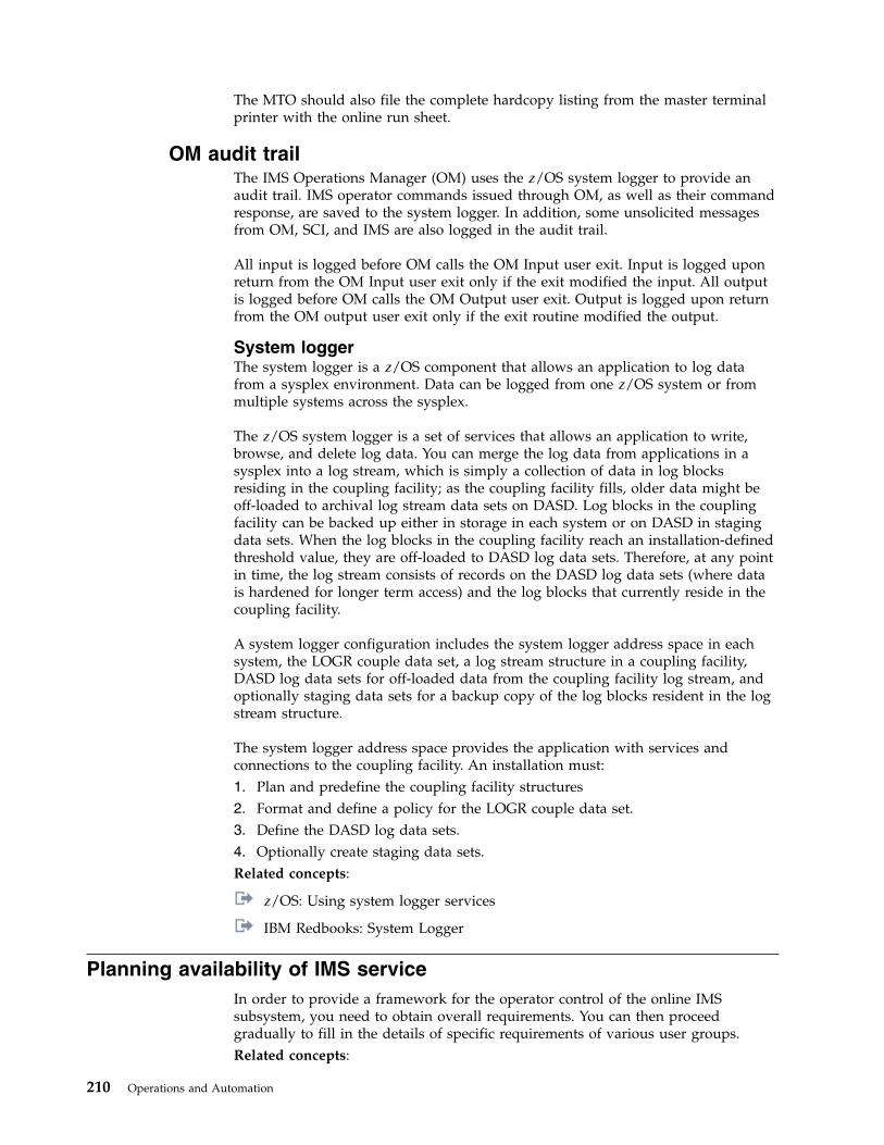
The MTO should also file the complete hardcopy listing from the master terminalprinter with the online run sheet.
OM audit trailThe IMS Operations Manager (OM) uses the z/OS system logger to provide anaudit trail. IMS operator commands issued through OM, as well as their commandresponse, are saved to the system logger. In addition, some unsolicited messagesfrom OM, SCI, and IMS are also logged in the audit trail.
All input is logged before OM calls the OM Input user exit. Input is logged uponreturn from the OM Input user exit only if the exit modified the input. All outputis logged before OM calls the OM Output user exit. Output is logged upon returnfrom the OM output user exit only if the exit routine modified the output.
System loggerThe system logger is a z/OS component that allows an application to log datafrom a sysplex environment. Data can be logged from one z/OS system or frommultiple systems across the sysplex.
The z/OS system logger is a set of services that allows an application to write,browse, and delete log data. You can merge the log data from applications in asysplex into a log stream, which is simply a collection of data in log blocksresiding in the coupling facility; as the coupling facility fills, older data might beoff-loaded to archival log stream data sets on DASD. Log blocks in the couplingfacility can be backed up either in storage in each system or on DASD in stagingdata sets. When the log blocks in the coupling facility reach an installation-definedthreshold value, they are off-loaded to DASD log data sets. Therefore, at any pointin time, the log stream consists of records on the DASD log data sets (where datais hardened for longer term access) and the log blocks that currently reside in thecoupling facility.
A system logger configuration includes the system logger address space in eachsystem, the LOGR couple data set, a log stream structure in a coupling facility,DASD log data sets for off-loaded data from the coupling facility log stream, andoptionally staging data sets for a backup copy of the log blocks resident in the logstream structure.
The system logger address space provides the application with services andconnections to the coupling facility. An installation must:1. Plan and predefine the coupling facility structures2. Format and define a policy for the LOGR couple data set.3. Define the DASD log data sets.4. Optionally create staging data sets.Related concepts:
z/OS: Using system logger services
IBM Redbooks: System Logger
Planning availability of IMS serviceIn order to provide a framework for the operator control of the online IMSsubsystem, you need to obtain overall requirements. You can then proceedgradually to fill in the details of specific requirements of various user groups.Related concepts:
210 Operations and Automation
“Planning the content of procedures” on page 202
Checklist for defining the production cycleWhen defining the production cycle, obtain the overall production cyclerequirement and the support requirements for databases and batch-programscheduling. Collecting the initial availability requirements ensures that you canplan your follow-up activities accordingly.
Take the following suggested steps to define the production cycle:1. Obtain the overall production cycle requirement.
For example, suppose the execution of an application program requires theonline subsystem to be available from 0400 to 2000 hours, with no weekendrequirements. Very often these requirements are made to fit the dataprocessing organization's constraints. In this example, the operations groupmust be agreeable to the early-morning scheduling (which is probablyrequired for transaction input from locations in different time zones).
2. Obtain support requirements for databases and batch-program scheduling.For example, a daily batch-report program might cause certain databases tobe unavailable until 0800. A /DBRECOVERY DB or UPDATE DBSTOP(ACCESS) command stops additional transaction or CCTL access andallows offline processing for the database named in the command. Anotherexample is a priority transaction, scheduled for database integrity purposes,that preempts other transaction processing.
The following table shows a checklist of initial availability requirements you needto collect.
Table 25. Availability requirements checklist
Availability requirement Follow-up activity
What are the available hours: Daily? Weekly? Check if a regular weekly time. Check daily start andstop times. Allow for weekends, holidays, and preventivemaintenance.
Which are services critical to the user? Summarize the transactions, programs, and databaseneeds. Summarize the CCTL's dependencies for programs(PSBs) and databases.
What is the target maximum down time? Establish guidelines for duration.
Are there any planned interruptions? Check requirements for normal restart. Determine howqueues are to be handled.
Are there variations of nucleus? Match nucleus suffix to system definition schedule.
Is there any special message region scheduling? Develop IMSMSG procedure variation. Find conditionsthat prompt scheduling.
What are the BMP scheduling requirements? Tailor IMSBATCH procedure for BMP. Find z/OS filerequirements.
What databases are not always online? List the databases, their conditions, and the reasons fortheir being offline.
What batch programs are to run during online schedule? Find any database conflicts. Find the required databaselevels and restart instructions.
What is the timing of database reorganization and relatedjobs?
Find jobs that run during online execution. Obtain masterschedule from DBA.
Do any application programs require exclusiveprocessing?
Find the effect on other online processing.
Chapter 6. Developing operating procedures 211

Table 25. Availability requirements checklist (continued)
Availability requirement Follow-up activity
Are there configuration variations or multiple IMSsubsystems?
Develop procedure support: plan for MSC, data sharing,DL/I separate address space, DBCTL, DCCTL,APPC/IMS, OTMA, or ETO.
Are you using a data propagation manager? Make sure both IMS and Db2 for z/OS are available onthe same z/OS system. Make sure the program librariesthat contain the data propagation user exit routines areavailable to all dependent IMS regions.
Devices available to the networkDocument which devices are to be initially available, those that should always beactive, and those that have restricted usage. The important attribute is whether theMTO needs to activate the connection or must make any alternative connections incase of terminal or line failures.
A second aspect of availability is to ensure proper control of the network. Youneed to document what terminals are connected and when.
The following table identifies some connection data you need to collect.
Table 26. Checklist for network control connection data
Connection data Follow-up activity
Which terminals are associated with services critical tothe user?
List the connection requirements. List the LTERMs.
Are VTAM terminals to be continuously connected? List those nodes and their LTERMs.
Are VTAM terminals to be connected on demand? Identify how each is controlled (MTO, VTAM operator, orremote terminal operator).
Are there planned reconfigurations? Develop sets of terminals and identify how they shouldbe controlled.
Are there alternate connection plans? Identify if there are alternate pairings, or occasionalusage.
Are intelligent stations as connected subsystems used? Identify operations for connected subsystems orterminals, and monitoring requirements.
Are switched lines used? Identify the users and give the LTERM names in thegroup.
Is there batched data entry or high-volume input? Identify the pattern of batched devices.
Are there special output storage devices? Identify use of printers or data devices.
Operations responsibilities for online control servicesIt is important to understand why an application program places restrictions onwhat commands you can issue. For example, online image copy is required atend-of-shift, but, because of the requirements of an IMS restart, no conflict indatabase level is permitted. This kind of restriction might require you to preventcertain programs from executing.
A third checklist identifies the use of support services and expected MTO controlactions. The following table presents this information; your emphasis should be onthe operational requirements.
212 Operations and Automation

Table 27. Checklist for online control services
Check requirement for: Follow-up activity
Dynamic allocation of databases Requires coding of DFSMDA macro and prior catalogingof databases.
Online database image copy List databases and schedule timing. Is image copy restartallowed?
Database surveyor When to be scheduled. Who is the contact for rangespecification?
Database recovery control Arrange for DASD dump entries. How are RECON datasets to be controlled? How are JCL generation facilities tobe used?
Simple checkpoint
/CHECKPOINTPURGE/CHECKPOINT DUMPQ/CHECKPOINT FREEZE/NRESTART
What conditions require the checkpoint? Is SNAPQrequired?
Must all queues be emptied?Can queues be held?What conditions warrant use of this command?Is queue rebuilding required?
Online system log management Determine archive procedures and whether WADS andOLDS are to be dynamically allocated.
Online change management Determine the scope and timing of online changes andhow to control processing.
Offline dump formatting management Establish transfer, archive, and formatting procedures.
IBM 3850 Mass Storage System (MSS) Obtain scenario of IBM 3850 usage.
Monitoring How will IMSMON data set be handled? Whatrequirements exist for traces or statistics?
SecuritySignonTransaction
Any override conditions?Any override conditions?What is update frequency and control procedure?
MTO abilities and operator responsibilitiesThe MTO's primary duty is to monitor the condition of the total IMS onlineenvironment, and to maintain normal service. Any alterations in committed serviceor recovery decisions are really part of a wider set of business responsibilities, notnecessarily those of the MTO.
When you are defining the duties of the master terminal operator, you must decidewhat actions are part of the normal duties, and what decisions require consultationwith other groups. From the end-user viewpoint, the MTO could represent thedata-processing staff, as well as the application-program contact. You need toarrange ahead of time what kind of support can be provided by the MTO, and ifthere is any way of shielding the MTO from unnecessary interruption.
The master terminal operator has the following abilities and responsibilities:v Responsibility for running IMS
The MTO starts and shuts down the IMS subsystem, starts regions, and managesthe system log.
v Knowledge of the ongoing status of the IMS subsystemThe MTO continuously monitors processing and the detects any error situations.
Chapter 6. Developing operating procedures 213
v Control over contents of the system and the networkThe MTO can control the network, connect other IMS systems, and performother prearranged tasks.
v Privileged commandsIn addition to the routine work, the MTO responds to error conditions, changesthe scheduling algorithm, alters passwords, and reconfigures the system asnecessary.
Normal operator actions (DB/DC or DCCTL)The z/OS system operator needs to initialize the IMS control region, but youshould plan to reduce the need for further involvement by the z/OS operator inIMS operations. In a busy system, responses to messages or instructions sent by anapplication program to the z/OS operator can be erratic. Such requirements arebetter handled by output messages to the IMS master terminal.
You should ask the z/OS system operator to relay any IMS messages (onesbeginning with any of the following prefixes: DFS, DSP, DXR, ELX, BPE, or CQS)to the IMS master terminal. You might also give the z/OS operator a list of theIMS job names. Because often the z/OS system console is physically separatedfrom the IMS master terminal, you need a local telephone or a paging line tomaintain communication between them.
You need to decide whether the z/OS operator or the IMS MTO should start IMSregions. If you want the z/OS operator to start them, one of the following IMSprocedures can be used:v IMSBATCH procedure to start batch message processing regionsv IMSRDR procedure to start message processing regions
The advantage of allowing the z/OS operator to start IMS regions is that theoperator can monitor any abnormal termination patterns and I/O requests.
The following table shows the actions usually performed by the MTO and thecommands usually reserved for the IMS master terminal.
Table 28. Master terminal operator actions usually performed
Activity IMS command
Activate IMS (cold start) /ERESTART COLDSYS
Start a message region /START REGION IMSMSG1
Start communication lines /START LINE ALL
Display message queues /DISPLAY
Start another message region /START REGION IMSMSG3
Prepare for VTAM communication /START DC
Initiate static VTAM sessions /OPNDST NODE ALL
Initiate dynamic VTAM sessions /OPNDST NODE AOI
Send message to terminals /BROADCAST
Shut down VTAM terminals and IMS /CHECKPOINT FREEZE QUIESCE
Restart IMS (warm start) /NRESTART
The IMS master terminal also works well as a display device. On the bottom of thescreen are two input lines, with room for a warning message. The remainder of the
214 Operations and Automation

screen is divided into two areas, each of 10 lines. The top portion shows the 10most recent IMS messages; new messages overlay old ones, so the display cyclesthrough the 10 lines. The lower portion is used to page through the output fromthe /DISPLAY command.
If you set the master terminal to use a 3270 format, some of the program functionkeys are predefined as follows:
PF KeyCommand or function
1 /DISPLAY
2 /DISPLAY ACTIVE
3 /DISPLAY STATUS
4 /START LINE
5 /STOP LINE
6 /DISPLAY POOL
7 /BROADCAST LTERM ALL
11 Next message page (NEXTMSGP)
12 Copy function
Tip: Create a PF key panel that shows these settings and place it with thekeyboard as a reminder for the operator.
Normal operator actions (DBCTL)The DBCTL MTO can control the DBCTL environment from any z/OS systemconsole. If your MTO operates from a different console (secondary system console)from the primary one where the z/OS operator sits, you must ensure a means ofcommunication between the two operators.
DBCTL requests for tape or DASD mounts must be given to the system consoleoperator. Some IMS messages (DFS prefix) originate from the CCTL region andthus appear on the primary system console; these messages should be relayed tothe MTO in case some action needs to be taken. For example, when the CCTL triesto connect to a DBCTL environment and the DBCTL subsystem is not yet running,the IMS database resource adapter (DRA), which is part of the CCTL region, issuesmessage DFS690A. In general, communication between the CCTL operator and theMTO is important.
As in the DB/DC or DCCTL environments, the z/OS operator can start IMS BMPsby using either the IMSRDR or the IMSBATCH procedure. Any activity of IMSdependent regions or utilities the z/OS operator controls should be recorded orcommunicated so that the MTO is aware of all IMS-related activity.
The following table shows the actions usually performed by the MTO and thecommands usually reserved for the IMS DBCTL master terminal.
Table 29. Master terminal operator actions usually performed
Activity IMS command
Activate IMS (cold start) /ERESTART COLDSYS
Start a BMP /START REGION IMSBMP
Chapter 6. Developing operating procedures 215
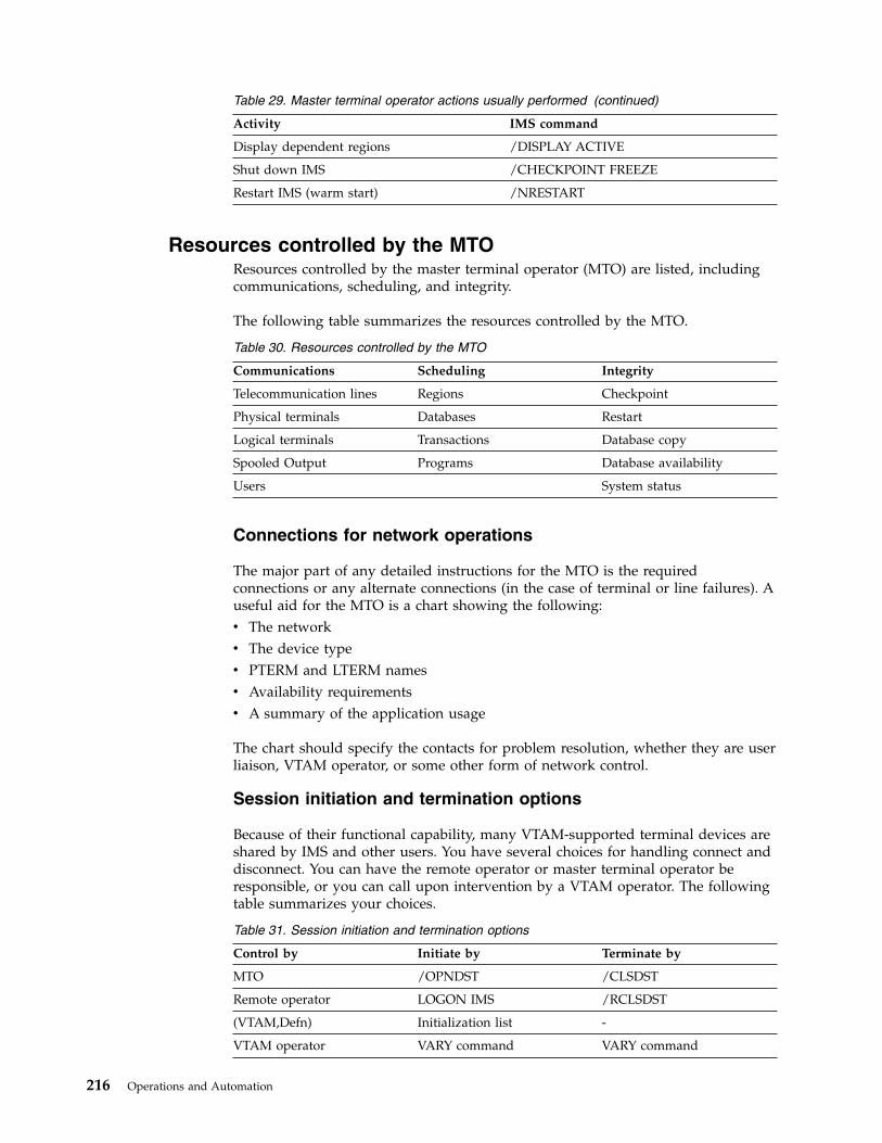
Table 29. Master terminal operator actions usually performed (continued)
Activity IMS command
Display dependent regions /DISPLAY ACTIVE
Shut down IMS /CHECKPOINT FREEZE
Restart IMS (warm start) /NRESTART
Resources controlled by the MTOResources controlled by the master terminal operator (MTO) are listed, includingcommunications, scheduling, and integrity.
The following table summarizes the resources controlled by the MTO.
Table 30. Resources controlled by the MTO
Communications Scheduling Integrity
Telecommunication lines Regions Checkpoint
Physical terminals Databases Restart
Logical terminals Transactions Database copy
Spooled Output Programs Database availability
Users System status
Connections for network operations
The major part of any detailed instructions for the MTO is the requiredconnections or any alternate connections (in the case of terminal or line failures). Auseful aid for the MTO is a chart showing the following:v The networkv The device typev PTERM and LTERM namesv Availability requirementsv A summary of the application usage
The chart should specify the contacts for problem resolution, whether they are userliaison, VTAM operator, or some other form of network control.
Session initiation and termination options
Because of their functional capability, many VTAM-supported terminal devices areshared by IMS and other users. You have several choices for handling connect anddisconnect. You can have the remote operator or master terminal operator beresponsible, or you can call upon intervention by a VTAM operator. The followingtable summarizes your choices.
Table 31. Session initiation and termination options
Control by Initiate by Terminate by
MTO /OPNDST /CLSDST
Remote operator LOGON IMS /RCLSDST
(VTAM,Defn) Initialization list -
VTAM operator VARY command VARY command
216 Operations and Automation

Secondary master terminal and auditing operational controlSome IMS commands are automatically copied to the terminal designated asSECONDARY in the system definition NAME macro. If you specify COPYLOG=ALL in theCOMM macro during system definition, then when other terminals besides themaster terminal enter any of these commands, copies of an entered command andits response are sent to the secondary master terminal.
To understand the actions taken by the MTO, you should obtain a permanentprinted copy of the command sequences issued by the MTO. This function istermed hardcopy logging.
The MTO can use the /SMCOPY MASTER OFF command to override the loggingof commands to the secondary master terminal. The MTO can also use thiscommand to turn off logging of command entry and responses from otherterminals. To resume logging to the secondary master terminal, the MTO can usethe /SMCOPY MASTER ON [TERMINAL ON] command.
This more permanent record is valuable for several reason, but the principal one isthat of accountability. You can also use the output to audit whether the operationscommand sequence and timing are providing committed service. The checklist inthe following table identifies the types of activities and related commands, andshows some of the ways you can use the secondary master terminal output.
Table 32. Using secondary master terminal output to audit performance.
Type of activity Command Output usage
Network control /OPNDST Check VTAM connection procedure.
/CLSDST Check VTAM disconnect procedure.
/RCLSDST Check expected disconnect.
/START Check network availability.
/RSTART Coordinate with terminal usage.
/STOP Investigate stopped resource.
/IDLE Investigate if there is lost or waiting output.
/MSASSIGN Check if planned MSC connect.
Device control /COMPT Check planned VTAM component switch.
/RCOMPT Check remote VTAM component allowed.
Resource control /ASSIGN Check that all uses fit operations plan.
/START Check region availability and queue control.
/STOP Investigate all events.
/PSTOP Investigate why input stopped.
/PURGE Investigate why service was restricted.
/MODIFY Audit the extent and timing of online changes.
/CHANGE Check size of MFS dynamic directory.
Security /MODIFY Set timing of authorization and password changes.
Chapter 6. Developing operating procedures 217

Table 32. Using secondary master terminal output to audit performance (continued).
Type of activity Command Output usage
Recovery /DBRECOVERY Investigate database errors.
/DBDUMP Investigate database errors and subsequent processing.
/DEQUEUE Investigate lost message or output.
/CHECKPOINT Coordinate with reported errors.
/SWITCH Investigate reasons for unplanned takeover activity.
/UNLOCK SYSTEM Investigate takeover activity.
Monitoring /DISPLAY Incorporate in monitoring feedback.Check use for scheduling.
/TRACE Coordinate with trace output.
HALDB OLR /INITIATE Initiate or resume HALDB Online Reorganization (OLR).
/TERMINATE Stop HALDB OLR.
/UPDATE Change the rate or the disposition flag of the DEL orNODEL data set of a HALDB OLR, or the dispositionflag of REL or NOREL to release ownership of OLR atnormal or abnormal shutdown of IMS.
Operator control of conversational transactionsThe master terminal operator should be aware of the potential use ofconversational transactions because their queue characteristics are somewhatdifferent from those of nonconversational transactions. The number ofconversational transactions that can be active at one time is 65535 per user orterminal. Also, the same individual transaction can be scheduled many times, butthe processing patterns can be quite different among the set.
For example, one conversational transaction could involve an extended search of adatabase, while another, using multiple-choice menus, might retrieve a single itemof data.
Another consideration for conversational transactions is whether the conversationsare to be active until they are complete or whether they can be held while the enduser is engaged in an offline activity.
Controlling conversational transactions
The following table summarizes the type of information that influences the contentof your operational procedures when the online IMS subsystem includesconversational transactions.
Table 33. Operator information for conversational transactions
Transaction attribute Information required Procedure impact
Which transactions areconversational?
Summary of purpose and processingcharacteristics.
Multiple messages might need themessage format buffer pool andmessage queues to be monitored.
Any dedicated terminals? What is themaximum number allowed to run?
Name LTERM and PTERM. Findmaximum storage using DASD andexpected loads.
Know impact of terminal problem.Advise remote terminal operator ofrestrictions and status.
218 Operations and Automation

Table 33. Operator information for conversational transactions (continued)
Transaction attribute Information required Procedure impact
Can conversations be held orreleased?
If so, how long? Is operator allowedto terminate?
MTO awareness of status. Use of/PSTOP and /EXIT commands. Useof /MODIFY warnings.
What recovery actions are to betaken?
At restart. Are abnormal terminationexit routines used?
Notify remote terminal operator andother recovery personnel of outputloss.
Remote terminal operator control for conversational transactions
A remote terminal operator can use a /FORMAT command to begin aconversation. This command formats an MFS-supported terminal screen. Or, theterminal operator can enter the initial transaction. To terminate the conversationbefore the normal program end, the terminal operator can use the /EXITcommand.
The operator can suspend the conversation (if the operator needs to leave theterminal area) by using the /HOLD command. In response, IMS issues messageDFS999I, which displays the identification number needed to resume theconversation with the transaction program. The terminal is then available for othertransaction activity.
On return to the terminal, the terminal operator can issue the /RELEASECONVERSATION nnnn command to resume the conversation, where nnnn is theconversation ID from the DFS999I message. As a convenience, IMS re-sends the lastoutput message to the terminal. Or the operator can issue the /EXITCONVERSATION nnnn command to terminate the conversation.
If the MFS formatting or the output content of the screen is lost during aconversation, enter the /HOLD command followed by the /RELEASE command.These commands resend the first physical page of the current message and restorethe format.
MTO control for conversational transactions
The master terminal operator can obtain a status of all conversations, held oractive. The following output from the /DISPLAY CONVERSATION commanddisplays the terminal address, the conversation identification number, and statusand type of all conversations:TERMINAL USER ID STATUS11- 2 0001 HELD4- 2 0002 ACTIVE,SCHEDULED4- 1 0011 HELDVT03 0012 ACTIVE
The MTO can terminate a conversation. For example, the /EXIT CONVERSATION0001 LINE 11 PTERM 2 command terminates the first conversation shown in thecommand output above. A /START LINE, /START NODE, or /START USERcommand also terminates the conversation, unless a program is already scheduledto process a portion of the conversation exchange.
Recommendation: Before terminating a conversation, the MTO should broadcast awarning message to that terminal.
Chapter 6. Developing operating procedures 219

Exit routines for abnormal termination of conversations
When a conversation terminates abnormally, a termination exit routine namedDFSCONE0 can gain control. Its use might be to initiate cleanup activity, or simplyto notify the input terminal of the canceled conversation. If the exit routinedetermines that more elaborate correction is required, it can schedule a transaction.This transaction can include the latest SPA, or a modified version of it, as amessage segment. IMS provides a default exit routine (DFSCONE0) whichschedules a transaction that includes the old SPA.
You can use the conversational termination exit routine to determine the effect ofoperator interruption.Related reference:
Conversational Abnormal Termination exit routine (DFSCONE0) (ExitRoutines)
MTO and tracing operationsThe MTO or an authorized remote terminal operator can initiate several kinds oftype-1 trace activity with the /TRACE command. Even though you might use theIMS Monitor fairly regularly, you should regard all tracing operations as “specialrequests”.
Because trace or monitoring actions affect the performance of the online IMSsystem, they are not part of normal operations. The validity of the trace dependsupon the processing taking place. Also, the operator can control the trace intervalwith the /TRACE command, so the operator must be aware of the trace timing.
Some types of trace requests do not require the person requesting the trace to bepresent during normal operations. The request should state the approximateduration of the trace and the type of monitoring. The main section should specifythe initial start and termination conditions, as well as any monitoring constraints tobe applied. Other sections should prompt for other details, such as queue levels,transactions to be active, or the time of day.
The types of tracing that can be requested are summarized in the following table.
Table 34. Trace and monitor options
Type of trace /TRACE parameters Operational effect
IMS Monitor SET MON opt Initiates IMS Monitor trace.
SET OFF MON Terminates the trace.
opt=ALL Traces all events.
opt=APDB Traces activity between application programsand databases.
opt=APMQ Traces activity between application programsand message queues.
opt=LA Traces line and logical link activity.
opt=SCHD Traces scheduling and termination events.
DL/I Image Capture SET PSB name opt Traces all DL/I calls for the named PSB.
SET OFF PSB name Terminates the trace.
opt=COMP Generates PCB and data-compare statementimages.
220 Operations and Automation
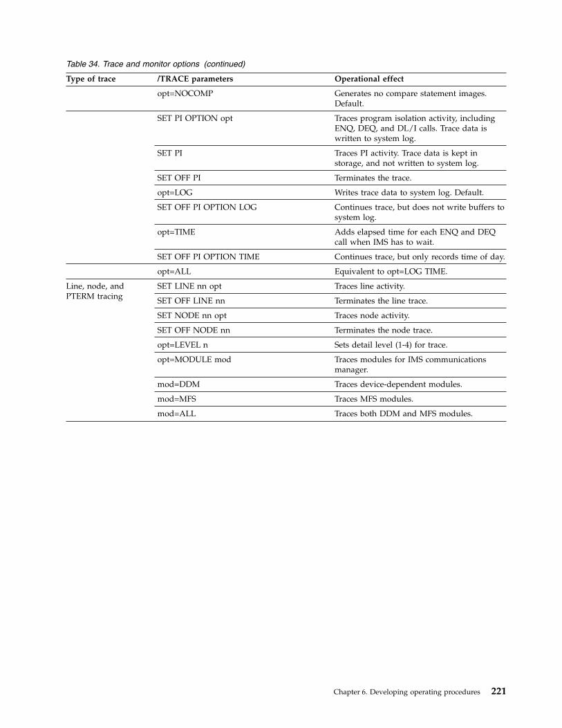
Table 34. Trace and monitor options (continued)
Type of trace /TRACE parameters Operational effect
opt=NOCOMP Generates no compare statement images.Default.
SET PI OPTION opt Traces program isolation activity, includingENQ, DEQ, and DL/I calls. Trace data iswritten to system log.
SET PI Traces PI activity. Trace data is kept instorage, and not written to system log.
SET OFF PI Terminates the trace.
opt=LOG Writes trace data to system log. Default.
SET OFF PI OPTION LOG Continues trace, but does not write buffers tosystem log.
opt=TIME Adds elapsed time for each ENQ and DEQcall when IMS has to wait.
SET OFF PI OPTION TIME Continues trace, but only records time of day.
opt=ALL Equivalent to opt=LOG TIME.
Line, node, andPTERM tracing
SET LINE nn opt Traces line activity.
SET OFF LINE nn Terminates the line trace.
SET NODE nn opt Traces node activity.
SET OFF NODE nn Terminates the node trace.
opt=LEVEL n Sets detail level (1-4) for trace.
opt=MODULE mod Traces modules for IMS communicationsmanager.
mod=DDM Traces device-dependent modules.
mod=MFS Traces MFS modules.
mod=ALL Traces both DDM and MFS modules.
Chapter 6. Developing operating procedures 221
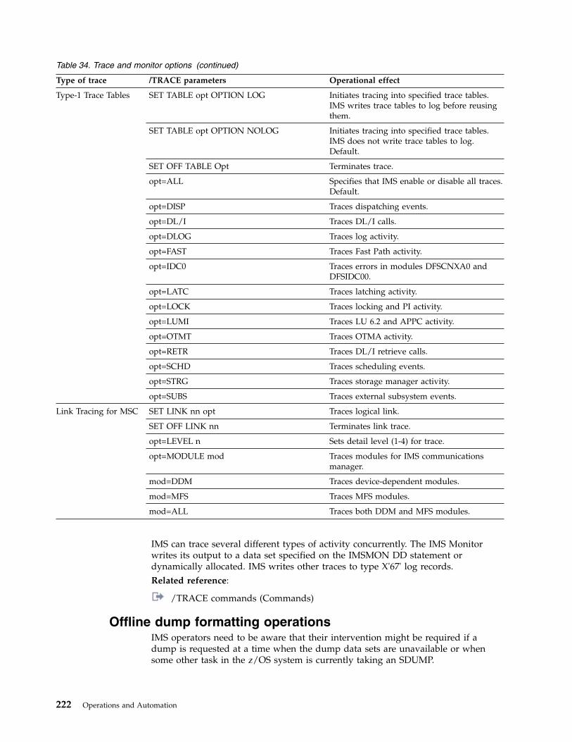
Table 34. Trace and monitor options (continued)
Type of trace /TRACE parameters Operational effect
Type-1 Trace Tables SET TABLE opt OPTION LOG Initiates tracing into specified trace tables.IMS writes trace tables to log before reusingthem.
SET TABLE opt OPTION NOLOG Initiates tracing into specified trace tables.IMS does not write trace tables to log.Default.
SET OFF TABLE Opt Terminates trace.
opt=ALL Specifies that IMS enable or disable all traces.Default.
opt=DISP Traces dispatching events.
opt=DL/I Traces DL/I calls.
opt=DLOG Traces log activity.
opt=FAST Traces Fast Path activity.
opt=IDC0 Traces errors in modules DFSCNXA0 andDFSIDC00.
opt=LATC Traces latching activity.
opt=LOCK Traces locking and PI activity.
opt=LUMI Traces LU 6.2 and APPC activity.
opt=OTMT Traces OTMA activity.
opt=RETR Traces DL/I retrieve calls.
opt=SCHD Traces scheduling events.
opt=STRG Traces storage manager activity.
opt=SUBS Traces external subsystem events.
Link Tracing for MSC SET LINK nn opt Traces logical link.
SET OFF LINK nn Terminates link trace.
opt=LEVEL n Sets detail level (1-4) for trace.
opt=MODULE mod Traces modules for IMS communicationsmanager.
mod=DDM Traces device-dependent modules.
mod=MFS Traces MFS modules.
mod=ALL Traces both DDM and MFS modules.
IMS can trace several different types of activity concurrently. The IMS Monitorwrites its output to a data set specified on the IMSMON DD statement ordynamically allocated. IMS writes other traces to type X'67' log records.Related reference:
/TRACE commands (Commands)
Offline dump formatting operationsIMS operators need to be aware that their intervention might be required if adump is requested at a time when the dump data sets are unavailable or whensome other task in the z/OS system is currently taking an SDUMP.
222 Operations and Automation

In these situations, IMS issues message DFS3906 or DFS3907. In addition, CCTLoperators must be aware that the CCTL can issue these messages when the IMSdatabase resource adapter (DRA) is trying to generate an SDUMP.
Designing operating proceduresYou can document operating procedures using flowcharts or a narrative style.
Operating procedure design using flowcharts and othergraphic techniques
Flowcharts have several obvious advantages over narrative presentations ofprocedures. For example, with a flowchart it is easy to get an overall picture ofwhat needs to be done. Another advantage is that when text accompanies eachflowchart, you can skip reading any text associated with a step that you alreadyunderstand.
If the flowchart, for example, says to start IMS and this step is understood, thereader does not need to read that “the system operator enters the /NRE commandfrom the system console...”.
When you use flowcharts or other graphics to document operating procedures, yougenerally accompany them with an expanded textual description of the varioussteps in the flowchart. The main disadvantage to using flowcharts is that they areoften difficult to maintain. Small changes to an operating procedure could requireyou to redesign an entire flowchart.
You might not need to use flowcharts for the IMS MTO. However, it is probablythe preferred technique when designing procedures for a recovery specialist orothers who need an overview of how something works or what actions are to beperformed.
Operating procedure design using narrativeThe advantage to using a narrative style is that it is relatively easy to maintain.There are no graphics to redraw, and changes to the procedures seldom requiremuch redesign.
The disadvantage is that the overall operation being performed is not alwaysobvious. In addition, if the users of the procedure suspect that they have taken awrong branch in the procedure, it is difficult to backtrack through the steps.
There are many ways to document procedures using a narrative style, rather thangraphics. For example, you could use a numbered list, where the reader starts atnumber 1, compares the situation with the information in number 1, thencontinues to number 2 or maybe jumps to number 15 depending on the decisionmade in number 1. This technique is essentially a narrative flowchart. As anotherexample, you could write scenarios, wherein the reader picks a scenario thatmatches their situation, and follows all the steps in the scenario.
Chapter 6. Developing operating procedures 223

IMS-to-IMS TCP/IP connection operationsThe communication path of an IMS-to-IMS TCP/IP connection passes throughmultiple IMS components: the IMS control region, the Structured Call Interface(SCI) of the Common Service Layer (CSL), IMS Connect, and either the IMSMultiple Systems Coupling (MSC) component or the IMS Open TransactionManager Access (OTMA) component.
Operational tasks for an IMS-to-IMS TCP/IP connection in one segment of anIMS-to-IMS TCP/IP connection impacts the connection in the other segments. Also,general operational tasks in the IMS system are also likely to impact anyIMS-to-IMS TCP/IP connections.Related concepts:“MSC operations” on page 237
Viewing configuration and status information for IMS-to-IMSTCP/IP connections in IMS Connect
You can view configuration and status information for IMS-to-IMS TCP/IPconnections by issuing IMS Connect commands.
The connection information you can view is generally the same regardless ofwhether the connection is used for Multiple Systems Coupling (MSC) or OpenTransaction Manager (OTMA). However, if you use MSC, you can also displayinformation about the MSC link.
Viewing MSC connection information for IMS-to-IMS TCP/IPcommunicationsYou can view configuration and status information for IMS-to-IMS TCP/IPconnections that are used for MSC by issuing IMS Connect commands.
Each MSC link requires two socket connections: a send socket connection and areceive socket connection. You display information about the send socketconnections by querying RMTIMSCON connection information. You displayinformation about the receive socket connection by querying the port information.
You can also display information about the definition and status of an MSC logicallink by querying the MSC configuration information in IMS Connect.v To display connection information on the sending side of a connection that is
used for MSC, issue any one of the following IMS Connect commands thatdisplay the RMTIMSCON connection information:– In the IMS type-2 format, QUERY IMSCON TYPE(RMTIMSCON)– In the WTOR format, VIEWRMT– In the z/OS MODIFY format, QUERY RMTIMSCON
v To display connection information on the receiving side of a connection that isused for MSC, issue any one of the following IMS Connect commands thatdisplay port information:– In the IMS type-2 format, QUERY IMSCON TYPE(PORT)– In the WTOR format, VIEWPORT– In the z/OS MODIFY format, QUERY PORT
v To display link information on either side of a connection that is used for MSC,issue any one of the following IMS Connect commands that display linkinformation:
224 Operations and Automation

– In the IMS type-2 format, QUERY IMSCON TYPE(MSC)– In the WTOR format, VIEWMSC– In the z/OS MODIFY format, QUERY MSC
Example: Viewing an MSC TCP/IP connection at the local and remoteIMS Connect instances
In the following example, the VIEWRMT command is issued at a local IMSConnect instance for a RMTIMSCON connection, ICON2, that is used by MSC tosend messages to the remote IMS installation.nnVIEWRMT ICON2
The example output shows that two send socket connections, MSCBB435 andMSC84CF7, are in CONN status on the RMTIMSCON connection ICON2. TheSENDCLNT IDs are auto-generated by the local IMS Connect instance whenestablishing the send socket connections to remote IMS Connect instance. In theexample, PORT=5555 shows that the local IMS Connect expects the remote IMSConnect to be listening on port 5555. The presence of the LCLPLKID valuesindicate that these are MSC connections and identify the local MSC physical linkthat they are using.HWSC0001I RMTIMSCON=ICON2 STATUS=ACTIVEHWSC0001I IP-ADDRESS=009.030.221.055 PORT=5555HWSC0001I HOSTNAME=ECSER14.VMEC.SVL.IBM.COMHWSC0001I AUTOCONN=N PERSISTENT=YHWSC0001I IDLETO=0HWSC0001I RESVSOC=2 NUMSOC=2HWSC0001I SENDCLNT LCLPLKID STATUS SECOND SENDPORTHWSC0001I MSCBB435 MSC12 CONN 6 1028HWSC0001I MSC84CF7 MSC12 CONN 56 1027HWSC0001I TOTAL SENDCLNTS=2 RECV=0 CONN=2 XMIT=0 OTHER=0
In the following example, the VIEWPORT command is issued at the local IMSConnect instance for port 9999.nnVIEWPORT 9999
The example output shows the receive socket connections, MSCC73E0 andMSC0EBB0, that are in RECV state on port 9999 at the local IMS Connect instance.Again, the presence of the LCLPLKID values indicate that these connections arebeing used for MSC, as well as the local MSC physical link that they are using.
HWSC0001I PORT=9999 STATUS=ACTIVE KEEPAV=0 NUMSOC=3 EDIT= TIMEOUT=0HWSC0001I CLIENTID LCLPLKID STATUS SECOND CLNTPORT IP-ADDRESSHWSC0001I MSCC73E0 MSC12 RECV 6 1026 0:0:0:0:0:FFFF:91E:DD37HWSC0001I MSC0EBB0 MSC12 RECV 56 1025 0:0:0:0:0:FFFF:91E:DD37HWSC0001I TOTAL CLIENTS=2 RECV=2 READ=0 CONN=0 XMIT=0 OTHER=0
The following examples for a remote IMS Connect instance correspond to thepreceding examples for a local IMS Connect instance.
In the following example, the VIEWPORT command is issued for port 5555 at theremote IMS Connect instance.nnVIEWPORT 5555
The output for the VIEWPORT command shows two receive socket connections,MSCBB435 and MSC84CF7, on port 5555. These CLIENTID values match theSENDCLNT values shown in the preceding example of the VIEWRMT commandat the local IMS Connect instance.
Chapter 6. Developing operating procedures 225
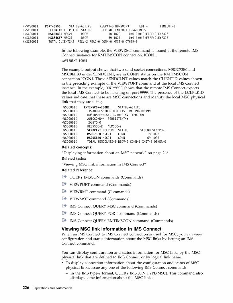
HWSC0001I PORT=5555 STATUS=ACTIVE KEEPAV=0 NUMSOC=3 EDIT= TIMEOUT=0HWSC0001I CLIENTID LCLPLKID STATUS SECOND CLNTPORT IP-ADDRESSHWSC0001I MSCBB435 MSC21 RECV 18 1028 0:0:0:0:0:FFFF:91E:7326HWSC0001I MSC84CF7 MSC21 RECV 69 1027 0:0:0:0:0:FFFF:91E:7326HWSC0001I TOTAL CLIENTS=2 RECV=2 READ=0 CONN=0 XMIT=0 OTHER=0
In the following example, the VIEWRMT command is issued at the remote IMSConnect instance for RMTIMSCON connection, ICON1.nnVIEWRMT ICON1
The example output shows that two send socket connections, MSCC73E0 andMSC0EBB0 under SENDCLNT, are in CONN status on the RMTIMSCONconnection ICON1. These SENDCLNT values match the CLIENTID values shownin the preceding example of the VIEWPORT command at the local IMS Connectinstance. In the example, PORT=9999 shows that the remote IMS Connect expectsthe local IMS Connect to be listening on port 9999. The presence of the LCLPLKIDvalues indicate that these are MSC connections and identify the local MSC physicallink that they are using.HWSC0001I RMTIMSCON=ICON1 STATUS=ACTIVEHWSC0001I IP-ADDRESS=009.030.115.038 PORT=9999HWSC0001I HOSTNAME=ECSER13.VMEC.SVL.IBM.COMHWSC0001I AUTOCONN=N PERSISTENT=YHWSC0001I IDLETO=0HWSC0001I RESVSOC=2 NUMSOC=2HWSC0001I SENDCLNT LCLPLKID STATUS SECOND SENDPORTHWSC0001I MSCC73E0 MSC21 CONN 18 1026HWSC0001I MSC0EBB0 MSC21 CONN 69 1025HWSC0001I TOTAL SENDCLNTS=2 RECV=0 CONN=2 XMIT=0 OTHER=0
Related concepts:“Displaying information about an MSC network” on page 246Related tasks:“Viewing MSC link information in IMS Connect”Related reference:
QUERY IMSCON commands (Commands)
VIEWPORT command (Commands)
VIEWRMT command (Commands)
VIEWMSC command (Commands)
IMS Connect QUERY MSC command (Commands)
IMS Connect QUERY PORT command (Commands)
IMS Connect QUERY RMTIMSCON command (Commands)
Viewing MSC link information in IMS ConnectWhen an IMS Connect to IMS Connect connection is used for MSC, you can viewconfiguration and status information about the MSC links by issuing an IMSConnect command.
You can display configuration and status information for MSC links by the MSCphysical link that are defined to IMS Connect or by logical link name.v To display connection information about the configuration and status of MSC
physical links, issue any one of the following IMS Connect commands:– In the IMS type-2 format, QUERY IMSCON TYPE(MSC). This command also
displays some information about the MSC links.
226 Operations and Automation

– In the WTOR format, VIEWMSC– In the z/OS MODIFY format, QUERY MSC
v To display status information for MSC logical links, issue the followingcommand:– In the IMS type-2 format, QUERY IMSCON TYPE(LINK)
Related concepts:“Displaying information about an MSC network” on page 246Related tasks:“Viewing MSC connection information for IMS-to-IMS TCP/IP communications”on page 224Related reference:
QUERY IMSCON commands (Commands)
VIEWMSC command (Commands)
IMS Connect QUERY MSC command (Commands)
Viewing OTMA connection information for IMS-to-IMS TCP/IPcommunicationsYou can view configuration and status information for IMS-to-IMS TCP/IPconnections that are used for OTMA by issuing IMS Connect commands.
The information that you can view for an IMS-to-IMS TCP/IP connection that isused for OTMA is different depending on whether you are viewing theinformation on the sending side of a connection or the receiving side of aconnection. For this reason, the commands you use to display the connectioninformation are also different on the sending and receiving sides of the connection.v To display connection information on the sending side of a connection that is
used for OTMA, issue any one of the following IMS Connect commands thatdisplay the RMTIMSCON connection information:– In the IMS type-2 format, QUERY IMSCON TYPE(RMTIMSCON)– In the WTOR format, VIEWRMT– In the z/OS MODIFY format, QUERY RMTIMSCON
v To display connection information on the receiving side of a connection that isused for OTMA, issue any one of the following IMS Connect commands thatdisplay port information:– In the IMS type-2 format, QUERY IMSCON TYPE(PORT)– In the WTOR format, VIEWPORT– In the z/OS MODIFY format, QUERY PORT
Example: IMS Connect to IMS Connect connections for OTMA
In the following example, the VIEWRMT command is issued at a sending IMSConnect instance for a RMTIMSCON connection, ICON2B.nnVIEWRMT ICON2B
The example output shows that there is one active send client socket connection,OTM924FA, on the RMTIMSCON connection ICON2B. The SENDCLNT ID isauto-generated by the sending IMS Connect instance when establishing theconnection with the receiving IMS Connect instance. In the example, PORT=5555shows that the sending IMS Connect expects the receiving IMS Connect to belistening on port 5555.
Chapter 6. Developing operating procedures 227
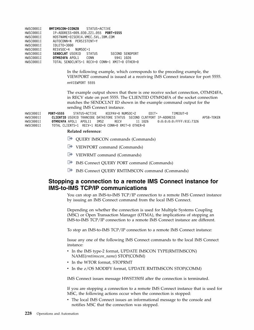
HWSC0001I RMTIMSCON=ICON2B STATUS=ACTIVEHWSC0001I IP-ADDRESS=009.030.221.055 PORT=5555HWSC0001I HOSTNAME=ECSER14.VMEC.SVL.IBM.COMHWSC0001I AUTOCONN=N PERSISTENT=YHWSC0001I IDLETO=3000HWSC0001I RESVSOC=4 NUMSOC=1HWSC0001I SENDCLNT USERID STATUS SECOND SENDPORTHWSC0001I OTM924FA APOL1 CONN 5941 1026HWSC0001I TOTAL SENDCLNTS=1 RECV=0 CONN=1 XMIT=0 OTHER=0
In the following example, which corresponds to the preceding example, theVIEWPORT command is issued at a receiving IMS Connect instance for port 5555.nnVIEWPORT 5555
The example output shows that there is one receive socket connection, OTM924FA,in RECV state on port 5555. The CLIENTID OTM924FA of the socket connectionmatches the SENDCLNT ID shown in the example command output for thesending IMS Connect instance.
HWSC0001I PORT=5555 STATUS=ACTIVE KEEPAV=0 NUMSOC=2 EDIT= TIMEOUT=0HWSC0001I CLIENTID USERID TRANCODE DATASTORE STATUS SECOND CLNTPORT IP-ADDRESS APSB-TOKENHWSC0001I OTM924FA APOL1 APOL11 IMS2 RECV 11 1026 0:0:0:0:0:FFFF:91E:7326HWSC0001I TOTAL CLIENTS=1 RECV=1 READ=0 CONN=0 XMIT=0 OTHER=0
Related reference:
QUERY IMSCON commands (Commands)
VIEWPORT command (Commands)
VIEWRMT command (Commands)
IMS Connect QUERY PORT command (Commands)
IMS Connect QUERY RMTIMSCON command (Commands)
Stopping a connection to a remote IMS Connect instance forIMS-to-IMS TCP/IP communications
You can stop an IMS-to-IMS TCP/IP connection to a remote IMS Connect instanceby issuing an IMS Connect command from the local IMS Connect.
Depending on whether the connection is used for Multiple Systems Coupling(MSC) or Open Transaction Manager (OTMA), the implications of stopping anIMS-to-IMS TCP/IP connection to a remote IMS Connect instance are different.
To stop an IMS-to-IMS TCP/IP connection to a remote IMS Connect instance:
Issue any one of the following IMS Connect commands to the local IMS Connectinstance:v In the IMS type-2 format, UPDATE IMSCON TYPE(RMTIMSCON)
NAME(rmtimscon_name) STOP(COMM)v In the WTOR format, STOPRMTv In the z/OS MODIFY format, UPDATE RMTIMSCON STOP(COMM)
IMS Connect issues message HWST3505I after the connection is terminated.
If you are stopping a connection to a remote IMS Connect instance that is used forMSC, the following actions occur when the connection is stopped:v The local IMS Connect issues an informational message to the console and
notifies MSC that the connection was stopped.
228 Operations and Automation
v IMS stops the MSC logical links that use the IMS-to-IMS TCP/IP connection.v The local IMS Connect disconnects the TCP/IP sockets associated with the
IMS-to-IMS TCP/IP connection.v If the local IMS Connect receives any messages from MSC for the stopped
connection, IMS Connect rejects the message and returns an error message toMSC.
If you are stopping a connection to a remote IMS Connect instance that is used forOTMA, the following actions occur when the connection is stopped:v The local IMS Connect disconnects the TCP/IP sockets associated with the
IMS-to-IMS TCP/IP connection.v If an acknowledgement (ACK) response is pending on any socket that uses the
connection, the local IMS Connect returns a negative acknowledgement (NAK)to OTMA in the local IMS system. IMS Connect issues message HWST3570E.
v If the local IMS Connect receives any OTMA messages from the local IMSsystem for the stopped connection, IMS Connect returns a NAK to OTMA withsense code 002A/0008 and issues message HWST3575W. OTMA leaves themessage at the front of the output queue.
Related reference:
IMS Connect commands (Commands)
UPDATE IMSCON commands (Commands)
Restarting a connection to a remote IMS Connect instance forIMS-to-IMS TCP/IP communications
You can restart a stopped IMS-to-IMS TCP/IP connection in a local IMS Connectinstance by issuing an online IMS Connect command.
Depending on whether the connection is used for Multiple Systems Coupling(MSC) or Open Transaction Manager (OTMA), the implications of restarting anIMS-to-IMS TCP/IP connection from IMS Connect are different.
If you are restarting a connection that is used for MSC, MSC communication doesnot resume until the MSC physical link is also started in the local IMS Connectinstance.
If you are restarting a connection that is used for OTMA, the following actionsoccur when the connection is started:v If the IMS-to-IMS TCP/IP connection is defined locally with AUTOCONN=Y, the
local IMS Connect establishes socket connections with the remote IMS Connectinstance. The number of socket connections opened is determined by theRESVSOC parameter in the RMTIMSCON configuration statement.
v The local IMS Connect notifies the local OTMA that the connection has beenrestarted and OTMA resumes sending messages on the connection.
To restart an IMS-to-IMS TCP/IP connection from the local IMS Connect instance:1. Issue any one of the following IMS Connect commands:v In the IMS type-2 format, UPDATE IMSCON TYPE(RMTIMSCON)
NAME(rmtimscon_name) START(COMM)v In the WTOR format, STARTRMTv In the z/OS MODIFY format, UPDATE RMTIMSCON START(COMM)
Chapter 6. Developing operating procedures 229

2. If the connection is used for MSC, start the MSC physical link in the local IMSConnect by issuing any one of the following IMS Connect commands:v In the IMS type-2 format, UPDATE IMSCON TYPE(MSC) NAME(lclPlkid)
START(COMM)v In the WTOR format, STARTMSC lclplk_id
v In the z/OS MODIFY format, UPDATE MSC NAME(lclPlkid) START(COMM)
IMS Connect issues message HWS3500I after the connection is restarted.Related reference:
IMS Connect commands (Commands)
UPDATE IMSCON commands (Commands)
Stopping IMS Connect send client sockets on IMS-to-IMSTCP/IP connections
You can stop IMS Connect send client socket connections on an IMS-to-IMSTCP/IP connection in a local IMS Connect by issuing an IMS Connect command,such as the WTOR format command STOPSCLN.
Usually, the STOPSCLN command and the equivalent IMS type-2 and z/OSMODIFY commands are used only to stop send client socket connections that areused for IMS Open Transaction Manager Access (OTMA).
Recommendation: Do not stop IMS Connect send client socket connections if theyare used for Multiple Systems Coupling (MSC). If you need to clean up socketsthat are used for MSC, use the STOPLINK command or the equivalent IMS type-2and z/OS MODIFY command.
In IMS Connect, the send client socket connection is represented by a client ID thatis automatically generated by IMS Connect when the socket connection isestablished.
When you stop a send client socket that is connected but idle, as indicated by aCONN status in IMS Connect, the following actions occur:v IMS Connect disconnects the send client socket and cleans up the associated
control blocks.v IMS Connect notifies the remote IMS Connect and the remote IMS Connect
disconnects the related socket and cleans up its control blocks.
When you stop a send client that is waiting for an acknowledgement from theremote IMS Connect, as indicated by a RECV status in IMS Connect, the followingactions occur:v IMS Connect disconnects the send client socket and cleans up the associated
control blocks.v IMS Connect issues a negative acknowledgement (NAK) to OTMA that direct
OTMA to reroute unacknowledged message to the IMS Connect dead letterqueue HWS$DLQ.
v IMS Connect issues message HWST3570E to the console.v When the remote IMS Connect attempts to return the acknowledgement, the
remote IMS Connect receives a socket error and disconnects the related socketand cleans up its control blocks.
230 Operations and Automation

To stop an IMS Connect send client socket of an IMS-to-IMS TCP/IP connection:
Issue any one of the following IMS Connect commands in the local IMS Connectinstance:v In the IMS type-2 format, UPDATE IMSCON TYPE(SENDCLNT)
NAME(sendclient_name) RMTIMSCON(rmtimscon_name) STOP(COMM)v In the WTOR format, STOPSCLNv In the z/OS MODIFY format, DELETE RMTIMSCON NAME (rmtimscon)
SENDCLNT(clientid)
IMS Connect issues message HWS3525I after the connection is terminated.Related reference:
IMS Connect commands (Commands)
UPDATE IMSCON commands (Commands)
Stopping IMS Connect communication with an IMSplex whenMSC TCP/IP links are supported
You can stop communications between a local IMS Connect instance and a localIMSplex by issuing an IMS Connect command, such as the WTOR formatcommand STOPIP.
Stopping IMSplex communications breaks all MSC TCP/IP physical links that aresupported by the local IMS Connect in the local IMSplex.
When a STOPIP or similar command is issued, the following actions occur forMSC TCP/IP links:v The local IMS Connect disconnects the parallel send and receive socket that
support the physical link and sends a shutdown directive to MSC in the localIMS system.
v When MSC receives the shutdown directive, MSC cleans up the physical linkand issues message DFS3176E.
v IMS Connect changes the status of the MSC TCP/IP physical link toDISCONNECTED.
To stop communication between a local IMS Connect instance and a local IMSplexfrom the local IMS Connect instance issue any one of the following IMS Connectcommands:v In the IMS type-2 format, UPDATE IMSCON TYPE(IMSPLEX)
NAME(imsplex_name) STOP(COMM)v In the WTOR format, STOPIP imsplex_id
v In the z/OS MODIFY format, UPDATE IMSPLEX NAME (imsplex_name)STOP(COMM)
Related reference:
IMS Connect commands (Commands)
UPDATE IMSCON commands (Commands)
Chapter 6. Developing operating procedures 231

Starting IMS Connect communication with an IMSplex whenMSC TCP/IP links are supported
You can start communications between a local IMS Connect and a local IMSplex byissuing an IMS Connect command, such as the WTOR format command STARTIP.
When a STARTIP or similar command is issued, communication resumes betweenIMS Connect and the IMSplex.
IMS Connect changes the status of the MSC TCP/IP links that it supports in theIMSplex to ACTIVE.
To start communication between a local IMS Connect and a local IMSplex from thelocal IMS Connect instance issue any one of the following IMS Connect commands:v In the IMS type-2 format, UPDATE IMSCON TYPE(IMSPLEX)
NAME(imsplex_name) START(COMM)v In the WTOR format, STARTIP imsplex_id
v In the z/OS MODIFY format, UPDATE IMSPLEX NAME (imsplex_name)START(COMM)
Related reference:
IMS Connect commands (Commands)
UPDATE IMSCON commands (Commands)
Cleaning up MSC logical link resources in IMS ConnectIf an MSC logical link has terminated in IMS, but the IMS Connect resourcesassociated with the logical link did not clean up automatically, you can clean upthe resources by using an IMS Connect command, such as the WTOR formatcommand STOPLINK.
Recommendation: Under normal circumstances, use the IMS command /PSTOP toterminate MSC logical links. Stop MSC links in IMS Connect only when the IMSConnect resources associated with an MSC logical link that has already terminatedhave failed to clean up correctly.
A logical link on one MSC physical link can have the same name as a logical linkon another physical link. To ensure that a logical link with a duplicate name is notstopped on another physical link, include the ID of the physical link that thelogical link is assigned to on the command when you stop a logical link. The ID ofthe physical link can be found on the on the LCLPLKID parameter of the MSCconfiguration statement.
When you clean up MSC logical links in a local IMS Connect instance by using acommand like STOPLINK, IMS Connect takes the following actions:v Stops any communication on the MSC logical linkv Notifies the local IMS that communication has stopped on the logical linkv Deletes the control blocks associated with the logical link and frees the
associated storagev Issues message HWSF3310I
To stop an MSC logical link and clean up its associated resources in a localinstance of IMS Connect issue any one of the following IMS Connect commands inthe local IMS Connect instance:
232 Operations and Automation

v In the IMS type-2 format, UPDATE IMSCON TYPE(LINK) NAME(linkname)MSC(lclplk_id) STOP(COMM)
v In the WTOR format, STOPLINK linkname lclPlkid
v In the z/OS MODIFY format, DELETE LINK NAME (linkname)LCLPLKID(lclPlkid)
IMS Connect issues message HWS3310I after the link is stopped.Related reference:
IMS Connect commands (Commands)
UPDATE IMSCON commands (Commands)
Stopping an MSC physical link in IMS ConnectDo not stop an MSC physical link in IMS Connect, unless you need to clear theaffinity of the link with an IMS system when TCP/IP generic resources are used.
Recommendation: Under normal circumstances, use the IMS command /PSTOP toterminate MSC physical links. Stop MSC physical links in IMS Connect only whenyou need to clear the affinity of an MSC physical link with a particular IMS systemthat uses TCP/IP generic resources.
When you stop an MSC physical link in a local IMS Connect instance by using acommand like STOPMSC, IMS Connect takes the following action:v Stops communication on the specified MSC physical link, including
communications on all the MSC logical links that are assigned to the physicallink.
v Informs IMS that communication has stopped on the physical link so that IMScan also terminate the physical link and any logical links that are assigned to thephysical link.
v Changes the status of the MSC physical link and its assigned logical links toNOT ACTIVE.
v For TCP/IP generic resources, clears affinity of a physical link to the IMS systemv Issues message HWSF3305I
Use the VIEWMSC command or the QUERY MSC command to displayinformation about MSC physical links that are defined to IMS Connect.
To stop an MSC physical link in a local instance of IMS Connect:
Issue any one of the following IMS Connect commands in the local IMS Connectinstance:v In the IMS type-2 format, UPDATE IMSCON TYPE(MSC) NAME(lclPlkid)
STOP(COMM)v In the WTOR format, STOPMSC lclPlkid
v In the z/OS MODIFY format, UPDATE MSC NAME (lclPlkid) STOP(COMM)
IMS Connect issues message HWS3310I after the link is stopped.Related concepts:
MSC TCP/IP generic resources (Communications and Connections)Related reference:
IMS Connect commands (Commands)
Chapter 6. Developing operating procedures 233
UPDATE IMSCON commands (Commands)
Operating ISC TCP/IP connectionsThe communication path of an ISC TCP/IP connection passes through multipleIMS components: the IMS control region, the Structured Call Interface (SCI) of theCommon Service Layer (CSL), and IMS Connect.
Operational tasks for an ISC TCP/IP connection in one segment of an ISC TCP/IPconnection impacts the connection in the other segments. Also, general operationaltasks in the IMS system are also likely to impact any ISC TCP/IP connections.
Under normal circumstances, you start, stop, and restart an ISC link from IMS byusing the /OPNDST and /QUIESCE type-1 commands. The /OPNDST commandstarts or restarts an ISC link to a remote CICS subsystem. The /QUIESCEcommand stops an ISC link to a remote CICS subsystem after any in-progresswork completes.
Occasionally, you might find it necessary to stop an ISC TCP/IP link from IMSConnect, such as might be the case if a link is shut down from IMS, but IMSConnect fails to properly clean up its resources that support the link. In IMSConnect, you can shut down an ISC link or you can shutdown a TCP/IPconnection to a remote CICS subsystem. When you shut down an ISC link in IMSConnect, all sessions on that link are terminated, but communications with theremote CICS subsystem might continue on other ISC links. If you shutdown aconnection to a remote CICS subsystem, all ISC links that connect to that remoteCICS subsystem are stopped, including all sessions on those links.
In rare extreme cases, you could also stop an ISC link by shutting downcommunications between SCI and either IMS or IMS Connect; however, doing sowould stop all communications in IMS or IMS Connect that require SCI, not justthose that use ISC TCP/IP links.
Cleaning up an ISC parallel session in IMS ConnectIf an ISC parallel session has terminated in IMS, but the IMS Connect resourcesassociated with the parallel session did not clean up automatically, you can cleanup the resources by using the IMS type-2 command UPDATE IMSCONTYPE(ISCUSER).
Recommendation: Under normal circumstances, use the IMS /QUIESCE NODEcommand to terminate ISC parallel sessions. Stop an ISC parallel session in IMSConnect only if the IMS Connect resources that are associated with the ISC parallelsession fail to clean up correctly after the session is terminated in IMS.
When you clean up ISC parallel sessions in a local IMS Connect instance by usingthe UPDATE IMSCON TYPE(ISCUSER) command, IMS Connect takes thefollowing actions:v Stops any communication on the ISC parallel sessionv Notifies the local IMS that communication has stopped on the parallel sessionv Deletes the control blocks associated with the parallel session and frees the
associated storagev Issues message HWSG4010I
234 Operations and Automation
To stop an ISC parallel session and clean up its associated resources in IMSConnect, issue the UPDATE IMSCON TYPE(ISCUSER) command.
IMS Connect issues message HWSG4010I after the link is stopped.Related reference:
QUERY IMSCON TYPE(ISCUSER) command (Commands)
/QUIESCE command (Commands)
UPDATE IMSCON TYPE(ISCUSER) command (Commands)
Stopping an ISC link in IMS ConnectYou can stop an ISC link in IMS Connect, but avoid doing so unless the ISC linkdid not clean up properly after the link was terminated in IMS or you need toprevent sessions from starting on the ISC link.
Under normal circumstances, stop ISC links from IMS by using the IMS type-1command /QUIESCE NODE, which terminates the ISC link after any in-progresswork completes. If the link must be terminated immediately without waiting forin-progress work to complete, use the IMS type-1 command /CLSDST NODE.
To stop an ISC link in a local instance of IMS Connect:
Issue the IMS type-2 format command UPDATE IMSCON TYPE(ISC)NAME(iscstmtid) STOP(COMM) in the local IMS Connect instance.
In response to the command, IMS Connect takes the following action:v Stops communication on the specified ISC link, including communications on all
the ISC sessions that are assigned to the link.v Closes the associated send and receive sockets.v Informs IMS that communication has stopped on the ISC link so that IMS can
also terminate the link and any sessions that are assigned to the link.v Changes the status of the ISC link and its assigned logical links to NOT
ACTIVE.v Issues message HWSG4005I.
Tip: Use the QUERY IMSCON TYPE(ISC) command to display information aboutthe ISC links that are defined to IMS Connect.
Before the link can be used again, the link must be started in IMS Connect by theUPDATE IMSCON TYPE(ISC) NAME(iscstmtid) START(COMM) command.Related tasks:“Restarting an ISC link in IMS Connect”Related reference:
QUERY IMSCON TYPE(ISC) command (Commands)
UPDATE IMSCON TYPE(ISC) command (Commands)
Restarting an ISC link in IMS ConnectYou need to restart an ISC link in IMS Connect after an ISC link was stoppedpreviously by an UPDATE IMSCON TYPE(ISC) NAME(isclnkid) STOP(COMM)command.
Chapter 6. Developing operating procedures 235
In rare circumstances, you might need to restart an ISC link after the link failedunexpectedly in IMS Connect.
ISC communication does not resume until the ISC session is also restarted in IMSby issuing the /OPNDST command.
To restart an ISC link in a local instance of IMS Connect:
Issue the IMS type-2 format command UPDATE IMSCON TYPE(ISC)NAME(isclnkid) START(COMM) in the local IMS Connect instance.
IMS Connect issues message HWSG4000I when the link restarts successfully.Related tasks:“Stopping an ISC link in IMS Connect” on page 235Related reference:
QUERY IMSCON TYPE(ISC) command (Commands)
UPDATE IMSCON TYPE(ISC) command (Commands)
Stopping a connection to a remote CICS subsystem from IMSConnect
You can stop an ISC TCP/IP connection to a remote CICS subsystem from IMSConnect.
Recommendation: Avoid stopping a connection to a remote CICS subsystemunless the connection did not clean up properly after the connection was shutdown in IMS or you need to prevent sessions from opening to the remote CICSsubsystem.
To stop an ISC TCP/IP connection to a remote CICS subsystem, issue the IMStype-2 command UPDATE IMSCON TYPE(RMTCICS) NAME(rmtcics_id)STOP(COMM)
IMS Connect performs the following actions when an ISC TCP/IP connection to aremote CICS subsystem is stopped in IMS Connect:v Informs IMS that communication stopped on the ISC link so that IMS can also
terminate the link and any sessions that are assigned to the link.v Disconnects the TCP/IP sockets associated with the ISC TCP/IP connection.v Changes the status of the connection to STOPPED.v Issues a message HWSV4405I to the console and notifies IMS that the connection
was stopped.
If IMS Connect receives any messages from IMS for the stopped connection, IMSConnect rejects the message, returns a NAK response message to IMS, and issuesmessage HWSG4040W.Related tasks:“Restarting a connection to a remote CICS subsystem in IMS Connect” on page 237
Related reference:
QUERY IMSCON TYPE(RMTCICS) command (Commands)
UPDATE IMSCON TYPE(RMTCICS) command (Commands)
236 Operations and Automation

Restarting a connection to a remote CICS subsystem in IMSConnect
You can restart an ISC TCP/IP connection that is stopped in IMS Connect byissuing an online IMS Connect command.
In rare circumstances, you might need to restart a connection to a remote CICSafter the connection failed unexpectedly in IMS Connect.
ISC communication does not resume until the ISC session is also restarted in IMSby issuing the /OPNDST command.
To restart an ISC TCP/IP connection in IMS Connect, issue the IMS type-2command UPDATE IMSCON TYPE(RMTCICS) NAME(rmtcics_id) START(COMM).
IMS Connect issues message HWSV4400I when the connection is restarted.Related tasks:“Stopping a connection to a remote CICS subsystem from IMS Connect” on page236Related reference:
QUERY IMSCON TYPE(RMTCICS) command (Commands)
UPDATE IMSCON TYPE(RMTCICS) command (Commands)
MSC operationsIn a non-sysplex environment, each IMS system in a Multiple Systems Coupling(MSC) configuration is operationally an independent unit. Each IMS systemexclusively owns its own communication resources, and is controlled by its ownmaster terminal.Related concepts:“IMS-to-IMS TCP/IP connection operations” on page 224Related tasks:“Modifying Multiple Systems Coupling resources” on page 37
MSC initializationTo start Multiple Systems Coupling (MSC) communications between two IMSsystems, issue either the IMS type-1 command /RSTART LINK or the IMS type-2command UPDATE MSLINK NAME(linkname) START(COMM).
If the physical link type is either a channel-to-channel connection or a main-storageto main-storage connection (MTM), you must issue the command in both IMSsystems at each end of the link.
If the physical link type is either TCP/IP or VTAM, you need to issue thecommand in only one IMS system. The normal procedure is for the operator toissue this command when a system has started. Communication is allowed only ifthe characteristics of the specified links are compatible. If a required link is notsuccessfully started, messages wait until the links are reassigned.
The SYSID of each IMS system running in a shared queues group can either becloned across all systems, or not. If the SYSIDs are not cloned, initialize all IMSsystems in the shared queues group before starting regions to process thetransactions on the shared queue to avoid occurrences of pseudoabend U0830.
Chapter 6. Developing operating procedures 237
After all IMS systems have been initialized, transaction processing can begin, andindividual IMS systems can be brought down and later restarted as needed.Initialization allows all IMS systems to exchange MSC SYSIDs and MSNAMEs, andcreates a SYSID table that contains all of the SYSIDs for that shared queues group.If the SYSIDs for all IMS systems in a shared queues group are cloned, then you donot need to perform this initialization.
Attention: If you cold start a non-shared queues system that has messagesqueued, the queued messages are lost. Because the messages that were lost can befrom or to terminals and programs in other systems, the impact of a cold start isnot limited to the cold-started system.
In a shared-queues environment, IMS systems in the IMSplex exchange SYSIDsand MSNAMEs at initialization. During this SYSID exchange, each IMS systemcreates dynamic MSNAMEs for any MSNAMEs that are defined in other IMSsystems that it does not define itself. The dynamic MSNAMEs result in paths to allof the IMS systems in the IMSplex. The SYSIDs are merged to create a commonSYSID routing table. The table is the same in each IMS. Therefore, any local SYSIDsare local in all IMS systems and override any remote or undefined SYSIDs. RemoteSYSIDs override only undefined SYSIDs.
MSC terminationYou terminate Multiple Systems Coupling (MSC) links from either of the twolinked IMS systems by issuing either a type-1 command /PSTOP LINK or a type-2command UPDATE MSLINK NAME(linkname) STOP(COMM). When transmissionterminates on one side, its partner in the other system terminates its owntransmission and notifies the MTO.
Use the command forms shown in the following table to terminate links betweenpartner MSC systems.
Table 35. Commands to terminate links
Command Keyword MSC use and effect
/IDLE LINK IMS forces termination of all transmissions on the physical linkassociated with the named logical link. Use only after a shutdowncheckpoint.
NOSHUT For TCP/IP and VTAM link types only, IMS forces the idle conditionwithout taking a shutdown checkpoint.
238 Operations and Automation
Table 35. Commands to terminate links (continued)
Command Keyword MSC use and effect
/PSTOP LINK IMS halts transmissions associated with the logical link between twopartner systems, but continues queuing for the remote resources.IMS enqueues, but does not send, broadcast messages that woulduse the link.
IMS stops the logical link in the partner system, and sends messageDFS2161 to its MTO.
LINK PURGE IMS forces PSTOP condition even if other system failed whilechannel-to-channel (CTC) I/O was in progress. CTC link type only.
MSPLINK Stops logons to an MSC TCP/IP or VTAM physical link and enablesthe operator to issue the /MSASSIGN command to reassign logicallinks to the physical link. Any links in sessions that have not beenstopped by the /PSTOP command are not affected by an/MSASSIGN command.
For physical links in a TCP/IP generic resource group, after thephysical link is stopped, all logical links must terminate normally toclear link affinity before they can be moved to a different IMSsystem.
UPDATE MSLINKNAME(linkname)
STOP(COMM) Halts transmissions associated with the logical link between twopartner systems, but queuing for the remote resources continues.Broadcast messages that would use the link are queued but not sent.This command is equivalent to the type-1 command /PSTOP LINK.
The logical link is stopped in the partner system and its MTO isnotified by message DFS2161.
OPTION(FORCE) This command applies to TCP/IP and VTAM link types and forces a/PSTOP condition.
OPTION(FORCE) leaves the link in PSTOPPED IDLE ERE mode.The subsequent restart of the link is an emergency restart.
For VTAM link types, STOP(COMM) without OPTION(FORCE)must be issued before OPTION(FORCE) is used. For TCP/IP links,OPTION(FORCE) can be used any time.
OPTION(FORCE) might need to be issued on both sides of the link.
UPDATE MSPLINKNAME(msplinkname)
STOP(LOGON) Stops logons to the physical link. This applies to MSC TCP/IP andVTAM links only. It stops logons to the physical link and enablesthe operator to reassign logical links to the physical link.
STOP(GENLOGON) For MSC TCP/IP links in a TCP/IP generic resource group only,stops logons to the IMS system on the physical link. After thecommand stops logons to the physical link and all logical links onthe physical link have terminated normally to clear link affinity withthe IMS system, the logical links can be reassigned to a physical linkon another IMS system.
Changing logical link assignmentsYou define initial logical link assignments (logical link to physical link) as part ofthe IMS system definition process. However, you can change logical linkassignments dynamically.
Chapter 6. Developing operating procedures 239

To dynamically make or change a logical link assignment, use either the type-1command /MSASSIGN or the type-2 command UPDATE MSLINKNAME(linkname) SET(MSPLINK(msplinkname)).
Recommendation: Use the /MSASSIGN command or the UPDATE MSLINKNAME(linkname) SET(MSPLINK(msplinkname)) command to create logical linksonly for unscheduled reassignments resulting from failing physical connections orsystems.
Because a logical link must always communicate with its partner, the operators forthe two systems must coordinate their assignments of corresponding physicallinks. You can replace any type of physical link with any other type of physicallink.
Changes to logical link assignments remain in effect until you change them usingan /MSASSIGN command, UPDATE MSLINK NAME(linkname) SET(MSPLINK(msplinkname)) command, or cold start IMS. The commands only alterthe relationship of MSC resources in the local system.
The logical link relationships you can change and the commands you can use tochange them include:v Logical link to physical link
– Type-1 command /MSASSIGN.– Type-2 command UPDATE MSLINK NAME(linkname) SET
(MSPLINK(msplinkname)).v Remote SYSID to logical link
– Type-1 command /MSASSIGN.– Type-2 command UPDATE MSNAME NAME(linkname) SET
(MSPLINK(msplinkname)) assigns an MSNAME with the desired remoteSYSID to a logical link. Alternately, you can modify the remote SYSID of theMSNAME already associated with the logical link by issuing the type-2command UPDATE MSNAME NAME(msname) SET(SIDR (remote_sysid)).
v Logical link path to logical link:– Type-1 command /MSASSIGN.– Type-2 command UPDATE MSNAME NAME(msname)
SET(MSLINK(mslinkname)).
You can also use the /MSASSIGN command to complete the following tasks:v Change a remote program to localv Change a local program to remotev Assign a logical path
When you modify logical link assignments:v Operating logical or physical links must be assigned one-to-one, except for
TCP/IP and VTAM link types, which can have parallel sessions in effect. In thiscase, multiple logical links can be assigned to one physical link.
v If the link uses TCP/IP or VTAM, before you assign a logical link either to orfrom an MSPLINK name you must stop the physical link by executing one ofthe following commands:– The type-1 command /PSTOP MSPLINK– The type-2 command UPDATE MSPLINK NAME(msplinkname)
STOP(LOGON)
240 Operations and Automation

– In a TCP/IP generic resource group, the type-2 command UPDATE MSPLINKNAME(msplinkname) STOP(GENLOGON)
v Before reassigning a logical link, you must stop the logical link by using either atype-1 command /PSTOP or a type-2 command UPDATE MSLINKNAME(linkname) STOP(COMM) and the logical link must be idle.
v A destination SYSID cannot be reassigned to a logical link unless its currentlyassigned logical link is idle after a type-1 command /PSTOP or a type-2command UPDATE MSLINK NAME(linkname) STOP(COMM).
v MSC communication can occur only when logical links in two IMS systemsshare the same partner identification and have assignment to an operatingcommunications facility between the systems.
v IMS does not determine whether the requested logical link assignment isreasonable or results in a valid configuration for MSC communication. This isonly done by communication with appropriate remote systems. You canaccomplish this using the /MSVERIFY command after making assignmentchanges.
Restarting a logical linkIf a restart is pending on a logical link because of a physical link failure, reestablishcommunications between both systems through an alternative physical link.
Restriction: In a TCP/IP generic resource group, where a physical link is definedin multiple IMS systems, if a logical link is in a PSTOPPED ERE state on any IMSsystem in the group, do not start a logical link that uses the same physical link onany other IMS system in the group. Before you can start a logical link on the samephysical link on another system, you must clear the affinity of the ERE link eitherby shutting it down normally or by resetting it to a COLD state.
As a precaution, display the affinity status of an MSC link on its current IMSsystem before moving the link by restarting it on another IMS system. If theaffinity is still active, shutdown the link normally, which resets the affinity status.If the link cannot be shut down normally, set the link to COLD status by issuingeither the type-1 command /CHANGE LINK linknum FORCSESS | SYNCSESSCOLDSESS or the type-2 command UPDATE MSLINKNAME(linkname)SET(SYNCOPT(COLDSESS)
Attention: Changing the link status from ERE to COLD or moving a link in EREstatus and restarting it on another IMS system prevents the synchronization of themessage sequence numbers during restart, which can cause the duplication or lossof messages.1. If the link uses TCP/IP or VTAM, before you assign a logical link either to or
from an MSPLINK name, stop the physical link by issuing one of the followingcommands:v The type-1 command /PSTOP MSPLINKv The type-2 command UPDATE MSPLINK NAME(msplinkname)
STOP(LOGON)v For links in a TCP/IP generic resource group only, the type-2 command
UPDATE MSPLINK NAME(msplinkname) STOP(GENLOGON)2. Reassign the logical link to the alternate physical link by using either of the
following commands:v The type-1 command /MSASSIGNv The type-2 command UPDATE MSLINK NAME(linkname)
SET(MSPLINK(msplinkname))
Chapter 6. Developing operating procedures 241
3. If the link uses TCP/IP or VTAM, restart the physical link by issuing one of thefollowing commands:v The type-1 command /RSTART MSPLINKv The type-2 command UPDATE MSPLINK NAME(msplinkname)
START(LOGON)v For links in a TCP/IP generic resource group only, the type-2 command
UPDATE MSPLINK NAME(msplinkname) START(GENLOGON)4. Start the logical link by issuing one of the following commands:v The type-1 command /RSTART LINKv The type-2 command UPDATE MSLINK NAME(linkname) START(COMM)
Switching TCP/IP and VTAM physical link typesBecause of the operational similarities between MSC physical links that useTCP/IP and those that use VTAM, the VTAM- and TCP/IP-type physical links arewell-suited to serve as a back-up link types for each other.
Prerequisite: In advance of any failure, you must define a redundant set ofphysical links that use the alternative link type and that duplicate the primary setof MSC physical links. Both TCP/IP and VTAM physical links are defined byusing either the MSPLINK system definition macros or the type-2 CREATEMSPLINK command.
Any supporting components required by the backup physical link type must alsobe pre-configured and ready for use. For example, if TCP/IP is your backup linktype, the Structured Call Interface (SCI) component of the Common Service Layer(CSL) and IMS Connect must also be configured and ready for use.
The following steps assume a scenario in which the primary physical links in useare VTAM physical links and the back up physical links are TCP/IP. However, thesteps are also a general guide for switching from TCP/IP to VTAM.
The steps reassign logical links on a failed VTAM physical link between afront-end IMS system and a back-end IMS system to a backup TCP/IP physicallink that was previously defined between the two systems.
In a failure scenario like this, any terminals on the front-end IMS system that werewaiting for a response are likely hung and message DFS3222I has been issued tothe front-end master terminal operator (MTO). On the back-end IMS system, theIMS applications have stopped receiving messages for processing and messageDFS3222I has also been issued to the back-end MTO.
The operators at the front-end and back-end IMS systems must coordinate thetiming of the steps to ensure that messages from the front-end IMS system do notstart flowing before the backend IMS system is ready to receive them.1. Optional: At the front-end IMS system, stop the remote transactions that route
messages on the failed physical link. When the remote transactions are stopped,any terminal that submits requests for the remote transactions receive messageDFS065.
2. At the back-end IMS system:a. Confirm that a local instance of IMS Connect is active and appropriately
configured to support the backup physical link from the back-end IMSsystem. For each MSC TCP/IP physical link that the IMS Connect instancesupports, at least one RMTIMSCON statement must be defined and one
242 Operations and Automation
MSC statement for each physical link must be defined in the IMS Connectconfiguration member in the IMS.PROCLIB data set.
b. Confirm that a local instance of SCI is active and available for use by theback-end IMS system and IMS Connect.
c. Reassign the logical links from the failed VTAM physical link to the TCP/IPphysical link by issuing either of the following commands:v The IMS type-2 command UPDATE MSLINK NAME(linkname)
SET(plinkname)v The IMS type-1 command /MSASSIGN LINK xxx to MSPLINK plnkname
3. At the front-end IMS system:a. Confirm that a local instance of IMS Connect is active and appropriately
configured to support the backup physical link from the front-end IMSsystem. For each MSC TCP/IP physical link that the IMS Connect instancesupports, at least one RMTIMSCON statement must be defined and oneMSC statement for each physical link must be defined in the IMS Connectconfiguration member in the IMS.PROCLIB data set.
b. Confirm that a local instance of SCI is active and available for use by thefront-end IMS system.
c. Reassign the logical links that use the failed VTAM physical link to theTCP/IP physical link by issuing either of the following commands:v The IMS type-2 command UPDATE MSLINK NAME(linkname)
SET(plinkname)v The IMS type-1 command /MSASSIGN LINK xxx to MSPLINK plnkname
d. After the logical links have been reassigned to the same TCP/IP physicallink at both the front-end and back-end IMS systems, start the logical linksby issuing either of the following commands:v The IMS type-2 command UPDATE MSLINK NAME(linkname)
START(COMM)v The IMS type-1 command /RSTART LINK xxx
e. If the remote transactions were stopped, restart them.Related concepts:
MSC physical links (Communications and Connections)“Recovery considerations for multiple systems” on page 249Related tasks:
Defining IMS-to-IMS TCP/IP connections for MSC (System Definition)Related reference:
MSPLINK macro (System Definition)
HWSCFGxx member of the IMS PROCLIB data set (System Definition)
CREATE MSPLINK command (Commands)
MSC TCP/IP link operationsOperating procedures for MSC TCP/IP links are generally the same as theoperating procedures for MSC VTAM links; however, a few differences do exist.
IMS Connect manages the TCP/IP connections that are required for MSC TCP/IP.Communication between MSC and IMS Connect is managed by the Structure CallInterface (SCI) component of the IMS Common Service Layer (CSL).
Chapter 6. Developing operating procedures 243

Under normal circumstances, the use of TCP/IP, IMS Connect, and SCI is notapparent during the operation of an MSC TCP/IP link. MSC TCP/IP links arestarted and stopped by using the same IMS commands that are used to initializeand terminate VTAM-type links. When you issue an UPDATE MSLINKNAME(linkname) START(COMM) command for a TCP/IP link in a local IMSsystem, the link is started in both the local and remote IMS and IMS Connect pairs.
IMS Connect also provides commands to control MSC TCP/IP links. Although youcan stop a TCP/IP link by using IMS Connect commands, only do when a link hasfailed to clean up properly in IMS Connect after terminating in IMS.
Other differences between the operating procedures for MSC TCP/IP links and theother MSC link types are found in the error recovery procedures and in themanagement of affinities when TCP/IP generic resources are used.Related concepts:“Monitoring IMS Connect connections” on page 110
MSC and IMS-to-IMS TCP/IP communications (Communications andConnections)Related tasks:
IMS-to-IMS TCP/IP connections (System Definition)Related reference:
/PSTOP command (Commands)
QUERY IMSCON commands (Commands)
QUERY MSLINK command (Commands)
QUERY MSPLINK command (Commands)
/RSTART command (Commands)
UPDATE MSLINK command (Commands)
UPDATE MSPLINK command (Commands)
IMS Connect WTOR commands (Commands)
IMS Connect z/OS commands (Commands)
Restarting MSC TCP/IP links after errorsIf an IMS system or an MSC TCP/IP link terminates unexpectedly, you need toconfirm that the MSC TCP/IP link has also been cleaned up properly in the remoteIMS system.
In the event of a failure, IMS attempts to clean up the MSC TCP/IP links at boththe local and remote site; however, if the failing IMS system is unable to notify theremote site of the failure, the remote site might not clean up the link.v To determine if a link has been cleaned up in the remote IMS system, you can
issue either the type-1 format /DISPLAY LINK command or the type-2 formatQUERY MSLINK NAME(linkname) command.
v After an MSC TCP/IP link terminates at a local site, if the remote site does notalso clean up the link, issue a /PSTOP LINK FORCE or an UPDATE MSLINKSTOP(COMM) OPTION(FORCE) in the remote IMS system. If the link isrestarted in the local IMS system before either the link or socket connection iscleaned up at the remote site, the link or socket connection is cleaned up at theremote site during restart processing.
244 Operations and Automation
v To restart a TCP/IP link after an IMS system is started, issue either an /RSTARTcommand or the UPDATE MSLINK START(COMM) command.
v To set a stopped MSC TCP/IP link to its coldstart status, issue either the type-1format command /CHANGE LINK COLDSESS or the type-2 format commandUPDATE MSLINK SET (SYNCOPT(COLDSESS)). The link must be stopped first.When specifying the COLDSESS keyword, the SYNCSESS or FORCSESSkeyword must also be specified.
Related reference:
/CHANGE LINK command (Commands)
QUERY IMSCON commands (Commands)
QUERY MSLINK command (Commands)
QUERY MSPLINK command (Commands)
/RSTART command (Commands)
UPDATE MSLINK command (Commands)
UPDATE MSPLINK command (Commands)
IMS Connect WTOR commands (Commands)
IMS Connect z/OS commands (Commands)
Commands that help control resources in an MSCenvironment
Uses and effects of Multiple System Coupling (MSC) commands are described sothat you can assess their effects in your MSC environment.
If an MSC error occurs when the MSC trace is not operational, check the log forX'67' records, because some error information is logged even when the link trace isnot set on.
When you suspect link problems, you can use either of the following twocommands to start a trace:v Type-1 command /TRA SET ON LINK X LEVEL 3 MODULE ALL.v Type-2 command UPDATE MSLINK NAME(mslinkname) START(TRACE). This
command uses the same level and module settings that were used the last timethe /TRACE SET (ON) LINK command was issued. If a /TRACE SET (ON)LINK command has not been issued since the last cold start, this commanddefaults to MODULE=ALL and LEVEL=4.
Table 36. MSC environment commands
Command MSC use and effect
/ASSIGN Change transaction priorities.
/BROADCAST Use of the LTERM keyword value ALL sends the broadcast message to allterminals of the local system only. No general broadcast capability existsfor remote MSC terminals. Their LTERMs must be defined in thebroadcasting system and specified in the command. Broadcasts to MTOsof remote MSC systems are possible even when the MTO terminals arenot defined in the broadcasting system; use the keyword MASTER. Thesystem must have defined the SYSIDs of such remote systems by usingMSNAME macros or by using the type-2 CREATE MSNAME command.
/CHANGE Change link mode table and session restart.
Chapter 6. Developing operating procedures 245
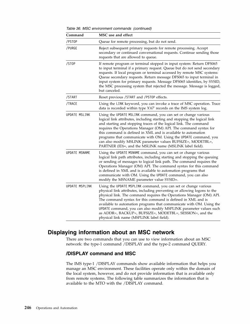
Table 36. MSC environment commands (continued)
Command MSC use and effect
/PSTOP Queue for remote processing, but do not send.
/PURGE Reject subsequent primary requests for remote processing. Acceptsecondary or continued conversational requests. Continue sending thoserequests that are allowed to queue.
/STOP If remote program or terminal stopped in input system: Return DFS065to input terminal if a primary request. Queue but do not send secondaryrequests. If local program or terminal accessed by remote MSC systems:Queue secondary requests. Return message DFS065 to input terminal ininput system for primary requests. Message DFS065 identifies, by SYSID,the MSC processing system that rejected the message. Message is logged,but canceled.
/START Reset previous /START and /PSTOP effects.
/TRACE Using the LINK keyword, you can invoke a trace of MSC operation. Tracedata is recorded within type X'67' records on the IMS system log.
UPDATE MSLINK Using the UPDATE MSLINK command, you can set or change variouslogical link attributes, including starting and stopping the logical linkand starting and stopping traces of the logical link. The commandrequires the Operations Manager (OM) API. The command syntax forthis command is defined in XML and is available to automationprograms that communicate with OM. Using the UPDATE command, youcan also modify MSLINK parameter values BUFSIZE=, MODETBL=,PARTNER (ID)=, and the MSLINK name (MSLINK label field).
UPDATE MSNAME Using the UPDATE MSNAME command, you can set or change variouslogical link path attributes, including starting and stopping the queuingor sending of messages to logical link path. The command requires theOperations Manager (OM) API. The command syntax for this commandis defined in XML and is available to automation programs thatcommunicate with OM. Using the UPDATE command, you can alsomodify the MSNAME parameter value SYSID=.
UPDATE MSPLINK Using the UPDATE MSPLINK command, you can set or change variousphysical link attributes, including preventing or allowing logons to thephysical link. The command requires the Operations Manager (OM) API.The command syntax for this command is defined in XML and isavailable to automation programs that communicate with OM. Using theUPDATE command, you can also modify MSPLINK parameter values suchas ADDR=, BACKUP=, BUFSIZE=, MODETBL=, SESSION=, and thephysical link name (MSPLINK label field).
Displaying information about an MSC networkThere are two commands that you can use to view information about an MSCnetwork: the type-1 command /DISPLAY and the type-2 command QUERY.
/DISPLAY command and MSC
The IMS type-1 /DISPLAY commands show available information that helps youmanage an MSC environment. These facilities operate only within the domain ofthe local system, however, and do not provide information that is available onlyfrom remote systems. The following table summarizes the information that isavailable to the MTO with the /DISPLAY command.
246 Operations and Automation
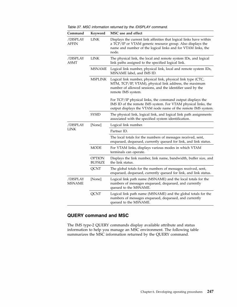
Table 37. MSC information returned by the /DISPLAY command.
Command Keyword MSC use and effect
/DISPLAYAFFIN
LINK Displays the current link affinities that logical links have withina TCP/IP or VTAM generic resource group. Also displays thename and number of the logical links and for VTAM links, thenode.
/DISPLAYASMT
LINK The physical link, the local and remote system IDs, and logicallink paths assigned to the specified logical link.
MSNAME Logical link number, physical link, local and remote system IDs,MSNAME label, and IMS ID.
MSPLINK Logical link number, physical link, physical link type (CTC,MTM, TCP/IP, VTAM), physical link address, the maximumnumber of allowed sessions, and the identifier used by theremote IMS system.
For TCP/IP physical links, the command output displays theIMS ID of the remote IMS system. For VTAM physical links, theoutput displays the VTAM node name of the remote IMS system.
SYSID The physical link, logical link, and logical link path assignmentsassociated with the specified system identification.
/DISPLAYLINK
[None] Logical link number.
Partner ID.
The local totals for the numbers of messages received, sent,enqueued, dequeued, currently queued for link, and link status.
MODE For VTAM links, displays various modes in which VTAMterminals can operate.
OPTIONBUFSIZE
Displays the link number, link name, bandwidth, buffer size, andthe link status.
QCNT The global totals for the numbers of messages received, sent,enqueued, dequeued, currently queued for link, and link status.
/DISPLAYMSNAME
[None] Logical link path name (MSNAME) and the local totals for thenumbers of messages enqueued, dequeued, and currentlyqueued to the MSNAME.
QCNT Logical link path name (MSNAME) and the global totals for thenumbers of messages enqueued, dequeued, and currentlyqueued to the MSNAME.
QUERY command and MSC
The IMS type-2 QUERY commands display available attribute and statusinformation to help you manage an MSC environment. The following tablesummarizes the MSC information returned by the QUERY command.
Chapter 6. Developing operating procedures 247

Table 38. MSC information returned by the QUERY command.
Command Keyword MSC use and effect
QUERYMSLINK
BANDWIDTH(ON|OFF) Identifies logical links that are or are not inbandwidth mode.
SHOW(ALL|attribute) Returns the user-defined attributes of logical links.You can limit the information returned byspecifying a valid attribute as a parameter of theSHOW() keyword.
STATUS(status_type) Identifies the logical links that have the specifiedstatus type.
QUERYMSNAME
QCNT() Identifies logical link paths that have queue countsrelative to a number you specify. For example, youcan view all logical link paths with a queue countthat is greater-than-or equal-to 100.
SHOW(ALL|attribute) Returns the user-defined attributes of logical linkpaths. You can limit the information returned byspecifying a valid attribute as a parameter of theSHOW() keyword.
STATUS(status_type) Identifies the logical link paths that have thespecified status type.
QUERYMSPLINK
SHOW(ALL|attribute) Returns the user-defined attributes of physical links.You can limit the information returned byspecifying a valid attribute as a parameter of theSHOW() keyword.
STATUS(status_type) Identifies the physical links that have the specifiedstatus type.
TYPE(link_type) Identifies physical links by their link types: CTC,MTM, TCP/IP, and VTAM. You can query one ormore link types at a time.
Related tasks:“Viewing MSC link information in IMS Connect” on page 226“Viewing MSC connection information for IMS-to-IMS TCP/IP communications”on page 224
Logical link path controlYou can use several commands to control logical link paths. The logical link path isthe lowest level of control across a Multiple Systems Coupling (MSC) environmentbecause it is the lowest level that is necessarily defined in intermediate MSCsystems.
Logical link paths are defined by SYSID pairs that identify the sending anddestination systems. You define logical link paths using the MSNAME systemdefinition macro or by using the type-2 CREATE MSNAME command. Thefollowing table summarizes the commands you can use for link control.
Table 39. Commands used to control MSC link paths
Command Keyword MSC use and effect
/START MSNAME Start a previously stopped MSNAME.
248 Operations and Automation
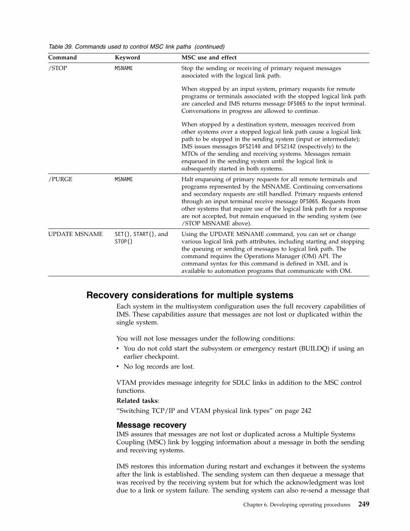
Table 39. Commands used to control MSC link paths (continued)
Command Keyword MSC use and effect
/STOP MSNAME Stop the sending or receiving of primary request messagesassociated with the logical link path.
When stopped by an input system, primary requests for remoteprograms or terminals associated with the stopped logical link pathare canceled and IMS returns message DFS065 to the input terminal.Conversations in progress are allowed to continue.
When stopped by a destination system, messages received fromother systems over a stopped logical link path cause a logical linkpath to be stopped in the sending system (input or intermediate);IMS issues messages DFS2140 and DFS2142 (respectively) to theMTOs of the sending and receiving systems. Messages remainenqueued in the sending system until the logical link issubsequently started in both systems.
/PURGE MSNAME Halt enqueuing of primary requests for all remote terminals andprograms represented by the MSNAME. Continuing conversationsand secondary requests are still handled. Primary requests enteredthrough an input terminal receive message DFS065. Requests fromother systems that require use of the logical link path for a responseare not accepted, but remain enqueued in the sending system (see/STOP MSNAME above).
UPDATE MSNAME SET(), START(), andSTOP()
Using the UPDATE MSNAME command, you can set or changevarious logical link path attributes, including starting and stoppingthe queuing or sending of messages to logical link path. Thecommand requires the Operations Manager (OM) API. Thecommand syntax for this command is defined in XML and isavailable to automation programs that communicate with OM.
Recovery considerations for multiple systemsEach system in the multisystem configuration uses the full recovery capabilities ofIMS. These capabilities assure that messages are not lost or duplicated within thesingle system.
You will not lose messages under the following conditions:v You do not cold start the subsystem or emergency restart (BUILDQ) if using an
earlier checkpoint.v No log records are lost.
VTAM provides message integrity for SDLC links in addition to the MSC controlfunctions.Related tasks:“Switching TCP/IP and VTAM physical link types” on page 242
Message recoveryIMS assures that messages are not lost or duplicated across a Multiple SystemsCoupling (MSC) link by logging information about a message in both the sendingand receiving systems.
IMS restores this information during restart and exchanges it between the systemsafter the link is established. The sending system can then dequeue a message thatwas received by the receiving system but for which the acknowledgment was lostdue to a link or system failure. The sending system can also re-send a message that
Chapter 6. Developing operating procedures 249
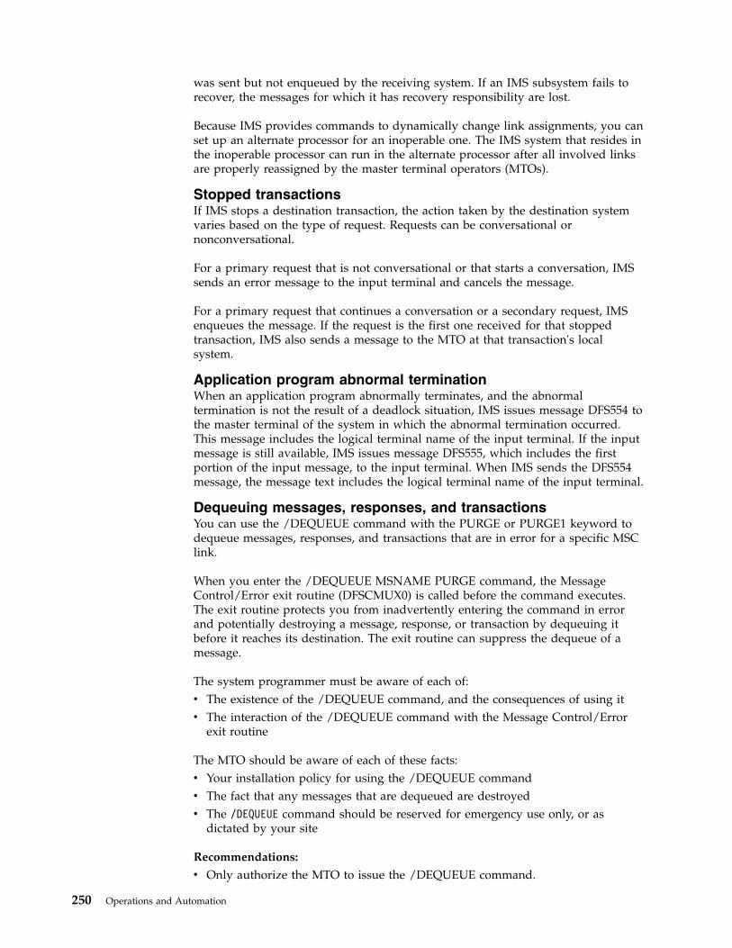
was sent but not enqueued by the receiving system. If an IMS subsystem fails torecover, the messages for which it has recovery responsibility are lost.
Because IMS provides commands to dynamically change link assignments, you canset up an alternate processor for an inoperable one. The IMS system that resides inthe inoperable processor can run in the alternate processor after all involved linksare properly reassigned by the master terminal operators (MTOs).
Stopped transactionsIf IMS stops a destination transaction, the action taken by the destination systemvaries based on the type of request. Requests can be conversational ornonconversational.
For a primary request that is not conversational or that starts a conversation, IMSsends an error message to the input terminal and cancels the message.
For a primary request that continues a conversation or a secondary request, IMSenqueues the message. If the request is the first one received for that stoppedtransaction, IMS also sends a message to the MTO at that transaction's localsystem.
Application program abnormal terminationWhen an application program abnormally terminates, and the abnormaltermination is not the result of a deadlock situation, IMS issues message DFS554 tothe master terminal of the system in which the abnormal termination occurred.This message includes the logical terminal name of the input terminal. If the inputmessage is still available, IMS issues message DFS555, which includes the firstportion of the input message, to the input terminal. When IMS sends the DFS554message, the message text includes the logical terminal name of the input terminal.
Dequeuing messages, responses, and transactionsYou can use the /DEQUEUE command with the PURGE or PURGE1 keyword todequeue messages, responses, and transactions that are in error for a specific MSClink.
When you enter the /DEQUEUE MSNAME PURGE command, the MessageControl/Error exit routine (DFSCMUX0) is called before the command executes.The exit routine protects you from inadvertently entering the command in errorand potentially destroying a message, response, or transaction by dequeuing itbefore it reaches its destination. The exit routine can suppress the dequeue of amessage.
The system programmer must be aware of each of:v The existence of the /DEQUEUE command, and the consequences of using itv The interaction of the /DEQUEUE command with the Message Control/Error
exit routine
The MTO should be aware of each of these facts:v Your installation policy for using the /DEQUEUE commandv The fact that any messages that are dequeued are destroyedv The /DEQUEUE command should be reserved for emergency use only, or as
dictated by your site
Recommendations:
v Only authorize the MTO to issue the /DEQUEUE command.
250 Operations and Automation

v Establish installation-specific standards for using the /DEQUEUE command. Besure to identify in advance and validate the scenarios where the MTO shoulduse this command. Consider the /DEQUEUE command when coding theMessage Control/Error exit routine.
Related reference:
/DEQUEUE command (Commands)
Message Control/Error exit routine (DFSCMUX0) (Exit Routines)
Establishing maintenance proceduresRunning IMS utilities on a regular, prescribed basis is one of the main tasks formaintaining IMS. Maintaining IMS might also involve additional tasks such asreorganizing databases and installing service regularly.
Maintaining IMS might involve the following activities (done manually orautomated):v Running reports, analyzing the reports, and taking action based on the analysisv Reorganizing databases on a regular basisv Performing preventive maintenance on the message queuesv Running IBM-supplied or vendor-supplied tools on a regular basisv Installing service on a regular basisv Running IMS-supplied utilities on a regular basis
The frequency with which utilities are run is an installation-dependent decision.
Tip: You can determine the current maintenance level of your IMS system byusing the /DIAGNOSE SNAP MODULE(modname) command.
Setting up standard JCLYou can set up standard JCL for the jobs that must be run (such as the utility jobs)as part of establishing procedures for your operations people.
Using DBRC can greatly assist you in this area, even though having completely“canned” JCL is not possible. For example, the MTO must supply the required logdata sets when running the Database Batch Backout utility. If you use DBRC forrecovery control, you may only have to set up JCL for DBRC itself.
Restriction: DBRC does not develop JCL for backout.
Operator test proceduresAfter you have prepared procedures for operating IMS, all those who operate thesystem should be given an opportunity to familiarize themselves with theprocedures. After that, all procedures should be thoroughly tested.
Simulating system failures
To test some of the recovery procedures, certain types of system failures must besimulated. The following table shows possible failures and how they can besimulated.
Chapter 6. Developing operating procedures 251
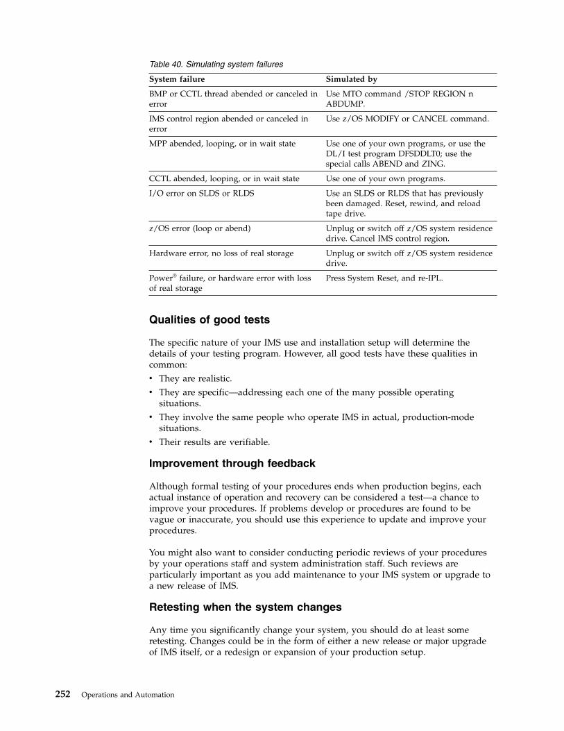
Table 40. Simulating system failures
System failure Simulated by
BMP or CCTL thread abended or canceled inerror
Use MTO command /STOP REGION nABDUMP.
IMS control region abended or canceled inerror
Use z/OS MODIFY or CANCEL command.
MPP abended, looping, or in wait state Use one of your own programs, or use theDL/I test program DFSDDLT0; use thespecial calls ABEND and ZING.
CCTL abended, looping, or in wait state Use one of your own programs.
I/O error on SLDS or RLDS Use an SLDS or RLDS that has previouslybeen damaged. Reset, rewind, and reloadtape drive.
z/OS error (loop or abend) Unplug or switch off z/OS system residencedrive. Cancel IMS control region.
Hardware error, no loss of real storage Unplug or switch off z/OS system residencedrive.
Power® failure, or hardware error with lossof real storage
Press System Reset, and re-IPL.
Qualities of good tests
The specific nature of your IMS use and installation setup will determine thedetails of your testing program. However, all good tests have these qualities incommon:v They are realistic.v They are specific—addressing each one of the many possible operating
situations.v They involve the same people who operate IMS in actual, production-mode
situations.v Their results are verifiable.
Improvement through feedback
Although formal testing of your procedures ends when production begins, eachactual instance of operation and recovery can be considered a test—a chance toimprove your procedures. If problems develop or procedures are found to bevague or inaccurate, you should use this experience to update and improve yourprocedures.
You might also want to consider conducting periodic reviews of your proceduresby your operations staff and system administration staff. Such reviews areparticularly important as you add maintenance to your IMS system or upgrade toa new release of IMS.
Retesting when the system changes
Any time you significantly change your system, you should do at least someretesting. Changes could be in the form of either a new release or major upgradeof IMS itself, or a redesign or expansion of your production setup.
252 Operations and Automation

The retesting should verify that your old procedures still function properly in thenew environment.Related concepts:
DL/I test program (DFSDDLT0) reference (Application Programming APIs)
Chapter 6. Developing operating procedures 253

254 Operations and Automation
Chapter 7. Developing user procedures
End users (remote terminal operators) are the people who use the terminalsconnected to IMS. End-user procedures should focus on the needs of end users,not on IMS operation.
It is important that your end-user procedures be good ones, because the success ofyour online system depends largely on its acceptance by your end users.
The procedures should be prepared as an integral part of the application-development process. The layout and organization of the procedures shouldsupport the business function. Procedures differ for different types of applications.Procedures for a bank teller, for example, should cover more than just the entry ofan IMS transaction. Procedures for a data-entry clerk, however, may consist largelyof instructions for entering transactions.
End-user procedures are generally packaged in a guide. You can develop the guideyourself, or it might be appropriate for individual application-development teamsto develop the guide. In the latter case, you should consider preparing “boilerplate” material to distribute to the application-development teams for basicprocedures that are always included in end-user guides. Do not forget to updatethe boiler plate information whenever you make major modifications to the onlineIMS system. For example, if you convert from using non-VTAM to using VTAM,you probably need to change terminal logon procedures.
In general, your procedures need to familiarize end users with how to:v Operate their terminalv Establish a connection to IMSv Communicate with IMSv Disconnect from IMSv Respond to error conditionsRelated concepts:“Operations personnel” on page 197
Procedures for user terminal operatorsThe application-development cycle should include the development of end-userprocedures, along with education about the transactions and terminal hardware.
The writers of the procedures need to consider the following points whendeveloping the end-user guide:v Consistency between remote and central controlv Which services should be provided by the online system rather than the terminal
or workstationv Coordination of support for end-usersv Definition of problem-reporting proceduresRelated concepts:“Planning the content of procedures” on page 202
© Copyright IBM Corp. 1974, 2017 255

User operator tasksAn end user performs one or more tasks as part of his or her job. You need toprovide your end users with instructions that are clearly written and accurate forthe task that they will perform.
These tasks can involve many of your IT tools and systems, of which IMS is one.You should review those tasks to be sure your procedural instructions do both ofthe following:v Help the user perform application-related tasksv Safeguard the primary task
You should review existing instructions that have implications for administrationservices. The following table shows a partial checklist illustrating the characteristicsof this review. You should expect other topics depending on the scope of the userprocedure.
Your review contributes to the usability of the procedures. You should plan tocorrect them based on testing and user feedback during actual production.
Table 41. Checklist for administrative services
Review item Related administration task
Are availability statements clear? Check scheduling algorithm and operationsprocedures.
Are response claims reasonable and notmisleading?
Reconcile with performance criteria. Ensureunusual delays are reported.
Are terminal connection proceduresdescribed?
Check whether the MTO or other operatorshelp in connection.
Are security requirements explained? Check security definition and maintenanceprocedure.
Is interpretative material included foroutput?
Check accuracy of IMS message andcommand output information.
Are instructions given for an alternativeconnection?
Check that the MTO has alternativeconfiguration instructions.
Are instructions given for response to systemand broadcast messages?
Check with developer on potential messages.
Are instructions given for service problemsfor the terminal, transaction input, andonline system failure?
Coordinate failure reporting and informationflow. Have MTO issue standard informationmessages.
Related concepts:“Operating instructions for terminal operators”
Operating instructions for terminal operatorsThe process and goals of developing end-user documentation include developinginformation in several stages and to tailor the documentation to the experiencelevel and information requirements of the end users.
The success and acceptance of an online system often depends on the quality ofthe end-user documentation. The operating procedures for terminal operators forman important part of this documentation, contributing to ongoing education andease of use for the applications.
256 Operations and Automation

Develop and refine the procedures in several stages:v Define initial structure and contentv Analyze existing proceduresv Test the new proceduresv Gather education feedbackv Gather production feedbackv Make any necessary modifications to the procedures
It is generally better to extract information from existing sources and tailor it to anapplication rather than point to total descriptions or general operation manuals.For example, describe the 3270 operational characteristics rather than assume thatthe operator is familiar with the content of the 3270 Data Stream Programmer'sReference.
Also, show representative screen formats rather than showing MFS output. Youcan obtain working copies of the screen layouts by using the copy feature on aremote 3277 terminal.
Do not ignore the last stage, the actual production cycle. In many cases, you canobtain useful feedback by selecting a group of end users to be pilot operators.Their mission is to validate and improve the end-user service. After making anynecessary changes, publish the final procedures.
Do not neglect to update the procedures when you make modifications to theonline IMS system. Sometimes the operational emphasis changes when you installsubsequent application programs or IMS features. Your same pilot group couldrenew their activities when hardware changes or other significant applicationchanges occur.
Some guidelines for the content of end-user operator documents follow. The goal isto have the document tuned to the experience level and information requirementsof the end users:v Make the main section procedural for the applications.
Ensure the instructions are sequenced in the order in which they are performed.Place transactions that are more frequently used, or more important, ahead ofothers. If there are numerous transactions, an alphabetic order might be better, ifyou include an introduction (or graphic) that indicates which are critical or usedfrequently.
v Illustrate your procedures with simple examples.Show both entry and response formats. Where IMS commands are used, showonly relevant keywords and explain the replies.
v Include instructions for error handling.Address not only input errors but also responses to warning messages from theapplication program. Where IMS connection or system problems might occur,provide alternative instructions. If this material is lengthy, you could place it inan appendix. Arrange the topics in the appendix by symptom. Provide anexplanation of error-reporting forms.
v Optionally, include a brief introduction to IMS and describe the MTO.The emphasis should not be on how IMS works, but on how it supports dataaccess and processing at your site. Distinguish, as necessary, between what IMSprovides and what the operating system and hardware provide.
v Identify the main hardware operational characteristics.
Chapter 7. Developing user procedures 257

Include advice that highlights efficient ways of using the terminal and warningsof any user actions that are prone to error. If appropriate, merge copies ofrelevant operating instructions into this section or appended to the document.
v Include only relevant IMS command operation details.Make sure that commands and options described are allowed for end-user use.Discourage the use of commands that reserve IMS resources, such as /HOLD forconversations or /IDLE which enqueues output messages.
v Include a list of contacts.Show names in preferred order and describe the conditions under which theuser should make contact.
Related concepts:“User operator tasks” on page 256
Potential use of IMS commandsAlthough the primary purpose of end-user procedures is to describe transactioninput, you might also allow the users to enter a subset of IMS commands so thatthey can make more informed use of IMS resources.
For example, if the end users can choose the order in which transactions aresubmitted, they can use a /DISPLAY command to gauge the current queue levels.
Recommendation: If you do allow end users to enter IMS commands, considerdisallowing the use of the ALL keyword to minimize the effect of these commands.
The following table presents a list of IMS commands and evaluates their potentialuse by a remote terminal operator. The /DISPLAY TRAN and QUERY TRANcommands are especially appropriate. However, because of the many keywordchoices for these commands, you should specify individual keywords. Forconvenient entry, include command abbreviations.
The commands in the table that are marked with an asterisk (*) are available to theremote terminal operator using default command security. To allow the remoteterminal operator to use other commands, you need to declare the full list ofcommands for that terminal through RACF (or an equivalent product). You canalso use the DFSCCMD0 exit routine for command security.
Table 42. Command suitability for use by a remote terminal operator.
Command group Command Default security End-user use Comments
End-user specific /RCLSDST * YES Acts as remote VARY offline (for VTAMterminals).
/RCOMPT * YES Decentralizes control of VTAM component.
/BROADCAST * YES Provides convenient user interaction; use ofmessage switching is preferred.
/SET * YES Provides convenient entry for batchedtransactions.
/RESET * YES Used with /SET.
/RDISPLAY * YES Identifies MTO location; used with/BROADCAST.
/CANCEL * YES Cancels both single- and multisegmentmessages.
/EXCLUSIVE * YES Safeguards discrete application usage.
258 Operations and Automation
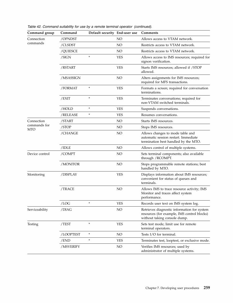
Table 42. Command suitability for use by a remote terminal operator (continued).
Command group Command Default security End-user use Comments
Connectioncommands
/OPNDST NO Allows access to VTAM network.
/CLSDST NO Restricts access to VTAM network.
/QUIESCE NO Restricts access to VTAM network.
/SIGN * YES Allows access to IMS resources; required forsignon verification.
/RSTART YES Starts IMS resources; allowed if /STOPallowed.
/MSASSIGN NO Alters assignments for IMS resources;required for MFS transactions.
/FORMAT * YES Formats a screen; required for conversationterminations.
/EXIT * YES Terminates conversations; required fornon-VTAM switched terminals.
/HOLD * YES Suspends conversations.
/RELEASE * YES Resumes conversations.
Connectioncommands forMTO
/START NO Starts IMS resources.
/STOP NO Stops IMS resources.
/CHANGE NO Allows changes to mode table andautomatic session restart. Immediatetermination best handled by the MTO.
/IDLE NO Allows control of multiple systems.
Device control /COMPT NO Sets terminal components; also availablethrough /RCOMPT.
/MONITOR NO Stops programmable remote stations; besthandled by MTO.
Monitoring /DISPLAY YES Displays information about IMS resources;convenient for status of queues andterminals.
/TRACE NO Allows IMS to trace resource activity; IMSMonitor and traces affect systemperformance.
/LOG * YES Records user text on IMS system log.
Serviceability /DIAG NO Retrieves diagnostic information for systemresources (for example, IMS control blocks)without taking console dump.
Testing /TEST * YES Sets test mode; limit use for remoteterminal operators.
/LOOPTEST * NO Tests I/O for terminal.
/END * YES Terminates test, looptest, or exclusive mode.
/MSVERIFY NO Verifies IMS resources; used byadministrator of multiple systems.
Chapter 7. Developing user procedures 259

Table 42. Command suitability for use by a remote terminal operator (continued).
Command group Command Default security End-user use Comments
Resource control /ASSIGN NO Assigns IMS resources; prime control ofresources for MTO.
/PSTOP NO Restricts use of resources.
/PURGE NO Restricts input to resources.
/LOCK * NO Restricts resource use; use only forsupervisor remote terminal operators.
/UNLOCK * NO Unlocks IMS resources.
/RMxxxxxx NO Allows control of DBRC resources; databaseavailability should be controlled by MTO.
/SMCOPY NO Controls the logging of system messages,commands, and command responses to thesecondary master terminal.
/MODIFY NO Allows online changes to IMS system.
Recovery /DBRECOVERYor UPDATE
NO Controls database availability; restrict toMTO.
/DBDUMP orUPDATE
NO Controls database availability; restrict toMTO.
/DEQUEUE NO Controls integrity of message queues;restrict to MTO.
/CHECKPOINT NO Shuts down IMS; restrict to MTO; simplecheckpoints can have a performance impact.
/ERESTART NO Restarts IMS; restrict to MTO.
/RECOVER NO Recovers full-function databases and FastPath areas; restrict to a DBA or the MTO.
/SWITCH NO Switches data sets used in an XRFenvironment; restrict to MTO.
Related concepts:“IMS commands used to communicate with IMS” on page 266Related reference:
IMS Command Language Modification facility (DFSCKWD0) (Exit Routines)
/DISPLAY TRAN command (Commands)
QUERY TRAN command (Commands)
Command Authorization exit routine (DFSCCMD0) (Exit Routines)
Problem reporting for a remote terminal operatorThe main flow of the end-user guide should present the normal operationssequence, but the operator needs to be prepared for unexpected or error responses.
When you examine the sequence of instructions for a remote terminal operator,you need to ask a series of “what-if” questions. The following are examples ofthese “what-if” questions:v What if the terminal is not operational, behaves erratically, or loses contact with
the system?
260 Operations and Automation
v What if the application program returns warning messages about the status of adatabase or of processing results?
v What if IMS system messages are received?v What if master terminal or other operator actions interrupt processing?v What if the z/OS or IMS system goes down?
You need to assess the importance of such unusual events and include appropriateprocedures for them. The end-user guide could describe recovery actions inlinewith normal operations or include the information in symptom-based appendixes.
If your installation has a problem-reporting center, having a user-liaison groupenables you to concentrate recovery skills rather than educating all end users.Many installations report terminal problems to network control personnel, andthey have appropriate details about IMS and the application programs it runs. It isoften a good idea to standardize problem reporting. You can prepare the answersto a series of questions, or elicit a problem's symptoms using a structured script.
Occasionally, the master terminal operator can be a point of contact. You shouldensure such contact is only be on a formal, prearranged basis, because the masterterminal operator has a primary duty of system control and monitoring. Anexample of acceptable contact is to request the scheduling of a BMP.
A good controlling technique is to require an error incident report. You can makepreformatted forms, with examples of the information required, available to theend user. The data on the forms should indicate what action was taken or ispending. Administration personnel can then review these events on a regular basis.In this way, you can detect common problems or differences in operationalprocedures.Related concepts:“Administration support for errors” on page 267
Connecting to IMSBefore a user can use a terminal, the master terminal operator (MTO) mustinitialize the communication network using one or more of the followingcommands: /START DC, /START NODE, and (possibly) /OPNDST for VTAMterminals.
Terminal startup for nonswitched lines
For startup to be successful, the remote terminal must be turned on. IMS notifiesthe remote terminal of a successful /START or UPDATE command with the DFS059terminal started message. Communication with IMS can only begin after thestartup message is received.
Exception: A remote terminal can communicate with the following terminalsbefore receiving message DFS059: the master terminal, physical terminals on themaster terminal line, and the system console.
VTAM terminals (nodes)
SLU type P, FINANCE (3600), and ISC terminal systems do not receiveIMS-generated connect messages. Instead, they communicate with a user-written
Chapter 7. Developing user procedures 261

program that resides in the terminal system's storage. Type-1 SLUs in unattendedmode also do not receive connect messages (because there is no operator to receivethe message).
VTAM terminals receive message DFS3649, DFS3650, or both. The DFS3649message requests signon information, and the DFS3650 message indicatessuccessful signon (or connection) and session status. Message DFS3649 alsoappears in the following situations: when failures occur during the signon process,when the operator signs off, or (for ETO only) automatic session timeout due toinactivity.
Releasing VTAM terminals hung in I/O
Use the /TRACE command to specify what action, if any, IMS should take when itdetermines that a VTAM response has been outstanding for a longer time than youspecify. This facility applies only to VTAM devices that have VTCBs or MSC links.
IMS can handle outstanding responses in one of the following ways:v No action.v Issue a message that I/O has been outstanding for a longer time than you have
specified; that is, the device has timed out.In this case, the operator must determine what action, if any, to take. Forexample, the MTO or an AOI program could issue an /IDLE command followedby an /ACTIVATE command and an /OPNDST command.
v Issue a message that I/O is outstanding followed by a VTAM VARY NET,INACTcommand to deactivate the terminal, and a VTAM VARY NET,ACT command toreactivate it. If the device is operable and defined to IMS as non-shared, andIMS is not shutting down, IMS issues a /OPNDST command to establish asession with the node.
Use the /DISPLAY command to display all the nodes that have I/O which hasbeen outstanding for a longer time than was specified during installation. The/DISPLAY TRACE command displays the status of all nodes that have I/Ooutstanding for a longer time than you specified using the /TRACE SETTIMEOUT command.
Fulfilling security requirements
Depending on the security options specified for the system, the end user mightneed to use the /SIGN command to provide a user ID for verification by IMS orRACF and supply an IMS or RACF password. Users with ETO terminals must usethe /SIGN command. You need to document the security procedures the end usermust follow.Related concepts:
IMS terminal network (Communications and Connections)Related reference:
Terminals and equipment supported by IMS 15 (Release Planning)
Communicating with IMSYou can communicate with IMS using transactions, sending messages to otherusers, and using IMS commands.
262 Operations and Automation
Transactions for communicating with IMSWhen using a terminal (a non-programmable workstation), the operator must entera transaction in a certain format in order for it to be recognized by IMS.
When the operator uses the /FORMAT command, IMS formats the screen usingMFS. This format is defined by the installation.
Transaction code format for entering transactions
Use the transaction code format shown below to send a message to an applicationprogram:transaction_code (password) text
where:
transaction_codeIs a 1- to 8-byte alphanumeric code defined during IMS system definition.Special characters (embedded blank, slash, dash, equal sign, comma, andperiod) are not allowed. A blank or left parenthesis must follow the transactioncode. You can use the COMM system definition macro to eliminate the needfor a blank in a segment consisting of only the transaction code.
(password)Is a password that must be entered with the transaction code (when requiredby installation security). Enclose the password in parentheses and concatenateit to the transaction code. If a password is not required, IMS ignores anypassword you enter.
For terminals using MFS, password entry is controlled by installation-definedformats.
textIs the single-segment or multi-segment input message. Only the first segmentof a multi-segment message can contain the transaction code and password.
Use the /SET command to send a continuous series of messages to the sameapplication program. The /SET command puts the terminal in preset mode andeliminates the need to enter the transaction code (and password, if required) foreach message. Preset mode fixes the destination for all messages entered from aterminal.
The text included in the transaction is application dependent, and should beclearly documented for each transaction type an end user might use.
Response mode for transactionsWhen the response mode is in effect, IMS does not accept input from the line,terminal, or user until IMS has sent an output response to the previous input.Response mode can be defined for either full function or Fast Path.
Response mode describes a connection between IMS and a communication line,terminal, or user that occurs for certain types of terminals or users underconditions specified during system definition.
You can specify communication lines, terminals, or users as:v Always operating in response modev Never operating in response mode
Chapter 7. Developing user procedures 263
v Operating in response mode only if the transaction code being processedspecifies it
Any transaction can be defined as a response-mode transaction. When IMS receivesan input transaction that requires response mode, IMS makes the terminalunusable (locks the keyboard) until IMS processes the transaction and sends theresponse.
While in response mode, if the user enters a single transaction for which theapplication program generates no response, IMS automatically sends messageDFS2082 as the response to the transaction. This message removes the terminalfrom response mode and unlocks the keyboard, if necessary.
While in response mode, if the user enters multiple transactions for which theapplication program generates no response, the keyboard remains locked and theterminal is unusable. The terminal remains in response mode even if the userattempts to unlock the keyboard (by, for example, pressing the RESET key on a3270 terminal); any subsequent input is rejected. The first output from anapplication program whose input originated from this terminal satisfies theresponse.
User IDs defined with ETO user descriptors remain in response mode afterabnormal session termination or autosignoff. In this situation, the end user shouldcontact the MTO (using a means other than the terminal or user ID). If theterminal is non-operational, the MTO can enter an /RSTART command to restoreterminal operation.
Attention: If you restart IMS while users are in response mode, what happens totransactions depends on whether they have reached a sync point:v If the transaction is complete (it has reached a sync point), and the end user is
waiting for a response, the user does not receive the normal response becauseIMS restart resets response mode. After the restart completes, the user mightreenter the transaction, which could adversely affect data integrity.
v If the transaction is incomplete (it has not reached a sync point), IMS discardsthe transaction.
You should develop operating procedures to cover this situation for all end userswho could be affected.
To reset static nodes and ETO dynamic users that are hung in Fast Path inputresponse mode, issue the /STOP and /START commands in sequence with theappropriate parameter. For static nodes, issue the commands /STOP NODE and/START NODE. For ETO dynamic users, issue the commands /STOP USER and/START USER.
Conversation mode for transactionsConversational processing allows an end user to have a continuing dialogue withan application program.
A user initiates a conversation by entering a transaction code that is defined asconversational. A conversation can follow an ETO user from one terminal toanother. The maximum number of conversations that can be active for one user orone terminal at a time is 65535.
The following commands affect conversations:
264 Operations and Automation

v /DISPLAY displays the status of conversational processing in the systemv /EXIT terminates an active or suspended conversationv /HOLD suspends an active conversationv /RELEASE restarts a held conversationv /RSTART LINE | NODE | USER recovers an active or suspended conversation
on a stopped line, node, or userv /START LINE | USER restarts the line or user but terminates the conversation
Using the appropriate keywords of the /DISPLAY command, the MTO candetermine:v The identification of all active (BUSY) or suspended (HELD) conversations in the
systemv The number of conversations active or suspended in the system or related to a
specific line, line and physical terminal, or userv The number of inactive available conversations (the maximum number of
conversations defined for the system minus the number of currently active orsuspended conversations)
When you use the /DISPLAY command to display the status of a line or physicalterminal, the displayed status includes, if applicable, the status of conversationsrelated to that line.
Operators-to-operator messagesAn end user can send messages to other operators by using the IMS messageswitch facility or by using the /BROADCAST command.
If your end users need to send messages, document clearly how they are to dothis.
When using message switching, the input format is as follows:logical_terminal_name text
where:
logical_terminal_nameIs the name of the logical terminal to which the message is to be sent. Thelogical terminal names allowed are specified during IMS system definition.
A blank must follow the logical terminal name. You can use the systemdefinition COMM macro to eliminate the need for a blank in a segmentconsisting of only the logical terminal name.
textIs the single-segment or multi-segment input message
For a multi-segment message, only the first segment should contain the logicalterminal name. If the logical terminal name is specified in subsequentsegments, it is treated as text.
You can use the /SET command to send a continuous series of messages to thesame logical terminal. The /SET command puts the terminal in preset mode andeliminates the need to enter the logical terminal name for each message. Presetmode fixes the destination for all messages entered from a terminal.
Chapter 7. Developing user procedures 265
IMS commands used to communicate with IMSAlthough the primary purpose of an end-user guide is to describe transactioninput, you might allow end users to use certain IMS commands. If you do, youshould document their use in the guide.Related concepts:“Potential use of IMS commands” on page 258
Commands for special operating modesIMS provides commands to enter and exit special operating modes, such as presetmode, test mode, MFSTEST mode, looptest mode, and exclusive mode. Thesemodes alter the relationship between the terminal and the system.
A special operating mode remains active until one of the following events occur:v The user issues a command to exit from the special operating modev The MTO stops and restarts the line, physical terminal, or user by issuing the
/START command
To restart a terminal or user without affecting its special operating mode, use the/RSTART command.
Preset mode
Preset mode fixes the destination for all messages entered from a terminal. Use the/SET command to enter preset mode. To leave preset mode, use the /RESETcommand.
Test mode
Test mode (also called “echo” mode) performs input and output operationsbetween a terminal and IMS. The /TEST command places a terminal in test mode.Messages entered from a terminal in test mode are transmitted back to thatterminal. The /END command terminates test mode. In an ETO environment, the/TEST command applies only to ETO-defined users, not to ETO-defined terminals.
MFSTEST mode
MFSTEST mode tests MFS control blocks without interrupting normal productionactivity. The /TEST MFS command places MFS-supported terminals in MFSTESTmode. The /END command terminates MFSTEST mode. In an ETO environment,the /TEST command applies only to ETO-defined users, not to ETO-definedterminals.
Looptest mode
Looptest mode tests output operations between a terminal and IMS. Use the/LOOPTEST command to enter this mode. This command creates an output writeloop that repeatedly transmits a single-segment message to the terminal beingtested. The /END command terminates looptest mode.
Exclusive mode
Exclusive mode prevents output messages from being transmitted to the terminal.
Exception: Output messages that are responses to messages entered at theterminal during exclusive mode are transmitted to the terminal.
266 Operations and Automation

After the terminal is removed from exclusive mode, the output messages are heldfor transmission. Use the /EXCLUSIVE command to enter exclusive mode, and the/END to leave exclusive mode. In an ETO environment, the /EXCLUSIVEcommand applies only to ETO-defined users, not to ETO-defined terminals.
Disconnecting from IMS
If an ETO-defined terminal or user ID is idle (no transactions are performed) for agiven amount of time, IMS automatically disconnects the terminal or user ID. Thisamount of time is determined by the MTO. The end user can sign back on byissuing the /SIGN command.Related tasks:
Autosignoff (ASOT) (Communications and Connections)
Autologoff (ALOT) (Communications and Connections)
Administration support for errorsAdministrative support for end users can be provided in a variety of ways, one ofwhich is to use a user-liaison group. By using a user-liaison group, you canconcentrate recovery skills, rather than educating all end users.
It is a good idea to standardize end-user problem reporting. You can have the enduser answer a series of questions before calling the user-liaison group, or you canhave the user-liaison group elicit problem symptoms from the end user using astructured script. Among other things, each report should include which systemand terminal experienced the error.
No matter how you decide to provide administrative support, the end-user guideshould include a contacts list. This list identifies the people to be called forapplication, system, or terminal errors. Names, functions, and telephone numbersshould be included in this list.Related concepts:“Problem reporting for a remote terminal operator” on page 260
Chapter 7. Developing user procedures 267

268 Operations and Automation
Chapter 8. Operations and IMS-supported devices
This topic describes the devices that IMS supports from an operations perspective.This information should help you develop those parts of your end-user proceduresthat are device related.
This topic assumes that you are familiar with the general features and operation ofeach device. The focus is on device operation when you use IMS.
3270 Information Display SystemDuring IMS system definition, you can specify that a 3270 system attached to IMSshould operate in forced-response mode, nonresponse mode, ortransaction-dependent response mode. For an Extended Terminal Option (ETO)terminal, specify these modes in the ETO user descriptor.
When 3270 terminals are not attached to IMS through VTAM , the MTO caninitiate their use by entering the appropriate /START LINE command for the linesto which the 3270 components are attached.
When 3270 terminals are attached to IMS through VTAM, they are initiated whenone of the following occurs:v The z/OS VTAM network operator enters a VARY NET command (for example,
VARY NET,ID=a,LOGON=b).v The IMS MTO enters the /OPNDST command.v If the 3270 terminal components are defined in the VTAM definition as
belonging to IMS, VTAM makes them automatically available.v The 3270 terminal operator enters a request to VTAM to be connected to IMS.
Each operational terminal receives a DFS059I message indicating that the terminalhas been started. The MTO can use a /DISPLAY command to determine whichlines are attached.
Interacting with IMSIf you enter data with a keyboard, a selector light pen, a magnetic card reader, orprogram function key special features, use the /FORMAT command to display aformat on the screen before you begin working with IMS.
After you receive either message DFS059I or DFS3650I telling you that the terminalor session is started, you can enter a transaction code, a command, or an IMSmessage switch.
When you enter a transaction code, IMS returns and displays the output data fromthe application program that processes that transaction. This output might includea prompt to solicit additional input. You can fill in only the blank fields on thescreen.
After entering data, press Enter to send it to IMS for processing by the applicationprogram. Continue in this manner until the interaction with IMS or the applicationprogram is complete.
© Copyright IBM Corp. 1974, 2017 269
3270 terminal components that operate with IMSYou must understand the various functions of 3270 terminal to work with IMS.
Terminal display sizeThe 3270 display station can display from 480 to 3564 characters of information,depending on the model. These characters can be alphanumeric characters, specialcharacters, certain device-control characters (visible on the screen), and attributebytes (not visible on the screen). In addition, you can prevent display ofinformation in certain fields on the screen.
The 3275 or 3277 terminal can display:v 480 characters (Model 1)v 1920 characters (Model 2)
The 3276 or 3278 terminal can display:v 480 or 960 characters (Model 1)v 1920 characters (Model 2)v 1920 or 2560 characters (Model 3)v 1920 or 3440 characters (Model 4)v 3564 characters (Model 5)
The 3279 terminal can display:v 1920 characters in 4 colors (Model 2A)v 2560 characters in 4 colors (Model 3A)v 1920 characters in 7 colors (Model 2B)v 2560 characters in 7 colors (Model 3B)
3270 terminal page-advance functionA transaction's output can be more than one full screen of data. You request theadditional output by pressing the PA1 (program access 1) key on the terminalkeyboard. If you continue to press the PA1 key, the terminal displays successivepages until you reach the end of the current message. If you press PA1 when thereare no more messages waiting to be sent to the display station, the display remainsunchanged or IMS sends an appropriate error message.
3270 terminal message-advance functionIf you press the PA2 key at any time during a message, IMS deletes the currentoutput message and displays the next message. If no messages are waiting whenyou press the PA2 key, IMS does not modify the screen.
How to enter passwords from 3270 through MFSEntering a password through Message Format Service (MFS) can be different frompassword entry on a cleared screen or on other IMS terminals.
The password can be created from:v Data read from a 3270 ID card readerv Data that you key into one or more fields or a portions of fields in the device
formatv Data that you key into a field that is not displayed on the screen and is
designated as the password field only in the device formatv Literalsv Combinations of the above
270 Operations and Automation

Terminal operator logical pagingIf you do not specify operator logical paging, the terminal operator can advancepages only one at a time, by using the page advance function. If you do specifyoperator logical paging in the application program's message output description,the terminal operator can page forward or backward to any page in a message.
With operator logical paging, the terminal operator can enter any of the functionsshown in the following table to display a particular logical page.
Table 43. Functions for Operator Logical Paging
Enter To display
= The next logical page
=n=nn=nnn=nnnn
The nth logical page of the message
The maximum value for nnnn is 4095.
=+n=+nn=+nnn
The nth logical page after the current page
The maximum value for nnn is 999.
=-n=-nn=-nnn=>nnn
The nth logical page before the current page
The maximum value for nnn is 999.
=L The last logical page of the message
Enter these functions in the screen area reserved for command and page requestinformation. If no area is reserved, either clear the screen (using the Clear key) andthen enter the paging request, or use the next logical page (NEXTLP) function if ithas been defined as a PF key in the format definition.
If you request a page outside the range of the pages in the message, IMS issues anerror message. After the error message displays, press the PA2 key to continue themessage that was being displayed when the error occurred. If a logical page in themessage is larger than one physical page, use the PA1 key to step from onephysical page to the next within a logical page.
Modified data tags and the 3270 keyboardIMS resets modified data tags each time it unlocks the 3270 keyboard.
Exception: IMS does not reset modified data tags when:v IMS sends a message using the SYSMSG field.v IMS sends output to its master terminal using the Message Format Service (MFS)
master-terminal format. IMS resets modified data tags only after you enter input.
3270 terminal screen protectionUnder certain conditions, IMS avoids sending output to a 3270 terminal that couldpossibly destroy the operator's current work. IMS protects the screen so that youcan safely enter data or control requests.
You can:
Chapter 8. Operations and IMS-supported devices 271
v Set the screen mode to protect and:– IMS successfully sends output to the screen.– You press the Clear key and IMS responds by unlocking the keyboard.– You or the application program perform a successful Copy function.
v Requested the NEXTMSGP function (the PA3 key or a PF key so defined) whenno output message was available.
The screen is not protected after you:v Press one of the following keys:
– Enter– PA1 or PA2– Any PF key (except a PF key defined as NEXTMSGP)
v Operate either of the following devices:– The selector light pen– The ID card reader
Attention: If the screen is protected, an IMS shutdown checkpoint cannotcomplete.
During IMS system definition (using the TERMINAL and TYPE macros or ETOlogon descriptors) you can specify that a 3270 screen be left in unprotected modewhen IMS sends an output message to it. In unprotected mode, IMS can sendoutput to the device at any time without requiring input from the terminal (aninput message or a PA1 or PA2 action). IMS provides this option on aterminal-by-terminal or message-by-message basis. The terminal option ofunprotected mode applies to all messages for that terminal. If you do not selectunprotected mode, MFS-formatted messages leave the screen protected orunprotected on a message-by-message basis, and messages that bypass MFS leavethe screen protected.
By allowing the terminal to be unprotected, IMS can continually update the 3270display terminal with current information without requiring the terminal operatorto initiate any action to receive output messages. Use this option only withterminals that require limited input and require the most current IMS outputmessage.
To avoid losing data, press the PA3 key (if the PA3 key is not used for copy) beforeentering data. When you press the PA3 key, you put the terminal in protectedmode, and you can enter data. After you enter the data, IMS returns the terminalto unprotected mode.
3270 terminal lock and unlock optionDuring IMS system definition, by using the TERMINAL and TYPE macros orExtended Terminal Option (ETO) logon descriptors, you can specify whether theapplication program or IMS should be responsible for unlocking the terminalkeyboard and resetting the modified data tags.
If you select LOCK, the application program unlocks the keyboard after it receivesinput. If you select UNLOCK, IMS controls the unlocking of the keyboard. This optiononly applies to messages that bypass Message Format Service (MFS) on outputwith a MOD name of DFS.EDTN.
272 Operations and Automation

If the application program terminates without unlocking the keyboard, you canunlock the keyboard by pressing the Reset key.
Attention: If the application has not terminated but is slow in responding, do notpress the Reset key and start entering data, because the data might be lost whenthe application program sends another output message to the terminal.
3270 MFS bypass optionIf you select the 3270 Message Format Service (MFS) bypass option (by using aMOD name of DFS.EDTN), the application program controls the functionsperformed by the Clear key, selector pen attention, PA1, PA2, or PA3 keys.
3270 MFS protected field validationSet MFSPFV=Y in the DFSDCxxx member of the IMS PROCLIB data set toconfigure the 3270 MFS protected field validation option, which verifies whetherthe content of a protected field from the input is different from the original contentsent out to the 3270 device.
3270 terminal programmed symbolsProgrammed symbols (PSs), an optional feature of the 3270 terminal, allow storageand access of up to six sets of 190 characters, each of which can be user-definedand loaded by the program. You can load PS buffers with either a VTAMapplication or a user-defined procedure. After the PS buffers are loaded, you canuse them on a field-by-field basis on the screens formatted by the Message FormatService (MFS).
If a hardware error occurs while you are loading a PS buffer, IMS:1. Returns the message used to load the PSs to the IMS message queue.2. Takes the terminal out of service (except for SLU-2 devices).3. Logs the error to the IMS log.4. Sends a message to the IMS master terminal.
After you correct the hardware error and the terminal is in service, IMS re-sendsthe message used to load the PSs.
If the PS load function failed because of an error in the message used to load them:1. Use the /DEQUEUE command to dequeue the message. You might have to
enter the /DEQUEUE command from the master terminal.2. Correct the error.3. Reenter the transaction to send the message to reload the PSs.
For SLU-2 devices, if you have not loaded the PS buffers and IMS sends a messagerequiring the use of a PS buffer, the 3270 terminal rejects the message and IMS:1. Returns the invalid message to the IMS queue.2. Logs the error to the IMS log.3. Sends a DFS2078I message to the node, telling you that the output was rejected.
However, if the message being rejected is in storage, IMS sends the DFS2078Imessage to the IMS master terminal and closes the node.
IMS leaves the terminal in protected mode after it receives the DFS2078I message.
Chapter 8. Operations and IMS-supported devices 273
3270 terminal screen formatsThe 3270 can operate with either an unformatted or a formatted screen.Additionally, there are also input formats supplied by IMS, and installation-definedformats.
Unformatted mode
The screen is in unformatted mode:v When you turn on the display stationv Whenever you press the Clear key on the keyboard
While the screen is in unformatted mode, you can enter the following types ofmessages:v IMS commandsv Paging requests (when a message using logical paging is in progress)v Transaction or message switch data that does not require Message Format
Service (MFS)
Formatted mode
IMS MFS defines the 3270 screen to have various fields with predetermined uses.The layout of the fields on the screen and the data displayed depend on theapplication program. A format consists of all the fields on a screen, and eachmessage sent to a 3270 terminal must indicate a specific format.
An application program might use several types of formats. The format on thescreen can change between messages, between input and output sequences of amessage, or between transactions.
Different formats define input areas at different locations on the screen. When the3270 terminal receives a message, the format usually places the 3270 cursor at thebeginning of the first input area. The input can consist of commands, transactions,or message switches.
IMS-supplied input formats
Some IMS-supplied formats allow one or two segments of input from the 3270screen (one segment equals one line on the screen). When you want more than twosegments of input, you can use the /FORMAT command to specify the DFSMO4format. This format is an IMS-supplied format that allows up to four segments ofinput data. Each segment in the format consists of only the data entered withoutnew line characters or other cursor-control characters.
Installation-defined formats
The installation can develop a variety of formats. Each format definitiondetermines the information that you can enter and the way that you can use theformat.
Installation-defined formats allow any of the following (either single-segment ormulti-segment):v Transactionsv Page requestsv Commands
274 Operations and Automation

If the current installation-defined format does not allow the necessary input, tryusing the page-advance function (PA1), the message-advance function (PA2), or theClear key to produce a screen format that allows entry of the desired data orcommand. Remember that using PA2 discards the remaining portion of the currentoutput message.Related concepts:“Operation using the MFS master-terminal formatting option” on page 277
Multiple physical page inputAn input message can consist of more than one physical page. For example, a 3275or 3277 Model 1 display (480 characters) requires four physical pages for an inputmessage designed to be equal to the 3275 or 3277 Model 2 screen size (1920characters).
Use the following operational sequence as a guide when preparing procedures for3270 operators who use Message Format Service (MFS) and enter multiple physicalpages of data to create one message.
Note: The following notes describe the processing that occurs in the previousfigure.1. IMS sends the data-entry format for the physical pages to the 3270 screen.2. The 3270 terminal is ready to accept your input whenever it displays the
format of a physical page. You can input data (to start or continue creating amessage) or use control functions.While the 3270 terminal displays the first physical page of an output message,your action determines what operation IMS performs:a. You can enter a message or choose not to enter a message.
Firstphysical
page
Secondphysical
page
Thirdphysical
page
Fourth (last)physical
page2
2
2
2
1
1
1
1
3
3
3
3
(IMSMFS
messageediting,
etc.)
Completedlogicalpage
3270 terminal IMS MFS Message queue
4
Figure 13. Data entry sequence for multiple physical pages
Chapter 8. Operations and IMS-supported devices 275

v When the 3270 terminal displays the first physical page and before yousignal data entry, the following control functions are valid:– The PA1, PA2, and PA3 keys– The Clear key– The NEXTPP, NEXTMSG, NEXTMSGP, and PAGEREQ functionsAfter you signal data entry, the rules for normal message creation apply.
b. When you do not signal data entry on the first physical page, IMS assumesa display-only operation. When the 3270 terminal is displaying the firstphysical page, MFS can create an input message only if an output messageis still available. An output message is not available if your previous requestdequeued the current message and no other messages are enqueued. WhenIMS displays any page other than the first physical page on a display-onlyoperation, only the following control functions are valid:v The Clear keyv The PA1, PA2, and PA3 keysAttempting any other function results in an error message.
c. You can create an input message and call for entry of that data:Enter the required data into the physical page format displayed on thescreen and then press Enter. Pressing a PF key that has not been assignedanother specific function also causes the data to be entered.You may want to advance to the next physical page without entering datafrom the currently displayed page. When the displayed physical page is notthe first physical page, press the PA1 key.
d. You can signal the end of the current input message by entering theENDMPPI function.MFS edits the data keyed onto the screen and then performsend-of-message procedures to send the message to the message queue.
e. You can cancel the current input message by pressing one of the Clear, PA2,or PA3 keys, or by entering one of the NEXTLP, NEXTMSGP, or PAGEREQfunctions.IMS performs the respective function and discards all previous input for thecurrent message.
3. You signal that the data on the screen is to be entered by pressing the Enterkey.MFS accepts the data from the 3270 terminal and performs any message editingthat is required (inserting fill characters, literals, and so forth).
4. MFS sends the completed message to the IMS message queue.You signal the end of the current message by entering the ENDMPPI function.MFS performs all required message editing and end-of-message procedures.
Additional rules that you must be aware of when you operate a 3270:v You can enter the following from any physical page, but only once per message:
– A PFK literal– An immediate pen-detect literal– An Op-ID card
v If you define DFLDs (device fields) with the same label on more than onephysical page, MFS accepts data from only the first one defined as a part of themessage.
276 Operations and Automation

3270 master terminal supportA 3270 terminal can be the IMS master terminal. When the IMS master terminal isa 3270 terminal, IMS sends all system messages to the primary device. IMS alsosends selected system-generated messages critical to IMS operation to thesecondary device.
A 3270 master terminal consists of two 3270 devices: a 3270 display (3275, 3276,3277, or 3278) and a 3270 printer (3284, 3286, 3287, 3288, or 3289). IMS defines the3270 display as the primary master terminal and the 3270 printer as the secondarymaster terminal. IMS does not support the 3284 Model 3 as a master terminal.
IMS responds only to the primary device in the following situations:v When you enter erroneous information, such as a nonexistent transaction code
or an invalid parameter, from the master terminalv When another operator switches a message specifically to the primary devicev When an application program inserts a message to the primary devicev When IMS issues a command-completed message or output from a /DISPLAY
command
If the secondary device is non-operational, IMS saves enqueued messages fortransmission when it becomes operational.
The /ASSIGN command allows independent assignment of the 3270 display and3270 printer.Related reference:
COMM macro (System Definition)
Operation using the MFS master-terminal formatting option:
When the IMS master terminal is a 3270 device, IMS displays system messageseither with IMS-supplied formats or with the MFS master-terminal format
The MFS master-terminal format is optional and is not available for all 3270display devices. Choosing a 3270 display with 24 lines by 80 columns (a 1920character display such as a 3275, 3276, 3277, or 3278 Model 2) as the IMS masterterminal allows use of the MFS master-terminal formatting option.
When you use this option, MFS divides the 3270 master-terminal screen into fourareas: a message area, a display area, a warning area, and a user input area. Thefollowing figure shows the relationship of the areas on the screen, followed by adescription of each area.
Chapter 8. Operations and IMS-supported devices 277

Related concepts:“3270 terminal screen formats” on page 274
Status line:
If the IMS subsystem is XRF capable, the top line of the screen displays fields inhigh intensity.
date The current date
time The current time
RSENAME: rsenameThe name specified for the RSENAME parameter in the DFSHSBxx member ofIMS.PROCLIB
status The current status, which can be null, ACTIVE, or BACKUP
phase The current XRF phase, which can be any of the following:
Null status ACTIVE status BACKUP status
INITIALIZATION null
AWAITING I/OPREVENTION
AWAITING SNAPQ
SYNCHRONIZATION
TRACKING INPROGRESS
TAKEOVER REQUESTED
TAKEOVER INPROGRESS
imsid The IMS ID of the active subsystem
Message area:
Message Format Service (MFS) designates the first ten lines of the screen as themessage area if the subsystem is not Extended Recovery Facility (XRF) capable, or
date time RSENAME: rsename status phase imsid
Message area (9 or 10 lines)
---------blank line-------------------------------------------------------------
Display area (10 lines)
---------Warning message area (1 line)---------------------------------PASSWORD:User input area (2 lines)
Figure 14. MFS screen format of 3270 (24-line, 80-column) master terminal
278 Operations and Automation

the first nine lines of the screen under the status line, if it is XRF capable. Whenyou signal readiness to receive output, IMS displays the new data on the top linein the area, overriding the previously displayed data, and inserts a blank linefollowing the new line to separate it from the old messages.
These lines receive such messages as:v Responses to IMS commands (except /DISPLAY, QUERY, and /RDISPLAY)v Messages sent from other terminals or applicationsv IMS system messages
When the message area is full and more data is ready for output, MFS sends amessage in the warning message area.
Display area:
Message Format Service (MFS) displays the output from the /DISPLAY, QUERY,and /RDISPLAY commands here, one page at a time. Each new page of thedisplayed data completely replaces the previously displayed page.
The ten lines below the message area are the display area.
Warning message area:
The warning message area contains a literal, PASSWORD, followed by a field inwhich you can enter an IMS password. To enter a password, position the cursorimmediately after the colon (:). You can press the back tab key to move the cursorfrom the user input area to the password field.
Line 22 is the warning message area. The four possible warning messages issuedby Message Format Service (MFS) are:
MASTER LINES WAITINGDisplayed when you receive a multisegment message that is larger thanthe currently available message area, or when the message area is full andadditional lines need to be displayed. To display the remaining lines, pressthe PA1 key.
MASTER MESSAGE WAITINGDisplayed when the message area is full and you receive a message fromanother terminal or from an application program. To display the messageand reset the warning, press the PA1 key.
DISPLAY LINES WAITINGDisplayed after the display area is full because the output of a /DISPLAY,QUERY, or /RDISPLAY command is more than 10 lines. To continuedisplaying the output, press the PA1 key.
USER MESSAGE WAITINGDisplayed when you receive a message for the master terminal that is notformatted in one of the IMS default formats. To display the message (in itsformat), press the PA1 key. To return the screen to the master format, enterany IMS command, or place the terminal in unprotected status and wait toreceive a message in the master format.
Chapter 8. Operations and IMS-supported devices 279

User-input Area:
The two bottom lines (lines 23 and 24) on the screen are the user-input area. Youcan enter up to two 79-character segments of input. When you are not enteringdata, the cursor is located at the beginning of this area (column 2 of line 23).
Message Format Service (MFS) returns the cursor to this location when a responseis received for the entered data. MFS leaves the entered data on the screen and youoverlay it with your next input.
A 3270 master terminal using the MFS master-terminal formatting option isnormally in unprotected status. This means that IMS can send output to theterminal at any time. You can put the terminal in protected status by pressing thePA3 key or the PFK11 key before entering input data.
The MFS-supplied master-terminal format defines literals for nine of the 3270program function (PF) keys. The PF keys, when used with the 3270 masterterminal formatting option, generate specific IMS commands. Pressing a PF keyinserts a command into the first segment, in front of the data. The commandsassociated with the nine PF keys are:
PF KeyCommand/Function
1 /DISPLAY
2 c
3 /DISPLAY STATUS
4 /START LINE
5 /STOP LINE
6 /DISPLAY POOL
7 /BROADCAST LTERM ALL
11 NEXTMSGP
12 Copy (3270 remote)
When pressing the PF7 key to enter the /BROADCAST LTERM ALL command,make sure the first line of input in the user-input area contains only the command.The second line of input should contain the data to be broadcast.
When you use the master-terminal format, MFS displays any message whose MODname begins with DFSMO (except DFSMO3) in the message area. MFS displays anymessage whose MOD name is DFSDSPO1 in the display area. Messages with otherMOD names cause the warning message USER MESSAGE WAITING.
3270 terminal copy functionYou can use the IMS Copy function to obtain a printed copy of the currentlydisplayed screen on a remote terminal. You can define the Copy function for oneor more terminals on a remote 3270 line.
You or an application program can use the Copy function through the use of thesystem control-area field. If you want to copy a screen from a display station, andthe Copy function is allowed for your terminal, press the PF12 key.
280 Operations and Automation

The rules that govern the Copy function are:
In the SNA environment:
For SNA-defined nodes (in other words, SLU 2), IMS sends a copy request to thedisplay node. The controller that selects the printer processes the copy command.The printer need not be defined to IMS.
In the non-SNA or bisync environment:
v If you request a copy from a 3275 display station, and a 3284 Model 3 printer isattached, the 3284-3 produces the hard copy.
v If you attempt a copy from a 3275 display station, and the 3284-3 printer is notready, IMS issues an appropriate error message.
v If you request a copy from a 3277 display that is attached to a 3271 or 3274control unit, or from a 3278 display attached to a 3274 control unit, or from a3276 display (Models 1 through 4), IMS selects one of the following printers toreceive the listing:– The printer that, during IMS system definition, you selected as eligible to
receive copies from a specific 3270 display.– The first available printer of a group of 3270 printers that, during IMS system
definition, you selected as eligible to receive copies from a specific 3270display. If all printers are currently busy, the keyboard on the display stationremains locked until a printer that can be used for the copy becomes free.
v If you attempt a copy from a 3270 display station attached to a 3271 or 3274control unit or from a 3276 display station and no printers are currentlyavailable (all printers are stopped, pstopped, in exclusive status, or requireintervention), IMS issues an appropriate error message.
v If you want all copy-function listings to be directed to a specific printer, you canuse the /STOP command to prohibit the use of the other printers, or you canturn off the other printers.
Restriction: The IMS copy function in the non-SNA/Bisync environment is notsupported for ETO terminals.
To terminate a Copy function before it has completed, press the Reset key followedby either the Clear key or the Enter key. IMS terminates the copy function andunlocks the keyboard.Related concepts:
Printer Operations
3270 terminal function keysCertain keys on the display station keyboard are reserved for use by IMS. If youpress any of these keys (or the selector light pen or operator ID reader) when theterminal is not screen protected, IMS might not be able to recognize your action.
Recommendation: Use these keys only when the screen is protected fromreceiving output.
These keys and their functions are:
PA1 — Page advanceThe page advance key requests IMS to display the next screen of the currentoutput message. The next screen can be the next physical page or the next
Chapter 8. Operations and IMS-supported devices 281
logical page. The page-advance function is the only method of advancing fromone physical page to the next physical page when a logical page consists ofmore than one physical page.
PA2 — Message advanceThe message-advance key requests IMS to display the next message enqueuedfor the terminal. IMS deletes the current message, even if you have notdisplayed every page of it. If no more messages are waiting for the terminal,IMS leaves the current message on the screen.
PA3 — NEXTMSGPThe PA3 key usually performs the NEXTMSGP (message-advance protect)function, but could instead perform the Copy function.
PF12 — CopyPF12 performs the Copy function for terminals that allow this function. TheCopy function causes IMS to print the current display. IMS does not restorekeyboard operation until it has either transferred the message to the 3270printer (3276, 3277, or 3278) or completed the printing (3275). After a copy hascompleted on a 3275, reposition the cursor to an appropriate location beforeattempting any input.
Clear KeyTo set the display screen to unformatted mode, press the Clear key once. Whilethe screen is in unformatted mode, it is protected from receiving other outputuntil you perform an input operation.
If IMS currently displays an output message, pressing the Clear key does notdequeue the output message.
If you press the Clear key when the terminal is not screen protected, IMSmight not recognize the Clear request. However, if IMS does recognize therequest, it unlocks the keyboard, displaying no data. If you press Clear andIMS responds by displaying data, the screen is invalid for input. You mustpress the Clear key again.
Enter KeyThe Enter key sends to IMS either the fields currently modified by the operatoror the last output message. The keyboard remains locked until IMS receives themessage and restores keyboard operation.
3284 Model 3 printer operationWhen attached to a 3275 terminal, IMS supports the 3284-3 printer as a componentof the 3275 terminal. IMS considers the display portion of the terminal to becomponent 1 (COMPT 1) and the printer portion to be component 2 (COMPT 2).
As with any component-type terminal, IMS sends messages to the two componentson a rotating basis.
If IMS cannot send messages to the printer component, it sends messagescontinuously to the display component, as if no printer component existed. Theoperator must intervene to allow printer output.
If IMS cannot send messages to the display component, it sends messages to theprinter as if the display component did not exist. As long as IMS can sendmessages to the printer component, no operator intervention is required.
Any situation (such as a stopped LTERM or non-operational printer) that preventssending messages to the LTERM or LTERMs assigned to a particular componentcauses IMS to stop sending messages to that component.
282 Operations and Automation
To suspend messages to either the printer or the display component, use the/RCOMPT command with the NOTRDY keyword. This command sets the componentthat you specify as non-operational (not ready) if the 3270 is attached using VTAM.
Using programmed symbols for IBM 3270Programmed Symbols (PS), an optional feature on the IBM 3270 terminal, lets youstore and access up to six character sets of 190 characters each that areuser-definable and program-loadable.
After the coded graphic character sets have been loaded into the PS buffers, theycan be used on a field-by-field basis by using Message Format Service (MFS).
If the PS buffers are desired and have not been loaded, they must be loaded by aVTAM application or by some other means.
Determining whether the buffers are loadedIf you know that the buffers have already been loaded with the desiredprogrammed symbols, you do not need to resend the entire load programmedsymbols data stream.
To determine if the buffers are loaded with the desired programmed symbols, useone of these methods:v Maintain a handwritten log at the device and record the current status of the PS
buffers.v Run a test transaction that attempts to use the desired programmed symbols.
Either the desired transaction's output is successfully displayed or an errormessage (DFS2078) is sent to the terminal and the message is returned to theIMS message queue, with the terminal left in protected mode. The message mustbe dequeued and a transaction started to load the programmed symbols buffer.
Loading the PS bufferIf the operator knows the PS buffers need to be loaded (because the device wasjust powered on), enter a response-mode transaction that loads programmedsymbols by using an installation-written application program that loads PS buffers.
The load PS data stream should be the first part of the message sent by theapplication program and a notification, such as THE PROGRAMMED SYMBOLS LOAD FORpsname COMPLETE should be the remainder. The notification informs the terminaloperator when the programmed symbols have been loaded. This transactionrequires the Message Format Service (MFS) bypass option.
When the output device for which the PS buffers are to be loaded includes aprinter or a different display, another technique must be used.
Example: These events illustrate one example of using an automated operatorapplication program:1. The master terminal operator at Display_A enters a transaction (response or
conversational) requesting that programmed symbols be loaded for Display_A,Printer_B, and Display_C.
2. In processing the transaction, an AOI program assigns LTERMs for Printer_Band Display_C, temporarily, to a special PTERM reserved for loading the PSbuffers. The AOI program assigns dummy LTERMs to Printer_B andDisplay_C.
Chapter 8. Operations and IMS-supported devices 283
3. The AOI program inserts the message containing the load programmedsymbols messages to the dummy LTERMs of Printer_B and Display_C.
4. The AOI program sends a programmed symbols message to Display_A.5. The master terminal operator visually verifies messages on both displays and
the printer and confirms to the transaction that the load was successful.6. The transaction reassigns the LTERMs back to their original status.Related reference:
MFS bypass for the 3270 or SLU 2 (Application Programming APIs)
Solving load problemsIf a hardware error occurs while loading a programmed symbols buffer, IMSperforms series of predefined actions.
If a hardware error occurs while loading a programmed symbols buffer:v The message used to load the programmed symbols is returned to the IMS
message queue.v The terminal is taken out of service.
Exception: SLU 2 devices are not taken out of service.v The error is logged on the IMS log.v Message DFS2078 is sent to the IMS master terminal. For AOI purposes, provide
the message number, if possible.
After the hardware error is corrected and the terminal is in service, the message toload the programmed symbols is resent.
If the loading of the programmed symbols fails because of an error in the messageto load the programmed symbols, the operator must:v Dequeue the message. The master terminal operator might need to issue the
dequeue (/DEQ) command.v Correct the error.v Reenter the transaction to resend the programmed symbols load message.
If a method is available for informing the next user of the programmed symbolsbuffer status, the terminals with loaded PS buffers should not be powered off.When a power failure occurs or a terminal is powered off, the contents of the PSbuffers might be lost.
When a terminal is powered on, if no IMS messages are waiting to be sent to thedisplay, an IMS response mode transaction should be entered to load all requiredPS buffers or some non-IMS method should be used to load the PS buffers.However, if IMS messages are waiting to be sent, and these messages require theuse of one or more PS buffers, sending the queued messages must be delayed untilthe PS buffers can be reloaded.
For SLU 2 devices, if the PS buffers are not loaded and a message requiring theuse of a programmed symbols buffer is sent to the terminal, the message is rejectedand IMS:v Returns the invalid message to the IMS queuev Logs the error on the IMS logv Sends message DFS2078 to the IMS master terminal and to the node, indicating
an output failure.
284 Operations and Automation

The terminal is left in protected mode after receipt of message DFS2078.
A user application program can be designed to queue to an LTERM an unsolicitedmessage requiring a particular programmed symbols buffer to be loaded. The firstpart of the message can include a load programmed symbols data stream;however, this message cannot be processed by Message Format Service (MFS).
Reloading the PS bufferWhen a message is waiting on the IMS queue for a terminal and requiresprogrammed symbols that are not loaded, you must load the programmedsymbols.
To load the programmed symbols, take one of the following actions:v If the terminal is attached by VTAM, load the PS buffers using a VTAM
application.v If a queued message requires a programmed symbols buffer, and it is normal
user output (for example, the output is not response mode or conversational),then use a response-mode transaction to load the programmed symbols buffer,which loads the programmed symbols buffer so that the queued message isproperly displayed.
v Dequeue (/DEQ) the message (or have the master terminal operator dequeuethe message) that requires the use of a programmed symbols buffer; enter atransaction to load the programmed symbols buffer required; and then reenterthe transaction that originally generated the queued message.
Application design considerationsA message that uses programmed symbols is different from other IMS outputmessages; it relies on the correct programmed symbol (PS) buffer content for itspresentation.
One application might require a PS buffer content that is incompatible with adifferent application. Further, the PS buffer can be erased by external action (suchas powering off the terminal). IMS helps in managing this PS buffer by keepingmessages that cannot be displayed on the IMS message queue; this allows the PSbuffer to be loaded and the message resent.
Multiple output messages can be queued for the same device. IMS uses a setalgorithm to determine which message to send to the terminal next. For example,response-mode output is always sent before any nonresponse-mode outputmessages are sent; this is very useful for programmed symbols, because it allows atransaction to be entered to load the PS buffer before other queued messages aresent to the terminal.
Provide a response-mode transaction to load the PS buffer. This transaction allowsits output to overtake any nonresponse-mode output that requires the PS buffer tobe loaded. A database keyed by LTERM name can be used to record the programsymbol set name that is to be loaded into the buffer. All IMS applications usingprogram symbols need to update this value whenever the PS buffer is loaded. Inthis way the terminal operator never needs to know the program symbol name.
Output messages using PS should be sent as nonresponse-mode, allowing the PSbuffer to be reloaded using a special response-mode transaction (described in theprevious paragraph). An alternative is to use a non-IMS program to load the PSbuffer.
Chapter 8. Operations and IMS-supported devices 285

An Automated Operator Interface (AOI) routine can be triggered by the DFS2078message, indicating a possible need to reload the PS buffer. This avoids the needfor any human intervention. If you choose this technique, provide for invalid orcorrupted 3270 data streams that produce the DFS2078 message, rather than anactual PS buffer problem. Be careful to design the AOI routine to detect and avoidlooping if it automatically reactivates the terminal.
Remote 3270 errors (VTAM)A remote 3270 can inform IMS about certain unusual conditions that it detectsduring its operation. When IMS receives a message of this type, called asense-status message, from a 3271, 3274, 3275, or 3276, IMS determines if itindicates an error or some normal condition. If the message indicates an error, IMSformats the message for printing and sends it to the z/OS system console.
The sense-status messages, in general, indicate the following 3270 conditions:v Device end (for example, operation complete on printer)v Intervention required (for example, out of paper or 3270 display power off)v Busy (operator action with unprotected screen)v Hardware-detected errors (for example, data check or control check)
An intervention-required condition can be caused when:v A display station is turned off (not on 3275)v A printer is turned off or has its covers openv A printer is without paperv A security keylock is in the off position
When IMS detects an intervention-required condition, it suspends output to theunit. When you make the unit ready (by turning power on or by putting paper inthe printer, for example), IMS resumes output. If a message is in progress whenIMS detects the intervention-required condition, IMS resends that message fromthe beginning. For a 3270 printer, IMS can only detect an intervention-requiredcondition that is caused by a power-off condition when IMS attempts to select thatdevice for printing.
To determine which printers and displays are in an intervention-required state on aremote 3270 line, enter a /DISPLAY LINE PTERM or /DISPLAY NODE command.Those units in an intervention-required state display as COMPINOP (componentinoperative).
IMS handles the printer on the 3275 (3284-3) differently when it detects theintervention-required condition. IMS marks the printer as having a componentinoperable. However, the 3275 display continues to receive output messages andretains all input capabilities. Operations on the 3284-3 printer resume when youmake the printer ready.
IMS retries 3271, 3274, 3275, and 3276 hardware-detected errors several timesbefore it considers the error to be permanent. If you do not correct the error, IMSsets the physical terminal to pstopped and inoperative status and considers itunformatted.
IMS tries to pinpoint the cause of any hardware failures. It tries to eliminate thesmallest component possible (for example, a terminal rather than a control unit, ora control unit rather than a line) when a problem forces elimination of resources.
286 Operations and Automation
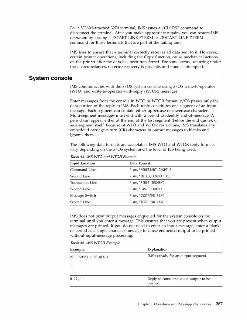
For a VTAM-attached 3270 terminal, IMS issues a /CLSDST command todisconnect the terminal. After you make appropriate repairs, you can restore IMSoperation by issuing a /START LINE PTERM or /RSTART LINE PTERMcommand for those terminals that are part of the failing unit.
IMS tries to ensure that a terminal correctly receives all data sent to it. However,certain printer operations, including the Copy function, cause mechanical actionson the printer after the data has been transferred. For some errors occurring underthese circumstances, no error recovery is possible, and none is attempted.
System consoleIMS communicates with the z/OS system console using z/OS write-to-operator(WTO) and write-to-operator-with-reply (WTOR) messages.
Enter messages from the console in WTO or WTOR format. z/OS passes only thedata portion of the reply to IMS. Each reply constitutes one segment of an inputmessage. Each segment can contain either uppercase or lowercase characters.Multi-segment messages must end with a period to identify end-of-message. Aperiod can appear either at the end of the last segment (before the end quote), oras a segment itself. Because of WTO and WTOR restrictions, IMS translates anyembedded carriage return (CR) characters in output messages to blanks andignores them.
The following data formats are acceptable. IMS WTO and WTOR reply formatsvary depending on the z/OS system and the level of JES being used.
Table 44. IMS WTO and WTOR Formats
Input Location Data Format
Command Line R nn,’/ERESTART CHKPT 0 ’
Second Line R nn,’BUILDQ FORMAT RS.’
Transaction Line R nn,’FIRST SEGMENT’
Second Line R nn,’LAST SEGMENT.’
Message Switch R nn,’DESTNAME TEXT’
Second Line R nn,’TEXT 2ND LINE.’
IMS does not print output messages enqueued for the system console on theterminal until you enter a message. This ensures that you are present when outputmessages are printed. If you do not need to enter an input message, enter a blankor period as a single-character message to cause enqueued output to be printedwithout input-message processing.
Table 45. IMS WTOR Example
Example Explanation
27 DFS996I *IMS READY
...
IMS is ready for an output segment.
R 27,’.’ Reply to cause enqueued output to beprinted.
Chapter 8. Operations and IMS-supported devices 287
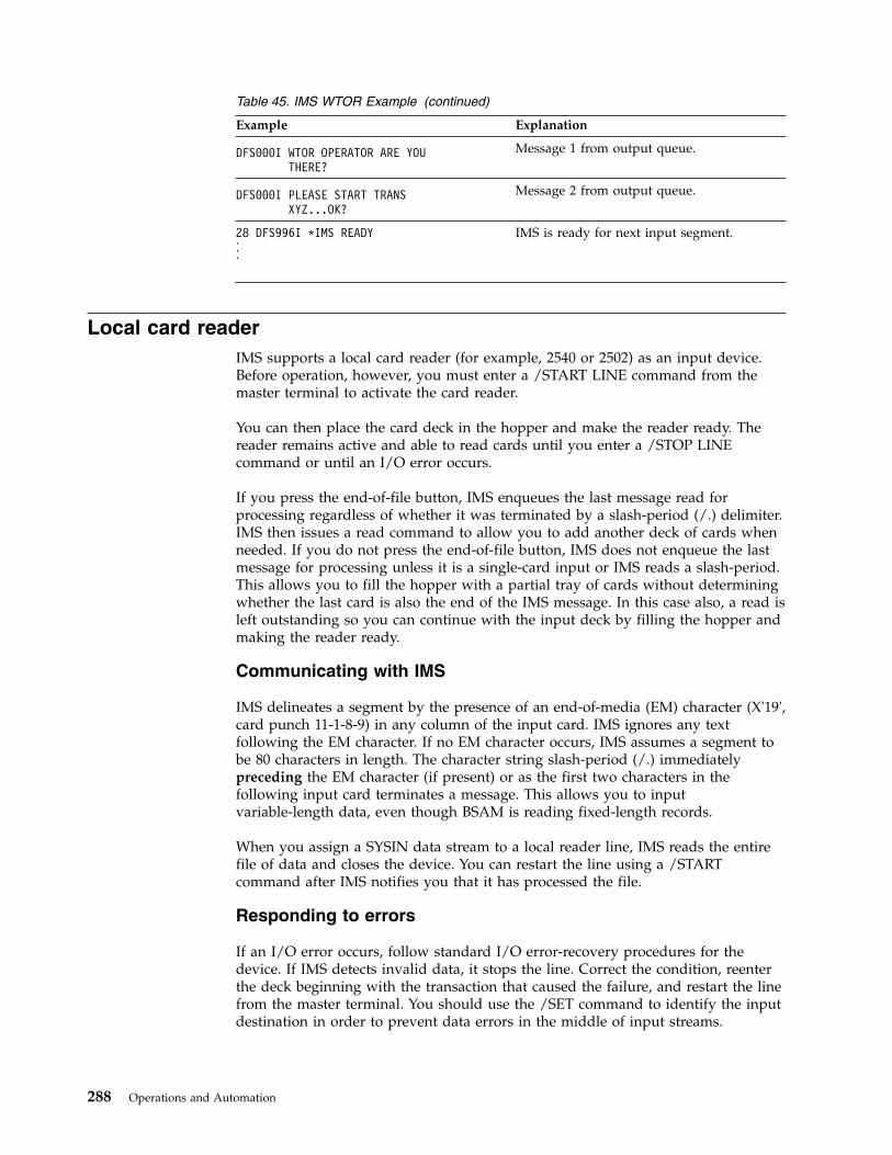
Table 45. IMS WTOR Example (continued)
Example Explanation
DFS000I WTOR OPERATOR ARE YOUTHERE?
Message 1 from output queue.
DFS000I PLEASE START TRANSXYZ...OK?
Message 2 from output queue.
28 DFS996I *IMS READY...
IMS is ready for next input segment.
Local card readerIMS supports a local card reader (for example, 2540 or 2502) as an input device.Before operation, however, you must enter a /START LINE command from themaster terminal to activate the card reader.
You can then place the card deck in the hopper and make the reader ready. Thereader remains active and able to read cards until you enter a /STOP LINEcommand or until an I/O error occurs.
If you press the end-of-file button, IMS enqueues the last message read forprocessing regardless of whether it was terminated by a slash-period (/.) delimiter.IMS then issues a read command to allow you to add another deck of cards whenneeded. If you do not press the end-of-file button, IMS does not enqueue the lastmessage for processing unless it is a single-card input or IMS reads a slash-period.This allows you to fill the hopper with a partial tray of cards without determiningwhether the last card is also the end of the IMS message. In this case also, a read isleft outstanding so you can continue with the input deck by filling the hopper andmaking the reader ready.
Communicating with IMS
IMS delineates a segment by the presence of an end-of-media (EM) character (X'19',card punch 11-1-8-9) in any column of the input card. IMS ignores any textfollowing the EM character. If no EM character occurs, IMS assumes a segment tobe 80 characters in length. The character string slash-period (/.) immediatelypreceding the EM character (if present) or as the first two characters in thefollowing input card terminates a message. This allows you to inputvariable-length data, even though BSAM is reading fixed-length records.
When you assign a SYSIN data stream to a local reader line, IMS reads the entirefile of data and closes the device. You can restart the line using a /STARTcommand after IMS notifies you that it has processed the file.
Responding to errors
If an I/O error occurs, follow standard I/O error-recovery procedures for thedevice. If IMS detects invalid data, it stops the line. Correct the condition, reenterthe deck beginning with the transaction that caused the failure, and restart the linefrom the master terminal. You should use the /SET command to identify the inputdestination in order to prevent data errors in the middle of input streams.
288 Operations and Automation

Local printerIMS supports a local printer (for example, 1443 or 1403) as a high-speed onlineoutput terminal. After you enter a /START LINE command from the masterterminal, the printer prints output as received from the application programwithout your intervention.
If a permanent I/O error occurs, IMS stops the terminal. Correct the error andrestart the line from the master terminal using the /START LINE PTERM or/RSTART LINE PTERM command.
Replace the magnetic tapeIf you use a tape for SYSIN or SYSOUT data sets, you must change tapes whenz/OS notifies you of end-of-volume (EOV).
To remove a tape before EOV for offline processing:1. Issue a /STOP LINE PTERM command from the master terminal.2. Remove the tape, mount a new one, and to continue processing, enter one of
the following commandsv /START LINE PTERMv /RSTART LINE PTERM
Disk data setsYou can allocate a disk data set for use as an intermediate data file accessed by anIMS application program or any other user program. The operation is the same asfor a tape file, but IMS provides no means of dismounting disk volumes.
When you allocate a group of disk data sets for the spooled SYSOUT option, theIMS Spool SYSOUT Print utility (DFSUPRT0) can copy one or more of these datasets to SYSOUT. IMS can automatically schedule this utility at end-of-volume onone of the data sets. An end-of-volume condition is also simulated:v If an I/O error occurs while writing to a spool data set.v During system initialization, if a spool data set was in use when the system was
last running and the spool data set was not printed.In this case, you must issue a /START LINE command to complete thescheduling procedure.
Recommendation: Define at least two data sets for your spool line.
You can reschedule the utility with the /STOP LINE PTERM command. You canalso start the utility at any time by issuing a /START REGION procname commandfrom the master terminal. IMS generates line numbers and PTERMs in thesequence of the input definition statements during IMS system definition. After thesystem is generated and ready to run, you can display line numbers to determinewhat line number was generated for a spool data set.
You must establish your own conventions for controlling special forms. Onepossible method is to allocate a logical terminal for each report. After you set upthe forms for a specific report, lock the other logical terminals using the /LOCKLTERM command, then place the terminal in exclusive mode using the/EXCLUSIVE command. Thereafter, IMS prints only the data enqueued for the
Chapter 8. Operations and IMS-supported devices 289
report you want. If you do not use a technique like this one, messages alternateamong the logical terminals associated with the line.
Programmable remote systemsOperators of programmable remote systems do not communicate directly withIMS, but rather with a user-written program that resides in the remote system'sstorage. If you use programmable remote systems, you must provide proceduresfor terminal operators.
SLU-1 devicesSLU-1 devices can include communication terminals and printers.
These topics describe the following SLU-1 devices as examples:v IBM SLU-1 Communication Terminal.v IBM SLU-1 Data Communication System (Programmable Models). The SLU-1
supports input from a transmit data set (TDS) or a user data set (UDS), inaddition to print data set (PDS) and UDS output if you define them to IMS asunattended.
v IBM SLU-1 Data Communication System (Nonprogrammable Models).
MFS is optionally available for TDS input and PDS output. You can define a SLU-1device for either attended or unattended operation.
Printers attached to IMS as SCS SLU-1 devices
Most of the printers have Cancel, PA1, and PA2 keys that can be used when thedevice is operating in SNA character string (SCS) mode and is attached to anappropriate controller, such as the 3174, 3274, 3601, or 4701. When these keys arepressed while IMS is printing a message, the following results occur:v If the Cancel key is pressed, IMS stops transmission and discards the current
output message (but does not dequeue it).v If a PA key is pressed, a string of characters is sent to IMS. You can define this
string of characters as transaction code APAK 01 for PA1 and APAK 02 for PA2,or you can use the appropriate IMS user exit routine to modify this string, forexample to set it to a command or message switch.
Restriction: You must specify CONSOLE instead of PRINTER1 for the COMPT1keyword of the TERMINAL macro (or the logon descriptor for the printer). In theTYPE macro or logon descriptor, specify the printer as UNITYPE=SLUTYPE1.
SLU-1 communication terminal
These topics describe IMS operations for a SLU-1 Communication Terminal or aSLU-1 Data Communication System (nonprogrammable models).
Connecting to IMS using SLU-1 devicesSecondary Logical Unit (SLU-1) devices can connect to IMS using a telephone dataset.
Prepare the SLU-1 device for communication before attempting to log on. See theSLU-1 operator's guide for the proper switch settings.
290 Operations and Automation
You should log on to terminals that are connected with a switched line using theprocedure below. Log on to terminals connected through a nonswitched line usingthe same procedure, but start with step 2.1. Establish connection with the computer through a telephone data set.2. Press the Sys Req key. The Proceed light should go on.3. Enter the logon message. For example, to log on to an IMS system named
IMSA:v Enter: LOGON applid (IMSA)v Response: DFS3650I SESSION STATUS
If you want host-initiated logon for a SLU-1 Data Communication System, youmust leave the terminal in a line-to-console job. To prepare the SLU-1 terminal forhost-initiated logon:1. Press the Start Job key. For a 3774 or 3775, also press the S key.2. Press the Line key.3. Press the Console key.4. Press the EOM (end of message) key.
Communicating with IMS using SLU-1 devicesYou can begin communication with IMS after you complete the logon procedure. Ifan output message is enqueued for the terminal, IMS attempts to send itimmediately after the DFS3650I message. If you begin to enter an input messagebefore you receive the output message, IMS sends the output message later.
Entering single-segment inputYou must remember to press the EOM key to let IMS know that you have entereda segment.
Enter single-segment input as follows:1. Enter the input data.2. Press the carriage-return key.
3. Press the EOM key.
Entering multi-segment inputWhen you set the AUTO switch to AUTO, you send data in the buffer plus anEOM to IMS when you press the carriage-return key or the Form Feed key. For aSLU-1 Communication Terminal, set the AUTO switch to OFF when you entermulti-segment input.
Enter multi-segment input as follows:1. Enter the first segment of the input.2. Press the carriage-return key.3. Press the EOB (end of buffer) key to send the buffer contents, if required. If you
want to enter another segment in this buffer, do not press the EOB key.4. Enter the next input segment.5. Press the carriage-return key.6. If there are more segments to enter, return to step 3. If not, press the EOM key.
Receiving an output messageYou can use the Cancel and Attn keys to interrupt output messages destined forSLU-1 devices.
Chapter 8. Operations and IMS-supported devices 291

IMS sends all output messages for a SLU-1 device in their entirety unless youinterrupt them at the device using the Cancel and Attn keys as follows:v The Cancel key stops the current message, which IMS then discards. If another
output message is presently enqueued, IMS sends it.v The Attn key causes IMS to finish sending the current message. When the
message completes, you can enter an input message.v The Attn key followed by the Cancel key stops the current message, which IMS
then discards. When the message is stopped, you can enter an input message.
SLU 1 with MFSDuring IMS system definition, you can define a SLU-1 terminal to work withMessage Format Service (MFS). Like a 3270 terminal, system-supplied formats areavailable.
Even when defined to operate with MFS, the SLU-1 terminal operates inunformatted mode (using IMS basic edit) until one of the following occurs:v You enter //midname.v MFS processes an output message to the terminal using an MFS message output
descriptor (MOD) that names an MFS message input descriptor (MID) to beused to process subsequent input data.
If you enter data on the same line as //midname, separate //midname from the datawith a blank. IMS discards the //midname and the blank, and formats the dataaccording to the named MID. If you enter //midname without any data on the sameline, IMS considers the next line received from the terminal to be the first line ofthe message.
When IMS processes an output message to a SLU-1 terminal using a MOD thatnames a MID, MFS uses that MID to format the next input from that terminal. Anapplication program, the IMS /FORMAT command, a message switch, or someIMS functions can create this output message.
When in formatted mode (using MFS), a SLU-1 terminal remains in formattedmode until one of the following occurs:v You enter two slashes (//) or two slashes followed by a blank. The terminal
returns to unformatted mode, and IMS discards the two blanks. The two slashesare escape characters.
v You enter two slashes, a blank, and data. MFS returns the terminal tounformatted mode, IMS discards the slashes and the blank, and formats the datausing basic edit.
v IMS sends an output message that does not name a MOD to the terminal.v IMS sends an output message whose MOD does not name a MID to the
terminal.
IMS uses MFS default formats for many output messages. When a terminalreceives such a message, the terminal goes into formatted mode, and MFSprocesses the next input message unless you use the escape characters. If in doubt,use the escape characters.
Disconnecting SLU-1 devices from IMSTo disconnect from IMS, press the Sys Req key and then enter a logoff command.For a SLU-1 Data Communication System, you can also press the Stop Job key.
292 Operations and Automation

SLU-2 devicesSLU-2 devices can initiate a session with IMS in several ways.Related reference:
Terminals and equipment supported by IMS 15 (Release Planning)
Using SLU-2 devices to connect and disconnect to IMSWhen you connect to or disconnect from IMS using a SLU-2 device, the procedureis the same regardless of the device.
If you define the terminal as the master terminal, IMS automatically enables theterminal for a session.
Initiate a session by using any one of the following three methods:v The VTAM network operator can enter the VARY NET command (VARY
NET,ID=a,LOGON=b).v You can enter the /OPNDST command from the IMS master terminal.v VTAM can make the unit automatically available if it is defined in the VTAM
definition as belonging to IMS.
Close a terminal session by issuing a /RCLSDST command.Related reference:
Terminals and equipment supported by IMS 15 (Release Planning)
3290 information panelWhen communicating with IMS using a 3290, the terminal operator might need toknow that how the PA1 key operates is based on what option is selected forpresenting pages to a partition.
If an error occurs, the 3290 session usually terminates. The 3290, not IMS, handlesdevice errors.Related concepts:
3290 information panel in partitioned format mode (Application ProgrammingAPIs)
NTO logical unitsIMS allows start-stop devices such as TTY and TTY-compatible devices (forexample, the 3101) to attach to IMS through VTAM.
The Network Terminal Option (NTO) Program Product handles the devicecharacteristics associated with line control and communication protocols, andtranslates them into SNA-SLU 1 communication protocols handled by VTAM andIMS. The operational characteristics of each device do not change, but sessioninitiation and termination are modified as described below.Related reference:
Terminals and equipment supported by IMS 15 (Release Planning)
Chapter 8. Operations and IMS-supported devices 293
Connecting to IMS using NTO devicesBefore you can initiate a Network Terminal Option (NTO) session, IMS mustrecognize the NTO device. You need to define the device to IMS and enter the/START DC from the master terminal.
For IMS to recognize the NTO device, you must do both of the following:1. Define the NTO device to IMS during IMS system definition using the PU
keyword in the TERMINAL macro. This keyword specifies the actual hardwarethat this NTO device represents.
2. Enter a /START DC command from the IMS master terminal.
IMS initiates a session with an NTO device when one of the following occurs:v You enter the LOGON APPLID(nnnnnnnn) command at the NTO terminal.v You enter an /OPNDST command (for nonswitched devices only) from the IMS
master terminal.v The VTAM network operator issues a VARY command with the LOGON= keyword
(for nonswitched devices only).
The NTO device receives a DFS3650I message when session initiation hascompleted successfully.
How to communicate with IMS from an NTO deviceThe Network Terminal Option (NTO) handles the device characteristics associatedwith line control and communication protocols, and translates them into SNA-SLU1 communication protocols handled by VTAM and IMS.
You can communicate with IMS from a network terminal option (NTO) deviceusing control characters, single-segment messages, and multi-segment messages.
Control characters
IMS uses the following control characters to delineate messages and messagesegments:
. (period)End-of-message. This character signifies the end of a multisegmentmessage when you do not use MFS.
CR Carriage return (X'0D').
LF Line feed (X'25').
Single-segment messages
To send data to IMS, use the following format:v Begin the message with a transaction code.v End the message with the CR and LF characters.
Example:transaction_code text CR,LF
294 Operations and Automation
Multi-segment messages
To send data to IMS, use the following format:v Begin the message with a transaction code.v End each segment with the CR and LF characters.v End the message with a period (.), followed by the CR and LF characters.
Example:transaction_code segment_1 CR,LF
segment_2 CR,LF. . .segment_n CR,LF
.,CR,LF
You can reverse the order of the CR and LF characters.
Operation of the NTO device is the same as for those devices without NTO andVTAM. For additional information on entering messages, receiving messages, usingresponse mode, using MFS, and using IMS commands from the terminal, see thepreceding sections on each type of physical device.
Disconnecting NTO devices from IMSYou can disconnect the session between a network terminal option (NTO) deviceand IMS by issuing certain commands. NTO devices will also disconnect whenIMS terminates or when VTAM terminates.
The session between an NTO device and IMS terminates when any of thefollowing occurs:v IMS terminates.v VTAM terminates.v The network operator enters a VARY INACT command.v You do one of the following at the NTO terminal:
– Issue a /RCLSDST command.– Enter a logoff command.– Disconnect the phone connection for a switched device.
v You enter the /CLSDST command from the IMS master terminal.v Data or transmission errors force termination of the session.
Restriction: You must not stop the NTO logical unit using the IMS /STOPcommand. The network operator must issue the VTAM VARY command (withANS=ON for switched devices).Related tasks:“Connecting to IMS using NTO devices” on page 294
Special operational notes and restrictionsTTY devices and devices acting as TTY devices use blank lines in the form ofcarriage returns and linefeeds both before and after a message to set off themessage for easier identification.
For TTY devices, IMS system messages cause a carriage return (CR) and linefeed(LF) before and after the message. Other output does not cause this to happen.
Chapter 8. Operations and IMS-supported devices 295
For 3101 devices acting as TTY devices, IMS sends a carriage return (CR) as X'0D'.This has the same effect on the 3101 screen for IMS system messages as thecarriage return (CR) and linefeed (LF) do for the TTY.
There are no component attachments to an NTO device. You must define eachcomponent as a unique NTO device to VTAM, the NTO Program Product, theNCP, and IMS.
An NTO device cannot be used as an IMS master terminal.
Master terminalIf you use a 3270 device, IMS requires that you use a 3270 display station with a3270 printer for the master terminal (IMS does not allow the 3284 Model 3 printer).The master terminal cannot be an ETO terminal or an LU 6.2 device.
You can define any of the following devices as the master terminal for an IMSsubsystem:v System consolev IBM 3270 Information Display System (nonswitched)v SLU-1 device (attended mode only)v SLU-2 device
296 Operations and Automation

Chapter 9. Automated operations
Automated operations are tools and techniques that help you improve yourinstallation's productivity. As your system grows more complex and your messagetraffic increases, automating certain tasks can increase efficiency of your system.
IMS operations can also be automated using Tivoli NetView for z/OS. BecauseTivoli NetView for z/OS functions independently of IMS, it can gather informationand issue commands that are not available to IMS.
You can use automated operations to:v Minimize errorsv Increase availabilityv Expedite problem diagnosis and prevention
IMS provides the following tools to help you automate your operations:v Time-controlled operations (TCO)v Automated Operator Interface (AOI)v REXX SPOC APIRelated tasks:“Recovering terminal sessions” on page 188Related reference:
Tivoli Software Information
Advantages of automationMany of the jobs that operators perform are simple, repetitive tasks, such asmonitoring the system and issuing recovery commands. You can often automatethese jobs and thereby free the operator for more complex activities, such asimplementing operational procedures.
In the IMS environment, TCO and AOI can improve your operator productivity by:v Improving operator productivity and accuracy. Automating operator tasks
simplifies procedures, reduces operator input, and minimizes operator errors.For example, TCO can reduce operator input by automatically monitoringsystem status, starting message regions and telecommunication lines, andnotifying users of system status.
v Expediting problem determination. An operator's primary job is to bypass or fixproblems quickly. If adequate information about a problem is not available, itmight not be possible for the operator to fix it quickly. Automated operations areespecially suited for problem determination. For example, TCO canautomatically gather necessary information and do diagnostic analysis so that aproblem can be quickly identified and corrected.
© Copyright IBM Corp. 1974, 2017 297

Deciding what to automateIdentifying operations that can be automated and implementing them requires asound understanding of your installation's operations. You must collect andanalyze various resources to identify which tasks are good candidates forautomation. Repetitive and predictable tasks are good candidates for automation.
Tip: The process of automating operations should be an iterative one. After youhave developed and used automated procedures, you should evaluate them and,in the process, consider whether any new tasks can be automated.
Resources you should analyze include:v System logsv Problem management reportsv Record of calls to the help deskv Operators' notes
Tools for automated operationsYou can use the Automated Operator Interface (AOI), the REXX SPOC API, andthe time-controlled operations (TCO) to help you automate the IMS subsystem.
IMS operations can also be automated using Tivoli NetView for z/OS. BecauseTivoli NetView for z/OS is independent of IMS, it can gather information andissue commands that are not available to IMS.
IMS provides the following tools to help you automate your operations:v Automated Operator Interface (AOI), of which there are two types:
– Type 1, available for the IMS DB/DC and DCCTL environments– Type 2, available for all IMS environments (DB/DC, DCCTL, and DBCTL)
v REXX SPOC API, available in an IMSplex environmentv Time-controlled operations (TCO), available for IMS DB/DC and DCCTL
environmentsRelated concepts:Chapter 11, “Type-2 automated operator (AO) application program (GMSG, ICMD,and RCMD calls),” on page 333Related reference:
Tivoli Software Information
IMS Automated Operator Interface (AOI)The IMS Automated Operator Interface (AOI) lets an application program, usingDL/I calls, issue most IMS operator commands and receive command responses.
AOI lets you write an exit routine to intercept:v IMS system messages routed to the MTOv Commandsv Command responses
Using AOI, you can examine these messages, commands, and command responsesand issue a message to any terminal or to the IMS message queue to be processedby an application program.
298 Operations and Automation

You can use AOI to develop commands tailored to your installation and toautomate some portions of the recovery process. AOI can relieve the MTO ofnumerous controlling and monitoring duties. This is especially useful if youmanage a large terminal network. IMS can send single segment or multi-segmentmessages. Your AOI exit must be able to handle both types of messages in theevent that messages run over one line.
Using AOI:v Relieves operators from repetitive command entry.v Increases accuracy for command entry, especially when the commands have
LTERM and telecommunication line control parameters.v Helps you control IMS resources at prearranged times, such as during region
startup and database image copy.v Lets you prompt the MTO to take specific actions.v Allows entry of commands with long operand lists. This can be important for
commands that are larger than can be entered from a terminal.
Automated operator programs can:v Supervise terminalsv Control IMS monitor and trace operationsv Help detect database problemsv Assist in recovery by issuing the commands /STOP DB, /LOCK DB, and either
the /DBRECOVERY DB or UPDATE DB STOP(ACCESS)Related concepts:Chapter 10, “Type-1 automated operator (AO) application program (GU, GN,CMD, and GCMD calls),” on page 323Chapter 11, “Type-2 automated operator (AO) application program (GMSG, ICMD,and RCMD calls),” on page 333
Security for AO application programs (System Administration)
AOI functionsThe IMS AOI consists of an exit routine and application program DL/I calls. Theexit routine is called the Automated Operator (AO) exit routine. An applicationprogram that issues the DL/I calls is called an AO application program. The termAOI refers to the overall function, rather than to either of its two parts.
IMS calls the AO exit routine continually for system messages, commands, andcommand responses. The AO exit routine can:v Examine IMS messages, commands, and command responsesv Manipulate IMS messagesv Send messages to an AO application program
By using an AO application program, you can:v Retrieve messages sent from an AO exit routinev Issue various IMS operator commandsv Retrieve responses to those commands
You can use the AO exit routine and application program together orindependently of each other. For example:
Chapter 9. Automated operations 299
v You could use just an AO exit routine to monitor IMS messages and deleteunwanted messages from the master terminal (z/OS system console in theDBCTL environment).
v You could use just an AO application program to issue a set of IMS commands,perhaps to start programs or databases. When used alone, you start the AOapplication program just like any other IMS application program.
v You could use both the AO exit routine and AO application program together.The exit routine could, for example, direct a message to the application program.The application program could then do specific processing based on the messageit receives from the exit routine. In this case, the AO exit routine starts theapplication program.
AOI can be used in any IMS environment (DB/DC, DBCTL, or DCCTL). But,depending on the environment, there are some differences in what AOI can do andwhat you must do to use it.Related concepts:“AOI and the IMS environments” on page 303
How to use AOI to complete different tasksYou can use the automated operator interface (AOI) to discard unwantedmessages, set up a batch window, restart application programs after an abend,customize messages, create an audit trail, or supervise terminals.
Discarding unwanted messages
You can write an AO exit routine to prevent the master terminal (z/OS systemconsole in the DBCTL environment) from being flooded with unwanted IMSmessages. You can still log discarded messages to the secondary master terminal(by issuing the /SMCOPY command from an AO application program) in case, forexample, the messages are subsequently needed for problem determination.
You can also prevent the logging of IMS system messages to the secondary masterterminal by using the /SMCOPY MSG OFF command.
Messages that are logged to the secondary master can also be controlled using atype-2 AO exit routine (DFSAOE00 or another AOIE type exit routine).
Setting up a batch window
You can write an AO application to set aside time (usually each night) for runningbatch jobs, that is, to set up a batch window. When you run batch jobs, youusually take the databases offline. To set up your batch window using an AOapplication program, you can write a multiple step job that:v Issues a /DBRECOVERY DB or UPDATE DB STOP(ACCESS) command to take
the database offline (BMP step)v Issues a /DISPLAY DB or QUERY DB command to determine when the
database is actually offline (BMP step)v Initiates your batch work and does routine operational tasks, such as making
image copies (batch step)v Issues a /START DB or UPDATE DB START(ACCESS) SET(ACCTYPE())
command to bring the databases online (BMP step)
300 Operations and Automation

Restarting application programs after an abend
When an application program abends, IMS issues a message and immediatelystops the program. You can write an AO exit routine that sends the message to anAO application program that can then issue the /START PROGRAM command toallow work to continue immediately, rather than waiting for the MTO to restart theprogram.
Customizing messages
You can write an exit routine that customizes IMS system messages before they arerouted to the master terminal. You can delete parts of messages that have nomeaning for the MTO. You can reformat a message to conform to a formatestablished at your installation. Or, you can add text to a message to tell an MTOwhat action to take in response to the message.
Creating an audit trail
You can use AOI to track system or user actions. For example, if you find thatcertain commands are not being used appropriately at your installation, you canintercept them with an AO exit routine. The AO exit routine can send a copy of thecommand to an AO application, which can in turn send the command, withpertinent user information, to the MTO, or copy it to the log for later analysis.
Supervising terminals
If your network is extensive, you might make one or more terminal operatorsresponsible for terminal availability. These operators also watch for communicationproblems and can reassign LTERMs to alternate devices. You can write an AOapplication program that performs the same tasks, and in effect, functions as asupervisory terminal. Either the MTO or someone entering the appropriatetransaction from a remote terminal can schedule the AO application program.
Processing of messages, commands, and command responsesThe automated operator interface (AOI) process system messages, command, andcommand responses. AOI lets an application program, using DL/I calls, issue mostIMS operator commands and receive command responses.
Because AOI can manipulate system messages, commands, and commandresponses, these topics define these terms and explains how AOI processes them.
Processing system messages
A system message is any IMS message that is not a direct response to a command.When IMS issues a system message, it sends a copy of the message to one or moreof the following:v IMS master terminal (z/OS system console in the DBCTL environment)v z/OS system consolev IMS secondary master terminal
IMS sends all system messages destined for the IMS master terminal to the AO exitroutine. IMS does not send copies of system messages destined for the z/OSsystem console (in a non-DBCTL environment) or the secondary master terminal to
Chapter 9. Automated operations 301
the AO exit routine. The AO exit routine can change or delete a system messagesent to the master terminal. In the DBCTL environment, the original copy of achanged or deleted message is lost.
Copies of a system message destined for the z/OS system console or the secondarymaster terminal, if the logging of system messages is not disabled, are sent beforethey are sent to the master terminal.
The logging of IMS system messages to the secondary master terminal is controlledby using the /SMCOPY MSG ON|OFF command.
Processing commands
A command is any IMS operator command. IMS sends a copy of all IMS operatorcommands entered from a terminal to the AO exit routine, but does not send thefollowing:v /FORMATv /LOOPTESTv /MSVERIFYv /RELEASE
In addition, in the IMS DB/DC and DCCTL environments, IMS does not send thefollowing commands:v /NRESTARTv /ERESTART
In addition, in the IMS DBCTL environment, IMS does not send the two restartcommands listed above to the AO exit routine.
IMS also sends copies of the following types of commands to type-2 AO exitroutines (DFSAOE00 and other AOIE type exit routines):v Commands issued by ICMD calls in an AO application programv IMS internally-generated commands
IMS does not execute the command until after IMS sends it to the AO exit routine.
Processing command responses
After a command is executed, IMS generates a command response. If an AO exitroutine expressed interest in the command, IMS sends a copy of the commandresponse to the routine. Any asynchronous system messages IMS produces as aresult of a command are not command responses; they are system messages.
IMS does not send copies of command responses for the following types ofcommands to type-2 AO exit routines:v Commands issued by ICMD calls in an AO application programv IMS internally-generated commands
To process a command response, the AO exit routine must check for messagesegments after the first one. The /DISPLAY, /RDISPLAY, and /RMxxxx commandsall generate multi-segment response messages.
302 Operations and Automation

AOI and the IMS environmentsYou can use one of two Automated Operator Interface (AOI) functions, dependingon which IMS environment you are operating in and what you want to do. TheAOI function for the IMS DB/DC and DCCTL environments is called type-1 AOI.The AOI function for the DB/DC, DCCTL, and DBCTL environments is calledtype-2 AOI.
Type-1 AOI uses the following DL/I calls:v CMD to issue operator commandsv GCMD to retrieve responses to those commandsv GU and GN to retrieve messages routed to the AO application program from the
AO exit routine
The AO exit routine you write in this environment is named DFSAOUE0. Type-1AOI uses the IMS message queues for communication between an AO applicationand an AO exit routine.
Type-2 AOI uses the following DL/I calls:v ICMD to issue operator commandsv RCMD to retrieve responses to those commandsv GMSG to retrieve messages routed to the AO application program from the AO
exit routine
The AO exit routine you write in this environment is an AOIE type exit routine.Type-2 AOI does not use the IMS message queues for communication between anAO application and an AO exit routine; instead, it uses an AOI token (aneight-byte name that associates messages with AO application programs).
Although this topic pairs the AO exit routine and application program togetherbased on the environments in which they operate, you could use a single AOapplication program to issue calls and retrieve messages from DFSAOUE0 andAOIE type exit routines. You can write such an application program to run in theIMS DB/DC or DCCTL environment, but not in the DBCTL environment.Related concepts:“Restart and recovery considerations” on page 338“AOI functions” on page 299
Type-1 AOIType-1 AOI consists of the AO exit routine, DFSAOUE0, and AO applicationprograms that use the GU, GN, CMD and GCMD calls. Type-1 AOI is applicable for theIMS DB/DC and DCCTL environments.
Type-1 AO exit routine (DFSAOUE0)
IMS calls the type-1 exit routine, DFSAOUE0, for:v System messages destined for the master terminalv A subset of operator-entered commandsv Associated command responses
DFSAOUE0 can examine these messages and commands before IMS sends orexecutes them. IMS does not call DFSAOUE0 for system messages destined forterminals other than the master terminal or for certain commands and commandresponses.
Chapter 9. Automated operations 303
DFSAOUE0 can handle both single-segment and multi-segment messages. You canwrite DFSAOUE0 to do the following:v Modify IMS system messages. In addition to modifying a message, DFSAOUE0
can add up to 20 bytes of text to the end of a message. A copy of the modifiedmessage can be sent to an alternate destination.Messages issued by IMS after a command has been entered (for example, theDFS058“command in progress” message) are not really messages; they arecommand responses and cannot be modified.
v Delete an IMS system message and, optionally, send a copy of the message to analternate destination.
v Ignore selected segments of a message or an entire message.v Send a copy of system messages, commands, or command responses to an
alternate destination.v Send a new message to an alternate destination in response to receiving a
system message, command, or command response.v Modify a copy of a command or command response and send the copy to an
alternate destination. Note that, unlike system messages, the exit routine canonly modify a copy of commands and command responses.
v Enter a transaction to be placed on a message queue. This function letsDFSAOUE0 schedule an AO application program. For example, after receivingstartup messages DFS680 and DFS994I, DFSAOUE0 could invoke an AOapplication program to enter a series of commands to start the network.
Restriction: In a shared-queues environment, any transactions to be processedby the local IMS subsystem (rather than using the shared queues) must bedefined as SERIAL. These transactions cannot be processed by other IMSsubsystems in the sysplex.
v Request the edited command buffer (when the input is a command) todetermine which command parameters succeeded or failed.
DFSAOUE0 can modify or delete system messages only. It can modify or delete thesystem message that the original destination (the master terminal) receives. It canalso send a modified copy to an alternate destination. You cannot, however, useDFSAOUE0 to modify or delete the original command or command response. Youcan use it to modify a copy of a command or command response that it sends toan alternate destination, but not the copy that the primary destination receives.
Your AO exit routine must be a standalone, 31-bit, reentrant module.
Specify your exit requirements by linking the exit routines you want to use in theIMS.SDFSRESL concatenation. You can specify both type-1 and type-2 AO exitroutines.
Type-1 AO application program (GU, GN, CMD and GCMD)
An AO application program can:v Issue DL/I calls to retrieve messages from DFSAOUE0 (or AOIE type exit
routines)v Issue a subset of IMS commandsv Retrieve the responses to those commands
Retrieving messages (GU and GN call)
304 Operations and Automation
An AO application program receives control when IMS enqueues a message withthe appropriate transaction code. The AO application program retrieves themessage from DFSAOUE0 by issuing GU and GN calls.
Issuing commands and retrieving command responses (CMD and GCMD)
The AO application program issues a command using the CMD call. You can onlyuse the CMD call if you also use the I/O PCB. PCB status codes indicate the resultsof a CMD call.
If there are more than one command response segments, the first one is returned tothe I/O area. Use the GCMD call to retrieve subsequent segments. This call, similarto a GN call, places subsequent command response segments in the I/O area.
Security
You can secure the CMD call by using RACF (or an equivalent product), the IMSCommand Authorization exit routine (DFSCCMD0), or a combination of RACF andthe exit routine. With the AOI= parameter on the TRANSACT system definitionmacro, you can specify which programs can issue operator commands. With RACFor DFSCCMD0, you can define which commands an AOI application program canissue.
Recovery
IMS puts messages sent from DFSAOUE0 to the AO application program on theIMS message queue. Therefore, all messages are recoverable at IMS restart.
Supported application program environments
The following table shows the types of application programs that can issue CMDand GCMD calls, by IMS environment.
Table 46. CMD and GCMD call support by application region type
Application region type
IMS environment
DB/DC DBCTL DCCTL
DRA thread No No N/A
BMP (non-message-driven) No No No
BMP (message-driven) Yes N/A Yes
MPP Yes N/A Yes
IFP No N/A No
Related concepts:
Type-1 AO command security (System Administration)
Type-2 AOIThe type-2 Automated Operator Interface (AOI) consists of AOIE type exit routines(including DFSAOE00), and AO application programs that use the GMSG, ICMD, andRCMD calls. Type-2 AOI is applicable for all IMS environments (DB/DC, DCCTL,and DBCTL).
Chapter 9. Automated operations 305
Type-2 AO exit routines (DFSAOE00 and other AOIE type exit routines)
IMS calls AOIE type exit routines for:v IMS system messages destined for the master terminalv Commands entered from a terminal and the responses to those commandsv Commands issued from an AO application program using the ICMD callv IMS internal commands
IMS does not call AOIE type exit routines for:v Command responses to internal commandsv Command responses to an AO application program ICMD callv Commands issued from an AO application using the CMD callv System messages for which the destination is not the master terminal
You can write AOIE type exit routines to complete the following tasks:v Modify the text of IMS system messages. An AOIE type exit routine can also
add up to 20 bytes of additional text to the end of a message.v Delete IMS system messages. In a DBCTL environment, if a message is deleted
or modified, IMS does not keep the original message sent to the z/OS systemconsole.
v Direct any system message, command, or command response to an AOapplication program.
v Filter the system messages sent to the secondary master terminal.v Start a BMP job (for example, an AO application program). AOIE type exit
routines can issue SVC 34 to start a BMP. You can use the APARM parameter of theEXEC statement to pass information to the AO application program. The AOapplication program can issue the DL/I INQY call to retrieve the value specifiedfor the APARM parameter. You can use the START command to override the APARMparameter of the EXEC statement.
AOIE type exit routines must use IMS AOI callable services to communicate withan AO application program. AOI callable services let you:v Direct messages, commands, and command responses to an AO application
programv Cancel messages previously directed to an AO application program but not yet
sent
Your AO exit routine must be a standalone, 31-bit, reentrant module.
Specify your exit requirements by linking the exit routines you want to use in theIMS.SDFSRESL concatenation. You can specify both type-1 and type-2 AO exitroutines.
Restriction: You cannot use AOIE type exit routines to modify or deletecommands and command responses, including commands from the z/OS systemconsole or an application program, or internally generated commands.
Type-2 AO application program (GMSG, ICMD, and RCMD)
An AO application program can issue DL/I calls to:v Retrieve messages from AOIE type exit routine (or DFSAOUE0)v Issue a subset of IMS commands
306 Operations and Automation
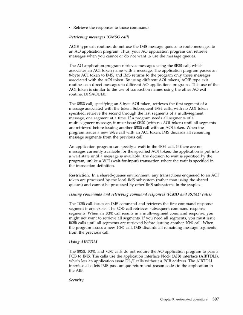
v Retrieve the responses to those commands
Retrieving messages (GMSG call)
AOIE type exit routines do not use the IMS message queues to route messages toan AO application program. Thus, your AO application program can retrievemessages when you cannot or do not want to use the message queues.
The AO application program retrieves messages using the GMSG call, whichassociates an AOI token name with a message. The application program passes an8-byte AOI token to IMS, and IMS returns to the program only those messagesassociated with the AOI token. By using different AOI tokens, AOIE type exitroutines can direct messages to different AO applications programs. This use of theAOI token is similar to the use of transaction names using the other AO exitroutine, DFSAOUE0.
The GMSG call, specifying an 8-byte AOI token, retrieves the first segment of amessage associated with the token. Subsequent GMSG calls, with no AOI tokenspecified, retrieve the second through the last segments of a multi-segmentmessage, one segment at a time. If a program needs all segments of amulti-segment message, it must issue GMSG (with no AOI token) until all segmentsare retrieved before issuing another GMSG call with an AOI token. When theprogram issues a new GMSG call with an AOI token, IMS discards all remainingmessage segments from the previous call.
An application program can specify a wait in the GMSG call. If there are nomessages currently available for the specified AOI token, the application is put intoa wait state until a message is available. The decision to wait is specified by theprogram, unlike a WFI (wait-for-input) transaction where the wait is specified inthe transaction definition.
Restriction: In a shared-queues environment, any transactions enqueued to an AOItoken are processed by the local IMS subsystem (rather than using the sharedqueues) and cannot be processed by other IMS subsystems in the sysplex.
Issuing commands and retrieving command responses (ICMD and RCMD calls)
The ICMD call issues an IMS command and retrieves the first command responsesegment if one exists. The RCMD call retrieves subsequent command responsesegments. When an ICMD call results in a multi-segment command response, youmight not want to retrieve all segments. If you need all segments, you must issueRCMD calls until all segments are retrieved before issuing another ICMD call. Whenthe program issues a new ICMD call, IMS discards all remaining message segmentsfrom the previous call.
Using AIBTDLI
The GMSG, ICMD, and RCMD calls do not require the AO application program to pass aPCB to IMS. The calls use the application interface block (AIB) interface (AIBTDLI),which lets an application issue DL/I calls without a PCB address. The AIBTDLIinterface also lets IMS pass unique return and reason codes to the application inthe AIB.
Security
Chapter 9. Automated operations 307
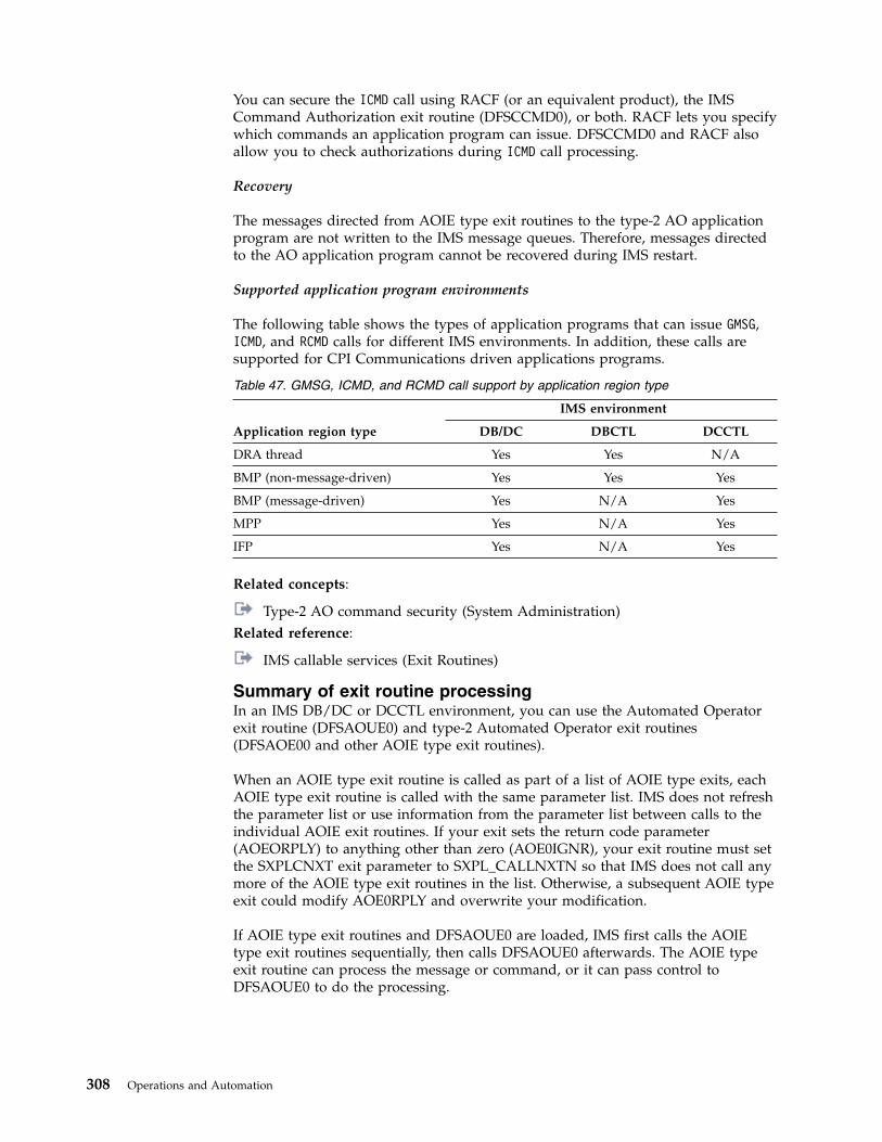
You can secure the ICMD call using RACF (or an equivalent product), the IMSCommand Authorization exit routine (DFSCCMD0), or both. RACF lets you specifywhich commands an application program can issue. DFSCCMD0 and RACF alsoallow you to check authorizations during ICMD call processing.
Recovery
The messages directed from AOIE type exit routines to the type-2 AO applicationprogram are not written to the IMS message queues. Therefore, messages directedto the AO application program cannot be recovered during IMS restart.
Supported application program environments
The following table shows the types of application programs that can issue GMSG,ICMD, and RCMD calls for different IMS environments. In addition, these calls aresupported for CPI Communications driven applications programs.
Table 47. GMSG, ICMD, and RCMD call support by application region type
Application region type
IMS environment
DB/DC DBCTL DCCTL
DRA thread Yes Yes N/A
BMP (non-message-driven) Yes Yes Yes
BMP (message-driven) Yes N/A Yes
MPP Yes N/A Yes
IFP Yes N/A Yes
Related concepts:
Type-2 AO command security (System Administration)Related reference:
IMS callable services (Exit Routines)
Summary of exit routine processingIn an IMS DB/DC or DCCTL environment, you can use the Automated Operatorexit routine (DFSAOUE0) and type-2 Automated Operator exit routines(DFSAOE00 and other AOIE type exit routines).
When an AOIE type exit routine is called as part of a list of AOIE type exits, eachAOIE type exit routine is called with the same parameter list. IMS does not refreshthe parameter list or use information from the parameter list between calls to theindividual AOIE exit routines. If your exit sets the return code parameter(AOEORPLY) to anything other than zero (AOE0IGNR), your exit routine must setthe SXPLCNXT exit parameter to SXPL_CALLNXTN so that IMS does not call anymore of the AOIE type exit routines in the list. Otherwise, a subsequent AOIE typeexit could modify AOE0RPLY and overwrite your modification.
If AOIE type exit routines and DFSAOUE0 are loaded, IMS first calls the AOIEtype exit routines sequentially, then calls DFSAOUE0 afterwards. The AOIE typeexit routine can process the message or command, or it can pass control toDFSAOUE0 to do the processing.
308 Operations and Automation
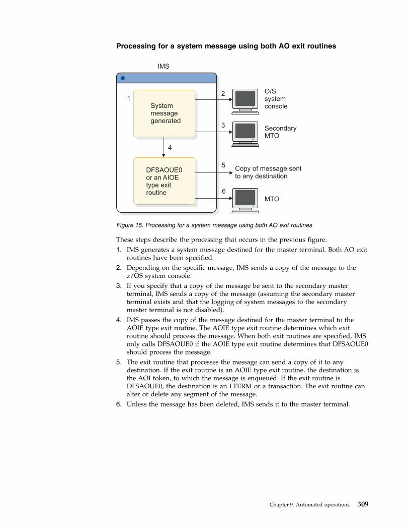
Processing for a system message using both AO exit routines
These steps describe the processing that occurs in the previous figure.1. IMS generates a system message destined for the master terminal. Both AO exit
routines have been specified.2. Depending on the specific message, IMS sends a copy of the message to the
z/OS system console.3. If you specify that a copy of the message be sent to the secondary master
terminal, IMS sends a copy of the message (assuming the secondary masterterminal exists and that the logging of system messages to the secondarymaster terminal is not disabled).
4. IMS passes the copy of the message destined for the master terminal to theAOIE type exit routine. The AOIE type exit routine determines which exitroutine should process the message. When both exit routines are specified, IMSonly calls DFSAOUE0 if the AOIE type exit routine determines that DFSAOUE0should process the message.
5. The exit routine that processes the message can send a copy of it to anydestination. If the exit routine is an AOIE type exit routine, the destination isthe AOI token, to which the message is enqueued. If the exit routine isDFSAOUE0, the destination is an LTERM or a transaction. The exit routine canalter or delete any segment of the message.
6. Unless the message has been deleted, IMS sends it to the master terminal.
Copy of message sentto any destination
12
IMS
3
4
5
6
O/Ssystemconsole
SecondaryMTO
MTO
DFSAOUE0or an AIOEtype exitroutine
Systemmessagegenerated
Figure 15. Processing for a system message using both AO exit routines
Chapter 9. Automated operations 309

Processing for a command using both AO exit routines
These steps describe the processing that occurs in the previous figure.1. When a command is entered from a terminal, IMS sends a copy of the
command to the AOIE type exit routine before executing the command. TheAOIE type exit routine determines whether to process the command itself orhave DFSAOUE0 process the command.
2. The exit routine that processes the command can send a copy of the commandto any destination. If the exit routine is an AOIE type exit routine, thedestination is the AOI token, to which the message is enqueued. If the exitroutine is DFSAOUE0, the destination is an LTERM or a transaction.
3. IMS executes the command and generates a command response.4. If the exit routine requested a copy of the command response, before sending
the command response, IMS passes it to whichever exit routine processed thecommand.
5. The exit routine that handles the command response can send a copy of it toany destination. If the exit routine is an AOIE type exit routine, the destinationis the AOI token, to which the message is enqueued. If the exit routine isDFSAOUE0, the destination is an LTERM or a transaction.
6. IMS sends the command response to the terminal that originated the command.
1
2
3
4
5
IMS
6
Copy of commandresponse sent toany destination
Copy of commandsent to any destination
Commandentered
Terminal
Commandresponse
Command
DFSAOUE0or an AIOEtype exitroutine
DFSAOUE0or an AIOEtype exitroutine
Figure 16. Processing for a command using both AO exit routines
310 Operations and Automation

Comparison of type-1 AOI and type-2 AOIThere are two different types of the automated operator interface (AOI): type-1 andtype-2. The type-1 AOI uses the DFSAOUE0 exit routine and the type-2 AOI usesAOIE type exit routines (including DFSAOE00). You can use the type-1 AOI in theIMS DB/DC and DCCTL environments. You can use the type-2 AOI in all IMSenvironments, DB/DC, DBCTL, and DCCTL.
The following comparisons show the differences between the type-1 AOI andtype-2 AOI:v Type-1 AOI uses the IMS message queues; type-2 AOI does not.v AOIE type exit routines can be used for control if messages are logged to the
secondary master; DFSAOUE0 cannot.v AOIE type exit routines can process internal commands and commands from a
type-2 AO application; DFSAOUE0 cannot.v DFSAOUE0 can send a message to an alternate destination and request the
edited command buffer when the message is a command; AOIE type exitroutines cannot.
v AOIE type exit routines use IMS AOI callable services; DFSAOUE0 does not.v The ICMD call uses RACF (or equivalent), the Command Authorization exit
routine (DFSCCMD0), or both, for security. The CMD call uses RACF (orequivalent), the Command Authorization exit routine (DFSCCMD0), or both forsecurity.
v An AO application program issues GU and GN calls to retrieve a message fromDFSAOUE0; it issues GMSG calls to retrieve messages from AOIE type exitroutines.
v MPP and message-driven BMP regions can issue CMD and GCMD calls in the IMSDB/DC and DCCTL environments. MPP, BMP, and IFP regions, DRA threads,and CPI Communications driven applications can issue ICMD and RCMD calls inthe IMS DB/DC, DBCTL, and DCCTL environments.
v Only specifically identified IMS applications are permitted to issue type-1 AOICMD and GCMD calls. To identify IMS applications to issue these type-1 AOI calls,include the AOI= parameter on the system definition TRANSACT macro. AllIMS applications are permitted to issue type-2 AOI ICMD and RCMD calls.
REXX SPOC APIThe REXX SPOC API allows REXX programs to submit IMS operator commands toan IMSplex, to retrieve command responses, and to subscribe to the OperationsManager (OM) for unsolicited system messages, which can include responses tocommands issued from any SPOC in an IMSplex that are routed back through OM.
The REXX language is a powerful command procedure language. Many operatorautomation programs are written in REXX and they can run in variousenvironments. REXX programs, using the REXX SPOC API, have the followingadvantages over other IMS automation tools like AOI and TCO:v Can issue type-2 commands to IMSplexes. REXX programs can also issue other
commands, such as z/OS operator commands or TSO commands to operate thesystem.
v Can examine command responses, unlike TCO, and take further action based onthose responses. Command responses that are returned to the REXX SPOC APIare in the form of XML statements; these responses are easier to parse than thecommand responses that are returned to the AOI interface. You can write REXXroutines to improve the self-healing and self-operating abilities of your system.
Chapter 9. Automated operations 311
For example, a REXX program issues the following command to query thesystem:QUERY TRAN NAME(prod001) SHOW(QCNT)
If the command response from the REXX SPOC API shows that work is delayed(the queue count is greater than you want), the REXX program can issueadditional operator commands to resolve the problem.
v Are independent of IMS (AOI runs as an IMS application program and TCOruns as an IBM subtask), and are therefore easier to implement and run.
v Can run in Tivoli NetView for z/OS.v Can issue /NRE and /ERE commands, unlike TCO.Related reference:
Tivoli Software Information
REXX SPOC API and the CSL (System Programming APIs)
IMS time-controlled operationsThe time-controlled operations (TCO) allows you to initiate time-driven proceduresfor any IMS operation.
TCO relieves the operator of any task that is performed routinely or at a specifictime each day. TCO can issue any IMS command that an operator can issuemanually, except the /NRESTART and /ERESTART commands. TCO can start andstop telecommunication lines and message regions, monitor periodic system status,and notify users of system status. TCO uses scripts that call specific exit routinesthat schedule transactions, execute commands, execute message switches, anddeliver deferred output.
TCO is upwardly compatible with and replaces IBM's Time Initiated Input Facility(TIIF) Field Developed Program.
TCO can generate any IMS input that an IMS operator can. Specifically, TCO can:v Execute time-initiated commands, transactions, and message switches.
Operators usually execute transactions and message switches manually atspecific times. TCO can perform these functions and can also execute commandsat specified times. Using TCO eliminates errors caused by incorrectly typingcommands.
Restriction: TCO cannot execute the IMS restart commands, /NRESTART and/ERESTART, or initiate conversational transactions. TCO also does not supportfull-function response mode or Fast Path input transactions.
v Start automatically during IMS initialization and terminate when IMS shutsdown.
In addition, you can:v Start, stop, and change TCO scripts without disrupting operations.
After starting IMS with the time-initiated function, you can:– Stop TCO processing– Add, delete, change, or replace a TCO script– Start processing an existing script– Begin processing a new script– Start TCO if it was not started automatically at IMS restart
312 Operations and Automation
These actions do not affect IMS operations.v Restart the initial script DFSTCF during IMS restart.
When IMS is restarted, TCO loads the initial script, called DFSTCF, forprocessing. If you stop TCO before IMS terminates, TCO will not startprocessing when IMS restarts.
v Test TCO scripts without interfering with online execution or shutting downIMS.Using the TCO Verification utility ensures IMS processes only error-free scriptsand can do so without disrupting normal operations.
The following are possible implementations of TCO facilities:v Starting IMS resourcesv Handling peak loadsv Scheduling low-priority and non-IMS jobsv Handling operations across multiple time zonesv Monitoring the systemv Updating user statusv Scheduling different procedures for different daysv Starting large IMS TM networks in phases to prevent resource contention or
deadlocksv Shutting down IMS
TCO componentsTCO (time-controlled operations) allows you to initiate time-driven procedures forany IMS operation. TCOs consist of many components and at least one exitroutine.
TCO consists of:v An initialization routine that performs initial housekeeping and starts the TCO
timer servicev A TCO timer service that processes startup requests and timer requests, calls an
exit routine, and waits for future requestsv A device-dependent module that passes the input generated by the timer service
to the IMS control regionv An offline script-member verification utility that ensures that IMS only processes
error-free scriptsv A termination routine that performs cleanup and tells the timer service when to
terminate
You also need an exit routine. This can be the exit routine IMS provides or an exitroutine you write.
TCO and the exit routines execute as a subtask of the IMS control region. An errorin the exit routine terminates TCO only, and does not disrupt IMS onlineoperation.
Installing time-controlled operationsThere are no IMS system definition parameters for time-controlled operations(TCO). Everything you need for TCO is automatically included when you installIMS.
Chapter 9. Automated operations 313
In order to initialize TCO when IMS starts, include a DFSTCF DD statement in theIMS procedure. You can use the data set name IMS.TCFSLIB, or you can useanother data set for your TCO scripts.
IMS defines two logical terminals for TCO: DFSTCF and DFSTCFI. These terminaldefinitions allow TCO input to appear as though it came from a terminal. You donot need to specify either LTERM name in your IMS stage 1 input. If you do, IMSissues a G979 message telling you that your stage 1 includes duplicate LTERMnames.
You can call RACF by specifying TCORACF=Y and call the Command AuthorizationExit Routine (DFSCCMD0), if it exists. To sign on a user ID to IMS, you can add a/SIGN ON command at the beginning of the TCO script and a /SIGN OFFcommand at the end of the script. RACF checks all subsequent commands todetermine if the signed-on user is authorized to issue the commands. Thecommands are then passed to the DFSCCMD0 exit routine.
How to use TCO to complete different tasksIMS loads and processes time-controlled operations (TCO) scripts and exit routinesin the IMS control region. So, you can modify either the script or the TCO exitroutine without stopping and restarting IMS or disrupting operations.
TCO operates by processing a script that is an unblocked 80-character member in apartitioned data set. The script contains time schedule requests and, optionally,messages that are passed to the TCO exit routine.
At the time specified in a time schedule request, IMS loads a TCO exit routine andschedules it to perform a task. If the TCO exit routine generates input, IMS passesthis input to the TCO device dependent module, which then passes the data toIMS using standard DL/I interfaces. If the data is a command, IMS executes it. If itis a transaction or a message switch, IMS enqueues it for processing.
IMS displays output generated from the input, including commands, on anynon-ETO device you specify. Thus, you can log all input and output forautomatically-generated commands or other activity.
Automatically starting IMS resources
After IMS starts, TCO can execute any non-restart commands. It can start messageregions and telecommunication lines, and automatically display the system status.
Peak load handling
The TCO exit routine can assign extra message regions or terminate messageregions that you no longer need based on the time of day or the status of the IMSmessage queues.
Start non-IMS jobs
TCO can start non-IMS-related jobs at a specific time by issuing the /STARTREGION procname command. For example, you can specify that:v At 8:00 p.m., TCO notifies users that an application will terminate.v At 8:15 p.m., TCO stops transactions for the application.v At 8:16 p.m., TCO starts the non-IMS job.
314 Operations and Automation
Schedule low-priority jobs
You might have some types of transactions that are processed only once or twice aday, usually by BMPs. By collecting these transactions in the message queues at 0priority, TCO can schedule and process the transactions at less busy times. Forexample, assuming your operators leave for lunch at 12:00 p.m., you can specifythat:v At 12:05 p.m., TCO issues an /ASSIGN command to reassign the transactions'
priority (greater than 0), so processing can begin. If a the transactions need aBMP, TCO can generate one using the /START REGION command.
v At 12:50 p.m., TCO reassigns the transactions' priority to 0.
By the time the operators return from lunch, processing can continue forhigh-priority jobs.
Handle multiple time zones
If some of your IMS systems are in one time zone, for example United StatesEastern-standard time, and other systems are in another time zone, for exampleUnited States Pacific time, the TCO exit routine can automatically start and stopterminals and other resources, taking the time difference into account.
System monitoring
TCO can automatically maintain periodic displays of the pools, message queues,and system status without operator intervention.
Update user status
You can automatically update the status or location of user terminals on a regularbasis.
Start large networks in phases
TCO can start a large teleprocessing network in phases to prevent IMS, VTAM, orNCP resource overloads. By issuing a command for a few nodes on each physicalline rather than all nodes on a few physical lines, the network starts more quicklybecause of increased parallel activity.
Starting large networks in phases example
While IMS is starting, TCO can issue an /OPNDST command to start 100 nodes. Aminute later, TCO can issue another /OPNDST command to start another 100nodes. Two minutes after startup, TCO can start another 100 nodes, and so on,until the entire network is started.
Shut down IMS
The TCO exit routine can notify users that IMS will shut down, and, for example,10 minutes later, it can stop the telecommunication lines and message regions. TCOcan even issue the /CHECKPOINT command to shut IMS down.
Stopping TCOUse the following time-controlled operations (TCO) commands to stop and restartTCO.
Chapter 9. Automated operations 315

To stop TCO, enter one of the following commands:/PSTOP LTERM DFSTCF/PSTOP LTERM ALL
To restart TCO, use one of the following commands:/START LTERM DFSTCF/START LTERM ALL
Time-controlled operations exit routineThe time-controlled operations (TCO) exit routine inserts messages on the IMSmessage queue for processing. The messages are the commands, transactions, andmessage switches that you specify in the time schedule requests and message setsthat make up a TCO script.
The TCO exit routine passes any data found in columns 56 through 71 of the timeschedule request to IMS for processing.
You do not need to write your own exit routine. You can schedule predefinedcommands, transactions, and message switches at predefined times usingDFSTXIT0, the TCO exit routine IMS supplies.
You must bind user-written exit routines with the TCO language interface module(DFSTDLI0) and place them in the IMS.SDFSRESL data set. A user-written exitroutine can have any name.
The following example shows a user-written exit routine, MYEXIT, being boundwith DFSTDLI0://XIT JOB ...//BIND EXEC PGM=IEWL//SYSUT1 DD UNIT=SYSDA,SPACE=(TRK,(20,20))//SYSPRINT DD SYSOUT=A//SYSLMOD DD DSN=IMS.SDFSRESL,DISP=SHR//INLIB DD DSN=IMS.OBJ,DISP=SHR//ADFSLOAD DD DSN=IMS.ADFSLOAD,DISP=SHR//SYSLIN DD *
INCLUDE INLIB(MYEXIT)INCLUDE ADFSLOAD(DFSTDLI0)NAME MYEXIT(R)
/*
To load and execute a user-written exit routine, a time schedule request in a TCOscript that is executing must refer to the routine. The following example shows atime schedule request in a TCO script that executes the user-written exit routine,MYEXIT:*TIME 1200 MYEXIT
v Columns 1-5 indicate that this is a time schedule request.v Columns 7-10 indicate that the request starts at 12:00 p.m.v Columns 12-19 indicate the name of the user exit routine, in this case MYEXIT.
TCO CNT Edit exit routineYou can use the TCO CNT Edit exit routine DFSTCNT0 to restrict users (LTERMs)from loading TCO scripts.
When IMS loads a TCO script, IMS calls the CNT exit routine to validate the loadrequest. If the routine rejects the load request, IMS sends an error message to theterminal attempting to load the script.
316 Operations and Automation
You do not need to write your own exit routine if you do not want to restrict anyusers from loading TCO scripts. IMS provides a default exit routine, DFSTCNT0,that is always called unless it is replaced with a customized exit routine. Thedefault exit routine allows all users to load TCO scripts.
You can write your own exit routine to authorizes certain users (LTERMs) to loadTCO scripts. You must name the exit routine DFSTCNT0 and replace the defaultroutine.
IMS uses the DFSTCNT0 exit routine instead of the Message Switching (Input) Editexit routine when the message switching destination is DFSTCF.
IMS does not use RACF to determine authorization loading for TCO scripts.
Time schedule requestsA time schedule request is a statement in a TCO script that tells IMS to process aparticular task at a specified time. A time schedule request also specifies which exitroutine is scheduled and what data should be passed to the exit routine.
A time schedule request can specify:v A time of day, by hour and minute.v A range of times, for example, every 10 minutes from 10:00 to 16:00.v IMS startup. Requests are scheduled immediately after IMS restart, or when a
new script is loaded.v A specified delay after IMS startup, for example, 10 minutes after startup.
A time schedule request either contains 16 bytes of data or refers to avariable-length message set that contains one or more single segment ormulti-segment messages.
The following figure shows two message sets and time schedule requests forbroadcasting a message. The example also shows a scale to indicate the alignmentof the fields..........1.........2.........3.........4.........5.........6.........7.........8
/BRO LTERM CTRL S00000001THE IMS TIME-CONTROLLED OPERATION IS UP. 00000002*TIME DFSTXIT0 S **** 00000003/BRO LTERM CTRL S00000004FIVE MINUTES HAVE ELAPSED SINCE STARTUP, AND TCO IS ACTIVE. 00000005*TIME DFSTXIT0 0005 S **** 00000006
In this example, the first message set is:/BRO LTERM CTRLTHE IMS TIME-CONTROLLED OPERATION IS UP
The presence of the S in column 72 indicates the end of a segment and that thenext segment is part of the same message. If there are any errors in this messageset, the numbers will be added to the error message. The time schedule requestindicates that this broadcast should take place as soon as the script is initialized.
The second message set in this example is:/BRO LTERM CTRLFIVE MINUTES HAVE ELAPSED SINCE STARTUP, AND TCO IS ACTIVE
Chapter 9. Automated operations 317
The associated time schedule request indicates that this message should bebroadcast 5 minutes after the script is initialized.
Required fields for time schedule requests
The required fields for a time schedule request specify the following: the time youwant the task to be performed, and to which exit routine to pass the script.v Columns 1-5 (ID) IDENTIFICATION
Must contain the characters *TIME. All other requests are treated as messagesets.
v Columns 12-19 (NAME) USER EXIT ROUTINE NAMEMust include the one- to eight-character name of the exit routine in theIMS.SDFSRESL data set. If the name has fewer than eight characters, it must beleft-justified and padded to the right with blanks. NAME must begin in column12.
Optional fields for time schedule requests
By specifying one or more optional fields, you can request tasks to be processedduring IMS startup or at a specified time following startup. You can also specifyfor processing to start, stop for an interval, and then restart.v Columns 7-10 (HHMM) START TIME
The time the task should start. A start time is required unless the request is forstartup. Valid values for HH are 00 to 23, and valid values for MM are 00 to 59.
v Columns 21-24 (HHMM) END TIMEThe time the task should end. Use this field only if you specify an interval timein columns 26-29. Otherwise, the field is ignored. This time must be a later timethan the start time specified in columns 7-10. Valid values for HH are 00 to 23,and valid values for MM are 00 to 59.If you request multiple dispatching for a task, the end time also stops themultiple dispatching. If you do not specify an end time, multiple dispatchingcontinues until the end of the day (2359).
v Columns 26-29 (HHMM) INTERVAL TIMEThis field specifies the amount of time you want to defer a request. The intervaltime can be any time after the start time (or startup) to a time before this requestis to be dispatched. Valid values for HH are 00 to 23, and valid values for MMare 00 to 59.
v Column 31 (Flag) RESIDENT INDICATORSpecifies whether the exit routine is resident in memory. If you specify anyrequest for an exit routine as resident, all requests use the resident copy. Theoptions for this column are:
Blank The exit routine is resident and paged in and out as required.
D The exit routine is loaded each time a request is generated.There is an advantage and a disadvantage to specifying the exit routine asresident:– Advantage: the request is performed more quickly because the system does
not have to load the routine each time it is needed to process a time schedulerequest.
– Disadvantage: the resident copy is always used; IMS does not load a newcopy. If you want to load a new copy of the exit routine, you must either
318 Operations and Automation

change the resident indicator on the time schedule request statements to “D”,or reload the TCO script using DFSTCF LOAD.
v Column 32 (Flag) DISPATCH INDICATORSpecifies when the request is dispatched (started). The options for this columnare:
Blank The request is dispatched each day at the start time specified in columns7-10. The start time in columns 7-10 is required.
O The request is dispatched the first day the script member is loaded. It isnot dispatched again until the TCO script is reinitialized. A start time incolumns 7-10 is required.
S The request is dispatched as soon as the script member is initialized,either when IMS starts or when the script member is loaded. The starttime, if specified in columns 7-10, is ignored.
If you specify an interval time in columns 26-29, the request is delayedfrom startup before the request is scheduled. With the “S” option, therequest is processed only once each time IMS is initialized or thescript-member is reloaded.
v Columns 33-35Reserved
v Columns 56-71 MESSAGE FLAGThis field includes 16 bytes of data to be passed to the exit routine, plus the timeof day. You can choose any data, or you can leave the field blank. If you set thisflag to ****, the previous message set, if any, is passed to the exit routineinstead of the 16 bytes found in the time schedule request.
v Columns 73-80 LINE NUMBERSequence numbers for the requests. If IMS or the TCO Verification utility detectsan error, the number found in columns 73-80 is included in the error message tohelp you to identify the cause of the error.
Recommendation: Include sequence numbers for all commands and messagesets.
Message setsA message set is made up of one or more messages in a TCO script-member to bepassed to an exit routine for processing. A message can consist of one or moremessage requests.
A message request is an 80-character string that defines data to be passed to theexit routine specified in a time schedule request.
Required fields for message setsv Columns 1-71 MESSAGE DATA
IMS commands to be executed. Columns 1-5 must not contain “*TIME” (unlessyou want to specify a timed schedule request).
v Column 72 CONTINUATIONAllows you to include single-segment or multi-segment messages and allowssegments or messages to be longer than 71 characters.The options for this column are:
Blank Indicates the end of the segment and the end of the message. The exit
Chapter 9. Automated operations 319

routine assumes that the next statement begins a new message. At theend of the message, you must include a time schedule request with“****” in columns 56-59.
S Indicates the end of the segment only (that is, that the next statementbegins a new segment of the same message).
X Indicates the segment is continued in the next statement. Multiplestatements are combined before the segment is passed to the exit routine.Only nine statements can be continued, for a total of 10 statements and710 characters. You must be careful not to exceed the large messagequeue buffer size.
Optional field for message setsv Column 73-80 LINE NUMBER
Sequence numbers for the requests. If IMS or the TCO Verification utility detectsan error, the number found in columns 73-80 is included in the error message tohelp you to identify the cause of the error.
Recommendation: Include sequence numbers for all commands and messagesets.
When IMS reaches the end of the TCO script, or at the end of the day, IMS startsagain at the beginning of the script. Time schedule requests for startup are notre-executed, unless you reload the script. Requests with the dispatch indicator setto O (one-time execution) are not rescheduled unless the script is reloaded.
Statements do not need to be in time sequence in the script, nor do startuprequests need to be first in the file. If TCO finds multiple startup schedulerequests, or more than one time schedule request for the same time, TCO processesthem in the order they are listed.
TCO Verification utilityUse the TCO Verification utility, DFSTVER0, to ensure your time-controlledoperations (TCO) scripts are error free. You should run the utility before youexecute any script online.
The utility detects any script errors that would occur during online execution,except an error caused by insufficient storage.
You must add a TCO script to the script library before you can execute the TCOVerification utility. You can verify more than one script at a time by assigning aninput control statement for each script you want to verify.Related reference:
Time-Controlled Operations Verification utility (DFSTVER0) (System Utilities)
LOAD command and processing a TCO scriptYou can process a new time-controlled operation (TCO) script without stopping(and restarting) IMS or TCO by sending a message switch to the TCO LTERM,DFSTCF. An operator, a program, or an exit routine can issue the command to loada new script.
When you loaded a new script, and IMS processes it, IMS disregards all previousschedule requests.
Being able to load TCO scripts dynamically allows you to do the following:
320 Operations and Automation
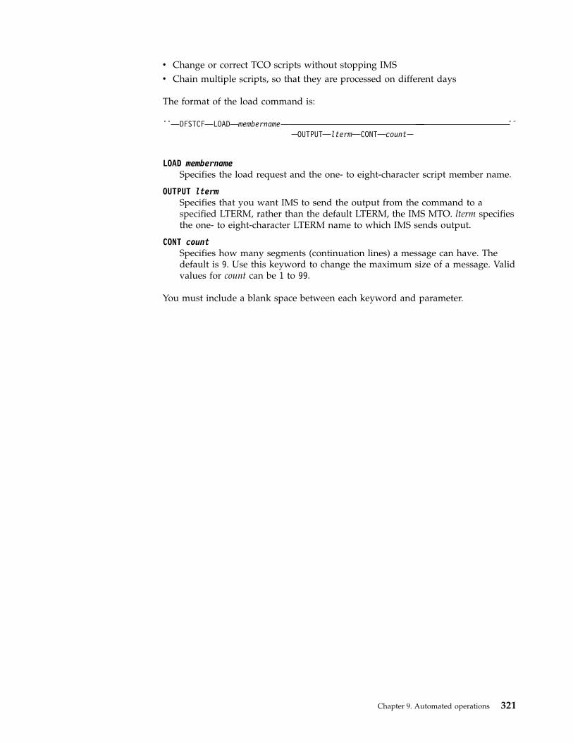
v Change or correct TCO scripts without stopping IMSv Chain multiple scripts, so that they are processed on different days
The format of the load command is:
►► DFSTCF LOAD membernameOUTPUT lterm CONT count
►◄
LOAD membernameSpecifies the load request and the one- to eight-character script member name.
OUTPUT ltermSpecifies that you want IMS to send the output from the command to aspecified LTERM, rather than the default LTERM, the IMS MTO. lterm specifiesthe one- to eight-character LTERM name to which IMS sends output.
CONT countSpecifies how many segments (continuation lines) a message can have. Thedefault is 9. Use this keyword to change the maximum size of a message. Validvalues for count can be 1 to 99.
You must include a blank space between each keyword and parameter.
Chapter 9. Automated operations 321

322 Operations and Automation
Chapter 10. Type-1 automated operator (AO) applicationprogram (GU, GN, CMD, and GCMD calls)
You can write type-1 automated operator (AO) application programs that willretrieve messages from the AO exit routine DFSAOUE0 (GU and GN calls), issue asubset of IMS operator commands (CMD call), or retrieve command responses forthe commands that are issued on the CMD call (GCMD call).Related concepts:Chapter 11, “Type-2 automated operator (AO) application program (GMSG, ICMD,and RCMD calls),” on page 333“Restart and recovery considerations” on page 338“IMS Automated Operator Interface (AOI)” on page 298
About the type-1 AO application program (GU, GN, CMD, and GCMDcalls)
The Automated Operator Interface (AOI) consists of several IMS functions thatallow installations to better monitor and control IMS activities. These functions canbe used separately or in conjunction with user-written programs and the masterterminal operator.
For example, one function includes a system definition option and an operatorcommand that gives the master terminal operator more control of the commandmessages sent to the secondary master terminal.
An AO application can issue a subset of IMS commands normally reserved for themaster terminal operator and receive responses to those commands by using thefollowing DL/I calls:v CMD (to issue commands and receive the first command response segment)v GCMD (to receive subsequent command response segments)
If there are any response segments, the first is returned to the user's I/O workarea. Subsequent segments are retrieved with GCMD. GCMD, similar to a get next(GN), places subsequent command response segments in the user's I/O work area.
The AO application receives control from IMS whenever a message with thecorrect transaction code has been queued for processing.
The following figure shows an AO application issuing a command with the CMDcall (1) and receiving the initial response segment to the command (2). The AOapplication uses the GCMD call (3) to obtain additional response segments (4), ifthey exist.
Another AOI function lets an AO application retrieve messages. GU and GN callsretrieve messages. The retrieved message can be from either:v A terminal from which the transaction was enteredv AO exit routine DFSAOUE0
© Copyright IBM Corp. 1974, 2017 323
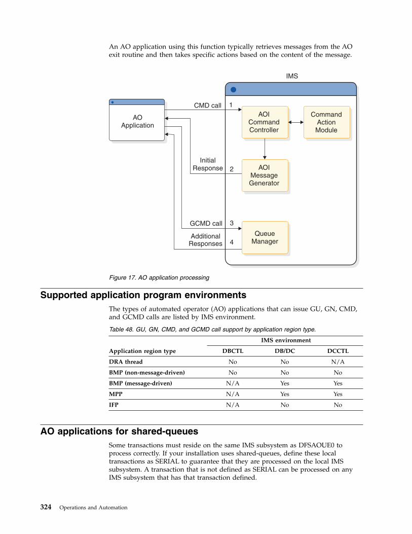
An AO application using this function typically retrieves messages from the AOexit routine and then takes specific actions based on the content of the message.
Supported application program environmentsThe types of automated operator (AO) applications that can issue GU, GN, CMD,and GCMD calls are listed by IMS environment.
Table 48. GU, GN, CMD, and GCMD call support by application region type.
Application region type
IMS environment
DBCTL DB/DC DCCTL
DRA thread No No N/A
BMP (non-message-driven) No No No
BMP (message-driven) N/A Yes Yes
MPP N/A Yes Yes
IFP N/A No No
AO applications for shared-queuesSome transactions must reside on the same IMS subsystem as DFSAOUE0 toprocess correctly. If your installation uses shared-queues, define these localtransactions as SERIAL to guarantee that they are processed on the local IMSsubsystem. A transaction that is not defined as SERIAL can be processed on anyIMS subsystem that has that transaction defined.
IMS
InitialResponse
GCMD call
AdditionalResponses
CMD call 1
2
3
4
AOApplication
CommandActionModule
QueueManager
AOIMessageGenerator
AOICommandController
Figure 17. AO application processing
324 Operations and Automation

Commands used with AO applications (CMD)To receive responses to these commands, use the GCMD call.
Format of commandsThe syntax and synonyms for commands are the same whether the command isentered using a CMD call or from a terminal. All messages returned in response toa CMD call or a command entered from the terminal are the same.
The general format of your I/O work area on a CMD call is:
LLZZ/verb KEYWORD1 P1 KEYWORD2 P2, P3. Comments
LL Two-byte field containing the length of the command text, including LLZZ
ZZ Two-byte field reserved for IMS
/ Indicates that an IMS command follows
verb The command you issued
KEYWORDxKeywords that apply to the command you issued
Px Parameters for the keywords you specified
. (period)End of the command
The length of a command is limited by the size of the I/O area; the size isspecified in the IOASIZE parameter in the PSBGEN macro during PCB generation.LL is the length of the command text. The size of the I/O area is the length of theactual command text, plus 4 bytes for LLZZ. The minimum size of the I/O workarea is 132 bytes. The fifth byte must be a slash (/), and the verb must followimmediately. The /BROADCAST and /LOOPTEST commands must have a periodbetween the command segment and text segment, and must be preceded by anLLZZ field that includes the size of the text. Comments can be added by placing aperiod (.) after the last parameter.
When issuing the /SSR command, do not code an end-of-message indicator(period). If a period is used, it is considered part of the text.
Responses to commandsThe execution of a command with a CMD call might result in a response thatcomprises one or more segments. The response is similar to that received by aterminal operator upon entering the same command. The maximum size responsereturned by IMS to the AO application is 132 bytes (including the 4-byte LLZZfield).
DFS messages that are the initial response to the command will be time-stampedeven if the NOTIMESTP keyword was coded on the COMM macro.
No response segments
This condition is indicated by a PCB status of blanks, showing that the executionof the command was successful or is in progress and would have resulted in oneof the following command responses had the command been entered from aterminal:
Chapter 10. Type-1 automated operator (AO) application program (GU, GN, CMD, and GCMD calls) 325
DFS058 XXX COMMAND COMPLETED (No EXCEPT phrase)DFS058 XXX COMMAND IN PROGRESS.
where XXX is the command issued by the automated operator.
DFS058 COMMAND COMPLETED indicates that no exceptional conditions are reported.
When DFS058 COMMAND IN PROGRESS is issued, one or more additional messages areissued to indicate whether the command was successful. These messages are sentto the master terminal rather than to AOI. Commands such as /DBDDUMP,/DBRECOVERY, /START DATABASE, /STOP DATABASE, and /SSR can result inmessage DFS058, followed by one or more asynchronous messages. Asynchronousmessages are not returned as responses to the AO application.
Response segments
Response segments are identical to the response to a command entered by theoperator, with preceding LLZZ and carriage control (optional) and trailing carriagecontrols (optional). A command might have executed successfully even though anon-blank PCB status code is returned. The status code CC indicates that one ormore response segments have been produced, which occurs when a commandpartially executes. For example, the EXCEPT condition of this message might bereturned as multiple segments.
Synchronization point processingWhen IMS is restarted or resets to an earlier checkpoint, it is possible that apreviously-issued command will be rescheduled for execution.
When the automated operator (AO) application regains control after a CMD call,IMS produces an initial response to the command. Command processing might beincomplete because additional IMS processing initiated by the command is still inprogress.
Command responses that are not retrieved by a GCMD call are discarded at asynchronization point or by another CMD call.
A synchronization point is reached when any of the following events occur:v The AO application requests the next input message with a GU call, assuming
the program is defined as MODE=SINGLE on the TRANSACT macro statement.v The program makes a CHKP call.v The program makes a SYNC call.v The program terminates.
Therefore, when IMS is restarted or resets to an earlier checkpoint, it is possiblethat a previously-issued command will be rescheduled for execution. An inputmessage, generated by an AO exit routine and destined for an AO application,could be rescheduled although the resources are no longer held by the AOapplication. PCB status codes indicate more precisely which condition, orcombination of conditions, exists.
Format identifiers for the /DISPLAY commandWhen a /DISPLAY command is issued from a CSLOMCMD or CSLOMI call, acommand response segment is always produced. If OPTION=AOPOUTPUT is
326 Operations and Automation
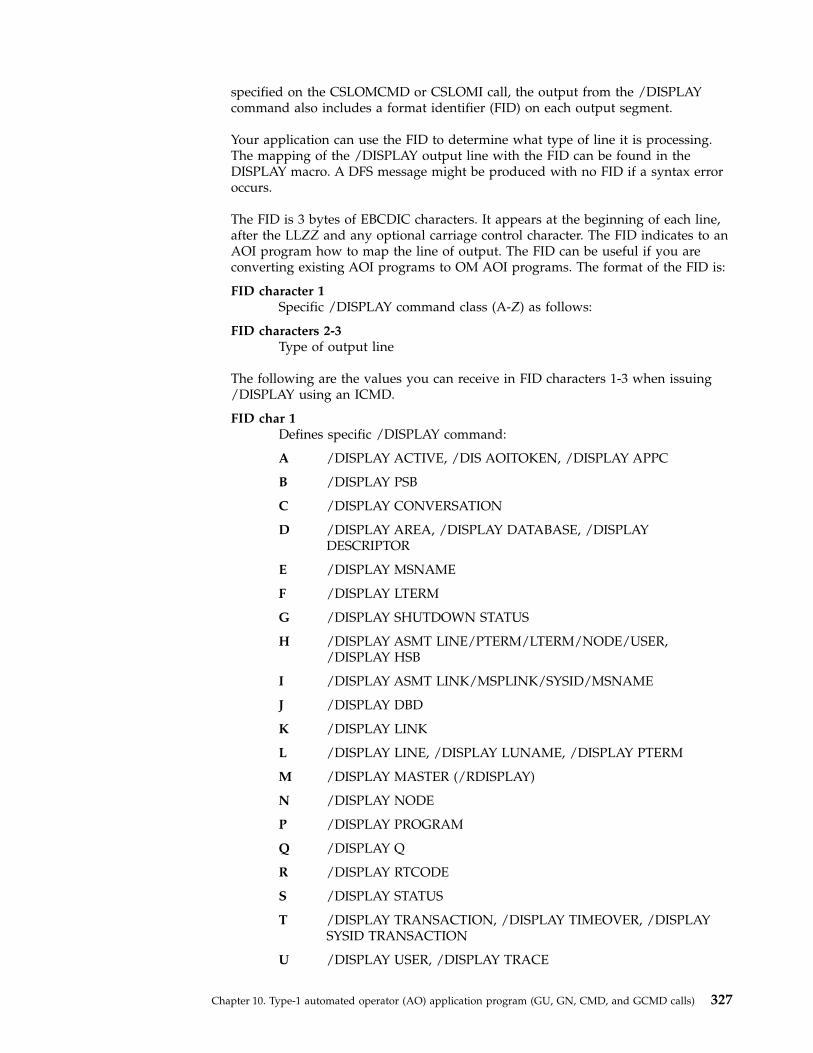
specified on the CSLOMCMD or CSLOMI call, the output from the /DISPLAYcommand also includes a format identifier (FID) on each output segment.
Your application can use the FID to determine what type of line it is processing.The mapping of the /DISPLAY output line with the FID can be found in theDISPLAY macro. A DFS message might be produced with no FID if a syntax erroroccurs.
The FID is 3 bytes of EBCDIC characters. It appears at the beginning of each line,after the LLZZ and any optional carriage control character. The FID indicates to anAOI program how to map the line of output. The FID can be useful if you areconverting existing AOI programs to OM AOI programs. The format of the FID is:
FID character 1Specific /DISPLAY command class (A-Z) as follows:
FID characters 2-3Type of output line
The following are the values you can receive in FID characters 1-3 when issuing/DISPLAY using an ICMD.
FID char 1Defines specific /DISPLAY command:
A /DISPLAY ACTIVE, /DIS AOITOKEN, /DISPLAY APPC
B /DISPLAY PSB
C /DISPLAY CONVERSATION
D /DISPLAY AREA, /DISPLAY DATABASE, /DISPLAYDESCRIPTOR
E /DISPLAY MSNAME
F /DISPLAY LTERM
G /DISPLAY SHUTDOWN STATUS
H /DISPLAY ASMT LINE/PTERM/LTERM/NODE/USER,/DISPLAY HSB
I /DISPLAY ASMT LINK/MSPLINK/SYSID/MSNAME
J /DISPLAY DBD
K /DISPLAY LINK
L /DISPLAY LINE, /DISPLAY LUNAME, /DISPLAY PTERM
M /DISPLAY MASTER (/RDISPLAY)
N /DISPLAY NODE
P /DISPLAY PROGRAM
Q /DISPLAY Q
R /DISPLAY RTCODE
S /DISPLAY STATUS
T /DISPLAY TRANSACTION, /DISPLAY TIMEOVER, /DISPLAYSYSID TRANSACTION
U /DISPLAY USER, /DISPLAY TRACE
Chapter 10. Type-1 automated operator (AO) application program (GU, GN, CMD, and GCMD calls) 327
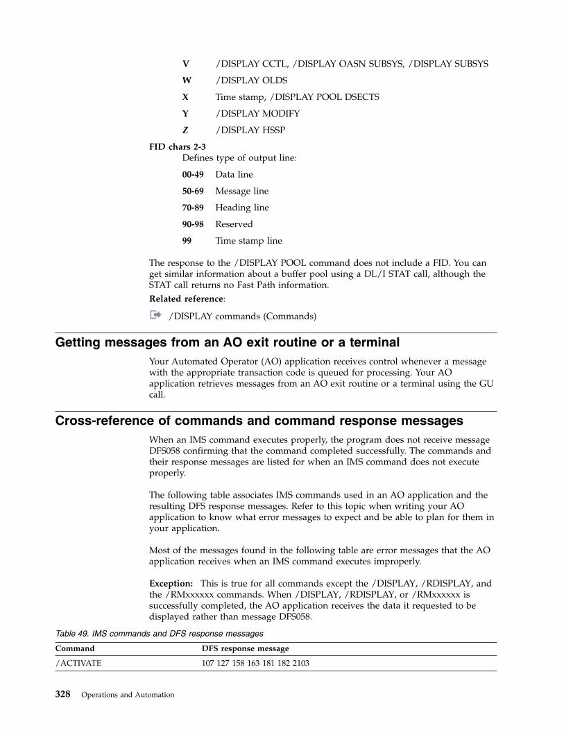
V /DISPLAY CCTL, /DISPLAY OASN SUBSYS, /DISPLAY SUBSYS
W /DISPLAY OLDS
X Time stamp, /DISPLAY POOL DSECTS
Y /DISPLAY MODIFY
Z /DISPLAY HSSP
FID chars 2-3Defines type of output line:
00-49 Data line
50-69 Message line
70-89 Heading line
90-98 Reserved
99 Time stamp line
The response to the /DISPLAY POOL command does not include a FID. You canget similar information about a buffer pool using a DL/I STAT call, although theSTAT call returns no Fast Path information.Related reference:
/DISPLAY commands (Commands)
Getting messages from an AO exit routine or a terminalYour Automated Operator (AO) application receives control whenever a messagewith the appropriate transaction code is queued for processing. Your AOapplication retrieves messages from an AO exit routine or a terminal using the GUcall.
Cross-reference of commands and command response messagesWhen an IMS command executes properly, the program does not receive messageDFS058 confirming that the command completed successfully. The commands andtheir response messages are listed for when an IMS command does not executeproperly.
The following table associates IMS commands used in an AO application and theresulting DFS response messages. Refer to this topic when writing your AOapplication to know what error messages to expect and be able to plan for them inyour application.
Most of the messages found in the following table are error messages that the AOapplication receives when an IMS command executes improperly.
Exception: This is true for all commands except the /DISPLAY, /RDISPLAY, andthe /RMxxxxxx commands. When /DISPLAY, /RDISPLAY, or /RMxxxxxx issuccessfully completed, the AO application receives the data it requested to bedisplayed rather than message DFS058.
Table 49. IMS commands and DFS response messages
Command DFS response message
/ACTIVATE 107 127 158 163 181 182 2103
328 Operations and Automation
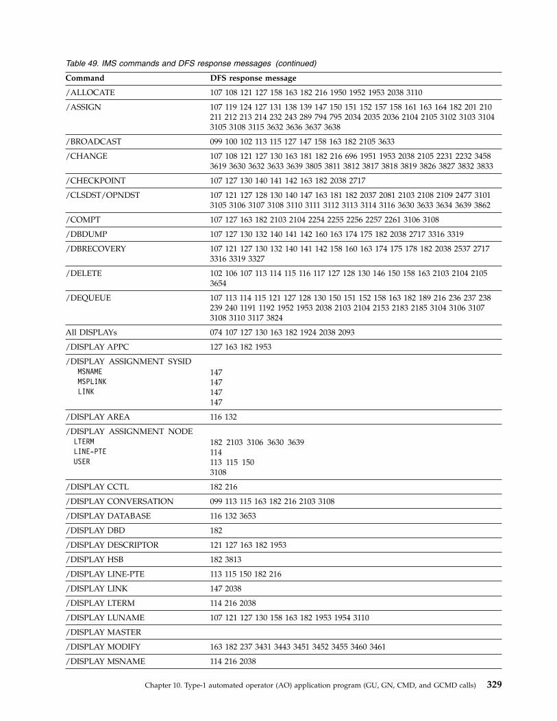
Table 49. IMS commands and DFS response messages (continued)
Command DFS response message
/ALLOCATE 107 108 121 127 158 163 182 216 1950 1952 1953 2038 3110
/ASSIGN 107 119 124 127 131 138 139 147 150 151 152 157 158 161 163 164 182 201 210211 212 213 214 232 243 289 794 795 2034 2035 2036 2104 2105 3102 3103 31043105 3108 3115 3632 3636 3637 3638
/BROADCAST 099 100 102 113 115 127 147 158 163 182 2105 3633
/CHANGE 107 108 121 127 130 163 181 182 216 696 1951 1953 2038 2105 2231 2232 34583619 3630 3632 3633 3639 3805 3811 3812 3817 3818 3819 3826 3827 3832 3833
/CHECKPOINT 107 127 130 140 141 142 163 182 2038 2717
/CLSDST/OPNDST 107 121 127 128 130 140 147 163 181 182 2037 2081 2103 2108 2109 2477 31013105 3106 3107 3108 3110 3111 3112 3113 3114 3116 3630 3633 3634 3639 3862
/COMPT 107 127 163 182 2103 2104 2254 2255 2256 2257 2261 3106 3108
/DBDUMP 107 127 130 132 140 141 142 160 163 174 175 182 2038 2717 3316 3319
/DBRECOVERY 107 121 127 130 132 140 141 142 158 160 163 174 175 178 182 2038 2537 27173316 3319 3327
/DELETE 102 106 107 113 114 115 116 117 127 128 130 146 150 158 163 2103 2104 21053654
/DEQUEUE 107 113 114 115 121 127 128 130 150 151 152 158 163 182 189 216 236 237 238239 240 1191 1192 1952 1953 2038 2103 2104 2153 2183 2185 3104 3106 31073108 3110 3117 3824
All DISPLAYs 074 107 127 130 163 182 1924 2038 2093
/DISPLAY APPC 127 163 182 1953
/DISPLAY ASSIGNMENT SYSIDMSNAMEMSPLINKLINK
147147147147
/DISPLAY AREA 116 132
/DISPLAY ASSIGNMENT NODELTERMLINE-PTEUSER
182 2103 3106 3630 3639114113 115 1503108
/DISPLAY CCTL 182 216
/DISPLAY CONVERSATION 099 113 115 163 182 216 2103 3108
/DISPLAY DATABASE 116 132 3653
/DISPLAY DBD 182
/DISPLAY DESCRIPTOR 121 127 163 182 1953
/DISPLAY HSB 182 3813
/DISPLAY LINE-PTE 113 115 150 182 216
/DISPLAY LINK 147 2038
/DISPLAY LTERM 114 216 2038
/DISPLAY LUNAME 107 121 127 130 158 163 182 1953 1954 3110
/DISPLAY MASTER
/DISPLAY MODIFY 163 182 237 3431 3443 3451 3452 3455 3460 3461
/DISPLAY MSNAME 114 216 2038
Chapter 10. Type-1 automated operator (AO) application program (GU, GN, CMD, and GCMD calls) 329
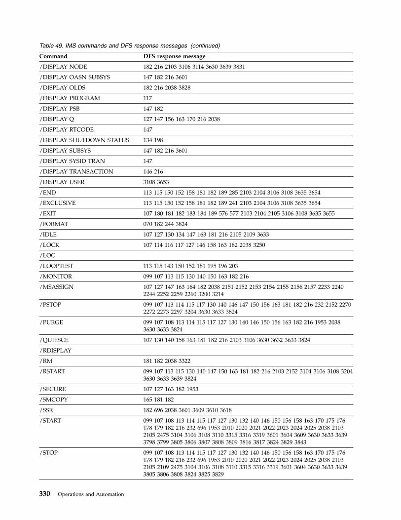
Table 49. IMS commands and DFS response messages (continued)
Command DFS response message
/DISPLAY NODE 182 216 2103 3106 3114 3630 3639 3831
/DISPLAY OASN SUBSYS 147 182 216 3601
/DISPLAY OLDS 182 216 2038 3828
/DISPLAY PROGRAM 117
/DISPLAY PSB 147 182
/DISPLAY Q 127 147 156 163 170 216 2038
/DISPLAY RTCODE 147
/DISPLAY SHUTDOWN STATUS 134 198
/DISPLAY SUBSYS 147 182 216 3601
/DISPLAY SYSID TRAN 147
/DISPLAY TRANSACTION 146 216
/DISPLAY USER 3108 3653
/END 113 115 150 152 158 181 182 189 285 2103 2104 3106 3108 3635 3654
/EXCLUSIVE 113 115 150 152 158 181 182 189 241 2103 2104 3106 3108 3635 3654
/EXIT 107 180 181 182 183 184 189 576 577 2103 2104 2105 3106 3108 3635 3655
/FORMAT 070 182 244 3824
/IDLE 107 127 130 134 147 163 181 216 2105 2109 3633
/LOCK 107 114 116 117 127 146 158 163 182 2038 3250
/LOG
/LOOPTEST 113 115 143 150 152 181 195 196 203
/MONITOR 099 107 113 115 130 140 150 163 182 216
/MSASSIGN 107 127 147 163 164 182 2038 2151 2152 2153 2154 2155 2156 2157 2233 22402244 2252 2259 2260 3200 3214
/PSTOP 099 107 113 114 115 117 130 140 146 147 150 156 163 181 182 216 232 2152 22702272 2273 2297 3204 3630 3633 3824
/PURGE 099 107 108 113 114 115 117 127 130 140 146 150 156 163 182 216 1953 20383630 3633 3824
/QUIESCE 107 130 140 158 163 181 182 216 2103 3106 3630 3632 3633 3824
/RDISPLAY
/RM 181 182 2038 3322
/RSTART 099 107 113 115 130 140 147 150 163 181 182 216 2103 2152 3104 3106 3108 32043630 3633 3639 3824
/SECURE 107 127 163 182 1953
/SMCOPY 165 181 182
/SSR 182 696 2038 3601 3609 3610 3618
/START 099 107 108 113 114 115 117 127 130 132 140 146 150 156 158 163 170 175 176178 179 182 216 232 696 1953 2010 2020 2021 2022 2023 2024 2025 2038 21032105 2475 3104 3106 3108 3110 3315 3316 3319 3601 3604 3609 3630 3633 36393798 3799 3805 3806 3807 3808 3809 3816 3817 3824 3829 3843
/STOP 099 107 108 113 114 115 117 127 130 132 140 146 150 156 158 163 170 175 176178 179 182 216 232 696 1953 2010 2020 2021 2022 2023 2024 2025 2038 21032105 2109 2475 3104 3106 3108 3110 3315 3316 3319 3601 3604 3630 3633 36393805 3806 3808 3824 3825 3829
330 Operations and Automation

Table 49. IMS commands and DFS response messages (continued)
Command DFS response message
/SWITCH 107 127 140 163 696 2038 3810 3813 3814 3824
/TEST 113 115 143 150 152 158 181 182 189 196 282 283 284 2103 2104 2158 3106 31083635 3654
/TRACE 107 108 113 130 147 150 158 163 182 216 237 279 280 281 314 775 1953 20282029 2030 2031 2032 2038 2093 2103 2104 2155 2460 3106 3108 3110 3630 36333639 3813
/UNLOCK 107 114 116 117 127 146 158 163 182 2038 3250 3813
/VUNLOAD 107 130 140 163 182 216
Sample AO application (UETRANS)A sample AO application is available from the IMS library (IMS.ADFSSRC, membername UETRANS). The sample shows use of AOI by an AO application and anassociated AO exit routine. The AO application is written in PL/I for theOptimizing Compiler.
The sample AO application:v Accepts only messages originating from the exit routine (indicated by a CG PCB
status code).v Upon receipt of a DFS994 message, looks for the character string EMERGENCY. If
found, it issues the command /RSTART LINE ALL. Otherwise, it issues thefollowing commands:/RSTART LINE ALL/START DATABASE ALL/START TRAN ALL
v Upon receipt of a terminal error message, it issues the command /RDISPLAY todetermine on which line and PTERM is the master terminal. If the erroroccurred on that line, it issues a /DISPLAY LINE ALL command to determinethe first available started line, and reassigns the master terminal to that line andPTERM.
v Upon receipt of an /ASSIGN command, if the response is a DFS119 message,reissues the command until it is successful. If the response is a DFS138 message,it restarts the line with an /RSTART command and reissues the /ASSIGNcommand. It reissues the /ASSIGN command a maximum of 20 times; if thecommand is not successfully completed after the 20th attempt, an appropriatemessage is issued.
The associated AO exit routine is assumed to:v Pass all DFS994 (checkpoint identifier) messages to the AO application.v Pass all terminal error messages to the AO application. The line number of the
terminal in error is placed in the last 20 bytes of the buffer. Message numberspassed are DFS001, DFS025, DFS026, DFS027, DFS029, DFS072, DFS250, DFS251,DFS253, DFS260, DFS269, DFS973, DFS998.
v Pass all /ASSIGN commands that receive a DFS119 or DFS138 message to theAO application. These messages indicate that either the LTERM is busy or theline is not started and cannot be reassigned.
v Ignore all other messages.
Chapter 10. Type-1 automated operator (AO) application program (GU, GN, CMD, and GCMD calls) 331

332 Operations and Automation
Chapter 11. Type-2 automated operator (AO) applicationprogram (GMSG, ICMD, and RCMD calls)
You can write type-2 automated operator (AO) application programs that willretrieve messages from an AOIE type exit routine (GMSG call), issue a subset ofIMS operator commands (ICMD call), or retrieve command responses forcommands issued on the ICMD call (RCMD calls).Related concepts:Chapter 10, “Type-1 automated operator (AO) application program (GU, GN,CMD, and GCMD calls),” on page 323“Tools for automated operations” on page 298“IMS Automated Operator Interface (AOI)” on page 298
About the type-2 AO application program (GMSG, ICMD, and RCMDcalls)
The automated operator (AO) application can help you monitor and control IMSactivities. You can use it separately or with a type-2 automated operator exit(DFSAOE00 or another AOIE type user exit).
This AO application can:v Issue DL/I calls to retrieve messages from an AOIE type exit routine (GMSG
call).v Issue a subset of IMS operator commands (ICMD call).v Retrieve responses to those commands from the AOIE type exit routine (RCMD
call).
Retrieving messages (GMSG call)
When an AOIE type exit routine is used to route messages to an AO application,the IMS message queues are not used. Instead, applications that cannot access themessage queues or that do not want to use the message queues retrieve themessages from the AOIE type exit routine.
The AO application retrieves messages using the GMSG call. GMSG associates anAOI token name with a message. The application passes an 8-byte AOI token toIMS, and IMS returns to the application a message associated with the AOI token.By using different AOI tokens, the AOIE type exit routine can direct messages todifferent AO applications.
The GMSG call, specifying an 8-byte token, retrieves the first segment of themessage associated with the token. Subsequent GMSG calls, with no tokenspecified, retrieve the second through n segments of a multi-segment message. Ifan application needs all segments of a multi-segment message, it must issue GMSGuntil all segments are retrieved before issuing another GMSG call with a tokenspecified. IMS discards all remaining message segments from the previous GMSGcall when a new GMSG call specifying an AOI token is issued from the same AOapplication.
© Copyright IBM Corp. 1974, 2017 333
An application can specify a wait on the GMSG call. If there are no messages forthe specified AOI token, the application is put into a wait state until a message isavailable. The decision to wait is specified by the application, unlike a WFI (waitfor input) transaction where the wait is specified in the transaction definition.
Defining the AOI token
You define the AOI token value. You also decide how the AO application gets theAOI token value. Some possible methods for doing these follow:v The token could be a hard-coded value understood by both the AOIE type exit
routine and the AO application.v A naming convention could be established that relates the name of an AOI token
to an AO application. For example, an AO application with the name ABCAOI02might use AOI token AOI02nnn.
v The AO application could issue an ICMD '/LOG data ' call with the AOI tokenin the data. The application would then issue a GMSG call with WAITAOIspecified for the AOI token named in the LOG call.The AOIE type exit routine will see the ICMD and can parse the data in theLOG command to get the AOI token name and any other information in thedata. The AOIE type exit routine inserts messages to the AOI token name; themessages are then returned to your AO application when the GMSG call isissued.
v The AOIE type exit routine could create a dynamic AOI token when it processesan IMS message. Then the AOIE type exit routine could issue an SVC 34 to starta BMP. The START command can override the APARM parameter on the EXECstatement. The APARM parameter is a way of passing information to the AOapplication. To retrieve the value specified on the APARM parameter, the AOapplication can issue the DL/I INQY call.
v The AOIE type exit routine could store an AOI token in an area that both theAOIE type exit routine and the AO application have access to. The AOapplication, when it starts, could get the AOI token from this area.
Related reference:
DL/I calls for IMS TM system services (Application Programming APIs)
Issuing commands and retrieving command responses (ICMDand RCMD calls)
ICMD issues an IMS command and retrieves the first command response segmentif one exists. RCMD retrieves subsequent command response segments. When theresponse to an ICMD call results in a multi-segment message, you might want toretrieve all message segments.
If you need all message segments, you must issue RCMDs until all segments areretrieved before issuing another ICMD call. IMS discards all remaining messagesegments from the previous ICMD call when a new ICMD is issued from the sameAO application.
Restriction: All messages queued to an AO application by an AOIE type exitroutine remain in the IMS subsystem to which they are queued. Only AOapplications in the local subsystem can issue a DL/I GMSG call to access thequeued messages. Because these messages are not written to a share-queuestructure, applications on other IMS subsystems cannot access them.
334 Operations and Automation
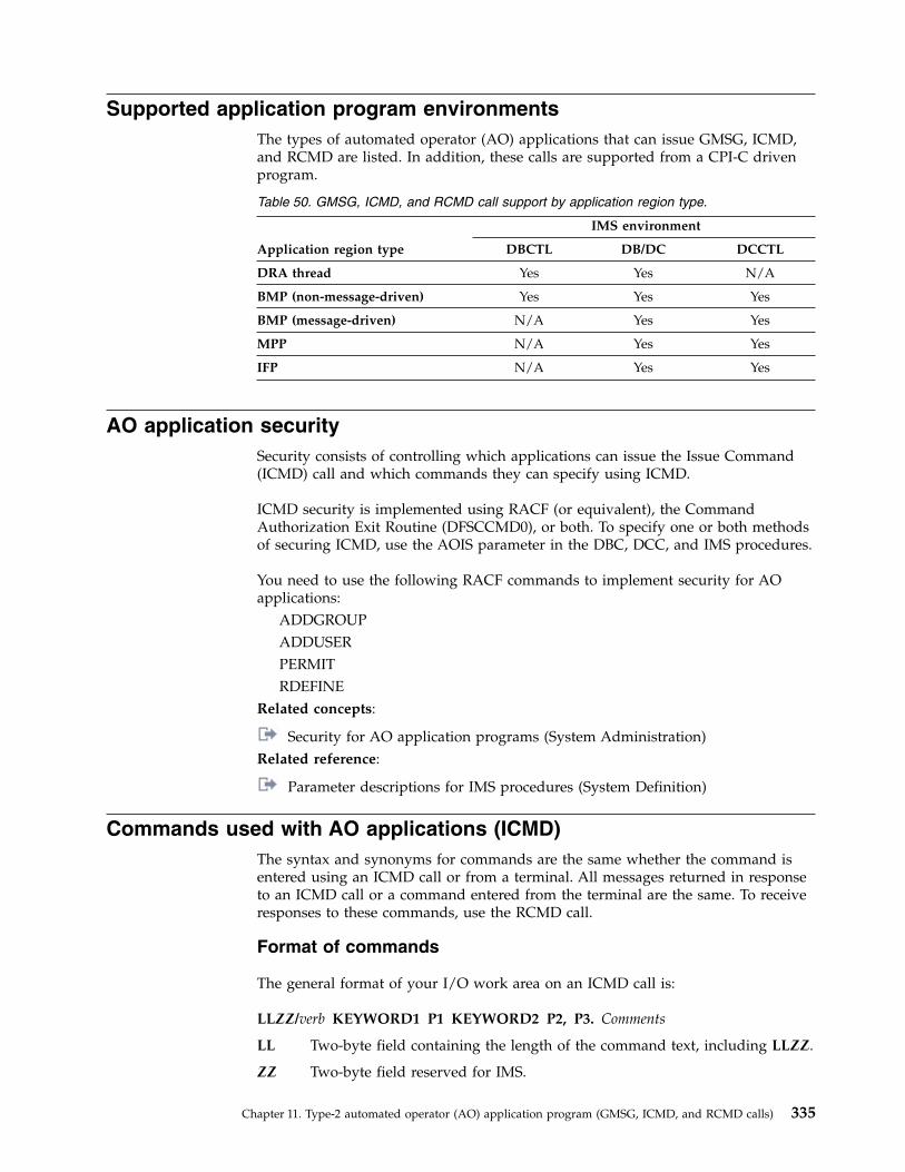
Supported application program environmentsThe types of automated operator (AO) applications that can issue GMSG, ICMD,and RCMD are listed. In addition, these calls are supported from a CPI-C drivenprogram.
Table 50. GMSG, ICMD, and RCMD call support by application region type.
Application region type
IMS environment
DBCTL DB/DC DCCTL
DRA thread Yes Yes N/A
BMP (non-message-driven) Yes Yes Yes
BMP (message-driven) N/A Yes Yes
MPP N/A Yes Yes
IFP N/A Yes Yes
AO application securitySecurity consists of controlling which applications can issue the Issue Command(ICMD) call and which commands they can specify using ICMD.
ICMD security is implemented using RACF (or equivalent), the CommandAuthorization Exit Routine (DFSCCMD0), or both. To specify one or both methodsof securing ICMD, use the AOIS parameter in the DBC, DCC, and IMS procedures.
You need to use the following RACF commands to implement security for AOapplications:
ADDGROUPADDUSERPERMITRDEFINE
Related concepts:
Security for AO application programs (System Administration)Related reference:
Parameter descriptions for IMS procedures (System Definition)
Commands used with AO applications (ICMD)The syntax and synonyms for commands are the same whether the command isentered using an ICMD call or from a terminal. All messages returned in responseto an ICMD call or a command entered from the terminal are the same. To receiveresponses to these commands, use the RCMD call.
Format of commands
The general format of your I/O work area on an ICMD call is:
LLZZ/verb KEYWORD1 P1 KEYWORD2 P2, P3. Comments
LL Two-byte field containing the length of the command text, including LLZZ.
ZZ Two-byte field reserved for IMS.
Chapter 11. Type-2 automated operator (AO) application program (GMSG, ICMD, and RCMD calls) 335

/ or CRCIndicates an IMS command follows. CRC (command recognition character)rather than a slash (/) is used in the DBCTL environment.
verb The command you issued.
KEYWORDxKeywords that apply to the command you issued.
Px Parameters for the keywords you specified.
. (period)End of the command.
The length of a command is limited by the size of the I/O area; the size isspecified in the IOASIZE parameter in the PSBGEN macro during PCB generation.LL is the length of the command text. The size of the I/O area is the length of theactual command text, plus 4 bytes for LLZZ. The minimum size of the I/O workarea is 132 bytes.
The fifth byte must be a slash (/) (or CRC for DBCTL), and the verb must followimmediately. The /BROADCAST and /LOOPTEST commands must have a periodbetween the command segment and text segment, and must be preceded by anLLZZ field that includes the size of the text. Comments can be added by placing aperiod (.) after the last parameter.
When issuing the /SSR command, do not code an end-of-message indicator(period). If a period is used, it is considered part of the text.
Responses to commandsThe execution of a command with an ICMD call might result in a response thatcomprises one or more segments. The response is similar to that received by aterminal operator upon entering the same command. The maximum size of theresponse returned by IMS to the AO application is 132 bytes (including the 4-byteLLZZ field). DFS messages that are the initial response to the command aretime-stamped even if the NOTIMESTP keyword is coded on the COMM macro.
No response segments
This condition is indicated when AIB return and reason codes are zero and thelength of the message returned is zero. These indicators tell you execution of thecommand was successful or is in progress and would have resulted in one of thefollowing command responses had the command been entered from a terminal:DFS058 XXX COMMAND COMPLETED (No EXCEPT phrase)DFS058 XXX COMMAND IN PROGRESS.
where XXX is the command issued by the automated operator.
When DFS058 COMMAND COMPLETED is issued, no exceptional conditions are reported.
When DFS058 COMMAND IN PROGRESS is issued, one or more additional messages areissued to indicate whether the command was successful. These messages are sentto the master terminal rather than to AOI. Commands such as /DBDDUMP,/DBRECOVERY, /START DATABASE, /STOP DATABASE, and /SSR can result inmessage DFS058, followed by one or more asynchronous messages. Asynchronousmessages are not returned as responses to the AO application.
336 Operations and Automation
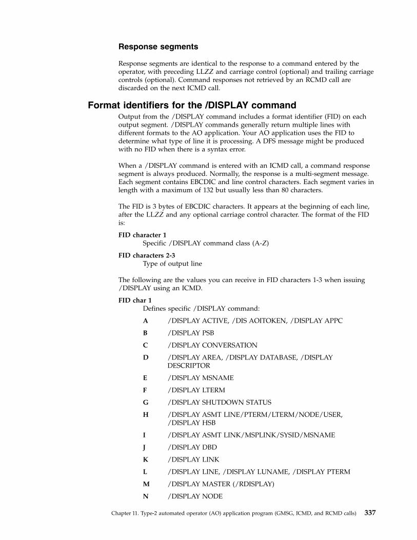
Response segments
Response segments are identical to the response to a command entered by theoperator, with preceding LLZZ and carriage control (optional) and trailing carriagecontrols (optional). Command responses not retrieved by an RCMD call arediscarded on the next ICMD call.
Format identifiers for the /DISPLAY commandOutput from the /DISPLAY command includes a format identifier (FID) on eachoutput segment. /DISPLAY commands generally return multiple lines withdifferent formats to the AO application. Your AO application uses the FID todetermine what type of line it is processing. A DFS message might be producedwith no FID when there is a syntax error.
When a /DISPLAY command is entered with an ICMD call, a command responsesegment is always produced. Normally, the response is a multi-segment message.Each segment contains EBCDIC and line control characters. Each segment varies inlength with a maximum of 132 but usually less than 80 characters.
The FID is 3 bytes of EBCDIC characters. It appears at the beginning of each line,after the LLZZ and any optional carriage control character. The format of the FIDis:
FID character 1Specific /DISPLAY command class (A-Z)
FID characters 2-3Type of output line
The following are the values you can receive in FID characters 1-3 when issuing/DISPLAY using an ICMD.
FID char 1Defines specific /DISPLAY command:
A /DISPLAY ACTIVE, /DIS AOITOKEN, /DISPLAY APPC
B /DISPLAY PSB
C /DISPLAY CONVERSATION
D /DISPLAY AREA, /DISPLAY DATABASE, /DISPLAYDESCRIPTOR
E /DISPLAY MSNAME
F /DISPLAY LTERM
G /DISPLAY SHUTDOWN STATUS
H /DISPLAY ASMT LINE/PTERM/LTERM/NODE/USER,/DISPLAY HSB
I /DISPLAY ASMT LINK/MSPLINK/SYSID/MSNAME
J /DISPLAY DBD
K /DISPLAY LINK
L /DISPLAY LINE, /DISPLAY LUNAME, /DISPLAY PTERM
M /DISPLAY MASTER (/RDISPLAY)
N /DISPLAY NODE
Chapter 11. Type-2 automated operator (AO) application program (GMSG, ICMD, and RCMD calls) 337

P /DISPLAY PROGRAM
Q /DISPLAY Q
R /DISPLAY RTCODE
S /DISPLAY STATUS
T /DISPLAY TRANSACTION, /DISPLAY TIMEOVER, /DISPLAYSYSID TRANSACTION
U /DISPLAY USER, /DISPLAY TRACE
V /DISPLAY CCTL, /DISPLAY OASN SUBSYS, /DISPLAY SUBSYS
W /DISPLAY OLDS
X Time stamp, /DISPLAY POOL DSECTS
Y /DISPLAY MODIFY
Z /DISPLAY HSSP
FID chars 2-3Defines type of output line:
00-49 Data line
50-69 Message line
70-89 Heading line
90-98 Reserved
99 Time stamp line
The response to the /DISPLAY POOL command does not include a FID. You canget similar information about a buffer pool using a DL/I STAT call, although theSTAT call returns no Fast Path information.
Restart and recovery considerationsMessages directed to an automated operator (AO) application cannot be recoveredat restart because the automated operator interface (AOI) does not use the IMSmessage queues in this environment.
When a recoverable command is issued by the ICMD call, log record X'02' isgenerated when the command completes. If a failure occurs, the command is notreprocessed at restart time. If a failure occurs after a command is completed butbefore the command response is returned, the command response is lost. Your AOapplication could issue the appropriate /DISPLAY command, if applicable, todetermine if the ICMD call executed successfully (as is required with asynchronouscommands).Related concepts:Chapter 10, “Type-1 automated operator (AO) application program (GU, GN,CMD, and GCMD calls),” on page 323“AOI and the IMS environments” on page 303
Sample AO application (DFSAOPGM)A sample AO application is available from the IMS library IMS.ADFSSMPL, membername DFSAOPGM.
338 Operations and Automation
Notices
This information was developed for products and services offered in the US. Thismaterial might be available from IBM in other languages. However, you may berequired to own a copy of the product or product version in that language in orderto access it.
IBM may not offer the products, services, or features discussed in this document inother countries. Consult your local IBM representative for information on theproducts and services currently available in your area. Any reference to an IBMproduct, program, or service is not intended to state or imply that only that IBMproduct, program, or service may be used. Any functionally equivalent product,program, or service that does not infringe any IBM intellectual property right maybe used instead. However, it is the user's responsibility to evaluate and verify theoperation of any non-IBM product, program, or service.
IBM may have patents or pending patent applications covering subject matterdescribed in this document. The furnishing of this document does not grant youany license to these patents. You can send license inquiries, in writing, to:
IBM Director of LicensingIBM CorporationNorth Castle Drive, MD-NC119Armonk, NY 10504-1785US
For license inquiries regarding double-byte character set (DBCS) information,contact the IBM Intellectual Property Department in your country or sendinquiries, in writing, to:
Intellectual Property LicensingLegal and Intellectual Property LawIBM Japan, Ltd.19-21, Nihonbashi-Hakozakicho, Chuo-kuTokyo 103-8510, Japan
INTERNATIONAL BUSINESS MACHINES CORPORATION PROVIDES THISPUBLICATION “AS IS” WITHOUT WARRANTY OF ANY KIND, EITHEREXPRESS OR IMPLIED, INCLUDING, BUT NOT LIMITED TO, THE IMPLIEDWARRANTIES OF NON-INFRINGEMENT, MERCHANTABILITY OR FITNESSFOR A PARTICULAR PURPOSE. Some jurisdictions do not allow disclaimer ofexpress or implied warranties in certain transactions, therefore, this statement maynot apply to you.
This information could include technical inaccuracies or typographical errors.Changes are periodically made to the information herein; these changes will beincorporated in new editions of the publication. IBM may make improvementsand/or changes in the product(s) and/or the program(s) described in thispublication at any time without notice.
Any references in this information to non-IBM websites are provided forconvenience only and do not in any manner serve as an endorsement of those
© Copyright IBM Corp. 1974, 2017 339
websites. The materials at those websites are not part of the materials for this IBMproduct and use of those websites is at your own risk.
IBM may use or distribute any of the information you provide in any way itbelieves appropriate without incurring any obligation to you.
Licensees of this program who wish to have information about it for the purposeof enabling: (i) the exchange of information between independently createdprograms and other programs (including this one) and (ii) the mutual use of theinformation which has been exchanged, should contact:
IBM Director of LicensingIBM CorporationNorth Castle Drive, MD-NC119Armonk, NY 10504-1785US
Such information may be available, subject to appropriate terms and conditions,including in some cases, payment of a fee.
The licensed program described in this document and all licensed materialavailable for it are provided by IBM under terms of the IBM Customer Agreement,IBM International Program License Agreement or any equivalent agreementbetween us.
The performance data and client examples cited are presented for illustrativepurposes only. Actual performance results may vary depending on specificconfigurations and operating conditions.
Information concerning non-IBM products was obtained from the suppliers ofthose products, their published announcements or other publicly available sources.IBM has not tested those products and cannot confirm the accuracy ofperformance, compatibility or any other claims related to non-IBM products.Questions on the capabilities of non-IBM products should be addressed to thesuppliers of those products.
Statements regarding IBM's future direction or intent are subject to change orwithdrawal without notice, and represent goals and objectives only.
This information contains examples of data and reports used in daily businessoperations. To illustrate them as completely as possible, the examples include thenames of individuals, companies, brands, and products. All of these names arefictitious and any similarity to actual people or business enterprises is entirelycoincidental.
COPYRIGHT LICENSE:
This information contains sample application programs in source language, whichillustrate programming techniques on various operating platforms. You may copy,modify, and distribute these sample programs in any form without payment toIBM, for the purposes of developing, using, marketing or distributing applicationprograms conforming to the application programming interface for the operatingplatform for which the sample programs are written. These examples have notbeen thoroughly tested under all conditions. IBM, therefore, cannot guarantee orimply reliability, serviceability, or function of these programs. The sample
340 Operations and Automation

programs are provided "AS IS", without warranty of any kind. IBM shall not beliable for any damages arising out of your use of the sample programs.
Each copy or any portion of these sample programs or any derivative workmust include a copyright notice as follows:© (your company name) (year).Portions of this code are derived from IBM Corp. Sample Programs.© Copyright IBM Corp. _enter the year or years_.
TrademarksIBM, the IBM logo, and ibm.com® are trademarks or registered trademarks ofInternational Business Machines Corp., registered in many jurisdictions worldwide.Other product and service names might be trademarks of IBM or other companies.A current list of IBM trademarks is available on the web at "Copyright andtrademark information" at http://www.ibm.com/legal/copytrade.shtml.
Adobe, the Adobe logo, and the PostScript logo are either registered trademarks ortrademarks of Adobe Systems Incorporated in the United States, and/or othercountries.
Linux is a registered trademark of Linus Torvalds in the United States, othercountries, or both.
Microsoft, Windows, Windows NT, and the Windows logo are trademarks ofMicrosoft Corporation in the United States, other countries, or both.
Java and all Java-based trademarks and logos are trademarks or registeredtrademarks of Oracle and/or its affiliates.
UNIX is a registered trademark of The Open Group in the United States and othercountries.
Terms and conditions for product documentationPermissions for the use of these publications are granted subject to the followingterms and conditions.
Applicability
These terms and conditions are in addition to any terms of use for the IBMwebsite.
Personal use
You may reproduce these publications for your personal, noncommercial useprovided that all proprietary notices are preserved. You may not distribute, displayor make derivative work of these publications, or any portion thereof, without theexpress consent of IBM.
Commercial use
You may reproduce, distribute and display these publications solely within yourenterprise provided that all proprietary notices are preserved. You may not makederivative works of these publications, or reproduce, distribute or display these
Notices 341
publications or any portion thereof outside your enterprise, without the expressconsent of IBM.
Rights
Except as expressly granted in this permission, no other permissions, licenses orrights are granted, either express or implied, to the publications or anyinformation, data, software or other intellectual property contained therein.
IBM reserves the right to withdraw the permissions granted herein whenever, in itsdiscretion, the use of the publications is detrimental to its interest or, asdetermined by IBM, the above instructions are not being properly followed.
You may not download, export or re-export this information except in fullcompliance with all applicable laws and regulations, including all United Statesexport laws and regulations.
IBM MAKES NO GUARANTEE ABOUT THE CONTENT OF THESEPUBLICATIONS. THE PUBLICATIONS ARE PROVIDED "AS-IS" AND WITHOUTWARRANTY OF ANY KIND, EITHER EXPRESSED OR IMPLIED, INCLUDINGBUT NOT LIMITED TO IMPLIED WARRANTIES OF MERCHANTABILITY,NON-INFRINGEMENT, AND FITNESS FOR A PARTICULAR PURPOSE.
IBM Online Privacy StatementIBM Software products, including software as a service solutions, (“SoftwareOfferings”) may use cookies or other technologies to collect product usageinformation, to help improve the end user experience, to tailor interactions withthe end user or for other purposes. In many cases no personally identifiableinformation is collected by the Software Offerings. Some of our Software Offeringscan help enable you to collect personally identifiable information. If this SoftwareOffering uses cookies to collect personally identifiable information, specificinformation about this offering’s use of cookies is set forth below.
This Software Offering does not use cookies or other technologies to collectpersonally identifiable information.
If the configurations deployed for this Software Offering provide you as customerthe ability to collect personally identifiable information from end users via cookiesand other technologies, you should seek your own legal advice about any lawsapplicable to such data collection, including any requirements for notice andconsent.
For more information about the use of various technologies, including cookies, forthese purposes, See IBM’s Privacy Policy at http://www.ibm.com/privacy andIBM’s Online Privacy Statement at http://www.ibm.com/privacy/details thesection entitled “Cookies, Web Beacons and Other Technologies” and the “IBMSoftware Products and Software-as-a-Service Privacy Statement” athttp://www.ibm.com/software/info/product-privacy.
342 Operations and Automation

Bibliography
This bibliography lists all of the publications in the IMS 15 library.
Title Acronym Order numberIMS Version 15 Application Programming APG SC27-6778IMS Version 15 Application Programming APIs APR SC27-6779IMS Version 15 Commands, Volume 1: IMSCommands A-M
CR1 SC27-6780
IMS Version 15 Commands, Volume 2: IMSCommands N-V
CR2 SC27-6781
IMS Version 15 Commands, Volume 3: IMSComponent and z/OS Commands
CR3 SC27-6782
IMS Version 15 Communications and Connections CCG SC27-6783IMS Version 15 Database Administration DAG SC27-6784IMS Version 15 Database Utilities DUR SC27-6785IMS Version 15 Diagnosis DGR GC27-6786IMS Version 15 Exit Routines ERR SC27-6787SC19-
4208IMS Version 15 Installation INS SC27-6788IMS Version 15 Licensed Program Specifications LPS GC27-6799IMS Version 15 Messages and Codes, Volume 1: DFSMessages
MC1 GC27-6789
IMS Version 15 Messages and Codes, Volume 2:Non-DFS Messages
MC2 GC27-6790
IMS Version 15 Messages and Codes, Volume 3: IMSAbend Codes
MC3 GC27-6791
IMS Version 15 Messages and Codes, Volume 4: IMSComponent Codes
MC4 GC27-6792
IMS Version 15 Operations and Automation OAG SC27-6793IMS Version 15 Release Planning RPG GC27-6794IMS Version 15 System Administration SAG SC27-6795IMS Version 15 System Definition SDG GC27-6796IMS Version 15 System Programming APIs SPR SC27-6797IMS Version 15 System Utilities SUR SC27-6798
© Copyright IBM Corp. 1974, 2017 343

344 Operations and Automation
Index
Special characters/ACTIVATE command 25/ASSIGN command 25
ETO 36terminals 25
/BROADCAST command 265/CHANGE command 38/CHECKPOINT command 122
DUMPQ 124FREEZE 124PURGE 124QUIESCE 128SNAPQ 169using 124
/CLSDST command 128/COMPT command 25/DBDUMP command 26/DBRECOVERY command
stopping database access 26/DEQUEUE command 25, 36
dequeuing messages, responses, andtransactions 250
/DISPLAY command 337CMD-generated 327CONV 38MSC 246terminals 25XRF 174
/ERESTART commandcold start 98emergency restart 80, 100emergency restart and dynamic
resource definition 81message queue recovery 194
/FORMAT command 269/IDLE command 25/MSASSIGN command 37/MSVERIFY command 37/NRESTART command
cold start 98message queue recovery 194warm start 79, 99
/RSTART LINK command 240, 241/SET command 265/START command
APPC 92DC 91IMS 64REGION 84
/STOP commandDC 121
/STOP REGION command 122/STOP SUBSYS command 50/TRACE command 107, 118
IMS Monitor 117options 220VTAM I/O Timeout facility 25
Numerics3270 Information Display System 2693270 keyboard 2713270 master terminal support 2773270 MFS bypass option 2733270 terminal
message-advance function 270page-advance function 270
3270 terminal components 2703270 terminal copy function 2803270 terminal function keys 2813284 Model 3 printer 2823290 information panel 293
Aabends
U0970 80abnormal termination 250ACBLIB
failure 142accessibility
features ixkeyboard shortcuts ix
ACTIVATE (/ACTIVATE) command 25active subsystem
how commands affect the alternatesubsystem 181
allocationWADS, spare 48
ALTIDXRF 168
AO (automated operator)application 325, 336
/DISPLAY command 337allowed commands 325CMD call 325
use 323command response
no response segment 325size 325
cross-reference of commands toresponses 328
definition 323described 323, 333DISPLAY command
command 327environments 324, 335functions 323GMSG call 333GU call status codes 326ICMD call 334issuing commands 334, 335RCMD call 334recovery 338responses to commands 325, 336restart 338retrieving command responses 334retrieving messages 333
AO (automated operator) application(continued)
sample applicationDFSAOPGM 339UETRANS 331
security 335segments
no response 325size 325
synchronization processingoccurrences 326rescheduling 326
with shared queues 325AO (Automated Operator) exit
routine 328AOI (Automated Operator Interface)
application program 303, 306command responses 301commands 301comparison of types 311DL/I calls 303exit routines 303, 306functions 299messages 300, 301overview 298type-1 303type-2 306types, comparison 311uses 300
AOIE type exit routines 306APG (automatic priority group) 84API
REXX SPOC 311APPC keyword 92APPC/IMS
stop 122, 129APPC/MVS
connecting to 92application program
create 28failures 147recording activity for 208recovery 147restart after abend 300
areaseffect of commands on 16
ARM (Automatic Restart Manager)restart RM 67SCI 65
ASSIGN (/ASSIGN) command 25ETO 36terminals 25
Attn key 292attributes
updatingdynamically 30
audit log 10audit trail
create 300operations manager (OM) 210
auditing operational control 217
© Copyright IBM Corp. 1974, 2017 X-1

automated operationsadvantages 297introduction 298overview 297TCO 312what to automate 298
Automated Operator (AO) exitroutine 328
Automated Operator Interface (AOI)messages 300uses 300
automatic priority group (APG) 84Automatic Restart Manager (ARM) 66,
103policy 87restart RM 67SCI 65usage 87
Availability Manager (AVM)starting 167
availability requirements 211AVM (Availability Manager)
starting 167
Bback up
IMSRSC repository 152backout
dynamicXRF 187
XRF 188backward recovery 148batch jobs
restarting 105setting up 300
Batch SPOC utility 10batch window
setting up 300block size
OLDS 44BMP (batch message processing program)
deferring backout of 102restarting 104, 147starting 85
BUILDQ keyword 194
Ccalls
GMSG 333ICMD 334RCMD 334
CANCEL command 136Cancel key 292card reader 288carriage return (CR) 295CCTL (coordinator controller)
failures 154thread 154thread looping 155
reconnecting 105starting 85
CEMT command 93, 129CHANGE command 38
changing modesOLDS 45WADS 47
CHECKPOINT (/CHECKPOINT)command
DUMPQ 124FREEZE 124PURGE 124SNAPQ 169using 124
CHECKPOINT commandQUIESCE 128
checkpointssystem action 122XRF 169
CICSconnecting to 93ISC session
connecting to 93terminating 129
ISC TCP/IP connectionsstopping a remote CICS connection
from IMS Connect 236class-1 terminals
XRF 172CLDST (/CLSDST) command 128cleanup failure 87clock
setting 73CMD call
use 323CMD calls 303
format 325status codes 325
cold start 87dynamic resource definition and cold
start 98general considerations 238MSC 238performing 75, 76
with IMSRSC repository 78with RDDS 77
resource structures 89structures 89when to perform 98
command formatCMD call 325
command responsesTSO SPOC 5type-1 and type-2 5
command shortcutsentering commands 7
command shortcuts panelTSO SPOC 6
command statusTSO SPOC 5
commands/ASSIGN 25, 36/BROADCAST 265/CHANGE 38/CHECKPOINT 122, 128, 194
FREEZE|DUMPQ|PURGE 122/CHECKPOINT FREEZE 189/DBDUMP 26/DBRECOVERY 26/DEQUEUE 25/DISPLAY 36, 38, 264, 337
commands (continued)/ERE 185/ERESTART 194, 312/EXIT 38, 264/FORMAT 263, 269/HOLD 264/MODIFY 37
start FDBR 160/MSVERIFY 37/NRESTART 194, 312/RELEASE 264/RMxxxxxx 193/RSTART LINE 264/SECURE 37/SET 263, 265/START LINE 264/STOP 38, 121/STOP BACKUP 189/STOP REGION 122/STOP SUBSYS 50/STOP WADS 48/SWITCH SYSTEM ACTIVE
[FORCE] 182/SWITCH SYSTEM FORCE 182/TRACE 107, 117, 118AO application 335AOI 301automated operator 325CANCEL 136CEMT 129CHANGE (/CHANGE) 38controlling MSC 245create recovery points 191, 192DBRC 193DEQUEUE 36DFSSPOC 3DUMP 136effect on
area 16database 16logical link 16logical link path 16logical terminal 16MSLINK 16MSNAME 16MSPLINK 16node 16physical link 16physical terminal 16program 16resources 16subsystem 16telecommunication line 16transaction 16transaction class 16user 16
emergency restart 100FDBR, using 159for end users 258, 266for multiple resources 13HALT NET 121issuing
TSO SPOC 1MODIFY 38, 131, 133
FDBR status 159terminate FDBR 160
X-2 Operations and Automation

commands (continued)response
AOI 301RSTART 92SETXCF 88SHUTDOWN CSLPLEX 133special operating modes,
controlling 266START 64, 65, 92
FDBR tracking 159start alternate subsystem 167START DC 91starting AVM 167STOP 92, 131syntax
z/OS 133TRACE CT 118type-2 50UPDATE 25, 26, 107, 121UPDATE PGM 30UPDATE TRAN 32UPDATE TRANDESC 32XRF 173Z NET 121
commands and responsesmessage cross-reference 328
Common Service Layer (CSL)shutting down 132
communicating with IMS 263communication terminals
SLU-1 devices 290component
shutting down 96COMPT (/COMPT) command 25connecting to IMS 261connections
IMS Connectchecking status, overview 110monitoring 110status by client 111status by port 111status for IMSplexes 112status for remote IMS Connect
instances 112status for SCI 112
console configuration 163control region
activityrecording 206
automatic restart 72failures 140restarting 63starting 63, 72stop 122
control responsibility 200controlling
IMS 1conversation
status 38conversational transactions
controlling 218MTO 218remote terminal operator 218stopped 250
conversational transactionscode 264conversations
terminate 38
CPI Communications driven programfailure 150recovery 150
CPI Communications driven programsrecovery 151
CQS (Common Queue Server)failure 87failures 153log recovery 154resource structure cold start 89restarting
cold start 87description 85warm start 86
restarting structuresallocation 88
shutting down 131starting 83starting manually 83structure cold start 89structure warm start 88
CQS0034ACQS structure rebuild 90
create recovery points 191, 192CSL (Common Service Layer)
ODBMshutting down 133
OMshutting down 134
RMshutting down 134
SCIshutting down 135
shutting down 131, 132starting 64
CSL OMrestart 66
CSLRM000started procedure 66
CSLZSHUT 131CTRACE 118
Ddata communications
APPC/IMS 122stop 122
data entry database 85data propagation
XRF 166data protection
IRLM 157data sets
dumpsavailable 137
failure 142failures 141RECON 49
removing spare 49RECONspare 49recovery utility 144system
XRF 180XRF 172, 180
initializing 166data sharing
FDBR (Fast Database Recovery) 157
data sharing (continued)recovery 156
data store connectionsstatus
IMS commands 113data-sharing environments
XRF 166database
accessing 50create dynamically 27effect of commands on 16failures 148integrity
re-establishing 140quiesce
recovery points 190recovery 148, 195stopping access to 26
Database Recovery Control (DBRC)/RMxxxxxx commands 193
database resource adapter (DRA)storage 138
DB Monitoractivating 116data, logging 117description 116performance gathering 116reactivating 116stop 116
DBCTL (Database Control)failures 155recovery 155service 190shutdown 122XRF 189
DBDUMP (/DBDUMP) command 26DBRC (database recovery control)
address space, starting 72database integrity 157
DBRC (Database Recovery Control)/RMxxxxxx commands 193commands, issuing 193
DBRECOVERY (/DBRECOVERY)command
stopping database access 26DC keyword 91dead letter queue 36DEDB (data entry database)
utility regions, starting 85defining groups
TSO SPOC 7dependent regions
adjusting processing load 25failures 146modifying 25starting 84stop 122
DEQUEUE (/DEQUEUE) command 25,36
dequeuing messages, responses, andtransactions 250
descriptorsupdating
dynamically 30devices
SLU-2 293devices supported 269
Index X-3
DFS3871I 167DFSAOE00 306DFSAOUE0 303DFSCCMD0 (IMS Command
Authorization exit routine) 306DFSERA10 (File Select and Formatting
utility) 115DFSILTA0 (Log Transaction Analysis
utility) 115DFSSPOC
commandsyntax 3
DFSTCF load command 320DFSTVER0 (TCO Verification
utility) 320DFSULTR0 (Log Recovery Utility) 144diagnostics
XRF 189disk data sets
allocate 289DISPLAY (/DISPLAY) command
CONV 38terminals 25XRF 174
display area 279displaying
current application name 178number of primary and backup
sessions 177session status 177terminal status 176
DRA (database resource adapter)storage 138
DRDcreate application program 28create database 27create transactions 28creating Fast Path routing code 28deleting runtime resources 34querying runtime descriptor
definitions 36querying runtime resource
definitions 36update runtime resource
definitions 29DUMP command 136DUMPQ keyword 124dumps
DUMP command 136formatting 136, 223keeping data sets available 137message queues 194MODIFY command 136SADMP 137stand-alone 137
dynamic application program creationcommands 28
dynamic resource definitioncold start 98emergency restart 81
dynamic resource definition (DRD) 26create application program 28create database 27create transactions 28creating Fast Path routing code 28deleting runtime resources 34
dynamic resource definition (DRD)(continued)
querying runtime descriptordefinitions 36
querying runtime resourcedefinitions 36
shutdown 127update runtime resource
definitions 29
EEEQE (extended error queue
element) 148emergency restart 80
/ERE command 194commands 100dynamic resource definition
(DRD) 81failures 140
end of volume (EOV)magnetic tape 289
end usertasks
writing 256end-user
developing operating proceduresfor 255
establishing operating instructionsfor 256
problem reporting 260entering single segment input 291environments
AO application 324, 335EOM key 291EOV
magnetic tape 289ERESTART (/ERESTART) command
cold start 98emergency restart 80, 100emergency restart and dynamic
resource definition 81message queue recovery 194
error messagesmonitoring 108
errorsI/O
IMS Monitor 118log 143
recovery 144OLDS read 143OLDS write 143responding to 267SLDS read 143WADS read 143WADS write 143
ESTAE (Extended Specified TaskAbnormal Exit) routines 139
ETR (External Time Reference) device 73exit routines
AOI 303, 306Automated Operator (AO) 328DFSTCNT0 316ESTAE (Extended Specified Task
Abnormal Exit), processing 80Extended Specified Task Abnormal
Exit (ESTAE), processing 80
extended error queue element(EEQE) 148
Extended Recovery Facility (XRF)data sets
initializing 166data-sharing environment 166determining parameters 166planning 163session management
terminals 168starting 166terminals 185tracking 172USERVAR 169
Extended Specified Task Abnormal Exit(ESTAE) routines 139
extended terminal operation (ETO)user assignments 36
external subsystemsfailure 50
Ffailures
ACBLIB 142application program 147CCTL 154
thread 154communication 150control region 140CQS 153data sets 141
message queue 141database 148DBCTL 155dependent regions 146emergency restart 140IRLM 156network 149re-establish database integrity 140RECON 142region controller 147session 150system 151system data sets 142
Fast Database Recoveryoverview 157
Fast Pathregions
restarting 148response mode 263
Fast Path routing codecreate dynamically 28
FDBR (Fast Database Recovery)commands 159initiate 160MODIFY
stop region functions 161online change function 159overview 157process 158reestablish tracking after
recovery 159status 159stopping region 161surveillance 158tracking 159
X-4 Operations and Automation
FDBR (Fast Database Recovery)(continued)
stopping 160using 159
FID (format identifier) 327, 337File Select and Formatting Print utility
(DFSERA10) 115flowcharts
operating procedures 223format
AO commands 325, 335format identifier (FID) 337
DISPLAY command 327formatting
MODIFY command 136offline 136offline dumps 223screen 274
formsincident report 208log activity 208utilities
execution 206forward recovery 148FPUTILstart DEDB utility region 85FREEZE keyword 124full function databases
response mode 263function keys
3270 terminal 281
Gglobal command status 94global online change
supported environments 13global resource
status 102GMSG call 333groups
definingTSO SPOC 7
GU call status codes 326
HHALDB Online Reorganization (OLR)
restrictions 50HALT NET command 121high-speed online output terminal 289
II/O prevention
XRF takeover 182I/O toleration
ending 183ICMD call 306ICMD calls
AO (automated operator)application 334
IDLE (/IDLE) command 25IFP (IMS Fast Path)
regions 85restart 148
image copyrecovery, using 156
IMSshutting down 121subsystem
connecting 50IMS Application menu 2IMS Command Authorization exit routine
(DFSCCMD0) 306IMS Connect
connectionschecking status, overview 110monitoring 110status 113status by client 111status by port 111status for IMSplexes 112status for remote IMS Connect
instances 112status for SCI 112
IMS-to-IMS TCP/IP communicationscleaning up an MSC logical
link 232IMS-to-IMS TCP/IP connections
MSC, viewing connectioninformation 224
MSC, viewing linkinformation 226
OTMA, viewing connectioninformation 227
starting communication with anIMSplex 232
stopping communication with anIMSplex 231
viewing connectioninformation 224
ISC TCP/IP communicationsrestarting an ISC TCP/IP link from
IMS Connect 236stopping an ISC TCP/IP link from
IMS Connect 235MSC
checking status, overview 110cleaning up an MSC logical
link 232monitoring 110viewing IMS-to-IMS TCP/IP
connection information 224viewing link information 226
ODBMchecking status, overview 110monitoring 110
OTMAconnection status 113viewing IMS-to-IMS TCP/IP
connection information 227restarting an ISC TCP/IP link from
IMS Connect 236stopping an ISC TCP/IP link from
IMS Connect 235viewing IMS-to-IMS TCP/IP
connection information 224XCF
connection status 113IMS Database Recovery Facility
compared to DFSURDB0 148remote terminal commands 258
IMS functionsdisabling 43enabling 43
IMS Monitoractivating 117description 117I/O errors 118log 118performance gathering 116
IMS Queue Control Facility 194IMS-to-IMS TCP/IP communications
cleaning up an MSC logical link inIMS Connect 232
IMS Connectcleaning up an MSC logical link in
IMS Connect 232stopping an MSC logical link 232viewing connection
information 224MSC
viewing connectioninformation 224
viewing link information in IMSConnect 226
operations 224OTMA
viewing connectioninformation 227
restarting a connection from IMSConnect 229
starting IMS Connect IMSplexcommunications 232
stopping a connection from IMSConnect 228
stopping a send client socketconnection 230, 233
stopping IMS Connect IMSplexcommunications 231
TCP/IP connection status 112IMSID
XRF 168IMSplex
CSLstarting 64
CSLZSHUT 131, 132IMS Connect
connection status 112modifying resources 13shutting down 131starting 63starting CSL address spaces 64
IMSRSC repositoryback up 152open 68recovering data sets 40, 41, 42recovery 152repopulate 152scratch 152start 69status 67stop 69update process 38
incident report formsguidance 208
informational messagesmonitoring 108
Index X-5
initializationdata sets
XRF 166input message
entering multiple physical pages 275internal resource lock manager (IRLM)
data protection 157failures 156monitoring 118tracing 118
Intersystem Communication (ISC)TCP/IP connections
restarting a connection from IMSConnect 237
starting a connection from IMSConnect 237
stopping a remote CICS connectionfrom IMS Connect 236
IRLM (internal resource lock manager)data protection 157failures 156monitoring 118recovery 156starting 83stop 130tracing 118
ISCTCP/IP links
cleaning up a parallel session inIMS Connect 234
IMS Connect, parallel sessioncleanup 234
stopping a parallel session in IMSConnect 234
ISC (Intersystem Communication)session, terminating 129sessions
connecting to 93TCP/IP connections
restarting a connection from IMSConnect 237
starting a connection from IMSConnect 237
stopping a remote CICS connectionfrom IMS Connect 236
users, assigning 36ISC over TCP/IP communications
IMS Connectparallel session cleanup 234
parallel session cleanup in IMSConnect 234
ISC TCP/IP communicationsoperations 234restarting an ISC TCP/IP link from
IMS Connect 236stopping an ISC TCP/IP link from
IMS Connect 235ISC TCP/IP connections
restarting a connection from IMSConnect 237
starting a connection from IMSConnect 237
stopping a remote CICS connectionfrom IMS Connect 236
JJava dependent regions
starting 85JCL
standardprocedures 251
JMP region 85
Kkeyboard shortcuts ixkeys
Attn 292Cancel 292
Llegal notices
notices 339trademarks 339, 341
linefeed (LF) 295link paths
control 248MSC 248
local timesetting 75
conditions 73locking
terminal keyboard 272locks
block-level 157Log Recovery utility (DFSKRSR0)
SLDS 146Log Recovery utility (DFSULTR0) 144logging
system loggerz/OS 210
logical linkeffect of commands on 16
logical link (MSLINKs)commands for controlling 16
logical link pathverifying consistency 37
logical link pathseffect of commands on 16
logical link paths (MSNAMEs)commands for controlling 16
logical paging 271logical terminal
effect of commands on 16logs
activity, recording 208controlling the characteristics of 44CQS, recovery 154errors 143IMS Monitor 118records
printing 115reports 116
recovery 144system utilities 114
loopingthread
CCTL failure 155lost messages in MSC 238
LTERMstatic user assignment 36
Mmagnetic tape
replacing 289maintenance
XRF 178maintenance procedures 251master terminal
location 163master terminal devices
3270 Information Display System 296SLU-1 device 296SLU-2 device 296System console 296
master-terminal formatoperation 277
messageAOI 301CQS0009W 88CQS0020I 85CQS0031A 86CQS0032A 86, 124CQS0034A 90CQS0102E 87CQS0300I 131customize 300DFS2216A 116DFS3872I 167DFS3873I 167DFS3906 223DFS3906I 137DFS3907 223DFS3907A 137DFS3907I 137DFS395A 147DFS681I 147DFS682I 147IEA793A 137IEA911E 137IST634I 177IST635I 176, 177IST809I 177queues
using Queue Control Facility 194message area 279Message Control/Error exit routine
(DFSCMUX0) 250Message Format Service (MFS) 279, 292
entering a password 270message formats
WTO 287WTOR 287
message processing regionsstarting 85
message queuesdumping 194recovery 141, 194
message recovery 249message sets
TCO 319messages
DFS0617I 80DFS3127I 80monitoring 108
X-6 Operations and Automation
messages (continued)send to other operators 265WTO 287WTOR 287
MFS (Message Format Service) 292MNPS
Multinode Persistent Session 99, 100modified data tags
resetting 271MODIFY command 136modifying resources online 13monitoring
/TRACE command, using 118database activity
FDBR 158IMS 107, 220IRLM (internal resource lock
manager) 118XRF 174
MPPstarting 85
MSASSIGN (/MSASSIGN) command 37MSC
IMS ConnectSCI connection status 112
MSC (Multiple Systems Coupling)/DEQUEUE command 250/DISPLAY command 246/RSTART LINK command 241assignment 37commands to control MSC 245dequeuing messages, responses, and
transactions 250initializing 237link paths 248message resynchronization 151physical links
switching TCP/IP and VTAMtypes 242
QUERY command 246restarting a logical link 240, 241stopping
terminating 238TCP/IP links
operations, overview 243restarting after errors 244
MSLINKseffect of commands on 16
MSNAMEseffect of commands on 16verifying consistency 37
MSPLINKseffect of commands on 16
MSVERIFY (/MSVERIFY) command 37MTO (master terminal operator) 214
/RSTART LINK command 237abilities and responsibilities 213auditing operational control 217conversational transactions 218description 63monitoring IMS 220network operations, planning for 216operations, controlling 213procedures
content 202resources controlled by 216tasks 161
MTO (master terminal operator)(continued)
termination of transmission 238UPDATE MSLINK 237
multi-segment inputenter 291
Multinode Persistent Session 99, 100Multinode Persistent Sessions (MNPS)
session managementterminals 168
Multiple Systems Coupling (MSC)/DISPLAY command 246/RSTART LINK command 241assignment 37commands to control MSC 245initializing 237link paths 248QUERY command 246restarting a logical link 240, 241stop 238TCP/IP links
operations, overview 243restarting after errors 244
terminating 238
NNCP (Network Control Program) 162network
failures 149fixing availability 212ID, deleting 38prerequisites to starting 91shutdown 129XRF 175, 185
network considerations 185Network Control Program (NCP)
planning 162network terminal option (NTO)
devices 293disconnecting 295
Network Terminal Option (NTO)device 294
nodeeffect of commands on 16
NRESTART (/NRESTART) commandcold start 98message queue recovery 194warm start 79, 99
NTO devicesconnecting 294disconnecting 295
NTO logical devices 293
OODBA (Open Database Access)
reconnecting 105ODBM
IMS ConnectSCI connection status 112
ODBM (Open Database Manager)restarting 66shutting down 133starting 65
offline dump formatting 136, 223
OLDSblock size
changing 44changing number of buffers 46changing space allocation 46mode
changing 45OLDS (online log data set)
archiving 195buffer, changing 44changing characteristics of 44location, changing 44mode, changing 44read error 143recovery 145write error 143
OLR (HALDB Online Reorganization)restrictions 50
OMaudit trail 210starting 66
OM (Operations Manager)shutting down 131starting 64
OM audit log display 10OM audit trail 9online change
introduction to 13online change function
FDBR 159online log data set (OLDS)
archiving 195buffer, changing 44changing characteristics of 44location, changing 44mode, changing 44read error 143recovery 145write error 143
online reorganization (OLR)HALDB
restrictions 50open
IMSRSC repository 68Open Database Manager (ODBM)
restarting 66shutting down 133starting 65
operating IMSrecovering
archiving OLDS 195message queues 194using DBRC commands 193using utilities for 195
operating proceduresdesigning
using graphics 223using text 223
operationsautomated 297, 298
Tivoli NetView for z/OS 298controlling with the MTO 213end-user
establishing instructions for 256IMS-to-IMS TCP/IP connections
cleaning up an MSC logical link inIMS Connect 232
Index X-7

operations (continued)IMS-to-IMS TCP/IP connections
(continued)MSC, viewing connection
information 224MSC, viewing link information in
IMS Connect 226OTMA, viewing connection
information 227restarting a connection from IMS
Connect 229starting IMS Connect IMSplex
communications 232stopping a connection from IMS
Connect 228stopping a send client socket
connection 230, 233stopping an MSC logical link in
IMS Connect 232stopping IMS Connect IMSplex
communications 231viewing IMS Connect connection
information 224ISC over TCP/IP
cleaning up a parallel session inIMS Connect 234
IMS Connect, parallel sessioncleanup 234
stopping a parallel session in IMSConnect 234
ISC TCP/IP connections 234restarting a connection from IMS
Connect 237restarting an ISC TCP/IP link from
IMS Connect 236starting a connection from IMS
Connect 237stopping a remote CICS connection
from IMS Connect 236stopping an ISC TCP/IP link from
IMS Connect 235MSC
TCP/IP link operations,overview 243
TCP/IP link restart aftererrors 244
MTO, auditing 217personnel 197procedures
designing 223developing 197, 255documenting 200maintenance 251multisystem 237planning 201record keeping 204testing 251
remote terminal operatorproblem reporting 260
responsibilities, establishing 212send messages 265setting up operator actions 214, 215specifying resources 216strategy 204TCP/IP connections
cleaning up an MSC logical link inIMS Connect 232
operations (continued)TCP/IP connections (continued)
ISC session cleanup, IMSConnect 234
MSC, viewing connectioninformation 224
MSC, viewing link information inIMS Connect 226
OTMA, viewing connectioninformation 227
restarting a connection from IMSConnect 237
restarting an IMS-to-IMSconnection from IMSConnect 229
restarting an ISC TCP/IP link fromIMS Connect 236
starting a connection from IMSConnect 237
starting IMS Connect IMSplexcommunications 232
stopping a remote CICS connectionfrom IMS Connect 236
stopping a send client socketconnection 230, 233
stopping an IMS-to-IMS connectionfrom IMS Connect 228
stopping an ISC TCP/IP link fromIMS Connect 235
stopping an MSC logical link inIMS Connect 232
stopping IMS Connect IMSplexcommunications 231
viewing IMS Connect connectioninformation 224
TCP/IP connections between IMSsystems 224
TCP/IP connections, ISC 234operations interactions 200operations manager (OM)
audit trail 210Operations Manager (OM)
shutting down 134starting 66
operatorcontrol
levels 204operator actions
setting up 215operators
prerequisite knowledge viioptions 220OTMA
stop 122transaction instance block (TIB)
setting 38output messages
interrupting 292output terminal
high-speed printer 289
Ppassword
entering through MFS 270performance
gathering data 116
PF keys 214PF keys for MTO 214, 280physical link
effect of commands on 16failure 240, 241
physical link (MSPLINKs)commands for controlling 16
physical linksswitching TCP/IP and VTAM
types 242physical terminal
effect of commands on 16planning
availability of service 210preinitialized DBCTL environment 190printers
local 289SLU-1 devices 290
procedurescontent 202operations
designing 223developing 197, 255documenting 200maintenance 251multisystem 237planning 201record keeping 204testing 251
setting up standard JCL 251processing
command 308system message 308
processing loadadjusting 25
production cycledefining 211
programeffect of commands on 16
programmable remote systemscommunication with IMS 290
programmed symbols (PS) 273administering 283definition 283designing applications 285determining if loaded 283example of loading 283how to load 283, 285solving load problems 284
programsupdating
dynamically 30protecting
3270 terminal screen 271PS (programmed symbols)
administering 283definition 283designing applications 285determining if loaded 283example of loading 283how to load 283, 285solving load problems 284
PURGE keyword 124
QQCF (Queue Control Facility) 141
X-8 Operations and Automation

QUERY commandMSC 246
Queue Control Facility (QCF)recovery 141
queuessuspend 99
QUIESCE keyword 128
RRACF (Resource Access Control Facility)
data spacereinitialization 37
RCMD call 306RCMD calls 334RDS (restart data set)
recovery 146RECON data sets
adding or spare 49changing the characteristics of 49DBRC 157defining 49recovering 142removing spare 49replacing 49replacing active 49restore 142spare
adding 49unusable 142
recordsDB Monitor, data 117
recovery3270 errors 286ACBLIB failures 142backward 148CCTL failures 154considerations 249control region failures 140CPI Communications driven
programs 151CPI Communications failures 150CQS log 154data set failures 141data sharing 156database 148
making recoverable 195database failure 148emergency restart failures 140executing related functions 193FDBR (Fast Database Recovery) 157FDBR, using 158forward 148IMSRSC repository 152in a DBCTL environment 155introduction 139IRLM 156log errors 144LU 6.2 failures 150message queues 141, 194messages for AO application 338methods, comparing 148multiple systems 249network failures 149OLDS 145RECON 142reestablish FDBR 159
recovery (continued)region controller failures 147remote terminal commands 258SLDS 146structure failures 153structures, for restart 90user access problems 161utilities 195VTAM message
resynchronization 151z/OS failures 139
recovery pointscreate 191, 192database quiesce 190
regionassignment 25CCTL 85class 25DEDB online utility 85failures 147Fast Path message-driven 85Java dependent 85looping 147
REGION keyword 84remote systems, programmable
communication with IMS 290remote terminal
failure 149remote terminal operator
conversational transactions 218replacing magnetic tape 289replacing RECON data sets 49repopulate
IMSRSC repository 152report
Statistical Analysis utility 116Repository Server
start 70stop 70, 71subordinate
start 71resource
changing online 13cleanup failure 87commands, remote terminal
operator 258modifying 13structure failures 153
Resource Manager (RM)shutting down 134starting 66
resource structurecold start 89
response modetransactions 263
responses to commands 336restart
after shutdown 96AO application 338automatic 72, 96, 103backout of BMPs, deferring 102batch jobs 105BMP regions 147component 96emergency 80, 100
failures 140
restart (continued)emergency restart and dynamic
resource definition 81IMS Fast Path regions 148IMSplex
RM 102SLDS as input 82structure recovery 90warm start 99z/OS Automatic Restart Manager 87
restart commands 96restart data set (RDS)
recovery 146restart RM
automatic restart manager 67restarting BMPs 104restarting CQS
cold start 87description 85structure initialization 88warm start 86
restarting IMS 63restarting ODBM 66restarting SCI
ARM 65REXX SPOC API
overview 311RM (Resource Manager)
shutting down 131starting 64
routing codesupdating
dynamically 32RSTART (/RSTART) LINK
command 241runtime
descriptor definitioncreate 27
resource definitioncreate 27
runtime descriptor definitions 26querying dynamically 36
runtime resource definitionsquerying dynamically 36update dynamically 29
runtime resourcesdeleting dynamically 34
SSADMP 137sample AO application
DFSAOPGM 339UETRANS 331
SCI (Structured Call Interface)restarting 65shutting down 131starting 64, 65
scratchIMSRSC repository 152
screen formatdisplay 269
secondary logical unit (SLU-1)telephone data set 290
securityAO applications 335
Index X-9

security (continued)options
specifying at startup 82RACF (Resource Access Control
Facility) 303, 306requirements, fulfilling 261
service availabilityplanning 210
session initiationSLU-2 devices 293
sessionsimmediate termination 128orderly termination 128recovery 150terminating 121, 128XRF 188
SET CLOCK command 75shutdown
accelerating 124control region 122dynamic resource definition
(DRD) 127forcing 136immediate 124IMS 121
/CHECKPOINT command 124network 129orderly 124restart 96VTAM 121
shutdown commands 96SHUTDOWN CSLPLEX command 133shutting down
IMSplex 131shutting down CQS 131shutting down the CSL 132single point of control (SPOC)
introduction 1single-segment
entering 291SLDS (system log data set)
as input to restart 82changing the characteristics of 48read error 143recovery 146
SLU-1 communication terminalAUTO switch 291
SLU-1 devices 291communication terminals 290disconnecting 293printers 290
SLU-2 devicesconnect to IMS 293
SNAPQ keyword 169space allocation
changingOLDS 46
SPOC (single point of control)introduction 1setting up 2starting 2
stand-alone dump 137standby
DBCTL 190start
BMP regions 85CCTL 85
start (continued)cold 75, 76, 98
IMSRSC repository 78RDDS 77
cold start and dynamic resourcedefinition 98
control region 72CQS subsystem 83DBRC address space 72DEDB utility regions 85dependent regions 84FDBR 160IMS 94IMS network, prerequisites 91IMSRSC repository 69IRLM subsystem 83Java dependent regions 85MPP regions 85MSC 237Repository Server 70
subordinate 71Transaction Manager 91warm 79, 99XRF 166, 167
START (/START) commandAPPC 92DC 91REGION 84
START commandCQS 83IMS 64, 72IRLM 83
starting IMS 63startup
security options, specifying 82XRF 167
statusIMSRSC repository 67
status line 278stop
APPC/IMS 122, 129control region 122dependent regions 122IMSRSC repository 69IRLM subsystem 130MSC 238OTMA 122Repository Server 70, 71Transaction Manager 121
STOP (/STOP) commandDC 121
Stop Job keydisconnecting SLU-1 devices 293
structurecold start 89empty 88initialization 88recovery for restart 90restarting CQS 88warm start 88
Structured Call Interface (SCI)shutting down 135starting 65
subsystemsconnecting or disconnecting 50effect of commands on 16identifying 168
support groupsoperations 200systems operations 200user liaison 200
surveillancechange 179start 179stop 179XRF 179
syntax diagramhow to read vii
Sys Req keydisconnecting SLU-1 devices 293
systemconsole
z/OS 287failure 151
system data setreallocating during restart 80
system definitionsXRF 170
system failure 151restarting BMP 104
system log data set (SLDS)as input to restart 82changing the characteristics of 48read error 143recovery 146
system programmersprerequisite knowledge vii
Ttakeover
active subsystemeasing workload 187
planned 181XRF 181
taskscommands for 50
TCO (time-controlled operations)CNT Edit exit routine 316commands 316components 313description 312exit routine 316installing 314large networks, starting 314message sets 319
request 319multiple time zones 314peak loads 314scheduling low-priority jobs 314scheduling non-IMS jobs 314script loading 320shutting down IMS 314starting IMS resources 314system, monitoring 314time schedule request
optional fields 317required fields 317
time schedule requests 317user status, updating 314uses 312using 314verification utility 320
X-10 Operations and Automation

TCO Verification utility(DFSTVER0) 320
TCP/IPconnections
checking status, overview 110monitoring 110status by client 111status by port 111status for IMSplexes 112status for remote IMS Connect
instances 112status for SCI 112
IMS-to-IMS TCP/IP connectionscleaning up an MSC logical link in
IMS Connect 232MSC, viewing connection
information 224MSC, viewing link information in
IMS Connect 226operations 224OTMA, viewing connection
information 227restarting a connection from IMS
Connect 229starting IMS Connect IMSplex
communications 232stopping a connection from IMS
Connect 228stopping a send client socket
connection 230, 233stopping an MSC logical link in
IMS Connect 232stopping IMS Connect IMSplex
communications 231viewing IMS Connect connection
information 224ISC TCP/IP connections
operations 234restarting a connection from IMS
Connect 237restarting an ISC TCP/IP link from
IMS Connect 236starting a connection from IMS
Connect 237stopping a remote CICS connection
from IMS Connect 236stopping an ISC TCP/IP link from
IMS Connect 235MSC
link operations, overview 243link restart after errors 244
telecommunication lineseffect of commands on 16modifying 25
telephone data setsecondary logical unit (SLU-1) 290
terminal display size 270terminal keyboard
locking and unlocking 272terminal operator logical paging 271terminal, startup 261terminals
administering 25assigning 25location
master 163modifying 25
terminals (continued)operating, end-user procedures 255restore operation 149session management
XRF 168supervise 300support
XRF 185XRF 185
terminating sessions 128testing procedures 251thread looping
CCTL 155TIB
OTMA 38time
setting 75conditions 73
time stamps 73time-controlled operations (TCO)
script loading 320TIMEZONE keyword 75Tivoli NetView for z/OS
automated operations 298TOD (time-of-day) clock 73TRACE (/TRACE) command 107
IMS Monitor 117options 220VTAM I/O Timeout facility 25
TRACE CT command 118trace options 220tracing
CTRACE, using 118tracking
FDBR 159start 159XRF 172
trademarks 339, 341transaction class
effect of commands on 16transaction code 263
format of 263transaction instance block (TIB)
setting 38Transaction Manager
APPC/MVS, connecting to 92CICS 93ISC, connecting to 93starting 91stop 121VTAM, connecting to 91
transactionsassignment 25controlling 25conversational 250, 264create dynamically 28effect of commands on 16entering 263modifying 25priorities 25response mode 263stopped 250
TSO SPOC 8, 9command responses 5command short cuts 7command shortcuts 6command status 5
TSO SPOC (continued)defining groups 7interface 1issuing
commands 1, 8type-1 commands 1type-2 commands 1
overview 1screen example 1setting up 2starting 2, 5
TTY device 295type-1 AOI
GCMD calls 303type-2 AOI 306type-2 commands 50types of AOI, comparison 311
Uunlocking
terminal keyboard 272update process
IMSRSC repository 38updating resources 26user
access problems 161ISC, LTERM assignment 36
user-input area 280users
effect of commands on 16USERVAR
initializing 169Management Enhancement 169
utilitiesDFSISTS0 (Statistical Analysis
utility) 116execution, recording 206Log Transaction Analysis utility
(DFSILTA0) 115recovery 195Statistical Analysis utility
(DFSISTS0) 116
VVTAM (Virtual Telecommunications
Access Method)connecting to 91message resynchronization 151MNPS 99, 100shutdown 121terminating a session 121, 128VTAM I/O Timeout facility 25XRF 188
WWADS (write-ahead data set)
adding or removing spare 47changing
allocation 48location 48space 48
characteristicschanging 47
Index X-11

WADS (write-ahead data set) (continued)error 143location
changing 47mode
changing 47modes
changing 47recovery 146spare 48
warm start 86introduction 99performing 79processing 99
warm starting structures 88warning message area 279warning messages
monitoring 108write-ahead data set (WADS)
adding or removing spare 47characteristics
changing 47error 143location
changing 47mode
changing 47recovery 146removing spare 48
write-to-operator (WTO)messages 287
write-to-operator-with-reply (WTOR)messages 287
WTOmessages 287
XXRF (Extended Recovery Facility)
availability manager 167backout 187, 188change surveillance 179checkpoint 169class-1 terminals 172commands 173, 174CPC 168data propagation 166data set 172data sets
initializing 166data-sharing environment 166DBCTL 189DBCTL service 190determining parameters 166diagnostics 189end users 185I/O toleration
end 183IMS identifier 168IMSID, ALTID 168maintenance 178monitoring 174network status 175new alternative, establishing 189online change 165operations 165
system status, explanation 174
XRF (Extended Recovery Facility)(continued)
overview 162planned
rules 181planning 163post-takeover 187session management
terminals 168start surveillance 179starting 166startup procedures 167stop surveillance 179subsystems
starting 167surveillance 179synchronization 169system data sets
updating 180system definitions 170takeover 181
conditions 181failure 185flow 182I/O prevention 182I/O toleration, ending 183manual control 184post-takeover 187terminal support 185TSO 186unplanned 181
terminal sessions, managing 169terminals 185, 188terminating 189tracking 172, 180
control region, dumping 180suspending operations 180
USERVAR 169, 186VTAM 188
ZZ NET command 121z/OS
Automatic Restart Manger 87command syntax 133failures 139
X-12 Operations and Automation


IBM®
Product Number: 5635-A065655-DS55655-TM4
Printed in USA
SC27-6793-00

Spine information:
IMS
Vers
ion
15.1
.0Op
erat
ions
and
Aut
omat
ion
IB
M