3583 Tape Library Maintenance Information - Your.Org
569
IBM TotalStorage 3583 Tape Library Maintenance Information for Multi-Path Libraries SA37-0425-04
-
Upload
khangminh22 -
Category
Documents
-
view
1 -
download
0
Transcript of 3583 Tape Library Maintenance Information - Your.Org

IBM TotalStorage3583 Tape Library
Maintenance Informationfor Multi-Path Libraries
SA37-0425-04
���


IBM TotalStorage3583 Tape Library
Maintenance Informationfor Multi-Path Libraries
SA37-0425-04
���

Note!
Before using this information and the product it supports, be sure to read the general information under “Notices” on page
D-1.
To ensure that you have the latest publications, visit the web at
http://www.ibm.com/storage/lto
Fifth Edition (March 2005)
This edition applies to the IBM TotalStorage 3583 Tape Library Maintenance Information, SA37-0425-04, and to the
subsequent releases and modifications until otherwise indicated in new editions. This edition replaces SA37-0425-03.
The revision character | found in this document identifies the information that has been added or changed.
A readers’ comment form is provided at the back of this guide. Either mail the form or fax it to (520) 799-2230. If the
form has been removed, address your comments about this guide to:
IBM Corporation
Department GZW
9000 South Rita Road
Tucson, Arizona 85775-4401
U.S.A.
© Copyright International Business Machines Corporation 2000, 2005. All rights reserved.
US Government Users Restricted Rights – Use, duplication or disclosure restricted by GSA ADP Schedule Contract
with IBM Corp.

Contents
Figures . . . . . . . . . . . . . . . . . . . . . . . . . . . . . . . . . . . . xiii
Tables . . . . . . . . . . . . . . . . . . . . . . . . . . . . . . . . . . . . xxi
Preface . . . . . . . . . . . . . . . . . . . . . . . . . . . . . . . . . . . xxiii
Intended Audience . . . . . . . . . . . . . . . . . . . . . . . . . . . . . . . xxiii
Organization . . . . . . . . . . . . . . . . . . . . . . . . . . . . . . . . . . xxiii
Related Publications . . . . . . . . . . . . . . . . . . . . . . . . . . . . . . . xxiv
Getting Assistance . . . . . . . . . . . . . . . . . . . . . . . . . . . . . . . xxiv
Chapter 1. Introduction . . . . . . . . . . . . . . . . . . . . . . . . . . . . . 1-1
Description . . . . . . . . . . . . . . . . . . . . . . . . . . . . . . . . . . 1-3
Server Attachment . . . . . . . . . . . . . . . . . . . . . . . . . . . . . . . . 1-4
SCSI Interface . . . . . . . . . . . . . . . . . . . . . . . . . . . . . . . . 1-4
Fibre Channel Interface . . . . . . . . . . . . . . . . . . . . . . . . . . . . . 1-7
San Data Gateway Module with Web Interface . . . . . . . . . . . . . . . . . . . . 1-9
Tape Drives and Drive Sleds . . . . . . . . . . . . . . . . . . . . . . . . . . . . 1-9
Ultrium 3 Tape Drives . . . . . . . . . . . . . . . . . . . . . . . . . . . . . 1-10
Ultrium 2 Tape Drives . . . . . . . . . . . . . . . . . . . . . . . . . . . . . 1-10
Ultrium 1 Tape Drives . . . . . . . . . . . . . . . . . . . . . . . . . . . . . 1-11
Speed Matching . . . . . . . . . . . . . . . . . . . . . . . . . . . . . . . 1-11
Channel Calibration . . . . . . . . . . . . . . . . . . . . . . . . . . . . . . 1-11
Power Management . . . . . . . . . . . . . . . . . . . . . . . . . . . . . . 1-11
Tape Cartridges . . . . . . . . . . . . . . . . . . . . . . . . . . . . . . . . 1-11
Mixing Media in Drives . . . . . . . . . . . . . . . . . . . . . . . . . . . . . 1-12
Mixing Drive Types . . . . . . . . . . . . . . . . . . . . . . . . . . . . . . 1-13
Environmental and Shipping Specifications for Tape Cartridges . . . . . . . . . . . . . . 1-14
Functional Units . . . . . . . . . . . . . . . . . . . . . . . . . . . . . . . . 1-15
Cartridge Storage . . . . . . . . . . . . . . . . . . . . . . . . . . . . . . . 1-15
I/O Station . . . . . . . . . . . . . . . . . . . . . . . . . . . . . . . . . 1-17
Library Control Hardware . . . . . . . . . . . . . . . . . . . . . . . . . . . . 1-17
Robotic System . . . . . . . . . . . . . . . . . . . . . . . . . . . . . . . 1-17
RMU with TotalStorage Specialist . . . . . . . . . . . . . . . . . . . . . . . . . 1-17
SAN Data Gateway Module with TotalStorage Specialist . . . . . . . . . . . . . . . . 1-18
Optional Features . . . . . . . . . . . . . . . . . . . . . . . . . . . . . . . 1-19
Feature License . . . . . . . . . . . . . . . . . . . . . . . . . . . . . . . . 1-20
Multi-Path Architecture . . . . . . . . . . . . . . . . . . . . . . . . . . . . . . 1-20
Library Sharing . . . . . . . . . . . . . . . . . . . . . . . . . . . . . . . . 1-20
Example Configurations . . . . . . . . . . . . . . . . . . . . . . . . . . . . 1-22
Using Multiple Logical Libraries . . . . . . . . . . . . . . . . . . . . . . . . . 1-23
Using Multiple Control Paths . . . . . . . . . . . . . . . . . . . . . . . . . . 1-23
Using Multiple Data Paths . . . . . . . . . . . . . . . . . . . . . . . . . . . 1-24
Specifications . . . . . . . . . . . . . . . . . . . . . . . . . . . . . . . . . 1-25
Product Environment . . . . . . . . . . . . . . . . . . . . . . . . . . . . . . 1-27
Maintenance Plan . . . . . . . . . . . . . . . . . . . . . . . . . . . . . . . 1-27
Maintenance Start . . . . . . . . . . . . . . . . . . . . . . . . . . . . . . 1-27
Preventive Maintenance . . . . . . . . . . . . . . . . . . . . . . . . . . . . 1-27
Functional Diagram . . . . . . . . . . . . . . . . . . . . . . . . . . . . . . . 1-28
Functional Diagram for a Library With the Multi-Path Feature . . . . . . . . . . . . . . . 1-30
Supported Servers, Operating Systems, and Software . . . . . . . . . . . . . . . . . . 1-31
Supported Device Drivers . . . . . . . . . . . . . . . . . . . . . . . . . . . . . 1-31
Chapter 2. Safety Instructions . . . . . . . . . . . . . . . . . . . . . . . . . . . 2-1
© Copyright IBM Corp. 2000, 2005 iii
||
||

Danger Notice . . . . . . . . . . . . . . . . . . . . . . . . . . . . . . . . . 2-2
Caution Notice . . . . . . . . . . . . . . . . . . . . . . . . . . . . . . . . . 2-2
Attention Notice . . . . . . . . . . . . . . . . . . . . . . . . . . . . . . . . . 2-4
Area of Application . . . . . . . . . . . . . . . . . . . . . . . . . . . . . . . . 2-4
Laser Safety and Compliance . . . . . . . . . . . . . . . . . . . . . . . . . . . . 2-4
Class I Laser Product . . . . . . . . . . . . . . . . . . . . . . . . . . . . . . 2-4
3583 Library ac Grounding Inspection . . . . . . . . . . . . . . . . . . . . . . . . . 2-5
Guards . . . . . . . . . . . . . . . . . . . . . . . . . . . . . . . . . . . . 2-6
Access to the Library . . . . . . . . . . . . . . . . . . . . . . . . . . . . . . 2-6
Main Switch . . . . . . . . . . . . . . . . . . . . . . . . . . . . . . . . . 2-7
Before Working on Equipment . . . . . . . . . . . . . . . . . . . . . . . . . . . 2-7
Normal Operating Modes . . . . . . . . . . . . . . . . . . . . . . . . . . . . 2-7
Emergency Operating Mode . . . . . . . . . . . . . . . . . . . . . . . . . . . 2-7
Before Restarting Equipment . . . . . . . . . . . . . . . . . . . . . . . . . . . . 2-8
Working on Parts With Line Voltage Present . . . . . . . . . . . . . . . . . . . . . 2-8
Mechanical Maintenance . . . . . . . . . . . . . . . . . . . . . . . . . . . . . 2-9
Safety Check . . . . . . . . . . . . . . . . . . . . . . . . . . . . . . . . . 2-9
Chapter 3. User Interfaces . . . . . . . . . . . . . . . . . . . . . . . . . . . . 3-1
Operator Panel . . . . . . . . . . . . . . . . . . . . . . . . . . . . . . . . . 3-2
I/O Station Status Area . . . . . . . . . . . . . . . . . . . . . . . . . . . . . 3-3
Library Status Area . . . . . . . . . . . . . . . . . . . . . . . . . . . . . . 3-5
Drive Status Area . . . . . . . . . . . . . . . . . . . . . . . . . . . . . . . 3-5
Message Area . . . . . . . . . . . . . . . . . . . . . . . . . . . . . . . . 3-7
Operator/CE Panel Menus . . . . . . . . . . . . . . . . . . . . . . . . . . . . 3-7
RMU with TotalStorage Specialist . . . . . . . . . . . . . . . . . . . . . . . . . . 3-8
TotalStorage Specialist Menu Description . . . . . . . . . . . . . . . . . . . . . . 3-8
Chapter 4. Operating Procedures . . . . . . . . . . . . . . . . . . . . . . . . . 4-1
Flowchart of Library Functions . . . . . . . . . . . . . . . . . . . . . . . . . . . 4-3
Using the Main Menu . . . . . . . . . . . . . . . . . . . . . . . . . . . . . . . 4-4
Selecting the Online or Offline State . . . . . . . . . . . . . . . . . . . . . . . . . 4-5
Accessing the Status Menu . . . . . . . . . . . . . . . . . . . . . . . . . . . . 4-6
Accessing the Command Menu . . . . . . . . . . . . . . . . . . . . . . . . . . . 4-7
Accessing the Setup Menu . . . . . . . . . . . . . . . . . . . . . . . . . . . . . 4-8
Accessing the Service Menu . . . . . . . . . . . . . . . . . . . . . . . . . . . . 4-9
Accessing the About the Library (About...) Menu . . . . . . . . . . . . . . . . . . . . 4-10
Turning on the Power to the Tape Library . . . . . . . . . . . . . . . . . . . . . . . 4-11
Shutting Down the Tape Library . . . . . . . . . . . . . . . . . . . . . . . . . . 4-12
Performing a Normal Shutdown . . . . . . . . . . . . . . . . . . . . . . . . . 4-12
Performing an Emergency Shutdown . . . . . . . . . . . . . . . . . . . . . . . 4-12
Restarting the Tape Library . . . . . . . . . . . . . . . . . . . . . . . . . . . . 4-13
Inserting Media . . . . . . . . . . . . . . . . . . . . . . . . . . . . . . . . 4-13
Inserting Media Through the I/O Station . . . . . . . . . . . . . . . . . . . . . . 4-13
Inserting Media Directly into the Tape Library . . . . . . . . . . . . . . . . . . . . 4-13
Removing Media . . . . . . . . . . . . . . . . . . . . . . . . . . . . . . . . 4-14
Removing Media Through the I/O Station . . . . . . . . . . . . . . . . . . . . . . 4-14
Removing Media Directly from the Tape Library . . . . . . . . . . . . . . . . . . . . 4-14
Viewing Library Status and Usage . . . . . . . . . . . . . . . . . . . . . . . . . 4-15
From the Web . . . . . . . . . . . . . . . . . . . . . . . . . . . . . . . . 4-15
From the Operator Panel . . . . . . . . . . . . . . . . . . . . . . . . . . . . 4-15
Viewing Drive Status . . . . . . . . . . . . . . . . . . . . . . . . . . . . . . 4-17
Viewing Information about a Drive . . . . . . . . . . . . . . . . . . . . . . . . 4-17
Viewing Storage Slot Status and Usage . . . . . . . . . . . . . . . . . . . . . . . 4-18
Viewing Information about a Storage Slot . . . . . . . . . . . . . . . . . . . . . . 4-19
Viewing Cartridge Locations . . . . . . . . . . . . . . . . . . . . . . . . . . . . 4-23
iv 3583 Tape Library Maintenance Information

Viewing the Command Log . . . . . . . . . . . . . . . . . . . . . . . . . . . . 4-25
From the Web . . . . . . . . . . . . . . . . . . . . . . . . . . . . . . . . 4-25
From the Operator Panel . . . . . . . . . . . . . . . . . . . . . . . . . . . . 4-25
Viewing the Library’s Error Log . . . . . . . . . . . . . . . . . . . . . . . . . . . 4-27
Adding or Removing Control Paths . . . . . . . . . . . . . . . . . . . . . . . . . 4-29
Viewing the Drive’s Error Log . . . . . . . . . . . . . . . . . . . . . . . . . . . 4-30
Clearing the Drive’s Error Log . . . . . . . . . . . . . . . . . . . . . . . . . . 4-31
Forcing a Drive Dump . . . . . . . . . . . . . . . . . . . . . . . . . . . . . 4-32
Copying a Drive Dump . . . . . . . . . . . . . . . . . . . . . . . . . . . . . 4-33
Performing a Preserve Dump . . . . . . . . . . . . . . . . . . . . . . . . . . 4-36
Moving a Cartridge . . . . . . . . . . . . . . . . . . . . . . . . . . . . . . . 4-38
Moving the Picker . . . . . . . . . . . . . . . . . . . . . . . . . . . . . . . 4-41
Performing an Inventory of the Library . . . . . . . . . . . . . . . . . . . . . . . . 4-43
Importing a Cartridge into the Library . . . . . . . . . . . . . . . . . . . . . . . . 4-47
Partitioning the Library . . . . . . . . . . . . . . . . . . . . . . . . . . . . . . 4-48
Performing the Partitioning Process . . . . . . . . . . . . . . . . . . . . . . . . 4-48
Enabling and Disabling Automatic Cleaning . . . . . . . . . . . . . . . . . . . . . . 4-49
Importing the Cleaning Cartridge . . . . . . . . . . . . . . . . . . . . . . . . . 4-50
Exporting the Cleaning Cartridge . . . . . . . . . . . . . . . . . . . . . . . . . 4-52
Scan Media in Drives . . . . . . . . . . . . . . . . . . . . . . . . . . . . . . 4-54
Exporting a Cartridge from the Library . . . . . . . . . . . . . . . . . . . . . . . . 4-56
Unloading a Cartridge from a Drive . . . . . . . . . . . . . . . . . . . . . . . . . 4-58
Resetting a Tape Drive . . . . . . . . . . . . . . . . . . . . . . . . . . . . . . 4-59
Setting up Remote Communication with the Library . . . . . . . . . . . . . . . . . . . 4-61
From the RMU . . . . . . . . . . . . . . . . . . . . . . . . . . . . . . . . 4-61
From the Operator Panel . . . . . . . . . . . . . . . . . . . . . . . . . . . . 4-61
Viewing or Changing a Drive’s SCSI ID and Control Path Status . . . . . . . . . . . . . . 4-64
Viewing or Changing an FC ID . . . . . . . . . . . . . . . . . . . . . . . . . . . 4-66
Changing the Date and Time . . . . . . . . . . . . . . . . . . . . . . . . . . . 4-68
From the RMU . . . . . . . . . . . . . . . . . . . . . . . . . . . . . . . . 4-68
From the Operator Panel . . . . . . . . . . . . . . . . . . . . . . . . . . . . 4-68
Enabling and Disabling Backlighting and Audio . . . . . . . . . . . . . . . . . . . . . 4-71
Choosing the Method of Inventory . . . . . . . . . . . . . . . . . . . . . . . . . 4-72
Configuring the I/O Station as Storage Slots . . . . . . . . . . . . . . . . . . . . . . 4-73
Enabling Security . . . . . . . . . . . . . . . . . . . . . . . . . . . . . . . . 4-74
Changing Your Passwords . . . . . . . . . . . . . . . . . . . . . . . . . . . . 4-75
RMU Password . . . . . . . . . . . . . . . . . . . . . . . . . . . . . . . 4-75
Operator Panel Password . . . . . . . . . . . . . . . . . . . . . . . . . . . . 4-75
Disabling Security . . . . . . . . . . . . . . . . . . . . . . . . . . . . . . . 4-77
Entering the Control Path Failover License Key . . . . . . . . . . . . . . . . . . . . . 4-79
Resolving Errors . . . . . . . . . . . . . . . . . . . . . . . . . . . . . . . . 4-80
Running Library Diagnostics . . . . . . . . . . . . . . . . . . . . . . . . . . . . 4-82
Checking the Sensors and Locking or Unlocking of the I/O Station Door . . . . . . . . . . 4-82
Checking the Picker’s Get and Put Capability . . . . . . . . . . . . . . . . . . . . 4-83
Checking the Picker’s Open, Close, Reach, and Retract Capabilities . . . . . . . . . . . . 4-87
Checking the Functionality of the Bar Code Reader . . . . . . . . . . . . . . . . . . 4-88
Checking the Movement of the Picker . . . . . . . . . . . . . . . . . . . . . . . 4-90
Exercising the Library . . . . . . . . . . . . . . . . . . . . . . . . . . . . . 4-95
Running Drive Diagnostics . . . . . . . . . . . . . . . . . . . . . . . . . . . . 4-103
Creating or Erasing an FMR Tape . . . . . . . . . . . . . . . . . . . . . . . . . 4-105
Removing and Replacing a Tape Drive . . . . . . . . . . . . . . . . . . . . . . . 4-107
Viewing the Library’s Serial Number and Firmware Level . . . . . . . . . . . . . . . . . 4-110
Setting the Length of the Media’s VOLSER . . . . . . . . . . . . . . . . . . . . . . 4-111
Uploading Library Error Log Information by Using the RMU . . . . . . . . . . . . . . . . 4-113
Updating Firmware . . . . . . . . . . . . . . . . . . . . . . . . . . . . . . . 4-114
Tools and Methods Available for Tape Drive and Library Firmware Updates . . . . . . . . . 4-114
Contents v
||

Installation Overview . . . . . . . . . . . . . . . . . . . . . . . . . . . . . 4-116
Step 1. Register for My Support . . . . . . . . . . . . . . . . . . . . . . . . . 4-116
Step 2. Determine current firmware levels installed on your library . . . . . . . . . . . . 4-117
Step 3. Download latest firmware from the web . . . . . . . . . . . . . . . . . . . 4-118
Step 4. Update RMU firmware . . . . . . . . . . . . . . . . . . . . . . . . . 4-119
Step 5. Update library firmware . . . . . . . . . . . . . . . . . . . . . . . . . 4-120
Step 6. Update drive firmware . . . . . . . . . . . . . . . . . . . . . . . . . 4-125
Step 7. Update SAN Data Gateway firmware . . . . . . . . . . . . . . . . . . . . 4-131
Retrieving Inquiry Data . . . . . . . . . . . . . . . . . . . . . . . . . . . . . 4-134
Cleaning Drives . . . . . . . . . . . . . . . . . . . . . . . . . . . . . . . . 4-135
Chapter 5. Start . . . . . . . . . . . . . . . . . . . . . . . . . . . . . . . . 5-1
Overview . . . . . . . . . . . . . . . . . . . . . . . . . . . . . . . . . . . 5-2
Maintenance Starting Point . . . . . . . . . . . . . . . . . . . . . . . . . . . . . 5-2
Library Service Approach . . . . . . . . . . . . . . . . . . . . . . . . . . . . 5-2
Start Service . . . . . . . . . . . . . . . . . . . . . . . . . . . . . . . . . 5-3
Analyze Tape Library Power Problems . . . . . . . . . . . . . . . . . . . . . . . 5-6
Analyze RMU Problems . . . . . . . . . . . . . . . . . . . . . . . . . . . . . 5-7
Other Library Failures . . . . . . . . . . . . . . . . . . . . . . . . . . . . . 5-8
Chapter 6. Fault Symptom Index . . . . . . . . . . . . . . . . . . . . . . . . . . 6-1
Overview . . . . . . . . . . . . . . . . . . . . . . . . . . . . . . . . . . . 6-2
Service Action Codes . . . . . . . . . . . . . . . . . . . . . . . . . . . . . . . 6-3
Operator Intervention Messages . . . . . . . . . . . . . . . . . . . . . . . . . 6-19
Operator Information Messages . . . . . . . . . . . . . . . . . . . . . . . . . 6-24
Drive Error Codes . . . . . . . . . . . . . . . . . . . . . . . . . . . . . . 6-25
Cleaning Cartridge Error Messages . . . . . . . . . . . . . . . . . . . . . . . . . 6-30
Chapter 7. Locations . . . . . . . . . . . . . . . . . . . . . . . . . . . . . . 7-1
Tape Library Subsystem Overview . . . . . . . . . . . . . . . . . . . . . . . . . . 7-2
Tape Library Front View . . . . . . . . . . . . . . . . . . . . . . . . . . . . . . 7-3
Rear View of Tape Library with SCSI Attachment . . . . . . . . . . . . . . . . . . . . 7-4
Rear View of Tape Library with Native Fibre Channel Attachment . . . . . . . . . . . . . . 7-5
Tape Library Serial Ports . . . . . . . . . . . . . . . . . . . . . . . . . . . . . 7-6
Y-Axis and Rotary-Axis Assembly . . . . . . . . . . . . . . . . . . . . . . . . . . 7-7
Picker Assembly . . . . . . . . . . . . . . . . . . . . . . . . . . . . . . . . 7-8
I/O Station (12 Slot) . . . . . . . . . . . . . . . . . . . . . . . . . . . . . . . 7-9
I/O Station (Single Slot) . . . . . . . . . . . . . . . . . . . . . . . . . . . . . 7-10
Main Controller PCBA . . . . . . . . . . . . . . . . . . . . . . . . . . . . . . 7-11
Display Assembly . . . . . . . . . . . . . . . . . . . . . . . . . . . . . . . . 7-12
Power Distribution PCBA (Type I) . . . . . . . . . . . . . . . . . . . . . . . . . . 7-13
Power Distribution Board (Type II) . . . . . . . . . . . . . . . . . . . . . . . . . 7-14
Picker Control Board . . . . . . . . . . . . . . . . . . . . . . . . . . . . . . 7-15
Host SCSI Interface Board . . . . . . . . . . . . . . . . . . . . . . . . . . . . 7-16
Serial Diagnostic Port Board . . . . . . . . . . . . . . . . . . . . . . . . . . . . 7-17
DC Power Supply Assembly . . . . . . . . . . . . . . . . . . . . . . . . . . . . 7-18
AC Input Power Module . . . . . . . . . . . . . . . . . . . . . . . . . . . . . 7-19
SAN Data Gateway Module (optional) . . . . . . . . . . . . . . . . . . . . . . . . 7-20
Remote Management Unit . . . . . . . . . . . . . . . . . . . . . . . . . . . . 7-21
Chapter 8. Check, Adjust, Remove, and Replace . . . . . . . . . . . . . . . . . . . 8-1
Cartridge Removal from Picker Assembly . . . . . . . . . . . . . . . . . . . . . . . 8-3
Tape Drive Sled . . . . . . . . . . . . . . . . . . . . . . . . . . . . . . . . . 8-4
Removing the Tape Drive Sled . . . . . . . . . . . . . . . . . . . . . . . . . . 8-4
Replacing the Tape Drive Sled . . . . . . . . . . . . . . . . . . . . . . . . . . 8-6
Picker Assembly . . . . . . . . . . . . . . . . . . . . . . . . . . . . . . . . 8-7
vi 3583 Tape Library Maintenance Information

Removing the Picker Assembly . . . . . . . . . . . . . . . . . . . . . . . . . . 8-7
Replacing the Picker Assembly . . . . . . . . . . . . . . . . . . . . . . . . . . 8-8
Picker Carriage Arm Assembly (Picker Assembly and Control Board) . . . . . . . . . . . . . 8-11
Removing the Picker Carriage Arm Assembly . . . . . . . . . . . . . . . . . . . . 8-11
Replacing the Picker Carriage Arm Assembly . . . . . . . . . . . . . . . . . . . . 8-13
Rotary Axis Motor . . . . . . . . . . . . . . . . . . . . . . . . . . . . . . . 8-14
Removing the Rotary Axis Motor . . . . . . . . . . . . . . . . . . . . . . . . . 8-14
Replacing the Rotary Axis Assembly . . . . . . . . . . . . . . . . . . . . . . . . 8-14
Picker Control Board . . . . . . . . . . . . . . . . . . . . . . . . . . . . . . 8-16
Removing the Picker Control Board . . . . . . . . . . . . . . . . . . . . . . . . 8-16
Replacing the Picker Control Board . . . . . . . . . . . . . . . . . . . . . . . . 8-16
Y-Axis Drive Belt . . . . . . . . . . . . . . . . . . . . . . . . . . . . . . . . 8-18
Removing the Y-Axis Drive Belt . . . . . . . . . . . . . . . . . . . . . . . . . 8-18
Replacing the Y-Axis Drive Belt . . . . . . . . . . . . . . . . . . . . . . . . . 8-21
Y-Axis Flex Cable . . . . . . . . . . . . . . . . . . . . . . . . . . . . . . . . 8-24
Removing the Y-Axis Flex Cable . . . . . . . . . . . . . . . . . . . . . . . . . 8-24
Replacing the Y-Axis Flex Cable . . . . . . . . . . . . . . . . . . . . . . . . . 8-24
Display Assembly Flex Cable . . . . . . . . . . . . . . . . . . . . . . . . . . . 8-25
Removing the Display Assembly Flex Cable . . . . . . . . . . . . . . . . . . . . . 8-25
Replacing the Display Assembly Flex Cable . . . . . . . . . . . . . . . . . . . . . 8-26
Main Controller to Power Distribution Cables (Power or Signal Interface) . . . . . . . . . . . 8-27
Removing the Main to Power Distribution Cables . . . . . . . . . . . . . . . . . . . 8-27
Replacing the Main to Power Distribution Cables . . . . . . . . . . . . . . . . . . . 8-27
Power Distribution to Drive Sled Cable . . . . . . . . . . . . . . . . . . . . . . . . 8-28
Removing the Power Distribution to Drive Sled Cable . . . . . . . . . . . . . . . . . 8-28
Replacing the Power Distribution to Drive Sled Cable . . . . . . . . . . . . . . . . . 8-28
Y-Axis Motor Assembly . . . . . . . . . . . . . . . . . . . . . . . . . . . . . . 8-29
Removing the Y-Axis Motor Assembly . . . . . . . . . . . . . . . . . . . . . . . 8-29
Replacing the Y-Axis Motor Assembly . . . . . . . . . . . . . . . . . . . . . . . 8-29
Y-Axis Drive Shaft Assembly . . . . . . . . . . . . . . . . . . . . . . . . . . . . 8-30
Removing the Vertical Axis Drive Shaft . . . . . . . . . . . . . . . . . . . . . . . 8-30
Replacing the Vertical Axis Drive Shaft Assembly . . . . . . . . . . . . . . . . . . . 8-30
Storage Columns . . . . . . . . . . . . . . . . . . . . . . . . . . . . . . . . 8-32
Removing the Storage Column . . . . . . . . . . . . . . . . . . . . . . . . . . 8-32
Replacing the Storage Column . . . . . . . . . . . . . . . . . . . . . . . . . . 8-32
Main Controller Board . . . . . . . . . . . . . . . . . . . . . . . . . . . . . . 8-34
Removing the Main Controller Board . . . . . . . . . . . . . . . . . . . . . . . 8-34
Replacing the Main Controller Board . . . . . . . . . . . . . . . . . . . . . . . . 8-34
RMU Network Interface Cable . . . . . . . . . . . . . . . . . . . . . . . . . . . 8-36
Removing the RMU Interface Cable . . . . . . . . . . . . . . . . . . . . . . . . 8-36
Replacing the RMU Interface Cable . . . . . . . . . . . . . . . . . . . . . . . . 8-38
Remote Management Unit . . . . . . . . . . . . . . . . . . . . . . . . . . . . 8-39
Remove RMU . . . . . . . . . . . . . . . . . . . . . . . . . . . . . . . . 8-39
Replace RMU . . . . . . . . . . . . . . . . . . . . . . . . . . . . . . . . 8-39
SAN Data Gateway Module . . . . . . . . . . . . . . . . . . . . . . . . . . . . 8-41
Remove SAN Data Gateway Module . . . . . . . . . . . . . . . . . . . . . . . 8-41
Replace SAN Data Gateway Module . . . . . . . . . . . . . . . . . . . . . . . 8-41
Accessory Bay Cable for the SAN Data Gateway Module . . . . . . . . . . . . . . . . . 8-42
Removing the Accessory Bay Cable for the SAN Data Gateway Module . . . . . . . . . . 8-42
Replacing the Accessory Bay Cable for the SAN Data Gateway Module . . . . . . . . . . 8-44
Host SCSI Interface Board . . . . . . . . . . . . . . . . . . . . . . . . . . . . 8-45
Removing the Host SCSI Interface Board . . . . . . . . . . . . . . . . . . . . . . 8-45
Replacing the Host SCSI Interface Board . . . . . . . . . . . . . . . . . . . . . . 8-45
Serial Diagnostic Port Board . . . . . . . . . . . . . . . . . . . . . . . . . . . . 8-46
Removing the Serial Diagnostic Port Board . . . . . . . . . . . . . . . . . . . . . 8-46
Replacing the Serial Diagnostic Port Board . . . . . . . . . . . . . . . . . . . . . 8-46
Contents vii

Display Assembly . . . . . . . . . . . . . . . . . . . . . . . . . . . . . . . . 8-47
Removing the Display Assembly . . . . . . . . . . . . . . . . . . . . . . . . . 8-47
Replacing the Display Assembly . . . . . . . . . . . . . . . . . . . . . . . . . 8-47
Power Distribution Board . . . . . . . . . . . . . . . . . . . . . . . . . . . . . 8-49
Removing the Power Distribution Board . . . . . . . . . . . . . . . . . . . . . . 8-49
Replacing the Power Distribution Board . . . . . . . . . . . . . . . . . . . . . . 8-49
12-Slot I/O Station . . . . . . . . . . . . . . . . . . . . . . . . . . . . . . . 8-50
Removing the I/O Station . . . . . . . . . . . . . . . . . . . . . . . . . . . . 8-50
Replacing the I/O Station . . . . . . . . . . . . . . . . . . . . . . . . . . . . 8-50
Single-Slot I/O Station . . . . . . . . . . . . . . . . . . . . . . . . . . . . . . 8-52
Removing the I/O Station . . . . . . . . . . . . . . . . . . . . . . . . . . . . 8-52
Replacing the I/O Station . . . . . . . . . . . . . . . . . . . . . . . . . . . . 8-52
Power Supplies Check Procedure . . . . . . . . . . . . . . . . . . . . . . . . . . 8-53
Power . . . . . . . . . . . . . . . . . . . . . . . . . . . . . . . . . . . . 8-53
ac Input Power Module . . . . . . . . . . . . . . . . . . . . . . . . . . . . 8-53
dc Power Supply . . . . . . . . . . . . . . . . . . . . . . . . . . . . . . . 8-54
Door Lock Assembly . . . . . . . . . . . . . . . . . . . . . . . . . . . . . . 8-57
Removing the Door Lock Assembly . . . . . . . . . . . . . . . . . . . . . . . . 8-57
Replacing the Door Lock Assembly . . . . . . . . . . . . . . . . . . . . . . . . 8-57
Door Interlock Switch and Cable Assembly . . . . . . . . . . . . . . . . . . . . . . 8-58
Removing the Door Interlock Switch . . . . . . . . . . . . . . . . . . . . . . . . 8-58
Replacing the Door Interlock Switch . . . . . . . . . . . . . . . . . . . . . . . . 8-58
Plastic Top Door . . . . . . . . . . . . . . . . . . . . . . . . . . . . . . . . 8-59
Removing the Plastic Top Door . . . . . . . . . . . . . . . . . . . . . . . . . . 8-59
Replacing the Plastic Top Door . . . . . . . . . . . . . . . . . . . . . . . . . . 8-59
Plastic Lower Front Door Panel . . . . . . . . . . . . . . . . . . . . . . . . . . 8-60
Removing the Plastic Lower Front Door Panel . . . . . . . . . . . . . . . . . . . . 8-60
Replacing the Plastic Lower Front Door Panel . . . . . . . . . . . . . . . . . . . . 8-60
Side Cover . . . . . . . . . . . . . . . . . . . . . . . . . . . . . . . . . . 8-61
Removing the Side Cover . . . . . . . . . . . . . . . . . . . . . . . . . . . . 8-61
Replacing the Side Cover . . . . . . . . . . . . . . . . . . . . . . . . . . . . 8-61
Top Cover . . . . . . . . . . . . . . . . . . . . . . . . . . . . . . . . . . 8-62
Removing the Top Cover . . . . . . . . . . . . . . . . . . . . . . . . . . . . 8-62
Replacing the Top Cover . . . . . . . . . . . . . . . . . . . . . . . . . . . . 8-62
Chapter 9. Service Procedures . . . . . . . . . . . . . . . . . . . . . . . . . . 9-1
Overview . . . . . . . . . . . . . . . . . . . . . . . . . . . . . . . . . . . 9-2
Methods of Capturing Logs . . . . . . . . . . . . . . . . . . . . . . . . . . . . 9-2
Capturing Logs by Using HyperTerminal . . . . . . . . . . . . . . . . . . . . . . . 9-2
Copying a Drive Dump to the Server Using the LTO-TDX Tool . . . . . . . . . . . . . . . . 9-4
Drive Log Dump Function . . . . . . . . . . . . . . . . . . . . . . . . . . . . 9-5
Updating Firmware . . . . . . . . . . . . . . . . . . . . . . . . . . . . . . . . 9-6
Tools and Methods Available for Tape Drive and Library Firmware Updates . . . . . . . . . . 9-6
Installation Overview . . . . . . . . . . . . . . . . . . . . . . . . . . . . . . 9-9
Step 1. Register for My Support . . . . . . . . . . . . . . . . . . . . . . . . . . 9-9
Step 2. Determine current firmware levels installed on your library . . . . . . . . . . . . . 9-10
Step 3. Download latest firmware from the web . . . . . . . . . . . . . . . . . . . . 9-11
Step 4. Update RMU firmware . . . . . . . . . . . . . . . . . . . . . . . . . . 9-12
Step 5. Update library firmware . . . . . . . . . . . . . . . . . . . . . . . . . 9-13
Step 6. Update drive firmware . . . . . . . . . . . . . . . . . . . . . . . . . . 9-18
Step 7. Update SAN Data Gateway firmware . . . . . . . . . . . . . . . . . . . . 9-24
Reseating Cables . . . . . . . . . . . . . . . . . . . . . . . . . . . . . . . . 9-27
Observing Library Robotics . . . . . . . . . . . . . . . . . . . . . . . . . . . . 9-29
SCSI or Fibre Channel Wrap Test . . . . . . . . . . . . . . . . . . . . . . . . . . 9-30
SAN Data Gateway Module Wrap Test . . . . . . . . . . . . . . . . . . . . . . . . 9-30
Cleaning the Bar Code Reader Lens . . . . . . . . . . . . . . . . . . . . . . . . 9-30
viii 3583 Tape Library Maintenance Information

Performing a Library Inventory . . . . . . . . . . . . . . . . . . . . . . . . . . . 9-30
Chapter 10. Messages . . . . . . . . . . . . . . . . . . . . . . . . . . . . . 10-1
Obtaining Tape Drive or Library Error Information at the Host . . . . . . . . . . . . . . . 10-2
Obtaining Error Information From an RS/6000 . . . . . . . . . . . . . . . . . . . . . 10-2
Obtaining Service Information Message from an AS/400 . . . . . . . . . . . . . . . . . 10-8
AS/400 System with RISC Processor . . . . . . . . . . . . . . . . . . . . . . . 10-8
Obtaining Error Information From a Sun System . . . . . . . . . . . . . . . . . . . . 10-9
Obtaining Error Information From an HP-UX System . . . . . . . . . . . . . . . . . . . 10-9
Chapter 11. Sense . . . . . . . . . . . . . . . . . . . . . . . . . . . . . . . 11-1
Library Sense Data . . . . . . . . . . . . . . . . . . . . . . . . . . . . . . . 11-2
Drive Sense Data . . . . . . . . . . . . . . . . . . . . . . . . . . . . . . . . 11-6
Chapter 12. Power . . . . . . . . . . . . . . . . . . . . . . . . . . . . . . . 12-1
Overview . . . . . . . . . . . . . . . . . . . . . . . . . . . . . . . . . . . 12-2
ac and dc Power . . . . . . . . . . . . . . . . . . . . . . . . . . . . . . . . 12-2
ac and dc Power Distribution . . . . . . . . . . . . . . . . . . . . . . . . . . . 12-3
ac and dc Power Distribution for Type I Power Supply in a Library With the Multi-Path Feature 12-4
ac and dc Power Distribution for Type II Power Supply in a Library With the Multi-Path Feature 12-5
Chapter 13. Cable . . . . . . . . . . . . . . . . . . . . . . . . . . . . . . . 13-1
Overview . . . . . . . . . . . . . . . . . . . . . . . . . . . . . . . . . . . 13-2
Cable Diagram for Type I Power Distribution PCBA in a Library With the Multi-Path Feature . . . . 13-3
Cable Diagram for Type II Power Distribution PCBA in a Library With the Multi-Path Feature . . . . 13-4
Chapter 14. Installation . . . . . . . . . . . . . . . . . . . . . . . . . . . . . 14-1
Step 1. Unpack the Library . . . . . . . . . . . . . . . . . . . . . . . . . . . . 14-2
Step 2. Verify Shipment Inventory . . . . . . . . . . . . . . . . . . . . . . . . . . 14-3
Step 3. Remove Packaging from Picker Assembly . . . . . . . . . . . . . . . . . . . . 14-4
Step 4. Turn on Power . . . . . . . . . . . . . . . . . . . . . . . . . . . . . . 14-5
Step 5. Run the Verify Test . . . . . . . . . . . . . . . . . . . . . . . . . . . . 14-7
Step 6. Turn off Power . . . . . . . . . . . . . . . . . . . . . . . . . . . . . . 14-9
Step 7. Install as Stand-Alone Unit or in Rack . . . . . . . . . . . . . . . . . . . . . 14-10
Installing a Stand-Alone Library . . . . . . . . . . . . . . . . . . . . . . . . . 14-10
Installing the Library into a Rack (optional) . . . . . . . . . . . . . . . . . . . . . 14-12
Step 8. Install Optional Features . . . . . . . . . . . . . . . . . . . . . . . . . . 14-25
Installing a Drive Sled . . . . . . . . . . . . . . . . . . . . . . . . . . . . 14-25
Installing a Storage Column . . . . . . . . . . . . . . . . . . . . . . . . . . 14-26
Installing a 12-Slot I/O Station . . . . . . . . . . . . . . . . . . . . . . . . . 14-29
Installing a 6-Cartridge Magazine . . . . . . . . . . . . . . . . . . . . . . . . 14-30
Installing a Redundant dc Power Supply . . . . . . . . . . . . . . . . . . . . . . 14-30
Installing a San Data Gateway Module . . . . . . . . . . . . . . . . . . . . . . 14-31
Step 9. Reposition Drives for Partitioning . . . . . . . . . . . . . . . . . . . . . . 14-33
Step 10. Install Cables and Terminators . . . . . . . . . . . . . . . . . . . . . . . 14-34
Making a Host-to-Drive Connection With Two Drives per SCSI Bus . . . . . . . . . . . . 14-34
Making a Host-to-Drive Connection With Three or more Drives per SCSI Bus . . . . . . . . 14-35
Making Host-to-Drive Connections with Native Fibre . . . . . . . . . . . . . . . . . 14-37
Making Host-to-Drive Connections with the San Data Gateway Module . . . . . . . . . . 14-38
Step 11. Turn on Power . . . . . . . . . . . . . . . . . . . . . . . . . . . . . 14-40
Step 12. Partition the Library . . . . . . . . . . . . . . . . . . . . . . . . . . . 14-41
Step 13. Set SCSI and FC IDs . . . . . . . . . . . . . . . . . . . . . . . . . . 14-42
Setting the SCSI IDs . . . . . . . . . . . . . . . . . . . . . . . . . . . . . 14-42
Setting the FC IDs . . . . . . . . . . . . . . . . . . . . . . . . . . . . . . 14-43
Step 14. Add Control Paths . . . . . . . . . . . . . . . . . . . . . . . . . . . 14-45
Enter the Control Path Failover License Key . . . . . . . . . . . . . . . . . . . . 14-45
Contents ix

Add Control Paths . . . . . . . . . . . . . . . . . . . . . . . . . . . . . . 14-45
Step 15. Install Additional Options . . . . . . . . . . . . . . . . . . . . . . . . . 14-47
Configure the San Data Gateway Module (optional) . . . . . . . . . . . . . . . . . . 14-47
Configure Other Options using Config Dialog . . . . . . . . . . . . . . . . . . . . 14-47
Enable Operator Panel Security . . . . . . . . . . . . . . . . . . . . . . . . . 14-49
Step 16. Import Cleaning Cartridge(s) . . . . . . . . . . . . . . . . . . . . . . . . 14-52
Step 17. Populate the Library with Data Cartridges . . . . . . . . . . . . . . . . . . . 14-54
Step 18. Configure the RMU . . . . . . . . . . . . . . . . . . . . . . . . . . . 14-55
Step 19. Verify Firmware Levels . . . . . . . . . . . . . . . . . . . . . . . . . . 14-59
Library Firmware . . . . . . . . . . . . . . . . . . . . . . . . . . . . . . 14-59
RMU Firmware . . . . . . . . . . . . . . . . . . . . . . . . . . . . . . . 14-60
Drive Firmware . . . . . . . . . . . . . . . . . . . . . . . . . . . . . . . 14-60
SAN Data Gateway Firmware . . . . . . . . . . . . . . . . . . . . . . . . . . 14-61
Updating Firmware . . . . . . . . . . . . . . . . . . . . . . . . . . . . . . 14-62
Step 20. Install a SCSI Host Adapter Card (if required) . . . . . . . . . . . . . . . . . 14-64
Step 21. Install Device Drivers and Backup Software . . . . . . . . . . . . . . . . . . 14-64
Step 22. Configure the Tape Library to the Server . . . . . . . . . . . . . . . . . . . 14-64
Step 23. Store Manuals and Documentation . . . . . . . . . . . . . . . . . . . . . 14-64
Chapter 15. Parts List . . . . . . . . . . . . . . . . . . . . . . . . . . . . . 15-1
Other Available Parts . . . . . . . . . . . . . . . . . . . . . . . . . . . . . . 15-4
Power Cords . . . . . . . . . . . . . . . . . . . . . . . . . . . . . . . . . 15-4
Power Cord Information . . . . . . . . . . . . . . . . . . . . . . . . . . . . 15-5
TapeAlert Flags . . . . . . . . . . . . . . . . . . . . . . . . . . . . . . . . A-1
TapeAlert Flags Supported by the Drive . . . . . . . . . . . . . . . . . . . . . . . . A-1
Setting the Write-Protect Switch . . . . . . . . . . . . . . . . . . . . . . . . . . . A-4
TapeAlert Flags Supported by the Library . . . . . . . . . . . . . . . . . . . . . . . A-5
Resolving Problems . . . . . . . . . . . . . . . . . . . . . . . . . . . . . . . A-6
Methods of Receiving Errors and Messages . . . . . . . . . . . . . . . . . . . . . A-7
Using Host Sense Data . . . . . . . . . . . . . . . . . . . . . . . . . . . . . A-8
Viewing the Drive Error Log . . . . . . . . . . . . . . . . . . . . . . . . . . . A-9
Resolving Problems Reported to the Server . . . . . . . . . . . . . . . . . . . . . . A-9
Fixing SCSI Bus Errors . . . . . . . . . . . . . . . . . . . . . . . . . . . . . A-9
Fixing Fibre Channel Errors . . . . . . . . . . . . . . . . . . . . . . . . . . . A-11
Resolving Media-Related Problems . . . . . . . . . . . . . . . . . . . . . . . . . A-14
Operating the Tape Drive . . . . . . . . . . . . . . . . . . . . . . . . . . . . . A-15
Status Light . . . . . . . . . . . . . . . . . . . . . . . . . . . . . . . . . A-16
Unload Button . . . . . . . . . . . . . . . . . . . . . . . . . . . . . . . . A-16
Single-Character Display . . . . . . . . . . . . . . . . . . . . . . . . . . . . A-16
Inserting a Tape Cartridge . . . . . . . . . . . . . . . . . . . . . . . . . . . A-17
Removing a Tape Cartridge . . . . . . . . . . . . . . . . . . . . . . . . . . . A-18
Cleaning the Drive Head . . . . . . . . . . . . . . . . . . . . . . . . . . . . A-18
Selecting a Diagnostic or Maintenance Function . . . . . . . . . . . . . . . . . . . A-19
Repositioning or Reattaching a Leader Pin . . . . . . . . . . . . . . . . . . . . . . A-28
Repositioning a Leader Pin . . . . . . . . . . . . . . . . . . . . . . . . . . . A-28
Reattaching a Leader Pin . . . . . . . . . . . . . . . . . . . . . . . . . . . . A-30
Removing a Tape Cartridge . . . . . . . . . . . . . . . . . . . . . . . . . . . . B-1
Resetting the Drive and Ejecting the Cartridge . . . . . . . . . . . . . . . . . . . . . B-1
Manually Removing a Tape Cartridge from an Ultrium 3 Tape Drive . . . . . . . . . . . . . . B-2
Manually Removing a Tape Cartridge . . . . . . . . . . . . . . . . . . . . . . . . B-2
Manually Removing the Tape Cartridge from an Ultrium 2 and 1 Tape Drive . . . . . . . . . . B-16
Removing the Cartridge . . . . . . . . . . . . . . . . . . . . . . . . . . . . B-16
Fixing an Internal Jam . . . . . . . . . . . . . . . . . . . . . . . . . . . . . B-19
x 3583 Tape Library Maintenance Information
||||
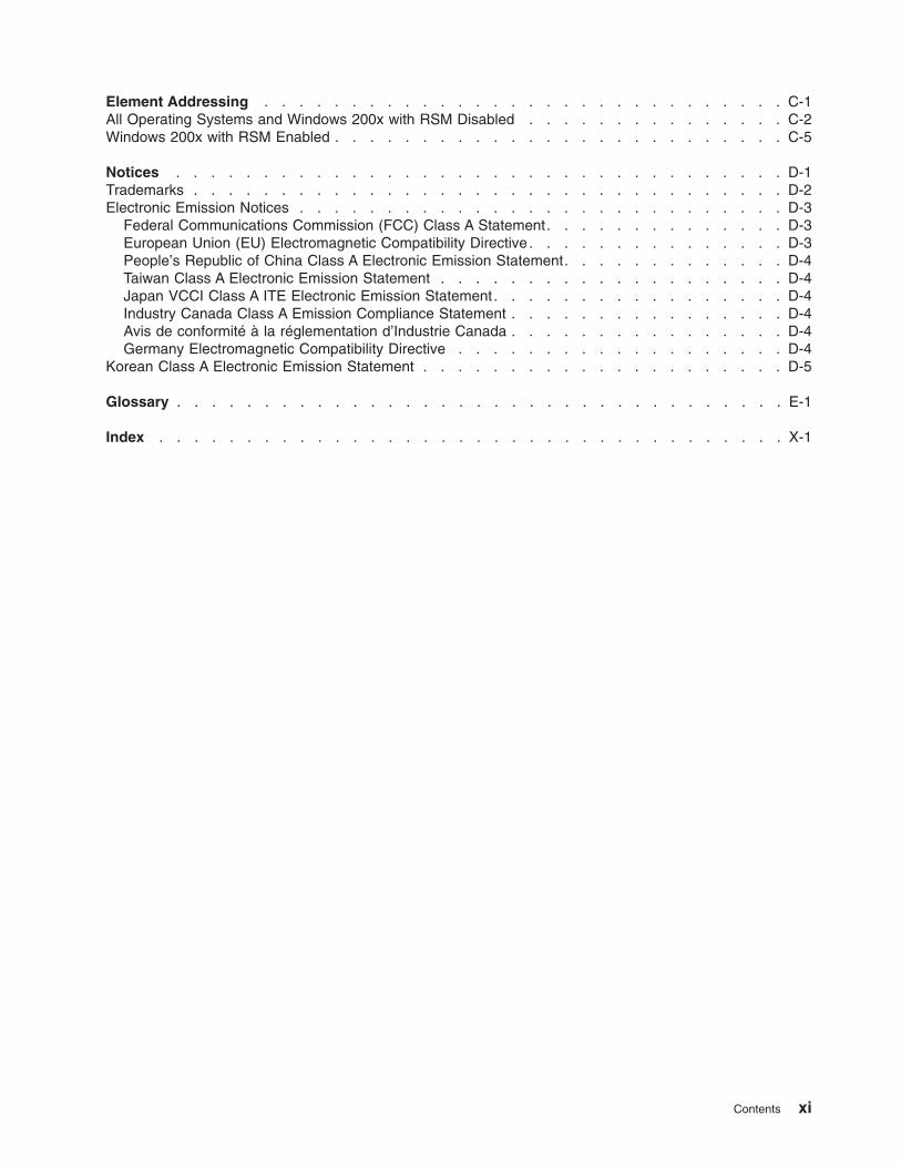
Element Addressing . . . . . . . . . . . . . . . . . . . . . . . . . . . . . . C-1
All Operating Systems and Windows 200x with RSM Disabled . . . . . . . . . . . . . . . C-2
Windows 200x with RSM Enabled . . . . . . . . . . . . . . . . . . . . . . . . . . C-5
Notices . . . . . . . . . . . . . . . . . . . . . . . . . . . . . . . . . . . D-1
Trademarks . . . . . . . . . . . . . . . . . . . . . . . . . . . . . . . . . . D-2
Electronic Emission Notices . . . . . . . . . . . . . . . . . . . . . . . . . . . . D-3
Federal Communications Commission (FCC) Class A Statement . . . . . . . . . . . . . . D-3
European Union (EU) Electromagnetic Compatibility Directive . . . . . . . . . . . . . . . D-3
People’s Republic of China Class A Electronic Emission Statement . . . . . . . . . . . . . D-4
Taiwan Class A Electronic Emission Statement . . . . . . . . . . . . . . . . . . . . D-4
Japan VCCI Class A ITE Electronic Emission Statement . . . . . . . . . . . . . . . . . D-4
Industry Canada Class A Emission Compliance Statement . . . . . . . . . . . . . . . . D-4
Avis de conformité à la réglementation d’Industrie Canada . . . . . . . . . . . . . . . . D-4
Germany Electromagnetic Compatibility Directive . . . . . . . . . . . . . . . . . . . D-4
Korean Class A Electronic Emission Statement . . . . . . . . . . . . . . . . . . . . . D-5
Glossary . . . . . . . . . . . . . . . . . . . . . . . . . . . . . . . . . . . E-1
Index . . . . . . . . . . . . . . . . . . . . . . . . . . . . . . . . . . . . X-1
Contents xi

xii 3583 Tape Library Maintenance Information

Figures
1-1. Ultrium Scalable Tape Library(Stand-alone configuration) . . . . . . . . . . . . . . . 1-4
1-2. Fibre Channel Ultrium 3 Tape Drive in the Ultrium Scalable Tape Library . . . . . . . . 1-10
1-3. Fibre Channel Ultrium 2 Tape Drive in the Ultrium Scalable Tape Library . . . . . . . . 1-10
1-4. SCSI Ultrium 1 Tape Drive in the Ultrium Scalable Tape Library . . . . . . . . . . . . 1-11
1-5. Examples of methods for mixing Ultrium drive types . . . . . . . . . . . . . . . . 1-14
1-6. Storage Column Configurations and Coordinate system . . . . . . . . . . . . . . 1-16
1-7. Examples of configurations for a Ultrium Scalable Tape Library . . . . . . . . . . . . 1-22
1-8. Functional diagram for a library with the Multi-Path feature . . . . . . . . . . . . . 1-30
2-1. AC Grounding Diagram (50 Hz and 60 Hz) . . . . . . . . . . . . . . . . . . . . 2-5
2-2. ac Power Module and dc Power Supplies locations . . . . . . . . . . . . . . . . . 2-7
3-1. Operator Panel . . . . . . . . . . . . . . . . . . . . . . . . . . . . . . 3-2
3-2. I/O Station Status Area . . . . . . . . . . . . . . . . . . . . . . . . . . . 3-3
3-3. Library Status Area . . . . . . . . . . . . . . . . . . . . . . . . . . . . 3-5
3-4. Drive Status Area . . . . . . . . . . . . . . . . . . . . . . . . . . . . . 3-5
3-5. Messages Area . . . . . . . . . . . . . . . . . . . . . . . . . . . . . . 3-7
3-6. TotalStorage Specialist home page . . . . . . . . . . . . . . . . . . . . . . . 3-8
3-7. Login Page . . . . . . . . . . . . . . . . . . . . . . . . . . . . . . . 3-9
3-8. Status page . . . . . . . . . . . . . . . . . . . . . . . . . . . . . . . 3-10
3-9. Login Page . . . . . . . . . . . . . . . . . . . . . . . . . . . . . . . 3-10
3-10. Configuration page . . . . . . . . . . . . . . . . . . . . . . . . . . . . 3-11
3-11. Firmware page . . . . . . . . . . . . . . . . . . . . . . . . . . . . . . 3-12
3-12. Diagnostics file page . . . . . . . . . . . . . . . . . . . . . . . . . . . 3-13
3-13. Operator panel page . . . . . . . . . . . . . . . . . . . . . . . . . . . 3-14
3-14. Logs page . . . . . . . . . . . . . . . . . . . . . . . . . . . . . . . 3-15
4-1. Flowchart of library functions . . . . . . . . . . . . . . . . . . . . . . . . . 4-3
4-2. Main Menu (initial screen) . . . . . . . . . . . . . . . . . . . . . . . . . . 4-4
4-3. Main Menu (alternate screen) . . . . . . . . . . . . . . . . . . . . . . . . . 4-4
4-4. Change Dialog . . . . . . . . . . . . . . . . . . . . . . . . . . . . . . 4-5
4-5. Offline Confirmation Dialog . . . . . . . . . . . . . . . . . . . . . . . . . . 4-5
4-6. Main Menu (initial screen) . . . . . . . . . . . . . . . . . . . . . . . . . . 4-6
4-7. Status Menu . . . . . . . . . . . . . . . . . . . . . . . . . . . . . . . 4-6
4-8. Main Menu (initial screen) . . . . . . . . . . . . . . . . . . . . . . . . . . 4-7
4-9. Command Menu . . . . . . . . . . . . . . . . . . . . . . . . . . . . . 4-7
4-10. Main Menu (initial screen) . . . . . . . . . . . . . . . . . . . . . . . . . . 4-8
4-11. Main Menu (alternate screen) . . . . . . . . . . . . . . . . . . . . . . . . . 4-8
4-12. Setup Menu . . . . . . . . . . . . . . . . . . . . . . . . . . . . . . . 4-8
4-13. Main Menu (initial screen) . . . . . . . . . . . . . . . . . . . . . . . . . . 4-9
4-14. Main Menu (alternate screen) . . . . . . . . . . . . . . . . . . . . . . . . . 4-9
4-15. Service Menu . . . . . . . . . . . . . . . . . . . . . . . . . . . . . . 4-9
4-16. Main Menu (initial screen) . . . . . . . . . . . . . . . . . . . . . . . . . 4-10
4-17. Main Menu (alternate screen) . . . . . . . . . . . . . . . . . . . . . . . . 4-10
4-18. About Menu . . . . . . . . . . . . . . . . . . . . . . . . . . . . . . . 4-10
4-19. Main power switch . . . . . . . . . . . . . . . . . . . . . . . . . . . . 4-11
4-20. Splash screen . . . . . . . . . . . . . . . . . . . . . . . . . . . . . . 4-11
4-21. Main Menu (initial screen) . . . . . . . . . . . . . . . . . . . . . . . . . 4-12
4-22. Status page . . . . . . . . . . . . . . . . . . . . . . . . . . . . . . . 4-15
4-23. Library Submenu . . . . . . . . . . . . . . . . . . . . . . . . . . . . . 4-16
4-24. System Dialog . . . . . . . . . . . . . . . . . . . . . . . . . . . . . . 4-16
4-25. Statistics Dialog . . . . . . . . . . . . . . . . . . . . . . . . . . . . . 4-16
4-26. Drives Dialog . . . . . . . . . . . . . . . . . . . . . . . . . . . . . . 4-17
4-27. Library Submenu . . . . . . . . . . . . . . . . . . . . . . . . . . . . . 4-18
4-28. System Dialog . . . . . . . . . . . . . . . . . . . . . . . . . . . . . . 4-18
4-29. Library Submenu . . . . . . . . . . . . . . . . . . . . . . . . . . . . . 4-19
© Copyright IBM Corp. 2000, 2005 xiii
||

4-30. Slot Dialog . . . . . . . . . . . . . . . . . . . . . . . . . . . . . . . 4-19
4-31. Change Magazine Dialog . . . . . . . . . . . . . . . . . . . . . . . . . . 4-20
4-32. Change Slot Dialog . . . . . . . . . . . . . . . . . . . . . . . . . . . . 4-20
4-33. Slot Status Dialog . . . . . . . . . . . . . . . . . . . . . . . . . . . . 4-21
4-34. Put/Get Information . . . . . . . . . . . . . . . . . . . . . . . . . . . . 4-21
4-35. Position Dialog . . . . . . . . . . . . . . . . . . . . . . . . . . . . . . 4-22
4-36. Library Submenu . . . . . . . . . . . . . . . . . . . . . . . . . . . . . 4-23
4-37. Media Dialog . . . . . . . . . . . . . . . . . . . . . . . . . . . . . . 4-23
4-38. Select Media Dialog . . . . . . . . . . . . . . . . . . . . . . . . . . . . 4-24
4-39. Media Information Dialog . . . . . . . . . . . . . . . . . . . . . . . . . . 4-24
4-40. Diagnostics file page . . . . . . . . . . . . . . . . . . . . . . . . . . . 4-25
4-41. Logs Submenu . . . . . . . . . . . . . . . . . . . . . . . . . . . . . 4-26
4-42. Command Log Dialog . . . . . . . . . . . . . . . . . . . . . . . . . . . 4-26
4-43. Print Dialog . . . . . . . . . . . . . . . . . . . . . . . . . . . . . . . 4-26
4-44. Logs Submenu . . . . . . . . . . . . . . . . . . . . . . . . . . . . . 4-27
4-45. Error Log Dialog . . . . . . . . . . . . . . . . . . . . . . . . . . . . . 4-27
4-46. Print Dialog . . . . . . . . . . . . . . . . . . . . . . . . . . . . . . . 4-28
4-47. Drives Submenu . . . . . . . . . . . . . . . . . . . . . . . . . . . . . 4-29
4-48. FC/SCSI Submenu . . . . . . . . . . . . . . . . . . . . . . . . . . . . 4-29
4-49. Logs Submenu . . . . . . . . . . . . . . . . . . . . . . . . . . . . . 4-30
4-50. Select Drive Dialog . . . . . . . . . . . . . . . . . . . . . . . . . . . . 4-30
4-51. Drive Log Dialog . . . . . . . . . . . . . . . . . . . . . . . . . . . . . 4-30
4-52. Drive Log Dialog . . . . . . . . . . . . . . . . . . . . . . . . . . . . . 4-31
4-53. Drive Error Log Options Submenu . . . . . . . . . . . . . . . . . . . . . . 4-32
4-54. Drive Log Dialog . . . . . . . . . . . . . . . . . . . . . . . . . . . . . 4-32
4-55. Drive Error Log Options Submenu . . . . . . . . . . . . . . . . . . . . . . 4-33
4-56. Drive Log Dialog . . . . . . . . . . . . . . . . . . . . . . . . . . . . . 4-34
4-57. Drive Error Log Options Submenu . . . . . . . . . . . . . . . . . . . . . . 4-35
4-58. Status page . . . . . . . . . . . . . . . . . . . . . . . . . . . . . . . 4-35
4-59. Login page . . . . . . . . . . . . . . . . . . . . . . . . . . . . . . . 4-36
4-60. Diagnostics file page . . . . . . . . . . . . . . . . . . . . . . . . . . . 4-36
4-61. Drive Log Dialog . . . . . . . . . . . . . . . . . . . . . . . . . . . . . 4-37
4-62. Drive Error Log Options Submenu . . . . . . . . . . . . . . . . . . . . . . 4-37
4-63. Move Submenu . . . . . . . . . . . . . . . . . . . . . . . . . . . . . 4-38
4-64. Source Move Media Dialog . . . . . . . . . . . . . . . . . . . . . . . . . 4-38
4-65. Change Magazine Dialog . . . . . . . . . . . . . . . . . . . . . . . . . . 4-39
4-66. Change Slot Dialog . . . . . . . . . . . . . . . . . . . . . . . . . . . . 4-39
4-67. Target Move Media Dialog . . . . . . . . . . . . . . . . . . . . . . . . . 4-40
4-68. Move Submenu . . . . . . . . . . . . . . . . . . . . . . . . . . . . . 4-41
4-69. Position Picker Dialog . . . . . . . . . . . . . . . . . . . . . . . . . . . 4-41
4-70. Change Magazine Dialog . . . . . . . . . . . . . . . . . . . . . . . . . . 4-42
4-71. Change Slot Dialog . . . . . . . . . . . . . . . . . . . . . . . . . . . . 4-42
4-72. Move Submenu . . . . . . . . . . . . . . . . . . . . . . . . . . . . . 4-43
4-73. Scan Barcode Dialog . . . . . . . . . . . . . . . . . . . . . . . . . . . 4-43
4-74. Change Magazine Dialog . . . . . . . . . . . . . . . . . . . . . . . . . . 4-44
4-75. Change Slot Dialog . . . . . . . . . . . . . . . . . . . . . . . . . . . . 4-44
4-76. Select Slots Dialog . . . . . . . . . . . . . . . . . . . . . . . . . . . . 4-44
4-77. Confirm Dialog . . . . . . . . . . . . . . . . . . . . . . . . . . . . . . 4-45
4-78. Completion Dialog . . . . . . . . . . . . . . . . . . . . . . . . . . . . 4-46
4-79. I/O Station Submenu . . . . . . . . . . . . . . . . . . . . . . . . . . . 4-47
4-80. Partitions Dialog . . . . . . . . . . . . . . . . . . . . . . . . . . . . . 4-48
4-81. Library Submenu . . . . . . . . . . . . . . . . . . . . . . . . . . . . . 4-49
4-82. More Dialog . . . . . . . . . . . . . . . . . . . . . . . . . . . . . . . 4-49
4-83. Autoclean Setup screen . . . . . . . . . . . . . . . . . . . . . . . . . . 4-50
4-84. I/O Station Submenu . . . . . . . . . . . . . . . . . . . . . . . . . . . 4-51
4-85. AutoClean Dialog . . . . . . . . . . . . . . . . . . . . . . . . . . . . . 4-51
xiv 3583 Tape Library Maintenance Information
|
||||

4-86. Cleaning Tape screen . . . . . . . . . . . . . . . . . . . . . . . . . . . 4-52
4-87. I/O Station Submenu . . . . . . . . . . . . . . . . . . . . . . . . . . . 4-53
4-88. AutoClean Dialog . . . . . . . . . . . . . . . . . . . . . . . . . . . . . 4-53
4-89. Export Cleaning Tape Dialog . . . . . . . . . . . . . . . . . . . . . . . . 4-53
4-90. More Submenu . . . . . . . . . . . . . . . . . . . . . . . . . . . . . 4-54
4-91. Scan Media Dialog . . . . . . . . . . . . . . . . . . . . . . . . . . . . 4-54
4-92. I/O Station Submenu . . . . . . . . . . . . . . . . . . . . . . . . . . . 4-56
4-93. Export Dialog . . . . . . . . . . . . . . . . . . . . . . . . . . . . . . 4-56
4-94. Export List Dialog . . . . . . . . . . . . . . . . . . . . . . . . . . . . . 4-56
4-95. Export Select Dialog . . . . . . . . . . . . . . . . . . . . . . . . . . . . 4-57
4-96. Drives Submenu . . . . . . . . . . . . . . . . . . . . . . . . . . . . . 4-58
4-97. Unload Dialog . . . . . . . . . . . . . . . . . . . . . . . . . . . . . . 4-58
4-98. Drives Submenu . . . . . . . . . . . . . . . . . . . . . . . . . . . . . 4-59
4-99. Reset Dialog . . . . . . . . . . . . . . . . . . . . . . . . . . . . . . 4-59
4-100. Reset Type Dialog . . . . . . . . . . . . . . . . . . . . . . . . . . . . 4-60
4-101. Configuration page . . . . . . . . . . . . . . . . . . . . . . . . . . . . 4-61
4-102. Library Submenu . . . . . . . . . . . . . . . . . . . . . . . . . . . . . 4-62
4-103. Confirm Changes Dialog . . . . . . . . . . . . . . . . . . . . . . . . . . 4-62
4-104. Confirm Changes Dialog . . . . . . . . . . . . . . . . . . . . . . . . . . 4-63
4-105. Drives Submenu . . . . . . . . . . . . . . . . . . . . . . . . . . . . . 4-64
4-106. Drive SCSI Dialog for Drives . . . . . . . . . . . . . . . . . . . . . . . . 4-64
4-107. FC Submenu . . . . . . . . . . . . . . . . . . . . . . . . . . . . . . 4-66
4-108. FC ID Dialog . . . . . . . . . . . . . . . . . . . . . . . . . . . . . . 4-66
4-109. Second page of the FC ID Dialog . . . . . . . . . . . . . . . . . . . . . . . 4-67
4-110. Configuration page . . . . . . . . . . . . . . . . . . . . . . . . . . . . 4-68
4-111. Utils Submenu . . . . . . . . . . . . . . . . . . . . . . . . . . . . . . 4-69
4-112. Date/Time Dialog . . . . . . . . . . . . . . . . . . . . . . . . . . . . . 4-69
4-113. Utils Submenu . . . . . . . . . . . . . . . . . . . . . . . . . . . . . . 4-71
4-114. Config Dialog . . . . . . . . . . . . . . . . . . . . . . . . . . . . . . 4-71
4-115. Utils Submenu . . . . . . . . . . . . . . . . . . . . . . . . . . . . . . 4-72
4-116. Config Dialog . . . . . . . . . . . . . . . . . . . . . . . . . . . . . . 4-72
4-117. Utils Submenu . . . . . . . . . . . . . . . . . . . . . . . . . . . . . . 4-73
4-118. Config Dialog . . . . . . . . . . . . . . . . . . . . . . . . . . . . . . 4-73
4-119. Utils Submenu . . . . . . . . . . . . . . . . . . . . . . . . . . . . . . 4-74
4-120. Secure Dialog . . . . . . . . . . . . . . . . . . . . . . . . . . . . . . 4-74
4-121. Utils Submenu . . . . . . . . . . . . . . . . . . . . . . . . . . . . . . 4-75
4-122. Enter Password Dialog . . . . . . . . . . . . . . . . . . . . . . . . . . . 4-75
4-123. Secure Dialog . . . . . . . . . . . . . . . . . . . . . . . . . . . . . . 4-76
4-124. Set/Change Password Dialog . . . . . . . . . . . . . . . . . . . . . . . . 4-76
4-125. Utils Submenu . . . . . . . . . . . . . . . . . . . . . . . . . . . . . . 4-77
4-126. Enter Password Dialog . . . . . . . . . . . . . . . . . . . . . . . . . . . 4-77
4-127. Security Enabled Dialog . . . . . . . . . . . . . . . . . . . . . . . . . . 4-77
4-128. Enter Password Dialog . . . . . . . . . . . . . . . . . . . . . . . . . . . 4-78
4-129. Secure Dialog . . . . . . . . . . . . . . . . . . . . . . . . . . . . . . 4-78
4-130. License Dialog . . . . . . . . . . . . . . . . . . . . . . . . . . . . . . 4-79
4-131. Start Dialog . . . . . . . . . . . . . . . . . . . . . . . . . . . . . . . 4-80
4-132. Normal Service Dialog . . . . . . . . . . . . . . . . . . . . . . . . . . . 4-80
4-133. Enter Password Dialog . . . . . . . . . . . . . . . . . . . . . . . . . . . 4-81
4-134. Library Submenu . . . . . . . . . . . . . . . . . . . . . . . . . . . . . 4-82
4-135. Diags Submenu . . . . . . . . . . . . . . . . . . . . . . . . . . . . . 4-82
4-136. Sensor Dialog . . . . . . . . . . . . . . . . . . . . . . . . . . . . . . 4-82
4-137. Library Submenu . . . . . . . . . . . . . . . . . . . . . . . . . . . . . 4-83
4-138. Diags Submenu . . . . . . . . . . . . . . . . . . . . . . . . . . . . . 4-84
4-139. Fingers Submenu . . . . . . . . . . . . . . . . . . . . . . . . . . . . . 4-84
4-140. Get/Put Dialog . . . . . . . . . . . . . . . . . . . . . . . . . . . . . . 4-84
4-141. New Start Slot Dialog . . . . . . . . . . . . . . . . . . . . . . . . . . . 4-85
Figures xv
||||

4-142. Get/Put Source Dialog . . . . . . . . . . . . . . . . . . . . . . . . . . . 4-85
4-143. Change Magazine Dialog . . . . . . . . . . . . . . . . . . . . . . . . . . 4-86
4-144. Change Slot Dialog . . . . . . . . . . . . . . . . . . . . . . . . . . . . 4-86
4-145. Get/Put Execution screen . . . . . . . . . . . . . . . . . . . . . . . . . . 4-86
4-146. Library Submenu . . . . . . . . . . . . . . . . . . . . . . . . . . . . . 4-87
4-147. Diags Submenu . . . . . . . . . . . . . . . . . . . . . . . . . . . . . 4-87
4-148. Fingers Submenu . . . . . . . . . . . . . . . . . . . . . . . . . . . . . 4-87
4-149. Step Dialog . . . . . . . . . . . . . . . . . . . . . . . . . . . . . . . 4-88
4-150. Picker Finger Dialog . . . . . . . . . . . . . . . . . . . . . . . . . . . . 4-88
4-151. Library Submenu . . . . . . . . . . . . . . . . . . . . . . . . . . . . . 4-89
4-152. Diags Submenu . . . . . . . . . . . . . . . . . . . . . . . . . . . . . 4-89
4-153. Fingers Submenu . . . . . . . . . . . . . . . . . . . . . . . . . . . . . 4-89
4-154. Reader Dialog . . . . . . . . . . . . . . . . . . . . . . . . . . . . . . 4-89
4-155. Bar Code Label Dialog . . . . . . . . . . . . . . . . . . . . . . . . . . . 4-90
4-156. Library Submenu . . . . . . . . . . . . . . . . . . . . . . . . . . . . . 4-90
4-157. Diags Submenu . . . . . . . . . . . . . . . . . . . . . . . . . . . . . 4-90
4-158. Picker Submenu . . . . . . . . . . . . . . . . . . . . . . . . . . . . . 4-91
4-159. Move Dialog . . . . . . . . . . . . . . . . . . . . . . . . . . . . . . 4-91
4-160. Use Axes Dialog . . . . . . . . . . . . . . . . . . . . . . . . . . . . . 4-91
4-161. Move Test Execution screen . . . . . . . . . . . . . . . . . . . . . . . . . 4-92
4-162. Library Submenu . . . . . . . . . . . . . . . . . . . . . . . . . . . . . 4-92
4-163. Diags Submenu . . . . . . . . . . . . . . . . . . . . . . . . . . . . . 4-93
4-164. Picker Submenu . . . . . . . . . . . . . . . . . . . . . . . . . . . . . 4-93
4-165. Step Dialog . . . . . . . . . . . . . . . . . . . . . . . . . . . . . . . 4-93
4-166. Axes Dialog . . . . . . . . . . . . . . . . . . . . . . . . . . . . . . . 4-93
4-167. Library Submenu . . . . . . . . . . . . . . . . . . . . . . . . . . . . . 4-94
4-168. Diags Submenu . . . . . . . . . . . . . . . . . . . . . . . . . . . . . 4-94
4-169. Picker Submenu . . . . . . . . . . . . . . . . . . . . . . . . . . . . . 4-95
4-170. Home Dialog . . . . . . . . . . . . . . . . . . . . . . . . . . . . . . 4-95
4-171. Library Submenu . . . . . . . . . . . . . . . . . . . . . . . . . . . . . 4-96
4-172. Exercise Submenu . . . . . . . . . . . . . . . . . . . . . . . . . . . . 4-96
4-173. Demo Dialog . . . . . . . . . . . . . . . . . . . . . . . . . . . . . . 4-96
4-174. Include Drives Dialog . . . . . . . . . . . . . . . . . . . . . . . . . . . 4-97
4-175. Demo Execution screen . . . . . . . . . . . . . . . . . . . . . . . . . . 4-97
4-176. Library Submenu . . . . . . . . . . . . . . . . . . . . . . . . . . . . . 4-98
4-177. Exercise Submenu . . . . . . . . . . . . . . . . . . . . . . . . . . . . 4-98
4-178. Self Test Dialog . . . . . . . . . . . . . . . . . . . . . . . . . . . . . 4-98
4-179. Include Drives Dialog . . . . . . . . . . . . . . . . . . . . . . . . . . . 4-99
4-180. Self Test Execution Dialog . . . . . . . . . . . . . . . . . . . . . . . . . 4-99
4-181. Library Submenu . . . . . . . . . . . . . . . . . . . . . . . . . . . . 4-100
4-182. Exercise Submenu . . . . . . . . . . . . . . . . . . . . . . . . . . . . 4-100
4-183. Verify Test Dialog . . . . . . . . . . . . . . . . . . . . . . . . . . . . 4-100
4-184. Verify Test Scratch Tape Dialog . . . . . . . . . . . . . . . . . . . . . . . 4-101
4-185. Diagnostic In Progress Screen . . . . . . . . . . . . . . . . . . . . . . . 4-101
4-186. Command Now Complete Screen . . . . . . . . . . . . . . . . . . . . . . 4-101
4-187. Library Submenu . . . . . . . . . . . . . . . . . . . . . . . . . . . . 4-102
4-188. Exercise Submenu . . . . . . . . . . . . . . . . . . . . . . . . . . . . 4-102
4-189. Exercise Submenu (alternate screen) . . . . . . . . . . . . . . . . . . . . . 4-102
4-190. Drives Dialog . . . . . . . . . . . . . . . . . . . . . . . . . . . . . . 4-103
4-191. Drive Service Dialog . . . . . . . . . . . . . . . . . . . . . . . . . . . 4-103
4-192. Drive Diagnostics Dialog . . . . . . . . . . . . . . . . . . . . . . . . . . 4-104
4-193. Drives Dialog . . . . . . . . . . . . . . . . . . . . . . . . . . . . . . 4-105
4-194. Drive Service Dialog . . . . . . . . . . . . . . . . . . . . . . . . . . . 4-105
4-195. FMR Tape Dialog . . . . . . . . . . . . . . . . . . . . . . . . . . . . 4-106
4-196. Scratch Tape Dialog . . . . . . . . . . . . . . . . . . . . . . . . . . . 4-106
4-197. Main Menu (initial screen) . . . . . . . . . . . . . . . . . . . . . . . . . 4-107
xvi 3583 Tape Library Maintenance Information

4-198. Main Menu (alternate screen) . . . . . . . . . . . . . . . . . . . . . . . . 4-107
4-199. Service Menu . . . . . . . . . . . . . . . . . . . . . . . . . . . . . . 4-108
4-200. Drives Dialog . . . . . . . . . . . . . . . . . . . . . . . . . . . . . . 4-108
4-201. Drive Service Dialog . . . . . . . . . . . . . . . . . . . . . . . . . . . 4-108
4-202. Repair Dialog . . . . . . . . . . . . . . . . . . . . . . . . . . . . . . 4-109
4-203. Detail Dialog . . . . . . . . . . . . . . . . . . . . . . . . . . . . . . 4-110
4-204. Library Submenu . . . . . . . . . . . . . . . . . . . . . . . . . . . . 4-111
4-205. Media Dialog . . . . . . . . . . . . . . . . . . . . . . . . . . . . . . 4-111
4-206. Media Dialog with the Volser field set to EXTENDED . . . . . . . . . . . . . . . 4-111
4-207. Reinventory screen . . . . . . . . . . . . . . . . . . . . . . . . . . . . 4-112
4-208. Diagnostics file page . . . . . . . . . . . . . . . . . . . . . . . . . . . 4-113
4-209. Logging on to the Server . . . . . . . . . . . . . . . . . . . . . . . . . 4-132
4-210. Initial Tree View . . . . . . . . . . . . . . . . . . . . . . . . . . . . . 4-132
4-211. Controls Menu . . . . . . . . . . . . . . . . . . . . . . . . . . . . . 4-133
5-1. Power Map . . . . . . . . . . . . . . . . . . . . . . . . . . . . . . . 5-6
5-2. RMU Map . . . . . . . . . . . . . . . . . . . . . . . . . . . . . . . . 5-7
6-1. Error Log Dialog . . . . . . . . . . . . . . . . . . . . . . . . . . . . . 6-3
7-1. Tape Library Overview (Standalone Model) . . . . . . . . . . . . . . . . . . . . 7-2
7-2. Front view of tape library with door opened . . . . . . . . . . . . . . . . . . . . 7-3
7-3. Rear view of tape library with SCSI attachment . . . . . . . . . . . . . . . . . . 7-4
7-4. Rear view of tape library with native fibre channel attachment . . . . . . . . . . . . . 7-5
7-5. Tape library serial ports . . . . . . . . . . . . . . . . . . . . . . . . . . . 7-6
7-6. Y-Axis and Rotary-Axis Assembly . . . . . . . . . . . . . . . . . . . . . . . 7-7
7-7. Picker Assembly . . . . . . . . . . . . . . . . . . . . . . . . . . . . . 7-8
7-8. Rear View of the I/O Station . . . . . . . . . . . . . . . . . . . . . . . . . 7-9
7-9. I/O Station (Single Slot) . . . . . . . . . . . . . . . . . . . . . . . . . . 7-10
7-10. Main controller PCBA . . . . . . . . . . . . . . . . . . . . . . . . . . . 7-11
7-11. Operator panel assembly . . . . . . . . . . . . . . . . . . . . . . . . . . 7-12
7-12. Power distribution PCBA (Type I) . . . . . . . . . . . . . . . . . . . . . . . 7-13
7-13. Power distribution PCBA (Type II) . . . . . . . . . . . . . . . . . . . . . . . 7-14
7-14. Picker control board . . . . . . . . . . . . . . . . . . . . . . . . . . . . 7-15
7-15. Host SCSI interface board for SCSI attachment . . . . . . . . . . . . . . . . . 7-16
7-16. Serial diagnostic port board for native Fibre Channel attachment . . . . . . . . . . . 7-17
7-17. DC Power Supply Assembly . . . . . . . . . . . . . . . . . . . . . . . . . 7-18
7-18. AC Power Input Module . . . . . . . . . . . . . . . . . . . . . . . . . . 7-19
7-19. SAN Data Gateway Module (optional) . . . . . . . . . . . . . . . . . . . . . 7-20
7-20. RMU . . . . . . . . . . . . . . . . . . . . . . . . . . . . . . . . . 7-21
8-1. Cartridge Removal from Picker Assembly . . . . . . . . . . . . . . . . . . . . 8-3
8-2. Cable Connections for a SCSI host attachment . . . . . . . . . . . . . . . . . . 8-4
8-3. Cable Connections for a native Fibre Channel host attachment . . . . . . . . . . . . 8-5
8-4. Tape Drive Sled Removal and Replacement . . . . . . . . . . . . . . . . . . . 8-6
8-5. Flat Washer and Casting . . . . . . . . . . . . . . . . . . . . . . . . . . 8-7
8-6. Picker Assembly Removal and Replacement . . . . . . . . . . . . . . . . . . . 8-9
8-7. Proper orientation of picker control PCBA to picker support ground wire connector 8-10
8-8. Top Cover Removal . . . . . . . . . . . . . . . . . . . . . . . . . . . . 8-11
8-9. Picker Carriage Arm Assembly Removal and Replacement . . . . . . . . . . . . . 8-12
8-10. Location of ground strap . . . . . . . . . . . . . . . . . . . . . . . . . . 8-13
8-11. Rotary Axis Motor Removal and Replacement . . . . . . . . . . . . . . . . . . 8-15
8-12. Picker Control Board Removal and Replacement . . . . . . . . . . . . . . . . . 8-17
8-13. Top Cover Removal . . . . . . . . . . . . . . . . . . . . . . . . . . . . 8-18
8-14. Y-Axis Drive Belt Removal and Replacement . . . . . . . . . . . . . . . . . . 8-19
8-15. Removing the belt clamps . . . . . . . . . . . . . . . . . . . . . . . . . 8-20
8-16. Tensioning screw and Ny-lock nuts . . . . . . . . . . . . . . . . . . . . . . 8-20
8-17. Stud and Tension pulley . . . . . . . . . . . . . . . . . . . . . . . . . . 8-21
8-18. Installing Belt Clamps . . . . . . . . . . . . . . . . . . . . . . . . . . . 8-22
8-19. Y-Axis Flex Cable Removal and Replacement . . . . . . . . . . . . . . . . . . 8-24
Figures xvii

8-20. Display Assembly Flex Cable Removal and Replacement . . . . . . . . . . . . . . 8-25
8-21. Display Assembly Flex Cable Removal and Replacement . . . . . . . . . . . . . . 8-26
8-22. Main to Power Distribution Cables Removal and Replacement . . . . . . . . . . . . 8-27
8-23. Power Distribution to Drive Sled Cable Removal and Replacement . . . . . . . . . . 8-28
8-24. Y-Axis Motor Assembly Removal and Replacement . . . . . . . . . . . . . . . . 8-30
8-25. Y-Axis Drive Shaft Removal and Replacement . . . . . . . . . . . . . . . . . . 8-31
8-26. Storage Removal and Replacement . . . . . . . . . . . . . . . . . . . . . . 8-33
8-27. Main Board Removal and Replacement . . . . . . . . . . . . . . . . . . . . 8-35
8-28. Removing the Lower Fibre Channel Bracket Sub-Assembly . . . . . . . . . . . . . 8-36
8-29. View of the RMU Bracket Sub-Assembly and RMU Interface Cable Connector . . . . . . 8-37
8-30. Sliding the Main Controller PCBA Out of the Guiding Tracks . . . . . . . . . . . . . 8-37
8-31. RMU . . . . . . . . . . . . . . . . . . . . . . . . . . . . . . . . . 8-39
8-32. RMU Jumpers . . . . . . . . . . . . . . . . . . . . . . . . . . . . . . 8-40
8-33. SAN Data Gateway Module . . . . . . . . . . . . . . . . . . . . . . . . . 8-41
8-34. Removing the T8 Torx Screws that Secure the Fibre Channel Bracket Sub-Assembly 8-42
8-35. Disconnecting the accessory bay cable from the Fibre Channel bracket sub-assembly 8-43
8-36. Disconnecting the accessory bay cable from the power distribution PCBA . . . . . . . . 8-44
8-37. Host SCSI Interface Board . . . . . . . . . . . . . . . . . . . . . . . . . 8-45
8-38. Serial Diagnostic Port Board Removal and Replacement . . . . . . . . . . . . . . 8-46
8-39. Display Assembly Removal and Replacement . . . . . . . . . . . . . . . . . . 8-48
8-40. Power Distribution Board Removal and Replacement . . . . . . . . . . . . . . . 8-50
8-41. I/O Station Removal and Replacement . . . . . . . . . . . . . . . . . . . . . 8-51
8-42. I/O Station, Single Slot . . . . . . . . . . . . . . . . . . . . . . . . . . . 8-52
8-43. ac Input Module Removal and Replacement . . . . . . . . . . . . . . . . . . . 8-53
8-44. Comparing dc Power Supplies . . . . . . . . . . . . . . . . . . . . . . . . 8-54
8-45. DC Power Supply Removal and Replacement . . . . . . . . . . . . . . . . . . 8-56
8-46. Door Lock Assembly, Remove/Replace . . . . . . . . . . . . . . . . . . . . . 8-57
8-47. Door Interlock Switch Removal and Replacement . . . . . . . . . . . . . . . . . 8-58
8-48. Plastic Top Door Removal and Replacement . . . . . . . . . . . . . . . . . . . 8-59
8-49. Plastic Lower Front Door Panel Removal and Replacement . . . . . . . . . . . . . 8-60
8-50. Side Cover Removal and Replacement . . . . . . . . . . . . . . . . . . . . . 8-61
8-51. Top Cover Removal and Replacement . . . . . . . . . . . . . . . . . . . . . 8-62
9-1. Logging on to the Server . . . . . . . . . . . . . . . . . . . . . . . . . . 9-25
9-2. Initial Tree View . . . . . . . . . . . . . . . . . . . . . . . . . . . . . 9-25
9-3. Controls Menu . . . . . . . . . . . . . . . . . . . . . . . . . . . . . . 9-26
9-4. Cable Diagram . . . . . . . . . . . . . . . . . . . . . . . . . . . . . . 9-28
9-5. Top Cover Removal . . . . . . . . . . . . . . . . . . . . . . . . . . . . 9-29
10-1. AIX ERRPT Library Error Log Example . . . . . . . . . . . . . . . . . . . . . 10-3
10-2. AIX ERRPT Drive Error Log Example . . . . . . . . . . . . . . . . . . . . . 10-4
10-3. Example of Error Suggesting SCSI Bus Problem, Which Takes Down Entire Bus 10-5
10-4. SCSI Problem Points to Library Control Path as Possible Cause . . . . . . . . . . . 10-6
10-5. AIX ERRPT Commands Error Log Example . . . . . . . . . . . . . . . . . . . 10-7
12-1. ac Power Module and dc Power Supplies locations . . . . . . . . . . . . . . . . 12-2
12-2. ac and dc power distribution for Type I power supply in a library with the Multi-Path feature 12-4
12-3. ac and dc power distribution for Type II power supply in a library with the Multi-Path feature 12-5
13-1. Cable diagram for Type I power distribution PCBA in a library with the Multi-Path feature 13-3
13-2. Cable diagram for Type II Power Distribution PCBA in a library with the Multi-Path feature 13-4
14-1. The sling for lifting the Ultrium Scalable Tape Library . . . . . . . . . . . . . . . . 14-2
14-2. Installing a stand-alone library . . . . . . . . . . . . . . . . . . . . . . . . 14-4
14-3. Main power switch . . . . . . . . . . . . . . . . . . . . . . . . . . . . 14-5
14-4. Operator panel . . . . . . . . . . . . . . . . . . . . . . . . . . . . . . 14-6
14-5. Library Submenu . . . . . . . . . . . . . . . . . . . . . . . . . . . . . 14-7
14-6. Verify Test Dialog . . . . . . . . . . . . . . . . . . . . . . . . . . . . . 14-7
14-7. Verify Test Scratch Tape Dialog . . . . . . . . . . . . . . . . . . . . . . . 14-8
14-8. Diagnostic In Progress Screen . . . . . . . . . . . . . . . . . . . . . . . . 14-8
14-9. Command Now Complete Screen . . . . . . . . . . . . . . . . . . . . . . . 14-8
xviii 3583 Tape Library Maintenance Information
||

14-10. Locking front casters . . . . . . . . . . . . . . . . . . . . . . . . . . . 14-11
14-11. Components of the rack mount kit . . . . . . . . . . . . . . . . . . . . . . 14-16
14-12. Example of standard racks . . . . . . . . . . . . . . . . . . . . . . . . . 14-17
14-13. Installing the front mounting brackets . . . . . . . . . . . . . . . . . . . . . 14-18
14-14. Installing the rear mounting brackets . . . . . . . . . . . . . . . . . . . . . 14-19
14-15. Installing the rear stop bracket . . . . . . . . . . . . . . . . . . . . . . . 14-20
14-16. Removing cartridges and magazines . . . . . . . . . . . . . . . . . . . . . 14-21
14-17. Removing the drive sleds and the DC power supplies . . . . . . . . . . . . . . . 14-22
14-18. Removing the casters . . . . . . . . . . . . . . . . . . . . . . . . . . . 14-22
14-19. Removing the side covers . . . . . . . . . . . . . . . . . . . . . . . . . 14-23
14-20. Placing the library into a rack (illustration shows converted library) . . . . . . . . . . 14-23
14-21. Installing a drive sled . . . . . . . . . . . . . . . . . . . . . . . . . . . 14-24
14-22. Proper orientation of the dc power supply . . . . . . . . . . . . . . . . . . . 14-24
14-23. Correct order for installing drive sleds (illustration shows converted library) . . . . . . . 14-25
14-24. Installing a drive sled that contains an Ultrium 1 Tape Drive . . . . . . . . . . . . . 14-26
14-25. Installing a drive sled that contains an Ultrium 2 or Ultrium 3 Tape Drive . . . . . . . . 14-26
14-26. Main power switch . . . . . . . . . . . . . . . . . . . . . . . . . . . . 14-27
14-27. Optional Column Magazine Alignment Plates for Column 4 only . . . . . . . . . . . 14-27
14-28. Installing a storage column . . . . . . . . . . . . . . . . . . . . . . . . . 14-28
14-29. Installing the 12-slot I/O station . . . . . . . . . . . . . . . . . . . . . . . 14-29
14-30. Installing a redundant dc power supply (illustration shows converted library) . . . . . . . 14-30
14-31. Installing a redundant dc power supply . . . . . . . . . . . . . . . . . . . . 14-31
14-32. Installing a San Data Gateway Module . . . . . . . . . . . . . . . . . . . . 14-32
14-33. Repositioning a drive sled for partitioning . . . . . . . . . . . . . . . . . . . 14-33
14-34. Making the host-to-drive connections with the SCSI Multi-Path feature and two hosts 14-34
14-35. Making the host-to-drive connections with three or more drives per SCSI bus . . . . . . 14-36
14-36. Making the host-to-drive connections with native Fibre Channel (Multi-Path library) 14-37
14-37. Cable connectors . . . . . . . . . . . . . . . . . . . . . . . . . . . . 14-38
14-38. Example of cabling with three or six drives installed (Multi-Path library) . . . . . . . . 14-39
14-39. Partitions Dialog . . . . . . . . . . . . . . . . . . . . . . . . . . . . . 14-41
14-40. Drive SCSI Dialog . . . . . . . . . . . . . . . . . . . . . . . . . . . . 14-42
14-41. Drive SCSI ID Dialog . . . . . . . . . . . . . . . . . . . . . . . . . . . 14-43
14-42. FC Submenu . . . . . . . . . . . . . . . . . . . . . . . . . . . . . . 14-43
14-43. Loop ID Dialog . . . . . . . . . . . . . . . . . . . . . . . . . . . . . 14-44
14-44. License Dialog . . . . . . . . . . . . . . . . . . . . . . . . . . . . . 14-45
14-45. SCSI Submenu . . . . . . . . . . . . . . . . . . . . . . . . . . . . . 14-46
14-46. Loop Submenu . . . . . . . . . . . . . . . . . . . . . . . . . . . . . 14-46
14-47. Setup Menu . . . . . . . . . . . . . . . . . . . . . . . . . . . . . . 14-47
14-48. Utils Submenu . . . . . . . . . . . . . . . . . . . . . . . . . . . . . 14-47
14-49. Config Dialog . . . . . . . . . . . . . . . . . . . . . . . . . . . . . . 14-48
14-50. Config I/O Station Dialog . . . . . . . . . . . . . . . . . . . . . . . . . 14-48
14-51. Setup Menu . . . . . . . . . . . . . . . . . . . . . . . . . . . . . . 14-49
14-52. Utils Submenu . . . . . . . . . . . . . . . . . . . . . . . . . . . . . 14-49
14-53. Secure Dialog . . . . . . . . . . . . . . . . . . . . . . . . . . . . . 14-50
14-54. Enter Password Dialog . . . . . . . . . . . . . . . . . . . . . . . . . . 14-50
14-55. Secure Dialog . . . . . . . . . . . . . . . . . . . . . . . . . . . . . 14-51
14-56. Set/Change Password Dialog . . . . . . . . . . . . . . . . . . . . . . . . 14-51
14-57. Command Menu . . . . . . . . . . . . . . . . . . . . . . . . . . . . 14-52
14-58. I/O Station Submenu . . . . . . . . . . . . . . . . . . . . . . . . . . . 14-52
14-59. AutoClean Dialog . . . . . . . . . . . . . . . . . . . . . . . . . . . . 14-52
14-60. Cleaning Tape screen . . . . . . . . . . . . . . . . . . . . . . . . . . . 14-53
14-61. RMU Dialog . . . . . . . . . . . . . . . . . . . . . . . . . . . . . . 14-55
14-62. Connecting the RMU to a computer (illustration shows converted library) . . . . . . . . 14-56
14-63. Status page . . . . . . . . . . . . . . . . . . . . . . . . . . . . . . 14-56
14-64. Login page . . . . . . . . . . . . . . . . . . . . . . . . . . . . . . . 14-57
14-65. Configuration page . . . . . . . . . . . . . . . . . . . . . . . . . . . . 14-58
Figures xix
||

14-66. About Menu . . . . . . . . . . . . . . . . . . . . . . . . . . . . . . 14-59
14-67. About Menu . . . . . . . . . . . . . . . . . . . . . . . . . . . . . . 14-60
14-68. Details Dialog . . . . . . . . . . . . . . . . . . . . . . . . . . . . . 14-60
14-69. Status Menu . . . . . . . . . . . . . . . . . . . . . . . . . . . . . . 14-61
14-70. Status Menu . . . . . . . . . . . . . . . . . . . . . . . . . . . . . . 14-61
14-71. Logging on to the Server . . . . . . . . . . . . . . . . . . . . . . . . . 14-62
14-72. Initial Tree View . . . . . . . . . . . . . . . . . . . . . . . . . . . . . 14-62
15-1. Types of receptacles . . . . . . . . . . . . . . . . . . . . . . . . . . . 15-7
A-1. Cartridge Write-Protect Switch . . . . . . . . . . . . . . . . . . . . . . . . A-4
A-2. Front view of the Ultrium Tape Drive . . . . . . . . . . . . . . . . . . . . . . A-15
A-3. Inserting a Cartridge into the Ultrium Tape Drive . . . . . . . . . . . . . . . . . A-17
A-4. Leader pin in the incorrect and correct positions . . . . . . . . . . . . . . . . . A-28
A-5. Placing the dislodged leader pin into the correct position . . . . . . . . . . . . . . A-29
A-6. Rewinding the tape into the cartridge . . . . . . . . . . . . . . . . . . . . . A-29
A-7. Leader Pin Reattachment Kit . . . . . . . . . . . . . . . . . . . . . . . . A-30
A-8. Attaching the leader pin attach tool to the cartridge . . . . . . . . . . . . . . . . A-31
A-9. Winding the tape out of the cartridge . . . . . . . . . . . . . . . . . . . . . A-32
A-10. Removing the C-clip from the leader pin . . . . . . . . . . . . . . . . . . . . A-32
A-11. Attaching the leader pin to the tape . . . . . . . . . . . . . . . . . . . . . . A-33
B-1. Resetting the Tape Drive . . . . . . . . . . . . . . . . . . . . . . . . . . B-2
B-2. Removing the cover from the internal drive . . . . . . . . . . . . . . . . . . . . B-4
B-3. Using hex wrench to rewind tape into cartridge . . . . . . . . . . . . . . . . . . B-6
B-4. Drive with cover removed to reveal gear train. . . . . . . . . . . . . . . . . . . B-7
B-5. Leader Block Assembly (LBA) . . . . . . . . . . . . . . . . . . . . . . . . B-8
B-6. Using hex wrench to rewind tape into cartridge . . . . . . . . . . . . . . . . . . B-9
B-7. Using hex wrench to rewind tape into cartridge . . . . . . . . . . . . . . . . . . B-10
B-8. Drive with cover removed to reveal gear train. . . . . . . . . . . . . . . . . . . B-11
B-9. Leader Block Assembly (LBA) . . . . . . . . . . . . . . . . . . . . . . . . B-12
B-10. Using hex wrench to rewind tape into cartridge . . . . . . . . . . . . . . . . . . B-13
B-11. Drive with cover removed to reveal gear train. . . . . . . . . . . . . . . . . . . B-14
B-12. Leader Block Assembly (LBA) . . . . . . . . . . . . . . . . . . . . . . . . B-15
B-13. Removing the Drive Sled . . . . . . . . . . . . . . . . . . . . . . . . . . B-17
B-14. Determining whether the tape is broken . . . . . . . . . . . . . . . . . . . . B-17
B-15. Removing the top cover of the drive . . . . . . . . . . . . . . . . . . . . . . B-20
B-16. Rewinding the leader pin into the tape cartridge . . . . . . . . . . . . . . . . . B-21
B-17. Guiding the leader block into the home position . . . . . . . . . . . . . . . . . B-22
B-18. Rotating the loader motor gear until the leader block is fully inside the drive . . . . . . . B-23
B-19. Rotating the loader motor gear so that the leader block retracts . . . . . . . . . . . B-24
B-20. Rotating the loader motor gear until the cartridge ejects . . . . . . . . . . . . . . B-25
C-1. Element addresses for a Ultrium Scalable Tape Library with a single-slot I/O station C-2
C-2. Element addresses for a Ultrium Scalable Tape Library with a multiple-slot I/O station C-3
C-3. Element addresses for a Ultrium Scalable Tape Library with a multiple-slot I/O station
configured as storage slots . . . . . . . . . . . . . . . . . . . . . . . . . C-4
C-4. Element addresses for a Ultrium Scalable Tape Library with a single-slot I/O station C-5
C-5. Element addresses for a Ultrium Scalable Tape Library with a multiple-slot I/O station C-6
C-6. Element addresses for a Ultrium Scalable Tape Library with a multiple-slot I/O station
configured as storage slots . . . . . . . . . . . . . . . . . . . . . . . . . C-7
xx 3583 Tape Library Maintenance Information
||||||||||||||||||||||

Tables
1-1. Maximum bus length between terminators . . . . . . . . . . . . . . . . . . . . 1-5
1-2. Recommended maximum quantity of drives per SCSI bus . . . . . . . . . . . . . . 1-6
1-3. Compatible cartridges and drives . . . . . . . . . . . . . . . . . . . . . . . 1-13
1-4. Environment for operating, storing, and shipping the IBM LTO Ultrium Tape Cartridge 1-15
1-5. Ultrium Scalable Tape Library Configurations . . . . . . . . . . . . . . . . . . 1-17
1-6. Optional features and codes for the Ultrium Scalable Tape Library . . . . . . . . . . . 1-19
1-7. Quantity of drives that are supported per adapter and operating system for iSeries and
AS/400 servers . . . . . . . . . . . . . . . . . . . . . . . . . . . . . 1-24
1-8. Specifications for the Ultrium Scalable Tape Library . . . . . . . . . . . . . . . . 1-25
1-9. Tape Library Major Functional Areas . . . . . . . . . . . . . . . . . . . . . . 1-28
2-1. Caution Notice Symbols . . . . . . . . . . . . . . . . . . . . . . . . . . . 2-2
2-2. Examples of Symbol Use . . . . . . . . . . . . . . . . . . . . . . . . . . 2-3
3-1. I/O Station Icons . . . . . . . . . . . . . . . . . . . . . . . . . . . . . 3-4
3-2. Library Status Area . . . . . . . . . . . . . . . . . . . . . . . . . . . . 3-5
3-3. Drive Status Icons . . . . . . . . . . . . . . . . . . . . . . . . . . . . . 3-6
4-1. Firmware levels . . . . . . . . . . . . . . . . . . . . . . . . . . . . . 4-117
5-1. Start Service . . . . . . . . . . . . . . . . . . . . . . . . . . . . . . . 5-3
5-2. Problem Analysis for Failures without Service Action Codes . . . . . . . . . . . . . 5-8
6-1. Service Action Codes . . . . . . . . . . . . . . . . . . . . . . . . . . . . 6-4
6-2. Operator intervention messages . . . . . . . . . . . . . . . . . . . . . . . 6-19
6-3. Operator information messages . . . . . . . . . . . . . . . . . . . . . . . 6-24
6-4. Drive error codes . . . . . . . . . . . . . . . . . . . . . . . . . . . . . 6-25
6-5. Handling errors during automatic cleaning . . . . . . . . . . . . . . . . . . . . 6-30
8-1. Interchange of Power Supplies with Library Power Architecture . . . . . . . . . . . . 8-55
9-1. Firmware levels . . . . . . . . . . . . . . . . . . . . . . . . . . . . . 9-10
9-2. Library Cables . . . . . . . . . . . . . . . . . . . . . . . . . . . . . . 9-27
10-1. AIX ERRPT Library Sense Data . . . . . . . . . . . . . . . . . . . . . . . 10-3
10-2. AIX ERRPT Drive Sense Data . . . . . . . . . . . . . . . . . . . . . . . . 10-4
11-1. Sense Information Format . . . . . . . . . . . . . . . . . . . . . . . . . 11-2
11-2. Sense Keys . . . . . . . . . . . . . . . . . . . . . . . . . . . . . . . 11-2
11-3. Additional Sense Codes and Qualifiers (Bytes 12 and 13) . . . . . . . . . . . . . . 11-3
11-4. LTO Tape Drive Sense Data . . . . . . . . . . . . . . . . . . . . . . . . . 11-6
14-1. Components of Rackmount Kit . . . . . . . . . . . . . . . . . . . . . . . 14-15
14-2. Optional Features . . . . . . . . . . . . . . . . . . . . . . . . . . . . 14-25
14-3. Correct position of longer cable with three or more drives per SCSI bus . . . . . . . . 14-35
15-1. Parts List for Ultrium Scalable Tape Library . . . . . . . . . . . . . . . . . . . 15-1
15-2. Other Available Parts . . . . . . . . . . . . . . . . . . . . . . . . . . . 15-4
15-3. Power cord information . . . . . . . . . . . . . . . . . . . . . . . . . . 15-5
A-1. TapeAlert Flags Supported by the Ultrium Tape Drive . . . . . . . . . . . . . . . . A-1
A-2. TapeAlert Flags Supported by the Tape Library . . . . . . . . . . . . . . . . . . A-5
A-3. Troubleshooting Tips for the Ultrium Tape Drive . . . . . . . . . . . . . . . . . . A-6
A-4. Methods of Receiving Errors and Messages for the Ultrium Tape Drive . . . . . . . . . A-7
A-5. Host Method of Recording Tape Drive Errors . . . . . . . . . . . . . . . . . . . A-8
A-6. Choosing the port for your topology and Fibre Channel connection . . . . . . . . . . A-11
A-7. Meaning of Status Light Activity . . . . . . . . . . . . . . . . . . . . . . . A-16
A-8. Diagnostic and maintenance functions . . . . . . . . . . . . . . . . . . . . . A-19
© Copyright IBM Corp. 2000, 2005 xxi

xxii 3583 Tape Library Maintenance Information

Preface
This guide contains information and instructions necessary for the installation and service of the IBM
TotalStorage 3583 Tape Library. Throughout this guide, references to the tape library or library will mean
the IBM TotalStorage 3583 Tape Library.
Intended Audience
This guide is intended for trained service personnel who install and repair the tape library.
Organization
This guide contains the following information.
v Chapter 1, “Introduction,” on page 1-1 describes the contents of this guide, as well as provides a
description of the tape library and its functions.
v Chapter 2, “Safety Instructions,” on page 2-1 gives general safety procedures.
v Chapter 3, “User Interfaces,” on page 3-1 provides a description of the Operator/CE Panel and RMU.
v Chapter 4, “Operating Procedures,” on page 4-1 describes menus available via the Operator/CE Panel
and the RMU.
v Chapter 5, “Start,” on page 5-1 provides a starting point for all maintenance actions.
v Chapter 6, “Fault Symptom Index,” on page 6-1 provides all service actions for reported symptoms.
v Chapter 7, “Locations,” on page 7-1 provides information to locate major components in the library.
v Chapter 8, “Check, Adjust, Remove, and Replace,” on page 8-1 provides procedures for making checks,
adjustments, removals and replacements of field replaceable units.
v Chapter 9, “Service Procedures,” on page 9-1 provides common service procedures for the library.
v Chapter 10, “Messages,” on page 10-1 gives information about obtaining tape drive error information at
the host or from RS/6000®, AS/400®, Sun, and HP-UX systems.
v Chapter 11, “Sense,” on page 11-1 provides sense information about the tape library and the Ultrium
Tape Drives.
v Chapter 12, “Power,” on page 12-1 provides power distribution diagram for the library.
v Chapter 13, “Cable,” on page 13-1 provides cable diagrams for the library.
v Chapter 14, “Installation,” on page 14-1 gives steps on installing the library.
v Chapter 15, “Parts List,” on page 15-1 lists FRU numbers for the parts in the library and provides power
cord information for different countries (or regions).
v “TapeAlert Flags” on page A-1 lists TapeAlert flags that the tape library and the Ultrium Tape Drive
support.
v “Removing a Tape Cartridge” on page B-1 provides information for removing a tape cartridge from an
Ultrium Tape Drive.
v “Element Addressing” on page C-1 shows element addressing information for the drives and storage
slots in the tape library.
© Copyright IBM Corp. 2000, 2005 xxiii

Related Publications
Refer to the following publications for additional information. To ensure that you have the latest
publications, visit the web at http://www.ibm.com/storage/lto .
v IBM TotalStorage 3583 Tape Library SCSI Reference, GA32-0453, provides supported SCSI commands
and protocol governing the behavior of SCSI interface for the tape library.
v IBM TotalStorage 3583 Tape Library Quick Reference, GX35-0557, illustrates how to install and operate
the tape library.
v IBM TotalStorage 3583 Tape Library Setup and Operator Guide, GA32-0411, provides information for
installing and operating the tape library.
v IBM Storage Area Network Data Gateway Module Setup, Operator, and Service Guide, GA32-0436,
provides installation, operation, and service information for the SAN Data Gateway Module.
v IBM Ultrium Device Driver Installation and User’s Guide, GA32-0430, provides instructions for attaching
IBM-supported hardware to open-systems operating systems. It indicates what devices and levels of
operating systems are supported. Also gives requirements for adapter cards, and tells how to configure
hosts to use the device driver. All the above are with the Ultrium family of devices.
v IBM Ultrium Device Driver Programming Reference , GC-0483, supplies information to application
owners who want to integrate their open-systems applications with IBM-supported Ultrium hardware.
The reference contains information about the application programming interfaces (APIs) for each of the
various supported operating-system environments.
Getting Assistance
If this document does not help you solve your problem, contact your next level of support.
xxiv 3583 Tape Library Maintenance Information

Chapter 1. Introduction
Description . . . . . . . . . . . . . . . . . . . . . . . . . . . . . . . . . . 1-3
Server Attachment . . . . . . . . . . . . . . . . . . . . . . . . . . . . . . . . 1-4
SCSI Interface . . . . . . . . . . . . . . . . . . . . . . . . . . . . . . . . 1-4
Physical Characteristics of the SCSI Interface . . . . . . . . . . . . . . . . . . . . 1-5
Using Multiple SCSI Buses . . . . . . . . . . . . . . . . . . . . . . . . . . . 1-6
Terminating the Bus . . . . . . . . . . . . . . . . . . . . . . . . . . . . . 1-6
SCSI Connectors and Adapters . . . . . . . . . . . . . . . . . . . . . . . . . 1-6
Fibre Channel Interface . . . . . . . . . . . . . . . . . . . . . . . . . . . . . 1-7
Cables and Speeds . . . . . . . . . . . . . . . . . . . . . . . . . . . . . 1-7
Using Zoning to Isolate Devices and Enhance Security . . . . . . . . . . . . . . . . 1-8
Using Persistent Binding to Ensure SCSI ID Assignment . . . . . . . . . . . . . . . . 1-8
Connectors and Adapters . . . . . . . . . . . . . . . . . . . . . . . . . . . 1-8
Connecting to the iSeries Server . . . . . . . . . . . . . . . . . . . . . . . . 1-8
Sharing on a Storage Area Network . . . . . . . . . . . . . . . . . . . . . . . 1-9
San Data Gateway Module with Web Interface . . . . . . . . . . . . . . . . . . . . 1-9
Tape Drives and Drive Sleds . . . . . . . . . . . . . . . . . . . . . . . . . . . . 1-9
Ultrium 3 Tape Drives . . . . . . . . . . . . . . . . . . . . . . . . . . . . . 1-10
Ultrium 2 Tape Drives . . . . . . . . . . . . . . . . . . . . . . . . . . . . . 1-10
Ultrium 1 Tape Drives . . . . . . . . . . . . . . . . . . . . . . . . . . . . . 1-11
Speed Matching . . . . . . . . . . . . . . . . . . . . . . . . . . . . . . . 1-11
Channel Calibration . . . . . . . . . . . . . . . . . . . . . . . . . . . . . . 1-11
Power Management . . . . . . . . . . . . . . . . . . . . . . . . . . . . . . 1-11
Tape Cartridges . . . . . . . . . . . . . . . . . . . . . . . . . . . . . . . . 1-11
Mixing Media in Drives . . . . . . . . . . . . . . . . . . . . . . . . . . . . . 1-12
Mixing Drive Types . . . . . . . . . . . . . . . . . . . . . . . . . . . . . . 1-13
Environmental and Shipping Specifications for Tape Cartridges . . . . . . . . . . . . . . 1-14
Functional Units . . . . . . . . . . . . . . . . . . . . . . . . . . . . . . . . 1-15
Cartridge Storage . . . . . . . . . . . . . . . . . . . . . . . . . . . . . . . 1-15
Storage Slot Numbering . . . . . . . . . . . . . . . . . . . . . . . . . . . 1-15
I/O Station . . . . . . . . . . . . . . . . . . . . . . . . . . . . . . . . . 1-17
Library Control Hardware . . . . . . . . . . . . . . . . . . . . . . . . . . . . 1-17
Robotic System . . . . . . . . . . . . . . . . . . . . . . . . . . . . . . . 1-17
RMU with TotalStorage Specialist . . . . . . . . . . . . . . . . . . . . . . . . . 1-17
SAN Data Gateway Module with TotalStorage Specialist . . . . . . . . . . . . . . . . 1-18
Optional Features . . . . . . . . . . . . . . . . . . . . . . . . . . . . . . . 1-19
Feature License . . . . . . . . . . . . . . . . . . . . . . . . . . . . . . . . 1-20
Multi-Path Architecture . . . . . . . . . . . . . . . . . . . . . . . . . . . . . . 1-20
Library Sharing . . . . . . . . . . . . . . . . . . . . . . . . . . . . . . . . 1-20
Example Configurations . . . . . . . . . . . . . . . . . . . . . . . . . . . . 1-22
Using Multiple Logical Libraries . . . . . . . . . . . . . . . . . . . . . . . . . 1-23
Using Multiple Logical Libraries for Library Sharing . . . . . . . . . . . . . . . . . 1-23
Using Multiple Logical Libraries for Mixed Drive Types . . . . . . . . . . . . . . . . 1-23
Using Multiple Control Paths . . . . . . . . . . . . . . . . . . . . . . . . . . 1-23
Using Multiple Control Paths for iSeries and AS/400 Attachment . . . . . . . . . . . . 1-24
Using Multiple Control Paths for Control Path Failover . . . . . . . . . . . . . . . . 1-24
Using Multiple Data Paths . . . . . . . . . . . . . . . . . . . . . . . . . . . 1-24
Specifications . . . . . . . . . . . . . . . . . . . . . . . . . . . . . . . . . 1-25
Product Environment . . . . . . . . . . . . . . . . . . . . . . . . . . . . . . 1-27
Maintenance Plan . . . . . . . . . . . . . . . . . . . . . . . . . . . . . . . 1-27
Maintenance Start . . . . . . . . . . . . . . . . . . . . . . . . . . . . . . 1-27
Preventive Maintenance . . . . . . . . . . . . . . . . . . . . . . . . . . . . 1-27
Functional Diagram . . . . . . . . . . . . . . . . . . . . . . . . . . . . . . . 1-28
Functional Diagram for a Library With the Multi-Path Feature . . . . . . . . . . . . . . . 1-30
© Copyright IBM Corp. 2000, 2005 1-1
||
||

Supported Servers, Operating Systems, and Software . . . . . . . . . . . . . . . . . . 1-31
Supported Device Drivers . . . . . . . . . . . . . . . . . . . . . . . . . . . . . 1-31
1-2 3583 Tape Library Maintenance Information

Description
The IBM® TotalStorage™ Ultrium Scalable Tape Library 3583 is a stand-alone or rack-mounted device that
provides reliable, automated tape handling and storage for unattended mid-range systems and network
servers. The library handles a wide range of data storage needs, including backup, archiving, software
program distribution, automatic data migration between disk storage and tape, and disaster recovery.
Cartridges can be mounted and dismounted on tape drives by using supporting software from the server
(host) without operator intervention.
The Ultrium Scalable Tape Library is installed with high-performance IBM LTO Ultrium Tape Drive
technology that offers the following capacities and speeds:
Drive Type Native Capacity 2:1 Compression Capacity Native Data Rate
Ultrium 3 400 GB 800 GB 80
Ultrium 2 200 GB 400 GB 35
Ultrium 1 100 GB 200 GB 15
Cross Platform Compatibility:
v Ultrium 3 tape Drives normally read and write on Ultrium 3 media. They can also read and write on
Ultrium 2 media using Ultrium 2 format. It can read but not write on Ultrium 1 format.
v Ultrium 2 Tape Drives normally read and write on Ultrium 2 media. They can also read and write on
Ultrium 1 media using Ultrium 1 format.
v Ultrium 1 Tape Drives normally read and write on Ultrium 1 media, and cannot read or write on Ultrium
2 or Ultrium 3 media.
Ultrium 2 Tape Drives can come with Low Voltage Differential (LVD) Ultra160 SCSI interfaces, High
Voltage Differential (HVD) Ultra SCSI interfaces, or the new 2-Gb Fibre Channel interface with fabric
attachment.
Ultrium 3 Tape Drives can come with Low Voltage Differential (LVD) Ultra160 SCSI interfaces or the new
2-Gb Fibre Channel interface with fabric attachment.
Additional new features include native switched fabric Fibre Channel drive attachment, Multi-Path
architecture, the ability to partition the library into three logical libraries, and an optional control path
failover feature for AIX®, Linux, and Solaris.
The library is designed for easy expansion. It can accommodate from one to six tape drives and has
cartridge storage configurations that hold 18, 36, 54, or 72 cartridges. With Ultrium 3 tape drives installed,
this provides total capacities of 7.2 terabyte (TB), 14.4 TB, 21.6 TB, and 28.8 TB of native data. With 2:1
compression the largest model of tape library can store 57.6 TB of data. Any starting configuration can be
upgraded to the maximum configuration of six drives and 72 cartridges. Upgrade features are modular
units that are easy to install.
The library offers two input/output (I/O) station options: single-slot or 12-slot. The 12-slot I/O station is
required to achieve the 72 cartridge maximum library configuration. With the 12-slot I/O station feature, the
library can be configured as 72 storage slots, or 60 storage slots and 12 I/O slots.
All libraries come equipped with one modular dc power supply. A second redundant power supply feature
is available.
A Remote Management Unit (RMU) comes standard in every library. The RMU provides remote access to
the library over a network. Library status can be sent to the network as Simple Network Management
Protocol (SNMP) traps. An application called the TotalStorage Specialist enables network access to the
library for more detailed status and control. The TotalStorage Specialist provides access to all library
operator panel functions.
Chapter 1. Introduction 1-3
|
|||||
||||
||||
||||||
||
||
||
|||
||
||||||

The Storage Area Network (SAN) Data Gateway Module is another available library feature. The gateway
provides the small computer system interface (SCSI) library with an avenue into a SAN infrastructure. With
2-Gigabit (Gbit) port speeds the library is compatible with 2-Gbit Fibre Channel components. It is also
backward compatible with 1-Gbit Fibre Channel hardware.
Figure 1-1 shows an example of an Ultrium Scalable Tape Library with optional features.
�1� I/O Station (12 slot shown) �8� RMU
�2� Front Door �9� Casters
�3� Door Lock �10� Tape Drive Sled
�4� Door Handle �11� Filler Plate
�5� Operator Panel �12� AC Input Power Module
�6� Host Interface Board (SCSI) or Serial Diagnostic
Port Board
�13� DC Power Supply
�7� SAN Data Gateway Module (optional) �14� Redundant dc Power Supply (optional)
Server Attachment
The Ultrium Scalable Tape Library can be attached to servers by using:
v “SCSI Interface”
v “Fibre Channel Interface” on page 1-7
v “San Data Gateway Module with Web Interface” on page 1-9
SCSI Interface
Note: Although the LVD hardware in the library is capable of operating in single-ended (SE) mode, SE
operation is not recommended or supported.
The library supports SCSI LVD and HVD attachments by using SCSI cables with 68-pin, D-connectors.
SCSI adapters must be properly terminated.
Before installing the SCSI cables, inspect all cables for damage. Do not install a cable if it is damaged.
Report the damage immediately by contacting your place of purchase.
Figure 1-1. Ultrium Scalable Tape Library(Stand-alone configuration)
1-4 3583 Tape Library Maintenance Information

The maximum allowable length of your bus cabling depends on the type of SCSI bus that you use (LVD or
HVD). For LVD, the maximum length is 25 m (82 ft) if one device is attached, and 12 m (40 ft) if more
than one device is attached. For HVD, the maximum length is 25 m (82 ft). The following guidelines
ensure compliance with the maximum allowable bus lengths:
v For a server with an LVD SCSI bus:
– Use a maximum system-to-device cable length of 10 m (33 ft) when attaching to the host interface
board (SCSI) and one or two daisy-chained drives.
– Use a maximum system-to-device cable length of 5 m (17 ft) when attaching to the host interface
board (SCSI) and three to six daisy-chained drives.
Note: For maximum performance, it is recommended to have two drives per SCSI bus.
– Only use the maximum system-to-device cable length of 25 m (82 ft) when attaching directly to one
device (a point to point interconnection).
v For a server with an HVD SCSI bus:
– Use a maximum system-to-device cable length of 20 m (65 ft) when attaching to the host interface
board (SCSI) and one to six daisy-chained drives.
– Only use the maximum system-to-device cable length of 25 m (82 ft) when attaching directly to one
device (a point-to-point interconnection).
Physical Characteristics of the SCSI Interface
The Ultrium Scalable Tape Library operates as a set of SCSI-2 or SCSI-3 devices. The Ultrium Tape
Drives attach to servers as follows:
v Ultrium 3 Tape Drives use an LVD Ultra160 SCSI interface
v Ultrium 2 Tape Drives use LVD Ultra160 SCSI and HVD Ultra SCSI interfaces
v Ultrium 1 Tape Drives use LVD Ultra2 SCSI and HVD Ultra SCSI interfaces
Each SCSI drive sled uses shielded, HD68-pin connectors, and can attach directly to a 2-byte-wide SCSI
cable.
Any combination of up to two initiators (servers) and up to four targets (devices) is allowed on a single
SCSI bus if the following conditions are met:
v The SCSI bus is terminated properly at each end
v Cable restrictions are followed according to the SCSI-3 specification
Under the SCSI-3 protocol, this type of attachment allows cable lengths of up to 25 m (81 ft) with the
appropriate cable and terminator. Table 1-1 gives the maximum bus length between terminators for the
LVD and HVD interfaces. For information about cable connectors, see “SCSI Connectors and Adapters” on
page 1-6.
Table 1-1. Maximum bus length between terminators
Type of Interconnection
Maximum Bus Length Between Terminators (in
meters)
Point-to-point (1 server and 1 drive) 25
Multi-drop/daisy-chain (1 server and multiple drives)
12 (LVD)
25 (HVD)
For maximum performance, multiple SCSI buses may be required (see “Using Multiple SCSI Buses” on
page 1-6), and IBM Ultrium Tape Drives must be the only target devices that are active on the bus.
Note: For maximum performance, the quantity of tape drives that you can attach to one SCSI bus is
limited, and is based on the type of bus that you have and the amount of data compression
achieved. Ultra SCSI buses have a bandwidth of 40 MB per second; Ultra2 SCSI buses have a
Chapter 1. Introduction 1-5
|

bandwidth of 80 MB per second; Ultra160 SCSI buses have a bandwidth of 160 MB per second.
Table 1-2 lists the types of SCSI buses and gives the recommended maximum quantity of drives
that you can attach.
Table 1-2. Recommended maximum quantity of drives per SCSI bus
Type of Drive
Type of SCSI Bus
Fast/Wide Ultra Ultra2 Ultra160/Ultra320
LVD Ultrium 3 N/A N/A N/A 2 (1 drive with 2:1
compression)
LVD Ultrium 2 N/A 1 2(1 drive at 2:1
compression)
4(2 drives at 2:1
compression)
LVD Ultrium 1 N/A 2(1 drive at 2:1
compression)
4(2 drives at 2:1
compression)
4(2 drives at 2:1
compression)
HVD Ultrium 1 or 2
(for AS/400 or iSeries;
see Note 1)
N/A (see Note 2) 1 N/A N/A
Notes:
1. If you are using an IBM AS/400 or IBM iSeries, you can attach only one HVD Ultrium 1 Tape Drive to the SCSI
bus.
2. N/A = not applicable.
Using Multiple SCSI Buses
The Ultrium Scalable Tape Library has two SCSI connectors for each tape drive in the library. Each drive
can be daisy-chained using a SCSI bus jumper that is included with each tape drive.
Removal of any jumpers will create up to 6 SCSI buses per library for attachment to multiple servers or to
multiple SCSI adapter cards on one server. Multiple SCSI buses may be required for maximum
performance, depending on the application and data compression ratio. Note, however, that library
(Medium Changer) control is required on at least one SCSI bus.
The Medium Changer device is required to be addressed via LUN 1 of the lowest-numbered drive position
of each logical library. The Medium Changer device may additionally be addressed via LUN 1 of other
drives in any logical library.
Any bus containing a Medium Changer device via LUN 1 of a drive is referred to as a control and data
path. Any other bus is referred to as a data path. For information about control paths, see “Library
Sharing” on page 1-20.
Terminating the Bus
The SCSI bus and all of the wires in the SCSI cable must be properly terminated according to the SCSI
standard.
You can mount an external terminator into one of the SCSI connectors. A terminator must be installed on
the last device on each end of a string of multiple devices. A terminator is included with each Ultrium Tape
Drive.
SCSI Connectors and Adapters
The Ultrium Scalable Tape Library is supported by a wide variety of servers (hosts), operating systems,
and adapters. These attachments can change throughout the product’s life cycle. To determine the latest
supported attachments, visit the web at http://www.ibm.com/storage/lto. Or, contact your IBM Sales
Representative.
1-6 3583 Tape Library Maintenance Information
|
|||

Notes on Connecting to the AS/400 and iSeries Servers: The following conditions apply to the SCSI
bus attachment of the Ultrium Scalable Tape Library to the IBM AS/400 and the IBM iSeries servers.
(Feature codes in the following list are abbreviated as FC.)
v An interposer (FC 2895 for the Ultrium Scalable Tape Library) is required to connect the library’s tape
drives to the Magnetic Media Subsystem Controller (FC 6501; applies to Ultrium 1 Tape Drive only). No
interposers are required to connect the library’s tape drives to the PCI Magnetic Media Controller (FC
2729), PCI Ultra Magnetic Media Controller (FC 2749), or Magnetic Media Controller (FC 6534).
v The PCI Magnetic Media Controller (FC 2729), PCI Ultra Magnetic Media Controller (FC 2749), and
Magnetic Media Controller (FC 6534) provide one port.
v The Magnetic Media Subsystem Controller (FC 6501; applies to Ultrium 1 Tape Drive only) provides two
ports, but one port must remain unused when connecting the Ultrium Scalable Tape Library. Each port
can support one or two of the library’s tape drives, but only one is recommended for optimum
performance.
v When the Ultrium Scalable Tape Library’s tape drives are attached, no other devices can be supported
on the ports for the PCI Magnetic Media Controller (FC 2729), PCI Ultra Magnetic Media Controller (FC
2749), Magnetic Media Subsystem Controller (FC 6501; applies to Ultrium 1 Tape Drive only), or
Magnetic Media Controller (FC 6534).
v An AS/400 or iSeries server cannot be interconnected with any other server (including another AS/400
or iSeries server) on the same SCSI bus.
v For the Ultrium Scalable Tape Library to be shared by an AS/400 or iSeries server and another type of
server at the same time, the library must be configured with multiple logical libraries (see “Library
Sharing” on page 1-20).
v For the Ultrium Scalable Tape Library to be shared by two or more AS/400 or iSeries servers at the
same time, the library must be configured with multiple control paths (see “Using Multiple Control Paths”
on page 1-23).
v If you plan to use the Ultrium Scalable Tape Library as an alternate IPL device, you must set one of the
SCSI addresses on its tape drives to 0 when you attach it with the PCI Magnetic Media Controller (FC
2729), PCI Ultra Magnetic Media Controller (FC 2749), Magnetic Media Subsystem Controller (FC 6501;
applies to Ultrium 1 Tape Drive only), Magnetic Media Controller (FC 6534), or 5702 adapter.
v Maximum performance by the Ultrium Tape Drive cannot be achieved with HVD SCSI. No increase in
performance is expected by replacing HVD Ultrium Tape Drives with HVD Ultrium Tape Drives.
Maximum performance can only be achieved with LVD SCSI or Fibre Channel attachment.
v LVD SCSI is supported with OS/2 V5R2 and the 5702 adapter. The 5702 uses Ultra160 SCSI
technology and VHDCI cable connectors. Multiple Ultrium Tape Drives can be attached to one 5702
adapter, but performance must be taken into consideration. Each iSeries adapter must have at least one
control path configured with the attached drives. The LVD Ultrium 1 Tape Drives are not supported.
v Multiple HVD SCSI Ultrium Tape Drives can be attached to the Magnetic Media Controller (FC 6534),
PCI Magnetic Media Controller (FC 2729), or PCI Ultra Magnetic Media Controller (FC 2749) adapters,
but performance must be taken into consideration. The HVD Ultrium 1 Tape Drive is limited to one drive
per iSeries adapter. Each iSeries adapter must have at least one control path configured with the
attached drives.
Fibre Channel Interface
Cables and Speeds
Ultrium 3 and Ultrium 2 Fibre Channel tape drives use LC duplex fiber optics cables.
The maximum distances that the Ultrium Scalable Tape Library supports on a Fibre Channel link is
determined by the link speed, the type of fiber (50 micron or 62.5 micron), and the device to which the
library is attached.
If the library attaches to an HBA, refer to the distances that are supported by the HBA. If the library
attaches to a switch, the supported distances are:
Chapter 1. Introduction 1-7
|

v For a 50-micron cable:
– 1-Gb link speed = up to 500 m (1640 ft)
– 2-Gb link speed = up to 300 m (984 ft)
v For a 62.5-micron cable:
– 1-Gb link speed = up to 175 m (574 ft)
– 2-Gb link speed = up to 150 m (492 ft)
The Ultrium Scalable Tape Library uses 50-micron cables internally. Therefore, you must use a 50-micron
cable to attach to the library’s port. To attach to a 62.5-micron SAN, you must attach the 50-micron cable
to an active port, such as a port on a switch.
Using Zoning to Isolate Devices and Enhance Security
For security reasons, it is important to limit the devices that a server or servers can recognize or access.
Also, some performance configurations and SAN configurations can result in a device being seen multiple
times from the same server. For example, if you have two HBAs from the same server connected to an
Ultrium Tape Drive in the library, the drive will be detected and appear as two logical devices. That is,
there will be two special files for one physical device. Zoning can address these issues.
Zoning allows you to partition your SAN into logical groupings of devices so that each group is isolated
from the other and can only access the devices in its own group. Two types of zoning exist: hardware
zoning and software zoning. Hardware zoning is based on physical fabric port number. Software zoning is
defined with WWNN or WWPN. While zoning can be reconfigured without causing an outage, some zoning
configurations can become complicated. The advantage of the library’s WWNN implementation is that you
can avoid the exposure of introducing zoning errors because you do not have to change the zoning
configuration if a drive needs service or replacement.
Using Persistent Binding to Ensure SCSI ID Assignment
When a server is booted, devices are discovered and assigned SCSI target and LUN IDs. It is possible for
these SCSI assignments to change between boots. Some operating systems do not guarantee that
devices will always be allocated the same SCSI target ID after rebooting. Also, some software depends on
this association, so you do not want it to change. The issue of SCSI ID assignment is addressed by
persistent binding.
Persistent binding is an HBA function that allows a subset of discovered targets to be bound between a
server and device. Implemented by a WWNN or WWPN, persistent binding causes a tape drive’s WWN to
be bound to a specific SCSI target ID. After a configuration has been set, it survives reboots and any
hardware configuration changes because the information is preserved. If a drive needs to be replaced, the
new drive assumes the WWNN of the old drive because the WWNN for the drive is location-dependent
within the library. Because the WWNN does not change, persistent binding does not need to be changed
which would cause an outage.
Connectors and Adapters
The Ultrium Scalable Tape Library is supported by a wide variety of servers (hosts), operating systems,
and adapters. These attachments can change throughout the product’s life cycle. To determine the latest
supported attachments, visit the web at http://www.ibm.com/storage/lto. Or, contact your IBM Sales
Representative.
Connecting to the iSeries Server
The iSeries does not require or allow you to set the Fibre Channel adapter settings. The adapter
automatically detects the connection type and device addressing. OS/400 support is as follows:
v For V5R1, the adapter supports:
– A single target with multiple LUNs
– 1-Gb/s connection
1-8 3583 Tape Library Maintenance Information

– For a Fibre Channel-Arbitrated Loop topology, connection through an L_ port to a device, hub or
switch
– For a point-to-point topology, connection through an N_port (directly to device only)
– Does not support fabric
v For V5R2, the adapter supports:
– Up to 16 devices, including multiple targets and multiple LUNs (each LUN on each target counts as
a device)
– 2-Gb/s connection (but will negotiate down to 1 Gb/s if necessary)
– For a Fibre Channel-Arbitrated Loop topology, connection through an L_ port to a device, hub or
switch
– For a point-to-point topology, connection through an N_port to an F_port
The iSeries Fibre Channel adapter does not support D-mode Alternate IPL. The Alternate Installation
function is used to restore a system from a Fibre Channel-attached device. With Alternate Installation
support, the system is loaded from a CD and directed to the Fibre Channel-attached device for a restore
from the tape that contains the saved data. The code on the CD is only used to get the restore from tape
started. All code and program temporary fixes (PTFs) are restored from the tape that contains the saved
data.
Sharing on a Storage Area Network
With Storage Area Network (SAN) components, the possibilities for connecting multiple systems and
multiple drives have increased. Not all software and systems are designed to share drives. Before you
install a drive that would allow two systems to share it, check that the systems and their software support
sharing. If your software does not support sharing, note that Fibre Channel switches have a zoning
capability to form a SAN partition. For systems that do not cooperate, use zoning to prevent the systems
from sharing the same drive. You can remove zoned partitions as you upgrade software and system
levels.
San Data Gateway Module with Web Interface
Attention
NOT SUPPORTED WITH ULTRIUM 3 TAPE DRIVES.
The Ultrium Scalable Tape Library can be connected to a Fibre Channel server by using the optional SAN
Data Gateway Module. The gateway is the interface between the tape library and the SAN (Storage Area
Network) or Fibre Channel server. It provides Fibre Channel connectivity to the SCSI tape drives and SCSI
medium changer in the library.
For installation instructions, refer to the IBM Storage Area Network Data Gateway Module Setup, Operator,
and Service Guide,(GA32-0436).
Tape Drives and Drive Sleds
The Ultrium Scalable Tape Library supports the IBM Ultrium 3 Tape Drive, Ultrium 2 Tape Drive, and
Ultrium 1 Tape Drive. Although the library can contain both LVD and HVD drives, both types of drives
cannot reside on the same SCSI bus.
Each tape drive in the Ultrium Scalable Tape Library is packaged in a container called a drive sled. The
drive sled is a field replaceable unit (FRU), and is designed for quick removal and replacement in the
library. The sections that follow describe the different types of drives.
Chapter 1. Introduction 1-9
|
|

Ultrium 3 Tape Drives
The IBM Ultrium 3 Tape Drive supports Fibre Channel or LVD Ultra160 interfaces. It features two HD68
connectors or one LC Fibre Channel connector. Figure 1-2 shows a Fibre Channel Ultrium 3 Tape Drive.
Ultrium 2 Tape Drives
The IBM Ultrium 2 Tape Drive supports Fibre Channel, LVD Ultra160, or HVD Ultra SCSI interfaces. It
features two HD68 connectors or one LC Fibre Channel connector. Figure 1-3 shows a Fibre Channel
Ultrium 2 Tape Drive.
Figure 1-2. Fibre Channel Ultrium 3 Tape Drive in the Ultrium Scalable Tape Library
Figure 1-3. Fibre Channel Ultrium 2 Tape Drive in the Ultrium Scalable Tape Library
1-10 3583 Tape Library Maintenance Information
|
|||

Ultrium 1 Tape Drives
IBM Ultrium 1 Tape Drive supports LVD Ultra2 SCSI or HVD Ultra SCSI interfaces. It features two HD68
connectors. Figure 1-4 shows a SCSI Ultrium 1 Tape Drive.
Speed Matching
To improve system performance, the Ultrium 3 Tape Drive and the Ultrium 2 Tape Drive use a technique
called speed matching to dynamically adjust its native (uncompressed) data rate to the slower data rate of
a server.
Channel Calibration
The channel calibration feature of the Ultrium 3 Tape Drive and theUltrium 2 Tape Drive customizes each
read/write data channel for optimum performance. The customization enables compensation for variations
in the recording channel transfer function, media characteristics, and read/write head characteristics.
Power Management
The Ultrium 2 Tape Drive’s power management function controls the drive’s electronics so that part of
them completely turn off when circuit functions are not needed for the drive’s operation.
Tape Cartridges
The library uses Ultrium Tape Cartridges that provide up to 400 GB native capacity and up to 800 GB with
2:1 hardware data compression. Supported cartridges include:
v IBM TotalStorage LTO Ultrium 400 GB Data Cartridge (Ultrium 3)
v IBM TotalStorage LTO Ultrium 200 GB Data Cartridge (Ultrium 2)
v IBM LTO Ultrium 100 GB Data Cartridge (Ultrium 1)
v IBM TotalStorage LTO Ultrium Cleaning Cartridge
v LTO Ultrium Cleaning Cartridge
Each tape cartridge in the library must have an external bar code label that is operator and machine
readable to identify the volume serial number (volser). The external label contains up to eight characters
Figure 1-4. SCSI Ultrium 1 Tape Drive in the Ultrium Scalable Tape Library. The tape drive is contained in a removable
drive sled. The view is from the rear of the library.
Chapter 1. Introduction 1-11
|
|
|
|

for the volser. The first six positions can be uppercase A–Z, or numerics 0–9, and the last two positions
are reserved. If a cartridge in a storage or I/O station slot (other than I/O station slot 1)does not contain a
label, the bar code reader on the robotics will treat that slot as empty.
For information about the types of labels that are supported by the library, refer to the IBM TotalStorage
3583 Tape Library Setup and Operator Guide.
The external bar code labels on the cartridges identify the cartridges to the tape library. The internal volser
must be identical to external bar code label on the physical volume.
Certain restrictions apply to mixing media in drives and mixing drive types. The sections that follow
describe those restrictions.
Mixing Media in Drives
Not all cartridges that are supported by the Ultrium Scalable Tape Library are compatible with its drives.
Table 1-3 on page 1-13 gives a matrix of compatible cartridges and drives.
Note: When labeled according to proper IBM bar code label specifications, the last character of the
cartridge’s volume serial number (VOLSER) indicates the generation of the media. For example, a
cartridge with a VOLSER of 000416L3 is an Ultrium 3 cartridge; a cartridge with a VOLSER of
000764L2 is an Ultrium 2 cartridge; a cartridge with a VOLSER of 003995L1 is an Ultrium 1
cartridge.
1-12 3583 Tape Library Maintenance Information
|
||

Table 1-3. Compatible cartridges and drives
Cartridges
Drives(see Notes 1 and 2)
Ultrium 3Tape Drive
Ultrium 2Tape Drive
Ultrium 1Tape Drive
Ultrium 3 Data Cartridge
(xxxxxxL3)
Y N N
Ultrium 2 Data Cartridge
(xxxxxxL2)
Y Y
N(see Note 3)
Ultrium 1 Data Cartridge
(xxxxxxL1)
Read Only Y Y
IBM TotalStorage LTO
Ultrium Cleaning Cartridge
(universal, CLNUxxL1)
Y Y
Y(see Note 4)
LTO Ultrium Cleaning
Cartridge (IBM only,
CLNIxxL1)
Y Y Y
Notes:
1. Y = supported.
2. N = unsupported.
3. The library rejects any command to move an Ultrium 2 of Ultrium 3 data cartridge with an L2 or L3 bar code
identifier to an Ultrium 1 drive, and returns a sense key of 5 and an additional sense code/additional sense code
qualifier of 30/00.
4. Requires drive firmware level 25D4 or higher.
Mixing Drive Types
The Ultrium Scalable Tape Library supports mixed Ultrium drive types in the same logical library. Some
independent software vendors (ISVs) support mixed drive types within logical libraries; others do not.
Some ISVs that support mixed drive types do so with restrictions. For details, have the customer contact
the applicable ISV.
For situations where the ISV support does not exist or does not meet customer requirements, the Ultrium
Scalable Tape Library provides another option to protect the customer’s investment by partitioning the tape
drives into separate logical libraries. The quantity and location of slots per partition are predetermined and
set by using menus in the library (see the section about partitioning logical libraries in the IBM
TotalStorage 3583 Tape Library Setup and Operator Guide. For additional details, see “Multi-Path
Architecture” on page 1-20.
Figure 1-5 on page 1-14 shows examples of methods for mixing Ultrium drive types.
Chapter 1. Introduction 1-13
||
|||||
|
|
|
|
||

Environmental and Shipping Specifications for Tape Cartridges
Before you use a tape cartridge, acclimate it to the operating environment for 24 hours or the time
necessary to prevent condensation in the drive (the time will vary, depending on the environmental
extremes to which the drive was exposed).
The best storage container for the cartridges (until they are opened) is the original shipping container. The
plastic wrapping prevents dirt from accumulating on the cartridges and partially protects them from
humidity changes.
When you ship a cartridge, place it in its jewel case or in a sealed, moisture-proof bag to protect it from
moisture, contaminants, and physical damage. Ship the cartridge in a shipping container that has enough
packing material to cushion the cartridge and prevent it from moving within the container.
Table 1-4 on page 1-15 gives the environment for operating, storing, and shipping IBM LTO Ultrium Tape
Cartridges.
Figure 1-5. Examples of methods for mixing Ultrium drive types
1-14 3583 Tape Library Maintenance Information

Table 1-4. Environment for operating, storing, and shipping the IBM LTO Ultrium Tape Cartridge
Environmental Specifications
Environmental
Factor
Operating Operational Storage Archival Storage Shipping
Temperature
10 to 45°C
(50 to 113°F)
16 to 32°C
(61 to 90°F)
16 to 25°C
(61 to 77°F)
−23 to 49°C
(−9 to 120°F)
Relative humidity
(noncondensing)
10 to 80% 20 to 80% 20 to 50% 5 to 80%
Wet bulb temperature
26°C
(79°F)
26°C
(79°F)
26°C
(79°F)
26°C
(79°F)
Notes:
1. Operational storage equals less than 1 year.
2. Archival storage equals 1 to 10 years.
Functional Units
The Ultrium Scalable Tape Library consists of the following functional units:
v Tape drives in drive sleds
v Cartridge storage
v Tape cartridge
v I/O station
v Library control hardware
v Robotics system
v RMU with TotalStorage Specialist
v SAN Data Gateway Module with TotalStorage Specialist (optional)
Except for the tape drives and tape cartridges, which are discussed on pages 1-9 and 1-11, the sections
that follow describe each functional unit.
Cartridge Storage
The Ultrium Scalable Tape Library can have up to five columns. One column contains tape drives, and one
to four columns contain cartridges. The columns are numbered 1 to 5 beginning with the I/O station
column and continuing clockwise. Column 1 can be a single slot I/O station or a multiple slot I/O station.
Column 2 is a cartridge storage column and is standard in all libraries. Column 3 is the drive column.
Columns 4 and 5 are optional cartridge storage columns which may also be installed depending on the
configuration.
Storage Slot Numbering
The I/O station and cartridge storage columns can have storage slot number designations. Each cartridge
column has three magazines containing six storage slots. The magazines within each column are
designated A to C from top to bottom. The slots within each magazine are numbered 1 to 6 from top to
bottom. The drives within the drive column are designated 1 to 6 from bottom to top (see Figure 1-6 on
page 1-16).
Chapter 1. Introduction 1-15

A cartridge’s physical address is represented as the column, magazine, slot location. Thus, for example, a
cartridge with a physical address of [4 C 2] is located in the fourth column, bottom magazine, second
magazine slot from the top.
Note: The location for the picker is identified as [0 @ 0].
To manipulate the media within the library, the host must reference each movement with source and target
designations. This is done via element addressing, which specifies precisely which slots within the library
are to be used. For information about element addressing, see “Element Addressing” on page C-1.
The total number of slots available per storage column is 19. However the host system only has access to
18. The fixed slot located at the top of storage columns 2, 4, and 5 is reserved for the cleaning cartridge
when the autoclean function is enabled. The bar code reader cannot read the label on the cartridge if it is
stored in the nonaddressable slot.
Figure 1-6. Storage Column Configurations and Coordinate system
1-16 3583 Tape Library Maintenance Information

I/O Station
This facility allows the insertion and ejection of cartridges without interrupting the normal operation of the
library. There are two models of the I/O station:
v The single slot I/O station has a capacity of one cartridge. The cartridge can be inserted or ejected by
opening the I/O station door.
v The 12-slot I/O station has a capacity of 12 LTO cartridges contained in two magazines. Magazines and
cartridges can be inserted or removed by opening the I/O station door. There is also one fixed
magazine that contains six LTO storage slots inside the front door, just below the I/O station door. The
12-slot I/O station can also be configured as 12 additional storage slots. The configuration determines
the number of cartridges available for data storage. Table 1-5 presents all possible I/O, storage
combinations.
Table 1-5. Ultrium Scalable Tape Library Configurations
Cartridge Storage
Columns Installed
Single Slot I/O Station
Installed
12 Slot I/O Station Installed
Configured as I/O Configured as Storage
2
Storage Slots: 18
I/O Slots: 1
Storage Slots: 24
I/O Slots: 12
Storage Slots: 36
I/O Slots: 0
2, 4
Storage Slots: 36
I/O Slots: 1
Storage Slots: 42
I/O Slots: 12
Storage Slots: 54
I/O Slots: 0
2, 4, 5
Storage Slots: 54
I/O Slots: 1
Storage Slots: 60
I/O Slots: 12
Storage Slots: 72
I/O Slots: 0
Library Control Hardware
The library control hardware controls all operations in the Ultrium Scalable Tape Library, including the
interaction between the library and operators. The library firmware creates and maintains the tape library
configuration, the physical location of the robotic system and the inventory of cartridges. The database will
be kept in the flash memory of the library control hardware.
Robotic System
The robotic system identifies and moves cartridges between the storage slots, tape drives and the I/O
Station. The robotic system has:
v A picker assembly for mounting a cartridge gripper and the bar code reader.
v A cartridge gripper for picking and placing cartridges in storage slots, tape drives or the I/O Station.
v A bar code reader for reading the external labels on the cartridges. The bar code reader is used during
the inventory process to locate and categorize all cartridges installed in the library. The bar code reader
is also used during the teaching process. The bar code reader reads the fiducial labels to identify the
types of storage magazines and tape drives installed in the library. Fiducial labels are bar code labels
located on tape drives and storage magazines. Each label has a different value to identify various types
of storage magazines or tape drives that may be installed in the library.
v A vertical (Y) axis drive for moving the picker assembly vertically in the library.
v A rotary (X) axis drive for moving the picker assembly between storage columns and drive columns.
v A reach (Z) axis drive for moving the gripper part of the picker assembly in a forward and backward
motion.
RMU with TotalStorage Specialist
The RMU provides remote access to the library over a network. You can attach the library to the network
through a 10/100 Ethernet port on the RMU. Any host on the network can access the library if it has a
Web browser installed. The RMU supports Microsoft® Internet Explorer version 4.0 and above, as well as
Chapter 1. Introduction 1-17

Netscape Navigator versions 4.01, 4.5, and 4.7X. The RMU can access all available functions without a
dedicated server or separate software. With the RMU and the TotalStorage Specialist you can perform
many remote functions:
v Checking system status, library and drive conditions, and firmware levels
v Operating all library operator panel functions
v Updating firmware in the RMU, the library controller, and the tape drives
v Retrieving the library command and error logs, drive dumps, and the RMU error log
v Configuring changes such as network, users, and date and time changes
v Accessing online tape library documentation
The RMU supports SNMP version 2.0 and can act as an SNMP server, responding to SNMP requests and
generating SNMP traps. An internal library serial interface enables the RMU to acquire TapeAlert 3.0
compatibility information from the drives and to send this information to an SNMP server. In the event of a
power loss, the RMU will detect the loss and generate an SNMP trap for notification.
SAN Data Gateway Module with TotalStorage Specialist
Attention
NOT SUPPORTED WITH ULTRIUM 3 TAPE DRIVES.
The Storage Area Network (SAN) Data Gateway Module is a legacy hardware component that, when
installed in the Ultrium Scalable Tape Library, serves as an interface between the library and a SAN or
Fibre Channel server. When you install the gateway into the library, the gateway connects the SCSI
devices in the library to the SAN or to a Fibre Channel server.
The gateway includes two Fibre Channel interfaces and four SCSI interfaces (interfaces are also known as
ports). The Fibre Channel ports of the gateway connect to the SAN or to a Fibre Channel server. They
provide two independent paths to the SCSI devices in the library. The SCSI ports of the gateway connect
to the library’s medium changer and tape drives.
A tape library that is attached to a SAN is available to all servers on the SAN. The gateway and all
attached devices appear on the SAN or Fibre Channel server as a single Fibre Channel loop ID (LID), with
each device addressable at a unique logical unit number (LUN) of that ID. The gateway’s address
assignments are persistent and will survive the power-up cycles of the library.
The gateway supports any of three available Fibre Channel topologies: point-to- point, arbitrated loop, or
switched fabric. It also can function in a public or private loop environment.
By using its TotalStorage Specialist web application, the gateway supports remote management,
configuration, and event notification over an Ethernet connection. It can log and analyze events, and runs
periodic health checks for predictive failure analysis. These management, configuration, and remote
notification capabilities are accessible by using the industry-standard SNMP protocol.
1-18 3583 Tape Library Maintenance Information
|

Optional Features
Table 1-6 lists the optional features for the Ultrium Scalable Tape Library.
Note: Except for the redundant dc power supply and the Multi-Path feature, the customer is responsible
for installing all optional features.
Table 1-6. Optional features and codes for the Ultrium Scalable Tape Library
Optional Feature Feature Code
Ultrium 3 Tape Drive with 2-Gb Fibre Channel interface 8035
Ultrium 3 Tape Drive with Low Voltage Differential (LVD) Ultra160
SCSI interface
8033
Ultrium 2 Tape Drive with 2-Gb Fibre Channel interface 8105
Ultrium 2 Tape Drive with High Voltage Differential (HVD) Ultra SCSI
interface
8104
Ultrium 2 Tape Drive with Low Voltage Differential (LVD) Ultra160
SCSI interface
8103
Ultrium 1 Tape Drive with LVD Ultra2 SCSI interface 8003
Ultrium 1 Tape Drive with HVD Ultra SCSI interface 8004
SAN Data Gateway Module, LVD 8005
Rackmount kit 8006
18-slot tape storage column 8007
Redundant DC power supply 8008
12-slot I/O station 8012
6-cartridge magazine with cover 8013
Control path failover 1680
Data path failover 1681
Multi-Path feature 9450(if ordered with new library)
1450(if ordered to upgrade existing
library)
Chapter 1. Introduction 1-19
||
||
|

Feature License
The Ultrium Scalable Tape Library uses a feature license to enable the control path failover feature.
The feature license controls the setting of feature-enabled flags that are based on a user input key and the
library’s serial number that is stored in the library’s vital product data (VPD). A unique key exists for each
library based on an encryption of the chassis serial number and a feature code.
The feature-enabled flags are stored in the library’s VPD and are preserved even when FRU components
are replaced. FRU components that contain a serial number also include a flag that allows the serial
number to be automatically updated in the field whenever the new part is installed. The serial number is
then set to the value of the original component.
After you enable a feature, neither you (the service representative) nor the customer can disable it. The
library’s serial number can only be assigned at the factory.
The control path failover feature requires the Multi-Path feature.
Multi-Path Architecture
The Ultrium Scalable Tape Library features the Storage Area Network (SAN)-ready Multi-Path Architecture,
which allows homogeneous or heterogeneous open systems applications to share the library’s robotics
without middleware or a dedicated server (host) acting as a library manager. The SAN-ready Multi-Path
Architecture makes sharing possible by letting you partition the library’s storage slots and tape drives into
logical libraries. Servers can then run separate applications for each logical library. This partitioning
capability extends the potential centralization of storage that the SAN enables. Partitioning also provides
investment protection for Ultrium 1 Tape Drive if your application does not support the mixing of Ultrium 1
and Ultrium 2 Tape Drives and media in the same logical library. The Multi-Path Architecture is compliant
with the following attachment interfaces:
v Small Computer Systems Interface (SCSI)
v Fibre Channel
Whether partitioned or not, the Ultrium Scalable Tape Library is certified for SAN solutions (such as
LAN-free backup).
The Multi-Path Architecture also lets you configure additional control paths for any one logical library. A
control path is a logical path into the library through which a server sends standard SCSI Medium Changer
commands to control the logical library. Additional control paths reduce the possibility that failure in one
control path will cause the entire library to be unavailable. Use of the control path failover feature further
reduces that possibility (see “Using Multiple Control Paths for Control Path Failover” on page 1-24).
For details about configuring the library to share robotics, see “Library Sharing.”
Library Sharing
The Ultrium Scalable Tape Library’s default configuration allows a single application to operate the library
through a single control path. Often, however, it is advantageous to be able to share a single library
between heterogeneous (dissimilar) or homogeneous (similar) applications. Some applications (and some
servers) do not allow for sharing a library between systems. With the Ultrium Scalable Tape Library,
however, you can create configurations that enable the library to process commands from multiple
heterogeneous applications (such as an IBM Eserver pSeries™ application and a Windows NT®
application) and multiple homogeneous applications (for example, the same application run by several
pSeries servers).
From the library’s web interface or operator panel, you can perform the following actions:
1-20 3583 Tape Library Maintenance Information

v Configure the library so that it is partitioned into separate logical libraries that independently
communicate with separate applications through separate control paths. This configuration (see
example �1� in Figure 1-7 on page 1-22) requires no special capabilities from the server or application.
(For more information, see “Using Multiple Logical Libraries” on page 1-23.)
v Configure any single logical library (including the entire physical library) so that it is shared by two or
more servers that are running the same application. Depending on the capabilities of the server and
application, there are several ways to set up this type of configuration. Three typical ways include:
– Configuring one server (host) to communicate with the library through a single control path; all other
servers send requests to that server through a network (see example �2� in Figure 1-7 on page
1-22). This configuration is used by Tivoli® Storage Manager (TSM).
– Configuring all of the servers to communicate with the library through a single, common control path
(see example �3� in Figure 1-7 on page 1-22). This configuration is used in high-availability
environments such as IBM’s High Availability Clustered Microprocessing (HACMP) and Microsoft’s
Systems Management Server (SMS) and Clustered Server Environments. Multi-initiator
configurations are only supported by certain adapters and ISVs. Check with your ISV.
– Configuring a single logical library to communicate with multiple servers through multiple control
paths. This configuration (see example �4� in Figure 1-7 on page 1-22) requires that you add control
paths (see “Using Multiple Control Paths” on page 1-23). It is used by Backup Recovery and Media
Services (BRMS).
Your library configuration is not limited to the examples shown in “Example Configurations” on page 1-22.
Many configurations are possible, and you can design them according to your business needs.
Chapter 1. Introduction 1-21

Example Configurations
Figure 1-7. Examples of configurations for a Ultrium Scalable Tape Library. Lines from one or more drives to the library
controller represent control paths.
1-22 3583 Tape Library Maintenance Information

Using Multiple Logical Libraries
To maximize your investment, you can use multiple logical libraries to share the physical library between
applications or to support mixed drive types for any application.
You can partition the Ultrium Scalable Tape Library into a maximum of three logical libraries. Each logical
library consists of:
v Tape drives
v Storage slots
v Input/output (I/O) slots
v Cartridge accessor
Each logical library has its own control path (a logical path into the library through which a server sends
standard SCSI Medium Changer commands to control the logical library). Each logical library control path
is available to servers through logical unit number 1 (LUN 1) of the first drive that is defined within that
logical library. A logical unit number is a number used by a server to identify a drive.
A logical library cannot share another logical library’s tape drives and storage slots. However, it does share
the I/O slots and the cartridge accessor on a first-come, first-served basis.
The sections that follow describe these uses for multiple logical libraries. To create or change multiple
logical libraries within your library, refer to the section about partitioning logical libraries in the IBM
TotalStorage 3583 Tape Library Planning and Operator Guide.
When automatic cleaning is enabled, any appropriate cleaning cartridge may be used to clean a drive in
any configured logical library, even if the cartridge resides in a column for a different logical library. For
additional details, see the sections about cleaning drives and enabling the autoclean function in the IBM
TotalStorage 3583 Tape Library Setup and Operator Guide.
Using Multiple Logical Libraries for Library Sharing
Multiple logical libraries are an effective way for the Ultrium Scalable Tape Library to simultaneously back
up and restore data from heterogeneous applications. For example, you can partition the library so that it
processes commands from Application 1 (about Department X) in Logical Library A, commands from
Application 2 (about Department Y) in Logical Library B, and commands from Application 3 (about
Department Z) in Logical Library C. In this configuration, the storage slots and drives in each logical library
are dedicated to that library and are not shared among other libraries. Commands issued by the
applications travel to the library through three unique control paths. Thus, the data processing for
Department X is confined to the storage slots and drives in Logical Library A, processing for Department Y
is confined to the storage slots and drives in Logical Library B, and so forth.
Using Multiple Logical Libraries for Mixed Drive Types
For applications that cannot support Ultrium 1, Ultrium 2, and Ultrium 3 Tape Drives and media in the
same logical library, you can partition multiple logical libraries to keep the drives and media separate. By
partitioning the physical library into one or more logical libraries, you ensure investment protection for any
one Ultrium 1 Tape Drive.
Note: The AS/400 and iSeries™ servers require that you separate unlike drives into separate logical
libraries.
Using Multiple Control Paths
In addition to creating multiple logical libraries, you can also configure any logical library to have more than
one control path. When you configure additional control paths, additional library sharing configurations and
availability options are made possible. Access to the logical library is on a first-come, first-served basis and
Chapter 1. Introduction 1-23
|

each control path for a logical library can accept commands while the library is in use by another control
path. By default, a logical library can communicate with the server only through the first LUN-1-enabled
drive that is installed in the partition.
Note: Microsoft Windows® 2000 Removable Storage Manager (RSM) does not support multiple control
paths within a logical library. IBM recommends that you disable RSM to use this feature.
To add or remove additional control paths, refer to the appropriate section in the IBM TotalStorage 3583
Tape Library Planning and Operator Guide. For a particular logical library, you can enable as many control
paths as there are drives in that logical library.
The sections that follow describe two potential uses for multiple control paths.
Using Multiple Control Paths for iSeries and AS/400 Attachment
The use of control paths for the iSeries and AS/400 servers is unique. In general, every iSeries adapter
must “see” the control path that is associated with the drives to which it is connected. Table 1-7 lists the
quantity of drives that are supported by a particular adapter and operating system (OS/400® 5.1 or OS/400
5.2).
Table 1-7. Quantity of drives that are supported per adapter and operating system for iSeries and AS/400 servers
Type of
Adapter
Quantity of Ultrium 3 Tape
Drives
Quantity of Ultrium 2 Tape
Drives
Quantity of Ultrium 1 Tape
Drives
OS/400 5.1 OS/400 5.2 OS/400 5.1 OS/400 5.2 OS/400 5.1 OS/400 5.2
HVD N/A N/A 1 to 6 1 to 6 1 1
LVD 1 to 6 1 to 6 1 to 6 1 to 6 N/A N/A
Fibre Channel 1 to 6 1 to 6 1 to 6 1 to 6 1 to 6 1 to 6
Note: N/A = not applicable
Using Multiple Control Paths for Control Path Failover
Command failures and timeouts are costly. Customers want their libraries to run smoothly and efficiently.
To ensure continued processing, the Ultrium Scalable Tape Library offers an optional control path failover
feature that enables the host device driver to resend the command to an alternate control path for the
same logical library. With control path failover installed, the alternate control path can include another
HBA, SAN, or library control path drive. The device driver initiates error recovery and continues the
operation on the alternate control path without interrupting the application. AIX, Linux, and Solaris hosts
are currently supported for this feature
The control path failover feature can be enabled at the factory, or it can be ordered later and installed by
the customer. To order the feature, the customer can call an IBM Sales Representative.
Note: The control path failover feature is activated by a license key.
For more information about using the control path failover feature, see the IBM Ultrium Device Drivers
Installation and User’s Guide.
Using Multiple Data Paths
Data Path Failover and Load Balancing exclusively supports native Fibre Channel Ultrium 3 Tape Drives in
a 3582 Tape Library using the IBM device driver for AIX and Linux. Data Path Failover is designed to
provide a failover mechanism in the IBM device driver, which enables you to configure multiple redundant
paths in a SAN environment. In the event of a path or component failure, the failover mechanism is
designed to automatically provide error recovery to retry the current operation using an alternate,
pre-configured path without aborting the current job in progress. This allows you flexibility in SAN
configuration, availability, and management.
1-24 3583 Tape Library Maintenance Information
||
|
|||||||

When accessing a tape drive device that has been configured with alternate pathing across multiple host
ports, the IBM device driver automatically selects a path through the host bus adapter (HBA) that has the
fewest open tape devices and assigns that path to the application. This autonomic self-optimizing
capability is called Load Balancing. The dynamic load balancing support is designed to optimize resources
for devices that have physical connections to multiple HBAs in the same machine. The device driver is
designed to dynamically track the usage on each HBA as applications open and close devices, and
balance the number of applications using each HBA in the machine. This may help optimize HBA
resources and improve overall performance. Further, Data Path Failover provides autonomic self-healing
capabilities similar to Control Path Failover, with transparent failover to an alternate data path in the event
of a failure in the primary host-side path. Data Path Failover and Load Balancing for Ultrium 3 Tape Drives
requires an optional feature.
For additional information, refer to your device driver documentation.
Specifications
Table 1-8 lists the specifications for the Ultrium Scalable Tape Library.
Table 1-8. Specifications for the Ultrium Scalable Tape Library
Specification Measurement
Physical Specifications
Width 44.1 cm (17.4 in.) rack unit
48.1 cm (18.9 in.) stand alone unit
Depth 73.5 cm (28.9 in.)
Height 68.5 cm (27.0 in.) (with casters)
Weight (6 drives and 72
cartridges)
65.8 kg (145 lb) (minimum configuration, no cartridges)
101.6 kg (224 lb) (maximum configuration, no cartridges)
118.4 kg (261 lb) (maximum configuration, with cartridges)
Height of library in rack 14 EIA units
Power Specifications
Voltage 100 to 240 Vac, 50 to 60 Hz
Current for 100 Vac 7.0 A
Current for 240 Vac 3.5 A
Maximum electrical power 0.840 kVA
Inrush current 45 A at 120 Vac, 90 A at 208 Vac
Other Specifications
Maximum altitude 2500 m (8202 ft) for operating and storage
Environmental Specifications
Environmental Factor
Operating(see Note)
Storage Shipping
Drive temperature
10 to 38°C(50 to 100°F)
−40 to 60°C(−40 to 140°F)
−40 to 60°C(−40 to 140°F)
Heat output 542 W (483 Cal/Hr) Not applicable Not applicable
Relative humidity 20 to 80% 10 to 90% 10 to 90%
Maximum wet bulb
temperature
26°C(79°F)
Noncondensing Noncondensing
Chapter 1. Introduction 1-25
|||||||||||
|

Table 1-8. Specifications for the Ultrium Scalable Tape Library (continued)
Note: The operating environment of the library must not conflict with the media storage requirements (see the
section about media storage requirements in the IBM TotalStorage 3583 Tape Library Setup and Operator Guide.
The library may be capable of operating at elevated temperatures for an extended period of time, the temperature
could shorten the useful life of media that is stored in the library. If media is stored in the library for more than 10
hours, the storage temperature requirements for media should be met. It should be assumed that media stored in the
library will be 2 degrees above ambient temperature when the library is powered on.
1-26 3583 Tape Library Maintenance Information

Product Environment
The tape library is designed to operate in a general business environment.
The library meets the acoustical requirements for general business area category 2D. Category 2D states
that the library should be installed a minimum of 4 m (13 ft.) from a permanent work station.
To allow for service access, install the library a minimum of 0.9 m (3 ft.) from all obstacles.
The library is a precision computer peripheral. To ensure maximum longevity of your library, place the
library away from dust, dirt, and airborne particulates:
v Keep the library away from high-traffic areas, especially if the floor is carpeted. Carpeting harbors dust
and people walking on the carpet can cause the carpet fibers and the dust to become airborne.
v Keep the library out of computer-printer rooms because of toner and paper dust. Additionally, do not
store paper supplies next to the library.
v Keep the library away from moving air caused by doorways, open windows, fans, and air conditioners.
Ensure that the machine covers are always kept closed to minimize any contamination from airborne
particles.
Maintenance Plan
The tape library consists of two hardware subsystems, the library and the tape drives. The tape drive is
packaged in a common drive sled and each drive sled is a FRU. When a drive failure occurs, the drive
sled is removed and returned to IBM for repair. The tape library maintenance package supports the library
and the library interfaces with the tape drives.
Maintenance Start
Start all maintenance activity for the tape library and the integrated subsystem using the START section in
this manual. A symptom to action table is provided to quickly determine which procedure to use for the
reported problem. You are also shown how to prepare the library for service. Subsystem problem
determination information is included to help determine the failing components. For hardware failures, the
Field Engineer will be directed to one of the following procedures to continue with maintenance activity:
v The START procedure in this manual
v The Tape Drive Supplemental Maintenance Package if available.
Preventive Maintenance
There is no Preventive Maintenance required on the library at this time. Service Action Code “FB” is
reserved for future expansion should there be a requirement for Preventative Maintenance.
Chapter 1. Introduction 1-27

Functional Diagram
The diagram on page 1-30 show the major functional areas of a library with and without the Multi-Path
feature. The items enclosed in boxes are FRUs. Table 1-9 describes each functional area.
Table 1-9. Tape Library Major Functional Areas
FRU/Sub-Assembly Description
Host Interface Board (SCSI) High voltage differential (HVD) and low voltage differential (LVD) SCSI
adapter board. This board is connected to the main controller board on one
side and the SCSI host system on the other side. Also contains a serial
interface into the library.
Note: This board will be present in a converted library.
Serial Diagnostic Port Board An adapter board connected to the main controller board and used as a
serial interface to the library.
*Main Controller Board Library control board, this board contains microprocessor, memory, motion
control, digital input and output (DI/DO), serial ports, real time clock and
interface to other boards in the library.
*Display Assembly Operator panel assembly which contains all switches and interfaces to a
message display to allow operator/CE to communicate with the library. This
assembly also controls the operations of the I/O Station, the door interlock
system, and ambient temperature sensor.
Power Distribution Board Connector board which receives ac input from the ac power module. It
distributes ac to dc power supplies and tape drive sleds. It also distributes dc
voltages to the library and drives. The power distribution board also contains
the servo controller for the Y-axis.
There are two versions of the power distribution board:
Type I is used with its companion dc power supply in older libraries
Type II contains a dc-to-dc converter that generates +5 Vdc from 12 Vdc
and is used in current production libraries. It requires a companion dc
power supply.
Picker Control Board This board communicates with the main controller board and controls the
rotary axis, gripper assembly and bar code reader.
Picker Assembly This assembly contains motor, sensors and mechanical components to move
the picker in the rotary axis and pick the cartridge.
Picker Carriage Arm Assembly This assembly contains the picker assembly and the picker control board.
Bar Code Reader Used in reading the bar code label on each cartridge as well as fiducial
labels located throughout the library. It is also used in teaching and inventory
of the library subsystem, the bar code reader is not a separate FRU but a
part of the picker assembly.
Y-Axis Motor and Belt Motor assembly to move the picker in vertical directions.
dc Power Supplies There are two types of dc power supplies:
v Type I produces both 12 Vdc and +5 Vdc power and must be used with its
companion power distribution PCBA. This power supply is used in an older
library.
v Type II only produces +12 Vdc and must be used with its companion
power distribution PCBA. This power supply is used in the current
production libraries.
I/O Station This assembly allows the operator to insert and eject cartridges without
interrupting the operation of the library. Contains motor, sensors and storage
slots.
1-28 3583 Tape Library Maintenance Information

Table 1-9. Tape Library Major Functional Areas (continued)
FRU/Sub-Assembly Description
ac Input Power Module This assembly is connected to the customer’s ac power source and
distributes ac to all major subassemblies within each tape library module (dc
power supplies, drives). It also contains a switch that controls the input ac
and has replaceable fuses for protection.
Tape Drive Sled Individual tape drive, dc power supply and drive control board packaged in
one assembly.
Storage Area Network (SAN) Data
Gateway Module (SANDGM)
The SANDGM allows the library and its drives to connect to a Fibre Channel
server.
*Remote Management Unit (RMU) Unit that is connected to the Main Controller Board and used for remote
management of the library.
Note: * = Locations where vital product data (VPD) is stored in the library.
Chapter 1. Introduction 1-29

Functional Diagram for a Library With the Multi-Path Feature
Figure 1-8. Functional diagram for a library with the Multi-Path feature
1-30 3583 Tape Library Maintenance Information

Supported Servers, Operating Systems, and Software
The Ultrium Scalable Tape Library is supported by a wide variety of servers (hosts) and operating systems,
as well as adapters. These attachments can change throughout the product’s life cycle. To determine the
latest supported attachments or to get a comprehensive list of compatible software, perform one of the
following:
v Visit the web at http://www.storage.ibm.com/tape/lto/3583/3583opn.pdf, then:
v Contact your IBM Sales Representative.
Notes:
1. IBM does not provide backup application software with the Ultrium Scalable Tape Library. To order
software, contact your IBM marketing representative, IBM Business Partner, or an independent
software provider.
2. If you attach your library to a non-IBM platform with non-IBM software, IBM recommends that you
contact your software vendor to obtain a matrix of compatible hardware, software, firmware revisions,
and adapter cards.
Supported Device Drivers
Device drivers are included in the ship group for the Ultrium Scalable Tape Library. IBM maintains the
latest levels of device drivers and driver documentation for the library on the Internet. You can use one of
the following procedures to access this material. (Note: If you do not have Internet access and you
need information about device drivers, contact your Marketing Representative.)
v Using a browser, type one of the following:
http://www.ibm.com/storage/lto
ftp://ftp.software.ibm.com/storage/devdrvr
v Using File Transfer Protocol (FTP), enter the following specifications:
FTP site: ftp.software.ibm.com
IP Addr: 207.25.253.26
Userid: anonymous
Password: (use your current e-mail address)
Directory: /storage/devdrvr
IBM provides Portable Document Format (.pdf) and Postscript (.ps) versions of its device driver
documentation in the /storage/devdrvr/Doc directory:
v IBM_ultrium_tape_IUG.pdf and IBM_ultrium_tape_IUG.ps contain the current version of the IBM Ultrium
Device Drivers Installation and User’s Guide.
v IBM_ultrium_tape_PROGREF.pdf and IBM_ultrium_tape_PROGREF.ps contain the current version of
the IBM Ultrium Device Drivers Programming Reference.
A list of device drivers for each supported server appears at /storage/devdrvr/ in the following directories:
Note: The device driver for the AS/400 server and iSeries server is included in the OS/400 operating
system.
v AIX
v HPUX
v Linux
v Solaris
v Windows
For more information about device drivers, refer to any of the preceding directories.
Chapter 1. Introduction 1-31

1-32 3583 Tape Library Maintenance Information

Chapter 2. Safety Instructions
Danger Notice . . . . . . . . . . . . . . . . . . . . . . . . . . . . . . . . . 2-2
Caution Notice . . . . . . . . . . . . . . . . . . . . . . . . . . . . . . . . . 2-2
Attention Notice . . . . . . . . . . . . . . . . . . . . . . . . . . . . . . . . . 2-4
Area of Application . . . . . . . . . . . . . . . . . . . . . . . . . . . . . . . . 2-4
Laser Safety and Compliance . . . . . . . . . . . . . . . . . . . . . . . . . . . . 2-4
Class I Laser Product . . . . . . . . . . . . . . . . . . . . . . . . . . . . . . 2-4
3583 Library ac Grounding Inspection . . . . . . . . . . . . . . . . . . . . . . . . . 2-5
Guards . . . . . . . . . . . . . . . . . . . . . . . . . . . . . . . . . . . . 2-6
Access to the Library . . . . . . . . . . . . . . . . . . . . . . . . . . . . . . 2-6
Main Switch . . . . . . . . . . . . . . . . . . . . . . . . . . . . . . . . . 2-7
Before Working on Equipment . . . . . . . . . . . . . . . . . . . . . . . . . . . 2-7
Normal Operating Modes . . . . . . . . . . . . . . . . . . . . . . . . . . . . 2-7
Emergency Operating Mode . . . . . . . . . . . . . . . . . . . . . . . . . . . 2-7
Before Restarting Equipment . . . . . . . . . . . . . . . . . . . . . . . . . . . . 2-8
Working on Parts With Line Voltage Present . . . . . . . . . . . . . . . . . . . . . 2-8
Mechanical Maintenance . . . . . . . . . . . . . . . . . . . . . . . . . . . . . 2-9
Safety Check . . . . . . . . . . . . . . . . . . . . . . . . . . . . . . . . . 2-9
© Copyright IBM Corp. 2000, 2005 2-1
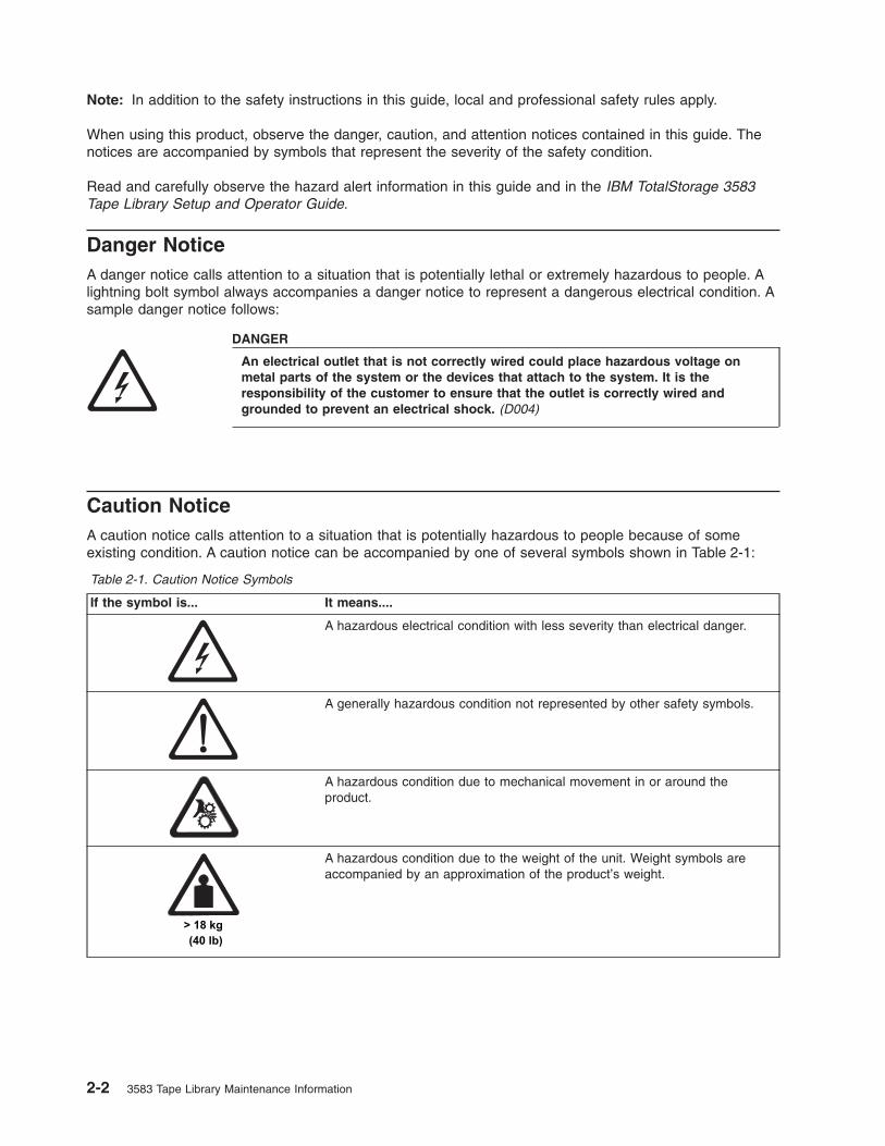
Note: In addition to the safety instructions in this guide, local and professional safety rules apply.
When using this product, observe the danger, caution, and attention notices contained in this guide. The
notices are accompanied by symbols that represent the severity of the safety condition.
Read and carefully observe the hazard alert information in this guide and in the IBM TotalStorage 3583
Tape Library Setup and Operator Guide.
Danger Notice
A danger notice calls attention to a situation that is potentially lethal or extremely hazardous to people. A
lightning bolt symbol always accompanies a danger notice to represent a dangerous electrical condition. A
sample danger notice follows:
DANGER
An electrical outlet that is not correctly wired could place hazardous voltage on
metal parts of the system or the devices that attach to the system. It is the
responsibility of the customer to ensure that the outlet is correctly wired and
grounded to prevent an electrical shock. (D004)
Caution Notice
A caution notice calls attention to a situation that is potentially hazardous to people because of some
existing condition. A caution notice can be accompanied by one of several symbols shown in Table 2-1:
Table 2-1. Caution Notice Symbols
If the symbol is... It means....
A hazardous electrical condition with less severity than electrical danger.
A generally hazardous condition not represented by other safety symbols.
A hazardous condition due to mechanical movement in or around the
product.
A hazardous condition due to the weight of the unit. Weight symbols are
accompanied by an approximation of the product’s weight.
2-2 3583 Tape Library Maintenance Information

Sample caution notices (See Table 2-2):
Table 2-2. Examples of Symbol Use
The controller card contains a lithium battery.
CAUTION:
The battery is a lithium ion battery. To avoid possible explosion, do not burn.
Exchange only with the IBM-approved part. Recycle or discard the battery as
instructed by local regulations. In the United States, IBM has a process for the
collection of this battery. For information, call 1–800–426–4333. Have the IBM part
number for the battery available when you call. (C007)
CAUTION:
To avoid personal injury, before lifting this unit, remove all appropriate subassemblies
per instructions to reduce the system weight. (C012)
CAUTION:
The weight of this part or unit is more than 55 kilograms (121.2 pounds). It takes
specially trained persons and/or a lifting device to safely lift this part or unit. (C011)
CAUTION:
This assembly contains mechanical moving parts. Use care when servicing this
assembly. (C025)
Chapter 2. Safety Instructions 2-3
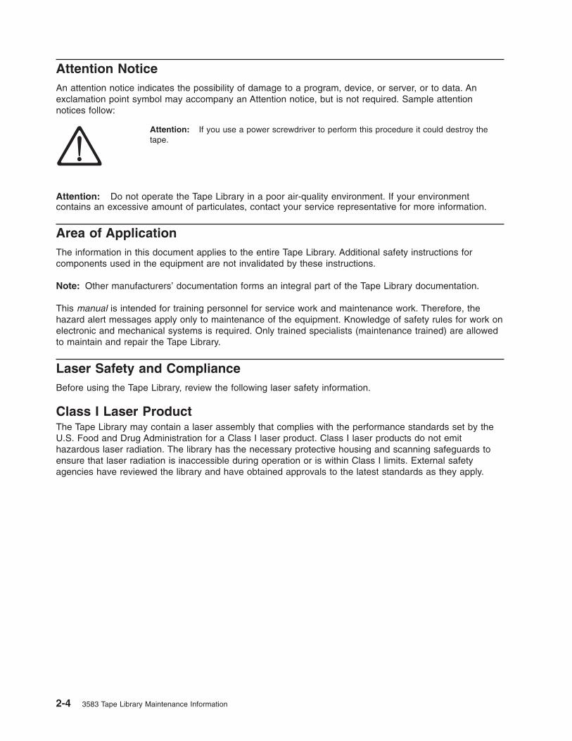
Attention Notice
An attention notice indicates the possibility of damage to a program, device, or server, or to data. An
exclamation point symbol may accompany an Attention notice, but is not required. Sample attention
notices follow:
Attention: If you use a power screwdriver to perform this procedure it could destroy the
tape.
Attention: Do not operate the Tape Library in a poor air-quality environment. If your environment
contains an excessive amount of particulates, contact your service representative for more information.
Area of Application
The information in this document applies to the entire Tape Library. Additional safety instructions for
components used in the equipment are not invalidated by these instructions.
Note: Other manufacturers’ documentation forms an integral part of the Tape Library documentation.
This manual is intended for training personnel for service work and maintenance work. Therefore, the
hazard alert messages apply only to maintenance of the equipment. Knowledge of safety rules for work on
electronic and mechanical systems is required. Only trained specialists (maintenance trained) are allowed
to maintain and repair the Tape Library.
Laser Safety and Compliance
Before using the Tape Library, review the following laser safety information.
Class I Laser Product
The Tape Library may contain a laser assembly that complies with the performance standards set by the
U.S. Food and Drug Administration for a Class I laser product. Class I laser products do not emit
hazardous laser radiation. The library has the necessary protective housing and scanning safeguards to
ensure that laser radiation is inaccessible during operation or is within Class I limits. External safety
agencies have reviewed the library and have obtained approvals to the latest standards as they apply.
2-4 3583 Tape Library Maintenance Information

3583 Library ac Grounding Inspection
1. Power Off the Tape Library by setting the Main Switch on the ac Power Module to the O position.
2. Disconnect all cables.
3. See Figure 2-1. Disconnect the power cord �1� from its source.
4. Check that no voltage exists between the housing on the power source and building ground.
5. Check that resistance is less than 0.1 ohm from the building ground to the power supply enclosure
�3�.
6. Inspect the power cable �1� for visible cracks, wear, or damage.
7. Check that the resistance between the power cable ground and the library frame �2� is less than 0.1
ohm.
8. Inspect the power supply enclosure covers �3� to ensure all screws are installed and tight.
Figure 2-1. AC Grounding Diagram (50 Hz and 60 Hz)
Chapter 2. Safety Instructions 2-5

Guards
The Tape Library system is equipped with the following guards:
v Access Control
v Main Switch
Access to the Library
The Tape Library is completely enclosed in a housing. The only access is provided by the monitored guard
door. The interlock is active when the Main Switch is switched ON.
The housing around the Tape Library serves as a separating guard. It separates the danger area of the
Tape Library system from the normal working area.
The danger area of the Tape Library system is the area in which persons could be injured because of
hazardous movements of the handling unit.
Hazardous movements can be:
v Expected movements
v Unexpected movements
The guard door can be opened from the outside only with a key. An authorized person is responsible for
this key.
CAUTION:
In the Tape Library, movements of components can cause serious injury. Access to this area is,
therefore, restricted to authorized persons. Persons who are not trained in the use of the system
should enter the Library only under supervision.
2-6 3583 Tape Library Maintenance Information

Main Switch
Before working inside the Tape Library or working with electrical components, ensure that the Main
Switch �1� in Figure 2-2 is OFF.
Before Working on Equipment
Before beginning work, become familiar with the location of the:
v Main Switch
v Power source connection
Note: Bridging of door guards is not advisable.
Attention: Never put door guards out of operation other than as instructed by supervision.
All drive units and all hazardous voltages are switched OFF.
Proceed with extreme caution if the system cannot be switched off at the main switch because of required
work (for example, functional checks).
Normal Operating Modes
In normal operation, the host controls the Tape Library.
Emergency Operating Mode
Emergency operations are meant for:
v Manual inserts and retrievals of media
v Manual operation of the drives
a67lo
357
1
Figure 2-2. ac Power Module and dc Power Supplies locations
Chapter 2. Safety Instructions 2-7
Before Restarting Equipment
Movement of components inside the library can cause serious injury. Before starting the Tape
Library, ensure that the library door is closed.
Working on Parts With Line Voltage Present
Caution Statements:
1. Contact with live electrical parts can cause severe or fatal burns and internal injury as the
consequence of electrical shock. After contact with live parts, persons often cannot break loose
from the part by themselves.
2. Components being worked on must only have voltage present when this is specifically
required.
3. Before working on other electrical components, switch OFF power with the Main switch.
4. Never assume a circuit is without power - always test for power off with a meter.
Work on live parts of the equipment must be authorized by supervision.
When performing such work, observe the following:
v Accident prevention rules
v Perform the following:
– Use only suitable tools and measuring devices in good working condition.
– Check the measuring devices for correct adjustment of measuring ranges.
– Work with one hand only. This can prevent injury to internal organs in case of electrical shock.
– Avoid contact with conducting floors (especially metal) or equipment parts. If necessary, cover the
working area with suitable protective rubber mats.
2-8 3583 Tape Library Maintenance Information

Mechanical Maintenance
Observe the following:
v Location of the escape routes and emergency exits - keep these free of obstacles
v Keep dismounted machine components and other parts safe and inaccessible for unauthorized persons
v Keep the equipment clean during work; clean up carefully afterward
Before and after work, remove and reinstall all safety provisions installed for maintenance, such as:
v Covers
v Hazard alert messages
v Warning signs
v Grounding wires
Clothing must be in agreement with the safety rules. Clothing:
v Must not have metal fasteners
v Should be close-fitting so that it cannot be caught in moving machine parts
v Button up or roll up the sleeves.
v Place the ends of a scarf into the clothing.
v For long hair, use a protection that fully covers it.
v Take off watch, rings, and jewelry.
Wear safety glasses when:
v Using a hammer
v Using an electric drill
v Working on springs, and retaining rings.
v Soldering, working on cables
v Cleaning with chemical agents
v All work that endangers the eyes
When handling heavy components, wear safety shoes.
Refrain from any action that could endanger persons or that could damage installations or
equipment.
Safety Check
Check all guards every six months:
v Door interlocks
v Tape Library access
Chapter 2. Safety Instructions 2-9

2-10 3583 Tape Library Maintenance Information

Chapter 3. User Interfaces
Operator Panel . . . . . . . . . . . . . . . . . . . . . . . . . . . . . . . . . 3-2
I/O Station Status Area . . . . . . . . . . . . . . . . . . . . . . . . . . . . . 3-3
Library Status Area . . . . . . . . . . . . . . . . . . . . . . . . . . . . . . 3-5
Drive Status Area . . . . . . . . . . . . . . . . . . . . . . . . . . . . . . . 3-5
Message Area . . . . . . . . . . . . . . . . . . . . . . . . . . . . . . . . 3-7
Operator/CE Panel Menus . . . . . . . . . . . . . . . . . . . . . . . . . . . . 3-7
RMU with TotalStorage Specialist . . . . . . . . . . . . . . . . . . . . . . . . . . 3-8
TotalStorage Specialist Menu Description . . . . . . . . . . . . . . . . . . . . . . 3-8
Top Information Frame . . . . . . . . . . . . . . . . . . . . . . . . . . . . 3-8
Left Navigation Frame . . . . . . . . . . . . . . . . . . . . . . . . . . . . 3-9
Center Navigation Frame . . . . . . . . . . . . . . . . . . . . . . . . . . . 3-9
Status . . . . . . . . . . . . . . . . . . . . . . . . . . . . . . . . . . 3-10
Configuration . . . . . . . . . . . . . . . . . . . . . . . . . . . . . . . 3-11
Firmware . . . . . . . . . . . . . . . . . . . . . . . . . . . . . . . . . 3-12
Diagnostics File . . . . . . . . . . . . . . . . . . . . . . . . . . . . . . 3-13
Operator Panel . . . . . . . . . . . . . . . . . . . . . . . . . . . . . . 3-14
Logs . . . . . . . . . . . . . . . . . . . . . . . . . . . . . . . . . . 3-15
© Copyright IBM Corp. 2000, 2005 3-1

Operator Panel
The operator Panel provides an interactive path between Operator and the Tape Library. See Figure 3-1
for an illustration of the Operator Panel. Visual indications and push-buttons �6� enable the Operator to
control the Tape Library.
The Tape Library Operator Panel is divided into five areas: I/O Station status �1�, library status �2�,
messages �3�, drive status �4�, and softkeys �5�.
Figure 3-1. Operator Panel
3-2 3583 Tape Library Maintenance Information

I/O Station Status Area
The I/O Station status area provides constant information about the I/O Station. See �1� in Figure 3-2.
Table 3-1 on page 3-4 provides a description of the icons shown in the I/O Station status area.
Figure 3-2. I/O Station Status Area
Chapter 3. User Interfaces 3-3

Figure 3-2 on page 3-3 provides an illustration of the icons shown in the I/O Station status area.
Table 3-1. I/O Station Icons
Icon Description
This icon is displayed on screen if the host has issued a PREVENT/ALLOW MEDIUM
REMOVAL SCSI command and locked the I/O Station.
This icon is displayed on screen if the I/O Station is locked. The I/O Station can be locked
by the following conditions.
v The host issues a PREVENT/ALLOW MEDIUM REMOVAL SCSI command and locks the
I/O Station
v The Tape Library is accessing an I/O Station slot.
v The I/O Station has been configured as all storage.
This icon is displayed if the I/O Station is unlocked.
These icons are displayed on screen for the six I/O Station states.
State 1: The I/O Station door is closed. Any cartridge in the I/O Station has previously been
inventoried.
State 2: The I/O Station door is partially open. Any cartridge in the I/O Station has previously
been inventoried.
State 3: The I/O Station door is fully open. Any cartridge in the I/O Station has previously
been inventoried. For an import operation, a cartridge can be inserted.
State 4: The I/O Station door is closed. A cartridge has been exported and not yet removed.
State 5: The I/O Station door is partially open. A cartridge has been exported and not yet
removed.
State 6: The I/O Station door is fully open. A cartridge has been exported and not yet
removed. While in this state, an exported cartridge can be removed.
These icons are displayed on screen to show the possible configurations of the I/O station.
Type 1: A single slot I/O Station icon (available on the standard I/O station).
Type 2: An I/O Station icon showing cartridges as indicated by the blackened out slots. A
total of 12 slots are available (only available on the optional multiple I/O station feature).
Type 3: A continuous storage icon. A total of 12 slots are available (only available on the
optional multiple I/O station feature).
3-4 3583 Tape Library Maintenance Information

Library Status Area
The library status area displays the current location, activity or state of the library. See �1� in Figure 3-3.
Table 3-2 describes the text displayed in the library status area.
Table 3-2. Library Status Area
Text Definition
OFFLINE The media changer equipment is in an Offline state.
ONLINE The media changer equipment is in an Online state.
Status or Attention Message The library reports status or messages to solicit operator intervention.
Drive Status Area
The drive status area provides constant information about the drives. See �1� in Figure 3-4.
Table 3-3 on page 3-6 provides a description of the icons shown in the drive status area.
Figure 3-3. Library Status Area
Figure 3-4. Drive Status Area
Chapter 3. User Interfaces 3-5

Figure 3-4 on page 3-5 provides an illustration of the icons shown in the drive status area.
Table 3-3. Drive Status Icons
Status Icon Description
Drive Present
A tape drive is present but does not contain a cartridge.
Power On
If power is applied to the tape drive, the Power On icon is
displayed.
Cleaning Required
If the tape drive cleaning is required, the Cleaning Required icon
is displayed.
Error Code
n
If a drive error occurs, an error code displays. See Table 6-4 on
page 6-25 for a list of drive error codes. “n” represents the
character displayed, it can be:
0 − 9, or A, B, E, F, o, c, b, d, h or C.
Compression On
If the tape drive is compressing data on tape, the Compression
On icon is displayed.
Write Protect
If the tape is write protected, the Write Protect icon is displayed.
Tape Activity
A tape drive is loading a cartridge.
A tape drive has a cartridge loaded.
A tape drive is rewinding a cartridge.
A tape drive is unloading a cartridge.
A tape drive has unloaded a cartridge.
A tape drive is reading data from a cartridge.
A tape drive is writing data to a cartridge.
A tape drive is erasing data from a cartridge.
A tape drive is locating data on a cartridge.
3-6 3583 Tape Library Maintenance Information
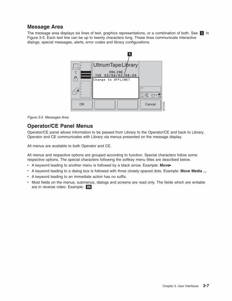
Message Area
The message area displays six lines of text, graphics representations, or a combination of both. See �1� in
Figure 3-5. Each text line can be up to twenty characters long. These lines communicate interactive
dialogs, special messages, alerts, error codes and library configurations.
Operator/CE Panel Menus
Operator/CE panel allows information to be passed from Library to the Operator/CE and back to Library.
Operator and CE communicates with Library via menus presented on the message display.
All menus are available to both Operator and CE.
All menus and respective options are grouped according to function. Special characters follow some
respective options. The special characters following the softkey menu titles are described below.
v A keyword leading to another menu is followed by a black arrow. Example: Move�
v A keyword leading to a dialog box is followed with three closely spaced dots. Example: Move Media ...
v A keyword leading to an immediate action has no suffix.
v Most fields on the menus, submenus, dialogs and screens are read only. The fields which are writable
are in reverse video. Example: �ON�
Figure 3-5. Messages Area
Chapter 3. User Interfaces 3-7

RMU with TotalStorage Specialist
The Remote Management Unit (RMU) provides remote access to the Ultrium Scalable Tape Library over a
network. You can attach the library to the network through a 10/100 Ethernet port on the RMU. Any server
on the network can access the library if it has a web browser installed. All available functions are
accessible without the need of a dedicated server or separate software. With the RMU and the
TotalStorage Specialist software application you can access many of the functions that are described in
the Operating Procedures chapter of the IBM TotalStorage Ultrium Scalable Tape Library 3583 Setup and
Operator Guide.
Note: Operation of the library from a browser will be slower than using the operator panel.
The operator panel page of the TotalStorage Specialist web interface is protected by a password and is a
direct interface to the operator panel of the attached library. It allows you to monitor the activity of the
library. Any action that you perform (for example, pressing a button) is shown both on the web page and
on the attached library.
TotalStorage Specialist Menu Description
The TotalStorage Specialist Home page is divided into three areas, the left navigation frame �1�, the
center navigation frame �2�, and the top information frame �3� (see Figure 3-6).
Top Information Frame
The top information frame (�3� in Figure 3-6) contains information for you to identify the tape library that
you are remotely managing. The frame shows the URL identifier and library type. The URL identifier is the
hostname given to the library during initial configuration. The library type is the ID string of the library and
is taken from standard inquiry data.
Figure 3-6. TotalStorage Specialist home page
3-8 3583 Tape Library Maintenance Information
|
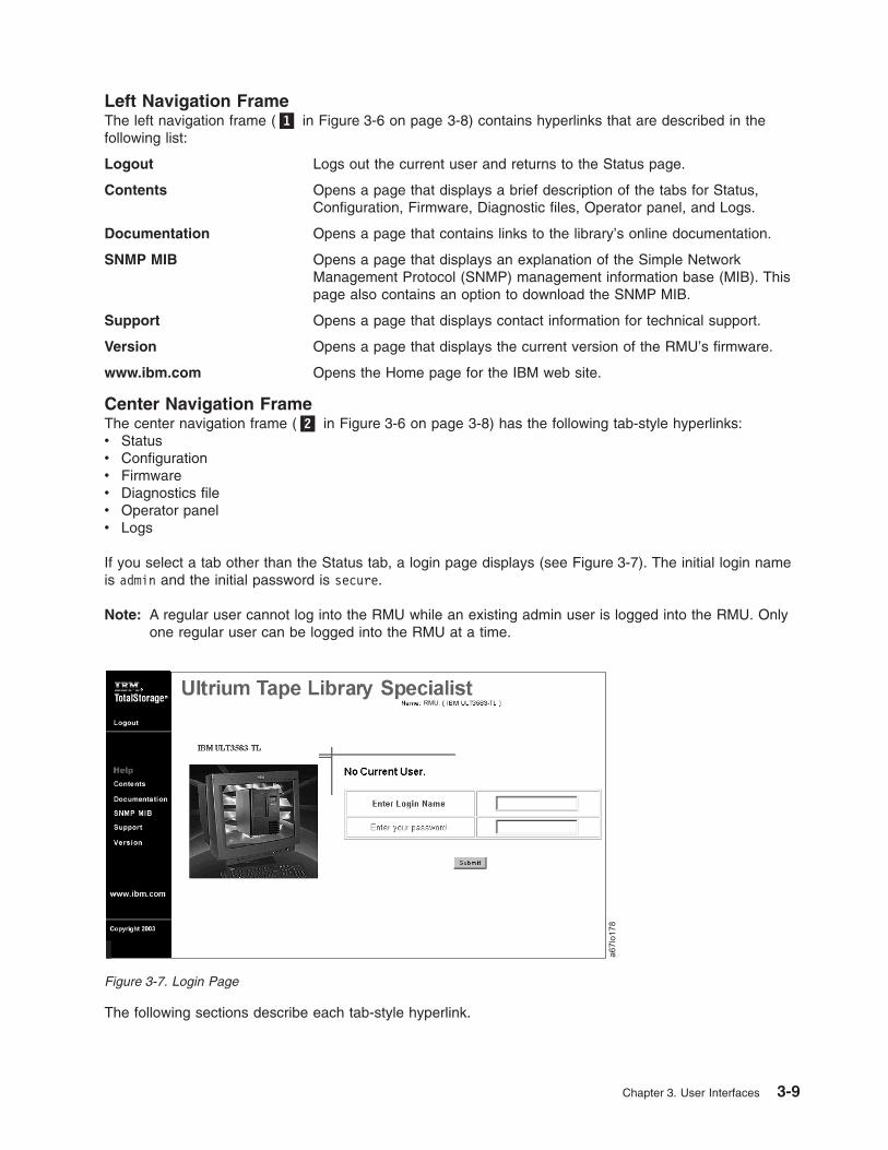
Left Navigation Frame
The left navigation frame (�1� in Figure 3-6 on page 3-8) contains hyperlinks that are described in the
following list:
Logout Logs out the current user and returns to the Status page.
Contents Opens a page that displays a brief description of the tabs for Status,
Configuration, Firmware, Diagnostic files, Operator panel, and Logs.
Documentation Opens a page that contains links to the library’s online documentation.
SNMP MIB Opens a page that displays an explanation of the Simple Network
Management Protocol (SNMP) management information base (MIB). This
page also contains an option to download the SNMP MIB.
Support Opens a page that displays contact information for technical support.
Version Opens a page that displays the current version of the RMU’s firmware.
www.ibm.com Opens the Home page for the IBM web site.
Center Navigation Frame
The center navigation frame (�2� in Figure 3-6 on page 3-8) has the following tab-style hyperlinks:
v Status
v Configuration
v Firmware
v Diagnostics file
v Operator panel
v Logs
If you select a tab other than the Status tab, a login page displays (see Figure 3-7). The initial login name
is admin and the initial password is secure.
Note: A regular user cannot log into the RMU while an existing admin user is logged into the RMU. Only
one regular user can be logged into the RMU at a time.
The following sections describe each tab-style hyperlink.
Figure 3-7. Login Page
Chapter 3. User Interfaces 3-9

Status
The Status page displays the current status of the library. From this page you can easily see if there are
problems with the system (see Figure 3-8).
The Status page is not protected by a password and is active even when you are not logged into the
RMU. If you select any tab other than the Status tab, a login page displays (see Figure 3-9). The initial
login name is admin and the initial password is secure.
Note: A regular user cannot log into the RMU while an existing admin user is logged into the RMU. Only
one regular user can be logged into the RMU at a time.
a67lo
177
Figure 3-8. Status page
Figure 3-9. Login Page
3-10 3583 Tape Library Maintenance Information

Configuration
The Configuration page is protected by a password and allows you to configure the remote management
unit. Network configuration (including SNMP), user configuration (adding users, setting passwords), and
date and time setup are all entered on this page (see Figure 3-10). The initial RMU network configuration
is done through the library operator panel during library installation and setup (see the IBM TotalStorage
Ultrium Scalable Tape Library 3583 Setup and Operator Guide).
a67lo
179
Figure 3-10. Configuration page
Chapter 3. User Interfaces 3-11

Firmware
The Firmware page (see Figure 3-11) is protected by a password and allows you to update the firmware of
the attached library, the RMU, or the drives in the library. For instructions about updating firmware, see
“Updating Firmware” on page 4-114.
Figure 3-11. Firmware page
3-12 3583 Tape Library Maintenance Information

Diagnostics File
The Diagnostics file page is protected by a password and allows you to upload (to a local computer) the
diagnostic information from the attached library. The diagnostic information may be useful to service
personnel in diagnosing problems. Information from the library (command and error logs), information from
the RMU (support and error log), and information from each installed drive (error and dump) can be
retrieved in text form. The system snapshot is a machine-decodable file which can only be used by service
personnel (see Figure 3-12).
Figure 3-12. Diagnostics file page
Chapter 3. User Interfaces 3-13

Operator Panel
The Operator panel page is protected by a password and is a direct interface to the operator panel of the
attached library. It allows you to monitor the activity of the library. Any action that you perform (for
example, pressing a button) is shown both on this page and on the attached library (see Figure 3-13).
Figure 3-13. Operator panel page
3-14 3583 Tape Library Maintenance Information

Logs
The Logs page is protected by a password and shows the last few entries of the library command log (see
Figure 3-14). To view the entire log, download it from the Diagnostics file page (see Figure 3-12 on page
3-13).
a67lo
183
StorWatchRMU
Figure 3-14. Logs page
Chapter 3. User Interfaces 3-15

3-16 3583 Tape Library Maintenance Information

Chapter 4. Operating Procedures
This chapter provides a summary of library operations, such as starting up, shutting down, handling media,
updating firmware, and cleaning drives. Use the following table to quickly locate operating procedures. The
procedures listed below are available from the library’s operator panel. Because the TotalStorage
Specialist web interface on the Remote Management Unit (RMU) has an operator panel tab selection, the
same procedures are available remotely. The RMU, however, has additional tab selections, such as
Firmware, Diagnostic file. These tab selections allow you to download library, drive and RMU firmware,
and to upload library log information by using the RMU.
If You Want To Do This... Go To Page...
Add or remove control paths 14-45
Calibrate the library 4-101
Choose the method of inventory 4-72
Clean a drive 4-49
Clear the drive’s error log 4-31
Configure the I/O station as storage slots 14-47
Copy a drive dump 4-34
Create or erase an FMR tape 4-105
Disable security 4-77
Enable and disable backlighting and audio 4-71
Enable or disable automatic cleaning 4-49
Enable security 14-49
Exercise the library 4-95
Export a cartridge from the library 4-56
Extend VOLSER length 4-107
Force a drive dump 4-32
Import a cartridge into the library 4-47
Move a cartridge 4-38
Move the picker 4-41
Partition the physical library into a logical library 4-48
Perform a demonstration of the library 4-95
Perform an inventory of the library 4-43
Perform a self test of the library 4-97
Perform a verify test of the library 4-99
Remove or replace a tape drive 4-107
Reset a tape drive 4-59
Resolve errors 4-80
Run drive diagnostics 4-103
Run library diagnostics 4-82
Scan media in drives 4-54
Select the online or offline state 4-5
Set up remote communication with the library 4-61
© Copyright IBM Corp. 2000, 2005 4-1

Unload a cartridge from a drive 4-58
Update drive, library, and RMU firmware 4-114
Upload library error log information by using the RMU 4-113
Use the Main Menu 4-4
If You Want To Change This... Go To Page...
Date and time 4-68
Drive SCSI ID 4-64
Drive FC ID 4-66
Password 14-50
If You Want To Check This... Go To Page...
Functionality of the bar code reader 4-88
Get and put capability of the picker 4-83
Homing capability of the picker 4-94
Motion patterns of the picker 4-90
Movement of the picker 4-90
Open, close, reach, and retract capabilities of the picker 4-87
Step capability of the picker 4-92
Sensors and locking or unlocking of the I/O station door 4-82
If You Want To View This... Go To Page...
Drive SCSI ID 4-64
Drive FC ID 4-66
Drive status 4-17
Library status and usage 4-15
Storage slot status and usage 4-18
Cartridge locations 4-23
Information about a drive 4-17
Information about a storage slot 4-19
Command log 4-25
Drive error log 4-30
Feature license 4-79
Library serial number and firmware level 4-110
4-2 3583 Tape Library Maintenance Information
|
|

Flowchart of Library Functions
Library
Drives
Logs
Library
Drives
Utils
Drives
StartLibrary
Diags
Exercise
SensorsLock/Unlock
Fingers
Picker
Move
I/O Station
Drives
System
Slot
Media
*Partitions/**SCSI
MEDIA
RMU
More
Demonstration
Self TestVerifyTestTeach
Read/Write Tests
Power On Self Test
SCSI/Fiber Wrap TestError Report
Run Diagnostics
Create/Erase FMR Tape
Remove or Replace DriveCancel
Get/Put
Step
Bar Code Scanner
Move
Step
Home
Move Media
*Applies to units with Multi-Path feature**Applies to units without Multi-Path feature
Position Picker
Scan Bar Code
Import
AutoClean
Export
Unload
Reset
Update Firmware
Command Log
Error Log
Drive LogOptions
Clear Log
Force Dump
Copy DumpPreserve Dump Date/Time
AutoCleanScan Media
*FC/SCSI...
*License
Config
Secure
More
About the LibrarySetup
Online/Offline
Service
Status Command More
a67lo
230
Figure 4-1. Flowchart of library functions
Chapter 4. Operating Procedures 4-3

Using the Main Menu
The Main Menu is the first interactive menu that displays after you turn on the power. The Main Menu
consists of two screens: the initial screen and the alternate screen. You can select all subsequent menus
and options from these two screens. Figure 4-2 shows the Main Menu’s initial screen and Figure 4-3
shows the Main Menu’s alternate screen.
To display the Main Menu’s alternate screen, press the button below the More softkey. The alternate
screen displays (see Figure 4-3).
To redisplay the Main Menu’s initial screen, press the button below the Back softkey. To choose any of the
selections, press the button below the desired softkey.
Figure 4-2. Main Menu (initial screen)
Figure 4-3. Main Menu (alternate screen)
4-4 3583 Tape Library Maintenance Information
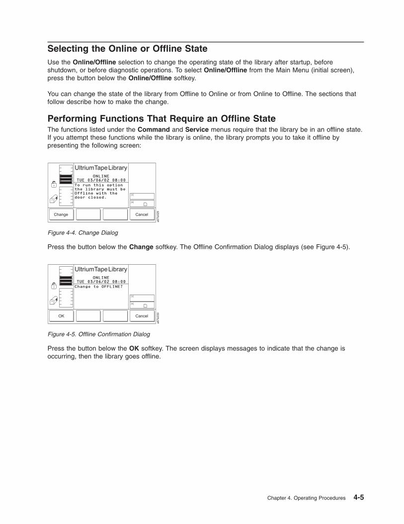
Selecting the Online or Offline State
Use the Online/Offline selection to change the operating state of the library after startup, before
shutdown, or before diagnostic operations. To select Online/Offline from the Main Menu (initial screen),
press the button below the Online/Offline softkey.
You can change the state of the library from Offline to Online or from Online to Offline. The sections that
follow describe how to make the change.
Performing Functions That Require an Offline State
The functions listed under the Command and Service menus require that the library be in an offline state.
If you attempt these functions while the library is online, the library prompts you to take it offline by
presenting the following screen:
Press the button below the Change softkey. The Offline Confirmation Dialog displays (see Figure 4-5).
Press the button below the OK softkey. The screen displays messages to indicate that the change is
occurring, then the library goes offline.
Figure 4-4. Change Dialog
Figure 4-5. Offline Confirmation Dialog
Chapter 4. Operating Procedures 4-5

Accessing the Status Menu
To access the Status Menu:
From the Main Menu’s initial screen, press the button below the Status softkey. The Status Menu displays
(see Figure 4-7).
Figure 4-6. Main Menu (initial screen)
Figure 4-7. Status Menu
4-6 3583 Tape Library Maintenance Information
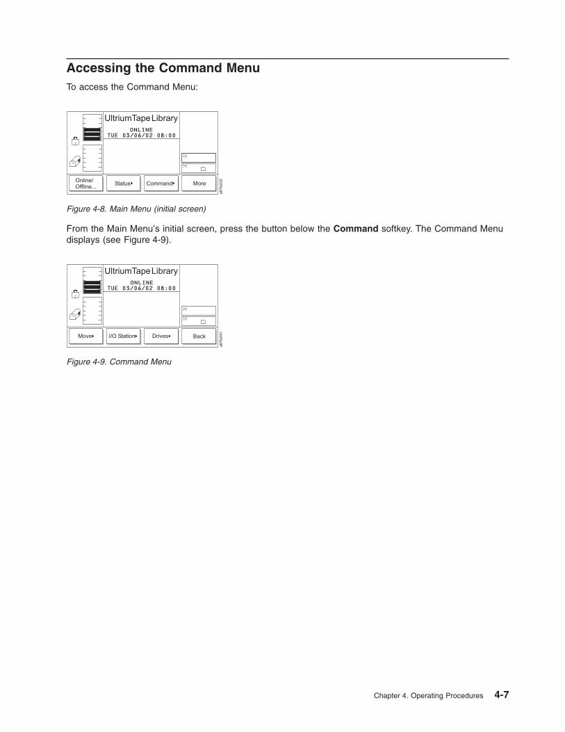
Accessing the Command Menu
To access the Command Menu:
From the Main Menu’s initial screen, press the button below the Command softkey. The Command Menu
displays (see Figure 4-9).
Figure 4-8. Main Menu (initial screen)
Figure 4-9. Command Menu
Chapter 4. Operating Procedures 4-7

Accessing the Setup Menu
To access the Setup Menu:
From the Main Menu’s initial screen, press the button below the More softkey. The Main Menu’s alternate
screen displays (see Figure 4-11).
Press the button below the Setup softkey. The Setup Menu displays (see Figure 4-12).
Figure 4-10. Main Menu (initial screen)
Figure 4-11. Main Menu (alternate screen)
Figure 4-12. Setup Menu
4-8 3583 Tape Library Maintenance Information

Accessing the Service Menu
To access the Service Menu:
From the Main Menu’s initial screen (see Figure 4-13), press the button below the More softkey. The Main
Menu’s alternate screen displays (see Figure 4-14).
Press the button below the Service softkey. The Service Menu displays (see Figure 4-15).
Figure 4-13. Main Menu (initial screen)
Figure 4-14. Main Menu (alternate screen)
Figure 4-15. Service Menu
Chapter 4. Operating Procedures 4-9

Accessing the About the Library (About...) Menu
To access the About.. Menu:
From the Main Menu’s initial screen, press the button below the More softkey. The Main Menu’s alternate
screen displays (see Figure 4-17).
Press the button below the About softkey. The About Menu displays the library’s serial number and
current version of firmware (see Figure 4-18).
Operator Intervention Message
If a problem causes an operator intervention message to appear, see Table 6-2 on page 6-19 for an
explanation of the parameters in the message.
Operator Information Message
During the course of normal operation, operator information messages appear. See “Operator Information
Messages” on page 6-24 for a list of the available messages.
Figure 4-16. Main Menu (initial screen)
Figure 4-17. Main Menu (alternate screen)
OK About... Cancel
ONLINE
a6
7lo
30
6
ULT3583-TL(C) 2000 IBM
SerNum : 90240050200Version: 6.01.0009
Details
UltriumTapeLibrary
03/06/03 08:00TUE
Figure 4-18. About Menu
4-10 3583 Tape Library Maintenance Information

Turning on the Power to the Tape Library
Perform the following to start the Ultrium Scalable Tape Library:
1. Securely latch the front door. The library does not require the door to be locked to operate properly.
You can lock the front door for library security or to prevent the door from being opened accidentally.
CAUTION:
Movements of mechanical components in the tape library can cause serious injury.
Before turning the main power switch ON, confirm that no danger exists to personnel
or property.
2. Push | on the main power switch (�1� in Figure 4-19) to turn on the power.
Power is applied to the tape library. The firmware starts the boot process with an introductory splash
screen (see Figure 4-20).
a67lo
357
1
Figure 4-19. Main power switch
a67lo
093
One moment, the
library is booting...
Figure 4-20. Splash screen
Chapter 4. Operating Procedures 4-11

The firmware initiates a SELF-TEST, TEACH (auto-configuration), and SCANNING operation. After all of
the firmware procedures are completed, the operator panel displays the Main Menu (initial screen) (see
Figure 4-21).
Shutting Down the Tape Library
You can shut down the Ultrium Scalable Tape Library normally or by the emergency shutdown method.
Attention: Except in emergencies, stop the library with the normal shutdown procedure before switching
off the main power switch. IBM is not responsible for damage that is caused by improper use of the main
power switch. All risk lies entirely with the user.
Performing a Normal Shutdown
To properly shut down the Ultrium Scalable Tape Library, perform the following steps:
1. Ensure that all cartridges are removed from the drives and are stored in the library’s storage slots.
2. Push O on the main power switch (�1� in Figure 4-19 on page 4-11) to turn off the power. Power is
removed from the tape library.
Performing an Emergency Shutdown
Attention: Perform the following in cases of emergency only.
Push O on the main power switch (�1� in Figure 4-19 on page 4-11) to turn off power. Power is removed
from the tape library. All picker movements stop immediately.
Figure 4-21. Main Menu (initial screen)
4-12 3583 Tape Library Maintenance Information

Restarting the Tape Library
Perform the following to restart the Ultrium Scalable Tape Library:
1. If applicable, correct any conditions that required a shutdown of the tape library.
2. See “Turning on the Power to the Tape Library” on page 4-11 for instructions about powering-on the
tape library.
Inserting Media
You can insert media into the Ultrium Scalable Tape Library by using the I/O station or by opening the front
door (a method called direct insertion). Use direct insertion the first time that you insert media into the
library. The sections that follow describe each method.
Inserting Media Through the I/O Station
Placement of new media into the library is best accomplished by using the I/O station. Using the I/O
station to insert cartridges (import) does not disrupt library operations. To insert cartridges through the I/O
station, perform the following procedure:
1. Open the door of the I/O station.
2. Insert the cartridge into an empty storage slot.
3. Close the door of the I/O station. The library locks the I/O station and executes the TEACH and
INVENTORY procedures for column 1. It then unlocks the I/O station.
4. Move the cartridge to the desired storage slot by using one of the following methods:
v Use the server’s software application.
v Issue the SCSI MOVE MEDIUM command from the server, with the source I/O station element
address and the destination storage element address.
v Refer to the procedure in “Importing a Cartridge into the Library” on page 4-47.
v Refer to the procedure in “Moving a Cartridge” on page 4-38.
Inserting Media Directly into the Tape Library
Attention: Do not use this method to insert a cleaning cartridge into the library. To insert a cleaning
cartridge, see “Enabling and Disabling Automatic Cleaning” on page 4-49.
To directly insert media, perform the following procedure:
1. Use the operator panel to place the library into the Offline state (Main Menu > Online/Offline > OK).
The picker completes any current task.
2. Unlock and open the library door.
3. Place the cartridge into the desired storage slot.
4. Close and lock the door.
The library executes the TEACH and INVENTORY procedures.
Chapter 4. Operating Procedures 4-13
Removing Media
You can remove media from the Ultrium Scalable Tape Library by using the I/O station or by opening the
front door (a method called direct removal). The sections that follow describe each method.
Removing Media Through the I/O Station
Use the I/O station to remove media from the library. Using the I/O station to remove cartridges (export)
does not disrupt library operations. To remove cartridges through the I/O station, perform the following
procedure:
1. Select the cartridges that you want to move to the I/O station by using one of the following methods:
v Use the server’s software application.
v Issue a SCSI MOVE MEDIUM command from the server with the source storage element address
and the destination I/O station element address.
v Refer to the procedure in “Exporting a Cartridge from the Library” on page 4-56.
v Refer to the procedure in “Moving a Cartridge” on page 4-38.
2. Open the door of the I/O station.
3. Remove the cartridge from the storage slot.
4. Close the door of the I/O station.
The library locks the I/O station and executes the TEACH and INVENTORY procedures for column 1. It
then unlocks the I/O station.
Removing Media Directly from the Tape Library
Attention: Do not use this method to remove a cleaning cartridge from the library. To remove a cleaning
cartridge, see “Enabling and Disabling Automatic Cleaning” on page 4-49.
To directly remove media, perform the following procedure:
1. Use the operator panel to place the library into the Offline state (Main Menu > Online/Offline > OK).
The picker completes any current task.
2. Unlock and open the library door.
3. Remove the cartridge from the desired storage slot.
4. Close and lock the door.
The library executes the TEACH and INVENTORY procedures.
4-14 3583 Tape Library Maintenance Information

Viewing Library Status and Usage
Library status and usage can viewed via the RMU and the Operator Panel.
From the Web
The status page displays the current status of the library. From this page you can easily see if there are
problems with the system (see Figure 4-22).
The status page is not protected by a password and is active even when you are not logged into the RMU.
From the Operator Panel
To view the quantity of occupied and empty storage slots, I/O station slots, and drives in the library,
perform the following steps. This procedure also allows you to determine usage statistics for the library.
Shortcut: Main Menu (initial screen) —> Status —> Library —> System
—> Next
1. Navigate to the Status Menu. For instructions, see “Accessing the Status Menu” on page 4-6.
a67lo
177
Figure 4-22. Status page
Chapter 4. Operating Procedures 4-15
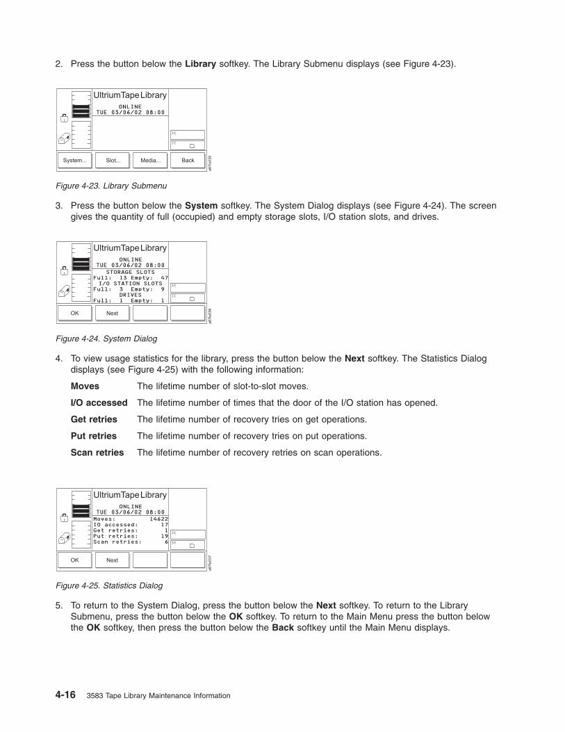
2. Press the button below the Library softkey. The Library Submenu displays (see Figure 4-23).
3. Press the button below the System softkey. The System Dialog displays (see Figure 4-24). The screen
gives the quantity of full (occupied) and empty storage slots, I/O station slots, and drives.
4. To view usage statistics for the library, press the button below the Next softkey. The Statistics Dialog
displays (see Figure 4-25) with the following information:
Moves The lifetime number of slot-to-slot moves.
I/O accessed The lifetime number of times that the door of the I/O station has opened.
Get retries The lifetime number of recovery tries on get operations.
Put retries The lifetime number of recovery tries on put operations.
Scan retries The lifetime number of recovery retries on scan operations.
5. To return to the System Dialog, press the button below the Next softkey. To return to the Library
Submenu, press the button below the OK softkey. To return to the Main Menu press the button below
the OK softkey, then press the button below the Back softkey until the Main Menu displays.
Figure 4-23. Library Submenu
Figure 4-24. System Dialog
Figure 4-25. Statistics Dialog
4-16 3583 Tape Library Maintenance Information

Viewing Drive Status
To view the quantity and location of occupied and empty drives in the library, refer to the icons on the
operator panel.
Viewing Information about a Drive
To view each drive’s number (location in the drive column), type, serial number, version of firmware, and
SCSI ID, perform the following steps.
Shortcut: Main Menu (initial screen) —> Status —> Drives —> Change
Drive
1. Navigate to the Status Menu. For instructions, see “Accessing the Status Menu” on page 4-6.
2. Press the button below the Drives softkey. The Drives Dialog displays (see Figure 4-26).
The Drives Dialog contains the following information about the currently selected drive:
Drive The number of the drive. The number is based on the location of the drive in the drive
column. The numbers range from 01 to 06, from bottom to top.
Type The type of the drive (IBM LTO).
Ser Num The serial number of the drive.
Version The level of firmware installed in the drive.
SCSI ID The SCSI ID of the drive.
3. To view the information about another drive, press the button below the Change Drive softkey until the
number of the drive that you want displays in the Drive field. The screen automatically refreshes with
information about that drive.
4. To return to the Status Menu, press the button below the OK or Cancel softkey. To return to the Main
Menu press the button below the OK or Cancel softkey, then press the button below the Back softkey
until the Main Menu displays.
Figure 4-26. Drives Dialog
Chapter 4. Operating Procedures 4-17

Viewing Storage Slot Status and Usage
To view the quantity of occupied and empty storage slots, perform the following steps. This procedure also
allows you to determine usage statistics for each storage slot.
To view the locations of cartridges in the library, see “Viewing Information about a Storage Slot” on page
4-19.
Shortcut: Main Menu (initial screen) —> Status —> Library —> System
1. Navigate to the Status Menu. For instructions, see “Accessing the Status Menu” on page 4-6.
2. Press the button below the Library softkey. The Library Submenu displays (see Figure 4-27).
3. Press the button below the System softkey. The System Dialog displays (see Figure 4-28). The screen
gives the number of full (occupied) and empty storage slots. It also lists the number of full and empty
I/O station slots and drives.
4. To return to the Library Submenu, press the button below the OK softkey. To return to the Main Menu
press the button below the OK softkey, then press the button below the Back softkey until the Main
Menu displays.
Figure 4-27. Library Submenu
Figure 4-28. System Dialog
4-18 3583 Tape Library Maintenance Information

Viewing Information about a Storage Slot
For each storage slot, you can view its 3-character physical address, whether it is full, empty or unable to
be occupied, and the bar code number and home position of the cartridge that occupies it. To view this
information, perform the following steps.
Shortcut: Main Menu (initial screen) —> Status —> Library —> Slot
1. Navigate to the Status Menu. For instructions, see “Accessing the Status Menu” on page 4-6.
2. Press the button below the Library softkey. The Library Submenu displays (see Figure 4-29).
3. Press the button below the Slot softkey. The Slot Dialog displays (see Figure 4-30) with a message
area that shows three icons.
v The left icon represents the columns in the library, with an arrow pointed to the column that is
currently selected.
v The middle icon represents the magazines in the currently selected column. The arrow points to the
currently selected magazine.
v The right icon represents the storage slots in the currently selected column and magazine. The
arrow points to the currently selected storage slot.
The position of the arrow in each of the three icons identifies the storage slot’s physical address. For
example, arrows that point to a column 1, magazine C, and storage slot 1 indicate a physical address
of 1 C 1. In the Slot Dialog, a slot’s physical address displays below the right icon (see Figure 4-30).
Figure 4-29. Library Submenu
Figure 4-30. Slot Dialog
Chapter 4. Operating Procedures 4-19

4. Perform one of the following:
v To view information about the currently selected storage slot, press the button below the OK softkey.
The Slot Status Dialog displays (see Figure 4-33 on page 4-21).
v To view information about another storage slot, specify its physical address by performing the
following steps:
a. Press the button below the Change Column softkey until the arrow in the left icon points to the
column that you want. Press the button below the Next softkey. The Change Magazine Dialog
displays (see Figure 4-31).
Note: If you choose the drive column (column 3), the Change Drive Dialog displays because no
slots or magazines are available in this column. To choose a different column, press the
button below the Next softkey, then press the button below the Change Column softkey
until the arrow points to the column that you want. Press the button below the Next
softkey to display the Change Magazine Dialog.
b. Press the button below the Change Magazine softkey until the arrow in the middle icon points
to the magazine that you want. Press the button below the Next softkey. The Change Slot
Dialog displays (see Figure 4-32).
c. Press the button below the Change Slot softkey until the arrow in the right icon points to the
storage slot that you want.
d. Perform one of the following:
– To accept the physical address of storage slot (located below the right icon), press the button
below the OK softkey.
– To cycle through the Change Column, Change Magazine, and Change Slot choices again,
press the Next softkey. Make your selections, then press the button below the OK softkey.
The screen similar to the Slot Status Dialog displays (see Figure 4-33 on page 4-21). The screen
shows the new 3-character address that you specified.
Figure 4-31. Change Magazine Dialog
Figure 4-32. Change Slot Dialog
4-20 3583 Tape Library Maintenance Information

The Slot Status Dialog contains the following information about the currently selected storage slot:
Slot The three-position physical address of the storage slot. Represented as x y z, where x
equals the number of the column, y equals the number of the magazine, and z equals
the number of the storage slot.
Status Indication of whether the cartridge is present (Full) or not present (Empty).
Volser Bar code number of the cartridge in the storage slot (the bar code number is also
called the volume serial number). If no cartridge is present in the slot, the value of this
field is None.
Source Element address of the cartridge in the storage slot (see “Element Addressing” on
page C-1). If no cartridge is present, the value of this field is None.
Valid Indication of whether the slot can (Yes) or cannot (No) be used.
To return to the Slot Dialog (see Figure 4-30 on page 4-19), press the button below the OK softkey.
5. To view information about put and get operations for the slot, press the button below the Next softkey.
The Put/Get Information screen displays (see Figure 4-34).
The Put/Get Information screen contains the following information about the currently selected storage
slot:
Total Puts Total put operations.
Put Retries Number of put retry operations.
Get Retries Number of get retry operations.
Reserved Indication of whether the slot is reserved (Yes) or not reserved (No) by a SCSI host.
Reserve ID The identifier for the slot reservation that was made by the SCSI host.
Reserved by The identifier of the host that reserved the slot.
To return to the Slot Dialog (see Figure 4-30 on page 4-19), press the button below the OK softkey.
6. To view the coordinates that the X-, Y-, and Z-axes use to move cartridges to and from the selected
slot, press the button below the Next softkey. The Position Dialog displays (see Figure 4-35 on page
4-22).
Figure 4-33. Slot Status Dialog. If you specified another slot, the new address displays in the Slot field.
Figure 4-34. Put/Get Information
Chapter 4. Operating Procedures 4-21

The Position Dialog contains the following information about the currently selected storage slot:
X-POS GET Rotary coordinate that the picker uses to retrieve a cartridge from the selected slot.
Y-POS GET Vertical coordinate that the picker uses to retrieve a cartridge from the selected slot.
Z-POS GET Horizontal coordinate that the picker uses to retrieve a cartridge from the selected slot.
X-POS PUT Rotary coordinate that the picker uses to insert a cartridge into the selected slot.
Y-POS PUT Vertical coordinate that the picker uses to insert a cartridge into the selected slot.
Z-POS PUT Horizontal coordinate that the picker uses to insert a cartridge into the selected slot.
7. To return to the Slot Status Dialog (see Figure 4-33 on page 4-21), press the button below the Next
softkey. To return to the Slot Dialog (see Figure 4-30 on page 4-19), press the button below the OK
softkey. To return to the Main Menu, press the button below the OK —> Cancel —> Back softkeys.
Continue to press the button below the Back softkey until the Main Menu displays.
Figure 4-35. Position Dialog
4-22 3583 Tape Library Maintenance Information

Viewing Cartridge Locations
To view the volume serial number (VOLSER), column, section, row, and cell number of a selected tape
cartridge, perform the following steps:
Shortcut: Main Menu (initial screen) —> Status —> Library —> Media
1. Navigate to the Status Menu. For instructions, see “Accessing the Status Menu” on page 4-6.
2. Press the button below the Library softkey. The Library Submenu displays (see Figure 4-36).
3. Press the button below the Media softkey. The Media Dialog displays a list of tape cartridges in the
library by their VOLSERs and their locations (see Figure 4-37). The location is a 3-character physical
address (x y z) where x equals the number of the column, y equals the number of the magazine, and
z equals the number of the storage slot.
Figure 4-36. Library Submenu
Figure 4-37. Media Dialog
Chapter 4. Operating Procedures 4-23
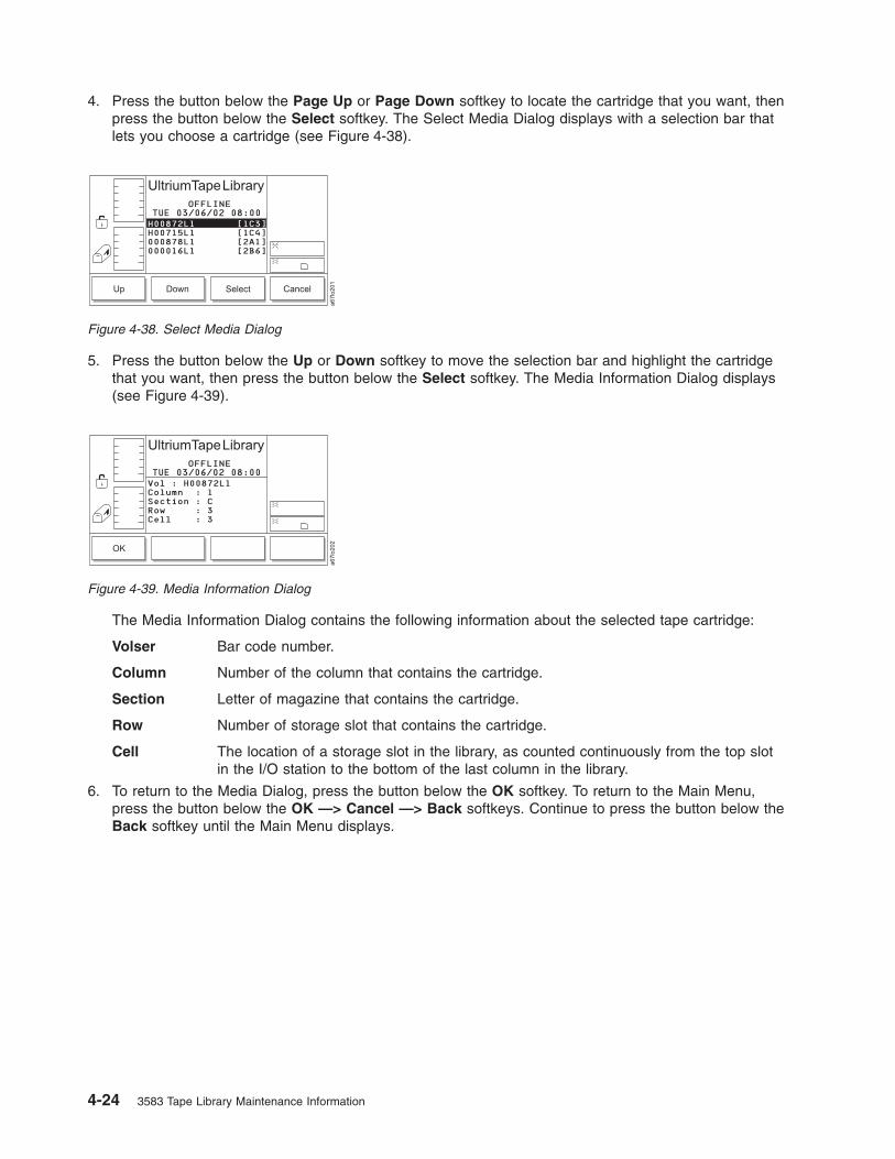
4. Press the button below the Page Up or Page Down softkey to locate the cartridge that you want, then
press the button below the Select softkey. The Select Media Dialog displays with a selection bar that
lets you choose a cartridge (see Figure 4-38).
5. Press the button below the Up or Down softkey to move the selection bar and highlight the cartridge
that you want, then press the button below the Select softkey. The Media Information Dialog displays
(see Figure 4-39).
The Media Information Dialog contains the following information about the selected tape cartridge:
Volser Bar code number.
Column Number of the column that contains the cartridge.
Section Letter of magazine that contains the cartridge.
Row Number of storage slot that contains the cartridge.
Cell The location of a storage slot in the library, as counted continuously from the top slot
in the I/O station to the bottom of the last column in the library.
6. To return to the Media Dialog, press the button below the OK softkey. To return to the Main Menu,
press the button below the OK —> Cancel —> Back softkeys. Continue to press the button below the
Back softkey until the Main Menu displays.
Figure 4-38. Select Media Dialog
Figure 4-39. Media Information Dialog
4-24 3583 Tape Library Maintenance Information

Viewing the Command Log
The Command Log can be viewed via the RMU or the Operator Panel.
From the Web
The logs page is protected by a password and shows the most recent entries in the library command log
(see Figure 4-40). To view the entire log, download it from the diagnostics file page (see Figure 3-12 on
page 3-13).
From the Operator Panel
Use the Command Log to view a log of library operations and to dump the log to the serial port for
printing. The Command Log displays the most recent entry and keeps a maximum of 50 entries.
For HyperTerminal connections and settings, see the section about retrieving command and error logs in
the IBM 3583 Ultrium Scalable Tape Library Maintenance Information manual.
Shortcut: Main Menu (initial screen) —> Status —> Logs —> Command
Log
1. Navigate to the Status Menu. For instructions, see “Accessing the Status Menu” on page 4-6.
Figure 4-40. Diagnostics file page
Chapter 4. Operating Procedures 4-25

2. Press the button below the Logs softkey. The Logs Submenu displays (see Figure 4-41).
3. Press the button below the Command Log softkey. The Command Log Dialog displays the date and
time of the most recent library operation and any message text (see Figure 4-42). The screen presents
one operation at a time. For each operation, the date is shown as mm/dd/yy, where mm equals the
month, dd equals the day, and yy equals the year. The time is shown as hh:mm:ss, where hh equals the
hour, mm equals the minute, and ss equals the second. The message text is useful to Engineering only.
4. Press the button below the Previous or Next softkey to view the date and time of the previous or next
command operation in the log.
5. Perform one of the following:
v To return to the Logs Submenu, press the button below the Cancel softkey.
v To print the command log, press the button below the Print softkey. The Print Dialog displays (see
Figure 4-43). Press the button below the OK softkey to send the log to your printer. After the
operation is complete, the screen refreshes. To return to the Logs Submenu, press the button below
the Cancel softkey.
6. To return to the Main Menu, press the button below the Back softkey until the Main Menu displays.
Figure 4-41. Logs Submenu
Figure 4-42. Command Log Dialog
Figure 4-43. Print Dialog
4-26 3583 Tape Library Maintenance Information

Viewing the Library’s Error Log
Use the Error Log to view a log of the library’s errors and to dump the log to the serial port for printing.
The Error Log displays the most recent entry and keeps a maximum of 213 entries.
Note: The error code that displays in the Error Log Dialog is for Engineering use only; it is not the Service
Action Code (SAC).
Shortcut: Main Menu (initial screen) —> Status —> Logs —> Error Log
1. Navigate to the Status Menu. For instructions, see “Accessing the Status Menu” on page 4-6.
2. Press the button below the Logs softkey. The Logs Submenu displays (see Figure 4-44).
3. Press the button below the Error Log softkey. The Error Log Dialog displays (see Figure 4-45).
The Error Log Dialog contains the following information about the most recent library error:
Date The date that the error occurred (shown as mm/dd/yy, where mm equals the month, dd
equals the day, and yy equals the year).
Time The time that the error occurred (the time is shown as hh:mm:ss, where hh equals the
hour, mm equals the minute, and ss equals the second).
Type The type of error that occurred. This message text is useful to Engineering only.
Error A hexadecimal number that is useful to Engineering only.
Modifier A hexadecimal number that is useful to Engineering only.
Board The printed circuit board adapter (PCBA) that is associated with the error. Valid values
are any PCBA.
4. Press the button below the Previous or Next softkey to view the date and time of the previous or next
error in the log. The screen presents one error at a time.
5. Perform one of the following:
Figure 4-44. Logs Submenu
Figure 4-45. Error Log Dialog
Chapter 4. Operating Procedures 4-27
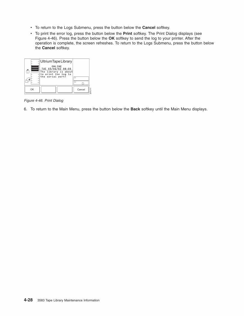
v To return to the Logs Submenu, press the button below the Cancel softkey.
v To print the error log, press the button below the Print softkey. The Print Dialog displays (see
Figure 4-46). Press the button below the OK softkey to send the log to your printer. After the
operation is complete, the screen refreshes. To return to the Logs Submenu, press the button below
the Cancel softkey.
6. To return to the Main Menu, press the button below the Back softkey until the Main Menu displays.
Figure 4-46. Print Dialog
4-28 3583 Tape Library Maintenance Information

Adding or Removing Control Paths
Before adding or removing control paths, you must activate the feature license. The maximum allowable
control paths for a library is equal to the quantity of drives assigned to that library.
Shortcut: Main Menu (initial screen) —> More —> Setup —> Drives —>
SCSI...
1. Navigate to the Setup Menu. For instructions, see “Accessing the Setup Menu” on page 4-8.
2. Press the button below the Drives softkey. The Drives Submenu displays (see Figure 4-47).
3. Press the button below the FC/SCSI softkey. The FC/SCSI submenu displays (see Figure 4-48). The
submenu gives the settings for the selected Fibre Channel drive. The value of the current drive
displays in the Drive: field. The Control path field indicates whether the drive is a control path. Valid
values are OFF or ON.
4. Perform one of the following:
v To accept the current values in the screen, press the button below the OK softkey.
v To change the value of the drive, press the button below the Change Drive softkey until the drive
that you want displays in the Drive field.
v To change the status of the drive as a control path, press the button below the Next softkey until ON
(to add) or OFF (to remove) displays in the Control path: field.
5. To return to the Drives Submenu, press the button below the Cancel softkey. To return to the Main
Menu, press the button below the Cancel softkey, then press the button below the Back softkey until
the Main Menu displays.
Figure 4-47. Drives Submenu
Figure 4-48. FC/SCSI Submenu
Chapter 4. Operating Procedures 4-29
|
|

Viewing the Drive’s Error Log
A maximum of 10 drive errors are available for viewing. To view a log of the drive’s error, perform the
following steps:
Shortcut: Main Menu (initial screen) —> Status —> Logs —> Drive Log
1. Navigate to the Status Menu. For instructions, see “Accessing the Status Menu” on page 4-6.
2. Press the button below the Logs softkey. The Logs Submenu displays (see Figure 4-49).
3. Press the button below the Drive Log softkey. The Select Drive Dialog displays (see Figure 4-50).
4. Perform one of the following:
v To accept the number of the currently displayed drive, press the button below the OK softkey.
v To change the number of the drive, press the button below the Change Drive softkey until the
number that you want displays. Then, press the button below the OK softkey. Valid values for the
Drive field are 01 through 06.
The Drive Log Dialog displays (see Figure 4-51).
The Drive Log Dialog contains the following information about the most recent drive errors:
Figure 4-49. Logs Submenu
Figure 4-50. Select Drive Dialog
Figure 4-51. Drive Log Dialog
4-30 3583 Tape Library Maintenance Information

Num The ID of the error.
Error The type of error, as defined in “Drive Error Codes” on page 6-25.
FSC1 Fault symptom code 1. This information is useful to Engineering only.
FSC2 Fault symptom code 2. This information is useful to Engineering only.
5. Press the button below the Previous or Next softkey to view information about previous or additional
drive errors in the log.
6. To return to the Logs Submenu (see Figure 4-49 on page 4-30), press the button below the Cancel
softkey. To return to the Main Menu, press the button below the Cancel softkey, then press the button
below the Back softkey until the Main Menu displays.
Clearing the Drive’s Error Log
To erase (clear) the current drive’s error log, perform the following steps:
Shortcut: Main Menu (initial screen) —> Status —> Logs —> Drive Log
—> OK (or Change Drive) —> Options —> Clear Log
1. Specify the drive that you want by performing steps 1 through 5 in “Viewing the Drive’s Error Log” on
page 4-30. The Drive Log Dialog displays (see Figure 4-52).
Figure 4-52. Drive Log Dialog
Chapter 4. Operating Procedures 4-31

2. Press the button below the Options softkey. The Drive Error Log Options Submenu displays (see
Figure 4-53).
3. Press the button below the Clear Log softkey. The library displays the message This option will
clear the current drive log contents.
4. Press the button below the OK softkey. The drive clears its error log and displays the message
Requested command is now complete.
5. To return to the Drive Error Logs Options Submenu (see Figure 4-53), press the button below the OK
softkey. To return to the Main Menu, press the button below the OK —> Back —> Cancel —> Back
softkeys. Continue to press the button below the Back softkey until the Main Menu displays.
Forcing a Drive Dump
Attention: If the tape drive detects a permanent error and displays an error code, it automatically forces
a drive dump (also known as a save of the firmware trace). If you force a drive dump, the existing dump
will be overwritten and data will be lost. After you force a drive dump, do not turn off the power to the tape
drive or you may lose the dump data.
From the Operator Panel
To force a drive dump, perform the following steps.
Shortcut: Main Menu (initial screen) —> Status —> Logs —> Drive Log
—> OK (or Change Drive) —> Options —> Force Dump
1. Specify the drive that you want by performing steps 1 through 5 in “Viewing the Drive’s Error Log” on
page 4-30. The Drive Log Dialog displays (see Figure 4-54).
Figure 4-53. Drive Error Log Options Submenu
Figure 4-54. Drive Log Dialog
4-32 3583 Tape Library Maintenance Information

2. Press the button below the Options softkey. The Drive Error Log Options Submenu displays (see
Figure 4-55).
3. Press the button below the Force Dump softkey. The library displays the message This option will
force a drive dump.
4. Press the button below the OK softkey. The drive forces the dump and displays the message
Requested command is now complete. To obtain the dump, see “Copying a Drive Dump to Tape
Cartridge Using the Operator Panel” on page 4-34.
5. To return to the Drive Error Logs Options Submenu (see Figure 4-55), press the button below the OK
softkey. To return to the Main Menu, press the button below the OK —> Back —> Cancel —> Back
softkeys. Continue to press the button below the Back softkey until the Main Menu displays.
Copying a Drive Dump
Copying a Drive Dump to the Server Using the LTO-TDX Tool
The tool, LTO-TDX, is the fastest method (approximately 5 seconds) for uploading LTO drive error dumps
(the current dump and a forced dump). In addition, this tool can be used to download LTO drive firmware
across the SCSI bus or fibre channel. The following information describes how to obtain the tool and lists
its capabilities.
1. The tool supports all IBM LTO Gen 1, Gen 2, and Gen 3 SCSI and FC drives. The tool will not
support any other manufacturer’s LTO drive. The tool is available for three different operating
systems:
v LTO-TDX_WinTool (for Windows operating systems)
v LTO-TDX_NWTool (for Netware operating systems)
v LTO-TDX_LxTool (for Linux operating systems)
2. The tool can perform two functions:
a. Upload a dump of the drive firmware logs from the drive to a computer system
b. Download firmware to the drive (see “Firmware download function” on page 4-127)
3. The tool is distributed from the IBM web site. Download the tool by visiting
http://www.ibm.com/storage/lto. The install package or an executable file will be placed on the host
system in a location chosen by the user.
4. When the user opens the install package, he will be presented with a license agreement that he must
accept to proceed with the install. The user will also be presented with a license anytime the
executable file is copied to another location where the firmware or dump folders do not exist. The tool
will detect the missing folders at launch and present the user’s license, assuming that this is the first
launch of a new copy of the tool. There will also be a function that allows the user to view the license
at will when he starts the tool.
5. The Windows install package will create a directory for the tool on the user’s hard disk and place the
executable file (the tool) in that directory. The install package will also load the file into the Programs
Menu accessed via the ″Start″ button and put an icon on the desktop of the Windows operating
system. The install package shall perform a similar function on any other operating system that has a
similar structure.
Figure 4-55. Drive Error Log Options Submenu
Chapter 4. Operating Procedures 4-33
|

6. Selection of the icon on the desktop or selection of the tool from the Program Menu will start the tool
and create the ″LTO Firmware″ and ″LTO Dumps″ files in the directory with the executable tool file.
7. The user must first put the firmware to be downloaded in the firmware folder.
8. Any dumps created will be put in the dump folder.
9. The tool will present a list of the supported devices on the bus. The tool will allow selection of a
target device and then perform the download or the dump on the target device.
10. The tool itself is a command line tool but it is menu driven and very simple to use.
11. The program displays are in English.
12. The user is responsible to make sure the drive is not in use when firmware is downloaded or a dump
is taken. He also must remove any cartridge from the drive or the firmware download function will not
work.
13. If the user does make a mistake, the program will respond with instructive error messages.
14. If no IBM LTO tape drives are on the bus, the tool will inform the user that there are none before
closing the tool window.
Drive Dump Function:
1. When the dump function is executed on a drive, the tool will read the existing dump on the drive, force
a dump, then read the forced dump. This will create two dump files.
2. The two dump files created by the dump function will be time stamped with month, day, hours,
minutes, and seconds and contain the drive serial number. The first dump file read has an ″A″ suffix.
The second file produced has a ″B″ suffix.
3. The Tool will place the files that are created in the ″LTO Dumps″ folder in the directory with the tool.
4. The tool creates the dump files with a file type of .dmp.
Copying a Drive Dump to Tape Cartridge Using the Operator Panel
Attention: Insert only a scratch data cartridge for this procedure. Data on the cartridge will be
overwritten.
To copy a drive’s error log to a tape cartridge using the operator panel, perform the following steps.
Shortcut: Main Menu (initial screen) —> Status —> Logs —> Drive Log
—> OK or Change Drive —> Options —> Copy Dump
1. Specify the drive that you want by performing steps 1 through 5 in “Viewing the Drive’s Error Log” on
page 4-30. The Drive Log Dialog displays (see Figure 4-56).
2. Press the button below the Options softkey. The Drive Error Log Options Submenu displays (see
Figure 4-57 on page 4-35).
Figure 4-56. Drive Log Dialog
4-34 3583 Tape Library Maintenance Information

3. Press the button below the Copy Dump softkey. The Copy Dump Dialog prompts you to insert a
scratch cartridge into the top I/O station slot.
4. After you insert the cartridge, press the button below the OK softkey. A message indicates that the
command is in progress while the picker moves the cartridge from the I/O station to the drive. After the
drive copies the dump to the tape, the picker returns the cartridge to the I/O station and displays the
message Requested command is now complete.
5. To return to the Drive Error Log Options Submenu (see Figure 4-57), press the button below the OK
softkey. To return to the Main Menu, press the button below the OK —> Back —> Cancel —> Back
softkeys. Continue to press the button below the Back softkey until the Main Menu displays.
Copying a Drive Dump to the Server Using the RMU
Copying a drive dump using the RMU is a very slow process (average copying time is over 1 hour). To
copy a drive dump using the RMU, follow these steps:
1. Open the RMU interface using an Internet browser. The Status page will display.
2. Click on the Diagnostic file tab and the Login page will display.
Figure 4-57. Drive Error Log Options Submenu
a67lo
177
Figure 4-58. Status page
Chapter 4. Operating Procedures 4-35

3. Enter your Login Name and password and click on Submit. The Diagnostics file page will display.
4. Select ″Drive x Dump″ (x being the number of the desired drive) and click on Retrieve selected file.
The dump will be saved in a file on the server.
Copying a Drive Dump Using SCSI Communication (TAPEUTIL and NTUtil)
Refer to the IBM Ultrium Device Drivers Installation and User’s Guide (GA32-0430) for instructions on
usage of the TAPEUTIL (Unix) and NTUtil (Windows) utilities for the particular Operating System that the
library is attached to.
Performing a Preserve Dump
Note: This procedure applies to LTO-3 drives only.
Figure 4-59. Login page
Figure 4-60. Diagnostics file page
4-36 3583 Tape Library Maintenance Information
|
|
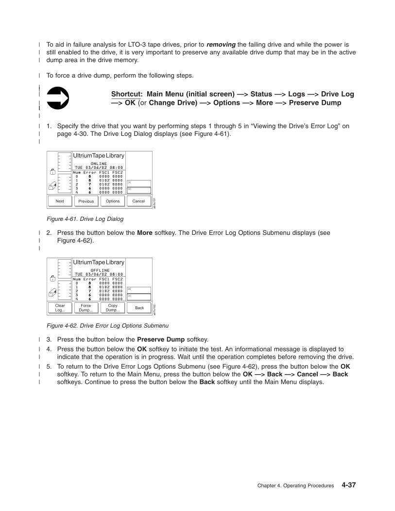
To aid in failure analysis for LTO-3 tape drives, prior to removing the failing drive and while the power is
still enabled to the drive, it is very important to preserve any available drive dump that may be in the active
dump area in the drive memory.
To force a drive dump, perform the following steps.
Shortcut: Main Menu (initial screen) —> Status —> Logs —> Drive Log
—> OK (or Change Drive) —> Options —> More —> Preserve Dump
1. Specify the drive that you want by performing steps 1 through 5 in “Viewing the Drive’s Error Log” on
page 4-30. The Drive Log Dialog displays (see Figure 4-61).
2. Press the button below the More softkey. The Drive Error Log Options Submenu displays (see
Figure 4-62).
3. Press the button below the Preserve Dump softkey.
4. Press the button below the OK softkey to initiate the test. An informational message is displayed to
indicate that the operation is in progress. Wait until the operation completes before removing the drive.
5. To return to the Drive Error Logs Options Submenu (see Figure 4-62), press the button below the OK
softkey. To return to the Main Menu, press the button below the OK —> Back —> Cancel —> Back
softkeys. Continue to press the button below the Back softkey until the Main Menu displays.
Figure 4-61. Drive Log Dialog
Figure 4-62. Drive Error Log Options Submenu
Chapter 4. Operating Procedures 4-37
|||
|
||
||
||
|
|||
|||
|
||
|||

Moving a Cartridge
To move a tape cartridge from a source location to a target location, perform the following steps.
Shortcut: Main Menu (initial screen) —> Command —> Move —> Move
Media
1. Navigate to the Command Menu. For instructions, see “Accessing the Command Menu” on page 4-7.
2. Press the button below the Move softkey. The Move Submenu displays (see Figure 4-63).
3. Press the button below the Move Media softkey. The Source Move Media Dialog displays (see
Figure 4-64) with a message area that shows three icons:
v The left icon represents the columns in the library, with an arrow pointed to the column that is
currently selected.
v The middle icon represents the magazines in the currently selected column. The arrow points to the
currently selected magazine.
v The right icon represents the storage slots in the currently selected column and magazine. The
arrow points to the currently selected storage slot.
The position of the arrow in each of the three icons identifies the storage slot’s physical address. For
example, arrows that point to a column 2, magazine A, and storage slot 1 indicate a physical address
of 2 A 1. In the Source Move Media Dialog, a slot’s physical address displays below the right icon (see
Figure 4-64).
4. Specify the cartridge that you want to move by performing one of the following:
v To move the cartridge from the physical address that is currently displayed, press the button below
the OK softkey.
v To move a cartridge from another location, specify its physical address by performing the following
steps:
a. Press the button below the Change Column softkey until the arrow in the left icon points to the
column that you want. Press the button below the Next softkey. The Change Magazine Dialog
displays (see Figure 4-65 on page 4-39).
Figure 4-63. Move Submenu
Figure 4-64. Source Move Media Dialog
4-38 3583 Tape Library Maintenance Information

Note: If you choose the drive column (column 3), the Change Drive Dialog displays because no
slots or magazines are available in this column. To choose a different column, press the
button below the Next softkey, then press the button below the Change Column softkey
until the arrow points to the column that you want. Press the button below the Next
softkey to display the Change Magazine Dialog.
b. Press the button below the Change Magazine softkey until the arrow in the middle icon points
to the magazine that you want. Press the Next softkey. The Change Slot Dialog displays (see
Figure 4-66).
c. Press the button below the Change Slot softkey until the arrow in the right icon points to the
storage slot that you want.
d. Perform one of the following:
– To accept the physical address of the storage slot (located below the right icon), press the
button below the OK softkey.
– To cycle through the Change Column, Change Magazine, and Change Slot choices again,
press the Next softkey. Make your selections, then press the button below the OK softkey.
Figure 4-65. Change Magazine Dialog
Figure 4-66. Change Slot Dialog
Chapter 4. Operating Procedures 4-39
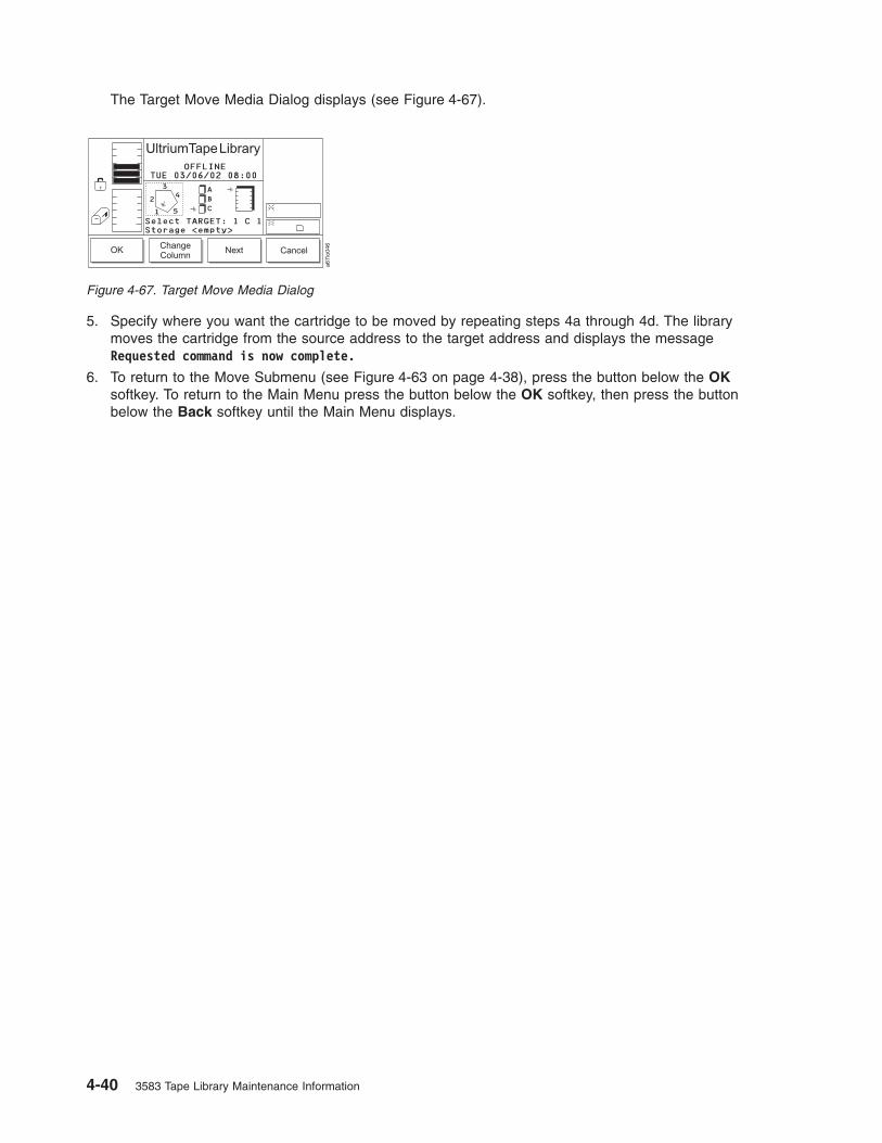
The Target Move Media Dialog displays (see Figure 4-67).
5. Specify where you want the cartridge to be moved by repeating steps 4a through 4d. The library
moves the cartridge from the source address to the target address and displays the message
Requested command is now complete.
6. To return to the Move Submenu (see Figure 4-63 on page 4-38), press the button below the OK
softkey. To return to the Main Menu press the button below the OK softkey, then press the button
below the Back softkey until the Main Menu displays.
Figure 4-67. Target Move Media Dialog
4-40 3583 Tape Library Maintenance Information

Moving the Picker
To move the picker in front of a specific element, perform the following steps.
Shortcut: Main Menu (initial screen) —> Command —> Move —>
Position Picker
1. Navigate to the Command Menu. For instructions, see “Accessing the Command Menu” on page 4-7.
2. Press the button below the Move softkey. The Move Submenu displays (see Figure 4-68).
3. Press the button below the Position Picker softkey. The Position Picker Dialog displays (see
Figure 4-69) with a message area that shows three icons:
v The left icon represents the columns in the library, with an arrow pointed to the column that is
currently selected.
v The middle icon represents the magazines in the currently selected column. The arrow points to the
currently selected magazine.
v The right icon represents the storage slots in the currently selected column and magazine. The
arrow points to the currently selected storage slot.
The position of the arrow in each of the three icons identifies the storage slot’s physical address. For
example, arrows that point to a column 2, magazine A, and storage slot 1 indicate a physical address
of 2 A 1. In the Position Picker Dialog, a slot’s physical address displays below the right icon (see
Figure 4-69).
4. Specify where you want the library to move the picker by performing one of the following:
v To move the picker to the address that is currently displayed, press the button below the OK
softkey.
v To move the picker to another location, specify the physical address by performing the following
steps:
a. Press the button below the Change Column softkey until the arrow in the left icon points to the
column that you want. Press the button below the Next softkey. The Change Magazine Dialog
displays (see Figure 4-70 on page 4-42).
Figure 4-68. Move Submenu
Figure 4-69. Position Picker Dialog
Chapter 4. Operating Procedures 4-41

Note: If you choose the drive column (column 3), the Change Drive Dialog displays because no
slots or magazines are available in this column. To choose a different column, press the
button below the Next softkey, then press the button below the Change Column softkey
until the arrow points to the column that you want. Press the button below the Next
softkey to display the Change Magazine Dialog.
b. Press the button below the Change Magazine softkey until the arrow in the middle icon points
to the magazine that you want. Press the Next softkey. The Change Slot Dialog displays (see
Figure 4-71).
c. Press the button below the Change Slot softkey until the arrow in the right icon points to the
storage slot that you want.
d. Perform one of the following:
– To accept the physical address of the storage slot (located below the right icon), press the
button below the OK softkey.
– To cycle through the Change Column, Change Magazine, and Change Slot choices again,
press the Next softkey. Make your selections, then press the button below the OK softkey.
The library moves the picker in front of the element that you specified and displays the message
Requested command is now complete.
5. To return to the Move Submenu (see Figure 4-68 on page 4-41), press the button below the OK
softkey. To return to the Main Menu press the button below the OK softkey, then press the button
below the Back softkey until the Main Menu displays.
Figure 4-70. Change Magazine Dialog
Figure 4-71. Change Slot Dialog
4-42 3583 Tape Library Maintenance Information

Performing an Inventory of the Library
To conduct an inventory on a specific quantity of storage slots, perform the following steps.
Note: To change how the library performs the inventory (by scanning labeled cartridges or touching
unlabeled cartridges), see “Choosing the Method of Inventory” on page 4-72.
Shortcut: Main Menu (initial screen) —> Command —> Move —> Scan
Barcode
1. Navigate to the Command Menu. For instructions, see “Accessing the Command Menu” on page 4-7.
2. Press the button below the Move softkey. The Move Submenu displays (see Figure 4-72).
3. Press the button below the Scan Barcode softkey. The Scan Barcode Dialog displays (see
Figure 4-73) with a message area that shows three icons:
v The left icon represents the columns in the library, with an arrow pointed to the column that is
currently selected.
v The middle icon represents the magazines in the currently selected column. The arrow points to the
currently selected magazine.
v The right icon represents the storage slots in the currently selected column and magazine. The
arrow points to the currently selected storage slot.
The position of the arrow in each of the three icons identifies the storage slot’s physical address. For
example, arrows that point to a column 2, magazine A, and storage slot 1 indicate a physical address
of 2 A 1. In the Scan Barcode Dialog, a slot’s physical address displays below the right icon (see
Figure 4-73).
4. Specify the storage slot at which you want the inventory to begin by performing one of the following:
v To begin the inventory at the physical address that is currently displayed, press the button below the
OK softkey.
v To begin the inventory at another location, specify the physical address by performing the following
steps:
Figure 4-72. Move Submenu
Figure 4-73. Scan Barcode Dialog
Chapter 4. Operating Procedures 4-43

a. Press the button below the Change Column softkey until the arrow in the left icon points to the
column that you want. Press the button below the Next softkey. The Change Magazine Dialog
displays (see Figure 4-74).
Note: If you choose the drive column (column 3), the Change Drive Dialog displays because no
slots or magazines are available in this column. To choose a different column, press the
button below the Next softkey, then press the button below the Change Column softkey
until the arrow points to the column that you want. Press the button below the Next
softkey to display the Change Magazine Dialog.
b. Press the button below the Change Magazine softkey until the arrow in the middle icon points
to the magazine that you want. Press the button below the Next softkey. The Change Slot
Dialog displays (see Figure 4-75).
c. Press the button below the Change Slot softkey until the arrow in the right icon points to the
storage slot that you want.
– To accept the physical address of the storage slot (located below the right icon), press the
button below the OK softkey.
– To cycle through the Change Column, Change Magazine, and Change Slot choices again,
press the Next softkey. Make your selections, then press the button below the OK softkey.
The Select Slots Dialog displays the quantity of slots to inventory (see Figure 4-76).
Figure 4-74. Change Magazine Dialog
Figure 4-75. Change Slot Dialog
Figure 4-76. Select Slots Dialog
4-44 3583 Tape Library Maintenance Information

Note: To perform a cartridge inventory of the entire library (I/O Station, all storage slots and
installed tape drives), leave the column, magazine and slot coordinates on column 1,
magazine C, and slot 1. To perform a cartridge inventory of the 12 slot I/O Station and
installed drives, choose column 1, magazine A, and slot 1. Choosing a slot other than 1
and/or magazine B will reduce the number of I/O Station slots inventoried. To choose a
cartridge inventory of the installed drives, choose column 3, All other choices will start the
inventory at the storage slot chosen and add to it the I/O Station slots and the installed
drives. The maximum locations that will be inventoried for any possible coordinates
selection will be initially listed in the ″slots to scan″ field in the Select Slots dialog screen.
for example, if the library contains a full complement of columns (4) and a full
complement of tape drives (6), the ″slots to scan″ field would be 72 + 6 = 78. The
operator may reduce this number to alter the stopping point.
5. To specify the quantity of slots to inventory, press the button below the Up or Down softkey to
increase or decrease the value in the field. The maximum number of slots that can be inventoried is
72. Press the button below the Next softkey. The Confirm Dialog displays (see Figure 4-77).
6. To specify whether you want the results of the inventory to display on the operator panel, press the
button below the Yes/No softkey until Yes or No displays in the Show results field.
7. To start the inventory, press the button below the OK softkey. The library begins the inventory at the
physical address that you specified. After the inventory is done, one of the following occurs:
v If you chose not to display the results, the library displays the message Requested command is now
complete.
Figure 4-77. Confirm Dialog
Chapter 4. Operating Procedures 4-45

v If you chose to display the results, the Completion Dialog displays (see Figure 4-78). The screen
shows the quantity of cartridges that were found in the storage slots, I/O station, and drives.
8. To return to the Move Submenu (see Figure 4-72 on page 4-43), press the button below the OK
softkey. To return to the Main Menu press the button below the OK softkey, then press the button
below the Back softkey until the Main Menu displays.
Figure 4-78. Completion Dialog
4-46 3583 Tape Library Maintenance Information

Importing a Cartridge into the Library
To move a tape cartridge from the I/O station to the first available slot, perform the following steps.
Shortcut: Main Menu (initial screen) —> Command —> I/O Station —>
Import
1. Navigate to the Command Menu. For instructions, see “Accessing the Command Menu” on page 4-7.
2. Press the button below the I/O Station softkey. The I/O Station Submenu displays (see Figure 4-79).
3. Press the button below the Import softkey. The picker moves the cartridge to the first available empty
slot and the library displays the message Requested command is now complete.
4. To return to the I/O Station Submenu (see Figure 4-79), press the button below the OK softkey. To
return to the Main Menu press the button below the OK softkey, then press the button below the Back
softkey until the Main Menu displays.
Figure 4-79. I/O Station Submenu
Chapter 4. Operating Procedures 4-47

Partitioning the Library
You can partition the Ultrium Scalable Tape Library into a maximum of three logical libraries. If your
application supports it, Ultrium 1, Ultrium 2, and Ultrium 3 drives and media are allowed in the same
logical library. Partitioning is possible only after you have installed drives that have the control path
enabled.
Performing the Partitioning Process
To partition the library, perform the following steps.
Shortcut: Main Menu (initial screen) —> More —> Setup —> Library
—> Partitions
The Partitions Dialog displays the number of logical libraries that are currently partitioned (see
Figure 4-80).
The Partition Dialog contains the following information:
part The quantity of logical libraries in the library. Valid values are from 1 to 3.
MB Indicates that the I/O station is configured as storage or as an I/O station. Valid values are
storage and I/O.
Perform one of the following:
v To accept the current quantity of logical libraries, press the button below the OK softkey.
v To change the quantity of logical libraries, press the button below the Next softkey until the quantity that
you want displays in the Partition available field, then press the button below the OK softkey. To
activate the changes, reboot the library.
OK Next Cancel
OFFLINE
a6
7lo
33
8
Partitions available1 part MB=storage
>1 part MB=IO2 part MB=IO3 part MB=IO
>
>>
UltriumTapeLibrary
03/12/03 19:59WED
Figure 4-80. Partitions Dialog
4-48 3583 Tape Library Maintenance Information
|

Enabling and Disabling Automatic Cleaning
Whenever a drive needs cleaning, the Ultrium Scalable Tape Library can automatically clean it after you
enable automatic cleaning and import a cleaning cartridge.
Notes:
1. Automatic cleaning is a function that needs to be enabled..
2. Automatic cleaning is incompatible with host/application based cleaning. Turn off the cleaning function
in the application and export the cleaning tapes. The server stops all cleaning inquiries to the drive.
3. You cannot enable automatic cleaning if you have configured the slots in the I/O station as storage
slots.
To enable or disable automatic cleaning, perform the following steps.
Shortcut: Main Menu (initial screen) —> More —> Setup —> Library
—> More —> AutoClean
1. Navigate to the Setup Menu. For instructions, see “Accessing the Setup Menu” on page 4-8.
2. Press the button below the Library softkey. The Library Submenu displays (see Figure 4-81).
3. Press the button below the More softkey. The More Dialog displays (see Figure 4-82).
Figure 4-81. Library Submenu
AutoClean...
ScanMedia
Back
OFFLINE
a6
7lo
34
6
Updating firmware onthe library requiresa reboot. Press OKto proceed.
FAST Read/Write
UltriumTapeLibrary
09/29/03 14:54MON
Figure 4-82. More Dialog
Chapter 4. Operating Procedures 4-49
|
||

4. Press the button below the AutoClean softkey. The Autoclean Setup screen displays (see
Figure 4-83).
5. Perform one of the following:
v To enable automatic cleaning, press the button below the Enable softkey until the screen displays a
checkmark in the checkbox beside the AutoClean field. The checkmark indicates that automatic
cleaning is currently enabled.
v To disable automatic cleaning, press the button below the Disable softkey until the checkmark
disappears from the checkbox. The absence of a checkmark means that automatic cleaning is
currently disabled.
6. Press the button below the OK softkey. The library enables or disables automatic cleaning and
redisplays the More Dialog (see Figure 4-82 on page 4-49).
7. Perform one of the following:
v To return to the Setup Menu (see Figure 4-12 on page 4-8), press the button below the Back
softkey.
v To return to the Main Menu press the button below the Back softkey until the Main Menu displays.
Importing the Cleaning Cartridge
Note: Cleaning cartridges are not required to be labeled, and are invisible and inaccessible to the server
when they are at their fixed slot locations.
Before you import a cleaning cartridge, make sure that autoclean is enabled (see “Enabling and Disabling
Automatic Cleaning” on page 4-49).
Shortcut: Main Menu (initial screen) —> Command —> I/O Station —>
AutoClean —> Import
1. Navigate to the Command Menu. For instructions, see “Accessing the Command Menu” on page 4-7.
Figure 4-83. Autoclean Setup screen
4-50 3583 Tape Library Maintenance Information

2. Press the button below the I/O Station softkey. The I/O Station Submenu displays (see Figure 4-84).
3. Press the button below the AutoClean softkey. The AutoClean Dialog displays (see Figure 4-85) with
the following information about cleaning cartridges and cleaning slots in the library.
Represents the quantity of storage slots that are designated for a cleaning cartridge.
A cleaning slot is located at the top of columns 2, 4, and 5. In the AutoClean Dialog,
slot 1 refers to the slot in column 2, slot 2 refers to the slot in column 4, and slot 3
refers to the slot in column 5. A shaded box means that the slot is occupied; a box
that contains no shading means that the slot is empty.
UseCnt The number of times that the cleaning cartridge has been used to clean a drive.
Valid values are 0 through 99, or EXP for an expired cartridge.
MaxCnt The number of times that the cleaning cartridge can be used to clean a drive. Valid
values are 50 (the maximum) or EXP for an expired cartridge. Values in the MaxCnt
column are read only.
Status Indicates whether the AutoClean function is currently enabled (Active) or disabled
(Inactive).
Figure 4-84. I/O Station Submenu
Figure 4-85. AutoClean Dialog
Chapter 4. Operating Procedures 4-51

4. If no cleaning cartridge is present in the library (each of the three rectangular boxes contain no
shading), import a cleaning cartridge by pressing the button below the Import softkey. The Cleaning
Tape screen displays (see Figure 4-86).
Note: The Import softkey is only available if there are empty cleaning cartridge storage slots.
5. Open the door of the I/O station and place a cleaning cartridge into the top slot of the I/O station. Use
only the top slot of the I/O station.
6. Close the door of the I/O station. The library executes the TEACH and INVENTORY procedures and
places the cleaning cartridge in the first available cleaning cartridge location..
7. Press the button below the OK softkey. The library imports the cleaning cartridge to the drive and
cleaning begins. When the cleaning is finished, the library displays the message Requested command is
now complete.
8. Perform one of the following:
v To return to the AutoClean Dialog, press the button below the OK softkey.
v To return to the Main Menu press the button below the OK softkey twice, then press the button
below the Back softkey until the Main Menu displays.
Handling Errors
For a list of cleaning cartridge error messages and actions required, refer to “Cleaning Cartridge Error
Messages” on page 6-30.
Exporting the Cleaning Cartridge
To export a cleaning cartridge, perform the following procedure.
Before you export a cleaning cartridge, make sure that autoclean is enabled (see “Enabling and Disabling
Automatic Cleaning” on page 4-49).
Shortcut: Main Menu (initial screen) —> Command —> I/O Station —>
AutoClean —> Export
1. Navigate to the Command Menu. For instructions, see “Accessing the Command Menu” on page 4-7.
Figure 4-86. Cleaning Tape screen
4-52 3583 Tape Library Maintenance Information

2. Press the button below the I/O Station softkey. The I/O Station Submenu displays (see Figure 4-87).
3. Press the button below the AutoClean softkey. The AutoClean Dialog displays (see Figure 4-88).
4. Press the button below the Export softkey. The Export Cleaning Tape Dialog displays (see
Figure 4-89).
Note: The Export softkey is only available if at least one cleaning cartridge has been detected.
5. Press the button below the Up or Down softkey to specify the cleaning slot that you want, then press
the button below the Select softkey. The library exports the cleaning cartridge from the slot that you
specified to a slot in the I/O station. When the export is finished, the library displays the message
Requested command is now complete.
6. Perform one of the following:
v To return to the AutoClean Dialog, press the button below the OK softkey.
v To return to the Main Menu press the button below the OK softkey twice, then press the button
below the Back softkey until the Main Menu displays.
7. Remove the cleaning cartridge from the I/O station.
8. Press the button below the Online/Offline softkey to place the library in the online state.
Figure 4-87. I/O Station Submenu
Figure 4-88. AutoClean Dialog
Figure 4-89. Export Cleaning Tape Dialog
Chapter 4. Operating Procedures 4-53

Scan Media in Drives
Scan Media configures your library to read and store the bar code number of media currently in tape
drives when running a library inventory on a power sequence or after opening and then closing the
library’s main door..
Shortcut: Main Menu (initial screen) —> More —> Setup —> Library
—> More —> Scan Media
1. Navigate to the Setup Menu. For instructions, see “Accessing the Setup Menu” on page 4-8.
2. Press the button below the Scan Media softkey (see Figure 4-90).
3. In the Scan Media Dialog, select a value for each of the fields displayed in the table below by pressing
the button below the Yes/No softkey.
Field Value Description
Scan media bar code in drives Yes Media in drives are unloaded and
placed into storage slots so that their
bar codes can be scanned as part of
inventory.
No Media are left in drives and are not
scanned.
Replace media back to drives Yes Media are moved back to their
original drive slots after their bar
codes are scanned.
No Media are left in their storage slots
after their bar codes are scanned.
4. Press the button below the OK softkey to accept the values selected.
5. Perform one of the following:
AutoClean...
ScanMedia
Back
OFFLINE
a6
7lo
34
6
Updating firmware onthe library requiresa reboot. Press OKto proceed.
FAST Read/Write
UltriumTapeLibrary
09/29/03 14:54MON
Figure 4-90. More Submenu
OFFLINE
a6
7lo
34
7
UltriumTapeLibrary
09/25/03 12:55THU
OK NextYes/No Cancel
Scan media barcodein drives:Replace media backto drives: No
No
Figure 4-91. Scan Media Dialog
4-54 3583 Tape Library Maintenance Information

v To return to the Setup Menu (see Figure 4-12 on page 4-8), press the button below the Back
softkey.
v To return to the Main Menu press the button below the Back softkey until the Main Menu displays.
Chapter 4. Operating Procedures 4-55

Exporting a Cartridge from the Library
To export a tape cartridge from the library to the I/O station, perform the following steps. You can select a
maximum of 12 tape cartridges during a single export operation.
Shortcut: Main Menu (initial screen) —> Command —> I/O Station —>
Export
1. Navigate to the Command Menu. For instructions, see “Accessing the Command Menu” on page 4-7.
2. Press the button below the I/O Station softkey. The I/O Station Submenu displays (see Figure 4-92).
3. Press the button below the Export softkey. The Export Dialog displays a message that describes the
export procedure (see Figure 4-93).
4. Press the button below the OK softkey. The Export List Dialog displays a list of tape cartridges that are
present in the library (see Figure 4-94). The cartridges are listed by their volume serial numbers
(VOLSERs) and physical addresses.
5. Press the button below the Page Up or Page Down softkey to locate the screen that contains the
cartridge that you want, then press the button below the Select softkey. The selection cursor displays
beside the first item on the screen (see Figure 4-95 on page 4-57).
Figure 4-92. I/O Station Submenu
Figure 4-93. Export Dialog
Figure 4-94. Export List Dialog
4-56 3583 Tape Library Maintenance Information

Note: To return to the Export List Dialog to make additional selections or cancel the export operation,
press the button below the Pages softkey.
6. Perform one or both of the following:
v To export the first cartridge in the list, press the button below the Select softkey to highlight and
select the cartridge.
v To export a cartridge other then the first one in the list, press the button below the Next softkey to
move the selection cursor to the cartridge that you want. Press the button below the Select softkey
to highlight and select the cartridge. You can highlight and select up to 12 cartridges at a time.
7. Press the button below OK softkey. The picker moves the cartridge that you specified to the I/O station
and the library displays the message Requested command is now complete.
8. To return to the I/O Station Submenu (see Figure 4-92 on page 4-56), press the button below the OK
softkey. To return to the Main Menu press the button below the OK softkey, then press the button
below the Back softkey until the Main Menu displays.
Figure 4-95. Export Select Dialog
Chapter 4. Operating Procedures 4-57

Unloading a Cartridge from a Drive
To unload a tape cartridge from a drive, perform the following steps.
Shortcut: Main Menu (initial screen) —> Command —> Drives —>
Unload
1. Navigate to the Command Menu. For instructions, see “Accessing the Command Menu” on page 4-7.
2. Press the button below the Drives softkey. The Drives Submenu displays (see Figure 4-96).
3. Press the button below the Unload softkey. The Unload Dialog displays (see Figure 4-97).
4. Perform one of the following:
v To unload the cartridge from the currently displayed drive, press the button below the OK softkey.
v To unload the cartridge from another drive, press the button below the Change Drive softkey until
the number of the drive that you want displays (drive numbers range from 01 to 06). Then, press the
button below the OK softkey.
The drive unloads the cartridge, the picker places it in its original slot, and the library displays the
message Requested command is now complete.
5. To return to the Drives Submenu (see Figure 4-96), press the button below the OK softkey. To return to
the Main Menu press the button below the OK softkey, then press the button below the Back softkey
until the Main Menu displays.
Figure 4-96. Drives Submenu
Figure 4-97. Unload Dialog
4-58 3583 Tape Library Maintenance Information

Resetting a Tape Drive
You can select the type of reset to perform on a tape drive. A soft reset causes the library to issue a
reboot command and reinitialize the drive without turning off its power. A hard reset causes the library to
cycle power to the drive (turn it off, then on). To reset a drive, perform the following steps.
Shortcut: Main Menu (initial screen) —> Command —> Drives —>
Reset
1. Navigate to the Command Menu. For instructions, see “Accessing the Command Menu” on page 4-7.
2. Press the button below the Drives softkey. The Drives Submenu displays (see Figure 4-98).
3. Press the button below the Reset softkey. The Reset Dialog displays with the message Make sure the
drive selected is OFFLINE! (see Figure 4-99). Ensure that the drive has completed all operations and
that no backup applications are running.
4. Perform one of the following:
v To reset the currently displayed drive, press the button below the Next softkey.
v To reset a drive other than the one that is currently displayed, press the button below the Change
Drive softkey until the number of the drive that you want displays in the Drive field (drive numbers
range from 01 to 06). Then, press the button below the Next softkey.
Figure 4-98. Drives Submenu
Figure 4-99. Reset Dialog
Chapter 4. Operating Procedures 4-59

The Reset Type Dialog displays (see Figure 4-100) and the selection cursor moves to the Reset Type
field.
5. To change the type of reset (hard or soft), press the button below the Change softkey. A soft reset
causes the library to issue a drive reset command; a hard reset causes the library to remove power
from the drive.
6. To reset the selected drive, press the button below the OK softkey. The library resets the drive and
displays the message Requested command is now complete.
7. To return to the Reset Dialog (see Figure 4-99 on page 4-59), press the button below the OK softkey.
To return to the Main Menu, press the button below the OK —> Cancel —> Back softkeys. Continue
to press the button below the Back softkey until the Main Menu displays.
Figure 4-100. Reset Type Dialog
4-60 3583 Tape Library Maintenance Information

Setting up Remote Communication with the Library
From the RMU
The configuration page (see Figure 4-101) is protected by a password and allows you to configure the
remote management unit’s network settings (including SNMP). You perform the initial RMU network
configuration through the library’s operator panel during library installation and setup (see “Step 18.
Configure the RMU” on page 14-55).
From the Operator Panel
To set up remote communication to the Ultrium Scalable Tape Library, perform the following steps.
Shortcut: Main Menu (initial screen) —> More —> Setup —> Library
—> RMU
1. Navigate to the Setup Menu. For instructions, see “Accessing the Setup Menu” on page 4-8.
a67lo
179
Figure 4-101. Configuration page
Chapter 4. Operating Procedures 4-61

2. Press the button below the Library softkey. The Library Submenu displays (see Figure 4-102).
3. Press the button below the RMU softkey. The Confirm Changes Dialog displays (see Figure 4-103)
with the following information:
IP The Internet protocol (IP) address of the library. The IP address is an identifier that is
unique to the library and is necessary for communication with the server. Valid values
are 000.000.000.000 through 255.255.255.255.
Sub The subnet mask address of the library. The subnet mask address identifies the
library’s local area network (LAN). Valid values are 000.000.000.000 through
255.255.255.255.
Gate The gateway address, which is the location at which networks attach to each other.
Valid values are 000.000.000.000 through 255.255.255.255.
Name The hostname that you assign to the RMU for communication with the library through
the RMU. Valid values are A through Z and 0 through 9.
4. To change the value in one or more fields, cycle through each field by pressing the button below the
Next softkey until the selection cursor highlights the value in the address that you want to change (an
address is divided into four sets of characters that are separated by periods; each set is called an
octet). Perform the following:
v To change the library’s IP address, press the button below the Next softkey until the selection cursor
highlights the octet that you want in the IP field. Press the button below the Up or Down softkeys
until the value that you want displays.
v To change the library’s subnet mask address, press the button below the Next softkey until the
selection cursor highlights the octet that you want in the Sub field. Press the button below the Up or
Down softkeys until the value that you want displays.
v To change the gateway address, press the button below the Next softkey until the selection cursor
highlights the octet that you want in the Gate field. Press the button below the Up or Down softkeys
until the value that you want displays.
MEDIA... RMU...Parti-tions...
More
a6
7lo
31
7
UltriumTapeLibraryONLINE
WED 03/12/03 20:20
Figure 4-102. Library Submenu
Figure 4-103. Confirm Changes Dialog
4-62 3583 Tape Library Maintenance Information

v To change the host name that is assigned to the RMU, press the button below the Next softkey until
the selection cursor highlights the first character in the Name field. Press the button below the Up or
Down softkeys to increase or decrease the alphabetical or numeric value. Repeat for each
character in the new host name.
5. Verify that the new settings are correct on the display, then press the button below the Next softkey
until the Confirm Changes Dialog displays (see Figure 4-104).
6. To accept the changes and establish the settings for remote communication between library and the
network, press the button below the OK softkey. The Library Submenu redisplays (see Figure 4-102 on
page 4-62). To return to the Main Menu, press the button below the Back softkey until the Main Menu
displays.
Figure 4-104. Confirm Changes Dialog
Chapter 4. Operating Procedures 4-63

Viewing or Changing a Drive’s SCSI ID and Control Path Status
To view or change a drive’s SCSI ID and control path status, perform the following steps.
Shortcut: Main Menu (initial screen) —> More —> Setup —> Drives —>
SCSI...
1. Navigate to the Setup Menu. For instructions, see “Accessing the Setup Menu” on page 4-8.
2. Press the button below the Drives softkey. The Drives Submenu displays (see Figure 4-105).
3. Press the button below the SCSI softkey. The Drive SCSI Dialog displays (see Figure 4-106). The
screen may vary, depending on whether your library has the Multi-Path feature.
The Ultrium Scalable Tape Library consists of up to seven SCSI devices: the library and six drives. The
default settings for the SCSI IDs are 1 through 6 for the drives.
Notes:
a. Do not select an ID that is already in use on the same SCSI bus.
b. Do not select the SCSI ID of the SCSI host adapter card. On the SCSI bus, any initiator (such as a
host adapter card) that needs to communicate with the library must have its SCSI ID set from 0 to
7. The SCSI ID of the SCSI host adapter card is usually higher than any device on the SCSI bus.
Generally, the SCSI ID for the host adapter is 7.
To determine whether a SCSI ID is already in use, see your system administrator.
The Drive SCSI Dialog contains the current and new (if you decide to change them) SCSI settings for
the drives. Settings are presented individually for each drive. The Drive SCSI Dialog includes the
following information:
Drive The number of the drive. The number is based on the location of the
drive in the drive column. The numbers range from 01 to 06, from
bottom to top.
SCSI ID The current and new SCSI ID of the selected drive. Valid values are
00 through 15.
Figure 4-105. Drives Submenu
ONLINE
a6
7lo
35
0
UltriumTapeLibrary
09/25/03 12:55THU
OK NextChange
DriveCancel
Drive :Control path: ON
CURRENT NEWSCSI ID: 002 002Drives with this ID:
NONE
01
Figure 4-106. Drive SCSI Dialog for Drives
4-64 3583 Tape Library Maintenance Information
|
|

Control path A logical path into the library through which a server sends standard
SCSI Medium Changer commands to control the logical library.
Drives with this ID The drive that has the same SCSI ID as the selected drive. This field
is for information only.
4. Perform one or more of the following:
v To accept the current settings, press the button below the Cancel softkey. The Drives Submenu
redisplays (see Figure 4-105 on page 4-64).
v To change the value in one or more fields, perform the following:
– To change the number of the drive, press the button below the Change Drive softkey until the
value that you want displays.
– To change the SCSI ID of the drive, press the button below the Next softkey until the selection
cursor highlights the value in the New column of the SCSI ID field. Press the button below the Up
or Down softkeys until the SCSI ID that you want displays. Verify that the new settings are
correct on the display and that no other drives have the SCSI ID that you specified (ensure that
the field Drives with this ID: NONE displays). Press the button below the Next softkey, then OK
softkey to accept the new settings. The library resets the drives with their new IDs and displays
the message Requested command is now complete. Press the button below the OK softkey to
return to the Drives Submenu (see Figure 4-105 on page 4-64). Wait approximately one minute
for the drive to accept the changes.
5. To return to the Main Menu press the button below the Back softkey until the Main Menu displays.
Chapter 4. Operating Procedures 4-65

Viewing or Changing an FC ID
Attention:
The Ultrium Scalable Tape Library assigns a default FC ID to each Ultrium Tape Drive that uses a Fibre
Channel interface. To view or change a drive’s Fibre Channel FC ID, perform the following steps.
Shortcut: Main Menu (initial screen) —> More —> Setup —> Drives —>
SCSI...
The FC submenu displays (see Figure 4-107). The submenu gives the settings for the selected Fibre
Channel drive. The value of the current drive displays in the Drive: field. The value of its FC ID displays in
the FC ID: CURRENT field.
To change the current drive, press the button below the Change Drive softkey until the number of the
drive you want displays in the Drive: field, then select OK.
To change the Control Path or FC ID setting for the drive, perform the following steps:
1. Press the button below the Next softkey. The FC ID Dialog displays (see Figure 4-108).
2. Press the button below the Up or Down softkey until the value that you want displays in the Control
path: or FC ID: NEW field.
3. Press the button below the Next softkey to display the second page of the FC ID Dialog (see
Figure 4-109 on page 4-67).
Figure 4-107. FC Submenu
Figure 4-108. FC ID Dialog
4-66 3583 Tape Library Maintenance Information
|
|
|
||
|
|||
|
|
||
|||

4. Press the button below the Change softkey as many times as necessary until the desired value is
displayed in the D2-Interface Speed: No Light Detected Setting: field.
5. Press the button below the Next softkey to move to the next item.
6. Press the button below the Change softkey as many times as necessary until the desired value is
displayed in the D2-Fibre Topology: No Light Detected Setting: field.
7. Press the button below the OK softkey to accept the changes.
8. To activate the new FC ID, cycle power to the library (turn it off, then on again).
OK Change Command Cancel
OFFLINE
a6
7lo
36
0
UltriumTapeLibrary
01/24/05 13:47MOND2-Interface Speed:
No Light Detected
Setting:
D2-Fibre Topology:
No Light Detected
Setting: Auto (L)
Auto
Next
Figure 4-109. Second page of the FC ID Dialog
Chapter 4. Operating Procedures 4-67
||
|
||
|
|

Changing the Date and Time
From the RMU
The configuration page (see Figure 4-110) is protected by a password and allows you to set the date and
time for the RMU.
From the Operator Panel
To set the date and time in the library, perform the following steps.
Shortcut: Main Menu (initial screen) —> More —> Setup —> Utils —>
Date/Time
1. Navigate to the Setup Menu. For instructions, see “Accessing the Setup Menu” on page 4-8.
a67lo
179
Figure 4-110. Configuration page
4-68 3583 Tape Library Maintenance Information

2. Press the button below the Utils softkey. The Utils Dialog displays (see Figure 4-111).
3. Press the button below the Date/Time softkey. The Date/Time Dialog displays (see Figure 4-112) with
the following information:
Year The year of the century. Valid values are 00 through 99.
Month The month of the year. Valid values are 0 through 12.
Day The day of the month. Valid values are 00 through 31.
Hour The hour of the day. Valid values are 0 through 23.
Min The minute of the hour. Valid values are 0 through 59.
Sec The second of the minute. Valid values are 0 through 59.
4. Perform one or more of the following:
v To change the value in the Year, Month, Day, Hour, Min, or Sec fields, press the button below the
Next softkey until the selection cursor highlights that value. Press the button below the Up or Down
softkeys until the value that you want displays. Press the Next softkey until the OK softkey displays.
v To synchronize the date and time between the server and the library, press the button below the
Next softkey until the selection cursor highlights the value in the Sync interface field. Press the
button below the Yes/No softkey until Yes (enable synchronization) or No (disable synchronization)
displays.
Figure 4-111. Utils Submenu
Up Down Next Cancel
OFFLINE
a6
7lo
06
5
Set the new values.
DATE TIME
Year : 99 Hour: 16
Month: 12 Min : 13
Day : 30 Sec : 52
00
UltriumTapeLibrary
03/06/02 08:00TUE
Figure 4-112. Date/Time Dialog
Chapter 4. Operating Procedures 4-69

5. Verify that the new settings are correct on the display, then press the button below the OK softkey to
accept the new date and time. The Utils Submenu redisplays (see Figure 4-111 on page 4-69).
6. To return to the Main Menu press the button below the Back softkey until the Main Menu displays.
4-70 3583 Tape Library Maintenance Information
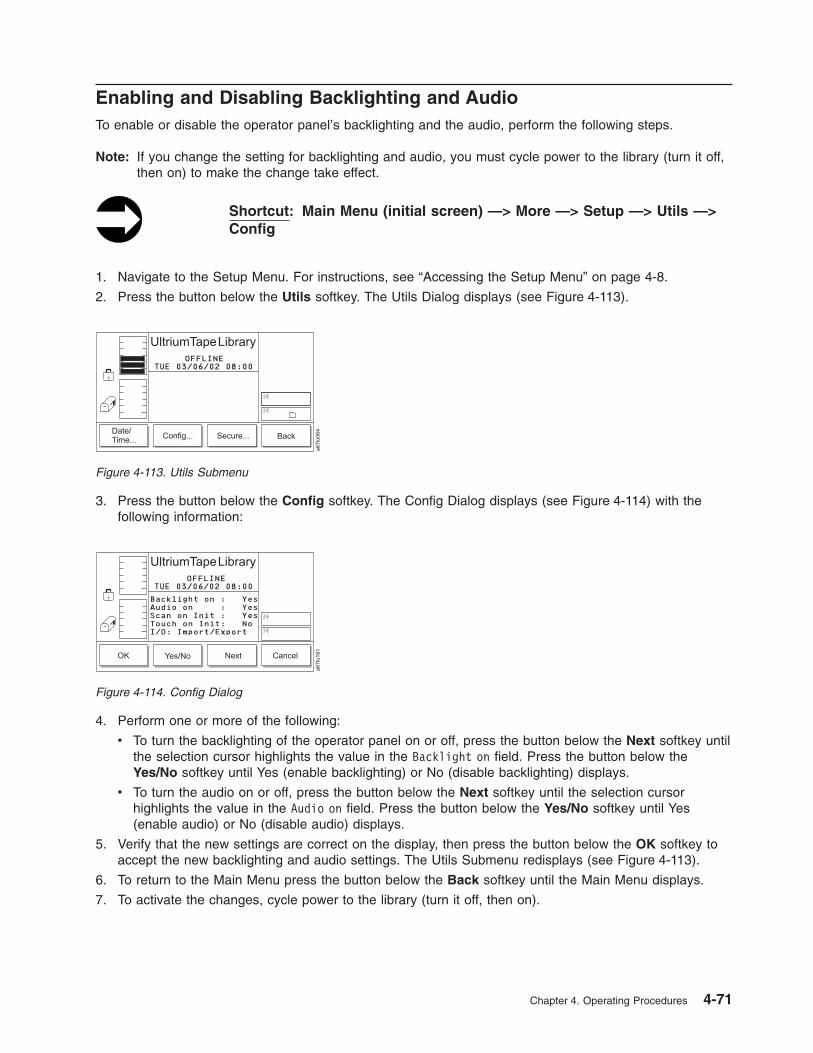
Enabling and Disabling Backlighting and Audio
To enable or disable the operator panel’s backlighting and the audio, perform the following steps.
Note: If you change the setting for backlighting and audio, you must cycle power to the library (turn it off,
then on) to make the change take effect.
Shortcut: Main Menu (initial screen) —> More —> Setup —> Utils —>
Config
1. Navigate to the Setup Menu. For instructions, see “Accessing the Setup Menu” on page 4-8.
2. Press the button below the Utils softkey. The Utils Dialog displays (see Figure 4-113).
3. Press the button below the Config softkey. The Config Dialog displays (see Figure 4-114) with the
following information:
4. Perform one or more of the following:
v To turn the backlighting of the operator panel on or off, press the button below the Next softkey until
the selection cursor highlights the value in the Backlight on field. Press the button below the
Yes/No softkey until Yes (enable backlighting) or No (disable backlighting) displays.
v To turn the audio on or off, press the button below the Next softkey until the selection cursor
highlights the value in the Audio on field. Press the button below the Yes/No softkey until Yes
(enable audio) or No (disable audio) displays.
5. Verify that the new settings are correct on the display, then press the button below the OK softkey to
accept the new backlighting and audio settings. The Utils Submenu redisplays (see Figure 4-113).
6. To return to the Main Menu press the button below the Back softkey until the Main Menu displays.
7. To activate the changes, cycle power to the library (turn it off, then on).
Figure 4-113. Utils Submenu
OK Yes/No Next Cancel
OFFLINE
a6
7lo
16
1
Backlight on : Yes
Audio on : Yes
Scan on Init : Yes
Touch on Init: No
I/O: Import/ExportFAST Read/Write
UltriumTapeLibrary
03/06/02 08:00TUE
Figure 4-114. Config Dialog
Chapter 4. Operating Procedures 4-71

Choosing the Method of Inventory
The library offers two ways to perform an inventory whenever you power it on (initialization). You can
configure the library so that it scans the bar codes on each labeled cartridge or touches each unlabeled
cartridge with the fingers of the picker. Each method provides an inventory of the library’s cartridges. The
scanning method is the default and takes less time than the touching method.
To choose the method of inventory during initialization, perform the following steps.
Shortcut: Main Menu (initial screen) —> More —> Setup —> Utils —>
Config
1. Navigate to the Setup Menu. For instructions, see “Accessing the Setup Menu” on page 4-8.
2. Press the button below the Utils softkey. The Utils Dialog displays (see Figure 4-115).
3. Press the button below the Config softkey. The Config Dialog displays (see Figure 4-116) with the
following information:
4. Perform one of the following:
v To cause the library to perform an inventory by scanning the bar codes on labeled cartridges, press
the button below the Next softkey until the selection cursor highlights the value in the Scan on Init
field. Press the button below the Yes/No softkey until Yes displays (enable scanning).
v To cause the library to perform an inventory by touching the cartridges, press the button below the
Next softkey until the selection cursor highlights the value in the Touch on Init field. Press the
button below the Yes/No softkey until Yes displays (enable touching).
5. Verify that the new setting is correct on the display, then press the button below the OK softkey to
accept the new inventory setting. The Utils Submenu redisplays (see Figure 4-115).
6. To return to the Main Menu press the button below the Back softkey until the Main Menu displays.
7. To activate the new setting, cycle power to the library (turn it off, then on).
Figure 4-115. Utils Submenu
OK Yes/No Next Cancel
OFFLINE
a6
7lo
16
1
Backlight on : Yes
Audio on : Yes
Scan on Init : Yes
Touch on Init: No
I/O: Import/ExportFAST Read/Write
UltriumTapeLibrary
03/06/02 08:00TUE
Figure 4-116. Config Dialog
4-72 3583 Tape Library Maintenance Information

Configuring the I/O Station as Storage Slots
To configure the I/O station as storage slots, perform the following steps.
Note: If you configure the I/O station as storage slots, you must cycle power to the library (turn it off, then
on) to make the change take effect.
Shortcut: Main Menu (initial screen) —> More —> Setup —> Utils —>
Config
1. Navigate to the Setup Menu. For instructions, see “Accessing the Setup Menu” on page 4-8.
2. Press the button below the Utils softkey. The Utils Dialog displays (see Figure 4-117).
3. Press the button below the Config softkey. The Config Dialog displays (see Figure 4-118) with the
following information:
4. Press the button below the Next softkey until the selection cursor highlights the value in the I/O
Station field. The screen automatically refreshes and the I/O Station field changes to I/O:
Import/Export.
5. Perform one of the following:
v To configure the I/O station as an import and export location, press the button below the Change
softkey until Imprt/Exprt displays.
v To configure the I/O station as cartridge storage slots, press the button below the Change softkey
until Storage displays.
6. Verify that the new setting is correct on the display, then press the button below the OK softkey to
accept the setting. The library displays a message that it must reboot to make the changes. Press the
button below the OK softkey. The Utils Submenu redisplays (see Figure 14-48 on page 14-47).
7. To return to the Main Menu press the button below the Back softkey until the Main Menu displays.
8. To activate the new setting, cycle power to the library (turn it off, then on).
Figure 4-117. Utils Submenu
OK Yes/No Next Cancel
OFFLINE
a6
7lo
16
1
Backlight on : Yes
Audio on : Yes
Scan on Init : Yes
Touch on Init: No
I/O: Import/ExportFAST Read/Write
UltriumTapeLibrary
03/06/02 08:00TUE
Figure 4-118. Config Dialog
Chapter 4. Operating Procedures 4-73

Enabling Security
The Enable Security feature allows you to protect your data. The default setting is Disable Security, but
you can enable security by using the following procedure.
Note: When security is enabled, the library will prompt you for your password each time that you attempt
to access certain protected procedures.
To enable security on the library, perform the following steps.
Shortcut: Main Menu (initial screen) —> More —> Setup —> Utils —>
Secure
1. Navigate to the Setup Menu. For instructions, see “Accessing the Setup Menu” on page 4-8.
2. Press the button below the Utils softkey. The Utils Dialog displays (see Figure 4-119).
3. Press the button below the Secure softkey. The Secure Dialog displays (see Figure 4-120).
4. Press the button below the Yes/No softkey until a checkmark displays in the checkbox beside the
Enable Security field. The library displays the message Security is now ON.
5. Press the button below the OK softkey to redisplay the Secure Dialog and view the new setting.
6. To return to the Utils Submenu, press the button below the OK softkey. To return to the Main Menu
press the button below the OK softkey, then press the button below the Back softkey until the Main
Menu displays.
Figure 4-119. Utils Submenu
Figure 4-120. Secure Dialog
4-74 3583 Tape Library Maintenance Information

Changing Your Passwords
You change your RMU password from the RMU and your operator panel security password from the
operator panel.
RMU Password
To change your RMU password from the RMU, see “Configuration” on page 3-11. When changing your
password, record it on the Library Configuration Form and place the form in a secure location.
Operator Panel Password
Shortcut: Main Menu (initial screen) —> More —> Setup —> Utils —>
Secure
1. Navigate to the Setup Menu. For instructions, see “Accessing the Setup Menu” on page 4-8.
2. Press the button below the Utils softkey. The Utils Dialog displays (see Figure 4-121).
3. Press the button below the Secure softkey. The Enter Password Dialog displays (see Figure 4-122).
Note: If security is enabled, you must enter the existing or default password to display the Secure
Dialog (see Figure 14-55 on page 14-51). The initial default password is 0000.
4. Enter your existing password by pressing the button below the Next softkey until the selection cursor
highlights the first character in the New field. Press the button below the Up or Down softkeys to
increase or decrease the numeric value.
5. Press the button below the OK softkey. The Secure Dialog screen displays (see Figure 4-123 on
page 4-76).
Note: In Figure 14-55 on page 14-51, the absence of a checkmark in the checkbox beside the
Enable Security field indicates that security has not been enabled.
Figure 4-121. Utils Submenu
Figure 4-122. Enter Password Dialog
Chapter 4. Operating Procedures 4-75
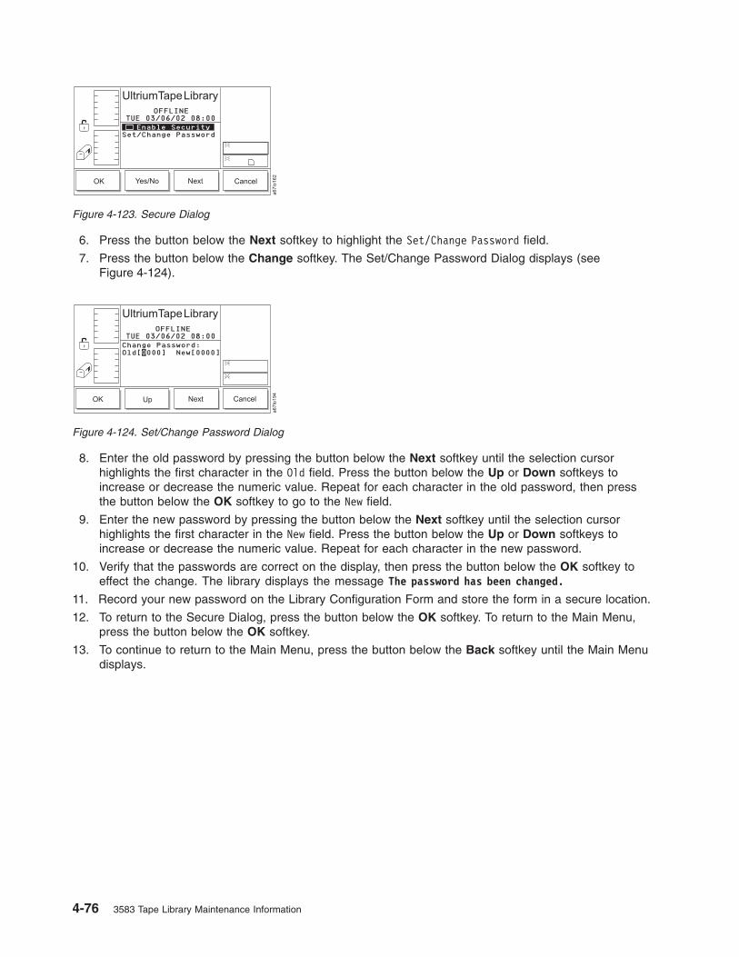
6. Press the button below the Next softkey to highlight the Set/Change Password field.
7. Press the button below the Change softkey. The Set/Change Password Dialog displays (see
Figure 4-124).
8. Enter the old password by pressing the button below the Next softkey until the selection cursor
highlights the first character in the Old field. Press the button below the Up or Down softkeys to
increase or decrease the numeric value. Repeat for each character in the old password, then press
the button below the OK softkey to go to the New field.
9. Enter the new password by pressing the button below the Next softkey until the selection cursor
highlights the first character in the New field. Press the button below the Up or Down softkeys to
increase or decrease the numeric value. Repeat for each character in the new password.
10. Verify that the passwords are correct on the display, then press the button below the OK softkey to
effect the change. The library displays the message The password has been changed.
11. Record your new password on the Library Configuration Form and store the form in a secure location.
12. To return to the Secure Dialog, press the button below the OK softkey. To return to the Main Menu,
press the button below the OK softkey.
13. To continue to return to the Main Menu, press the button below the Back softkey until the Main Menu
displays.
Figure 4-123. Secure Dialog
Figure 4-124. Set/Change Password Dialog
4-76 3583 Tape Library Maintenance Information

Disabling Security
To disable security on the library, perform the following steps.
Shortcut: Main Menu (initial screen) —> More —> Setup —> Utils —>
Secure
1. Navigate to the Setup Menu. For instructions, see “Accessing the Setup Menu” on page 4-8.
2. Press the button below the Utils softkey. The Utils Dialog displays (see Figure 4-125).
3. Press the button below the Secure softkey. The Enter Password Dialog displays (see Figure 4-126).
4. Enter your password by pressing the button below the Next softkey until the selection cursor
highlights the character that you want to change. Press the button below the Up or Down softkeys to
increase or decrease the numeric value. Repeat as necessary for each character in the password.
5. Verify that the password is correct on the display, then press the button below the OK softkey. The
Security Enabled Dialog displays with a checkmark beside the Enable Security field to indicate that
security is currently enabled (see Figure 4-127).
Figure 4-125. Utils Submenu
Figure 4-126. Enter Password Dialog
Figure 4-127. Security Enabled Dialog
Chapter 4. Operating Procedures 4-77

6. Press the button below the Yes/No softkey until the checkmark disappears from the checkbox beside
the Enable Security field. The Enter Password Dialog displays (see Figure 4-128).
7. Enter your password by pressing the button below the Next softkey until the selection cursor
highlights the character that you want to change. Press the button below the Up or Down softkeys to
increase or decrease the numeric value. Repeat as necessary for each character in the password.
8. Verify that the password is correct on the display, then press the button below the OK softkey. The
library displays the message Security is now OFF.
9. Press the button below the OK softkey to redisplay the Secure Dialog and view the new setting (see
Figure 4-129). Recommendation: Security is now OFF and eliminates the need for a password. If the password has
been changed to something other than the default password [0000], it is recommended to change it back
to the default password. Otherwise, if security is enabled sometime in the future, the current password will
still be in effect and will have to be remembered in order to navigate through the screens or even to
disable security.
10. To return to the Utils Submenu, press the button below the OK softkey. To return to the Main Menu
press the button below the OK softkey, then press the button below the Back softkey until the Main
Menu displays.
Figure 4-128. Enter Password Dialog
Figure 4-129. Secure Dialog
4-78 3583 Tape Library Maintenance Information
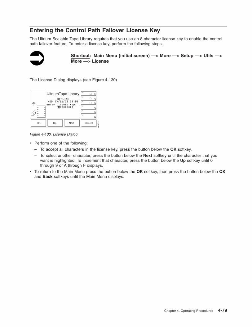
Entering the Control Path Failover License Key
The Ultrium Scalable Tape Library requires that you use an 8-character license key to enable the control
path failover feature. To enter a license key, perform the following steps.
Shortcut: Main Menu (initial screen) —> More —> Setup —> Utils —>
More —> License
The License Dialog displays (see Figure 4-130).
v Perform one of the following:
– To accept all characters in the license key, press the button below the OK softkey.
– To select another character, press the button below the Next softkey until the character that you
want is highlighted. To increment that character, press the button below the Up softkey until 0
through 9 or A through F displays.
v To return to the Main Menu press the button below the OK softkey, then press the button below the OK
and Back softkeys until the Main Menu displays.
Figure 4-130. License Dialog
Chapter 4. Operating Procedures 4-79

Resolving Errors
If a problem occurs during operation, you can view service action codes (SACs) from which you can
determine the source of the error and the action required to correct it. To view the SACs, perform the
following steps.
Shortcut: Main Menu (initial screen) —> More —> Service —> Start
1. Navigate to the Service Menu. For instructions, see “Accessing the Service Menu” on page 4-9.
2. Press the button below the Start softkey. The Start Dialog displays (see Figure 4-131) with the
NORMAL service type highlighted.
3. Perform one of the following:
v To view the SAC codes and resolve the error by yourself (normal service), press the button below
the OK softkey. The Normal Service Dialog displays a list of SACs and a message when there are
no more SACs to report (see Figure 4-132). To return to the Service Menu, press the button below
the OK softkey.
v Instruction for service personnel only: To reenter the library’s serial number after you have
replaced the main controller board, press the button below the Normal/Advanced softkey. The
screen refreshes and highlights the ADVANCED service type. The Enter Password Dialog displays
(see Figure 4-133 on page 4-81).
Figure 4-131. Start Dialog
Figure 4-132. Normal Service Dialog
4-80 3583 Tape Library Maintenance Information

Enter the 4-character password (if you do not know the password, contact your Support Center). To
enter the password, perform the following steps:
a. Press the button below the Up or Down softkey to increase or decrease the value in the
highlighted field, then press the button below the Next softkey to accept the value and move to
the next character in the password.
b. Repeat step 3a for each character in the password until the complete password displays.
c. Verify that the password is correct on the display, then press the button below the OK softkey to
access the screen in which you can reenter the library’s serial number.
d. Repeat step 3a to enter each character of the serial number until the complete serial number
displays. The preferred method of entering the library serial number on a new main controller
board utilizes the library serial port using the command setser (see the section about the main
controller board in the Ultrium Scalable Tape Library Maintenance Information guide). Libraries
with the Multi-Path feature use internal 3583 library arbitration firmware to set the serial number
and eliminate the need for manual entry of the serial number that is required in machines
without the Multi-Path feature.
Figure 4-133. Enter Password Dialog
Chapter 4. Operating Procedures 4-81

Running Library Diagnostics
The library includes diagnostics for the sensors, the vertical and rotary axes of the picker, and the fingers
on the picker. The sections that follow describe each type of diagnostic.
Checking the Sensors and Locking or Unlocking of the I/O Station
Door
To view the status of library mechanisms through their sensors and to lock or unlock the I/O station door,
perform the following steps.
Shortcut: Main Menu (initial screen) —> More —> Service —> Library
—> Diags —> Sensors
1. Navigate to the Service Menu. For instructions, see “Accessing the Service Menu” on page 4-9.
2. Press the button below the Library softkey. The Library Submenu displays (see Figure 4-134).
3. Press the button below the Diags softkey. The Diags Submenu displays (see Figure 4-135).
4. Press the button below the Sensors softkey. The Sensor Dialog displays (see Figure 4-136).
Change Command Cancel
ONLINE
To run this option
the library must be
Offline with the
door closed.
a6
7lo
06
9
UltriumTapeLibrary
01/24/05 14:06MON
Figure 4-134. Library Submenu
Figure 4-135. Diags Submenu
Figure 4-136. Sensor Dialog
4-82 3583 Tape Library Maintenance Information
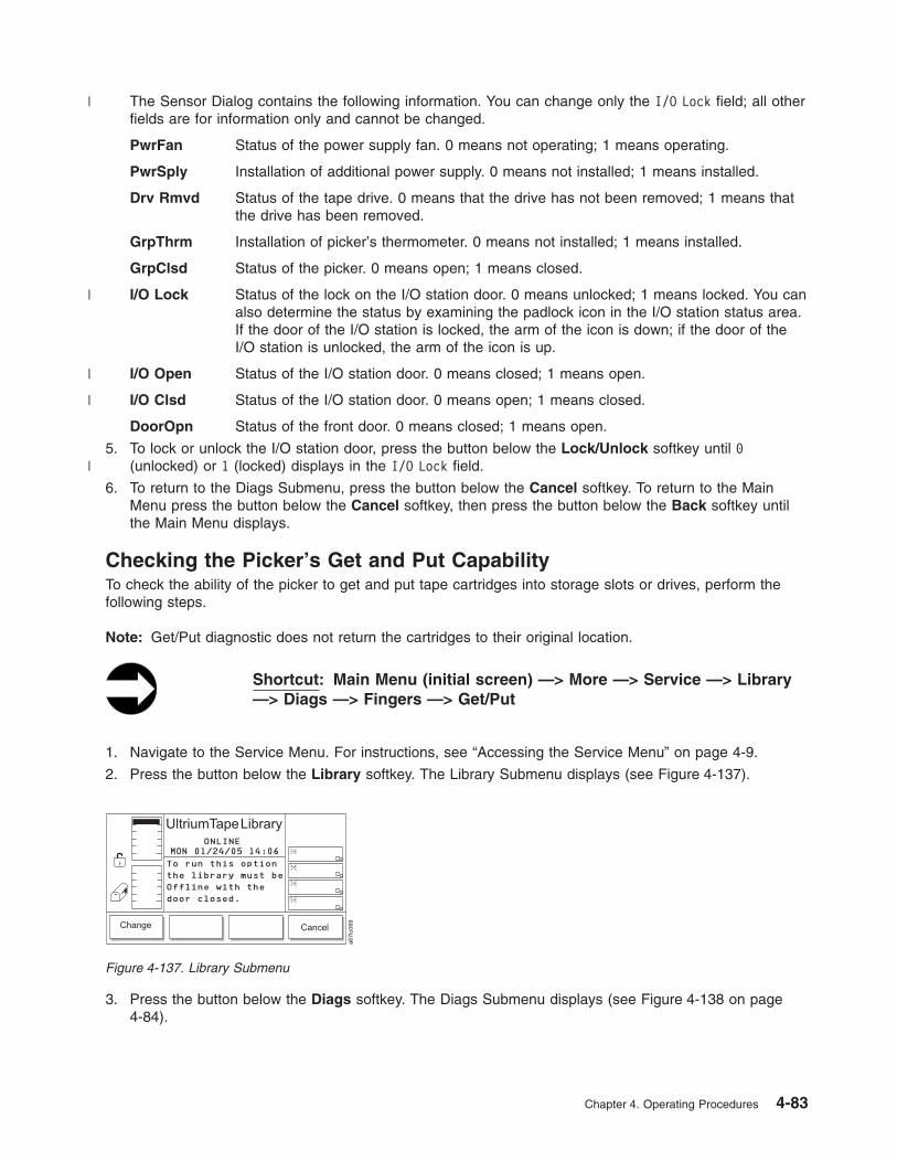
The Sensor Dialog contains the following information. You can change only the I/O Lock field; all other
fields are for information only and cannot be changed.
PwrFan Status of the power supply fan. 0 means not operating; 1 means operating.
PwrSply Installation of additional power supply. 0 means not installed; 1 means installed.
Drv Rmvd Status of the tape drive. 0 means that the drive has not been removed; 1 means that
the drive has been removed.
GrpThrm Installation of picker’s thermometer. 0 means not installed; 1 means installed.
GrpClsd Status of the picker. 0 means open; 1 means closed.
I/O Lock Status of the lock on the I/O station door. 0 means unlocked; 1 means locked. You can
also determine the status by examining the padlock icon in the I/O station status area.
If the door of the I/O station is locked, the arm of the icon is down; if the door of the
I/O station is unlocked, the arm of the icon is up.
I/O Open Status of the I/O station door. 0 means closed; 1 means open.
I/O Clsd Status of the I/O station door. 0 means open; 1 means closed.
DoorOpn Status of the front door. 0 means closed; 1 means open.
5. To lock or unlock the I/O station door, press the button below the Lock/Unlock softkey until 0
(unlocked) or 1 (locked) displays in the I/O Lock field.
6. To return to the Diags Submenu, press the button below the Cancel softkey. To return to the Main
Menu press the button below the Cancel softkey, then press the button below the Back softkey until
the Main Menu displays.
Checking the Picker’s Get and Put Capability
To check the ability of the picker to get and put tape cartridges into storage slots or drives, perform the
following steps.
Note: Get/Put diagnostic does not return the cartridges to their original location.
Shortcut: Main Menu (initial screen) —> More —> Service —> Library
—> Diags —> Fingers —> Get/Put
1. Navigate to the Service Menu. For instructions, see “Accessing the Service Menu” on page 4-9.
2. Press the button below the Library softkey. The Library Submenu displays (see Figure 4-137).
3. Press the button below the Diags softkey. The Diags Submenu displays (see Figure 4-138 on page
4-84).
Change Command Cancel
ONLINE
To run this option
the library must be
Offline with the
door closed.
a6
7lo
06
9
UltriumTapeLibrary
01/24/05 14:06MON
Figure 4-137. Library Submenu
Chapter 4. Operating Procedures 4-83
|
|
|
|
|

4. Press the button below the Fingers softkey. The Fingers Submenu displays (see Figure 4-139).
5. Press the button below the Get/Put softkey. The Get/Put Dialog displays (see Figure 4-140).
The Get/Put Dialog contains the following information:
Cycles to run Specifies the number of cycles to run. Valid values are 1 through 9999.
Number of slots Specifies the number of slots to use during the cycles. Valid values are
1 through 72.
Starting slot Indicates the slot location from which the Get/Put diagnostic will begin.
This a read-only field that you can only change after you specify Yes in
the New start slot field (see the description of the next field).
New start slot Specifies the new slot location from which the Get/Put diagnostic will
begin. Valid values are Yes (change the start slot) or No (use this
installed).
6. Perform one or more of the following:
v To change the value in the Cycles to run field, press the button below the Up or Down softkeys
until the value that you want displays.
v To change the value in the Number of slots field, press the button below the Next softkey until the
selection cursor highlights that field. Press the button below the Up or Down softkeys until the value
that you want displays.
Figure 4-138. Diags Submenu
Figure 4-139. Fingers Submenu
Figure 4-140. Get/Put Dialog
4-84 3583 Tape Library Maintenance Information
|
|

v To change the value in the Starting slot field, perform the following steps:
a. Press the button below the Next softkey until the selection cursor highlights the New start slot
field. The New Start Slot Dialog displays (see Figure 4-141).
b. Press the button below the Yes/No softkey until Yes displays.
c. Press the button below the OK softkey. The Get/Put Source Dialog displays (see Figure 4-142)
with a message area that shows three icons:
– The left icon represents the columns in the library, with an arrow pointed to the column that is
currently selected.
– The middle icon represents the magazines in the currently selected column. The arrow points
to the currently selected magazine.
– The right icon represents the storage slots in the currently selected column and magazine.
The arrow points to the currently selected storage slot.
The position of the arrow in each of the three icons identifies the storage slot’s physical address.
For example, arrows that point to a column 2, magazine A, and storage slot 1 indicate a physical
address of 2 A 1. In the Get/Put Source Dialog, a slot’s physical address displays below the
right icon (see Figure 4-142).
v Specify the new location from which you want the Get/Put diagnostic to start by performing one of
the following:
– To specify the physical address that is currently displayed, press the button below the OK
softkey.
– To specify another location, perform the following steps:
a. Press the button below the Change Column softkey until the arrow in the left icon points to
the column that you want. Press the button below the Next softkey. The Change Magazine
Dialog displays (see Figure 4-143 on page 4-86).
Note: If you choose the drive column (column 3), the Change Drive Dialog displays because
no slots or magazines are available in this column. To choose a different column,
press the button below the Next softkey, then press the button below the Change
Figure 4-141. New Start Slot Dialog
Figure 4-142. Get/Put Source Dialog
Chapter 4. Operating Procedures 4-85
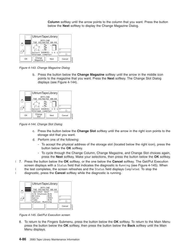
Column softkey until the arrow points to the column that you want. Press the button
below the Next softkey to display the Change Magazine Dialog.
b. Press the button below the Change Magazine softkey until the arrow in the middle icon
points to the magazine that you want. Press the Next softkey. The Change Slot Dialog
displays (see Figure 4-144).
c. Press the button below the Change Slot softkey until the arrow in the right icon points to the
storage slot that you want.
d. Perform one of the following:
- To accept the physical address of the storage slot (located below the right icon), press the
button below the OK softkey.
- To cycle through the Change Column, Change Magazine, and Change Slot choices again,
press the Next softkey. Make your selections, then press the button below the OK softkey.
7. Press the button below the OK softkey, or the one below the Cancel softkey. The Get/Put Execution
screen displays with a Status field that indicates the diagnostic is Running (see Figure 4-145). When
the test completes, the screen refreshes and the Status field displays Completed. To stop the
diagnostic, press the Cancel softkey while the diagnostic is running.
8. To return to the Fingers Submenu, press the button below the OK softkey. To return to the Main Menu
press the button below the OK softkey, then press the button below the Back softkey until the Main
Menu displays.
Figure 4-143. Change Magazine Dialog
Figure 4-144. Change Slot Dialog
Figure 4-145. Get/Put Execution screen
4-86 3583 Tape Library Maintenance Information
|
||

Checking the Picker’s Open, Close, Reach, and Retract Capabilities
To check the ability of the picker to open, close, reach, and retract its fingers, perform the following steps.
Note: This is an advanced diagnostic that is not intended for use during normal operation.
Shortcut: Main Menu (initial screen) —> More —> Service —> Library
—> Diags —> Fingers —> Step
1. Navigate to the Service Menu. For instructions, see “Accessing the Service Menu” on page 4-9.
2. Press the button below the Library softkey. The Library Submenu displays (see Figure 4-146).
3. Press the button below the Diags softkey. The Diags Submenu displays (see Figure 4-147).
4. Press the button below the Fingers softkey. The Fingers Submenu displays (see Figure 4-148).
5. Press the button below the Step softkey. The Step Dialog displays a reminder that this diagnostic
should be used by trained personnel only (see Figure 4-149 on page 4-88).
Change Command Cancel
ONLINE
To run this option
the library must be
Offline with the
door closed.
a6
7lo
06
9UltriumTapeLibrary
01/24/05 14:06MON
Figure 4-146. Library Submenu
Figure 4-147. Diags Submenu
Figure 4-148. Fingers Submenu
Chapter 4. Operating Procedures 4-87

6. Press the button below the OK softkey. The Picker Finger Dialog displays (see Figure 4-150).
The Picker Finger Dialog contains the following information:
Grip Indicates whether the picker’s fingers are open or closed. Valid values are OPEN or
CLOSED.
Reach Indicates whether the picker’s fingers are extended or retracted. Valid values are
EXTENDED or RETRACTED.
7. Perform one or more of the following:
v To open or close the picker’s fingers, press the button below the Open/Close softkey until the value
that you want displays in the Grip field.
v To extend or retract the picker’s fingers, press the button below the Extend/Retract softkey until the
value that you want displays in the Reach field.
8. To return to the Fingers Submenu, press the button below the Cancel softkey. To return to the Main
Menu press the button below the Cancel softkey, then press the button below the Back softkey until
the Main Menu displays.
Checking the Functionality of the Bar Code Reader
To check the ability of the bar code reader to read the bar code labels on the tape cartridges, perform the
following steps.
Note: Before beginning this procedure, choose an occupied slot as a point of reference and position the
picker in front of that slot (see “Moving the Picker” on page 4-41). Make a note of the cartridge’s
VOLSER.
Shortcut: Main Menu (initial screen) —> More —> Service —> Library
—> Diags —> Fingers —> Scanner
1. Navigate to the Service Menu. For instructions, see “Accessing the Service Menu” on page 4-9.
Figure 4-149. Step Dialog
Figure 4-150. Picker Finger Dialog
4-88 3583 Tape Library Maintenance Information

2. Press the button below the Library softkey. The Library Submenu displays (see Figure 4-151).
3. Press the button below the Diags softkey. The Diags Submenu displays (see Figure 4-152).
4. Press the button below the Fingers softkey. The Fingers Submenu displays (see Figure 4-153).
5. Press the button below the Scanner softkey. The Reader Dialog displays (see Figure 4-154).
6. Press the button below the Scan softkey. The bar code reader scans the cartridge that is currently in
front of it. The Bar Code Label Dialog displays the cartridge’s VOLSER (see Figure 4-155 on page
4-90). Ensure that the VOLSER on the operator panel matches the VOLSER on the cartridge.
Change Command Cancel
ONLINE
To run this option
the library must be
Offline with the
door closed.
a6
7lo
06
9
UltriumTapeLibrary
01/24/05 14:06MON
Figure 4-151. Library Submenu
Figure 4-152. Diags Submenu
Figure 4-153. Fingers Submenu
Figure 4-154. Reader Dialog
Chapter 4. Operating Procedures 4-89

7. To return to the Fingers Submenu, press the button below the Cancel softkey. To return to the Main
Menu press the button below the Cancel softkey, then press the button below the Back softkey until
the Main Menu displays.
Checking the Movement of the Picker
The Picker diagnostic checks the ability of the picker to move its vertical and rotary axes in motion
patterns and in incremental steps. It also tests the picker’s ability to locate to the home position. The
sections that follow describe each procedure.
Checking the Picker’s Motion Patterns
To check the ability of the picker to move the vertical and rotary axes in motion patterns, perform the
following steps.
Shortcut: Main Menu (initial screen) —> More —> Service —> Library
—> Diags —> Picker —> Move
1. Navigate to the Service Menu. For instructions, see “Accessing the Service Menu” on page 4-9.
2. Press the button below the Library softkey. The Library Submenu displays (see Figure 4-156).
3. Press the button below the Diags softkey. The Diags Submenu displays (see Figure 4-157).
Figure 4-155. Bar Code Label Dialog
Change Command Cancel
ONLINE
To run this option
the library must be
Offline with the
door closed.
a6
7lo
06
9
UltriumTapeLibrary
01/24/05 14:06MON
Figure 4-156. Library Submenu
Figure 4-157. Diags Submenu
4-90 3583 Tape Library Maintenance Information
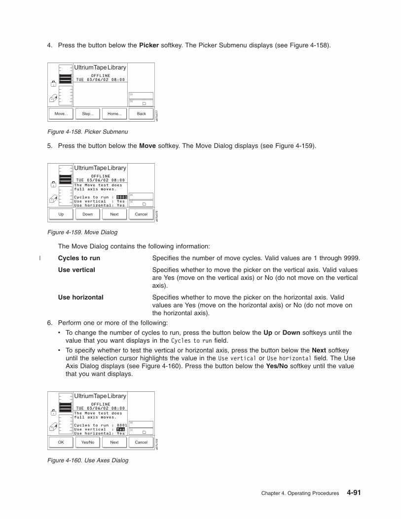
4. Press the button below the Picker softkey. The Picker Submenu displays (see Figure 4-158).
5. Press the button below the Move softkey. The Move Dialog displays (see Figure 4-159).
The Move Dialog contains the following information:
Cycles to run Specifies the number of move cycles. Valid values are 1 through 9999.
Use vertical Specifies whether to move the picker on the vertical axis. Valid values
are Yes (move on the vertical axis) or No (do not move on the vertical
axis).
Use horizontal Specifies whether to move the picker on the horizontal axis. Valid
values are Yes (move on the horizontal axis) or No (do not move on
the horizontal axis).
6. Perform one or more of the following:
v To change the number of cycles to run, press the button below the Up or Down softkeys until the
value that you want displays in the Cycles to run field.
v To specify whether to test the vertical or horizontal axis, press the button below the Next softkey
until the selection cursor highlights the value in the Use vertical or Use horizontal field. The Use
Axis Dialog displays (see Figure 4-160). Press the button below the Yes/No softkey until the value
that you want displays.
Figure 4-158. Picker Submenu
Figure 4-159. Move Dialog
Figure 4-160. Use Axes Dialog
Chapter 4. Operating Procedures 4-91
|

7. Press the button below the OK softkey to perform the diagnostic. The Move Test Execution screen
displays (see Figure 4-145 on page 4-86) with a summary of the test settings and a Status field that
indicates that the diagnostic is Running. When the test completes, the screen refreshes and the Status
field displays Completed.
8. To return to the Picker Submenu, press the button below the OK softkey. To return to the Main Menu
press the button below the OK softkey, then press the button below the Back softkey until the Main
Menu displays.
Checking the Picker’s Step Capability
To check the ability of the picker to move vertically and to rotate in incremental steps, perform the
following instructions.
Note: This is an advanced diagnostic tool that is not intended for use during normal operation.
Shortcut: Main Menu (initial screen) —> More —> Service —> Library
—> Diags —> Picker —> Step
1. Navigate to the Service Menu. For instructions, see “Accessing the Service Menu” on page 4-9.
2. Press the button below the Library softkey. The Library Submenu displays (see Figure 4-162).
3. Press the button below the Diags softkey. The Diags Submenu displays (see Figure 4-163 on page
4-93).
Figure 4-161. Move Test Execution screen
Change Command Cancel
ONLINE
To run this option
the library must be
Offline with the
door closed.
a6
7lo
06
9
UltriumTapeLibrary
01/24/05 14:06MON
Figure 4-162. Library Submenu
4-92 3583 Tape Library Maintenance Information

4. Press the button below the Picker softkey. The Picker Submenu displays (see Figure 4-164).
5. Press the button below the Step softkey. The Step Dialog displays a reminder that this diagnostic
should be used by trained personnel only (see Figure 4-165).
6. Press the button below the OK softkey. The Axes Dialog displays (see Figure 4-166).
The Axes Dialog contains the following information:
Pivot axis Indicates the degrees of the rotary position. Valid values are 000.0 through 360.0.
Vert. axis Indicates the height of the picker in millimeters. Valid values are 000.0 through the
maximum range.
Figure 4-163. Diags Submenu
Figure 4-164. Picker Submenu
Figure 4-165. Step Dialog
Figure 4-166. Axes Dialog
Chapter 4. Operating Procedures 4-93

Step amount Indicates tenths of millimeters to step. Valid values are 001 through 100.
7. Perform one or more of the following:
v To change the degrees of the rotary position, press the button below the Up or Down softkeys until
the value that you want displays in the Pivot axis field.
v To change the height of the picker, press the button below the Next softkey until the selection cursor
highlights the value in the Vert. axis field. Then, press the button below the Up or Down softkeys
until the value that you want displays.
v To change the amount of the step, press the button below the Next softkey until the selection cursor
highlights the value in the Step amount field. Then, press the button below the Up or Down softkeys
until the value that you want displays.
8. To accept the changes and return to the Picker Submenu, press the button below the Cancel softkey.
To return to the Main Menu press the button below the Cancel softkey, then press the button below
the Back softkey until the Main Menu displays.
Checking the Picker’s Homing Capability
To check the ability of the picker to locate the vertical and rotary axes to the home position, perform the
following steps.
Shortcut: Main Menu (initial screen) —> More —> Service —> Library
—> Diags —> Picker —> Home
1. Navigate to the Service Menu. For instructions, see “Accessing the Service Menu” on page 4-9.
2. Press the button below the Library softkey. The Library Submenu displays (see Figure 4-167).
3. Press the button below the Diags softkey. The Diags Submenu displays (see Figure 4-168).
4. Press the button below the Picker softkey. The Picker Submenu displays (see Figure 4-169 on page
4-95).
Change Command Cancel
ONLINE
To run this option
the library must be
Offline with the
door closed.
a6
7lo
06
9
UltriumTapeLibrary
01/24/05 14:06MON
Figure 4-167. Library Submenu
Figure 4-168. Diags Submenu
4-94 3583 Tape Library Maintenance Information

5. Press the button below the Home softkey. The Home Dialog displays (see Figure 4-170) with a
message stating that the picker will relocate to its zero position on all axes.
6. Press the button below the OK softkey. The picker returns to the home position and the library displays
the message Requested command is now complete.
7. To return to the Picker Submenu, press the button below the OK softkey. To return to the Main Menu
press the button below the OK softkey, then press the button below the Back softkey until the Main
Menu displays.
Exercising the Library
The library’s exercises include a demonstration, a self test, and a calibration procedure known as Teach.
The sections that follow describe each exercise.
Performing a Demonstration of the Library
The library’s demonstration (demo) illustrates random cartridge movement in the library. The minimum
number of cartridges recommended for this routine is two per drive, plus one additional cartridge. To
perform a demo of the library, use the following steps.
Note: This operation does not return the cartridges to their original location.
Shortcut: Main Menu (initial screen) —> More —> Service —> Library
—> Exercise —> Demo
1. Navigate to the Service Menu. For instructions, see “Accessing the Service Menu” on page 4-9.
2. Press the button below the Library softkey. The Library Submenu displays (see Figure 4-171 on page
4-96).
Figure 4-169. Picker Submenu
Figure 4-170. Home Dialog
Chapter 4. Operating Procedures 4-95

3. Press the button below the Exercise softkey. The Exercise Submenu displays (see Figure 4-172).
4. Press the button below the Demo softkey. The Demo Dialog displays (see Figure 4-173).
The Demo Dialog contains the following information:
Demo Mode Indicates whether to run the demo based on a quantity of cycles or
hours. Valid values are Cycle and Time.
Cycles to run Specifies the number of cycles to run during the demo. This field
displays only if you chose Demo Mode: Cycle. Valid values are 1
through 9999.
Hours to run Specifies the number of hours to run the demo. This field displays only
if you chose Demo Mode: Time. Valid values are 2 through 24.
Include drives Specifies whether to include drives in the demo. Valid values are Yes
(include drives in the demo) or No (do not include drives in the demo).
I/O Station Specifies whether to include the I/O station in the demo. Valid values
are Yes (include the I/O station in the demo) or No (do not include the
I/O station in the demo).
5. Perform one of the following:
v To accept the current settings, go to step 6 on page 4-97.
Change Command Cancel
ONLINE
To run this option
the library must be
Offline with the
door closed.
a6
7lo
06
9
UltriumTapeLibrary
01/24/05 14:06MON
Figure 4-171. Library Submenu
Demo...Self
Test...VerifyTest...
More
OFFLINE
a6
7lo
14
1
Updating firmware onthe library requiresa reboot. Press OKto proceed.
FAST Read/Write
UltriumTapeLibrary
02/14/04 16:48SAT
Figure 4-172. Exercise Submenu
Figure 4-173. Demo Dialog
4-96 3583 Tape Library Maintenance Information
|

v To change the value in one or more fields, press the button below the Next softkey until the
selection cursor highlights the value in that field. Perform one of the following:
– To change the mode of the demo (cycles or hours), press the button below the Up or Down
softkeys until the value that you want displays in the Demo Mode field.
– To change the number of cycles or hours to run the demo, press the button below the Next
softkey until the selection cursor highlights the value in the Cycles to run or Hours to run field.
Press the button below the Up or Down softkeys until the value that you want displays.
– To include drives or the I/O station in the demo, press the button below the Next softkey until the
selection cursor highlights the value in the Include drives or I/O Station field. The screen
automatically refreshes and displays a Yes/No softkey (see Figure 4-174). Press the button
below the Yes/No softkey until the value that you want displays.
6. Verify that the new settings are correct on the display, then press the button below the OK softkey to
begin the demo. The Demo Execution screen displays (see Figure 4-175) with a summary of the test
settings and a Status field that indicates that the diagnostic is Running. When the test completes, the
screen refreshes and the Status field displays Completed.
7. To return to the Exercise Submenu, press the button below the OK softkey. To return to the Main Menu
press the button below the OK softkey, then press the button below the Back softkey until the Main
Menu displays.
Performing a Self Test of the Library
The library’s self test runs a series of diagnostics to test its sensors, the lock and unlock function of its
door, and the movement of all motors. When the library contains drives, the routine also sends
communication messages to the drive sleds. No cartridges are moved during the self test. To perform a
self test of the library, use the following steps.
Shortcut: Main Menu (initial screen) —> More —> Service —> Library
—> Exercise —> Self Test
1. Navigate to the Service Menu. For instructions, see “Accessing the Service Menu” on page 4-9.
Figure 4-174. Include Drives Dialog
Figure 4-175. Demo Execution screen
Chapter 4. Operating Procedures 4-97

2. Press the button below the Library softkey. The Library Submenu displays (see Figure 4-176).
3. Press the button below the Exercise softkey. The Exercise Submenu displays (see Figure 4-177).
4. Press the button below the Self Test softkey. The Self Test Dialog displays (see Figure 4-178).
The Self Test Dialog contains the following information:
Cycles to run Indicates the number of test cycles to run. Valid values are 0 through
999.
Include drives Specifies whether to include drives in the demo. Valid values are Yes
(include drives in the self test) or No (do not include drives in the self
test).
5. Perform one of the following:
v To accept the number of cycles to run, press the button below the Next softkey to advance the
selection cursor to the next field.
v To change the number of cycles to run during the self test, press the button below the Up or Down
softkeys until the value that you want displays. Press the button below the Next softkey to advance
the selection cursor to the next field.
6. To include or exclude drives in the self test, press the button below the Next softkey until the selection
cursor highlights the Include drives field. The screen refreshes and the Include Drives Dialog displays
Change Command Cancel
ONLINE
To run this option
the library must be
Offline with the
door closed.
a6
7lo
06
9
UltriumTapeLibrary
01/24/05 14:06MON
Figure 4-176. Library Submenu
Demo...Self
Test...VerifyTest...
More
OFFLINE
a6
7lo
14
1
Updating firmware onthe library requiresa reboot. Press OKto proceed.
FAST Read/Write
UltriumTapeLibrary
02/14/04 16:48SAT
Figure 4-177. Exercise Submenu
Figure 4-178. Self Test Dialog
4-98 3583 Tape Library Maintenance Information

(see Figure 4-179). Press the button below the Yes/No softkey until Yes (include drives) or No (exclude
drives) displays.
7. Press the button below the OK softkey to perform the self test. The Self Test Execution Dialog displays
a summary of the test settings and a Status field that indicates that the diagnostic is Running. When
the test completes, the screen refreshes and the Status field displays Completed (see Figure 4-180).
8. To return to the Exercise Submenu, press the button below the OK softkey. To return to the Main Menu
press the button below the OK softkey, then press the button below the Back softkey until the Main
Menu displays.
Performing a Verify Test of the Library
The Verify Test runs the following tests on the library:
v Power On Self Test (POST)
v FAST Read/Write drive test
v A test of the robot range of motion
v A bar code scanner test
Shortcut: Main Menu (initial screen) —> More —> Service —> Library
—> Exercise —> Verify Test
1. Navigate to the Service Menu. For instructions, see “Accessing the Service Menu” on page 4-9.
2. Press the button below the Library softkey. The Library Submenu displays (see Figure 4-181 on page
4-100).
Figure 4-179. Include Drives Dialog
Figure 4-180. Self Test Execution Dialog
Chapter 4. Operating Procedures 4-99

3. Press the button below the Exercise softkey. The Exercise Submenu displays (see Figure 4-182).
4. Press the button below the Verify Test softkey. The Verify Test Dialog displays (see Figure 4-183).
5. In the Verify Test Dialog’s Include Drive(s) field, press the button below the Change softkey to select
one of the following values:
Value Description
All Includes all the drives in the test
1 - 6 Includes a specific drive in the test
6. When the correct value is selected, press the button below the OK softkey. The Verify Test Scratch
Tape Dialog displays (see Figure 4-184 on page 4-101).
Change Command Cancel
ONLINE
To run this option
the library must be
Offline with the
door closed.
a6
7lo
06
9
UltriumTapeLibrary
01/24/05 14:06MON
Figure 4-181. Library Submenu
Demo...Self
Test...VerifyTest...
More
OFFLINE
a6
7lo
14
1
Updating firmware onthe library requiresa reboot. Press OKto proceed.
FAST Read/Write
UltriumTapeLibrary
02/14/04 16:48SAT
Figure 4-182. Exercise Submenu
OK Change Cancel
OFFLINE
a6
7lo
34
1
UltriumTapeLibrary
02/14/04 16:56SATTest may interruptbackups in progress.Be sure to unloaddrives before test.
FAST Read/WriteInclude Drive(s): All
Figure 4-183. Verify Test Dialog
4-100 3583 Tape Library Maintenance Information

7. Open the I/O Station.
8. Insert a scratch tape into the top slot of the I/O Station.
9. Close the I/O Station and the library will execute the TEACH and INVENTORY procedures.
10. When the diagnostic begins, the Diagnostic In Progress Screen displays (see Figure 4-185).
The library runs a Power On Self Test (POST) to verify the hardware is working properly. Then the
library ensures communication with the drives. If the drive(s) have a cartridge loaded, the library
moves the cartridge to its home slot. The library then reads the bar code on the scratch tape and
moves the scratch tape to the drive(s) and runs a FAST Read/Write test on the tape. The tape is then
moved back to slot 1A1, and the bar code is read a second time and compared with the earlier
reading.
11. When the tape is returned to the I/O Station, the Command Now Complete Screen displays (see
Figure 4-186).
12. To return to the Exercise Submenu, press the button below the OK softkey. To return to the Main
Menu press the button below the OK softkey, then press the button below the Back softkey until the
Main Menu displays.
Calibrating the Library
The calibration procedure is also known as Teach. To calibrate the proper position of the gripper in the
library, perform the following steps.
Cancel
OFFLINE
a6
7lo
34
2
UltriumTapeLibrary
02/14/04 17:05SATPlace a scratch tapeinto [1 A 1] (topslot of I/O Station)It will be returnedthere on completionof operation.
Figure 4-184. Verify Test Scratch Tape Dialog
Cancel
OFFLINE
a6
7lo
34
3
UltriumTapeLibrary
02/14/04 17:14SATDiagnostic is now inprogress...
Figure 4-185. Diagnostic In Progress Screen
OFFLINE
a6
7lo
34
4
UltriumTapeLibrary
02/14/04 17:19SATDiagnostic completedsuccessfully! Removescratch tape from[1 A 1].
OK
Figure 4-186. Command Now Complete Screen
Chapter 4. Operating Procedures 4-101

Shortcut: Main Menu (initial screen) —> More —> Service —> Library
—> Exercise —> More > Teach
1. Navigate to the Service Menu. For instructions, see “Accessing the Service Menu” on page 4-9.
2. Press the button below the Library softkey. The Library Submenu displays (see Figure 4-187).
3. Press the button below the Exercise softkey. The Exercise Submenu displays (see Figure 4-188).
4. Press the button below the More softkey. The library Exercise Submenu (alternate screen) displays
(see
5. Press the button below the Teach softkey. The library displays the message Select OK to Teach.
6. Press the button below the OK softkey to begin the calibration. When the calibration is finished, the
library displays the message The requested Teach completed OK.
7. To return to the Exercise Submenu, press the button below the OK softkey. To return to the Main Menu
press the button below the OK softkey, then press the button below the Back softkey until the Main
Menu displays.
Change Command Cancel
ONLINE
To run this option
the library must be
Offline with the
door closed.a
67
lo0
69
UltriumTapeLibrary
01/24/05 14:06MON
Figure 4-187. Library Submenu
Demo...Self
Test...VerifyTest...
More
OFFLINE
a6
7lo
14
1
Updating firmware onthe library requiresa reboot. Press OKto proceed.
FAST Read/Write
UltriumTapeLibrary
02/14/04 16:48SAT
Figure 4-188. Exercise Submenu
OFFLINE
a6
7lo
34
5
UltriumTapeLibrary
02/14/04 17:35SAT
Teach Back
Figure 4-189. Exercise Submenu (alternate screen)
4-102 3583 Tape Library Maintenance Information

Running Drive Diagnostics
Attention: Insert only a scratch data cartridge for this procedure. Data on the cartridge will be
overwritten.
The drive diagnostics test the drive’s normal and fast read/write capability, as well as the function of its
media, head, electrical power, and SCSI circuitry. The sections that follow describe each type of
diagnostic.
To select a drive and run a diagnostic on it, perform the following steps:
Shortcut: Main Menu (initial screen) —> More —> Service —> Drives
—> OK or Change Drive—> Diags
1. Navigate to the Service Menu. For instructions, see “Accessing the Service Menu” on page 4-9.
2. Press the button below the Drives softkey. The Drives Dialog displays the number of a drive in the
library and its current level of firmware (see Figure 4-190).
3. Perform one of the following:
v To run the diagnostic on the currently displayed drive, press the button below the OK softkey.
v To run the diagnostic on a different drive, press the button below the Change Drive softkey until the
number of the drive that you want displays. Press the button below the OK softkey.
The Drive Service Dialog displays (see Figure 4-191).
4. Press the button below the Diags softkey. The Drive Diagnostics Dialog displays the first of the six
diagnostics that you can run on the specified drive (see Figure 4-192 on page 4-104). Each diagnostic
is presented one at a time.
Figure 4-190. Drives Dialog
Figure 4-191. Drive Service Dialog
Chapter 4. Operating Procedures 4-103

The Drive Diagnostics Dialog contains the following supported tests:
FAST Read/Write Performs a load and unload operation, and a read and write test.
NORMAL Read/Write Performs a load and unload operation, a read and write test, and other
related tests. The NORMAL Read/Write test is more comprehensive
and longer in duration than the FAST Read/Write test.
Media Read/Write Tests whether a suspect tape cartridge and its magnetic tape are
acceptable.
Head Read/Write Tests whether a suspect tape cartridge and its magnetic tape are
acceptable.
Power On Self Test Tests the drive’s initialization process.
FC/SCSI Wrap Test Tests the SCSI circuitry.
Error Report Reports on errors in the event of a drive error condition.
5. Perform one of the following:
v To accept and run the currently displayed drive diagnostic, press the button below the OK softkey.
v To specify and run a different drive diagnostic, press the button below the Change softkey until the
diagnostic that you want displays. Press the button below the OK softkey.
6. Perform one of the following:
v For the FAST Read/Write, NORMAL Read/Write, Media Read/Write, and Head Read/Write
diagnostic, open the door of the I/O station and insert a scratch tape into the top slot. Close the
door of the I/O station and press the button below the OK softkey.
v For the Power On Self Test, press the button below the OK softkey.
v For the SCSI Wrap Test connect the SCSI wrap tool to one SCSI port of the drive and the
single-ended terminator that was shipped with the drive to the other SCSI port of the drive, and
press the button below the OK softkey.
The library begins the diagnostic. When the test is complete, the library displays the message
Requested command is now complete.
7. To return to the Drive Diagnostics Dialog, press the button below the OK softkey. To return to the Main
Menu press the button below the OK softkey, then press the button below the Cancel and Back
softkeys until the Main Menu displays.
Figure 4-192. Drive Diagnostics Dialog
4-104 3583 Tape Library Maintenance Information
||
||

Creating or Erasing an FMR Tape
Before you can create a field microcode replacement (FMR) tape, you must have previously obtained the
new firmware file by downloading it from the web, ordering it on a CD or diskette, or copying it from a
drive that is already loaded with the new firmware.
To download the new firmware file from the web, visit http://www.ibm.com/storage/lto.
To order the new firmware file on a CD or diskette, contact your IBM Service Representative.
To copy an FMR tape from a drive that is already loaded with the new firmware, refer to the steps in this
procedure.
Shortcut: Main Menu (initial screen) —> More —> Service —> Drives
—> OK —> FMR Tape
1. Navigate to the Service Menu. For instructions, see “Accessing the Service Menu” on page 4-9.
2. Press the button below the Drives softkey. The Drives Dialog displays the message Make sure the
drive selected is OFFLINE! and the number of a drive in the library (see Figure 4-193). Ensure that
the drive has completed all operations and that no backup applications are running. Within the drive
column, drives are numbered 01 through 06 from bottom to top.
3. Perform one of the following:
v To accept the current drive, press the button below the OK softkey.
v To specify a different drive, press the button below the Change Drive softkey until the number of
the drive that you want displays. Press the button below the OK softkey.
The Drive Service Dialog displays (see Figure 4-194).
4. Press the button below the FMR Tape softkey. The FMR Tape Dialog displays (see Figure 4-195 on
page 4-106) with the Create or Erase function highlighted.
Figure 4-193. Drives Dialog
Figure 4-194. Drive Service Dialog
Chapter 4. Operating Procedures 4-105

5. Perform one of the following:
v To accept the currently displayed function (Create or Erase), press the button below the OK softkey.
v To specify another function, press the button below the Change softkey until the function that you
want displays. Press the button below the OK softkey.
The Scratch Tape Dialog displays (see Figure 4-196).
6. Open the door of the I/O station and insert a scratch tape into the top slot. Close the door of the I/O
station and press the button below the OK softkey. The library creates or erases the FMR tape,
displays status messages, and returns the newly created FMR tape to its original slot. When the task
is complete, the library displays the message Requested command is now complete.
7. To return to the Scratch Tape Dialog, press the button below the OK softkey. To return to the Main
Menu, press the button below the OK softkey. Then press the button below the Cancel softkey until
the Main Menu displays (or press the button below the Change softkey to erase the FMR tape).
Figure 4-195. FMR Tape Dialog
Figure 4-196. Scratch Tape Dialog
4-106 3583 Tape Library Maintenance Information

Removing and Replacing a Tape Drive
Note: (Ultrium 3 drives only) Before removing and replacing a tape drive, perform a Preserve Dump to
gather diagnostic information about the drive. See “Performing a Preserve Dump” on page 4-36 for
more information.The Repair option is used to inform the library that a drive is about to be taken out of the library.
Communication to the drive will discontinue until the drive has been replaced.
To notify the library that a drive is being removed or replaced, perform the following steps:
Note: To physically remove or replace a tape drive, see the appropriate section in the IBM Ultrium
Scalable Tape Library Maintenance Information manual.
Shortcut: Main Menu (initial screen) —> More —> Service —> Drives
—> OK —> Repair
1. From the Main Menu’s initial screen, press the button below the More softkey. The Main Menu’s
alternate screen displays (see Figure 4-198).
2. Press the button below the Service softkey. The Service Menu displays (see Figure 4-199 on page
4-108).
Figure 4-197. Main Menu (initial screen)
Figure 4-198. Main Menu (alternate screen)
Chapter 4. Operating Procedures 4-107
||||

3. Press the button below the Drives softkey. The Drives Dialog displays the number of a drive in the
library (see Figure 4-200). Within the drive column, drives are numbered 01 through 06 from bottom to
top.
4. Perform one of the following:
v To accept the current drive, press the button below the OK softkey.
v To specify a different drive, press the button below the Change Drive softkey until the number of
the drive that you want displays. Press the button below the OK softkey.
The Drive Service Dialog displays (see Figure 4-201).
5. Press the button below the Repair softkey. The Repair Dialog displays (see Figure 4-202 on page
4-109) with the Remove or Replace function highlighted.
Figure 4-199. Service Menu
Figure 4-200. Drives Dialog
Figure 4-201. Drive Service Dialog
4-108 3583 Tape Library Maintenance Information

6. Perform one of the following:
v To accept the currently displayed function (Remove or Replace), press the button below the OK
softkey.
v To specify another function, press the button below the Change softkey until the function that you
want displays. Press the button below the OK softkey.
When the task is complete, the library displays the message Requested command is now complete.
7. Press the button below the OK softkey. The library displays the message You can now remove the
drive or You can now replace the drive. To physically remove or replace a tape drive, see the
appropriate section in the IBM Ultrium Scalable Tape Library Maintenance Information manual.
8. To return to the Repair Dialog, press the button below the OK softkey. To return to the Main Menu,
press the button below the OK softkey. Then press the button below the Cancel and Back softkeys
until the Main Menu displays.
Note: Allow a few moments for the library and drives to reinitialize.
Figure 4-202. Repair Dialog
Chapter 4. Operating Procedures 4-109
|

Viewing the Library’s Serial Number and Firmware Level
To display the library’s serial number, firmware version, and application and boot code for the picker, drive
sleds, main board, and display, perform the following steps:
Shortcut: Main Menu (initial screen) —> More —> About —> Details—>
OK
1. Navigate to the About... Menu. For instructions, see “Accessing the About the Library (About...) Menu”
on page 4-10.
2. To view the library’s current application and boot code for the picker, drive sleds, main board, and
display, press the button below the Details softkey. The Detail Dialog displays (see Figure 4-203).
Continue to press the button below the Details softkey until all details have displayed.
Note: All code levels must be the same. However, if the boot code is at 02.01.0001 or above, it does
not have to have to match the other code levels.
3. To return to the Main Menu (alternate screen), press the button below the OK softkey. To return to the
Main Menu (initial screen) press the button below the OK softkey, then press the button below the
Back softkey until the Main Menu displays.
OK About... Cancel
OFFLINE
a6
7lo
30
7
MainAppl :PickAppl :DispAppl :MainBoot : 2.01.0001PickBoot :DispBoot :
6.01.00096.01.00096.01.0009
2.01.00012.01.0001
Details
UltriumTapeLibrary
03/06/03 08:00TUE
Figure 4-203. Detail Dialog
4-110 3583 Tape Library Maintenance Information

Setting the Length of the Media’s VOLSER
You can extend the length of the volume serial number (VOLSER) on your cartridge’s bar code label. To
set the length, perform the following steps.
Shortcut: Main Menu (initial screen) —> More —> Setup —> Library
—> MEDIA
1. Navigate to the Setup Menu. For instructions, see “Accessing the Setup Menu” on page 4-8.
2. Press the button below the Library softkey. The Library Submenu displays (see Figure 4-204).
3. Press the button below the MEDIA softkey. The Media Dialog displays the Volser field (see
Figure 4-205). Available settings are:
DEFAULT A bar code label of up to 6 characters.
EXTENDED A bar code label of between 5 and 16 characters.
4. Press the button below the Change softkey so that the Volser field changes to EXTENDED (see
Figure 4-206).
Figure 4-204. Library Submenu
Figure 4-205. Media Dialog
Figure 4-206. Media Dialog with the Volser field set to EXTENDED
Chapter 4. Operating Procedures 4-111
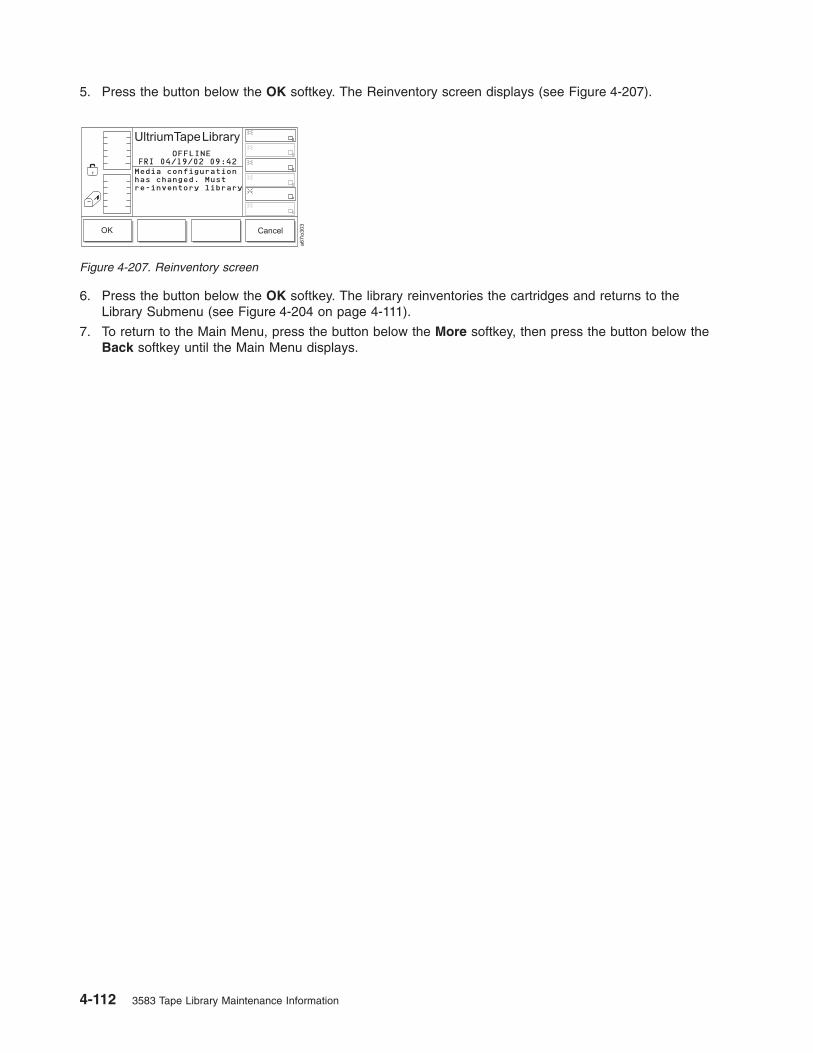
5. Press the button below the OK softkey. The Reinventory screen displays (see Figure 4-207).
6. Press the button below the OK softkey. The library reinventories the cartridges and returns to the
Library Submenu (see Figure 4-204 on page 4-111).
7. To return to the Main Menu, press the button below the More softkey, then press the button below the
Back softkey until the Main Menu displays.
Figure 4-207. Reinventory screen
4-112 3583 Tape Library Maintenance Information

Uploading Library Error Log Information by Using the RMU
The RMU’s Diagnostics file page is protected by a password and allows you to upload (to a local
computer) the diagnostic information from the attached library. The diagnostic information may be useful to
service personnel in diagnosing problems. Information from the library (command and error logs) and
information from the RMU’s Error Log can be retrieved in text form by selecting the Diagnostics file page
or Logs page from the RMU. Also included are the error log and drive dump to each drive in the library.
(The library and drive logs are typically used by service personnel only.)
Figure 4-208. Diagnostics file page
Chapter 4. Operating Procedures 4-113
Updating Firmware
Attention::
1. To ensure optimum performance from the Ultrium Scalable Tape Library, use the latest level of
firmware. It is the customer’s responsibility to obtain and install all firmware.
2. Before visiting the web to obtain the latest level of library firmware, you must determine which
generation of library firmware that you have. Library firmware for a library without the Multi-Path feature
starts with 3.xx.xxxx; library firmware for a library with the Multi-Path feature starts with 5.xx.xxxx. A
library without the Multi-Path feature cannot be loaded on a library that is already enabled with the
Multi-Path feature.
You can update firmware for the drives, the library, or the RMU by using the following methods:
v RMU
v SCSI bus
v FMR tape (drive firmware only)
v Library serial port (library firmware only)
v San Data Gateway Module (optional, if the library has an optional San Data Gateway Module installed)
Tools and Methods Available for Tape Drive and Library Firmware
Updates
Instructions for using the following tools and methods for updating firmware are included in this document.
v “ITDT SCSI Firmware Update, Dump Retrieval, and Library/Drive Test Tool” on page 4-115
v “LTO-TDX SCSI Tape Drive Firmware Update and Drive Dump Retrieval Tool” on page 4-115
v “SCSI NTUTIL (Windows) and TAPEUTIL (AIX) Drive and Library Firmware Update Tools” on page
4-115
v “RMU Method” on page 4-115
v “FMR Cartridge (Drive Only)” on page 4-115
v “SAN Data Gateway Firmware Update” on page 4-115
4-114 3583 Tape Library Maintenance Information
|

ITDT SCSI Firmware Update, Dump Retrieval, and Library/Drive Test Tool
Attention
At the time of publication, the ITDT tool was not available. Register with MySupport
(http://www.ibm.com/support/mySupport) to be notified by email when the tool becomes available,
or periodically check the IBM web site (http://www.ibm.com/storage/lto) .
The ITDT tool offers multiple functional capabilities that simplify the task of updating tape and library
firmware. It is available for most major platforms (Windows, AIX, Sun, Linux, Netware, and so on), and
requires no special device drivers. This tool is similar to the LTO-TDX drive-only firmware update and
dump retrieval tool described later in this chapter.
Note: The ITDT tool is available on the IBM website http://www.ibm.com/storage/support/lto. In
addition to the executable file (.exe), a README file will be posted on the web page. The README
file describes the features and capabilities of the ITDT tool, provides downloading instructions, and
gives detailed information on how to use the tool.
You use the ITDT tool to perform the following tasks:
v Update firmware using SCSI to all IBM LTO Tape Drive and Tape Library products (non-IBM devices
may not be selected).
v Upload drive and library dump files
v Perform drive and library diagnostics, including drive read/write diagnostics
The ITDT tool is a command line utility. To invoke it, enter the executable itdt from the directory where the
tool is located. The Help feature gives a brief explanation of each function and shows the required syntax.
LTO-TDX SCSI Tape Drive Firmware Update and Drive Dump Retrieval Tool
This is a command line tool available on the IBM web site and explained fully in the Tape Drive Firmware
Update section. This tool is also device driver independent.
SCSI NTUTIL (Windows) and TAPEUTIL (AIX) Drive and Library Firmware Update
Tools
Both of these tools require the IBM device drivers to be installed. If the application does not use the IBM
device drivers, the application drivers must first be stopped. A full explanation of these tools are located in
both the library and drive firmware update sections.
RMU Method
The RMU is a library component method which can be used to update firmware in all library components
(library, drive and RMU). The RMU method is a convenient method, however, drive updates will take about
1 hour. The RMU method is the only method listed to update the RMU itself. The RMU method is
explained in all firmware update sections.
Library Serial Port Method
The library serial port can be used to update firmware in the library only. A special firmware update
executable (3583DLMP.exe) is required and is located on the IBM web site.
FMR Cartridge (Drive Only)
Under certain circumstances where none of the above tools or methods can be used, tape drive FMR
cartridges are available to update the tape drive firmware.
SAN Data Gateway Firmware Update
The SAN Data Gateway Module firmware can be updated using one of the following two methods (both
methods are explained in the SAN Data Gateway Setup, Operator, and Service Guide):
Chapter 4. Operating Procedures 4-115
||
|||||||
||||
||||
|
||
|
|
||
|
1. The Controls pull down menu on the client/server software (ethernet). This is the most convenient
method and recommended method.
2. The SAN Data Gateway Module serial port.
Installation Overview
Complete the following steps to update library, drive, RMU, and SAN Data Gateway firmware:
v “Step 1. Register for My Support”
v “Step 2. Determine current firmware levels installed on your library” on page 4-117
v “Step 3. Download latest firmware from the web” on page 4-118
v “Step 4. Update RMU firmware” on page 4-119
v “Step 5. Update library firmware” on page 4-120
v “Step 6. Update drive firmware” on page 4-125
v “Step 7. Update SAN Data Gateway firmware” on page 4-131
For instructions on completing each step, refer to the sections that follow.
Step 1. Register for My Support
My Support registration provides email notification when new firmware levels have been updated and are
available for download and installation. To register for My Support:
1. Visit the web at http://www.ibm.com/support/mySupport.
2. Under We use IBM Registration, click on Register.
3. Fill in the information required for registration. Items with an asterisk (*) are required fields.
4. Login. Enter your User ID and Password and click Go to access My Support.
5. Enter the information required for your My support profile.
a. Under Select a product family:, select Computer Storage and click on Go.
b. Under Computer Tape Storage, select Computer Tape Libraries.
c. Click Save & return at the bottom of the page.
d. Review your profile for correctness.
e. Under Select mail preferences, check the boxes labeled Flashes and Downloadable files, and
click Submit.
f. Under Welcome, (your name), click on Sign out to end your session.
4-116 3583 Tape Library Maintenance Information

Step 2. Determine current firmware levels installed on your library
While determining levels of firmware currently installed on your library, record these firmware levels in
Table 4-1.
After determining the current levels of firmware installed on your library, determine the latest levels of
firmware that are available for the library, drives, RMU, and SAN Data Gateway. For information on
determining the latest levels of firmware available and downloading the firmware, see “Step 3. Download
latest firmware from the web” on page 4-118.
Table 4-1. Firmware levels
Device Currently Installed Firmware Levels Latest Firmware Level on Web
LTO Ultrium 1 Tape Drive SCSI
LTO Ultrium 2 Tape Drive SCSI
LTO Ultrium 2 Tape Drive Fibre
LTO Ultrium 3 Tape Drive LVD SCSI
LTO Ultrium 3 Tape Drive Fibre
Non-Multi-Path Library (firmware
below 4.99.002)
Non-Multi-Path RMU
Multi-Path Library (firmware above
5.14.0001)
Multi-Path RMU
SAN Data Gateway Firmware
Determining current level of library firmware
To determine the version of library firmware using the 3583 display:
1. Select More.
2. Select About.
3. Record the current firmware version of the library in Table 4-1 for use later in this procedure.
Determining current level of RMU firmware
To determine the version of RMU firmware using the 3583 display:
1. Select Details in the About Menu screen.
2. Scroll down until RMU displays.
3. Record the current firmware version of the RMU in Table 4-1 for use later in this procedure.
4. Press OK then Back to return to the Main Menu initial screen.
Determining current level of drive firmware
To determine the version of drive firwmare using the 3583 display:
1. Select Status.
2. Select Drives.
3. Record the current firmware version of each drive in Table 4-1 for use later in this procedure.
4. Select OK then Back to return to the Main Menu.
Determining current level of SAN Data Gateway firmware
To determine the SAN Data Gateway firmware level, refer to “Determining the level of firmware on the
SAN Data Gateway Module” on page 4-131. Record the current firmware level of the SAN Data Gateway
in Table 4-1.
Chapter 4. Operating Procedures 4-117
|
|

Step 3. Download latest firmware from the web
Note: Before updating firmware on the drives, the library, or the RMU, use your server to set the library
and drives OFFLINE for all attached servers.
To find out whether the drives, the library, the RMU, or the SAN Data Gateway are loaded with the most
current firmware:
1. Visit the web at http://www.ibm.com/storage/lto .
2. Compare the latest level of firmware against the firmware currently on your device (library, drive, or
RMU).
3. If the latest level available is at a higher number than the firmware currently on your device:
a. Record the latest level firmware number in Table 4-1 on page 4-117.
b. Download the firmware onto your server.
For the SAN Data Gateway Client/Server Software, the ITDT Library and Drive Firmware Download Tool,
and the LTO-TDX Drive Firmware Download Tool:
Attention
At the time of publication, the ITDT tool was not available. Register with MySupport
(http://www.ibm.com/support/mySupport) to be notified by email when the tool becomes available,
or periodically check the IBM web site (http://www.ibm.com/storage/lto) .
v Visit the web at http://www.ibm.com/storage/lto .
Note: Update your Library Configuration Form with the latest firmware level information.
4-118 3583 Tape Library Maintenance Information
|||

Step 4. Update RMU firmware
If you have not already done so, determine the current version of RMU firmware installed on your library.
For instructions, see “Determining current level of RMU firmware” on page 4-117.
Note: If the RMU firmware is down-level use the RMU to update the RMU firmware.
v If the RMU has a firmware version lower than the level recorded in Table 4-1 on page 4-117 then you
should install the new RMU firmware. See “Step 3. Download latest firmware from the web” on page
4-118, then go to “Updating RMU firmware.”
v If the RMU firmware is already at the latest level, proceed to “Step 5. Update library firmware” on page
4-120.
Updating RMU firmware
Note: Ensure that you have downloaded the latest firmware from http://www.ibm.com/storage/lto
__ 1. Make sure that the host application is not using the library.
__ 2. Make sure that no tape cartridges are in the drives.
__ 3. Locate the xxxx.lif file from the temporary directory on the server.
__ 4. Use your web browser to access the TotalStorage Specialist using the RMU IP address.
__ 5. Select the Firmware tab (login, if necessary). The firmware page displays.
__ 6. Select RMU.
__ 7. Enter the path and filename of the library firmware file, or browse for the file.
__ 8. Select Update Firmware.
__ 9. Wait for the firmware update to complete.
__ 10. Verify that the firmware update completed successfully by checking the RMU firmware version as
described in “Determining current level of RMU firmware” on page 4-117.
v If the RMU firmware version is the level recorded in Table 4-1 on page 4-117, the firmware
update completed successfully. Proceed to “Step 5. Update library firmware” on page 4-120.
v If the RMU firmware version is still lower than he level recorded in Table 4-1 on page 4-117, the
firmware update failed. Retry the firmware update. If the error continues, contact your IBM
Service representative.
Chapter 4. Operating Procedures 4-119

Step 5. Update library firmware
If you have not already done so, determine the current version of library code installed on your library. For
instructions, see “Determining current level of library firmware” on page 4-117.
v If the library has a firmware version lower than the level recorded in Table 4-1 on page 4-117 then you
should install the new library firmware. See “Step 3. Download latest firmware from the web” on page
4-118, then go to “Updating library firmware.”
v If the library firmware is at the latest level, proceed to “Step 6. Update drive firmware” on page 4-125.
Note: In most cases the host server provides alternate methods of determining the Inquiry information -
including the firmware version - of attached SCSI devices. These methods (such as TapeUtil or
NTUtil) may be used if you are familiar with them, but they are not covered in these instructions.
Updating library firmware
Important: If the library firmware is currently at version 2.6x.xxxx, do NOT use the SCSI method to
update the library firmware. Instead, use the RMU or serial port methods.
Attention: When updating library firmware, do not power-off the 3583 Library for at least 5 minutes after
the update is complete or the library may become unusable.
Review the following methods of updating library firmware to determine which method you should use:
v Using the RMU: To update library firmware using the Remote Management Unit (RMU), go to
“Updating library firmware using the RMU.”
Note: If your library has an RMU and you are familiar with using a web browser to work with the library
then the RMU method is recommended. If your library does not have an RMU the serial port
method is recommended.
v Using the library serial port: To update library firmware using the library serial port and the download
program, go to “Updating library firmware using the library serial port” on page 4-121.
v Using SCSI: To update library firmware using SCSI, go to “Updating library firmware using SCSI” on
page 4-121.
Updating library firmware using the RMU:
Note: Ensure that you have downloaded the latest firmware from http://www.ibm.com/storage/lto
__ 1. Make sure that the host application is not using the library.
__ 2. Make sure that no tape cartridges are in the drives.
__ 3. Locate the Vx_xx_xx.lif file from the temporary directory on the server.
__ 4. Use your web browser to access the TotalStorage Specialist using the RMU IP address.
__ 5. Select the Firmware tab (login, if necessary). The firmware page displays.
__ 6. Select Update Library Firmware.
__ 7. Enter the path and filename of the library firmware file, or browse for the file.
__ 8. Select Update Firmware.
__ 9. Wait for the firmware update to complete. The library will reboot and run its Power On Self Test
(POST).
__ 10. Verify that the firmware update completed successfully by checking the library firmware version as
described in “Determining current level of library firmware” on page 4-117.
v If the library firmware version is the level recorded in Table 4-1 on page 4-117, the firmware
update completed successfully. Go to “Step 6. Update drive firmware” on page 4-125.
Note: Some backup application software packages will not reflect the firmware change until the
registry is refreshed by rebooting the server.
4-120 3583 Tape Library Maintenance Information

v If the library firmware version is still lower than the level recorded in Table 4-1 on page 4-117,
the firmware update failed. Retry the firmware update. If the error continues, contact your IBM
Service representative.
Updating library firmware using the library serial port:
Note: Ensure that you have downloaded the latest firmware and executables from
http://www.ibm.com/storage/lto. For Non-Multi Path use download.exe and for Multi Path use
3583DLMP.exe. You will need the firmware and the executable in the same directory.
To use this procedure you must have a pass-through serial cable (provided with the library) connected
between the library serial port and the serial (COM) port on a PC running DOS or Windows95/98/NT/2000.
__ 1. Make sure that the host application is not using the library.
__ 2. Make sure that no tape cartridges are in the drives.
__ 3. Locate the Vx_xx_xx.lif file from the temporary directory on the server.
__ 4. Locate the download.exe (for non-multi-path libraries) or 3583DLMP.exe (for multi-path libraries) file
from the temporary directory on the server.
__ 5. On the PC, go to a command prompt and change directory (CD) to the temporary directory where
the library firmware and download.exe or 3583DLMP.exe files are located. As an example, if the
files are located in C:\TEMP, type CD \TEMP and press Enter.
__ 6. Type DOWNLOAD -C1 -F<filename>.lif (for non-Multi-Path) or 3583DLMP -C1 -F<filename>.lif
(for Multi-Path). Then press Enter.
Note: Characters C and F are case sensitive - they must be capitalized.
Note: -C specifies the PC serial port number. -C1 is COM1. If you are using COM2 change the -C1
to -C2 etc.
Note: -F<filename> specifies the file name of the library firmware to be downloaded.
__ 7. Wait for the firmware update process to complete. The library will reboot and run its POST.
__ 8. Verify that the firmware update completed successfully by checking the library firmware version as
described in “Determining current level of library firmware” on page 4-117.
v If the library firmware version is the level recorded in Table 4-1 on page 4-117, the firmware
update completed successfully. Go to “Step 6. Update drive firmware” on page 4-125.
Note: Some backup application software packages will not reflect the firmware change until the
registry is refreshed by rebooting the server.
v If the library firmware version is still lower than the level recorded in Table 4-1 on page 4-117, the
firmware update failed. Retry the firmware update. If the error continues, contact your IBM
Service representative.
Updating library firmware using SCSI: Use the following information to assist you in downloading
library firmware from your server (host system) over the SCSI bus using the device drivers and utilities
supplied by IBM.
For more detailed information about using the IBM device drivers and utilities (NTUTIL or TAPEUTIL), refer
to the IBM Ultrium Device Drivers Installation and User’s Guide that was shipped with the library. For the
latest version of the User’s Guide, visit the web at http://www.ibm.com/storage/lto.
v For information on the most efficient method of updating library firmware, go to “Updating Library
Firmware over the SCSI bus using the ITDT Tool” on page 4-122.
Chapter 4. Operating Procedures 4-121
||
Attention
At the time of publication, the ITDT tool was not available. Register with MySupport
(http://www.ibm.com/support/mySupport) to be notified by email when the tool becomes
available, or periodically check the IBM web site (http://www.ibm.com/storage/lto) .
v If the library is connected to a Windows server, go to “Updating library firmware over the SCSI bus
using NTUTIL (Windows).”
v If the library is connected to a Unix server, go to “Updating library firmware over the SCSI bus using
TAPEUTIL (Unix)” on page 4-123.
Note: Unix includes AIX, Sun Solaris, HP-UX, Linux, etc.
Updating Library Firmware over the SCSI bus using the ITDT Tool: For information on the ITDT Tool, see
“ITDT SCSI Firmware Update, Dump Retrieval, and Library/Drive Test Tool” on page 4-115.
Updating library firmware over the SCSI bus using NTUTIL (Windows):
The following procedure describes how to update the library firmware using NTUTIL.
__ 1. If you have not already done so, install the IBM Ultrium Device Driver.
__ 2. If you are using a software application that utilizes a different device driver, you will need to stop
that device driver and then start the IBM Ultrium Device Driver. To start or stop a device driver
perform the following steps:
v Windows NT:
__ a. Click on the Windows START button.
__ b. Select Settings, then click on Control Panel.
__ c. Double-click on Devices.
__ d. Scroll down to the device driver you want to start/stop.
__ e. Click on the device driver to highlight it.
__ f. Click on the Stop or Start button.
Note: If you are using a software application that utilizes a different device driver, you
should set the IBM Ultrium Device Driver to Manual mode. To do this click on the
device driver to highlight it, then click on the Startup button, select Manual, and
click on OK.
v Windows 2000:
__ a. Click on the Windows START button.
__ b. Select Settings, then click on Control Panel.
__ c. Double-click on Administrative Tools.
__ d. Double-click on Computer Management.
__ e. Click on Device Manager.
__ f. Scroll down to the device driver you want to start/stop.
__ g. Click on the device driver to highlight it.
__ h. Click on the Stop or Start button.
Note: If you are using a software application that utilizes a different device driver, you
should set the IBM Ultrium Device Driver to Manual mode. To do this click on the
device driver to highlight it, then click on the Startup button, select Manual, and
click on OK.
4-122 3583 Tape Library Maintenance Information
|
|||||||
|
||

__ 3. Open a Command Prompt and change the prompt to the temporary directory where you
downloaded and extracted the firmware file. As an example, if the firmware file is in C:\TEMP then
type CD \TEMP and press Enter.
__ 4. Type NTUTIL and press Enter.
__ 5. Type 1 and press Enter to select Manual Test.
__ 6. Type 8 and press Enter to select Library Mode.
__ 7. Type 88 and press Enter to select List registered devices.
__ 8. Write down the tape and library paths for use later in this procedure.
__ 9. Type 1 and press Enter to set device special file.
__ 10. Type the name of a tape path displayed in the previous step and press Enter. Then type the name
of the library path displayed in the previous step and press Enter.
__ 11. Type 20 and press Enter to open both the drive and media changer. When prompted to select a
Mode, type 1 and press Enter to select Read/Write mode.
__ 12. Type 49, press Enter, then choose ″library″ or ″drive″.
__ 13. At the NTUtil Command Prompt, type 82 to update microcode.
__ 14. Follow the instructions to select the device you want to update.
__ 15. When prompted to enter the FMR name, type the file name of the library firmware file without the
.lif extension and press Enter.
Note: Updating the library firmware using NTUtil takes about 10 minutes. When the firmware
update process has been completed the library will reset itself and go through a normal
power on process.
__ 16. Close the NTUTIL session.
__ 17. Verify that the firmware update completed successfully by checking the library firmware version as
described in “Determining current level of library firmware” on page 4-117.
v If the library firmware version is the level recorded in Table 4-1 on page 4-117, the firmware
update completed successfully. Go to “Step 6. Update drive firmware” on page 4-125.
Note: Some backup application software packages will not reflect the firmware change until the
registry is refreshed by rebooting the server.
v If the library firmware version is still lower than the level recorded in Table 4-1 on page 4-117,
the firmware update failed. Retry the firmware update. If the error continues, contact your IBM
Service representative.
Updating library firmware over the SCSI bus using TAPEUTIL (Unix):
The following procedure describes how to update the library firmware in the 3583 Tape Library over the
SCSI bus using TAPEUTIL.
Note: Refer to the IBM Ultrium Device Drivers Installation and User’s Guide for instructions on usage of
the TAPEUTIL utility for the particular Operating System that the device is attached to. This
document is also available on the IBM website, http://www.ibm.com/storage/lto. The instructions
below are given as an example and refer to the AIX Operating System.
__ 1. Change the current directory to the temporary directory where the library firmware file is located.
Note: Make note of the exact filename of the firmware that is to be used (case sensitive).
__ 2. Ensure that the library is Available (not just defined) to the Atape device driver by listing the
devices. Use the command lsdev -Cc tape.
__ 3. Open a TAPEUTIL session.
__ 4. Select option 4 - tape drive service aids.
__ 5. Select Microcode load.
__ 6. Select the library device you want to upgrade.
Chapter 4. Operating Procedures 4-123

__ 7. Enter the exact filename you noted in step 1 on page 4-123.
__ 8. Press F7 Commit.
Note: Updating the library firmware using TapeUtil takes about 10 minutes. When the firmware
update process has been completed the library will reset itself and go through a normal
power on process.
__ 9. Close the TAPEUTIL session.
__ 10. Verify that the firmware update completed successfully by checking the library firmware version as
described in “Determining current level of library firmware” on page 4-117.
v If the library firmware version is the level recorded in Table 4-1 on page 4-117, the firmware
update completed successfully. Go to “Step 6. Update drive firmware” on page 4-125.
Note: Some backup application software packages will not reflect the firmware change until the
registry is refreshed by rebooting the server.
v If the library firmware version is still lower than the level recorded in Table 4-1 on page 4-117,
the firmware update failed. Retry the firmware update. If the error continues, contact your IBM
Service representative.
4-124 3583 Tape Library Maintenance Information

Step 6. Update drive firmware
If you have not already done so, determine the current level of drive firmware. For instructions, see
“Determining current level of drive firmware” on page 4-117.
v If any drive has a firmware version lower than the level recorded in Table 4-1 on page 4-117, then you
should install the new drive firmware. See “Step 3. Download latest firmware from the web” on page
4-118, then go to “Updating drive firmware.”
v If the drive firmware in all drives is already at the latest level, proceed to “Step 7. Update SAN Data
Gateway firmware” on page 4-131.
Note: In most cases the host server provides alternate methods of determining the Inquiry information -
including the code version - of attached SCSI devices. These methods (such as TapeUtil or NTUtil)
may be used if you are familiar with them, but they are not covered in these instructions.
Updating drive firmware
Attention: When updating drive firmware, do not power-off the 3583 Library for at least 5 minutes after
the update is complete or the drives may become unusable.
Review the following methods of updating drive firmware to determine which method you should use:
v Over the SCSI bus using the ITDT Tool: To update drive firmware using the new SCSI ITDT tool, go
to “Updating drive firmware over the SCSI bus using the ITDT Tool” on page 4-126.
Attention
At the time of publication, the ITDT tool was not available. Register with MySupport
(http://www.ibm.com/support/mySupport) to be notified by email when the tool becomes
available, or periodically check the IBM web site (http://www.ibm.com/storage/lto) .
v Over the SCSI bus using the LTO-TDX Tool: To update drive firmware using the SCSI LTO-TDX tool
(for Windows, Linux, and Netware), go to “Updating drive firmware over the SCSI bus using the
LTO-TDX Tool” on page 4-126.
Note: The LTO-TDX tool is the most efficient method for downloading LTO drive firmware across the
SCSI bus or fibre channel. This is the recommended method for updating drive firmware. The
LTO-TDX tool is not device driver dependent.
v Using the RMU: To update drive firmware using the Remote Management Unit (RMU), go to “Updating
drive firmware using the RMU” on page 4-129.
Note: If your library has an RMU and you are familiar with using a web browser to work with the library
then the RMU method is recommended because it is easy. However it takes approximately 60
minutes to update the first drive and 15 minutes for each additional drive.
v Over the SCS bus using NTUTIL or TAPEUTIL: To update drive firmware using the SCSI NTUTIL
(Windows) or TAPEUTIL (Unix) tools, go to “Updating drive firmware using SCSI.”
v Using an FMR Tape: To update drive firmware using an FMR tape, go to “Updating drive firmware
using an FMR tape” on page 4-130.
Note: The FMR tape method is only used when the library is attached to an iSeries (AS/400) host
server.
Updating drive firmware using SCSI: There are two methods for updating drive firmware using the
SCSI bus. ITDT or LTO-TDX is the preferred method for updating drive firmware using the SCSI bus.
NTUTIL and TAPEUTIL are alternate methods and are described in following sections.
Chapter 4. Operating Procedures 4-125
|||
|||||||
|

Attention
At the time of publication, the ITDT tool was not available. Register with MySupport
(http://www.ibm.com/support/mySupport) to be notified by email when the tool becomes available,
or periodically check the IBM web site (http://www.ibm.com/storage/lto) .
Note: LTO-TDX also has drive dump capture capabilities
Updating drive firmware over the SCSI bus using the ITDT Tool: To update drive firmware using the new
ITDT tool, go to “ITDT SCSI Firmware Update, Dump Retrieval, and Library/Drive Test Tool” on page
4-115.
Updating drive firmware over the SCSI bus using the LTO-TDX Tool:
The tool, LTO-TDX, is the most efficient method for downloading LTO drive firmware across the SCSI bus
or fibre channel. In addition, this tool can be used to upload LTO drive dumps. The following information
describes how to obtain the tool and lists its capabilities.
1. The tool supports all IBM LTO Gen 1 and Gen 2 SCSI and FC drives. The tool will not support any
other manufacturer’s LTO drive. The tool is available for three different operating systems:
v LTO-TDX_WinTool (for Windows operating systems)
v LTO-TDX_NWTool (for Netware operating systems)
v LTO-TDX_LxTool (for Linux operating systems)
2. The tool can perform two functions:
a. Download firmware to the drive
b. Upload a dump of the drive to a host system (see “Drive dump function” on page 4-127)
3. The tool is distributed from the IBM web site. Download the tool by visiting
http://www.ibm.com/storage/lto/. The install package or an executable file will be placed on the
host system in a location chosen by the user.
4. When the user opens the install package, he will be presented with a license agreement that he must
accept to proceed with the install. The user will also be presented with a license anytime the
executable file is copied to another location where the firmware or dump folders do not exist. The tool
will detect the missing folders at launch and present the user’s license, assuming that this is the first
launch of a new copy of the tool. There will also be a function that allows the user to view the license
at will when he starts the tool.
5. The Windows install package will create a directory for the tool on the user’s hard disk and place the
executable file (the tool) in that directory. The install package will also load the file into the Programs
Menu accessed via the ″Start″ button and put an icon on the desktop of the Windows operating
system. The install package shall perform a similar function on any other operating system that has a
similar structure.
6. Selection of the icon on the desktop or selection of the tool from the Program Menu will start the tool
and create the ″LTO Firmware″ and ″LTO Dumps″ files in the directory with the executable tool file.
7. The user must first put the firmware to be downloaded in the firmware folder.
8. Any dumps created will be put in the dump folder.
9. The tool will present a list of the supported devices on the bus. The tool will allow selection of a
target device and then perform the download or the dump on the target device.
10. The tool itself is a command line tool but it is menu driven and very simple to use.
11. The program displays are in English.
12. The user is responsible to make sure the drive is not in use when firmware is downloaded or a dump
is taken. He also must remove any cartridge from the drive or the firmware download function will not
work.
13. If the user does make a mistake, the program will respond with instructive error messages.
4-126 3583 Tape Library Maintenance Information
|||
|||

14. If no IBM LTO tape drives are on the bus, the tool will inform the user that there are none before
closing the tool window.
Firmware download function:
1. The tool is capable of displaying the current firmware level for any drive on the bus.
2. The tool does a check to see if a cartridge is in the drive (cartridge present sensor activated). If a
cartridge is present, an error will be posted and the user shall be asked to remove the cartridge.
3. The tool downloads code to IBM LTO drives ONLY. The tool shall recognize ULT3580-TDX inquiry
string devices as well as ULTRIUM-TDX devices. The letter ″X″ could be 1, 2, 3, or 4.
4. The tool is capable of loading back level (older) code.
5. The program presents the user with a numbered list of firmware files available for selection from the
LTO Firmware folder. The user can then select the number of the firmware file for the program to load.
6. After the firmware has been loaded into drive memory the drive automatically reboots. The tool
discourages the user from power cycling the drive before the reboot is complete. A message is
displayed saying ″Updating.....Please Wait″ until the reboot is complete. A progress gauge is displayed
letting the user knows something is still happening.
7. A ″Wait″ message is displayed on the user screen during firmware load.
8. If the program tries to load code and it fails with a sense Key 5 and an ASC/ASCQ of 82/83, the
following wording is displayed: ″Bad Firmware Detected. The firmware is the wrong type for your tape
drive or the file is corrupted.″ Download the file again from the IBM Web site and try the procedure
again.
Drive dump function:
1. When the dump function is executed on a drive, the tool will read the existing dump on the drive, force
a dump, then read the forced dump. This will create two dump files.
2. The two dump files created by the dump function will be time stamped with month, day, hour, minutes,
and seconds and contain the drive serial number. The first dump file read has an ″A″ suffix. The
second file produced has a ″B″ suffix.
3. The Tool will place the files that are created in the ″LTO Dumps″ folder in the directory with the tool.
4. The tool creates the dump files with a file type of .dmp.
Updating drive firmware over the SCSI bus using NTUTIL (Windows):
The following procedure describes how to update the drive firmware using NTUTIL.
__ 1. If you have not already done so, install the IBM Ultrium Device Driver.
__ 2. If you are using a software application that utilizes a different device driver, you will need to stop
that device driver and then start the IBM Ultrium Device Driver. To start or stop a device driver
perform the following steps:
v Windows NT:
__ a. Click on the Windows START button.
__ b. Select Settings, then click on Control Panel.
__ c. Double-click on Devices.
__ d. Scroll down to the device driver you want to start/stop.
__ e. Click on the device driver to highlight it.
__ f. Click on the Stop or Start button.
Note: If you are using a software application that utilizes a different device driver, you
should set the IBM Ultrium Device Driver to Manual mode. To do this click on the
device driver to highlight it, then click on the Startup button, select Manual, and
click on OK.
v Windows 2000:
Chapter 4. Operating Procedures 4-127

__ a. Click on the Windows START button.
__ b. Select Settings, then click on Control Panel.
__ c. Double-click on Administrative Tools.
__ d. Double-click on Computer Management.
__ e. Click on Device Manager.
__ f. Scroll down to the device driver you want to start/stop.
__ g. Click on the device driver to highlight it.
__ h. Click on the Stop or Start button.
Note: If you are using a software application that utilizes a different device driver, you
should set the IBM Ultrium Device Driver to Manual mode. To do this click on the
device driver to highlight it, then click on the Startup button, select Manual, and
click on OK.
__ 3. Open a Command Prompt and change the prompt to the temporary directory where you
downloaded the firmware file. As an example, if the firmware file is in C:\TEMP then type CD
\TEMP and press Enter.
__ 4. Type NTUTIL and press Enter.
__ 5. Type 1 and press Enter to select Manual Test.
__ 6. Type 88 and press Enter to select List registered devices.
__ 7. Write down the tape and library paths for use later in this procedure.
__ 8. Type 1 and press Enter to set device special file.
__ 9. Type the name of a tape path displayed in the previous step and press Enter. Then type the name
of the library path displayed in the previous step and press Enter.
__ 10. Type 20 and press Enter to open both the drive and media changer. When prompted to select a
Mode, type 1 and press Enter to select Read/Write mode.
__ 11. Type 49 and press Enter to issue an Inquiry to verify that you have established a connection to the
library.
__ 12. At the NTUtil Command Prompt, type 82 to update microcode.
__ 13. Follow the instructions to select the device you want to update.
__ 14. When prompted to enter the FMR name, type the file name of the drive firmware file without the
.ro extension and press Enter.
Note: Updating the drive firmware using NTUtil takes about 10 minutes. When the firmware
update process has been completed the library will reset itself and go through a normal
power on process.
__ 15. Repeat this procedure starting from step 8 for each drive.
__ 16. Close the NTUTIL session.
__ 17. Verify that the firmware update completed successfully by checking the drive firmware version as
described in “Determining current level of drive firmware” on page 4-117.
v If the drive firmware version is the level recorded in Table 4-1 on page 4-117, the firmware
update completed successfully.
Note: Some backup application software packages will not reflect the firmware change until the
registry is refreshed by rebooting the server.
v If the drive firmware version is still lower than the level recorded in Table 4-1 on page 4-117, the
firmware update failed. Retry the firmware update. If the error continues, contact your IBM
Service representative.
Updating drive firmware over the SCSI bus using TAPEUTIL (Unix):
4-128 3583 Tape Library Maintenance Information

Note: Unix includes AIX, Sun Solaris, HP-UX, Linux, etc.
The following procedure describes how to update the tape drive firmware in the 3583 Tape Library over
the SCSI bus using TAPEUTIL.
Note: Refer to the IBM Ultrium Device Drivers Installation and User’s Guide for instructions on usage of
the TAPEUTIL utility for the particular Operating System that the device is attached to. This
document is also available on the IBM website, http://www.ibm.com/storage/lto. The instructions
below are given as an example and refer to the AIX Operating System.
__ 1. Change the current directory to the temporary directory where the drive firmware file is located.
Note: Make note of the exact filename of the firmware that is to be used (case sensitive).
__ 2. Ensure that the drive is Available (not just defined) to the Atape device driver by listing the
devices. Use the command lsdev -Cc tape.
__ 3. Open a TAPEUTIL session.
__ 4. Select option 4 - tape drive service aids.
__ 5. Select microcode load.
__ 6. Enter the exact filename you noted in step 1.
__ 7. Press F7 Commit.
Note: Updating the tape drive firmware using TapeUtil takes about 5 minutes. When the firmware
update process has been completed the tape drive will reset itself and go through a normal
power on process.
__ 8. For additional drives, repeat this procedure starting at step 4.
__ 9. Close the TAPEUTIL session.
__ 10. Verify that the firmware update completed successfully by checking the drive firmware version as
described in “Determining current level of drive firmware” on page 4-117.
v If the tape drive firmware version is the level recorded in Table 4-1 on page 4-117, the firmware
update completed successfully.
Note: Some backup application software packages will not reflect the firmware change until the
registry is refreshed by rebooting the server.
v If the drive firmware version is still lower than the level recorded in Table 4-1 on page 4-117, the
firmware update failed. Retry the firmware update. If the error continues, contact your IBM
Service representative.
Updating drive firmware using the RMU:
__ 1. Make sure that the host application is not using the library.
__ 2. Make sure that no tape cartridges are in the drives.
__ 3. Locate the Ultrium1 code xxxxL1S.ro file or Ultrium 2 code xxxxL2S.ro (for SCSI) or xxxxL2F.ro
(for Fibre) file from the temporary directory on the server.
__ 4. Use your web browser to access the TotalStorage Specialist.
__ 5. Select the Firmware tab (login, if necessary). The RMU firmware page displays.
__ 6. Select a drive(s) to update.
__ 7. Press and hold the Ctrl key and left click on each drive you want to update.
Note: If your library has multiple drive types, only select one drive type to update.
__ 8. Enter the path and filename of the drive firmware file, or browse for the file.
__ 9. Select Update Firmware.
__ 10. Wait for the firmware update to complete.
Chapter 4. Operating Procedures 4-129
__ 11. Verify that the firmware update completed successfully by checking the drive firmware version as
described in “Determining current level of drive firmware” on page 4-117.
v If the drive firmware version is the level recorded in Table 4-1 on page 4-117, the firmware
update completed successfully.
Note: Some backup application software packages will not reflect the firmware change until the
registry is refreshed by rebooting the server.
v If the drive firmware version is still lower than the level recorded in Table 4-1 on page 4-117, the
firmware update failed. Retry the firmware update. If the error continues, contact your IBM
Service representative.
__ 12. If you have more drive types to update, go back to step 5 on page 4-129 and update the next
drive.
Updating drive firmware using an FMR tape:
Note: If using the FMR process order the FMR tape separately.
__ 1. Do not load it into the tape drive at this time, but have it ready to load later in this procedure.
__ 2. Make sure that the host application is not using the library or tape drive.
__ 3. Make sure that no tape cartridges are in the drives and that the top slot of the I/O Station is
empty.
__ 4. To install the new firmware image using the FMR tape, select Command > Drives > Firmware
Update.
__ 5. Open the I/O station.
__ 6. Place the FMR tape into the top slot of the I/O station.
__ 7. Close the I/O station. The library executes the TEACH and INVENTORY procedures.
__ 8. Select OK. The Select Drives Dialog displays.
__ 9. Use Select to select one or more drives to be updated.
__ 10. When your drive selection is complete, select OK. The Firmware-Update Dialog displays.
The picker takes the FMR tape out of the I/O station and places it into the selected drive or drives.
The drive updates the firmware and unloads the FMR tape. The picker removes the FMR tape
from the drive and returns it to the I/O station.
__ 11. Remove the FMR tape and store it for later use, such as to update code on a new or replacement
tape drive.
__ 12. Verify that the firmware update completed successfully by checking the drive firmware version as
described in “Determining current level of drive firmware” on page 4-117.
v If the drive firmware version is the level recorded in Table 4-1 on page 4-117, the firmware
update completed successfully.
Note: Some backup application software packages will not reflect the firmware change until the
registry is refreshed by rebooting the server.
v If the drive firmware version is still lower than the level recorded in Table 4-1 on page 4-117, the
firmware update failed. Retry the firmware update. If the error continues, contact your IBM
Service representative.
4-130 3583 Tape Library Maintenance Information

Step 7. Update SAN Data Gateway firmware
Detailed instructions for updating the SAN Data Gateway firmware are listed in the IBM Storage Area
Network Data Gateway Module Setup, Operator, and Service Guide. The sections below include basic
information on determining the current level of firmware on your SAN Data Gateway Module and updating
that firmware, if necessary.
Determining the level of firmware on the SAN Data Gateway Module
If the library has a SAN Data Gateway installed, it is highly recommended to install the software for the
IBM StorWatch SAN Data Gateway Specialist to minimally monitor the SAN Data Gateway operation and
for firmware update purposes. The software, which includes server and client software components, is
located on the same website as the SAN Data Gateway firmware (http://www.ibm.com/storage/lto).
The server and client software can be located on the same PC or laptop and is easily started via access
to the Programs folder on the desktop. By using the StorWatch Specialist, connectivity to the drives and
library are graphically displayed thus helping to diagnose problems. The menu bar provides many
diagnostics and functions as well as providing the capability to update SAN Data Gateway firmware.
Details of operation are located in Chapter 3 of the IBM Storage Area Network Data Gateway Module
Setup, Operator, and Service Guide. Installation information is located in Chapter 2.
Appendices A and B of the same document describes in detail how to access and test the SAN Data
Gateway via the serial service port using a null modem serial cable. the particular HyperTerminal
connectivity parameters are listed together with the Command Reference and descriptions.
To update the SAN Data Gateway firmware, complete the following steps:
__ 1. Start the StorWatch Specialist server application if not already started.
__ 2. Start the StorWatch Specialist client application if not already started.
Note: For information about starting the StorWatch Specialist server and client for Solaris, AIX, and
other platforms, refer to the following web site at: http://www.ibm.com/storage/lto.
v To start the server using Windows NT
__ a. Click Start.
__ b. Click Programs —> StorWatch Specialist —> Server.
v To start the server using Windows 2000
__ a. Click Start.
__ b. Click Programs —> StorWatch Specialist —> Client.
__ 3. Connect the server (this is automatically done if the server and client are started and run on the
same system).
__ 4. Log on to the server.
__ 5. To log on, type ″Admin″ in the Enter User Name field and type ″password″ (or the current
password) in the Enter Password field, then click OK. Refer to Figure 4-209 on page 4-132 and
Figure 4-210 on page 4-132.
Chapter 4. Operating Procedures 4-131

Note: Ensure the IBM Gateway Module is highlighted.
a6
7r0
01
0
Admin
Figure 4-209. Logging on to the Server
a6
7r0
01
2
Figure 4-210. Initial Tree View
4-132 3583 Tape Library Maintenance Information

Updating SAN Data Gateway firmware
__ 1. Click on Controls pull down menu.
__ 2. Click on the Update Firmware selection.
__ 3. Locate the SAN Data Gateway code that was downloaded from http://www.ibm.com/storage/lto.
Refer to Figure 4-211
a67r0
057
Figure 4-211. Controls Menu
Chapter 4. Operating Procedures 4-133

Retrieving Inquiry Data
Two methods are available for retrieving the SCSI inquiry identification of the tape library:
Host utility
To retrieve SCSI inquiry data by using your server and a utility such as TAPEUTIL or NTUTIL,
refer to the documentation for your server.
RMU To retrieve inquiry data using the RMU, open an web browser and type the IP address or
hostname of the RMU. The TotalStorage Specialist Status page displays. The SCSI inquiry data of
the library is shown in the upper right corner of the web page (for example, Name: RMU (IBM
ULT3583–TL)).
4-134 3583 Tape Library Maintenance Information

Cleaning Drives
Whenever a drive requires cleaning, it alerts you with a message on the library operator panel or host
console. The library uses the IBM TotalStorage Cleaning Cartridge or the IBM LTO Ultrium Cleaning
Cartridge to clean the drive with whatever cleaning method that you choose. In all methods, cleaning is
performed after the data cartridge has been unloaded from the drive and before the next load. All cleaning
cartridges that are processed by the library must bear a bar code label.
Note: The volume serial number (VOLSER) on the cartridge’s bar code label must begin with CLN, or the
library treats the cleaning cartridge as a data cartridge during an inventory.
Three methods of cleaning the Ultrium Tape Drive are available:
Automatic cleaning
Automatic cleaning enables the Ultrium Scalable Tape Library to automatically respond to any tape
drive’s request for cleaning and to begin the cleaning process. Automatic cleaning makes the
cleaning process transparent to any host application that uses the library. You can enable or
disable automatic cleaning by using the library’s operator panel. The setting is stored in
non-volatile memory and becomes the default during subsequent power-on cycles. The cleaning
cartridge must be located in a nonaddressable storage slot.
Host cleaning
Host/Application maintained and activated is the default condition. Host cleaning enables the
server to detect the need to clean an Ultrium Tape Drive and to control the cleaning process. The
cleaning cartridge must be stored in one of the available storage slots within the library. For more
information, see the section about cleaning in your application software documentation.
Manual cleaning
Manual cleaning requires that you use the Move Media command from the library’s operator panel
to insert a cleaning cartridge into the library to perform cleaning on one or more of the Ultrium
Tape Drives (see “Moving a Cartridge” on page 4-38).
IBM recommends that you make sure the automatic cleaning method is always enabled. By continually
keeping itself clean, a drive does not shut itself down because of improper maintenance or contaminants
that cause the drive to fail.
Cleaning the drive on a periodic basis is not recommended. Only clean the drive when the cleaning
symbol displays in the drive status area of the operator panel.
Chapter 4. Operating Procedures 4-135

4-136 3583 Tape Library Maintenance Information

Chapter 5. Start
Overview . . . . . . . . . . . . . . . . . . . . . . . . . . . . . . . . . . . 5-2
Maintenance Starting Point . . . . . . . . . . . . . . . . . . . . . . . . . . . . . 5-2
Library Service Approach . . . . . . . . . . . . . . . . . . . . . . . . . . . . 5-2
Start Service . . . . . . . . . . . . . . . . . . . . . . . . . . . . . . . . . 5-3
Analyze Tape Library Power Problems . . . . . . . . . . . . . . . . . . . . . . . 5-6
Analyze RMU Problems . . . . . . . . . . . . . . . . . . . . . . . . . . . . . 5-7
Other Library Failures . . . . . . . . . . . . . . . . . . . . . . . . . . . . . 5-8
© Copyright IBM Corp. 2000, 2005 5-1

Overview
All service actions should begin with the START Section (this section). This chapter provides procedures
and pointers to other sections of this book to be used by the Field Engineer for all service actions.
Maintenance Starting Point
Library Service Approach
If you are here because of a suspected problem with the Storage Area Network (SAN) Data Gateway
Module go to IBM Storage Area Network Data Gateway Module Setup, Operator, and Service Guide to
complete this service action.
Note: Some problems may be difficult to isolate between the gateway module and library SCSI host
interface board. This is especially true for SCSI bus problems. The following procedure is an aid in
determining which FRU is at fault.
1. See the IBM Storage Area Network Data Gateway Module Setup, Operator, and Service Guide
introduction chapter, LED indicators to verify the LEDs on the gateway are in the correct state. If
LED indicators are in the correct state then proceed with step 2. If LED indicators are not in
correct state proceed with MAP section of IBM Storage Area Network Data Gateway Module
Setup, Operator, and Service Guide.
2. If a particular SCSI port or target devices on a particular SCSI port are not functioning do the
following:
a. Go to the SCSI MAP in MAP section of IBM Storage Area Network Data Gateway Module
Setup, Operator, and Service Guide and proceed as directed. If you do not find a problem
return here to step 2b.
b. Proceed with the Start section here. The 3583 library diagnostics contain a SCSI wrap test
for the tape drives only. The library SCSI host interface board is not tested.
Begin all other service actions here. Start at the top of each table. Locate the reason you are here in the
left column and perform the action in the right column.
Maintenance Hints:
1. If a problem is fixed by replugging of a cable or card, enter a specific comment in the field tracking
system.
2. If the problem is intermittent and will not fail, replacement of the FRU Group may be appropriate.
Based on the severity of the problem and customer input, determine the correct action to take.
Recommended maintenance procedure steps:
1. Use Table 5-1 on page 5-3 to determine the service action to perform. The symptoms and actions are
listed in order of priority.
2. Follow the recommended service procedure until a list of possible FRUs is recommended for the
problem.
3. Review the FRU list, ensure that all associated Boards and cables are properly seated, and inspect
mechanical assemblies for obvious damage before ordering or replacing FRUs.
4. Replace recommended FRUs in the order specified. If a FRU does not correct the problem, reinsert
the original FRU and return the new FRU to stock.
5. Verify that the library is functioning correctly. For library firmware levels greater than 5.22 select
More->Service->Library->Exercise->Verify Test.
6. Return the library to customer use.
5-2 3583 Tape Library Maintenance Information

Start Service
Use the following table to start your service call.
Table 5-1. Start Service
If ... Perform this Action
A dc power indicator is NOT on. The
indicator for the power supply is located on
the dc power supply assembly �2� (see
Figure 7-17 on page 7-18). Check power
before proceeding with any library
maintenance (refer to “Power Supplies
Check Procedure” on page 8-53).
Go to procedure “Analyze Tape Library Power Problems” on page 5-6.
Library subsystem power problem -
(includes library and tape drives).
Go to procedure “Analyze Tape Library Power Problems” on page 5-6.
Drives do not respond to commands
from a SCSI host.
1. Ensure the SCSI IDs of the drives are set properly.
2. Ensure the SCSI bus is properly terminated and the correct
terminator is being used. Also, ensure that the SCSI Wrap Plug
(diagnostic tool) is not inadvertently being used as a terminator.
3. Verify that the SCSI cable is securely and properly attached to the
drive and also at all points back to the Host adapter card. Also,
check each cable connector for bent pins.
4. Go to “Main Controller Board” on page 8-34 to replace the main
controller board.
If Library contains a SAN Data Gateway,
Drives or Library not responding to
commands from a Fibre Channel host.
1. Ensure the SCSI bus is properly terminated and the correct
terminator is being used. Also, ensure that the SCSI Wrap Plug
(diagnostic tool) is not inadvertently being used as a terminator.
Also, check terminator and SCSI cable connectors for proper secure
attachment and for bent pins.
2. Ensure that the library LUN addresses are properly mapped to what
the Host expects. Sometimes re-cabling the SCSI ports and drives
will alter the LUN mapping at the library thus causing the Host not to
be addressed properly.
3. Go to the IBM Storage Area Network Data Gateway Module Setup,
Operator, and Service Guide to identify problems in the gateway
configuration or hardware.
4. Check cable connections on the Main Controller Board and the Host
Interface Board connector to the Main Controller Board. Ensure that
the cable retention clips are present on the Main Controller Board
and that the holding tabs are not broken. See “Reseating Cables” on
page 9-27. (Retention clips replacement FRU, P/N 19P5362)
5. Go to “Main Controller Board” on page 8-34 to replace the main
controller board.
The Library firmware does not complete
the boot-up process and appears hung.
Failure of the main menu to appear on the
Operator panel after one minute indicates
that the boot-up process is not completing.
1. Power off the library and wait at least one minute before power on
to recover the problem.
2. If a library firmware update was just performed, try to repeat the
update procedure.
3. Check cable connections on the Main Controller Board. Ensure that
the cable retention clips are present on the Main Controller Board
and that the holding tabs are not broken. See “Reseating Cables” on
page 9-27. (Retention clips replacement FRU, P/N 19P5362)
4. Go to procedure “Main Controller Board” on page 8-34 to replace
the main controller board.
Chapter 5. Start 5-3
||
|
|||
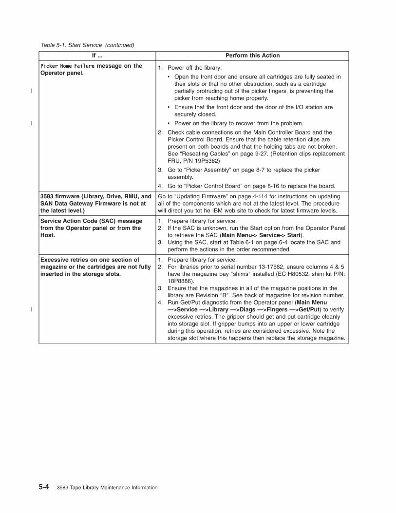
Table 5-1. Start Service (continued)
If ... Perform this Action
Picker Home Failure message on the
Operator panel.
1. Power off the library:
v Open the front door and ensure all cartridges are fully seated in
their slots or that no other obstruction, such as a cartridge
partially protruding out of the picker fingers, is preventing the
picker from reaching home properly.
v Ensure that the front door and the door of the I/O station are
securely closed.
v Power on the library to recover from the problem.
2. Check cable connections on the Main Controller Board and the
Picker Control Board. Ensure that the cable retention clips are
present on both boards and that the holding tabs are not broken.
See “Reseating Cables” on page 9-27. (Retention clips replacement
FRU, P/N 19P5362)
3. Go to “Picker Assembly” on page 8-7 to replace the picker
assembly.
4. Go to “Picker Control Board” on page 8-16 to replace the board.
3583 firmware (Library, Drive, RMU, and
SAN Data Gateway Firmware is not at
the latest level.)
Go to “Updating Firmware” on page 4-114 for instructions on updating
all of the components which are not at the latest level. The procedure
will direct you tot he IBM web site to check for latest firmware levels.
Service Action Code (SAC) message
from the Operator panel or from the
Host.
1. Prepare library for service.
2. If the SAC is unknown, run the Start option from the Operator Panel
to retrieve the SAC (Main Menu-> Service-> Start).
3. Using the SAC, start at Table 6-1 on page 6-4 locate the SAC and
perform the actions in the order recommended.
Excessive retries on one section of
magazine or the cartridges are not fully
inserted in the storage slots.
1. Prepare library for service.
2. For libraries prior to serial number 13-17562, ensure columns 4 & 5
have the magazine bay ″shims″ installed (EC H80532, shim kit P/N:
18P8886).
3. Ensure that the magazines in all of the magazine positions in the
library are Revision ″B″. See back of magazine for revision number.
4. Run Get/Put diagnostic from the Operator panel (Main Menu
—>Service —>Library —>Diags —>Fingers —>Get/Put) to verify
excessive retries. The gripper should get and put cartridge cleanly
into storage slot. If gripper bumps into an upper or lower cartridge
during this operation, retries are considered excessive. Note the
storage slot where this happens then replace the storage magazine.
5-4 3583 Tape Library Maintenance Information
|
|
|

Table 5-1. Start Service (continued)
If ... Perform this Action
Customer reported that not all
cartridges are being seen by the library
1. Prepare library for service.
2. Clean the Bar Code Reader’s lens. See “Cleaning the Bar Code
Reader Lens” on page 9-30.
3. Check that the cartridge labels are correctly applied and that they
are supported labels. See the IBM TotalStorage 3583 Tape Library
Setup and Operator Guide
4. After performing the above two steps, verification of the bar code
reader function can be performed on a particular cartridge in
question or on any cartridge in a slot within the library. Perform the
following two functions to perform a bar code reader scan of a
cartridge label:
v Move the picker in front of the cartridge slot which is to be read:
Main Menu-> Command-> Move-> Position Picker
v Scan the cartridge label in this slot: Main Menu-> More->
Service-> Library-> Diags-> Fingers-> Scanner->Scan
Compare the just scanned cartridge to the actual label.
5. Perform the serial port INV command three times to verify that the
bar code reader always reads correctly each cartridge label every
pass. See “Performing a Library Inventory” on page 9-30..
6. Replace the Picker Assembly (see “Picker Assembly” on page 8-7).
7. Replace the Picker Control PCBA (see “Replacing the Picker Control
Board” on page 8-16).
RMU Problem 1. Verify RMU firmware is at the latest level (go to “Updating Firmware”
on page 4-114).
2. Go to “Analyze RMU Problems” on page 5-7.
Library Problem - No Error Message
(includes visual symptoms or noise from
the picker)
1. Prepare library for service.
2. Go to procedure “Other Library Failures” on page 5-8 to analyze the
problem.
Drive sense data from host error logs is
collected
Go to procedure Chapter 11, “Sense,” on page 11-1.
A drive or library tape alert, drive error
code, or other SCSI or Fibre Channel
connectivity errors reported to the
server was collected, or if media type
problems are occurring.
Go to “TapeAlert Flags” on page A-1 for actions to be taken. Also, this
appendix contains several suggested procedures and diagnostics which
can be used to either correct the problem or help to isolate the failing
area of the library.
Install the Tape Library Go to Chapter 14, “Installation,” on page 14-1 to verify proper
installation of the library and any components.
Retrieving Error log, Trace Data and
Command Log
Go to procedure “Methods of Capturing Logs” on page 9-2.
Note: Please have these logs ″captured″ prior to calling the Support
Center.
Chapter 5. Start 5-5
|

Analyze Tape Library Power Problems
Is theOperator Panel
DisplayON?
Yes
No Yes
Is the customer
voltage OK?
Ask your customer to
have the input line
voltage checked.
Yes
Replace dcPower Module
No
Library Power is OK
Yes
Yes
No
No
NoYes
No
No
Yes
No
Replace the following FRUs:
- Display Assembly
- Main Controller Board
- Power Distribution Board
- Power Cable between
Power Distribution Board &
Main Controller Board
- Display Assembly Cable
Yes
Are LEDson all drives
green?
Replace the following FRUs:
- Failing Tape Drive Sled
- Power Distribution Board
- Main Controller Board
- Cable between Power
Distribution and Failing Drive
a67m
0052
Disconnect the AC power cable fromthe wall outlet and the Library.Check the two fuses in the AC InputPower Module. Replace them ifnecessary.
Measure for the appropriate voltagelevels at the customer voltage sourceat the wall, it should measure between110-230 V ac +/- 10%, single phase.Replace them if necessary.
Are twodc Power Modules
installed in theLibrary?
Are twodc Power Modules
installed in theLibrary?
Is theLED green?
Is one of the
LEDs red?dc Power Module
Make sure the ac Power Cord is plugged in and the dc Power Modules are installed properly. Power Up the Library,observe the Library Operator Panel Display and the dc Power Modules’ LEDs before proceeding.
Is theLED on the dcPower Module
ON?
You may have one of thefollowing problems:
1. AC Distribution problem:Replace the following FRUsuntil the problem is resolved:- AC Input Module- Power Distribution Board- AC Power Cord
2. A short in the dc power:Refer to the Power DistributionDiagram. Disconnect FRUs oneat a time. Power on the libraryafter each FRU is disconnectedto isolate the shortedcomponent. Replace the FRUthat caused the short.
Figure 5-1. Power Map
5-6 3583 Tape Library Maintenance Information

Analyze RMU Problems
Use Figure 5-2 to help resolve these problems with the RMU:
v SAC A0 00
v Failure to start an Ethernet session from attached PC
v Unexpected LED activity
Note: If the RMU is directly attached to the PC (PC and RMU only), a special RJ45 ethernet crossover
cable must be used. Otherwise, if the RMU is part of a network hub, a normal straight-through
RJ45 ethernet cable must be used.
Yes
Yes
Yes
Obtain correct IP addressfor RMU from user
Correct IP addressand retry operation
Replace RMU
Check RJ45 cable,replace if original is bad
Replace RMU
Replace:1. RMU2. Cable between RMU and
Main Controller Board3. Main Controller Board
Note:Must match IP address which wasconfigured at RMU dialog box.
No
No
No
a67m
0088
Is
LED either
amber or green?
Does
LED remain
amber?
Is
LED green?
IsIP address
correct?
Yes
No2
2
3
1
23
RMU error
Suspected
1
Figure 5-2. RMU Map
Chapter 5. Start 5-7

Other Library Failures
Use the following table to perform problem analysis for Library failures that appear as Visual, Audible, or
other Symptoms without Service Action Codes (SACs).
Table 5-2. Problem Analysis for Failures without Service Action Codes
Symptom Possible Causes Actions or FRUs Reference Information on Page
Bearing noise
or squeak from
Y-axis
Defective bearing Replace:
casting supporting picker
assembly
Y-axis belt
picker assembly
Y-axis motor
8-78-188-7
8-29
Binding Y-axis Defective bearing Replace:
casting supporting picker
assembly
Y-axis belt
picker assembly
Y-axis motor
8-78-188-7
8-29
Rotary axis
vibration
(oscillation)
when stopping
or stopped
Servo problem Replace:
picker control board
rotary axis motor
8-168-14
Fuse or fuses
blown on ac
input module.
Shorted
component or
heavy load on
circuit
Replace the fuse and
power-on the library. If the
fuse continues to blow,
examine the power diagrams
and isolate the failing
component by unplugging
cables in the fuse circuit until
the failing FRU is determined.
12-4
12-5
I/O station
problem
I/O station
mechanical or
electronic failure
Replace:
I/O station assembly
display assembly
main controller board
8-508-478-34
Operator panel
display
incorrect
operation
Operator panel
electronic failure
Replace:
display assembly
main controller board
Operator panel cable
8-478-34
Operator panel
switches
incorrect
operation
Operator panel
electronic failure
Replace:
display assembly
main controller board
Operator panel cable
8-478-34
Operator panel
No indicators
are working
+5 V dc voltage
missing from
Operator panel
Replace:
dc power supply assembly
main controller board
display assembly
display assembly cable
8-548-348-25
5-8 3583 Tape Library Maintenance Information

Chapter 6. Fault Symptom Index
Overview . . . . . . . . . . . . . . . . . . . . . . . . . . . . . . . . . . . 6-2
Service Action Codes . . . . . . . . . . . . . . . . . . . . . . . . . . . . . . . 6-3
Operator Intervention Messages . . . . . . . . . . . . . . . . . . . . . . . . . 6-19
Operator Information Messages . . . . . . . . . . . . . . . . . . . . . . . . . 6-24
Drive Error Codes . . . . . . . . . . . . . . . . . . . . . . . . . . . . . . 6-25
Cleaning Cartridge Error Messages . . . . . . . . . . . . . . . . . . . . . . . . . 6-30
© Copyright IBM Corp. 2000, 2005 6-1

Overview
The following are definitions for acronyms and the acronyms used in this chapter:
1. Remote Management Unit will be referred to as RMU.
2. Service Action Code will be referred to as SAC.
3. Power−On−Self−Test will be referred to as POST.
When a failure occurs, the Tape Library firmware performs error recovery and error reporting. If the failure
requires a service call, a two-byte SAC is generated and presented on the Operator/CE panel. This SAC is
the result of the Tape Library firmware analyzing all pertinent information available at the time of failure
which include sense data, the operation in progress, error and threshold data and any data returned from
diagnostic routines invoked by the firmware to isolate the failure.
Prior to performing the suggested actions for each SAC, it is recommended that you retrieve the
Command and Error logs in case you need further assistance from Product Support to resolve the
problem. To retrieve logs, see “Methods of Capturing Logs” on page 9-2
6-2 3583 Tape Library Maintenance Information

Service Action Codes
Table 6-1 on page 6-4 lists the SACs, the error description and the actions that can be performed in
addition to the FRUs that can be replaced. Each SAC consists of two bytes “nn xx”:
v “nn”: SAC.
v “xx”: SAC modifier. This byte identifies the processor that reports the error:
– “00” = Main Controller
– “10” = Picker Controller
– “20” = Display Controller
– “3x” = Drive Sled Controller (“x” = Drive ID (1 to 6)).
– “40” = Host Interface Controller (SCSI)
– “50” = RMU Controller
Note: For most SACs, the modifier is extra information, thus the value is not important; however, a
small number of SACs will use this modifier to further refine the actions to be performed.
The SACs requiring the modifier value are documented so that the suggested actions are
grouped depending on the value of the modifier.
The table also lists the FRU names and a reference column which points to the page containing the
location of the FRU or the procedure on how to perform the suggested action.
Actions associated with each SAC are listed in their order of probability. Always perform the
actions in the order listed, starting with the top action and continue down the list until the problem
is resolved.
Press the button below the Main Menu (initial screen) —> Status —> Logs —> Error Log softkeys. The
Error Log Dialog displays (see Figure 6-1).
Note: The error code that displays in the Error Log Dialog is for Engineering use only; it is not the Service
Action Code (SAC).
Figure 6-1. Error Log Dialog
Chapter 6. Fault Symptom Index 6-3

Note: When an action calls for observation of the library Robotics you must remove library top cover, see
“Observing Library Robotics” on page 9-29.
Table 6-1. Service Action Codes
SAC Type of Error Perform these actions See Page
01 xx Type 1 Software Power off and on the tape library to recover from the
error. Use the Main Switch to perform this action, wait at
least one minute between power off and on.
02 xx Type 2 Software Power off and on the tape library to recover from the
error. Use the Main Switch to perform this action, wait at
least one minute between power off and on.
03 xx Type 3 Software Power off and on the tape library to recover from the
error. Use the Main Switch to perform this action, wait at
least one minute between power off and on.
04 xx Type 4 Software Power off and on the tape library to recover from the
error. Use the Main Switch to perform this action, wait at
least one minute between power off and on.
05 xx Permanent operating system
error
Power off and on the tape library to recover from the
error. Use the Main Switch to perform this action, wait at
least one minute between power off and on.
Contact next level of support.
10 xx Bar code reader
communications failed.
Clean the bar code reader with a lint free cloth. Retry the
failing operation (this could be inventory, scan, teach, or
any other operation where bar code reader is involved).
7-8
Power off and on the tape library to recover from the
error. Use the Main Switch to perform this action, wait at
least one minute between power off and on.
Replace picker assembly. 8-7
Replace picker control board. 8-16
11 xx Bar code reader
communication is OK, Data
received from bar code reader
is bad.
Clean the bar code reader with a lint free cloth. Retry the
failing operation (this could be inventory, scan, teach, or
any other operation where bar code reader is involved).
7-8
Replace picker assembly. 8-7
Replace picker control board. 8-16
12 00 Bar code reader
communication is OK, bar
code reader reports data is
bad.
Replace picker assembly. 8-7
13 xx Cannot read bar code label or
label is bad.
Check Cartridge labels to ensure that they meet
specifications and installed properly and not damaged or
dirty, the slots in question are displayed with the SAC.
Ensure that scan beam is not obstructed.
Clean the bar code reader with a lint free cloth. Retry the
failing operation (this could be inventory, scan, teach, or
any other operation where bar code reader is involved).
7-8
Power off and on the tape library to recover from the
error. Use the main power switch to perform this action,
wait at least one minute between power off and on.
Replace picker assembly. 8-7
6-4 3583 Tape Library Maintenance Information

Table 6-1. Service Action Codes (continued)
SAC Type of Error Perform these actions See Page
14 xx The system detects Serial
Number is missing from its
NVRAM.
Record and reenter System Serial Number (Using serial
cable and HyperTerminal, enter “setser” command from
HyperTerminal prompt.
8-34
15 XX An intermittent scanning error
was detected. During Demo,
the library performs inventory
after each complete demo
cycle and detects a mismatch
between the number of
cartridges scanned and its
previous database.
Note the number of cartridges installed in the library and
use the operator panel to compare this information with
the number of cartridges reported by the library. Examine
the cartridges that are installed but not reported by the
library for proper cartridge labels and replace labels if
necessary. Note that if a whole column of cartridges is
missing, the column fiducial label can be defective. In this
case, the whole storage column must be replaced.
If all labels are correct, clear the SAC and retry the Demo
program.
8-32
If the problem remains, replace the Picker Assembly. 8-7
20 00 Serial port connection
failures.
Replace main controller board. 8-34
Replace the host interface board (SCSI). 8-45
Replace serial port cable between host system and host
interface board (SCSI).
Problem is in host system.
21 xx NVRAM failures. Check Library configuration and reenter all data (SCSI
ID, Time/Date, Library Serial Number, and any other valid
data).
Power off and on the tape library a few times to see if the
same error condition reappears. Use the Main Switch to
perform this action, wait at least one minute between
power off and on.
Note: If the error reappears after a number of power
on/off cycles, replace library main controller board. 8-34
22 00 Fail to communicate with
Operator panel.
Reseat cable between main controller and display
assembly.
9-27
Replace cable between main controller and display
assembly.
8-47
Replace main controller board. 8-34
Replace display assembly. 8-47
23 00 An unexpected interrupt is
received.
Replace main controller board. 8-34
Replace picker control board. 8-16
30 00 A fatal error is detected in
SCSI Port.
Verify the SCSI bus connection to Library is properly
terminated and powered.
Verify that the Library SCSI is properly configured by
using the Operator panel (Main Menu —>More —>Setup
—>Library —>SCSI).
Replace main controller board. 8-34
Replace host interface board (SCSI). 8-45
Chapter 6. Fault Symptom Index 6-5

Table 6-1. Service Action Codes (continued)
SAC Type of Error Perform these actions See Page
31 00 A fatal error is detected in
SCSI Port.
Verify SCSI bus connected to Library Port is properly
terminated and powered.
Verify Library SCSI Port is properly configured by using
Operator panel (Main Menu —>More —>Setup
—>Library —>SCSI).
Replace main controller board. 8-34
Replace host interface board (SCSI). 8-45
32 00 Wrong SCSI bus connection
detected. A single-ended SCSI
bus is connected to Library
set up in Differential mode.
Verify Host SCSI bus is same type as Library host
interface board (SCSI).
Verify LVD-HVD switch is set correctly on Library host
interface board (SCSI).
7-16
33 00 Wrong SCSI bus connection
detected. A single-ended SCSI
bus is connected to Library
set up in Differential mode.
Verify Host SCSI bus is same type as Library host
interface board (SCSI).
Verify LVD-HVD switch is set correctly on Library host
interface board (SCSI).
8-45
34 00 A general SCSI failure is
detected.
Verify that the SCSI host is working properly.
35 00 A fatal SCSI error is detected. Verify SCSI connected to Library is properly terminated
and powered.
Verify Library SCSI is properly configured (if applicable)
by using Operator panel (Main Menu —>More —>Setup
—>Library —>SCSI).
Replace Library main controller board. 8-34
Replace the host interface board (SCSI). 8-45
38 xx The RMU cannot
communicate with the
Dynamic Host Configuration
Protocol (DHCP) server.
Ensure the network cable is properly connected to the
RMU and verify that the RMU is set up to work in DHCP
mode (Main Menu —>Setup —>Library —>RMU).
Verify that the DHCP server is properly set up and
configured. Test to see if the DHCP server can ping the
RMU.
5-7
Replace the RMU. 8-39
39 xx An external network error was
detected by the RMU
Ensure the network cable is properly connected to the
RMU.
5-7
Verify that the network the RMU is connected to is
working properly.
5-7
Replace the RMU. 8-39
40 xx The Library detects that Servo
power is missing.
Replace dc power supply. 8-54
Replace power distribution board. 8-49
6-6 3583 Tape Library Maintenance Information

Table 6-1. Service Action Codes (continued)
SAC Type of Error Perform these actions See Page
42 xx An invalid library
configuration was detected:
The I/O station storage
column is missing or drive
modules are not installed in
the allowable configurations.
Ensure all tape drive modules are properly installed (refer
to the instructions in the IBM TotalStorage 3583 Tape
Library Setup and Operator Guide. Drive sled 1 must be
installed at the bottom slot of drive column. If you have a
library with the Multi-Path feature, see the section about
partitioning in the IBM TotalStorage 3583 Tape Library
Setup and Operator Guide.
Ensure that the firmware level of all PCBAs installed in
the library match.
Ensure I/O station column (column 1) is installed and
fiducial label is properly installed. Ensure the fiducial label
is not damaged. Fiducial label is present on both
standard I/O and 12 slot I/O station.
Ensure the picker assembly flex cable is properly
connected and seated at the picker control board. If not
routed properly, this cable can pop out of its connector
when the picker flex cable cover is installed.
9-27
Verify that the bar code reader is working properly:
v With the library offline, open the door, observe a
cartridge to be tested. Write down the cartridge label
number and column/slot location. Close the door. The
library will immediately perform an inventory of all the
cartridges in the library.
v When the inventory has completed, at the Operator
panel, press Command—>Move—>Move Media. When
asked to Select Target, enter the cartridge column/slot
location you wrote down earlier. The library should
respond back with a message stating that the target
address already has a cartridge in it. It will also display
data such as: Target:xxx (representing the column/slot
address) and the bar code label number of the
cartridge in that slot address.
If bar code reader is working properly, the value of
scanned bar code will be displayed on the Operator
panel. If diagnostic failed, replace:
– Picker assembly
– Picker Control PCBA 8-7
43 xx An unknown library
configuration is detected, the
bar code reader reads a
fiducial label where none is
expected.
Ensure that the firmware level in the tape library supports
the hardware installed.
If you are unable to determine the defective part, perform
a serial trace (see “Capturing Serial Logs” on page 9-4).
9-4
Check for a dirty, damaged, missing or wrong fiducial
label located on storage columns, magazines, or tape
drive sleds in the library, and replace the part that is
defective.
Chapter 6. Fault Symptom Index 6-7

Table 6-1. Service Action Codes (continued)
SAC Type of Error Perform these actions See Page
44 xx An unknown fiducial label is
detected during a teach
operation.
Ensure that the firmware level in the tape library supports
the hardware installed.
If you are unable to determine the defective part, perform
a serial trace (see “Capturing Serial Logs” on page 9-4).
9-4
Check for a dirty, damaged, missing or wrong fiducial
label located on storage columns, magazines, or tape
drive sleds in the library, and replace the part that is
defective.
46 xx A failure was detected during
the scanning of fiducial or
cartridge labels. This failure
can be caused by a number of
things. Perform the following
actions to recover from the
failure.
This error can be caused by a dirty bar code reader (dust
or fingerprints). Clean the bar code reader window with a
lint free cloth and retry the operation.
7-8
This error can be caused by a dirty, damaged or missing
fiducial label on the magazine. To isolate the problem
magazine, perform one of the following procedures:
v Note the number of magazines installed in the library
(each magazine should have at least one cartridge in
it) and use the Operator panel to compare this
information with the number of magazines reported by
the library. If the library is equipped with a 12 slot I/O
station, the icons representing the magazines in the
I/O station column are displayed in the I/O station
area.
v Remove one magazine at a time and retry the
operation until the problem is resolved (Main Menu
—>Status —>Library —>System or Slot). Replace the
failing magazine if found.
This error can be caused by a dirty, damaged or incorrect
cartridge bar code label. To isolate the problem cartridge,
try one of the following procedures:
v Note the number of cartridges installed in the library
and use the Operator panel to compare this
information with the number of cartridges reported by
the library.
v Remove a few cartridges at a time and retry the
operation until the problem is resolved (Main Menu
—>Status —>Library —>System or Slot). Replace the
bar code label on the cartridge.
This error can also be caused by hardware failures:
v Ensure the picker assembly flex cable connector is
properly seated on the picker control board.
v Inspect the picker flex cable for any obvious damage.
Rotate the picker assembly to maximum counter
clockwise (grip fingers facing the drive column) and
inspect the area of the cable loop that is near the
rotary motor encoder. If the Picker flex cable does not
contain enough slack in this loop, the encoder on the
Rotary axis motor can rub on the cable and cause
damage. If the picker flex cable is damaged, replace
the picker assembly.
9-27
8-7
6-8 3583 Tape Library Maintenance Information
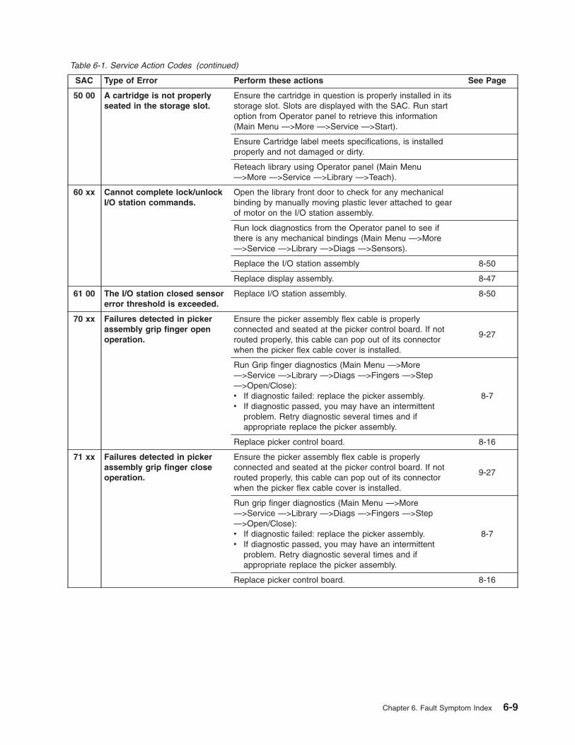
Table 6-1. Service Action Codes (continued)
SAC Type of Error Perform these actions See Page
50 00 A cartridge is not properly
seated in the storage slot.
Ensure the cartridge in question is properly installed in its
storage slot. Slots are displayed with the SAC. Run start
option from Operator panel to retrieve this information
(Main Menu —>More —>Service —>Start).
Ensure Cartridge label meets specifications, is installed
properly and not damaged or dirty.
Reteach library using Operator panel (Main Menu
—>More —>Service —>Library —>Teach).
60 xx Cannot complete lock/unlock
I/O station commands.
Open the library front door to check for any mechanical
binding by manually moving plastic lever attached to gear
of motor on the I/O station assembly.
Run lock diagnostics from the Operator panel to see if
there is any mechanical bindings (Main Menu —>More
—>Service —>Library —>Diags —>Sensors).
Replace the I/O station assembly 8-50
Replace display assembly. 8-47
61 00 The I/O station closed sensor
error threshold is exceeded.
Replace I/O station assembly. 8-50
70 xx Failures detected in picker
assembly grip finger open
operation.
Ensure the picker assembly flex cable is properly
connected and seated at the picker control board. If not
routed properly, this cable can pop out of its connector
when the picker flex cable cover is installed.
9-27
Run Grip finger diagnostics (Main Menu —>More
—>Service —>Library —>Diags —>Fingers —>Step
—>Open/Close):
v If diagnostic failed: replace the picker assembly.
v If diagnostic passed, you may have an intermittent
problem. Retry diagnostic several times and if
appropriate replace the picker assembly.
8-7
Replace picker control board. 8-16
71 xx Failures detected in picker
assembly grip finger close
operation.
Ensure the picker assembly flex cable is properly
connected and seated at the picker control board. If not
routed properly, this cable can pop out of its connector
when the picker flex cable cover is installed.
9-27
Run grip finger diagnostics (Main Menu —>More
—>Service —>Library —>Diags —>Fingers —>Step
—>Open/Close):
v If diagnostic failed: replace the picker assembly.
v If diagnostic passed, you may have an intermittent
problem. Retry diagnostic several times and if
appropriate replace the picker assembly.
8-7
Replace picker control board. 8-16
Chapter 6. Fault Symptom Index 6-9

Table 6-1. Service Action Codes (continued)
SAC Type of Error Perform these actions See Page
72 xx Get command was issued but
sensor indicated a cartridge is
already present in picker
assembly.
Look into picker assembly to see if a cartridge is present.
If a cartridge is found:
v Recover the cartridge, place it in any empty slot, close
the door and retry failing operation.
v Perform actions in SAC “02 00”.
If a cartridge is not found in the picker assembly:
Perform the actions in SAC “73 xx”.
73 xx Failures detected in picker
assembly finger open/close
operations.
Ensure that the firmware level is at 5.22 or higher.
Ensure the picker assembly flex cable is properly
connected and seated at the picker control PCBA. If not
routed properly, this cable can pop out of its connector
when the picker flex cable cover is installed.
9-27
Run Grip finger diagnostics (Main Menu —>More
—>Service —>Library —>Diags —>Fingers —>Step
—>Open/Close):
v If diagnostic failed: replace picker assembly.
v If diagnostic passed, retry it several times. If it fails
during successive retries or if intermittent failures
continue to occur during normal operations, replace
the picker assembly.
8-7
Check cartridge for physical damage.
Check for a stuck cartridge in a tape drive or storage slot.
Replace the tape drive or magazine. Close the door and
retry the failed operation.
8-4
Replace picker control PCBA. 8-16
74 00 Get command was issued but
the sensor indicated source
location is empty.
Error can be caused by a cartridge not fully inserted in
storage slot above failing slot. Check to see if this
condition exists, if so, push the cartridge into its slot.
Reinventory the Library (Main Menu —>Commands
—>Inventory).
Error may be caused by picker not getting to its intended
target due to a defective Y-Axis belt. Locate the picker
and compare its coordinates with the failing slot’s
coordinates posted with this SAC. Adjust or replace the
Y-Axis belt if they do not match.
8-18
Look into location (slot or drive) and see if a cartridge is
present.
If a cartridge is found:
Perform the actions in SAC “73 xx”.
If a cartridge is not found in this location:
Perform the actions in SAC “02 xx”.
75 00 A failure is detected in the
picker assembly.
Replace picker assembly. 8-7
Replace picker control board 8-16
76 00 A teach failure is caused by
the picker assembly out of
alignment condition.
Make sure Y-axis drive belt is properly installed and
tensioned.
Step 18 on
page 8-22
6-10 3583 Tape Library Maintenance Information

Table 6-1. Service Action Codes (continued)
SAC Type of Error Perform these actions See Page
77 xx Failures detected in the picker
assembly during a reach axis
retract operation.
Ensure the picker assembly flex cable is properly
connected and seated at the picker control PCBA. If not
routed properly, this cable can pop out of its connector
when the picker flex cable cover is installed.
9-27
Check for failure to retrieve a cartridge from a magazine.
Replace the magazine, close the door, and retry the
failed operation.
Check the cartridge for physical damage.
Replace picker assembly. 8-7
This failure can be the result of the drive not ejecting the
cartridge properly so that the picker can retrieve it. Check
the drive for proper cartridge ejection (the cartridge must
be easily retrieved without any force); replace the drive if
necessary.
8-4
Replace picker control PCBA. 8-16
78 xx A put command was issued
but sensor indicated the
cartridge is not present in
picker assembly.
Look into the picker assembly and see if a cartridge is
present.If a cartridge is found:
Perform the actions in SAC “73 xx”.
If a cartridge is not found in the picker assembly:
Perform the actions in SAC “02 xx”.
79 xx Failures detected in putting a
cartridge into a tape drive.
Check the tape drive to ensure it’s properly seated,
powered on and working properly.
Replace picker assembly. 8-7
Replace picker control board. 8-16
7A xx Failures detected in picker
assembly during a reach axis
retract (to home position)
operation.
Ensure the picker assembly flex cable is properly
connected and seated at the picker control PCBA. If not
routed properly, this cable can pop out of its connector
when the picker flex cable cover is installed.
9-27
Check for the failure to retrieve a cartridge from a
magazine. Verify that all magazines in the library are
stamped on the back with REVB. Replace all magazines
that are not REVB, close the door, and retry the failed
operation.
Check the cartridge for physical damage.
Replace picker assembly. 8-7
This failure can be the result of the drive not ejecting the
cartridge properly so that the picker can retrieve it. Check
the drive for proper cartridge ejection (the cartridge must
be easily retrieved without any force); replace the drive if
necessary.
8-4
Replace picker control PCBA. 8-16
Chapter 6. Fault Symptom Index 6-11

Table 6-1. Service Action Codes (continued)
SAC Type of Error Perform these actions See Page
7C xx Failures detected in picker
assembly during a reach axis
extend operation.
Check for obstruction in the slot. Obstruction can be:
v An unlabeled cartridge of a bad label
v A cartridge in the slot during a put operation
v The slot wall in the magazine is too tight
v A tape drive failure that prevents the cartridge from
being inserted properly
Remove obstruction or replace the magazine or drive,
close door and retry the failing operation.
Perform the actions in SAC “7A xx”.
7D xx Failure detected while getting
a cartridge from a tape drive.
Check the Tape drive to see if a cartridge is present.If a cartridge is found in the tape drive:Remove cartridge from the tape drive, power drive off
then on and retry the operation.If a cartridge is not found in the tape drive:Perform actions in SAC “02 xx”.
7E xx Failure detected while
pushing a cartridge into a
tape drive feed slot.
Check the cartridge for any physical damage.
Replace the failing tape drive sled. 8-4
80 xx Failures detected in the
rotary-axis servo system.
Inspect gearing between the rotary axis motor and picker
assembly. Replace following FRUs in the order shown:
Replace rotary axis motor. 8-14
Replace picker assembly. 8-7
Replace picker control board. 8-16
81 xx Failures detected in the Y-axis
servo system (can be the
result of SAC 7A XX).
Check Y-axis for any binds by moving it up and down.
The binding can be between picker assembly and
Y−shaft. If any binds exist, replace appropriate FRU.
Replace Y−axis motor assembly. 8-29
Replace power distribution board. 8-49
Replace Y−axis drive belt. 8-18
82 xx An unexpected motion control
condition was received.
If the SAC modifier “xx” is:
00 - Replace power distribution board.
10 - Replace picker control boardand picker assembly.
8-498-168-7
Replace signal cable between main controller board and
power distribution board.
8-27
Replace power cable between main controller board and
power distribution board.
8-27
83 xx Locate fiducial command
failed with no target found.
This failure is most likely to
occur during initial
installation of library
subsystem.
Ensure all fiducial labels are present and within
specification.
Clean all teach fiducial labels.
6-12 3583 Tape Library Maintenance Information

Table 6-1. Service Action Codes (continued)
SAC Type of Error Perform these actions See Page
84 xx Y-axis failed to reach target. Check for mechanical binding in Y-axis. 8-29
Replace Y-axis motor. 8-29
Replace Y-axis drive belt. 8-18
Replace power distribution board. 8-49
Replace the Y−shaft (if obvious damage). 8-30
Replace Y−axis flex cable. 8-24
85 xx Rotary axis failed to reach
target.
Check for mechanical binding in rotary axis. 8-14
Replace rotary axis motor. 8-14
Replace picker assembly. 8-7
Replace picker control board. 8-16
86 00 The first full speed move
command issued when picker
is at home position failed.
Check for mechanical binding in both rotary and Y-axis.
Press power switch to the O position and wait one
minute. Now press the power switch to the | position and
observe the picker assembly to see which axis (rotary or
Y) fails to move:If the rotary-axis fails to move:
Perform the actions in SAC “80”.
If the Y−axis fails to move:
Perform the actions in SAC “81”.
If both axes fail to move:
Replace the main controller board.
Replace the picker control board.
Replace the power distribution board.
Replace Y−axis flex cable.
8-34
8-16
8-49
8-24
87 00 Picker assembly cannot move
away from rotary axis home
position.
Replace rotary axis motor. 8-14
Replace picker control board. 8-16
Replace picker assembly. 8-7
88 00 Picker assembly cannot move
away from Y-axis home
position.
Replace Y-axis motor. 8-29
Replace power distribution board. 8-49
Check the belt for proper tension, replace the Y−belt if
broken or worn.
8-18
Check Y-axis for any binds by moving it up and down.
Binding can be between picker assembly and the
Y−shaft. If any binds exist, replace appropriate FRU.
8-29
89 xx Failure was detected while
communicating with the
motion controllers.
Note: Verify that the Picker
Assembly with the latest ESD
changes (DATE CODE of
05/12/03 or later) is installed.
If the SAC modifier “xx” is:
00 - Replace power distribution board.
10 - Replace the picker control board
and the picker assembly.
8-49
8-16
8-7
Replace signal cable between main controller board and
power distribution board.
8-27
Replace power cable between main controller board and
power distribution board.
8-27
Chapter 6. Fault Symptom Index 6-13

Table 6-1. Service Action Codes (continued)
SAC Type of Error Perform these actions See Page
8A xx The returned sense indicated
that a motion command
completed sooner than
expected.
If “xx” = “00 “- Check the Y−axis for any bindings,
binding can be caused by an object (like a cartridge) that
prevents the Y−axis from homing and reaching its target
correctly.
If a bind is found, remove the bind and retry the
operation.
If a bind is not found, replace the Y−axis motor
assembly. 8-29
If “xx” = “10” - Check rotary axis for any bindings,
binding can be caused by an object (like a cartridge) that
prevents the rotary axis from homing and reaching its
target correctly:
If a bind is found, remove the bind and retry the
operation.
If a bind is not found, replace the rotary axis motor,
then picker assembly.
8-14
8-7
8B xx Servo failures detected but
the axis is not known.
Replace picker assembly. 8-7
Replace picker control PCBA. 8-16
Replace power distribution PCBA. 8-49
Replace rotary-axis motor. 8-14
Perform the actions in service Action Code ″73 xx″. 6-10
90 00 A down level main controller
board was detected by the
Library firmware when a new
board is required for this
library configuration to
operate.
Update the library firmware. 4-114
91 00 A down level picker control
board was detected by the
library firmware when a new
board is required for this
library configuration to
operate.
Update the firmware. 4-114
92 xx A down level board was
detected by library firmware
when a new board is required
for this library configuration
to operate.
Update the firmware. 4-114
6-14 3583 Tape Library Maintenance Information
|

Table 6-1. Service Action Codes (continued)
SAC Type of Error Perform these actions See Page
93 xx A failure was detected in drive
communication hardware
within the library: library
cannot communicate with one
or more drives (note the
physical location of the failing
drive, this information is
presented with the SAC).
If the accompanying message indicated that the library
cannot communicate with one specific tape drive:
v Make sure the tape drive in question is properly
installed in its drive slot.
v Verify code installed in drive PCBA.
v Replace failing tape drive sled.
v Replace cable between power distribution board and
the failing drive.
v Replace power distribution board.
If the library cannot communicate with multiple drives:
v Replace the power distribution board.
v Replace library main controller board
v Replace cable between power distribution board and
the failing drive.
4-117
8-4
8-28
8-49
8-49
8-34
8-28
94 xx Communication was
previously established
between library and tape drive
but the library detected
communication is no longer
present or the drive status is
not as expected.
Note: Coordinates of the
failing tape drive sled is
posted on Operator panel but
if this information was reset
by the Operator, it can be
retrieved by going to the error
log and refer to the error
modifier “xxxx”, this value
will show the failing drive
If SAC modifier “xx” = “00”:
v Make sure that the failing tape drive sled is properly
installed and powered on.
v See if there is a cartridge in the failing tape drive
preventing the drive from becoming ready. If cartridge
is present eject the cartridge, retry the operation
replacing the tape drive sled if appropriate.
v Replace the power distribution board.
v Replace cable between failing tape drive and power
distribution board.
8-4
8-49
8-28
If the SAC modifier “xx” = “3x” (where x equals 1
through 6), replace tape drive sled identified by SAC
modifier.
8-4
95 xx Picker assembly delivered a
cartridge to a tape drive but
the drive does not confirm
tape loading status. The “xx”
part of the SAC identifies the
drive.
If another tape drive is available, retry the operation by
loading the same cartridge into that tape drive:
v If the operation failed, inspect the cartridge for damage
and replace it.
v If the operation is successful, verify that the original
failing tape drive is failing by loading another cartridge
into that drive. Replace the drive if this operation
failed.
8-4
98 xx The firmware installed on the
tape drive is not supported by
the Library. The “xx” part of
the SAC identifies the drive.
Update the drive firmware with the latest level. 4-114
A0 xx Communication is not
established between the main
controller and the RMU.
Ensure RMU is properly installed in the library. 5-7
Reseat cable between main controller board and RMU. 9-27
Replace RMU. 8-39
Replace main controller board. 8-34
Chapter 6. Fault Symptom Index 6-15

Table 6-1. Service Action Codes (continued)
SAC Type of Error Perform these actions See Page
A1 xx A generic communication
error was detected between
the main controller board and
one of the auxiliary controller
boards in the library. Use the
SAC modifier “xx” and follow
the appropriate actions below.
If the SAC modifier “xx” = “00”:
v Reseat cable between main Controller and picker
controller board.
v Replace picker control board.
v Replace library main controller board.
v Replace the display assembly.
9-27
8-16
8-34
8-47
If the SAC modifier “xx” = “10”:
v Reseat cable between main Controller and picker
controller board.
v Replace picker control board.
9-27
8-16
If the SAC modifier “xx” = “20”:
v Reseat Cable between main control and display
control board.
v Replace display control board.
9-27
8-47
If the SAC modifier “xx” = “3x”:
v Reseat serial communication cable between main
control and power distribution board.
v Replace drive sled x.
9-27
8-4
If the SAC modifier “xx” = “40”:
v Replace host interface board (SCSI). 8-45
If the SAC modifier “xx” = “50”:
v Replace RMU. 8-39
Replace main control board. 8-34
A2 xx Communication was initially
established but is now lost
between the main controller
board and the picker control
board.
Note: Verify that the Picker
Assembly with the latest ESD
changes (DATE CODE of
05/12/03 or later) is installed.
Reseat the cable between main Controller and picker
control boards.
9-27
Replace the picker assembly. 8-7
Replace the picker control board. 8-16
Replace Library main controller board. 8-34
A3 xx Communication was initially
established but is now lost
between the main controller
board and the display control
board.
Reseat the cable between main Controller and display
control boards.
9-27
Replace the display assembly. 8-47
Replace the main controller board. 8-34
D0 xx Library detected that one of
the dc power supplies has
failed, this error condition
only occurs in libraries
equipped with the dual dc
power supplies feature.
Observe LEDs located on each dc power supply. The
LED should be either green or red. Red LED indicates
power supply had failed. Replace failing power supply.
8-54
D1 xx Library detected ac input to
one bank of the dc power
supplies is missing. This error
condition only occurs in
libraries equipped with the
dual dc power supplies
feature.
Observe the LEDs located on each dc power supply. The
LED should be either green of red. Red LED indicates
the power supply had failed. Replace the failing power
supply.
8-54
Replace the power distribution board. 8-49
6-16 3583 Tape Library Maintenance Information

Table 6-1. Service Action Codes (continued)
SAC Type of Error Perform these actions See Page
D2 xx Library detected a fan has
failed in one of the dc power
supplies or in one of the tape
drives.
If the SAC modifier xx = 00:
v If the library has only one dc power supply, replace it.
v If the library has 2 dc power supplies, the failing supply
displays a red LED. Observe the LED on the power
supplies and replace the failing one.
8-55
If the SAC modifier xx = 3x, replace the drive that is
identified by the modifier x where x equals drive 1
through 6 (as shown in “Storage Slot Numbering” on
page 1-15).
8-55
E0 xx A cartridge is stuck in picker
assembly, Operator
intervention is required to
remove cartridge from the
grip fingers.
Perform procedure “Cartridge Removal from Picker
Assembly” on page 8-3.
E1 00 I/O station door is not fully
closed, Operator intervention
is required to close the door.
Close the door on the I/O station.
E2 xx Front door is not fully closed.
Operator intervention is
required to close the door.
Close the front door.
If the SAC code is intermittent, replace the door switch. 8-58
E3 00 Wrong SCSI bus connection
is detected. A single-ended
SCSI device is connected to
library configured in
differential mode.
Check library configuration to ensure all devices on the
library SCSI port have the same SCSI type.
If problem is not corrected, perform the actions in SAC
“30 00”.
E4 00 Wrong SCSI bus connection
is detected. A single-ended
SCSI device is connected to
library configured in
differential mode.
Check library configuration to ensure that all devices on
the library SCSI port have the same SCSI type.
If the problem is not corrected, perform actions in SAC
“31 00”.
E5 00 SCSI bus connected to library
is not properly terminated.
Ensure that both ends of the SCSI bus connected to
library are properly terminated. A terminator is shipped
with each library SCSI adapter card.
If the problem is not corrected, perform the actions in
SAC “30 00”.
E6 00 SCSI bus connected to library
is not properly terminated.
Ensure that both ends of the SCSI bus connected to
library Port are properly terminated. A terminator is
shipped with each library SCSI adapter card.
If the problem is not corrected, perform the actions in
SAC “31 00”.
Chapter 6. Fault Symptom Index 6-17

Table 6-1. Service Action Codes (continued)
SAC Type of Error Perform these actions See Page
E7 xx Picker assembly detected a
cartridge is not present in the
grip fingers. Cartridge may
not be seated properly in grip
fingers or the get operation is
not successful. Locate the
cartridge in question:
If cartridge is not properly seated in the grip fingers,
remove the cartridge. Insert cartridge in any empty slot
and retry the operation.
If cartridge is not in the Picker but located in its original
slot, see if the cartridge is seated too tightly in the slot. If
cartridge is seated to tight in the slot replace the
magazine, reinventory and retry the operation.
Run grip finger diagnostics (Main Menu —>More
—>Service —>Library —>Diags —>Fingers —>Step
—>Open/Close):
v If the diagnostic failed: replace the picker assembly.
v If the diagnostic passed, you may have an intermittent
problem. Retry the diagnostic several times and
replace the picker assembly if appropriate.
8-7
E8 xx During a move to put
cartridge after a successful
get command, the picker
assembly detected the
cartridge is no longer present
in the grip fingers. Locate
cartridge in question:
If a cartridge is found:
Recover cartridge, reinventory Library and retry the
operation.
If a cartridge is not found, run grip finger diagnostics
(Main Menu —>More —>Service —>Library —>Diags
—>Fingers —>Step —>Open/Close):
v If diagnostic failed: replace the picker assembly.
v If diagnostic passed, you may have an intermittent
problem. Retry diagnostic several times and replace
the picker assembly if appropriate.
8-7
EA 00 Failures were detected while
running the diagnostic loop
test from main controller
board to all sensors on the
I/O station assembly.
Replace Library main controller board. 8-34
Replace display control board. 8-47
Replace the I/O station assembly 8-50
Replace the Display Cable. 8-25
F0 00 Failures were detected while
running diagnostic loop test
from main controller board to
the picker control board.
Replace library main controller board. 8-34
Replace picker control board. 8-16
Replace Y-axis flex cable. 8-24
F1 00 Failures were detected while
running diagnostic loop test
from main controller board to
the display control board.
Replace library main control board. 8-34
Replace display control board. 8-47
Replace the display panel cable. 8-47
F7 00 Failures detected in the main
controller board during POST.
Replace Library main controller board. 8-34
F8 00 Failures detected in the picker
control board during POST.
Replace library picker control board. 8-16
F9 00 Failures detected in the
display control board during
POST.
Replace display control board. 8-47
FA 00 Failures detected in the SCSI
host interface board (SCSI)
during POST.
Replace host interface board (SCSI). 8-45
FB 00 Invalid SAC (No Longer
Supported)
v Press OK on library Operator panel to clear SAC.
v Ensure library firmware is at latest level.
4-117
6-18 3583 Tape Library Maintenance Information
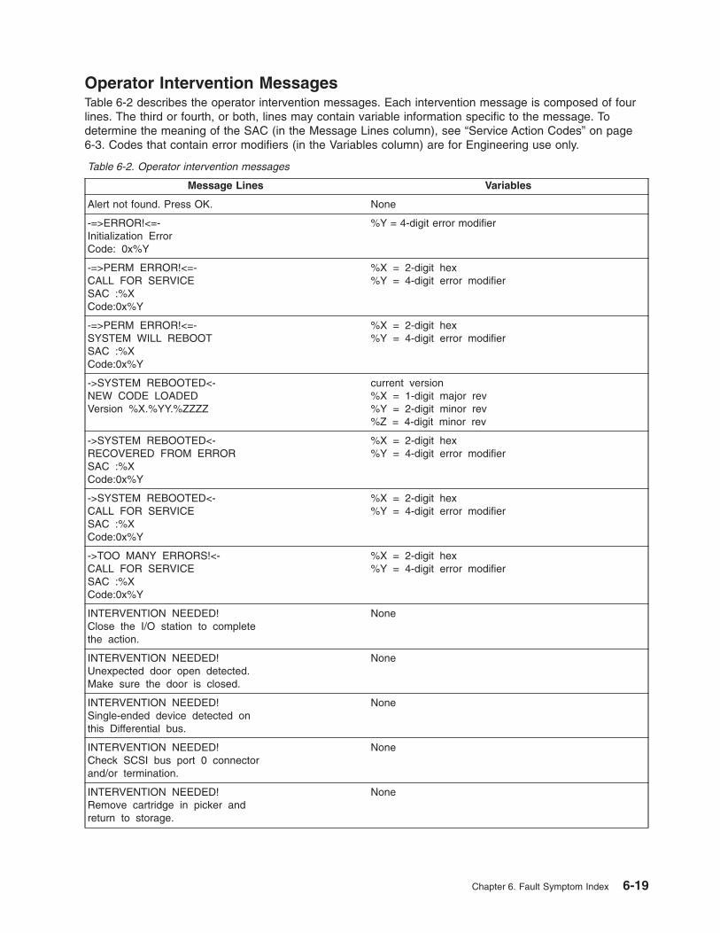
Operator Intervention Messages
Table 6-2 describes the operator intervention messages. Each intervention message is composed of four
lines. The third or fourth, or both, lines may contain variable information specific to the message. To
determine the meaning of the SAC (in the Message Lines column), see “Service Action Codes” on page
6-3. Codes that contain error modifiers (in the Variables column) are for Engineering use only.
Table 6-2. Operator intervention messages
Message Lines Variables
Alert not found. Press OK. None
-=>ERROR!<=-
Initialization Error
Code: 0x%Y
%Y = 4-digit error modifier
-=>PERM ERROR!<=-
CALL FOR SERVICE
SAC :%X
Code:0x%Y
%X = 2-digit hex
%Y = 4-digit error modifier
-=>PERM ERROR!<=-
SYSTEM WILL REBOOT
SAC :%X
Code:0x%Y
%X = 2-digit hex
%Y = 4-digit error modifier
->SYSTEM REBOOTED<-
NEW CODE LOADED
Version %X.%YY.%ZZZZ
current version
%X = 1-digit major rev
%Y = 2-digit minor rev
%Z = 4-digit minor rev
->SYSTEM REBOOTED<-
RECOVERED FROM ERROR
SAC :%X
Code:0x%Y
%X = 2-digit hex
%Y = 4-digit error modifier
->SYSTEM REBOOTED<-
CALL FOR SERVICE
SAC :%X
Code:0x%Y
%X = 2-digit hex
%Y = 4-digit error modifier
->TOO MANY ERRORS!<-
CALL FOR SERVICE
SAC :%X
Code:0x%Y
%X = 2-digit hex
%Y = 4-digit error modifier
INTERVENTION NEEDED!
Close the I/O station to complete
the action.
None
INTERVENTION NEEDED!
Unexpected door open detected.
Make sure the door is closed.
None
INTERVENTION NEEDED!
Single-ended device detected on
this Differential bus.
None
INTERVENTION NEEDED!
Check SCSI bus port 0 connector
and/or termination.
None
INTERVENTION NEEDED!
Remove cartridge in picker and
return to storage.
None
Chapter 6. Fault Symptom Index 6-19

Table 6-2. Operator intervention messages (continued)
Message Lines Variables
BAD MEDIA
Cannot get type.
Please label media.
Slot [%X %Y %Z]
%X = column number
%Y = magazine number
%Z = slot number
INTERVENTION NEEDED!
Remove cartridge from slot.
Slot [%X %Y %Z]
%X = column number
%Y = magazine number
%Z = slot number
UPSIDE DOWN MEDIA
Ensure cartridge is in slot properly.
Slot [%X %Y %Z]
%X = column number
%Y = magazine number
%Z = slot number
SLOT IS OBSTRUCTED
Please check to see if slot is empty.
Slot [%X %Y %Z]
%X = column number
%Y = magazine number
%Z = slot number
SLOT IS EMPTY
Please check to see if slot is full.
Slot [%X %Y %Z]
%X = column number
%Y = magazine number
%Z = slot number
DRIVE COMM FAILED
Please verify drive
communication path.
Drive %N [%X %Y %Z]
%N = drive number
%X = column number
%Y = magazine number
%Z = slot number
DRIVE SCSI ID FAILED
Please verify drive
SCSI id setting for
Drive %N [%X %Y %Z]
%N = drive number
%X = column number
%Y = magazine number
%Z = slot number
TAPE PUSH FAILED
Please remove tape
from drive.
Drive %N [%X %Y %Z]
%N = drive number
%X = column number
%Y = magazine number
%Z = slot number
DRIVE INIT FAILED
Please correct drive
initialization for
Drive %N [%X %Y %Z]
%N = drive number
%X = column number
%Y = magazine number
%Z = slot number
DRIVE CLEAN FAILED
A cleaning operation
failed to clean
Drive %N [%X %Y %Z]
%N = drive number
%X = column number
%Y = magazine number
%Z = slot number
INVALID LABEL
Please check media
for valid label
Slot [%X %Y %Z]
%X = column number
%Y = magazine number
%Z = slot number
DUPLICATE LABEL
Please check volsers
at element address
%X and %Y
%X = element address
%Y = element address
The screen message [0 @ 0] indicates that the cartridge
is on the picker assembly
SER NUMBER MISSING
Please enter the system
serial number via the monitor.
None
6-20 3583 Tape Library Maintenance Information

Table 6-2. Operator intervention messages (continued)
Message Lines Variables
One or more drives
has downlevel
firmware. You may
wish to update these
drives.
See your user documentation.
None
Your library
firmware versions do
not match. Download
the latest version
to the library.
None
The Use-Count must
be less than the
Max-Count.
Value Range: 0-99.
None
Autoclean is
disabled. Access is
denied. Use
autoclean’s Setup
menu to enable.
None
No fixed cleaning
slots installed.
Autoclean access is
denied.
None
You are changing the
I/O
configuration.
Autoclean will
automatically be
disabled.
None
CLEAN TAPE MISSING
A previously defined
tape is missing: %X
%X = cartridge number
CLEAN TAPE EXPIRED
Please remove the
cleaning tape number
%X
%X = cartridge number
No cleaning tape in
cleaning slot %X
Write down data.
Will remove record.
Use-Count: %Y
Max-Count: %Z
%X = cartridge number%Y = use-count number%Y = max-count number
Cleaning Power-Out
Recovery failed for
slot %X. Write down
data and remove tape.
Use-Count: %Y
Max-Count: %Z
%X = slot number%Y = use-count number%Y = max-count number
Chapter 6. Fault Symptom Index 6-21

Table 6-2. Operator intervention messages (continued)
Message Lines Variables
No record for existing-
ing cleaning tape.
Remove cleaning tape
from slot %X
manually and insert
it via the front
panel.
%X = slot number
Cleaning tape %X has
expired. Export the
cleaning tape via
the front panel.
See your user documentation.
%X = cartridge number
Your cleaning tapes
are expired or not
in the system.
Please import a new
cleaning tape.
None
%X of cleaning
tape failed.
Tape should not be in
target position
%X = Import or Export
There is no cleaning
slot available for
importing new
cleaning tapes.
None
Invalid cleaning
tape inserted.
None
WARNING - There are
no cleaning tapes
available in any of
your cleaning cells
to perform cleaning.
None
There is no clean-
ing tape available
in cleaning call %X
to perform cleaning.
%X = slot number
There is no cleaning
slot available for
importing new
cleaning tapes.
None
There is no tape
in [ 1 A 1 ].
Please insert a
cleaning tape and
retry import
None
I/O station is
configured as
storage. Autoclean
may not be enabled.
None
6-22 3583 Tape Library Maintenance Information

Table 6-2. Operator intervention messages (continued)
Message Lines Variables
Partition is not
accessible.
Library
configuration has
changed.
None
Chapter 6. Fault Symptom Index 6-23

Operator Information Messages
Table 6-3 lists the operator information messages.
Table 6-3. Operator information messages
Message Lines Variables
INITIALIZING None
OFFLINE None
ONLINE None
HOMING PICKER None
TEACHING COLUMN [%X] %X = column number
SCANNING COLUMN [%X] %X = column number
INITIALIZING DRIVES None
GOING READY None
DOOR IS OPEN None
PICKER HOME FAIL None
PICKER NOT HOME None
GOING ONLINE None
GOING OFFLINE None
–=>ERROR!<=- None
REBOOTING None
CARTRIDGE RECOVERY None
CARTRIDGE IN PICKER None
SELF TEST FAILED None
6-24 3583 Tape Library Maintenance Information

Drive Error Codes
Note: Before removing the tape drive sled, preserve the drive dump. For instructions, see “Performing a
Preserve Dump” on page 4-36.
Errors and informational messages that pertain to the tape drive are shown in the drive status area of the
operator panel. Table 6-4 describes the codes that display.
Note: In this table, enclosure refers to the Ultrium Scalable Tape Library.
Attention: If the tape drive detects a permanent error and displays an error code other than 0, it
automatically performs a drive dump. If you force a drive dump, the existing dump will be overwritten and
data will be lost. After you force a drive dump, do not turn off the power to the tape drive or library, or you
may lose the dump data.
Table 6-4. Drive error codes
Code Cause and Action
0 No error occurred and no action is required. This code displays:
v When power is cycled (turned off, then on) to the tape drive.
v When diagnostics have finished running and no error occurred.
Note: The single-character display is blank during normal operation of the tape drive.
1 Cooling problem. The tape drive detected that the recommended operating temperature was
exceeded. Perform the following action:
1. If a fan is present in the enclosure, ensure that it is rotating and is quiet. If not, replace the fan
(for instructions about replacing the fan, see your enclosure’s documentation).
2. Remove any blockage that prevents air from flowing freely through the tape drive.
3. Ensure that the operating temperature and airflow is within the specified range (see
“Specifications” on page 1-25).
4. If the operating temperature is within the specified range and the problem persists, replace the
tape drive.
The error code clears when you power-off the tape drive or place it in maintenance mode.
2 Power problem. The tape drive detected that the externally supplied power is either approaching
the specified voltage limits (the drive is still operating) or is outside the specified voltage limits (the
drive is not operating). Perform the following action:
1. Ensure that the power connector is properly seated.
2. Ensure that the proper dc voltages are being applied within the tolerances allowed (see
“Specifications” on page 1-25).
3. If the proper voltages are being applied but the problem persists, replace the tape drive.
The error code clears when you power-off the tape drive or place it in maintenance mode.
Chapter 6. Fault Symptom Index 6-25
||

Table 6-4. Drive error codes (continued)
Code Cause and Action
3 Firmware problem. The tape drive determined that a firmware error occurred. Perform the
following action:
1. Collect a drive dump from one of the following:
Note: Do not force a new dump; the tape drive has already created one.
v Server’s SCSI or Fibre Channel interface by using a device driver utility or system tool. To
obtain a dump, determine whether your server is installed with a utility that can read files
from the server’s memory. If it is, use that utility to obtain the dump. For information about
using IBM’s utility programs to obtain drive dumps, see the IBM Ultrium Device Drivers
Installation and User’s Guide. To determine where to send a file that contains a drive dump
to be analyzed, contact your Support Center.
v Ultrium Tape Drives (to copy a drive dump, see “Copying a Drive Dump to Tape Cartridge
Using the Operator Panel” on page 4-34).
2. Power the tape drive off and on, then retry the operation that produced the error.
3. If the problem persists, download new firmware and retry the operation.
4. If the problem persists, send the drive dump that you collected in step 1 to your Support
Center.
The error code clears when you power-off the tape drive or place it in maintenance mode.
4 Firmware or tape drive problem. The tape drive determined that a firmware or tape drive
hardware failure occurred. Perform the following action:
1. Collect a drive dump from one of the following:
Note: Do not force a new dump; one already exists.
v Server’s SCSI or Fibre Channel interface by using a device driver utility or system tool. To
obtain a dump, determine whether your server is installed with a utility that can read files
from the server’s memory. If it is, use that utility to obtain the dump. For information about
using IBM’s utility programs to obtain drive dumps, see the IBM Ultrium Device Drivers
Installation and User’s Guide. To determine where to send a file that contains a drive dump
to be analyzed, contact your Support Center.
v Ultrium Tape Drives (to copy a drive dump, see “Copying a Drive Dump to Tape Cartridge
Using the Operator Panel” on page 4-34).
2. Power the tape drive off and on, then retry the operation that produced the error. The error
code clears when you power-off the tape drive or place it in maintenance mode.
3. If the problem persists, run the Normal (long) Read/Write Test. (See “Running Drive
Diagnostics” on page 4-103.)
v If the test failed, contact IBM Technical Support Center and replace the drive.
v If the test passed, you may have a firmware problem. Ensure that you have the latest level
of firmware, then contact IBM Technical Support Center and send them the drive dump that
you collected in Step 1.
5 Tape drive hardware problem. The drive determined that a tape path or read/write error occurred.
To prevent damage to the drive or tape, the drive will not allow you to insert a cartridge if the
current cartridge was successfully ejected. The error code may clear when you cycle power to the
tape drive or place it in maintenance mode. If the problem persists, replace the tape drive.
6-26 3583 Tape Library Maintenance Information
||
|
|||

Table 6-4. Drive error codes (continued)
Code Cause and Action
6 Tape drive or media error. The drive determined that an error occurred, but it cannot isolate the
error to faulty hardware or to the tape cartridge. Perform the following action:
For Problems with Writing Data:
If the problem occurred while the drive was writing data to the tape, and if you know the volume
serial number (located on the cartridge label) of the tape cartridge loaded in the drive when the
problem occurred, retry the operation with a different cartridge:
v If the operation succeeds, the original cartridge was defective. Copy data from the defective
cartridge and discard it.
v If the operation fails and another drive is available, insert the cartridge into the other drive and
retry the operation.
– If the operation fails, discard the defective cartridge.
– If the operation succeeds, insert a scratch cartridge into the first drive and run the Normal
Read/Write Test (see “Running Drive Diagnostics” on page 4-103).
- If the diagnostics fail, replace the drive.
- If the diagnostics succeed, the error was temporary.v If the operation fails and another drive is not available, insert a scratch cartridge into the drive
and run the Normal Read/Write Test (see “Running Drive Diagnostics” on page 4-103).
– If the diagnostics fail, replace the drive.
– If the diagnostics succeed, discard the cartridge that caused the problem.
If the problem occurs with multiple tape cartridges or if you do not know the tape cartridge’s
volume serial number, run the Normal Read/Write Test (see “Running Drive Diagnostics” on page
4-103):
v If the diagnostics fail, replace the tape drive.
v If the diagnostics succeed, run the Head Read/Write test (see “Running Drive Diagnostics” on
page 4-103).
– If the Head Read/Write Test () fails, replace the tape drive.
– If the Head Read/Write Test () succeeds, replace the cartridges that caused the problem.
The error code clears when you remove the tape cartridge or place the drive in maintenance mode.
For Problems with Reading Data:
If the problem occurred while the drive was reading data from the tape, and if you know the volume
serial number of the tape cartridge, perform one of the following procedures:
v If another drive is available, insert the cartridge into the other drive and retry the operation:
– If the operation fails, discard the defective cartridge.
– If the operation succeeds, insert a scratch cartridge into the first drive and run the Normal
Read/Write Test (see “Running Drive Diagnostics” on page 4-103):
- If the diagnostics fail, replace the drive.
- If the diagnostics succeed, the error was temporary.v If another drive is not available, insert a scratch cartridge into the drive and run the Normal
Read/Write Test (see “Running Drive Diagnostics” on page 4-103):
– If the diagnostics fail, replace the drive.
– If the diagnostics succeed, discard the cartridge that caused the problem.
If the problem occurs with multiple tape cartridges or if you do not know the tape cartridge’s
volume serial number, run the Normal Read/Write Test (see “Running Drive Diagnostics” on page
4-103):
v If the diagnostics fail, replace the tape drive.
v If the diagnostics succeed, run the Head Read/Write test (refer to the appropriate section in the
library’s operator guide guide):
– If the Head Read/Write Test diagnostic (see “Running Drive Diagnostics” on page 4-103) fails,
replace the tape drive.
– If the Head Read/Write Test diagnostic (see “Running Drive Diagnostics” on page 4-103)
succeeds, replace the cartridges that caused the problem.
The error code clears when you remove the tape cartridge or place the drive in maintenance mode.
Chapter 6. Fault Symptom Index 6-27
||||||||
||||||||
||||||||
||||

Table 6-4. Drive error codes (continued)
Code Cause and Action
7 A high probability of media error. The tape drive determined that an error occurred because of a
faulty tape cartridge, an expired cleaning cartridge, or the insertion of an FMR cartridge as a data
cartridge.
v If the problem only occurs with a cleaning cartridge, replace the cleaning cartridge.
v If the problem was caused by an FMR cartridge that is no longer needed, go to “Running Drive
Diagnostics” on page 4-103 and erase the FMR cartridge.
v Try another tape cartridge. If the problem only occurs with one cartridge, replace the failing
cartridge. If the problem occurs with multiple cartridges, use the following procedure:
1. If possible, run the tape cartridges in a different drive. If the operation in the other drive fails
with an error code of 6 or 7, replace the media. If the operation succeeds, run the Media
Read/Write diagnostic test on all of the failing cartridges (see “Running Drive Diagnostics” on
page 4-103).
2. If the Media Test diagnostic test fails, replace the media. If it runs successfully, clean the
drive. (See “Cleaning Drives” on page 4-135.) Then run the ″Normal Read/Write″ diagnostic
test. (See “Running Drive Diagnostics” on page 4-103.)
3. If the Normal Read/Write test fails, replace the drive. If the Normal Read/Write test runs
successfully, the problem may have been corrected by cleaning the drive. Repeat the
operation that produced the original media error.
The error code clears when you remove the cartridge or place the drive in maintenance mode.
8 For SCSI drive:
Tape drive or SCSI bus failure. The tape drive determined that a failure occurred in the tape
drive’s hardware or in the SCSI bus. See “Fixing SCSI Bus Errors” on page A-9. The error code
clears 10 seconds after the drive detected the error or when you place the drive in maintenance
mode.
For Fibre Channel drive:
Tape drive or Fibre Channel failure. The tape drive determined that a failure occurred in the tape
drive’s hardware or in the Fibre Channel. It detects light through the fiber cable but cannot perform
data communication properly. The length of the cable between the devices should not exceed 500
m (1640 ft). See “Fixing Fibre Channel Errors” on page A-11. The error code clears when the drive
detects light and can communicate, or when you place the drive in maintenance mode.
9 Tape drive or LDI (RS-422) error. The tape drive determined that a failure occurred in the tape
drive hardware or in the LDI (RS-422) connection.
v Power cycle the drive. If the power-on self test is successful, the problem is resolved.
v If the problem persists, replace the tape drive sled (see “Tape Drive Sled” on page 8-4).
v If the problem persists after replacing the drive, the problem is with the cable between the drive
sled and the power distribution board, the power distribution board itself, or the main board.
The error code clears when you place the drive in maintenance mode.
o, c, b, or h No error or message assigned. There may be a problem with the single-character display. Turn
the power off, then on and determine whether all segments on the single-character display are lit. If
so, you may have a down-level version of both your library’s firmware and documentation (the
documentation may not describe all of the available error codes). Refer to the latest version of the
firmware or documentation.
A Tape drive hardware problem. The tape drive determined that a problem occurred which
degraded the operation of the tape drive, but it did not restrict continued use. If the problem
persists, replace the tape drive. The drive is usable, though the single-character display continues
to indicate an error and the status light flashes amber.
The error code may clear when you cycle power to the tape drive or place it in maintenance mode.
B No error or message is assigned. See error code 8 in this table.
6-28 3583 Tape Library Maintenance Information
|||
|
||
||
||||
|||
|||

Table 6-4. Drive error codes (continued)
Code Cause and Action
C The tape drive needs to be cleaned. Clean the tape drive. See the section about cleaning drives
in the IBM TotalStorage 3583 Tape Library Setup and Operator Guide.
The error code clears when you clean the tape drive or place it in maintenance mode.
d Fibre Channel AL_PA conflict. More than one device has the same address. Each device must
have its own unique AL_PA address. See the section about setting Loop IDs in the IBM
TotalStorage 3583 Tape Library Setup and Operator Guide.
D No error or message assigned. See error code 0 in this table.
E Informational message. The tape drive’s Fibre Channel port has been placed offline by another
device or by an operator. This code is set when the Offline command is received from another
device on the Fibre Channel interface. Determine why the device at the other end of the Fibre
Channel (the server, switch, or other device) placed the drive offline.
The drive is placed online when it receives the Online command from the Fibre Channel interface.
After a reset, the drive comes online.
F The tape drive determined that no light is being received over the Fibre Channel. See “Fixing
Fibre Channel Errors” on page A-11.
The error code clears when the drive detects light or when you place the drive in maintenance
mode.
Chapter 6. Fault Symptom Index 6-29

Cleaning Cartridge Error Messages
Table 6-5. Handling errors during automatic cleaning
Error Cause Required Action
Non-cleaning cartridge
imported
User error. Export the non-cleaning cartridge to the I/O station
(ignore the message about the cartridge being expired).
Missing cleaning cartridge The cleaning cartridge was
manually removed while the
door was open.
Open the door of the library and manually insert a
cleaning cartridge into the slot from which it is missing.
Unexpected cleaning slot
full
A non-cleaning cartridge
was placed into the fixed
slot while the door was
open.
Remove the non-cleaning cartridge from the fixed slot.
Cleaning tape usage limit
met
The cartridge used its
allotted cleanings.
Export the expired cartridge to the I/O station and
discard it.
All cleaning tapes used All cartridges used their
allotted cleanings.
Export the expired cartridges to the I/O station and
discard them. Insert new cleaning cartridges into the
library.
Failed get or put of cleaning
tape
Electromechanical failure. Note the SAC code that displays on the operator panel,
then refer to “Service Action Codes” on page 6-3 to
resolve the error.
Power outage while
handling cleaning tape
User error or random power
failure.
Access the automatic cleaning function and determine
which columns contain cleaning cartridges (see the
Operating Procedure chapter in the IBM TotalStorage
Ultrium Scalable Tape Library 3583 Setup and Operator
Guide). Open the door of the library and inspect the
columns to determine from which slot the cleaning
cartridge is missing. Manually remove the cleaning
cartridge from the gripper and return it to the slot from
which it is missing.
Power outage while
cleaning drive
User error or random power
failure.
Reapply the power and allow the drive to complete the
operation.
6-30 3583 Tape Library Maintenance Information

Chapter 7. Locations
Tape Library Subsystem Overview . . . . . . . . . . . . . . . . . . . . . . . . . . 7-2
Tape Library Front View . . . . . . . . . . . . . . . . . . . . . . . . . . . . . . 7-3
Rear View of Tape Library with SCSI Attachment . . . . . . . . . . . . . . . . . . . . 7-4
Rear View of Tape Library with Native Fibre Channel Attachment . . . . . . . . . . . . . . 7-5
Tape Library Serial Ports . . . . . . . . . . . . . . . . . . . . . . . . . . . . . 7-6
Y-Axis and Rotary-Axis Assembly . . . . . . . . . . . . . . . . . . . . . . . . . . 7-7
Picker Assembly . . . . . . . . . . . . . . . . . . . . . . . . . . . . . . . . 7-8
I/O Station (12 Slot) . . . . . . . . . . . . . . . . . . . . . . . . . . . . . . . 7-9
I/O Station (Single Slot) . . . . . . . . . . . . . . . . . . . . . . . . . . . . . 7-10
Main Controller PCBA . . . . . . . . . . . . . . . . . . . . . . . . . . . . . . 7-11
Display Assembly . . . . . . . . . . . . . . . . . . . . . . . . . . . . . . . . 7-12
Power Distribution PCBA (Type I) . . . . . . . . . . . . . . . . . . . . . . . . . . 7-13
Power Distribution Board (Type II) . . . . . . . . . . . . . . . . . . . . . . . . . 7-14
Picker Control Board . . . . . . . . . . . . . . . . . . . . . . . . . . . . . . 7-15
Host SCSI Interface Board . . . . . . . . . . . . . . . . . . . . . . . . . . . . 7-16
Serial Diagnostic Port Board . . . . . . . . . . . . . . . . . . . . . . . . . . . . 7-17
DC Power Supply Assembly . . . . . . . . . . . . . . . . . . . . . . . . . . . . 7-18
AC Input Power Module . . . . . . . . . . . . . . . . . . . . . . . . . . . . . 7-19
SAN Data Gateway Module (optional) . . . . . . . . . . . . . . . . . . . . . . . . 7-20
Remote Management Unit . . . . . . . . . . . . . . . . . . . . . . . . . . . . 7-21
© Copyright IBM Corp. 2000, 2005 7-1
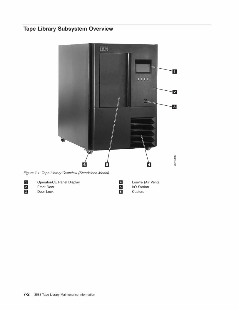
Tape Library Subsystem Overview
�1� Operator/CE Panel Display �4� Louvre (Air Vent)
�2� Front Door �5� I/O Station
�3� Door Lock �6� Casters
a67m
0003
1
2
3
5 46
Figure 7-1. Tape Library Overview (Standalone Model)
7-2 3583 Tape Library Maintenance Information

Tape Library Front View
�1� I/O Station �6� I/O Station Column 1
�2� Operator/CE Panel Assembly �7� Storage Column 5
�3� I/O Station Cable Harness �8� Picker Assembly
�4� Door Lock & Interlock Switch �9� Y−Axis Drive Shaft
�5� Front Panel (Lower)
a67m
0004
1
2
3
5
4
6
9
8
7
Figure 7-2. Front view of tape library with door opened
Chapter 7. Locations 7-3

Rear View of Tape Library with SCSI Attachment
�1� Host Interface Board �5� SCSI Tape Drive Sled
�2� SAN Data Gateway Module (optional) �6� DC Power Supply & Redundant dc Power Supply
�3� RMU �7� Filler Panel
�4� AC Input Power Module
a67m
0005
3
5
4
2
1
7
6
Figure 7-3. Rear view of tape library with SCSI attachment. The drive contains Ultrium 1 Tape Drives. Figure shows
converted library.
7-4 3583 Tape Library Maintenance Information
||

Rear View of Tape Library with Native Fibre Channel Attachment
�1� Serial Diagnostic Port Board �5� Ac Input Power Module
�2� Remote Management Unit �6� Fiber Tape Drive Sled
�3� Filler Panel �7� LC Connector
�4� DC Power Supply & Redundant dc Power Supply
Figure 7-4. Rear view of tape library with native fibre channel attachment. The drive contains Ultrium 2 Tape Drives.
Chapter 7. Locations 7-5
|
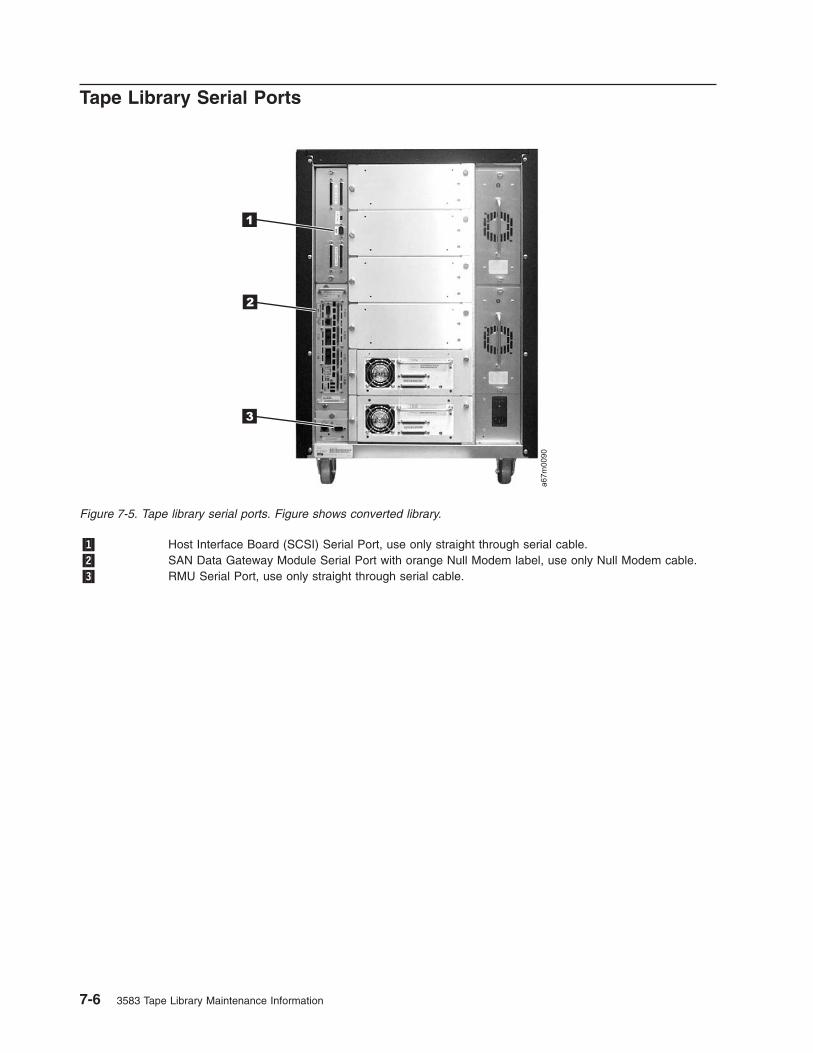
Tape Library Serial Ports
�1� Host Interface Board (SCSI) Serial Port, use only straight through serial cable.
�2� SAN Data Gateway Module Serial Port with orange Null Modem label, use only Null Modem cable.
�3� RMU Serial Port, use only straight through serial cable.
a67m
0090
3
2
1
Figure 7-5. Tape library serial ports. Figure shows converted library.
7-6 3583 Tape Library Maintenance Information

Y-Axis and Rotary-Axis Assembly
�1� Y−Axis Motor Assembly �4� Rotary Axis Motor Mounting Screw (1 of 4)
�2� Y−Axis Motor Assembly Mounting Screws �5� Rotary Axis Cable Harness
�3� Rotary Axis Motor Assembly
a67m
0006
1 2 3 4 5
Figure 7-6. Y-Axis and Rotary-Axis Assembly
Chapter 7. Locations 7-7

Picker Assembly
�1� Picker Control Board �6� Picker Flex Cable
�2� Y−Axis Flex Cable �7� E−clip & Washer
�3� Bar Code Reader Scan Beam Window �8� Picker Shaft
�4� Bar Code Reader Cover �9� Top Washer
�5� Picker Assembly �10� Picker Flex Cable Cover
Note: For proper orientation of picker control PCBA to picker support ground wire connector, see
Figure 8-7 on page 8-10.
a67m
0007
1 2 4 5
678910
3
Figure 7-7. Picker Assembly
7-8 3583 Tape Library Maintenance Information
||

I/O Station (12 Slot)
�1� Cable Clamps �3� Storage Magazine
�2� I/O Station Door �4� Cable Harness
a67m
0008
1
2
34
Figure 7-8. Rear View of the I/O Station
Chapter 7. Locations 7-9

I/O Station (Single Slot)
�1� Cable Clamps �3� Storage Magazine
�2� I/O Station Door �4� Cable Harness
a67m
0072
4
1 2
3
Figure 7-9. I/O Station (Single Slot)
7-10 3583 Tape Library Maintenance Information

Main Controller PCBA
�1� Power Distribution Board Cable Connector
(Power)
�5� Picker Control Board Cable Connector
�2� Host Interface Board (SCSI) Cable Connector �6� Power Distribution Board Cable Connector
(Signal)
�3� RMU �7� Display Control Board Cable Connector
�4� Unused
a67m
0009
1
7
6 2
34
5
Figure 7-10. Main controller PCBA. The board supports both SCSI and native Fibre Channel attachment.
Chapter 7. Locations 7-11

Display Assembly
�1� LCD Assembly �5� Cable Connector to Main Control Board
�2� Display Control Board �6� Power Cable to Display Back Light
�3� Cable Connector to Door Interlock Switch �7� Display Back Light
�4� Cable to LCD Display Assembly
a67m
0010
1
7 6
2 3
4
5
Figure 7-11. Operator panel assembly. The assembly supports both SCSI and native Fibre Channel attachment.
7-12 3583 Tape Library Maintenance Information
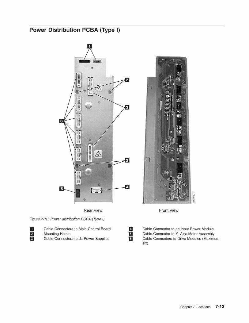
Power Distribution PCBA (Type I)
�1� Cable Connectors to Main Control Board �4� Cable Connector to ac Input Power Module
�2� Mounting Holes �5� Cable Connector to Y−Axis Motor Assembly
�3� Cable Connectors to dc Power Supplies �6� Cable Connectors to Drive Modules (Maximum
six)
a67m
0011
1
6
2
2
3
45
Rear View Front View
Figure 7-12. Power distribution PCBA (Type I)
Chapter 7. Locations 7-13

Power Distribution Board (Type II)
�1� Cable Connectors to Main Control Board �5� Cable Connector to Y−Axis Motor Assembly
�2� Mounting Holes �6� Cable Connectors to Drive Modules (Maximum
six)
�3� Cable Connectors to dc Power Supplies �7� SAN Data Gateway Module Power Connector
�4� Cable Connector to ac Input Power Module
Note: Includes sticker for new power architecture (NPA).
a67m
0081
1
6
7
2
2
3
45
Rear View Front View
Figure 7-13. Power distribution PCBA (Type II)
7-14 3583 Tape Library Maintenance Information

Picker Control Board
�1� Y−Axis Flex Cable Connector �3� Picker Assembly Flex Cable Connector
�2� Rotary Axis Motor Cable Connector
Figure 7-14. Picker control board
Chapter 7. Locations 7-15

Host SCSI Interface Board
�1� Mounting Screws (Captive) �4� Serial Port Connector
�2� HVD SCSI Cable Connectors �5� LVD SCSI Cable Connectors
�3� LVD — HVD Selector Switch
a67m
0051
2
3
4
5
1
1
Figure 7-15. Host SCSI interface board for SCSI attachment. This board will appear in a converted library; however,
only the serial port will be utilized.
7-16 3583 Tape Library Maintenance Information

Serial Diagnostic Port Board
�1� Mounting Screws (Captive) �2� Library Serial Port Connector
Figure 7-16. Serial diagnostic port board for native Fibre Channel attachment
Chapter 7. Locations 7-17

DC Power Supply Assembly
�1� DC Power Supply (old) �4� Power Supply LED (Green = Good) (Red = Fail)
�2� DC Power Supply (new, required for Fibre
Channel support)
�5� Handle
�3� Thumbscrews (Mounting) �6� NPA Label (new power architecture)
a67m
0013
1
3 3
5 5
4 4
3 3
NPA
NPA
2
6
Figure 7-17. DC Power Supply Assembly. Figure shows converted library.
7-18 3583 Tape Library Maintenance Information

AC Input Power Module
�1� AC Power Connector to Power Distribution Board �3� Mounting Holes
�2� Main ac Power Switch �4� Fuse Holder
a67m
0014
1
2
4
3
Front View
Rear View
Figure 7-18. AC Power Input Module. Figure shows converted library.
Chapter 7. Locations 7-19

SAN Data Gateway Module (optional)
�1� Thumbscrew �3� 2 Gbit GBIC
�2� Handle �4� Connector to Power Distribution Board
a67m
0086
3
4
2
2
1
1
Figure 7-19. SAN Data Gateway Module (optional). Figure shows converted library.
7-20 3583 Tape Library Maintenance Information

Remote Management Unit
�1� RMU �5� Speed LED (yellow)
�2� Thumbscrew �6� Ethernet Link LED (green)
�3� Serial Port �7� Ethernet Port
�4� Status LED
Red = Power On/Failure
Yellow = Booting
Green = Initialized
Flashing Green = Active
a67m
0089
1
2
54
7
6
3
Figure 7-20. RMU. Figure shows converted library.
Chapter 7. Locations 7-21

7-22 3583 Tape Library Maintenance Information

Chapter 8. Check, Adjust, Remove, and Replace
Cartridge Removal from Picker Assembly . . . . . . . . . . . . . . . . . . . . . . . 8-3
Tape Drive Sled . . . . . . . . . . . . . . . . . . . . . . . . . . . . . . . . . 8-4
Removing the Tape Drive Sled . . . . . . . . . . . . . . . . . . . . . . . . . . 8-4
Replacing the Tape Drive Sled . . . . . . . . . . . . . . . . . . . . . . . . . . 8-6
Picker Assembly . . . . . . . . . . . . . . . . . . . . . . . . . . . . . . . . 8-7
Removing the Picker Assembly . . . . . . . . . . . . . . . . . . . . . . . . . . 8-7
Replacing the Picker Assembly . . . . . . . . . . . . . . . . . . . . . . . . . . 8-8
Picker Carriage Arm Assembly (Picker Assembly and Control Board) . . . . . . . . . . . . . 8-11
Removing the Picker Carriage Arm Assembly . . . . . . . . . . . . . . . . . . . . 8-11
Replacing the Picker Carriage Arm Assembly . . . . . . . . . . . . . . . . . . . . 8-13
Rotary Axis Motor . . . . . . . . . . . . . . . . . . . . . . . . . . . . . . . 8-14
Removing the Rotary Axis Motor . . . . . . . . . . . . . . . . . . . . . . . . . 8-14
Replacing the Rotary Axis Assembly . . . . . . . . . . . . . . . . . . . . . . . . 8-14
Picker Control Board . . . . . . . . . . . . . . . . . . . . . . . . . . . . . . 8-16
Removing the Picker Control Board . . . . . . . . . . . . . . . . . . . . . . . . 8-16
Replacing the Picker Control Board . . . . . . . . . . . . . . . . . . . . . . . . 8-16
Y-Axis Drive Belt . . . . . . . . . . . . . . . . . . . . . . . . . . . . . . . . 8-18
Removing the Y-Axis Drive Belt . . . . . . . . . . . . . . . . . . . . . . . . . 8-18
Replacing the Y-Axis Drive Belt . . . . . . . . . . . . . . . . . . . . . . . . . 8-21
Y-Axis Flex Cable . . . . . . . . . . . . . . . . . . . . . . . . . . . . . . . . 8-24
Removing the Y-Axis Flex Cable . . . . . . . . . . . . . . . . . . . . . . . . . 8-24
Replacing the Y-Axis Flex Cable . . . . . . . . . . . . . . . . . . . . . . . . . 8-24
Display Assembly Flex Cable . . . . . . . . . . . . . . . . . . . . . . . . . . . 8-25
Removing the Display Assembly Flex Cable . . . . . . . . . . . . . . . . . . . . . 8-25
Replacing the Display Assembly Flex Cable . . . . . . . . . . . . . . . . . . . . . 8-26
Main Controller to Power Distribution Cables (Power or Signal Interface) . . . . . . . . . . . 8-27
Removing the Main to Power Distribution Cables . . . . . . . . . . . . . . . . . . . 8-27
Replacing the Main to Power Distribution Cables . . . . . . . . . . . . . . . . . . . 8-27
Power Distribution to Drive Sled Cable . . . . . . . . . . . . . . . . . . . . . . . . 8-28
Removing the Power Distribution to Drive Sled Cable . . . . . . . . . . . . . . . . . 8-28
Replacing the Power Distribution to Drive Sled Cable . . . . . . . . . . . . . . . . . 8-28
Y-Axis Motor Assembly . . . . . . . . . . . . . . . . . . . . . . . . . . . . . . 8-29
Removing the Y-Axis Motor Assembly . . . . . . . . . . . . . . . . . . . . . . . 8-29
Replacing the Y-Axis Motor Assembly . . . . . . . . . . . . . . . . . . . . . . . 8-29
Y-Axis Drive Shaft Assembly . . . . . . . . . . . . . . . . . . . . . . . . . . . . 8-30
Removing the Vertical Axis Drive Shaft . . . . . . . . . . . . . . . . . . . . . . . 8-30
Replacing the Vertical Axis Drive Shaft Assembly . . . . . . . . . . . . . . . . . . . 8-30
Storage Columns . . . . . . . . . . . . . . . . . . . . . . . . . . . . . . . . 8-32
Removing the Storage Column . . . . . . . . . . . . . . . . . . . . . . . . . . 8-32
Replacing the Storage Column . . . . . . . . . . . . . . . . . . . . . . . . . . 8-32
Main Controller Board . . . . . . . . . . . . . . . . . . . . . . . . . . . . . . 8-34
Removing the Main Controller Board . . . . . . . . . . . . . . . . . . . . . . . 8-34
Replacing the Main Controller Board . . . . . . . . . . . . . . . . . . . . . . . . 8-34
RMU Network Interface Cable . . . . . . . . . . . . . . . . . . . . . . . . . . . 8-36
Removing the RMU Interface Cable . . . . . . . . . . . . . . . . . . . . . . . . 8-36
Replacing the RMU Interface Cable . . . . . . . . . . . . . . . . . . . . . . . . 8-38
Remote Management Unit . . . . . . . . . . . . . . . . . . . . . . . . . . . . 8-39
Remove RMU . . . . . . . . . . . . . . . . . . . . . . . . . . . . . . . . 8-39
Replace RMU . . . . . . . . . . . . . . . . . . . . . . . . . . . . . . . . 8-39
SAN Data Gateway Module . . . . . . . . . . . . . . . . . . . . . . . . . . . . 8-41
Remove SAN Data Gateway Module . . . . . . . . . . . . . . . . . . . . . . . 8-41
Replace SAN Data Gateway Module . . . . . . . . . . . . . . . . . . . . . . . 8-41
Accessory Bay Cable for the SAN Data Gateway Module . . . . . . . . . . . . . . . . . 8-42
© Copyright IBM Corp. 2000, 2005 8-1

Removing the Accessory Bay Cable for the SAN Data Gateway Module . . . . . . . . . . 8-42
Replacing the Accessory Bay Cable for the SAN Data Gateway Module . . . . . . . . . . 8-44
Host SCSI Interface Board . . . . . . . . . . . . . . . . . . . . . . . . . . . . 8-45
Removing the Host SCSI Interface Board . . . . . . . . . . . . . . . . . . . . . . 8-45
Replacing the Host SCSI Interface Board . . . . . . . . . . . . . . . . . . . . . . 8-45
Serial Diagnostic Port Board . . . . . . . . . . . . . . . . . . . . . . . . . . . . 8-46
Removing the Serial Diagnostic Port Board . . . . . . . . . . . . . . . . . . . . . 8-46
Replacing the Serial Diagnostic Port Board . . . . . . . . . . . . . . . . . . . . . 8-46
Display Assembly . . . . . . . . . . . . . . . . . . . . . . . . . . . . . . . . 8-47
Removing the Display Assembly . . . . . . . . . . . . . . . . . . . . . . . . . 8-47
Replacing the Display Assembly . . . . . . . . . . . . . . . . . . . . . . . . . 8-47
Power Distribution Board . . . . . . . . . . . . . . . . . . . . . . . . . . . . . 8-49
Removing the Power Distribution Board . . . . . . . . . . . . . . . . . . . . . . 8-49
Replacing the Power Distribution Board . . . . . . . . . . . . . . . . . . . . . . 8-49
12-Slot I/O Station . . . . . . . . . . . . . . . . . . . . . . . . . . . . . . . 8-50
Removing the I/O Station . . . . . . . . . . . . . . . . . . . . . . . . . . . . 8-50
Replacing the I/O Station . . . . . . . . . . . . . . . . . . . . . . . . . . . . 8-50
Single-Slot I/O Station . . . . . . . . . . . . . . . . . . . . . . . . . . . . . . 8-52
Removing the I/O Station . . . . . . . . . . . . . . . . . . . . . . . . . . . . 8-52
Replacing the I/O Station . . . . . . . . . . . . . . . . . . . . . . . . . . . . 8-52
Power Supplies Check Procedure . . . . . . . . . . . . . . . . . . . . . . . . . . 8-53
Power . . . . . . . . . . . . . . . . . . . . . . . . . . . . . . . . . . . . 8-53
ac Input Power Module . . . . . . . . . . . . . . . . . . . . . . . . . . . . 8-53
Removing the ac Input Module . . . . . . . . . . . . . . . . . . . . . . . . . 8-53
Replacing the ac Input Module . . . . . . . . . . . . . . . . . . . . . . . . . 8-53
dc Power Supply . . . . . . . . . . . . . . . . . . . . . . . . . . . . . . . 8-54
Verifying dc Power Supply Level . . . . . . . . . . . . . . . . . . . . . . . . 8-54
Removing the dc Power Supply . . . . . . . . . . . . . . . . . . . . . . . . 8-55
Replacing the dc Power Supply . . . . . . . . . . . . . . . . . . . . . . . . 8-56
Door Lock Assembly . . . . . . . . . . . . . . . . . . . . . . . . . . . . . . 8-57
Removing the Door Lock Assembly . . . . . . . . . . . . . . . . . . . . . . . . 8-57
Replacing the Door Lock Assembly . . . . . . . . . . . . . . . . . . . . . . . . 8-57
Door Interlock Switch and Cable Assembly . . . . . . . . . . . . . . . . . . . . . . 8-58
Removing the Door Interlock Switch . . . . . . . . . . . . . . . . . . . . . . . . 8-58
Replacing the Door Interlock Switch . . . . . . . . . . . . . . . . . . . . . . . . 8-58
Plastic Top Door . . . . . . . . . . . . . . . . . . . . . . . . . . . . . . . . 8-59
Removing the Plastic Top Door . . . . . . . . . . . . . . . . . . . . . . . . . . 8-59
Replacing the Plastic Top Door . . . . . . . . . . . . . . . . . . . . . . . . . . 8-59
Plastic Lower Front Door Panel . . . . . . . . . . . . . . . . . . . . . . . . . . 8-60
Removing the Plastic Lower Front Door Panel . . . . . . . . . . . . . . . . . . . . 8-60
Replacing the Plastic Lower Front Door Panel . . . . . . . . . . . . . . . . . . . . 8-60
Side Cover . . . . . . . . . . . . . . . . . . . . . . . . . . . . . . . . . . 8-61
Removing the Side Cover . . . . . . . . . . . . . . . . . . . . . . . . . . . . 8-61
Replacing the Side Cover . . . . . . . . . . . . . . . . . . . . . . . . . . . . 8-61
Top Cover . . . . . . . . . . . . . . . . . . . . . . . . . . . . . . . . . . 8-62
Removing the Top Cover . . . . . . . . . . . . . . . . . . . . . . . . . . . . 8-62
Replacing the Top Cover . . . . . . . . . . . . . . . . . . . . . . . . . . . . 8-62
This section contains step by step procedures to adjust, remove and replace all Tape Library field
replaceable units (FRUs).
8-2 3583 Tape Library Maintenance Information
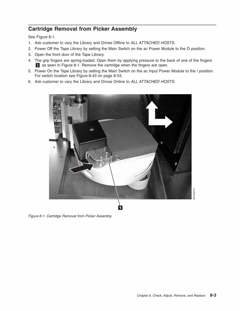
Cartridge Removal from Picker Assembly
See Figure 8-1.
1. Ask customer to vary the Library and Drives Offline to ALL ATTACHED HOSTS.
2. Power Off the Tape Library by setting the Main Switch on the ac Power Module to the O position.
3. Open the front door of the Tape Library.
4. The grip fingers are spring-loaded. Open them by applying pressure to the back of one of the fingers
�1� as seen in Figure 8-1. Remove the cartridge when the fingers are open.
5. Power On the Tape Library by setting the Main Switch on the ac Input Power Module to the | position.
For switch location see Figure 8-43 on page 8-53.
6. Ask customer to vary the Library and Drives Online to ALL ATTACHED HOSTS.
a67m
0015
1
Figure 8-1. Cartridge Removal from Picker Assembly
Chapter 8. Check, Adjust, Remove, and Replace 8-3

Tape Drive Sled
Tools that are required: None.
Removing the Tape Drive Sled
Note: Before removing the tape drive sled, preserve the drive dump. For instructions, see “Performing a
Preserve Dump” on page 4-36.
See Figure 8-2 for example of SCSI host connections (example on right). If there are multiple hosts that
are connected to the drives, determine the SCSI bus that the failing drive is connected to.
See Figure 8-3 on page 8-5 for example of Fibre Channel host connections (example on left). If there are
multiple hosts that are connected to the drives, determine the SCSI bus that the failing drive is connected
to.
Figure 8-2. Cable Connections for a SCSI host attachment. Illustration on the right depicts a SCSI host attachment.
Illustration on the left depicts a SCSI host attachment via a SAN Data Gateway Module.
8-4 3583 Tape Library Maintenance Information
||

See Figure 8-4 on page 8-6.
1. Ask customer to vary the Library and Drives Offline to ALL ATTACHED HOSTS. Ensure that the SCSI
bus is quiesced before proceeding.
2. Prepare the Library using the Operator Panel (Main Menu —> More —> Service —> Drives —>
Select Drives —> OK —> Repair —> Remove) prior to removing the Tape drive.
3. Power Off the Tape Library by setting the Main Switch on the ac Power Module to the O position.
4. Disconnect all SCSI cables to the Drive Sled.
5. Loosen the two captive thumbscrews �1� from the drive sled �2� and slide the drive out using the drive
handle �3�.
6. Return failing Tape Drive by using specified procedures.
Figure 8-3. Cable Connections for a native Fibre Channel host attachment
Chapter 8. Check, Adjust, Remove, and Replace 8-5

Replacing the Tape Drive Sled
See Figure 8-4.
Perform the above procedure in reverse order.
Before you ask customer to vary the library online, wait for library to complete initialization.
Initialization will take approximately six minutes after power is applied to the library. This allows
the tape drive to be configured to SCSI address of failed tape drive.
Note: It is very important to be aware that each drive sled contains both drive firmware and library
firmware.
v Library firmware: Replacement boards containing library firmware, such as the Tape Drive Sled,
may come from stock with a firmware level other than the current firmware level that is in the
other firmware components in the library. It is even possible that the firmware may be
incompatible (non-multi-path architecture type firmware). Thus, it is very important to always
check the firmware level of the library (Main Menu —> More —> About —> Details) and update
the firmware in the entire library to the latest level (see “Updating Firmware” on page 4-114).
For proper operation of the library, ensure that the firmware level of the replacement part
matches the library firmware level of the entire library.
v Drive firmware: Drive firmware in the drive within the replacement drive sled from stock may
also be at a different level than the other drives in the library. While LTO 1 and LTO 2 drive types
have different firmware levels, if the library contains both drive types, all the drives of both types
(including the replacement drive) should be brought up to the latest level.
Note: The boot code of the new part does not have to match the boot code of the other parts in the
library.
Notify the Library that a new drive is replaced by selecting (Main Menu —> Service —> Drives —>
Repair —> Replace).
Ask customer to vary the Library and Drives Online to ALL ATTACHED HOSTS.
a67m
0016
1
2 3
Figure 8-4. Tape Drive Sled Removal and Replacement
8-6 3583 Tape Library Maintenance Information

Picker Assembly
For Picker Assembly Part Number, see Table 15-1 on page 15-1.See Figure 8-6 on page 8-9 for locations of the components in the following procedure:
Tools that are required: Phillips screwdriver, Flat blade screwdriver, T8, T10 and T20 Torx drivers,
flashlight.
Removing the Picker Assembly
1. Ask customer to vary the Library and Drives Offline to ALL ATTACHED HOSTS.
2. Power Off the Tape Library by setting the Main Switch on the ac Power Module to the O position.
3. Open the Tape Library front door.
4. Refer to Figure 8-26 on page 8-33 and remove the left front storage column (column 2) �2� by
removing screws �1� and �5�. Screws �5� can be reached through holes �4�.
5. See Figure 8-6 on page 8-9 for step 5 through step 9. Lift the Picker Assembly and position it in the
middle of the Y−shaft for easy access to its components.
6. Remove the T20 Torx screws �3�, then remove the sheet metal cover.
7. Disconnect the Picker Assembly Flex cable �7� from the Picker Control Board �1�.
8. Use a flat blade screwdriver to pry the E-clip �4� from the Picker shaft. Remove the E-clip and the
washer �5� from the Picker shaft.
9. Lift the Picker Assembly up and remove it from the metal base.
Note: See Figure 8-5, there is another washer �1� between the Picker Assembly and the casting �2�.
Do not lose this washer.
a67m
00692
1
Figure 8-5. Flat Washer and Casting
Chapter 8. Check, Adjust, Remove, and Replace 8-7

Replacing the Picker Assembly
Note: See Figure 8-6 on page 8-9. Before attaching the flex cable cover with the Torx screws, raise
the picker assembly and position the cover so that the two pins on the base casting are
centered in the holes �6�. Now tighten the Torx screws. Be sure to install the ground strap,
and note that the eyelets of the ground strap are of different sizes.
Perform the procedure for removing the picker assembly in reverse order. Ask customer to vary the Library
and Drives Online to ALL ATTACHED HOSTS.
For proper operation of the library, ensure that the firmware level of the replacement part matches the
firmware level of the entire library.
Note: The boot code of the new part does not have to match the boot code of the other parts in the
library.
8-8 3583 Tape Library Maintenance Information

Make sure that the connectors on the ground wire between the Picker Control PCBA and the Picker
Support are connected so that they do not protrude above the Picker Support. The correct orientation of
the ground wire connectors is shown in Figure 8-7 on page 8-10.
a67m
0017
1 2 2
6
7
45
3
Figure 8-6. Picker Assembly Removal and Replacement
Chapter 8. Check, Adjust, Remove, and Replace 8-9

Figure 8-7. Proper orientation of picker control PCBA to picker support ground wire connector. Illustration shows
ground strap disconnected from the Carriage Arm Assembly.
8-10 3583 Tape Library Maintenance Information
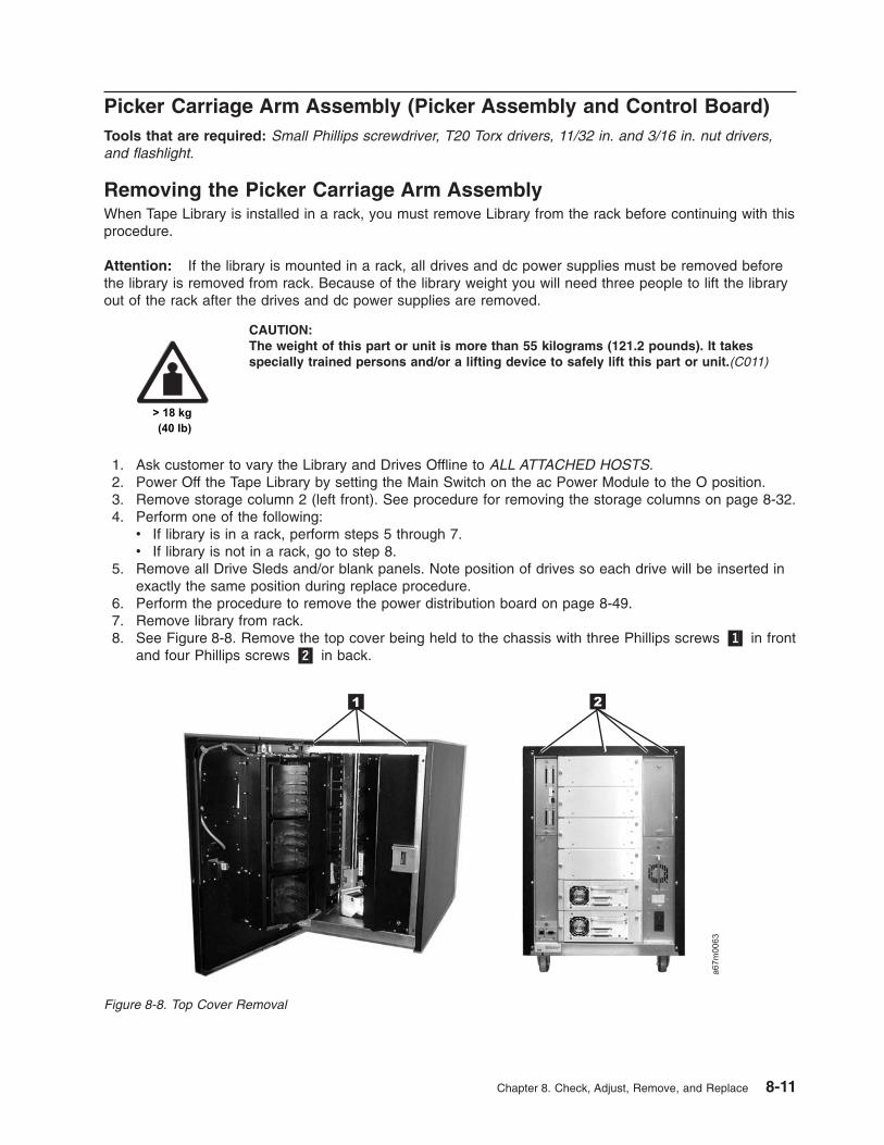
Picker Carriage Arm Assembly (Picker Assembly and Control Board)
Tools that are required: Small Phillips screwdriver, T20 Torx drivers, 11/32 in. and 3/16 in. nut drivers,
and flashlight.
Removing the Picker Carriage Arm Assembly
When Tape Library is installed in a rack, you must remove Library from the rack before continuing with this
procedure.
Attention: If the library is mounted in a rack, all drives and dc power supplies must be removed before
the library is removed from rack. Because of the library weight you will need three people to lift the library
out of the rack after the drives and dc power supplies are removed.
CAUTION:
The weight of this part or unit is more than 55 kilograms (121.2 pounds). It takes
specially trained persons and/or a lifting device to safely lift this part or unit.(C011)
1. Ask customer to vary the Library and Drives Offline to ALL ATTACHED HOSTS.
2. Power Off the Tape Library by setting the Main Switch on the ac Power Module to the O position.
3. Remove storage column 2 (left front). See procedure for removing the storage columns on page 8-32.
4. Perform one of the following:
v If library is in a rack, perform steps 5 through 7.
v If library is not in a rack, go to step 8. 5. Remove all Drive Sleds and/or blank panels. Note position of drives so each drive will be inserted in
exactly the same position during replace procedure.
6. Perform the procedure to remove the power distribution board on page 8-49.
7. Remove library from rack.
8. See Figure 8-8. Remove the top cover being held to the chassis with three Phillips screws �1� in front
and four Phillips screws �2� in back.
a67m
0063
1 2
Figure 8-8. Top Cover Removal
Chapter 8. Check, Adjust, Remove, and Replace 8-11

9. Remove the three Phillips screws attaching the drive shaft to the top of the chassis (see Figure 8-25
on page 8-31 �1�). From the front of the Library, unscrew the drive shaft counterclockwise out of the
chassis bottom.
See Figure 8-14 on page 8-19 for step 10 through step 13:
10. Slide the Drive Shaft �2� up and out of Picker casting and on out through the top of library. Put the
shaft aside where it will not be nicked or scratched.
11. Disconnect the Y-Axis Flex Cable �6� from the Picker Control Board. You may need to raise the
Picker Assembly up to a serviceable position.
12. Remove the three screws �1� which hold the Picker Carriage Assembly �3� and Picker Board to the
belt clamp plate. When installing a new FRU assembly, ensure that the ground cable located
behind the belt clamp plate is attached to the belt clamp plate.
13. Lift the whole Picker Carriage Assembly out of the belt clamp plate and the Picker Guide �5� out of
guide rail.
Figure 8-9. Picker Carriage Arm Assembly Removal and Replacement
8-12 3583 Tape Library Maintenance Information

Replacing the Picker Carriage Arm Assembly
To replace the Picker Carriage Arm Assembly, perform the above procedure in reverse order. Refer to
Figure 8-10 and observe the location of the ground strap �1� mentioned in step 12 on page 8-12.
Figure 8-10. Location of ground strap
Chapter 8. Check, Adjust, Remove, and Replace 8-13
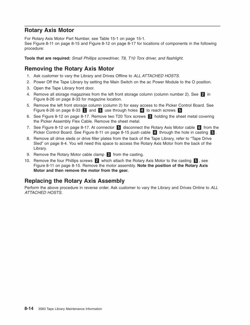
Rotary Axis Motor
For Rotary Axis Motor Part Number, see Table 15-1 on page 15-1.See Figure 8-11 on page 8-15 and Figure 8-12 on page 8-17 for locations of components in the following
procedure:
Tools that are required: Small Phillips screwdriver, T8, T10 Torx driver, and flashlight.
Removing the Rotary Axis Motor
1. Ask customer to vary the Library and Drives Offline to ALL ATTACHED HOSTS.
2. Power Off the Tape Library by setting the Main Switch on the ac Power Module to the O position.
3. Open the Tape Library front door.
4. Remove all storage magazines from the left front storage column (column number 2). See �2� in
Figure 8-26 on page 8-33 for magazine location.
5. Remove the left front storage column (column 2) for easy access to the Picker Control Board. See
Figure 8-26 on page 8-33 �1� and �5� use through holes �4� to reach screws �5�
6. See Figure 8-12 on page 8-17. Remove two T20 Torx screws �3� holding the sheet metal covering
the Picker Assembly Flex Cable. Remove the sheet metal.
7. See Figure 8-12 on page 8-17. At connector �5� disconnect the Rotary Axis Motor cable �6� from the
Picker Control Board. See Figure 8-11 on page 8-15 push cable �4� through the hole in casting �5�.
8. Remove all drive sleds or drive filler plates from the back of the Tape Library, refer to “Tape Drive
Sled” on page 8-4. You will need this space to access the Rotary Axis Motor from the back of the
Library.
9. Remove the Rotary Motor cable clamp �3� from the casting.
10. Remove the four Phillips screws �2� which attach the Rotary Axis Motor to the casting �5�, see
Figure 8-11 on page 8-15. Remove the motor assembly. Note the position of the Rotary Axis
Motor and then remove the motor from the gear.
Replacing the Rotary Axis Assembly
Perform the above procedure in reverse order. Ask customer to vary the Library and Drives Online to ALL
ATTACHED HOSTS.
8-14 3583 Tape Library Maintenance Information

a67m
0018
1 3 42 5
Figure 8-11. Rotary Axis Motor Removal and Replacement
Chapter 8. Check, Adjust, Remove, and Replace 8-15
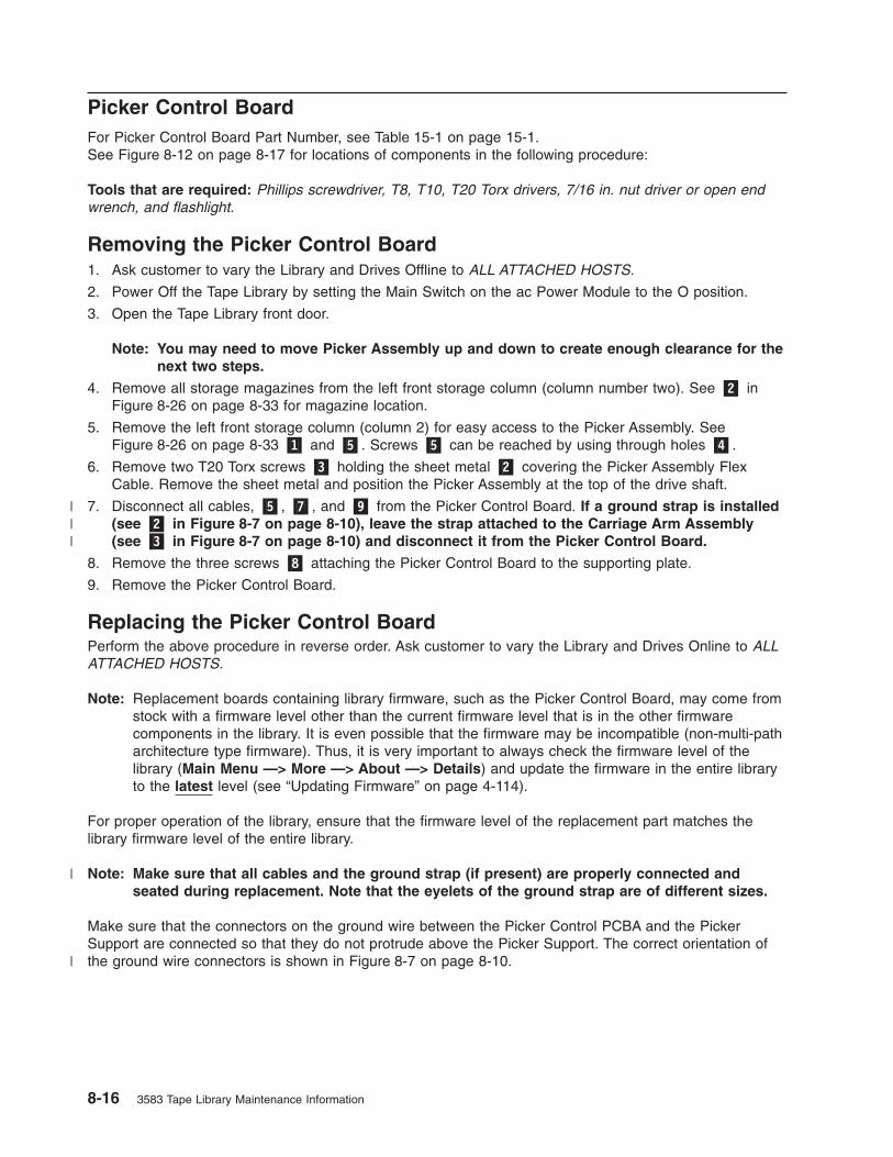
Picker Control Board
For Picker Control Board Part Number, see Table 15-1 on page 15-1.See Figure 8-12 on page 8-17 for locations of components in the following procedure:
Tools that are required: Phillips screwdriver, T8, T10, T20 Torx drivers, 7/16 in. nut driver or open end
wrench, and flashlight.
Removing the Picker Control Board
1. Ask customer to vary the Library and Drives Offline to ALL ATTACHED HOSTS.
2. Power Off the Tape Library by setting the Main Switch on the ac Power Module to the O position.
3. Open the Tape Library front door.
Note: You may need to move Picker Assembly up and down to create enough clearance for the
next two steps.
4. Remove all storage magazines from the left front storage column (column number two). See �2� in
Figure 8-26 on page 8-33 for magazine location.
5. Remove the left front storage column (column 2) for easy access to the Picker Assembly. See
Figure 8-26 on page 8-33 �1� and �5�. Screws �5� can be reached by using through holes �4�.
6. Remove two T20 Torx screws �3� holding the sheet metal �2� covering the Picker Assembly Flex
Cable. Remove the sheet metal and position the Picker Assembly at the top of the drive shaft.
7. Disconnect all cables, �5�, �7�, and �9� from the Picker Control Board. If a ground strap is installed
(see �2� in Figure 8-7 on page 8-10), leave the strap attached to the Carriage Arm Assembly
(see �3� in Figure 8-7 on page 8-10) and disconnect it from the Picker Control Board.
8. Remove the three screws �8� attaching the Picker Control Board to the supporting plate.
9. Remove the Picker Control Board.
Replacing the Picker Control Board
Perform the above procedure in reverse order. Ask customer to vary the Library and Drives Online to ALL
ATTACHED HOSTS.
Note: Replacement boards containing library firmware, such as the Picker Control Board, may come from
stock with a firmware level other than the current firmware level that is in the other firmware
components in the library. It is even possible that the firmware may be incompatible (non-multi-path
architecture type firmware). Thus, it is very important to always check the firmware level of the
library (Main Menu —> More —> About —> Details) and update the firmware in the entire library
to the latest level (see “Updating Firmware” on page 4-114).
For proper operation of the library, ensure that the firmware level of the replacement part matches the
library firmware level of the entire library.
Note: Make sure that all cables and the ground strap (if present) are properly connected and
seated during replacement. Note that the eyelets of the ground strap are of different sizes.
Make sure that the connectors on the ground wire between the Picker Control PCBA and the Picker
Support are connected so that they do not protrude above the Picker Support. The correct orientation of
the ground wire connectors is shown in Figure 8-7 on page 8-10.
8-16 3583 Tape Library Maintenance Information
|||
|
|

a67m
0019
1 2
6
7
4
5
8
9
2
3
Figure 8-12. Picker Control Board Removal and Replacement
Chapter 8. Check, Adjust, Remove, and Replace 8-17

Y-Axis Drive Belt
Notes:
1. For Y-Axis drive belt Part Number, see Table 15-1 on page 15-1.
2. Tools that are required: Small Phillips screwdriver, T10 and T20 Torx drivers, 11/32 in. and 3/16 in.
nut drivers, and flashlight.
Removing the Y-Axis Drive Belt
When Tape Library is installed in a rack, you must remove Library from the rack before continuing with this
procedure.
Attention: All drives and dc power supplies must be removed before Library is removed from rack.
Because of the Library weight you will need three people to lift the Library out of the rack after the drives
and dc power supplies are removed.
CAUTION:
The weight of this part or unit is more than 55 kilograms (121.2 pounds). It takes
specially trained persons and/or a lifting device to safely lift this part or unit.(C011)
1. Ask customer to vary the Library and Drives Offline to ALL ATTACHED HOSTS.
2. Power Off the Tape Library by setting the Main Switch on the ac Power Module to the O position.
3. You will need to remove storage column 2 (left front) and storage column 5 (right front) if present. To
do this see procedure remove the “Storage Columns” on page 8-32.
4. Remove all Drive Sleds and/or blank panels. Note position of drives so each drive will be inserted in
exactly the same position during replace procedure.
5. Perform Procedure Remove the “Power Distribution Board” on page 8-49.
6. If Library is in a rack, remove library from rack now.
7. See Figure 8-13. Remove the top cover being held to the chassis with three Phillips screws �1� in
front and four T10 Torx screws �2� in back. Newer models will have all seven screws Phillips head.
8. Position the Picker Assembly approximately half way between top and bottom chassis.
a67m
0063
1 2
Figure 8-13. Top Cover Removal. Figure shows converted library.
8-18 3583 Tape Library Maintenance Information

9. Remove the three Phillips screws attaching the drive shaft to the top of the chassis (See Figure 8-25
on page 8-31 �1�). From the front of the Library, unscrew the drive shaft counterclockwise out of the
chassis bottom.
See Figure 8-14 for step 10 through step 13:
10. Slide the Drive Shaft �2� up and out of Picker casting and on out through the top of library. Put the
shaft aside where it will not be nicked or scratched.
11. Disconnect the Y-Axis Flex Cable �6� from the Picker Control Board.
12. Remove the T20 Torx screw �1� which hold the Picker Assembly casting �3� and Picker Board to the
belt clamp plate.
13. Lift the whole Picker Assembly casting out of the belt clamp plate and the Picker Guide �5� out of
guide rail.
14. See Figure 8-15 on page 8-20 for this step. Pay particular attention to the clearance between two
ends of the belt �5� at the belt clamps before proceeding. You will need to maintain same clearance
between ends of the new belt. The plastic belt retainer �7� behind belt clamps �3� can fall off when
you remove the four belt clamp nuts. Be careful to save these belt clamps and retainer which will be
needed to maintain alignment of the new belt when installed. Remove four belt clamp nuts �4� by
using 3/16 in. nut driver.
a67m
0045
1 2 3
4
5
6
7
Figure 8-14. Y-Axis Drive Belt Removal and Replacement
Chapter 8. Check, Adjust, Remove, and Replace 8-19

Step 15 through step 16 will be accomplished at rear of the Library in area where you removed the
dc power supply or supplies.
15. See Figure 8-16. Loosen three Ny-lock nuts �2� (11/32 Nut driver) then loosen the tensioning screw
�1� (T20 Torx driver) to release the belt tension. Do not remove the tensioning screw or Ny-lock nuts.
You may have to loosen the two Phillips screws holding the Flex Cable clamp plate �1� shown
in Figure 8-19 on page 8-24 to loosen the belt tension.
16. Remove the drive belt. Go to “Replacing the Y-Axis Drive Belt” on page 8-21.
1
2
3
3 a67m
0046
4 4
5
6
7
8
Figure 8-15. Removing the belt clamps
1
2
3
a67m
0043
Figure 8-16. Tensioning screw and Ny-lock nuts
8-20 3583 Tape Library Maintenance Information

Replacing the Y-Axis Drive Belt
Note: Prior to installing the new belt, ensure that it is the same length as the old belt.
1. Step 2 through step 3 are accomplished at back of library.
2. See Figure 8-17. Take new belt so teeth are away from you. Thread one end over idler pulley �4� so
belt teeth mesh with idler pulley teeth. You will need to keep idler pulley from turning by using paper
to act as a brake.
3. Thread the other end of the belt �1� under drive pulley. Drive pulley �2� is located in the back at left
of the Y-Axis drive motor �3�.
4. Step 5 through 25 on page 8-23 will be done at front of the Library.
5. See Figure 8-18 on page 8-22. Find the ends of the Y-axis drive belt at top and bottom of the
retaining wall. Bring the top end of belt down behind belt clamp plate �2� and through slot �8� in the
belt clamp plate.
6. Retrieve plastic belt retainer �7� and clamps �3�.
7. Bring top belt end down over upper part of plastic belt retainer. Install upper belt clamp �3� but do not
install nuts. With belt clamp held in place align belt end with bottom of upper belt clamp. Now install
two of the 3/16 in. nuts and tighten to hold upper part of belt.
8. Now retrieve lower belt end and bring it up to lower part of plastic belt retainer �7�.
9. Ensure lower belt end is within 1/16 in. �5� of top end of belt at plastic belt retainer �7�.
10. Install lower belt clamp and remaining two 3/16 in. nuts �4� to retain lower portion of drive belt.
a67m
0068
1
2 3 4
Figure 8-17. Stud and Tension pulley
Chapter 8. Check, Adjust, Remove, and Replace 8-21
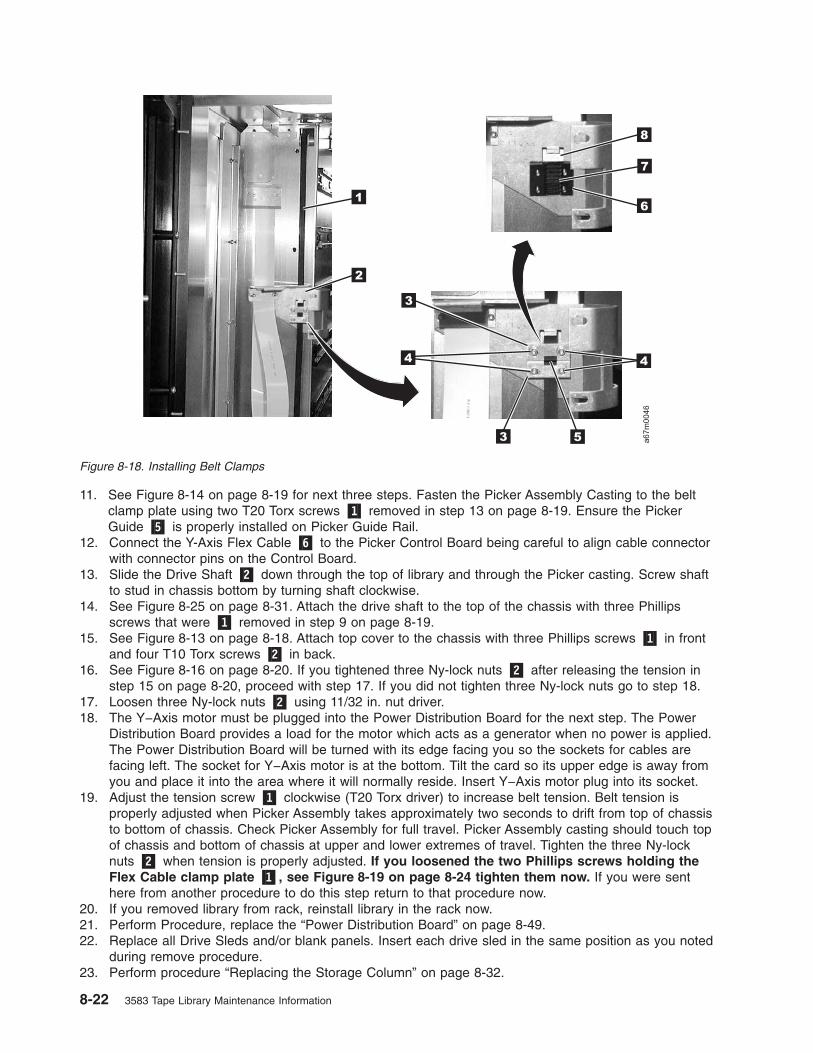
11. See Figure 8-14 on page 8-19 for next three steps. Fasten the Picker Assembly Casting to the belt
clamp plate using two T20 Torx screws �1� removed in step 13 on page 8-19. Ensure the Picker
Guide �5� is properly installed on Picker Guide Rail.
12. Connect the Y-Axis Flex Cable �6� to the Picker Control Board being careful to align cable connector
with connector pins on the Control Board.
13. Slide the Drive Shaft �2� down through the top of library and through the Picker casting. Screw shaft
to stud in chassis bottom by turning shaft clockwise.
14. See Figure 8-25 on page 8-31. Attach the drive shaft to the top of the chassis with three Phillips
screws that were �1� removed in step 9 on page 8-19.
15. See Figure 8-13 on page 8-18. Attach top cover to the chassis with three Phillips screws �1� in front
and four T10 Torx screws �2� in back.
16. See Figure 8-16 on page 8-20. If you tightened three Ny-lock nuts �2� after releasing the tension in
step 15 on page 8-20, proceed with step 17. If you did not tighten three Ny-lock nuts go to step 18.
17. Loosen three Ny-lock nuts �2� using 11/32 in. nut driver.
18. The Y−Axis motor must be plugged into the Power Distribution Board for the next step. The Power
Distribution Board provides a load for the motor which acts as a generator when no power is applied.
The Power Distribution Board will be turned with its edge facing you so the sockets for cables are
facing left. The socket for Y−Axis motor is at the bottom. Tilt the card so its upper edge is away from
you and place it into the area where it will normally reside. Insert Y−Axis motor plug into its socket.
19. Adjust the tension screw �1� clockwise (T20 Torx driver) to increase belt tension. Belt tension is
properly adjusted when Picker Assembly takes approximately two seconds to drift from top of chassis
to bottom of chassis. Check Picker Assembly for full travel. Picker Assembly casting should touch top
of chassis and bottom of chassis at upper and lower extremes of travel. Tighten the three Ny-lock
nuts �2� when tension is properly adjusted. If you loosened the two Phillips screws holding the
Flex Cable clamp plate �1�, see Figure 8-19 on page 8-24 tighten them now. If you were sent
here from another procedure to do this step return to that procedure now.
20. If you removed library from rack, reinstall library in the rack now.
21. Perform Procedure, replace the “Power Distribution Board” on page 8-49.
22. Replace all Drive Sleds and/or blank panels. Insert each drive sled in the same position as you noted
during remove procedure.
23. Perform procedure “Replacing the Storage Column” on page 8-32.
1
2
3
3 a67m
0046
4 4
5
6
7
8
Figure 8-18. Installing Belt Clamps
8-22 3583 Tape Library Maintenance Information

24. Power On the Tape Library by setting the Main Switch on the ac Input Power Module to the | position.
For switch location see Figure 8-43 on page 8-53.
25. Ask customer to vary the Library and Drives Online to ALL ATTACHED HOSTS.
Chapter 8. Check, Adjust, Remove, and Replace 8-23

Y-Axis Flex Cable
For Y-Axis flex cable Part Number see Table 15-1 on page 15-1.See Figure 8-19 for locations of components in the following procedure.Tools that are required: Phillips screwdriver, T8, T10 and T20 Torx drivers and flashlight.
Removing the Y-Axis Flex Cable
1. Perform Step 1 on page 8-11 through Step 11 on page 8-19 of Procedure “Removing the Y-Axis Drive
Belt” on page 8-18.
2. Remove the two Cable Clamp Plates �1�, see Figure 8-19.
3. Push the Y-Axis Flex Cable �2� to the back of the Library via the opening vacated by the Cable Clamp
Plate.
4. Remove the Y-Axis Flex Cable from the cable clamps.
5. Perform Procedure Remove the Main Controller Board (refer to “Removing the Main Controller Board”
on page 8-34) and disconnect the Y-axis Flex cable from the Main Controller Board.
6. From the back of the Library, slide the cable through the cable channel and remove it.
Replacing the Y-Axis Flex Cable
1. The replacement flex cable is not folded when it is shipped from the factory. Carefully fold
replacement cable by using fold marks on new cable and the old cable as a template.
2. Perform “Removing the Y-Axis Flex Cable” in reverse order.
3. Ensure Y−Axis drive belt tension is properly adjusted. To check and adjust belt tension see “Replacing
the Y-Axis Drive Belt” on page 8-21 step 18 on page 8-22. Return here after belt tension is properly
adjusted.
4. Power On the Tape Library by setting the Main Switch on the ac Input Power Module to the | position.
For switch location see Figure 8-43 on page 8-53.
5. Ask customer to vary the Library and Drives Online to ALL ATTACHED HOSTS..
a67m
0047
1
2
Figure 8-19. Y-Axis Flex Cable Removal and Replacement
8-24 3583 Tape Library Maintenance Information

Display Assembly Flex Cable
For Display Assembly Flex Cable Part Number see Table 15-1 on page 15-1.See Figure 8-20 for locations of components in the following procedure.Tools that are required: Phillips screwdriver, T8, T10 and T20 Torx drivers and flashlight.
Removing the Display Assembly Flex Cable
Perform Step 1 on page 8-11 through Step 12 on page 8-19 of Procedure “Removing the Y-Axis
Drive Belt” on page 8-18.
1. See Figure 8-20, remove the four screws �2� attaching the Cable cover �1� to the chassis.
2. Remove the display assembly flex cable from all the cable clamps.
3. See Figure 8-49 on page 8-60, remove four screws �2� and remove Lower Grill �3� from the Door
assembly.
4. Refer to Figure 8-21 on page 8-26 and remove the Display Assembly Flex Cable from the cable
clamps.
1
2
a67m
0048
Figure 8-20. Display Assembly Flex Cable Removal and Replacement
Chapter 8. Check, Adjust, Remove, and Replace 8-25
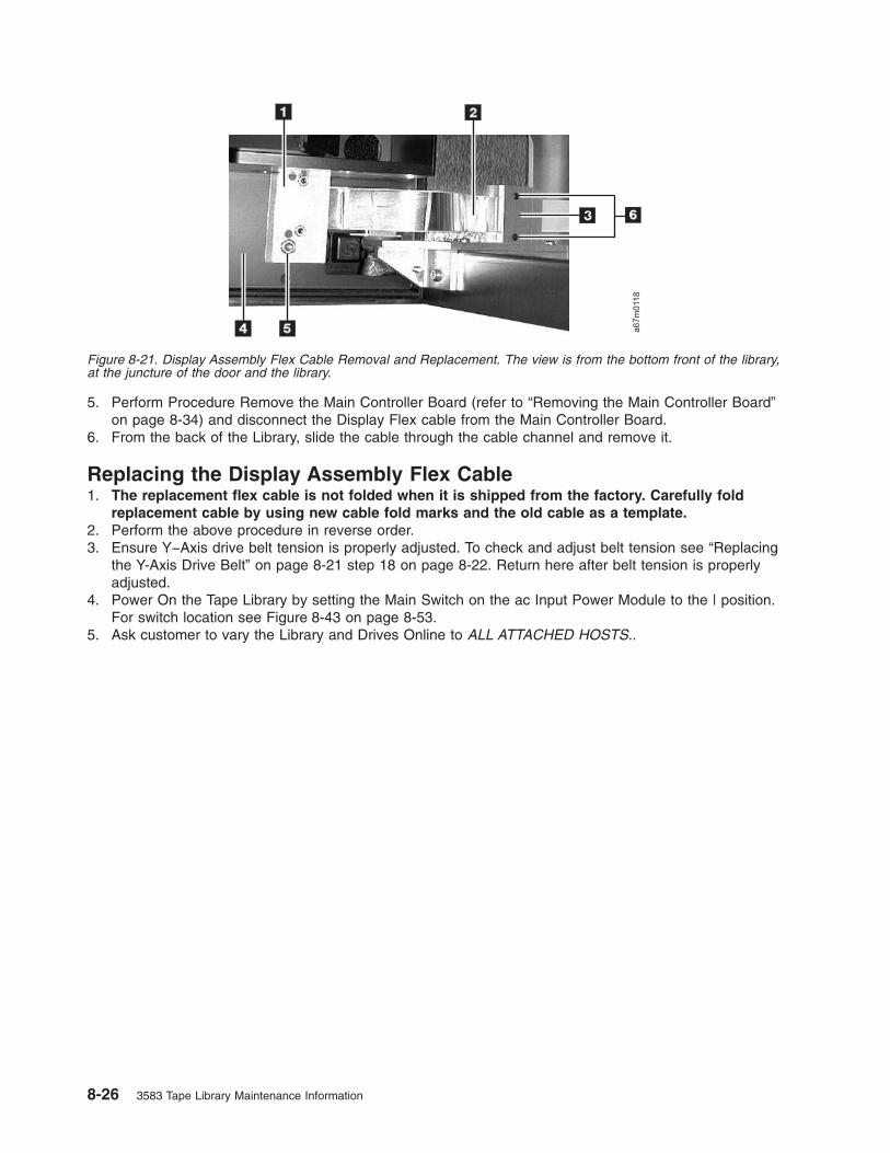
5. Perform Procedure Remove the Main Controller Board (refer to “Removing the Main Controller Board”
on page 8-34) and disconnect the Display Flex cable from the Main Controller Board.
6. From the back of the Library, slide the cable through the cable channel and remove it.
Replacing the Display Assembly Flex Cable
1. The replacement flex cable is not folded when it is shipped from the factory. Carefully fold
replacement cable by using new cable fold marks and the old cable as a template.
2. Perform the above procedure in reverse order.
3. Ensure Y−Axis drive belt tension is properly adjusted. To check and adjust belt tension see “Replacing
the Y-Axis Drive Belt” on page 8-21 step 18 on page 8-22. Return here after belt tension is properly
adjusted.
4. Power On the Tape Library by setting the Main Switch on the ac Input Power Module to the | position.
For switch location see Figure 8-43 on page 8-53.
5. Ask customer to vary the Library and Drives Online to ALL ATTACHED HOSTS..
Figure 8-21. Display Assembly Flex Cable Removal and Replacement. The view is from the bottom front of the library,
at the juncture of the door and the library.
8-26 3583 Tape Library Maintenance Information

Main Controller to Power Distribution Cables (Power or Signal
Interface)
There are two cables between the Main Controller Board and the Power Distribution Board. One carries
power distribution and the other provides the signal interface. For Part Numbers, see Table 15-1 on page
15-1.Tools that are required: Phillips screwdriver, T10, T20 Torx drivers and flashlight.
Removing the Main to Power Distribution Cables
1. Ask customer to vary the Library and Drives Offline to ALL ATTACHED HOSTS.
2. Power Off the Tape Library by setting the Main Switch on the ac Power Module to the O position.
3. Perform Procedure Remove the “dc Power Supply” on page 8-54.
4. Perform Procedure Remove the “ac Input Power Module” on page 8-53.
5. Disconnect the failing cable (either Power �6� or Signal �5� Interface) from the Power Distribution
Board. (See Figure 8-22).
6. Disconnect all SCSI cables at the Library Host Interface Board (SCSI).
7. Loosen the two captive screws on the Host Interface Board (SCSI). (See Figure 8-37 on page 8-45
�1�), then remove the Host Interface Board (SCSI) from the Main Controller Board.
8. (See Figure 8-27 on page 8-35). Remove the T8 Torx screw �2� holding the Main Controller Board to
the Library chassis. Now slide the Main Controller Board partially out of the guiding tracks �3�.
9. (See Figure 8-22), disconnect failing cable, (Power �2� or Signal �1�), from Main Controller Board.
10. Slide cable through the cable channel and remove it.
Replacing the Main to Power Distribution Cables
Perform the above procedure in reverse order. The replacement flex cable is not folded when it is
shipped from the factory. Carefully fold the replacement cable by using the fold marks and the old
cable as a template. Ask customer to vary the Library and Drives Online to ALL ATTACHED HOSTS.
a67m
0071
64 5
1 2 3
Figure 8-22. Main to Power Distribution Cables Removal and Replacement
Chapter 8. Check, Adjust, Remove, and Replace 8-27

Power Distribution to Drive Sled Cable
There are six cables between the Power Distribution Board and the six Drive Sleds, each one can be
replaced independently of the others. For cable part numbers see Table 15-1 on page 15-1.See Figure 8-23 for locations of components in the following procedure.Tools that are required: Phillips screwdriver, T8 Torx driver and flashlight.
Removing the Power Distribution to Drive Sled Cable
1. Ask customer to vary the Library and Drives Offline to ALL ATTACHED HOSTS.
2. Power Off the Tape Library by setting the Main Switch on the ac Power Module to the O position.
3. Remove the Drive Sled associated with the failing cable. See Procedure Remove the “Tape Drive Sled”
on page 8-4.
4. Remove all dc Power Supplies or Power Supply Filler Plate, see “Removing the dc Power Supply” on
page 8-55.
5. Perform Procedure Remove the “ac Input Power Module” on page 8-53.
6. See Figure 8-23 for step 6 through step 9. Disconnect the failing cable �2� from the Power Distribution
Board.
7. Remove the cable clamp �3� from the chassis.
8. Remove the Phillips screw and Torx screw �1� and �4�.
9. Push the connector and its bracket through the hole and remove the cable.
Replacing the Power Distribution to Drive Sled Cable
Perform the above procedure in reverse order. Ask customer to vary the Library and Drives Online to ALL
ATTACHED HOSTS.
a67m
0062
1
2
34
Figure 8-23. Power Distribution to Drive Sled Cable Removal and Replacement
8-28 3583 Tape Library Maintenance Information

Y-Axis Motor Assembly
For Y-Axis motor part number, see Table 15-1 on page 15-1.See Figure 8-24 on page 8-30 for locations of components in the following procedure.Tools that are required: Phillips screwdriver, 11/32 in. Nut driver, T10 & T20 Torx drivers and flashlight.
Removing the Y-Axis Motor Assembly
1. Ask customer to vary the Library and Drives Offline to ALL ATTACHED HOSTS.
2. Power Off the Tape Library by setting the Main Switch on the ac Power Module to the O position.
3. Perform Procedure Remove the “dc Power Supply” on page 8-54.
4. Perform Procedure Remove the “ac Input Power Module” on page 8-53.
5. Perform Procedure Remove the “Power Distribution Board” on page 8-49.
6. Use Figure 8-16 on page 8-20, loosen the three Ny-lock nuts �2� (11/32 in. Nut driver) then loosen
the tensioning screw �1� clockwise (T20 Torx driver) to release the belt tension. Do not remove the
screws. You may have to loosen the two Phillips screws holding the Flex Cable clamp plate, see
Figure 8-14 on page 8-19 to loosen the belt tension.
7. Remove the two screws �3� attaching the Y-Axis motor assembly to the chassis.
Note: A long shaft T20 Torx screw driver may be required.
8. Remove the motor Assembly �2� from the belt.
Replacing the Y-Axis Motor Assembly
1. Perform the above procedure in reverse order.
2. Ensure Y−Axis drive belt tension is properly adjusted. To check and adjust belt tension see “Replacing
the Y-Axis Drive Belt” on page 8-21 step 18 on page 8-22. Return here after belt tension is properly
adjusted.
3. Power On the Tape Library by setting the Main Switch on the ac Input Power Module to the | position.
For switch location see Figure 8-43 on page 8-53.
4. Ask customer to vary the Library and Drives Online to ALL ATTACHED HOSTS..
Chapter 8. Check, Adjust, Remove, and Replace 8-29

Y-Axis Drive Shaft Assembly
Note: If the library is installed in a rack, you must slide it out prior to performing this procedure.See Figure 8-25 on page 8-31 for locations of components in this procedure.Tools that are required: Phillips screwdriver, T10 Torx driver.
Removing the Vertical Axis Drive Shaft
1. Ask customer to vary the Library and Drives Offline to ALL ATTACHED HOSTS.
2. Power Off the Tape Library by setting the Main Switch on the ac Power Module to the O position.
3. Open the front door of the Library and remove storage column two (left front). See Procedure Remove
the “Storage Columns” on page 8-32.
4. Remove the top cover. The top cover is attached to the chassis with three Phillips screws on the front
and four T10 Torx screws in the back.
5. Remove the three Phillips screws �1� attaching the drive shaft to the top of the chassis. From the front
of the Library, unscrew the drive shaft �2� counterclockwise out of the chassis bottom.
6. Lift the Drive Shaft �2� out of the Picker Assembly casting and remove the Drive shaft through the top
of the chassis.
Replacing the Vertical Axis Drive Shaft Assembly
Perform the above procedure in reverse order. Ask customer to vary the Library and Drives Online to ALL
ATTACHED HOSTS.
a67m
0020
1
2
3
Figure 8-24. Y-Axis Motor Assembly Removal and Replacement
8-30 3583 Tape Library Maintenance Information

a67m
0053
2
1
Figure 8-25. Y-Axis Drive Shaft Removal and Replacement
Chapter 8. Check, Adjust, Remove, and Replace 8-31

Storage Columns
For Storage Columns Part Number, see Table 15-1 on page 15-1.See Figure 8-26 on page 8-33 for locations of components in the following procedure.Tools that are required: 11-mm or 7/16-in. Nut driver, allen wrench or T20 Torx and flashlight.
Removing the Storage Column
1. Ask customer to vary the Library and Drives Offline to ALL ATTACHED HOSTS.
2. Power Off the Tape Library by setting the Main Switch on the ac Power Module to the O position.
3. Open the Tape Library front door.
4. Note magazine positions so you can return each magazine to the same position. Remove all storage
magazines �2� from the column you wish to remove. In order to remove the bottom tape magazines,
you will have to manually raise the picker robotic system out of the way.
5. Remove the top bolt �1� by using the 7/16 in. Nut driver.
6. Perform one of the following two steps depending on the column you are removing:
a. Remove columns 2 or 4, using Torx or allen wrench to remove two bottom screws �5�. These two
screws can be reached by using the through holes �4�.
b. If you are removing column 5, use the 7/16 in. nut driver to remove the bolt �3� attaching the
storage column to the bracket.7. If necessary, move the picker assembly to a position in the vertical axis to allow access to the storage
column. Gently slide the storage column out of the library front door. See Figure 7-7 on page 7-8. It
may be easier to remove the storage column 2 if the bar code reader cover �4� is removed from
the Picker Assembly.
Replacing the Storage Column
See Table 15-1 on page 15-1 for the correct Part Number. Perform the above procedure in reverse order.
Make sure that you install the storage column in front of the mounting bracket of the library (see top
picture in Figure 8-26 on page 8-33). Replace magazines in same positions as noted in step 4. Ask
customer to vary the Library and Drives Online to ALL ATTACHED HOSTS. Be sure to reteach and
reinventory the Library by using the Operator Panel if these options are not set automatically.
8-32 3583 Tape Library Maintenance Information
||
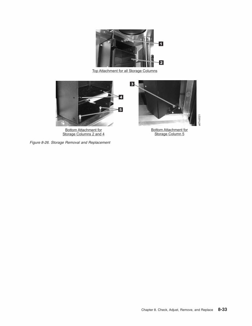
a67m
0021
1
2
Top Attachment for all Storage Columns
Bottom Attachment forStorage Columns 2 and 4
Bottom Attachment forStorage Column 5
3
4
5
Figure 8-26. Storage Removal and Replacement
Chapter 8. Check, Adjust, Remove, and Replace 8-33

Main Controller Board
Note: Do not exchange the Main Controller Board, Remote Management Unit, or Display Assembly in the
same operation. Instead, exchange one card and determine whether the problem still exists. If so,
reinstall the original card before exchanging the other cards. This is necessary to avoid loss of all
configuration settings and library VPD.
For Main Controller Board Part Number, see Table 15-1 on page 15-1.See Figure 8-27 on page 8-35 for locations of components in the following procedure.Before doing the following remove procedure, if possible, retrieve all Tape Library Subsystem
configuration data such as SCSI ID. Using the Setup option on operator panel (Main Menu
—>Setup —>Library).Tools that are required: Phillips screwdriver, T8 Torx driver and flashlight.
Removing the Main Controller Board
1. Ask customer to vary the Library and Drives Offline to ALL ATTACHED HOSTS.
2. Power Off the Tape Library by setting the Main Switch on the ac Power Module to the O position.
3. Loosen the two captive screws on the Serial Diagnostic Port Board (or Host SCSI Interface Board in a
converted library), (See Figure 8-37 on page 8-45 �1�), then remove the Host SCSI Interface Board
from the Main Board.
4. (See Figure 8-27 on page 8-35). Remove the T8 Torx screw �2� holding the Main Controller Board to
the Library chassis. Now slide the Main Controller Board partially out of the guiding tracks �3�.
5. Disconnect all cables from the Main Controller Board.
6. Remove the Main Controller Board and its supporting plate.
Replacing the Main Controller Board
Perform the removal steps in reverse order.
v Replacement boards containing library firmware, such as the Main Controller Board, may come from
stock with a firmware level other than the current firmware level that is in the other firmware
components in the library. It is even possible that the firmware may be incompatible (non-multi-path
architecture type firmware). Thus, it is very important to always check the firmware level of the library
(Main Menu —> More —> About —> Details) and update the firmware in the entire library to the
latest level (see “Updating Firmware” on page 4-114).
For proper operation of the library, ensure that the firmware level of the replacement part matches the
library firmware level of the entire library.
Note: The boot code of the new part does not have to match the boot code of the other parts in the
library.
v For libraries with the Multi-Path feature, the library serial number to be stored on the new main
controller board is determined internally by arbitration firmware because the serial number is stored in
several library locations. If the arbitration firmware cannot determine the serial number through
arbitration, the firmware displays the choices on the operator panel and instructs the operator to choose
the correct one.
v Ask customer to vary the Library and Drives Online to ALL ATTACHED HOSTS.
8-34 3583 Tape Library Maintenance Information
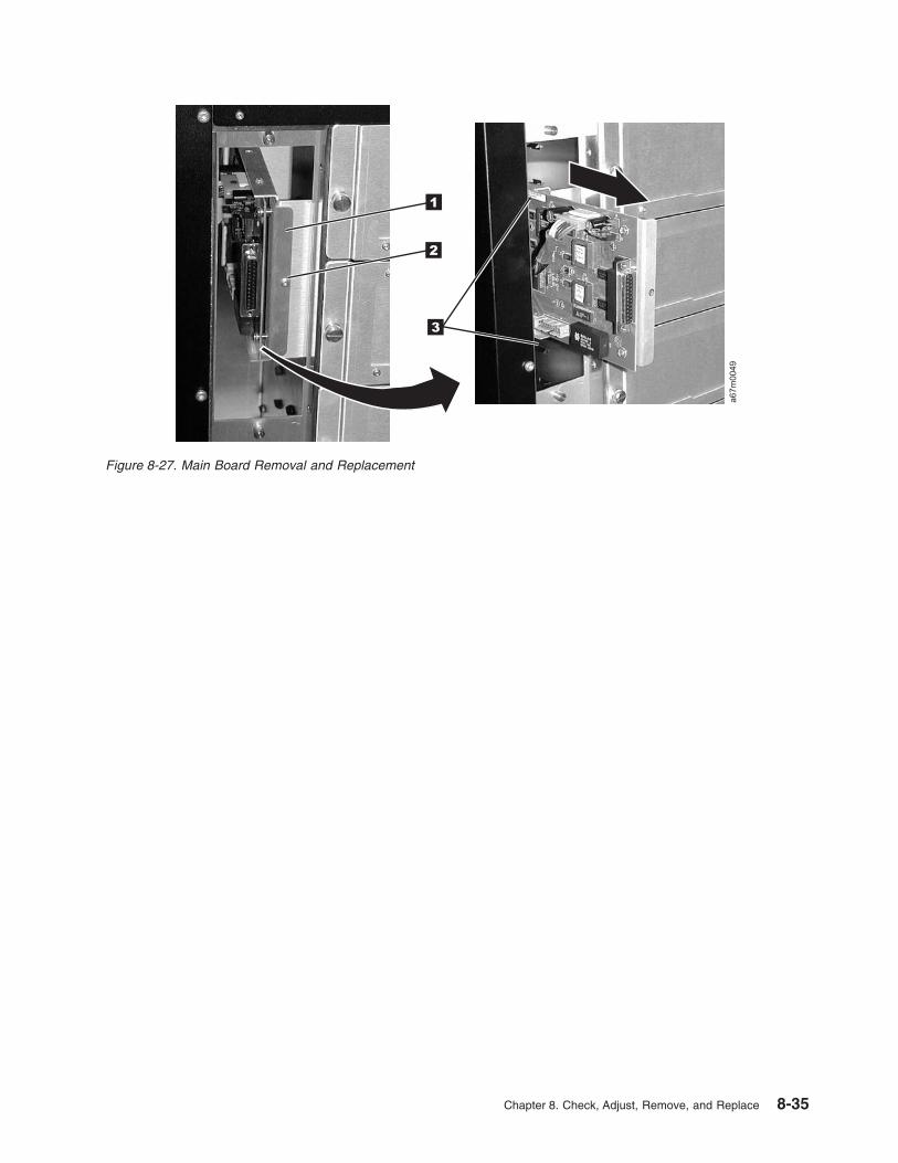
1
2
a67m
0049
3
Figure 8-27. Main Board Removal and Replacement
Chapter 8. Check, Adjust, Remove, and Replace 8-35

RMU Network Interface Cable
For RMU Network Interface Cable Part Number, see Table 15-1 on page 15-1.Tools that are required: T8 Torx drivers and 11/32 in. nut driver.
Removing the RMU Interface Cable
1. Perform the procedure for removing the SAN Data Gateway Module. See “SAN Data Gateway Module”
on page 8-41.
2. Perform the procedure for removing the RMU. See “Remote Management Unit” on page 8-39.
3. Remove the two T8 Torx screws (�1� in Figure 8-28) that secure the Lower Fibre Channel Bracket
Sub-Assembly to the chassis, then remove the bracket from the chassis.
4. Remove the 11/32 nut �2� that secures the RMU Interface Cable to the rear of the chassis.
Figure 8-28. Removing the Lower Fibre Channel Bracket Sub-Assembly
8-36 3583 Tape Library Maintenance Information

5. Remove the two T8 Torx screws (�1� in Figure 8-29) that secure the RMU Bracket Sub-Assembly to
the bottom of the chassis and slide the bracket out of the chassis.
6. Remove the two T8 Torx screws �2� that secure the RMU Interface Cable connector to the RMU
Bracket Sub-Assembly and disconnect the RMU Interface Cable from the RMU Bracket Sub-Assembly.
7. Remove the T8 Torx screw (�1� in Figure 8-30) holding the Main Controller PCBA to the library chassis
and slide the Main Controller PCBA partly out of the guiding tracks.
8. Disconnect the RMU Interface Cable from the Main Controller PCBA and remove the RMU Interface
Cable �2�.
Figure 8-29. View of the RMU Bracket Sub-Assembly and RMU Interface Cable Connector
Figure 8-30. Sliding the Main Controller PCBA Out of the Guiding Tracks
Chapter 8. Check, Adjust, Remove, and Replace 8-37

9. Remove the cable clamp from the old RMU Interface Cable and reattach the clamp to the new RMU
Interface Cable.
Replacing the RMU Interface Cable
Perform the removal steps in reverse order. Be careful not to bend pins when connecting cables.
8-38 3583 Tape Library Maintenance Information

Remote Management Unit
Note: Do not exchange the Main Controller Board, Remote Management Unit, or Display Assembly in the
same operation. Instead, exchange one card and determine whether the problem still exists. If so,
reinstall the original card before exchanging the other cards. This is necessary to avoid loss of all
configuration settings and library VPD.
For RMU Part Number, see Table 15-1 on page 15-1.See Figure 8-31 for locations of components in the following procedure.Tools that are required: Phillips Screwdriver (0).
Remove RMU
1. See Figure 8-31 for RMU location in library.
2. Ensure the RMU �1� is dormant.
3. Disconnect the customer’s Ethernet cable from the RMU.
4. Loosen the thumbscrew �2� on the RMU and slide unit out of library.
Replace RMU
1. See Figure 8-32 on page 8-40 for the next steps. Before you install the RMU in the library look into the
end of the RMU and verify that the four jumpers are located as shown in detail �3�.
2. Slide the RMU �1� into the library and tighten the thumbscrew �2�.
3. Connect the network cable to RMU.
4. Ensure the RMU firmware is the latest by checking the IBM web site
(http://www.ibm.com/storage/lto). See “Updating Firmware” on page 4-114 for updating RMU
firmware.
5. Advise the customer that the RMU is available for configuration. For instructions, refer the customer to
the section about configuring the RMU in the installation chapter of the IBM TotalStorage 3583 Tape
Library Setup and Operator Guide.
a67m
0076
1
2
Figure 8-31. RMU
Chapter 8. Check, Adjust, Remove, and Replace 8-39

a67m
0074
1 2
3
Figure 8-32. RMU Jumpers
8-40 3583 Tape Library Maintenance Information
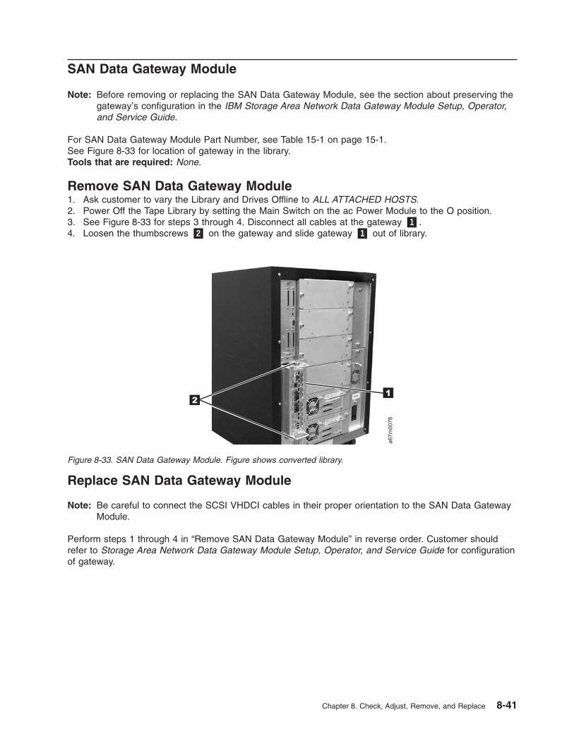
SAN Data Gateway Module
Note: Before removing or replacing the SAN Data Gateway Module, see the section about preserving the
gateway’s configuration in the IBM Storage Area Network Data Gateway Module Setup, Operator,
and Service Guide.
For SAN Data Gateway Module Part Number, see Table 15-1 on page 15-1.See Figure 8-33 for location of gateway in the library.Tools that are required: None.
Remove SAN Data Gateway Module
1. Ask customer to vary the Library and Drives Offline to ALL ATTACHED HOSTS.
2. Power Off the Tape Library by setting the Main Switch on the ac Power Module to the O position.
3. See Figure 8-33 for steps 3 through 4. Disconnect all cables at the gateway �1�.
4. Loosen the thumbscrews �2� on the gateway and slide gateway �1� out of library.
Replace SAN Data Gateway Module
Note: Be careful to connect the SCSI VHDCI cables in their proper orientation to the SAN Data Gateway
Module.
Perform steps 1 through 4 in “Remove SAN Data Gateway Module” in reverse order. Customer should
refer to Storage Area Network Data Gateway Module Setup, Operator, and Service Guide for configuration
of gateway.
a67m
0078
12
Figure 8-33. SAN Data Gateway Module. Figure shows converted library.
Chapter 8. Check, Adjust, Remove, and Replace 8-41
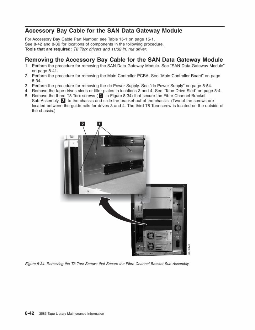
Accessory Bay Cable for the SAN Data Gateway Module
For Accessory Bay Cable Part Number, see Table 15-1 on page 15-1.
See 8-42 and 8-36 for locations of components in the following procedure.Tools that are required: T8 Torx drivers and 11/32 in. nut driver.
Removing the Accessory Bay Cable for the SAN Data Gateway Module
1. Perform the procedure for removing the SAN Data Gateway Module. See “SAN Data Gateway Module”
on page 8-41.
2. Perform the procedure for removing the Main Controller PCBA. See “Main Controller Board” on page
8-34.
3. Perform the procedure for removing the dc Power Supply. See “dc Power Supply” on page 8-54.
4. Remove the tape drives sleds or filler plates in locations 3 and 4. See “Tape Drive Sled” on page 8-4.
5. Remove the three T8 Torx screws (�1� in Figure 8-34) that secure the Fibre Channel Bracket
Sub-Assembly �2� to the chassis and slide the bracket out of the chassis. (Two of the screws are
located between the guide rails for drives 3 and 4. The third T8 Torx screw is located on the outside of
the chassis.)
Figure 8-34. Removing the T8 Torx Screws that Secure the Fibre Channel Bracket Sub-Assembly
8-42 3583 Tape Library Maintenance Information

6. Disconnect the Accessory Bay Cable (�1� in Figure 8-35) from the Fibre Channel Bracket
Sub-Assembly. If necessary, cut the cable connector locking tabs.
Figure 8-35. Disconnecting the accessory bay cable from the Fibre Channel bracket sub-assembly. Figure shows a
converted library.
Chapter 8. Check, Adjust, Remove, and Replace 8-43

7. Disconnect the Accessory Bay Cable from the Power Distribution PCBA (�1� in Figure 8-36). Remove
the Accessory Bay Cable by sliding it through the cable channel.
Replacing the Accessory Bay Cable for the SAN Data Gateway Module
Perform the removal steps in reverse order.
Note: The Accessory Bay Cable is routed behind the ribbon cables that connect to the Main Controller
PCBA. Also, because alignment of the Torx screws between the guide rails for tape drive sleds 3
and 4 may be difficult when reinstalling the Fibre Channel Sub-Assembly, start the Torx screws by
hand to ensure the bracket is properly fitted.
Figure 8-36. Disconnecting the accessory bay cable from the power distribution PCBA. Figure shows a converted
library.
8-44 3583 Tape Library Maintenance Information

Host SCSI Interface Board
For Host SCSI Interface Board Part Number, see Table 15-1 on page 15-1.See Figure 8-37 for locations of components in the following procedure.Tools that are required: Phillips screwdriver.
Note: The Host SCSI Interface Board is a required board for a non-multi-path library. The only function of
this board in a multi-path library is the serial port. If the serial port become defective, the board is to
be replaced by the Serial Diagnostic Port Board (see 8-46).
Removing the Host SCSI Interface Board
1. Ask customer to vary the Library and Drives Offline to ALL ATTACHED HOSTS.
2. Power Off the Tape Library by setting the Main Switch on the ac Power Module to the O position.
3. Loosen the two captive screws �1� on the Host SCSI Interface Board. Remove the Host SCSI
Interface Board from the Main Board.
Replacing the Host SCSI Interface Board
Replace this board with the Serial Diagnostic Port Board (see 8-46). Ask customer to vary the Library and
Drives Online to ALL ATTACHED HOSTS.
1
a67m
0050
Figure 8-37. Host SCSI Interface Board. This board will be present in a converted library; however, only the serial port
will be utilized.
Chapter 8. Check, Adjust, Remove, and Replace 8-45

Serial Diagnostic Port Board
For Host SCSI Interface Board Part Number, see Table 15-1 on page 15-1.See Figure 8-37 on page 8-45 for locations of components in the following procedure.Tools that are required: Phillips screwdriver.
Removing the Serial Diagnostic Port Board
1. Ask customer to vary the Library and Drives Offline to ALL ATTACHED HOSTS.
2. Power Off the Tape Library by setting the Main Switch on the ac Power Module to the O position.
3. Loosen the two captive screws �1� on the Serial Diagnostic Port Board. Remove the Serial Diagnostic
Port Board from the Main Board.
Replacing the Serial Diagnostic Port Board
Perform the removal steps in reverse order. Ask customer to vary the Library and Drives Online to ALL
ATTACHED HOSTS.
Figure 8-38. Serial Diagnostic Port Board Removal and Replacement
8-46 3583 Tape Library Maintenance Information

Display Assembly
Note: Do not exchange the Main Controller Board, Remote Management Unit, or Display Assembly in the
same operation. Instead, exchange one card and determine whether the problem still exists. If so,
reinstall the original card before exchanging the other cards. This is necessary to avoid loss of all
configuration settings and library VPD.
For Display Assembly Part Number, see Table 15-1 on page 15-1.Tools that are required: Phillips screwdriver and T8 Torx driver.See Figure 8-39 on page 8-48 for locations of components in the following procedure.
Removing the Display Assembly
1. Ask customer to vary the Library and Drives Offline to ALL ATTACHED HOSTS.
2. Power Off the Tape Library by setting the Main Switch on the ac Power Module to the O position.
3. Open the Tape Library front door.
4. Remove the six T8 Torx screws holding the Display Assembly to the front door. Refer to �1� in
Figure 8-47 on page 8-58 for locations of these screws.
5. Disconnect cables �3� and �6� from the Display Control Board. Be careful not to bend pins when
disconnecting cables.
6. Remove the Display Assembly.
Replacing the Display Assembly
Perform the removal steps in reverse order. Be careful not to bend pins when connecting cables.
Note: Replacement boards containing library firmware, such as the Display Assembly, may come from
stock with a firmware level other than the current firmware level that is in the other firmware
components in the library. It is even possible that the firmware may be incompatible (non-multi-path
architecture type firmware). Thus, it is very important to always check the firmware level of the
library (Main Menu —> More —> About —> Details) and update the firmware in the entire library
to the latest level (see “Updating Firmware” on page 4-114).
For proper operation of the library, ensure that the firmware level of the replacement part matches the
firmware level of the entire library.
Note: The boot code of the new part does not have to match the boot code of the other parts in the
library.
Chapter 8. Check, Adjust, Remove, and Replace 8-47

a67m
0022
1 2 3 4
5678
Figure 8-39. Display Assembly Removal and Replacement
8-48 3583 Tape Library Maintenance Information

Power Distribution Board
For Type II and Type I Power Distribution Board Part Numbers, see Table 15-1 on page 15-1.See Figure 8-40 on page 8-50 for locations of components in the following procedure.Tools that are required: Phillips screwdriver, T8 Torx driver, 11/32 in. open wrench and flashlight.
Removing the Power Distribution Board
1. Ask customer to vary the Library and Drives Offline to ALL ATTACHED HOSTS.
2. Power Off the Tape Library by setting the Main Switch on the ac Power Module to the O position.
3. Perform Procedure Remove the “dc Power Supply” on page 8-54.
4. Perform Procedure Remove the “ac Input Power Module” on page 8-53.
5. Remove drive sleds in positions 3, 4, and 5 to access bracket screws.
6. Remove four screws �1� then remove bracket �2�.
7. Disconnect all cables on the side of the Power Distribution Board facing you. There are:
a. Six Drive sled cables �8�.
b. Two cables from the Main Controller Board �3� (Power and Signal).
c. The Y-Axis Motor Assembly cable �6�.
d. San Appliance Module power cable (only on Type II board) �11�. 8. Using 11/32 in. wrench, remove four nuts �7� holding Power Distribution Board to chassis wall.
9. Lift Power Distribution Board out of the mounting studs �7� and rotate its right side toward you. Be
persistent this is a tight fit.
10. Tilt the bottom of Board slightly toward you to remove it.
11. Remove and retain seven screws �9� holding the metal bracket �10� to board you just removed. Use
screws �9� to attach bracket �10� to the Type II board.
Replacing the Power Distribution Board
Perform the above procedure in reverse order. Ask customer to vary the Library and Drives Online to ALL
ATTACHED HOSTS.
Chapter 8. Check, Adjust, Remove, and Replace 8-49

12-Slot I/O Station
For I/O station assembly part number, see Table 15-1 on page 15-1.Tools that are required: T20 Torx driver and 11/32 in. nut driver.
Removing the I/O Station
1. Ask customer to vary the Library and Drives Offline to ALL ATTACHED HOSTS.
2. Power Off the Tape Library by setting the Main Switch on the ac Power Module to the O position.
3. Open the Tape Library front door.
4. Remove all magazines (if present) �4�, �5� and cartridges from the I/O Station.
5. See Figure 8-41 on page 8-51, disconnect the I/O Station cable harness �3� from the Display
Assembly �2� by disconnecting cable connector �7�.
6. Remove the four I/O Station cable clamps �1�. Three of the cable clamps are attached to the door
using T20 Torx screws and one is attached with a 11/32 in. nut.
7. Remove eight 11/32 in. nuts �6�, four on each side holding the I/O Station assembly �4� to the front
door.
8. Remove the I/O Station.
Replacing the I/O Station
Perform the above procedure in reverse order. Ask customer to vary the Library and Drives Online to ALL
ATTACHED HOSTS.
Figure 8-40. Power Distribution Board Removal and Replacement
8-50 3583 Tape Library Maintenance Information

a67m
0025
1 1
6
2 3
57
4
Figure 8-41. I/O Station Removal and Replacement
Chapter 8. Check, Adjust, Remove, and Replace 8-51

Single-Slot I/O Station
For I/O station assembly part number, see Table 15-1 on page 15-1.Tools that are required: T20 Torx driver and 11/32 in. nut driver.
Removing the I/O Station
1. Ask customer to vary the Library and Drives Offline to ALL ATTACHED HOSTS.
2. Power Off the Tape Library by setting the Main Switch on the ac Power Module to the O position.
3. Open the Tape Library front door.
4. See Figure 8-42, if a cartridge is present at the I/O Station �3�, remove cartridge.
5. See Figure 8-41 on page 8-51, disconnect the I/O Station cable harness �3� from the Display
Assembly �2� by disconnecting cable connector �7�.
6. Remove the four I/O Station cable clamps �1�. Three of the cable clamps are attached to the door
using T20 Torx screws and one is attached with a 11/32 in. nut.
7. Remove eight 11/32 nuts �6�, four on each side holding the I/O Station assembly �4� to the front door.
8. Remove the I/O Station.
Replacing the I/O Station
Perform the above procedure in reverse order. Ask customer to vary the Library and Drives Online to ALL
ATTACHED HOSTS.
a67m
0072
4
1 2
3
Figure 8-42. I/O Station, Single Slot
8-52 3583 Tape Library Maintenance Information

Power Supplies Check Procedure
1. Check dc Power Supply by observing light-emitting diode (LED) indicator located on the back of each
installed Power Supply, refer to Figure 7-17 on page 7-18. If this LED is RED, replace the Power
Supply by using Procedure “dc Power Supply” on page 8-54.
2. Problem which sent you here may be caused by blown fuses (5A) on the ac Input Power Module.
Refer to Figure 8-43 for location of fuses. If fuses are blown, replace fuses and power up the Library. If
fuses continue to blow, perform Procedure Remove the “ac Input Power Module.”
Power
ac Input Power Module
See Table 15-1 on page 15-1 for ac Power Input Module Part Number.See Figure 8-43 for locations of components in the following procedure.Tools that are required: T8 Torx driver.
Removing the ac Input Module
1. Ask customer to vary the Library and Drives Offline to ALL ATTACHED HOSTS.
2. Power Off the Tape Library by setting the Main Switch on the ac Power Module to the O position.
3. Disconnect the mainline ac power cable �5� from the ac Input Power Module.
4. Slide the fuse holder �3� out to the stop. Allow fuse holder to tilt down.
5. Check the fuses �3� and replace them if necessary.
6. If you replaced fuses in step 5 and fixed the problem go to “Replacing the ac Input Module.” Otherwise
proceed with step 7.
7. Slide fuse holder back into the receptacle. Remove the two Torx screws �4� fastening the ac Power
Module to the chassis.
8. Slide the ac Input Module �1� away from the frame and remove the ac Input Module.
Replacing the ac Input Module
Perform above procedure in reverse order. Ask customer to vary the Library and Drives Online to ALL
ATTACHED HOSTS.
a67m
0026
1
2
3
4
5
3
Figure 8-43. ac Input Module Removal and Replacement
Chapter 8. Check, Adjust, Remove, and Replace 8-53

dc Power Supply
Attention: Up to 240 V ac is present at the power module connectors when the main power
cord is connected to a power source. (RSFTD010)
This procedure removes and replaces the dc Power Supply or either supply if redundant supply is present.See Table 15-1 on page 15-1 for dc Power Supply Part Number.See Figure 8-45 on page 8-56 for locations of components in the following procedure.Tools that are required: None.
Verifying dc Power Supply Level
Before replacing a dc Power Supply in the Tape Library, verify that you have the correct dc Power Supply.
1. From the rear of the library, locate the one or two dc power supplies that are currently installed in the
library (�1� in Figure 8-44).
a. If the Type II power architecture (NPA) label �2� is present on the dc Power Supply �1�, then the
replacement dc Power Supply also needs to have the NPA label.
b. If the NPA label �2� is not present on the dc Power Supply �1�, then the replacement dc Power
Supply should not have the NPA label.
Note: The presence of the label indicates that the library contains a Type II power architecture and
requires a Type II level of dc Power Supply. The library will not operate properly if the power
supplies and power architectures are not at the same level. See “Power Distribution PCBA
(Type I)” on page 7-13 and “Power Distribution Board (Type II)” on page 7-14 to verify which
power architecture is installed in the library.
2. If the dc Power Supplies do not match, do not continue with this installation. Have the customer
contact his or her IBM Business Partner or IBM Sales Representative to order the correct dc Power
Supply needed for this procedure. Verify that it is the correct power supply.
3. If the dc Power Supplies match, continue with the installation.
Figure 8-44. Comparing dc Power Supplies
8-54 3583 Tape Library Maintenance Information

Table 8-1 identifies the effect of mixing dc Power Supplies in libraries that have the Type I power
architecture or the Type II power architecture.
Table 8-1. Interchange of Power Supplies with Library Power Architecture
Library Type Power Supply Effect
Type I power architecture design 1 Type I Library operates normally.
1 Type II v Library will not power up (display remains dark).
v The LED on the back of the Power Supply will remain unlit
(neither red or green). There will be a noise (not always
clearly audible) coming from one or both stepper motors
(gripper and door latch). This is because there is +12 V at the
stepper drivers, but no +5 V and they will be in an unknown
state. The library should be turned OFF.
1 Type I / 1
Type II
v Library will operate.
v The Type II Power Supply will have the red LED turned on.
There will be redundancy for +12 V, but not for +5 V.
Type II power architecture
design
1 Type I v Library will power up.
v LED on the back of the original Power Supply will turn red and
the display will show SAC D2 00, see Table 6-1 on page 6-4
1 Type II Library operates normally.
1 Type I / 1
Type II
v Library will operate.
v LED on the back of the original Power Supply will turn red and
the display will show SAC D2 00, see Table 6-1 on page 6-4
Removing the dc Power Supply
1. If you have a redundant dc Power Supply installed in the Library go to step 4. The failing dc
Power Supply can be removed with the Library powered On.
2. If you do not have a redundant dc Power Supply: Ask customer to vary the Library and Drives Offline
to ALL ATTACHED HOSTS.
3. Power Off the Tape Library by setting the Main Switch on the ac Power Module to the O position.
4. Loosen the two captive thumbscrews �3� located on the back of power supply, see Figure 8-45 on
page 8-56 and slide dc Power Supply out of the library.
Chapter 8. Check, Adjust, Remove, and Replace 8-55

Replacing the dc Power Supply
Perform the removal steps in reverse order. Ask customer to vary the Library and Drives Online to ALL
ATTACHED HOSTS.Before inserting dc Power Supply, be sure to orient Power Supply so LED indicator �1� is as seen
in Figure 8-45.
a67m
0027
1 2
3
Figure 8-45. DC Power Supply Removal and Replacement. Figure shows a converted library.
8-56 3583 Tape Library Maintenance Information

Door Lock Assembly
See Table 15-1 on page 15-1 for door lock Part Number.See Figure 8-46 for location of components in following procedure.Tools that are Required: Phillips head screwdriver.
Removing the Door Lock Assembly
1. Ask customer to vary the Library and Drives Offline to ALL ATTACHED HOSTS.
2. Power Off the Tape Library by setting the Main Switch on the ac Power Module to the O position.
3. Open the front door of the Library.
4. See Figure 8-46, note the position of the latch �3�. Latch must be in the same position during
replacement as during removal.
5. Remove Phillips head screw �4� from back of door lock assembly. Be careful to retain small spacer�2�
which is behind the latch �3�. This spacer must be used when the new mechanism is installed. Pull the
tumbler assembly �1� out the front of lock housing.
Replacing the Door Lock Assembly
Do not over tighten the Phillips Head Screw while replacing assembly. Perform the above procedure
in reverse order. Ask customer to vary the Library and Drives Online to ALL ATTACHED HOSTS.
a67m
0073
1 2 3 4
Figure 8-46. Door Lock Assembly, Remove/Replace
Chapter 8. Check, Adjust, Remove, and Replace 8-57

Door Interlock Switch and Cable Assembly
See Table 15-1 on page 15-1 for Door Interlock Switch and Cable Assembly Part Number.See Figure 8-47 for locations of components in the following procedure.Tools that are required: T8 Torx driver and small pliers.
Removing the Door Interlock Switch
1. Ask customer to vary the Library and Drives Offline to ALL ATTACHED HOSTS.
2. Power Off the Tape Library by setting the Main Switch on the ac Power Module to the O position.
3. Open the front door of the Library.
4. Remove the two T8 Torx screws �3� and nuts that attach the Door Interlock switch �2� to the door. You
will need the pliers to hold the nuts while removing the screws.
5. Remove the six T8 Torx screws �1� that attach the Operator Panel Assembly �4� to the door. See
Procedure Remove the “Display Assembly” on page 8-47 for more information.
6. Disconnect the cable between the Door Interlock switch and the Display Control Board.
7. Remove the switch from the bracket.
Replacing the Door Interlock Switch
Do not over tighten the screws and nuts when reinstalling the Door Interlock Switch. Perform the
above procedure in reverse order. Ask customer to vary the Library and Drives Online to ALL ATTACHED
HOSTS.
a67m
0031
1
3
4
2
Figure 8-47. Door Interlock Switch Removal and Replacement
8-58 3583 Tape Library Maintenance Information

Plastic Top Door
See Table 15-1 on page 15-1 for Plastic Top Door Part Number.See Figure 8-48 for locations of components in the following procedure.Tools that are required: Phillips screwdriver and T20 Torx driver.
Removing the Plastic Top Door
1. Ask customer to vary the Library and Drives Offline to ALL ATTACHED HOSTS.
2. Power Off the Tape Library by setting the Main Switch on the ac Power Module to the O position.
3. Open the front door of the Library.
4. The Plastic Top Door attaches to the door frame with eight screws �1�. Remove these screws shown
in Figure 8-48.
5. Remove the Plastic Top Door from the door frame, you may need to close the door slightly. Guide the
lock �2� through the opening in the door frame to remove the door.
6. Remove the rubber Operator Panel Button Assembly from the door (this is to be re-installed in the
replacement door).
Replacing the Plastic Top Door
Perform the above procedure in reverse order. Ask customer to vary the Library and Drives Online to ALL
ATTACHED HOSTS.
a67m
0054
11
2
Figure 8-48. Plastic Top Door Removal and Replacement
Chapter 8. Check, Adjust, Remove, and Replace 8-59

Plastic Lower Front Door Panel
See Table 15-1 on page 15-1 for plastic lower front door panel part number.See Figure 8-49 for locations of components in the following procedure.Tools that are required: Phillips screwdriver and T20 Torx driver.
Removing the Plastic Lower Front Door Panel
1. Ask customer to vary the Library and Drives Offline to ALL ATTACHED HOSTS.
2. Power Off the Tape Library by setting the Main Switch on the ac Power Module to the O position.
3. Open the front door of the Library.
4. The Plastic Lower Front Door Panel is attached to the door frame with four screws �1�. Remove these
screws shown in Figure 8-49.
5. Remove the Plastic Lower Front Door Panel �2� from the door frame.
Replacing the Plastic Lower Front Door Panel
Perform the above procedure in reverse order. Ask customer to vary the Library and Drives Online to ALL
ATTACHED HOSTS.
a67m
0055
1
2
Figure 8-49. Plastic Lower Front Door Panel Removal and Replacement
8-60 3583 Tape Library Maintenance Information

Side Cover
See Table 15-1 on page 15-1 for Side Cover Part Number.See Figure 8-50 for locations of components in the following procedure.Tools that are required: Phillips screwdriver.
Removing the Side Cover
1. Ask customer to vary the Library and Drives Offline to ALL ATTACHED HOSTS.
2. Power Off the Tape Library by setting the Main Switch on the ac Power Module to the O position.
3. Open the front door of the Library.
4. Remove the four Phillips screws �1� as shown in Figure 8-50. After removing the Phillips screws, the
cover �2� can only be removed if you open the front door.
Replacing the Side Cover
Perform the above procedure in reverse order. Ask customer to vary the Library and Drives Online to ALL
ATTACHED HOSTS.
Note: Replacement cover that is used for either side of the Library.
a67m
0036
1
2
3
4
Figure 8-50. Side Cover Removal and Replacement
Chapter 8. Check, Adjust, Remove, and Replace 8-61

Top Cover
See Table 15-1 on page 15-1 for Top Cover Part Number.See Figure 8-50 on page 8-61 for locations of components in the following procedure.Tools that are required: Phillips screwdriver, T10 Torx driver.
Removing the Top Cover
1. Ask customer to vary the Library and Drives Offline to ALL ATTACHED HOSTS.
2. Power Off the Tape Library by setting the Main Switch on the ac Power Module to the O position.
3. Open the front door of the Library.
4. See Figure 8-51, remove the three screws �1� in front and four screws �2� in back.
5. Remove top cover.
Replacing the Top Cover
Perform the above procedure in reverse order. Ask customer to vary the Library and Drives Online to ALL
ATTACHED HOSTS.
a67m
0063
1 2
Figure 8-51. Top Cover Removal and Replacement. Figure shows converted library.
8-62 3583 Tape Library Maintenance Information
Chapter 9. Service Procedures
Overview . . . . . . . . . . . . . . . . . . . . . . . . . . . . . . . . . . . 9-2
Methods of Capturing Logs . . . . . . . . . . . . . . . . . . . . . . . . . . . . 9-2
Capturing Logs by Using HyperTerminal . . . . . . . . . . . . . . . . . . . . . . . 9-2
Capturing Command Logs . . . . . . . . . . . . . . . . . . . . . . . . . . . 9-2
Capturing Error Logs . . . . . . . . . . . . . . . . . . . . . . . . . . . . . 9-3
Capturing Boot-Up Logs . . . . . . . . . . . . . . . . . . . . . . . . . . . . 9-3
Capturing Serial Logs . . . . . . . . . . . . . . . . . . . . . . . . . . . . . 9-4
Copying a Drive Dump to the Server Using the LTO-TDX Tool . . . . . . . . . . . . . . . . 9-4
Drive Log Dump Function . . . . . . . . . . . . . . . . . . . . . . . . . . . . 9-5
Updating Firmware . . . . . . . . . . . . . . . . . . . . . . . . . . . . . . . . 9-6
Tools and Methods Available for Tape Drive and Library Firmware Updates . . . . . . . . . . 9-6
CE Direct Connect Method for Downloading Firmware . . . . . . . . . . . . . . . . 9-6
ITDT SCSI Firmware Update, Dump Retrieval and Library/Drive Test Tool . . . . . . . . . 9-7
LTO-TDX SCSI Tape Drive Firmware Update and Drive Dump Retrieval Tool . . . . . . . . 9-8
SCSI NTUTIL (Windows) and TAPEUTIL (AIX) Drive and Library Firmware Update Tools . . . . 9-8
RMU Method . . . . . . . . . . . . . . . . . . . . . . . . . . . . . . . . 9-8
Library Serial Port Method . . . . . . . . . . . . . . . . . . . . . . . . . . . 9-8
FMR Cartridge (Drive Only) . . . . . . . . . . . . . . . . . . . . . . . . . . 9-8
SAN Data Gateway Firmware Update . . . . . . . . . . . . . . . . . . . . . . . 9-8
Installation Overview . . . . . . . . . . . . . . . . . . . . . . . . . . . . . . 9-9
Step 1. Register for My Support . . . . . . . . . . . . . . . . . . . . . . . . . . 9-9
Step 2. Determine current firmware levels installed on your library . . . . . . . . . . . . . 9-10
Determining current level of library firmware . . . . . . . . . . . . . . . . . . . . 9-10
Determining current level of RMU firmware . . . . . . . . . . . . . . . . . . . . 9-10
Determining current level of drive firmware . . . . . . . . . . . . . . . . . . . . 9-10
Determining current level of SAN Data Gateway firmware . . . . . . . . . . . . . . . 9-10
Step 3. Download latest firmware from the web . . . . . . . . . . . . . . . . . . . . 9-11
Step 4. Update RMU firmware . . . . . . . . . . . . . . . . . . . . . . . . . . 9-12
Updating RMU firmware . . . . . . . . . . . . . . . . . . . . . . . . . . . 9-12
Step 5. Update library firmware . . . . . . . . . . . . . . . . . . . . . . . . . 9-13
Updating library firmware . . . . . . . . . . . . . . . . . . . . . . . . . . . 9-13
Step 6. Update drive firmware . . . . . . . . . . . . . . . . . . . . . . . . . . 9-18
Updating drive firmware . . . . . . . . . . . . . . . . . . . . . . . . . . . 9-18
Step 7. Update SAN Data Gateway firmware . . . . . . . . . . . . . . . . . . . . 9-24
Determining the level of firmware on the SAN Data Gateway Module . . . . . . . . . . . 9-24
Updating SAN Data Gateway firmware . . . . . . . . . . . . . . . . . . . . . . 9-26
Reseating Cables . . . . . . . . . . . . . . . . . . . . . . . . . . . . . . . . 9-27
Observing Library Robotics . . . . . . . . . . . . . . . . . . . . . . . . . . . . 9-29
SCSI or Fibre Channel Wrap Test . . . . . . . . . . . . . . . . . . . . . . . . . . 9-30
SAN Data Gateway Module Wrap Test . . . . . . . . . . . . . . . . . . . . . . . . 9-30
Cleaning the Bar Code Reader Lens . . . . . . . . . . . . . . . . . . . . . . . . 9-30
Performing a Library Inventory . . . . . . . . . . . . . . . . . . . . . . . . . . . 9-30
© Copyright IBM Corp. 2000, 2005 9-1
||

Overview
This chapter describes common service procedures for the Tape Library.
Methods of Capturing Logs
There are three methods for retrieving logs:
v Look at the logs by using the Operator panel (Main Menu >Status > Logs then select either >Error Log
or >Command Log). Collect as many errors and commands as possible.
v Use HyperTerminal on a PC running Windows that is equipped with an RS-232 port and a straight
through serial cable P/N 19P1945 (a null modem cable will not work) connected to the serial port on
the host interface board (serial diagnostic port board).
v Collect the Command and Error Logs by using the Remote Management Unit (RMU). Refer to the IBM
TotalStorage 3583 Tape Library Setup and Operator Guide for instructions about how to perform this
task.
Capturing Logs by Using HyperTerminal
To isolate issues, command logs and error logs may be collected from the Ultrium Scalable Tape Library
by using the Microsoft HyperTerminal application. If the issue relates to the boot-up process, the serial log
may also need to be collected. Serial log capture is performed by recording the machine’s boot-up steps,
which are logged into the serial port (as text) as the events occur within the library.
The method of capture logs requires a PC running Windows, and equipped with an RS-232 serial port and
a straight-through serial cable (a null-modem cable will not work). Connect the serial cable from the PC
COM port (any COM port will work) to the serial port located on the SCSI host interface board (serial
diagnostic port board).
After a capture is complete, it may be attached to an e-mail message and forwarded to a support center at
their request. When you close the HyperTerminal session, you can save it for future use.
Capturing Command Logs
1. Start the Microsoft HyperTerminal application by selecting Start —> programs —> accessories —>
communications —> HyperTerminal.
2. Name the new connection (for example, 3583 serial capture).
3. Configure the session for the correct Comm Port in the Connect using field.
4. Set the protocol to 38400 8,N,1 with flow control set to none and emulation (if applicable) to ANSI.
5. Press Enter a few times until Monitor> displays.
6. If required, type help to confirm communications.
7. From the HyperTerminal transfer pulldown, select Capture Text.
8. Select the directory and set the file name for the output text file. For example,
C:\Temp\3583_command_logs.TXT.
9. Select the Start radio button.
10. From Status menu of the 3583 operator panel, select Logs.
11. From the Logs submenu, select Command Log.
12. Press the print button to send the command log to the 3583 serial port and to your PC’s
HyperTerminal session.
13. Wait for the transfer to complete.
14. From the HyperTerminal transfer pulldown, select Capture Text, then Stop.
9-2 3583 Tape Library Maintenance Information

Capturing Error Logs
1. Start the Microsoft HyperTerminal application by selecting Start —> programs —> accessories —>
communications —> HyperTerminal.
2. Name the new connection (for example, 3583 serial capture).
3. Configure the session for the correct Comm Port in the Connect using field.
4. Set the protocol to 38400 8,N,1 with flow control set to none and emulation (if applicable) to ANSI.
5. Press Enter a few times until Monitor> displays.
6. If required, type help to confirm communications.
7. From the HyperTerminal transfer pulldown, select Capture Text.
8. Select the directory and set the file name for the output text file. For example,
C:\Temp\3583_error_logs.TXT.
9. Select the Start radio button.
10. From Status menu of the 3583 operator panel, select Logs.
11. From the Logs submenu, select Error Log.
12. Press the print button to send the command log to the 3583 serial port and to your PC’s
HyperTerminal session.
13. Wait for the transfer to complete.
14. From the HyperTerminal transfer pulldown, select Capture Text, then Stop.
Capturing Boot-Up Logs
1. Power-off the library.
2. Start the Microsoft HyperTerminal application by selecting Start —> programs —> accessories —>
communications —> HyperTerminal.
3. Name the new connection (for example, 3583 serial capture).
4. Configure the session for the correct Comm Port in the Connect using field.
5. Set the protocol to 38400 8,N,1 with flow control set to none and emulation (if applicable) to ANSI.
6. From the HyperTerminal transfer pulldown, select Capture Text.
7. Select the directory and set the file name for the output text file. For example,
C:\Temp\3583_Boot_up.TXT.
8. Select the Start radio button.
In the step that follows, stop the capture as noted in step 10 when the library indicates ONLINE and
information stops scrolling across your HyperTerminal screen.
9. Power-on the library and watch for ONLINE . The following screen displays:
# ADIC Scalar 100 Main Boot ROM
# Copyright (C) 1999,2000 by Advanced Digital Information Corporation.
# All Rights Reserved. Non-published.
# Revision: 2.01.0001 10/12/2000
# We are a Production Main board and we are
ALIVE
10. From the HyperTerminal transfer pulldown, select Capture Text, then Stop.
Chapter 9. Service Procedures 9-3

Capturing Serial Logs
1. Start the Microsoft HyperTerminal application by selecting Start —> programs —> accessories —>
communications —> HyperTerminal.
2. Name the new connection (for example, 3583 serial capture).
3. Configure the session for the correct Comm Port in the Connect using field.
4. Set the protocol to 38400 8,N,1 with flow control set to none and emulation (if applicable) to ANSI.
5. Press Enter a few times until Monitor> displays.
6. If required, type help to confirm communications.
7. From the HyperTerminal transfer pulldown, select Capture Text.
8. Select the directory and set the file name for the output text file. For example,
C:\Temp\3583_Serial_log.txt.
9. Select the Start radio button.
10. Power-off the library, wait 10 seconds, then power-on the library. The following screen displays:
# ADIC Scalar 100 Main Boot ROM
# Copyright (C) 1999,2000 by Advanced Digital Information Corporation.
# All Rights Reserved. Non-published.
# Revision: 2.01.0001 10/12/2000
# We are a Production Main board and we are
ALIVE
11. After the error or capture sequence is shown, issue the PLOG and PERR commands to include
command and error log details.
12. From the HyperTerminal transfer pulldown, select Capture Text, then Stop.
Copying a Drive Dump to the Server Using the LTO-TDX Tool
The tool, LTO-TDX, is the fastest method (approximately 5 seconds) for uploading LTO drive error dumps
(the current dump and a forced dump). In addition, this tool can be used to download LTO drive firmware
across the SCSI bus or fibre channel. The following information describes how to obtain the tool and lists
its capabilities.
1. The tool supports all IBM LTO Gen 1 and Gen 2 SCSI and FC drives. The tool will not support any
other manufacturer’s LTO drive. The tool is available for three different operating systems:
v LTO-TDX_WinTool (for Windows operating systems)
v LTO-TDX_NWTool (for Netware operating systems)
v LTO-TDX_LxTool (for Linux operating systems)
2. The tool can perform two functions:
a. Upload a dump of the drive firmware logs from the drive to a computer system
b. Download firmware to the drive (see “Firmware download function” on page 9-20)
3. The tool is distributed from the IBM web site. Download the tool by visiting
http://www.ibm.com/storage/lto. The install package or an executable file will be placed on the host
system in a location chosen by the user.
4. When the user opens the install package, he will be presented with a license agreement that he must
accept to proceed with the install. The user will also be presented with a license anytime the
executable file is copied to another location where the firmware or dump folders do not exist. The tool
will detect the missing folders at launch and present the user’s license, assuming that this is the first
launch of a new copy of the tool. There will also be a function that allows the user to view the license
at will when he starts the tool.
5. The Windows install package will create a directory for the tool on the user’s hard disk and place the
executable file (the tool) in that directory. The install package will also load the file into the Programs
9-4 3583 Tape Library Maintenance Information

Menu accessed via the ″Start″ button and put an icon on the desktop of the Windows operating
system. The install package shall perform a similar function on any other operating system that has a
similar structure.
6. Selection of the icon on the desktop or selection of the tool from the Program Menu will start the tool
and create the ″LTO Firmware″ and ″LTO Dumps″ files in the directory with the executable tool file.
7. The user must first put the firmware to be downloaded in the firmware folder.
8. Any dumps created will be put in the dump folder.
9. The tool will present a list of the supported devices on the bus. The tool will allow selection of a
target device and then perform the download or the dump on the target device.
10. The tool itself is a command line tool but it is menu driven and very simple to use.
11. The program displays are in English.
12. The user is responsible to make sure the drive is not in use when firmware is downloaded or a dump
is taken. He also must remove any cartridge from the drive or the firmware download function will not
work.
13. If the user does make a mistake, the program will respond with instructive error messages.
14. If no IBM LTO tape drives are on the bus, the tool will inform the user that there are none before
closing the tool window.
Drive Log Dump Function
1. When the dump function is executed on a drive, the tool will read the existing dump on the drive, force
a dump, then read the forced dump. This will create two dump files.
2. The two dump files created by the dump function will be time stamped with year, month, day, and
seconds and contain the drive serial number. The first dump file read has an ″A″ suffix. The second file
produced has a ″B″ suffix.
3. The Tool will place the files that are created in the ″LTO Dumps″ folder in the directory with the tool.
4. The tool creates the dump files with a file type of .dmp.
Chapter 9. Service Procedures 9-5

Updating Firmware
These instructions update firmware on one or more of the following IBM 3583 model L18/L36/L72 devices:
v LTO Ultrium 1 and LTO Ultrium 2 Tape Drive
v Multi-Path (firmware above 5.14.0000) and Non-Multi-Path (firmware up to 5.00.00) libraries
v Remote Management Unit (RMU)
v SAN Data Gateway
Attention::
1. To ensure optimum performance from the Ultrium Scalable Tape Library, use the latest level of
firmware. It is the customer’s responsibility to obtain and install all firmware.
2. Before visiting the web to obtain the latest level of library firmware, you must determine which
generation of library firmware that you have. Library firmware for a library without the Multi-Path feature
starts with 3.xx.xxxx; library firmware for a library with the Multi-Path feature starts with 5.xx.xxxx. A
library without the Multi-Path feature cannot be loaded on a library that is already enabled with the
Multi-Path feature.
You can update firmware for the drives, the library, or the RMU by using the following methods:
v RMU
v SCSI bus
v FMR tape (drive firmware only)
v Library serial port (library firmware only)
v San Data Gateway Module (optional, if the library has an optional San Data Gateway Module installed)
Tools and Methods Available for Tape Drive and Library Firmware
Updates
Instructions for using the following tools and methods for updating firmware are included this document.
v “CE Direct Connect Method for Downloading Firmware”
v ITDT
Attention
At the time of publication, the ITDT tool was not available. Register with MySupport
(http://www.ibm.com/support/mySupport) to be notified by email when the tool becomes
available, or periodically check the IBM web site (http://www.ibm.com/storage/lto) .
v “LTO-TDX SCSI Tape Drive Firmware Update and Drive Dump Retrieval Tool” on page 9-8
v “SCSI NTUTIL (Windows) and TAPEUTIL (AIX) Drive and Library Firmware Update Tools” on page
4-115
v “RMU Method” on page 9-8
v “FMR Cartridge (Drive Only)” on page 9-8
v “SAN Data Gateway Firmware Update” on page 9-8
CE Direct Connect Method for Downloading Firmware
Since the RMU is the most efficient method for downloading library and RMU firmware, the following
procedure is listed to provide the CE with instructions to enable a direct ethernet connection to the library
RMU using the CE laptop.
1. Prior to attaching the PC to the RMU, ensure that the firmware file (or files) to be downloaded (library,
RMU or drive) is present in a directory on the PC.
2. Disconnect the customer’s ethernet cable on the RMU and use an ethernet crossover cable (P/N
09L0294) to directly attach your PC to the RMU.
9-6 3583 Tape Library Maintenance Information
||
|||||||
|
3. On the PC, right Click on ″Network Places″ and pick Properties.
4. Right Click on the LAN Connection for the Ethernet and pick Properties.
5. Pick ″Internet Protocol (TCPIP)″ and then Properties.
6. Turn ON the ″Use the following IP address″ : Hard code the IP address to be 1 digit off in the last
field of the RMU IP address from the front panel.
Note: To see the RMU Network parameters: More->Setup->Library->RMU
7. Set the PC Gateway and Mask the same as the RMU front panel config data.
Note: If the customer is not using the RMU, create an RMU IP, Gateway and Mask....for example:
IP : 192.001.001.101
Gateway : 192.001.001.000
Mask : 255.255.255.000
For this example, the PC’s IP address could be 192.001.001.100
8. Reboot the laptop.
9. Bring up the WEB page by typing in the URL on the browser (Internet Explorer or Netscape) as
″http://xxx.xxx.xxx.xxx″ where ″xxx.xxx.xxx.xxx″ is the IP address of the RMU.
10. Login to the RMU firmware page using the name ″admin″ and the password ″secure″. If the customer
has changed the password, then the current password must be used.
11. When complete, be sure to reattach the customer’s ethernet cable to the RMU.
ITDT SCSI Firmware Update, Dump Retrieval and Library/Drive Test Tool
Attention
At the time of publication, the ITDT tool was not available. Register with MySupport
(http://www.ibm.com/support/mySupport) to be notified by email when the tool becomes available,
or periodically check the IBM web site (http://www.ibm.com/storage/lto) .
A newly designed tool, ITDT, (available on the IBM website during the third quarter of 2004) is a tool with
multiple functional capability and is a very quick, convenient and efficient method for both drive and library
firmware updates. As a note, both drive and library dump retrievals can be performed by the tool as well.
Currently, the tool is very similar to the LTO-TDX drive only firmware update and drive dump retrieval tool
(explained in detail later on in the Tape Drive Update firmware paragraph in this section). ITDT is located
on the IBM website in the same area as the LTO-TDX tool. Download the tool by visiting
http://www.ibm.com/storage/lto/. Below are listed some of the capabilities of this tool:
1. Firmware update capability via SCSI to all IBM LTO Tape Drive and Tape Library products.
2. The tool does not require any special device drivers.
3. The tool is available for most major platforms (Windows, AIX, SUN, Linux, NetWare).
4. The tool is capable of uploading drive and library dump files.
5. The tool capable of exercising drive and library diagnostics including drive read/write diagnostics.
6. The tool scans the SCSI bus and will find and display for selection all IBM LTO devices. The tool will
not display and allow for selection any non-IBM device.
7. Each function has ″Help″ selection which explains the required syntax as well as a brief explanation of
the particular function.
8. A Readme text file will be posted with the .exe for a thorough explanation of initial tool download
information from the web as well as explanation of tool capabilities.
9. The tool is currently a ″command line″ tool with a simple entry by keying in the executable name, itdt,
from the directory where the tool is located.
Chapter 9. Service Procedures 9-7
|
|||||||
|||||||
|
|
|
|
|
||
||
||
||

In the following firmware update sections which explain each method in detail, only a brief mention of ITDT
will be made since the Readme text file will more fully explain tool usage.
LTO-TDX SCSI Tape Drive Firmware Update and Drive Dump Retrieval Tool
This is a command line tool available on the IBM web site and explained fully in the Tape Drive Firmware
Update section. This tool is also device driver independent.
SCSI NTUTIL (Windows) and TAPEUTIL (AIX) Drive and Library Firmware Update
Tools
Both of these tools require the IBM device drivers to be installed. If the application does not use the IBM
device drivers, the application drivers must first be stopped. A full explanation of these tools are located in
both the library and drive firmware update sections.
RMU Method
The RMU is a library component method which can be used to update firmware in all library components
(library, drive and RMU). The RMU method is a convenient method, however, drive updates will take about
1 hour. The RMU method is the only method listed to update the RMU itself. The RMU method is
explained in all firmware update sections.
Library Serial Port Method
The library serial port can be used to update firmware in the library only. A special firmware update
executable (3583DLMP.exe) is required and is located on the IBM web site.
FMR Cartridge (Drive Only)
Under certain circumstances where none of the above tools or methods can be used, tape drive FMR
cartridges are available to update the tape drive firmware.
SAN Data Gateway Firmware Update
The SAN Data Gateway Module firmware can be updated using one of the following two methods (both
methods are explained in the SAN Data Gateway Setup, Operator, and Service Guide):
1. The Controls pull down menu on the client/server software (ethernet). This is the most convenient
method and recommended method.
2. The SAN Data Gateway Module serial port (not recommended as this method is very slow).
9-8 3583 Tape Library Maintenance Information
||
|

Installation Overview
Complete the following steps to update library, drive, RMU, and SAN Data Gateway firmware:
v “Step 1. Register for My Support”
v “Step 2. Determine current firmware levels installed on your library” on page 9-10
v “Step 3. Download latest firmware from the web” on page 9-11
v “Step 4. Update RMU firmware” on page 9-12
v “Library Firmware” on page 14-59
v “Drive Firmware” on page 14-60
v “Step 7. Update SAN Data Gateway firmware” on page 9-24
For instructions on completing each step, refer to the sections that follow.
Step 1. Register for My Support
My Support registration provides email notification when new firmware levels have been updated and are
available for download and installation. To register for My Support:
1. Visit the web at http://www.ibm.com/support/mySupport.
2. Under We use IBM Registration, click on Register.
3. Fill in the information required for registration. Items with an asterisk (*) are required fields.
4. Login. Enter your User ID and Password and click Go to access My Support.
5. Enter the information required for your My support profile.
a. Under Select a product family:, select Computer Storage and click on Go.
b. Under Computer Tape Storage, select Computer Tape Libraries.
c. Click Save & return at the bottom of the page.
d. Review your profile for correctness.
e. Under Select mail preferences, check the boxes labeled Flashes and Downloadable files, and
click Submit.
f. Under Welcome, (your name), click on Sign out to end your session.
Chapter 9. Service Procedures 9-9

Step 2. Determine current firmware levels installed on your library
While determining levels of firmware currently installed on your library, record these firmware levels in
Table 4-1 on page 4-117.
After determining the current levels of firmware installed on your library, determine the latest levels of
firmware that are available for the library, drives, RMU, and SAN Data Gateway. For information on
determining the latest levels of firmware available and downloading the firmware, see “Step 3. Download
latest firmware from the web” on page 9-11.
Table 9-1. Firmware levels
Device Currently Installed Firmware Levels Latest Firmware Level on Web
LTO Ultrium 1 Tape Drive SCSI
LTO Ultrium 2 Tape Drive SCSI
LTO Ultrium 2 Tape Drive Fibre
LTO Ultrium 3 Tape Drive SCSI
LTO Ultrium 3 Tape Drive Fibre
Non-Multi-Path Library (firmware
below 4.99.002)
Non-Multi-Path RMU
Multi-Path Library (firmware above
5.14.0001)
Multi-Path RMU
SAN Data Gateway Firmware
Determining current level of library firmware
To determine the version of library firmware using the 3583 display:
1. Select More.
2. Select About.
3. Record the current firmware version of the library in Table 9-1 for use later in this procedure.
Determining current level of RMU firmware
To determine the version of RMU firmware using the 3583 display:
1. Select Details in the About Menu screen.
2. Scroll down until RMU displays.
3. Record the current firmware version of the RMU in Table 9-1 for use later in this procedure.
4. Press OK then Back to return to the Main Menu initial screen.
Determining current level of drive firmware
To determine the version of drive firwmare using the 3583 display:
1. Select Status.
2. Select Drives.
3. Record the current firmware version of each drive in Table 9-1 for use later in this procedure.
4. Select OK then Back to return to the Main Menu.
Determining current level of SAN Data Gateway firmware
To determine the SAN Data Gateway firmware level, refer to “Determining the level of firmware on the
SAN Data Gateway Module” on page 9-24. Record the current firmware level of the SAN Data Gateway in
Table 9-1.
9-10 3583 Tape Library Maintenance Information
|
|

Step 3. Download latest firmware from the web
Note: Before updating firmware on the drives, the library, or the RMU, use your server to set the library
and drives OFFLINE for all attached servers.
To find out whether the drives, the library, the RMU, or the SAN Data Gateway are loaded with the most
current firmware:
1. Visit the web at http://www.ibm.com/storage/lto .
2. Compare the latest level of firmware against the firmware currently on your device (library, drive, or
RMU).
3. If the latest level available is at a higher number than the firmware currently on your device:
a. Record the latest level firmware number in Table 9-1 on page 9-10.
b. Download the firmware onto your server.
For the SAN Data Gateway Client/Server Software, the ITDT Library and Drive Firmware Download Tool,
and the LTO-TDX Drive Firmware Download Tool:
Attention
At the time of publication, the ITDT tool was not available. Register with MySupport
(http://www.ibm.com/support/mySupport) to be notified by email when the tool becomes available,
or periodically check the IBM web site (http://www.ibm.com/storage/lto) .
v Visit the web at http://www.ibm.com/storage/lto .
Note: Update your Library Configuration Form with the latest firmware level information.
Chapter 9. Service Procedures 9-11
|||
Step 4. Update RMU firmware
If you have not already done so, determine the current version of RMU firmware installed on your library.
For instructions, see “Determining current level of RMU firmware” on page 9-10.
Note: If the RMU firmware is down-level use the RMU to update the RMU firmware.
v If the RMU has a firmware version lower than the level recorded in Table 9-1 on page 9-10 then you
should install the new RMU firmware. See “Step 3. Download latest firmware from the web” on page
9-11, then go to “Updating RMU firmware.”
v If the RMU firmware is already at the latest level, proceed to “Library Firmware” on page 14-59.
Updating RMU firmware
Note: Ensure that you have downloaded the latest firmware from http://www.ibm.com/storage/lto
__ 1. Make sure that the host application is not using the library.
__ 2. Make sure that no tape cartridges are in the drives.
__ 3. Locate the xxxx.lif file from the temporary directory on the server.
__ 4. Use your web browser to access the TotalStorage Specialist using the RMU IP address.
__ 5. Select the Firmware tab (login, if necessary). The firmware page displays.
__ 6. Select RMU.
__ 7. Enter the path and filename of the library firmware file, or browse for the file.
__ 8. Select Update Firmware.
__ 9. Wait for the firmware update to complete.
__ 10. Verify that the firmware update completed successfully by checking the RMU firmware version as
described in “Determining current level of RMU firmware” on page 9-10.
v If the RMU firmware version is the level recorded in Table 9-1 on page 9-10, the firmware
update completed successfully. Proceed to “Step 5. Update library firmware” on page 9-13.
v If the RMU firmware version is still lower than he level recorded in Table 9-1 on page 9-10, the
firmware update failed. Retry the firmware update. If the error continues, contact your IBM
Service representative.
9-12 3583 Tape Library Maintenance Information

Step 5. Update library firmware
If you have not already done so, determine the current version of library code installed on your library. For
instructions, see “Determining current level of library firmware” on page 9-10.
v If the library has a firmware version lower than the level recorded in Table 9-1 on page 9-10 then you
should install the new library firmware. See “Step 3. Download latest firmware from the web” on page
9-11, then go to “Updating library firmware.”
v If the library firmware is at the latest level, proceed to “Step 6. Update drive firmware” on page 9-18.
Note: In most cases the host server provides alternate methods of determining the Inquiry information -
including the firmware version - of attached SCSI devices. These methods (such as TapeUtil or
NTUtil) may be used if you are familiar with them, but they are not covered in these instructions.
Updating library firmware
Important: If the library firmware is currently at version 2.6x.xxxx, do NOT use the SCSI method to
update the library firmware. Instead, use the RMU or serial port methods.
Attention: When updating library firmware, do not power-off the 3583 Library for at least 5 minutes after
the update is complete or the library may become unusable.
Review the following methods of updating library firmware to determine which method you should use:
v Using the RMU: To update library firmware using the Remote Management Unit (RMU), go to
“Updating library firmware using the RMU.”
Note: If your library has an RMU and you are familiar with using a web browser to work with the library
then the RMU method is recommended. If your library does not have an RMU the serial port
method is recommended.
v Using the library serial port: To update library firmware using the library serial port and the download
program, go to “Updating library firmware using the library serial port” on page 9-14.
v Using SCSI: To update library firmware using SCSI, go to “Updating library firmware using SCSI” on
page 9-14.
Updating library firmware using the RMU:
Note: Ensure that you have downloaded the latest firmware from http://www.ibm.com/storage/lto
__ 1. Make sure that the host application is not using the library.
__ 2. Make sure that no tape cartridges are in the drives.
__ 3. Locate the Vx_xx_xx.lif file from the temporary directory on the server.
__ 4. Use your web browser to access the TotalStorage Specialist using the RMU IP address.
__ 5. Select the Firmware tab (login, if necessary). The firmware page displays.
__ 6. Select Update Library Firmware.
__ 7. Enter the path and filename of the library firmware file, or browse for the file.
__ 8. Select Update Firmware.
__ 9. Wait for the firmware update to complete. The library will reboot and run its Power On Self Test
(POST).
__ 10. Verify that the firmware update completed successfully by checking the library firmware version as
described in “Determining current level of library firmware” on page 9-10.
v If the library firmware version is the level recorded in Table 9-1 on page 9-10, the firmware
update completed successfully. Go to “Step 6. Update drive firmware” on page 9-18.
Note: Some backup application software packages will not reflect the firmware change until the
registry is refreshed by rebooting the server.
Chapter 9. Service Procedures 9-13

v If the library firmware version is still lower than the level recorded in Table 9-1 on page 9-10, the
firmware update failed. Retry the firmware update. If the error continues, contact your IBM
Service representative.
Updating library firmware using the library serial port:
Note: Ensure that you have downloaded the latest firmware and executables from
http://www.ibm.com/storage/lto. For Non-Multi Path use download.exe and for Multi Path use
3583DLMP.exe. You will need the firmware and the executable in the same directory.
To use this procedure you must have a pass-through serial cable (provided with the library) connected
between the library serial port and the serial (COM) port on a PC running DOS or Windows95/98/NT/2000.
__ 1. Make sure that the host application is not using the library.
__ 2. Make sure that no tape cartridges are in the drives.
__ 3. Locate the Vx_xx_xx.lif file from the temporary directory on the server.
__ 4. Locate the download.exe (for non-multi-path libraries) or 3583DLMP.exe (for multi-path libraries) file
from the temporary directory on the server.
__ 5. On the PC, go to a command prompt and change directory (CD) to the temporary directory where
the library firmware and download.exe or 3583DLMP.exe files are located. As an example, if the
files are located in C:\TEMP, type CD \TEMP and press Enter.
__ 6. Type DOWNLOAD -C1 -F<filename>.lif (for non-Multi-Path) or 3583DLMP -C1 -F<filename>.lif
(for Multi-Path). Then press Enter.
Note: Characters C and F are case sensitive - they must be capitalized.
Note: -C specifies the PC serial port number. -C1 is COM1. If you are using COM2 change the -C1
to -C2 etc.
Note: -F<filename> specifies the file name of the library firmware to be downloaded.
__ 7. Wait for the firmware update process to complete. The library will reboot and run its POST.
__ 8. Verify that the firmware update completed successfully by checking the library firmware version as
described in “Determining current level of library firmware” on page 9-10.
v If the library firmware version is the level recorded in Table 9-1 on page 9-10, the firmware
update completed successfully. Go to “Step 6. Update drive firmware” on page 9-18.
Note: Some backup application software packages will not reflect the firmware change until the
registry is refreshed by rebooting the server.
v If the library firmware version is still lower than the level recorded in Table 9-1 on page 9-10, the
firmware update failed. Retry the firmware update. If the error continues, contact your IBM
Service representative.
Updating library firmware using SCSI: Use the following information to assist you in downloading
library firmware from your server (host system) over the SCSI bus using the device drivers and utilities
supplied by IBM.
For more detailed information about using the IBM device drivers and utilities (NTUTIL or TAPEUTIL), refer
to the IBM Ultrium Device Drivers Installation and User’s Guide that was shipped with the library. For the
latest version of the User’s Guide, visit the web at http://www.ibm.com/storage/lto.
v For information on the most efficient method of updating library firmware, go to “Updating Library
Firmware over the SCSI bus using the ITDT Tool” on page 9-15.
9-14 3583 Tape Library Maintenance Information

Attention
At the time of publication, the ITDT tool was not available. Register with MySupport
(http://www.ibm.com/support/mySupport) to be notified by email when the tool becomes
available, or periodically check the IBM web site (http://www.ibm.com/storage/lto) .
v If the library is connected to a Windows server, go to “Updating library firmware over the SCSI bus
using NTUTIL (Windows).”
v If the library is connected to a Unix server, go to “Updating library firmware over the SCSI bus using
TAPEUTIL (Unix)” on page 9-16.
Note: Unix includes AIX, Sun Solaris, HP-UX, Linux, etc.
Updating Library Firmware over the SCSI bus using the ITDT Tool:
For information on the ITDT Tool, see “ITDT SCSI Firmware Update, Dump Retrieval and Library/Drive
Test Tool” on page 9-7.
Updating library firmware over the SCSI bus using NTUTIL (Windows):
The following procedure describes how to update the library firmware using NTUTIL.
__ 1. If you have not already done so, install the IBM Ultrium Device Driver.
__ 2. If you are using a software application that utilizes a different device driver, you will need to stop
that device driver and then start the IBM Ultrium Device Driver. To start or stop a device driver
perform the following steps:
v Windows NT:
__ a. Click on the Windows START button.
__ b. Select Settings, then click on Control Panel.
__ c. Double-click on Devices.
__ d. Scroll down to the device driver you want to start/stop.
__ e. Click on the device driver to highlight it.
__ f. Click on the Stop or Start button.
Note: If you are using a software application that utilizes a different device driver, you
should set the IBM Ultrium Device Driver to Manual mode. To do this click on the
device driver to highlight it, then click on the Startup button, select Manual, and
click on OK.
v Windows 2000:
__ a. Click on the Windows START button.
__ b. Select Settings, then click on Control Panel.
__ c. Double-click on Administrative Tools.
__ d. Double-click on Computer Management.
__ e. Click on Device Manager.
__ f. Scroll down to the device driver you want to start/stop.
__ g. Click on the device driver to highlight it.
__ h. Click on the Stop or Start button.
Note: If you are using a software application that utilizes a different device driver, you
should set the IBM Ultrium Device Driver to Manual mode. To do this click on the
device driver to highlight it, then click on the Startup button, select Manual, and
click on OK.
Chapter 9. Service Procedures 9-15
|||
||

__ 3. Open a Command Prompt and change the prompt to the temporary directory where you
downloaded and extracted the firmware file. As an example, if the firmware file is in C:\TEMP then
type CD \TEMP and press Enter.
__ 4. Type NTUTIL and press Enter.
__ 5. Type 1 and press Enter to select Manual Test.
__ 6. Type 8 and press Enter to select Library Mode.
__ 7. Type 88 and press Enter to select List registered devices.
__ 8. Write down the tape and library paths for use later in this procedure.
__ 9. Type 1 and press Enter to set device special file.
__ 10. Type the name of a tape path displayed in the previous step and press Enter. Then type the name
of the library path displayed in the previous step and press Enter.
__ 11. Type 20 and press Enter to open both the drive and media changer. When prompted to select a
Mode, type 1 and press Enter to select Read/Write mode.
__ 12. Type 49, press Enter, then choose ″library″ or ″drive″.
__ 13. At the NTUtil Command Prompt, type 82 to update microcode.
__ 14. Follow the instructions to select the device you want to update.
__ 15. When prompted to enter the FMR name, type the file name of the library firmware file without the
.lif extension and press Enter.
Note: Updating the library firmware using NTUtil takes about 10 minutes. When the firmware
update process has been completed the library will reset itself and go through a normal
power on process.
__ 16. Close the NTUTIL session.
__ 17. Verify that the firmware update completed successfully by checking the library firmware version as
described in “Determining current level of library firmware” on page 9-10.
v If the library firmware version is the level recorded in Table 9-1 on page 9-10, the firmware
update completed successfully. Go to “Step 6. Update drive firmware” on page 9-18.
Note: Some backup application software packages will not reflect the firmware change until the
registry is refreshed by rebooting the server.
v If the library firmware version is still lower than the level recorded in Table 9-1 on page 9-10, the
firmware update failed. Retry the firmware update. If the error continues, contact your IBM
Service representative.
Updating library firmware over the SCSI bus using TAPEUTIL (Unix):
The following procedure describes how to update the library firmware in the 3583 Tape Library over the
SCSI bus using TAPEUTIL.
Note: Refer to the IBM Ultrium Device Drivers Installation and User’s Guide for instructions on usage of
the TAPEUTIL utility for the particular Operating System that the device is attached to. This
document is also available on the IBM website, http://www.ibm.com/storage/lto. The instructions
below are given as an example and refer to the AIX Operating System.
__ 1. Change the current directory to the temporary directory where the library firmware file is located.
Note: Make note of the exact filename of the firmware that is to be used (case sensitive).
__ 2. Ensure that the library is Available (not just defined) to the Atape device driver by listing the
devices. Use the command lsdev -Cc tape.
__ 3. Open a TAPEUTIL session.
__ 4. Select option 4 - tape drive service aids.
__ 5. Select Microcode load.
__ 6. Select the library device you want to upgrade.
9-16 3583 Tape Library Maintenance Information
__ 7. Enter the exact filename you noted in step 1 on page 9-16.
__ 8. Press F7 Commit.
Note: Updating the library firmware using TapeUtil takes about 10 minutes. When the firmware
update process has been completed the library will reset itself and go through a normal
power on process.
__ 9. Close the TAPEUTIL session.
__ 10. Verify that the firmware update completed successfully by checking the library firmware version as
described in “Determining current level of library firmware” on page 9-10.
v If the library firmware version is the level recorded in Table 9-1 on page 9-10, the firmware
update completed successfully. Go to “Step 6. Update drive firmware” on page 9-18.
Note: Some backup application software packages will not reflect the firmware change until the
registry is refreshed by rebooting the server.
v If the library firmware version is still lower than the level recorded in Table 9-1 on page 9-10, the
firmware update failed. Retry the firmware update. If the error continues, contact your IBM
Service representative.
Chapter 9. Service Procedures 9-17
Step 6. Update drive firmware
If you have not already done so, determine the current level of drive firmware. For instructions, see
“Determining current level of drive firmware” on page 9-10.
v If any drive has a firmware version lower than the level recorded in Table 9-1 on page 9-10, then you
should install the new drive firmware. See “Step 3. Download latest firmware from the web” on page
9-11, then go to “Updating drive firmware.”
v If the drive firmware in all drives is already at the latest level, proceed to “Step 7. Update SAN Data
Gateway firmware” on page 9-24.
Note: In most cases the host server provides alternate methods of determining the Inquiry information -
including the code version - of attached SCSI devices. These methods (such as TapeUtil or NTUtil)
may be used if you are familiar with them, but they are not covered in these instructions.
Updating drive firmware
Attention: When updating drive firmware, do not power-off the 3583 Library for at least 5 minutes after
the update is complete or the drives may become unusable.
Review the following methods of updating drive firmware to determine which method you should use:
v Over the SCSI bus using the ITDT Tool: To update drive firmware using the new SCSI ITDT tool, go
to “Updating drive firmware over the SCSI bus using the ITDT Tool” on page 9-19.
Attention
At the time of publication, the ITDT tool was not available. Register with MySupport
(http://www.ibm.com/support/mySupport) to be notified by email when the tool becomes
available, or periodically check the IBM web site (http://www.ibm.com/storage/lto) .
v Over the SCSI bus using the LTO-TDX Tool: To update drive firmware using the SCSI LTO-TDX tool
(for Windows, Linux, and Netware), go to “Updating drive firmware over the SCSI bus using the
LTO-TDX Tool” on page 9-19.
Note: The LTO-TDX tool is the most efficient method for downloading LTO drive firmware across the
SCSI bus or fibre channel. This is the recommended method for updating drive firmware. The
LTO-TDX tool is not device driver dependent.
v Using the RMU: To update drive firmware using the Remote Management Unit (RMU), go to “Updating
drive firmware using the RMU” on page 9-22.
Note: If your library has an RMU and you are familiar with using a web browser to work with the library
then the RMU method is recommended because it is easy. However it takes approximately 60
minutes to update the first drive and 15 minutes for each additional drive.
v Over the SCS bus using NTUTIL or TAPEUTIL: To update drive firmware using the SCSI NTUTIL
(Windows) or TAPEUTIL (Unix) tools, go to “Updating drive firmware using SCSI.”
v Using an FMR Tape: To update drive firmware using an FMR tape, go to “Updating drive firmware
using an FMR tape” on page 9-23.
Note: The FMR tape method is only used when the library is attached to an iSeries (AS/400) host
server.
Updating drive firmware using SCSI: There are two methods for updating drive firmware using the
SCSI bus. ITDT or LTO-TDX is the preferred method for updating drive firmware using the SCSI bus..
NTUTIL and TAPEUTIL are alternate methods and are described in following sections.
9-18 3583 Tape Library Maintenance Information
|||
|||||||
|

Attention
At the time of publication, the ITDT tool was not available. Register with MySupport
(http://www.ibm.com/support/mySupport) to be notified by email when the tool becomes available,
or periodically check the IBM web site (http://www.ibm.com/storage/lto) .
Note: LTO-TDX also has drive dump capture capabilities
Updating drive firmware over the SCSI bus using the ITDT Tool:
To update drive firmware using the new ITDT tool, go to “ITDT SCSI Firmware Update, Dump Retrieval
and Library/Drive Test Tool” on page 9-7.
Updating drive firmware over the SCSI bus using the LTO-TDX Tool:
The tool, LTO-TDX, is the most efficient method for downloading LTO drive firmware across the SCSI bus
or fibre channel. In addition, this tool can be used to upload LTO drive dumps. The following information
describes how to obtain the tool and lists its capabilities.
1. The tool supports all IBM LTO Gen 1 and Gen 2 SCSI and FC drives. The tool will not support any
other manufacturer’s LTO drive. The tool is available for three different operating systems:
v LTO-TDX_WinTool (for Windows operating systems)
v LTO-TDX_NWTool (for Netware operating systems)
v LTO-TDX_LxTool (for Linux operating systems)
2. The tool can perform two functions:
a. Download firmware to the drive
b. Upload a dump of the drive to a host system (see “Copying a Drive Dump to the Server Using the
LTO-TDX Tool” on page 9-4)
3. The tool is distributed from the IBM web site. Download the tool by visiting
http://www.ibm.com/storage/lto/. The install package or an executable file will be placed on the
host system in a location chosen by the user.
4. When the user opens the install package, he will be presented with a license agreement that he must
accept to proceed with the install. The user will also be presented with a license anytime the
executable file is copied to another location where the firmware or dump folders do not exist. The tool
will detect the missing folders at launch and present the user’s license, assuming that this is the first
launch of a new copy of the tool. There will also be a function that allows the user to view the license
at will when he starts the tool.
5. The Windows install package will create a directory for the tool on the user’s hard disk and place the
executable file (the tool) in that directory. The install package will also load the file into the Programs
Menu accessed via the ″Start″ button and put an icon on the desktop of the Windows operating
system. The install package shall perform a similar function on any other operating system that has a
similar structure.
6. Selection of the icon on the desktop or selection of the tool from the Program Menu will start the tool
and create the ″LTO Firmware″ and ″LTO Dumps″ files in the directory with the executable tool file.
7. The user must first put the firmware to be downloaded in the firmware folder.
8. Any dumps created will be put in the dump folder.
9. The tool will present a list of the supported devices on the bus. The tool will allow selection of a
target device and then perform the download or the dump on the target device.
10. The tool itself is a command line tool but it is menu driven and very simple to use.
11. The program displays are in English.
12. The user is responsible to make sure the drive is not in use when firmware is downloaded or a dump
is taken. He also must remove any cartridge from the drive or the firmware download function will not
work.
Chapter 9. Service Procedures 9-19
|||
|||

13. If the user does make a mistake, the program will respond with instructive error messages.
14. If no IBM LTO tape drives are on the bus, the tool will inform the user that there are none before
closing the tool window.
Firmware download function:
1. The tool is capable of displaying the current firmware level for any drive on the bus.
2. The tool does a check to see if a cartridge is in the drive (cartridge present sensor activated). If a
cartridge is present, an error will be posted and the user shall be asked to remove the cartridge.
3. The tool downloads code to IBM LTO drives ONLY. The tool shall recognize ULT3580-TDX inquiry
string devices as well as ULTRIUM-TDX devices. The letter ″X″ could be 1, 2, 3, or 4.
4. The tool is capable of loading back level (older) code.
5. The program presents the user with a numbered list of firmware files available for selection from the
LTO Firmware folder. The user can then select the number of the firmware file for the program to load.
6. After the firmware has been loaded into drive memory the drive automatically reboots. The tool
discourages the user from power cycling the drive before the reboot is complete. A message is
displayed saying ″Updating.....Please Wait″ until the reboot is complete. A progress gauge is displayed
letting the user knows something is still happening.
7. A ″Wait″ message is displayed on the user screen during firmware load.
8. If the program tries to load code and it fails with a sense Key 5 and an ASC/ASCQ of 82/83, the
following wording is displayed: ″Bad Firmware Detected. The firmware is the wrong type for your tape
drive or the file is corrupted.″ Download the file again from the IBM Web site and try the procedure
again.
Drive dump function:
1. When the dump function is executed on a drive, the tool will read the existing dump on the drive, force
a dump, then read the forced dump. This will create two dump files.
2. The two dump files created by the dump function will be time stamped with month, day, hour, minutes,
and seconds and contain the drive serial number. The first dump file read has an ″A″ suffix. The
second file produced has a ″B″ suffix.
3. The Tool will place the files that are created in the ″LTO Dumps″ folder in the directory with the tool.
4. The tool creates the dump files with a file type of .dmp.
Updating drive firmware over the SCSI bus using NTUTIL (Windows):
The following procedure describes how to update the drive firmware using NTUTIL.
__ 1. If you have not already done so, install the IBM Ultrium Device Driver.
__ 2. If you are using a software application that utilizes a different device driver, you will need to stop
that device driver and then start the IBM Ultrium Device Driver. To start or stop a device driver
perform the following steps:
v Windows NT:
__ a. Click on the Windows START button.
__ b. Select Settings, then click on Control Panel.
__ c. Double-click on Devices.
__ d. Scroll down to the device driver you want to start/stop.
__ e. Click on the device driver to highlight it.
__ f. Click on the Stop or Start button.
Note: If you are using a software application that utilizes a different device driver, you
should set the IBM Ultrium Device Driver to Manual mode. To do this click on the
device driver to highlight it, then click on the Startup button, select Manual, and
click on OK.
9-20 3583 Tape Library Maintenance Information
v Windows 2000:
__ a. Click on the Windows START button.
__ b. Select Settings, then click on Control Panel.
__ c. Double-click on Administrative Tools.
__ d. Double-click on Computer Management.
__ e. Click on Device Manager.
__ f. Scroll down to the device driver you want to start/stop.
__ g. Click on the device driver to highlight it.
__ h. Click on the Stop or Start button.
Note: If you are using a software application that utilizes a different device driver, you
should set the IBM Ultrium Device Driver to Manual mode. To do this click on the
device driver to highlight it, then click on the Startup button, select Manual, and
click on OK.
__ 3. Open a Command Prompt and change the prompt to the temporary directory where you
downloaded the firmware file. As an example, if the firmware file is in C:\TEMP then type CD
\TEMP and press Enter.
__ 4. Type NTUTIL and press Enter.
__ 5. Type 1 and press Enter to select Manual Test.
__ 6. Type 88 and press Enter to select List registered devices.
__ 7. Write down the tape and library paths for use later in this procedure.
__ 8. Type 1 and press Enter to set device special file.
__ 9. Type the name of a tape path displayed in the previous step and press Enter. Then type the name
of the library path displayed in the previous step and press Enter.
__ 10. Type 20 and press Enter to open both the drive and media changer. When prompted to select a
Mode, type 1 and press Enter to select Read/Write mode.
__ 11. Type 49 and press Enter to issue an Inquiry to verify that you have established a connection to the
library.
__ 12. At the NTUtil Command Prompt, type 82 to update microcode.
__ 13. Follow the instructions to select the device you want to update.
__ 14. When prompted to enter the FMR name, type the file name of the drive firmware file without the
.ro extension and press Enter.
Note: Updating the drive firmware using NTUtil takes about 10 minutes. When the firmware
update process has been completed the library will reset itself and go through a normal
power on process.
__ 15. Repeat this procedure starting from step 8 for each drive.
__ 16. Close the NTUTIL session.
__ 17. Verify that the firmware update completed successfully by checking the drive firmware version as
described in “Determining current level of drive firmware” on page 9-10.
v If the drive firmware version is the level recorded in Table 9-1 on page 9-10, the firmware
update completed successfully.
Note: Some backup application software packages will not reflect the firmware change until the
registry is refreshed by rebooting the server.
v If the drive firmware version is still lower than the level recorded in Table 9-1 on page 9-10, the
firmware update failed. Retry the firmware update. If the error continues, contact your IBM
Service representative.
Updating drive firmware over the SCSI bus using TAPEUTIL (Unix):
Chapter 9. Service Procedures 9-21

Note: Unix includes AIX, Sun Solaris, HP-UX, Linux, etc.
The following procedure describes how to update the tape drive firmware in the 3583 Tape Library over
the SCSI bus using TAPEUTIL.
Note: Refer to the IBM Ultrium Device Drivers Installation and User’s Guide for instructions on usage of
the TAPEUTIL utility for the particular Operating System that the device is attached to. This
document is also available on the IBM website, http://www.ibm.com/storage/lto. The instructions
below are given as an example and refer to the AIX Operating System.
__ 1. Change the current directory to the temporary directory where the drive firmware file is located.
Note: Make note of the exact filename of the firmware that is to be used (case sensitive).
__ 2. Ensure that the drive is Available (not just defined) to the Atape device driver by listing the
devices. Use the command lsdev -Cc tape.
__ 3. Open a TAPEUTIL session.
__ 4. Select option 4 - tape drive service aids.
__ 5. Select microcode load.
__ 6. Enter the exact filename you noted in step 1.
__ 7. Press F7 Commit.
Note: Updating the tape drive firmware using TapeUtil takes about 5 minutes. When the firmware
update process has been completed the tape drive will reset itself and go through a normal
power on process.
__ 8. For additional drives, repeat this procedure starting at step 4.
__ 9. Close the TAPEUTIL session.
__ 10. Verify that the firmware update completed successfully by checking the drive firmware version as
described in “Determining current level of drive firmware” on page 4-117.
v If the tape drive firmware version is the level recorded in Table 9-1 on page 9-10, the firmware
update completed successfully.
Note: Some backup application software packages will not reflect the firmware change until the
registry is refreshed by rebooting the server.
v If the drive firmware version is still lower than the level recorded in Table 9-1 on page 9-10, the
firmware update failed. Retry the firmware update. If the error continues, contact your IBM
Service representative.
Updating drive firmware using the RMU:
__ 1. Make sure that the host application is not using the library.
__ 2. Make sure that no tape cartridges are in the drives.
__ 3. Locate the Ultrium1 code xxxxL1S.ro file or Ultrium 2 code xxxxL2S.ro (for SCSI) or xxxxL2F.ro
(for Fibre) file from the temporary directory on the server.
__ 4. Use your web browser to access the TotalStorage Specialist.
__ 5. Select the Firmware tab (login, if necessary). The RMU firmware page displays.
__ 6. Select a drive(s) to update.
__ 7. Press and hold the Ctrl key and left click on each drive you want to update.
Note: If your library has multiple drive types, only select one drive type to update.
__ 8. Enter the path and filename of the drive firmware file, or browse for the file.
__ 9. Select Update Firmware.
__ 10. Wait for the firmware update to complete.
9-22 3583 Tape Library Maintenance Information

__ 11. Verify that the firmware update completed successfully by checking the drive firmware version as
described in “Determining current level of drive firmware” on page 9-10.
v If the drive firmware version is the level recorded in Table 9-1 on page 9-10, the firmware
update completed successfully.
Note: Some backup application software packages will not reflect the firmware change until the
registry is refreshed by rebooting the server.
v If the drive firmware version is still lower than the level recorded in Table 9-1 on page 9-10, the
firmware update failed. Retry the firmware update. If the error continues, contact your IBM
Service representative.
__ 12. If you have more drive types to update, go back to step 5 on page 9-22 and update the next drive.
Updating drive firmware using an FMR tape:
Note: If using the FMR process order the FMR tape separately.
__ 1. Do not load it into the tape drive at this time, but have it ready to load later in this procedure.
__ 2. Make sure that the host application is not using the library or tape drive.
__ 3. Make sure that no tape cartridges are in the drives and that the top slot of the I/O Station is
empty.
__ 4. To install the new firmware image using the FMR tape, select Command → Drives → Firmware
Update.
__ 5. Open the I/O station.
__ 6. Place the FMR tape into the top slot of the I/O station.
__ 7. Close the I/O station. The library executes the TEACH and INVENTORY procedures.
__ 8. Select OK. The Select Drives Dialog displays.
__ 9. Use Select to select one or more drives to be updated.
__ 10. When your drive selection is complete, select OK. The Firmware-Update Dialog displays.
The picker takes the FMR tape out of the I/O station and places it into the selected drive or drives.
The drive updates the firmware and unloads the FMR tape. The picker removes the FMR tape
from the drive and returns it to the I/O station.
__ 11. Remove the FMR tape and store it for later use, such as to update code on a new or replacement
tape drive.
__ 12. Verify that the firmware update completed successfully by checking the drive firmware version as
described in “Determining current level of drive firmware” on page 9-10.
v If the drive firmware version is the level recorded in Table 9-1 on page 9-10, the firmware
update completed successfully.
Note: Some backup application software packages will not reflect the firmware change until the
registry is refreshed by rebooting the server.
v If the drive firmware version is still lower than the level recorded in Table 9-1 on page 9-10, the
firmware update failed. Retry the firmware update. If the error continues, contact your IBM
Service representative.
Chapter 9. Service Procedures 9-23

Step 7. Update SAN Data Gateway firmware
Detailed instructions for updating the SAN Data Gateway firmware are listed in the IBM Storage Area
Network Data Gateway Module Setup, Operator, and Service Guide. The sections below include basic
information on determining the current level of firmware on your SAN Data Gateway Module and updating
that firmware, if necessary.
Note: Before removing or replacing the SAN Data Gateway Module, see the section about preserving the
gateway’s configuration in the IBM Storage Area Network Data Gateway Module Setup, Operator,
and Service Guide.
Determining the level of firmware on the SAN Data Gateway Module
If the library has a SAN Data Gateway installed, it is highly recommended to install the software for the
IBM StorWatch SAN Data Gateway Specialist to minimally monitor the SAN Data Gateway operation and
for firmware update purposes. The software, which includes server and client software components, is
located on the same website as the SAN Data Gateway firmware (http://www.ibm.com/storage/lto).
The server and client software can be located on the same PC or laptop and is easily started via access
to the Programs folder on the desktop. By using the StorWatch Specialist, connectivity to the drives and
library are graphically displayed thus helping to diagnose problems. The menu bar provides many
diagnostics and functions as well as providing the capability to update SAN Data Gateway firmware.
Details of operation are located in Chapter 3 of the IBM Storage Area Network Data Gateway Module
Setup, Operator, and Service Guide. Installation information is located in Chapter 2.
Appendices A and B of the same document describes in detail how to access and test the SAN Data
Gateway via the serial service port using a null modem serial cable. the particular HyperTerminal
connectivity parameters are listed together with the Command Reference and descriptions.
To update the SAN Data Gateway firmware, complete the following steps:
__ 1. Start the StorWatch Specialist server application if not already started.
__ 2. Start the StorWatch Specialist client application if not already started.
Note: For information about starting the StorWatch Specialist server and client for Solaris, AIX, and
other platforms, refer to the following web site at: http://www.ibm.com/storage/lto.
v To start the server using Windows NT
__ a. Click Start.
__ b. Click Programs —> StorWatch Specialist —> Server.
v To start the server using Windows 2000
__ a. Click Start.
__ b. Click Programs —> StorWatch Specialist —> Client.
__ 3. Connect the server (this is automatically done if the server and client are started and run on the
same system).
__ 4. Log on to the server.
__ 5. To log on, type ″Admin″ in the Enter User Name field and type ″password″ (or the current
password) in the Enter Password field, then click OK. Refer to Figure 9-1 on page 9-25 and
Figure 9-2 on page 9-25.
9-24 3583 Tape Library Maintenance Information
|||

Note: Ensure the IBM Gateway Module is highlighted.
a6
7r0
01
0
Admin
Figure 9-1. Logging on to the Server
a6
7r0
01
2
Figure 9-2. Initial Tree View
Chapter 9. Service Procedures 9-25

Updating SAN Data Gateway firmware
__ 1. Click on Controls pull down menu.
__ 2. Click on the Update Firmware selection.
__ 3. Locate the SAN Data Gateway code that was downloaded from http://www.ibm.com/storage/lto.
Refer to Figure 9-3
a67r0
057
Figure 9-3. Controls Menu
9-26 3583 Tape Library Maintenance Information

Reseating Cables
To reseat cables in the Tape Library perform the following steps:
1. Locate each cable by finding the key number in Table 9-2 and the corresponding key number in
Figure 9-4 on page 9-28.
2. If access to the cable connection requires removal of covers or cartridge columns see the appropriate
page in the Check, Adjust, Remove and Replace chapter.
3. Do not remove the cable connection. Press firmly on each connector to ensure the cable connector is
firmly seated on the board or other component.
Table 9-2. Library Cables
Key From
Remove,
Replace
Procedure
To
Remove,
Replace
Procedure
�1� Picker Control Board 8-16 Picker Assembly 8-7
�2� Picker Control Board 8-16 Rotary Axis Motor 8-14
�3� Picker Control Board 8-16 Main Controller Board 8-4
�4� Main Controller Board 8-4 Power Distribution Board (signal) 8-49
�5� Main Controller Board 8-27 Display Control Board 8-47
�6� Main Controller Board 8-4 Power Distribution Board
(distribution)
8-49
�7� Main Controller Board 8-4 Host Interface Board 8-45
�8� Main Controller Board 8-4 RMU 8-39
�9� Power Distribution Board 8-49 Y-Axis Motor Assembly 8-29
�10� Power Distribution Board 8-49 SAN Data Gateway Module 8-41
�11� Display Control Power Cable 8-47 Display Back Light 8-47
�12� Display Control Board 8-47 Door Interlock Switch 8-58
�13� Display Control Board 8-47 LCD Assembly 8-47
Chapter 9. Service Procedures 9-27

a6
7m
00
87
DisplayControlBoard
SAN DataGatewayModule
MainController
Board
RMU
PowerDistribution
Board(new)
PickerControlBoard
PickerAssembly
NotUsed
1
6
6
2
7
4
4
9
11
12
135
3
10
8
Figure 9-4. Cable Diagram
9-28 3583 Tape Library Maintenance Information

Observing Library Robotics
Perform the following steps to observe the robotics within the library.Tools that are required: Phillips screwdriver, T10 Torx driver.
Note: The picker assembly contains a charge coupled diode (CCD), it is not a laser device and presents
no laser danger.
CAUTION:
When you are observing the Robotics action do not reach into the Robotics area while power
switch is in the | position.
1. Ask customer to vary the Library and Drives Offline to ALL ATTACHED HOSTS.
2. Open the front door of the Library.
3. Remove the three screws �1� in front and four screws �2� in back, see Figure 9-5.
4. Remove top cover.
5. Close the front door securely.
6. Retry the operation that directed you to this procedure and view the library robotics through the holes
in the top of the library.
a67m
0063
1 2
Figure 9-5. Top Cover Removal
Chapter 9. Service Procedures 9-29

SCSI or Fibre Channel Wrap Test
You are here because of a suspected SCSI or Fibre Channel connector or cable problem.
See Table 15-1 on page 15-1 for part number of SCSI Wrap Tool and SCSI Terminator.
Tools that are Required: SCSI or Fibre Channel Wrap Tool, the single-ended SCSI Terminator that was
shipped with the drive.
1. Ask customer to vary the Library and Drives Offline to ALL ATTACHED HOSTS.
2. From the main menu select Online/Offline —> OK.
3. Remove the SCSI or Fibre Channel Cables from the drive being tested.
4. Install correct SCSI Wrap Tool (HVD or LVD) to lower connector or install Fibre Channel Wrap Tool to
the connector.
5. For SCSI, install the correct (HVD or LVD) SCSI Terminator to the upper connector. Alternative is to
connect SCSI cable which has terminator at the end of daisy chain to the upper connector.
6. Start the SCSI or Fibre Channel Wrap Test by selecting More —> Service —> Drives —> Change
Drive/OK —> Diags —> SCSI Wrap Test/Fibre Wrap Test—> OK.
Note: At Change Drive if you need to change drive address choose this key. If operator panel
shows correct drive address choose OK.
7. If the wrap test failed go to “Removing the Tape Drive Sled” on page 8-4.
8. If the wrap test is successful suspect the SCSI or Fibre Channel Cables.
9. If cables do not fix the problem call your next level of support.
10. When problem is fixed reconnect all cables.
11. Ask customer to vary the Library and Drives Online to ALL ATTACHED HOSTS.
SAN Data Gateway Module Wrap Test
To perform wrap tests for the SAN Data Gateway Module, refer to the instructions in the IBM Storage Area
Network Data Gateway Module Setup, Operator, and Service Guide.
Cleaning the Bar Code Reader Lens
If the bar code scanner is unable to read a bar code label, the lens on the reader may need to be cleaned.
To clean the Bar Code Reader lens:
1. Ask customer to vary the Library Offline to host.
2. Open the library’s front door.
3. Lift the Picker Assembly and gently rotate until the bar code reader lens is visible.
4. Wipe the bar code reader lens with a lint-free cloth. DO NOT USE ALCOHOL OR ANY CLEANING
LIQUID.
5. Close the library’s front door.
6. Ask customer to vary the Library Online to host.
Performing a Library Inventory
1. Start the Microsoft HyperTerminal application by selecting Start —> programs —> accessories —>
communications —> HyperTerminal.
2. Name the new connection (for example, 3583 serial capture).
3. Configure the session for the correct Comm Port in the Connect using field.
4. Set the protocol to 38400 8,N,1 with flow control set to none and emulation (if applicable) to ANSI.
5. Press Enter a few times until Monitor> displays.
6. If required, type help to confirm communications.
7. From the HyperTerminal transfer pulldown, select Capture Text.
9-30 3583 Tape Library Maintenance Information

8. Select the directory and set the file name for the output text file. For example,
C:\Temp\3583_Barcode_log.txt.
9. Select the Start radio button.
10. At the Monitor prompt, issue the INV command.
11. When the inventory completes, repeat Steps 10 and 11 two more times.
12. From the HyperTerminal transfer pulldown, select Capture Text, then Stop.
13. View the created text as in Step 8 and verify that the number of cartridges inventoried and VOLSERs
are the same between all three.
Chapter 9. Service Procedures 9-31

9-32 3583 Tape Library Maintenance Information
Chapter 10. Messages
Obtaining Tape Drive or Library Error Information at the Host . . . . . . . . . . . . . . . 10-2
Obtaining Error Information From an RS/6000 . . . . . . . . . . . . . . . . . . . . . 10-2
Obtaining Service Information Message from an AS/400 . . . . . . . . . . . . . . . . . 10-8
AS/400 System with RISC Processor . . . . . . . . . . . . . . . . . . . . . . . 10-8
Obtaining Error Information From a Sun System . . . . . . . . . . . . . . . . . . . . 10-9
Obtaining Error Information From an HP-UX System . . . . . . . . . . . . . . . . . . . 10-9
© Copyright IBM Corp. 2000, 2005 10-1

Obtaining Tape Drive or Library Error Information at the Host
IBM device drivers for the RS/6000 and AS/400 systems log error information when an error occurs on a
tape drive or library.
The error information includes the following:
1. Device VPD
2. SCSI command parameters
3. SCSI sense data (if available)
Obtaining Error Information From an RS/6000
The AIX Tape and Media Changer Device Driver for the RS/6000 provides logging to the system error log
for a variety of errors. You can view the error log by following this procedure.
1. At the AIX command line, type errpt |pg to display a summary report, or type errpt -a |pg to display a
detailed report. Press [Enter].
Note: In most cases you will use the summary report to find the date and time of any errors related to
library devices, then use the detail report to obtain the sense data needed to identify the cause
of the error.
2. Press [Enter] to scroll through the error log.
3. Type q and press [Enter], to quit the error log at any time.
To correct a problem you noticed in the errpt report, determine the type of error by using the examples
that follow:
v For library errors [Resource Name = smcn (for example, smc0) and Resource Type = 3583]), refer to
Figure 10-1 on page 10-3 and locate the SCSI sense data.
v For drive errors [Resource Name = rmtn (for example, rmt0) and Resource Type = LTO], refer to
Figure 10-2 on page 10-4 and locate the SCSI sense data.
v For SCSI bus errors (not SCSI adapter errors), refer to Figure 10-3 on page 10-5 and Figure 10-4 on
page 10-6 to determine which host adapter, SCSI bus, and device or devices are affected. After you
have determined which device or devices are affected, go to “Fixing SCSI Bus Errors” on page A-9 to
resolve the problem.
v For Fibre Channel errors (not Fibre Channel adapter errors), determine which host adapter and device
are affected, and go to “Fixing Fibre Channel Errors” on page A-11.
v For SCSI adapter errors (not SCSI bus errors), use the maintenance package for the host.
Note: See Chapter 11, “Sense,” on page 11-1 for further details on sense data.
10-2 3583 Tape Library Maintenance Information

Library Error Log Example
Table 10-1. AIX ERRPT Library Sense Data
Hex Description
A5 SCSI Command
0001, 1009, 0101 Command Parameters
70 Byte 0 of Library Sense Data
04 Sense Key
4400 ASC/ASCQ (Additional Sense Code/Additional Sense Code Qualifier)
81 Library SAC (Service Action Code)
Drive Error Log Example
LABEL: TAPE_ERR2
IDENTIFIER: 476B351D
Date/Time: Wed Oct 11 11:42:17
Sequence Number: 25265
Machine ID: 000D090D4C00
Node ID: tsm
Error Class: H
Error Type: PERM
Resource Name: smc0
Resource Class: tape
Resource Type: 3583
Location: 40-60-00-6,0
VPD:
Manufacturer................IBM
Machine Type and Model......ULT3583-TL
Serial Number...............IBM7810698
Device Specific . (FW) .....5.14 (Firmware Level)
Description
TAPE DRIVE FAILURE
Probable Causes
TAPE DRIVE
Failure Causes
TAPE
TAPE DRIVE
Recommended Actions
PERFORM PROBLEM DETERMINATION PROCEDURES
Detail Data
SENSE DATA
0C00 0000 A500 0001 1009 0101 0000 0000 0000 0000 7000 0400 0000 0046 0000 0000
4400 8100 0000 0000 0000 0000 0000 0200 4801 E300 0000 0000 0000 0000 0000 0000
0000 0000 0000 0000 0000 0000 0000 0000 0000 0000 0000 0000 0000 0000 0000 0000
0000 0000 0000 0000 0000 0000 0000 0000 0000 0000 0000 0000 0000 0000 0000 0000
0000 0000 0000 0000 0000 0000 0000 0000 0000 0000 0000 0000 0000 0000
Figure 10-1. AIX ERRPT Library Error Log Example
Chapter 10. Messages 10-3
|

Table 10-2. AIX ERRPT Drive Sense Data
Hex Description
01 SCSI Command
0000, 0200, 0000 Command Parameters
70 Byte 0 of Tape Drive Sense Data
03 Sense key (Hardware error in this example)
5200 ASC/ASCQ (Additional Sense Code/Additional Sense Code Qualifier)
20B0 FSC (Fault Symptom Code)
058A Relative LPOS
02 SCSI ID
LABEL: TAPE_ERR1
IDENTIFIER: 4865FA9B
Date/Time: Wed Oct 10 11:39:43
Sequence Number: 25264
Machine ID: 000D090D4C00
Node ID: tsm
Class: H
Type: PERM
Resource Name: rmt2
Resource Class: tape
Resource Type: LTO
Location: 40-60-00-2,0
VPD:
Manufacturer................IBM
Machine Type and Model......ULT3580-TD1
Serial Number...............1300015078
Device Specific.(FW)........25D4 (Firmware Level)
Description
TAPE OPERATION ERROR
Probable Causes
TAPE
User Causes
MEDIA DEFECTIVE
DIRTY READ/WRITE HEAD
Recommended Actions
FOR REMOVABLE MEDIA, CHANGE MEDIA AND RETRY
PERFORM PROBLEM DETERMINATION PROCEDURES
Detail Data
SENSE DATA
0602 0000 0100 0000 0200 0000 0000 0000 0000 0000 7000 0300 0000 001C 0000 0000
5200 0700 20B0 0000 0000 0000 0000 0000 0000 0000 058A 0212 0000 0000 0000 0000
0000 0000 0000 0000 0000 0000 0000 0000 0000 0000 0000 0000 0000 0000 0000 0000
0000 0000 0000 0000 0000 0000 0000 0000 0000 0000 0000 0000 0000 0000 0000 0000
0000 0000 0000 0000 0000 0000 0000 0000 0000 0000 0000 0000 0000 0000
Figure 10-2. AIX ERRPT Drive Error Log Example
10-4 3583 Tape Library Maintenance Information

SCSI Bus Error Example
LABEL: SCSI_ERR10
IDENTIFIER: 0BA49C99
Date/Time: Wed Oct 17 09:55:32
Sequence Number: 16140
Machine Id: 00003ABF4C00
Node Id: ofgtsm
Class: H
Type: TEMP
Resource Name: scsi3
Resource Class: adapter
Resource Type: sym896
Location: 40-59
VPD:
Product Specific.( ).......DUAL CHANNEL PCI TO ULTRA2 SCSI
ADAPTER
Part Number.................03N3606
EC Level....................F71335
Manufacture ID..............A16592
Serial Number...............0749
Description
SCSI BUS ERROR
Probable Causes
CABLE
CABLE TERMINATOR
DEVICE
ADAPTER
Failure Causes
CABLE LOOSE OR DEFECTIVE
DEVICE
ADAPTER
Recommended Actions
PERFORM PROBLEM DETERMINATION PROCEDURES
CHECK CABLE AND ITS CONNECTIONS
Detail Data
SENSE DATA
0001 0017 0000 0000 0000 0091 0000 0000 0000 0000 0000 0000 0000 0000 0000 0000
0000 0000 0000 4304 0000 0000 0000 0000 2000 0003 0203 6760 9808 0000 F7FB E1B8
0000 0015 000B 0210 0678 C800 0000 8200 8277 1B20 00A2 ED00 0000 0002 FFFF FFFF
00FF 0000 111F F000 F3DF F110
Figure 10-3. Example of Error Suggesting SCSI Bus Problem, Which Takes Down Entire Bus
Chapter 10. Messages 10-5

SCSI Bus Error Example
LABEL: TAPE_ERR4
IDENTIFIER: 5537AC5F
Date/Time: Wed Oct 17 09:00:41
Sequence Number: 16101
Machine Id: 00003ABF4C00
Node Id: ofgtsm
Class: H
Type: PERM
Resource Name: smc0
Resource Class: tape
Resource Type: 3583
Location: 40-58-00-0,1
VPD:
Manufacturer................IBM
Machine Type and Model......ULT3583-TL
Serial Number...............IBM7810698
Device Specific.(FW)........2.80
Description
TAPE DRIVE FAILURE
Probable Causes
ADAPTER
TAPE DRIVE
Failure Causes
ADAPTER
TAPE DRIVE
Recommended Actions
PERFORM PROBLEM DETERMINATION PROCEDURES
Detail Data
SENSE DATA
0600 0000 1200 0000 FF00 0000 0000 0000 0200 0800 0000 0000 0000 0000 0000 0000
0000 0000 0000 0000 0000 0000 0000 0000 0000 0000 0000 0000 0000 0000 0000 0000
0000 0000 0000 0000 0000 0000 0000 0000 0000 0000 0000 0000 0000 0000 0000 0000
0000 0000 0000 0000 0000 0000 0000 0000 0000 0000 0000 0000 0000 0000 0000 0000
0000 0000 0000 0000 0000 0000 0000 0000 0000 0000 0000 0000 0000 0000
Figure 10-4. SCSI Problem Points to Library Control Path as Possible Cause
10-6 3583 Tape Library Maintenance Information

Summary Report
�1� �2� �3��4� �5� �6�
FFE2F73A 1012150900 U H rmt5 UNDETERMINED ERROR
0BA49C99 1012150800 T H scsi8 SCSI BUS ERROR �7�
C60BB505 1012141500 P S SOFTWARE PROGRAM ABNORM TERMINATED
C42F11D4 1012105200 U S VSC:DE SOFTWARE ERROR
C42F11D4 1012105000 U S VSC:DE SOFTWARE ERROR
FFFA352B 1012104900 U S MS:CS SOFTWARE ERROR
FFFA352B 1012104900 U S MS:CS SOFTWARE ERROR
5537AC5F 1012091700 P H rmt9 TAPE DRIVE FAILURE
5537AC5F 1012091700 P H rmt9 TAPE DRIVE FAILURE
5537AC5F 1012091700 P H rmt9 TAPE DRIVE FAILURE
5537AC5F 1012091600 P H rmt8 TAPE DRIVE FAILURE
5537AC5F 1012091600 P H rmt8 TAPE DRIVE FAILURE
5537AC5F 1012091600 P H rmt8 TAPE DRIVE FAILURE
C60BB505 1012082000 P S SOFTWARE PROGRAM ABNORM TERMINATED
C42F11D4 1011183600 U S VSC:DE SOFTWARE ERROR
C42F11D4 1011183300 U S VSC:DE SOFTWARE ERROR
C42F11D4 1011181800 U S VSC:DE SOFTWARE ERROR
C42F11D4 1011174700 U S VSC:DE SOFTWARE ERROR
FFFA352B 1011172900 U S MS:CS SOFTWARE ERROR
FFFA352B 1011172900 U S MS:CS SOFTWARE ERROR
C42F11D4 1011155300 U S VSC:DE SOFTWARE ERROR
C42F11D4 1011153900 U S VSC:DE SOFTWARE ERROR
C42F11D4 1011153800 U S VSC:DE SOFTWARE ERROR
C42F11D4 1011150900 U S VSC:DE SOFTWARE ERROR
Figure 10-5. AIX ERRPT Commands Error Log Example
Chapter 10. Messages 10-7
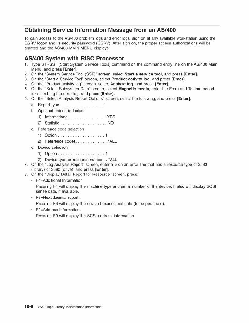
Obtaining Service Information Message from an AS/400
To gain access to the AS/400 problem logs and error logs, sign on at any available workstation using the
QSRV logon and its security password (QSRV). After sign on, the proper access authorizations will be
granted and the AS/400 MAIN MENU displays.
AS/400 System with RISC Processor
1. Type STRSST (Start System Service Tools) command on the command entry line on the AS/400 Main
Menu, and press [Enter].
2. On the “System Service Tool (SST)” screen, select Start a service tool, and press [Enter].
3. On the “Start a Service Tool” screen, select Product activity log, and press [Enter].
4. On the “Product activity log” screen, select Analyze log, and press [Enter].
5. On the “Select Subsystem Data” screen, select Magnetic media, enter the From and To time period
for searching the error log, and press [Enter].
6. On the “Select Analysis Report Options” screen, select the following, and press [Enter].
a. Report type. . . . . . . . . . . . . . . . . . 1
b. Optional entries to include
1) Informational . . . . . . . . . . . . . . . YES
2) Statistic . . . . . . . . . . . . . . . . . . . NO
c. Reference code selection
1) Option . . . . . . . . . . . . . . . . . . . 1
2) Reference codes. . . . . . . . . . . . . *ALL
d. Device selection
1) Option . . . . . . . . . . . . . . . . . . . 1
2) Device type or resource names . . *ALL7. On the “Log Analysis Report” screen, enter a 5 on an error line that has a resource type of 3583
(library) or 3580 (drive), and press [Enter].
8. On the “Display Detail Report for Resource” screen, press:
v F4=Additional Information.
Pressing F4 will display the machine type and serial number of the device. It also will display SCSI
sense data, if available.
v F6=Hexadecimal report.
Pressing F6 will display the device hexadecimal data (for support use).
v F9=Address Information.
Pressing F9 will display the SCSI address information.
10-8 3583 Tape Library Maintenance Information

Obtaining Error Information From a Sun System
The Sun system does not provide error logs for analysis; therefore, you must use error logs from the
application (such as Tivoli Storage Manager), or the Device Error Log for problem determination. When
you have located the error information, go to Chapter 5, “Start,” on page 5-1.
The two following service aid programs are provided with the IBM SCSI Tape Device Driver for SunOS:
v Tape service program
A tape service program called tapesrvc.c is provided and contains the following service aids:
– Query device serial number
– Format tape cartridge
– Force device error dump
– Save device error dump
– Download device code
The tape service program is invoked by using the /opt/stddutil/tapesrvc command.
Note: You must have root authority to run the tape service program.
The program is menu driven. Use discretion when running this program because it opens the device in
diagnostic mode.
v Sample program
A sample program called tapetest.c is provided, which gives a demonstration of the device driver
interface usage.
The sample program is invoked by using the /opt/stddutil/tapetest command. The program is useful for
verifying that the device driver and the device are functional. The program is menu driven.
Obtaining Error Information From an HP-UX System
The HP-UX system does not provide error logs for analysis; therefore, you must use error logs from the
application (such as Tivoli Storage Manager), or the Device Error Log for problem determination. When
you have located the error information, go to Chapter 5, “Start,” on page 5-1.
Chapter 10. Messages 10-9

10-10 3583 Tape Library Maintenance Information

Chapter 11. Sense
Library Sense Data . . . . . . . . . . . . . . . . . . . . . . . . . . . . . . . 11-2
Drive Sense Data . . . . . . . . . . . . . . . . . . . . . . . . . . . . . . . . 11-6
© Copyright IBM Corp. 2000, 2005 11-1

Library Sense Data
Table 11-1. Sense Information Format
Bits 7 6 5 4 3 2 1 0
Bytes
0 Valid 70 = Existing Error71 = Deferred Error
1 Reserved
2 Reserved Sense Key(see Table 11-2)
3
:
6
MSB
Information Bytes
LSB
7 Additional Sense Length (n–7)
If the sense key is 4, the additional sense length is 70. For all other errors, the additional sense length
is 10.
8
:
11
MSB
Command Specific Bytes
LSB
12 Additional Sense Code (ASC)(see Table 11-3 on page 11-3)
13 Additional Sense Qualifier (ASCQ)
(see Table 11-3 on page 11-3)
14 Service Action Code
15 SKSV C/D Reserved BPV Bit Pointer
16
17
MSB
Field Pointer
LSB
Table 11-2. Sense Keys
Sense Key Description
0h No Sense. No specific sense key information to report.
2h Not Ready. The library is not ready to perform motion commands.
4h Hardware Error. A hardware error was detected and operator intervention may be required.
5h Illegal Request. The CDB or supplied parameter data contains an unsupported or illegal
parameter.
6h Unit Attention. The library operating status changed. The cartridge inventory may be invalid.
Bh Command Aborted. The library aborted a command. The initiator may try the command again.
11-2 3583 Tape Library Maintenance Information
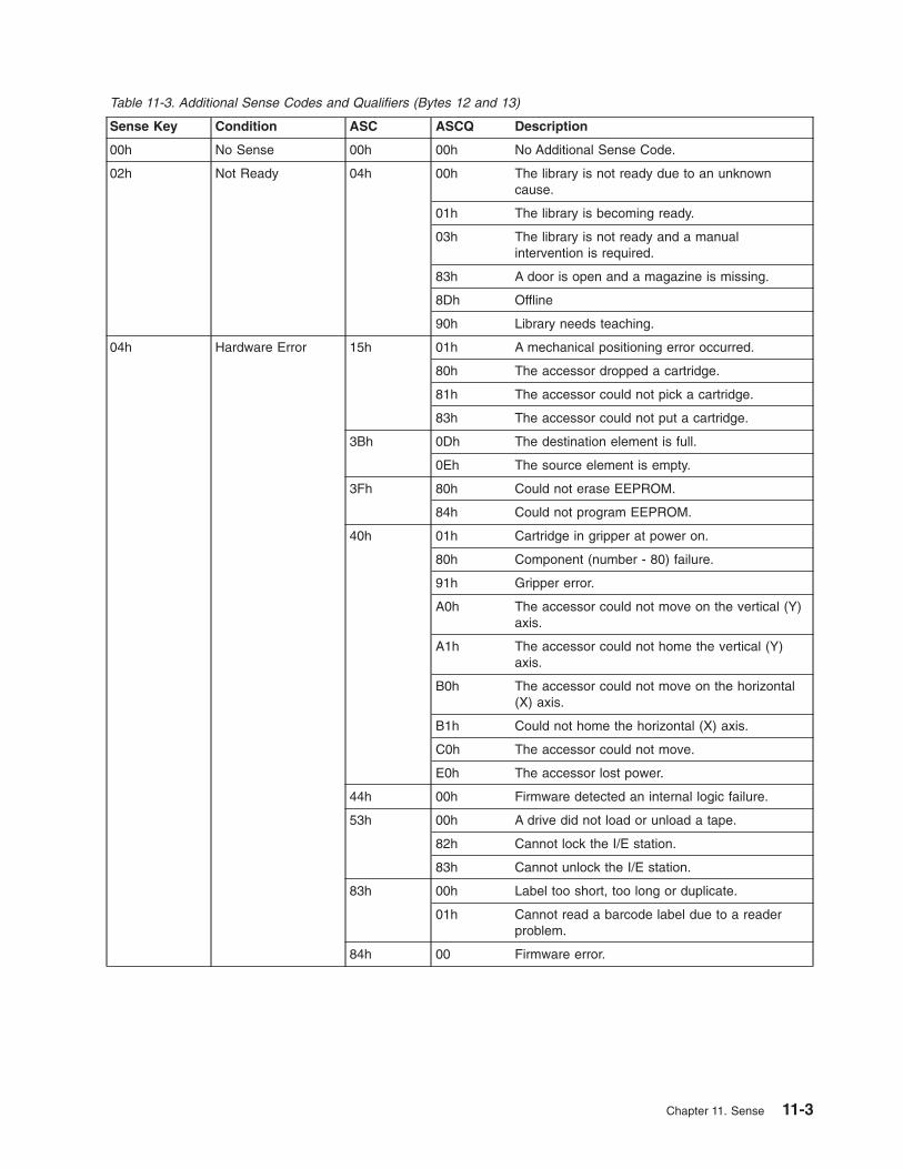
Table 11-3. Additional Sense Codes and Qualifiers (Bytes 12 and 13)
Sense Key Condition ASC ASCQ Description
00h No Sense 00h 00h No Additional Sense Code.
02h Not Ready 04h 00h The library is not ready due to an unknown
cause.
01h The library is becoming ready.
03h The library is not ready and a manual
intervention is required.
83h A door is open and a magazine is missing.
8Dh Offline
90h Library needs teaching.
04h Hardware Error 15h 01h A mechanical positioning error occurred.
80h The accessor dropped a cartridge.
81h The accessor could not pick a cartridge.
83h The accessor could not put a cartridge.
3Bh 0Dh The destination element is full.
0Eh The source element is empty.
3Fh 80h Could not erase EEPROM.
84h Could not program EEPROM.
40h 01h Cartridge in gripper at power on.
80h Component (number - 80) failure.
91h Gripper error.
A0h The accessor could not move on the vertical (Y)
axis.
A1h The accessor could not home the vertical (Y)
axis.
B0h The accessor could not move on the horizontal
(X) axis.
B1h Could not home the horizontal (X) axis.
C0h The accessor could not move.
E0h The accessor lost power.
44h 00h Firmware detected an internal logic failure.
53h 00h A drive did not load or unload a tape.
82h Cannot lock the I/E station.
83h Cannot unlock the I/E station.
83h 00h Label too short, too long or duplicate.
01h Cannot read a barcode label due to a reader
problem.
84h 00 Firmware error.
Chapter 11. Sense 11-3

Table 11-3. Additional Sense Codes and Qualifiers (Bytes 12 and 13) (continued)
05h Illegal Request 1Ah 00h Parameter List length error.
20h 00h Illegal opcode in CDB.
21h 01h Invalid element address in CDB.
24h 00h Invalid field in CDB.
80h Attempt to write a read-only buffer.
25h 00h Illegal LUN.
26h 00h Invalid field in Parameter List.
02h Invalid parameter in Parameter List.
80h Parameter data checksum failure.
30h 00h Incompatible media installed.
3Bh 0Dh Destination element full for MOVE MEDIUM
command.
0Eh Source element empty for MOVE MEDIUM
command.
85h Destination of MOVE MEDIUM command cannot
be accessor.
86h Source of MOVE MEDIUM command cannot be
accessor.
87h Cartridge stuck in tape drive.
90h Source cartridge loaded into tape drive and not
accessible.
A0h Media type does not match destination media
type.
3Dh 00h Invalid bit in “Identify” message.
3Eh 00h Incorrect LUN configuration.
44h 00h Firmware detected an internal logic failure.
53h 01h A drive did not unload a tape.
80h Cartridge rejected in the Mailbox because it was
not properly loaded.
81h Mailbox is open.
83h 02h Cartridge magazine not installed.
03h Cell status and barcode questionable.
04h Drive not installed.
06h Unit Attention 28h 00h Door or doors opened and closed.
01h Mailbox opened.
29h 00h Power on, SCSI bus reset, or Bus device reset
occurred.
80h Reset for permanent error occurred.
81h Reset into degraded mode of operation.
2Ah 01h Mode parameters have been changed.
3Fh 01h New firmware loaded.
11-4 3583 Tape Library Maintenance Information

Table 11-3. Additional Sense Codes and Qualifiers (Bytes 12 and 13) (continued)
0Bh Abort 43h 00h Message received at inappropriate time.
45h 00h Host rejected “Identify” message sent for
reselection.
47h 00h Message system was disabled during parity error
detection on SCSI bus, message system enabled
but initiator rejected “Restore Data Pointer,” or all
parity error retries exhausted.
48h 00h Received an “Initiator Detected Error” or initiator
rejected “Restore Data Pointer” in response to an
“Initiator Detected Error.”
4Eh 00h Disconnect during command processing.
Chapter 11. Sense 11-5
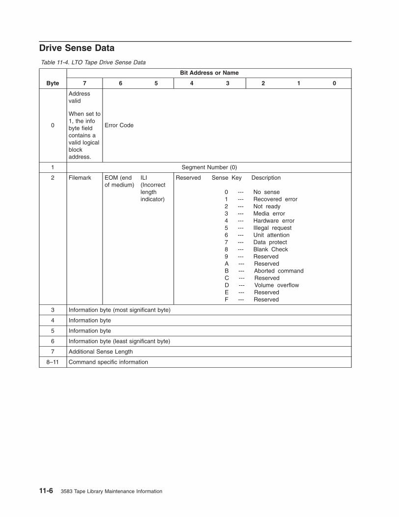
Drive Sense Data
Table 11-4. LTO Tape Drive Sense Data
Byte
Bit Address or Name
7 6 5 4 3 2 1 0
0
Address
valid
When set to
1, the info
byte field
contains a
valid logical
block
address.
Error Code
1 Segment Number (0)
2 Filemark EOM (end
of medium)
ILI
(Incorrect
length
indicator)
Reserved Sense Key Description
0 --- No sense
1 --- Recovered error
2 --- Not ready
3 --- Media error
4 --- Hardware error
5 --- Illegal request
6 --- Unit attention
7 --- Data protect
8 --- Blank Check
9 --- Reserved
A --- Reserved
B --- Aborted command
C --- Reserved
D --- Volume overflow
E --- Reserved
F --- Reserved
3 Information byte (most significant byte)
4 Information byte
5 Information byte
6 Information byte (least significant byte)
7 Additional Sense Length
8–11 Command specific information
11-6 3583 Tape Library Maintenance Information

Table 11-4. LTO Tape Drive Sense Data (continued)
Byte
Bit Address or Name
7 6 5 4 3 2 1 0
12–13 Additional Sense Code (ASC)
Additional Sense Code Qualifier (ASCQ)
Byte 12 Byte 13
ASC ASCQ
00 00 - No additional sense — The flags in the sense data indicate the reason for
the command failure
00 01 - Filemark detected — A Read or Space command terminated early due to an FM
The FM flag is set.
00 02 - EOM — A Write or Write File Marks command failed because the physical
end of tape was encountered, or a Read or Space command encountered EOM
The EOM flag is set
00 04 - BOM — A space command ended at Beginning of Tape
The EOM bit is also set
00 05 - EOD — Read or Space command terminated early
because End of Data was encountered
00 16 - Operation in progress
04 00 - Cause not reportable — A cartridge is present in the drive, but it is in the
process of being unloaded
04 01 - Becoming Ready — A media access command was received during a
front panel initiated load or an immediate reported load command
04 02 - Initializing Command Required — A cartridge is present in the drive, but is not
logically loaded. A Load command is required
04 03 - Manual Intervention Required — A cartridge is present in the drive but could
not be loaded or unloaded without manual intervention
04 12 - Logical Unit Not Ready, Offline
08 01 - Logical Unit Communication Failure
09 00 - Track Following Error (Servo)
0C 00 - Write Error — A Write operation has failed. This is probably due to bad
media, but may be hardware related
11 00 - Unrecovered Read Error — A Read operation failed. This is probably due
to bad media, but may be hardware related
14 00 - Recorded Entity Not Found — A space or Locate command failed because
a format violation prevented the target from being found.
14 03 - End Of Data not found — A Read type operation failed because a format
violation related to a missing EOD data set
17 01 - Recovered Data with Retries
1A 00 - Parameter list length error — The amount of parameter data sent is incorrect
20 00 - Invalid Command Operation Code — The Operation Code in the command
was not a valid Operation Code
24 00 - Invalid field in CDB — An invalid field has been detected in a
Command Descriptor Block
25 00 - LUN not supported — The command was addressed to a non-existent
logical unit number
26 00 - Invalid Field in Parameter List — An invalid field has been detected in the
data sent during the data phase
27 00 - Write Protect — A Write type operation has been requested on a cartridge which
has been write protected
28 00 - Not Ready to Ready Transition — A cartridge has been loaded successfully into
the drive and is now ready to be accessed
28 01 - Import or Export Element Accessed
29 00 - Reset — The drive has powered on, received a reset signal or a bus device
reset signal since the initiator last accessed it
`29 04 - Device Internal Reset
(Continued on next page)
Chapter 11. Sense 11-7
|
|||
|
|
|

Table 11-4. LTO Tape Drive Sense Data (continued)
Byte
Bit Address or Name
7 6 5 4 3 2 1 0
12–13 Additional Sense Code (ASC) —
Additional Sense Code Qualifier (ASCQ) (Continued)
Byte 12 Byte 13
ASC ASCQ
2A 01 - Mode Parameters Changed — The Mode parameters for the drive have
been changed by an initiator other than the one issuing the command
2C 00 - Command Sequence Error
2F 00 - Commands Cleared by Another Initiator30 00 - Incompatible Media Installed — A write type o executed because it is not supported on the cartridge type that is loaded.
30 01 - Unknown Format — An operation could not be carried out because the cartridge
in the drive is of a format not supported by the drive
30 02 - Incompatible Format — An operation could not be completed because the
Logical Format is not correct
30 03 - Cleaning Cartridge Installed — An operation could not be carried out
because the cartridge in the drive is a cleaning cartridge
30 05 - Cannot Write Medium, Incompatible Format
30 07 - Cleaning Failure — A cleaning operation was attempted, but could not
be completed for some reason
31 00 - Media format corrupted — Data could not be read because the format on tape is
not valid, but is a known format. A failure occurred attempting to write the FID
37 00 - Rounded parameter — A Mode Select command parameter has been
rounded because the drive can not store it with the accuracy of the command.
3A 00 - Media Not Present — A media access command has been received
when there is no cartridge loaded
3B 00 - Sequential Positioning Error — A command has failed and left the logical
position at an unexpected location
3B 0C - Position Past Beginning of Medium — A command that required the medium to be at BOP was
attempted when the medium was not at BOP (e.g., Set Capacity)
3D 00 - Invalid bits in identify Message — An illegal Identify Message has been
received at the drive at the start of a command
3E 00 - Logical Unit has not Self-Configured — The drive has just powered on and
has not completed its self test sequence and can not process commands
3F 01 - Code Download — The firmware in the drive has just been changed
by a Write Buffer command
3F 03 - Inquiry Data has Changed
3F 0E - Reported LUNs Data has Changed
3F 0F - Echo Buffer Overwritten
40 xx - Diagnostic failure — A diagnostic test has failed. The xx (ASCQ) is a
vendor specific code indicating the failing component.
41 00 - Data Path Failure
43 00 - Message Error — A message could not be sent or received due to excessive
transmission errors
44 00 - Internal target failure — A hardware failure has been detected in the drive
that has caused the command to fail
45 00 - Select/Reset Failure — An attempt to reselect an initiator in order to
complete the command has failed
48 00 - Initiator Detected Error Message Received
49 00 - Invalid Message Error
4A 00 - Command Phase Error
4B 00 - Data Phase Error — A command could not be completed because too many
parity errors occurred during the Data phase
4E 00 - Overlapped Commands — An initiator selected the drive even though it
already had a command outstanding in the drive
(Continued on next page)
11-8 3583 Tape Library Maintenance Information
||
|
|||
|
|||

Table 11-4. LTO Tape Drive Sense Data (continued)
Byte
Bit Address or Name
7 6 5 4 3 2 1 0
12–13 Additional Sense Code (ASC) —
Additional Sense Code Qualifier (ASCQ) (Continued)
Byte 12 Byte 13
ASC ASCQ
50 00 - Write Append Error — A write type command failed because the point at
which to append data was unreadable
51 00 - Erase failure — An Erase command failed to erase the required area on the
media
52 00 - Cartridge fault — A command could not be completed due to a fault in the
tape cartridge
53 00 - Media Load/Eject Failed — (Sense Key 03) An attempt to load or eject
the cartridge failed due to a problem with the cartridge.
53 00 - Media Load/Eject Failed — (Sense Key 04) An attempt to load or eject
the cartridge failed due to a problem with the drive
53 02 - Media Removal Prevented — An Unload command has failed to eject the
cartridge because media removal has been prevented
5A 01 - Operator Medium Removal Request
5D 00 - Failure Prediction Threshold — Failure Prediction thresholds have been
exceeded indicating that a failure may occur soon
5D FF - Failure Prediction False — A Mode Select command has been used to test
for Failure Prediction system.
82 82 - Drive requires cleaning — The drive has detected that a cleaning operation
is required to maintain good operation
82 83 - Bad Code Detected — The data transferred to the drive during a
firmware upgrade is corrupt or incompatible with drive hardware
A3 01 - OEM Vendor-Specific
14 FRU code
15 SKSV C/D Reserved BPV
When set to
1, the bit
pointer is
valid.
Bit pointer
16 –17 SKSV = 0: First Error Fault Symptom Code (FSC).
SKSV = 1: Field Pointer
18–19 First Error Flag Data
20 Reserved (0)
21 CLN Reserved Reserved VolValid
22–28 Volume Label
29 Current Wrap
30–33 Relative LPOS
34 SCSI Address
35 Reserved Reserved
The descriptions below serve only as an overview of sense reporting in the tape drive. This tape drive
conforms to all sense field reporting as specified in the SCSI standards.
Chapter 11. Sense 11-9
|
|

Notes:
1. The Error Code field (Byte 0) is set to 70h to indicate a current error, that is one associated with the
most recently received command. It is set to 71h to indicate a deferred error which is not associated
with the current command.
2. The segment number (Byte 1) is zero since the Copy, Compare, and Copy and Verify commands are
not supported.
3. The File Mark flag (Byte 2, bit 7) is set if a Space, Read, or Verify command did not complete
because a file mark was read.
4. The End of Media (EOM) flag (Byte 2, bit 6) is set if a Write or Write File Marks command completed
in the early warning area. Spacing into BOM also causes this flag to be set. It is also set on an
attempt to read or space past EOD, or if an attempt is made to space into Beginning of Media.
5. The Illegal Length Indicator (ILI) flag (Byte 2, bit 5) is set if a Read or Verify ended because a block
was read from tape that did not have the block length requested in the command.
6. The Information Bytes (Bytes 3–5) are only valid if the Valid flag is set. This occurs only for current
errors and not for deferred errors.
7. The Field Replaceable Unit field (Byte 14) is set to either zero or to a non-zero, vendor-specific code
indicating which part of the drive is suspected of causing the failure.
8. The Clean (CLN) flag (Byte 21, bit 3) is set if the drive needs cleaning and clear otherwise.
9. The Volume Label Fields Valid (VolValid) bit (Byte 21, bit 0) is set if the Volume Label being reported
is valid.
10. The Volume Label field (Bytes 22–28) reports the volume label if a cartridge is loaded in the drive and
Volume Label Fields Valid is set.
11. The Current Wrap field (Byte 29) reports the physical wrap of the tape. The least significant bit
reflects the current physical direction. A 0 means that the current direction is away from the physical
beginning of the tape. A 1 means that the current direction is towards the physical beginning of the
tape.
12. Relative LPOS fields (Bytes 30–33) reports the current physical position on the tape.
13. SCSI Address field (Byte 34) reports the SCSI Bus Address for the drive. Values returned range from
00h to 0Fh.
11-10 3583 Tape Library Maintenance Information

Chapter 12. Power
Overview . . . . . . . . . . . . . . . . . . . . . . . . . . . . . . . . . . . 12-2
ac and dc Power . . . . . . . . . . . . . . . . . . . . . . . . . . . . . . . . 12-2
ac and dc Power Distribution . . . . . . . . . . . . . . . . . . . . . . . . . . . 12-3
ac and dc Power Distribution for Type I Power Supply in a Library With the Multi-Path Feature 12-4
ac and dc Power Distribution for Type II Power Supply in a Library With the Multi-Path Feature 12-5
© Copyright IBM Corp. 2000, 2005 12-1

Overview
This chapter describes the power system for the Ultrium Scalable Tape Library.
ac and dc Power
The Tape Library contains an ac Input Power Module �3� that requires 110 V or 230 V, 10 Amperes single
phase ac power. The ac Power Module supplies ac to the dc Power Supplies �1� and all Tape Drive Sleds
�4� in the Library.
Standard Tape Library configuration requires one dc Power Supply which generates +5 V dc and +12 V dc
to be used in the Library. An optional dc Power Supply can be installed to provide dc power redundancy in
the Library. When two dc Power Supplies are installed, one output switches on in the event the other
output should fail. The dc Power Supplies are auto-ranging and can accept either 110 or 230 V ac.
Each Drive Sled has a built-in dc Power Supply and only requires ac input. This dc Power Supply is also
auto-ranging and can accept either 110 or 230 V ac.
Figure 12-1 shows the locations of the ac Power Module and the dc Power Supplies in the Tape Library.
a67m
0271
1
2
34
Figure 12-1. ac Power Module and dc Power Supplies locations. Figure shows a converted library.
12-2 3583 Tape Library Maintenance Information

ac and dc Power Distribution
The AC Input Power Module distributes ac to all Tape Drive Modules and the DC Power Supplies through
the Power Distribution PCBA. The output of the AC Input Power Module is controlled by a Switch and
protected by two 5A fuses. The DC Power Supplies and all Tape Drive Modules are plugged into the
Power Distribution PCBA with self-docking or blind-mate connectors.
Each DC Power Supply has a built-in switch that is activated as the DC Power Supply is plugged into the
Power Distribution PCBA. ac voltage is immediately available to the DC Power Supply as soon as the
connection is made.
There are two versions of the DC Power Supplies, with each requiring a corresponding Power Distribution
PCBA to operate. Physically, these two types of DC Power supplies look the same. You need to order the
correct one for the library. The library will not power up if the DC power supply and the Power
Distribution PCBA are not compatible:
v Type I dc power supply provides +5 Vdc and +12 Vdc to the Power distribution PCBA to be distributed
throughout the library. This DC Power Supply is used in older libraries.
v Type II dc power supply only provides +12 Vdc to its associated Power Distribution PCBA. The Power
Distribution PCBA generates +5 Vdc from the +12 Vdc and distributes these two voltages throughout
the library. This DC Power Supply is used in newer libraries to handle additional appliances, such as the
SAN Data Gateway Module.
When two DC Power Supplies are installed in the library, their outputs are connected together. If one of
these DC Power Supplies fails, the library can still operate normally. Each DC Power Supply also has an
LED indicator in the back to indicate its status:
v Green indicates that the power supply is operating normally
v Red indicates a failures that requires a replacement
The operator panel presents a message when this condition occurs. The failing DC Power Supply can be
removed and replaced without interrupting the library’s operations.
As each Tape Drive Module is plugged into the Power Distribution PCBA, its Drive Communication PCBA
receives +5 Vdc power from the Power Distribution PCBA. Firmware on the Drive Communication PCBA
attempts to communicate with the library firmware. After this communication is established, the library
firmware activates a relay that provides ac power to the Tape Drive Module. Options are provided through
the operator panel menus to remove and restore ac power to the Tape Drive Module during a service call.
Use the following diagrams for ac and dc power distribution within the library:
v “ac and dc Power Distribution for Type I Power Supply in a Library With the Multi-Path Feature” on page
12-4. Note that each DC Power Supply generates +5 Vdc and +12 Vdc.
v “ac and dc Power Distribution for Type II Power Supply in a Library With the Multi-Path Feature” on
page 12-5. Note that each DC Power Supply generates only +12 Vdc and there is a dc-to-dc converter
on the Power Distribution PCBA that generates +5 Vdc from the +12 Vdc.
Chapter 12. Power 12-3

ac and dc Power Distribution for Type I Power Supply in a Library With
the Multi-Path Feature
SerialDiagnosticPort Board
DiagnosticPort
Main Board
Power Distribution Board
Drive Sled #6
AC Module
RemoteManagementUnit (RMU)
LCDDisplay
110-220 V ac
+5
Vdc
+12
Vdc
Drive Sled #1
PowerGood/FailIndicators
DCPowerSupply #2
DCPowerSupply #1
+5 V dc
+12 V dc
Y-AxisMotor
Assembly
Relay
Relay
+12 V
+5 V
Picker Board
Display Board
+12 V dc
+5 V dc
+5 V dc
Rotary Motor
I/O StationAssembly
FRU
PickerAssembly
FRU
a67m
0203
Legend
PCBA internal lines
Cables (Discrete or Ribbon)
Connectors
Figure 12-2. ac and dc power distribution for Type I power supply in a library with the Multi-Path feature
12-4 3583 Tape Library Maintenance Information

ac and dc Power Distribution for Type II Power Supply in a Library
With the Multi-Path Feature
Figure 12-3. ac and dc power distribution for Type II power supply in a library with the Multi-Path feature
Chapter 12. Power 12-5

12-6 3583 Tape Library Maintenance Information

Chapter 13. Cable
Overview . . . . . . . . . . . . . . . . . . . . . . . . . . . . . . . . . . . 13-2
Cable Diagram for Type I Power Distribution PCBA in a Library With the Multi-Path Feature . . . . 13-3
Cable Diagram for Type II Power Distribution PCBA in a Library With the Multi-Path Feature . . . . 13-4
© Copyright IBM Corp. 2000, 2005 13-1

Overview
This chapter shows the interconnections between major components in the Ultrium Scalable Tape Library.
The following diagrams show the connector and cable designations. The designation J used in the
diagrams means connectors on electronic cards or major assemblies.
v “Cable Diagram for Type I Power Distribution PCBA in a Library With the Multi-Path Feature” on page
13-3.
v “Cable Diagram for Type II Power Distribution PCBA in a Library With the Multi-Path Feature” on page
13-4
13-2 3583 Tape Library Maintenance Information
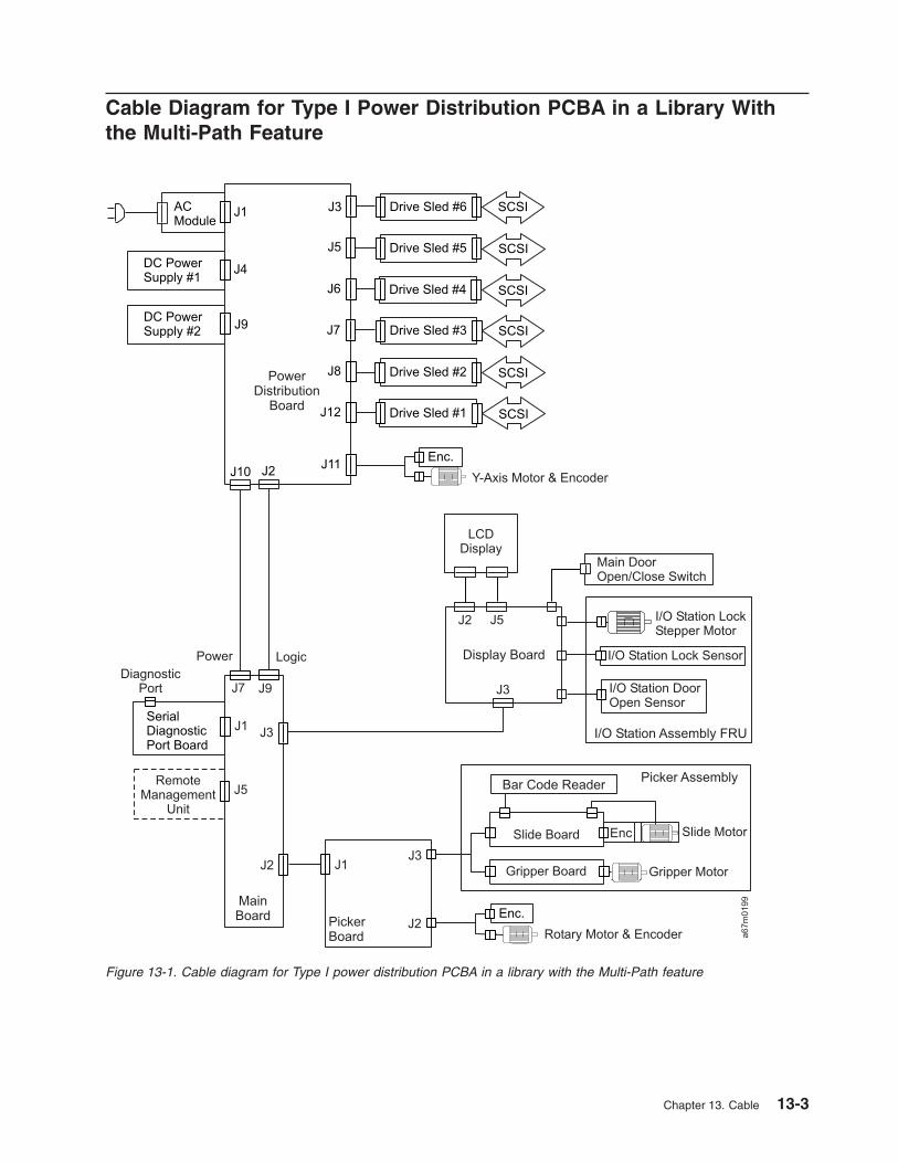
Cable Diagram for Type I Power Distribution PCBA in a Library With
the Multi-Path Feature
Figure 13-1. Cable diagram for Type I power distribution PCBA in a library with the Multi-Path feature
Chapter 13. Cable 13-3

Cable Diagram for Type II Power Distribution PCBA in a Library With
the Multi-Path Feature
Figure 13-2. Cable diagram for Type II Power Distribution PCBA in a library with the Multi-Path feature
13-4 3583 Tape Library Maintenance Information

Chapter 14. Installation
Attention: The Ultrium Scalable Tape Library is a customer setup unit. It is the customer’s responsibility
to install this product.
To ensure optimum performance, obtain the latest level of firmware from the web by visiting
http://www.ibm.com/storage/lto. Be sure to verify that you have the latest firmware installed on your
machine before you contact IBM for any necessary technical support.
If you choose not to install this product yourself, IBM will install it for a fee. You can purchase installation
services by contacting your local IBM Service office or your IBM Business Partner.
To install the Ultrium Scalable Tape Library, complete the following steps. For more information, refer to
the instructions for each step in this chapter.
v “Step 1. Unpack the Library” on page 14-2
v “Step 2. Verify Shipment Inventory” on page 14-3
v “Step 3. Remove Packaging from Picker Assembly” on page 14-4
v “Step 4. Turn on Power” on page 14-5
v “Step 5. Run the Verify Test” on page 14-7
v “Step 6. Turn off Power” on page 14-9
v “Step 7. Install as Stand-Alone Unit or in Rack” on page 14-10
v “Step 8. Install Optional Features” on page 14-25
v “Step 9. Reposition Drives for Partitioning” on page 14-33
v “Step 10. Install Cables and Terminators” on page 14-34
v “Step 11. Turn on Power” on page 14-40
v “Step 12. Partition the Library” on page 14-41
v “Step 13. Set SCSI and FC IDs” on page 14-42
v “Step 14. Add Control Paths” on page 14-45
v “Step 15. Install Additional Options” on page 14-47
v “Step 16. Import Cleaning Cartridge(s)” on page 14-52
v “Step 17. Populate the Library with Data Cartridges” on page 14-54
v “Step 18. Configure the RMU” on page 14-55
v “Step 19. Verify Firmware Levels” on page 14-59
v “Step 20. Install a SCSI Host Adapter Card (if required)” on page 14-64
v “Step 21. Install Device Drivers and Backup Software” on page 14-64
v “Step 22. Configure the Tape Library to the Server” on page 14-64
v “Step 23. Store Manuals and Documentation” on page 14-64
© Copyright IBM Corp. 2000, 2005 14-1

Step 1. Unpack the Library
To unpack the Ultrium Scalable Tape Library, use the sling (see �1� in Figure 14-1) that is shipped with the
Ultrium Scalable Tape Library to lift and move the library into place. It is recommended that four people
use the handles �2� of the sling to lift the library. For additional information, read the printed instructions
located on the shipping container.
Inspect the library for shipping damage. If there is damage, do not install it. Report the damage
immediately by contacting your place of purchase.
Figure 14-1. The sling for lifting the Ultrium Scalable Tape Library
14-2 3583 Tape Library Maintenance Information

Step 2. Verify Shipment Inventory
__ 1. Front door key (taped to the back of the library)
__ 2. Power cord (for the appropriate cord for your country or region, see “Power Cords” on page 15-4)
__ 3. Up to six optional Ultrium Tape Drives (SCSI and/or Fibre Channel)
__ 4. Drive-to-drive SCSI cable (0.4 m) and terminator with each SCSI drive ordered
__ 5. Host-to-device SCSI bus cable (4.5 m or 5 m as specified or ordered)
__ 6. Device-to-device SCSI bus cable (0.7 m) for connection between the SCSI host interface board
and the first SCSI drive
__ 7. LVD single-connector SCSI wrap tool or HVD/DIFF single-connector SCSI wrap tool, or both
__ 8. Serial cable (straight through; that is, the cable’s wires connect to identical connector pins on each
end)
__ 9. Optional San Data Gateway Module (if ordered)
__ 10. Optional native Fibre Channel cable (if ordered)
__ 11. Optional native Fibre Channel wrap tool (if ordered)
__ 12. IBM LTO Ultrium Data Cartridge
__ 13. IBM LTO Ultrium Cleaning Cartridge
__ 14. Rack mount Kit (feature code 8006)
__ 15. Device driver kit that includes:
v CD that contains the Open Systems Device Drivers
v Copy of the IBM Ultrium Device Drivers Installation and User’s Guide
Note: Device driver support is subject to change. For information about the latest supported
device drivers (and to download them), see “Supported Device Drivers” on page 1-31.
__ 16. Ultrium Scalable Tape Library Quick Reference
__ 17. Ultrium Scalable Tape Library Setup and Operator Guide (this guide)
__ 18. Ultrium Scalable Tape Library Maintenance Information
__ 19. IBM Externally Attached Devices Safety Information manual
Note: To ensure that you have the latest publications and the latest firmware, visit the web at
http://www.ibm.com/storage/lto.
Chapter 14. Installation 14-3

Step 3. Remove Packaging from Picker Assembly
1. Open the front door �1� by using the key �2� (see Figure 14-2).
2. Remove the band �3� that secures the picker assembly �4� to the frame.
Note: Attach the band to the library key ring for safe keeping. The band will need to be reinstalled if
the library is relocated.
3. Close the front door securely.
Figure 14-2. Installing a stand-alone library
14-4 3583 Tape Library Maintenance Information

Step 4. Turn on Power
Attention: Before turning on the power, make sure that qualified personnel verify
the proper voltage at the outlet. If the voltage is incorrect, damage to the power
supply could occur.
1. Ensure that the power switch is set to off by pressing O on the power switch (see �1� in Figure 14-3).
2. Plug the power cord into the Ultrium Scalable Tape Library, then plug the other end into a grounded
electrical outlet.
3. Push | on the power switch to turn on the power. The library takes a few minutes to perform
initialization.
4. Inspect the rear panel to ensure that all drive LEDs are green.
v If all LEDs are green, proceed with the installation.
v If any LEDs are not green:
a. Power off the library.
b. Loosen the two thumbscrews on a drive.
c. Pull the drive part way out of the library.
d. Push the drive back into the library.
e. Tighten the two thumbscrews on the drive.
f. Power on the library.
– If all LEDs are green, proceed with the installation.
– If any LEDs are not green, contact your Service Representative.
a67lo
357
1
Figure 14-3. Main power switch
Chapter 14. Installation 14-5
|
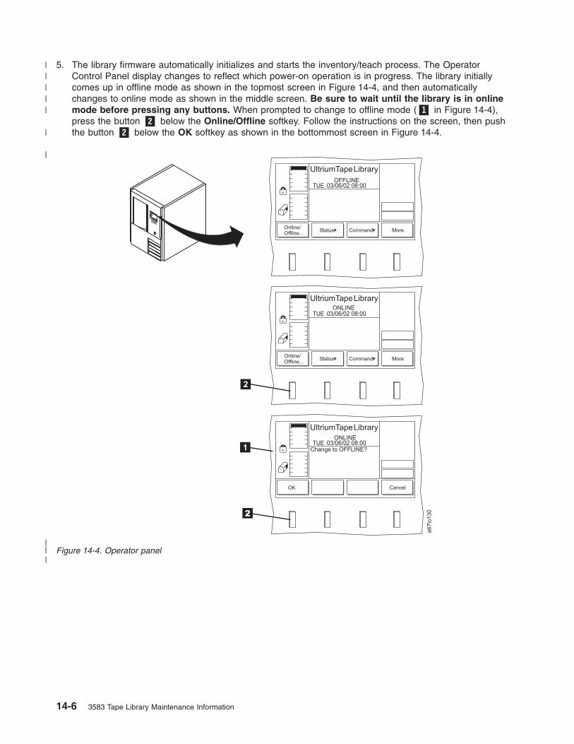
5. The library firmware automatically initializes and starts the inventory/teach process. The Operator
Control Panel display changes to reflect which power-on operation is in progress. The library initially
comes up in offline mode as shown in the topmost screen in Figure 14-4, and then automatically
changes to online mode as shown in the middle screen. Be sure to wait until the library is in online
mode before pressing any buttons. When prompted to change to offline mode (�1� in Figure 14-4),
press the button �2� below the Online/Offline softkey. Follow the instructions on the screen, then push
the button �2� below the OK softkey as shown in the bottommost screen in Figure 14-4.
a67lo
130
Online/Offline...
OK
Online/Offline...
Status
Status
Command
Command
More
Cancel
More
ONLINE
ONLINE
OFFLINE
2
Change to OFFLINE?
UltriumTapeLibrary
UltriumTapeLibrary
UltriumTapeLibrary
03/06/02 08:00
03/06/02 08:00
03/06/02 08:00
TUE
TUE
TUE
1
2
Figure 14-4. Operator panel
14-6 3583 Tape Library Maintenance Information
|
|||
|||||
|

Step 5. Run the Verify Test
The Verify Test runs the following tests on the library:
v Power On Self Test (POST)
v FAST Read/Write drive test
v A test of the robot range of motion
v A bar code scanner test
Shortcut: Main Menu (initial screen) —> More —> Service —> Library
—> Exercise —> Verify Test
1. Navigate to the Service Menu. For instructions, see “Accessing the Service Menu” on page 4-9.
2. Press the button below the Library softkey. The Library Submenu is displayed (see Figure 14-5).
3. Press the button below the Change softkey to change to initiate the change to Offline mode. Then,
press the button below the OK softkey.
4. Press the button below the Exercise softkey . The Exercise Submenu is displayed.
5. Press the button below the Verify Test softkey. The Verify Test Dialog is displayed (see Figure 14-6).
6. In the Verify Test Dialog’s Include Drive(s) field, press the button below the Change softkey to select
ALL, if necessary.
7. When the correct value is selected, press the button below the OK softkey. The Verify Test Scratch
Tape Dialog displays (see Figure 14-7 on page 14-8).
Change Command Cancel
ONLINE
To run this option
the library must be
Offline with the
door closed.
a6
7lo
06
9
UltriumTapeLibrary
01/24/05 14:06MON
Figure 14-5. Library Submenu
OK Change Cancel
OFFLINE
a6
7lo
34
1
UltriumTapeLibrary
02/14/04 16:56SATTest may interruptbackups in progress.Be sure to unloaddrives before test.
FAST Read/WriteInclude Drive(s): All
Figure 14-6. Verify Test Dialog
Chapter 14. Installation 14-7
||

8. Open the I/O Station.
9. Insert a scratch tape into the top slot of the I/O Station.
Notes:
a. Refer to Table 1-3 on page 1-13 to determine the type of drives resident in the library.
b. Refer to the cartridge compatibility table on Table 1-3 on page 1-13 for information on which type
of cartridge to use.
c. If a cartridge is already in the slot, the Operator Control Panel displays a warning message
indicating that the slot contains an unknown tape. Check to ensure that it is a scratch tape before
proceeding.
10. Close the I/O Station and the library will execute the TEACH and INVENTORY procedures.
11. When the diagnostic begins, the Diagnostic In Progress Screen displays (see Figure 14-8).
The library runs a Power On Self Test (POST) to verify the hardware is working properly. Then the
library ensures communication with the drives. If the drive has a cartridge loaded, the library moves
the cartridge to its home slot. The library then reads the bar code on the scratch tape and moves the
scratch tape to the drive and runs a FAST Read/Write test on the tape. The tape is then moved back
to slot 1A1, and the bar code is read a second time and compared with the earlier reading.
12. When the tape is returned to the I/O Station, the Command Now Complete Screen displays (see
Figure 14-9).
13. Press the button below the OK softkey to return to the Exercise Submenu.
Cancel
OFFLINE
a6
7lo
34
2
UltriumTapeLibrary
02/14/04 17:05SATPlace a scratch tapeinto [1 A 1] (topslot of I/O Station)It will be returnedthere on completionof operation.
Figure 14-7. Verify Test Scratch Tape Dialog
Cancel
OFFLINE
a6
7lo
34
3
UltriumTapeLibrary
02/14/04 17:14SATDiagnostic is now inprogress...
Figure 14-8. Diagnostic In Progress Screen
OFFLINE
a6
7lo
34
4
UltriumTapeLibrary
02/14/04 17:19SATDiagnostic completedsuccessfully! Removescratch tape from[1 A 1].
OK
Figure 14-9. Command Now Complete Screen
14-8 3583 Tape Library Maintenance Information
|
|
|
||
|||

14. Press the button below the OK softkey, then press the button below the Back softkey to return to the
Main Menu.
Step 6. Turn off Power
To properly shut down the Ultrium Scalable Tape Library, perform the following steps:
1. Ensure that all cartridges are removed from the drives and are stored in the library’s storage slots.
2. Push O on the main power switch (�1� in Figure 14-3 on page 14-5) to turn off the power. Power is
removed from the tape library.
Chapter 14. Installation 14-9

Step 7. Install as Stand-Alone Unit or in Rack
You can install the Ultrium Scalable Tape Library as a stand-alone model or in a standard 19-inch rack (14
U of space is required). Choose one of the procedures below:
v “Installing a Stand-Alone Library”
v “Installing the Library into a Rack (optional)” on page 14-12
Installing a Stand-Alone Library
Before you begin the installation, complete the following tasks.
v Familiarize yourself with the installation instructions and understand the requirements for connecting
cables between the server, the library, and the tape drives.
v Use the inventory checklist to verify that you have received the items that are required for installation.
Performing the Installation Procedure
CAUTION:
The weight of this part or unit is more than 55 kilograms (121.2
pounds). It takes four people with a lifting device to safely lift
this part or unit.
There are no required tools for installing a stand-alone library
1. If you are installing the library on a raised floor, place the hole cutout under the rear of the frame.
14-10 3583 Tape Library Maintenance Information

2. Lock the two front casters �1� in place by turning the latch �2� counterclockwise (see Figure 14-10).
3. Perform one of the following:
v If you intend to install one or more optional features, go to “Step 8. Install Optional Features” on
page 14-25.
v If you do not intend to install an optional feature, go to “Step 9. Reposition Drives for Partitioning” on
page 14-33.
Figure 14-10. Locking front casters
Chapter 14. Installation 14-11

Installing the Library into a Rack (optional)
Attention: Review the information in “Rack Safety” before installing the library into a rack.
To install the Ultrium Scalable Tape Library into a rack, the Rack Mount Kit (feature code 8006) is required.
Note: Before you begin the installation, familiarize yourself with the installation instructions and
understand the requirements for connecting cables between the server, the library, and the tape
drives.
To install the Ultrium Scalable Tape Library, complete the following:
__ 1. “Review the Guidelines” on page 14-14
__ 2. “Verify the Rack Mount Kit” on page 14-15
__ 3. “Install the Rack Mount Hardware” on page 14-17
__ 4. “Remove Components to Reduce Library Weight” on page 14-21
__ 5. “Place the Library into the Rack” on page 14-23
__ 6. “Replace Library Components” on page 14-24
Rack Safety
The following general safety information should be used for all rack mounted devices.
DANGER
v Always lower the leveling pads on the rack cabinet.
v Always install stabilizer brackets on the rack cabinet.
v To avoid hazardous conditions due to uneven mechanical loading, always install the heaviest
devices in the bottom of the rack cabinet. Always install servers and optional devices starting
from the bottom of the rack cabinet.
v Rack mounted devices are not to be used as a shelf or work space. Do not place any object
on top of rack mounted devices.
v Each rack cabinet might have more than one power cord. Be sure to disconnect all power
cords in the rack cabinet before servicing any device in the rack cabinet.
v Connect all devices installed in a rack cabinet to power devices installed in the same rack
cabinet. Do not plug a power cord from a device installed in one rack cabinet into a power
device installed in a different rack cabinet.
v An electrical outlet that is not correctly wired could place hazardous voltage on the metal
parts of the system or the devices that attach to the system. It is the responsibility of the
customer to ensure that the outlet is correctly wired and grounded to prevent an electrical
shock.
14-12 3583 Tape Library Maintenance Information

CAUTION:
v Do not install a unit in a rack where the internal rack ambient temperatures will exceed the
manufacturer’s recommended ambient temperature for all your rack mounted devices.
v Do not install a unit in a rack where the air flow is compromised. Ensure that air flow is not
blocked or educed on any side, front, or back of a unit used for air flow through the unit.
v Consideration should be given to the connection of the equipment to the supply circuit so that
overloading of the circuits does not compromise the supply wiring or overcurrent protection. To
provide the correct power connection to a rack, refer to the rating labels located on the
equipment in the rack to determine the total pwer requirement of the supply circuit.
v (For sliding drawers) Do not pull out or install any drawer or feature if the rack stabilizer brackets
are not attached to the rack. Do not pull out more than one drawer at a time. The rack may
become unstable if you pull out more than one drawer at a time.
v (For fixed drawers) This drawer is a fixed drawer and should not be moved for servicing unless
specified by the manufacturer. Attempting to move the drawer partially or completely out of the
rack may cause the rack to become unstable or cause the drawer to fall out of the rack.
(R001)
CAUTION:
Removing components from the upper positions in the rack cabinet improves rack stability during
relocation. Follow these general guidelines whenever you relocate a populated rack cabinet within
a room or building:
v Reduce the weight of the rack cabinet by removing equipment starting at the top of the rack
cabinet. When possible, restore the rack cabinet to the configuration of the rack cabinet as you
received it. If this configuration is not known, you must do the following:
– Remove all devices in the 32U position and above.
– Ensure that the heaviest devices are installed in the bottom of the rack cabinet.
– Ensure that there are no empty U-levels between devices installed in the rack cabinet below
the 32U level.
v If the rack cabinet you are relocating is part of a suite of rack cabinets, detach the rack cabinet
from the suite.
v Inspect the route that you plan to take to eliminate potential hazards.
v Verify that the route that you choose can support the weight of the loaded rack cabinet. Refer to
the documentation that comes with your rack cabinet for the weight of a loaded rack cabinet.
v Verify that all door openings are at least 760 x 230 mm (30 x 80 in.).
v Ensure that all devices, shelves, drawers, doors, and cables are secure.
v Ensure that the four leveling pads are raised to their highest position.
v Ensure that there is no stabilizer bracket installed on the rack cabinet during movement.
v Do not use a ramp inclined at more than ten degrees.
v Once the rack cabinet is in the new location, do the following:
– Lower the four leveling pads.
– Install stabilizer brackets on the rack cabinet.
– If you removed any devices from the rack cabinet, repopulate the rack cabinet from the
lowest position to the highest position.
v If a long distance relocation is required, restore the rack cabinet to the configuration of the rack
cabinet as you received it. Pack the rack cabinet in the original packaging material, or
equivalent. Also lower the leveling pads to raise the casters off of the pallet and bolt the rack
cabinet to the pallet.
(R002)
Chapter 14. Installation 14-13
Tools Required
v Phillips screw driver
v Flat head screw driver
Review the Guidelines
For proper library operation and to meet safety requirements, review the following guidelines before
performing the installation:
v Do not install the Ultrium Scalable Tape Library in a rack where the maximum internal ambient
temperature will exceed 38°C.
v Do not install the Ultrium Scalable Tape Library in a rack where the airflow is compromised. Do not
block or otherwise restrict airflow to the power supply front or rear vents.
v When installing the Ultrium Scalable Tape Library into a rack, ensure that a hazardous condition is not
created due to uneven mechanical loading. If the rack has a stabilizer, it must be firmly attached before
you install or remove the library.
v The Ultrium Scalable Tape Library requires 6 amps of power with an input of 100 Vac or 3 amps with an
input of 240 Vac. Connect the library to the power supply circuit so that the overloading of circuits does
not compromise the supply wiring or overcurrent protection.
v Ensure that the Ultrium Scalable Tape Library is properly grounded when in the rack (see step 2 on
page 14-23).
14-14 3583 Tape Library Maintenance Information

Verify the Rack Mount Kit
1. Open the shipping carton and remove the components of the kit (see Figure 14-11 on page 14-16).
2. Verify that you received the parts listed in Table 14-1.
Table 14-1. Components of Rackmount Kit
Component
Number
Description Quantity
�1� Screws, pan head Phillips, M5 x 16 mm, .8 pitch, black zinc 10
�2� Finishing washers, M5, black polyamide 10
�3� Cage nuts, M5 (for rack rails that have square mounting holes) 10
�4� Clip nuts, M5 x .8, steel (for rack rails that have round mounting holes) 10
�5� Front mounting brackets 2
�6� Rear mounting brackets 2
�7� Screws, flat head, 8–32 x 3/8 in. 4
�8� Screws, pan head Phillips, 8–32 x 3/8 in. 2
�9� Rear stop bracket 1
�10� Nuts, with integral lock washer, 8–32 2
Power cords (not shown) 2
Chapter 14. Installation 14-15

a67m
0034
12
3
45
6
8
7
7
9
10
10
68
Rear View
Figure 14-11. Components of the rack mount kit
14-16 3583 Tape Library Maintenance Information

Install the Rack Mount Hardware
Required tools (not supplied): Phillips screwdriver and a 11/32-in. nut driver or wrench.
1. The Ultrium Scalable Tape Library requires 14 U of space in a standard 19-in. rack. Ensure that the
space is available and allocated in the rack.
Note: Each U is 4.45 cm (1.75 in.) and is usually marked by three holes in the rack (see
Figure 14-12).
2. If you are installing the library into a rack that has a front door, remove the front door to simplify the
subsequent steps.
3. If the rack has a stabilizing mechanism, such as wheel locks, ensure that they are locked and the
rack is stable before proceeding.
a67lo
126
4.45 cm(1.75 in.)
4.45 cm(1.75 in.)
4.45 cm(1.75 in.)
4.45 cm(1.75 in.)
Figure 14-12. Example of standard racks
Chapter 14. Installation 14-17
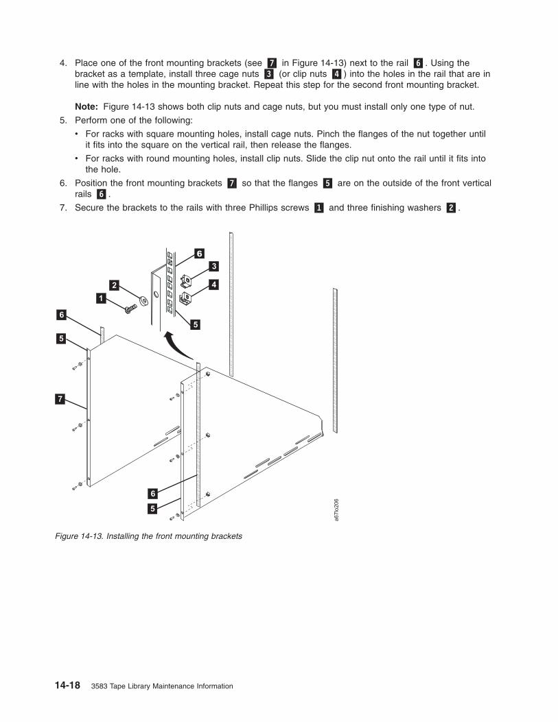
4. Place one of the front mounting brackets (see �7� in Figure 14-13) next to the rail �6�. Using the
bracket as a template, install three cage nuts �3� (or clip nuts �4�) into the holes in the rail that are in
line with the holes in the mounting bracket. Repeat this step for the second front mounting bracket.
Note: Figure 14-13 shows both clip nuts and cage nuts, but you must install only one type of nut.
5. Perform one of the following:
v For racks with square mounting holes, install cage nuts. Pinch the flanges of the nut together until
it fits into the square on the vertical rail, then release the flanges.
v For racks with round mounting holes, install clip nuts. Slide the clip nut onto the rail until it fits into
the hole.
6. Position the front mounting brackets �7� so that the flanges �5� are on the outside of the front vertical
rails �6�.
7. Secure the brackets to the rails with three Phillips screws �1� and three finishing washers �2�.
Figure 14-13. Installing the front mounting brackets
14-18 3583 Tape Library Maintenance Information

8. Place one of the rear mounting brackets (see �7� in Figure 14-14) next to the rail �6�. Using the
bracket as a template, install two cage nuts �3� (or clip nuts �4�) into the holes in the rail that are in
line with the holes in the mounting bracket. Repeat this step for the second rear mounting bracket.
9. Position the rear mounting brackets �7� so that the flanges �5� are on the outside of the rear vertical
rails �6�.
10. Secure the brackets loosely to the rails with two Phillips screws �1� and two finishing washers �2�.
a67lo
128
Rear View
1
2
7
7
5
3
46
8
5
6
5
6
Figure 14-14. Installing the rear mounting brackets
Chapter 14. Installation 14-19

11. Attach the front mounting brackets (see �2� in Figure 14-15) to the rear mounting brackets �1� by
placing four screws �3� through the slots, two on each side. Secure the brackets loosely by tightening
the screws.
12. Place the rear stop bracket �4� on the studs �5� located on the mounting brackets �2�. To have
clearance for the rear stop bracket, you may need to push the front mounting brackets against the
rear vertical rails. Secure the rear stop bracket by tightening the two nuts �6�.
13. Tighten all nuts and screws.
a67lo
129
Rear View
1
2
3
3
4
5
5 6
6
Figure 14-15. Installing the rear stop bracket
14-20 3583 Tape Library Maintenance Information

Remove Components to Reduce Library Weight
Required tools (not supplied): Phillips screwdriver and a 3/8-in. wrench
If drives are already installed in the library, go to step 3.
Note: When the library is secured in the rack you will not be able to see the serial number label
located on the lower left corner on the back of the library. Locate the serial number label and
record the serial number on the Library Configuration Form for future reference.
CAUTION:
The weight of this part or unit is more than 55 kilograms (121.2
pounds). It takes four people with a lifting device to safely lift
this part or unit. (C011)
1. Remove all of the cartridges �1� and magazines �2� from the storage columns within the library (see
Figure 14-16). To remove a magazine, grasp the tabs at its corners and pull the magazine toward you.
2. Close the front door securely.
3. To reduce its weight, remove all drive sleds and dc power supplies that are installed in the library. Note
the position of the drive sleds as you remove them; you will need to replace them in the same
positions. Loosen the captive thumbscrews �1� and slide the drive sled �2� and dc power supply �3�
out of the chassis (see Figure 14-17 on page 14-22).
a67lo
131
2
1
Figure 14-16. Removing cartridges and magazines
Chapter 14. Installation 14-21

Note: For the next procedure, use the sling to place the library onto its side.
4. Remove the four casters (�2� and �4� in Figure 14-18) from the bottom of the library. Use a 3/8-in.
wrench to remove the bolts �1� that secure each caster to the frame (there can be up to four bolts).
5. Return the library to its upright position.
Note: In the step that follows, open the front door (see �4� in Figure 14-19 on page 14-23) completely
before removing the side covers.
6. Remove the four Phillips screws �1� that secure each side cover �2�, then remove both side covers.
21
1
3
a67lo
125
Figure 14-17. Removing the drive sleds and the DC power supplies. The figure shows an Ultrium 1 Tape Drive on the
sled.
a67lo
119
2
3 4
1
1
Figure 14-18. Removing the casters
14-22 3583 Tape Library Maintenance Information

Place the Library into the Rack
1. From the front of the rack, use the handles �3� located on both sides of the library to lift the library
onto the rackmount hardware.
2. Slide the library (�1� in Figure 14-20) onto the rackmount hardware until it stops against the rear stop
bracket �3�. Using the two Phillips screws �2�, attach the library to the rear stop bracket �3�. This
ensures that the library is secured to the rack and is properly grounded.
a67
m0036
1
2
3
4
Figure 14-19. Removing the side covers
a67m
0035
1
2
3
2
Figure 14-20. Placing the library into a rack (illustration shows converted library)
Chapter 14. Installation 14-23

Replace Library Components
1. Use the following steps to install the drive sleds that you removed in step 3 on page 14-21.
a. From the rear of the library, locate the drive slot where you want to install a drive sled.
b. Slide the drive sled �2� into position and tighten the two captive thumbscrews �1� (see
Figure 14-21).
Attention: Up to 240 V ac is present at the power supply connectors when the main power
cord is connected to a power source.
2. Use the following steps to install the dc power supplies that you removed in step 3 on page 14-21.
a. From the rear of the library, locate the slot where you want to install the dc power supply.
Note: Before inserting the dc power supply, be sure to orient the power supply so that the
light-emitting diode (LED) �3� is located as shown in Figure 14-22.
b. Slide the dc power supply �1� into position until it mates with the power distribution board and
tighten the two captive thumbscrews �2�.
3. Reinstall the magazines and cartridges that you removed in step 1 on page 14-21.
4. If you intend to install one or more optional features, go to “Step 8. Install Optional Features” on page
14-25. Otherwise, go to “Step 10. Install Cables and Terminators” on page 14-34.
a67m
0037
2
3
1
Figure 14-21. Installing a drive sled
a67m
0038
1
2
3
Figure 14-22. Proper orientation of the dc power supply
14-24 3583 Tape Library Maintenance Information

Step 8. Install Optional Features
If you are not installing an optional feature, go to “Step 9. Reposition Drives for Partitioning” on page
14-33.
If you ordered one or more optional features, install them now. Refer to Table 14-2 to find the correct
procedure.
Note: Except for the Multi-Path feature, the customer is responsible for installing all optional features.
Table 14-2. Optional Features
To install... Go to page...
Installing a drive sled 14-25
Redundant dc power supply (feature code 8008) 14-30Must be installed by a trained IBM Service Representative
San Data Gateway Module 14-31
12-slot I/O station (feature code 8012) 14-29
18-slot tape storage column (feature code 8007) 14-26
6-cartridge magazine with cover (feature code 8013) 14-30
Installing a Drive Sled
When installing drive sleds for SCSI and Fibre Channel Tape Drives in the Ultrium Scalable Tape Library,
you must insert the first sled in the bottom drive slot (slot 1). Add subsequent sleds directly above the last
sled that is installed, from bottom to top (slots 2, 3, 4, 5, 6) with no empty slots (see Figure 14-23).
If you use partitioning, refer to the Setup and Operator Guide for guidelines.
Drive sleds that are attached to the same SCSI server must be installed next to each other in the library or
the drive-to-drive cables may not reach. For example, if the library uses LVD, HVD, and Fibre Channel
drives, all drive sleds that attach to these drives must be together. If there is more than one server for the
LVD, HVD/DIFF, or Fibre Channel drive sleds, the sleds that attach to the same server must be installed
together.
Note: The Multi-Path Ultrium Scalable Tape Library consists of up to six SCSI devices: the six drives. The
default settings for the SCSI IDs are 1 through 6 for the drives.
1. Use the server to set the library and the drives Offline for all attached servers.
2. Power-off the Ultrium Scalable Tape Library by pushing O on the power switch (see �1� in
Figure 14-26 on page 14-27).
Figure 14-23. Correct order for installing drive sleds (illustration shows converted library)
Chapter 14. Installation 14-25
|

3. From the rear of the library, locate the drive slot where you want to install the drive sled. Loosen the
two captive thumbscrews on the filler plate and remove the filler plate (see �1� in Figure 14-24 or
Figure 14-25). Save the filler plate for future drive maintenance activity.
4. Slide the tape drive sled �2� into position and tighten the two captive thumbscrews.
5. Install any additional optional features (see “Step 8. Install Optional Features” on page 14-25).
Otherwise, go to “Step 9. Reposition Drives for Partitioning” on page 14-33.
Installing a Storage Column
Tools Required
v 10 mm or 3/8 in. nut driver or flat head screw driver
v T20 Torx driver
v Flashlight (optional)
Verify Shipment Contents
Check Off Part Number Description
19P4527 Storage Column (FC 8007)
Four 8-32 X 3/8 Torx 20 screws
Four 1/4-20 X 1/2 hex bolts, sloted
18P8886 Magazine Alignment Plates Kit (OPTIONAL FOR COLUMN 4 ONLY)
19P1501 Installation Instructions
Preparing for Installation
For instructions on removing an existing storage column, refer to IBM TotalStorage Ultrium Scalable Tape
Library 3583 Maintenance Information (SA37-0425). To install a storage column, complete the steps below.
__ Step 1. Use the server to set the library and drives Offline for all attached servers.
Figure 14-24. Installing a drive sled that contains an Ultrium 1 Tape Drive
Figure 14-25. Installing a drive sled that contains an Ultrium 2 or Ultrium 3 Tape Drive
14-26 3583 Tape Library Maintenance Information

__ Step 2. Power-off the library by pushing O on the power switch (see �1� in Figure 14-26).
__ Step 3. Open the library’s front door.
__ Step 4. If necessary, gently move the picker assembly to a position in the Y-axis to allow access room.
Installing Magazine Alignment Plates Kit in Column 4 (Optional)
Note: Column magazine alignment plates are to be installed in Column 4 only!
To install the Column Magazine Alignment Plates in Column 4:
__ 1. Place the column on its back on a sturdy work surface and remove the magazines, if necessary.
__ 2. Place a white alignment plate in each magazine slot in the column (�1�) and push each alignment
plate firmly against the back wall of the column (�2�).
a67lo
357
1
Figure 14-26. Main power switch
Figure 14-27. Optional Column Magazine Alignment Plates for Column 4 only
Chapter 14. Installation 14-27

Installing Storage Columns
Note: Any parts removed during this installation and not specified for reinstallation are the property of the
library owner.
Installing Storage Column 4:
__ 1. Insert the column inside the chassis along the right wall aligning the holes in the floor of the column
with the holes in the floor of the chassis.
__ 2. Insert a T20 Torx driver through the access holes (�4� in Figure 14-28) in the bottom shelf of the
column, and install two 8-32 X 3/8 Torx 20 screws (�5� in Figure 14-28) to attach the storage
column to the floor of the chassis.
__ 3. Using a nut driver or flat head screw driver, install one 1/4-20 X 1/2 bolt (see �1� in Figure 14-28) to
secure the top of the column to the chassis.
__ 4. Insert all magazines (see �2� in Figure 14-28) in the storage column.
__ 5. Proceed to “Installing Storage Column 5” or bring the library back online and resume normal
operations.
Installing Storage Column 5:
1. Insert the column inside the chassis with the back of the column against the mounting bracket located
in the front right corner of the floor of the chassis.
2. Using a nut driver or flat head screw driver, insert and tighten one 1/4-20 X 1/2 bolt (�3� in
Figure 14-28) to attach the storage column to the mounting bracket located in the front right corner of
the floor of the chassis.
3. Using the nut driver or flat head screw driver, install one 1/4-20 X 1/2 bolt (see �1� in Figure 14-28) to
secure the top of the column to the chassis.
4. Insert all magazines (see �2� in Figure 14-28) in the storage column.
5. Bring the library back online and resume normal operations.
a67m
0021
1
2
Top Attachment for all Storage Columns
Bottom Attachment forStorage Columns 2 and 4
Bottom Attachment forStorage Column 5
3
4
5
Figure 14-28. Installing a storage column
14-28 3583 Tape Library Maintenance Information

Installing a 12-Slot I/O Station
Required tools (not supplied): T20 Torx driver and a 11/32-in. nut driver.
1. Power-off the Ultrium Scalable Tape Library by pushing O on the power switch (see �1� in
Figure 4-19 on page 4-11).
2. Open the library’s front door.
3. If present, remove the cartridge from the single-slot I/O station.
4. Remove the four I/O station cable clamps (see �1� in Figure 14-29). Three of the cable clamps are
attached to the door with a T20 Torx screw, and one is attached with a 11/32-in. nut.
5. Disconnect the I/O station cable connector �7� from the display assembly �2�.
6. Remove the eight 11/32-in. nuts �6� (four on each side) that secure the I/O station assembly to the
front door.
7. Remove the single-slot I/O station.
8. The 12-slot I/O station is installed the same way as the single-slot I/O station. Perform the above
steps in reverse order to install the 12-slot I/O station.
9. Insert two magazines �4� in the I/O station and one magazine �5� in the fixed location below the I/O
station magazines.
10. Install any additional optional features (see step “Step 8. Install Optional Features” on page 14-25).
Otherwise, go to “Step 9. Reposition Drives for Partitioning” on page 14-33.
a67m
0025
1 1
6
2 3
57
4
Figure 14-29. Installing the 12-slot I/O station
Chapter 14. Installation 14-29

Installing a 6-Cartridge Magazine
1. Open the door of the library.
2. Grasp the sides of the magazine and press it into one of the magazine slots.
3. Close the front door.
Installing a Redundant dc Power Supply
Attention: Up to 240 V ac is present at the power supply connectors when the main power
cord is connected to a power source.
1. Verify that the correct dc power supply is currently installed in the library by locating the dc power
supply at the rear of the library (see �1� in Figure 14-30 and examining it for a label:
v If the new power architecture (NPA) label �2� is present, the redundant dc power supply must also
bear the NPA label.
v If the NPA label is not present, the redundant dc power supply must not bear the NPA label.
v If the labels on the dc power supplies do not match, do not continue with this installation. Contact
your IBM Business Partner or IBM Marketing Representative to order the correct dc power supply.
v If the labels on the dc power supplies match, go to step 2 to continue the installation.
Note: The presence of the NPA label indicates that the Ultrium Scalable Tape Library contains a new
power architecture and requires a new level of dc power supply. The library will not operate
properly if the power supplies and power architectures are not at the same level.
2. Locate the slot �3� where the redundant dc power supply will be installed.
3. Loosen the two captive thumbscrews �4� on the cover plate and remove the cover plate (see
Figure 14-31 on page 14-31).
Note: Before inserting the dc power supply, be sure to orient the power supply so that the LED �3� is
located as shown in Figure 14-31 on page 14-31.
4. Slide the power supply (�1� in Figure 14-31 on page 14-31) into position until it mates with the power
distribution board and tighten the two captive thumbscrews �2�.
5. Inspect the rear panel to ensure that all LEDs are green.
a67m
0264
NPA
2
1
3
4
Figure 14-30. Installing a redundant dc power supply (illustration shows converted library)
14-30 3583 Tape Library Maintenance Information

v If all LEDs are green, proceed with the installation.
v If any LEDs are not green:
a. Power off the library.
b. Loosen the two thumbscrews on the power supply.
c. Pull the power supply part way out of the library.
d. Push the power supply back into the library.
e. Tighten the two thumbscrews on the power supply.
f. Power on the library.
– If all LEDs are green, proceed with the installation.
– If any LEDs are not green, contact your Service Representative.
6. Install any additional optional features (see step “Step 8. Install Optional Features” on page 14-25).
Otherwise, go to “Step 9. Reposition Drives for Partitioning” on page 14-33.
Installing a San Data Gateway Module
Note: This feature is not supported with Ultrium 3 drives.
The San Data Gateway Module enables the SCSI protocol to be converted to Fibre Channel protocol. The
following procedure applies only to libraries that do not have native Fibre Channel connections.
Verify Module Kit Inventory
__ 1. Four VHDCI-to-HD68 SCSI bus (signal) cables (0.6 m)
__ 2. Two 2-Gbit GBICs (installed in gateway)
__ 3. LVD terminator
__ 4. IBM Storage Area Network Data Gateway Module Setup, Operator, and Service Guide
__ 5. Service accessory kit:
v VHDCI-to-VHDCI SCSI wrap cable (0.5 m)
v SC-to-SC Fibre Channel coupler block
v Gateway service tools:
– Null modem cable
– Ethernet wrap tool
– Fibre Channel wrap tool
a67m
0038
1
2
3
Figure 14-31. Installing a redundant dc power supply
Chapter 14. Installation 14-31
|

Install the Module
1. From the rear of the Ultrium Scalable Tape Library, locate the dc power supply (see �3� in
Figure 14-32) and examine it for a label:
a. If the NPA label �4� is present, proceed with the installation of the San Data Gateway Module.
b. If the NPA label �4� is not present, the library does not have the required power architecture to
support the San Data Gateway Module. Do not continue with this procedure. Contact your IBM
Business Partner or IBM Marketing Representative to order the necessary parts.2. Use the server to set the library and drives Offline for all attached servers.
3. Power-off the Ultrium Scalable Tape Library by pushing O on the power switch (see �1� in Figure 4-19
on page 4-11).
4. From the rear of the library, locate the slot where you want to install the gateway (see Figure 14-32).
Loosen the two captive thumbscrews on the cover plate and remove the cover plate.
5. Slide the gateway into position (see �1� in Figure 14-32) and tighten the two captive thumbscrews �2�.
6. Install any additional optional features (see step “Step 8. Install Optional Features” on page 14-25).
Otherwise, go to “Step 9. Reposition Drives for Partitioning” on page 14-33.
Note: After you have completed the installation of the library, go to the installation section in the IBM
Storage Area Network Data Gateway Module Setup, Operator, and Service Guide to configure
the gateway for use. IBM does not supply the fiber cable for this installation. To order the
appropriate fiber cable, contact your IBM Business Partner or IBM Marketing Representative.
a67lo
359
1
3
42
NPA
Figure 14-32. Installing a San Data Gateway Module
14-32 3583 Tape Library Maintenance Information

Step 9. Reposition Drives for Partitioning
Drives are preinstalled in the library at the factory for testing purposes before the library is shipped to the
customer. It may be necessary to reposition the drives to partition the library.
Note: For more information on partitioning, refer to Installation Planning in the Setup and Operator Guide.
To reposition a drive, perform the following:
1. Power off the library.
2. Loosen the thumbscrews (�1�) on the drive sled (�2�).
3. Pull the drive from the column using the handle (�3�). Support the bottom of the drive with your other
hand.
4. Move the drive to its new location.
5. Tighten the thumbscrews (�1�).
6. Repeat this procedure for each drive that needs to be repositioned.
a67m
0016
1
2 3
Figure 14-33. Repositioning a drive sled for partitioning
Chapter 14. Installation 14-33

Step 10. Install Cables and Terminators
To install cables and terminators, choose one of the following procedures:
v “Making a Host-to-Drive Connection With Two Drives per SCSI Bus.”
v “Making Host-to-Drive Connections with Native Fibre” on page 14-37.
v “Making Host-to-Drive Connections with the San Data Gateway Module” on page 14-38.
Making a Host-to-Drive Connection With Two Drives per SCSI Bus
To make a host-to-drive connection with the SCSI Multi-Path feature and two servers (hosts):
1. Attach the first host cable (�1� in Figure 14-34) to the lowest available drive in the logical library.
2. If attaching to the next device in a chain, connect the cable �2� to the other SCSI connector �3� on the
drive.
3. Insert a SCSI terminator �4�. Make sure that you use the terminator and not the wrap tool. They
look very similar. You can tell the difference by their part numbers, which are stamped on each.
4. Attach a second host cable �5� to one of the SCSI connectors on Drive 3 and terminate the remaining
connector �6�.
Figure 14-34. Making the host-to-drive connections with the SCSI Multi-Path feature and two hosts
14-34 3583 Tape Library Maintenance Information

Making a Host-to-Drive Connection With Three or more Drives per
SCSI Bus
Note: For optimum performance, it is recommended to have a maximum of two drives per SCSI bus.
To make a host-to-drive connection with three or more drives per SCSI bus:
1. Attach the host cable (�1� in Figure 14-35 on page 14-36) to the lower SCSI connector in the lowest
drive in the logical library.
2. To attach to the next device in a chain, connect the cable �2� to the upper SCSI connector in the
lowest drive in the logical library and to the lower SCSI connector �3� on the next drive. Repeat this
step for every drive in the SCSI bus.
EXCEPTION: If there are more than two drives in the library, either the drives should be split between
SCSI buses so that there are no more than two drives per SCSI bus, or connect the drives so that no
more than two consecutive drives are connected using the same cable length. Drives connected using
cables less than 1 m �2� should be separated from other drives by cables greater than or equal to 1 m
�5�.
Table 14-3. Correct position of longer cable with three or more drives per SCSI bus
No. of Drives in SCSI Bus Longer Cable Connecting These Drives
3 2 and 3
4 2 and 3
5 2 and 3; 4 and 5
6 2 and 3; 4 and 5
3. Insert a SCSI terminator in the top SCSI connector �6� on the last drive in the SCSI Bus. Make sure
that you use the terminator and not the wrap tool. They look very similar. You can tell the
difference by their part numbers, which are stamped on each.
Chapter 14. Installation 14-35

a67m
0267
5
6
12
3
4
Figure 14-35. Making the host-to-drive connections with three or more drives per SCSI bus
14-36 3583 Tape Library Maintenance Information

Making Host-to-Drive Connections with Native Fibre
Note: The Multi-Path feature is a prerequisite to having Fibre Channel drives in the Ultrium Scalable Tape
Library.
To connect to the host by using a native Fibre Channel connection, attach the host cables (�1� in
Figure 14-36) to the LC connectors �2� of the Ultrium 2 Tape Drives that you want.
Figure 14-36. Making the host-to-drive connections with native Fibre Channel (Multi-Path library)
Chapter 14. Installation 14-37

Making Host-to-Drive Connections with the San Data Gateway Module
Notes:
1. This feature is not supported with Ultrium 3 drives.
2. IBM does not supply the fiber optic cable for this procedure. To order the appropriate fiber cable,
contact your IBM Business Partner or IBM Marketing Representative
IBM recommends that you use a fiber cable with 50-micron core fiber.
Before installing the fiber and SCSI cables, inspect all cables for damage. Do not install a cable if it is
damaged. Report the damage immediately by contacting your place of purchase.
Figure 14-37 shows examples of the Fibre Channel and SCSI connectors.
�1� LC Fibre Channel connector �4� HD68 SCSI connector
�2� SC Fibre Channel connector �5� VHDCI SCSI connector
�3� SC-to-LC Fibre Channel interposer
Connecting the Fiber Cable from the Host to the Library
Attach the fiber cable from the host (server) to the GBIC of one of the Fibre Channel connectors on the
gateway (�1� in Figure 14-38 on page 14-39).
Note: The short-wave, multimode GBICs that are installed in the gateway are SC-style and are capable of
2-Gbit speeds. They automatically switch to a 1-Gbit speed if attached to a 1-Gbit system. The
installed GBICs support a maximum cable length of 300 m (984 ft) at 2-Gbit speeds and 500 m
(1640 ft) at 1-Gbit speeds. If you are attaching to a server that has an LC-style connector, you will
need to use an SC-to-LC fiber optic cable, or an SC-to-SC cable and an LC-to-SC interposer.
Connecting the SCSI Cables from the Library to the Drives
Because the SCSI ports on the gateway are LVD, use only the LVD connections on the library’ SCSI host
interface board and LVD drives. Figure 14-38 on page 14-39 shows examples of SCSI cable connections
with three drives and six drives installed. The host cable is shown as �1�.
Note: The cabling configuration may affect performance.
a6
7m
00
85
1 2 3
4 5
Figure 14-37. Cable connectors
14-38 3583 Tape Library Maintenance Information
|
|
||

1. Attach the SCSI cables �2� from the drives to the SCSI ports of the gateway. (Four 0.6-m
VHDCI-to-HD68 SCSI cables are provided with each library. If your library is installed with more than
four drives, daisy-chain the drives by using HD68-to-HD68 cables �3�.)
2. Install a terminator �6� on the last SCSI device on each SCSI bus. Each of the four gateway SCSI
ports is a separate SCSI bus. Each one must be terminated at the last device on the bus.
Note: Ensure that you are using an LVD terminator. Also, IBM provides a terminator for each drive
and the library.
3. Go to “Step 11. Turn on Power” on page 14-40 to continue the installation of the library.
a67m
0263
6
6
1
1
2
3
Figure 14-38. Example of cabling with three or six drives installed (Multi-Path library). The library with three drives is
on the left; the library with six drives is on the right.
Chapter 14. Installation 14-39

Step 11. Turn on Power
Attention: Before turning on the power, make sure that qualified personnel verify
the proper voltage at the outlet. If the voltage is incorrect, damage to the power
supply could occur.
1. Push | on the power switch to turn on the power. The library takes a few minutes to perform
initialization.
2. Inspect the rear panel to ensure that all drive LEDs are green.
v If all LEDs are green, proceed with the installation.
v If any LEDs are not green:
a. Power off the library.
b. Loosen the two thumbscrews on a drive.
c. Pull the drive part way out of the library.
d. Push the drive back into the library.
e. Tighten the two thumbscrews on the drive.
f. Power on the library.
– If all LEDs are green, proceed with the installation.
– If any LEDs are not green, contact your Service Representative.
3. The library firmware automatically initializes and starts the inventory/teach process. After initialization is
complete, proceed to the next section for information on partitioning the library.
14-40 3583 Tape Library Maintenance Information
|

Step 12. Partition the Library
To partition the library, perform the following steps.
Shortcut: Main Menu (initial screen) —> More —> Setup —> Library
—> Partitions
Note: Most functions can be performed with the library Online or Offline. If a function requires the library
to be Offline, the function will first provide a selection to go Offline.
The Partitions Dialog displays the number of logical libraries that are currently partitioned (see
Figure 14-39).
The Partition Dialog contains the following information:
part The quantity of logical libraries in the library. Valid values are from 1 to 3.
MB Indicates that the I/O station is configured as storage or as an I/O station. Valid values are
storage and I/O.
Perform one of the following:
v To accept the current quantity of logical libraries, press the button below the OK softkey.
v To change the quantity of logical libraries, press the button below the Next softkey until the quantity that
you want displays in the Partition available field, then press the button below the OK softkey. To
activate the changes, follow the instructions to reboot the library.
OK Next Cancel
OFFLINE
a6
7lo
33
8
Partitions available1 part MB=storage
>1 part MB=IO2 part MB=IO3 part MB=IO
>
>>
UltriumTapeLibrary
03/12/03 19:59WED
Figure 14-39. Partitions Dialog
Chapter 14. Installation 14-41

Step 13. Set SCSI and FC IDs
Setting the SCSI IDs
The Multi-Path Ultrium Scalable Tape Library consists of up to six SCSI or fiber devices. The default
settings for the SCSI IDs are 1 through 6 for the drives. Depending on your requirements, you may need
to change the SCSI ID default settings for your installation.
Notes:
1. Do not select an ID that is already in use on the same SCSI bus.
2. Do not select the SCSI ID of the SCSI host adapter card. On the SCSI bus, any initiator (such as a
host adapter card) that needs to communicate with the library must have its SCSI ID set from 0 to 15.
The SCSI ID of the SCSI host adapter card is usually higher than any device on the SCSI bus.
Generally, the SCSI ID for the host adapter is 7.
3. Use similar precautions for setting fibre loop IDs.
Setting the SCSI IDs of the Drives
To determine the existing SCSI IDs for the drives, perform the following steps:
Shortcut: Main Menu (initial screen) —> More —> Setup —> Drives —>
SCSI/FC
1. The current drive is the value in the Drive: field. The existing drive’s SCSI ID is the value in the SCSI
ID: CURRENT field.
To change the current drive, press the button below the Change Drive softkey until the number of the
drive you want displays in the Drive: field, then select OK.
To change the SCSI ID setting for the drive, perform the following steps:
1. Press the button below the Next softkey. The Drive SCSI ID Dialog displays (see Figure 14-41 on
page 14-43).
ONLINE
a67lo
350
UltriumTapeLibrary
09/25/03 12:55THU
OK NextChange
DriveCancel
Drive :Control path: ON
CURRENT NEWSCSI ID: 002 002Drives with this ID:
NONE
01
Figure 14-40. Drive SCSI Dialog
14-42 3583 Tape Library Maintenance Information
|
|

2. Press the button below the Up or Down softkey until the ID that you want displays in the SCSI ID: NEW
field.
3. Press the button below the Next softkey until the OK softkey displays.
4. Press the button below the OK softkey to accept the new ID.
5. To activate the new SCSI ID, cycle power to the library (turn it off, then on again).
Setting the FC IDs
To determine the existing Fibre Channel Loop IDs for the drives, perform the following steps.
Shortcut: Main Menu (initial screen) —> More —> Setup —> Drives —>
SCSI/FC
Note: Even though the library may contain fibre channel drives, the softkey on the operator panel will
show ″SCSI″. However, the drives will be correctly identified as SCSI or fiber in subsequent
screens.
1. The submenu gives the settings for the selected Fibre Channel drive. The value of the current drive
displays in the Drive: field. Acceptable values are 000 to 127. The value of its FC ID displays in the FC
ID: CURRENT field.
To change the current drive, press the button below the Change Drive softkey until the number of the
drive you want displays in the Drive: field, then select OK.
To change the Loop ID setting for the drive, perform the following steps:
ONLINE
a67lo
349
UltriumTapeLibrary
09/25/03 12:55THU
Up NextDown Cancel
Drive : 01Control path: ON
CURRENT NEWSCSI ID: 002Drives with this ID:
NONE
002
Figure 14-41. Drive SCSI ID Dialog
Figure 14-42. FC Submenu
Chapter 14. Installation 14-43
|
|||
|
|

1. Press the button below the Next softkey. The Loop ID Dialog displays (see Figure 14-43).
2. Press the button below the Up or Down softkey until the ID that you want displays in the FC ID: NEW
field.
3. Press the button below the Next softkey until the OK softkey displays.
Figure 14-43. Loop ID Dialog
14-44 3583 Tape Library Maintenance Information
|

Step 14. Add Control Paths
The maximum allowable control paths for a library is equal to the quantity of drives assigned to that library.
Enter the Control Path Failover License Key
The Ultrium Scalable Tape Library requires that you use an 8-character license key to enable the control
path failover feature. To enter a license key, perform the following steps.
Note: The Control Path Failover License Key must be purchased separately. Contact your IBM Sales
Representative and order Feature Code 1680.
Shortcut: Main Menu (initial screen) —> More —> Setup —> Utils —>
More —> License
The License Dialog displays (see Figure 14-44).
v Perform one of the following:
– To accept all characters in the license key, press the button below the OK softkey.
– To select another character, press the button below the Next softkey until the character that you
want is highlighted. To increment that character, press the button below the Up softkey until 0
through 9 or A through F displays.
v Press the button below the OK softkey, then press the button below the Drives softkey. Continue to the
next section to add control paths.
Add Control Paths
1. Press the button below the SCSI/FC softkey. Depending on the type of drive, the SCSI or FC
Submenudisplays (see Figure 14-45 on page 14-46). The submenu gives the settings for the selected
Fibre Channel drive. The value of the current drive displays in the Drive: field. The Control path field
indicates whether the drive is a control path. Valid values are OFF or ON.
Figure 14-44. License Dialog
Chapter 14. Installation 14-45
|

2. Perform one of the following:
v To accept the current values in the screen, press the button below the OK softkey.
v To change the value of the drive, press the button below the Change Drive softkey until the drive
that you want displays in the Drive field.
v To change the status of the drive as a control path, press the button below the Next softkey until ON
(to add) or OFF (to remove) displays in the Control path: field.
3. To return to the Drives Submenu, press the button below the Cancel softkey. To return to the Main
Menu, press the button below the Cancel softkey, then press the button below the Back softkey until
the Main Menu displays.
ONLINE
a6
7lo
35
1
UltriumTapeLibrary
09/25/03 12:55THU
OK NextChange Cancel
Drive : 01Control path:
CURRENT NEWSCSI ID: 002 002Drives with this ID:
NONE
ON
Figure 14-45. SCSI Submenu
ONLINEa
67
lo3
48
UltriumTapeLibrary
09/25/03 12:55THU
OK NextChange Cancel
Drive : 01Control path:
CURRENT NEWFC ID: 126 126Drives with this ID:
NONE
ON
Figure 14-46. Loop Submenu
14-46 3583 Tape Library Maintenance Information

Step 15. Install Additional Options
The following optional installations can be completed at this time.
v “Configure the San Data Gateway Module (optional)”
v “Configure Other Options using Config Dialog”
v “Enable Operator Panel Security” on page 14-49
Configure the San Data Gateway Module (optional)
Note: This feature is not supported with Ultrium 3 drives.
If you choose to use the library’s San Data Gateway Module, refer to the instructions for configuring the
gateway in the IBM Storage Area Network Data Gateway Module Setup, Operator, and Service Guide.
Configure Other Options using Config Dialog
Using the Config Dialog on the operator panel, the following options can be configured:
v Operator panel backlighting
v Operator panel audio
v Cartridge scan on initialization
v Cartridge touch on initialization
v I/O station used as storage
Shortcut: Main Menu (initial screen) —> More —> Setup —> Utils —>
Config
1. Navigate to the Setup Menu. For instructions, see “Accessing the Setup Menu” on page 4-8.
2. Press the button below the Utils softkey. The Utils Dialog displays (see Figure 14-48).
Figure 14-47. Setup Menu
Figure 14-48. Utils Submenu
Chapter 14. Installation 14-47
|

3. Press the button below the Config softkey. The Config Dialog displays (see Figure 14-49) with the
following information:
Field Value Description
Backlight on Yes Turns on the backlighting
No Turns off the backlighting
Audio on Yes Enables audio output
No Disables audio output
Scan on Init Yes The picker will scan for all cartridges upon library
initialization.
No The library will not scan for all cartridges upon library
initialization.
Touch on Init Yes Unlabeled tape inventory support
No No unlabeled tape inventory support
Mailbox (I/O Station) Imprt/Exprt The I/O station is configured as a cartridge
import/export location. Recommended setting
Storage The I/O station is configured as cartridge storage.
Attention:
It is recommended that the library be configured to Scan on Init unless your library has no bar code
labels. In that case, Touch on Init should be also be enabled.
4. Press the button beneath the desired softkey.
v If the button beneath the OK softkey is pressed, the current field values are accepted, and the Utils
Submenu is displayed (see Figure 14-48 on page 14-47).
v If the button beneath the Yes/No softkey is pressed, the selected field is changed to one of the
associated field values listed above.
v If the button beneath the Next softkey is pressed, the next field in the list is made active. If the next
field is the last field, the Config I/O Station Dialog is displayed (see Figure 14-50).
v If the button beneath the Cancel softkey is pressed, the Utils Submenu is displayed (see
Figure 14-48 on page 14-47).
OK Yes/No Next Cancel
OFFLINE
a6
7lo
16
1
Backlight on : Yes
Audio on : Yes
Scan on Init : Yes
Touch on Init: No
I/O: Import/ExportFAST Read/Write
UltriumTapeLibrary
03/06/02 08:00TUE
Figure 14-49. Config Dialog
OFFLINE
A6
7lo
35
3
UltriumTapeLibrary
09/25/03 12:55THU
OK NextChange Cancel
Backlight onAudio onScan on InitTouch on InitMailbox:
: Yes: Yes: Yes: No
Imprt/Exprt
Figure 14-50. Config I/O Station Dialog
14-48 3583 Tape Library Maintenance Information
|
|
||

5. In the Config I/O Station Dialog, press the button beneath the desired softkey.
v If the button beneath the OK softkey is pressed, the current field values are accepted and the Utils
Submenu is displayed (see Figure 14-48 on page 14-47).
v If the button beneath the Change softkey is pressed, the Mailbox (I/O station) field value is changed
to Import/Export or Storage.
v If the button beneath the Next softkey is pressed, the Config Dialog is displayed (Figure 14-49 on
page 14-48).
v If the button beneath the Cancel softkey is pressed, the Utils Submenu is displayed (see
Figure 14-48 on page 14-47).
Note: If you configure the I/O station as storage slots, you must cycle power to the library (turn it off, then
on) to make the change take effect.
Enable Operator Panel Security
The Enable Security feature allows you to protect your data. The default setting is Disable Security, but
you can enable security by using the following procedure.
Note: When security is enabled, the library will prompt you for your password each time that you attempt
to access certain protected procedures.
To enable security on the library, perform the following steps.
Shortcut: Main Menu (initial screen) —> More —> Setup —> Utils —>
Secure
1. Navigate to the Setup Menu. For instructions, see “Accessing the Setup Menu” on page 4-8.
2. Press the button below the Utils softkey. The Utils Dialog displays (see Figure 14-52).
Figure 14-51. Setup Menu
Figure 14-52. Utils Submenu
Chapter 14. Installation 14-49

3. Press the button below the Secure softkey. The Secure Dialog displays (see Figure 14-53).
4. Press the button below the Yes/No softkey until a checkmark displays in the checkbox beside the
Enable Security field. The library displays the message Security is now ON.
5. Press the button below the OK softkey to redisplay the Secure Dialog and view the new setting.
6. Press the button below the OK softkey and return to the Utils Submenu.
Change Your Password
After you have enabled operator panel security, change the password. The initial login password is 0000.
When changing your password, record the new password on the Library Configuration Form and place the
form in a secure location.
Note: The RMU password is different from the operator panel password. To change your RMU password,
see “Configuration” on page 3-11.
To change the operator panel password, follow these steps:
1. Press the button below the Secure softkey. The Enter Password Dialog displays (see Figure 14-54).
Note: If security is enabled, you must enter the existing or default password (0000) to display the
Secure Dialog (see Figure 14-55 on page 14-51).
2. Enter your existing password by pressing the button below the Next softkey until the selection cursor
highlights the first character in the New field. Press the button below the Up or Down softkeys to
increase or decrease the numeric value.
3. Press the button below the OK softkey. The Secure Dialog screen displays (see Figure 14-55 on
page 14-51).
Note: In Figure 14-55 on page 14-51, the absence of a checkmark in the checkbox beside the
Enable Security field indicates that security has not been enabled.
Figure 14-53. Secure Dialog
Figure 14-54. Enter Password Dialog
14-50 3583 Tape Library Maintenance Information

4. Press the button below the Next softkey to highlight the Set/Change Password field.
5. Press the button below the Change softkey. The Set/Change Password Dialog displays (see
Figure 14-56).
6. Enter the old password by pressing the button below the Next softkey until the selection cursor
highlights the first character in the Old field. Press the button below the Up or Down softkeys to
increase or decrease the numeric value. Repeat for each character in the old password, then press
the button below the OK softkey to go to the New field.
7. Enter the new password by pressing the button below the Next softkey until the selection cursor
highlights the first character in the New field. Press the button below the Up or Down softkeys to
increase or decrease the numeric value. Repeat for each character in the new password.
8. Verify that the passwords are correct on the display, then press the button below the OK softkey to
effect the change. The library displays the message The password has been changed.
9. To return to the Secure Dialog, press the button below the OK softkey. To return to the Main Menu,
press the button below the OK softkey.
10. To continue to return to the Main Menu, press the button below the Back softkey until the Main Menu
displays.
Note: When changing your password, record the new password on the Library Configuration Form.
Figure 14-55. Secure Dialog
Figure 14-56. Set/Change Password Dialog
Chapter 14. Installation 14-51

Step 16. Import Cleaning Cartridge(s)
Note: Cleaning cartridges are not required to be labeled, and are transparent and inaccessible to the
server when they are at their fixed slot locations.
Before you import a cleaning cartridge, make sure that autoclean is enabled (see “Enabling and Disabling
Automatic Cleaning” on page 4-49).
Shortcut: Main Menu (initial screen) —> Command —> I/O Station —>
AutoClean —> Import
1. Navigate to the Command Menu. For instructions, see “Accessing the Command Menu” on page 4-7.
2. Press the button below the I/O Station softkey. The I/O Station Submenu displays (see Figure 14-58).
3. Press the button below the AutoClean softkey. The AutoClean Dialog displays (see Figure 14-59) with
the following information about cleaning cartridges and cleaning slots in the library.
Figure 14-57. Command Menu
Figure 14-58. I/O Station Submenu
Figure 14-59. AutoClean Dialog
14-52 3583 Tape Library Maintenance Information

á
Represents the quantity of storage slots that are designated for a cleaning cartridge.
A cleaning slot is located at the top of columns 2, 4, and 5. In the AutoClean Dialog,
slot 1 refers to the slot in column 2, slot 2 refers to the slot in column 4, and slot 3
refers to the slot in column 5. A shaded box means that the slot is occupied; a box
that contains no shading means that the slot is empty.
UseCnt The number of times that the cleaning cartridge has been used to clean a drive.
Valid values are 0 through 99, or EXP for an expired cartridge.
Note: This count is maintained by the drive firmware and stored in a cartridge
memory save area on the cleaning cartridges.
MaxCnt The number of times that the cleaning cartridge can be used to clean a drive. Valid
values are 50 (the maximum) or EXP for an expired cartridge. Values in the MaxCnt
column are read only.
Status Indicates whether the AutoClean function is currently enabled (Active) or disabled
(Inactive).
4. If no cleaning cartridge is present in the library (each of the three rectangular boxes contain no
shading), import a cleaning cartridge by pressing the button below the Import softkey. The Cleaning
Tape screen displays (see Figure 14-60).
Note: The Import softkey is only available if there are empty cleaning cartridge storage slots; the
Export soft key is only available if there is at least one cleaning cartridge.
5. Open the door of the I/O station and place a cleaning cartridge into the top slot of the I/O station. Use
only the top slot of the I/O station.
6. Close the door of the I/O station. The library executes the TEACH and INVENTORY procedures.
7. Perform one of the following:
v To return to the AutoClean Dialog, press the button below the OK softkey.
v To return to the Main Menu press the button below the OK softkey twice, then press the button
below the Back softkey until the Main Menu displays.
Figure 14-60. Cleaning Tape screen
Chapter 14. Installation 14-53
||

Step 17. Populate the Library with Data Cartridges
Attention: Do not use this method to insert a cleaning cartridge into the library. To insert a cleaning
cartridge, see “Step 16. Import Cleaning Cartridge(s)” on page 14-52.
To directly insert media, perform the following procedure:
1. Use the operator panel to place the library into the Offline state (Main Menu > Online/Offline > OK).
The picker completes any current task.
2. Unlock and open the library door.
3. Place the cartridges into the desired storage slots.
4. Close and lock the door.
The library executes the TEACH and INVENTORY procedures.
14-54 3583 Tape Library Maintenance Information

Step 18. Configure the RMU
The Remote Management Unit (RMU) is a removable circuit board that facilitates access to the web and
the TotalStorage Specialist. After you configure the RMU, you can perform all of the library’s operator
panel operations from a remote site.
To set up the RMU for proper operation, you must enter the RMU network address and hostname (obtain
the address and hostname from your system administrator). The RMU network address consists of an IP
address, subnet mask, and gateway IP address. The hostname is the name given by your system
administrator to the library. After you establish the RMU network address and hostname, you can use a
web browser to access the TotalStorage Specialist application. By using the TotalStorage Specialist, you
can verify the RMU network address, create accounts, and create passwords. You can also broadcast the
RMU network address and hostname to potential RMU users.
To configure the RMU for use, perform the following steps:
1. Press the following push buttons: Main Menu (initial screen) Setup > Library > RMU. The RMU
dialog displays (see Figure 14-61).
Note: If the RMU dialog does not display and the operator panel displays the message Could not
establish communication with the RMU board a problem exists with the RMU connection.
Disconnect the RMU from the library by loosening its thumbscrews and pulling it out
approximately 7 cm (3 in.). Wait 5 seconds, then reconnect the RMU (you do not have to
power-off the library). Return to step 1 and restart the procedure.
2. Use the push buttons below the Up or Down softkeys to enter the IP address, subnet address,
gateway, and name, similar to the example values shown in Figure 14-61. Press the button below the
Next softkey to accept the current field and advance to the next field.
3. After you have set the value for each field, press the button below the OK softkey to accept the
settings and return to the Library menu.
4. Attach an Ethernet cable (�2� in Figure 14-62 on page 14-56) with RJ-45 connectors to the RMU �3�
and an Ethernet hub �4� that is attached to a computer �5�.
Note: You can also attach a computer, without using an Ethernet hub, directly to the RMU by using a
crossover cable (not shown).
When you configure the Ultrium Scalable Tape Library to a network the media access control address
(MAC ID) that appears on the RMU (see �1� in Figure 14-62 on page 14-56) must match the MAC
Address that displays on the Library Status screen of the TotalStorage Specialist (see Figure 14-63 on
page 14-56). The MAC ID is the RMU’s serial number. It appears on the RMU as RMU S/N: xxxxxxxxxx
(where xxxxxxxxxx equals the serial number); the same number must appear on the Library Status
screen of the TotalStorage Specialist, although colons typically separate the characters.
Figure 14-61. RMU Dialog
Chapter 14. Installation 14-55

5. On the terminal of your server, use a web browser to type the IP address or the hostname of the RMU.
The TotalStorage Specialist Status page displays (see Figure 14-63).
6. Select the Configuration tab. The Login page displays (see Figure 14-64 on page 14-57).
Figure 14-62. Connecting the RMU to a computer (illustration shows converted library)
a67lo
177
Figure 14-63. Status page
14-56 3583 Tape Library Maintenance Information

7. Enter the login name and password (the initial login name is admin and the initial password is secure),
then click on Submit. The Configuration page displays (see Figure 14-65 on page 14-58). You can now
add new users and change the password.
Figure 14-64. Login page
Chapter 14. Installation 14-57

8. Verify that the TotalStorage Specialist functions are operational (see “TotalStorage Specialist Menu
Description” on page 3-8).
a67lo
179
Figure 14-65. Configuration page
14-58 3583 Tape Library Maintenance Information

Step 19. Verify Firmware Levels
Refer to the following sections for information on verifying:
v “Library Firmware”
v “Drive Firmware” on page 14-60
v “RMU Firmware” on page 14-60
v “SAN Data Gateway Firmware” on page 14-61
Library Firmware
To determine the current version of library code installed using the operator panel:
1. Navigate to the About... Menu. For instructions, see “Accessing the About the Library (About...) Menu”
on page 4-10.
2. Record the library serial number (SerNum) and firmware version (Version) on the Library Configuration
Form.
3. Press the button below the OK softkey to return to the Main Menu (alternate screen).
4. Press the button below the Back softkey to return to the Main Menu screen.
OK About... Cancel
ONLINE
a67lo
306
ULT3583-TL(C) 2000 IBM
SerNum : 90240050200Version: 6.01.0009
Details
UltriumTapeLibrary
03/06/03 08:00TUE
Figure 14-66. About Menu
Chapter 14. Installation 14-59

RMU Firmware
To determine the current version of RMU code using the operator panel:
1. Navigate to the About Menu. For instructions, see “Accessing the About the Library (About...) Menu” on
page 4-10.
2. Press the button below the Details softkey.
3. Continue to press the button below the Details softkey until RMU displays.
4. Record the firmware version (RMU) on the Library Configuration Form.
Drive Firmware
To determine the current version of drive code installed using the operator panel:
1. Navigate to the Status Menu. For instructions, see “Accessing the Status Menu” on page 4-6.
OK About... Cancel
ONLINE
a67lo
306
ULT3583-TL(C) 2000 IBM
SerNum : 90240050200Version: 6.01.0009
Details
UltriumTapeLibrary
03/06/03 08:00TUE
Figure 14-67. About Menu
OK About... Cancel
OFFLINE
a67lo
307
MainAppl :PickAppl :DispAppl :MainBoot : 2.01.0001PickBoot :DispBoot :
6.01.00096.01.00096.01.0009
2.01.00012.01.0001
Details
UltriumTapeLibrary
03/06/03 08:00TUE
Figure 14-68. Details Dialog
14-60 3583 Tape Library Maintenance Information

2. Record the drive type (Type), serial number (SerNum), firmware version (Version), and SCSI/Loop ID
(ID) for each drive in the library on the Library Configuration Form. To select another drive, press the
button below the Change Drive softkey.
3. After determining the firmware levels of all installed drives, press the button below the OK softkey.
SAN Data Gateway Firmware
Note: This feature is not supported with Ultrium 3 drives.
__ 1. Start the StorWatch Specialist server application if not already started.
__ 2. Start the StorWatch Specialist client application if not already started.
__ 3. Connect the server (this is automatically done if the server and client are started and run on the
same system).
__ 4. Log on to the server.
Note: For information about starting the StorWatch Specialist server and client for Solaris, AIX, and
other platforms, refer to the following web site at: http://www.ibm.com/storage/lto.
v To start the server using Windows NT
__ a. Click Start.
__ b. Click Programs —> StorWatch Specialist —> Server.
v To start the server using Windows 2000
__ a. Click Start.
__ b. Click Programs —> StorWatch Specialist —> Client.
Figure 14-69. Status Menu
Figure 14-70. Status Menu
Chapter 14. Installation 14-61
|

__ 5. To log on, type ″Admin″ in the Enter User Name field and type ″password″ (or current password) in
the Enter Password field, then click OK. Refer to Figure 14-71 and Figure 14-72.
Note: Ensure the IBM Gateway Module is highlighted.
Updating Firmware
Refer to “Updating Firmware” on page 4-114 to:
v Ensure that the drives, library, RMU, and optional San Data Gateway Module are loaded with the most
current firmware.
v Ensure that all library components are loaded with the same level of firmware.
v If necessary, download and install new firmware.
a6
7r0
01
0
Admin
Figure 14-71. Logging on to the Server
a6
7r0
01
2
Figure 14-72. Initial Tree View
14-62 3583 Tape Library Maintenance Information

Note: If you choose to update the firmware by using the SCSI bus, you must first install the IBM device
drivers (see “Step 20. Install a SCSI Host Adapter Card (if required)” on page 14-64). Instructions
for determining compatible device drivers are given in “Supported Device Drivers” on page 1-31. If
your configuration uses the IBM AS/400 or iSeries server, do not install IBM device drivers (they are
already installed).
Chapter 14. Installation 14-63

Step 20. Install a SCSI Host Adapter Card (if required)
If there are no other devices attached to your server, you may need to install a SCSI host adapter card in
the server. To determine whether your server needs an LVD or HVD/DIFF SCSI host adapter card,
examine the label between the two SCSI connectors at the rear of the library:
v If
SCSI LVD/SE
appears on the label, your server needs an LVD SCSI host adapter card.
v If
SCSI DIFF
appears on the label, your server needs an HVD/DIFF SCSI host adapter card.
To install an adapter, refer to the instructions that accompany it, as well as to the section about SCSI card
installation in the documentation for your server. For a list of supported adapters and required interposers,
go to the Technical Support section on the web at http://www.ibm.com/storage/lto.
Although the LVD hardware in the Ultrium Scalable Tape Library is capable of operating in the
single-ended (SE) mode, SE operation is not recommended or supported.
Step 21. Install Device Drivers and Backup Software
A device driver is host firmware that enables the Ultrium Scalable Tape Library to interact with a variety of
servers. Install device drivers for the library as follows:
v If you intend to use the library with existing or new commercial backup application software (see
“Supported Servers, Operating Systems, and Software” on page 1-31), refer to that application’s
installation instructions to install the device driver and to configure the library. IBM recommends that you
do not install any device driver from the CD that was shipped with the tape drive. Conflicts could occur
over which driver controls the drive. Only install a device driver from the CD if the instructions from your
backup application software tell you to do so. Do not install IBM device drivers if your configuration uses
the IBM AS/400 or iSeries server; they are already installed.
v If you do not intend to use the library with commercial backup application software, install the device
driver from the CD that was shipped with the library. Refer to the installation instructions in the Ultrium
Device Driver Installation and User’s Guide, which is on the CD and also included in published form.
The CD contains drivers and installation instructions for the supported operating systems.
Step 22. Configure the Tape Library to the Server
To configure the Ultrium Scalable Tape Library for use, refer to the documentation for your server and
application software.
Step 23. Store Manuals and Documentation
Store the Ultrium Scalable Tape Library’s key, manuals, Library Configuration Form, device driver software,
and other miscellaneous hardware in a safe location for preventive maintenance or service activity.
14-64 3583 Tape Library Maintenance Information

Chapter 15. Parts List
This section include a list of field replaceable units (FRUs) for the Ultrium Scalable Tape Library. It also
includes a list of compatible power cords.
Table 15-1. Parts List for Ultrium Scalable Tape Library
FRU Type FRU Name
FRU Part
Number
Reference Information on
Page
Boards Power Distribution Board (Type II, required for
Fibre Channel support)
19P3255 8-49
Power Distribution Board (Type I) 19P1749 8-49
Main Controller Board 19P3467 8-34
Host SCSI Interface Board (without Multi-Path
feature)
35L1068 8-45
Serial Diagnostic Port Board (with Multi-Path
feature)
18P8171 8-46
Picker Control Board 19P3469 8-16
Display Assembly 19P3468 8-47
Modules Remote Management Unit (RMU) 19P3254 8-39
GBIC (2 Gbit) 19P3259 8-41
Power DC Power Supply Module (Type II, required for
Fibre Channel support)
19P3256 8-54
DC Power Supply Module (Type I) 35L1071 8-54
AC Input Power Module 35L1072 8-53
Tape Drive
Sleds
LTO 3 LVD Ultra160 Drive Sled 96P1561 8-4
LTO 3 Fibre Channel Drive Sled 96P1562 8-4
Ultrium 2 Tape Drive Sled (LTO - LVD) 18P8157 8-4
Ultrium 2 Tape Drive Sled (LTO - HVD) 18P8158 8-4
Ultrium 1 Tape Drive Sled (LTO - LVD) 19P3978 8-4
Ultrium 1 Tape Drive Sled (LTO - HVD) 35L1080 8-4
Ultrium 2 Tape Drive Sled (LTO - Fibre Channel) 18P8159 8-4
Terminators
(SCSI)
LVD 19P0874 Not applicable
HVD 61G8324 Not applicable
Wrap Tool
(SCSI)
LVD 19P0481 9-30
HVD 19P1213 9-30
Fibre Channel
Wrap Tool
LC Wrap Tool 11P3847 9-30
Interposers
(SCSI)
VHDCI-to-HD68 19P0482 Not applicable
Interposers
(Fibre)
SC-to-LC 11P1373 Not applicable
Fuses AC Input (5 amp) 19P1665 8-53
© Copyright IBM Corp. 2000, 2005 15-1
|
|
Table 15-1. Parts List for Ultrium Scalable Tape Library (continued)
FRU Type FRU Name
FRU Part
Number
Reference Information on
Page
Mechanical
Parts
Y-Axis Motor Assembly 35L1077 8-29
Picker Assembly 19P3470 8-7
Picker Arm Carriage Assembly 18P7450 8-11
Library Front Door Key 35L1086 Not applicable
Door Lock Assembly 35L1095 8-57
I/O Station Assembly (Single Slot) - LTO 19P5284 8-52
I/O Station Assembly (Multiple Slot) - LTO 19P4531 8-50
Rotary Axis Motor Assembly 35L1076 8-14
Storage Column (LTO) 19P4530 8-32
Storage Magazine (LTO) 19P4529 Not applicable
Y-Axis Drive Belt 19P5666 8-18
Top Plastic Door Cover 35L1089 8-59
Plastic Lower Grill 35L1090 8-60
Side Cover 35L1091 8-61
Drive Filler Panel 35L1093 8-7
Library Top Cover 19P1281 8-62
Caster Kit 35L1092 See the section about installing
the library in the IBM
TotalStorage 3583 Tape Library
Setup and Operator Guide
Screw Kit 18P9169
Cables Cable between Main Controller Board and
Display Control Board
35L1081 8-25
Cable between Main Controller Board and
Picker Control Board
35L1082 8-24
Cable between Power Distribution Board and
Individual Drive Sled
35L1083 8-28
Signal Cable between Main Controller Board
and Power Distribution Board
35L1084 8-27
Power Cable between Main Controller Board
and Power Distribution Board
35L1085 8-27
Door Interlock Switch Cable and Cable
Assembly
35L1094 8-58
Cable between Power Distribution Board and
SAN Data Gateway Module (Accessory Bay
Cable)
19P3257 8-42
Serial Cable (Straight Through) 19P1945 4-114
RMU Interface Cable 19P5364 8-36
RJ45 Crossover Cable 09L0294 9-6
Cable Retainer Clips 19P5362 Not applicable
15-2 3583 Tape Library Maintenance Information
|

Table 15-1. Parts List for Ultrium Scalable Tape Library (continued)
FRU Type FRU Name
FRU Part
Number
Reference Information on
Page
Cables,
Universal
HD68-to-HD68
((LVD/HVD)
SCSI)
Cable, 0.41 m 19P0872 Not applicable
Cable, 0.72 m 19P0873 Not applicable
Cable, 5.0 m 19P0052 Not applicable
Cable, 10 m 19P0053 Not applicable
Cable, 25 m 19P0054 Not applicable
Cables,
Universal
VHDCI-to-HD68
((LVD/HVD)
SCSI)
Cable, 0.6 m 19P3132 Not applicable
Cable, 2.5 m 19P0279 Not applicable
Cable, 4.5 m 19P0050 Not applicable
Cable, 10 m 19P0048 Not applicable
Cable, 20 m 19P0049 Not applicable
Cable, 25 m 35L1977 Not applicable
Cables,
SC-to-SC
(Fibre
Channel)
Cable, 5 m 03K9201 Not applicable
Cable, 25 m 03K9204 Not applicable
Cable, 61 m 54G3390 Not applicable
Cables,
LC-to-LC
(Fibre
Channel)
Cable, 5 m 18P8693 Not applicable
Cable, 13 m 18P8694 Not applicable
Cable, 25 m 18P8695 Not applicable
Cable, 61 m 18P8696 Not applicable
Cables,
SC-to-LC
(Fibre
Channel)
Cable, 7 m 11P1345 Not applicable
Cable, 13 m 11P1346 Not applicable
Cable, 25 m 11P1347 Not applicable
Cable, 61 m 11P1350 Not applicable
Chapter 15. Parts List 15-3
||||
||
||
||
||

Other Available Parts
Table 15-2. Other Available Parts
Part Name Part Number Refer to...
Kits
Rack Mount Kit with Rack Power Cord 35L1559 See the section about
installing the library in the
IBM TotalStorage 3583 Tape
Library Setup and Operator
Guide
SAN Data Gateway Module Service Accessory Kit:
v VHDCI-to-VHDCI SCSI wrap cable (0.5 m)
v SC-to-SC Fibre Channel coupler block
v Gateway service tools:
– Null modem cable
– Ethernet wrap tool
– Fibre Channel wrap tool
19P3461 Included in Ship Group; see
the inventory checklist
located in the section about
installing the library in the
IBM TotalStorage 3583 Tape
Library Setup and Operator
Guide
Cables, Power
Rack Mount Power Cable 05H8911 See the section about
installing the library in the
IBM TotalStorage 3583 Tape
Library Setup and Operator
Guide
All Other Library Power Cords “Power Cords”
Power Cords
To avoid electrical shock, a power cord with a grounded attachment plug has been
provided. Use only properly grounded outlets.
“Power Cords” lists the power cord part number, feature code, the country or region
where the power cord can be used, and the plug’s standard reference. The last
column in the table contains an index number that you can match to a specific
receptacle type in “Power Cords.” These power cords are only available at the time
of initial purchase or as a field replaceable unit (FRU) part from your IBM Service
Representative.
All power cords use an appliance coupler that complies with the International
Electrotechnical Commission (IEC) Standard 320, Sheet C13.
If the power cord that you receive does not match your receptacle, contact your
local dealer.
Power cords used in the United States and Canada are listed by Underwriter’s
Laboratories (UL), are certified by the Canadian Standards Association (CSA), and
comply with the plug standards of the National Electrical Manufacturers Association
(NEMA). For other worldwide geographies, plug standards are listed in “Power
Cords.”
15-4 3583 Tape Library Maintenance Information

Power Cord Information
Table 15-3. Power cord information
Description, Feature
Code (FC), and Part
Number (PN)
Plug Standard
Reference
Country or Region
Index
Number in
Figure 15-1
on page
15-7
US/Canada
2.8 m, 125V
FC 9800
PN 6952300
(See Note)
NEMA 5-15P Aruba, Bahamas, Barbados, Bermuda, Bolivia,
Brazil, Canada, Cayman Islands, Colombia, Costa
Rica, Curacao, Dominican Republic, Ecuador, El
Salvador, Guatemala, Guyana, Haiti, Honduras,
Jamaica, Japan, Liberia, Mexico, Netherlands
Antilles, Nicaragua, Panama, Peru, Philippines,
Saudi Arabia, South Korea, Suriname, Taiwan,
Trinidad Tobago, Venezuela, US
1
Chicago
1.8 m, 125 V
FC 9986
PN 6952301
NEMA 5-15P Chicago, U.S.A. 1
US/Canada
2.8 m, 250 V
FC 9833
PN 1838574
NEMA 6-15P Aruba, Bahamas, Barbados, Bermuda, Bolivia,
Brazil, Canada, Cayman Islands, Costa Rica,
Curacao, Dominican Republic, Ecuador, El
Salvador, Guatemala, Guyana, Haiti, Honduras,
Jamaica, Japan, Liberia, Netherlands Antilles,
Nicaragua, Panama, Peru, Philippines, Suriname,
Taiwan, Thailand, Trinidad Tobago, Venezuela,
US
2
Australia
2.8 m, 250V
FC 9831
PN 13F9940
AS 3112NZS 198
Argentina, Australia, China, Colombia, New
Zealand, Papua New Guinea, Paraguay, Uruguay,
Western Samoa
3
France, Germany
2.8 m, 250V
FC 9820
PN 13F9979
CEE 7 - VII Afghanistan, Algeria, Andorra, Angola, Aruba,
Austria, Belgium, Benin, Brazil, Bulgaria, Burkina
Faso, Burundi, Cameroon, Central African
Republic, Chad, Congo-Brazzaville, Curacao,
Czech Republic, Democractic Republic of Congo,
Denmark, Egypt, Finland, France, French Guiana,
Germany, Greece, Guinea, Hungary, Iceland,
Indonesia, Iran, Ivory Coast, Jordan, Kenya,
Korea, Lebanon, Luxembourg, Macau, Malagasy,
Mali, Martinique, Mauritania, Mauritius, Monaco,
Morocco, Mozambique, Netherlands, Netherlands
Antilles, New Caledonia, Niger, Norway, Poland,
Portugal, Romania, Russia, Saudi Arabia,
Senegal, Spain, Sweden, Sudan, Syria, Togo,
Tunisia, Turkey, Yugoslavia, Zaire, Zimbabwe,
Vietnam
4
Denmark
2.8 m, 250V
FC 9821
PN 13F9997
DK2-5A Denmark 5
Chapter 15. Parts List 15-5
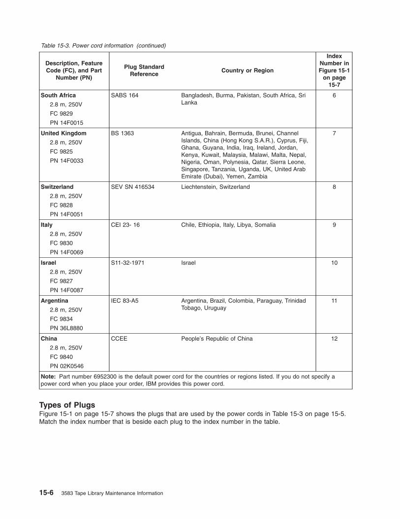
Table 15-3. Power cord information (continued)
Description, Feature
Code (FC), and Part
Number (PN)
Plug Standard
Reference
Country or Region
Index
Number in
Figure 15-1
on page
15-7
South Africa
2.8 m, 250V
FC 9829
PN 14F0015
SABS 164 Bangladesh, Burma, Pakistan, South Africa, Sri
Lanka
6
United Kingdom
2.8 m, 250V
FC 9825
PN 14F0033
BS 1363 Antigua, Bahrain, Bermuda, Brunei, Channel
Islands, China (Hong Kong S.A.R.), Cyprus, Fiji,
Ghana, Guyana, India, Iraq, Ireland, Jordan,
Kenya, Kuwait, Malaysia, Malawi, Malta, Nepal,
Nigeria, Oman, Polynesia, Qatar, Sierra Leone,
Singapore, Tanzania, Uganda, UK, United Arab
Emirate (Dubai), Yemen, Zambia
7
Switzerland
2.8 m, 250V
FC 9828
PN 14F0051
SEV SN 416534 Liechtenstein, Switzerland 8
Italy
2.8 m, 250V
FC 9830
PN 14F0069
CEI 23- 16 Chile, Ethiopia, Italy, Libya, Somalia 9
Israel
2.8 m, 250V
FC 9827
PN 14F0087
S11-32-1971 Israel 10
Argentina
2.8 m, 250V
FC 9834
PN 36L8880
IEC 83-A5 Argentina, Brazil, Colombia, Paraguay, Trinidad
Tobago, Uruguay
11
China
2.8 m, 250V
FC 9840
PN 02K0546
CCEE People’s Republic of China 12
Note: Part number 6952300 is the default power cord for the countries or regions listed. If you do not specify a
power cord when you place your order, IBM provides this power cord.
Types of Plugs
Figure 15-1 on page 15-7 shows the plugs that are used by the power cords in Table 15-3 on page 15-5.
Match the index number that is beside each plug to the index number in the table.
15-6 3583 Tape Library Maintenance Information

1 2 3 4
5 6 7 8
9 10 11 12
x26
416
Figure 15-1. Types of receptacles
Chapter 15. Parts List 15-7

15-8 3583 Tape Library Maintenance Information

TapeAlert Flags
This appendix is intended to provide additional information to the reader about the tape drive. All
error code and diagnostic information contained in this chapter can be accessed from the Operator
Panel of the Library. The drive portion of the Operator Panel Display will contain any drive error
codes. Therefore there is no need to open the Library to access the buttons on the drive as
described in this chapter. See IBM TotalStorage 3583 Tape Library Setup and Operator Guide for a
complete description of the Operator Panel functions and Displays.
TapeAlert is a standard that defines status conditions and problems experienced by devices such as tape
drives, autoloaders, and libraries. The standard enables a server to read TapeAlert messages (called flags)
from a tape drive via the SCSI bus. The server reads the flags from Log Sense Page 0x2E.
The Ultrium Scalable Tape Library is compatible with TapeAlert technology, which provides error and
diagnostic information about the drives and the library to the server. Because library and drive firmware
may change periodically, the SNMP interface in the library does not require code changes if devices add
additional TapeAlerts that are not supported today. However, should this occur the MIB is written to
minimize impact to the SNMP monitoring station. At the time of this writing, the TapeAlert flags in this
appendix correctly represent TapeAlerts that will be sent. The MIB file should not be taken to mean that all
traps that are defined in the MIB will be sent by the library or that they will be sent in the future.
This appendix lists TapeAlert flags that are supported by the Ultrium Tape Drives and the Ultrium Scalable
Tape Library.
TapeAlert Flags Supported by the Drive
Table A-1. TapeAlert Flags Supported by the Ultrium Tape Drive
Flag
Number Flag Description Action Required
3 Hard error Set for any unrecoverable read,
write, or positioning error. (This flag
is set in conjunction with flags 4, 5,
or 6.)
See the Action Required column for
Flag Number 4, 5, or 6 in this table.
4 Media Set for any unrecoverable read,
write, or positioning error that is due
to a faulty tape cartridge.
Replace the tape cartridge.
5 Read failure Set for any unrecoverable read error
where isolation is uncertain and
failure could be due to a faulty tape
cartridge or to faulty drive hardware.
If Flag 4 is also set, the cartridge is
defective. Replace the tape cartridge.
If Flag Number 4 is not set, see Error
Code 6 in Table 6-4 on page 6-25.
6 Write failure Set for any unrecoverable write or
positioning error where isolation is
uncertain and failure could be due to
a faulty tape cartridge or to faulty
drive hardware.
If Flag Number 9 is also set, make
sure that the write-protect switch is
set so that data can be written to the
tape (see “Setting the Write-Protect
Switch” on page A-4). If Flag Number
4 is also set, the cartridge is
defective. Replace the tape cartridge.
If Flag Number 4 is not set, see Error
Code 6 page Table 6-4 on page 6-25.
8 Not data grade Set when the cartridge is not
data-grade. Any data that you write
to the tape is at risk.
Replace the tape with a data-grade
tape.
© Copyright IBM Corp. 2000, 2005 A-1

Table A-1. TapeAlert Flags Supported by the Ultrium Tape Drive (continued)
Flag
Number Flag Description Action Required
9 Write protect Set when the tape drive detects that
the tape cartridge is write-protected.
Make sure that the cartridge’s
write-protect switch is set so that the
tape drive can write data to the tape
(see “Setting the Write-Protect
Switch” on page A-4).
10 No removal Set when the tape drive receives an
UNLOAD command after the server
prevented the tape cartridge from
being removed.
Refer to the documentation for your
server’s operating system.
11 Cleaning media Set when you load a cleaning
cartridge into the drive.
No action required.
12 Unsupported format Set when you load an unsupported
cartridge type into the drive or when
the cartridge format has been
corrupted.
Use a supported tape cartridge.
14 Unrecoverable snapped
tape
Set when the operation failed
because the tape in the drive
snapped.
Do not attempt to extract the old tape
cartridge. Call the tape drive
supplier’s help line.
15 Cartridge memory chip
failure
Set when a cartridge memory (CM)
failure is detected on the loaded tape
cartridge.
Replace the tape cartridge. If this
error occurs on multiple cartridges,
see Error Code 6 in Table 6-4 on
page 6-25
16 Forced eject Set when you manually unload the
tape cartridge while the drive was
reading or writing.
No action required.
18 Tape directory corrupted
in the cartridge memory
Set when the drive detects that the
tape directory in the cartridge
memory has been corrupted.
Re-read all data from the tape to
rebuild the tape directory.
20 Clean now Set when the tape drive detects that
it needs cleaning.
Clean the tape drive (see the section
about cleaning drives in the IBM
TotalStorage 3583 Tape Library
Planning and Operator Guide).
21 Clean periodic Set when the drive detects that it
needs routine cleaning.
Clean the tape drive as soon as
possible. The drive can continue to
operate, but you should clean the
drive soon. See the section about
cleaning drives in the IBM
TotalStorage 3583 Tape Library
Planning and Operator Guide.
22 Expired clean Set when the tape drive detects a
cleaning cartridge that has expired.
Replace the cleaning cartridge.
23 Invalid cleaning tape Set when the drive expects a
cleaning cartridge and the loaded
cartridge is not a cleaning cartridge.
Use a valid cleaning cartridge.
30 Hardware A Set when a hardware failure occurs
that requires that you reset the tape
drive to recover.
If resetting the drive does not recover
the error, note the error code on the
single-character display and see
Table 6-4 on page 6-25 for the
appropriate instructions.
A-2 3583 Tape Library Maintenance Information

Table A-1. TapeAlert Flags Supported by the Ultrium Tape Drive (continued)
Flag
Number Flag Description Action Required
31 Hardware B Set when the tape drive fails its
internal Power-On Self Tests.
Note the error code on the
single-character display and see
Table 6-4 on page 6-25 for the
appropriate instructions.
32 Interface Set when the tape drive detects a
problem with the SCSI, Fibre
Channel, or RS-422 interface.
Locate Error Code 8 or 9 in Table 6-4
on page 6-25
33 Eject media Set when a failure occurs that
requires you to unload the cartridge
from the drive.
Unload the tape cartridge, then
reinsert it and restart the operation.
34 Download fail Set when an FMR image is
unsuccessfully downloaded to the
tape drive through the SCSI or Fibre
Channel interface.
Ensure that it is the correct FMR
image. Download the FMR image
again.
36 Drive temperature Set when the drive’s temperature
sensor indicates that the drive’s
temperature is exceeding the
recommended temperature of the
library.
See Error Code 1 in Table 6-4 on
page 6-25
37 Drive voltage Set when the drive detects that the
externally supplied voltages are
either approaching the specified
voltage limits or are outside the
voltage limits (see Table 1-8 on page
1-25).
See Error Code 2 in Table 6-4 on
page 6-25
39 Diagnostics required Set when the drive detects a failure
that requires diagnostics for isolation.
See Error Code 6 in Table 6-4 on
page 6-25
51 Tape directory invalid at
unload
Set when the tape directory on the
tape cartridge that was previously
unloaded is corrupted. The
file-search performance is degraded.
Use your backup software to rebuild
the tape directory by reading all the
data.
52 Tape system area write
failure
Set when the tape cartridge that was
previously unloaded could not write
its system area successfully.
Copy the data to another tape
cartridge, then discard the old
cartridge.
53 Tape system area read
failure
Set when the tape system area could
not be read successfully at load time.
Copy the data to another tape
cartridge, then discard the old
cartridge.
TapeAlert Flags A-3

Setting the Write-Protect Switch
The position of the write-protect switch on the tape cartridge (see �1�) determines whether you can write
to the tape:
v If the switch is set to
(solid red), data cannot be written to the tape.
v If the switch is set to unlocked (black void), data can be written to the tape.
Advise your customer that it is better to use the host application software to write protect the cartridges
instead of manually using the write protect switch. The host software will identify a cartridge that no longer
contains current data. The host software will then make a scratch cartridge by removing the software
generated write protect.
If you must manually set the write-protect switch �1�, slide it left or right to the desired position.
A6
7E
00
26
1
Figure A-1. Cartridge Write-Protect Switch
A-4 3583 Tape Library Maintenance Information

TapeAlert Flags Supported by the Library
Table A-2. TapeAlert Flags Supported by the Tape Library
Flag
Number Flag Description Action Required
1 Library hardware A The library has trouble
communicating with the drive.
Restart the operation.
2 Library hardware B The library has a hardware failure. Restart the operation.
4 Library hardware D The library has a hardware fault that
is not mechanically related.
Restart the operation.
7 Predictive failure Predictive failure of library hardware. Not applicable.
8 Library maintenance Library Preventive Maintenance
required.
Not applicable.
13 Library pick retry The operation to pick a cartridge had
to perform an excessive number of
retries before succeeding.
No action needs to be taken at this
time.
14 Library place retry The operation to place a cartridge
had to perform an excessive number
of retries before succeeding.
No action needs to be taken at this
time.
15 Library load retry The operation to load a cartridge into
a drive had to perform an excessive
number of retries before succeeding.
No action needs to be taken at this
time.
16 Library door A library door is open and prevents
the library from functioning.
Close the library door.
17 Library I/O station A problem exists with the I/O station. 1. Ensure that there is no
obstruction in the I/O station.
2. Restart the operation.
19 Library security Library door opened then closed
during operation.
Library security has been
compromised.
20 Library security mode Library security mode changed. The security mode of the library has
been changed. For information
purposes only. No action required.
21 Library offline Library manually turned offline. The library has been manually turned
offline and is unavailable for use.
23 Library scan retry The operation to scan the bar code
on a cartridge had to perform an
excessive number of retries before
succeeding. A potential problem
exists with the bar code label or the
reader hardware in the library
mechanism.
Check for damaged, misaligned, or
peeling bar code labels on cartridges.
24 Library inventory An inventory of the media was
inconsistent.
1. Run a library inventory to correct
the inconsistency.
2. Restart the operation.
28 Power supply A redundant power supply failure
exists inside the library.
Contact your IBM Technical Support
32 Unreadable bar code
label
During an inventory or scan, the
library was unable to read a bar code
label on a cartridge.
Check for damaged, misaligned, or
peeling bar code labels on the
cartridge.
TapeAlert Flags A-5

Resolving Problems
If you encounter problems when running the Ultrium Tape Drive, refer to Table A-3. If the problem is not
identified in Table A-3, refer to “Methods of Receiving Errors and Messages” on page A-7.
Table A-3. Troubleshooting Tips for the Ultrium Tape Drive
If the problem is this.... Do this....
A code displays on the
single-character display.
The Ultrium Tape Drive detected an error or is directing you to an
informational message. See Table 6-4 on page 6-25.
The status light or single-character
display never turns on.
The Ultrium Tape Drive has not been properly terminated or has no power. If
the SCSI bus is terminated externally, try a different terminator or use the
drive’s internal termination. If the SCSI bus is terminated properly, check the
power at the power source. Ensure the tape drive sled is connected properly,
(see “Tape Drive Sled” on page 8-4). If the problem persists, replace the tape
drive sled.
The Ultrium Tape Drive won’t load a
tape cartridge.
One of the following has occurred:
v A tape cartridge is already inserted. To remove the cartridge, press the
unload button. If the cartridge does not eject, turn off the power to Ultrium
Tape Drive, then turn it back on and press the unload button.
v The tape cartridge was inserted incorrectly. To properly insert a cartridge,
see “Inserting a Tape Cartridge” on page A-17.
v The tape cartridge was defective. Insert another tape cartridge. If the
problem persists, replace the tape drive sled (see “Tape Drive Sled” on
page 8-4).
v The Ultrium Tape Drive has no power. Ensure the drive sled is plugged
into the Library correctly. (See “Tape Drive Sled” on page 8-4.) If there are
multiple drives in the library and the other drives are powered up correctly,
suspect the power cable or power distribution card.
v If the problem exists for multiple cartridges, the Ultrium Tape Drive is
defective. Replace the tape drive (see “Tape Drive Sled” on page 8-4).
The Ultrium Tape Drive won’t unload
the tape cartridge.
The tape cartridge is stuck or is broken. Press the unload button. If the
cartridge does not eject, turn off the power to Ultrium Tape Drive, then turn it
back on. If the cartridge still does not eject, manually remove it (see
“Removing a Tape Cartridge” on page B-1).
The host received TapeAlert
messages.
See “TapeAlert Flags” on page A-1.
The host reported SCSI problems
(such as selection or command
time-outs, or parity errors).
See “Resolving Problems Reported to the Server” on page A-9.
A library reported an interface
problem.
Run drive diagnostics. The drive sled or RS-422 circuitry may be defective.
Refer to the section about running drive diagnostics in the IBM TotalStorage
3583 Tape Library Planning and Operator Guide.
Codes display on the single-character
display, but the status light doesn’t
turn on.
The Ultrium Tape Drive is defective. Replace the tape drive sled, (see “Tape
Drive Sled” on page 8-4).
A-6 3583 Tape Library Maintenance Information

Methods of Receiving Errors and Messages
Use Table A-4 as a guide for identifying error and message codes reported to the Ultrium Tape Drive,
library, or host.
Note: The codes on the single-character display have different meanings, depending on whether they
display during normal operations or while the drive is in maintenance mode. Codes that occur
during normal operations are defined in Table 6-4 on page 6-25. Codes that occur while in
maintenance mode are defined in Table A-8 on page A-19
Table A-4. Methods of Receiving Errors and Messages for the Ultrium Tape Drive
If the error or message was
presented by.... Do this....
The library’s display (if the tape drive
is enclosed in a library or autoloader)
See “Maintenance Starting Point” on page 5-2.
The tape drive’s single-character
display and the status light flashes
yellow
See Table 6-4 on page 6-25. To determine the meaning of status light
activity, see “Status Light” on page A-16.
The tape drive’s single-character
display and the status light is solid
yellow
See Table A-8 on page A-19. To determine the meaning of status light
activity, see “Status Light” on page A-16.
SCSI log sense data (such as
TapeAlert flags) or request sense data
at the host console
See “TapeAlert Flags” on page A-1, Table 6-4 on page 6-25, Chapter 10,
“Messages,” on page 10-1, Chapter 11, “Sense,” on page 11-1, or “Using
Host Sense Data” on page A-8.
Drive sense data sent to a library (if
the tape drive is enclosed in a library)
See “Maintenance Starting Point” on page 5-2, Chapter 10, “Messages,” on
page 10-1, and Chapter 11, “Sense,” on page 11-1, then see Table 6-4 on
page 6-25
The tape drive’s error log See Table 6-4 on page 6-25 and “Viewing the Drive Error Log” on page A-9
Descriptions and Corrective Actions for Errors and Messages
For a description of the errors and messages that pertain to the Ultrium Tape Drive, see “Drive Error
Codes” on page 6-25.
TapeAlert Flags A-7

Using Host Sense Data
Table A-5 lists the hosts to which the Ultrium Tape Drive attaches. It gives the operating system for each
host and describes how the host records errors from the Ultrium Tape Drive.
To determine the meaning of host sense data, see Chapter 10, “Messages,” on page 10-1 and Chapter 11,
“Sense,” on page 11-1. Also refer to the IBM Ultrium Device Drivers Installation and User’s Guide or visit
the web at http://www.ibm.com/storage/lto.
Table A-5. Host Method of Recording Tape Drive Errors
Host Operating System Method of Recording Tape Drive Errors
IBM AS/400 or iSeries OS/400 Records tape drive errors and associated sense data in
the AS/400 problem and error logs. View the logs by
using the System Service Tools application and the
userid QSRV.
IBM RS/6000, RS/6000/SP,
or pSeries
AIX Uses the IBM Atape device driver (provided with the
Ultrium Tape Drive) to record tape drive errors and sense
data in the host error log. View the host error log by
using one or more of the following utilities: tapeutil, diag,
smit, or errpt.
HP HP-UX Uses the IBM device driver for HP. Error and trace
logging are proprietary to Hewlett-Packard.
Sun Microsystems Solaris Uses the IBM device driver for Solaris to post sense
information to the Solaris host-wide messages file
/var/adm/messages.
Intel-based PCs Windows-based operating
systems
Uses the NTUTIL device driver to log some sense data
in the Event Viewer host log.
A-8 3583 Tape Library Maintenance Information
Viewing the Drive Error Log
The Ultrium Tape Drive keeps an error log that you can use to identify and correct errors. The log contains
the 10 most recent error codes, which appear (one at a time) on the single-character display.
To view the drive error log:
1. Make sure that no cartridge is in the drive.
2. Within a 1 second interval press the unload button 3 times. The status light becomes solid amber,
indicating that the drive is in maintenance mode.
Note: If a cartridge is in the drive, it will eject the first time that you press the unload button and the
drive will not be placed in maintenance mode. To continue placing the drive in maintenance
mode, perform the preceding step.
3. Press the unload button once per second until 9 appears in the single-character display.
Note: If you cycle past the desired code, press the unload button once per second until the code
redisplays.
4. Press the unload button to view the most recent error code.
5. Refer to Table 6-4 on page 6-25 to determine the meaning of the code and the action to take.
6. Press the unload button to view the next error code. (The codes are ordered; the most recent is
presented first and the oldest (tenth) is presented last. Each time you press the unload button to view
an error, the single-character display turns on, the error displays, then the single-character display
turns off.)
7. Continue to press the unload button until the 10 error codes have been displayed. After you display the
tenth error code, the Ultrium Tape Drive automatically exits maintenance mode.
To re-display the error codes, repeat steps 1-7.
This function is also available from the library’s operator panel by selecting Main Menu —> Status —>
Logs —> Drive Log.
Resolving Problems Reported to the Server
Fixing SCSI Bus Errors
Note: If you are using a Storage Area Network (SAN) Data Gateway to convert a drive with a SCSI
interface to a Fibre Channel interface, ensure that the problem is occurring between the SAN Data
Gateway and the drive by running the SCSI wrap test on the drive and running the SCSI loopback
test on the SAN Data Gateway. (To run the SCSI wrap test, see Function Code 6 in Table A-8 on
page A-19; to run the SCSI loopback test, refer to the section about that test in the IBM Storage
Area Network Gateway Module Setup, Operator, and Service Guide.) If you are using a Fibre
Channel drive and are having problems, see “Fixing Fibre Channel Errors” on page A-11.
Fixing a Consistent Error with a Single Drive on a SCSI Bus
1. Ensure that the power is on to the Ultrium Tape Drive.
2. Ensure that the tape drive’s SCSI address is the same as the SCSI address assigned by the server.
3. Run the SCSI wrap test (see Function Code 6 in Table A-8 on page A-19).
v If the test runs successfully, replace the SCSI terminator first, then the SCSI cable and the
interposer (if installed). Repeat the operation that caused the error. If you replaced the SCSI
terminator or SCSI cable and the problem persists, the fault is with the server’s hardware or
software. To isolate the cause of the failure, refer to the server’s service documentation.
v If the test fails, replace the tape drive (see “Tape Drive Sled” on page 8-4).
TapeAlert Flags A-9

Fixing a Consistent Error with Multiple Drives on a SCSI Bus
When a consistent error occurs in a configuration that has multiple tape drives on the SCSI bus, you must
determine if the problem exists with more than one tape drive. If the problem is with all of the devices on
the SCSI bus, the bus is stuck in a SCSI phase and cannot change to another phase or the SCSI cable
from the server to the first device is defective.
1. Ensure that the SCSI cable from the server to the first device is connected.
2. Disconnect all but the first tape drive on the SCSI bus. Move the terminator to the first SCSI device.
3. Run a device driver utility (such as IBM’s ntutil or tapeutil) to determine whether the error will occur.
v If the error occurs, run the SCSI wrap test on the first tape drive (see Function Code 6 in Table A-8
on page A-19).
– If the test runs successfully, replace the SCSI terminator first, then the SCSI cable and the
interposer (if installed) to the first tape drive. Repeat the operation that caused the error. If you
replaced the SCSI terminator or SCSI cable and the problem persists, the fault is with the
server’s hardware or software. To isolate the cause of the failure, refer to the server’s service
documentation.
– If the test fails, replace the tape drive (see “Tape Drive Sled” on page 8-4).
v If the error does not occur, connect one tape drive at a time back to the bus and repeat step 3 for
each tape drive until you can identify which drive is defective.
Note: Ensure that the SCSI terminator is always on the last tape drive on the SCSI bus.
4. Determine if the problem is with only one tape drive or with two or more tape drives.
v If the problem is with only one tape drive, run the SCSI wrap test on that tape drive (see Function
Code 6 in Table A-8 on page A-19).
– If the test runs successfully, replace the SCSI terminator first, then the SCSI cable to that tape
drive and interposer (if installed).
– If the test fails, replace the tape drive (see “Tape Drive Sled” on page 8-4).
v If the problem is with two or more tape drives, locate the first tape drive that has the error and
replace the SCSI cable that connects the tape drive and the interposer (if installed).
Fixing an Intermittent Error with a Single Drive on a SCSI Bus
1. Replace the SCSI terminator on the tape drive.
2. Run the operation that caused the error. If the problem persists, the problem may be with the cable.
3. Isolate which cable is causing the problem by replacing one cable at a time and running the operation
that caused the error after each replacement. If the problem persists after all cables have been
replaced, the problem may be with the Ultrium Tape Drive.
4. Replace the tape drive (see “Tape Drive Sled” on page 8-4). If the problem persists, the problem is
with your server. Consult your server’s documentation.
Fixing an Intermittent Error with Multiples Drives on a SCSI Bus
Refer to the server’s error logs to determine which tape drive is the source of the problem:
v If only one tape drive is reporting a SCSI failure, replace that tape drive (see “Tape Drive Sled” on page
8-4).
v If multiple tape drives are reporting SCSI failures, the problem may be with the terminator or the SCSI
cables:
– Replace the terminator and run the operation that caused the error. If the problem persists, the
problem may be with the cables.
– Isolate which cable is causing the problem by replacing one cable at a time and run the operation
that caused the error after each replacement.
A-10 3583 Tape Library Maintenance Information

Fixing Fibre Channel Errors
If you are connected to a Fibre Channel Storage Area Network (SAN) by using a SAN Data Gateway, use
the IBM Storage Area Network Gateway Module Setup, Operator, and Service Guide to determine whether
the problem is occurring between the drive and the SAN Data Gateway. If you are using a SCSI drive and
are having SCSI problems, see “Fixing SCSI Bus Errors” on page A-9.
Supported Topologies
The Ultrium 2 tape drive and the Ultrium 3 tape drive can be attached in a two-node configuration, either
directly to a switch as a public device (switched fabric) or directly to a host bus adapter (HBA) as a private
device. It can do so in a Point-to-Point topology (through an N_port or F_port) or Arbitrated Loop topology
(through an L_port or FL_port).
The Ultrium 2 tape drive and the Ultrium 3 tape drive automatically configures to an L_port or an N_port
when it boots. The type of port to which it configures depends on whether the drive recognizes the
connection as a loop or a point-to-point connection:
v An L_port supports a Fibre Channel Arbitrated Loop connection to an NL_port or FL_port.
v An N_port supports direct connection to another N_port or to an F_port (for example, a director-class
switch) in a point-to-point topology.
Regardless of the port to which you connect the drive, it automatically configures to a public device
(through an F_port or FL_port to a switch) or to a private device (through an N_port or L_port by using
direct attachment to a server).
Table A-6 lists the topologies in which the Ultrium 2 tape drive and the Ultrium 3 tape drive can operate,
the Fibre Channel server connections that are available, and the port (NL, N, FL, or F) through which
communication must occur.
Table A-6. Choosing the port for your topology and Fibre Channel connection
Type of Topology
Type of Fibre Channel Connection to Server
Direct Connection(Private)
Switched Fabric(Public)
Fibre Channel-Arbitrated Loop(can be Two-Node Arbitrated Loop or
Two-Node Switched Fabric Loop; is
limited to two nodes)
L_Port FL_Port
Point-to-Point(two nodes)
N_Port F_Port
Starting Problem Determination
Before starting the problem determination, perform the following steps:
1. Determine the type of Fibre Channel topology that you are using (see page A-11). Ensure that the
drive and the port to which it is attached are configured in compatible topologies.
2. Using this guide or the service guides of associated switch, hub, or fiber products, try to determine
where the problem exists (whether in the drive, cable, or the device to which the drive and cable
attach).
3. Ensure that the configuration and software levels are supported (to determine the latest supported
attachments or to get a comprehensive list of compatible software, perform one of the following):
v Visit the web at http://www.ibm.com/storage/lto.
v Contact your IBM Sales Representative.
4. Ensure that the Fibre Channel cables are installed correctly. Refer to the appropriate steps about
cabling in the installation section of the IBM TotalStorage 3583 Tape Library Setup and Operator
Guide.
TapeAlert Flags A-11
|
|
|

5. Go to one of the following procedures:
v “Fixing a Consistent Error with a Single Drive on a Fibre Channel Loop”
v “Fixing a Consistent Error with Multiple Drives on a Fibre Channel Loop”
v “Fixing a Consistent Error in a Point-to-Point Topology” on page A-13
v “Fixing Intermittent Fibre Channel Errors” on page A-14
Fixing a Consistent Error with a Single Drive on a Fibre Channel Loop
1. Ensure that the tape drive is powered on.
2. Verify that the tape drive’s serial number is the same as the drive serial number that the server
program is using.
3. Ensure that the drive’s Fibre Channel AL_PA is set correctly, that it is on the loop, and that it is not
being used by another device (see the section about setting Fibre Channel Loop IDs in the installation
chapter of the IBM TotalStorage 3583 Tape Library Setup and Operator Guide). The tape drive must
be able to detect light and communicate with the server.
4. Run the Fibre Channel wrap test at the drive’s Fibre Channel connector (see Function Code 6 in
Table A-8 on page A-19).
v If the test fails, replace the tape drive.
v If the test is successful, go to step 5.
5. Run the Fibre Channel wrap test at the end of the fiber cable (see Function Code 6 in Table A-8 on
page A-19).
v If the test fails, replace the fiber cable.
v If the test is successful, go to step 6.
6. Check the Fibre Channel cable connection at the server.
7. Using a device driver utility such as ntutil or tapeutil, verify that the drive is properly configured and
available at the server.
8. If the problem persists, the fault may be with the server’s hardware or software. Refer to your server’s
service manual.
9. When the problem is corrected (or determined to be a server problem), restore all of the fiber cables to
their correct position.
Fixing a Consistent Error with Multiple Drives on a Fibre Channel Loop
Use the following procedure to determine if all of the drives on the Fibre Channel have the problem:
1. Use a device driver utility (such as ntutil or tapeutil) to verify that the drive is available and properly
configured at the server.
2. Determine the type of Fibre Channel topology that you are using (see “Supported Topologies” on page
A-11).
3. Using this guide or the service guides of associated switch, hub, or fiber products, try to isolate which
part of the Fibre Channel Storage Area Network (SAN) is experiencing problems.
4. Perform one of the following:
v If the problem exists on a small number of drives, go to “Fixing a Consistent Error with a Single
Drive on a Fibre Channel Loop.”
v If the problem exists with a large number of drives, perform the following steps:
a. Disconnect all except one failing drive on the Fibre Channel.
b. Run the Fibre Channel wrap test to determine if a failure occurs on that drive (see Function
Code 6 in Table A-8 on page A-19). If it does, perform the procedure in “Fixing a Consistent
Error with a Single Drive on a Fibre Channel Loop.”
c. Continue to connect one drive at a time to the Fibre Channel loop.
5. When the problem is corrected, restore all of the Fibre Channel cables to their correct position.
A-12 3583 Tape Library Maintenance Information
Fixing a Consistent Error in a Point-to-Point Topology
1. Ensure that the tape drive is powered on.
2. Verify that the tape drive’s serial number is the same as the drive serial number that the server
program is using.
3. Ensure that the drive is connected to the host or switch. The drive must be able to detect light and
communicate with the server.
4. Run the Fibre Channel wrap test at the drive’s Fibre Channel connector (see Function Code 6 in
Table A-8 on page A-19).
v If the test fails, replace the tape drive.
v If the test is successful, go to step 5.
5. Run the Fibre Channel wrap test at the end of the fiber cable (see Function Code 6 in Table A-8 on
page A-19).
v If the test fails, replace the fiber cable.
v If the test is successful, go to step 6.
6. Check the Fibre Channel cable connection at the server.
7. Using a device driver utility such as ntutil or tapeutil, verify that the drive is properly configured and
available at the server.
8. If the problem persists, the fault may be with the server’s hardware or software. Refer to your server’s
service manual.
9. When the problem is corrected (or determined to be a server problem), restore all of the fiber cables to
their correct position.
TapeAlert Flags A-13

Fixing Intermittent Fibre Channel Errors
1. Determine the type of Fibre Channel topology that you are using (see “Supported Topologies” on page
A-11).
2. Ensure that the configuration and software levels are supported (to determine the latest supported
attachments or to get a comprehensive list of compatible software, perform one of the following):
v Visit the web at http://www.ibm.com/storage/lto.
v Contact your IBM Sales Representative.
3. Check that each Fibre Channel cable does not exceed 500 m (1640 ft).
4. Ensure that all Fibre Channel cables are installed correctly. Refer to the appropriate steps about
cabling in the installation section of the IBM TotalStorage 3583 Tape Library Setup and Operator
Guide.
5. Using this guide or the service guides of associated switch, hub, or fiber products, determine that a
problem exists between the drive, drive cable, and the device to which they attach. Try to isolate which
part of the Storage Area Network (SAN) is experiencing problems.
6. Using this guide or the service guides of associated switch, hub, or fiber products, verify that the SAN
configurations are correct (such as switch zoning for drive sharing).
7. Obtain all errors reported by the drive to the server (see “Using Host Sense Data” on page A-8), then
contact your OEM Product Application Engineer (PAE) for error analysis.
Resolving Media-Related Problems
To resolve problems that are related to media, the Ultrium Tape Drive includes:
v Test Cartridge & Media diagnostic that verifies whether a suspect cartridge and its magnetic tape are
acceptable for use (see Function E in Table A-8 on page A-19).
v A Statistical Analysis and Reporting System (SARS) to assist in isolating failures between media and
hardware. To determine the cause of failure, SARS uses the cartridge performance history that is saved
in the cartridge memory (CM) and the drive performance history that is kept in the drive’s flash erasable
programmable read-only memory (EPROM). Any failures that SARS detects are reported as TapeAlert
flags on the host (see “TapeAlert Flags” on page A-1).
Attention: If you insert the IBM LTO Ultrium Data Cartridge into another manufacturer’s tape drive,
the SARS data in the cartridge memory may become lost or invalid.
If you encounter a media-related problem, use the following procedure:
Attention: When you run the Test Cartridge & Media diagnostic, data on the suspect tape is overwritten.
Similarly, use only a scratch data cartridge when you run tape drive diagnostics; the test overwrites data
on the cartridge.
1. If possible, run the tape cartridge in a different tape drive. If the operation in the other tape drive fails
and 6 or 7 displays, replace the media. If the operation succeeds, run the Test Cartridge & Media
diagnostic (see Function Code E in Table A-8 on page A-19).
2. If the Test Cartridge & Media diagnostic fails, replace the media. If it runs successfully, clean the tape
drive and run the tape drive diagnostics (see the section about running drive diagnostics in the IBM
TotalStorage 3583 Tape Library Planning and Operator Guide and Function Code 1 in Table A-8 on
page A-19).
3. If the tape drive diagnostics fail, replace the tape drive sled, see “Tape Drive Sled” on page 8-4. If the
tape drive diagnostics run successfully, perform the operation that produced the initial media error.
A-14 3583 Tape Library Maintenance Information

Operating the Tape Drive
Attention: Before you use a tape cartridge, acclimate it to the operating environment for 24 hours or the
time necessary to prevent condensation on the cartridge or in the drive (the time will vary, depending on
the environment extremes to which the cartridge and drive were exposed).
When operating the Ultrium Tape Drive, refer to Figure A-2 which shows the front of the unit.
�1� Unload button �3� Single-character display
�2� Status light
Note: Ultrium 2 and Ultrium 3 tape drives have similar operator panels. Ultrium 2 is shown in Figure A-2.
Figure A-2. Front view of the Ultrium Tape Drive
TapeAlert Flags A-15
|

Status Light
The status light (�2� in Figure A-2 on page A-15) is a light-emitting diode (LED) that provides information
about the state of the Ultrium Tape Drives. The light can be green or amber, and (when lit) solid or
flashing. Table A-7 lists the conditions of the status light and provides an explanation of what each
condition means.
Table A-7. Meaning of Status Light Activity
Color and Condition of
Status Light
Meaning
Off The tape drive has no power or is powered off.
Green/Solid The tape drive is powered on and is idle.
Green/Flashing The tape drive is reading from the tape, writing to the tape, rewinding the tape,
locating data on the tape, loading the tape, or unloading the tape. The status light also
flashes green if the tape drive contains a cartridge during the power-on cycle. In this
case, the drive completes POST and slowly rewinds the tape (the process may take
approximately 13 minutes). The light stops blinking and becomes solid when the drive
completes the recovery and is ready for a read or write operation. To eject the
cartridge, press the unload button.
Amber/Solid The tape drive is powering on, is resetting, or is in maintenance mode. For information
about the functions that are available when the drive is in maintenance mode, see
“Selecting a Diagnostic or Maintenance Function” on page A-19.
Amber/Flashing One of the following applies:
v If the light flashes once per second, an error occurred and the tape drive or media
may require service. Note the code on the single-character display, then go to
Table 6-4 on page 6-25 to determine the action that is required. If a solid C appears
in the single-character display, the drive needs cleaning.
v If the light flashes twice per second, the tape drive is updating firmware. For more
information, see “Updating Firmware” on page 4-114.
v If the light flashes four times per second, the tape drive detected an error and is
performing a firmware recovery. It resets automatically.
Unload Button
The unload button (�1� in Figure A-2 on page A-15) enables you to perform the following functions:
v Rewind the tape into the cartridge and eject the cartridge from the tape drive. For more information, see
“Removing a Tape Cartridge” on page A-18.
v Enter or exit maintenance mode, or perform diagnostic or maintenance functions. For more information,
see “Selecting a Diagnostic or Maintenance Function” on page A-19.
v Perform a panic reset of the drive. Attention: If the tape drive detected a permanent error and
displayed an error code, it automatically forces a drive dump (also known as a save of the firmware
trace). If you perform a panic reset of the drive, the existing dump will be overwritten and lost. To
perform a panic reset, press and hold the unload button on the drive for 10 seconds. The drive forces a
dump and overwrites the existing dump. The drive then reboots to allow communication.
Single-Character Display
The Ultrium Tape Drive features a light-emitting diode (LED) (�3� in Figure A-2 on page A-15) that
presents a single-character code for:
v Diagnostic or maintenance functions
v Error conditions and informational messages
Table A-8 on page A-19 lists each single-character code used for diagnostic or maintenance functions.
Table 6-4 on page 6-25 lists the codes for error conditions and informational messages. If multiple errors
A-16 3583 Tape Library Maintenance Information

occur, the code with the highest priority (represented by the lowest number) displays first. When the error
is corrected, the code with the next highest priority displays, and so on until no errors remain.
Single Red Dot
The single-character display is blank during normal operation. However, if a drive dump is present while
the drive is in maintenance mode, a single red dot illuminates on the display. This indicator is for use by
IBM Support personnel. To copy the dump to tape, see Function Code 5 in Table A-8 on page A-19.
The red dot turns off when you obtain the dump (by using a data cartridge, a SCSI command, or a library
command). If no dump is present while the drive is in maintenance mode, the single red dot does not
illuminate.
Inserting a Tape Cartridge
To insert a tape cartridge:
1. Ensure that the Ultrium Tape Drive is powered-on.
2. Ensure that the write-protect switch is properly set (see Figure A-1 on page A-4).
3. Grasp the cartridge so that the write-protect switch faces you (see �1� in Figure A-3).
4. Slide the cartridge into the tape load compartment.
Notes:
a. If the cartridge is already in an ejected position and you want to reinsert it, remove the cartridge
then insert it again.
b. If the cartridge is already loaded and you cycle the power (turn it off, then on), the tape will reload.
Figure A-3. Inserting a Cartridge into the Ultrium Tape Drive
TapeAlert Flags A-17
Removing a Tape Cartridge
To remove a tape cartridge:
1. Ensure that the Ultrium Tape Drive is powered on.
2. Press the unload button. The drive rewinds the tape and partially ejects the cartridge. The status light
flashes green while the tape rewinds, then goes out before the cartridge partially ejects.
3. After the cartridge partially ejects, grasp the cartridge and remove it.
If you are unable to remove the cartridge, see “Removing a Tape Cartridge” on page B-1. Whenever you
unload a tape cartridge, the Ultrium Tape Drive writes any pertinent information to the cartridge memory.
Cleaning the Drive Head
Attention: To clean the drive head, use the IBM TotalStorage Cleaning Cartridge (Ultrium LTO 2), the
IBM LTO Ultrium Cleaning Cartridge, or an IBM-approved cleaning cartridge.
Clean the drive head whenever C displays on the single-character display and the status light flashes
amber. To clean the head, insert the cleaning cartridge into the tape load compartment (see Figure A-3 on
page A-17). The drive performs the cleaning automatically. When the cleaning is finished, the drive ejects
the cartridge. The cleaning cartridges are generally valid for 50 uses.
Automatic Cleaning
Automatic cleaning enables the Ultrium Scalable Tape Library to automatically respond to any tape drive’s
request for cleaning and to begin the cleaning process. Automatic cleaning makes the cleaning process
transparent to any host application that uses the library. You can enable or disable automatic cleaning by
using the library’s operator panel. The setting is stored in non-volatile memory and becomes the default
during subsequent power-on cycles. The cleaning cartridge must be located in a nonaddressable storage
slot. For more information, see the section about enabling or disabling automatic cleaning in the IBM
TotalStorage 3583 Tape Library Planning and Operator Guide.
A-18 3583 Tape Library Maintenance Information

Selecting a Diagnostic or Maintenance Function
The Ultrium 2 Tape Drive can run diagnostics, test write and read functions, test a suspect tape cartridge,
update its own firmware, and perform other diagnostic and maintenance functions listed in Table A-8. The
drive must be in maintenance mode to perform these functions. To place the drive in maintenance mode
and to select a function, see Table A-8.
Attention: Maintenance functions cannot be performed concurrently with read or write operations. While
in maintenance mode, the Ultrium 2 Tape Drive does not receive SCSI commands from the host.
Table A-8. Diagnostic and maintenance functions
Function Code 1 - Run SCSI or Fibre Channel Tape Drive Diagnostics
Causes the tape drive to run self tests.
Attention: Insert only a scratch data cartridge for this test. Data on the cartridge will be overwritten.
1. Make sure that no cartridge is in the drive.
2. Within a 1.5-second interval, press the unload button three times. The status light becomes solid amber, which
means that the drive is in maintenance mode.
3. Press the unload button once per 1.5 seconds until 1 appears in the single-character display. If you cycle past 1,
continue to press the unload button until it redisplays.
4. To select the function, press and hold the unload button for 3 seconds. After you select the function, 1 flashes,
the drive runs diagnostics for approximately 90 seconds, then C flashes. When C flashes, the drive is waiting for a
cartridge.
5. Within 60 seconds, insert a scratch data cartridge (or the tape drive exits maintenance mode). After you insert the
cartridge, 1 flashes:
v If the diagnostic completes successfully, it begins again and runs for a maximum of 10 times. Each loop takes
approximately 20 minutes to run. After the tenth loop, the diagnostic stops and automatically exits maintenance
mode. To halt the diagnostic, press the unload button within the first 20 minutes of the test (or the diagnostic
will run another 20 minutes). The drive acknowledges the request by slowing the length of time that the
currently displayed character flashes on the single-character display (from twice per second to once per
second). The diagnostic continues to the end of its loop and then stops. The tape drive then displays 0,
rewinds and unloads the cartridge, and exits maintenance mode.
v If the diagnostics fail, the status light flashes amber and an error code displays. The tape drive unloads the
tape cartridge and exits maintenance mode. To resolve the error, locate the code in Table 6-4 on page 6-25.
TapeAlert Flags A-19

Table A-8. Diagnostic and maintenance functions (continued)
Function Code 2 - Update Tape Drive Firmware from FMR Tape
Causes the tape drive to load updated firmware from a field microcode replacement (FMR) tape.
Attention: Do not power-off the tape drive while loading code.
1. Make sure that no cartridge is in the drive.
2. Within a 1.5-second interval, press the unload button three times. The status light becomes solid amber, which
means that the drive is in maintenance mode.
3. Press the unload button once per 1.5 seconds until 2 appears in the single-character display. If you cycle past 2,
continue to press the unload button until it redisplays.
4. To select the function, press and hold the unload button for 3 seconds. After you select the function, C flashes.
When C flashes, the drive is waiting for a cartridge. Within 60 seconds, insert the FMR tape cartridge (or the tape
drive exits maintenance mode). After you insert the cartridge, 2 flashes and the tape drive loads the updated
firmware from the FMR tape cartridge into its erasable programmable read-only memory (EPROM) area:
v If the update completes successfully, the tape drive displays 0, rewinds and unloads the FMR tape, resets
itself, and is ready to use the new firmware.
v If the update fails, the tape drive posts an error code to the single-character display (to resolve the error, see
Table 6-4 on page 6-25). The drive then unloads the FMR tape and exits maintenance mode.
Function Code 3 - Create FMR Tape
Causes the tape drive to copy its field microcode replacement (FMR) data to a scratch data cartridge.
Attention: If you select this function, the tape drive will overwrite existing data on the scratch data cartridge.
1. Make sure that no cartridge is in the drive.
2. Within a 1.5-second interval, press the unload button three times. The status light becomes solid amber, which
means that the drive is in maintenance mode.
3. Press the unload button once per 1.5 seconds until 3 appears in the single-character display. If you cycle past 3,
continue to press the unload button until it redisplays.
4. To select the function, press and hold the unload button for 3 seconds. After you select the function, C flashes.
When C flashes, the drive is waiting for a cartridge. Within 60 seconds, insert a scratch data cartridge that is not
write protected (or the tape drive exits maintenance mode). After you insert the cartridge, 3 flashes and the tape
drive copies the FMR data to the scratch data cartridge:
v If the tape drive creates the FMR tape successfully, it displays 0, rewinds and unloads the new FMR tape, and
exits maintenance mode.
v If the tape drive fails to create the FMR tape, it displays 7, unloads the FMR tape, and exits maintenance
mode.
A-20 3583 Tape Library Maintenance Information

Table A-8. Diagnostic and maintenance functions (continued)
Function Code 4 - Force a Drive Dump
Causes the tape drive to perform a collection (or dump) of data. (A drive dump is also known as a save of the
firmware trace.) The dump (firmware trace) can only be analyzed by IBM.
Note: When an error code displays, a red dot also displays to remind you that a dump already exists. If you perform
Function Code 4, it will overwrite the dump and cause the error information to be lost.
1. Make sure that no cartridge is in the drive.
2. Within a 1.5-second interval, press the unload button three times. The status light becomes solid amber, which
means that the drive is in maintenance mode.
3. Press the unload button once per 1.5 seconds until 4 appears in the single-character display. If you cycle past 4,
continue to press the unload button until it redisplays.
4. To select the function, press and hold the unload button for 3 seconds. After you select the function, 4 displays,
followed by 0. The single-character display then goes blank, and the tape drive exits maintenance mode.
An illuminated red dot on the single-character display indicates that a drive dump has been created. To retrieve the
dump from the drive, see Function Code 5 on page A-21.
You can also perform this operation when the tape drive is in normal operating mode. Simply press and hold the
unload button for 10 seconds.
Function Code 5 - Copy the Drive Dump to Tape (at Beginning of Tape)
Causes the tape drive to copy data from a drive dump (captured with Function Code 4) to the beginning of a scratch
data cartridge. An illuminated red dot on the single-character display indicates that a drive dump has been created.
1. Make sure that no cartridge is in the drive.
2. Within a 1.5-second interval, press the unload button three times. The status light becomes solid amber, which
means that the drive is in maintenance mode.
3. Press the unload button once per 1.5 seconds until 5 appears in the single-character display. If you cycle past 5,
continue to press the unload button until it redisplays.
4. To select the function, press and hold the unload button for 3 seconds. After you select the function, C flashes.
When C flashes, the drive is waiting for a cartridge. Within 60 seconds, insert a scratch data cartridge that is not
write-protected (or the tape drive exits maintenance mode). After you insert the cartridge, 5 flashes and the tape
drive writes the dump data to the tape (at the beginning of the tape). When the function is complete, 0 displays,
the drive rewinds and unloads the tape, and exits maintenance mode.
From the server, issue the SCSI READ command to read the dump from the tape to a file or electronic image.
For information about where to send the electronic image, contact your OEM Product Application Engineer (PAE).
TapeAlert Flags A-21
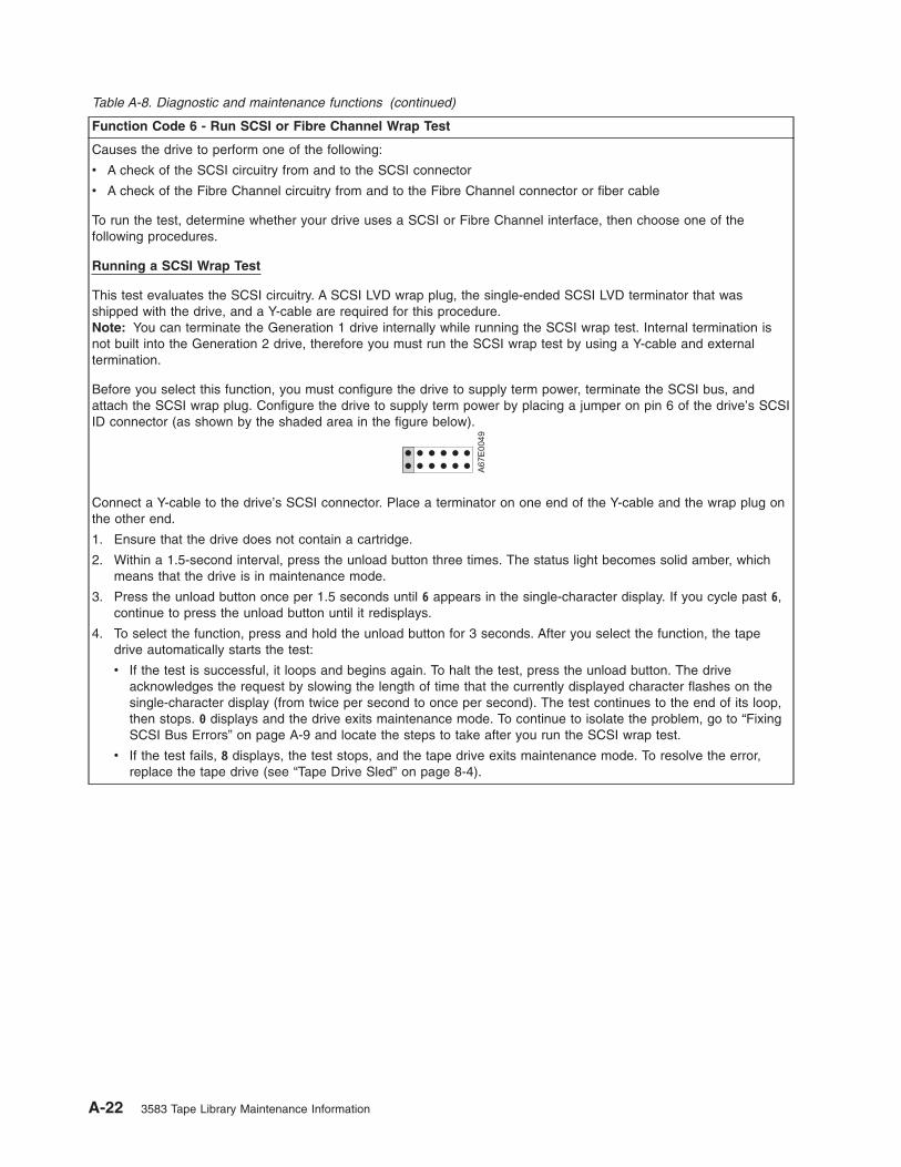
Table A-8. Diagnostic and maintenance functions (continued)
Function Code 6 - Run SCSI or Fibre Channel Wrap Test
Causes the drive to perform one of the following:
v A check of the SCSI circuitry from and to the SCSI connector
v A check of the Fibre Channel circuitry from and to the Fibre Channel connector or fiber cable
To run the test, determine whether your drive uses a SCSI or Fibre Channel interface, then choose one of the
following procedures.
Running a SCSI Wrap Test
This test evaluates the SCSI circuitry. A SCSI LVD wrap plug, the single-ended SCSI LVD terminator that was
shipped with the drive, and a Y-cable are required for this procedure.
Note: You can terminate the Generation 1 drive internally while running the SCSI wrap test. Internal termination is
not built into the Generation 2 drive, therefore you must run the SCSI wrap test by using a Y-cable and external
termination.
Before you select this function, you must configure the drive to supply term power, terminate the SCSI bus, and
attach the SCSI wrap plug. Configure the drive to supply term power by placing a jumper on pin 6 of the drive’s SCSI
ID connector (as shown by the shaded area in the figure below).
A6
7E
00
49
Connect a Y-cable to the drive’s SCSI connector. Place a terminator on one end of the Y-cable and the wrap plug on
the other end.
1. Ensure that the drive does not contain a cartridge.
2. Within a 1.5-second interval, press the unload button three times. The status light becomes solid amber, which
means that the drive is in maintenance mode.
3. Press the unload button once per 1.5 seconds until 6 appears in the single-character display. If you cycle past 6,
continue to press the unload button until it redisplays.
4. To select the function, press and hold the unload button for 3 seconds. After you select the function, the tape
drive automatically starts the test:
v If the test is successful, it loops and begins again. To halt the test, press the unload button. The drive
acknowledges the request by slowing the length of time that the currently displayed character flashes on the
single-character display (from twice per second to once per second). The test continues to the end of its loop,
then stops. 0 displays and the drive exits maintenance mode. To continue to isolate the problem, go to “Fixing
SCSI Bus Errors” on page A-9 and locate the steps to take after you run the SCSI wrap test.
v If the test fails, 8 displays, the test stops, and the tape drive exits maintenance mode. To resolve the error,
replace the tape drive (see “Tape Drive Sled” on page 8-4).
A-22 3583 Tape Library Maintenance Information

Table A-8. Diagnostic and maintenance functions (continued)
Running a Fibre Channel Wrap Test
This test evaluates the Fibre Channel circuitry at the drive’s Fibre Channel connector, then at the fiber cable. A Fibre
Channel wrap plug is required for this procedure. To run the wrap test through the fiber cable, a duplex adapter is
required.
All cables and wrap plugs are hot-pluggable (that is, they can be removed from or added to the drive while the drive
or its enclosure is powered-on). Do not bend the fiber cable more than a radius of 50.8 mm (2 in.) or the optical fiber
may break.
1. Take all devices on the Fibre Channel offline (for instructions, refer to your server’s documentation).
2. Make sure that no cartridge is in the drive.
3. Disconnect the fiber cable from the drive and replace it with the Fibre Channel wrap plug. (When you disconnect
the cable, the connection to the Fibre Channel loop may break, but will be restored at the end of the procedure
when you reconnect the cable. For other devices on the loop, operations may temporarily be disrupted.)
Attention: Do not run the wrap test while the drive is connected to a Fibre Channel loop. This could disturb
the Fibre Channel loop and cause performance or I/O problems.
4. Within a 1.5-second interval, press the unload button three times. The status light becomes solid amber, which
means that the drive is in maintenance mode.
Note: If a cartridge is in the drive, it will eject the first time that you press the unload button and the drive will
not be placed in maintenance mode. To continue placing the drive in maintenance mode, remove the cartridge
and repeat this step.
5. Press the unload button once per 1.5 seconds until 6 appears in the single-character display.
Note: If you cycle past 6, press the unload button once per second until it redisplays.
Testing the Circuitry at the Drive’s Fibre Channel Connector
6. To select the function, press and hold the unload button for 3 seconds. After you select the function, the tape
drive automatically starts the test:
v If the test is successful, the circuitry at the drive’s Fibre Channel connector is working properly. The test loops
and begins again. Press the unload button. 0 displays and the tape drive exits maintenance mode. Continue
to step 7 to test the fiber cable.
v If the test fails, an error code displays and the status light flashes amber. The test stops and the drive exits
maintenance mode. To resolve the error, locate the code in Table 6-4 on page 6-25.
7. Disconnect the Fibre Channel wrap plug from the drive.
Testing the Circuitry at the Fiber Cable
8. Connect the duplex adapter, then the Fibre Channel wrap plug to the end of the fiber cable.
Note: The Fibre Channel wrap test can only be run on cable lengths up to 250 meters (820 ft).
9. Within a 1.5-second interval, press the unload button three times. The status light becomes solid amber, which
means that the drive is in maintenance mode.
Note: If a cartridge is in the drive, it will eject the first time that you press the unload button and the drive will
not be placed in maintenance mode. To continue placing the drive in maintenance mode, remove the cartridge
and repeat this step.
10. Press the unload button once per 1.5 seconds until 6 appears in the single-character display.
Note: If you cycle past 6, press the unload button once per second until it redisplays.
11. To select the function, press and hold the unload button for 3 seconds. After you select the function, the tape
drive automatically starts the test:
v If the test is successful, the drive and the cable are working properly. The problem is at the server. To resolve
the error, refer to the service guide for the server.
v If the test fails, replace the fiber cable.
12. Remove the Fibre Channel wrap plug and the duplex adapter, and reconnect the fiber cable.
TapeAlert Flags A-23

Table A-8. Diagnostic and maintenance functions (continued)
Function Code 7 - Run LDI or RS-422 Wrap Test
Causes the tape drive to perform a check of the circuitry from and to the LDI or RS-422 connector.
Before you select this function, attach an LDI or RS-422 wrap plug to the tape drive:s LDI or RS-422 connector (in
place of the LDI or RS-422 cable).
1. Make sure that no cartridge is in the drive.
2. Within a 1.5-second interval, press the unload button three times. The status light becomes solid amber, which
means that the drive is in maintenance mode.
3. Press the unload button once per 1.5 seconds until 7 appears in the single-character display. If you cycle past 7,
continue to press the unload button until it redisplays.
4. To select the function, press and hold the unload button for 3 seconds. After you select the function, 7 flashes
and the tape drive automatically starts the test:
v If the test is successful, it loops and begins again. To halt the test, press the unload button. The test continues
to the end of its loop and then stops. The tape drive then displays 0 and exits maintenance mode.
v If the test fails, 9 displays, the test stops, and the tape drive exits maintenance mode. To resolve the error,
locate 9 in Table 6-4 on page 6-25.
Function Code 8 - Convert FMR Tape to Scratch Tape
Causes the tape drive to erase the field microcode replacement (FMR) data on a scratch data cartridge and rewrite
the cartridge memory on the tape. This turns the cartridge into a valid scratch data cartridge.
1. Make sure that no cartridge is in the drive.
2. Within a 1.5-second interval, press the unload button three times. The status light becomes solid amber, which
means that the drive is in maintenance mode.
3. Press the unload button once per 1.5 seconds until 8 appears in the single-character display. If you cycle past 8,
continue to press the unload button until it redisplays.
4. To select the function, press and hold the unload button for 3 seconds. After you select the function, C flashes.
When C flashes, the drive is waiting for a cartridge. Within 60 seconds, insert the FMR cartridge (or the tape drive
exits maintenance mode). After you insert the cartridge, 8 flashes, the tape drive erases the firmware on the tape,
then rewrites the header in the cartridge memory to change the cartridge to a valid scratch data cartridge:
v If the operation is successful, the tape drive displays 0, rewinds and ejects the newly converted scratch data
cartridge, and exits maintenance mode.
v If the operation is not successful, an error code displays. To resolve the error, locate the code in Table 6-4 on
page 6-25.
A-24 3583 Tape Library Maintenance Information

Table A-8. Diagnostic and maintenance functions (continued)
Function Code 9 - Display Error Code Log
Causes the tape drive to display the last 10 error codes, one at a time (the codes are ordered; the most recent is
presented first and the oldest (tenth) is presented last).
1. Make sure that no cartridge is in the drive.
2. Within a 1.5-second interval, press the unload button three times. The status light becomes solid amber, which
means that the drive is in maintenance mode.
3. Press the unload button once per 1.5 seconds until 9 appears in the single-character display. If you cycle past 9,
continue to press the unload button until it redisplays.
4. To select the function, press and hold the unload button for 3 seconds. After you select the function, press the
unload button to view the most recent error code. Press the unload button again to view successive error codes.
If you press the unload button for 3 seconds after the tenth error code displays, 0 displays (if there are no errors
in the log) and the drive exits maintenance mode.
Function Code A - Clear Error Code Log
Causes the tape drive to erase the contents of the error code log.
1. Make sure that no cartridge is in the drive.
2. Within a 1.5-second interval, press the unload button three times. The status light becomes solid amber, which
means that the drive is in maintenance mode.
3. Press the unload button once per 1.5 seconds until A appears in the single-character display. If you cycle past A,
continue to press the unload button until it redisplays.
4. To select the function, press and hold the unload button for 3 seconds. After you select the function, the tape
drive erases all errors from the error code log, displays 0, then exits maintenance mode.
Function Code C - Insert Cartridge into Tape Drive
This function cannot be selected by itself. It relates to other maintenance functions (such as Run Tape Drive
Diagnostics or Create FMR Tape) that require an FMR tape cartridge or scratch tape cartridge that is not write
protected.
TapeAlert Flags A-25

Table A-8. Diagnostic and maintenance functions (continued)
Function Code E - Test Cartridge & Media
Causes the tape drive to perform a Write/Read test (on the edge bands) to ensure that a suspect cartridge and its
magnetic tape are acceptable. The tape drive takes approximately 10 minutes to run the test.
Attention: Data on the suspect tape will be overwritten.
1. Make sure that no cartridge is in the drive.
2. Within a 1.5-second interval, press the unload button three times. The status light becomes solid amber, which
means that the drive is in maintenance mode.
3. Press the unload button once per 1.5 seconds until E appears in the single-character display. If you cycle past E,
continue to press the unload button until it redisplays.
4. To select the function, press and hold the unload button for 3 seconds. After you select the function, C flashes.
When C flashes, the drive is waiting for a cartridge. Within 60 seconds, insert the suspect data cartridge (or the
tape drive exits maintenance mode). After you insert the cartridge, E flashes and the test begins:
v If no error is detected, the test begins again and runs for a maximum of 10 times. After the tenth loop, the test
stops and the drive automatically exits maintenance mode. To halt the test, press the unload button. The drive
acknowledges the request by slowing the length of time that the currently displayed character flashes on the
single-character display (from twice per second to once per second). The test continues to the end of its loop
and then stops. The tape drive then rewinds and unloads the cartridge, displays 0, and exits maintenance
mode.
v If an error is detected, the tape drive displays 7, unloads the tape cartridge, and exits maintenance mode. To
resolve the error, locate 7 in Table 6-4 on page 6-25.
Function Code F - Fast Read/Write Test
Causes the tape drive to perform tests to ensure that the drive can read from and write to tape. This diagnostic
performs fewer tests than the Run Tape Drive Diagnostics test (Function Code 1). The tape drive takes approximately
three minutes to run the test. The Fast Read/Write Test is not as comprehensive a test and is not recommended for
isolating errors between the drive and the media.
Attention: Data on the suspect tape will be overwritten.
1. Make sure that no cartridge is in the drive.
2. Within a 1.5-second interval, press the unload button three times. The status light becomes solid amber, which
means that the drive is in maintenance mode.
3. Press the unload button once per 1.5 seconds until F appears in the single-character display. If you cycle past F,
continue to press the unload button until it redisplays.
4. To select the function, press and hold the unload button for 3 seconds. After you select the function, C flashes.
When C flashes, the drive is waiting for a cartridge. Within 60 seconds, insert the suspect data cartridge (or the
tape drive exits maintenance mode). After you insert the cartridge, F flashes and the test begins.
v If no error is detected, the test begins again and runs for a maximum of 10 times. Each loop takes
approximately 3 minutes to run. After the tenth loop, the test stops and the drive automatically exits
maintenance mode. To halt the test, press the unload button. The drive acknowledges the request by slowing
the length of time that the currently displayed character flashes on the single-character display (from twice per
second to once per second). The test continues to the end of its loop and then stops. The tape drive then
rewinds and unloads the cartridge, displays 0, and exits maintenance mode.
v If an error is detected, the tape drive displays an error code, unloads the tape cartridge, and exits maintenance
mode. To resolve the error, locate the code in Table 6-4 on page 6-25.
A-26 3583 Tape Library Maintenance Information

Table A-8. Diagnostic and maintenance functions (continued)
Function Code H - Test Head
Causes the tape drive to perform the Head Resistance Measurements test and a Write/Read test (on the center of
the tape). The drive runs these tests to ensure that the tape drive’s head and tape-carriage mechanics are working
correctly. The tape drive takes approximately 10 minutes to run the test.
1. Make sure that no cartridge is in the drive.
2. Within a 1.5-second interval, press the unload button three times. The status light becomes solid amber, which
means that the drive is in maintenance mode.
3. Press the unload button once per 1.5 seconds until H appears in the single-character display. If you cycle past H,
continue to press the unload button until it redisplays.
4. To select the function, press and hold the unload button for 3 seconds. After you select the function, C flashes.
When C flashes, the drive is waiting for a cartridge. Within 60 seconds, insert a scratch data cartridge (or the tape
drive exits maintenance mode). After you insert the cartridge, H flashes and the test begins:
v If no error is detected, the test begins again and runs for a maximum of 10 times. Each loop takes
approximately 10 minutes to run. After the tenth loop, the test stops and the drive automatically exits
maintenance mode. To halt the test, press the unload button. The drive acknowledges the request by slowing
the length of time that the currently displayed character flashes on the single-character display (from twice per
second to once per second). The test continues to the end of its loop and then stops. The tape drive then
rewinds and unloads the cartridge, displays 0, and exits maintenance mode.
v If an error is detected, the tape drive displays 5, unloads the tape cartridge, and exits maintenance mode. To
resolve the error, locate 5 in Table 6-4 on page 6-25.
Function Code L - Reserved for Future Use
Reserved for future use.
Function Code P or U - Enable or Disable Post Error Reporting
Used by support personnel during error detection, this function is an alternate method of setting or preventing the
post error (PER) bit in the SCSI Read-Write Error Recovery Page. For more information, refer to the MODE SENSE
command in the IBM TotalStorage LTO Ultrium Tape Drive SCSI Reference.
1. Make sure that no cartridge is in the drive.
2. Within a 1.5-second interval, press the unload button three times. The status light becomes solid amber, which
means that the drive is in maintenance mode.
3. Perform one of the following:
v To enable post error reporting, press the unload button once per 1.5 seconds until U appears in the
single-character display. If you cycle past U, continue to press the unload button until it redisplays.
v To disable post error reporting, press the unload button once per 1.5 seconds until P appears in the
single-character display. If you cycle past P, continue to press the unload button until it redisplays.
4. To select the function, press and hold the unload button for 3 seconds. After you select the function, the drive
displays one of the following:
v P to indicate that post error reporting is enabled.
v U to indicate that post error reporting is disabled.
Exiting Maintenance Mode
To manually exit maintenance mode, press the unload button once per second until 0 appears on the
single-character display. Press and hold the unload button for 3 seconds. The drive exits maintenance
mode (the solid amber status light turns off).
TapeAlert Flags A-27

Repositioning or Reattaching a Leader Pin
Attention: Use a repaired tape cartridge only to recover data and move it to
another cartridge. Continued use of a repaired cartridge may void the warranties of
the drive and the cartridge.
If the leader pin in your cartridge becomes dislodged from its pin-retaining spring clips or detaches from
the tape, you must use the IBM Leader Pin Reattachment Kit (part number 08L9129) to reposition or
reattach it. (Do not reattach the pin if you must remove more than 7 meters (23 feet) of leader tape.) The
sections that follow describe each procedure.
Repositioning a Leader Pin
A leader pin that is improperly seated inside a cartridge can interfere with the operation of the drive.
Figure A-4 shows a leader pin in the incorrect �1� and correct �2� positions.
To place the leader pin in its proper position, you will need the following tools:
v Plastic or blunt-end tweezers
v Cartridge manual rewind tool (from Leader Pin Reattachment Kit, part number 08L9129)
Figure A-4. Leader pin in the incorrect and correct positions. The cartridge door is open and the leader pin is visible
inside the cartridge.
A-28 3583 Tape Library Maintenance Information

To reposition the leader pin, perform the following steps.
1. Slide open the cartridge door (�1� in Figure A-5) and locate the leader pin �2� (you may need to shake
the cartridge gently to roll the pin toward the door).
2. With plastic or blunt-end tweezers, grasp the leader pin and position it in the pin-retaining spring clips
�3�.
3. Press the leader pin gently into the clips until it snaps into place and is firmly seated. Ensure that there
are no gaps in the seam of the cartridge �4�.
Attention: If gaps exist, do not continue with this procedure and do not use the cartridge. Instead,
contact your OEM Product Application Engineer (PAE).
4. Close the cartridge door.
5. To rewind the tape, insert the cartridge manual rewind tool (�1� in Figure A-6) into the cartridge’s hub
�2� and turn it clockwise until the tape becomes taut.
6. Remove the rewind tool by pulling it away from the cartridge.
Figure A-5. Placing the dislodged leader pin into the correct position. The cartridge door is open to show the leader
pin.
Figure A-6. Rewinding the tape into the cartridge
TapeAlert Flags A-29

Reattaching a Leader Pin
The first meter of tape in a cartridge is leader tape. Once the leader tape has been removed there is a
possibility of tape breakage. After reattaching the leader pin, transfer data from the defective tape
cartridge. Do not reuse the defective tape cartridge.
The Leader Pin Reattachment Kit contains three parts:
v Leader pin attach tool (see �1� in Figure A-7). A plastic brace that holds the cartridge door open.
v Cartridge manual rewind tool (see �2� in Figure A-7). A device that fits into the cartridge’s hub and
lets you wind the tape into and out of the cartridge.
v Pin supplies (see �3� in Figure A-7). Leader pins and C-clips.
Attention:
v Use only the IBM Leader Pin Reattachment Kit to reattach the leader pin to the tape. Other methods of
reattaching the pin will damage the tape, the drive, or both.
v Use this procedure on your tape cartridge only when the leader pin detaches from the magnetic tape
and you must copy the cartridge’s data onto another cartridge. Destroy the damaged cartridge after you
copy the data. This procedure may affect the performance of the leader pin during threading and
unloading operations.
v Touch only the end of the tape. Touching the tape in an area other than the end can damage the tape’s
surface or edges, which may interfere with read or write reliability.
A67E
0042
1
2
3
Figure A-7. Leader Pin Reattachment Kit
A-30 3583 Tape Library Maintenance Information

The following procedure describes how to reattach a leader pin.
To reattach a leader pin by using the IBM Leader Pin Reattachment Kit:
1. Attach the leader pin attach tool (�1� in Figure A-8) to the cartridge �2� so that the tool’s hook �3�
latches into the cartridge’s door �4�. Pull the tool back to hold the door open, then slide the tool onto
the cartridge. Open the tool’s pivot arm �5�.
Figure A-8. Attaching the leader pin attach tool to the cartridge. To hold the cartridge door open, hook the tool into the
door and pull the tool back.
TapeAlert Flags A-31

2. To find the end of the tape inside the cartridge, attach the cartridge manual rewind tool (�1� in
Figure A-9) to the cartridge’s hub �2� by fitting the tool’s teeth between the teeth of the hub. Turn the
tool clockwise until you see the end of the tape inside the cartridge. Then, slowly turn the rewind tool
counterclockwise to bring the tape edge toward the cartridge door �3�.
3. Continue to turn the rewind tool counterclockwise until approximately 12.7 cm (5 in.) of tape hangs
from the cartridge door. If necessary, grasp the tape and pull gently to unwind it from the cartridge.
4. Remove the rewind tool by pulling it away from the cartridge. Set the tool and the cartridge aside.
5. On the leader pin (�1� in Figure A-10), locate the open side of the C-clip �2�. The C-clip is a small
black part that secures the tape �3� to the pin.
6. Remove the C-clip from the leader pin by using your fingers to push the clip away from the pin. Set
the pin aside and discard the clip.
Figure A-9. Winding the tape out of the cartridge. Turn the cartridge manual rewind tool clockwise to see the end of
the tape, then turn it counterclockwise to bring the tape to the cartridge door.
A67E
0036
1
2
3
Figure A-10. Removing the C-clip from the leader pin. Use your fingers to push the C-clip from the leader pin.
A-32 3583 Tape Library Maintenance Information

7. Position the tape in the alignment groove of the leader pin attach tool (see �1� in Figure A-11).
8. Place a new C-clip into the retention groove �2� (Figure A-11) on the leader pin attachment tool and
make sure that the clip’s open side faces up.
9. Place the leader pin (from step 6 on page A-32) into the cavity �3� (Figure A-11) of the leader pin
attach tool.
Attention: To prevent the leader pin from rolling into the cartridge, in the following step use care when
folding the tape over the pin.
10. Fold the tape over the leader pin and hold it with your fingers (see Figure A-11).
Note: Use care to ensure that the tape is centered over the leader pin. Failure to properly center the
tape on the pin will cause the repaired cartridge to fail. When the tape is properly centered, a
0.25-mm (0.01-in.) gap exists on both sides of the pin.
11. Close the pivot arm �4� of the leader pin attach tool by swinging it over the leader pin so that the
C-clip snaps onto the pin and the tape.
12. Swing the pivot arm open and trim the excess tape �5� so that it is flush with the reattached leader
pin �6�.
13. Use your fingers to remove the leader pin from the cavity �3� in the leader pin attach tool.
14. Use the cartridge manual rewind tool to wind the tape back into the cartridge (wind the tape
clockwise). Ensure that the leader pin is latched by the pin-retaining spring clips on each end of the
leader pin.
A67E
0037
1
6
2
3
4
5
Figure A-11. Attaching the leader pin to the tape
TapeAlert Flags A-33

15. Remove the rewind tool.
16. Remove the leader pin attach tool by lifting its end up and away from the cartridge.
Attention: Use a repaired tape cartridge only to recover data and move it to
another cartridge. Continued use of a repaired cartridge may void the warranties of
the drive and the cartridge.
A-34 3583 Tape Library Maintenance Information

Removing a Tape Cartridge
If a tape cartridge fails to eject from the Ultrium Tape Drive there are two methods to remove the cartridge.
The following sections describe the two procedures, resetting the drive and ejecting the cartridge, and
manually removing the cartridge.
Visit the web at http://www-1.ibm.com/servers/storage/support/lto/3580.html and under Learn click on LTO
Cartridge removal for Ultrium 1 and Ultrium 2 Tape Drives and watch a video of the procedure.
Note: Before removing the tape drive sled, preserve the drive dump. For instructions, see “Performing a
Preserve Dump” on page 4-36.
Resetting the Drive and Ejecting the Cartridge
If a tape cartridge fails to eject from the Ultrium Tape Drive, you can perform the following steps to reset
the drive and eject the cartridge.
1. Vary the library and drives Offline to all attached hosts.
2. Open the library front door.
3. Locate the drive that contains the stuck tape cartridge. If the picker (�1� in Figure B-1 on page B-2) is
in front of the drive �2�, gently lift and hold the picker out of the way.
4. Press and release the eject button �5� on the front of the drive and wait for approximately two minutes.
If the cartridge ejects the procedure was successful. If the cartridge does not eject continue with the
next step.
5. Press and hold the eject button �5� for at least 10 seconds. The single character display �3� should
change as the drive performs a power-on self test (POST). If this does not happen cycle power to the
library (turn it off, then on again).
Note: If you raised the picker to access the tape drive, lower the picker before cycling power to the
library.
6. After a reset or power cycle, the drive should start a slow rewind. During the slow rewind the activity
LED �4� will be flashing. You must wait for the LED to stop flashing, indicating that the slow rewind is
complete. This process may take up to 20 minutes.
7. Press and release the eject button �5� on the front of the drive and wait for approximately two minutes.
If the cartridge ejects the procedure was successful. If the cartridge does not eject continue with the
following procedure.
© Copyright IBM Corp. 2000, 2005 B-1
||

Manually Removing a Tape Cartridge from an Ultrium 3 Tape Drive
Attention:
If you are not a trained service person, do not attempt to open the drive for repairs.
Attempting a repair other than the manual removal of a cartridge will void your warranty.
For Ultrium 3 drives only. Before attempting to remove a tape from the drive, it is very important to
preserve the active dump information in non-volatile storage in case the drive has to be replaced. This
dump information will be used by the Repair Center when they perform failure analysis on the returned
drive. Execute the following sequence before powering OFF the drive:
Path: Main Menu —>Status Menu —> Logs —> Drive Log —> Options
—> Preserve Dump
Manually Removing a Tape Cartridge
The purpose of this section is to assist you in determining the condition of the cartridge or the magnetic
tape and to direct you to the procedure you must follow to remove the cartridge.
a67m
0083
1 2
543
Figure B-1. Resetting the Tape Drive
B-2 3583 Tape Library Maintenance Information
|
||||||
||||
||
||
||
|
|
||

Attention
v Before using this procedure, you must have exhausted all other means of removing the tape
cartridge from the drive. Use this procedure only if you cannot remove the tape cartridge by using
any other means.
v Determine from the customer if the cartridge contains critical customer data. If the cartridge
contains sensitive data that cannot leave the site, inform the customer that certain failure
conditions diagnostics will be performed to test the drive for continued use.
v The following removal procedures can destroy customer data! Use extreme care when handling
or removing the customer’s tape cartridges to minimize tape damage and lost data.
v DO NOT TOUCH the magnetic tape or tape path. Both are extremely sensitive to the oil and salt
from your skin. Use clean, lint-free gloves when working around magnetic tape or the tape path
components.
v Electrostatic-sensitive components: Consider using an ESD Kit.
v After you remove the tape cartridge, advise the customer to copy the data to another cartridge and
to remove this tape cartridge from service.
v Do not use power tools or magnetic tools to perform this procedure.
v To avoid contamination and electrostatic-discharge damage to the drive, never touch the head or
electronic components inside the drive.
v If you cannot remove the cartridge from the drive using the following procedures, contact your next
level of support.
Before You Begin
1. If you have not already done so, attempt to remove the cartridge with the device power ON and using
library manager, a host application, or the Unload Button.
2. If you have not already done so, attempt to remove the cartridge by power cycling the drive. Look for
the drive to attempt a mid-tape recovery.
Note: It can take as long as five minutes for the cartridge to rewind and unload.
3. If the cartridge unloads, inform the operator that the cartridge is unloaded. If the cartridge does not
unload, continue with this procedure.
Recommended Tools
v 2.5 mm offset hex wrench (do not use magnetized wrench)
v #1 Phillips screwdriver
v ESD Kit
v Flashlight (optional)
v #1 Flathead screwdriver (optional)
Beginning Procedure
__ 1. Refer to the enclosure documentation for instructions on removing the drive.
__ 2. Place the drive on a non-slip, sturdy work surface.
__ 3. Ground yourself to the drive by using an ESD Kit.
__ 4. Remove the cover of the drive by performing the following steps:
a. Using a Phillips screwdriver, remove the three screws and washers (see �1� in Figure B-2 on
page B-4) that secure the bezel �2� to the internal drive, then remove the bezel.
b. Remove the cover of the internal drive by performing the following steps:
1) Remove the four cover-mounting screws and washers �3�.
Removing a Tape Cartridge B-3
|
|
|||
|||
||
|||
|
||
|
||
|||||
|||
||
|
||
||
|
|
|
|
||
|
|
|
||
|
|
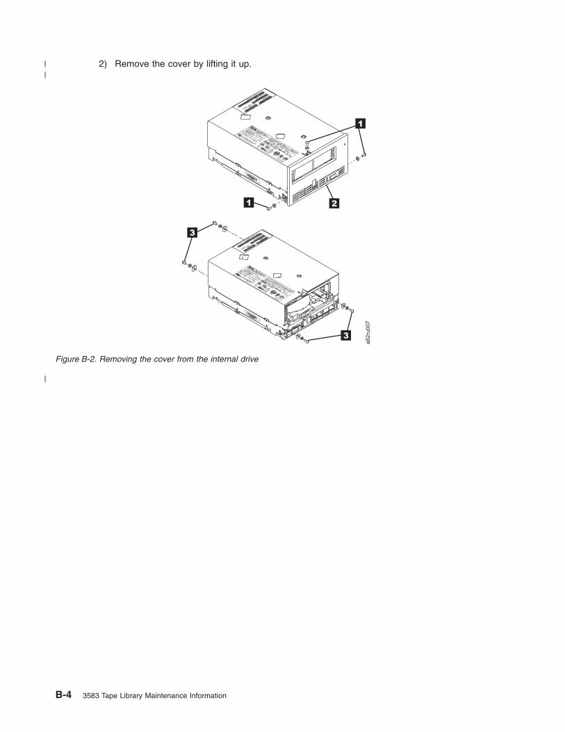
2) Remove the cover by lifting it up.
3
2
1
1
3
a82ru
007
Figure B-2. Removing the cover from the internal drive
B-4 3583 Tape Library Maintenance Information
||
|

__ 5. Inspect the drive to decide which of the following conditions most closely matches the symptom on
the drive:
v Tape spooled off the supply reel - All the tape appears to be on the take up reel and no tape is
on the supply reel (inside the cartridge). Test the drive after the procedure is completed.
v Tape pulled from leader pin (or broken at the front end) - All the tape appears to be on the
supply reel (inside the cartridge) and very little or no tape appears to be on the take up reel. The
leader block is positioned in the take up reel. Return the drive after the procedure is completed.
v Tape broken in mid-tape - Tape appears to be on both the supply reel (inside the cartridge) and
take up reel. Test the drive after the procedure is completed.
v Tape tangled along tape path - Tape appears to be tangled and damaged but in tact. Return
the drive after the procedure is completed.
-- OR --
No damage to tape (or no apparent failure) - There appears to be no damage or slack to the
tape. Return the drive after the procedure is completed.
Removing a Tape Cartridge B-5
||
||
|||
||
||
|
||
|

Tape Spooled off Supply Reel
__ 1. With the front of the drive facing you, pull an arm’s length of tape out of the take up reel from the
left side of the drive.
__ 2. From the take up reel, thread tape around the rear of the tape path and over the head rollers on
the left side of the drive.
__ 3. Set the drive on its left side with the head and tape path facing up.
__ 4. Moisten a cotton swab with water and wet approximately 13 mm (0.5 in.) of the tape end and feed
it onto the supply reel (inside the cartridge).
__ 5. From the bottom of the drive, insert a 2.5 mm offset hex wrench through the bottom cover access
hole and into the reel motor axle.
__ 6. Turn the supply reel clockwise, allowing the moistened tape to adhere to the hub as it winds
around the supply reel (inside the cartridge).
__ 7. Continue spooling into the cartridge until the tape is taut and remains within the flanges of the tape
guiding rollers. Ensure that you do not stretch the tape.
__ 8. Reassemble the drive, reversing the steps in “Beginning Procedure” on page B-3.
__ 9. Allow the drive to perform mid-tape recovery. This takes several minutes. When this activity
completes, the cartridge ejects automatically.
__ 10. Test the drive (see “Running Drive Diagnostics” on page 4-103) to determine if it should be
replaced.
a82ru
0081
Figure B-3. Using hex wrench to rewind tape into cartridge
B-6 3583 Tape Library Maintenance Information
|||
||
|
||
|||
||
||
|
||
||

Tape Pulled from or Broken near Leader Pin
�1� Loader motor worm gear �6� Threader mechanism gear
�2� Cartridge loader tray guide bearing �7� Lever
�3� Rotator stub �8� Loader mechanism gear
�4� Threader motor worm gear �9� Threader worm gear
�5� Threader intermediate gear
__ 1. From the left side of the drive, pull out tape from the take up reel.
Note: If there is more than approximately 0.6 m (2 ft.) of tape on the take up reel, go to “Tape
Broken in Mid-tape” on page B-8.
__ 2. If there is less than approximately 0.6 m (2 ft.) of tape on the take up reel, cut off the excess tape
as close to the leader pin, as possible.
__ 3. Locate the threader motor worm gear (�4� in Figure B-4) the rear of the drive. You can either:
a. Use your finger to rotate the threader motor worm gear and slowly rotate the threader
mechanism gear (�6� in Figure B-4) clockwise; or
b. Use a #1 flathead screwdriver to turn the threader worm gear (�9� in Figure B-4) clockwise.
This rotates the threader motor worm gear (�4� in Figure B-4) clockwise, drawing the tape leader
block assembly (LBA) into the cartridge.
__ 4. As the LBA is secured in the cartridge, you should hear the LBA retention spring clips click into
place. If you do not hear the click, continue rolling until the threader motor worm gear (�4� in
Figure B-4) stops. The LBA is in the correct position.
a82ru
009
1
2 3
4
5
6
78
9
Figure B-4. Drive with cover removed to reveal gear train.
Removing a Tape Cartridge B-7
||
|||||
||||
||||
||||
|||||
|
||
||
|
||
|
||
|||
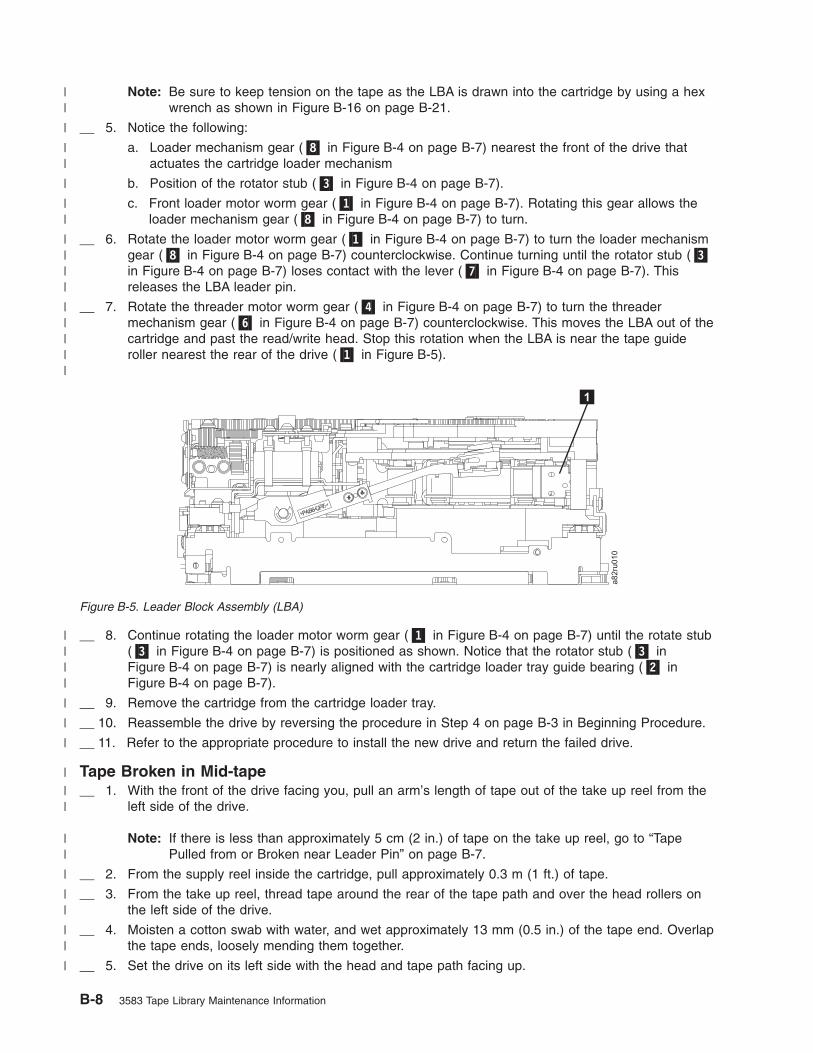
Note: Be sure to keep tension on the tape as the LBA is drawn into the cartridge by using a hex
wrench as shown in Figure B-16 on page B-21.
__ 5. Notice the following:
a. Loader mechanism gear (�8� in Figure B-4 on page B-7) nearest the front of the drive that
actuates the cartridge loader mechanism
b. Position of the rotator stub (�3� in Figure B-4 on page B-7).
c. Front loader motor worm gear (�1� in Figure B-4 on page B-7). Rotating this gear allows the
loader mechanism gear (�8� in Figure B-4 on page B-7) to turn.
__ 6. Rotate the loader motor worm gear (�1� in Figure B-4 on page B-7) to turn the loader mechanism
gear (�8� in Figure B-4 on page B-7) counterclockwise. Continue turning until the rotator stub (�3�
in Figure B-4 on page B-7) loses contact with the lever (�7� in Figure B-4 on page B-7). This
releases the LBA leader pin.
__ 7. Rotate the threader motor worm gear (�4� in Figure B-4 on page B-7) to turn the threader
mechanism gear (�6� in Figure B-4 on page B-7) counterclockwise. This moves the LBA out of the
cartridge and past the read/write head. Stop this rotation when the LBA is near the tape guide
roller nearest the rear of the drive (�1� in Figure B-5).
__ 8. Continue rotating the loader motor worm gear (�1� in Figure B-4 on page B-7) until the rotate stub
(�3� in Figure B-4 on page B-7) is positioned as shown. Notice that the rotator stub (�3� in
Figure B-4 on page B-7) is nearly aligned with the cartridge loader tray guide bearing (�2� in
Figure B-4 on page B-7).
__ 9. Remove the cartridge from the cartridge loader tray.
__ 10. Reassemble the drive by reversing the procedure in Step 4 on page B-3 in Beginning Procedure.
__ 11. Refer to the appropriate procedure to install the new drive and return the failed drive.
Tape Broken in Mid-tape
__ 1. With the front of the drive facing you, pull an arm’s length of tape out of the take up reel from the
left side of the drive.
Note: If there is less than approximately 5 cm (2 in.) of tape on the take up reel, go to “Tape
Pulled from or Broken near Leader Pin” on page B-7.
__ 2. From the supply reel inside the cartridge, pull approximately 0.3 m (1 ft.) of tape.
__ 3. From the take up reel, thread tape around the rear of the tape path and over the head rollers on
the left side of the drive.
__ 4. Moisten a cotton swab with water, and wet approximately 13 mm (0.5 in.) of the tape end. Overlap
the tape ends, loosely mending them together.
__ 5. Set the drive on its left side with the head and tape path facing up.
a82ru
010
1
Figure B-5. Leader Block Assembly (LBA)
B-8 3583 Tape Library Maintenance Information
||
|
||
|
||
||||
|||||
||||
|
|
|
|||
||
|
||
||
|

__ 6. From the bottom of the drive, locate the access hole (�1� in Figure B-6) in the bottom cover. Insert
a 2.5 mm offset hex wrench through the bottom cover access hole and into the reel motor axle.
begin spooling tape back into the cartridge by turning the hex wrench clockwise.
__ 7. Turn the supply reel clockwise, carefully guiding the mended portion of the tape to wind around
the hub of the supply reel located inside the cartridge. Continue spooling into the cartridge until the
tape is taut. The tape must remain within the flanges of the tape guiding rollers. Ensure that you
do not stretch the tape.
__ 8. Reassemble the drive by reversing the procedure in Step 4 on page B-3 in Beginning Procedure.
__ 9. Allow the drive to perform mid-tape recovery. This takes several minutes. When this activity
completes, the cartridge ejects automatically.
__ 10. Test the drive (see “Running Drive Diagnostics” on page 4-103) to determine if it should be
replaced.
Tape Tangled along Tape Path
__ 1. Carefully pull out excess tape and untangle.
Note: If you find the tape to be broken, go to one of the following appropriate procedures:
v “Tape Spooled off Supply Reel” on page B-6
v “Tape Pulled from or Broken near Leader Pin” on page B-7
--OR--
“Tape Broken in Mid-tape” on page B-8
__ 2. Set the drive on its left side with the head and tape path facing up.
a82ru
0081
Figure B-6. Using hex wrench to rewind tape into cartridge
Removing a Tape Cartridge B-9
||||
||||
|
||
||
||
|
|
|
|
|
||

__ 3. From the bottom of the drive, locate the access hole (�1� in Figure B-7).
__ 4. Insert a 2.5 mm offset hex wrench through the bottom cover access hole and into the reel motor
axle. Begin spooling the tape back into the cartridge by turning the hex wrench clockwise.
__ 5. Continue spooling into the cartridge until the tape is taut and remains within the flanges of the tape
guiding rollers. Ensure that you do not stretch the tape.
__ 6. Locate the threader motor worm gear (�4� in Figure B-8 on page B-11) on the rear of the drive.
You can either:
a. Use your finger to rotate the treader motor worm gear and slowly rotate the threader
mechanism gear (�6� in Figure B-8 on page B-11) clockwise; OR
b. Use a #1 flathead screwdriver to turn the worm gear (�9� in Figure B-8 on page B-11)
clockwise.
This rotates the threader motor worm gear (�4� in Figure B-8 on page B-11) clockwise, drawing
the LBA into the cartridge.
a82ru
0081
Figure B-7. Using hex wrench to rewind tape into cartridge
B-10 3583 Tape Library Maintenance Information
|
||
||
||
||
||
|||

�1� Loader motor worm gear �6� Threader mechanism gear
�2� Cartridge loader tray guide bearing �7� Lever
�3� Rotator stub �8� Loader mechanism gear
�4� Threader motor worm gear �9� Threader worm gear
�5� Threader intermediate gear
__ 7. As the tape leader block assembly (LBA) is secured in the cartridge, you should hear the LBA
retention spring clips click into place. If you do not hear the click, continue rolling until the threader
motor worm gear (�4� in Figure B-8) stops. The LBA is in the correct position.
Note: Be sure to keep tension on the tape as the LBA is drawn into the cartridge by using a hex
wrench as shown in Figure B-7 on page B-10.
__ 8. Notice the:
a. Loader mechanism gear (�8� in Figure B-8) nearest the front of the drive that actuates the
cartridge loader mechanism.
b. Position of the rotate stub (�3� in Figure B-8).
c. Front loader motor worm gear (�1� in Figure B-8). Rotating this gear allows the loader
mechanism gear (�8� in Figure B-8) to turn.
__ 9. Rotate the loader motor worm gear (�1� in Figure B-8) to turn the threader mechanism gear (�6�
in Figure B-8) counterclockwise. Continue turning until the rotator stub (�3� in Figure B-8) loses
contact with the lever (�7� in Figure B-8). This releases the LBA leader pin.
__ 10. Rotate the threader motor worm gear (�4� in Figure B-8) to turn the threader mechanism gear (�6�
in Figure B-8) counterclockwise. This moves the LBA out of the cartridge and past the read/write
a82ru
009
1
2 3
4
5
6
78
9
Figure B-8. Drive with cover removed to reveal gear train.
Removing a Tape Cartridge B-11
|||||
||||
||||
||||
|||||
|||
||
|
||
|
||
|||
||

head. Stop this rotation when the LBA is near the tape guide roller nearest the rear of the drive
shown as �1� Figure B-9.
__ 11. Continue rotating the loader motor worm gear (�1� in Figure B-8 on page B-11) until the rotator
stub (�3� in Figure B-8 on page B-11) is positioned as shown. Notice that the rotator stub (�3� in
Figure B-8 on page B-11) is nearly aligned with the cartridge loader tray guide bearing (�2� in
Figure B-8 on page B-11).
__ 12. Remove the cartridge from the cartridge loader tray.
__ 13. Reassemble the drive by reversing the procedure in Step 4 on page B-3 in Beginning Procedure.
__ 14. Refer to the appropriate procedure to install the new drive and return the failed drive.
a82ru
010
1
Figure B-9. Leader Block Assembly (LBA)
B-12 3583 Tape Library Maintenance Information
|||
||||
|
|
|
|

No Apparent Failure or Damage to Tape
__ 1. Set the drive on its left side with the head and tape path facing up.
__ 2. From the bottom of the drive, locate the access hole (�1� in Figure B-10).
__ 3. Insert a 2.5 mm offset hex wrench through the bottom cover access hole and into the reel motor
axle. Begin spooling the tape back into the cartridge by turning the hex wrench clockwise.
__ 4. Continue spooling into the cartridge until the tape is taut and remains within the flanges of the tape
guiding rollers. Ensure that you do not stretch the tape.
__ 5. Locate the threader motor worm gear (�4� in Figure B-11 on page B-14) on the rear of the drive.
You can either:
a. Use your finger to rotate the threader motor worm gear and slowly rotate the threader
mechanism gear (�6� in Figure B-11 on page B-14) clockwise;
--OR--
b. Use a #1 flathead screwdriver to turn the threader worm gear (�9� in Figure B-11 on page
B-14) clockwise.
This rotates the threader motor worm gear (�4� in Figure B-11 on page B-14) clockwise, drawing
the LBA into the cartridge.
a82ru
0081
Figure B-10. Using hex wrench to rewind tape into cartridge
Removing a Tape Cartridge B-13
|||
|
||
||
||
||
|
||
|||

�1� Loader motor worm gear �6� Threader mechanism gear
�2� Cartridge loader tray guide bearing �7� Lever
�3� Rotator stub �8� Loader mechanism gear
�4� Threader motor worm gear �9� Threader worm gear
�5� Threader intermediate gear
__ 6. As the tape leader block assembly (LBA) is secured in the cartridge, you should hear the LBA
retention spring clips click into place. If you do not hear the click, continue rolling until the threader
motor worm gear (�4� in Figure B-8 on page B-11) stops. The LBA is in the correct position.
Note: Be sure to keep tension on the tape as the LBA is drawn into the cartridge by using a hex
wrench as shown in Figure B-7 on page B-10.
__ 7. Notice the:
a. Loader mechanism gear (�8� in Figure B-11) nearest the front of the drive that actuates the
cartridge loader mechanism.
b. Position of the rotate stub (�3� in Figure B-11).
c. Front loader motor worm gear (�1� in Figure B-11). Rotating this gear allows the loader
mechanism gear (�8� in Figure B-11) to turn.
__ 8. Rotate the loader motor worm gear (�1� in Figure B-11) to turn the threader mechanism gear (�6�
in Figure B-11) counterclockwise. Continue turning until the rotator stub (�3� in Figure B-11) loses
contact with the lever (�7� in Figure B-11). This releases the LBA leader pin.
__ 9. Rotate the threader motor worm gear (�4� in Figure B-11) to turn the threader mechanism gear
(�6� in Figure B-11) counterclockwise. This moves the LBA out of the cartridge and past the
a82ru
009
1
2 3
4
5
6
78
9
Figure B-11. Drive with cover removed to reveal gear train.
B-14 3583 Tape Library Maintenance Information
|||||
||||
||||
||||
|||||
|||
||
|
||
|
||
|||
||

read/write head. Stop this rotation when the LBA is near the tape guide roller nearest the rear of
the drive shown as �1� Figure B-12.
__ 10. Continue rotating the loader motor worm gear (�1� in Figure B-11 on page B-14) until the rotator
stub (�3� in Figure B-11 on page B-14) is positioned as shown. Notice that the rotator stub (�3� in
Figure B-11 on page B-14) is nearly aligned with the cartridge loader tray guide bearing (�2� in
Figure B-11 on page B-14).
__ 11. Remove the cartridge from the cartridge loader tray.
__ 12. Reassemble the drive by reversing the procedure in Step 4 on page B-3 in Beginning Procedure.
__ 13. Refer to the appropriate procedure to install the new drive and return the failed drive.
a82ru
010
1
Figure B-12. Leader Block Assembly (LBA)
Removing a Tape Cartridge B-15
|||
||||
|
|
|

Manually Removing the Tape Cartridge from an Ultrium 2 and 1 Tape
Drive
Attention:
If you are not a trained service person, do not attempt to open the drive for repairs.
Attempting a repair other than the manual removal of a tape cartridge will void your warranty.
Removing the Cartridge
If a tape cartridge fails to eject from an Ultrium Tape Drive, you can manually remove the cartridge. The
following tools are required for the procedure:
v 2.5-mm allen wrench
v Small-blade screwdriver or potentiometer-setting tool
v 2-mm hex wrench
v #3 Phillips screwdriver
v Needle-nose pliers
v Flashlight (optional)
Attention: Before performing this procedure, note the following:
v Ensure that you have attempted all normal methods of removing the tape
cartridge from the drive. Refer to “Resetting the Drive and Ejecting the Cartridge”
on page B-1.
v This procedure may damage the stuck tape cartridge. If you use this procedure,
copy the data from the stuck cartridge to another cartridge. If you choose to
reuse the stuck cartridge, refer to the instructions in “Repositioning or Reattaching
a Leader Pin” on page A-28. If you believe the cartridge has been damaged,
replace it.
v If you use a power screwdriver to perform this procedure it could destroy the
tape.
v Never touch the head or electronic components within the drive. Touching may
cause contamination or damage by electrostatic discharge.
To manually remove a tape cartridge, perform the following steps:
1. Ask customer to vary the Library and Drives Offline to ALL ATTACHED HOSTS.
2. Prepare the Library for drive sled removal. Using the operator panel, select More —> Service —>
Drives —> Repair —> Remove.
3. Power Off the Tape Library by setting the Main Switch on the ac Input Power Module to the O
position.
4. Disconnect all cables to the drive sled that contains the stuck cartridge.
5. Loosen the two captive thumbscrews �1� on the drive sled �2� and slide the drive sled out using the
handle �3� (see Figure B-13 on page B-17).
B-16 3583 Tape Library Maintenance Information

6. Place the drive sled so the front of the drive faces you, then tilt it on its left side (see Figure B-14).
7. Locate the access hole at the bottom of the unit �1� in Figure B-14.
8. Insert a 2.5-mm allen wrench into the access hole �1� and position the wrench so it is seated in the
screw of the supply reel motor (not visible).
9. Push open the door of the tape load compartment and locate the flag �2� on the drive’s takeup reel.
Attention: In the following step, rotate the allen wrench clockwise, not
counterclockwise. A counterclockwise motion may damage the tape.
10. To determine whether the tape is broken, watch the flag �2� on the drive’s takeup reel while you
rotate the allen wrench �1� clockwise (do not let the wrench move counterclockwise):
v If you feel resistance to the allen wrench while attempting to turn the supply reel motor screw
clockwise, go to step 12 on page B-18.
v If the takeup reel turns when you rotate the supply reel motor screw clockwise with the allen
wrench, the tape is not broken. Go to step 11 on page B-18.
a67m
0016
1
2 3
Figure B-13. Removing the Drive Sled
Figure B-14. Determining whether the tape is broken. The view is from the front of the drive.
Removing a Tape Cartridge B-17

v If the takeup reel does not turn when you rotate the supply reel motor screw clockwise with the
allen wrench and if supply reel motor screw rotates freely, the tape is broken. You must determine
the location of the leader block. To do so, insert a small-blade screwdriver or potentiometer-setting
tool into the access hole for the loader motor gear �3�. Rotate the screwdriver counterclockwise.
You may have to rotate for a lengthy period:
– If the cartridge moves up, the tape is completely in the cartridge and the leader block is in the
home position. Continue rotating the screwdriver until the cartridge ejects. Remove the
cartridge.
– If you feel resistance and the cartridge does not move up, the leader block is not in the home
position. Contact your IBM Service Representative to perform the procedure in “Fixing an
Internal Jam” on page B-19.11. Continue to rotate the allen wrench until you feel resistance. The tape has been rewound as far as it
can go without unthreading.
Note: The number of rotations required depends on where the beginning of the tape is on the take
up reel. You may have to rotate the allen wrench for a lengthy period.
12. With the allen wrench still inserted into the bottom access hole, insert a small-blade screwdriver or
potentiometer-setting tool into the access hole for the loader motor gear �3�.
13. While keeping torque on the supply reel motor screw and rotating the allen wrench �1� clockwise,
rotate the loader motor gear with the small-blade screwdriver �3� counterclockwise (see arrow). As
you rotate the screwdriver, the allen wrench moves slightly.
14. With the small-blade screwdriver continue to rotate the loader motor gear in the unload direction
(counterclockwise).
v If you feel no resistance to the allen wrench and the cartridge slowly moves up and out of the tape
load compartment, the procedure was successful. Go to step 15.
v If you feel resistance to the allen wrench and the cartridge does not move, the loader mechanism
is jammed or the leader block is not at the home position. Remove the small-blade screwdriver and
contact your IBM Service Representative to perform the procedure in “Fixing an Internal Jam” on
page B-19.15. Remove the tape cartridge. If the leader pin is not seated correctly in the cartridge, see
“Repositioning or Reattaching a Leader Pin” on page A-28.
16. Copy the data on the stuck tape cartridge to another cartridge. After you remove the stuck tape
cartridge, advise customer to copy the data on the tape to another tape. Then, advise the customer to
discard the stuck tape cartridge.
17. Slide the drive sled into slot you removed it from using the handle �3� (see Figure B-13 on page
B-17). Tighten the two captive thumbscrews �1� on the drive sled �2�.
18. Connect the SCSI cables that were disconnected in step 4 on page B-16.
19. Power On the library by setting the Main Switch on the ac Input Power Module to the | position.
20. Refer to Table A-8 on page A-19 and run the Fast Read/Write Diagnostic (Function Code F).
21. Ask customer to vary the Library and Drives Online to ALL ATTACHED HOSTS.
B-18 3583 Tape Library Maintenance Information

Fixing an Internal Jam
Attention:
This procedure must be performed only by trained service personnel.
If problem-determination procedures identify the Ultrium Tape Drive as
the source of a problem, replace the entire unit. If you are not a trained
service person, do not attempt to open the drive for repairs. Attempting a
repair other than the manual removal of a tape cartridge will void your
warranty.
Before performing this procedure, ensure that you have completed the steps
that begin on page B-16. Do not attempt this procedure until you have
completed these steps.
If you have reached this point, the tape is broken or the leader pin dropped (or looked like it dropped) from
the leader block. To fix these conditions, perform the following procedure.
1. Tilt the drive so that its bottom rests on a nonslip surface.
2. Remove the cover of the drive by performing the following steps:
a. Use an appropriate tool to remove the three screws and washers (see �1� in Figure B-15 on page
B-20) that secure the bezel �2�. Remove the bezel.
b. Use a screwdriver to remove the four cover-mounting screws and washers �3�.
c. Remove the cover by lifting it up. Set the cover aside.
Removing a Tape Cartridge B-19

3. Examine the drive to determine the cause of the problem:
v If the tape is broken, do not attempt repair. Return the drive and the stuck tape to your reseller for
maintenance (note that your tape will be scrapped).
v If the leader pin dropped from the leader block, go to step 4 on page B-21 and continue this
procedure.
v If the leader block pulled the tape (but not the pin) from the spool so that it looks like the pin was
dropped, go to step 4 on page B-21 and continue this procedure.
Figure B-15. Removing the top cover of the drive
B-20 3583 Tape Library Maintenance Information

4. Place the tape drive so that the front faces you, then tilt it on its left side (see Figure B-16).
5. At the bottom of the drive, locate the access hole (�1� in Figure B-16).
Attention: In the following steps, do not allow drive components to touch the head
�2�. Damage may result to the head.
6. Insert a 2.5-mm allen wrench into the access hole and position the wrench so that it is seated in the
screw of the supply reel motor.
7. With clean needle-nose pliers, grasp the end of the leader pin and pull it out of the cartridge so that
you can grip it with your fingers (see �3� in Figure B-16).
Note: If the leader pin is not connected to the tape, set the pin aside. After you remove the cartridge,
reattach the pin (see “Repositioning or Reattaching a Leader Pin” on page A-28).
Figure B-16. Rewinding the leader pin into the tape cartridge
Removing a Tape Cartridge B-21

8. While keeping the tape taut with your fingers, rotate the allen wrench clockwise �1� to wind the
excess tape into the cartridge. Guide the leader pin toward the cartridge and drop it inside the
cartridge door. Ensure that no tape is left outside of the cartridge. Remove the allen wrench.
Note: Do not attempt to seat the leader pin into the cartridge’s clips; this will interfere with the motion
of the leader block.
9. Manually rotate the loader motor gear (see �1� in Figure B-17) in the unload direction
(counterclockwise) until the leader block �2� reaches the last roller �3�.
10. While manually rotating the loader motor gear in the unload direction, guide the end of the leader
block �2� into the white guide block �4�.
Figure B-17. Guiding the leader block into the home position
B-22 3583 Tape Library Maintenance Information

11. Rotate the loader motor gear in the unload direction until the leader block is fully inside the drive (see
�1� in Figure B-18).
Figure B-18. Rotating the loader motor gear until the leader block is fully inside the drive. The drive is shown on its
side. The head is on the right and the arm of the head brush at the bottom of the figure.
Removing a Tape Cartridge B-23

12. Continue to rotate the loader motor gear counterclockwise. The leader block retracts and occupies
the opening to the drive (see �1� in Figure B-19).
Figure B-19. Rotating the loader motor gear so that the leader block retracts. The drive is shown on its side. The head
is on the right and the arm of the head brush at the bottom of the figure.
B-24 3583 Tape Library Maintenance Information

13. Rotate the loader motor gear counterclockwise until you feel resistance and the cartridge rises and
ejects (see Figure B-20).
14. Remove the tape cartridge. If the leader pin is not seated correctly in the cartridge, see
“Repositioning or Reattaching a Leader Pin” on page A-28.
15. Copy the data on the stuck tape cartridge to another cartridge. If appropriate, return the stuck tape
cartridge for analysis in its original packaging or in the packaging from its replacement.
16. Reassemble the tape drive by reversing the preceding steps.
17. Install the new Tape Drive Sled.
18. Restore power to the tape library by setting the main power switch to |.
19. Ask the customer to vary the Library and Drives Online to ALL ATTACHED HOSTS.
20. To ensure that the drive operates properly, refer to page A-19 and select Function Code 1 - Run Tape
Drive Diagnostics.
If you need help with this procedure, contact your OEM Product Application Engineer (PAE).
Figure B-20. Rotating the loader motor gear until the cartridge ejects
Removing a Tape Cartridge B-25

B-26 3583 Tape Library Maintenance Information

Element Addressing
Note: The phrase Windows 200x in this appendix refers to both Microsoft Windows 2000 and Microsoft
Windows 2003 operating systems.
© Copyright IBM Corp. 2000, 2005 C-1

All Operating Systems and Windows 200x with RSM Disabled
Element addressing in this section applies to all operating systems and Windows 200x that has the
Remote Storage Manager (RSM) disabled.
Figure C-1 shows the element addressing for the Ultrium Scalable Tape Library with a single-slot I/O
station.
Figure C-1. Element addresses for a Ultrium Scalable Tape Library with a single-slot I/O station. RSM (in Windows
200x) is disabled.
C-2 3583 Tape Library Maintenance Information

Figure C-2 shows the element addressing for the Ultrium Scalable Tape Library with a multiple-slot I/O
station configured as I/O slots.
Figure C-2. Element addresses for a Ultrium Scalable Tape Library with a multiple-slot I/O station. RSM (in Windows
200x) is disabled.
Element Addressing C-3

Figure C-3 shows the element addressing for the Ultrium Scalable Tape Library with a multiple-slot I/O
station configured as storage slots.
Figure C-3. Element addresses for a Ultrium Scalable Tape Library with a multiple-slot I/O station configured as
storage slots. RSM (in Windows 200x) is disabled.
C-4 3583 Tape Library Maintenance Information

Windows 200x with RSM Enabled
Element addressing in this section applies to the Windows 200x operating system that has the Remote
Storage Manager (RSM) enabled.
Figure C-4 shows the element addressing for the Ultrium Scalable Tape Library with a single-slot I/O
station.
Figure C-4. Element addresses for a Ultrium Scalable Tape Library with a single-slot I/O station. RSM (in Windows
200x) is enabled.
Element Addressing C-5

Figure C-5 shows the element addressing for the Ultrium Scalable Tape Library with a multiple-slot I/O
station configured as I/O slots.
Figure C-5. Element addresses for a Ultrium Scalable Tape Library with a multiple-slot I/O station. RSM (in Windows
200x) is enabled.
C-6 3583 Tape Library Maintenance Information

Figure C-6 shows the element addressing for the Ultrium Scalable Tape Library with a multiple-slot I/O
station configured as storage slots.
Figure C-6. Element addresses for a Ultrium Scalable Tape Library with a multiple-slot I/O station configured as
storage slots. RSM (in Windows 200x) is enabled.
Element Addressing C-7

C-8 3583 Tape Library Maintenance Information

Notices
This information was developed for products and services offered in the U.S.A. IBM may not offer the
products, services, or features discussed in this document in other countries (or regions). Consult your
local IBM representative for information on the products and services currently available in your area. Any
reference to an IBM product, program, or service is not intended to state or imply that only that IBM
product, program, or service may be used. Any functionally equivalent product, program, or service that
does not infringe any IBM intellectual property right may be used instead. However, it is the user’s
responsibility to evaluate and verify the operation of any non-IBM product, program, or service.
IBM may have patents or pending patent applications covering subject matter described in this document.
The furnishing of this document does not give you any license to these patents. You can send license
inquiries, in writing, to:
IBM Director of Licensing
IBM Corporation
North Castle Drive
Armonk, NY 10504-1785
U.S.A.
For license inquiries regarding double-byte (DBCS) information, contact the IBM Intellectual Property
Department in your country (or region) or send inquiries, in writing, to:
IBM World Trade Asia Corporation
Licensing
2-31 Roppongi 3-chome, Minato-ku
Tokyo 106, Japan
The following paragraph does not apply to the United Kingdom or any other country (or region)
where such provisions are inconsistent with local law: INTERNATIONAL BUSINESS MACHINES
CORPORATION PROVIDES THIS PUBLICATION “AS IS” WITHOUT WARRANTY OF ANY KIND,
EITHER EXPRESS OR IMPLIED, INCLUDING, BUT NOT LIMITED TO, THE IMPLIED WARRANTIES OF
NON-INFRINGEMENT, MERCHANTABILITY OR FITNESS FOR A PARTICULAR PURPOSE. Some states
(or regions) do not allow disclaimer of express or implied warranties in certain transactions, therefore, this
statement may not apply to you.
This information could include technical inaccuracies or typographical errors. Changes are periodically
made to the information herein; these changes will be incorporated in new editions of the publication. IBM
may make improvements and/or changes in the product(s) and/or the program(s) described in this
publication at any time without notice.
Any references in this information to non-IBM web sites are provided for convenience only and do not in
any manner serve as an endorsement of those web sites. The materials at those web sites are not part of
the materials for this IBM product and use of those web sites is at your own risk.
IBM may use or distribute any of the information you supply in any way it believes appropriate without
incurring any obligation to you.
Licensees of this program who wish to have information about it for the purpose of enabling: (i) the
exchange of information between independently created programs and other programs (including this one)
and (ii) the mutual use of the information which has been exchanged, should contact:
IBM Corporation,
Department GZW
9000 South Rita Road
Tucson, Arizona 85775-4401 U.S.A.
© Copyright IBM Corp. 2000, 2005 D-1

Such information may be available, subject to appropriate terms and conditions, including in some cases,
payment of a fee.
The licensed program described in this information and all licensed material available for it are provided by
IBM under terms of the IBM Customer Agreement, IBM International Program License Agreement, or any
equivalent agreement between us.
Any performance data contained herein was determined in a controlled environment. Therefore, the results
obtained in other operating environments may vary significantly. Some measurements may have been
made on development-level systems and there is no guarantee that these measurements will be the same
on generally available systems. Furthermore, some measurement may have been estimated through
extrapolation. Actual results may vary. Users of this document should verify the applicable data for their
specific environment.
Information concerning non-IBM products was obtained from the suppliers of those products, their
published announcements or other publicly available sources. IBM has not tested those products and
cannot confirm the accuracy of performance, compatibility or any other claims related to non-IBM products.
Questions on the capabilities of non-IBM products should be addressed to the suppliers of those products.
All statements regarding IBM’s future direction or intent are subject to change or withdrawal without notice,
and represent goals and objectives only.
All IBM prices shown are IBM’s suggested retail prices, are current and are subject to change without
notice. Dealer prices may vary.
This information is for planning purposes only. The information herein is subject to change before the
products described become available.
This information contains examples of data and reports used in daily business operations. To illustrate
them as completely as possible, the examples include the names of individuals, companies, brands, and
products. All of these names are fictitious and any similarity to the names and addresses used by an
actual business enterprise is entirely coincidental.
Trademarks
The following are trademarks of International Business Machines Corporation in the United States, or other
countries (or regions), or both:
AIX RS/6000
AS/400 xSeries
IBM Tivoli
iSeries TotalStorage
OS/400 xSeries
pSeries
The following are U.S. trademarks of Hewlett-Packard Company, International Business Machines
Corporation, and Certance.
Linear Tape-Open
LTO
Ultrium
Intel is a registered trademark of Intel Corporation in the United States, or other countries (or regions), or
both.
D-2 3583 Tape Library Maintenance Information

Microsoft, Windows, Windows NT, Windows 2000, and the Windows logo are registered trademarks of
Microsoft Corporation in the United States, or other countries (or regions), or both.
Solaris and Sun are registered trademarks of Sun Microsystems Incorporated.
Unix is a trademark of The Open Group in the United States, or other countries or regions, or both.
Other company, product, or service names may be the trademarks or service marks of others.
Electronic Emission Notices
Federal Communications Commission (FCC) Class A Statement
Note: This equipment has been tested and found to comply with the limits for a Class A digital device,
pursuant to Part 15 of the FCC Rules. These limits are designed to provide reasonable protection against
harmful interference when the equipment is operated in a commercial environment. This equipment
generates, uses, and can radiate radio frequency energy and, if not installed and used in accordance with
the instruction manual, may cause harmful interference to radio communications. Operation of this
equipment in a residential area is likely to cause harmful interference, in which case the user will be
required to correct the interference at his own expense.
IBM is not responsible for any radio or television interference caused by unauthorized changes or
modifications to this equipment. Unauthorized changes or modifications could void the user’s authority to
operate the equipment.
This device complies with Part 15 of the FCC Rules. Operation is subject to the following two conditions:
(1) this device may not cause harmful interference, and (2) this device must accept any interference
received, including interference that may cause undesired operation.
European Union (EU) Electromagnetic Compatibility Directive
This product is in conformity with the protection requirements of EU Council Directive 89/336/EEC on the
approximation of the laws of the Member States relating to electromagnetic compatibility. IBM cannot
accept responsibility for any failure to satisfy the protection requirements resulting from a
non-recommended modification of the product, including the fitting of non-IBM option cards.
This product has been tested and found to comply with the limits for Class A Information Technology
Equipment according to European Standard EN 55022. The limits for Class A equipment were derived for
commercial and industrial environments to provide reasonable protection against interference with licensed
communication equipment.
Attention: This is a Class A product. In a domestic environment this product may cause radio
interference in which case the user may be required to take adequate measures.
Properly shielded and grounded cables and connectors must be used in order to reduce the potential for
causing interference to radio and TV communications and to other electrical or electronic equipment. Such
cables and connectors are available from IBM authorized dealers. IBM cannot accept responsibility for any
interference caused by using other than recommended cables and connectors.
Notices D-3

People’s Republic of China Class A Electronic Emission Statement
Taiwan Class A Electronic Emission Statement
Japan VCCI Class A ITE Electronic Emission Statement
Industry Canada Class A Emission Compliance Statement
This Class A digital apparatus complies with Canadian ICES-003.
Avis de conformité à la réglementation d’Industrie Canada
Cet appareil numérique de la classe A est conform à la norme NMB-003 du Canada.
Germany Electromagnetic Compatibility Directive
Zulassungsbescheinigung laut dem Deutschen Gesetz über die elektromagnetische Verträglichkeit
von Geräten (EMVG) vom 18. September 1998 (bzw. der EMC EG Richtlinie 89/336)
Dieses Gerät ist berechtigt, in Übereinstimmung mit dem Deutschen EMVG das EG-Konformitätszeichen -
CE - zu führen.
Verantwortlich für die Konformitätserklärung nach Paragraph 5 des EMVG ist die: IBM Deutschland
Informationssysteme GmbH 70548 Stuttgart.
Informationen in Hinsicht EMVG Paragraph 4 Abs. (1) 4:
Das Gerät erfüllt die Schutzanforderungen nach EN 55024 und
EN 55022 Klasse A.
D-4 3583 Tape Library Maintenance Information

EN 55022 Klasse A Geräte müssen mit folgendem Warnhinweis versehen werden: ″Warnung: dies ist eine
Einrichtung der Klasse A. Diese Einrichtung kann im Wohnbereich Funkstörungen verursachen; in diesem
Fall kann vom Betreiber verlangt werden, angemessene Maßnahmen durchzuführen und dafür
aufzukommen.″
Anmerkung: Um die Einhaltung des EMVG sicherzustellen, sind die Geräte wie in den IBM Handbüchern
angegeben zu installieren und zu betreiben.
Korean Class A Electronic Emission Statement
Notices D-5

D-6 3583 Tape Library Maintenance Information

Glossary
This glossary defines the special terms,
abbreviations, and acronyms that are used in this
publication. If you do not find the term you are
looking for, refer to the index or to the Dictionary
of Computing, 1994.
Numbers
2:1 compression. The relationship between the
quantity of data that can be stored with compression as
compared to the quantity of data that can be stored
without compression. In 2:1 compression, twice as
much data can be stored with compression as can be
stored without compression.
Ultrium Scalable Tape Library. A device that can be
attached to a supported server and used to write data to
and from magnetic tape. With its robotics, the Tape
Library can process up to 72 tape cartridges each with
a capacity of 100 GB and at a data transfer rate of 14.9
MB per second.
A
A. Ampere.
ac. Alternating current.
access method. A technique for moving data between
main storage and input or output devices.
adapter card. A circuit board that adds function to a
computer.
adj. Adjustment.
AIX. Advanced Interactive Executive. IBM’s
implementation of the UNIX® operating system. The
RS/6000 system, among others, uses AIX as it’s
operating system.
alphanumeric. Pertaining to a character set that
contains letters, numerals, and usually other characters,
such as punctuation marks.
alter. To change.
ambient temperature. The temperature of air or other
media in a designated area, particularly the area
surrounding equipment.
ampere (A). A unit of measure for electric current that
is equivalent to a flow of one coulomb per second, or to
the current produced by one volt applied across a
resistance of one ohm.
ANSI. American National Standards Institute.
archive. To collect and store files in a designated
place.
ASCII. American National Standard Code for
Information Interchange. A 7 bit coded character set (8
bits including parity check) that consists of control
characters and graphic characters.
assigning a device . The establishing of the
relationship of a device to a running task, process, job,
or program.
assignment. The naming of a specific device to
perform a function.
asynchronous. Pertaining to two or more processes
that do not depend upon the occurrence of specific
events such as common timing signals.
attention (notice). A word for calling attention to the
possibility of danger to a program, device, or system, or
to data. Contrast with caution and danger.
ATTN. Attention.
AUTOCLEAN function. A choice on the Tape Library’s
menu that lets you specify the library to automatically
clean the tape drive head with a cleaning cartridge.
B
backup. To make additional copies of documents or
software for safekeeping.
bar code. A code representing characters by sets of
parallel bars of varying thickness and separation which
are read optically by transverse scanning.
bar code label. Pertaining to the Tape Library, a slip
of paper bearing a bar code and having an adhesive
backing. The bar code label must be affixed to a tape
cartridge to enable the library to identify the cartridge
and its volume serial number.
bar code reader. In the Tape Library, a laser device
specialized for scanning and reading bar codes and
converting them into either the ASCII or EBCDIC digital
character code.
bezel. Decorative and safety cover.
bicolored. Having two colors.
bit. Either of the digits 0 or 1 when used in the binary
numbering system.
BM or bill of materials. A list of specific types and
amounts of direct materials expected to be used to
produce a given job or quantity of output.
© Copyright IBM Corp. 2000, 2005 E-1

browser. A client program that initiates requests to a
Web server and displays the information that the server
returns.
buffer . A routine or storage used to compensate for a
difference in rate of flow of data or time of occurrence of
events, when transferring data from one device to
another.
bus . A facility for transferring data between several
devices located between two end points, only one
device being able to transmit at a given moment.
byte. A string consisting of a certain number of bits
(usually 8) that are treated as a unit and represent a
character. A fundamental data unit.
C
capacity. The amount of data that can be contained
on storage media and expressed in bytes of data.
cartridge manual rewind tool. A device that can be
fitted into the reel of a cartridge and used to rewind tape
into or out of the cartridge.
cartridge storage slot. Individual slot located within a
magazine that is used to house tape cartridges.
caution (notice) . A word to call attention to possible
personal harm to people. Contrast with attention and
danger.
CE . Customer engineer; field engineer; service
representative.
centimeter (cm). One one-hundredth of a meter (0.01
m). Approximately 0.39 inch.
channel command . An instruction that directs a data
channel, control unit, or device to perform an operation
or set of operations.
char . Character.
CHK . Check.
cleaning cartridge. A tape cartridge that is used to
clean the heads of a tape drive. Contrast with data
cartridge.
command . A control signal that initiates an action or
the start of a sequence of actions.
compact disc (CD). A disc, usually 4.75 inches in
diameter, from which data is read optically by means of
a laser.
compression. The process of eliminating gaps, empty
fields, redundancies, and unnecessary data to shorten
the length of records or blocks.
concurrent . Refers to diagnostic procedures that can
be run on one control unit while the rest of the
subsystem remains available for customer applications.
contingent connection. A connection between a
channel path and a drive caused when a unit check
occurs during an I/O operation.
controller . A device that provides the interface
between a system and one or more tape drives.
CP . Circuit protector.
ctrl . Control.
CU . Control unit.
D
danger (notice) . A word to call attention to possible
lethal harm to people. Contrast with attention and
caution.
data . Any representations such as characters or
analog quantities to which meaning is or might be
assigned.
data buffer . The storage buffer in the control unit.
This buffer is used to increase the data transfer rate
between the control unit and the channel.
data cartridge. A tape cartridge dedicated to storing
data. Contrast with cleaning cartridge.
data check . A synchronous or asynchronous
indication of a condition caused by invalid data or
incorrect positioning of data.
dc . Direct current.
degauss. To make a magnetic tape nonmagnetic by
means of electrical coils carrying currents that neutralize
the magnetism of the tape.
degausser. A device that makes magnetic tape
nonmagnetic.
degradation . A decrease in quality of output or
throughput or an increase in machine error rate.
degraded . Decreased in quality of output or
throughput or increased machine error rate.
deserialize . To change from serial-by-bit to
parallel-by-byte.
detented . A part being held in position with a catch or
lever.
device. Any hardware component or peripheral, such
as a tape drive or tape library, that can receive and
send data.
E-2 3583 Tape Library Maintenance Information

device driver. A file that contains the code needed to
use an attached device.
DIAG . Diagnostic section of maintenance information
manual.
differential . See High Voltage Differential (HVD).
direct access storage . A storage device in which the
access time is independent of the location of the data.
download. (1) To transfer programs or data from a
computer to a connected device, typically a personal
computer. (2) To transfer data from a computer to a
connected device, such as a workstation or
microcomputer.
DRAM . Dynamic random-access memory.
drive, magnetic tape . A mechanism for moving
magnetic tape and controlling its movement.
DRV . Drive.
DSE . Data security erase.
DSP . Digital signal processor.
E
EBCDIC. Extended binary-coded decimal interchange
code.
EC . Edge connector. Engineering change.
ECC . Error correction code.
EEPROM . Electrically erasable programmable
read-only memory.
EIA . Electronics Industries Association.
EIA unit . A unit of measure, established by the
Electronic Industries Association, equal to 44.45
millimeters (1.75 inches).
eject. To remove or force out from within.
electronic mail. Correspondence in the form of
messages transmitted between user terminals over a
computer network.
e-mail. See electronic mail.
EPO . Emergency power off.
EPROM . Erasable programmable read only memory.
EQC . Equipment check.
equipment check . An asynchronous indication of a
malfunction.
Error log . A dataset or file in a product or system
where error information is stored for later access.
ESD . Electrostatic discharge.
F
fault symptom code (FSC) . A hexadecimal code
generated by the drive or the control unit microcode in
response to a detected subsystem error.
FC . Feature code.
FCC . Federal communications commission.
FE . Field engineer, customer engineer, or service
representative.
fiducial . A target used for teaching a physical location
to a robot.
field replaceable unit (FRU) . An assembly that is
replaced in its entirety when any one of its components
fails.
file . A named set of records stored or processed as a
unit. Also referred to as a dataset.
file protection . The processes and procedures
established in an information system that are designed
to inhibit unauthorized access to, contamination of, or
deletion of a file.
file transfer protocol (FTP). In the Internet suite of
protocols, an application layer protocol that uses TCP
and Telnet services to transfer bulk-data files between
machines or hosts.
firmware. Proprietary code that is usually delivered as
microcode as part of an operating system. Firmware is
more efficient than software loaded from an alterable
medium and more adaptable to change than pure
hardware circuitry. An example of firmware is the Basic
Input/Output System (BIOS) in read-only memory
(ROM) on a PC motherboard.
FLASH EEPROM . An electrically erasable
programmable read-only memory (EEPROM) that can
be updated.
FMR . Field microcode replacement.
format . The arrangement or layout of data on a data
medium.
formatter . Part of a magnetic tape subsystem that
performs data conversion, speed matching, encoding,
first level error recovery, and interfaces to one or more
tape drives.
FP . File protect.
frayed . Damaged as if by an abrasive substance.
FRU . Field replaceable unit.
FSC . Fault symptom code.
Glossary E-3

FSI . Fault symptom index.
functional microcode . Microcode that is resident in
the machine during normal customer operation.
G
g. Gram.
GB. gigabyte.
GBIC. Gigabit Interface Converter.
Gbi. gigabit
gigabit (Gbit). 1 000 000 000 bits.
gigabyte (GB). 1 000 000 000 bytes.
Gigabit Interface Converter (GBIC). Converts copper
interface to optic interface.
gnd . Ground.
H
hertz (Hz) . Unit of frequency. One hertz equals one
cycle per second.
hex . Hexadecimal.
High Voltage Differential (HVD). A logic signaling
system that enables data communication between a
supported host and the Tape Library. HVD signaling
uses a paired plus and minus signal level to reduce the
effects of noise on the SCSI bus. Any noise injected into
the signal is present in both a plus and minus state, and
is thereby canceled. Synonymous with differential.
HVD. SCSI Bus High Voltage Differential
Hz . Hertz (cycles per second).
I
IBM Ultrium Tape Drive. Located within the Tape
Library, a data-storage device that controls the
movement of the magnetic tape in an IBM LTO Ultrium
Tape Cartridge. The drive houses the mechanism (drive
head) that reads and writes data to the tape. The drive
is the first of four drives planned for the Ultrium format.
Its native data capacity is 100 GB per cartridge; with 2:1
compression, its capacity is up to 200 GB.
ID . Identifier.
identifier (ID) . (1) In programming languages, a
lexical unit that names a language object; for example,
the names of variables, arrays, records, labels, or
procedures. An identifier usually consists of a letter
optionally followed by letters, digits, or other characters.
(2) One or more characters used to identify or name
data element and possibly to indicate certain properties
of that data element. (3) A sequence of bits or
characters that identifies a program, device, or system
to another program, device, or system.
IML . Initial microprogram load.
initial microprogram load (IML) . The action of
loading a microprogram from an external storage to
writable control storage.
initiator . The component that executes a command.
The initiator can be the host system or the tape control
unit.
INST . Installation.
interface . A shared boundary. An interface might be a
hardware component to link two devices or it might be a
portion of storage or registers accessed by two or more
computer programs.
interposer . The part used to convert a 68-pin
connector to a 50-pin D-shell connector.
intervention required . Manual action is needed.
INTRO . Introduction.
I/O . Input/output.
IOP . Input/output processor.
IPL . Initial program load.
ITST . Idle-time self-test.
K
kilogram (kg). One thousand grams (approximately
2.2 pounds).
km . kilometer. 1000 Meters, Approximately 5/8 mile.
L
LAN . Local area network. A computer network within
a limited area.
LCD. See liquid crystal display.
LED . Light-emitting diode.
Linear Tape-Open (LTO). A type of tape storage
technology developed by the IBM Corporation,
Hewlett-Packard, and Certance. LTO technology is an
“open format” technology, which means that its users
will have multiple sources of product and media. The
“open” nature of LTO technology enables compatibility
between different vendors’ offerings by ensuring that
vendors comply with verification standards. The LTO
technology is implemented in two formats: the Accelis
format focuses on fast access; the Ultrium format
E-4 3583 Tape Library Maintenance Information

focuses on high capacity. The Ultrium format is the
preferred format when capacity (rather than fast access)
is the key storage consideration. An Ultrium cartridge
has a compressed data capacity of up to 200 GB (2:1
compression) and a native data capacity of up to 100
GB. The Ultrium format is designed with a 4-generation
road map that provides for up to 1.6 TB per cartridge
(2:1 compression) in Generation 4, with compressed
transfer rate of up to 320 MB per second.
liquid crystal display (LCD). A low-power display
technology used in computers and other I/O devices.
loadable . Having the ability to be loaded.
LTO cartridge memory (LTO-CM). Within each LTO
Ultrium data cartridge, an embedded electronics and
interface module that can store and retrieve a
cartridge’s historical usage and other information.
LVD. SCSI Bus Low Voltage Differential
M
magnetic tape . A tape with a magnetical surface
layer on which data can be stored by magnetic
recording.
MAP . Maintenance analysis procedure.
mask . A pattern of characters that controls the
retention or elimination of portions of another pattern of
characters. To use a pattern of characters to control the
retention or elimination of portions of another pattern of
characters.
master file . A file used as an authority in a given job
and that is relatively permanent, even though its
contents may change. Synonymous with main file.
MB . Mega Byte (usually expressed as data rate in
MB/s or MB/second).
media capacity . The amount of data that can be
contained on a storage medium, expressed in bytes of
data.
media-type identifier. Pertaining to the bar code on
the bar code label of the IBM Ultrium Tape Cartridge, a
2-character code, L1, that represents information about
the cartridge. L identifies the cartridge as one that can
be read by devices which incorporate LTO technology; 1
indicates that it is the first generation of its type.
mega . One million of.
meter. In the Metric System, the basic unit of length;
equal to approximately 39.37 inches.
micro . One millionth of.
microcode . (1) One or more micro instructions. (2) A
code, representing the instructions of an instruction set,
implemented in a part of storage that is not
program-addressable. (3) To design, write, and test one
or more micro instructions. (4) See also microprogram.
microdiagnostic routine . A program that runs under
the control of a supervisor, usually to identify field
replaceable units.
microdiagnostic utility . A program that is run by the
customer engineer to test the machine.
microinstruction . A basic or elementary machine
instruction.
microprogram . A group of microinstructions that
when executed performs a preplanned function.
The term microprogram represents a dynamic
arrangement or selection of one or more groups of
microinstructions for execution to perform a particular
function. The term microcode represents
microinstructions used in a product as an alternative to
hard-wired circuitry to implement certain functions of a
processor or other system component.
MIM . Media information message.
mm . Millimeter.
modifier . That which changes the meaning.
mount a device . To assign an I/O device with a
request to the operator.
MP . Microprocessor.
ms . Millisecond.
MSG . Message.
multipath . Pertaining to using more than one path.
N
N/A . Not applicable.
node . In a network, a point at which one or more
functional units connect channels or data circuits.
NVS . Nonvolatile storage. A storage device whose
contents are not lost when power is cut off.
O
oersted. The unit of magnetic field strength in the
unrationalized centimeter-gram-second (cgs)
electromagnetic system. The oersted is the magnetic
field strength in the interior of an elongated, uniformly
wound solenoid that is excited with a linear current
density in its winding of one abampere per 4π
centimeters of axial length.
Glossary E-5

offline . Pertaining to the operation of a functional unit
without the continual control of a computer. Contrast
with online.
online . Pertaining to the operation of a functional unit
that is under the continual control of a computer.
Contrast with offline.
OPER . Operation.
ov . Over voltage.
overrun . Loss of data because a receiving device is
unable to accept data at the rate it is transmitted.
overtightening . To tighten too much.
P
parameter . A variable that is given a constant value
for a specified application and that may denote the
application.
p bit . Parity bit.
PC . Parity check.
PCC . Power control compartment.
PDF. Portable Document Format.
PE . Parity error. Product engineer.
pick. Pertaining to the Tape Library, to remove, by
means of a robotic device, a tape cartridge from a
storage slot or drive.
picker. A robotic mechanism located inside the Tape
Library that moves cartridges between the cartridge
storage slots and the drive.
PM . Preventive maintenance.
POR . Power-on reset.
port . A physical connection for communication
between the 3590 and the host processor. The 3590
has two SCSI ports.
Portable Document Format (PDF). A standard
specified by Adobe Systems, Incorporated, for the
electronic distribution of documents. PDF files are
compact, can be distributed globally (via e-mail, the
Web, intranets, or CD-ROM), and can be viewed with
the Acrobat Reader, which is software from Adobe
Systems that can be downloaded at no cost from the
Adobe Systems home page.
PROM . Programmable read only memory.
PS . Power supply.
PWR . Power.
R
rack. A unit that houses the components of a storage
subsystem, such as the Tape Library.
rackmount kit. A packaged collection of articles used
to install the rack mounted version of the Tape Library.
RAM . Random access memory.
Random access memory . A storage device into
which data is entered and from which data is retrieved
in a nonsequential manner.
RAS . Reliability, availability, and serviceability.
record . A collection of related data or words, treated
as a unit.
recording density . The number of bits in a single
linear track measured per unit of length of the recording
medium.
recoverable error . An error condition that allows
continued execution of a program.
ref . Reference.
reg . Register.
reinventory . To inventory again.
retension . The process or function of tightening the
tape onto the cartridge, if it is sensed that the tape has
a loose wrap on the cartridge.
RPQ . Request for price quotation.
R/W . Read/write.
S
s . Seconds of time.
SAC. Service Action Code. Code developed to indicate
possible FRU or FRU’s to replace to repair the
hardware.
scratch cartridge. A data cartridge that contains no
useful data, but can be written to with new data.
SCSI . Small computer system interface.
segment . A part.
sel . Select.
serialize . To change from parallel-by-byte to
serial-by-bit.
serializer . A device that converts a space distribution
of simultaneous states representing data into a
corresponding time sequence of states.
E-6 3583 Tape Library Maintenance Information

servo, servos . An adjective for use in qualifying
some part or aspect of a servomechanism.
servomechanism . A feedback control system in
which at least one of the system signals represents
mechanical motion.
Small Computer Systems Interface (SCSI). A
standard used by computer manufacturers for attaching
peripheral devices (such as tape drives, hard disks,
CD-ROM players, printers, and scanners) to computers
(servers). Pronounced “scuzzy”. Variations of the SCSI
interface provide for faster data transmission rates than
standard serial and parallel ports (up to 160 megabytes
per second). The variations include:
v Fast/Wide SCSI: Uses a 16-bit bus, and supports
data rates of up to 20 MBps.
v SCSI-1: Uses an 8-bit bus, and supports data rates
of 4 MBps.
v SCSI-2: Same as SCSI-1, but uses a 50-pin
connector instead of a 25-pin connector, and
supports multiple devices.
v Ultra SCSI: Uses an 8- or 16-bit bus, and supports
data rates of 20 or 40 MBps.
v Ultra2 SCSI: Uses an 8- or 16-bit bus and supports
data rates of 40 or 80 MBps.
v Ultra3 SCSI: Uses a 16-bit bus and supports data
rates of 80 or 160 MBps.
v Ultra160 SCSI: Uses a 16-bit bus and supports data
rates of 80 or 160 MBps.
SNS . Sense.
special feature . A feature that can be ordered to
enhance the capability, storage capacity, or performance
of a product, but is not essential for its basic work.
SR . Service representative, see also CE.
SRAM . Static random access memory.
SS . Status store.
ST . Store.
standard feature . The significant design elements of
a product that are included as part of the fundamental
product.
START . Start maintenance.
subsystem . A secondary or subordinate system,
usually capable of operating independently of, or
asynchronously with, a controlling system.
SUPP . Support.
sync . Synchronous, synchronize. Occurring with a
regular or predictable time relationship.
T
tachometer, tach . A device that emits pulses that are
used to measure/check speed or distance.
tape cartridge . A container holding magnetic tape
that can be processed without separating it from the
container.
tape void . An area in the tape in which no signal can
be detected.
TCP/IP . Transmission Control Protocol/Internet
Protocol.
TCU . Tape control unit.
TH . Thermal.
thread/load operation . A procedure that places tape
along the tape path.
TM . Tapemark.
U
UART . Universal asynchronous receiver/transmitter.
unload . Prepare the tape cartridge for removal from
the drive.
utilities . Utility programs.
utility programs . A computer program in general
support of the processes of a computer; for instance, a
diagnostic program.
uv . Under voltage.
V
VOLSER . Volume serial number.
volume . A certain portion of data, together with its
data carrier, that can be handled conveniently as a unit.
VPD . Vital product data. The information contained
within the tape drive that requires nonvolatile storage
used by functional areas of the drive, and information
required for manufacturing, RAS, and engineering.
W
word . A character string that is convenient for some
purpose to consider as an entity.
Write . Write command.
WT . world trade.
Glossary E-7

X
XR . External register.
XRA . External register address register.
E-8 3583 Tape Library Maintenance Information

Index
Special characters A-2, A-3
(RMU), Remote Management Unit 8-39
RMU, Remove 8-39
RMU, Replace 8-39
FC Idsviewing/changing 4-66
Aac grounding diagram 2-5
ac input power module 1-29
remove/replace procedure 8-53
ac input power module view 7-19
access 2-6
analyze power problem 5-6
area of application 2-4
associated references xxiv
AS/400in library configurations 1-21
attaching leader pin to tape, procedure A-28
Audioenabling/disabling 4-71
Auto Cleanenabling/disabling 4-49
automatic cleaningdescription 1-23
axis assembly view 7-7
BBacklighting
enabling/disabling 4-71
bar code reader 1-28
before restarting equipment 2-8
live parts 2-8
before working on equipmentoperating modes 2-7
emergency operating mode 2-7
normal operating mode 2-7
bus cable, SCSIcable, host interface board (SCSI) to tape
drive 15-2
cable, tape drive to tape drive 15-2
Ccable diagram 13-2
cable diagrams 13-2
cablesdisplay assembly 8-25
main to power distribution 8-27
maximum length of SCSI 1-4
power distribution to drive sled 8-28
Y-axis 8-24
cartridgeCartridge Removal, Manual B-1
cartridge (continued)removal procedure 8-3
Cartridgecleaning
import 14-52
datapopulate library 14-54
environmental specifications 1-14
shipping specifications 1-14
cartridge storage 1-15
Cartridgescleaning
error messages 6-30
errors 4-52
exporting 4-52
importing 4-50
exporting 4-56
importing 4-47
locations 4-23
moving 4-38
unloading from drive 4-58
channel calibration 1-11
Channel Router, Fibre 8-41
check, adjust, remove, replaceremove, replace 8-4, 8-6, 8-7, 8-8, 8-11, 8-14, 8-16,
8-18, 8-21, 8-24, 8-25, 8-26, 8-27, 8-28, 8-29, 8-30,
8-32, 8-34, 8-36, 8-38, 8-42, 8-44, 8-45, 8-46, 8-47,
8-49, 8-50, 8-52, 8-53, 8-55, 8-56, 8-58, 8-59, 8-60,
8-61, 8-62
Check, Adjust, Remove, Replace 8-2
Cleaning cartridgeimport 14-52
Cleaning cartridgeserror messages 6-30
clearing error code log A-25
Columninstallation 14-26
configurationssample 1-20, 1-22
Configuring to server 14-64
control pathadditional, role in reducing library failure 1-20, 1-23
additional, role in reducing library failure in iSeries
servers 1-24
using for control path failover 1-24
Control pathadding 14-45
Control Path Failoverentering license key 4-79
control path failover featureuse with multiple control paths 1-24
Control Pathsadding/removing 4-29
converting an FMR tape to a scratch tape A-24
copying a drive dump to tape A-21
creating an FMR tape A-20
© Copyright IBM Corp. 2000, 2005 X-1
|
DData Cartridge
populate library 14-54
Datechanging 4-68
dc power supplyremove/replace procedure 8-54
dc power supply assembly view 7-18
depth of tape library 1-25
Device drivers 1-31
installing 14-64
diagnosticsfast read/write test A-26
Fibre Channel wrap test A-23
Library/Drive Interface wrap test (LDI or
RS-422) A-24
SCSI wrap test A-22
Test Cartridge & Media A-26
Test Head A-27
Diagnosticsdrive 4-103
library 4-82
bar code reader functionality 4-88
exercise 4-95
I/O station sensors 4-82
picker capabilities 4-87
Picker Get/Put 4-83
picker movement 4-90
dimensions of tape library 1-25
display assemblycable remove/replace procedure 8-25
display assembly view 7-12, 7-20
display control boardremove/replace procedure 8-47
displaying error code log A-25
door interlock switchI/O station 1-17
remove/replace procedure 8-58
Drivecleaning 4-135
removing/replacing 4-107
resetting 4-59
drive dumpcopying to tape A-21
forcing A-21
Drive Dumpcopying 4-33
LTO-TDX Tool 4-33
TAPEUTIL/NTUTIL 4-36
using operator panel 4-34
using the RMU 4-35
forcing 4-32
drive errorsIsolate Media A-14
Media errors A-14
Test Media A-14
drive sleddescription 1-9
Drive sledinstallation 14-25
Drive Statusviewing 4-17
drive, tapeDrive Diag or Maint Function A-19
Drive Display A-16
Drive Head Clean A-18
Drive in Maint Mode A-19
Drive Unload Button A-16
Drive, Exit Maint Mode A-27
Drive, Operating A-15
light, drive status A-16
Manually Remove Tape Cartridge from Drive B-1
DrivesScan Media 4-54
Eelement addressing
for other supported operating systems C-2
for Windows 2000 with RSM Enabled C-5
emergency operating mode 2-7
environment 1-27
operating 1-27
particulates 1-27
error code logclearing A-25
displaying A-25
Error messagescleaning cartridge 6-30
operator information 6-24
operator intervention 6-19
errorsFibre Channel A-11
obtaining from library and drives 10-2
RS/6000 10-2
SCSI bus A-9
Errorsresolving 4-80
errors, libraryErrors, Library (SAC) 6-3
errpt command, using 10-2
Ffabric, switched A-11
fast read/write test A-26
FC-AL topology A-11
Fibre Channel drivecompatibility with Multi-Path Architecture 1-20
fixing errors A-11
supported topologies A-11
wrap test A-23
Fibre Channel interface 1-7
cables and speeds 1-7
connectors and adapters 1-8
iSeries connection 1-8
persistent binding 1-8
sharing on a SAN 1-9
zoning 1-8
Fibre Channel Router 8-41
FCR, Remove 8-41
X-2 3583 Tape Library Maintenance Information

Fibre Channel Router (continued)FCR, Replace 8-41
Fibre Channel-Arbitrated Loop topology A-11
firmwarerecovery from error A-16
updatingfrom FMR tape A-16, A-20
updating by using San Data Gateway Modulethrough SCSI or Fibre Channel interface A-16
Firmwareinstalling 4-116
updating 4-114, 9-6
tools/methods 4-114
verifying levels 14-59
viewing level 4-110
FMR tapeconverting to scratch tape A-24
creating A-20
updating firmware from A-20
FMR Tapecreating/erasing 4-105
forcing a drive dump A-21
functional description 1-3
functional diagram 1-28
ac input power module 1-29
bar code reader 1-28
display board 1-28
host interface board (SCSI) 1-28
insert/eject station 1-28
main controller board 1-28
picker assembly 1-28
picker carriage arm assembly 1-28
picker control board 1-28
power distribution board 1-28
power supplies 1-28
SAN Data Gateway Module 1-29
tape drive sleds 1-29
vertical axis motor and belt 1-28
functional units 1-15
Gglossary E-1
grounding diagram 2-5
guards 2-6, 5-5
access 2-6
main switch 2-7
Hhead, testing A-27
height of tape library 1-25
high voltage differential (HVD/DIFF) SCSI interface 1-9
hostsharing library 1-20
host interface board (SCSI) 1-28
remove/replace procedure 8-45
Host Interface Board (SCSI) 1-17
host interface board (SCSI) view 7-16
hp-ux system error information 10-9
HVD/DIFF SCSI interfaceSee high voltage differential (HVD/DIFF) SCSI
interface
II/O station 1-28
12 Slot installation 14-29
configuring as storage slots 14-47
description 1-17
I/O station, multiple 1-3, 1-4, 1-17, 8-50, 8-52
I/O station, single 1-3, 1-17, 8-50, 8-52
I/O Stationconfigure as storage 4-73
I/O station view 7-9
IBM Ultrium Tape Drive 1-9
Inquiry Dataretrieving 4-134
installationremove/replace procedure 8-50, 8-52
Installation 14-1
intended use 2-2
interfaces, supported 1-9
Inventorychoosing method 4-72
performing 4-43
ITDT Tool 4-115
Lleader pin
reattaching to tape A-30
repositioning in cartridge A-28
leader pin attachment kit, orderingusing A-31
library control hardware 1-17
library service approach 3-2, 5-2
push buttons 3-2
visual indications 3-2
Library status and usageviewing 4-15
operator panel 4-15
RMU 4-15
Library/Drive (LDI) wrap test, running A-24
light-emitting diode (LED) A-16
light, status A-16
live parts 2-8
Locations 7-1, 7-2
logical librarycreating and using multiple for sharing 1-23
description 1-20
maximum quantity in library 1-21
sharing 1-20
using with mixed drive types 1-23
logical unit number (LUN)description 1-23
LogsCommand
viewing 4-25
Drive Errorclearing 4-31
Index X-3

Logs (continued)Drive Error (continued)
viewing 4-30
library erroruploading via RMU 4-113
Library Errorviewing 4-27
Loop IDssetting for Multi-Path 14-42
low voltage differential (LVD) SCSI interface 1-9
low-power mode 1-11
LTO-TDXdrive dump 4-34, 9-5
LUN, description 1-23
LVD SCSI interfaceSee low voltage differential (LVD) SCSI interface
MMagazine
installation 14-30
main controller boardremove/replace procedure 8-34
main controller board view 7-11
Main Menu 4-4
main switch 2-7
main to power distributioncable remove/replace procedure 8-27
maintenance functionclearing error code log A-25
converting an FMR tape to a scratch tape A-24
copying drive dump to tape A-21
creating FMR tape A-20
displaying error code log A-25
forcing drive dump A-21
inserting cartridge into tape drive A-25
maintenance modeupdating firmware from FMR tape A-20
maintenance plan 1-27
maintenance start 1-27
preventive maintenance 1-27
maintenance start 1-27
maintenance starting point 5-2
analyze power problems 5-6
library service approach 5-2
other library failures 5-8
start service 5-3
Management Unit (RMU), Remote 8-39
manual tape cartridge removalManual Tape Cartridge Removal Procedure B-1
McDATA switch A-11
mechanical maintenance 2-9
Mediacartridge
environmental specifications 1-14
shipping specifications 1-14
inserting 4-13
removing 4-14
scan 4-54
VOLSER length 4-111
Menu Tree 4-3
MenusAbout the Library
accessing 4-10
Commandaccessing 4-7
Mainusing 4-4
Serviceaccessing 4-9
Setupaccessing 4-8
Statusaccessing 4-6
Messagesoperator information 4-10
operator intervention 4-10
messages, drive errorCorrective Actions A-7
Do This A-7
Drive Error Log A-9
Error Messages, Receiving A-7
Host Sense Data A-8
Media Related Problems A-14
Media, Drive Isolation A-14
Messages, Receiving A-7
SCSI Bus Errors, Fix A-9
Tape Errors, AS/400 A-8
Tape Errors, HP A-8
Tape Errors, PCs (Intel based) A-8
Tape Errors, RS/6000 A-8
tape errors, server reported A-9
Tape Errors, Sun A-8
microcode xxiv
mixed drive types, protection against non-support 1-20
modifierSAC modifiers 6-3
motorMotor, Rotary Axis 8-14
Y-axis motor assembly remove/replace 8-29
motor assembly P/N 15-2
motor assembly picture 8-30
Multi-Path Architecture 1-20
cables and terminators installation 14-34
multiple control pathsfor control path failover 1-24
for iSeries and AS/400 attachment 1-24
My Support 4-116
Nnormal operating mode 2-7
OOffline 4-5
Online 4-5
operating modes 2-7
Operating systems supported 1-31
Operator panelenable security 14-49
X-4 3583 Tape Library Maintenance Information

Operator panel (continued)security
changing password 14-50
optional features 1-19
San Data Gateway Module 1-18
Optional features installation 14-25
other library failures 3-8, 5-8
overviewcable 13-2
FRU (field replaceable unit) 8-2
poweroverview 12-2
Ppanic reset, performing A-16
Partitioning 4-48
partitioning capability of SAN-ready Multi-Path
Architecture 1-20
Partitionsconfiguring 14-40
Passwordschanging 4-75
Pickermoving 4-41
picker assembly 1-28
remove/replace procedure 8-7
picker carriage arm assembly 1-28
picker control board view 7-15
point-to-point connection A-11
powerac and dc power distribution 12-3
inventory list, power cord 15-4
specifications 1-25
Powerturning off 14-9
turning on 14-5, 14-40
power distribution boardremove/replace procedure 8-49
power distribution board view 7-13, 7-14
power distribution to drive sledcable remove/replace procedure 8-28
power management 1-11
power supplies 1-28
check procedure 8-53
Power supplyredundant dc installation 14-30
Powering off 4-12
emergency shutdown 4-12
normal shutdown 4-12
Powering on 4-11
preventive maintenance 1-27
RRack installation 14-12
red dot A-17
Remote Management Unit (RMU) 8-39
Remove RMU 8-39
Replace RMU 8-39
resetting the tape drivepanic reset A-16
resolving problemsResolving Problems, Hints A-6
Restarting library 4-13
RMUconfigure 14-55
setting up 4-61
roboticsintroduction 1-17
rotary axis motorfigure, remove replace 8-15
remove/replace procedure 8-14
rotary axis motor figure 8-15
rotary axis motor part number 15-2
Router, Fibre Channel 8-41
Remove FCR 8-41
Replace FCR 8-41
RS-422 wrap test, running A-24
RS/6000error information 10-2
Ssafety check 2-9
safety instructions 2-1
SAN Data Gateway Module 1-9
configuring 14-47
installation 14-31
SCSI drivefixing errors A-9
wrap test A-22, A-23
SCSI Host Adapter cardinstalling 14-64
SCSI IDssetting for Multi-Path 14-42
viewing/changing 4-64
SCSI interface 1-4
AS/400 and iSeries connections 1-7
bus termination 1-6
connectors and adapters 1-6
description 1-9
multiple buses 1-6
physical characteristics 1-5
SCSI wrap test, running A-22
SCSI wrap toolSCSI Wrap tool, HVD 15-1
HVD Wrap Tool P/N 15-1
SCSI Wrap tool, LVD 15-1
LVD WrapTool P/N 15-1
Securitydisabling 4-77
enable 14-49
enabling 4-74
serial diagnostic port boardreplacing 8-46
Serial Numberviewing 4-110
Server attachment 1-4
Servers supported 1-31
Index X-5

service action codeoverview 6-2
table 6-3
service action codes (SAC)(SAC) Definitions 6-3
servicing the tape drive 9-2, A-16
Shims kitinstallation 14-27
Shipment inventory checklist 14-3
single red dot A-17
single-character display A-16
sled, description of tape drive 1-9
Software supported 1-31
specification, library 1-25
speed matching 1-11
Stand-Alone unit installation 14-10
startSee start service
start service 5-3
status light A-16
Storage Area Network (SAN) Data Gateway Moduledescription 1-18
functional diagram 1-29
storage columnremove/replace procedure 8-32
Storage Slot Status and Usageviewing 4-18
subsystem description 1-3
functional description 1-3
functional units 1-15
cartridge storage 1-15
I/O station 1-17
library control hardware 1-17
subsystem overview figure 7-2
switched fabric loop A-11
Ttape cartridge 1-11
Fast Read/Write test A-26
leader pinreattaching A-30
repositioning A-28
Tape Cartridge Removal, Manual B-1
test cartridge and media diagnostic A-26
using a repaired cartridge A-28
tape drivequantity in library 1-9
Tape drivereposition 14-33
tape drive sledremove/replace Procedure 8-4
tape drive sleds 1-29
Tape Library rear view 7-4
Tape Libraryfront view 7-3
TapeAlert flagsDefinition, TapeAlert Flags A-1
LTO Drive Supported Flags A-1
Table of Drive Alert Flags A-1
TapeAlert Flags, Library A-5
Test Cartridge & Media diagnostic A-26
Test Head diagnostic A-27
Timechanging 4-68
topologies, supported Fibre Channel A-11
TotalStorage Specialist applicationuse with San Data Gateway Module 1-18
two-node configuration A-11
UUltrium Tape Drives 1-9
Unit (RMU), Remote Management 8-39
unload button A-16
Unpacking instructions 14-2
updating firmwarefrom FMR tape A-16, A-20
through SCSI or Fibre Channel interface A-16
VVerify Test 14-7
vertical axis motor and belt 1-28
voltage 1-25
Wweight of tape library 1-25
width of tape library 1-25
wrap test, runningFibre Channel A-23
LDI (or RS-422) A-24
SCSI A-22
write-protect switchWrite Protect Switch Setting A-2
YY-axis
cable remove/replace procedure 8-24
drive belt - remove/replace procedure 8-18
Picker Assembly 8-7
Remove Picker Assembly 8-7
Replace Picker Assembly 8-8
Picker Control Board 8-16
Remove Picker Control Board 8-16
Replace Picker Control Board 8-16
Y-axis drive shaft assembly 8-30
X-6 3583 Tape Library Maintenance Information

Readers’ Comments — We’d Like to Hear from You
IBM TotalStorage3583 Tape Library
Maintenance Informationfor Multi-Path Libraries
Publication No. SA37-0425-04
Overall, how satisfied are you with the information in this book?
Very Satisfied Satisfied Neutral Dissatisfied Very Dissatisfied
Overall satisfaction h h h h h
How satisfied are you that the information in this book is:
Very Satisfied Satisfied Neutral Dissatisfied Very Dissatisfied
Accurate h h h h h
Complete h h h h h
Easy to find h h h h h
Easy to understand h h h h h
Well organized h h h h h
Applicable to your tasks h h h h h
Please tell us how we can improve this book:
Thank you for your responses. May we contact you? h Yes h No
When you send comments to IBM, you grant IBM a nonexclusive right to use or distribute your comments in any
way it believes appropriate without incurring any obligation to you.
Name
Address
Company or Organization
Phone No.

Readers’ Comments — We’d Like to Hear from You SA37-0425-04
SA37-0425-04
����
Cut or FoldAlong Line
Cut or FoldAlong Line
Fold and Tape Please do not staple Fold and Tape
Fold and Tape Please do not staple Fold and Tape
NO POSTAGENECESSARYIF MAILED IN THEUNITED STATES
BUSINESS REPLY MAIL FIRST-CLASS MAIL PERMIT NO. 40 ARMONK, NEW YORK
POSTAGE WILL BE PAID BY ADDRESSEE
International Business Machines Corporation
Information Development
Department GZW
9000 South Rita Road
Tucson, Arizona U.S.A. 85775-4401
_ _ _ _ _ _ _ _ _ _ _ _ _ _ _ _ _ _ _ _ _ _ _ _ _ _ _ _ _ _ _ _ _ _ _ _ _ _ _ _ _ _ _ _ _ _ _ _ _ _ _ _ _ _ _ _ _ _ _ _ _ _ _ _ _ _ _ _ _ _ _ _ _ _ _ _ _ _ _ _ _ _ _ _ _ _ _ _ _
_ _ _ _ _ _ _ _ _ _ _ _ _ _ _ _ _ _ _ _ _ _ _ _ _ _ _ _ _ _ _ _ _ _ _ _ _ _ _ _ _ _ _ _ _ _ _ _ _ _ _ _ _ _ _ _ _ _ _ _ _ _ _ _ _ _ _ _ _ _ _ _ _ _ _ _ _ _ _ _ _ _ _ _ _ _ _ _ _
__
__
__
__
__
__
__
__
__
__
__
__
__
__
__
__
__
__
__
__
__
__
__
__
__
__
__
__
__
__
__
__
__
__
__
__
__
__
__
__
__
__
__
__
__
__
__
__
__
_


����
Part Number: 96P1617
Printed in USA
SA37-0425-04
(1P)
P/N:
96
P161
7

Spine information:
��
�
IBM
To
talS
tora
ge35
83 Ta
pe L
ibra
ry
3583
Ta
pe L
ibra
ry M
aint
enan
ce In
form
atio
n