
On the sharpness of straight edge blades in cutting soft solids: Part I – indentation experiments
20
On the sharpness of straight edge blades in cutting soft solids: Part I – indentation experiments C.T. McCarthy 1 , M. Hussey, M.D. Gilchrist * School of Electrical, Electronic and Mechanical Engineering, University College Dublin, Dublin 4, Ireland Received 6 June 2006; received in revised form 4 October 2006; accepted 19 October 2006 Available online 5 December 2006 Abstract The sharpness of a blade is a key parameter in cutting soft solids, such as biological tissues, foodstuffs or elastomeric materials. It has a first order effect on the effort, and hence energy needed to cut, the quality of the cut surface and the life of the cutting instrument. To date, there is no standard definition, measurement or protocol to quantify blade sharpness. This paper derives a quantitative index of blade sharpness via indentation experiments in which elastomeric materials are cut using both sharp and blunt straight edge blades. It is found that the depth of blade indentation required to initiate a cut or crack in the target material is a function of the condition or sharpness of the blade’s cutting edge, and this property is used to formulate a so-called ‘‘blade sharpness index’’ (BSI). It is shown theoretically that this index is zero for an infinitely sharp blade and increases in a quadratic manner for increasing bluntness. For the blades tested herein, the sharpness index was found to vary between 0.2 for sharp blades and 0.5 for blunt blades, respectively. To examine the suitability of the index in other cutting configurations, experiments are performed using different blade types, target materials and cutting rates and it is found that the index is independent of the target material and cutting rate and thus pertains to the blade only. In the companion Part II to this paper a finite element model is developed to examine the effect of blade geometry on the sharpness index derived herein. Ó 2006 Elsevier Ltd. All rights reserved. Keywords: Cutting mechanics; Polymers; Soft solids; Indentation; Crack initiation; Sharpness 1. Introduction The sharpness of a cutting instrument is a fundamentally important parameter in all cutting applications. It strongly influences the forces generated and energy required during the cutting process, the life of the cutting edge, and the surface finish or quality of the cut surface. A number of studies in diverse areas such as general surgery [1–3], forensic medicine [4–10], meat processing [11–15], zoology [16,17] and cutting tool evaluation 0013-7944/$ - see front matter Ó 2006 Elsevier Ltd. All rights reserved. doi:10.1016/j.engfracmech.2006.10.015 * Corresponding author. E-mail address: [email protected] (M.D. Gilchrist). 1 Present address: Materials and Surface Science Institute, Department of Mechanical and Aeronautical Engineering, University of Limerick, Limerick, Ireland. Engineering Fracture Mechanics 74 (2007) 2205–2224 www.elsevier.com/locate/engfracmech
-
Upload
independent -
Category
Documents
-
view
2 -
download
0
Transcript of On the sharpness of straight edge blades in cutting soft solids: Part I – indentation experiments

Engineering Fracture Mechanics 74 (2007) 2205–2224
www.elsevier.com/locate/engfracmech
On the sharpness of straight edge blades in cutting softsolids: Part I – indentation experiments
C.T. McCarthy 1, M. Hussey, M.D. Gilchrist *
School of Electrical, Electronic and Mechanical Engineering, University College Dublin, Dublin 4, Ireland
Received 6 June 2006; received in revised form 4 October 2006; accepted 19 October 2006Available online 5 December 2006
Abstract
The sharpness of a blade is a key parameter in cutting soft solids, such as biological tissues, foodstuffs or elastomericmaterials. It has a first order effect on the effort, and hence energy needed to cut, the quality of the cut surface and the lifeof the cutting instrument. To date, there is no standard definition, measurement or protocol to quantify blade sharpness.This paper derives a quantitative index of blade sharpness via indentation experiments in which elastomeric materials arecut using both sharp and blunt straight edge blades. It is found that the depth of blade indentation required to initiate a cutor crack in the target material is a function of the condition or sharpness of the blade’s cutting edge, and this property isused to formulate a so-called ‘‘blade sharpness index’’ (BSI). It is shown theoretically that this index is zero for an infinitelysharp blade and increases in a quadratic manner for increasing bluntness. For the blades tested herein, the sharpness indexwas found to vary between 0.2 for sharp blades and 0.5 for blunt blades, respectively. To examine the suitability of theindex in other cutting configurations, experiments are performed using different blade types, target materials and cuttingrates and it is found that the index is independent of the target material and cutting rate and thus pertains to the bladeonly. In the companion Part II to this paper a finite element model is developed to examine the effect of blade geometryon the sharpness index derived herein.� 2006 Elsevier Ltd. All rights reserved.
Keywords: Cutting mechanics; Polymers; Soft solids; Indentation; Crack initiation; Sharpness
1. Introduction
The sharpness of a cutting instrument is a fundamentally important parameter in all cutting applications. Itstrongly influences the forces generated and energy required during the cutting process, the life of the cuttingedge, and the surface finish or quality of the cut surface. A number of studies in diverse areas such as generalsurgery [1–3], forensic medicine [4–10], meat processing [11–15], zoology [16,17] and cutting tool evaluation
0013-7944/$ - see front matter � 2006 Elsevier Ltd. All rights reserved.
doi:10.1016/j.engfracmech.2006.10.015
* Corresponding author.E-mail address: [email protected] (M.D. Gilchrist).
1 Present address: Materials and Surface Science Institute, Department of Mechanical and Aeronautical Engineering, University ofLimerick, Limerick, Ireland.

Nomenclature
dA increment of newly created surface areadU strain energydx increment of blade displacementdC work absorbed (energy dissipated) in remote plastic flowdK elastic strain energy stored during indentationE energyF applied forceh length of cut surfaceJIc mode I fracture toughnessP friction forcet thickness of substrate materialu blade displacementX force acting on bladed depth of blade indentation
Subscripti initiation
2206 C.T. McCarthy et al. / Engineering Fracture Mechanics 74 (2007) 2205–2224
[18] have loosely used the term sharpness to describe the performance of a cutting instrument. However, inthese studies the definition of blade sharpness differs significantly. For example, in [1,2,11], sharpness is iden-tified by a level of force exerted by the cutting instrument during a cutting trial. Refs. [16–18] define sharpnessas the radius of the cutting edge, while [3] define it by the power required to incise corneal tissue. There is, asyet, no acceptable definition for the sharpness of a cutting edge.
Despite the lack of standardisation, there are many industries in which blade sharpness plays an importantrole and affects not only the cutting process, but often has a direct influence on human life. In the medicalindustry, for example, studies have shown that a sharp scalpel blade will produce a wound of high quality,which will be less painful for the recovering patient, and will heal with less scarring than a blunt blade[19,20]. These findings are in agreement with similar studies carried out using suturing needles [21,22]. Inthe food processing industry, a number of studies conducted by McGorry et al. [11–13] have shown thatmusculoskeletal disorders of the upper extremities could easily occur to workers using blades that are notsufficiently sharp.
A considerable number of studies has been carried out to measure the forces generated during cutting andpiercing of soft solids [11,22–24]. These force measurements have been used in the development of roboticassisted surgery and minimally invasive surgery [22,23], assessing the performance of scalpel blades [24] andinvestigating the force levels transmitted to butchers during routine meat cutting operations [11]. Commonto all these studies is that a specialist cutting rig was developed, where the cutting instrument was pushedthrough a low stiffness substrate or target material, and the resulting forces measured with a load cell mountedeither on the blade or the substrate fixing.
In forensic medicine, the assessment of force required to inflict a stab wound plays an important role [4,5,8],because the exact degree of this force is often the cause of disagreements in criminal proceedings regarding themurderous intent of an assailant, or the possibility that a victim accidentally fell against a weapon held in afixed position by the assailant. It is extremely difficult to assess the force needed for penetrating a body becauseit is dependent on the sharpness of the weapon, nature of clothing, depth of wounds and type of tissue pen-etrated [4]. In a forensic suicide study, Ueno et al. [4] found that for a given blade impact energy, the sharpnessof the tip was the most important factor in predicting skin penetration. This finding is in agreement with theworks of Knight [6,7] and Green [8], who described in detail the dynamics of stab wounds based on experi-ments on cadavers, and found that the sharpness of the tip of the weapon was the most important factorfor penetration of skin.
C.T. McCarthy et al. / Engineering Fracture Mechanics 74 (2007) 2205–2224 2207
A number of studies have considered the effect of cutting blade geometry on the forces generated during acutting operation [13,18,25]. McGorry et al. [18] examined the effect of blade angles (ranging from 20� to 50�)on cutting tool grip forces and moments exerted by professionals during two different meatpacking operationsand found that blade angle did not have a significant affect on these measures. However, this finding is in dis-agreement with the work of Moore et al. [25] who found, while cutting sugar beet, that the cutting forceincreased as the wedge angle increased. Studies that have examined the effect of the cutting tool tip radius havefound that as the radius increases, the cutting forces also increase [18,26,27].
The above studies highlight the need to accurately determine blade sharpness across very different fields ofscience and engineering. The fact that there is no standard definition, measurement or protocol to quantify thesharpness of a cutting instrument is largely due to the complexity and diversity of variables associated withcutting edge profiles [28]. However, a recent international standard addresses sharpness and proposes an edgeretention test for cutlery [29]. This standard specifies the sharpness and edge retention of knives which are pro-duced for professional and domestic use in the preparation of food of all kinds, specifically those knivesintended for hand use. The standard describes a test procedure to evaluate blade ‘‘performance’’: the principleof the procedure is to reproduce a reciprocating cutting action, by forward and reverse strokes, against a syn-thetic test medium under controlled parameters. The depth of cut produced by a 50 N load in the syntheticmaterial per cutting cycle is used to evaluate the blade performance.
While this cutlery standard does provide a good starting point for a general definition of blade sharpness,much work is needed to investigate the fundamental mechanisms controlling the sharpness of a cutting instru-ment. Hence, the aim of this paper is to firstly propose a new definition of blade sharpness and subsequentlyquantify this measure for different blade types and target materials. In addition, the effect of cutting rate on theproposed sharpness index is examined. In the companion Part II to this paper, a detailed finite element modelis constructed to investigate the mechanics associated with indentation type cutting. This model is used sub-sequently to examine the effect of blade geometry on the proposed sharpness index derived in this presentpaper.
2. Problem description
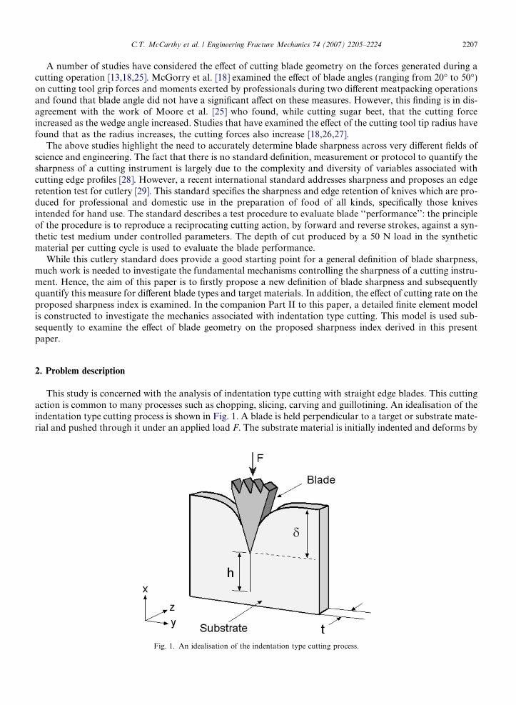
This study is concerned with the analysis of indentation type cutting with straight edge blades. This cuttingaction is common to many processes such as chopping, slicing, carving and guillotining. An idealisation of theindentation type cutting process is shown in Fig. 1. A blade is held perpendicular to a target or substrate mate-rial and pushed through it under an applied load F. The substrate material is initially indented and deforms by
Fig. 1. An idealisation of the indentation type cutting process.

2208 C.T. McCarthy et al. / Engineering Fracture Mechanics 74 (2007) 2205–2224
an amount d. At some maximum depth, di, termed the penetration depth or depth to cut initiation, cuttinginitiates. Depending upon the substrate material, this initial deformation can consist of both elastic and plasticcomponents. Upon further loading, a cut or crack initiates, the substrate opens and the blade moves into thisnewly created volume. This process continues with increasing force until steady state cutting is established.The length of the cut surface is denoted by h and the substrate material thickness by t, as shown in Fig. 1.For the materials considered in this study, it should be noted that upon unloading, (i.e., retracting the blade)the initial deformation d was generally fully recovered and the final cut length was equal to h.
Following a general procedure used in previous research in cutting soft solids [11,22–24] as discussed above,the approach taken here in quantifying blade sharpness involves pushing a straight edge blade through a sub-strate material at a fixed velocity and observing the forces generated. Most of the experiments are performed
Fig. 2. Photographs of the blades used in this study. (a) SM scalpel blade. (b) SM scalpel blade – micrograph of cross-section. (c) CAMBrazor blade. (d) CAMB razor blade – micrograph of cross-section.

C.T. McCarthy et al. / Engineering Fracture Mechanics 74 (2007) 2205–2224 2209
using a No. 16 straight edged surgical scalpel blade, manufactured by Swann-Morton, as shown in Fig. 2(a).This blade has a wedge angle of 25� and a thickness of 0.4 mm as shown in Fig. 2(b). A detailed microscopicanalysis on the tip radius was performed and is presented in Part II of this paper, the main finding of which isthat no tip radius is purposely machined into these blades. The Swann-Morton blade will subsequently bereferred to as the SM blade.
To examine the suitability of the proposed sharpness index to other blade types, a second set of experi-ments are performed using a razor blade, manufactured by CAMB Machine Knives International (typeCMK 152), as shown in Fig. 2(c). Differently from the SM blade, this blade has a double wedge angle witha 32� tip angle and 17� standard angle, as shown in Fig. 2(d). This blade has a thickness 0.23 mm and, asbefore, there is no apparent radius machined into the tip. This blade will be referred to subsequently asthe CAMB blade.
A 2.25 mm thick polyurethane sheet with a Shore hardness of 40 A was used as the cutting medium in mostof the experiments. This material was chosen as it has a similar constitutive form to that of most soft bio-mate-rials (i.e., a J-shaped stress–strain curve), thus rendering this analysis suitable for applications in cutting bio-logical tissues such as skin. Due to their anisotropic and heterogeneous nature, real biological tissues were notused in the analysis since they were unlikely to provide the repeatability needed to highlight differences inblade sharpness and would also require extensive experimentation to characterise their anisotropic materialproperties. In this paper, the polyurethane material will subsequently be referred to as the PU substrate.To investigate the independence of the proposed sharpness index on the substrate material used, additionalcutting experiments were performed using a 1.6 mm thick silicone rubber sheet with a Shore hardness of60 A. This material will subsequently be referred to as the SI substrate.
This paper is set out as follows. Firstly, indentation type cutting experiments are performed using sharp andblunt SM blades and PU substrates. The results from these tests are used to formulate a suitable criterion for ablade sharpness metric, and a corresponding sharpness index is then derived from first principles. The pro-posed index consists of a number of parameters which are necessarily determined by a series of experiments.The index is then calculated for sets of both sharp and blunt blades. To illustrate the generic applicability ofthis index to other cutting configurations, experiments are performed using different blade types and substratematerials. Finally, the effect of cutting rate on the proposed sharpness index is examined.
3. Experimental cutting trials
The test rig used for the experimental cutting trials is shown in Fig. 3. The rig was connected to a 50 kNTinius-Olsen universal testing machine. The rig was manufactured from tool steel and ground flat and squareto ensure that the substrate was mounted flat and orthogonal with respect to the blade. The lower part held the
Fig. 3. Experimental rig used for the cutting trials.

2210 C.T. McCarthy et al. / Engineering Fracture Mechanics 74 (2007) 2205–2224
substrate material between two anti-buckle clamps. To minimise slipping, emery paper was inserted betweenthe substrate and clamps and then the clamps were tightened lightly by rotating a clamping screw locatedbeneath the base plate plateau. This provided sufficient clamping force without inducing noticeablecompressive transverse stress in the substrate (due to the Poisson effect). No direct pre-stress was appliedto the substrate in order to avoid cut formation or crack growth in front of the blade tip due to transverseloadings.
The upper part of the rig held the blade via a blade handle (also by Swann-Morton) and the whole systemwas attached to the moving cross-head of the testing machine. Lake and Yeoh [30] carried out a study on cut-ting rubber sheets with razor blades and found that slow cutting rates produced relatively constant steady statecutting forces, while medium and fast rates produced a saw–tooth pattern, which was associated with a stick-slip behaviour caused by the substrate material splitting ahead of the blade. Consequently, in most of the pres-ent experiments the blade was pushed through the substrate material at a quasi-static rate of 10 mm/min. Toinvestigate the effect of cutting rate on the proposed sharpness index higher cutting rates were also examined.The reaction force was measured by a 100 N load cell mounted above the blade clamp. Due to the relativelyhigh rigidity of the blade clamping apparatus and low cutting forces observed, it was assumed that the cross-head displacement was an accurate measure of the blade displacement. The sampling frequency for both theload and displacement data was 6 Hz. The following sections describe the results from testing both sharp andblunt blades.
3.1. Sharp blades
For this test series the term ‘‘sharp’’ refers to a virgin blade in an unused state. For each test, a new SMblade was removed from its protective packaging and fixed onto the blade handle of the test rig. For repeat-ability, three tests were performed and the corresponding load–deflection curves are shown in Fig. 4(a). As canbe seen, all three curves rise initially in a non-linear manner to a blade displacement of approximately 2 mm.The three tests are in very close agreement up to this point. The curves then become linear until approximately12 mm blade displacement. Again, good agreement is obtained in the linear region with only small differencesin load and gradient being observed. After approximately 12 mm blade displacement the loads become rela-tively constant and oscillate around the 30 N level, which is a result of using a quasi-static loading rate, asdiscussed above.
In order to examine the characteristics of the cutting process, the gradient of each load–deflection curve inFig. 4(a) is plotted as a function of blade displacement in Fig. 4(b). These curves were generated by calculatingthe tangent modulus as a moving average of the values from 27 adjacent pairs of data points in the load–deflection curve. This level of averaging was chosen as it sufficiently smoothed the initially noisy data, withoutmasking any of the salient features of the cutting process.
The stiffness curves highlight some very interesting features of the cutting process. Firstly, they rise linearlyup to approximately 2 mm blade displacement, at which point they become essentially constant. From a sep-arate test in which the blade was progressively lowered in 0.05 mm increments and then retracted to allow thesubstrate to be examined, it was found that the point where the stiffness curves just deviate from linearity (i.e.,Point A in Fig. 4(b)) corresponds to the point were a cut initiates in the substrate. It will be shown later thatthis point is, in fact, a function of the blade condition and can thus be used to formulate a blade sharpnessmetric. The physical level of blade indentation at the onset of cut formation is shown in Fig. 5. As can be seen,extensive deformation has occurred in the substrate, which is due to its highly elastic nature. This has signif-icant relevance in the development of a finite element model in Part II of this paper, where a three-term Ogden[32] strain energy density function is used to capture this non-linear material behaviour.
The locations marked A, B, C and D in Fig. 4(b) correspond to the cutting configurations shown schemat-ically in Fig. 6(a)–(d), respectively. After the cut initiates, the stiffness curves remain relatively constant (regionB of Fig. 4(b)) until approximately 9 mm blade displacement. This region of constant stiffness represents thenewly created cut surface passing over the side of the blade, as illustrated in Fig. 6(b). It should be noted thatthe blade height is 7 mm. After 9 mm blade displacement (i.e., d + h = 2 + 7 = 9 mm; see Fig. 1), the stiffnesscurves start to reduce (region C of Fig. 4(b)) and this region represents the onset of steady state cutting. Steadystate cutting takes some time to stabilise since the initial portion of the newly formed cut surface has to

Fig. 4. Indentation cutting with sharp SM blades. (a) Load–deflection curves. (b) Corresponding stiffness–deflection curves.
C.T. McCarthy et al. / Engineering Fracture Mechanics 74 (2007) 2205–2224 2211
completely pass over the sides of the blade and re-contact above the back of the blade (as illustrated inFig. 6(c)), hence region C is prolonged. After approximately 16 mm blade displacement, the stiffness curvesapproach zero stiffness and osculate around this value (region D of Fig. 4(b)). This region represents fullyestablished steady state cutting, i.e., where the cutting forces become constant (around a mean value ofapproximately 30 N), as shown in Fig. 4(a). During steady state cutting the blade and substrate reach an equi-librium state, as illustrated in Fig. 6(d).
3.2. Blunt blades
Following the same procedure, a series of tests were carried out with a new blade being used for each repeatof the test. However, differently from the sharp blade tests of Section 3.1, each blade was artificially blunted by

Fig. 5. Photograph showing the level of blade indentation at the point of cut formation in the substrate.
Fig. 6. Different stages of the indentation cutting process. (a) Initial indentation at the point of cut formation. (b) Intermediate cuttingwhere the cut material travels up the side of the blade. (c) Onset of steady state cutting where the substrate material re-contacts above theback of the blade. (d) Steady state cutting, (a), (b), (c) and (d) correspond to locations A, B, C and D in Fig. 4(b).
2212 C.T. McCarthy et al. / Engineering Fracture Mechanics 74 (2007) 2205–2224
lightly rubbing a strip of fine silica glass paper (180 Grit) along the tip of the blade, in a direction parallel tothe blade handle. One pass was sufficient to blunt the blade. The corresponding load–deflection and stiffnessplots for these cutting tests are shown in Fig. 7(a) and (b), respectively. The load–deflection response for eachtest shows excellent agreement until approximately 22 mm blade displacement, after which Test 1 shows asevere downturn. This was due to the substrate material buckling out of plane in a wrinkling type manner,causing the material to bend rather than be cut. This phenomenon was also observed by Lake and Yeoh[30] when cutting rubber sheets with blunt knives.
Also shown in Fig. 7(a) is a typical sharp load–deflection curve and as can be seen the load–deflectionresponses for the blunt blades are considerably different in form and magnitude to that of the sharp blade.However, initially the blunt set of curves are identical to the sharp one, and both display a non-linear behav-iour associated with the indentation process before the cut initiates in the substrate. Turning to Fig. 7(b), it canbe seen that the stiffness plots for the blunt blades rise in an essentially linear manner (similar to the typicalsharp curve as also shown in Fig. 7(b)) until approximately 4 mm blade displacement (Point E, Fig. 7(b)) atwhich point they rapidly drop off to zero stiffness before rising again. The stiffness curves dropping to zerosignify a plateau region in the load defection curves, i.e., a region where the forces become constant momen-

Fig. 7. Indentation cutting with blunt SM blades. (a) Load–deflection curves. (b) Corresponding stiffness–deflection curves.
C.T. McCarthy et al. / Engineering Fracture Mechanics 74 (2007) 2205–2224 2213
tarily. Physically, this corresponds to the blade penetrating the substrate and a crack (or cut) then propagatingin front of the blade tip, thereby reducing the resistance to cutting. It was found in separate retraction exper-iments (again, by lowering and retracting the blade in small increments to inspect the substrate surface) thatPoint E (as with Point A for the sharp blades) corresponds to the point where the cut initiates in the substrate.Hence, it is concluded that the point where the stiffness plot just deviates from linearity corresponds to thepoint where a cut initiates in the substrate.
However, Point E in Fig. 7(b) clearly occurs at a considerably higher blade displacement and load level thanthat of Point A in Fig. 4(b) for the sharp blades. As the testing conditions were identical (apart from the con-dition of the blade tip) for both sets of experiments, it can be concluded that the depth of blade indentationwhere a cut initiates in the substrate is a function of the condition of the blade tip or the ‘‘sharpness’’ of theblade. This penetration depth can thus be used to formulate a blade sharpness metric.

2214 C.T. McCarthy et al. / Engineering Fracture Mechanics 74 (2007) 2205–2224
4. Derivation of a sharpness metric
Before deriving a new sharpness metric, it is important to state some axioms which such a criterion shouldmeet. First and foremost, such a metric should clearly identify differences between sharp and blunt cuttingedges. Second, it should ultimately pertain to the blade only, and not be affected by the substrate material.Third, it should be related to the mechanics of the cutting process, such as mode of opening of the substrate;this is necessary in order to distinguish between different types of cutting processes, such as those characterisedby modes I, II and III fracture mechanisms. Finally, it should be intuitive and easily obtained from experimen-tal data or analysis.
As discussed in Section 3, the level of blade displacement where a stiffness plot first deviates from linearitycorresponds to the point where a cut initiates in the substrate. This level of blade displacement is a function ofthe condition or sharpness of the blade tip and can be determined uniquely by measuring the blade displace-ment required to initiate a cut in the substrate. By mapping back to the load–deflection curve, the energyrequired to initiate a cut in the substrate can be determined. It is postulated here that this energy can be usedto quantify differences between sharp and blunt cutting edges. This energy, referred to here as the ‘‘cut initi-ation energy’’ or Ei, can be obtained by integrating the load–deflection curve from the start of the test up tothe point where a cut or crack just initiates in the substrate, i.e.,
Ei ¼Z
di
F dx ð1Þ
where F is the cutting force, dx is an increment of blade displacement in the loading direction (see Fig. 1 forcoordinate system used) and di is the blade displacement or indentation depth at which a cut initiates in thesubstrate. This blade displacement di is determined from Points A and E in Figs. 4(b) and 7(b) for sharp andblunt blades, respectively.
The cut initiation energy, Ei, is dependent on the thickness of the substrate used. In order to eliminate thisdependency from any sharpness metric, the cut initiation energy is normalised with respect to the substratethickness. Hence, a cut initiation energy per unit thickness, E�i is defined as
E�i ¼R
diF dx
tð2Þ
where t is the thickness of the substrate, as shown in Fig. 1. It is important to consider the substrate material inany sharpness metric, but ultimately such a metric should pertain to the blade only since the blade’s intendedfunction is in general, not known a priori. The influence of a particular substrate material on a sharpness met-ric can similarly be generalised from a set of physical experiments by normalising the cut initiation energy perunit thickness (i.e., Eq. (2)) by the substrate’s fracture toughness, i.e.,
E�i ¼R
diF dx
tJ Ic
ð3Þ
where: E�i is the normalised cut initiation energy per unit thickness of substrate and JIc is the Mode I fracturetoughness of the substrate. This intrinsic material property represents the energy required to create a unit areaof cut surface in non-linear elastic materials [39] (the focus of the present study) and so equates the appliedenergy (i.e., the numerator in Eq. (3)) to the energy needed to create a cut (or crack) in a given substrate.For this analysis the opening mode (i.e., Mode I) fracture toughness, JIc, should be used, as it is this modein which the substrate opens during cutting. However, normalising with respect to the mode of fracture allowsthis particular metric to be used for other cutting modes such as scissors cutting, which produces a tearingMode III fracture [33,34] or a combined opening tension and sliding shear Mode I/II, present when hand carv-ing meat with a knife, for example.
Finally, it is hypothesised that the sharpness of a blade is inversely proportional to the indentation depth toinitiate a cut or crack in the substrate, di. That is, as the blade sharpness increases, the indentation depth to cutinitiation reduces. This is suggested by the results of the experiments performed in Section 3, where it wasfound that the sharp (i.e., new) blades required approximately 2 mm indentation to initiate a cut, while the

C.T. McCarthy et al. / Engineering Fracture Mechanics 74 (2007) 2205–2224 2215
blunt blades required approximately 4 mm. Hence, a measure for blade sharpness, or more appropriately ablade sharpness index or BSI, can now be written as
TableExperi
Substr
PU
SI
BSI ¼R
diF dx
ditJ Ic
ð4Þ
This metric relates the energy required to initiate a cut in a given substrate to the fracture toughness and thick-ness of the substrate and to the indentation depth for cut initiation, i.e., the penetration depth. The numeratoris a scalar energy quantity, while the dominator is related to the material, geometric and indentation depth tofracture of the substrate, thus providing a simple formula to evaluate blade sharpness. It should be noted thatthe sharpness index of Eq. (4) is a dimensionless quantity.
5. Blade sharpness index evaluation
In this section the parameters of the BSI (Eq. (4)) are first evaluated using test data from Section 3. Addi-tional tests are also necessary to determine some BSI parameters and these are described. The BSI is then cal-culated for different blades and substrates.
5.1. Evaluation of di
As discussed previously, the blade displacement required to initiate a cut in the substrate, i.e., di, can bedetermined by progressively lowering the blade into the substrate and then retracting it to examine the substratesurface for evidence of cut formation. However, it was found that this point corresponds to the point where thestiffness curves just deviate from linearity. Hence, di was determined for both the sharp and blunt bladesfrom the stiffness plots of Figs. 4(b) and 7(b), respectively, and the results for these tests are summarised inTable 1.
5.2. Evaluation of Ei
After determining di, the cut initiation energy Ei can be determined by integrating the load–deflectionresponse from a cutting experiment from the start of the test (i.e., where the load just starts to rise) up todi. This was done by numerically integrating the load–deflection test data of Section 3 according to the follow-ing equation:
Ei ¼Z di
x0
F dx � 1
2
XN
j¼1
F jðxjþ1 � xj�1Þ ð5Þ
where Fj and xj are the force and displacement values at experimental data point j, respectively, x0 is the displace-ment where the force just starts to rise and N is the total number of data points up to cut initiation. Table 1 liststhe results for the cut initiation energies Ei for each test.
1mental data for evaluating the BSI for SM blades
ate material Blade condition Test no. di (mm) F at di (N) Ei (N mm) t (mm) JIc (kJ m�2) BSI
Sharp 1 2.03 4 3.87 2.25 3.67 0.231
2 1.97 3.76 3.58 0.219
3 2.08 3.6 3.41 0.200
Blunt 1 4.07 9.9 17.65 2.25 3.67 0.526
2 4.10 9.5 17.04 0.504
3 4.07 9.6 17.05 0.512
Sharp 1 0.43 0.98 0.257 1.6 1.85 0.202
2 0.44 0.92 0.273 0.210
3 0.44 0.99 0.3082 0.237

2216 C.T. McCarthy et al. / Engineering Fracture Mechanics 74 (2007) 2205–2224
5.3. Experiments to determine Mode I fracture toughness, JIc
This paper is concerned with the sharpness of blades for applications in cutting soft solids. Due to thehighly deformable nature of these materials, it is difficult to determine their fracture toughness using standardfracture toughness tests. One approach that has been used to evaluate the fracture toughness of ‘‘soft’’ solidssuch as biological materials and foodstuffs is to carry out a cutting test [33–35].
A recent paper by Doran et al. [33] proposed a simple model to determine the fracture toughness of thinbiological membranes. The approach used was to transversely load a thin strip of chicken skin and then forcea surgical blade through it. The resulting load–deflection characteristics were used to calculate the fracturetoughness JIc or the so called ‘‘resistance to fracture’’ using the following equation:
J Ic ¼ðXu� dKÞ þ dU � dC
dAð6Þ
where X is the force acting on the blade and u is the blade displacement. The term dK represents the elasticstrain energy stored in the membrane during indentation (i.e., before cutting initiates), dU represents the strainenergy stored in the substrate (due to, for example, transverse loading), dC represents the work absorbed inremote plastic flow and dA is an increment of newly created surface area due to cutting. As a starting point,this model is adopted here in an attempt to determine the Mode I fracture toughness of the PU substratematerial.
The experimental cutting rig described in Section 3 was used to carry out the cutting trials to determine thePU fracture toughness. This rig is similar in functionality to that used by [33]. However, it does not induce anytransverse loading into the substrate material and, as a result, the stored strain energy term dU in Eq. (6) iszero. However, a consequence of not applying any transverse pre-stress is that the substrate material remainsin contact with the sides of the blade during cutting, as illustrated in Fig. 6(b)–(d). Hence, energy is dissipateddue to friction between the sides of the blade and the substrate. To account for this, Eq. (6) is modified here toinclude energy dissipation due to friction, Pu
J Ic ¼Xu� dK� Pu� dC
dAð7Þ
where P is the total friction force acting between the blade and substrate.Doran et al. [33] stated that if a sharp blade is used during the test, the level of remote (from the tip) plastic
flow can be regarded as negligible and dC can be ignored. In the experiments performed here, when the bladewas retracted after cutting, the substrate material returned to its initial position without any apparent plasticdeformation. Hence, it was assumed here that the energy dissipated due to plastic flow, dC, was negligible andso this term in Eq. (7) was ignored. Hence Eq. (7) becomes
J Ic ¼Xu� dK� Pu
dAð8Þ
This equation can be rearranged to give
ðX � PÞu ¼ J IcdAþ dK ð9Þ
which is the equation of a straight line since dK is a constant for a given test. The slope of this line is equal toJIc and the Y-intercept is equal to dK. The dK term has the effect of shifting the curve along the Y-axis but doesnot affect the slope of the curve and hence can be ignored in the calculation of JIc. Hence, the final equationused to calculate JIc was
J Ic ¼ðX � P Þu
dAð10Þ
where the product Xu in Eq. (10) can be determined by integrating the load–displacement curve obtained froma cutting trial.

Fig. 8. Load–displacement curves for a cutting pass (X), a free pass (P) and the difference (X � P).
C.T. McCarthy et al. / Engineering Fracture Mechanics 74 (2007) 2205–2224 2217
To calculate JIc, an additional set of cutting experiments to those reported in Section 3 were performedand a typical load–deflection curve is shown in Fig. 8. An approach used to estimate the energy due to fric-tion when determining the Mode III fracture toughness of a soft biological tissue using a scissors cutting test[34] was to first carry out a cutting test, and then repeat this test with the cut substrate still in place. In thisway, all test parameters are identical to the initial cutting trial except that in the second or free pass noenergy is needed to cut the material, since it has been cut previously in the cutting pass. In this way, theenergy due to friction can be determined. Brown et al. [36] used a similar approach to determine the frictionforces generated when cutting foodstuffs. Following these studies, it was decided to adopt this approach herein order to determine the friction energy term, Pu in Eq. (10). The approach taken was to first carry out acutting experiment as normal. The blade was then retracted after the cutting pass and the substrate materialwas allowed to settle back to its initial position. Finally, the experiment was repeated with the cut substratestill left in the lower part of the test rig and the load–displacement data was recorded. Fig. 8 shows theresults from this free pass and it can be seen that significant force and hence energy is needed to pushthe blade though the pre-cut material. The area under this curve determines the energy dissipated due tofriction. By calculating the difference between the load–deflection curves for the cutting pass and the freepass, the (X � P) term in Eq. (10) can be determined as a function of blade displacement; this is also plottedin Fig. 8.
The product term (X � P)u in Eq. (10) is the area under the difference curve (X � P) in Fig. 8 and can beevaluated by integrating this curve with respect to the blade indentation depth. This was achieved here by inte-grating the test data using an equation similar to Eq. (5). The resulting (X � P)u term is plotted as a functionof the cut area dA in Fig. 9 for three repeats of the tests. The cut area was determined by
dA ¼ 2ht ð11Þ
where t is the thickness of the substrate (which is 2.25 mm for the PU material), h is the length of the cut andthe factor 2 represents the new surfaces that are created on both sides of the blade. Note that dA does notinclude the initial indentation depth to cut initiation, di.As can be seen the curves in Fig. 9 are essentially bi-linear, with the first quasi-linear region representinginitial indentation, penetration of the substrate and intermediate cutting (as depicted in Fig. 6(a)–(c)), whilethe second quasi-linear region represents steady state cutting (c.f. Fig. 6(d)). The fracture toughness JIc shouldonly be calculated from the slope of the steady state cutting region (as shown in Fig. 9) since the system is in

Fig. 9. (X � P)u term as a function of cut area dA.
2218 C.T. McCarthy et al. / Engineering Fracture Mechanics 74 (2007) 2205–2224
equilibrium at this stage. As found previously, steady state cutting was well established at h = 14 mm (i.e., ablade displacement of 16 mm �di � 2 mm) and so from Eq. (11) steady state cutting is found at dA P 63 mm.Hence, the fracture toughness JIc was obtained from the slopes of best-fit linear curves to the data atdA P 63 mm and the resulting values are shown Table 2.
5.4. Evaluation of blade sharpness
At this point, all the necessary data to calculate the BSI (Eq. (4)) for the sharp and blunt blades have beendetermined and are listed in Table 1. However before doing so, a closed form expression for the BSI is derivedin order to help understand its attributes. By examining the initial portion of the load–displacement curve (i.e.,from 0 to di) for both the sharp and blunt blades in Section 3, it was found that they can be represented almostexactly by the following closed form quadratic expression:
TableJIc val
Mater
PU
SI
F ¼ Ax2 þ Bx ð12Þ
where F is the load, x is the blade displacement and A and B are both empirical constants (and are equal to0.24 N/mm2 and 1.44 N/mm for the PU substrate, respectively, regardless of whether the blade is sharp orblunt). Substituting Eq. (12) into Eq. (4) and carrying out the integration yields the following closed-formexpression for the blade sharpness index:
2ues for the PU and SI substrates
ial Test no. JIc (kJ m�2) Average Standard deviation
1 3.816 3.67 0.1722 3.4813 3.713
1 1.974 1.85 0.1182 1.7393 1.850

TableExperi
Substr
PU
C.T. McCarthy et al. / Engineering Fracture Mechanics 74 (2007) 2205–2224 2219
BSI ¼ 2Ad2i þ 3Bdi
6tJ Ic
ð13Þ
From this equation, it can be seen that the BSI is a quadratic function of blade indentation depth to cut ini-tiation di. For an infinitely sharp blade, di would tend towards zero, i.e., di! 0 and so, in the limit the BSIwould equal zero (i.e., LimðBSIÞdi!0 ¼ 0Þ. Hence, for an infinitely sharp blade the BSI would be zero, thusproviding a lower bound. The BSI is unbound for di > 0 and so increasing values of BSI represent increasinglevels of blade bluntness.
By entering the parameters listed in Table 1 into Eq. (4) the BSI was determined for both the sharp andblunt blades, and the results are also listed in Table 1. The average BSI value for the sharp SM blade is0.216 with a standard deviation of 0.016, while the average value for the blunt blade is 0.514 with a standarddeviation of 0.012. The sharp blades produce a lower BSI than the blunt blades, as expected, and they differ bya factor of approximately 2.4. It should be noted that the BSI scale is non-linear. However, for the BSI rangemeasured here (0.216 6 BSI 6 0.514), the linear term in Eq. (13) dominates since the B coefficient is six timesgreater than the A coefficient (A = 0.24 N/mm2, B = 1.44 N/mm), and so the BSI suggests that the sharpblades are approximately 2.4 times more effective than the blunt blades. In Part II of this paper a finite elementmodel is used to investigate the effect of different blade geometry factors such as wedge angle and tip radius onthe blade sharpness index.
5.5. Verification of substrate independence
For this study, silicone (SI) rubber was procured from a local prosthetic implant manufacturer and used asthe substrate material in a new set of experiments. These experiments were carried out in order to demonstratethat the BSI is independent of the substrate material used. The composition for the SI material was a standardformulation of polydialkylsiloxane propane, as used in the medical device industry [37]. It had a Shore hard-ness of 60 A and a thickness of 1.6 mm. Following identical procedures to those outlined in Section 3, thissharpness study yielded the results shown in the last rows of Table 1. The first thing to note is that the inden-tation depth to cut initiation, di, is considerably lower than that for the PU substrate, and as a result the cutinitiation energy, Ei, is also considerably lower. The fracture toughness for this material was determined fol-lowing the procedure outlined in Section 5.3 and the results are listed in Table 2. The average value of thisfracture toughness is in broad agreement with values for Sil8800 and B452 type silicone rubbers obtained usinga trouser tear test [38], thus verifying the validity of the current approach.
The results for the BSI when cutting the SI substrate are listed in Table 1. The average BSI value is 0.216with a standard deviation of 0.018. This value is, on average, very close to that obtained when cutting the PUsubstrate, thus demonstrating that the BSI is independent of the substrate used, at least for the two materialtypes examined here.
5.6. Application to other blade types
In order to show that the BSI is generically applicable to other blade types, experiments were performedusing a CAMB blade to cut a PU substrate. These blades are designed differently to the surgical scalpel blades
3mental data for evaluating the BSI for sharp CAMB razor blades
ate material Test no. di (mm) F at di (N) F at 2 mm (N) Ei (N mm) t (mm) JIc (kJ m�2) BSI BSI Ave. (S.D.)
1 2.32 4.48 3.78 4.77 2.25 3.67 0.249 0.251 (0.006)
2 2.34 4.6 3.9 4.92 0.255
3 2.32 4.56 3.86 4.88 0.255
4 2.31 4.48 3.8 4.84 0.254
5 2.28 4.18 3.54 4.52 0.241
6 2.34 4.4 3.73 4.75 0.246
7 2.27 4.35 3.78 4.83 0.258
2220 C.T. McCarthy et al. / Engineering Fracture Mechanics 74 (2007) 2205–2224
used thus far, and have an aluminum spine on the back of the blade (as shown in Fig. 2(c)) for fixing, ratherthan a slot for a blade handle as used in the fixing of SM blades. As a result, the sharpness-testing rig shown inFig. 3 had to be modified in order to test these razor blades.
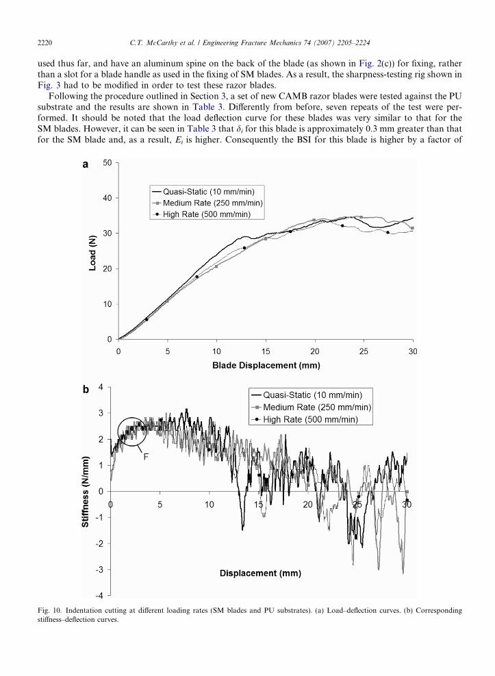
Following the procedure outlined in Section 3, a set of new CAMB razor blades were tested against the PUsubstrate and the results are shown in Table 3. Differently from before, seven repeats of the test were per-formed. It should be noted that the load deflection curve for these blades was very similar to that for theSM blades. However, it can be seen in Table 3 that di for this blade is approximately 0.3 mm greater than thatfor the SM blade and, as a result, Ei is higher. Consequently the BSI for this blade is higher by a factor of
Fig. 10. Indentation cutting at different loading rates (SM blades and PU substrates). (a) Load–deflection curves. (b) Correspondingstiffness–deflection curves.
C.T. McCarthy et al. / Engineering Fracture Mechanics 74 (2007) 2205–2224 2221
approximately 1.16, indicating that the SM blade is a sharper instrument. This is intuitively consistent with avisual imspection of the geometries of Fig. 2(b) and (d): the SM blade has a smaller wedge angle at the tip thanthe CAMB blade and thus it should be expected that the SM blade is a sharper instrument.
To investigate this hypothesis, the reaction forces for SM and CAMB blades are examined at 2 mm bladedisplacement (i.e., di for the SM blade) and the results are listed in Tables 1 and 3, respectively. As can be seen,there is virtually no difference in the loads at this displacement level for both types of blade. This highlightsthat the proposed BSI can distinguish between blades that produce similar load levels, but have different levelsof indentation to cause a cut to initiate in a substrate, thus suggesting that force alone is not a complete indi-cator of blade sharpness, as currently used in a number of professional areas.
5.7. Effects of cutting rate
Finally, to investigate the effect of cutting rate on the proposed sharpness index, cutting experiments werecarried out at higher loading rates using SM blades and PU substrates. In a previous study [31], a surgeoncarried out a cutting demonstration with a scalpel blade and a surrogate skin substrate and it was found thata typical rate for cutting abdominal skin was approximately 1800 mm/min. While it was desirable to carry outcutting trials at this speed, current testing resources could only achieve a maximum cross-head velocity of500 mm/min. Hence for this study, this rate and half this rate (i.e., 250 mm/min) were used to investigatethe effect of cutting rate.
Fig. 10(a) shows the load–deflection curves for the quasi-static, medium and high loading rate cutting tests.The curves show some rate dependent differences between the quasi-static and medium rates but very littlebetween medium and high rates. By computing the total area under the load–deflection curves it can be shownthat as the cutting rate increases the amount of energy consumed in cutting reduces, but this reduction is smallfor the rates examined herein. Following the previous approach, the stiffness curves are plotted in Fig. 10(b)and it can be seen that there is no noticeable change in di (i.e., Point F in Fig. 10(b)) or Ei since the initialportions of the load–deflection curves are very similar. Assuming that the fracture toughness JIc is rate inde-pendent, it can be concluded that the proposed sharpness index is independent of cutting rate.
6. Discussion
Various alternative approaches to determine the performance or sharpness of a blade require that the bladeis used for a significant amount of cutting [12,29] and this obviously leads to some degradation of the blade’scutting edge. These measurement procedures can cause degradation of the variable being measured and thustheir usefulness is questionable. The approach for characterising blade sharpness as developed in the presentinvestigation has the advantage that the blade is only required to indent the substrate one single time by asmall amount, thus minimising wear on the blade. In fact, it has been found in a parallel study using SEMand microscopy [40] that no detectable wear occurs to the SM blades during the first cutting pass (usingPU substrates) and hence the approach developed here could easily be adopted by industry as a quality controlmeasure to ensure that blades are sharp before being sent out to market.
For simplicity, this study focused on indentation type cutting which is very common in chopping, slicing,carving and guillotining. However, before this method is adopted by industry, it should be critically accessedunder a number of different cutting scenarios, such as mixed or combined mode cutting. One such case couldbe achieved by cutting with the blade at an angle to the substrate material, thus exciting both Mode I andMode II fracture mechanisms. This would be more representative of the cutting action typically used by a sur-geon for example, but has a drawback in that the Mode II fracture toughness would have to be measured andthe BSI equation would have to be vectorised. Other types of cutting actions such as sawing or cutting withcurved or toothed blades would be worthwhile future investigations.
In this study no direct pre-stress was applied to the substrate so as to simplify the analysis by avoiding thedU term in Eq. (6), i.e., the stored strain energy due to specimen elongation before cutting. In practice, thisterm can sometimes be present when, for example, a surgeon cuts with a scalpel blade and places his thumband index finger in such a way as to force skin separation when cutting commences. On the other hand, thisterm can often be negligible or absent when, for example, certain stabbing incidents occur or when cutting

2222 C.T. McCarthy et al. / Engineering Fracture Mechanics 74 (2007) 2205–2224
food stuffs. The approach taken here was to minimise the complexity of the analysis and so the dU term wasavoided by ensuring that no direct pre-stresses were applied to the substrate. The introduction of pre-stressinto the analysis would be an interesting future development as the effects of pre-stress on the blade sharpnessindex could be examined. It should be noted, however, that pre-stress could distract from the blade sharpnessmeasurement as pres-stress could control the growth of the crack in front of the blade tip with the effect thatthe blade may not contribute to the cutting process.
Although no direct pre-stress was applied to the substrate, some compressive pre-stress could have beenpresent due to specimen clamping (due to the Poisson effect). While great care was taken when clampingthe specimen to ensure that this stress was minimised, it is possible that some could have remained. Therewould be merit in developing a clamping rig that could vary the distance between the clamps so that the effectof clamping distance and pressure could be analysed.
The stiffness curves of sharp blades (Fig. 4) identify typical characteristics of the cutting process, i.e., initialindentation, steady state cutting etc. and are thus a useful way to examine the cutting process. These curves areeasy to produce once the cutting forces and blade displacements are available and could be used in most cut-ting applications to identify the different stages of the cutting process. However, the blunt stiffness curves iden-tify initial indentation but thereafter change significantly with respect to the sharp case and fail to identify anyrecognisable stages of the cutting process. This is due to the random nature of cutting with blunt blades inwhich the substrate can buckle under the blade combined with tearing and possibly many other local non-lin-ear events such as wrinkling. Although difficult, it would be very interesting to develop a method to examinethe initiation and growth of the cut in front of the blade tip for both sharp and blunt blades. This could beachieved by mounting a microscope and camera onto the blade and moving the substrate relative to the blade(rather than moving the blade as in the case here).
It was hypothesised that the BSI should be independent of the substrate material used, and should thus onlypertain to the blade. This was shown to be true for the polyurethane and silicone substrates tested. However,the question arises ‘‘Is a blade that is considered sharp when cutting a soft solid, such as natural rubber orskin, for example, still sharp when required to cut a metallic material, such as steel or aluminum?’’. It is selfevident that any blade designed to cut a soft solid would be completely inadequate to cut a metal for any sig-nificant length of time, if at all. However, to answer this question, one must consider the micromechanicaldeformation that takes place at the blade’s tip during cutting. If the relative material properties, such as stiff-ness, strength, fracture toughness and hardness are comparable between the blade and substrate, extensiveplastic deformation will occur at the blade’s tip (due to the high concentration of stress at that point), beforedi is reached in the substrate. As a result, the geometry of the blade tip would flatten out to a point where thephysics of the problem would change from a cutting phenomenon to a contact phenomenon. By using the BSIto characterise blade sharpness in such a scenario, it would appear that the blade is blunt, since significantamount of energy would be necessary to reach di (if it were attained at all). However, this blunting occursas a result of the measurement process and not because the blade was initially blunt. Hence, blade sharpnessis independent of the substrate used, but in order to measure it, the material properties of the substrateshould be orders of magnitude less than those of the blade, so as to avoid changing the geometry of the bladetip.
Cutting force and depth of cut in a substrate under a predefined load have both been used in the past asindicators of blade sharpness. However, these approaches can be misleading because they are dependent onwhere the system is sampled. For example, if one decided to evaluate the cutting force from the tests carriedout here at a blade displacement of 12 mm, the results of Fig. 7(a) would imply that the blunt blade is sharpersince it produces a lower load then the sharp blade at this blade displacement. Hence cutting force alone isprobably not a good measure of blade sharpness. The same argument for blade displacement or depth ofcut would most likely exist if the experiments were performed with force being the control variable. The pro-posed index has been found to identify differences between sharp and blunt blades without being influenced bythe substrate used and the cutting rate and so it appears that the index properly represents blade sharpness formany disparate applications.
Finally, this paper has not considered the effect of blade geometry, such as wedge angle, tip radius or sur-face finish on the BSI. Manufacturing unique blades with custom designed geometric ratios would be extre-mely difficult and expensive and is outside the scope of this paper. However, to overcome this, a finite

C.T. McCarthy et al. / Engineering Fracture Mechanics 74 (2007) 2205–2224 2223
element model is developed in Part II of this paper and used to investigate the effect that these geometric fac-tors have on the proposed BSI.
7. Conclusions
This paper has developed a quantitative metric for the sharpness of a straight edged blade. This dimension-less metric, the blade sharpness index (BSI), is relevant to a wide range of applications associated with cuttingsoft solids including the meat processing industry, surgery, forensic medicine, zoology, and some machiningprocesses. The generalised form of the BSI is given as
BSI ¼R
diF dx
ditJ Ic
This relates the energy required to initiate a cut in a substrate to the fracture toughness and thickness of theparticular substrate and to the indentation depth required to penetrate the substrate. The particular mecha-nism of cutting for which this metric has been developed is termed indentation cutting in which a blade ispushed perpendicularly through a substrate akin to creating a Mode I fracture. This is representative of guil-lotining, chopping, and certain chopping or carving processes. In this case, the index can be given by a closedform expression:
BSI ¼ 2Ad2i þ 3Bdi
6tJ Ic
In this case the BSI is a simple quadratic function of the depth required to initiate a cut in a given substrate, di.An infinitely sharp blade would have di and BSI tending to zero whilst increasing values of BSI would repre-sent increasing levels of blade bluntness.
This index has been verified for a range of blade sharpness conditions and for a range of soft polymer sub-strates under different rates of loading. A companion paper [41] describes the results of a computational anal-ysis of alternative blade geometries including tip radius and wedge angle.
Acknowledgements
The authors gratefully acknowledge Enterprise Ireland for funding this research under the auspices of theCommercialisation Fund (ATRP/2002/422B).
References
[1] Watkins FH, London SD, Neal JG, Thacker JG, Edlich RF. Biomechanical performance of cutting edge surgical needles. J EmergMed 1997;15(5):679–85.
[2] Thacker JG, Rodeheaver GT, Towler MA, Edlich RF. Surgical needle sharpness. Am J Surg 1989;157(3):334–9.[3] Huebscher HJ, Gober GJ, Lommatzsch PK. The sharpness of incision instruments in corneal tissue. Ophthal Surg 1989;20(2):120–3.[4] Ueno Y, Asano M, Nushida H, Adachi J, Tatsuno Y. An unusual case of suicide by stabbing with a falling weighted dagger. Forensic
Sci Int 1999;101(3):229–36.[5] O’Callaghan PT, Jones MD, James DS, Leadbeatter S, Evans SL, Nokes LDM. A biomechanical reconstruction of a wound caused
by a glass shard: a case report. Forensic Sci Int 2001;117(3):221–31.[6] Knight B. The dynamics of stab wounds. Forensic Sci 1975;6(3):249–55.[7] Saukko P, Knight B. Knight’s Forensic pathology. Arnold; 2004.[8] Green MA. Stab wound dynamics: a recording technique for use in medico-legal investigations. J Forensic Sci 1978;18(3–4):161–3.[9] Gilchrist MD. Experimental device for simulating traumatic brain injury resulting from linear accelerations. Strain 2004;40:180–92.
[10] Horgan TJ, Gilchrist MD. The creation of three-dimensional finite element models for simulating head impact biomechanics. Int JCrashworthiness 2003;8(4):353–66.
[11] McGorry RW, Dowd PC, Dempsey PG. Cutting moments and grip forces in meat cutting operations and the effect of knifesharpness. Appl Ergon 2003;34(4):375–82.
[12] McGorry RW, Dowd PC, Dempsey PG. A technique for field measurement of knife sharpness. Appl Ergon 2005;36(5):635–40.[13] McGorry RW, Dowd PC, Dempsey PG. The effect of blade finish and blade edge angle on forces used in meat cutting operations.
Appl Ergon 2005;36(1):71–7.[14] King MJ. Knife and impact cutting of lamb bone. Meat Sci 1999;52(1):29–38.
2224 C.T. McCarthy et al. / Engineering Fracture Mechanics 74 (2007) 2205–2224
[15] Bishu RR, Calkins C, Lei X, Chin A. Effect of knife type and sharpness on cutting forces. Adv Occupat Ergon Safety 1996;2:479–83.[16] Popowics TE, Fortelius M. On the cutting edge: tooth blade sharpness in herbivorous and faunivorous mammals. Ann Zool Fennici
1997;34:73–88.[17] Evans AR. Connecting morphology, function and tooth wear in microchiropterans. Biol J Linnean Soc 2005;85(1):81–96.[18] Yuan JJ, Zhou M, Dong S. Effect of diamond tool sharpness on minimum cutting thickness and cutting surface integrity in
ultraprecision machining. J Mater Process Tech 1996;62(4):327–30.[19] Black D, Marks R, Caunt A. Measurement of scalpel blade sharpness and its relationship to wound healing. Bioengng Skin
1985;1:111–23.[20] Izmailov GA, Orenburov PI, Repin VA, Gorbunov SM, Ismailov SG. Evaluation of the healing of skin wounds inflicted by steel
scalpels with various levels of sharpness. Khirurgiia (Mosk) 1989;6:75–8.[21] Towler MA, Rodeheaver GT. Influence of cutting edge configuration on surgical needle penetration forces. J Emerg Med
1988;6(6):475–81.[22] Frick TB, Marucci DD, Cartmill JA, Martin CJ, Walsh WR. Resistance forces acting on suture needles. J Biomech
2001;34(10):1335–40.[23] Tholey G, Chanthasopeephan T, Hu T, Desai JP, Lau A. Measuring grasping and cutting forces for reality-based haptic modeling.
Int Congress Series 2003;1256:794–800.[24] Santhanam R, Valenta HL. Cutting force measurement platform for quantitative assessment of surgical cutting instruments. Biomed
Sci Instrum 1996;32:237–43.[25] Moore MA, King FS, Davis PF, Manby TCD. The effect of knife geometry on cutting force and fracture in sugar beet topping. J Agr
Engng Res 1979;24(1):11–27.[26] Meehan RR, Kumar J, Earl M, Svenson E, Burns SJ. Role of blade sharpness in cutting instabilities of polyethylene terephthalate. J
Mat Sci Lett 1999;18(2):93–5.[27] Goh SM, Charalambides MN, Williams JG. On the mechanics of wire cutting of cheese. Engng Fract Mech 2005;72(6):931–46.[28] Reilly GA, McCormack BAO, Taylor D. Cutting sharpness measurement: a critical review. J Mat Process Tech 2004;153–154:261–7.[29] ISO International Standard Materials and articles in contact with foodstuff – Cutlery and table hollowware. Part 5: Specification for
sharpness and edge retention test of cutlery. ISO 8442-5:2004(E), 2004.[30] Lake GJ, Yeoh OH. Measurement of rubber cutting resistance in the absence of friction. Int J Fract 1978;14(5):509–26.[31] McCarthy CT, O’Dwyer E, Hussey M, Gilchrist MD, O’Dowd NP. A numerical and experimental investigation into the forces
generated when cutting biomaterials. In: Helmus M, Medlin D, editors. Medical device materials II. Proceedings of the materials andprocesses for medical devices conference, August 25–27, 2004, St. Paul, MN, USA. ASM International; 2005. p. 140–5.
[32] Ogden RW. Large deformation isotropic elasticity: on the correlation of theory and experiment for incompressible rubberlike solids.Proc R Soc Lond A 1972;326:565–84.
[33] Doran CF, McCormack BAO, Macey A. A simplified model to determine the contribution of strain energy in the failure process ofthin biological membranes during cutting. Strain 2004;40(4):173–9.
[34] Pereira BP, Lucas PW, Swee-Hin T. Ranking the fracture toughness of thin mammalian soft tissues using the scissors cutting test. JBiomech 1997;30(1):91–4.
[35] Atkins AG. Toughness and cutting: a new way of simultaneously determining ductile fracture toughness and strength. Engng FractMech 2005;72(6):849–60.
[36] Brown T, James ST, Purnell GL. Cutting forces in food: experimental measurements. J Food Engng 2005;70(2):165–70.[37] Compton RA. Silicone manufacturing for long-term implants. J Long-term Eff Med Imp 1997;7(1):29–54.[38] Shergold OA, Fleck NA. Mechanisms of deep penetration of soft solids, with application to the injection and wounding of skin. Proc
R Soc Lond A 2004;460:3037–58.[39] Anderson TL. Fracture mechanics. 2nd ed. LLC: CRC Press; 1995.[40] O’Dwyer E, Experimental cutting of surrogate soft biological tissue with unserrated blades, M.Eng.Sc. thesis, University College
Dublin, 2005.[41] McCarthy C, Hussey M, Gilchrist MD, On the sharpness of straight edge blades in cutting soft solids: Part II: Analysis of blade
geometry, in preparation.