
PR0JECTIONS OF STRAIGHT LINES
32
1 | Page PR0JECTIONS OF STRAIGHT LINES M. S. GOUTHAM DEPT.OF MECH. ENGG. VJIT
Transcript of PR0JECTIONS OF STRAIGHT LINES
1 | P a g e
PR0JECTIONS OF STRAIGHT LINES
M. S. GOUTHAMDEPT.OF MECH. ENGG.VJIT
STRAIGHT LINE is a ONE DIMENSIONAL object.
Has only LENGTH & NO THICKNESS.
Any position of a STRAIGHT LINE with respect (w.r.t.) H. P. will be represented in the FRONT VIEW
Any position of a STRAIGHT LINE with respect (w.r.t.) V. P. will be represented in the TOP VIEW
POSITION OF ST. LINE w. r. t. H.P & V. P & THEIR REPRESENTATION ON DRAWING SHEET.
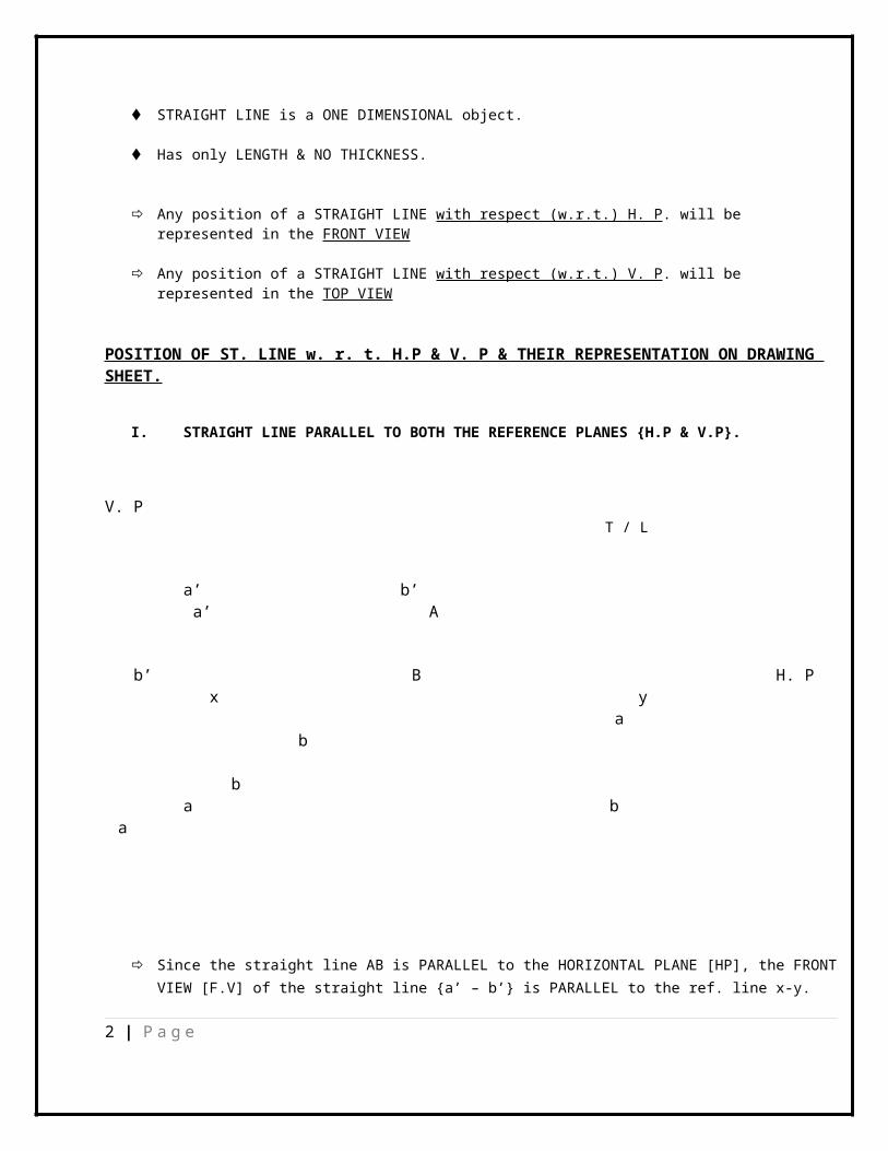
I. STRAIGHT LINE PARALLEL TO BOTH THE REFERENCE PLANES {H.P & V.P}.
V. P
T / L
a’ b’ a’ A
b’ B H. Px y
a b
b a b
a
Since the straight line AB is PARALLEL to the HORIZONTAL PLANE [HP], the FRONTVIEW [F.V] of the straight line {a’ – b’} is PARALLEL to the ref. line x-y.
2 | P a g e
Similarly, the TOP VIEW [T.V] of the straight line is PARALLEL to the ref. line x-y as the original straight AB is parallel to the VERTICAL PLANE [VP].
Also the distance of the F.V from x-y, will be equal to the distance of the original straight line from the HORIZONTAL PLANE [HP].
Similarly, the distance of the T.V from x-y, will be equal to the distance of the original straight line from the VERTICAL PLANE [VP].
THE ORIGINAL LENGTH OF A STRAIGHT LINE IS CALLED AS TRUE LENGTH & THE TRUE LENGTH OF A STRAIGHT LINE CAN BE PROJECTED ONLY ON A PARALLEL REFERENCE PLANE {HP / VP}
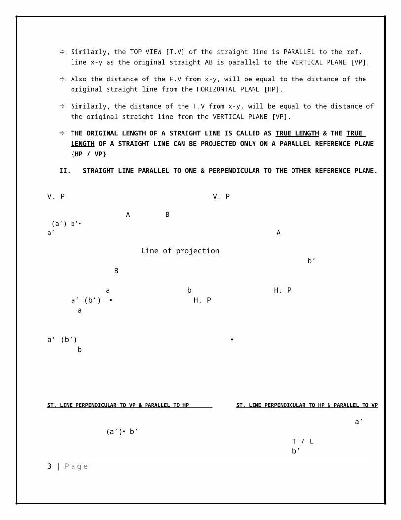
II. STRAIGHT LINE PARALLEL TO ONE & PERPENDICULAR TO THE OTHER REFERENCE PLANE.
V. P V. P
A B (a’) b’ a’ A
Line of projection b’
B
a b H. P a’ (b’) H. P
a
a’ (b’) b
ST. LINE PERPENDICULAR TO VP & PARALLEL TO HP ST. LINE PERPENDICULAR TO HP & PARALLEL TO VP
a’ (a’) b’
T / L b’
3 | P a g e
x y x y
a T / L
a (b) b
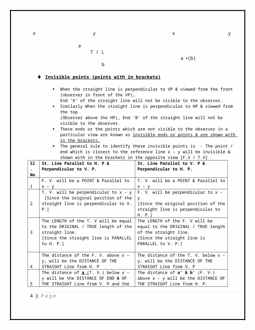
Invisible points {points with in brackets}
When the straight line is perpendicular to VP & viewed from the front (observer in front of the VP),End ‘A’ of the straight line will not be visible to the observer.
Similarly When the straight line is perpendicular to HP & viewed from the top (Observer above the HP), End ‘B’ of the straight line will not be visible to the observer.
These ends or the points which are not visible to the observer in a particular view are known as invisible ends or points & are shown with in the brackets.
The general rule to identify these invisible points is - The point / end which is closest to the reference line x – y will be invisible & shown with in the brackets in the opposite view [F.V / T.V]
Sl. No
St. Line Parallel to H. P & Perpendicular to V. P.
St. Line Parallel to V. P & Perpendicular to H. P.
1F. V. will be a POINT & Parallel to x – y
T. V. will be a POINT & Parallel tox – y
2
T. V. will be perpendicular to x – y [Since the original position of thestraight line is perpendicular to V.P.]
F. V. will be perpendicular to x – y[Since the original position of thestraight line is perpendicular to H. P.]
3
The LENGTH of the T. V will be equalto the ORIGINAL / TRUE length of thestraight line.[Since the straight line is PARALLELto H. P.]
The LENGTH of the F. V will be equal to the ORIGINAL / TRUE lengthof the straight line.[Since the straight line is PARALLEL to V. P.]
4
The distance of the F. V. above x – y, will be the DISTANCE OF THE STRAIGHT Line from H. P
The distance of the T. V. below x –y, will be the DISTANCE OF THE STRAIGHT Line from V. P
5
The distance of a ( T. V.) below x – y will be the DISTANCE OF END A OF THE STRAIGHT Line from V. P and the
The distance of a’ & b’ (F. V.) above x – y will be the DISTANCE OFTHE STRAIGHT Line from H. P.
4 | P a g e
length of a – b (T. V.) will be equal to the ORIGINAL / TRUE length of the straight line.
PL. NOTE THAT REPRESENTATION OF PROJECTION OF A STRAIGHT LINE MUST ALWAYS START FROM THE VIEW[F. V. / T. V. / S. V] WHERE THE TRUE LENGTH OF THE ST. LINE IS COMING.
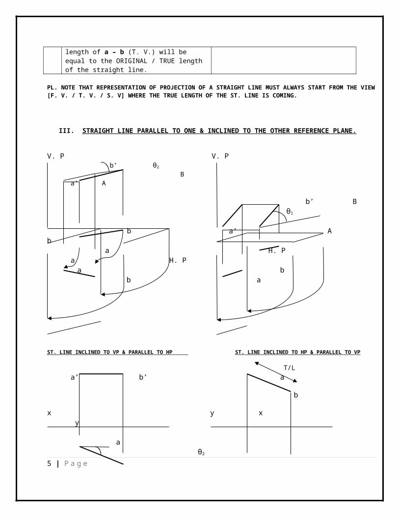
III. STRAIGHT LINE PARALLEL TO ONE & INCLINED TO THE OTHER REFERENCE PLANE.
V. P V. P b’ θ2
B a’ A
b’ B θ1
b a’ A
b a H. P a H. P
a b b a
ST. LINE INCLINED TO VP & PARALLEL TO HP ST. LINE INCLINED TO HP & PARALLEL TO VP
T/La’ b’ a
b
x y x y
a θ2
5 | P a g e
bT / L
a’ b’
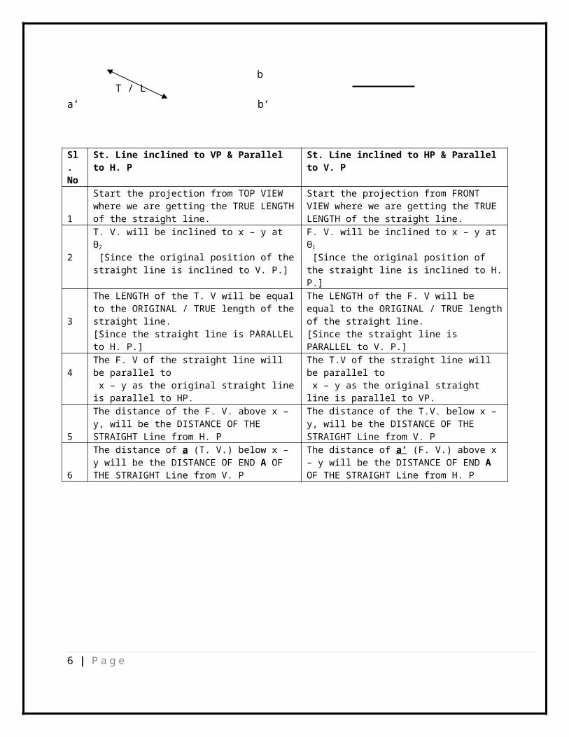
Sl. No
St. Line inclined to VP & Parallel to H. P
St. Line inclined to HP & Parallel to V. P
1
Start the projection from TOP VIEW where we are getting the TRUE LENGTHof the straight line.
Start the projection from FRONT VIEW where we are getting the TRUE LENGTH of the straight line.
2
T. V. will be inclined to x – y at θ2
[Since the original position of thestraight line is inclined to V. P.]
F. V. will be inclined to x – y at θ1
[Since the original position of the straight line is inclined to H.P.]
3
The LENGTH of the T. V will be equalto the ORIGINAL / TRUE length of thestraight line.[Since the straight line is PARALLELto H. P.]
The LENGTH of the F. V will be equal to the ORIGINAL / TRUE lengthof the straight line.[Since the straight line is PARALLEL to V. P.]
4The F. V of the straight line will be parallel to x – y as the original straight lineis parallel to HP.
The T.V of the straight line will be parallel to x – y as the original straight line is parallel to VP.
5
The distance of the F. V. above x – y, will be the DISTANCE OF THE STRAIGHT Line from H. P
The distance of the T.V. below x – y, will be the DISTANCE OF THE STRAIGHT Line from V. P
6
The distance of a (T. V.) below x – y will be the DISTANCE OF END A OF THE STRAIGHT Line from V. P
The distance of a’ (F. V.) above x – y will be the DISTANCE OF END A OF THE STRAIGHT Line from H. P
6 | P a g e
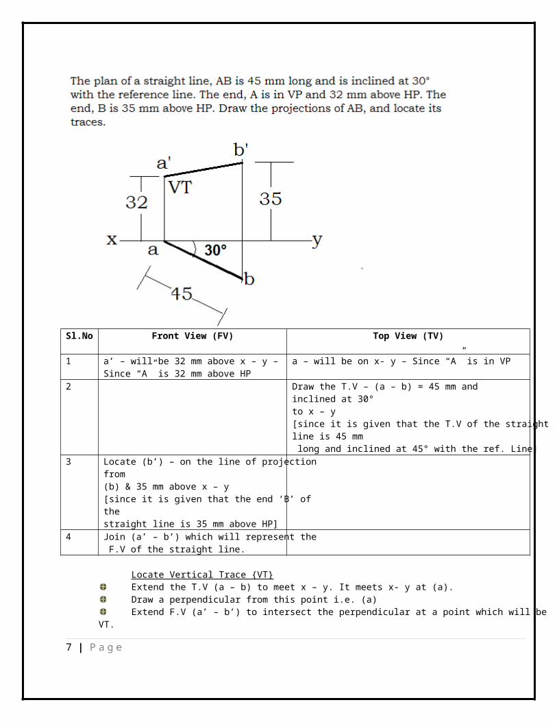
Sl.No Front View (FV) Top View (TV)
1 a’ – will be 32 mm above x – y –Since “A” is 32 mm above HP
a – will be on x- y – Since “A” is in VP
2 Draw the T.V – (a – b) = 45 mm and inclined at 30° to x – y [since it is given that the T.V of the straight line is 45 mm long and inclined at 45° with the ref. Line]
3 Locate (b’) – on the line of projectionfrom (b) & 35 mm above x – y[since it is given that the end ‘B’ of the straight line is 35 mm above HP]
4 Join (a’ – b’) which will represent the F.V of the straight line.
Locate Vertical Trace {VT}Extend the T.V (a – b) to meet x – y. It meets x- y at (a).Draw a perpendicular from this point i.e. (a)Extend F.V (a’ – b’) to intersect the perpendicular at a point which will be
VT.
7 | P a g e
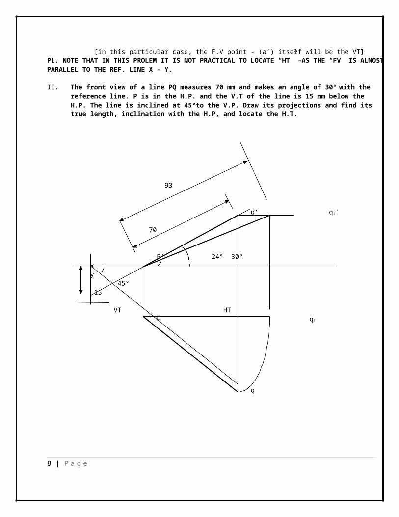
[in this particular case, the F.V point - (a’) itself will be the VT]PL. NOTE THAT IN THIS PROLEM IT IS NOT PRACTICAL TO LOCATE “HT” –AS THE “FV” IS ALMOST PARALLEL TO THE REF. LINE X – Y.
II. The front view of a line PQ measures 70 mm and makes an angle of 30° with the reference line. P is in the H.P. and the V.T of the line is 15 mm below the H.P. The line is inclined at 45°to the V.P. Draw its projections and find its true length, inclination with the H.P, and locate the H.T.
93
q’ q1’
70
P’ 24° 30° x
y 45°
15
VT HT P q1
q
8 | P a g e
Sl. No
Front View (F.V) Top View (T.V)
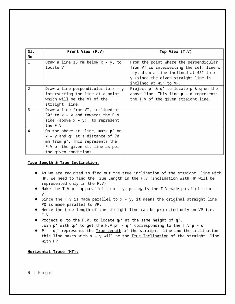
1 Draw a line 15 mm below x – y, to locate VT
From the point where the perpendicular from VT is intersecting the ref. line x– y, draw a line inclined at 45° to x –y (since the given straight line is inclined at 45° to VP.
2 Draw a line perpendicular to x – yintersecting the line at a point which will be the VT of the straight line.
Project p’ & q’ to locate p & q on the above line. This line p – q represents the T.V of the given straight line.
3 Draw a line from VT, inclined at 30° to x – y and towards the F.V side (above x – y), to represent the F.V
4 On the above st. line, mark p’ on x – y and q’ at a distance of 70 mm from p’. This represents the F.V of the given st. line as per the given conditions.
True length & True Inclination:
As we are required to find out the true inclination of the straight line withHP, we need to find the True Length in the F.V (inclination with HP will be represented only in the F.V)
Make the T.V p – q parallel to x – y. p – q1 is the T.V made parallel to x – y.
Since the T.V is made parallel to x – y, it means the original straight line PQ is made parallel to VP.
Hence the true length of the straight line can be projected only on VP i.e. F.V.
Project q1 to the F.V, to locate q1’ at the same height of q’.Join p’ with q1’ to get the F.V p’ – q1’ corresponding to the T.V p – q1
P’ – q1’ represents the True Length of the straight line and the inclination this line makes with x – y will be the True Inclination of the straight line with HP
Horizontal Trace (HT):
9 | P a g e
Extend the F.V (p’ – q’) to meet x – y at a point (in this case p’ – q’ is meeting x – y at p’).
From the above point (p’) draw a perpendicular. Extend the T.V to intersect this perpendicular at a point which will be the HT
of the straight line. (in this case the T.V is intersecting the perpendicular at – p).
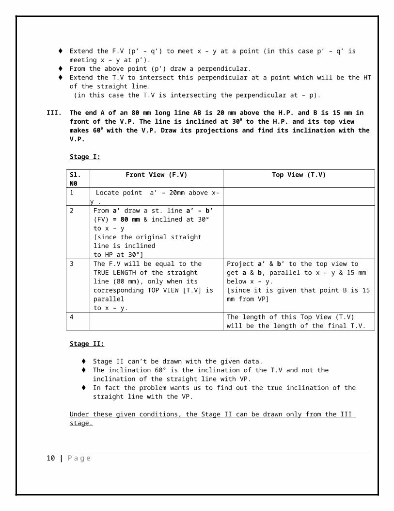
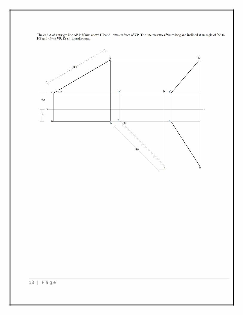
III. The end A of an 80 mm long line AB is 20 mm above the H.P. and B is 15 mm in front of the V.P. The line is inclined at 300 to the H.P. and its top view makes 600 with the V.P. Draw its projections and find its inclination with theV.P.
Stage I:
Sl. N0
Front View (F.V) Top View (T.V)
1 Locate point a’ – 20mm above x-y .
2 From a’ draw a st. line a’ – b’ (FV) = 80 mm & inclined at 30° to x – y[since the original straight line is inclined to HP at 30°]
3 The F.V will be equal to the TRUE LENGTH of the straight line (80 mm), only when its corresponding TOP VIEW [T.V] is parallel to x – y.
Project a’ & b’ to the top view to get a & b, parallel to x – y & 15 mm below x – y.[since it is given that point B is 15mm from VP]
4 The length of this Top View (T.V) will be the length of the final T.V.
Stage II:
Stage II can’t be drawn with the given data. The inclination 60° is the inclination of the T.V and not the
inclination of the straight line with VP. In fact the problem wants us to find out the true inclination of the
straight line with the VP.
Under these given conditions, the Stage II can be drawn only from the III stage.
10 | P a g e
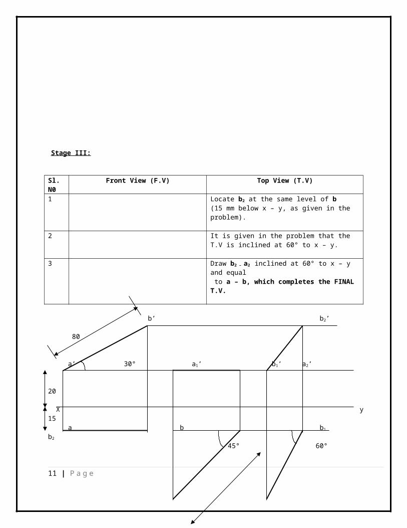
Stage III:
Sl. N0
Front View (F.V) Top View (T.V)
1 Locate b2 at the same level of b (15 mm below x – y, as given in the problem).
2 It is given in the problem that the T.V is inclined at 60° to x – y.
3 Draw b2 – a2 inclined at 60° to x – y and equal to a – b, which completes the FINAL T.V.
b’ b2’
80
a’ 30° a1’ b1’ a2’
20
X y15 a b b1 b2
45° 60°
11 | P a g e
80 80
a1 a2
Now go back to Stage II.
Stage II:
Sl. N0
Front View (F.V) Top View (T.V)
1 Locate b1 at the same level of b (15 mm below x – y)
2 Project a2 towards II stage.3 From b1 cut an arc with an arc radius
of 80mm (True Length of the given straight line) on the projection fromb2 – to locate a1.
4 Project a1 & b1 towards the F.V to draw the corresponding F.V (a1’- b1’) parallel to x – y andat a height of 20 mm from x – y.
The T.V will be equal to the TRUE LENGTH of the straight line (80 mm),only when its corresponding FRONT VIEW is parallel to x – y
5 a1’- b1’ = Final length of Front View.
Now again go back to III stage to complete the projections of the straight line in the given position.
Stage III:
Sl. N0
Front View (F.V) Top View (T.V)
1 Project a2 towards the front view and locate a2’ at the same height of - a (20mm above x – y)
2 From a2’ cut an arc with an arc radius equal to a1’- b1’, to cut the horizontal projection from b’, to locate b2’.
12 | P a g e
3 a2’ – b2’ is the final FV.(pl. note that b2’ & b2 must lie on the same line of projection / straight line)
THE INCLINATION THE TOP VIEW IN THE II STAGE MAKES WITH X –Y IS THE INCLINATION OF THE STRAIGHT LINE WITH THE V. P.
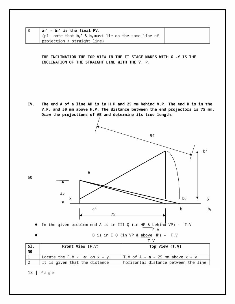
IV. The end A of a line AB is in H.P and 25 mm behind V.P. The end B is in the V.P. and 50 mm above H.P. The distance between the end projectors is 75 mm. Draw the projections of AB and determine its true length.
94
b’
a 50
25x b1’ y a’ b b1
75
In the given problem end A is in III Q (in HP & behind VP) - T.V F.V
B is in I Q (in VP & above HP) - F.V T.V
Sl. N0
Front View (F.V) Top View (T.V)
1 Locate the F.V - a’ on x – y. T.V of A – a – 25 mm above x – y2 It is given that the distance horizontal distance between the line
13 | P a g e

between the PROJECTORS is 75 mm. of projection of a – a’ & b – b’3 Locate the F.V - b’ 50 mm above
x – yT.V – b on x - y
4 a’ – b’ represents the F.V of the straight line in the given position.
a – b represents the T.V of the straight line in the given position.
True Length:Since true Length can be obtained only on a parallel ref. plane, make either the FV / TV parallel to x – y so that the corresponding T.V / F.V will represent the true length ofthe straight lineLet us make the F.V - a’ – b’ parallel to x – y. Which means the straight line is made parallel to the HP.The resultant T.V will now be equal to the T/ L of the straight line.Make a’ – b’ parallel to x – y, by bringing down b’ to b1’.a’ – b1’ is the F.V made parallel to x – y. Since b’ has been shifted to a new position b1’ the corresponding T.V point b also will get shifted to b1.
[b1 has to be in line with both b & b1’]Join a with b1 and a – b1 will be = True Length of the straight line AB
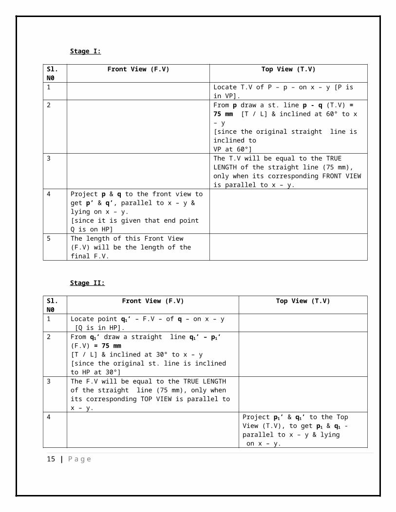
V. A line PQ 75 mm long, has its end P in the V.P. and the end Q in the H.P. The line is inclined at 30o to the H.P. and at 600 to the V.P. Draw its projections & locate its traces.
75 P1’ p2’
p’ q’ 30° q1’ HT q2’x y
p 60° p 1 q1 VT p2
75
q q2
14 | P a g e
Stage I:
Sl. N0
Front View (F.V) Top View (T.V)
1 Locate T.V of P – p – on x – y [P is in VP].
2 From p draw a st. line p - q (T.V) = 75 mm [T / L] & inclined at 60° to x – y[since the original straight line is inclined to VP at 60°]
3 The T.V will be equal to the TRUE LENGTH of the straight line (75 mm), only when its corresponding FRONT VIEWis parallel to x – y.
4 Project p & q to the front view toget p’ & q’, parallel to x – y & lying on x – y.[since it is given that end point Q is on HP]
5 The length of this Front View (F.V) will be the length of the final F.V.
Stage II:
Sl. N0
Front View (F.V) Top View (T.V)
1 Locate point q1’ – F.V – of q – on x – y [Q is in HP].
2 From q1’ draw a straight line q1’ – p1’ (F.V) = 75 mm [T / L] & inclined at 30° to x – y[since the original st. line is inclined to HP at 30°]
3 The F.V will be equal to the TRUE LENGTH of the straight line (75 mm), only when its corresponding TOP VIEW is parallel to x – y.
4 Project p1’ & q1’ to the Top View (T.V), to get p1 & q1 - parallel to x – y & lying on x – y.
15 | P a g e
[Since it is given that end point P is on VP]
5 The length of this Top View (T.V) will be the length of thefinal T.V.
Stage III:
Sl. N0
Front View (F.V) Top View (T.V)
1 Extend horizontal projections from p1’ & q1’
Extend horizontal projections from p & q
2 q2’ will lie on x – y as Q is in HP p2 will lie on x – y as P is in VP3 with q2’ as center and arc radius
equal to p’ – q’ (final length of F.V from Stage I), draw an arc to cut the horizontal projection from p1’ at p2’
With p2 as center and arc radius equalto p1 – q1 (final length of T.V from stage II), draw an arc to cut the horizontal projection from q at q2.
4 p2’ - q2’ represent the FINAL F.V p2 - q2 represents the FINAL T.V
Traces:
HT: Extend FV to meet x – y at any point. From this point draw a perpendicular. Extend the TV to intersect the perpendicular at a point, which will be
HT
VT:
Extend TV to meet x – y at any point. From this point draw a perpendicular. Extend the FV to intersect the perpendicular at a point, which will be
VT
IN THE PRESENT CASE BOTH HT AND VT WILL COINCIDE AND LIE ON X – Y AS THE FINAL FV &TV ARE
COMING AS EXACT VERTICAL PROJECTIONS.
PLEASW NOTE THAT THE FINAL T.V & F.V WILL APPEAR AS STRAIGHT LINES IF THE SUM OF ORIGINAL INCLINATIONS WITH - HP & VP – ARE EQUAL TO 90°
16 | P a g e

17 | P a g e
18 | P a g e

The top view of a line 70 mm long measures 60 mm, while the length of the front view is 5o mm. Its one end
is 8 mm in front of VP and 12 mm above HP. Draw the projections of the line and determine its inclinations with
HP and VP. {CSE – June’ 2013}
19 | P a g e
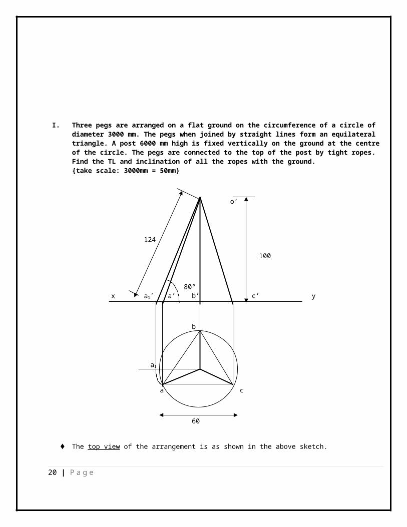
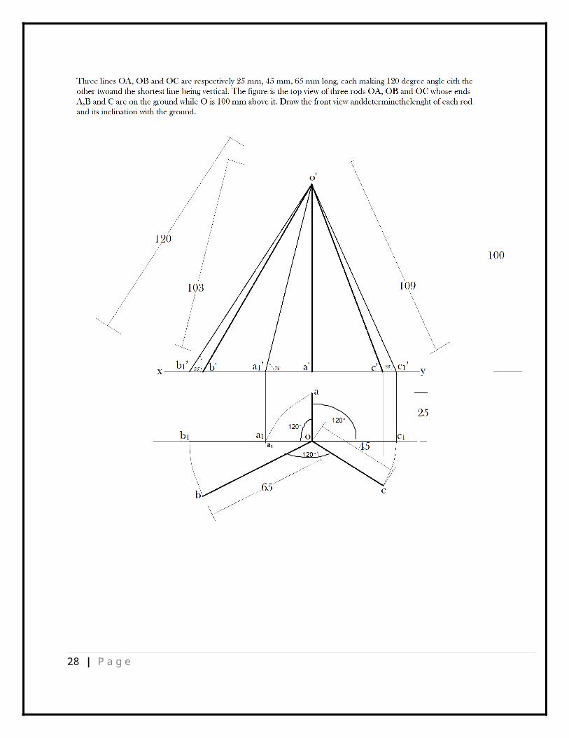
I. Three pegs are arranged on a flat ground on the circumference of a circle of diameter 3000 mm. The pegs when joined by straight lines form an equilateral triangle. A post 6000 mm high is fixed vertically on the ground at the centre of the circle. The pegs are connected to the top of the post by tight ropes. Find the TL and inclination of all the ropes with the ground. {take scale: 3000mm = 50mm}
o’
124
100
80° x a1’ a’ b’ c’ y
b
a1
o
a c
60
The top view of the arrangement is as shown in the above sketch.
20 | P a g e

In the TOP VIEW o – a, o – b & o – c represent the three ROPES, connected to the three PEGS- a, b & c forming an equilateral triangle on the circumference of acircle on the ground.
“o” – represents the TOP VIEW of the POLE at the center of the ground circle.
Since the three pegs A, B & C are fixed to the ground – i.e. HP The FV of the three pegs i.e. a’, b’ & c’ will lie on the ref. line x – y. o’ – represents the top of the CENTER POLE, at a height of 120 mm (as per
scale) in the FV. In the Front View o’ – a’, o’ – b’ & o’ – c’ represent the ropes connecting
the PEGS on the ground with the Top of the POLE at the center.
Since all the three ropes are part of an equilateral triangle on the ground, their TRUE LENGTH and their INCLINATION with the ground (HP) will be same and it is sufficient if we can find out the TRUE LENGTH and INCLINATION of one rope.True length:
Make the top view o – a parallel to x- y – which means we are making the st. line parallel to VP When the st. line is parallel to VP, it’s TV will be parallel to x – yWhen the st. line is parallel to VP, it’s projection on VP i.e. FV will represent the TRUE LENGTH of the st. line.o – a1 is the TV made parallel to x –y.Project “a1” to x – y and locate a1’, since a’ is located on x – y. o’ – a1’ represents the TRUE LENGTH of the ROPE “OA”
The inclination the line o’ – a 1’ makes with x – y, is the inclination of the ROPE with the GROUND (HP)
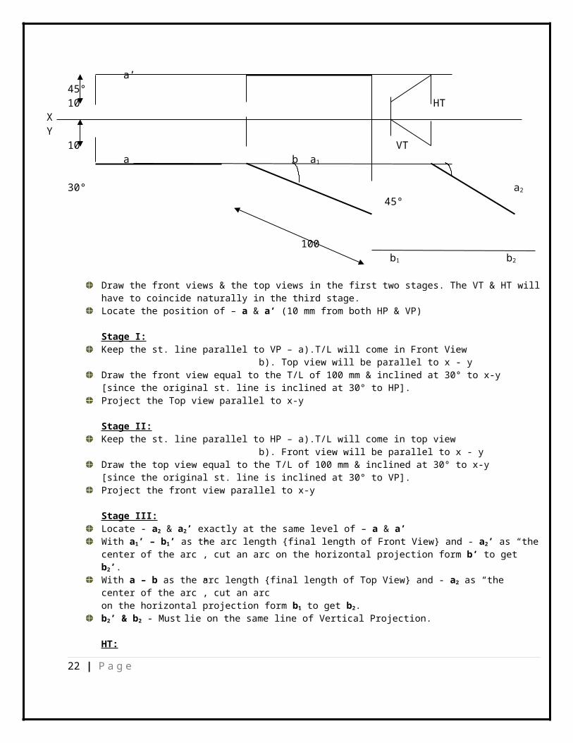
II. The HT and VT of a straight line coincide with each other. The view from aboveand the view from the front make equal inclinations of 30° to XY. One of the ends of the line is 10 mm from the HP and 10 mm from the VP. The true length of the line is 100 mm. Draw the projections and find the inclinations of the line with the HP and the VP.
b2’100 b’
30° a1’ b1’ a2’
21 | P a g e
a’ 45°10 HT
X Y
10 VT a b a1 30° a2
45°
100 b1 b2
Draw the front views & the top views in the first two stages. The VT & HT willhave to coincide naturally in the third stage.Locate the position of – a & a’ (10 mm from both HP & VP)
Stage I: Keep the st. line parallel to VP – a).T/L will come in Front View
b). Top view will be parallel to x - y Draw the front view equal to the T/L of 100 mm & inclined at 30° to x-y [since the original st. line is inclined at 30° to HP]. Project the Top view parallel to x-y
Stage II: Keep the st. line parallel to HP – a).T/L will come in top view
b). Front view will be parallel to x - y Draw the top view equal to the T/L of 100 mm & inclined at 30° to x-y [since the original st. line is inclined at 30° to VP]. Project the front view parallel to x-y
Stage III: Locate - a2 & a2’ exactly at the same level of – a & a’With a1’ – b1’ as the arc length {final length of Front View} and - a2’ as “thecenter of the arc”, cut an arc on the horizontal projection form b’ to get b2’.With a – b as the arc length {final length of Top View} and - a2 as “the center of the arc”, cut an arc on the horizontal projection form b1 to get b2.b2’ & b2 - Must lie on the same line of Vertical Projection.
HT:
22 | P a g e

Extend FV to meet x-y at a ‘point’.From the above ‘point’ – draw a Perpendicular line.Extend the TV to intersect the perpendicular line.The point of intersection is HT (Horizontal Trace).VT: Extend TV to meet x-y at a ‘point’.From the above ‘point’ – draw a Perpendicular line.Extend the FV to intersect the perpendicular line.The point of intersection is VT (Vertical Trace).
III. A 90 mm long line PQ is inclined at 45° to the H.P and 30° to the V.P. Its endP is in the H.P. and 40 mm in front of the V.P. Draw its projections keeping the end Q in the fourth quadrant
x P’ p1’ p2’ y
q1’ 45°
40
p q p1 30° p2
q’
q2’ 90
90
q1
q2
23 | P a g e
Locate end ‘P’ of the st. line as per the given position (1st. angle) End Q is given as in 4th. Angle [both TV & FV will be below x-y]
Stage I: Keep the st. line parallel to VP – a).T/L will come in Front View
b). Top view will be parallel to x - y Draw the front view p’ – q’ equal to the T/L of 90 mm & inclined at 45° to x-y
[since the original st. line is inclined at 45° to HP]. Pl. note, while p’ is above x – y [P is in 1 st . angle], q’ will be below x
– y [Q is in 4 th . Angle] Project the Top view p – q parallel to x-y
Stage II: Keep the st. line parallel to HP – a).T/L will come in top view
b). Front view will be parallel to x - y Draw the top view p1 – q1 equal to the T/L of 90 mm & inclined at 30° to x-y [since the original st. line is inclined at 30° to VP]. Project the front view p1’ – q1’ parallel to x-y, with q1’ marked below x - y
Stage III: Locate - p2 & p2’ exactly at the same level of – p & p’ With p1’ – q1’ as the arc length {final length of Front View} and - p2’as “the
center of the arc”, cut an arc on the horizontal projection form q’ to get q2’.
With p – q as the arc length {final length of Top View} and - p2 as “the center of the arc”, cut an arc on the horizontal projection form q1 to get q2.
b2’ & b2 - Must lie on the same line of Vertical Projection.
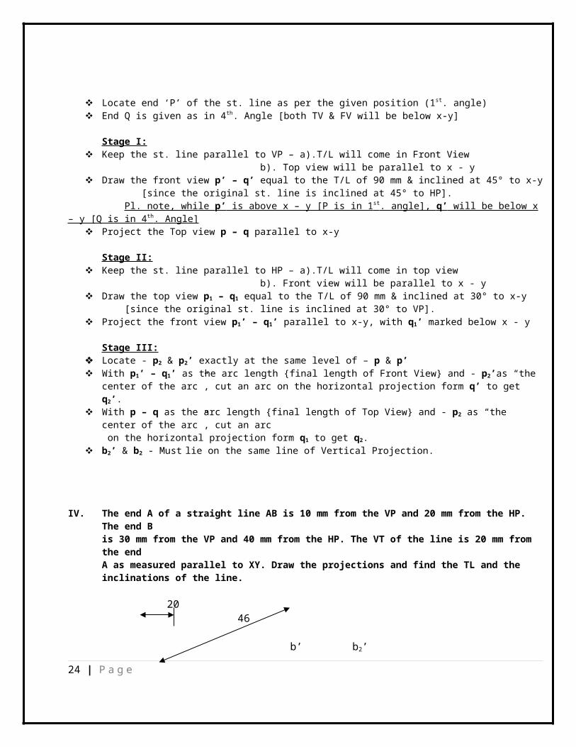
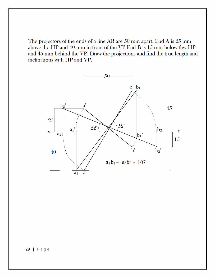
IV. The end A of a straight line AB is 10 mm from the VP and 20 mm from the HP. The end B is 30 mm from the VP and 40 mm from the HP. The VT of the line is 20 mm from the end A as measured parallel to XY. Draw the projections and find the TL and the inclinations of the line.
2046
b’ b2’
24 | P a g e
40 25° a’ b1’
VT 20 x y 10
a 20° b2
30
46 b1
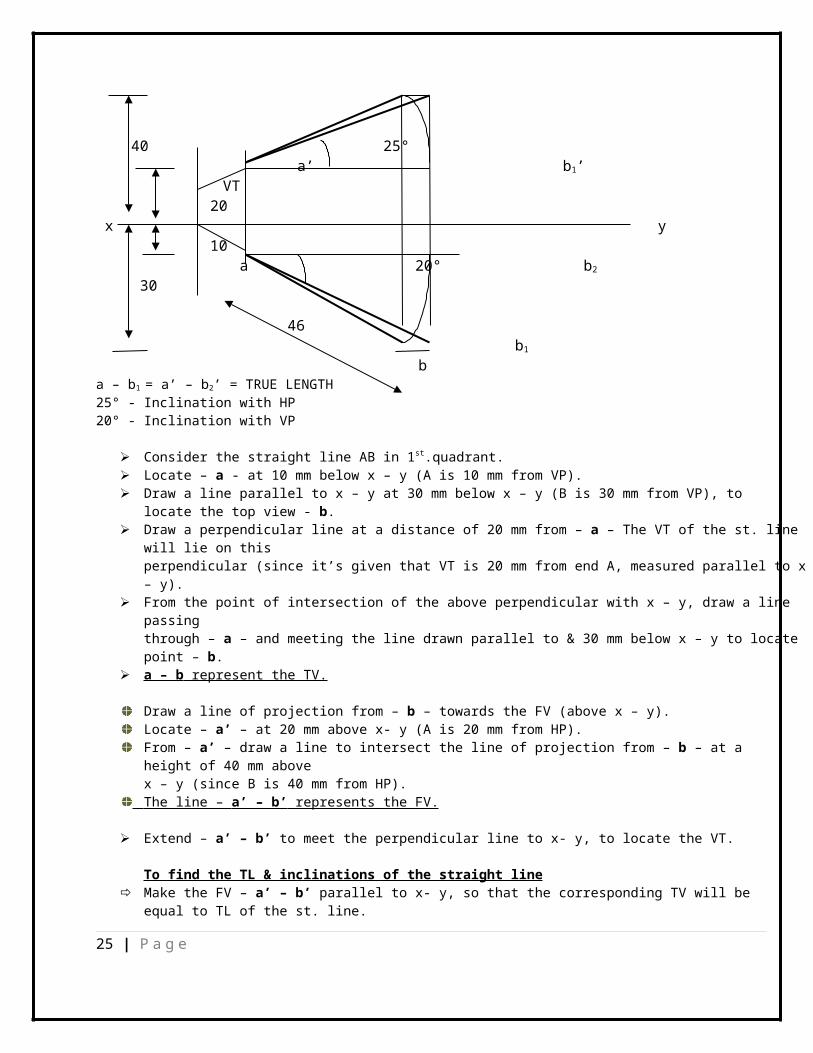
ba – b1 = a’ – b2’ = TRUE LENGTH25° - Inclination with HP20° - Inclination with VP
Consider the straight line AB in 1st.quadrant. Locate – a - at 10 mm below x – y (A is 10 mm from VP). Draw a line parallel to x – y at 30 mm below x – y (B is 30 mm from VP), to
locate the top view - b. Draw a perpendicular line at a distance of 20 mm from – a – The VT of the st. line
will lie on this perpendicular (since it’s given that VT is 20 mm from end A, measured parallel to x– y).
From the point of intersection of the above perpendicular with x – y, draw a line passing through – a – and meeting the line drawn parallel to & 30 mm below x – y to locatepoint – b.
a – b represent the TV.
Draw a line of projection from – b – towards the FV (above x – y).Locate – a’ – at 20 mm above x- y (A is 20 mm from HP).From – a’ – draw a line to intersect the line of projection from – b – at a height of 40 mm above x – y (since B is 40 mm from HP).
The line – a’ – b’ represents the FV.
Extend – a’ – b’ to meet the perpendicular line to x- y, to locate the VT.
To find the TL & inclinations of the straight line Make the FV – a’ – b’ parallel to x- y, so that the corresponding TV will be
equal to TL of the st. line.
25 | P a g e
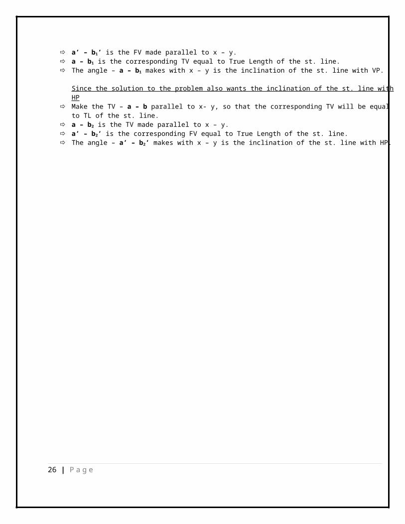
a’ – b1’ is the FV made parallel to x – y. a – b1 is the corresponding TV equal to True Length of the st. line. The angle – a – b1 makes with x – y is the inclination of the st. line with VP.
Since the solution to the problem also wants the inclination of the st. line withHP
Make the TV – a – b parallel to x- y, so that the corresponding TV will be equal to TL of the st. line.
a – b2 is the TV made parallel to x – y. a’ – b2’ is the corresponding FV equal to True Length of the st. line. The angle – a’ – b2’ makes with x – y is the inclination of the st. line with HP.
26 | P a g e

27 | P a g e
28 | P a g e
29 | P a g e
30 | P a g e
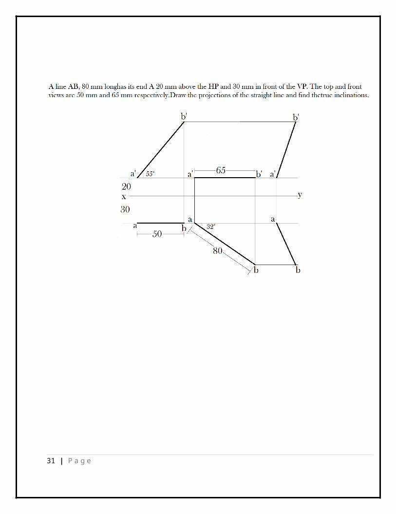
31 | P a g e

32 | P a g e


![Straight Lines Slides [Compatibility Mode]](https://static.fdokumen.com/doc/165x107/6316ee6071e3f2062906978b/straight-lines-slides-compatibility-mode.jpg)

