Series 2, 3, 4, & 5 Aluminum - Straight Sections
11
Series 2, 3, 4, & 5 Aluminum Series 2, 3, 4, & 5 Aluminum - Straight Sections I-1 B-Line series Cable Tray Systems Eaton
-
Upload
khangminh22 -
Category
Documents
-
view
3 -
download
0
Transcript of Series 2, 3, 4, & 5 Aluminum - Straight Sections
Series 2, 3, 4, & 5 Aluminum
Series 2, 3, 4, & 5 Aluminum - Straight Sections
I-1 B-Line series Cable Tray SystemsEaton
Series 2, 3, 4, &
5 Alum
inum
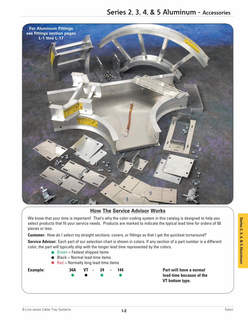
How The Service Advisor Works
We know that your time is important! That’s why the color-coding system in this catalog is designed to help youselect products that fit your service needs. Products are marked to indicate the typical lead time for orders of 50pieces or less.Customer: How do I select my straight sections. covers, or fittings so that I get the quickest turnaround?Service Advisor: Each part of our selection chart is shown in colors. If any section of a part number is a differentcolor, the part will typically ship with the longer lead time represented by the colors.
Green = Fastest shipped itemsBlack = Normal lead-time itemsRed = Normally long lead-time items
Example: 34A VT - 24 - 144 Part will have a normallead time because of the VT bottom type.
For Aluminum Fittingssee fittings section pages
L-1 thru L-17
Series 2, 3, 4, & 5 Aluminum - Accessories
I-2B-Line series Cable Tray Systems Eaton
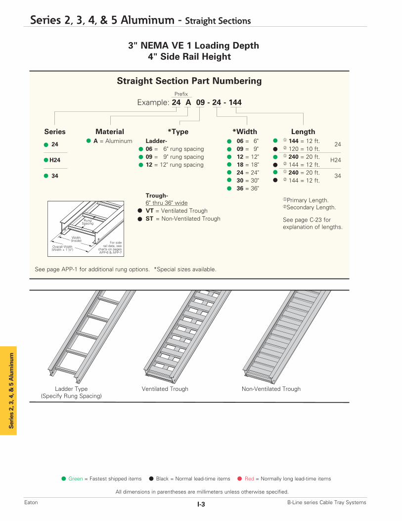
3" NEMA VE 1 Loading Depth4" Side Rail Height
Ladder Type(Specify Rung Spacing)
Ventilated Trough Non-Ventilated Trough
Overall Width(Width + 11/2")
For siderail data, see
charts on pagesAPP-6 & APP-7
RungSpacing
Width(Inside)
Straight Section Part NumberingPrefix
Example: 24 A 09 - 24 - 144
Series Material *Type *Width Length
24 A = Aluminum Ladder- 06 = 6" ¨ 144 = 12 ft. 2406 = 6" rung spacing 09 = 9" ¡ 120 = 10 ft.
H24 09 = 9" rung spacing 12 = 12" ¨ 240 = 20 ft. H2412 = 12" rung spacing 18 = 18" ¡ 144 = 12 ft.
34 24 = 24" ¨ 240 = 20 ft. 3430 = 30" ¡ 144 = 12 ft. 36 = 36"
Trough-6" thru 36" wideVT = Ventilated TroughST = Non-Ventilated Trough
See page APP-1 for additional rung options. *Special sizes available.
Series 2, 3, 4, & 5 Aluminum
¨Primary Length.¡Secondary Length.
See page C-23 for explanation of lengths.
Green = Fastest shipped items Black = Normal lead-time items Red = Normally long lead-time items
All dimensions in parentheses are millimeters unless otherwise specified.
Series 2, 3, 4, & 5 Aluminum - Straight Sections
I-3 B-Line series Cable Tray SystemsEaton
Series 2, 3, 4, &
5 Alum
inum
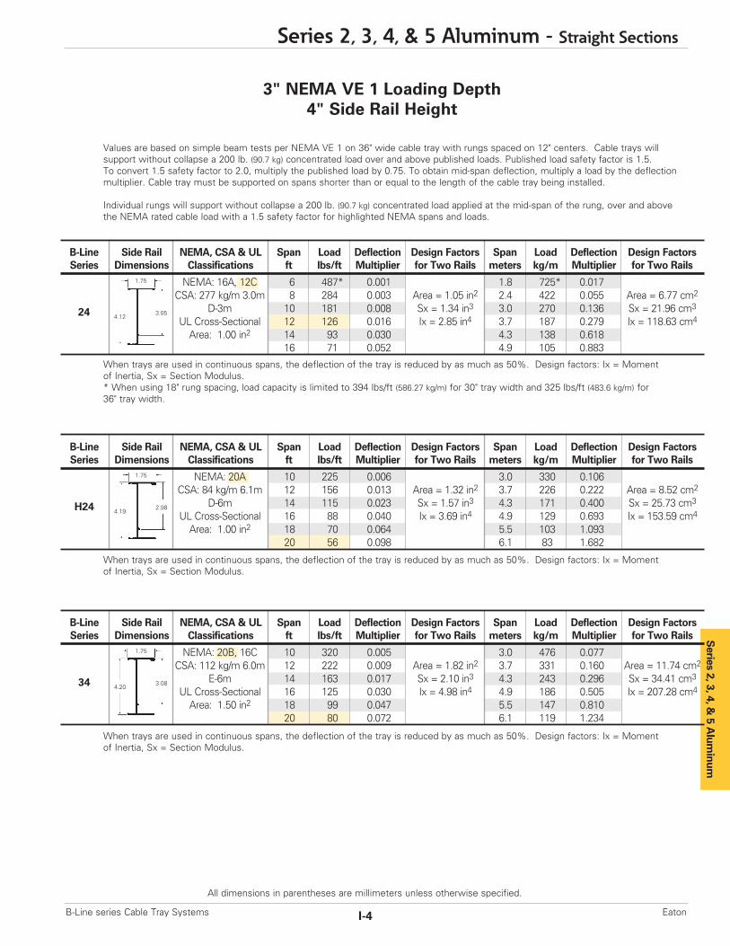
Values are based on simple beam tests per NEMA VE 1 on 36" wide cable tray with rungs spaced on 12" centers. Cable trays will support without collapse a 200 lb. (90.7 kg) concentrated load over and above published loads. Published load safety factor is 1.5. To convert 1.5 safety factor to 2.0, multiply the published load by 0.75. To obtain mid-span deflection, multiply a load by the deflectionmultiplier. Cable tray must be supported on spans shorter than or equal to the length of the cable tray being installed.
Individual rungs will support without collapse a 200 lb. (90.7 kg) concentrated load applied at the mid-span of the rung, over and abovethe NEMA rated cable load with a 1.5 safety factor for highlighted NEMA spans and loads.
When trays are used in continuous spans, the deflection of the tray is reduced by as much as 50%. Design factors: Ix = Momentof Inertia, Sx = Section Modulus.
3" NEMA VE 1 Loading Depth4" Side Rail Height
When trays are used in continuous spans, the deflection of the tray is reduced by as much as 50%. Design factors: Ix = Momentof Inertia, Sx = Section Modulus.* When using 18" rung spacing, load capacity is limited to 394 lbs/ft (586.27 kg/m) for 30" tray width and 325 lbs/ft (483.6 kg/m) for36" tray width.
When trays are used in continuous spans, the deflection of the tray is reduced by as much as 50%. Design factors: Ix = Momentof Inertia, Sx = Section Modulus.
Series 2, 3, 4, & 5 Aluminum - Straight Sections
I-4B-Line series Cable Tray Systems Eaton
All dimensions in parentheses are millimeters unless otherwise specified.
B-Line Side Rail NEMA, CSA & UL Span Load Deflection Design Factors Span Load Deflection Design FactorsSeries Dimensions Classifications ft lbs/ft Multiplier for Two Rails meters kg/m Multiplier for Two Rails
NEMA: 16A, 12C 6 487* 0.001 1.8 725* 0.017CSA: 277 kg/m 3.0m 8 284 0.003 Area = 1.05 in2 2.4 422 0.055 Area = 6.77 cm2
D-3m 10 181 0.008 Sx = 1.34 in3 3.0 270 0.136 Sx = 21.96 cm3
UL Cross-Sectional 12 126 0.016 Ix = 2.85 in4 3.7 187 0.279 Ix = 118.63 cm4
Area: 1.00 in2 14 93 0.030 4.3 138 0.61816 71 0.052 4.9 105 0.883
1.75
4.123.0524
B-Line Side Rail NEMA, CSA & UL Span Load Deflection Design Factors Span Load Deflection Design FactorsSeries Dimensions Classifications ft lbs/ft Multiplier for Two Rails meters kg/m Multiplier for Two Rails
NEMA: 20A 10 225 0.006 3.0 330 0.106CSA: 84 kg/m 6.1m 12 156 0.013 Area = 1.32 in2 3.7 226 0.222 Area = 8.52 cm2
D-6m 14 115 0.023 Sx = 1.57 in3 4.3 171 0.400 Sx = 25.73 cm3
UL Cross-Sectional 16 88 0.040 Ix = 3.69 in4 4.9 129 0.693 Ix = 153.59 cm4
Area: 1.00 in2 18 70 0.064 5.5 103 1.09320 56 0.098 6.1 83 1.682
1.75
4.192.98H24
B-Line Side Rail NEMA, CSA & UL Span Load Deflection Design Factors Span Load Deflection Design FactorsSeries Dimensions Classifications ft lbs/ft Multiplier for Two Rails meters kg/m Multiplier for Two Rails
NEMA: 20B, 16C 10 320 0.005 3.0 476 0.077CSA: 112 kg/m 6.0m 12 222 0.009 Area = 1.82 in2 3.7 331 0.160 Area = 11.74 cm2
E-6m 14 163 0.017 Sx = 2.10 in3 4.3 243 0.296 Sx = 34.41 cm3
UL Cross-Sectional 16 125 0.030 Ix = 4.98 in4 4.9 186 0.505 Ix = 207.28 cm4
Area: 1.50 in2 18 99 0.047 5.5 147 0.81020 80 0.072 6.1 119 1.234
1.75
4.203.0834
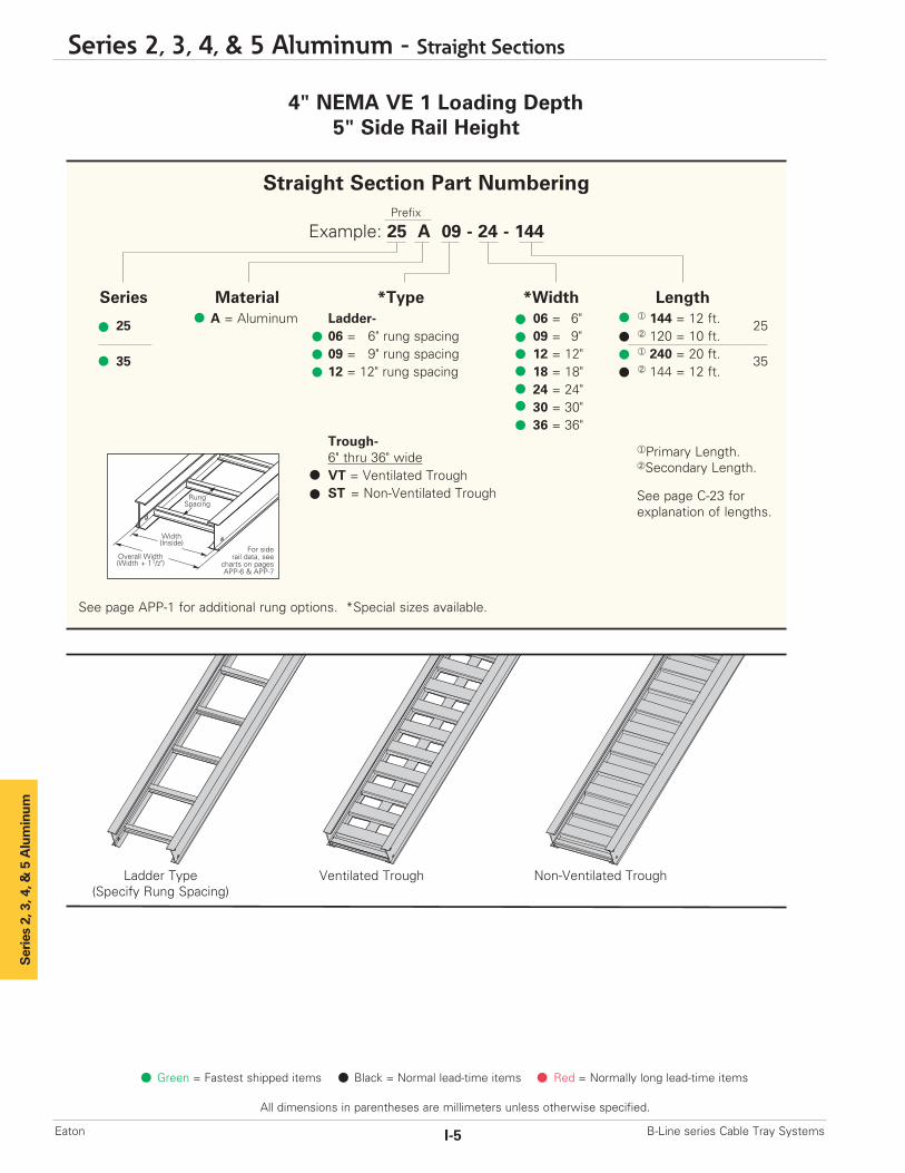
4" NEMA VE 1 Loading Depth5" Side Rail Height
Ladder Type(Specify Rung Spacing)
Ventilated Trough Non-Ventilated Trough
Series 2, 3, 4, & 5 Aluminum
Green = Fastest shipped items Black = Normal lead-time items Red = Normally long lead-time items
All dimensions in parentheses are millimeters unless otherwise specified.
Series 2, 3, 4, & 5 Aluminum - Straight Sections
I-5 B-Line series Cable Tray SystemsEaton
Overall Width(Width + 11/2")
For siderail data, see
charts on pagesAPP-6 & APP-7
RungSpacing
Width(Inside)
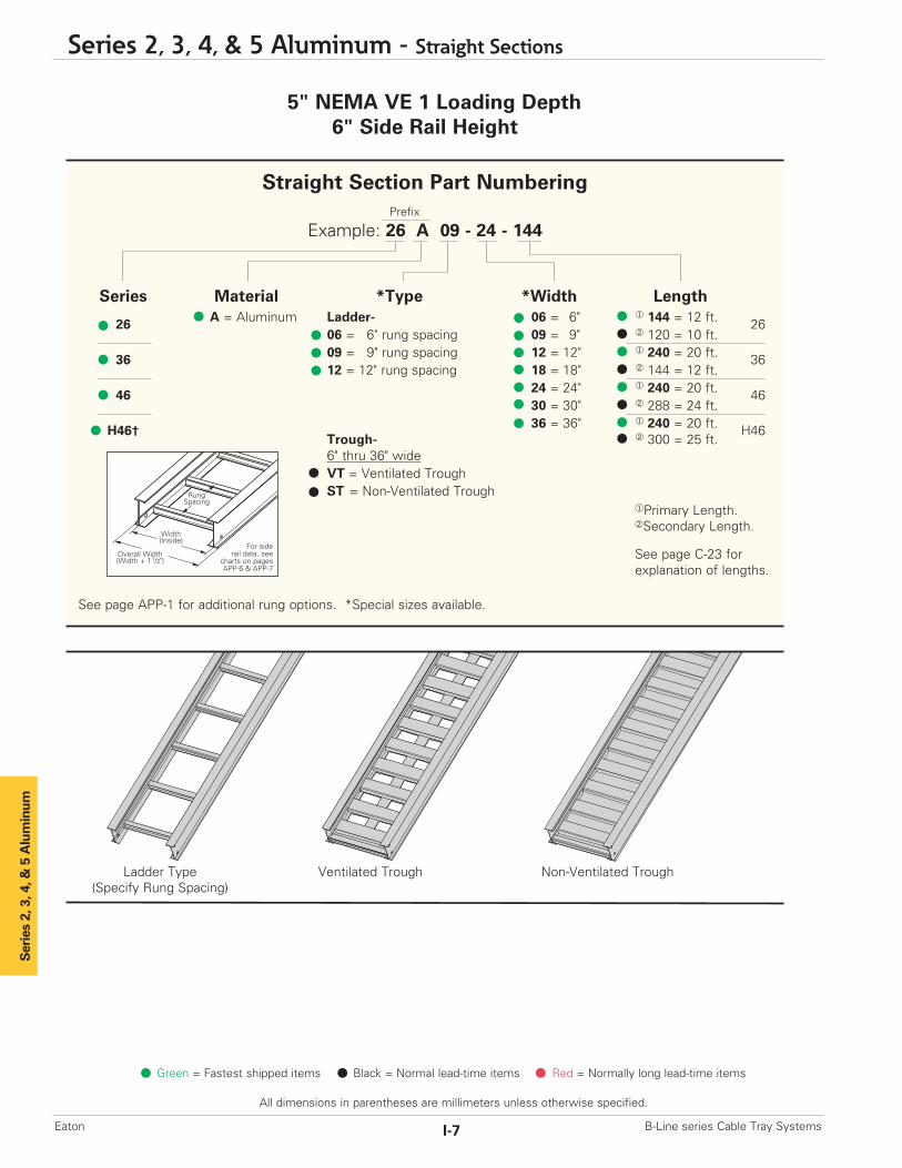
Straight Section Part NumberingPrefix
Example: 25 A 09 - 24 - 144
Series Material *Type *Width Length
25 A = Aluminum Ladder- 06 = 6" ¨ 144 = 12 ft. 2506 = 6" rung spacing 09 = 9" ¡ 120 = 10 ft.
35 09 = 9" rung spacing 12 = 12" ¨ 240 = 20 ft. 3512 = 12" rung spacing 18 = 18" ¡ 144 = 12 ft.
24 = 24"30 = 30"36 = 36"
Trough-6" thru 36" wideVT = Ventilated TroughST = Non-Ventilated Trough
See page APP-1 for additional rung options. *Special sizes available.
¨Primary Length.¡Secondary Length.
See page C-23 for explanation of lengths.
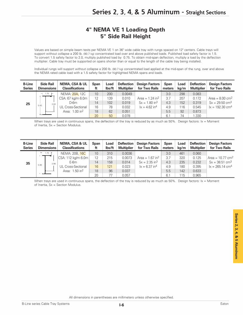
Values are based on simple beam tests per NEMA VE 1 on 36" wide cable tray with rungs spaced on 12" centers. Cable trays willsupport without collapse a 200 lb. (90.7 kg) concentrated load over and above published loads. Published load safety factor is 1.5. To convert 1.5 safety factor to 2.0, multiply published load by 0.75. To obtain mid-span deflection, multiply a load by the deflectionmultiplier. Cable tray must be supported on spans shorter than or equal to the length of the cable tray being installed.
Individual rungs will support without collapse a 200 lb. (90.7 kg) concentrated load applied at the mid-span of the rung, over and abovethe NEMA rated cable load with a 1.5 safety factor for highlighted NEMA spans and loads.
When trays are used in continuous spans, the deflection of the tray is reduced by as much as 50%. Design factors: Ix = Momentof Inertia, Sx = Section Modulus.
When trays are used in continuous spans, the deflection of the tray is reduced by as much as 50%. Design factors: Ix = Momentof Inertia, Sx = Section Modulus.
4" NEMA VE 1 Loading Depth5" Side Rail Height
Series 2, 3, 4, &
5 Alum
inum
Series 2, 3, 4, & 5 Aluminum - Straight Sections
I-6B-Line series Cable Tray Systems Eaton
All dimensions in parentheses are millimeters unless otherwise specified.
B-Line Side Rail NEMA, CSA & UL Span Load Deflection Design Factors Span Load Deflection Design FactorsSeries Dimensions Classifications ft lbs/ft Multiplier for Two Rails meters kg/m Multiplier for Two Rails
NEMA: 20A, 12C 10 200 0.0049 3.0 298 0.083CSA: 67 kg/m 6.0m 12 139 0.010 Area = 1.24 in2 3.7 207 0.172 Area = 8.00 cm2
D-6m 14 102 0.019 Sx = 1.80 in3 4.3 152 0.319 Sx = 29.50 cm3
UL Cross-Sectional 16 78 0.032 Ix = 4.62 in4 4.9 116 0.545 Ix = 192.30 cm4
Area: 1.00 in2 18 62 0.051 5.5 92 0.87320 50 0.078 6.1 74 1.330
1.75
5.003.9325
B-Line Side Rail NEMA, CSA & UL Span Load Deflection Design Factors Span Load Deflection Design FactorsSeries Dimensions Classifications ft lbs/ft Multiplier for Two Rails meters kg/m Multiplier for Two Rails
NEMA: 20B, 16C 10 310 0.0036 3.0 461 0.060CSA: 112 kg/m 6.0m 12 215 0.0073 Area = 1.67 in2 3.7 320 0.125 Area = 10.77 cm2
E-6m 14 158 0.014 Sx = 2.35 in3 4.3 235 0.232 Sx = 38.51 cm3
UL Cross-Sectional 16 121 0.023 Ix = 6.37 in4 4.9 180 0.395 Ix = 265.14 cm4
Area: 1.50 in2 18 96 0.037 5.5 142 0.63320 77 0.057 6.1 115 0.965
1.75
5.063.9635
5" NEMA VE 1 Loading Depth6" Side Rail Height
Ladder Type(Specify Rung Spacing)
Ventilated Trough Non-Ventilated Trough
Series 2, 3, 4, & 5 Aluminum
Green = Fastest shipped items Black = Normal lead-time items Red = Normally long lead-time items
All dimensions in parentheses are millimeters unless otherwise specified.
Series 2, 3, 4, & 5 Aluminum - Straight Sections
I-7 B-Line series Cable Tray SystemsEaton
Overall Width(Width + 11/2")
For siderail data, see
charts on pagesAPP-6 & APP-7
RungSpacing
Width(Inside)
Straight Section Part NumberingPrefix
Example: 26 A 09 - 24 - 144
Series Material *Type *Width Length
26 A = Aluminum Ladder- 06 = 6" ¨ 144 = 12 ft. 2606 = 6" rung spacing 09 = 9" ¡ 120 = 10 ft.
36 09 = 9" rung spacing 12 = 12" ¨ 240 = 20 ft. 3612 = 12" rung spacing 18 = 18" ¡ 144 = 12 ft.
46 24 = 24" ¨ 240 = 20 ft. 4630 = 30" ¡ 288 = 24 ft.
H46†36 = 36" ¨ 240 = 20 ft. H46
Trough- ¡ 300 = 25 ft.6" thru 36" wideVT = Ventilated TroughST = Non-Ventilated Trough
See page APP-1 for additional rung options. *Special sizes available.
¨Primary Length.¡Secondary Length.
See page C-23 for explanation of lengths.
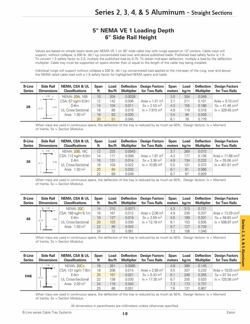
Values are based on simple beam tests per NEMA VE 1 on 36" wide cable tray with rungs spaced on 12" centers. Cable trays will support, without collapse, a 200 lb. (90.7 kg) concentrated load over and above published loads. Published load safety factor is 1.5. To convert 1.5 safety factor to 2.0, multiply the published load by 0.75. To obtain mid-span deflection, multiply a load by the deflectionmultiplier. Cable tray must be supported on spans shorter than or equal to the length of the cable tray being installed.
Individual rungs will support without collapse a 200 lb. (90.7 kg) concentrated load applied at the mid-span of the rung, over and abovethe NEMA rated cable load with a 1.5 safety factor for highlighted NEMA spans and loads.
When trays are used in continuous spans, the deflection of the tray is reduced by as much as 50%. Design factors: Ix = Momentof Inertia, Sx = Section Modulus.
5" NEMA VE 1 Loading Depth6" Side Rail Height
When trays are used in continuous spans, the deflection of the tray is reduced by as much as 50%. Design factors: Ix = Momentof Inertia, Sx = Section Modulus.
When trays are used in continuous spans, the deflection of the tray is reduced by as much as 50%. Design factors: Ix = Momentof Inertia, Sx = Section Modulus.
When trays are used in continuous spans, the deflection of the tray is reduced by as much as 50%. Design factors: Ix = Momentof Inertia, Sx = Section Modulus.
Series 2, 3, 4, & 5 Aluminum - Straight Sections
I-8B-Line series Cable Tray Systems Eaton
All dimensions in parentheses are millimeters unless otherwise specified.
B-Line Side Rail NEMA, CSA & UL Span Load Deflection Design Factors Span Load Deflection Design FactorsSeries Dimensions Classifications ft lbs/ft Multiplier for Two Rails meters kg/m Multiplier for Two Rails
NEMA: 20A, 16B 10 204 0.0028 3.0 304 0.049CSA: 67 kg/m 6.0m 12 142 0.006 Area = 1.41 in2 3.7 211 0.101 Area = 9.10 cm2
D-6m 14 104 0.011 Sx = 2.53 in3 4.3 155 0.186 Sx = 41.46 cm3
UL Cross-Sectional 16 80 0.019 Ix = 7.915 in4 4.9 119 0.318 Ix = 329.45 cm4
Area: 1.00 in2 18 63 0.030 5.5 94 0.50920 51 0.045 6.1 76 0.776
2.00
6.125.0426
B-Line Side Rail NEMA, CSA & UL Span Load Deflection Design Factors Span Load Deflection Design FactorsSeries Dimensions Classifications ft lbs/ft Multiplier for Two Rails meters kg/m Multiplier for Two Rails
NEMA: 20B, 16C 12 233 0.0043 3.7 269 0.073CSA: 112 kg/m 6.0m 14 171 0.008 Area = 1.81 in2 4.3 177 0.136 Area = 11.68 cm2
E-6m 16 131 0.014 Sx = 3.36 in3 4.9 134 0.232 Sx = 55.06 cm3
UL Cross-Sectional 18 104 0.022 Ix = 10.85 in4 5.5 101 0.372 Ix = 451.61 cm4
Area: 1.50 in2 20 84 0.033 6.1 81 0.56622 69 0.049 6.7 67 0.829
2.00
6.175.0636
B-Line Side Rail NEMA, CSA & UL Span Load Deflection Design Factors Span Load Deflection Design FactorsSeries Dimensions Classifications ft lbs/ft Multiplier for Two Rails meters kg/m Multiplier for Two Rails
NEMA: 20C 14 210 0.0071 4.3 313 0.121CSA: 168 kg/m 6.1m 16 161 0.012 Area = 2.06 in2 4.9 239 0.207 Area = 13.29 cm2
E-6m 18 127 0.019 Sx = 3.59 in3 5.5 189 0.331 Sx = 58.83 cm3
UL Cross-Sectional 20 103 0.030 Ix = 12.18 in4 6.1 153 0.505 Ix = 506.97 cm4
Area: 1.50 in2 22 85 0.043 6.7 127 0.73924 72 0.061 7.3 106 1.046
2.00
6.195.0846 S
eries 2, 3, 4, & 5 A
luminum
B-Line Side Rail NEMA, CSA & UL Span Load Deflection Design Factors Span Load Deflection Design FactorsSeries Dimensions Classifications ft lbs/ft Multiplier for Two Rails meters kg/m Multiplier for Two Rails
NEMA: 20C+ 16 261 0.0085 4.9 388 0.145CSA: 131 kg/m 7.6m 18 206 0.014 Area = 2.95 in2 5.5 307 0.233 Area = 19.03 cm2
E-6m 20 167 0.021 Sx = 5.33 in3 6.1 248 0.355 Sx = 87.34 cm3
UL Cross-Sectional 22 138 0.030 Ix = 17.30 in4 6.7 205 0.520 Ix = 720.08 cm4
Area: 2.00 in2 24 116 0.043 7.3 173 0.73725 88 0.051 7.6 131 0.867
2.00
6.245.09H46
6" NEMA VE 1 Loading Depth7" Side Rail Height
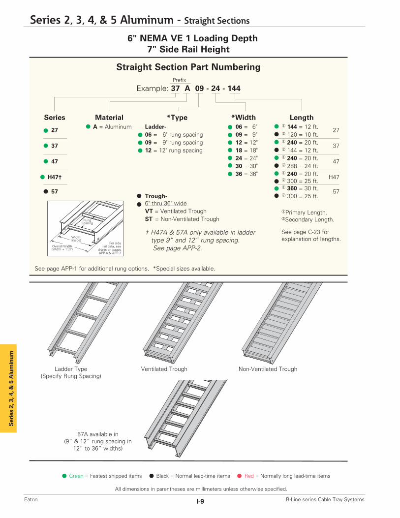
Ladder Type(Specify Rung Spacing)
57A available in(9” & 12” rung spacing in
12” to 36” widths)
Ventilated Trough Non-Ventilated Trough
Series 2, 3, 4, & 5 Aluminum
Green = Fastest shipped items Black = Normal lead-time items Red = Normally long lead-time items
All dimensions in parentheses are millimeters unless otherwise specified.
Series 2, 3, 4, & 5 Aluminum - Straight Sections
I-9 B-Line series Cable Tray SystemsEaton
Overall Width(Width + 11/2")
For siderail data, see
charts on pagesAPP-6 & APP-7
RungSpacing
Width(Inside)
Straight Section Part NumberingPrefix
Example: 37 A 09 - 24 - 144
Series Material *Type *Width Length
27 A = Aluminum Ladder- 06 = 6" ¨ 144 = 12 ft. 2706 = 6" rung spacing 09 = 9" ¡ 120 = 10 ft.
37 09 = 9" rung spacing 12 = 12" ¨ 240 = 20 ft. 3712 = 12" rung spacing 18 = 18" ¡ 144 = 12 ft.
47 24 = 24" ¨ 240 = 20 ft. 4730 = 30" ¡ 288 = 24 ft.
H47†36 = 36" ¨ 240 = 20 ft. H47
¡ 300 = 25 ft.
57¨ 360 = 30 ft. 57
Trough- ¡ 300 = 25 ft.6" thru 36" wideVT = Ventilated TroughST = Non-Ventilated Trough
† H47A & 57A only available in laddertype 9” and 12” rung spacing.See page APP-2.
See page APP-1 for additional rung options. *Special sizes available.
¨Primary Length.¡Secondary Length.
See page C-23 for explanation of lengths.
Series 2, 3, 4, &
5 Alum
inum
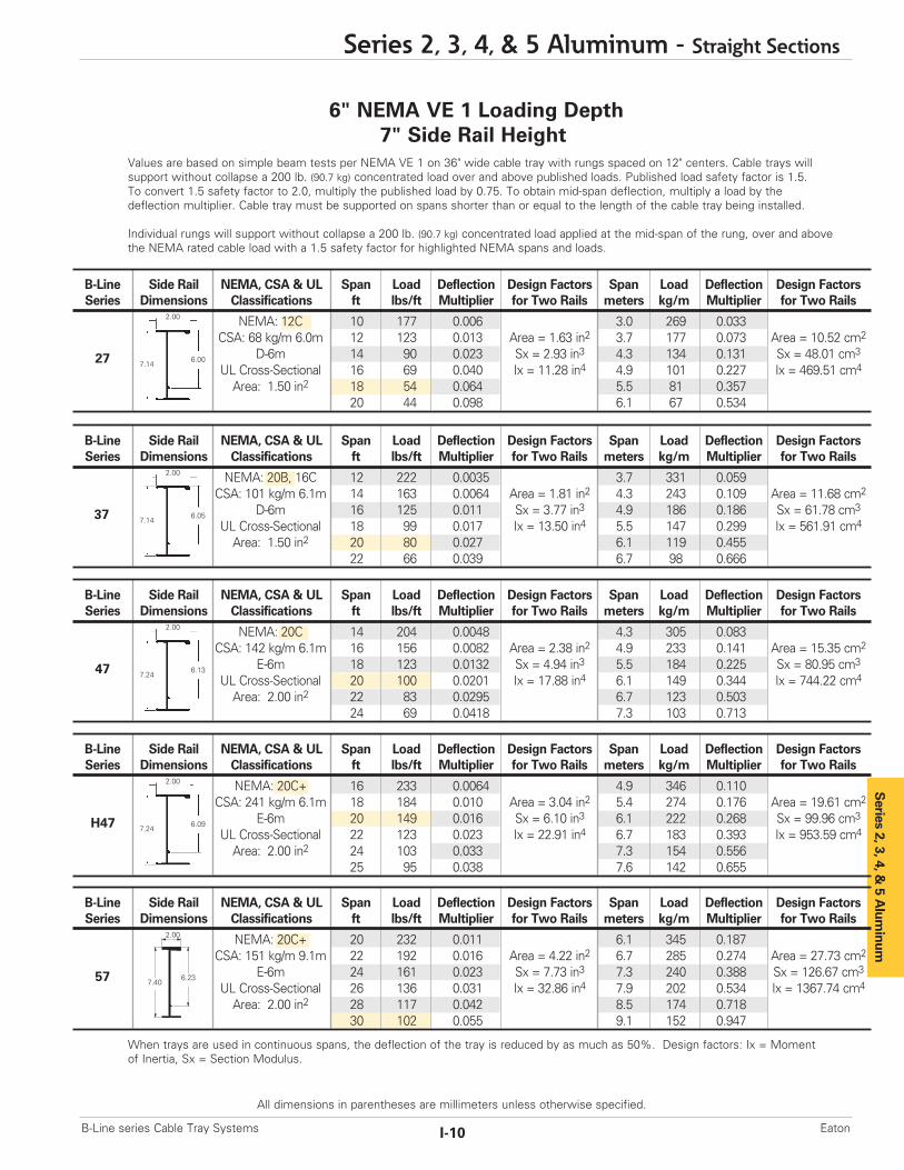
B-Line Side Rail NEMA, CSA & UL Span Load Deflection Design Factors Span Load Deflection Design FactorsSeries Dimensions Classifications ft lbs/ft Multiplier for Two Rails meters kg/m Multiplier for Two Rails
NEMA: 12C 10 177 0.006 3.0 269 0.033CSA: 68 kg/m 6.0m 12 123 0.013 Area = 1.63 in2 3.7 177 0.073 Area = 10.52 cm2
D-6m 14 90 0.023 Sx = 2.93 in3 4.3 134 0.131 Sx = 48.01 cm3
UL Cross-Sectional 16 69 0.040 Ix = 11.28 in4 4.9 101 0.227 Ix = 469.51 cm4
Area: 1.50 in2 18 54 0.064 5.5 81 0.35720 44 0.098 6.1 67 0.534
Values are based on simple beam tests per NEMA VE 1 on 36" wide cable tray with rungs spaced on 12" centers. Cable trays willsupport without collapse a 200 lb. (90.7 kg) concentrated load over and above published loads. Published load safety factor is 1.5. To convert 1.5 safety factor to 2.0, multiply the published load by 0.75. To obtain mid-span deflection, multiply a load by thedeflection multiplier. Cable tray must be supported on spans shorter than or equal to the length of the cable tray being installed.
Individual rungs will support without collapse a 200 lb. (90.7 kg) concentrated load applied at the mid-span of the rung, over and abovethe NEMA rated cable load with a 1.5 safety factor for highlighted NEMA spans and loads.
2.00
7.146.00
6" NEMA VE 1 Loading Depth7" Side Rail Height
27
B-Line Side Rail NEMA, CSA & UL Span Load Deflection Design Factors Span Load Deflection Design FactorsSeries Dimensions Classifications ft lbs/ft Multiplier for Two Rails meters kg/m Multiplier for Two Rails
NEMA: 20B, 16C 12 222 0.0035 3.7 331 0.059CSA: 101 kg/m 6.1m 14 163 0.0064 Area = 1.81 in2 4.3 243 0.109 Area = 11.68 cm2
D-6m 16 125 0.011 Sx = 3.77 in3 4.9 186 0.186 Sx = 61.78 cm3
UL Cross-Sectional 18 99 0.017 Ix = 13.50 in4 5.5 147 0.299 Ix = 561.91 cm4
Area: 1.50 in2 20 80 0.027 6.1 119 0.45522 66 0.039 6.7 98 0.666
2.00
7.146.0537
B-Line Side Rail NEMA, CSA & UL Span Load Deflection Design Factors Span Load Deflection Design FactorsSeries Dimensions Classifications ft lbs/ft Multiplier for Two Rails meters kg/m Multiplier for Two Rails
NEMA: 20C 14 204 0.0048 4.3 305 0.083CSA: 142 kg/m 6.1m 16 156 0.0082 Area = 2.38 in2 4.9 233 0.141 Area = 15.35 cm2
E-6m 18 123 0.0132 Sx = 4.94 in3 5.5 184 0.225 Sx = 80.95 cm3
UL Cross-Sectional 20 100 0.0201 Ix = 17.88 in4 6.1 149 0.344 Ix = 744.22 cm4
Area: 2.00 in2 22 83 0.0295 6.7 123 0.50324 69 0.0418 7.3 103 0.713
2.00
7.246.1347
B-Line Side Rail NEMA, CSA & UL Span Load Deflection Design Factors Span Load Deflection Design FactorsSeries Dimensions Classifications ft lbs/ft Multiplier for Two Rails meters kg/m Multiplier for Two Rails
NEMA: 20C+ 16 233 0.0064 4.9 346 0.110CSA: 241 kg/m 6.1m 18 184 0.010 Area = 3.04 in2 5.4 274 0.176 Area = 19.61 cm2
E-6m 20 149 0.016 Sx = 6.10 in3 6.1 222 0.268 Sx = 99.96 cm3
UL Cross-Sectional 22 123 0.023 Ix = 22.91 in4 6.7 183 0.393 Ix = 953.59 cm4
Area: 2.00 in2 24 103 0.033 7.3 154 0.55625 95 0.038 7.6 142 0.655
2.00
7.246.09H47
B-Line Side Rail NEMA, CSA & UL Span Load Deflection Design Factors Span Load Deflection Design FactorsSeries Dimensions Classifications ft lbs/ft Multiplier for Two Rails meters kg/m Multiplier for Two Rails
NEMA: 20C+ 20 232 0.011 6.1 345 0.187CSA: 151 kg/m 9.1m 22 192 0.016 Area = 4.22 in2 6.7 285 0.274 Area = 27.73 cm2
E-6m 24 161 0.023 Sx = 7.73 in3 7.3 240 0.388 Sx = 126.67 cm3
UL Cross-Sectional 26 136 0.031 Ix = 32.86 in4 7.9 202 0.534 Ix = 1367.74 cm4
Area: 2.00 in2 28 117 0.042 8.5 174 0.71830 102 0.055 9.1 152 0.947
2.00
7.406.2357
When trays are used in continuous spans, the deflection of the tray is reduced by as much as 50%. Design factors: Ix = Momentof Inertia, Sx = Section Modulus.
Series 2, 3, 4, & 5 Aluminum - Straight Sections
I-10B-Line series Cable Tray Systems Eaton
All dimensions in parentheses are millimeters unless otherwise specified.
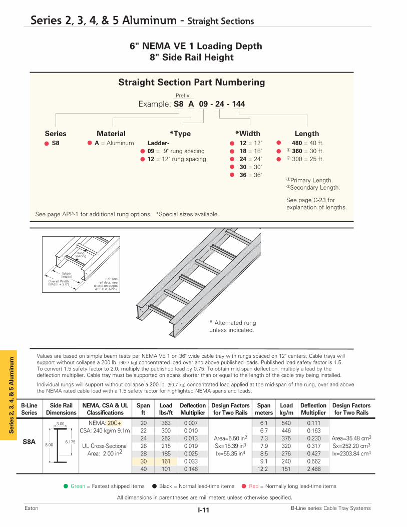
6" NEMA VE 1 Loading Depth8" Side Rail Height
Series 2, 3, 4, & 5 Aluminum
* Alternated rung unless indicated.
B-Line Side Rail NEMA, CSA & UL Span Load Deflection Design Factors Span Load Deflection Design FactorsSeries Dimensions Classifications ft lbs/ft Multiplier for Two Rails meters kg/m Multiplier for Two Rails
NEMA: 20C+ 20 363 0.007 6.1 540 0.111CSA: 240 kg/m 9.1m 22 300 0.010 6.7 446 0.163
24 252 0.013 Area=5.50 in2 7.3 375 0.230 Area=35.48 cm2
UL Cross-Sectional 26 215 0.019 Sx=15.39 in3 7.9 320 0.317 Sx=252.20 cm3
Area: 2.00 in2 28 185 0.025 Ix=55.35 in4 8.5 276 0.427 Ix=2303.84 cm4
30 161 0.033 9.1 240 0.56240 101 0.146 12.2 151 2.488
3.00
8.006.175S8A
Overall Width(Width + 2.0")
For siderail data, see
charts on pagesAPP-6 & APP-7
RungSpacing
Width(Inside)
Values are based on simple beam tests per NEMA VE 1 on 36" wide cable tray with rungs spaced on 12" centers. Cable trays willsupport without collapse a 200 lb. (90.7 kg) concentrated load over and above published loads. Published load safety factor is 1.5. To convert 1.5 safety factor to 2.0, multiply the published load by 0.75. To obtain mid-span deflection, multiply a load by thedeflection multiplier. Cable tray must be supported on spans shorter than or equal to the length of the cable tray being installed.
Individual rungs will support without collapse a 200 lb. (90.7 kg) concentrated load applied at the mid-span of the rung, over and abovethe NEMA rated cable load with a 1.5 safety factor for highlighted NEMA spans and loads.
Green = Fastest shipped items Black = Normal lead-time items Red = Normally long lead-time items
All dimensions in parentheses are millimeters unless otherwise specified.
Series 2, 3, 4, & 5 Aluminum - Straight Sections
I-11 B-Line series Cable Tray SystemsEaton
Straight Section Part NumberingPrefix
Example: S8 A 09 - 24 - 144
Series Material *Type *Width LengthS8 A = Aluminum Ladder- 12 = 12" 480 = 40 ft.
09 = 9" rung spacing 18 = 18" ¨ 360 = 30 ft.12 = 12" rung spacing 24 = 24" ¡ 300 = 25 ft.
30 = 30"36 = 36"
See page APP-1 for additional rung options. *Special sizes available.
¨Primary Length.¡Secondary Length.
See page C-23 for explanation of lengths.