Design of 9-Meter Carbon-Fiberglass Prototype Blades
46
SANDIA REPORT SAND2007-0201 Unlimited Release Printed September 2007 Design of 9-Meter Carbon-Fiberglass Prototype Blades: CX-100 and TX-100 Derek Berry, Principal Investigator TPI Composites, Inc. 373 Market Street Warren, RI 02885 Tom Ashwill, Sandia Technical Monitor Prepared by Sandia National Laboratories Albuquerque, New Mexico 87185 and Livermore, California 94550 Sandia is a multiprogram laboratory operated by Sandia Corporation, a Lockheed Martin Company, for the United States Department of Energy’s National Nuclear Security Administration under Contract DE-AC04-94AL85000. Approved for public release; further dissemination unlimited.
-
Upload
khangminh22 -
Category
Documents
-
view
2 -
download
0
Transcript of Design of 9-Meter Carbon-Fiberglass Prototype Blades
SANDIA REPORT SAND2007-0201 Unlimited Release Printed September 2007
Design of 9-Meter Carbon-Fiberglass Prototype Blades: CX-100 and TX-100 Derek Berry, Principal Investigator TPI Composites, Inc. 373 Market Street Warren, RI 02885 Tom Ashwill, Sandia Technical Monitor Prepared by Sandia National Laboratories Albuquerque, New Mexico 87185 and Livermore, California 94550 Sandia is a multiprogram laboratory operated by Sandia Corporation, a Lockheed Martin Company, for the United States Department of Energy’s National Nuclear Security Administration under Contract DE-AC04-94AL85000. Approved for public release; further dissemination unlimited.
Issued by Sandia National Laboratories, operated for the United States Department of Energy by Sandia Corporation. NOTICE: This report was prepared as an account of work sponsored by an agency of the United States Government. Neither the United States Government, nor any agency thereof, nor any of their employees, nor any of their contractors, subcontractors, or their employees, make any warranty, express or implied, or assume any legal liability or responsibility for the accuracy, completeness, or usefulness of any information, apparatus, product, or process disclosed, or represent that its use would not infringe privately owned rights. Reference herein to any specific commercial product, process, or service by trade name, trademark, manufacturer, or otherwise, does not necessarily constitute or imply its endorsement, recommendation, or favoring by the United States Government, any agency thereof, or any of their contractors or subcontractors. The views and opinions expressed herein do not necessarily state or reflect those of the United States Government, any agency thereof, or any of their contractors. Printed in the United States of America. This report has been reproduced directly from the best available copy. Available to DOE and DOE contractors from U.S. Department of Energy Office of Scientific and Technical Information P.O. Box 62 Oak Ridge, TN 37831 Telephone: (865) 576-8401 Facsimile: (865) 576-5728 E-Mail: [email protected] Online ordering: http://www.osti.gov/bridge Available to the public from U.S. Department of Commerce National Technical Information Service 5285 Port Royal Rd. Springfield, VA 22161 Telephone: (800) 553-6847 Facsimile: (703) 605-6900 E-Mail: [email protected] Online order: http://www.ntis.gov/help/ordermethods.asp?loc=7-4-0#online
2
Design of 9-Meter Carbon-Fiberglass Prototype Blades: CX-100 and TX-100
Final Project Report
TPI Composites, Inc. 373 Market Street Warren, RI 02885
Principal Investigator: Derek Berry
Sandia Technical Monitor: Tom Ashwill
Abstract TPI Composites, Inc. (TPI), Global Energy Concepts, LLC (GEC), and MDZ Consulting (MDZ) have collaborated on a project to design, manufacture, and test prototype carbon-fiberglass hybrid wind turbine blades of 9-m length. The project, funded by Sandia National Laboratories, involves prototype blades in both conventional (unidirectional spar fibers running along the blade span) and “adaptive” (carbon fibers in off-axis orientation to achieve bend-twist-coupling) configurations. After manufacture, laboratory testing is being conducted to determine the static and fatigue strength of the prototypes, in conjunction with field testing to evaluate the performance under operational conditions.
SAND2007-0201 Unlimited Release
Printed September 2007
3
4
Acknowledgements The work in this report was completed by TPI, Global Energy Concepts (GEC), and MDZ Consulting for Sandia National Laboratories under Sandia Purchase Order No. 72852. The author wishes to acknowledge the contributions of TPI Project Manager Steve Nolet, Sandia Technical Monitor Tom Ashwill, Paul Veers, and other Sandia personnel to this project. The NuMAD interface to ANSYS, developed by Daniel Laird of Sandia, was used extensively to facilitate the blade design and analyses performed. At GEC, Dayton Griffin was the technical lead for preliminary structural design, and David Malcolm and Mark Young made substantial contributions in the area of aeroelastic modeling.
5
Table of Contents
NOMENCLATURE...................................................................................................................... 7
EXECUTIVE SUMMARY .......................................................................................................... 8
SECTION 1 - INTRODUCTION ................................................................................................ 9 1.1 BACKGROUND.................................................................................................................. 9 1.2 OBJECTIVES ..................................................................................................................... 9 1.3 PROJECT OVERVIEW ...................................................................................................... 10
SECTION 2 - BASELINE BLADE/TURBINE SYSTEM ...................................................... 11 2.1 TURBINE SYSTEM........................................................................................................... 11 2.2 BASELINE 9-M BLADE.................................................................................................... 13
SECTION 3 - DESIGN APPROACH ....................................................................................... 14 3.1 LOADS DEVELOPMENT................................................................................................... 14
3.1.1 CX-100.................................................................................................................. 16 3.1.2 TX-100.................................................................................................................. 16
3.2 MATERIAL PROPERTIES ................................................................................................. 17 3.3 GENERAL DESIGN METHODOLOGY ................................................................................ 19
SECTION 4 - CX-100 DESIGN................................................................................................. 21
SECTION 5 - TX-100 DESIGN................................................................................................. 25 5.1 LOAD CASES (OPERATIONAL BENDING MOMENTS)....................................................... 25 5.2 SKIN CONSTRUCTION..................................................................................................... 27 5.3 FINAL DESIGN SUMMARY .............................................................................................. 27 5.4 ANTICIPATED TECHNICAL CHALLENGES FOR THE TX-100 ............................................ 30
SECTION 6 - TX-100 MODELED IN VSVP OPERATION.................................................. 32 6.1 BASELINE GX-100 IN VSVP OPERATION ...................................................................... 32 6.2 FSFP VERSUS VSVP GX-100 BASELINE ....................................................................... 35 6.3 VSVP TX-100............................................................................................................... 36
SECTION 7 - CONCLUSIONS................................................................................................. 39
SECTION 8 - REFERENCES ................................................................................................... 40
6
List of Figures
Figure 1. Modified Micon 65 Turbine (Shown with SERI-8 Blades) .......................................... 11 Figure 2. Finite Element Mesh of Baseline Blade Geometry ....................................................... 13 Figure 3. Biased Skins Constructed with Carbon Unidirectional/Biaxial Fiberglass Fabrics ...... 14 Figure 4. Example Rainflow-Counts for CX-100 Root-Bending Loads (9.2-m Blade Length)... 15 Figure 5. SAERTEX Triaxial Carbon-Fiberglass Fabric.............................................................. 18 Figure 6. Comparison of GX-100 and CX-100 Stiffness Distributions........................................ 22 Figure 7. Fabricated CX-100 Skins at TPI Composites................................................................ 24 Figure 8. Schematic Layout for Design of Twist-Coupled Blade Skins....................................... 25 Figure 9. Aeroelastic Response of TX-100 to Fluctuating Loads (8 m/s Mean Wind Speed) ..... 28 Figure 10. Fabricated TX-100 Skins at TPI Composites.............................................................. 30 Figure 11. RPM to Blade Pitch PID Block Diagram.................................................................... 33 Figure 12. Variable-Speed Turbine Torque-Speed Curve ............................................................ 34 Figure 13. ADAMS Calculated Rotor Power ............................................................................... 34
List of Tables
Table 1. Selected Loads for Baseline LIST Turbine (Load Cases per IEC Class II-B) ............... 12 Table 2. Baseline Planform Dimensions....................................................................................... 13 Table 3. Representative Ranking of Peak Load Cases for (9.2-m) GX-100/CX-100 Blades....... 16 Table 4. Lamina Properties used in Design Calculations ............................................................. 18 Table 5. Material Strain Data used for Static Evaluation ............................................................. 19 Table 6. Evaluation of Baseline GX-100 Fiberglass Spar ............................................................ 21 Table 7. Static (Compressive) Strength Margins.......................................................................... 22 Table 8. CX-100 Spar Cap Summary ........................................................................................... 23 Table 9. Blade Mass and Tip Deflection Results.......................................................................... 23 Table 10. TX-100 Coupling Properties......................................................................................... 28 Table 11. Summary of TX-100 Load Reductions (Baseline Fixed-Speed,
Fixed-Pitch Operation).......................................................................................................... 29 Table 12. Minimum Pitch Angle and Peak Power........................................................................ 35 Table 13. Selected GX-100 System Loads (9.0-m blades with IEC Class II-B Wind Input)....... 35 Table 14. TX-100 and GX-100 VSVP Mode: Selected System Loads ........................................ 36 Table 15. Summary of Blade Tip Elastic Rotation ....................................................................... 38
7
Nomenclature
c chord length (m)
CL,Max maximum lift coefficient
CP,max maximum rotor power coefficient
EIFlap flapwise blade stiffness (N-m2)
Ex longitudinal modulus (GPa)
Ey transverse modulus (GPa)
GJ torsional blade stiffness (N-m2)
Gxy shear modulus (GPa)
m meters
MB blade bending moment (N-m)
BM mean blade bending moment (N-m)
MB,Turb Turbulent fluctuation of blade bending moment from mean (N-m)
R rotor radius (m)
ε material strain (%)
εdesign design value of material strain (%)
Δ delta [difference] (%)
γm combined partial safety factor for materials
νxy major Poisson’s ratio of laminate
υf laminate fiber volume fraction
8
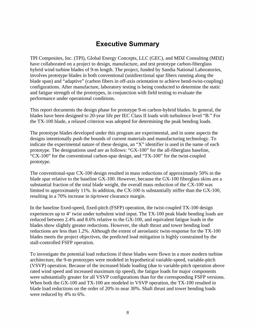
Executive Summary
TPI Composites, Inc. (TPI), Global Energy Concepts, LLC (GEC), and MDZ Consulting (MDZ) have collaborated on a project to design, manufacture, and test prototype carbon-fiberglass hybrid wind turbine blades of 9-m length. The project, funded by Sandia National Laboratories, involves prototype blades in both conventional (unidirectional spar fibers running along the blade span) and “adaptive” (carbon fibers in off-axis orientation to achieve bend-twist-coupling) configurations. After manufacture, laboratory testing is being conducted to determine the static and fatigue strength of the prototypes, in conjunction with field testing to evaluate the performance under operational conditions. This report documents the design phase for prototype 9-m carbon-hybrid blades. In general, the blades have been designed to 20-year life per IEC Class II loads with turbulence level “B.” For the TX-100 blade, a relaxed criterion was adopted for determining the peak bending loads. The prototype blades developed under this program are experimental, and in some aspects the designs intentionally push the bounds of current materials and manufacturing technology. To indicate the experimental nature of these designs, an “X” identifier is used in the name of each prototype. The designations used are as follows: “GX-100” for the all-fiberglass baseline, “CX-100” for the conventional carbon-spar design, and “TX-100” for the twist-coupled prototype. The conventional-spar CX-100 design resulted in mass reductions of approximately 50% in the blade spar relative to the baseline GX-100. However, because the GX-100 fiberglass skins are a substantial fraction of the total blade weight, the overall mass reduction of the CX-100 was limited to approximately 11%. In addition, the CX-100 is substantially stiffer than the GX-100, resulting in a 70% increase in tip/tower clearance margin. In the baseline fixed-speed, fixed-pitch (FSFP) operation, the twist-coupled TX-100 design experiences up to 4° twist under turbulent wind input. The TX-100 peak blade bending loads are reduced between 2.4% and 8.6% relative to the GX-100, and equivalent fatigue loads in the blades show slightly greater reductions. However, the shaft thrust and tower bending load reductions are less than 1.2%. Although the extent of aeroelastic twist-response for the TX-100 blades meets the project objectives, the predicted load mitigation is highly constrained by the stall-controlled FSFP operation. To investigate the potential load reductions if these blades were flown in a more modern turbine architecture, the 9-m prototypes were modeled in hypothetical variable-speed, variable-pitch (VSVP) operation. Because of the increased blade loading (due to variable-pitch operation above rated wind speed and increased maximum tip speed), the fatigue loads for major components were substantially greater for all VSVP configurations than for the corresponding FSFP versions. When both the GX-100 and TX-100 are modeled in VSVP operation, the TX-100 resulted in blade load reductions on the order of 20% to near 30%. Shaft thrust and tower bending loads were reduced by 4% to 6%.
9
Section 1 - Introduction
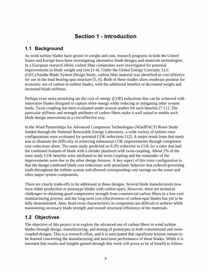
1.1 Background As wind turbine blades have grown in weight and cost, research programs in both the United States and Europe have been investigating alternative blade designs and materials technologies. In a European research effort, carbon fiber composites were investigated for potential improvements in blade weight and cost [1-4]. Under the Global Energy Concepts, LLC (GEC)/Sandia Blade System Design Study, carbon fiber material was identified as cost effective for use in the load bearing spar structure [5, 6]. Both of these studies show moderate promise for economic use of carbon in turbine blades, with the additional benefits of decreased weight and increased blade stiffness. Perhaps even more promising are the cost of energy (COE) reductions that can be achieved with innovative blades designed to capture more energy while reducing or mitigating other system loads. Twist-coupling has been evaluated under several studies for such benefits [7-11]. The particular stiffness and strength attributes of carbon fibers make it well suited to enable such blade design innovations in a cost-effective way. In the Wind Partnerships for Advanced Component Technologies (WindPACT) Rotor Study funded through the National Renewable Energy Laboratory, a wide variety of turbine rotor configurations were evaluated for potential COE reductions [12]. A major result from that study was to illustrate the difficulty in achieving substantial COE improvements through component cost reductions alone. The same study predicted an 8.2% reduction in COE for a rotor that had the combined features of blade with a slender planform with twist-coupling. About 2% of the rotor study COE benefits were attributed to the twist-coupling and the remainder of the improvements were due to the other design features. A key aspect of this rotor configuration is that the design combined blade cost reductions with aeroelastic behavior that reduced governing loads throughout the turbine system and allowed corresponding cost savings on the tower and other major system components. There are clearly trade-offs to be addressed in these designs. Several blade manufacturers now have either production or prototype blades with carbon spars. However, there are technical challenges in obtaining good compressive strength from commercial carbon fibers in a low-cost manufacturing process, and the long-term cost effectiveness of carbon-spar blades has yet to be fully demonstrated. Also, bend-twist characteristics in composites are difficult to achieve while maintaining necessary blade strength and overall structural efficiency of the materials.
1.2 Objectives The objective of this project is to explore the advanced use of carbon fibers in wind turbine blades through design, manufacturing, and testing of prototypes in both conventional and twist-coupled designs. This is a research effort, and it is anticipated that significant lessons remain to be learned concerning the manufacturing and structural performance of these blades. While it is intended that results and insights gained through this work will prove to be of benefit to follow-
10
on scale-up and commercial development of advanced blades incorporating carbon fibers, the objectives of this project do not include optimization of COE, code validation/enhancement, design for certification, or near-term commercialization of the resulting designs.
1.3 Project Overview The prototype blades developed under this program are experimental, and in some aspects the designs intentionally push the bounds of current materials and manufacturing technology. To indicate the experimental nature of these designs, an “X” identifier is used in the name of each prototype. The designations used are as follows: “GX-100” for the all-fiberglass baseline, “CX-100” for the conventional carbon-spar design, and “TX-100” for the twist-coupled prototype. This is a multi-phase project. In the initial phase, preliminary and detailed designs were developed for the conventional and twist-coupled prototypes. The detailed designs included laminate schedules, manufacturing instructions, and estimated fabrications costs. The CX-100 prototypes were manufactured by TPI Composites in July 2004, and the TX-100 blades were manufactured in October 2004. Following the fabrication of the prototypes, three test programs are being conducted for these blades: destructive structural testing (static and fatigue) at the National Wind Technology Center, non-destructive testing at Sandia National Laboratories, and field testing on the modified Micon 65 wind turbine used for the Long-Term Inflow and Structural Testing (LIST) program [13] at the USDA test facility in Bushland, Texas. The current report covers the design phase of the 9-m prototype project. The design methods and criteria, and the development of the baseline blade/turbine system model are presented, along with the structural layout and manufacturing concept for the prototypes. The design process is described, and the final CX-100 and TX-100 designs are presented along with predicted performance improvements (e.g., reduced weight and increased stiffness for the CX-100; load-mitigation for the TX-100).
11
Section 2 - Baseline Blade/Turbine System
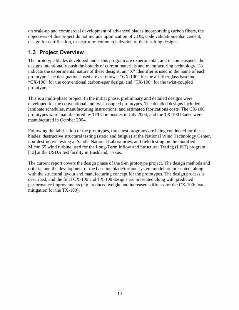
2.1 Turbine System The LIST turbine (modified Micon 65) at Bushland, Texas, has been chosen as the test bed for the field testing of the prototype blades. Therefore, the LIST turbine, shown in Figure 1, was used as the baseline system for ADAMS modeling and loads development.
Figure 1. Modified Micon 65 Turbine (Shown with SERI-8 Blades)
A two-step approach was taken to develop the baseline turbine system model. The first was to model the LIST turbine with the existing SERI-8 blades. For this configuration, field measurements of turbine system performance and loads were available to verify the ADAMS modeling results and calibrate/tune the model as necessary. However, because the SERI-8 blades are not the intended baseline for the 9-m prototype development project, the LIST turbine system was then modeled in hypothetical operation with the GX-100 blades. The objectives of the baseline turbine modeling were to:
• develop and validate a LIST turbine system model that will be used (with blade substitutions) throughout the project,
12
• predict the incremental change in turbine system loads if the existing SERI-8 blades were replaced by the GX-100 blades, and
• develop a data set that will be used for comparing the predicted loads and power performance of carbon-fiberglass hybrid prototypes against the all-fiberglass (GX-100) baseline.
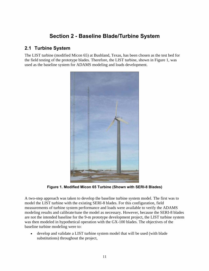
Loads comparisons for the twist-coupled blades are complicated somewhat by the fixed-speed, fixed-pitch (FSFP) architecture of the LIST turbine. This issue will be discussed further in the section covering the TX-100 preliminary design. The GX-100 blades were developed iteratively. The external mold shape was based on the ERS-100 blade which was developed by TPI under Sandia subcontract [14]. The GX-100 skins were assumed to be the same as the ERS-100, but the spar cap was modified to achieve near-zero design margins for 20-year life at IEC Class II-B. Because the ERS-100 was designed to a more rigorous condition (30-year life at IEC Class I-A), the GX-100 spar cap has been substantially reduced relative to the ERS-100. Note that there is no current plan to fabricate or test a GX-100 blade. Rather, this hypothetical design was developed so that analytical comparisons with the CX-100 and TX-100 blades could be made. Design margins and blade mass for the GX-100 blade will be presented in the following sections. Table 1 shows a comparison of some key system loads modeled for the LIST turbine with the existing SERI-8 and the GX-100 blades. The peak loads show reductions on the order of 10%. Equivalent fatigue loads are substantially increased, which indicates that the LIST turbine is suitable for testing of a GX-100 blade, but would be questionable for long-term operation. Loads modeled for the CX-100 and TX-100 designs will be compared with those for the GX-100 to establish suitability of the LIST turbine for testing of the carbon-hybrid prototypes.
Table 1. Selected Loads for Baseline LIST Turbine (Load Cases per IEC Class II-B)
Load Units Type SERI-8 GX-100 Load Peak 99.0 88.1 -10.9%
Root Flap Bending kN-m Fatigue 14.4 16.4 13.7% Peak 70.4 64.7 -8.0%
Shaft Thrust kN Fatigue 1.4 2.2 61.6% Peak 40.5 37.5 -7.6%
Yaw Bearing kN-m Fatigue 4.9 7.9 60.4% Peak 1650.0 1510.0 -8.5%
Tower Base (fore-aft) kN-m Fatigue 54.5 88.0 61.5%
13
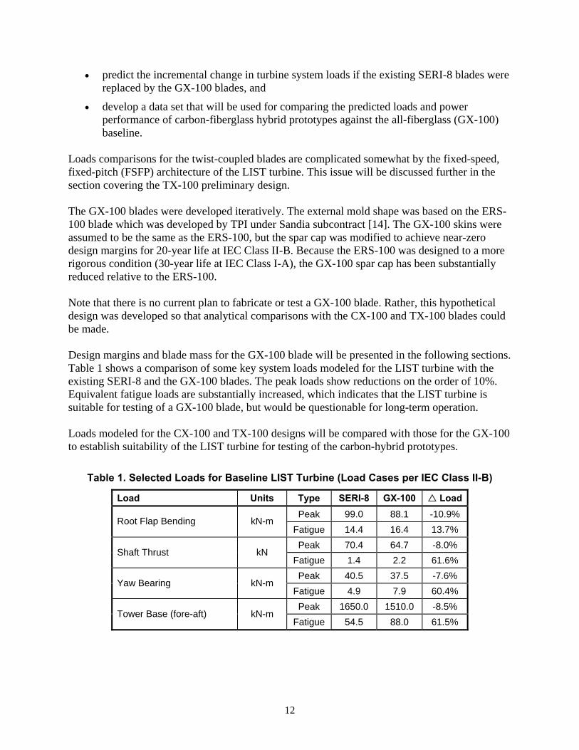
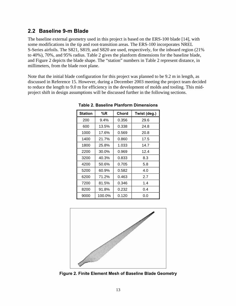
2.2 Baseline 9-m Blade The baseline external geometry used in this project is based on the ERS-100 blade [14], with some modifications in the tip and root-transition areas. The ERS-100 incorporates NREL S-Series airfoils. The S821, S819, and S820 are used, respectively, for the inboard region (21% to 40%), 70%, and 95% radius. Table 2 gives the planform dimensions for the baseline blade, and Figure 2 depicts the blade shape. The “station” numbers in Table 2 represent distance, in millimeters, from the blade root plane. Note that the initial blade configuration for this project was planned to be 9.2 m in length, as discussed in Reference 15. However, during a December 2003 meeting the project team decided to reduce the length to 9.0 m for efficiency in the development of molds and tooling. This mid-project shift in design assumptions will be discussed further in the following sections.
Table 2. Baseline Planform Dimensions
Station %R Chord Twist (deg.) 200 9.4% 0.356 29.6 600 13.5% 0.338 24.8
1000 17.6% 0.569 20.8 1400 21.7% 0.860 17.5 1800 25.8% 1.033 14.7 2200 30.0% 0.969 12.4 3200 40.3% 0.833 8.3 4200 50.6% 0.705 5.8 5200 60.9% 0.582 4.0 6200 71.2% 0.463 2.7 7200 81.5% 0.346 1.4 8200 91.8% 0.232 0.4 9000 100.0% 0.120 0.0
Figure 2. Finite Element Mesh of Baseline Blade Geometry
14
Section 3 - Design Approach
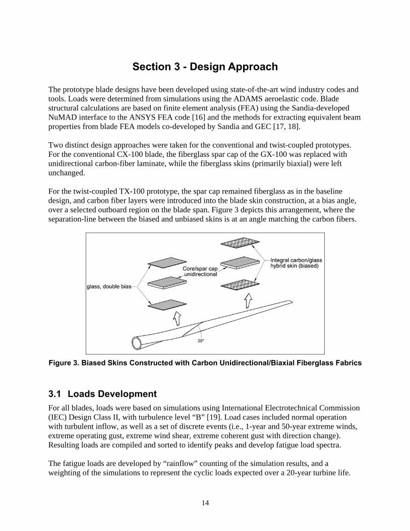
The prototype blade designs have been developed using state-of-the-art wind industry codes and tools. Loads were determined from simulations using the ADAMS aeroelastic code. Blade structural calculations are based on finite element analysis (FEA) using the Sandia-developed NuMAD interface to the ANSYS FEA code [16] and the methods for extracting equivalent beam properties from blade FEA models co-developed by Sandia and GEC [17, 18]. Two distinct design approaches were taken for the conventional and twist-coupled prototypes. For the conventional CX-100 blade, the fiberglass spar cap of the GX-100 was replaced with unidirectional carbon-fiber laminate, while the fiberglass skins (primarily biaxial) were left unchanged. For the twist-coupled TX-100 prototype, the spar cap remained fiberglass as in the baseline design, and carbon fiber layers were introduced into the blade skin construction, at a bias angle, over a selected outboard region on the blade span. Figure 3 depicts this arrangement, where the separation-line between the biased and unbiased skins is at an angle matching the carbon fibers.
Figure 3. Biased Skins Constructed with Carbon Unidirectional/Biaxial Fiberglass Fabrics
3.1 Loads Development For all blades, loads were based on simulations using International Electrotechnical Commission (IEC) Design Class II, with turbulence level “B” [19]. Load cases included normal operation with turbulent inflow, as well as a set of discrete events (i.e., 1-year and 50-year extreme winds, extreme operating gust, extreme wind shear, extreme coherent gust with direction change). Resulting loads are compiled and sorted to identify peaks and develop fatigue load spectra. The fatigue loads are developed by “rainflow” counting of the simulation results, and a weighting of the simulations to represent the cyclic loads expected over a 20-year turbine life.
15
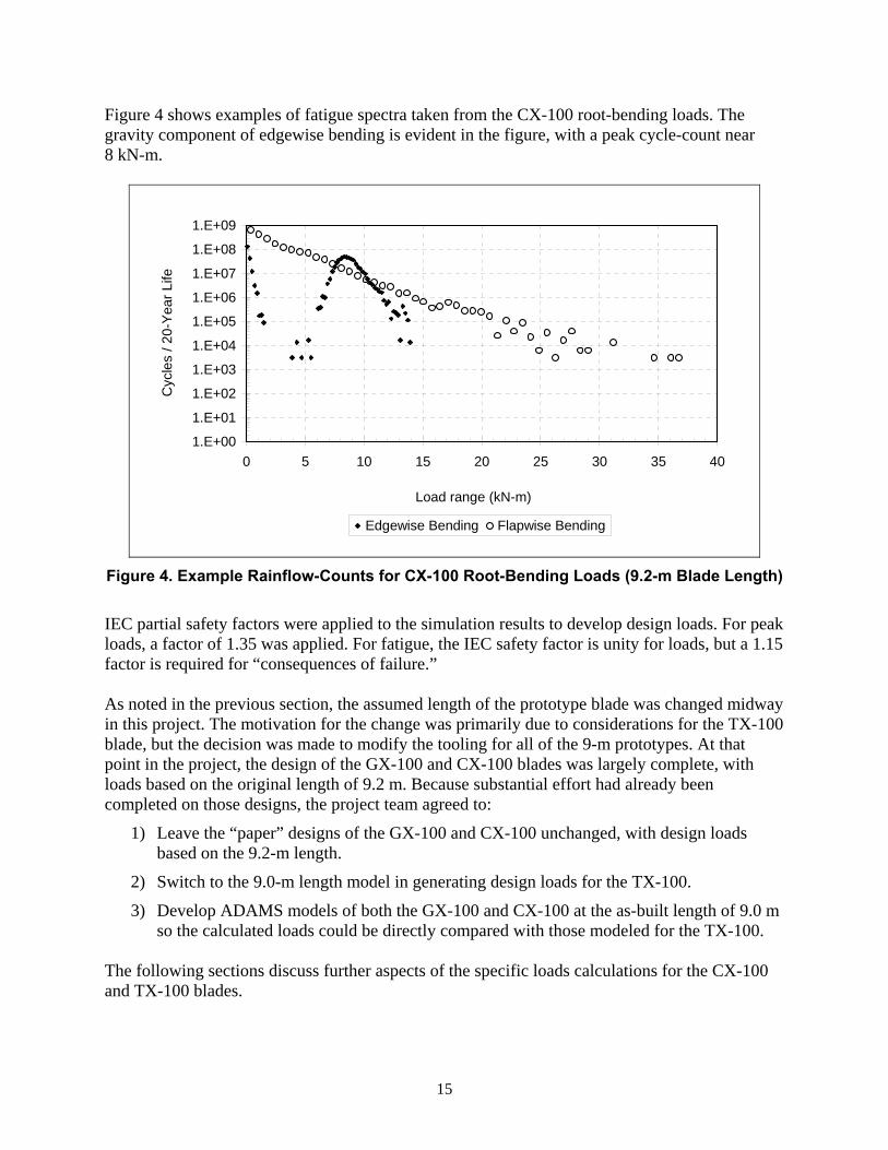
Figure 4 shows examples of fatigue spectra taken from the CX-100 root-bending loads. The gravity component of edgewise bending is evident in the figure, with a peak cycle-count near 8 kN-m.
1.E+00
1.E+01
1.E+02
1.E+03
1.E+04
1.E+05
1.E+06
1.E+07
1.E+08
1.E+09
0 5 10 15 20 25 30 35 40
Load range (kN-m)
Cyc
les
/ 20-
Yea
r Life
Edgewise Bending Flapwise Bending
Figure 4. Example Rainflow-Counts for CX-100 Root-Bending Loads (9.2-m Blade Length)
IEC partial safety factors were applied to the simulation results to develop design loads. For peak loads, a factor of 1.35 was applied. For fatigue, the IEC safety factor is unity for loads, but a 1.15 factor is required for “consequences of failure.” As noted in the previous section, the assumed length of the prototype blade was changed midway in this project. The motivation for the change was primarily due to considerations for the TX-100 blade, but the decision was made to modify the tooling for all of the 9-m prototypes. At that point in the project, the design of the GX-100 and CX-100 blades was largely complete, with loads based on the original length of 9.2 m. Because substantial effort had already been completed on those designs, the project team agreed to:
1) Leave the “paper” designs of the GX-100 and CX-100 unchanged, with design loads based on the 9.2-m length.
2) Switch to the 9.0-m length model in generating design loads for the TX-100.
3) Develop ADAMS models of both the GX-100 and CX-100 at the as-built length of 9.0 m so the calculated loads could be directly compared with those modeled for the TX-100.
The following sections discuss further aspects of the specific loads calculations for the CX-100 and TX-100 blades.
16
3.1.1 CX-100 The design loads for the both the GX-100 and CX-100 blades were developed by a straightforward application of the IEC Class II-B load cases. As a result of the fixed-pitch architecture of the LIST turbine, the governing load case for the CX-100 blade was the 50-year extreme wind. Note that the calculated loads for the GX-100 and CX-100 blade were nearly identical, and so are not further distinguished from each other in the following discussions (Table 3).
3.1.2 TX-100 The initial iterations of the TX-100 blade also used the same loads as the CX-100. However, it was determined that these design loads were constraining the extent of aeroelastic twist-response during normal operation. This issue is illustrated in Table 3, which lists the peak root flap bending (RFB) and out-of-plane tip displacements that result from various IEC load cases for the baseline GX-100/CX-100 blades at 9.2-m length. The load cases resulting in the nine highest RFB loads are shown, in descending order. The absolute highest RFB load and tip displacement results from the 50-year extreme wind model which assumes a parked turbine in un-faulted condition (0° tip pitch for the LIST turbine).
Table 3. Representative Ranking of Peak Load Cases for (9.2-m) GX-100/CX-100 Blades
Root Flap Bending Out-of Plane Tip Displacement
Load Case Moment (kN-m)
% of 50-year Extreme
Deflection (m)
% of 50-year Extreme
50-year extreme wind, 0° pitch 88.1 100.0 0.81 100.0 50-year extreme wind, 90° pitch 44.6 50.6 Negligible N/A Normal turbulence at 24 m/s mean 53.8 61.0 0.55 67.9 Extreme operating gust, 50-year 48.2 54.7 0.49 60.5 Extreme direction change, 50-year 46.8 53.1 0.51 63.0 Extreme gust with direction change 44.7 50.7 0.52 64.2 Normal turbulence at 20 m/s mean 43.8 49.7 0.45 55.6 Extreme operating gust, 1-year 42.4 48.1 0.44 54.3 Extreme direction change, 1-year 41.2 46.7 0.44 54.3 Normal turbulence at 16 m/s mean 36.0 40.8 0.37 45.7
Also shown, in italics, is a hypothetical load case that assumes the turbine has full-span pitch control. For such a case, the 50-year extreme wind load would assume that the turbine is parked with blades fully feathered to 90°. Table 3 indicates that the difference between RFB loads for the 50-year extreme wind at 0° and 90° is nearly 50%. This differential is particularly high for the aerodynamic design of this turbine blade, as the use of low maximum lift (CL,Max) airfoils results in a large difference between the drag-dominated 0° pitch and lift-dominated 90° pitch cases. Table 3 quantifies the extent to which the bending loads under normal turbulence are small relative to the peak 50-year bending. At a mean wind speed of 24 m/s, the maximum RFB load
17
due to turbulent inflow is only 61% of the 50-year (0° pitch) load, and at a mean wind speed of 16 m/s, the turbulent peaks are slightly more than 40% of the overall peak. If the TX-100 blade is structurally designed (e.g., maximum allowable material strain) per the peak 50-year bending, then the material strain and twist-response seen in the blade during normal turbulent operation is greatly constrained. Considering this issue, the project team decided to modify the design criteria for the TX-100, such that the 50-year extreme wind model at 0° pitch need not be considered. From the trends illustrated in Table 3, this would mean that the peak bending loads would result from the normal turbulence model at the near cut-out wind speed of 24 m/s. In turn, this would mean that the peak bending load experienced during normal turbulence would be 100% of the overall peak, which would allow for the maximum possible twist-coupling response. Reviewing the data of Table 3, it is seen that this relaxed design criterion allows the blade to be designed as if the 50-year extreme wind load case is at a pitch of 90°. Therefore, the design criteria applied to the TX-100 are consistent with a full-span, pitch control configuration that has become standard for modern, utility-scale wind turbines.
3.2 Material Properties For conventional fiberglass materials, the mechanical properties assumed are consistent with those used in the original ERS-100 design. Micromechanics calculations were used to calculate stiffness properties for the unidirectional carbon-fiber material. For fiberglass strength, the values assumed in Reference 5 were used. Initial strength estimates for carbon materials were developed based on results from the DOE/MSU database program [20]. Safety factors for materials were selected by GEC based on the Germanischer Lloyd (GL) list of default factors for each material type and manufacturing process [21]. Table 4 lists the lamina mechanical properties used in the design calculations. Classical laminate theory (CLT) was used to parametrically evaluate the properties for various laminate constructions that included biased carbon fibers. FEA models used multi-layer composite shell elements with the data from Table 4 input directly. The mechanical properties listed in the table assume fiber volume fractions of υf = 0.5. The 0.63 mm thickness shown for unidirectional carbon assumes a fabric areal weight of 500 grams per square meter (gsm). However, a range of carbon fabric areal weights was used in the blade models with the thickness varied as appropriate. Material selection was done with the assumption that a vacuum-assisted resin transfer method (VARTM) process would be used for manufacturing. Specifically, the designs assumed that the fabrication would use TPI’s proprietary VARTM process, SCRIMPTM. Several candidate resin systems and carbon-fabric styles were evaluated at TPI for possible use in these prototypes. The goal was to identify systems that combined good infusibility while minimizing waviness and other irregularities in the alignment of the carbon fibers.
18
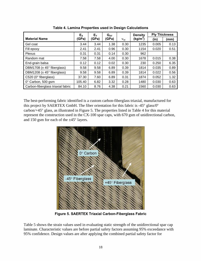
Table 4. Lamina Properties used in Design Calculations
Ply Thickness Material Name
EX (GPa)
EY (GPa)
GXY (GPa) νxy
Density (kg/m3) (in) (mm)
Gel coat 3.44 3.44 1.38 0.30 1235 0.005 0.13Fill epoxy 2.41 2.41 0.96 0.30 1154 0.020 0.51Plexus 0.31 0.31 0.14 0.30 962 Random mat 7.58 7.58 4.00 0.30 1678 0.015 0.38End-grain balsa 0.12 0.12 0.02 0.30 230 0.250 6.35DBM1708 (± 45° fiberglass) 9.58 9.58 6.89 0.39 1814 0.035 0.89DBM1208 (± 45° fiberglass) 9.58 9.58 6.89 0.39 1814 0.022 0.56C520 (0° fiberglass) 37.30 7.60 6.89 0.31 1874 0.052 1.320° Carbon, 500 gsm 105.40 6.82 3.32 0.28 1480 0.030 0.63Carbon-fiberglass triaxial fabric 84.10 8.76 4.38 0.21 1560 0.030 0.63
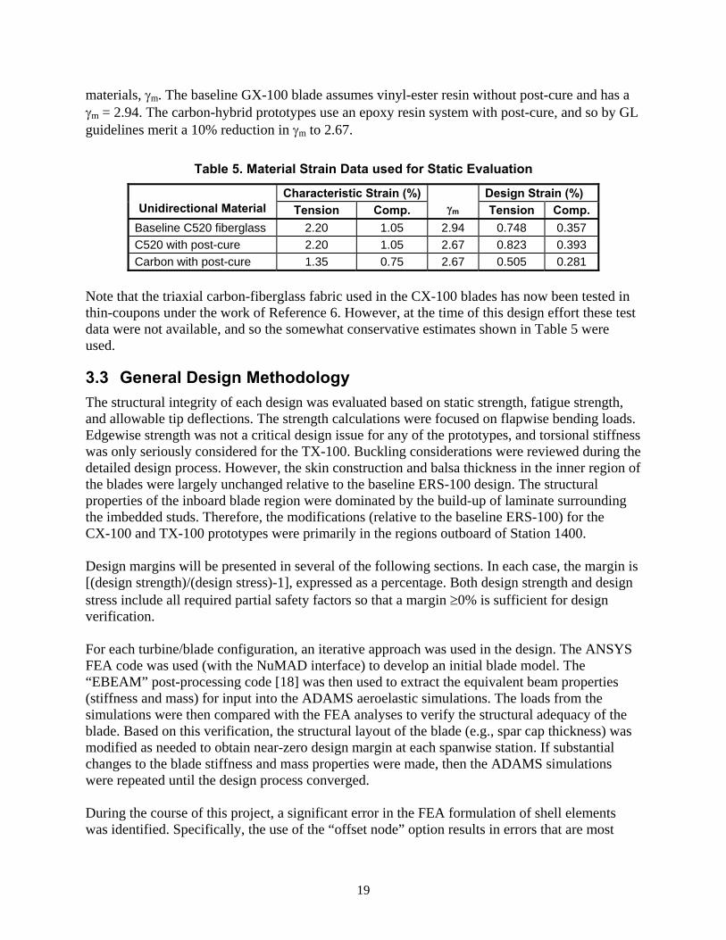
The best-performing fabric identified is a custom carbon-fiberglass triaxial, manufactured for this project by SAERTEX GmbH. The fiber orientation for this fabric is -45° glass/0° carbon/+45° glass, as illustrated in Figure 5. The properties listed in Table 4 for this material represent the construction used in the CX-100 spar caps, with 670 gsm of unidirectional carbon, and 150 gsm for each of the ±45° layers.
Figure 5. SAERTEX Triaxial Carbon-Fiberglass Fabric
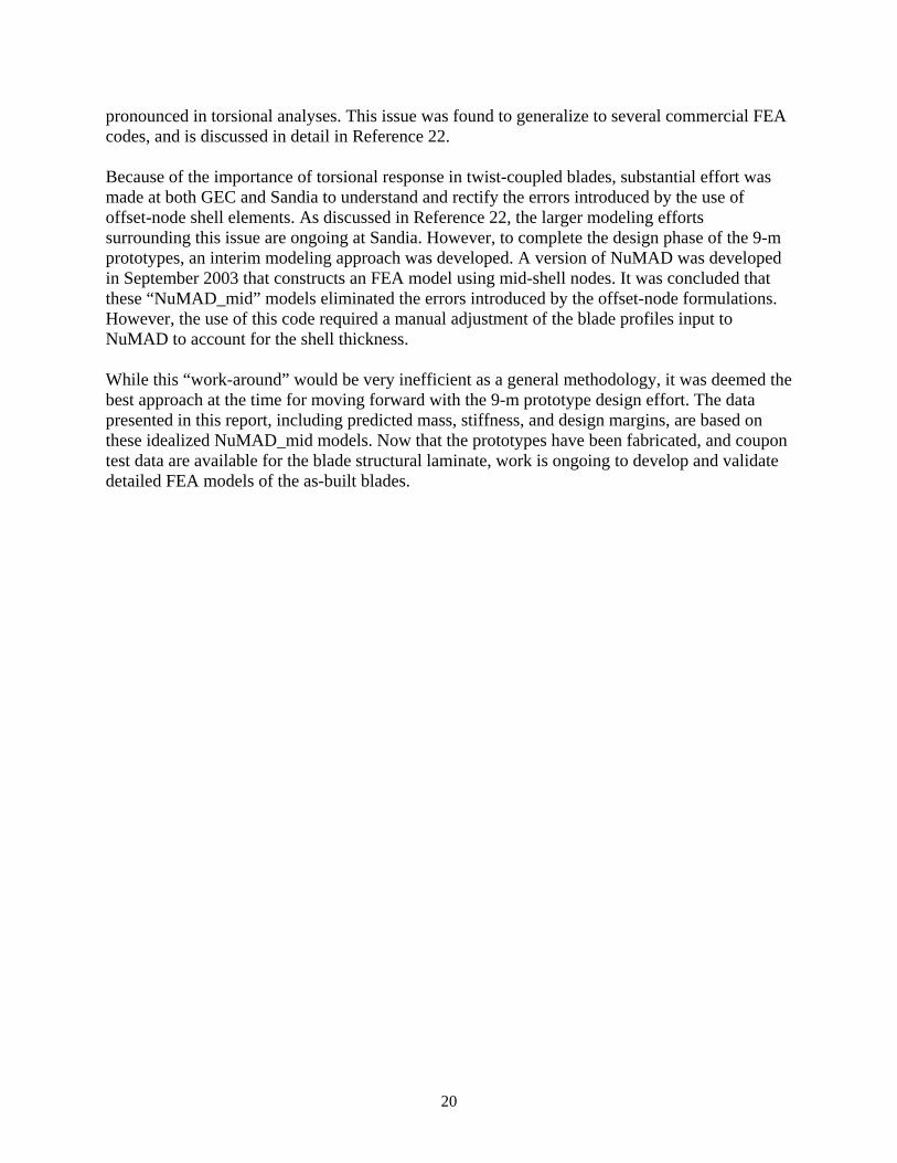
Table 5 shows the strain values used in evaluating static strength of the unidirectional spar cap laminate. Characteristic values are before partial safety factors assuming 95% exceedance with 95% confidence. Design values are after applying the combined partial safety factor for
19
materials, γm. The baseline GX-100 blade assumes vinyl-ester resin without post-cure and has a γm = 2.94. The carbon-hybrid prototypes use an epoxy resin system with post-cure, and so by GL guidelines merit a 10% reduction in γm to 2.67.
Table 5. Material Strain Data used for Static Evaluation
Characteristic Strain (%) Design Strain (%) Unidirectional Material Tension Comp. γm Tension Comp.
Baseline C520 fiberglass 2.20 1.05 2.94 0.748 0.357 C520 with post-cure 2.20 1.05 2.67 0.823 0.393 Carbon with post-cure 1.35 0.75 2.67 0.505 0.281
Note that the triaxial carbon-fiberglass fabric used in the CX-100 blades has now been tested in thin-coupons under the work of Reference 6. However, at the time of this design effort these test data were not available, and so the somewhat conservative estimates shown in Table 5 were used.
3.3 General Design Methodology The structural integrity of each design was evaluated based on static strength, fatigue strength, and allowable tip deflections. The strength calculations were focused on flapwise bending loads. Edgewise strength was not a critical design issue for any of the prototypes, and torsional stiffness was only seriously considered for the TX-100. Buckling considerations were reviewed during the detailed design process. However, the skin construction and balsa thickness in the inner region of the blades were largely unchanged relative to the baseline ERS-100 design. The structural properties of the inboard blade region were dominated by the build-up of laminate surrounding the imbedded studs. Therefore, the modifications (relative to the baseline ERS-100) for the CX-100 and TX-100 prototypes were primarily in the regions outboard of Station 1400. Design margins will be presented in several of the following sections. In each case, the margin is [(design strength)/(design stress)-1], expressed as a percentage. Both design strength and design stress include all required partial safety factors so that a margin ≥0% is sufficient for design verification. For each turbine/blade configuration, an iterative approach was used in the design. The ANSYS FEA code was used (with the NuMAD interface) to develop an initial blade model. The “EBEAM” post-processing code [18] was then used to extract the equivalent beam properties (stiffness and mass) for input into the ADAMS aeroelastic simulations. The loads from the simulations were then compared with the FEA analyses to verify the structural adequacy of the blade. Based on this verification, the structural layout of the blade (e.g., spar cap thickness) was modified as needed to obtain near-zero design margin at each spanwise station. If substantial changes to the blade stiffness and mass properties were made, then the ADAMS simulations were repeated until the design process converged. During the course of this project, a significant error in the FEA formulation of shell elements was identified. Specifically, the use of the “offset node” option results in errors that are most
20
pronounced in torsional analyses. This issue was found to generalize to several commercial FEA codes, and is discussed in detail in Reference 22. Because of the importance of torsional response in twist-coupled blades, substantial effort was made at both GEC and Sandia to understand and rectify the errors introduced by the use of offset-node shell elements. As discussed in Reference 22, the larger modeling efforts surrounding this issue are ongoing at Sandia. However, to complete the design phase of the 9-m prototypes, an interim modeling approach was developed. A version of NuMAD was developed in September 2003 that constructs an FEA model using mid-shell nodes. It was concluded that these “NuMAD_mid” models eliminated the errors introduced by the offset-node formulations. However, the use of this code required a manual adjustment of the blade profiles input to NuMAD to account for the shell thickness. While this “work-around” would be very inefficient as a general methodology, it was deemed the best approach at the time for moving forward with the 9-m prototype design effort. The data presented in this report, including predicted mass, stiffness, and design margins, are based on these idealized NuMAD_mid models. Now that the prototypes have been fabricated, and coupon test data are available for the blade structural laminate, work is ongoing to develop and validate detailed FEA models of the as-built blades.
21
Section 4 - CX-100 Design
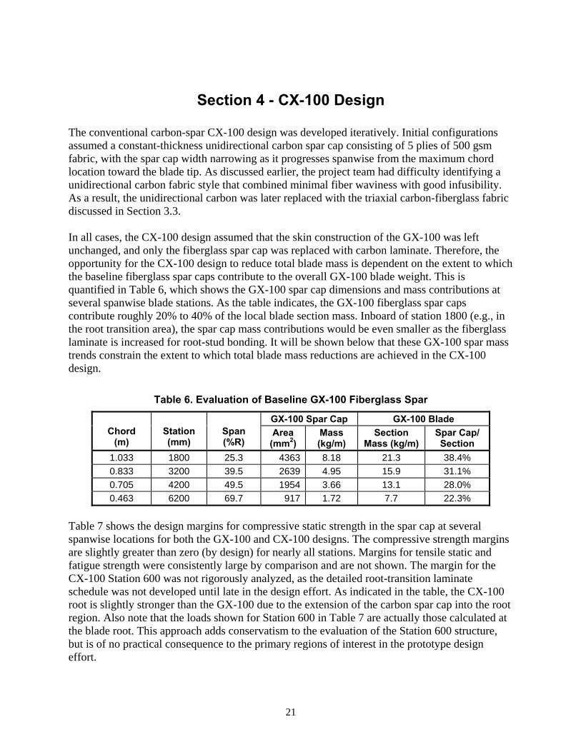
The conventional carbon-spar CX-100 design was developed iteratively. Initial configurations assumed a constant-thickness unidirectional carbon spar cap consisting of 5 plies of 500 gsm fabric, with the spar cap width narrowing as it progresses spanwise from the maximum chord location toward the blade tip. As discussed earlier, the project team had difficulty identifying a unidirectional carbon fabric style that combined minimal fiber waviness with good infusibility. As a result, the unidirectional carbon was later replaced with the triaxial carbon-fiberglass fabric discussed in Section 3.3. In all cases, the CX-100 design assumed that the skin construction of the GX-100 was left unchanged, and only the fiberglass spar cap was replaced with carbon laminate. Therefore, the opportunity for the CX-100 design to reduce total blade mass is dependent on the extent to which the baseline fiberglass spar caps contribute to the overall GX-100 blade weight. This is quantified in Table 6, which shows the GX-100 spar cap dimensions and mass contributions at several spanwise blade stations. As the table indicates, the GX-100 fiberglass spar caps contribute roughly 20% to 40% of the local blade section mass. Inboard of station 1800 (e.g., in the root transition area), the spar cap mass contributions would be even smaller as the fiberglass laminate is increased for root-stud bonding. It will be shown below that these GX-100 spar mass trends constrain the extent to which total blade mass reductions are achieved in the CX-100 design.
Table 6. Evaluation of Baseline GX-100 Fiberglass Spar
GX-100 Spar Cap GX-100 Blade Chord
(m) Station (mm)
Span (%R)
Area (mm2)
Mass (kg/m)
Section Mass (kg/m)
Spar Cap/ Section
1.033 1800 25.3 4363 8.18 21.3 38.4% 0.833 3200 39.5 2639 4.95 15.9 31.1% 0.705 4200 49.5 1954 3.66 13.1 28.0% 0.463 6200 69.7 917 1.72 7.7 22.3%
Table 7 shows the design margins for compressive static strength in the spar cap at several spanwise locations for both the GX-100 and CX-100 designs. The compressive strength margins are slightly greater than zero (by design) for nearly all stations. Margins for tensile static and fatigue strength were consistently large by comparison and are not shown. The margin for the CX-100 Station 600 was not rigorously analyzed, as the detailed root-transition laminate schedule was not developed until late in the design effort. As indicated in the table, the CX-100 root is slightly stronger than the GX-100 due to the extension of the carbon spar cap into the root region. Also note that the loads shown for Station 600 in Table 7 are actually those calculated at the blade root. This approach adds conservatism to the evaluation of the Station 600 structure, but is of no practical consequence to the primary regions of interest in the prototype design effort.
22
Table 7. Static (Compressive) Strength Margins
Strength Margin (%) Station (mm)
Span* (%R)
Design Moment(kN-m) GX-100 CX-100
600 13.2 88.1 4.8% 4.8%** 1800 25.3 49.0 5.0% 0.9% 3200 39.5 27.0 5.9% 11.8% 4200 49.5 16.9 0.9% 9.0% 6200 69.7 4.6 6.5% 7.7%
* Based on 9.2-m blade length ** Actual margin slightly higher due to continuation of carbon spar into root buildup
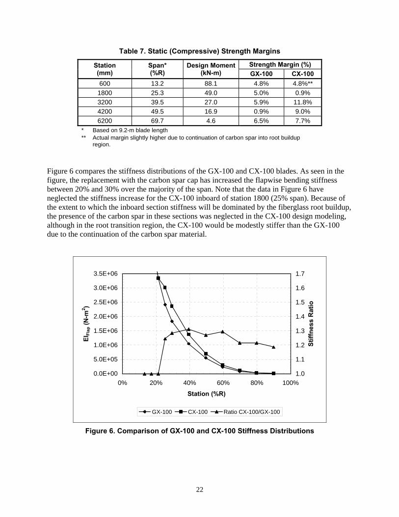
region. Figure 6 compares the stiffness distributions of the GX-100 and CX-100 blades. As seen in the figure, the replacement with the carbon spar cap has increased the flapwise bending stiffness between 20% and 30% over the majority of the span. Note that the data in Figure 6 have neglected the stiffness increase for the CX-100 inboard of station 1800 (25% span). Because of the extent to which the inboard section stiffness will be dominated by the fiberglass root buildup, the presence of the carbon spar in these sections was neglected in the CX-100 design modeling, although in the root transition region, the CX-100 would be modestly stiffer than the GX-100 due to the continuation of the carbon spar material.
0.0E+00
5.0E+05
1.0E+06
1.5E+06
2.0E+06
2.5E+06
3.0E+06
3.5E+06
0% 20% 40% 60% 80% 100%
Station (%R)
EIFl
ap (N
-m2 )
1.0
1.1
1.2
1.3
1.4
1.5
1.6
1.7
Stiff
ness
Rat
io
GX-100 CX-100 Ratio CX-100/GX-100
Figure 6. Comparison of GX-100 and CX-100 Stiffness Distributions
23
A summary of the CX-100 spar design is given in Table 8. As seen in the table, the reductions in spar cap mass (relative to the GX-100) are about 50%. However, the corresponding reductions in the local blade mass/length are only between 10% and 20%. This mitigation of the sectional blade mass reductions results from the baseline GX-100 spar mass trends as presented in Table 6.
Table 8. CX-100 Spar Cap Summary
CX-100 Spar Cap with Carbon-Glass Triax Station (mm)
Span (%R)
Area (mm2)
Mass (kg/m)
Δ Area (from GX-100)
Δ Mass (from GX-100)
Δ Section Mass
1800 25.3 2432 3.79 -44.3% -53.6% -19.7%3200 39.5 1634 2.55 -38.1% -48.4% -15.1%4200 49.5 1199 1.87 -38.7% -48.9% -15.3%6200 69.7 545 0.85 -40.5% -50.5% -11.3%
As expected, the inclusion of the fiberglass-dominated root region further constrains the reduction in total blade mass. This is quantified in Table 9, where mass reductions for the composite portion of the blade (excluding root connection hardware) are 11.6%. When the root hardware is included, the mass reductions are only 10.8%.
Table 9. Blade Mass and Tip Deflection Results
Item GX-100 CX-100 Δ (%) Laminate Mass (kg) 142.2 125.7 -11.6 Total Mass with Studs (kg) 153.2 136.7 -10.8 Tip Deflection Margin (%) 43.2 113.8 70.6
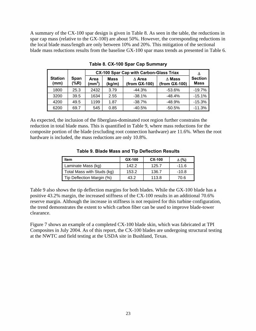
Table 9 also shows the tip deflection margins for both blades. While the GX-100 blade has a positive 43.2% margin, the increased stiffness of the CX-100 results in an additional 70.6% reserve margin. Although the increase in stiffness is not required for this turbine configuration, the trend demonstrates the extent to which carbon fiber can be used to improve blade-tower clearance. Figure 7 shows an example of a completed CX-100 blade skin, which was fabricated at TPI Composites in July 2004. As of this report, the CX-100 blades are undergoing structural testing at the NWTC and field testing at the USDA site in Bushland, Texas.
24
Figure 7. Fabricated CX-100 Skins at TPI Composites
25
Section 5 - TX-100 Design
Within the overall structural concept selected for this project, the design variables that can be varied to affect the TX-100 twist-coupling are:
• bias angle of off-axis carbon skin plies,
• spanwise introduction location for biased skins,
• thickness of carbon skin plies,
• remaining components of skin construction (i.e., extent of biaxial fiberglass content, core, non-structural layers),
• design of the fiberglass spar, and
• criteria used for design (i.e., required load cases, assumptions on material strength, safety factors).
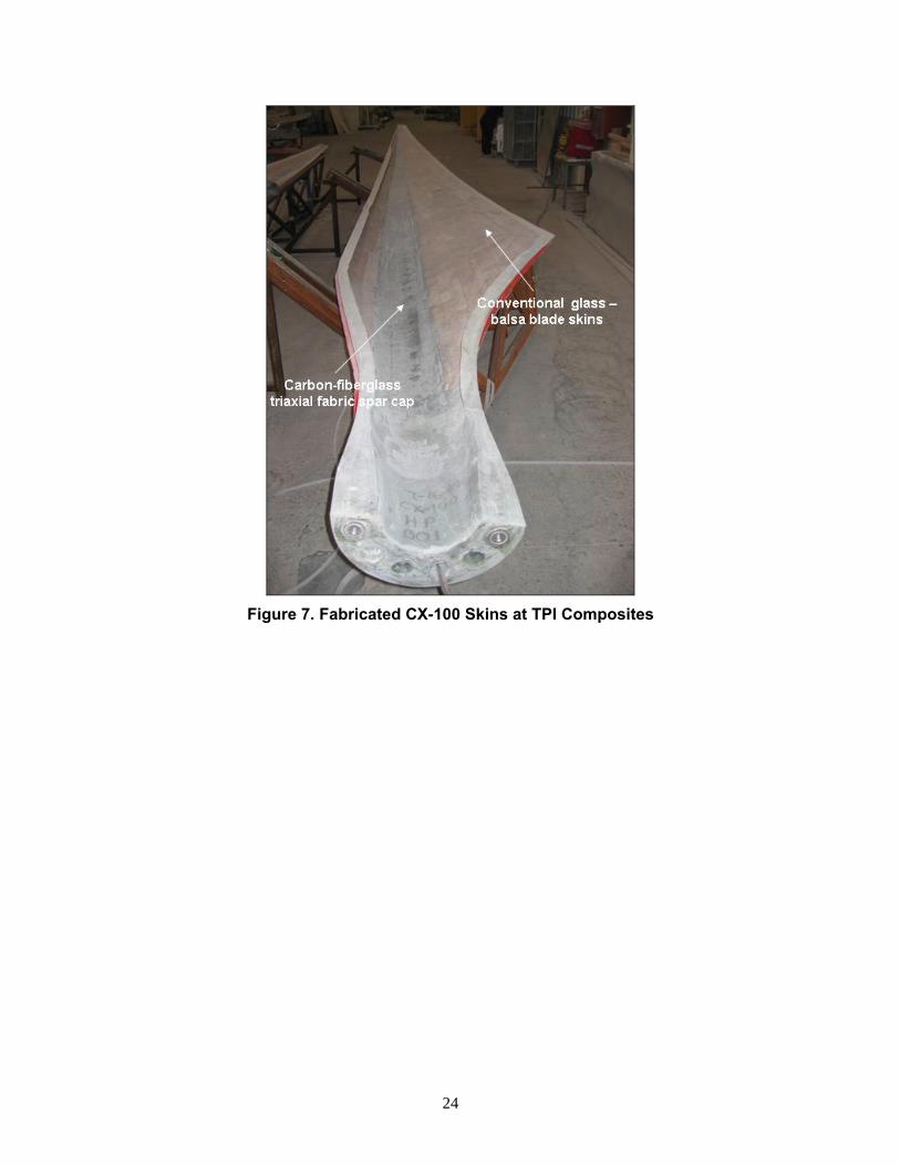
Figure 8 provides a schematic of the skin layout, and indicates two of the parameters considered in the design (bias angle and spanwise introduction location). All of these design variables are inter-related, and extensive parametric studies were performed during this project to evaluate trade-offs between them.
Bias Angle
SpanwiseIntroduction
Location
PitchAxis
Figure 8. Schematic Layout for Design of Twist-Coupled Blade Skins
5.1 Load Cases (Operational Bending Moments) During turbine operation, the flap bending moment at any blade station, MB, is composed of two components: a mean bending moment, BM , due to the quasi-steady inflow, and an additional bending contribution, MB,Turb, resulting from turbulent fluctuations. The twist induced by BM is generally not beneficial and may lead to some loss in power performance if not compensated for by re-pitching of the blade or an adjustment to the twist schedule of the undeformed blade. Load mitigation during normal operation with turbulent inflow results only from the fluctuating bending loads, ΔMB = MB,Turb - BM .
26
For the case of a variable-pitch turbine, some load mitigation will be also be realized for the 50-year extreme wind event (parked with blades at full feather) as that load case is lift-dominated and pitch-to-feather twist-coupling will be effective. A fixed-pitch, stall-regulated design will not see this benefit as the 50-year extreme wind load case (parked with blade tip chord nominally perpendicular to the wind) is drag-dominated and the relief from twist-coupling will be negligible. Understanding the relationship between operational bending moments, peak bending moments, and governing design criteria is critical to the design of twist-coupled blades. First, in the case where the peak bending moment governs the design of a blade section, then that peak load will result in the maximum amount of strain allowable for the material in question, and for twist-coupled blades, a corresponding maximum amount of torsional distortion. For example, if a peak operational bending load (i.e., load under turbulent inflow) is 80% of the peak load from all load cases, and the blade section design is governed by static strength considerations, then it can be immediately inferred that at the critical-fiber location, the blade section sees up to 80% of its design strain value under normal turbulent loading. For such a design, the extent to which a blade will be in an effective operational range of twist-coupling can be estimated by two ratios: the ratio of mean bending load at wind speed to turbulent peak loads at the same average speed, and the ratio of the peak turbulent bending loads to the peak from all load cases (governing load). The latter ratio tells you the maximum fraction of the design strain that the blade section sees in turbulent operation, and the former indicates the range of strains experienced in the load-mitigating response, which is directly proportional to the range of torsional distortion (twist) realized. The estimation is less direct in the case where a blade section is governed by other than static strength. In this case, the strain experienced at peak bending load is less than the design value. For example, if a blade section is stiffness governed and has a 30% reserve margin in static strength, then the blade will see only 77% of its design strain under peak bending load. If, as in the previous example, the peak operational load is 80% of the overall peak load, then the maximum strain is 61% of the design strain, and the strain range under turbulent operation (peak turbulent – mean) is a smaller fraction yet. The bottom line is that maximum twist-coupling is achieved when the bending load ratios of (peak turbulent)/(governing load) and (peak turbulent at wind speed)/(mean at wind speed) are both high, and the section structure is governed by static strength requirements. An understanding of these design drivers led to the decision to modify the TX-100 design criteria (elimination of the 50-year extreme wind model at 0°pitch), as discussed in Section 3.1.2. Given that the TX-100 blade is a experimental prototype, the modified criteria are not considered to be overly risky. Laboratory tests will be used to compare predicted with measured structural properties irrespective of the load cases considered in developing the design. Field testing of the TX-100 blades on the LIST turbine will include additional monitoring and safety procedures to ensure that the blades are not operated beyond their design limits.
27
5.2 Skin Construction Once the issue of design loads was understood and resolved, the majority of the remaining TX-100 design work focused on the topic of skin construction. This comprises the bias angle and thickness of the off-axis carbon skin plies, as well as all the other constituents of the skin. Several candidate skin constructions were considered. Objectives for the skin construction include achieving maximum twist-coupling response, structural integrity of skins under aerodynamic load, sufficient shell rigidity for blade handling, and high manufacturing feasibility. Numerous parametric trade-offs were performed during the course of this project. Among the general trends identified are:
• Excess static strength margin decreases twist-coupling response, particularly if the margin is the result of additional spar material, as opposed to biased skin.
• Reducing the biased-carbon thickness in the outer blade gives modest improvements in coupling response, but with substantially less carbon fiber used.
• 500 gsm (nominal) in biased carbon skins appears near-optimal if a single fabric weight is used for entire blade.
The construction that best met all of the project objectives was determined to be a triaxial carbon-fiberglass hybrid fabric, rotated so that the carbon fibers are at a 20° angle with respect to the blade longitudinal axis. The triaxial fabric selected is similar to that used for the CX-100 (-45° glass/0° carbon/+45° glass). However, the TX-100 fabric has 500 gsm of unidirectional carbon, and 150 gsm for each of the ±45° layers. The introduction of biased carbon into the TX-100 skins resulted in a significant stiffening of the blade shell. As a result, the TX-100 blade skins naturally carry a larger portion of the bending load than do the GX-100 skins. This effect, combined with the modified design criterion that reduces the peak design load, allowed for a substantial reduction of the fiberglass spar cap relative to the GX-100 spar. The spar cap in the final TX-100 design effectively ends by the 50% span location, and the bending loads in the outer blade are carried entirely by the biased skins. Although this design achieves good twist-coupling and load mitigation under turbulent loads, it is a substantial departure from the original assumption that a load-bearing unidirectional spar cap would extend the full length of the blade. Technical uncertainties and anticipated challenges for this design will be discussed in Section 5.4.
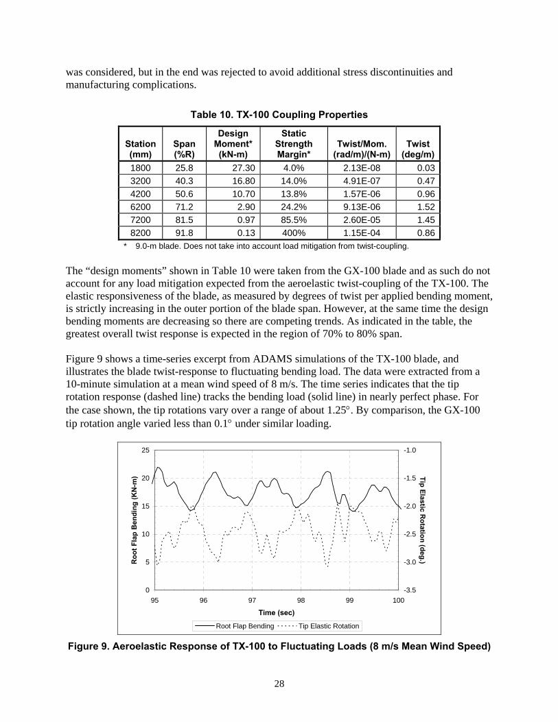
5.3 Final Design Summary The coupling properties for the TX-100 design are given in Table 10. In this final configuration, the introduction point of the biased skin material was moved inboard to station 1400, and the fiberglass spar cap has tapered completely out of the blade slightly outboard of station 4200. Note that all of the design loads and load reductions in the following sections are based on 9.0-m versions of the prototype blades. As seen in Table 10, the static strength design margins are slightly positive at the mid-span, and increase rapidly in the outer part of the blade. This is because the bending loads are carried entirely by stressed skins in the outer part of the blade, and a constant-thickness of carbon skin was used in the design. The option of varying the carbon skin thickness in the spanwise direction
28
was considered, but in the end was rejected to avoid additional stress discontinuities and manufacturing complications.
Table 10. TX-100 Coupling Properties
Station (mm)
Span (%R)
Design Moment*(kN-m)
Static Strength Margin*
Twist/Mom. (rad/m)/(N-m)
Twist (deg/m)
1800 25.8 27.30 4.0% 2.13E-08 0.03 3200 40.3 16.80 14.0% 4.91E-07 0.47 4200 50.6 10.70 13.8% 1.57E-06 0.96 6200 71.2 2.90 24.2% 9.13E-06 1.52 7200 81.5 0.97 85.5% 2.60E-05 1.45 8200 91.8 0.13 400% 1.15E-04 0.86
* 9.0-m blade. Does not take into account load mitigation from twist-coupling. The “design moments” shown in Table 10 were taken from the GX-100 blade and as such do not account for any load mitigation expected from the aeroelastic twist-coupling of the TX-100. The elastic responsiveness of the blade, as measured by degrees of twist per applied bending moment, is strictly increasing in the outer portion of the blade span. However, at the same time the design bending moments are decreasing so there are competing trends. As indicated in the table, the greatest overall twist response is expected in the region of 70% to 80% span. Figure 9 shows a time-series excerpt from ADAMS simulations of the TX-100 blade, and illustrates the blade twist-response to fluctuating bending load. The data were extracted from a 10-minute simulation at a mean wind speed of 8 m/s. The time series indicates that the tip rotation response (dashed line) tracks the bending load (solid line) in nearly perfect phase. For the case shown, the tip rotations vary over a range of about 1.25°. By comparison, the GX-100 tip rotation angle varied less than 0.1° under similar loading.
0
5
10
15
20
25
95 96 97 98 99 100
Time (sec)
Roo
t Fla
p B
endi
ng (K
N-m
)
-3.5
-3.0
-2.5
-2.0
-1.5
-1.0
Tip Elastic Rotation (deg.)
Root Flap Bending Tip Elastic Rotation Figure 9. Aeroelastic Response of TX-100 to Fluctuating Loads (8 m/s Mean Wind Speed)
29
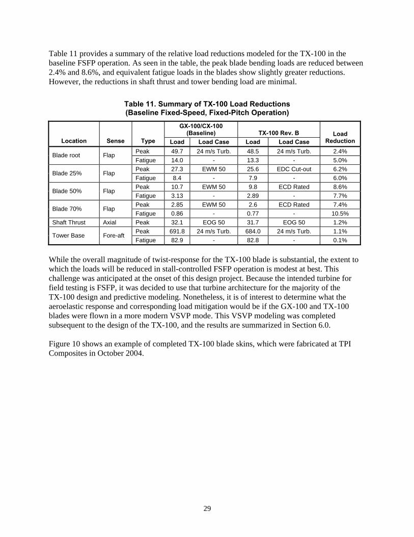
Table 11 provides a summary of the relative load reductions modeled for the TX-100 in the baseline FSFP operation. As seen in the table, the peak blade bending loads are reduced between 2.4% and 8.6%, and equivalent fatigue loads in the blades show slightly greater reductions. However, the reductions in shaft thrust and tower bending load are minimal.
Table 11. Summary of TX-100 Load Reductions (Baseline Fixed-Speed, Fixed-Pitch Operation)
GX-100/CX-100 (Baseline) TX-100 Rev. B
Location Sense Type Load Load Case Load Load Case Load
Reduction Peak 49.7 24 m/s Turb. 48.5 24 m/s Turb. 2.4% Blade root Flap Fatigue 14.0 - 13.3 - 5.0% Peak 27.3 EWM 50 25.6 EDC Cut-out 6.2%
Blade 25% Flap Fatigue 8.4 - 7.9 - 6.0% Peak 10.7 EWM 50 9.8 ECD Rated 8.6%
Blade 50% Flap Fatigue 3.13 - 2.89 - 7.7% Peak 2.85 EWM 50 2.6 ECD Rated 7.4%
Blade 70% Flap Fatigue 0.86 - 0.77 - 10.5%
Shaft Thrust Axial Peak 32.1 EOG 50 31.7 EOG 50 1.2% Peak 691.8 24 m/s Turb. 684.0 24 m/s Turb. 1.1%
Tower Base Fore-aft Fatigue 82.9 - 82.8 - 0.1%
While the overall magnitude of twist-response for the TX-100 blade is substantial, the extent to which the loads will be reduced in stall-controlled FSFP operation is modest at best. This challenge was anticipated at the onset of this design project. Because the intended turbine for field testing is FSFP, it was decided to use that turbine architecture for the majority of the TX-100 design and predictive modeling. Nonetheless, it is of interest to determine what the aeroelastic response and corresponding load mitigation would be if the GX-100 and TX-100 blades were flown in a more modern VSVP mode. This VSVP modeling was completed subsequent to the design of the TX-100, and the results are summarized in Section 6.0. Figure 10 shows an example of completed TX-100 blade skins, which were fabricated at TPI Composites in October 2004.
30
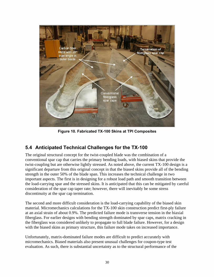
Figure 10. Fabricated TX-100 Skins at TPI Composites
5.4 Anticipated Technical Challenges for the TX-100 The original structural concept for the twist-coupled blade was the combination of a conventional spar cap that carries the primary bending loads, with biased skins that provide the twist-coupling but are otherwise lightly stressed. As noted above, the current TX-100 design is a significant departure from this original concept in that the biased skins provide all of the bending strength in the outer 50% of the blade span. This increases the technical challenge in two important aspects. The first is in designing for a robust load path and smooth transition between the load-carrying spar and the stressed skins. It is anticipated that this can be mitigated by careful consideration of the spar cap taper rate; however, there will inevitably be some stress discontinuity at the spar cap termination. The second and more difficult consideration is the load-carrying capability of the biased skin material. Micromechanics calculations for the TX-100 skin construction predict first-ply failure at an axial strain of about 0.9%. The predicted failure mode is transverse tension in the biaxial fiberglass. For earlier designs with bending strength dominated by spar caps, matrix cracking in the fiberglass was considered unlikely to propagate to full blade failure. However, for a design with the biased skins as primary structure, this failure mode takes on increased importance. Unfortunately, matrix-dominated failure modes are difficult to predict accurately with micromechanics. Biased materials also present unusual challenges for coupon-type test evaluation. As such, there is substantial uncertainty as to the structural performance of the
31
TX-100 blades. The structural testing is expected to provide significant insights into the linear-elastic response, static strength, and fatigue characteristics of this unusual blade/skin configuration. The design drivers for skin construction and load-carrying spars scale differently with blade size. Previous modeling of this basic design concept at the MW-scale resulted in designs with the skins carrying a much lower fraction of the total bending loads, and a largely conventional spar extending over the full blade span. From that standpoint, the current TX-100 design is considered “aggressive.” If the design proves to be structurally robust and provides the intended aeroelastic benefits, the project team is confident that the concept can be applied with minimal risk at larger scales.
32
Section 6 - TX-100 Modeled in VSVP operation
As noted above, following the completed design of the 9-m prototypes, they were modeled in a VSVP architecture. Specific objectives of the modeling are to:
• develop and validate a VSVP ADAMS model of the LIST turbine,
• compare key system design loads for the baseline GX-100 blade operating in VSVP mode to FSFP stall-controlled mode, and
• calculate key system design loads for the TX-100 and CX-100 blades operating in VSVP modes and compare these loads to the GX-100 VSVP loads.
6.1 Baseline GX-100 in VSVP Operation The development of the baseline FSFP turbine ADAMS model was discussed in Section 2.1. The models developed for the FSFP turbines were modified to incorporate variable speed and variable pitch to feather operation. The following summarizes these modifications:
• A tip speed ratio (TSR) of 8.5 was identified for optimum performance.
• A maximum tip speed of 75 m/s was selected to allow a reasonable range of variable-speed operation for this TSR.
• A minimum pitch angle was selected to optimize power output in low winds.
• Rotational joints were incorporated at the blade-to-hub connections to allow blade pitching motion.
• A pitch actuator model that converts pitch position demand to a pitching moment was implemented.
• The induction generator model was replaced with a variable-speed generator model.
• A control algorithm for the blade pitch demand was implemented using a custom subroutine linked to the ADAMS executable routine.
Power performance modeling indicated that the peak power coefficient (CP,max) occurred at a TSR of 8.5. The baseline (fixed) rotational speed of the LIST turbine is 55 rpm. In variable-speed operation (tracking the optimal TSR of 8.5), the rotor with 9-m blades would reach 55 rpm at a wind speed of only 6.6 m/s. In order to allow variable-speed operation over a larger range of wind speeds, a maximum tip speed of 75 m/s (equivalent to 74 rpm) was chosen. This allows variable-speed operation up to 8.9 m/s. Although this increase in maximum tip speed makes the VSVP modeling more representative of modern turbine designs, it adds some complications when comparing loads for fixed-speed and VSVP operation of the GX-100 blades. The blade pitch is used to control rotor rpm. Below rated rpm, the blade pitch is held at its minimum (least feathered) position. The blades pitch to feather when the rpm exceeds the specified rated level using a Proportional-Integral-Derivative (PID) control algorithm. The input to this algorithm is the rotor rpm and the output is a demanded pitch angle. A gain schedule is
33
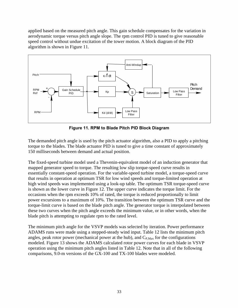
applied based on the measured pitch angle. This gain schedule compensates for the variation in aerodynamic torque versus pitch angle slope. The rpm control PID is tuned to give reasonable speed control without undue excitation of the tower motion. A block diagram of the PID algorithm is shown in Figure 11.
Low PassFilterSaturation
Anti-Windup
KpGain SchedulePID
Ki f dt
Kd (d/dt) Low PassFilter
+
-S
Pitch
RPM Ref
RPM
PitchDemand
Figure 11. RPM to Blade Pitch PID Block Diagram
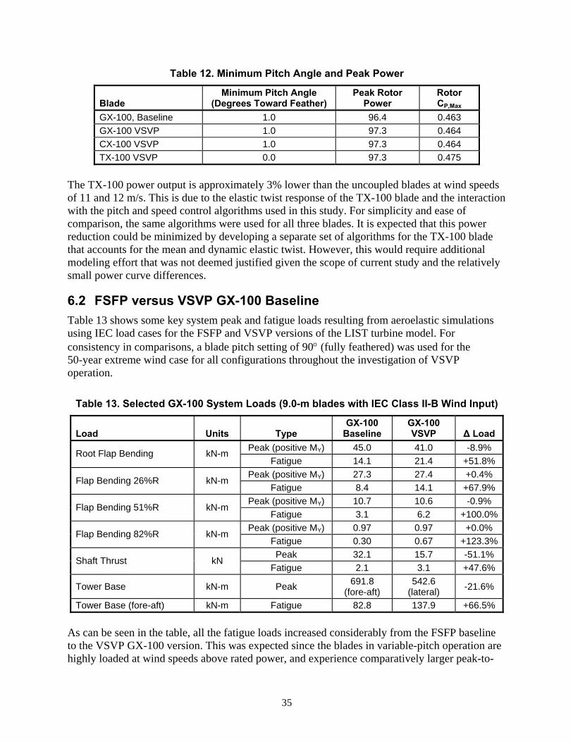
The demanded pitch angle is used by the pitch actuator algorithm, also a PID to apply a pitching torque to the blades. The blade actuator PID is tuned to give a time constant of approximately 150 milliseconds between demand and actual position. The fixed-speed turbine model used a Thevenin-equivalent model of an induction generator that mapped generator speed to torque. The resulting low slip torque-speed curve results in essentially constant-speed operation. For the variable-speed turbine model, a torque-speed curve that results in operation at optimum TSR for low wind speeds and torque-limited operation at high wind speeds was implemented using a look-up table. The optimum TSR torque-speed curve is shown as the lower curve in Figure 12. The upper curve indicates the torque limit. For the occasions when the rpm exceeds 10% of rated, the torque is reduced proportionally to limit power excursions to a maximum of 10%. The transition between the optimum TSR curve and the torque-limit curve is based on the blade pitch angle. The generator torque is interpolated between these two curves when the pitch angle exceeds the minimum value, or in other words, when the blade pitch is attempting to regulate rpm to the rated level. The minimum pitch angle for the VSVP models was selected by iteration. Power performance ADAMS runs were made using a stepped-steady wind input. Table 12 lists the minimum pitch angles, peak rotor power (mechanical power at the hub), and CP,Max for the configurations modeled. Figure 13 shows the ADAMS calculated rotor power curves for each blade in VSVP operation using the minimum pitch angles listed in Table 12. Note that in all of the following comparisons, 9.0-m versions of the GX-100 and TX-100 blades were modeled.
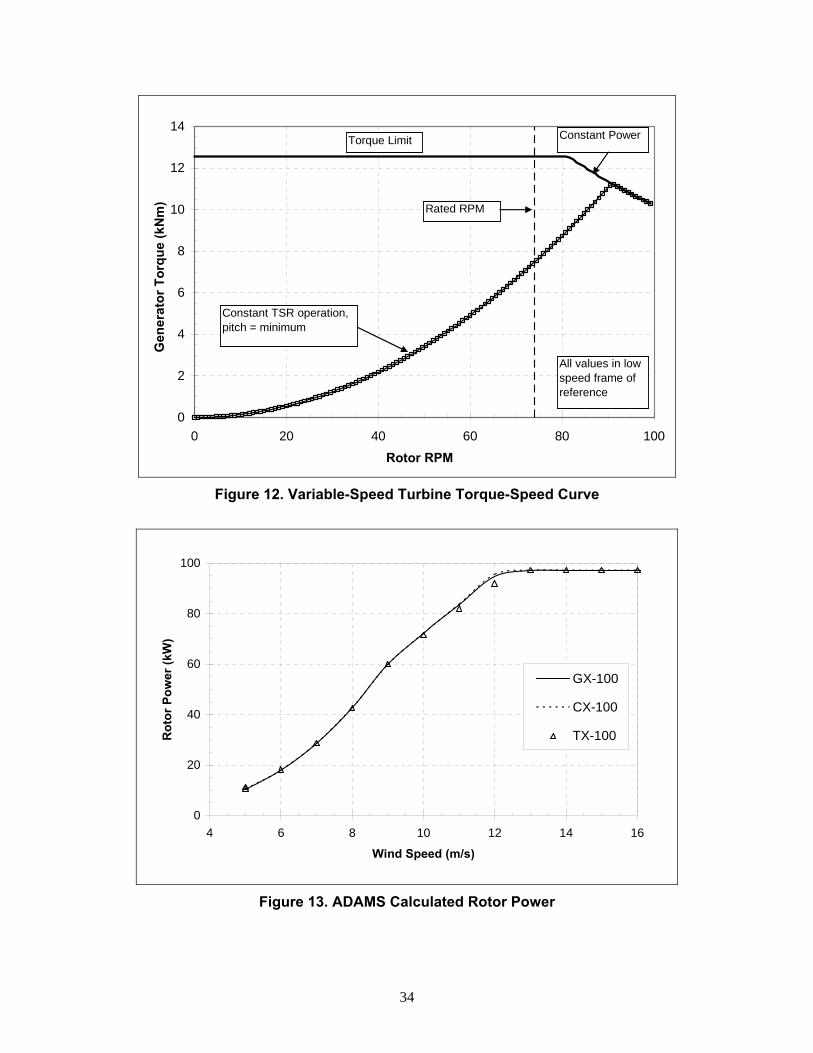
34
0
2
4
6
8
10
12
14
0 20 40 60 80 100
Rotor RPM
Gen
erat
or T
orqu
e (k
Nm
)
All values in low speed frame of reference
Constant TSR operation, pitch = minimum
Torque Limit Constant Power
Rated RPM
Figure 12. Variable-Speed Turbine Torque-Speed Curve
0
20
40
60
80
100
4 6 8 10 12 14 16
Wind Speed (m/s)
Rot
or P
ower
(kW
)
GX-100
CX-100
TX-100
Figure 13. ADAMS Calculated Rotor Power
35
Table 12. Minimum Pitch Angle and Peak Power
Blade Minimum Pitch Angle
(Degrees Toward Feather) Peak Rotor
Power Rotor CP,Max
GX-100, Baseline 1.0 96.4 0.463 GX-100 VSVP 1.0 97.3 0.464 CX-100 VSVP 1.0 97.3 0.464 TX-100 VSVP 0.0 97.3 0.475
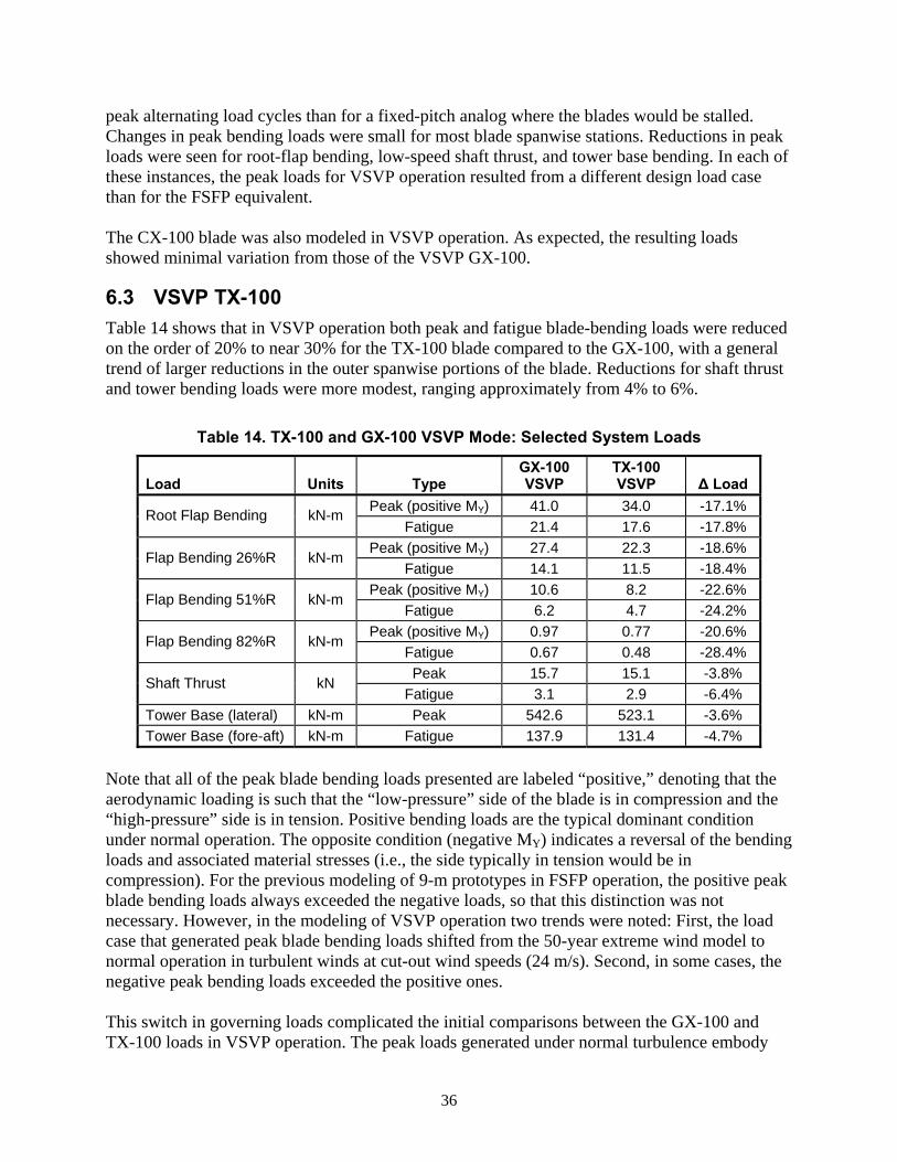
The TX-100 power output is approximately 3% lower than the uncoupled blades at wind speeds of 11 and 12 m/s. This is due to the elastic twist response of the TX-100 blade and the interaction with the pitch and speed control algorithms used in this study. For simplicity and ease of comparison, the same algorithms were used for all three blades. It is expected that this power reduction could be minimized by developing a separate set of algorithms for the TX-100 blade that accounts for the mean and dynamic elastic twist. However, this would require additional modeling effort that was not deemed justified given the scope of current study and the relatively small power curve differences.
6.2 FSFP versus VSVP GX-100 Baseline Table 13 shows some key system peak and fatigue loads resulting from aeroelastic simulations using IEC load cases for the FSFP and VSVP versions of the LIST turbine model. For consistency in comparisons, a blade pitch setting of 90° (fully feathered) was used for the 50-year extreme wind case for all configurations throughout the investigation of VSVP operation.
Table 13. Selected GX-100 System Loads (9.0-m blades with IEC Class II-B Wind Input)
Load Units Type GX-100
Baseline GX-100 VSVP Δ Load
Peak (positive MY) 45.0 41.0 -8.9% Root Flap Bending kN-m Fatigue 14.1 21.4 +51.8%
Peak (positive MY) 27.3 27.4 +0.4% Flap Bending 26%R kN-m
Fatigue 8.4 14.1 +67.9% Peak (positive MY) 10.7 10.6 -0.9%
Flap Bending 51%R kN-m Fatigue 3.1 6.2 +100.0%
Peak (positive MY) 0.97 0.97 +0.0% Flap Bending 82%R kN-m
Fatigue 0.30 0.67 +123.3%Peak 32.1 15.7 -51.1%
Shaft Thrust kN Fatigue 2.1 3.1 +47.6%
Tower Base kN-m Peak 691.8 (fore-aft)
542.6 (lateral) -21.6%
Tower Base (fore-aft) kN-m Fatigue 82.8 137.9 +66.5% As can be seen in the table, all the fatigue loads increased considerably from the FSFP baseline to the VSVP GX-100 version. This was expected since the blades in variable-pitch operation are highly loaded at wind speeds above rated power, and experience comparatively larger peak-to-
36
peak alternating load cycles than for a fixed-pitch analog where the blades would be stalled. Changes in peak bending loads were small for most blade spanwise stations. Reductions in peak loads were seen for root-flap bending, low-speed shaft thrust, and tower base bending. In each of these instances, the peak loads for VSVP operation resulted from a different design load case than for the FSFP equivalent. The CX-100 blade was also modeled in VSVP operation. As expected, the resulting loads showed minimal variation from those of the VSVP GX-100.
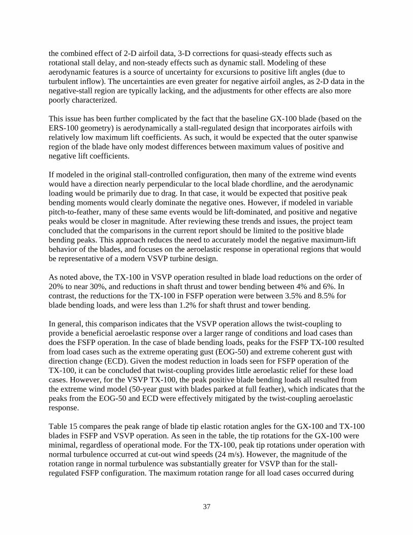
6.3 VSVP TX-100 Table 14 shows that in VSVP operation both peak and fatigue blade-bending loads were reduced on the order of 20% to near 30% for the TX-100 blade compared to the GX-100, with a general trend of larger reductions in the outer spanwise portions of the blade. Reductions for shaft thrust and tower bending loads were more modest, ranging approximately from 4% to 6%.
Table 14. TX-100 and GX-100 VSVP Mode: Selected System Loads
Load Units Type GX-100 VSVP
TX-100 VSVP Δ Load
Peak (positive MY) 41.0 34.0 -17.1% Root Flap Bending kN-m Fatigue 21.4 17.6 -17.8%
Peak (positive MY) 27.4 22.3 -18.6% Flap Bending 26%R kN-m
Fatigue 14.1 11.5 -18.4% Peak (positive MY) 10.6 8.2 -22.6%
Flap Bending 51%R kN-m Fatigue 6.2 4.7 -24.2%
Peak (positive MY) 0.97 0.77 -20.6% Flap Bending 82%R kN-m
Fatigue 0.67 0.48 -28.4% Peak 15.7 15.1 -3.8%
Shaft Thrust kN Fatigue 3.1 2.9 -6.4%
Tower Base (lateral) kN-m Peak 542.6 523.1 -3.6% Tower Base (fore-aft) kN-m Fatigue 137.9 131.4 -4.7%
Note that all of the peak blade bending loads presented are labeled “positive,” denoting that the aerodynamic loading is such that the “low-pressure” side of the blade is in compression and the “high-pressure” side is in tension. Positive bending loads are the typical dominant condition under normal operation. The opposite condition (negative MY) indicates a reversal of the bending loads and associated material stresses (i.e., the side typically in tension would be in compression). For the previous modeling of 9-m prototypes in FSFP operation, the positive peak blade bending loads always exceeded the negative loads, so that this distinction was not necessary. However, in the modeling of VSVP operation two trends were noted: First, the load case that generated peak blade bending loads shifted from the 50-year extreme wind model to normal operation in turbulent winds at cut-out wind speeds (24 m/s). Second, in some cases, the negative peak bending loads exceeded the positive ones. This switch in governing loads complicated the initial comparisons between the GX-100 and TX-100 loads in VSVP operation. The peak loads generated under normal turbulence embody
37
the combined effect of 2-D airfoil data, 3-D corrections for quasi-steady effects such as rotational stall delay, and non-steady effects such as dynamic stall. Modeling of these aerodynamic features is a source of uncertainty for excursions to positive lift angles (due to turbulent inflow). The uncertainties are even greater for negative airfoil angles, as 2-D data in the negative-stall region are typically lacking, and the adjustments for other effects are also more poorly characterized. This issue has been further complicated by the fact that the baseline GX-100 blade (based on the ERS-100 geometry) is aerodynamically a stall-regulated design that incorporates airfoils with relatively low maximum lift coefficients. As such, it would be expected that the outer spanwise region of the blade have only modest differences between maximum values of positive and negative lift coefficients. If modeled in the original stall-controlled configuration, then many of the extreme wind events would have a direction nearly perpendicular to the local blade chordline, and the aerodynamic loading would be primarily due to drag. In that case, it would be expected that positive peak bending moments would clearly dominate the negative ones. However, if modeled in variable pitch-to-feather, many of these same events would be lift-dominated, and positive and negative peaks would be closer in magnitude. After reviewing these trends and issues, the project team concluded that the comparisons in the current report should be limited to the positive blade bending peaks. This approach reduces the need to accurately model the negative maximum-lift behavior of the blades, and focuses on the aeroelastic response in operational regions that would be representative of a modern VSVP turbine design. As noted above, the TX-100 in VSVP operation resulted in blade load reductions on the order of 20% to near 30%, and reductions in shaft thrust and tower bending between 4% and 6%. In contrast, the reductions for the TX-100 in FSFP operation were between 3.5% and 8.5% for blade bending loads, and were less than 1.2% for shaft thrust and tower bending. In general, this comparison indicates that the VSVP operation allows the twist-coupling to provide a beneficial aeroelastic response over a larger range of conditions and load cases than does the FSFP operation. In the case of blade bending loads, peaks for the FSFP TX-100 resulted from load cases such as the extreme operating gust (EOG-50) and extreme coherent gust with direction change (ECD). Given the modest reduction in loads seen for FSFP operation of the TX-100, it can be concluded that twist-coupling provides little aeroelastic relief for these load cases. However, for the VSVP TX-100, the peak positive blade bending loads all resulted from the extreme wind model (50-year gust with blades parked at full feather), which indicates that the peaks from the EOG-50 and ECD were effectively mitigated by the twist-coupling aeroelastic response. Table 15 compares the peak range of blade tip elastic rotation angles for the GX-100 and TX-100 blades in FSFP and VSVP operation. As seen in the table, the tip rotations for the GX-100 were minimal, regardless of operational mode. For the TX-100, peak tip rotations under operation with normal turbulence occurred at cut-out wind speeds (24 m/s). However, the magnitude of the rotation range in normal turbulence was substantially greater for VSVP than for the stall-regulated FSFP configuration. The maximum rotation range for all load cases occurred during
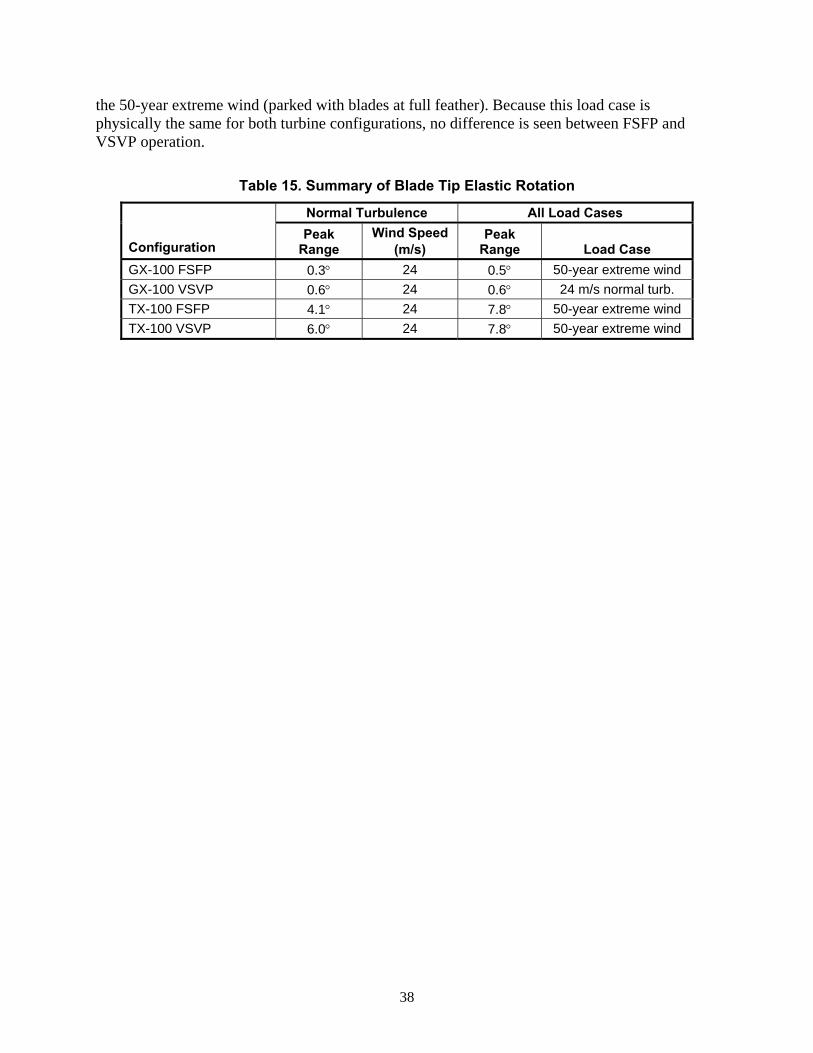
38
the 50-year extreme wind (parked with blades at full feather). Because this load case is physically the same for both turbine configurations, no difference is seen between FSFP and VSVP operation.
Table 15. Summary of Blade Tip Elastic Rotation
Normal Turbulence All Load Cases
Configuration Peak
Range Wind Speed
(m/s) Peak
Range Load Case GX-100 FSFP 0.3° 24 0.5° 50-year extreme wind GX-100 VSVP 0.6° 24 0.6° 24 m/s normal turb. TX-100 FSFP 4.1° 24 7.8° 50-year extreme wind TX-100 VSVP 6.0° 24 7.8° 50-year extreme wind
39
Section 7 - Conclusions
This report documents the design of prototype 9-m carbon-hybrid blades in both conventional and twist-coupled configurations. In general, the blades have been designed to 20-year life per IEC Class II loads with turbulence level “B.” For the TX-100 blade, a relaxed criterion was adopted for determining the peak bending load. The conventional-spar CX-100 design resulted in mass reductions of approximately 50% in the blade spar. However, because the baseline GX-100 fiberglass skins are a substantial fraction of the total blade weight, the overall mass reduction of the CX-100 was limited to approximately 11%. In addition, the CX-100 is substantially stiffer than the GX-100, resulting in a 70% increase in tip/tower clearance margin. In the baseline FSFP operation, the twist-coupled TX-100 design achieves up to 4° twist under turbulent wind input. The TX-100 peak blade bending loads are reduced between 2.4% and 8.6% relative to the GX-100, and equivalent fatigue loads in the blades show slightly greater reductions. However, the reductions in shaft thrust and tower bending loads are less than 1.2%. Although the extent of aeroelastic twist-response for the TX-100 blades meets the project objectives, the predicted load mitigation is highly constrained by the stall-controlled FSFP operation. To investigate the potential load reductions if these blades were flown in a more modern turbine architecture, the 9-m prototypes were modeled in hypothetical VSVP operation. Because of the increased blade loading (due to variable-pitch operation above rated wind speed and increased maximum tip speed), the fatigue loads for major components were substantially greater for all VSVP configurations than for the corresponding FSFP versions. When both the GX-100 and TX-100 are modeled in VSVP operation, the TX-100 resulted in blade bending load reductions on the order of 20% to near 30%. Shaft thrust and tower bending loads were reduced by 4% to 6%. For all loads, the reductions from aeroelastic twist-coupling response were substantially greater for VSVP than for FSFP operation. As of this report, the fabrication of the CX-100 and TX-100 prototypes has been completed, and the structural and field tests are ongoing. Coupon test data for carbon materials used in the 9-m prototypes are being generated as part of the work in Reference 6. These test data will provide excellent opportunities for the validation of the predictive codes and methods that have been used in the design of the 9-m prototypes.

40
Section 8 - References
1. Joosse, P.A., et al. (January 10-13, 2000). Economic Use of Carbon Fibres in Large Wind Turbine Blades? Proceedings of AIAA/ASME Wind Energy Symposium. Reno, NV.
2. Joosse, P.A., et al. (July 2-6, 2001). Toward Cost Effective Large Turbine Components with Carbon Fibers. Presented at the 2001 European Wind Energy Conference and Exhibition, Copenhagen.
3. Joosse, P.A., et al. (July 2-6, 2001). Fatigue Properties of Low-Cost Carbon Fiber Material. Presented at the 2001 European Wind Energy Conference and Exhibition, Copenhagen.
4. Joosse, P.A., et al. (January 14-17, 2002). Toward Cost Effective Large Turbine Components with Carbon Fibers. Proceedings of AIAA/ASME Wind Energy Symposium. Reno, NV.
5. Griffin, D.A. (July, 2002). Blade System Design Studies Volume I: Composite Technologies for Large Wind Turbine Blades. SAND2002-1879. Albuquerque, NM: Sandia National Laboratories.
6. Griffin, D.A. (June, 2004). Blade System Design Studies Volume II: Preliminary Blade Designs and Recommended Test Matrix. SAND2004-0073. Albuquerque, NM: Sandia National Laboratories.
7. Lobitz, D.W. and Laino, D.J. (January 11-14, 1999). Load Mitigation with Twist-Coupled HAWT Blades. Proceedings of the 1999 AIAA/ASME Wind Energy Symposium. Reno, NV.
8. D.W. Lobitz, P.S. Veers, G. R. Eisler, D.J. Laino, P.G. Migliore, G. Bir. (May 2001). The Use of Twist-Coupled Blades to Enhance the Performance of Horizontal Axis Wind Turbines. SAND2001-1303. Albuquerque, NM: Sandia National Laboratories.
9. C.H. Ong and S.W. Tsai. (March 2000). The Use of Carbon Fibers in Wind Turbine Blade Design: a SERI-8 Blade Example. SAND 2000-0478. Albuquerque, NM: Sandia National Laboratories.
10. J. Locke and I.C. Hidalgo. (August 2002). The Implementation of Braided Composite Materials in the Design of a Bend-Twist Coupled Blade. SAND2002-2425. Albuquerque, NM: Sandia National Laboratories.
11. D.A. Griffin. (August 2002). Evaluation of Design Concepts for Adaptive Wind Turbine Blades. SAND2002-2424. Albuquerque, NM: Sandia National Laboratories.
41
12. D.J. Malcolm and A.C. Hansen. (August 2002). WindPACT Turbine Rotor Design Study: June 2000–June 2002. 82 pp.; NICH Report No. SR-500-32495. National Renewable Energy Laboratory.
13. Sutherland, J. H., Jones, P. L. and Neal, B.A. (2001). The Long-Term Inflow and Structural Test Program, Proceedings of the 2001 ASME Wind Energy Symposium, p. 162.
14. TPI Composites, Inc. (May 2001). Blade Manufacturing Improvements Development of the ERS-100 Blade. SAND2001-1381, Sandia National Laboratories, Albuquerque NM.
15. Griffin, D.A., Berry, D., Zuteck, M.D., and Ashwill, T.A. (January 2004). Development of Prototype Carbon-Fiberglass Wind Turbine Blades: Conventional and Twist-Coupled Designs. 2004 AIAA/ASME Wind Energy Symposium. Reno, NV.
16. Laird, D.L. (August 2001). NuMAD User’s Manual. SAND2001-2375. Sandia National Laboratories. Albuquerque, NM.
17. Malcolm, D.J. and Laird, D.L. (January 2003). Modeling of Blades as Equivalent Beams for Aeroelastic Analysis 2003 AIAA/ASME Wind Energy Symposium. Reno, NV.
18. Malcolm, D.M. and Laird, D.L. (January 2005). Identification and Use of Blade Physical Properties. 2005 AIAA/ASME Wind Energy Symposium. Reno, NV.
19. International Electrotechnical Commission. (1999). IEC 61400-1: Wind turbine generator systems – Part 1: Safety Requirements, 2nd Edition. International Standard 1400-1.
20. Mandell, J.F., Samborsky, D.D. (1997). “DOE/MSU Composite Material Fatigue Database: Test Methods, Materials and Analysis.” SAND97-3002. Sandia National Laboratories. Albuquerque, NM.
21. Germanischer Lloyd (1999). Rules and Regulations IV – Non-Marine Technology, Part 1 – Wind Energy, Regulation for the Certification of Wind Energy Conversion Systems.
22. Laird, D.L. and Malcolm, D.J. (January 2005). Finite Element Modeling of Wind Turbine Blade. 2005 AIAA/ASME Wind Energy Symposium. Reno, NV.
DISTRIBUTION
Tom Acker Northern Arizona University PO Box 15600 Flagstaff, AZ 86011-5600 James Ahlgrimm Office of Wind and Hydropower Technologies EE-2B Forrestal Building U.S. Department of Energy 1000 Independence Avenue SW Washington, DC 20585 Ian Baring-Gould NREL/NWTC 1617 Cole Boulevard MS 3811 Golden, CO 80401 Keith Bennett, P.E. Project Manager U.S. Department of Energy, Golden Field Office 1617 Cole Blvd Golden, CO 80401-3393 Karl Bergey University of Oklahoma Aerospace Engineering Department Norman, OK 73069 Mike Bergey Bergey Wind Power Company 2200 Industrial Blvd. Norman, Ok 73069 Derek Berry (10) TPI Composites, Inc. 373 Market Street Warren, RI 02885-0328 Gunjit Bir NREL/NWTC 1617 Cole Boulevard MS 3811 Golden, CO 80401 Marshall Buhl NREL/NWTC 1617 Cole Boulevard Golden, CO 80401 C. P. Sandy Butterfield NREL/NWTC 1617 Cole Boulevard Golden, CO 80401
Garrett Bywaters Northern Power Systems 182 Mad River Park Waitsfield, VT 05673 Doug Cairns Montana State University Department of Mechanical & Industrial Engineering College of Engineering P.O. Box 173800 Bozeman, MT 59717-3800 David Calley Southwest Windpower 1801 West Route 66 Flagstaff, AZ 86001 Stan Calvert Office of Wind and Hydropower Technologies EE-2B Forrestal Building U.S. Department of Energy 1000 Independence Avenue SW Washington, DC 20585 Larry Carr NASA Ames Research Center 24285 Summerhill Ave. Los Altos, CA 94024 Jamie Chapman Texas Tech University Wind Science & Engineering Research Center Box 41023 Lubbock, TX 79409-1023 Kip Cheney PO Box 456 Middlebury, CT 06762 Craig Christensen, Vice President GE Wind 13681 Chantico Road Tehachapi, CA 93561 R. Nolan Clark USDA - Agricultural Research Service P.O. Drawer 10 Bushland, TX 79012
C. Cohee Foam Matrix, Inc. 1123 E. Redondo Blvd. Inglewood, CA 90302 Joe Cohen Princeton Economic Research, Inc. 1700 Rockville Pike Suite 550 Rockville, MD 20852 C. Jito Coleman Northern Power Systems 182 Mad River Park Waitsfield, VT 05673 Ken J. Deering The Wind Turbine Company PO Box 40569 Bellevue, WA 98015-4569 James Dehlsen Clipper Windpower Technology, Inc. 6305 Carpinteria Ave. Suite 300 Carpinteria, CA 93013 Edgar DeMeo Renewable Energy Consulting Services 2791 Emerson St. Palo Alto, CA 94306 Phillip Dougherty Office of Wind and Hydropower Technologies EE-2B Forrestal Building U.S. Department of Energy 1000 Independence Avenue SW Washington, DC 20585 S. Finn GE Global Research One Research Circle Niskayuna, NY 12309 Peter Finnegan GE Global Research One Research Circle Niskayuna, NY 12309 Trudy Forsyth NREL/NWTC 1617 Cole Boulevard Golden, CO 80401
Briam Glenn Clipper Windpower Technology, Inc. 6305 Carpinteria Ave. Suite 300 Carpinteria, CA 93013 R. Gopalakrishnan GE Wind Energy GTTC, 300 Garlington Road Greenville, SC 29602 Dayton Griffin (5) Global Energy Concepts, LLC 5729 Lakeview Drive NE, Ste. 100 Kirkland, WA 98033 Maureen Hand NREL/NWTC 1617 Cole Boulevard Golden, CO 80401 Thomas Hermann Odonata Research 202 Russell Ave. S. Minneapolis, MN 55405-1932 D. Hodges Georgia Institute of Technology 270 Ferst Drive Atlanta, GA 30332 William E. Holley GE Wind Energy GTTC, M/D 100D 300 Garlington Rd., P.O. Box 648 Greenville, SC 29602-0648 Adam Holman Alternative Energy Institute West Texas A & M University USDA-Agricultural Research Service Conservation & Production Research Laboratory P.O. Drawer 10 Bushland, TX 79012-0010 D.M. Hoyt NSE Composites 1101 N. Northlake Way, Suite 4 Seattle, WA 98103 Scott Hughes NREL/NWTC 1617 Cole Boulevard, MS 3911 Golden, CO 80401
Kevin Jackson Dynamic Design 123 C Street Davis, CA 95616 Eric Jacobsen GE Wind Energy GTTC, 300 Garlington Road Greenville, SC 29602 George James Structures & Dynamics Branch Mail Code ES2 NASA Johnson Space Center 2101 NASA Rd 1 Houston, TX 77058 Jason Jonkman NREL/NWTC 1617 Cole Boulevard Golden, CO 80401 Gary Kanaby Knight & Carver Yacht Center 1313 Bay Marina Drive National City, CA 91950 Jason Kiddy System Planning & Analysis, Inc. 2001 North Beauregard St. Alexandria, VA 22311 M. Kramer Foam Matrix, Inc. PO Box 6394 Malibu CA 90264 David Laino Windward Engineering 8219 Glen Arbor Dr. Rosedale, MD 21237-3379 Scott Larwood 1120 N. Stockton St. Stockton, CA 95203 Bill Leighty Alaska Applied Sciences, Inc. P.O. Box 20993 Juneau, AK 99802-0993
Dennis H. Lin Office of Wind and Hydropower Technologies EE-2B Forrestal Building U.S. Department of Energy 1000 Independence Avenue SW Washington, DC 20585 Wendy Lin GE Global Research One Research Circle Niskayuna, NY 12309 Steven P. Lindenberg Office of Wind and Hydropower Technologies EE-2B Forrestal Building U.S. Department of Energy 1000 Independence Avenue SW Washington, DC 20585 Steve Lockard TPI Composites, Inc. 373 Market Street Warren, RI 02885-0367 James Locke AIRBUS North America Engineering, Inc. 213 Mead Street Wichita, KS 67202 James Lyons GE Corporate Research & Development General Electric Bldg. K1. Room 3C33, One Research Circle Niskayuna, NY 12309 David Malcolm Global Energy Concepts, LLC 1809 7th Ave., Suite 900 Seattle, WA 98101 John F. Mandell Montana State University 302 Cableigh Hall Bozeman, MT 59717 Tim McCoy Global Energy Concepts, LLC 5729 Lakeview Drive NE, Ste. 100 Kirkland, WA 98033 L. McKittrick Montana State University Mechanical & Industrial Engineering Dept. 220 Roberts Hall Bozeman, MT 59717
Amir Mikhail Clipper Windpower Technology, Inc. 6305 Carpinteria Ave. Suite 300 Carpinteria, CA 93013 Francisco Alejandro Moreno Office of Wind and Hydropower Technologies EE-2B Forrestal Building U.S. Department of Energy 1000 Independence Avenue SW Washington, DC 20585 Patrick Moriarty NREL/NWTC 1617 Cole Boulevard Golden, CO 80401 Walt Musial NREL/NWTC 1617 Cole Boulevard Golden, CO 80401 NWTC Library (5) NREL/NWTC 1617 Cole Boulevard Golden, CO 80401 Byron Neal USDA - Agricultural Research Service P.O. Drawer 10 Bushland, TX 79012 Steve Nolet TPI Composites, Inc. 373 Market Street Warren, RI 02885-0328 Richard Osgood NREL/NWTC 1617 Cole Boulevard Golden, CO 80401 Tim Olsen Tim Olsen Consulting 1428 S. Humboldt St. Denver, CO 80210 Robert Z. Poore Global Energy Concepts, LLC 5729 Lakeview Drive NE Suite 100 Kirkland, WA 98033
Robert Preus Abundant Renewable Energy 22700 NE Mountain Top Road Newberg, OR 97132 Jim Richmond MDEC 3368 Mountain Trail Ave. Newbury Park, CA 91320 Michael Robinson NREL/NWTC 1617 Cole Boulevard Golden, CO 80401 Daniel Sanchez U.S. Department of Energy NNSA/SSO P.O. Box 5400 Mail Stop: 0184 Albuquerque, NM 87185-0184 Scott Schreck NREL/NWTC 1617 Cole Boulevard Golden, CO 80401 David Simms NREL/NWTC 1617 Cole Boulevard Golden, CO 80401 Brian Smith NREL/NWTC 1617 Cole Boulevard Golden, CO 80401 J. Sommer Molded Fiber Glass Companies/West 9400 Holly Road Adelanto, CA 92301 Ken Starcher Alternative Energy Institute West Texas A & M University P.O. Box 248 Canyon, TX 79016 Fred Stoll Webcore Technologies 8821 Washington Church Rd. Miamisburg, OH 45342 Herb Sutherland 1700 Camino Gusto NW Albuquerque, NM 87107-2615
Andrew Swift Texas Tech University Civil Engineering PO Box 41023 Lubbock, TX 79409-1023 J. Thompson ATK Composite Structures PO Box 160433 MS YC14 Clearfield, UT 84016-0433 Robert W. Thresher NREL/NWTC 1617 Cole Boulevard Golden, CO 80401 Steve Tsai Stanford University Aeronautics & Astronautics Durand Bldg. Room 381 Stanford, CA 94305-4035 William A. Vachon W. A. Vachon & Associates P.O. Box 149 Manchester, MA 01944 Case P. van Dam Dept. of Mechanical & Aerospace Eng. University of California, Davis One Shields Avenue Davis, CA 95616-5294 Jeroen van Dam Windward Engineering NREL/NWTC 1617 Cole Boulevard Golden, CO 80401 Brian Vick USDA - Agricultural Research Service P.O. Drawer 10 Bushland, TX 79012 Carl Weinberg Weinberg & Associates 42 Green Oaks Court Walnut Creek, CA 94596-5808 Kyle Wetzel Wetzel Engineering, Inc. PO Box 4153 Lawrence, KS 66046-1153
Mike Zuteck MDZ Consulting 601 Clear Lake Road Clear Lake Shores, TX 77565
Internal M.S. 0557 T. J. Baca, 1525 M.S. 0847 J. M. Redmond, 1524 M.S. 0557 T. G. Carne, 1524 M.S. 0557 T. W. Simmermacher, 1524 M.S. 0557 D. T. Griffith, 1524 M.S. 1124 J. R. Zayas, 6333 M.S. 1124 T. D. Ashwill, 6333 (10) M.S. 1124 D. E. Berg, 6333 M.S. 1124 S. M. Gershin, 6333 M.S. 1124 R.R. Hill, 6333 M.S. 1124 W. Johnson, 6333 M.S. 1124 P. L. Jones, 6333 M.S. 1124 D. L. Laird, 6333 M.S. 1124 D. W. Lobitz, 6333 M.S. 1124 J. Paquette, 6333 M.S. 1124 M. A. Rumsey, 6333 M.S. 1124 J. Stinebaugh, 6333 M.S. 1124 P. S. Veers, 6333 M.S. 0612 A. M. Lucero, 04532 M.S. 0899 Technical Library, 9536 (Electronic)