An Application of Adaptive Blades on Convertible MAVs
17
An Application of Adaptive Blades on Convertible MAVs Peng Lv, Fazila Mohd-Zawawi, Emmanuel Benard, Sebastien Prothin, Jean-Marc Moschetta and Joseph Morlier Reprinted from International Journal of Micro Air Vehicles Volume 5 · Number 4 · December 2013 Multi-Science Publishing ISSN 1756-8293
-
Upload
independent -
Category
Documents
-
view
1 -
download
0
Transcript of An Application of Adaptive Blades on Convertible MAVs

An Application of Adaptive Bladeson Convertible MAVs
Peng Lv, Fazila Mohd-Zawawi, Emmanuel Benard, Sebastien Prothin,Jean-Marc Moschetta and Joseph Morlier
Reprinted from
International Journal ofMicro Air Vehicles
Volume 5 · Number 4 · December 2013
Multi-Science PublishingISSN 1756-8293

Volume 5 · Number 4 · 2013
An Application of Adaptive Bladeson Convertible MAVs
Peng Lv, Fazila Mohd-Zawawi, Emmanuel Benard, Sebastien Prothin,Jean-Marc Moschetta and Joseph Morlier
Institut Supérieur de l’Aéronautique et de l’Espace, University of Toulouse, France
ABSTRACTA passive twist control is considered as an adaptive way to maximize the overallefficiency of a proprotor developed for convertible Micro Air Vehicles. The variedoperation conditions suggest different twist distributions for hover and forward flightwith the constraint of identical planform. In this work, adaption of the proprotorgeometry is achieved by centrifugal force induced twist. Classical Lamination Theory isused to predict structural loads, while Blade Element Momentum Theory is employed tounderstand the aerodynamic benefits of adaptive proprotor as applied on Micro AirVehicles. Tip mass is proposed to increase the stability and generate negative torsion forrotating blade. Validation of the procedure is based on measurements of bladedeformation, performed by laser displacement sensors. While negative torsion is foundin both rotor and propeller modes, level of deformation is still below what is required foroptimum dual operation.
1. INTRODUCTIONConvertible rotor aircraft has been developed for versatility services for several years, as it combinesthe merits of a helicopter and airplane. It has the capacity of Vertical/Short TakeOff and Landing(VSTOL) like a helicopter, through tilting rotor, then converts to forward flight at relatively high speed,as an airplane. The three main convertible rotor configurations are the tilt-rotor, tilt-wing and tilt-body.Tilt-rotor aircraft was developed in early 1950s, exemplified by the Bell XV-3 operating the firsttransition from hover to forward flight. In 1970s, XV-15 demonstrated the feasibility of tilt-rotorconcept. The success of XV-15 led to the V-22 project, leading to the first production tilt-rotor aircraftin the world. Recently, the tilt concept has attracted the attention of MAV research community. In 2008,Shkarayev and Moschetta introduced the concept of tilt-body MAV, which has a tilt-body configurationand is capable of flying in hover and forward flight [1]. This configuration of tilt-body MAV wassuccessfully tested in flight.
Designing a proprotor to operate efficiently in hover and forward flight presents a challenge sincethe inflow velocity and thrust requirement for each flight condition are quite distinct. In hover, theinflow velocity is small and the proprotor must provide high thrust to support the aircraft weight. Bycontrast, in forward flight, the inflow velocity is relatively large and the low thrust must only overcomethe drag. The difference in the inflow and thrust requirements between the two flight modes suggestsdifferent blade twist and chord distributions. In terms of twist effect on efficiency, high blade twist onthe proprotor allows the aircraft to fly faster and more efficiently, whereas low blade twist increases theefficiency in hover. In 1983, McVeigh obtained the twist of XV-15 proprotor through linearinterpolation of twist between ideal rotor and propeller by a compromise analysis [2]. Although thistrade-off solution provided an acceptable performance on XV-15, the stiff proprotor with certain twistcannot maximize the efficiency for both flights. In 1988, Nixon proposed a passive blade twist controlfor the proprotor on XV-15 [3]. The study demonstrated successfully the feasibility of the passive bladecontrol on conventional tilt-rotor aircraft. The small proprotors also suffer the problem caused bydifferent twist between hover and forward flight. However, due to the small size of MAV, the complextailored cross section of blade for passive twist control based on conventional tiltrotor aircraft is notavailable any more.
In this paper, a numerical method is employed to obtain the optimal twist distributions of proprotor.In order to achieve the varied twist, the concept of centrifugal force induced twist will be introduced as
229

a more practical method for proprotor of MAV. Then, the deformation of rotating laminate blade ismeasured using laser displacement sensors. Finally, this concept is assumed to be applied on a MAVand the potential benefits are evaluated using Blade Element Momentum Theory model.
2. OPTIMAL BALDE TWIST OF MAVION2.1 Mission of MAVionMAVion, a tilt-body MAV developed by ISAE, is designed to fly in both hover and forward flight, as shownin Fig. 1. The typical wing Reynolds number of its operation conditions is below 100,000. In hover mode,the nominal thrust 2N to support the weight while it becomes 0.3N to balance the drag in forward flight.
Figure 1: The MAVion, a convertible MAV developed in ISAE
Table 1: MAVion properties
Table 2: Mission of MAVion
2.2 Optimum twist distributions in hover and forward flightFor a blade rotating in a free-stream with the rotational plane perpendicular to the flow direction, theoptimum performance is realized when the blade twist distribution is such that the Betz condition issatisfied [3, 8]. The Betz condition describes that the trailing vortex sheet moves aft as a rigid helicalsheet, which means the wake displacement velocity is radically constant. Using Blade ElementMomentum Theory (BEMT) to satisfy the Betz condition, the displacement velocity of the vortex sheet
Hover Forward flight
Inflow velocity (m/s) 0 16
RPM 11,000 11,000
Thrust (N) 2 0.3
Wingspan (m) Airfoil Wing Area (m2) Aspect Ratio Aileron Area (m2)
0.36 MH45 0.0792 1.64 0.0216
230 An Application of Adaptive Blades on Convertible MAVs
International Journal of Micro Air Vehicles

can be approximately expressed by:
(1)
Where ω is rotational velocity, R is the blade radius, µ is tip speed ratio which is defined by inflowvelocity V, rotational velocity ω and blade radius R, µ = ωR
V , CT is the thrust coefficient. Furthermore,the optimum blade twist distribution is:
(2)
Where r is the local radius, αopt is the optimum angle of attack in terms of lift-drag ratio.For a radicallyconstant chord and airfoil section, αopt can be ignored since it is always the same for each of bladeelement. It cannot influence the built-in twist of blade. According to Tab. 2, the optimum twistdistributions of MAVion were calculated using Eqs. 1 and 2, which are shown in Fig. 2.
In order to distinguish the twist distributions, they were plotted by the translations in Y axis directionso that the twist in each mode at 0.75R is 0. With respect to the built-in twist, it shows nonlinear witharound –35˚ twist from blade root to tip. By contrast, the twist distribution in hover is shown to behighly nonlinear with –15˚ twist from blade root to tip. Hence, different flight modes suggest variedbuilt-in twist distributions of blade. The solution is to find an adaptive proprotor which can deform intwist and adapt different flight conditions.
Figure 2: Optimum twist distributions
3. EXLORATION OF PASSIVE TWIST CONTROL3.1 Concept of centrifugal force induced twistA deformable, durable and stable blade for MAV proprotor is characterized by the deformation, failureperformance and dynamics behavior. To be specific, with respect to the adaptive proprotor ofconvertible MAV, there are five requirements. Firstly, it should be capable of deforming in terms oftwist to adapt different flight conditions. Meanwhile, the deformation should be stable during therotation. Besides, the design should be practical to be applied on MAV without size problem. Moreover,it can take the airloads without large blade bending. Finally, this adaptive proprotor should have anacceptable fatigue performance.
The initial step of the procedure is to select suitable reinforcing fiber for the laminate blade. Thesignificant factor to select a reinforcing fiber for small-scale proprotor is linked to its tailoring capacity.Glass/epoxy was determined for the MAV flexible proprotor in current study. In order to improve the
0 0.02 0.04 0.06 0.08 0.1-5
0
5
10
15
20
25
30
35
Radius, m
Tw
ist,
deg
prop twistrotor twist
Peng Lv, Fazila Mohd-Zawawi, Emmanuel Benard, Sebastien Prothin, 231Jean-Marc Moschetta and Joseph Morlier
Volume 5 · Number 4 · 2013

aerodynamic performance of flat plate at low Reynolds number, the thickness of laminate blade shouldbe thin enough to provide a low thickness-to-chord ratio [5]. Thus, two typical laminate configurationsare considered here, a symmetric laminate [θ, –θ]T, and an antisymmetric laminate [θ, θ]T. A criticalissue in the design of a laminate blade is failure analysis. The comparison of strength of UD and angle-ply laminates was described based on a typical carbon/epoxy composite (AS4/3501-6) using first plyfailure analysis [6]. All of the uniaxial tensile strength, uniaxial compressive strength and in-plane shearstrength of the angle-ply laminate are evidently higher than those of the off-axis UD material. Thus, incurrent study, antisymmetric laminates [θ, –θ]T are employed as balanced laminates. The layup ofspecimen was selected as [45˚, –45˚]T.
The adaptive proprotor should not only be flexible to produce the required deformation, but alsostable to maintain the required twist in each of flight mode. For a stable blade, the blade Center ofGravity (CG) must be ahead of the aerodynamic center [7]. Hence, a concept of centrifugal forceinduced twist was proposed for adaptive proprotor of convertible MAV. In this concept, tip mass isdesigned to adjust the global CG of laminate blade. In addition, tip mass is beneficial for improving thenose-down twisting moment and increasing the torsion of laminate blades. On one hand, tip mass isrequired to be heavy enough to be able to adjust the global CG. On the other hand, it should be lightenough to provide weight efficiency for the application on MAVs. Fig. 3 demonstrates the tip masswhich can slide in the chordwise direction at blade tip.
Figure 3: Tip mass model
Figure 4: Schematic of Centrifugal Force Induced Twist
The concept of CFIT for adaptive proprotor is described in Fig. 4. The blade is rotating in the anti-clockwise direction in a rotation speed Ω. Factor k is used to define the position of tip rod in thechordwise direction. For example, k=0.5 means that the twisting axis is on the midpoint of tip rod. If kis between 0 and 1, the twisting axis is on the tip rod. Else, the tip rod rotates about the off-body axis.The length of tip rod is represented by L. There is a mass element dm on the rotating blade which cangenerate a certain centrifugal force FC. It has a component in the chordwise direction of blade. Thecomponent tends to flat the blade cross section with an initial pitch angleθ. This is the method ofcentrifugal force induced twist blade to generate torsion.
232 An Application of Adaptive Blades on Convertible MAVs
International Journal of Micro Air Vehicles
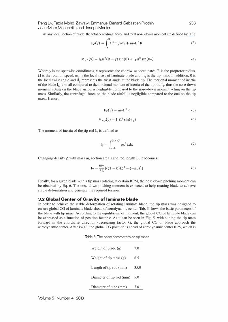
At any local section of blade, the total centrifugal force and total nose-down moment are defined by [13]:
(3)
(4)
Where y is the spanwise coordinates, x represents the chordwise coordinates, R is the proprotor radius,Ω is the rotation speed, my is the local mass of laminate blade and mT is the tip mass. In addition, θ isthe local twist angle and θT represents the twist angle at the blade tip. The torsional moment of inertiaof the blade Ιθ is small compared to the torsional moment of inertia of the tip rod IT, thus the nose-downmoment acting on the blade airfoil is negligible compared to the nose-down moment acting on the tipmass. Similarly, the centrifugal force on the blade airfoil is negligible compared to the one on the tipmass. Hence,
(5)
(6)
The moment of inertia of the tip rod IT is defined as:
(7)
Changing density ρ with mass m, section area s and rod length L, it becomes:
(8)
Finally, for a given blade with a tip mass rotating at certain RPM, the nose-down pitching moment canbe obtained by Eq. 6. The nose-down pitching moment is expected to help rotating blade to achievestable deformation and generate the required torsion.
3.2 Global Center of Gravity of laminate bladeIn order to achieve the stable deformation of rotating laminate blade, the tip mass was designed toensure global CG of laminate blade ahead of aerodynamic center. Tab. 3 shows the basic parameters ofthe blade with tip mass. According to the equilibrium of moment, the global CG of laminate blade canbe expressed as a function of position factor k. As it can be seen in Fig. 5, with sliding the tip massforward in the chordwise direction (decreasing factor k), the global CG of blade approach theaerodynamic center. After k=0.3, the global CG position is ahead of aerodynamic center 0.25, which is
Peng Lv, Fazila Mohd-Zawawi, Emmanuel Benard, Sebastien Prothin, 233Jean-Marc Moschetta and Joseph Morlier
Volume 5 · Number 4 · 2013
Weight of blade (g) 7.0
Weight of tip mass (g) 6.5
Length of tip rod (mm) 35.0
Diameter of tip rod (mm) 5.0
Diameter of tube (mm) 7.0
Table 3: The basic parameters on tip mass

normalized by the chord of blade. This indicates the tip mass can help to improve the stability ofrotating blade.
Figure 5: Global CG
3.3 Torsion of rotating laminate bladeThe Classical Lamination Theory (CLT) demonstrates that, for a general composite laminate, the forcesand moments on it are related to the strains and curvatures at reference surface. The 6 × 6 matrixconsisting of the components Aij, Bij and Dij (i, j = 1, 2, 6)is the laminate stiffness matrix, is also calledABD matrix. In order to be able to obtain the strains and curvatures at the reference surface in terms ofthe force and moment resultants, the ABD matrix is inversed and then becomes the laminatecompliance matrix consisting of the components ij, and dij (i, j = 1, 2, 6). The torsion can be directlygiven by the curvature:
(9)
Where Nx, Ny and Nxy are the tensile forces in the directions of x, y and xy. Besides, Mx, My and Mxyrepresent the moments in varied directions. Terms b16, b26, b66, d16, d26 and d66 are the correspondingcompliance factors.
Since the nose-down pitching moment is obtained, the torsion of rotating laminate blade can becalculated directly using Eq. 9. Fig. 6 gives the blade tip twist of rotating laminate blade with the
0.2 0.25 0.3 0.35 0.4 0.45 0.50.2
0.25
0.3
0.35
0.4
k
PC
G/C
234 An Application of Adaptive Blades on Convertible MAVs
International Journal of Micro Air Vehicles
-1 -0.5 0 0.5 1 1.5 2-30
-25
-20
-15
-10
-5
0
k
Tip
twis
t, de
g
Collective pitch 35°
Collective pitch 55°
Figure 6: Torsion prediction

variation of tip mass position at 1,500RPM. The torsion of adaptive proprotor is generated at thereasonable level which is between 0 and –30˚.
3.4 Measurement of blade deformationA key issue to study flexible blade is to use validated predictive simulations and therefore, in thedomain of aeroelasticity, to measure accurately deformations. Optical measurement techniques havebeen developing for some years in aerodynamics, materials and structure, such as HolographicInterferometry (HI), Electronic Speckle Pattern Interferometry (ESPI), Projection Moiré Interferometry(PMI) and Digital Image Correlation (DIC) [8]. In 1998, Fleming obtained the 3-D deformation of rotorblade using PMI technique [9]. However, it has low sensitivity for in-plane deformation and moderatefor out-of-plane deformation. By contrast, DIC has a relatively high sensitivity that can reach 1/30,000of the test field [10]. In 2011, Lawson demonstrated the deformation of a rotating blade using DIC [11].The technique was found to have many advantages including high resolution results, non-intrusivemeasurement, and good accuracy over a range of scales. However, DIC needs a preprocessing whichis to apply a stochastic speckle pattern to the surface by spraying it with a high-contrast and non-reflective paint. This complex painting will probably affect the stiffness of small MAV blades. Hence,in this study, LDS based method was developed to measure blade deformation in both of hover andforward flight.
The final laminate blades with tip masses are shown in Fig. 7. The bending and torsion distributionsduring rotation are considered as the blade deformation, since beneficial torsion can increase the overallperformance while bending tends to decrease the thrust. In order to measure the deformation of rotatinglaminate blade, a laser displacement sensor system was developed, as shown in Fig. 8. To avoid anydisturbance on flow field, the two laser displacement sensors were fixed at an incidence angle tomeasure the blade deformation. The laser displacement sensor used in this experiment is a KEYENCELK-G502. The sampling frequency was set to 10,000Hz. Diffuse reflection mode of laser displacementsensor was used for measurements. The distance of reference was 500mm, and the range of measuringwas between -250mm to 500mm. For a long range measurement, the measuring accuracy is typically±0.1% of Full Scale (FS). In order to reconstruct the deformed blade and to extract the bending andtorsion, the post-processing methodology based on polynomial surface fitting was developed for LDStechnology. The adaptive proprotor were respectively tested in rotor mode, 1,100RPM, 1,300RPM andpropeller mode, inflow velocity 8m/s, 800RPM (limited by current motor). The position factor k of tipmass on adaptive proprotor was set to 0.25. The results were compared with the predictions from aFluid Structure Model (FSI) which was based on the combination of BEMT and beam model.
Figure 7: Adaptive proprotor
Peng Lv, Fazila Mohd-Zawawi, Emmanuel Benard, Sebastien Prothin, 235Jean-Marc Moschetta and Joseph Morlier
Volume 5 · Number 4 · 2013

Figure 8: LDS rig
The detailed bending and torsion were extracted according to surface function and shown in Figs. 9 and10. The experimental results were plotted with 95% confidence bounds of the fitting. In rotor mode,with increasing RPM, the bending from measurements decreased obviously due to the centrifugalstiffening effect (Figs. 9(a), 9(b)). By contrast, the torsion from measurements increases by high nose-down pitching moment of increased RPM (Figs. 10(a), 10(b)). FSI model also reveals this phenomenonin rotor mode. As it can be seen from the results of experiments and FSI model (Fig. 9(c)), even RPMis only 800 (low RPM has no strong stiffening effect), the bending still is relatively low due to the
236 An Application of Adaptive Blades on Convertible MAVs
International Journal of Micro Air Vehicles
(a) Rotor mode: 1,100RPM
0 50 100 150 200-5
0
5
10
15
Span, mm
Ben
ding
, mm
Measurement (tip bending 6.6mm)Confidence bounds of measurementFSI model (tip bending 5.7mm)
Figure 9: (Continued)

inflow airloads acting on the blade. The torsion is also low since there was no adequate nose-downpitching moment in this case (Fig. 10(c)). It was found that the centrifugal force induced twist blade iscapable of generating negative torsions in two modes. Besides, in propeller mode, the laminate bladecan take airloads without large negative bending.
Peng Lv, Fazila Mohd-Zawawi, Emmanuel Benard, Sebastien Prothin, 237Jean-Marc Moschetta and Joseph Morlier
Volume 5 · Number 4 · 2013
(b) Rotor mode: 1,300RPM
0 50 100 150 200-5
0
5
10
15
Span, mm
Ben
ding
, mm
Measurement (tip bending 2.8mm)Confidence bounds of measurementFSI model (tip bending 4.9mm)
(c) Propeller mode: 800RPM, inflow 8m/s
0 50 100 150 200-5
0
5
10
15
Span, mm
Ben
ding
, mm
Measurement (tip bending 4.3mm)Confidence bounds of measurementFSI model (tip bending 2.7mm)
Figure 9: Bending distribution

238 An Application of Adaptive Blades on Convertible MAVs
International Journal of Micro Air Vehicles
(a) Rotor mode: 1,100RPM
0 50 100 150 200-10
-5
0
5
10
Span, mm
Tor
sion
, deg
ree
Measurement (tip torsion -5.4°)
Confidence bounds of measurement
FSI model (tip torsion -8.0°)
(b) Rotor mode: 1,300RPM
(c) Propeller mode: 800RPM, inflow 8m/s
0 50 100 150 200-10
-5
0
5
10
Span, mm
Tor
sion
, deg
ree
Measurement (tip torsion -7.6°)
Confidence bounds of measurement
FSI model (tip torsion -9.5°)
0 50 100 150 200-10
-5
0
5
10
Span, mm
Tor
sion
, deg
ree
Measurement (tip torsion -2.4°)
Confidence bounds of measurement
FSI model (tip torsion -3.1°)
Figure 10: Torsion distribution

4. APPLICATIONS ON MAVIONSince the adaptive proprotor showed the potential negative torsion generated respectively in rotor andpropeller mode, hence, this concept was applied on MAVion. Based on the geometry of widely usedAPC86 commercial propeller with a diameter 0.2m (Fig. 11), a rigid blade, a rigid blade with collectivepitch control and an adaptive blade with collective pitch control were compared using BEMT [12, 13].The detailed chord and twist distributions of APC86 are given by Figs. 12 and 13.The twist distributionof APC86 exhibits the bi-linear behavior. The root twist of rigid APC86 is around 45˚ and the tip twistis 20˚. In order to compare the adaptive concept with current propeller on MAVion, two additionallinear twist distributions are defined, based on –10˚ and –30˚ of global twist.
Figure 11: Top and side views of APC86
Figure 12: Chord distribution of APC86
0 0.2 0.4 0.6 0.8 12
4
6
8
10
12
14x 10
-3
r/R
c/R
Peng Lv, Fazila Mohd-Zawawi, Emmanuel Benard, Sebastien Prothin, 239Jean-Marc Moschetta and Joseph Morlier
Volume 5 · Number 4 · 2013

Figure 13: Twist distributions of APC86 and potential adaptive blades
Figure 14: Program of evaluating potential benefits of adaptive twist
∆β represents the variation of collective pitch. APC86 rigid blade without collective pitch control (∆β = 0)was inputted to BEMT model to find a RPM which can provide 2N for hover and 0.3N for forwardflight.APC86 rigid blade with collective pitch control (∆β ≠ 0) means the APC86 rigid blade wasmounted with different collective pitches. A number of RPMs were obtained by BEMT model toachieve the given thrusts for each collective pitch. On the adaptive blade with collective pitch control(∆β ≠ 0), the blades with two potential twist distributions –10˚ and –30˚ were analyzed with a series ofcollective pitches through BEMT model respectively. With the required thrusts, the correspondingRPMs were obtained. Finally, FM and propulsive efficiency can be calculated and compared in bothrotor and propeller modes (Fig. 14).
The marker corresponds to the APC86 rigid blade without collective pitch control. The curve withmarker shows the required RPMs of APC86 rigid blade for different collective pitches in each mode.Fig. 15 demonstrates the required RPM for the cases discussed above to achieve 2N for rotor mode. Ascan be seen, 6,500RPM is required to reach the thrust target (∆β = 0).In Fig. 16, the APC86 rigid bladewithout collective pitch control needs around 6,000RPM to obtain the thrust 0.3N at inflow velocity
Given thrust
APC86 twist,
BEMT model
APC86 twist,
Adaptive twist,
RPM
FM; Efficiency
0 0.2 0.4 0.6 0.8 110
15
20
25
30
35
40
45
50
r/R
twis
t, de
gree
APC86 twist
Adaptive twist -10°
Adaptive twist -30°
240 An Application of Adaptive Blades on Convertible MAVs
International Journal of Micro Air Vehicles
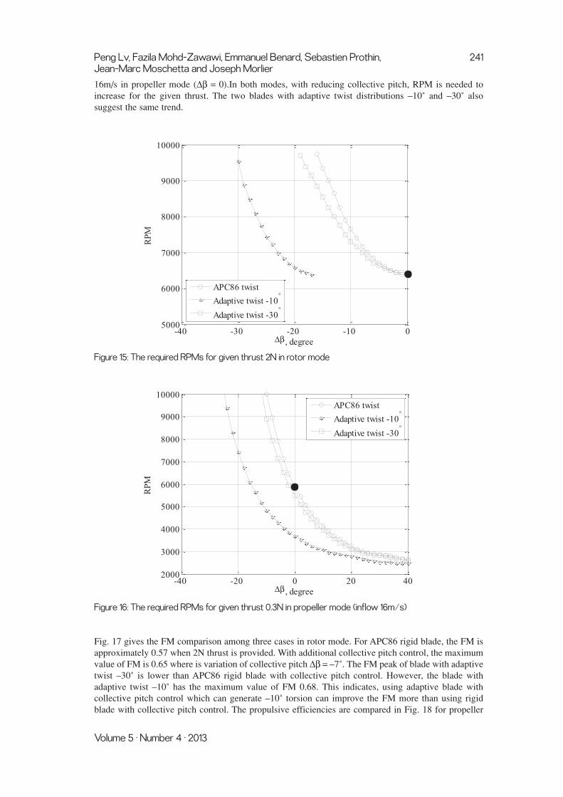
16m/s in propeller mode (∆β = 0).In both modes, with reducing collective pitch, RPM is needed toincrease for the given thrust. The two blades with adaptive twist distributions –10˚ and –30˚ alsosuggest the same trend.
Figure 15: The required RPMs for given thrust 2N in rotor mode
Figure 16: The required RPMs for given thrust 0.3N in propeller mode (inflow 16m/s)
Fig. 17 gives the FM comparison among three cases in rotor mode. For APC86 rigid blade, the FM isapproximately 0.57 when 2N thrust is provided. With additional collective pitch control, the maximumvalue of FM is 0.65 where is variation of collective pitch ∆β = –7˚. The FM peak of blade with adaptivetwist –30˚ is lower than APC86 rigid blade with collective pitch control. However, the blade withadaptive twist –10˚ has the maximum value of FM 0.68. This indicates, using adaptive blade withcollective pitch control which can generate –10˚ torsion can improve the FM more than using rigidblade with collective pitch control. The propulsive efficiencies are compared in Fig. 18 for propeller
-40 -20 0 20 402000
3000
4000
5000
6000
7000
8000
9000
10000
∆β, degree
RPM
APC86 twist
Adaptive twist -10°
Adaptive twist -30°
-40 -30 -20 -10 05000
6000
7000
8000
9000
10000
∆β, degree
RPM
APC86 twist
Adaptive twist -10°
Adaptive twist -30°
Peng Lv, Fazila Mohd-Zawawi, Emmanuel Benard, Sebastien Prothin, 241Jean-Marc Moschetta and Joseph Morlier
Volume 5 · Number 4 · 2013

mode. For the APC86 rigid blade without collective pitch control, the propulsive efficiency is 0.6.When the APC86 rigid blade is with collective pitch control, the peak of propulsive efficiency becomes0.7 at ∆β = 15˚.
The adaptive blade with collective pitch control which can generate torsion –30˚ has the sameefficiency peak with APC86 rigid blade with collective pitch control, since the original twist ofAPC8X6 is relatively high with a bi-linear –45˚.
Figure 17: FM comparison in rotor mode
Figure 18: Propulsive efficiency comparison in propeller mode
CONCLUSIONTo adapt different flight modes and increase the overall efficiency for convertible MAV, a centrifugalforce induced twist concept of adaptive blade was proposed in present study. A glass fiber laminateblade with stacking sequence [45˚, 45˚]T was used for adaptive proprotor. Meanwhile, tip mass wasdesigned to increase the stability by ensuring the global CG ahead of aerodynamic center, and to
-40 -30 -20 -10 0 10 20 30 400.2
0.3
0.4
0.5
0.6
0.7
0.8
∆β, degree
Prop
ulsi
ve e
ffic
ienc
y
APC86 twist
Adaptive twist -10°
Adaptive twist -30°
-40 -35 -30 -25 -20 -15 -10 -5 00.5
0.55
0.6
0.65
0.7
∆β, degree
FM
APC86 twist
Adaptive twist -10°
Adaptive twist -30°
242 An Application of Adaptive Blades on Convertible MAVs
International Journal of Micro Air Vehicles

generate negative torsion by increasing nose-down pitching moment. LDS rig and corresponding post-processing method were implemented to measure the deformation of rotating blade. The feasibility ofadaptive blade was verified since the negative torsion was observed respectively in rotor and propellermode. The potential adaptive proprotor which can generate –10˚ torsion has the peak of FM in rotormode. In propeller mode, the blade with –30˚ has the same maximum value of efficiency with APC86rigid propeller of bi-linear twist. The application of adaptive blade is not only in aerodynamicefficiency but also in dynamic performance. In the next study, an optical derotator, a sophisticated toolfor performing non-contact vibration measurements on rotating parts with laser vibrometers, will beemployed to study the dynamic response of rotating adaptive proprotor for MAVion. In addition, theaerodynamic performance is also going to be tested in each mode.
ACKNOWLEDGEMENTSThis work is supported by the China Scholarship Council(CSC) and Malaysian Ministry of HigherEducation (MOHE). The authors thank Rémy CHANTON and Xavier FOULQUIER for their supportin conducting the experiments.
REFERENCES[1] S. Shkarayev, J. M. Moschetta and B. Bataille, Aerodynamic Design of Micro Air Vehicles for
Vertical Flight, Journal of Aircraft, Vol. 45, No. 5, 2008, pp. 1715-1724.
[2] M. A. McVeigh, H. J. Rosenstein and F. J. McHugh, Aerodynamic Design of the XV-15 AdvancedComposite Tilt Rotor Blade, 39th Annual Forum of the American Helicopter Society, St. Louis,MO, May 1983.
[3] M. W. Nixon, Improvements to Tilt Rotor Performance through Passive Blade Twist Control,NASA Technical Memorandum 100583, April 1988.
[4] B. J. Hein and I. Chopra, Hover Performance of a Micro Air Vehicle: Rotors at Low ReynoldsNumber, International Specialists Meeting Unmanned Rotorcraft: Design, Control ans Testing,Chandler, AZ, January 2005.
[5] M. Drela, XFOIL 6.9 User Guide, Massachusetts Institute of Technology, 2001.
[6] I. M. Daniel and O. Ishai, Engineering Mechanics of Composite Materials, Oxford UniversityPress 1994.
[7] J. Sicard, Investigation of an Extremely Flexible Stowable Rotor for Micro-helicopters, Master’sthesis, University of Texas at Austin, May 2011.
[8] S. Rajpal, Optical Methods of Measurement: Whole-field Techniques, Second edition, Francisand Taylor/CRC Press, 2009.
[9] G. A. Fleming and S. Gorton, Measurement of Rotorcraft Blade Deformation Using ProjectionMoiré Interferometry, Proceedings of the 3rd International Conference on VibrationMeasurements by Laser Techniques: Advances and Applications, SPIE the International Societyfor Optical Engineering, Ancona, Italy, June 1998, pp. 514-527.
[10] T. Schmidt and J. Tyson, Full-Field Dynamic Displacement and Strain Measurement UsingAdvanced 3D Image Correlation Photogrammetry: Part 1, Experimental Techniques, Vol. 27, No.3, 2003, pp. 47-50.
[11] M. S. Lawson and J. Sirohi, Measurement of Deformation of Rotating Blades Using DigitalImage Correlation, Proceedings of 52nd AIAA/ASME/ASCE/AHS/ASC Structures, StructuralDynamics and Materials Conference, Denver, Colorado, April 2011.
[12] J. G. Leishman, Principles of Helicopter Aerodynamics, Cambridge Aerospace Series, 2ndedition, 2006.
[13] P. Lv, S. Prothin, F. M. Zawawi, E. Benard, Joseph Morlier and J. M. Moschetta, Study of AFlexible Blade for Optimized Proprotor, ERCOFTAC International Symposium, UnsteadySeparation in Fluid-Structure Interaction, Mykonos, Greece, June 2013.
[14] F. Moha-Zawawi, S. Prothin, P. Lv, E. Benard, J. M. Moschetta and J. Morlier, Study of a flexibleUAV proprotor 48th International Symposium of Applied Aerodynamics Saint-Louis, Vol. 30,2013, pp. 1-10.
Peng Lv, Fazila Mohd-Zawawi, Emmanuel Benard, Sebastien Prothin, 243Jean-Marc Moschetta and Joseph Morlier
Volume 5 · Number 4 · 2013