Corrosion-Fatigue Failure of Gas-Turbine Blades in an Oil and ...
8
materials Article Corrosion-Fatigue Failure of Gas-Turbine Blades in an Oil and Gas Production Plant Mojtaba Rajabinezhad 1 , Abbas Bahrami 1 , Mohammad Mousavinia 2 , Seyed Jalil Seyedi 3 and Peyman Taheri 4, * 1 Department of Materials Engineering, Isfahan University of Technology, Isfahan 84156-83111, Iran; [email protected] (M.R.); [email protected] (A.B.) 2 Inspection and Corrosion Engineering Department, Pars Oil and Gas Company (POGC), Assalouyeh 1414713111, Iran; [email protected] 3 National Iranian South Oilfields Company (NISOC), South Turbine Maintenance Centeral Shop, Omidieh 61735-1333, Iran; [email protected] 4 Department of Materials Science and Engineering, Delft University of Technology, Mekelweg 2, 2628 CD Delft, The Netherlands * Correspondence: [email protected]; Tel.: +31-15-278-1683 Received: 10 January 2020; Accepted: 14 February 2020; Published: 18 February 2020 Abstract: This paper investigates the root cause of a failure in gas-turbine blades, made of Nimonic-105 nickel-based superalloy. The failure was reported in two blades in the second stage of a turbine-compressor of a gas turbine in the hot section. Two failed blades were broken from the root and from the airfoil. The failure took place after 20 k h of service exposure in the temperature range 700–850 ◦ C, with the rotating speed being in the range 15,000–16,000 rpm. The microstructures of the failed blades were studied using optical/electron microscopes. Energy dispersive X-ray spectroscopy (EDS) was employed for phase identification. Results showed that failure first initiated from the root. The dominant failure mechanism in the root was concluded to be corrosion-fatigue. The failure scenario was suggested based on the results obtained. Keywords: gas turbine; corrosion-fatigue; blades; failure 1. Introduction Gas-turbine blades are known to be extremely critical and important components in power plants. They are expected to operate in harsh working conditions, such as high temperature, high pressure and complex dynamic loading conditions. Degradation and failure of gas-turbine blades can obviously have severe negative implications for the integrity and functionality of gas turbines and hence the output of a power plant. Failures of gas-turbine blades can be due to creep damage, high-temperature corrosion, high-temperature oxidation, fatigue, erosion, and foreign object damage [1–15]. Obviously, in most cases the failure is due to the interrelation of more than one failure mechanism [2]. As a case in point, creep and fatigue can simultaneously result in failure in gas-turbine blades [2]. Increasing the operating temperature in gas turbines has always been a target, given that any increase in service temperature is associated with an increase in the efficiency and output of a turbine. Among different candidate materials for harsh high-temperature working conditions in turbines, nickel- and cobalt-based superalloys have long been known as the best options on the grounds that these alloys are capable of working at high temperature, while they keep their properties [16]. These alloys benefit from a unique and exceptional combination of high-temperature mechanical properties (i.e., superior creep resistance), excellent resistance to high-temperature degradation/oxidation, and superior microstructural stability during high-temperature service [17]. Nickel-based superalloys Materials 2020, 13, 900; doi:10.3390/ma13040900 www.mdpi.com/journal/materials
-
Upload
khangminh22 -
Category
Documents
-
view
3 -
download
0
Transcript of Corrosion-Fatigue Failure of Gas-Turbine Blades in an Oil and ...
materials
Article
Corrosion-Fatigue Failure of Gas-Turbine Blades in anOil and Gas Production Plant
Mojtaba Rajabinezhad 1, Abbas Bahrami 1, Mohammad Mousavinia 2, Seyed Jalil Seyedi 3 andPeyman Taheri 4,*
1 Department of Materials Engineering, Isfahan University of Technology, Isfahan 84156-83111, Iran;[email protected] (M.R.); [email protected] (A.B.)
2 Inspection and Corrosion Engineering Department, Pars Oil and Gas Company (POGC), Assalouyeh1414713111, Iran; [email protected]
3 National Iranian South Oilfields Company (NISOC), South Turbine Maintenance Centeral Shop, Omidieh61735-1333, Iran; [email protected]
4 Department of Materials Science and Engineering, Delft University of Technology, Mekelweg 2, 2628 CDDelft, The Netherlands
* Correspondence: [email protected]; Tel.: +31-15-278-1683
Received: 10 January 2020; Accepted: 14 February 2020; Published: 18 February 2020�����������������
Abstract: This paper investigates the root cause of a failure in gas-turbine blades, made ofNimonic-105 nickel-based superalloy. The failure was reported in two blades in the second stage of aturbine-compressor of a gas turbine in the hot section. Two failed blades were broken from the rootand from the airfoil. The failure took place after 20 k h of service exposure in the temperature range700–850 ◦C, with the rotating speed being in the range 15,000–16,000 rpm. The microstructures of thefailed blades were studied using optical/electron microscopes. Energy dispersive X-ray spectroscopy(EDS) was employed for phase identification. Results showed that failure first initiated from theroot. The dominant failure mechanism in the root was concluded to be corrosion-fatigue. The failurescenario was suggested based on the results obtained.
Keywords: gas turbine; corrosion-fatigue; blades; failure
1. Introduction
Gas-turbine blades are known to be extremely critical and important components in power plants.They are expected to operate in harsh working conditions, such as high temperature, high pressureand complex dynamic loading conditions. Degradation and failure of gas-turbine blades can obviouslyhave severe negative implications for the integrity and functionality of gas turbines and hence theoutput of a power plant. Failures of gas-turbine blades can be due to creep damage, high-temperaturecorrosion, high-temperature oxidation, fatigue, erosion, and foreign object damage [1–15]. Obviously,in most cases the failure is due to the interrelation of more than one failure mechanism [2]. As a casein point, creep and fatigue can simultaneously result in failure in gas-turbine blades [2]. Increasingthe operating temperature in gas turbines has always been a target, given that any increase in servicetemperature is associated with an increase in the efficiency and output of a turbine.
Among different candidate materials for harsh high-temperature working conditions in turbines,nickel- and cobalt-based superalloys have long been known as the best options on the grounds thatthese alloys are capable of working at high temperature, while they keep their properties [16]. Thesealloys benefit from a unique and exceptional combination of high-temperature mechanical properties(i.e., superior creep resistance), excellent resistance to high-temperature degradation/oxidation, andsuperior microstructural stability during high-temperature service [17]. Nickel-based superalloys
Materials 2020, 13, 900; doi:10.3390/ma13040900 www.mdpi.com/journal/materials
Materials 2020, 13, 900 2 of 8
are extensively used in critical components in aerospace and gas-turbine engines. In fact, about50 wt.% of aero/gas turbine-engines are made of nickel-based superalloys [18]. Other applicationsof nickel-based superalloys include chemical/petrochemical plants, high-temperature reactors, andmarine applications. Different grades of nickel-based superalloys are now currently used in differentapplications, amongst which Inconel 718 is one of the most widely used. Other widely used gradesinclude FGH95, ME-16, RR1000, IN-100, Udimet 720LI, Nimonic 80A, Inconel 825, Nimonic C-263,Nimonic-75, and Nimonic-105 [19]. The latter alloy is extensively used in hot combustion chambers ofgas turbines [20], with service temperatures being as high as 950 ◦C. Nimonic-105 is often cast in air.For more demanding and sensitive applications, vacuum melting is highly recommended.
This research investigates a failure in gas-turbine blades in the second stage of a turbine-compressorof a gas turbine (i.e., the gas producer or hot section) in an oil and gas production plant. The failedblades were made of Nimonic-105 nickel-based superalloy. The main focus in this investigation is on themicrostructural and metallurgical aspects of the failure. Even though the consequences of failures in thethird row might not be as severe as those in the first and second rows, they need to be evaluated andanalyzed carefully. Failures of blades in a gas turbine are often catastrophic in the sense that this causessevere damages in the turbine, associated with a significant economic loss. Therefore, it is necessaryto conduct a failure investigation to analyze the root cause of failure and eventually to mitigate similarfailures in any oil- and gas-production and power plants. This certainly has positive implications for thesystem reliability and service life of a gas turbine. Lessons learnt from a failure study will certainly beuseful in planning failure mitigation strategies in similar plants/set-ups [21–30]. It will be shown that thefailure, reported in this study, is a corrosion-fatigue failure. Given that not so many corrosion-fatiguefailures have been reported in the literature, this manuscript will certainly be useful, especially when itcomes to analyzing/controlling the same form of damage in similar gas turbines.
2. Experimental
The microstructural analyses in this case were performed using scanning electron microscopy (SEM,Philips, Eindhoven, The Netherlands) and optical microscopy (OM, Nikon, Japan). Energy-dispersiveX-ray spectroscopy (Philips, The Netherlands) was employed to study chemical compositions ofdifferent phases in the microstructure. Failed blades were first visually evaluated. Macro images werethen taken by Stereo Microscope Nikon SMZ 800 (Nikon, Tokyo, Japan). For optical microscopy, sampleswere first ground with grinding papers. Samples were then polished with diamond paste (3 and 1 µm).Fractography was also performed on failed specimens to determine dominant failure mechanisms.
3. Case Background
This failure is related to a gas turbine where its input air volume can be as high as 5220 m3/h.Approximately 40% of this sucked-in air is used for combustion. The sucked-in air pressure is close to100 psi. The combustion air to fuel ratio is 15. The fuel is a methane/ethane gas mixture which hasbeen dried before entering into the gas turbine. The failure in this case was in blades in the secondstage in which 69 blades are assembled on a disk. Based on the available specification, blades aremade of Nimonic-105. Nickel-based rotating blades are expected to operate under extreme workingconditions, where erosion and corrosion phenomena come into play. Besides, blades in nickel-basedsuperalloys in aggressive working conditions are expected to show great resistance against cavitationalerosion. Blades in the second stage are expected to have service life over 100 k h up to 120 k h. In thiscase, blades failed after approximately 20 k h service, which makes this failure a typical prematureincident. A major drawback of having a blade fail in a whole assembly is that all the blades have tobe replaced with brand new blades or blades with similar service lifetime. This has to do with thefact that it is a routine practice to make sure all blades are in similar conditions in terms of servicelife. This makes the interpretation of non-destructive testing (NDT) results much easier. The workingtemperature in the hot section of the turbine is 700–850 ◦C. The rotating speed of the blades is in
Materials 2020, 13, 900 3 of 8
the range 15,000–16,000 rpm. The blades are made of Nimonic-105 nickel-based superalloy with thefollowing chemical composition (Table 1).
Table 1. Chemical composition of Nimonic-105 nickel-based superalloy.
Element C Si Cu Fe >Mn Cr Ti Al Co Mo Zr Ni
wt. % 0.1 0.5 0.1 0.5 0.6 15.0 1.0 4.5 19.0 5.0 0.1 Bal.
4. Results and Discussion
4.1. Visual Observations
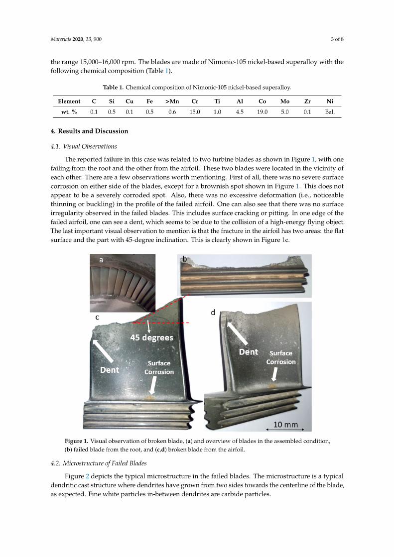
The reported failure in this case was related to two turbine blades as shown in Figure 1, with onefailing from the root and the other from the airfoil. These two blades were located in the vicinity ofeach other. There are a few observations worth mentioning. First of all, there was no severe surfacecorrosion on either side of the blades, except for a brownish spot shown in Figure 1. This does notappear to be a severely corroded spot. Also, there was no excessive deformation (i.e., noticeablethinning or buckling) in the profile of the failed airfoil. One can also see that there was no surfaceirregularity observed in the failed blades. This includes surface cracking or pitting. In one edge of thefailed airfoil, one can see a dent, which seems to be due to the collision of a high-energy flying object.The last important visual observation to mention is that the fracture in the airfoil has two areas: the flatsurface and the part with 45-degree inclination. This is clearly shown in Figure 1c.
Materials 2020, 9, x FOR PEER REVIEW 3 of 8
easier. The working temperature in the hot section of the turbine is 700–850 °C. The rotating speed of the blades is in the range 15,000–16,000 rpm. The blades are made of Nimonic-105 nickel-based superalloy with the following chemical composition (Table 1).
Table 1. Chemical composition of Nimonic-105 nickel-based superalloy.
Element C Si Cu Fe Mn Cr Ti Al Co Mo Zr Ni wt. % 0.1 0.5 0.1 0.5 0.6 15.0 1.0 4.5 19.0 5.0 0.1 Bal.
4. Results and Discussion
4.1. Visual Observations
The reported failure in this case was related to two turbine blades as shown in Figure 1, with one failing from the root and the other from the airfoil. These two blades were located in the vicinity of each other. There are a few observations worth mentioning. First of all, there was no severe surface corrosion on either side of the blades, except for a brownish spot shown in Figure 1. This does not appear to be a severely corroded spot. Also, there was no excessive deformation (i.e., noticeable thinning or buckling) in the profile of the failed airfoil. One can also see that there was no surface irregularity observed in the failed blades. This includes surface cracking or pitting. In one edge of the failed airfoil, one can see a dent, which seems to be due to the collision of a high-energy flying object. The last important visual observation to mention is that the fracture in the airfoil has two areas: the flat surface and the part with 45-degree inclination. This is clearly shown in Figure 1c.
Figure 1. Visual observation of broken blade, (a) and overview of blades in the assembled condition, (b) failed blade from the root, and (c,d) broken blade from the airfoil.
4.2. Microstructure of Failed Blades
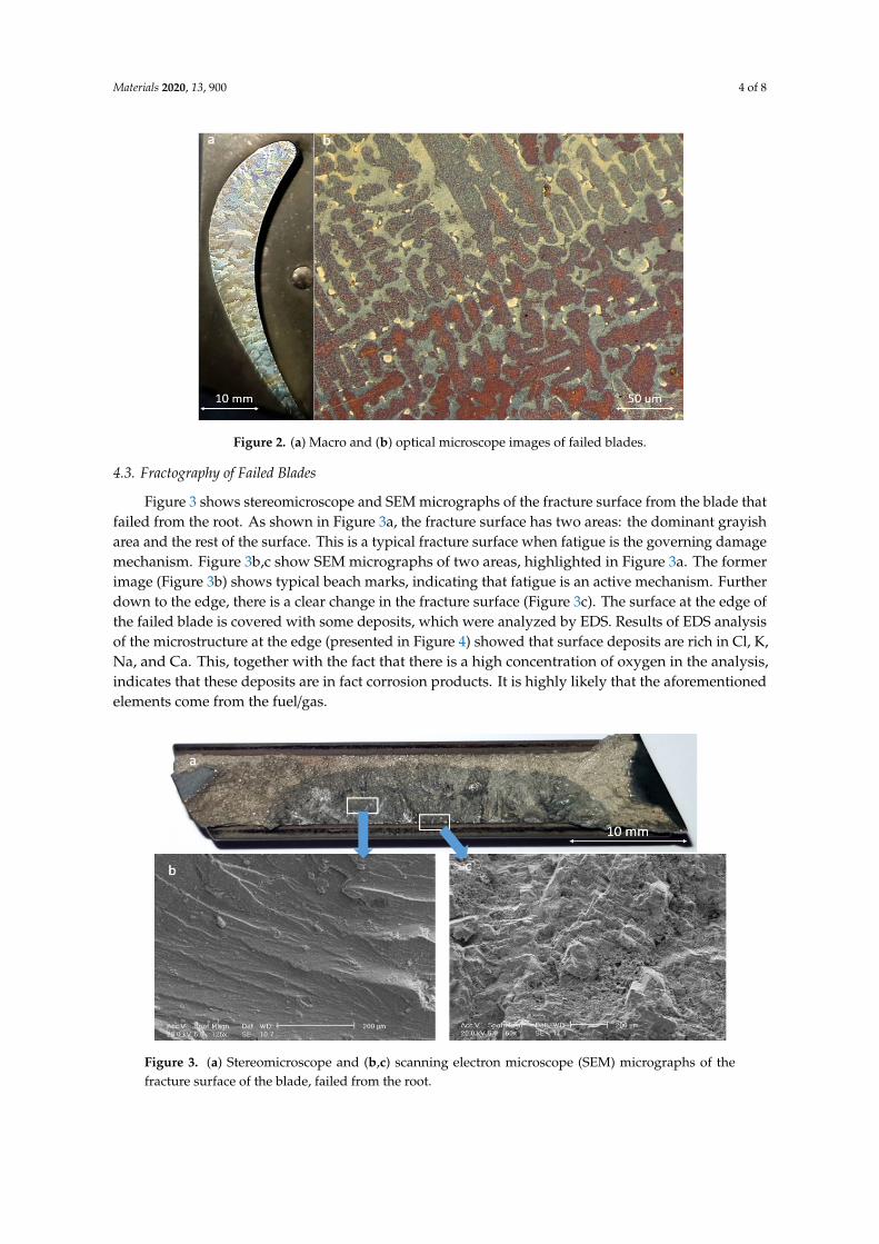
Figure 2 depicts the typical microstructure in the failed blades. The microstructure is a typical dendritic cast structure where dendrites have grown from two sides towards the centerline of the blade, as expected. Fine white particles in-between dendrites are carbide particles.
Figure 1. Visual observation of broken blade, (a) and overview of blades in the assembled condition,(b) failed blade from the root, and (c,d) broken blade from the airfoil.
4.2. Microstructure of Failed Blades
Figure 2 depicts the typical microstructure in the failed blades. The microstructure is a typicaldendritic cast structure where dendrites have grown from two sides towards the centerline of the blade,as expected. Fine white particles in-between dendrites are carbide particles.
Materials 2020, 13, 900 4 of 8
Materials 2020, 9, x FOR PEER REVIEW 4 of 8
Figure 2. (a) Macro and (b) optical microscope images of failed blades.
4.3. Fractography of Failed Blades
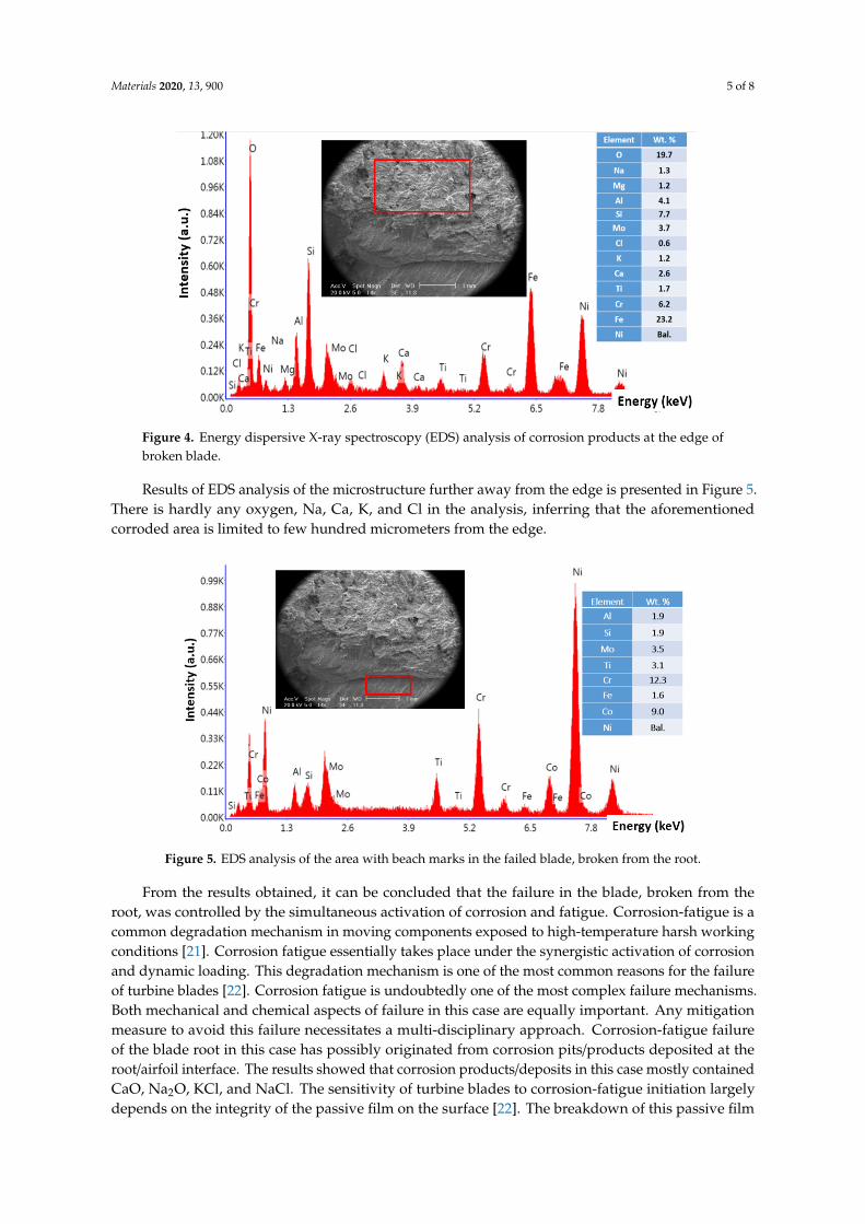
Figure 3 shows stereomicroscope and SEM micrographs of the fracture surface from the blade that failed from the root. As shown in Figure 3a, the fracture surface has two areas: the dominant grayish area and the rest of the surface. This is a typical fracture surface when fatigue is the governing damage mechanism. Figure 3b,c show SEM micrographs of two areas, highlighted in Figure 3a. The former image (Figure 3b) shows typical beach marks, indicating that fatigue is an active mechanism. Further down to the edge, there is a clear change in the fracture surface (Figure 3c). The surface at the edge of the failed blade is covered with some deposits, which were analyzed by EDS. Results of EDS analysis of the microstructure at the edge (presented in Figure 4) showed that surface deposits are rich in Cl, K, Na, and Ca. This, together with the fact that there is a high concentration of oxygen in the analysis, indicates that these deposits are in fact corrosion products. It is highly likely that the aforementioned elements come from the fuel/gas.
Figure 3. (a) Stereomicroscope and (b,c) scanning electron microscope (SEM) micrographs of the fracture surface of the blade, failed from the root.
Figure 2. (a) Macro and (b) optical microscope images of failed blades.
4.3. Fractography of Failed Blades
Figure 3 shows stereomicroscope and SEM micrographs of the fracture surface from the blade thatfailed from the root. As shown in Figure 3a, the fracture surface has two areas: the dominant grayisharea and the rest of the surface. This is a typical fracture surface when fatigue is the governing damagemechanism. Figure 3b,c show SEM micrographs of two areas, highlighted in Figure 3a. The formerimage (Figure 3b) shows typical beach marks, indicating that fatigue is an active mechanism. Furtherdown to the edge, there is a clear change in the fracture surface (Figure 3c). The surface at the edge ofthe failed blade is covered with some deposits, which were analyzed by EDS. Results of EDS analysisof the microstructure at the edge (presented in Figure 4) showed that surface deposits are rich in Cl, K,Na, and Ca. This, together with the fact that there is a high concentration of oxygen in the analysis,indicates that these deposits are in fact corrosion products. It is highly likely that the aforementionedelements come from the fuel/gas.
Materials 2020, 9, x FOR PEER REVIEW 4 of 8
Figure 2. (a) Macro and (b) optical microscope images of failed blades.
4.3. Fractography of Failed Blades
Figure 3 shows stereomicroscope and SEM micrographs of the fracture surface from the blade that failed from the root. As shown in Figure 3a, the fracture surface has two areas: the dominant grayish area and the rest of the surface. This is a typical fracture surface when fatigue is the governing damage mechanism. Figure 3b,c show SEM micrographs of two areas, highlighted in Figure 3a. The former image (Figure 3b) shows typical beach marks, indicating that fatigue is an active mechanism. Further down to the edge, there is a clear change in the fracture surface (Figure 3c). The surface at the edge of the failed blade is covered with some deposits, which were analyzed by EDS. Results of EDS analysis of the microstructure at the edge (presented in Figure 4) showed that surface deposits are rich in Cl, K, Na, and Ca. This, together with the fact that there is a high concentration of oxygen in the analysis, indicates that these deposits are in fact corrosion products. It is highly likely that the aforementioned elements come from the fuel/gas.
Figure 3. (a) Stereomicroscope and (b,c) scanning electron microscope (SEM) micrographs of the fracture surface of the blade, failed from the root.
Figure 3. (a) Stereomicroscope and (b,c) scanning electron microscope (SEM) micrographs of thefracture surface of the blade, failed from the root.
Materials 2020, 13, 900 5 of 8
Materials 2020, 9, x FOR PEER REVIEW 5 of 8
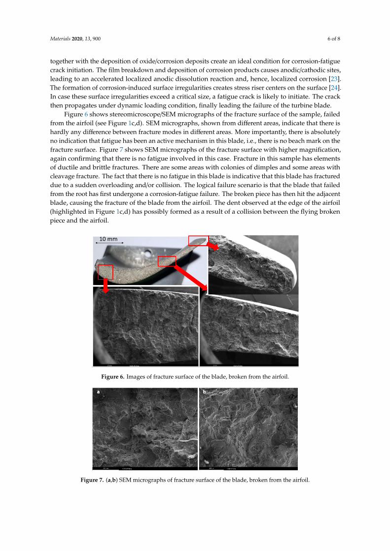
Figure 4. Energy dispersive X-ray spectroscopy (EDS) analysis of corrosion products at the edge of broken blade.
Results of EDS analysis of the microstructure further away from the edge is presented in Figure 5. There is hardly any oxygen, Na, Ca, K, and Cl in the analysis, inferring that the aforementioned corroded area is limited to few hundred micrometers from the edge.
Figure 5. EDS analysis of the area with beach marks in the failed blade, broken from the root.
From the results obtained, it can be concluded that the failure in the blade, broken from the root, was controlled by the simultaneous activation of corrosion and fatigue. Corrosion-fatigue is a common degradation mechanism in moving components exposed to high-temperature harsh working conditions [21]. Corrosion fatigue essentially takes place under the synergistic activation of corrosion and dynamic loading. This degradation mechanism is one of the most common reasons for the failure of turbine blades [22]. Corrosion fatigue is undoubtedly one of the most complex failure mechanisms. Both mechanical and chemical aspects of failure in this case are equally important. Any mitigation measure to avoid this failure necessitates a multi-disciplinary approach. Corrosion-fatigue failure of the blade root in this case has possibly originated from corrosion pits/products deposited at the root/airfoil interface. The results showed that corrosion products/deposits in this case mostly contained CaO, Na2O, KCl, and NaCl. The sensitivity of turbine blades to corrosion-fatigue initiation
Figure 4. Energy dispersive X-ray spectroscopy (EDS) analysis of corrosion products at the edge ofbroken blade.
Results of EDS analysis of the microstructure further away from the edge is presented in Figure 5.There is hardly any oxygen, Na, Ca, K, and Cl in the analysis, inferring that the aforementionedcorroded area is limited to few hundred micrometers from the edge.
Materials 2020, 9, x FOR PEER REVIEW 5 of 8
Figure 4. Energy dispersive X-ray spectroscopy (EDS) analysis of corrosion products at the edge of broken blade.
Results of EDS analysis of the microstructure further away from the edge is presented in Figure 5. There is hardly any oxygen, Na, Ca, K, and Cl in the analysis, inferring that the aforementioned corroded area is limited to few hundred micrometers from the edge.
Figure 5. EDS analysis of the area with beach marks in the failed blade, broken from the root.
From the results obtained, it can be concluded that the failure in the blade, broken from the root, was controlled by the simultaneous activation of corrosion and fatigue. Corrosion-fatigue is a common degradation mechanism in moving components exposed to high-temperature harsh working conditions [21]. Corrosion fatigue essentially takes place under the synergistic activation of corrosion and dynamic loading. This degradation mechanism is one of the most common reasons for the failure of turbine blades [22]. Corrosion fatigue is undoubtedly one of the most complex failure mechanisms. Both mechanical and chemical aspects of failure in this case are equally important. Any mitigation measure to avoid this failure necessitates a multi-disciplinary approach. Corrosion-fatigue failure of the blade root in this case has possibly originated from corrosion pits/products deposited at the root/airfoil interface. The results showed that corrosion products/deposits in this case mostly contained CaO, Na2O, KCl, and NaCl. The sensitivity of turbine blades to corrosion-fatigue initiation
Figure 5. EDS analysis of the area with beach marks in the failed blade, broken from the root.
From the results obtained, it can be concluded that the failure in the blade, broken from theroot, was controlled by the simultaneous activation of corrosion and fatigue. Corrosion-fatigue is acommon degradation mechanism in moving components exposed to high-temperature harsh workingconditions [21]. Corrosion fatigue essentially takes place under the synergistic activation of corrosionand dynamic loading. This degradation mechanism is one of the most common reasons for the failureof turbine blades [22]. Corrosion fatigue is undoubtedly one of the most complex failure mechanisms.Both mechanical and chemical aspects of failure in this case are equally important. Any mitigationmeasure to avoid this failure necessitates a multi-disciplinary approach. Corrosion-fatigue failureof the blade root in this case has possibly originated from corrosion pits/products deposited at theroot/airfoil interface. The results showed that corrosion products/deposits in this case mostly containedCaO, Na2O, KCl, and NaCl. The sensitivity of turbine blades to corrosion-fatigue initiation largelydepends on the integrity of the passive film on the surface [22]. The breakdown of this passive film
Materials 2020, 13, 900 6 of 8
together with the deposition of oxide/corrosion deposits create an ideal condition for corrosion-fatiguecrack initiation. The film breakdown and deposition of corrosion products causes anodic/cathodic sites,leading to an accelerated localized anodic dissolution reaction and, hence, localized corrosion [23].The formation of corrosion-induced surface irregularities creates stress riser centers on the surface [24].In case these surface irregularities exceed a critical size, a fatigue crack is likely to initiate. The crackthen propagates under dynamic loading condition, finally leading the failure of the turbine blade.
Figure 6 shows stereomicroscope/SEM micrographs of the fracture surface of the sample, failedfrom the airfoil (see Figure 1c,d). SEM micrographs, shown from different areas, indicate that there ishardly any difference between fracture modes in different areas. More importantly, there is absolutelyno indication that fatigue has been an active mechanism in this blade, i.e., there is no beach mark on thefracture surface. Figure 7 shows SEM micrographs of the fracture surface with higher magnification,again confirming that there is no fatigue involved in this case. Fracture in this sample has elementsof ductile and brittle fractures. There are some areas with colonies of dimples and some areas withcleavage fracture. The fact that there is no fatigue in this blade is indicative that this blade has fractureddue to a sudden overloading and/or collision. The logical failure scenario is that the blade that failedfrom the root has first undergone a corrosion-fatigue failure. The broken piece has then hit the adjacentblade, causing the fracture of the blade from the airfoil. The dent observed at the edge of the airfoil(highlighted in Figure 1c,d) has possibly formed as a result of a collision between the flying brokenpiece and the airfoil.
Materials 2020, 9, x FOR PEER REVIEW 6 of 8
largely depends on the integrity of the passive film on the surface [22]. The breakdown of this passive film together with the deposition of oxide/corrosion deposits create an ideal condition for corrosion-fatigue crack initiation. The film breakdown and deposition of corrosion products causes anodic/cathodic sites, leading to an accelerated localized anodic dissolution reaction and, hence, localized corrosion [23]. The formation of corrosion-induced surface irregularities creates stress riser centers on the surface [24]. In case these surface irregularities exceed a critical size, a fatigue crack is likely to initiate. The crack then propagates under dynamic loading condition, finally leading the failure of the turbine blade.
Figure 6 shows stereomicroscope/SEM micrographs of the fracture surface of the sample, failed from the airfoil (see Figure 1c,d). SEM micrographs, shown from different areas, indicate that there is hardly any difference between fracture modes in different areas. More importantly, there is absolutely no indication that fatigue has been an active mechanism in this blade, i.e., there is no beach mark on the fracture surface. Figure 7 shows SEM micrographs of the fracture surface with higher magnification, again confirming that there is no fatigue involved in this case. Fracture in this sample has elements of ductile and brittle fractures. There are some areas with colonies of dimples and some areas with cleavage fracture. The fact that there is no fatigue in this blade is indicative that this blade has fractured due to a sudden overloading and/or collision. The logical failure scenario is that the blade that failed from the root has first undergone a corrosion-fatigue failure. The broken piece has then hit the adjacent blade, causing the fracture of the blade from the airfoil. The dent observed at the edge of the airfoil (highlighted in Figure 1c,d) has possibly formed as a result of a collision between the flying broken piece and the airfoil.
Figure 6. Images of fracture surface of the blade, broken from the airfoil.
Figure 7. (a,b) SEM micrographs of fracture surface of the blade, broken from the airfoil.
Figure 6. Images of fracture surface of the blade, broken from the airfoil.
Materials 2020, 9, x FOR PEER REVIEW 6 of 8
largely depends on the integrity of the passive film on the surface [22]. The breakdown of this passive film together with the deposition of oxide/corrosion deposits create an ideal condition for corrosion-fatigue crack initiation. The film breakdown and deposition of corrosion products causes anodic/cathodic sites, leading to an accelerated localized anodic dissolution reaction and, hence, localized corrosion [23]. The formation of corrosion-induced surface irregularities creates stress riser centers on the surface [24]. In case these surface irregularities exceed a critical size, a fatigue crack is likely to initiate. The crack then propagates under dynamic loading condition, finally leading the failure of the turbine blade.
Figure 6 shows stereomicroscope/SEM micrographs of the fracture surface of the sample, failed from the airfoil (see Figure 1c,d). SEM micrographs, shown from different areas, indicate that there is hardly any difference between fracture modes in different areas. More importantly, there is absolutely no indication that fatigue has been an active mechanism in this blade, i.e., there is no beach mark on the fracture surface. Figure 7 shows SEM micrographs of the fracture surface with higher magnification, again confirming that there is no fatigue involved in this case. Fracture in this sample has elements of ductile and brittle fractures. There are some areas with colonies of dimples and some areas with cleavage fracture. The fact that there is no fatigue in this blade is indicative that this blade has fractured due to a sudden overloading and/or collision. The logical failure scenario is that the blade that failed from the root has first undergone a corrosion-fatigue failure. The broken piece has then hit the adjacent blade, causing the fracture of the blade from the airfoil. The dent observed at the edge of the airfoil (highlighted in Figure 1c,d) has possibly formed as a result of a collision between the flying broken piece and the airfoil.
Figure 6. Images of fracture surface of the blade, broken from the airfoil.
Figure 7. (a,b) SEM micrographs of fracture surface of the blade, broken from the airfoil. Figure 7. (a,b) SEM micrographs of fracture surface of the blade, broken from the airfoil.
Materials 2020, 13, 900 7 of 8
5. Concluding Remarks
This paper investigates a failure in gas-turbine blades made of Nimonic-105 nickel-based superalloy.Two broken blades were investigated, with one having failed from the root and the other from theairfoil. Blades are from the second row of the gas producer/hot section of a gas turbine with workingtemperature being in the range 700–850 ◦C and rotating speed in the range 15,000–16,000 rpm. Thefailure was reported after 20 k hours of service, which is much shorter than the anticipated service life.The following conclusions can be drawn, based on the data obtained:
− Nimonic-105 superalloy in this case had a typical dendritic cast structure, with dendrites growingfrom the edges towards the center.
− There were no surface irregularities, excessive deformation, buckling, or surface cracking observedon the surface of the blades, except for a dent on the edge of one of the broken blades.
− Results showed that corrosion fatigue is the governing failure mechanism in the blade that failedfrom the root. In this case, there are corrosion deposits at the edge of the blade, rich in Cl, Ca, O,Na, and K. Fatigue cracks have initiated from corroded spots at the edge of the blade.
− Fractography of the blade that failed from the airfoil showed that, contrary to the former case,there is hardly any fatigue involved in the failure of this blade.
− It was concluded that the blade that failed from the root first underwent a corrosion-fatiguefailure, finally ending up in the breakage of the airfoil from the root. The broken piece then hitthe adjacent blade in its trajectory, causing the fracture of the adjacent blade from the airfoil. Thedent observed at the edge of the airfoil possibly formed as a result of the collision between theflying broken piece and the airfoil.
− Given that both corrosion and fatigue mechanisms were involved in this failure, it is important tominimize mechanical vibrations and to reduce contaminants in the system. The latter necessitatesfurther investigation on the origins of the Cl, Na, and Ca-containing residues and how they canbe controlled/eliminated from the system.
Author Contributions: Conceptualization, M.R. and M.M.; methodology, M.R., S.J.S. and A.B.; formal analysis,A.B., S.J.S. and M.M.; investigation, M.R. and M.M.; writing—original draft preparation, A.B.; writing—reviewand editing, A.B. and P.T.; visualization, A.B.; supervision, A.B., M.M. and P.T.; project administration, P.T. Allauthors have read and agreed to the published version of the manuscript.
Funding: This research received no external funding.
Acknowledgments: Authors would like to thank Delft University of Technology for support in publishingthis manuscript.
Conflicts of Interest: The authors declare no conflict of interest.
References
1. Maktouf, W.; Saï, K. An investigation of premature fatigue failures of gas turbine blade. Eng. Fail. Anal.2015, 47, 89–101. [CrossRef]
2. Carter, T. Common failures in gas turbine blades. Eng. Fail. Anal. 2005, 12, 237–247. [CrossRef]3. Wang, W.; Xuan, F. Failure analysis of the final stage blade in steam turbine. Eng. Fail. Anal. 2007, 14,
632–641. [CrossRef]4. Vardar, N.; Ekerim, A. Failure analysis of gas turbine blades in a thermal power plant. Eng. Fail. Anal. 2007,
14, 743–749. [CrossRef]5. Bhaumik, S.K.; Sujata, M. Failure of a low pressure turbine rotor blade of an aero engine. Eng. Fail. Anal.
2006, 13, 1202–1219. [CrossRef]6. Kargarnejad, S.; Djavanroodi, F. Failure assessment of Nimonic 80 A gas turbine blade. Eng. Fail. Anal. 2012,
26, 211–219. [CrossRef]7. Qu, S.; Fu, C.; Dong, C.; Tian, J.; Zhang, Z. Failure analysis of the 1st stage blades in gas turbine engine. Eng.
Fail. Anal. 2013, 32, 292–303. [CrossRef]
Materials 2020, 13, 900 8 of 8
8. Poursaeidi, E.; Babaei, A.; Mohammadi Arhani, M.; Arablu, M. Effects of natural frequencies on the failure ofR1 compressor blades. Eng. Fail. Anal. 2012, 25, 304–315. [CrossRef]
9. Rama Rao, A.; Dutta, B. Vibration analysis for detecting failure of compressor blade. Eng. Fail. Anal. 2012,25, 211–218. [CrossRef]
10. Witek, L. Experimental crack propagation and failure analysis of the first stage compressor blade subjectedto vibration. Eng. Fail. Anal. 2009, 16, 2163–2170. [CrossRef]
11. Mazur, Z.; Garcia-Illescas, R.; Porcayo-Calderon, J. Last stage blades failure analysis of a 28 MW geothermalturbine. Eng. Fail. Anal. 2009, 16, 1020–1032. [CrossRef]
12. Witek, L. Numerical stress and crack initiation analysis of the compressor blades after foreign object damagesubjected to high-cycle fatigue. Eng. Fail. Anal. 2011, 18, 2111–2125. [CrossRef]
13. Silveira, E.; Atxaga, G.; Irisarri, A. Failure analysis of a set of compressor blades. Eng. Fail. Anal. 2008, 15,666–674. [CrossRef]
14. Lourenço, N.; Graça, M.; Franco, L.A.L.; Silva, O. Fatigue failure of a compressor blade. Eng. Fail. Anal. 2008,15, 1150–1154. [CrossRef]
15. Bhagi, L.; Gupta, P.; Rastogi, V. Fractographic investigations of the failure of L-1 low pressure steam turbineblade. Case Stud. Eng. Fail. Anal. 2013, 1, 72–78. [CrossRef]
16. Ziegler, D.; Puccinelli, M.; Bergallo, B.; Picasso, A. Investigation of turbine blade failure in a thermal powerplant. Case Stud. Eng. Fail. Anal. 2013, 1, 192–199. [CrossRef]
17. Kolagar, A.M.; Tabrizi, N.; Cheraghzadeh, M.; Shahriari, M.S. Failure analysis of gas turbine first stage blademade of nickel-based superalloy. Case Stud. Eng. Fail. Anal. 2017, 8, 61–68. [CrossRef]
18. Mousavi Anijdan, S.H.; Bahrami, A. A new method in prediction of TCP phases formation in superalloys.Mater. Sci. Eng. A 2005, 396, 138–142. [CrossRef]
19. Thakur, A.; Gangopadhyay, S. State-of-the-art in surface integrity in machining of nickel-based super alloys.Int. J. Machine Tools Manuf. 2016, 100, 25–54. [CrossRef]
20. Wright, P.K.; Chow, J.G. Deformation characteristics of nickel alloys during machining. J. Eng. Mater. Tech.ASME 1982, 104, 85–93. [CrossRef]
21. Schönbauer, B.; Tschegg, S.; Perlega, A.; Salzman, R.; Rieger, N.; Zhou, S.; Turnbull, A.; Gandy, D. Fatigue lifeestimation of pitted 12% Cr turbine blade steel in different environments and at different stress ratios. Int. J.Fatigue 2014, 65, 33–43. [CrossRef]
22. Larrosa, N.O.; Akid, R.; Ainsworth, R.A. Corrosion-fatigue: A review of damage tolerance models. Int.Mater. Rev. 2017, 63, 283–308. [CrossRef]
23. Kiani Khouzani, M.; Bahrami, A.; Hosseini-Abari, A.; Khandouzi, M.; Taheri, P. Microbiologically InfluencedCorrosion of a Pipeline in a Petrochemical Plant. Metals 2019, 9, 459. [CrossRef]
24. Kiani Khouzani, M.; Bahrami, A.; Eslami, A. Metallurgical aspects of failure in a broken femoral HIPprosthesis. Eng. Fail. Anal. 2018, 90, 168–178. [CrossRef]
25. Hadizadeh, B.; Bahrami, A.; Eslami, A.; Abdian, K.; Younes Araghi, M.; Etezazi, M. Establishing the cause offailure in continuous casting rolls. Eng. Fail. Anal. 2020, 108, 104346. [CrossRef]
26. Bahrami, A.; Taheri, P. Creep failure of reformer tubes in a petrochemical plant. Metals 2019, 9, 1026.[CrossRef]
27. Bahrami, A.; Kiani Khouzani, M.; Mokhtari, S.A.; Zareh, S.; Yazdan Mehr, M. Root cause analysis of surfacecracks in heavy steel plates during the hot rolling process. Metals 2019, 9, 801. [CrossRef]
28. Abdali Varnosfaderani, M.; Eslami, A.; Saiedi, N.; Bahrami, A. Metallurgical aspects of a blowdown pipefailure in a petrochemical plant. Eng. Fail. Anal. 2019, 98, 141–149. [CrossRef]
29. Bahrami, A.; Mousavi Anijdan, S.H.; Taheri, P.; Yazdan Mehr, M. Failure of AISI 304H stainless steel elbowsin a heat exchanger. Eng. Fail. Anal. 2018, 90, 397–403. [CrossRef]
30. Bahrami, A.; Taheri, P. A Study on the failure of AISI 304 stainless steel tubes in a gas heater unit. Metals2019, 9, 969. [CrossRef]
© 2020 by the authors. Licensee MDPI, Basel, Switzerland. This article is an open accessarticle distributed under the terms and conditions of the Creative Commons Attribution(CC BY) license (http://creativecommons.org/licenses/by/4.0/).