Gas Turbine Diagnostic Algorithm Testing Using the Software ...

Assignment No:2Assignment Title:Function and operation of gas turbine engines Unit No:83 Unit Title: Aircraft Gas Turbine Engines
TASK: 01 (P4)
1.1
TURBOPROP ENGINE: A turboprop engine is a type of aircraft power
plant which uses a gas turbine to drive a propeller. Turboprop engines
also belong to the group torque turbine engine. Speed of the shaft of
this engine is very high. In this engine a reduction gearbox is
required between the engine shaft and propeller for reducing
invariable requires speed.
The engine's exhaust gases contain little energy and play a minor role
in the propulsion of the aircraft. A turboprop engine can be two types
of engine. One is single spool engine and other is twin spool engine.
Advantage of turboprop engine:
At lower altitude turboprop engine is more efficient than
turbojet engine.
Turboprop engine can give high thrust power with respect of fuel
consumption.
It creates lees noise than turbo jet engine.
Propeller of this engine can rotate in different angles.
It can create more thrust.
When aircraft is on take of position in maximum angle then it can
give maximum thrust.
Page | 1 ZIAD IBNE ANISH ID#ACB-09-04-20

Assignment No:2Assignment Title:Function and operation of gas turbine engines Unit No:83 Unit Title: Aircraft Gas Turbine Engines
This type of engine aircraft takes short field for takeoff and
landing.
Disadvantage of turboprop engine:
Less thrust then turbojet engines.
Providing low speed
Turboprop engines aircraft are flying at lower altitude
efficiently
Used in short distance aircraft
Turbojet engines: As a pure jet called turbojet engine. Turbojets
consist of an air inlet, an air compressor, a combustion chamber,
turbine, exhaust nozzles.
Advantage of turbojet engine:
Turbojets are more efficient then turboprop at higher altitude
It is situated for subsonic and supersonic.
Less time consuming top fly any where
Disadvantage of turbojet engine:
Fuel consumption is very high
Creating noise pollution
Page | 2 ZIAD IBNE ANISH ID#ACB-09-04-20

Assignment No:2Assignment Title:Function and operation of gas turbine engines Unit No:83 Unit Title: Aircraft Gas Turbine Engines
Inefficient at the lower altitude
Maintenance cost at higher rate
1.2
APU: It stands for Auxiliary power unit. When an aircraft is on
ground then it is called ground power unit. And in flying condition it
is called airborne Auxiliary power unit.
Construction:
This consists of compressor single entry centrifugal compressor or
axial flow compressor followed by centrifugal compressor, reverse flow
combustion chamber, turbine and exhaust.
Operation:
Air goes into the compressor through intake. The impeller is rotated
at higher speed by the turbine and air flows into the combustion
chamber. Therefore combustion chamber is reversed type. In the
combustion chamber fuel is mixing and combustion takes place. After
combustion the gas flows at higher speed that rotate the turbine. Of
course APU is not provided thrust but it drives some different
accessories.
Installation of APU:
APU is located at the tail section by means of nuts and bolt. There
are some struits to attach with APU.
Page | 3 ZIAD IBNE ANISH ID#ACB-09-04-20

Assignment No:2Assignment Title:Function and operation of gas turbine engines Unit No:83 Unit Title: Aircraft Gas Turbine Engines
TASK: 02 (P5)
Various type of air intake used in gas turbine engines now a day. Some
of them are:
Pitot type intake
Side scoop intake
Wing root inlet
Air flow through a Pitot type intake is described below:
This type of intake has divergent duct shaped interior to receive
ram air at the entry and convert to ram pressure as maximum as
possible before delivery to the compressor , which means the intake
increase the pressure and describe the velocity of incoming air.
This type of intake is most suitable to pod installed engine under
the wing and also fuselages side mounted engines.
Page | 4 ZIAD IBNE ANISH ID#ACB-09-04-20

Assignment No:2Assignment Title:Function and operation of gas turbine engines Unit No:83 Unit Title: Aircraft Gas Turbine Engines
TASK: 03 (P6)
Centrifugal flow compressor: The centrifugal flow compressor is a
single or two stage units employing an impeller to accelerate the air
and a diffuser to produce the required pressure rise.
It is consist of three main components:
(a) Impeller and the casing
(b) Diffuser
(c) Manifold
Page | 5 ZIAD IBNE ANISH ID#ACB-09-04-20

Assignment No:2Assignment Title:Function and operation of gas turbine engines Unit No:83 Unit Title: Aircraft Gas Turbine Engines
FIG: Centrifugal compressor
Construction: The construction of the compressor centers on the
impeller, diffuser and air intake system. The impeller shaft rotates
in ball and roller bearings and is either common to the
turbine shaft or split in the centre or connected by a coupling, which
is usually designed for ease of detachment.
Impellers: The impeller consists of a .forged, disc with integral,
radically disposed vanes on one or both sides forming convergentPage | 6 ZIAD IBNE ANISH ID#ACB-09-04-20

Assignment No:2Assignment Title:Function and operation of gas turbine engines Unit No:83 Unit Title: Aircraft Gas Turbine Engines passages in conjunction with the compressor casing. The vanes may be
swept back, but for ease of manufacture straight radial vanes are
usually employed.
Diffuser: The diffuser assembly may be an integral part of the
compressor casing or a separately attached assembly. In each instance
it consists of a number of vanes formed tangential to the impeller.
The vane passages are divergent to convert the kinetic energy into
pressure energy and the inner edges of the vanes are in line with the
direction of the resultant airflow from the impeller. The clearance
between the impeller and the diffuser is an important factor, as too
small a clearance will set up aerodynamic buffeting impulses that
could be transferred to the impeller and create an unsteady airflow
and vibration.
Operation: The impeller is rotated at high speed by the turbine and
air is continuously induced into the centre of the impeller.
Centrifugal action causes it to flow radically outwards along the
vanes to the impeller tip, thus accelerating the air and also causing
a rise in pressure to occur. The air, on leaving the impeller, passes
into the diffuser section where the passages form divergent nozzles
that convert most of the kinetic energy into pressure energy. To
maintain the efficiency of the compressor, it is necessary to prevent
excessive air leakage between the impeller and the casing; this is
achieved by keeping their clearances as small as possible.
Page | 7 ZIAD IBNE ANISH ID#ACB-09-04-20

Assignment No:2Assignment Title:Function and operation of gas turbine engines Unit No:83 Unit Title: Aircraft Gas Turbine Engines Axial flow compressor: This type of compressor has one or more rotor
assemblies, which carry blades of airfoil section. The compressor is a
multi-stage unit as the amount of pressure increase by each stage is
small; a stage consists of a row of rotating blades followed by a row
of stator vanes.
Construction: The construction of the compressor centers on the rotor
assembly and casings. The rotor shaft is supported in ball and roller
bearings and coupled to the turbine shaft in a manner that allows for
any slight variation of alignment.
FIG: Axial flow compressor
The cylindrical casing assembly may consist of a number of cylindrical
casings with a bolted axial joint between each stage or the casing may
be in two halves with a bolted centre line joint.
Page | 8 ZIAD IBNE ANISH ID#ACB-09-04-20

Assignment No:2Assignment Title:Function and operation of gas turbine engines Unit No:83 Unit Title: Aircraft Gas Turbine Engines
Fig. Rotors of drum and disc construction
Rotors: In compressor designs (fig. 3-10) the rotational speed is such
that a disc is required to support the centrifugal blade load. The
rotor assembly may be of a drum or disc-type construction, or a
combination of both types.
The drum-type rotor consists of a one or two-piece forging on to which
are secured the rotor blades. The disc type rotor has the rotor blades
attached to separate discs, which are then splinted to the rotor shaft
and separated by integral or-individual spacer rings.
Rotor blades: The rotor blades are of airfoil section and usually
designed to give a pressure gradient along their length to ensure that
Page | 9 ZIAD IBNE ANISH ID#ACB-09-04-20

Assignment No:2Assignment Title:Function and operation of gas turbine engines Unit No:83 Unit Title: Aircraft Gas Turbine Engines the air maintains a reasonably uniform axial velocity. 'Twist' the
blade from root to tip to give the correct angle of attack at each
point. The length of the blades varies from front to rear; the frontal
& low pressure blades are longer then the rare.
Stator blades: The stator vanes are again of airfoil section and are
secured into the compressor casing or into stator vane retaining
rings, which are themselves secured to the casing. The blades are
often mounted in packs in the front stages and may be shrouded at
their tips to minimize the vibration effect of flow variations on the
longer blades. It is also necessary to lock the stator blades in such
a manner that they will not rotate around the casing.
Operation: When the compressor starts rolling at high speed by the
turbine, air is continuously induced into the compressor, which is
then accelerated by the rotating blades and swept rearwards onto the
adjacent row of stator vanes. So, the pressure is increased in every
stage. The pressure ratio of outgoing air & inlet air is between 1:1
and 1:2. Though the pressure ratio of each stage is small but it
increases too much at the end of last stage because it has multistage
compressor. Where high pressure ratios are required from a single
compressor this problem can be overcome by introducing variable stator
vanes in the front stages of the system.
TASK: 04(P7)
Page | 10 ZIAD IBNE ANISH ID#ACB-09-04-20

Assignment No:2Assignment Title:Function and operation of gas turbine engines Unit No:83 Unit Title: Aircraft Gas Turbine Engines Multiple can: This type of combustion chamber is used on centrifugal
compressor engines and the earlier types of axial flow compressor
engines. The chambers are disposed around the engine. And compressor
delivery air is directed by ducts to pass into the individual
chambers. Each chamber has an inner flame tube around which there is
an air casing. The separate flame tubes are all interconnected.
FIG: Multi can type combustion chamber
Can annular: The can-annular combustion chamber bridges the
evolutionary gap between the multiple and annular types. A number of
flame tubes are fitted inside a common air casing. This arrangement
combines the ease of overhaul and testing of the multiple systems with
the compactness of the annular system.
Page | 11 ZIAD IBNE ANISH ID#ACB-09-04-20

Assignment No:2Assignment Title:Function and operation of gas turbine engines Unit No:83 Unit Title: Aircraft Gas Turbine Engines
Annular: This type of combustion chamber consists of a single flame
tube, completely annular in form, which is contained in an inner and
outer casing. The main advantage of the annular chamber is that, for
the same power output, the length of the chamber is only 75 per cent
of that
of a tubo-annular system of the same diameter, resulting in
considerable saving of weight and production cost.
Page | 12 ZIAD IBNE ANISH ID#ACB-09-04-20

Assignment No:2Assignment Title:Function and operation of gas turbine engines Unit No:83 Unit Title: Aircraft Gas Turbine Engines
FIG: Annular type combustion chamber
4.1
use of individual components of the combustion chamber:
Case:
Diffuser
Liner
Dome and Swirler
Fuel injector:
4.2
Advantages Page | 13 ZIAD IBNE ANISH ID#ACB-09-04-20

Assignment No:2Assignment Title:Function and operation of gas turbine engines Unit No:83 Unit Title: Aircraft Gas Turbine Engines Multiple can type:
In multiple can combustion chambers, chambers are disposed around
the engine and compressor delivery air is directed by ducts to
pass into the individual chambers.
The separate flame tubes are all interconnected. This allows each
tube to operate at the same pressure and also allows combustion
to propagate around the flame tubes during engine starting.
Can annular type:
The turbo-annular combustion chamber bridges the evolutionary gap
between the multiple and annular types.
A number of flame tubes are fitted inside a common air casing.
This arrangement combines the ease of overhaul and testing of the
multiple systems with the compactness of the annular system.
Annular type:
This type of combustion chamber consists of a single flame tube,
completely annular in form, which is contained in an inner and
outer casing.
For the same power output, the length of the chamber is only 75
per cent of that of a turbo-annular system of the same diameter,
resulting in considerable saving of weight and production cost.
The elimination of combustion propagation problems from chamber
to chamber.
Page | 14 ZIAD IBNE ANISH ID#ACB-09-04-20

Assignment No:2Assignment Title:Function and operation of gas turbine engines Unit No:83 Unit Title: Aircraft Gas Turbine Engines
TASK: 05 (P8)
Impulse turbine:
In the stator –nozzles; the entire pressure drops. Pressure in the
rotor is same thought the fluid density is remaining constants
approximately.
Page | 15 ZIAD IBNE ANISH ID#ACB-09-04-20

Assignment No:2Assignment Title:Function and operation of gas turbine engines Unit No:83 Unit Title: Aircraft Gas Turbine Engines
Operation:
From figure we can see that The position of the nozzle moving blades,
stationary blades and the second row of moving blades in a Curtis
stage of an impulse turbine. As the impulse turbine is built in single
stages so it has two or more simple turbines on the same shaft. The
blades exert a corresponding force on the fluid to change its momentum
and the fluid exerts a corresponding reactive force on the blades.
This reactive force acts about the axis of rotation to form a torque
and rotors turns continuously.
Page | 16 ZIAD IBNE ANISH ID#ACB-09-04-20

Assignment No:2Assignment Title:Function and operation of gas turbine engines Unit No:83 Unit Title: Aircraft Gas Turbine Engines
So the steam is expanded in the nozzle which gives up part of its
energy in pushing the row of blades (A), is redirected in the second
row of moving blades by the stationary row of blades (B). The steam
gives up more of its velocity in the row of moving blades (C). The
stationary row of blades is used to reverse the direction of the steam
flow.
Reaction turbine:
Here the nozzle guide vanes have parallel air passes. This air is
served directly to the rotor blades. And the desired angle of the air
passage of the nozzle of a reaction turbine is slightly convergent,
so it increases in its exit velocity.
Page | 17 ZIAD IBNE ANISH ID#ACB-09-04-20

Assignment No:2Assignment Title:Function and operation of gas turbine engines Unit No:83 Unit Title: Aircraft Gas Turbine Engines
Operation:
In reaction turbine from the convergent duct the gas is passage and
accelerates for driving turbine. The area of the rotor passages
decreases from entrance to exit. So the pressure drops and the
velocity increase in the blades. In the other ways the area of stator
passages is approximately constant. As a result force is generated.
This force is trans- mitted to the blades. So the momentum of the
fluid is changed by a force exerted on the blades.
Impulse/ reaction turbine:
Page | 18 ZIAD IBNE ANISH ID#ACB-09-04-20
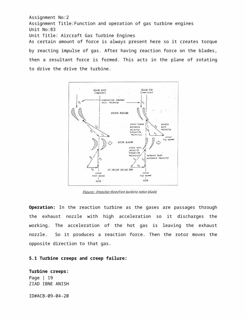
Assignment No:2Assignment Title:Function and operation of gas turbine engines Unit No:83 Unit Title: Aircraft Gas Turbine Engines As certain amount of force is always present here so it creates torque
by reacting impulse of gas. After having reaction force on the blades,
then a resultant force is formed. This acts in the plane of rotating
to drive the drive the turbine.
Operation: In the reaction turbine as the gases are passages through
the exhaust nozzle with high acceleration so it discharges the
working. The acceleration of the hot gas is leaving the exhaust
nozzle. So it produces a reaction force. Then the rotor moves the
opposite direction to that gas.
5.1 Turbine creeps and creep failure:
Turbine creeps:Page | 19 ZIAD IBNE ANISH ID#ACB-09-04-20

Assignment No:2Assignment Title:Function and operation of gas turbine engines Unit No:83 Unit Title: Aircraft Gas Turbine Engines Turbine blades increase in length and also in disk diameter as they
are under continues stress in yield point.
Turbine creep depends on three factors RPM, mass of blade and gas
temperature. As mass of blade is constant any change in RPM and/or gas
temperature will change the characteristics of the blade.
Creep failure:
If plastic deformation results about 0.2% then it is said to have been
failed in creep. A curve on creep strain vs. time shows that as more
the turbine blade operates for longer period of time the closer the
time for fracture comes nearer. To make it short the creep failure
will occur after extensive hours of use.
5.2 Film cooling of turbine blades
Page | 20 ZIAD IBNE ANISH ID#ACB-09-04-20

Assignment No:2Assignment Title:Function and operation of gas turbine engines Unit No:83 Unit Title: Aircraft Gas Turbine Engines After long experiment the designer found that the combustor exit
temperature more will be the thrust. But this exceeding temperature
damages high pressure turbine components specially the turbine blades.
FIG: Film cooling of turbine blades
Turbine blades melt in this exceeding temperature. To prevent this
from happening film cooling was incorporated into the blades. There
are some small holes in the turbine blades through which cool air
comes from the compressor stage. The cool air makes a thin, cool,
insulating blanket of air on the surface of blades which prevent
blades to melt in the excess operating heat.
TASK: 06 (P9)
Exhaust system of turbojet engine:
The exhaust system of gas turbine engines passes the turbine
discharge gases to the atmosphere. The turbojet engine produces
thrust mainly from exhaust jet. Exhaust gases passes to
Page | 21 ZIAD IBNE ANISH ID#ACB-09-04-20

Assignment No:2Assignment Title:Function and operation of gas turbine engines Unit No:83 Unit Title: Aircraft Gas Turbine Engines atmosphere through propelling nozzle which is a convergent
passage thus increase the jet velocity. At low thrust
conditions the exits velocity is subsonic only but during most
operating conditions the exits velocity reaches speed of sound
in relation to the exhaust gas temperature. At this condition
propelling nozzle is said to be chocked i.e. velocity cannot be
increase unless temperature get increase. Pressure difference
across the exhaust nozzle area gives pressure thrust. This is
additional thrust which is the result of momentum changed of
the gas stream. The velocity and pressure of the exhaust gases
create the thrust in the turbo-jet engine. The design of the
exhaust system therefore, exerts a considerable influence on
the performance of the engine. To reduce these losses, the
turbine rear struts in the exhaust unit are designed to
straighten out the flow before the gases pass into the jet
pipe.
Gas flow through mixed by pass engine:
The by-pass engine mixer unit mixes the hot and cold gas
streams. The operation of mixed by pass engine is to mixing the
hot and cold air stream before they are discharged into the
atmosphere and reduce the noice.In low by-pass ratio engine,
mixer unit thoroughly mixes the two gas flows into the turbine
exhaust gas flow However, an improvement can be made If two gas
flow flows within a common or integrated nozzle assembly. This
partially mixes the gas flows prior to ejection to atmosphere.
Page | 22 ZIAD IBNE ANISH ID#ACB-09-04-20

Assignment No:2Assignment Title:Function and operation of gas turbine engines Unit No:83 Unit Title: Aircraft Gas Turbine Engines TASK: 07 (M2)
After Burner:
The system used to inject the fuel in the thrust jet is called
afterburner. Afterburners are generally used to provide additional
power to reaction engines, commonly known as jet engines, whenever it
is necessary. Reaction engines, which are some sort of turbine
engines, work by compressing atmospheric air gathered through the air
intake of the engine and using it to create a combustible mix along
with the fuel, which is then lit. The rapid expansion of the
combustible mix generates thrust and power for the turbine at the same
time, which in turn drives the compressor.
Figure: - Afterburner System
Operation of after burner:Page | 23 ZIAD IBNE ANISH ID#ACB-09-04-20

Assignment No:2Assignment Title:Function and operation of gas turbine engines Unit No:83 Unit Title: Aircraft Gas Turbine Engines Afterburning (or reheat) is a method of augmenting the basic thrust of
an engine to improve the aircraft take-off, climb and (for military
aircraft) combat performance. The increased power could be obtained by
the use of a larger engine, but as this would increase the weight,
frontal area and overall fuel consumption, afterburning provides the
best method of thrust augmentation for short periods.
Figure: - Principle of Afterburning
Afterburning consists of the introduction and burning of fuel between
the engine turbine and the jet pipe propelling nozzle, utilizing the
unburned oxygen in the exhaust gas to support combustion. The
resultant increase in the temperature of the exhaust gas gives an
increased velocity of the jet leaving the propelling nozzle and
therefore increases the engine thrust.
Water-Methanol systems:
The maximum power output of a gas turbine engine depends to a large
extent upon the density or weight of the airflow passing through the
engine. There is, therefore, a reduction in thrust or shaft horsepowerPage | 24 ZIAD IBNE ANISH ID#ACB-09-04-20

Assignment No:2Assignment Title:Function and operation of gas turbine engines Unit No:83 Unit Title: Aircraft Gas Turbine Engines as the atmospheric pressure decreases with altitude, and/or the
ambient air temperature increases.
Under these conditions, the power output can be restored or, in some
instances, boosted for take-off by cooling the airflow with water or
water/methanol mixture (coolant). When methanol is added to the water
it gives anti-freezing properties and also provides an additional
source of fuel. There are two basic methods of injecting the coolant
into the airflow. Some engines have the coolant sprayed directly into
the compressor inlet, but the injection of coolant into the
combustion chamber inlet is usually more suitable for axial flow
compressor engines. This is because a more even distribution can be
obtained and a greater quantity of coolant can be satisfactorily
injected.
Page | 25 ZIAD IBNE ANISH ID#ACB-09-04-20

Assignment No:2Assignment Title:Function and operation of gas turbine engines Unit No:83 Unit Title: Aircraft Gas Turbine Engines
Figure: - Turbo jet thrust restoration
How thrust augmentation affects engine performance:
The sole purpose of thrust augmentation methods is to increase engine
performance. Two methods of thrust augmentation are mentioned above.
Afterburner and Water injection method. Afterburner burns unborn
oxygen after they have left the turbine, this increases engine
performance because even though it uses more fuel it, greatly increase
the thrust produced by the engine. Water injection also utilizes a
similar method where water methanol mixture is sprayed into the
compressor. The purpose of this too is to increase thrust thus
increasing engine performance.
Page | 26 ZIAD IBNE ANISH ID#ACB-09-04-20

Assignment No:2Assignment Title:Function and operation of gas turbine engines Unit No:83 Unit Title: Aircraft Gas Turbine Engines
Page | 27 ZIAD IBNE ANISH ID#ACB-09-04-20
Copyright © 2022 FDOKUMEN