Reducing Vibrations Generated in a Gas Turbine Model ...
9
Engineering and Technology Journal 39 (09) (2021) 1454-1462 Engineering and Technology Journal Journal homepage: https://etj.uotechnology.edu.iq 1454 http://doi.org/10.30684/etj.v39i9.2134 Received 23 April 2021; Accepted 22 May 2021; Available online 25 September 2021 2412-0758/©Publishing rights belong to University of Technology’s Press, Baghdad, Iraq This is an open access article under the CC BY 4.0 license http://creativecommons.org/licenses/by/4.0 Reducing Vibrations Generated in a Gas Turbine Model MS9001E Used in South Baghdad Power Plant Station by Improving the Design of Bearings with Damper Alaa J. Abdulah*, Muhannad Z. Khalifa , Abdul Jabbar O. Hanfesh University of Technology, Electromechanical Eng. Dep., Baghdad, Iraq. *Corresponding author Email: [email protected] HIGHLIGHTS ABSTRACT Dynamic analysis system performance for gas turbine MS9001E before and after development. Reduction of the first mode deformation value from 1.3134 mm to 0.0023 mm at 12 Hz. Using of electrical damper instead of mechanical and suitable oil lubricant for the gas turbine. Replacement of the Journal bearing type with the tilt-pad bearing. Gas turbines are engines an energy plant makes use of for generating the rotary motion to show power generators. The gas turbine is largely a combustion engine for changing natural gas or different liquid fuels to rotational mechanical energy. Often, the gas turbine generates excessive noise or vibrations. In this work, the problem of vibrations occurrence in the gas turbine model MS9001E used in the south Baghdad power station is solved. This is done by making a groove in the bearing pad to increase the oil flow, replacing the bearing type with a tilt-pad bearing type with damper. The finite element method was used in the analysis process by ANSYS program. The results showed a decrease in the values of vibration amplitude, total deformation, stress, and strain. ARTICLE INFO Handling editor: Muhsin J. Jweeg Keywords: Geometry of gas turbine Transient Analysis Harmonic Analysis Strains Vibration Frequency 1. Introduction The gas unit that is used in power plants consists of three main parts, which are the air compressor, the combustion chamber, and the turbine. There are studies which have shown that the mechanical vibrations that were mentioned previously occur at varying rates in each part [1]. The gas turbine engine rotating machine has many different components, and each component must be designed to withstand different operating conditions. Any elastic machine with mass can vibrate. With A common problem with vibration is failure caused by fatigue or deformation. Vibration at the resonance frequency is the main cause of excessive deformation. If the natural frequency of the system is the same as the excitation frequency, Resonance is usually found. When resonance occurs, the vibration may increase indefinitely. The vibration will only stop because it is related to the damping of the system. This makes finding the natural frequency crucial [2]. Vibration analysis of rotating machinery in industrial plants is widely used to ensure premature fault diagnosis before these machinery malfunctions. [3].A Yasser Hammed, etc... Showed there are numerous objectives are to be fulfilled inside a standard gas turbine analysis. first of this objective is are expecting the natural frequencies and decide the mode shapes of the turbine system at the ones natural frequencies, Identify critical speeds inside or close to the operating speed range of a rotor system, make an unbalance response analysis of a gas turbine as a way to calculate rotor displacement and quantify the forces acting at the rotor helps which can be prompted because of rotor imbalance and Assess capacity dangers and operating problems in general related to the rotor-
-
Upload
khangminh22 -
Category
Documents
-
view
1 -
download
0
Transcript of Reducing Vibrations Generated in a Gas Turbine Model ...
Engineering and Technology Journal 39 (09) (2021) 1454-1462
Engineering and Technology Journal Journal homepage: https://etj.uotechnology.edu.iq
1454 http://doi.org/10.30684/etj.v39i9.2134
Received 23 April 2021; Accepted 22 May 2021; Available online 25 September 2021 2412-0758/©Publishing rights belong to University of Technology’s Press, Baghdad, Iraq
This is an open access article under the CC BY 4.0 license http://creativecommons.org/licenses/by/4.0
Reducing Vibrations Generated in a Gas Turbine Model MS9001E Used
in South Baghdad Power Plant Station by Improving the Design of
Bearings with Damper
Alaa J. Abdulah*, Muhannad Z. Khalifa , Abdul Jabbar O. Hanfesh
University of Technology, Electromechanical Eng. Dep., Baghdad, Iraq.
*Corresponding author Email: [email protected]
H I G H L I G H T S
A B S T R A C T
Dynamic analysis system performance for
gas turbine MS9001E before and after
development.
Reduction of the first mode deformation
value from 1.3134 mm to 0.0023 mm at 12
Hz.
Using of electrical damper instead of
mechanical and suitable oil lubricant for the
gas turbine.
Replacement of the Journal bearing type
with the tilt-pad bearing.
Gas turbines are engines an energy plant makes use of for generating the rotary
motion to show power generators. The gas turbine is largely a combustion engine
for changing natural gas or different liquid fuels to rotational mechanical energy.
Often, the gas turbine generates excessive noise or vibrations. In this work, the
problem of vibrations occurrence in the gas turbine model MS9001E used in the
south Baghdad power station is solved. This is done by making a groove in the
bearing pad to increase the oil flow, replacing the bearing type with a tilt-pad
bearing type with damper. The finite element method was used in the analysis
process by ANSYS program. The results showed a decrease in the values of
vibration amplitude, total deformation, stress, and strain.
A R T I C L E I N F O
Handling editor: Muhsin J. Jweeg
Keywords:
Geometry of gas turbine
Transient Analysis
Harmonic Analysis
Strains
Vibration Frequency
1. Introduction
The gas unit that is used in power plants consists of three main parts, which are the air compressor, the combustion
chamber, and the turbine. There are studies which have shown that the mechanical vibrations that were mentioned previously
occur at varying rates in each part [1]. The gas turbine engine rotating machine has many different components, and each
component must be designed to withstand different operating conditions. Any elastic machine with mass can vibrate. With A
common problem with vibration is failure caused by fatigue or deformation. Vibration at the resonance frequency is the main
cause of excessive deformation. If the natural frequency of the system is the same as the excitation frequency, Resonance is
usually found. When resonance occurs, the vibration may increase indefinitely. The vibration will only stop because it is
related to the damping of the system. This makes finding the natural frequency crucial [2]. Vibration analysis of rotating
machinery in industrial plants is widely used to ensure premature fault diagnosis before these machinery malfunctions. [3].A
Yasser Hammed, etc... Showed there are numerous objectives are to be fulfilled inside a standard gas turbine analysis. first of
this objective is are expecting the natural frequencies and decide the mode shapes of the turbine system at the ones natural
frequencies, Identify critical speeds inside or close to the operating speed range of a rotor system, make an unbalance response
analysis of a gas turbine as a way to calculate rotor displacement and quantify the forces acting at the rotor helps which can be
prompted because of rotor imbalance and Assess capacity dangers and operating problems in general related to the rotor-
Alaa J. Abdulah et al. Engineering and Technology Journal 39 (09) (2021) 1454-1462
1455
dynamics of a given rotor system [4]. Kulvir studied Singh Higher burn temperatures can best be reached through using the
progressed materials for components along with combustor, nozzles, buckets (rotating blades), turbine wheels and spacers.
These critical parts facing various operating conditions with reference to temperature, transient loads and environment. The
temperature of the new gas direction parts (combustor, nozzles and buckets,) of a gas turbine is beyond the abilities of the
materials used in gas turbines for this reason requiring using many advanced materials like super alloys,[5]. Ogbonnaya et al.
studied Compressors associated with turbines. Surge and Stalls are two main kinds of instabilities that often occur in
compressor systems that affect gas turbines. This instability often results in excessive vibration due to pressure, and commands
are given through this phenomenon [6]. Mohammad h.j, etc., studied a program primarily based totally at the finite element
approach is developed for rotor dynamic analysis of gas turbine rotors. The lateral vibration conduct of a certain gas turbine
rotor is analyzed the usage of the developed finite detail program and coupled lateral-torsional vibration conduct of the rotor
has analyzed the usage of a 3-D finite element model, [7]. The tip clearance between the compressor's rotating blades and its
casing will adversely affect performance, so Cause energy loss. Over time, the gradual increase in the tip clearance is an
important reason for the compressor. Performance drops. However, in modern high-efficiency compressors, the key
requirements for optimal performance depend on Minimize the radial gap between the rotating blade disc and the housing. So
there is a danger of contact between rotations Blade disks and enclosures have increased significantly [8]. The knowledge gap
highlights that the studies dealt with the issue of the gas turbine in terms of analyzing the vibrations in the rotor and (shaft-
disk-blade) as well as studying the materials and alloys that make up the gas turbine system and did not address the process of
analyzing the vibration of all parts of the gas turbine and making improvements to reduce the amount of vibrations. This paper
aims to make improvements to the gas turbine model MS9001E used in the South Baghdad Station to reduce vibrations. This is
done by collecting data obtained from the operation and control department of the station which show the values of vibrations
in the gas turbine through the monitoring screen.
2. The gas turbine model (ms9001e)
This model used in south Baghdad Power Plant station, this station can supply max power is about 130.14 MW at
rotation speed 3000 r.p.m.
2.1 Description of this model
The gas turbine model (MS9001E) is a single-shaft heavy-duty gas turbine specially developed for generator drive
services in the 50 Hz market. Its efficiency is about. It is 33% in a simple cycle and more than 50% in a combined cycle.
MS9001E is consists of 17-stage compressor rotor, 3-stage turbine rotor, three bearing (the first one plain bearing is located
under compressor, the second is elliptical bearing located between the compressor and the turbine, the third is tilt pad journal
bearing located end of the turbine shaft).
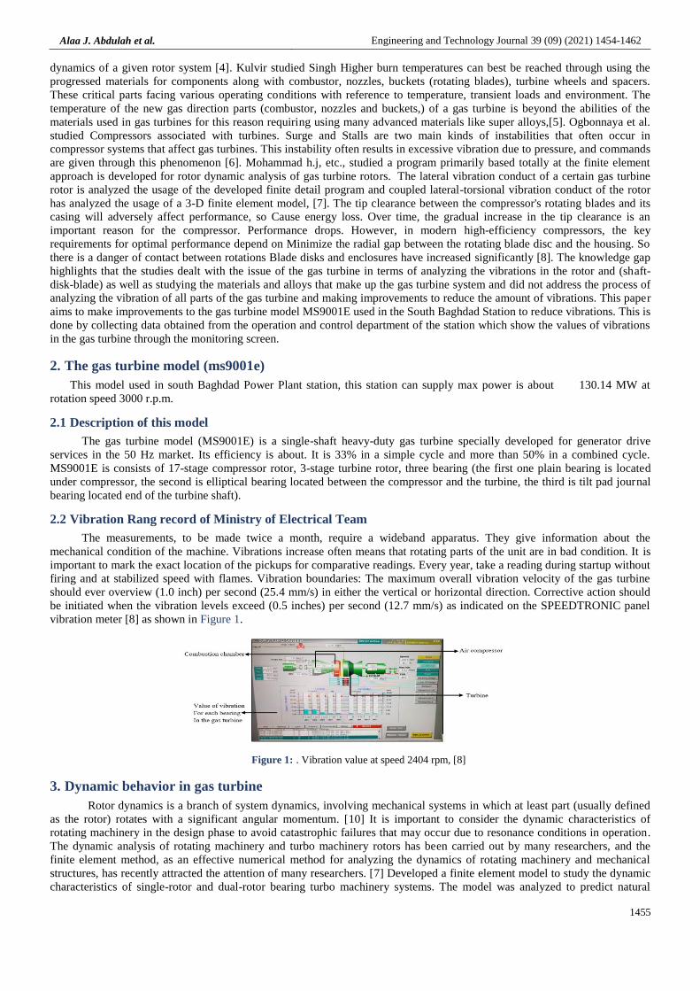
2.2 Vibration Rang record of Ministry of Electrical Team
The measurements, to be made twice a month, require a wideband apparatus. They give information about the
mechanical condition of the machine. Vibrations increase often means that rotating parts of the unit are in bad condition. It is
important to mark the exact location of the pickups for comparative readings. Every year, take a reading during startup without
firing and at stabilized speed with flames. Vibration boundaries: The maximum overall vibration velocity of the gas turbine
should ever overview (1.0 inch) per second (25.4 mm/s) in either the vertical or horizontal direction. Corrective action should
be initiated when the vibration levels exceed (0.5 inches) per second (12.7 mm/s) as indicated on the SPEEDTRONIC panel
vibration meter [8] as shown in Figure 1.
Figure 1: . Vibration value at speed 2404 rpm, [8]
3. Dynamic behavior in gas turbine
Rotor dynamics is a branch of system dynamics, involving mechanical systems in which at least part (usually defined
as the rotor) rotates with a significant angular momentum. [10] It is important to consider the dynamic characteristics of
rotating machinery in the design phase to avoid catastrophic failures that may occur due to resonance conditions in operation.
The dynamic analysis of rotating machinery and turbo machinery rotors has been carried out by many researchers, and the
finite element method, as an effective numerical method for analyzing the dynamics of rotating machinery and mechanical
structures, has recently attracted the attention of many researchers. [7] Developed a finite element model to study the dynamic
characteristics of single-rotor and dual-rotor bearing turbo machinery systems. The model was analyzed to predict natural
Alaa J. Abdulah et al. Engineering and Technology Journal 39 (09) (2021) 1454-1462
1456
frequencies, generate critical speed maps, and estimate bearing stiffness. They proved that the speed ratio between the high-
speed and low-speed shafts of the dual-rotor can be used as one of the design parameters of the dual-rotor system. [11]. the vibration signal is presented by the following expression [12].
)1()sin(.)( tAtx
Where is the frequency of vibration, is the phase and A the amplitude of vibration in micrometers [µm].The vibration
speed ν(t), Equations (2) and the vibration acceleration a(t), Equations (3) are obtained by differentiating vibration expression
Eq. (1) as follows:
)3()sin(..)(
)(
)2()cos(.)(
)(
2
tAAdt
tdvta
tAdt
tdxtv
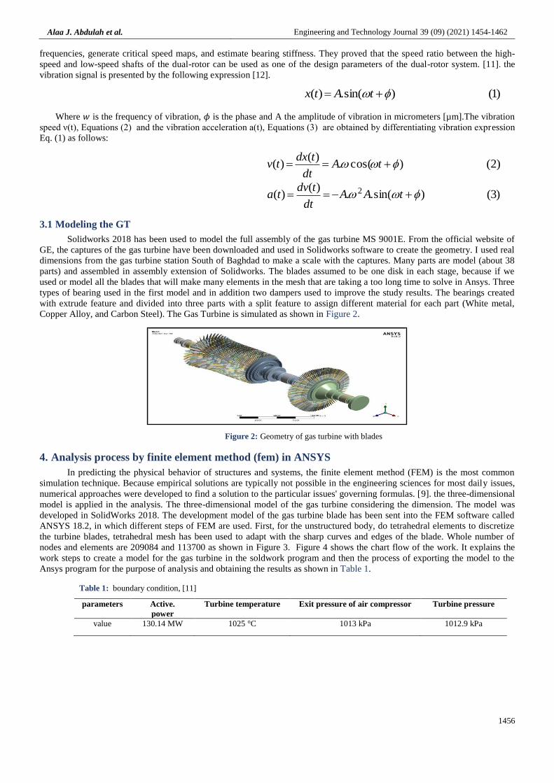
3.1 Modeling the GT
Solidworks 2018 has been used to model the full assembly of the gas turbine MS 9001E. From the official website of
GE, the captures of the gas turbine have been downloaded and used in Solidworks software to create the geometry. I used real
dimensions from the gas turbine station South of Baghdad to make a scale with the captures. Many parts are model (about 38
parts) and assembled in assembly extension of Solidworks. The blades assumed to be one disk in each stage, because if we
used or model all the blades that will make many elements in the mesh that are taking a too long time to solve in Ansys. Three
types of bearing used in the first model and in addition two dampers used to improve the study results. The bearings created
with extrude feature and divided into three parts with a split feature to assign different material for each part (White metal,
Copper Alloy, and Carbon Steel). The Gas Turbine is simulated as shown in Figure 2.
Figure 2: Geometry of gas turbine with blades
4. Analysis process by finite element method (fem) in ANSYS
In predicting the physical behavior of structures and systems, the finite element method (FEM) is the most common
simulation technique. Because empirical solutions are typically not possible in the engineering sciences for most daily issues,
numerical approaches were developed to find a solution to the particular issues' governing formulas. [9]. the three-dimensional
model is applied in the analysis. The three-dimensional model of the gas turbine considering the dimension. The model was
developed in SolidWorks 2018. The development model of the gas turbine blade has been sent into the FEM software called
ANSYS 18.2, in which different steps of FEM are used. First, for the unstructured body, do tetrahedral elements to discretize
the turbine blades, tetrahedral mesh has been used to adapt with the sharp curves and edges of the blade. Whole number of
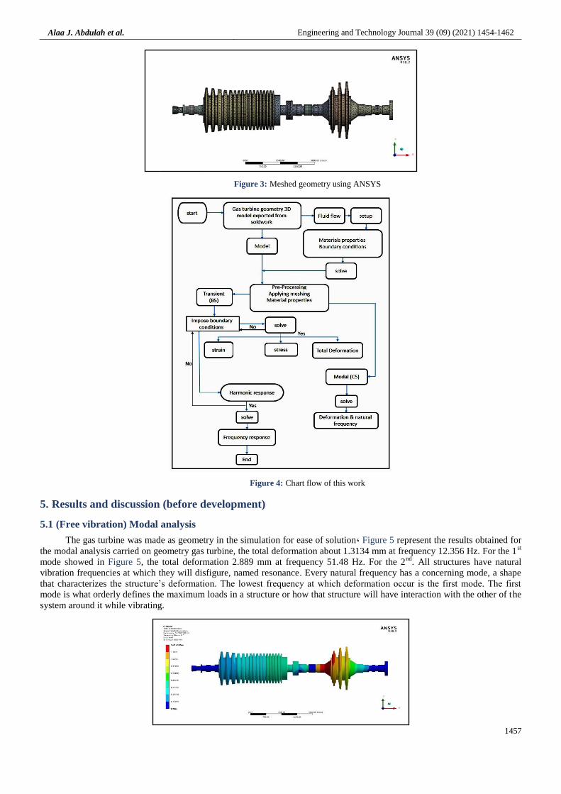
nodes and elements are 209084 and 113700 as shown in Figure 3. Figure 4 shows the chart flow of the work. It explains the
work steps to create a model for the gas turbine in the soldwork program and then the process of exporting the model to the
Ansys program for the purpose of analysis and obtaining the results as shown in Table 1.
Table 1: boundary condition, [11]
parameters Active.
power
Turbine temperature Exit pressure of air compressor Turbine pressure
value 130.14 MW 1025 °C 1013 kPa 1012.9 kPa
Alaa J. Abdulah et al. Engineering and Technology Journal 39 (09) (2021) 1454-1462
1457
Figure 3: Meshed geometry using ANSYS
Figure 4: Chart flow of this work
5. Results and discussion (before development)
5.1 (Free vibration) Modal analysis
The gas turbine was made as geometry in the simulation for ease of solution, Figure 5 represent the results obtained for
the modal analysis carried on geometry gas turbine, the total deformation about 1.3134 mm at frequency 12.356 Hz. For the 1st
mode showed in Figure 5, the total deformation 2.889 mm at frequency 51.48 Hz. For the 2nd
. All structures have natural
vibration frequencies at which they will disfigure, named resonance. Every natural frequency has a concerning mode, a shape
that characterizes the structure’s deformation. The lowest frequency at which deformation occur is the first mode. The first
mode is what orderly defines the maximum loads in a structure or how that structure will have interaction with the other of the
system around it while vibrating.
Alaa J. Abdulah et al. Engineering and Technology Journal 39 (09) (2021) 1454-1462
1458
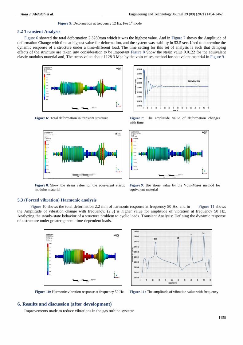
Figure 5: Deformation at frequency 12 Hz. For 1st mode
5.2 Transient Analysis
Figure 6 showed the total deformation 2.3289mm which it was the highest value. And in Figure 7 shows the Amplitude of
deformation Change with time at highest value for deformation, and the system was stability in 53.5 sec. Used to determine the
dynamic response of a structure under a time-different load. The time setting for this set of analysis is such that damping
effects of the structure are taken into consideration to be important Figure 8 Show the strain value 0.0122 for the equivalent
elastic modulus material and, The stress value about 1128.3 Mpa by the voin-mises method for equivalent material in Figure 9.
Figure 6: Total deformation in transient structure Figure 7: The amplitude value of deformation changes
with time
Figure 8: Show the strain value for the equivalent elastic
modulus material
Figure 9: The stress value by the Voin-Mises method for
equivalent material
5.3 (Forced vibration) Harmonic analysis
Figure 10 shows the total deformation 2.2 mm of harmonic response at frequency 50 Hz. and in Figure 11 shows
the Amplitude of vibration change with frequency. (2.3) is higher value for amplitude of vibration at frequency 50 Hz.
Analyzing the steady-state behavior of a structure problem to cyclic loads. Transient Analysis: Defining the dynamic response
of a structure under greater general time-dependent loads.
Figure 10: Harmonic vibration response at frequency 50 Hz Figure 11: The amplitude of vibration value with frequency
6. Results and discussion (after development)
Improvements made to reduce vibrations in the gas turbine system:
Alaa J. Abdulah et al. Engineering and Technology Journal 39 (09) (2021) 1454-1462
1459
The type of bearings used in the system changed to tilt-pad bearing, because of their excellent stability 1)
performance. Tilt pad bearings produce, very small destabilizing cross-coupled stiffness in any case of
geometry, speed, load, or operating anomaly. Table 2 shows the materials properties of bearing.
Using mechanical dampers under the base of gas turbine system. Which is a common solution to reduce 2)
the amount of vibrations that occur in the system.
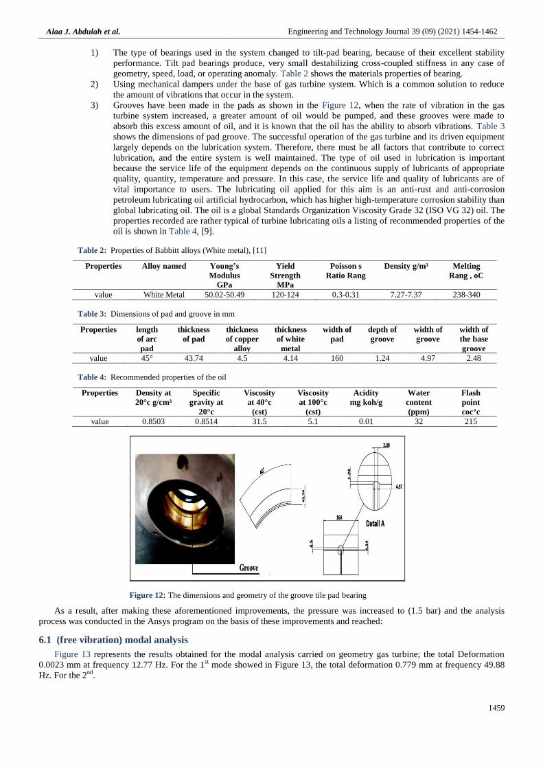
Grooves have been made in the pads as shown in the Figure 12, when the rate of vibration in the gas 3)
turbine system increased, a greater amount of oil would be pumped, and these grooves were made to
absorb this excess amount of oil, and it is known that the oil has the ability to absorb vibrations. Table 3
shows the dimensions of pad groove. The successful operation of the gas turbine and its driven equipment
largely depends on the lubrication system. Therefore, there must be all factors that contribute to correct
lubrication, and the entire system is well maintained. The type of oil used in lubrication is important
because the service life of the equipment depends on the continuous supply of lubricants of appropriate
quality, quantity, temperature and pressure. In this case, the service life and quality of lubricants are of
vital importance to users. The lubricating oil applied for this aim is an anti-rust and anti-corrosion
petroleum lubricating oil artificial hydrocarbon, which has higher high-temperature corrosion stability than
global lubricating oil. The oil is a global Standards Organization Viscosity Grade 32 (ISO VG 32) oil. The
properties recorded are rather typical of turbine lubricating oils a listing of recommended properties of the
oil is shown in Table 4, [9].
Table 2: Properties of Babbitt alloys (White metal), [11]
Properties Alloy named Young’s
Modulus
GPa
Yield
Strength
MPa
Poisson s
Ratio Rang
Density g/m³ Melting
Rang , oC
value White Metal 50.02-50.49 120-124 0.3-0.31 7.27-7.37 238-340
Table 3: Dimensions of pad and groove in mm
Properties length
of arc
pad
thickness
of pad
thickness
of copper
alloy
thickness
of white
metal
width of
pad
depth of
groove
width of
groove
width of
the base
groove
value 45° 43.74 4.5 4.14 160 1.24 4.97 2.48
Table 4: Recommended properties of the oil
Properties Density at
20°c g/cm³
Specific
gravity at
20°c
Viscosity
at 40°c
(cst)
Viscosity
at 100°c
(cst)
Acidity
mg koh/g
Water
content
(ppm)
Flash
point
coc°c
value 0.8503 0.8514 31.5 5.1 0.01 32 215
Figure 12: The dimensions and geometry of the groove tile pad bearing
As a result, after making these aforementioned improvements, the pressure was increased to (1.5 bar) and the analysis
process was conducted in the Ansys program on the basis of these improvements and reached:
6.1 (free vibration) modal analysis
Figure 13 represents the results obtained for the modal analysis carried on geometry gas turbine; the total Deformation
0.0023 mm at frequency 12.77 Hz. For the 1st mode showed in Figure 13, the total deformation 0.779 mm at frequency 49.88
Hz. For the 2nd
.
Alaa J. Abdulah et al. Engineering and Technology Journal 39 (09) (2021) 1454-1462
1460
.
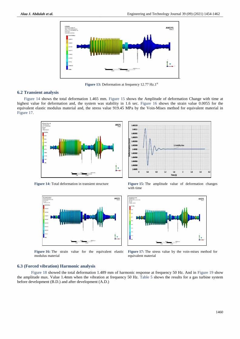
Figure 13: Deformation at frequency 12.77 Hz.1st
6.2 Transient analysis
Figure 14 shows the total deformation 1.465 mm. Figure 15 shows the Amplitude of deformation Change with time at
highest value for deformation and, the system was stability in 1.6 sec. Figure 16 shows the strain value 0.0055 for the
equivalent elastic modulus material and, the stress value 919.45 MPa by the Voin-Mises method for equivalent material in
Figure 17.
Figure 14: Total deformation in transient structure Figure 15: The amplitude value of deformation changes
with time
Figure 16: The strain value for the equivalent elastic
modulus material
Figure 17: The stress value by the voin-mises method for
equivalent material
6.3 (Forced vibration) Harmonic analysis
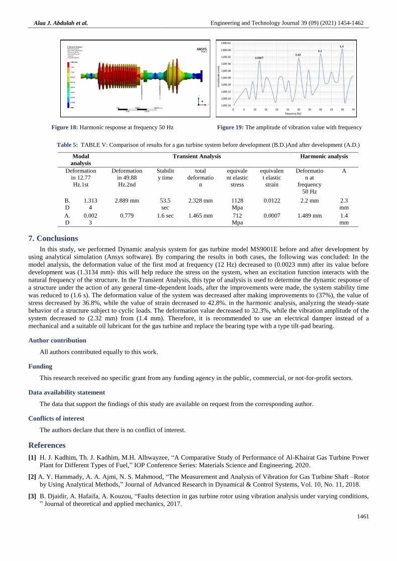
Figure 18 showed the total deformation 1.489 mm of harmonic response at frequency 50 Hz. And in Figure 19 show
the amplitude max. Value 1.4mm when the vibration at frequency 50 Hz. Table 5 shows the results for a gas turbine system
before development (B.D.) and after development (A.D.)
Alaa J. Abdulah et al. Engineering and Technology Journal 39 (09) (2021) 1454-1462
1461
Figure 18: Harmonic response at frequency 50 Hz Figure 19: The amplitude of vibration value with frequency
Table 5: TABLE V: Comparison of results for a gas turbine system before development (B.D.)And after development (A.D.)
Modal
analysis
Transient Analysis Harmonic analysis
Deformation
in 12.77
Hz.1st
Deformation
in 49.88
Hz.2nd
Stabilit
y time
total
deformatio
n
equivale
nt elastic
stress
equivalen
t elastic
strain
Deformatio
n at
frequency
50 Hz
A
B.
D
1.313
4
2.889 mm 53.5
sec
2.328 mm 1128
Mpa
0.0122 2.2 mm 2.3
mm
A.
D
0.002
3
0.779 1.6 sec 1.465 mm 712
Mpa
0.0007 1.489 mm 1.4
mm
7. Conclusions
In this study, we performed Dynamic analysis system for gas turbine model MS9001E before and after development by
using analytical simulation (Ansys software). By comparing the results in both cases, the following was concluded: In the
model analysis, the deformation value of the first mod at frequency (12 Hz) decreased to (0.0023 mm) after its value before
development was (1.3134 mm), this will help reduce the stress on the system, when an excitation function interacts with the
natural frequency of the structure. In the Transient Analysis, this type of analysis is used to determine the dynamic response of
a structure under the action of any general time-dependent loads, after the improvements were made, the system stability time
was reduced to (1.6 s). The deformation value of the system was decreased after making improvements to (37%), the value of
stress decreased by 36.8%, while the value of strain decreased to 42.8%. in the harmonic analysis, analyzing the steady-state
behavior of a structure subject to cyclic loads. The deformation value decreased to 32.3%, while the vibration amplitude of the
system decreased to (2.32 mm) from (1.4 mm). Therefore, it is recommended to use an electrical damper instead of a
mechanical and a suitable oil lubricant for the gas turbine and replace the bearing type with a type tilt-pad bearing.
Author contribution
All authors contributed equally to this work.
Funding
This research received no specific grant from any funding agency in the public, commercial, or not-for-profit sectors.
Data availability statement
The data that support the findings of this study are available on request from the corresponding author.
Conflicts of interest
The authors declare that there is no conflict of interest.
References
[1] H. J. Kadhim, Th. J. Kadhim, M.H. Alhwayzee, “A Comparative Study of Performance of Al-Khairat Gas Turbine Power
Plant for Different Types of Fuel,” IOP Conference Series: Materials Science and Engineering, 2020.
[2] A. Y. Hammady, A. A. Ajmi, N. S. Mahmood, “The Measurement and Analysis of Vibration for Gas Turbine Shaft –Rotor
by Using Analytical Methods,” Journal of Advanced Research in Dynamical & Control Systems, Vol. 10, No. 11, 2018.
[3] B. Djaidir, A. Hafaifa, A. Kouzou, “Faults detection in gas turbine rotor using vibration analysis under varying conditions,
” Journal of theoretical and applied mechanics, 2017.
Alaa J. Abdulah et al. Engineering and Technology Journal 39 (09) (2021) 1454-1462
1462
[4] H. Mansoora, M. Al-shammari, A. Al-Hamood, “Theoretical Analysis of the Vibrations in Gas Turbine Rotor,” 3rd
International Conference on Engineering Sciences IOP Conf. Series: Materials Science and Engineering 671, 2020.
[5] M. Dost, R. Jansen, “reducing noise from gas turbines,” Noise & Vibration Worldwide, 49(9-10), 298–301. Doi:
10.1177/0957456518801237, 2018.
[6] S. K. Saif, G. R. Rameshkumar, “Vibration Diagnosis Approach for Industrial Gas Turbine and Failure Analysis,” British
Journal of Applied Science & Technology 14(2): 1-9, 2016, Article no. BJAST.23163 ISSN: 2231-0843, NLM ID:
101664541, 2016.
[7] M.V.S. Babu1, A. Rama Krishna, and K.N.S. Suman, “Review of Journal Bearing Materials and Current Trends,”
Columbia International Publishing American Journal of Materials Science and Technology Vol. 4 No. 2 pp. 72-83. 2018.
[8] E. Poursaeidi, H. Ghaemi, M. Charmchi, “Effects of temperature gradient on compressor casing in an industrial gas
turbine,” Case Studies in Thermal Engineering 3, 35–42, 2014.
[9] Manual of General Electric(GE) Model: MS9001E Power Systems, 2002.http://www.fi
powerweb.com/Engine/Industrial/GE-MS9001.html
[10] M.H. Jalali, B. Shahriari, “Elastic Stress Analysis of Rotating Functionally Graded Annular Disk of Variable Thickness
Using Finite Difference,” Method, Mathematical Problems in Engineering, Volume, Article ID 1871674, 2018.
[11] M. H. Jalali, N. Nouri, S. Ziaei-Rad, “On The Finite Element Modeling Of Turbo Machinery Rotors In Rotor Dynamic
Analysis,” Proceedings of The Canadian Society for Mechanical Engineering International Congress 2018.
[12] B. Djaidir, A. Hafaifa, A. Kouzou, “Faults detection in gas turbine rotor using vibration analysis under varying conditions,
” journal of theoretical and applied mechanics 55, 2, pp. 393-406, Warsaw DOI: 10.15632/jtam-pl.55.2.393,2017.