


Steam Turbine Engineering - Forgotten Books
861
-
Upload
khangminh22 -
Category
Documents
-
view
0 -
download
0
Transcript of Steam Turbine Engineering - Forgotten Books


STEA M TURB IN E
EN G I N E E R I N G
T. STEVENS H. M . HOBARTE .M . , B .s e
.,
WITH 5 16 ILLUSTRAT IONS
NEW YORK
TH E M A C M I LLA N 0 0.
64-66 F IFTH AVENUE
LONDON : WHITTAKER AND 00.
1906
[All rights reserved]


T HK
9 9 9 6 9
OCT 8 1906
C901
PREFA CE
NOTWITHSTANDING the treatises on the Steam Turbine which havealready been published , there is still a distinct field heretofore notcovered. This relates to a consideration of the subject from thestandpoint of the purchaser and user. While the purchaser isonly incidentally interested in the theory and design of the steamturbine, he is deeply concerned as to the question of its economyas regards not only steam consumption but also fi rst cost andmaintenance. I t is, moreover, to him of great importance to bein a position to estimate the relative total costs and economy ofcomplete projects in which, on the one hand, steam turbines, and,on the other hand
,other types of prime mover are employed .
M anufacturers and D esigners become so absorbed in theirrespective occupations that they are apt to lose sight of, or nothave time to investigate, some aspects of the subject. Thus
,to
them also, we believe , our work may prove of service.
The authors wish to embrace this opportunity of making dueacknowledgment of the assistance rendered them by designers,manufacturers
,and users.
In the former class should be mentioned Professor Rateau ,
D irectors Zoelly and O . Lasche, M . Sosnowski, M r F. Samuelson ,
M rWm. Gray, M r August Kruesi, and M r Konrad Andersson.
The list of M anufacturers who have placed data at our disposalincludes — The Socié té de Laval of France ; M essrs GreenwoodBatley, Leeds ; The de Laval Steam Turbine Co.,
Trenton,N .J The
Maschinenbau-Anstalt Humboldt,Kalk
,near Cologne ; M essrs
Brown-Boveri Co. ; The Brush Electrical Engineering Cc.,Ltd. ;
Willans Robinson,Ltd. ; M essrs C. A . Parsons Cc . ; The
Westinghouse Cos. of Pittsburg and M anchester ; The GeneralElectric Co. of America ; The British Thomson-Houston Cc. ;M essrs Bellies M orcom ; M essrs Bumstead Chandler ;M essrs Browett, Lindley Co. M essrs Howden ; Messrs Van der
v

vi PREFACE
Kerchove ; M essrs Escher, Wyss St 00. The Hoovens-OwensRentschler Co. Gesellschaft fur Elektrische lndustrie ofKarlsruhe ; The Allgemeine Elektricitats Gesellschaft ; M essrsFraser Chalmers ; M essrs Turbinia deutsche M arine A g ; M essrsParsons M arine Steam Turbine Co . M essrs Babcock Wilcox ;M essrs W. H . Allen Co. ; M essrs Edwards Air-Pump Syndicate ;M essrs M irrlees
,Watson Cc. ; M essrs Wheeler Condenser
Engineering Co. ; M essrs Biles Gray ; M essrs T. Sugden,Ltd. ;
M essrs Klein Eng. Cc . ; M essrs Yarrow 8: Co.In supplyingus data regardingplants employing steam turbines,
and also (in order to obtain comparisons) regarding piston-engineplants, we are indebted to the courtesy of
M rW. J. Bache,Gloucester . M r Jas. D alrymple
,Glasgow .
S. E. Barnes, Cleethorpe. H . D ickinson , Leeds.
Ralph Bennett, Los Angeles, S. E. Fedden , Sheflield.
Cal. S. B. Fortenbaugh, LotsA . J . Bird, Guernsey . Road
,Chelsea.
R . Birkett, Burnley. O . F. Francis,Kirkcaldy.
C. N . Black,M etropolitan W. Alan Fraser
,Nelson.
S. R. Co. , Kansas City. W . Jensen,Chatham.
R. Blackmore, Stalybridge. C. Jones, Neseden.
G . A. Bruce,Lowestoft. F. A . Knight, M cKenna Co.
J. K . Brydges, Eastbourne. H . Tomlinson Lee,Wim
W . J . W . Bullock, West bledon.
Ham. C. F. Parkinson, Paisley.
C. D . Burnet, Carlisle. H . H . Perry , Brimsdown .
A . D . Chalmers, Gilling S. L. Pearce,M anchester.
ham. Geoff'
ry Porter, Worthing.
J. R. Chapman,Under A . H . Pott
,Brimsdown.
ground Electric Rys. Co. H . Richardson,D undee.
of London . Eustace Ridley, London.
G . Charleton, Kiddermin J. A. Robertson,Greenock .
ster. W . M . Rogerson ,Halifax.
A . T. Cooper,Reading. S. D . Schofield,
Shipley.
The Chief Engineers oi A . H . Shaw,I lford .
Alpha Place,Chelsea ; Barnes ; J. Shaw
,M ersey Ry.
Boston N .S.R. Co. , Lowell ; C. E . C. Shawfield, WolverBurton-on-Trent ; Harrogate ; hampton.
Quincy Point Power Station ; H. R Sinnett,Barrow.
Old Colony St. Ry. Co. ; Scar T. Robert Smith,Leicester.
borough E. S. Cc . ; Walsall. N . Swafiield,Reading.

PREPACE
Mr C. D . Taite , Salford. M r W . C. Ullmann,East Ham.
H. M . Taylor,M iddles S. J . Watson
,Bury.
borough . A . E. Whi te,Hull.
J . W. Towle, Lots Road, H . E . Yerbury, Sheffi eld .
Chelsea. J . W. Hendry, Victorian.
For permission to reproduce illustrations which have appearedin Proceedings of learned Societies, we have to express our thanksto the Secretaries of the Institutions of Civil Engineers, ElectricalEngineers, M echanical Engineers, Naval A rchitects, Engineers andShipbuilders of Scotland
,South Wales Engineers, and M anchester
Association ofEngineers. Also to The Electrical Review,E lectrical
World and Engineer, The E lectrician ,The Engineer, Engineering,
Power,The Street Railway Jo nrnal, Tramway and Railway World
,
gesamte a binenwesen,M essrs Babcock Wilcox , Machinery,
Technology Quarterly, Electric Jaw'
nal, D ie Turbine.
Our work has also been most distinctly promoted by the
cc-operation of M essrs Parshall and Parry, M r A . S. Garfield,M r C. W. G . Little, M r T. C. Elder, M r F. Punga, M r John Gray
,
M r A . G . Ellis, M r O. M . Kraus, M r T. S. Pipe, M r P. J . M itchell.M r John R Hewett very kindly collected the General Electric
Co.
’
s (of NewYork) data for us, and visited four Curtis plants to
gather further details ; and M r Eustace D own very kindly collecteddata on the Neasden plant, with permission of the ConsultingEngineer.


C O N T E N T S
1 . INT RODUCTORY
3. THE D E LA VAL TURBINE
4. THE PARsONs TURB INE
5 . THE CURTIs STEAM TURBINE
6 . RATEAU STEAM TURBINE
7 . TE E ZOELLY STEAM TURBINE
8. THE RIED LER-STUMrr TURBINE
9 . TR ! A. E . G . TURBINE
10. THE HAM ILTON-HOLEWARTB TURBINE
11 . THE ELBK'I 'RA STEAM TURBINE
12. THE UNION STEAM TURBINE
13. A BEOArITULATION or TEE PROPERTIEB or STEAM
14. CALORIrIc VALUE or FUELS
15 . TrrIOAI. REsUurs As TO STEAM ECONOMY IN MODERN PIsTON
ENGINEB
16. M EAN BEPREBENTATIvE REsULTs FOB STEAM TuRBINEs,
‘
AND
COMPAR IBON WITH REsULTs FOR PISTON ENGINEs
17 . STEAM PREssUB E,SUPERBEAT
,AND VACUUM IN PLANTS IN
OPERATION

CONTENTS
OHAP.
18. CONDENsERs
19 . FOUNDATIONS
20. BUILD INGs
21. BOILER AND SUrEBB EATER SURFACE INBTALLED
22. ExAMrLEs or STEAM TURBINE PLANTS
23. MARINE STEAM TuRBINEs
24. B IBLIOGRAPHY
Ap pEND Ix
iNDEx

STEAM TURBINE ENGINEERING
CHAPTER I
INTRODUCTORY
EXCELLENT steam economy is nowobtainable by the steam turbinewhen operated condensing, and improved manufacturing methods,stimulated by competition, are slowly reducing the first cost.Great initial savings in foundations, and in consequence of thesmall floor space required , are also sometimes effected by employing steam turbines. The Oil consumption is very low; and as no
Oil is present in the cylinders, there being no parts there requiringlubrication
, not only does the condensation become directlyavailable for feed water, but there is the further advantagethat high superheat introduces no diffi culties relating tochoice of lubricant. In sets of large capacity the steamturbine Offers advantagw in all these respects. In small setsthe steam economy is none too good , but the other advantageswill
,nevertheless
,often justify its use in preference to the piston
engine.Against these advantages must be set the great sacrifice in
economy when,through any cause
,a plant must be temporarily
Operated non-condensing ; also the greater outlay entailed forcondensing plant, owing to the supreme importance which thedegree of vacuum has upon the turbine’s economy. It is
probable that, with the better understanding of the methods Of
employing superheated steam, a given degree of superheat willensure a greater percentage improvement in the steam economy in
the piston engine than in the steam turbine. This, however,

2 STEAM TURB INE ENGINEERING
depends somewhat upon the type of steam turbine ; as does alsothe economy at light loads, with respect to which it may be safelyasserted that the piston engine is not excelled by the steamturbine, as has been so often incorrectly stated. In fact
,the
marvellously rapid progress which has recently taken place in the
development Of the steam turbine has already reacted to stimulatethe designers and manufacturers of piston engines, and markedimprovements are again becoming very evident in this class Of
steam engine.High speed— the very feature which has led to the small size ,
weight, and (to a less degree) cost Of the steam turbine— has alsobrought with it disadvantages, especially as regards the design Of
direct-connected electric generators ; and the present tendency isto reduce the speeds, as far as considerations of steam economypermit. It would probably be good practice, in spite Of increasedsize , to work at speeds well below this point, since a slight sacrificein steam economy would be more than offset by the far moresatisfactory results, not only in the design of the electrical apparatus, but also in the mechanical design of the turbine itself.There is thus a large array of considerations requiring detaileddiscussion.
Parsons and de Laval were the pioneers in the development Ofthe commercial steam turbine
,and it requires no further justifica
tion that the description of their designs is given precedence inthe following chapters.
In the immediately succeeding chapters are given descriptionsof the turbines of the remaining leading types.
These descriptive chapters are followed by a recapitulation ofthe properties Of steam
,with new tables and curves to suit
present requirements, and data tabulated for convenient com
parison and reference on various electricity supply plants and
marine steam turbines.
Cost — As yet the steam turbine, as regards first cost, issomewhat more expensive than the piston engine. In a paperentitled The Steam Turbine
,
l Chilton gives £3250 as the cost ofprime mover and generator for a 500 kilowatt set, whether Ofthe piston-engine or turbine-driven type. This works out at£6
,58. per rated kilowatt. Includingcondensing plant, the piston
engine plant is increased to £7 , 68. per kilowatt, as against £7 , 88.
per kilowatt for the turbine plant.
Proc. Inst. E lcc. Engrs” vol. 33, pp. 587—601, Feb. 2, 1904 .

IN TROD UCTORY
Other accessible cost data is as follows
TABLE IA .
Date.
1Whitby U.D .O. Ordered 1905 Parsons
Turbo-generstor only 1 000
denser, twomotordriven pumps
3Watford U.D .C. Tender 1904 Includesexoiter, cOn 1 500
denser, air punip,circulating pump
‘Derby Ordered 1905 Parsons 7's 1 500
1904 615 Turbo-generator snd 1 750condenser plant
1 750
1 E lectrical R am , 11,9 E lectrician, 105 , Electrician ,
3 Electrical Engineer, on ,
4 Electrical Ea ten, 755, mama: Engineer, Electrical R m ,213
,
TABLE I II. — 1900. CAM BRIDGE ELECTRIOII ‘Y SUPPLY 00. Two 500K.W.
Reciprocating Engex clud ing Condensers and Pumps.
Parsons
shout
sum-I3 World and Engineer, March 51 , 1900, p. m .

STEAM TURBINE ENGINEERING
Costs of some Turbo-Generators and Condenser
Planta— Tho prices that have appeared in the electrical press in
the last eighteen months are included below with as much detail aspracticable. Unfortunately, such information is generally published without specifically stating what is included.
Tenders for four sets, each 65 kilowatt, 110 volts, were discussedin M arine Rundschau for January 1904 in dealing with ProfessorRiedler
'
s paper Ueber D ampfturbinen.
”Reciprocating engines
were ordered.
TABLE I I . —PR Icns or 65 K .W. TURBO-DTNAMOE AN D
REOIPBOOATING SETs.
Weighlta
o
tfedSet
“if"i i i?
”it .w.
Marks 33.
Piston en
gne and d 116
Riedler tumpf.dynamo . N M 1340 17 1 376
Parsons Turbo dynamo 16-55 1440 188 4 l °4
Parsons “as it mi ht have 17 1 37 6been if the tur ine hadbeen des
'
ed 0 5 metrelonger (a ut 20 ins.)
TABLE I I IA .
Date. Tenderer.
Greenock Tender 1904 Brush not stated pos
Henley (Steffi) Tend’r1904
3StMarylebone Tender 1904 Parsons Rating not etatated.
Apparentl
gvcondensers and four500 K .W. with 2
condensers. If as
Stepney Ordered 1905
2 E lect. Rea . p. 144,
B loc. E rma, p. 724 ,4 Electra, p. 047 ,

INTROD UOTORY 5
TABLE II IB.
Purch ser. Date
|1m i Corporation . Ordered 1003 Willapa i T 1000 law.
3 Leeds Corporation 1904 CuBrt
és
n2 1000
aNorth Mott . ans. Co. , 1005 Brain'
s 1000Wills-denl Bloc. Times, 248, 2 Electrician , 445 , sons/0s. a 13733 . Times, 774,
TABLE IV.
per Rated K .W.
easingPian
4:
per
Ton
Number
of
Units.
Rated
K
W
Rhenanlan West halianl lech 'lcity Wor Essen,b Brown-Dover! 6
x0
3.Power, p. 407 , July
A certain Reciprocating Set”33
05 .
B . T. It By. J .,
Curtis Bet erected .
Am. B. B . A. ,
Tenders on 1000 Kilowatt and 1500 Kilowatt Sets.
The various tender prices (in at and decimals) for the followingplaces are tabulated. The accepted price is in bold type in each
TABLE V.— TURBO-GENERATORs.
Phases. Cyciu . Volta
Poplar Condenser plant andsteamexciter.
Condenser plant ande armature.
0iy‘lp
ne condenser
gt and switch
Oondenser plant andexeiteran
pd switch
Condenser plant and
exciterand switch
Condenser plant and
exciterand switch


8 STEAM TURBINE ENG INEERIN G
TABLE VIL— C‘
ourt ET r. POWER-HOUBE COsTs PER RATED K.W. INs'
rALLsD ,I N
D EC I M ALs or A POUND .
Mrw. 0. Census. 170mm",A R 6“
.
0 Power“33casing Engine P M 8. 3m Tug.
bins Plant,Thornhiil,
Maximum . M inimum. 0000K.W.
5
Plant
,
Reciprocatin
Turbine
Plant
K.
W.
LandFoundationsSidingsRoadwaysLanding
y8
Ch'
gi
llzting ater Intake and
Buildings . 15°
Chimneys . l 2
Flues
Total of items 2 to 9
M ACH INERY
Settings3°C
SuperheatersStokers .
Drivers
BamomisersCoal Conveyor
Bunkers
$1311ConveyorP 08Coverin
FeedwaterHes i
l xcitersCondensersAirPumpsCirculating PumpsLift Pumpsg’gitchboard
h Gabi400 0-0
wer ouse cs
Comm,“ 6 00 I s 3 00 0-0
Travelling CraneIncidentais (as concrete 01 0-4floor)
Total of Machi itemsngineering superv 51071 and
contingencies 10 per cent.
Totai of items zto so . 132 50
Power-house perHorse-power
A fair average cost perK W . 105 21 0Transmission SystemSubstations K .W.
Probable costcomplete under £45 per ILW.
taking
43 Source of Data Electric Ra ilway Economics, by W. C .
Gotshall,
M ‘Graw Pub. Co .,
NewYork.
21 E lect. P ower June 1904 . Land for ten times this plant, £5500. See Ch. XXI I . fordetails Of this lent.2 M r Gotshall said in 1903,
“Steam turbine plants cost 70 per cent. Of above marimum, an will
probably be much lesswithin a fewyears.
10 STEAM TURBINE ENGINEERING
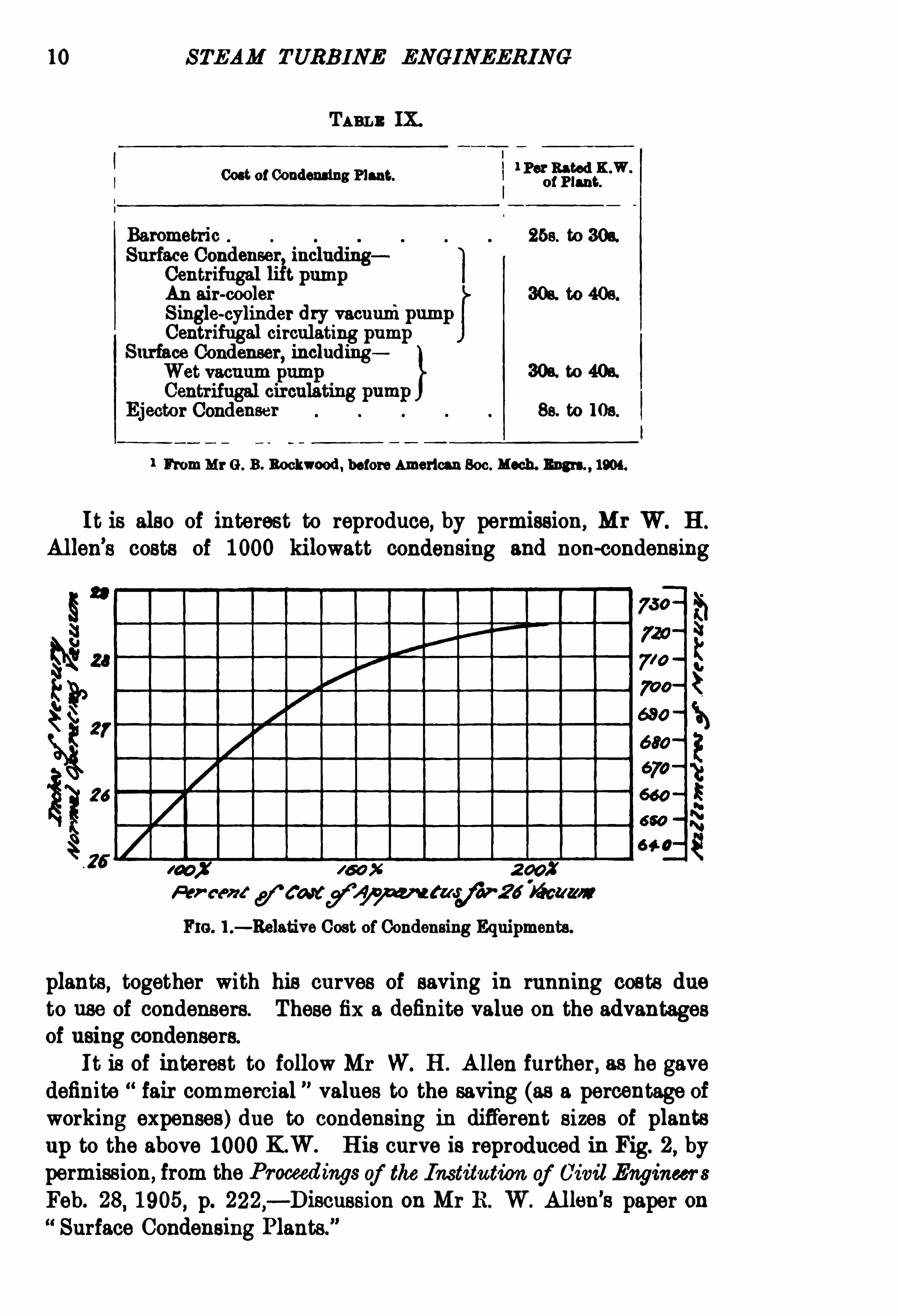
TABLE IX.
I
Cost ofCondensing Plant. 1 P“;am} ?
Barometric 253. to 3os.
Surface Condenser includingCentrifugal t pumpAn air-cooler 308. to 405 .
Single-cylinder dry vacuum
Centrifugal circulating pumSurface Condenser
,including
30s. to 405.
user Se. to 108.
1 FromM r G . B . Bockwood, before American Soc. M esh. Bum ,1904.
It is also of interest to reproduce, by permission, M r W. H .
Al len’
s costs of 1000 kilowatt condensing and non-condensing
Fm. 1.— Relative Cost ofCondensing Equipments.
plants, together with his curves of saving in running costs dueto use of condensers. These fix a definite value on the advantagesof using condensers.
I t is of interest to follow M r W. H . A llen further , as he gavedefinite fair commercial ” values to the saving (as a percentage ofworking expenses) due to condensing in different sizes of plantsup to the above 1000KW. His curve is reproduced in Fig. 2, bypermission, from the Proceedings of the Institution of Civil EngineersFeb. 28
,1905, p. 222,— Discussion on M r B . W. Al len
’
s paper onSurface Condensing Plants.
”

I NTROD UCTORY
TAe . L — MaW. H. ALLnN’s Couru Arrvs CAPITAL Cosrs AND Wosx mc
Coe're or 1000K.W. Conmmsms AND NON-COND ENSING PLANTS.
Proceedings, Institution of cm: Engineers, Feb. 28,1905, p. 221.
Cost in s pea° Rated K.W.
Capital Cost.
Non-condensing. Condensing.
Engine and dynamo Steam fl °5we.perK .W.H . 21 lbs. perL E E .
Four lbs. per hour Three lbs. per hour
Nab -upfeed
founds
Working Cost perm m . m days of 10hours.
Water at 9d. per 1000 galgs:
cent. loss gal ,1000gallons per hourmake up
urlons per for cooling tower 108
220 gallons per hourmake-up feed
Coal atms. per ton °
52 tons per 0 r 100tons per hourlbs. per K .W.H . 81 lbs. per K .W.H.
lbs. per B E E R .
0men
on £9885
Balance in favour of Con
per cent.
and superheat are the same in each case.
W eight— In the paper which has been already referred
to in this chapter,Chilton has given the interesting data set
forth in Table X I .
Cost per ton — The cost per ton, as derived from the datain the preceding paragraphs, is stated when weight is known.
Speed — For land plants it has come to be assumed thatthere is no alternative but to run steam turbines at speeds several

12 STEAM TURB INE ENGINEER ING
times greater than those of the highest-speed reciprocatingengines. One need not investigate deeply to discover that this isa hasty conclusion. Thus marine steam turbines are being builtfor speeds and weights differing far less than those from the
speeds and weights of piston engines. The tests of vesselsequipped with both types of engine have demonstrated that while
100 200
S IZ E OF UNITS K ILOWATTS .
Fm. 2.-Saving due to Condensing as a percentage ofWorking Expenses.
at high speeds the turbine vessels excel in economy , the steamconsumption down to fairly low speeds is but little in excess ofthat of the piston engine. For the Cunard liners nowapproachingcompletion the four turbines constituting the equipment of one
vessel are of horse-power,and run at a normal speed of 160
revolutions per minute.

INTROD UCTOR Y 13
TAnLn XI .— C ourAaArm Warenrs or PISTON ENGINES AND TURBINES
(sxo wsrvs or DrNANos), IN METRIC Tom , i s. IN Tons or 1000 Kes.
(2204 Lns.)
Weight of SlowOutput. speed Engine.
The fact that turbine vessels generally weigh practically as
much as vessels equipped with piston engines indicates that, whenrun at speeds comparable to the speeds of piston engines, theturbine loses its advantage of less weight. Nevertheless, it isfairly apparent that the turbine can be designed for good economyat far lower speeds than are commonly associated with it. Thisis most important
,since the dynamo would not only be better,
but ac tually cheaper, at lower speeds than those now customaryfor land turbines. For continuous current sets
,a radical re
duction of speed is essential before satisfactory sets of largecapacity will become practicable. For alternating current setsmuch more moderate reductions in speed will lead to satisfactorydesigns at minimum cost
,and one should differentiate between
high periodicity and low periodicity sets, the preferable speed forthe former being higher than for the latter.
Some data has been published by Grauert, showing the efl‘
ect
of the speed on the economy.
Emmett has also published tests showing the effect of speedon economy.
The Humboldt Co. have built 100horse-power and 150 horse

14 STEAM TURB INE ENGINEERING
power turbines with two different wheel diameters, and theeconomy results for the 100 horse-power machine, at an absoluteadmission pressure of 13 kilograms per square centimetre saturated steam and a 92 per cent. vacuum, are given in Table XII .
TABLn XII .
Rated output in horse-power
D iameter of rotor in mm.
Speed of wheel in revolutions per
minute
Peripheral speed in metres per second
Full load steam consumption in Kgs.
per kilowatt-hour
From these results it appears that in this particular case an
330 264
264
Speed effects a.decrease of 100 x
25 per cent. in the peripheral
12
increase of 100 x
12 per cent. in the
steam consumption.
Also, for this 100 horse-power machine, from an inspection ofTable (p. the percentage gain in steam consumption due toan increase in peripheral Speed appears to be approximately thesame for all values of admission pressure of the steam.
Peripheral Speeds ofWheels .
—Practice varies greatly as
to the peripheral Speeds of the rotors of steam turbines. A numberof instances have been brought together in Table XIII ,
where are
also set forth,in some cases, the wheel diameters, the speeds in
revolutions per minute, and the centrifugal force at the periphery,in kilograms per kilogram.
Peripheral Speeds Pressure at Bearings.
— For Parsons’
turbines the product of feet per second and lbs. per square inch atbearings has been stated to be 2500 to 3000. In the BrushParsons 1000K .W. unit this product is 1500.
The peripheral speeds at bearings are stated for a few units in
Table XI I I .

INTROD UCTORY 15
Table XI II . brings together the peripheral speeds, centrifugalforce at periphery of largest circumference, and the rated outputper moving vane for some sizes of each type of turbo-generator.
TABLE XI I I .
i img 2 5 -m
u o
33 5 as5b M o
a: gE s 3n:
z a3
De h val
Parsons005
Westinghouse-Parsons
Curtis (vertical)
514 4 1
Rateau 100 00
225 uas1 02
0 8
Riedler-Stumpf
L BJ}.
Hamfl ton-Holswarth
3001 70 s.s. Vi'
i
ctnn'
an
s.s. Ca rmam‘
a
0 05
0-10

STEAM TURBINE ENGINEERING
Revolutions per M inute. In Table X IV . are broughttogether, for turbo-generators of various types, the speeds and therated output in kilowatts for all sizes.
TABLB X IV .
Parsons. Bataan. L BJ}.
A.C.
1 800 760 0 000
1 300 I: 1 000

18 STEAM TURBINE ENGINEERING
of the expression KW.H. has the advantage of having been
universally adopted throughout the technical world as an
expression for electrical energy , and it is equally suitable as an
expression for mechanical energy and for heat energy.
We believe that the advantages of expressing these three formsof energy in the same terms will appeal to engineers ; and while we
should have preferred the kilogram-calorie for this
universal unit of energy, we are convinced that but little headwaycould be made in a lifetime in replacing the British Thermal
Unit and the horse-power hour by the kilogram
calorie On the other hand, the engineering professionthroughout the world has shown considerable and often spon
taneous readiness to employ the kilowatt-hour not onlyas an expression for electrical energy , but, to a large extent, alsofor mechanical energy, and we do not anticipate insuperablediffi culty in promptly obtaining for the kilowatt-hour afairly extended use as an expression for heat energy. I t willbecome the task Of a later generation to substitute the kilogram
calorie as general unit Of energy, for the then universallyadopted kilowatt-hour
The horse-power hour need rarely be mentioned. So far asreference need be made to it in this treatise , we shall denote itby the letters H RH .
The same remarks apply to the foot-pound and the metrekilogram,
which are expressed by the letters ft.-lb. and m.
-kg.
respectively.
TABLE XV .— ENERGY, WORK AND HEAT UNrrs
,wrrn ABBREV IATIONs
AND CORRESPOND ING VALD Es ExPREsSED I N JOULEs.
l
Abbreviation . Value in 3011100.
1 kilowatt-hour l K .W.H .
1 kilogram-calorie l Kg.C.
1 kilogram-metre 1 Kg. m.
l horse-power hour 1 H .P.H .
1 British thermal unit . 1 B.Th.U.
1 foot pound 1 ft. lb.
The Joule may be defined as 107 ergs, or as onewatt second.

NOMENCLATURE 19
Practical Units for Power.— For unit of power we shall
employ the kilowatt to as great an extent as practicable,and often also the horse-power owing to the wide use
which it still unfortunately enjoys. The by which wedenote one kilogram-calorie (one Kg.C.) per second, will, we hope,ultimately come to be adopted as the commercial unit for power.It should
,however
,be given some appropriate name.
SO far as is reasonable,we shall endeavour to Often employ
more than one alte rnative unit in the text,tables
,and curves, and
we trust that this will render our work more useful to thoseaccustomed to particular units. We hope it will not encourageprocrastination on the part of any engineers in familiarising themselves with the metric system.
The following tables will be useful in transforming values fromone set of units to another.
TABLE XV I.— POWER UN ITS, WITH ABBREV IATIONS AND THEI R
CORRESPOND ING VALUES EXPRESSED IN WATTS .
Abbreviation. Value inWatts.
1 kilowatt 1 KW.
1 kilogram-calorie per second 1 Kg.
l kilogram-metre per second
1 horse power
1 British thermal unit per second 1
l foot-pound per second 1 ft. lb. 8. i'
366
TAB LE XVII .— EQUIVALENT VALUES FOR WORK, ENERGY AND HEAT
,
ExPRESSED IN D IFFERENT UNITS (ENGLISH AND METR IC).
K .W.H . i II .P.U . B .Th .U. Ft. lb.
1 K .W .H. is equal to 307000 2054000:
1 is equal to 000110 0001550
1 KgJ I . is equal to 000000272 000000005 000000
I H .P .H . is equal to 274000 3000000
1 B .Th.U . is equal to 0000203 02 52 107 0 0000003
1 ft. is equal to 00111001877 01111324 01 382 OW N S 0001285

20 STEAM TURBINE ENGINEERING
Itmay be of interest to students to follow the deduction Of the value of
l K .W.H . in Kg.C. by converting through the British units, as this willset forth the interconnection of the various units employed.
746 watts=33,000 ft. lbs. per minute= 1 Bri tish H .P.
1 Kw. L999x ft. lbs. perminute .
( 46
ft. lbs. per second.
1 K.W. second ft. lbs.
1 K W. hour 3600x ft. lbs.
The mechanical equivalent Of l ft. lbs.,or 7 78 ft. lbs ,
raise
1 lb. ofwater 1° Fahr. at 60°
F . This is Joule’s equivalent.
2x 2-2 x ft. lbs. raise 1 Kg. ofwater 1° Cent.
3080 ft. lbs. 1 large calorie.
2654000K .W. h 0 .C.1 our
308086 Kg
TABLE XVIII .-EQUIVALENT VALUES FOR POWER ExPRESSED IN
D IFFERENT UN ITS (ENGLISH AND M ETRIC).
K .W. Eg.C.S. Kg. Ft. lbs. 8.
1 K .W is equal to
1 Kg.C.S. is equal to
l Kg.M .S. is equal to 000081 000284 001815 000930
1 H .P. is equal to
1 is equal to
1 ft. lb. s. is equal to . 0001350 01 303 0001235
TABLE X IX .
— LENGTHS.
l Statute Nautical Kiio 1 GermanP°°i ° “N M M iles . M iles.
mm metres . SeaMiles.
00330 0001304 i00001044 00040 00001040
3 1 0005682 0000493 9144/1i7 01110494
5280 1760 1 00684 16090 10093 00690
6080 2026 11 515 1 18532 10532 10007
32809 10936 0006214 0006596 0001 010054
1 kilometre 32800 10930 00396
1 German seamileI60750 20250 ll °i 507 00003 1851
-9

l
1
1
l
l
NOMENCLATURE
TABLE XX .— AREAS AND VOLUMES.
33m. Yards. Cer
slametres. yet".
1 000044 00077 10 0451
144 1 01 111 029
1290 9 l 03010 1550 001070 0001100 1
1550 10 70 11 00 10000
(hibic Cubic Cubic Cubic
°
000645 100929
0 8361
00001
1
CubicYards. Centimetres M etres.
cubic inch 1 0005787 00002143 16086
foot 1728 1 00370 28310 00283
yard . 46660 27 1 764500 0 7645
centimetre . 00610 0000035 00000013 1 10-0
metre 61030 13080 106 1
TABLE XX I — WEIGHTS AND PRESSURES.
waleure.
Long Ton. Metric Tons.
000446 0 45361 1016
000984 1
00842 1000
PuEssoRBs
lb. per sq. inch .
ks Per sq cm
inchho
ofmercury

22 STEAM TURBINE ENGINEERING
TABLE XX IL— POWEB .
Ft. Lbs. per1 Sm na_ M etr. H.P.
1 B.H.P. 550 10 14 7004
1 ft. lb. r second l 1 00 1843
l metr. .P. 542 47 1 75
1 kgm. per second 72 33 00 133 1
We wish to express regret that England and America adhereso persistently to antiquated and inferior systems of units.
Throughout the Continent of Europe, steam engineers are employing the metric system ; and largely in consequence of thiscircumstance there is a close understanding between steam and
electrical engineers. On the Continent of Europe the younger
generation of engineers is being educated to employ the metricsystem exclusively. To these circumstances
,in our opinion, is to
be attributed , far more than to some other alleged causes, the rapidrate at which Germany and Switzerland are coming to the fron tas rivals of English-speaking countries in manufacture and
commerce.
TABLE XXIII .— EQUIVALENT VALUES roa SPEED ExPB Esl IN D IFFERENT
UNrrs (ENeLisB AND ME'raxo).
W p“ ”as 02:03??e
1 mile per hour l°
467 1009 0 4470
1 knot (nauticalm. per hour) 1°
l b2 1089 1053 00 15
1 foot per second 0082 0092 1097 0-305
1 kilometre per hour
1 metre per second 1043
Equivalent Values for Speeds— To facilitate the conversion
of speeds from one system of units to another, we have given in
Table XXIV . equivalent values of speeds, expressed in metres per
second , feet per minute, etc for speeds ranging from 1 metre per
second to 100metres per second. Speeds greater than 100m. sec .
can be easily converted by simple multiplication ; thus for 220metres per second the same sequence of figures holds as for 22metres per second.

N OM ENOLATUBE 23
TABLE XXIV.
So far as costs and prices are mentioned,these are often
expressed decimally in pounds or shillings or pence : thusdenotes ten and one half pounds
,and not ten pounds five shillings.
The decimal system is appreciated by everyone who has taken the
pains to become acquainted with its simplicity .

CHAPTER II I
THE DE LAVAL TURBINE
THE de Laval turbine is an excellent instance of rational engineering development. In 1883we find de Laval but in the
FIG . 8.— Hero
’s Turbine
,120.
light of modern knowledge, on the lines of Hero’
s turbine of E C120
,or thereabouts. In Figs. 3 and 4 these two turbines are
illustrated side by side.For some years (10 Laval appears to have continued his investi
gations along the lines of the Hero type (see British Patent No.
16020 of but in 1889 there was granted to de Laval BritishPatent No. 7 143, in which we find the inventor occupied with the
24

26 STEAM TURB INE ENGINEERIN G
theless, the type of turbine developed under de Laval’
s personaldirection
,and universally known under his name, appears, pending
radical developments,to have reached its limitations so far as
relates to the capacity of a single machine. While several manufacturers of other types are supplying steam turbines Of from5000 to horse-power capacity per machine, the largest sizesupplied by the de Laval companies remains at 300 horse-power.From this capacity downwards, however, the de Laval turbine isin far more extensive use than any other type , having now for all
countries a record of some 5000 steam turbines installed , comprising motors, electric generating sets, pumps and ventilators.
The aggregate rated capacity of these 5000 turbines is over
FIG . 5A .— Branca
,1628. F10 . 5B.
— D e Laval.
horse-power,or an average rated capacity of some 30
horse-power per turbine.
THE D IVERGING NOZZLE INTRODUCED BY D E LAVAL.
The most important feature introduced by de Laval is that ofthe diverging nozzle (see British Patent No. 7 143 of theprinciple Of which has greatly influenced the development, notonly of the de Laval type , but of steam turbines in general. Fig.
6 is taken from de Laval’
s British Patent NO. 7 143 of 1889 , thetext ofwhich,
Owing to its importance and brevity, we reproduce
as followsMy invention relates to an improvement in turbines which
are set in motion by means of a current of steam and the Objectof the improvement is to increase, by complete expansion, thevelocity of the steam current, thus producing the relatively largestquantity of via viewof the steam.
“ I attain this object by the construction of the steam supply

THE DE LA VAL TURB INE 27
pipe in such a manner that the cross sections of the same areslowly increased near to the turbine wheel and in the direction of
the latter. The ratio of increasing the cross sections is due to theproportion and distance between the smallest section and thelargest one,
.
in such a manner that in the steam passage betweenthese two sections a permanent current of steam is producedunder isoé ntropical expansion.
“The accompanying drawing, in which is a front viewand a side elevation,
both partly in section, shows the mouthpiece Of a steam supply M
,constructed as above described
,in
Fm. 6 .— De Laval
’s Expanding Nozzle, 1889 .
combination with a turbine wheel A . b is the smallest and c thelargest cross section. Between both these sections the steamexpands from the pressure 05 5?P0 (P0 boiler pressure) to the
pressure of the receiver P2).
Having nowparticularly described and ascertained the natureOfmy said invention,
and in what manner it is to be performed,I declare that what I claim is
In steam turbines, the combination of the turbine wheel witha steam supply
,the cross sections of which increase regularly near
to the turbine wheel and in the direction of the same,substantially
as and for the purpose specified.

28 STEAM TURB INE ENGINEERING
RELATIVE SPEED or STEAM AND TURBINE.
From the above patent description alone, the significance of
the diverging nozzle is not immediately apparent. The followingrough elementary considerations may be useful.
In the fi rst place , it will be well to explain the action of thede Laval type of steam turbine by a hypothetical example
Suppose a perfectly elastic body 1 with a mass, M ,weighing one
kg. , to be travelling in a straight line through a frictionlessmedium (in a region where g= 98 metres per second), at a uniformvelocity , V ,
of 1000 metres per second. The kinetic energy ofthis body, 020. the energy possessed by it in virtue of its motion,
is equal to lMV’ or
,
1 x9
3
5x 10002 : kilogrammetres.
Suppose this body to collide with a far larger perfectly rigidbody movingin the same direction at one-half the speed ; to. at aspeed of 500 metres per second , the relative speed of the twobodies thus being 1000 metres per second. Its
motion relatively to the far larger body will, in virtue of thecollision , be reversed in direction , relatively to the far
larger body, the perfectly elastic body of one kilogram willprecisely reverse its direction and will assume a velocity of 500metres per second relatively to this far larger body. But since
the larger body continues at substantially the same speedwhich it possessed before the collision, at a speed of 500
metres per second , the absolute speed of the fi rst body has become500 metres per second , 010. it remains motionless in
space, and hence has given up its entire kinetic energy to the farlarger body
?
Substituting the bladed rim Of the revolving wheel of the
1 It is convenient to mentally picture this body as a sphere.
3 Our conceptions of speed can only be relative. Thus when the perfectlyrigid body is itselfmovingwith a speed V
'
in the same direction as the elastic
body, we should say that the perfectly elastic body, having a speed V,would
c ollidewith a relative speed of onlyV V'
, and therefore would also be repelled
with a relative speed ofV V'
. IfV'
27we should conclude that the elastic
body is thrown back with a speedE2“
,
relative to the rigid body ; and as the
rigid body moves with an absolut e speed of1; the absolute speed of the elastic
body after the impactwill necessarily be zero.

THE D E LAVAL TURBINE
steam turbine for the “ far larger body, and one kilogram ofsteam for the perfectly elastic body, we at once see the basis forthe statement that the speed of the blades should preferablyapproach one-half the speed of the impinging steam. For werethis the case, and were both bodies, the blades and the steam,
perfectly elastic, and were the steam to impinge from a directionnormal to the plane of the blades at the point Of impact , than thesteam would be left stationary in space by the moving blade and
depleted of its kinetic energy. Since the direction of impact isnot normal
,and since the bodies concerned are not perfectly
elas tic,this ideal velocity is only a rough guide ; and furthermore,
the present state of engineering knowledge is so limited that outof consideration for the constructional standpoint, much lowerperipheral speeds are generally employed than correspond to halfthe speed of the impinging steam.
TOTAL EFFICIENCY or CONVERSION or ENERGY IN STEAM .
There nowarise the three questionsI . How much energy is required to raise one kilogram of
steam ?I I . Howgreat a proportion of this energy per kilogram may
be converted into energy of translational motion,i s ,
into kineticenergy
I I I . What will be the corresponding velocity of this steamLet us take an instance where the steam is at an absolute
pressure of 13 kilograms per sq. cm. (010. 13 metric atmospheres)and with 50
° Cent. Of superheat. Under these conditions thetotal heat required to raise one kilogram of steam
“
from one kilo.
gram of water at 0°
Cent. amounts to 698 calories kilogramdegree calories).
l To many engineers, the magnitude of thisamount of energy is more readily appreciated if it is expressed bythe equivalent in kilowatt-hours.
698 calories 0812 kilowatt-hours.
For the present purpose, as we wish to arrive finally at thevelocity of the steam when emerging from the mouth of the nozzle,we shall express the amount of the energy by its equivalent inkilogrammetres.
698 calories kilogrammetres.
Nowif this energy could be transformed completely into thekinetic form into energy of translational motion) , than V
,the
This subject is dealtwith inmore detail in Chapter XI I I .

30 STEAM TURB INE ENGINEERING
speed of the steam in metres per second,would be derived by
solving the equation
1xW :
V = 2420metres per second.
When steam flows through plane orifices, it has been experi
mentally demonstrated that, independently Oi the ratios of the
pressures on the two sides of the orifice (so long as this ratio is at
least 2 l ), and also largely independent of the contour of the
orifice,the velocity of the flow of the steam through the orifi ce
is nearly constant. It has,in fact
,the values shown in the curve
ofFig. 7 .
From this curve we see that steam flowing from a source wherethe absolute pressure is 13 kilograms per sq. cm. through a planeorifice on the other side of which the pressure is 0134 kilogramper sq. cm. ,
tie ,into a 26 in. (66 cm.) or 860 per cent. vacuum ,
will emerge from the orifice with a velocity of 450 metres persecond. The kinetic energy per kilogram of steam after emergingfrom the orifice will be
1x9
1
8x 4502 kilogrammetres.
x 100Thi s represents only 3 48 per cent. of the total
energy per kilogram of steam at this pressure. Since,moreover,
this kinetic energy is exerted in every direction,it will be liberal to
estimate that not over 2 per cent. could be rendered available forimpartingmotion to the turbine wheel by impinging on the blades.
By de Laval’
s diverging nozzle,however, there is actually
Obtained,under those conditions ofpressure , a velocity of the steam
emerging from the mouth of the orifice of some 1100 metres persecond
,and this steam is in a state of rectilinear translational
motion parallel to the axis of the nozzle. Were it not for lossesdue to friction against the sides of the nozzle , the velocity wouldbe 1170 metres per second, as may be seen from the theoreticalcurves of Fig. 8
,which have been deduced by the authors from
data published by Garrison ,Andersson, and Sosnowski. l
1 The de Laval Steam Turbine,
” Charles Garrison,Technology Quarterly,
vol. xvii. p. 14, March 1904 ; Steam Turbines,with Special R eference to
the dc Laval Type of Turbines,
”Konrad Andersson
,Transactions of the
Institution of Engimers and Shipbuilders in Scotland, vol. xlvi .,November
1902 La Turbine 5 Vapeur de Laval,”K. Sosnowski, Paris, Imprimerie H .
Cherest,1903, p. 18.

THE D E LAVAL TURB INE 31
5 0mm Pres su re in lfgs.p ar33cm .
FIG. 7
The velocity of 1100metres per second corresponds to
4x$3x 11002 kilogrammetres
of kinetic energy per kilogram of steam,or
x 100
of the total energy necessary to raise the steam. From therelative positions and forms of the mouth of the nozzle and theblades of the turbine wheel, as shown in the right-hand illustration
per cent.

32 STEAM TURB INE ENGINEERING
Fig. 5B,and in the illustration Fig. 6
,it is evident that nearly
the entire kinetic energy of the steam will be directed upon the
wheel. Hence, of the 0812 kilowatt hours of energy to raiseone kilogram of steam there is applied to driving the wheel, as amaximum
,
08 12x 02 08 0169 kilowatt-hours.
flbco/ute 5 54m 9 6 881410 mmeg/a Ins/oer a; Uenbim
aé er
FIG . 8.— Theoretical Speeds of Steamwhen discharging through
D e Laval nozzlesfrom stated pressures .
B=into 860 per cont. cacwwm.
For a turbine wheel Of 100 per cent. efficiency, we ought,therefore
,to Obtain a kilowatt-hour for every
50 kilograms of steam,
or a brake H.P.H. for 5°9 x kilograms of steam, under
the assumed conditions of an absolute admission pressure of 13
kilograms per sq. cm. and 50° C. superheat, and a condenser


THE D E LA VAL TURB INE 37
FIG . 14 .-Efliciencies ofSteam-Turbine Driven Alternators.
consumption per kilowatt-hour output from the dynamo drivenby the turbine. To transpose the values in the cases of carefultests in which no dynamo was employed , we have undertaken an
examination of the efficiencies of dynamo-electric generators of awide range of outputs , speeds, voltages, and, in the case ofpolyphase generators, periodicities. The investigation comprisedabout 150 different machines by various firms and designers.
From this data, curves were deduced setting forth, in terms of therated output
,the efficiencies at 25 per cent.
,50 per cent., 7 5
per cent., 100 per cent. , and 150 per cent. of the rated output.Obviously there is not yet suffi cient progress in the design of
steam turbine-driven dynamo-electric generators to obtain usefulaverages for the efficiencies of machines designed for theseextremely high speeds, but in lieu of such information we exam.
ined at lower speeds the influence Of the rated speed 011 the
efi ciencies, and we failed to find any marked uniform effect.
Further progress in the art will doubtless reveal some considerablevariation in the effi ciencies, due to the variations in the speed ,
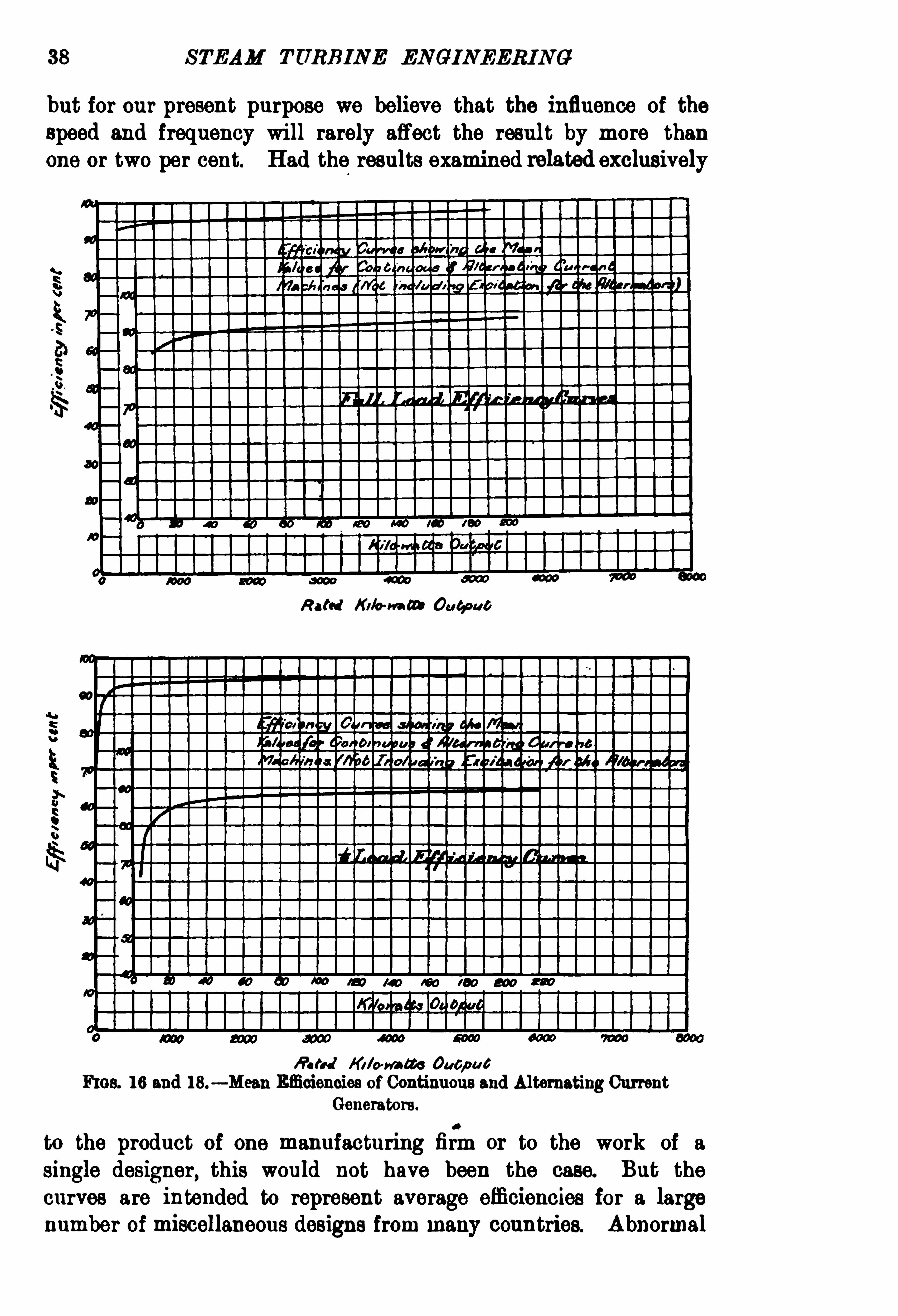
38 STEAM TURB INE ENGINEERING
but for our present purpose we believe that the influence of thespeed and frequency will rarely affect the result by more thanone or two per cent. Had the results examined relawd exclusively
Rated Kilo-m m 044000 0
fi sh-J Ki lo-m ete Oucpu t
FIGS. 16 and 18.— Mean Efficiencies ofContinuous and Alternating Current
Generators.
to the product of one manufacturing firmor to the work of asingle designer, this would not have been the case. But thecurves are intended to represent average efficiencies for a largenumber of miscellaneous designs from many countries. Abnormal
THE D E LA VAL TURB INE 39
voltages, of course , affect the results, but these are neglectedin the curves, which are intended to relate to a wide range ofintermediate voltages. In the case of a very high-voltage
Ruled Ki lo-mm Gab/ W 6
FIGS . 17 and 19 .— Mean Efficiencies ofContinuous and Alternating Current
Generators.
polyphase generator or a very low-voltage continuous current
generator, an extra allowance should be made at the discretionof the engineer referring to these curves for any special purpose .
The results for the continuous current dynamos are set forth

40 STEAM TURBINE ENGINEERING
in Figs. 9,10
,11, and 12
, and for the polyphase dynamos inFigs. and 15. In the case of the polyphase dynamos,the excitation loss has not been included in deriving the effi ciencies,since the excitation will be supplied from an external source ofpower.
I t will be seen from Figs. 9 to 15 that there is but littledifference between the average results for the efficiencies ofalternating current and of continuous current dynamos. For thepractical purposes of the present investigation,
it ismore convenientto consult the curves of Figs. 16 to 19
,which are mean results
for alternating and continuous-current dynamos.
In all instances where the tests were made by measuring theoutput from the dynamo, and the input in quantity of steam,
wehave taken the observed results as the basis for our work and havehad no occasion to consult the curves of Figs. 16 to 19 . Where
,
however,the output from the turbine shaft alone was measured ,
we have assumed the addition Of a dynamo having the efficienciesset forth by these curves and have deduced results for the outputin kilowatt hours from this hypothetical dynamo, per kilogram of
steam consumed by the turbine.In this way we obtained curves from which the results set
forth in Table XXV . have been derived. From the curves fromwhich we have deduced this table, we have read off the inter
polated values,and this accounts for such entries as 37 nozzles
open.
”Such an entry merely indicates that the load was inter
mediate between the loads at which 3 and 4 nozzles, respectively,were opened. Of course , each nozzle is either completely openedor completely closed.
On the basis of one or the other of the various sets of testresults recorded in Table XXV . many interesting deductions maybe made. See folding sheets, pages
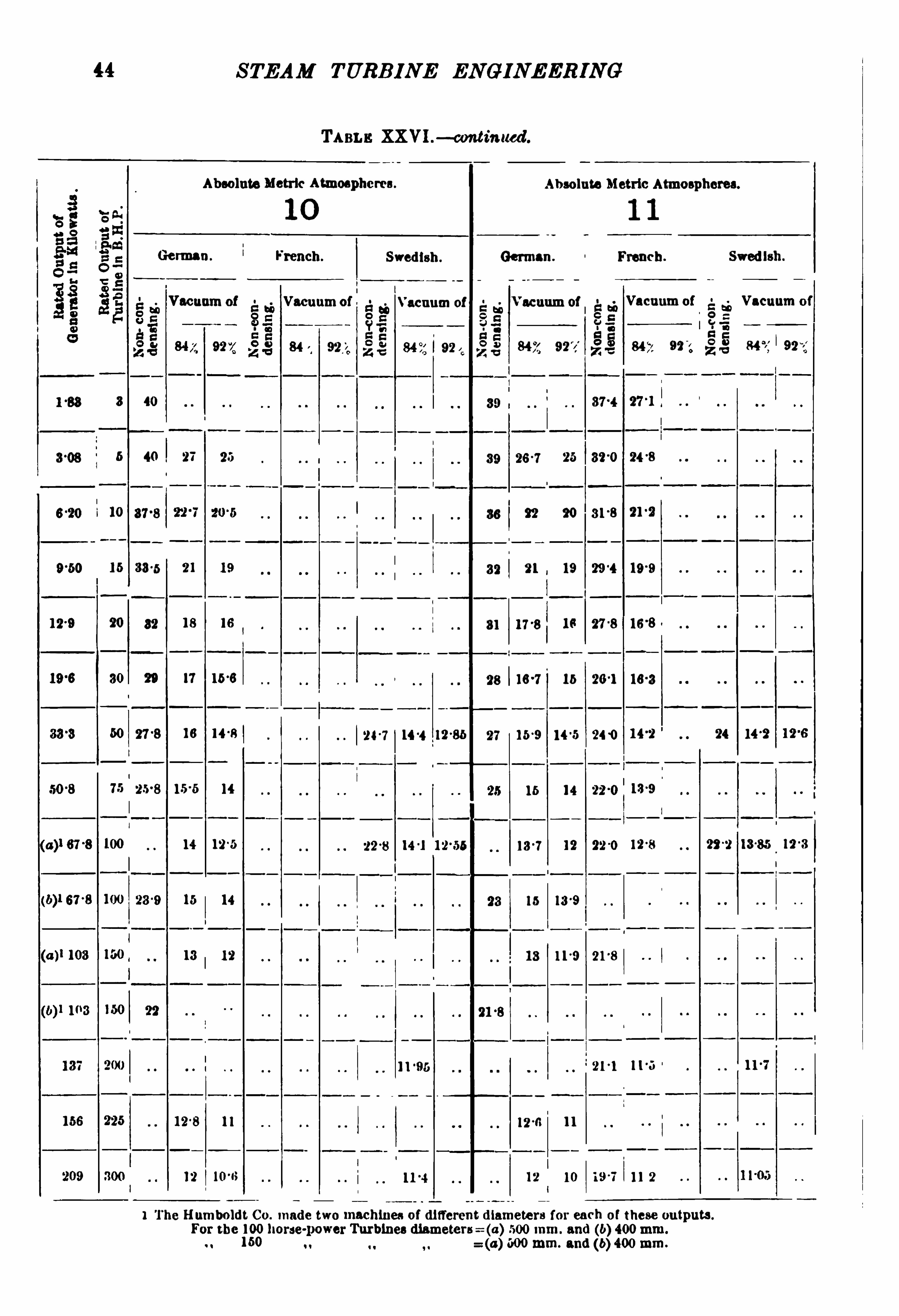
In Table XXVI . the German and Swedish estimates are from
Baa dcr D ampfl urbinen, A . M usil,Leipzig, B . G . Teubner
,1904,
pp. 80 and 93. The French estimates are from The Steam
Turbine,”R . H . Thurston ,
Transactions, American Society ofM echanical Engineers, vol. xxii., p. 215
,1901.
TIIE EFFECT OF VARYING THE PRESSURE.
Le t us first concentrate our attention on the effect of varyingpressure at full load .
From Test I I . ofTable XXV .,relating to a -kilowatt set,we


THE D E LA VAL TURB INE
TABLE XXVI. — FULL-LOAD STEAM CONSUM PTION OF D E LAVAL STEAM TURBINE SETS IN
KILOORAM s OF DRY SATURATED STEAM PER KI LOWA '
I‘
T-HOUB OUTPUT FROM THE DYNAMO.
Absolute Metric A tmospheres. Absolute Metric Atmospheres .
4 5
German French Swedish . German. French Swedish
Vacuum of
g3?Vacuum of
g2Vacuum of
ggVacuum of
53;Vacuum of
g:5Vacuum of
842, 922 55 84 7,
844, 927, 35 922 is: 847
,
922 55 927.
31 280
_
30
_
Z
25 23
240 22 230 21
19
1 0 112257 5 ?
III n T.
(a )! 67-8 1s's I:
18 i ; 15 8
160 14 15 l
1 The Humboldt Co. made two machines of different diameters for each of these Outputs ,
For the 100 1101'se-power Turbines diameters=(a) 500mm. and (b) 400mm .
M 150n n (a) mm. and (b) 400mm.

10
15
(a)1 67'8 100
STEAM TURBINE ENGINEERING
TABLE XXVI.— continued.
Absolute Metric Atmospheres.
German .
Vacuum of
(were 100 -7
(a)1 103 160
(b)1 103 150
137 200
14
The Humboldt CO. made two machines of different diameters for each of these outputs.
For the 100 horse-powerTurbines diameters= (a) 500mm. and (b) 400mm.
(a) 500mm. and (b) 400mm.9 1 150
French .
Vacuum of
90
Swedish.
24
19
18
17
16
15
16
14
20
17
15
18
1 1°~i
82 °2
300
25 ° 7
23°4
Absolute Metric Ahnespheres.
German. French. Swedish.
é. é Vacuum of
85a: E
84 7 92x fig 84 7. 927,
43 290
280 26 0

THE D E LAVAL TURB INE
TABLE XXVI. -cm1tinued .
Absolute Metric Atmospheres.Absolute Metric Atmospheres.
8
German. French. Swedish . German French. Swedish .
Vacuum of Vacuum of Vacuumoi‘ Vacuum of Vacuum of Vacuum of
847, 927, 847, 922
8 48
340
4 1 23
86-5 22
” 7
810 17 0
29 7
i 75 27 0 10
(a)! 67 1i 100
(a)1 103
103
209 800 13 11
l The Humboldt 00. made two machines of different diameters for each of these outputs
For the 100horse-power Turbines diameters-E m;600mm. and
(b) 400mm.
to 100 (a 500mm. and 5) 400mm.
STEAM TURB INE ENGINE ERING
TABLE XXV1.—c<mtinued .
Absolute Metric Atmospheres .
German.
Vacuum of
8 40
5 40 27
I
i 10
16 30-5 21
30 20 17 150
TIE;
TIT.
"
13 12
12 8 i i
French.
Vacuum of
Swedish .
acunm of
12
12
Non-con
denslng.
Absolute M etric Atmospheres.
German. French.
Vacuum of a56Vacuum of
C :7 :a t:
84 11 992 912 842?
25 320 24 -9
22 20 81-8 210
21 , 19 190
17 -9 Is 27 0 115-8
.
184 15 261 160
150 10 5 240
16 14
13-7 12 22-0 120
15 13-9
13 110 21-8
‘211 11-5
120 11
I12 10 11 2
Swedish.
Vacuum of
24
1 The Humboldt Co. made two machines of different diamete rs for each of these outputs.
For the 100 horse-power Turbines diameters=(a) 500mm. and (b) 400mm.
(a) 500mm. and (b) 400mm.150 0 !

THE D E LAVAL TURBINE
TABLE XxVl. —continued.
Absolute Metric Aunospheres.
French. Swedish.
Vacuum of Vacuum of
3 38 's
5 38 26
10 340 22 20
13 31 20 6 180
20 30 17 0 18
30 27 160 16
50 26 14 5 23-3 14-0
75 24 16 13-8
(wer e 22 15 15 7
(a)1 103 150 120 11
I
(191 103 150 . 21
150 225 12'
1 1
209 300 110 1 10
Absolute Metric Atmospheres.
German. Wench. Swedish .
Vacuum of Vacuum of Vacuum of
24-8
281 194
14 22-8 18 75 13-8 120
210 180
12 4 210 13-46 1206
11 °6
I 11 °8 10
1 The Humboldt Co . made two machines of different diameters for each of these outputs.
For the
{fighorse-power Turbines dismeters : (a
(aH n l500mm. and (b) 400mm.
500mm. and (b) 400mm.

STEAM TURB INE EN G INEERIN G
TABLE XXVI.— amh‘
mm l.
Ahsoiute Metric Atmospheres Absolute Metric Atmospheres.
Genuan . French . Swedish. German. French. Swedish.
Vacuum of Vacuum of Vacuum of Vacuum o i
(a)1 31-3 100 13 113
100 21 14-3 13 we 13
;a) 1 103 130 12-7 11 12-3 11
b)! 103 100 13-3
12 12 v 10°
l
11-0 i10 11 10
l The Humboldt 00 . made two machines of diiYereut diameters for each of these outputs.For the 100 horse-powerTurbines 600mm. and (b) 400mm.
160 (a ) 600mm. and (104-00mm.

(a)1 67‘8 100
37-3 100
103 160
(b)l 103 100
m I;
153
209 -o
STEAM TURBINE EN GINEERING
TABLB XXVI .— continued .
Absolute Metric Atmospheres.
German. Fhens-h. Swedish .
Vacuum at Vacuum ofVacuum of
l The Humboldt Co . ma de two machine s of differen t diameters for each of these outputs.
{a} 500mm. and (b) 400mm.
For the 100 horse-power Turbines diamete rs :
150
Absolute Metric Atmospheres.
German French .
Vacuum oi’
of
h
600 mm. and (61 400mm.
Swedish .
Vacuum oi

THE D E LAVAL TURB INE
TA XXV1. continued .
Absolute Metric Atmospheres . Absolute Metric Atmospheres.
German French . Swedish . German. i-‘
much. Swedish.
Vacuum oi eenum of Vacuum oi’ Vacuum of Vacuum oi
24-2
23-1 22-3
10
190 180
Ka l‘fl‘s 100 11 8
(by 103
156 226
l The Humboldt Co . made two machines of different diameters for each of these outputs.
For the 100 horse-power Turbines diumcte rs=za) 610mm. and (b) 400mm.
160 a) 500 111111. and (10400 mm.
4
50 STEAM TURB INE ENGINEERING
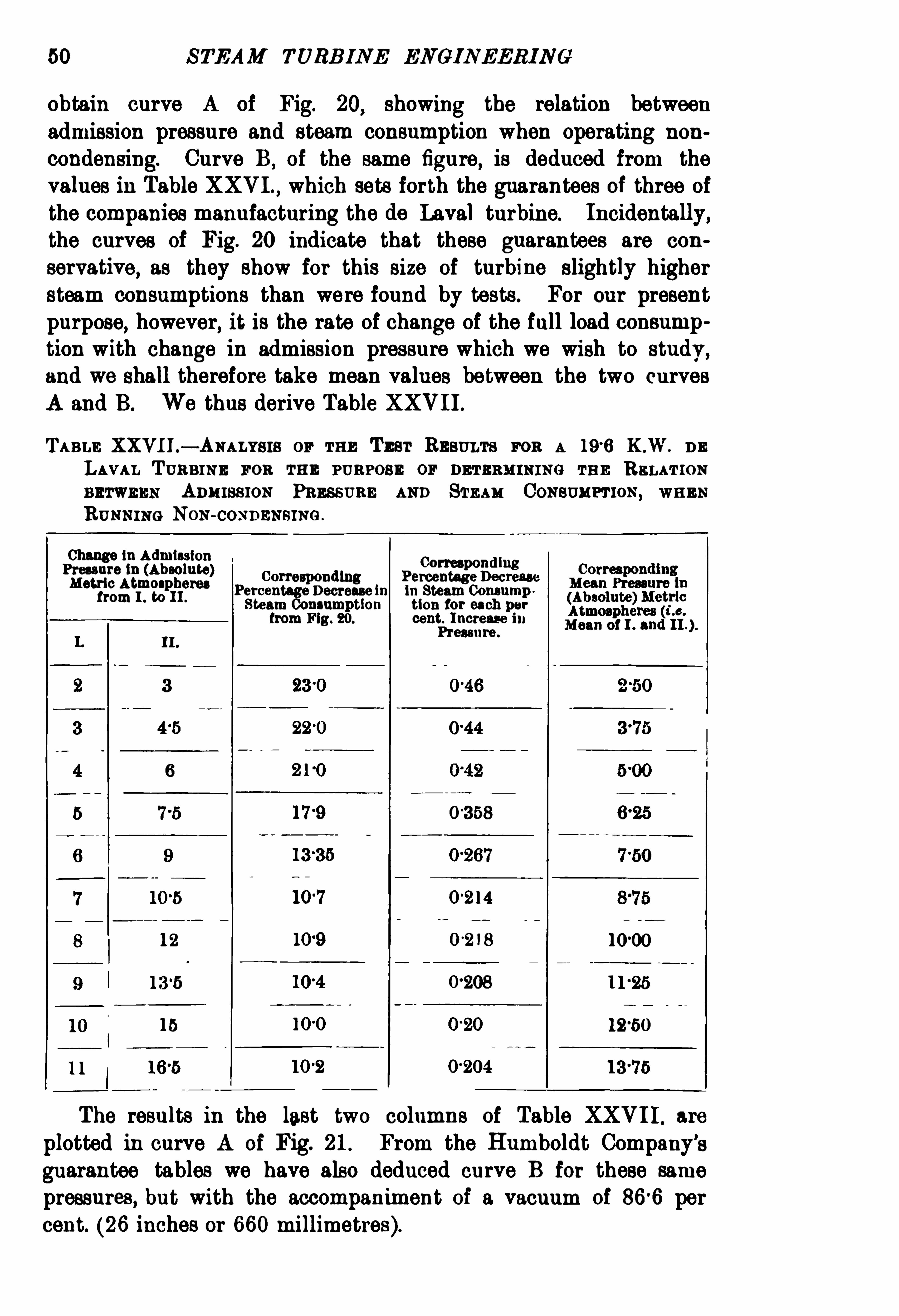
obtain curve A of Fig. 20,
showing the relation betweenadmission pressure and steam consumption when operating non
condensing. Curve B, of the same figure, is deduced from the
values in Table XXVI .,which sets forth the guarantees of three of
the companies manufacturing the do Laval turbine. Incidentally,the curves of Fig. 20 indicate that these guarantees are con
servative,as they show for this size of turbine slightly higher
steam consumptions than were found by tests. For our presentpurpose
,however
,it is the rate of change of the full load consump
tion with change in admission pressure which we wish to study,and we shall therefore take mean values between the two curvesA and B. We thus derive Table XXVI I .
TABLE XXVI I .— ANALYsls or THE TEsr RESULTs FOR A 190 K .W. D E
LAVAL TURBINE FOR THE PURPOSE or DETERM INING TE E RELATION
BETWEEN Am ussmN PRESSURE AND STEAM CONSUMPTION ,WHEN
RUNNING NON-COND ENSING .
Change in Admission CorrespondingPrm ure in (AbsoluteM etric Atmospheres
)Per
Corresponding Perc entage Decreasecentage Decrease in in Steam Consumpfrom 1 ° to 11.
Steam Consumption tion for each per
from F ig. 20. cent. I ncrease inPressure .
03 58
14
8
1
The results in the last two columns of Table XXVI I . are
plotted in curve A of Fig. 21. From the Humboldt Company’s
guarantee tables we have also deduced curve B for these samepressures, but with the accompaniment of a vacuum of 860 percent. (26 inches or 660millimetres).


52 STEAM TURB INE ENG INEER ING
By comparing the Humboldt Company’s guarantees for their
larger sizes of de Laval turbine,the same rate of decrease in steam
consumption per per cent. increase in admission pressure is foundto obtain ,
and hence at full load the curves of Fig. 21 may betaken as correct not only for the 190 kilowatt size, but for all
sizes of do Laval steam turbine generating sets up to the largeston their lists, which has a full-load rating of 209 kflowatts.
THE EFFECT or VARYING THE VACUUM .
The next point is to study, at full load, the decrease in steamconsumption per per cent. increase in vacuum. We shall at fi rstconfine our investigation to an admission pressure of 13 (absolute)metric atmospheres and no superheat , andwe shall base our studyupon the values guaranteed by the Humboldt Company as givenin Table XXVI .
Analysing these guarantees at a pressure of 13 (absolute) metricatmospheres and no superheat
,for sets of 190
,508
,102 and 209
kilowatts capacity, we obtain the curves of Fig. 22. These all
show approximately the percentage decrease in steam consumption
per per cent. increase in vacuum,plotted in the curve of Fig. 23.
Now by first applying corrections for different pressures and
next for different vacua,we are in a position to reduce any
observed full-load results to terms of the performance of a set ofcorresponding rated output, but designed for and operated at anadmission pressure of 13 (absolute) metric atmospheres, andiwitha vacuum of 860 per cent. (26 inches or 660 millimetres for abarometric pressure of 30 inches or 760 millimetres), and with no
superheat. By this means we derive from the full-load data inTable XXV . the values set forth in Section A of Table XXV I I I .
,in
which have also been entered up for the corresponding sizes thevalues taken from the guarantee lists of the French , German ,
and
Swedish de Laval companies.
Thus from the data under the heading of Reference No. I . ofTable XXV . we see that Lea and M eden found 29 kilograms perkilowatt-hour to be the steam consumption of a 10 kilowatt setat full load , for an admission pressure of 11 (absolute) metricatmospheres, no superheat
,and working non-condensing. From
Fig. 21 we find that a turbine working under the same conditionsin all other respects
,but with an admission pressure of 13
(absolute ) metric atmospheres instead of 11,will have its steam
consumption reduced per cent. for each per cent. increase in

THE D E LAVAL TURB INE 53
fl r c e n Cage Mi a / um
M ean Kat' s/ um m per cen t‘
F108 . 22 and 23.— Efl
°
ect ofVacuum on Steam Consumption.
steam pressure. This value is derived from curve A for the mean
steam pressure of
212 (absolute) metric atmospheres.

54 STEAM TURB INE ENGINEERI NG
Nowan increase from 11 to 13 atmospheres is an increase of
13
511x per cent.
Hence the improvement in economy will be
182 x 02 1 3 8 per cent.,
and the steam consumption will be reduced to
290 x kilograms per kilowatt-hour.
In all cases where the change in pressure is a matter of but afew atmospheres, it suffices to thus employ the mean percentageincrease as obtained from the curves in Fig. 21.
Nowwhat will be the economy when we introduce the furtherchange from working non-condensing to working with 860 percent. vacuum? In this case the change is rather too great tomake it desirable to employ the rate of change at the mean valueof the vacuum at 433 per cent. vacuum), as obtained fromFig. 23. It is preferable to consult the curves in Fig. 22, fromall four of which we find that the steam consumption with avacuum of 860 per cent. is approximately 61 per cent. of theconsumption when working non-condensing, or, over this widerange, the average rate of decrease in steam consumption for each
per cent. increase in vacuum is
100— 615
86004 per cent
FULL-LOAD STEAM CONSUMPTION.
Hence the full-load steam consumption of a -kilowatt turbo setfor operation at a pressure of 13 (absolute) metric atmospheresand with an 86 6 per cent. vacuum,
will be
x 170 kilograms per kilowatt-hour.
This is the value entered up under reference No. I . in section Aof Table XXVI II . In the same way
,by derivation from the full-load
test results in Table XXV . we have obtained values for the remainingsizes at full load for these same admission and exhaust pressures,and these have been embodied in the appropriate section of TableXXV I I I . The full-load values in section A of Table XXVI II . havebeen plotted in Fig. 24
,which shows the steam consumption at full
rated load for various rated outputs, at an absolute pressure of
13 kilograms, 86 6 per cent. vacuum and no superheat. The

56
VI I I .
XI I I .
XVI I .
XVI I I .
X IX .
STEAM TURBINE ENG INEERING
TABLE XXV [IL— 50°
C . SUPERNEAT .
2000
2000
1250
1000
10 500
Steam Consumption of the De Laval Steamrhine at Various Loads per K .W . Hour Outputat 13 Absolute M etric Atmospheres and an880 per cent. Vacuum. 60
°
C. Superheat.
11 8
Full load .
1'
1 140 6
1
1 11—
65
13 4 7 1279
165 18 55 B ‘T_
14 75
11-7 1 11-4
9-5 7 117 1
"
375“
1 17 1
1 1075
9 7 l 10 1
0 2 1 10 1
1 10 1
1
9 35 1
9 4 110-2
1
Ti"5"
10 55
10 4
18 45
1
l Derived from guarantees in section A for the same vacuum,viz. 84 per cent.

THE D E LA VAL TURB INE 57
difference between the guaranteed steam consumptions of theFrench, German,
and Swedish firms,and those found from the
test results given in Table XXVII I .
,which are the values of steam
consumption derived from published tests corrected to a constantabsolute pressure of 13 kilograms and an 86 6 per cent. vacuum
Fil l! le ad 0001446 in [07m mFm. 24.
— Full-Load Steam Consumption.
with no superheat, was extremely small. It has therefore beenfound advisable to take for these values the mean curve given inFig. 24 . The curve in this figure can now be taken as fairlyrepresenting the steam consumption of the de Laval steam turbineat full load, for any rated output from 10 to 209 kilowatts
,at an
absolute pressure of 13 kilograms and 860 per cent. vacuum,with
no superheat.
HALF-LOAD STEAM CONSUMPTION .
The steam consumption for designs of various rated outputshas now been found for full load. I t is necessary to investigatethe matter in the same way for half load . Let us first examinewhether the curves in Figs. 20 to 23 can be taken as alsocorresponding to the conditions at half load. The first stepconsists in ascertaining Whether a curve showing the steamconsumption at half load for various pressures has the same lawas the corresponding curve for full load.

58 STEAM TURB INE EN GINEERING
TABLE XXIX — Bem msn PERCENTAGE D ECREAsE IN STEAM CONSUMP
TION PER DEGREE CENTIGRA DE or SUPERHEAT.
Name of Firm.
Greenwood Batley, Leeds 10°
C.
Greenwood Batley, Leeds C .
Greenwood Batley, Leeds C. 01 45
Socié té De Laval . 50°
C. 01 60
Socié té De Laval . 80°
C.
Humboldt 00 . 50°
0. 15
For this purpose, let us first examine the results of the testsof a 190 kilowatt set when running non-condensing at variouspressures as set forth in Table XXV ,
under reference No. II . We
find the following values for the steam consumption at full andhalf load
TABLE XXX .
lConsumption
m r
Admission Pressure ,Ratio ofHalf-Load to
in Absolute Metric i Full-Load SteamAtmospheres. Consumption.
33 11Load
30
From the data in the last column we see that the advantage
gained by an increase of admission pressure for a 190 kilowattset running non-condensing is, on the average , so far as thisparticular test shows, somewhat greater at half load than at fullload. Let us
,however
,investigate the case of the 209 kilowatt
set, the largest size manufactured. For this purpose we haveanalysed the various test results contained in Table XXV . forturbines of this size, and have therefrom deduced the curves
THE D E LA VAL TURB IN E 59
A and B of F ig. 25, showing the dependence of the steamconsumption on the admission pressure when running condensing.
The ratio of the values in curves A and B is constant at forall pressures from 10 to 17 absolute metric atmospheres. The
law of variation of steam consumption with varying pressure istherefore, for this case, approximately the same at half load as atfull load. Now
,inasmuch as the percentage variation of steam
consumption per per cent. variation of admission pressure is in
”I n nis/an fm m /utcj in hiya /e e r 32 cm .
FIG . 25.— Steam Consumption 209 K.W. De Laval Set.
any case such an exceedingly lowvalue , it is evident that no errorof consequence will be introduced by using at half load the samecorrection curves already employed at full load, namely, the curvesof Fig. 21, for all sizes of de Laval turbines, in spite of the slightdeparture from this relation shown by the tests of the 190
kilowatt set, when running non-condensing with varying admissionpressure. This has been done in the following analysis.
VARYING VACUA AT HALF LOAD .
The next step is to ascertain whether we may also use at halfload the curve in Fig. 23 for correcting for varying vacua. For

60 STEAM TURBINE ENG INEERING
this purpose it is fi rst necessary to determine the consumption of
steam at half load for various sizes, with constant pressure and no
superheat, and running non-condensing.
The corresponding values for full load have been plotted fromthe data in Table XXVI . for an absolute pressure of 13 metricatmospheres, and give us curve A of Fig. 26. The HumboldtCompany state that at half load the steam consumption is about12 per cent. hig her than at full load. Even should this percentagenot be exactly right, it is suffi ciently so to serve the presentpurpose. Curve B of Fig. 26 is plotted with ordinate s 12 per
M /o -watt s 0a 6p u t at Rated [ L l/ [M
FIG . 26 .
(Refer to Tables XX V. and XX VI . )
cent. greater than the ordinates of curve A of Fig. 26, and givesus the approximate steam consumption of the various sizes at halfload
,13 absolute metric atmospheres admission pressure
,and
running non-condensing. Curve C of Fig. 26 has been deducedfrom an analysis of a number of the test results at half load inTable XXV . By a comparison of curves B and C of Fig. 26 we
find that at half load a 93 per cent. vacuum reduces the steamconsumption of all sizes to some 56 per cent. of the consumptionwhen working non-condensing. From a comparison of the fourcurves given in Fig. 22 for full load , we find that the corresponding percentage reduction already ascertained to occur at fullload may, for practical purposes, be taken as identical. Hence

THE D E LA VAL TURBINE 6 1
we may employ the curves of Figs. 22 and 23 for vacuumcorrections, not only at full load, but also at half load.
We thus find that it is practicable to use the data of the set ofcurves of Figs. 21
,22, and 23
,corresponding to full load
,for
correcting the steam consumption for various pressures and vacuaat half load. We can nowat once derive the values of the steamconsumption at half load for a constant absolute pressure of 13kilograms and 860 per cent. vacuum, and with no superheat. This
Ra ted Fit” Loa d C u b /ou t In MYO a n d !
FIG . 27 .— Steam Consumption De Laval Turbine at HalfLoad.
(Plollcdfrom Values in Column A , Table XX VI I I . )
has been done with the values given in Table XXV ,at half load
,
for various outputs, and the corrected values are shown in the
appropriate section of Table XXVI I I .,and are plotted in Fig. 27 .
From the curve of this figure we can find the steam consumptionat half load for sizes from 10 to 209 kilowatts, at the specifiedpressure and vacuum.
QUARTER-LOAD STEAM CONSUMPTION.
The same method of investigation has been carried out in the
case of the quarter-load values. From the curves of Fig. 28 it

62 STEAM TURB INE ENGI NEERING
will be seen that for a 190 kilowatt set the conditions are
approximately the same as at half load, so far as relates to therate of variation in steam consumption as a function of theadmission pressure
,the ratio of the values in curve A , repre
senting one-quarter load,to those in curve B, representing full
load , ranging from at a pressure of 4 absolute metric atmospheres, to at 12 metric atmospheres. The rate of increase insteam consumption with varying pressures is taken as remainingfairly constant at full, half, and quarter loads, throughout a widerange of mean pressures. The curves of Fig. 29, which have
4 b 8 f2 /4 18 2 9
”dm / SS /on He sse/ re m fifys p er $zcentfmeaer
FIG . 28. K.W. De Laval Set, with Varying Pressure.
been constructed in order to investigate the effect of varyingvacua at quarter load, have been derived in exactly the same wayas those in Fig. 26 ; but instead of taking 12 per cent. increasein steam consumption above that at full load, as guaranteed forthe half load value, we have taken 25 per cent. as representingthe increase at quarter load, this being the percentage quoted bythe Humboldt Company.
The ratio of the values in curves C and B of Fig. 29 is fairlyconstant for all sizes, and has a mean value of about Thatis to say, a 93 per cent. vacuum decreases the steam consumptionat quarte r loads to about 56 per cent. of the steam consumptionwhen running non-condensing, the admission pressure being 13

64 STEAM TURB INE ENGINEERIN G
in consumption due to variation in vacuum. Should a do Lavalturbine be operated with all the nozzles open at all loads
,the effect
of increasing pressure would doubtless be to further increase thesteam consumption at light loads.
EFFECT OF SUPERHEAT ON STEAM CONSUMPTION.
The question of superheat has, up to the present,not been
to m 160 M £ 0 2 0
Rated fi d / Load Ou t/out m M /amsd is
FIG . 30.— Steam Consumption D e Laval Turbine, Quarter Load.
(Plotfcdf'rom Column A ,
Table XX VI I I . )
touched upon . In order to arrive at representative values for the
gain in economy for the de Laval turbine due to a moderatedegree of superheat, we have shown in Table XXIX . the percentage
gain in economy as estimated by vari ous firms manufacturing thistype of turbine, and the means of those values have been employed

THE D E LA VAL TURB INE 65
in deducing the curve of Fig. 31. From this curve we can
estimate the percentage gain in economy per degree Cent. increasein superheat.
The curves of Figs. 24 , 27 , and 30, which Show the steamconsumption of the de Laval steam turbine at full
,half
, and
quarter loads,at a constant absolute pressure of 13 kilograms and
an 866 per cent. vacuum, have been employed as the basis fromwhich we have deduced the steam consumption with a superheat
750 1 S uperfiaab Cent /grade.
FIG . 81. — Effect on Steam Consumption of Increase in Superheat.
(FromTabl e XX IX . )
of 50° Cent ,and the results are plotted in curves A ,
B, and C of
Fig. 32. As the steam consumption for auxiliaries is onlyincluded in one of the tests analysed, the results in Fig. 32 areto be taken as representing the consumption exclusive of
auxiliaries.
In Table XXVII I .,column B , will be found the steam consump
tion values taken from Table XXV and transformed to a constantabsolute pressure of 13 kilograms per square centimetre , and an
86 6 per cent. vacuum, with a superheat, of 50’
cent. , at full, half,and quarter loads.

66 STEAM TURB INE EN GINEERING
In Fig. 33 are shown for an absolute pressure of 13 kilograms
and 86 6 per cent. vacuum and a superheat of 50° Cent., for theentire range of rated capacities, the percentages by which the
steam consumption at half load and quarter load exceed the steam
consumption at full load. It is evident from the curves that forall but the smaller sizes, the steam consumption at half loadexceeds that at full load by from 10 per cent. to 12 per cent., and
so so 100 120 m l60 zap an 229
M E ” [ and Ou t/«1 6 ln M /ofi a ta
FIG . 32.— Steam Consumption ofde Laval Steam Turbine.
A=Full Ioadfrom F ig. 24. A ll corrected for Superw .
B=Half load from F ig. 27.
C Quarter load.
the steam consumption at quarter load exceeds that at full loadby some 26 per cent. The percentages only apply when thenumber of nozzles opened is varied by hand in proportion to theload. In reference No. I . of Table XXV . is given the record ofa
test on a kilowatt generating set by Lea and M eden,in which
all the nozzles remained Open at all loads. The results, reducedto an admission pressure of 13 atmospheres, a vacuum of percent. and 50° Cent. of superheat, are plotted in Fig. 34 , together


68 STEAM TURB INE ENGINEERING
with the corresponding results when the number of nozzles openedis changed in proportion to the load. In the case where all thenozzles are open at all loads, it is seen that the steam consumptionat half load exceeds the full load steam consumption by 38 percent. as against only 18 per cent. when the number of nozzlesopened is in proportion to the load. Inasmuch as the de la va]turbines are not provided with any automatic arrangements forchanging the number of nozzles Opened as the load changes, it is
not altogether right that the type should have the credit of givingsuch low results for steam consumption at light loads as areobtained by closing the nozzles as the load de
creases.
Tm: INTERNAL Lossns IN THE DE LAVAL TURBINE.
A list of these losses has been given on p. 33.
I . Nozzle Losses. Could the steam be expanded in a
diverging nozzle to the desired pressure without any friction orother losses, all the available energy would be transformed intokinetic energy , i s. the steam would flow out with a speed whichcan be calculated from the following formula :
1
Speed in metres per second = 44 4 available energyin kilogrammetres.
There are, however, losses due to the friction of the steamagainst the inner surface of the nozzle
,and most probably also
due to the formation of eddies and whirls. It is customary toindicate these losses by stating the corresponding percentagedecrease in speed. For correctly designed de Laval nozzles, the
speed reduction due to nozzle friction generally varies between5 per cent. and 8 per cent. The corresponding losses of energyare therefore between 10 and 15 per cent. Delaporte 2 found theexceptionally low value of 2 6 per cent. decrease of speed. Ofcourse the above average losses refer only to correctly designednozzles. It is clear that a nozzle can be correctly proportionedonly for a given amount of steam passing through it and for givenconditions as to admission and exhaust pressure. In all caseswhere a nozzle is used under different conditions from those forwhich it is designed, the losses will be higher. Any change inthe admission pressure or in the exhaust pressure has a greatinfluence on the effi ciency of the nozzle, or on the shape of the
1 This formula is derived from the formula for kinetic energy on p. 28.
2 D elaporte, Revue dc M écam'
que , 1902, p. 406 .
THE D E LA VAL TURB INE 69
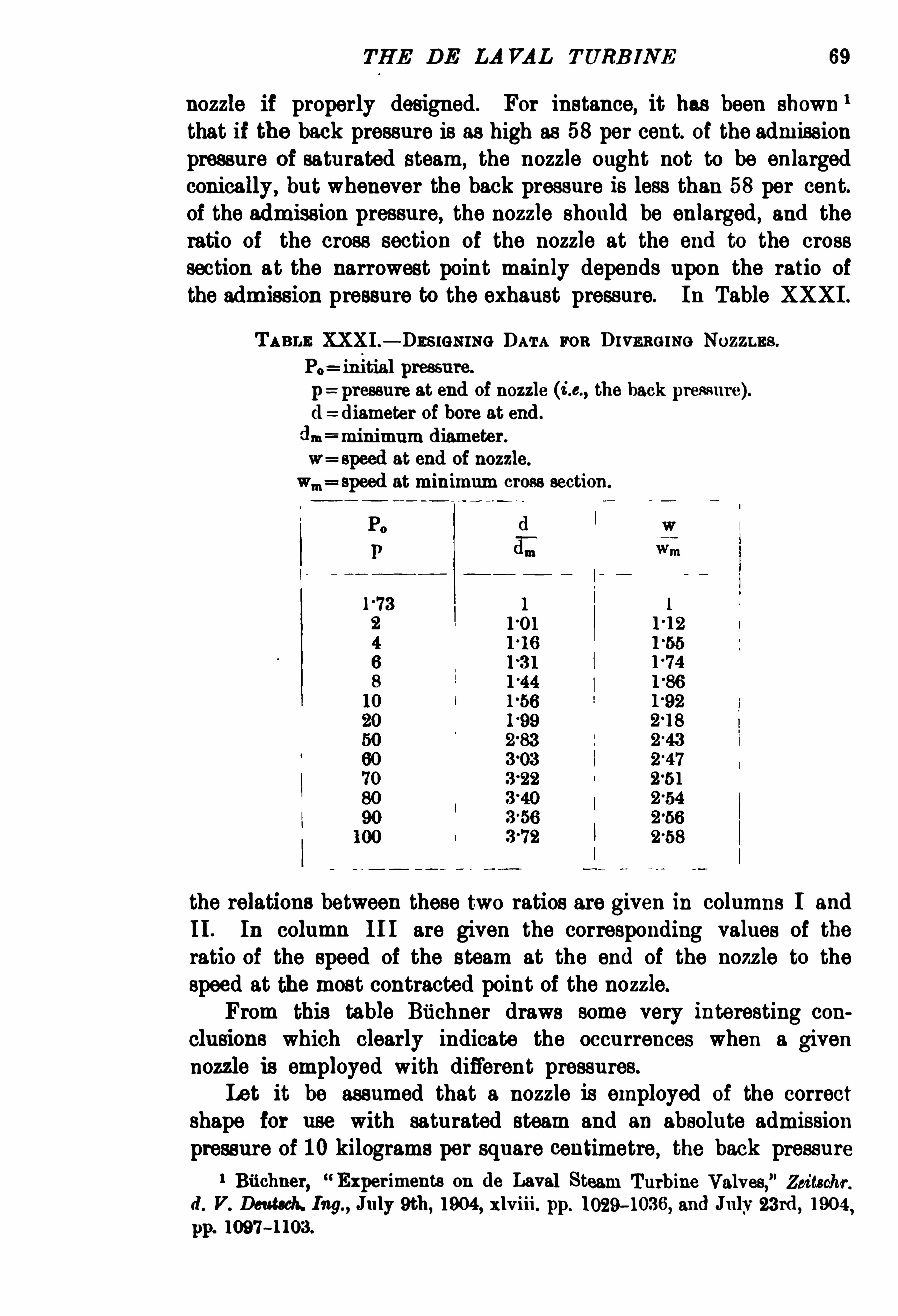
nozzle if properly designed . For instance,it has been shown 1
that if the back pressure is as high as 58 per cent. of the admissionpressure of saturated steam,
the nozzle ought not to be enlargedconically , but whenever the back pressure is less than 58 per cent.of the admission pressure, the nozzle should be enlarged , and theratio of the cross section of the nozzle at the end to the crosssection at the narrowest point mainly depends upon the ratio ofthe admission pressure to the exhaust pressure. In Table XXXI .
TABLE XXXI .— DESIGNING DATA FOR D rvnnorNe Nozznns.
P0 initial pressure.
p=pressure at end of nozzle (La, the back pressure).(1 diameter ofbore at end.
(Lu z-minimum diameter.
w= speed at end of nozzle.
wm speed at minimum cross section.
Po
P
the relations between these two ratios are given in columns I and
I I . In column I I I are given the corresponding values of theratio of the speed of the steam at the end of the nozzle to thespeed at the most contracted point of the nozzle.From this table Buchner draws some very interesting con
clusions which clearly indicate the occurrences when a givennozzle is employed with different pressures.
Let it be assumed that a nozzle is employed of the correctshape for use with saturated steam and an absolute admissionpressure of 10 kilograms per square centimetre , the back pressure
1 Buchner,
Experiments on de Laval Steam Turbine Valves,” Zeitschf
r.
d. V. Deutaoh. Ing.,July 9th, 1904 , xlviii. pp. 10294 036, and July 23rd, 1904 ,
pp. 1097 — 1103.

70 STEAM TURBINE ENGINEERIN G
being1 kilogram per square centimetre. From Table XXXI . we findthat the diameter at the end of the nozzle should in this case be56 per cent. larger than at the narrowest point. For this case,let us assume that the pressure at any point of the nozzle has beencalculated or found by experiment. If we use the same nozzle fora 20 per cent. greater admission pressure without altering theback pressure, then the pressure at any point of the tube will be20 per cent. greater than before. As the speed of the steamremains practically constant (one-half of one per cent. increase) ,the degree of wetness also remains practically constant. The
mechanical energy imparted to the . steam has therefore remainedpractically the same (only one per cent. increase), while withanother nozzle of suitable design for this greater pressure, theincrease in mechanical energy would have amounted to approxi
mately 16 per cent.Very peculiar phenomena occur when,
with a given nozzle,
the admission pressure is reduced below the most favourable value.
Theoretically, the pressure at each point of the tube should thendecrease in the same ratio , to. the steam should expand to apressure lower than the back pressure, so that on leaving thenozzle the steam would again be compressed.
There are,however not yet available the results of sufficiently
exhaustive tens to permit of deducing the losses due to suchdecrease in admission pressure. It is, however, clear that anyreduction in the pressure caused by throttling must be aecom
panied by a loss, in so far as energy capable of being convertedinto mechanical energy is transformed into heat by losses takingplace in the nozzle.11. Losses due to Leakage between Nozzles and Vanes .
— The leakage losses can be taken proportional to the differenceof pressure between the end of the nozzle and that at the entranceto the vanes, and to the clearance between the nozzle and the
vanes. As in the de Laval turbine the difference of pressure isvery small
,the leakage losses should also be very small, or possibly
even negligible.
III . Losses due to Radiation from the Turbine Casing.
— These losses are comparatively small. They are proportionalto the difference between the temperature of the turbine casingand that of the surrounding atmosphere and to the surface of thecasing. It would, however, be erroneous to conclude that thelosses thus occasioned are direct losses, and as such are to besubtracted from the mechanical energy available. This may occur

7 2 STEAM TURB INE ENGI NEERIN G
roughly as the 3rd power of the speed . It has been confirmedby several other experimenters that the power lies between 2 8
and 3 5 . This loss has a great resemblance to the windage loss indynamos
,and also to train resistance at high speeds. For a very
Fm. 35.— Friction Losses in a 30H.P. de Ia val Turbine.
large alternator, one of the authors recently found the windageloss varied approximately as the 3
°
5th power,but this may have
been due to the very excessive vibrations existing at the extremelyhigh speeds at which it was run for the purposes of the test. The
train resistance due to wind friction is generally assumed to beproportional to the g power, therefore the loss is proportional tothe 2 7 power. As an average the 3rd power seems to give a fairagreement with most of the test results.

TH E D E LAVAL TURB INE 73
Judging from Fig. 36, air at 30° Cent , and at absolute
pressure of one metric atmosphere, causes a 35 per cent. to 40 per
cent. greater loss than saturated steam at the same pressure.
In Fig. 37 the influence of superheat on the wheel losses is
shown for an absolute pressure of 1 kilogram per square centi
metre, and also for an absolute pressure of 04 kilogram per
square centimetre.With the exception of a small part of the left-hand end of the
curves,the losses seem to decrease proportionately to the increase
of superheat. The sudden increase near saturation is mostprobably due to the presence of water in the steam, and theavoidance of wetness thus forms one of the principal advantagesobtained by the employment of superheat. The dotted linesrepresent the specific weight of the steam,
and the close agreement

STEAM TURB INE EN G INEERI NG
which exists between the losses and the specific weight seems toindicate that the wheel losses are approximately proportional tothe specific weight.
In Fig. 38 the influence of pressure on the friction loss isclearly shown. The range is from 04 to l kilogram per squarecentimetre. In this case the values are also approximately proportional to the specific weight.
l In comparing the losses fordifferent media, this relation no longer holds good . For instance
,
Fro . 37.
in Fig. 36 the losses for air and saturated steam differ roughlyin the ratio The specific weight for the same conditionsvaries, however, in the ratio (i s. as and hencethe wheel losses have not increased at nearly so great a rate as thespecific weights.
In order to apply these and other results at once to turbines1 T he weight of one cubic metre of saturated steam is (accord ing to
Zeuner,Tech. M odynamik— Felix, Leipzig, 1901— vol. ii. p. 37 ) equal to
06 88 p.
” 39 Kg.,but for any particular case it is more convenient to take it
from the steam tables . For superheated steam the volume in cubic metres of
1 kilogram of steam can be found from the expression
x (absolute temperature)Abs. pressure in kilogram per sq. metre
This applies to temperatures not far from saturation,according to Tumlirz
(see Chap. XIII .)
Volume

THE D E LA VAL TURB INE 75
of different dimensions, Stodola has proposed to take these wheel
losses as being proportional to the square of the diameter, thethird power of the peripheral speed, and the specific weightof the medium. It seems, however, that the influence of thediameter has been overestimated by Stodola, as this formula gives,for very large diameters, considerably too high values. For
instance , Ports 1 remarks that a 150 horse-power de Laval turbineabsorbed 35 horse-power at no load when revolving at normal
Pres s are of Saar/ rated 5m 10
FIG. 88.
speed in steam at atmospheric pressure, and 2 33 horse-power
when revolving at the same speed in a vacuum of 28 inches
(933 per cent. vacuum). The 150 horse-power de Laval turbine
has a diameter of 55 centimetres and a peripheral speed of 330
metres per second. The 30 horse-power de Laval turbine tested
by Lewicki had a diameter of 20 centimetres and a peripheral
speed of 210 metres per second. According to Stodola, the wheel
losses of the 150 horse-power turbine would have to be 29 times 1
1 Ports,Steam T urbines
,
” Journal Inst. Electrical Engineers, vol.xxxiii.
p. 887,February 1lth, 1904 .
“
(a (are

76 STEAM TURB INE EN G INEERING
larger than in the 30 horse-power turbine under equivalent conditions. The tests give , however, a ratio of onlyIt seems considerably more probable that the wheel losses are
proportional to the expressionDiameter “x (peripheral speed)
3 x specific weight ofmedium,
and that the value of a: lies between 10 and 15 .
In the 150 horse power test,the specific weight also had a
proportional influence,namely
,
Specific weight at 1 atmosphere (1587Specific weight with 28-inch vacuum 0045
Losses at atmospheric pressure 35
Losses at vacuum of 28 inches 23 3
Considering the extreme range, these results are in excellentagreement. I t must
,however
,not be thought that the losses
measured when the turbine is driven in a stagnant medium arethe same as those occurring during actual conditions of operationat full load. The conditions for these two cases offer so manystriking differences that it would be a mere coincidence were thelosses to be the same in both cases. A t full load a part of thevanes are filled by the steam flowing from the nozzles over thevanes and then onward to the condenser. Therefore the conditionswould be similar to those in a test with stagnant steam onlybetween two adjacent nozzles. This has also been shown experi
mentally , as described in Stodola’
s treatise,3rd edi tion , pp. 131 , 132.
By increasing the number of nozzles, Lasche1 found considerable
decrease in the losses, which can be explained by the decrease inthe friction of those vanes filled at any moment with stagnantsteam.
A second reason why the wheel losses at full load should bedifferent from the losses observed with stagnant steam lies in the
fact' that the wheel losses entail a conversion of mechanicalenergy into heat. At full load a part of the heat is, however,reconverted into mechanical energy, as it has heated the vanes,and these give back the heat to the useful ste am. The percentageof the losses recovered stands in a certain ratio to the percentageof total heat convertible into mechanical energy. That is to say,
the higher the pressure , the lower the vacuum ; and the higher thesuperheat
, the higher will be the percentage of the wheel losses,which may be again converted into mechanical energy. Roughly
1 Stodola,D ie D ampfturbinen, 3rd edition
, pp. 130 and 131.
THE D E LA VAL TURBINE 77
speaking, this percentage in practical cases varies between 15 percent. and 25 per cent.
V . Losses due to the Friction of the Steam travellingover the Vance — The losses in the steam when travelling overthe vanes are entirely different from the losses due to theresistance of the turbine wheel rotating in the steam. The latterlosses entail a conversion into heat of mechanical energy of thewheel. The former losses involve a decrease in the speed of thesteam, and therefore a conversion of the mechanical energy of theste am into heat. Both losses, however, share in common thefeature that the heat they occasion is not entirely lost, but servesto increase the temperature and energy of the st6 am,
and thus allowsof partial recovery. These losses are by far the largest of all othercomponents of the total internal loss.
Suppose that the steam at the moment of impact moves alongthe vanes with a speed of 800metres per second. Then, theoreti
cally, the steam on leaving the vanes should still have a speed of800 metres per second. It is, however, found that the speed is
,
say, only 600 metres per second A good explanation of all thefactors causing this very considerable decrease has not yet been
given , but it is generally assumed that the steam within the vanesmay set up whirls and eddies, to reduce which the only meansseems to be to increase the number of vanes per centimetre of
periphery. The loss in energy due to the decrease of the speedfrom 800 to 600 metres per second can be easily calculated. A
kilogram of steam travelling with a speed of 800 metres persecond has a ln
'
netic energy of
1 2_2 x
x 800 ki logrammetres,
and at 600metres per second a kinetic energy of
1 2o
4 k2 x 98
x 600 18,00 i logi ammetres.
The total loss is therefore
kilogrammetres
33 kilogram-calories.
The decrease of the speed generally amounts to from 15 to 25
per cent.,though there may be exceptional cases, especially for
low speeds, in which the percentage decrease is somewhat
Itmust be clearly understood that the speed with which the

78 STEAM TURB IN E ENGINEERI NG
steam flows over the vanes is altogether different from the absolutespeed of the steam, which , of course, depends upon the peripheralspeed of the turbine and upon the curvature of the vanes. The
absolute energy taken from the steam should be calculated as
before,but by taking the absolute speeds of the steam the
difference between these two results would give the energy convertedinto mechanical energy.
VI . Losses due to Bearing Friction.
— Some idea of themagnitude of these losses in a de Laval turbine may be gatheredfrom a consideration of curve I I I of Fig. 35 ,
which shows thelosses in the bearings and gearing of a 30 horse-power motorinvestigated by l‘ewicki. These investigations have been describedin the preceding section. An examination of the curve indicatesthat the bearing and gearing loss is some 7 5 per cent. of the ratedfull-load output .For a 200 horse-power de Laval turbine , D elaporte 1 assumes
about horse-power bearing loss.
VII . Loss in Speed-reduction Gearing — This is very
dependent upon the workmanship employed in the manufacture ofthe gearing. It is, nevertheless, of relatively large amount, andmay be taken as at least 5 per cent. in gears in good condition.
It doubtless runs well up towards 10 per cent. in moderately worn
gears, and hence is a leading cause of any slight increase of steamconsumption which probably generally occurs in the course of timein steam turbines. Thus Niethammer 2 refers to a 200 horsepower (140K W .) de Laval turbine as having, when new
,a steam
consumption of 97 kilograms per with a vacuum of 7 1ems ,
as against a steam consumption after five years of serviceof 101 kilograms per with a 64 cm. vacuum and
(presumably) the same admission pressure and temperature inboth cases. These figures, however, reduced to the same vacuum,
show a deterioration of only about 2 per cent.W ear ofVanes or Buckets — Deterioration is also stated to
occur as a consequence of wear of the vanes or buckets.
”In this
connection the following quotation from Lea and M edeu’
s paper,The de Laval Steam Turbine,
” 3 is not without interest“ I t might be interesting to touch on the practical difficulties
1 Delaporte
,Revue dc M e
'
cunique, 1902, s. 406 .
D ie Dampfl urbinen, page 104.
3 Paper by Lea and M eden,entitled The de Laval Steam Turbine
, pre
sented at the C hicago meeting (May and June 1904) of the American Soci etv
of M echanical Engineers, and forming part of vol. xxv.-of the Transactions.

STEAM TURB INE EN GINEERIN G
five years ; The wear affects only the steam inlet side of thebuckets, and will only increase the steam consumption to a slightdegree. In tests made on a turbine of 100 horse-power, where theedge of the buckets had been worn away about one-sixteenth of aninch
,the steam consumption was about 5 per cent. higher than
with new buckets. The wheel and buckets are, however, so
designed that an insertion of a new set of buckets can be easilymade at a small cost.”
Curve II I of Fig. 35 shows the value of the loss in bearings and
gearing for a 30 horse-power de Laval turbine. D elaporte 1 estimates the gearing losses oi a 200 horse-power de Laval turbineat as low as 1 per cent. , whilst the gearing and bearing frictioncombined of a 300 horse-power de Laval turbine in good conditionshould, in his opinion, be roughly taken as 3 per cent.VIII . Losses in Dynamo — These may be obtained from the
efiiciency curves already given in Figs. 16 to 19, from which itis seen that at full load they range about 7 per cent. of the outputin the largest size (209 K .W . dynamo coupled to 300 horse-powerturbine), up to some 15 per cent. in a 10 K .W. size. At one
quarter load the dynamo losses range from some 18 per cent. of theoutput in a 209 K .W. size, down to some 30 per cent. in a 10K .W. size. It is important that the extent of these losses at lightloads in small sizes should be realised , for in the case of anelectric generating set in which the load fluctuates so widely thatthe average load is but a small percentage of the rated load , ahigher
“all-day ” economy would be obtained by a dynamo
especially designed to have high efficiency at light loads, even atthe sacrifice of a few per cent. in the full-load efficiency.
IX . Losses due to Residual Kinetic Energy in the
Steam passing to the Condenser.
— The steam passes to the
condenser still possessed of a considerable percentage of the energywith which it entered the admission nozzle. It may be roughly
stated that this rejected energy will be less the nearer the velocity
of the turbine blades approaches one-half the velocity of the impinging steam. In the 300 horse-power turbine the mean diameterat the blades is 07 6 metre, and the speed of the wheel is
rp m. The linear velocity of the blades is thus 424 metres per
second. With an admission pressure of 13 absolute metricatmospheres and a condenser pressure of 86 6 per cent.
,the
absolute velocity of the impinging steam,allowing 15 per cent. loss
in the nozzle, will be 1090 metres per second. A t the usual1 Delaporte, Revue de M éumique, 1902, s. 406.

THE D E LA VAL TURB I N E
angles at which the nozzles are inclined to the direction of movement of the vanes, this velocity may be imagined to be resolvedinto two components : one in the direction of the movement of theblades
,and amounting to about 0°
94 x metres persecond, and the other component perpendicular to the first one,and amounting to 0
°34 l x 1090=370 metres per second. We mayassume (see p. 77) that the speed of the steam relative to thevanes decreases 20 per cent. during the passage over the vanes.
Hence the speed of 370metres per second is mduced to 296 metres
per second. The other component would be reduced by an amountequal to twice the peripheral speed of the vanes, provided that novane friction existed. Allowing, however, for the assumed 20 percent. less in the relative speed, the resulting decrease in speed isequal to some 2 25 times the peripheral speed.
1030 x 424 1030 954 76 metres per second.
The absolute speed of the steam after leaving the vanes is equal to
J 762+ 296
2= 306 metres per second.
The energy loss in percentage of the energy of the steam on
emerging from the admission nozzles is equal to
x 100 78 per cent.1090
In the smaller sizes the blade velocity is still lower, and theenergy passing on to the condenser is a correspondingly greaterpercentage of the total energy in the steam at admission.
Summation of Losses — Ia view of these analyses of thecomponent losses, we are in a position to make a rough allocationof the total loss amongst those components.
Taking the case of a 209 kilowatt set and denoting by 100 the
gross energy supplied to the admission nozzles,the distribution is
roughly as follows
l . Nozzle losses 12
2. Leakage losses 13. Radiation losses
4 . Losses due to friction of the turbine wheel revolving in the steam 4
5 . Losses due to friction of the steam travelling over the vanes 9
l
7 . Losses in
pipeed reduction gearing 2
8. Losses in ynamo 4
9 . Losses due to residual kinetic energy in the steam passing to
condenser
Output
Gross input
1 09 4-005 20°

82 STEAM TURB INE EN G INEER ING
Of course, the conditions under which the turbine runs, t o.
whether with or without condenser, whether at the most favourablespeed or at a speed far below the most favourable speed , wouldchange the relative importance of the component losses, but theabove may be considered to give arough idea of the amount and dis
tribution of those losses in a normalde Laval turbine of the 300
power (209 kilowatt) size whenrunning condensing.
LONG ITUD INAL
rnANsvcnae
Fm. 89 .— 20 H.P. dc Laval Turbine.
General D escription — In Fig . 39 are shown drawings of a
20 horse-power de Laval turbine.
The turbine wheel A is mounted upon the flexible shaft Bbetween the spherical-seated bearing C and the stuffing box D .
The teeth of the two pinions EE are cut in the metal of the shaft

THE D E LA VAL TURB INE
itself. Bearings FG supported in the frame of the gear case areprovided just outside the pinions. The pinions EE engage the gearwheel H mounted on the shaft J , supported in the bearings KKK .
The power is in this instance transmitted from the pulley L.
A case in which a dynamo is driven from the power shaft isshown in the sectional plan in Fig which represents a 30
horse-power continuous-current set. The rated capacity of thedynamo is 20 kilowatt. Excellent -outline drawings with numerousdimensions are given for a de Laval 200horse-power seton p. 227 ofthe third edition of Stodola
’
s treatise ‘
D ie Dampfturbinen. In sets offrom 50 horse-power upwards, two gear wheels, two power shafts,and two dynamos are employed. The arrangement of the two
power shafts is well illustrated in Fig. 4 1, taken from an article inIllacltinery for November 1904 , entitled The de Laval SteamTurbine and itsManufacture. The illustration
,which is a horizontal
sec tionalview taken through the turbine andgear shafts, shows strikingly the relative sizes of the turbine and the reduction gearing.
The Turbine Wheel — In the small and medium sizes thedesign of wheel shown in Fig. 42 is employed. T
,the hub of the
wheel, is bored out, and a thin steel bushingis drawn into the hubby a nut at one end. The middle portion of the bushing is boredwith a taper of 4 per cent. The bushing is forced on the shaft andthen pinned in place as shown.
Thewheel may be removed from the shaft by drawing it off thesteel bushing after removing the nut.
Since the presence of a hole, no matter how small,
“
through theturbine wheel reduces its strength to at least one-half, it has beenfound necessary , in the larger sizes of de Laval turbines, wherevery high peripheral speeds are employed, to abandon the design
shown in Fig. 42 in favour of that shown in Fig. 43, in which asolid hub is recessed at each end, and the flexible shaft ismade withenlarged flanged ends which fit into the recesses and are boltedsolidly in place. The recesses and shaft ends are machined with a4 per cent. taper in order that the parts may be accurately centredand fitted solidly together.The turbine wheels are made of a special grade of high carbon
steel. Musil (Baa der Dampftwbt'
nen , p. 66,Leipzig,
B. G . Teubner)states
aThe turbine wheel is made from the toughest
homogeneous
Turbine,”Technology Quarterly for March 1904 Massa
chusetts Inst. of

84 STEAM TURB INE ENG INEERING
nickel steel,with a breaking strength of about 90 kilogram per
square millimetre, 10 to 12 per cent. elongation,and with an elastic
limit of 65 kilogram per square millimetre.”
THE D E LA VAL TURB INE
This doubtless relates to the de Laval turbines manufacturedby the H umboldt Company. The form of the wheel
,with the
section increasing toward the hub, is arrived by preportioning
it to have equal specific stresses throughout, and a factor of safetyof about 8. This does not hold true at the rim,
where , just belowthe blades, annular grooves are turned on each side of the wheel ,with the object of ensuring that in the case of a dangerously h
igh

86 STEAM TURB INE EN GI NEERING
speed being accidentally attained, due to failure of the governor , thewheel shall burst at this point , as the section is so reduced that theSpecific stresses are about 50 per cent. higher than in the rest ofthe wheel. At normal speed the factor Of safety at this reducedsection is about 5 and since the stresses vary with the square of
the speed , the wheel will burst at this point at about double itsnormal speed . It has been found by actual experiments that no
great damage results, for the rim holding the buckets is broken up
into very small pieces,which can do no damage to the wheel case .
Lea and M eden 1 state that in tests on wheels not having this reducedsection at the rim
,the wheels have
burst through the centre in two or
three heavy pieces, and the pieceshave been driven through an eXperi
mental wheel case Of steel castings
FIG . 42. Fro . 48.
havingwalls two inches thick. With the wheels as made,however
,
they are perfectly safe ; and in the event Of the rim being stripped ,no damage will result except to the wheel itself. Furthermore, assoon as the rim breaks, the wheel becomes unbalanced ; and as the
clearance between the heavy hub of the wheel and the safetybearings in the surrounding wheel casing is very small
,as may
be seen from Fig. 39 . the hub Ofwheel will. owing to the flexibilityof the shaft
,come in contact with the sides of these circular
Openings in the casing into which it extends, and these will act asa brake on the wheel and assist in bringing it to rest. With thebuckets broken Off
, the steam can no longer act to rotate the wheel,1 The de Laval Steam Turbine (Amer. Soc. lurch . E ayrs ,
vol. 25 , p. 1056,
June


THE D E LA VAL TURB INE 89
TA B LE XxX l l .— Sonn Dara or WHE ELS AND VANES or Vaaroos S IZES
‘ 24 M
O F DE LAVAL STEAM Tuaamns .
7 5 about
150
157
1 188
16

STEAM TURB INE ENG INEERING
TABLE XXX I I .— conti
'
nued.
G
EE
PH
0
256
81“
seeu
c
Essenuu
S
Enh
nm
3.63a
5
£58
90
v0.
23
10
I 300
34013 000


THE D E LA VAL TURB INE
variations in load. But in practice de Laval turbines are regulatedby hand so far as relates to control Of the nozzles, and hence it isprobable that they are often operating at light loads with all thenozzles Open
,and hence at lower efficiency.
D e Laval turbines,as supplied by M essrs Greenwood Batley ,
Leeds,are provided with such a number Of nozzle holes as to
always make it possible to put in the required number of nozzlesfor any admission pressure between 5 and 15 absolute metricatmospheres. In Fig. 45 , which is a photograph of a 225 horsepowe r turbine motor
,two of the additional nozzle holes plugged
up inste ad of fi tted with adjustable nozzles are seen.
The degree Ofsuperheat affects the design Ofthe nozzles so slightlyas not to render it necessary to employ special designs. Lewicki 1
has,however
,found that for very high degrees of superheat the
Fig. 461— Section through (10 Laval Nozzle and Valve.
bronze nozzles and valves Of a 30 horse-power turbine with whichhe experimented had to be replaced by others Of iron ,
on accountOf the lower coefficient Of expansion of the latter material.
I t thus appears that a de Laval turbine provided with nozzlesfor a certain pressure and vacuum will not give the best resultswith different boiler and condenser pressures, and the nozzlesshould be changed to suit the changed conditions. Sometimesturbines are fi tted with two sets Of nozzles, the one set suitablefor running condensing and the other for running non-condensing.
Fig. 46 shows a section through a nozzle and valve as builtat the de Laval Steam Turbine Works at Trenton,
N .J In thisfigure the valve C operated by the hand wheel opens or closesthe passage for the steam from the steam chest A to the nozzle B .
On emerging from the mouth of the nozzle B,the steam impinges
1 D ie Anwendung hoherUeberhitzunghelmB ctl'icb von Dampfturbi
nen,
”
Ernst Lewicki, Zet'
tschr. Vere'ines D eutsch.
P1903
, pp . 49 1-497 , April 4th, 1903, pp 525‘147’

94 STEAM TURB INE ENGINEERING
upon the blades D Of the turbine wheel, delivering up to the wheelthe bulk of its kinetic energy, and passing Off at the other side Of
the wheel to ultimately arrive at the condenser. In an article inMachinery (p. 124
,Nov. it is stated that “ the nozzles
are turned to gauge on their outside and reamed to the requiredtaper on the inside. Over 600 reamers of different tapers arekept in the tool room of the works at Trenton,
N .J .,US A
,for
this purpose. The nozzles are simply driven into place in thecasing, but are threaded at their inner ends to facilitate removalby means Of a jamb nut. The taper Of the nozzles ranges fromabout 6 to 12 degrees total taper, and they are located with theiroutlet about 3 millimetres from the wheel blades.
”
M essrs Greenwood Batley’s design of nozzle and valve and
stuffing box is indicate d in the sketch in Fig. 47 .
Fm. 47 .— Nozzle and Valve in Messrs Greenwood and Batley’s de Laval Turbine.
The largest sizes of de Laval turbines are generally furnishedwith eight nozzles.
The Flexible Shaft — Oi hardly less importance than thediverging nozzle is the use of the flexible shaft devised by de Laval
to permit Of operating with the very high speeds necessary with asingle-wheel turbine. These very high speeds entail enormouscentrifugal forces. Thus
,from the data for the 300 horse-power
turbine given in Table XXXI I. ,we see that the addition ofa weightof one gramme at the periphery of the wheel will subject it toan unbalanced centrifugal force of 47 kilograms. It is impracti
cable to deal by means Of rigid shafts with such forces as are liableto be encountered in these cases, and hence de Laval employs aflexible shaft permitting the wheel to rotate about its centre of
gravity in virtue of the gyrostatic effect. The wheel is not
mounted midway between its bearings, but wnsiderably nearerthe spherical-seated outer bearing. When it is started up fromrest, if its centre of gravity is not precisely in the axis Of the

96 STEAM TURB INE EN GINEERIN G
is carried in a self-aligning spherical-seated casing, held inwardsby a helical spring against its seat in the turbine casing.
On the other side of wheel shaft passes through

THE D E LA VAL TURB INE 97
loose-fitting bearing B, which serves primarily as a stuffing box.
A t either side Of the pinions the shaft is carried in two bearings,which are best seen at C C in Fig. 41 p. 85.
Gears — As already stated,the teeth of the pinions are cut
directly on an extension Of the flexible shaft, and are stated 1 to beof ‘60 or ‘
70 ca rbon steel. The gears are stated to be ofmild 2 0 carbon steel
,Of a grade similar to that used for car
wheel tyres.
”Up to and including the 30 horse-power size solid
steel gears are employed, but for the larger sizes they have castiron centres and mild steel rims. The pitch Of the teeth isabout millimetres in the smallest and some 66 millimetres inthe largest sizes. I t is stated in Machinery (p. 125, Nov. 1904)that “ the success in running these gears at high speed is due inpart to the fine pitch and the spiral angle of the teeth , whichthus brings a large number of teeth in mesh at one time , makingthe working pressure at each tooth very light, and reducing thelikelihood of abrasion. The gears run at the very high linearvelocity of some 30metres per second.
Table XXXI I I . contains some interesting data of gears, pinions,shafts and bearings. The data in Table XXXI II. is only veryrough , and has been compiled from a number of sources, the data inwhich was Often more or less contradictory. The manufacturersare naturally averse to publishing precise data. Nevertheless, itis useful to have a general survey of the range of values employed .
It is seen from Table XXXII I . that the speed of the flexible shaftat the bearing surface is in some cases over 20 metres persecond.
The teeth Of the pinions are cut at an angle of and, as
indicated in Fig. 4 1, one Of the pinions carries teeth out on a lefthanded and the other on a right-handed spiral. This preventslongitudinal motion.
Lubrication — The low-speed bearings on each side of the
gear wheels are provided with Oil rings. The Oil is distributed tothe high-speed bearings by a shallow spiral groove (see Fig. 49)turned in the shell. In a 100 horse-power machine this groove isabout 04 millimetre pitch. Sight feed lubricators are employedfor the high-speed bearings. Lea and M eden state (Trans. Am.
Inst. Mech. Eayrs.,vol. xxv.,
1904, P 1064 ) that ring oiling has
not proved to be satisfactory for the high-speed bearings. This,
they say, is because the turbins Wheelshaft usually vibrates
1 M achinery for Nov . 1904, The Q m Tfacturers
,
”
p. 125 .
8
1181731urbine and its M ann


THE D E LA VAL TURBINE
or Vu uone Srzxe or D ] LAVAL Tunemne.

100 STEAM TURBINE ENGINEERING
TABLE XXXIII .— continued.
21
2 000
1 600
15 000
208 11-0

102 STEAM TURBINE ENGI NEERIN G
TABLE XXXIII .— continued.
I Low
10 600

THE D E LA VAL TURBINE 103
TABLE XXX II I. —contimwd.

104 STEAM TURBINE EN GINEERING
slightly, and this vibration is communicated to the oil rings, which ,refusing to followthe shaft, do not furnish proper lubrication.
“ It is also found that the temperature of the oil will in thiscase increase too much
,and drip lubrication has been found more
satisfactory , only a small quantity of oil being required. Withthe high speed it is very important that the lubrication shouldnot be interrupted
, as it takes but a short time for the hearing to
run hot. Wick lubrication has so far proved the most reliable.It must, however, be arranged so that the oil leaves the wick tubein drops
,and with a sight glass below the tube through which
the amount of feed can be ascertained. The oil is filtered by thewick ,
which ensures clean oil in the bearing, and the oil will flowas long as any oil remains in the tank. With oil tanks of amplesize there will not be much attendance required . It seems,though, in the present advanced stage , that opposition is sometimes met with in having this method of lubrication used. The
common sight-feed lubricator , with such a small number of dropsas are required
,has the disadvantage of a very small opening
for the oil, so that a small amount of dirt will suddenly interruptthe lubrication. The bearings will then immediately heat. Anymechanical arrangement for forced lubrication is in itself moreor less apt to get out of order. It is all right for slow-speedmachinery, which, in case of interruption of the oiling, can run aconsiderable time on the oil already supplied
,and until the
trouble can be discovered and remedied , but it is more or lessuncertain for high-speed apparatus.
”
The gears are continuously lubricated with a moderate amountof oil. They are encased as effectively as practicable to prevent theentrance of extraneous matter such as dust or grit. It is statedthat with suitable care they will run for many years withoutvisible wear. Lea and M eden state that the gear wheels wereoriginally made of bronze, but it was found that they becamecrystallised after a couple of years of continuous operation
,and
pieces of teeth were broken off and destroyed the gears.
The enormous size of the speed-reduction gearing as comparedwith the size of the turbine itself is well shown in Fig. 4 1.
The centrifugal throttling governor and vacuum valve areillustrated in Figs. 5 1 and 50.
Fig. 50 shows the governor in section and shows the outsideof the steam valve . The bell-crank lever L is fixed to a spindlewhich passes into the pipe and carries a straight lever inside thepipe (see Fig. 50) which operates the steam throttle valve. Fig.
106 STEAM TURBINE EN GINEERIN G
greater than when condensing that it is impossible for full steamsupply (valves fully open) to
’
give excessive speed .
1
Overload Capacity of the de Laval Turbine.— This
is largely dependent upon the number of nozzles with whichthe turbine is equipped. It is customary to supply the turbinewith sufi cient nozzle capacity to carry continuously at least 10percent. overload. If
,however
,a heavier overload capacity is desired ,
it can be provided by substituting suitable nozzles,and it is
sometimes required that the machine shall carry at least 25 per
FIG. 51.— Governor Valve.
cent. overload for fairly long periods continuously. In suchcases the turbine case is generally fi tted with one nozzle inaddition to the usual number, this being opened only when theoverload comes on. If a heavier overload than one for which thenozzles are designed comes on,
the speed falls off. The same size,
weight, and general design of turbine is employed for a given out
put, whether for running condensing or non-condensing. The
only difference relates to the design of the nozzles. In smallturbines
,which are required to run either condensing or non
condensing, two entirely different sets of nozzles are provided for
1 Mr Charles Garrison, S.E., in Proceedings of the Society of Arts, M ass. Imt.
of Tech., March 1904 , stated that a 150 h.p. condensing turbine would not
come up to rated full-load speed when run non-condensing with all nozzles
open and with no load.
”

THE D E LA VAL TURBINE 107
F108. 52 and 53.— De Laval Turbines and Generators. Approximate Weight and
Floor Space.
Direct Coupled Sets.
108 STEAM TURBIN E ENGINEERING
Free. 54 and 55 .— De Laval Steam Turbines . Approximate Weight and
Floor Space ofTurbines.
For Rope or Belt Driving.
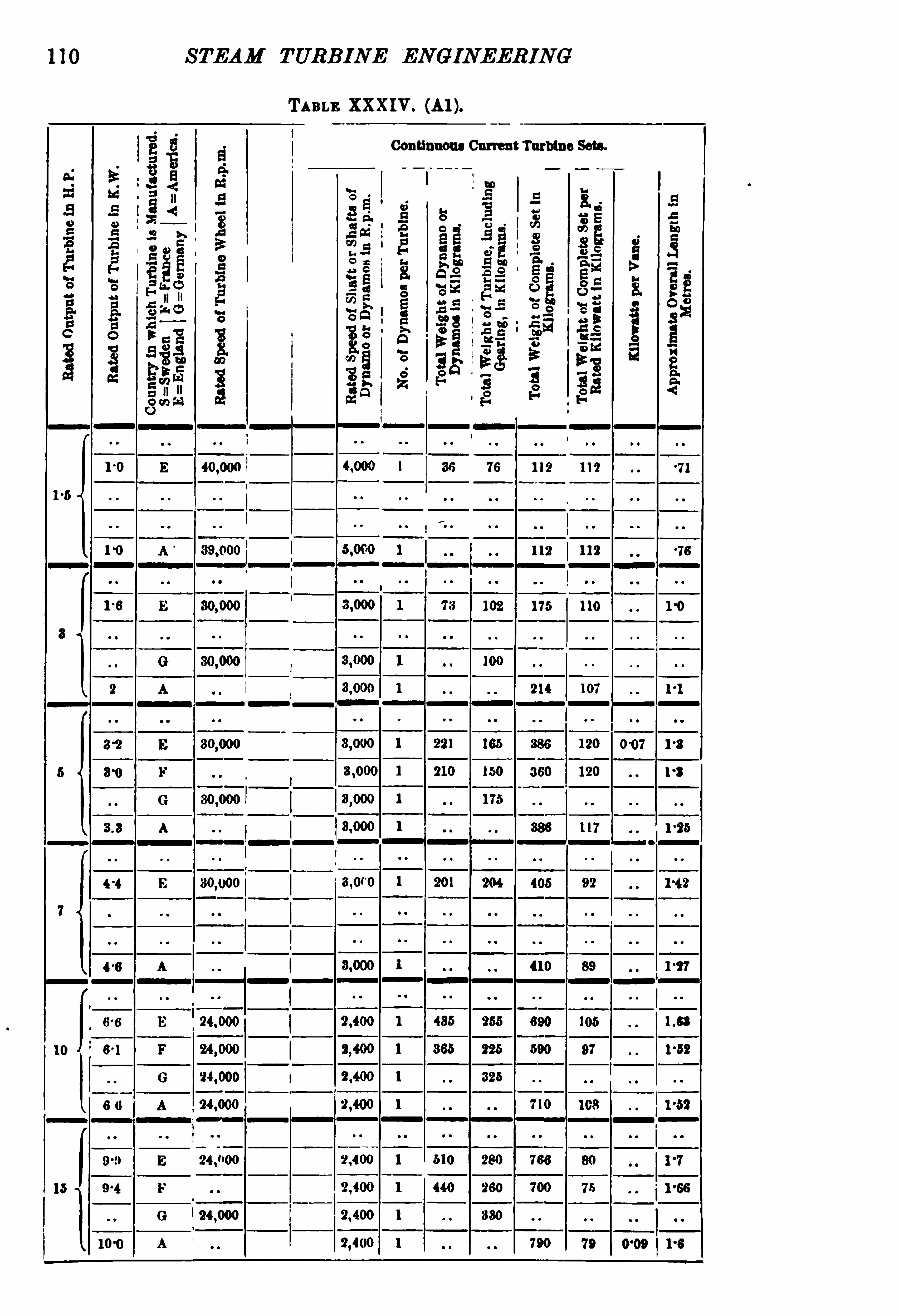
110 STEAM TURBINE ENGINEERING
TABLE XXXIV . (AI ).
Conflnuous Current Turbine Sets.
112 11?
112 112
115 110
‘24 000
I

THE D E LA VAL TURBINE 111
TABLE XXXIV . (A2).
Continuous Current Sets. Alternating Current Turbine Sets (ExcludlngiExcfters).

112 STEAM TURBINE EN GINEERING
TABLE XXXIV . (AS).
Alternating Current Turbine Sets (Excluding Bu tters).

1 14 STEAM TURBINE ENGINEERING
TABLE XXXIV . (B2).
Continuous Current Sets. Alternating Current Turbine Sets ( Excluding Excitem) .

THE D E LA VAL TURBINE 115
TABLE XXXIV. (B3).
Alternating CurrentTurbine Sets (Excluding Exciter-s) .

116 STEAM TURBINE ENGINEERI NG
TABLI XXXIV .
Continuous Current Turbine Sets.
as
as
2 400 52
12 000
73
7 000 8 650
70
10 600

118 STEAM TURBINE ENGINEERING
TABLE XXXIV. (CS).
Alternating Current Turbine Sets (Excluding Exclters).
220mm 2

CHAPTER IV
THE masons TURBINE
PABBONS’ early contributions to steam turbine development date
from practically the same period as de Laval’s,and it is only
in the interests of lucidity that we have given fi rst place to adiscussion of the de Laval turbine ; for the Parsons turbine, as
regards both construction and operation,is considerably less
simple than the de Laval turbine.Passing over the historical development of the Parsons type of
turbine and coming to the modern machine, it should first bepointed out that turbines differing in many respects from one
another,but all possessing the main features of the Parsons type,
are now being built by a number of more or less independentmanufacturers. M ost of the sets at present installed have beenbuilt by one or the other of the three following concernsM essrs C. A. Parsons Co Newcastle-on-Tyne ; M essrs Brown ,
Boveri Cc. ,Baden
,Switzerland The Westinghouse Companies,
of Pittsburg, Pa.,
and M anchester, England . A largenumber of other companies have also taken out licenses tomanufacture Parsons turbines, but suffi cient time has as
yet hardly elapsed to permit of reporting progress in thesequarters.
l
The development of the Parsons turbine for marine purposesis referred to in a later chapter. In the present chapter landturbines only will be discussed.
The turbines built by M essrs C. A . Parsons Co. and thoseby M essrs Brown
,Boveri Co. are very similar , and will be
referred to as Parsons turbines. The modifications made by theWestinghouse Co. are more extensive
,although the main principles
1 The Brush Co. has sent us particulars of one of their designs (see Fig. 58,
facing p.

STEAM TURBINE EN GI NEERING
of the Parsons type are retained ; they have expanding nozzles atthe high-pressure end.
In the Parsons turbine, so-called stationary guide vanes ’ areemployed instead of the diverging nozzles of the de Laval turbineto direct the steam against the vanes of the running wheel. It is
not attempted in these guide vanes'
to transform the energy of thesteam completely into kinetic energy energy of translationalmotion), and on emerging from the guide vanes the energy of thesteam is only partly kinetic. That portion which is kinetic is
more or less completely imparted to the vanes of the movingwheel, according to very much the same general principlesdescribed in Chapter I I I on the de Laval turbine. A further partof the energy of the steam emerging from the guide vanes is
employed to drive forward the vanes of the moving wheel byexpansion. A third portion is passed on to the next set of vanes,imbued with a diminished store of energy. A leading characteristic of the Parsons turbine
,as compared with the de Laval type,
thus relates to the employment of many stages in the former asagainst one stage in the latter. For this purpose the Parsonsturb ine is built with a very large number of sets of fixed vanesalternating with a corresponding number of sets of vanesmounted on the periphery of a rotating drum. Whereas in
the de Laval type, in which the steam is, in the diverging nozzle ,already expanded down to the pressure in the condenser
,in con
sequence oi which the wheel revolves in a medium of very lowdensity and with an approximately equal pressure on each side ofthe wheel
,the wheel of the Parsons turbine rotates in a medium
having a high density at the admission end and a very lowdensity at the exhaust end. Not only would this, for a givenperipheral speed, necessitate considerably higher friction of
the wheel aganst the medium in which it revolves, but thereis the further disadvantage that there is a leakage of steam,
increasing with the clearances between the rotating and stationaryparts. Hence it would be expected that it would be verydesirable in turbines of the Parsons type to employ a minimumof clearance. Furthermore
,there is an end pressure acting
in the direction of flow of the steam from the admission to
the exhaust end. The end pressure is offset by the use of
so-called ‘ balance pistons,’
connected with a suitable numberof points along the cylinder by means of passages cored out in
the casing.
In Figs. 56,57 , and 58 are shown sections through the

STEAM TURBINE ENGINEERING
cylinders of three designs of Parsons turbine , and in Fig. 59 areshown in plan and elevation the outlines of a direct-connectedturbo-generating set. These have been furnished us through thecourtesy of M essrs Brown,
Boveri Co.,the Westinghouse Cc .,
and the Brush Co and admirably serve the purpose of explainingthe Parsons type. The turbine rotor A (Figs. 56 , 57 , and
58) consists of a long drum, supported in bearings at B B. At
the periphery of the rotor are carried the vanes C, arranged in a
Flo. 57 .— Westinghouse
-Pareons Steam Turbine.
number of rings varying according to the output, speed , and
required economy. In the 400 kilowatt Westinghouse-Parsonsturbine illustrated in Fig. 60, with the top half of the casingremoved , there are 116 rings of vanes, 58 of these being on therotor. The total number of vanes in the Parsons type is
enormous (see Table XXXVI ., p. Thus in a 750 kilowattturbine there are stated to be some revolving vanes and an
equal number of fixed vanes, making a total of vanes.
This is 20 rotating vanes per kilowatt , or 0050 kilowatts perrotating vane.
l Between the rings of rotating vanes are the
1 The 2000 kilowatt Westinghouse-Parsons turbine installed at the Yoker
station of the Clyde Valley Power Co. are stated to have over vanes,
presumably on the roto r. This gives kilowatt per rotating vane. It has also
been stated that in a certain Westinghouse-Parsons 500 kilowatt turbine there
are rotating and fixed vanes,or 0031 kilowatt per rotating vane.


124 STEAM TURBINE ENGINEERING
stationary vanes D (Fig. The contour and relative positionof the fixed and rotating vanes are indicated in Fig. 61. Goingfrom the high-pressure to the low-pressure end of the turbine, the
FIG . 60.— 400 K.W. Westinghouse
-Parsons Turbine, uncovered.
(J. R. Bibbins, The Electric Journa l, June
rings increase in diameter. Thus in the design illustrated in Fig.
56 three different diameters are employed. In the Westinghouse-Parsons 400 kilowatt turbine, illustrated in F ig. 60
,there
is a still larger number of different diameters. The increase in
”M I/”6
FIG . 61.— D iagram of Brown Boveri-Parsons Vanes.
diameter of the drum is also accompanied by an increase in radiallength of the rotating and fixed vanes. This is most clearlyshown in the turbine illustrated in Fig. 62, in which one readilydistinguishes, from an examination of the top half of the casing,that there are seven different lengths of vanes. There is also an

THE PARSONS TURBINE 125
accompanying increase in the width of the vanes. M usil states 1
that in a 7 50 kilowatt turbine set, which, from an analysis of his
1 Bars der Dampfturbinen, A . Musil, p. 102 (Leipzig, B. G . Teubner), 1904.

126 STEAM TURBINE ENGINEERING
data,appears to have a speed of 1500 revolutions per minute, the
proportions are approximately as follows
First Row. Lust Row.
D iameter to middle of radial depth of vane
Peri heral speed in metres r sec .
Pitcfi at diameter to mi dle of radial
de th of vane .
Widt of vane in direction para llel to shaft
Radial length of vane
No. of vanes per ring
From this data the total number of rings of vanes on the rotorappears to be about 68.
8th Row,half size.
Section,1§ actual size.
11th Row,halfsize.
Flo . 63 — 400 K.W. Westinghouse-Parsons Turbine Low-Pressure Vanes.
(J . R. Bibbins, The Electric Journa l, June
Photographs of low-pressure rotor vanes of the 400 kilowattWestinghouse-Parsons turbine, already illustrated in Fig. 60,
areshown in Fig. 63. Vane A corresponds to the eighth and vaneB to the eleventh row. The section of the vane is illustrated bythe photograph in Fig. 63. The vanes are of bronze
,and are
rolled in long rods and afterwards cut up into suitable lengths.
It is stated by M usil (Bau de'
r D ampfturbinen ,p. 103) that when

128 STEAM TURBINE ENGINEERING
method of fixing the blades by Fullagar’
s construction . Fig. 64
is a longitudinal section through part of the drum and casing of aturbine, and Fig. 65 is a section through the line A A. Fig. 66 is a
F lo. 65 .— Developed Section on A A , Fig. 64.
perspective view ofa portion of a ring of blades adapted for fixing ina groove on the rotor drum,
and Fig. 67 shows a single detachedblade. at represents the rotary drum
, and c rotating blades ;
Flo . 66.— Perspective ViewofRing ofBlades in an Annular Groove in
Rotary Spindle ofa Turbine.
while b represents the stationary case, and d the fixed blades. The
blades c and d are cut from a strip of rolled or drawn metal of therequired crescent-shaped section ; the root end is flattened to awedge shape by pressure between special dies, as shown at C
s.
The drum n and easing b have grooves g and Ii,in which are rings

THE PARSONS TURBINE 129
of brass i. In the flat side of these rings are cut wedge-shapednotches k, into which fit the wedge ends of the blades
,which latter
are secured firmly by a caulking strip l, . caulked into the groovealongside the strip i . The upper ends of the blades are completelyencircled by what is designated a
“combined fitting and baffling
ring,
”
shown at m in the figures.
These rings are of thin metal of channel section,or two
channels one within the other, and are formed with perforations n ,
pitched at the required distance to receive projections 0 on theouter ends of the blades, to which the rings m are secured.
Leakage of steam is prevented by the close proximity of thebaffling rings and the un-slotted faces of the rings i .
It is claimed that by the means described the rings of bladeswill be rendered strong and light , and can be easily
,quickly , and
cheaply machined to fit the casing and spindle or drum.
FIG. 67 .— Cl is inlet edge, 0
2 is outlet edge.
Fig. 68 shows the appearance of a portion of the finishedblading on the turbine shaft.
M essrs Brown, Boveri Co. state that there is a clearance of
from 3 to 4 mm. ,in a direction parallel to the shaft
,between the
fi xed and moving vanes, and a radial clearance of from 2 to 3 mm.
between the extremities of the moving blades and the inner wallsof the casing. It is stated that, in spite of allegations to thecontrary
,it has been found that these comparatively large clear
ances do not entail any appreciable sacrifice in economy.
The chief consideration underlying the employment of manystages is, that it permits of a reduction ofthe speed of the turbine, asexpressed in revolutions per minute ,
together with a further reduetion in the peripheral speed . It might, with a fair approximationto the truth
,be said that it permits ofa reduction in the magnitude
of the product of these two quantities. This is,of course
,very
desirable, since not only does it avoid the necessity of resorting tospeed-reduction mechanisms, but it permits of restricting thestresses in the material of the rotating wheel to values not very
greatly in excess of those heretofore customary in machine design.
9

130 STEAM TURB INE ENGINEERING
Theorising aside, it appears in practice to be fairly conclusivelyestablished that the modern examples of large Parsons turbinesshow an excellent steam economy , in spite of the possibly morerational lines on which it ismaintained that some of the more recenttypes have been designed. In fact
,it is the contention of the
advocates of the Parsons type that it excels precisely in virtueof the employment of the impact and reaction principles in suchcombination as to obtain the maximum resultant of advantages.
By means of the large number of stages, the diameters of the
Fm. 68.— Willans-Parsons Turbine.
F ixed and Moving Vanes.
wheels are so greatly reduced as to largely offset the tendency toincreased friction loss due to rotation in a medium of rather highaverage density. Whereas the peripheral speed employed in thelargest size of the de Laval type amounts to 425 metres persecond , the peripheral speed employed by M essrs Parsons rarelyexceeds 125 metres per second, even in their largest sets, whichare of several thousand kilowatts rated capacity. Considerablysmaller peripheral speeds are employed in their smaller sets.
The balance pistons, to which reference has already been madeon p. 120, are shown at E E E of Fig. 56, three sets being employedin this design. The passages cored out in the casing, and communi

132 STEAM TURB IN E ENGINEERING
Bearing Pressure— The product of peripheral velocity, in
feet per second and pressure in pounds per square inch, is
generally 2500 (in some cases according to London , and
in a 1000 kilowatt Brush-Parsons turbine, the rotor of whichweighs 6300 lbs. , this product isThrust Bearing
— Fig. 69 shows clearly the method of
adjusting the position of the moving vanes with reference to thefixed vanes. The lower half of the bearing is fixed and the collarson the shaft are in contact on their left side in the figure, whilethe upper half is adjustable along the shaft and takes the thrust
FIG . 69.— Brush-Parsons Thrust Blocks.
W. Chilton, Inst. E .E. M chr. , Feb. 2, 1904.
on the opposite side of these collars. It is thus evident that theshaft cannot move either to the right or the left.Regulator
— A simple and ingenious piece of mechanism is
employed to control the quantity of steam admitted according tothe load on the turbine.
M essrsBrown,Boveri Co.
’
s construction is illustrated in Fig. 70.
The admission of steam into the turbine is not continuous, but
consists of a series of intermittent admissions of steam (gusts), atregular inte rvals, at a frequency of about 150 to 250 per minute ,
according to the size of the turbine. The duration of each ofthese gusts is controlled by the regulator, and is longer or shorteraccording to the load.
Mechanical Construction of Steam Turbines, W. A . J . London,Free.
Inst. E lec. Eagre , vol. 35 , p. 189 , June 1905 .
3 The Steam Turbine,W. Chilton
,Manchester Local Section
,Proc. Inst.
E lec. Engra, vol. 33, p. 587 , February 2nd, 1904 .

THE PARSONS TURB INE 133
The steam enters through a valve V ,which is given a vertically
oscillating motion, and which for heavy loads, and correspondingsteam consumptions
,remains at each admission raised for a
longer time than it remains on its seat , thus admitting moresteam,
and vice versa for light loads. This is accomplished thusThe opening and closing of the valve V is controlled by a
small piston B mounted above the valve. On the lower face ofthis piston the steam pressure acts
,while it tends to stay at the
F IG . 70.— Brown Boveri-Parsons.
lower end of its cylinder by action of a strong spring pressing on
its upper face .
An auxiliary valve with spindle G , possessing an oscillatorymovement from an eccentric X (Figs. 70 and causes the
lower face of the piston B to communicate with the exhaust,and thus the valve V falls again to its seat.
The spindle G of this auxiliary valve is linked up to the muff
M of the ball governor R,which latter thus augments or dim
inishes the amplitude of the oscillations of the valve G ,and in
consequence causes the valve V to open a longer or shorter time
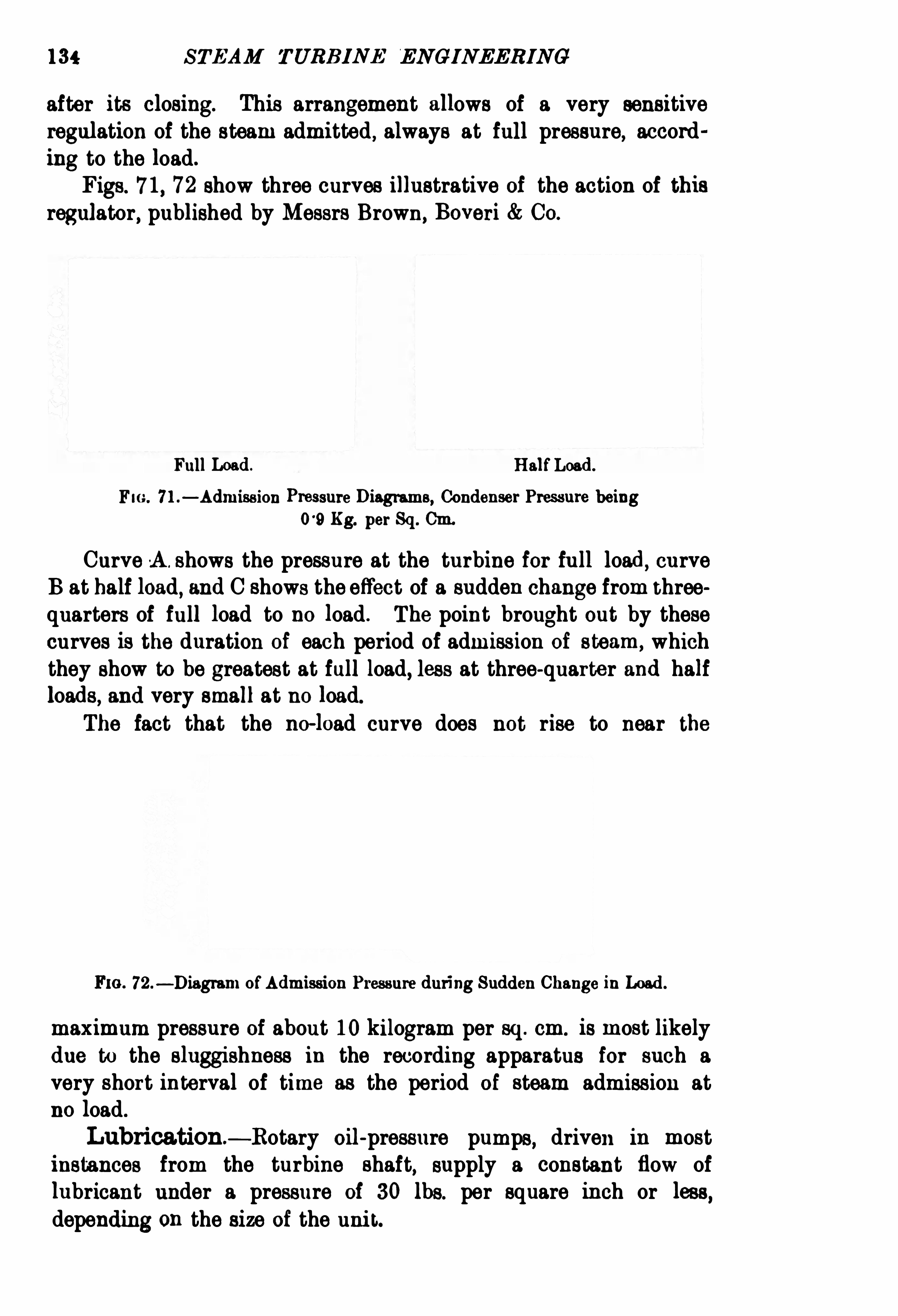
134 STEAM TURBINE ENGI NEERING
after its closing. This arrangement allows of a very sensitiveregulation of the steam admitted , always at full pressure, according to the load.
Figs. 7 1, 72 show three curves illustrative of the action of thisregulator, published by M essrs Brown,
Boveri Co.
Full Load. HalfLoad.
F IG . 7 l .— Admission Pressure D iagrams, Condenser Pressure being
09 Kg. per Sq . Cm.
Curve A . shows the pressure at the turbine for full load, curveB at half load, and C shows the effect of a sudden change from threequarters of full load to no load . The point brought out by thesecurves is the duration of each period of admission of steam, whichthey show to be greatest at full load, less at three-quarter and halfloads, and very small at no load.
The fact that the no-load curve does not rise to near the
FIG . 72.— D iagram ofAdmission Pressure during Sudden Change in Load.
maximum pressure of about 10 kilogram per sq . cm. is most likelydue to the sluggishness in the recording apparatus for such avery short interval of time as the period of steam admission atno load .
Lubrication — Rotary oil-pressure pumps, driven in mostinstances from the turbine shaft
,supply a constant flow of
lubricant under a pressure of 30 lbs. per square inch or less,
depending on the size of the unit.

136 STEAM TURB INE EN GINEERING
in opposite directions through the cylinders , the steam ultimatelyflowing off from both ends to the condenser. This construction
eliminates end thrust,and obviates the necessity of employing
balance pistons. The design is shown in plan and elevation in
Figs. 383,384 , PP. 540, 541 .


138 STEAM TURB INE EN GINEERING

140 STEAM TURBINE ENGINEERING


142 STEAM TURB INE ENGINEERING

144 STEAM TURB INE EN GINEERING

THE PARSONS TURBINE
sets are capable of sustaining an overload of 50 per cent. by theaid of automatic by-passes.
The steam fi rst passes through the main disc type stopvalve, which is controlled from the platform by a hand wheelthrough gearing. It then flows through an emergency shut-downvalve
,a strainer
, and a double-seated poppet governor valve, thelatter being operated by a steam relay controlled by the centrifugal governor, this admission valve being thereby directly con
trolled by the speed of the turbine.At the end of the shaft opposite to that at which the centri
fugal governor is attached is fi tted an emergency governor ; thislatter acts if the speed of the turbine rises to a predeterminedmaximum and the centrifugal governor fails from any cause
,
opening an auxiliary valve,which in turn closes the emergency
throttle valve.After entering at the centre of the cylinder, the steam next
passes through a series of nozzles and impulse blades, thisoperation being repeated until the steam has expanded approxi
mately to atmospheric pressure. Then the steam passes througha series of pressure blades on the Parsons principle 1 until theexhaust is reached. A thrust block is fitted at the extreme end
of the cylinder,but as there is no end thrust, owing to the use of
the double-flow design,this is only required for the longi
tudinal adjustment of the rotor.The rotor is constructed as a rolled steel drum with a diameter
of 19 5 metres, thus giving a peripheral speed at the root of thevanes of 103 metres per second . A forged-steel umbrella-shapeddisc is shrunk into each end, and at the same time the ends ofthe high-carbon steel shaft are pressed into these discs, thus
giving a very light and strong construction. The construction isstated to have the advantage of virtually eliminating the balancing difficulties met with in cast-steel and other non-homogeneousmaterials. The material can be depended upon for uniformdensity throughout, and by machining it to gauge a perfectbalance should be obtained. The first series of blades are ofdrop-forged steel
,and are dovetailed in form, and are caulked
into grooves cut in the surface of the cylinder. The low-pressureblades are made of delta metal
,in order to avoid any corrosion due
to wetness of the expanding steam.
It is stated that the combination bed plate of each turbo
generator weighs about kilograms (52 tone).1 The Tramway and RailwayW
’
orld,February 1905 .

146 S TEAM TURB INE ENGINEERING
This same double-flowdesign is employed in the three-phase, 25
cycle, 2000 kilowatt, 1500 volt turbo-generating
sets supplied by the Westinghouse Co. for the Clyde Valley PowerCo.
’
s station at Yoker.The Westinghouse Co. are employing the double-flow type as
their standard design,only the early machines and the small
sizes being of the single-flow type. A section of an early BrushParsons turbo-generator is shown in Fig. 84.

148 STEAM TURB INE ENGINEERIN G
The rough overall dimensions are given as— length 153
metres,width 52 metres, weight 4 6 metres, floor space 7950
square decimetres,or 106 square decimetre per kilowatt output.
These figures are published too late to be added in the curvesof Figs. 86 to 89 , but they have been included in Table XXXVIwhere comparison can be made with other sets.
A surface condenser will be located beneath the turbine inthe foundations proper. The makers state that this arrangement
III/g rams for fri /Ofl z
FIG . 86 .— Approximate TotalWeights ofN rbo-Generators of the Parsons Type.
is in all respects equivalent to that claimed as the special propertyof the vertical type of turbine
,which the makers of the latest
type state needs considerable extra space for condenser and
turbine auxiliaries. The new turbines will operate at approximately 175 lbs. pressure
,28 inc h (933 per cent. ) vacuum, and
100°
F . (555 C. ) superheat, the normal speed being 750revolutionsper minute . Under these conditions the steam consumption is calculated at about 16 lbs. (72 5 kilograms) per kilowatt-hour at fullrated load.


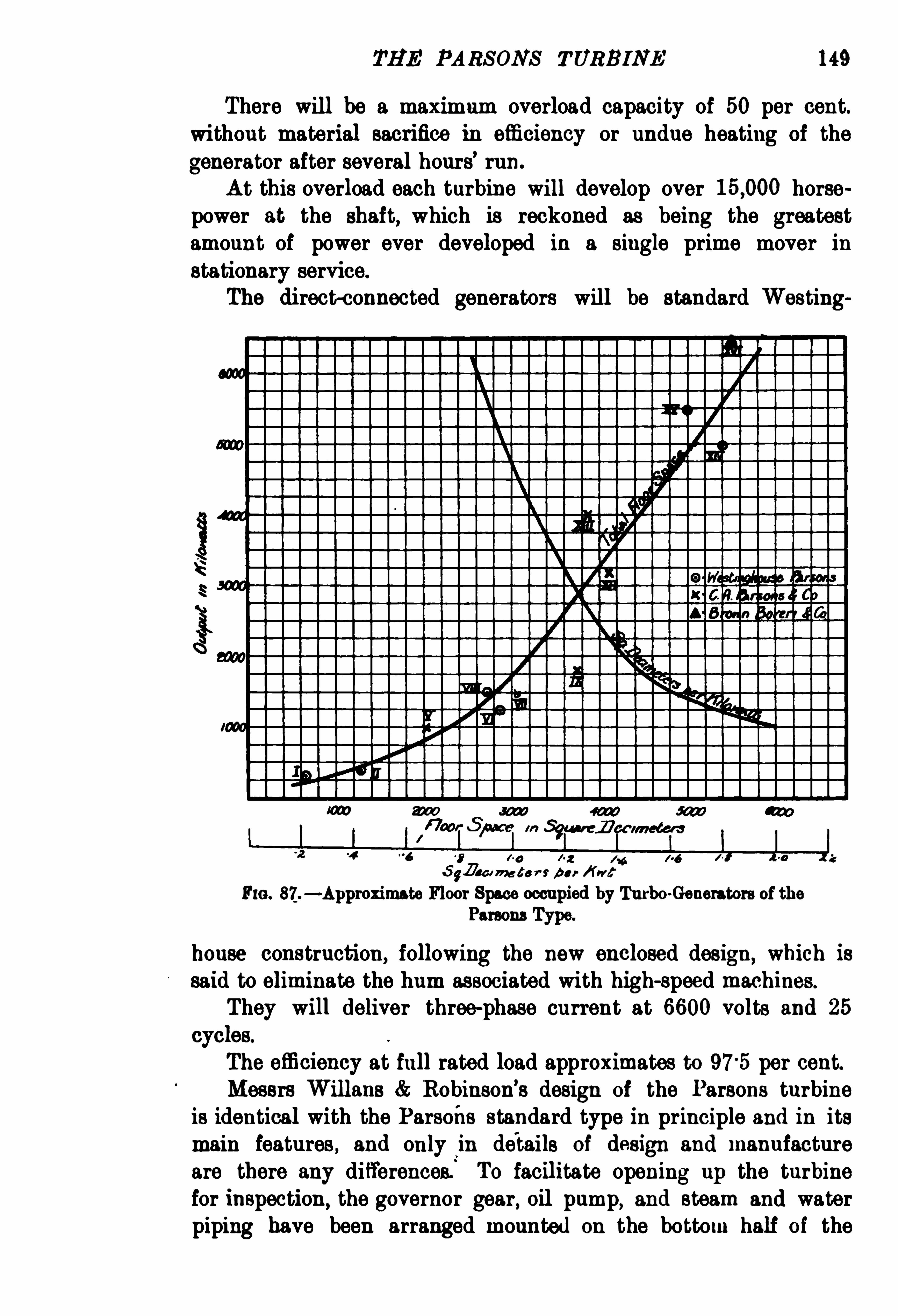
THE PARSONS TURBINE 149
There will be a maximum overload capacity of 50 per cent.
without material sacrifice in efliciency or undue heating of the
generator after several hours’
run.
At this overload each turbine will develop over horsepower at the shaft, which is reckoned as being the greatestamount of power ever developed in a single prime mover instationary service.
The direct-connected generators will be standard Westing
Em. 87.— Approximate Floor Space occupied by Turbo-Generators ofthe
house construction, following the new enclosed design, which issaid to eliminate the hum associated with high-speed machines.
They will deliver three-phase current at 6600 volts and 25
cycles.
The effi ciency at full rated load approximates to 975 per cent.M essrs Willans Robinson’
s design of the Parsons turbineis identical with the Parsons standard type in principle and in itsmain features, and only in details of design and manufactureare there any differences. To facilitate opening up the turbinefor inspection
,the governor gear, oil pump, and steam and water
piping have been arranged mounted on the bottom half of the

150 STEAM TURBINE ENGINEERING
FIG . 88.— Approximate Overall Length ofTurbo-Generators ofthe Parsons Type.
IO00
FIG . 89.— Rated Speeds ofTurbo
-Generators of the Parsons Type.

152 STEAM TURB INE ENG INEERING

THE PARSONS TURBINE 153
against 11 metres, the mean length for a 1000 kilowatt set, asshown by curve in Fig. 89.
The valve chest is arranged at the side of the bottom half ofcylinder, thus allowing the cylinder to be opened out for inspection without breaking any steam-pipe joints
,whereas in the
Parsons standard types the steam-pipe joints have to be broken,
and in the larger sizes the valve chest has to be lifted off
as well.The main bearings are made adjustable both vertically and
horizontally, and are also supported on spherical seats.The oil pump is a rotary one instead of reciprocating, and in
the 1500 kilowatt size and above it is driven separately by amotor
,and the governor driven direct from the turbine shaft
,
thus dispensing with worm gear and toothed wheels.The turbines and generators are carried on one continuous
underbed of very stiff box section, which ensures much betteralignment of plant when being erected on site.
The oil cooler is contained in this underbed, another portion ofwhich is used as an oil reservoir.
The main lubricating pipes are also contained in the underbed,
giving the plant a neater appearance.Fig. 84 illustrates the original Brush-Parsons 1000 kilowatt
turbo-generator, and is shown with the latest type (Fig.
whereby some interesting comparisons may be made.
InTable XXXV I. have been compiled some general particularsof a number of representative Parsons turbo-generating sets ofvarious manufacture, and of outputs ranging from 300 kilowattto 7500kilowatt.
From the data contained in this table the curves in Figs. 86,
87 , 88, and 89 have been plotted .
Fig. 86 shows the weight of complete sets and the weight perkilowatt output, plotted against rated output. In Fig. 87 areplotted total floor space occupied by the complete set, and the
floor area per kilowatt output, plotted against output.Fig. 88 shows the approximate overall length of combined
sets, and in Fig. 89 a curve is plotted showing the variation ofrated speed of Parsons turbines with the rated output.
The points representing the position of the various machines
given in Table XXXVI . are marked on these curves with numberscorresponding to the reference numbers in column 1 of TableXXXVI .

154 STEAM TURB INE ENGINEERI NG
TABLE XXXVI .— Soxu PAarrooLABs or Dnmnsrons AND Warenrs or TUBBo
GENEBAroas or PARSONS TYPE .
5 5
l 115 541-4 are
1500'
-9
115-0 2070 1 4
112-5 211
-8
1 13-0 27-5 3000
VI II . 1010 .20-7 2700
145-0 } 215-9 3750
150-0 270 4000
105-0 115
-0 4125 m
xm . 4000 1000 153-0 250 3330
5000 ' 750 139-0 40 4 5410 1-03
1000 . 1-051 103 147
-0 34
-5 5500 1-0
1300 30-5 5500 0
-35
xv11. 7500'
750 153 0 , 52 7050 1-05
1 Diameter at bottom ofvanes= m.
ou r largest vanea=2°4m.
STEAM TURB INE ENGINEERING
We purpose now to consider the question of steam consumption of the Parsons steam turbine. The results of a very largenumber of careful tests are available, and these have been broughttogether in Table XXXVI I . As in the case of the correspondingdiscussion of the de Laval sets, we have assumed a hypotheticaldirect-connected dynamo in those cases where no dynamo waspresent
,and we have suitably modified the results by means of
the dynamo efliciency curves in Figs. 16 to 19 (see pp. 38 and 39
of Chapte r so as to express the steam consumption in termsof the kilograms of steam per kilowatt-hour output from thishypothetical dynamo. In cases where the tests were originallymade with a direct-connected dynamo
,no reference to the effici
ency curves of Figs. 16 to 19 has been necessary.
The most striking’
point revealed by an analysis of the testsset forth in Table XXXV II . is , that the steam consumption ispractically independent of the admission pressure for a very widerange of pressures. We were
,of course, aware that the admission
pressure made far less difference than in the case of reciprocatingsteam engines. We find
,however, that for a vacuum of per
cent. and for 50° Cent. of superheat
,of two turbines of a given
rated capacity, but designed, say, the one for an absolute admissionpressure of 7 metric atmospheres, and the other for 14 metricatmospheres, the steam consumption is, on the average, generallyjust about the same. I t may be of interest to describe the roughbut practical methods of analysis by which we have arrived atthis result.
Individual tests on a particular turbine at different pressuresnaturally give results showing a slight variation with the pressure,but our general conclusion, as summed up above, is based upon theaverage of a large collection of tests, and may fairly be taken as
corresponding to turbines suitably designed for the pressures withwhich they are to be used.
In Figs. 91 to 98 are plotted the results of tests on turbinesof the same rating at each of two or three different pressures ineach case.
In all these figures the curve A corresponds to the lowerpressure, curve B to the higher ; and in cases where test figureswere available for a still higher pressure, curve C is drawncorresponding thereto. Out of all the numerous test figuresavailable, in only one case can we find results for one and thesame turbine tested at two different pressures on various loads.
These results relate to a 3200 kilowatt Brown-Boveri-Parsons


158 STEAM TURBINE ENGINEERING
metre to 14 kilograms per square centimetre ; that is, a 40 percent. increase in pressure gave a decrease of 52 per cent. in steam
FIG. 93.— 300K.W. No. VIII. on Tables
'
XXXVI. and XLI I.
Fm. 94 .-1000K.W. No. XIV. on Tables XXXVII.:and XLII.
F108. 93 and 94 .— Variation in Steam Consumptionwith Change in Pressure.
consumption ; the decrease in steam consumption for each per cent.
increase in pressure thus being per cent. at full load.
The two curves cross at about 42 per cent. of full load, the


STEAM TURB INE ENGIN EERING
Percentage g'
fir/l Raced Load
FIG . 97. — Two 100 K.W. Parsons. A . Kgs . Abs. B Kgs. Abs. 8°
C.
Superheat, 90 5 per cent. Vacuum.
fi rcentgge f fi d/ Fah d Load
FIG . 98.— 3200K.W. Brown-Bovari-Parsons set.
FIGS. 97 and 98.— Variation in Steam Consumption with Change in Pressure.
A.— Messrs Brown
,Boveri 8: Cc . , Turbines d Vap mr, Sept. 1904, p. 39.
B. Trials ofTurbines for D riving Dynamos,
”by C. A. Parsons and G . G. Stoney,
International Engineering Congress, Glasgow,1901 .
This is probably explained by the loss due to leakage of steambeing greater the higher the pressure of the steam,
and to theincreased friction due to rotation in a denser medium.
In each of the other Figs.,91 to 97 , we have brought

THE PARSONS TURB INE 161
together turbines of the same rating to compare their steamconsumption at different pressures, but under the same conditionsas to vacuum and superheat.
In three of these cases,Figs. 91, 92, 93, the steam con
sumption is actually higher for the higher pressure at full load.
This result is contrary to experience , and we would attributeit to the fact that in each case the tests at different pressureswere made on two separate turbines, when slight differences inconstruction and workmanship might account for either machinebeing inferior to the other as regards steam economy.
In the four cases of Figs. 94 to 97 the results are similar tothat in fi g. 98 referred to above— viz. at light loads the steamconsumption is greater for higher pressures, and at loads fromabout one-half load and upwards the consumption is smaller forhigher pressures, there being a certain load where the consumptionis apparently the same for all pressures.
In the case of Fig. 94 the two curves actually cross in twoplaces ; and, bearing in mind that each curve is for a differentmachine, we would regard this as evidence of the differences insteam consumption being due rather to differences in the characteristics of the machines than to the effect of difference inpressure.We have not thought it suffi ciently justifiable to attempt to
determine the lawof variation of steam economy with pressure on
the basis of these results to any degree of accuracy, but results of
tests on individual turbines with varying pressure for each, atseveral conditions of load
,would be very desirable for this purpose.
We also obtained from various manufacturers of the Parsonstype of steam turbine statements indicating that in theirexperience the variation of steam consumption with varyingadmission pressure has been found to be very small at all loads
,
although they all find a slowly improving economy accompanyingincreasing admission pressure.With non-condensing sets the use of a high pressure nu
doubtedly has a marked effect in improving the economy, but weconsider it sufi ciently well established by our investigations thatfor turbines of the Parsons type , as at present designed and built
,
when operated with a good vacuum, the improvement in economyfrom an absolute admission pressure of 8 kilograms per squarecentimfi re upwards is so slight as to not be worth taking intoaccount.
A t any rate , it is extremely unlikely that an improvement in11

162 STEAM TURBINE EN GINEERING
steam economy of more than about 01 0 per cent. per per cent.increase in admission pressure will be obtained at full load under
good conditions as to vacuum and superheat for an absoluteadmission pressure of 7 kilograms per square centimetre ; and thiswill probably decrease to an improvement of not more than 005
per cent. per per cent. increase in admission pressure for absoluteadmission pressure of some 14 kilograms per square centimetre.For the range of pressures customarily employed ( 10 to 16
absolute atmospheres) the steam consumption at full load can thus,for all practical purposes, be taken as independent of the admission pressure.
It is somewhat premature to announce this conclusion prior tothe description of the following exhaustive analysis of publisheddata of steam comsumption.
For a preliminary assumption , we proceeded to ignore theinfluence of variations in the admission pressure, and to investigatethe laws of variation with vacuum and superheat.The effect of varying vacuum has been studied by a number of
investigators. The results on five different turbines at full ratedload are shown in Fig. 99. Representing by 100 the steam con
sumption at 866 per cent. vacuum,the results of Fig. 99 have
been reproduced in Fig. 100, and it appears that the tests are in
close agreement as regards the percentage variation in full loadsteam consumption with varying vacuum, as to be represented bya single curve. In other words
,the same rate of variation may, for
all practical purposes, be taken for all sizes of Parsons turbines.
From Fig. 100 we see that 3 Parsons turbine consumes at fullload 38 per cent. more steam when running non-condensingthan when running with a vacuum of 866 per cent. Of course,there may be considerable variations from this particular percentage in individual cases, as the development of the Parsons turbinehas extended over many years, and the principles of design havebeen gradually developed during this time .
Furthermore, in all analyses of this character the difficultyarises that a turbine is designed for some particular pressure,vacuum
,or amount of superheat
,and hence it is argued that com
pala tive tests, when one of these conditions is varied, do not afl‘
ord
correct information as to the relative economy of turbines designedfor the different conditions. While this is to some extent true
,
the conclusions drawn from a single turbine operated under variedconditions may nevertheless often afford a fairly good idea of theinfluence of such variations
,evenwhen a special design is provided

164 STEAM TURBINE ENGI NEER IN G
FIG. 100 — Mean Steam Consumption at Full Load for Parsons Turbines withVaryingVacua. See Curves A to E, Fig. 99.
4 0 K.
m to so 40 so so 70 so so n o
M ena ge of Klee/ am
Fro . 101.— 500K.W. and 300K.W. Famous Turbineswith Varying Vacua.
densing. The curves fall very close together, and the conclusionsdrawn from either curve would
,for the practical man
, give the

THE PARSONS TURB INE 165
required information for either case with sufficient accuracy.
Both curves were taken.
at full rated load.It is next necessary to investigate the effect of varying vacuum
at other than full rated load. F ig. 102 contains results republished by M essrs Parsons and Stoney. They relate to tests of a500 kilowatt set at quarter, half, and full load, and at varyingvacua. The corresponding curves in Fig. 103 have been deduced
g rew/di eKzewmFm. 102 — Steam Consultiption with an Increase in Vacuum for a 500 K.W. 2500
Parsons Turbo-Alternator, Abe. Steam Pressure 10‘
85 Eye. and no Super
heat. Trials of Steam Turbines for Driving Dynamos, C. A. Parsons and
G. G. Stoney, International Engineering Congress,Glasgow,1901
, Table VII . )
by representing the steam consumption at 86 6 per cent. vacuumby 100 in each case. From the relative positions of the three
curves of Fig. 103, it is evident that the percentage decreasein steam consumption is, for a given increase in vacuum, greaterthe less the load.
In Figs. 104 and 105 are given corresponding results obtainedby Bibbins on a 300 kilowatt turbine.It is assumed that the percentage improvement in economy

166 STEAM TURB INE EN G INEERIN G
with increasing vacuum is independent of the degree of superheat.There is as yet an insufficiency of published data to permit us toverify this assumption.
Neither the tests of Parsons and Stoney (Figs. 102 and 103)nor those of Bibbins (Figs. 104 and 105 ) are as clear as they
5 0 4 0 70 80 .90
FIG . 103.— Percentage Variation in Steam Consumption with an Increase in Vacuum.
A 500 K.W. 2500 li .p.m. Pars ons Turbo-Alternator at Various Loads,with a
Constant Absolute Steam Pressure of Kgs. and no Superheat.
might have been made by these authors. This will appear fromthe following considerations
In Fig. 106 is given a curve of the steam consumption of a500 kilowatt turbine set at no load , with varyingvacuum,
absolutepressure of 109 metric atmospheres, and no superheat. This isplotted from Table 8 of Parsons and Stoney
'
s paper, and, extendedas shown by the dotted line, indicates that the steam consumptionwhen running non-condensing would be 2900 kilograms per hour,or times as great as for an 86 6 per cent. vacuum. In this

168 STEAM TURB INE EN GI NEERING
same paper of Parsons and Stoney is found the followingstatement
In non-condensing plants also many tests have been made ,but, as will be expected , the steam turbine compares rather morefavourably with the reciprocating engine in condensing types. In
a 100 kilowatt size a consumption of 39 pounds per kilowatt-hourhas been attained
,and in a 250 kilowatt turbo-dy namo 38 pounds
per kilowatt-hour, both with about 130 pounds steam pressure and
no superheat. In larger sizes of 1500 kilowatt with 200 pounds
Steamm umption in Lbs. per Hour.
36a m Consu l-"palm in [ 9 3 p er Hour
F IG. 106 .-Steam Consumption at No Load. 500K.W. Parsonswith VaryingVacua.
steam pressure and 150° Fahr. superheat, a consumption of 285
pounds per kilowatt-hour non-condensing has been guaranteed . and
is expected to be easily attained , if not surpassed.
”
From the data contained in this statement the curve of Fig.
107 has been constructed , and shows for running non-condensingwith no superheat a full load steam consumption of 16 5 kilo
grams per kilowatt-hour for a 500 kilowatt set.We nowhave sufficient data of the 500 kilowatt set to work
out the graphical construction shown in F ig. 108.
We obtain the full load point for other than an 866 per cent.vacuum by applying percentage corrections obtained from the curve


170 STEAM TURB INE ENGINEERING
of Fig. 101. The steam consumptions at no load for different vacuaare obtained from Fig. 106. We then draw straight lines connectingthese two points, and can thus obtain the steam consumptions atintermediate loads by interpolation. In the curves ofFig. 108 weobtain the steam consumption in kilograms per hour, but fromthese values are readily deduced the steam consumptions expressed in kilograms per kilowatt-hour as shown in Fig. 109 .
o x m .-co m m as“
ao sv w eo mfi re-snag s of firlI fi t t ed
Fro. 109. — Steam per K.W.H. 500K.W. Parsons Turbine.
Guided by the conclusions embodied in the curves in Figs. 100and
109 , we have obtained the curves in Fig. 110, which show forParsons turbines at full rated load, half load, and quarter load thepercentage decrease in steam consumption per per cent. increase invacuum. Thus
,by increasing the vacuum from 834 per cent.
(25 inches) to 866 per cent. (26 inches), mean vacuum 850
per cent. (255 inches), we obtain the results shown in TableXXXV I I I .
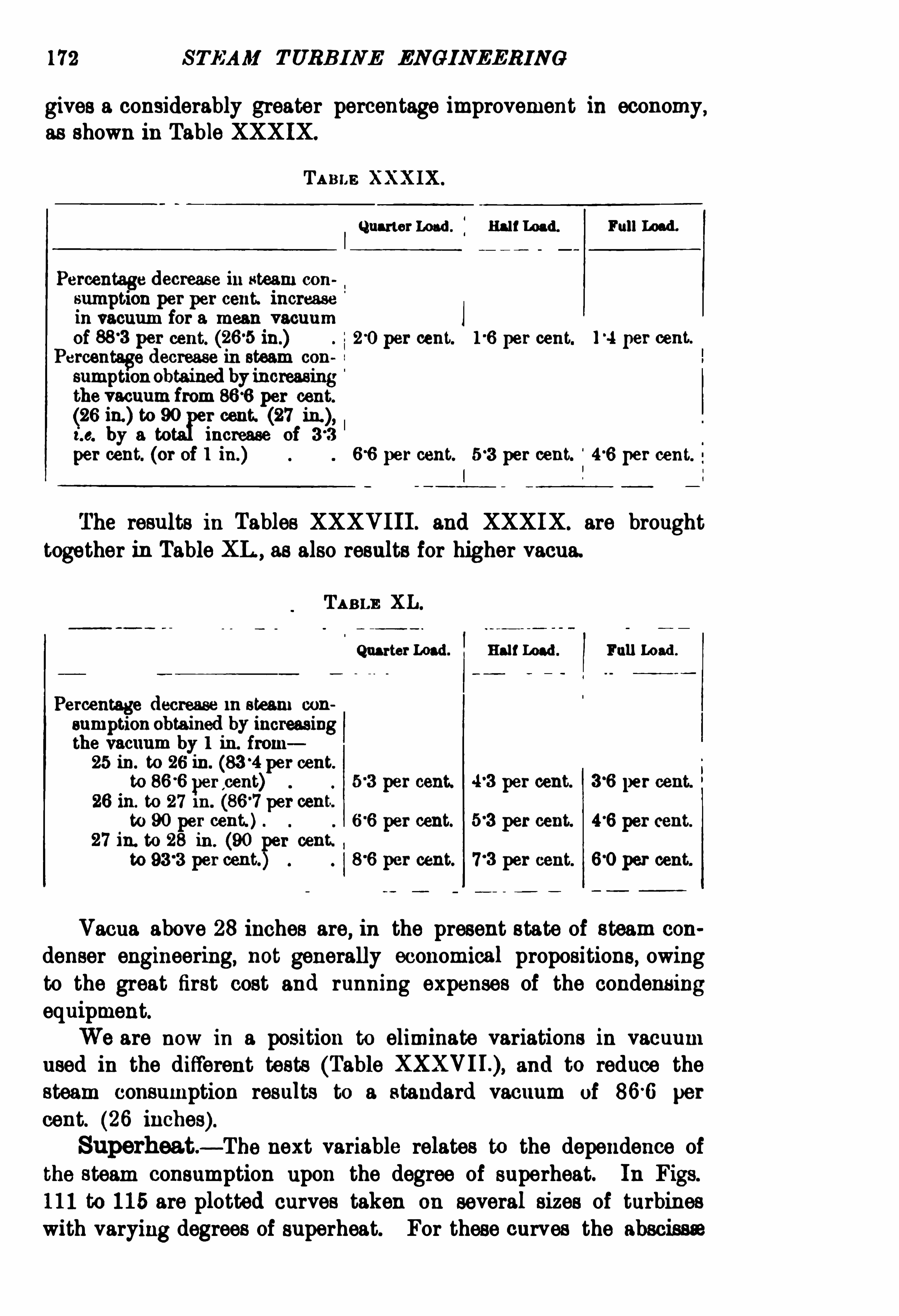
172 STEAM TURBINE ENGINEERING
gives a considerably greater percentage improvement in economy,as shown in Table XXXIX.
TA BLE XXX IX .
QuarterLoad . j RalfLoad. Full Load.
Percentage decrease in steam con
sumption per per cent. increasein vacuum for a mean vacuumof per cent. in.) 20 per cent. per cent. l
°
4 per cent.
Percentage decrease in steam con
sumption obtained by increasingthe vacuum from per cent.
(26 in.) to 90 r cent. (27i.e. by a to increase of 33
per cent. (or of 1 in.) 66 per cent. per cent. 46 per cent.
The results in Tables XXXV I II . and XXXIX. are broughttoge ther in Table XL , as also results for higher vacua.
TABLE XL.
QuarterLoad. Half lo ad . Full Load .
Percentage decrease rn steam con
sumption obtained by increasingthe vacuum by 1 in. from25 in. to 26 in. per cent.
to 86 6 percent) 5 3 per cent. per cent. 36 per cent.
26 in. to 27 in. per cent.
to 90 per cent. ) 66 per cent. per cent. 46 per cent.
27 in. to 28 in . (90 r cent. ,
to per cent. 86 per cent. per cent. 60 per cent.
Vacua above 28 inches are, in the present state of steam con
denser engineering, not generally economical propositions, owingto the great first cost and running expenses of the condensingequipment.We are now in a position to eliminate variations in vacuum
used in the different tests (Table and to reduce thesteam consumption results to a standard vacuum of 86 6 per
cent. (26 inches) .Superheat.
— The next variable relates to the dependence ofthe steam consumption upon the degree of superheat. In Figs.
111 to 115 are plotted curves taken on several sizes of turbineswith varying degrees of superheat. For these curves the abscissa


176 STEAM TURBINE ENG INEER IN G
more convenient in the case of these tests, which were madeat definite percentages of rated load
,to plot the results in
this way.
The values of the steam consumption at rated full load havefor all these cases been employed in plotting the curves of Fig. 117 ,
fi mawrl of&1,ber6ed l (man)mD ei rees ( Er/[11rd
A=See Fig. 111 . D =See Fig. 113.
B 1 12. E 114.
O n 1 13. F 115.
Fro. 117 .— The Steam Consumption of Various Sizes ofPars ons Steam Turbine
at h ill Rated Loadwith Varying Superheat.
in which superheats in degrees Centigrade are employed as
abscissse.
Fig. 118 is derived from the curves of Fig. 117 by representingby 100 the steam consumption with 50
° Cent. of superheat.The mean curve drawn for this group is reproduced in Fig. 119 ,
and may be taken as a fairly true indicator, for the Parsons typeof turbine, of the amount by which the degree of superheat affectsthe steam economy at rated full load.

THE PARSONS TURB INE 17 7
But at light loads the effect of a given amount of superheat is to improve the steam economy to a somewhat greaterextent than at full load . This is evident from a study ofTable XLI .
An analysis of the above table shows us that a given amountof superheat in degrees Cent. occasions a percentage improvementin steam economy at 20 per cent. of full load. which may be
Super/teat in Degrees C’entz
'
gradc. Letters refer to Fig. 117.
Fm. l l8.— Varistions in Full Load Steam Consumptionwith Varying
Superheat ofa Parsons Turbine.
roughly taken as some 25 per cent. greater than the correspondingpercentage improvement at rated full load . The value varies
greatly, however, and appears (see curves of Fig. 113,corresponding
to 90 per cent. and 94 per cent. vacua) to be also dependent uponthe accompanying vacuum. There is
,however, insufficient data
for tracing out the extent of the dependence upon the vacua ofthe improvement in economy with increasing superheat
,and it
will not be taken into further consideration. The three12
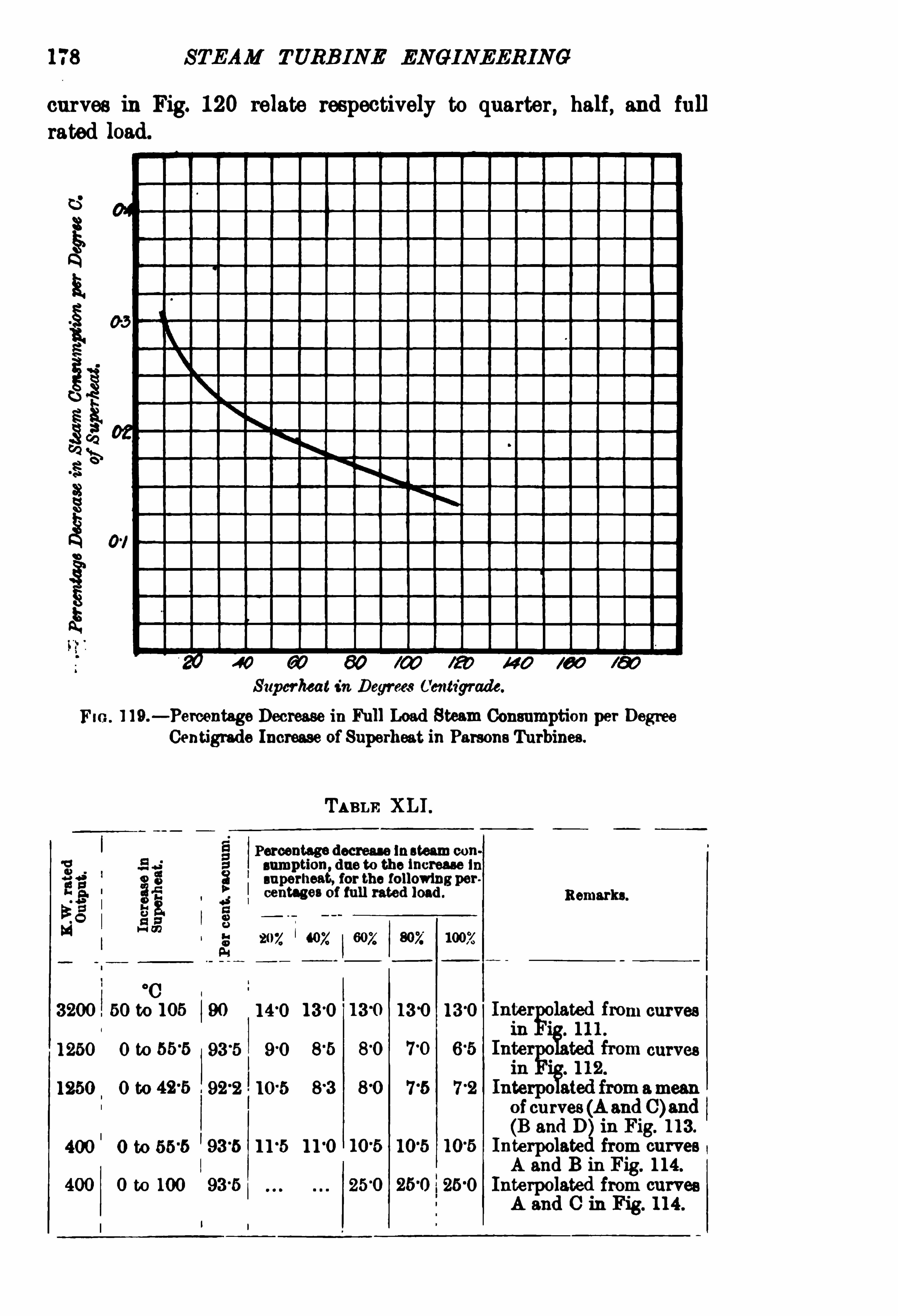
178 STEAM TURB INE ENGINEERING
curves in Fig. 120 relate respectively to quarter, half, and fullrated
Superheat in D eyrmrCmtv'
grade.
1 19.— Percentage Decrease in Full Load Steam Consumption per Degree
Centigrsde Increase ofSuperheat. in Parsons Turbines.
TABLE XLI .
E Percentage decrease In steam con
9 sumption,due to the increase In
superheat, for the followingper.
centsges of full rated load . Remarks.
207. 40K 602 807;
°
C
3200 b0 t0 105 90 140 130 130 130 m curves
1250 0 t0 55°
5 93 5 curves
1250 0 to 42'
5 92 2 83 715 72 emesuofcurves (A andC)and(B and D in Fig. 113.
400 o to 55-5 93
-5 11
-5 11
-0 10
-5 10 5 10
-5 Interpolate from curves
A and B in Fig. 114.
400 0 to 100 9315 25 0 250 250 Interpolated from curves
A and C in Fig. 114 .

180 STEAM TURB INE EN GINEERING
TABLE XLI I .— SHOWING rm:STEAM Consm rroxwrrn A Consranr VACUUM
or ran cam . AND 50°
Czar. or Snrm nu r ron rm:Paasoxs Swan
Tuaamn,wrrn Vanrmo Ansowrn Sru u Panssnnns, as 1111111e mom
was Tnsr Resume on TABLE XXXVI I .
Steam Com mption in I n ner K.W. fl our for various percentages ofPull i111d
55 5 53 8
i? 5 E i“
is i i“
Iwe 5 85 5
7 211-2 18
—
10 5 55 18-4_
a
_o 125 99 0
7 181 11 00 125 117 00_100 152 0
°
100
100 120 990 115
100 l 1°
o
-05 1i °
5 I11°7O 11 110 11 °70
2011 1 10-9 0
2011 141 0 1 10110 110-50
200 18 .0
250 111 111 ,10 110 18
_
2511 9 9 0 10110
300 11 7 0 01116"
8001
1000 1170—
0
300 1111311 1 10 110 1040 '
3011 T2 201
8511 115 0 1
-
9790 11 50
850 119 01 1100 117 20
150 109 0 m107 110
_875 1
h
“
400 10°
5 0 9 115 W7 511 7 511 9 111 7 511
400fi
400 122 09-25 9 1111 11 90 8 911
400 9 55
$ 00 11 00 10 10 9 50 11 00
:00 _ 11°
00 l
400 18°
40 120 0 9
400 9-30 9 80
400 111—
7 0 11 011 11 50 £ 05 11 50 1400
11 00 l l fl )
400 117-50 990 9 50— c
400 11°
—
110 92 5-111 50

XV I I .
THE PARSONS TURB INE
TABLE XLII .— cont1§nued.
SteamConsumption in Kgsp ur
r K .W . Hour (or 11111101111 Percentages of1111 Rated Load.
502 .
11 50
11 50
- 1_ *# fi
9 10
l l’
fl )
109 0 11 50 |
11 40
3-70_h
11 50
”
3715
7 00
920 110 70 10°70
9°
i80—~ v .
fi
11 60 11 60 l l'
fi ) l l'
fi )I
11°
C!)
8°
05 l 10°
00
7 42— ¢n
12°

182 STEAM TURBINE EN GINEERING
TABLE XLIII .— Snowme THE STEAM Consuun xon u A M EAN ABSOLUTE
Smu t Pnnssvnz or 126 KGB. PER Sq . Cm,AN 866 PER CENT.
Vacuum, u m 50°
CENT. or Samarium ,non THE PARSONS S mu t
TURBINE . (Fnon TABLE XLII .)
Steam Consumption in Kg; per K .W. fl our for various Percentages ofFullRated M I.
11117. I 12074
11 °50 1100
I
1 3
1

184 STEAM TURBINE ENGINEERIN G
TABLE XLI I I .-continued.
Steam Consumption in Kgs. perK .W. fl our for various Percentages of Full
Rated Loud.
XVI I .
XVIII.
l
In Fig. 121 the results at rated full load from Table XLIII .absolute atmospheres) are plotted as circles, and the results
at rated full load from Table XLIV . (8 absolute atmospheres) havebeen plotted as crosses. All these observations are evidentlyrepresented fairly well enough for practical purposes by thesingle curve of the figure.
In the same way, the curves of Figs. 122 and 123 show theaverage results at half load and quarter load to be practicallyindependent of the pressure.
The three firms who have manufactured the greatest numberof turbines of the Parsons type
,namely
, 0. A . Parsons Cc.,
Westinghouse Cc ., and Brown-Boveri, have obtained practically
identical results as regards steam economy. This is seen in
Table XLV ., where have been brought together, in such a
way as to permit of comparison in this respect,the results
of the published tests on sets of from 300 to 500 kilowattcapacity, this being the range of sizes for which all three

THE PARSONS TURBINE 185
TABLE XLIV .— SE OW1NO TE E STEAM CONSUMPTION AT A MEAN ABSOLUTE
STEAM PRESSURE OF 80 Kes. per So. Cm,AN PER OENT. VACUUM ,
AND 60°
CENT. SUPERB RAT, FOR THE PARSONS STEAM TURBINE. (FROM
TABLE XLII .)
Steam Consumption in Kgs. K.W. fl our (or various Percentages
Bel
gi um
(film-t.of Eu Rated Load .
202 407; 602
24 1
1020
1400
l 93 5
XVI I .
firms have published enough tests to permit of a useful com
parison.
Our analysis of the economy tests of the Parsons type ofturbine shows the percentages increase in steam consumptionwith decreasing load to be Of the values set forth in Tables XLV I.and XLV II .
In Table XLV I. we have set forth figures showing representa

186 STEAM
Westinghouse
Brown-BoveriParsons.
Parsons.
WestinghouseParsons.
Brown-Boveri .Parsons.
Brown-BovertParsons.
WestinghouseParsons.
Brown-BoveriParsons.
Parsons.
Westinghouse
i Parsons.
Parsons.
Brown-Boveri
Parsons.
TURBINE ENGINEERIN G
Kilowatts Output.
Reference Number.
Q
1038
0
.

188 STEAM TURBINE ENGINEERING
tive values Of steam consumption for Parsons type turbines,based on the numerous test results given in this chapter
, and
already shown in the mean curves in Figs. 121,122, and 123.
FIG . 122.— Half Rated Load.
Table XLVII . , derived from the previous table, shows the percentage by which the steam consumption at half and quarter ratedload exceeds the consumption at full load. It may be noted,
that
TABLE XLVII .
Rated Output Percentage bat-ru sh the Steam Consumption per K.W.
Hour exceeds thatK .W. at 11Load, Vacuum per cent. , Superheat.50° C.
K .W. Half load. Quarter load.

THE PARSONS TURBINE 189
as the size Of the unit is increased, there is a diminution in thisexcess.
The figures given in these two tables are all for our standardconditions, viz. vacuum 86 per cent. (26 inches) and 50
°
0. superheat.
In the Marim Rundscha/wfor January 1904 are given someinteresting particulars Of a 65 kilowatt
,110 volt Brown-Boveri
Flo. 123.— Quarter Rated Load.
FIGS. 122 and l28.— Steam Consumption : Parsons T urbines.
O=12 °5 Kgs. Abs. from Table XLIII.X 8 XLIV .
50°
C. Superheat per cent. Vacuum.
Parsons set, for use in marine lighting plants. The outlinedimensions are Shown in Fig. 124 . The pressure
,temperature
,
and vacuum are not given , but it is stated that the steam con
sumption was 188 kilograms per kilowatt-hour, and that a lowerfigure could have been Obtained by an increase in the length Of
the turbine. The specification,however
,only called for a steam
consumption Of from 18 to 19 kilograms per kilowatt-hour. Itis stated that an increase in length Of metres would have

190 STEAM TURBINE ENGINEERING
permitted Of a design with a steam consumption Of 17 kilogramsper kilowatt-hour, and that its weight would be some 3000kilograms. In a tender for supplying four of these kilowatt
mo
4_sso m -k
21 60
T
J.i?1
FIG . 124.— 65 K.W. 110-volt Parsons Turb o-Generator.
D imcnmbns in M illimelres.
(Grauert, f;ber D ampfl urbincn. )
sets to the German navy,the price was marks
,or about
£1070 per set, or £16, 58. per kilowatt. The price for an equiva
lent piston-‘engine set, such as has been extensively used for suchplant
,works out at £7 50, or about £11 , 68. per kilowatt.

192 STEAM TURBINE ENGINEERING
arrangement is very much Simplified, as each small nozzle or a
group Of nozzles may be controlled by a separate valve, and changesin load may be taken care of by shutting Off or opening one or
more of the nozzles,preferably those nozzles which will leave the
belt continuous.
Vanes or Buckets — Curved vanes or Side walls to thepassages in the earliest designs were mounted on one or moredrums, and had a less angle at the discharge than at thereceiving end,
Fig. 125 .
The latest practice puts a smaller angle at the entrance than atthe discharge Side.
the Vanes — By 1902 the vanes were machine
FIG . 125.— Revolving Vanes or Buckets for Curtis Turbine. These are
bolted around the periphery ofa disc.
cut out of solid metal around the circumference Of a disc ;Special tools, on which numerous improvements have been made,having been designed for this work .
Stages or Pressure Steps— The number of moving
vanes or buckets against which the steam impinges betweenthe admission nozzles and the condenser varies in differentdesigns, and the tendency in new designs is to increase thenumber.
The smallest units (on horizontal Shafts) are built with one
stage, and the largest have in recent cases four and five stages.
Fig. 126 shows the revolving part Of the second stage of a 500kilowatt two-stage unit.Steam Economy — The degree of expansion desired and the

THE CURTIS TURBINE 193
peripheral speed dete rmine the number Of stages and number ofrows of vanes in each stage.
1
M r Kruesifi in a paper 1903, said, Greater
FIG . 126.— BucketWheels and Intermediates. Second Stage Of500K.W.
Two-Stage American Curtis Turbine.
economy is probably due to the fact that the steam is moreeffectively directed against the wheels by the nozzles than byintermediate stationary vanes.
The same angle at receiving and discharge end was used in first 600 kilowatt Curtis turbines (two-stage six rows revolving vanes, four rows stationaryvanes, two sets nozzles). Page 2, The Steam Turbine in Modern Engineering,
”
byW. L. R. Emmet, Chicago, 1904, American Society OfM echanical Engineers.
2 Association OfEdison 1. Companies, 24th Convention, Septem11
>e
§° 1903.

194 STEAM TURBINE ENGINEERING
The 5000 kilowatt un its illustrated in W. L. R. Emmet’sChicago paper
1shows only two stages (i s. two sets of expanding
nozzles) , with four rows of revolving vanes in each stage.The Newport machines mentioned in the same paper 1 are
500 kilowatt units, and have only two stages with three rows of
revolving vanes per stage.The later designs Of every Size from 500 kilowatts upwards
have at least four stages. One seven-stage machine is in the list,p. 209.
The delivery Side of a row of first-stage nozzles for a 2000kilowatt unit is shown in Fig. 127 ; and as the partitions are
FIG. 127.— First-Stage Nozzle for 2000 K.W. Curtis Steam Turbine.
reduced here to knife edges, it is clear that the expanded steamenters in practically a single belt.Diaphragms between Stages .
— A diaphragm containingintermediate nozzles is placed between successive stages.
This reduces the leakage area around the Shaft to an annulusof comparatively small diameter, and the makers claim that thediaphragm is practically steam-tight.
Fig. 128 Shows a diaphragm with twenty-eight expandingnozzles.
Synchronising.— For synchronising and for adjusting the
load between several units, each main governor has a supplementary spring which alters the speed corresponding to a givenload about 21 per cent. on either Side Of normal without affectingthe regulation. The regulation can be altered by adjustments of
the governor weights.
1 American Society of M echanical Engineers, Chicago, June 1904 .

Flo . 129 .— 500 K.W. Vertical Two-Stage Curtis Turbine and 500 Volt ContinuousCurrent Generator
,4 Poles 1800R.p.m. (Cork Tramways. )

THE CURTIS TURBINE 197
For this reason the first valve in each such set of valves suppliessteam through a balanced throttle valve to the first nozzle, and thesmaller variations are taken care Of by this throttle.
The operation Of the valves is arranged so that the throttle mustbe fully opened before another can open
,and the throttle then
assumes a position corresponding to the load, gradually opening or
closing as more or less steam is required. When reducing the
Pro . 180.— Governor and Synchronising Motor on a 5000 K.W. Curtis Turbine.
steam supply to a greater extent than the throttle can deal with,the throttle must be fully closed before another valve closes, thenthe throttle takes up a position corresponding to the newload
conditions, receiving its motion from the governor. An increasein the governor speed closes the throttle , and a decrease in speed
opens it.In the standard control, which is illustrated schematically in
Fig. 131 , the governor A moves an electric controlling switch B,

[98 STEAM TURBINE ENGINEERING
which governs the circuits of a set Of ironclad 1 magnets C,
controlling a set Of pilot valves D . The switch contacts are
arranged so that the pilot valves open and close in a predetermined
sequence,dependent on the load conditions, and the operation Of
each pilot valve is followed by the operation Of a corresponding1 For these electrical coils non-fibrous and non-flammable insulation is
used which is said to withstand 500° E ,but seldom is subjected to more than
half that temperature.

STEAM TURBIN E ENGINEERING
AS an alternative device, a type of pilot valves operated bycams on a Shaft, moved by the aid Of a hydraulic device under thecontrol of the governor, has been made experimentally , but requires
FIG . 132.— Another Arrangement OfElectrically-controlled Pilot Valve
and Main Valve.
D up licate Parts bear the same Number in arbor:° three I lluslratiozw.
an exceptionally powerful governor. This has not been developedcommercially.
The governor is usually set for a speed regulation of 2 per cent.between full load and no load.

TH E CURTIS TURBI NE 201
Emergency Governor.-On the shaft below the electric
generator and above the steam turbine, in Curtis turbo-generatorswith vertical shafts, a centrifugal device balanced against a springis located. This Shuts Offsteam by tripping a trigger which dropsa weight, instantaneously closing a butterfly valve in the mainsteam pipe when the speed Of rotation exceeds a predetermined
Flo. 188.— Electrically-Operated Valves and Emergency Stop Valvele vers : 500 K.W. Curtis Turbine at Cork.
limit, usually 15 per cent. above normal. I t is shown partly in
Figs. 129 and 133, p. 196.
Vertical Shaft — For driving electric generating machineryfor units above 500 kilowatts the vertical shaft (already mentioned)was introduced,
having a large footstep bearing, supplied withlubricant (Oil or water) under such a pressure that it supports theweight of the rotating parts.
Obviously this gives the simplest Shaft design.
Footstep Bearing— The film of Oil or water which supports
the rotating parts is about 005 inch thick.

202 STEAM TURBINE ENGINE ERING
TABLE XLVII I .— On. SUPPLY 1 TO FOOTSTEP BEARING OF VERTIOAL
CURTIS TURBO-GENERATOR,WHEN OIL Is USED.
O il Pum CapacitPressure lbs . 5 Safe Flow
p y
per sq . inch . per M inute .
Gallons. Gallons. Pressure .
l'
uit.
l A . H . Kruesi, Denver, June 1906 , M eeting National Electric Light Association,
Features of Vertical Curtis Steam Turbines.
9 Concerning oil in other bearings, see p. 204, also p . 212.
FIG . 134.— Step
The bearing consists Of two circular cast-iron plates (Fig.
one beingfixed to the shaft ; through the other, the stationary plate,the Oil or water is forced by a pressure pump .

STEAM TURBI NE ENG INEERI NG
rings 3 lowpressure Of steam maintained to prevent leakage of Oil
into the condenser.With water lubrication in the footstep the water discharges
through a guide bearing, taking the place Of the above packingbetween the atmosphere and the condenser. The water from thesehearings passes Off with the condenser discharge (see Fig.
The amount ofwater per cent. to per cent. of the amount
F IG . 136.— Curtis Turbo-Generatorwith Subbase Condenser.
used for steam. Except when running non-condensing, the supplyfor the footstep is taken from the air-pump discharge, thus neitheradding nor taking water from the hot-well system. Water fromthe air-pump
,being free from air and impurities
,is most suitable
for this purpose.
Other Bearings — A tank , fed through a resistance from thefootstep oil pump,l when Oil is used for this delivers oil by gravityto the middle and upper bearings.
1 See Baffle Pressure, Table XLVI I I . , p. 202.

THE CURTIS TURBIN E 205
The middle bearing is made in halves and can be removedsideways.
The upper bearing can be lifted Off the end of the Shaft after the
governor has been removed.
Glands — Packing is provided around the shaft below the upperbearing.
Quantity of Oil — Through the upper and middle bearings thecirculation amounts to
10gallons of Oil per hour in a 500 kilowatt unit30 5000
the Oil being strained and cooled after each passage through thebearings.Accumulator.
— An accumulator is supplied by the samemeans as the footstep
,and it stores enough lubricant under
pressure to keep the footstep supplied during some ten minutesD uring this period an audible Signal calls attention to the factthat this reserve is being used up.
If the supply of lubricant to the footstep bearing is interrupted,or is less in pressure than it should be , a switch,
which is held shutby that pressure
,automatically opens the electric control circuit
of the valve magnets elsewhere described (p .
The openingof th1s switch can also be made to close ah auxiliarycircuit, which on closing trips the circuit breaker of the generator.It is then impossible for the generator to receive current from othersources which might motor it. In fact
,without this device such
an accident did happen in Fisk Street station Of the CommonwealthElectric Company
‘
of Chicago,l resulting in considerable damage ,
where three-phase, twenty-five cycle, 6600 volt, 5000 kilowattCurtis turbO-alternators are installed, supplying rotaries whichalso draw power from another generating plant.
Condensers.
— In the plants using Curtis turbines in GreatB1i tain there are various types Of surface condensers installed
,
with , we find, an average cooling surface of 3 square feet per ratedkilowatt. In America the cooling surface installed varies from36 to 43 square feet per rated kilowatt. o
Subbase Condenser.— The vertical type of turbine lends itself
to a special design of surface condenser immediately beneath the
turbine,which Offers advantages in the absence ofmany joints and
in large passage for the low-pressure steam.
1 Power,p. 548
,September 1904, gives the Editor’s explanation of this
accident.

206 STEAM TURBINE ENGINEERING
TABLE XLIX .— AREAS or STEAM PASSAGES.
Curtis Turbines with Separate Condensers.
and
us
SteamAdmission . To Atmosphere. To Condenser.
assas
3?T.5
6 057 12 22
6 035 14
8“
05 16°
20 12 1 1.
1500 10‘
052‘
17 1 IO 16 1.'
1
2000 10°
039 201 24 "22 100 24
3000 12 30°
24 127 30 1‘
2
l4‘
031 30 22 162 36 1‘
1
Curti s Turbines with Subhase '
0ndensers.
6'
diam.
9'
8”diam.
1 These antedate Mr F . Samue lson’
s impro vement. With h is grouping of nozzles under one
valve the number of valves is reduced.
9 Fig. 7 , Emmet’
s Ch icago Paper.
It is not apparent howsuch a set can be run non-condensingwhile repairs are being made to the condenser, as no condenservalve can be supplied of such area conveniently.
1 The atmos
pheric exhaust is about the middle Of the stages at the side. A
subbase type Of condenser is in use at Fulham and HarrogateCorporations Electricity Works under 7 50 kilowatt Curtis turboalternators, at Hammersmith Corporation Electricity Works, andCounty of London Company
’
s City Road andWandsworth stations,1 See area Of exhaust passages above.

208 STEAM TURB INE EN GINEERIN G
Sioned drawings, kindly supplied by the makers, for steam , atmospheric exhaust, and exhaust to condenser.
N0 reduction in area per rated kilowatt follows the increase insize of unit with separate condensers. This, for large units, is not
unnecessary Size of passages, but it has Obviously the advantage of
giving less reduction in vacuum between the condenser and the
turbine.
Peripheral Speed of Vanes .
— This is generally about
TABLE L.— Stzss AND TYPES OF CURTIS TURBO-GENERATORS WHICH
HAVE BEEN BUILT.
Continuous Current Sets.
1 Non-c on Hori 60 L000 Headli ht Shuntdensing. woun
15 1 4000 80 Train Lighting.
1 125
25 1 3600
7 5 2400 2
150 1 2000
1800 4‘
100 1800 3
4
2000 3 550 Two Generators oneTurbine.
I
Cork Trams,Fig. 129 .
575 See p. 212.
1 25 per cent. overlou l fortwo hours Shunt or compound wound .
9 15 lbs. per sq . inch oil pressure supplied by pump through worm gear011 turbine shaft.
325 to 400 feet per second (about 100 to 125 metres per
second).Pressure Regulation in the Stages
— In the earlier two
stage machines, second stage , hand operated valves were providedfor adjusting the pressure for any load.
While it is desirable to approximately maintain correctpressure relation between the stages at all loads, variation in
the pressures can be allowed without materially affecting the
economy.

THE CURTIS TURBINE 209
TABLE LI .— T°wo Phase and Three-Phase Sets. 60 and 50 Cycles.
Rated K .W . Shaft. Poles. Volts .
100 1 3600 3 Condens Horizontal.ing
Vertical.
l Overload capacity 25 per cent. for two hours. Oil pressure pump through worm gear of!
shaft, 15 lbs. per sq . inch.
2 Excitation 5 K.W . at full load.
3 Newport,Rhode Island This appears to be rated at nearly 0 6 K .W . per moving vane, as
the NSWport turbines have six rows of revolving vanes, 4 rows Of fixed vanes, 2 nozzles, 1895 total
number of vanes 3 phases (Emmet at Chicago,4 1500 K .W. 8 rows revolving vanes, 4 rows fixed vanes
,4 nozzles.
5 Boston Edison Co . Figs. 383 to 390, also Figs. 386 , 387 , pp. 543-547 .
8 M elbourne.
7 Yorkshire Power Co. Figs. 397 , 399 . For 2000K .W. see Figs. 891 to 393, pp. 548-549 .
TABLE LIL— Two-Phase and Three-Phase Sets. 40 and 25 Cycles.
Rated K .W. Shaft. Poles. 1 Volts.
Condens. Vertical.
Q
R}
80002
1 Four 5000 K .W. Curtis turbines for Commonwealth Co . , Chicago, had two stages 8 rowsrevolving vanes, 6 rows fixed vanes, 30 valves in two sets of 15 for admission. The cast-iron
diaphragm was fi tted with hand-operated valves supplying second stage . I t was intended to
replace these by automatic second stage valves . (Emmet'
s Chicago Paper, June 1904, Amer.
Soc . M ech.
2 Stated as 9000 K .W. twenty-four hour rating, 60 per cent. overload for two hours, in E lee.
World and Rama, 385 , Sept. 2, 1905, forWaterside Station No . 2, NewYork Edison Co .
14

STEAM TURBINE ENGINEERING
If the valves are set to give normal pressure in the first stageat full load
,a partial vacuum may exist in the first stage when
running on light loads. This reduces the rotation losses due tooperatingin the rarer medium ,
and thus counterbalances the lossesdue to incorrect pressure relations between the stages. In thethree and four-stage turbines the pressure in the first stage is
FI G. l 38.— Commutator of 4 Pole 500 K.W. 1800 R p m. 650 Volt Continuous
Current Curtis Turbo-Generator.
controlled by automatic valves which open or close nozzle passagesleading to the second stage.
Hand operated valves are provided in the second stage forvarying the number of active nozzles
,but these are seldom
required. If the turbine is called upon to operate , say at highoverload,
for a long period,it will slightly improve the economy to
open more nozzles, thereby lowering the pressure in the stage.

212 STEAM TURBINE ENGIN EERIN G
Dorchester Unit — This is a direct-current 2000 kilowattCurtis General Electric machine, 750 revolutions per minute, 10poles
,575 volts, and weighs complete 95 lbs. per kilowatt
,
(lbs. total). Height 21 feet, diameter of base 11 feet 2inches. The guaranteed steam consumption with 180 lbs. steampressure
, 100°
F . superheat, and not over 2 inches absolute backpressure in the condenser, is as follows
K .W . at the Lbs. perSwitchboard.
1000
1500
2000
2500
For the step-bearing water is supplied by either of twosteam pumps, delivering 7 5 gallons per minute at 800 lbs. persquare inch. For the other bearings oil is supplied by eitherof two pumps, delivering 08 gallons per minute at 35 lbs.
pressure.Brake.
—'
l‘
o stop the turbo-generator, a brake bearing on thelower surface of a chilled cast-iron ring is sometimes provided,
withthe brake shoes set about 00 1 inch below the brake ring.
It is said that the revolving part of the 5000kilowatt machinesin Fisk Street Station of the Commonwealth Electric Co. ofChicago continued to run for four or five hours after the steamhad been shut off
,if no load was put on the generator to act as a
brake.M anufacturers of Curtis Turbines. There are four
companies engaged in manufacturing this type of machine— theBritish Thomson-Houston Co. at Rugby, Compagnie FrancaiseThomson-Houston in Paris
,Allgemeine Elektricita
‘
i ts Gesellschaft,
Berlin, and the General Electric Company at Schenectady andLynn ,
U.S.A . There are a fewof these turbines in service in England of
750 and 1500 kilowatts rated capacity. In America there are in
use and under construction two of 8000 kilowatts, about twentyfour of 5000 kilowatts rated capacity, and eight of 3000 kilowattsrated capacity , and one of 5000 kilowatt was installed as long ago
as October 1903,also eighteen of 2000 kilowatts, twenty-four of
1500 kilowatts, and 125 of 500 kilowatts.
At Rugby the following have been constructed
Yorkshire Power Co. 3 of 1500 K .W.
Lancashire 4
Hammersmith Corporation 1

THE CURTIS TURBINE 2 i3
County of London E S. Co .
Leeds City TramwaysWimbledon CorporationMelbourne
Harrogate
Rangoon
Messrs Bolckow,Vaughan Co.
Steam Consumption — On steam consumption we have not
enough data to make comparisons such as have been made in the
lnitu tBa sal?6 64
Fro. 139.—Efl
'
ect ofChange in Initial Pressure in 600K.W. Curtis
Steam Thirbines.
earlier chapters on other types of turbines. The student’s pointof view is quite different from the manufacturer’s ; and so longas the demand is-what it seems to be
,it may be natural for
turbines to be supplied without exhaustive tests beingpublished.
The English and the American makers have kindly given permission for their te sts to be reproduced showing the effects on steamconsumption of changes in initial pressure in a 600kilowatt Curtissteam turbine (Fig. 139 , above), the effect of changes in vacuumin a 500 kilowatt and in a 600 kilowatt unit (Fig. 140, p. and
the effect of varying the superheat (Fig. 141,p.

214 STEAM TURBINE EN GINEERING
500-Kilowatt Tests — An alternating current 500 kilowattunit was installed at Rugby over two years ago, and continuous
at 20 zoo l6o‘
C‘
.
S u/aer/iea é ”dd /ed
A=150 lbs. per Sq. In. 28) in. Vacuum 500 K.W. , F. Samuelson,Engineering,
p. 188, Feb. 5, 1905.
B==Do. do. 500K.W. Proceedings Engineers Club, Philadelphia, April 1904.
C=140lbs. do. do. 600K.W. ,General Electric Co. ofNewYork
,May 1903.
Fm.140.— Curtis Turbines : Efl
'
ect ofSuperheat on Steam Consumption.
current units of same capacity at Cork and Rugby, Figs. 142, 143,
and Table LVI .The NeWport plant contains three 500 kilowatt Curtis turbo

216 STEAM TURBINE ENGIN EERING
inch in diameter by 3 inches stroke,and has an input of 3 amps.
85 volts. Oil is used for footstep and other bearings, and 9 gallonsis the consumption per month for each unit.
A=160 lbs. per Sq. In. (11°2 Kgs. ) Zero Superheat, 95 per cent. Vacuum.
B F.
(11 5 Kgs. ) 115°
F. 64°
C.
D 290°
F . (100°
C. )
FIG . 142. — Steam Consumption of 500K.W. Curtis Turbine Vacuum
Constant at 95 per cent.
The circulating water, when taken in at 36°
F . in winter and
72°
F. in summer, is discharged at 55°
F . in winter and 90°
F . in
summer.One 30 kilowatt, 125 volt generator, driven by a 305 revolu

THE CURTIS TURBIN E
tions per minute steam engine , having cylinder of 11 inches diameter by 8 inches stroke, and a generator of 35 kilowatt, 720revolutions per minute
,driven by an induction motor, supply the
exciting current.M r F . Samuelson’
s tests on an alternating 500 kilowatt unit at
m
A=155 lbs. per Sq. In Abs. Kgs. ) Zero Superheat 95 per cent. Vacuum.
B 150°
F'
. (83°
C. )Kgs. ) 150
°
F. (83°
FIG . 143.— Steam Consumption ofa 600 K.W. Curtis Turbine at Various
Loads,Vacuum Constant at 95 per cent.
Rugby were presented to the Rugby EngineeringSociety,November
1903. M r Chas. M erz,consulting engineer to Cork Tramways,
published some te sts on a 500 kilowatt continuous current set
installed at Cork .
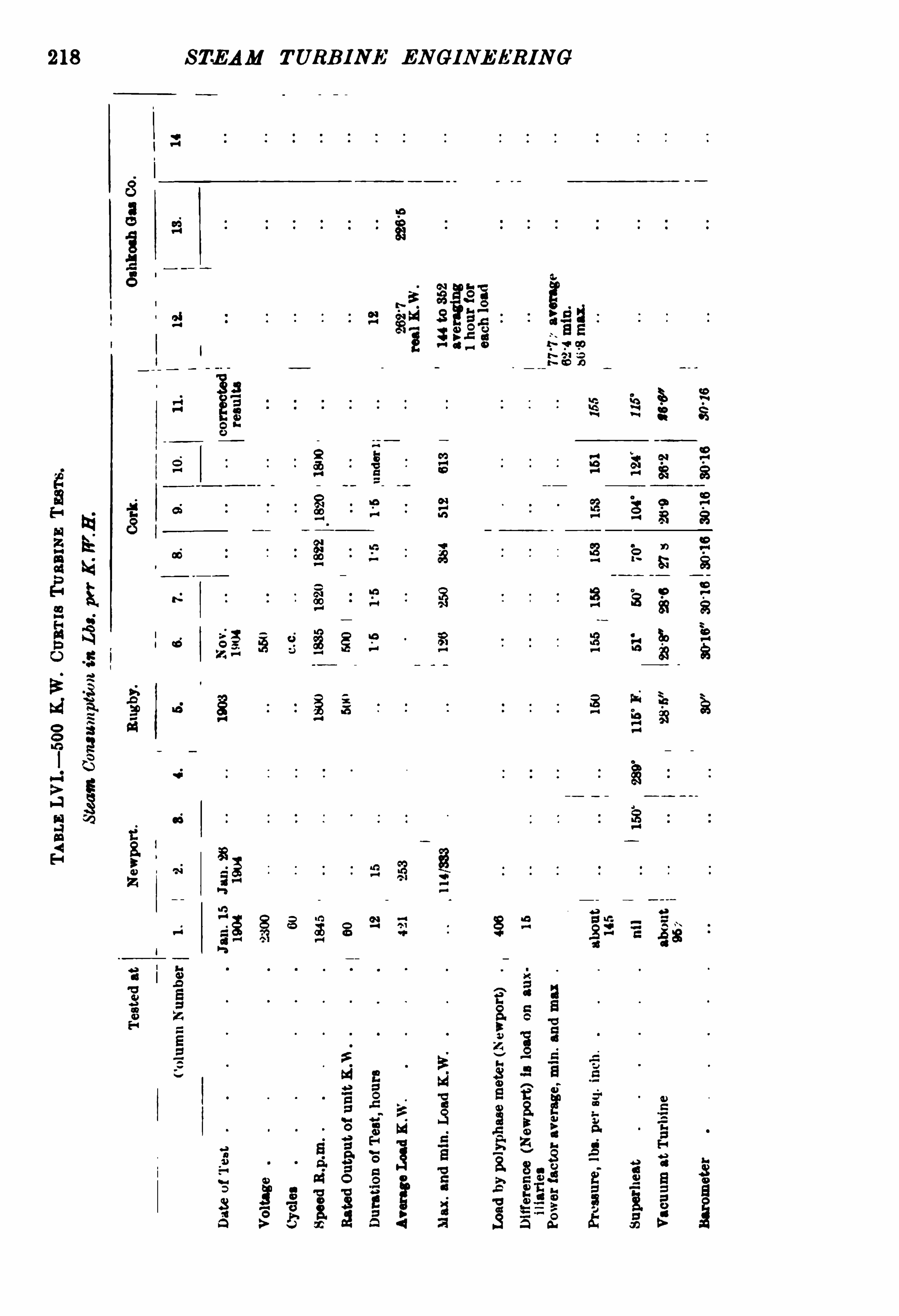
218 STEAM TURB INE EN GINE ERING
00
84
500
12

220 STEAM TURB INE ENGINEERI NG
A 500 kilowatt Curtis turbo—generator, installed by the OshkoshGas Light Co.
,Wisconsin,
in D ecember 1904 , was tested byM r Otto E. Osthoff
,of Messrs H. M . Byllesby Co. , consulting
engineers, on what he called commercial runs, averaging one hourfor each load. The generator is wound for 3 phases, 60 cycles,2300 volts ; the condenser, by Worthington ,
has 2000 square feetcooling surface. The footstep-bearing is supplied with water at300 lbs. per square inch from either of two Worthington doubleacting pumps, which also supply an accumulator as a reserve in casethe pump fails. The two upper bearings are lubricatedwith oil by
gravity.
TABLE Lvi i . "TESTS ON 2000 K.W. CURTIs STEAM TURB INES .
Pound; of PM III'
OJ Inches Of Absolute 80 1“ 307 0111Steam r n , r
3203 tions per Reference.l
Load Duration. sq ,
' Vacuum.
Pressure.
h“ F.
minute .
K-W M inutes.
Junems.
June 1005 .
250 5Mar. 12, 1904.
Test No. 4 .
750
l The 1905 tests were made on a 4-stage turbine of essentially the same design as machinesbuilt two years earlier, but run at higher vane or bucket speed, and with improved vanes and
nozzles.
The numbered tests as stated abovewere on a 3-stage turbine.
The numbered tests indicated by x in Fig. 144 are taken from a summary, p. 43, P roceedings
of National Electric Light A ssociation,Boston, Mass May 1904 , Report of the Committee for
the Investigation of the Steam Turbine,"W . C. L. Eglin,F. Sargent, and A . C. Dunham.
The 1904 tests indicated by e in Fig. 144 are taken from p. 204,Prom dings of Engi neers
’
Club of P hiladelphia , April 1904, W. L. R . Emmet.The 1905 tests indicated by [j in F ig. 144 are from p . 17 , Proceedings National E lectric
Light Associa tion ,Denver, June 11 , 1905 , Augustus H. Kruesi. The June 1905 tests indicated by
A in Fig . 144 are by M essrs Sargent and Ferguson, St. Ry. J oan ,p. 150, July 22, 1905 .
Non-oondensing. At rated load non-condensing, about twice as great as it would be withgood vacuum.
— W. L. R . Emmet. Compare columns Table LVI .


222 STEAM TURB INE ENG INEER ING
The summary of numbered tests referred to above gives thefollowing interesting figures on each of the three stages in the 2000kilowatt unit tested. These tests were probably made at themakers’ works, and may have been on the same machine as thosereported under dates February and M arch 1904 above.
TABLE LIX .~ -POWEB roa Ane rAnrss.
Rating ofMotors.
Place.
Air Pump. Circulating. Step Bearing.
Other
Bearings
.
15 H .P. 20 H .P.
In
Eut In ut 7 1
.W. .W.
12 H.P. 35 H .P
9 K .W. 18 K .W.
SeeF ig. 145
lnput 1800 Input5400'
lbs. steam lbs.steam
per hour per hour
A llauxiliaries driven Chicago Edison Co.
by a single cylinder
Corliss engine,whichdelivers 70 I .H .P.
when 5000K .W. unit
is running at full
load.
”
1 Emmet, Proceedings Engrs. Club, Philadelphia , xxi . April 1904 .
2 F . Samuelson, Rugby Engineering Society, Nov. 5 , 1908. See also p . 454 for data on other
plants, and p. 430 for input to auxiliaries.
j P'
s/ ( I L e t a
Flo . l 45.— Power used by Auxiliaries to 2000 K.W. Curtis Turbine.
C Circulating Pump . A Air Pump . L=L ift Pump from hotwell.
Casual Observations ofPowerOutput from StepdownTransformers supplying Constant Speed Motors at St Louis Exhibition (assuming the power constant for
all loads). From Report Am. St. Ry. Assoc Oct. 1904, p. 184, by Mr J . R.
Bibbins.
Other Illustrations .
— In the chapter on Examples of TurbinePlants several Curtis Installations are listed and illustrated.
Newport, R.I .
Rugby.
’
Fulham, London .
Schenectady.
Quincy.
St Louis Exhibition .
Boston Edison Co.

STEAM TURB INE ENGINEERING
the input to a motor-driven lift pump (motor rated at 120 horsepower) for cooling towers (22 feet diameter, 4 1 feet high) .
END ELEVAT 'ON 3 | DE EL‘VAT'ON .
Sea :‘46 lacs. i Foor
F m. 147 .— Harrogate 750 K.W. Single
-phase Curtis Turbo
-Generatorwith
Allen’s 2600 Sq. Ft. Subbase Surface Condenser Plant.
(From Pros. Inst. Civil Engineers. )
Thus,for the same coal consumption that gave 1150 K .W .
non-condensing 1815 K .W . are obtained from
the combined plant.The guarantees for the low-pressure turbine are
With Absolute Admission Pressurelbs. per sq. in.
Wetness Factor
Vacuum Abs. Back Pressure lbs. per sq. in .
Steam Consumption perFull Load
Half

THE CURTIS TURBINE
Flo. 148 — Rugby Curtis 500 K W. Turbo-Generator.
[0l0
CHAPTER VI
RATEAU STEAM TURBINE
PROFESSOR A . RATEAU,of the Ecole Supé rieure des M ines, Paris,
brought upon the question of steam turbine design his
Flo . 149 .—Rateau Turbine, Elevation in Section.
(From The Electrical Review. )
A ,steam admission. ml
,m2
,etc . ,
diaphragms carrying B1 ,
R1,B2, etc. , guide vanes as in periphery B2, etc.
of fig. 152. K, exhaust to condenser.
01, C2, etc revolving vanes. L,steam admission to N .
See note, p. 235. N , reverse vanes.
highly technical knowledge, and has attained excellent results insteam economy. He has devoted attention to the problem of
saving some of the energy which was usually wasted in hoistingplants and steel works
,in steam exhausted into the atmosphere, by
226
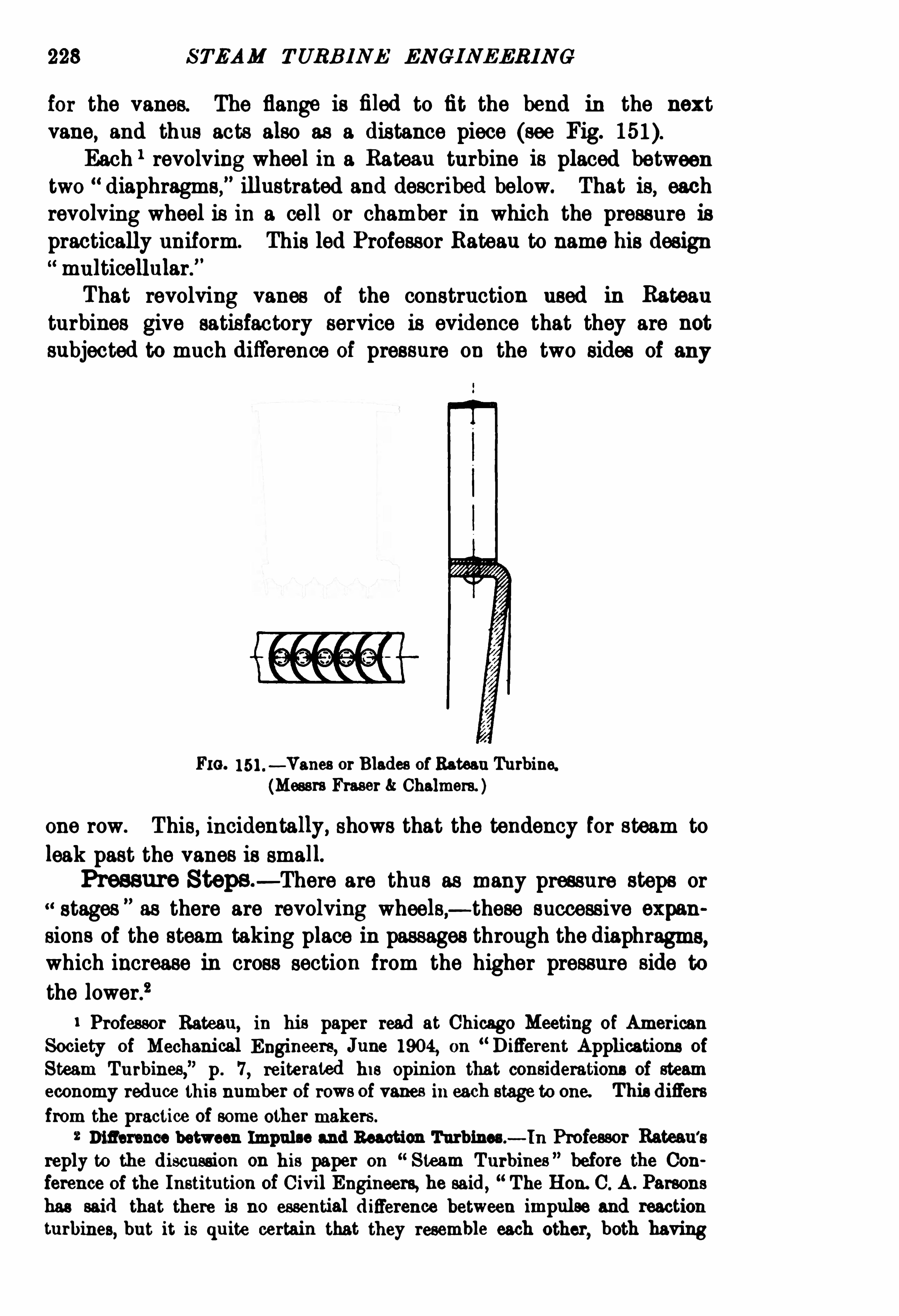
228 STEAM TURB INE ENGINEERIN G
for the vanes. The flange is fi led to fit the bend in the nextvane
,and thus acts also as a distance piece (see Fig.
Each 1 revolving wheel in a Rateau turbine is placed betweentwo diaphragms,
” illustrated and described below. That is,each
revolving wheel is in a cell or chamber in which the pressure ispractically uniform. This led Professor Rateau to name his designmulticellular.”
That revolving vanes of the construction used in Rateauturbines give satisfactory service is evidence that they are not
subjected to much difference of pressure on the two sides of any
FIG.— Vanes or Blades ofRateau Turbine.
(Messrs Fraser Chalmers. )
one row. This, incidentally, shows that the tendency for steam to
leak past the vanes is small.
Pressure Steps— There are thus as many pressure steps or
stages”
as there are revolving wheels,— these successive expan
sions of the steam taking place in passages through the diaphragms,which increase in cross section from the higher pressure side to
the lower.2
Professor Rateau, in his paper read at Chicago Meeting of Amsrican
Society of M echanical Engineers, June 1904, on D ifferent Applications of
Steam Turbines,
” p. 7 , reiterated his opinion that considerations of steam
economy reduce this number of rows ofvanes in each stage to one. This differs
from the practice of some other makers.
2 Diflerence between Impulse and Reaction Turbines.— ln Professor Rateau
'
s
reply to the discussion on his paper on“Steam Turbines
”before the Con
ference of the Institution ofCivil Engineers, he said, The Hon. C. A . Parsons
has said that there is no essential difference between impulse and reaction
turbines,but it is quite certain that they resemble each other
,both having

RATEAU STEAM TURB I NE
Diaphragms — The fixed diaphragms are made, in small sizes,of one casting. In larger sizes a stronger construction is provided.
A number of arms join the rim to the hub,and the spaces between
the arms are covered on each side of the diaphragm with planishedsheet steel.
FIG . 152 — D iaphragms ofRateau Turbine.
(From Eled rical Review. )
Fig. 152 shows a group of diaphragms, and the number of fixeddistributor guide blades
”
(expanding nozzles), through the first is
rotary wheels and guide blades. There are,however
, essential differences
between the two,and it is only necessary to open a treatise on hydraulic
engines to see that hydraulic engineers attach great importance to the distinc
tion between the two types."Professor Rateau had not suffi cient time to
develop the reasons for the distinction, but stated that the speed triangle at
the entrance to the wheel was very different in the one case fromwhat itwas inthe other. F ig. 155 shows the speed triangle and the shape of the vanes of
his impulse turbine,and F ig. 164 those for a reaction turbine (the latter in
the Jonval type).As the steam-turbines revolve generally too fast for the work they have
to perform,means have to be taken to reduce the speed, and one of them is to
cause the turbine to work by impulse, and not by reaction.
”

230 STEAM TURB INE ENGINEERING
small, and this number increases as the position of the diaphragmon the shaft approaches the exhaust end of the turbine. The
complete circumference is thus occupied in the last wheels.
The path of any particle of steam through the turbine
obviously be a helix it is therefore arranged that these fixedguideblades shall he set along that path.
The diaphragms are fixed in grooves in the inside of the turbinecasing. From Fig. 153 it will be seen that the case is dividedon the horizontal diameter.

232 STEAM TURB INE ENGINEERING
Shaft — The shafts are made of nickel steel, and are steppedto facilitate the placing of the revolving wheels.
shaft runs through these diaphragms antifriction metalbushes.
1 The leakage area around the shafts is thus a small annulus.
1 Professor Rateau,as reported, E ngineeri ng, July 17
,1903, p. 105
,stated
that he works to millimetre play, but he added that the shaft makes its

RATEAU STEAM TURB INE 233
own play when 02 mm. (008 in .) is insufficient. In his Chicago 1904
paper, D ifferent Applications of Steam Turbines, p. 13,he stated the
loss by leakage and by friction in the bearings as IQper cent. of the normal
power in a 1500 B .H.P. 1500 Rp m. multicellular turbine, and the loss due to
friction of thewheels upon the steam as 25 per cent. more, — 4 per cent. total.

STEAM TURB INE ENGINEERING
Speed Control — The speed of the Rateau turbine at Bruaycan be varied by hand regulation of a spring between 1500 and
1800 revolutions per minute ( i.e. about 10 per cent. either wayfrom the mean speed). In other cases the speed control amountsto 15 to 20 per cent. either way.
Expanding Nozzle— D r A . Stodola pointed out that violent
acoustic vibrations,which he should always avoid, are set up by
using too short nozzles,
by allowing the steam to leave thenozzle at a slight over-pressure, which, according to ProfessorBateau’
s tests,
“gave only very slight decrease in pressure upon
the moving vanes.
”
Governor and Compensator — Tha general arrangement ofthe governor and compensator that M essrs Fraser Chalmers employ on turbines is shown on Fig. 156. The governor is drivenfrom the turbine shaft by worm gearing as shown on drawing.
The centrifugal force of the masses is in part balanced by the transverse springs which are applied directly to the masses ; an exteriorregulating spring S is applied to complete the balancing.
The movements of the masses are transmitted to the governorlever by a spindle
,the top part of which is a tee on which press
the levers of the governor balls. The articulations of the massesand of the transversal springs and ofthe central spindle are made onpoint or knife edges. Ball bearings are provided for the verticalspindle. The employment of knife edges and ball bearings for themoving parts reduce the friction of the governor to a small value.The governor is completed by a compensator, the pinions of
which are worked by worm gearing off the governor shaft. By
the aid of the compensator the speed of turbine remains constantunder a variable load. When a variation of speed takes placethe governor acts on the throttle valve, causing it to take aposition suitable to the change of load, but with a speed slightlydifferent to that which it had before the variation. The rod is
shifted and one of the feathers which it carries is seized by one
or other of the toothed pinions, turning it in one direction or
the other,increasing or diminishing its length by the nut, and
bringing back the governor lever to its mean position. Governingis now re-established, the throttle valve occupying a positionsuitable to the newload. With the compensator the same speedis maintained with all loads.
Regulator Valve— The stop valve and governor throttle
valve consist of ordinary stop valve operated by hand and doublebeat balanced throttling valve controlled by governor.


236 STEAM TURBINE ENGINEERING
Glands — The stuffing box used by M essrs Sautter, Harlé
Compagnie, Paris, in their Rateau turbines, has a pressure of
12 lbs. per square inch absolute (8 of atmospheric pressure)maintained in a chamber.
Two rings are held in place around the shaft by springs,
and parallel with shaft by other springs, to prevent air leakinginto that chamber.
Oerlikon-Rateau Turbines .
— The vertical turbine illustrated admits steam through a 160-millimetre diameter inletbelow the turbine, and the steam flows upwards, leaving the
turbine through a 350-millimetre diameter exhaust pipe. The
radius of the largest revolving wheel is 440 millimetres .
1
Extent of Use — In the summer of 1905 there were atworkand under construction Rateau turbines, in sizes from 10 to 2300
horse-power, as follows
For ship propulsion horse-power.
Electric Generators
Turbo-Pumps
Turbo-Fans and Air Compressors
TABLE LX .— Dmnnsrous
,OUTPUTS
,AND SPEEDS or RATEAU Tuanmns
oournnn TO Onamxon Gunman -one .
Weight per K .W .
Rated K .W. 1 Length. Breadth. Height.
2000 1 1750
1 Figs. 158— 160.2 Figs . 162, 163.
We are indebted to Professor D r Stodola’s third German edition of The
Steam Turbine for these Figures, 158, 159, 160.

Flo. l59.— 100K.W. Rateau Steam Turbine by Mm hinenfabrik Oerlikon,
8000R pm. (Fig.

STEAM TURBINE ENGINEERING
Peripheral Speed— Professor Rateau states the speed at
which the steam and any particles which it may take with itstrike the vanes, in his multicel lular turbines, is a quarter, or evena fifth, of that usual in the de Laval turbine. The latter he statedas 1100 to 1200metres per second (3600 to 3900feet per second).
1
Clearances — The clearance between moving vanes or blades
F10 . 160.— Plan ofFig. 159.
and fixed parts is 3 to 6 millimetres (i to inch). The shaft is
bushed,as stated above, in each diaphragm,which ofi
'
ers when newonly a small annulus around the shaft for leakage— 02 millimetre
(008 inch) being allowed here. The clearance on the exhaust side
of the vanes or blades is sto 3 inch.
Other Applications — Professor Rateau has designed centri
fugal pumps and fans and compressors for coupling to his steam
1 Consult page 32.

240 STEAM TURBINE ENG INEERING
Power consumed by Auxiliaries .
— Professor Rateau gave
the increase in work on air and circulating pumps to maintain
28-inch vacuum (0068 kgm. per sq. cm. absolute) as compared
with 26 inch vacuum (0 136 kgm. per sq. cm.) as not more than
2 per cent. to 3 per cent., while the saving in steam consumption

RATEAU STEAM TURBIN E
of the turbine is theoretically 12 per cent. with 10 atmospheres
initial pressure.
Calculations on a 2000-kilowatt Rateau Turbine.
A ssuming 200 lbs. per sq. inch,29 ins. vacuum, 350
°
C . temperature
FIG . l 63.— End V iews of Fig.
of steam, a steam consumption of 85 lbs. per horse-power-hour,
to 1 19 lbs. per kilowatt-hour, using 96 per cent. efficiency,from
Fig. 16. p: 38.
TABLE LXII .— ErrEcr or RED UCING THE VACUUM IN LOW-PRESSURE RATEAU
TURBINE wrrB H EAT ACCUM ULATOR .
‘
Anxlssion ro TUBBINE . CoxnsnsEB .
Per K .W B r.
Kg. per Lbsper
sq . cm. sq . n.
2 28 5 (14 lbs. gauge) Surface ‘
08 126 100%2 13 1 1
-5 32 1152
2 Ejector 18 163 36 1307,
l 1 142 Surface 08 16 3 36 100%1 Jet 13 19 6 43 120%1 Ejector 18 224 495 1372.
05 Surface 08 495 100%O
°
5 Jet ‘
13 132%05 Ejector
‘
18 38°
C 84 1707,
1 From M rWaiter Rappl port on 1 he Rateau Steam Turbine , The Electrical Review, June 17 ,
1904, p. 1009. M r P. J . M itchell before West of Scotland Iron and Steel Institute, Dec. 1904 ,
Engineering, Dec. 18, 1904 , p. 881 .

242 STEAM TURBINE JNGINEERI NG
The normal case is the middle set in Table LXI I . above,where
the steam goes to the turbine at atmospheric pressure.
TABLE LXI II .— Tss'r or 350 K .W . RATEAU MULTICELLULAR TURBO-ALTER
NATOB FOR THE Socmrs PAVIN D E LAFARGE AT TEIL (ABDECB E).
3000 3-Phase, 1000 Volts— cm 01 three sets.
Test atLoad. Full Load 866 K .W. HalfLoad 176 K .W .
Steam per hourK .W. hour
Temperature ofsteamSuperheatSteam pressure absolute 1
Before the step valve kg. persq cm. 150 lbs. per sq . in.kg. persq . cm. 205 lbs per“lo ill.
After 144 5-7 81
Exhaust 27Vacuum in con .
denser 68 's cm. 661 cm. inches.
Total efficiency 4“ per cent. 44-4 per cent.
The following are results of tests on the first of three Rateau
turbines driving continuous-current generators at the mines at
Penarroya,Spain
TABLE LXIV.—TEs'
r or 500 E H .P. (370 K.W.) RATEAU TURBO-GENERATOR,Fmsr FOR PENARROYA , BY SA UTTER, HAB LE Co. (Fig.
Fig. 161 gives these in curves using English units.
F"ldTest L
qmn
1230cent. of
127K I 27K i:géliifg
Load E .H.P.
1 64 1 545 535
K .W . 470 400 393Revolutions per minute 2400Steam pressure
Kg. per sq. crn. absolute 11Lbs. per sq. inch gauge 140 125 123
Vacuum (W eary)Kg. per sq. cm. absolute
Lbs. inch
Superheat
Steam consumedKg. per hour
iibs'
E H Pr
fpe
K .W.H.
Lbs.
Total efficienc
Copper brushes are used here .
The no-load steam consumption with fields excited is 10 per cent. of the full-load steamconsumption.
The second set (of three) for Penarroyawas submitted to a competent committee.ProfessorStodola,
ProfessorWyssling, and Pro fessor Ferny, of the Zurich Polytechnicum, and their resultsare given in the following Tables taken from the English translation by D r L. C. Loewenstein ofProfessor Dr. Stodola
'
s 2nd German edition of The Steam Turbine (Constable,
10°
C. 10°
0 zero
37579600 8300
91 5 95 520-2 20
-5 21
-3
56°
8z
1 of 786 watts.

STEAM TURBINE ENGINEERIN G244
«be
a
s.
5
6
8
99
3
9
8
$
3
81a
3am
0
33
88
$
3
c
éog
9
8
9
8
P
g
9
3
be»
0
8k
w‘r
m
Ema
a.
“
P
S
P
Srm;
9
2h
oé
wu
$
3
when
“
32
c
an
9
5
Pam
9
8
Pan»
r
an
91
8
90
3
be
:
«65
Puma
P
uc
8
mu
3
8
89
83
8
3a
9
3
F
an
9
3»
P
an
P
om
fi
g9
vP
am
ow8
mm
8c
3
a: ergassesa:
$
3
won”
9
3"o
bm
P
g9
5»
t
hen
T
:
hr
s
v5.
3
an
2
?
8
To
:
P
am
°
50
9
3
«be
no
a
afi
ow
coo¢
n
on
£13
C
Z.
P
an
9
3
who
25
80.
Sh.
»
man
u
«fin
90a
T
an
n
6a
9
8m
«a
s
w
as
2:
s
:
a
s
b
een
$
8»
wa
s
9
5
«
he
wa
s
so
:
32
8
3.
3c
8”
3.
an
c
z.9
3
H
N7
89
2.”a.
“
n
8gm
«.
n
G
5
5
Pa
s
ovE
N
$
3
_
ca.
=fl
92:
9
:
”m
g:a
9
8
a.
s
c.
I
new.
”an.
”
9
83m
m
g«a
fi
gf
ab
P
8
numb
0
3;
fi
g.
a
P
un
h.
mew
P
ena
mY
N
9
°
T
ana
a
mt"
fl
own
9
3m
5
86
9
6Pawn
To
:
mfi fi é éh i s

RATEA U STEAM TURBINE 245
TABLE LXVI . -Tss'r‘ on A 500 K.W. RATEAU-BLOW ER, Hu mCo. TURBINE .
Steam consumedK.W. Speed.
In Front ofCondenser.
perK.W. Hour.
A“mm“ m m .
Kg. per Lbs. per Kg. per Lbs. i20
2?sq . cm” sq . In. sq . om. sq .
sq . om. M ercury.
Kg. Lbs.R p m.
1 From TheW Review, June 17 , 1904.p . 1011 .
TABLE LXVII .— Tnswon A 1000 K .W. RATEAU TURBINE MADE AT
M ASCHINENFABRIK, OERLIKON, SWITZERLAND .
Steam consumedAbsolute Steam Pressure. Condenser.per K .W. Hour.
8 In front offi rstI W
rm At Boiler.
movingwheel.
Kg. per Lbs. per Kg. persq . cm. sq . in. sq . cm. sq . in.

246 STEAM TURBINE ENGINEERING
TABLE LXVI I I .
— Tss'rs,
l APRIL 5,1902
, ON 225 K .W. LOW-PRESSURERATEAU TURBINE WITH HEAT Accm A 'ron FOR PI 'r No. 5 , BRUAYM INES
,PA S-DE-CALAIS. (Fig.
Steam Consumed rAdmission to Turbine . Condenser.
K .W . Hour.
P"E. Tempere Absolute
2: ture . I Pressure .
K .W.
0
No Load .
Not excited. Inc 111 m 01 4 m we so an (m per hour) (1m )
70 new 111 23: car s o es 81-0 097
m Ieoo‘ m cos on
]
-Is so we I 57s
1591 m 090 12-3 2-9 us as 54-0
use 147 297 l ero
l
' 0 24
Carbon brushes are used here .
1 From “Dal es-en: Applications of Steam T urbines, by Professor Rateau, Chicago, 1904 .
The tests were msde st works of M essrs Seutter, B erle et Cie .. Psris, by M . Ssuvsge , Chief
Engineer ofthe French Corps of M ines, and M . Picou, Electrical Engineer for the Engineers of
the Brusy Coal M ines, Pns-de-Csiais, in 1902.
3 It will be easiest for those accustomed to the vacuum gauge to note the range betweencolumns 7 and 9 .
8 The eiiiciency is the ratio ofdynamo output to the theoretic energy in the steam supplied.
TABLE LXIX .— Tr:s'
r or
STATION or
(at 736)Steam per E.H .F. hour
K .W. hour
Combined effi ciency
This turbine has only twelve revolvingwheels.
D eductions from Tests — Suffi cient tests on independent
machines are not available for comparisons, such as have been
made in the earlier chapters of this book , to be attempted here.
Regenerative Heat Accumulators .— These
,being adjuncts
to steam turbines, deserve consideration here. They have beenmade in four forms.
‘
B ulletin (It In Soot/ te'
dc l’
lnduslric M ine'
rale. The Utilisation of
Exhaust Steam by the application of Steam Accunmlators and CondensingTurbines
,
” North of England Institute of M ining and M echanical Engineers.
E lectrical Review, p. 312, Aug. 21,1903. Engineeri ng, July 3, 17 , 1903.
400 E.H.P. RATEAU TURBINE AT GENERATINGCIE. ELECTRIQUR DE LA LOIRE .
170 lbs. per sq. in . absolute.
388 E .H .P. at generator terminals.
285 K .W.
lbs.
26
per cent.
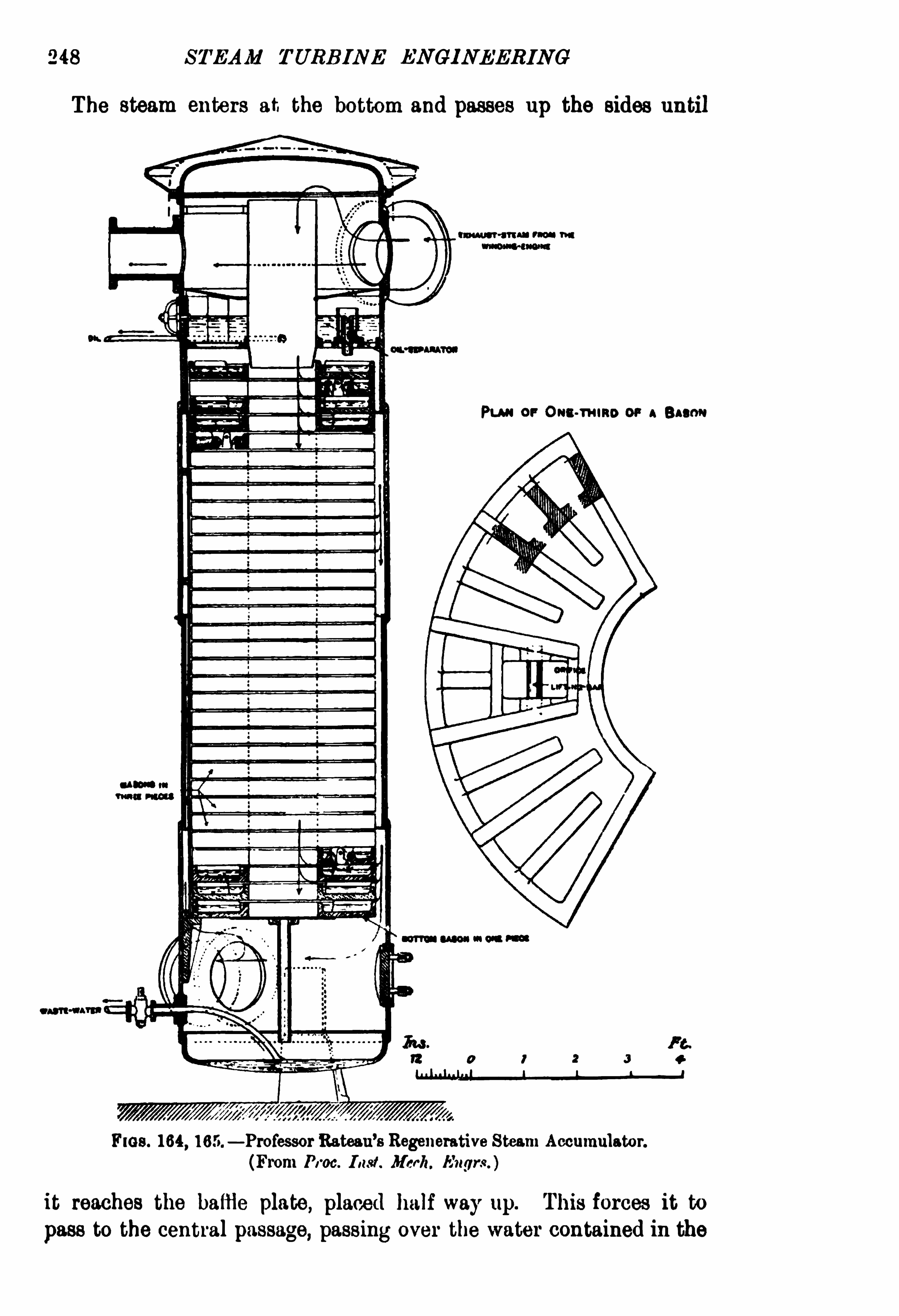
248 STEAM TURB INE ENGINEERING
The steam enters at the bottom and passes up the sides until
(mm -aru PM W
Pu n or Ont -m um or Bacon
CA“ in
FIGS. 164,165.
— ProfessorBateau’s Regenerative Steam Accumulator.
(From Pros. I Nd . M erit. It'
ugrs. )
it reaches the baffle plate, placed halfway up. This forces it to
pass to the central passage, passing over the water contained in the

RATEAU STEAM TURBINE
his passage is blocked at the top by another baffle plate,it to pass from the central passage , over the surface of
Sk
imam
a
com
288o
=owm
8
v
5.
9.
xcoo
89
329
3
3
6
3.
M
E
5ESQ
256
3$5
23
595389
22-8ao
2
8h
e
3no
g
ame
no
9
53
839
4
838
was
Eou
fio
nowno
no
ne»
4
3
8
Sn
a
wom
an
5
5$55
2.
588
s3
.
4
ESQ
Bo
b
55
33
5
8
ES»
325
833
.
EBanA
g.
5
3
A
539?
at»
3
Eou
fio
no
x
mzoza
fizoo
85
8vo—asoo
év
amw©
5
w338m
.
9
Su
e—258
8
on
meow0
5
oEd
Sa
.
u
mz
mfis
.
EEcm~
QSo
Ea
g
v.
E
t
.
8
8m4
Spa
9
335
:
28
63;.
85com
.
5m
3
0
3
38
880:
gfi
fio
noweu
$4
.
m<
.
3‘
«M
8ma
fia
?»
52a
Spa
$5
218
63a.
88ccv
.
3wa
s

250 STEAM TURBINE ENGINEERING
the water, to the annular passage outside the trays. I t then rises
to the top of the vessel and passes to the turbine.
The action of the accumulator is as follows
The steam, in traversing it, gives up a portion of its heat to
the cast-iron and to the water in condensing on the cooler
surfaces.
When the primary engines stop, the turbine continues to draw
steam from the accumulator and the pressure gradually drops.
The moment this occurs, the heat given up to the cast-iron and
water is gradually given off in the form of low-pressure steam.
Reunion M ines 600 H .-P. Accumulator Plant — A t the
Reunion M ines of the Saragossa-A licante Railway
,M adrid
,old
rails are arranged to take the place of the pans of water described
above,because, in this instance, the rails were scrap and cheap.
Here the tanks are horizontal.Fig. 173, page 258, shows an internal view of another accumu
lator of the old rail type ,working at the Hucknall Torkard
Collieries, Ld.,No. 2 pit, near Nottingham, consisting also of a
carefully stacked mass of old rails,so placed that the steam has
to pass longitudinally through small passages. In doing so, part
of its heat is given up to the metal,and water forms on the
surfaces. Heat transference takes place as in the case of the
cast-iron water type , and steam is regenerated as the pressure
falls.
Bethune M ines Heat Accumulator — At the Bethune
M ines, Pas-de-Calais, a 350 horse-power accumulator of another
form is in use. Several large pipes, with vertical passages betweenthem,
are arranged horizontally inside a horizontal cylinder which
is nearly fi lled with wate r. The exhaust steam enters the pipes
and passes into the passages through numerous small openings inthe pipes, causing rapid movement of the water,which flows up anddown through the passages and around the walls of the tank.
Plates are arranged to direct the flow. Fig. 167 shows the
design.
The steam entering these oval tubes forces out the water, andwhen it reaches the first row of holes, escapes through them and
rises in the form of bubbles of steam. If the area of the first row
is insuffi cient,the water-level in the oval tubes is further depressed,
and the second row is uncovered until suffi cient area is provided.
Part of the steam,in passing through the water, is condensed
, the
remainder going to the turbine. When the primary engine stops,
the pressure drops. The same regenerative action takes place ;

252 STEAM TURBINE ENGIN EERIN G
hour, developing 350 horse-power1 when the primary engine has
stops of as much as, but not over, a minute.
The air compressor driven by this low-pressure turbine of 350
horse-power at 4500 revolutions per minute gives an air-pressure
of 85 lbs. per square inch (gauge) .Another similar plant is described and illustrated in Figs. 168
to 17 1, page 253.
The heat accumulato r has a double-boat relief valve to give a
large area for a small lift in case the load on the turbine is too
small to utilise the supply of steam.
A lso, provision is made for taking boiler steam direct to the
turbine through a reducing valve in case the primary engine is
not working, or automatically when the absolute pressure in the
accumulator falls below a predetermined amount. When the
primary engine is notworking, the valve between the accumulatorand turbine is closed. Under these conditions the steam con
sumption rate is increased from 25 per ce nt. to 50 per cent.
Naturally ,the conditions of service in each case require careful
study before it can be decided whether heat accumulation will
prove economical .Supplementary High
-Pressure Turbine. When the
primary engine is idle for long periods during which the turbine
is needed,Professor Rateau provides an additional high-pressure
section to the turbine ,which avoids the loss of efficiency just
mentioned. This section is not in use when the primary engine is
running.
At Bruay— The main winding engine winds on an average
fifty times per hour from a depth of 7 50 ft., totalling about 200
tons, t o. 2500 foot-tons per minute 170 useful horse-power, anduses presumably lbs. of steam. Of this, 3500 lbs. is
assumed to be lost by condensation , leaving lbs. per hour
exhausted into the atmosphere. This,Professor Rateau calculated
,
would give at least 400 not electrical H .P.H. (about 300 kilowatthours) when utilised ih his low-pressure condensing turbines at
35 lbs. per electrical E .P.H . (4 7 lbs. per kilowatt-hour)?
Professor Rateau also estimated the steam consumption of an
unnamed rollingmill engine at lbs. per hour in intermittent
1 The Utilisation ofExhaust Steam in Steam Turbines. Mr Battu before
the Western Society of Engineers, 1904 . The Engineer, Nov. 4,1904
, p. 455 .
2 The Bruay M ines turbine, tested by M essrs Sauvage and Picou (see Table
LXVl I I ., page was a 225 kilowatt turbine
,and had 7 wheels
,each 880
mm. (343inches) diameter, i s. 7 expansions. Engineeri ng, June 5 , 1903, p. 746 .


RATEAU STEAM TURBINE 253
draughts, and be calculated that this would sufiice,with heat
accumulator and low-pressure turbine, to supply 1000 horse-power,or with the exhaust from steam hammers and all other engines to
three times this amount. Of course, this is without increasingeither boiler plant or coal consumption.
FM . 169. Rateau Heat Accumulator. Swel Co. ofScotland Nov. 1905.
HALLSIDE Wouxs,NEWTON,
LANARKSHIRE.
Fig. 168 shows the general arrangement of the plant at the
works of the Steel Company of Scotland.
The primary engines exhausting to the accumulator are as
followsOne cogging engine, 2 cylinders, each 40 inches diameter x 5
foot stroke.

25 4 STEAM TURBIN E ENGIN EERIN G
One finishing main engine, 42 inches diameter x by 5 foot
stroke.
Two small mill engines, driving 14 inch and 18 inch mills.
One 10 ton and one 4 ton steam-hammers.
The total amount of steam from these engines was estimated
by M r P. J . M itchel l, who designed the plant, and to whom weare indebted for all this data, as lbs. per hour, after makingdeductions for pipe condensation
,etc.
Itwas therefore decided to install two 450kilowatt low-pressureturbo-generators, conforming to the then existing works pressureof 230 volts. The output of the mills having been largelyincreased in the last few months, makes it probable that another
unit can be added,making the total power recovered from these
engines 2100 B.H .P.
The accumulator shown in plan and elevation to the right is
surmounted by a receiver which breaks the violent shocks of the
exhaust steam. It communicates by means of pipes with the
accumulator. The steam,on leaving the accumulator
, passes
through a 21 inch main to the inlet valves of the turbines A
high-pressure main is brought into the engine
-room at the opposite
end up to this pipe, and is fitted with the special reducing valvefor supplying reduced pressure live steam to the turbines whenthe main engines are standing for rol l changing, etc .
As the high-speed generating set supplying current to the
works has been thrown out of operation by the installation of the
turbines, no current is available for starting up the condensing
plant, and the reducing valves being shut positively when pressurerises above 14 7 lbs. absolute
,the turbines cannot be started
without some special method of opening the reducing valve and
running the turbine to atmosphere . This is provided, and a
system of levers leading from the stop-valve enables the turbine
to run to atmosphere until sufficient current is generated to start
up the condensing plant, when the lever is released,and the plant
works at or belowatmospheric pressure.
The turbine exhausts to a barometric jet condenser capableofmaintaining a 90 per cent. vacuum.
Figs. 170 and 17 1 show the turbine coupled to a Siemens
direct-current generator, 1950 amperes, 230 volts, with specialcommutator, ventilating device, and carbon brushes.
The turbine has an output of 700 B.H .P. at 1500 revolutions
per minute when exhausting to 27 inch vacuum with atmospheric
inlet pressure. The effi ciency compared with the theoretical duty

256 STEAM TURB INE ENG INEERIN ?

RATEAU STEAM TURBINE 257
It has eleven wheels, of slightly varying diameter, the mean
being about 39 7 5 inches ; the mean peripheral speed 80 metres
per second.
The space occupied by the turbo-generator is 22 feet x 6 feet.
A photo of the accumulator is shown in Fig. 169, p. 253.
On stopping the main engines one turbine has run with the17

258 STEAM TURBINE EN GINEERING
live steam supply cut off for six minutes at a load of 1700amperes,and at the end of nine minutes an output of 500 amperes was
still given, the supply coming only from the accumulator, in whichthe pressure was reduced to 10 inch vacuum.
The accumulator was designed to give full load with engine
stoppages of 40 seconds when both turbines are working.
Fm. 173.— Interior ofHeat Accumulator at Hucknall Torkard Colliery,
showing the old rails used.
HUCKNALL TORKARD COLLIERY,NOTTINGHAM .
This plant is driven by a small part of the exhaust steam from
a 36 inch x 6 foot stroke double cylinder winding engine.
About one fourth of the steam is used at full load in the
turbine, the remainder blowing off at the relief valve. The steam
exhausts from the winding engine for 12 seconds,and is then cut
off for 40 seconds.
The plantbeinga small one,and sufficient scrap colliery train railsbeing available, the old rail type of accumulator was decided upon .

CHAPTER V I I
THE ZOELLY STEAM TURBINE
IN 1903, M essrs Escher Wyss Co.
1of Zurich undertook the
manufacture of this type of turbine. In its design,the fall of
pressure in the steam is confined to the fixed parts of the turbine,
so that each revolving vane runs in a medium of almost uniform
pressure.
As in the Rateau turbine (and unlike the Curtis) , all the kinetic
energy developed in each fixed guide passage is utilised in a singlerevolvingwheel.
The cylinders are fixed to the bed symmetrically,with a viewto
avoid warping due to heating. Each cylinder is divided in a
horizontal plane through its centre, and the flangesare ground to a
steam-tight metal-to-metal joint.
Vanes — Nickel steel , carefully polished to reduce friction of
the steam,is used to make the blades, which have their inner ends
shaped to fit the dovetail formed of the wheel disc and the ring
marked S in Fig. 17 5 . Special steel distance pieces g it, similarly
shaped,maintain the spacing between adjacent vanes. The ring
S is screwed on after all the blades and distance pieces are in place.
In plan (bottom of Fig. the section of the vanes is shown.
Each forms about. a third of a complete cylinder, the two edges
presenting equal angles.
A single piece of Siemens-M artin press-forged steel , shaped
as shown in Fig. 17 5 , forms each wheel disc . The thickness of
disc and of blades tapers outwards, the determination of the
1 The Siemens Halske Cc . ,Berlin Bremer Maschinen und Armaturen
fabrik, Bremen ; M essrs Krupp Sons,Essen ; and Vereinigte Augsburger
undNurnberger Maschinenfabrik are at present engaged on production of the
Zoelly Turbine .

THE ZOELLY STEAM TURBINE 261
sections being based on Professor Stodola’
s calculations ‘ to reduce
centrifugal effects to a minimum.
1 The Engineer, p. 556, June 3, 1904. Atte ntion was called in Engineeri ng,
p. 7 7 1, June 3, 1904, to Parsons having patented in 1893
,butwithout developing
commercially, the use of lowperipheral speed by splittingup the expansion into
several stages and passing the steam,at spee ds thus reduced to practical limits,
through as many pairs of guide and revolvingwheels as there are“steps
”of
expansion.

262 STEAM TURBINE ENGIN EERING
D iaphragms — Fig. 176 shows the guide blade disc or dia
phragm (made in halves,with a groundmetal-to—metal joint betweenthem)which carries the expandingnozzles orguide blades. The boss
r surrounds the boss of the revolvingwheel (Fig. 175 , below), and is
grooved internally (but there are no corresponding grooves shownon the revolving wheel), to reduce leakage to a minimum. The
faces at k and h,Fig. 176, are machined, and successive diaphragms
have face K of one,making a joint with h of the next. The
revolving vanes run with clearance in the space near k. The
outer part, lettered h is, is cast in one with the centre 02,
as
TH E E N G I N E E R
FIG . 175 — RevolvingWheel Disc with Blades inserted.
shown at p p . The guide passages and bridges pp make up the
circumference. The bridges cover a larger are in the high-pressure
end of the turbine (ti e. admission is limited to a small are). One
of the guide blades is shown flat at m,n,a,Fig. 176, and several
shaped in place at m in section in the same Figure. Obliqueslots l l are shown in the outer rim h and inner rim at O
z,and the
projections a n on each blade fit into these slots,and over them
are screwed the rings Ol , 02, sunk in groves turned for them.
Governor.— A centrifugal governor and an auxiliary oil
cylinder control the speed. An accumulator,fed from the
rotary pump which supplies the bearings, provides oil pressure

264 STEAM TURB IN E EN GINEERIN G
In the tests quoted in Table LXX I I . and curves Fig. 180
the oilwas supplied at 30°
to 35°
C., and flowed away at 40
°
to 50°
C.
Glands — Grooved metallic packing is used where the shaft
passes through the end of a cylinder.
177 .— Governor (with Throttle in section).
a,supplies oil under pressure. L,
auxiliary oil cylinder.
b,returns oil. k
,steam throttle.
See also Fig. 174.
TABLE LXX I .
The speeds standardised by M essrs EscherWyss Co. are
KW . R . P. M . KW . R . P. M .
340 3000 1350 1800
475 1700 1500
675 2000
1000 2600
500H .P. (370 K .W . ) unit has
Maximum diameter revolvingRevolutions per minute
Peripheral speed
neailyNumber of Pressure steps
RevolvingwheelsBlades per wheel
Generator 3-phase
Pressure
Output per blade O'
3 K .W.
(Table LXX I I . ,Fig. 180)
45 inches
ft. per minute
600 ft. per second
10
10
132
600 volts

TH E ZOELLY STEAM TURBIN E 265
The Managing D irector of M essrs Escher Wyss Co.,Zurich,
Switzerland,and Ravensburg, Germany
,has kindly placed at
our disposal the tests previously1published, together with some
later tests and illustrations of the machines which he has designed,
and which are known by his name.
Stahl und Eisen,Number 18
,1904, by J . Weishaupl. Zeitsclmft des
Vereines deutscher Ingenieure, 1904. Engineering and The Engineer, June 3rd,1904. Stodola
’s The Steam Turbine.

STEAM TURBINE ENGINEERING
TABLE LXXII.— Tm°
rs or 500 H.P. ZOLLY TUBBINE naIV INc
Test Number
Percen eofRatedLoad Per cent.
870K.
Date ofTestTime ofstartTime finishedDuration of TestTotal powerExcitation
,volt amperes
Usefulpower (subtractingexcitation, but not subtractin
gwork of air
pump)No. of revolutions Perminute .
at Entrance to SeparatorAtm. abs .
Pressure Lbs. per
sq. in . abs.
Temperature(
15:Temp. of saturation 2
Superhcat 23.At Entrance to FirstGuideWheel
Atm. absPressure Lbs. per
in abs
Temperature(
3;Temp . of satura tion
(135.
Superheat
Pressure at exit from lst l A
L
t
z‘
$2:guide wheel 1 ‘
1i ii. abs
Pressure in connecting!pipe 1 in . abs
tm abs.
Pressure in exhaust pipe Lbs per
Temp. in Exhaust Pipe
Pressure in condenser
PipeTemp. of con. Tankdoused steam
0P ipeTank
Barometer readingTotal steam consumptionper hour
Glicam consumption peruseful K .W
’
hourTheoretical steam con
sumption-per K .W . re
ferred to condition ofsteam at entrance tosteam separator andvacuum in exhaust pipe
Steam consumption perB .H .P . hour
Thermodynamic efficiency Per cent.
8 967
187°8
889 0183 7
07 09
sssv
see-7
4 887107 74
8 7"
s-m
107 43
Saturated Steam.
161°
8 161 ‘2
1861
188 936 1
°
2
162'
26
1040
31
zero zero
8 996 8 can
111 9
1621 1646
1040 186 °
1831 5 183°C
1 °O
1 Unless tests covered eriods of day and of night there are errors probably in the date s. Test 2 overlaps3 and 4 . The no-load test 0. 8 is stated to have been taken during the 243 K .W . test No 11 .
99 105 91 85 50 88
810 08 85Ja.04 85 1a.04 04 85Ja.o4 04 85Ja.04 85Ja.048hr. 10 8hr. 15 8hr. 55 4 hr. 00 11hr.85 10hr858hr. 10 4 hr. 85 . 4 hr. 45 SM . 85 8m.m 5 br.oo 18hr85 11 hr 10
1m 50 50 50 so so 85
8884 7 88501 8407 8 18805 “080497
“808 887 85 8401 18808 excited not
excited
001 ) 1, 908 8 98 8071480 101
'
7
1790 1m0 1840 1590 188 1080 1080
3560 3472 3280 8130 217 0
1880 154 4 1880 1047 9108540 3540 326
'
5 8090 2205 196010 0-8 00 10 8 8 84 4 1 11 7
1 1 4 0 4°
8 2l°
1
8 44 0058 008827 °
04 9 5 82
1088 0088 07 89 088 01 764
‘
703
00715 00781 om 013 57 00881 00581 0051 00514
1051 1059 00979 00856 00714 07 858 07 554
891 890 880 880 880
1021 1030 1020 980 i 97 0 900 900 10700°048 00471 0051 0058 0044 0044 0048
00761 00921I00487 00 487
884 88088 9 ”0 ”0
780 61‘7
7 50 8 0-2 74 5 720
781 780 780 781
8 778-8 8 8885 8 8810 8 184 8 1 soso 4850
8 325 8 7 5 4 682 6 2 6490 1 025 2 6
9074 9 742 10070 10018 11185722201 24065 25099 83069

STEAM TURBI N E ENGI NEERING

THE ZOELLY STEAM TURBINE 269
TABLE LXXIII . ZOELLY TURBINE 405 K.W.
Date of Test, M ay 1904 . M oderate Superheat. Higher superheat.
1. Load
2. D uration ofTest minutes3. Revolutions per minute
Before the admission valve4 . Pressure absolutekg. per sq. cm.
lbs. per sq inch
5 . Temperature °
C.
°
F .
6 . Temperature of saturate d
Steam°
C.
Temperature of saturated
steam°
F .
7 . Superheat (5— 6)
8. Vacuum in cm. of mercury(33
°
9. Vacuum m cm. reduced to0°C.
Inches
10. Barometer mm. of mercury at
728 at 20°
728 729 at 72911. Barometer ri 1m. reduced to 0
°
C 725 725 727 727I nches
I2. Pressure in exhaust pipe to
condenser absolute kg. per
sq. .cm .
13. Output in K.W.
Steam consumption
14 . Per hour, gs.
lbs.15 . Per K W Hour kgs.
lbs.
Lbs. per sq. inch
TA BLE LXX IV.
—Accar'r.m cs Team,475 K .W. ZOELLY TURBO -GENERATOR
FOR Jommmsaoao .
Date . February 23, 1906 . February 24 . 1906
Load K .W.
Speed R P.M .
Pressure at admlesion atmospheresabsolute (at 14 22)
Lbs. per sq. melt absoluteTemperature °
C .
Pressure 1n front of 1st set of nozzles.
Absolute atmosphereLbs. per sq. inch absolute
Vacuum per cent.Inches ofmercury
Steam consumption kg. per hour
k
q;sper K .W hour
L
Full
3187
1125
455
5 load
3214
117 0166
458
Full
3139
164
284543
5 load
3254
168
521

270 STEAM TURBI NE E NGINEERING
Constant Speed and D ifi‘
erent Loads — Tests, January25th
,1904
,were taken in this order
, 8, 7 , 5 , 4 , 3, as the times ofstarting show. Fewer significant figures in results of tests probably
50 200 so
Kilowatt Hours
Fm. 180.— Zoelly Curves, from Table LXXII. See Table for English Units.
accord with the degree of accuracy of the instruments used and
with the scale of the plotted curves. These results are plotted in
Fig. 180.
TABLE LXXV .
— 405 ZOELLY TURB INE GENERATOR . ACCEPTANCE TEST AT
THE POWER STATION ,M ilHLHAUSEN ,
TR fi R INC EN,GERM ANY. (Fig,
Date.Feb. 27 , 1905.
Load K .W. 1321 9 2082 1 2915 2 3911 3 46322E .H .P. 232 52
Dynamo effi ciency [estimated
Speed R .P.M .
Pressure at admissionatmospheresabsolute (at
Lbs. per sq. inchTemperature °
C.
Pressure in front of l st set of
nozzles. Atmos here absolute
L 8. per sq. inch
Vacuum per cent.
Steam consumption per hour : kgs.
lbs.
Per K .W Hour : kgs.
Per H .P. hour : kgs.
Thermodynal’
nic effi ciency

272 STEAM TURBINE ENGINEERING
Constant Pressure and Variable Speed— Tests 9 , 10, and
11 show constant total steam consumption with speed from 7 percent. above normal (3000) at 80 per cent. of rated load to speed63 per cent. of normal at 66 per cent. of rated load.
M ore recent tests, M ay 1904 ,on the same 405 K .W. Zoelly
turbo-generator, with different amounts of superheat, are on
p. 269.
Zoelly M arine Turbines — The Zoelly turbine is to developthe motive power for the 500 ton (displacement) vessel now beingtested by M essrs Howaldt
,Kiel, for the German merchant
marine. This vessel will have three shafts, and will develop 1000to 1200 horse-power.

CHAPTER V III
THE RIEDLER-STUMPF TURBINE
FROM Table XXV. on p. 40we find that the largest de Laval turbineis rated at 300 horse-power.
l The turbine wheel runs atrevolutions per minute, and has a diameter, measured from the
middle of the blades,of metres. This gives a peripheral
speed of 420 metres per second,which is sufficiently high to
constitute some approach to half the velocity of the impingingsteam. The speed of revolutions per minute ,
however,
necessitates the use of reduction gearing to obtain practicablespeeds for dynamos to be driven by the turbines. Could thespeed of the turbine wheel be reduced to, say, 3000 revolutions perminute ,
the direct driving of alternating current dynamos withoutthe intervention of reduction gearing would become practicable incertain cases, although half this speed, and even much less, wouldbe of great advantage, more especially for sets of large capacity.
In order to retain the peripheral speed of 420 metres per secondit would be necessary for a 3000 revolutions per minute wheel to
have a diameter of1
3
0
65
0
0
0
0x 07 6 2 66 metres.
The centrifugal force at the rim would then be inversely as
the diameters, or37232x 47 metric tons per kilogram weight
of material at the periphery, as against 47 tons for the smallerwheel.
Such proportions as these have been employed in the RiedlerStumpf type of steam turbine
,and by thus avoiding the necessity
for speed reduction gearing,they have been able to build sets of
very large capacity . Except for the use of far larger diameters
With the exception of the 350 horse-power design listed by the Soc1eté deLaval ofFrance, ofwhich we have 110 particulars.
273

274 STEAM TURBINE ENGINE ERI NG
and the avoidance of speed reduction gearing, the simpler types ofRiedler-Stumpf turbine involve the same general principles as those
182.— Riedler-Stumpf 2000Horse-power Wheel.
employed in the de Laval type,although in details of design and
construction many interesting and novel features are introduced.
FIG . 183.— Riedler-Stumpf 2000 Horse-powerWheel.
Figs. 182, 183, and 184 illustrate the wheel of a 2000 horse
power (2000 x 07 36 1475 kilowatt) Riedler-Stumpf turbine.

276 STEAM TURBIN E EN GINEERING
Such a case is shown in Fig. 186 , and it will be seen that the hubis gradually increased in thickness toward the centre, as in thede Laval type, for the purpose of decreasing the otherwiseabnormal stresses in the material at this point.
The nickel steel employed for the wheel of the M oabit 2000horse-power turbine has a breaking strength of 9500 kilograms persquare centimetre and an elastic limit of 7 500kilograms per squarecentimetre. The buckets were milled in the rim of the wheel.There are 150 buckets on the periphery
,the pitch thus being
about 42millimetres. Each bucket is double (see Figs 182 to1475
2 x 1504 9 kilowatts, a far
higher value than is customary in other steam turbines. Au
and the output per half-bucket is
FIG . 186 .— Riedler-StumpfMoabit Set.
alternating current dynamo of 1475 kilowatts rated capacity isdriven from this turbine
,and the set is installed at the M oabit
Central Station of the Berlin Electrical Works. The set is
illustrated in Fig. 186.
From some published descriptions of this set it would beinferred that no outer hearing has been provided for the turbinewheel
,and that it is overhung as indicated in Fig. 187 , the wheel
hub construction being that indicated in Fig. 188.
By a careful study of the descriptions, however, this appearsnot to be the case
,and the construction indicated in Fig. 187 is
apparently an alternative design for the same rating, as. 2000
horse-power and 3000 revolutions per minute. In the case of theM oabit set an outer bearingwas employed.
The maximum stress in the wheel shown in F igs. 182 to 184

THE R I EDLER-STUMPF TURBINE 27 7
amounts to 1900 kilograms per square centimetre, the factor of
safety thus being 3383or 5 . It has been proposed in later
designs of this type to employ forged steel, with a breakingstrength of 5000 kilograms per square centimetre. This would
,
on one hand,reduce the factor of safety to about 2 5 , but the
material could probably be relied upon to be more uniform thannickel steel. As, however, the stress increases as the square ofthe speed, the wheel, if it had a factor of safety of only 2 5 , would
3750
FIG . 187 .— Riedler-StumpfT urbine 2000Horse-power, 3000R.p.m.
burst at a speed some 60 per cent. in excess of the rated speed.
Hence , so low a factor of safety would not be sufficient ifthe speed regulator and the safety governor both failed, in whichcase a speed of, say, double the rated speed might be attained bythe wheel, although the rapidly increasing friction of the wheel
,
of the bearings, and especially of the rotor of the direct connecteddynamo would make so great an increase in speed less probablethan would appear to be the case from a mere consideration of therelative speeds of the steam and the buckets . The greateststresses in the Riedler-Stumpf wheel are not in the rim, but on a

278 STEAM TURBINE ENGINEERING
section near or at the axis,and hence
,should a wheel burst, the
destruction occasioned not only to the turbine but to surroundingproperty would equal or exceed that accompanying the burstingof fly wheels. On the contrary
,as explained in Chapter III., the
breaking of a do Laval wheel is a trifling matter. In a Parsonsturbine the stresses are far more moderate, owing to the lowerperipheral speeds.
The nozzles discharge jets of steam in the plane of the wheelinstead of from the side as in the de Laval design,
and this isclaimed to have the advantage of avoiding all axial thrust. In thedesign illustrated in Figs. 182 to 184 the steam , in impinging on
the rim of the wheel,is divided into two streams, in virtue of the
FIG. 188.— Wheel Hub.
double design of the buckets. These two streams flow to theright and to the left respectively. In another design illustratedin Fig. 185 there is but one rowof single buckets.
In the 2000 horse-power M oabit set there is a radial clearanceof 3 millimetres between the ends of the nozzles and the peripheryof the wheel. M easured in the direction of the axis of the nozzle,the clearance is about 10 millimetres. As the expansion of thesteam is completed in the nozzle (as in the de Laval type), aconsiderable clearance occasions no loss or diminution in capacity ,and this is stated to have been shown experimentally to be thecase for the lliedler-Stumpf type when the radial clearance wasincreased from 3 millimetres to 5 millimetres.
The wheel is highly polished, with a view to decreasing the

280 STEAM TURBINE EN G INEERING
employed in this design . The precise method of arrangement or
the nozzles in the casing is shown in Fig. 191. The rectangularform of the nozzle permits of discharging a nearly continuous beltof steam and a full utilisation of the buckets. In some of thesmaller sizes of Riedler-Stumpf turbine it is not necessary to havea complete ring of nozzles over the periphery . In such cases,instead of distributing the nozzles at equal distances around theperiphery, they are placed in a single group at one section of theperiphery.
The impossibility of obtaining very low speeds by the use of
a single wheel acted upon but once by the jet of steam led to
FIG . 190A — Riedler-Stumpf 2000Horse-power, 3000 R.p.m.
Ringfor Holding Nozzles.
(From the Designers. )
suggested modifications of the simple form of Reidler-Stumpfturbine from that embodied in the 2000 horse-power, 3000revolutions per minute ,
M oabit machine.
The first of these suggested modifications consisted in theintroduction of two successive impacts of the steam upon a singlewheel by means of stationary reversing nozzles. This planappears to have been proposed by Pilbrow in 1843, and has beenvery clearly described by Lilienthal in 1890. The RiedlerStumpf reversing nozzle
,Fig. 192
,resembles the arrangement
described by Lilienthal which is illustrated in Fig. 193, and may
be described as followsLilienthal showed a simple figure to explain a way of intro

THE RIEDLER-STUMPF TURBINE 281
ducing the steam a second time into the revolving buckets. Thisfigure has been reproduced in Fig. 193, and it can be seen that the
F10 . 1908.— Riug ofNozzles.
expanding nozzle delivers steam in to one bucket a. ofwheel
,and this discharges into the stationary reversing guide
Flo . 191 .— Riedler-StumpfNozzles in Casing.
marked c, which in turn delivers into the next bucket b.
helical shape of the reversing guide is necessary in order to takethe steam to the adjacent bucket. The figure is merely diagram

282 STEAM TURBINE EN GINEERING
metical,and shows no clearance between fixed reversing guide
F10 . 192.— Reversing Nozzle.
c and revolving buckets a and b. Such clearance would, of course,
be necessary in a practical machine . From above preliminary
FIG . 193 — Lilienthal Reversing Nozzle .
description of Lilienthal’
s proposal it will perhaps be easier tofollow the course of the steam in Riedler
’
s design as shown in

284 STEAM TURBINE ENGINEERING
siderable sacrifice in economy. In the case of this design,in
which,from the overall dimensions given,
it is evident that thewheels have a diameter of about 2 metres, the peripheral speedhas the very lowvalue of 52 metres per second. It is not clearwhy it would not be preferable to at least double the wheeldiameter
,and correspondingly reduce the number of stages. The
use of so low a peripheral speed at once sacrifices one of themost attractive amongst the underlying principles of the RiedlerStumpf type.
Vertical-Shaft Riedler-Stumpf Turbines — A design for a
Fro . 195. — Riedler-Stumpf 500 K.W. Turbo-dynamo, 500 R.p.m.
2000K .W . 7 50 revolutions per minute set with a vertical shaft isshown in Fig. 196. This design is worked out with two pressurestages and two speed st eps per pressure stage. In Fig. 197 we havean illustration of a 500 kilowatt 7 50 revolution per minute verticaldesign with four pressure stages and two speed steps per pressurestage . The peripheral speed in this design is 118 metres persecond
,the diameter of the wheels being about 3 metres.
Riedler’
s general conclusion, however, appears to be that whilereduction of speed by means of many pressure stages is consistentwith high economy , it is undesirable to employ more than twospeed steps per pressure stage , as this entails great friction lossesbetween the steam and the buckets and reversing nozzles.

THE RIEDLER-STUMPF TURBINE 285
While the Riedler-Stumpf turbine in its simplest form with asingle wheel differed from the de Laval design chiefly in the far
F lo . 196.— 2000 K.W.
, 750 Vertical Design.
greater wheel diameter, and the consequent avoidance of reductiongearing, the types with both pressure and speed stages are closelyon the lines of the Curtis turbine. The Riedler-Stumpf turbines

286 STEAM TURBINE ENGINEERING
were for a time built by the Allgemeine Elektricitaets-Gesellschaftof Berlin.
The Riedler-Stumpf type has now more or less merged its
identity in the A . E. C . type described in the following chapte r.It seems to the writers that while the main ideas of the originaltype with a single wheel were most attractive , these were carried
Flo. 197.— 500 K.W. 750 R.p.m.
(From The Engineer . )
to an extreme which was inconsistent with the production of safeconstructions. As development in the production of materials of
great strength proceeds, there will doubtless be a reversion towardslarge diameters, accompanied by high peripheral speeds.
Grauert’
s contribution to the discussion of Riedler’
s paperon Steam Turbines 1 is published in the Marine Rundschau for
January 1904 ,and contains data of a small Reidler-Stumpf turbo
Ueber Dampfturbinen,” by Herr Prof. D r. ing. Riedler, Jahrbuch der
Schifibautechnischen Gesellsclwfl ,vol. v. p. 249 .

288 STEAM TURBINE EN GINEERIN G
reversing nozzles (as in the design illustrated in Fig. 199) thesteam consumption was decreased to 17 kilograms per kilowatthour for the same speed and output.
Fro. 199.
Steam Consumption — The published results as regards thesteam consumption of the Riedler-Stumpf turbine are broughttogether in Table LXXVI .

THE R IE DLER-STUM PF TURB INE 289
TABLE LXXVI .— TEST RESULTS on RIEDLER-STUMPF TURBO-GENERATING
SET,RATED OUTPUT or 1475 K .W.,
AND D IRECT-COUPLED To D . C.
Drusno.
Source ofData.
8000 103 89RIedIer (paper on
124 92 g d tItIed Ueber Dampié turbinen.
"read befo re
113 92 9 2 the Schlffbaute ch”
a a nlscheu Gesellscheft ,118 85 89 Berlin. Proceedt
'
s,vol. v. p. 249
11 . 91 1345 3800 14-75 as 7-5 1

CHAPTER IX
THE A .E.G . TURBINE
THE Allgemeine Elektricitats-Gesellschaft of Berlin first ente redthe turbine field with designs of the Riedler-Stumpf type. Withinthe last two years, however, the rights for the Curtis turbinepatents in several countries have come into their hands, and thesituation has led to the development of a distinctive A.E.G .
type.Owing to these circumstances there has been a long develop
mental period during which numerous varied types have beenbuilt.The 2000 Horse -power Riedler ~ Stumpf set at the M oabit
Central Station,which was built by the Allgemeine Elektricitats
Gesellschaft, has already been described in Chapter V III.Numerous other earlier types have been described in an article
on p. 1205 of the Zeitschrift des Veret'
nes Deutscher Ingenieure forAugust 13th, 1904 ,
entitled D ie D ampfturbinen der AllgemeineElectricitats Gesellschaft, Berlin . The article is by M r O.
Lasche, the director of the turbine department of the AllgemeineElektricitats-Gesellschaft. We do not propose to dwell uponthese earlier types, in some of which two cylinders wereemployed
,but shall confine our attention chiefly to some
examples of the latest designs, photographs of which havebeen placed at our disposal for this purpose by the courtesy ofM r Lasche. In these latest designs a single overhung cylinderis employed.
General Construction.— The design arrived at has been
adopted from a consideration of the requirements of the dynamono less than those of the turbine. The dynamo is securedto a base plate between two main bearings, and the turbine is
supported upon an extension of the base plate. A small additional290

292 STEAM TURBINE ENGINEERING
condensing may carry nearly its full load,and as economically as
possible, only a part of the full supply of steam is carried to thesecond stage ; the remainder is exhausted into the atmosphereimmediately after having completed its work in the first stage.The discharge from the first stage is generally ultimately conveyedto the atmosphere by the same pipe which discharges from the
second stage .
Bearings— Oil is carried under pressure to the bearings, a
F IG . 200.— 10 K.W. A .E.G. Set.
rotary pump, driven by the turbine itself , being provided for thepurpose. The bearings are cab led by water circulation.
Shaft — The shaft is of nickel steel or of Siemens-M artin steel,
both these materials having been found equally satisfactory as
regards their behaviour at the bearing surfaces.
The photographs in Figs. 200 and 201 illustrate sets for 10and 20 kilowatt. This latter set was designed for a marineinstallation. Some of the leading data of these two small sets is
given in Table LXXV II.

THE A .E.G . TURBINE
TABLE LXXVI I .
Rated out at
W e
in .p.m.
oltage
Absolute steam pressure in kgs. per sq . cm.
Superheat 1n degrees Cent.
Vacuum .
Approximate steamconsumption at rated full load in
kgs. pe1 kilowatt~ hourComplete weight of set .
Peripheral speed of turbine wheel 1n metres per secondPeripheral s d of commutator in metres per second
Material ofTree
brushes
293

294 STEAM TURBINE ENGINEERING
Description of the Regulator.— The regulator is driven
from the main shaft by means of worm gearing. The AllgemeineElektricitats-Gesellschaft does not wish to publish details of thisregulator at present, further than to state that it acts indirectly
by controlling the pressure of the oil behind a piston in a smallcylinder. This piston acts on the throttle valve . Their formermethod of regulation by means of opening and closing the communication with the several nozzles by the position of a steel band(see Stodola , D ie D ampfturbim ,
pp. 252 and 253, Figs. 224 , 225 ,and 226) has been abandoned,
for constructional reasons.
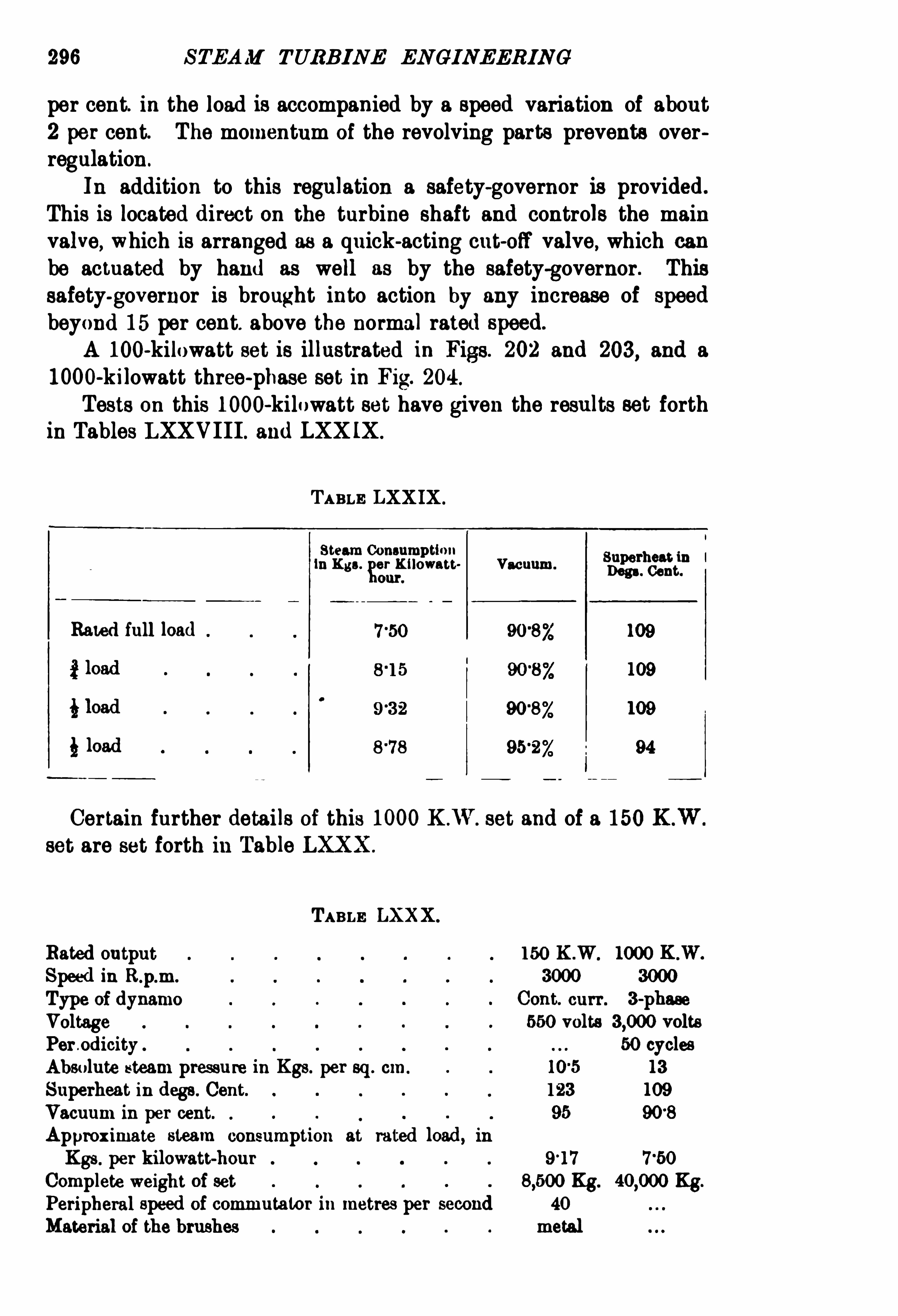
296 STEAM TURBINE EN GINEERING
per cent. in the load is accompanied by a speed variation of about2 per cent. The momentum of the revolving parts prevents overregulation .
In addition to this regulation a safety-governor is provided.
This is located direct on the turbine shaft and controls the mainvalve, which is arranged as a quick-acting cut-off valve , which can
be actuated by hand as well as by the safety-governor. Thissafety-governor is brought into action by any increase of Speedbeyond 15 per cent. above the normal rated speed.
A 100-kilowatt set is illustrated in Figs. 202 and 203, and a1000-kilowatt three-phase set in F ig. 204 .
Tests on this 1000-kilowatt set have given the results set forthin Tables LXXVIII. and LXX IX .
TABLE LXXIX .
Steam ConsumptionIn Kgs.
Ker
.
Kilowatt Vacuum.
Snapethgdt
m
Rated full load
Certain further details of this 1000K .W . set and of a 150K .Wset are set forth in Table LXXX .
TABLE LXXX.
Rated outputSpeed in R.p.m.
Type ofdynamo
Voltage
Pero dicityAbsolute steam pressure in Kgs. per sq. cm.
Superheat in degs. Cent.
Vacuum m per cent.
Approximate steam consumption at rated load, in
Kgs . per kilowatt-hourComplete weight of set Kg. Kg.
Peripheral speed of commutator in metres per second 40
Material of the brushes metal
150 K .W. 1000 K .W.
3000
Cont. curr. 3-phase550 volts volts
50 cycles
13
109
908

THE A .E .G . TURB IN E ; 297
The Allgemeine Elektricitats-Gesellschaft builds polyphaseturbo-generating sets in capacities of from 100 kilowatts to 6000
kilowatts. The speeds for a periodicity of 50 cycles per secondare as follows

298 STEAM TURBINE ENGINEERING
TABLE LXXXI .
Rated Output In K .W. Speed in R .p.m. No. ofPoles.
100 t0 1000
1500 150 3000
4000 t0 6000
Continuous-current turbo-generating sets are built in capacitiesranging from 50 kilowatts up to 7 50 kilowatts. The swede are
as followsTABLE LXXXI I .
Rated Output In K .W. Speed In R .p.m.
50 10 300
A ll these machines have metal brushes.
In addition to the above line of machines, a line employingcarbon brushes is built in capacities of from 2 kilowatts to 20kilowatts. These are made in the sizes shown in Table LXXX III.
TABLE LXXXII I .
fiadlgl
'
l
:at l
Volta. Speed In
65 and 1 15
65 and 115
In polyphase sets for operation in parallel, the regulation isprovided with a spring adjustment controlled by a hand wheel,which permits of bringing the speed of the unloaded machine downto the speed of the loaded machine with which it is to besynchronised.
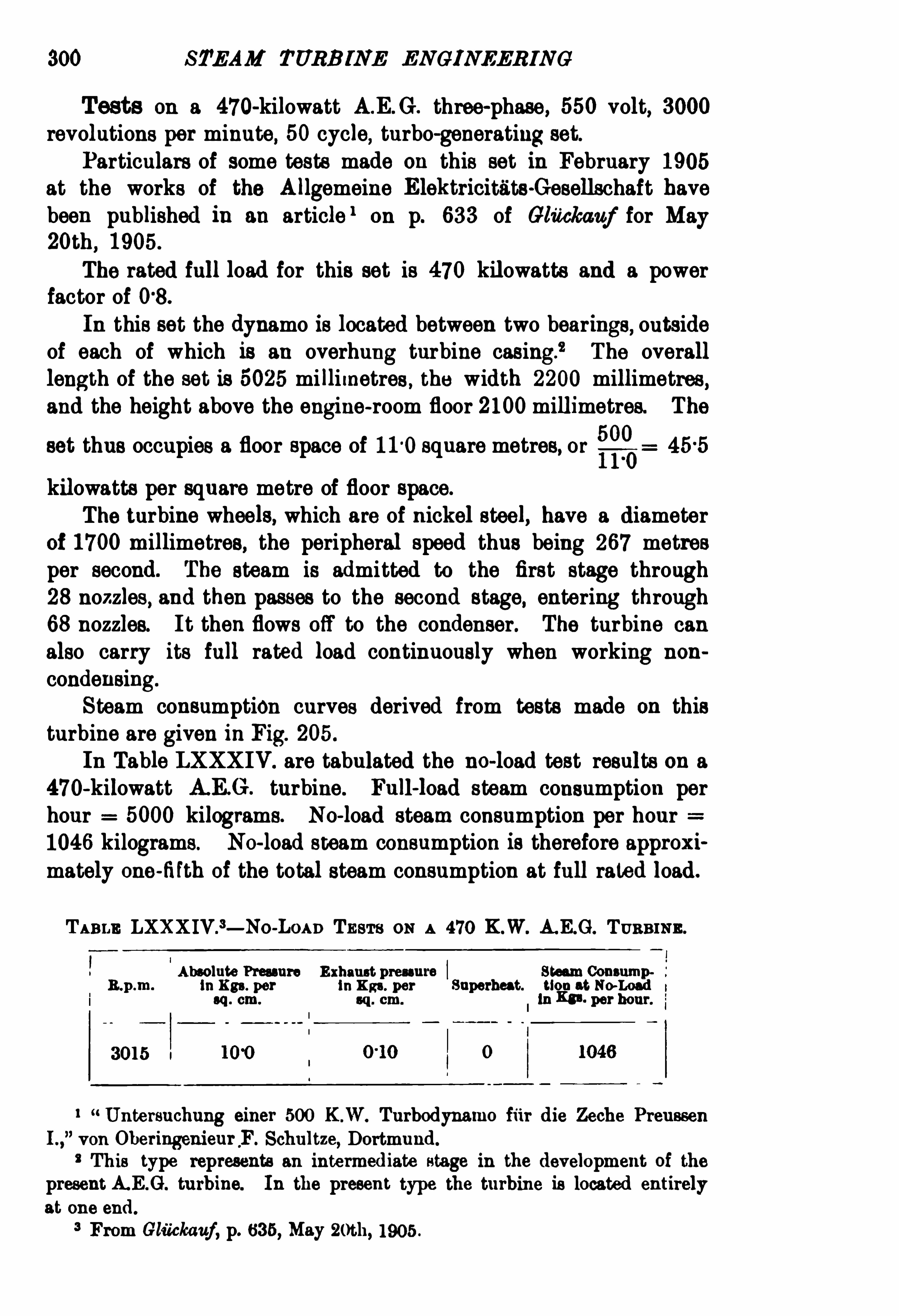
300 STEAM TURB INE ENGINEERING
Tests on a 470-kilowatt A.E.G . three-phase , 550 volt, 3000revolutions per minute, 50 cycle, turbo-generating set.
Particulars of some tests made on this set in February 1905at the works of the Allgemeine Elektricitats-Gesellschaft havebeen published in an article 1 on p. 633 of Glitckauf for M ay20th
,1905.
The rated full load for this set is 470 kilowatts and a powerfactor of 08 .
In this set the dynamo is located between two bearings, outsideof each of which is an overhung turbine casing.
” The overalllength of the set is 5025 mi llimetres, the width 2200 millimetres,and the height above the engine-room floor 2100millimetres. The
set thus occupies a floor space of 110 square metres, or$22)kilowatts per square metre of floor space.
The turbine wheels, which are of nickel steel, have a diameterof 1700millimetres, the peripheral speed thus being 267 metresper second. The steam is admitted to the first stage through28 nozzles, and then passes to the second stage, entering through68 nozzles. It then flows off to the condenser. The turbine can
also carry its full rated load continuously when working non
condensing.
Steam consumption curves derived from tests made on thisturbine are given in Fig. 205 .
In Table LXXXIV. are tabulated the no-load test results on a470-kilowatt A.E G . turbine. Full-load steam consumption perhour 5000 kilograms. No-load steam consumption per hour1046 kilograms. No-load steam consumption is therefore approximately one-fifth of the total steam consumption at full rated load.
TABLE LXXXIV .
3— No-L0An TESTS ON A 470 K.W. A. E.G. TURBINE .
Absolute Pressure Exhaust pressure swam ConsumpR.p .m. In Kgs. per In Kgs. per Superheat. tIou at No-Load t
sq . cm. sq . cm. in Kn . per hour.
3015 u
l Untersuchung einer 500 K .W. Turbodynamo fiir die Zeche Preussen
I .,von OberingenieurF . Schultze, D ortmund.
This type represents an intermediate stage in the development of the
present A.E.G. turbine. In the present type the turbine is located entirely
at one end.
3 From Gluckauf, p. 635, May 2oth, 1905 .

THE A .E .G . TURBINE 301
The test results shown in Table LXXXV . (reference numbersI II .
,IV .
,VI and IX.) have been derived from curves given in the
article by O. Lasche, entitled D ie D ampfturbinen der
Berlin (Zeitschr. Vereines D eutsch. Ing., p. 1207 , August 13th,
The pressure under which the above tests were conductedwas 12 kilograms gauge pressure, or 13 kilograms absolute pressure.
The vacuum is not stated in the article, but the manufacturers havekindly furnished us with particulars in which they state that a
Fm. 205. — Steam Consumption A.E.G . 470 K.W. Set.
95 per cent. vacuum was employed in these tests, but that theycan nowget the same steam economy when employing a vacuumof from 90 to 91 per cent. I t has therefore been thought advieable by the authors, in the case of these tests, to state the
corresponding vacuum for the tests as being 92 per cent — eu
intermediate value. The manufacturers further state that thetemperature of the steam was 300° C. , which for 13 kilogramsabsolute pressure gives a superheat of about 109
°
C.
The test results set forth in Table LXXXV . have been correctedso as to correspond to the standard conditions of reference , namely ,of 13 kilograms absolute pressure, a vacuum of per cent. and

STEAM TURBINE ENGINEERING
TABLE LXXXV .— SUMMARY or TEsT RESULTS
Anemia was"cm
109
0
ON
53
0 l l°0
0 0
110 . OM 109
109 119
50°
of superheat. The curves used in the case of the de Lavalturbine, for estimating the variation in steam consumption for a
80
3
Be
n
.
Ma
!
nosa
E..
n=oo
£
35in
“
a.
.
88
So
.
cm
2:
30a
man
gin
a
.
8
.
cmuo
a
a
:
and
4
89a
25
m
SENnon
.
«a
fignoo
emu
.
no
i—eo
4
2.
395
Results for 40 r
Cent. ofRatedga l

304 STEAM TURBINE ENGINEERING
The derived results are set forth in Table LXXXV I. Since in theA.E.G . turbines the expansion is completed in the nozzles, it isbelieved that the correction factors for variations in pressure,superheat, and vacuum should approximate to those derived from
TABLE LXXXVI .— Ss owmo THE INFERRBD STEAM CONSUM PTION, w s A
CONSTANT ABSOLUTE STEAM PRESSURE or 13 Res ,A VACUUM or
PER CENT .
,AND 50
°
C. or SUPERHEAT FOR THE A.E .G . TURBINE, As
DERIVED raon TEST RESULTS ON TABLE LXXXV .
S E S E ~ s°
i s e s -B’
a
gaze, 59 5
.gas , gas ,
h e: so » h e : h a g g o o s-a
gas gaze Essa Essa gags 5335S 9 3 8 c“
: 35 3 : 9 3 9 3a g o n g o a m 8 ». w-c m sage w°o §a a .s c: .z: a 5
“.z
$5? $55 5 25 “2?s: an: an:
“an? “
an:
Results Results Results Results Results Resultsior 202 ior«oz ior 002 ior 807° ior 1007, ioroi Rated oi Rated oi Rated oi Rated oi Rated oi Rated
Load. Load. Load.
10
10 4
VI I I
our analysis of the results on de Laval turbines. Thus, in examining the tests on the 470-kilowatt set as given in Table LXXXV . ,
we find that 53° Cent. of superheat at nearly constant admissionpressure and vacuum reduces the steam consumption by 56 percent. as against 74 per cent. , corresponding to the curve in Fig. 31
for the de Laval turbine. The tests on the 470-kilowatt set atconstant admission pressure and temperature , but with a 5 per cent.


306 STEAM TURB INE EN GINEERIN G
improvement in vacuum, Show a decreased steam consumption Of
7 per cent. as against 62 5 per cent. , correSponding to the curve inFig. 23 for the de Laval turbine.
The Allgemeine Elektricitélts-Gesellschaft also manufacturecondensers for steam turbine installations
,one type of which is
indicated in Figs. 196 and 197 in the base of their vertical typeof Riedler-Stumpf turbine.Admission Nozzles .
— Fig. 206 shows a photograph of theinterior of a turbine set.

308 STEAM TURB INE ENGIN EERING
including generator, is 40 feet 21} long and 9 feet 8 inches wide, andweighs lbs. The turbine is designed for an admissionpressure of 14 absolute metric atmospheres and a vacuum of 93 °5
P re ss a r e
B e t te r
Co n den se r
FIG. 207. — Hamilton-Holzwarth’s Theoretical D iagram ofChanges in
Pressure and Velocity.
per cent. (28 inches of mercury). The design appears to havealtogether some 32 wheels, and, say, a mean of 150 blades perwheel, or a total of 4800 vanes. This gives about 021 kilowattper vane.1 The diameter of the largest wheel appears to be
1 We have seen in Chapter IV . that in a 750 kilowatt set of the Parsons
type there are some vanes,or 005 kilowatts per moving vane.

THE HAM ILTON-HOLZWARTH TURB INE 309
about 31 metres, giving a peripheral Speed of 240 metres persecond. It is noteworthy that the number of wheels and bladesis comparatively large, yet it is far below the number employedin the Parsons type.It is seen from Fig. 208 that the running wheel comprises
steel discs riveted to both sides of a cast steel hub, which ismounted upon and Splined to the shaft. The vanes are held tothe steel discs by means of rivets passing through the discs andthrough extensions from the vanes, which are gripped betweenthe discs. A thin steel band is tied around the wheel at the outerend of the vanes, and this band constitutes an outside wall to the
Fi t}. 208.— RevolvingWheel.
steam passages. Fig. 209 illustrates the design of wheel indicatedin Holzwarth’
s U.S.A . patent N0. 752340, of February l6th, 1904 .
This figure also well illustrates the construction of the vanes orbuckets. These are lune-shaped and hollow, so as to reduce theirweight. They are milled on both edges. It is stated that testsshow that when mounted on the rim of the wheel as indicated, ablade will withstand a pull of 400 kilograms. Each wheel isindependently balanced to well within 2 grams.
The wheels have been designed throughout with a view to lightconstruction. This permits of the use of a shaft of relatively smalldiameter
, and a proportionately small bore for the stationary discs,with consequent reduced opportuni ty for leakage of steam fromstage to stage without passing through the vanes.
The Stationary Discs — The construction of the stationary

310 STEAM TURB INE ENG INEER ING
discs is illustrated in F ig. 210. The discs are set in grooves inthe turbine casings, the latter being horizontally Spli t as in theParsons type . But while the stationary blades belonging to the
Fm. 209.— Holzwarth Turbine. U.S. Patent Feb. 16
, 1904.
upper half of the turbine are lifted with the upper half of thecasing in the Parsons turbine , the rings holding the stationaryblades remain in place in the Hamilton-Holzwarth type. The
vanes are of drop forged steel of the shape indicated in Fig. 210.
They are,of course , of increasing radial height in successive discs,


THE HAM ILTON-HOLZWARTH TURB INE 313

314 STEAM TURBINE ENGINEERING
pipe to the high pressure end of the turbine. From the ringchannel in the turbine head the steam reaches the first set of
stationary vanes, which are rigidly connected to the head. F romhere the steam flows in a full cylindrical belt through the successive
stages and to the condenser.
FIG . 213.— End ViewofFig. 212.
It is arranged that the high-pressure steam,when admitted
directly to the low-pressure casing for temporary overloads, shallhave an injector action
,dragging along with it the low-pressure
steam from the last stage of the high-pressure casing, instead ofbuilding up a back pressure at that point. This by-pass arrangement is controlled by the governor.

STEAM TURBINE ENGINEERING
1000 kilowatt set the shaft is in three sections, connected byflexible couplings. This arrangement permits of independentexpansion and contraction under the influence of temperature.With further reference to this point
,the casings are not fastened
to the bed plate. The turbine shafts and casings are held rigidonly at the exhaust ends by means of the high-pressure and lowpressure pedestals respectively . Thus they can expand in the
direction opposite to that in which the steam flows. At the intakeends of the two casings there are no rigid connections . There ishardly any axial thrust on the wheels
,as the expansion of the
steam occurs in the fixed vanes only. Any small thrust present istaken up by a thrust ball bearing. Bymeans of this hearingthe shaftmay be moved in an axial direction in order to adjust the relativepositions of ring wheels and stationary discs. Owing to the use ofthe flexible couplings, each shaft can be thus adjusted by itselfwithout affecting the location of the other shafts. The three Shaftsbelonging respectively to the high-pressure casing, the low-pressurecasing, and the dynamo are each proportioned in accordance withthe requirements. Owing to the lightness of the wheels the twoformer shafts are of relatively small diameter, whereas the shaft tothe dynamo is larger because of the very considerable weight ofthe rotor.The design of flexible coupling employed between the difl
'
erent
sections of shaft is of interest. It was required that this couplingshould easily transmit the turning moment , stand the high angularvelocity
, and allow ample clearance for shifting and moving thecoupled shafts in axial and radial direction. Each half of thecoupling consists of a disc, secured upon the end of the shaft bymeans of keys. The discs are fi tted near their outer circumferencewith projecting teeth, consisting of steel laminations. The teeth ofone disc fit between the corresponding teeth of the other disc, sothat a number of pairs of brushes distributed around the
circumference are always flexibly engaged in either direction ofrotation. It is stated by the manufacturers that this coupling issuitable for any practical angular velocity and for the transmissionof large powers.
Stufi ng Boxes.
— The stufling boxes used at each end of each
casing are illustrated in Fig. 215. The design is based upon the
principle that a shaft revolving in a box of suffi cient length and
with small clearance throttles any escaping steam. Instead ofproviding a long box, the required length of leakage surface isobtained by the telescopic construction shown in Fig. 215.

THE HAM ILTON-H OLZWARTH TURB INE 317
A ring fastened to the shaft and revolving with it extendsaxially into the deep groove of another ring which does not
revolve. The stationary grooved ring presses against the adjoiningbearing bushing. The space between this ring, the bushings, andthe shaft is connected with a drain pipe on the pressure side and awater pipe on the vacuum side. By this means it is impossible forsteam to leak along the shaft.
The bearings for the turbine shaft are made with cylindricalshells, but those for the generator Shaft
,having greater weight
to carry, have spherical shells to ensure their alignment.The pedestals and caps of the bearings are arranged so that the
oil inlet and outlet are placed close together, and none of the piping
Fm. 215.— Stufling Box.
has to be deranged to take out the bushings. The oil flows to thebottom bushing under a slight pressure and is led off through thecap to the oil outlet in the pedestal It is stated that thedimensions of the bearings are such that they can be guaranteed torun cool without any risk.
Govem or.— Fig. 216 shows the arrangement of the govern
ing mechanism. The worm on the turbine shaft W keeps thedisc on revolving. The position of the centrifugal governorM on the end of the turbine shaft fixes the point of contactof the friction wheel a on the rotating disc m. When on one
side of the centre of m the rotation of e closes the valve on
spindle a,on the opposite side of the centre of m it opens the
valve ; on the centre it produces no movement ; also the springcontrolled lever glc holds disc m out of contact with e at this
position.

318 STEAM TURBINE ENGINEERING
The speed of the valve’s motion depends on the distance of thecontact from the centre of m.
If the speed exceeds the normal by 2 5 per cent. , the springbalance p shuts off steam.
Fm. 216 .— Governing M echanism. Position with Turbine at Normal Speed.
W, turbine shaft. 1,spindle carryingm.
f, spindlewhich actuates valve on a. m,friction disc.
a ,valve spindle. c
,friction wheel sliding on feather
a,hollowshaft fixed towormwheel. in f.
(From zm mnd. V. d. I .,Jan. 28, 1905 , andU.s.A. Patent 761966,
Lubrication — A pump driven off a worm on the main Shaftsupplies oil under pressure and forces it through a strainer and
cooler after it has passed through the bearings.

CHAPTER XI
THE ELEKTRA STEAM TURBINE
THE Elektra Steam Turbine will be understood by reference to thedrawings in Fig. 217 , and the photograph in Fig. 218, whichshows the parts of a 50 horse-power turbine. The turbine is atpresent built only in sizes of from 10 to 300 horse-power ratedoutput
,but it is the intention of the Gesellschaft fiir Elektrische
Industrie of Karlsruhe to develop designs for larger sizes. It ispointed out by the manufacturers to whom we are indebted forour information that the Elektra turbine runs at moderate speedswithout the need of reduction gearing, as in the de Laval type, onthe one hand, and without the employment of wheels of largediameters and high peripheral speeds, as in the Riedler-Stumpf andother types
,on the other hand. Like both of these types
,the
Elektra turbine in its simplest form has but a single runningwheel
,and in this respect differs from the Parsons, Rateau,
Zoelly,
and the other multiple wheel turbines.The relatively lowspeed is obtained by utilising four successive
impacts of the jet of steam against the vanes of the running wheelin passing from the admission nozzle to the exhaust outlet. The
energy of the steam is transformed by expansion in the nozzleinto kinetic energy, a part of which is delivered to the vanes of
the wheel at each impact.A casing, in which are cast two concentric steam passagesp and
q, surrounds the working parts. The steam is admitted by thepassage p , and after performing its work , leaves the turbine by thepassage q. The steam arriving by p is discharged against thevanes of the wheel through the two nozzles. The steam reboundsfrom the vanes into the first of the reversing passages g, and istherein guided for a second time against the vanes of the wheel
,
Thisprocess is continued until,after several (usually four) impacts,320


322 STEAM TURB INE EN G INEERING
it flows off to the outlet 9. The passages from p to q are graduallyincreased in section to correspond with the increasing volume and
decreasing speed of the steam .
Construction . Peripheral Speed and Clearance — The
general construction of the turbine wheel may be understood by
Flo . 218.— 50Horse-power Elektra SteamITurbine.
reference to the illustrations. The steel vanes are mounted on awrought-iron or steel disc , and are held in place by a press-ring.
The peripheral speed is only from 80 to 100 metres per second(260 to 330feet). As the steam flows radially back and forth overthe vanes of the wheel, there is no end-thrust. The clearancebetween the running vanes and the stationary nozzles is about 3millimetres.

324 STEAM TURBINE ENGINE ERING
TABLE LXXXIX. SINGLE AND DOUBLE-WHEEL ELExTRA TURBINE SETS,COMPRISING A DIRECT-CONNECTED GENERATOR.
Corresponding ValuesGuaranteed Steam Consumption in inferred ior Absolute
E Rated Kgs. per K ilowatt-hour. Adm. Pressure of 18 K3 .
2Speed No. oi Absolute Admission Pressure=11 Kgs . Superheat=50° Cent.
sin Wheels. per sq . cm. Vacuum=86 °6 per cent.
a; g g aR .p.m. Superheat=5u
‘
Cent. (The Standard con
l l3 5, Vacuum=90 per cent. ditions adopted through
a uout this treatise).
10 6 3 4000
15 9 6 4000
20 130 3500
30 197 3500 1 and (and 12 8 for the 2-wheel 172 (and 13 4 for2 type) the 2-wheel type)
50 33 3 3000
75 5 10 3000
100 680 3000
200 135 3000
300 f200 3000
TABLE XC .
— SlNOLE-WHEEL ELEKTRA TURBINES.
S 5.a. E EE go g2+33 .35 o
'
b $3s-g i
? 3 “a; 37.2c' 9 o 3.
9 ; s 2 n
275 300 0042
325 300 0063
400 400 310 0065
310
900 525 400 l 150 1350
3000 l250 400 1150 1450
100— 120 3000 1500 400 0‘
25

THE ELEKTRA STEAM TURB INE 325
TABLE XCI.
Percentage Increase in Steam Consumptionover that at Rated Full Load for an Absolute Fo
azasmqgmdby For a fl uctuating
Admission Pressure of 11 Kgs. per sq . cm., 50°
Arran ment.Cent. oi Superheat, and a 907, Vacuum.
3°
10 per cent. 55 per cent.
6 per cent. 20 per cent.
3 per cent. 7 per cent.
Dimensions — A 50 horse-power 2-whee1 turbine (exclusiveof dynamo) requires a floor space of x 11 metres, and has a
height of 15 metres.
FIG. 219.-ApproximateWeights ofElektra Turbines.
Curve A Total Weights.
B Weight per Horse-power Output.
Curves indicating the approximate weights of,and floor space
occupied by , Elektra Steam Turbines are shown in Figs. 219
and 220.

326 STEAM TURB INE ENGINEERING
2f é vr fl ‘“ in Q . De
on-u ter s [ v ”.P.
a s
I'
d» (a 6 ”aren a/ err .
FIG. 220 — Approximate Floor Space occupied by Elektra Turbines.
A Total (Lower Scale).B=perHorse-power (Upper Scale).


Fro. 225.— Low-Pressure Wheel of 800Horse-power Union Steam Turbine
,showing
also section ofsurrounding Casing, with Rings ofStationary Vanes Reproduced
oforiginal.

STEAM TURBINE ENG INE JRING
belt of nozzles occupying the entire periphery. In the low-pressuresection the stationary vanes
,as in the Parsons type, of course
occupy the entire periphery,the vanes increasing in radial depth
toward the low-pressure end,as seen in Fig. 225 . A plan view
of the 300 horse-power set is given in Fig. 227 . The regulator is illustrated in Figs. 228 to 230. Its operation is basedupon variations in the quantity of the steam ,
which is, of course,a function of the load, and it controls a distributing valve, whichacts to admit the steam through a varying number of nozzles.
Flo. 227.— Plan ofVertical 300Horse-power Union Steam Turbine.
Thus there is no throttling of the steam, and this contributes tohigh economy, as the pressure conditions, at least in the first stages,are practically the same at all loads.
A safety-regulator is also provided as shown in Figs. 228 to 230.
This acts to close a quick-acting main steam valve when the speedrises to a certain point above the normal. The operation is as
followsA block M is capable of a slight movement along the turbine
shaft by means of the pressure of the projecting arms of theweights 6
,whose position is determined by the centrifugal force
corresponding to the speed. The upward movement of M bringsits conical surface into engagement with the rim Of the wheel

THE UNI ON STEAM TURBINE 333
1310 . 228.— Governor and Safety-Regulator ofVertical 800Horse-power Union
SteamTurbine. Scale,1 inch 1 foot.

STEAM TURB INE EN G INEER IN G
segment 5, which , in turning, brings the support a into such aposition that the beam d may be pulled down by the spring as
shown ,thus promptly closing the main valve.
Section on O P.
Fro . 229.— Side Elevation Safety Regulator,
The safety-regulator of the horizontal type of Union turbine isshown in Fig. 231. The action in this case differs from thatemployed in the safety-regulator used for the vertical type,
and is
as follows

336 STEAM TURB I NE EN GINEERING
in the vertical type of turbine,the weight Of the rotor is almost
equalised.
Fro . 231.— Safety-Regulator for Horizontal Type ofUnion Steam Turbine.
Scale, 2 inches 1 foot. Type D 30.
The authors are indebted to the courtesy of M essrs TheM aschinenbau-Actien-Gesellschaft Union of Essen, the manu

THE UN ION STEAM TURB INE 337


340 STEAM TURB INE ENG INEER IN G
facturers Of the Union turbine,for kindly placing at their disposal
most of the illustrations in this chapter. Other illustrations and
details have been taken , by permission,from the Zeitschrift des
FIG . 234.— Photograph of 50Horse-power Union Steam Turbine.
Verez'
nes D eutscher I ngenieure for June 24th,1905 ,
D ampftur
binen,
” p. 1046, and the Zeitschrift fair das Gesamte Turbinenwesmfor June 15th,
1905,
“ D ie Union-D ampfturbine,” p. 209.

CHAPTER XIII
A RECAPITULA'
I‘
ION or THE PROPERTIES or STEAM
THE properties of steam can be conveniently studied in con
nection with Table XC III . or XCIV. In column I. are giventhe absolute pressures in kilograms per square centimetre, rangingfrom kilograms per square centimetre up to 18 kilograms persquare centimetre. A certain temperature corresponds to each
pressure at which water evaporates. This temperature is givenin column 2 in degrees of the Centigrade thermometer scale,and in column 3 in degrees Centigrade above absolute zero- 273
°
Table XCIV . gives the corresponding Fahrenheittemperatures.
In all practical applications Of steam tables and of steam curvesthe chief interest attaches to the energy possessed by the steamunder various conditions Of pressure and temperature, which can
theoretically be converted into work .
Heat in Liquid— Before evaporating at any fixed pressure,
water must first be heated to the corresponding temperature
(t) given in column 2,and each kilogram Of water at 0
°
Cent.requires for that purpose approximately one kilogram-calorie foreach degree Of temperature above 0
°
C.,approximately as many
kilogram-calories as the number expressing temperature, given incolumn 2. This amount of heat, called the
“ heat in the liquid,”
or
sensible heat ” (S) , is given with fair accuracy by the formula
8 : to+0-00002 z0
2+0-0000003 te
a [metric units, Table xcm .]
S 32 t,+ (t, [English units, Table XCIV .]
the subscripts c and F indicating the Centigrade and Fahrenheitthermometer scales respectively.
Latent H6&t.— TO effect evaporation additional energy is
341

342 STEAM TURB INE EN GINEERING
TABLE XCII I .— (METE IO UNITS)— PROPERTIES or STEAM .
CONSULT a sn COLUMNS To OBTAIN Tan
ENI RGY IN KG. 0. OONTAINED IN ONE Ks . or STEAM .
Component Parts, s' 6 . Increase in Total Rue i .s. EnergyEnergywhen Heating one Kg. oi contained 11 one Kg. of
o‘
0'
d .i
a 3g 3sA a s. a n
r, a8.
a is:Q E 5 E
3 gm$ 3
an at0) v4
06 1. 10) 06 1. 11) 001. (12)
599 617 ass600 616 636601 619 687
N .B .— i denotes the temperature oi saturated steam.

344 STEAM TURB IN E EN G INEERIN G
TABLE XCI II .—(METRIO UN ITs)— eontinued.
m
Col. (1 ) 001. (24 ) Col. (26) Col. (26) Col . (27 ) 001. (28) Col . (29)
as aw ass-03 pass
24-1 281 321
'
0415 0856 0312
2os 24-6 27
-7
‘
0412‘
0362
16-0 21
-4 ar e
19s 21'
s
15-0 17 6 19
-70
P 406
“
621 I

RECAP ITULATI ON OF PROPERTI ES OF STEAM
O
38
5231"6
61
2,
o
mq
amg
p
ww
cu
SR
S
R
S
S
8338
838
3
8
3
On
Fahrenheit
Scale.
79 '8
102
ms116
121
126
131
135
414
539
551
561
569575
581 89 5
586
590594
598
601
607613
617 126 1
622 1306
630636
642 15 ] °2
648653 161
‘
7
66 1
669
676
682 1911
687692 202697 207701 211
706 215
710 219
7 19 228
727 236
734 244
740
746 257752 262
757 268
762 273767771
775
77 9
783
787794800 812807 318
812 324
818 330
823 335
828
832 345
837 349
841 354845 358
849 362
853
857 370860 374
864 377
867 381
870 384
874 388
87 7 39 1
TABLE XCIV.— (ENOLISE UNITS).
Component Parts, 126 . Increase inEnergy when heating one Lb. of
IsCol. (1) Col. (2) 035 3) Col. (4) Col.
959
956
950
945941
937
9 17913
CONSULT THESE COLUMNS To OBTAIN THE
ENERGY IN B .TH .U. UONTAINEB IN ONE LB . or STEAM .
Steam at
345
Total Energy. Energycontained in 1 Lb. ofSteamat
.
h.
8»a.
83
3m
8
“
8285
.
h.
Sa
.
aaozamazm
sea
2
8
3m
3
8585
.
m.
c.
:
.
h.
82
a.
88m
8
85
883
(8)(7) Col
7
Col . (6) C01
36
37 0

TABLE XCIV.— (ENemsn UN1T8)
CONSULT 1 8 88] 0014171 1 8 TO OBTAIN TH! 117 B .H .U. NEON ABY
TO 141 1811 0112 LB. STI AX A! PRESSURE.
Compound Pom, B est required to Total Energy “0 H“ ; mmrd-e l Lb-of wralle l Lb. 5a ter ut s2
'
F . toSteam“
‘
3 43
g3
“a
553 5351" 15 53
.w -mma fi s h
hh
.
73 ha o “ 8 .
w 3 3 5 2 5 5Col. (15) 05 1. (18) 05 1. (17) _001. (18) Col (20)
47 7 47 7 I 1100 1154 1202
47-9 1110 1158 1208
47-9 1113 1181 12091115 1183 12111117 1185 1213
481 1119 1187 12151121 1189 12181122 1170 1218
1123 1 171 1 21948-3 47-9 1124 1172
1125 1173
1127 1175
1129 1177
1130 1179
480 1132 1180
1134 1 183
1138 1185
1138 1187
1189 1189
1141 1190
1144 1193
1148 1198
1148 1198
1150 1200
1152 1202
1153 1204
1155 1205
1158 12071157 1208
1158 1210
1181 1213
1183 1218
1180 1218
1188 1221
1170 1223
117 1 1225
1173 1227
1174 1229
1178 1281
1177 1233
1178 1234
1 180 1238
1181 12371182 12391184 1242
1188 1244
1188 12471190 12491191 125 1
1193 1253
1194 1255
1198 12571197 1259
1193 1281
1200 12831201 12851202 12881203 1268
1204 12701205 1271
1208 127 3
1207 12741208 12751209

STEAM TURB INE ENGINEERING
required, called the“ latent heat (L) . This is made up of two
distinct components : first , that part required for evaporation
(internal latent heat , L) ; second, that part required to overcomethe mechanical work of expanding during evaporation againstpressure, from the volume of water up to the volume of saturatedsteam (external latent heat,
The latter component amounts to only from 6 per cent. to10 per cent of the total, but nevertheless it is of importance tocarefully distinguish between the energy that is required in orderto obtain a kilogram of steam at a given pressure, and the slightlyless amount of energy existing in a kilogram of steam at thatpressure. For this purpose we have in Tables XCIII . and XCIV.
given two distinct groups of columns. Columns 4 to 12,Table
XCI II . , show the energy existing in one kilogram of steam in
excess of that existing in one kilogram of water at 0°
Centand columns 13 to 21 show the energy necessary to produce onekilogram of steam from one kilogram of water at 0
°
Cent. inkilogram degree calories.
Table XCIV . gives in columns 4 to 12 the energy existingin one pound of steam in excess of that in one pound Of waterat 32° F and columns 13 to 21 show the energy necessary toproduce one pound of steam from water at 32
°
F . ,all in British
thermal units.
Let us first consider the columns giving the energy existing ina kilogram (or a pound) of steam. In column 4 the heat in thewater just prior to vaporisation is given in terms of the kilogramdegree calories per kilogram ,
— Table XCIII. (in B .Th.U. in TableThis differs at the higher temperatures by about 2 per
cent. from the temperature of water in degrees Centigrade above0°
of that scale, and at lower temperatures by a considerablysmaller percentage.The whole amount of the latent heat, is given in
column 14 .
InternalLatentHeat — The largeadditional amount ofenergyL, imparted to the steam during vaporisation is given in column 5.
It may be calculated by Zenner’s approximate formula,
L, 57 54 0791 $0 [metric units].
L. 1062 tp [English units].
Steam and W atch — Let us nowconsider the intermediatecondition in which only a part of the water is evaporated. Suppose

RE CAPI TULATION OF PROPERTIES OF STEAM 349
that 90 per cent. Of the total water is in the form of steam ,the
remaining 10 per cen t. still being liquid. The steam may be saidto have 10 per cent. ofmoisture, or to have a wetness factor a: = 0 1 .
It is clear that in such a mixture the energy is equal to the heatin the liquid plus 09 of the heat of vaporisation of the wholequantity ,
S+ ( I — :c) L,.
The Convertible Energy in Saturated Steam.— For
column 9,the values in columns 4 and 5 have been added together ,
thus giving the energy existing in one kilogram of saturated steam .
It can also be considered as the difference between the total heat ,H
, and the external latent heat, L,
S+ Iq = H — L, .
Total Heat — The total heat, H ,in column 18
,is the heat
energy necessary to raise one unit of weight of water from freezingpoint up to saturated steam at a definite pressure and correspondingtemperature. This is given by the approximate equations,
H 6065 0305 to [in kilogram calories].
H 1082 0305 t]? [in
Superheating.— Aa soon as the Water has been completely
evaporated,any additional supply of energy raises the temperature
of the steam , assuming the pressure is kept constant. This bringsus to what is known as the region of superheated steam . Duringthe last few years the subject of superheated steam has come into
great prominence, and its properties are of extreme interest. Ofthe additional energy required at constant pressure to raise thetemperature of saturated steam , one part is necessary to providethe energy for overcoming the external pressure. This constitutesabout 22 to 24 per cent. of the total additional energy. The
remaining 78 to 76 per cent. serves to increase the availableinternal energy, to increase the temperature Of the steam .
The total additional energy per kilogram of superheated steam isequal to the Specific heat at constant pressure
,Op ,multiplied
by t’ — t,the difference in temperature of the superheated steam
,
t’
, and of the saturated steam,t, where C, may be taken from Fig.

350 STEAM TURBI NE EN GINEERIN G
235. Three curves of F ig. 235 have been plotted by the formulaproposed by Professor Callendar.1 This formula is as follows
c, 093 (4
g)?p .
Cp = specific heat at the constant pressure , p .
p = absolute pressure in Kgs. per sq. cm.
T 273 t absolute temperature (Centigrade).
For Table XCIV .
,in English units, the following formula has
been used .
0,= 0477 000654
TE.3
.p‘
T; 4594 t, absolute Fahrenheit temperature.t,-=temperature of the superheated steam on Fahrenheit scale .
The Curve 04,Fig. 235 , has been plotted (for comparison with
C,) by the formula proposed by Professor Linde (see footnote,page
_1 C 373 3
C —,F )
T is absolute Centigrade temperature ; J is Joule’
s mechanicalequivalent Of heat==427 ; p is pressure in kgs. per square metre ;n= 4 °232 ; B= 47
°10 ; a= 0'
000002 ; C= O°O31.
Professor Lorenz gave a simpler formula, which we have not
used here,in Zeitsch/r. d. 77 87 8727138 (187433811. 171987188147 8, 1904 , p. 700
C, ,
000
The total heat of superheated steam is— t).
The energy used in overcoming external pressure during superheating can be calculated in the same way as for saturated steam.
The external latent heat is calculated by the formula
_P“;I».J
Here p is pressure ; 15 is the increase in volume ; and J is
Joule’s mechanical equivalent of heat.
1 Professor Callendar proposed this formula in a paper read before the
Royal Society (Pros. Royal Society, November i 4th, The formula has
also been used by Professor D r. Mollier for his steam curves and tables, whichhave just been published in Berlin by Messrs Julius Springer. Dr M ollier’s
curves form a very desirable supplement to anywork on steam turbines.
[in metric units].

352 STEAM TURBINE ENGINEER ING
Specifi c W eights and Volumes of Superheated Steam .
The volume Of superheated steam is for practical purposescorrect enough if calculated by the formula given by Tumlirz.
l
170 : 00047 1 T 0016 p . (in metric units).o=volume in cu. m . per kg.
p = absolute pressure in kgs. per sq. cm.
T= absolute temperature on the Centigrade scale.
pv= 0'5963 T — O'2563p . (in English units).
o= volume in cu. feet per lb.
p = abe. pressure in lbs. per sq. in.
T= abs. temperature on the Fahrenheit scale.
We note also the formula given by Linde,2 which shows the
influence of the variable specific heat
373 3
zw=°0047 1 T —p 000002 17) [0031 (T ) - 00052]
when p,v, and T are in metric measures. In English measures
Linde’s formula is
67 1-4 3
pv=05963T 16 02p(1 + 000000014 1p )[0031( T 0
On pages 344 and 347 are given the specific weights and thespecific volumes Of saturated and superheated steam
,for all usual
pressures and superheats up to 150°
C and 300°
F . It is interestingto note that the specific weight of saturated steam increases verynearly in proportion to the pressure.8 Thus
Abs. pressure= 0' 1 Kg. per sq. cm. Spec. weight=0°
067 Kg. per cub. metre .
Abs. pressure= 10 Kg. per sq. cm. Spec. weight= 0°
587 Kg. per cub. metre.
Abs. pressure= 10 Kg. per sq . cm. Spec. weight= 5'
l l Kg. per cub. metre.
The specific volume ofwet steam can be taken as approximately
Specific volume 2 7 (1 a:
)o,
Tumlirz, Sitzungsbefidttc der AW . (1. Winm ahaflm M ath -Nauru).
Kl. Wien, 1899 , I la, page 1058.
2B . Linde, D ie thermischen Eigenschaften des gesattigten und des uber
hitzten Wasserdampfes zwischen 100°
und -Heft 21, dcr M ittheilungm
fiber Forsd mngsarbeam, or Zeitschr. d. Vercz'
nes dmtsch. Ing.,1905, Oct.
21 and 28,page 1745 .
3 According to Zeuner, it varies approximately as the 0 939 power of the
absolute pressure.

RECAPI TULATION OF PROPERTI ES OF STEAM 353
where a: is the wetness factor and v the specific volume ofsaturated steam.
Without going into the theory of thermodynamics, a fewinstances may be given to illustrate the behaviour of steam undervarious conditions. In accordance with the law of the conservation of energy, we know that when one kilogram of steam has
been brought from one state into another, no energy has beencreated or annihilated. If the total energy belonging to one
kilogram of steam in the second state is larger than in the firststate, there must have been an input of energy from some externalsource ; and if lower, energy must have been liberated, that is tosay, given up to some other object
,or changed in form. For
instance , one kilogram of saturated steam before expanding in an
engine may have an absolute pressure of, say,13 kilograms per
square centimetre,and when leaving the engine a pressure of, say,
03 kilogram per square centimetre and a wetness factor of 04 .
From Table XCIII. we find that before expanding the kilogram ofsteam contained 618 kilogram-calories of energy , and when leavingthe engine only kilogram-calories. Therefore in the engine itself the steam mus t have given up an amountof energy equal to 618 kilogram-calories. If thesteam, when entering or when leaving, had an inappreciable speed,we should not have to add to the above value the mechanicalenergy due to the velocity of the steam , the kinetic energy.
For instance in the above case the speed during expansion in thecylinder behind the piston will be negligible, but during exhaustfrom the cylinder it may amount to 300 metres per second.
In this case the energy in the steam when leaving would be
382 107 393 kilogram-calories.
The energy given up by one kilogram ofsteam duringexpansionin the cylinder is therefore in this case equal to 618kilogram-calories.
It must be carefully understood that this law does not tellus what has become of the 236 or 225 kilogram-calories that havebeen given up by the steam . It may have been converted eitherinto mechanical energy or into heat. It is, however, the purposeof a steam engine or a steam turbine to convert as much as
possible of the original energy available in the steam intomechanical energy. From this point of view we must ascertainthe lawaccording to which the energy available in the steam can
be converted into mechanical energy.

354 STEAM TURBINE ENGINEERI NG
For this purpose let us picture to ourselves an experiment inwhich steam is transformed from one state in which it has a givenamount of internal energy,
into another state in which it has aless amount. Let the conditions be such as to prevent any of theenergy being given up as heat. We thus have the conditionsnecessary for studying the process of converting internal energyinto mechanical energy , as we have cut 011
”
all other ways in whichthe internal energy of the steam can be transformed. The
experiment could be of the following natureIn a closed cylinder
,the sides of which are of non-conducting
material, a kilogram of saturated steam has an absolute pressureof p kilograms per square centimetre and a volume of v cubicmetres.Let us nowpermit the piston to move under the influence of
the pressure,the volume increasing to 0
1. The work done by the
steam in moving the piston is mechanical energy. We shall inthis experiment find that part of the steam in the cylinder hasbeen condensed, that is to say, the steam has become wet steam.
The pressure has, of course, also decreased. As a rough approxi
mation, we may say that if the volume of the saturated steam has
increased in the above experiment by l per cent. , the pressure hasdecreased 11 per cent. , that is, the pressure falls at a slightlyhigher rate than the volume increases. The exact relation betweenthe two factors is
17016
constant , whereIs : 11 35
(33 the wetness factor).
This can be approximately shown by reference to Table XCI II.Suppose we have saturated steam at an absolute pressure of 10
kilograms per square centimetre, and let it expand in the cylinderdescribed above to 9 kilograms per square centimetre
,the total
mechanical work done is approximately proportional to theincrease in volume multiplied by the mean pressure during theexpansion. A t 10 kilograms the energy in the steam was 615, at9 kilograms it is 6 14 — wx 437 , where x denotes the wetnessfactor.
The total energy that has been lost in expanding from 10
kilograms to 9 kilograms per square centimetre is therefore
1
The volume at 10 kilograms per square centimetre was 01 95 ,

356 STEAM TURBINE ENGINEERING
sides of the cylinder or by the piston. Let us also assume that thepipes between boiler and engine are of so large a section as
not to cause any decrease of pressure during the passage of thesteam. Let the cylinder be of such dimensions that the weightof the contained steam at the moment of cut-off is 1 kilogram.
The absolute pressure is p kilograms per square centimetre. Ifa is the volume of 1 kilogram of saturated steam at the pressure
p ,then it is clear that
,up to the point of cut-off
,the piston has
a
T“
piston in square metres. The total force acting through thatdistance is, if we neglect for the moment the counter-pressure,
E }?kilogram,therefore the total work done is
x Fp =1
moved through a distance of metres,where F is the area of the
pv (metre kilograms)
23 °4 pv kilogram-calories.
Suppose the steam to be saturated and p = 10 kilogramsper square centimetre. Then v= 0°195 cu. m.
,and the work
done,up to the point of cut-off, is 23
°4 x 10x kilogramcalories.
Therefore the total energy available in the steam whenentering is the internal energy, to be obtained from column 9 ofTable XCIII .
,plus the work done up to the point of cut-ofl
'
,
provided that no decrease of pressure takes place up to that point.We find this total energy to be kilogram-calories.
This is precisely the amount of energy necessary to raise thesteam , as given in column 18, Table XCII I . Therefore we see thatwhile at the commencement of the admission to the cylinder theamount of energy necessary to produce steam of the prescribedconditions of pressure and temperature was available , at the pointof cut-off there is available only the less amount of energy given incolumns 4 to 12, and this is the total amount of energy than
existing in the steam . We might examine , in exactly the sameway as before, the work done during expansion,
as we have here,
in accordance with our original assumption,the condition that none
of the energy can be converted into heat. Let us,however
, use
the shorter method, and employ the formula
pv"constant (k 0°lar).
If the steam , which at cut-off is at an absolute pressure of 10kilograms per square centimetre, expands to five times its original

RECAPI TULATION OF PROPERTIES OF STEAM 357
volume before leaving the cylinder, we should conclude that p has
decreased to El times its original pressure, to 16 kilograms
per square centimetre. The work done during this time is 68
kilogram-calories, as may be found by calculating p(Av)1step-by
step, or by plottingp as a function of v, and taking the area betweenthe curve of p and the abscissae
,or
,better still
,by integrating the
differential p x do. There are very ingenious ways of obtainingthese results directly from tables
,but space will not permit us to
further discuss this part of the subject. We see that the totalenergy converted into mechanical work is 46+ 68 114 kilogramcalories, provided that no counter-pressure exists. It is
,however
,
clear that if the engine were working non-condensing, the exhaustpressure would be slightly more than 1 kilogram per squarecentimetre, and we should have to subtrac t
1-03 5 x 0195 x m.kg.
counter-pressure. volume of cylinder.
metre kilograms= 23 kilogram-calories. Thereforetotal work done would be
114 23 91 kilogram-calories.
If, by means of a condenser , the exhaust pressure is reduced to,say, 01 kilogram per square centimetre
,the total energy
converted into mechanical energy is
114 2 112 kilogram-calories.
In both cases it is clear that more work might have beenobtained from the steam by letting it expand to the exhaustpressure, in the fi rst case to kilogram and in the second
to 01 kilogram. This would, in the first case, have led to a slightincrease in the amount of mechanical energy obtained, and in the
second case to a very great increase. It can be shown , then, thatthe amount of mechanical work obtained is exactly equal to the
difference between the energy necessary to raise the steam to its
condition when entering and the energy necessary to raise thesteam to its condition when leaving.
The same lawholds good in steam turbines, provided that herealso no losses take place. But the energy which , in the case ofthe steam engine, is converted directly into mechanical work, is in
1 Av increase of volume.

358 STEAM TUB/{IN EN GINEERING
the case of a de Laval nozzle first converted into kinetic energy ofthe steam. For instance, in the case of saturated steam enteringat a pressure of 10 kilograms per square centimetre and leaving at1 kilogram per square centimetre, the mechanical work obtainedwould be approximately 90kilogram-calories per kilogram of steam.
Therefore the speed of the steam can be obtained from
Wives“
—
2 x 9 8
Velocity 868 metres per second.
= 90x 427
I t is evident that this calculation may also be applied to
FIG . 236.—
'
l‘
heoretical Consumption of the Perfect Machine. Kgs. per H . P.H .
(M etric Units).
See Appendixfor Table of e u'
valcnts in Kgs. per K .
any admission pressure, whether the steam is saturated,super
heated, or wet ; also to any back pressure.
Professor Rateau gave in his paper “ D ifferent Applicationsof Steam Turbines, Chicago , 1904 (Proceedings I nstitution ofM echanical Engineers), the theoretical consumption of the
perfect machine in the following empirical formula for use whenthe steam is saturated and dry at admission

STEAM TURBINE ENGINEERING
expressed in kilowatt-hours. This sheet is similar to,though on
a much smaller scale than,the curves recently published by
fi gures :Cent'
g nsd Tit/ 10m m
Fm. 238.— Volume and Pressure ofSteam at LowTemperat ures.
The volume corresponding to a given pressure is to be read at the intersection of
Curve V with the vertical temperature line which passes through Curve P at
that pressure.
Professor R. H. Smith in his Commercial Economy in Steam and
other The rmal Power° Plants (Constable, in which he used
foot-lbs. as his unit.

RECAPITULATION OF PROPERTIES OF STEAM 361
FIG . 239 — Properties ofSaturated Steam andWater.
T9=Total Heat ofSaturated Steam from 32°
F. (0°
W, Water
Lg: Latent Vaporisation from and at each Temperature.
L, less Work done expanding against Pressure.
T,=Total Saturated Steam less Work done expanding against Pressure.
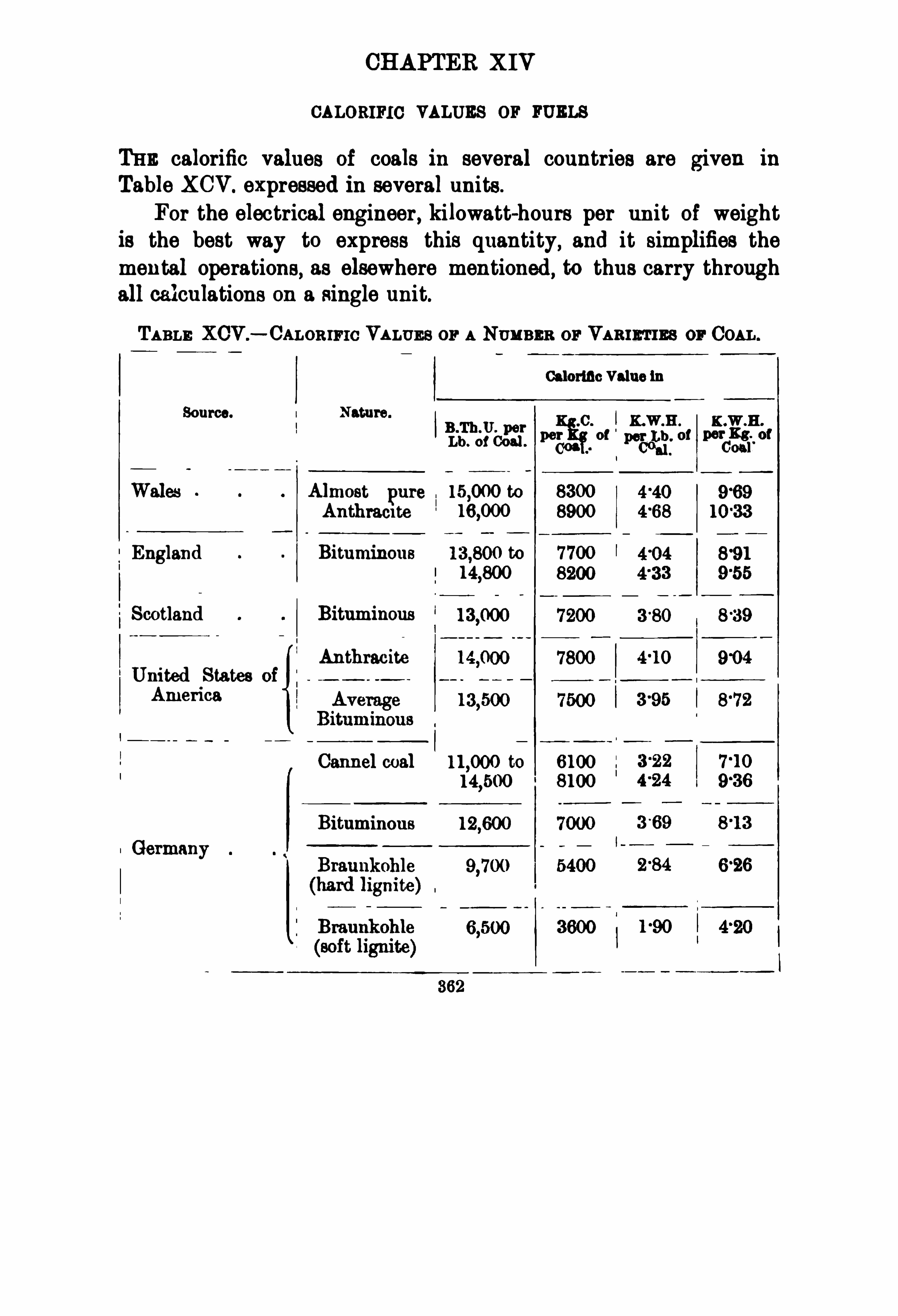
CHAPTER X IV
CALORIFIC VALUES or wa s
THE calorific values of coals in several countries are given in
Table XCV. expressed in several units.
For the electrical engineer, kilowatt-hours per unit of weightis the best way to express this quantity
, and it simplifies themental operations, as elsewhere mentioned, to thus carry throughall calculations on a single unit.
TABLE XCV . CALOR IF IC VALUEs or A NUMBER or VAanrrIEs or COAL.
Calorino Valuc iu
Source. Nature.
0 K.W B K W H.
B .Th.U.
Lb. of033 ”5“ 0
° “001
3: ”055.
Wales Almost pure to 8300
Anthraci te 8900
England Bituminous to 7 700I 8200
Scotland Bituminous
AnthraciteUnited States
America
Carmel coal to 6100
8100
Bituminous
Germany

364 STEAM TURBINE ENGINEERI NG
proportion to the heat required. In testing boilers, it has becomecustomary to base figures on saturated steam at atmospheric pressure , and to further assume that the feed water has a temperatureof 100
°
C. (from and at 212°
Consulting the table above referred to, we find the heat necessary to raise one kilogram of steam to these conditions to be 537kilogram-calories, or 06 25 kilowatt-hours. This permits us to
deduce the values set forth in Table XCVI .
TABLE XCV I .
Kgs. ofSteam raleed per onn . of
Boiler M elency. Coal burned (the Goal has a OalorificValue of 7600115 -calm).
100 per cent.
The foregoing values are generally denoted in the metricsystem as— kilograms of steam “ from and at 100
°
0. per kilo
gram oi coal.In the English system it is customary to speak of the— lbs. of
steam “ from and at 212°
F .
” per lb. of coal.
The general range, in different parts of Great Britain,of the
price of coal of an average calorific value of 87 kilowatt-hours
(7 500 kilogram-calories) per kilogram,is from 4 to 16 shillings
per ton of 1000 kilograms (2200 lbs. For our standard conditionsof steam— an absolute pressure of 13 kilograms per square cm .
and 50°
C. of superheat, and with feed water at 50°
C.— we shall,
with coal of this quality and steam-raising plant of 60x, and
807, effi ciency, get 6930, 8120, and 9280 kilograms of steam per tonof coal. From column 2 of Table XCVII. we can , for coal of thisquality, at various prices in shillings per ton delivered on
site , obtain the cost for fuel in shillings per 1000 kilograms ofsteam produced. In columns 3 to 10 are set forth the cor
responding fuel costs in pence per kilowatt-hour generated, for thecase of steam-driven sets when operatingwith steam consumptionsof 6 to 20 kilograms of steam per kilowatt-hour of output.If the feed water supplied to the boiler has a temperature
other than 50°
C. before entering the boiler, the values given inTable XCVII. require to be altered slightly. For instance, if thetemperature of the feed water is 10° C.,
the values in columns

CALOR IF IO VALUES OF F UELS 365
TABLE XCV lI .
Cost of Coal In Pence per Kilowatt-hour absolute resoure ofSteam 13 Kgs. per sq . cm. 60
°
Cent. Su r as Fee Water 60°
Cent.) at the Steam Consumption of (sta at t c t0p of column) .
K ilogram per Kilowatt-hour.
°
I
§fi
l
‘
I
‘
I
‘
I
‘
l
‘
I
‘
l
‘
l
‘
l
“
I
‘
l
“
I
“
I
‘
l
‘
I
é
° l77
5
u.qq o
b58
5 s?

366 STEAM TURBINE ENGINEERING
TABLE XVCII .— eomi‘
mwd .
Cost of Coal in Peace per K ilowatt-hour (absolute pressure of
Steam 13 Kgs. per sq . cm. , 50“
Cent. Superheat, feed water 60’Cent.) at a Steam Consumption of
Kilogram per K ilowatt-hour.
003 1 03
-254
9 to 10 must be increased by 670 . Table XCVIII . gives suchcorrections.
The effi ciency of the boiler has been given as varying between
602, and It is as well to distinguish between the effi ciencyof the boiler as measured by test and the all-year effi ciency of theboiler. While, in the first case ,
the efficiency is very often as high
as 752, or 8070 , the same boiler may give an all-year efficiency ofonly 5070 or and in some cases considerably lower still.Very often the boilers must be kept under pressure for a long timewithout any work being done, and it is clear that in this case thelosses due to radiation,
which normally rarely exceed 570 to l0°
/nwould increase in importance. The authors have compiled a tablein which are recorded the results for the actual all-year coalconsumption per kilowatt-hour for some stations. All this datahas been obtained directly from the Engineers of the generating

368 STEAM TURB INE ENGINEERING
TABLE XCIX .— CoAL COST AND QUALITY USED I N sons
ELECTRICITY PLANTS.
Coal used. Water.
Name.
bPrlc
r Ton, E
li“: 0
2; 321“fi g,
1 in“ Switchboard . M 8:
12,000 -
5
0°
8d gallon
dry oil
12
lnterboro (Subway),NewYork
Manhattan Elevated,NewYork
Manchester,D icken
son St.
LeedsPinkstonKansas City, Met.
S.R . Co.
42 Salford43 Westham45 Kelham Is.
,Sheifi eld .
46 Alpha Place,Chelsea .
47 Lowell,U.S .A .
52 Reading
53 I lford
55 Leicester
56 Wolverhampton
57 Greenock .
58 Eastham,London
59 Lowestoft .
60 Burton-on-Trent

CALOR IF I C VALUES OF F UELS 369
TABLE XOIX . continued.
Coal used.
Pri er TonKm” Lbs. evapor
So
liLila a. t ated er Lb.
“3 Switchboard. of oal.
Hull TramwaysStalybridgeBurnle
Walsal
Bury, Lance
Eastbourne
Gloucester
Kirkcaldy .
Barrow-ia-Furness
Gillingham
Carlisle
ChathamBarnes
Worthing .
Guernsey, Les Amhalles .
St Sampson 16
Cleethorpes l 1,500 8
Shirebrook
B . W . Allen'
s Test B.Th.U.
“ Rheola. 7900Kg.C. per Kg. , Inst.“On Surface
Condenser Plants,"Feb. 28, 1906.

CHAPTER XV
TYPICAL RESULTS AS TO STEAM ECONOMY IN MODERN
PISTON ENG INES
FOUR representative firms of piston engine builders in England,designated in this chapter as firms A
,B, C,
and D,have very
Rated flutput m [fl/anewFIG . 240.
— Steam Consumption : Firm A’s Reciprocating Engines.
l3 °
4 Kgs. per Sq . Cm. Absolute, 55 5°
C. Superheat, 86°
6 per cent. Vacuum.
l uarter Load II=HalfLoad I II=Three Quarters Load IV=Rated
Full Load.
kindly furnished us with their guarantees as regards steam con
sumption. Firm A builds small engines. Their guarantees,expressed in terms of the kilograms steam consumption per kilowatt-hour output from a hypothetical direct-connected generator,have been plotted in the curves of Fig. 240. Firms B and C
370
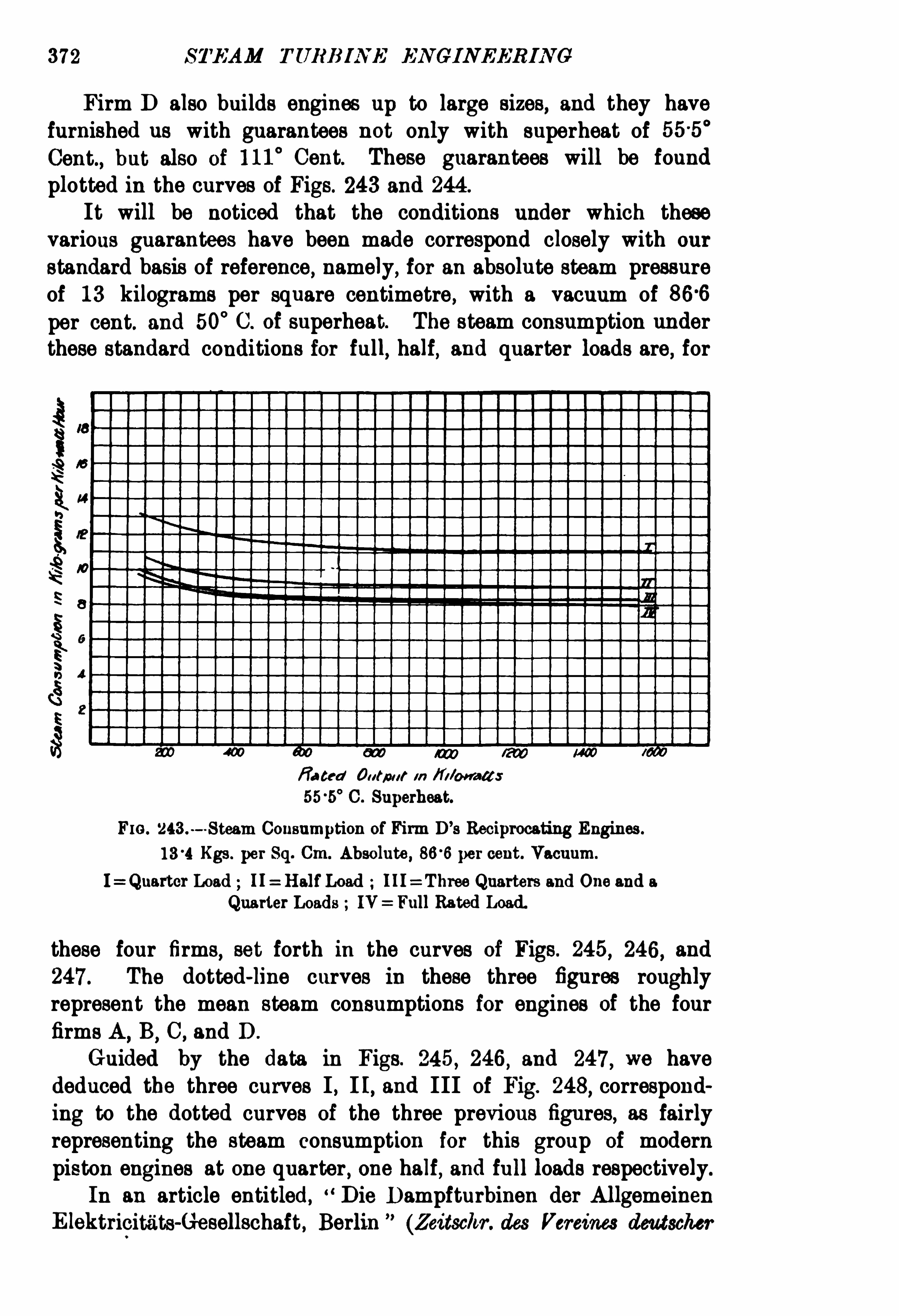
37 2 STEAM TURB INE EN GIN EER IN G
Firm D also builds engines up to large sizes, and they havefurnished us with guarantees not only with superheat of 555 °
Cent., but also of 111°
Cent. These guarantees will be foundplotted in the curves Of Figs. 243 and 244 .
It will be noticed that the conditions under which thesevarious guarantees have been made correspond closely with our
standard basis Of reference , namely, for an absolute steam pressureof 13 kilograms per square centimetre , with a vacuum ofper cent. and 50
°
C. of superheat. The steam consumption underthese standard conditions for full, half, and quarter loads are, for
Rated Output 111 ”donates
C. Superheat.
FIG . 243.-Steam Consumption of Firm D
’s Reciprocating Engines.
Kgs. per Sq. Cm. Absolute , per cent. Vacuum.
I=Quartcr Load I I HalfLoad I ll=Three Quarters and One and aQuarter Loads IV Full Rated Load.
these four firms,set forth in the curves of Figs. 245 , 246, and
247 . The dotted-line curves in these three figures roughlyrepresent the mean steam consumptions for engines of the fourfirms A
,B
,C, and D .
Guided by the data in Figs. 245 , 246, and 247 , we havededuced the three curves I , I I, and III Of Fig. 248
,correspond
ing to the dotted curves of the three previous figures, as fairlyrepresenting the steam consumption for this group of modernpiston engines at one quarter , one half, and full loads respectively.
In an article entitled, D ie D ampfturbinen der AllgemeinenElektricitiitS-Gesellschaft , Berlin (Zeitschr. des Vereines deutscher

STEAM E CON OM Y IN M OD ERN PISTON ENGINES 373
Ingeniowre, August 13th , 1904 ,p. 1209
,Fig. Lasche has pub
lished a curve which he states represents the rated full-load steameconomy of good modern piston engines at an absolute admissionpressure Of 13 kilograms per square centimetre , with some superheat and good vacuum. Lasche’s curve is given in Fig. 249 as
curve L,and the rated full-load curve of Fig. 248 is reproduced as
curve III.F ull Load Steam Consumption Piston Engines
— We
have also compiled in Table C. the full-load steam consumptions of thirty-three piston engines of 19 different manufacturers
fated Output m I l l/meals
111°
C. Superheat.
F IG . 244 .— Steam Consumption of Firm D ’
s Reciprocating Engines.
Kgs. per Sq. Cm. Absolute,86
°
6 per cent. Vacuum.
I=Quarter Load II HalfLoad III=Three Quarters and One and a
Quarter Loads IV : Full Rated Load.
of five different countries. M ost of this data was derived frompublished results. In a few cases the guarantees of themakers were employed. To afford a common basis of comparison
,
the results were reduced,by correction curves which will be
described later in this chapter, to terms of the steam consumptionfor our standard reference conditions of an absolute admissionpressure of 13 kilograms per square centimetre (corresponding to a
gauge pressure of 170 pounds per square inch) , with a superheat of50
°
Cent. (90°
and with an per cent. (26 inches, or 660millimetres) vacuum. Where the results were expressed in termsof the indicated horse-power or brake horse-power, we reduced

FIG. 215.— Full Rated Load.
F IG . 246.— HalfRated Load.
Tat ed Output 10 Elb a-(csFIG . 247 .
— Quarter Rated Load.
F IGS . and 247 .— Steam Consumption ofReciprocating Engines.
50°
C . S
uperheat, 86
°
6 per cent. Vacuum.
A,B,an D 13
‘«i KgS.I
peq . Cm. Absolute.
Dotted Curve Is the M ean ofthe Foui° Full Lines.

STEAM TURB INE EN GINE JRIN G
TABLE C .—D s°
rAILs or RESULTS D ERIVED FROM PUBLISR ED
35
158 126 10 2
158 126 102
100 I 9'
3
385 66 7'55
385 66 7'
53
885 66
375 l l°
1
11 7
440
600 120
625 101
700 101
720 80 15’
0
'
087
’
082
’
134
'
073
‘
044
'
130
'
144
107
85 '
6 8’
4
1 75
680
75 7
50
50
’
130 48'
5 7 7 5
Prof. Schroeter
1900
Prof. Unwin
Prof. Thurston
Dec
—
16, 17102
Prof. Ewing
M . Longridge
May 25, 1893
May 25 , 1893
May 25 , 1898
Feb. 5 1902
May 5, 1901
Where installed.
Leicester Water
Works
Near Manningtree
Lincoln
Augsburg
Do.
Leeds

Manufacturer ofthe ISteam Engine.
Type ofPiston Engine. Source of Data.
Karchova HorizontalTandemCompound Paper by C. V . Kerr, Amer. Soc.
Mech. Bugra. ,vol. xxv.
Hawthorn, Davey CG. Pumping Engine The Engineer , April28, 1905, p. 416.
Kerchove Slow-speed Compound Thr Engineer, January 8, 1904 , p. 47.
DO.
Milwaukee Pumping Engine
Easton 8: CO. Horizontal Tandem 2-cylinderCompound
James Howden 8: Co. High-Speed Triple Expansion E l. Review
, August 18, 1905, p. xxv.
Bellis a Moreom The Engi neer, July 28, 1905 , p. 78
Cole, Merchant a Morley Vertical Cross Compound The Engineer, June 2, 1905, p. 548
Slow-speed Compound
D°° L’
sii
iiIn“
James Howden Co. High-speed Triple Expansion E l. Review, August 18, 1905, p. xxv.
Harrisburg Foundry and Tiindem (bmpound Trans . Amer. Soc. Mech. Eng-rs
Machine Works vol. xxv Dec. 1903, pp. 1— 16.
Slow-speed Triple Expansion Z.d. V.Deut. Ing.. Aug. 19/05,
Compound Corliss E 1. Review, Apri l 8, 1905, p. 575.
Wallsend Slipway and Slow-speed Triple Expansion Proc. Inst. Mech. Engrs. at NewEng. CO. castle. By W. B. Woodhouse.
Proc. Inst. Civil Engra , vol. cli.
p. 200. By T. H. Minshall.
Hick, Hargreaves 8: Co. 3-crank Triple Expansion‘
The Engineer, July 7 , 1905, p. 2.
Work Augsburg Slow-speed Triple Expansion Z.d. V.D cut.I p. 1352.
to caICulate the steam consumptions reduced to our standard conditions, the missing details have
and assumed.
—
The Engineer, April 28, 1905, p. 416.
TheEngineer, Janusry 9 , 1903, p. 46.

STEAM TURB INE ENGINEERING
TABLE C.
Where Installed.
102 l 13°
3 -10
90 °
239 . Aug.
h
Weisbaden850 90 9
-41 -
20 59-2 s
°l Aug 1901
910 60 -077 May 13, 1900
21 1070'
83 °074 June 9 , 1903l
Strasburg
1135'
88 -10
-29
lAug. 14 , Weisbaden
°236 82 I 1 Aug.
Leeds
25 1500 March 1903 Manchester Cor
potation
1600 100 12-1 7 190 51
-8 7
-5 Sept.
1900,83 Oct. Berlin
1900 83 14-2 83 7 2 5 Oct. DO.
1900 83 14-1
-
Oct. 24, 1899 D o.
2600 86 10-3 °082 T 7
-9
2600 86°
082 I 121
2600|86 103 °
082 17 1
29 2800 75'
100 8-84
'
7 5 Apr. 1, 1902 : GlasgowProf. Barr Tramways
30 3200 94'
130 85' Greenwich
81 3800 76 14-0 -105 Feb. 1904
'
New YorkAndrewWitham Edison Plant
andWells
32 3900'
75 14-4
-105 65 5 7
-7 1 Manchester Cor
poration
33 5000 75 NewYork

380 STEAM TURB INE EN GINEERING
The results were divided into three groups of eleven each,corresponding to the smallest, the intermediate, and the largestsizes.
Group I . ranged from 140K .W. to 400 K .W.
I I. 440 K .W. to 1135 K .W.
II I. 1170K .W. to 5000K .W.
The mean steam consumptions at rated full load were as
follows
Group I . Kgs. lbs.) per kilowatt-hour.II . Kgs. lbs.)III. Kgs. lbs.)
The next step consisted in taking the three lowest results fromeach group and averaging them,
as shown in Table CI.
TABLE CI .
Group I . Group II . Group III .
140K .W. to 400K .W. 440K .W. to 1136 K .W. 1170K .W . to 6000K .W.
As these nine results are obtained from engines of sevendifferent manufacturers in four different countries , they may fairlybe taken as indicative of the possibilities of piston engines as atype. One point to note is, that practically as good economy in
steam consumption is obtainable on small sizes as on large sizes.
The results for the thirty-three cases set forth in Table 0.
have been plotted in Fig. 250. In this figure the test resultsare indicated by circles, and the results, reduced to our standardconditions
,have been indicated by crosses. In Fig. 251 the latter
are reproduced, together with curves L and II I . of Fig. 249.
With these groups of data available, the next question thatarises relates to the curve to be adopted as representative of the

STEAfrI JCON OM Y IN M OD ERN PISTON EN GI NES 381
average steam consumption of the best types of modern pistonengines. We consider that Fig. 25 1 affords ample evidence that
R ev/é d Oafiaf M ff/Votwo/f:
Fm. 250.— Steam Consumption ofPiston Engines at Rated Full Load, from
published Tests.
0=Test Conditions. X 0 reduced to our Standard Conditions.
R es/ed OU/fl (If ( I:
Fm. 251.— Steam Consumptions ofPiston Engines at Full Load.
Curves L and III from Fig. 249.
Points X are other published Tests reduced to our Standard Conditions.
even Lasche’s curve (L) hardly does justice to the reciprocatingengine, since considerably better results have frequently been oh

382 STEAM TURB I NE ENGINEERING
tained, and sometimes under less favourable conditions of pressure ,
temperature, and vacuum. That curve III . lies so much higherthan many of the plotted published results may be partly due toits representing a rough mean instead of the best amongst the
guarantees sent us, and also to the necessity,on the part of the
manufacturers, to make suffi ciently conservative guarantees to leavethemselves a margin of safety.
We have finally decided to take as the representative curve forthe steam consumption of piston engines, when operated at ratedfull load
,with an absolute admission pressure of 13 kilograms per
fi afm’ fl lfia/ a?! [ i on /13 .
Fig. 252.— Standard Representative Curve for Steam Consumption ofModern
Piston Engines at Full Rated Load.
Under the Standard Conditions : Absolute Admission Pressure 13 Kgs. per Sq. Cm.
50°
C. Superheat, per cent. (26 Ins. ) Vacuum. (Derived from Fig.
square centimetre, 50°
C. of superheat and a vacuum of 866 percent. (26 inches), the curve shown dotted in Fig. 251. Withregard to this representative curve, it should be noted that Lasche
’
s
curve was deduced from full-load tests, run probably with a bettervacuum and a greater amount of superheat than those of our
standard conditions, the admission pressure being about the same.
A curve derived from Lasche’s, but with our standard conditions,would lie above curve III. Taking this fact into consideration
and also the lowpositions of some of our plotted results, we havedecided that a fairly representative curve for our standardconditions can be obtained by embodying a portion of Lasche
’
s

384 STEAM TURB INE ENG INEERING
and shall in subsequent comparisons consider these as reprosentative values for the steam consumption of modernpiston engines when operating under the specified conditionsof an absolute admission pressure of 13 kilograms per squarecentimetre
,50
°
C. of superheat, and a vacuum of 866 per cent.
(26 inches).VaryingAdmission Pressure : Piston Engines.
— We haveseen in Chapter IV . that very little difference is effected in
the steam economy of the Parsons type of steam turbine byvariations of the admission pressure
,and we believe that it may
Fm. 254.- Variations in Steam Consumptionwith Varying Pressure. Piston
Engineswith 50°
C. Superheat, per cent. Vacuum.
be correctly stated that most of the types of steam turbine,
while more dependent upon the admission pressure than theParsons type, are much less dependent upon the value of thisfactor than are most piston steam engines.
To investigate this point of the dependency of the steamconsumption of the modern piston engine on the admission pressure, we have obtained from two leading English manufacturers ofpiston engines their estimates of the relation between steameconomy and admission pressure. Representing as 100 the steamconsumption under our standard conditions of an absoluteadmission pressure of 13 kilograms per square centimetre
,a

STEAM ECON OM Y IN M OD ERN P ISTON EN GIN ES 385
superheat of 50° C and a vacuum of 866 per cent., then for thesame number of degrees of superheat and the same vacuum thefigures representative of the consumption for other admissionpressures may be obtained from Fig. 254 for the piston enginesof these two manufacturers. We propose to take the dotted lineas representative for piston engines in general.Varying Superheat : Piston Engines
— As to the effectof superheat on piston engines, we have compared useful datafrom seven firms. This data has been embodied in the curves of
o la 20 so N I G W M /Il M / y lu lu /to m
Six/mica, I ) flag / res [mfg/al e .
Flo . 255 .— Piston Engines : Variations in Steam Consumption at Full Load,
with Varying Superheats.
13 Kgs. per Sq. Cm. Absolute, 86'
6 per cent. Vacuum.
Fig. 255 , and the dotted-line curve will be taken as representativeof the effect of superheat on the steam consumption of pistonengines for our standard conditions of admission pressure and
vacuum.
The mean is replotted separately in Fig. 256 , and it is againplotted in Fig. 257 , in terms of the average percentage decreasein steam consumption per 1
°
Cent. of superheat above thetemperature of saturated steam. It should be noticed that thepercentage gain by superheat is well sustained up to very highsuperheats
,and hence piston engine manufacturers have a great
incentive to adopt for a given pressure as high a steam tempera25


388 STEAM TURB INE EN GINEERIN G
The losses due to cylinder condensation play a very importantrole
, and the cost and weight of the whole set is increased con
siderably in striving to make the best use of so very good vacua.
Now,with this data for the effect of admission pressure
, superheat
,and vacuum on the steam consumption
,we can,
from our meancurve (Fig. 252) for piston engines, designed for our standardconditions
,obtain a series of curves -oi full-load economy of piston
engines designed for other conditions. Such a series of full-loadsteam-consumption curves is given in Figs. 258 to 269 .
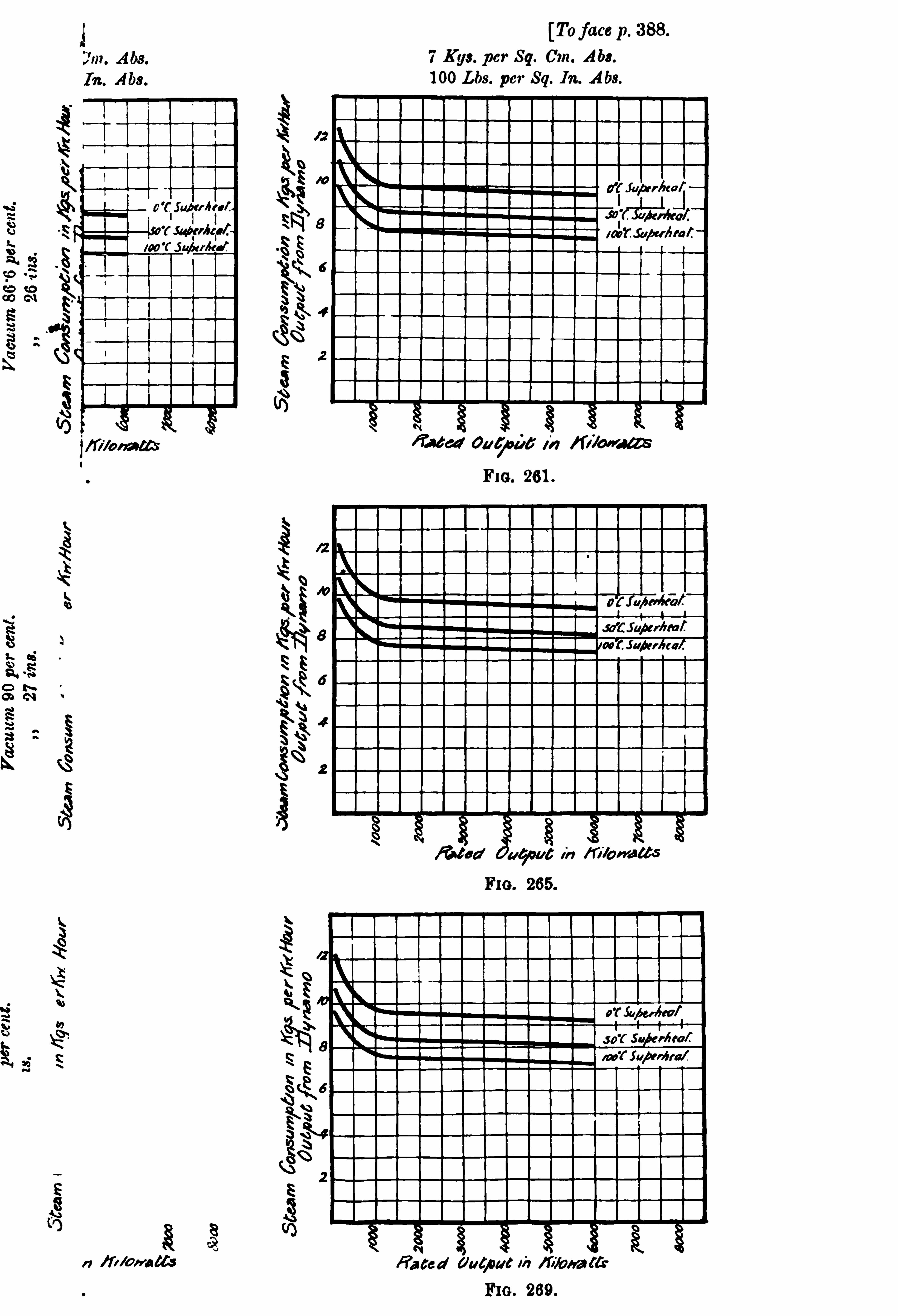


RES ULTS FOR TURB INES AND PI STON ENGINES 391
Rated 00 60 0 6 m Kl /O N 66:
Flo. 272.— QuarterLoad.
Free. 270, 271 , and 272.— Steam Consumption ofSteam Turbines.
13 Kgs. per Sq. Cm. Absolute, 50°
C. Superheat, 86 6 per cent. Vacuum.
P=Parsons, L=de Laval, E=Elektra.
of the reciprocating engines, but also of steam turbines. Nevertheless, our conclusions have only been deduced after a verythorough investigation, and we consider that they give as gooda general comparison between the two great classes of steamengines as can at present he arrived at.
Before we develop for steam turbines a series of curves,similar to those of Figs. 258 to 269 representing piston engines,we must consider the influence of admission pressure, superheat,and vacuum on the steam consumption of steam turbines. The
question has already been considered in the previous chapters forsome of the types of turbines.
For the purpose of comparison between piston engines and
turbines as two classes of steam engine, as regards their respectivesteam economies, we have decided to confine ourselves to theParsons steam turbine, since the data and test results on thistype are far more exhaustive than those on any other ; also the

392 S TEAM TURB IN E IN GINEERING
Fm. 273 — Turbines.
Fm.
‘274.— Modern Piston Engines.
FIGS. 273 and 274.— Representative Steam Consumptions for Turbines
and Modern Piston Engines.
13 Kgs. per Sq . Cm. Absolute, 50°
C. Superheat, per cent. Vacuum.
range of capacity over which tests have been made is greater.From these and other considerations
,this type of steam turbine

394 STEAM TURB INE EN GI NEERIN G
this set of curves i t would be well to describe briefly the curvesrepresented in F igs. 300, 301, and 302. Throughout, the com
Fro. 275 .— Rated Full Load.
Ra ted Outfi t/ 6 m ”Mo ira“:
FIG . 276 .-HalfLoad.
parisons have been drawn between the full-load steam consumptionsonly of piston engines and steam turbines. In Figs. 300, 301 ,

RESULTS FOR TURB INES AND PISTON ENGINES 395
and 302,however, an attempt has been made [Ito represent in
diagrammatic form the increase in steam consumption with the
decrease of load. The abscissae indicate the load, the ordinatesrepresenting the steam consumption as a percentage of that at
fully-rated load.
Fig. 300 is confined to modern piston engines. There areeight curves in all
,representing the consumptions of nine different
engines, ranging in capacity from 30 kilowatt to 1600 kilowatt.
In addition to the actual consumption curves, two limit-curves
FIG . 277.— QuarterLoad.
Free. 275, 276, and 277. ofRepresentative Steam Consumptions,
Turbines and Piston Engines.
Our Standard Conditions : 13 Kgs. per Sq. Cm. Absolute, 50°
C.,
per cent. (26 Ins.
have been drawn,fairly representing what may generally be
considered as the highest and lowest steam consumptions atvarious loads.
A few words concerning curve IX of Fig. 300 will not beout of place at this point. Curve IX is for a 1600 kilowattengine by M ‘Intosh Seymour
,and it will be noticed from
the shape of the curve that the minimum steam consumption
occurs when the engine is running at about 5 load.
Fig. 301 contains similar curves for steam consumptions of

396 STEAM TURB INE ENGINE ERING
steam turbines ranging from 250 kilowatt to 4000 kilowatt out
put. On account of certain difficulties previously mentioned,only the Parsons type has been considered. In this figure, as inFig. 300
,upper and lower limit-curves have been drawn.
In Fig. 302 the limit-curves of Figs. 300 and 301 have
Ema /00qf<5aloerlrafl0 in fl ay / ea: an 4:
FI G. 278.— Variations in Steam Consumptionwith Varying Superheat,Parsons Turbines. (From Fig.
been replotted, the dotted line representing piston engines, thefull line steam turbines. The areas enclosed have been shaded
with vertical and horizontal lines respectively.
From this diagram it is obvious that there is practically no
difference, so far as relates to these sets of tests, as regards thepercentage of steam consumption at full load between the twotypes of steam engines. This diagram is instructive, inasmuch as
it indicates graphically within what limits the steam consumption


RESULTS FOR TURB INES AND PISTON ENGINES 397
at various loads, expressed as a percentage of the full-load con
sumption,can be expected to lie.
Returning nowto Figs. 292 to 299 , it should be noticed that,
under the conditions of a good vacuum and a low admissionpressure, the steam turbine has certainly an advantage over
FIG . 279 .— Percentage Decrease in Full Load Steam Comsumption ofParsons
Turbine per 1 per cent. Increase in Vacuum. (From Fig.
the piston engine. Generally speaking, the highest steameconomies have been obtained with piston engines, though, at thesame time, a point very little inferior has been reached byturbines when working under favourable conditions. As can beseen from the set of figures Nos. 292 to 299
,and also by
reference to figures previously given , it is a notable fact that theemployment of superheat has a considerably greater influence on


RES ULTS FOR TURBI NES AN D P ISTON ENGINES 401
Fro. 297.
Fm. 299 .
Steam Consumptions allwith 100° C. Superheat.
Steam Turbines : Full Lines .
to 209 , and 280 to


404 STEAM TURB I NE ENG INEERING
encountered arising from dealing with high temperatures. In
the case of the piston engine , whose steam economy is so greatlyaffected by the admission pressure, the amount of superheat usedis limited
,on account of the very high temperatures to be dealt
with, owing to the high admission pressure.On the grounds of the utilisation of high vacuum,
thereare certain obstacles in the way of the development ofthe steam turbine
,consequent on the necessity of more perfect
condensing plant. The initial outlay would thus be considerably increased
,though there doubtless will follow a considerable
advancement in the design of condensers, both as regards efficiencyand cost.
So far,these remarks have related only to steam economy ,
though for an absolute comparison there are , of course , manyother points which call for consideration. An exhaustiveinvestigation from this point of view will not be attempted,
but
there is the question of oil economy, which affects the cases bothof piston engines and steam turbines, and is worthy of mentionat this juncture. In districts where the cost of coal is 128. perton
, the cost of oil will generally amount to some 8 per cent. ofthe cost of coal in the case of good modern piston engines. It isclaimed that for the operation of steam turbines the outlay foroil will be reduced to an almost negligible amount (05 per cent.to 2 per cent ). If we take it at 3 per cent. for a district wherecoal costs 123. per ton
,there remains a 5 per cent . advantage for
the steam turbine as far as relates to the combined outlay forcoal and oil. Hence the steam turbine can afford to have an
inferiority of 5 per cent. in steam consumption .
It is too early as yet to attempt to arrive at any useful conclusions as to the relative rates of depreciation of the two typesof engine .
Figs. 292 to 299 give a comparison between piston enginesand steam turbines as regards their respective steam consumptions,but regarding
.
the comparison from another standpoint , namely ,that of commercial efficiency
,a series of curves has been plotted
in Figs. 303 to 310. In the first place, a definition of theprecise meaning of this term,
commercial efliciency,
’
as used
here, should be given.
Taking into consideration the absolute pressure with thecorresponding saturation temperature, and also the amount ofsuperheat used
,the number of heat units per kilogram of steam
requiredwas calculated. Taking the value of the steam consumed

RESULTS FOR TURB INES AND PISTON ENGINES 405
for a certain output (obtained from curves of F igs. 292 to 299)from our previous calculation of the number of heat units perkilogram of steam, we can obtain the total number of heat unitsrequired for that particular output. Having reduced this valueto work units
,such as kilowatt-hours
,the commercial efficiency in
per cent. can be obtained, and takes the form of the expression
Output in kilowatt-hours x 100
Number of kilowatt-hours communicated to the feed water
The value of this expression gives us the commercial efficiencyin percentage of the particular output considered. By thesemeans the commercial efliciency curves of Figs. 303 to 310,
both for piston engines (dotted lines) and steam turbines (fulllines), have been plotted.
In these calculations, of course,no question of boiler and
furnace efficiencies have been dealt with, there being no reasonwhy these should differ in any respect in the cases either ofpiston engines or of steam turbines, further than the considerationthat in the turbine the steam nowhere comes into contact withoil
,and may thus be returned to the boiler more free from
impurities,the boiler consequently being more readily maintained
in a condition permitting of high efficiency.
This set of curves (Figs. 303 to 310) perhaps bring out moreclearly the distinctive characteristics and properties of the twotypes of steam engine. By an examination of the commercialefficiency curves, we can appreciate the relative effects ofadmission pressure, vacuum ,
and superheat. As shown before bythe steam-consumption curves, we can see that as regards increaseof admission pressure the economy and the consequent effi ciency ismore benefi ted in the case of the piston engine, the improvementbeing scarcely appreciable with steam turbines. With superheat
,
also, the commercial efficiency of piston engines is improved to a
greater extent than is that of the steam turbine. With vacuum,
however,the results of improving this condition are reversed, it
having a much more beneficial effect with steam turbines than inthe case of piston engines.
Still another comparison has been drawn up in Figs. 311 to
318. These curves have been plotted in order to show howthe commercial efficiencies of piston engines and steam turbinesimprove with the increase of admission pressure under variousconditions of superheat and vacuum. The axis of abscissa ofeach curve is scaled to represent the absolute admission pressure


Fro . 308.— 16 Kgs . Aha ; 100
°
0 86 6 per cent.
225 Lbs. Abs. ; 180°
F. ; 26 Ins. (From Fig.
FIG . 310.— 16 Kgs. Aha ; 100
°
C. ; per cent.
225 Lbs. Abs. ; 180°
F. ; 28 Ins. (From Fig.
Full Load ofPiston Engines— (P)— and Steam Turbines— (T) Parsons).
Exhaust Pressure s. Superheat 100°
C. in all.


4 12 STEAM TURB INE ENGINEERING
Ou tp u o I n M /mvaws
FIG. 319 — Piston Engines.
FIGS. 319 and 320.— liepresentative Steam Consumptions
All full lines are on our Standard Conditions : 13 Kgs. Abs
Dotted Curves : see Table above.
in kilograms per square centimetre, the ordinates indicating thecommercial effi ciency in percentage .
These curves have been plotted from the efficiency curves ofFigs. 303 to 310, and also from the steam-consumption curves ofFigs. 258 to 269 and Figs. 280 to 291.
Examining this series of curves, it is evident, by the comparisonof the mean slope of the curves for piston engines and that of the

RESULTS FOR TURB INES AND P ISTON ENG INES 4 13
curves for steam turbines, that admission pressure has a much
greater effect on piston engines than on steam turbines. Whilein both cases the efficiency improves as the admission pressureincreases, this improvement is , in the case of the steam turbine,very slight indeed.
It will also be noticed that in the case of piston engines thetwo highest efficiencies are obtained with 100
°
C. (in our curves)superheat
,while the effect of vacuum is not so marked as with
steam turbines. Consider Fig. 316, for example
Fro . 320.— Steam T urbines.
ofPiston Engines and Steam Turbines at all Loads.
50°
C. ; per cent 185 Lbs. Abs ; 90°
F. ; 26 Ins.
Here we see that keeping the vacuum at per cent. and
increasing the amount of superheat from 50°
C. to 100° 0. causesbut slight improvement in the commercial efficiency. Now
,
considering curves C and B,we see that increasing the vacuum
from per cent. to 93 3 per cent., at the same time decreasingthe amount of superheat by 50° C.
,results in a very considerable
increase in the commercial efficiency .

414 STEAM TURB INE EN GINEERING
These curves,therefore
,again bring out the salient character
istics peculiar to the two types of steam turbines as regards theeffects of admission pressure
,vacuum
,and superheat on their
respective commercial efi ciencies.
F igs. 319 and 320, though not the result of comparisonspreviously made, should prove to be of some interest. In Fig.
319 is plotted a set of curves (full lines) representing the steamconsumption under our standard conditions of 13 kilogramsabsolute admission pressure
,per cent. vacuum,
and superheatof 50
°
C.,at various loads of piston engines of particular capacities,
derived from curves in Fig. 253. The capacities indicated are
100 kilowatt,400 kilowatt, 1000 kilowatt, 3000 kilowatt, and
5500 kilowatt.In addition to these, three curves for individual piston engines
are shown in dotted lines. A small table is attached, from whichthe particulars concerning these three engines can be obtained.
It will be seen that the trend of these curves is the same as thatof the full-line curves which have been derived from our originalsteam-consumption curves of Fig. 253.
Curve III. here represents the engine which is indicated inFig. 300 by curve IX.
,concerning which a few remarks have
already been made. This type of engine , met with most commonlyin the United States
,is so designed and constructed that the
maximum steam economy occurs at loads not above i of fullload.
Fig. 320 is similar to Fig. 319, and comprises steam-consumption curves at various loads of turbines of capacities of 100kilowatt
,400 kilowatt
,1000 kilowatt, 3000 kilowatt, and 5500
kilowatt. The curves in this figure have been derived fromthose of Fig. 273, which represent means for steam turbines
generally.
In Fig. 321 these sets of curves have been brought togetherinto one diagram ,
in order to make comparison more easy.
as
regards the relative steam economies of piston engines and
turbines generally, at various outputs. In this diagram thedotted-line curves represent piston engines and the full-linecurves represent turbines. It is important to note
,however
,that
throughout the previous comparisons steam turbines have beenrepresented by the Parsons type, whereas in the comparisonshown in Fig. 321 the curves were obtained from those ofFig. 273, which represent means for steam turbines as aclass.


RESULTS FOR TURB INES AND P ISTON ENGINES 417
16 Kgs. per Sq. 0m.
Fro. 823.


Elam/ate fldmrse / on fi eeeure / é fi gs/oer 5g
Fro. 331.
Fro. 333.
under the Extreme Conditions Absolute Admission Pressures of16 Kgs. and 7 Kgs.
per cent. with a Superheat of 100° Centigrade.

CHAPTER XV II
STEAM PRESSURE, SUPERHEAT,AND VACUUM IN PLANTS
IN OPERATION
To select the most economical plant which fully provides foroperation without inconvenience to consumers, and withoutunnecessary demands upon the operating and maintenance staffs,requires a thorough acquaintance with all that has been done inthis direction.
In parallel columns,for facility of comparisons, various details
of steam turbine and reciprocating plants, reduced to as simpleunits as possible
,have been arranged, dealing with all sizes of
units in existence and all capacities of plants. And these willform a nucleus and a systematic outline for further additions tothis data.
The practical value of such an arrangement of data has beendemonstrated by years of use of similar accumulations of figures,based on the experience of the authors in the design and operationof power plants
,and on their studies of the designs of other
engineers.
The writers endeavoured to accumulate data on steam-pressure,superheat, and vacuum in power stations, using all types of steamdriven generators, as well as data on the power consumed byauxiliaries in each type of plant
,by asking every Chief Engineer to
give answers to a printed list of questions.
The Post Office held back most of the inquiries to foreignengineers , because they ruled it illegal to enclose in an unsealedenvelope a stamped envelope to prepay the reply postage on theprinted forms. The envelopes for England were then sealed. As
so few replies were received, and as considerable variations in theinterpretations put upon the questions would have necessitated
422


428 STEAM TURBINE EN GINE .
‘
RING
M r J . R . Bibbins put before the American Street RailwayAssociation 1 a summary of an investigation of the general practiceas to pressure , superheat, and vacuum in forty-six unnamed plants,using or installing a single type ofsteam turbine, the WestinghouseParsons. It is not possible to say howmany of the Westinghouseplants included in Tables CIII . , ClV .
,were in M r Bibbins’
summary,of which we repeat certain details in Table CV .
TABLE CV.— a suns, SUPERHEAT , AND Vaomm.
A Summary offorty-six unnamedWestinghouse SteamTurbine Plants, investigated
by Mr J. R Bibbins, American Street Railway Association,Oct. 1904, Table B,
p. 201 .
The figures represent the number of plants working under conditions stated at
the head ofeach column, ofcapacity and for the purpose stated on the left hand.
Limits of Superheat. Un its ofVacuum.
Limits of SteamPressure .
D esmezdgfim m“
Inchesof“stem?Use made ofthe
Supply.
w’wo Traction
to
to
to Power
Traction
£000 to Power
to Power
I
Below
Totals . 7 5 9 20 20 9 5
1 Report of American Street Railway Association, St Louis Meeting, Oct.
1904, Steam Turbine Power Plants.”

CHAPTER XV I I I
conmmsnns
A LIM ITED amount of data on the condensers used with some of
the plants mentioned in Tables CI I I . and CIV . is tabulatedbelow.
The conditions under which each station is placed withreference to condensing water largely determines the type and
size of condensing plant ; but, in the absence of complete infor
mation, it is of interest to compare the surface of condensers per
rated kilowatt of plant ; also the relation between condenser
surface and boiler heating surface, and the pounds of steam
condensed per hour by each square foot of cooling surface in the
condensers.
Extra Cost of High Vacuum . Steam turbine manu
facturers are, naturally , continually drawing attention to the
advantages derivable from high vacuum and superheat, and the
question is as often raised as to the increased cost of plant and of
running expense.
The reduction in steam consumption due to increase in vacuum
and in superheat has been investigated in the chapters on Parsons
and de Laval turbines, and a few instances mentioned of tests in
this connection on other types of turbines. I t remains for atten
tion to be turned to the economy of installing plant, at increasedcost, for producing the higher vacuum.
M r J. R. Bibbins calculated three cases of a 2000 kilowatt plantin which the condenser equipment to give 28 inches vacuum costs
£8001 more per rated kilowatt) than an equipment whichwould give only 26 inches vacuum. See p. 434 , Table CX I .
1 The a tra cost is stated by M r Bibbins. For total cost of other plants see
Table VI I ., p. 8, items 28 to 30.

STEAM TURBINE ENGINEERING
TABLE CVI. —Srn u Tonnmns
Surface Condensers in Table 07 1.
1 Chelsea, Lots Rd. . 8 351 1 c.
26 Port Dundee,Gl ow. 37
8 Quincy Point, 5 41! 57X
31 Ourtil Tua eatBtLouia
16 Los Angeles, U.S.A . Wheeler
15 Shameld. 1053000 11 .
27 Ygerfl bde alley ,E .8.
u rumou r. co. e rleea
10 Lanoaahire P . Co. ,
2 l nterboro'
Rapid Tran
si tSubway,N ewYork28 E lberfeld 4 000 4
17A 3 as
178 St Pancraa
18 English M‘Kcnna Co .
20 Harrogate
30 Broad Street, Johnstown, Pa.
, U.S .A .
10 Scarborough
TABLE ( N IL— Some TURBINES AND Exemns
36 Manhattan (E levated) , 13 per Worthin n 10 Nil. N il.NewYork) I .H.P . and 160 p
guar motor
35 Interboro’
Rapid TransitSubway NewYork(see also i’ abovev
v)
32 l ethal-well Clyde alleyB .8. Co.
4 Neaeden,London , M etro
politan B y. Co .
37 ManchesterCorporation 1 500
33 Shieldhall, Glasgow 48000
XYoker 1 inch tubes feet long. c.c .means Counter Current.

$2
8
8
8
8
8
41
40
STEAM TURBINE EN GIN EERIN G
Lowell, Boston and NSt. By. 00 .
Stalybridge
Maker’
s Statement
Paisley
Wolverhampton
BurnleyHarrogate
M iddlesboro'
Worthing
M etr. St. Ry. , KansasCity
Pinkston, Glasgow
M anchester
Leeds
Tests furnished byM irrlees-WatsonCo .
Ilford
DundeeG .N . and C IL , London
East Ham
Wimbledon
PartickTest at 667, of its
rated capacity. inrnished by M ir-risesWatson Co.
1 l-inch tubes.
Steam
Kortlng
Wheeler
2 l-inch tubes.
TABLE CVIII.— Sonn Tunsmns AND
Surface Condensers in Table CK .
TABLE OIL — Sons
TAB LE CX .— REcwnocn mo Excmns
3 Tubes inch, 6'8 1eet long.

COND ENSERS
Enemas wrrn Jm Comm on s.
Vacuum. Air Pumps. Circulating Pumps. ififl‘
m 32:13adll
:
332sE
32:8 s83g
te
EJ ltc'
roa Connxnsnns.
86 B.H.P. plus
pipe friction.
50 so
56 25
es 24°5 t0 %
'
6 so
so as so 5
22 2525
25
21 17 K .W .
wrrn SURFACE Connnnsnns.
main so
gal
1 Power, Jan. 1904 .3 150R .p .m. direct-coupled motor.
3 Onemotor drives both air and circulating pumps.
28

STEAM TURBINE ENGINEERING
TABLa CX.
SuM e Condensers.
80 M aa wRy M . W. Co. 1 1 800Test at 657 of itsrated capacity furnished by M irrleesWatson 00 .
81 Govan
82 Burton88 R ingsend, Dublin .
55 Leicester61 Hull20 Harro toHA Brims own74 Chatham and District .
75 Barnes
77 Guernsey ColeMarchent84 W. H . Booth on
“Con
densingPlant,”Cassier
Hag. Oct -Nov. 1904 .
TABLE CX I . -RBLA 'rrvn ECONOMY l or 28 INCHES VACUUM ova-n 26 M eans
2000 K.W. PLANT, £800 INCB BABBD Cos'r,DUE TO RAISING VACUUM
more 26 INCHES To 28 INCHES.
8, usAverage Hours of 3Load in Service a;
r:K .W . per Day. 1 3
ga
4
1 Report ofAmerican S treet Railway A ssociation, p. 179 , Oct. 1904, M r J. B . Bibbins, SteamTurbine Power Plants.
”Five per cent. interest and 7
°
5 per cent. depreciation on extra cost of
condenser equipment, 015penny per K .W .H . extra power consumed, are charged, and fivepenoc
per 1000gallons for feedwater saved is credited .
3a
.
c.
38.
.
ia
£5
3
0
31“
a
s.
NSRM
53m

436 STEAM TURBI NE EN GINEERING
TABLB CXII .— CoomNo Town s wrrn CONBBNssn or RA'
rnn CAPACITY .
Lbs. ofSteam per
Hour Condensed.
Tower D imensions. Fans.
Data fromI
Length ,Breadth. Height. D iam. to
l{ill
-lye
I
W . H.
15 000
2000 40
K.W. sq . ft. tank 78 none 30°
F .
30ft. diam. none
K .W . sq . ft.
1 This assumes 16 towers total. The drawing in Proc. Inst. Electrical Engineer , Dec.
’
06 , is
unfinished.
9 M essrs T. Sugden 0.Co. rate the Neasden plant at gallons, cooled per hour in the
height of summer from 110“F . to 80
’
giving with t he condensing plant installed 27 inches
vacuum at normal load and 26 inches atmaximum load . See items 67 to 7OA ,
“ Neasden, and
Fig. 404 , p . 660.
FIG. 334 .
— Surface Condenser Plant at Partick, per Hour,
2300Sq . Ft. Test in Table OX . p. 432.

COND ENSERS 437
Fig. 334 shows the M irrlees Watson surface condenser,with
one motor driving both air pump and circulating pump, installedat Partick. The makers kindly supplied test results stated in
Table CX .
TABLE CXI II.— M ARINB CONnns Bs : CONDBNBBB SunrAc s AND Boa a
Sune s lN sou s Vasss scurrrnn wira Sm u t TunBrNBs .
Steam per hour. 2 Ratio RatioF
Condenser At”0
L,Name of Vessel. Surface : Speed Lbs r
Surface to £2,sq . ft. Knots. i331 Boiler Heat
Cbt
iidenser ing Surface . Crate.Area.
” 9°
19 1 000 24
5 88018
23
22 18
I t wil l be noted that of the fewturbine vessels whose rate of
condensation per square foot of surface is stated in Table CX III . ,
only the Viper approaches to the figure stated as ordinarymarine practice
”
in Table CX IV .
In the turbine set installed at Fulham, illustrated by courtesyof M r A . J. Fuller, on page 558 (Fig. the condenser
,which
is of the subbase type, is set out of sight belowthe engine-roomfloor level.Some details and illustrations of the condensers in use at Lots
Road,Chelsea ; Neasden ; Carville ; Delray, Detroit ; L. Street,
Boston ; Quincy Point ; Yoker ; M otherwell ; Thornhill ; Radcliffe ;Brimsdown ; and English M
‘Kenna Co. are included in ChapterXX I I . , pp. 454— 629 .
There are also references to pages containing illustrations inconnection with the different types of turbine described in the
earlier chapters of this book at the end of this chapter (on p.

438 STEAM TURBINE ENGI NEERING
It is of interest here to indicate the range of experiments
described in M r R. W. Allen’
s paper on Surface CondensingPlants,
”read before the Institution of Civil Engineers, Feb
ruary 28,1905 , by the following brief notes on it and on the
discussion.
TABLB CX IV .
Lbs. ofAir Pump Capacity.
Steam Condensed perHour per Volume per Volume inSq. Ft of 1 Lb. of
Volume ofCondenser Steam
CondensedSurface. Condensed .
Steam.
Mr B. W . ALLnn’s 800 sq . ft. condenser
Experiments with engine 5 to 25without engines 5 to 10
Coolingwater used 40 to 120 times the}isht of steam
Ina
nited States with very largeturbines, 2-stage air pump
Mr Allen'
B own equally good resultswith single-stage air pump
Mr W. J . HARD ING had under noticesingle-acting air pump
Three throw air pump , 1000 s
q. ft
}condenser . (3MM r Allen
’
s rule 06 to 19 to 23Ordinary Marine Practice as much as .
See also Table CXI I I .
Cla med for concentric condenserAdmitted for concentri c condenser
M rW. H . PAN BmEveryday work of condenser with
cooling tower 30 ft. diam. on roofdealing with steam from 800K.W .
engine. (Pumps use 8 5 per cent. ,fans use 2 5 per cent. of mainengine input).
Large-steam turbine he had inspected.
M r Farm. EDWARDS disagreed with the usual velocity ofwater through tubes, via , 200to 300
feet per minute .
He mentioned that the mercury gauge reads 0 25 inch at absolute vacuum,while his own
design ofgauge reads correctly .
Mr HARVEY E. M OLBprefers 2-stage dry-air pump to wet~ s ir pump.
He quoted the specifi cation of N.Y .C. a H.R.B . Co. for “ 2-stage dry-air pumps, guaranteed
hotwell water within 1‘
F . of the temperature corresponding with the vacuum in the
condenser.
He stated t hat Lots Road, Chelsea, and Neasden have dry air-pumps, and water is taken out
practically as hot as the vaporised steam.

440 STEAM TURBINE EN GINEERIN G
two 1000 K .W. Parsons-Peebles sets, with one A llen condenser
(4400 sq. at Poplar, London.
Other condensers are illustrated in connection with turbineson pages 207 , 224, 252, 286, 314 .

CHAPTER X IX
FOUNDATIONS
THOUGH some advocates 1 of the steam turbine would have
this subject passed over as unimportant, the foundations in
the elevation of nearly every turbine plant that has been builtare a very prominent feature.
M r E. H. Sniffin, ofM essrs Westinghouse, Church, Kerr Co.,
put forward3curves of the cubic yards and cost of foundations
for various arbitrary combinations of steam generating units.
Fig. 337 and Table CXV. compare his foundations with those of a
few recent steam turbo-generators. M r Sniflin’
s results are here
reduced to the volume for one steam-driven unit,this being
‘
a
practical basis.
M essrs Willans Robinson’
s foundations for two 1000K .W.
turbo-generators are of interest in the following table. As stated
there. the turbine and condenser occupy the same position in plan.
We have taken the liberty of assuming 3 feet depth of turbine
foundation below the basement floor on which the condensers
stand, but have not included the foundation under the condenser.
The weight of condenser plant is, however, included, as noted, but
its effect on the pressure per square foot is small .The Central London Railway Allis horizontal cross compound
engine foundation natural ly meets M r Sniffin’
s curves. The
1 The following extract is not justified by any turbine we have seen As
iswell known,the absence of any kind of vibration or external thrust permits
the employment of any kind of foundation of sufi cient strength to sustain
the dead weight.”— J. R. Bibbins, p. 187 , Report, American Street Ry. Assn.,
Oct. 1904 .
3American Street Railway Association, Report of Meeting, Oct. 1902, at
Detroit, p. 182. The price in America for concrete foundations laid was givenas 37 , about 29 shillings, per cubic yard.
441

442 STEAM TURBINE ENGINEERING
W u to m/ 76 .5 $ 442 4 sw
U s “.300
.
m”00

444 STEAM TURB INE ENGINEERING.
Interborough (Subway) , New York , 4 cylinder-engine foundationshould, of course, lie above the curve V and belowH
,if H were
plotted so far. The vertical turbine CT fallswell belowthe Parsons,while Chelsea, equipped with vertical condenser andWestinghouse
Parsons sets,is considerably above M r Snifiin
’
s estimates for
turbines.
Flo. 337A .— Section thro ugh NewYork Edison Co.
’s New K.W. Waterside
Station (No. See also pages 455 , 481 , and 491 .
Approximate scale 1 570.
CHAPTER XX
BUILDINGS
THE areas and volumes of engine-rooms and boiler-houses are
given below,taking first those steam turbine plants on which
data has been secured, then some mixed plants, and finally some
reciprocating engine plants. The item numbers correspond withthose in Tables 0111 CIV .
, p. 424 , on pressure, superheat, and
vacuum in use in the same plants.
In every case where the ultimate capacity Of present buildingsis known the useful figures are based on it, but in other cases the
size per kilowatt installed is the best that is available.
This table is intended for use when preparing preliminaryestimates, as one can form from it a very definite idea, based
on named existing plants, of the dimensions necessary for any
probable arrangement of generating units.
Plans of sites of some recent turbine plants are shown on
pages 4 55 , 464 to 467 .
Exterior views of seven Power-Houses will be found on pages
468 to 474 (Figs. 343 to
Sections and plans of buildings are on pages 444 and 470
to 490.

STEAM TURBINE ENGINEERIN G446
Ultimate Rated K .W.
Present Buildings.
8
28c
.
m38
38
383:
83
:
ImmImmmI
_
m>
E
mmm«a
mm
8
382
a
8a
a ) v v fl fi v o m v m wmm m mwfl fl fi —n n mwNumber.

STEAM TURBI NE ENGINEERING448
aw
.
3
1m
Sade-moms
.
Beoa
ée—uun
ens—o
b
Fa
P
m
Ultimate Rated K .W.
Present Buildings.
installed.
Total Rated K .W.
A
Power Factorincluded.
PIm
ouv
on»
on“
ooo
$
2co
co
oou.
mo
onm
c
aZN
onm
oo~
I
onR .p.m.
oov
oom
ooo
ow
or;
oom
om“.
was
com.
ooo
on
own
coo
oon
ooo
com
oow
oon
Rated K.W .
co m m en tat o rs!.N fl fl fl fi fi h fl fi fi‘G N
Number.
Reference Number.

449BUILD IN GS
lah
on”
ooo
ooo
omm
cow.
o
fi .
o
zo
zomm
ooo
ooo
ooo
ooo
oca
oom
our.
ooo
onm
ooo
o
fion”
mac
ooo
ooo
ooo
mafl
ooo
onv
ooo
r i fl e-‘ rfl fl m N N fl H H fi m N r-d r-‘ fl

450 STEAM TURBINE ENGINEERING
E t.
g3:Ultimate.
Ede$335 3 Installedsass
rs we orQ
Ultimate.
Installed.
Ultimate
Total Rated K.W.
installed.
Power Factorincluded.
5t:o
to
gR .p.m
El o o o o g o o o o o o o o o o oRated K .W.
W l assas saras eaae
ee
3
Number.
H H r-s fl fl lo fl m N N fl N N N n v N N r-t fl fl wfi
Reference Number.

CHAPTER XXI
BOILER AND SUPERHEATER sUBrAcIr. INsTALLBD
A TABLE of boiler heating surface, grate area, superheater surface,
and economiser surface for some of the plants enumerated above
is given here.
TABLE CXIX.— BOILBB HEATING SURFACE , SUPERHEATER SUBrAOB , GBAT s AREA,
AND EOONON IBBB SURFACE IN sous ELECTRICITY PLANTs.
Boiler Heating Boiler Grate SuperheaterSurface. Area. Surface.
Economiser Surface.
Sq . ft. er Sq . ft. r
Name. Rated {.W. Rated 20
W.
01 2
008
YorkshireNe tune Bank, Newcastle
ifax
emI”xéi-o
Kifdenm’
mi
ter
Yoker, Clyde ValleyMot herwellInterboro
’
(Subway). N.Y . someManhattan Elevated, N .Y .
Manchester D ickenson St.
Pinkston,GlasgowKansas City M et.
Metro olitaln,Paris
Salfor
West HamC. L. Railway

BOILER AND SUPERHEATER S URFACE INSTALLED 453
TABLE CXIX.- continued.
Boiler Heating Boiler Grate SuperheaterSurface Ar“ . Surface .
Eeouomiser Surface.
Sq . ft. per Sq . it.
Name . Rated K .W . RatedN .
BOUND
none
64 Walsall65 Bury, Lanes66A Eastbourne 87 non
condensed668 North Shore Railway, San crude
Francisco Oil67 Gloucester 5
-9
68 Kirkcaldy lo's69 Barrow-ln-Furness708 Hamilton7 1 Smithfield Market none
72 Gillingham .
73 Carlisle74 Chatham75 Barnes76 Worthing77 Guernsey, Les Ambelies
St Sampson78 Cleethorpes none
New York Edison, Water 100side No. 8
.
c.-ma
s
don
g325
6&
a.
.
m
se..
q
ca
n
D

CHAPTER XXII
EXAMPLES OF STEAM TURBINE PLANTS
THE following pages contain a digest of essential details of a
number of the latest steam turbine plants.
This listing of corresponding parts of plants in parallelcolumns (starting from the coal pile and advancing to the
kilowatt) is commended to students as of value, because it
facilitates reference to the details which everyone concerned in
arranging such plants must study and compare.
In the Preface will be found acknowledgment of the assist
ance rendered in the collection of this data,and a considerable
part of it and many of the illustrations are from the valuabletechnical papers to which credit is given.
The compilers venture to think that if technical papers wouldadopt such a standard outline instead of, or supplementary to, theusual text descriptive of new plants, that their readers wouldappreciate and derive more benefit from the data. It would beessential to reproduce each time the same spacing of the outlineform to permit immediate comparisons by placing the new data
alongside the earlier collection.
The plants included here are Lots Road,Chelsea ; Neasden ;
Carville ; D elray, D etroit; L. Street, Boston ; Quiny Point; Yoker ;M otherwell ; Thornhill ; Radcliffe ; Brimsdown ; and English
M ‘Kenna Co.
The New York Edison Company’
s NewWaterside Station is
illustrated,by the courtesy of the Power Publishing Co.
,on pages
444,455 , and 481. The capacity of this station will be
K .W.,with ultimate capacity,with present sizes of units, of
These units,mentioned on pp. 147 and 209
,are the largest that
have been undertaken.

456
1. Name of Generating Station
STEAM TURBINE ENGINEERIN G
2. Cost per ultimate rated K.W. £44. for K.w.
l
capacity
Owners
4. Location
6 . Frontage
7 . Supply to Consumers
8. Consumers
l l .
12.
19.
Type ofStructure
Maker ofFrame
Erection b14. WharfWe 1
15 .
16.
17 .
18.
19.
20.
21.
22.
23.
24.
25
26.
27 .
28.
29.
h and.
HeightPlan
11
0 Buildings
D imensionsBoiler houseEngine roomTransformer H.
SectionalElevation ofBuildings
Roof-glazin00Basement
Floors ofBoiler roomWalls ofBoiler room
Floor ofSwitchboard Galleries .
Floor of Engine room
Walls ofEngine-room
Staircases
Electric LiftDelivery of Goal
.
to Powerhouse, one end
1 Electrical Review,June
Underground Electri c Rys. Co. ofLondon, Ltd.
Chelsea,London. Fig. 338.
acres.
824ft. Lots Road, Chelsea ; 1100ft. on the
RiverThames and Chelsea Creek.
11,000 volts,3 phase, 335 cycles, to 24 sub
stations 600 volts continuous substations.
Metropolitan District Railway Baker Street
and Waterloo (Tube ) Railway CharingCross
and Hampstead (Tube) Railway ; Edgewareand Hampstead (Tube) Railway.y
Ri 343, 344, p. 468.
85 t. belowLots Road.
220 of concrete.
140ft. high to peak ofboiler-house roof.
See Fig. 350, p. 470.
Eclipse,’ by Mellowes ArCo. ,
Ltd Sheffield.
18ins. above highest recorded tide 3 feetbelowthe level ofLots Road ; 19ft. head room : 3
parts : 2 for ashes, middle for pumps.Concrete and expanded metal
Checkered steel plates.
ofsteel to bunkers at each chimney.Basement to the second boiler-room floor.A t West End by Railway. West London
Extension Railway runs over hoppers on
opposite side, Chelsea Creek.
An inclined bucket conveyorwill be erected to
span the creek .
IContinued on p . 492.
p. 938. 24 substations and 300 miles of cable
presumably included. Power house probably under £30 per K.W.
6000 tons ofsteel frame. Brick and terra-cotta
panelled.
British Westinghouse Co .
Mayoh Haley (the Fulham SteelWorks
Portland cementfacedwith Stafl'
ordshire blocks.980ft. long, 30ft. high.
See Fig. 351, p. 47 1 .
453511 long by 175ft. wide.
looft.
75ft.

EXAM PLE OF STEAM TURBINE PLANTS
l . Neu den.
3. Metropolitan Railway Co. Newcasilaiupon
-Tyne Electric SupplyCo .
4 . Neasden, London, N .W. Carville. Fig. 339.
2. 3670 square yards.
7 . 550 volts continuous current from 6000 volts, 8 phases, 40 cycles.9 substations, volts, 3 600 volts continuous current from 5
phases, 33gcycl
8. Metropolitan Railway Company and 37 miles double track, North-EasternBranches. By.
9. Fig. 345 , p. 468.
10. 8ft. deep by H R. 6ih . wide, concrete.
11 . Engine house,
red brick and buff Steel frame, filled in corrugated
terrac otta ; boiler house, steel and iron.
red brick.
12. Heavywork b Hein, Lehman 8: Co. ,
details by rman Long.
13. British Westinghouse14 . None.
See Fig. 353, p. 473. Fig. 355, p. 475.
324ft. long by lOlft. wide.
63ft. by s2lft.Engine
-room, 2332ft. by 43§ft.Transformer house, 66ft. by 485i?“46ft. basement floor to bottom chord
See
d roof truss.
353, 472.Manages dzCd
)
, Ltd.
Concrete, with 2in. of granolitli ic
surface.
24 . Blue bricks.
26. Concrete and expanded metal.26. Concrete and mosaic, themain genera
tors resting on brickwork jackarches.
33° Ofsteel.
29:At south end : Siding of Metropolitan By N .E. Ry. Co. Au overhead sidingRailway, running over hoppers. (1 in 25 grade), conveyed by electric
locomotive, two 75 horse powerWestin house 500 volt motors.4 M .P. Overhead conductor ; Bowcollector.
[Continued on p . 493.

458 STEAM TURBINE EN GINEERIN G
1 . Name of Generating Station Delray,U.SA .
2. Cost per ultimate rated K.W.
capacity
Detroit Edison Co .
4. Location Delray,3; miles from Detroit, M ich.
5. Area 39 acres. Fig. 340, p. 466.
6. Frontage
7 . Supply to Consumers
8. Consumers Edison Illuminating Co. Peninsular Electric
Light Co. D etroit United Railways.
Fig. 346, p. 468.
11 . Type ofStructure Steel frame, brick panelled.
12. Maker ofFrame
18. Erection by14 . WharfWall
Len th and Height15 . Plan 0 Buildings Two boiler-rooms
,separated by a firewall, and
one turbine-room. Fig. 356, p. 476 .
16. Dimensions17 . Boiler-house 158ft. wide, 162ft. long.
18. Engine-room 51ft. wide, l 79ft. long.
19 . Transformer H.
20. Height
21. SectionalElevation ofBuildings Figs. 357 and 358, p. 477 .
22. Roof-glazin23. Basement oor Reinforced concrete.
24. Floors ofBoiler-room
25. Floor ofSwitchboard Galleries26 . Floor ofEngine
-room
Walls ofEngine-room
27 . Staircases
28. Electric lift29. Delivery of Coal to Power By rail to a coal tower farthest from the river.
house,one end In this tower, coal is hoisted, crushed, and
screened.
[Conti nued on p. 494 .

460 STEAM TURB INE EN G INE ER IN G
Yoker.
2. Cost per ultimate rated K.W.
3. Owners Clyde Valley Electrical Power Co.
4 . Location On bank ofRiver Clyde.
5. Area
6 . Frontage
7 . Supply to Consumers 3 base, 25 cycles, volts . (In Clydenk from 2— 150 K.W. motor generator sets
in first switch gallery.)
From 2 substations.
9 . Buildings Fig. 347 , 468.10. Foundations
p
11 . Type ofStructure
12. Maker of Frame
13. Erection b14. WharfWa l
h and Height15. Plan 0 Buildings
16. D imensions
17 . Boiler-house 186ft. by 5oft.18. Engine room 252ft. by 43ft. 6ins.
19. Transformer H.
20.
21. Sectional Elevation ofBuildings22. Roofglazin
0023. Basement
24. Floors ofBoiler-roomWalls ofBoiler-room
25 . Floor ofSwitchboard Galleries .
28. Floor ofEngine room Italian mosaic.
Walls ofEngine-room . White glazed bricks.
27 . Staircases28. Electri c Lift29. Delivery of Coal to Power By rail to private siding, dumped by‘
a hyhouse, one end draulio ram into the crusher hrough
a crusher and screen opera by a motor,10H.P. enclosed shuntmotor, 650R.p.m.
[am oun t on p . 496 .

EXAM PLES OF STEAM TURB INE PLAN TS 461
2. Motherwell is a duplicate of Yoker, £45, including 6000K.W. Transmisu onexcept condensing plant. 000 K.W. See details in
3. Clyde Valley.
between River Calder and
Fig. 342, p. 466.
7 . 3 phase, 25 cycles, volts. volts, 50 cycles, 3 phases
volts, 50 cycles, 3 phases ; 500 voltscontinuouscurrent ; 400volts,50 oles,3phases ; 230volts, 50cycles, 3passes.
8. From 10 substations. Colherias, etc.
Fig. 348, 469.
3ft. bed 0 concrete overwhole area.
Steel frame, brick panelled.
Redpath, Brown 4; 00 .
Fig. 364, p. 485.
16.
17 . was. by 50ft. 70ft. b son.18. 252ft. by 43ft. looft. y19.
20.
Fig. 365, p. 484.
By road, rail, or river. Into hoppersbeneath road and rails.
[Continued on p . 497 .

462 STEAM TURBINE ENGINEERING
3. Owners Lancashire Electric Power Co.
4. Location Radcliffe, between the River Irwell and the
Lsncashire 8: Yorkshire Ry.
5 . Area 20acres area is secured.
6. Frontage
7 . Supply to Consumers volts, 3 phase current, an area covering1200 square miles.
Fig. 354 , p. 474.
Piers
11. Type ofStructure
Erection b
WharfWa
Len h and Height
Plan 0 Buildin
D imensionsBoiler-house
Engine-room
Transformer H.
Height
SectionalElevation ofBuildingsRoof-glazin
Basement oor
24 . Floors ofBoiler-roomWalls ofBoiler-room
25. Floor ofSwitchboard Galleries26 . Floor ofEngine
-room
Walls ofEngine-room
Staircases
None.Delivery of Goal to By railway, a single line near the
house,one end buildings, containing hoppers. Each truck
is hauled and tipped by electric loco-craneinto one of the hoppers (oul one at resent).Stothert Pitt, two G. E. 8 B.TIEmotorsfor hauling and one 30H.P. motor for hoisting or tipping, overhead trolley 220volts.
[Continued onp . 498.

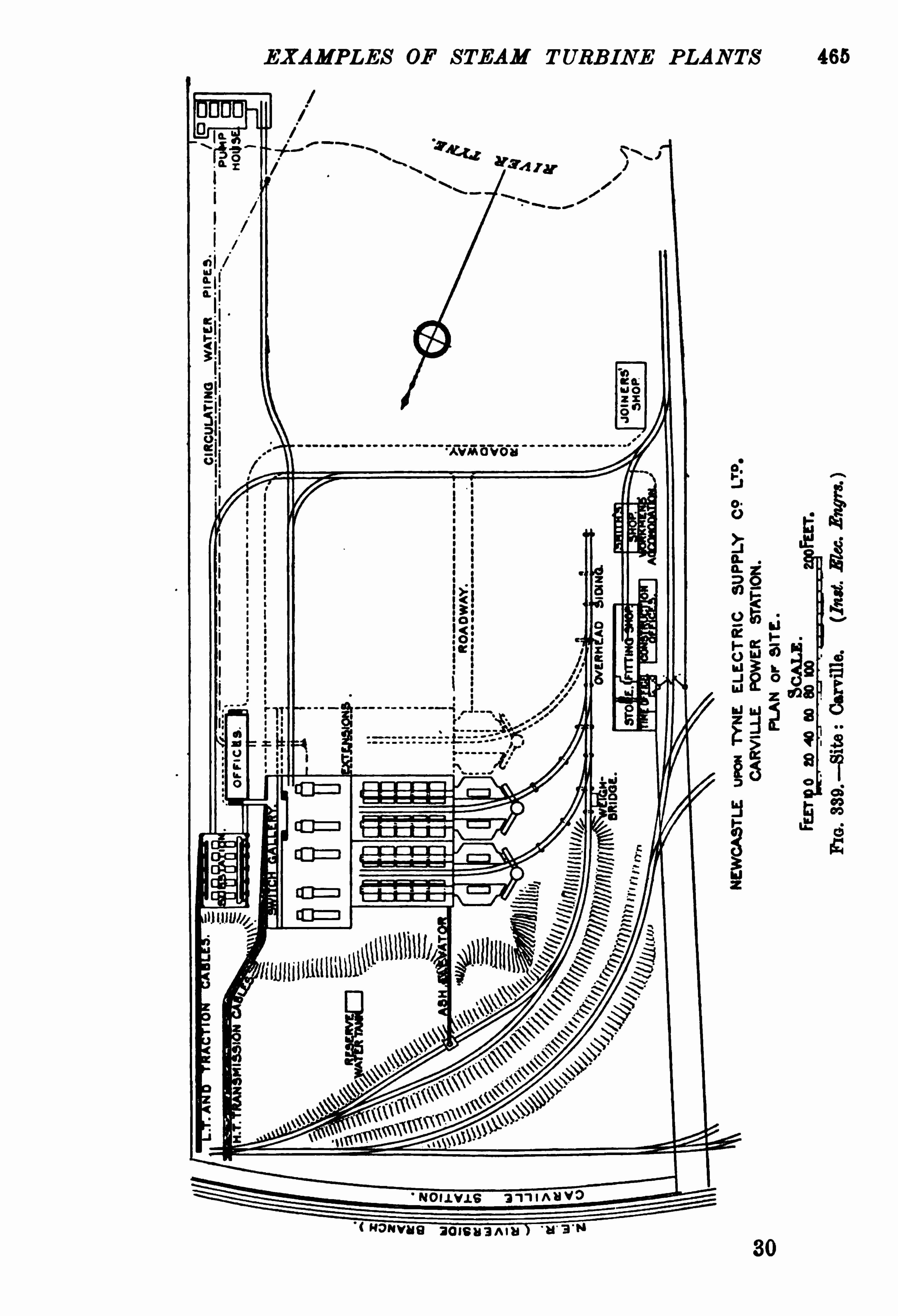

466 STEAM TURB INE ENGINEERIN G
SaltWell
m nReta ining run
it “4
FORT WAYNE
FI G . 340.— Site : Delray, Detroit.World and Eng
'r. )
lame cue-shes
m a m .
FIG . 342.— Site : Thornhill R EL — Y orkshire Power Co.


47 6 STEAM TURBINE EN GINEERING
FIG . 356.— D elray
,D etroit : Plan ofPower-House.
W'
orld and Engr. )
FIG . 358.— Delray, Detroit : Boiler-House.


482 STEAM TURBINE ENGINEERING
FIG . 362.— Quincy Point Plan of Power-House.


492 STEAM TURB INE EN GINEERING
Name of Generating Station Lots Road, Chelsea. [From p . 456.
30. Conveyors See Figs. 371 , 372, 373, p. 508.
Conveyor capacity AtEast End ofpower-house bywater.
driven by A tidal basin spanned by cranes.
Speed of travel
Direction oftravel
M otor driving Conveyor
31 . Wharf Cranes : Number 2
Capacity 1}tons grab on each.
Maker Beecham 8L Kostman, Duisburg.
Driven by Electric Motors Horse-powerSupplied by Conductors in slotted conduit.
32. Coal Weighed Automatically in tower, thence through
hoppers to
33. Rubber Belt Conveyor At ground level. Belt 380ft. by 30in. by i in.
Driven by 15 horse-power, 220 volt, 3 phase motor.
Belt delivers to 2 Crushers .
3 1. Co nveyors outside Power-house
Number ofBucketsDriven byMaker ofConveyorSteel inclined Tower
35 . Conveyors above bunkers
20 horse-
power motors
,220 volts, .3
Ebsee,
teach be On same'
des Narrow auge
Railway Track for Coa t ippin devi
Maker ofConveyors Mead , Morrison 65 Cc. ,New or
36. Bunkers : Capacity tons (3 weeks’supply) ; ton per
ultimate K.W. capacity.
37 . Daily Consumption 800 tom.
38. Coal fed to Boiler By gravi ty through chutes.
[Continued on p . 500.
Inclined. Fig. 373, p. 508.
240 tons per hour.
l 45i ft.154, spaced 2ft. 8ins. apart.
30horse-power 3 hase motors at top of each.
John A . Mead o. ,NewYork.
Mayob Haley .
2 Rubber belts 97oft. and 980ft. by 2ft. by
fi in.

EXAM PLES OF STEAM TURBINE PLANTS 493
Carville.
32. Automatically by Avery machines, Automatic weighing machine to stoker
fitted into shoots between bunkers hoppers.
and stoker hoppers.
3 phase motors, 440 volts.
Graham, Morton 8: Co Ltd.
35 . Continuous bucket type.
36. 1500 tons. 1200 tons. Dimensions ofbunker is 95ft.length, 22ft. wide, 14ft. deep steel
87plate divided in 5 compartments.
88:Through hoppers, by gravity. From bunkers, through cast-steelmouthpi eces.
[Continued on p . 501.
[From 457.
Waggons, before passing to the bunkers,have to pass over a weigh bridge,operated electrically. Motoroperatedforward raises we on on flanges of
its wheels, sco es waggon,
sets
signal points, recordsweight. Switchreversed, it lowers waggon, clearssignal andwheels.

494 STEAM TURB INE ENGINEERING
Name of Generating Station Delray, U.S.A. [Fromp . 458.
30. Conveyors
Conveyor capacity
driven bySpeed oftravel
D irection of travel
Motor driving Conveyor
81. Wharf Cranes : Number
MakerDriven bySupplied by
32. CoalWeighed
33. Rubber Belt Conveyor At ground level.
Driven byBelt delivers to
84. Conveyors outside Power-house
Number ofBucketsDriven byMaker ofConxeyorSteel inclined Tower
35. Conveyors above bunkers From coal towers to bunkers.
70 tons per hour.
Maker ofConveyors
36. Bunkers : Capacity tons.
37 . Daily Consumption . 215 to 300 tons.
88. Coalyfed to Borler By gravity .
[Continued on p. 502.

496 STEAM TURB INE EN GINEER ING
Name of Generating Station Yoker. [From p . 460.
80. Conveyors
Conveyor capacity
driven bySpeed of travel
Direction of travel
Motor drivingConveyor
31. Wharf Cranes : NumberCapacity
MakerDriven bySupplied by
32 . Coal Weighed Automatically , each hundredweight recordedon indicator.
83. Rubber Belt ConveyorDriven byBelt deliversto
34 . Conveyors outside Power-house
Number ofBucketsDriven byMaker ofConveyorSteel inclined Tower
85. Conveyors above bunkers Bucket Conveyor to bunker above boilers,Graham
, Morton 63 Co.
15 horse-power enclosed shunt motor.
Maker ofConveyors
86. Bunkers : Capacity
37 Daily Consumption38. Coal fed to Boiler Through chuteswith motor-driven agitator to
prevent coal sticking.
[Continued on p . 504 .

EXAMPLES OF STEAM TURB INE PLANTS 497
Motherwell. [From p . 461 .
By automatic measuring chutes.
Buckets 1 cu. ft. each convey 25 tons
per hour. 45ft. per minute in either
irection,10 horse-power, 750 revolu
tions per minute , 220 volt motor,Babcock Wilcox.
By gravity through chutes.
[Continued on p . 505 .
32

498 STEAM TURBINE ENGINEERING
Name of Generating Station [From p. 462.
30. Conveyors See Fig. 375athighest level, also item 32 below,
p. 511.
Conveyor capacity
driven bySpeed oftravel
D irection oftravel
M otor driving Conveyor
31. Wharf Cranes : Number . Electric locomotive crane.
Capacity
MakerDriven bySupplied by
32. CoalWeighed
33. Rubber Belt ConveyorDriven by
“
Belt delivers to
84. Conveyors outside Power-house
Ca ity
Number ofBucketsD riven byMaker ofConveyorSteel inclined Tower
35. Conveyors above bunkers
Maker ofConveyors
36 . Bunkers Capacity
37 Daily Consumption38 Coal fed to Borler
[Continued on p . 506 .
The coal is discharged from the hopper into a
trolley car ofabout 20cwt. capac1ty, is thenweighed, and the weight automaticallyrecorded. The loaded car travels down 3 percent. gradient. The car, after attainmmomentum, picks up an endless ropewhiolifts a counterweight. The car unloads itselfover any bunker, and is then drawn backb ythe counterweight and projected to the topunder the discharging hopper. See Fig. 375 ,
p. 511.

500 STEAM TURB INE EN GINEERING
Name of Generating Station Chelsea. [Fromp . 492.
39 . Ash Removal Ash chutes to basement.
Special Ash Railway Self-dumping buckets on Narrow Gauge
Railway.
Haulage in Basement Accumulator Locomotive by R T.H. Co. Ltd.
Emptied into Barges by Pneumatic hoists on riverwall.Stored in Ash pocket.
Caloriiic ValueCost per ton
41. Boiler Flues : Location
Flue Area
42. Chimneys : Builders Alphons Custodis Chimney Construction Co.
Material
275ft. from basement floor.
HR.
Area at top 283 sq. ft.
bottomHeight ofFirebrick Lining .
Foundations D imensions 42
ft. l
iy 42ft. by 34ft. 6in. belowground-floor
eve
Volume 2200 cubic yards ofconcrete in each foundation.
43. Boilers : Location On two floors.
175 lbs. per in.
Babcock 8: W1 cox,Ltd.
Number 64, with room for 16 more.
Piped in sets of 8 boilers for each turbine.
Figs. 380, 381, p. 514.
HeatingSurface each
Grate Area each .
Number of Tubes in Widthand Height
Capacity each per hour lbs. per hour.
normalFeedwater tern rature
Capacity when owed
[Continued on p . 5 16.

EXAMPLES OF STEAM TURB INE PLANTS .501
Carville. [From 498.
Northumberland small coal.B.Th.U.
5s. 9d. per ton in 1904.
41. 28ft. wide height, 6fk to 2oft. (over 2 above boilers on steel girders.
head).104 sq. ft. main line area. Induced draught, with natural
bye-pass.
l .
6oft. above line level.
176 sq. R. 150 sq. ft.
19 by 21 by 21ft.
310 cubic yds.
43. Floor on same level as basement Original.
180 lbs. per in. (l) 200. 200 lbs. per in. 800.
Babcock W1 cox. Babcock isW cox.
10marine type.3with 10111. mains to headers.
ft.110 sq.ft.
lbs. per hour
per as ft. )lbs. water perhour normal. lbs. ofwater lbs.
With feed 100° F. Withfeedat 100° F. lbs.
lbs. ofwater per hour when lbs. ofwater
[Continued on p. 517.

502 STEAM TURB INE EN GINEERING
Name of Generating Station Delray. [Fromp . 494.
39 . Ash Removal By brick-lined hoppers.
Special Ash Railway Thence by gravity to trucks on narrowgaugerailway in basement.
Haulage in Basement At present by hand. An electric storagebattery
E ed Ba b
locomotivewill be installed.mpti into rges yStored in
40. Coal nowused
Calorific ValueCost per ton
Flue Area 80 sq. ft. per 1000boiler horse-power.
Steel, linedwith red firebrick throughout.
D iameter at top and second) ; 16ft. (third). Thesea draught to operate the
of their rated capacity withthe economisers cut out.
Area at top 108 sq . ft. and 201 sq . ft. (third).
bottomHeight ofFirebrick LiningFoundations D imensions 4 fans are erected formechanical draught,
15 feet diam. by 6ft. 6in.wide at the peri£-ll
1erydirectly beneath the chimneys, and
°
ven
by Chandler automaticen
gines, usin l per cent. of the
l)01 or power is ey serve.Volume
43. Boilers Location
200 lbs. per sq. in.
Stirling Co.
Number 24.
Piped in sets of 6 for each turbine.
Heating Surface each 4834 sq. ft.
Grate Area each
Number of’
Ihibes in Widthand Height
Capacity each 520 horse-power.

504 STEAM TURB INE ENGINEERIN G
Name of Generating Station Yoker. [Fromp 496 .
39 . Ash Removal By the coal conveyors.
Special Ash Railway
Haulage in Basement
Emptied into Barges byStored in
40. Coal nowused
Calorific Value
Cost per ton
41 . Boiler Flues Location Along the back of the boiler-house.
Flue Area
42 . Chimneys Builders
Material Custodia type of special perforated andmoulledbri cks.
1 .
225ft. above foundations.
D iameter at top
Area at top 103 sq. ft.
bottom 14tt. than ,150 sq. ft.
Height of Firebrick Lining 85ft above foundations.
Foundations D imensions 2116 sq. ft. area.
Volume 2 tons average weight over the entiresq . ft.
43. Boilers : Location
175 lbs. per sq. in.
Babcock Wilcox.
Number 4 double-drumwater tube.
Piped in sets of
Heating Surface each 4400 sq. ft.
Grate Area each
Number of Tubes in Widthand Height
Capacity
[Continued onp . 520.

EXAM PLES OF STEAM TURBINE PLANTS 505
Motherwell.
89 . Duplicate ofYoker, except condenser.
[Fromp. 497.
By[gravity into small tip trucks on a
2 gauge railway in basement, finallycharged into barges.
Daily tests beingmade.
In basement.
26 sq. ft. for 1 boiler ; 34 ft. for 2boi lers 40 sq. ft. for 3 bo
'
era.
2, one to each set of8 boilers.l 5oft
loft.
78 sq. it.
62ft. from base.
160 lbs. r in .
BabcockI:W
‘
ilcox.
6, for the 6000kilowatt plant.6, only 4 installed.
lbs. ofwater per hour feed at
60°
F.
[Continued on p. 521.

506 STEAM TURB INE ENGINE JR IN G
Name of Generating Station [Fromp. 498.
39 . Ash Removal From bunkers into measuring shoots, thenceinto stoker hoppers.
Special Ash Railway By gravity into ash trucks running on a lightrailway track 1n the basement.
Haulage in Basement
Emptied into Barges byStored in .
40. Coal nowused
Calorific Value
Cost per ton
41. Boiler Flues : Location Under each rowof boilers.
Flue Area
42. Chimneys Builders
Material
2, one to each set of3 boilers.
l5oft.
D iameter at t0p
Area at top
bottomHeight of Firebnck Lining .
Foundations D imensions
Volume
48. Boilers Location
160 lbs. per sq. in.
Babcock it Wilcox.
NumberPiped in sets of
Heating Surface each
Grate Area each .
Number of Tubes in Widthand Height
Capacity lbs. ofwater per hour,with feed at 80°
F.
[Continued o np. 522.

508 STEAM TURB INE ENGINEERING
Fro . 371.
FIG . 372.
Fre e. 871, 372, and 378.— Lots Road, Chelsea Coal-ReceivingArrangements at b at
Inclined Bucket Conveyor (item 84. p.


5 16 STEAM TURB INE EN G INEERING
Name of Generating Station Lots Road, Chelsea. From p . 500.
44. Mechanical Stoker's 83 sq. ft. chain grate each boiler.
Motor for Stokers 12,each 15 horse power.
Westinghouse C.B. 3 phase, 220 volts, 635R.p.m.
, four lines of shafting under floor,
8 motors on each.
45 . Superheater Type Babcock it Wilcox.
Superheating Surface each
Degrees addedFinal Temperature
46. BoilerFeed : NumberofMains 2, one on each boiler-room floor
,Ring.
D iameterFeed Pumps cohnectcd to 2
,take supply from either of two pumps and
each feed either oftwo groups ofboiler.Pumps : Total number 8 in basement. Fig. 382 ante , p. 515.
MakerType
Steam CylindersStrokePump PlungersDiameter
Overall Size
Capacity each
Against 225 lbs. per sq . in.
Using Steam at 165
Steam received fromSteam exhausts to Feedwater heater.
Steam consumed 1 lb. steam per 120 lbs. water delivered.
47 . Economisers : Number 12 Greens each 576 tubes
Type 8 288
Number ofTubes 9216.
Length ofTubes loft. st. loin. and 1e5m. centres.
Internal Diameter ofTubes
Heating Surface for each
Boiler
Scrapers driven by 16 motors, one motor to each 576 tubes, of
3 horse-power, E.T.H . Co.
’s type A. 1.T
3 phase, 220 volts, 955 R .p.m.
Thermometerfor FeedWater At each end ofeach group.
[Continued onp . 524 .
7 Worthington Steam Pum CoyVertical Simplex Compouu 1 Heisler
,Erie,
Pa. triple expansion, with compensatingvalve gear.
l filin. and 26111 Worthington.
18in.
2.
95in.
14ft. high by 8ft. wide.
gallons per hour.

EXAM PLES OF STEAM TURB INE PLAN TS 517
Neasden. Carville. [From p. 501 .
44. Rouey , wide by about 7ft. deep Chain grate. With thermal stor
ity lbs. per
hour for 2 hours
per day. Eu
gineering,”Nov.
Superseded nowby chain grates. 4, 1905 .
Westinghouse Engines.
Single acting compound through
worm gearing.
45. Babcock Wilcox.
150°
F.i 150
°
F .
46. 2 mains 7in. diam. from feed-
figmps No oil-separating device.
tapering to 4in. diam. at last iler.
2 pumps, both connected to both 1 to each set of5 boilers.
mains.
2. 3, one is spam.
Weir. Clark, Chapman Co.
Tandem compound. Woodeson.
N0 oil used in cylinders.No rings fitted to pistons.
Sin. and 14in.
24in.
Gun-metal.9in.
16ft. height.
gallons per hour (rated lbs. ofwater per hour.evaporation of all 10 boilers).
180 lbs. pressure. 200 lbs. per sq. in.
180 lbs. per sq. in. superheated.
12in. header. Boilers by special pipe.
Feed heaters. Hotwell (throu h a spiral coil, whereit is condensed
47 . 1, E. Green Son, Ltd Manchester.
Green.
5 horse-power 3 phase motor, 440 Motor.
volts.
[Continued onp . 525.

518 S T JAM TURB IN E EN GINEER ING
Name of Generating Station [From p . 502.
44 . M echanical Stokers 12 under each battery of 6 boilers. Roney.
Motor for Stoker's 2 steam engines.
45 . Superheater : Type
Superheating Surface each 2000 sq. ft.
Degrees added 27 5°
F. at boilers.
Final Temperature
46 . Boiler Feed : Number of Ring From hotwell into which condenser air
Mains discharge.
DiameterFeed Pumps connected to Each battery of six boilers is fed by an
each independent pump.
Pumps : Total number 2, also on each boiler an International Injectorfor emergency use.
Maker Worthington.
Type Turbine centrifugal pump.
Two 60 H.P. Induction motors.
8 inch.
Against
Using steam at
Steam received fromSteam exhausts to
Steam consumed
47 . Economisers Number 8.
Type Westinghouse patent circulating pattern by the
Greens Fuel Econ. Co. ,with scraping gear.
Number ofTubes 104 sections of 12 tubes in each of 4 banks.Length ofTubes One economiser for 6 boilers.Internal D iameter of Tubes
Heating Surface for each
Boiler
Scrapers driven by 10 horse-power induction motors flue gases
enter 460°
F. leave 200°
F. ; water fromheaters at 175 F .
Thermometerfor FeedWater
[Continued on p . 526 .

520 STEAM TURB INE ENGINEER ING
Name of Generating Station Yoker. [Fromp. 504 .
44 . M echanical Stokers 4 Emmy stoker by Westinghouse Co.
Motor for Stokers Throughworm gearing by steam-engines.
5 horse-powerWestinghouse engines 400R.p.m.
45 . Snperheater : Type
Superheating Surface each
Degrees added 150°F.
Final Temperature
46. Boiler Feed : Number of Ring The feed water from hotwell, to which it isMains pumped from the condensers by a centrifugal
pump driven by a vertical shaft motor.
D iameterFeed Pumps connected to
eachPumps : Total number 2 in the basement.
Maker J. P. Hall 3: Sons, Ltd.
Type Tandem compound double-acting.
Steam CylindersStrokePump PlungersDiameter
Overall Size
Capacity each 9600gallons per hour.
Against 175 lbs. per sq . in.
Using steam at
Steam received fromSteam exhausts to
Steam consumed
47 . Eoonomisers : Number 1 to each pair ofboilers ; l in 2 sections.Type Green.
Number ofTubes 480 (Engineer stated 430 tubes).Length ofTubes loft.
Internal D iameter ofTubesHeating Surface for each
Boiler
Scrapers driven by
Thermometer for FeedWater
[Continued on p . 528.
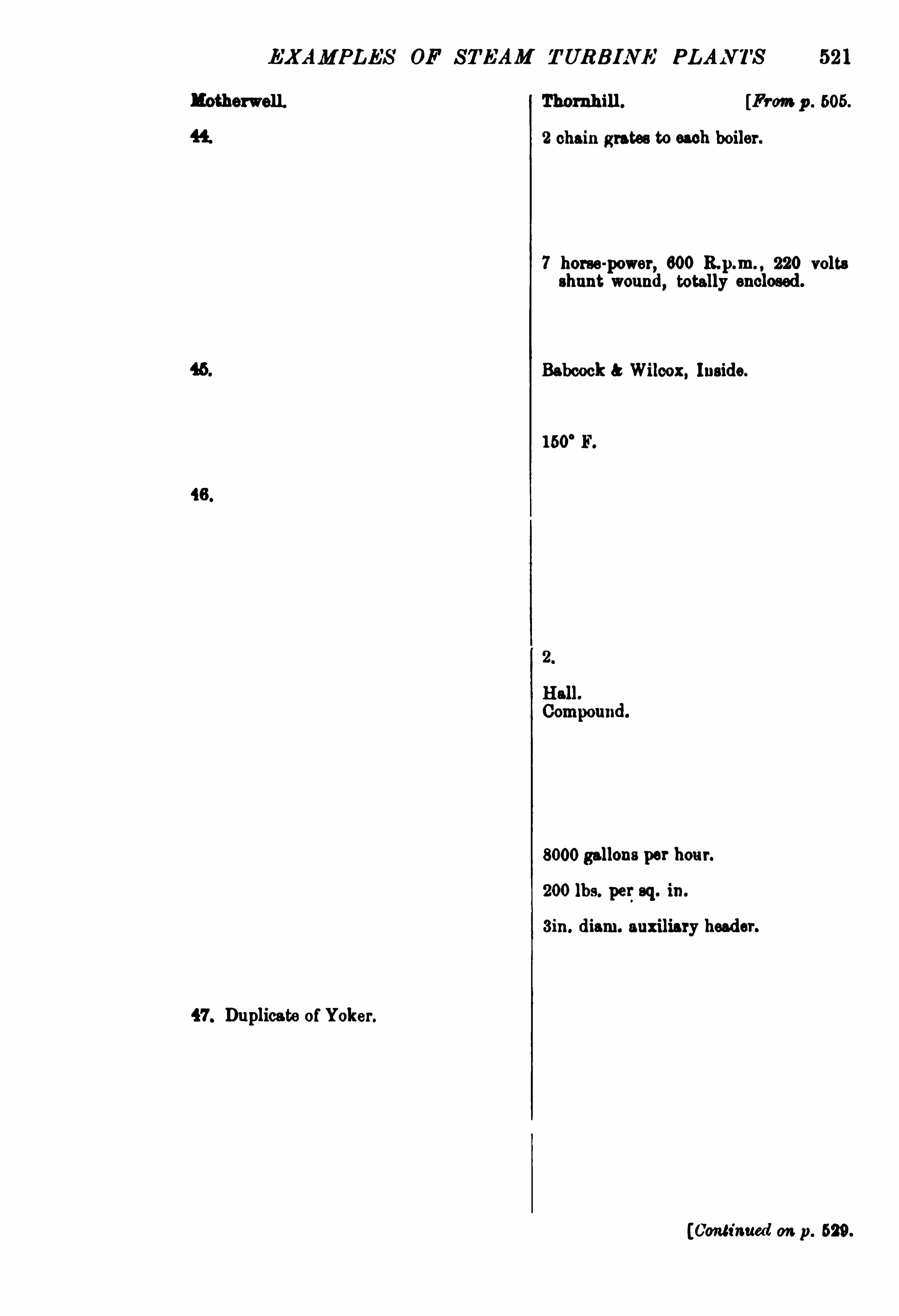
EXAM PLES OF STEAM TURBINE PLAN TS 521
l otherwell. Thornhill . [From p . 605.
2 chain grates to each boiler.
7 horse-power, 600 220 volts
shunt wound,totally enclosed.
Babcock Wilcox, Inside.
160°
F.
8000gallons per hour.
200 lbs. per sq. in.
3in. diam. auxiliary header.
47 . Duplicate ofYoker.
[Continued on p. 529 .

522 STEAM TURB INE ENGINEERING
Name of Generating Station [From p . 506 .
44 . Mechanical Stokers Chain grates.
Motor for Stokers
45 . Superheater Type Babcock Wilcox.
Superheating surface each
Degrees addedFinal Temperature
46 . Boiler Feed Number ofMains
D iameterFeed Pumps connected to
eachPumps Total number
Maker Messrs J. P. Hall Sons,Ltd.
Type Steam-pump, compound type.
Steam CylindersStroke l2in. 2oin. x l l i in.
Pump Plungers 24in.
DiameterOverall Size
Capacity each gallons per hour.
Against 200 lbs. per sq . in.
Using Steam at
Steam received fromSteam exhausts to
Steam consumed
47 . Economisers : NumberType
Number ofTubesLength ofTubes
Internal D iameter of 'lhibes .
Heating Surface for each
Boiler
Scrapers driven by
Thermometer for FoodWater
[Continued on p. 530.

524 S TEAM TURB INE ENG INEER ING
Name of Generating Station Lots Road, Chelsea. [From 5 16 .
48. Steam PipingEach Boiler supplies Steam 6in. solid drawn pipe to header.
through
Pipe Covering
Stamped steel screwed on and afterwardsexp .anded
To each group of8 boilers.
Maker of Pipes Babcock 8: Wilcox.
49 . Water SupplyTaken from Storage tank on second floor ofoil-coolinghouse .
Taken from Well Slin. Artesianwell by compressed air.
Depth ofWell
50. Auxiliary Water Supply Town mains through ball-valve.
51 . 2nd Auxiliary Water Supply Riverwater.52. Main Steam Pipe to each Tur l 4ins. diam. lap
-welded steel.
bine
Main Steam Pipe to all Ex
citers
Auxiliary Pipe
Expansion taken byFlanges
Auxiliary HeaderSupplied from
Expansion taken byFlanges
54. Condensed Steam fromdensera
55 . Feed-water Heaters get
from Exhaust of
56 . Main Steam Turbine Figs. . 540. See also pp. 140-4.
'
{qype Horizontal doub e-flowWestinghouse
—Parsons .
umber 8.
5500 K.W.
British Westinghouse.
1000 revolutions perminute.
[Continued on p . 582.
Easy bend.
Stamped steel, riveted.
loins. diam. for exciter engines.
3 of the main headers by mm. diam. solid
drawn steel pipe.
Easy bends.
Stamped steel,riveted.
Is fed into the high-level suction and falls
through feed-water heaters into lowersuction
pipe, fromwhich it is pumped through the
economisers.
Boiler feed pumps a sump is providedfor condensed steam.

EXAM PLES OF STEAM TURB INE PLANTS 525
Neasden. Carville. [From p . 517 .
Minimum number ofdissimilar parts .
l
7in. steelwelded pipe. Solid drawn mild steel pipe.
Ma caium covering by Hobdell,
ay Cc. , London.
Welded steel. Forged steel.
Piggott 00 Birmingham.
2 Artesianwells.
Firstwell, gallons per hour
ca acity ; second well,
ga lons per hour capacity.
400ft. storage in a lake of 2 acres,
5I'
t. depth, and gallonscapacity.
50. Town mains.
51 .
52. mm. diam.
The Holly System of Drains is ih
stalled.
Lar e bends. Large bends.
Stee shrunk and welded.
54 . Pumped to top ofcooling towers ; waterfrom base of tower flows into lake.
55. Auxiliary pump engines.
56. Fig. 385 , p. 542. Fig. 355,ante
, p. 475.
Double-dow. Parsons.
4 .4.
3500K.W. Two 2000 K.W. ,two 4000K.W.
2
British Westinghouse. C. A . Parsons 8: Co.
1000 revolutions per minute. 1200 revolutions per minute. Max.
varied 5 per cent.
[Continu al on p. 533.
1 Discussion by Mr J. H. Rosenthal on Power Station D esign,
” by Merz
McLellan,Proc . In t. E .E . , p. 874, 28th Apr. 1904.
9 Fig. 355 rates these at 8500 K.W.

526 STEAM TURB INE E .
'
GINEERI NG
Name of Generating Station .
48. Steam Piping :
Delray,U.S.A . [From p . 5 18.
Each Boiler supplies Steam Steel pipe, extra heavy.
through
Maker ofPipes49 . Water Supply :
Taken from (Feed Pipes)
Taken from Well
D epth ofWell
50. Auxiliary Water Supply
5 1 . 2nd AuxiliaryWater Supply52. Main Steam Pipe to each Tur
bine
Main Steam Pipe to all Ex
citers 0
Auxiliary Pipe
Expansion taken byFlanges
53. Auxiliary HeaderSupplied from
Expansion taken byFlanges
54 . Condensed Steam.
from Corn:densers
55 . Feed-water Heaters get heat
from Exhaust of
56 . Main Steam TurbineType
Number
D etroit River.
2 elevated tanks of and gallons
capacity.
Duplicate Sin . motor-driven Worthington lowpressure turbine pumps, each capable of
supplying all the water,force the hotwell
water through cast-iron mains to four 5000horse-power Cochrane feed-water heaters.
Fig. 386 , p. 543.
Four-stage Curtis, vertical.
4 .
3000 K.W.
General Electric, Schenectady.
[Continued o np . 534 .

528 STEAM TURB INE EN GINEERIN G
Name of Generating Station [From p . 520.
48. Steam Piping :
Each Boiler supplies Steamthrough
Maker ofPipes49 . Water Supply
Taken from City mains.
Taken from Well
Depth ofWell
50. Auxiliary Water Supply
51. zud Auxiliary Water Supply River.52. Main Steam Pipe to each Tur
bine
Main Steam Pipe to all Ex
citers
Auxiliary Pipe
Expansion taken byFlanges
53. Auxiliary HeaderSupplied from
Expansion taken byFlanges
54 . Condensed Steam from Con
densera
55. Feed-water Heaters get beat An auxiliary heater by J. Wright 8: Cc . , 700
from Exhaust of sq. ft. heating surface.
56 . Main Steam Turbine Figs. 394- 5 , p. 550, also pp. 146-7 .
pe Double-flowWestinghouse-Parsons.
umber 2. The engine-room will accommodate one
1
12mm unit of 2000 K.W. and one of 3500
.W.
3000 horse-power.
British Westinghouse.
1500 revolutions per minute.
[Continued on p . 536 .

EXAMPL'
S OF STEAM TURB INE PLAN TS 529
Thornhill. [Fromp . 521.
48. Duplicate ofYoker Mild steel, lap-welded, riveted branches
7in. diam. pipe into 12in. diam. mainsteam pipe, 2 separators at each endof steam ring. The steam throu h
12in. diam. separators into h or
parallel to engine-room.
2 hotwells ; the receive the dischargefrom the con cussra.
The arrangement of the steam and feedwater piping is designed so that one
halfofthe boiler-house can be isolatedfrom the other.
Sins. diam. cd'
main header.
6ins. diam. to exciters ; Sins. diam.
auxiliary to exciters.
3ins. diam. underneath main header.
3ins. diam. line over each set ofboiler.
Figs. 397 , 898, p. 558.Vertical
3.
1500 K.W.
British Thomson-Houston.
-1000 revolutions perminute.
[Continued onp . 537.
34

530 STEAM TURB INE ENG INEERING
Name of Generating Station
48. Steam PipingEach Boiler supplies Steamthrough
Maker ofPipes49. Water Supply
Taken from
Taken from Well
Depth ofWell
50. Auxiliary Water Supply
51. 2ud Auxiliary Water Supply52. Main Steam Pipe to each Tur
bine
Main Steam Pipe to all Ex
citers
Auxiliary Pipe
Expansion taken byFlanges
53. Auxiliary HeaderSupplied from
Expansion taken byFlanges
54. Condensed Steam from Con
densera
55 . Feed-water Heaters get heat
from Exhaust of
56. Main Steam TurbineTypeNumber
[From p . 522.
Figs. 399,400
, p. 555 .
Vertical Curtis.
4 .
1500 K.W.
British Thomson-Houston.
1000 revolutions perminute.
[Continued on p. 538.

532 STEAM TURB IN E ENGINEERING
Name of Generating Station LotsRoad, Chelsea. [F rom p . 524.
Speed Control 10 per cent. above or belownormal by electric
control operated from control board.
Bed late Dimensions 48ft. l lins. by l i ft. «line.
B eig t above Floor 13fl:. 10ins.Platform Dimensions 4ft. 6ins. above floor, overhangs bed-plate.
Foundation 5oft. by 15ft. by 39ft. deep each. See p. 442.
Area 750 sq. ft.
Steam Pressure 1 75 lbs. per sq. in.
100°
F. at the turbine.
ed 50per cent. per automatic by-pass.
57 . Steam.
Consumption, lbs. perK.W.H.
Guaranteeswith 165 lbs. per sq. in 100°
F. superheat.
27in. vacuum.
At 25 per cent. overload lbs. per K.W.H.
Full load 17 7 lbs. per K.W.H.
i load lbs. per K.W.H .
5 load 21'
4 lbs. per K.W.H.
4 load
Rotating portion 6ft. 5in. diam. rolled steel drum.
Weights
Peripheral Speed ofDrum 336ft. per second.
Main Bearings Spherical cast-iron linedwith babbitt.
Cooled by Water circulation.
Quantity Water circulated 40gallons perminutewhen required.
Coupling to Generator
58. Steam Valves
59 . Emargency Governor
60. Centrifugal Governor
61 . After (passing through the Atmiddle,and passes in two directions through
valves Steam enters expanding nozzles.
[Continued onp . 562.
Flexible claw’of forged steel running in oil.
The steam passes on its way to the turbinethrough the following — Main disc-type stopvalve, operated from platform by gearing.
Operate s at maximum speed an auxiliaryvalve
,which in turn closes emergency shut
down valve. Through steam strainer.
Geared to turbine shaft, operates a double-seat
poppet valve through a small steam relay.

EXAM PLES OF STEAM TURB INE PLANTS
Mechanical and electrical.
Seep
. 442, Fig. 337.
41 ; y 12 by 22ft. deep.
175 lbs. per in.
180°
F . at tur ine.
25 per cent. for 6 hours with 26ln.
vacuum.
160 lbs. per sq. in. pressure, 27in.
vacuum rated load.
17 lbs. per K.W.H.
201 lbs. per K.W.H.
Turbineweighs 165 tons generator
weighs 17 tons.
18,000ft. per min.
l 6in. diameter.
Oil (under pressure) andwater.
1000gallons per hour.
58. By Fletcher Co. ,Ashton-under
Lyne.
59. Controls 10 per cent. above
no position on end of main
shaft.
60. Worm gear (ratio 10 to 1 ) from mainshaft
,controlled by electricity
from switchboard.
533
[From 525 .
3 per cent. between no-load”
and
normal load ; 5 per cent. betweenno load andmaximum load ; 6 per
cent. when running atmaximum load.
14 °5tt.
200 lba , 150°
F 95 per cent.
15 lbs. per K.W.H.
Mars e McLellan, BritishEngineer ,
18 lbs. per K .W. , 4000K.W.
19 lbs. per K.W. , 2000K.W.
Ordina governor supplemented bygovernor and valve to admitressure steam to low-pressure
[Continued on p . 563.

534 STEAM TURB INE JNG IN EERING
Name of Generating Station Delray, U.S.A .
Speed Control
Bed late D imensions
Heig tt shove Floor
Platform D imensionsFoundation
Area
Steam Pressure 200 lbs. per sq. in.
Superheat 200°
F .
Overload supplied
Steam Consumption, lbs.K.W.H .
Guaranteeswith
At 25 per cent. overload
Full load
2 load
é load1 load
Rotating portion
Weights
Peripheral Speed of l) .rum
Main Bearings
Cooled by
Quantity Water circulated
Coupling to Generator
58. Steam Valves 12 poppet valves on each side, controlled bymagnets.
59. Emergency Governor
60. Centrifugal Governor
61. After passing through the
valves Steam enters
[Continued on p. 564 .

536 STEAM TURB INE EN GINE ERING
Name of Generating Station [Fromp . 528.
Speed Control blades each turbine.
Bed late DimensionsB eig t above Floor
Platform D imensionsFoundation
Area
Steam PressiireSuperheat
Overload supplied 3750horse-power overload capacity.
57 . Steam Consumption, lbs.K.W.H.
Guaranteeswith
Full load
1 load1}load
4 load
Rotating portion
Weights
Peripheral Speed ofDrum
Main Bearings 440 ft. per sec.
Quantity Water circulated
Coupling to Generator D irect-connected.
59. Energency Governor
60. Centrifugal Governor
61. After passing through the
valves Steam enters
[Continued o np . 566 .


538 STEAM TURBINE ENGINEERING
Name of Generating Station
Speed Control
Bed late DimensionsHeig tt shove Floor
Platform DimensionsFoundation
Area
Steam PressureSuperheat
Overload supplied
Steam Consumption, lbs.K.W.H .
Guaranteeswith Tested at maker’
a works ; 150 lbs. pressureand 100
°
eu erbeat and 28in. vacuum ; 16‘
4
lbs. per K. . .H
At 25 per cent. overloadFull load
i loada}load4 load
Rotatingportion
Weights
Peripheral Speed ofDrum
Main Bearings
Cooled by
Quantity Water circulated
Coupling to Generator
59 . Emergency Governor
60. Centrifugal Governor
61. After passing through the
valves Steam enters
[Continued on p . 568.


548 STEAM TURB INE EN GINEERING
FIG . 39l .— Quincy Point : Turbine Platforms, p. 527 .


EXAM PLES OF STEAM TURBINE
Flo. 401.— Brimsdown Turbine-Room and Switchboards.
H.T. Switchboard on gallery : L.T. on floor level.


562 STEAM TURB INE EN G INE JR ING
Name of Generating Station Lo ts Road, Chelsea. [From p. 532.
62. First Series of Impulse Vanes Drop forged steel.
Lowest Pressure Vanes Deltametal.
63. Lubrication Centri fugal system under
Pressure 3oft. head.
Quantity passed through 33 gallons perminute.
Bearings of one Turbine
Unit
Total Capacity ofPlant 350gallons perminute.
Water-cooling Jacket 40gallons perminute.
64. Oil-cooling Plant
Position
2nd floor3rd floorHe
'
ht ofGravity TankOil
l
Pipe to Engine-roomOil D ischarge
Oil Coolers : NumberSurface each
Oil pumped by
Driven by 3 motors,
each 7§ horse-power, 220 volts,
3 phase, 955 revolutions perminute.Coolingwater pumped by 3 pumps.
Driven by 3 motors, each 3 horse power, 220 volts,3 phase, 635 revolutions per minute.
Oil delivered65. Atmospheric Exhaust
Size and Position 6oin. diam. against each chimney,up through
roof.
Valve Air-controlled type.
66 . Turbine
h
Exhaust to Condenser 21 sq. ft. total (two 44in. diam. openings).eac
67 . Condensers : Type Vertical surface. Fig. 403, ante, p. 559.
Maker James Simpson 8: Cc . , Ltd.
[Continued o np. 570.
Separate building.
gallons.
James Simpson 8: Cc . ,Ltd.
Feed-water storage tank.
Oil-filtering tanks.
3oft. above level ofturbine bed.
6ins. diam. ringmain.
By gravity to basement.3.
686 sq . ft. brass tubes.
3 centrifugal pumps.

564 STEAM TURB I NE E NG INE JRIN G
Name of Generating Station Delray,U.S.A. [From p . 534.
62. First Series of Impulse VanesLowest Pressure Vanes Between the first and second a
automatic by-pass valve
,an a hand
operated by-pass beWeen 2nd and 3rd
63. Lubrication ingwith water steady-bearing with
Pressure
Quantity passed through
Beari ngs of one Turbine
UnitTotal Capacity ofPlant
Water-coolingJacket
64 . Oil-cooling PlantPosition
2nd floor3rd floor
ht ofGravity TankOil
i
Pipe to Engine roomOil D ischarge
Oil Coolers NumberSurface each
Oil pumped by 2 Blake pumps, 3 by 2 by Sins. , pum ing from2 tanks in the basement to a taui in the
gallery.
Driven by
Coolingwater pumped byDriven by
Oil delivered65 . Atmospheric Exhaust
Size and Position
Valve .
66 . Turbine i-k hanat to Condenser When the exhaust steam is not used for the
each eva mmtion of salt, it is taken direct to
con ensers.
67 . Condensers : Type Wheeler surface.
Maker
[Continued on p . 572.
650 lbs. per sq. in. of water, pumped by 2
steam pumps 10ins. by 2§ina by 1
made b Deane Brothers,Indiano lie
, to a
hydrau ic accumulator by R. D . cod e Co.
A reserve is afforded by 2 electric pumpsdriven by 5 horse
-power motors.
Each step-bearing requires 4 gallons water per
minute.

EXAM PLES OF STEAM TURB INE PLAN TS 565
L. Street Station,Boston
,U.S.A . Quincy Point, Mass US A
[From p. 535.
68. Footstep:water 900lbs. per sq. in. Ao Waterfootste bearing : 3 steam-drivencumulator supplies water during pumps an 2 accumulators carry 1010 minutes. A triplex motor minutes’ supply.driven pump in reserve.
Through filter : Fig. 859 near“Turbine Room.
Forwaterto step-bearings of the turbinesthere are 3 steam-driven pumps and
2 accumulators .
65. 3oin. diam
67 . Surface. Admiralty surface.
Worthington. Wheeler Condenser 8: Engineering Co .
[Continued on p . 673.

566 STEAM TURB INE E'
GINEER IN G
Name of Generating Station Yoker. [From p . 536 .
62. First Series of Impulse Vanes Drop forged steel.
Lowest Premure Vanes Special metal.
63. Lubrication
Pressure The oil is pumped b a special oil pump to a
tank in the roof0 boiler-house, and flows bygravity under a head of 60ft. to the bearings.
Quantity passed through
Bearings of one Turbine
Unit
Total Capacity ofPlant A large tank in basement of e e-room, with
supply which should set one to twoyears.
Water-cooling Jacket64 . Oil-cooling Plant
Position
CapacityMaker2nd floor3rd floor
fGravity Tankm
NumberSurface each
Oil pumped by
Driven by
Coolingwater pumped byD riven by
Oil delivered
65 . Atmospheric ExhaustSize and Position
Valve
66. Turbine Exhaust to Condenser
each
67 . Condensers : Type . Vertical surface
Maker Mirrlees-Watson Co.

568 STEAM TURB INE EN G IN JERIN G
Name of Generating Station Radcliffe . [From p. 688.
62. First Series of Impulse VanesLowest Pressure Vanes
68. Lubrication 400 lbs.
310
;sq. in. ofwater drawn from
pump harge.
Pressure Fig. 400, p. 666.
Quantity passed through E gallonswater perminute.
Bearings of one Turbine
Unit
Total Capacity ofPlant 2gallon oil tc other bearings.
Water-cooling Jacket
64. Oil-cooling Plant
Position
Ca cityMa er
2nd floor
3rd floorHe
'
ht ofGravity TankOil
‘
fi’ipe to Engine-roomOil D ischarge
Oil Coolers : NumberSurface each
Oil pumped by
D riven by
Coolingwater pumped byDriven by
Oil delivered
65 . Atmospheric ExhaustSize and Position
Valve
66 . Turbine Exhaust to Condenser
each
67 . Condensers : Type Surface. Vertical.
Maker
[Continued on p. 676 .

EXAM PLES OF STEAM TURB INE PLAN TS 569
[From p . 639 . Power Station of the English M‘Kenna
Process Co Ltd .
62 . Special alloy
68. Forced.
8 to 12 lbs. per sq. in.
80gallons per minute.
64 . Ground floor at side ofturbine.
Worm on turbine.
Gravites from storage tank.
By Templer Rance.
66 . 3 ft. diam.
7 sq. ft. area.
67 . Horizontal surface.Willans Robinson, direct-coupled to
turbo-exhaust by an expansion joint.
M irrlees-Watson Co. 3, one for each unit ; the top of con
densera are 3ft. belowwater-level incooling
-tower.
[Continued on p . 677 .

570 STEAM TURB INE ENGINE JRIN G
Name ofGenerating Station
Number and Position
Each condenses
Steam condensed(per s
q. ft.
per hour at rate full oad
Surface r lb.p.hr. ofSteam,
Tubes umber and Length
Each Condenser has
Steam passes throughIllustration
68. Air Pumps : NumberType
Each Cylinder
Each driven by
Motor Spindle
D ischarge capacityIllustration
69. Lift Pumps : Number
Position ofPumpEach driven by
Motor Spindle
Position ofMotor
Water ofCondensation to
By PumpDriven by
Lots Road,Chelsea. [Fromp . 562.
8 in pits alongside each engine foundation.
Topwithin 29ft. of lowest tide.
sq. ft.
lbs. with lbs. (item 57 , p.
lbs. with 17 7 lbs.
(with lbs. per3822 tubes, 16ft. long, l in. diam. , set vertically.
24in . by M in.
40 horse-power Westinghouse motor, 220volts,3 phase, 636 R.p.m.
Horizontal.
eight 5in. horizontal centrifugal for liftingcondensed steam up to feed
-pump suction.
Bottom of condenser pit.20 horse-powerWestinghouse motor, 220 volts,3 phase, 635 R.p.m.
Vertical.
Basement level.
[Continued on p . 578.
3 motors, 40 horse-power, 40 horse-power,and 20 horse-power.
Once 16ft. tubes.
p. 659.
8
Worthington horizontal dry vacuum (separatelift pump).

572 STEAM TURB I .VI'. ENG IN F FRING
Name of Generating Station Delray, U.S.A. [F romp . 564 .
Number and Position 4,one for each turbine in the basement in a
room of 22ft. wide and 174ft. long, overheadtravelling crane of 22ft . span and 15 tons
capacity.Each condenses
Hei ht
Su see each sq . ft. of tube cooling surface.
Steam condensedcper s
q. ft.
per hour at rate full oad
Surface er lb. per hour
Tubes : umber and Length
Each Condenser has
Steam passes throughIllustration p. 477.
68. Air Pumps : Number 4.
Type Edward’swet vacuum triplex.
Each Cylinder
Each driven by 60horse-power, 220 volt, 3 phase motor.
Motor SpindleDischarge capacityIllustration
69 . Lift Pumps : Number
Position ofPumpEach driven by
Motor Spindle
Position ofMotor
Water ofCondensation to
By PumpD riven by
[Continued on p. 680
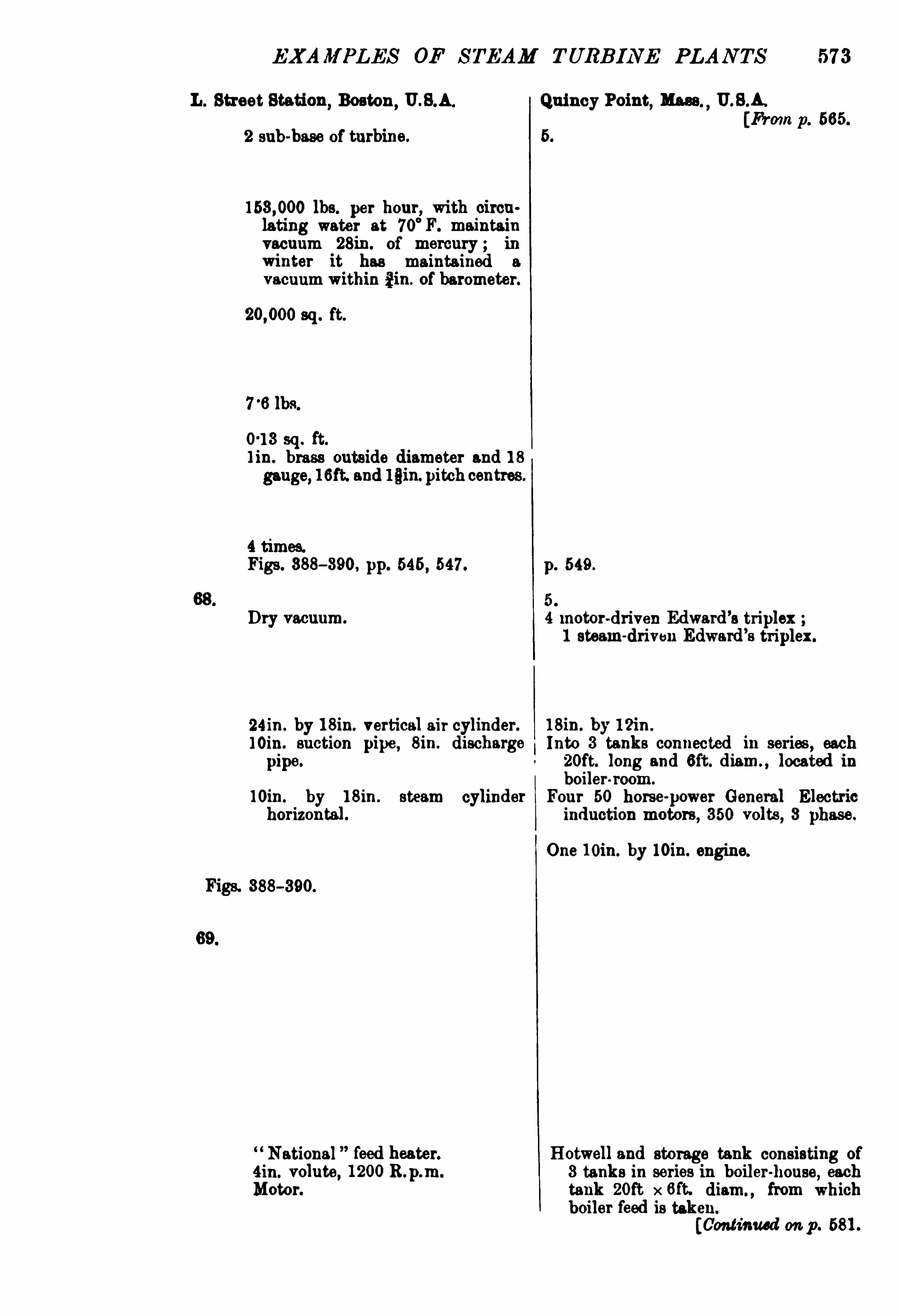
EXAM PLES OF STEAM TURBINE PLANTS 57 3
L. Street Station,Boston
,U.S.A. Quincy Point, Mass U.S.A.
[From17. 565.
2 sub-base of turbine. 5.
lbs. per hour, with circu
lating water at 70°
F. maintainvacuum 28in. of mercury in
winter it has maintained a
vacuumwithin £in. of barometer.
sq . ft.
lbs.
0 13 sq. ft.
l in. brass outside diameter and 18
gauge, 16ft. and lain.pitch centres.
4 times.Figs. 388— 390, pp. 645 , 647 . p. 549 .
5 .
Dry vacuum. 4 motor-driven Edward’s triplex1 steam-driven Edward’s triplex.
24 in . by l 8in. vertical air cylinder. 18in. by 12in .
loin. suction pipe , 8in. discharge Into 3 tanks connected in series,each
pipe. 2oft. long and 6ft. diam. ,located in
boiler-room.
mm. by 18in . steam cylinder Four 50 horse-power General Electric
horizontal. induction motors, 350 volts,3 phase.
Onemin. by loin. engine.
Figs. 388-390.
National feed heater. Hotwell and storage tank consisting of«tin. volute, 1200R.p.m. 3 tanks in series in boiler-house, each
Motor. tank 2oft x 6ft. diam. ,from which
boiler feed is taken.
[Continued on p. 581.

574 STEAM TURB INE ENG INEER IN G
Name ofGenerating Station Yoker. [From p. 566 .
Number and Position 2 1 alongside each turbine.
Each condenses lbs. per hour.
lbs. total.
6250 sq . ft:cooling surface.
Steam condensed per sq. foot
per hourat rated full loadSurface each r lb. ofsteamTubes : Num r and Length 143ft. long, 1 in. diam. 18 S.W.G.
Each Condenser has
Steam passes through Three lengths oftube.Illustration Counter to steam, p. 550.
68. Air Pumps : Number 2 in Basement.Type Two-eta e dry air pump horizontal. Both air
c lin ers fittedwith mechanically controlleds ids.
Each CylinderDischarge
Each driven by
Motor Spindle
D ischarge capacityIllustration
Position ofM pEach driven by
Motor Spindle
Position ofM otor
Water ofCondensation to Hotwell in the basement.By Pump Centrifugal pump.
Driven by 6 horse-power vertical-shaft shunt-woundmotor, 625 R. p.m.

57 6 STEAM TURB INE EN G INE JR ING
Name ofGenerating Station [Fromp . 568.
Number and Position
Each condensers
He'
htSur ace each 4500 sq . ft.
Steam condensed r ft. 5'
4.
per hourat ra full oadSurface r lb. per hour (with lbs. per K.W.
T ubes :finmber and Length
Each Condenser has
Steam passes throughIllustration p. 655.
68. Air Pumps : Number 4, one to each condenser.
Type Edward’s three-throw.
Each Cylinder 15in. diam., 8in. stroke.
D ischarge
Each driven by Motor, 165 R. p.m.
Motor Spindle
Discharge capacity cub. ft. per hour.
Illustration
69 . Lift Pumps : Number
Motor Spindle
Position ofM otor
Water ofCondensation to
By PumpDriven by
[Continued on p. 584.

EXAM PLES OF STEAM TURB INE PLAN TS 57 7
Power Station of the English M‘Kenna
Process 00. Ltd. [Fromp . 669.Three
,alongside each turbo. 3.
2630 sq. ft.
7 .
About 10 ft. 4 in. long.
pp. 488, 489.
68. 3.
Edward’
s three-throw. Edward’
s two-throw type, with a force
ump (delivering to hotwell) drivenm the end of crank shaft
,drawing
from the sur 0 tank at base of air
rump, intow ich the air pump itselfslivers.
12i in. diam. 6in. stroke.
Motor 9 horse-power, 110 volts c.c. 95 horse-power Siemens shunt motor250 volts, 750 to 850 17 amp. ,
with 275 in. vacuum.
2500gallons per hour.
A 150K.W. rotaryand a 50K.W. rotary,and transformers off main bus-bars
supply 250 volt current for driving
con enser plant.
[Continued on p . 585.
37

578 STEAM TURB INE EN G INEERIN G
Name of Generating Station Lots Road , Chelsea. [From 670.
70. Circulating PumpMaker Worthington.
Number 8, piped on syphon principle.
Type 20in. centrifugal horizontal.
Position Bottom ofcondenser pit.Each driven by 40horse-powermotor, Westinghouse, 220volts,
3 phase, 635 R. p.m.
Motor Spindle Vertical spindle.Position ofM otor At basement level.Rated Duty
CirculatingWater from River Thames.
66111. diam. cast-iron in river bed.
Direction ofFlow Reversible up to condenser.
Pipes supplied and laid by John Cochrane tr Sons, Westminster.Circulatron Pipes Steel riveted to get hold ofconcrete on land.
Pipes sup lied by Babcock Wilcox.
Pipes lai by Perry.
Circulating Pipes to Con 20in. and 22in. diameter of cast-iron.
densera
Circulation provided for is times steam consumption:Cooling Towers Number
Capacity per hourArea each
Height
Space beWeen
Area Tank under towersDepth
Distributing Pipes
7 1. Main Generators
NumberMaker
RatingNumber ofPhaseCycles per second8 eedoltage per phase
Amperes per phase,
Tern rature rise
Re ation
Speed variation
Overload 50 per cent. for two hours.
Temperature rise
[Continued on p. 686 .
Figs. 383, 384, ante, also p8, with room for 10
,and 1 alt-size.
Westinghouse.
5500 X. \V.
3.
33A.
1000 R.p.m.
289 , with non-inductive load.

580 STEAM TURB INE ENGINEERING
Name ofGenerating Station Delray,U.S.A. [Erma p . 5 72.
70. Circulating Pump In thepump house, SSR. by M R.
Maker Worthi ngton.
Number 4 .
18in. centrifugal.
Position.
Main floor of pum -houae.Each drrven by 76 horse power in notion motor.
MotorSpindle
Position ofMotor
Rated Duty
CirculatingWater from Detroit River.
3 sets of screens to sto rubbish, first, vertical
bars ; others remova 10wire nets.A culvert extendingbeneath the fouroondensers.
Direction ofFlow
Pipes supplied yand
grculatron
li b
Pi
pea s
Pipes lardpb
l
yCirculating
yPipes to Con
densera
Circulation provided for
Cooling Towers : Number
Capacity per hourArea each
Height
Space betweenArea Tank under towersDepthDistributing Pipes
7 1. Main Generators Fig. 386,ante, p. 543.
Number 4 .
Maker Gen. Elec. Co. ofNewYork .
RatingNumber ofPhasesCycles per second8
oltage per phase
Amperes per phase, full load
Speed variation
Overload 50 per cent. continuously without damage70 per cent. for a short time.
Temperature rise
[Continued on p . 588.

EXAM PLES OF STEAM TURB IN E PLAN TS 581
L. Street Station, Boston, U.S.A. Quincy Point, m .,U.S.A .
[From p. 578.
70.
5.
24in. volute centri fugal for priming 4 motor-driven,1 steam-driven, 18in.
an ejector on discharge. low-lift double-suction Morris type.
16in. b 16in. Harrisburg engine, Four 100 horse-power G.E. induction
200 p.m. motor, 350 volts ; one 12in. by loin.
steam engine.
2 masonry conduits 56 sq. ft. each.
2 fine so per screens in series,cleaned y removing one.
1 conduit 78 sq. ft , dis
kept from rutake by
through sea wall,each
ft.with submerged racks.
70times steam consumption.
7 1. Figs. 388, 389, 390, m , p. 545.gigs. 391, 392, 999, ante, p. 549.
2.
Gen. Else. Co . ofNewYork. Gen. Else. Co. ofNewYork.
5000K.W.
9.
so.
614 R.p.m.
60per cent. for 2 hours.
[Continued on p. 589 .

582 STEAM TURBINE ENGINEERING
[From p . 574.
Centrifugal.
Position
Each driven by Steam-driven.
Motor SpindlePosition ofMotor
Rated Duty
CirculatingWater from River Cl do alongside, b gravi into well18ft. diam. and Mt. befriw low
ty
by 2 pipes, each soin. diam.
36in diam. cast-iron.
s6in. diam. into spillway on bank ofriver.
Direction ofFlow
Pi eu lied and
CigtilatiirlirPipes su
‘pipli by
Pipes la'
byCirculating Pipes to Con
densers
Circulation provided for isCooling Towers : Number
Capacity per hourArea each
HeightSpace betweenArea Tank underTowersDepth
Distributing Pipes
7 1 . Main Generators
NumberMaker
RatingNumber ofPhasesCycles per second8
oltage per.
phaseAmperes per phase, full load
Temperature rise
[Continued on p. 690.
Figs. p. 560, also pp.
2.
Westinghouse.
2000K.W.
3.
25 .
1500R.p.m.

584 STEAM TURB INE EN G INEERIN G
Name of Generating Station
Motor Spindle
Position ofMotor
Rated Duty
CirculatingWater from
Pipes supplied and laid byCirculation PiPipes supplie byPipes laid byCirculating Pipes to Con
densers
Circulation provided for rs
7os . Cooling Towers . Number
Capacity per hourArea each
Space betweenArea Tank under TowersD epth
D istributing Pipes
7 1. Main Generators
NumberMaker
RatingNumber ofPhasesCycles per secondSpeed .
Voltage per phase
Amperes per phase, full load
Temperature riseRegulation
Speed variation
Overload
Temperature rise
Radcliffe. [From p . 576 .
Fig. ante, p. 555.
[Continued on p . 592.

EXAM PLES OF STEAM TURB INE PLAN TS
Brimsdown. Power Station of the English M‘Kenna
Procom Cc . ,Ltd. [From p . 57 7 .
70. Centrifugal.Gwynne.
At side of condenser.
Motor, direct-coupled. 46 B.H .P. Siemens shunt motor, direct
current, 250volts, 605 to 705 R.p.mthe current taken, 110 amps. at 250
volts, maintainin a steady vacuum of
275 11. at full l
1700gallons per minute. gallons per hour, against 27ft.head to Donat cooling tower.
Lea Canal. By gravity through condenser to suctionside ofcirculating pump.
In suction pits. mm. diam.
Into coal barge dock.
J. Spencer Co.
10-in. diam. to each.
60 times full-load steam. 1 Donat, 2700 sq. ft.
70A . No towers.
7 1. Fig. 401, p. 557 . Fig. ante
, p. 488.
3. 3.
Brown-Roveri.
760 K.W. at 08 power factor.8.
26.
1500R.p.m.
440.
3 per cent.25 per cent. for 1 hour.
Test : 26°
C.after 6 hours’full load.
[Continued on p . 598.

586 STEAM TURBINE EN G INEERIN G
Name of Generating Station Lots Road,Chelsea.
Rotor SolidWhitworth fluid-pressed steel.Number of Poles 4.
Excitation 125 volts, 180 amps. full load .
Per cent. ofOutput per cent. unity power factor.Electrical Efficiency
11 loadFull load
2 load5i
Dimensrons
72. Exciten , take steam through
Exhaust into
Engines Number
Horse-power 200 horse-power.
Maker W. H . Allen, Son tr Cc ., Ltd. ,
Bedford.
Overload 25 per cent.
Type Compound enclosed.
Cy inderdiameters 12in. and 21in.
Pressure
Consumption guaranteedwith Pressure 165 lbs. per sq . in. pressure.
Superheat 23°
F. superheat.
Vacuum 24ins. vacuum.
Full Load condensing 15 7 lbs. of steam per I .H.P . hour, equal tolbs. ofsteam per K.W. hour.
Half
Full Load non-condensingHalf
Exciter Generator
Number 4 direct-coupled.
l
Maker British Thomson-Houston Cc. , Ltd.
Rating 125 kilowatts .
Percentage oftotalKilowatts 11 per cent.
installedVoltage 125 volts.
6 pole, flat compound.
Overload capacity 25 per cent. for2 hourswithoutmovingbrushes50 per cent. momentarily.
Temperature rise
Electrical EfficiencyFull load
Half load
[Continued on p . 594.

588 STEAM TURB INE EN GINE JRING
Name of Generating Station Delray,U.S.A. [From p . 580.
Rotor
Number ofPolesExcitation
Per cent. ofOutput
Electrical EfficiencyI} loadFull load
3 load
5i
72. Excite“ ,take steam through
Exhaust into
Engines Number 1 engine-driven exciter for emergency use in
basement.Horse-power
Maker
TyCy
'
nder diameters
Stroke
Speed .
Lubrication
Consiimption guarantedd
SuperheatVacuum
Full Load condensing
HalfFull Load noncbndenHalf
7 9 D
mug
Exciter GeneratorNumber of 83 cells, at 125
Maker60 kilowatts.
Percentage of total Kilowatts 1 2 per cent.
installed
Voltage 126 to 200 volts.
Type Motorgenerators driven by 75 horse
-power ih
duction motors.
Overload capacity
Temperature rise
Electrical Efi ciencyFull load
Halfload
[Continued onp. 696.

JXAM PLES OF STEAM TURBINE PLAN TS
L. Street Station ,Boston
,U.S.A. Quincy Point, Mass ,
U.S.A.
[Fromp . 581.
2 ; one 75 K.W. and 50 K.W.
General Elec . Cc . , Schenectady.
Vertical comp.
310R.p.m. 76 K.W. engine.400 60
3, onebein a 50kilowattmotorgenerator(350 v0 ts 75 horse-power 3 phasemotor).
General Eleo. Cc ., Schenectady.
76 kilowatts, 60 kilowatts, and 50 kilowatts.
1‘
75 per cent.
[Continue don p. 597

590 S TEAM TURB INE ENGINEERIN G
Name ofGenerating Station Yoker. [From p 582.
Rotor
Number ofPolesExcitation
Per cent. ofOutput
Electrical Efi ciencyI} loadFull load
fl loadii n
Dimensions
72 . Exciters, take steam through
Exhaust into A separate Worthin
rgton surface condenser
,600
sq . ft. cooling an ace .
Engines Number 2.
Horse-power Each 76 K.W.
Maker Westinghouse. Fig. 396 , p. 552.
Overload
Type Vertical compound.
Cy inderdiameters l l in . andmm. diam.
Stroke
LubricationPressure
Consumption guaranteedwith Pressure
Superheat
VacuumFull Load condensing
Half
Full Load non-condensingHalf n n
Exciter Generator
Number
Percentage of total Kilowattsinstalled
Voltage 125 volts d. c. (supply also coal and ashconveyer, cruslrers
,agitators, economisers
,
pumps, travelling crane switches).Compound.
Overload capacity
Temperature rise
Electrical EfficiencyFull load
Half load
[Co ntinued on p. 598.

592 STEAM TURB INE ENGINEERING
Name of Generating Station [Fran p . 584 .
Rotor .
Number ofPoles .
Excitation
Per cent. ofOutput
72. Excite” , h ke steam throughExhaust into Feed-water heater.
Engines Number
Horse-power 3 sets of Allen en es also as auxiliary power.
Maker Allen a E.T.H . Cg“:
Overload
diameters
Stroke
Speed .
LubricationPressure
Consumption guaranteedwith Pressure
SuperheatVacuum
Full Load condensing
HalfFull Load non condensingHalf
Exciter Generator
Number Three 6 poles.
Maker British Thomson-Houston Co Ltd.
Rating 150kilowatts.
Percentage ofTotalKilowatts per cent.
installed
Voltage 220 volts.
Compound.
Overload capacity
Temperature rise
Electrical EflioienoyFull load
Halfload
[Continued on p . 600.

EXAM PLES OF STEAM TURB I NE PLANTS 593
Guarantee 40°
C.after 10hrs full load.
4.
80amps., 110 volts.“if . l ).
95 per cent. (p. f. l ) .94 per cent.
92 per cent.l2it. 8in. x 6it. 7in. x 6ft. 6in .
high.
2 condensers (2 engines to each).
Four.
2 of 150 B.H.P. 2 of80 B .H .P.
Belliss-B.T.H. sets.
None.
Com und 2 crank.
9 an l5in. 75and l‘
2in.
9 in.
435 R.p.m.
Forced.
30 lbs. per sq . in.
150 lbs. per sq. in.
16 lbs. perhr. 172 lbs. per hr.
B .T.H. Co.
2 of100K.W. I2 of 50K.W.
75°
F. after 24 hrs. at full load.
Power Station of the English M‘Kenna
Process Co. ,Ltd. [From 19. 585.
2.
250 volts originally, 65 volts now.
2. Originally for exciting, etc.
Bellies.
Hollis-Siemens type.
These also do lighting. These are nowan creeded for exciting current by 65
v0 t sets.
2. D irect-driven exciter now off gener
ator shaft.
65 volts now.
Siemens.
[Cont inued on p . 601 .
38

594 STEAM TURBINE ENG INEERING
Name of Generating Station [From p . 586 .
78. Overhead Travelling Cranes : 2.
NumberSize
Herbert, Morris Bastert.
Capacity 20 tons each.
Span s7it.
Lifting : Height 57ft.Motive Power 125 volts continuous current.
Number ofMotors
Lifting Motor Horse-powerSpeed
Cross-runHorse-powerLong
-run Horse ower74. Switchgear, made y B.T.H. Co. D iagrams, Figs. , pp. 602, 605.
High-tension Switches
operated by c.c. motors, 220 volts.
Generator Switches First gallery. Figs. 407 , 408, 409.
Bus Junction Second Fig. 418.
Bus bars Separate compartments.Feeder Switches Third gallery.
Generator Instrument Panels 11 panels vertical. Fig. 412, p. 607 .
Position Second gallery, on projecting gallery, over
looking turbo-generators.
On each
Generator Control Panels
On each
Feeder Inst. Control Board
Number ofFeederPanelsOil Switch Motor Con
trol Panel
Number ofFeedersEach Feeder has
Auxiliary Switchboard Controls
Panels
PositionExciter Bus
A . 0. Bus, 220 voltsEmergency Switches
Generator Cables
3 A.O. ammeters ; voltmeter ; indicatingwattmeter ; recording wattmeter ; powerfactormeter field ammeter.
11 on table beneath instrument panels.Generator oil switch ; bus junction switchfeeder group switch ; indicatinfield rheostat controller ; fieldswitch ; governor control switch, engine
signal synchronising switch.
Fig. 410.
17 .
1 c.c. 220 volts.
68.
Ammeter ; wattmeter ; control switch ; indicating lam
-red, closed ; green, open switch.
Over] time-limit relays,With electric
gong to soundwhen feeder switch opens.
Four 125 K.W. exciter,220 volts ; 8 sets of 8
transformers ; one 125 K.W. synchronousmotor generator 2batteries ofaccumulators89 motors
,3 ph. 220 volts 12 motors c.c. ,
125 volts ; 93 oil switch motors, 220volts ;
local lighting. Figs. 415 , 416.2 battery panels 2 c.c. feeder panels ; 2
motor generator panels 1 load panel 4
exciter (single pole) panels ; 18 a.c. panelshand operated oil sm tches.
First endgallery.
In 2 sections .
Under floor in 2 sections .
Throwoil switch motors on tomotorgenerator,or one exciter ifbatteries fail.
In screwed piping imbedded in concrete galleryfloorwith no junction boxes.
[ Continued on p . 626

596 STEAM TURB INE ENGINEER ING
Name of Generating Station Delray, U.8.A. [From p . 588.
78. Overhead Travelling Cranes
NumberSize 1 electric.
TyMa er Northern Engineering Cc .
Capacity 35 tons.
51ft.
Motive Power 8-phase induction motors.Number ofMotors
MakerLifting Motor Home-powerSpeed
Cross-runHorse-power SpeedLong run Horse ower Speed
Switchgear, made yHigh tension Switches Fig. 428, p. 617.
operated by 125 volt exciting circuit.
Generator Switches First gallery.
Bus Junction
Bus bars Belowfirst ls
Feeder Switches8d ry
Generator Instrument PanelsPosition Second gallery .
On each
Generator Control Panels 24 panels.
On each
Feeder Inst. 81. Control Board
Number ofFeederPanels 9 .
Oil Switch Motor Con
trol Panel
Number of FeedersEach Feeder has
Auxiliary Switchboard Controls
Rheostats worked by sprocket chains run in
i ron pipes.
Panels
Position
ExciterBus
A. 0. Bus, 220 voltsEmergency Switches
Generator Cables
[D elray end s.

EXAM PLES OF STEAM TURB INE PLAN TS 597
L. Street Station,Boston
,U.S.A. Quincy Point, Mass ,
U.S.A.
78[From p. 589.
8 series-wound, totally enclosed.
Westinghouse.
25 horse-power, 460R.p.m.
4 horse-power, 985 R.p.m.
10 horse-power, 650R.p.m.
Fig. 429.
Lowvoltage auxiliary circuit.
In cells on switchboard floor.
Three volts feeder panels.
I c.c. booster panel 1 totalisingpanel ;8 a.c. and 8 c.c. rotary panels ; 4 c .c.
feederpanels ; I emerge
‘pxciyfeederpanel;
8 exciter panels ; 2 a iary panels.
(1 substation
[L. Street, Boston,
[Continued on p. 629 .

598 STEAM TURB INE ENGINEERING
[M p . 590.
78. Overhead Travelling Cranes
NumberSize l .
8motors.O. A . Munker Co.
Capacity 80 tons.
Span 42ft.L1fting : Height 125 volts from exciters.
Motive PowerNumber ofMotors
MakerLifting Motor Horse 25 horse-power, 460R.p.m. series.Speed
Cross runHorse-powerSpeed 4 horse-power, 935 R.p.m. series.
Long run Horse-powerSpeed 10 horse power, 650 R. .m. series.
. Switchgear, made by Westinghouse, in 3 galHigh
-tension Switches Figs. 430,481
, 432.operated by Exciter circuit.
Generator Switches
Bus Junction
Bus bars To la in brick com rtrnenta
Feeder Switchesp 8“ ry P6
Generator InstrumentPanels
On each
Generator Control Panels See Fig. 429, p. 618.
On each D iagram as described under Neasden, p. 595
Feeder Inst. Control Board
NumberofFeederPanels
Oil Switch Motor Con
trol Panel
Number ofFeedersEach Feeder has
Auxiliary Switchboard Controls
Panels
Position
Exciter Bus .
A. C. Bus, 220 volts
Emergency Switches
GeneratorCables
[Faber ends.

600 STEAM TURB INE ENGINEER ING
Name of Generating Station Radcliffe . [From p . 592 .
73. Overhead h ovelling Cranes
NumberSize
CapacitySpan
Lifting : Height .
Motive PowerNumber ofMotors
MakerLifting Motor HoSpeed
Cross-run Horse power SpeedLong run Horse-powerSpeed
Switchgear, made by B T.H . Co. D iagram,435, p. 622.
High Tension Switches Oil.
operated by c c. motors.
Generator Switches Fig. 436, p. 623.
Bus Junction
Bus bars
Feeder SwitchesGenerator Instrument Panels 4 generator oil switches.
Position Control switches and instruments mountedtogether.
On each
Generator Control Panels
On each
Feeder Inst. 8: Control BoardNumber of FeederPanels 10 feeder oil switches.
Oil Switch Motor Con
trol Panel
Number of FeedersEach Feeder has
Auxiliary Switchboard Con Fig. 437 , p. 624.
trols
Panels
Position
Exciter Bus .
A . C. Bus,220 Volts
Emergency Switches
Generator Cables

EXAM PLES OF STEAM TURB INE PLANTS 601
Power Station of the English M‘
Kenna
Process Co. , Ltd. [From p . 598.
78. One.
Carrick and Ritchie.25 tons.
45 ft.19.
Electric.
One of 10 horse-power.
18in. permin. full load up to
permin. light load.
40 permin.
4oft. rmin.
00. Siemens. 487A , p. 625.
Oil.
c .c. motors.
8 orator panels.Impanel.
1 a. c. and 1 s
ic. rotary panels ; one
lightin pane 2 exciter nels ; 6feeder
gnels. The load is
“; sets of
rolls,'
ven by six 500 horse-power3 ph. induction motors, with pilotcontrol gear.
To sto the rolls the automatic circuitbrea or is trip by a push
-button
circuit,which a so starts a pilot motoron starting switch, thus cutting inresistance ready for a fresh start
, andduring this operation a pilot lampglows.
To start, another bell circuit signalswhich circuit breaker is to be closed.
As soon as the pilot motor has cut outall resistance attendant signals commence rolling.
The data on Brimsdown was supplied
by Mr A . H . Pott, chiefengineer.
[Brimsdotm ends.


610 STEAM TURBINE ENGINEERING
Fm. 4 16.-Lots Road
,Chelsea Auxiliary Plant Switchboard.
(Tramway and Railway World.)


620 STEAM TURB INE ENG INEERING
F10 . 43l .— Quincy Point : Switchboards and D .C.
Fro. 432.— Yoker ; High-tension Oil Switches.


626 STEAM TURB INE ENG INEERING
Name ofGenerating Station Lots Road,Chelsea. [Fromp . 594.
7 5. TransformersNumberMakerTyVol; primaryVolts secondaryK.W. ratin
Number of cts
Connection
Supplying Motors for auxiliary plant.
7 6. Auxiliary Alternate Current None.
Generating Plant
Takes Steam through
Exhaust into
En'
s e Numberaker
tion
Generator : Number
77 . Auxiliary PumpsNumberMaker
Connected
Pumping against.
head
Steam received fromSteam exhausts into
Used
[Lots Road, Chelsea, ends.

628 STEAM TURB INE EN G INEER ING
Name of Generating Station Neasden. [From p . 627 .
78. Substation
In Power-houseSit uation In basement below the level of the generator
house floor.7 9 .
'h-ansformersNumberMakerCapacityTypeRe ulation
Vo tage
Maximum Temperature rise
Full load 45°
C . for 24 hours.
25 per cent. overload 60°
C. for 24 hours.
50 60°
C . for 1 hour.EMciencies guaranteed
4 load . 97 per cent.
2load per cent.Full load 97
°
4 per cent.Controlled From high
-tension substation
through oil switches.
80. Rotaries
Number 3.
Compound-wound.
British Westinghouse Co .
800 kilowatts each.
Number of Poles 10.
Efficiencies guaranteed
1 load
Qload .
Full loadPole pieces
ArmatureMaximum Temperature
guaranteed
Normal load25 per cent. overload
50
Starting arrangemerit
Brushes
12.
Westinghouse.
200 kilowatts each.
Oil-insulated— self-coolin
1'
75 per cent. no load toTull load.
primary per phase, 440 secondary perphase.
40°
C . 24 hours.
50°
C . 24 hours.
60°
C. 1 hour.
Induction motor on extended shaft on end of
rotary bed-plate.
Carbon for continuous current, copper for
alternate current.

EXAMPLES OF STEAM TURB INE PLANTS 629
Quincy Point, Mass , U.S.A. [From p. 597.
Fig. 368.
On one side main turbine room.
3.
General Electric Cc. , Schenectady.
825.
Air blast,3 phase.
1 auxiliary transformer 3 phase supplies
850 volts to drive exciters,blowers, con
densera, conveyormotors.
3.
Compound.
750 K.W. , 25 cycles, 600 volts.
[Qu incy Point ends.
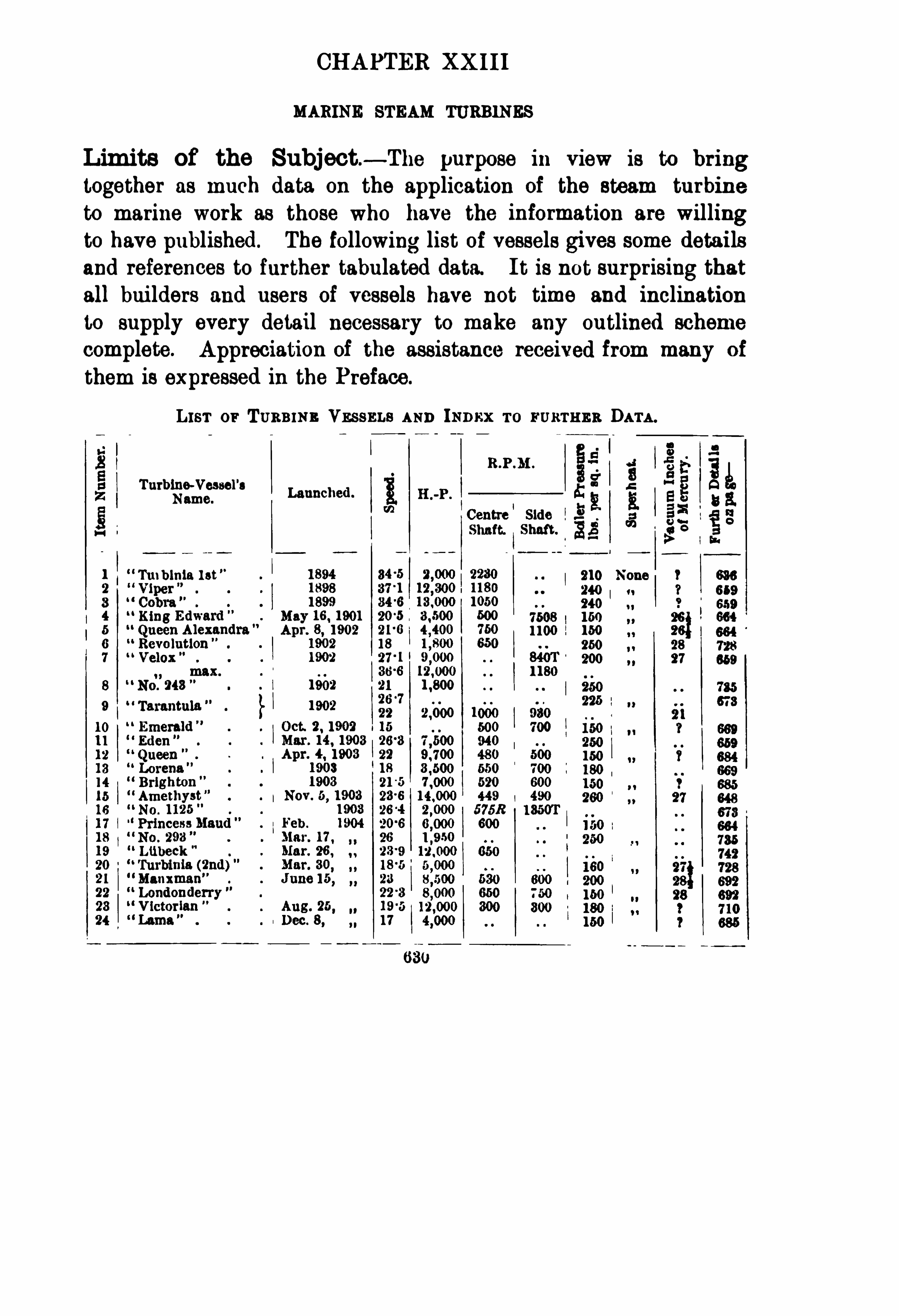
CHAPTER XX II I
MARINE STEAM TURBINES
Limits of the Subject — The purpose in view is to bring
together as much data on the application of the steam turbine
to marine work as those who have the information are willingto have published. The following list of vessels gives some detailsand references to further tabulated data. I t is not surprising that
all bui lders and users of vessels have not time and inclinationto supply every detail necessary to make any outlined scheme
complete. Appreciation of the assistance received from many of
them is expressed in the Preface.
h er or Tuanwa Vssssns AND 111s ro rusrnnn DATA .
8 IR.P.M .
g g i? 3ATurbine-Vessel
'
aA:g 8 8 he
Name.Launched.
1 1 s 5 BaI 2. 8. 5 3Centre Side :s S I 133111111. Shaft. g s e 5
Ti nblnia 1st 210 None 1 638
240 1 1 7 659240
7508 160 26} 6641100 150 es;
250 28
27200
2
°
o
°
co

632 STEAM TURB INE ENGINEERING
Law or Tuaams VESSELS AND Is p az ro m am as Dara— continued .
Turbine-Vessel’
lLaunched.
Name. a
Centre Side .3;Shaft. Shaft. 3
67 General Steam N. Co . Mar. 27 , 1906. 21 One by Messrs enny.
Kingfisher
M ary, etc. toBoulogne.
68 Burn Line One by Messrs Fairlield a Go
Ardrou an to Belfast.
69 Creole 15 0) tons, long,wit. beam, CurtisTurbines) .M organLme , Southern
70 Hamburg-Heligoland 20 6,
One by Vulcan, p. 748.
s.s. Co.
71 Caledonisn Steam 7 One by Messrs Denny.
Packet Co .
2—8 Alien Line Two larger than Victorian or“ Virginian.
74 Coast D evelopment One for River Thames by Messrs Denny.
Co London (BelleSteamers).
75 Metropoli tan S .S. Co. ,Two by Messrs Roach, Chester, Pa. , U.S.A .
NewYork76 Eastern s.s. Co . One by Messrs Roach, Chester, Pa., U.S.A .
U.S.A .
Condensers, etc .— Table CX I I I .
, p. 437 , gives the surface of
Marine Condensers, Steam per hour, and per square foot of con
denser surface and ratios of condenser surface to boiler heatingsurface, and of the latter
‘
t o grate area for turbine vessels, so far
as these have been ascertained.
Comparisons with Reciprocating Engines— An effort
has been made to put alongside the tabulated data on turbine
driven vessels dimensions of the reciprocating-engined vessel
which runs on the same route and is nearest in size to the turbine
vesse l .In mostcases this is incomplete, but in every case care has been
taken to avoid any confusion of the two by using distinctive type.
The turbinewas considered theoretically superior at high speedsto the reciprocating engines, and the Hon. C. A . Parsons
’
earliestwork used 2200 revolutions per minute, but the speed has been
reduced rapidly,and we have 300 revolutions on the Allan liners
and 180 revolutions as specified maximum on the new Cunardliners, with about 160 actual .Limits of Speed and Size — From the report of Professor
Bateau’
s paper before the Institute of Naval Architects,M arch
25th, 1904 , the following is outlined1. The total surface (size) of propellers is mainly determined by
the principal cross section of the ship.

MAR INE STEAM TURB INES 633
2. The size of the turbines is limited only by the speed of
rotation,and not by the power developed.
3. The speed of the turbine must be reduced in proportion to
the speed of the ship, so the dimensions of the turbine are increased
(either by increasing the number of rings or by increasing their
diameter).4. The power increases approximately as the cube of the speed
of the vessel .5. There IS a lower limit of speed, belowwhich the use of steam
turbines alone cannot be recommended.
6. Professor Rateau,in his paper before the Association
Technique M aritime in 1902, put this speed limit at about
20 knots for turbines alone.
7 . For reciprocating engines and turbines the same authorityfixes this limit at “ 15 knots, or even less.
”
8. Clearances between moving and fixed parts in the Rateau
type of turbine generally exceed 3 millimetres, and may even be
5 to 6 millimetres.
Other Opinions on the Lower Limit of Speed for
Turbine Vessels — Sir William White did not accept M r
Rateau’
s limit of 20 knots, and stated he had been designinga yacht with turbine engines which would have an economicalSpeed at 12 to 13 knots, the
“maximum speed being consider
ably higher.
Sir William White was one of the Commission of Experts
appointed by Lord Inverclyde and the other directors of the
Cunard Company to consider the question of turbines versus
reciprocating engines for their latest vessels.
Cunard Commission .— The complete list ofmembers of that
Commission in alphabetical order isI . M r James Bain,
M arine Superintendent of Cunard Company.
2 M r T. Bell, Engineer-D irector of M essrs John Brown Cc .,
3. M r H. J . Brock, of M essrs D enny,D umbarton.
4 . M r Andrew Laing,M anaging
-D irector of the WallsendEngineering Co.
5. M r J. T. M ilton,Chief Engineer-Surveyor of Lloyd
’
s.
6. Engineer-Rear-Admiral H . J. Oram, Deputy Engineer
-in
Chief of the Royal Navy.
7 . SirWm. H .White , representing M essrs C. S. SwanHunter, Ltd.
,Newcastle-on-Tyne.
Professor Rateau’
s limit of 20knots is evidently not accepted by

STEAM TURBINE ENGINEERING
The Parsons M arine Steam Turbine Company . as they have
equipped the Lorena ,Priiwess M aud, Tarantula ,
Turbinia (the one
for Canadian river service), Lhasa ,Lingo, A llan liners, and the
A lbion,etc.
,with turbines for lower speeds than 20 knots.
50 60
96 or SPEED
F IG . 438.— From H o arding/s Inst. Naval Architects.
Relative Consumption of Steam : Turbines rersas
Reciprocating Engines— Fig. 438 includes Professor Rateau
’
s
roughly approximate comparison of the general variation of
steam consumption per H .P.H . for a turbine and a reciprocating
engine ,assuming they consume equal quantities of steam at the
maximum speed. The steam consumption of the reciprocating

636 STEAM TURBINE ENGIN EERING
Going astern .— SirWilliam White considers too much im
portance had been placed on the power required with the engin es
reversed,as itwas not possible to go astern at very high speed .
In the case of the Viper a speed of 14 knots was made go ingastern : this was very high, and as the vessel was not then unde r
control , a less proportion of powerwould have been sufficient fo r
the backward motion.
1
The Parsons M arine Steam Turbine Company fi t separate
high-pressure turbines, as a rule
,for going astern on the
same shafts which carry low-pressure turbines for forward
propulsion.
Professor Rateau patented in 1898 a go aste rn turbine hidden
inside the low-pressure main (i .e. forward) turbine without using
additional space. This system was adopted in the French torpedo
boat No. 243, and in the Libellule, etc.
Economical Steam Consumption at all Speeds To
secure economy at all speeds a combination of reciprocating engine
exhausting into turbines has been advocated and tried. Professor
Rateau considers the division of power between the reciprocating
engine and the turbine should be
TABLE CXX .
— v 1s10n or Powsa BETWEEN Rscrraoca'rmo ENG INE AND
TURB INES 1x V ESSELS ADA P'I‘ED iron Ecoxourcu . Resunrs AT ALL
Srs sns.
Not less than
And can well be
The Parsons Patents 367 (1897 ) and 1655 1 ( 1900) deal With theuse ofthe reciprocatingengine for the expansion ofsteam from boiler
pressure , and for the further expansion of the reciprocatingengine’
s
“exhaust
”
the use of a low-pressure turbine. The economy in
fuel per horse-power developed by the adoption of this so-calledmongrel
”system is estimated 2 by the Hon. 0. A . Parsons as at
least 15 per cent.
Professor Rateau supplied two Rateau turbines on the two side
shafts to M essrs Yarrow Co. for the Caroline,which has
a 250 B.H .P reciprocating engine on the centre shaft.
The First Parsons M arine Steam Turbine — The firstvessel
fi tted with a steam turbine was an experimental one, and it was
put through thirty-one trials,with various arrangements ofturbines
1 Institution of Naval Archite cts,discussion
,March 25th
,1904 .
3 The Engineer, January 8th, 1904 , p. 46.

M AR IN E STEAM TURB INES 637
and propellers. These tests were described by the Hon. C. A .
Parsons,M .A ER. S., before the Institution of Naval Architects,
June 26th, 1903, and by permission the following details and re
Fio. 439. Turbinia (the First).
( The Inslitule ofW aters an dShipbuilders of Scotland . )
sults are reproduced, the results from the report of Professor J . A .
Ewing, in his series of tests of the Turbi 'nia in 1897 , and
some subsequent tests also beinggiven.
Name ofVessel
Date of first trial
Name ofBuilder
Place
Vessel’s length
beam
draught
displacement
Heating surface
Grate area
Condensers’surface
Expansion ratio
Air pumps
Circulation
Feed pumps
Oil circulation
Turbinia.
Nov. 14, 1894 .
The Parsons Marine Steam Turbine Co.
Wallsend-on-Tyne.
100 feet (305 metres).9 n
3'
9
445 tons.
One double-ended water-tubetype.
1100 sq. ft. (1022 sq .
42 sq. ft. (39 sq.
4200 sq. ft. (390 sq.
150 fold.
one main and one small spare.
by reversible scoops. Whenscoops not available, by small
pump.
one main and one spare.
to shaft bearings and thrusts
from one pump.

638 STEA}! TURB INE EN G INEERING
Going astern — In the three-shaft arrangement the midd leshaftwas extended forward and carried a go
—astern turbine and
a fan for forced draught.
Boiler,3 screws
,shafting, tanks
Hull complete
Water and coal
Total displacement 44 5 tons.
Flo. 440. Turbinia P.H.P. (10 to 32 Knots).


642 STEAM TURBINE EN GINEERIN G
TABLE CXXII .-RBsUL'rs or Warns Commun ion Tza'rs BY Paornsson
J. A. EWING, F .R.S. (ARRANGED m OBDBB on Bu rma. )
FeedWater M eter.
Lbs. per our.
1 Tests by M r Stanley Dunkeiey on behalfof Professor Ewing.
9 Supplementary test by M r Gerald Stoney.
From the curves of Figs. 440— 1 Professor Ewing obtained the
relations in Table CXX III . between the speed, the feed water, the
propulsive horse-power and the feed water per (pro
pulsive) H .P.H . (the numbers in brackets having been obtained by
producing the curves). These he plotted in Figs. 441— 4 , pp. 639—4 1 .
TABLE CXX II I .
Feed WaterPropulsive H.P .
Feed WaterSpeed in knots .
in lbs. per hour . P0?P.H .P . Hour.
Siemens MeterKent
Siemens
Siemens Meter1

644 STEAM TURBINE EN GI NEERING
undergone many trials, and having been to the Solent and bac k
and to Paris and back in the interval. She was next run withthree propellers of 28 in. diameter and 28 in. pitch, the resul ts
being shown in Figs. 446 and 447 .
The single propellers show the greatest advantage at about 21
knots, where the'
gain amounts to 2 knots.
Cavitation — The loss of efficiency which had been observed
at certain speeds in some vessels fi ttedwith tandem propellers on
each shaft seemed to be due to interference and cavitation,and Figs.
448— 450and the description ofthe Hon. 0. A . Parsons’
experiments1
made to demonstrate this are reproduced.
The extremely high speed, so far as marine propulsion is con
cerned, atwhich it is necessary for steam turbines to run in order
to be efficient, introduces some modification of conditions in regard
to the propellers. Water being a more or less viscous fluid,it is
only possible for it to flowin at the back of a rotating blade of a
propeller at a limited speed. If,therefore
,a very high number
of revolutions be adopted,there is apt to be a cavity at the back
Of the propeller ; this naturally detracts largely from efficiency.
In torpedo vessels propelled by ordinary engines the limit was
previously very nearly reached,if not passed,
and M r Sydney W.
Barnaby,Of Chiswick
,investigated this subject in connection with
the Thorneycroft torpedo-boat destroyers. M r Parsons had to
deal with this difficulty in a magnified degree, and in order to get
certain data on the subject he made some very interesting and
ingenious experiments. M odel screws, which were made to revolvewith great rapidity,
were placed in a bath of water brought to a.
temperature just short of boiling point. The immersion of the
screwwas proportionate to that Of an actual screwworking a
propeller. The ratio Of depth beneath the surface of the water
was a necessary factor in the experiment, for it wil l be easilyunderstood that the extent Of the vacuum is influenced by the
pressure Of the water in the neighbourhood Of the place where thevacuum is to be formed, and that pressure is, Of course
, governed
by the head of water above the spot. A close resemblance inthese respects to the actual working conditions of the screw being
thus Obtained,M r Parsons proceeded to actually show the pheno
mena that occurred in the followingway.
The water being near boiling point, the reduction in pressure at
the back Of the blades led to the formation of steam, according to
the well-known law that the boiling point occurs at a lower1 By courtesy of the Parsons Marine Steam Turbine Co.,
Ld .


646 STEAM TURBINE ENGINEERING
temperature as pressure is reduced. Intermittent illumination o f
the propeller was obtained from an arc lamp by means of an
ordinary lantern with condenser and mirrors. In this way the
propellerwas illuminated in a definite position of each revolution ,
the light falling on one point only, so that the shape, form, and
growth Of the cavities could be clearly traced, the propeller appearing stationary the cavities about the blades could also be observedin the same way. The propellerwas running at 1500 revolutions
per minute, and the exposure was of a second in duration .
In Figs. 448— 450 we reprint illustrations of these cavitation
experiments. In describing them,M r Parsons stated that a blister
was first formed a little behind the leading edge , and near the tipof the blade ; then ,
as the speed of revolution was increased, itenlarged in all directions, until, at a speed corresponding to that
of the Turbinia’
s first and original single propeller, it had grownso as to cover a section Of the screwdisc
,of When the speed
was still further increased,the screw as a whole revolved in a
cylindrical cavity,from one end of which the blade scraped off
layers Of solidwater,delivering them to the other. In this extreme
case nearly the whole energy of the screw was expended in
maintaining this vacuous space. This shows thatwhen the cavityhad grown to be a little larger than the width of the blade the
leading edge acted like a wedge , the forward side ofthe edge givingnegative thrust. In Fig. 448 the high speed of 1500 revolutionsOf propeller per minute is shown . By the aid Of these experiments
M r Parsons was able to determine the proper dimensions of a
propeller and the corresponding speed of revolution . The resulthas been that the total efficiency of the mechanism has been greatlyincreased
,and the high speeds attained experimentally have been
reached in practice.
The speed Of the latest largest turbines (for Cunard Company) ,it will be noted, was limited to 180 revolutions per minute.
Stopping the Turbinia from Full Speed— The Hon .
C. A . Parsons stated, M arch 19th, 1901 , in reply to the discussion
on his paper before the Institution of Engineers and Shipbui ldersin Scotland, that the propulsive power of the Turbiate was one
ninth of herweightwhen at full speed ; and when the steam wasshut off
,that retarding force alone (if it were continuously and
uniformlymaintained, and allowingfor themomentum ofthe stream
lines of the vessel) would bring her to rest in about 550feet.
Assuming the stern turbines were put into operation as quicklyas possible, he thought she would be brought to rest under 300feet

STEAM TURBINE ENGINEERING
British Admiralty.Third Class Cruisers.
Reciprocating-Engine Cruisers .
Topaze.
IAug. 14, 1902
Nov. 5, 1903
Nov. 1904. Nov. 1904Armstrong, Gamma”,
Camnial,
Whitworth Laird 00. d: I . 00.
81 CO .
Elswick Birkcnhead B irkcnhead
3601°
t.
89ft. 1051s . 89 11. 105111. 8912. 105111. 30fl .
4oh. 40fl . 40ft.Beam, including rollingchocks
Moulded depth (amidships) 21ft. 8in. Zlfl . Sin. 21./t.
Depth, upper deck to keel .
Depth, promenade deck to
healDraught
— mean l 4i'
t. 6in. 61311. Lift. I“.
Armament 12 4in. Q.F. 18 Q.F . 12 O. F . 13 Q.F .
8 8 pounder
s
84 11011111131 8-8 pounder 8-3 pounder
Q. F. gn Q.F . guns 0.F . guns Q F . gu ns
2 Maximsn
2 M ax ims 2 Max ims2-18in. torpedo 2 torpedo 2 18m. torpedo 84 8511. ta p ed
tubes above tubes above tubes above tubes about
water water waterDisplacement 8009 tons 3009 8009 tons
Protection, conmng tower 3in . IS in.
Protective deck over flat l in. , flat l in. , flat l in
machinery
s
paces slopes 2ih . slopes slopes 21111 .
Protective so at ends flat 0'
75iu ., fi at fi at
slopes l in. slopes slopes l in.
Speed (forward) 38 '
63 knots knots
Speed (astern)Radius ofaction at 20knots
, 8160 2140760 tons
Normal coal, 800 tonsAverage runningg s
‘pleedll speedTime to stop from
aheadHorse-power
Maker Hawthorn,Laird N or Reed
Leslie, 8100 . mand mand
Modified Yar water tuberow watertube
Number installed 109ingleended 1081.
11g1e ended waingleended 103-high
Tube diameter lgin.and1§in. 1u z11 a 1uf 0 and
(2 rows) 11“gim
Rated capacity (lbs . per
hour)Heating surface, sq. ft. 25 ,968
Grate area 4935Draught pressure (water) l
'
6in. to l'
7ih . I 7 1°
11. t02 6‘ 1’n.I


STEAM TURB INE ENGINEERIN G
Course of Steam when Cruising up to 14 knots.
Steam enters high-pressure cruising turbine.
Thence intermediate cruising turbine.
main high-press. turbine.
main low-press. turbine.
condenser.
At 18 and 20 knots the steam first enters the intermediate
cruising turbine, the high-pressure cruising turbine being out of
service.
At full speed the cruising turbines are both out of service.
For Comparison.— Reciprocating Engines in otherVessels.
Reciprocating-Engine Cruisers.
Amethyst. Sapphire. D iamond .
Piston Engines
Maker Cammell,d: I . Co. Laird cf: Co.
, Laird ct Co. ,
B irkenhead .
TypeNumberCylinders , diameters
Revolutions per minute ,
full speed
StrokeRated power, condensingRated power, non con
deusingComparat
'
we Steam Cou
sumption.
l a. per hour of steam at 100 per cent.
20 knotsLbs. per hour of steam at 80 per cent. 100per cent.
18 knotsLbs. per hour of steam at 100per cent .
14 knotsLbs. per hour of steam at 100per cent.
10knotsExhaust 1 steam fromauxilia
xengines
Ame yat”
passed to .
Coal burned per hour, full
speed
Condenser
Made byType
1 This gives the reciprocating engines an advantage.

STEAM TURBINE ENGIN EERING652
aav
vow
v.
96
.
En
bm
$
59
5
.
n
9
1.
goes
Swab
33.
we
?one
a
bm
Pam
.
n
fima
n
m
N.
gwa
$
8
as
am
mam
om
v
ow
dpm
a
mm
mm
b.
N.
3
h.
m5
5
80m
.
o
e
5.as
53
em
ma
ze:
wm
cmwas
omma
ze
em
39
80
0
2
.
se
u
se
323
S
.
w.
.
z
mhe
34

653M ARINE STEAM TURBINES
3.
as8“
a
s.
Q
a».
S
a
s».
e.
a
s
new.
SN
a
:
e
d
SN
SN
3
m
g
see
secs
Se
36
a
s
we
a
ma
ss.
mess.
683
.
o
63
£3s
.
e.
a.
a
n
was
3
as
as.
nfim
s e n s e s
w
as
as
as
as
as.
as
is
wa
s
Se
5a
a
s.
was
we
:
SS
was
8x
sea
as
was .
as .
a
s
“as
New
was
$
5
$8
9
3
a
n
was
as
s
8
3
33
$
3
was
we:u
se
s.
s..
see
N
ew
ea.
a.
was
we
as
S
3
9
2
24
«N
3
ea
“
a
8
ea
8
as
R
3»
e
a.
5
as
«
5
g
SN
k
u
se
.
wfis
ea
as s
ume
te
a
ge
ne s
is

STEAM TURBINE ENGI NEERING

STEAM TURBI NE E NGINEERIN G
TABLE CXXVI IL— Coxru usox or Torn . Sru u Consuxm on.
Amethyst.
24 Hours’ Trial at 10Knots.
I
I.H .P. (Indicated horse
power)Speed
'
1n knots .
Totalwater per hour in lbs.Water for auxiliary lbs .
per hour
Water for auxiliary— per 21 tcent. of total per cm
Water per I.H .P. hourlbs.
24 Hours’
Trial at 14 Knots.
Speed in knotsTotalwater per hourm lbs.Water for auxiliaries— lbs.
per hour
Water for auxiliaries— per
cent of total
Water per I .H .P. hour lbs.
30Hours’ Trial at 18Knots.
Speedm knots .
Totalwatc1 r hourm lbs.
Water per I . . .P hour
I.H .P.
Speed 1n knots .
Totalwaterper hour 1n lbs.
Water per I .H.P. hour
Amethyst.
4 Hours’Trial at Full Power.
I .H.P. . 14 ,000l
10,200Speed
— knots 23 06 23 63 21 826 22 103 22'
34Totalwaterper hour 176 ,845 l . 190
,£525 l . 309
,950lbs. 199 ,140lbs. 226“4401113
Water per I .H.P. hour 13 6 lbs. 13'
6 lbs. 2 1 98 lbs. lbs . 23 2 lbs I
l The Indicated Horse-power of the Steam Turbine Vessel is equal to that of the duplicate vessels.
It is clear from Figs. 452— 5 that the turbines of theAmethyst
are more economical than the reciprocating engines of the duplicatecruisers for speeds above 15 knots
,and less economical below
15 knots.
Warships steam at cruising speed for 90 per cent. to 95 per
cent. of the time they are in service.

MARINE STEAM TURBINES
TABLE CXXIX — Coxrluusoxs or Con . Consol es Br Dorms/1m CamerasTuasmss versus Rscrrnocarmc Escmss.
Type ofEngines. Turbines. Reciprocating.
Amethyst. Topaze. Sapphire. D iamond .
24 Hours’Trial at 10Knots.
Indicated horse-power 897 ‘
Total coal burnt 31 tons
Total burnt per hour . 2893 lbs.
Total
gun t per hour per
Ezraticn per pound of (M
coal
M iles run per ton ofcoal
24 Hours at 14 Knots.
Indicated horse-powerTotal burnt
Total burnt per hour .
Total burnt per 1.H.P. per
hour
Evaporation per pound of 9'
85
coal
Miles run per ton ofcoal
80Hour: at 18 Knots .
Indicated horse-powerTotal coal burnt
per hour
I.H .P.
Evaporation per pound of 9 15
cal
Miles run per ton ofcoal
8 Hours at 20Knots.
Indicated horse-powerTotal burnt
per hour
I.H .P.
Evaporation per pound of
coal
Miles run per ton ofcoal
4 Hours at Full Power.
Indicated horse-power
Total coal burnt— tons
per hour— lbs
I.H.P.— 1bs.
dEvaporation per poun of
coal— lbs.
Miles run per ton ofcoal l
1
1 The power in the case of the Amethyst is, of course , assumed?the form of the ship is identical in
a 1 cases.

658 STEAM TURBINE ENGINEERING
TABLE CXXX — CourAs ArrvE STEAM Consunr'rron rnou THE FULL
Genu s or Fro. 46 4, STATED IN PERCENTAGES,ABE
At 10knots Topaze uses 19 per cent. less than Amethyst.
15 same as Amethyst.
16 knots Amethyst uses 6 per cent. less than Topaze.
18 17
20 21
21 33
22 36
TABLE CXXX1.— COMPARISON or TOTAL STEAM or
“Ansrsrsr”AND
MAIN ENGINES STEAM or TorAzs .
”
Lbs. per I .H.P. Hour.
M echanical Amethyst Topaze"Main Recipro
Engineers Research Turbines including eatingEngines, emludCommittee Trials. Auxiliaries. ing Aum
'
liaries .
Main consideration. Economy in Steam.
“W“vizgé
nmm W ’fi fi
'
fi'wm
14 knots
TABLE CXXX II .— Se or AM ETHYST’S PBopELLEE s AT D IFFERENT
SPEEns (MEAN or THREE PBorELLEBs).
10 knots 113 per cent.
14 l3°
6
18
20
very heavy weather23 63 smooth sea
TABLE ( XXXIII .— Ru ne s or ACTION or
“Amethyst”COMPARED m a
Topaze. Coal capacity 750 tons each vessel.
Type 01 Engine.
Parsons
Speed knots Radius N .M . Radius N .M Advantage
10 6670 7800 31 per cent.14 4950 5100 3 per cent.18 3600
20 3160
22
per cent. speed
14 radius

STEAM TURBINE ENGINEERING
Cobra.
” Velox. Eden.
H'
h-pressure Turbines
umber 2 1 2
Position outer shafts. outer shafts
Revolutions per minute 1180 1060
Low-pressure TurbinesNumber 2 2
Position inner shafts inner shafts
Revolutions per minute 1180
Cc-astern TurbmesNumber 2 2
Position inner shafts inner shafts
Revolutions per minuteRated horse-power con
densingRated horse-power non
condensingPiston engines I.H .P. each
Maker .
Type
NumberCylinders’ diametersRevolutions per minutefull speed
Connected to l.p. Tur
bine shaft by
Stroke .
Rated power condens
ingRated power non-con
densingSteam consumedWei ht of steam per hourfu l apsed
Coal burned er I .H.P.
hour at spec
Coal burned total per
hour
Condenser
Made byTypeNumberSurface, sq. ft. 8000
Surface of augmentcr none
Illustrations of vessel Fig. 456 Fig 457
Guaranteed Speed knots 31
From preliminary experi
ments
Steam per I.H .P. hour 159 118.
Propulsive coefficient, i s. 55 per cent
ratio of ropulsive
H .P. to I .H.E.
1,1Starboard turbines were independent ofPort turbines in
“Viper and in Cobra.
31 knots,lbs.
27 knots25 lbs.
knots,26
'
2 knots See Table
7°
35 tons tons CXX X V1.,
11} knots , p . 663 .
n ot. per
hour.

MARINE STEAM TURB INES 661
TABLE CXXXIV.
“VELox ” TRIALS.
Mean speed 1 hour at full power . knots
Fastest pair of runs, mean
Mean revolutions per minute 1180
Forced draught (water gauge) 4} inchesFastest run
represented I .H.P.
Flo. 456 Viper.
(The I nst. of Enyrs. an dShipbuilders of Scotland. )
TABLE CXXXV .
Taking-over Trials on River Tyne.
Full power, mean speed 270 7 knots.
Coal consumed tons per hour.
2
Steam pressure 200 lbs. per sq. in.
Boilers in use 4
R.P.M . of turbines 840
Vacuum 27 inches ofmercury.
Coal Consumption Trial of Reciprocating Engine.
D uration of trial 12 hours.
Speed knots.
Coal consumed cwts. per hour.
Steam pressure 212 lbs. per sq. in.
R .P.M . of engines
Vacuum inches ofmercury.
1 The E ngineer, 241, M arch 6 , 19 03.
2 The Engineer, p. 39 , July 8, 1904 , gave tons per hour at knots.
Recent Torpedo-Boat D estroyers.
1— For comparisons , we
give below a return made to an“order of the Honourable the
1 The E ngineer, supplemented by data on coal,by courtesy of the builders
ofdestroyers built and launche dbetween January 1st, 1902, and July 1904 .

662 STEAM TURBINE ENGINEERING

STEAM TURBINE ENGINEE RIN G
Isle ofMan Steam Packet G.W. Ry. Cc. , and3mm”
Co. o.s. Ry. (Ireland).
Name of Vessel Viking.
Date oflaunch March 7 , 1905Name ofbuilder Armstrong,W. Co.
PlaceVessel
’s length overall
BeamDepth, upper deck to keelPassenger accommodationSpeed .
Boilers .
Pressure
Turbines
D isplacementPassengers accommodatedShafts .
High pressure Turbines . numberLow-pressure Turbines : number
1 The St George,”
St Patrick, and St David will run between Fiahguard, North
Pembrokeshire, and Rosslare , Co. Wexford. The journey is 64 nautical miles (62 statute miles) .Timc , 2}hours.
9 Season'
swork : 8880 nauticalmiles on 4210 tons of coal, ton per K.M . ; average speed,
221 knots . Economy over Reciprocating vessel on same route , 28 per cent. , and one engineer,two greasers, and one fanman less stair.
Turbine Steamers, Ltd. ,
s tain John Williamson ,Managing
irector.
River Clyde Passenger Service,Greenock and Campbeltown.
Turbine Vessels.
R‘Ciprm i"?Engine Turbine
King Queen D zwhess ofEdwa Alexandra. I Hamilton. Maud.
Feb.no, 1904
Place
Vessel’
s length overall 250572. 300 ft.
Vessel’
s ls 11 betweenperpendicu er
Bea
Moulded depth to maindeck
Depth to promenade deckDrau ht
Rud ere

MARINE STEAM TURB INES
Turbine Vessels.
King“ Queen
Edv a Alexandra.
Pass
qnger accommodation 1994or
Number ofcrewlst class2nd class8rd class
700562
20°48 knots 21 63knots
Average running speed
Horse-power, from Messrs 3500
Denny’a tank experi
mentsBoilers
Maker . Denny Co . Denny 8: Co.
8 furnaces
Return tube Largedouble
double ended
ended.
Number installed 1
Rated capacity (lbs. perhour)
Heating surface, total .
Grate area
Draught pressure (water) ins.
Steam pressure 150 lbs. per 150 lbs per
in. I sq. in.
Feed-beaterreceives steamexhaust from
D iameterNone. None.
Number
5 5
Per shaft Centre Each Tandem side‘:shaft. side. propellers,l 2
Number ofblades eachOne. Four.
57ins. 40ins. 48ins. 36ins.
Distance apart Mt.
Rudders
Triple Ea:
paneton
Estimate.
lD uchess qf
1 Queen Alexandra’
s prepallers changed 1008 to one each shalt.
Princess
l aud.
”
150
60 ins.
at bothends

STEAM TURB INE ENGINEERIN G
King QueenEdward . Alexandra.
Made byNumber
Steam steeringgear by
Hi h-pressureTurbinesumber 1 1
Position Centre shaft Centre shaft
Revolutions perminute 500 750
Expansion Five fold
Lowpressure TurbinesNumberPosition
shaft
Revolutions perminute 760
Expansion 25 fold
Total expansion 125 fold
Go astern Turbin
Number 2 2
Inside ex Inside ex
haust end of haust end of
l. p. turbines l.p. turbines
Revolutions per minuteRated H.
-p. condensing
Rated horse-power non
condensingFor comparison . Rec1pro
eating Engines in
Pia
oth
lgr
.
vessels
ton n as :
Maker .
gin
Cylinders diametersRevolutions per minute
full speed
Stroke .
Rated powercondehamgRated power non con
dousingSteam consumedW ht of steamper underI5 lbs.
I . .P. hour full speed
Coal burned per hour full
speedMam Condensers
Made by
fi berSurface
Surface of augmenter(ifany)
Power used by augmenter
Steamerfor commfi son.
Triple Ea:
l aud.

STEAM TURB INE ENGINEERING
Turbine Vessels.
KingEdward.
” Alexandra. Hamilton.
Vacuum inches mercuryRevolutions per minuteh.
p. turbine
Revo utions per minutel.p. turbine
Revolutions per minutereciprocating engines
Average sea speed on 160
miles run to Campbeltown andback
Ave coalconsumed, ih 18 tons
clu ingli hting, perdayAverage consumedper 1
‘8 lbs.
equivalent I.H .P. hour
FIG . 459. Queen Alexandra.

MARINE STEAM TURB INES
TABLE CXXXVI I .— Conrs nrsos or COAL Consunr'rron.
Reciprocating
Days running . 79 80
Total knotsTotal ofcoal burnt I 1480 tons 1909 tons 1769 tons
Average speedI 18}knots 185 knots 165 knots
Coalpermileat same speed 264 lbs. 353 lbs. 253 lbs.M iles per ton of coal 85 6Q 9
Authority Capt.Williamson Capt. Wi lliamson The Mechan ical
Engineer, Feb.
1,1902
STEAM TURBINE YACHTS .
Name of Vessel Narcissus Emerald Io rena Libellule Albion
Built for . A. E. M iller Sir
Mendy, Christopher
Derby Fumess
Mr Gould
Turbine yacht1903
Dec . Oct.
F. J. Stephen Cox & King,
LondonFairfield A . Stephen Ramage a
a Son Ltd. Ferguson ,
Place Glasgow Leith
Vessel’s length 245ft. 236ft. 263ft. 270ft.
Length between per 198ft.
pendicular
Beam 28ft. 8in. 33ft. Sin.
Beam,1ncluding rolling
checks
Depth, moulded . l8it. 6ih . 20ft~ 3ih .
Depth, upper deck to
keelDepth, romeuade deckto kee
Draught
Passenger accommodation
Tonnage, by yachtmeasurement
Displacement 1303 tons
Speed forward knots 1
astern
Length ofJourney
1 With 240 to ns of coal on board.
His Majesty the King of England’
s yacht is equipped with turbines . The Mahrouasa, the Khedive'
s
yacht, ls also equippedwith turbines. See p. 031 , items 60and 61.

STEAM TURB INE ENGINEERING
S'
rm Tunama Yaou'
rs— continued.
Narcissus”
Elnorald Lorena Libellule
Average s
peed
Horse
m-ge-power I .ma 8500
Boilers
MakerType Mult1tubular Single
-endedScotch
Number installedRated capacity (lbs. perhour)
Heating surface, total .
Grate area
Draught (water) pressureForced draught
— t
Steam pressure bs. 180 lbs. 150 lbs.
per sq. inch.
unnels :
Number
Superheaters none
Shafts
D iameter
Number ofblades eachDiameter
Steam turbine Rateau
Made by Parsons Parsons,
weight1
TyreCruism TurbineNum er
Position
H1
§h-pressureTurbinesumber 1 1
Position Centre shaft Centre shafl:
Revolutions per minute 500 550
Low-pressure Turbines :Number 2 2
Position Each side Each side
shaft shaft
Revolutions per minute 700 700
Go astern Turbines
NumberPosition
Revolutions per minuteRated horse-power con
densingRated horse-power non
condensingSteam consumedWei
glht of steam per hourspeed
1 70tons lessweight than the reciprocatingmachinery originally designed for the Lorena.


reciprocating
Steam pressureatboiler?At step valveIn h .p. TurbineIn 1.p. TurbineVacuum (mercury)
R evolutions rminute:Centre Tur
'
ne
WingTurbinesAir and circulatingpumps
M ean speed onmeasuredmile
Steam pressureboilers per sq. in.
Steam ressure in h.p.
Turb ne
Steam pressure in l.p.
TurbineVacuum inchesmercury
at
MARINE STEAM TURB INES
Sm u Tuna!NB Vacu a-M ud
Narcissus.’ Emerald.
”
Lorena.
” Libellule.
150 60
Su m Tunama Vasame BUILT BY Mnesns Yan owa Co LTD .
Turbine Steam Reciprocatingand Turbine
Yacht. Steam Yachts.
Tarantula. Caroline.
”No. 1125 .
Col.M‘Calmon
Mr W. K . Russia
Vanderbilt,1902
Yarrow“
Data kindly supplied by M essrs Yarrow 00 .
Albion.

67 4 STEAM TURB IN E ENGI NEERING
Srs AM Tenants Vaseline— continued.
Turbine Steam Reciprocat'
and Turbine
Yacht. Steam achtet
Tarantula. Caroline. No. 1125.
Place Poplar,London PoplarVessel
’s length overall 152ft. 6in 152ft. 6in
Length between perpendicular
I Depth
Tonnage by yachtmeasDisplacement 140 tons 140 tons
Dra ht 5ft.
Spee knots forward 26 4
astern Reci roosting Reciprocatin
10 14 knots knotsLength ofJourneyAverage runningHorse-powerBoilers .
Maker Yarrow
Righ t installed
Rated capacity (lbs. per hour)
Heating surface tots
Grate area, tototalDraught pressure (water)Steam pressure— lbs. per sq. in.
Funnels
Number .
DiameterSuperheaters none none none
Shafts :
D iameter
8, later 5
r shaft centre sides2 centre sides
umber ofblades each 8
Diameter 37in. 32iu.
34in.
SteamT urbine
Made by Parsons OerlikonWorks
Type Rateau Tur Parsons
binesNumber
Recip. Eng1ne 250B .H.P.
Course of steam .
Reciprocating Engine
Number none
Horse-powerPosition .
Revolutions perminute .
1 Later 86in. propeller on each shaft.
2 See p. 082 for the five propellers ; only the original 3 are referred to here.
3 Reciprocating engine takes steam from boiler and delivers exhaust to condenser. Turbines
do likewise.

67 6 STEAM TURB INE ENGINE ERIN G
STEAM TURBINE Vrs sicLs— continued.
'
lhi rbine Steam Reciprocating;and
'
Ihi rbine
Yacht. Steam achts.
Tarantula. Caroline. No. 1125 .
Electric-lighting Engine
Maker
“iiK. capacity eachPosition
Drawin ofvessel
oftur ins
ofcondensing plant
ofreciprocating enginesIllustration of vessel .
ofTurbines
Feed PumpsMade byTypeNumberWater cylinder diameterstroke
Steam cylinder diameterCapacity per hourSteam consumed per hour
Oil circulation umps
Oil pressure, bs. per sq. in.
Steam consumed per hour
Boilers, includingwater .
Turbine machinery— lbs . 17 ,2oo1
Main reciprocating engines
Shafting
Test Res ults Tables belowWhenfir inghowmany boilers .
1
Guaranteed speed .
Six hours’
trial speed
Mean speed on measuredmile
Whenfi ring all boilersGuaranteed speed .
M ean speed 011 measuredmileWith di splacement
Steam pressure at boilers, lbs. per
. in.
in .P. turbine
in L.P. turbine
Vacuum,inches mercury
Revolutions per minute H.P.
Turbine
L P.
’
h irbine
reciprocating engines
Fuel liquid“3 Welsh coal Welsh coal
1 Capable ofover 2000 horse-power ; 815 lbs. weight per horse-power output.
9 D ie Turbine, p. 28, Oct. 1904 .


MARINE STEAM TURB INES 681
TABLE CXXXVIII. —“ Oaroline RESULTS or Finer Tss'
rs or a s Ym owa Co.
’s Tonn no Boa-r u '
t rub wrrn one Rscrrsocsrmo Enema TwoRu n e Tusnmss. (Fig.
Trials m October 13th,1903 (wind rather strong).
Each of two turbine shafts had a three-bladed propeller, 32 in. diam. 30 in. pitch.
The centre (reciprocating engine) shaft had a propeller 48 66
Number ofTrial. II.II I I .
Number ofruns on measured mileNumber ofpropellersEifective pressure of steam on
admission to high-pressure tur
bine, lbs. per sq . in .
Condenser vaccuum— inches
Speeds attained in various runs— in knots
Mean speed of vessel— in knotsRevolutions perminute ofrec1p1ocating engine
Revolutions per minute of high
pressure turbine
Revolutions per minute of low1ressure turbine
E. . .P developed on shaft oi'
reciprocatin engine
Slip of prope ers driven by re
ciprocatin engine
Slip ofprope lers driven by high
pressure turbineSl1p of propellers driven by low
pressure turbine
The E .H.P. developed on shaftwas arrived at by deducting 10per cent. recorded by the Wattindicator.
1 In the first trial the reciprocating engine alone received steam, while the turbines revolved
idly , due to the action oi the water on their propellers. The other trials were made withprogressively increased steam pressure, supplied to the high-pressure turbine.
9 The low-pressure turbine gave more power than the high-pressure turbine , due, ProfessorRateau stated ,
to the condenser giving better results thanwere anticipated.
The complete absence of vibration was especially note
worthy.
Additional Propellers on Carolina’
s Turbine Shafts.
Curves B, C,
and D , Fig. 47 1 (opposite), showed that the
propeller surface was rather too small for speeds above 21 knotsA second propeller was consequently added to each of the turbine
shafts.

682 STEAM TURB INE ENGINEERING
TABLE CXXXIX — Rnscurs or Snooun Tns'rs or Masses Ysm w Co.
’s
ToarxDo-Bosr.
Trials r un January 19th, 1904, with 5 propellers.
On the middle shaft (reciprocating engine) one propeller 42 in diam. 66 in. pitch .
one side shaft (high-press. turbine) two 33 33
other side shaft (low 32 32
Number ofTrial
E ilective pressure oi steam on
admission to high pressure tur
bine— lbs. per sq . in.
Condenser vacuummercury
Speed of vessel (two runs)knots
Mean speed of vessel— knotsRevolutions perminute of reciprocating engine
Revolutions per minute of
.
high
pressure turbine
Revolutions per minute of low
pras sure turbineSl1p ofpropellers driven by reciprocating en
gine
Slip of prope ler driven by high
pressure turbine 13 6 7,Slip of propeller driven by low
pressure turbine 24‘
0‘
X,
l The turbines were designed for 156 lbs. per sq. in. For the same steam consumption
the speed is less than on October i sth,1903 (see previous records, p . except at
maximum speed.
The two screws on each turbine shaft give better resultsthan the single screws in the previous trials, but the efficiency
of the turbines is much less, their speed having been greatlyreduced.
The added screws, located near the hull, gave rise to consider
able vibration.
To obtain the estimated efficiency of the turbines it wasnecessary to reduce the propeller surface and allow the
turbines to revolve faster ; this was done for the third set of
trials.

STEAM TURB INE EN GINEERING
Date of launch
In regular passenger service
Name ofbuilder
PlaceVessel
’
s length overall
BeamMoulded depth
Depth .
Promenade deck to keelDraughtWatertight bulkheads, numberPassenger accommodation ,
re'
stered
lst c ass
2nd class
3rd classDisplacementNet re
'
stei
Speed onward— knotsSpeed astern— knotsLength ofJourneyTime on journey
Running speed knotsHorse-power I.H.P.
Boilers
Maker
Nyurzber si ls-euded
Number ddl
u
gble-ended
Rated capacity, lbs . r hour
Heating surface, tots
Grate area
Draught pressure (incheswater)
Steam
;pressure (lbs. per sq .
in.
Funnels
D iameter
Queen.
South-Eastern and Chatham Railway 00 .
Dovar— Calais.
Turbine Steamers.
Onward . Invicta.
April 4 , 1903 March 11,1905 April 19 , 1905
June 28,1903 Spring 1905
Denny Denny
Dumbarton Dumbarton31Oft.
4oft.
3loft.
40ft.
26ft. 6in.
1700 tons

British India Steam Navigation Co.
’
Zealand.
Newhaven and D ieppe.
Turbine Driven.
Anmdel. “ Linga.
” “ Lama.
” “ Lunka.
”
8, 1904
Aug. 1904
M ary J: Denny
D umber-ton Dumbarton300ft.
43ft.
106020113 2440tons
ao-u
m
113-03°
18-03
'
30; at.
l The l aheno, 5500 tons, 7000 li .P 17 ) knots.3 turbine-driven propellers, has been added to the of
N .Z.
’s fleet. 400 feet long, 60 feet beam, 32; feet deep . M aheno accommodates 223 first-class, u s second-c lass,
60 third-class passengers. Trials Sept. as. 1905,with 3000 tons dead weight. 17 15 knots with all boilers. I t has
2 double-ended,2 single-ended boilers, B owden
’
s forced draught.
3 The “fi ngers”and two sister ships 2300 tons, 6000 H.
-P., 18 knots, 3 turbine-driven propellers added to
the Co.
’
s fleet. 800feet long, built by M essrs Workman-Clark.

STEAM TURB INE EN G INEERING
Turbine Steamers.
Queen. Onward ” Invicta.
"
totalofblades each
Diameter
Made by Parsons SteamTurbine Co.
Governors
H'
h pressure Turbines
umberPosition
Revolutions perminute.
Expansion
Low-pressure TurbinesNumber
I Revolutions perminute
Expansion
Total ratio ofexpansion
Go-astern h rbines :
NumberPosition
Revolutions perminuteRated horse-power condensingRated H .
-p
.
. non-condensingFor comparison . Reciprocating
Engines .
Piston Engines
Maker .
Cylinders diameters
l Queen has only three propellers now, 7zim. andWins. diam.

STEAM TURB INE ENGINEERIN G
Turbine Steamers.Steamer.
Name of Vessel Queen. Onward. Invicta.
R.p.m. full speedStrokeRated power condensingRated power non condensingSteam consumed .
Weight of steam per hour fulls eed
Coa r I .H.P. hour— lbs.
Coal urut at full speed
Surface
Power used byAir Pump and Circulating 1 beam engine
Pump .
Maker
Vacuummaintained at full
discharge at full
Steamdper hour used at full
Ai
znp
ifump barrel diameterstroke
Steam cylinder diameter
Strokes perminuteCirculating Pump on air pump
engine shaft
Made byTypeSteam per hour at full speed
Weight of simulati ng water !
per unitweight of steamTemperature suctionTemperature discharge
Electric lighting Engine .
Maker
Position
1 Queen does journey in 9 minutes less time than Victoria and Empress on the same weight of coal.

M ARINE STEAM TURB INES
Turbine Driven .
Brighton.
” “Dieppe. Arundel.“ In ongana.
” “Lhassa.
“Linga.
” “Lama.
1 In a comparisonwith a Reciprocating Vessel of equal power by Mr R . J . Walker at Liverpool Eng. Soc Feb .
1906. the Dieppe consumed l '
8 : i'
8 ; 20 lbs. per B .P.H . against the reciproca ting vessel'
s I °S and P6 lbs o
per H .P .H . at full, threeq uarters , andjone-tbird power respectively.

STEAM TURB INE ENGINEERING
Turbine Steamers.
Queen. Onward. Invicta. Vida -( q
Steam TillerMade by Brown Bros.
Figures .— Crosssectionshowing Fig. 472
turbines and condensersIllustration of vessel Fig. 473
Weir
Water cylinder diam. strokeSteam cylinder diameterCapacity per hourSteam consumed per hour
Oil circulation— pressure
— consumption infinitesimall
Steam consumed per hour
Boilers, includingwaterTurbinemachineryMain reciprocating enginesShaftin
otal
Guaranteed speed, knotsFour-hour trial, knots .
Mean speedonmeasuredmile, 21 76
knotsSpeed with h.p. steam in 13
two l. .p turbines,h.p.
turbine running idle
Steam pressui e at boilers pe1
In
s
t.
“l
p. receiver per sq. i
In 1.p. turbine (mean) 119 1 121113.
sq. in
Vacuum— mohes mercuryR.
p.. .m horse-power turbinep. turbine
Reciprocating engines .
Engine-room staff .
S'
ngrom forward speed of
Vesselbrought to restm time
Vessel brought to rest in
distance
Retardation feet per sec.
‘3
Average superiority over
paddle steamers
Ing‘qdweather
In weather
1 Chairman ,S .E . Ry. Co .

692 STEAM TURB INE ENG INEER ING
Van s “w as. 00p a n. L 9 M .
F IG . 472. — The Queen. S.E. St C. Ry. Co. Dover-Calais.
Cross-Section of Steamer, showing Turbines and Condensers.
Servi ce M idland Railway Co.
Heysham Harbour to IrelandRoute
and to Isle ofMan.
Turbine Steamers.
Name of Veasel Manxman . Antrim. D onegal .
June 15 , 1904 Mar. 22, 1904.
M essrs Biles, Gray 8; Cc . ,London.
Wm. Denny [Viokers, Sons, John B rown Ca ird ti
and Bros . 8: Maxim «b Co.
, Ltd . Ltd.
Place llunibarto n Barrow Clydelmnk Greenoclr
Vessel’
s length overall 33nit. Ju’
Ufl . 421017.
Length between porpcn~
dicular
BeamBreadth (moulded) 42ft.
Depth, upper deck to keel M fr.
Depth , promenade deck to 251‘.ft
keel
D raft ltlft.
Passenger accommodatio n
l st class
2nd class
3rd class
D isplacement 2400 to ns 2400 t ons
Gr oss tonnage’086 2174
Net 629
iSpeed forwar d knots 23 knots


696 STEAM TURBI NE EN GI NEERI NG
Name of Vessel
Rated h.-p. non-condensing
eating EnginesMaker
TypeNumber .
Cylinders diameters
Revolutions per minutefull speed
StrokeRated power condensing .
Rated power non”con
densingSteam consumed .
Wei ht of steam per hour
fu 1 speedWeight of steam per hour
halfspeed
Coal burned per hour (fullspeed)
Main Condenser
Made byTypeNumber
Surface ofaugmenter
Steam used by augmenter
Illustration
Air PumpMakerTypeSupplementary dry air
pumpVacuum maintained at
full speed
Temperature of discharge
at full speed
Lbs. steam per hour used
at full speed
Illustration
Turbine Steamers.
Manxman.
DonnySurface
2
8700
Augmenter condenser by none
Air pump barrel diameter “ins. x 9ins. 23ins.
O
x Sin.
and strokeSteam cylinder diameter
Strokes perminute .
Circulating PumpMade by Paul,
barton barton
10ins.
Dum Paul,Dum
Reciprocating Engines .
4 m m. M I.
1. B row'
nA:Go. Caird 4: Co
Clydebank GreenockTriple ezpans. trip le armies .
I2
two ofMine. two of“in s190 190
30ins.
No data available .
B rown rd
24'
5 ins.
My 492201m. x 16uw. 2012713 . x 16m

MARINE STEAM TURB INE S 697
Turbine Steamers. Reciprocating Engines.
Nam of Vessel . Manxman. A ntrim. D onegal.
TypeSteamp. hourat fullspeedWeight of circulatingwater per unit weightofsteam
Temperature suctiondischarge
Electric-lighting Engine two turbines two turbines two rec ip ro
cating eatingMaker Parsons D e Laval Bellies d: Bellies «t
M oreom M arcomT
Kywcapacity eachPosition shaft tunnel engine-room
Drawin ofvessel Figs. Figs. F igs
of tur ine Figs.
and 484
of reciprocating engim s F igs.
for comparisonofboiler arrangement Fig. 488 to 49]
ofcondensing plant . Fig. 486
of slip ofpropeller Table CXLI . Table CXL I .
Photographs of vessel .
of engine room Figs.
7
485 and48
of turbine details
of condenserof air and circulating F ig. 49
pumpsof rec1procating engines
Feed PumpsMade by Weir Weir Weir c ir
Type direct double direct double direct double direct double
act. act. act. act.
Number . 2
Water cylinder— diame tei 1 line.
strokeSteam cylinder diameter . 26ins. 26ins. 36 ill8.
Capacity per hourSteam consumed per hour
Oil circulation two Weir
Steam consumed per hour
Boilers, includingwater 390 tons 460 tons
Turbine machinery 160 tons
Mainreciprocatingengincs
Shafting
.
Propellers
Total 575 tons 630 tons
Weights of propellers obtained by difference from total weights as stated, July 20, 1005, and partialweights in Engineering.


"I ,O YR‘A’O
FIGS. 480and 481.
M ARINE STEAM TURB INE S 701
Fm. 480.
TURBINE ROOM .
Fm. 481 .
M idland Ry. Co.
’s S.S. Londonderry and Manxman .
”


704 STEAM TURB INE ENGINEERING
By the courtesy of M r William Gray of M essrs Biles, GrayCc .
,who designed these vessels, many details not previously
published are included above.
Our acknowledgments for illustrations are due to the Institution
of Naval Architects, the M idland Railway Company’
s Officials,
and the Editors of Engineering.
Tu m CXLI .— a or.u'rrons AND Su es or Tenants 1 1m Rscrraoea'mro
Eas tman Smr.
l l am a.
”
Speed.
M eanRevolutionsPercentage Sli
MeanRevolutions
per M inute.p.
per M inute .
15 knots
Position of Starting Platforms .
— In the M anxman the
starting platform is on the same level as the turbines ; in the
Londonderry it is on the level of the deck above, and the effect
is not quite so satisfactory in respect of light, or overseeing by the
engineer-in-charge.
Fig 485 on the previous page is reproduced from a photographic
view looking towards the port side of the ship, and shows all three
turbines. The high-pressure turbine is in the centre, and the
mechanism connected with the governing is clearly indicated.
Governing Turbines .
— The governors, which are mounted on
each shaft,only come into operation in the event of a breakdown ,
or of excessive racing of the propeller shafts. The system of
centrifugal governor generally adopted in Persons turbines moves
a smal l relay plunger which regulates the steam admitted to a


STEAM TURB INE ENGINEERING
F m. 488.
m u 0?
F LI N I f ”PFC. DEC“
80 !LER ROOM .
Fro . 489.
FIGS. 488 and 489. — Midland Railway Co.
’s Four Steamers Londonderry,
”
“Manxman,
”Antrim, and Donegal.


M ARINE STEAM TURB INES 709
relay ,which in turn actuates the main throttle valve, generally of
the balanced double-beat type. The exhaust from the steam relayis utilised for the steam packing of the end glands. Thus the
governor, having only to move the small plunger, has very littlework to do
,and therefore can be made very sensitive . The
sensitiveness is still further increased by keeping the whole
governor gear in slight movement by connecting one of the pivots
of the lovers with a cam. These movements are so rapid as not
to affect the even turningmoment of the turbine.
Steam By-pass to Intermediate Stage
— Ou the top of
the high-pressure turbine is the by
-pass valve which is used for
the admission of steam at full pressure to an intermediate stage on
the high-pressure turbine , so as to increase the power— at the
expense, however, of economy . D uring the trials of the M nnxman
no such high-pressure steam was admitted at the intermediate
stage, the turbines beingworked to the full degree of expansion.
Steam to Glands,eta — The pipes for the admission ofsteam
to the glands, as well as the smaller pipes for oil and waterservice
,are also shown. The passage
-way between the turbines
leads to the after-end of the engine-room
,where the oil pumps are
placed, as well as to the tunnels.
Some Test Results — Two other trials were made over the
measured mile,and the results
,subsequent to the official test, may
be given
TABLE CXLI I .
— Uxorrrcu n Teer or M I D LAN D Ru nway Co .
’
s Srnan sn
M ANXMAN .
”
M ean speed of two runs
Boiler pressure per sq. in.
Steam in high-press ure turbine
low-pressure turbine, portstarboard
Vacuum in condenser, por
starboardRevolutionsperminute , high
-pressure turbine
lowTemperature of feed-water leaving heaterAir-pressure in stokehold
TABLE CXLII I .
— Orrlcmn Tns'r or M IDLAND RA ILWAY Co .
’s SrsAnna
M ANXM AN .
”
Mean speed
Revolutions,high
-pressure turbine
Revolutions,low-pressure turbine
1 Vacuum, port
Vacuum,starboard
l The vacuumwas read by a mercury co lumn connected to the main condenser discharge .

7 10 STEAM TURBINE ENGINEERING
Augmenter Condenser — The high vacuum was maintainedthroughout frequently as high as 29 in.
,by the use of a vacuum
augmenter. In it the air pumps are placed about 3 ft. below the
bottom of the condenser (Fig. 486, p. From near the
bottom a pipe is led to an auxiliary condenser, about one
twentieth the cooling surface of the main condenser, and in a
contracted portion of this pipe 8. small steam jet is placed,
which acts in the same way as a steam exhauster,or the jet in the
funnel of a locomotive, and sucks nearly all the residual air and
vapour from the condenser, and delivers it to the air pumps. A
water seal is provided, as shown in Fig 486, to prevent the air
and vapour returning to the condenser. Thus,if there is a vacuum
of 27} in . to 28 in. in the condenser, there may be only about 26
in. in the air pump, which therefore need only be of small size, the
jet compressing the air and vapour from the condenser to about
half of its original volume. The smal l quantity of steam from this
steam jet, which is only about 15 per cent. of that used by the
turbine at full load,together with the air extracted, is cooled down
and condensed by the auxiliary condenser, which is general lysupplied with water in parallel with the mam condenser. Con
densation in a condenser takes place much more rapidly and
effectually if the air is thoroughly extracted than if there is much
air present.
Allan Line Cc . , Ltd.
Liverpool to Canada.
Pioneer Turbine Vesselsfor Ocean Service.
Recaprocatmg Enym a.
Name of Vessel Victorian. Tunisian . Bavarian.
Jan . 17 , 1900
A: Son
Vessel’s length overall
Beam
Bulkhead compartments .
Water-tight spaces , totalDraught .
Passen er accommodationl st c ass
2nd class
3rd class

7 12 STEAM TURBINE ENG INEER ING
Pioneer Turbine Vesselsfor Ocean Service.
Victorian .
”Virginian. Tunisian . Bavarian.
Rated h.-p. condensing
Rated h.-p. non-condensing
For comparison ReciprOo
eatin
gEngines
Piston nginesMaker Denny
pe Triple Earp .
umberCylinders diametersR.p.m. full speedStrokeRated power condensingRated power non-con
densingSteam consumedWei ht of steam per hourin 1 speed
Wei ht of steam per hourha fspeed
Coal consumed perhour (fullspeed)
Condenser
Made by D ennyType Hart
’
z. tubular
NumberSurface
Surface of ‘augmenter
condenser
Power used by‘aug
menter ’ condenserAir Pump : Fig. 492
Maker Weir
T pe Beamseuum maintained at 28in.
full speedTemperature of discharge 80
at full speed
Steam per hour used at
full speedAir pump barrel diameter 31in. x 21in .
and strokeSteam cylinder diameter 1 lin. x 21in.
Strokes perminuteCirculating PumpMade by GwynnTypo
Steam perhourat fullspeedWeightofcirculatin waterperunitweight 0 steam
Temperature suctiondischarge
Electric-lighting Engine
M akerType Enclosed

MARINE STEAM TURB INES 7 13
PioneerTurbine Vessels I
for Ocean Service.
M procatzng Engines.
Virginian. Tunisian. Bavarian.
K.W. capacity eachPosition ’Tween decks
Telegraph system and print Marconiing outfit
Illustration ofvessel Fig. 493
Illustration ofturbine details Fig. 494, 515
Illustration of condensingplant
Feed PumpsMade by Weir
Type Vertical
Number 2
Watercylinderdiam. stroke 14in.
Steam cylinderdiameter 19in. x 3oin.
Capacity per hour 11 strokes permin.
Steam consumed per hourOil circulationSteam consumed per hourWeights
Boilers, includingwaterTurbine machineryMain reciprocatingenginesShafting
Total
Number ofboilers in use 8
Guaranteed speed, knots 17
per hour
Six hour trial speed 18'5
Mean speed on measured 19
mileMaximum speed on meas 195
9
ured mileR.p.m. of turbine 26073 (298)Whenfi ring all boilersGuaranteed speed 17M ean speed on measured 19
mileSteam pressure at boilers 180
per sq . in.
In h.p. receiver 170
In l.p receiver 26Vacuum, inches mercury 28
Revolutions per minute h.p. 297turbine
Revolutions perminute l.p. 300
turbine
R.p.m. reciprocating engines None
1 The l.p . turbine weighs 78 tons. 2 This speed and revolutions per minute with (estimated)H .P. on March l 6th, 1905 , of! Skelmorlie. Other tests made on Clyde, M arch 2oth, 1906 (bottom
not cleaned before trials after lying up 3 months) , and included herewith data and photos on p . 7 78 ,
“an. 515 and 516, by courtesy ofChief Engineer, J . W . Hendry .
3 400 tonsweight saved by turbines. J . H. Biles , LL.D . , British Association,1905 .


STEAM TURB INE ENGINEER IN G
Cunard S.8. Co.
Liverpool to NewY ork and Boston.
Mercantile Cruisers.
Tuasms Srmu sas. Rf 6 l7fl'
uoafi r‘ i
'j ll l ’t
Name of Vessell
m'
n
rt
nr
gige
é .
Cum in
Lac.”
l Date of layingkeel plate May 17 ,1904
Date of launch Feb 21,
Ju ly 13 ,
1905 1904Date of completion Nov. 1905 1906 End 1907 Jan. 1
1905
Name ofbuilder
Cl de
bznkVessel
’s length overall
Between perpendicular 660
Breadth 72m.
Includin rollingchocks
Depth mou ded 62ft.
keel to roof navig. 90ft.
bridge
keel to funnel top l i 4ft.
mast top 205ft.
Boat deck 80
D raught 33111. 33 or34ft.
Passenger accommo da 3100
tion and crewlst class
2nd
3rd
Steerage
Otiicers and crewGross tonnage
D isplacement 30,000
21 knots 25 knots 25 knots
l ('
aroula equal to the Saxonia,tested by Navy Bo iler Committee, E ngineering, 723, Dec . l st, 19 6
131 lbs. steam per
1 1 '
s 1 lb. coal.

M ARINE STEAM TURB INES
Tuanwa S'
rns nsns. Rec iprocating.
Cmnpan iaN ame of Vessel m n
r
flge
di
aCaro nia . and
Lucaa ia.
A verage running speed 18 knots 25 knots 25 knots 18 22 k nots
Quickest run Queenstown 6§ days 7 days esti 5 d. 7 hr.
and NewYork estimated 23 m.
Horse-power I.H.P. to 7 to to
estimated estimated estimatedBo ilers
M akerTypeNumber installed
Furnace diameterRated capacity (lbs . perhour)Heating surface
,total sq
Grate area 1200sq.ft.
D raught pressure B owden’
s
(water)Steam pressure (lbs. per
sq . in . )Funnels
NumberD iameter
Superheaters
Pro ller Shafts
umberD iameterWe
'
ht
Pro 1 ers per shaft
umber ofblades eachD iameter
S team’
h irbine
Made by
H igh pressure Tur
bines
NumberPosition
Revolutions per minuteLow-pressureTurbinesNumberPosition
Diameter of rotor

STEAM TURB INE EN GINEERING
Tuanwa Su n rises.
Mauri OrderedName of Vessel tame .
”July 1905.
Caronia .
Length of rotor
Revolutions perminuteGo-astarn TurbmesNumberPosition
Revolutions perminuteRated h.
-p. condensing
Rated horse-power non
condensingFor omnparison Recipro Height from shaft
eating Engines centre, 30ft.
Height from bed, 36ft.Piston Engines
MakerTyre
R epart
Cylinders diameters
Revolutions perminutefull speed
Stroke
Rated power condensin
Rs power non-con
densingPressure
For both Turbines and
Reciprocating Engines
Steam consumedWeight of steam per hour
full speed
Condenser
Surface
Ifany augmenterSurface of
paVyacuum maintained atl
1 Csrmania has also two double dry-sir pumps 20 in. diam 7 in. stroke.


'
STEAM TURB INE ENGINEERING
TURBINE STEAM ERS.
Unnamed.
July,1905.
Caronia.
Steamconsumedp. hour
Boilers, includingwaterTurbine machineryMain reciprocating en
gines
ShaftingTotal .
Savingofweight over re 2% to 32, sameciprocating engine
Numberofboilers in useGuaranteedspeed,knotsper hour
Six-hour trial speedMean speed offour runson measured mile
1 Each l.p . turbine weighs 340 tons.
2 Each l.p . turbinewillweigh about 420 tons . Csrmanla’
s turbines contain blades.
Fm. 503.
FIGS . 503 and 504.— Cross-Section Carmania and Caronia Engine
-Rooms.

STEAM TURB I NE ENGINEER IN G
TABLE CXLIV.— RESULTS or OFF ICIAL TR IAL “CARONIA .
Average for 12M ean of 4 Runs. Hours.
Revolutions per minuteI .H .P . port
I .H .P . starboard
Total I .H .P .
Boiler pressure lbs. per sq. inch
H.P. receiver pressure
I sl I .P . receiver
2nd I .P . receiver
L.P. receiver
M ean speed of ship 196 2
American Turbine Vessels.
Turbine.
1
Ste
amship 5113? U.S.A. Navy Turbine Vessels.Toronto.
Besi
%er
Tur
Name of Vessel him231“
$ 279(thesecond) Street
NewYoi'k.
Date oflaunch 1905 (1)
Name ofbuilder
PlaceVessel
’s length overall 420ft. 420ft.
Length between perpondicular
BeamBeam,
including rollingchocks
Depth,upper deck to
keel
D raught
D isplacement ton 3750 tons 3750 tons
1 To suit canals between St Lawrence river and Hamilton.
9 A second for th is service , but American built,was announced by The Engineer, p. 47 1 , Nov. 11th, 1904.
8 The E ngineer , Feb. 2sth, 1905 .4 M arine Engineer. January 1906 .

MARINE STEAM TURB INES
TurbineStea
c
r
gshlp $2211? U.S.A. Navy Turbine Vessels.
Toronto.
Dominer
TurT.
binia ’ Tavlor, Armoured Scout Scout'
(thesecond)221 Mercer Cruiser.
“ Salem.
” “ Cheater.
Street,
NewYork
Speed forward 24 knots 24 knots
Speed per hour asternLength ofjourneyAverage runnin 8 edHorse-power I 151P
a
BoilersMaker
16,
DiameterHeating surface, totalGrate area
Draught pressure
(water)
per sq. m.
Heatin surface per
1.H.
Heating surface per sq.
ft. grate
I.H.P.per sq. ft. ofgrateSuperheaters Probably none
1 none
ShaftsNumberDiameter
Pro llers per shaft
umber ofblades eachLength ofbladesDiameterPitch 3ft. 4in. 12ins.
Steam Turbine0
Made by Parsons Curti sturbine turbine
1 Produced by small Curtis turbine, 2800 revolutions perminute .
3 H .P. turbine 122 lbs. ; L P. turbine 46 1i). Vacuum 27 ; inches.
3 The shaft is inside a 15-inch diameter tube between hull and keel, beginning 5 feet shaft the bow, and ending5 feet forward of stern, and is geared to turbine. E ngineering Times , p. 418, September lot 904. Repeated
inquiries by letter bring no news of tests .

STEAM TURBINE ENGINEERING
Steamshi P’
to
00 0 ,
P {atU.S.A. Navy Turbine Veu els.
Toronto.
TurTa lor, Armoured Scout Scout
binia u
(thesecond)22
Stregl
t?“ Cruiser. Salem.
” Chester.
NewYork 1
Parsons
Revolutions perminute
Low-pressureNumberPosition
Revolutions perminute(lo-astern Turbines
Position
Revolutions perminuteRated horse-power con
dousingRated horse-power non
condensing
Ste ofblades
h row
lDiameter : inches
outside case
ofblades
1 Steam enters through four nozzles into lst stage ,where it expands from 285 lbs. per sq. inch absolute to 16
lbs. per sq . inch absolute . I t passes through another set of four nozzles into 2nd stage,where it expands to less
than 1 lb. per sq . inch .
3 (lo-ahead 6 feet 6 ins., go
-astern 5 feet 6 ins., total 11 feet 0 ins.

STEAM TURB INE ENGI NEERING
TurbirfigStet P 5252? U.S.A . Navy Turbine V essels.
Toronto.
Desi or
..m,ii
3 6 7 011»binia
J, Taylor, Armoured Scout Scout
tion.
”221 M ercer Cruiser. Salem.
” Cheater.
”
'(the second) S I t
NewYo’
rk
Feed Pumps
gyade by
lak"
B 0
Hugh “ 2
Water cylmder dis
.
6 ins. x 9
meter ins. x asins. x 8
ins.
StrokeSteam cylinder diameter . 28ins.
Capacity per hourSteam consumed per hourOil circulation . Two Weir
Steam consumed perhour
Pressure
Boilers,includin water 140 tons
l Tu1bine mac inery 821
lbs.
H per 58
throttle to exhaustShaftingAuxiliary machinery
I Tests See p. 7ss Seep. 734Engine room staff for 34OOH .P.
estimated H.P. 1 engineer
1 oilerandwatertender
3 firemen
1 coal
passer
1 Reciprocating engines of torpedo boats 11} lbs. per I .H.P. The turbines in Revolution had never been apart
since first put up, covering a period of I ; years — Report, U.S . Navy Bureau ofSteam Engineering, Oct. 6th. 1913 .
Trials under control ofProfessor E. Denton from 96 to 1100 brake horse-power.
Tests of the Revolution.— Tests have been made to
determine the power given out by the turbines. A length of
torsion-shaftwas inserted in the tail shafting, and apparatus was
provided for ascertaining the angle of torsion. A t the same time
the steam condensed during the tests was pumped into measuring

M ARINE STEAM TURB INES 7 33
tanks on deck. The trials were under the control of ProfessorJames E. D enton. Tests were made at various powers, rangingfrom 96 brake horse-power to 1100 brake horse-power per turbine,and Professor Denton reports The economy from the turbine
is therefore probably quite equal at full power to that afforded byaverage high
-speed marine triple-expansion engines, and it is nearlythe same for one-tenth of full power.
”
He adds,that by an
improvement, which he suggests, the water consumption can be
considerably reduced. The weight of each turbine, from its
throttle valve to the exhaust pipe flange, is 8§ lb. per indicated
horse-power, and the space occupied is one-tenth of a cubic foot
per indicated horse-power. The indicated horse-power is arrived
at by adding a percentage to the brake horse-power. The Revolu
tion commenced her trials in April 1902, and has been runningfor many months. No repairs whatever have been made on the
turbines, and so far there has been no appreciable wear. Three
pairs of screws were designed and built for the boat before the
trials commenced. The speed proved to be very nearly the same
with all of them,although the revolutions of the turbines varied
from 750 to 600 per minute. As the displacement of the vesselis 18 per cent. more than the builders estimated, none of the
screws is exactly adapted to the conditions (Engineering,D ecember
11th, 1903, p.
1800 I .H .P. was developed at 672 revolutions per minute,using lbs. per I .H .P. in these two-stage Curtis turbines.
(From Professor D enton’
s tests,Jour. Am. S.N.A November
Quick Stop Trials — Running full speed ahead, then sud
denly reversing both turbines, the vessel came to a standstill in32 seconds.
Curtis Turbine versus Reciprocating Engineer— Recip
roosting engines, built especially light for U.S. torpedo boats,
weigh 11§ lbs. per as compared with 82lbs. per equivalentI .H .P. of the Curtis turbines in the Revoluti on.
Oil Consumed by Reciprocating Engines— One gallon
of oil per ton of coal burnt was given as a rough figure for the oil
consumed in marine reciprocating engines, by The Steamship ,
August 1904 , p. 43.
Turbinia. (the second).— Passage to America,Stornoway to
Sydney, Cape Breton,6 days. Average Speed IH knots per hour.
Coal capacity 110 tons.

7 34 STEAM TURBINE ENGINEERING
TABLE CXLV . Tuanwu ”(ran Snconn) TRIALS.
Pressures. On Lake Ontario. Regular Runs.
Boiler— lbs. per sq. in .
In i s
HP)
Turbine — lbs. per. sq. in .
LR
Vacuum,mercuryastern turbine
BarometerD istance
,miles (5280 it.)
Time,minutes
Coal— lbs. per I .H .P. hour
Feed water,temperature F .
Evaporation— lbs. per lb. coal
R.p.m. centre Turbine
R.p.m. starboard wingRevolutions per minute portwingOil pump pressure
— lbs.
Temperature injection water 52°
F .
discharge
Belgian State Railways.Dover-Ostend.
Turbine Vessels.
m om m m mDate of launch
Name ofbuilderPlace
Vessel’s length over all
I Length between perpendicularBeamBeam,
including rolling chocksDepth, upperdeck to keelDepth, promenade deck to keelD raught
Passen r accommodationS ed orwardorse-power estimated
Boilers 150 lbs. per sq . in.
T pe Multitubular
Nyumber 8
Steam'
h irbines
Made byNumberType .
1 Thiswas tenth vessel added to fleet ofnine reciprocatingvessels .
'
1he Princess Clementine”
has reciprocating engines of9000 I .H .P.
2 “ Princess Elizabeth”has sq . ft. heating surface , 484 sq . ft. grate , H .P . turbine in
centre and l.p . on each side, 600 18 knots speed astern. Budders fore and aft
Mar. 80, 1905
Socie'
teA. John CockerillHoboken, Belgium
355ft.
344i!"4oft.
344
305ft.
9ft.
"lin.
1000
24 knots


M AR INE STEAM TURB INES 737
FRENCH NAVY : TORPED O-BOATs— continued .
Name of Veasel No. 243 No. 293. No. 294 .
Feed PumpsMade byT
Feedie
eater byOil circulation
Steam consumed per hourFilter by Normand
Boilers,includingwater
Turbine machineryMain reciprocating engines
Shafting'
l‘
otal
Guaranteed speed 20 knots.\ican speed on measured mile .
Number ofruns averagedMean spee d2 hours continuousrun
Revolutions per minute h.p.
turbine
Revolutions per minute l.p.
Consumption of steam dur ing8 hours
'
trial at 14 knots perhour
Condition of vesselNo. 243 has been tried with six
different arrangements of
propellers, in pairs and bythrees on each shaft
Highest speed at full powerCorrespondin to variation ofeiliciency 0
Results of two trials
TA BLE CXLV I .— Tas'
r Rnsuurs or A RATEAU TURBI NE DRIVI NG A THREE
PHASE ALTERNATOR . (DUPLICATE or TURBINE IN FRENCH Toarnno
Boar No .
Revolutions per AdmissionPressure Steam, Lbs. per
Minute. Lbs. per Sq . In. Hour


7 40 STEA M TURB IN E ENG INEER ING
The tests were made under the direc tion of French Admiraltyengineers on a liquid resistance ‘ load
,
’
the turbine tested being
a duplicate of that installed in French Torpedo Boat No. 243.
The, efficiencies represent the following ratio
Ftfir iencvefi
'
ective power developed on turbine shaft
power in steam consumed,assuming no loss
between pressure of admission and pressure at
exhaust into condenser. (See Figs. 236 , 237 ,
pp. 358,
The values tabulated were obtained by reducing the speed of
rotation to the uniform speed of 1700 revolutions per minute ,and
the condenser vacuum to 26 inches ofmercury.
The test gave 54 per cent. etficiencv. The original estimatedvalue is stated to have been per cent.
At full power
Steam pressure on admiss ion 145 lbs. per sq . In
Revolutions per minute 900 1
Tota l steam per hour lbs.
Steam per effective H.P. hour on shaft lbs.
2
Efliciency as defined above 54 per cent.
Effective H .P. on shaft __ 920 H .P.
1 Professor Rateau, before Institution of Naval Architects , M ar. 26th , 1904 .
2 At 1800R .p m. , the speed for which the turbine was designed , the efficiency is rather higherand consumption lower.
TA BLE L\'
I l. — FRENCR TORPEDO -BOAT No . 243. F ITTED wrrn RATEA UT l‘RBlNES.
Trials run December 6th,1902.
Four propellers, 209 inches diameter,
230 inches pitch.
Number of Trial 1.
Speed knots— (mean of 2
runs)Revolutions per minute of
turbine
Effective pressure on ad
mission to h.p. turbine,lbs. per sq. in . 80
Condenser vacuum,inches of
mercurv 28 4 26 268
Mean slip of propelle I s 31 12, 304 2 311 /o
l Gauges fa iled . Pressure therefore no t recorded .

MAR INE STE AM TUR B IN IS 74 1
TA BLE CXLVH I .
~ — FRENCH TORPEDO-BO AT No. 243.
Trials run January 22nd, 1903.
Six propellers : diameter, 236 in. pitch, in .
Number of Trial
Speed of vessel (in knots)mean of three runs 170?
Rotation of turbines— revol
utions per minuteEffective pressure of steamon a dmi ssion to turbines— lbs. per sq . in. 1009 8
Condenser vacuum— ins. of
mercuryM ean slip ofpropellers
TABLE CXLIX .— FRENCH TORPEDO-BOAT No . 293.
Trials run J am 1904 .
Per Horse-power Hour.
Speed— Knots Draught.
Steam.
Same as at 26 knots Sameas at 21knot
More than at M o re than at
19 knots 19 knots
The ‘cruising
’turbine runs idle
above this speed
above 21
_"m ( 100mm.) Same as at 14 knots Same asat 19 knotswater gauge
1 E ight hours'
trial at 14 knots , 361 kgs. of coal per hour.
‘2 Two hours'
full speed trial, knots average.
261538 knotsmaximum.

STEAM TURB IN E ENGINEERING
GermanMerchant M arine.
German TurbineCruisers.
American.
Name of Vessel Ltlbeck. Wacht. s 125 . Kaiser.
Date of launch 1904 1904 Apr. 8, 1905
Name ofbuilder F. Schichau Howaldt’s i Vulcan
Trials n
Vessel’s ength
Vessel’s length between
perpendicular-s
7 metres,
7‘
20 metres,
23°
5ft.
10ft.
Displacement 500 tons 1950 tons
Gross tonnage
Speed forward knotsastern
Length ofjourneyAverage running speed
Horse-power I .H. l’.
Boilers
MakerType
Number installedRated capacity (lbs. per
hour)Heating surface
,total
Grate area
Draughtpressure (water)Steam pressure
Funnels
NumberD iameter
Superheaters none none
Shafts
NumberDiameters
Propellers , per shaft 1 each shaft
Number ofblades eachDiameter
The Hamburg ls sister ship to the Duba i , but has reciprocating engines.


STEA ."TURB IN E EN GINE ERING
German Merchant l arine.
German Turbine
Name of Van d Lflbeck. Wacht. S 125 .
Vacuum maintained a t
full speed
Temperature of dis
charge at full spe d
Steam per hour used at
full speed
Air pump barrel dia
meter and strokeSteamcylinderdiameter
Strokes per minuteCirculating PumpMade by
Steam r hour at full
speedWeight of circulatingwater perunitweightofsteam
Temperature suctionTemperaturesottie-lightingEngine
Maker
TywK. capacity eachPosition
Illustrations pp. 744 , 7 45 pp. 746 , 74 7 p c u
l The German navy has ordered 30 Parso ns tnrbi i ce fo r l l) n nuns .
TA BLE CL. Recon!) CO AL Coxsunr'
rlox— (l lleemnoc u lxc Exc is ns).
Service . Vesse l'
s Name . Per I .H.P . Hour.
1 The E ngineer, December 2ard, 1904 , p. 625 .
The Hamburg Heligoland 00 . has a turbine vessel 2000 to ns, 300 ft. long, 38 ft. beam. 20
knots ,with 2 shafts driven by Curtis turbines built by Vulcan
,
"Stettin.

CHAPTER XX IV
BIBLIOGRAPHY 1
WHILE no claim to completeness is put forward for this Biblio
graphy ,it is nevertheless, exclusive of library compilations,
probably as exhaustive as any which is yet available to the
general reader. It comprises not only the books and articles towhich the writers have had occasion to refer in the course of their
own studies of the subject of Steam Turbine Engineering, but
also a large number of references published from time to time in
technical periodicals.
The Bibliography is divided into five sections, dealing respec
tively with the following subjectspass
Section A .— Steam Turbine Engineering in General, and
Descriptions of particular Types of Turbines belowB .
— Particular Plants 762
C.— Superheated Steam 768
D .— Condensing Plant 7 7 1
E .— Marine Installations
The references in each section are arranged in the order of
their dates.
SECTION A .
STEAM TURBINE ENGINEERING IN GENERAL,AND
DESCRIPTIONS OF PARTICULAR TYPES OF TURBINES.
1888.
Description of the Compound Steam Turbine and Turbo-Generator,
” C . A .
Parsons Proc. Inst. M ech. Eayrs., p. 480
,Aug.
1889 .
Notes on the Steam Turbine,”J . B . Webb (Amer. Soc. M ech. Eayrs. Trans ,
vol. x . p. 680,1888
1 For the preparation ofthis Bibliography the anthem are indebted to Mr F. R. Senior.
749

750 STEAM TURB INE ENGINEERIN G
Tests of a 10 H .P. de Laval Steam Turbine,W. F . M . Goes (Amer. Soc.
M ech. Engrs. Trans.,vol. xvii. p. 81
,
Tests to showthe Influence ofMoisture in Steam on the Economy of S .T.
(ibid.,xviii. p. 699,
1899 .
Heat Engines and Steam Turbines,
” C. A . Parsons (Electrician, xliv. pp.
83-84,Nov. 10
,1899 . Presidential Address to the Institution of Junior
Engineers) .1900.
Steam Turbines (Elec. World and Engineer, xxxv. pp. 308—313,March 3
,
Parsons Steam Turbine”
(Amer. E lectrician,xii. pp. 124- 127, March 1900 ;
also M och. Engineer, v. pp. 409— 411,March 24
,
Steam Turbines”
(Amer. Electrician,xii. p. 133
,March
Steam Turbines,
” R . H . Thurston (Amer. Soc. of M ech. Engrs. Trans,xxii.
p. 170,Dec.
Steam Turbines,” F . Hodgkinson (Paper read before the Engineers
’Society
of Western Pennsylvania, Nov . 20,1900, Railroad Gazette
,xxxii. pp.
857-860; Dec. 28,
Steam Turbines (Amer. E lectrician,xii. p. 565
,Dec.
Rapport sur Ice T. aVapeur,” Rateau (Congres I . de M Paris
,
1901 .
Steam Turbines”
(E lec. Rm,N .Y ., xxxviii., Jan. 5
,
Steam Turbine”(Engineering, lxx. pp. 830—831, 1900 ; also Electrician, xlvi.
pp. 425 —428, Jan . 11,
Tests on a 300 H .P. dc Laval Steam Turbine,
”W. Jacobson (Zeitschr. Vereiwm
D eutsch. Ing.,xlv. pp. 150- 15 1, Feb. 2
,
“Steam Turbines for Electric Lighting”
(Feilden’s M ag , p. 364-369, March
Seger Steam Turbine (Genie Civi l, xxxviii. pp. 3 13-315, March 9,
Steam Turbine,”J . A . Ewing (Electrician, xlvii. pp. 254— 256 , June 7 ,
Steam Turbine Trials, C . A . Parsons and G . G . Stoney (Inst. M ech. Eng. Proc. ,
iv. pp. 797-812. GlasgowEng. Congress (Section
Brown-Beveri Steam Turbine ” (Zeitschr. Vereines Dmtsch. Ing.,xlv. p. 1583,
Nov. 2,
The Future of the Steam Turbine,
”W. E. Warrilow (E lec. Review, Nov. 15,
Tests of the de Laval Steam Turbine,” E. Lewicki (Zeitschr. Vereines Deta ch.
Ing.,Nov. 20
,
The Steam Consumption of the de Laval Steam Turbine, A. Schmidt
(Zeitschr. Vereines D autah. Ing.,Nov. 23
,
1902.
Recherches Experimental“ cur l’Econlement de la Vapeur dc l’Eau (Jimmie
,
par A. Rateau. Paris : D unod, 1902.
Brown-Boveri-Parsons SteamTurbine (L’Ind. E lwin
,April 10, 1902, p.


B IBLIOGRAPH Y 753
M itteilungenuber Dampfturbinen von Brown-Boveri-Parsons,
” O. Reidt
(Z. d. V. d. Ing., Jan. 23,
Riedler-Stumpf Steam Turbine, R. H . Smith (Engineer, xcvi. pp. 587— 588,Dec. 18
,and pp. 611— 612, Dec. 25 , 1903 also M ech. Engr.,
xiii. pp. 356
359, Mar. 12,
Theory and Construction of Steam Turbines,P. Stierstorfer
,1904 . Leipzig
Oskar Leiner.
Westinghouse Steam Turbines of Large Output (Amer. Electrician,xvi.
pp. 60-61,Jan .
Steam Turbines,
”R iedler (E lektr. Bahnen
,Jan .
Turbo-Alternators and Double-Current Generators for Glasgow (E lectrician ,
lii. pp. 442— 443,Jan. 8
,
Experiments on the FlowofSteam from Apertures and Nozzles of Various
Forms,
” M . F . Gutermuth (Zeitschr. Vereines D eutsch. Ing.,xlviii. pp. 75
84,Jan . 16
,1904 . Commun ication from the Maschinenbau Laboratorium
der Technischen Hochschule,Darmstadt) .
Experience with an Installation of Brown-Boveri-Parsons Steam Turbines,
O . Reidt (Zeitschr. Vereines D entsclt. Ing.,xlviii. pp. 118- 121
,Jan . 23,
Electric Governing of Steam Turbines”
(Western E lectrician,xxxiv. p. 69
,
Jan. 23,
Steam Consumption of the Turbo-Alternator (Engineer, xcvn . p. 108, Jan.
29,
Convention of the North-Western Electrical Association ”
(Elec. World,Jan.
30,
The Turbine Problem,H. F . Schmidt (Amer. Electrician, xvi. pp. 76— 80
,
Feb.
High Power Steam Turbine”(Power, Feb.
Curtis Steam Turbine,”F . Samuelson (E lectrician,
Iii. pp. 596— 598, Feb. 5,
1904 . Paper read before the Rugby Eng. Society).Steam Turbines,
” F . C . Porte (Paper read before the D ublin Local Section
of the Inst. Elec . Engrs.,Feb. 11
,1904
,Journ.
,vol. xxxiii. p.
The Riedler-StumpfTurbines”
(Engng.
,Feb. 12,
The Steam Turbine,
”Chilton (Elec. Rev.
,Feb. 12 and Feb. 19,
Steam Turbine Dynamos,”F . Niethammer (Zeitschr f. E lektroteclm. Wi en
,
xxii. pp. 7 7-80, Feb. 7 , 1904 , and pp. 96 -100,Feb. 14
,1904 Elec. World
and Engr.,xliii. pp. 558-560
,Mar. 19
, pp. 595 — 598,Mar. 26
,
Curtis Steam Turbine, Barker (Engineering, Feb. 19,
Expansion of the Steam in the Nozzles of Steam Turbines,
"A . Koob
(Zeitschr. Vereines Deutsch. Ing.,xlviii. pp. Feb. 20
,1904 . Paper
read before the Bayerischen Bezirksverein).
Turbo-Electric Wagon”
(M ech. Engr.
,xiii. pp. 254— 255 , Feb. 20
,
“Test of a 1250 K .W. Steam Turbine,
”A . M . Mattice (Elec. lVorld and
Engineer, xliii. pp. 356— 360,Feb. 20
,
The Brush-Parsons Steam Turbine ” Chilton (Electrician, Feb. 26,
Steam Turbines,
” F . Hodgkinson (E lectric Club Journal, i. pp. 84-94, Mar.
Shop Testing ofSteam Turbines,
” J . R . Bibbins (Eng. N ews,li. pp. 213—215
,
Mar. 3,
The Riedler-Stumpf Steam Turbines” Rappaport (E lec. Rein
,Mar. 4
,
48


756 STEAM TURB INE ENG INEERING
Theoretical and Practical Considerations in Steam Turbine Work, F .
Hodgkinson (Amer. Soc. M ech. Engrs Trans,xxv. No. 031
, pp. 1— 50,
1904 ; M ech. Engr.
, xiv. pp. 152— 154,July 30, and pp. 204-209, Aug. 6 ,
The Steam Turbine,” C . A . Parsons, G . G . Stoney, and C . P. Martin (Inst. of
E lec. Engrs Journ.,xxxiii. pp. 794-837, July 1904 ; Elec. World and
Engr.,xliii. pp. 1084- 1085 , June 14,
Steam Turbines,” F . C . Porte (Inst. E lec. Engrs.,
June 23, pp. 867—891, July
1904 . Paper read before the Dublin Local Section, Feb. 11,
The Steam Turbine and the Reciprocating Engine compared,”G . G . Bennett
(Power, N .Y .,xxiv. p. 423
,July 1904 . Paper read before the Ohio Soc.
ofMech. Electrs. and Steam
Commercial Testing of Steam Turbines, A . G . Christy (E lec. Club. Journal,
i. p. 387 , Aug.
Theoretical Consideration of the Steam Turbine,
” H . W. Swarm (FaradayHouse Journal, Aug. 2
,
Theory ofSteam Turbines,
”Warburden (Portf. Econ . M achin.,Aug.
Steam Turbine Construction,
” 0. Lasche (Zeitschr. Vereines Deutsch. Ingxlviii. pp. 1205- 1212
,Aug. 13
,and pp. 1252- 1256, Aug. 20
,1904 ;
Engineering, lxxviii . pp. 231- 233 and 246,Aug. 19
,and pp. 329-332,
Sept. 9, 1904 ; and Power, xxiv . pp. 577— 581, Oct.
Brown-Roveri Steam Turbines ” (E lektricitdt, Aug. 19 and 26 ,The St Louis Exhibition ”
(Engng.,Aug. 19 and Aug. 26
,
Die VVeltausstellung in St Louis,” Friihlich (Z. d. V . d. Ing.,
Aug. 27 and
Sept. 3,
“Steam Turbine Construction,
” 0 . Lasche (Engng.
,Aug. 19
,
The Steam Turbine and its Uses. D escription of the Warren-Crocker Tur
bine,
”E . C. Crocker (West. E lec.
,Aug. 27 , 1904 Elec. World and Engr.
,
xliv. pp. 336—337. Aug. 27,1904 . Paper read before the loth Annual
Convention of the Ohio Elec. Light Assoc ).Steam Turbines : A Review of Principal Systems
”
(Helios, Aug. 31, Sept.
7,21
,28
,and Oct. 12
,
D ifferent Types of Steam Turbines (Revue M e'
canique, Aug. 31,
D escription and Advantages of the A .E .G . Steam Turbines,
” O . Lasche
(Stahl u . Eisen,Sep. 1,
The Steam Turbine : D ifferent Types and Speed of Wheels,” H . B. Brydon
(Engineer, Chicago, Sept. 1,The Steam Turbine : The General Theory, and with its Special Types,
” M .
Blieden (Engin . Times , Sept. 1, 8,D ie Dampfturbinen auf derWeltausstellungin St Louis 1904 (Zeitsch.f. d. g.
Turbinenw.,i. 1
, pp. 3-6,Sept. 1, 1904 i. 2, pp. 23-27 , Sept. 10,
The Zoelly Steam Turbine,” W. Rappaport (E lec. Review, Sept. 2,
“Steam Turbine Generators,
”B . A . Behrend (E lec. Review, N .Y .
,xlv. pp.
375-378, Sept. 10,Elementar-Theorie der Dampfturbinen in analytischer und graphischer
Entwicklung,”Rateau (Zeitsch.f. d. g. Turbinenw.
,i. 2
, pp. 17 -23, Sept.
10,
The Zoelly Steam Turbine,’ J . Weishaupl (Stahl u. E isen, Sept. 15,
Turbo-Dynamos D iffi culties in their Construction”
(Elettricita, Sept. 16
and 23,

B IBLIOGRAPH Y 757
Die Dampfturbine von Zoelly (E lelct. Zeitech.,Sept. 8,
The Westinghouse Turbine Exhibit at St Louis”
(Elec. World and Engr.,
Sept. 17 ,Thermodynamische Rechentafel fur Dampfturbinen, Prosll (Z. d. V. d.
Ing.,Sept. 17,
“Amerikanische Dampfturbinen, Feldmann (Z. d. V. d. Ing., Sept. 24,
Kolben dampfmaschine und Dampfturbine, Krull (Z. f. d. g. Turbinenw.
,
i. 3, pp. 33— 36,Sept. 20, 1904 i . 4, pp. 55-5 7, Oct. 1,
A fewNotes on the Steam Turbine,” G. L. Parsons (Electricity, Sept. 23 and
30,
Warren-Crocker Steam Turbine, A . C . Crocker (Elec. Review, N .Y .
,Sept.
The Zoelly Steam Turbine”
(Ge'
nie Unfit, Sept. 24,Simme Steam Turbine Engines,
” J . Richards (Jour n. Assoc. Engin. Soc ,Sept.
Thermodynaschinen Rechentafel fur Dampfturbinen, Dr Prosll (Verlag. T .
Springer, Berlin,Die Dampft urbine von Zoelly,
”Felsenberg (Z. f. d. g. Turbinenw. ,
i. 4, pp.
52—55 , Oct. 1,The Steam Turbine
”
(Engin. Times,Oct 6
,
Hamilton-Holzwarth Steam Turbine ” (E lec. Review, N .Y . , Oct. 8, 1904 ; and
M achinery, Nov .
D ie Dampfturbine von Rateau Z.f. d. g. Turbinenw I. 5 , pp. 69— 74,Oct.
10,1904 ; i . 6, pp. as-9 1, Oct. 20,
Some Problems in Steam Turbine Design (Street Railway Review, Oct. 14 ,
“ Improvements in Fractional Supply Steam Turbine,” A . Elling (l
’rac. Engr.,
Oct. 14 and 28,
Steam Turbines,
” M . F . Gutermuth (Zeitschr. d. Vereines D eutsche. Ing.,xlviii.
pp. 1554 — 156 1,Oct. 15 , 1904 . Paper read before the Darmstadt Haupt
versammlung).
On Turbine Dynamos,” F . Niethammer (Elec. World and Engr., Oct. 15 ,
Steam Turbines of the Curtis Type,” R. H . Rice (Engin. Res , Oct. 15 West.
E lec.,Oct. 22 Trans. R.R. Gazette, Oct. 28,
The‘
Rateau Steam Turbine and its Applications”(E lekt. u. I ’olyt. Rundsch. ,
Oct. 15,
“Steam Turbines of the Curtis and Westinghouse-Parsons Types
”(E lec.
World and Engineer, Oct. 15,
Steam Turbines and Internal Combustion Engines”
(Elec. Res,N .Y .
, Oct.
22,
Steam Turbines,
” R. H . Rice (West. E lec. ,xxxv. pp. 333 and 334, Oct. 22,
1904 . Paper read before the Amer. Street Railway Assoc. at St. Louis,Oct. 13,
Steam Turbines”
(Revue M e'
canique , Oct. 31“The Hamilton-Holzwarth Steam Turbine (Amer. E lectrician, Oct. 1904 ;
and Engin. Record, Oct. 1,Riedler-Stumpf Steam Turbine and its Applications,
” A. Riedler (Power,Oct.
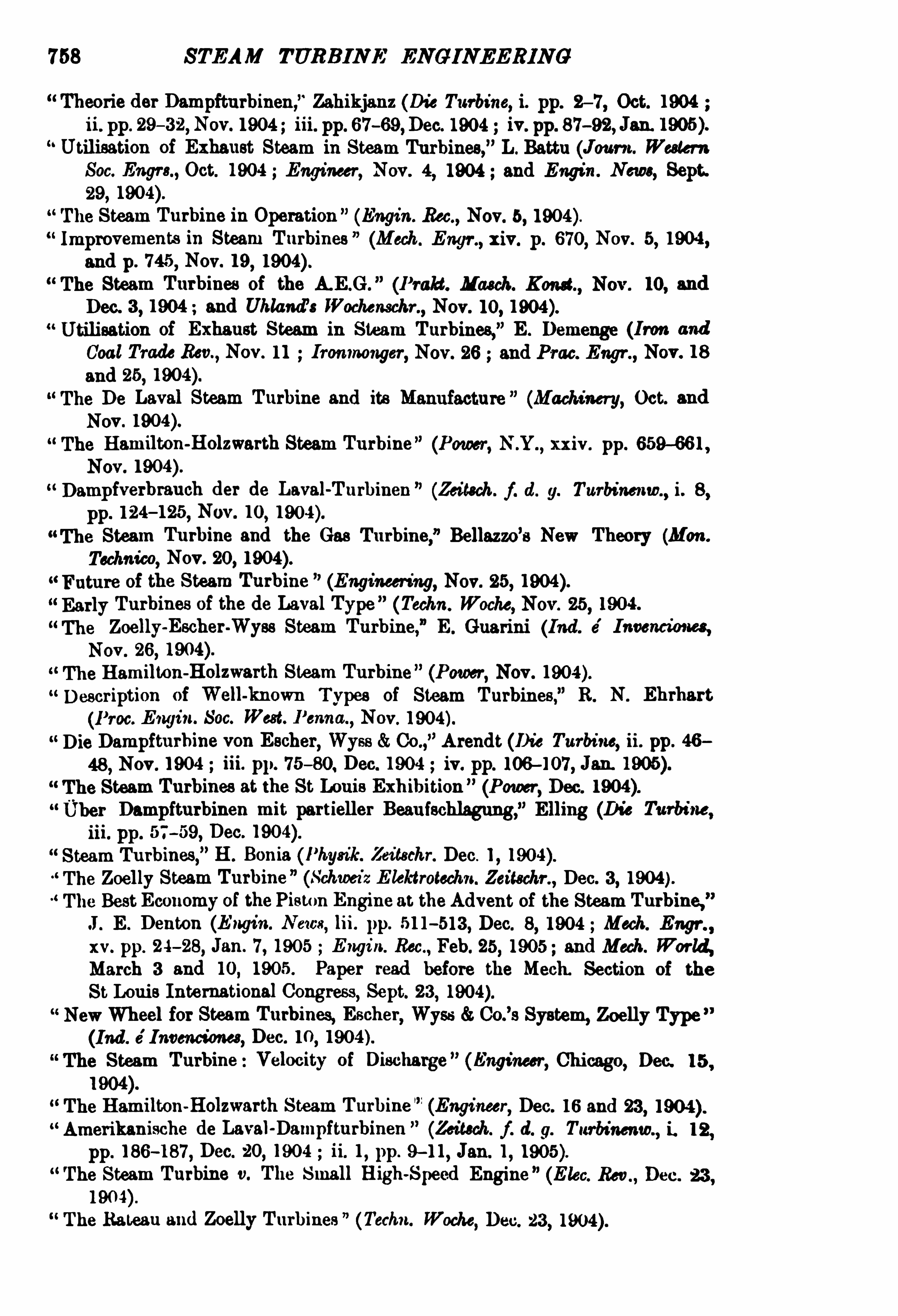

760 STEAM TURB INE EN GI NEERIN G
Rotor ofTurbo-Generators (Elec. IVorld and Engr.,xlv. p. 207 , Jan. 28
,1905
and E lectrician, liv. p. 848, March 10,
The Phenomena of Flowin Steam Turbine Tuyeres (Revue M e'
canique, Jan .
31,
A Reviewof the Seger Steam Turbine” (M achinery, Jan.
D escription and Theory of Steam Turbines,” A . Hanssens
, (Bull. Ing. Elect.
M ontefiore,” Jan — Feb.
Unipolar Dynamos”
(Elec. World and Engr.,Feb. 4 ,
The Steam Turbine of the C. D ekeyser (Industrie, Feb. 12 and
19,
The Steam Turbine,
” F . G . Gasche (Engineer, Chicago, Feb. 15,
Beitrag zur Einteilung'
der Dampfturbinen,” Lewicki (Zeitsch.f. d. g. Turbw.
,
ii . 4, pp. 49-52, Feb. 15 ,
Some Data of the A .E.G . Steam Turbine,F . Koester (Elec. World and
Engineer, Feb. 18,
Steam Turbines The ir Application from an Electrical Point of View,
L. Munch (Eclair. Electr.,Feb. 18 and 25 , March 4, 1 l , 18 and 25 ,
The Steam Turbine Its D evelopment, Possibilities, and Relative Advantages
as compared with the Reciprocating Engine,” D . A . Willey (Tech. World
,
Feb.
The Standardisation of Steam Turbines,C. C. Chatelier (Revue M e
'
tallnrgie,Feb.
M ultiple Steam Turbines, A . M elencovich (Trans. I nst. Engrs. and Shipbuilders of Scotland, xlviii., Feb. 1905 M ech. lVorld, Feb. 24 and March 3
Engin . Times,March 9 ; and M ech. Engr.,
April 8,Making a Small Curtis Turbine,
” H. J . Travis (Power, Feb.
The Kerr Compound Steam Turbine (Power, Feb.
The Zoelly Steam Turbine (Indian and East. Engr .,Feb.
Utilisation of Low Pressure Steam in Steam Turbines,
”A . Lapouche (D ie
Turbine, Feb. and March
Thermodynamic Table for Calculating Steam Turbines, R. Proell (RevueM e
'
canique, Feb. 28,
The D etermination of the Elements of Steam Turbines,
” Kopp (RevueM e
’
caniqne, Feb. 28, 1905 )On the Actual Pressure of Steam Turbines (Revue M écanique, Feb. 28,
Feed Water Heaters for Steam Turbine Plant (Engineer, Chicago, March 1
D ie Westinghouse-Parsons-Dampfturbine
”(Zeitsch f. d. g. Turbinenw.
,ii. 5 ,
pp. 7 1— 75, March 1,
The Steam Turbine of the (Genie Civi l, March 4 ,The Conducting Theory of Gases and the Steam Turbine ” (E lect. Rer .,
March 10,
The Union Steam Turbine (Gturkauf, March 11,
Mechanical Construction ofSteam Turbines,
”W. J . A. London (Elea. Engr
March 10 Prac. Engr.,March 17 , 24 . and 31 ; E lectrician, March 24 E lec.
Rev , April 14 E lec.,Rev
,N .Y .
,April 15 Zeitschr.f. Elektrotechn. IVien,
xxiii. pp. 400—402, June 25 and Inst. Elect. Engineers, Journ .,xxv. pp.
163— 196, Juue 1905 . Paper read before the Manchester Local Section of
the Inst. Elec.

B IBLIOGRAPH Y 761
Computation Tables for Steam Turbines,”D . Banki (Zeitsehr. Vereines D eutsch.
Ing.,March 25
,
Elektra’ Steam Turbine ” (E lettrici ta, M ilan, pp. 205— 207 , March 31,
Elektra ’ Steam Turbine,” O. Arendt (D ie Turbine, March
D ifferent Types of Steam Turbines”
(Revue M e'
canique, March
Compound Steam Turbines” (Bull. Tech. Ass. Ing. Bruxelles,March-April
NewSteam Turbine Ideas (Power, xxv. pp. 209— 211,April 1905, European
edition).Steam Turbines Fundamental Principles
”
(Tonind Zeitung, April 4 ,
Curtis Steam Turbines,” C . B. Burleigh (Paper read before the NewEngland
Railroad Club at Boston, Mass ,April 11,
Commercial Efficiency of Prime M overs,
” A. M . Downie (Engineer, xcix. pp.
4 15— 416,April 28, 1905 . Paper read before the Glasgow University
Eng.
Durability of Steam Turbines ” (Engineer, Chicago, May 1,
Homopolar and Unipolar Continuous-Current Machines (Elektr. Bahnen,
May 4,
Bericht tiber Versuche an Elektra-Dampfturbinen,” Gutermuth (Zeitsch.
f. d. g. Turbinenw.
,ii. 10
, pp. 145 — 149, May 15,
Betrachtungen uber rotieren de Laufrader von Dampfturbinen und deren
W'
ellen,” Wagner (Z. f. d. g. Turbinenw.
,ii. 10
, pp. 150- 15 1, May 15,
1905 ii. 12, pp. 179— 181
,June 15
,1905 ; ii. 16 , pp. 241- 243
,Aug,
15 ,
1905 )Beitrage zur Theorie stationaren Stromung von Gaseu und Dampfen,Proell (Z.f. d. g. Turbinenw.
,ii. 10, pp. 15 1— 154
,May 15 ,
150 K .W. Dampfturbine der technischen Hochschule Danzig”
(Z. f. d. g.
Twrbinenw.,ii. 10, pp. 154— 155
,May 15 ,
Turbo-Generators,” F . Niethammer (Zeitsehr. Vereines. D eutsch. Ing.
,xlix. pp.
762— 770, May 13, and pp. 818—824 , May 20,
The British Thomson-Houston Co.
’sWorks Description of the Curtis Steam
Turbine ” (Engineering, May 19, 1905 Iron and Coal Trades Rev.,May 19
E lec. Engr., May 19 ; Elec. Rev.,May 19 and Tram. d: Rly. World
,June
The Willens-Parsons Steam Turbine ” (Elec. Re in,May 26, 1905 E lec. Engr.
,
May 26 and Coll. Guard, May 26,
Steam Turbines,
”W. E . Boileau (West. Elecn.,May 27 ,
The D ischarge of Steam from Nozzles,
”A . Rateau (Power, N .Y .
,May
Steam Turbines” (Franklin Inst. Journ.,clix. pp. 325-363, May 1905 ; and
Page’s Weekly, vii. pp. 26— 28, July 7 ,
Time for StartingSteam Turbines and Reciprocating Engines,” A . S . Mann
(Page’s Weekly, vi. pp. 1187— 1189, June 2 StreetRly. Journ .
,xxv. p. 1039
,
June 10,1905 . Abstract from Amer. Soc . M ech. Engrs.
,also Elect. Rea
,
June 23,and Engin. Rea ,
June 10,
The Steam Turbine,” Bull (Engin. News
,June 15
,
Uber Regelung von Dampfturbinen,”Gentsch. (Z.f. d. g. Turbinenw.,
11. 12,
pp. 17 7 — 179, June 15, 1905 ; ii. 13, pp. 200— 202, July 1, 1905 ii. 15, pp .
228-231, Aug. 1,1905 ; ii. 16, pp. 244— 248
,Aug. 15 ; ii. 18, pp. 279
282, Sept. 15,

762 STEAM TURB INE ENGINEERIN G
Turbo-Generators,” J . Delemont (Eclair. Electr. ,
xliii. pp,415-422
, June 17 ,
Step Bearings ofthe Curtis Steam Turbine (Elec. World and Engr.
,xlv. p.
1136,June 17
,
Steam Turbines in America ”
(Engin . Res , June 24 ,D e Laval Steam Turbine Applications,
” J . L. Mohun (Cassier’
s M ag.
,xxviii .
pp. 103- 113,June
Test of Steam Turbine after Two Years ’ Service ” (E lect. Rea ,N .Y .,
xlvii . pp.
29-30, July
Operating Features ofVertical Curtis Steam Turbines, A. H . Kruesi (Eng.
Rec.,lii . pp. 8— 10, July 1,
Modern Economical Steam Engines and Turbines”(Engineer, July 7 ,
D ie Union-Dampfturbine”
(Z.f. d. g. Turbinenw.,n . 14
, pp. 209-214,July
15,
Steam Consumption of Curtis Steam Turbines ” (E lec. World and Engr.,July
Ausfiuss des Dampfes aus Turbinendusen,” Newton Wright (D ie Turbine, x.
pp. 284—285 , JulyA .E .G . Dampfturbinen
”(D ie Turbine, x. pp. 276— 279
,July 1905 ; xi. pp.
304—307 , Aug. 1905 xii. pp. 332—337 , Sept.
Modern Power Plant Design,” F. Koester (EngineeringM ag ,
Aug,
Beitrage zur Bestimmung des Wirkungsgrades und Dampfverbrauches an
Dampfturbinen,” Anders (Z. f. d. g. Turbinenw ii. 14
, pp. 214—220,
July 15 , 1905 n . 15 , pp. 225-228,Aug. 1,
D ieWillans-Parsonsche Dampfturbine,”Gradenwitz (Z.f. d. g. Turbinenw. ,
ii. 18, pp. 282—284 , Sept. 15 ,
D ieUnion-Dampfturbine”
(D ie Turbine, ii. pp. 31—37 , Nov.
Considerations sur les Turbines h Vapeur e chutes de Vitesse ,
”
par A Rateau
(Congres International de la Me'
canique, etc. Liege, 1905 Imprimerie La
Meuse SteAnon).The Steam Consumption of Piston Engines,
” T . Stevens and H . M . Hobart
(Power, Dec. 1905 , p. 732 Science Abstracts,134
,Feb. 26
,
The Effect of Admission Pressure on the Economy of Steam'h irbines
,
T. Stevens and H . M . Hobart (Engineering, pp. 289— 292, March 2 and
March 9,1906
, pp. 322
The Steam Consumption of Reciprocating Engines, and The Economy of
Steam Turbines compared with that ofReciprocatingEngines,” T. Stevens
and H . M . Hobart (E lectrical World, pp. 369— 37 1
,Feb. 17 , pp. 4 10—4 12
,
Feb. 24 ,
SECTION B.
PARTICULAR PLANTS.
Cambridge Electricity Supply Works (Elec. Engin.,xxv. pp. 42— 49 , Jan .
12,
Steam Turbine at Elberfeld (E lec. Rev., Oct. 12,
Steam Turbine at Hartford, Conn . (Power, N .Y . , xxii. pp. 1-3, JulyElectrical Power Station at Neptune Bank, Newcastle-ou-Tyne,
” W. B .
Woodhouse (Inst. M ech. Engrs. Proc.,iii. pp. 453-481
,July

7 64 STEAM TURB INE ENGINEERING
The Power-House of the Interborough Rapid Transit Co. (Eng. Rea ,Jan.
23,
Cleveland and South-Western Ry. Co.,Carlisle
,Lorain
,U.S.A . (Street By.
Journ.,Jan. 30,
Westinghouse Steam Turbine at Orangeburg, N .Y . (Amer. Elec.,xvi. pp.
169- 172,Apr.
Electric Traction on the Metr0politan Railway (Engineer, xcvii. pp. 158
and 159,Feb. 12, pp. 183— 184 , Feb. 19, pp. 202-203
,Feb. 26
,and pp.
253 —254,Mar. 11
,1904 ; and Tram. and Rly. World, xvi. pp. 17—44, July
Port Huron Light and Power Co.
’8 Station
,J . E . Davidson (E lec. World
and Engr. xliii. pp. 681—686,Apr. 9,
Kraftwerk der Interborough Rapid Transit Co.,NewYork (Zeitsch. d. V. d.
Ing.,April
Kraftwerk Lots Road in Chelsea bei London (Z. d. V . d. Ing.
,April 16 ,
The Yale and Towns Mfg. Co .
’s Plant
”
(Iron Age, Apr. 21,
Scarborough Electric Tramways”(Tram. Rly. World
,xv. pp. 494—500, May
Lanes Power Co. (Radcliffe) (E lec. Power, May 4,
Test of Steam Turbines at the Newport Station of the Old Colony Street
Rly.
”
(Engin. Rea, May 14, 190
Expansion of the Boston Edison System”(Elec. World and Engr.
,May 21,
1904 )Combined Lighting and Heating Central Station System in Indianapolis
(West E lec., xxxiv. pp. 431—433, May 28,D erby ElectricityWorks and Tramways (E lectrician, liii. pp. 301—305, June
10,and pp. 342—344
,June 17 ,
Das neue Kraftwerk und Maschinenbaulaboratorium der Technischen
Hochschule Darmstadt,
”Gute rmuth (Z. d. V. d. Ing.
,June 11 and June
18,1904L
D ie Einrichtungen im neuen Kraftwerk der Techn. Hochschule Darmstadt,
Sangel (Z. d. V. d. I ng.,July 16,
Notes on Steam Turbo-Electric GeneratingPlants, G . Wilkinson (E lectricity,July 1, 8, 15, Aug. 5 , 12, 19, 26, and Sept. 2, 190
Neepsend Power Station of the Sheffi eld Electricity Department (E lec. Reta ,
lv. pp. 99— 103,July 15 , and pp. 139— 142
,July 22,
Steam Turbine Lighting Plant at Jacksonville, Fla.
”
(E lec. World and Engr.
,
xliv. pp. 138- 139, July 23, 1904 ; and E lec. Rein, N .Y .,xlv . pp. 66- 67 ,
July 9,
Schenectady Works of the General Electric Co.
”
(Engineering, lxxviii.
pp. 17 1— 175, and 186,Aug. 5 , and pp. 202-206 and 208—209
,Aug. 12,
Steam Turbine Power Plant for D ubuque, Iowa (Street Rly. Journ.,xxiv.
pp. 184-194 , Aug. 6,1904 ; and Engin . Re a
,Aug. 13,
London MetrOpolitan Electric Tramways (Tram. and Rly. World, xvi.
pp. 139— 14 1, Aug. 11,
“ Power Supply to Tramways in North London”
(E lectrician, liii. pp. 665
666,Aug. 12, 702
— 705 , Aug. 19 , 742-745, Aug. 26, and 784— 787, Sept.
2,


766 STEAM TURB INE ENGINEERING
1905 .
Long Island City Power-House of the Pennsylvania Railroad”(E lec. World
and Engr. ,Jan. 7 ,
A Large South African Motor Plant” (E lec. World and Engr.,Jan. 7
,
Efficiency Tests of a D irect-connected Steam Turbine Fan Blower Set,0. R . Waller (Engin . News, Jan. 9
,
Steam Turbine Power Plant of the New York,New Haven, and Hartford
R .R .
”(Engin. Rec .
,Jan. 21,
New Turbo-Generating Station of the Edison Electric Illuminating Co.,
Boston,”E. Moultrop (Trans. Amer. Inst. E lec. Engrs., Jan. ; and Eng.
Rec.,Feb. 11,
Electric Power Supply from Central Stations in Great Britain,” Addenbrooke
(Engin . M ag.,Feb.
Power Plant of the Anheuser-Busch Brewing Association at St Louis (Amer.
E lectn.,Jan. 1905 and Engineer, Chicago, Feb. 1
,
Central Station Work in Detroit (E lec. World and Engr.,xlv. pp. 243— 246
,
Feb. 4 , and pp. 291— 295,Feb. 11
,
The Turbine Power Station of the Terre Haute Traction and Light 00 .
(Eng. Rec.,Feb. 4 ,
Metropolitan D istrict Railway Electrification (Tram. and Ry. World,xvii.
pp. 97— 155 , Feb. 9,
The New Steam Turbine Plant of the Public Service Corporation, N .J
(Street Ry. Journ.,Feb. 18,
Shipley ElectricityWor (Elec. Rec.,Feb. 24,
The Dutch Point Plant ofthe Hartford Electric Light Co.
”(Engineering Rec.,
11. pp. 204 — 206,Feb. 25 ,
Edison Electric Co.,Los Angeles, Cal.
”(E lec . World and Engr.,
xlv.,Feb. 25 ,
The NewYork Underground F . Koester (Zeitsehr. d. Vereines Deutsch .
Ing.,March 4
,
Construction of the Port Morris Power-House for the New York Central
R.R.
”
(Engin. Rec.,March 4
,
Tests of Turbo-Generators at Neepsend, Sheffield (Power, March 1905
Engineering, March 10,1905 ; E lectrician, liv. pp. 826-827
,March 10
,
1905 and M ech. Engr.
,March 25
,
Parallel Runn ing of a 5500 K.W. Westinghouse-Parsons Turbo-Generator
(Engin . Rec.,March 11
,1905 ; E lec. World and Engr.,
xlv. pp. 305—306,
Feb. 11,
Edison Electric Co.
’s System in Southern California
”(Elec. World and Engr.
,
March 11 and 25, 1905 .
Prime Movers : The Rival Claims for Central Station Work” (Times Engin.
Supplement, March 22,The Brown-Roveri-Parsons H .P. Plant in the Electric Power Station
ofEssen (Gliickauf, April 8,Steam Turbine Plant at St Ouen ,
Paris,L. Troske (Zeitschr. Vereines Deutsch.
Ing.,xlix. pp. 5 11— 5 17
,April 1, and pp. 570—5 77 , April 8,
The Application of Steam Turbines to Automobiles,” J. Izart (Vie Antam.
,
April 15 ,


B IBLI OGRAPH Y 7 69
Test of an Engine using Superheated Steam,
” E. K . Scott (Tram. Rly. World,
xiv. pp. 450-452, Nov. 12,
Superheated Steam for Steam Engines,” J . Goodman (C
'assier’s M ag.
,xxv. pp.
18—26,Nov.
Superheated Steam,
”F . J . Rowan (Trans. Inst. Engin. and Shipbuilders, zlvn .
pp. 1-24,Oct. 1903, pp. 1 20
,Nov. 1903
, pp. 1-22,Dec. 1903, and pp.
1- 16,Feb. 23,
Tes ts of a Compound Engine using Superheated Steam,
” D . S. Jacobus
(Eng. Rec.,xlviii. pp. 724-725 , Dec. 12
,1903. Abstract of a Paper read
before the Amer. Soc. ofM ech.
The Energy Equivalent of a Given D egree of Superheat in Steam and the
Behaviour of Superheated Steam near the Condensation Limit,
” A .
Griessman (Zeitechr. Vereines D eutsch. Ing., xlvii. pp. 1852- 1857 , Dec. 19 ,
Superheated Steam,
” S. West. Soc. Engrs. Journ.,viii. pp. 69 1— 7 15, D ec.
New Types of Superheaters,”W. H . Watkinson (Inst. Naval Archs. Trans.
,
xlv pp. 266— 280,
l904 .
Specific Heat of Superheated Steam,
” Prof. Dr. Weyrauch (Zeitschr. Vereines
D eutsch. Ing., xlviii. pp. 24—28, Jan. 2, 1904, and pp. 50-54, Jan. 9, 1904 ,
and Bull. Soc. d’Encouragement, 106, pp. 206—230, March
Turbines and Superheated Steam,Booth (E lec. Review, Feb. 26,
Superheated Steam at aPumping Station (Eng. Rec.
, xlix. p. 397 ,March 26,
The Conduction of Superheated Steam,
” 0 . Berner (Zeitschr. Vereines
Deutsch. Ing. ,xlviii. pp. 473-478, April 2, pp. 530-536, April 9 , and pp.
560—564,April 16,
Thermal Effect and Practical Utility of Superheated Steam,
” R . H . Smith
(E lec. Rec .,liv. pp. 77 1-773, May 13,
The Behaviour of Superheated Steam in Piston Engines,”F . Richter (Zeitschr.
Vereines D eutsch. Ing.,xlviii. pp. 617 — 623, April 30, pp. 67 1— 676, May 7 ,
and pp. 706— 709 , May 14 ,The Specific Heat of Superheated Steam
,
” H . Lorenz (Zeitschr. Vereines
Deutsch. Ing.,xlviii. pp. 698-700
,May 14 ,
“Use of Superheated Steam and Reheaters in Compound Engines of Large
Size,
” L. S. Marks (Amer. Soc. M ech. Engrs. Trans , xxv. No. 021, pp. 1
59,1904 ; Paper presented at the Chicago M eeting, May and June 19 04 ;
Engineer, xcvi ii. pp. 29-30, July 8,Specific Heat of Superheated Steam,
” R. H . Smith (Engineer, xcviii. pp. 25
26, July 8,Specific Heat of Superheated Steam (Engin. Rec., 1. pp. 83—84, July 16
,
The Schmidt Superheater (Telen. Tids ,July 23,
Generation of Superheated Steam,
” 0 . Bem er (Zeitschr. Vereines Deutsch.
Ing., xlvii. pp. 1545— 1552, Oct. 24
,and pp. 1586-1593, Oct. 31, 1903,
Power,N .Y .
,xxiv. pp. 463—46 4, Aug. 1904
Principles and Practice of Superheating,”W. H. Booth (Tram. Rly. World
,
xvi . pp. 146— 148, Aug.

7 70 STEAM TURB INE ENGINEERIN G
Specifi c Heat and Total Heat of Superheated Steam,
” G . A. Orrok (Power ,N.Y .,
xxiv. pp. 486—488, Aug.
Superheaters,” B. Taylor (Power, N .Y .,
Aug.
On Superheated Steam for Steam Turbines,
” A. H . Gibson (Elec. M ag.,
Aug.
Specific Heat of Superheated Steam,
” H. Lorenz (Zeitschr. Vereines D eutschr.
Ing.,Aug. 6,
The Schmidt Superheater (E lektrotethn. Tide. Aug. 10,
Superheating (EngineeringReview, Sept.Advantages of Superheating or Steam Jacketing as applied to Steam
Turbines,
” A. H . Gibson (Eng. Rec.,xi. pp. 161- 167 , Sept.
The Hering Superheater and its Application to Steam Boilers (Uhland s
Zeitschr.,Sept. 1,
European Practice in the Use of Superheated Steam,
” F . Koester (Power,N .Y .,
xxiv. pp. 558-559, Sept. 1904 , and pp. 598—5 99, Oct.
The Assistance of Superheated Steam for Reducing the Cost of Electric
Energy, E . J. Fox (Iron and Coal Trades Rec.,Nov. 4,
The Specific Heat of Superheated Steam,
”S. A. Reeve (Journ. Worcester
Polytechn . Inst , Nov.
Einfiuss der Uberhitzung bei Dampfturbinen,” Lapouche (Die Turbine, i. pp.
13- 16, Oct. 1904 ii. pp. 34 —36, Nov.
The Specific Heat ofSuperheated Steam,
”R. H. Smith (Revue M etallurgie,
Dec.
A Contribution to the Study of Superheaters and Superheating (Vulkan,Dec . 15 and 31 ,
The Schmidt Steam Superheater (Engineering, Dec. 23,
An Improved Down-take Superheater”
(Power, N.Y .,Jan.
Economy in Superheat (Engineer, Chicago, Feb. 1,
The Specific Heat ofSuperheated Steam (Engineer, xcix. p. 105, Feb. 3, pp.
135- 136 , Feb. 10,
The Tinker’s Superheater,
”
(E lek Tidsch.,Feb. 20,
A Compound Superheater employed in Berlin,” R. Hildebrand (Power, N .Y .
Mar.
Effects ofSuperheating and ofVacuum on Steam Engine Economy,” R. M .
Neilson (Eng. M ag.,March
,April, May, June, and July 1905 . Bull. Soc.
d’Encouragement, 107 , pp. 645 — 663, May
Superheater D uties and D esign,” F . Koester (Power, N .Y .,
March 1905 and
Prac. Engr.,March 24.
Superheated Steam,
”A. G . Gibson (M ech. Engr.,
xv. pp. 423-426, March 25,
and pp. 458-45 9, April 1, 1905 . Paper read before the Owens CollegeEng. Soc.,
Feb. 7 ,
Experiments on the Transmission ofHeat in a Heizmann Superheate r, O .
Berner (Zeitsehr. Vereines Deutsch. Ing.,xlix. pp. 46 1—466
,March 25
,and
pp. 564— 5 70, April 8,
D ifferent Types of Superheaters (Revue M écanique, MaySpecific Heat of Superheated Steam
,
” R. C. H. Heck (Power, May 1905 ;M achinery, June

7 72 STEAM TURB INE ENGI NE'
RING
6000 H.P. Conover Jet Condenser”
(Power, N .Y .,xxiii . pp. 475—478, Sept.
Saturated Air Condensers”(Power, N .Y .
,xxiii. pp. 672— 674 , Dec.
Jennison Water-Cooler Tower ” (Power, N .Y .,xxiii. pp. 682—685 , D ec.
Theory of the Cooling Tower, H . L . Nachman (Power, N .Y ., xxiii. pp. 674
676,D ec.
Condensing Plant for High Vacuum,
”W. H . Roy (M ech. Engr.,xi t. pp. 812
814,D ec. 12
, pp. 827 829 , Dec. 19,and pp. 860— 864 , Dec. 26, 1903. Paper
read before the Manchester Assoc. of Engrs.,Nov. 28
,
Condenser Plant at GlasgowElectric Power Station (Power, N .Y .
,xxiv. pp.
36-38, Jan.
Independent Condensing Plant”
(Engineer, xcvii. pp. 40—46,Jan . 8,
Steam Heating from a Central Station,” F . B . Hofft (Engr. News
,li. pp.
68
Sextuple-Effect D istillers
”
(E lec. Rec .,liv. pp. 197 — 199, Jan . 29,
Recent Experiments with Surface Condensers with Separate Circulation of
Cold Air and HotWater,
” Berling (Zeitschr. Vereines D eutsch. Ing.,xlviii.
pp. 253— 255 , Feb. 13, 1904. Report read before the 5th Hauptversamm
lung der Schifi'
bautechn, Gesellschaft, Nov. 19-20,
Cooling Tower and Condensing Equipment in an Atlanta Plant (Eng. Rec.,
1. pp. 54—55, July 9,
Condensing Plant,
” E . K . Scott (Tram. Rly. World, xvi . p. 149,Aug.
“Steam Turbine Condensing Outfits (Ekc. World and Engr. , Sept. 17 ,
The Separation of Oil from Condensing Water by means of Electricity
(Genie Civil, Sept. 24,Condensing Plant,
”W. H. Booth (Cassier, xxvi. pp. 543— 559,Get
,and xxvii.
pp. 60— 7 1, Nov.
Pumping and Condensing Machinery at St Louis” (Engineer, Chicago, Oct.15 ,
A H .P. Surface Condensing Plant”(Uhland
’s Zeitschr. Nov. 10
,
Cooling Towers,” C. Hubbard (Engineer, Chicago, Nov
Condensers for Steam Turbines,” G . I . Rockwood (Engin. Times, Dec. 8
and 15 ; Engin. Rec., Dec. 10 ; Street Rly. Journ.,D ec. 10 ; Engineer,
Chicago, D ec. 15 M ech. World,Dec. 30 ; Iron and Coal Trades Rec.,
Dec.
30 ; E lec. Rev.,N .Y .,
Dec. 31,1904 ; Power, N .Y .,
xxv. pp. 46—47 , Jan.
1905 ; M ech. Engr.,xv. pp. 2—3
,Jan. 7
,1905 . Paper read before the
Amer. Soc. ofM ech. Bugra., Trans ,vol.
Condensing Machinery,” W. E . Storey (Engin. Times, Dec. 8 and 15
,
Water-Cooling Towers of the Jarvis Type”(Prac. Engr.,
Dec. 9,
Theory and Operation of Injection Condensers, A . Rateau (D ingl. Polyt.Jour n., D ec. 10 and 17 ,
Losses in Non-condensing Engines,” J. B. Stanwood (Trans. Amer. Soc. M ech.
Engrs.,vol. xxvi., 1904 ; Eng. Rec.
,Dec. 10
,

B IBLIOGRAPH Y 7 73
Cooling Towers of the Westinghouse Installation at St Louis (Engineer,Chicago, Dec. 15
,
The Measurement of Vacuum and the Economic Working of Turbines,
C. Turnbull (Engin. Times,D ec. 22
,
Steam Heating in connection with Condensing Engines, R . P. Bolton
(Engin. Rem,N .Y .,
Jan .
Condensing Machinery (Prae. Engr.,Jan. 6, 13, and 20,
Independent Surface Plant”
(Power, N .Y .,Feb.
Counter-Current Jet Condenser” (Amer. E lectn., Feb.
Power required for Condensing,
Auxiharies in a Steam Turbine Plant,J. R . Bibbins (Power, N .Y .,
Feb.
High Vacuum Condensing Plants,” E. K. Scott (Aust. M in . Stand ,
Mar. 22,
The Condensation of Steam in Plants with Intermittent and Strongly
Fluctuating Loads,” A . Scherbius (Helios
,March 1 and 8,
Advantages of the Alberger or Barometric Type of Condenser over other
Types”
(Elec. Engr., March 10,
Condenser for Steam Turbines (M ech. Engr.,xv. p. 428, March 25
,
Effects of Superheating and of Vacuum on Steam Engine Economy,” R . M .
Neilson (Eng. M ag.,March, April, May, June, and July 1905 and Bull.
Soc. d’Erwouragement, cvii. pp. 645— 662, May
An Improved Condenser of the M irrless Watson Type (Page’s Weekly,
April 28,High Vacuum Condensers,
” J. D . Bailie (Inst. E lec. E . Journ. ,xxxiv. pp,
49 1—497,April 1905 E lectrician, liv. pp. 674-675, Feb. 10
,
“Cooling Water for Condensers,”E. R . Briggs (Amer. M ada
,June 3
,
Influence of Vacuum on the Steam Consumption of Steam Turbines A .
Lapouche (D ie Turbine, JulyUber Wesser-Ruckkuhlwerke
, Carl Rudolf (Zeitsdi. f. d. g. Turbinenw.
,u .
17 , pp. 264— 267, Sept. 1,
SECTION E .
M ARINE INSTALLATIONS.
l 903.
Steam Turbine Ships”
(Zeitschr. d. Vereines D eutsch. Ing.,April 11,
The New Turbine Channel Steamer ‘
Queen (Engineer, June 19 and
July 3,The Steam Turbine
,
”C . A. Parsons (Engineeri ng, July 10 and 17,
The Turbine Steamer Brighton (Engineer, Sept. 4 ,Tests of Steam Turbines (Iron Age, Dec. 3,


STEAM TURB INE ENGINEERIN G
A Comparison of the Performances of Turbinesand Reciprocating Engines in
the M idland Ry. Co.
’s Steamers
,
” W. Gray (Inst. of Naval Arch ,July
The Turbine-dru en Channel Steamer D ieppe (Engng. Aug.
Marine Turbine Engine Building,” Sir C. M ‘Laren (Times Eng. Supplement,
Sept. 13,Vibrationsercheinungen der Dampfer,
” Schlick (Z. d. V. d. Ing., Sept. 16 ,
Turbinendampfer Kaiser’
(Z. f. d. g. Turbinenw.,n . 20, pp. 319—320, Oct.
The Determination of the Principal D imensions of the Steam'
lhirbine, withSpecial Reference to Marine Work
,
”E . M . Speakman (Paper read before
the Inst. of Engrs. and Shipbuilders of Scotland, Oct. 24,Die Turbine im Kriegsschifl
'
bau ” (D ie Turbine, i. pp. 24— 25,Oct.


STEAM TURB INE ENG INEER ING
EQUI VALENT Consvurrrons, xm.— emuinued.
Output from Electric Generatorcorresponding to Engine Con
sumptious (ofStated Edic icncies)per stated in the
Columns on the right of this.
Consumption per Indicated Horse-Power Hour.
Combined i-Ziflciency of Engine and Genera tor.
Consumption per Consumption perK.W.H . Output. I
K8”. Pounds. Kgs. Pounds. Kgs. Pounds. Kgs. Pounds . Kgs
I
Pounds. Kira. Pounds. K8! P on ds .
4 5 4”
as". we
1
2-22
5-35 e-a-s
2-92
2-46 61 3 I 2-95 1
10 2-7 1 5-97
10-05 7 50 c
7 50
4-73 10 43 3 53
7 so 3 04
107 3 3°6 i i 3 e-so
11
11-03 i 6 98
3-50 I r-n
3o | s
5-37 u s e
5-41 11-91
5-44 18 e-n 3-45
13 06 r es use we
s-so ze st 3-13
ass 13-51t
we:
we u se
«rse 3-05 e-re 7-71
5-90 18 we
a W '44 8
_3-7
s-os i s-w 4-54 10 7 3-4 1
70 per cant. 75 per cent. 80per cent. 85 per cent. I 90 per cen t .


APPEN D IX
EQUIV ALENT CONSUMPT IONB, era — continued.
Output from E19 0“?Generator Consumption per Indicated Horse-Power Hour.corresponding to Engine Con
sumptious (ofStated Effi ciencies)per stated in the
Columns on the right of this. Combined Eifl ciency of Engine and Generator.
iowugpga't'pmr 70 per cent. 76 per cent. 80 per cent. 85 per cent. 00per cent.
Kgs. Pounds. Kgs. Pounds. Kgs . Pounds. Kgs Kgs. Pounds .
7 7 °
—
73 19 W21 55
W f__
21'56
_W
9 85 23
18
22
10
8 39 18 28 19 58
18 37 21
19 73 W20
162 7 35 -9 18 7 5 20 08 22-78 109 3 21. 10
36
711-56
116-2 122 5 27 W 110 1I
16 45 36 3 27 06
16 50 36 4. 27 11. 27 77—
10?_25
16 72 36 9
37
_W
37 -2 27 -78 7 075
20-94 T073
21 11 42
37 -7 5 10-22
I 37 -8 24
21-10
522-31
_17
3875 13 | 26 °w

STEAM TURB INE ENGINEERING
EQUIVALENT 001mmm oss, m — mnfi mwd.
Output from Electr'
c Generatorcorrespond'ng to Engine Con
Consumption per Indicated Horse-Power Hoursumption: (ofStated Emciencies)pe
'
stated in theColumns on the right of this. Combined Eucbncy of Engine and Generator.
Co11sumpt10 11 per ConsumptionperKW.H. Output.
70 per cent. 76 per cent. 85 per cent.
90 28
1
30-87
1
l 10' l 4
1
i37 °
5s
“1 0
i
27 2 7
124 1 I
19 '96
88
1
1219-57
[ 27 9 8

788 STEAM TURBINE ENGINEERING
TABLE CLI .— VACUA .
Equivalent Values based on the Metric Atmosphere, i .6 . ,1 Kg. per
Sq. Cm. l M etn o Atmosphere.
Reading OfMercury Vacuum Absolute Pressure in CondenserGauge .
Per cent. of
Lbs. per Sq . EnglishInch“Inch. Atmosphere .

APPEND IX 789
TABLE CL11.— VACUA .
Equivalent Values based on the English Atmosphere, i .6., 30 inches or 760mm.
ofMercury 1 English Atmosphere.
Reading OfM ercury VacuumAbsolute Pressure in Condenser.
Gauge.
Per cent. of
E 11511 L178 .
1mm“Atmggphere.
“Opus?
Sq
i111211:
Sq
01 240 1 °763
o°
l447
0°
1653
0 207 i 2 94
700 111m. 29 1) inches. 80 inches 702millimetres.


792 INDEX
Appendix, 779Areas and Volumes, E uivalents of,
(English an M etric), table,21
Argonaut, H.M .S. Turbine Cruiser,Steam Consumption of, 635 , fig. , 634
A rundel, Reciprocating Engine Steamer,details of
,table
,685 et seq.
Atmosphere, see Metric do.
Atmospheric Exhaust, 566 ExhaustAugmenter Cond
7
enser in Turbine Steamers,lo
Auxiliaries, (Rateau), power consumed by,
240
BALANCE Pistons, (Parsons), uses of, 120
Barometric Jet Condensers, used withTurbines and Engines,table
,430- 1
Reciprocating Engine Steamer,
details of, table, 7 10at so] .
Bearin (s), 363 Thrust BearingA . G . ,
290,
Curtis ,Footstep, 201
Oil Supply to, 201 , table, 202Others, 204 , 49 see table, 202
Glands, 205
Oil circulated through, 205de Laval
, 95 , fig. , 96
Hamilton-Holzwarth, 316-7Parsons,Flexible, 131
Thrust, 132 d: fig.
Rateau, 235 4: note, figs , 232, 233
Zoelly, 263, ill 268
Thrust, ib.
Peripheral Speeds Pressure at, 14 , table,15
Bearing Pressure, (Parsons), 132Bed-plate, Hamilton
-Holzwarth Turbine,separate for each Casingand for the Dynamo, 311,Casings not bolted downto, 316
Belgian State Railways, Turbine Steamersof
,table
, 734
Bethune M ines, Rateau Heat Accumulator
at,250, fig. ,
251
Bibbins,J . R. , 366 WestinghouseTurbines,
Cost ofHigh VacuumBibliography, 749B ingera, Turbine Steamer
,details of
,
tables, 63, 685 note
Blades , or Buckets, see also Buckets and
Vanes
de Laval, 87 , fig.
,88
Fullagar’s method for fixing, 127-8,
figs"127 , 128-30,
ill 139 , clairns made for,129
Board of Trade Unit, defined,17 note
Boileds), sec Steam Turbine Plants, (48)large, well-designed,
efi ciency of com
plete Steam-raising Plant
with, 363, measured bytest, and by all-yearrunning, 366 , tabla, 368
-9 ,kilo
gams of steam
got in ,
per°
logram ofGoa 363,364 4: table
testing of,basis of figures for findingSteam produced, in ratios
to coal consumed, 864
Boiler-Feed, see Steam Turbine Plants,
(46 )Boiler-Flues do. do. (41 )Boiler-grate area , in some of the Plants
referred to table, 452-3
Boiler-heating surface, do . do . ib.
Boiler-houses , sec Buildings
Boiler and Superheater Surface Installed,452, table, 452
— 3
Boston, L. Street, see Steam Turbine
Plant
Brake for Curtis Turbo-Generator, 212
Branca’
s Turbine, 25
Brighton,Turbine Steamer, detail of, table ,
685 et seq. ,ilk
,694
Brimsdown ,sec Steam Turbine Plant
British India Steam Navigation Co .
’
s
Turbine Steamers, table,
685 atmy.
British Thermal Unit, defined,17 «I: note
British Thomson Houston Co. ,Rugby,
makers of the (h utis'
h i rbine, 212, 213
British Naval Vessels , Turbine Driven,
Battleships, Cruisers, Tor
pedo boats, Destroyers,etc. , table, 630— 1
British-made Turbines ,seeCurtis, de Laval,
and Parsons
Brown, Boveri Cc. , Switzerland,builders of Parsons Tur
bines,119
Marine lighting-plants, 189, fig. , 190
Cost of,as compared with that of
equivalent Piston-engines,
190
Turbo-dynamo, 135, ill. , 136
do. , at Essen, (their largest), 135Turbo-generating set, 3 phase, 4-pole
atFrankfort, described 135 ,ills
,137 , 138, do see table
facing 156, flg. , 173
Steam Consumption in , variation in,
with Change of Pres sure, 161, fig. ,
160
with Constant Pressure
Vacuum, j ig. ,
173Bruay M ines
, Rateau Accumulator at,247 , fig ,
249,253
Rateau Supplementary High Pressure
Turbine at, 252

IND EX
Brush Co. builders of Parsons Turbines,119 note, fig. facing 122
Brush-Parsons Turbo-generator, earliest
and latestdesigns, 146,figs.
facing 148, new features
in the latter,151-3
Brushes, Carbon and M etal,used in A .E.G .
Turbo-generators, 298
Buckets,see also Blades, and Vanes,
de Laval, 87 , fig , 88
Wear in,Losses due to, 78
Riedler-Stumpf,Double, 276 , figs ,
274, 275, 278Number of, 276Overlap of
,reason for, 279, fig. ,
274
Single, 278, fig. , 275
Buildings, sec Steam Turbine Plants,Engine
-rooms, Boiler-Houses, and
Power-Houses,for Tur
bines, M ixed, and Recipro
cating Engine Plants,Area and Volumes of, 445, tables,
446— 51, ills. 468—74 , plans,-90
CALOR I FIC Values of Fuels, 362 at seq .
tables, 362, 364-9
Campania and Lucania, ReciprocatingEngine Steamers, detailsof, table, 716 at seq .
Carmania and other Turbine Steamers,(Cunard details of,table, 7 16 atug. ,
i ll. , 720
Engine room, cross section,
fig , 726 ; low pressure
and Astern rotor,ill.
721 propellers, ill. , 723 ;Turbine room,
ill , 723,
plan, etc. , figs , 724
Caroline, Reciprocating Engine and Steam
Turbine Yacht (RateauTurbine), 636, details of,tables
,631, 673 cl seq
figs , 678, 679 ; tests of,
tables , 680, 680
Additional Propellers on Turbine Shaft
of, 681 , results with, 682,summary of, 683, tables,682, 683
Carmiia ,Reciprocatin Engine Steamer,
(Cunard details of,
table, 7 16 cl seq . ,Engine
room, cross-section, fig726 , do. , elevation and
plan, figs , 725
Results ofTrials, table, 728
Carville, sec Steam Turbine Plant
Casing(s), (A.E.G. 291, (Elektra), 320High and lowpressure, (Hamilton Holz
warth), 311 4: note , 314not fixed to Bed-plate, 316
Cavitation, Parsons’experiments in over
coming, 644-6, figs , 64?
Rateau, 238
Riedler-Stumpf, large, 278
793
Central London Railway, foundations forTurbines and other Enines of, 441 , table, 443
Chelsea Power ouse, London, Westinghouse Parsons Turbo
generating sets at, 135 de
note, a seq. {m. , 140-4,
540-1, u s also Lots RoadunderSteamTurbine Plant
Chester, Turbine Scout, details of,
table, 728 at seq.
Chimneys, m Steam Turbine Plants, (42)Circulating Pumps, m PumpsClearances in Turbines
Brown-Boveri Parsons, largeness of, in
relation to Economy, 120,
129
Curtis, minimum, between fixed and
moving parts, latest designs, table 211
Elektra, 322
Parsons, and Willans-Parsons, smallnessof
,the chief factor .of
efficiency , 151
Calorific value of
as expressed by the authors, 363ofvarieties of, in various units
,table
,
362, d: see tables, 342, 345
Consum tion, sac Boilers,Amt l yst, compared with that of
Topaze etc. , figs , 655,tables 656 at seq.
Reciprocating Engine Cruisers, Record, table, 748
Turbinio ( lst), (approximate ), table,648
Delivery of, and Storage
etc .
, see SteamTurbine ants (29— 40)
Economy in Turbines and Piston En
gines, 404
Price of,of average value of 87 K.W.
hours per Kg. , 364 , table,365
Cobra, Turbine To ode-Boat D estroyer,deta
'
s of,tables
,630,
659-60
Condenser in, table, 437
Collars on Rotating Drum, (Willaha
Parsons), as factors ofeffi ciency
, 151
Commercial Effi ciency of Turbines andPiston Engines compared,404 cl seq., figs. 406 -11
the same, under Extreme Conditions,
figs ,416— 7
the same, under increased AdmissionPressure and varyingSuperheat and Vacuum
,
405-11
Commutator, CurtisTurbo-Generator,M . ,
210

794 IND EX
Compagnie Fran Thomson-Houston,Pg makers of CurtisTurbines, 212
Comparison of Cost of D ifl'
erent Types of
Engines, table, 9
Compensator, (Rateau), 234 , fig. facing232
Compressors coupled to Rateau Turbines,238
Condensers, sec
( Sgeam Turbine Plants,
6
Barometric Jet, usedwith Turbines andPiston Engines, table
,
430— 1 «2 see 254
Ej ector, table , 132—3Extra cost of High Vacuum in, 429 ,
435 , table, 434
Jet, used with Turbines and PistonEngines, table, 432
— 3
in MarineTurbineVessels, 632, table, 437in Au enter do.
, 7 10
Proba lee improvements in, 404ofRated Capacity, Cooling Towerswith,
table, 436
Surface,Mirrlees-Watson
, at Partick, 437 , j ig ,
486
range of Experiments on, (Allen’s
paper), 438 50 tables,figs
usedwith Piston Engines, table , 432-3usedwith Turbines, table, 430-1
used with Plants referred to, in tables atpp
. 424— 7 , figs. 470— 2,5, 470-7 480
,482 5,
488-90
in various makes of Turbine a'N rbo
generators
A.E.G 291 , 306, figs ,285, 286
Curtis, 205, figs ,204, 207 , 224. m. ,
207de Laval
,80
,82
Hamilton-Holzwarth, 314Parsons, i lls. 147
Rateau, 227 , j igs. facing, 252, 257Barometric Jet, 254
Riedler-Stumpf, fig ,285, 286
Union,331
Condensing Plants, see also Turbo Generators and
Cost of, 9-10 dc tables, see alsofly. , 12
and Non-Condensing do. , Costs of,
(Allen on), 10-11 46
tables
Consumption, see Coal, and SteamContinuous current A.E.G . Turbo-genera
tors, 50-750K.W. Speeds
of, 298 Jr table
Convertible Energy, ace EnerCoolingTowers, 386 Steam Tur ine Plants,
(70A )with Condenser of Rated Capacity , table
436
Cork, m Rugby and Cork
Cost ofBrown-Boveri-Paraons W hine Marine
Lighting Plant, 189, fig.
190, as com red withthat of equiva ent Piston
Engine, 190D ifferent Types of Engines, Comparison
of,table 9
extra, of High Vacuum,429 , 435, table ,
434
first, ofSteam Turbines, 2, 3, d: tablesin relation to Steam Turbines, 2
— 11,tables
, 3- 11
Costs and Prices, decimally expressed in
thiswork,23
Coupling, flexible, between Shaft-sections,(Hamilton-H olzwarth) ,316
Cranes, Overhead'
h '
avelling, sec SteamTurbine Plants, (73)
Wharf,see, as above, (31)
Cruisers, Turbine D riven
British, see Amethyst andGerman
,details of, table, 724 et seq.
U.S. Navy ,Armoured do., details of
,table
, 728
cl seq.
Cunard S S. 00.
Commission of, objects and personnel of,633
Turbine and Piston Steamers of, table,716 ci seq. ill. , 727
Curtis'h lrbines, 191 cl seq .
comparison of vertical do. ,with Union
Turbine, 331
Firms manufacturing, 212,Four Stage, Revolving Part of, fig ,
223
General Description, 191
Bearings
Footstep, 201- 4, figs.
Oil Supply to , 201, table, 202
Accumulator for, 205Packin for, 203 4
: fig.
Water ubrication in,204 4:fig.
Other kinds, 204 d: see table, 202
Glands, 205
Oil circulated trough, 205
ClearancesMinimum between fixed and
moving parts, latest de
signs, tables, 211
Condensers ,205, figs. 204 , 207 , 224 ,ill. , 207
Diaphragms between Stages, 194,fig. ,
195
Governors for Synchronisin 194,199 , ills ,
196 . 19 -9
Valves in, 197— 9 , figs , 198, 200,i ll. , 201
Emergency do. ,201, ills , 196 , 201
ozzles, expanding, in, 191— 4, 195,s. , 194 , 195
as arms for Marine Work, 195number of
,199

7 96
de Laval Turbines (continued)Steam Consumption inFull Load, 40, 52, 54
withoutSuperheat, fig. 57 , tables , 55
with do . 64 , figs 64 at seq.
with 50 C. do. ,table
, 56
Estimated Percentage Decrease inSteam Consumption per
Degree
Superheat, table, 58
with Varying Pressure, 40, inset 4:table 40, 41 ct seq .
with Varyin Vacuum, 52, fig., 53
Full,Half, andQuarter load, curves
for,
at, 389 , figs , 390,
391
Half-load, 57 , tables ¢t~ fig 58
,59
with Varying Vacua, 59 , figs ,
60, 61
Quarter load, 61 , fig8. , 62, 63
Steam Ecouom in, 33
Energy in, otal Efficiency of Con
version of,29
Weights and Floorspace Dimensions of,and output of various,109
, figs , 107 , 108
Wheel, breaking of, unimportant, and
why, 32—3, 86, 278de Laval Turbo Generating sets, direct
coupled, Designs and
Ratrng of, 109 , tables
110- 18
Delray, sec Steam Turbine PlantDesigning Data for D iverging Nozzles ,
(de Laval), table, 69Deterioration, (do Laval), due to Wear
ofVanes or Buckets, 78D iamond , sea T Sapphire, and
D iamond ,Cr uisers
D iaphragms inCurtis
’
Ihrrbines, 194 , fi g. , 195
Rateau do. ,229 defig. ,
230
Zoelly do. , 262, fig. , 263
D ieppe, Turbine Steamer, details of, tables
Dimensions, Weights, Speeds, Outputs,etc. ofCurtis Turbines and
Generatorswith orwithoutCondensers , tables, 211
Elektra Turbines, 325, figs ,325 , 326
Hamilton-Holzwarth Turbine,direct
coupled with Generator,table, 319
Oerlikon-Rateau Turbines, table, 236Parsons Type
’
Ihrrbo-Generator
Approximate Floor Space, over-all
length and weight, figs ,
Some particulars of, table, 154-5
D iverging Nozzles,see Nozzles
D onegal , Piston Steamer, details of,table
692 at u g. , plans and
sections of, fig. , 698 ;Engine
-room do. , fig. 700
Centigrade of
IND EX
Dorchester Unit, Curtis General ElectricMachines, 212
Double-flow design, sac Westinghouse
Parsons
Double wheel Types of Turbines, mA.E.G.,
Elektra, Parsons,Rateau, and Zoelly
D readnought, H .M .S. Turbine Battleship,table, 636
Dynamo (de Laval), losses in, 80used with A .E.G. Turbine, position of,
290
Ecoxou lslm Surface, in some of the Plantsreferred to, table, 452
—3
Economisers, see SteamTurbine Plants, (47 )nom of
Coal, in Turbines and Piston Engines,404
Oil, in the same, 404Steam, (Curtis), 192—4
in relation to Admission Pressure, 161- 2do. to Condensing,fig.
,12
do. to size ofClearances ,120
,129
E lm,Turbine Tor o-boat Destroyer,
de 8 of,tables, 630,
659—60
Coal Consumption of,in com narison
withPistonEngine essels,table, 668
Efficienc seaCommercial do.
ofBoi ers, see Boilers
small Clearances in relation to , Parsons
and Willans Parsons
Turbines,15 1
Ejector Condensers, m Condensers
Elek tra TurbinesD imensions
,Weights, and Floor-Spaceof
, 325 , figs ,325
,326
Double and Single WheelGeneral Description of
,820, figa , 821 ,
322, 325 , 326, tabla , 323,324
, 825, m., 822
Casing, 820Clearance
, 322
Nozzles,320, 322
Steam Passages, concentric and
reversing, 320
Vanes,320
,322
Wheel,820, 322, fig , 321, m. , 822
Peripheral Speed, 822
Rim to,822
Sizes of, (IO—300 320
Speed of, moderate, howsecured, 820
SteamAdmission
,Passage through and Ex
pansion of,in relation to Moderate Speeds, 820
do. to Thrust, 322Consumption inCurves for, atHalf, and Quarter Loads, 389
note, figs. , 390, 391

IND EX
Elektra Turbines, Steam, Consumptionin (continued )
ih various Sizes, and at various
Loads, 323,tables, 323,
824 , 325
impacts of, utilised to securemoderate
Speed, 320
Turbine Sets comprising Direct-con
nected Generator,table
,
324
Electric Generators used in Calculations,Efficiencies of
, (de Laval),33
, figs. 3414Enwrald
,Turbine Yacht
,details of, tables,
630, 669 cl seq.
Emergency Governor, (Zoelly), 263Emmet
,Mr
,tests by, on Curtis Turbo
generator, Newliort, table,218-9 (cols. 1 — 4) do.
referred to on Speed and
Economy, 13End Pressure, or Thrust, (Parsons), how
caused and howoffset, 120
(Westinghouse-Parsons), howeliminated,
Energyexpressions used for, in Steam Engineer
ing, 17 , 18, table, 18
Equivalent Statements of, (English and
M etric), table, 22relation of, to Heat in Steam and partly
evaporated Water,348-9
requisite to produce Steam of given
qualities in relation to
total do. , 356, tables, 342
et seq.
ofSteamConvertible, importance of, 341in Saturated Steam
, 349 , tables,
342,845
in relation to
Exhaust Pressure, 357Ex neicu
,355 , 356
— 7Resi ual Kinetic in passing to Con
denser losses due to, (de
Laval), 80in Steam and partly evaporated Water,
relations between, 348- 9
Total efficiency of Conversion of, in,
(do Laval), 29used in Overcoming External pressure
during Superheating, 349,howcalculated, 350
Energy, Work,
and Heat Units, withAbbreviations, and Cor
responding Values,
ex
pressed in Joules, table, 18Engine
-rooms,sec Buildings
Engines, (see also Piston,and Reci roost
ing do.,
and Tur ines),D itferent Types of, Com
parison ofCost of, table, 9
English M‘Kenna Co m Steam Turbine
Plant
797
FANS con led to Rateau Turbines , 238
Firms bni ding various Turbines, see under
namesFirst Cost ofSteam Turbines, 2, 3 4: tables
Flexible Bearings , see Bearings
Couplings , see Couplings
Shaft, sec Shaft
Floor Space, 346 D imensionsFoot-pound, (ft defined, 18
Footstep Bearing, see Bearings
Foundations, 441 cl seq. fig. 442,table,
443, ill ,444
for A. E.G. machines, lightness of, 291
Frankfort Electricity Works, BrownBoveri Parsons Turbo
Dynamo at, 135 , ills. 137 ,138
,a see table
,facing 156Fraser 8; Chalmers, makers of Rateau
Turbines , 234,
sec i lls.
227 d o.
French Naval Torpedo Boatswith Rateau’
h i rbines, details of,table,
785, i ll 738, tests of
duplicate turbine, 740,table, 637 ; propellers of
,
ill. , 739
French-made Turbines,see Rateau
Friction in
de Laval Turbines,
Losses due to
in Bearings, 78
ofSteam, travellingover Vanes, 7 7.
due to TurbineWheel revolving inSteam, 71
Equivalent Consumption of Steam per
K.W. hour, E.H .P. hour,
and I .H .P. hour, tables,779— 87
Equivalents in different units,English
and Metric, of
Areas and Volumes,table
,21
Lengths, table , 20
Statements of Energy, table, 22Values for power, table, 20for Vacua, table, 788— 9
for Work , Energy , and Heat, tables,19, 22
Escher, Wyss, Co .
,and other firms,
manufacturing Zoelly Turbines, 260 «b note, 265 d:
note
Essen Electrici
gWorks, Brown-Boveri
arsons largest Turbo
Dynamo at,135
Ewing, Prof. , tests of, on Turbinia (l st),637 cl seq.
,tables
,ib.
Examples of Steam Turbine Plants,see
Steam Turbine Plants
Exciters,see Steam Turbine Plants, (72)
Exhaust Pr essure. see Pressure
Expansion,Adiabatic, ofSteam in relation
to Energy , 355, 356— 7External Pressure, see Pressure
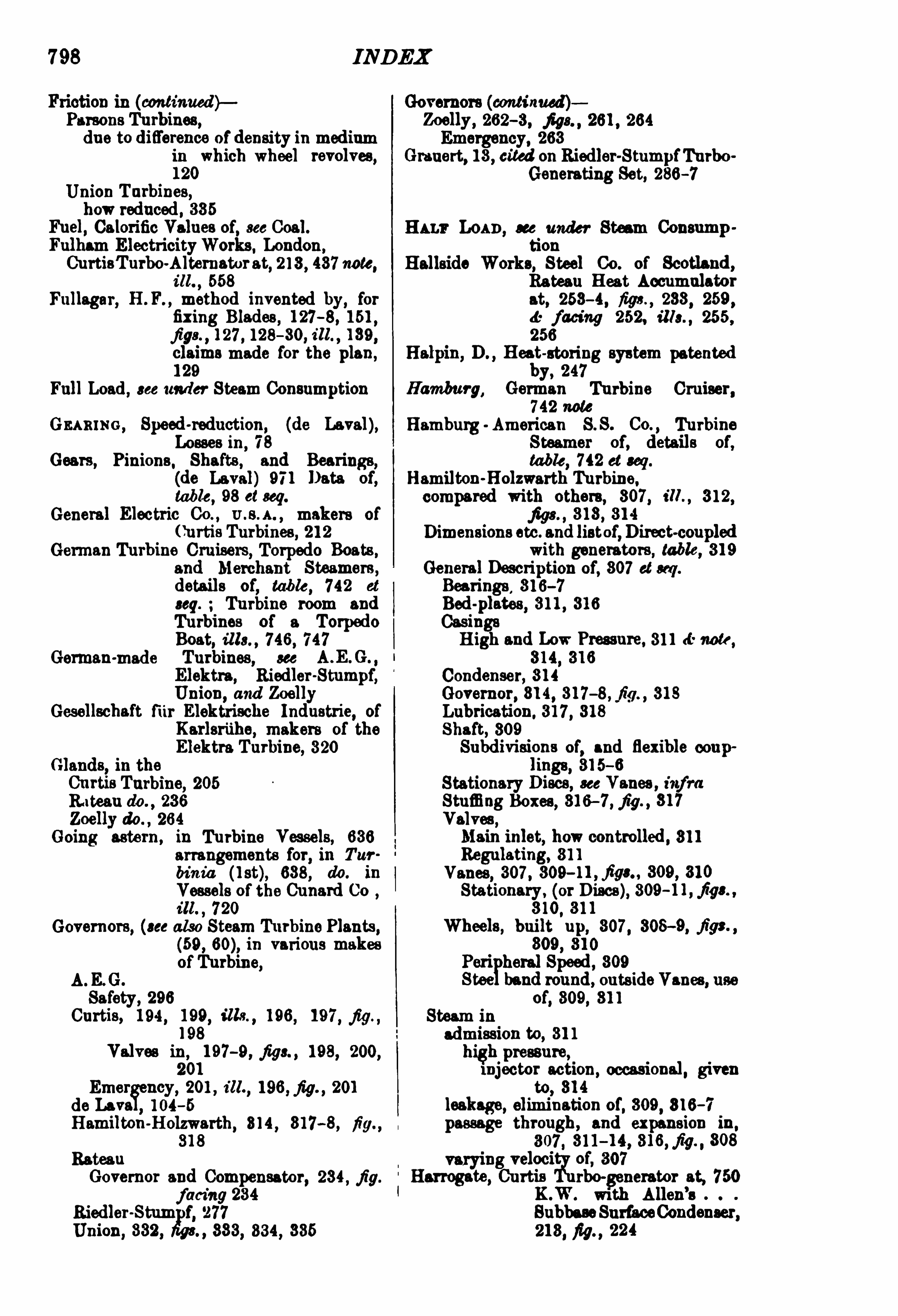
7 98 IND EX
Friction in (cmztinued ) Governors (continued)Parsons Turbines,due to difi
'
erence ofdensity in mediumin which wheel revolves
,
120
Union Turbines,howreduced, 385
Fuel, Calorific Values of, see Coal.
Fulham ElectricityWorks, London ,
(hirtisTurbo-Alternatorat, 213, 487 note,M . , 558
Fullagar, H. F. , method invented by, forfixing Blades , 127
-8, 151 ,
j igs ,127 , 128— 30, i ll. , 139,
claims made for the plan,
129
Full Load, see under Steam Consumption
GEARING , Speed-reduction
, (de Laval),Losses in, 78
Gears, Pinions,Shafts, and Bearings,
(dc Laval) 971 Data of,table
,98 cl seq.
General Electric Cc . , makers of
Curtis Turbines, 212
German Turbine Cruisers, Torpedo Boats ,and Merchant Steamers ,
details of,table
, 742 et
seq. Turbine room and
Turbines of a Torpedo
Boat, ills. , 746, 747Turbines, see
Elektra, Riedler-Stumpf,Union, and Zoelly
Gesellschaft fur Elektrische Industrie, of
Karlsriihe, makers of the
Elektra Turbine, 320Glands
,in the
Curtis Turbine, 205
R ites“do .,236
Zoelly do. , 264
Going astern, in Turbine Ves sels, 636arrangements for, in Tur
binz'
a (l st), 638, do. in
Vessels ofthe Cunard Co
ill 720
Governors, (see also Steam T urbine Plants,
(59 , in various makes
German-made
ofTurbine,
A.E.G.
Safety , 296Curtis, 194 , 199, ills ,
196,197 , fig ,
198
Valves in, 197-9 , figs , 198, 200,201
Emer ncy, 201 , z'
ll.,196 , fig.
, 201
de Lava 104-5
Hamilton-Holzwarth, 814 , 817-8, fig318
Rateau
Governor and Compensator, 234 , fig.
facing 234Riedler-Stun f
,277
Union,332, 333, 334 , 335
Zoelly,262-3, j igs"261, 264
Emergency, 263Grauert, 13, cited on Riedler-StumpfTurbo
Generating Set, 286-7
Hans Loan,see under Steam Consumption
B ellside Works,Steel Co. of Scotland,
Rateau Heat Accumulatorat, 253
- 4, figs ,
233,259
,
facing 252, ills. , 255 ,256
Halpin, D Heat-storing system patented
by, 247Hamburg, German Turbine Cruiser,
742 note
Hamburg American S S. Co. , Turbine
Steamer of, details of,table
, 742 et seq.
Hamilton-Holzwarth Turbine,compared with others, 307 , m. , 312,
j igs. , 313, 314
Dimensions etc. and listof,D irect-coupled
with generators , table, 319General Description of
,307 cl seq .
Bearings,316-7
Bed-plates, 311 , 316
CasingsHigh and LowPressure, 311 <5 note
,
Condenser, 314Governor, 814, 317 318
Lubrication, 317 , 318
Shaft, 309
Subdivisions of,and flexible coup
lings, 315-6
Stationary Discs, see Vanes , infraStuffing Boxes, 316
— 7 , fig , 317
Valves ,Main inlet, howcontrolled, 311
Regulating, 311
Vanes,307 , 309-11 , figs.. 309 , 810
Stationary , (or D iscs), 309-11, figs. ,
Wheels, built up, 307 , 308-9, figs. ,
809, 310
Peri heral Speed, 309
Steerband round, outside Vanes, useof, 309, 311
Steam in
admission to, 31 1high pressure,injector action
,occasional, given
to, 314
leakage, elimination of,309
,816-7
passage through, and expansion in,
307 , 311- 14, 316, fig.
,308
g veloci'
t
i'
ylof
, 307
Harrogate , Curtis rho-generator at, 750K.W. with Allen
’s
SubbaseSurfaceCondenser,213, M . ,
224

800 INDEX
Losses in de Laval Turbine (continued)Summation ofthe above
,and percentage
allocation, 81
Lots Road, Chelsea, see Steam Turbine
PlantLow-pressure TurbinesCurtis, described, 223, table, 224
Rateau, with Heat Accumulator,
Steam Consumption of,effect on,
of reducingVacuum,
table, 241 tests
on , table, 246
Lubes/c,German Turbine Cruiser, details
of, tables, 630, 742 at cm. ,
ills , 744 , 745Lubrication
, see Steam Turbine Plants (63)A.E.G. Turbine
,292
Curtis, (bywater) 204 «t fig.
de Laval, 97 , fig.
, 96
Hamilton-Holzwarth, 317 , 318Parsons, 134Oil consumption for different aim
,
table, 185
Zoelly, 263Lucam
'
a , see Campania and LucaniaLunka
, Turbine Steamer, details of, tables,631
,685 et seq.
Lusitania, Turbine Steamer, 631 , 716
MAHENO, details of, tables, 631, 685 note
Mahmussa , Turbine Yacht,table, 631 (detail 61 dwe te),669 note
Main Generators,7
see Steam Turbine Plants,1 )
Main Steam Turbines, see Steam Turbine
Plants, (56 )Manxma n , Turbine Steamer, details of
tables,630, 692 et seq.
Plans and sections, fig. , 698
Position ofStarting Platforms in, 704
Revolutions and Slips of
Compared with Reciprocating EngineVessel, table, 704
Steam to Glands etc. ,in
, 709Tests, table, 709Turbine Room,
ill. , 703,Cross section, fig. , 703
do. , and Condensers, i ll. (ff fig. , 705
Marine Condensers in Some Turbine-DrivenVessels, 437 ck table
Li hting Plant,mwn-Boveri Pnrsons, 189, fig. ,
190
Cost of, compared with that of
equivalent Piston Engine
Engine Plant, 190
Riedler-Stumpf, smallTurbo-generatorfor, 286
— 7 , fig.,287
Marine Steam Turbines, and TurbineVessels, 680 et seq.
ComparisonswithReciprocatingEngines,632, tables, 648
—9 , 650— 1
cl seq. , figs ,634, 655
relative Steam Consumption, 684-5
Marine Steam Turbines, sto. (cmuinuedyCondensers in , 632, table, 437Augmenter do. , 710
First Parsons Marine Turbine Ship,Turbinia (l st) , 636 , ill. ,687 , tables, 630, 637 , 689 ,642, 643, 647 , j igs ,
638-9 ,640-1, 645
GoingAstern in , 636 , 638, i ll. , 720
Governing Turbines in, 704 , 709
Stopping from Full Speed, 646
List of Turbine Vessels, and Index to
further Data, table, 630—2
Recent Torpedo-Boat Destroyers, 661—8.
table, 668
Reciprocating Engines combined with,Economy of Steam (
‘
on
sumption secured by, 636
Oil-consum tion in, 733
Speed and ize Limits for, Bateau’s
and Winter’s opinionscited, 632, 683, Views of
the Parsons Marine
Steam Turbine Co. 634 ,
of Mr Speckman, 635Starting Platforms in
, position of, 704
Steam By-pass to Intermediate Stage in,709
Turbines and Turbo-generators used in,A .E.C . 20K.W. , 292, fig. , 293, table ,
ih.
Curtis, Vans and Nozzle arrangement
for, 195
Zoelly, 272
Maschinenbau-Aktien Gesellschaft Union,Essen, builders of the
Union Turbine, 327
Mauritania , Turbine Steamer, 631, 716
Mean Representative Results as to Steam
Consumption ,see under
Piston engines , and under
Steam TurbinesMechanical Stokers, see Steam Thi rbine
Plants, (44 )Merz
, C H Tests by, on a Curtis Turbo
Alternator at Cork, 217 ,table, 218-9 (cola. 6— 11 )
Metre-kilogram, (m. defined, 18
Metric system,use of, in its bearing on
Continental rivalry withEnglish speaking coun
tries, 22
Metric and English Units Measures etc .,
see Equivalents in different
units
M idland Railway 00.
’
s Turbine and
Reciprocating Engine
Steamers, tables, 630, 692et seq.
M irrlees-Watson Surface-Condenser, Par
tick, 437 , ill. , 486
Moabit 2000H.P. Riedler-StumpfTurbinedescribed, 276, 278, 279,
figs , 276, 277 , 279, 290

801IND EX
Modern Piston Engines, see PistonEnginesMoney, decimally expressed in this work,
23
Motherwell,see Steam Turbine Plant
Multicellular Turbo-Alternator, (Rateau),850 K.W. , Tests of, table,242
Multiple-Wheel pe of Turbines, see
A. G., Parsons, Rateau,
and Zoelly Turbines
NARC'I SSUS , Turbine Yacht, details of,tables, 331 , 669 et seq.
Naval Vessels, with Turbines andReciprocating Engines , comparisons of, tables, 630
—1 , 648at so
Neasden, see Steam rbine PlantNew York Edison Co.
’s New Waterside
Station, 147 , 209 , note454 , ills., 444 , 455, 481
ewport Electric Lighting Power StationCurtis Turbine, details of, 214
-7 , testson,
)table, 218 9 , (cola.
1— 4
Nickel Steel, emplo ed in Wheels andN0 es (Riedler-Stumpf),276, 279
Expressions for Ener defined, 17 , 18,table, 1
Board of Trade Unit, 17a: note
British Thermal Unit, 174: note
Foot-pound, (ih-lb ), 18Horse power-hour, (H.P.H. 18Kilogram
-calorie, (K 17Kilowatt-hour, 17 J: noteMetre-kilograms, (K. 18
Warme Einheit, (W. 17Practical Units for Power, 19 tablesHorse-Power
, 19Kg.O.S. , (one kilogram-calorie per
second), 19Kilowatt, (K.W. 19
Non-condensingParsonsTurbine, are underParsons Turbines
Nozzles in different Turbines291, 804 , 306, fig. , 305
Curtis, 191— 4, 195, j igs ,194, 195
de Laval, 26, 27 , 87 , figs , 26, 27 , 98, 94low in
, 68, table, 69, d: see 70Rateau, 229, 234 , fig. , 229
Riedler-Stumpf, and Lilienthal and
Riedler-Stumpf, 278, 279 ,288
, j igs , 274 , 279, 280,281
,230-2, 288,figs.
,232
,
288
Union, 827 , 831 , 882, fig 828Nozzles
,ofdifferent types
Dive'
ngA. .G. ,
291
deLaval, 26, 27 , 87 ,figs , 26, 27
ozzles, Diverging (continued)Union, 881
Ex nding‘
urtis, 19 1-4, 195, j igs ,194, 195
Number of, 199Rateau, m. , 229
Reversin
Lilient andRiedler-Stumpf, 280-2,288, figs ,
282,288
Nozzles and Vanes, Leakage between, (doLaval), Losses due to 70
No. 1125 , Turbine Steam Yacht, detailsof
,tables 630
,673 cl seq.
Osamxon-Ra'
rnau Turbines, described,
236 a note, j ys. , 285 , 237 ,238, 240, 241
D imensions, Outputs, and Speeds of,table
,236
100K.W. ill. , 235, table, 2861000K.W. Test of, table, 245
Oil-Consumption in Lubrication, Parsons
Thirbines, various sizes,table, 135, Zoelly Turbine,263-4
in Reciprocating Marine Engines, 783Oil-cooling plan?
se
;SteamTurbine Plant,
64.
Oil-economy in Turbines and Piston Eu
gines, 404
Oil-supply, to Bearings, (Curtis), 201, 204 ,table
,202 Accumulator
for, 205, (Parsons), function of
, 181
1000 and 1500 Kilowatt Sets, Tenders andaccepted Prices for, 5—7tables
Onward,'h irbine Steamer, details of
,
tables, 684 cl seq.
Osbonw, Turbine Yacht (King Edward’s),
table, 631 a note, 669 note
Osthofi'
, O. E.,tests by, on Curtis Turboenerator, Oshkosh Gas
orks, 220, table, 218—9,(cola. 12-14 )
Outputs, see Dimensions etc.Overall Length, see Dimensions etc.
Overhead TravellingCranes, see Cranes
Pars ons, C. A. 3 Cc., chiefmakers ofthe
Famous Turbine, 119,also Brown Boveri Parsons, and WestinghouseParsons
Parsons, Hon. C. A. , 682, 637experiments of
, regarding Cavitation,644-6, j igs , 647
patents of,for securing LowPeripheral Speed,
261 note
for utilising Expansion of Steam,
247

802
Parsons, Hon. C. A. (continued )pioneer (see also de Laval) of the Com
mercial Steam Turbine, 2views of, cited, on advantages of joint
use of Turbines and Re
ciprocating Marine Eu
gines, 636-7
and Stoney, tests by, of Turbines forD riving Dynamos, resultsof, cited
,as to effects of
Varying Vacuum on SteamConsumption, 165-8,figs ,
Parsons Marine Steam Turbine Co.
arran ementa of, for Goin Astern, 636
first rbine Shi of,see arhinia l st
lowspeeds rovi ed for,by, 634
“mongrel’
system of,for securing
Economical Steam Con
sumption at all Speeds,636
Steam Trials of Amsthyst, fitted withParsons Turbines, table
,
682
views of, cited , on Speed and Size LimitsforMarineSteamTurbines,634
Parsons-Peebles Turbo Generators,with
Allen Surface Condensers,440 dcj ig.
Parsons Turbine, 119chosen for comparison of results between
Piston Engines and SteamTurbines, and why, 391-2
described, 120 et 121,122
,J:
facing 122, 123, 124, i lls ,
125-30, 132- 4, 136-8,140-2
,144
, 146,147, a
facing 148, 152, table, 135effi ciency of, in relation to Smallness of
Clearances, 151
Firms building, 119 dc note,see also
under each nameGeneral description of
Balance Pistons, 120, j igs ,121, 122
defac ingBearing, Flexible, 181
Pressure,132
Thrust, 132 <9 fig.
Friction in, howcaused, 120Lubrication in, 134
Oil-consum tion for various sizes,te
,135
Regulator, 132, fig , 133
action of, figs , 134
Rotor, 122, figs , 121, 122, d: facing
122, i ll. , 143
Steamadmission,
occasional direct, to
intermediate Stages, 131
progress through, 131
as acted on by guide Vanes, 120
leakages of, howcaused, 120, howdisposed of, 181
IND EX
Parsons Turbine, General description of
Vanes
fixed and moving,construction of, 120—9
numbers of, 122 6: note, 308-9at high
-pressure end, criticism of,331
relative position of,howsecured
,
132 46 fig.
stationary guide,”120
difference in fi ring, and those
of Hamilton Holzwarth'
h 1rbine,310
Wheel, 120resemblances to, of that ofUnion
Turbine, 881
SteamConsumption in, 156, 4
: tablefacingdo . 4: see do .
,under Piston
Engines and Steam Tur
bines
at Full, Half, and Quarter Loads ,curves for, 389, j igs.
,390,
891
do. do. Average, with definite
Vacuum and Superheat,table , 187 , excess of Half
and Quarter Loads over
Full do. , table 188do. with Constant Vacuum and
definite Sn rheat, withVarying A lute SteamPressures, tables, 180-1 ,186
do. do. do. and Mean Absolute
Pressure, tables, 182 - 4,185
Percentage decrease in,in relation
to less Load and moreVacuum,
165, figs"165 ,
166
in relation to Pressure, (Admission) and Changes in Pressure, 156 et seq. , 179 , j igs157
facing 396with Various Loads
,see Full, and
Average do. , supra
Full, non-condensing, excess of,overspecifiedVacuum,
162,
fig. , 164
with varyingSuperheat,figs.176, 177, 178, table , 178
Half, fig ,188
Quarter, fig , 189
do. with Constant Vacuum and
Superheat, and MeanAbso
lute Pressure, tables, 182-4 ,185, do. with VaryingPressure, tables 180-1
do. , with Varying Superheat, 162cl seq. 891, 893j igs ,
171-9 ,896 , table, 178
804 IND EX
Pressures, Admissioninrelation to Steam Economy , 161— 2
increased, in relation to CommercialEflicienc of Turbines andPiston ugines, 405 , 412
at ug., figs ,
406— 11
in relation to SteamEconomy, 161— 2in relation to Steam Consumption
dc Laval K.W. Tur
bine running Non-con
densing, table, 50, see also
table, 58
do. do. Parsons Turbine, 156 at
se figs 157-60, do . andot ers, 391, 393, 403, j igs"facing 396
increased, in relation to CommercialEfficiency of Turbines and
Piston Engines, 405, 412
et ug., fiy8. , 406
— 11
Varying,in relation to Steam Consumption
ofPiston Engines, 384 dcj igofTurbinesde Laval, 40, tables, facing 40,
41 et seq.
Parsons and others, slight effectof, 156 at ug. , 179 , 384 ,391, 393, 403,157-60, d
' fact'
ng 396
Westinghouse, and BrownBoveri-Parsons sets
,161,
figs , 158, 159, 160
Bearing, (Parsons), 132Constant, and Variable Speed, (Zoelly),
tests of,272, table, 276
(cola. 9, 10, 11 )End, (Parsons), causes and cure of, 120,Exhaust
, Energy of Steam in relation
to , 357
External, Energy ofSteam used in over
coming, during Super
heating, how calculated,350
Initial
Change in, effect of,on Steam Con
sumption-fig.
ofPeripheral Speeds, at Bearings, 14 ,table, 15
Regulation of, in Stages, Valves for,
(Curtis), 208— 10Sections, Steps or Stages,A .E.C . Turbine, 291
Rateau do. 228 d: note
Riedler-Stumpfdo. , 283 46 fig.
Union do. , 327Superheat, and Vacuum in Plants in
Operation, 422 at seq. dc
tables
in use with Reciprocating Engines,table, 426 — 7 , summary
,
t able, 423
do. do. Turbines, table, 424-5 ,summary, table, 423
Pressure and Volumeat lowTemperatures, 859, fig.
,360
relation between, for SuperheatedSteam ,
385
Prices ofCoal, see CoalM m Elizabeth, Turbine Steamer,
details of, tables, 631 , 734
Princess Maud,Turbine Steamer, detailsof
,and comparison with
Reciprocating Engine
Steamer,tabla ,
630, 664
a seq.
Propeller“) ofFrench Turbine Torpedo Boats,
i ll.
, 739
w in ia ,l st, trials with difl
'
erent
numbers of, 643—4
,
Additional,on Turbine Shafl: of, S.Y .
Caroline , 681, results of
tests of, 682—3 J: tables
Propeller-Slip of Amethyst, at Different
Speeds, table , 658
Properties ofSteam,see under Steam
Pumps.Air
, Circulating, andLift, see Steambine Plant, (70)
Rateau Turbo-P umps, fig. ,239
, tests
of,table, 239 é note
Quan'
rnn-Loan, see under Steam Con
sumption
Queen, Turbine Steamer, details of, tables,630, 684 at ug. , ill. 693,cross-section,M . , 692
Que en A lexandra,Turbine Steamer,
details of and'
com rison
with Reciprocating ngineVessel
,tables , 630, 664
at ug.
, ill. , 668
Condenser in,table
,437
Quick-Stop Trials, Revolution’
h i rbine
Steamer, 733
Quincy Point, see Steam Turbine Plant
Kama'
rion from Turbine Casing, (deLaval), Losses due to, 70
Radcliffe, see Steam Turbine PlantRateau , Professor A. , (see also Rateau
of his work in SteamTurbine design, 226
-7Cc-astern Turbine invented by, 636
V iews of, cited ,on
Impulse andReactionTurbines, differ.
encebetween, 228— 9 note (3)Limits of S and Size for Marine
team Turbines, 6324Numbers of Vanea in relation to
Steam Economy, 228 note
Results ofTests of Torpedo Boat, No.
1125 , with Turbines and
ReciprocatingEnginea683

INDEX
Rateau, ProfessorA Views of (continued
Theoretical Steam Consumption ofthe
Perfect Machine, 358—9
44,-j igs.Rateau Regenerative Heat Accumulator,
226— 7 , 246-50, j igs ,248
,
249
various types of, atBethune Mines, 250, fig. , 251
Bruay M ines, 247 , fig. , 249
Hallside Works, 253-4, figs ,
253,
259,43 facing 252, ills ,
255 , 256
Hucknall Torkard Colliery, 250, 258,j igs , 257 , 258
Reunion M ines,250
Rateau Turbines,see also Oerlikon Rateau
do. Jr: Surface CondensersApplications of
, to Centrifugal Pumps,Fans, and Compressors,238
Extent ofuse of, 236
400 E.H.P. ,Test on
,table
,246
General description,227 , figs 226,
230
Bearings, 235 ch note, figs ,227 , 232,
233
D iaphragms, 229 , 230, fig.,229
Glands, 236
Governor and Compensator, 234 , fig.
facing 232Nozzles
,
Expanding, 229, 234 , j ig. , 229
Pressure Steps or Stages in, 228 (t
M te (2)
RegulatingValve, 234
Shaft,232 ch note 232—3
Speed Control, (see Governor ct Regulating Valve, supra ), 234
8 Reduction, 229 note
anes or Blades, Revolving, 227, 228.e note
, j igs 226, 228
Wheels of,
Peripheral Speed of, comparedwiththe de Laval do. ,
238
resemblance to, of those of Union
Turbine, 237LowPressure, with Heat Accumulator,Steam Consumption of
,effect on, of
reducing the Vacuum in,
table, 241
Tests on, (225 table, 246
Power Consumed by Auxiliaries, 240
used on Ships,on the Caroline, in conjunction with
a Reciprocating Engine,636 , figs ,
679, 680, tes ts
of,table
, 681
duplicate ofthose in French Torpedo
Boats, tests of, 740, table,
737Rateau Turbo-Alternator Multicellular,
350 K.W Tests of,table,
242
805
Rateau Turbo-Alternator (continued)Turbo Generators
700 B.H.P. , 254 , ill 255 , figs , 227,253
Supplementary High Pressure,
at
Bruay, 2522000 K.W. , Steam Consumption in,
241, seefig. , p. 38
do. do. , b S utter, Harlé Co. ,
370 xlv. , figs 232,233
,table, 239
note, Test of, tables, 242,243, 244 , Jr note 242
500 K.W. Tests of, table, 245
Turbo-Pumps, tests of, fig. , 239, table,239 J: note
Rated Speeds of Parsons Type Turbo
generators, fig. ,150
Reaction Turbines , Difference betweenImpulse Turbines and
,
Rateau on, 228-9 note (3)
Recapitulation of the Properties of Steam
(subheads, seeunder Steam)341 at m. , figs , 351,358-61
,tables
,342, 345 ,
352
Reciprocating Engine(s), see also Piston
Engines
in use with Steam Pressure, Superheat,and Vacuum, table, 426
— 7 ,summary, table, 423
in use in Steam ShipsComparison of
,with Marine Steam
Turbines, 632, tables,648-9 ,650-1 at ug. , figs , 634,655, Oil Consumption of,733
,relative Consumption
ofSteam, 634-5
in Cruisers,Record Coal Consumption, table, 748
in Naval Vessels, tables, 643-9 et seq.
in Steamers owned by Railway Co.
’s.
L.B. a R. and Chemin de Fer del’Ouest
,table, 685 st seq.
Midland Railway, table, 692 et seq.
S.E. 8: C. Railway, table, 684 ct seq.
Steam Pressure, Superheat, and Vacuumin use with, table, 426-7 ,summary, table, 423
Surface Condensers used with, table,
432—3
Regenerative Heat Accumulator, (Rateau) ,226-7 , 246— 50, figs , 248,249
Regulating Valves, see Valves
Regulation, see also Governors, etc. ,A .E .G. Polyphase Turbo-generator Sets
forworking parallel, 298Curtis Turbine
,in Stages, 208
-10
Regulator in different Turbines,A .E.G 294— 6
Brown-Boveri-Parsons,122, fig. ,
133
action of, j ig. , 134
Parsons,122
Rateau, 234, fig. ,facing 282

INDEX
Regulator'
1n different Turbines (contd .
Union,332
, fig. ,333
Safety (10. vertical and horizontal
types , 332, 334,figs. ,333- 6
Residual Kinetic Energy, see EnergyResults, see Mean Representative do.
Reunion Mines, Rateau Heat Accumulatorat, 250
Revolution , American Turbine Yacht,details of, table, 728 st seq .
Tests of, 732 et seq.
1. Quick Stop'
I‘
rials, 733
2 . Weight ofC urtisTurbine as against
that of Reciprocating Eu
gines , 7333. Oil Consumed by, 733
Revolutions per minute, various Ty ice of
Turbo generators, ta le, 16
Revolving part of Four Stage Curtis
Turbine, fig ,223
Vanes or Blades,see Vanes
Riedler-St11mpfTurbine, 273 ct seq.
builders of, 286 , 290
Details of,Buckets, or Vanes,
D ouble, 276 , j igs ,274 , 275
Single, 278, fi g ,275
Number of, 2 16Overlap of, reason for, 279 , fig. ,
274 ,compared to that in Union Tur
bine, 335
Clearance, large, 278Governor
,277
Nozzles , 280, figs , 274 ,279 , 280, 281
Reversing, (Lilienthal), 280— 2, 288,j ig/s. ,
282,288
Pressure Stages 283 s-fig.
Shaft m , rigid, 279
Speed Regulator, 277Steam admission to, 278, 283-3, figs ,
27 4, 279 ,Consumption ,
288, table, 289Wheel
, (2000H .P. 274— 9 , j igs” 274 ,276
Breaking Strength of,276
Hub of, 275— 6, j igs , 274, 276,278
Pe1ipheral Speed of,275
Stresses 011,276-8
Weight of, 279
Proportions of, eliminating need for
Speed reduction gearing,273
type, comparedwith de Laval Turbine,similarity of general
principles,do. with Flektra Tu1bine, 320mergence of, in that of A.E.G. Tur
bine, (q. .v 286
Vertical Shaft design,284, figs. (show
ing condensers) ,RiedleroStumpf, Turbo
-generator,
small size, 20. H.P.
, 287-8, fig , 288
Riedler-Stumpf, Turbo-generator (contd .
small size forMarine Lighting, details of,Grauert on
,286— 7 ,fig. , 287
Test res ults on 1475 K.W. direct-coupledto D .C. Dynamo
,table
, 289
2000 H.P. set, M oabit Works, Berlin ,
described,276 , 278, 279 ,
j igs ,276 , 277 , 279 , 290
Rims,orRings, toWheels, various Turbines
de Laval, 28Elektra
,322
Hamilton-Holzwarth, 309, 31 1
Rateau, 279
Riedler-Stumpf, 277 , 278, 279 , figs"280, 281
Union, 335
Rotor of
Parsons Turbine, 122, figs , 121, 122 43
facing 122, ill. , 143Union
'
h 1rbine,weight of, howequalised ,
335— 6
Westinghouse Parsons Turbo generators ,145, ill. , 143
Rugby, Curtis Turbine Plant at, 500 K.W.
alternating current, 214,ill. , 225
Rugby and Cork , Curtis Turbine Plant at,continuous current
, tests
of,214, figs ,
216,table,
218-9 (col. 5 )
Sara'
rv-Rmvnu on, (Union), vertical andhorizontal types, 332, 334 ,figs , 333, 334, 335, 336
St George, Turbine Steamer, details of,
tables,631
Economy in, 664
Salem,Turbine Scout, details of,
tables, 631 , 728 et seq.
Samuelson, tests by, on Curtis
-TurboAlternator, Rugby, 217 ,table , 218-9 (col.
Sapphire, see Topaze, Sapphire, andD iamond
,Cruisers
Saturated Steam,see Steam
Seagull, H.M .S . Torpedo Gunboat, SteamConsumption 012635 , g.,634
Sensible Heat, see Heat in LiquidShafts ofvarious Turbines
A.E .G. , 292
Curtis,
Vertical,201
de Laval,Flexible, 94 , fig. , 95
Hamilton-Holzwarth, 309
Subdivision of, and Flexible Coupling, 315
-6
Rateau , 232 de note 232— 3
Riedler-Stumpf,Rigid, 279Vertical, 284
Single-Wheel Types of Turbines, see
de Laval, Elektra, and
Riedler-Stumpf

Steam, Properties of Energy, Convertible
(continua )in relation to
Exhaust Pressure, reduced, 357Expansion ,
355,856-7
requisite to produce Steam of given
qualities, in relation to
otal Energy, 856, tables,342 et seq.
in Steam and Water, (Water partlyevaporated), relations between
,348— 9
used in overcoming External Pressure during Superheating,howcalculated, 350
fl oat
in Liquid, or Sensible Heat,tables, 342, 345
Latent,
341-8
External, duringSuperheating,350
Internal, 348
Total, 349
Steam, see also Steam, Saturated, andSuperheated, infra
behaviour of, under various con
ditions, instances of,353-7
in Piston En'
nes, 354— 5
in Steam Tur ines, 357-8Consumption , Theoretical, of the
Perfect Machine, Rateauon, 358, 359 d:figs.
Su rheatin
xternal tent Heat, 350
Specific Heat, 350, fig. , 351
Total Heat, 340
Volume and Pressure of, at LowTemperature, 359,fig , 360
Saturated,Adiabatic Expansion of, in relation
to Energy, 355Convertible Energy, in, 349, tables,
Specific Weights and Volumes of,
351 .4.-fig.
Temperature of, see table, 342, a seq.
andWater, Properties of, 359,fig.
, 360
Superheated, see also Superheat
Jr. Superheating
prospects of imlpz
ovsd Economywith,in ton Engines, (1)
Steam By-pass, to Intermediate Stage,
Turbine Vessels, 709Steam to Glands, Turbine Vessels, ih.Steam Piping, a
ge Steam Turbine Plants,48)
Steam Pressure, Superheat, and Vacuumin Plants in Operation,422 et seq. ,
tables,423
,
424-5 , 426— 7 , 428Steam Ships, with Steam Turbines
,
Marine Steam Turbines
and Turbine Vessels
Steam Turbine Plant and GeneratingStation,
Boston L. Street Steam Turbine Plant
and Station,
Figures, Plans, and Illustrations of,Elevation of BoilerHouse
,M . , 478
Sectional do. , j ig., 480
Transverse do., fig. , 479
Main Steam Turbine, ill. , 545Elevation, fig 546
Plan, fig. ,547
Piping D etails, fig., 481
Plan of Power House, 478Sectional do. , fig. ,
480
Site,467
Brimsdown Steam Turbine Plant and
Station,
flar
e, Plans, and Illustrations of,l receiving and conveying,
511 , 512—13
Elevation, ill 469
Sectional do. , fig. , 487Plan
,486
Turbine Room and Switch-boards,ill. , 557
Carville Steam Turbine Plant and
Station,Fi
gures
,Plans, and Illustrations of,
lavation, sectional, fig., 475
Exciting Circuit D iagram, M . , 613
Plan, 475
Site, lan, 465
Switc es Motor-operated, ill ., 616
Switch boards, ills , 6 14, 615
Switch gear, back and front viewof,
figs , 612
General arrangement of, j igs.
facing 612High Tension, cross m tion of,
fig. facing 612Synchronising Connections
, fig.
acing 612
Wiring iagram,M . , 611
Delray, Detroit, Steam Turbine Plantand Station,
gprea, Plans, and Illustrations of,
babies, plan,M . , 617
Elevation,i ll. , 468
Main Turbine and Generator,ill. 543
Plans,Boiler House,M . , 476
PowerHouse, fig. , 45.
Longitudinal Section, fig. 47 7Site, plan, 466
Switches , oil and disconnecting,
plan, fig. , 617
Transformers, plan, 617English M
‘Kenna 00. Steam TurbinePlant and Station,
res, Plans, and Illustrations of,ovation, fig. , 489and do. , Sectional, fig. , 490
Plan, 489

IND EX 809
Steam Turbine Plant and GeneratingStation (continued )
Lots Road, Chelsea, Steam Turbine
Plant and Station,see also
135 J: note at no. do ills ,
140- 4, 540, 541
Pi n'
es, Plans, and Illustrations of,ilerHouse, ill. , 514
Circuits, fig. ,602
Coal receiving arrangements, all
508, fig.,509
Condenser, ill. , 559Elevation
,ill. , 468
Sectional do. , fig. , 470
Food Pump, ill. , 5 15Generator Switch and Potential
Transformers, ill. , 603Generators , shown infig. 602
Main Steam Turbine, fig. , 540
Piping from 8 Boilers to one Header,ill. , 515
Plan, fig. ,47 1
Rheostats,M otor-operated, ill. , 609
Site, lan, 464
Switc (es),Bus bar sectionalisingoil,fig 608
Knife, in series, etc.
, j ig., ib.
Switch gear and cables,elevation
and diag. j igs"604—5Switch-boards,Auxiliary, 610Feeder, and Generator, i lls. , 606 ,
607Turbine Room, ill. , 541
Motherwell Steam Turbine Plant and
Station,
Pi res, Plans, and Illustrations of,ndenser
,ill.
,561
easden Steam Turbine Plant and
Station,
Ih'
res, Plans, and Illustrations of,oolingTowers, ill. , 560Elevation, ill. , 468
Sectional do. , fig. , 473Main Steam Turbine, fig. , 542
Plan, 472
Quincy Point Steam h rbine Plant and
Station
Pi res,Plans, andIllustrations of,
rtis Turbo-Generator, 3 views,
549
Elevation ofPower House, ill. , 483Plan ofPowerHouse, 482
Switch-boards, ill. , 620Turbine Platform, fig.
, 548
cliffs Steam Turbine Plant and
Station,F
'
res,Plans, and Illustrations of,
al delivery, ill. , 510, fig. , 511
Electric Circuit to Auxiliaries, diam of
, j ig. , 624
Electric onnections, diagram of,
fig. 622
Elevation, ill. 474
Steam Turbine Plant and GeneratingStation— Radcliffewould. )
Plans, and Illustrations of,
witch board, Main, and oilSwitches
,ill. , 623
Turbine room, interior, ill 555
Water Accumulator and Pump forfootste Bearings, ill. , 556
Thornhill Steam bine Plant andStation
,
Pi res , Plans, and Illustrations of,arm
'
s set, with Condenser, al l 553
Elevation,i ll. , 469
Sectional do. , 484
Exciters, ill. , 554
Feeder Panels, Main H T ill.
,621
Plan,485
Site, lan,466
Switc -board, Main, continuous
current Panels, ill 621
Yoker Steam Turbine Plant and Station,
Figures, Plans, and Illustrations of,
see also 146, é ills"146, 147Elevation, i ll. , 468
Exciter sets, i ll. , 552Main Generating sets and Conden
ser,ill. , 550
set, ill. , 551
Switches, High tension oil, all 620
Switch-boards,Control and Instrument
,ill. , 618
Gallery, ill. , 619Parts common to the above stationsBoiler Feed
,516-23
Flues , 500-7and Superheater Surface etc see
table, 452-3
Boilers, 500-7
Buildings, (9. 456— 63
Chimne s, (42. 500-7
Coal, alive of,
and storage,also
r
Bunker capacity, consumption, quality, ashremoval etc. , (29456-63, 492—507
Cost per ultimate rated K.W. capa
city, (2. 456-63
Economisers,
516-23
Governors, (59 , 532-39
Main Steamh rbmes, 524-31
Mechanical Stokers, 516 -23
Pumps, (under 516— 23
Steam Consumption, 532-39
Piping, (48. 524-31Valves
, 532-39
Superheaters, 516-23
Water-Supply, (49 ct 524-31WharfCranes
,492— 99
Steam Turbines, see also Turbines, Turboalternators etc. and various
makes under namesCommercial Efi ciencies of, and ofPiston
Engines, under ExtremeConditions,M . ,
416-7

810
Steam Turbines (contimwdyCondensers usedwith, table, 430—1, 432—3Cost in relation to, 2- 11, tables, 3— 11
Comparison of Cost of Different typesofEngines, table, 9
ofCom lete Power House, 9 , table, 8
ofCon ensingPlant, 9 , 10, «2 tables
of Condensing and Nou-CondensingPlant 10-11 42
tables
rim Cost,2,3, 4: tables
per Ton, howarrived at, 11, table (ofWeight), 13
of some Turbo-Generators and Con
denser Plants, 4—7Tenders and accepted Prices for 1000
K.W. and 1500 K.W. set
J: tables, 5-7
Steam Turbines,Mean RepresentativeResults as to Steam
Consumption for, 389 at
seq . j igs ,393, and com
rison with results for
iston Engines, 393 cl seq. ,
figs , 398-401
the same at Various Loads, as a Per
centage of the Full Load
Consumption,395, figs. ,
402— 3
Standards of Reference for, 389
Steam h rbincs,
Steam Consumption in, atFull, Half, and Quarter Loads,
curves for, 389, figs , 390,391
Pros and Cons ofEconomy obtainable by, Operated
Condensing, 1Speed in relation to, 2Weight in relation to ,
and cost per
ton, table, 13Steam Turbine Ships, see Turbine VesselsSteam Valves
,see Steam Turbine Plant,
and ValvesStokers
,Mechanical
,see SteamTurbines,(44)
Stoney, see Parsons and StoneyStoppingfrom all Speed, Turbinia , (1st), 646Quickly, trials of the Resolution , 733
in A.E.G. Turbines, howdealtwith, 29 1
on Wheel of Riedler-Stnmpf Turbine,276-8
(Hamilton Holzwarth),316-7 , fig. , 317
Superheat, see also Pressure, Superheatand Vacuum
in relation to Steam ConsumptionA.E.G. Turbine
, 304 Jr. table
Curtis do. , fig. , 214
de Laval do. 64 , figs ,64 cl say.
with and without at various loads,
tables,55 , 56
with varying do. , table, 58
Stumng boxes,
IN DEX
Su rheat
wins.effect of, on Consumption of
Parsons Turbine, see supra
Piston Engines, 385 , figs. , 385, 386Zoelly Turbo
-generator, table, 269
Superheated Steam, prospects ofimprovedresultswith, on the PistonEngine, 1
Superheater Surface, in some of the Plantsreferred to , table, 452—3
Superheaters, sec Steam Turbine Plants ,(45 )
Su rheating, 349
nsrgy for overcoming External Pressure during, 349 , howcalculated, 350
Supplementary High Pressure Rateau
Turbines , 252
Surface Condensers, sec Condensers
Switches, Switch rs etc .
,on Steam
Tur ine Plants, (74)
Superheat, in relation to Steam Con
sumption (continued)Paraons
'
Ib rbine
Constant, with Constant Vacuumand M ean Absolute Pres ~
sure, tables , 182-4, 185
do. and Varying AbsolutePressure , tabla
,180-1 ,
186
do. ,at Full, Half, and
Quarter Loads, Average,table, 187 , excess of Halfand Quarter loads over
Full, table, 188
Varying, 162 st u g. , 391, 393,M a,
171-9, 396, table , 178
Various typesated Percentage Decrease in,
per degree of, Centigrade,
table, 58
TABLES of Equivalent Areas, lengths,Measures
,Pressures,Units,
Weights, etc . , in English
and Metric Forms, 19-23Tarantula , Turbine Yacht, details of,
tables , 630, 673 ct ug. ,
i ll. , 677Tests
,are under Names of Turbines etc. ,
tested
Thornhill, see Steam Turbine PlantThrust, in various Turbines
Elektra,howabolished, 322
Parsons,howcaused, and howdealtwith, 120,
132, dcfig.
Westinghouse Parsons,howeliminated
,145, 146
Thrust Bearings, m Bearings
Tonnage in relation to Cost,11
,table, 18

Vacuum (continual)Varying,
Piston Engines, 387 , figs. , facing388
do. and Steam Turbines,405, 412
cl seq. , j igs” 406— 11do. ,
in Steam ’
h irbines
Curtis, fig 215
de Laval,Full Load, 52, figs. ,
53
HalfLoad, 59 , fig. , 60, 61
Parsons, 162 et seq. 176, 177 ,391 , 393, tables, 163, 171 ,172, j igs.
,163-73, 397
High, Extra Cost of, 429 , 435 , table, 434Obstacles connectedwith, 404
Reduction of,in LowPressure RateauTurbinewithAccumulator,Effect of on Steam Consumption, table, 241
Vacuum, Steam Pressure,and Superheat,
in Plants inOperation, 422cl seq. , J: tables
Vacuum Valve, see Valves
Valves, see also Steam Valves
between A .E.G . Turbine and Condenser,uses of, 291
Distributing, in Regulator of Union
Turbine,332
,— 5
in Governor, Curtis Turbine, 197-9,
figs , 198, 200, 201
Main Inlet, Hamilton-Holzwarth Turbine
, how controlled,
311
Pressure Regulation, in Stages, CurtisTurbine
, 208-10
Regulating, Hamilton-Holzwarth'Iur
bine, 211
Regulator, Rateau Turbine, 234, fig.
facing 232in Safety-Governor
, A .E.G.
’
h i rbine,296
in Safety-Re lators, Union Turbineunction of
,332-4, 335,
336Safety, in Casing ofA .E G. Turbine, 291Vacuum, de Laval Turbine, 4 04- 5
Vanes,see also Blades, and Buckets
numberof, in relation to Steam Economy ,Rateau on
, 228 note
in various makes ofTurbinesA.E .G 291
Curtis, 192 «fr-fig.
Peripheral Speed of, 208
for Marine Work,195
de Laval
Friction of Steam inLosses due
3
Wear of, Deterioration due to, 78Elektra, 320, 322Hamilton-Holzwarth
, 307 , 309- 11 ,
figs. ,309
,310
Stationary do. (or D iscs), 309-11,314, figa , 810, 311
over,
Vanes in variousmakes ofTurbines (could )Parsons,construction ofetc. , 126
-7fixed andmovingcontour of, 124 , figs», 124, 126
relative position of,124, how
secured, 132 d: fig.
stationary “ guide”do.
,120
at high pressure end, criticism
on,331
numbers of, 122 «i note, 308-9
proportions of,in 750 K.W. set,
125-6, table, 126
Union,moving and fixed,
figs , 329 , 330
number of,331
overlap of, 335
Willaha-Parsons, 151,ill 139, see
also 127Vanes and Nozzles,Losses due to Leakage between, (do
Laval), 70Vanes andWheelsSome Data of Various Sizes of
, (deLaval), table , 89 at seq.
Velez , Turbine and Reci
grocating Engine
Tor oat Destroyer,663, details of, tables, 630,659—60, 663, ill. , 662
Coal Consumption and Speed of,com
Eared with Reciprocatingu no Ships, table, 663
Trials of, tables, 661
Vertical Shaft design Turbines,Curtis, 201
Riedler-Stumpf, 284Victoria , Reciprocating Engine Steamer,
details of, table, 684 cl seq.
Victorian , pioneer ocean going Turbine
Steamer, details of, table,630, 710 el seq. ill. 714
Turbine Casing for, all 7 15
Vilcing, Turbine Steamer, details of, tables,631, 664
Economy in,table , 664
Viper, Turbine Tor
pedo Boat Destroyer,
detai of,tables, 630,
659-60, ill ,661
Condenser'
in,table
, 437
Virginian , pioneer ocean going Turbine
details of,tables
,
631, 710 et seq. ,ill. , 7 14
Volumes , see Areas and Voluni es, Specific
Weights and Volumes, andSteam atLowTemperatures
Wanna Einheit, defined,17
Water, see also Steam andWater
Consumption, Turbinia 1st,tests of,
etc. , tables, 642
Lubrication, (Curtis), 204 d.fig.
Supply, see Steam Turbine Plants , (49GH Q -l

Wear, see Vanes, do Laval Wheels, in different makes of TurbinesWeight, see D imensions etc. ,
and SpecificWe
'
ht
Economy of, in re ation to Speeds, 13
in relation to Steam’
h irbines and Cost
per ton, 11, table , 13
of Wheel, Riedler Stumpf Turbine,
279
Weights and Pressures, uivalents of, in
English an M etric Units,tables, 21
Wait Beam Air Pum in M idland Rail
way .
’s Steamers, ill. ,
708
Weishaupt, J. tests, and illustrations of
20311y Turbines designedby, 265 4: note , ill. 263,table
,266-7
Westinghouse Companies of Pittsburg,and Manchester,
England, builders of Par
sons'I\1rbines, 119
Westinghouse-Parsons
Turbo-generating sets, at
ChelseaPowerHouse, 1353: note, clm.
, cm. ,140- 4 , 540,
541
NewYork Edison Co. largest yet
undertaken, 147 , 209 note
454, ills. , 444, 455,481
Yoker,Double-flow design, 146
,
ills. , 146, 147tables 154-5, 4
: facing 156features of,Direct-connected enclosed des
Hum eliminated,149
Double-flow design, absence of
Thrust With, 145, 143
Efficiency of largest, at Full-Load
,
149
Overload possible with, 145 ,149
Rotor of, 145, ill. , 143
Steam inflowof
,145
velocity of, 143Steam Consumption in, 143, 148,
table, 143
Variation in
with Varying Pressure, fig ,
159
with Va g Superheat, figs”g
u
ll
“,175
Summary of, in reference to SteamPressure, Superheat, and
Vacuum, 428 (t table
WharfCranes, see Cranes Yaon'
rs,Turbine driven, (see also No.
Wheels, in difi'
erentmakes ofTurbines list of,with owners
Peripheral Speeds of, 14,table
, and data, tables, 630-1,
15 669 et seq.
291 Turbine and Reciprocating Engine,Peripheral Speeds of, 291 table
,673 cl seq.
de Laval, 88— 6, fig. , 86Breaking of, unimportant, 278Description of
, 83, figa , 82,84,
85, 86
Losses due
7
to Bearing Friction of,8
do. to Friction of, Revolv
ing in the Steam, 71Elektra, 320, 822, 821, ill. , 822Peripheral Sp 322
Hamilton-Holzwarth,
Built-up, 307 , 808— 9, figa , 809,310
Peri heral Speed, 809Stee band round, outside Vanes, use
of, 309, 811Parsons
Resemblance of, to those of Union
Turbine,381
Rotating in medium of graduateddensity, 120
Riedler-Stumpf, (2000 H .P. 274-9,figs. , 274 , 276
Breaking-strength of,276
Hub of, 275-6, figs 274, 276, 278Peripheral Speed of, 275Stresses on, 276—8
Weight of, 279Union, 327 , 331, 835, figs. , 329, 330,
385,ill. , 831
Zoelly, discs of, 260, fig” 262Wheels and Vanes, (de Laval), Various
sizes, Some Data of, table,89 at seq.
White, SirW cited , on
Going Astern, in Turbine Vessels, 636Limits of Speed and Size for Marine
Steam Turbines, 633Willans and Robinson Parsons Turbines
with Allen Surface Con
denser, 439 4:fig.
details of, 151-3, ill. , 152Steam Consumption in, 161
Vanes , fixation of, 151 , ill. , 139, see
also 127features of Foun ationa of, for two
1000 K.W. Turbo-generrators
,441
, table, «3Wire binding of Vanes
, (Famous),127 of: note
Work, relation to, of Energy of Steam
,
341Work, Heat and Energy Units, sec Energy
etc.

814 IND EX
Ltd. , SteamTurbine Vesselsbuilt by, table, 673
Yoker Power House, (see also Steam Tur
bine Plants and Generating Stations), Westinghouse Co.
’s Turbo-generat
ing sets for, 146 , ills. , 146 ,147 , table, 154— 5, defacing156
Zosnnr TurbineGeneral Description of
, 260,
figs. , 261 , 265
Bearings, 263, i ll. , 268
Thrust do.,ib.
Diaphragms, 262, fig. ,263
ram-ran sr sum . as» am , nnmsuasu.
Zoelly Turbine, General description of
(continual)Glands, 26 4
Governor, 262-3 ,M a , 261 , 264
Emergency do. , 268
Lubrication, (oiling), 268Vanes, 260, fig. , 262
Wheel discs , 260, fig. ,262
Ma ine Turbines, 272Tests of, withConstant Pressure and Variable
Speed, 270, 272, tabla,266-7 , fig.
, 270
Constant Speed andDifferent
270& fig. , tabla 266—7Varied Superheat, table, 269