Vibration Analysis of Gas Turbine SIEMENS 162MW - Zenodo
9
Abstract—Vibration analysis of most critical equipment is considered as one of the most challenging activities in preventive maintenance. Utilities are heart of the process in big industrial plants like petrochemical zones. Vibration analysis methods and condition monitoring systems of these kinds of equipments are developed too much in recent years. On the other hand, there are too much operation factors like inlet and outlet pressures and temperatures that should be monitored. In this paper, some of the most effective concepts and techniques related to gas turbine vibration analysis are discussed. In addition, a gas turbine SIEMENS 162MW - V94.2 vibration case history related to Iran power industry in Fars province is explained. Vibration monitoring system and machinery technical specification are introduced. Besides, absolute and relative vibration trends, turbine and compressor orbits, Fast Fourier transform (FFT) in absolute vibrations, vibration modal analysis, turbine and compressor start up and shut down conditions, bode diagrams for relative vibrations, Nyquist diagrams and waterfall or three-dimensional FFT diagrams in startup and trip conditions are discussed with relative graphs. Furthermore, Split Resonance in gas turbines is discussed in details. Moreover, some updated vibration monitoring system, blade manufacturing technique and modern damping mechanism are discussed in this paper. Keywords—Gas turbine, turbine compressor, vibration data collector, utility, condition monitoring, non-contact probe, Relative Vibration, Absolute Vibration, Split Resonance, Time Wave Form (TWF), Fast Fourier transform (FFT). I. INTRODUCTION HERE are two set of probes in gas turbines. The shaft relative vibrations (micrometer peak to peak) are measured by none contact probes. The condition monitoring systems of these kinds of probes are usually Bently Nevada. Besides, Absolute Vibration (mm/s RMS) is measured by contact probes. Both systems are equipped with alert and danger facilities in process main board sub stations. The gas turbine is tripped in danger condition. The parallel condition monitoring system can reduce the risks like probe installation mistakes. System reliability is increased by this method. The condition monitoring (CM) group data collectors like Easy viber and Vibro 60 are connected with these kinds of board facilities. Data collector software like spectra pro and XMS options are adjusted for gas turbine specification Omid A. Zargar is with the Department of mechanical engineering - Jawaharlal Nehru technological university Hyderabad, Kukatpally, Hyderabad-500085, Andra Pradesh India. (Phone +91-40-23158661 to 4, fax +91-40-23156184, e-mail: [email protected]). properly. Vibration data and trends like time wave form (TWF), fast Fourier transform (FFT) and phase values are measured. These kinds of data support the gas turbine vibration analysis. The regular and close monitoring helps the CM group to have better evaluations and make more efficient decisions. Relative vibration trends and values are measured by none contacted Eddy current probes. The basic principles of Eddy current probes are discussed in [1]. Fig. 1 None contact probe connection main board in substation Fig. 2 Typical relative vibration monitoring system Gas turbines vibration monitoring systems are usually equipped with some contact piezoelectric probes. Absolute vibrations in mm/s RMS are measured. The absolute and relative vibration data are compared. Fake trips are distinguished easily by this method. Probe installation mistakes are usually caused such fake trips. CA303 and CE136 Accelerometer are shown in Fig 4. Vibration Analysis of Gas Turbine SIEMENS 162MW - V94.2 Related to Iran Power Plant Industry in Fars Province Omid A. Zargar T World Academy of Science, Engineering and Technology International Journal of Aerospace and Mechanical Engineering Vol:8, No:4, 2014 778 International Scholarly and Scientific Research & Innovation 8(4) 2014 scholar.waset.org/1307-6892/9998407 International Science Index, Aerospace and Mechanical Engineering Vol:8, No:4, 2014 waset.org/Publication/9998407
-
Upload
khangminh22 -
Category
Documents
-
view
1 -
download
0
Transcript of Vibration Analysis of Gas Turbine SIEMENS 162MW - Zenodo

Abstract—Vibration analysis of most critical equipment is
considered as one of the most challenging activities in preventive
maintenance. Utilities are heart of the process in big industrial plants
like petrochemical zones. Vibration analysis methods and condition
monitoring systems of these kinds of equipments are developed too
much in recent years. On the other hand, there are too much operation factors like inlet and outlet pressures and temperatures that should be
monitored. In this paper, some of the most effective concepts and
techniques related to gas turbine vibration analysis are discussed. In addition, a gas turbine SIEMENS 162MW - V94.2 vibration case
history related to Iran power industry in Fars province is explained.
Vibration monitoring system and machinery technical specification are introduced. Besides, absolute and relative vibration trends,
turbine and compressor orbits, Fast Fourier transform (FFT) in
absolute vibrations, vibration modal analysis, turbine and compressor
start up and shut down conditions, bode diagrams for relative vibrations, Nyquist diagrams and waterfall or three-dimensional FFT
diagrams in startup and trip conditions are discussed with relative
graphs. Furthermore, Split Resonance in gas turbines is discussed in
details. Moreover, some updated vibration monitoring system, blade
manufacturing technique and modern damping mechanism are
discussed in this paper.
Keywords—Gas turbine, turbine compressor, vibration data
collector, utility, condition monitoring, non-contact probe, Relative
Vibration, Absolute Vibration, Split Resonance, Time Wave Form
(TWF), Fast Fourier transform (FFT).
I. INTRODUCTION
HERE are two set of probes in gas turbines. The shaft
relative vibrations (micrometer peak to peak) are
measured by none contact probes. The condition monitoring
systems of these kinds of probes are usually Bently Nevada.
Besides, Absolute Vibration (mm/s RMS) is measured by
contact probes. Both systems are equipped with alert and
danger facilities in process main board sub stations.
The gas turbine is tripped in danger condition. The parallel
condition monitoring system can reduce the risks like probe
installation mistakes. System reliability is increased by this
method.
The condition monitoring (CM) group data collectors like
Easy viber and Vibro 60 are connected with these kinds of
board facilities. Data collector software like spectra pro and
XMS options are adjusted for gas turbine specification
Omid A. Zargar is with the Department of mechanical engineering -
Jawaharlal Nehru technological university Hyderabad, Kukatpally, Hyderabad-500085, Andra Pradesh India. (Phone +91-40-23158661 to 4, fax
+91-40-23156184, e-mail: [email protected]).
properly. Vibration data and trends like time wave form
(TWF), fast Fourier transform (FFT) and phase values are
measured. These kinds of data support the gas turbine
vibration analysis. The regular and close monitoring helps the
CM group to have better evaluations and make more efficient
decisions. Relative vibration trends and values are measured
by none contacted Eddy current probes. The basic principles
of Eddy current probes are discussed in [1].
Fig. 1 None contact probe connection main board in substation
Fig. 2 Typical relative vibration monitoring system
Gas turbines vibration monitoring systems are usually
equipped with some contact piezoelectric probes. Absolute
vibrations in mm/s RMS are measured. The absolute and
relative vibration data are compared. Fake trips are
distinguished easily by this method. Probe installation
mistakes are usually caused such fake trips. CA303 and
CE136 Accelerometer are shown in Fig 4.
Vibration Analysis of Gas Turbine SIEMENS 162MW -
V94.2 Related to Iran Power Plant Industry in Fars
Province Omid A. Zargar
T
World Academy of Science, Engineering and TechnologyInternational Journal of Aerospace and Mechanical Engineering
Vol:8, No:4, 2014
778International Scholarly and Scientific Research & Innovation 8(4) 2014 scholar.waset.org/1307-6892/9998407
Inte
rnat
iona
l Sci
ence
Ind
ex, A
eros
pace
and
Mec
hani
cal E
ngin
eeri
ng V
ol:8
, No:
4, 2
014
was
et.o
rg/P
ublic
atio
n/99
9840
7

Gas turbine systems are usually equipped with some
vibration indicators. These indicators are usually installed in
main board substations. The absolute and relative vibration
data and trends are presented [2]. Besides, the basic principles
of piezoelectric probes are discussed in [3].
Fig. 3 Typical Eddy Current Probe System (CMSS 68)
Fig. 4 CA303 and CE136 Accelerometer
Misalignment and unbalance is the most cause of machine
vibration. An unbalanced rotor always cause more vibration
and generates excessive force in the bearing area and reduces
the life of the machine. Understanding and practicing the
fundamentals of rotating shaft parameters is the first step in
reducing unnecessary vibration, reducing maintenance costs
and increasing machine uptime. Misalignment and unbalance
have unique characteristics in FFT, TWF or phase behavior of
machine. Vibration analysis could predict unexpected shut
down in industrial plants [4].
Some successful vibration analysis case reports discussed in
[5]-[8]. Besides, field balance of gas turbine utilities discussed
in [9]. In addition, the shaft crack is one of the most
challenging concepts in most critical equipment fault
diagnosis. The shaft crack characteristics are unique. The
guidelines are identified in different ways. This fault is
distinguished with different techniques. Moreover, some
parametric study has been conducted to discuss the effect of
the crack location and material gradient on both the natural
frequencies and the corresponding mode shapes [10].
The journal bearing wear is considered as an important
factor in preventive maintenance. This factor is affected by
lubrication. The oil sample locations are identified by CM
engineers. Nowadays new lubricants are introduced to
lubrication world. An environmental friendly palm-grease has
already been formulated from modified RBDPO (Refined
Bleach Deodorized Palm Oil) as base oil and lithium soap as
thickener. Such palm-grease is dedicated for general
application and equipment working in different industries
(such as oil and petrochemical industries). This type of
lubricants are improved the machine performance. Besides,
these lubricants are usually used for high speed machines.
Tribology performance, especially the anti-wear property of
this lubricant are considerably improved [11].
The signal processing methods are developed too much in
recent years. One of the alternative statistical analyses is
known as I-kaz Multi Level method. This method was
originally developed base on I-kazTM but with higher order of
signal decomposition. The new I-kaz Multi Level method was
proven very sensitive and detects very well in amplitude and
frequency changes of a measured signal. Nowadays high
speed machines TWF and FFT are achieved with more
resolutions [12].
Robust real time surveillance and secure system, for critical
oil pipeline infrastructures, with combination of conventional
network and wireless sensor network along with microwave
network shows significant improvement with eleven times
more efficient to conventional systems by reducing leakage
and loss reporting time to control center. This system will be
more efficient to detect any threats in real time and can report
to central control room without any further delay. These
techniques are recently developed for gas turbine condition
monitoring specially in remote areas [13].
Different maintenance strategies such as corrective, time
based, preventive, condition-based and predictive maintenance
are used for different equipment. New fuzzy multi criteria
model is introduced and it is used for the optimization
World Academy of Science, Engineering and TechnologyInternational Journal of Aerospace and Mechanical Engineering
Vol:8, No:4, 2014
779International Scholarly and Scientific Research & Innovation 8(4) 2014 scholar.waset.org/1307-6892/9998407
Inte
rnat
iona
l Sci
ence
Ind
ex, A
eros
pace
and
Mec
hani
cal E
ngin
eeri
ng V
ol:8
, No:
4, 2
014
was
et.o
rg/P
ublic
atio
n/99
9840
7
decision making of the complex systems. Maintenance
strategies have been modeled with consideration of several
fuzzy parameters. Different machine parts with respect to
introduced criteria may need different maintenance policies.
Suitable maintenance policies can be selected [14].
Several modern vibration monitoring systems are recently
developed in USA for gas turbines. The vibration monitoring
system acquires vibration data from an engine and processes
the data with advanced algorithms to determine engine
component health, both in a diagnostic and prognostic fashion.
The method includes the steps of measuring an operating
parameter and a corresponding set of vibration amplitudes for
a plurality of rotating components during a period of operation
and normalizing the set of measured vibration amplitudes
based on established amplitude limits.
According to one embodiment, the method comprises,
receiving engine data from the turbine engine while in service,
where the engine data include vibration data measured by one
or more sensors disposed on the turbine engine. The method
further comprises receiving user input through a user interface,
processing the vibration data in response to the user input and
displaying the processed vibration data through the user
interface.
The processed data being displayed is a function of a time
parameter. According to another embodiment, the method
comprises, receiving engine data from the plurality of turbine
engines while in service, where the engine data include
vibration data measured by a plurality of sensors disposed on
the turbine engines. The method further includes receiving
user input through a user interface, processing the vibration
data in response to the user input and displaying the processed
vibration data through the user interface. The processed data
being displayed as a function of a time parameter associated
with at least one of the turbine engines.
According to still another embodiment, the system
comprises a general data module configured to receive
periodic data from a controller of a turbine engine. The
periodic data representing operational states of the turbine
engine, a vibration data module configured to receive
vibration data from a measurement module associated with the
turbine engine and generate a functional relationship between
the vibration data and a time parameter according to user
input.
The vibration data including information about vibration of
the turbine engine provided by a plurality of sensors
associated with the turbine engine. The database configured to
store periodic and vibration data. This method provides the
historical data in response to the user input. Historical data
module configured to retrieve the periodic and vibration data
from the database. Some display device configured to display
periodic, vibration, and historical data [15].
II. EXPERIMENTAL DETAILS
The case history about vibration and operation behavior of
gas turbine SIEMENS 162MW - V94.2 Related to Iran Power
Plant Industry in Fars Province is explained in this part. Gas
turbine technical specifications are briefly discussed. Gas
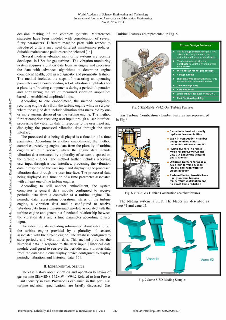
Turbine Features are represented in Fig. 5.
Fig. 5 SIEMENS V94.2 Gas Turbine Features
Gas Turbine Combustion chamber features are represented
in Fig 6.
Fig. 6 V94.2 Gas Turbine Combustion chamber features
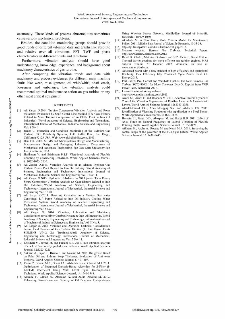
The blading system is SI3D. The blades are described as
vane #1 and vane #2.
Fig. 7 Some SI3D Blading Samples
World Academy of Science, Engineering and TechnologyInternational Journal of Aerospace and Mechanical Engineering
Vol:8, No:4, 2014
780International Scholarly and Scientific Research & Innovation 8(4) 2014 scholar.waset.org/1307-6892/9998407
Inte
rnat
iona
l Sci
ence
Ind
ex, A
eros
pace
and
Mec
hani
cal E
ngin
eeri
ng V
ol:8
, No:
4, 2
014
was
et.o
rg/P
ublic
atio
n/99
9840
7

Main rotor and typical blades related to gas turbine
SIEMENS162MW - V94.2 are shown in Fig 8. In addition,
blades design features plot is shown in Fig 9.
Fig. 8 Typical blades related to gas turbine SIEMENS162MW -
V94.2
Fig. 9 Blades design features plot
Employing wet compression system is available in market
since 2003.
Fig. 10 Wet compression process
Machinery features and basic principles related to gas
turbine SIEMENS162MW - V94.2 are determined. Vibration
analysis will be discussed in details in the next stage. Before,
it is worthy to discuss some new and interesting patent and
innovation in gas turbine world [16].
Turbine blade for industrial gas turbine is used which
includes a blade substrate formed of a single-crystal heat-
resistant alloy containing C: 0.06 to 0.08%, B: 0.016 to
0.035%, Hf: 0.2 to 0.3%, Cr: 6.9 to 7.3%, Mo: 0.7 to 1.0%, W:
7.0 to 9.0%, Re: 1.2 to 1.6%, Ta: 8.5 to 9.5%, Nb: 0.6 to 1.0%,
Al: 4.9 to 5.2%, Co: 0.8 to 1.2%, and the remainder
substantially consisting of Ni with reference to mass, and
includes a diffusion barrier layer, a metal layer, a bond coat,
and a top coat, these layers and coats being stacked in this
order on a surface of the blade substrate, the metal layer
having a thickness of 5 to 30 micrometer.
Therefore, the turbine blade can be provided which has a
thermal barrier coating formed without loss of a function of
the diffusion barrier layer [15].
Damper system recently developed in gas turbine world.
The damper includes a width dimension, a height dimension,
and a length dimension, and a forward plate and an automatic
fine tuning (AFT) plate. The AFT plate is larger than the
forward plate along the width and height dimension and
includes an upper portion extending in the height dimension,
the upper portion having a non-symmetric configuration. The
damper further includes a longitudinal structure extending in
the length dimension and connecting the forward plate and the
AFT plate.
The damper includes a width dimension, a height
dimension, and a length dimension, and a forward plate. The
damper further includes an AFT plate including a larger area
than the forward plate along the width and height dimension,
an upper portion having an upper point that is offset with
respect to a central axis of the AFT plate extending in the
height dimension, and a rectangular-shaped discourager
extending AFT in the length dimension from the AFT plate.
The damper also includes a longitudinal structure extending in
the length dimension and connecting the forward plate and the
AFT plate.
The turbine rotor assembly includes a turbine rotor having a
plurality of turbine blade slots, and a plurality of turbine
World Academy of Science, Engineering and TechnologyInternational Journal of Aerospace and Mechanical Engineering
Vol:8, No:4, 2014
781International Scholarly and Scientific Research & Innovation 8(4) 2014 scholar.waset.org/1307-6892/9998407
Inte
rnat
iona
l Sci
ence
Ind
ex, A
eros
pace
and
Mec
hani
cal E
ngin
eeri
ng V
ol:8
, No:
4, 2
014
was
et.o
rg/P
ublic
atio
n/99
9840
7

blades having an airfoil, a platform, and a root structure, the
root structure of each turbine blade shaped to be received in a
corresponding turbine blade slot of the turbine rotor.
The turbine rotor assembly also includes an under-platform
gap formed adjacent and below the platforms of adjacent
turbine blades, and an under-platform cavity formed between
an outer radial surface of the rotor and adjacent turbine blade
root structures, and below adjacent turbine blade platforms.
The turbine rotor assembly further includes a turbine
damper located within at least one of the under-platform
cavities, the turbine damper including a width dimension, a
height dimension, and a length dimension. The damper further
includes a forward plate sized to provide a forward flow gap
into the under platform cavity and the under-platform gap, and
an AFT plate sized to cover a portion of the under platform
cavity and a portion of the under-platform gap [15].
Gas-turbine engines used in transportation, energy, and
defense sectors rely on high-temperature thermal-barrier
coatings (TBCs) for improved efficiencies and power. The
promise of still higher efficiencies and other benefits is driving
TBCs research and development worldwide. An introduction
to TBCs-complex, multi-layer evolving systems are presented,
where these fascinating systems touch on several known
phenomena in materials science and engineering [17].
Facilitates removal of the patent pending lateral generator
from between the turbines for maintenance or repair is already
investigated by several gas turbine manufacturers [18].
Energy efficiency is one of the main objectives for the
development of new power plant technology in order to reduce
fuel consumption and emissions. In response to the increasing,
worldwide need for reliable, low cost and environmentally
compatible generation. New Siemens SGT5-8000H Gas
Turbine is recently introduced by Siemens Company.
The SGT5-8000H will have a net power output of at least
340 MW and will be optimized for the combined cycle
process with a net power output of more than 530 MW. A
major benefit for the customer is the high efficiency of 60%.
Efficiency not only plays an important role with respect to
environmental aspects, but also for the profitability of the
power plant.
As fuel is the largest single cost item for running a power
plant, an increase of two percentage points can save the
operator millions of Euros over the entire life cycle of a
combined cycle power plant with a capacity of 530 MW [19].
III. RESULTS AND DISCUSSION
In this part a case history related to Gas Turbine SIEMENS
V94.2 is explained. This gas turbine is related to Iran Power
Plant Industry in Fars Province and is in main operation board
high vibration.
A. Case History
Duration: Tuesday, April 24, 2012 to Friday, May 4, 2012.
After facing some problems in gas turbine Fars utility
startup period, the gas turbine was tripped in 1000 RPM. The
trip was because of high amounts of vibrations. The vibration
groups were take part a session for analyzing the balancing
condition of rotor and gas turbine foundation.
Both the balancing and foundation maintenance data was in
good conditions then vibration groups decided to close
monitoring the gas turbine. Further investigations in
maintenance history showed that gas turbine middle shaft was
falling during machinery maintenance actions and installed
after repair in machinery workshop. There was a strong
hypothesis that this may the main root of all vibration
problems in this machine. The vibration analysis of hypothesis
is discussed.
Besides, other possibilities are mentioned. First, the
electronic group checked the absolute and relative
conditioners to adjust the related options with technical
documents. Then the analyzer group readjusts all the
adaptation numbers in turning gear condition with technical
document. After that, all the relative vibrations in turbine,
compressor and generator were monitored in 600 RPM in the
next stage.
The operation condition were not agree to continue
increasing RPM then in the next day the gas turbine first start
up to 600 RPM then process were decided to reduce the RPM
up to 450 and after one hour they were increased the RPM
little by little up to 990 RPM gradually. In this stage Gas
turbine trip occurred because of high amount of absolute
vibrations. As we checked all the trend of vibration
monitoring data it was clear that the gas turbine did not have
any problem up to 750 RPM.
In addition, there was an acceptable adaptation between all
monitoring systems in process board and CM vibration trends
in both absolute and relative monitoring systems.
Unfortunately, after 750 RPM the related vibrations were
increasing gradually. In addition, the absolute vibrations were
increased dramatically after 940 RPM but relative vibrations
were decreased slightly.
Absolute vibrations were increased and relative vibrations
were decreased simultaneously. This increasing in absolute
vibration in turbine side was 17.5mm/s RMS that caused
vibration trip in 990 RPM.
The absolute and relative vibrations were decreased slightly
in the same manner in trip period. Furthermore, All journals
temperature monitoring trends were normal and in range
during this period. The decreasing relative vibration with
increasing in absolute vibration was never seen in other gas
turbines by the vibration groups and it seems to be a new
vibration behavior!
World Academy of Science, Engineering and TechnologyInternational Journal of Aerospace and Mechanical Engineering
Vol:8, No:4, 2014
782International Scholarly and Scientific Research & Innovation 8(4) 2014 scholar.waset.org/1307-6892/9998407
Inte
rnat
iona
l Sci
ence
Ind
ex, A
eros
pace
and
Mec
hani
cal E
ngin
eeri
ng V
ol:8
, No:
4, 2
014
was
et.o
rg/P
ublic
atio
n/99
9840
7

Fig. 11 Absolute and relative vibration trends from control
monitoring system process main board
Because of low frequency condition, the absolute sensors
cannot help in vibration analysis but there is some valuable
information in relative sensors data that called slow roll in CM
texts and will help us in shaft centerline analysis.
Fig. 12 Turbine and compressor orbit OCE and CE in turning gear condition
TABLE I
SHAFT POSITION BY 9-VOLT INITIAL INSTALLATION
Y X
-40 -75
-45 115
Vibrations in 750 RPM should be focused because of the
higher amplitudes. Besides, FFT Absolute vibrations turbine
side in 600 RPM (horizontal, vertical and axial) is shown in
Fig 13.
Fig. 13 FFT Absolute vibrations turbine side in 600 RPM (horizontal, vertical and axial)
750 RPM approximately is beginning of the first gas turbine
SIEMENS162MW - V94.2 critical speed and the vibration
data in this condition can help too much for the gas turbine
vibration analysis.
World Academy of Science, Engineering and TechnologyInternational Journal of Aerospace and Mechanical Engineering
Vol:8, No:4, 2014
783International Scholarly and Scientific Research & Innovation 8(4) 2014 scholar.waset.org/1307-6892/9998407
Inte
rnat
iona
l Sci
ence
Ind
ex, A
eros
pace
and
Mec
hani
cal E
ngin
eeri
ng V
ol:8
, No:
4, 2
014
was
et.o
rg/P
ublic
atio
n/99
9840
7

Fig. 14 Relative vibrations FFT turbine 1, turbine 2, compressor and
OCE in 750 RPM
Fig. 15 Orbits turbine, compressor, OCE and CE in 750 RPM
Vibration modal analysis 1X (left is related to turbine side)
is shown in Fig 16. Vibration modal analysis is obtained by
using the phase values and their trends in different locations
(points).
Fig. 16 Vibration modal analysis 1X (left is related to turbine side)
Vibration monitoring system in operation main board
showed that the relative vibration decreased suddenly when
absolute vibration caused gas turbine trip. In addition, CM
vibration graphs indicated the same information.
Fig. 17 Turbine and compressor start up and shut down condition
(trip position are indicated by cursor)
The reason of this phenomena could be discovered by
drawing bode diagrams for relative vibration sensors in both
turbine and compressor.
Fig. 18 Turbine relative vibrations Bode diagrams
Fig. 19 Compressor relative vibrations Bode diagrams
As shown in above bode diagrams, overall amplitude
vibration was decreased in one sensor and was increased in
other sensor simultaneously. This increasing behavior is
related to a turbine side mode of vibration for 940 RPM in 30˚
sensor but this mode of vibration was disappeared and was
replaced by another mode of vibration in 90˚ sensor.
This phenomenon caused high amount of vibrations in
turbine side and occurred after increasing RPM. Besides, these
phenomena indicated in gas turbine Nyquist diagrams and are
called Split Resonance. Split Resonance may cause Backward
World Academy of Science, Engineering and TechnologyInternational Journal of Aerospace and Mechanical Engineering
Vol:8, No:4, 2014
784International Scholarly and Scientific Research & Innovation 8(4) 2014 scholar.waset.org/1307-6892/9998407
Inte
rnat
iona
l Sci
ence
Ind
ex, A
eros
pace
and
Mec
hani
cal E
ngin
eeri
ng V
ol:8
, No:
4, 2
014
was
et.o
rg/P
ublic
atio
n/99
9840
7

whirl between 940 to 980 RPM in both turbine and
compressor journals [20].
Fig. 20 Turbine and compressor relative vibrations Nyquist diagrams
Finally, turbine and compressor relative vibrations
waterfall or three-dimensional FFT diagrams were obtained
(for startup and trip). These diagrams were developed some
hypothesis in gas turbine fault diagnosis.
Fig. 21 Turbine and compressor three-dimensional FFT diagrams for
startup and trip (waterfall graphs)
In this part, most critical equipment rotor faults are
compared with the vibration evidences in mentioned gas
turbine. Small amount of these kinds of faults usually are
existed in normal behavior of industrial rotors but high
amounts of these faults may cause trip in all somewhat most
critical equipment.
The piezoelectric layers are used for sensors and actuators.
Micro vibrations, generally defined as low amplitude
vibrations at frequencies up to 1 kHz. An adaptive inverse
dynamics control was used to suppress the vibration of a
simply supported panel. These kinds of techniques can
effectively utilize in most critical equipment condition
monitoring systems [21].
In addition, stochastic identification technique is proposed
to estimate both the parameters and order of multi-input and
multi-output vibrating structural systems. In complex
machinery systems like gas turbine hundreds of parts may
originate hundreds of frequency vibration is such a complex
condition time modeling systems like vibration modal
analysis. These techniques are utilized in fault diagnosis and
sometime cause some partial modification to improve the
machine performance and machine vibration behavior [22].
Sub harmonic vibrations existed specially in higher RPM of
gas turbine but trip was in low RPM and wear could not be a
main problem. Angular misalignment is based on axial
vibrations and there were no high axial vibrations in this
machine. In addition, Phase analysis information provided no
evidence of any misalignment. There was no 0.48 X
(X=current rotor RPM) in this gas turbine FFT then oil
whip/whirl could not be the problem.
Recent investigations showed that lateral natural
frequencies are increased by applying tension axial loading
and decreased by applying compression axial loading at the
ends of the rotating shaft. Gas turbine vibration behavior was
provided no evidences of natural frequencies. Besides, the
axial vibrations were not too high [23].
Moreover, there were no shaft crack evidences like 2X in
half critical speed (Due to three dimensional or waterfall
FFT). Besides, there were no rotary looseness evidences in gas
turbine TWF. In addition, foundation phase analysis showed
that there is no looseness in the gas turbine.
Turbine limit load control is one of the most important parts
in any gas turbine system that has direct effects in vibration
behavior of machine. There are a number of methods recently
are developed for these kinds of behaviors and characteristics
in gas turbines [24].
Three conditions should exist simultaneously to represent
unbalance [20]. Fist, all relative vibrations in different
directions should be considerably high. After that, none
contact main vibrations should have 90˚shift phase. Finally,
the main frequency should be 1X in FFT.
All these evidences existed in this gas turbine. These
evidences showed that the vibration analysis group should
predicted rotor unbalance. Therefore, vibration analysis team
recommended gas turbine field balance.
After field balance of the rotor, turbine started up (Some
interesting case reports related to similar gas turbines field
balances were discussed in [9]).
Both absolute and relative vibrations were reduced too
much. All vibrations were in range of technical documents.
There was no trip in Bently Nevada panels and there was no
abnormal noise in gas turbine any more.
IV. CURRENT AND FUTURE DEVELOPMENT
The process parameters like inlet and outlet pressure and
temperature trends should be monitored and make sure that all
parameters are in the gas turbine technical document ranges.
In addition, changing in load and RPM should be monitored
World Academy of Science, Engineering and TechnologyInternational Journal of Aerospace and Mechanical Engineering
Vol:8, No:4, 2014
785International Scholarly and Scientific Research & Innovation 8(4) 2014 scholar.waset.org/1307-6892/9998407
Inte
rnat
iona
l Sci
ence
Ind
ex, A
eros
pace
and
Mec
hani
cal E
ngin
eeri
ng V
ol:8
, No:
4, 2
014
was
et.o
rg/P
ublic
atio
n/99
9840
7
accurately. These kinds of process abnormalities sometimes
cause serious mechanical problems.
Besides, the condition monitoring groups should provide
good trends of different vibration data and graphs like absolute
and relative over all vibrations, FFT, TWF and phase
characteristics in different points and directions.
Furthermore, vibration analysts should have good
understanding, knowledge, experience, and background about
machinery characteristics of gas turbine.
After comparing the vibration trends and data with
machinery and process evidences for different main machine
faults like wear, misalignment, oil whip/whirl, shaft crack,
looseness and unbalance, the vibration analysts could
recommend optimal maintenance action on gas turbine or any
other most critical equipment.
REFERENCES
[1] Ali Zargar O.2014. Turbine Compressor Vibration Analysis and Rotor movement Evaluation by Shaft Center Line Method (The Case History
Related to Main Turbine Compressor of an Olefin Plant in Iran Oil
Industries). World Academy of Science, Engineering and Technology. International Journal of Mechanical, Industrial Science and Engineering
Vol: 8 No: 1.
[2] James C. Protection and Condition Monitoring of the LM6000 Gas Turbine. SKF Reliability Systems, 4141 Ruffin Road, San Diego,
California 92123 USA, Web: www.skfreliability.com. 2003.
[3] Hsu T.R. 2008. MEMS and Microsystems Design and Manufacturing. Microsystems Design and Packaging Laboratory. Department of
Mechanical and Aerospace Engineering. San Jose State University San
Jose, California, USA. [4] Hariharan V. and Srinivasan P.S.S. Vibrational Analysis of Flexible
Coupling by Considering Unbalance. World Applied Sciences Journal,
8: 1022-1023. 2010. [5] Ali Zargar O.2013. Vibration Analysis of an Alstom Typhoon Gas
Turbine Power Plant Related to Iran Oil Industry. World Academy of
Science, Engineering and Technology. International Journal of Mechanical, Industrial Science and Engineering Vol: 7 No: 11.
[6] Ali Zargar O.2013. Hydraulic Unbalance in Oil Injected Twin Rotary
Screw Compressor Vibration Analysis (A Case History Related to Iran Oil Industries).World Academy of Science, Engineering and
Technology. International Journal of Mechanical, Industrial Science and
Engineering Vol:7 No:11. [7] Ali Zargar O.2014. Detecting Cavitation in a Vertical Sea water
Centrifugal Lift Pump Related to Iran Oil Industry Cooling Water
Circulation System. World Academy of Science, Engineering and Technology. International Journal of Mechanical, Industrial Science and
Engineering Vol: 8 No: 1.
[8] Ali Zargar O. 2014. Vibration, Lubrication and Machinery Consideration for a Mixer Gearbox Related to Iran Oil Industries. World
Academy of Science, Engineering and Technology. International Journal
of Mechanical, Industrial Science and Engineering Vol: 8 No: 3. [9] Ali Zargar O. 2013. Vibration and Operation Technical Consideration
before Field Balance of Gas Turbine Utilities (In Iran Power Plants
SIEMENS V94.2 Gas Turbines).World Academy of Science, Engineering and Technology. International Journal of Mechanical,
Industrial Science and Engineering Vol: 7 No: 11.
[10] Eftekhari M., Javadi M. and Farsani R.E. 2011. Free vibration analysis of cracked functionally graded material beam. World Applied Sciences
Journal, 12:1223-1225.
[11] Sukirno A., Fajar R., Bismo S. and Nasikin M. 2009. Bio grease Based on Palm Oil and Lithium Soap Thickener: Evaluation of Anti wear
Property. World Applied Sciences Journal, 6: 401-407.
[12] Karim Z., Nuawi M.Z., Ghani J.A., Abdullah S. and Ghazali M.J. 2011. Optimization of Integrated Kurtosis-Based Algorithm for Z-Filter (I-
KazTM) Coefficient Using Multi Level Signal Decomposition
Technique. World Applied Sciences Journal, 14:1546-1548. [13] Alsaade F., Zaman N., Abdullah A. and Zafar Dawood M. 2012.
Enhancing Surveillance and Security of Oil Pipelines Transportation
Using Wireless Sensor Network. Middle-East Journal of Scientific
Research, 11:1029-1030.
[14] Akhshabi M. A New Fuzzy Multi Criteria Model for Maintenance Policy. 2011. Middle-East Journal of Scientific Research, 10:33-38.
[15] http://tgs.freshpatents.com/Gas-Turbine-bx1.php,2013.
[16] Siemens website, Siemens Gas Turbines, Technical Papers. http://www.energy.siemens.com,2012.
[17] David R. Clarke, Matthias Oechsner and N.P. Padture, Guest Editors.
Thermal-barrier coatings for more efficient gas-turbine engines. MRS bulletin volume 37 October 2012. Available on line at:
www.mrs.org/bulletin.
[18] Advanced power with a new standard of high efficiency and operational flexibility. Flex Efficiency fifty Combined Cycle Power Plant. GE
Energy.2013.
[19] Phil Ratliff, Paul Garbett and Willibald Fischer. The New Siemens Gas Turbine SGT5-8000H for More Customer Benefit. Reprint from VGB
Power Tech, September 2007.
[20] I learn vibration-training website: http://www.mobiusinstitute.com/,2013.
[21] Azadi M., Azadi E. and Roopaei M. 2011. Adaptive Inverse Dynamics
Control for Vibration Suppression of Flexible Panel with Piezoelectric Layers. World Applied Sciences Journal, 12: 2343-2351.
[22] Abu-El-Yazied T.G., Abu-El-Haggag S.Y. and Al-Fares F.S. 2009.
Identification of Vibrating Structures with Application to a Steel Tower. World Applied Sciences Journal, 6: 1673-1674.
[23] Hosseini H., Ganji D.D., Abaspour M. and Kaliji H.D. 2011. Effect of
Axial Force on Natural Frequency of Lateral Vibration of Flexible Rotating Shafts. World Applied Sciences Journal, 15: 858-859.
[24] Afkhami H., Argha A., Ropaee M. and Noori M.A. 2011. Surveying the
control loops of the governor of the V94.2 gas turbine. World Applied Sciences Journal, 15: 1438-1440.
World Academy of Science, Engineering and TechnologyInternational Journal of Aerospace and Mechanical Engineering
Vol:8, No:4, 2014
786International Scholarly and Scientific Research & Innovation 8(4) 2014 scholar.waset.org/1307-6892/9998407
Inte
rnat
iona
l Sci
ence
Ind
ex, A
eros
pace
and
Mec
hani
cal E
ngin
eeri
ng V
ol:8
, No:
4, 2
014
was
et.o
rg/P
ublic
atio
n/99
9840
7