
Simulation of fatigue failure in composite axial compressor blades
8
Simulation of fatigue failure in composite axial compressor blades Qubo Li a,⇑ , Janusz Piechna b , Norbert Müeller a a Turbomachinery Laboratory, Department of Mechanical Engineering, Michigan State University, East Lansing, MI 48824-1226, USA b Institute of Aeronautics and Applied Mechanics, Warsaw University of Technology, Warsaw, Poland article info Article history: Received 3 August 2010 Accepted 23 November 2010 Available online 2 December 2010 Keywords: Composite axial impeller Fatigue Finite element method Damage accumulation abstract Centrifugal forces are generated by a spinning impeller, of magnitudes that create large stresses. Aerody- namic forces are also imparted on an impeller blade, which varies with time and position. These two forces play different roles during compressor events. Damage accumulated from these events results in the fatigue failure of impeller material and structure. Therefore, it is important to design an impeller against dynamic and fatigue failure. The finite element method has been used in the study of impeller fracture mechanics and is regarded as an important tool in the design and analysis of material and struc- tures. Novel axial composite impellers, manufactured through filament winding technology, were invented and studied at Michigan State University. These impellers will be used to compress water vapor so as to use it as a refrigerant. In this study dynamic and fatigue behavior of two types of composite impellers 8B and 8C, were analyzed using commercial code ANSYS. Firstly, load cases were identified calculated and evaluated. Static analysis was then performed with a full 3-D finite element model. The critical zone where fatigue failure begins was extracted and used to determine life assessment positions. Secondly, aerodynamic forces imparted on the blade were obtained from FLUENT, so that damage from dynamic stresses could be calculated. Finally, based on the FEM and FLUENT simulation results, a linear damage accumulation model was employed as a damage estimation rule to predict life of the two composite impellers. A conservative life of 6498 h for 8B was calculated by this method, as was a life of 5435 h of 8C. Based on the method, safe fatigue life reduces for about 32% in case of 8B and 40% in case of 8C com- pared with conventional approaches where aerodynamic forces are omitted. Ó 2010 Elsevier Ltd. All rights reserved. 1. Introduction Of all the statistical data regarding fracture failure, the study of these events in rotating parts and structures account for more than 80% of the cases [1]. This relates to the high degree of interest in the failure of complicated rotating and moving systems. The root causes behind these failures vary a lot based on different operating conditions, such as high rotational speed and elevated tempera- ture. In general, compressor blade failures can be grouped into two categories: (a) fatigue, including both high-cycle fatigue (HCF) and low-cycle fatigue (LCF) [2–6] and (b) creep rupture [7]. Blade fatigue failures are often related to anomalies in mechanical behaviors and manufacturing defects. Because the mechanical per- formance requirements of compressor blades have high theoretical significance and application value, a precise life prediction is very important. Fig. 1 shows a comparison between different industrial components and their expected life cycles. Considering centrifugal stresses for the life prediction of impel- ler blade components, we examine the non-steady-state usage. Typically there is a high accelerating stage during every start-up, where low-cycle fatigue problems exist. The same problem hap- pens at every shut-down period where the deceleration effects cause large LCF problems. In this case, because of large loading changes from centrifugal forces within a short time, low-cycle fati- gue approaches are suitable to calculate damage in these two periods. From an aerodynamic viewpoint, when rotor blades rotate, the pressure difference from the suction side and pressure side changes periodically due to the aerodynamic impact from stator. These pressure differences change periodically which produce cyc- lic loads on rotor blades. Since this aerodynamic force is typically small compared with centrifugal force, it is usually neglected by investigators [8]. A relative small pressure stress coming from blade’s suction side and pressure side would generate dynamic pressure force changes along the blade’s rotating angle. This force is far less than many materials’ elastic force limit, and investigation of damage accumulation in this period can be done via high-cycle fatigue approaches. Under high temperature and high rpm condi- tions, this relatively small oscillating force coupled with a high centrifugal force would impact the impeller blades fatigue life, and possibly shorten the service life significantly. In published 0261-3069/$ - see front matter Ó 2010 Elsevier Ltd. All rights reserved. doi:10.1016/j.matdes.2010.11.051 ⇑ Corresponding author. E-mail address: [email protected] (Q. Li). Materials and Design 32 (2011) 2058–2065 Contents lists available at ScienceDirect Materials and Design journal homepage: www.elsevier.com/locate/matdes
-
Upload
michiganstate -
Category
Documents
-
view
0 -
download
0
Transcript of Simulation of fatigue failure in composite axial compressor blades
Materials and Design 32 (2011) 2058–2065
Contents lists available at ScienceDirect
Materials and Design
journal homepage: www.elsevier .com/locate /matdes
Simulation of fatigue failure in composite axial compressor blades
Qubo Li a,⇑, Janusz Piechna b, Norbert Müeller a
a Turbomachinery Laboratory, Department of Mechanical Engineering, Michigan State University, East Lansing, MI 48824-1226, USAb Institute of Aeronautics and Applied Mechanics, Warsaw University of Technology, Warsaw, Poland
a r t i c l e i n f o
Article history:Received 3 August 2010Accepted 23 November 2010Available online 2 December 2010
Keywords:Composite axial impellerFatigueFinite element methodDamage accumulation
0261-3069/$ - see front matter � 2010 Elsevier Ltd. Adoi:10.1016/j.matdes.2010.11.051
⇑ Corresponding author.E-mail address: [email protected] (Q. Li).
a b s t r a c t
Centrifugal forces are generated by a spinning impeller, of magnitudes that create large stresses. Aerody-namic forces are also imparted on an impeller blade, which varies with time and position. These twoforces play different roles during compressor events. Damage accumulated from these events results inthe fatigue failure of impeller material and structure. Therefore, it is important to design an impelleragainst dynamic and fatigue failure. The finite element method has been used in the study of impellerfracture mechanics and is regarded as an important tool in the design and analysis of material and struc-tures.
Novel axial composite impellers, manufactured through filament winding technology, were inventedand studied at Michigan State University. These impellers will be used to compress water vapor so asto use it as a refrigerant. In this study dynamic and fatigue behavior of two types of composite impellers8B and 8C, were analyzed using commercial code ANSYS. Firstly, load cases were identified calculated andevaluated. Static analysis was then performed with a full 3-D finite element model. The critical zonewhere fatigue failure begins was extracted and used to determine life assessment positions. Secondly,aerodynamic forces imparted on the blade were obtained from FLUENT, so that damage from dynamicstresses could be calculated. Finally, based on the FEM and FLUENT simulation results, a linear damageaccumulation model was employed as a damage estimation rule to predict life of the two compositeimpellers. A conservative life of 6498 h for 8B was calculated by this method, as was a life of 5435 h of8C. Based on the method, safe fatigue life reduces for about 32% in case of 8B and 40% in case of 8C com-pared with conventional approaches where aerodynamic forces are omitted.
� 2010 Elsevier Ltd. All rights reserved.
1. Introduction
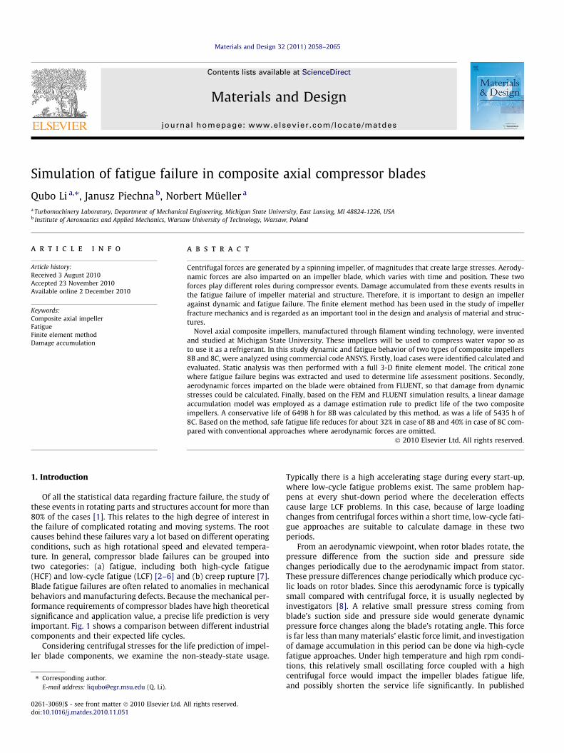
Of all the statistical data regarding fracture failure, the study ofthese events in rotating parts and structures account for more than80% of the cases [1]. This relates to the high degree of interest inthe failure of complicated rotating and moving systems. The rootcauses behind these failures vary a lot based on different operatingconditions, such as high rotational speed and elevated tempera-ture. In general, compressor blade failures can be grouped intotwo categories: (a) fatigue, including both high-cycle fatigue(HCF) and low-cycle fatigue (LCF) [2–6] and (b) creep rupture [7].Blade fatigue failures are often related to anomalies in mechanicalbehaviors and manufacturing defects. Because the mechanical per-formance requirements of compressor blades have high theoreticalsignificance and application value, a precise life prediction is veryimportant. Fig. 1 shows a comparison between different industrialcomponents and their expected life cycles.
Considering centrifugal stresses for the life prediction of impel-ler blade components, we examine the non-steady-state usage.
ll rights reserved.
Typically there is a high accelerating stage during every start-up,where low-cycle fatigue problems exist. The same problem hap-pens at every shut-down period where the deceleration effectscause large LCF problems. In this case, because of large loadingchanges from centrifugal forces within a short time, low-cycle fati-gue approaches are suitable to calculate damage in these twoperiods.
From an aerodynamic viewpoint, when rotor blades rotate, thepressure difference from the suction side and pressure sidechanges periodically due to the aerodynamic impact from stator.These pressure differences change periodically which produce cyc-lic loads on rotor blades. Since this aerodynamic force is typicallysmall compared with centrifugal force, it is usually neglected byinvestigators [8]. A relative small pressure stress coming fromblade’s suction side and pressure side would generate dynamicpressure force changes along the blade’s rotating angle. This forceis far less than many materials’ elastic force limit, and investigationof damage accumulation in this period can be done via high-cyclefatigue approaches. Under high temperature and high rpm condi-tions, this relatively small oscillating force coupled with a highcentrifugal force would impact the impeller blades fatigue life,and possibly shorten the service life significantly. In published
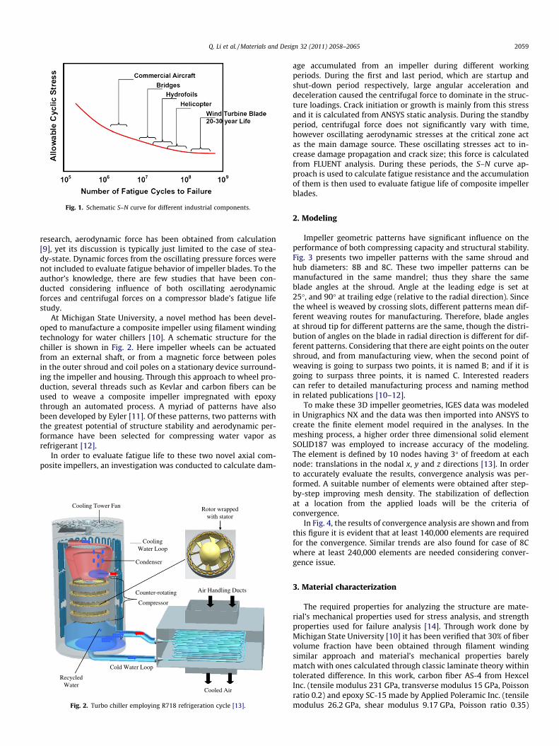
Fig. 1. Schematic S–N curve for different industrial components.
Q. Li et al. / Materials and Design 32 (2011) 2058–2065 2059
research, aerodynamic force has been obtained from calculation[9], yet its discussion is typically just limited to the case of stea-dy-state. Dynamic forces from the oscillating pressure forces werenot included to evaluate fatigue behavior of impeller blades. To theauthor’s knowledge, there are few studies that have been con-ducted considering influence of both oscillating aerodynamicforces and centrifugal forces on a compressor blade’s fatigue lifestudy.
At Michigan State University, a novel method has been devel-oped to manufacture a composite impeller using filament windingtechnology for water chillers [10]. A schematic structure for thechiller is shown in Fig. 2. Here impeller wheels can be actuatedfrom an external shaft, or from a magnetic force between polesin the outer shroud and coil poles on a stationary device surround-ing the impeller and housing. Through this approach to wheel pro-duction, several threads such as Kevlar and carbon fibers can beused to weave a composite impeller impregnated with epoxythrough an automated process. A myriad of patterns have alsobeen developed by Eyler [11]. Of these patterns, two patterns withthe greatest potential of structure stability and aerodynamic per-formance have been selected for compressing water vapor asrefrigerant [12].
In order to evaluate fatigue life to these two novel axial com-posite impellers, an investigation was conducted to calculate dam-
Air Handling Ducts
Cold Water Loop
Counter-rotating
Compressor
Cooling Tower Fan
Cooling Water Loop
Condenser
Recycled Water
Cooled Air
Rotor wrapped with stator
Fig. 2. Turbo chiller employing R718 refrigeration cycle [13].
age accumulated from an impeller during different workingperiods. During the first and last period, which are startup andshut-down period respectively, large angular acceleration anddeceleration caused the centrifugal force to dominate in the struc-ture loadings. Crack initiation or growth is mainly from this stressand it is calculated from ANSYS static analysis. During the standbyperiod, centrifugal force does not significantly vary with time,however oscillating aerodynamic stresses at the critical zone actas the main damage source. These oscillating stresses act to in-crease damage propagation and crack size; this force is calculatedfrom FLUENT analysis. During these periods, the S–N curve ap-proach is used to calculate fatigue resistance and the accumulationof them is then used to evaluate fatigue life of composite impellerblades.
2. Modeling
Impeller geometric patterns have significant influence on theperformance of both compressing capacity and structural stability.Fig. 3 presents two impeller patterns with the same shroud andhub diameters: 8B and 8C. These two impeller patterns can bemanufactured in the same mandrel; thus they share the sameblade angles at the shroud. Angle at the leading edge is set at25�, and 90� at trailing edge (relative to the radial direction). Sincethe wheel is weaved by crossing slots, different patterns mean dif-ferent weaving routes for manufacturing. Therefore, blade anglesat shroud tip for different patterns are the same, though the distri-bution of angles on the blade in radial direction is different for dif-ferent patterns. Considering that there are eight points on the outershroud, and from manufacturing view, when the second point ofweaving is going to surpass two points, it is named B; and if it isgoing to surpass three points, it is named C. Interested readerscan refer to detailed manufacturing process and naming methodin related publications [10–12].
To make these 3D impeller geometries, IGES data was modeledin Unigraphics NX and the data was then imported into ANSYS tocreate the finite element model required in the analyses. In themeshing process, a higher order three dimensional solid elementSOLID187 was employed to increase accuracy of the modeling.The element is defined by 10 nodes having 3� of freedom at eachnode: translations in the nodal x, y and z directions [13]. In orderto accurately evaluate the results, convergence analysis was per-formed. A suitable number of elements were obtained after step-by-step improving mesh density. The stabilization of deflectionat a location from the applied loads will be the criteria ofconvergence.
In Fig. 4, the results of convergence analysis are shown and fromthis figure it is evident that at least 140,000 elements are requiredfor the convergence. Similar trends are also found for case of 8Cwhere at least 240,000 elements are needed considering conver-gence issue.
3. Material characterization
The required properties for analyzing the structure are mate-rial’s mechanical properties used for stress analysis, and strengthproperties used for failure analysis [14]. Through work done byMichigan State University [10] it has been verified that 30% of fibervolume fraction have been obtained through filament windingsimilar approach and material’s mechanical properties barelymatch with ones calculated through classic laminate theory withintolerated difference. In this work, carbon fiber AS-4 from HexcelInc. (tensile modulus 231 GPa, transverse modulus 15 GPa, Poissonratio 0.2) and epoxy SC-15 made by Applied Poleramic Inc. (tensilemodulus 26.2 GPa, shear modulus 9.17 GPa, Poisson ratio 0.35)

Fig. 3. Rotor 3D 8B(left) and 8C(right) patterns.
Convergence Based on Deflection
0.20.40.60.8
11.21.41.61.8
2
Number of elements
Shro
ud d
efle
ctio
n
Convergence Based on Stress
8.0E+07
1.0E+08
1.2E+08
1.4E+08
1.6E+08
1.8E+08
2.0E+08
2.2E+08
0 20,000 40,000 60,000 80,000 100,000 120,000 140,000 160,000 180,000 200,000
0 20,000 40,000 60,000 80,000 100,000 120,000 140,000 160,000 180,000 200,000
Number of elements
Max
Von
s M
isse
s St
ress
Fig. 4. Convergence graphs of FE model.
Table 1Material mechanical properties (GPa).
Material E11 E22 = E33 G12 = G13 G23 m12 = m13 = m23
Carbon fiber 231 15 15 7 0.2Epoxy 26.2 26.2 9.17 9.17 0.35U-D composite 87.64 22.84 14.52 8.52 0.31
2060 Q. Li et al. / Materials and Design 32 (2011) 2058–2065
were used as composite constituents; a similar fiber volume frac-tion of 30% can be obtained using this novel manufacturing meth-od. According to mechanics of composite materials [15],unidirectional (U-D) composites mechanical properties can bedetermined from micromechanics model from:
E1 ¼ Ef 1Vf þ EmVm ð1Þ
E2 ¼Vf
Efþ Vm
Em
� ��1
ð2Þ
v12 ¼ v f V f þ vmVm ð3Þ
G12 ¼Vf
Gfþ Vm
Gm
� ��1
ð4Þ
Calculated mechanical properties are listed in Table 1. Theseorthotropic material properties will be used as input for a furtherANSYS simulation. With a fiber volume fraction 30% obtainedthrough the filament winding method, composite density canreach about 1.31 g/cm3 with tensile strength of 1.40 GPa.
Centrifugal force
Aerodynamic force blade
Fracture blade root 1
Fracture blade root 2
shroud
hub
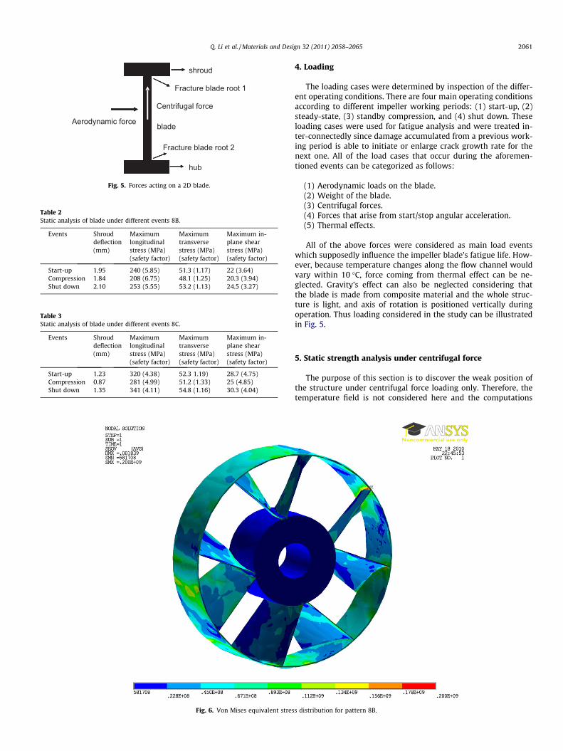
Fig. 5. Forces acting on a 2D blade.
Table 2Static analysis of blade under different events 8B.
Events Shrouddeflection(mm)
Maximumlongitudinalstress (MPa)(safety factor)
Maximumtransversestress (MPa)(safety factor)
Maximum in-plane shearstress (MPa)(safety factor)
Start-up 1.95 240 (5.85) 51.3 (1.17) 22 (3.64)Compression 1.84 208 (6.75) 48.1 (1.25) 20.3 (3.94)Shut down 2.10 253 (5.55) 53.2 (1.13) 24.5 (3.27)
Table 3Static analysis of blade under different events 8C.
Events Shrouddeflection(mm)
Maximumlongitudinalstress (MPa)(safety factor)
Maximumtransversestress (MPa)(safety factor)
Maximum in-plane shearstress (MPa)(safety factor)
Start-up 1.23 320 (4.38) 52.3 1.19) 28.7 (4.75)Compression 0.87 281 (4.99) 51.2 (1.33) 25 (4.85)Shut down 1.35 341 (4.11) 54.8 (1.16) 30.3 (4.04)
Fig. 6. Von Mises equivalent stres
Q. Li et al. / Materials and Design 32 (2011) 2058–2065 2061
4. Loading
The loading cases were determined by inspection of the differ-ent operating conditions. There are four main operating conditionsaccording to different impeller working periods: (1) start-up, (2)steady-state, (3) standby compression, and (4) shut down. Theseloading cases were used for fatigue analysis and were treated in-ter-connectedly since damage accumulated from a previous work-ing period is able to initiate or enlarge crack growth rate for thenext one. All of the load cases that occur during the aforemen-tioned events can be categorized as follows:
(1) Aerodynamic loads on the blade.(2) Weight of the blade.(3) Centrifugal forces.(4) Forces that arise from start/stop angular acceleration.(5) Thermal effects.
All of the above forces were considered as main load eventswhich supposedly influence the impeller blade’s fatigue life. How-ever, because temperature changes along the flow channel wouldvary within 10 �C, force coming from thermal effect can be ne-glected. Gravity’s effect can also be neglected considering thatthe blade is made from composite material and the whole struc-ture is light, and axis of rotation is positioned vertically duringoperation. Thus loading considered in the study can be illustratedin Fig. 5.
5. Static strength analysis under centrifugal force
The purpose of this section is to discover the weak position ofthe structure under centrifugal force loading only. Therefore, thetemperature field is not considered here and the computations
s distribution for pattern 8B.

2062 Q. Li et al. / Materials and Design 32 (2011) 2058–2065
were performed under a temperature of 50 �C, which is the testingrig’s average testing temperature.
With the start of the compressor, surfaces connecting theshroud and blade body come into steady contact state very quickly.Therefore the FE problem is a nonlinear problem and surface tosurface contact elements are used for this purpose. The results ofthese analyses are summarized in Table 2 for 8B and Table 3 for8C; here the rated loads correspond to the speed of 9000 rpm(steady-state operation speed). The safety factor results show thatin all cases both structures are in a safe condition under rpm of
11
119
120
121
122
124123
Fig. 7. Keypoint location i
Fig. 8. Von Mises equivalent stres
9000. When the tip clearance is 4 mm, for the maximum shrouddeflection case the impeller shroud will not hit the cylinder wall.
Fig. 6 shows that the Von Mises stress distribution on the impel-ler blade 8B and it is shown that maximum Von Mises stress existsat the fracture blade root 1 between blade body and shroud whichis supposed to be the critical zone. In addition, considering vibra-tions of blades, the connection root between blade body andshroud is also a dangerous area where an interaction of low cycleand high-cycle fatigue exists. This critical surface results in mostfracture failure in service mainly due to the influence of stress con-
111
112
113
114
115
1167
118
n the critical section.
s distribution for pattern 8C.

Q. Li et al. / Materials and Design 32 (2011) 2058–2065 2063
centration factors. As it is illustrated in Fig. 7, positions at key-points 114 and 121 have equal, and the largest, stress concentra-
Fig. 9. FLUENT static pressure distribution on the blade for 8B.
Fig. 10. FLUENT static pressure distribution on the blade for 8C.
Aerodynamic pr
1500
2000
2500
3000
3500
4000
4500
5000
5500
6000
6500
0 30 60 90 120 150 180
Rotating a
Stat
ic p
ress
ure,
Pas
cal
Fig. 11. Transient static pressure trend at
tion factors. These positions are supposed to be weak points,where during start-up and shut-down periods centrifugal force isonly considered. Changes of aerodynamic force are negligible com-pared with changes of centrifugal force’s change during these twoperiods. Similar phenomenon can also be observed for 8C patternin Fig. 8. It can be seen that the critical zone locates at the cornerwhere blades meet together, and it will be the area where maxi-mum damage accumulation occurs when centrifugal force is onlyconsidered as the main oscillating stress source.
6. Strength analysis under peak aerodynamic flow
The fluid analysis was carried out to estimate the aerodynamicforce exerted on the blade. Simulation was made using the com-mercial fluid dynamic software FLUENT. One stationery wheelwhich is similar to the 8C pattern and one rotating wheel (8B or8C pattern) were considered in the model. In the fluid calculation,a moving mesh was used so that the rotor impeller’s movementwas relative to the rotating fluid’s reference frame. The centralpart, which is mainly connected with a shaft to convert torque,has been ignored for aerodynamic performance calculation. Theblade velocity was set to be rx, where x is the rotating speed(9000 rpm) and r is the tip distance of the blade from wheel center.The fluid was assumed to be an ideal gas and viscous. The k–eequation was used to model the turbulence where enhanced walltreatment was set up to make sure the y+ value near the wallwas between 20 and 500 [16].
The static pressure distributions around the rotor blade for 8Bwere calculated and are shown in Fig. 9. The maximum static pres-sure locations are found at the corner between trailing edge of theblade and shroud. This is where the blade imparts kinetic energythe most into pressure energy thus the highest static pressure. Asimilar phenomenon for 8C pattern can be shown in Fig. 10. Whenthe impeller wheel rotates, transient static pressure at both pres-sure and suction sides, were also traced and it was found thatmean aerodynamic static pressure was about 4000 Pascal; as seenin Fig. 11. A linear distribution of aerodynamic force can be as-sumed on the blade based on the observation in Fig. 9, and thismean stress loading is also the pressure difference between suctionand pressure sides. Mean aerodynamic stress from the bending ef-fect at keypoint 114 is 27 MPa which is nearly 10 times less thancentrifugal stress (200 MPa). The critical zone of the structure fromaerodynamic stress only is located at the fracture blade root 2 be-tween blade body and hub.
essure on blade tip
210 240 270 300 330 360 390
ngle, Degree
weak point under 9000 rpm for 8B.

Table 4Linear elastic FEM analysis results for 8B.
Key positions Linear elastic analysis
A. Centrifugalstress (MPa)
B. Aerodynamic meanbending stress (MPa)
A + B
Key point 114 atfracture blade root1
200 9.3 209.3
Key point at fractureblade root 2
158 27 185
Table 5Linear elastic FEM analysis results for 8C.
Key positions Linear elastic analysis
A. Centrifugalstress (MPa)
B. Aerodynamic meanbending stress (MPa)
A + B
Key point 114 atfracture blade root1
278 1.1 279.1
Key point at fractureblade root 2
162 5.3 167.3
0
0.2
0.4
0.6
0.8
1
0 3 6 9 12 15 18 21 24 27Log (Nf), Cycles
S=St
ress
/Str
engt
h
Fig. 12. S–N for unidirectional carbon/epoxy composite material under longitudinalloading [19].
2064 Q. Li et al. / Materials and Design 32 (2011) 2058–2065
Linear elastic FEM results based on ANSYS calculation for 8B arelisted in Table 4 for several critical zones. Where keypoint 114 isthe critical zone during the start-up period and the keypoint atfracture blade root 2 is the other critical zone when aerodynamicstress is the only load during compression stage.
By summing aerodynamic stress and centrifugal stress together,combined stress during compressor standby period which will beimportant for fatigue life investigation next can be expressed suchas:
r ¼ rcentrifugal þ raerodynamic ð5Þ
From values listed in Table 4, it is readily found that keypoint114 would be the critical zone during standby stage since it hasthe biggest stress than other locations. Similar procedures werealso taken for 8C pattern where FEM results are listed in Table 5.
During standby periods, centrifugal force acts as constant meanstress while aerodynamic bending stress acts in an oscillating man-ner. Since both weak points in these two patterns locate at theplace around keypoint 114, and difference between maximumand minimum oscillating stress from bending effect is small com-paring with the mean centrifugal stress, it is thus reasonable tohave an R ratio in these two patterns equal to one. The value of thisR ratio is considered an important influence factor for crack growthrates [17]. Interestingly in the pattern 8C where centrifugal stressas mean stress is higher than 8B, the magnitude of oscillating stressfrom aerodynamic mean bending effect is smaller; still distancebetween this pattern’s maximum stress intensity factor and itsmaterial’s critical stress state is smaller than 8B, and it is foundthat crack growth rate in 8C during this period will be higher than8B. By comparing these two patterns, it is obvious that weak posi-tions locate at the same place, where blades intercross withshroud, and the 8C pattern has higher stress intensity factor than8B, even though a better aerodynamic performance has been foundin this pattern [12].
7. Accumulated fatigue damage
To model damage accumulated for fatigue mechanics of com-posite material, Ye [18] proposed stiffness degradation techniqueas a single criteria and based Ye’s model, Shookrieh improved itwith several practical parameters which make the model moreclosed with experimental data [19].
Based on the model, a normalized S–N curve in a unidirectionalcarbon/epoxy composite material under longitudinal fatigue load-ing has been obtained in Fig. 12. The figure is also validatedthrough available experimental data related with fatigue damagemodeling of composite materials [20–22]. In order to model accu-mulated damage during different stages in this study, this figure isused to calculate fatigue cycles at specific stress condition.
8. Life prediction results and discussions
As it is mentioned at the beginning of this work, the main pur-pose of this research is to evaluate fatigue life of two patterns ofcomposite impeller’s. This is done by calculating damage accumu-lated during different impeller working stages. Since centrifugaland aerodynamic stresses are the main loadings considered, loadprocedures can be simplified as in Fig. 11. From stress analysis inprevious sections, we have known that there exist stress concen-tration factors on the fracture blade roots and the critical zone infacture blade root 1 has the biggest dynamic stress changes. It isnecessary to consider points such as keypoint 114 as the weakpoints for structural life prediction. Similar conclusions have beenreached by authors to investigate impeller blade’s fatigue life[9,19].
During compressor start-up period, Dtstart, keypoint 114 in frac-ture blade root 1 is subjected to the heaviest tensile stress. Herethis point also has the largest stress concentration factor comparedto all other keypoints. Local damaging occurs as micro-crack nucle-ation occurs. Damage caused by the centrifugal stress is reciprocalto the fatigue resistance of the material at the same load range, Nf,i
according to Miner’s linear rule [23]:
di ¼1
Nf ;ið6Þ
The damage due to ni load cycles of the load rang i during differentworking range, is given by
di;n ¼ ni � di ¼ni
Nf ;ið7Þ
And the total damage caused to the detail by the load cycles of dif-ferent load levels is thus:
Dtot ¼X
i
di;n ¼X ni
Nf ;ið8Þ
In this case, the total fatigue life the impeller blade can be cal-culated through:
1Nf¼ Dtot ¼
X ni
Nf ;i¼ nstart
Nf ;startþ ncomp
Nf ;compþ nshut-down
Nf ;shut-downð9Þ
Taking Miner’s linear law as above, this composite impeller canrotate 3.2 � 105 cycles with a converted 9455 h before its cata-strophic failure (for 8B) and 7390 h for 8C. Since Miner’s law isbased on linear assumption, the law itself is overly conservative

t
p
Δtc
Δtstart
ΔtshutΔ
Fig. 13. Loadings for blade life determination.
Table 6Life prediction results of patterns.
Patterns Lifecycles
Lifeinhour
Modified life in hour(centrifugal + aeroloads)
Modified life in hour(only centrifugalload)
8B 3.2 � 105 9455 6498 95008C 2.5 � 105 7390 5077 8500
Q. Li et al. / Materials and Design 32 (2011) 2058–2065 2065
in fatigue life predictions, especially in the compression stagewhere stress change is low and variable amplitude loading in thisstudy is considered. To improve the reliability of the predicted life,effects of vibrations and load variations should be considered.Here, we adopt a modified coefficient of 1.455 for the fractureblade root 1. The number of is based on a scatter factor of loads.From this consideration, we can draw a conclusion that fatigue lifetime of 6498 h for 8B and 5077 for 8C is a safe and conservativevalue.
Following the same procedure, except omitting aerodynamicstress in conventional approaches where only start and stop proce-dures exist in Fig. 13, calculated results in Table 6 show that safefatigue life time for 8B is about 9500 h, for 8C is 8500 h. It thereforeindicates that by taking into account of the high frequency aerody-namic load with small amplitude, a prediction of safe fatigue lifereduces about 32% for 8B and 40% for 8C. Presented results showthe importance of proposed methodology taking account termsomitted in conventional approaches; in order to predict a better fa-tigue life in such complicated geometry, more sophisticated andexact method integrated with aerodynamic and centrifugal loadsshould be proposed and applied.
9. Conclusion
The aim of this study was to numerically simulate two types ofaxial composite impellers’ fatigue life using both finite elementanalysis (FEA) and computational fluid dynamic (CFD) method.This paper presents first time the consideration of simultaneousinfluence on the predicted safe life of specific impeller, of two typesof load having different features. The low frequency load compo-nent is characterized by high load amplitude in contrary to a highfrequency aerodynamic load of small amplitude.
In this work, carbon fiber/epoxy composites with fiber volumefraction of 30% were used for blade structure. To simplify the mod-eling process, linear elastic stress strain relationship was assumed
for finite element analysis and composite micromechanical model-ing theory was used to predict composite’s physical and mechani-cal properties. Convergence issues were discussed and addressedbefore various loading to the blade, and all load cases, were iden-tified calculated and evaluated and negligible cases were ignored.By performing finite element modeling, the critical zone of theblade can be obtained at the tip of blade. The impeller rotates atthe designed rpm of 7000 and safety factors for fatigue life havebeen calculated based on FE analysis results. In order to betterevaluate impeller’s fatigue life, this work considered aerodynamicforce’s effect to the blade beam. From FLUENT calculation, a tran-sient static pressure trend was obtained which provided informa-tion for a further calculation of aerodynamic stress bending effectin ANSYS. Methodology of combining centrifugal stress and aero-dynamic stress from bending effect would improve fatigue life’sinvestigation accuracy. Based on this methodology and by usingMiner’s linear law, fatigue life evaluation was conducted basedon the detailed simulation results. Considering vibration and loadvariation effects, the fatigue life was modified. 8B pattern has a fa-tigue life of 6498 h and 8C pattern has shorter one 5077 h. Com-pared with conventional approaches where aerodynamic loadsare omitted, safe fatigue life has been reduced for 32% in case of8B and 40% in case of 8C. It is thus concluded that aerodynamicloads is important especially when fatigue life is predicted insophisticated impeller geometry.
References
[1] Zhang MN. Collections on aeroengine service life and speeding-up simulatedtrial operation. Shenyang: Liaoning Science Technology Press; 1991 [inChinese].
[2] Burns J. Gas turbine engine blade life prediction for high cycle fatigue. Thetechnical cooperation program (TTCP); 1998. P-TP1.
[3] Conor PC. Compressor blade high cycle fatigue life – case study. The technicalcooperation program (TTCP); 1998. P-TP1.
[4] Troshchenko VT, Prokopenko AV. Fatigue strength and life of compressorblades for marine gas turbine engines. Strength Mater 1999;31(1).
[5] Reddy TSR. A review of recent aeroelastic analysis methods for propulsion atNASA Lewis research center. NASA Technical Paper; 1993. p. 3406.
[6] Walls DP, deLaneuville RE, Cunningham SE. Damage tolerance based lifeprediction in gas turbine engine blades under vibratory high cycle fatigue. JEng Gas Turbines Power 1997;119:143–6.
[7] Witek L, Wierzbinska M, Poznanska A. Fracture analysis of compressor blade ofa helicopter engine. Eng Fail Anal 2008;16(5):1616–22.
[8] Lijie Chen YL, Xie Liyang. Power-exponent function model for low cycle fatiguelife prediction and its applications – part II: life prediction of turbine bladesunder creep-fatigue interaction. Int J Fatigue 2007;29:10–9.
[9] Kermanpur A, Sepehri Amin H, Ziaei-Rad S, Nourbakhshnia N, MosaddeghfarM. Failure analysis of Ti6A14V gas turbine compressor blades. Eng Fail Anal2008;15:1052–64.
[10] Qubo Li, Gaetano Restivo, Mueller N. Using filament winding approach tomanufacture composite impellers for water chiller. J Adv Mater2010;42(4):45–55.
[11] Allen Eyler, Mueller N. Simulation and production of wound impellers. ASMEPaper IMECE2008-51310; 2008.
[12] Qubo Li, Piechna J, Mueller N. Aerodynamic design and CFD analysis of a novelaxial compressor. In: 40th AIAA fluid dynamics conference, Chicago; 2010.
[13] ANSYS, ANSYS Theory Reference Manual R.A. Inc., Editor; 2003.[14] Tsai SW, Hoa SV, Gay D. Composite materials, design and applications. CRC
Press; 2003.[15] Jones RM. Mechanics of composite materials. 1st ed. Berlin: Springer; 1975. p.
85-98.[16] ANSYS, ANSYS FLUENT 12.0 User’s Guide, R.A. Inc., Editor; 2003.[17] Sanford RJ. Principles of fracture mechanics. Prentice Hall; 2002. p. 293.[18] Ye L. On fatigue damage accumulation and material degradation in composite
materials. Compos Sci Technol 1989;36:339–50.[19] Mahmood M, Shokrieh RR. Simulation of fatigue failure in a full composite
wind turbine blade. Compos Struct 2006;74:332–42.[20] Shokrieh M, Lessard Larry B. Progressive fatigue damage modeling of
composite materials, part I: modeling. J Compos Mater 2000;34(13):1056–80.[21] Charewicz Alain, Daniel Isaac M. Damage mechanics and accumulation in
graphite/epoxy laminates. Compos Mater: Fatigue Fract, ASTM STP 907; 1986.p. 247–97.
[22] Lee JW, Daniel IM, Yaniv G. Fatigue life prediction of cross-ply compositelaminated. Compos Mater: Fatigue Fract, ASTM STP 1012; 1989. p. 19–28.
[23] Miner MA. Cumulative damage in fatigue. J Appl Mech 1945;12(3):159–64.