On extensibility effects in the cross-slot flow bifurcation
12
J. Non-Newtonian Fluid Mech. 156 (2009) 58–69 Contents lists available at ScienceDirect Journal of Non-Newtonian Fluid Mechanics journal homepage: www.elsevier.com/locate/jnnfm On extensibility effects in the cross-slot flow bifurcation Gerardo N. Rocha a , Robert J. Poole b , Manuel A. Alves c , Paulo J. Oliveira d,∗ a Depart. Eng. Electromecânica, Unidade Materiais Têxteis e Papeleiros, Universidade da Beira Interior, 6201-001 Covilhã, Portugal b Department of Engineering, University of Liverpool, Brownlow Street, Liverpool L69 3GH, UK c Departamento de Engenharia Química, CEFT, Faculdade de Engenharia da Universidade do Porto, R. Dr Roberto Frias, 4200-465 Porto, Portugal d Departamento de Engenharia Electromecânica, Unidade Materiais Têxteis e Papeleiros, Universidade da Beira Interior, 6201-001 Covilhã, Portugal article info Article history: Received 24 April 2008 Received in revised form 18 June 2008 Accepted 19 June 2008 Keywords: Cross-slot Bifurcation FENE models Instability predictions abstract The flow of finite-extensibility models in a two-dimensional planar cross-slot geometry is studied numer- ically, using a finite-volume method, with a view to quantifying the influences of the level of extensibility, concentration parameter, and sharpness of corners, on the occurrence of the bifurcated flow pattern that is known to exist above a critical Deborah number. The work reported here extends previous studies, in which the viscoelastic flow of upper-convected Maxwell (UCM) and Oldroyd-B fluids (i.e. infinitely exten- sionable models) in a cross-slot geometry was shown to go through a supercritical instability at a critical value of the Deborah number, by providing further numerical data with controlled accuracy. We map the effects of the L 2 parameter in two different closures of the finite extendable non-linear elastic (FENE) model (the FENE-CR and FENE-P models), for a channel-intersecting geometry having sharp, “slightly” and “markedly” rounded corners. The results show the phenomenon to be largely controlled by the exten- sional properties of the constitutive model, with the critical Deborah number for bifurcation tending to be reduced as extensibility increases. In contrast, rounding of the corners exhibits only a marginal influence on the triggering mechanism leading to the pitchfork bifurcation, which seems essentially to be restricted to the central region in the vicinity of the stagnation point. © 2008 Elsevier B.V. All rights reserved. 1. Introduction Viscoelastic fluid flow in a cross-slot geometry has been a widely employed test case in computational rheology (e.g. Harlen et al. [1]; Singh and Leal [2]; Remmelgas et al. [3]) because it offers a number of interesting advantages over similar flows. Most significantly it is a geometry that, due to the existence of an interior stagnation point, can generate a high degree of accumulated Hencky strain, much higher than in comparable contraction flows and flow around cylinders, see for instance Peters et al. [4]. Hence it is particu- larly suited for the investigation of extensional flow properties, allowing almost complete uncoil of flexible polymer molecules. Experimental studies, often in conjuction with numerical simu- lations (Schoonen et al. [5]), have also been conducted for the cross-slot flow having both sharp and rounded corners, and more sophisticated constitutive models have been employed such as a newly proposed version of the Pom–Pom model (Verbeeten et al. ∗ Corresponding author. Fax: +351 275329972. E-mail addresses: [email protected] (G.N. Rocha), [email protected] (R.J. Poole), [email protected] (M.A. Alves), [email protected] (P.J. Oliveira). [6]). Similar interior stagnation-point geometries such as the two- (Remmelgas and Leal [7]) and four- (Feng and Leal [8]) roll mills have been considered in numerical simulation studies as a means of obtaining the extensional viscosity of dilute polymer solutions from optical measurements of molecular stretch. Very recently two papers have been published, one experi- mental and the other numerical, which have revived interest in the cross-slot geometry. Arratia et al. [9] visualized the flow of a flexible polyacrylamide solution in a microfabricated geometry formed by the crossing of two rectangular cross-section chan- nels and observed that, even for the very low Reynolds number of their experiments, the polymer solution flow tended to evolve to a non-symmetric pattern while the corresponding Newtonian flow remained perfectly symmetric regardless of flow rate. That asymmetric flow pattern, with the incoming flow tending to be preferentially diverted to one of the outlet arms of the cross, was found to be steady at small to moderate Deborah numbers (De), thus corresponding to a supercritical pitchfork bifurcation (Larson [10]). When the flow rate was further increased, the flow remained spatially asymmetric but became unsteady. Such bifurcation phe- nomena had never been predicted in previous studies concerned with the cross-slot flow, in which most researchers adopted for the solution domain only one quarter of the full geometry, in the belief 0377-0257/$ – see front matter © 2008 Elsevier B.V. All rights reserved. doi:10.1016/j.jnnfm.2008.06.008
-
Upload
independent -
Category
Documents
-
view
2 -
download
0
Transcript of On extensibility effects in the cross-slot flow bifurcation

O
Ga
b
c
d
a
ARRA
KCBFI
1
eSoipmclaElcsn
r(
0d
J. Non-Newtonian Fluid Mech. 156 (2009) 58–69
Contents lists available at ScienceDirect
Journal of Non-Newtonian Fluid Mechanics
journa l homepage: www.e lsev ier .com/ locate / jnnfm
n extensibility effects in the cross-slot flow bifurcation
erardo N. Rochaa, Robert J. Pooleb, Manuel A. Alvesc, Paulo J. Oliveirad,∗
Depart. Eng. Electromecânica, Unidade Materiais Têxteis e Papeleiros, Universidade da Beira Interior, 6201-001 Covilhã, PortugalDepartment of Engineering, University of Liverpool, Brownlow Street, Liverpool L69 3GH, UKDepartamento de Engenharia Química, CEFT, Faculdade de Engenharia da Universidade do Porto, R. Dr Roberto Frias, 4200-465 Porto, PortugalDepartamento de Engenharia Electromecânica, Unidade Materiais Têxteis e Papeleiros, Universidade da Beira Interior, 6201-001 Covilhã, Portugal
r t i c l e i n f o
rticle history:eceived 24 April 2008eceived in revised form 18 June 2008ccepted 19 June 2008
eywords:ross-slotifurcation
a b s t r a c t
The flow of finite-extensibility models in a two-dimensional planar cross-slot geometry is studied numer-ically, using a finite-volume method, with a view to quantifying the influences of the level of extensibility,concentration parameter, and sharpness of corners, on the occurrence of the bifurcated flow pattern thatis known to exist above a critical Deborah number. The work reported here extends previous studies, inwhich the viscoelastic flow of upper-convected Maxwell (UCM) and Oldroyd-B fluids (i.e. infinitely exten-sionable models) in a cross-slot geometry was shown to go through a supercritical instability at a criticalvalue of the Deborah number, by providing further numerical data with controlled accuracy. We map the
2
ENE modelsnstability predictionseffects of the L parameter in two different closures of the finite extendable non-linear elastic (FENE)model (the FENE-CR and FENE-P models), for a channel-intersecting geometry having sharp, “slightly”and “markedly” rounded corners. The results show the phenomenon to be largely controlled by the exten-sional properties of the constitutive model, with the critical Deborah number for bifurcation tending to bereduced as extensibility increases. In contrast, rounding of the corners exhibits only a marginal influenceon the triggering mechanism leading to the pitchfork bifurcation, which seems essentially to be restrictedto the central region in the vicinity of the stagnation point.
[(hof
mtafnot
. Introduction
Viscoelastic fluid flow in a cross-slot geometry has been a widelymployed test case in computational rheology (e.g. Harlen et al. [1];ingh and Leal [2]; Remmelgas et al. [3]) because it offers a numberf interesting advantages over similar flows. Most significantly its a geometry that, due to the existence of an interior stagnationoint, can generate a high degree of accumulated Hencky strain,uch higher than in comparable contraction flows and flow around
ylinders, see for instance Peters et al. [4]. Hence it is particu-arly suited for the investigation of extensional flow properties,llowing almost complete uncoil of flexible polymer molecules.xperimental studies, often in conjuction with numerical simu-
ations (Schoonen et al. [5]), have also been conducted for theross-slot flow having both sharp and rounded corners, and moreophisticated constitutive models have been employed such as aewly proposed version of the Pom–Pom model (Verbeeten et al.∗ Corresponding author. Fax: +351 275329972.E-mail addresses: [email protected] (G.N. Rocha),
[email protected] (R.J. Poole), [email protected] (M.A. Alves), [email protected]. Oliveira).
flapft[snws
377-0257/$ – see front matter © 2008 Elsevier B.V. All rights reserved.oi:10.1016/j.jnnfm.2008.06.008
© 2008 Elsevier B.V. All rights reserved.
6]). Similar interior stagnation-point geometries such as the two-Remmelgas and Leal [7]) and four- (Feng and Leal [8]) roll millsave been considered in numerical simulation studies as a meansf obtaining the extensional viscosity of dilute polymer solutionsrom optical measurements of molecular stretch.
Very recently two papers have been published, one experi-ental and the other numerical, which have revived interest in
he cross-slot geometry. Arratia et al. [9] visualized the flow offlexible polyacrylamide solution in a microfabricated geometry
ormed by the crossing of two rectangular cross-section chan-els and observed that, even for the very low Reynolds numberf their experiments, the polymer solution flow tended to evolveo a non-symmetric pattern while the corresponding Newtonianow remained perfectly symmetric regardless of flow rate. Thatsymmetric flow pattern, with the incoming flow tending to bereferentially diverted to one of the outlet arms of the cross, wasound to be steady at small to moderate Deborah numbers (De),hus corresponding to a supercritical pitchfork bifurcation (Larson
10]). When the flow rate was further increased, the flow remainedpatially asymmetric but became unsteady. Such bifurcation phe-omena had never been predicted in previous studies concernedith the cross-slot flow, in which most researchers adopted for theolution domain only one quarter of the full geometry, in the belief

G.N. Rocha et al. / J. Non-Newtonian Fluid Mech. 156 (2009) 58–69 59
d (b) s
ttrtccaTmacerisIesPinFC
2
aganowWiib
2
Nns
∇
�
wc
�
�
rtap
itcab�t
f
a
f
tusehT
omv
Fig. 1. (a) Schematic of the cross-slot geometry an
hat the resulting flow would follow the symmetry imposed byhat same solution domain, and thus sparing useful computationalesources. However, motivated by the thought-provoking observa-ions of Arratia et al. [9], Poole et al. [11] simulated the completeross-slot geometry using the simplest of the available differentialonstitutive models, the upper-convected Maxwell (UCM) model,nd were able to reproduce the main features of the experiments.heir predictions were in qualitative agreement with all the experi-ental observations: a supercritical bifurcation was found to occur
t a critical Deborah number of Decr≈0.31, under creeping-flowonditions, and at higher De the flow became unsteady. A physicalxplanation was proposed based on a centrifugal-type instabilityesulting from the distortion of the velocity field as the flow turnednto the upper and lower arms, due to the elastic compressivetresses generated by the two opposing incoming fluid streams.n the present study the objective is to probe the effects of finitextensionability, polymer concentration and the effects of cornerharpness. The current results dramatically extend the results ofoole et al., which were based on the essentially phenomenolog-cal UCM model, with the use of more realistic finite extendableon-linear elastic (FENE) models. Both the original shear-thinningENE-P model (Bird et al. [12,13]) and the constant-viscosity FENE-R (Chilcott and Rallison [14]) model will be considered.
. Problem definition
The task is to solve the equations of motion, together with a suit-ble constitutive equation for the stresses, in the two-dimensionaleometry depicted in Fig. 1. The two incoming channels aressumed to be aligned with the x-axis while the two outgoing chan-els are aligned with the y-axis. All channels have a constant widthf d, which will serve as a length scale, and are 10d long, a valuee have confirmed to be sufficiently large to eliminate end effects.ith the x–y origin located at the centre of the cross-slot (Fig. 1),
nlet flow conditions with an average velocity U, to be used as veloc-ty scale, are prescribed at x =±10.5d, and outlet flow conditionsased on zero-streamwise gradients at y =±10.5d.
.1. Governing equations
By assuming incompressibility and separation of stress into a
ewtonian solvent contribution, with constant viscosity �s, and aon-Newtonian polymeric part �, the mass and momentum con-ervation equations are:· u = 0, (1)
accoa
olution domain for the rounded-corner geometry.
Du
Dt= −∇p+ 2�s∇ · D +∇ · �, (2)
here D = 1/2(�u +�uT) is the rate of deformation tensor, and theonstitutive equations employed are:
+ �
∇(�
f
)= 2�pD (FENE-CR), (3)
+ �
∇(�
f
)= 2a�p
(1f
)D − a�p
D
Dt
(1f
)I. (FENE-P). (4)
In the above equations � is a relaxation time, �p is the zero-shearate polymer viscosity (Bird et al. [12] gives �p = nkT�b/(b + 5) inerms of basic microstructure quantities), the constant a is defineds a = L2/(L2−3) where L2 (or, equivalently, b) is the extensibilityarameter, f is a function of the stress invariants defined below, I
s the identity tensor, and∇
(A) = DA/Dt − (A ·∇u+∇uT · A) denoteshe upper-convected derivative (Oldroyd [15]). Zero-shear rate vis-osities are often prescribed by a solvent viscosity ratio defineds ˇ = �s/�0, where �0 = �s + �p is the zero-shear rate viscosity. Foroth models, shear-thinning in the first-normal stress coefficient1 is controlled by the function f which depends on the trace of
he polymer stress as
(�) = L2 + (�/�p)Tr(�)L2 − 3
(FENE-CR), (5)
nd
(�) = L2 + (�/a�p)Tr(�)L2 − 3
(FENE-P). (6)
These two functions have an almost identical dependence on therace of the stress, except for the factor a which is approximatelynity when L2 is large (L→∞, a→1). In spite of this agreement, thehear viscosity dependency of the FENE-P model is markedly differ-nt as can be inferred from inspection of the first term on the rightand side of Eq. (4) because �p is divided by a term proportional tor(�) thus inducing shear-thinning of the shear viscosity.
We recall that the FENE-P model was derived from kinetic the-ry by Bird et al. [13] for a two-bead/spring-connector molecularodel, without accounting for dumbbell interactions and excluded
olume effects, and the only approximation required to obtain the
bove closed-form equation was the Peterlin approximation for theonnector force. The model predicts a shear-thinning shear vis-osity but since in the present calculations the minimum valuef the solvent viscosity ratio is just ˇ = 0.05, the decay of �(�) ist most about one decade. In contrast the FENE-CR model results
60 G.N. Rocha et al. / J. Non-Newtonian Fluid Mech. 156 (2009) 58–69
of mes
ftvhosesltPb
L
Wa
2
smcwcsffaO
mcat
TM
B
IIIIV
N
sttcictcz
cNOnmdttfti
3
cDbca
Fig. 2. Mesh-generating blocks and detail
rom an empirical a-posteriori modification to the FENE-P equa-ion in order to produce a model which exhibits a constant sheariscosity (Chilcott and Rallison [14]). In spite of this somewhat ad-oc empiricism, the model is very useful as it allows the studyf elastic effects without the sometimes conflicting influence ofhear-thinning in shear viscosity. In both models the molecularxtensibility is measured by the parameter L2 which represents thequare of the ratio of the maximum dumbbell extension to its equi-ibrium value. Finally we note that Eqs. (4) and (6) already includehe corrections introduced by Bird et al. [12] to their original FENE-
equation in order to make it more consistent, and the relationetween L2 and the more common b parameter is:
2 = b+ 5. (7)
ith this correspondence, the parameter a can also be defined as= (b + 5)/(b + 2).
.2. Solution method
A finite-volume method (Oliveira et al. [16]) is used to solve theet of Eqs. (1)–(3), or (1), (2) and (4) depending on the choice of FENEodel. The scheme is a fully implicit, time-marching, pressure-
orrection method, based on the collocated mesh arrangement,ith all unknown variables (velocities, pressure and stresses)
alculated at the centre of the control-volumes, and employingecond-order discretization schemes: the three-time level methodor the unsteady terms; the CUBISTA scheme (Alves et al. [17])or the advective terms; and central differences for the diffusivend source terms. The algorithm was here applied as described inliveira [18] where further details can be found.
The solution domain of Fig. 1 was covered with a computationalesh generated by blocks, as shown in Fig. 2, and the main mesh
haracteristics are provided in Table 1. This base mesh was designedfter a number of mesh refinement studies so that we guaranteehat the results were only marginally affected by mesh fineness:
able 1ain characteristics of base mesh
lock Nx Ny fx fy
50 51 0.929296 1.0I 51 51 1.0 1.0II 51 50 1.0 0.929296V 51 50 1.0 1.075369
50 51 1.075369 1.0
CV 12801
ctwtiaQ
ebittia
h near the intersection (−4≤ x/d, y/d≤4).
ome results of these studies are provided later in order to quantifyhe accuracy of the predictions. It is worth noting that we inten-ionally selected the number of cells placed uniformly across eachhannels to be an odd figure (51 cells, giving a nominal cell spac-ng of �y∼=0.02d) thus producing a row of cells exactly along theentreline of the two intersecting channels. Although orthogonal,he mesh is non-uniform along the length of the inlet and outlethannels in order to concentrate cells in the common intersectionone of the cross-slot (block II in Fig. 2).
For the FENE-CR model, on account of the constant shear vis-osity, the fully developed velocity profile is parabolic as in theewtonian case and it is a relatively straightforward matter (e.g.liveira [19]) to derive the shear �xy and normal �xx stress compo-ent profiles to be applied at the two inlet sections. For the FENE-Podel, and especially when ˇ /= 0, the problem of obtaining fully
eveloped velocity and stress profiles is much more involved andhe analytical solution obtained by Cruz et al. [20] was applied athe inlet sections. With these exact profiles imposed at inlet it isar simpler to evaluate the pressure loss due to the cross-slot (Sec-ion 3.5) since a linearly decaying pressure variation is establishedmmediately from the two inlet planes.
. Results
Quantitative results are essentially provided in terms of a bifur-ation variable, which we have chosen to be the flow rate imbalanceQ, as a function of the Deborah number, De = �U/d. A robustifurcation variable should vary from 0, indicating absence of bifur-ation, to ±1 above the critical point when three steady solutionsre possible (the “symmetric” solution, which is not stable; a bifur-ated solution with more flow coming from the left and goinghrough the upper channel; and the opposite bifurcated solutionith more flow from the left into the lower channel). The defini-
ion is thus DQ = (Q1−Q2)/Q with flow rates Q1 and Q2 indicatedn Fig. 1; the total flow rate in each incoming channel is Q = Udnd this incoming flow splits at the cross-slot region such that= Q1 + Q2.
Most calculations are for a Reynolds number (Re = �Ud/�0) ofxactly zero, since it has already been established that the insta-ility is purely elastic in nature and we do not want to consider
nertial effects here; this was specified by omitting the convectiveerms in the momentum equations (�u·�u = 0) but, of course, not inhe constitutive equations. Poole et al. [11] have shown that a smallncrease of inertia, with Re being increased from 0 to 3, leads to anttenuation of the asymmetry. Simulations containing a small, but

G.N. Rocha et al. / J. Non-Newtonian Fluid Mech. 156 (2009) 58–69 61
Fig. 3. Variation of asymmetry parameter DQ with Deborah number for the FENE-CRmodel: influence of extensibility (ˇ = 0.1). Symbols (�): finer mesh with L2 = 100.
Table 2Bifurcation data for the FENE-CR fluid: (a) varying L2 (ˇ = 0.1) and (b) varying ˇ(L2 = 100) (critical conditions indicated in bold)
(a) L2 = 50 L2 = 100 L2 = 200
De DQ De DQ De DQ
0.00 0.000 0.00 0.000 0.00 0.0000.10 0.000 0.10 0.000 0.10 0.0000.20 0.000 0.20 0.000 0.20 0.0000.30 0.000 0.30 0.000 0.30 0.0000.40 0.000 0.40 0.000 0.40 0.0700.50 0.000 0.455 0.021 0.41 0.2180.60 0.006 0.46 0.132 0.42 0.3480.61 0.104 0.47 0.272 0.43 0.4380.62 0.196 0.48 0.360 0.44 0.5040.63 0.262 0.49 0.426 0.45 0.5560.64 0.314 0.50 0.478 0.46 0.5980.65 0.356 0.51 0.520 0.47 0.6360.66 0.392 0.52 0.556 0.48 0.6680.67 0.422 0.53 0.588 0.49 0.6940.68 0.448 0.54 0.614 0.50 0.7180.69 0.472 0.55 0.638 0.55 0.8020.70 0.492 0.60 0.724 0.60 0.8520.75 0.572 0.70 0.812 0.65 0.8820.80 0.626 0.80 0.854 0.70 0.9020.90 0.692 0.90 0.876 0.75 0.9161.00 0.730 1.00 0.888 0.80 0.926
(b) ˇ = 0.05 ˇ = 0.10 ˇ = 0.20
De DQ De DQ De DQ
0.00 0.000 0.00 0.000 0.00 0.0000.10 0.000 0.10 0.000 0.10 0.0000.20 0.000 0.20 0.000 0.20 0.0000.30 0.000 0.30 0.000 0.30 0.0000.40 0.002 0.40 0.000 0.40 0.0000.41 0.190 0.455 0.021 0.50 0.0000.42 0.316 0.46 0.132 0.60 0.0000.43 0.398 0.47 0.272 0.65 0.0000.44 0.460 0.48 0.360 0.67 0.0140.45 0.510 0.49 0.426 0.68 0.0560.46 0.552 0.50 0.478 0.69 0.1980.47 0.586 0.51 0.520 0.70 0.2960.48 0.616 0.52 0.556 0.71 0.3660.49 0.642 0.53 0.588 0.72 0.4200.50 0.666 0.54 0.614 0.73 0.4460.55 0.748 0.55 0.638 0.74 0.5020.60 0.798 0.60 0.724 0.75 0.5340.65 0.830 0.70 0.812 0.80 0.6440.70 0.852 0.80 0.854 0.85 0.710– – 0.90 0.876 0.90 0.752– – 1.00 0.888 1.00 0.804
Table 3Convergence with mesh refinement: values of DQ for L2 = 100 and ˇ = 0.1
De Mesh 1N = 51
Mesh 2N = 101
Extrapolation Error Mesh 1 (%) Error Mesh 2 (%)
000
fit
3
f2Fawmhtctmiseclmsti[ebcepvtspatd
tonnoItaDec
Diw
.5 0.478 0.499 0.506 5.5 1.4
.6 0.724 0.739 0.744 2.7 0.7
.7 0.812 0.825 0.829 2.0 0.5
nite, amount of inertia (Re = 0.01) where essentially identical tohe creeping-flow results (Re = 0).
.1. Effect of extensibility
Fig. 3 shows bifurcation plots obtained with the FENE-CR modelor three values of the extensibility parameter, L2 = 50, 100 and00, at a fixed base value of the solvent viscosity ratio ˇ = 0.1.or the purpose of future comparisons, the corresponding datare detailed in Table 2a. L2 = 100 is a typical extensibility valuehich has been used in many other studies (Bird et al. [13]; Rem-elgas et al. [3]; Oliveira [18]) and so here we are doubling and
alving that base extensibility. It is also useful to keep in mindhat the UCM and Oldroyd-B models correspond to L2 =∞ and theritical Deborah number for the occurrence of a bifurcated solu-ion was found to be Decr≈0.31 by Poole et al. [11] for the UCM
odel. The variation of the asymmetry parameter, DQ, vs. De seenn Fig. 3 is typical of supercritical pitchfork bifurcations, with twotable (and steady) possible end states; either most of the flowntering from the left channel leaves through the upper verticalhannel (DQ→+1) or, alternatively, most flow leaves through theower channel (DQ→−1). Numerically, any of theses two solutions
ay be obtained, depending on the exact initial conditions, timetep employed, or any other “numerical” parameter. The bifurca-ion is thus very similar to the viscoelastic Coanda effect predictedn two-dimensional planar expansions (Oliveira [19]; Rocha et al.21])—compare Fig. 3 here with Fig. 13 in Oliveira [19] (for a 1:3xpansion) for example. However an important difference shoulde pointed out: while in the planar expansion the pitchfork bifur-ation was essentially an inertial effect (for increasing Re) withlasticity tending to promote stability, here for the cross-slot it is aurely elastic instability (Re = 0) and elasticity through extensionaliscosity (�E increases with L2) having a destabilising effect. Whenhe molecular stretch is allowed to reach large values, thus inducingtrong extensional viscosities in the cross-slot central region whereolymer molecules tend to remain for a long time and thereforere expected to uncoil and become fully stretched, the bifurca-ion occurs at lower flow rates (that is, as L2 increases, then Decr
ecreases, cf. Fig. 11 further down).As commented upon above, in order to quantify the discretiza-
ion errors involved in our simulations we have carried out a setf simulations for the case L2 = 100 using a mesh with double theumber of control volumes along each direction (having a totalumber of 50,601 control volumes and a minimum mesh spacingf �y∼=0.01d) and these predictions are also indicated in Fig. 3.n the figures the differences between meshes are hardly percep-ible and we may conclude that our base mesh provides adequateccuracy. Predictions of DQ on the two meshes at some selectedeborah numbers are also provided in Table 3, indicating differ-nces between meshes of at most 5% in the region close to theritical point when DQ raises sharply.
Theoretically, a bifurcation variable such as DQ should scale asQ ∼
√De− Decr for De above the critical point, Decr; this scaling
s apparent from Fig. 3 and will be discussed in the next subsection,here both influences of L2 and ˇ are analysed.
62 G.N. Rocha et al. / J. Non-Newtonian Fluid Mech. 156 (2009) 58–69
40; (c)
flmshovo(tfiisvstv“flfrtastttmtc
3
tL[cvvttfmittcctIpDaat
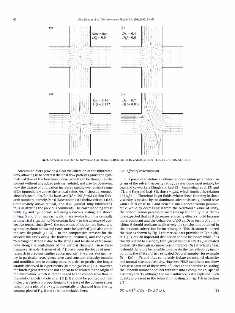
Fig. 4. Streamline maps for: (a) Newtonian fluid; (b) De = 0.
Streamline plots provide a clear visualization of the bifurcatedow, allowing us to contrast the final flow pattern against the sym-etrical flow of the Newtonian case (which can be thought as the
olvent without any added polymer solute), and also for observingow the degree of bifurcation increases rapidly over a short rangef De immediately above the critical value. Fig. 4 shows a zoomediew of streamlines for the base case (L2 = 100, ˇ = 0.1) at four Deb-rah numbers, namely De = 0 (Newtonian), 0.4 (below critical), 0.46immediately above critical) and 0.70 (almost fully bifurcated),hus illustrating the previous comments. The corresponding stresselds �xx and �yy, normalised using a viscous scaling, are shown
n Figs. 5 and 6 for increasing De: these evolve from the centrallyymmetrical situation of Newtonian flow – in the absence of con-ective terms, since Re = 0, the equations of motion are linear andymmetry about both x and y axis must be satisfied (and also abouthe two diagonals, y =±x) – to the compressive stresses for theiscoelastic cases along the horizontal channels, and the typicalbirefringent strands” due to the strong and localised extensionalow along the centrelines of the vertical channels. These bire-
ringence strands (Harlen et al. [1]) have been the focus of muchesearch in previous studies concerned with the cross-slot geome-ry, in particular researchers have used constant-viscosity models,nd modifications to existing ones, in order to predict the longertrands observed in experiments (Remmelgas et al. [3]). However,he birefringent strands do not appear to be related to the origin of
he bifurcation, which is rather linked to the compressive flow inhe inlet channels (Poole et al. [11]). It should be pointed out thatolecular stretch is proportional to the trace of the polymer stressensor, but a plot of �xx + �yy is essentially unchanged from the �yy
ontour plots of Fig. 6 and so is not included here.
ed3
D
De = 0.46; and (d) De = 0.70 (FENE-CR, L2 = 100 and ˇ = 0.1).
.2. Effect of concentration
It is possible to define a polymer concentration parameter c inerms of the solvent viscosity ratio ˇ, as was done most notably byeal and co-workers (Singh and Leal [2]; Remmelgas et al. [3] and7]; and Feng and Leal [8]); thus c = �p/�s which implies the relation= (1/ˇ)−1. Therefore Boger fluids, whose shear-thinning in sheariscosity is masked by the dominant solvent viscosity, should havealues of ˇ close to 1 and hence a small concentration parame-er c, while by decreasing ˇ from the Newtonian value of unity,he concentration parameter increases up to infinity. It is there-ore expected that as ˇ decreases, elasticity effects should become
ore dominant and the behaviour of DQ vs. De in terms of dimin-shing ˇ should replicate qualitatively the conclusions obtained inhe previous subsection for increasing L2. This situation is indeedhe case as shown by Fig. 7 (numerical data provided in Table 2b),f. Fig. 3, but an important distinction should be made: while L2 islosely related to elasticity through extensional effects, ˇ is relatedo elasticity through normal-stress difference (N1) effects in shear.t should therefore be possible to separate the two effects by incor-orating the effect of ˇ in a re-scaled Deborah number, for examplee←De(1−ˇ), and thus completely isolate extensional elasticitynd normal-stresses elasticity. However, FENE models do not allowclear separation of these two influences and therefore re-scaling
he Deborah number does not translate into a complete collapse of
lasticity effects, although the main influence is still captured. Suchuality is present in the bifurcation scaling (cf. Fig. 11b in Section.3):Q ∝ A(L2)√
De− Decr(ˇ, L2), (8)

G.N. Rocha et al. / J. Non-Newtonian Fluid Mech. 156 (2009) 58–69 63
Fig. 5. Contour plots of horizontal normal stress �xx/(�0U/d) for: (a) Newtonian fluid; (b) De = 0.40; (c) De = 0.46; and (d) De = 0.70. (FENE-CR, L2 = 100 and ˇ = 0.1).
Fig. 6. Contour plots of vertical normal stress �yy/(�0U/d) for: (a) Newtonian fluid; (b) De = 0.40; (c) De = 0.46; and (d) De = 0.70. (FENE-CR, L2 = 100 and ˇ = 0.1).

64 G.N. Rocha et al. / J. Non-Newtonian Fluid Mech. 156 (2009) 58–69
FC(
woeeicWdDb
dtaiawt
TCa
(
2
(
TP(
(
2
(
Ftm
ig. 7. Variation of asymmetry parameter DQ with Deborah number for the FENE-R model: influence of polymer concentration through solvent viscosity ratio ˇL2 = 100).
hich is drawn on the basis of Figs. 3 and 7. While the critical Deb-rah number is controlled by both normal stress and extensionallasticity, the magnitude of the bifurcation is mainly controlled byxtensibility. Our predictions yield the results for A and Decr givenn Tables 4 and 5 which also include the results for the roundedorner cases which we discuss in detail in the following section.
hile in Table 4 the critical De is obtained directly from the rawata of Table 1, being thus dependent on the step used to increasee, in Table 5 both A and Decr are estimated from a linear correlationetween DQ2 and De close to the critical De.
Figure 8 provides an illustration of the quality of the fittingefined by Eq. (8) when most data points of the DQ vs. De varia-ion are included and the Decr are assumed from the data of Table 2nd are given in Table 4. A fine tuning of a correlation like Eq. (8)
s achieved by linearising it to obtain DQ2 = A2(De−Decr) and thusrrive at A and Decr by a standard linear regression technique. In thisay the critical point in terms of Deborah number is not based onhe assumed step for the increase in De, which was the same for all
able 4ritical Deborah numbers for bifurcation: (a) varying L2, at ˇ = 0.1 and (b) varying ˇ,t L2 = 100
Sharp R = 0.05d R = 0.5d
a) L2
50 0.61 0.63 0.85100 0.46 0.47 0.6200 0.41 0.42 0.54
b) �0.05 0.41 0.42 0.560.10 0.46 0.47 0.620.20 0.68 0.70 0.86
able 5arameters of the square-root fitting according to Eq. (8): (a) varying L2 (ˇ = 0.1) andb) varying ˇ (L2 = 100)
Sharp corners R = 0.05d R = 0.5d
Decr A Decr A Decr A
a) L2 (ˇ = 0.1)50 0.607 1.74 0.625 1.69 0.849 1.34
100 0.456 2.32 0.468 2.26 0.618 1.8000 0.402 2.58 0.410 2.47 0.539 2.11
b) ˇ (L2 = 100)0.05 0.402 2.36 0.412 2.31 0.554 1.930.10 0.456 2.32 0.468 2.26 0.618 1.800.20 0.682 2.18 0.698 2.11 0.855 1.61
mtbibeAosr
3
spntPicebfcvihtc
ig. 8. (a) Square-root fitting of the bifurcation data for the FENE-CR model withhree extensibility values (cf. Eq. (8)) and (b) Zoomed view shows DQ2 vs. De on two
eshes including linear regressions.
eshes (we varied De by steps of �De = 0.01), but rather on the par-icular correlation defined as DQ ≈
√De− Decr valid for pitchfork
ifurcations as discussed in the previous subsection. By employ-ng a standard least-squares fitting procedure we obtained for thease case (L2 = 100, ˇ = 0.1) the values A = 2.344 and Decr = 0.457 (lin-ar correlation coefficient, r = 0.999) on the base mesh (N = 51), and= 2.437 and Decr = 0.456 (linear correlation coefficient, r = 0.997)n the finer mesh (N = 101). In this way a more precise error mea-ure based on the critical De value is 0.001/0.456 = 0.2%, while itaises to 3.8% for the coefficient A.
.3. Effect of rounding corners: R = 0.05d and 0.5d
A natural question that arises is related with the presence ofharp corners and whether the bifurcation is triggered by someossible imbalance of the high stresses generated in those cor-er regions. Sharp corners are well known to be troublesome inhe numerical solution of viscoelastic flow equations (Owens andhilips [22]) and in many of the early simulations of the cross-slot,n which only one quarter of the full geometry was simulated, theorner was artificially rounded by a slight amount (e.g. Remmelgast al. [3]) in order to enable solutions at high Deborah numbers toe obtained. Even experimental studies (Schoonen et al. [5]) haveollowed the route of rounding the corners to avoid extreme stressoncentration and allow easier interpretation of the birefringenceisualizations. Since our argument to explain the bifurcation, and
ndeed the explanation put forth by Poole et al. [11], hinges on theigh compressive stresses generated in the centreline region of thewo incoming flow streams, then we do not expect rounding of theorners to affect significantly the bifurcation phenomenon.
G.N. Rocha et al. / J. Non-Newtonian Fluid Mech. 156 (2009) 58–69 65
Fig. 9. Effect of rounding the corners on the asymmetry plot for two curvature radiusw0
t0atcbacTtrDcnFaatRtioc(tlw(tp
Table 6Bifurcation data for the FENE-CR fluid in the rounded geometry (R = 0.5d): (a) varyingL2 (ˇ = 0.1) and (b) varying ˇ (L2 = 100) (critical conditions indicated in bold)
(a) L2 = 50 L2 = 100 L2 = 200
De DQ De DQ De DQ
0.00 0.000 0.00 0.000 0.00 0.0000.10 0.000 0.10 0.000 0.10 0.0000.20 0.000 0.20 0.000 0.20 0.0000.30 0.000 0.30 0.000 0.30 0.0000.40 0.000 0.40 0.000 0.40 0.0000.50 0.000 0.50 0.000 0.50 0.0000.60 0.000 0.60 0.000 0.53 0.0000.70 0.000 0.61 0.000 0.54 0.0660.80 0.000 0.62 0.076 0.55 0.2180.85 0.056 0.63 0.200 0.56 0.3040.86 0.138 0.64 0.268 0.57 0.3700.87 0.192 0.65 0.324 0.58 0.4220.88 0.234 0.66 0.372 0.59 0.4680.89 0.268 0.67 0.412 0.60 0.5050.90 0.296 0.68 0.444 0.65 0.6380.91 0.322 0.69 0.474 0.70 0.7190.92 0.346 0.70 0.501 0.75 0.7720.93 0.366 0.75 0.600 0.80 0.8100.94 0.384 0.80 0.666 0.85 0.8360.95 0.402 0.90 0.746 0.90 0.8561.00 0.470 1.00 0.790 1.00 0.884
(b) ˇ = 0.05 ˇ = 0.10 ˇ = 0.20
De DQ De DQ De DQ
0.00 0.000 0.00 0.000 0.00 0.0000.10 0.000 0.10 0.000 0.10 0.0000.20 0.000 0.20 0.000 0.20 0.0000.30 0.000 0.30 0.000 0.30 0.0000.40 0.000 0.40 0.000 0.40 0.0000.50 0.000 0.50 0.000 0.50 0.0000.55 0.000 0.60 0.000 0.60 0.0000.56 0.146 0.61 0.000 0.70 0.0000.57 0.244 0.62 0.076 0.80 0.0000.58 0.312 0.63 0.200 0.85 0.0000.59 0.366 0.64 0.268 0.86 0.1100.60 0.410 0.65 0.324 0.87 0.1980.61 0.448 0.66 0.372 0.88 0.2560.62 0.480 0.67 0.412 0.89 0.3020.63 0.510 0.68 0.444 0.90 0.3420.64 0.534 0.69 0.474 0.91 0.3760.65 0.558 0.70 0.500 0.92 0.4060.70 0.644 0.75 0.600 0.93 0.434– – 0.80 0.666 0.94 0.458– – 0.90 0.746 0.95 0.480–
3
CssSesFbtnastronger tendency to yield a non-steady end-state flow: while for
ith the FENE-CR model: R = 0.05d and 0.5d. (a) L2 = 50, 100 and 200 and (b) ˇ = 0.05,.1, 0.2.
In order to test this hypothesis, two modified cross-slot geome-ries (see Fig. 1b) with corners rounded up to curvature radius of.05d (small curvature) and 0.5d (large curvature) were preparednd covered with non-orthogonal meshes having similar charac-eristics to the sharp-corner geometries in Table 1. The resultingritical Deborah numbers for the onset of the supercritical insta-ility are provided in Tables 4 and 5, for both a constant ˇ = 0.1nd increasing L2, and a constant L2 = 100 and increasing ˇ; bifur-ation plots are shown in Fig. 9 and the numerical data given inable 6 for the milder curvature case. It is clear from these resultshat the above supposition holds: when the corners are first slightlyounded (R = 0.05d) both the critical values and the variation ofQ with De remains virtually unchanged from the sharp-cornerases. One may thus safely conclude that the triggering mecha-ism for the bifurcation is not controlled by near-corner features.or the larger curvature geometry the velocity field is significantlyltered (as quantified in Fig. 10 for the base Newtonian flow) withn anticipated reduction of strain rate, ε = ∂u/∂x, on approachinghe internal stagnation point at the cross-slot centre (by 32% from= 0 to R = 0.5d) and therefore the expected outcome is a stabiliza-
ion of the flow with a delay of the instability onset, as we observen our simulations and show in Table 5 and Fig. 11a. The changef the base flow strain rate is reflected in the extensional-relatedharacteristics (the slope of the variation of Decr with L2 in Fig. 11asolid lines), especially at low L2, is now significantly different tohe sharp-corner case) but the influence of concentration (dashedines) is hardly different from the sharp-corner cases. In Fig. 11b
e plot the same critical De data but as a function of the group
1−ˇ)L2/ˇ: a reasonable correlation is obtained thus implying thathe critical Deborah number is in fact controlled by the ratio ofolymer and solvent maximum elongational viscosities.tDfl
– 1.00 0.790 1.00 0.566
.4. Effect of viscoelastic model
In terms of both shear and extensional properties the FENE-R and FENE-P models are not too dissimilar, except for thehear viscosity which, as we have already discussed, is con-tant for the FENE-CR and shear-thinning for the FENE-P model.ince the cross-slot bifurcation is essentially controlled byxtensional/compressional effects along the channels centreline,ignificant differences between these two models are not expected.ig. 12 shows a comparison between the FENE-P (points denotedy symbols) and FENE-CR (lines) bifurcation plots revealing thathe shear-thinning model tends to bifurcate at a lower Deborahumber, for the two extensional parameters shown, that is L2 = 50nd 100. At the higher extensibility the FENE-P model has a much
he FENE-CR model the flow bifurcates but remains steady up toe≈1, for the FENE-P model the results suggest that a slightlyuctuating bifurcated-flow regime tends to set in at much lower

66 G.N. Rocha et al. / J. Non-Newtonian Fluid Mech. 156 (2009) 58–69
Fc
lnmt
Ft(ˇ
Ft
pspitfie
ig. 10. Profiles of strain rate for Newtonian flow along the two incoming-channelsentreline: influence of corner curvature, R = 0, 0.05d and 0.5d.
evels of Deborah number. In order to illustrate this unsteady phe-omenon, which was also observed by Arratia et al. [9] in theicrofluidic apparatus when this bifurcation was measured for
he first time, the FENE-P model predictions of DQ at De = 0.46 are
ig. 11. Critical Deborah number for the FENE-CR model and various corner curva-ures as a function of: (a) extensibility and polymer concentration separately andb) the maximum extensional stress group (1−ˇ)L2/ˇ. Note: in part (b) solid lines,= 0.1; dashed lines, L2 = 100.
gwis
3
tildfiie
F
ig. 12. FENE-P (symbols) and FENE-CR (full line) model predictions of the bifurca-ion diagram for L2 = 50 and 100.
lotted in Fig. 13 where a periodic evolution of the asymmetry ishown with a period of about 50 time units (d/U). While this cyclicattern is not an expected outcome of the FENE-P model, since
n general shear-thinning tends to stabilize the numerical solu-ion and allows higher Deborah numbers to be reached, the floweld resulting from the simulations in a zone very close to the re-ntrant corners shows signs of some local velocity perturbations,enerated by the very large stresses existing at those locations,hich appear to be responsible for the onset of the second instabil-
ty and the time-dependent oscillations present in the numericalolution.
.5. Energy loss
It would be useful to have an all-encompassing explanation forhe onset mechanism that leads to the bifurcated flows observedn the cross-slot configuration for both constitutive models. In theimit, if one could establish that there is a reduction of energy torive the flow when it bifurcates, then it would be possible to argue
or a “less-effort” mechanism to explain the bifurcation. This effects actually observed in simulation works as well as theoretical stud-es (Lagnado et al. [23]) and a possible measure of this effect is tovaluate the pressure drop required to drive the flow in the cross-ig. 13. Time-dependent evolution of DQ for FENE-P model at De = 0.46 (L2 = 100).
G.N. Rocha et al. / J. Non-Newtonian Fluid Mech. 156 (2009) 58–69 67
F in (cloo ); (c) cˇ
sFta
C
tpi2scsvs�tNdapv
lF
eWcytfeaistioDbFmfoctf
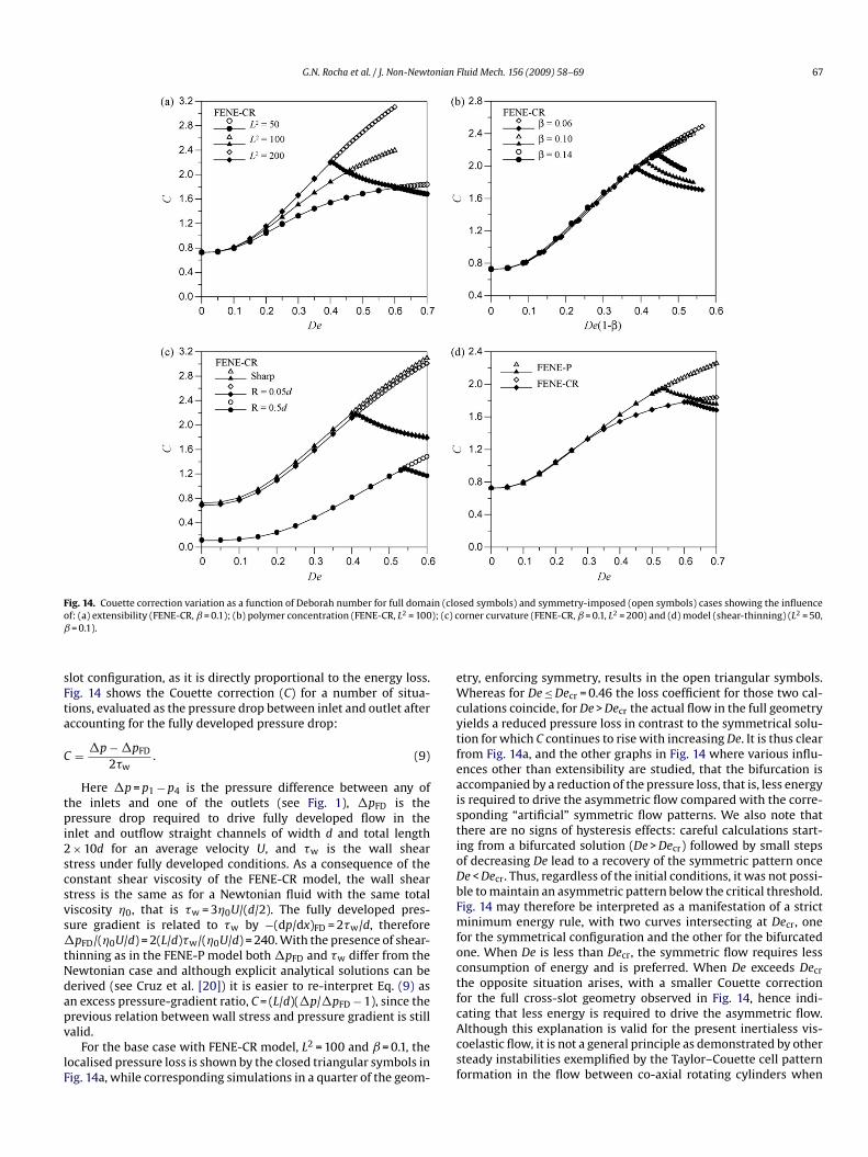
ig. 14. Couette correction variation as a function of Deborah number for full domaf: (a) extensibility (FENE-CR, ˇ = 0.1); (b) polymer concentration (FENE-CR, L2 = 100= 0.1).
lot configuration, as it is directly proportional to the energy loss.ig. 14 shows the Couette correction (C) for a number of situa-ions, evaluated as the pressure drop between inlet and outlet afterccounting for the fully developed pressure drop:
= �p−�pFD
2�w. (9)
Here �p = p1−p4 is the pressure difference between any ofhe inlets and one of the outlets (see Fig. 1), �pFD is theressure drop required to drive fully developed flow in the
nlet and outflow straight channels of width d and total length×10d for an average velocity U, and �w is the wall shear
tress under fully developed conditions. As a consequence of theonstant shear viscosity of the FENE-CR model, the wall sheartress is the same as for a Newtonian fluid with the same totaliscosity �0, that is �w = 3�0U/(d/2). The fully developed pres-ure gradient is related to �w by −(dp/dx)FD = 2�w/d, thereforepFD/(�0U/d) = 2(L/d)�w/(�0U/d) = 240. With the presence of shear-
hinning as in the FENE-P model both �pFD and �w differ from theewtonian case and although explicit analytical solutions can beerived (see Cruz et al. [20]) it is easier to re-interpret Eq. (9) asn excess pressure-gradient ratio, C = (L/d)(�p/�pFD−1), since the
revious relation between wall stress and pressure gradient is stillalid.For the base case with FENE-CR model, L2 = 100 and ˇ = 0.1, theocalised pressure loss is shown by the closed triangular symbols inig. 14a, while corresponding simulations in a quarter of the geom-
cAcsf
sed symbols) and symmetry-imposed (open symbols) cases showing the influenceorner curvature (FENE-CR, ˇ = 0.1, L2 = 200) and (d) model (shear-thinning) (L2 = 50,
try, enforcing symmetry, results in the open triangular symbols.hereas for De≤Decr = 0.46 the loss coefficient for those two cal-
ulations coincide, for De > Decr the actual flow in the full geometryields a reduced pressure loss in contrast to the symmetrical solu-ion for which C continues to rise with increasing De. It is thus clearrom Fig. 14a, and the other graphs in Fig. 14 where various influ-nces other than extensibility are studied, that the bifurcation isccompanied by a reduction of the pressure loss, that is, less energys required to drive the asymmetric flow compared with the corre-ponding “artificial” symmetric flow patterns. We also note thathere are no signs of hysteresis effects: careful calculations start-ng from a bifurcated solution (De > Decr) followed by small stepsf decreasing De lead to a recovery of the symmetric pattern oncee < Decr. Thus, regardless of the initial conditions, it was not possi-le to maintain an asymmetric pattern below the critical threshold.ig. 14 may therefore be interpreted as a manifestation of a strictinimum energy rule, with two curves intersecting at Decr, one
or the symmetrical configuration and the other for the bifurcatedne. When De is less than Decr, the symmetric flow requires lessonsumption of energy and is preferred. When De exceeds Decr
he opposite situation arises, with a smaller Couette correctionor the full cross-slot geometry observed in Fig. 14, hence indi-
ating that less energy is required to drive the asymmetric flow.lthough this explanation is valid for the present inertialess vis-oelastic flow, it is not a general principle as demonstrated by otherteady instabilities exemplified by the Taylor–Couette cell patternormation in the flow between co-axial rotating cylinders when
6 nian
to
Oaatinslcuclw
ecmsppetphebdˇttenwartbfsiFowadcrw(
4
ecriartfl
bbtcessbtammtrcaEedtct(tnt
A
uMai
R
[
[
[
[
8 G.N. Rocha et al. / J. Non-Newto
he Taylor number (and consequently Re) exceeds a certain thresh-ld.
Lagnado et al. [23] conducted a linear stability analysis of theldroyd-B model for the flow close to a planar stagnation pointnd found an instability at finite Weissenberg numbers. While theirnalysis can only be used as a guide to the present situation, sincehey assumed an unbounded flow with a base velocity field whichs significantly different to the current case, it is interesting toote that they find a stronger stability for the case when the maintagnation streamlines meet at an acute angle. That is, a bifurcated-ike stagnation flow of an Oldroyd-B fluid is more stable than theonfiguration at 90◦, which may be viewed as the correspondingn-bifurcated case. The theoretical results of Lagnado et al. [23] areorroborated by the present study: the bifurcated flow dissipatesess energy and it is here preferred to the possible symmetric flow
ith incoming and outgoing streams making a 90◦ angle.In addition, Fig. 14 also illustrates the various influences of
xtensibility (Fig. 14a), polymer concentration (Fig. 14b), cornerurvature (Fig. 14c) and constitutive model (Fig. 14d). While theaximum extensibility of the molecules for the FENE-CR model is
een (Fig. 14a) to have an important influence upon the localisedressure loss coefficient for Deborah numbers up to the criticaloint when the bifurcation occurs, with lower L2 and thus smallerlongational viscosities showing reduced Couette corrections, oncehe asymmetrical patterns set in the evolution of C vs. De is inde-endent of extensibility. The solvent viscosity ratio, on the otherand, has hardly any influence upon C under subcritical conditions,specially when plotted as a function of a modified Deborah num-er De(1−ˇ), and the C vs. De(1−ˇ)variation for De > Decr followsifferent paths essentially because for higher concentration (lower) the bifurcation occurs at earlier De. These two graphs in Fig. 14
hus provide a clear distinction between two factors contributingo viscoelasticity: elongational-related elasticity and normal-stresslasticity. Fig. 14c shows once more that slightly rounding the cor-ers has only a marginal effect on the flow and the pressure drop,hile significant corner curvature strongly reduces the strain rates
nd hence gives rise to much smaller pressure drops in the wholeange of De, both sub- and supercritical. The final graph quantifieshe effect on the constitutive model: for up to De≈0.35 (We≈1.0)oth the FENE-CR and FENE-P yield the same values of C; however,or higher De the FENE-P predicts higher pressure losses. This mighteem counter-intuitive on account of the shear-thinning character-stics of the FENE-P compared with the constant viscosity of theENE-CR model. However it should be realised that the definitionf C balances the effect of shear-thinning due to the scaling with theall shear stress (�w in the denominator of Eq. (9)); as commented
bove, C might be written as a normalised additional channel lengthue to steeper pressure gradient compared with the fully developedase. In this case, the higher C value of the FENE-P model must beelated to a stronger rise of the elongational viscosity for this modelhich leads to the earlier transition to assymmetry observed before
cf. Fig. 12).
. Conclusions
This numerical study has investigated the influence of finitextensibility and polymer concentration on the steady flow bifur-ation that occurs in a cross-slot geometry having both sharp andounded corners, with two different curvature radii. The rheolog-
cal models employed were the FENE-CR and FENE-P, exhibitingconstant shear viscosity and a shear-thinning shear viscosity,espectively, and being adequate for the simulation of dilute unen-angled polymer solutions. In all cases the inertialess viscoelasticow through the symmetric cross-like geometry was predicted to
[
[
Fluid Mech. 156 (2009) 58–69
ecome asymmetric, while remaining steady, for a Deborah num-er above a critical threshold level, in qualitative agreement withhe experiments of Arratia et al. [9] in a microfluidic apparatus. Thatritical Deborah number decreases with increasing values of thextensibility parameter of the FENE models, here taken as L2, thusuggesting the more elastic the fluid (in the sense of higher exten-ional viscosities) the earlier the flow destabilises and evolves to aifurcated pattern. Regarding the influence of polymer concentra-ion the effect is similar to that of L2, which is not surprising sincen added amount of polymer in a given solvent corresponds to aore elastic liquid. A measure of the amplitude of the secondaryotion generated by the instability is provided by the asymme-
ry parameter DQ which offers a measure of the imbalance of flowate exiting through each outlet arm of the cross-slot. When theontrolling variable De is raised, the bifurcation measure DQ variesccording to a theoretically expected square-root curve, given byq. (8), with the magnitude parameter A depending only on thextensibility of the model (L2), while the critical Deborah numberepends on both L2 and ˇ which act jointly as (1−ˇ) L2/ˇ. Finally,he introduction of a small degree of curvature into the cross-slotorners is shown to have practically no influence upon the bifurca-ion characteristics: both the amplitude A and the critical DeborahDe)cr remain virtually unchanged. This finding provides supporto the explanation of Poole et al. [11] for the bifurcation mecha-ism which resided on the compressive-like flow located aroundhe central stagnation point.
cknowledgements
Funding by Fundacão para a Ciência e a Tecnologia (Portugal)nder grant SFRH/BD/22644/2005 and projects PTDC/EME-FE/70186/2006 and PTDC/EQU-FTT/71800/2006 are gratefully
cknowledged. We are grateful to a referee for suggesting the scal-ng used in Fig. 11b.
eferences
[1] O.G. Harlen, J.M. Rallison, M.D. Chilcott, High-Deborah-number flows of dilutepolymer solutions, J. Non-Newtonian Fluid Mech. 34 (1990) 319–349.
[2] P. Singh, L.G. Leal, Finite element simulation of flow around a 3pi/2 corner usingthe FENE dumbbell model, J. Non-Newtonian Fluid Mech. 58 (1995) 279–313.
[3] J. Remmelgas, P. Singh, L.G. Leal, Computational studies of nonlinear dumbbellmodels of Boger fluids in a cross-slot flow, J. Non-Newtonian Fluid Mech. 88(1999) 31–61.
[4] G.W.M. Peters, J.F.M. Schoonen, F.P.T. Baaijens, H.E.H. Meijer, On the perfor-mance of enhanced constitutive models for polymer melts in a cross-slot flow,J. Non-Newtonian Fluid Mech. 82 (1999) 387–427.
[5] J.F.M. Schoonen, F.H.M. Swartjes, G.W.M. Peters, F.P.T. Baaijens, H.E.H. Meijer,A 3D numerical/experimental study on a stagnation flow of a polyisobutylenesolution, J. Non-Newtonian Fluid Mech. 79 (1998) 529–561.
[6] W.M.H. Verbeeten, G.W.M. Peters, F.P.T. Baaijens, Viscoelastic analysis ofcomplex polymer melt flows using the eXtended Pom–Pom model, J. Non-Newtonian Fluid Mech. 108 (2002) 301–326.
[7] J. Remmelgas, L.G. Leal, Computational studies of the FENE-CR model in a two-roll mill, J. Non-Newtonian Fluid Mech. 89 (2000) 231–249.
[8] J. Feng, L.G. Leal, Transient extension and relaxation of a dilute polymer solutionin a four-roll mill, J. Non-Newtonian Fluid Mech. 90 (2000) 117–123.
[9] P.E. Arratia, C.C. Thomas, J. Diorio, J.P. Gollub, Elastic instabilities of polymersolutions in cross-channel flow, Phys. Rev. Lett. 96 (2006) 144502.
10] R.G. Larson, Review: instabilities in viscoelastic flows, Rheol. Acta 31 (1992)213–263.
11] R.J. Poole, M.A. Alves, P.J. Oliveira, Purely elastic flow asymmetries, Phys. Rev.Lett. 99 (2007) 164503.
12] R.B. Bird, O. Hassager, R.C. Armstrong, C.F. Curtiss, Dynamics of Polymeric Liq-uids, Kinetic Theory, vol. 2, John Wiley, New York, 1987.
13] R.B. Bird, P.J. Dotson, N.L. Johnson, Polymer solution rheology based on a finitely
extensible bead-spring chain model, J. Non-Newtonian Fluid Mech. 7 (1980)213–235.14] M.D. Chilcott, J.M. Rallison, Creeping flow of dilute polymer solutions pastcylinders and spheres, J. Non-Newtonian Fluid Mech. 29 (1988) 381–432.
15] J.G. Oldroyd, On the formulation of rheological equations of state, Proc. R. Soc.Lond. A 200 (1950) 523–541.

nian F
[
[
[
[
[
[
G.N. Rocha et al. / J. Non-Newto
16] P.J. Oliveira, F.T. Pinho, G.A. Pinto, Numerical simulation of on-linear elasticflows with a general collocated finite-volume method, J. Non-Newtonian FluidMech. 79 (1998) 1–43.
17] M.A. Alves, P.J. Oliveira, F.T. Pinho, A convergent and universally bounded inter-polation scheme for the treatment of advection, Int. J. Numer. Meth. Fluids 41
(2003) 47–75.18] P.J. Oliveira, Method for time-dependent simulations of viscoelastic flows:vortex shedding behind cylinder, J. Non-Newtonian Fluid Mech. 101 (2001)113–137.
19] P.J. Oliveira, Asymmetric flows of viscoelastic fluids in symmetric planar expan-sion geometries, J. Non-Newtonian Fluid Mech. 114 (2003) 33–63.
[
[
luid Mech. 156 (2009) 58–69 69
20] D.O.A. Cruz, F.T. Pinho, P.J. Oliveira, Analytical solutions for fully developed lam-inar flow of some viscoelastic liquids with a Newtonian solvent contribution,J. Non-Newtonian Fluid Mech. 132 (2005) 28–35.
21] G.N. Rocha, R.J. Poole, P.J. Oliveira, Bifurcation phenomena in viscoelastic flowsthrough a symmetric 1:4 expansion, J. Non-Newtonian Fluid Mech. 141 (2007)
1–17.22] R.G. Owens, T.N. Phillips, Computational Rheology, World Scientific Press,2002.
23] R.R. Lagnado, N. Phan-Thien, L.G. Leal, The stability of two-dimensional lin-ear flows of an Oldroyd-type fluid, J. Non-Newtonian Fluid Mech. 18 (1985)25–59.