ON THE EFFECT OF CORNER CURVATURE IN LAMINAR FLOW THROUGH A CROSS-SLOT CHANNEL
15
1 XXIX CILAMCE – Iberian Latin American Congress on Computational Methods in Engineering November 4-7, 2008, Maceió-Alagoas, Brazil ON THE EFFECT OF CORNER CURVATURE IN LAMINAR FLOW THROUGH A CROSS-SLOT CHANNEL Gerardo N. Rocha [email protected] Departamento de Engenheria Electromecânica, Unidade Materiais Têxteis e Papeleiros, Universidade da Beira Interior, Edifício das Engenharias, 6201-001, Covilhã – Portugal Robert J. Poole [email protected] Department of Engineering, University of Liverpool, Liverpool, L69 3GH, UK Manuel M. Alves [email protected] Faculdade de Engenharia da Universidade do Porto, Dep. to de Engenharia Química, CEFT Rua Dr. Roberto Frias, 4200-130, Porto – Portugal Paulo J. Oliveira [email protected] Departamento de Engenharia Electromecânica, Unidade Materiais Têxteis e Papeleiros, Universidade da Beira Interior, Edifício das Engenharias, 6201-001, Covilhã – Portugal Abstract. The flow of viscoelastic liquids through a cross-slot geometry is studied by means of numerical simulations. The geometry is planar and the constitutive model follows the FENE- CR (constant shear viscosity) equation, valid for relative dilute solutions of polymeric fluids, under fully developed flow conditions. A fully implicit finite-volume numerical method is used to solve the governing equations. For Deborah numbers above a critical value (dependent on the extensibility parameter of the model L 2 and the solvent viscosity ratio β) the flow becomes asymmetric but remains steady. This effect is solely due to the elastic nature of the flowing fluid, i.e. the instability is purely elastic in nature. The main objectives of the present study are: to examine the possible effects of rounding the corners of the geometry (curvature radius of R = 0.05d and 0.5d, where d is the channels’ width) for a range of values of the controlling non-dimensional parameters (De, L 2 and β); to calculate the critical Deborah number of the symmetry-breaking bifurcation; and to document on the flow asymmetries occurring in this kind of geometry. Our results are in qualitative agreement with recent experimental observations presented by Arratia et al. (2006) and numerical results for infinite extensibility models (UCM and Oldroyd-B) previously published by Poole et al. (2007). Keywords: Purely elastic instabilities; Rounded corners; Viscoelastic fluid; FENE-CR model; Finite-volume method.
Transcript of ON THE EFFECT OF CORNER CURVATURE IN LAMINAR FLOW THROUGH A CROSS-SLOT CHANNEL

1
XXIX CILAMCE – Iberian Latin American Congress on Computational Methods in Engineering
November 4-7, 2008, Maceió-Alagoas, Brazil
ON THE EFFECT OF CORNER CURVATURE IN LAMINAR FLOW THROUGH A
CROSS-SLOT CHANNEL
Gerardo N. Rocha
Departamento de Engenheria Electromecânica, Unidade Materiais Têxteis e Papeleiros,
Universidade da Beira Interior, Edifício das Engenharias, 6201-001, Covilhã – Portugal
Robert J. Poole
Department of Engineering, University of Liverpool, Liverpool, L69 3GH, UK
Manuel M. Alves
Faculdade de Engenharia da Universidade do Porto, Dep.to de Engenharia Química, CEFT
Rua Dr. Roberto Frias, 4200-130, Porto – Portugal
Paulo J. Oliveira
Departamento de Engenharia Electromecânica, Unidade Materiais Têxteis e Papeleiros,
Universidade da Beira Interior, Edifício das Engenharias, 6201-001, Covilhã – Portugal
Abstract. The flow of viscoelastic liquids through a cross-slot geometry is studied by means of
numerical simulations. The geometry is planar and the constitutive model follows the FENE-
CR (constant shear viscosity) equation, valid for relative dilute solutions of polymeric fluids,
under fully developed flow conditions. A fully implicit finite-volume numerical method is used
to solve the governing equations. For Deborah numbers above a critical value (dependent on
the extensibility parameter of the model L2 and the solvent viscosity ratio β) the flow becomes
asymmetric but remains steady. This effect is solely due to the elastic nature of the flowing
fluid, i.e. the instability is purely elastic in nature. The main objectives of the present study
are: to examine the possible effects of rounding the corners of the geometry (curvature radius
of R = 0.05d and 0.5d, where d is the channels’ width) for a range of values of the controlling
non-dimensional parameters (De, L2 and β); to calculate the critical Deborah number of the
symmetry-breaking bifurcation; and to document on the flow asymmetries occurring in this
kind of geometry. Our results are in qualitative agreement with recent experimental
observations presented by Arratia et al. (2006) and numerical results for infinite extensibility
models (UCM and Oldroyd-B) previously published by Poole et al. (2007).
Keywords: Purely elastic instabilities; Rounded corners; Viscoelastic fluid; FENE-CR model;
Finite-volume method.
2
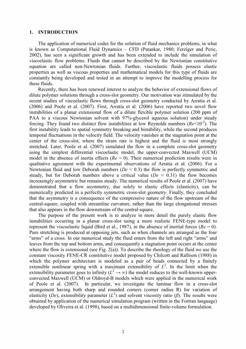
1. INTRODUCTION
The application of numerical codes for the solution of fluid mechanics problems, in what
is known as Computational Fluid Dynamics – CFD (Patankar, 1980; Ferziger and Peric,
2002), has seen a significant growth and has been extended to include the simulation of
viscoelastic flow problems. Fluids that cannot be described by the Newtonian constitutive
equation are called non-Newtonian fluids. Further, viscoelastic fluids possess elastic
properties as well as viscous properties and mathematical models for this type of fluids are
constantly being developed and tested in an attempt to improve the modelling process for
these fluids.
Recently, there has been renewed interest to analyze the behavior of extensional flows of
dilute polymer solutions through a cross-slot geometry. Our motivation was stimulated by the
recent studies of viscoelastic flows through cross-slot geometry conducted by Arratia et al.
(2006) and Poole et al. (2007). First, Arratia et al. (2006) have reported two novel flow
instabilities of a planar extensional flow of a dilute flexible polymer solution (200 ppm of
PAA to a viscous Newtonian solvent with 97%-glycerol aqueous solution) under steady
forcing. They found two distinct flow instabilities at low Reynolds numbers (Re<10-2). The
first instability leads to spatial symmetry breaking and bistability, while the second produces
temporal fluctuations in the velocity field. The velocity vanishes at the stagnation point at the
center of the cross-slot, where the strain rate is highest and the fluid is most strongly
stretched. Later, Poole et al. (2007) simulated the flow in a complete cross-slot geometry
using the simplest differential viscoelastic model, the upper-convected Maxwell (UCM)
model in the absence of inertia effects (Re = 0). Their numerical prediction results were in
qualitative agreement with the experimental observations of Arratia et al. (2006). For a
Newtonian fluid and low Deborah numbers (De < 0.3) the flow is perfectly symmetric and
steady, but for Deborah numbers above a critical value (De ≈ 0.31) the flow becomes
increasingly asymmetric but remains steady. The numerical results of Poole et al. (2007) have
demonstrated that a flow asymmetry, due solely to elastic effects (elasticity), can be
numerically predicted in a perfectly symmetric cross-slot geometry. Finally, they concluded
that the asymmetry is a consequence of the compressive nature of the flow upstream of the
central-square, coupled with streamline curvature, rather than the large elongational stresses
that also appears in the flow downstream of the central-square.
The purpose of the present work is to analyze in more detail the purely elastic flow
instabilities occurring in a planar cross-slot using a more realistic FENE-type model to
represent the viscoelastic liquid (Bird et al., 1987), in the absence of inertial forces (Re = 0).
Pure stretching is produced at opposing jets, such as when channels are arranged as the four
“arms” of a cross. In our numerical study the fluid enters from the left and right “arms” and
leaves from the top and bottom arms, and consequently a stagnation point occurs at the center
where the flow is extensional (see Fig. 2(a)). To describe the rheology of the fluid we use the
constant viscosity FENE-CR constitutive model proposed by Chilcott and Rallison (1988) in
which the polymer architecture is modeled as a pair of beads connected by a finitely
extensible nonlinear spring with a maximum extensibility of L2. In the limit when the
extensibility parameter goes to infinity (L2 → ∞) the model reduces to the well-known upper-
convected Maxwell (UCM) or Oldroyd-B models which were applied in the numerical work
of Poole et al. (2007). In particular, we investigate the laminar flow in a cross-slot
arrangement having both sharp and rounded corners (corner radius R) for variation of
elasticity (De), extensibility parameter (L2) and solvent viscosity ratio (β). The results were
obtained by application of the numerical simulation program (written in the Fortran language)
developed by Oliveira et al. (1998), based on a multidimensional finite-volume formulation.
3
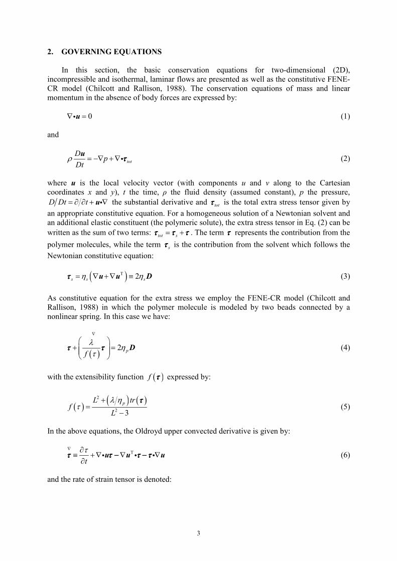
2. GOVERNING EQUATIONS
In this section, the basic conservation equations for two-dimensional (2D),
incompressible and isothermal, laminar flows are presented as well as the constitutive FENE-
CR model (Chilcott and Rallison, 1988). The conservation equations of mass and linear
momentum in the absence of body forces are expressed by:
0∇ =iu (1)
and
tot
Dp
Dtρ = −∇ + ∇i
uττττ (2)
where u is the local velocity vector (with components u and v along to the Cartesian
coordinates x and y), t the time, ρ the fluid density (assumed constant), p the pressure,
D Dt t= ∂ ∂ + ∇iu the substantial derivative and totττττ is the total extra stress tensor given by
an appropriate constitutive equation. For a homogeneous solution of a Newtonian solvent and
an additional elastic constituent (the polymeric solute), the extra stress tensor in Eq. (2) can be
written as the sum of two terms: tot s= +τ τ ττ τ ττ τ ττ τ τ . The term ττττ represents the contribution from the
polymer molecules, while the term sττττ is the contribution from the solvent which follows the
Newtonian constitutive equation:
( )T 2s s sη η= ∇ + ∇ ≡u u Dττττ (3)
As constitutive equation for the extra stress we employ the FENE-CR model (Chilcott and
Rallison, 1988) in which the polymer molecule is modeled by two beads connected by a
nonlinear spring. In this case we have:
( )
2 pf
λη
τ
∇
+ =
Dτ ττ ττ ττ τ (4)
with the extensibility function ( )f ττττ expressed by:
( )( ) ( )2
2 3
pL trf
L
λ ητ
+=
−
ττττ (5)
In the above equations, the Oldroyd upper convected derivative is given by:
T
t
τ∇ ∂≡ + ∇ ∇ ∇
∂i i iu u uτ τ − τ − ττ τ − τ − ττ τ − τ − ττ τ − τ − τ (6)
and the rate of strain tensor is denoted:
4
( )T1
2= ∇ + ∇D u u (7)
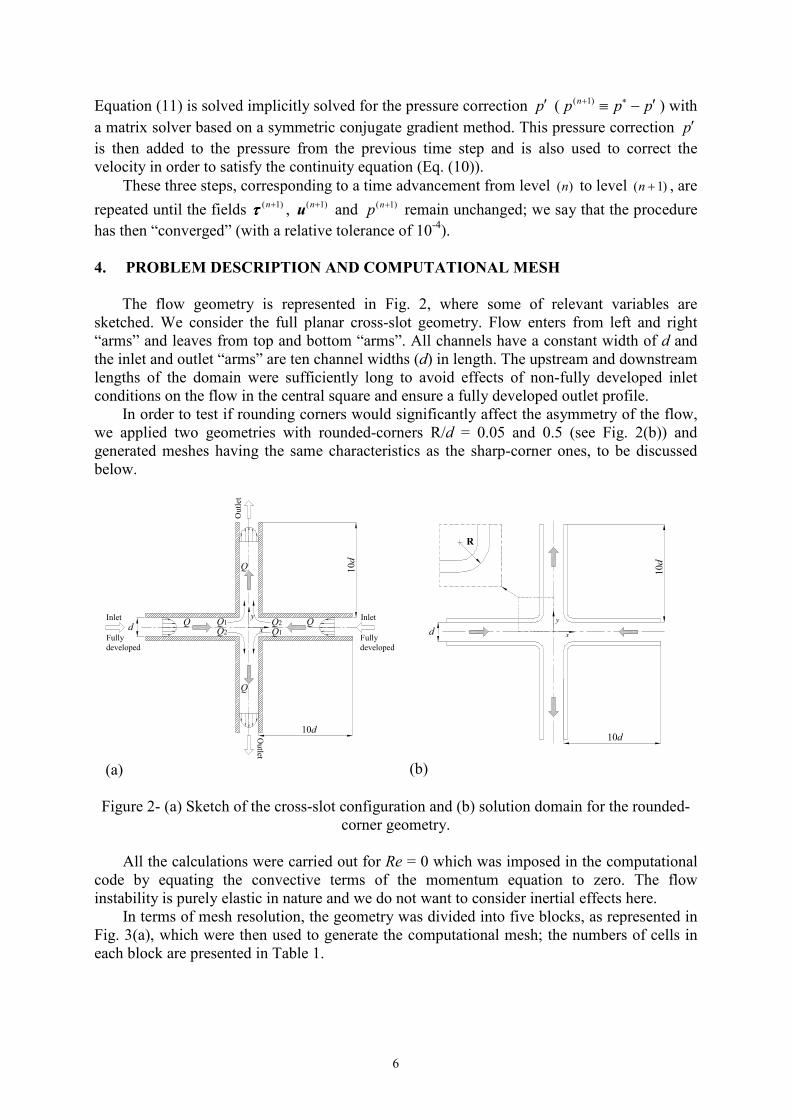
where sη is the solvent viscosity (constant), pη the contribution of polymer to the total shear
viscosity 0 s pη η η= + (also taken as constant), λ the constant zero-shear rate relaxation time,
and L2 the extensibility parameter that measures the size of the polymer molecule in relation
to its equilibrium size.
There are five non-dimensional parameters to this flow problem: the radius of curvature
R (geometric parameter); the solvent viscosity ratio 0sβ η η= (concentration parameter); the
Reynolds number 0Re Udρ η= (dynamic parameter); and the extensibility parameter of the
FENE-CR model, L2 , and the Deborah number, De U dλ= (constitutive parameters).
3. NUMERICAL METODOLOGY
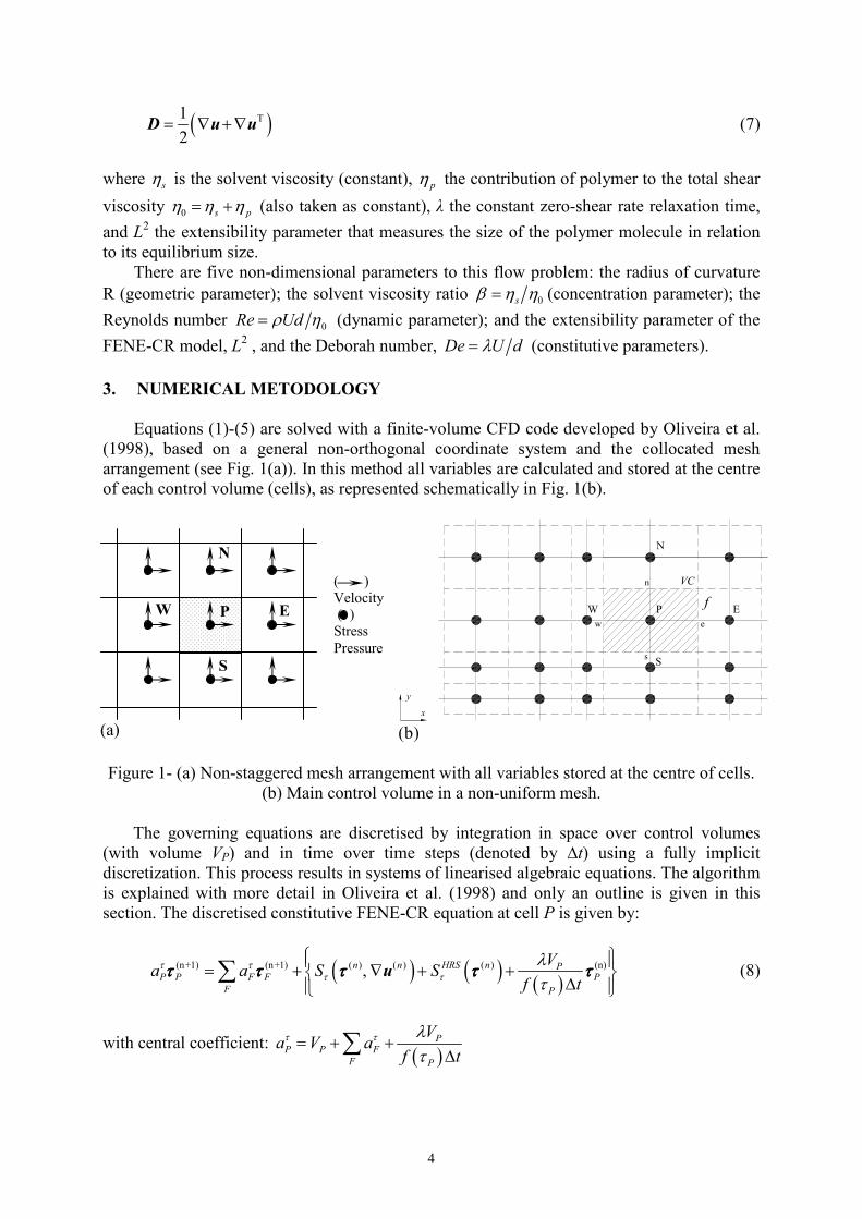
Equations (1)-(5) are solved with a finite-volume CFD code developed by Oliveira et al.
(1998), based on a general non-orthogonal coordinate system and the collocated mesh
arrangement (see Fig. 1(a)). In this method all variables are calculated and stored at the centre
of each control volume (cells), as represented schematically in Fig. 1(b).
(a)
PW E
N
S
y
x
ew
n
s
VC
(b)
Figure 1- (a) Non-staggered mesh arrangement with all variables stored at the centre of cells.
(b) Main control volume in a non-uniform mesh.
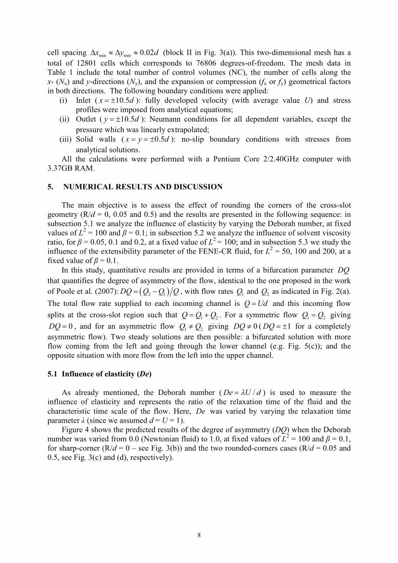
The governing equations are discretised by integration in space over control volumes
(with volume VP) and in time over time steps (denoted by ∆t) using a fully implicit
discretization. This process results in systems of linearised algebraic equations. The algorithm
is explained with more detail in Oliveira et al. (1998) and only an outline is given in this
section. The discretised constitutive FENE-CR equation at cell P is given by:
( ) ( ) ( )(n+1) (n+1) ( ) ( ) ( ) (n)n n HRS n P
P P F F P
F P
Va a S S
f t
τ ττ τ
λτ
= + , ∇ + +
∆ ∑τ τ τ τ ττ τ τ τ ττ τ τ τ ττ τ τ τ τu (8)
with central coefficient: ( )
PP P F
F P
Va V a
f t
τ τ λτ
= + +∆∑
N
P
S
E W
( )
Velocity
( )
Stress
Pressure
f
5
where VP is the volume of cell P and the stress coefficients Faτ are composed by convective
fluxes. These convective fluxes are calculated at cell faces located between cell P and any of
its neighbouring cells F (in this work the summations are over 4 neighbouring cells for W, E,
S and N with compass notation: West, East, South and North, see Fig. 1(b)). The stress
sources terms Sτ depend simultaneously on the stress tensor ττττ and velocity gradients∇u
which are evaluated at the previous time level ( )n .
In the first step of the algorithm the above set of linear equations (Eq. (8)), for the stress
tensor, are solved sequentially by a bi-conjugate gradient method, to obtain each stress
component ijτ at the new time level ( 1)n + . A solution for a steady-state problem is
effectively approached by a succession of time advancement steps where t∆ acts as an
inertial-relaxation term.
In the second step, the discretised momentum conservation equations is solved implicitly
for the intermediate velocity ∗u :
( ) ( ) ( ) ( )( ) ( 1)
_
n n HRS nPP P F F u u u Dif u P
F
Va a S p S S S
t
ρ∗ ∗ + = + ∇ + ∇ + + + ∆
∑ ττττu u u u ui (9)
with: PP F
F
Va a
t
ρ= +
∆∑
where the coefficients Fa have convective and diffusive contributions. The velocity source
terms uS (on the right hand side of Eq. (9) inside curled brackets) represent the effects due to
the pressure gradient, the elastic stress divergence term, the artificial diffusive term (explicit
part) and the high-resolution scheme, respectively. The last term inside the curled brackets is
the inertial term resulting from the temporal derivative. All the coefficients of the discretised
equations are calculated using the upwind scheme for the convective terms, and the high-
resolution convective scheme CUBISTA (Alves et al., 2003) is implemented with the deferred
correction technique (Khosla and Rubin, 1974) through the source terms HRSS .
After updating the stress fields in the first step of the algorithm, the discretised
momentum conservation equations (Eq. (9)) are solved sequentially, with the same solution
method, for each velocity component (u and v). Pressure is assumed from the previous time
step. In general, the velocity components ∗u from solution of Eq. (9) do not satisfy the
discretised continuity conservation equation, expressed by:
( 1) 0n+∇ =iu (10)
The third step of the algorithm involves a correction to ∗u obtained from a re-arrangement of
the continuity equation into a Poisson pressure-correction equation, having the form:
( )p p
P P F F
F
a p a p ∗′ ′= − ∇∑ iu (11)
with: p p
P F
F
a a= ∑
6
Equation (11) is solved implicitly solved for the pressure correction p′ ( ( 1)np p p+ ∗ ′≡ − ) with
a matrix solver based on a symmetric conjugate gradient method. This pressure correction p′ is then added to the pressure from the previous time step and is also used to correct the
velocity in order to satisfy the continuity equation (Eq. (10)).
These three steps, corresponding to a time advancement from level ( )n to level ( 1)n + , are
repeated until the fields ( 1)n+ττττ , ( 1)n+u and ( 1)np + remain unchanged; we say that the procedure
has then “converged” (with a relative tolerance of 10-4).
4. PROBLEM DESCRIPTION AND COMPUTATIONAL MESH
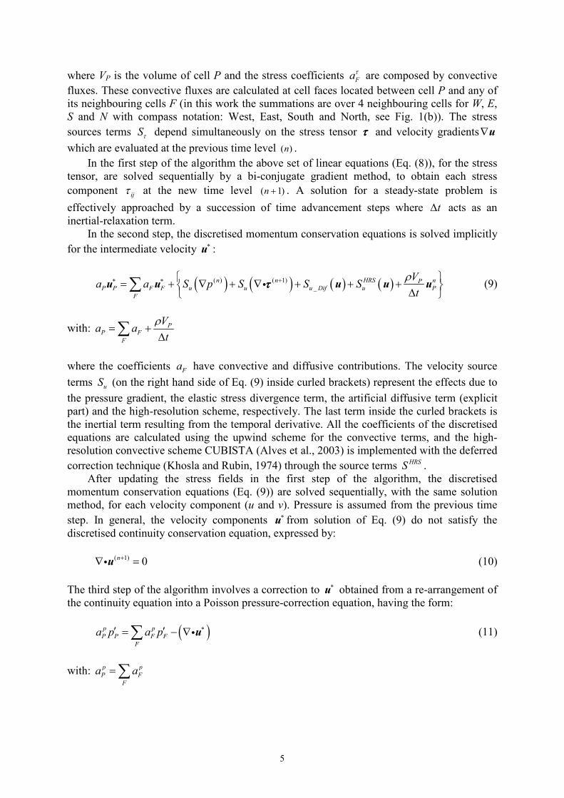
The flow geometry is represented in Fig. 2, where some of relevant variables are
sketched. We consider the full planar cross-slot geometry. Flow enters from left and right
“arms” and leaves from top and bottom “arms”. All channels have a constant width of d and
the inlet and outlet “arms” are ten channel widths (d) in length. The upstream and downstream
lengths of the domain were sufficiently long to avoid effects of non-fully developed inlet
conditions on the flow in the central square and ensure a fully developed outlet profile.
In order to test if rounding corners would significantly affect the asymmetry of the flow,
we applied two geometries with rounded-corners R/d = 0.05 and 0.5 (see Fig. 2(b)) and
generated meshes having the same characteristics as the sharp-corner ones, to be discussed
below.
10d
10d
d
y
xQ1
Q2
Q2
Q1
Q Q
Q
Q
Inlet
Fully
developed
Inlet
Fully
developed
Outlet
Outlet
(a)
10d
10d
d
y
x
R
(b)
Figure 2- (a) Sketch of the cross-slot configuration and (b) solution domain for the rounded-
corner geometry.
All the calculations were carried out for Re = 0 which was imposed in the computational
code by equating the convective terms of the momentum equation to zero. The flow
instability is purely elastic in nature and we do not want to consider inertial effects here.
In terms of mesh resolution, the geometry was divided into five blocks, as represented in
Fig. 3(a), which were then used to generate the computational mesh; the numbers of cells in
each block are presented in Table 1.

7
(a)
(b)
(c)
(d)
Figure 3- (a) Schematic definition of the blocks used to generate the mesh. Zoomed view
( [ ]2 , 2x d d∈ − + and [ ]2 , 2y d d∈ − + ) of mesh for (b) sharp-corner (R = 0) and rounded
corners with (c) R = 0.05d (small curvature) and (d) R = 0.5d (large curvature).
Table 1. Main characteristics of computational mesh
Blocks Nx Ny fx fy
I 50 51 0.929296 1.000000
II 51 51 1.000000 1.000000
III 51 50 1.000000 0.929296
IV 51 50 1.000000 1.075369
V 50 51 1.075369 1.000000
NC = 12801
As seen in Fig. 3, the mesh is orthogonal but non-uniform along the inlet and outlet
channels, with increasing concentration of cells on approaching the central square (see Fig.
3(b)-(d)). The central square ( x and 0.5y d≤ ) was mapped with a uniform mesh having
x
y
I II
III
IV
V
8
cell spacing min min 0.02x y d∆ ≈ ∆ ≈ (block II in Fig. 3(a)). This two-dimensional mesh has a
total of 12801 cells which corresponds to 76806 degrees-of-freedom. The mesh data in
Table 1 include the total number of control volumes (NC), the number of cells along the
x- (Nx) and y-directions (Ny), and the expansion or compression (fx or fy) geometrical factors
in both directions. The following boundary conditions were applied:
(i) Inlet ( 10.5x d= ± ): fully developed velocity (with average value U) and stress
profiles were imposed from analytical equations;
(ii) Outlet ( 10.5y d= ± ): Neumann conditions for all dependent variables, except the
pressure which was linearly extrapolated;
(iii) Solid walls ( 0.5x y d= = ± ): no-slip boundary conditions with stresses from
analytical solutions.
All the calculations were performed with a Pentium Core 2/2.40GHz computer with
3.37GB RAM.
5. NUMERICAL RESULTS AND DISCUSSION
The main objective is to assess the effect of rounding the corners of the cross-slot
geometry (R/d = 0, 0.05 and 0.5) and the results are presented in the following sequence: in
subsection 5.1 we analyze the influence of elasticity by varying the Deborah number, at fixed
values of L2 = 100 and β = 0.1; in subsection 5.2 we analyze the influence of solvent viscosity
ratio, for β = 0.05, 0.1 and 0.2, at a fixed value of L2 = 100; and in subsection 5.3 we study the
influence of the extensibility parameter of the FENE-CR fluid, for L2 = 50, 100 and 200, at a
fixed value of β = 0.1.
In this study, quantitative results are provided in terms of a bifurcation parameter DQ
that quantifies the degree of asymmetry of the flow, identical to the one proposed in the work
of Poole et al. (2007): ( )2 1DQ Q Q Q= − , with flow rates 1Q and 2Q as indicated in Fig. 2(a).
The total flow rate supplied to each incoming channel is Q Ud= and this incoming flow
splits at the cross-slot region such that 1 2Q Q Q= + . For a symmetric flow 1 2Q Q= giving
0DQ = , and for an asymmetric flow 1 2Q Q≠ giving 0DQ ≠ ( 1DQ = ± for a completely
asymmetric flow). Two steady solutions are then possible: a bifurcated solution with more
flow coming from the left and going through the lower channel (e.g. Fig. 5(c)); and the
opposite situation with more flow from the left into the upper channel.
5.1 Influence of elasticity (De)
As already mentioned, the Deborah number ( /De U dλ= ) is used to measure the
influence of elasticity and represents the ratio of the relaxation time of the fluid and the
characteristic time scale of the flow. Here, De was varied by varying the relaxation time
parameter λ (since we assumed d = U = 1).
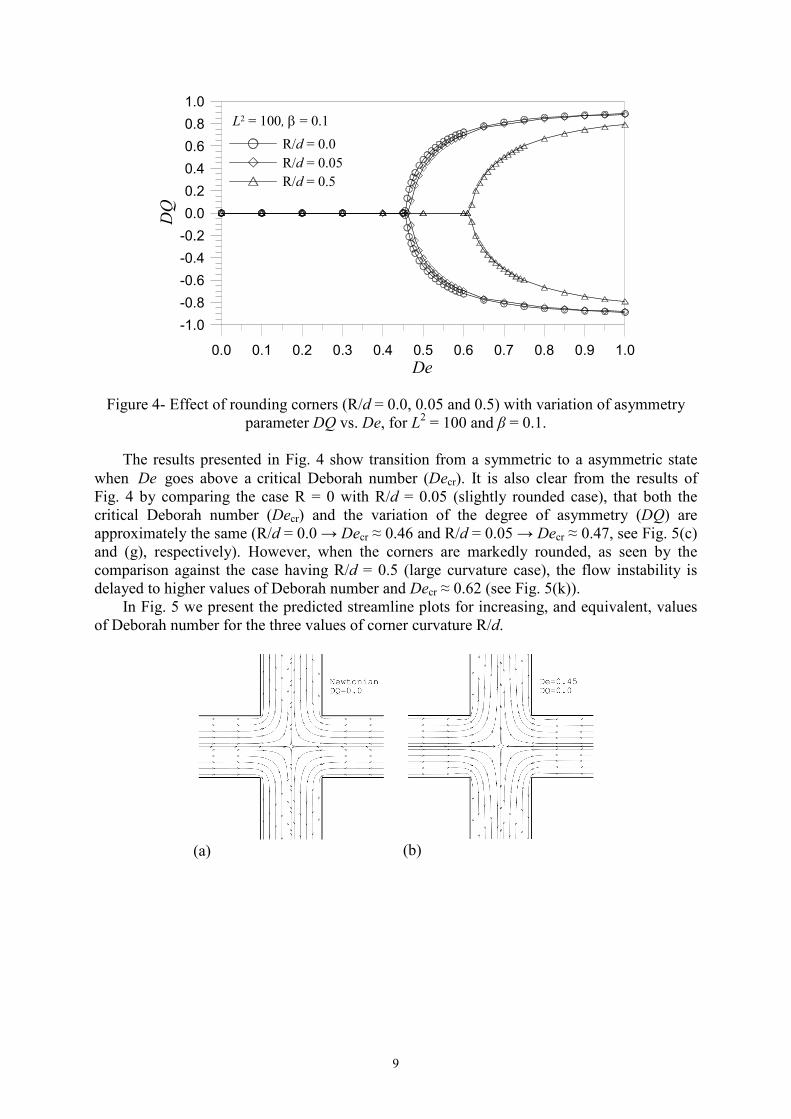
Figure 4 shows the predicted results of the degree of asymmetry (DQ) when the Deborah
number was varied from 0.0 (Newtonian fluid) to 1.0, at fixed values of L2 = 100 and β = 0.1,
for sharp-corner (R/d = 0 – see Fig. 3(b)) and the two rounded-corners cases (R/d = 0.05 and
0.5, see Fig. 3(c) and (d), respectively).
9
0.0 0.1 0.2 0.3 0.4 0.5 0.6 0.7 0.8 0.9 1.0
De
-1.0
-0.8
-0.6
-0.4
-0.2
0.0
0.2
0.4
0.6
0.8
1.0
DQ
R/d = 0.0
R/d = 0.05
R/d = 0.5
L2 = 100, β = 0.1
Figure 4- Effect of rounding corners (R/d = 0.0, 0.05 and 0.5) with variation of asymmetry
parameter DQ vs. De, for L2 = 100 and β = 0.1.
The results presented in Fig. 4 show transition from a symmetric to a asymmetric state
when De goes above a critical Deborah number (Decr). It is also clear from the results of
Fig. 4 by comparing the case R = 0 with R/d = 0.05 (slightly rounded case), that both the
critical Deborah number (Decr) and the variation of the degree of asymmetry (DQ) are
approximately the same (R/d = 0.0 → Decr ≈ 0.46 and R/d = 0.05 → Decr ≈ 0.47, see Fig. 5(c)
and (g), respectively). However, when the corners are markedly rounded, as seen by the
comparison against the case having R/d = 0.5 (large curvature case), the flow instability is
delayed to higher values of Deborah number and Decr ≈ 0.62 (see Fig. 5(k)).
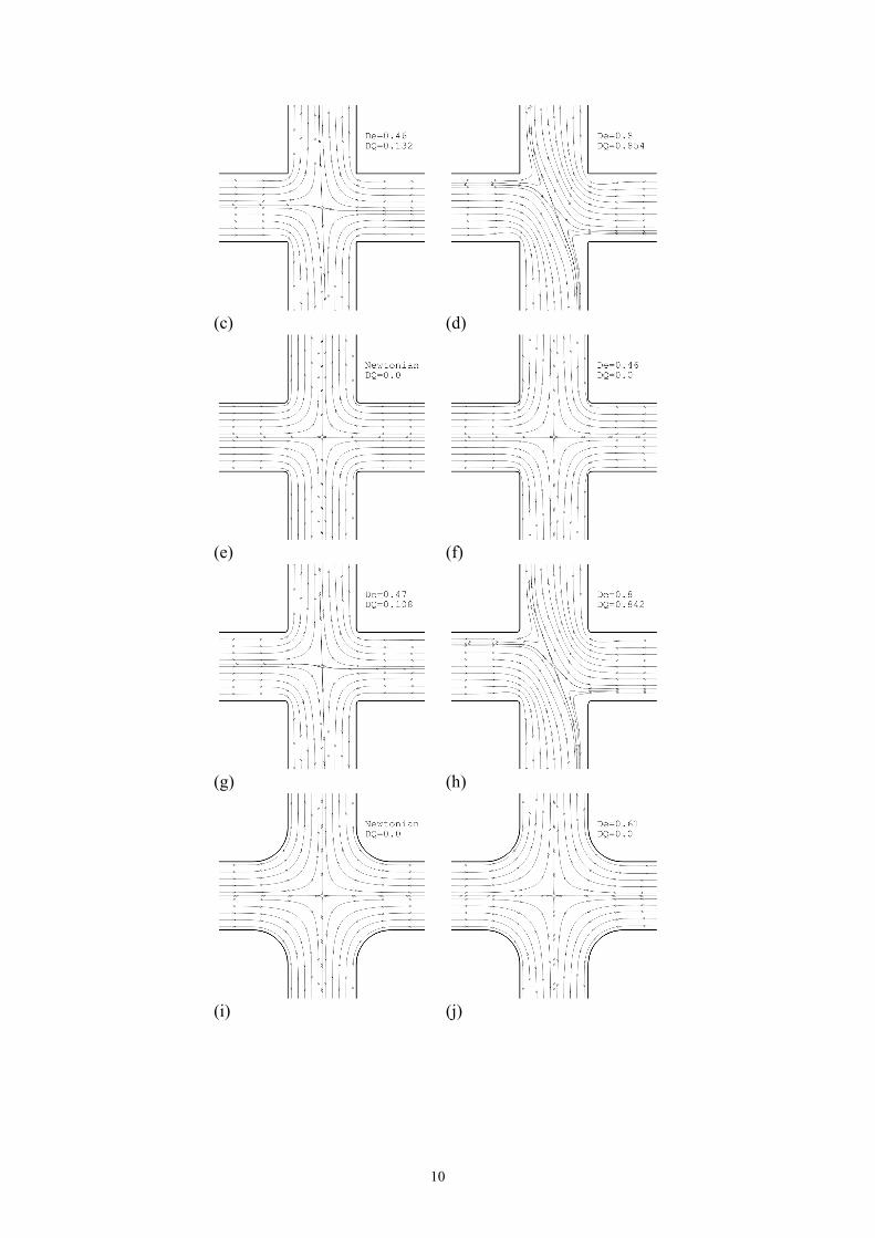
In Fig. 5 we present the predicted streamline plots for increasing, and equivalent, values
of Deborah number for the three values of corner curvature R/d.
(a)
(b)
10
(c)
(d)
(e)
(f)
(g)
(h)
(i)
(j)
11
(k)
(l)
Figure 5- Predicted streamline plots for: (a)-(d) sharp-corners R/d = 0.0; (e)-(h) rounded
corner R/d = 0.05; and (i)-(l) rounded corner R/d = 0.5 (L2 = 100 and β = 0.1).
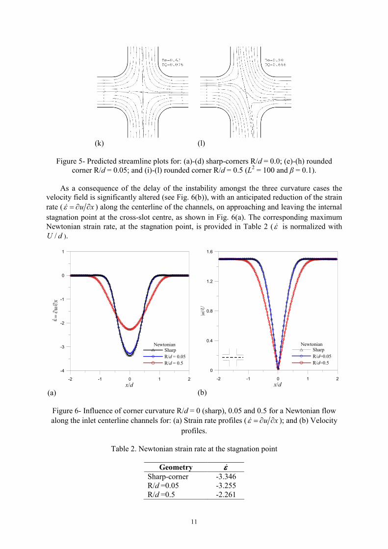
As a consequence of the delay of the instability amongst the three curvature cases the
velocity field is significantly altered (see Fig. 6(b)), with an anticipated reduction of the strain
rate ( u xε = ∂ ∂� ) along the centerline of the channels, on approaching and leaving the internal
stagnation point at the cross-slot centre, as shown in Fig. 6(a). The corresponding maximum
Newtonian strain rate, at the stagnation point, is provided in Table 2 (ε� is normalized with
/U d ).
-2 -1 0 1 2
x/d
-4
-3
-2
-1
0
1
ε.=
∂u/∂x
NewtonianSharp
R/d = 0.05
R/d = 0.5
(a)
-2 -1 0 1 2
x/d
0
0.4
0.8
1.2
1.6
|u|/U
NewtonianSharp
R/d=0.05
R/d=0.5
(b)
Figure 6- Influence of corner curvature R/d = 0 (sharp), 0.05 and 0.5 for a Newtonian flow
along the inlet centerline channels for: (a) Strain rate profiles ( u xε = ∂ ∂� ); and (b) Velocity
profiles.
Table 2. Newtonian strain rate at the stagnation point
Geometry �εεεε
Sharp-corner -3.346
R/d =0.05 -3.255
R/d =0.5 -2.261
12
We can conclude from Fig. 6 that when the corner is first only slightly rounded
(R/d = 0.05) the results remain unchanged compared with the sharp-corner case, showing a
strain rate difference at the stagnation point of 2.7%. However, comparing the sharp-corner
case with the larger curvature case (R/d = 0.5) we see that the difference is more significative,
with a strain rate difference at the stagnation point of 32%.
5.2 Influence of solvent concentration (β)
In this subsection we look at the effect of rounding the corners when varying the solvent
concentration β = 0.05, 0.10 and 0.20, at a fixed L2 = 100. The influence of solvent viscosity
ratio is controlled by the β parameter which measures the ratio of Newtonian solvent shear
viscosity to the total shear viscosity of the polymer solution. In other words, this parameter
provides a measure of polymer concentration and by decreasing β the elasticity of the fluid
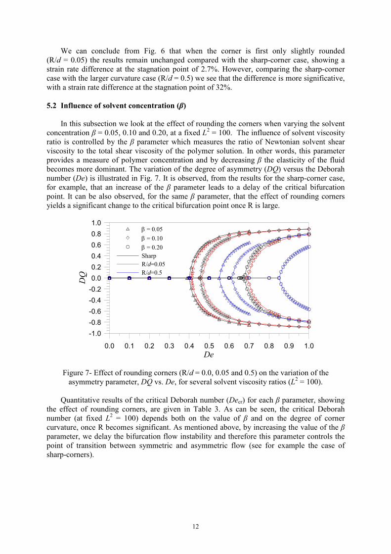
becomes more dominant. The variation of the degree of asymmetry (DQ) versus the Deborah
number (De) is illustrated in Fig. 7. It is observed, from the results for the sharp-corner case,
for example, that an increase of the β parameter leads to a delay of the critical bifurcation
point. It can be also observed, for the same β parameter, that the effect of rounding corners
yields a significant change to the critical bifurcation point once R is large.
0.0 0.1 0.2 0.3 0.4 0.5 0.6 0.7 0.8 0.9 1.0
De
-1.0
-0.8
-0.6
-0.4
-0.2
0.0
0.2
0.4
0.6
0.8
1.0
DQ
β = 0.05
β = 0.10
β = 0.20Sharp
R/d=0.05
R/d=0.5
Figure 7- Effect of rounding corners (R/d = 0.0, 0.05 and 0.5) on the variation of the
asymmetry parameter, DQ vs. De, for several solvent viscosity ratios (L2 = 100).
Quantitative results of the critical Deborah number (Decr) for each β parameter, showing
the effect of rounding corners, are given in Table 3. As can be seen, the critical Deborah
number (at fixed L2 = 100) depends both on the value of β and on the degree of corner
curvature, once R becomes significant. As mentioned above, by increasing the value of the β
parameter, we delay the bifurcation flow instability and therefore this parameter controls the
point of transition between symmetric and asymmetric flow (see for example the case of
sharp-corners).
13
Table 3. Computed values of the critical Deborah number (Decr) for selected values of the
solvent viscosity β and L2 =100.
β Sharp-corner R/d = 0.05 R/d = 0.5
0.05 0.41 0.42 0.56
0.10 0.46 0.47 0.62
0.20 0.68 0.70 0.86
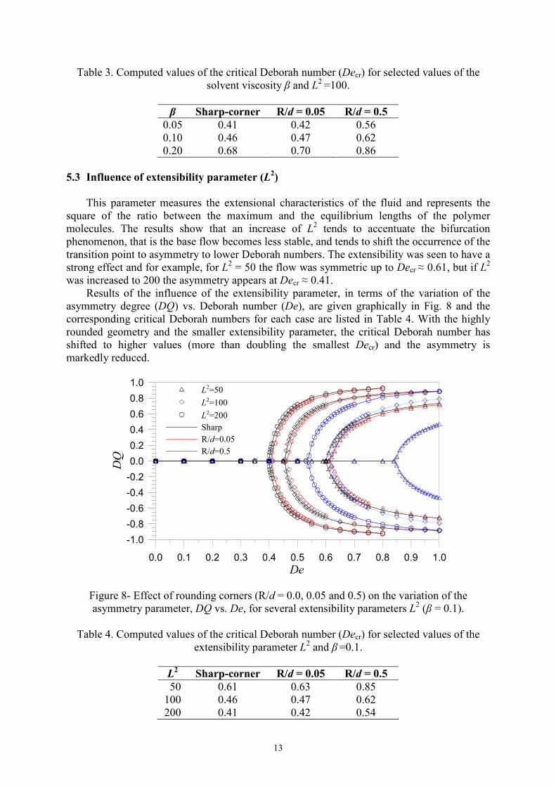
5.3 Influence of extensibility parameter (L2)
This parameter measures the extensional characteristics of the fluid and represents the
square of the ratio between the maximum and the equilibrium lengths of the polymer
molecules. The results show that an increase of L2 tends to accentuate the bifurcation
phenomenon, that is the base flow becomes less stable, and tends to shift the occurrence of the
transition point to asymmetry to lower Deborah numbers. The extensibility was seen to have a
strong effect and for example, for L2 = 50 the flow was symmetric up to Decr ≈ 0.61, but if L
2
was increased to 200 the asymmetry appears at Decr ≈ 0.41.
Results of the influence of the extensibility parameter, in terms of the variation of the
asymmetry degree (DQ) vs. Deborah number (De), are given graphically in Fig. 8 and the
corresponding critical Deborah numbers for each case are listed in Table 4. With the highly
rounded geometry and the smaller extensibility parameter, the critical Deborah number has
shifted to higher values (more than doubling the smallest Decr) and the asymmetry is
markedly reduced.
0.0 0.1 0.2 0.3 0.4 0.5 0.6 0.7 0.8 0.9 1.0
De
-1.0
-0.8
-0.6
-0.4
-0.2
0.0
0.2
0.4
0.6
0.8
1.0
DQ
L2=50
L2=100
L2=200
Sharp
R/d=0.05
R/d=0.5
Figure 8- Effect of rounding corners (R/d = 0.0, 0.05 and 0.5) on the variation of the
asymmetry parameter, DQ vs. De, for several extensibility parameters L2 (β = 0.1).
Table 4. Computed values of the critical Deborah number (Decr) for selected values of the
extensibility parameter L2 and β
=0.1.
L2 Sharp-corner R/d = 0.05 R/d = 0.5
50 0.61 0.63 0.85
100 0.46 0.47 0.62
200 0.41 0.42 0.54
14
6. CONCLUSIONS
Numerical simulations of the flow of a FENE-CR model fluid through a planar cross-slot
geometry have been presented in the absence of inertia effects (Re = 0). Steady-state results
were carried out in a range of De = 0 – 1 for the full domain geometry, and the effect of
rounding corners was studied in conjunction with the influence of elasticity (controlled by
Deborah number), of the solvent concentration (controlled by β parameter) and, finally, of the
extensibility parameter (controlled by L2 parameter). It is shown that the triggering
mechanism for the bifurcation phenomenon is not controlled by slightly rounding of the
corners, since the extensional strain rate at the cross-slot center is not affected by such small
level of wall curvature. The elasticity directly drives the instability of the flow and a Decr
defines the transition point from symmetric to asymmetric flow. For De values lower than
Decr the flow is symmetric and stable, while for values above Decr the flow becomes
asymmetric and the DQ parameter grows for increasing De. The solvent viscosity ratio β
which is a measure of the polymer concentration (polymer concentration 1c β∝ ), when
reduced, leads to an anticipation of the bifurcation phenomenon (see Fig. 7). Finally, the
extensibility parameter L2, which controls the extensional viscosity of the fluid, has a strong
effect in the flow and for increasing L2 the critical point controlled by the Deborah number
decreases substantially (see Fig. 8).
Acknowledgements
The authors would like to acknowledge the financial support from Fundação para a
Ciência e a Tecnologia (FCT, Portugal) under grant SFRH/BD/22644/2005 (G.N. Rocha) and
projects PTDC/EME-MFE/70186/2006 and PTDC/EQU-FTT/1800/2006.
REFERENCES
Alves, M. A., Oliveira, P. J., & Pinho, F. T., 2003. A convergent and universally bounded
interpolation scheme for the treatment of advection. Int. J. Numer. Mech. Fluids, vol. 41,
pp. 47-75.
Arratia, P. E., Thomas, C. C., Diorio, J. D., & Gollub, J. P., 2006. Elastic instabilities of
polymer solutions in extensional flows. Physical Review Letters, vol. 96, n. 14, pp.
144502.
Bird, R. B., Curtiss, C. F., Armstrong, R. C., & Hassager, O., 1987. Dynamics of Polymeric
Liquids: Kinetic Theory. John-Wiley & Sons.
Chilcott, M. D., & Rallison, J. M., 1988. Creeping flow of dilute polymer solutions past
cylinders and spheres. J. Non-Newtonian Fluid Mech., vol. 29, pp. 381-432.
Ferziger, J. H., & Peric, M., 2002. Computational Methods for Fluid Dynamics. Springer-
Verlag.
Khosla, P. K., & Rubin, S. G., 1974. A diagonally dominant second-order accurate implicit
scheme. Computers and Fluids, vol. 2, pp. 207-209.
15
Oliveira, P. J., Pinho, F. T., & Pinto, G. A., 1998. Numerical simulation of non-linear elastic
flows with a general collocated finite-volume method. J. Non-Newtonian Fluid Mech.,
vol. 79, pp. 1-43.
Patankar, S. V., 1980. Numerical Heat Transfer and Fluid Flow. Hemisphere Publishing
Corporation.
Poole, R. J., Alves, M. A., & Oliveira, P. J., 2007. Purely-elastic flow asymmetries. Physical
Review Letters, vol. 99, n. 16, pp. 164503.