of Theory And Manufacturing Procedura - Ibiblio
107
of Theory And Manufacturing Procedura For
-
Upload
khangminh22 -
Category
Documents
-
view
3 -
download
0
Transcript of of Theory And Manufacturing Procedura - Ibiblio

of
Theory And Manufacturing Procedura
For
Gyro Familiarization Manual
Handbook
of
Theory And Manufacturing Procedures
For
AC Spark }:>lug Gyros
September 30i 1960
Prepared Byr
AC Spark Plug The Electronics Division
or General Motors Corporation

Thi s manua l has beer. prepared by the Gyro Project Department of the Field Service Di vi 3ion of AC Spark l ug in cooperation with the Gyro E'ngil~eering Department aml Gyro Produc t i on Depar "Lment . The ma::mal p r eae:1ts general gyroscopic t heory and manufa cturing concepts of AC f.ipark Plug gyros for use by a ll depart ments witb_n AC Spark Plug a s sociated with the 1-eed fo::c gyro fami.lia r iza tion.
TABLE OF CONTENTS
I. Gyroscopic Theory:
A. Definition
B. Stabilization Gyros
C. Accelerometer Gyros
II. Gyro Parts and Assembly:
A. 1.0 x 10⁷ Rate Integrating Gyro (Model II)
B. 1.0 x 10⁴ Pendulous Integrating Gyro (Model II-A)
c. 25 IRIG 1.4 x 10⁵ Inertial R.eference Integrating Gyro and 25 PIG o.6 x 105 Pendulous Integrating Gyro
D. 2FBJ-2C 2.0 x 10⁶ Floated Beryllium Gyro
E. 1.0 x 10⁷ Rate Integrating Gyro (Models VI-A and VIII)
F. J.0 x 107 Mark VII-B
III. Gyro Testing:
A. 1.0 x 10⁷ Rate Integrating Gyro (Model II)
B. 1.0 x 10⁴ Pendulous Integrating Gyro (Model II-A)
c. 25 IRIG 1.4 x 10⁵ rgertial Reference Integrating Gyro and 25 PIG o.6 x 10 Pendulous Integrating Gyro
D. 2Fffi-2C 2.0 x 10⁶ Floated Beryllium Gyro
IV. Individual Gyro Characteristics:
v. Microsyn Theory:
A. Magnetic Suspension Operation
B. Signal Microsyn Operation
C. Torque Microsyn Operation
VI. System Applications:
Page No,
Figure Number
1 - a
1 - b
2
3
4
5
6
7
8
9
10
11
12
13 & 14
LIST OF ILLUSTRATIONS
Illustrations
Single Degree of Freedom Gyro
Two Degrees of Freedom Gyro
Gyro Axis Identification
Precessional Torques
Coriolis Force (Earth)
Coriolis Force (Gyro)
Floated, Single Degree of Freedom Gyro
Simplified Control Diagram
Simplified Nulling Diagram
Sectional View - 1.0 x 10⁷ Model II Gyro Wheel
Rotational Balancing Fixture
Longitudinal Balancing Fixture
Sectional View - 1.0 x 10⁷ Model II Gyro Jewel Bearing Assembly
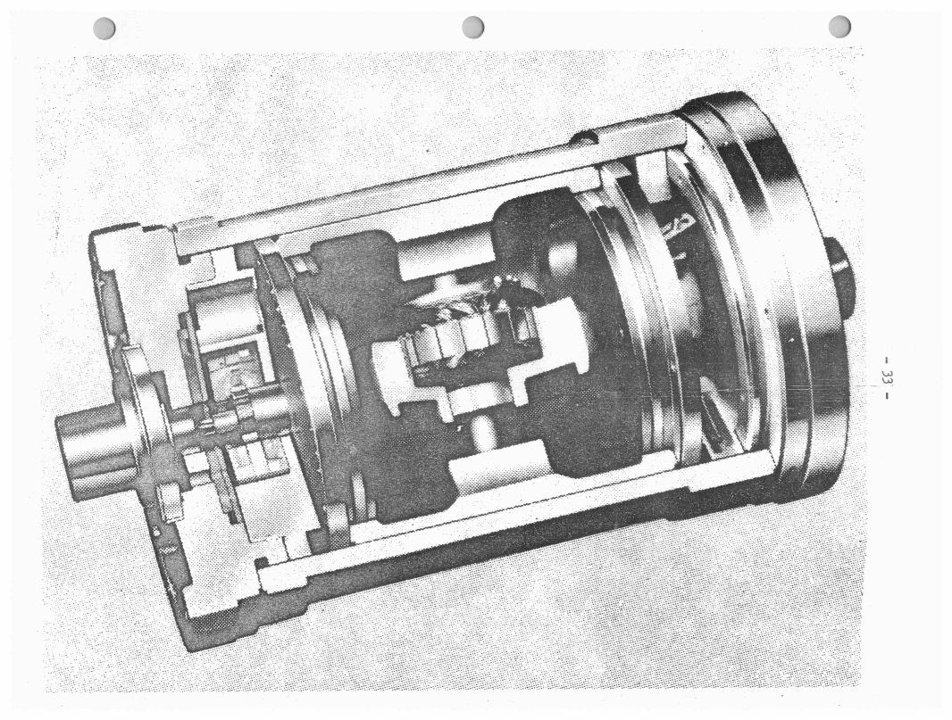
Sec'tional Views - 1.0 x 10⁷ Model II Gyro
Pendulosity Adjustment -1.0 x lo4 Model II-A Pendulous Integrating Gyro
Sectional View - 1.0 x 1c4 Model II-A Pendulous Integrating Gyro
Sectional View - 25 IRIG Wheel Assembly
Sectional View - 25 PIG Wheel Assembly
25 PIG and 25 IRIG Float Assembly
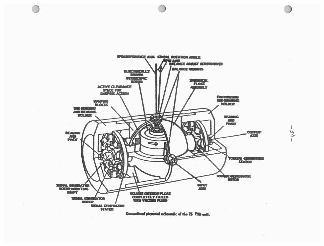
Cutaway View - 25 IRIG
2FID-2C Balancing
2FID-2C Half P"ower Point Current -Frequency Curve
Page No,
Figure
15
16
17
' 18
19
20
21
22
23
Number Illustrations
2F00-2C Testing Fluid Package
Simple Magnetic Circuit -Magnetic Suspension
Inductance - Air Gap Curve for Magnetic Circuit
Simple Capacitive Magnetic Circuit
Current - Air Gap Curve
Energy - Air Gap Diagram
Double Magnetic Ctrcuit
Force Diagram for Magnetic Suspension
Mark VII Miorosyn
Page No.

- 1 -
I. GYROSCOPIC THEORY:
A. Definition:
A gyroscope may be defined as a rotating ma.as, in the form ot
a wheel, which is free to rotate about an axis mounted in a
gimba.l. A gimba.l, in turn, is a mechanical frame containing
two mutually perpendicular axes, one of which is the axis the
gyro wheel rotates about. The other axis is .used to permit
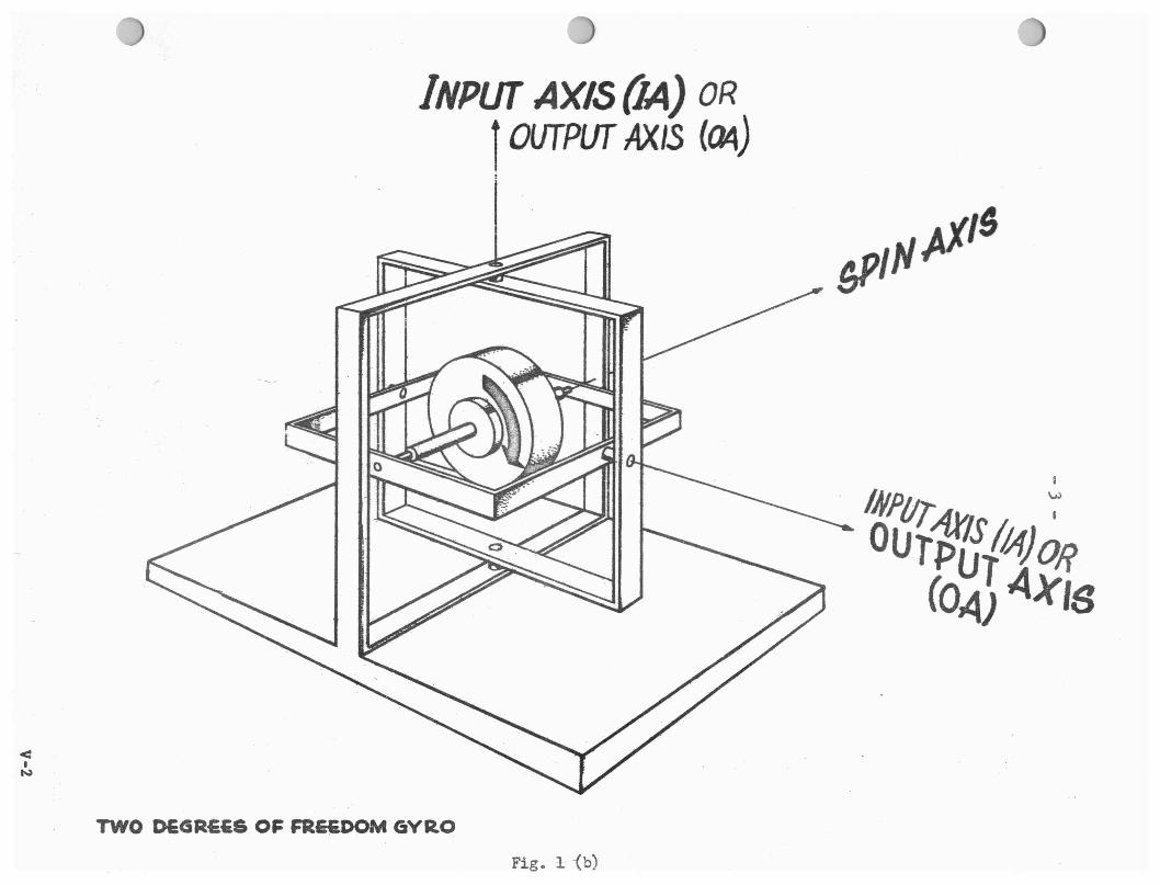
the gimbal to rotate, (Figure 1-a). A gyro is classified by
the number of degrees of freedom it has. A gyro mounted in
one gimbal is said to have one degree of freedom. (This is
true only if the gyro wheel is not rotating about an axis
parallel with the gimbal axis.) A gyro mounted in two gimbals
is then said to have two degrees of freedom. Two degrees of
freedom is a limit even if a gyro were mounted in three gimbals.
This is true since in this case the gyro would necessarily have
to rotate about an axis which is parallel to one of the gimbal
axis. Figures 1-a and 1-b show a single degree of freedom and
a two degree of freedom gyro. Since all of the gyros presently
manufactured by AC Spark Plug are single degree of freedom gyros,
discussion will be limited to gyros of this type.
Gyroscopic action may be defined as the ability of the gyro ele
ment, generally known as the gyro wheel, to transmit an outside
torque which is applied to an axis normal to both the spin axis
(SA), of the gyro element and the plane in which the gimbal lies,
to another axis which is also normal to the spin axi$ (SA) but

SDGLE DEGBEB· OP' FBDD(I( GYRO Fig. 1 (a)
< I
N
INPUT AXIS {IA) OR l OUTPUT AXIS (C14)
TWO DEGRE£& O~ FRE£DOM. GYRO
Fig. 1 (b)

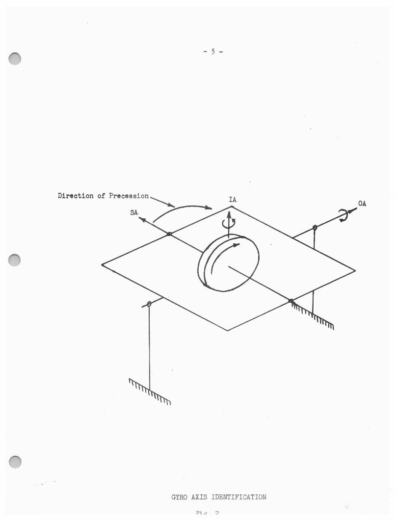
which lies in the same plane as the gimbal. The ax.is about which
the outside torque is applied is known as the input axis (IA), and
the ax.is to which the torque is transmitted is known as the output
axis (OA), Figure 2.
These two axes ~re 90° apart and each is 90° from the SA. The
reason for the torque transmission lies within the ability of
the gyro element to precess since it has one degree of freedom
through the gimbal. The term precess refers to the property of
the gyro to rotate about an axis, the OA, other than the one it is
being forced to rotate around, the IA. Precession can also be ex
plained by use of Newton's first law of motion concerning inertia
of moving or stationary bodies.
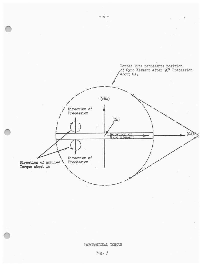
Considering a single point on the circumference of the gyro ele
ment, at any instant in time it will have a tangential velocity
vector pointing to a point in space which it will attempt to follow
due to centrifugal foroe, Figure 3, Observing the gyro element
trom a point in space above it, IA appearing as a point, it is noted
that applying a torque about the input axis in either direction will
cause the gyro element to precess in such a manner as to cause the
velocity vector to attempt to always point toward the same point in
Bpa.oe, assuming the same instant in time is considered,
A muoh simpler method of determining direction of precuaion is the
right hand rule, First considering the direction of gyro element
rotation, when the fingers of the t i ght l:1!!lg are curved in the dir
oction of rotation, the thumb will point toward the plus end of the S,A
- 5 -
OA
GYRO AXIS IDENTIFICATION
- 6 -
Dotted line represents po.sition .1
of Gyro Element after 90° Precession about OA.
. \ Direction of Direction of Applied\ Precession Torque about IA \
' ., ' ,.._ ..,...., ....__ --- --- ----
PRECESSIONAL TORQUE
Fig. 3

- 7 -
· '·S!Yld.larly-, . when the fingers of the right hand are curved in the dir
ection of applied torque about IA, the thumb will point toward the plus
end of the IA.
When a torque is applied about the IA, the plus end of the SA will
attempt to move toward the plus· end of the IA, It must be noted
here that when using this rule to determine direction of precession,
it is necessary to remember that the direction is always f!:.Q.m the
plus end of the SA !2 the plus end of the IA. The torque which results
about the OA due to precession is known as gyroscopic torque. It is
necessary at this point to acquaint the reader with a fourth a.xis which
ie an intergral part of the gyro. This axis is called the spin ref
Arence axis (SRA), The SRA is a reference from which the degree of
precession is established. The SA and the SRA are coincidental when
the gyro is nulled or has experienced no precession. The SRA is, as
has been stated previously, a reference and thus it always ·remains 90°
from the IA when precession occurs.
The entire phenomena of gyroscopic action is caused by a force known
as Coriolis Force, A coriolis force is developed whenever an object is
rotating about two axes sinrultaneously. As an example, let us assume
there is a body located at a point A on the surface of the earth as
shown in Figure 4.' In a 24 hour period this body must move a distance
equal to the circumference of the earth at the particular latitude of
point A around an axis through _the poles. It therefore must have a
component of velocity directed ton~rd the East with respect to an
observer in space.

Polar Axis ~
-DRAWING OF EARnt SHOWING CORIOLIS FORCES
Fig, 4
- 9 -
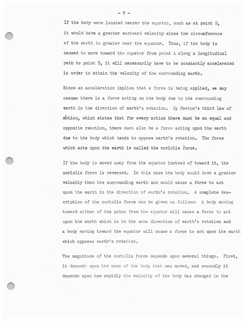
If the body were located nearer the equat,or, such as at point B,
it would have a greater eastward velocity since the circumference
of the earth is greater near the equator. Thus, if the body is
caused to move toward thH Eiquator from point A along a longituoinal
path to point B, it will necessarily have to be constantly a·ccelerated
in order to attain the velocity of the surroundins earth.
Since an acceleration implies that a force is being applied, we ma.y
nssume there is a force acting on the body due to the surrounding
earth in the direction of earth's rotation. Dy Mewton 1s third law of
' motion, which states that for every action there must be an -equal and
opposite reaction, there must also be a force acting upon the earth
due to the body which tends· to oppose earth's rotation. The force I
which acts upon the earth is called the coriolis force.
If the body is moved away from the equator instead of toward it, the
coriolis force is rever,sed. In this case the body would have a greater
velocity than the surrounding earth and would cause a force to act
upon the earth in the direction of earth's rotation. A complete des
cription of the coriolis force can be given as follows: A body moving
toward either of the poles from the equator will cause a force to act
upon the earth which is in the same direction of earth's rotation and
a body moving toward the equator w-111 cause a force to act upon the earth
which opposes earth's rotation.
The rragnitude of the coriolis force depends upon several thingsa First,
it depends upon the mass of the body that was moved, and secondly it
depends upon how rapidly the velocity of the body has chaneed in the
- 10 -
•1nirection of earth's rotation, This change in velocity, in turn, is
dependent upon two things. First, it depends upon the velocity of
any point on the earth's surface which can be determined by knowing
the angular velocity (w) of the earth, and secondly it depends upon
the change in the distance of the body from the polar ¢s, Thus,
the coriolis force may be represented by the formulas
F: Km wAr
Wherer K = constant
m = mass of the body
w ■ angular velocity of the earth
.tr = change in radiuo to the polar axis •
Since K, m and ware all constants, the magnitude of the coriolis
force depends only upon the change in r (4rl. An analogy can be
made between the body moving on the earth's surface and the spinning
gyro element. The formula above would hold true for a gyro wheres
K = constant
m: ma.ss of a particle on the circumference of the spinning wheel
w = angular velocity of a torque applied about the gyro IA
Ar= change in radius of the particle on the circum-ference of the spinning wheel to the IA
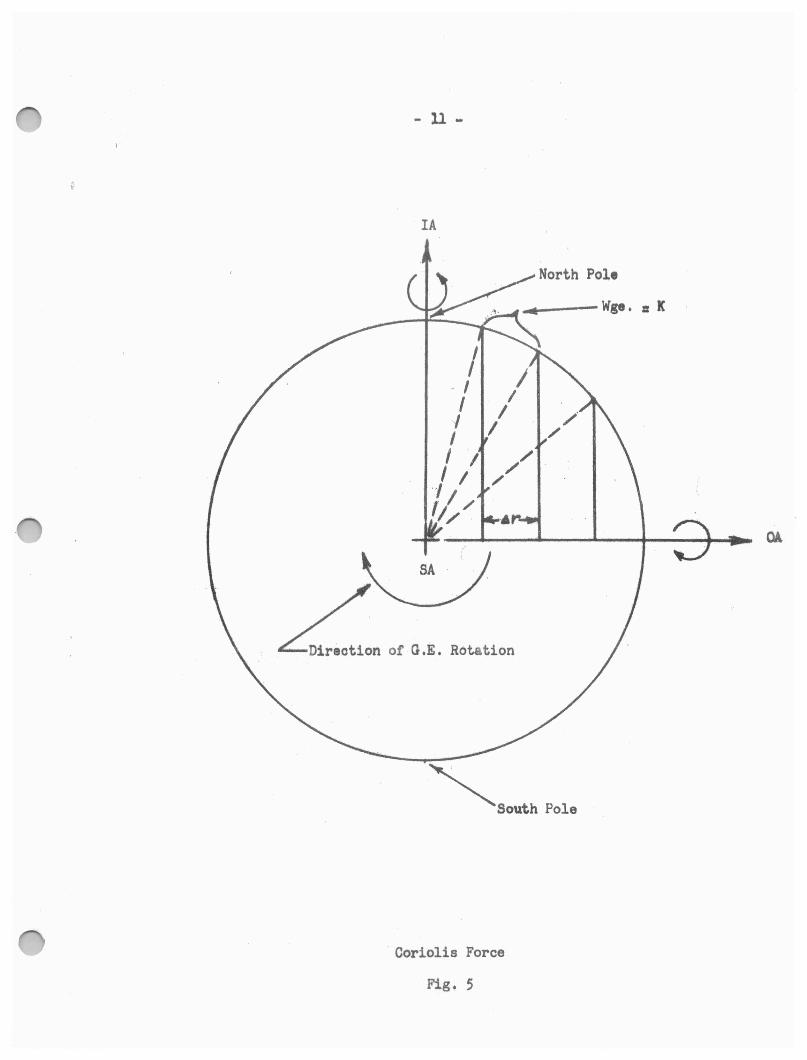
Recognizing the fact that all particles on the gyro element behave
in the same manner, all particles of the gyro element are moving
at a constant angular velocity about the SA just as the body on
the earth's surface moved from the North Pole toward the equator.
If an external torque is applied about the IA, the gyro element will
attempt to rotate about the IA just as the earth rotates about its
- ll -
IA
I .. I I I I I I I I
. -, t I / I/ . ..
r
SA
Ln of O,E, Rotation
~South Pole
Coriolis Force
Fig. 5
- 12 - I
polar axis. The two rotations s_imultaneously will produce a coriolis
force to act upon the gyro element causing it to precess and produce a
torque about OA. The torque produced about .OA can be expressed by the
formula:
Wheres
ToA = WrA X HsA
ToA: gyroscopic torque or torque about OA
WIA: angular velocity of the torque applied about IA
HsA: angular momontum about SA of the gyro wheel
It should be noted that any variation of HsA will critically effect
the torque produced about OA. For the output torque about OA to vary
proportionally with the angular velocity of the torque applied about
IA in euch a way as to be utilized effectively, the angular momentum of
the wheel about SA (HsA), must remain constant, This ie accomplished
in most gyros by use of a synchronous motor to drive the gyro element at
a constant velocity, Since synchronous motors are dapen, ent upon fre
quency of the input voltage to the motor, a frequency regulator is
used to critically control the voltage frequency and thus control motor
speed at a constant value. The synchronous motor is a physical and in
ttgral part of the gyro wheel, thus control of motor speed automatically
controls gyro wheel speed.
It must also be mentioned here that if the body on the earth's surface
is moved at a constant angular velocity from point A to point B, the
radi~ to the polar axis changes most rapidly at the pole. Thus, the
coriolis force is a neximum at the pole and decreases to zero at the
equator. The same holds true for the gyro element. As the SA of the
- 13 -
gyro element precesses toward the IA, the coriolis force diminished
constantly since the particles of the gyro element tend to move about
the IA rather than away from it. As 90° of precession is approached,
the ooriolis force goes to zero.
Single degree of freedom gyros can be divided into three types, each
of which responds to a gyroscopic action about the OA in a different
manner. The response of a gyro will depend upon what type·restraint
is applied to the gimbal. If the resistance to motion of the gimbal
is due only to the inertia of the g:tmbal and gyro element and to the
bearing fricition of the gimbal, the gyro is known as an integrating
gyro, This type gyro has previously been illustrated in Figure 2.
The integrating gyro is seldom used and its name has become confused witt
that of the rate-integrating gyro. Tho term "integrating" is often used
when discussing what is actually a rate-integrating type,
A rate-integrating gyro is one which has a viscous restraint applied
to it in addition to its inertial and frictional retraints. A viscous
restraint produces a torque which is proportional to the angular velocitJ
of the gyro gimbal about the OA and directed so as to oppose the motion
of the gimbal. Thus, the gyro gimbal will be accelerated until an ang
ular velocity is reached at which the viscous torque is equal and opposit
to the gyroscopic torque. Since the angular velocity of the gimbal is
proportional to the gyroscopic torque, the change in position of the
gimbal during any time interval will be proportional to the integral
of the input angular velocity. Hence, the gyro is called a rate-in
tegrating gyro.

- 14 -
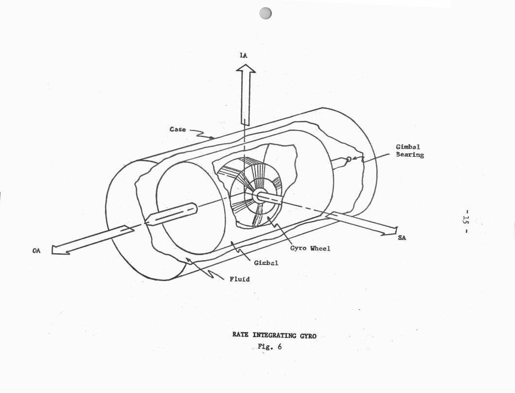
A viscous restraint will be provided if a gyro gimbal is placed in
a fluid as shown in Figure 6. In the figure, the gyro gimbal completely· \
encloses the gyro element so that the fluid will have no ~orqu:tng effect
about the gyro element SA. As the gimbal begins to move, the layers of
fluid near the gimbal tend to move while the layers i'urther away from
the gimbal tend to remain stationary. This movement between layers of
the fluid produces a stress in the fluid which oppos~s gimbal motion.
Since a linear relationship between the angular velocity of the gimbal
and the viscous streeo of the fluid i .e sometimes desirabla, a special
fluid which has this linearity is often used.
The property of a rluid to set up etrensos and to produoe viscous
torquing is oe.lled dnmping. Following ia a formuln for finding
n"\gular veloolty at whtoh a gyro rotates about the OA when damping
i1 involved,
Wheres ToA: torque about the OA
Co : coefficient of damping
WoA: angulai- velocity about the OA
A gyro which is not only restrained by inertial., frictioual and
viscous restraints,. but is al so elastically re~t.ra .i. ned by use of
such thiugs as springs or torsion bars is called a rate gyro. An
elastic restraint is one which produces a restraining torque proportional
to the distance the gimbal has moved from its null, or c&ntered position.
Whenever a rotating gyro gimbal reachijs a point where the elastic res-
OA
Fluid
RATE Drl'EGRATING GYRO
Fig. 6
Gimbal 3eari?ig
SA
I I-' V\

- 16 -
traint is equal to the gyroscopic torque, the gimbal will stop rotating
and provide an angular posi tion indication which is proportional to the
input angular velocity. A .rate gyro could be constructElJd from the rate
integrating gyro shown in Figure 6 by attaching a spring to the gimbal
to produce the desired elast ic restraint.
Of the three types of gyros discussed thus far , AC Spark Plug presently
manufactures both the rate-integrating and the rate gyro • . These gyros
are used for two different applications, these being stabilization and
accelerometer gyros. Each of thes will be ex.a.mi.ned. and ex·p~a.ined in
more detail later.
In additi on t o the torques · thus far menti.oned that effect gyro oper&.tiofl,
another torque referred to as Friction Torque markedly effucts gyro opw
eration. Since in most applications frictional torques greatly degrade
gyro operation, great .. pa.ins aro t&.ken to reduce them as much as possible .
One type of fricition, known as Coulomb Friction, is caused by and is
directly proportional to the pressure between gimba.l pivots and t he giln
bal pivot bearings. Since much of thi.s friction is ca usod by the weight
of the gi mbal and the r;yro el ement, l t can be :rc ciuced +o nearlJr zero by
using a viscous dampi ng flui d whi ch has the same average density as the
gimbal assembly . I n thi s m-1nner t he same viscous sub~~ta.nce utilized for
restraining purposes as previously mentioned may be used for flotation
purposes to buoy up t he gyro gimbr:i l, (or float as .it is called when it
completely surrounds t he gyro element1 thus reducing bearing fricition
to a very small amount. Gyros using a viscous damping substance for
flotation purposes are r eferrf,d to as float ed gyros . All of the eyros
- 17 -
presently manufactured by AC Spark Plug are floated gyros.
Another method presently employed on some gyros to aid flotation
in decreasing fricition between pivots and pivot bearings is magnetic
suspension. Magneti.c suspension is an electrical ai.d utilizing an
eight pole ndcrosyn which is wired such that it builds up ·a magnetic
field about the pivot end, t.hus holding the pi.vet in the bearing center.
Microsyn operation will be di scussed in greater detai.l later.
Gyroscopes are often misunderst.ood due- to the incorrect impressl on
that a gyro tends to remain : igid in space-. Act,ua.J.ly, if a cyro
is intended to remain . rigid in spa.ca it mu·st be gimballed about.
three axes to allow unreetricted movement such t.ha.t no outside
torques are able to act upon the gyro element, A gyro r~y .be
moved a.bout any axis just, a.s eaf'Jily B.c a. stationary block with
the snme inertia if the input · torque is applied a°Qout t.he Pl'Oper·
axis. The property of a gyro which differs from that of a statior~ry
mass is that a gyro will rotate about an axis other than the one
a.bout which the outsi.de torque is being applied.
B. Stabilization Gyros:
Since man first began to increase his rr.ovements about the face
of the earth to the present age of space exploration, a need
for orientation with ris surroundings has existed. There is
c. vaila.ble today an extremely sen.dti ve and accurate means with
which to navigate on water, undeI' tr,.-: Wd.t-cr or in space. Nav
ization of 6Xtr eme acc-uracy has been made possible through the
- 18 -
use of gyros in a system known as inertial guidance. One of
the important functions of an inertial guidance system is to
accurately control a stabilized platform, which ma.y be r~ferred
to as a controlled member, to insure adherance to a fine line
of reference from which the desired navigation might be per
formed. The duty of maintaining a controlled member in the
desired orientation falls to the unit known as the stabilization ·
gyro.
The stabilization gyros ma.nufactured by AC Spark Plug are single
degree of freedom, rate-integrating, .rloatad gyros. A simple
illustration of the type of gyro Just montioned is given in
Figure 6. Beginning with the innermost pa.rte, a simple gyro
configuration will be given along with the functions of each
component part.
~h• primary action or a Byro is that of the gyro element. It is
spun about the SA at a given constant spoed. The end points of
the SA are physically attached to the float such that any pre
cession of the gyro element automatically causes an angular
movement of the float. The float ends are pivoted within the
gyro case in jewel bearings and the area between float and
case entirely filled with a viscous damping fluid. The gyro
is so constructed that the pivot axis of the float is coin
cicental with and assumes the function of the gyro OA. The
gyro case is attached to the controlled member in such a
manner that any movement or angular acceleration of the con
trolled member produces an input torque about the gyro IA.

- 19 -
Since an anguler ,acceleration about IA produces a proportional
gyroscopic torqHe about OA, the attitude of the controlled
member can be •mabl.tained by utilizing the gyroscopic torque in
the form of an•el~trioal signal . Thia is accomplished by use
of a torque generator ((T.G.) and a signal generator (S.G.).
The T.O. is physically attached to one end or the gyro case
concentric to the OA and the S,G, is physically atts,'ched to. the
other end of the gyro case concentric to the gyro OA. The
function of the T.G. is to transform an electrical signal to a
mechanical 100vement and conversely the function of the s.o. is
to transform a mechanical movement into an electrical signal.
Both the T.G, and the S,G, consist of two part 3, a stator winding
and a metal rotor which moves angularly wi thin the stator. The
rotor is phyaically attached to the pivot end of the float, hence
nny movement of the float cauoeo n movement o.f thei rot.or• within
the stator, A moro detailod discussion of both the T.G. and the
S,G, will be gone into later.
Both the T.G. and the S.G. are aligned on the OA such that they
reach a condition of no output, or null, simultaneousl y. The
float is equipped with mechanical stops which limit float rotation
to a very small arc and prevent the T.G. and S,G. from roaching
electrical saturation. An excessive amount of float freedom,or
gyro element precession, is not necessary since the response time
for error correction is such that the float will normally never rotate
to a position where the meehanical stops are engaged before the error
is driven out.

- 20 -
Since the gyro case is physically attached to the controlled
member and since the error or controlled movement takes place
between the gyro case and the float, any movement of the con
trolled member about the gyro IA will be felt by the gyro ele~
ment causing it to precess. As it precesses, the fl.oat and
the s.o. with it, rotate causing an electrical output from th•
s.o. Thia output is used to operate a servo motor which in turn
drives out the controlled member error angle. As the controlled
member is driven back toward a null, it produces a reverse ·torque
about the IA from the original movement. This causes the gyro
element to precess in the opposite direction, thus returning-the
s.o. toward a null position. When a condition or no s.o. output
occurs, the SfrYO motor· stops driving the controlled member and a
static condition exists until another controlled member movement
takes place.
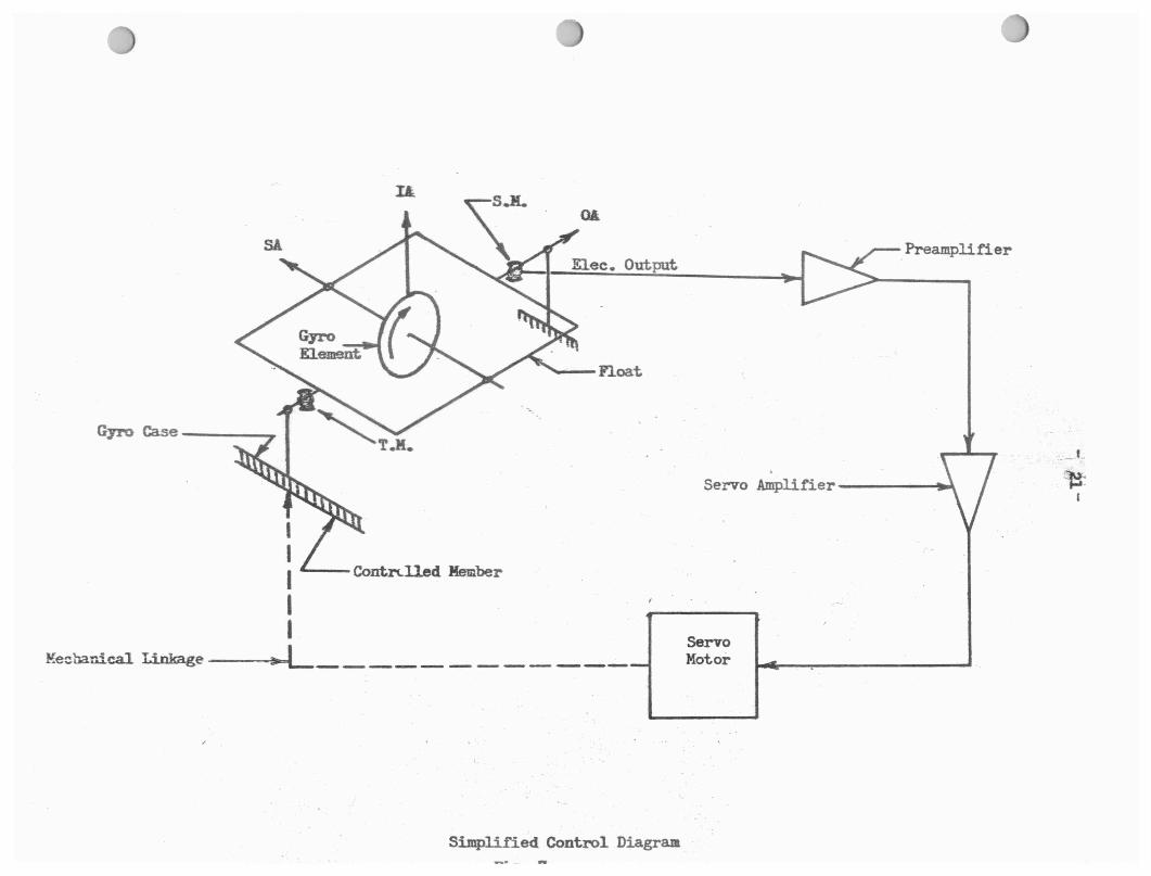
A simple control diagram using a stabilization gyro is shown
in Figure 7, Ir a .completely stabilized platform is desired
along three mutually perpendicular axes, it wuld be necessary
to incorporate three stabilization gyros whose input axes were
mutually perpendicular to facilitate sensing angular accelerations
about~three ,platform axes. It would also be necessary to employ
three gimbals, or controlled member, whose axes were also mutually
perpendicular to allow tree movement or the stabilized platform. I
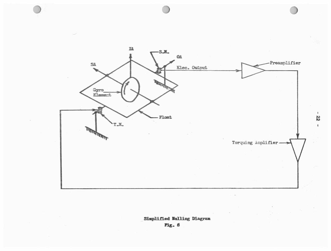
In addition to using the s.G. output in a servo loop to drive the
servo motor, the same output is employed to null the gyro as shown
in Figure 8. In this configuration the electrical signal from the
---Float
•
--Contl"(.lled Member
~e:banica1 l.:i.nkage---••-iL _____ - ------
Sj mp] i fied Control Diagram
Preamplifier
Servo Ampli.fier-----119"
Servo Motor
Simplified &n]Ji.ng Diagra:& 11'.ig. 8
Preamplifier
- 23 -
S,G, is amplified and returned to the T,G, which torques out any
error in s.G. poaition with respect to null, thus aligning the float
to ite center or null posil~ion. Again, a.s the error is felt hy the
S ,G., :1 t sends a signal to tha T .G, io c·lln t: c-, t t.hfa ~r1~cr &r.d tl.& t.l~e
.T,G, drives the float in an angular movement the S,G, returns to
zero output, thus stopping the T ,J, action and agai_n 1.i null cond1.tion
exists,
No attempt has been made here to explain all applications and oper
ations of a stabilization gyro, but merely to familiarize the reader
with th0 basJ.c functions from which he l!}:l,y expand, Actuall~, under
varying appli:'cations, many variations may be used which are pecullarJ-..
to a particular system requirement or nesign, n must be romomberod
that this basic gyro configuratlon is characteristic of all AC Spark
Plug manufactured gyros,
C, Accelerometer Gyrost
The operation of an accelerometer gyro is basically the same as that
of a stabilization gyro in that it is a rate-inteerating, single de
gree of freedom, floated gyro. The major design difference is in the
gyro wheel, Gyros are employed in a guidance system to perform two
functions, These functi.ons are to sense any devia t..ion of the stabi
lized platform from the desired orientation, which has beon discussed,
and to sense any acceleration of the platform while in or out of the
desired orientation, The latter duty falls to the accelerometer gyro,
The accelerometer gyros must sen3e acceleration along Any of the three
system axes or a combination of accelerations between atly"'of..;the- uu.
- 24 -
Along with the difference in gyro wheel design from that of the
stabilization gyro, the accelerometer gyro reacts differently than
the stabilization gyro in that it will sense an acceler~tion !,_long
its IA rather than react to an angular veloci.ty about its IA.
The second, or the reaction, is a direct result of the first, or gyro
wheel design. An accelerometer gyro has a specifie? amount of pre
cision unbalance displaced along the plus SA and any acceleration
along the IA will cause the gyro element to act as a pendulum, thus
producing precession and an output torque about OAt The precision
unbalance of the gyro along the plus SA represents the action of the
gyro lmown as pendulosity. The degree of pendulosity incorporated
into a gyro determines the degree of gyroscopic torque for a given
aoceleration. The gyroscopic torque produced causes an angular move
ment of both the tloa~ and s.o. The S.G. output is utilized to drive
a servo motor whioh is mechanically linked to the acoeleromater, driving
it about its IA. Thus, the aooelerometer gyro has become an ACCELERO•
METER. It must ·be remembered that the accelerometer gyro in itself
is not a ccmplete 1ccELEROMETER. The related feedback servo system
is necessary for the gyro to attain this end.
To acoomplieh this, it is necessary to mount the gyro in a housing
which is pirated on an axis ooinoident with the gyro IA. The direc
tion of the accelerometer rotation about IA produces a torque about
the gyro IA and a gyro element precession in opposition to pondulosit7,
thus attempting to maintain a gyro null. The entire process will pro
duce a constant angular velocity of the accelerome~er ·tor a .giv.etha~JL•·
- 25 -
ration along the IA. As the accelerometer experiences an increase
in acceleration along IA, the rotational angular velocity about IA
will increase proportionally. The gyro function of integration stems fl
its ability to distinguish a rate of change of velooit1, (aoceleration)J
along the gyro IA and transform it into a proportional angular velocity
about IA. This ability forms the basis for the term Pendulous Integ
rating Gyro.
II. GYRO PARTS AND ASSEMBLY,
Each of the gyros being ooneidered will be treated individually and
in turn. Major part names ari . lieted in tabular form and will be
identified while assembly sequence and procedure ie being dieoussed.
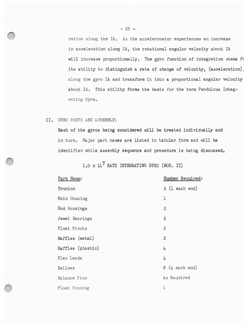
1,0 x 1c} RATE INTEXlRATING GYRO (MJD. II)
Part Namea Number Required&
Trunion 2 (l eaoh end)
Main Housing 1
End Houl'lings 2
Jewel Bearings 2
Float Pivots 2
Baffles (metal) 2
Baffles (plastic) 4
Flex Leads 4
Bellows 8 (4 each end)
Balance Pins As Required
Float Housing 1

Float End Plates
Gyro Wheel
Gyro Shaft (SA)
Wheel Bearings
Motor Stator
Hyeterisie Rings
Heating Element
Sensing Element
Microsyn Rotors
Microsyn Stators
Balance Forks
Venier Nuts
Stop Pine
Seal Ball
Sealing Ball Sorew
Balance Studs
- 26 -
2
1
1
2
1
J (2 End Housing, 1 -Main Housing)
1
2
2
2 (On front end ot Main Housing)
4 (On front of float)
2 (On front of float)
2 (1 each end Main Housing)
2
4
The following is an outline form of gyro assembly which closely follow.s
aotual manufacturing procedures:
I. Visual Inspection of all Partet
A. Deburr parts where necessary.
1. This is a par~icularly critical area in gyro production. Since
extremely close tolerances are maintained, any foreign material
within the iooving parts will seriously degrade gyro performance.
Particles of foreign material too small to be detected by the un
aided eye will cause adverse consequences. Thus, all cleaning,
deburring and the major pa.rt of assembly must be done under power-,
ful microscopes.
- 27 -
II. Wheel Package Assembly:
A. Mating Hysteresis Rings to Gyro Wheel:
1. The hysteresis rings are made of a material whioh possesses the
magneti.c qualities necessary to cause the gyro wheel, tG which
they are physically attached, to respond as the rotor of a motor.
An interference fit exists between the rings and the shoulder in
side the wheel race.
B. Bearing Selections
1. The appropriate size bearings are selected to fit the gyro wheel.
At the same time the properly sized bearing spacers are selected
to insure proper preload conditions,
C. Motor Sta tort
1, The motor stator consists or wire wound core which fits inside
the gyro wheel and physically attached to the gyro shaft.
n. Gyro Shaft (SA)
1. The gyro wheel, bearings, bearing spacers and the motor stator
are mounted on the gyro shaft to comprise the wheel package.
Appropriate preloading is employed to insure proper bearing and
spacer fit,
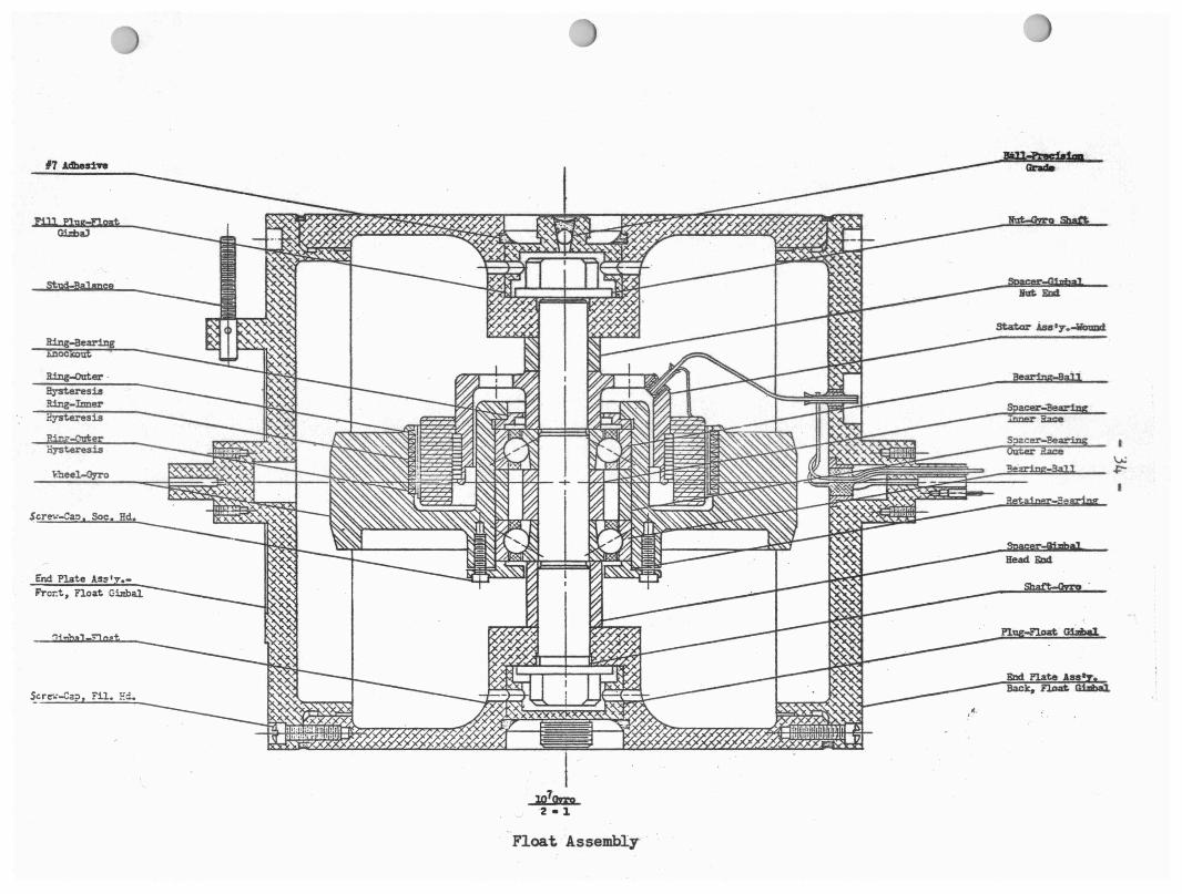
III, Float Assembly:
A, One end of the gyro shaft is threaded and the other has a hexagonal
head much like a simple bolt, The threaded end is inserted thru the
minus SA side of the float and the wheel package is installed on the
gyro shart. The threaded end of the gyro shaft extends thru the float
mount and a nut is threaded on and tightened to ensure proper fit ot
bearing spacers. This also accomplishes bearing preloading.

1, 0 x 1.07 Rate Integr,: ... ting Gyro ·;Jheel
- 29 -
D. The next operation performed is to install the float end plates.
These are nachined to give an interference fit and are drawn down
with cap screws. Once the end plates are properly and firmly pos
itioned, all float joints are sealed with cement. The float is then
evacuated of all air by pressurizing with Helium and leak checking
ie dona employing a Mass Spectrometer which is sensitive to Helium
gae. After leak checking is completed, a quantity of Helium ie left
inside the float equal to a pressure eJ.ightly over atmospheric. The
purpose of the Helium being left inside th.e float is to insure a min
imum of oxidation and to reduce wind friction effects on the gyro wheel.
IV. Mioroayn Rotor Mounting:
A, The torque and signal mioorsyn rotoro are fitted over the stud shafts
on both ends or the float. They are aligned to ineure coincidence of
their a~etrical axos and firmly tightened down with the two holding
eorewo provided for eaoh rotor,
v. Float Pivot Mountings
A. Each of the flo~t end plates hae a protruding stub shaft 'Nhioh has a
drilled hola t.o receiva the pivot body with an interference fit. These
drilled holes are on the float longitttdinal axl.o and so situated to
allow the fnstalled pivot to assume the gyro OA, The pivots are pressed
into place and checked for concentrici ty about the float longi tudina]
axis.
VI. Float Bala.ncings
A. Rotational Dalanoings
1, A balancing tank fixture is employed for rotational balancing using
two fluids of different density. One fluid density is such that it
- 30 -
will allow the float to sink and the other fluid tends to buoy
the float up. A set of roller bearings fixed side by slde cm both
ends of the tank are employed to either suspend the float by the
pivots int.he lighter fluid or to depress the float in the heavier
fl.ui.d. (See Figure 9). In both cases the float is completely
immersed in the fluid. The float is first balanced in the less
dense fluid and then in the more dense fluid to insure proper
balance. If the float is ·out of balance rotationally, it w-111
tend to rotate about its longitudinal axis in the flu:i.<l~ Coarse
balancing is a.ccompl:Lahf~d by adding balance pins into drilled holes
in the ends of the float in the end plates. The holes are drilled
in the end plates near the ci.rcum:ferential edge. Fine ba.lancinc is
accomplished by adjustment of the vern:i.er nuts.
B. Longitudinal .Ela.lancing:
1. Again a tank fixture is used but .no bearing supports are used.
In this case the supports are in the form of wires leading from
one end of a balance scale to the pivots of the float, (Figure 10)
The fluid used is an approximate one--half. to one-half solution of
the t.wo fluids used for rote.tiorml balancing. Tho object is to
:r•(-:ach a fluid dens.i t.y which ju:;;t. beeirn; . to buoy the float :30 ur,
t<.1 put the least mment possible on the balance arm a-nd yet not
entirely remove the float weight. The longitudinal unbalance will
be evidenced by a dif.ferenGe in scale readings. Au bc~forE' , coarse
balti.n.cing is accomplished by use of balance pins, belne careful
to split the total unbalance between the two pins and placing these
180° from each other around the end plate circumfErence so as not
Wl
- 31-Ratational Balancing Fixture
Tanlc
Roller Bearing
Float
r· Balance . I, •
.._----------------•Pin Fluid Area
Fig. 9
Note: Float pivots rest on top ot roller bearings when suspended in lighter Fluid and underneath bearings when buoyed in heavier Fluid. For purpose or simplioity,only one balance pin is shown, In practice,several pins are installed on both ends or Float,
l,ongitudinal Balancing Fixture
Float
Fig. 10
Notes To obtain a porfeot oalanoe1Wl must equal W2.
W2

L Jewel Bearing Assembly
1.0 x 10⁷ Model II Rate Intergating Gyro.
::)}lil!!!l1f!:< ... .. ·:· .
-- . ·.:·::·.•
:.:;.·:; ..
I
~ I
17 .&dberiff
~Ellll
~ere-..--Cao Soc. Hd
End Plate Ass•y •• fi'ror.t, noat Gimbal
..,
End Plate Ass Back. ~ GiJlbal.
Float Assembly- ·
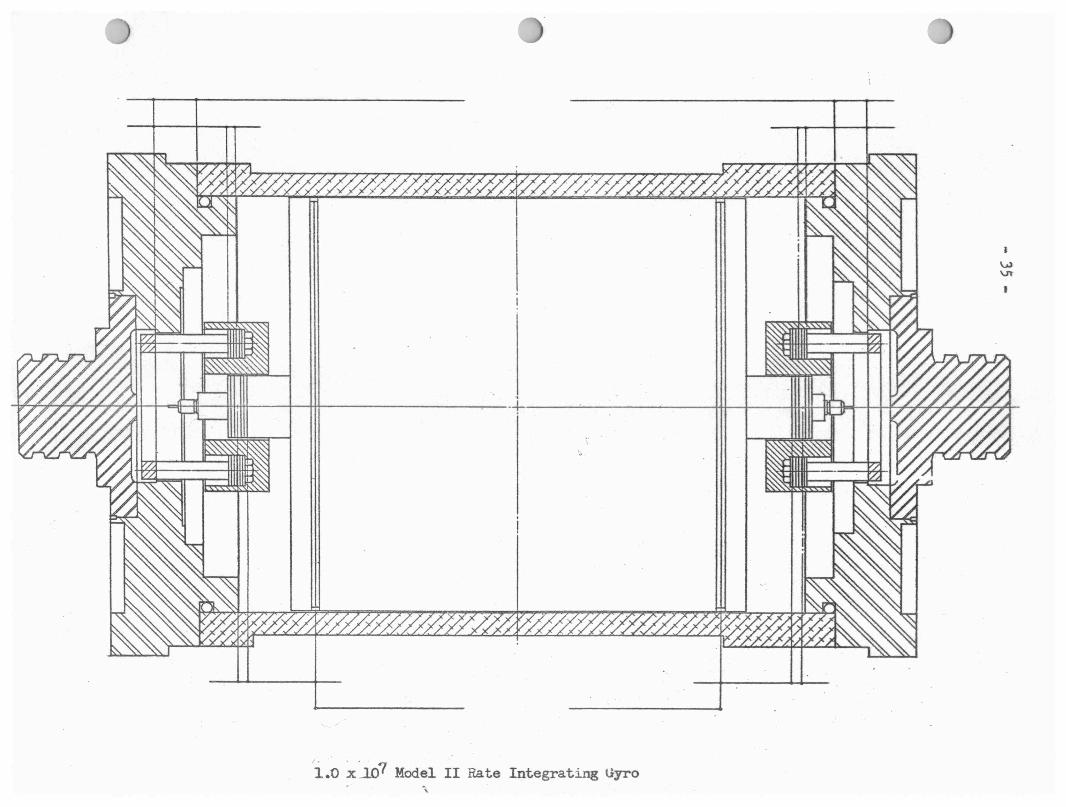
i.o xir? Model II Rate Integrating Uyro
- 36 -
to destroy rotational balance of the float. Fine balancing is
again accomplished by vernier nut adjustment. Here also the total
unbalance must be split between two opposite verniers.
VII. End Housing Assemblyt
A. The end housing assembly consists of two plastic baffles, power leads,
four (4) expansion-contraction bellows, one metal baffle and a microsyn
stator for each end housing~
1. or the two plastic baffles, one is slotted to receive the wheel
power leads, although not. ma.king physical contact with them, and
, , 1, the other acts as a cover for the flex leads. The baffles just
described are part of the back end housing and also hold the T,G,
terminals in plaoe.
2, The front end housing plastic baffles serve a similar purpose in
that the S,G, terminals are anchored in them, In both oases the
plastic baffles are placed into the end housings first,
J, Wheel power leads are fitted into plaoe and soldered,
Four (4) bellows are emplaoed in e aoh end housing to ibsorb expani.
sion and contraction of the damping fluid should there be a tran-
sient in gyro temperature.
5 • . A metal baffle is positioned over that part of the assembly dis
cussed thus far and fastened down securely with screws. This
baffle protects the plastic part and holds the bellows in place.
6. The microsyn s~ators ar-e then mounted and secured in place with
four mounting studs.
VIII. Jewel Bearing Assembly:
A. Jewel Bearing Holder:
- 37 -
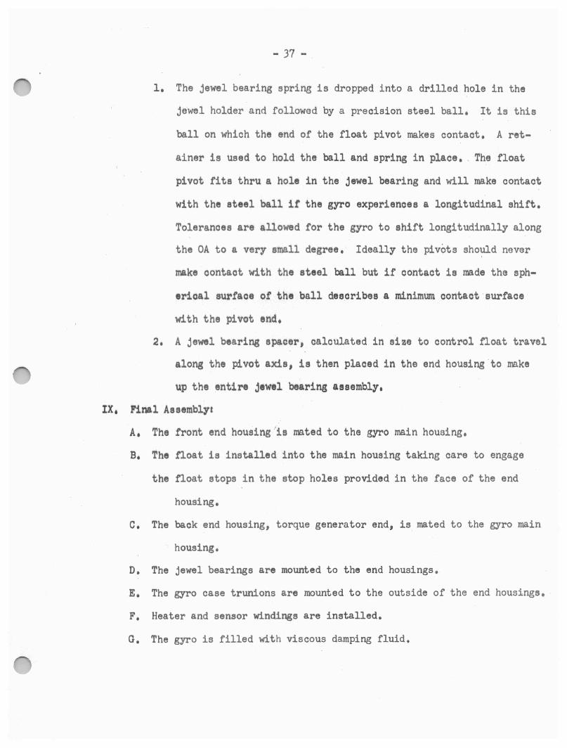
1. The jewel bearing spring is dropped into a drilled hole in the
jewel holder and followed by a precision steel ball. It is this
ball on which the end of the float pivot makes contact. A ret
ainer is used to hold the ball and spring in place • . The float
pivot fits thru a hole in the jewel bearing and will make contact
with the steel ball if the gyro experiences a longitudinal shift.
Tolerances are allowed for the gyro to shift longitudinally along
the OA to a very small degree. Ideally the pivots should never
make oontact with the steel ball but if contact is made the sph
erical surface of the ball describes a minimum contact surface
with the pivot end.
2. A jewel bearing spacer• calculated in size to control .t'loat travel
along the pivot axis, is then placed in the end housing .to make
up the entire jewel bearing assembly,
IX, Final Assembly&
A, The front end housing .. is nnted to the gyro main houaing.
B. The float is installed into the main housing taking care to engage
the float stops in the stop holes provided in the face of the end
housing.
c. The back end housing, torque generator end, is mated to the gyro main
housing.
D. The jewel bearings are mounted to the end housings.
E. The gyro case trunions are mounted to the outside of the end housings.
F. Heater and sensor windings are installed.
G. The gyro is filled with viscous damping fluid.

X. Mio ro syn Centering 1 ·
A, Microeyna are centered to insure proper positioning of the miorosyn
,rotor within the stator bo~h translationall7 and rotationally- and
also to insure both mioro1yn1 are at a null simultaneously, Since
the miorosyn rotors have already been aligned, further alignment muat
concern itself with adjustment or th• mioroayn stator mounting studs,
1,0 x 10⁴ PENDULOUS INTF.DRATINO GYRO
P.ar~ Names Number Reguire41
Hystereeia Rings --Gyro Wheel l
W,heel Bearings 2
07ro Shaft (SA) l
Motor Stator l
Wheel Fork l
Float Shell l
Miorosyn Rotor, 2
Miorosyn Stators 2
Float Pivots 2
Float Balance Assembly- 1 (Consists of 4 vernier nuts on 4 balance studs)
Jewel Bearings 2
Main Housing 1
Signal End Housing 1
Sleeve 1
Flex Le~ds 3
Aluminum Baffle 1

End Cap
Can
Sensor Windings
Heater Windings
Stop Pin
- J9 -
1
1
1
1
1
The following ie an outline form of gyro assembly which closely followe
actual 11flnufacturing procedures:
I. Visual Inspection of all Parts:
A. The same inspection procedures are followed as for the 1.0 x 10⁷
Model II gyro,
II. Wheel Package A11emblyi
A. Hysteresis rings are mated to the gyro wheel,
1. An interference fit exists between the wheel and the rings.
B. Select and Install Wheel Bearingas
1, Properly sized bearings are selected and fitted -to the wheel, The
wheel and b~aringa are centrifuged at 400 g1 a to remove excess oil
and foreign material,
2. Bearings are .preloaded and run-up and run-down cheoke are made.
Run-up checks and run-down checks are indicative of preload con
ditions of the wheel bearings,
c. The wheel, bearings and motor stator are mounted to the gyro shaft,
The aaaembly thus tar comprises the wheel package. The wheel package
is then mounted in' the wheel fork.
III, Float Assemblya
A. Matching Whoel Package and Fork to the Float Shell
1, The wheel pa.okage and fork are fitted into the shell and the joint
,: 40 -
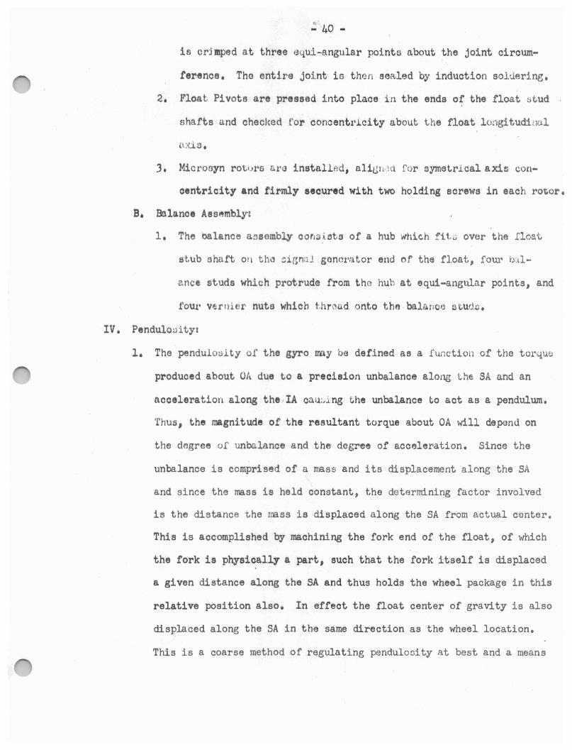
is crjmped at three e4.ui-angular points a.bout the joint ciroum
.ferenoe. The entire joint is then sealed by induction soltlerlng.
2. Float Pivots are pressed into place :in the ends of t,he float stud
shafts and checked t'or concentl'icity about the float lo:1gitudirn,1. l
J. Microoyn rot•Jl'S a r installfid, a.liiJ li•.~ <t for symetrlcal axi!l con
oentricity and firmly secured with two holding screws in each rotor.
B. &lance Assembly:
1. The balance aneembl,y cor1sist.s of a hub which fi.1~.:.i over the l'l c-a.t
st.ub shnft on th~ ::; ir,mll gonerator end of the fl.oat, four b:.11 ...
~nee studs which protrude from the hub at equi-angular points, and
!'OU.l' Vl!lrni er nuts which t hread. onto tho . bal,'l. n0/3 otuda .
IV. Pendulooity:
l. The pendulo~ity of the gyro my be de.fined as a function of the torquei
produced about OA due to a precision unbalance along the: SA and an
acoeleration along the • IA ca1.i.:,i ng the unbalance t.o aot as a pendulum.
'thus, the magni.tude of the resultant torque about OA will depend on
the degree of unbalance and the degree of acceleration. Since the
unbalance is comprised of a mass and its displacement along the SA
and since the mass is held constant, the determining factor involved
is the distance the mass is displaced along the SA from actual center .
This is accomplished by ma.chining the fork end of the float, of which
the fork is physically a part, such that the fork itself is displaced
a given distance along the SA and thus holds the wheel package in this
relative position also. In effect the float center of gravity is also
displaced along the SA in the same direction as the wheel location.
This is a coarse method of regulating pendulosity at best and a means
- 41 -
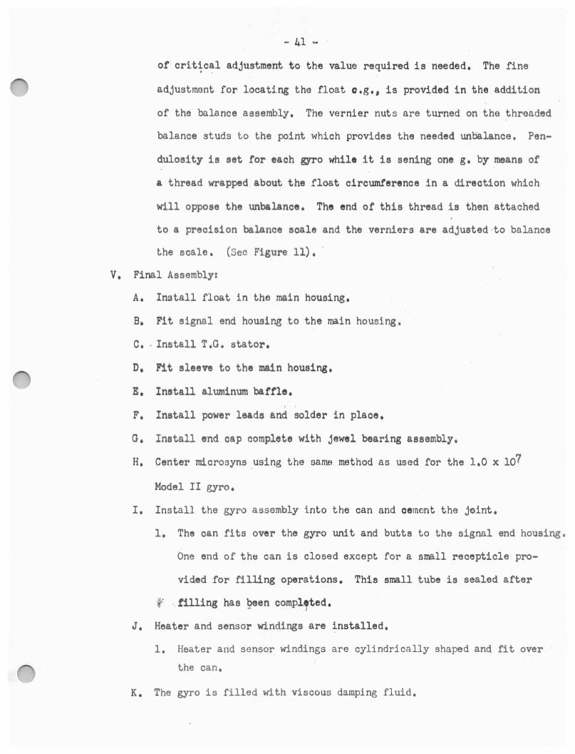
of critical adjustment to the value required is needed. The fine . . adjustment for locating the float o .g., is provided in the addition
of the balance assembly. The vernier nuts are turned on the threaded
balance studs to the point which provides the needed unoalance. Pen
dulosity is set for each gyro while it is saning one g. by means of
a thread wrapped about the float circumference in a direction which
will oppose the unbalance. The end of this thread is then attached
to a precision balance scale and the verniers are adjusted •to balance
the scale. (Sec Figure 11) • ·
V. Final Assembly:
A. Install float in the main housing.
B. Flt signal end housing to the ma.in housing.
c • . Install T.G. stator.
D, Fit sleeve to the main housing.
E. Install aluminum baffle.
F. Install power leads and solder in place.
o. Install end cap complete with jewel bearing assembly.
·H. Center microsyns .using the sama method as used for the 1.0 x 10⁷
Model II gyro.
I. Install the gyro assembly into the can and cement the joint.
1. The can fits over the gyro unit and butts to the signal end housing .
One end of the can is closed except for a small recepticle pro
vided for filling operations. This small tube is sealed after
if' .. tilling has 9een compl,ted.
J. Heater and sensor windings are installed.
1. Heater and sensor windings are cylindrically shaped and fit over ·
the can.
K. The gyro is filled with viscous damping fluid.

w
Note: W represents desired pendulosity.
Pendulosity Adjustment
h.g . 11
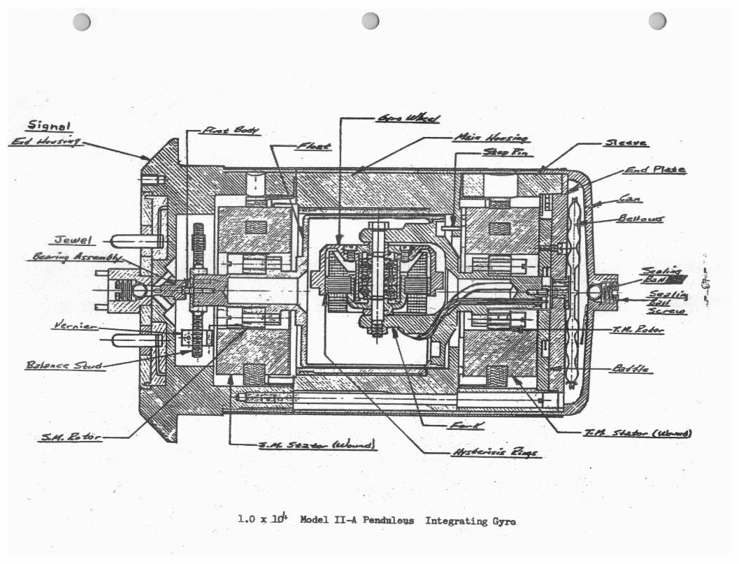
$igt,al &d' ~.,r.;,,,
•
1.0 ~ ..:u:fa. Model II-A Pendnl.e1)41 Integrating Gyro_
- 44 -
25 IRIG 1.l~ x 105 INERTIAL REFERENCE INTEGRATING GYRO and
25 PIG 0.6 x 10⁵ PENDULOUS INTIDRATING GYRO
Notes The 25 PIG and the 25 TRIG gyros are physically identical except
for their wheel assemblies, Therefore .s> all gyro parts and assembl,7
for both gyros are given i n one discussion except for the wheel
assemblies where a differentiation will be ma.de.
Pa.rt Name:
Gyro Sha.rt
Wheel Hub (IRIG)
Wheel Insert (IRIG)
Hysteresi s Rings
Inertia Rims (IRIG)
Wheel Bearings
Preload Nuts
Preload Bushings
Motor Stator
Number Reguir,ed1
1
1
1
. Floa.t Ilemlspheres
Float Gimbal
2
2
2
2
1
2
1
2
2
2
2
2
2
2
2
I
Microsyn Rotors
Microsyn Stators
Float Pivots
Damping Blocks
Printed Circuit Microsyn Leads
Printed Circuit Shields
Jewel Bearings
Bellows End Caps
End Housings,
Flex Leads
Baffles
Flex Lead Plates
Mai.n flous i n"(
Main Cover Shroud
End Cover Shrouds I
Sealing &lla
Sealing Ball Screws
Balance Screws
Balance Springs
Thermistor
Pendulous Ring (P IG)
Wheel Web (PIG)
Wheel Hub (PIG)
Pivot· Adjustment Screws
- ,.5 -
2
3
2
2
1.
1
2
2
2
El
4,
1
l
l
l
8
The following is an outline form of gyro assembly which closely follows actual
mnnufa.cturing procedure:'.!:
I. Visual Inspecti.on ,of all Par.ts:
A. The procedures are slmi lar t o provious1y me nt,ioned gyros.
II. Wheel Package Assembl~:
A. Bearing selection and preload members installed.
l, Bearings are selected for proper fit to wheel shaft and wheel hub,
Th~ bearings are pressed into place in the wheel hub and the gyro
shaft i& fitted :.-.hru the bearings. The preload nut is dropped ove-:r--
- 46 -
the shaft to fit intertace with the bearing■• The preload bushi114 !
is then turr:ied into the preload nut to insure aJDOOth · thre&~ . opera-· .
,t;ion. The wheel bearings are centrifuged at 21000 g1 s to remove
exce·ss oil and toreign material.
B. Insert Installations
1. The wheel insert ti ts over the wheel hub with inte~'terence be
tween the insert I.D, and the wheel hub O,D, The wheel insert 11 oylindrionlly shaped and ia ot the same dimensional width as the
wheel hub,
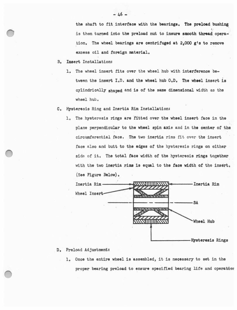
c. Hysteresis Ring and Inertia Rim Installations
1. The .hysterasis rings are ·titted over the wheel insert face in the
plane perpendicular to the wheel spin axis and in the center ot .the
oirounu'erential face, The two inertia rims fit over the inaert
face also and butt .to t~e •cl&•• ot the hysteresis rings on oither
aide of it, The total ta01 ·w1dth ot the hysteresis rings together
with the two inertia .rima ia equal to the tace width ot the ina~rt,
(See Figure Below),
Wheel Insert
---SA
Wheel Hub
---------•ffyatere•i• Rings
D, Preload Adjustment t
l. Once the entire wheel is ·aesembled, it is necessary to set in the
proper bearing preload to ensure specified bearing life and opera~
I .· - 47 - 1
\
This 1• aooompliahed by wrapping a thread several turns around . ~ . the hysteresis rings with a given weight attached to the opposite
l
end of the thread. The weight is a_llowed to tall, thus rotating
the wheel and preload is adjueted until the desired wheel aPM ia ,
obtained. Thie m1thod of setting pr1l0&d 11 only an approximation,
however, and turth•r adjustments are neoeaaary at a later stage ot ·
a11emb:t,,
III, Float Sphere Asaemblya
A, Motor Stator Installations
l, The motor tater is preosed into the heated tloat gimbal and ct•
rnnnt, d n plaoe. When the gimbal 00011 an intert,renoe tit rcsmain1
betwoen iteelt an~ the ·lflOtor stator,
B, Float Pivot Inat.&llationa
l, The float. pivots are threaded into the ends ot the ·r1oat stub
l'Jhatta on en,,h end _9r the tloat gimbal, Four pivot adjuotment
r.rews aro thread&d into plaoa tor each pivot and uniformly tightenec
while checking pivot ooncentrioity about the float gimbal longitu•
diro1l axis. ,
c. Plus SRA Float Hemisphere Assemblyc
l. Tho plus SRA hemisphere ie threaded onto the plus SRA end ot the
gyro shatt and cemented in place,
D, Minus SRA Float· Hemisphere Aaeembl7 and Wheel Package Installations
l, The wheel package assembly io installed into the float assemb~
' and the minus SRA hemisphere and bushing are assembled over the
minus end or tne gyro wheel shaft, Stainless steel balance weights • r • ',.
are assembled into the minus SRA and IA portsylntt: ·aluminum ·'balan•
- 48 -
weights are assembled into the minu1 SRA and IA port,. The SRA , •
poll't1 are loaated in the tloat hemi1pher1 along the SRA and the ' '
IA port■ are l~oated in th, float gimbal along the IA. The tl1&i
a11embly i1 then mounted on pivot r11t1 and two balana, a~m■ ot
equal length and weight are installed oppo1it• ,aoh other alone
the SRA in threaded hole ■ in the tloat 1imbal 1h&tt. A pan 11
plaoed on thr , ~dot eaah balo.noe nrm and weight• a:r, added to the
light.er :pan :i.r,,; .::.:, t he tloat 11ae111bly balance■ on the piv~t :re11t1~
From the reiquirod wttight, ne·aeuarr to balana, the tloat a11embl1,
the S'Jl"Oper nhim ■iH 111 d1t1rrninud and a ■him ot th• pre■·oribed
size and weight 11 inetallad under the pl~• SRA bushing and oementtd
in plaoe. Th• minu1 ,SRA ,hemiophero ie then mounted in poeition
and 01m1nted in plaa,.
E. Dt1r1ng Preload Adju~tmenc1
The tloat, 1a mounted in a tixture that will maintain an atmosphere ot
helium gao, The wheel torminal1 are oonneoted to a two pha11, 800
oyole power 1ouroe and the wheel 11 b:roucht up to 1ynohronou11 ape1d. •
Whilu maint,aining a float temporature ot lJ7° tah:renhei·t, the run-down
time ot the wheel from s~ohronouo speed is recorded, It the run-down , I
time does n~t co~reepond with 'the epeo1.f'ied value, the bearing pre•
load is adjusted by means ot the preload nut while the whe~l is ~ing and run-down times are again taken. This 1 procedure ie repeated as
necessary until proper bearing preload is obtained. The minus SRA
bushing, is then cemented and the tlont ie degassed and tilled with
helium.

- 49 -
F. Microsyn Rotor ·Installation and Alignments I
1. The miorosyn rotors are wrung onto the tapered gimbal atub ~hafts
·and aligned suoh that the flat surfaces are parallel to the pitoh
diameter of the IA oolance port threads and the s.o. ~n4 T~G.
rotors are in line aoroos the flats. The miorosyn rotors are
then secured in place with cement.
o. Longitudinal Ba.lancinga
1. After determining the weight necessary for the proper balance,
weights of the proper size nra threaded :i.nt,o the float gimbo.l stub ,
shafts in the tapped hole provided, The balance weight .. hole on
the S .o. end of the Bimbal stub shaft is drilled at rieht angles
to th~ st~ub shaft a.i;,.d also at right angloe to the balano~ weight (
hole on the T .n. end of the gimba.l stub shaft. In other · words,
one balance Wt)ight holo is parallel to 311.A and ~he other balance
weight hole is parallel to the IA. Longitudinal balancing is done .· i •,
in a fluid poaeeatJlng a tlensi ty very oind.lar to tho damping fluid
uaed to flll the unit.
H. Rotational Balanoing1
1. The float, is inDt.allBd in a flotation tank and tho sized balance
weights that wore in□ t.c.1lled durine longitudinnl balancing are ad
justed along their axis for the proper rotational balance. (See
Figure 12). The balance screws used for this operution are re
ferred to as the PRA (Preliminary Rotation~l Adjust) balance weights.
· By definition, the term PRA indicates that a coarse balance is
obtained thru adjustment of the PR.A balance weights and that
additionnl adjustments are necessar;r t.o reach an accurate state '

WHEEL· A·S -SEM BLY --- 2 5 PI G --_M O D 1 -
SHAFT -AND BEARING
ASSEMBL~7
96 THO/IN
92 THO/IN_
INERTIAL ELEMENT ASSEMBLY
I \.Jl 0
i

I
(PRA) Balance Weight
SIil
2S Pm or 25 IRIG Floa~ Assewb~ 5 llc-l1W Balance Veigbt.e Conftprat.iaa
Fig. 12
Ql I
~ I
- 52 .•
weights provided. The FRA balance wo 1 ': hi ,, , ., r· · 1,; ,, I , ·: , , ·: · ')
eight in number, are located 1.n thP.l ba ]anc 1:: porLt. r1n ixJ t li. ende ..
0£ the SRA and IA, Two FRA balance we Lei rt c iu•i thr1.;d1fo'd into
each port a.nd are separatod by i\ balnr.cs wt.• j ah·. rq' ring ,. Acl,1ust
ment of the FRA balance woightJu u.lont~ ::m11 and IA Mni:'ltHut,es final
rot,ati.onal balancing of t,hl/J gy.ro !'lo.g,t , (l'n th~ oarJu of t.he 25 PIG I
unit., the balance s r.r• t>tJl'.i :Hc1 a,,J,J 1 \i,1,~,l t.(, ,:,b':1 i ri '·"'' pt·i.,por pondul--
osity as required.)
IV. End Housing Assembly,
A. Terminal Seal AHembly1
l, The terminal seal is .titt,~d .in t. c thei c,nci lwu 1J inr, ,:i.ni1 e,oldored in
pla.oe.
B. M.1.0,•c1ayo St.at.or A~Hmhly:
l, The m.it)roc.,yn et~LLtu,r ia flt.tt,d lnto tho n,1ai ,,.r tl1 ··, 1lll'1 hcrnuins and
care is t,akftn to iMura ~ri,;mr hot.u,mins of thti 111lct·o,,yn eta.tor
C. Pr l.nttd Cfrc1.dt A~J:;ornbly:
1. Th~ printed circu L iQ in~t ullud i n the onrt h~us1nc and tho ter
minal~ are affixed to th~ printod circuit Bnd ~olderPd.
L r'ollowing &Hembly of the ent1l"e end hou3ing, tt. :l ::J enc:a.paulated
wit..h poUing compound to phy!ica.11,Y seal in placn all the assembled
par·Lo within. The potUr1g r.ompound also serves as an insulator
for the elec.tric.al circuitry within the end housing assemblyo
V. F.t nL\l A eeemb Ly:
A. F'1.a.)( L~at.io t
l., The f'ltix: leads are installed in th~ :!'lex le&rl pl1nt,o i-. nd 1ii:l:kt•11'1
l.n pl&C$~
B. Tht T,G, nd damping block ·1o inatallad :tr, thf!l mnin hrH13~. •'G• I I I •
C. A f'l x J.end battle ia i nst.ulltd ' in tha T.G ~ ond of th!?' m"tJ.:1 ho1.1, ... :1a '
and reoured :1 n plao, with two 1.cirew-1. .. ·
D. 1'he (ly1•0 !loot nstHtmbly :I.a f .i.tt l.'ld into th, m.'l.in hou~,~. ri.!;,o
E.. A ci mp na block and a tlflx hid· bA!'tle r" o.es0rnbl•1t\ .1 r1to ~he ;J ,O.
end 01' t,he n11ir1 houdnn l\nd 1:1eout-ed in place" ·
P' ij Th& t'lex ltBd 110.eembly '.I.a inotalled in ·thi, f .l.ek l~>ild ·b:iUl<!t a,,d. ' .
l'J OJdl'JlrtHl ,u t,ho .J.oat, 1.1ot1,a1nbly,
0. &i..h rmd ht~Ubi ns lil11.1ambJ.. H arft r L tt ,1d ~.~, th~ ll'Air1 hi-:,m:·.1 ! !J, ~. d
:.incunad in place.
!lo B.>t..h ,jewel bus.ring Otlt•omblho 1u•u .aottt,nb:lo<i ~C> th •~ and h~Ut.4i n~ci,
I ft SimULtr p1•01.io1Ht~ &au 1mp{ei,t1d tor ~h~ 1..0 ;c 107 M~,tlul n ,,..,H a1•0
t'ol'low1.1d to eoo.J. t,he ;l!, PIO an·I 2; !Frttf unitll,
Nnh : Approxima'te~1· t,he ume proeo'duroe are uoed to ~l3s1.1ir,Vt~
the whHl packa~e for 1,he 25 P!Q unit as wero utrnrt f ci r t,h,,
.2; WIG uz1i t.. 1,efer to the lfot 1,f part nt\111(.1/G fc r :,om~n-
• •, 1
V.1. Filling Proc:eiduN:t:
A. After the unit hMo beun pre -vv~ouated for 120 h1~u:h3 1. ~ f.:txt,urt! J
bell..:,we a.dapt.e.r• 1e mounteid on .thfl gyro .ror,. ocH.:h bell.,,ws " 'rhe !'ix-,'
be.lJ.t•ws a prerlaterinrned umoun t A.rtti to rna.Lntai 1'l tho.i..r cc•n~·.ract,')d
--■GCIS --•■s aDEal& .....
IIINIL --...... ....
..
--.............. Sl'AllJR C
mwd.GU cmil.El&YFILUD ..............
D hf s· 1:11 J C 4tla2S • .._
•
wur• ... IE-E
saa w --•
I
~ I

- 55 -
condl tion throughout t.he f i.11.i ng operation. This is done tr.:i
insure a ffi:l.rgin of safety in thH E.'Vent the gyro experience:., .: x.
cesai ve cooling after it ha~ been filled. The gyro is then
evacuated again for a 2 hour period and after th:is evacuation per
iod +.ht= gyro is filled with v:i.scous damping fluid. Once the filling
opfration haz- been completed, both ends of the gyro arE': e,ealed with
sea.1.1 r,g balli:; and se;,,llng pl tU?,:.:, .
No t.ei At the present time the 25 PIG and 25 IRIG uniti:. cannot. b':l
,:1;.1 s s1 fled as cold gyros and therefore must be kept at a
temperature of 13 5+5 degrees fahreheit for the life of the -1
gyros.
2FID-2C 2.-0 x ·106 r'LOATED BERYLLIUM GYRO
Part Name,
Working Capacitors
Wheel Bearings
Gyro Shaft
Bearing Spacers
Motor St.a.tor
Hysteresis Rings
Gyro Hub
*':i"sli/¥,·Gyro Rim
Gyro Float Gimbal
Gyro Float Shell
Balance Mounts
Balance Paddles
Nupfber Reguire41
8 (4 for each microsyn)
2
l
2
1
1
1
1
l
4
4

Balance Ring
Micros,n Rotor•
Mioros,n Stators
Float Pivote
Power Leads
Power Lead Battle
Balance Fork•
BellOWI
Jewel Bearing A11em.bli11
End Housing,
Main Houain, ,I; I , •; • ;
Stop Pin · · · ··: , • • ·
Mi0ro1,n Shield•
Stalina Balli
Stalina Sor1w1
- 56 -
l
2
2
2
3
l
2
2
2
2
l
l
2
2
a The following 11 an outline ton ot u,ro a111abl, whioh olo11l7 tollow1
·'
actual •nutaoturina prooedUN1•
I, Wheel Paolcagt A11embl71
A. Bearing Selection, Evaluation and Calibration,
l. The bearing■ whiah are to be u11d in the wheel package are
ohoaen in pair• to ineure proper 1111t.ohing ot imer diameters.
The bearing 1et is the oentritu«td at 400 g 11 to remove ex-
cess oilo A low speed dynamomet•r t, u1ed to obtain torque
trace, ot th~ b••ringe wut,, the dletr,d preload oonditii••
Thi• l• cltM ,.., •ti""1.ll• whether a, not the bearings are
accept•P1• .tc1, tu,thep assembly' into the gyro unit wheei package,
'·

.. 57 - 1 I
B. Gyro Wheel Assembly and Ba.larloe1
1. The gyro wheel hub is heated to reoeive the hysteresis rings
tor an irtterferenoe fit. The gyro wheel rim ie then heat.ad ·
and titted over the wheel hub. Since the wheel hub ie oon
sttuoted from beryllium whioh is quite light material, the
wheel rim must be oonstruoted of a heavier mo.terial to gain
the proper inertial oharaoteristios from whioh the desired
angular momentum (H) can be obtained.
Naxt 1 the be~ring paokage .. oonsistina of an inner ra.oo
spacer; an outer race epaoer and the bearings is aaaemblad
in bearing tooln. The gyro wheel is heated and the boa.r.Lng
p..r.i.oko.ge is assernbled to thB wheel, The bearings are thr1n giv-
(, ,., t hr:1 deetrect preload in a baJ.a.noing fixturo and the wha~l io
run ~o aynohr•onha.tion. The delgri,o of unbl1.l11ncei io O(l)termined
Elnd bBlancing prootdurea are por£ormed, Those oonaisti of' ax
tr·aoting wheel mater111l at the points of unbalance untH the
wheel is symetrioally balanced.
II, 01mbal Aese~blyt
A. A float-bnlance ring of a prodeterm.ined weight value i~ utilized
to act as a longitudinal balance correction for the float. It is
simply a. metal ring which is fitted over the float stub sho.ft; on
the si.gnal genera.tor ~nd of the float. Heat is applied to the ,1
float-balance ring beforo n.ssembly to the stub shaft so as to
produce an interference fit with the stub shaft.
B. Assembly of Wheel Package to the Gimbal:
1. The wheel spacers, eyro wh~el _and motor stator are . assembled
.. 58 -
to a stub shaft and inserted into the gimbal. Next, the
etub shart is removed and the final shaft inserted thru the
gimbal and the wheel paokage to oom·plete the gimbal and wheel
package assembly. The ehaf't nuts are tightened alternately
to provide the desirl9d preload and to coaree balance the·
assembly rotationally.
III, Float Aoaemblys
A. Shell and Oimbul Asoemblya
1, The float aholl is heate4 and slipped over the gimbal, At'ter
oooling, an interterenoe tit remCL1ns botwoen the nhell .and , ..
gimbal, Tht oiroumtertntial joints ar, then oealed,
B, Pivot Inr,tnl.ln.t:lones
1. Tht pivot ■ art prt11td ·into the pivot holt■ on oaoh ~nd .ot
iht float and otrnenttd in place, Attar the adheai~• h&1 ,
ourod, pivot oono,ntrioi·ty to the tloat long1 tudin11l AAis
i1 oheoktd, j
0, lt.lanoe Mount In1t1llation1
1, The 'bal¬ mounte art politioned on t,he T.o. end ot tho float
and 110ured in plaot with mounting sorewa and ndhoaivo, The
balance paddles are then-poised and threaded into the balance
mounts. Poising ot tho balance paddles is aoo~mpl.'h.lhed by
insuring symetriaal balance about the longitudinal axis ot _the 1 '
paddle,
IV. Float Balanoinga
A. Longitudinal Balancingz
1. The longitudinal balancing is accomplished by adding weight siugs

- 59 -
to either end of the float shell iti the slot provided in each
end of the shell end circumference. It is necessary to add
slugs to compensate for the unbalance present by proportionini
the necessary weight to two or more slugs. The slugs are ·then
positioned in the slots at equiaogular intervals to prevent des
truction or the exieitng degree of rotational be.lance, See Figure 13
B, Rotational Balancing:
1, The tour balance plddles, which are mounted at equiangular in
te1ale about the float epd circumference, are adjusted by turning
their threaded portion thru the balance mounts to position the
paddles at a point which will rotationally balance the float.
See Figure 14•
V. End Housing Assemblyt
A. Mioroayn Stator•·
1. The microsyn stators are ·mounted in each of the end housings
and cemented in place.
2. The shield assemblies are mounted on the miorosyn stators
and cemented in place.
J, The wheel power leads are soldered to the power lead etand
oJte and the standoffs are assembled to the end housings.
The entire internal assembly is then potted to s,fure the parts·
in plaoe and to provide insulation or the electrical circuitry.
VI. General Assembly- of th.e Gyro Units
A. Power Lead Battle Aseembl71
1, Power lead ribbons are assembled to a soldering fixture,
A battle oollet is then soldered to one end or the ribbon
' \•'j .
Fig, 13 .
Fi~. 14 ,.
I'
- 61
and a glmbal coll.et is soldered to the other. The oo.ffle
collects are then cemented to the baffle.
B. Jewel Bearing Installation:
1. The jewel bearing assembly is 1nounted on the end housing.
C. The back end housing is mounted to the main housing and the
balance forks are assembled to the main housing. Care must
be exercioed to align the balance forks such that they will
receive the balance paddles without interference when the .
float i s fitted into the rrain· housing
O. The microsyn rotors are mounted to the float stub shafts and
aligned.
E. The float assembly is mount~d in a fixture and the main housing
with the attached back end housing is lowered over the float
while oheoking to insure proper seating or the float pivot in
the jewel bearing, ,• r. Th• unit ie turned over euoh that the signal end ia up and the
battle retainer snap ring is titted in place inoide the mai.n
housing,
o. The power lead battle assembly ia mounted to the baffle retainer
and the gimbal oollets are pressed over the power lead poeta,
H, The tront end houeing is assembled to the ma.in housing to complete
the 11eembl7 ot the gyro unit,
I, The gyro unit is then evacuated and tilled with the appropriate
damping fluid, Arter fill.1.ng prooeduro:s nre cnmploted, the unit
is sealed with the SAS.ling balls and eonling b.q,11 ocrewa,
J, Microayn ccnterlng is accompliohod by ut.i liz1nP, th~> rna.gnetio eue•

pension system. Re.dial voltaees a.re not.ed when r..o rrcs pondJ ng polt,
pairs or the T .G. and S .G. are shorted out allowi.ng the float. pi vctt1
to come to rest against the jewel bearing. A value· ot center poo-•
i tion in terms or radial voltages is determined and the ·ma.gn.otic sus
pension working capacitors values a.re esta.bli.shed to obt.a.in the
desirod float poeition.

1.0 x 10? RATE INTEGRATING GYRO (Mod. VI-A)
I. Due to their classified nature, assembly procedures for the Model
VI-A gyro must be omitted from this booklet.. Reference may be. ma.de
to Engineering Specification ES-3737 for assembly procedures. It
ma.y be noted her that except for certain normal:lz1 ng for pa.rticu.la·r
systems applications, the Model VI-A is construct_ed and ass_embled
similar to the Model II. Two factors which ma.y be mention.ed here
that are considered major differences f rom the Model II, are the
employment of an outer heater jacket or cover on the Model VI~A
al)d also a difference in gyro mot.or require111onts.
3.0 x 10⁷ RATE INTF.OMTING GYRO (Mark VII-B)
1.0 x 10⁷ RATE ItmnRATING GYRO (Model Vlrl:)
I. These gyros are currently · in a production st.age where assembly pro- !.__ ,
cedu.ree are not a va.ila ble or firm. The only purpose in mentioning
them here ls merely to acquaint the reader with ·their existance as
gyros within the AC Spark Plug gyro program.
III. GYRO TESTIOO:
The fo.Uowing d!.scussion is concerned with the area of gyro testi.ng.
Each gyro i.s subjected to test to insure proper ope·ration an? quality.
Teeting procedures differ slightly for the individual gyro types or
models and will be discussed separately for each type or model. ·
1.0 x 10⁷ Mod. II RATE INTIDRATING GYRO
I, Resistance and Continuity Checki -
A. Gyro w:lrlng is checked for open crl.rouits or shor-t.ed circuits,
B. RGsistance values for the heater and sensor ~ndings are checked
to establish thei.r adhe.rance to specifications.
II, Mioroeyn Centerings
A, Micros;yn ce~tering i .a checked by raie.ing the gyro temperat..u.rl.'l< and
allowing the float to "sink" t,o the point wharf.I! pivot cont~ct. is \ I
m!l.de with the jewel bearing. The gyro 1~ pos·itlom.,d with tha SRA
vertical for this che~k. Both T :o. and S .G. out.put i s m~rrl.t,,>:z•e:d
for plus SRA up and plus SRA down. Di.fference in plus and ndnu$
values indicates the amount of translational 100vemen~ of the
microsyn rotor within the stator and whether or not the m:i crosyn
is centered properly.
III. Flotat.ion1
A. Flotation of the grro is necessary to insure m.lrdmwn f.ri.cti"n
betwG~m 'the pivot.a and the jewel bearings. This is accomplished
by adjusting the g:rro temperature, which will control the .flu.1.d
dendt1, to a point where the float neither slnk.s nor b~, com.es
e.xcesolvely buoyant. Flotation will occur at a point where th0
T ,G. and s.M. outputs are midway .betwt:1en Microsyn Cent,e.r1ng val,1(.;;:, .
Gyro temperature is controlled by controlling the, resistance o.f.'
the sensor winding, The proper sen:3or resistance is noted a nd
- 65 -
recorded. Gyro operationjl while in use and for. a]l further
testing, is performed at the flotation temperature derived from
this check.
IV. Gravity Transientss
A. The gravity transient check is performed to ineure absence of either
air bubbles in the damping tluid or damping fluid withi.n the noat
oarlty. Tests are taken at !'our positionsJ plus SRA both u.p and
dow and plus !A both up and -down. OA is horizontal at all times
and the ghro wheel is n,q1 rotating. Wi.th these cond.itions met,
no outAide forces other than gravity ~ill act upon the gyro.
Excitation current is supplled to the control winding of the T.G.
to hold the t'loat. at a null poai.tion, The amount of current re
quired to hold this null ia recorded graphically and any urib-ll ...
ancs du!'t to eithe:r o.t the causes previousl,Y mentioned wUl oau1•
a current tluctuation ·'ithiah oa.n be road from th& graph,
v. Float Unbalance,
· A, To determine any rotational tloat ur1balanoe, the .rloa.t is d.r-:!. •1~" ·
from null to a point or a given s.o. output and t,hen driven back
with a conetant input to the T ,0. 'l'h1.a :11 done in b•:>th a pl u~
and minus direct.ion .from nul 1 and the t,ime requir·ed t.o return to
a. null ia rocorded. Any unbalance will be indica.t ~d hy an exc.:~rrni v~
return time differential between the plua and mi.mtl:l rot:.at 1 on;,i. l d:i:re·c ...
t.ion.
vr. Wheel Run--up1
A, The gyro wheel is excited and run to snychronous speed.
B. The starting and running current are checked.
- 66 -
C. The run-up and run-down times are checked~ These will be an in
dication of bearin~ NM!"on ,nd preload.
D. The voltage where the whee~ drops out of snychronization is noted
aa the voltage is decreased and th~ wheel is running down. ' .
E. The wheel is checked for proper direction of rotation.
F. The gyro is checked for a proper S .G. null after the wheel is at
snyohronous speed.
G. Heater power drain is observed after wheel is at. anychronous speed ,
H. Heater oyoling time is checked, both on and off ·time.
VII. Tumbling Tests
A. Since it is impoaeible to manufacture a perfect gyro, it becomes
necessary to teat the gyro to determine the degree or. inac:ourar~y
present due to a form or unbalance. Generally there are threlS
ditter~nt t7pee ot unbalance to be considered, These are naes
·unbalance, risidua.l unbalance, and compliance unbalance, The
ti re t of these, ma.as unbalance, can be c on1 ri but..ed to an s ccurr1•
ulation of minor machining and assembly ina.ocuracies but .. is.n. 't
of an incurable nature si.nce a means of adjustment h13.s bN'n
provided to neutralize the unbalance in roto. t.lon by means of
balancing pins and vernier nuts,
1
The second type of unt~lance mentioned, ri.sidual, can be con.t.ribut,ed
t,o a combination ot torques applied about the OA r.rom flex. leads,
and microsyn reaction qualil:.i.ea. The torque applied due to fl.dY.
leads can be cornpensat.ed for by applying a eonsta.nt current into
t,he T,G. t.o oppose this torquo once the compem;a.tion necessary h9.t1
- 67 i-
been deter mined during the tumbHng test . Microsyn reaction quali. t,iP.-~
can only be cont rolled thru stri.ct adherance to good manufactur ing
procedures and quality control.
The third type of unbalance to be diecuseed ., compliance unbalance,
is the only one which cannot be compensated fo r to any grea·t. dr::gr ee ,
Compliance unbal ance i s due to inherent rraterial abili.ty t o rF..t a i.n
i ts cent er of gravi.ty thru restriction of plas t ic flow ~ or in ot,her
wor ds, i t s i soelastlc quali t l es . CompU nnce unba l a nce niay al :=;o
be due to a shift withi.n the floated unit such a.a a moveme nt of·
wheel bearing orienta.t,Jon from the original position, Thi.s mlgh t
be caused in part by 0;1 working its way bet ween t.h.e bea1•.inge and
spacers i n exceeei ve quantitieo, hence the reason for centri fuglng
the wheel beari ngs prior to assembly. One method of holdi.ng com
pliance unbalance to a minimum would be adhero.nca to atr.to t. Ernscim?lY
proeedurea and material selection.
A tumbling test will indicate how much and of which type of unbal
ance is present ·in the gyro, Tho test tabla is posit. .i. oned such that.
the table rotational axis is parallel to the earth•~ ax.ts of ro t,ation .
The table ls driven at a constant rnte and the eyro, thru closed 1,,op
between the S,G. and T.G., is allowed to hold itself at a null wh:l..l e
the torquing current required to hold a. null i s r ecorde:d graphic,1.lly. I
Each run consists of tho table being driven thru three completo re v-
olutions 1n both CW and CCW directions. Runs are also made wi t h th.a
gyro i n di f f er ent attl tudes i.n res }Ject to t he table plane . A Fc)url.("l"
Analysis is done on the graph trace to disti nguis the type or un-
- 68 -
balance from each other and their magnitudes. After compensations
necessary for mass unbalance correction have been performed, a ·
final tumbling run is done to determine ulti.mata gyro quality.
VIII. Servo Tests
A. The purpose or a servo test is to determine how well the gyro is
able to maintain an accurate reference from the original att.itude.
Tho degree of inability of the gyro to perform this 'task is referred
to as Drift Rate. A~ain, the table ia positioned such that its
rotational axis ia parallel to the ERA (enrt.h I s rotatt.ona.1 ;axJ.s).
The Byro is positionec.1 on the table in an attitude such that its
IA is ooino:ldent with the table rotational a.xis to impreS(3 the
torque due to earth rotation ent.irely about the IA. The s.a. 01.1t
p1,1t ia applied to the table drive servo motor so aa to drive the
table at a tat.o proportional to the output torque, or gyroscopic
tqrque, produced b;y the gyro, A t,h~oretioally porreot gyz·o, heing
opaoe reterenoed, would oausG tho table to rotate thru one ccnnplete
revolution in an exact twenty-four hour period since the earth rnakes
one complete revolution about ERA in the same period of time. For
an actual -gyro, the table doee not rotate at, sidereal rate . This lo
due to the effects of unbalance torques about the OA of t he gyro
that add to or subtract .from the torque produoed by the rnt.at:i on of
the earth, depending upon the direct.:! on of unbalance , I .f the tc1.blo
rate is measured with respect to the earth and the eart.h ra.to sub
t,racted, the torque about the OA of tho [!;fro duo to unba.lanae ')rquo
may be cal<rnlated as a function of gravity and the angle of table
rotati.on with respect to a given zero reference. The tablo rate
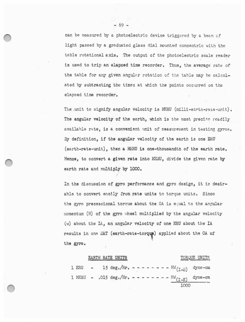
- 69 -
can be measured by a photoelectric device triggered by a beam of
light passed by a graduated glass dial mounted concentric with the
table rotational axis. The output of the photoelectric scale· r-eade1•
is used to .trip an elapsed time recorder. Thus, the averaee ra.t.e of
the table for any given ancul[lr rotation of the table may be ca1cul
ntod by subtraot.inr; tho times a.t which the pointo occ1..1.rred on the
elApoed Ume recorder.
The .unit to signify angular velocity ia MERU (milli-e:1rth-rat.e-unit,),
The angular velooi ty of the earth, which io ·~he most, preoi6~ rcQdily
avail.able r•ato, io n convenient; unit of Jlleasurememt in teatil'\8 eyro1:1,
By definition, it the angul:ar velocity or the earth io one ERU
(earth-rate-unit), then a MEHU is one-thoueandt,h or the earth rate,
Hence, to convert a given rate into MJ.1.am, cli.v:1 de the given rn tfl by
earth rate and multiply by 1000,
In the diaouseion of gyro performance and gyro design, it i~ daair
ab1e to convert ans:Uy from rate unite to torque units, Sinco
t.he gyro preceaaional torque about the OA is e•.Jl.lS.l t,o the anr,ular
momentum (H) of the gyro wheel mult1.plled by the angular veloci t;y
(w) about the IA, an angular velocity of one ERU about t;he IA
rasults in onE'I ERT (earth-rate-torq,.) applied about the 0A of
the gyro.
1 ERU
EARTH RATE UNITS
15 deg./Hr.
1 MERU - ,015 deg./Hr. - - HW(I-E) 1000
dyne-cm
dyne-cm
Where:
. - 70
. H : Angular r- - -- · ,+,um of the gyro wheel in I gram-cm2?,/eeo.
W(I-E) - AnBular velocity of the earth in respect - to inertial space, .
• 7,2722 x 10-S rad./sec, measured in sidereal time
1.0 x 10⁴ PENDULOUS INTJroRATING GYRO
I, Resistance and Continuity Checks
A, Same aa for 1,0 x 10⁴ Model II Rate Integrating Gyro
II~ Miorosyn Polarity and Null Cha0k1
A. The gyro is positioned on the table such ·that plus OA is horizontal and
M • ♦ 1 .. l:aing West, and plus SRA vertical down, The S,G, is excited o.
and the table is rotated CW about OA. The S,G, output to an osoillo-
10ope is m:>nitored to determine miorosyn polarity. The oscilloscope
will indicate the phae$ of the S,G, outpµt for the particular ro➔ ation ,•
about OA of the gyro.
B. The gyro is checked for a proper null voltage,
c. S,G, voltages at the float rotational stopa are checked,
D. The gyro is checked tor smooth float rotation.
III, Gyro Wheel Power and Phasing Cheokl
A, The ourrant. required to run the gyro wheel to snyohronization is
noted. This is used as an indication of bearing preload conditions.
' B, Both run-up and run-down time ot the gyro wheel is ohecked. Thie
is also an indication or bearing prGload conditions.
c. The gyro wheel is checked for the proper direction of rotation.
This is accomplished by observing the gyrQ wheel excitation for
- 71 -
the proper phase lead-lag charaoteristice.
IV. Damping Co~tficient (CD) Check: I
A. The gyro is positioned with plus OA horizontal and plus SRA down.
The wheel is allowed to renoh eynohronoue speed and the float ia
torqued until a S,G, output ot l,O volte ia reached, The time re
quired for the float to return to a point whore tho S,G, output
voltage ie 200 mv ia recorded, The Damping Ooettiod.ent iu co.lou ..
lated using the formulas
ad: P x 0.6213 x Tavg,
Where P ■ P1ndulolit7
'l'a.vg, ■ Av~raga return timo tor t.hei f'lont,
The oom10r roaiata.noa ia adJuntod until the proposr gyro tompf!trtturo
io roaohed to provide the required damping,
v. Friction Levol Oheok1
A, Tht gyro tloat 11 torqued about ita OA while tloat mov~m,nt ia
obHrvfld thru S,Q, output v0lt1go, The time requirr,d and the
condition ot float movement 11 indicative of triotion levol botwaon
jewel boaringo and float pivots,
VI. Float Travel Oheokl
A. The gyro float travel is oheoked by oompnring S,G, plus and minua
atop voltage■, S,O, sensitivity ie obtaintd by meaauring the
s.o, output voltage &t both plue and minus 4o ot tloo.t, rotation
and taking l/4 the average or tho two voltages.
VII• Tumbling Tests
A, The gyro ia positioned on the table such that the IA is coincident
w::l.th the rotational axis of the turntable, The table is rotated at
- 72 -
a fixed rate of 270 degrees per hour. Table position i1 indexed to
a recorder graph eveey 10 degrees. The torquing current is recorded
on the graph where it is graphically converted to read in t~rms or
dyne-om or torque. The table tilt angle ia adjusted tor each test
to approximately balance the gyro preceeaional torque.
Torqu• record■ are anal.71ed on a 36 point baeib !or.average terms
and first harmonic•. Ma.xi.mum deviation trom the average on each
run is recorded ae tumblil'II threshold, Harmonica are assumed to
be '"'or, ui 1li1nment ot the 111"0 to the table and are eubt·raoted
troll the a1'aly1ed reoordina, An additional .deviation trom the aver-. \
tie 11 computed tor eaoh run ot eaoh teat and the larger ot these
de~atione 11 known a, Compensated Twablin& Threshold, A point for
point repeatability 11 done by determining the ditterenoe between
the rir■t and 11oond r~volution1 tor eaoh test, The larger or th•••
ia known as Tumblin& Repeatabilit1,
VIII. · Servo Testa
A, With the gyro positioned on the turntable such that the IA ia coin
cident with the table rotational axis, the gyro is allowed to drive
the table thru three uninterrupted revolutions. Thie is done with
the QTO aenaing .3 X 10-.3,, a and also £or l X i.o-2g• s.
Actual and theoretical wluee are compared on a .36 point per rev
olution basis tor proper angular rate and position to determine
gyro accuraoy.
IX. Sensitivity Ratio Cheoki
A. The gyro sensitivity ratio is determined by positioning the gyro in
- 73 -
servo operation sensing both a plus and a minus one g. and determining t .
average table angular rate. The average of the two values determines se1
eitivity ratio whioh is a criterion for grading the gyro as to quality.
, X. Riaidual Torque Checks
A. With the gyro in servo position as above and sensing both a plus
and a minus g., the T.G. reference winding is excited with a spec
ified amperage and the average table angular rate is determined.
One-half ~he distance in the .two values is converted into dyne-om
of torque and deeignated as Risidual Torque.
XI. Command Sensitivity Checks
A. With the gyro in eervo position as above and sensing both a plus
and a minus one g., the T,G, is excited with varying amount• or
current, Comparison ot proportional table rate■ at ea~h v&lue of
excitation current determi.nee a Command Sensitivity,
25 PIG and 25 IRIG•PENDULOUS INTEGRATING and
INERTIAL REFERENCE INTEXlRATING OYROSt
I. Due to the classified nature of testing techniques for the 25 PIG and
25 IRIG units, no discussion of the subject will be held in this book
let, If the reader desires to familiarize himeaelf with the test pro
cedure, he may reter to the following Engineering Specifications,
ES-5427 ES-5428
ES-5429 ES-54.30
It is permitted to mention, however, that in respect to gyro quality,
approxirmtely the same characteristics are noted in test for the 25 PIG
and 2; IRIO units as for each of the rate-integrating and pendulous
integrating models previously discussed.
- 74 -
2F00-2C FLOATED BERYLLIUM GYRO 2.0 x 10⁶
I. Resistance and Continuity Cheokt
A • . Resietance and continuity checks are done on all the internal
circuitry or the gyro. Included in the check is determination or
the values or resistance within the heater and sensor windings of
the heater jacket to insure that the gyro is subjected to the pro
per temperature.
II. Half Power Point Determinationt
A, The 2FBl-20 unit utilizes a magnetic suspension system to reduce
frici tion be_tween !'loat · pi vote and jewel bearings. For the magnetic
suspension system to operate properly, it must operate on the proper
side of the cUl'rent-frequenoy curve and at the right point on the
curve, It oan be seen from the current-frequency curve below that a
half power point exists on both sides of the curve. It is extremely
important that operation or the ayetem is performed at the upper
half power point, The reason for this is that the inductance oharao
teriatios of the mioroeyn poles reverse themaelvea b~tween the upper
and lower half power points in respect to frequency, If operation
occurs at the lower half power point on the curve, reaction of the
poles or the microeyn would be such that they would draw tho miorosyn
rotor away from tho pivot center inctead of toward the pivot center.
Sinoe it is possible to opera.ta· at either half power point, a. ohei,k
:i.1:1 necessary to insure opera.tion at the prope r one.
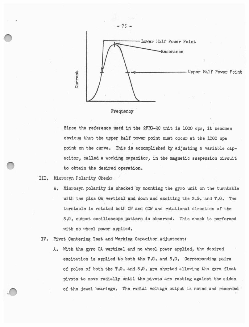
- 75 -
~lf Power Point
Resonance
~---------Upper Half Power Point
Frequency
Since the reference used in the 2FBl-2C unit is 1000 ops, it becomes
obvious that the upper half power point must occur at the 1000 cps
point on the curve. This is accomplished by.adjusting a variable cap
acitor, called a working capacitor, in the magnetic suspension circuit
to obtain the desired operation.
III. Microayn Polarity Check&
A, Miorosyn polarity is checked by mounting the gyro unit on the turntable
with the plus OA vertical and down and exciting the s.G. and T.G. The
turntable is rotated both CW and COW and rotational direction of the
s.G. output oscilloscope pattern is observed. This check is performed
with no wheel power applied.
IV. Pivot Centering Test and Working Capacitor Adjustments
A, With the gyro OA vertical and no wheel power applied, the desired
excitation is applied to both the T.G, and S,G. Corresponding pairs
of poles of both the T,G. and s.o. are shorted allowing the gyro float
pivots to move radially until the ,pivots are resting against the sides
ot the jewel bearings, The radial voltage output is noted and recorded

- 76 -
as Emax• This procedure is repeated for the four pairs of poles for
' .
the T.G. and s.G. and the radial voltages recorded. When the short is
removed from the pole pairs, the float is allowed to come to rest due
to the influence of the suspension -system ann the radial voltage is
noted and recorded as Er•st• Pivot center radial voltage (E~tr•) is
onloulated by averaging Emx• tor each opposing pole pair and the
working oapaoitors are adjusted to produce the calculated Eotr• value
when all miorosyn poles are operating normally and the float is at
rest in the magnetic suspension system.
v. Float Stop and Float Freedom Checks
A, With the gyro mounted with plus OA vertical and down and with no
wheel power applied, both the T,G, and S,G. are oxoitad, The float
ia torqued out to the stop in both a plus and minus direction alter
nately-, The S,G, output voltage and the time required .tor the noat ..
to return to a null position are observed, Float operation while being
driven to the stops is also observed to insure smooth rotational move
ment.
VI, Motor Fower Conawnption Cheoke1
A, Motor power requirements to drive the gyro wheel to snychronization
are noted, A oheck is also made on wheel power requirements at given
time· intervals after the wheel has reached synchronous speed,
VII. Rundown and Preload Teet1
A, Total rundown time from enychronous speed to zero rpm of the wheel .
is observed. Also, by employing an audio oscillator standard to
accurately control wheel power frequency, a rundown time between
6oO and 120 rpm' s is noted to determine the bearing preload conditions;···
- 77 -
VIII. Float Uncertainty Tests
A. With no wheel power applied, plus OA vertical, down and excitation
applied to both the T.O. and s.o., the float i~ torqued to s.G.
output vol tag, 'varyi.hg from zero to atop values. Reverse torque _is
applied for eaoh S.u. output to return the float to w.i.thin 5 mv of
the null position. The tumbling loop is engaged and the degree of
torquing current necessary to balance the float ~or each run is re
corded. The ability of the torquing loop to return the float to a bal
anced, or null, condition and tha ability of the float to ailow itself
to be driven to a balanced condition with a given torque applied det
ermines float uncertainty. .This method ie used primarily to determine
if there has been any leakage of damping fluid into the float cavity.
A second type of test is given the gyro to determine if there might be
any gaeeeoue bubble in the damping fluid, In this check tho {!;fro is
allowed to remain at a null with the above excitations applied and the
t~mperature is allowed to vary J0 below normal. It has been found
that a temperature variation will cause a bubble in the dampj_ng fluid
to move its position in respect to the float and will be evidenced by
a change in torquing current.
IX. Gravity Transient Checks
A. With no wheel power applied, plus OA parallel to turntable axis., into
the table and horizontal North, and excitation applied to both T,G. a.nd
s.G., the gyro iB rotated until plus IA is vertical-down. Twenty (20)
minutes is allowed for gyro stabilization, Torquing current is applied
to the T.G. to null the float. The torquing current is then removed
and the tumbling loop is engaged. Torque to balance the float in

- 78 -
terms of dyne-cm is recorded for a twenty (20) minute period. The gyro
is rotated thru JflJ0 in 90° increments with the preceeding steps· re
peated for each 90° position, The change in torque to balance from
initial to final values in each orientation will indicate the degree
ot unbalance present as they are affected by the full gravity veot~r,
X, Capacitor Package Checks
A, All o.r the gyro testing done to the· present point has been done utilizing
the teet console working capacitors, At this point it becomes necessary .. ' ~
to mount the capacitor packase whioh haa been fabricated f'or• tho apeci-
tio gyro under test on the ,wro and retest sevoral tunotio~s or the
SYrO while using the !'ixed capacitors, gwt,dr:aturG rosistor and damping
r11i1tor in the p&Ok&S•• Those teats which must be repeated arc, llttted
b1low1
1, Workins Capacitor Value,
2, Halt-Power Point Cheak
3. Pivot Centering Teat
4, Null Voltage Cheak
XI, Tmnbling Tests
A, With wheel power applied, T,G. and S,G, excitation applied, pluB OA
parallel to the turntable axis, parallel to EA'!: .30 aro seconds and into
the table and the gyro operating at flotation temperature, the tumbling
loop is engaged. The gyro is positioned with plus IA West for a zero '
reference, The turntablf is driven in a CW direction at twelve (12)
times earth rate. Four complete CW revolutions are allowed,· The dir
ection of table rotation is then reversed and three CCW revolutions
are allowed, Torque to balance in terms of dyne-cm is recorded through-
- 79 -
out both the CW and CCW directiom1 of table rotation. The magnitud~
of torque to balance is determined at each 10° increment of turntable
rotation for the last three CW table rotations and all thr·ee CCW table
rotations. The resulting data. points are reduced by a Fourier Anal.ysin
and converted to gyro unbalance coefficienl,u in terms of MERU. P.e
ri.1.1otion of the data po.i.nts by Fourier Ana.lyois separa.tes the degree
or unbalanoe as contributed by r:lsidual, SHA unbalanco, IA unbalance ,
oompliance and indicates the magnitude of each.
XII. Servo Drirt Teet:
A• Aa for t,be previously discussed units, the servo test is performed to
determine the ability of the gyro to maintain an accurat.e referenc"•
The servo drift. teat for the 2FEG -2C unit ,ia con<:luctcd ns follow.:.l ::
The gyro ie mount,ed to the turnta.ble rmoh t.ho. t IA is parallel to tht.' I
t,urntnble aµa, plus IA out or the table and perpendi cula.r t.o tho EHA ,
Plus OA is 4,o COW from the Eaet. One hour of running time i~ all ow~d
.for the gyro wheel to 'stabilize at synchronous speed.
A compeneation current is applied to the T.G. which causes the p.,yro
to drift noticeably in one d;l rcction and the gyro is allowed t(; d:c l ft
under these oonditions for one-•quarter (t/1~) of an hour, The compen5.at:..c,
currrmt and total dr:i.ft are not-ed and recorded c1.:J Ic1
and D1.
Another compensation current ia a.ppl:te,d wh.ich oauees tho gyro dr-1 ft
rate to decrease or reverse the direotion as noted for the f 'j r·ot. com
penoation value applied, The gyro is again allowed to drift under t.he-&tt
oondi tiom, for one-quarter (l/4) of an hour, The compe:nsatton cunont.
applied and the total drirt are again noted and re~orded a.~~ le~ and D2,
- 80 - -, I
A compen~,11 tion ratio is calculf.l Led from the information obt.aini:?d tc
determine the proper aver2.gc current necess~ry to compensate for th.is
ris:i.rlual unhaj ance, (R-•term) • This compensation current is applied and
the gyro is allowed to drift for one-quarter (1,h) of an hour. · If t-bi!
gyro continues to drift beyond specifics.tions, fine adjustment,s are made
in compensation current to obtain zero drfit,.
Once the proper com1:cnsation current has been obtained for zero drift,
or drift within specifications, the gyr-o i~l realigned to the d~isired ·t.tJro
table at:.titude and a two (2) hour drift test is run~ Several runs with
the gyro mounted 1.n varying attit.udet➔ are made to determlnei final gyr"O
drift qualitiee.
Assuming that proper componsation ou.rrent adjUfltmenta were mod,~ to pro
duce zaro d1··ift dl..~· t,o risipu-Rl unhola.nces, any turntnhle movement fr·om
the initial posit.ion over the two (2) hour period aro indicntivc ot e,yr-o
inacou1•aciea due to uncertainty torquno and gyro quality, A thooreti ....
cally perfoot gyro free of uncertainty torque a would p1•oduce no t..ur-n
taule movement duri"B the final drift test,
XIII. Torque Generator Califbration Check:
A. Coarse Control W1nding Calibration Check~
J, With the gyro aligned to the turnt,t:i.ble w1th the IA parall~l to
tho turntable rotational axle and perpendlr.ular to thf) ERA, wh~~l
power and excitation to the T ,G. and S .G, ar·e a.ppl.ied, It is ex
i;r~n1ely important that the speci f.ied T ,G. pl'lma.ry curi:•ot!t :b main
tained throughout the test. The servo loop :lo closfld and ~:"'W.l ·i.d
rune are done with varying va] ues of T ,G, secondary ex.oitc1tion,
The t.tme required for th~ float to tr,1wil thru a. specified angle
- 81 -
is recorded and is used to_ determine T.G. calibration.
B. Fine Control .Winding Calibration Check:
1. Same as for coarse control winding calibration check.
XIV. Flotation Temperature Determination: ,.,
A. The method used here ie the same ao used for the 1.0 x lOf Mod, II gyro.
XV. Gyro Sensitivity Determination:
A. The gyro is set up with an initial attitude the same as for the servo
drift test, The turntable is rotated until the S.G, outpu.t voltage r-e,aohes
the desired value, At this point the degree of table rotation is noted,
The table is then quickly rotated in the opposite direction until a S,G,
null is indicated and table position ie again rioted. The amount of turn•
t,able movement required 1;o result in the desired S,G. output and th• ditt-:..r
erenc.e in turntable position ae compared to its initial pc,si.tion after
returning to a S,O, null ie indicative ot the gyro sensitivity-. Theoret•
ically, a porfeot gyr~ would have cauead the turntable to return eXLLctly
to its original position when the s.G. null was obt.ained,
NOTEs Figure 15 illustrates a special device known as a Fluid Package which is
used while performing all of the final testing of ·the 2F:00-2C units, The
Fluid Package does not comprise any part of the gyro, but is merely used
as a temperat11re regulating device for the gyro, The 2F00--2C dt'tpends on
circulation of heated fluid around it throU8h a ducted Fl.ui.d Jacket !'or
the proper temperature conditions,. The Fluid ,la.ck~t, not shown, i .s phy
sically attached to the gyro as an outer oa~e about the ma.in housing and
covers over the e.nd housings which allow the heated fluid to paas through
them, The Fluid Package acts as an insulator-oven to aid in mainta.i.ning
proper gyro temperature,
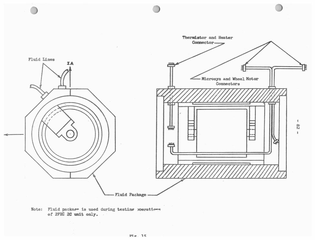
Fluid Lines
Note: Fluid packav,.. is used during test.izu! >oerati~ ot 2F'OO 2C uni~ only.
Thermistor and Heater Connector
- 83 -
Individual Gyro Charact.eristi cs :
I. 1.0 x 10⁷ Model II Rate Integrating Gyro :
A. Construction:
1. Aluminum nlloy used in basic strucl.ure
2. Cyli.ndrioally shaped float .
D. Symbolisrn: ,..
1. 1.0 x 10' indicates the gyro wheel angular momenl.wn in
dyno-cm/rad./sec.
C. Excitation Reqtti rernonts:
1. Whee] Supply: (12,000 RPM)
a. 2 phase, 45 volt, 400 cpe.
b. 400 ms. starting currant
2. Torque Genera.tor F.xcitatiom
.3. Signal Gonc rat.or Exc.tt.atic,n~
11 • 1 voJ t,, hOO cps
D. Ilot Gy-ro:
J.. Tho unit mu9t not be a: l::>wed to cool but must b8 rna.int.aine.d. in
a. haated conditton for t-he life of the gyro after filling.
2. Flol,,?.ticn occllr~. normally bE:l,we r.•n 160 n11d ll,51·' F' .
J. Utili.7,e~; blfl.nkot twaLera to 1n:.vint,:tln gyro t.e1nper,:1.t ,.1re .

- 841 - .
II. 1.0 x 10⁴ Pendulous Integrating (}yros
A. Construotioni
l. Aluminum alloy used in basio structure
'-• Cylindrically shaped float
B. Symbolism:
1. 1.0 x 10⁴ indicates the gyro wheel angular mom~nturn in
dyne-om/rad./seo,
o. Excitation Requirementss
l, Wheel Bupplys (S,000 RPM)
a. 2 phase, 4.25 volts, 400 ops,
2. Torque Oon~rator Exoitationt
a. 120 ma, 400 ops.
3, Signal Generator Excitation:
a. 1 volt, 400 ops,
D. Hot Gyros
1, The unit must not be allowed to cool but mul!lt be m9.in·~ainnd
in a headted oondi tion tor the 11 f'e of the gyro after filling.
2. Temperature o.r. the unit ie adjusted to obtain the de$1.red
dampir1g 0ha1•aote.rlstios. I
- 85 -
III. 2FB1-2C Rate Integrating Gyro:
A. Construction:
l. Beryllium is Used in basic structur(!,,.
2. Gyromet material is used for the heavy metal wheel rim.
J. Cylindrically shaped float.
B. Symbolisms
1. First number 2 identifies the unit as pos sessing an angular momentwn
of 2.0 x 10⁵ dyne-om/rad./oeo,
2, 1"00 indicates the unit as a Floated Beryll:lum Gyro.
J. 20 indicates the unit model nwnber.
a. Exoitation Requirements:
1, Wheel Supply: (12,000 RPM)
a. 2 phaoe, 30 volts, 400 ope,
2. Torque Generator ExoitatLon1
a, 24 ma, 1000 ope,
3, Signal Gonorator Excitations
a, 10 vol ta, 1000 CJH.1,
D, lff\enotio Suopenaion1
l. The unit employs 8 pole miorooyn eta tore combined with 8 work:1.ng
oape.oitora,
E, Cold Gyros
~• The unit po11oes.1:1es tho ability to be transportc,d and st,ored at. t"mpsr•
tu1-es below the oporr.ting flotation temporaturo of .146?:1°F,

- 86 -
IV. 25 PIG Pendulous Integrating Gyro:
A. Construction:
1. Beryllium is used in basio structure
2. Spherically ahaped float.
B. Symbolism1
1. Numerals 25 indicate nominal unit diameter im tenths of inches.
2. PIG indicates a Pendulous Integrating 071"0.
J. Unit angular mment.ut
a. Titan - J.O x 104 qne-oa/rad./••o•
b. Polaris - o.6 x 10S dyne-om/rad./aeo.
c. Excitation Requirementss
1. Wheel Supplys
a. Titan - 2 phase, 17 volts, 400 cps.
b. Polaris - 2 phase, 28 volts, 800 ops. ,
2. Torque Generator - Excitations
a. Titan - 10 volts, 1000 cps.
b. Polaris - 10 volts, 800 ops.
J. Signal Generator Excitation:
a, Titan - 10 volts, 1000 cps.
b, Polaris - 10 volts, 800 cps.
D. Magnetic Suspensien:
1, Two 4-pole microsyns and 8 working capacitors.
E. Cold Gyro:
1. The unit is classified as a gold gyro only when it is shrouded.
V, 25 !RIG Rate Int egrat i ng Gyro:
A. Constructien:
1. Beryllium is used in basic structure.
2, Spherically shaped f l eat.

B, S:,mboli11at
1, The nU111.erals 25 indicate nominal unit diameter in tenths et incne,.
2, IRIG indicates Inertial Reference Integrating Oyn.
3, .1,4 x 10S dyne-cm/rad,/aec,
O. Excitation Requirementst
1, Wheel Supplys (16,000 RPM)
" •• 2 pha■e, 28 volte, 800 op,.
2, Torque Generator Exoitation1
a, 10 v., 24 ma or ).6 v., 10 ma.
3, Signal Generator Excitations
a •. 10 v., 24 ma or ).6 v., 10 ma.
D, Magnetic Suspensions
1, The unit emplo7s 8 pole Jli.oorsyn 1tator11 combined with 8 wrking
oapaoiter,.
E, Cold G,rea
1. The unit is classified as a cold gyr• .2!!z when i\ i1 shrouded • .
This enables the unit to be tramspGrted and stored at temperatures
·below the operating flotation temperature or 1371 F.
VI. 1.0 x 10⁷ Model VI-A Rate Integrating Gyros
A. Construction:
1, Aluminum alloy used in basic structure,
2. Cylindrically shaped float.
B. Symbolism:
1, 1.0 x 10⁷ indicates the gyro wheel angular momentum in dyne-om/rad./seo.
2 • . VI-A indicates particular gyro model.
O. Excitation Requirements:
1, Wheel Supply:
a. 2 phase, 45 volts, 400 cps.
2. Torque Generator Excitation:
a. 120 ma, 400 cps.

3, Signal General Ex~itation1
•• 125 ma, 400 ops.
D. Oold O;yrcu
.. 8'8
1. The unit 11 o,oled \o a iew teaperat.ure ot+ •• F, betere te■t and
mar be oonsidered a 0011 ITN>•
VII, l.Q x 107 Model VIII Rate Inttgratiag 07N& .
A, Oon1tructio111t
2, Cylindricall.J' 1haped tleat, lead 1eal1,
B, S711boli1111
l. 1.0 x 10 7 indicates the uro wheel angw.ar mo■eatua in d.yllle-om/raci,/seo,
2. Numeral VIII indicates particular gyro model,
C, Excitation Requireae111te1
1, Wheel Suppl71
a, .3 phase, 120 volt, square wan.
2. Torque Generator:
a. D.O. excited, pernw.nent nw.gnet, single winding. Scale factor=
7.5°/hr./ma of torquing current.
3, Signal Generatori
a. Capacitive pickoff operating on 25 volts, 5 KC,
D, 0~ld Gyrot
1, The unit operates at a flotation temperature of 125° F. Temperature
cycling to+ 65• F. is done after filling and the gyro is classified
as cold,
VIII, 3.0 x 10⁷ Mark VII-B Rate Integrating G;yr0:
A, Construction:
Jl, Aluminum alloy is used for the outer housing basic structure and
Beryllium is used fer the floated 'Wlit structure.
2. Cylindrically ebaped tleat.
3. A mechanical type tor~u•r is used in some wdts.
B • S111boli eat
1. ).Ox 107 indicates the gyro wheel angula:r •••ntu in dpe-oa./rad,/eeo,
2, MK VII-B indioatH the partioul.ar 'Wlit model,
0, Excitation Requirement••
1, Wheel Supply1
a. 2 pbaee, 45 volte, 400 opa.
2. Torque Generators
a. D.O. Exoited, perman•nt magnet, lingle windima when aeohanioal
torquer 11 net ued.
3, Signal Generator Exoitationt
a. )0 ma, 1000 cp1,
D, Hot Gyre
1, Heat must be mintained on thi1 wdt oontin\loul.7 att1r tilling, e
Operating f'loation temperature is 14,:ti F,
E. Magnetic Suspension:
1. Sa11e as previous unite.
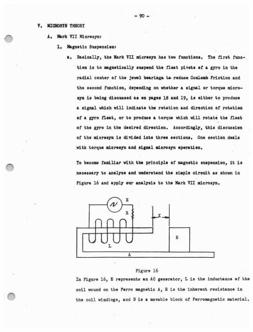
- 90 -
V • IIIOROSTI THJOC>Rt
.A• Nark VII Miona71u
1, Mlpetio Supenli•••
a, ~•iaall.7, \Ill• Nark nI. JliorH711 ha■ two tuotion■• The ti.rat tuna-
. \iea i1 to •1••tioal17 ■upend th• tloat pivot■ et a aro in t.h•
racts.al ceat.er et th• jewl be&rillg•. t.e,. r•d.••· Co.-1.oa\a. Frio\ion and
the ■eoond tQDction, depending on whet.her a ■ignal or torque micro
.,. i1 'Nina di■o•■■•d •• •• paa•• 18 aad 19, i• •1 ther to produce
a 1iana]. whioh will indioat• the rotation ud dir~otion ot rot.at.1••
et a aro tleat., or to produoe a torque which . will rotate t.h• tloa\
ot tbe g,ro iq t.h• de■ired clireotimn. Aooordingl7, thi1 dieoueeien
ot the ld.ore1,a 11 diTided into thn• 1eotion1, On• section deal,
w1 th torque lliore1711 ancl li1nal llioro•Jn operation,
To 'Hoo• tud.liar with tbt principle ot magnetic eu■pen■ion, it i■
n•o•1n17 .to anal7H and under■tand th• aiapl• oirouit •• ■hown in
Figure 16 and appl7 ev aaal.Jai• to the Mark VII JlioroaJJI,
r~ .... ---+--+---+---+---i ----.
B
A
Figure 16
In Figure 16, E repnsents an AO generator, Lis the inductance et tne
coil wound on the Ferro magnetic A, R is the inherent resistance in
the coil wi.qdings, and Bis a movable block or Ferromagnetic material.
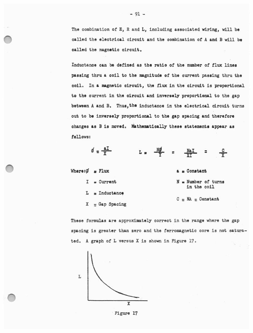
- 91 -
The combination of E, Randt, including associated wiring, will be
called the electrical circuit and the combination ot A and B will be
called the magnetic circuit.
Indttotanoe can be defined as the ratio of the number of flux lines
passing thru a coil to the magnitude ot the current passing thru the
ooil. In a magnetic circuit, the nux in the circuit is ·proportional
to the current in the circuit and inver••~r propQrtional to the gap
between A and B. Thue,the inductance in the electrical circuit turns
out to be inversely proportional to the gap spacing and therefore
' changes as B 1111 mved, Mathematically- these statement, appear aa
tollows t
0 - ..!L - X L • -4 = NaI - .+ X! -
Whtrll~ ■ Flux a ■ Oon■tant
I • Current N • Number ot turn■ in the coil
L • Inductance C =NA: Constant
X = Gap Spacing
These formulas are approximately correct in the range where the gap
spacing is greater than zero and the ferromagnetic core is not -satura
ted. A graph of L versus Xis shown in Figure 17~
L
X
· Figure 17
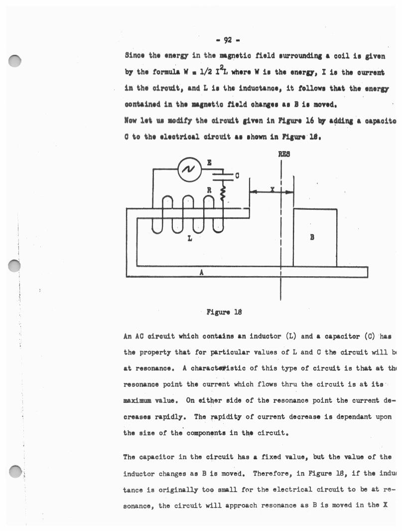
• 92 •
Sino• th• •n•ra in the •11'.l•tio titld 1urz-ounding a ooil 11 liven
bf th, tormul& W ■ 1/a x2t wh•r• W 11th• ,n,r11, I 11 tht ourr,at
in the oirom.t', and L ii th• lnduotanoe, it follow, th&\ the 1n,r11
ooniaintd in th• •1n,tio titld oh&na•• &I B ii IIOVtd,
low 11\ u aodit7 th• oiro\11\ 1iwn in Piave 16 bJ ••na ·a oapaoito
0 to \be 1l1otrioal oil"ouit a, 1hown in Pi1ve ·ll,
w I I
I
a
A
· Figure l8
An AC oirouit which contains an inductor (L) and a capacitor (C) ha1
the property that for particular values of L and C the circui·t will b
at resonance. A charaot.eiistio of this type of circuit is tha.t at till
resonance point the current which flows thru the circuit is at its ·
maximum value. On eit~er eide of the resonance point the current de
crease• rapidly. Th~ rapidity or current decrease is dependant upon
the size or the compon,nte int~• circuit.
The capacitor in the circuit has a fixed value, but the value or the
inductor changes as Bis moved. Therefore, in Figure 18, if the induc
tance is originally toe small for the electrical circuit to be at re
sonance, the circuit will approach resonance as Bis moved in the X
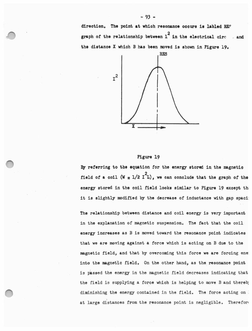
- 93 -
direction. The point at wbioh re1onana1 oaoure 11 labled RB~ 2
graph ot the relationship between l in the electrical circ , and
the di1t&no1 X which B has been moved ie ahown in Figure 19. RES
Figure 19
a, ret,rrina to th• equation tor the enera etored in the magnetio 2
tield ot a coil (W s 1/2 IL), we can conclude that the graph ot the
enera stored in the coil field look, similar to Figure 19 exeept th1
it 1e alightly mditied by the decreai,e of ind'llctance with gap spaci:
The relationship between distance and coil energy is very important
in the explanation of magnetic suspension. The fact that the coil
energ7 increases as Bis moved toward the resonance point indicates
that we are moving against a force which is acting on B due to the
magnetic field, and that by overcoming this force we are forcing ene:
into the magnetic field. On the other hand, as the resonance point
is passed the energy in the magnetic field decreases indicating that
the field is supplying a force which is helping to move Band thereb;
diminishing the energy contained in the field. The force acting on :
' at large distances from the resonance point is negligible. Therefori
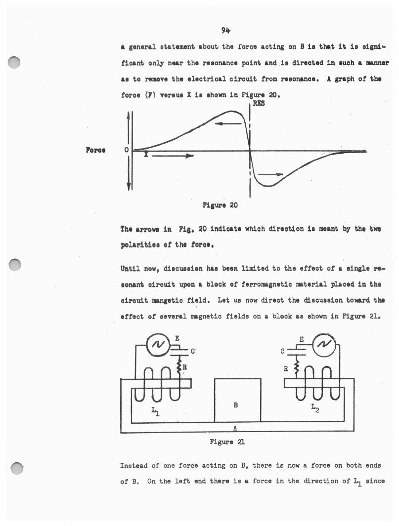
a general statement about! the force acting on Bi■ that it 11 eigni•
tioant only near the re1onance point and .ii directed in 1uoh a Jl&llJltr
a1 to remove the electrical circuit trom reeon,.noe. A graph ot the
tore, (F' Ttrl\11 Xii lhQwn in Figure 20.
IRE
Haur• 20
The arron in Fil• 20 indicate which direction ii meant bf the twe
polariti•• ot tht torot,
Until now, d11cue■ion ha1 been limited to the etteot ot a single N•
1onant circuit upon a block •t terromagnetic material placed in the
circuit angetic field. Let ue now direct the disou111ion toward the
ettect or several magnetic fields on a block as shown in Figure. 21.
C
B
A.
Figure 21
Instead of one force acting on B, there is now a force on both ends
of B. On the left end there is a force in the direction of Li since
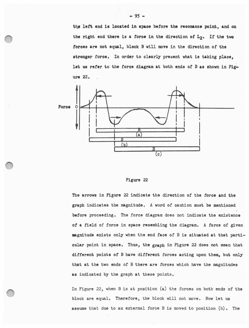
Foro•
- 9; -
tq, left end i• located in 1paoe before the resonance point, and on
the right end there is a force in the direoti'on or L2, Ir the two
toro•s aN not equal, block B will move in the direction or the
1t.ronger force,
let ue refer to
ure 22.
1 0
!
In order to clearly present what is taking piaoe,
the force diagram at both ends ot Bas shown in Fig-
:e (a)
I
(c) I
Figure 22
The arrows in Figure 22 indicate the direction of the force and the·
graph indicates the magnitude. A word of caution must be mentioned
before proceeding. The force diagram does not indicate the existence
ot a field of force in space resembling the diagram. A force of given
•gnitude exists only when the end face of B is situated at that parti
cular point in space. Thus, the graph in Figure 22 does not mean that
different points ot B have different forces acting upon them, but only
that at the two ends of B there are forces which have the magnitudes
as indicated by the graph at these points.
In Figure 22, when Bis at position (a) the forces on both ends of the
block are equal. Therefore, the block will not move. Now let us
assume that due to an external force Bis moved to position (b). The
forces on both ends of the ~lock are no longer equal and the block
will be forced to move back to its original position due to the influ
ence or the unequal forces. Thua a means haa been developed to clamp
Bat a point between the two reasonant magnetic oirouita.
I It Bis aoted 'I.\POn by such a large external foroe as to foroe it to
position (o) or to any point where one end of Bis slightly past the
maximum point indioated on the force diagram, the sum of the foroea
aoting on the end taoes ot the blook no longer attempt to move the
blook back to its original position. For this reason, circuits which
utilize magnetio clamping are oonatructed in such a manner a.a to make
it impossible for the al.amped unit to physically move beyond a given
de1ir1d position. Thua, the unit ia magnetically clamped between thee•
ph11ical limits.
A schematic diagram ot the Mark VII mi0r0>syn is shown in Figure 2.3.
There are eight poles each of which contains two windings,. The seo-1
ondary windings marked Sare used either to develop a torque in the
microsyn or t o develop a signal which is sent to an external circuit to
indicate t hat float rotation has occured. The primary windings marked
Pare grouped together in pairs by connecting the primary windings of
two poles in series and are used to develop the magnetic suspension
forces and also to induce voltages in the secondary. The insert marked ....
B is actually a microsyn rotor which is physically attached to the
float end.
The opposing poles of the microsyn act together to clamp Bas the pre
vious discussion has i ndicated, but in this case the poles completely
surround B causing a clamping action in all directions and B may be
said to be radially suspended.
In the previous discussion very little attention was given to the flux
pnthu in tho magnetic material, In the Mark VII, due to the complexity
of the circuit and the dual purpose of each primary coil, thio must
not be ignored. The instantaneous flux paths are indicat~d by the
dotted lines in Figure 23. However, the nux paths in B have been
shown only for pole 1.
There are two types of motion that B may possess. Either translational
movement along the diameter of the pole face cirol~, or rotational
movement, either OW or CCW, about the .float longitudinal axis. It is
desired that the rotational movement be indicated by an increase in the
number of flux lines through poles 1, 3, ;, and 7, and by a decrease
in the number of flux lines through poles 2, 4, 6 and 8. 'rhis is what , ..
will happen with the poles wound as shown in Figure 23, Note that this
is true onl~ because the windings en poles 1 and; are wound opposite
to the windings on poles 3 and 7, Therefore, the decreases in reluc
tance to nux lines into Bis coupled with a decrease in reluctance to
flux lines out of Band the flux increases. If the windings were not
wound differently, the decrease of reluctance into B would be coupled
to an increase . in reluctance out of Band the flux thru all poles would
remain constant.
Another point which can now be understood is the necessity for two pri
mary coils being series connected. It is necessary that the magnetic
suapensi0n system be sensitive to translational movement and yet if
rotational movement of B causes an increase in flux thru a pole, it
will change the inductance of the coil which is wound on that pole.
By connecting two adjacent poles in seriesj an increase in the induc
tance of one is compensated for by a decrease in inductance of the
other causing the suspension system to be insensitive to rota~ional
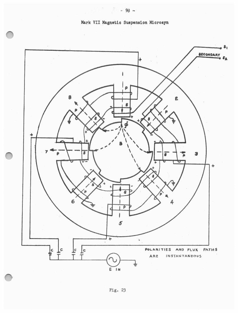
r 98 .,.
Mark VII Magnetic Suepensi9n Mioroeyn
C C C C
I \ \ I \
I 8 \ \ ,,,,.~ ' \
\
' \
5
T.__ __ T_T.....____._T _ ___.~-\.:::J * E IN
Fig . 23
,-----....
_3
+
Po1..~"l'Tll:S AHO FLU~ PATHS ARE INSTANTANeous
- 99 -
movement of B,
2. Signal Miorosyn:
a. The ei.gnal micro syn tunctt,on ot the circuit ia accomplished thru the
UH ot secondary windinge halt ot which ~e wound eo as t<:> produce a
voltage in phaee and the other halt ,rowid 10 a, to produce a voltage
whioh i1 out ot phaee with the prima17 excitation voltage, In Figure
23 the 1econd&ri11 on poles l, 3, 5, and 7 are wound in phase and th•
secondaries on poles 2, 4, 6, and Sare wound out of phase with their
re1peotive primarie,. It B ie in its neutral (null) position, the flux
throuch all polee is equal and the voltagee induced in the 110ondarie1
art equal. Sinoe th• secondary windings are series comected, the in and
out or pha~e voltage■ produce an output ot zero when algebraioly added
to11th1r. The in1tantaneou1 polarities are shown on the diagram, A ,
rotation ot Bin the COW direction will oau11 an increase in the IM.I•
nitude ot the in-phaoe voltage and a decrease in magnitude ot the out
ot-phase voltage, The output voltage will therefore be in~pha11 with
the excitation voltage and of a magnitude proportional to the rotational
distance traveled by the miorosyn rotor. Similarly, a CW rotation will
produce an out-of-phase voltage output. Thus, we have a device which
indicates direction and Jl)agnitude of rotation.
3. Torque Micorsyn:
a. A torque microsyn differs from a signal micorsyn only in the respect
that a voltage is applied to the secondary windings in order to strengthen
or diminish the magnetic fielqs through certain poles and thus create
a force which tends to rotate the microsyn rotor. If a signal in phase
with the primary voltage is applied to S, in Figure 23, the motion created
will be CCW. An out-of- phase voltage on s, will produce a CW rotor move-
ment.
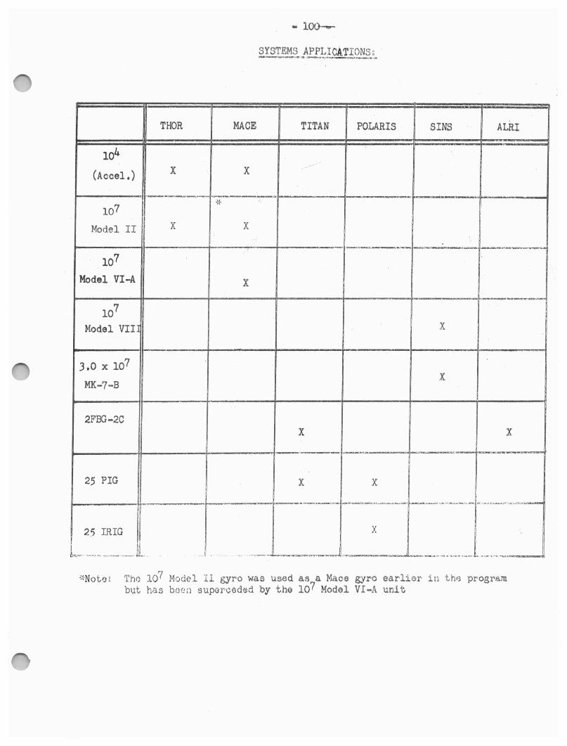
SYSTEMS APPLICATIONS ~ __ a_.._.,.._,, ____ .._,. ,,.
THOR MACE TITAN POLARIS SINS ALRI ' ·
104 X X -
(Accel.)
-----·--.. -{~ ' 107
Model II X X
-- _...__ ---·-··--___ __ ...,.. ____
107
Model VI-A X
107
Model VIIl X
3,0 X 10⁷ X
MK-7-B
2FBG-2C X X
_ ,...,.._.__..._. ~---·· ......... ...__..,..., .,_ ___ . ___
25 PIG X X
_, ........ .__..---:=a: i.-~,,.~-..... --~ .... ...._.,. ; ........................ -.. ,.~ .... ,--..~·r,;,;.._,.._,.,._._
25 IRIG X
.¾.. . ' ·-........ . .. -- -· - -· -· .. .. ,_,,,...._ .• __...,._,..__2!:t'-r.._.,.._.__.., :..-....•.-:~•-•- i..--... r •-.:.,i, tr"!'• •• -.~ .. r .... w, ... ..,..., .... -.. "~~
Th0 107 Model II gyro was used as a Mace gyro ear-lier in t,h0 progrf.lrn but has been supercedeid by tho 107 Model VI-A unit
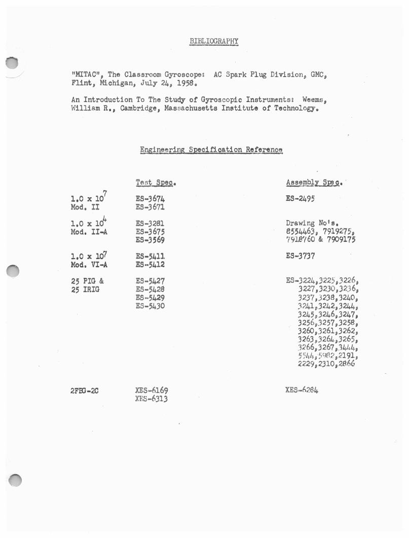
BIBLIOORAPKY
"MITAC", The Classroom Gyroscope: AC Spark Plug Division, GMC, Flint, Michigan, July 24, 19580
An Introduction To The Study of Gyroscopic Instruments: Weems, William R., Cambridge, Massachusetts Institute of Technology.
~,,Mineering Specification Reference
~ s;eeo. ~_mbly_ SP3.9,, · 7 1.0 X 10 ES-3674 ES-24-95
Mod. II ES-3671
1,0 X lcf ES-3281 Ora w1 ng No' s. Mod. II-A ES-3675 8554463, 7919275,
ES-3569 '791871;/J & 7909175
l,.0 X 107 ES-5411 ES-3737 Mod. VI-A ES--5412
25 PIG & ES-5427 ES-3224, 32.25, 322.6, 25 IRIG ES-5428 3227 ,3230,.3236,
ES-5429 32.37 ,3238,3240, ES-5430 )?.41,3242,3244,
3245 ,3246,3247, 3256,.3257,3258, .326o,3261,.3262., .'326.3 .,J26L.,3265, 3266,3267 , .'3444, 551th, !;9H?. ,2191, 2229,2310,2~66
2FlU-2C XES-fil69 Xl£S .. f>284 XJDS-6J13