OCT 0 2 2006 - DSpace@MIT
60
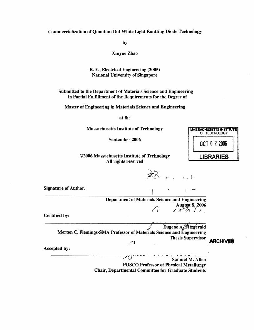
Commercialization of Quantum Dot White Light Emitting Diode Technology by Xinyue Zhao B. E., Electrical Engineering (2005) National University of Singapore Submitted to the Department of Materials Science and Engineering in Partial Fulfillment of the Requirements for the Degree of Master of Engineering in Materials Science and Engineering at the Massachusetts Institute of Technology MASSACHUSETTS INSI1TUTE OF TECHNOLOGY September 2006 OCT 02 2006 @2006 Massachusetts Institute of Technology LIBRARIES All rights reserved Signature of Author: Department of Materials Science and Engineering August 8, 2006 Certified by: tugene A/itzg rald Merton C. Flemings-SMA Professor of Materials Science and Engineering Thesis Supervisor ARCHIVN8 Accepted by:: Samuel M. Allen POSCO Professor of Physical Metallurgy Chair, Departmental Committee for Graduate Students ;ý 7
-
Upload
khangminh22 -
Category
Documents
-
view
1 -
download
0
Transcript of OCT 0 2 2006 - DSpace@MIT
Commercialization of Quantum Dot White Light Emitting Diode Technology
by
Xinyue Zhao
B. E., Electrical Engineering (2005)National University of Singapore
Submitted to the Department of Materials Science and Engineeringin Partial Fulfillment of the Requirements for the Degree of
Master of Engineering in Materials Science and Engineering
at the
Massachusetts Institute of Technology MASSACHUSETTS INSI1TUTEOF TECHNOLOGY
September 2006 OCT 0 2 2006
@2006 Massachusetts Institute of Technology LIBRARIESAll rights reserved
Signature of Author:
Department of Materials Science and EngineeringAugust 8, 2006
Certified by:
tugene A/itzg raldMerton C. Flemings-SMA Professor of Materials Science and Engineering
Thesis SupervisorARCHIVN8
Accepted by::
Samuel M. AllenPOSCO Professor of Physical Metallurgy
Chair, Departmental Committee for Graduate Students
;ý 7
Commercialization of Quantum Dot White Light Emitting Diode Technology
by
Xinyue Zhao
Submitted to the Department of Materials Science andEngineering on August 18, 2006 in Partial Fulfillment of the
Requirements for the Degree of Master of Engineering inMaterials Science and Engineering
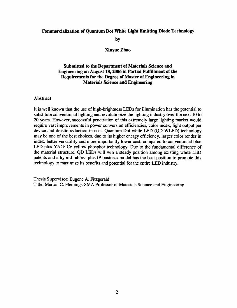
Abstract
It is well known that the use of high-brightness LEDs for illumination has the potential tosubstitute conventional lighting and revolutionize the lighting industry over the next 10 to20 years. However, successful penetration of this extremely large lighting market wouldrequire vast improvements in power conversion efficiencies, color index, light output perdevice and drastic reduction in cost. Quantum Dot white LED (QD WLED) technologymay be one of the best choices, due to its higher energy efficiency, larger color render inindex, better versatility and more importantly lower cost, compared to conventional blueLED plus YAG: Ce yellow phosphor technology. Due to the fundamental difference ofthe material structure, QD LEDs will win a steady position among existing white LEDpatents and a hybrid fabless plus IP business model has the best position to promote thistechnology to maximize its benefits and potential for the entire LED industry.
Thesis Supervisor: Eugene A. FitzgeraldTitle: Merton C. Flemings-SMA Professor of Materials Science and Engineering

Acknowledgements
I am highly indebted to my thesis advisor, Prof. Eugene A. Fitzgerald from MIT and Prof.Soon Jin Chua from NUS. They are both highly accomplished scientists and their help wasinvaluable for completing this thesis. Prof. Fitzgerald is not only a great researcher but alsoan enthusiastic entrepreneur. From the interactions that I had with him, I graduallyaccumulated knowledge on the process of starting up a new high tech business.
Prof Chua has been my advisor for Undergraduate Research and Opportunity Program, myFinal Year Project and now my M.Eng thesis from NUS side. I have been his student for thepast four years. He has provided me with so much support that I cannot thank him in anyform. I only can work harder to continue his passion for research and Singapore industrydevelopment.
Secondly, I would like to thank Dr. Aaron Danner and Mr. Huang En Li from Avago. Theygave me practical suggestions from an industrial point of view on my thesis topic. I alsowould like to thank Mr. Hsueh-Shih Chen from Industrial Technology Research InstituteTaiwan. He answered my emails and gave me very helpful suggestions on practical issuesabout QD white LED, despite the fact that we hardly know each other.
I would like to thank my parents for all their unflinching support they have given andcontinue to give wherever I am. My father has taught me strict self-discipline and strong willto progress in life. My mother has given me strength and capability to face difficulties. Withall the character they have imbibed in me, I was able to first complete my undergraduatestudy abroad in Singapore, then the SMA courses and now, my master's thesis.
I also want to dedicate my great thanks to my SMA AMM&NS 05/06 classmate RangarajanVijayaraghavan, who has given me so much help for my thesis. He has induced my active andinnovative thinking by giving me his brilliant ideas on both science and business topic. He ismy greatest friend in the past year and I believe he will be continuing to be a great friendthrough out my life.
I want to thank Ms. Jocelyn Sales and Dr. John Desforge from MIT SMA office. They helpedme very much in contacting my advisor from MIT side, which was essential for the smoothprogress of my thesis.
Finally I want to thank my fellow classmates SMA AMM&NS 05/06. Without their companyand encouragement, I would have been subjected to tremendous stress due to the toughcoursework. However, I enjoyed my life and study for the past year because of theirexistence.
I plan to enter the industry as an accomplished engineer having learnt so much from eminentprofessors and in the coming years put to good use the ideas and concepts they have taughtme. Someday I hope to bring about a major contribution to the scientific community thatimproves the common man's everyday life. That will be the day when I would have left alasting impression in the sands of time.
August 9, 2006
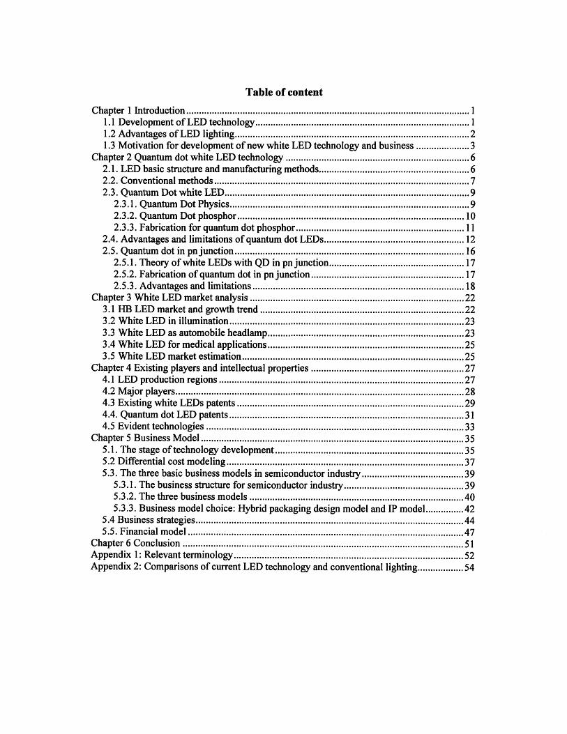
Table of content
C hapter 1 Introduction ............................................................................................................... 11.1 Development of LED technology......................................................................... 11.2 Advantages of LED lighting................................................................................... 21.3 Motivation for development of new white LED technology and business .................. 3
Chapter 2 Quantum dot white LED technology ..................................... ... ............. 62.1. LED basic structure and manufacturing methods................................................... 62.2. Conventional m ethods ............................................................................................ 72.3. Quantum Dot white LED ....................................... ................................................... 9
2.3.1. Quantum Dot Physics..................................................................................... 92.3.2. Quantum Dot phosphor.................................................... 102.3.3. Fabrication for quantum dot phosphor................................ ............................ 11
2.4. Advantages and limitations of quantum dot LEDs................................ ........ 122.5. Quantum dot in pnjunction.......................................................................................... 16
2.5.1. Theory of white LEDs with QD in pn junction................... ........ 172.5.2. Fabrication of quantum dot in pn junction.............................. ............ 172.5.3. Advantages and limitations ......................................................................... 18
Chapter 3 White LED market analysis ....................................................... 223.1 HB LED market and growth trend ..................................... ..... ................ 223.2 W hite LED in illum ination ............................................................ .......................... 233.3 White LED as automobile headlamp............................................. 233.4 White LED for medical applications............................................. 253.5 White LED market estimation ........................................................................... 25
Chapter 4 Existing players and intellectual properties ..................................... ...... 274.1 LED production regions ............................................................. ............................. 274.2 M ajor players................................................................................................................. 284.3 Existing white LEDs patents ............................................................................. 294.4. Q uantum dot LED patents ............................................................................................ 314.5 Evident technologies ......................................................................... ...................... 33
Chapter 5 Business M odel ........................................... ...................................................... 355.1. The stage of technology development.......................... ................. 355.2 D ifferential cost m odeling ............................................................ ........................... 375.3. The three basic business models in semiconductor industry................................ 39
5.3.1. The business structure for semiconductor industry.............................. ........... 395.3.2. The three business models ..................................... ...... .................. 405.3.3. Business model choice: Hybrid packaging design model and IP model ........ 42
5.4 B usiness strategies......................................................................................................... 445.5. Financial m odel .............................................. ........................................................ 47
C hapter 6 C onclusion ....................................................... ................................................. 51Appendix 1: Relevant term inology..................................... ............................................... 52Appendix 2: Comparisons of current LED technology and conventional lighting............... 54
List of figures
Figure 1-1 Trend of increasing light output per package of LEDs and decreasing of cost........ 2Figure 1-2 Energy consumption in US ..................................... ....... ................... 4Figure 2-1 Schematic of the LED and GaN based LED die structure .................................... 6Figure 2-2 General types of White-Light LED Devices .................................................. 7Figure 2-3 Structure of white LED and phosphor conversion ........................................ 8Figure 2-4 Spectrum of white LED ........................................ ........ ................. 9Figure 2-5 Illustration of a buried InAs quantum dot embedded into a GaAs barrier materiall0Figure 2-6 Quantum Dot phosphor with different positions.................. ........ 12Figure 2-7 Performance of the QD white LEDs ................................................................... 12Figure 2-8 Clear differences of the color rendition in the August Renoir painting ................. 14Figure 2-9 Light traveling pass in LED .................................... ........................... 15Figure 2-10 Schematic diagram for pn junction with quantum dot in between................... 17Figure 3-1 The key applications for HB-LEDs............................................ 22Figure 3-2 The light output of an LED Headlamp prototype ....................................... 25Figure 4-1 Deals and disputes in the white LED industry: the key intellectual property
relationships as of September 2005 ................................................................. 31Figure 4-2 Two embodiments of an LED according to the invention .................................. 32Figure 5-1 Technology development and confidence in chosen market ................................. 35Figure 5-2 Semiconductor industry production flow.................................. ............ 40Figure 5-3 Basic business models for semiconductor industry ............................................... 41Figure 5-4 Large and growing SIP market (source: Gartner group)................................. 42

List of tables
Table 4-1 Key US patents covering white LEDs.............................. .... ........ 30Table 4-2 M ajor phsphors patented ......................................................................... 30Table 5-1 Price comparison of CdSe and YAG precursors .................................................... 37Table 5-2 Lumileds LED price comparison................................38
Chapter 1 Introduction
Until the last decade, LEDs could only produce green, red, and yellow light, which
limited their use in only signs, signals and indicators. Then came blue LEDs, which have
since been altered to emit white light, which makes the dream of LEDs replacing
conventional incandescent and fluorescent lighting within approach. However, there are
still many problems with the current technology, which need novel ideas to solve and
hence the present white LED performance can be largely improved to the extent that
LEDs can be made comparable or even better the current lighting. Quantum dot white
LED is one of them and it has the promising potential to pull the dream nearer.
1.1 Development of LED technology
Since the development of the first commercial visible light emitting diodes (LEDs) in
1968, LED technology has under gone a series of both evolutionary and revolutionary
changes. For the first 25 years of their history, the materials available for LED fabrication
(primarily gallium phosphide (GaP) and gallium arsenide phosphide (GaAsP) were low
in efficiency and allowed LEDs to be used primarily as low brightness indicator lamps
and alphanumeric displays. Moreover, their spectral range was limited to yellow-green,
orange, and red.
In the early to mid-1990s a new generation of LED materials was developed that enabled
the fabrication of high-brightness devices across the entire visible spectrum, opening up
large new markets that were not addressable by previous material technologies. These
materials, indium gallium aluminium phosphide (InGaAlP) and indium gallium nitride
(InGaN), have formed the foundation for the large (1.8 billion in 2002) high brightness
LED industry that has evolved since 1995.
Presently, LEDs are still in the stage of further improvement in their luminous efficiency
and reduction of cost. Figure 1-1, shows how the light output of LEDs has increased 201
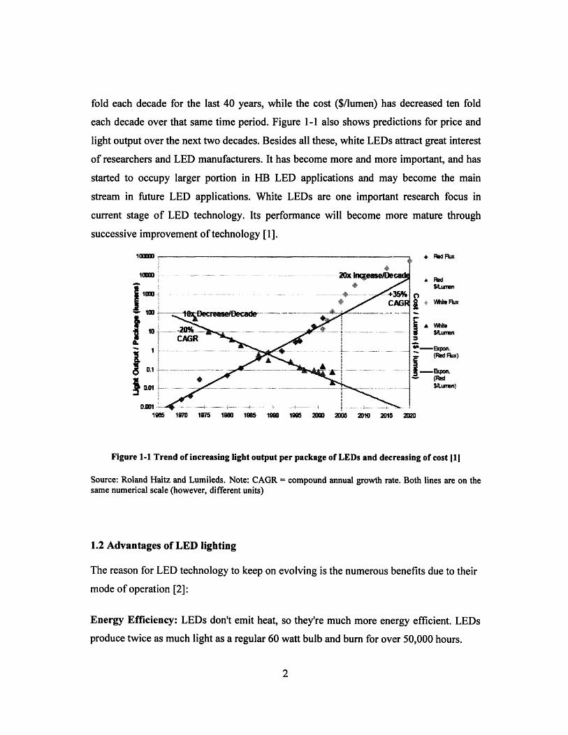
fold each decade for the last 40 years, while the cost ($/lumen) has decreased ten fold
each decade over that same time period. Figure 1-1 also shows predictions for price and
light output over the next two decades. Besides all these, white LEDs attract great interest
of researchers and LED manufacturers. It has become more and more important, and has
started to occupy larger portion in HB LED applications and may become the main
stream in future LED applications. White LEDs are one important research focus in
current stage of LED technology. Its performance will become more mature through
successive improvement of technology [1].
1lUUUU
1000Im
10
0.1
Dim
* Red1
Ratumn+ Wihe Fka
A SiMei
1905 1970 1975 19890 190 1900 2000 2005 201D 2015 2020
Figure 1-1 Trend of increasing light output per package of LEDs and decreasing of cost [1]
Source: Roland Haitz and Lumileds. Note: CAGR = compound annual growth rate. Both lines are on thesame numerical scale (however, different units)
1.2 Advantages of LED lighting
The reason for LED technology to keep on evolving is the numerous benefits due to their
mode of operation [2]:
Energy Efficiency: LEDs don't emit heat, so they're much more energy efficient. LEDs
produce twice as much light as a regular 60 watt bulb and burn for over 50,000 hours.
Long Life: Some LEDs are projected to produce a long service life of about 100,000
hours. For this reason LEDs are ideal for hard-to-reach/maintain fixtures. Much longer
life reduces maintenance requirements.
Durable: LEDs are highly rugged. They feature no filament that can be damaged due to
shock and vibrations. They are subject to heat, however, and being overdriven by the
power supply.
Small Size/Design Flexibility: A single LED is very small and produces little light
overall. However, this weakness is actually its strength. LEDs can be combined in any
shape to produce desired lumen packages as the design goals and economics permit. In
addition, LEDs can be considered miniature light fixtures; distribution of light can be
controlled by the LEDs' epoxy lens, simplifying the construction of architectural fixtures
designed to utilize LEDs.
Other Benefits, such as lights instantly, can be easily dimmed, silent operation, low-
voltage power supply (increased safety).
1.3 Motivation for development of new white LED technology and business
All these advantages make great impact on our life. First, and the most important, is the
impact on energy consumption. In the U.S., about one-third of all primary energy is used
to produce electricity, and of this electricity about one-fifth is used to produce light. If the
displacement of traditional lighting by solid-state lighting can be accelerated by even one
year, U.S. consumers would save roughly $35 billion. The use of high-brightness LEDs
for illumination has the potential to revolutionize the lighting industry over the next 10 to
20 years [3].
Ifi
III
IIII
Year
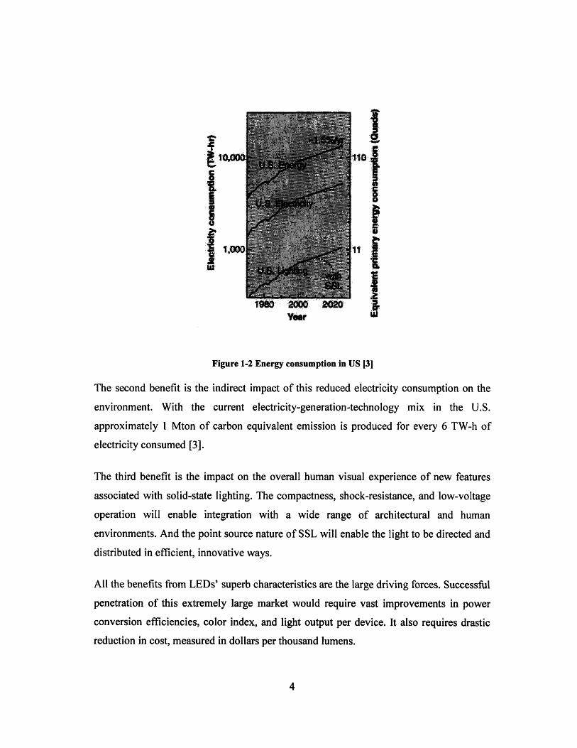
Figure 1-2 Energy consumption in US [31
The second benefit is the indirect impact of this reduced electricity consumption on the
environment. With the current electricity-generation-technology mix in the U.S.
approximately 1 Mton of carbon equivalent emission is produced for every 6 TW-h of
electricity consumed [3].
The third benefit is the impact on the overall human visual experience of new features
associated with solid-state lighting. The compactness, shock-resistance, and low-voltage
operation will enable integration with a wide range of architectural and human
environments. And the point source nature of SSL will enable the light to be directed and
distributed in efficient, innovative ways.
All the benefits from LEDs' superb characteristics are the large driving forces. Successful
penetration of this extremely large market would require vast improvements in power
conversion efficiencies, color index, and light output per device. It also requires drastic
reduction in cost, measured in dollars per thousand lumens.
.m
Reference
[1]. "Solid-State Lighting Research and Development Protfolio", Multi-Year Program
Plan FY'07-FY' 12 prepared for: Lighting Research and Development Building
Technologies Program Office of Evergy Efficiency and Renewable Energy U.S.
Department of Energy
[2]. http://lightingdesignlab.com/articles/LED_fund/led advant.htm
[3]. Jeffrey V.Tsao, "Roadmap projects significant LED penetration of lighting market
by 2010", Laser Focus World, May 2003
Chapter 2 Quantum dot white LED technology
2.1. LED basic structure and manufacturing methods
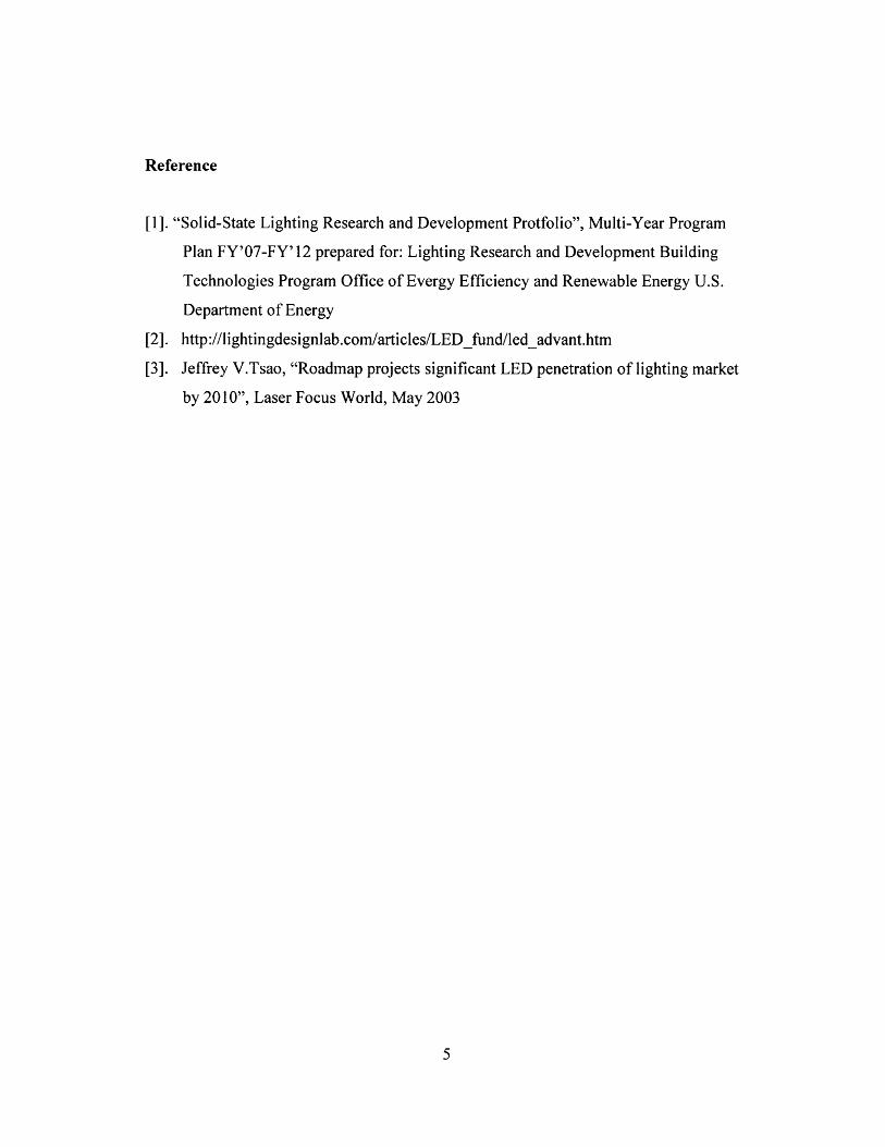
Commercial LED normally includes of three parts: the semiconductor die itself, the
mounting substrate and the encapsulant. An LED die (chip) normally is fabricated using
LPE, VPE or MOCVD. After leads are put on, the chip is encapsulated. Figure 2-1(a)
shows the schematic structure of a commercial LED. Figure 2-1(b) shows an InGaN die
structure as an example.
p-tyiit / ddp-c Oit3
in-tV L rKmI) ttip
Leadt framtý
n-type GaN
buffcr byriramro
subrante
Figure 2-1 Schematic of the LED and GaN based LED die structure [1,2]
Different colors of LEDs have been achieved from infrared to ultraviolet mainly based on
different materials used for the die, as we know the color emitted is directly related to the
bandgap of the chip material used. Typically, AlGaAs is for red, AlGaInP is for orange-
yellow-green, and AlGaInN is for green-blue. The fact that different material is used for
producing different color, may lead to a problem: How to produce white light, a
combination of red, blue and green, with a single chip? Since white light has many
important applications, such as general illumination, surgical operation and headlights for
automobiles and trucks, a lot of effort has been put in to study producing white LED with
the most efficient design. In this chapter, the conventional methods and novel methods of
mixing colors to get white light are discussed.
n
2.2. Conventional methods
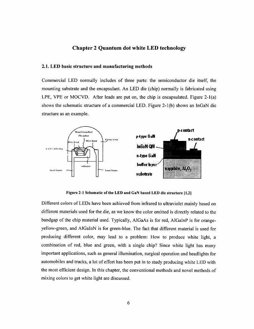
There are two common approaches for producing white-light LED: (a) discrete color-
mixing (b) phosphor-conversion LEDs (pc-LEDs) [3]. The schematic diagram of these
two methods is shown below in Fig. 2-2:
.eit White
pcLEDosphors Color
Mixinga or UV LED
mixing optics
colored LEDs
(a) Phosphor-Conversion LED (b) Color-Mixing
Figure 2-2 General types of White-Light LED Devices
Color mixing approach starts with discrete colored sources and uses color mixing optics
to blend together the light output from these sources to create white-light emission. The
lamp contains a minimum of two LEDs (blue and yellow), but can also have three (red,
blue, and green) or four (red, blue, green, and yellow). As no phosphors are used, there is
no energy lost in the conversion process, thereby exhibiting the potential for higher
efficiency. This method also gives good quality white light with high color rendering
index (CRI). The spectrum is shown in Fig 2-4 (a). Nichia was the first manufacturer to
use this method to produce white-light LED devices on a commercial scale in 1997. It has
since been adopted by numerous other manufacturers as the method for white-light LEDs
used in display and conspicuity applications [3].
The drawback of this approach is the increased complexity for blending the discrete
colors. It would require multi-chip mounting and potentially sophisticated optics for
blending the discrete colors. It may also require color control feedback circuitry that
could address the different degradation and thermal characteristics of the discrete LED
chips. Furthermore, this method is more costly than wavelength conversion method. Due
to all these disadvantages, this method is not commonly adopted today. The dominant
method to produce white LEDs is pc-LEDs.
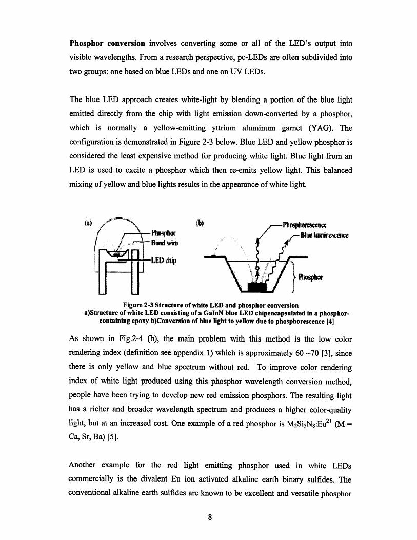
Phosphor conversion involves converting some or all of the LED's output into
visible wavelengths. From a research perspective, pc-LEDs are often subdivided into
two groups: one based on blue LEDs and one on UV LEDs.
The blue LED approach creates white-light by blending a portion of the blue light
emitted directly from the chip with light emission down-converted by a phosphor,
which is normally a yellow-emitting yttrium aluminum garnet (YAG). The
configuration is demonstrated in Figure 2-3 below. Blue LED and yellow phosphor is
considered the least expensive method for producing white light. Blue light from an
LED is used to excite a phosphor which then re-emits yellow light. This balanced
mixing of yellow and blue lights results in the appearance of white light.
-Blwe uminm -twe.... ......•... ... ..'... , -B u l n i
~ L
Figure 2-3 Structure of white LED and phosphor conversiona)Structure of white LED consisting of a GaInN blue LED chipencapsulated in a phosphor-
containing epoxy b)Conversion of blue light to yellow due to phosphorescence [4]
As shown in Fig.2-4 (b), the main problem with this method is the low color
rendering index (definition see appendix 1) which is approximately 60 -70 [3], since
there is only yellow and blue spectrum without red. To improve color rendering
index of white light produced using this phosphor wavelength conversion method,
people have been trying to develop new red emission phosphors. The resulting light
has a richer and broader wavelength spectrum and produces a higher color-quality
light, but at an increased cost. One example of a red phosphor is M2SisN8 :Eu 2+ (M
Ca, Sr, Ba) [5].
Another example for the red light emitting phosphor used in white LEDs
commercially is the divalent Eu ion activated alkaline earth binary sulfides. The
conventional alkaline earth sulfides are known to be excellent and versatile phosphor
rii,

materials. As members of alkaline earth sulfide families, especially Eu2+ doped SrS
and CaS were considered to be the most promising candidates for red phosphor.
However, the binary sulfide-based phosphors have low chemical stabilities and low
luminescence [6].
The UV LED approach starts with a UV-emitting LED chip that energizes phosphors
designed to emit light in the visible spectrum. All the UV energy is adsorbed and
converted into the visible spectrum by the phosphors. A pc-LED using a UV LED
chip is similar to the blue LED system, but has some important differences. In this
type of pc-LED, the LED radiates energy in the UV (340-380nm) or near-UV
(<430nm) that excites phosphors, which down-convert the UV radiation into the
visible wavelengths. The discrete emissions from the phosphors combine to produce
white light [3].
rnospEmiss
Canmhined
I·1A PAPr FAA ~A i1
470 525 590 630 (nm) 417 L o 5tV w5 ) Inmi
(a) (b)
Figure 2-4 Spectrum of white LED(a). Color mixing (b). Wavelength conversion (blue LED and yellow phosphor) [71
2.3. Quantum Dot white LED
2.3.1. Quantum Dot PhysicsQuantum dots are nanocrystals with size smaller than 10nm. Each dot contains only
33 or 34 pairs of atoms or from 100 to 1,000 electrons. In a quantum dot (QD),
electrons and holes are confined in all three dimensions [8]. They have very different
behaviors compared to electrons and holes in bulk semiconductor due to the
confinement. They have discretized quantum dot bands and therefore semiconductor
quantum dots, e.g., InAs dots embedded in GaAs, behave like non- or weakly
interacting single atoms as shown in Figure 2-5.
9
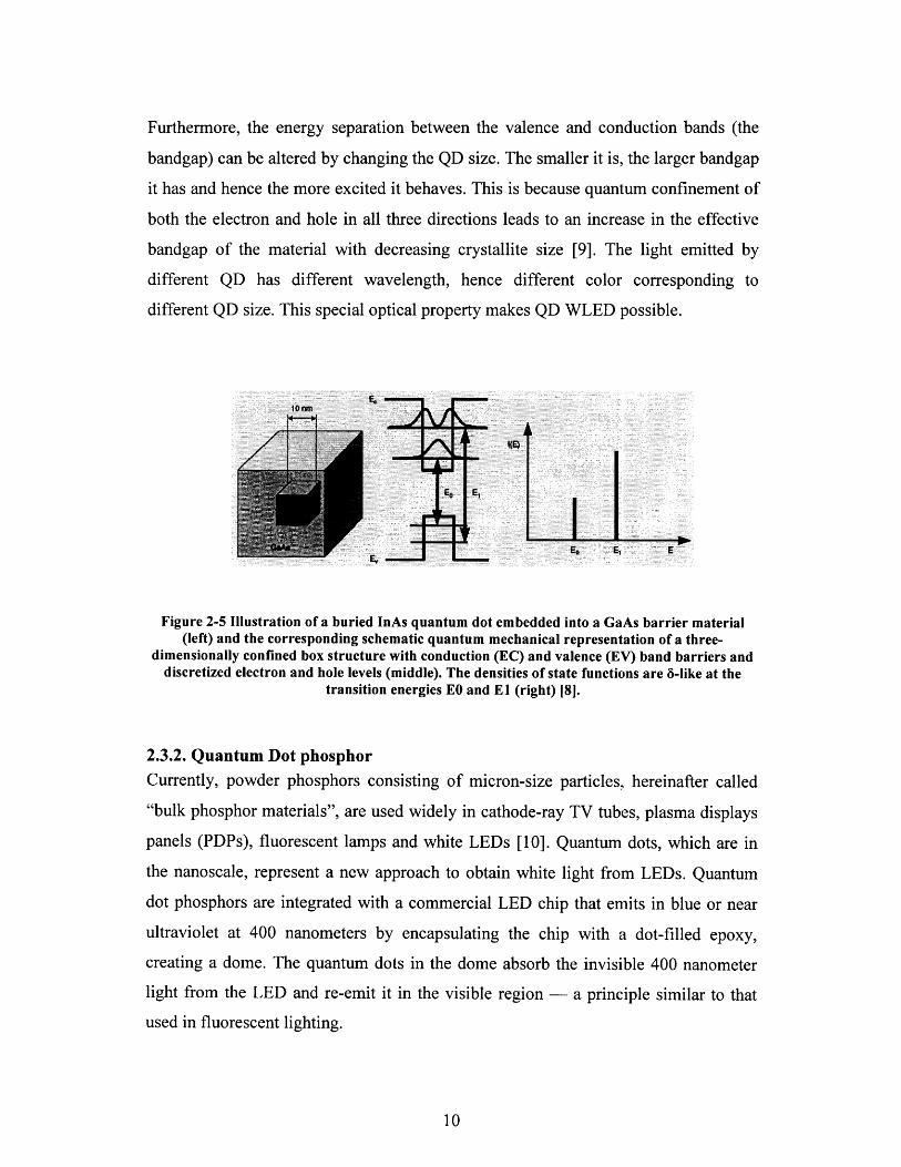
Furthermore, the energy separation between the valence and conduction bands (the
bandgap) can be altered by changing the QD size. The smaller it is, the larger bandgap
it has and hence the more excited it behaves. This is because quantum confinement of
both the electron and hole in all three directions leads to an increase in the effective
bandgap of the material with decreasing crystallite size [9]. The light emitted by
different QD has different wavelength, hence different color corresponding to
different QD size. This special optical property makes QD WLED possible.
Figure 2-5 Illustration of a buried InAs quantum dot embedded into a GaAs barrier material(left) and the corresponding schematic quantum mechanical representation of a three-
dimensionally confined box structure with conduction (EC) and valence (EV) band barriers anddiscretized electron and hole levels (middle). The densities of state functions are 6-like at the
transition energies EO and El (right) [8].
2.3.2. Quantum Dot phosphorCurrently, powder phosphors consisting of micron-size particles, hereinafter called
"bulk phosphor materials", are used widely in cathode-ray TV tubes, plasma displays
panels (PDPs), fluorescent lamps and white LEDs [10]. Quantum dots, which are in
the nanoscale, represent a new approach to obtain white light from LEDs. Quantum
dot phosphors are integrated with a commercial LED chip that emits in blue or near
ultraviolet at 400 nanometers by encapsulating the chip with a dot-filled epoxy,
creating a dome. The quantum dots in the dome absorb the invisible 400 nanometer
light from the LED and re-emit it in the visible region - a principle similar to that
used in fluorescent lighting.
LED light still impinges on phosphor coating composed of quantum dots, but instead
of encountering traditional semiconductor energy bands, the LED photons would
encounter the discretized energy bands specific to quantum dots. The discretized
nature of quantum dot bands means that the energy separation between the valence
and conduction bands (the bandgap) can be altered with the addition or the subtraction
of just one atom, making for a size dependent bandgap. Predetermining the size of the
quantum dots would fix the emitted photon wavelength at the appropriate customer-
specified color, even if it is not naturally occurring, an ability limited only to dots.
For nanophosphors, white light is generated by intermixing red, green, and blue
emitting dots homogenously within the phosphor. Thus, quantum dots need only a
single excitation source for multiple emission colors, even to the point of producing
industry quality white light.
2.3.3. Fabrication of quantum dot phosphor
An example of white LED with quantum dot phosphor was demonstrated by Hsueh-
Shih Chen's group [11]. White light-emitting diodes (WLEDs) were fabricated by
combining blue InGaN chips with luminescent colloidal core-shell CdSe-ZnSe QDs.
The CdSe QDs were synthesized in supersaturated solution. Experimentally, CdO,
TOPO, and HPA/TDPA were loaded in a three-neck flask. At about 3000C, reddish
CdO powder was dissolved and generated a colorless homogeneous solution.
Introducing tellurium, selenium, and sulfur stock solutions yield high quality
nanocrystals. TEM measurements indicate narrow distribution of these QD size and
X-ray powder diffraction shows high crystallinity of these wurtzite nanocrystals. The
dot size can be easily controlled by the reaction time [17, 12].
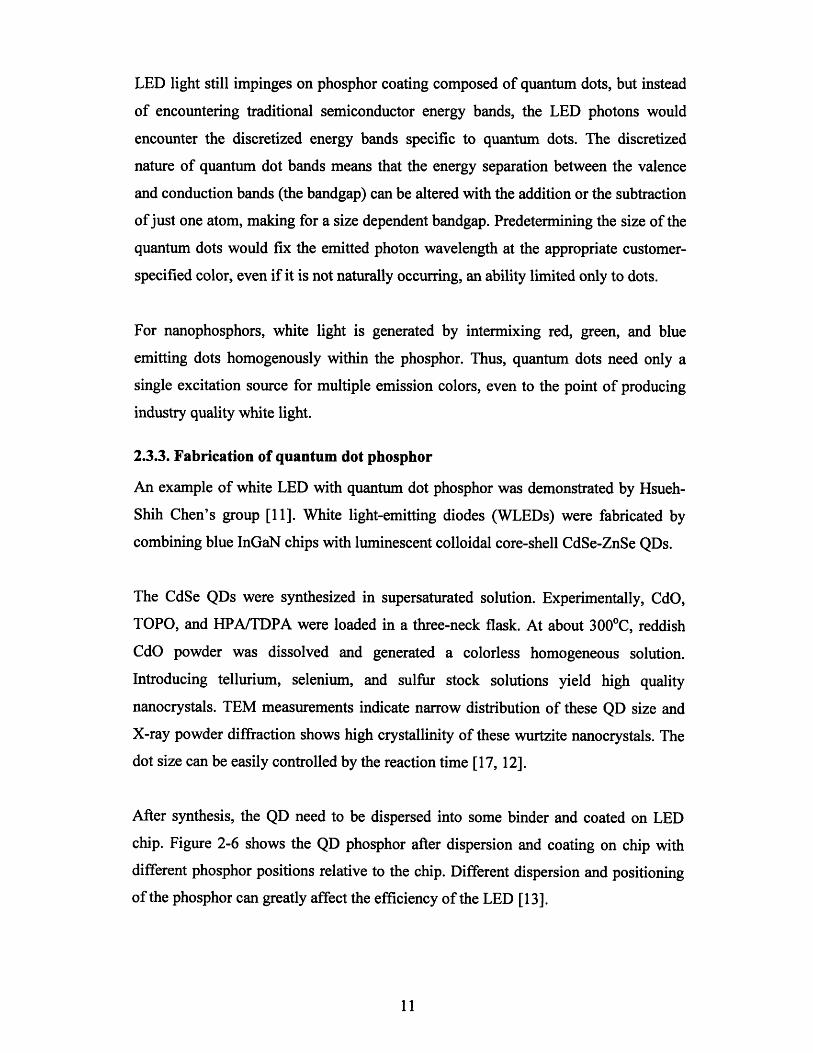
After synthesis, the QD need to be dispersed into some binder and coated on LED
chip. Figure 2-6 shows the QD phosphor after dispersion and coating on chip with
different phosphor positions relative to the chip. Different dispersion and positioning
of the phosphor can greatly affect the efficiency of the LED [13].
1W M -
Dispersed Phosphor Settled Phosphor Planar Phosphor
Figure 2-6 Quantum Dot phosphor with different positions [14]
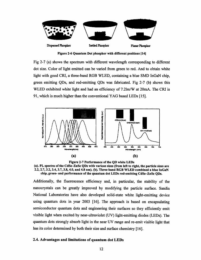
Fig 2-7 (a) shows the spectrum with different wavelength corresponding to different
dot size. Color of light emitted can be varied from green to red. And to obtain white
light with good CRI, a three-band RGB WLED, containing a blue SMD InGaN chip,
green emitting QDs, and red-emitting QDs was fabricated. Fig 2-7 (b) shows this
WLED exhibited white light and had an efficiency of 7.21m/W at 20mA. The CRI is
91, which is much higher than the conventional YAG based LEDs [15].
Waveloenh(nm) Wavelength (nm)
(a) (b)
Figure 2-7 Performance of the QD white LEDs(a). PL spectra of the CdSe-ZnSe QDs with various sizes (from left to right, the particle sizes are2.2, 2.7, 3.2, 3.4, 3.7, 3.8, 4.0, and 4.8 nm). (b). Three-band RGB WLED combined a blue InGaN
chip, green- and performance of the quantum dot LEDs red-emitting CdSe-ZnSe QDs.
Additionally, the fluorescence efficiency and, in particular, the stability of the
nanocrystals can be greatly improved by modifying the particle surface. Sandia
National Laboratories have also developed solid-state white light-emitting device
using quantum dots in year 2003 [16]. The approach is based on encapsulating
semiconductor quantum dots and engineering their surfaces so they efficiently emit
visible light when excited by near-ultraviolet (UV) light-emitting diodes (LEDs). The
quantum dots strongly absorb light in the near UV range and re-emit visible light that
has its color determined by both their size and surface chemistry [16].
2.4. Advantages and limitations of quantum dot LEDs
I
_e
]
QD LEDs have many advantages over LEDs with conventional phosphor.
Theoretically they have better CRI at cheaper cost, better luminous efficacy, more
flexible and stable. The utilization of quantum dot to produce white light may
overcome some problems with current white LED technology [17].
Advantage 1:: High color rendering index and easy color tuning
For nanophosphors, while the optical properties of conventional bulk phosphor
powders are determined solely by the phosphor's chemical composition, in quantum
dots the optical properties such as light absorbance are determined by the size of the
dot. Changing the size produces dramatic changes in color. This also can be applied to
QD in pn junctions. QD size will always affect the color of the light emitting. Thus, it
provides a convenient way in tuning the emission light color.
More importantly, since different size QDs emit light with different wavelength, when
all these lights are mixed together, it gives high CRI. The CRI can be as high as 91
simply achieved by using phosphor with different QD size. And a typical CRI value
for currently commercialized white LED is below 70 (appendix 3). Higher CRI with
conventional phosphor will have higher cost.
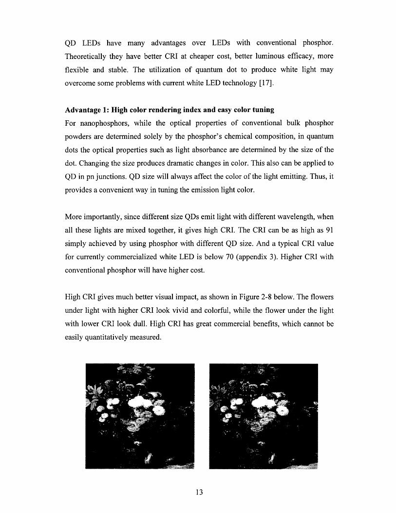
High CRI gives much better visual impact, as shown in Figure 2-8 below. The flowers
under light with higher CRI look vivid and colorful, while the flower under the light
with lower CRI look dull. High CRI has great commercial benefits, which cannot be
easily quantitatively measured.
Figure 2-8 Clear differences of the color rendition in the August Renoir painting(left hand side: high CRI; right hand side low CRI) [7]
Advantage 2: High energy efficiency
The energy efficiency of presently available commercial white LED products is in the
range of 40 lumens per watt. The target for solid-state light sources is to reach 150
lumens per watt by 2012. For white LEDs to reach this target, improvements are
needed in several areas, including the internal quantum efficiency [18], the light
extraction efficiency, and the phosphor efficiency [19]. There are several factors,
which affect the phosphor efficiency, the physical shape of the phosphor, position of
phosphor, the refractive index mismatch and the photoluminescence efficiency.
There are energy losses when the light is down converted to longer wavelength light.
This loss is unavoidable, but there are some other losses that can be reduced or even
avoided by substituting conventional phosphor with QD phosphor.
a). The optical property of such QD system is closely related to the nature of excitons,
which are the electron-hole pairs that can be created by the absorption of photons. The
recombination is much easier to happen for QD than in bulk material. Hence,
wavelength conversion loss can be greatly reduced and luminous efficacy can be
further improved. According to literature, the quantum efficiency for matrix free QD
is between 1% to 10%. We take the average 5% in the following calculation [20].
The typical output of YAG is 8 photons/keV[21]. Assuming the wavelength of
incoming photons is 450nm, which is in the blue range, the photon energy is
1.24/0.45= 2.76 eV. The total number of incoming photons will be 362. The rough
quantum efficiency is 8/362=2.2%. So we can see that CdSe QD has larger quantum
efficiency.
b). For nanophosphors, since QD has a much smaller size than the wavelength of
visible light, it eliminates all light scattering and the associated optical losses. Optical
backscattering losses using larger conventional phosphors reduce the package
efficiency by as much as 50 percent [22, 23]. A method to cut down the loss due to
backward scattering of light would be in bringing particle size down to the nano level
where light scattering becomes faint [10]. Physically, the rough surface of QD
phosphor reduces backscattering. Nano-sizing not only reduces light scattering but
also improves the relative surface area of the material.
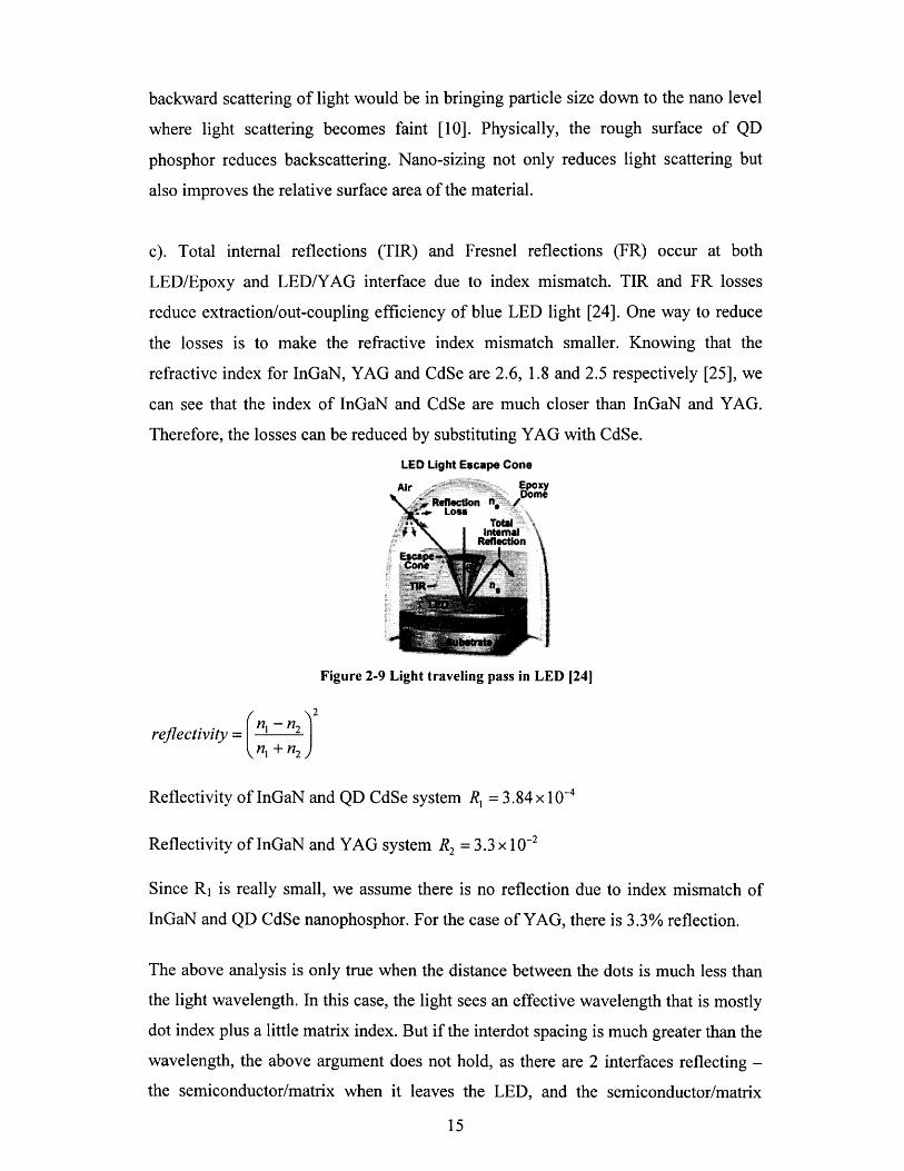
c). Total internal reflections (TIR) and Fresnel reflections (FR) occur at both
LED/Epoxy and LED/YAG interface due to index mismatch. TIR and FR losses
reduce extraction/out-coupling efficiency of blue LED light [24]. One way to reduce
the losses is to make the refractive index mismatch smaller. Knowing that the
refractive index for InGaN, YAG and CdSe are 2.6, 1.8 and 2.5 respectively [25], we
can see that the index of InGaN and CdSe are much closer than InGaN and YAG.
Therefore, the losses can be reduced by substituting YAG with CdSe.
LED Light Escape Cone
KYne
Figure 2-9 Light traveling pass in LED [24]
2
reflectivity = n, +-n2
Reflectivity of InGaN and QD CdSe system R, = 3.84 x 10- 4
Reflectivity of InGaN and YAG system R2 = 3.3 x 10⁻²
Since R1 is really small, we assume there is no reflection due to index mismatch of
InGaN and QD CdSe nanophosphor. For the case of YAG, there is 3.3% reflection.
The above analysis is only true when the distance between the dots is much less than
the light wavelength. In this case, the light sees an effective wavelength that is mostly
dot index plus a little matrix index. But if the interdot spacing is much greater than the
wavelength, the above argument does not hold, as there are 2 interfaces reflecting -
the semiconductor/matrix when it leaves the LED, and the semiconductor/matrix
15
when it enters the dot. In this case, the index of the matrix comes into the picture.
The index mismatch of matrix/LED, matrix/CdSe becomes important. Another effect
that can influence the light path is that if the dot spacing is on the order of the
wavelength of light, a lot of scattering will occur. The scattering may increase the
chances of light absorbance, or it may also scatter the light away and reduce the
absorbance. Therefore, dispersion configuration in the matrix and the matrix material
has great influence on the energy efficiency. A good configuration and suitable
material has the potential to reduce reflection and increase energy efficiency [26].
Advantage 3: Low cost
QD phosphor has lower cost mainly due to cheaper precursor and an easier process.
The details on the estimates of cost will be discussed in chapter 5.
Advantage 4: Better versatility
For nanophosphors, the extremely small size and versatility of form for quantum dots
would allow them to be inserted into any medium necessary to accommodate any
underlying light emitting source. For QDs inserted in pn junction, their extremely
small size and versatility of form allows them to be inserted into any medium
necessary - paint, water, plastics and more [17].
Limitation & obstacles
According to Appendix 2, commercialized white LED has a luminous efficacy 20
Im/W. The current QD LED only has a luminous efficiency around 7 Im/W. This may
be due to poor dispersion and the material that is used for the binder. The QDs
photoluminescence is strongly affected by its binders, which also influence QDs
stability and dispersion. A good binder in which QDs disperse well may be found but
the QD emission intensity reduces. After dispersing, QDs need to be coated onto the
LED chip. Poor coating technique may be another reason for low luminescence.
Another main problem with this technology is thermal stability especially when QDs
loaded on high-power GaN chips [28].
2.5. Quantum dot in pn junction
2.5.1. Theory of white LEDs with QD in pn junction
Current LED technology produces electroluminescent, non-tunable light emission
through the use of a p-n semiconductor junction. As an electrical current is driven
through the junction, electrons are excited across the bandgap into the conduction
band. From there, the electrons diffuse away from the junction, and proceed to decay
back across the bandgap to the valence band, accompanied by the emission of light
with a wavelength corresponding to the energy of the bandgap.
Quantum dot material was used as LED phosphor in the earlier part of this chapter. In
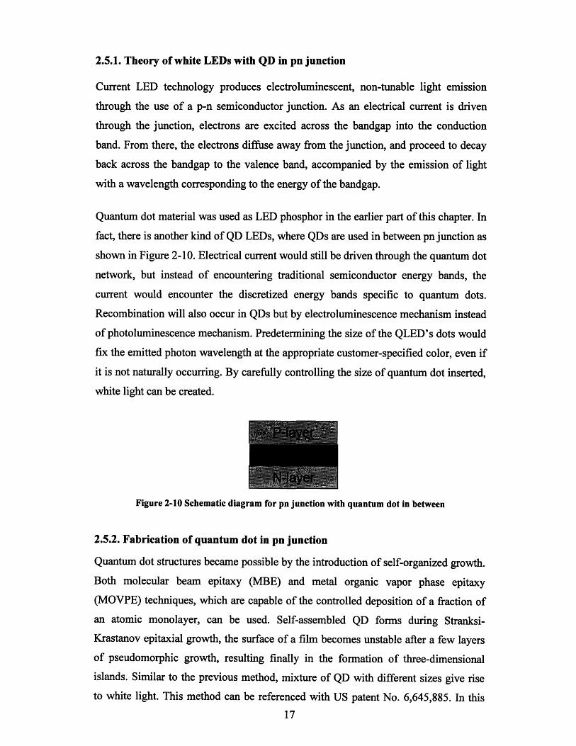
fact, there is another kind of QD LEDs, where QDs are used in between pn junction as
shown in Figure 2-10. Electrical current would still be driven through the quantum dot
network, but instead of encountering traditional semiconductor energy bands, the
current would encounter the discretized energy bands specific to quantum dots.
Recombination will also occur in QDs but by electroluminescence mechanism instead
of photoluminescence mechanism. Predetermining the size of the QLED's dots would
fix the emitted photon wavelength at the appropriate customer-specified color, even if
it is not naturally occurring. By carefully controlling the size of quantum dot inserted,
white light can be created.
Figure 2-10 Schematic diagram for pn junction with quantum dot in between
2.5.2. Fabrication of quantum dot in pn junction
Quantum dot structures became possible by the introduction of self-organized growth.
Both molecular beam epitaxy (MBE) and metal organic vapor phase epitaxy
(MOVPE) techniques, which are capable of the controlled deposition of a fraction of
an atomic monolayer, can be used. Self-assembled QD forms during Stranksi-
Krastanov epitaxial growth, the surface of a film becomes unstable after a few layers
of pseudomorphic growth, resulting finally in the formation of three-dimensional
islands. Similar to the previous method, mixture of QD with different sizes give rise
to white light. This method can be referenced with US patent No. 6,645,885. In this
17
patent, Indium Nitride (InN) and Indium-rich Indium Gallium Nitride (InGaN)
quantum dots embedded in single and multiple InxGal-xN quantum wells (QWs) are
formed by using TMIn and /or Triethylindium (TEIn) as antisurfactant during
MOCVD growth.
Another way of incorporating QD into the p-n junction conductive layer is to mix
colloidally produced quantum dot with a transparent and electrically conductive host
matrix, and coat in between the junction. This way requires less cost than epitaxy [9].
2.5.3. Advantages and limitations
Advantage 1: Even higher energy efficiency
There are always energy losses in terms of pc-LED. As mentioned earlier in this
chapter, the energy losses are associated with the conversion from shorter wavelength
to longer wavelength. Some of the photons may just be absorbed by the phosphor
instead of being converted to yellow light. The loss is also related to the reflection
and backscattering between LED and phosphor interface. However, for this QD in pn
junction method, there is no phosphor, so all the losses can be avoided. Below is the
estimation of the amount of energy that can be saved compared to the conventional
yellow.
From blue light to red light, the amount of energy saved is:
Energy of blue light: 1.24/0.46 = 2.7eV
Energy of red light: 1.24/0.70 = 1.77eV
Percentage of engery losses: 0.93/2.7 * 100% = 34%
So 34% energy due to wavelength conversion can be saved by adopting this method.
Advantage 2: Even lower cost
Since there is no phosphor, the cost for phosphor is totally reduced. As we analyzed in
part 2.4, the cost of phosphor is roughly 1/6 of the total white LED cost or the 1/5 of a
blue LED cost.
Limitations and Obstacles 1

According to the above mentioned patent, growth of the active layers of blue and
green LEDs can be achieved, but it is not efficient in producing red light from GaN pn
junction. A possible reason is, in industry, the material system Ga, In and N is used to
produce blue or green light rather than yellow light due to the natrual bandgap range
of these material. It is very difficult to achieve red light emission bandgap using this
material system. Due to this reason, the red light emitting quantum dot is hard to
grow.
Limitations and obstacles 2
Another possible reason it is hard to get good control of quantum dot size and position
[27]. Although theoretically it should work and give different color light with
different dot sizes, in production line there may not be a workable die among 100
wafers. Since the repeatability is very low, so far none of the fabs are willing to invest
in this technology.
Quantum dot is a very new research field, some phenomena associated with it are not
well understood so far and its growth control is also in a lab research stage. QDs is a
broad field and it has many applications. QD LED is just a technology overlap of
Quantum dot and LEDs. To finally achieve QD in pn junction LED, QD technology
needs to be developed to a more mature stage.
Limitations and obstacles 3
The growth of InxGal-xN alloys and quantum wells is extremely difficult mostly due
to the trade-off between the epilayer quality and the amount of InN incorporation into
the alloy. Lowering the growth temperature results in the indium content at the
expense of reduced crystalline quality. The lattice mismatch and different thermal
stability of the two constituents InN and GaN, also complicate the growth of InxGal_
xN. The lattice mismatch can lead to a miscibility gap [7] which causes fluctuations of
In content across the film.
Limitation and obstacles 4
For the colloidally produced quantum dot in electrically conductive layer, the devices
require a transparent, electrically conductive host matrix, which severely limits the
available materials for producing LEDs by this method [9].
Reference
[1]. Cheng-Huang KUO, Jinn-Kong SHEU, Shoou-Jinn CHANG, "n-
UV+Blue/Green/Red White Light Emitting Diode Lamps", Jpn. J. Appl. Phys.
Vol. 42 (2003) pp. 2284-2287
[2]. http://www.nanotechnology.bilkent.edu.tr/research%20areas/
documents/LEDs.html
[3]. "Solid-State Lighting Research and Development Protfolio", Multi-Year
Program Plan FY'07-FY' 12 prepared for: Lighting Research and Development
Building Technologies Program Office of Evergy Efficiency and Renewable
Energy U.S. Department of Energy
[4]. http://www.mse.berkeley.edu/classes/matscil02/F01 reports/whiteled.pdf
[5]. Y.Q. Li, J.E.J. van Steen, J.W.H. van Krevel, "Luminescence properties of red-
emitting M2SisN 8:Eu2+ (M = Ca, Sr, Ba) LED conversion phosphors", Journal
of Alloys and Compounds 417 (2006) 273-279
[6]. Chongfeng Guo, Dexiu Huang, Qiang Su,"Methods to improve the
fluorescence intensity of CaS:Eu2+ red-emitting phosphor for white LED",
Materials Science and Engineering B 130 (2006) 189-193
[7]. Institute of Material Research and Engineering Singapore Prof. Chua SJ QD
White light 29 Sept 05 presentation on White light LED
[8]. Johann Peter Reithmaier, Alfred Forchel,"semiconductor quantum dots" IEEE
Circuits & Devices magazine November 2003
[9]. US patent no. 6,501,091
[10]. http://www.nitto.com/company/release/05_ 10_1 8/index.html
[11]. Hsueh Shih Chen, Shian Jy Jassy Wang, " White light emission from organics
capped ZnSe quantum dots and application in white-light-emitting diodes",
Applied Physics Letters 86, 131905 (2005)
[12]. http://www.aist.go.jp/aist_e/latest_research/2006/20060601/20060601 .html
[13]. Jong Kyu Kim, Hong Luo, Eric Red Schubert, "Strongly Enhanced Phosphor
Efficiency in GaInN White Light-Emitting Diodes Using Remote Phosphor
Configuration and Diffuse Reflector Cup", Japanese Journal of Applied
Physics, Vol. 44, No.21, 2005, pp. L649-L651
[14]. Shankar M. Venugopal, "Recent advances in the development of Quantum
Splitting Phosphors and White LED Phosphors", GE India Technology Centre,
Bangalore
[15]. Hsueh-Shih Chen,Cheng-Kuo Hsu,and Hsin-Yen Hong, "InGaN-CdSe-ZnSe
Quantum Dots White LEDs", IEEE Photonics Technology Letters, Vol.18,
No. 1 ,January 1,2006
[16]. www.physlink.com/News/071403QuantumDotLED.cfm
[17]. www. evidenttech.com
[18]. http://www.answers.com/topic/quantum-efficiency
[19]. Nadarajah Narendran, "Improved Performance White LED", Lighting
Research Center, Rensselaer Polytechnic Institute, Troy, NY 12180
[20]. F. Gindele, R. Westpha ling, and U. Woggona, "Optical gain and high quantum
efficiency of matrix-free, closely packed CdSe quantum dots", Appl. Phys.
Lett. 71 (15), 13 October 1997
[21]. Saint-Gobain Crystal YAG data sheet
[22]. E. Fred Schubert and Jong Kyu Kim, "Solid-State Light Sources Getting
Smart", 27MAY2005VOL 308 SCIENCE, 1274
[23]. http://www.netl.doe.gov/ssl/portfolio05/EnhancedOpticalEfficiencyPackage.htm
[24]. http://www.nsf.gov/eng/sbir/SECTOR/Devices%20II/PhosphorTech.pdf
[25]. B. Jensen and A. Torabit, "Refractive index of hexagonal II-VI compounds
CdSe, CdS, and CdSexS_-x", Vol. 3, No. 6, June 1986, J. Opt. Soc. Am. B
[26]. Jong Kyu KIM, Hong LUO, "Strongly Enhanced Phosphor Efficiency in
GaInN White Light-Emitting Diodes Using Remote Phosphor Configuration
and Diffuse Reflector Cup", Japanese Journal of Applied Physics Vol. 44, No.
21, 2005, pp. L 649-L 651
[27]. M. Noemi Perez-Paza and Xuecong Zhou, "Single layer and stacked CdSe self-
assembled quantum dots with ZnCdMgSe barriers for visible and white light
emitters", J. Vac. Sci. Technol. B 23,,3..., May/Jun 2005
[28]. Email communicated with Prof. Chua, Prof. Fitzgerald, Dr. Aaron Danner, Mr.
Huang en li and Hsueh-Shih Chen
Chapter 3 White LED market analysis
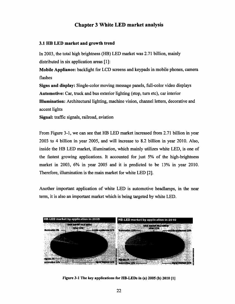
3.1 HB LED market and growth trend
In 2003, the total high brightness (HB) LED market was 2.71 billion, mainly
distributed in six application areas [1]:
Mobile Appliance: backlight for LCD screens and keypads in mobile phones, camera
flashes
Signs and display: Single-color moving message panels, full-color video displays
Automotive: Car, truck and bus exterior lighting (stop, turn etc), car interior
Illumination: Architectural lighting, machine vision, channel letters, decorative and
accent lights
Signal: traffic signals, railroad, aviation
From Figure 3-1, we can see that HB LED market increased from 2.71 billion in year
2003 to 4 billion in year 2005, and will increase to 8.2 billion in year 2010. Also,
inside the HB LED market, illumination, which mainly utilizes white LED, is one of
the fastest growing applications. It accounted for just 5% of the high-brightness
market in 2003, 6% in year 2005 and it is predicted to be 13% in year 2010.
Therefore, illumination is the main market for white LED [2].
Another important application of white LED is automotive headlamps, in the near
term, it is also an important market which is being targeted by white LED.
•• -•.•.•, 4•a k by app.icatio.n.•i 2. .......................ation in 20...
Figure 3-1 The key applications for HB-LEDs in (a) 2005 (b) 2010 [1]

3.2 White LED in illumination
The key to the near-term adoption of high brightness LEDs in illumination
applications is not to target applications where traditional lighting (fluorescent,
halogen, incandescent) is firmly entrenched, or where lower cost is desired, and where
maintenance and replacement costs are low. It takes a great deal of effort, time and
money to convince lighting manufacturers and their customers to shift away from
applications in which traditional lightings have been successfully used for many
years. What will help the illumination market for LEDs the most is to use LEDs in
new applications where it is not possible or at least very undesirable) to use traditional
lighting, or in applications that place a high premium on a particular attribute of
LEDs, such as reliability. Currently, the major uses of LEDs in lighting applications
fall primarily within seven applications [3]:
--Channel letter/contour lighting
--Architecture/retail/theme
--Industrial/machine vision
--Consumer portable/novelty (such as flashlights and key lights);
--Maitainess retrofit (socket-compatible replacement lamps);
--Safety/security (exit signs and emergency lighting);
--Specialty illumination (such as aircraft interior lighting and task lights).
According to Figure 3-1, in year 2010, illumination market will reach 13%* $8.2
million =US$lbillion, which represents a near term market size.
Today, lighting product sales in the U.S. are worth approximately $11.9 billion
annually. Of this, approximately $2.65 billion is associated with lamps while the
remaining sales are divided between fixtures, components (including ballasts and
controls) and associated services such as design and maintenance. Therefore, the long
term illumination market is approximately US$2.65 billion.
3.3 White LED as automobile headlamp
LEDs have had a reasonably successful history in penetrating the automotive lighting
market over the past 20 years. Conventional LEDs have long been used for various
indicator-lamp functions inside the car. The first significant use for LEDs as exterior
signaling is the stop lamp on Nissan 280Z in 1998. Automotive signaling got
substantial growth in early 1990s. And by 2004, approximately 40% of all
automobiles and light trucks produced worldwide featured LED-based center high-
mounted stop lamps. LEDs are also used for rear-stop, turn, and tail lamp but only for
high-end luxury cars. To varying degrees, high-brightness LEDs are being adopted for
most forms of automotive lighting. Now, LEDs are poised to move into the one
remaining, and potentially most lucrative, automotive-lighting application: headlamps
[4].
In the first quarter of 2005, three major automotive-lighting companies announced
LED-based headlamps that would be ready for adoption into production automobiles
in the next few years: Stanley Electric, Visteon (Van Buren Township, MI), and Hella
KTaA Hueck&Co. (Lippstadt, Germany). Standley announced that it would start
producing white LED-based headlamps in 2007. It stated that its production capacity
would be sufficient to supply 5000 vehicles per month in 2007 and 600,000 vehicles
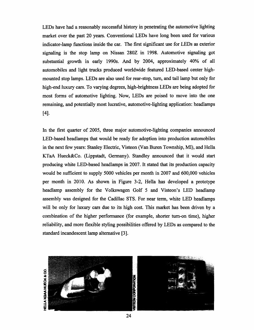
per month in 2010. As shown in Figure 3-2, Hella has developed a prototype
headlamp assembly for the Volkswagen Golf 5 and Visteon's LED headlamp
assembly was designed for the Cadillac STS. For near term, white LED headlamps
will be only for luxury cars due to its high cost. This market has been driven by a
combination of the higher performance (for example, shorter turn-on time), higher
reliability, and more flexible styling possibilities offered by LEDs as compared to the
standard incandescent lamp alternative [3].
8

Figure 3-2 The light output of an LED Headlamp prototypeThe light output of an LED Headlamp prototype developed by Hella KGaA Hueck & Co. (left)
and Visteon's LED headlamp assembly for the Cadillac STS (right)
We can expect to see an increasing number of cars on the road with LED headlamps
in 2007 and beyond. This application will be one of the most promising new markets
for HB LEDs in the second half of this decade, and will be a strong component of an
expected $1 billion market for HB LEDs in automotive lighting in 2009. 20% of the
total amount may go for headlamps, so it is approximately $200 million business for
the near term market.
3.4 White LED for medical applications
A special application for white LED is medical applications, especially for surgical
operation, which requires the highest quality and quantity of lighting. Common
ceiling surgical halogen lighting system cannot provide an adequate amount of beams
because the surgeons' heads hinder the illuminations from reaching the operation
field. A solution is the doctor wears goggles with white LED. The light should have
high color rendering index in order to render inherent color of raw flesh such as skin,
blood, fat tissue and internal organs.
Since the white LEDs used were composed of InGaN-blue-emitters and YAG-yellow-
phosphors, the color rendering property was not sufficient in the reddish colors [4]. So
far there are not much consolidated data on this area, but it shows that high light
quality is a very important issue for LED development.
3.5 White LED market estimation
* Present
white LED market = $240 million (mainly from illumination)
* Near term (around year 2010)
white LED market = $1,200 million/year (from illumination and automotive
headlamps)
* Future
white LED market = the entire illumination market ~ 3 billion
(US market only)
Reference
[1]. "Solid-State Lighting Research and Development Protfolio", Multi-Year
Program Plan FY'07-FY' 12 Prepared for: Lighting Research and Development
Building Technologies Program Office of Evergy Efficiency and Renewable
Energy U.S. Department of Energy
[2]. www.ledmagzine.com
[3]. Rovert V.steele, "High-brightness LEDs open new illumination markets", Laser
Focus World, May 2003
[4]. Robert V.Steele, "LED automotive headlamps move closer to market", Laser
Focus World, November 2005
[5]. http://adsabs.harvard.edu/abs/2001 SPIE.4445... 13S
Chapter 4 Existing players and intellectual properties
4.1 LED production regions
The major LED production regions are United States, Japan, South Korea, China,
Taiwan and Europe. Governments in these regions support LED development, since
LED technology can save huge amount of energy if it at last becomes mature. There
are also LED consortiums that help promoting LED industries in these regions [1].
Japan
A consortium of companies and universities in Japan are developing efficient white
LEDs and fixtures for solid-state lighting applications. Japan's Light for the 21st
Century program was initiated with the goal of developing UV LEDs for solid-state
white lighting. The project, which ended in 2004, brings together 13 companies and
four universities. Research is proceeding in five main areas, namely substrates,
epitaxy, devices, lamps and fixtures.
Taiwan
Taiwan is investing in solid-state lighting at the national level. The "Next Generation
Lighting project" involves a consortium of 11 companies. Predicted earlier between
2003 and 2005, approximately NT$ 383 million would be invested in the technology.
The goal is to achieve 50 Im/W output products and 100 Im/W in the "Taiwanese
companies ramp up MOCVD capacity" (Compound Semiconductor, June 2004) and
"Formosa Epitaxy forms white LED consortium" (Global Sources, January 2004)
respectively.
China
China has also made public its intentions to support the development of solid state
lighting. Called the "Semiconductor Lighting Project," four industrial bases for solid-
state lighting will be developed with government support: Xiamen city ( Fujian
province ), Shanghai, Dalian ( Liaoning province ), and Nanchang ( Jiangxi province
). Roughly $12 million total is estimated as the government investment.
South Korea
Korea has identified that solid-state lighting is an important technology. Korea's
Photonics Technology Institute (KOPTI) works with LED developments. In addition,
Korea apparently has an initiative funded for about $20M per year aiming to produce
an 80 lm/W white LED in 2008.
Europe and USA
The European Union is also investing in programs that either directly or indirectly
support Solid-State Lighting.
4.2 Major players
All over the world there are over 300 LED manufacturers and distributors distributed
in these areas mentioned above [2]. Some of the companies are listed below:
US: Cree, Avago, Vishay
Europe: Osram, Lumileds
Japan: Nichia, Toyoda Goesi, Standley, Rohm, Intematix, Citizen
Taiwan: Everlight Electroics, Cotoo (HK), Kingbright, Opto tech, Harvatek, Lite-on
Korea: Samsung SEM
Among all, the "big five" LED manufacturers are Nichia, Osram, Toyoda Gosei, Cree
and Lumileds.
Nichia's LED products include compound semiconductor materials (e.g. as LED
infrared epitaxial wafers), Packaged LEDs and ultra violet LEDs. There are lamp
shape white LED under packaged LEDs category. Their chromaticity coordinate
equals to (0.41,0.39) and luminous intensity is from, 1250 to 9,200 mcd.
Cree's LED product families include LED chips, packaged LEDs and LED
backlighting solutions. The packaged LEDs, which are labeled as Xlamp series, are
mainly for lighting purpose. Cree has its distributors all over the world, such as
Europe, USA, Australia, New Zealand, Mainland China and Taiwan.
Lumileds is a fully integrated manufacturer of LED dice, packaged LEDs, and high-
brightness LEDs -Luxeon designed for integration into general lighting products. The
company markets LED solutions designed specifically for automotive applications,
LCD displays, general lighting, portable applications, signage, traffic signals, and
other segments.
Osram is a lighting company. It has lighting product from conventional incandescent
lamps to the new LED lighting solution. Its LED design suits into different purposes.
For example, Dragonlight is for high luminous intensity applications. Linearlight is
for Contour lighting and injecting light into diffused or transparent light guides.
Toyoda Gosei's nature of business is research, development, manufacture and sales
of: Parts for automobiles, conveyors, ships and various other transportation
equipment; rubber, plastic and urethane components for agricultural, construction and
machine tool equipment etc. LEDs is just 2.9% of total sales for year 2005. However
it still has the capability to produce high brightness white LEDs.
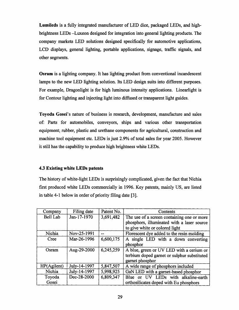
4.3 Existing white LEDs patents
The history of white-light LEDs is surprisingly complicated, given the fact that Nichia
first produced white LEDs commercially in 1996. Key patents, mainly US, are listed
in table 4-1 below in order of priority filing date [3].
Company Filing date Patent No. ContentsBell Lab Jan-17-1970 3,691,482 The use of a screen containing one or more
phosphors, illuminated with a laser sourceto give white or colored light
Nichia Nov-25-1991 -- Florescent dye added to the resin moldingCree Mar-26-1996 6,600,175 A single LED with a down converting
phosphorOsram Aug-29-2000 6,245,259 A blue, green or UV LED with a cerium or
terbium doped garnet or sulphur substitutedgarnet phosphor
HP(Agilent) July-14-1997 5,847,507 A wide range of phosphors includedNichia July-14-1997 5,998,925 GaN LED with a garnet-based phosphorToyoda Dec-28-2000 6,809,347 Blue or UV LEDs with alkaline-earthGosei orthosilicates doped with Eu phosphors
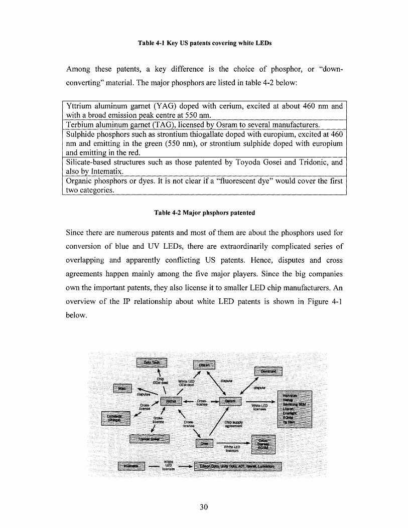
Table 4-1 Key US patents covering white LEDs
Among these patents, a key difference is the choice of phosphor, or "down-
converting" material. The major phosphors are listed in table 4-2 below:
Yttrium aluminum garnet (YAG) doped with cerium, excited at about 460 nm andwith a broad emission peak centre at 550 nm.Terbium aluminum garnet (TAG), licensed by Osram to several manufacturers.Sulphide phosphors such as strontium thiogallate doped with europium, excited at 460nm and emitting in the green (550 nm), or strontium sulphide doped with europiumand emitting in the red.Silicate-based structures such as those patented by Toyoda Gosei and Tridonic, andalso by Intematix.Organic phosphors or dyes. It is not clear if a "fluorescent dye" would cover the firsttwo categories.
Table 4-2 Major phsphors patented
Since there are numerous patents and most of them are about the phosphors used for
conversion of blue and UV LEDs, there are extraordinarily complicated series of
overlapping and apparently conflicting US patents. Hence, disputes and cross
agreements happen mainly among the five major players. Since the big companies
own the important patents, they also license it to smaller LED chip manufacturers. An
overview of the IP relationship about white LED patents is shown in Figure 4-1
below.
Figure 4-1 Deals and disputes in the white LED industry: the key intellectual propertyrelationships as of September 2005
Andrew Phillips of phconsult Ltd reports on a situation: the white LED area is a
minefield of patents, cross-licensing agreements and infringement lawsuits involving
the big five manufacturers. This can prove extremely daunting for new players
entering the field.
However, apparently QD WLED can avoid these disputes about patents, since QD
phosphor, which has a nanocrystal form, is totally different from conventional
phosphors described by these patents. This is another advantage of QD WLED
technology. It gives a steady position for the newly started business among the
competitive market and complicated IP network.
4.4. Quantum dot LED patents
There are also patents on quantum dot LEDs. Below are two important patents on QD
phosphor and QD in between pn junction.
US Patent No. 6,501,091
This patent is about QD phosphor and its assignees are Massachusetts Institute of
Technology and Hewlett-Packard Company. Date of patent is Dec. 31, 2002. It
patented an electronic device comprising a population of quantum dots embedded in a
host matrix and a primary light source which causes the dots to emit secondary light
of a selected color, and a method of making such a device. The size distribution of the
quantum dots is chosen to allow light of a particular color to be emitted therefrom.
The light emitted from the device may be of either a pure (monochromatic) color, or a
mixed (polychromatic) color, and may consist solely of light emitted from the dots
themselves, or of a mixture of light emitted from the dots and light emitted from the
primary source. The dots desirably are composed of an undoped semiconductor such
as CdSe, and may optionally be overcoated to increase photoluminescence. In one
embodiment of this aspect, the quantum dots comprise CdS, CdSe, CdTe, ZnS or
ZnSe and optionally be overcoated with a material comprising ZnS, XnSe, CdS,
CdSe, CdTe, or MgSe. The host matrix may be any material in which quantum dots
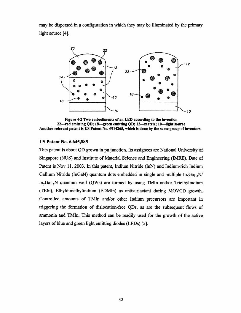
may be dispersed in a configuration in which they may be illuminated by the primary
light source [4].
1222 -
16
in
* fD
"o,• •
Figure 4-2 Two embodiments of an LED according to the invention22-red emitting QD; 18--green emitting QD; 12-matrix; 10--light source
Another relevant patent is US Patent No. 6914265, which is done by the same group of inventors.
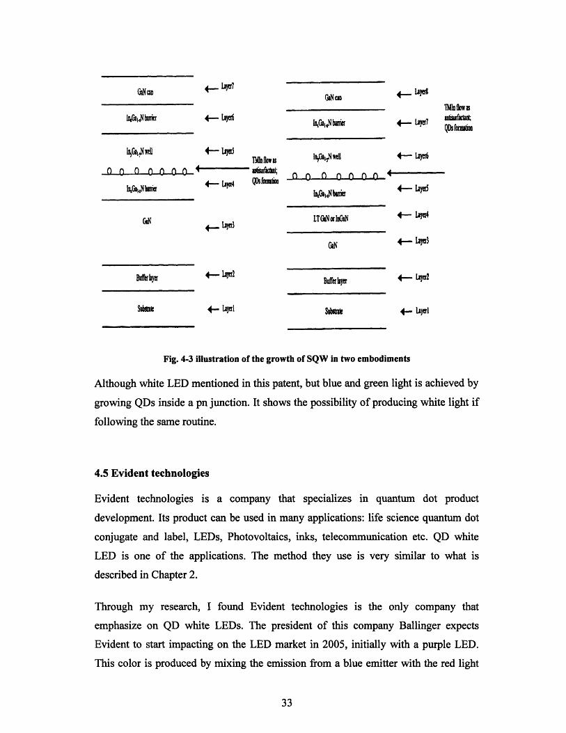
US Patent No. 6,645,885
This patent is about QD grown in pn junction. Its assignees are National University of
Singapore (NUS) and Institute of Material Science and Engineering (IMRE). Date of
Patent is Nov 11, 2003. In this patent, Indium Nitride (InN) and Indium-rich Indium
Gallium Nitride (InGaN) quantum dots embedded in single and multiple InxGal-.N/
InyGal.yN quantum well (QWs) are formed by using TMIn and/or Triethylindium
(TEIn), Ethyldimethylindium (EDMIn) as antisurfactant during MOVCD growth.
Controlled amounts of TMIn and/or other Indium precursors are important in
triggering the formation of dislocation-free QDs, as are the subsequent flows of
ammonia and TMIn. This method can be readily used for the growth of the active
layers of blue and green light emitting diodes (LEDs) [5].
1
I llY\
# L,#, -- | ] I
W m +, - LAW7
kGakNcnr 4-- LOe
I10an0wet 4 - La TIfw
() n i) f) 0- 4 06OWnt10G1-1Nbsrir 4- Lacr4 QDSf hIiou
GiN 4 -t•j.,l'Ibn
Bufrhyer
Subt*et
4- *2
GN w
n1Gal.,N buier
Iba1f* 4- iycd
h1AjklNhf 4- 1iye
OLN +- layU3
.ff*e *
4- Lyrl Sf*ia
Fig. 4-3 illustration of the growth of SQW in two embodiments
Although white LED mentioned in this patent, but blue and green light is achieved by
growing QDs inside a pn junction. It shows the possibility of producing white light if
following the same routine.
4.5 Evident technologies
Evident technologies is a company that specializes in quantum dot product
development. Its product can be used in many applications: life science quantum dot
conjugate and label, LEDs, Photovoltaics, inks, telecommunication etc. QD white
LED is one of the applications. The method they use is very similar to what is
described in Chapter 2.
Through my research, I found Evident technologies is the only company that
emphasize on QD white LEDs. The president of this company Ballinger expects
Evident to start impacting on the LED market in 2005, initially with a purple LED.
This color is produced by mixing the emission from a blue emitter with the red light
4~ IA)l!I Uliflow;4- Lacri awucas~~iQDS fna&d
4- LaIr
4- LIyetl
from down-converting nanocrystals. The white LED market is seen as a mid-term
project, two years from revenue generation [6].
However, Evident is a company that produces QDs. It is not an LED manufacturer. It
is still possible to open a company that concentrates on LED production and design
and is more proficient in LED field. In this case, there can be collaboration between
our QD LED company and Evident in order to accelerate the speed of development of
this technology [7,8].
Reference
[1]. Solid state lighting, National programs
[2]. http://lightemittingdiodes.globalspec.com/specsearch/suppliers/opticsoptical_
components/light_sources/light_emitting_diodes?SrchItem=2&RegEvent=new
[3]. Small companies fight for a foothold in white LED sector", Ledmagzine,
October 2005
[4]. US patent 6,501,091
[5]. US patent 6,645,885
[6]. http://www.compoundsemiconductor.net/articles/magazine/10/12/2/
[7]. www.evittech.com
[8]. "phosphors development for LED lighting", III-Vs Review, the advanced
semiconductor magazine, April 2005

Chapter 5 Business model
5.1. The stage of technology development
To see if a technology is suitable for establishing a company, it must be ready to
develop a product or service from it using standard engineering practice. The
technology must be advantageous enough so that it enables development of a product
or service that can hold its own against likely competitors at the time of its market
entry. The technology also needs to be protectable through some combination of
patents [1]. The QD white LEDs technique also needs to be examined according to all
these criteria before any investment is made.
It may take 30 years or longer for a new technology to develop from its birth till its
commercialization. An example is from the invention of first point contact transistor
in year 1947 to first integrated circuit in 1957 till today's computer. This process can
be demonstrated in Figure 5.1. The big peaks show the major obstacles that need to be
overcome before the technology is fully explored and utilized. People's confidence
about it in market will remain low, until it reaches the point that only small obstacles
remain. The best investment point is at the cross point of technology uncertainty and
confidence in chosen market, where you have the advantages to occupy the market in
front of late coming competitors and at the same time with relatively low risk.
Teclmologic,Barriers
uncertaWUty
"Technology Driven" "Market Driven""Broad Market Impact" "Good Focus"
Figure 5-1 Technology development and confidence in chosen market [2]
4 0 +..--
The first commercially usable LEDs were developed in'the 1960's by combining three
primary elements: gallium, arsenic and phosphorus (GaAsP) to obtain a 655nm red
light source. At that time, the brightness was low and only red color was available, so
the applications were very limited. Over the past few decades, the technology has
developed and overcome several major obstacles. In the 1970's, additional colors and
wavelengths became available, such as green and yellow. It wasn't until the 1980's
when a new material, GaA1As (gallium aluminum arsenide) was developed, that a
rapid growth in the use of LEDs began to occur. GaAlAs technology provided
superior performance over previously available LEDs. The brightness was over 10
times greater than standard LEDs due to increased efficiency and multi-layer,
heterojunction type structures. Recently, the usage of InGaAlP makes the brightness
even higher and blue LEDs have become available in production quantities.
Due to a host of developments and improvements after their initial discovery in the
50's/early 60's, the current red LED technology is very mature. However, in
comparison, blue LED is delayed by 30 years. So if we plot Figure 5.1 for red and
blue LED separately, we find that red and blue technologies are shifted by 30 years.
Red is far beyond the tipping point but blue just comes close to it. If we plot Figure
5.1 with respect to solid state lighting, which requires the blue, it appears that we are
quite close to the tipping point, about 15 years after the blue LED's significant
moment at Nichia.
At the tipping point there are only some small obstacles lying ahead before LEDs
finally achieving the general lighting goal. The minor difficulty that remains is how to
get equally good quality light as incandescent and luminescent light with low cost and
high efficiency. To solve these minor problems, investigation and improvements are
needed in several areas, such as epitaxy and packaging. According to the analysis in
chapter 2, QD WLED technique has the potential to be the solution to finally
overcome one of these minor barriers from the packaging point of view at the initial
stage, and probably most of the barriers at later stage when QD technology becomes
mature [3].
Furthermore, QD white LED technique is protectable, because most of the patents on
LED are about normal phosphors and the disputes among the major companies are
also not related to QD phosphor. The protection of patents avoids trouble in our
company development and ensures a market where we have no similar competitors.
However, we can see that the quantum dot in pn junction technique is not a suitable
technology to invest at this stage. It is still in its infancy stage and it has large
obstacles to overcome. The market confidence about this technique is very low
according to some professionals from LED industry [10]. This is mainly due to the
difficulty in growing quantum dot with good control of size and arrangement, which
leads to very low yield in real production.
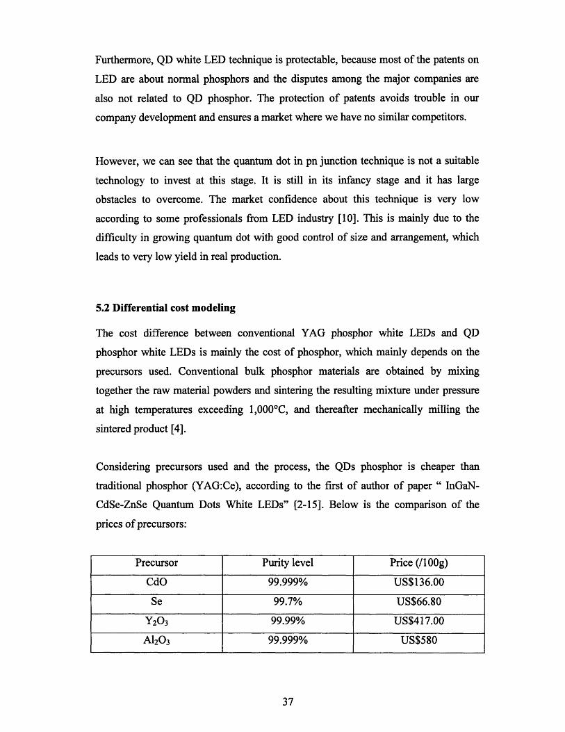
5.2 Differential cost modeling
The cost difference between conventional YAG phosphor white LEDs and QD
phosphor white LEDs is mainly the cost of phosphor, which mainly depends on the
precursors used. Conventional bulk phosphor materials are obtained by mixing
together the raw material powders and sintering the resulting mixture under pressure
at high temperatures exceeding 1,0000 C, and thereafter mechanically milling the
sintered product [4].
Considering precursors used and the process, the QDs phosphor is cheaper than
traditional phosphor (YAG:Ce), according to the first of author of paper " InGaN-
CdSe-ZnSe Quantum Dots White LEDs" [2-15]. Below is the comparison of the
prices of precursors:
Precursor Purity level Price (/100g)
CdO 99.999% US$136.00
Se 99.7% US$66.80
Y20 3 99.99% US$417.00
A120 3 99.999% US$580

Table 5-1 Price comparison of CdSe and YAG precursors [5]
From the table we can see that the cost of Y20 3 and A120 3 is much higher than CdO
and Se. Since there is purity level and other process parameters involved in, we
cannot directly conclude the cost ratio from these numbers. According to author of
paper "InGaN-CdSe-ZnSe Quantum Dots White LEDs", IEEE Photonics Technology
Letters, Vol.18, No.1,January 1,2006, the cost of YAG is slightly cheaper than CdO.
A rough estimation here is 5% cheaper.
Besides this difference in cost of material, since YAG is protected by Nichia, it is
much harder to overcome those patents and is not profitable to seek a license from
Nichia. Even if we could, we still need to pay. How much do we need to pay? The
table below lists the prices for different blue and white LEDs produced by Lumileds.
The cost column is estimated according to the rule of thumb, price = 1.2 * cost.
Table 5-2 Lumileds LED price comparison [61
Comparison of the price difference between blue and white LEDs
line:
Luxeon emitter: 2.99 - 2.41 = US$0.58
Luxeon star C: 3.59 - 3.01= US$0.58
Luxeon III star hex: 4.05 - 3.46 = US$0.59
of the same product
Despite the variation of prices of LEDs with different specification, the price
difference between blue and white LEDs is always around US$0.58. The cost
difference is always US$0.5. Because the chips and the packaging technique used are
38
Product line Color Price Cost
Luxeon emitter Royal blue $2.41 2.01
Luxeon emitter White $2.99 2.49
Luxeon star C Royal blue $3.01 2.51
Luxeon star C White $3.59 2.99
Luxeon III star hex Royal blue $3.46 2.88
Luxeon III star hex White $4.05 3.38

similar for blue and white LEDs from same production line, it can be concluded that
the US$0.58 is the amount of money charged for the yellow phosphor that is used for
white LEDs. The corresponding cost is always US$0.5.
Let us take the medium price Luxeon star C as the calculation basis. The YAG
phosphor cost is about 1/6 of the total LED cost. If we assume Nichia gets 2% of each
white LED being sold, then we have:
3.59 * 2% = US$0.072
0.072/ (3.59-2.99) = 15%
The cost of phorsphor increases by 15%. Together with the cost of material and
fabrication process, the total amount of cost that can be reduced by using QD
phosphor is:
5% + 15% = 20%
Critical assumption 1: The slight cost difference between QD phosphor and YAG
phosphor is based on the precursor cost difference. The processing cost is not really
known here.
Critical assumption 2: The cost comparison is done under the assumption that the
performance of the YAG phosphor is equally good as quantum dot phosphor, such as
CRI. However, one thing to note here is that to get a good CRI, more complicated
phosphors need to be used, which may increase the cost to even higher levels.
5.3. The three basic business models in semiconductor industry
After the above discussion, it is clear that QD phosphor is a technique that we can
invest in and it is quite profitable because of its relatively low cost (in the case that
only precursor cost is considered) and high quality compared to its competitors.
However, what is the best business model and business strategy to optimize the
profit? We can only get the answer after we take a close look at the semiconductor
industry.
5.3.1. The business structure for semiconductor industry
The figure below shows a rough production chain in semiconductor industry. In the
chain, wafer manufacturers earn profit by producing wafers from raw materials. III-V
wafer fabs run their business by processing the wafers into LED chips (die) and a
packaging and testing firm processes those LED dies into LEDs or other relevant
product. The last member on this chain, the distributor will distribute the LEDs to the
end users. There are many companies who are specialized in each element in the
chain. There are also companies, such as Lumileds, that cover three elements in the
chain, from III-V fab to distributors. Our QD white LED technique comes in the third
part - packaging and testing.
Figure 5-2 Semiconductor industry production flow
5.3.2. The three business models
However, the real chain is not as simple as this, because the three basic business
models come into picture, which are the manufacturing model, fabless model and IP
model.
Manufacturing model in semiconductor industry refers to wafer foundries, such as
Chartered, TSMC, SMIC. Fabless model also can be called design and distribution
model, and a company operating in this model only makes chip design instead of
producing them. They may also be in charge of distributing the final products.
Examples of such companies are Altera, ATI, PMC-Sierra. In the IP model, a
company only provides IP. It makes profit through collecting royalty or issuing design
license. For royalties' case, the IP company receives royalties for every chip that is
sold. These are usually a percentage of the final selling price of the product. For
licensing case, the silicon designer has to pay the IP company for the IP design block
he uses. MIPS, Virage Logic, Rambus are all IP business model companies.
Manufacturing model provides the actual product, design model provides the design
and is responsible for goods distribution and IP model provides more abstract ideas.
The relationship between the three basic models is shown in the Figure 5-3 below.
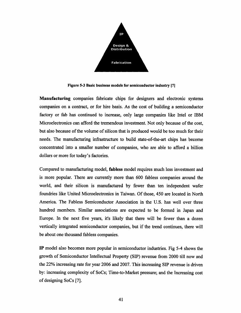
S. 6
I I 6
mFigure 5-3 Basic business models for semiconductor industry 17]
Manufacturing companies fabricate chips for designers and electronic systems
companies on a contract, or for hire basis. As the cost of building a semiconductor
factory or fab has continued to increase, only large companies like Intel or IBM
Microelectronics can afford the tremendous investment. Not only because of the cost,
but also because of the volume of silicon that is produced would be too much for their
needs. The manufacturing infrastructure to build state-of-the-art chips has become
concentrated into a smaller number of companies, who are able to afford a billion
dollars or more for today's factories.
Compared to manufacturing model, fabless model requires much less investment and
is more popular. There are currently more than 600 fabless companies around the
world, and their silicon is manufactured by fewer than ten independent wafer
foundries like United Microelectronics in Taiwan. Of those, 450 are located in North
America. The Fabless Semiconductor Association in the U.S. has well over three
hundred members. Similar associations are expected to be formed in Japan and
Europe. In the next five years, it's likely that there will be fewer than a dozen
vertically integrated semiconductor companies, but if the trend continues, there will
be about one thousand fabless companies.
IP model also becomes more popular in semiconductor industries. Fig 5-4 shows the
growth of Semiconductor Intellectual Property (SIP) revenue from 2000 till now and
the 22% increasing rate for year 2006 and 2007. This increasing SIP revenue is driven
by: increasing complexity of SoCs; Time-to-Market pressure; and the Increasing cost
of designing SoCs [7].

Figure 5-4 Large and growing SIP market (source: Gartner group) 171
To compare the three models again, manufacturing model has lowest gross margin
and largest investment among the three. Fabless model has better gross margin, but it
requires close partnership with foundries, packaging and searching for distribution
channels. IP model has the highest gross margin and requires little physical
investment. Therefore, in current semiconductor industry, manufacturing model is
limited to only a few companies, while fabless and IP models have become the trendy
choice for new entrants.
5.3.3. Business model choice: Hybrid packaging design model and IP model
Although the QD WLED technique is not part of the chip production but part of LED
packaging, we still can classify the business into three similar models. Manufacturing
model means the real packaging production. For design model, companies only do
packaging design and LED distribution. For IP model, companies provide IPs for
packaging design.
According to the discussion above about a semiconductor wafer fab, there are several
issues to consider before establishing a packaging factory.
Firstly, manufacturing model requires huge investments including tooling, cash,
inventory and labor charges. Typically a testing machine costs around a million US
dollars. For a startup company, the initial investment is around $20-50 million.
Finding sources for funding is the first problem to solve.
42
Cree is one of the major players in LED industry. According to its 2005 financial
report, its estimated net income for year 2005 is 91 million. Its total equity in year
2005 is 712.9 million. Assuming the newly started up company has the same growth
rate as Cree, it needs at least 712.9/91 = 8 years to break even. However, it is really an
optimistic estimation, since the newly started companies face more risk in losing their
money.
And all the investment is under a high risk. If the products cannot be sold within a
certain time period, the business will be in danger. It is possible that we may end up
losing whatever we have invested.
Secondly, there are numerous companies producing LEDs in US, Japan, mainland
China, Europe etc. They have well established networks and distribution channels. It
is hard for a new startup company to survive in such a competitive environment.
Thus manufacturing model seems to be not the best choice. Then how about IP
model? The key point for a business established on an IP model to succeed is that the
technology should be really unique or fundamental, or at least it should be able to be
applied to a broad range of industrial applications. Based on the evaluation of QD
WLED technology, it can be concluded that QD WLED is qualified for a promising
IP model technology. It involves nanoparticles, which is fundamentally different from
traditional white LED methods. Furthermore, it produces good quality white light
with high energy efficiency and versatile for application, which makes this technology
very attractive. More importantly, the lower cost will make this technology more
appealing.
Due to the fundamental difference between QD WLED and conventional WLED, a
series of supporting IPs can be further developed. Also, QD is a new material science
area and it has more applications in photonics. For example, it also can be applied to
Organic Light Emitting Diode (OLED) to enhance its performance. For a business
based on IP model, it is easy to switch to neighboring technology and provide relative
IPs, compared to fabless model. Therefore, IP model is the best choice for QD
WLEDs.
Based on all the research of current semiconductor status and the analysis for our QD
WLED technique, I conclude that hybrid fables and IP model is the best choice for
our company [8]. The main reasons are:
-- Huge investment for manufacturing model
-- High pressure for distribution goods if we take up a manufacturing model or full
scale fabless model
-- Less risk
-- Easy to transfer to other relevant technology
-- Our technology is protected by IP
5.4 Business strategies
Stage 1: Develop a prototype and do market testing (2007)
This is the initial startup stage. At this stage, there are two things that need to be
approved. Firstly, we must ensure that the LEDs based on this QD WLED packaging
method should be able to function properly. To achieve this, the packaging procedure
will be carried out in an existing LED packaging company or supporting research
institute and prototype LEDs will be developed [9]. The prototype should have
optimized light output and other optimum performance parameters. Secondly, market
testing will be carried out. Based on this prototype, survey and interviews will be
carried out among LED manufacturers and packaging companies. There is no
business at this stage and no revenue, but only investment.
Stage 2: Production in small volume (2008)
Successful market testing shows the potential for the new product in the market and a
good prototype LED performance guarantees the production in larger volume. At this
stage, one packaging machine and one testing machine will be rented from a machine
vendor. InGaN chips will be ordered from III-V wafer fabs and quantum dots from

QD manufacturers. A few engineers will be hired to do the packaging and testing
using our QD WLED design. Some experienced sales engineers will be hired The
LEDs will be demonstrated to big LED companies and at the same time, they will be
sold to lamp making industries at a cheap price. Challenges at this market entry level
is satisfying real customers in the face of competition and making a profit [1].
Business concept at stage 2:
Offering: white LEDs
Market segment: lamp making industry
As analyzed previously, the market segment where white LEDs are targeted are
mainly automobiles, trucks and buses, novel and portable lighting, and general
illumination and surgical operations. Considering that the phosphor/QD part is a small
part of the overall cost, it is clear that this initially will be driven by its other
advantages. The better color rendering index implies that the markets chosen to enter
initially should emphasize on high CRI, such as museum illumination and surgical
operations etc. The design flexibility shows the automobile headlamp industry may
be a profitable target, since styling for this market is really important.
Distribution channel: Direct sales to lamp manufacturers.
Demonstration will be still done for lamp manufacturers and the advantages will be
explained to them too. At this stage marketing should be done together with
distribution to increase market segment. So, indirect distribution is not a good choice.
Channel structure: Email order and phone order will be available also with free
shipment.
Supplier: III-V LEDs chip manufacturers and Quantum Dot manufacturers are raw
material suppliers. The machine vendors will rent their machine to our company.
Partnerships with raw material suppliers can be established.
Stage 3: Production transfer (2008-2010)
After stage 2, the low profit and sales focus period, our QD white LEDs will start to
become popular around lamp makers. As the demand for our white LEDs becomes
higher, the production task will be slowly transferred to other LED packaging
companies based on our packaging design. Our company will be gradually
concentrating on design instead of manufacture.
Business concept at this stage 3:
Offering: White LEDs packaging design and consultancy
Market segment: LED manufacturers and LED packaging firm. Our design will
gradually cover all areas of white LEDs applications, as we further reduce the cost
and improve energy efficiency of our QD LEDs.
Distribution channel: direct to LED packaging firm
Stage 4: Technology further development (2010 - 2015)
As more revenue is collected, investment will be made in research to improve on the
technology and to explore neighboring technology. Most of the research is conducted
in universities and institutes. More relevant intellectual property and packaging design
will be made, so that the business runs in hybrid mode of both IP and packaging
design. Offering for IP model is the intellectual property itself.
Business concept at this stage 4:
Offering: White LEDs packaging design and IP, Enhanced and customized phosphor
performance, advanced material deposition technologies
Market segment: LED manufacturers, LED packaging firms and LED packaging
design companies
Distribution channel: Directly sell designs to LED manufacturers and packaging
company, direct license IP to manufacturing firms and design firms or collect royalty
Suppliers: Most of the IPs will be supported by research and development in
universities and institutes, which are paid by our funding. Some of the IPs will be
licensed from other IP owners and companies, who are not willing to take care of their
own IPs.
At this stage, company is fully established. More advanced business strategies can be
applied. To develop more advanced and powerful technology related to white LED
and OLED or even tunable LEDs, more investment can be got from government and
joint ventures can be made with LED manufacturers.
Critical assumption: Each stage is assumed to be successful.
5.5. Financial model
The financial model describes the flow of money through your business [1]. This
financial model is done according to the four stages business strategies.
Stage 1 (1st year--2007), this initial stage, basically is the stage to burn cash in order
to gain momentum. Investment is made for prototype development in market test and
prototype. There is no business and no revenue.
Prototype development: 100K
Market testing: 100K
Stage 2 (2nd year--2008), small scale production. Since the material cost is huge, the
financial model for this stage is done on monthly basis.
Cost of conventional LED US$2.99
Cost of QD LED US$2.89
Selling price of conventional LED US$3.59
Selling price of QD LED US$3.47
Assume each wafer has 5,000 dices and the yield is 80%. Also, assume our company
at this stage processes 100 wafers a month (since too large production at this stage is
risky, considering the distribution pressure).
Estimated profit 4,000* 100*(3.47-2.89)* 12 = US$2.73M
However, the company at this stage is in start-up stage. It is in market entry level. The
strategy is to occupy market share instead of getting profit. So a better selling price is
US$3.18, which is 1.1 times of cost.
Estimated profit 4,000* 100*(3.18-2.89)*12 = US$1.39M
Stage 3: Production transfer (2008-2010)
We are at the stage of transition from manufacturing model to fabless model.
Assuming we keep the same manufacturing capacity as stage 2, and are able to get
twice the capacity out of fabless model production, we have:
Estimated profit of manufacturing part:
If keep the original capacity, Profit = 2.73M
Estimated profit of fabless part:
If the sales are twice of manufacturing model:
1.39M*2 = 2.78M
Total profit: US$5.51 M
Stage 4: further investment in developing the technology (5 th - 10 th year--2015)
At this stage, our company works under hybrid mode of both fabless model and IP
model. Both fabless and IP model requires much less investment. Fabless model
makes us control the distribution of goods and we get rid of excess distribution burden
by running IP model at the same time. The total revenue is the sum of the two.
Profit from fabless model:
Assume it is 5 times of the initial capacity
1.39M*5=US$6.95M
I choose 1.39M, which is the profit at a price equal to 1.1 times of cost, instead of the
higher profit due to two reasons. Firstly, I believe Fabless model earns less profit than
manufacturing model. Secondly, as the technology becomes more mature, the profit
margin will gradually reduce.
For an IP model company to succeed, another crucial factor is to choose the correct
licensee. Normally, the licensee company should have a strong brand and good
distribution channels and network. According to the analysis of existing players in
Chapter 4, Cree and Lumileds, are two of the main reasonable choices. If the royalty
is 1.5% of every product sold, then the profit is shown in the calculation below:
Cree's 1st quarter 2006 LED revenue: 86.5million
Estimated for whole year 2006: 346 million
For white LED: 12% x 346 million = 41.52 million
Estimated Profit from licensing with Cree: 2% x 41.52 million= $0.83 million
Lumileds 1st quarter 2006 LED revenue: 100million
Estimated profit from licensing with Lumileds: 12% x 400 million x 2% = $0.96
million
The total profit from the two companies: $0.83 million + $0.96 million = 1.79 million
Since QD WLED is a patent of a fundamental concept, which is to use quantum dot as
phosphor or integrate quantum dot in the LED pn junction, it can be broadly applied
to WLED industry. If 10% of the WLED production globally adopts this patent in
year 2009, the profit can be calculated as:
Revenue generated in a year: 2%* 10%* $1,100 million = 2.2 million
If 50% penetration:
Revenue generated in a year: 2%*50%* $1,000 million = 10 million
If we have 5 patents:
Revenue generated in a year: 2%* 10%* $1,000 million *5 = 10 million
Estimated profit of both IP model and fabless model in a year:
6.95M +10M = US$17M
Reference
[1]. Roger E.Levien,Ph.D., "Taking technology to market", Crisp publications,
ISBN 1-56052-439-1
[2]. Class 3.207 lecture notes 4
[3]. http://www.netl.doe.gov/ssl/portfolio05/EnhancedOpticalEfficiencyPackage.htm
[4]. http://www.nitto.com/company/release/05_10_18/index.html
[5]. https://wwwl.fishersci.com/Coupon?catnum=NC9247828
[6]. www.lumileds.com
[7]. http://www.itac.ca/SMC/2005/05Nov29VirageLogic.pdf
[8]. European Semiconductors Fabless Review: Blurring Business Models
[9]. http://www.nsf.gov/eng/sbir/SECTOR/Devices%20II/PhosphorTech.pdf
[10]. Personal correspondence with Mr. Huang En Li from Avago Technologies,
Singapore
Chapter 6 Conclusion
SSL will have great impact in our lives in terms of energy saving, environment andvariety of lighting design. However, the current WLED technology still needs toimprove on luminous efficacy, light quality and reduction of cost. QD WLED has thepotential to realize the improvement due to its better luminous efficacy, better colorrendering index and versatility, compared to conventional blue LED plus yellowphosphor methods.
There are two forms of QD WLED. One is QD phosphor and the other one is QDincorporated in between pn junction. Both of them have similar characteristic basedon the nature of QD. But the latter method has even lower cost due to the phosphorfree design.
For near term, illumination associated with novel applications and automotiveindustry is the major targeting market with $1.2 billion size in year 2010. However, inthe long term and hopefully in the near future, the biggest market for white LED isgeneral lighting, since currently some fundamental research issues still need to beaddressed.
Due to the fundamental difference in the material structure, QD LEDs will win asteady position among existing white LED patents and an IP business model has thebest position to promote this technology to the entire market. An estimated profit with50% market penetration is US$ 9 million in the year 2010.
Appendix 1: Relevant terminology
1. Luminous efficacy is the ratio of the total apparent power of a light source to itsactual total power. In other words, it is the ratio of luminous flux to radiant flux.
Luminous efficacy = luminous flux/radiant flux
In photometry, luminous flux is the measure of the perceived power of light. It isadjusted to represent the sensitivity of the human eye. Radiant flux is the measure ofthe total power of light emitted.
Wavelengths of light outside of the visible spectrum aren't useful for illuminationbecause they can't be seen by the human eye. Furthermore, the eye responds more tosome wavelengths of light than others, even within the visible spectrum. Thisresponse of the eye is represented by the luminosity function. Luminous efficacymeasures the fraction of power which is useful for lighting.
The candela (symbol: cd) is the SI base unit of luminous intensity (that is, poweremitted by a light source in a particular direction, with wavelengths weighted by theluminosity function, a standardized model of the sensitivity of the human eye).
The lumen (symbol: lm) is the SI unit of luminous flux. 1 Im = 1 cd-sr
Note that luminous efficacy is totally different from energy efficiency. Energyefficiency is a measure of how many percentage of power is utilized. Luminousefficacy is a measure of how much percentage out of the radiant flux contributes tovisible range.
power outputefficiency t7 = = W/Venergypower input
3. Color Rendering Index (CRI)
The color rendering index (CRI), is a measure of the ability of a light source toreproduce the colors of various objects being lit by the source. It is a method devisedby the International Commission on Illumination (CIE). The best possible rendition ofcolors is specified by a CRI of one hundred, while the very poorest rendition isspecified by a CRI of zero. For a source like a low-pressure sodium vapor lamp,which is monochromatic, the CRI is nearly zero, but for a source like an incandescentlight bulb, which emits essentially blackbody radiation, it is nearly a hundred. TheCRI is measured by comparing the color rendering of the test source to that of a"perfect" source which is generally a black body radiator.
4. Color temperature
"Visible light" is commonly described by its color temperature. A traditionalincandescent light source's color temperature is determined by comparing its hue witha theoretical, heated black-body radiator. The lamp's color temperature is thetemperature in kelvins at which the heated black-body radiator matches the hue of thelamp.
Because it is the standard against which other light sources are compared, the colortemperature of a black-body radiator is equal to its surface temperature in kelvins,using the temperature scale named after the 19th-century British physicist WilliamThomson, 1st Baron Kelvin. (Note: it should not be construed that the colortemperature refers to the thermal temperature of anything other than the black-bodyradiator.) An incandescent light is very close to being a black-body radiator.However, many other light sources, such as fluorescent lamps, do not emit radiationin the form of a black-body curve, and are assigned what is known as a correlatedcolor temperature (CCT), which is the color temperature of a black body whichmost closely matches the lamp's light emission curve. Because such an approximationis not required for incandescent light, the CCT for an incandescent light is simply itsunadjusted kelvin value derived from the comparison to a heated black-body radiator.
As the sun crosses the sky, it may appear to be red, orange, yellow, white, or blue,depending on position. The changing colors of the sun and sky as the day passes alsomatch colors produced by a black-body radiator at certain temperatures in kelvin.
So according to color temperature, white LEDs include warm and cool whiteaccording to their color temperature.
Reference
[1]. http://en.wikipedia.org/wiki[2]. http://www.techmind.org/colour/coltemp.html
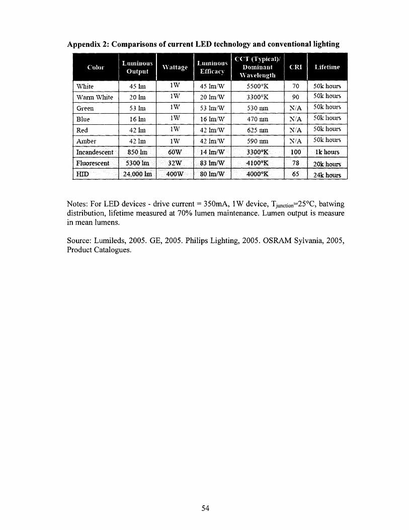
Appendix 2: Comparisons of current LED technology and conventional lighting
NTWhite
Warm White
Green
Blue
Red
Amber
Incandescent
Fluorescent
HID
Notes: For LED devices - drive current = 350mA, 1W device, Tjunction=250C, batwingdistribution, lifetime measured at 70% lumen maintenance. Lumen output is measurein mean lumens.
Source: Lumileds, 2005. GE, 2005. Philips Lighting, 2005. OSRAM Sylvania, 2005,Product Catalogues.
45 hni20 hii
53 hn
16 Im
42 lm
42 Imrn
850 1m
5300 aIm
24,000 Im
1W
1W
1W
1W
1W
60W32W
400W
45 ImWN
20 linmW
53 ImW
16 hndAW
42 Im/W
42 lmiWV
14 Im/W83 lmIW
80 IN/W
55000K
33000K
530 rmn
470 murn
625 iun
590 rmn33000K4100"K
40000K
90
Ni/A
N'/A
N/A
N/A
10078
65
50k hours
50k hours
50k hours
50k hours
50k hours
50k hours
1k hours
20k hours
24k hours