at the - DSpace@MIT
94
AN APPARATUS FOR STUDYING COMBUSTION IN A LAMINAR MIXING ZONE by David Fo Merrion Four Year Diploma (Mechanical Engineering) General Motors Institute 1958 Submitted in Partial Requirement for Master of Fulfillment of the Degree of Science the at the Massachusetts Institute of Technology August 24, 1959 Signature of Author .. e00 oe00000** o00 0 00 Department of Mechanical Engineering August 24, 1959 Certified by-..-.. .. o.. W . . ..... . . ........ Thesis Supervisor Accepted by .......... .. * .* *c Chairman, Departsental Committee on G 7 aduate Students 1 a
-
Upload
khangminh22 -
Category
Documents
-
view
2 -
download
0
Transcript of at the - DSpace@MIT

AN APPARATUS FOR STUDYING COMBUSTION IN A
LAMINAR MIXING ZONE
by
David Fo Merrion
Four Year Diploma(Mechanical Engineering)General Motors Institute
1958
Submitted in PartialRequirement for
Master of
Fulfillment ofthe Degree ofScience
the
at theMassachusetts Institute of Technology
August 24, 1959
Signature of Author .. e00 oe00000** o00 0 00
Department of Mechanical EngineeringAugust 24, 1959
Certified by-..-.. .. o.. W . . ..... . . ........
Thesis Supervisor
Accepted by .......... ... * .* *cChairman, Departsental Committee
on G 7aduate Students
1
a

AN APPARATUS FOR STUDYING COMBUSTION IN AAMINAR MIXING ZONE
by
David F, Merrion
Submitted to the Department of Mechanical Engineering onAugust 2, 1959, in partial fulfillment of the requirements forthe degree of Master of Science,
ABSTRACT
Background material of how this problem arises in bluffbody flame stabilization in rocket engines is presented.References are given for the previous theoretical and experi-mental work performed in this field.
A preliminary testing apparatus is described which wasused to investigate the variables of an experimental apparatusfor studying combustion in a lminar mixing zone. The resultsof this preliminary testing apparatus were used to design andbuild a final apparatus.
The final apparatus has an outer hot stream and an innercold stream. The enclosure is made mainly of i-'ebrick, cera-mic burners, and a castable refractory, Kaocast. The hot streamis hot combustion products that are produced in twenty burners.The stream is mixed with dilutent and passed through flowstraighteners and a converging section. The cold stream iscombustible gases that are also passed through flow straighte-ners and a converging section. These two streams mix at avery thin section and procede up through a pyrex tube forobserving the resulting combustion.
Thesis Supervisor: A. R. Rogowski
Title: Associate Professor of Mechanical Engineering
it
r

FOREWORD
The work described in this thesis commenced in the fall
term of 1958 when Professor T Y. Toong suggested the topic
to the author, Actual testing was not sta'ted until January,
1959. Due to Professor Toong's leave of absence, it was begun
under the guidance of Professor A R Rogowski. All work
was done in the Sloan Automotive Laboratory,
Financial support was obtained from the Research Grant
of the Shell Oil Company for the materials in the apparatus
and from Detroit Diesel Engine Division of the General Motors
Corporation for my time involved in this project.
Throughout the research, Professor Rogowski and T No
Chen constantly provided professional guidance and moral
support. Much valuable help came from Professor C, Fo Taylor,
Mr J Caloggero, Mr P McGovern, and Mr E Gugger.
The author wishes to thank all those who assisted in any
way during the thesis project, especially his wife, Jean, for
her typing and indulgence. It is hoped that this apparatus
will become a worthy addition to the many combustion research
projects of the Sloan Laboratories0
IIi
0P

TABLE OF CONTENTS
Page
Abstract ii
Foreword iii
Table of Contents iv
List of Illustrations vi
Io INTRODUCT ION 1
IIo CONCLUSIONS AND RECOMMENDATIONS 2
General Conclusions 2
Specific Conclusions 2
Recommendations 5
IIo .BACKGROUN1D MATERIAL 7
IVo PRELIMINARY TESTING APPARATUS 11
Hot Combustion Products Section 11
Cold Combustible Gases Section 12
External Sections 16
Experimental Procedure and Results 16
Vo FINAL APPARATUS .19
Hot Combustion Products Section 19
Bottom Enclosure 19
Top Enclosure 22
Center Enclosure 24
Burners 26
Introduction of Dilutent 29
Flow Straighteners 30
iv

Cold Combustible Gases Section
Straightening and Calming Section
Center Tube
External Sections
Conclusions
APPEND IX
Section A.
Section B.
Page
31
31
34
36
38
40
Calculations of the StoichiometricFuel-air Ratio for Cambridge NaturalGas 42
Calculation of Flow Area for HotStream 43
Calculation for Number of Burners 43
Calculation for Boundary LayerThickness at Two Positions of theStraightening and Calming Section 47
Design of Final Apparatus - Side View 50
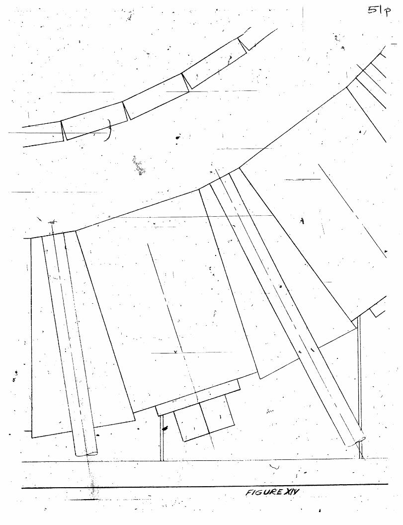
Design of Final Apparatus - Top View 51
Design of Straightening and CalmingSection 52
BIBLIOGRAPHY
v

LIST OF ILLUSTRATIONS
Figure Page
I. Bluff Body Flame Stabilizer 7
II. Schematic of Flame Initiation 8
III Preliminary Testing Apparatus 13
IVo Test Section of Preliminary Testing Apparatus 14
Vo Firebrick Base 20
VIo Top Enclosure 20
VIIo Center Enclosure and Mold 25
VIIIo Final Apparatus - Open Position 27
IX. Straightening and Calming Section 32
X. Center Tube 35
XIo Bottom of Final Apparatus 35
XII. Final Apparatus - Closed Position 37
XIII, Design of Final Apparatus - Side View 50
XIV. Design of Final Apparatus - Top View 51
XV. Design of Straightening and Calming Section 52
vi
i
i

I. INTRODUCTION
The study of combustion in a laminar mixing zone was
initiated from the combustion problems in thermal et pro-
pulsion -systems. Previously; theoretical and some experi-
mental work has been performed on combustion in mixing zones
by studying the characteristics of the mixing of hot com-
bustion products with cold combustible gases.
The specific problems of this thesis were to determine
the variables connected with the testing of an apparatus to
study cmbust'ion in a laminar mixing zone and to use these
results to design a more complete apparatus to be operated
over a wide range of conditions.
The general procedure followed in this investigation
included: research into past theoretical and experimental
work, building and testing a preliminary apparatus, designing
a final apparatus, and partially building this final apparatus.
It is the two-fold purpose of this thesis to present the
results of the preliminary testing apparatus and to present
the design of a new apparatus to study combustion in a laminar
mixing zone.
The organization of the thesis will follow the exact
sequence of the investigations as follows:
III Background Material
IV Preliminary Testing Apparatus
V Final Apparatus
1
i

IIo CONCLUSIONS AND RECOMMENDATIONS
The purpose of this section in the thesis is to present
the conclusions of the investigation undertaken and to pro-
vide recommendations resulting from this investigation. Since
the actual conclusion drawn from the investigation is a physi-
cal design and a physical apparatus, drawings and photographs
will concur with the following conclusions.
General Conclusions:
The following are the general conclusions resulting from
the investigation0
lo The experimental work previously performed was not
quite as extensive as was felt it could have been
and many relationships were not investigated. Thus,
further experimental work was undertaken (page 10)o
2o Thus, the only possible solution was to design a
better, more complete apparatus (page 18)o
30 The three sections, Hot Combustion Products Section,
Cold Combustible Gases Section and External Sections
constitute the final apparatus for studying com-
bustion in a laminar mixing zone (page 39)o
Specific Conc lusions
The following are the specific conclusions resulting
from the investigation arranged by the thesis sections in
which they are developed0
2

3
Section III
1o The temperature profile of the cold stream could
not be controlled due to heating from the hot
stream
20 The velocity profile of the two streams could
not be controlled because of turbulence and
thick boundary layers
30 The hot stream temperature could not be held
uniform or controlled.
Section IV
Hot Products Section Data
Bottom Enclosure
over-all size
center hole
material
Top Enclosure
outside diameter
height
center diameter
flow curvature
material
Center Enclosure
tip diameter
hub diameter
hole diameter
height
material
3' x 31
2" diameter
f irebrick
3in4i"
5°625"
cub ic
steel - Kaocast
17"
2.5"
2"
6.9"
Kaocast
I-1

4
Burners
numb er 20
size 3-1/16" x 3-1/16" x 5-13/32"
make Selas KZ-552-SN3
Dilutent
size 1/2 " diameter
material stainless steel tubes
Flow Straighteners
size per piece 3" x 1-1/2" x 7/6"
hole diameter 1/8"
holes per piece 55
number of pieces 43
material Alsimag 222
Cold Combustible Gases Section Data
Straightening and Calming Section
outside diameter 5o5"
inside diameter 4o04" to 1o5"
flow curvature cubic
material aluminum
tube size 1/8" diameter, 014" wall5" long
number of tubes 880
tube material brass
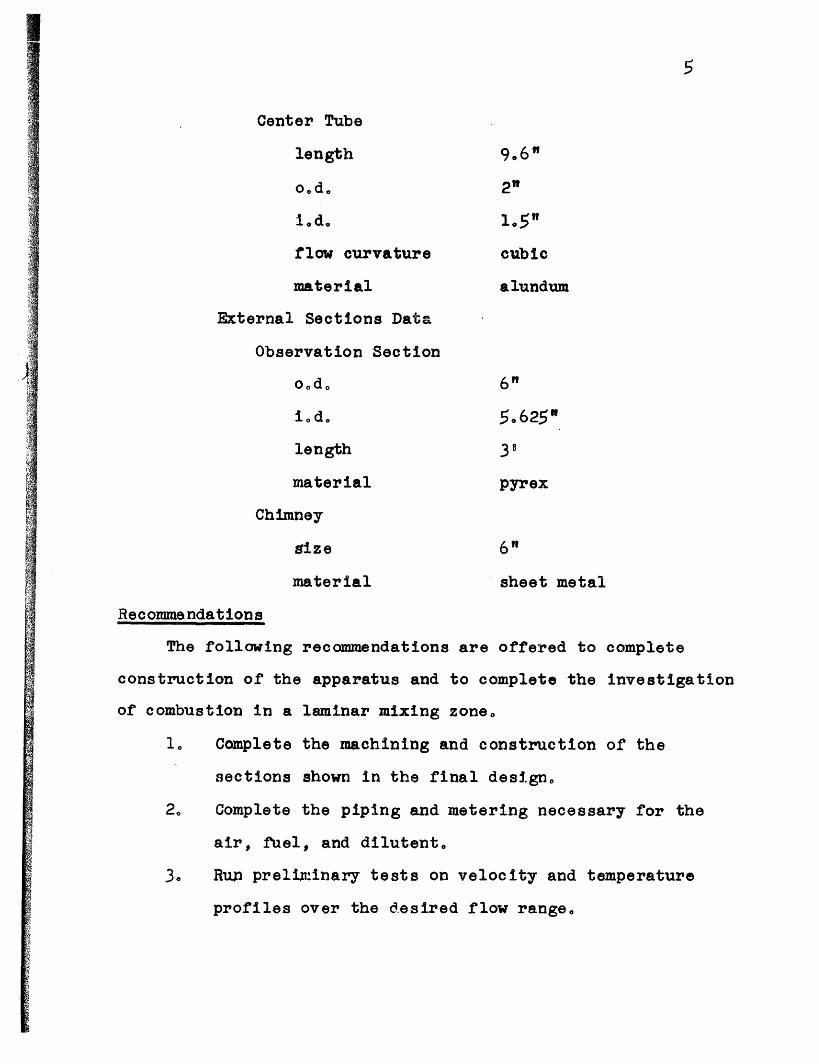
Center Tube
length
o.d.
iod
flow curvature
material
External Sections Data
Observation Section
o~do
iodo
length
material
Chimney
vize
material
6"
sheet metal
Recommendations
The following recommendations are offered to complete
construction of the apparatus and to complete the investiga
of combustion in a laminar mixing zone.
1o Complete the machining and construction of the
sections shown in the final design.
2o Complete the piping and metering necessary for th,
air, fuel, and dilutent
3° Run preli.inary tests on velocity and temperature
profiles over the desired flow range.
5
9.6"
2n"
1.5"cubic
alundum
6n"
50625"
39
pyrex
I
:'
l
Ition
e

6
4. Investigate combustion and ignition in a laminar
mixing zone by correlating detachment distances
with velocities, fuel-air ratios, temperatures,
and uels.
14�

III. BACKGROUND MATERIAL
The problem of ignition and combustion in a laminar
mixing zone is a physical problem to which much recent research
has been devoted. Two of the main situations associated with
this problem are thermal et propulsion systems and rocket
motors. Specifically this problem arises in a ram et com-
bustion chamber where bluff bodies re used to provide a
relatively stagnant region in which a pilot flame can stabilize.
The bluff body is required because the mixture velocity is much
greater than the burning velocity. When using a bluff body
flame stabilizer, only a portion of the combustible mixture
is passed into the stagnant region and is burned as follows:
Cold Combustible MGses
Hot Combustion Products
so b Hot Combustion Products
Cold Combustible Gases
Figure I. Bluff Body Flame Stabilizer
7
Flow
8
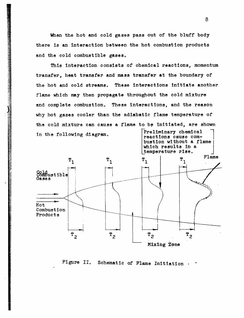
When the hot and cold gases pass out of the bluff body
there is an interaction between the hot combustion products
and the cold combustible gases.
This interaction consists of chemical reactions, momentum
transfer, heat transfer and mass transfer at the boundary of
the hot and cold streams, These interactions initiate another
flame which may then propagate throughout the cold mixture
and complete combustion0 These interactions, and the reason
why hot gases cooler than the adiabatic flame temperature of
the cold mixture can cause a flame to b initiated, are shown
in the following diagram. 'eliminar chemical Ireactions cause com-bustion without a flamewhich results in atemperature rise
Figure II Schematic of Flame Initiation

9
There have been investigations simulating this process
with a hot stream of gases mixing with a cold stream at some
boundary, Marble and Adamson1 were one of the first to take
a theoretical approach to the problem. They made their
analysis for one stream of cool combustible mixture, and the
second of hot combustion products with uniform initial velo-
city profiles. They used the boundary layer integral technique,
introduced by Krman, to make simplifications.
After Marble and Adamson did their analysis, others
refined it. S. I Cheng and A A Kovitz2 did theoretical
work on "Ignition in the Laminar Wake of a Flat Plate" and
used Blausius profiles as initial velocity distributions.This was done as an improvement over Marble and Adamsongs
uniform profiles. S. I. Pai3 did his theoretical work on
"Laminar Jet Mixing of Two Compressible Fluids with Heat
Release". He made a general analysis, and then simplified
it for several specific cases, One specific case included
Marble and Adamson's uniform profile considerations, The
only experimental work performed was by F H Wright and
J. L Becker4 on "Combustion in the Mixing Zone Between Two
Parallel Streams". The equipment consisted of a cylindrical
apparatus with an inner hot stream, heated by exhaust gases
from a turbojet can burner, and an outer cold stream. Their
results included correlations between the detachment distance
of the flame from the point where the two streams mixed to

10
equivalence ratio* and hot stream temperature for various
stream velocities0
The investigations made by the above men are the bulk
of the theoretical and experimental work that has been done
in this field. The experimental work previously performed
was not quite as extensive as was felt it could have been
and many relationships were not investigatedo Thus, further
experimental work was undertaken 0
*fuel-air ratio/stoichiometric fuel-air ratio
i:
51
M ;
g
t i1
-4
-- �I L-� I

IV. PRELIMINARY TESTING APPARATUS
The experimental investigations made by Wright and Becker
were not completely satisfactory and further experimental
work was desired, Following the recommendations of a paper
by C W Haldeman (term paper for T. Y Toong, 1958) a
preliminary testing apparatus was built to determine the problems
that would be encountered in an apparatus of this kind and to
determine if a flame could be initiated,
One of the basic differences of this apparatus from the
one Wright and Becker used was the hot stream was the outer
stream and the cold stream was the inner stream0 The reason
for this is illustrated by Figure IIo It can be seen that if
another hot stream is added above the one shown, as in a
pipe9 then the two flames initiated will meet and produce
a flame similar to a bunsen burner flame0
Hot Combustion Products Section
Hot gases were produced with four bunsen burners by
burning a mixture of air and natural gas0 A baffle and
screen were used above the burning gases to mix and smooth
the flowo It was found immediately that the hot gases that
approached the mixing section were not of uniform temperature.
Thus, a gas range burner was incorporated since it was
uniformly circular and had a hole in the center for central
cold stream tube. The flow capacity of the burner was
increased by symmetrically drilling more holes in the burner
face o
11
i'

12
The burner was supplied with air from a large centri-
fugal pump that was metered by an orifice. The fuel was
natural gas from the gas main, and it was metered by a cali-
brated rotometer. Valving was provided to adjust either air
or fuel flow (see Figure III)o The hot stream was always
operated at a stoichiometric fuel-air ratio (15: 1) (see
Appendix, Section A) because it was not desirous to have
excess air or fuel in the hot stream to interact with the
cold streamo
In order to stabilize the flame producing the hot
gases, a stainless steel wall was inserted around the burner
(see Figure .IV) This wall helped stabilize the flame by
the vortex motion of the gases along the wallo The stainless
steel wall was sealed to the burner with refractory clay to
prevent diluting or radical leakage.
A screen was used further upstream to allow a five-
inch section for the large scale turbulence to mix the
gases (see Figure IV), The screen also served to break up
the boundary layer. The stainless steel screen would then
smooth the flow and convert the large scale turbulence to
small scale turbulence ust before mixing0
Cold Combustible Gases Section
The cold gases were introduced into the apparatus by a
pipe that entered through the center of the hot burner and
ascended above it approximately eight inches0 The pipe was
cast iron, 5/8" diameter9 that was ground to a sharp edge

Is"1
:�i'�'�;::·iJ;T"c�,"�"'� 'f:.,q11111�_1_
· c, ·· · · r�w�...,ii·l"::'f':::::::-·"·'·i·.;�'i'";;·I·-,,bi.��;· \'irUi T''·�
���····iir., · �`''' '·(·I'-'··i· I·r··�··· ·....-
· ··. Llrir ·t·, ' ·'·..·*- �-"'-··.·,'�1.-'c·� ··· ·.·": +·- ,·····.;i�····... "i�·
·- · · ·,�.;..... ���_:....., ·..... -··.....,�... ����:-.....�� ..... · · · · ·......
·-·· · ·:::::;�·····;:::`'�'`'···I: : : : : · · · ·: : : : . ' ' ' ' ` ' ' ' " ;· ' ' ' ' ' ' ' � .- · · ·.. ; : :1 , · · · · ·...·.. ·- · · ·-- ·:�·-····· · · · ·· · · · · · · · · · · ·.· · · · · - · · · · · �···-·
: · · -· · · · . · . ; : : ' · · · · ·· · .. : : · · · · · · · · · · · ·- ·. ·.... � · � · · · · ·· · ·-
� '''''i .t :::::�;ll�jg:A;f;�·c�ii�:;n�·��:�;4·b�:
PRElviMNARY TESTING APPARATUS
If' ` ' ' ' ̀ '`''''� ̀ ''''�''''''': : : · ·· · · · ... :· · · · · · · · · · · ·· · · · · · · · · · -· · · · · ·.....::·-····...· · · · · · · · · · ··· · ··- · i· · · · · · · · · . - -·····.. · · · · · · · · ·. ·· · · · ·.... : : · · · · · · ·
FIG'URE IJ". Xl

14._P~--- . = .
X N WLNS° N dW*II5
N patrols-- - >N
r4 -
TEST SECTION OF PREL1M1TARY TESTIMG PPARtS TUS
L _ _
t
r-
, ol- , s-li_ ' ' * .~~~~~~~~~~~~~
F GLU RE IV

15
at the top to facilitate mixing at a minimum thickness, The
sharp edge allowed mixing with small scale eddies,
The cold gases consisted of an air and fuel mixture at
room temperature, The air was supplied by a small blower
shown under the table in Figure III. The fluctuations in
the flow were smoothed by passing the flow into a tank and
then tapping off the tanko The air was metered by a rotor
meter, passed through a valve, and then mixed with fuel.
Again the fuel was natural gas from the main, and it was
metered by a small rotameter The rotometers for the air and
fuel were calibrated with the wet test meter shown in
Figure III.
The mixture of fuel and air was introduced through the
center pipe at a velocity equal to the hot stream velocity.
Since the mixture was combustible a flame could be initiated.
The flame could stabilize, flash-back or blow-offo If it
stabilizes or blows-off there is no problem, but if it
flashes back, it could flash back down. the center pipeR
because the top of the pipe is ground to a sharp edge and it
will not act as a flame holder. Thus, the flame in an
enclosure containing a combustible mixture could cause an
explosion. In order to prevent this, a quenching screen was
inserted inside the center pipe approximately one inch below
the mixing pointo
4w

16
-External Sections
The apparatus was situated on a table shown in Figure IIIo
The build up then consisted of a flat refractory plate, a
sheet metal section and pyrex tube9 six inches in diameter
and three feet longo The sheet metal section allowed the
pipes to be 'entered through the wall and the pyrex tube
allowed visual observation of the flames. All Joining
sections were sealed from air leakage by a clay material0
This was necessary since an exact fuel-air mixture was
required.
An exhaust chimney was built out of six-inch diameter,
three-feet long9 sheet metal tubing section with a can
welded to the end (see Figure III)o The chimney passed
through the ceiling to the outside.
Exerimental Pocedure and Results
Experimental testing was performed on this preliminary
apparatus in a trial and error manner since its function was
to disclose the variables connected with an apparatus of this
kindo Testing consisted of lighting the hot stream burner,
varying the fuel-air ratio of the cold stream and varying the
velocity of both streams. As stated previously, the hot
stream was always operated at a stoichiometric fuel-air ratio.
The procedure for testing was to light the hot stream burner,
turn on the air and fuel to the center burner and wait for
a flame to be initiated, The temperature of the hot and cold

17
streams were in the range of 1500°F and 1000F respectively.
The temperatures were measured with a shielded thermocouple
that was suspended in the streams. The velocities ranged
from five feet per second to two feet per secondo The low
values of velocity were due to the limited flow through
the hot burner without causing blow-off.
One of the first deficiencies found in this apparatus
was the heating of the cold stream pipe. The hot gases were
passing over almost the full length of the pipe and after
considerable operating the center pipe would be red-hoto
This meant that the temperature profile of the cold stream
was hardly uniform and was constantly varying as operation
continuedo This information did prove to be useful in
later work.
There were flames initiated with this apparatus but none
were very conclusive. After operating for short periods of
time, it was found that if the fuel to the hot stream burner
was shut off, a flame would be initiated at the top of thecenter pipes This flame seemed to stabilize on the top of
the center pipe even though the pipe was ground to a sharp
edge. If the cold stream velocity were high enough at
times the flame would blow-off. Still many-other times there
would be no flame initiated at all. Of course all this
information was obtained in the transient condition of
turning off the fuel to the hot stream burner0 These same
results could never be acquired under steady state conditions.

18
The temperature of the cold stream was one variable not
changed except for the heating in the boundary layer of the
cold stream. This was investigated by starting under the
normal conditions and allowing the copter pipe to be
heated. This meant that the cold stream was being heated,
but still no resulting flame was observedo
Many other trial and error procedures were investigated
and only under transient conditions could any of the three
conditions of flames be found ie: blow-off, flash-back, or
a stabilized flame on the center pipe0 The limitations of
velocity and temperature profile were the greatest problems0
The velocity could not be increased appreciably since there
was not enough space for additional burners. The temperature
profile of the cold stream could not be controlled because
if the pipe were wrapped with a cooling coil, the streams
could not mix at a thin section0 Then there were many small
problems that could not be solved with the preliminary
apparatus such as the following: straightening the flow for
both the hot and cold stream, striving for a uniform velocity
and temperature profile and adding dilutent to control the
hot stream temperature. Thus, with the above results in mind,
the only possible solution was to design a better, more
corlplete apparatus.

V. FINAL APPARATUS
The preliminary testing apparatus performed a portion of
its function, which was to initiate a flame or divulge infor-
mation for another design. The apparatus achieved the latter
of these two, and ideas for a final design were taken from
the resultso Different designs were considered, all of
which had an inner cold stream and outer hot stream for
previously discussed reasons0 Essentially the following
factors were included in each design: insulation of the
cold stream from the hot stream, provisions made to have
uniform velocity, and temperature distributions and provision
for larger flows with dilutent Basically the designs under
consideration differed only in the means by which the hot
gases were introducedo The final design chosen consists of
three sections: Hot Combustion Products Section, Cold
Combustible Gases Section, and External Sections (Figures
XIII and XIV in Appendix B)o
Hot Combustion Products Section
The hot combustion -products section is the one in which
the hot gases are produced for the mixing zone0 This section
consists of a bottom enclosure, a top enclosure, a center
enclosure, burners, introduction of dilutent and flow
straighteners.
Bottom Enclosure
The bottom enclosure is show-n n Figure V as a fire-
brick base. The center of the base has a two-inch diameter
19

20
~~~~~~fi~~~~~~~~~~~Ae
FIGURE V FIREBRICK BASE (BOTTOM ENCLOSURE)
FIGURE VI TOP ENCLOSURE
I
i
I

21
-hole in it9 to pass the center tube through, and provisions
for connecting the cold combustible gases section.
The firebrick is a K-30 insulating type that will
stand service temperatures up to 2900QF in a directly exposed
position0 The thermal conductivity is low (ranging from o161
btu/hr ft F at 500°F to 432 btu/hr ft OF at 2500°F) which
means less heat loss and higher operating temperatures. The
firebrick also has a low heat-storage-capacity so closer and
faster temperature control can be obtained.
The bottom enclosure consists of 32 pieces of this
type firebrick that are 9" x 4-1/2" x 2 1/2 " The bricks
are layed on their 9" x 4-1/2" face and cemented together
with air-set Babcock and Wilcox mortar that has a temperature
range as high as 30000Fo The hole for the center tube was
made by filing quarter-circles in the corners of the four
center bricks which were then joined together0 Bolts
(1/4-28 x 2) were mounted through the four bricks so the
cold combustible gases section could be joined to the f ire
brick.> Since the heads of the bolts would be covered when
the whole apparatus was assembled, the bolt heads,4 with large
washers for support, were recessed in the brick0 The bolt
heads were then prevented from turning by putting metal strips
in the hole along the bolt head flats and filling the hole
with air-set mortar0 This allows the pieces to be assembled
and disassembled with nuts, without holding the bolt headso
I

22
The whole bottom enclosure rests on a piece of transite placed
on a table. Both the transite and table have an eight-inch
hole in the center to receive the cold combustible gases
sect ion o
Top Enclosure
The top enclosure is the top half of the hot products
flow path* (Figure VI)o Since the flow of hot products must
make a 900 angle turn from the horizontal to the vertical,
some. flow path'was necessary. It was decided to use a cubic
curve for a path, as in nozzle flow, so there would be no
slope or change of slope at the mixing zone. The other end
of the curve was smoothed with an 11058 inch radius so the
flow would start out of the straighteners on a smooth curveo0
The top enclosure is partly a piece of reinforced
castable, 4" thick, made from Babcock and Wilcox Kaocasto
Kaocast can withstand a continuous temperature of 3000eF and
will melt at 3200EF° It is made of refractory calcines or
grogs blended with a binder° Kaocast will set in air, but
full strength is not obtained until firing° The remaining
portion of the enclosure is a steel plate 30" in diameter
and 1/4 thick with a 5625" diameter hole bored in the
center. The steel plate has a steel band around it that is
4-1/4'" high and 1/8" thick0
The center enclosure and the center tube make up the otherhalf of the 'flow path0
#See section on Flow Straighteners
.I

23
The top enclosure was made by welding the band to the
plate and filling the bottom of this enclosure with reinforce-
ment, The reinforcement consisted of four pieces of one-inch
angle iron welded radially, evenly spaced from the outer edge
to within an inch of the center holeo These were used to
keep the plate from deflecting and to help reinforce the
Kaocast Short pieces of bent welding rod were welded at
random to the bottom of' the plate, also to act as a reinforc,-
mento The angle iron and the welding rods were then covered
Tw.th tar and the kaocast was poured in. A sheet steel
template was used to form the desired smoothed cubic curve
The tar was utilized because iron has a larger coefficient of
expansion than the kaocast and it was feared cracking would
Oecur.
The kaocast was cured for 2 hours, Since a furnace
large enough for firing 'the piece was not available, it
was fired by a natural gas burner*, in an enclosure of fire-
brick and a piece of transitep to approximately 300°Fo
Firing is only necessary to alleviate the kaocast of moisture
3aXBd to strengthen it, The firing must be slow at first,
which was obtained by this method, and can be faster at
higher temperatures, which will be obtained when in operation
kfter firing, the curved portion of the enclosure was covered
with a very thin layer of air-set mortar, to achieve a
ne of the bners described in the section titled Burners.
__ �_I__ � __ _ __
smoother surface, and then was sanded to the final shape
desired
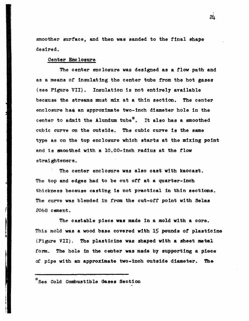
Center Enclosure
The center enclosure was designed as a flow path and
as a means of insulating the center tube from the hot gases
(see Figure VII)o Insulation is not entirely available
because the streams must mix at a thin section. The center
enclosure has an approximate two-inch diameter hole in the
center to admit the Alundum tube*s It also has a smoothed
cubic curve on the outside. The cubic curve is the same
type as on the top enclosure which starts at the mixing point
and is smoothed with a 10o00-inch radius at the flow
straighteners.The center enclosure was also cast with kaocasto
The top and edges had to be cut off at a quarter-inch
thickness because casting is not practical in thin sectionS 0
The curve was blended in from the cut-off point with Selas
206G cemento
The castable piece was made in a mold with a core.
This mold was a wood base covered with 15 pounds of plasticine
(Figure VII), The plasticine was shaped with a sheet metal
form,, The hole in the center was made by supporting a piece-
of pipe with an approximate two-inch outside diameter. The,
*See Cold Combustible Gases Section
l

S-
-if
j, i
E-·
ill
ZDi
tJL

26
plasticine and the pipe were covered with a heavy oil so
the kaoc'ast would parto The kaocast was then put in the mold
in small quantities and tamped down to insure the best
obtainable surface on the flow side. The cast piece did
not readily part and the mold had to be partially dismantled.
The center enclosure was then allowed to cure for 24 hours
before it was firedo The firing was done in the Metallurgical
Foundry on the following schedule:
150F 16 hours2000 F 1 hour300OF 1 hour400°F 1 hour600eF 1 hour800OF 1 hour900F 1/2 hour
After firing the castable was covered with a thin
layer of air-set mortar and was sanded to a smooth surfaces
Burn ers
The hot combustion products section was designed
without any specific burner in mindo The producing of hot
products can be done in many ways so the burners were
determined after the flow paths were ascertainedo A burner
that could stand the high enclosure temperature was needed.
Alsos one that would operate over a large flow range so
that a large velocity range could be obtainedo
A burner was found that has these characteristics0
It was a Selas KZ-552-SN3 duradiant burner9 (Figure VIII).
The burner consists of a metal mixture tube with a square

r
07
: ' .. _
FINAL APPARATUS-OPENFIGTJRE VIII POSITION
rf
ir

28
ceramic housing around it. The burner is designed to operate
in an enclosure but on account of the metal mixture tube it
will only stand an enclosure temperature of approximately
2500Fo. The burning end has a refractory cup-shaped design
in it, A molded high temperature ceramic tip is fitted in
the cup and screws into the metal mixing tube. The tip has
numerous narrow slots molded into its periphery which acts
as a distributing head. The radial flow of mixture passes
out the tip and is burned within the refractory cup. The
inside of the cup is rough and promotes turbulence and thus,
completes burning The burning also heat the cup to a
high temperature where it becomes incandescent. It is the
turbulence and the high cup temperature that give fast
burning and the desired large flow range. The flow range
for the Selas duradiant burner is 5 to 50 cubic feet/hour
of natural gas. Calculations were made for the number of
burners required by assuming a temperature range of 1800°R
to 300eR and a velocity range of 25 feet/second to 200 feet/
second. The calculations were made at the four extreme con-
ditions and the limiting factors were the maximum and minirmum
flow of each burner (see Appendix, Section A). From these
calculations, twenty burners were determined to be satis-
factory. A high velocity was chosen because low velocities
can be obtained by shutting off some of the burners. Once
the apparatus is operated, the maximum temperature can be
determined and the calculations will have to be revised.

29
The twenty burners9 with pieces of firebrick between
them9 were mounted on the firebrick with Selas 206G sealing
cement (Figure VIII)o This cement is a heat setting break-
able cement good for temperature up to 30000Fo It sets to
a hard consistency but can be used for sealing only, not
bindingo It is recommended that the burners be connected
with fitting so a 1/4=inch rubber hose can be used for
connecting the manifold to each burnero A rubber hose is
advised for easy assembly and as prevention against an
explosion in the manifold. Any large pressure rise will ust
blow the rubber hose off,
Introduction of Dilutent
Dilutent is necessary to give temperature control
of hot products0 A non-reactive gas is desired so the fuel
air ratio will not be affected. The fuel-air ratio must
always be stoichiometric or extra fuel or air will be present
in the mixing zone0 The most available non-reactive gas is
nitrogen which serves as a good dilutento
The design shows dilutent being introduced in one-half
inch tubes mounted between each burner at the top of the flow
passage, The tubes can be made out of stainless steel or an
equivalent high-temperature metal. The tubes were shown at
the top of the flow passage. Since the dilutent will be cold
and the hot gases will have a tendency to rise, the dilutent
will have a better chance to mix than if it were introduced
at the bottom of the passage.
I
30
The tubes can be supported by their solid connections
or if connected with rubber hoses, they can be supported
with the pieces of firebrick that go between the burners
and the Selas 206G sealing cement. Some of the pieces of
firebrick that go between the burners will have to be remov-
able to permit lighting of the burners with a torch.
Flow- Straighteners
The flow out of the burners and from the dilutent
tubes is not a very -smooth, well mixed, or straight flowo
Thus, some means were needed to remedy this situation. The
ideal device would be a straightening and calming section
with a length-diameter ratio of fifty0 This would give fully
developed flow in the holes and cause mixing, straightening
and convert the large-scale turbulence to small-scale
turbulence. But, the hot stream being annular would mean
that many small holes would have to be radially drilled in
an annular section that would be able to withstand the high
temperatures of the hot products0 If some material of this
type could. be found, and if it had a fine grain, the smallest
practical drill size would be 1/16" diameter This results
in a piece over three inches long to give a length-diameter
ratio of fifty, This would considerably increase the size
of the apparatus.
A material was found that is machinable and will
withstand a continuous temperature of 25006Fo It is magnesium

31
silicate or Alsimag 222 from the American Lava Corporation.
The material comes in pieces 4.5" x 4.5" x 7/16" and it is
of a porous nature. The company advises that, in machining,
a 1/8" wall be maintained. With these results the flow
straighteners were designed as pieces 3" x 1-1/2" x 7/16"
with 1/8" holes on 1/8" spacing in the 3" x 1-1/2" face.
(Figure VIII)o The holes are drilled straight through and
the pieces are mounted radially in the 3" high flow passage,
2" from the burner outlet with Selas 206G cemenit It is
realized that this type of straightener will not act as the
one previously mentioned but it is a compromise in the design.
This grid will tend to mix the products and the dilutent
because of the pressure gradient across it as well as
reduce some turbulence and straighten the flowo The converging
section after the straighteners will also help the flow
because it will tend to elongate the vortex tubes and decrease
the boundary layer thicknesso
Cold Combustible Gases Section
The cold combustible gases section is for the introduction
of a variable fuel-air mixture into the mixing zone. This
section consists of a straightening and calming section and
a center tube.
Straightening and alming Section
This section is shown in Figures IX and XI and is made
of aluminum. The purpose of this section is to straighten and

32
rZC
t3E-4
r
Hcc5n
ti
in,
I1iI
Ii
iIi
i
I
I
-- Yes
tI

33
calm the mixture that has been piped in. This is done with a
straightening tube bundle and converging section, The same
theory applies here as it did to the hot products straightening
section, but In this case the ideal section could be used,
The straightening tube bundle consists of approx-
imately 880 brass tubes that have 1/8 " outside diameter and
a o014" wallo In order to obtain a length-diameter ratio of
509 a 5" bundle was required. This will result in fully
developed flow in the tubes and thus, will decrease the turbu-
lence o
The next part of the section is a converging section
from 404" to 15"o It consists of two cubic curves and
will serve to improve. the flow pattern by decreasing the
boundary layer thickness and elongating the vortex tubes.
The whole section is mounted to the bottom enclosure
on the bolts that were previously discussed, with nuts
and Selas 206=G cement on the face to act as a s-ealero A
four-inch pipe with a flange can be connected to the inlet
with bolts and can be sealed with a standard Parker 2156
O0ring.
Quite a dilemma occurred over the placement of the
straightening and calming section. One argument was to place
it as close to the mixing zone as possible so as to keep the
boundary layer thickness to a miniana but at the sacrifice
of the insulating center enclosure. The other argument was

34
to place the section at the bottom of the bottom enclosure
to take full advantage of the insulation at the sacrifice
of the boundary layer thickness0 An evaluation of the effect
of the length on the boundary layer thickness (Appendix 19
Section A) and the fact that the center enclosure would be
a much more complicated casting, determined the choice of
putting the section at the bottom of the bottom enclosure
as it is shown 0
Center Tube
The center tube is one of the most important portions
of this apparatus because it constitutes the point where the
hot and cold stream will mix. (Figure X) o The tube is
shown in the design as a hollow cylinder 96" long with a
2" od and a 1-11/ 2 " iodo The tip has the contour of the
beginning of the inner cubic curve which makes a thin sec-
tion at, the tip.
The actual tube is this size and made of alundumo
Alundum is aluminum oxide that is very hard and will with-
stand temperatures as high as 2640*Fo Grinding is required
to machine it0
The tube was machined by mounting it in a lathe and
machining the contour with a diamond0 The diamond was a
grinding wheel dresser0 The contour was made following a
template
The tube mounts in the middle of the center enclosure
and rests on the luminum stning and almlng section.

M
f9p4
p4
c4
z
zC
C
H"I*s
N,
w2-
E-4A
u
Po
zHr%4
·i ·:-;L
j·I'.?'
·-��."�'� g;,:·,
t-
i I

36
Selas 206=G was used on the outside and bottom of the tube
as well as used to blend the curve from the tube to the c6nter
enclosure ,The tube may not be satisfactory if it burns at the
thin section.. In this case it may be advisable to make aremovable ..tip so another could be inserted. Also if the
flame that is initiated above the center tube flashes back
it may burn, the straightening tubes. If this happens then
a quenching screen will have to be placed in the center tube,
which could be done by inserting it under the removable tp.
These two designs would have been incorporated in the appara-
tue but a two-piece tube is much more complicated than a
one-piece tube especially if it is not necessary. Also
the idea of using or not using quenching screen is quite
a dilema because, as stated previously, a flash-back may
burn up the straightening tube, but a quenching screen will
put turbulence back into the flow that was so painstakingly
taken out. Thus, these two items were left until testing
can be perfomed.
External Sections
The only sections external to the actual apparatus are
the aforementioned pyrex tube and sheet metal chimney.
(Figure XII). The pyrex tube can be set on the metal housing
of the top enclosure and sealed with Selas 206-G cement. Ifthe pyrex tube is not adequate for est'ing purposes, a vyeortube can withstand higher temporr.&t than pyrex but a piece
N

37
-- Chimney
----- Pyrex Tube
iL . - Top Enclosure
IFIGURE XI FINAL APPARATUS-CLOSED POSITION
tki
- ii' i
....

38
with 6" Od. Mid 1" lon-g i iibbd ti $2330 86 It wil be
nece-ssIy to rearrtinge the ehfitrby t hib it itUit6d Vi8"
the pyrex tube but oth-#r*i-se it 'fhould b th't.oughly
adequate for a ehau t S'btem
The final apparatus ineo'pt"'rated all the ideas from the'
prelimina-ry testing apparatus which includes a hot eotbudttion
product- section, a old embus-tible gases section and m
external section. The hot produets section has enough
burnere to permit a large flow range and dlutent to- permit
a large temperature control0 The section has flow straigheners
that are not fully adequate but are a compromise between a
theoretical straightening section and the material-size-machining problem. The section has a onverging flow path
to perfect the flow pattern-and a zero slope curve at the
mixing point.
The cold gases section has a straightening and calming
section for control of an unfavorable flow pattern, It has
an insulated center tube (insulated by the center enclosure,
an air space and the center tube) plus a thin section at
the mixing point.
The external section has a pyrex tube to permit visual
observation of the initiated flame and a chimney to exhaust
the burned and unburned gases.I

39
These three sections, the hot combustion products
section, the cold combustible gases section and the external
section constitute the final apparatus for studying combus-
tion in a laminar mixing zone,

APPENDIX
4o
I

APPEADIX, SECTION A
CALCULTIONS
41

42
Calculation of the Stoichiometric Fuel-air Ratio for Cambridge
Natural Gas
Percentages reported as follows from the Gas Companry
GEI4 93.25%
26s 3.93%
C3 8 .97%
C02 .92
H2 .34%
Others e59%
Balancing the chemical equation, assuming complete combustion
.9325 CH4 + .0393 C2H6 + .0097 C3H8 + .0092 C02 + .0034 H2
+ 2.0525 02 + 7.7213 N2 1.0494 002 + 2.025 H20 + 7.7213 N2
Air required
2.0525 moles 02 x 32 lb/mole = 65.68 lb
7.7213 moles N2 x 28.16 lb/mole = 217.43 lb
lbs air required = 283,11
Fuel required
CH4 .9325 moles x 16 lb/mole = 14.92 lb
C2H6 e0393 moles x 30 lb/mole = 1.18 lb
C3H8 .0097 moles x 44 lb/mole = .426 lb
002 .0092 moles x 44 lb/mole = .405 lb
H2 .0034 moles x 2 lb/mole = .0068 lb
16.937 lb

43
Fuel required = 16.9378 lbs
( F )X stoichiometric 16 7 = e.0598
Calculation of Flow Area of Hot Stream
hole in top enclosure =
diameter of center tube=
2
5o 625 inches
1.5 inches
nD2t4
A = m(50625) 2-4 -
_- °4 = 24.85 - 1.77
A = 23,08 sq. in. x sq. t, = .1605 sq. ft.
A = .1605 sq. ft.
Calculation for Number of Burners
velocity range
temperature range
burner flow range
25-200 ft/sec
18000R - 3500OR
5 - 50 cuoft. fuel/hr.(Selas Bulletin C-1037)
Number of burners must be adequate so for over the ranges
listed above the burners are not operating above or below
their capacity.
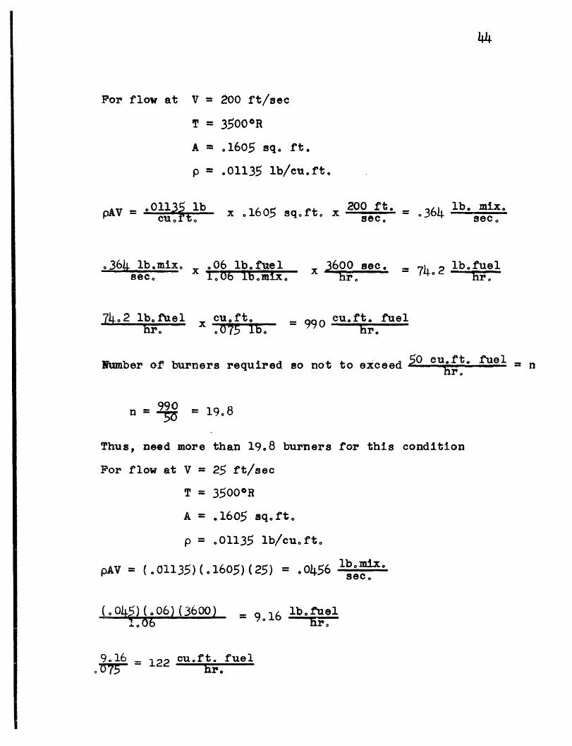
For flow at V = 200 ft/sec
T = 3500oR
A = .1605 sq. ft.
p = .01135 lb/cu.ft.
pAV = 01135 lbcu. f t. x 16 05 sqrt x 200 ft. = 364 lb. mix.
364 lb.o x .06 lb. fuelsee. e .Ob lb ma x x 3600 sec.e = 74 2 lb. fuel
742 lfuel x cu.ft cu. ft. fuelhr. -07 990 hr.
r. = 990 cufftt fuelNumber of burners required so not to exceed . fuel =n
n = 0 = 19.8
Thus, need more than 19.8 burners for this condition
For flow at V = 25 ft/sec
T = 3500°R
A = .1605 sq. ft
p = .01135 lb/cu.ft.
pAV = (01135)(.1605) (25) = 0456 lb.mix.sec.
(:04.) (.06) (3600).06 = 916 lb.fuel' .. ir.'
9.16 = 122 cu.ft. fuelv 8 hr.

Number of burners required so not to be less than
cu. ftfuelhr. - -
n - 12= 24.4
Thus, need less than 24°4 burners for this condition
For flow at: V = 200 ft/seco
T = 1800°R
A = 1605 sqoft.
p = .0221 lb/cu.ft.
I lbomiX.pAV = (.0221)(.1605) (2)0) .71-le
But dilutent was required to get down to 1800°R which is part
of the 711 lb.mixo/sec. and
(WCp T) nitrogen (WCp T)products
(W) (.24)(1800-530) = (W)(.2.) (3500-1800)
Witrogen = = = 1.338products
but = itrogen roduct 711 lb.mix./sec.
2, 338 rodut 71products =711
products '304 b.products/sec.

(.3o (.06) (3600)
62
= 62 lb., fe 1
= 827 u.ftr. fuel= 827 . P
Number of burners required so not to exceed 50 cu.ft.fuel/hr = n
n = 8 = 16..5
Thus, need more than 16.5 burners for this condition.
For flow at V = 25 ft./sec.
T = 1800OR
A = .1605 sq.ft.
p = .0221 lb./cu.ft.
2. 338 Wpoducsproducts
pAV = (.0221) (.1605) (25)
Wnitrogen + ¥products
Wproducts
( 038) (o6) (3600)1,Oh
= .0887 lb.mix./sec.
= .0887 lb/mix.sec.
= .0887
= .038 lb.products/sec.
= 7075 lb.fuelhr .
= 103.2 ou.ft. fuel
Number of burners required so not to be less than cu.ft.fuel = n
n = = 20.6
Thus, need less than 20.6 burners for this condition.

Looking at all these conditions it is obvious that the
number of burners required is 20.
oaloilat ion for B Tdwr ayar !hick.s at To Positio.ns @'
the .t-ra:.thte.At--s and CA. ,mx......a .So.1iQ
The "wrst conditions were taken for these calculations
which are low velocity and high temperature.
Assuming the Section is at the bottom of the bottom
enclosure the following conditions prevail:
X = 9.6" (assuming the main boundary layer growth isafter the straightening and calming section)
V
T
P
Using the
25 ft./sec,
= 70°F (no heating from hot stream)
= .075 lb/cu.ft.
= .0177 x 242 lb/hr.ft
exact solution for the boundary layer thickness
= 5
b _ 5 / ( e 0177)( 2o42)(9e6)_(12) lbo il.to 8cecueit o. I 2 (e075 } e O lb0o hrse e
- 5.00073 sq. in. = (5)(.02705)in.
.135 inches

48
Assuming the section to be as close to the mixing zone as
possible the following conditions prevail:
X 3"
V = 25 ft./Sec.
T - 800°F (heated from hot stream)
p = 0315 lb/cuoft,
, , = oO327 x 242 lb/hroft.
= 5 I (.0 327) ( 2.42) (3) (12) sq.oin.(25) ( o0315) (3600)
d = 5 o0010 Sgq in. = (5) (.0317) inches
= .1585 inches
Thus, it is seen that the boundary layer is thinner when -,he
section is mounted at the bottom of the bottom enclosure,
even though the distance is larger, the insulation and sim-
plicity of design are greater.

APPENDIX, SECTION B
DES IGN
'49

i-I') a -1-.I **"
* , V 5r· o
~1
. ..
I,.
'p
I .{M. -.
* /* I~~~ -7c n~F~
I-
. . .- '
(.4 *
-, -
/ jPV* .*.. I I
J.
. _-I- _
I
rIIII
I
I. * .
.~ J· ·. ~ -i /
-;~~~~~~~~~~~~~~t-s-- ^ _ /; ,.," ' ,-.Z; :
.: ' . :' ... . . ,.
" ' -*. ' ' ' ·.' . . * "'' ',
· .., -;. . -...... . ~, ; .... ',.',-.,';...* --=i.-,~~~~~ ~ ' - '. %i 7 /2 · ·. ~ _',.. · ;' '· ' , , ' . . . '.~...... .. _ . _. s .
. . .... ' .' ·
* ;e' ,"', .'"wi ........ ..1. . . '.¥.~..B~ "r
·" " .i.~:" · ~ "' '" '
I
1ANt7X_-,041C 70^./ ::
l:
I I
. I I -
I
tr~
: j :: ;
· ��'�''
·.r ·' · 'r�'r b··
. I. If.~~~~~··~-·----- _F---~_
I . . t
P
I
-- I
I
- - -~~~~~~~~~~~~~~~~~~~_~~~~ k.
* I i '
r i- __ - . I
W
.. I '
. .
. . Oe

'c'7/yo0 a0, . L UT/ 7'.. ·I ·,
.I
II .. 4.
- .. .b .
· · t·i,
cr. . · ·r·k. ;·-··I�··· ::· r i;ir
�s;-.�! ·rq·' :L
1
" ' '. . . ... . . /
, kf
,. I5
4.'
*Ii V.
.~- ... .. .
.~ ~ ~ ~ ~ ~ ~ ~~~..
A. . , -
.-.. - .. -. .,
. %!
I 4
/
· : P ·
--- ·.--- ·--- ----
!I . I I
1. .
_* 1- · -i. . ·-- .
I
-- -- · . i ---· · ~~~~~~~~~~~~~~~~~~~� · - · ? · L
b --
* - { t : I
· I
·\ · L. ;·r ··r
Y1�
;;,;
· ··;··I-··'!··'· �·-
i'''··!'·` -�·;-:�-.. :-. · .···�·
:· ·-�:·-I··;·1.,
:�i6iill ;.·j·l�;- .:-··-;;-·· · ·- ·· · ·-- · · · ·A. - - - | '1 - ~ ~ ~ ~ ~ -... __ ,
____ ---.- * I t.
.
It
. ..... -
z
I .I . .
t
I .
.
I
.1
I
'Pl..1
iP%- -Ti
-1J
.
-. 7
: . A 1
.1. I- , I .
:,_,_~
. . f i
.1 , ,I
17- --,5 7;eAA*,t7

'': !* ~I
'( _ -' ' . _ '/
' _------~ i
I ~ ~ / -
I
1.
., I le
0r ,Q I,* C.r A/
I
'
It
'7
I .
C S.
__ I - ]1
·-~~~~~~~~~~~~~~~~~~~~~~~~~~~~~~~~~~~~~~~~~~~~~~~~~~~~~~~1-
--------·1
\i ;
'I-
I
I;I
II
I- i
I- iI
i .
C7~~~is-C ~~-------
I =
- C--
-C -I r - - I I - -
t1
c
;..;.
; ·r··
31:.·i ··iir I%

, I ti j
r
/i4
. I
.. i
4
. .
. .
', .. ar.'
· P~~ ~%~ ~- .
li· . · .*II~~~~~~~~~
I.
.V' "'*6·
..
. e -I, 1- v ,eS w
.
- .." , . _i
. .', d
t :
'1.
__I _ I
- W
jt
��
I I
,% : I
7 q
I
I .
. .'. .' . I
I
,..
.k'
4
. .1·
I -
';I
0
i .
.
,·
4.
r-, %iI!'
i
i
.^11411.el" C....... I _. T · ,
. . . I. I I

p{aocZ - J
_ I
2o
II
L ,SEL A 5
.i*,~4
_�_
F~
I
i
I
I III -
I
f
1 ':
i
tt
~~t~c 0- -4114c~
f
-·

If
I
I~,,ra '
i ,r v star
d
/. .I
5I ~- -. XV
i. .
_, , ..9I . . o . . - ,
I , V---F F t r | I I I, , *~~~~~~~· n· ·O L Xai 4
1. ` � · "
r' rr··'-
z -·*`u-z
s� : -· r a.·
ir · ·
1 �4. , � ' '� ` `-t
··a
* � · � r·
is
.Pt�·
I
i
26-'c_7S5
-S,
;
i''
�
'U·
'I
FV7
I .
d�i-·
·.J-
� . · ' \ L9" �·.:l-�;·�i�5:
i ��
Ir
.,N,;
.cq f- "I..I 1
7 , ,
'ill
I P
� .....
...
P-
'"' I··'
i I
i . - 1
I
-.1
."O,~~~~~~~~~-
r"I:·· "
I .I
~~N , i, ~,
.
i" -:
t,.
J,
a
,
%
-" : ·� �· ' "' " -- � · 1·
.
-
I.
._
--- I
. .I -
-N'AS~
-^ 74-F'le~ J~jM~; 'L-D1Lt~-1 ~ ~ ~ _ __~-.-

. /k/ ..
, I.j
9_..o
I
'I
07cr2O r7 vcz. 5elie
9
.i
, ? ,
11;
4
/
I
4
5c.,4 ..

s5Ot\
i
I
l;
I
U ..,
-1.2
· -- - -D 1-1-1-1- ,, ., a -X I1 ~ .; o d._- .-i,
£
I
1
I .
I
t
II
I· ·
I.
- at

* .' ... .
, ' //A/ C, 5 AE K. 'l./~ z,,,.~c,~- .,le..V
. 7
e I I.
It
-I'
-; i
' _ ..
4.
. ..A.
,'
I
,i E~
b
I
.-; --.', I''· ·.
-I
.
I .
I . .
I
1. - -
. f i
' - I. I
t
;:JL;7iii
If .I
j
IC=-" CC-z_ -457-7-eveff
;E7140e-
I
o
r.`
·r -i�r-
-··.- ·:-. .·�-·r
r rr
'
��·;·: ;.--·-
i. #

so r
CA4 -
$~~~33
%V e
4;-
i

AIN5~~/W~~~/ ~·A~
~7'AL/cpA~v 7E Ali~
l
.I
.
t
_ __ __
j I
. .
i
� 4A- -. -W-,
i
I
I.
. -,= .~ 4-" kj117;41IL/7;C
.4
· ·f0 Kf.
I~:i
- ..

7YA: -
r.
. .
ntA
Sna. OnN

7
2-ofcA.
f'I
t
1.
4~
-
- s t rr v - -.
.I'
I
.. L. ,
f-
o'
¢.
-- -- :·
3
I . . .
I
*I
'V
i .I:
f
11.

- .1.. a .. .._ .. _ * - -. ------ - -
; ~-- -- - f
.
tl li .l
i
v X
'7
I
4
I
4'�1�"
. I
I .,A
4-1'
til
I
I
I
;I~~~~~~~~~~~~~~~~~~~~~~~~~~~~~~~~~.. -
l I
I . .
I
6·
;
?
-
-4

/
,'
' A I,
d
#I
I~I
l, ·
.......... ~r r
At
_ t
v
i w I
ilj
I
MA,
I' t- .-�·111· �·111�· .-·lll�··IC 1�·(�1�.�·131. TllllfC ---- �·l�·lbLI�·
i �C Lf ··

I '
1'
S
I I~~~~~~~~~- '
., S
7-" ;
i -
I .
.4
I'
.
_ _
.. ..: .':! .- I i J: '" ' O~ ""
I.~-- I
i
4r
II. .
I
I
A-.-t- ,., I
._..~~~~~~~
It:
.i
I ,
I I
I . .
:Ts· .? . ~
Ii
I
II
I . .
...- = .
T--T. -
I..
Y \
I '
,·' · .-i;
/I
�cc-
4
r/
I
. .I
iI ,/
-4~~~~~~o ,
/
AI ' -
-I
I
w ,
1* : V
_I__ ·
----------
. \ I
I
.,
. -
- IiI
iI
.�-I
I-
i~~r 5 -i-P------

a 1
I
4,
Ve
L.1I
-
i, . I - :i.
iIiI
; T 7-7/ 7 .- ·
B U~~~N~~--,- ·
cr ia
I
I r
%. .
. . I~~.. .
.1
I Z",
/ f

IhL
iY
I
P
---- · ''~~~~~~~~~~~~~~~~~~~~
.4"
. I
';,; - I ! '-
0 -
I
I;
4.
___ i'll..~
\
/s·
~ c~T 7<AV~ -
c.. ,,I~ /:.: I I
z hr I / -, i | , ,· ·· ·,
· ·
-�·· :�. ro
� r
·�· .. I·ii
9··�
�a
· · g
------
J
I1
/e ·
�
r
LI *,
I -~~~~~~~~~~~~~~~~~~ '. . I I " I~~~~~~~~~~~~~~~~~~~~~~~~~~~~~~~~~~~~~~,
i z., ,
r
,..;· .
* He ~ ~ :'* > Xr
~~~~~~
4~~~~~~~~~
.
r
j, ·i ·. "
�
I
O
~~~~. I.~ . *- | /~~~~~~~~2
I! ~ ~ ~ ~ ~ ~ ~ .
i;~~~~~~~~
s
r
2.�
· ' ·. ;I�.
9 - .
ri~~~~~~~~~~~~~~~~~~~~~
. , Al ~ ~ ~ ~ I;

/ asi -l.
. f1
*
.
-L-
--
r.rr
I
v
I

t ,.f
I.
4.
I
It
-4
t,
e-
I
-·CI -P-1
I

I
,.
i- - - ,
. .
.. , · ...
t
.,~~~~~~~~~~~~~~~~~~~P
. ,~~~~~~~~~~2

rI
V
I, ',.
.
a
-*�IC�
I
e
1�I·
I
I
C'
~'~Ba.77;o/i;, ~~ - IV4---l - -AiEF -11F

ber. ' ;Al
*
· --f , -
1 . J.
S ~ ~ ~ A11 I
A-.
I
i
I
V
.,
-_· i ~ m m-
__�__��_��_ ��
I
'--
I .. .. I .' 1 '
: i·.
. .
4
.r
;
-I-
/
I *1

5lo
?
zs
'A
Se
_ .
1 _ _ � _�_��� __ ______ __�__ __ __
-j
I
V
l
II
i:I
.!
-~ - - - . . -, 7 1 i
r

/-
'
J
"I
4,
. .
i . ;. ISt
C_g�
''
· . .·- ·-- ·- L · C�----'t
Or -
5ly
N
. l.-!
. I I
'IiiI
I~~~~~~~~~~~~~~~~~~~~~~~~~~~- S
/
I - ../
J
i
.: ·
i
I4
11
4'
I -i
. . tI.--e.- - -------

s r- I T
- ; - .
i _'
. I
.t ¢
J
/ 1-
i . ~~~~~~~~~~~~~~~~~~
S1 I' -
-.
A1
I1j .' . , ~. . ,
,:iv 4 t/PlafiTiF t - c'/'f/V -5/r/c'Ao/RA 2 -r,- - - --
, , N- . 1 -~C .,, tj
lt-l- - s MP AZO1V .- ~ 4 C4 t I/ ,'?IL')P- r.- ~ _I- . ._ _ n-^ - -- --- --- ' r-- r - - - -
i
I ·1 1·
---' ------- � �-'-- -II1ICII·si i� :, �' Pp'~ C1 � v
i·-·r ��-· · rr " Y
-I* II·� -Y�-· �
I
. 1 I -
1:."
..
I I-j·
! I
!l
7 : t t I , - l I :--- -Z., Z- - .
I-I.41
*R.;Fjj�i�(�ZS4 itlr�l �3;-.�*PI ,i·sZit;z: · ·
'' j"� ;d · IF�S'LL ·.
h . �. -
.i~~~~~~~~~~~~~~~~~~~~. i 1
)J r ~~~~~~

2
:,i
/
ki'I-.
* Z~~~J/ / L Aiv~ ,VJ'i3 TAY' A'OZ-
. I
1 .
I i-
-04.

iz,R
/50
-4---
If -qhl.. it -#tii
I-
I ,
I
I
I
. :::-
-15-2-L

t-
. p
a 1
4. a 4 5 Da/.
F* .
V-
-,
i_:
"' . ./
':50 anAA.,
· I~/ L4 ~-AA, TA/ ·. -' , , . "
............ - .i- _ . --I- -
c- e
.. A__
..
_ e
I
-4- -. ffo
.,
11
-~-- .~..~-~~....~~. ....- .- . ... .. .. - . .
iI-

. ;S / /,'. -/9O0 i.Y SpA3cea A· . *::: /.: ... 7SZ..O
v
K
I
4,
.
,.
7 \/ 4 O S TA 4'4 Ys e - ' .-
-_ . .
AS...tflr
.1
---------------
--- · i .t -- ~~~~~~~~~~I II
i\I ·
k1.
r··
r
k.4~~~~~~~~~1
,........
.4
_ -�...�. __:-·��·
...
"ZA �·;· .·-`r r..

I.
I I
l
} R~~~~~~~~~~~~~~~~~.
".... I
06
i
I/
-- --
r
1
i... _._.._ ___� c . �
r
t-"e '� ---- ;�--t r1;--- -- - .- -.. I I.

' A
4. 04 DA.
/, I'
I
i
I
N
I/
~S~ C-/AAR 4BEOW IFOR P~j~e - ,gr - 1ec ~rool- L~q r~
.:
Ii·d
*1
.t.* !
I
o. . , .
I * .
I - ..j
.C a.ks3 f.000 --. 0ZC014ooz £V/as 7Y
J40 c . .T0 - .090.o~/ "~ .-. Ooo
. -~. O f ·OL nook & o
1..
-J
?__
- ~-------·cl -- - ---- --
- l X N. ---
I--
-
-
-
.. ·- -. ". ·- --r- -- . , -
I
I
_l '
I' rn
A'
.0
i
f
i '-0.4'-).I
t
I j Ak
1

.
.2
L- 5 5~00 /4.
- . o40
I --- - --·ir 7, 1::T , -
T/ 4
N
-4
...... v
71r ---. . - " I
4
I
!,-·
f
. :71e -
A D, w '
o

:,- -2Lt
.E
16
. I
.~.__..-~ -~-.,,_..,.' . ... ._ .. .......... . .... ~~, .'.......... . ,-_. _ N~ p R N A L . O~ $F~ U~ T : r L M30 R A T O YM SACfUSE Ei-TTS IN-STrUTo OF T jOH-N r-C5rX1 E iq/q/,~ 4E//Ad c: A c.4 cM/A 5cV #7/e0
~.~ - -_ . ......... ...... .. .... _ · _ ~ ~ ~ U. rs I
~~~~~~~...mrIr 'll
- - - ------- ·-- - - - - -
. L6I -
l..
i
I ! . . -i
. . i. .i
, . -'". ir--- ·- · ·-------- · · ---
_ . =e--Z V & &

BIBLIOGRAPHY
1. Marble,F.E, and Adamson, T.C. Jro, "Ignition and Combustionin a Laminar Miking Zone", Selected Combustion Problems,pp. 111-131, Butterworth Scientific Publications, London,1954.
2. Cheng, S.Io and Kovitz, A.A., "Ignition in the Laminar Wakeof a Flat Plate", Sixth Symposium (International) onCombustion, pp. 18-427, Reinhold Publishing Corporation,New York, 1957.
3. Pai, SI, "Laminar Jet Mixing of Two Compressible Fluidswith Heat Release", Journal of Aeronautical Sciences,Vol. 23, No. 11, ppo 1012-1018, Noyemberr, 1956.
4. Wright, FH., and Becker, J.L., "Combustion in the MixingZone between Two Parallel Streams", Jet Propulsion, Vol. 26,No. 11, November, 1956,

MITLibrariesDocument Services
Room 14-055177 Massachusetts AvenueCambridge, MA 02139Ph: 61 7.253.5668 Fax: 617.253.1 690Email: [email protected]://libraries. mit. edu/docs
DISCLAIMER OF QUALITY
Due to the condition of the original material, there are unavoidableflaws in this reproduction. We have made every effort possible toprovide you with the best copy available. If you are dissatisfied withthis product and find it unusable, please contact Document Services assoon as possible.
Thank you.
Merrion, David -Thesis, M.S. M.E., 1959An Apparartus for Studying Combustion in a Laminar Zone
Pages 50-52 contain oversize map designs that were filmed insections. They could not be scanned as single sheets due to sizerestrictions.