09165878.pdf - DSpace@MIT
170
. . . .. i 0 N' 'J SJ n *1 4 A. * ** ...... . . .. . .11 0 * * Sal *N *b *, . ... . * *. *. 8 * * *AY* *. .. *.. * 11
-
Upload
khangminh22 -
Category
Documents
-
view
0 -
download
0
Transcript of 09165878.pdf - DSpace@MIT

. .* * .* ..
.. i 0
N' 'J SJn *14 A.
* ** ......
. . .. . .11 0* *Sal *N
*b *, .*. ... . * *. *. 8 * **AY**. .. *.. *
11

MITLibrades77 Massachusetts AvenueCambridge, MA 02139http://Iibraries.mit.edu/ask
DISCLAIMER NOTICE
Due to the condition of the original material, there are unavoidableflaws in this reproduction. We have made every effort possible toprovide you with the best copy available.
Thank you.
Despite pagination irregularities, this is the mostcomplete copy available.

WALL SHEAR-STRESS AND LAMINARISATION IN ACCELERATED TURBULENT COMPRESSIBLE
BOUNDARY-LAYERS
by
JAMES LUDLOW NASH-WEBBER
Under the Sponsorship of:
General Electric Company
Allison Division of General Motors Company
GAS TURBINE LABORATORY
REPORT No. 94
April L968
MASSACHUSETTS INSTITUTE OF TECHNOLOGY
Cambridge, Massachusetts

Per ardua ad astra
Eheu, fugaces I

ABSTRACT
Turbulent-laminar transition in compressible, steeply-accelerated,
adiabatic, turbulent boundary layers on a smooth wall was investigated
experimentally in the ranges of Mach and Reynold's numbers typical of
nozzles used in propulsive devices. Correlation of the present and
previously published data suggests that the transition of such a shear
layer may be predicted by consideration of its trajectory on a plane
having an acceleration parameter K and a Reynold's number R62 as
coordinates. An ab initio design method has been developed, based on
these findings, which will ensure laminar flow before and at the throat
of a sufficiently small nozzle operating at sufficiently small total
pressure. A new type of surface-pitot was developed and calibrated and
used to measure wall shear stresses in both transitional and non-
transitional flows. Decrease of wall shear-stress in laminarising flows
was found.
General-purpose computer programs for data-reduction, surface-pitot
calibration and interpretation and boundary layer development predictions
were developed.

ii.
ACKNOWLEDGEMENTS
Being as it were the child of two of the Institute's families--
the Aero & Astro Dept. Propulsion Group and the Gas Turbine Lab., I have
many people to thank for their ever-available help in advancing my work.
The pleasant working conditions within these groups provides a welcome
degree of insulation from the insensate pressures of the Institute as a
whole. Though it is perhaps invidious to single out anyone, I should
like to thank most especially:
Professor Edward Taylor, whose outgoing personality and incisive
insight into the problem made research a pleasure;
Professor Gordon Oates, who, as project supervisor always
contrived to maintain a sense of humor and a degree of optimism despite
all setbacks;
The other members of my Thesis Committee, for their time and trouble
in setting me back on the straight and narrow at frequent intervals;
Thorwald Christensen, without whose skill and tireless efforts
in the machine-shop and at a dozen other trades the experiment would
have clanked to a halt;
John and Joan Moore for their valuable assistance with the
machine calculations;
Lotti Gopalakrishnan, for typing and retyping the reports, often
from my atrocious scrawl, and for feeding me coffee and cookies at
frequent intervals; and
Bonnie, who saw the work through to the end, and was an ever-present
help in time of trouble.

iii.
TABLE OF CONTENTS
page
Abstract
Acknowledgements
Table of Contents iii
List of Figures v
List of Tables vii
Notation viii
I. Introduction 1
A. Motivation and Background to the Problem 1
B. Introduction to the present study 8
II. Experimental Program 12
A. Apparatus 12
1. The GTL supersonic wind tunnel 12
2. Test sections 13
3. Probes, skin friction fences and associated equipment 15
B. Calibration 18
1. Skin friction fence calibration and interpretation 18
2. Linearity checks of transducers and recorders 23
C. Experimental Procedure 24
III. Theoretical Program 27
A. A brief survey of computational methods 27
B. The method of Moses and Launder 29
C. The method of Walz et al. 33
1. A brief presentation of theory 33
2. Computational scheme 36
3. New relations of Fernholz and Escudier 40
4. Comparisons with existing data 42

IV. Presentation and Discussion of Results
A. Location of Turbulent-Laminar Transition Points
B. Shear-Layer Trajectories in the K - R62 Plane
C. Recommended Design Procedure for Laminar-ThroatSupersonic Nozzles
1. Adiabatic Wall
2. More General Cases
D. General Discussion
V. Conclusions and Recommendations for Further Study
VI. References
Appendix I
Appendix II
Appendix III
Appendix IV
Appendix V
Appendix VI
Appendix
Appendix
Appendix
VII
VIII
Ix
Theory of the Skin-Friction Fence
FORTRAN IV Programs to Calibrate and InterpretSkin Friction Fence Readings
Theory of Asymmetric Two-Dimensional ContractionFlow
Extract from the Experimental DataTables 1 - 5
FORTRAN IV Program to Compute Boundary-LayerDevelopment according to the Modified Method of WalzTable 6
Notes on Experimental Data Used for Testing theWalz Method
The Skin Friction Law of Fernholz
The Temperature Profile Relation of Van Driest
FORTRAN IV Program to Compute Boundary LayerIntegral Parameters from Raw Data
Figures 1 - 32
iv.
45
45
48
52
52
54
54
56
58
63
67
75
80
90
109
111
112
113

V.
LIST OF FIGURES
1. Test section of G.T.L. supersonic wind tunnel.
2. Test equipment and traversing rigs.
3. Miniature total-head probes.
4. Skin-friction fences.
5. Schematic layout of test section.
6. Construction of skin-friction fences.
7. Various wall-pitot geometries.
8. Test section nozzle profiles.
9. Velocity and acceleration parameter distributions. Test section
pressure gradient distributions.
10. Typical X-Y recorder trace.
11. Comparison of H * and 6 calculations with data of Moses50 and
12 2
Goldberg62 in adverse pressure-gradients.
12. Comparison of H and R6 calculations with data of Launder28
2in a favorable pressure-gradient.
13. Comparison of H * and 6 calculations with data of Smith &12 2
Walker6 3 in zero pressure-gradient.
14. Comparison of measured and computed skin-friction - Nozzle A.
15. Comparison of measured and computed skin-friction - Nozzle B.
16. Comparison of measured and computed skin-friction - Nozzle C.
17. Comparison of measured and computed skin-friction - Nozzle C with
spoiler.
18. Shape-factors development - Nozzle A.
19. Shape-factors development - Nozzle B.
20. Shape-factors development - Nozzle C.

vi.
21. Shape-factors development - Nozzle C with spoiler.
22. Comparison of measured and computed R - Nozzle A.
23. Comparison of measured and computed R - Nozzle B.62
24. Comparison of measured and computed R - Nozzle C.
25). Comparison of measured and computed R -Nozzle C with spoiler.
26. Typical boundary-layer trajectories on a K - R plot.
27. Construction of boundary points for the laminarising region.
28. Turbulent-laminar transition boundary for an adiabatic wall shear
layer.
29. Sublayer fence calibration procedure.
30. Interpretation of sublayer fence readings for flow with arbitrary
Mach number and pressure-gradient.
31. Combined calibration data points for all fences and runs and
best-fit line through 532 points.
32. Machine plot of calibration data points and best-fit lines for
fence 28.

vii.
LIST OF TABLES
1. Test Section Parameters
2. Shear layer measurements - Nozzle A.
3. Shear layer measurements - Nozzle B.
4. Shear layer measurements - Nozzle C.
5. Shear layer measurements - Nozzle C with spoiler.
6. Effect of Parameter "NUMBER".

viii.
NOTATJON
A, A
B, B
C
a, b
cf
cf
c D
d
f , f2, F
FR, FL
H1 2
H12
H3 2
H32
K
M
N, n
P
AP
R6
r
T
T'I
Constants used in skin friction fence calibration relations
Constants of skin friction law (See Appendix I)
Skin friction coefficient (T /ip u2 )w 2 6 6
Walz' skin friction coefficient (C /p u2 )w 6
Walz' shear work integral
Fence height
Functions defined in Appendices I & II
Shape factor =(6 )U / (62 u
Shape factor 6 16 2
Shape factor (63 )u / 2U
Shape factor,= 63 /62\., du
Acceleration Parameter =w . d6UT dx
Mach Number 6
Empirical exponents used in Walz' theory (See III.C.1)
Pressure
Pressure difference
Reynold's Number (general); Radius
Reynold's Number based on momentum thickness 6 6 2
Recovery factor
Temperature
Sommer & Short reference temperature:
M2 + T _)T6 [1 + .035 M2 + 0.45 ( w -)6 T

ix.
U, u
uT
v
x
y
z
Greek letters
OLa
Y
6
6
61
2
3
6
Vy 1
P
T
A
Velocities in the x direction
Friction velocity (T /P)
Velocity in the y direction
Streamwise coordinate
Normal coordinate
Walz' normal cordinate
Skin friction function (See III.C.1 and III.B)
Dissipation function (See III.C.1)
Ratio of specific heats c / cp V
Conventional boundary layer thickness
Boundary layer thickness defined by Launder (See III.B)
Displacement thickness 6 (1 - Pu )dy0 p 6u6
6
0
Momentum thickness
Energy thickness
Density defect thickness
'p
Pu u) dyp6 u6 u
Pu -u _2) dyP6u6 u6
PU 6 dyP6u6 p
Viscosity
Kinematic viscosity
Correction functions of Walz' 3 3 theory (See III.C.1)
Density
Heat transfer parameter
Shear stress
Heat conduction coefficient
Shape factor of Escudier (See III.C.3)

x.
Subscripts
0 Stagnation conditions
6 Free-stream conditions
w Wall conditions
e Recovery conditions
u Evaluated with constant fluid properties
62 Based on momentum thickness
d Based on fence height
E Effective (in turbulent flow)

1.
I. INTRODUCTION
A. Motivation and Background to the Problem
Fluid dynamicists of the more classical sort have spent much time and
effort on trying to understand the behavior of boundary-layers in adverse
pressure-gradients. Comparatively little effort has been devoted to the
phenomena occuring in favorable pressure-gradient flows. Many propulsive
devices, however, incorporate favorable pressure-gradient flows, and the
continuing effort to push these to their limits of performance is currently
rendering mandatory a much larger effort aimed at a better understanding of
such flows. This study attempts to redress further the imbalance of research
effort and, in particular, to advance our knowledge of the "relaminarisation"
phenomenon.
The turbulent flow problem has been with us from the dawnings of fluid
dynamics. Progress toward satisfactory enunciation of the problem, let
alone elucidation, has been distressingly slow. In particular, when we
come to examine the status of the turbulent shear flow problem, we find a
wide divergence between the need of the designer of any sort of fluid-flow
equipment for information and the ability of the theoretician to supply it.
Since the problem will not go away, this has resulted in the formation of a
large school of empiricists dedicated to the production of useable design
data. The efforts of these workers are, nevertheless, greatly hampered by
the inability of the available theory to point towards the correct design
of experiments or greatly to help with the correlation of their results.
It has accordingly been necessary to break the problem up into many smaller
pieces, and these often indeed into several special cases before useful
progress could be made.
On two such sub-problems,a great deal of work has been done. These
are the laminar-turbulent transition problem and the equilibrium turbulent

2.
boundary-layer problem. In these problems, for several special cases
where the upstream history of the shear layer may be carefully controlled,
"theory" and experiment have been notably at one. In particular, there have
resulted the useful similarity laws of Clauser1 and of Coles2 for equi-
librium and near-equilibrium shear flows, and several plausible transform
theories to allow the extension of incompressible results to compressible
flow have been proposed. Two major schools of thought on the subject of
transforms are presided over by Coles and Crocco , but their differences
have yet to be resolved. Efforts at a general treatment of the turbulent
shear-flow problem have appeard at intervals, most recently and notably
10those of Hawthorne' and Kutateladze and Leont'ev
Several types of computational method for such flows have been
developed, based on these ideas. These appear to enjoy success in direct
ratio to the similarity between the problem to which they are applied and
the data from which they were formulated. These methods will be treated in
Section III of this report.
On the subject of turbulent shear flows which are very far from equi-
librium, our ignorance is most profound. Nature has, however, decreed that
such flows are to be found in many of our fluid-flow devices, which circum-
stance renders an attack on the problem highly desirable, though scarcely
more tractable for all that. In particular, a new and important phenomenon
has manifested itself in the special case of turbulent shear flows in a
very strongly negative pressure gradient, such as can occur in certain duct
flow devices, such as nozzles and turbine blades. This phenomenon is
evidenced as a very considerable decrease in the macroscopic transport
properties of the shear layer.
This has led to previously inexplicably low results in nozzle heat-
transfer experiments such as those of Wilson and Pope5 in 1954, who were

3.
apparently the first to encounter the phenomenon, at least in the Western
world: Papers by Deich et al 29, 30 refer to a first discovery, in 1948, in
Russia, of the phenomenon, during study of trans- and supersonic flows past
a sphere, and later encounters, in steam ejectors, in 1954.
It was widely speculated ' 8 that this most desirable (in general)
phenomenon might be identified with the onset of a reverse transition from
turbulent to laminar shear flow. Conclusive evidence of reverse transition
was reported by Senoo11 in 1957. He investigated the end-wall flow of a
turbine nozzle cascade, finding that for the conditions of his experiment,
the boundary layer, while demonstrably turbulent upstream of the throat,
exhibited a laminar profile in and downstream of the throat. Little insight
into the flow mechanisms involved could, however, be gained from this study.
During this period also, very large efforts in rocket-engine research
were getting under way. Countless tests to measure combustion chamber and
nozzle heat-transfer rates were run. Attempts to correlate and elucidate
these results proved less than satisfactory. Indeed, the best known of these,
the correlation of Bartz12 could seldom be relied on to produce results for
the peak heat flux accurate within a factor of two either way, even in those
rare cases where the boundary-layer upstream of the nozzle was well determined.
References 13 through 16 are representative of the heat transfer measurements
reported in the literature.
To account for that residuum of grossly low heat transfer results
which could not be prodded into the same pen with the majority, invocation
of the notion of a turbulent-laminar reverse transition of the boundary-
layer was sometimes attempted, on frankly intuitive grounds. In 1954,
Preston had suggested that there might be some minimum value of Reynolds
number, R62, say 320, based on momentum thickness, below which a turbulent
boundary layer could not exist. There might then perhaps be significant

4.
effects if the sharply accelerated shear layer attained sufficiently small
values of 62- Qualitative arguments could be brought to bear on the effect
of the stretching of vortex filaments in the shear layer by the acceleration
of the free-stream flow: namely that the scale of the turbulence should be
shifted towards the small wave lengths, thus promoting molecular-viscous
dissipation. It was not clear whether the required deficit of turbulent
energy production vis A vis dissipation would require,in addition, a
mechanism for suppressing turbulence production. The details of such a
mechanism were also wanting. Indeed, stability theory of turbulent shear
flows was, and remains, in that limbo reserved for interesting but un-
solved problems.
A common feature of these studies was the complexity of the flows
studied. There was no way to separate out the effects of wall-cooling,
wall curvature, chemical reaction, compressibility, multiphase flow, free-
stream turbulence, wall roughness or free-stream acceleration, each of which
could be expected to have some effect on the phenomenon.
This dilemma was apparent to several workers. Amongst the first to
attempt more concisely defined experiments were: Back and his co-workers
at JPL; the group at Stanford, separately reported by Kline and co-
workers and by Moretti and Kays; the group at United Aircraft Research
Labs; and several groups in Russia. References 18 through 20 contain
essentially the same material from JPL; 21, 22 and 23 refer to Stanford
works which themselves list their precursors; 24, 25 and 26 are
complementary, and cover the UAC work; and 29 reviews the Russian work.
Most significantly for a better understanding of the mechanisms involved,
Launder27, 28 conducted detailed experiments in which all effects bar
that of free-stream acceleration were effectively absent. It is worth-
while to review briefly the important conclusions to be drawn from the
above studies.

5.
The JPL workers ran tests on a 45'-15' conical-conical convergent-
divergent nozzle through which a mixture of air and methanol combustion
products at some 1500*R was passed, with stagnation pressures from 30 to 250
psia. The nozzle was water-cooled in annular segments, and the mean heat
flux per segment measured calorimetrically. Typical free-stream/wall
temperature-ratios were about 2. Thickness of the inlet boundary layer, which
was measured, could be varied by changing the length of the nozzle approach
section.
Compared with the best current laminar and turbulent boundary-layer
heat-transfer theories in use in that laboratory, it was found that although
experimental values and the turbulent prediction were in fair agreement at
the higher stagnation pressures tested, there was a tendency in the lower
stagnation pressure tests - i.e. the lower Reynold's number tests - for
the experimental data to fall away from the turbulent prediction and approach
the laminar one. Although the detailed conclusions of this study were
subsequently disputed by O'Brien 24, the general and expected tendency for
preferential laminarisation at the lower Reynolds numbers appeard to be
confirmed.
No detailed boundary-layer measurements were taken down-stream of the
nozzle entry, and there was no way to separate out conclusively the
individual effects of wall-cooling and acceleration on the relaminarisation
phenomenon.
The study at UAC Research Labs24, 25, 26 was similar in concept, but
here a two-dimensional test geometry rather similar to the one reported in
the present study was used. Cryogenic cooling of the test section was used,
giving large free-stream/wall temperature-ratios and some detailed boundary-
layer measurements were taken. It was again found that relaminarisation
occurred for flow Reynolds Numbers below some upper limit for each of a

6.
series of nozzles having different values of an acceleration parameter, and
that this reverse transition was promoted by increased wall cooling. Since
this study was definitely hardware-oriented, the data were presented in
terms of quantities like rocket thrust level and throat Reynolds numbers,
which inevitably makes comparison with other data difficult in any quantitative
way. Again, the effects of wall cooling and acceleration of the free stream
were not separately discoverable.
Moretti and Kays23 conducted an experiment in which both free-stream
velocity and wall temperature could be varied continuously for a turbulent
boundary layer having effectively constant fluid properties. They found
clear evidence of relaminarisation for values of K, the free-stream
acceleration parameter, greater than about 2.5 x 10⁻⁶, with heat transfer
reduced to levels anticipated for a laminar boundary layer. Significantly,
there was no further reduction in heat transfer for values of K greater than
3.5 x 10⁻⁶, from which it was concluded that turbulence production was com-
pletely suppressed in this regime. Since the free-stream/wall temperature-
ratio was near unity for this study, one might conclude that the results
observed were due primarily to the acceleration effect.
In a massive study of flows in water channels, Schraub2 1 and Kline 2 2
and their many co-workers found that turbulence production appears to occur
in "bursts" of a complex flow structure within what has traditionally been
called the "laminar sublayer", and that the rate of bursting could be
correlated (inversely) with the value of K, with complete suppression forK >
3.5 x -6.These studies have advanced enormously our understanding of the
mechanism of turbulence production.
Deich and Lazarev29 reported in 1964 on experiments run on three
different test sections at the Moscow Power Engineering Institute: an
axi-symmetric tunnel with a second throat, a two-dimensional tunnel with

7.
a second throat and a tunnel with a skewed-axis nozzle and diffuser. For
the first two, it was found that despite a high level of free-stream
turbulence induced by a normal shock just downstream of the first throat,
the acceleration imposed on the turbulent boundary layers approaching the
second throat rendered them laminar, as detected both by total-head
traverses and hot-wire measurements. More detailed shear layer measurements
were made on the third test section, where relaminarisation was again found.
It was found, moreover, that the onset of relaminarisation was marked
always by a sharp decrease in momentum thickness not attributable to the
effects of pressure gradient on a fully turbulent boundary layer.
This work is unfortunately reported in very sparse detail, making
comparison with other work difficult. If one assumes, however, that the
stagnation pressure was near one atmosphere for these tests, then K was
over 4 x 10 , i.e. well within the limits required for relaminarisation
as found in the present study and earlier work.
27 28In 1963 and 1964 Launder 2 made very detailed boundary-layer
measurements in highly accelerated flows of an adiabatic turbulent boundary
layer at very low Mach and Reynold's numbers (M < 0.07, R62 < 1.2 x 10 ).
He found that for K > 2 x 10⁻⁶ the boundary layer underwent a progressive
reversion to a state almost indistinguishable from a laminar one in terms of
mean velocity profile, shear stress, separation bahavior, mean energy
balance and re-transition (to turbulent) behavior, while nevertheless
retaining a marked turbulence signal. He found also that the onset of
relaminarisation was marked by a large and unmistakable rise in the value
of the shape-factor H12, and was preceded by large departures of the mean
profile from the logarithmic "law of the wall" universally valid for near-
equilibrium turbulent boundary layers. This work is a striking confirmation
of the entirely independent Russian results mentioned above.

8.
From the velocity-profile oriented point of view, it appeared that the
relaminarisation process in Launder's flows proceeded through the growth of
the "laminar sublayer" within the turbulent shear layer until the latter was
supplanted entirely. This finding is in no way invalidated by the discovery
by Kline et al.22 of the further details of the process, involving
formation of an unsteady, bursting "streak" structure within the "laminar"
flow. We might, however, in the light of these discoveries, do well to
modify our conceptual model of a "laminar" sublayer, and simply note the
existence of a region near the wall in which molecular viscosity dominates
the flow.
There seems no reason to suppose a priori that the well-known
Reynold's analogy between heat and momentum transfer should be valid for
highly non-equilibrium turbulent flows like those treated above, and indeed,
in 1963, Romanenko, Leont'ev and Oblivin39 reported on experiments in which
both heat transfer and shear stresses in a highly accelerated flow near
M = 0.5 were measured, leading them to conclude that the Reynold's analogy
should indeed be abandoned for such flows. Their shear measurements were
taken with hot-wire equipment, and wall shear stress was inferred from the
conservation relations for the shear layer in integral form. No great
accuracy is to be expected from this procedure (see ref. 35), and their
alternate method of finding the wall shear stress, essentially that of
Clauser seems equally suspect in view of the large departures from
universality found by Launder and others for such shear layers.
B. Introduction to the Present Study
Given the above considerable body of knowledge about the relaminarisation
phenomenon, it seemed desirable, when assessing the goals of the present
study, to try to extend our knowledge into flow regimes typical of actual
fluid machinery, as measured by such parameters as Mach and Reynold's numbers,

9.
and to express the results in some form immediately useful for design
purposes. It seemed clear that a necessary first step was the separation
of the effects of free-stream acceleration and strong wall-cooling. This
study treats the adiabatic-wall case. It also seemed desirable to measure
as directly as possible wall shear stresses typical of highly non-equi-
librium accelerating flows, this information being scanty or absent in all
the reported work up to the time the project was initiated.
Recent work by Hopkins and Keener31 and by Patel32 gave reason to
believe that some form of wall-pitot could be used for this purpose -
see Section II.B.l. and Appendix I. The present study appears to incor-
porate the first published attempt to measure local wall shear-stress by
a quasi-direct method in turbulent compressible boundary layers in extreme
pressure gradients. The calibration procedure revealed a "universal"
calibration for the essentially two-dimensional wall-pitot geometry chosen.
This happy circumstance offers a new and useful technique for skin
friction measurements in very thin boundary layers, with or without an
imposed pressure gradient.
To facilitate both instrumentation and comparison with the major part
of previously published data, a nominally two-dimensional experimental
geometry was chosen. Provision was made for variation of the imposed
pressure gradient, and for detailed shear-layer measurements. Unit
Reynold's number could be varied through a 10:1 range. Section II.A
treats the experimental facility.
Examination of velocity-profile development in a series of pressure
gradients, taken in conjunction with the associated and confirmatory wall
shear stress measurements allowed the delineation of the coupled effects
of acceleration and characteristic Reynold's number. These results are
presented in the form of a directly useful "laminarisation map" having

10.
these parameters as codrdinates.
Any given nozzle-wall shear-layer has a trajectory on such a diagram.
Thus, if laminarisation is found to occur within some region of the diagram,
entry of the trajectory corresponding to any actual or proposed device into
such a region indicates the onset of laminarisation in that device. This
process may, however, not be carried to completion if the boundary layer
remains within the required ranges of K and R for an insufficient flow
length. These matters are treated in Section IV.
A computation scheme suitable for general turbulent and laminar two-
dimensional and axi-symmetric compressible boundary-layer calculations was
33, 34developed, based essentially on that of Walz . This scheme can be
applied at the design stage of nozzle development, allowing rapid and
reasonably accurate estimation of the onset and/or absence of any
laminarising phenomena.
Further improvements in the prediction method were sought through
incorporation of the recent, improved empirical relations of Fernholz3 5
36and of Escudier . These various schemes were also extensively compared
with data from the literature, covering both equilibrium and non-equilibrium
cases in favorable and adverse pressure gradients.
A complete listing of the FORTRAN IV computer program associated with
these schemes is given in Appendix V. Every effort has been made to
facilitate the routine use of this program even by those totally unfamiliar
with the details of the method.
Since the present study is for the adiabatic-wall case, and it has
37, 38been found that wall cooling promotes reverse transition 37 , the
suggested design procedure is essentially conservative except for cases
where the fluid is cooler than the nozzle. It is qualitatively clear how

11.
the "stability boundary" found in this study should move with positive or
negative heat transfer, but quantitative information awaits much more
experimental work.
33.
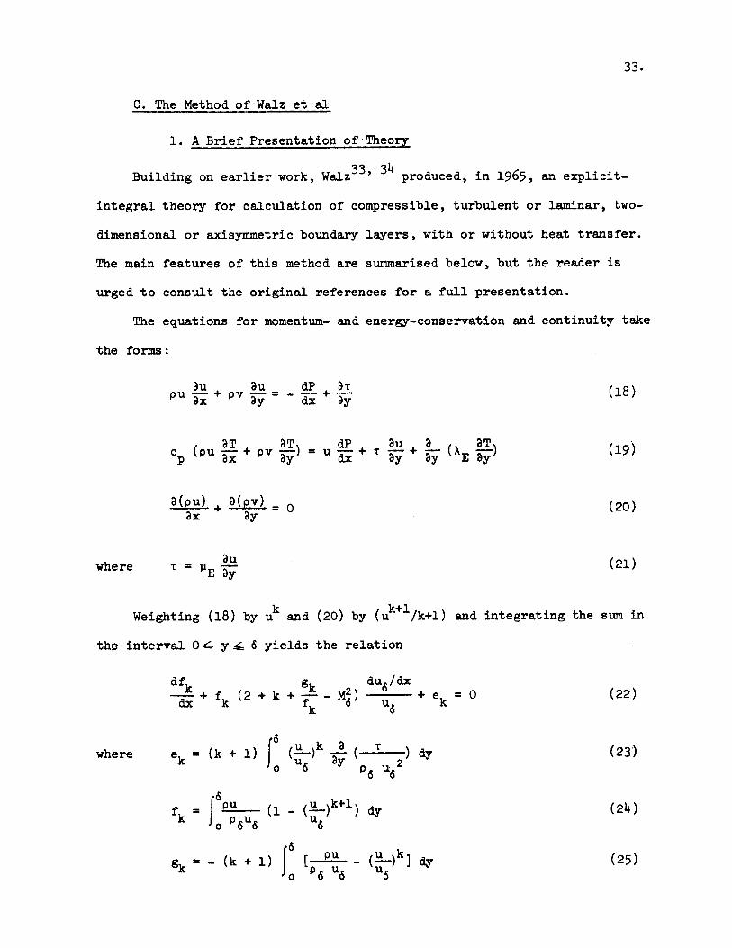
C. The Method of Walz et al
1. A Brief Presentation of Theory
Building on earlier work, Walz 3 3' produced, in 1965, an explicit-
integral theory for calculation of compressible, turbulent or laminar, two-
dimensional or axisymmetric boundary layers, with or without heat transfer.
The main features of this method are summarised below, but the reader is
urged to consult the original references for a full presentation.
The equations for momentum- and energy-conservation and continuity take
the forms:
au + vau dP ar 1PU +p = - T + T(18)
c x Ty dx uy
c (Pu aT+ P, a) = U dp+ T aU+ a(X a) (19)p ax ay dx ay ay E ay
apu) + a = 0 (20)ax ay
where T= DE (21)
Weighting (18) by uk and (20) by (u k+/k+l) and integrating the sum in
the interval 0 - y -- 6 yields the relation
dfk 2 du6 /dx- + f (2 + k + - M )du +e = 0 (22)dx k fk 6 u6 k
k 6
where e = (k + 1) (u)ka( ' ) y (23)k uj ay 2
_ = Pu u )k+l dy (24)
fk =JPu ( u)
g = - (k + 1) [ u ( k] dy (25)k P6 U ud

34.
k can be any arbitrary dimensionless number, but the particular choices of
k = 0 and k = 1 are particularly interesting physically, resulting in the
usual momentum integral equation and the kinetic-energy integral equation, with
9 i, gi E 264, fo 62, f= 63 (26)
T
and -e c f2 = C (27)
06 6
(1e CD c f f - d ( ) (28)
o w 6
These last two quantities, namely the skin friction coefficient 'C and the
shear work (or "dissipation") integral 'ZD have been written with a tilde
to emphasise that they are not the usual definitions, having exactly half
the numerical value of the more conventional forms.
Walz also finds it useful to introduce the quantities (6i)u, (62)u
(63)u (64)u where the subscript indicates that the integrals are to be
performed with p B p6 .
Shape factors H,12 H12 *, H32 H 32* and H 4 can now be defined:
H1 2 (6)u/(62)u H1 2* =61/62
H32 (63)1/(62)u 63/62 (29)
H 43 64/63
A length parameter is also defined:
z = 62 R (30)
Two auxiliary functions incorporating C' and 'D may be introduced
with advantage, viz.:
a 62 62 (31)c - c (31
f n (62) D RN (62)u62 62

35.
Finally, a heat-transfer parameter is required, viz.:
T -T
T e T(32)e 6
Towhere e =1+ rl M2 (33)
Putting (23) - (33) into (22) results in the integral relations for
momentum and kinetic-energy conservation for compressible laminar and
turbulent boundary layers with heat transfer in the form:
dz du /dx du /dx u6
u +n du 6/dx-)F2= (34)
dH3 * du /dx F32 + H * 6 (F3 - -) = 0 (35)dx 32 u6 z
where F, E (2 + n) + (1 + n) H -m2 (36)12 6
F2 2 (1 + n) a (62/(62)u
F 3 E 1 - H1 2* + 2 H (38)
F4 (62) (2 R N - a H3 2 (39)
It should also be noted that the shape factors are connected by the
relations:
HH *= 12 + r -- M2 (H* -0) (40)12 62/(62)u 2 6 32
H - 0H * = r Y1M2 H32 (143 2 6 H 3 2
Up to this point, the development has involved no empirical
approximations. For the solution of the coupled equations (34) and (35) we
now require a hierarchy of empirical relations, summarised below. Only

14.
chosen to impose the required pressure gradients on its boundary layer.
These are shown in Figure 8.
For calibration of the skin friction fences, which required an
accurately zero pressure gradient, a flexible 0.375" aluminum plate was
opposed to the test plate. This was mounted on jackscrews to allow
variation of its contour. The L.E. of this plate was again faired into the
main contraction with a nose-piece. Considerable difficulty was initially
experienced with highly non-uniform (in y) velocity distributions in the
free-stream with the test section set up in this calibration configuration.
This was a consequence of the 2:1 asymmetry of the second stage of the
contraction. A first-order analysis of this potential flow problem due
to Oates 52 indicated a method of determining that position of the leading-
edge/nose-piece with respect to the test plate's nose-piece which would give
minimum distortion of the free-stream velocity distribution near the entrance.
This analysis is treated in Appendix III. Repositioning of the flexible
plate L.E. yielded a distribution less than 1% from uniform at the first
measuring station (x = 12").
Throughout this report, the origin of cordinates is the L.E. of the
plastic test plate, which is also the location of the boundary layer trip.
This was a 0.06" x 0.1" transverse slot in the surface. A more substantial
roughness element or "spoiler" consisting of a 2" wide strip of 0.062"
perforated steel plate, laid flat on the surface, could also be fitted at
this point to provide an artificially thickened shear layer.
Nozzle-blocks A, B and C were chosen in their final forms with a view
to obtaining interesting trajectories on a K - R62 diagram, discussion of
which is the main burden of Section IV of this report. Nozzle-block A is
in fact one of the two blocks used to form the uniform Mach 2 flow which is

15.
the usual business of the tunnel. Table 1 lists the important characteristics
of the free-stream flows produced by these three test sections. See also
figure 9.
Thirty-nine static pressure orifices (0.016") were distributed along the
centerline of the plastic plate, with a variable spacing so as to allow
accurate determination of gradients in the converging and throat regions of
the test sections. These were connected to a bank of mercury manometers.
In addition, for the zero pressure gradient operation required for
calibration, seven downstream orifices, distributed over the whole instru-
mented length of the test section, were monitored for differential static
pressure with respect to the L.E. tap, using inclined water manometers.
This enabled the jackscrews to be adjusted so as to obtain a maximum
deviation from constant static pressure of less than 0.05%.
Stagnation pressure for the isentropic part of the flow was measured
with an 0.059" pitot probe in the free-stream at x = 14". Total temperature
was monitored with a bare thermocouple in the-settling-section.
3. Probes, skin-friction fences and associated equipment
Total-pressure distribution in the shear layers could be measured at
twelve statons along the test plate. Conventional flattened, sharp-edged
total head probes were used for this purpose. Some of these are shown in
Figure 2. Tip sizes varied from 0.007" x 0.025" to 0.017" x 0.042", the
smallest size being used wherever practicable. These probes were mounted
in remotely controlled and/or driven traversing rigs, as illustrated in
Figure 3. These had traversing ranges of 1.3" and 2.2", using micrometer
heads as the rotating elements. A miniature 10-turn helipot was driven off
each head by a step-down pulley system. Acting as voltage-dividers.,these
supplied the X-channel signals for a pair of Moseley X-Y recorders.

16.
Pitot-static differential pressure was fed in each case to one of a
number of differential-pressure transducers, having ranges between 0 + 0.2
psid to 0 + 15 psid. These were mostly of the Statham unbonded strain-
gauge type except for an Eico 0 + 0.5 psid variable reluctance type. This
latter was found to be unreliable below 0.1 psid and was consequently not
used in this range. Three well-filtered, smoothed solid-state DC power-
supplies of nominal 6, 10 and 28 V ratings were used to supply the
references for the various transducers and helipots. These were supplied,
in turn, off a 115 V. AC magnetic type line-voltage stabilizer. A twenty-
minute warmup period proved adequate to ensure that reference-voltage
variations over the course of some hours remained smaller than the test-
equipment resolution. In no case did ripple exceed 0.1%.
The signals from the transducers were fed to the Y-channels of the
X-Y recorders. Grounded, shielded cable was used for all connections. The
transducers themselves were isolated from rapid temperature fluctuations and
mechanical shock in specially-constructed enclosures, which served to main-
tain their operating components in the same orientation with respect to the
gravity vector. This last precaution was found to be an absolute necessity
for accurate work. A valved bypass system provided for accurate zeroing of
each transducer/recorder pair immediately before each traverse in the actual
electrical and ambient-pressure environment then existing.
One of the probe-traversing rigs was motorised, the motor speed being
variable from 3 to 15 rpm through variable input DC voltage, supplied by a
nominal 28 V DC power supply connected to line through a variable trans-
former.
The skin-friction sublayer-fence configuration chosen was that of
Figure 6. This provides for a square-edged step in the surface many times

17.
wider than its height, preceded by a minimally-sized round orifice designed
to measure the pressure of the field immediately in front of the step.
This geometry is only one of several possible. Some of the others are
shown in Figure 7. Although the pressure difference created between this
type of fence and a local static orifice is only about a third that of a
double-sided geometry, the former was chosen as being easiest to make in
the very small sizes required (d < 0.002" in some cases). There was also
the problem of dust and oil-film contamination. Other workers have had
considerable difficulty detecting contamination in the double-sided
configuration, due to the presence of two similarly-sized tiny orifices. In
the present geometry, the local static tap has 16 times the area of the
fence orifice and is effectively always clear. This allows an easier
determination of the onset of contamination.
The fences of each nominal size (d = .010", .007", .004" and .002")
were milled en masse and rigorously cleaned and degreased after the
drilling and deburring of the nominal 0.0039" orifices. Deburring was
accomplished under high magnification.
The fences were mounted in a 4 x 7 array, with one fence of each of the
four nominal sizes at each station. They were a light press-fit into reamed
holes and were sealed on the underside with epoxy cement. After mounting,
each fence-element L.E. was carefully blended into the plastic surface by
hand scraping under magnification. Finally, the actual finished fence
heights were measured to better than 0.0001" using a dial gauge and traverse.
Figure 4 shows some of the fences mounted in the test plate. Precautions,
not always entirely successful, were taken to exclude dust and oil from the
test surface.
The fences, and the local static-pressure orifices at each of the
seven x stations, were connected to a bank of 28 U-tube water manometers

18.
except in cases where the large shear to be encountered necessitated the
substitution of mercury instruments for certain fences. Since the total
pressure differences to be measured were as little as 0.1% of the total
dynamic head, and the tunnel ambient-pressure was usually considerably
above or below atmospheric, great care had to be taken in sealing each
of the several hundred tubing joints in the various pressure-measuring
systems. "Glyptal"enamel was used for this purpose.
The theory of wall-pitots in general, and the single-sided skin-
friction fence in particular is treated in Appendix I. The calibration and
interpretation procedure used forms the burden of Section B.1 of this
chapter.
It is believed that this constitutes the first reported use of this
particular geometry-for-shear-stress measurements.
B. Calibration
1. Skin-Friction,Fence Calibration and Interpretation
The object of the calibration procedure used was to provide, for each
individual fence, a unique relation between its readings, the local skin
friction and any other pertinent parameters of the flow field. (See
Appendix I)
A choice of "reference standard" for the calibration had to be made
between three possibilities
a) skin-friction balance as used by Coles2 and others31,41
b) Preston tube 0,
c) calculation.
Choice a) was rejected on the grounds of complexity, difficulty and
expense. Considerable doubt as to the calibration of the Preston tube is
still evident in the literature, with various investigations4o, 41, 42

19.
showing differences of up to 15% in their calibrations, whereas the recent
work of Fernholz35 on a correlation of skin-friction data in zero-pressure-
gradient flows gave a law which correlated the available data within 5%
for some 80% of the data and within 10% for the remainder. It was, there-
fore, decided to calibrate with reference to this correlation law, which
is set out in Appendix VII. The fairly elaborate logic of the calibration
may best be understood through reference to the block diagram of Figure 29.
For an adiabatic flow, the Fernholz law requires knowledge of the
local values of R62 and M The test section was operated in a zero-
pressure-gradient flow, at fixed subsonic M6 , at a series of Reynolds
numbers. Boundary-layer total-head traverses were taken at a series of
streamwise-distributed stations for each nominal Reynolds number increment.
Thus the momentum-thickness distributions on the test wall could be measured,
and the local skin friction computed. At the same time, readings were taken
of the skin-friction-fence manometers. Since the density corrections
required for evaluation of the experimental velocity profiles were small at
the Mach number chosen (M6 = 0.45), no total-temperature traverses were
thought necessary. Reliance was placed on the well-known relation of
Van Driest for the temperature profile of a turbulent boundary layer on an
adiabatic flat plate, which gives T = T (Tw, M6, u/u6 ). This is set out in
Appendix VIII.
A machine integration procedure was used to evaluate the experimental
profiles for the integral thicknesses 61, 62' 63' 16 ( ' (6) 3)u and
for the shape factors H1 2 , H32 , H*1 2, H*3 2. This is set out in Appendix IX.
Finally, the measured results and the computed c were plotted against
each other in a suitable non-dimensional form for each fence. The method of
non-dimensionalisation chosen was that of Hopkins and Keener31, which

20.
provides the necessary corrections for effects of compressibility. Since
their procedure had proved to work well for both Preston tubes and Stanton
tubes, there seemed little reason to doubt that it would prove equally
reliable for the generically similar skin-friction fence. The details of
this procedure are described in Appendix I.
Examination of the reduced calibration data, showed that for each
individual fence, the data could be well fitted by a law of the form
log(FR) = A + B log (FL) + C [log(FL)] 2 (1)
where C is a very small coefficient. This was not unexpected, since the
results for a Preston tube are similar 4, but the fidelity of the data to the
above law was nevertheless comforting. Furthermore, it was found that all
the data of all the fences could be fitted remarkably well by the linear
part of the same law, viz.:
log (FR) = A + B log (FL) (2)
Figure 31 shows all 532 measured data points on the same plot, and
the best-fit line for form (2) through them, while Figure 32 shows the
results for a typical individual fence. All the curve-fitting was done by
46machine using standard techniques .
This whole data reduction procedure was combined into a single computer
program which is listed in Appendix II, and whose logic is, in part, the
subject of Figure 30.
Since curve-fitting routines are essentially "mindless" affairs, the
precaution was taken of getting a machine plot (Calcomp) of the two- and
three-term calibration curves, equation (1),for each fencetogether with all
the data points for that fence. This allowed an evaluation of which curves

21.
could reasonably be extrapolated outside the ranges of shear covered in
the calibration runs. See figures 31 and 32. In those few cases where
fence readings showed marked scatter, it was decided to use the"universal"
calibration (equation (2)) instead. The "universal" calibration constants
found were:
A = -0.18668 and B = 0.74325 (3)
To review, we now had a relation for each fence, and a "universal"
one for all fences, of the form:
cf = c (AP, P6, M6, T 6 (4)
or, since isentropic flow may be assumed,
cf = c (AP, P w P , T ) (5)
in terms of experimentally measured quantities. These relations were
obtained at a fixed Mach number and in zero pressure gradient.
Thus,to interpret the readings of a given fence at some other Mach
number, only a simple inversion of the procedure of Hopkins and Keener was
required, but to complete the interpretation, a correction had to be made
for the effects on the readings of any pressure gradient present.
We have, up to now, no entirely successful analytical description of the
viscous flow over a step, with or without an axial pressure gradient,
despite several valiant attempts, most notably by Gadd 4 4 , Thom45, Trilling
and Hdkkinen 2, Taylor5 1 and Patel 3 2
The simple first-order correction procedure described by Patel did,
however, show that we might expect such corrections to be reasonably small -
less than 25% - even in the most severe pressure gradients we proposed to
investigate. In contrast, Preston tube corrections can be over 60%. With

22.
this in mind, therefore, a somewhat extended form of Patel's analysis was
completed, taking into account non-uniformity of fluid properties, and
using a rather more realistic, but still inexact, prescription for the
effect of the oncoming non-uniform (in y) momentum flux on the readings of
the device. This is set out in Appendix I.
It should be recognised that the solution of this problem involves the
solution of the full two-dimensional Navier-Stokes equations for a
compressible fluid, with mixed boundary conditions, a task which is
currently considerably beyond the state of the art. Even the attempt by
Gadd on the purely incompressible laminar Couette flow over a small step
proved of limited applicability. There is certainly room for work on a
better correction procedure - either theoretical or experimental - than
that used here. Given such an improved procedure, the data of this study
could easily be reworked to incorporate it.
The assumption is made that the effects of compressibility and of
pressure gradient are only weakly coupled. This will be true for any
boundary layer whose laminar sublayer has sensibly constant (in y) fluid
properties, especially density. For flows up to at least Mach 2, this
assumption will not be seriously in error to at least the order of accuracy
implied by the pressure-gradient-effects correction-analysis.
It will be seen from Figure 30, which treats the logic of the inter-
pretation procedure, that such a decoupling is in fact assumed, since in
each cycle of the iteration procedure described in Appendix I, the raw
reading is corrected before reference to the calibration equation.
The exponent in the relation
AP = aTb (6)
required by the correction analysis to account for effects of unit Reynold's

23.
number variation was obtained by a best-fit to all the calibration data.
A value of 1.31 proved to fit all but 10% of the data to better than 5%.
The computer program for the iterative interpretation procedure
described above, detailed in Appendix I and whose logic forms the subject
of Figure 30 is listed in Appendix II. In addition to the RHS quantities
of equations (1, 2), the program also requires a value, in each case for the
d(P/P )relative pressure gradient, dx , obtained from some such diagram as
Figure 8. The constants A, B and C for each fence and A , B1 are punched onto
cards as part of the output of the calibration program. These cards then
form part of the data set of the interpretation'program.
Examination of the output of the program for a given run reveals at
once whether any of the four fences at each x station were partially blocked
by dust or oil, through a clearly spurious low value of.cf by comparison with
its neighbors. A choice can also be made between the calibration curves to
be used in the event - such as at very low absolute values of shear - that
extrapolation beyond the calibrated range is needed. In any event, the
differences over which this somewhat subjective "weighting" had to be
exercised seldom amounted to as much as 10%. Manometer-reading errors at
very low absolute shears (AP < 2 mm water) were the largest single source
of random error, though the effects of dust and oil in putting certain
fences completely out of commission for individual runs were certainly more
prevalent at these low densities. It is thus not surprising to find that
experimental scatter of c values is most marked at the lowest-density
tunnel-operating conditions.
2. Linearity Checks of Transducers and Recorders
At several intervals during the course of the experiments, linearity
checks were performed on the transducers and recorders used. A manometer

24.
was used as the reference standard. Care was taken to ensure that the same
transducer-recorder pairing was maintained for all subsequent tests.
It was found that each pair was commendably linear throughout its whole
nominal range, except very close to zero pressure difference. The Statham
transducers were superior to the Eico in this respect.
The linearity of response of the traverse-reporting potentiometers and
recorder channels was also checked at intervals. Provided that due care was
taken to allow sufficient warmup time for the line-voltage stabilisation
device, power supplies and recorder D.C. amplifiers, no deviation from
linearity, within the resolution capability of the recorder, was ever found.
Exclusive of the above caveat, the Moseley recorders were found to be
astonishingly drift-free over a period of hours, and are to be highly
recommended.
C. Experimental Procedure
For each nozzle profile to be tested, the tunnel was run at a series of
standard conditions on P0, T and back-pressure, as nearly as possible.
Local static pressures were measured, allowing establishment of local free-
stream quantities, and, by numerical differentiation, all pressure-gradient-
dependent quantities such as K. Assumption of a recovery factor of 0.88
(see e.g. Ref. 34) allowed determination of local fluid properties at the
surface. The pressure-ratio data were smoothed before being put into the
various computational schemes discussed in the next chapter.
Total-head traverses could be taken two at a time, using the two
traversing rigs, for each standard operating condition, provided that the
probes were not so placed as to cause mutual interference. In each case, the
scale factors on the X-Y recorders were adjusted so as to yield the largest
trace that would fit onto the 8-1/2" x 11" plotting sheets. The traversing

25.
rigs were driven sufficiently slowly that there was negligible "lag" or
"hysteresis" in the plotting procedure.
The data of these traces were then converted to digital form, using
variable y spacing to improve accuracy in regions of large u2 variation, and
punched onto cards for machine computation of the various integral para-
meters required for this study. The program used is written-up and listed in
Appendix IX. Since total-temperature measurements were not attempted in the
shear layers, density corrections are supplied through the relation of
Van Driest . (See Appendix VII.) This applies, strictly speaking, only to
the zero-pressure-gradient case, but, since the highest Mach number encountered
for a traverse was only about 0.8, the density corrections are small, and
the final effect on the integral parameters even further attenuated.
To further the general utility of the program, provision has been made
for insertion of u and T data if required. The perennial problem of how to
approximate the effect of the first element of such a digitised list is also
treated in Appendix IX.
As a check, 62 and 63 were plotted versus P for each x, for each nozzle
as the data-taking proceeded. In this way faulty data could be culled and
the required runs repeated. In cases where there appears to be no reason to
favor or discard some data that conflicts with other data obtained under
nominally the same conditions, all the conflicting data elements are listed
or plotted elsewhere in this report. To resolve doubts, resort was sometimes
had to "fill-in" runs at intermediate values of P0
The values chosen for the parameters required to initiate the
prediction programs were the means of several sets of profile data at the
particular upstream point chosen. The points chosen were at nearly zero
pressure gradient for all runs.

26.
The skin-friction-fence manometers were read at each standard operating
condition, for each run. The values quoted in Tables 2 - 5 are weighted means
of several runs, except when the data appeared to group around two or more
values. This occurrence probably indicated an incipient problem with
contamination, but in such cases, both values are listed, since there seems
little valid means to choose between them. Interpretation of the readings
required machine computation by the procedure listed in Appendix II.
The tunnel had to be shut down and the test-section doors removed for
each change of probe stations. This procedure was unavoidably laborious and
resulted in large accumulations of tunnel time for a relatively small amount
of data.
In determining the set of "standard" conditions to be run for each
nozzle, a quick check of the actual pressure field was made for each nozzle,
and a starting profile measured. This enabled a prediction of the likely
trajectories for the shear layer on a K - R62 plot, assuming fully turbulent
behavior. In this way, the range of P0 likely to bracket the appearance of
laminarisation could be estimated, and much unnecessary data-gathering avoided.

27.
III. THEOREFICAL PROGRAM
A. Brief Survey of Computational Methods
There exists a vast multitude of computational methods for the incom-
pressible turbulent two-dimensional boundary-layer. There exist also a few
theories for compressible boundary layers, usually based on some adaptation
of an incompressible theory. Fortunately, several excellent reviews of
computation methods 36, 48, 49 have appeared recently, which offer some
guidance in the maze. There is no point in paraphrasing these here except
insofar as the special needs of this study dictate.
In his admirably clear scheme for classifying such theories, Spalding
distinguishes between:
(i) "Complete" theories, which aim to solve, by numerical means,
more-or-less exactly the partial differential equations of conservation
of mass, momentum, energy, etc., using as additional input empirical
information about local quantities in the shear-layer such as effective
viscosity, effective Prandtl number, etc. Patankar & Spalding 53 and
Mellor & Gibson 55 have recently produced improved theories of this type.
(ii) "Parametric Integral" theories, in which profile relations
containing several free parameters are assumed to hold good at each
longitudinal station. The partial differential equations are then mul-
tiplied by each of a set of weighti.ng functions of the dependent and/or
independent variables and integrated across the layer, yielding a set of
ordinary differential equations having the streamwise co5rdinate as the
independent variable and the free paramenters as the dependent variables,
which appear linearly. These then require a matrix inversion for isola-
tion, followed by numerical integration of the resultant set of first-

28.
order equations, yielding finally the free paramenters as algebraic
functions of the streamwise co*rdinate. From these, any desired property
of the solution may be exhibited - to the accuracy to which that property
may be described by the number and nature of the parameters involved.
(iii) "Explicit Integral" theories, in which the partial differen-
tial equations, weighted in some manner, are integrated over the shear
layer as a first step, yielding ordinary differential equations in
"integral parameters" such as 61,62, 63, etc. with the streamwise coardinate
as the independent variable. These are then subject to relatively quick and
simple numerical solution procedures. These methods differ chiefly in the
weighting functions used, the number and nature of the conservation laws
invoked and the auxiliary relations used to relate explicitly the various
integral parameters one to another.
One has to agree with Spalding that the approach of type (i) offers
much hope of eventual relief from the woes of trying to relate an ever
larger hierarchy of empirical correlations as we attempt to compute ever
more more complex flows. However, the empirical input required for use
of any type (i) method in the present case of a compressible boundary
layer which may or may not undergo laminarisation appears utterly lacking
at this juncture. The inputs required for types (ii) and (iii) computation
are more easily obtained from commonly measured quantities. To this end,
a representative method of each of these latter types will be examined
further.
The method of Moses 50 and Laundsr 28 represents an early attempt
to apply a parametric integral method to the problem of an incompressible
laminarising flow. Further work on th4s method is treated in Section B.
The method of Walz 3 3 of type (iii) purports to compute all
cases of laminar or turbulent, compressible or incompressible, two-

29.
dimensional or axisymmetric boundary layers, with or without heat-transfer,
and as such is probably unique in its field. It seemed worthwhile, for the
ends of this study, to make a considerable effert to develop a readily
useable and foolproof machine-computation procedure incorporating this
overall method, and to explore some of its limitations, especially in
highly non-equilibrium compressible shear-flows. The relatively trans-
parent nature of the auxiliary relations used in type (iii) methods offers
perhaps the best hope, at the present state of the art, of ascertaining
the modifications required for prediction of such flows. Section C
deals further with this phase of the study.
None of the above methods can be invoked without a more-or-less
precise knowlege of the properties of the shear layer at the starting
point. Given an error in the specification of the starting conditions,
there is a uniform ten4ency for the prediction to diverge from experiment
in adverse, and to approach it in favorable pressure-gradients (usually).
Type (ii) methods appear particularly susceptible to this starting problem.
B. The Method of Moses and Launder
In 1964 Moses50 proposed a parametric integral theory for calculation
of turbulent incompressible boundary layers. This corresponds precisely
with the type (ii) scheme outlined above, where the momentum integral
equation is the chief conservation relation invoked. A parametric
description of the local velocity profile of the form
-= 1 + a log + (1 - 3 (7)2+ 2 (Y-)3) (M)
is used, where a,8 are the parameters, which are related to other variables
of the problem by the relations

30.
= ( f)1/2 (8)K 2
= a(log (aR6) + 1.1237) - 1 (9)
K is the familiar constant from the Coles2 universal velocity profile:
u - log ( T) + B + f- w( ) (10)u K V K
T
Since two parameters are invoked, two conservation relations are
required. This is accomplished by causing the momentum integral equation
to be separately satisfied over two strips, each of height 6/2. This
requires empirical specification of the effective viscosity and turbulent
normal stress at the join .
With the procedure outlined in part A supra, the net result is a pair
of simultaneous, first-order, ordinary differential equations in a and S
of the form
d6d= F (a, a, 6, u ) (I1)dx 1 6
d= F (a, , 6, u ) (12)dx 2 6
which can be solved by the familiar Runge-Kutta numerical procedure, given
starting values of 6, a and u6 at some x. Further details of the procedure
are given in the cited reference.
The author has strong objections to the use of the quantity 6 in either
experimental or theoretical work of any sort. This quantity is extremely
ill-defined, particularly for boundary layers having a large value of the
shape factor H 32. In particular, its use as a normalizing quantity either
for presenting experimental data or for computational purposes is funda-
mentally unsound, though staggeringly widespread, nevertheless.

31.
Launder28 subsequently modified this computational method in an effort
to calculate the development of an incompressible turbulent boundary layer
undergoing turbulent-laminar transition. The shear layer was again considered
in two strips, characterised as a "viscous inner layer" and a "shear free
outer layer", but the position of the boundary between the strips was
allowed to vary. This boundary was at height 6 L. A parametric representation
of velocity profiles in the form
u = a ( - (L.) + ( -1) (y ) 0 a .U6 6L L u6
(13)
-U 6 a u u
ud u8
was used, where a (u/u6 L). In addition, a Reynold's number was introduced
as an explicit third parameter, defined as
u 6R 6 L (14)
6L
This required another conservation equation, and conservation of mass
within the shear layer was invoked. The net result was a set of three
o.d.e.'s of form
do = F 1 (a, 8, R6 , u, du6 (15)L
d8 = F2 (a, 8, 6 6, du ) (16)L
d 6 du6= F3 (a, R6 , 9 , ) (17)
These are again solvable by the Runge-Kutta technique, given starting
values of a, 8 and R It should be noticed that the parameter a is

32.
connected to the wall shear-stress in the same way in the Launder and Moses
formulations.
In order to obtain predictions of the data of his experiment, Launder
required resort to a non-systematic specification of both the shear stress
at the join between the strips and also the specification of that point
(in x) from which the calculation should be initiated.
Additional criticisms of this calculation method also arise, from the
point of view of ab initio calculation, as, e.g., in basic design: a, a and
6L are not easily estimable or empirically well-known. Also, the assumption
of mass-conservation within the shear layer seems physically unrealistic
and manifestly raises some question as to the identity of the outer part of
the shear layer vis-&-vis the free stream.
During the early phase of the present study, an attempt was made to
overcome these objections through a more systematic formulation, and
specification of an entrainment condition, A la Head 61, in place of the
mass-conservation relation. Attention was also given to a parametric
representation of the density profile of this sort of shear layer in a
compressible flow, with a view to obtaining a parametric integral prediction
method for compressible relaminarising flows. This effort proved fruitless,
due to the almost complete lack of experimental data and an inability to
systemise the choice of initial conditions sufficiently well for an ab initio
calculation, and was, therefore, abandoned.
Given a very considerable experimental effort over a period of some
years, it may well be possible to generate sufficient data to permit the
formulation of a sound parametric integral theory for the compressible case.
This data would almost certainly, however, provide the required input for a
"complete" theory of the type (i) discussed in section A. This latter
approach is, in the end, likely to prove the most generally useful.

33.
C. The Method of Walz et al
1. A Brief Presentation of Theory
Building on earlier work, Walz 3 3 ' produced, in 1965, an explicit-
integral theory for calculation of compressible, turbulent or laminar, two-
dimensional or axisymmetric boundary layers, with or without heat transfer.
The main features of this method are summarised below, but the reader is
urged to consult the original references for a full presentation.
The equations for momentum- and energy-conservation and continuity take
the forms:
P u + Pv dP + T 18)ax ydx uy
c (Pu + P, ) = U + T + (A ) (19)p ax ay dx ay ay E ay
a(pu) + = 0 (20)
where T = y au (21)E y
Weighting (18) by uk and (20) by (u k+/k+l) and integrating the sum in
the interval 04 y.4 6 yields the relation
df du d6 / dx-k+ f (2+ k +--- m2) + e =0 (22)dx k fk 6 u6 k
where ek= (k + 1) ( u ' )dy (23)k u ay 2
fk ~ fo P6 u 6u
= (k + 1) [ u _(u)k] dy (25)Sp6 u6 u

34.
k can be any arbitrary dimensionless number, but the particular choices of
k a 0 and k = 1 are particularly interesting physically, resulting in the
usual momentum integral equation and the kinetic-energy integral equation, with
g 0 61, 1g, 264, fo 62, fi 63 (26)
Tand -e 0 P 2 (27)
'6 16
el cD W =f d ( u) (28)o w 6
These last two quantities, namely the skin friction coefficient 'C% and thef
shear work (or "dissipation") integral 'cD have been written with a tilde
to emphasise that they are not the usual definitions, having exactly half
the numerical value of the more conventional forms.
Walz also finds it useful to introduce the quantities (61)u, (62)u9
(63),j (64)u where the subscript indicates that the integrals are to be
performed with p B p6 .
Shape factors H1 2, H1 2*, H32, H32 * and H 4 3* can now be defined:
H1 2 (61)u/(62) H1 2 61/62
H3 2 (63)/(62) H3 2* 63/62 (29)
H4 3* 64/63
A length parameter is also defined:
z = 62 R n (30)
Two auxiliary functions incorporating W and 'c may be introducedf Dmabeitoud
with advantage, viz.:
a 62 6 62C = D ( (31)f n62 6 N (62U
622

35.
Finally, a heat-transfer parameter is required, viz.:
T -Te e w w (32)
T - Te 6
where e= 1 + r Y M2 (33)T6 Y 6
Putting (23) - (33) into (22) results in the integral relations for
momentum and kinetic-energy conservation for compressible laminar and
turbulent boundary layers with heat transfer in the form:
du/d du w/dx u+ z u6 (F + n du /dx u 6 F2 0 (34)dx 6 Iu 6 /d ) 2
dH * du 6 /dx F4d2 + H u (F3 - -) = 0 (35)dx 32 u 6 z
where F1 (2 + n) + (1 + n) H2 -m (36)12 6
F2 (1 + n) a (62/(62)u) (37)
F 3 1 - H1 2* + 2 H (38)
F4 62 (20 R N - a H3 2 (39)
It should also be noted that the shape factors are connected by the
relations:
HH * = 12 + r Y-1 M2 (H * -6) (4o)12 62/(62) 2 6 32
H *= r H M2 32 - (41) 43 2 6 H32
Up to this point, the development has involved no empirical
approximations. For the solution of the coupled equations (34) and (35) we
now require a hierarchy of empirical relations, summarised below. Only

36.
those for a turbulent boundary layer are given, those for the laminar case
being similar in nature:
(62/(62)) [1 + r M (H32* - 0) (2 - H 32 )0] (42)
H 3 24 , H3 2 [1 + (2 - H32)*1 (43)
where -1 - 0.0719 M6 + 0.00419 M (44)
and $ 0.0114 M6 (2 - 0)0,8 (45)
Also,
H1 2 -m + 1.48 (2 - H32) + 104 (2-H )6.7 (46)
a , 0.0566 H32 - 0.0842 (47)
a 0.0056 (48)
n ~0.268 (49)
N 0.168 (50)
r 0.88 (51)
The functions $ and 0 are seen to be correction functions for
compressibility and heat-transfer effects, and are claimed to be useful
up to M6 = 5.
2. Computational Scheme
Mean values of F (j = 1, 4) may be defined over finite Ax |xi - xi 1 I:
F = (F + F ) (52)
The coupled differential equations (34), (35) may be put into axi-
symmetric form by the Mangler58 coSrdinate transformation, and can then be
written in the finite-difference form:

37.
n+J-z R 1+ -Ax +(R /R )~
z 1 = Bz 2 z 2 ) (53)i-i i-i i-1
(H32 i Ax 2
(H32 *i- (H32*) i-l i-
where
-(U Fi~ T-(6ilF3
Az = uji Tui (55)
BE1 - Az (u6).-1/(u6) (56B z= z(56)Z (1 + Fi)(l - (u 6)i-l/(u6)i)
B =1 - AH (u 6 )i-l/(u6 )i
H (1 + Y 3)(l - (u6)i-l/(u6 i)
and R is the cross-sectional radius. For the two-dimensional case, R= 1
for all i.
This development assumes that the "universal" functions F are in fact
linearisable, an assumption which fails significantly only very near to a
separation point.
There are several conceivable ways of "marching-out" the coupled
equations (53) and (54) by computation involving iterative steps. Only one
of these, to be described below, proves to be unconditionally stable for all
cases short of separation.
The following quantities are necessary and sufficient input for a
calculation:
(i) Initial conditions on: x, u6 , (62)u, (63)u
(ii) The quantities Pi=, To, Ax

38.
(iii) The velocity field, in the form of a table of u6 vs. x (or
(P 6 ) /P vs. x)
(iv) In the case of heat transfer, a table of T vs. x
(v) In the axisymmetric case, a table of R vs. x
This information, in conjunction with the hierarchy of exact and
empirical relations (38) - (51) and their antecedents allows the following
stepwise procedure:
(i) Find (H 32*).i
(ii) Estimate (H32*) i=2
(iii) Thus find all coefficiets of (53) and (54)
(iv) Hence obtain a first estimate of zi=2
(v) Put these estimates of (H 3 2 *) i=2 and zi=2 into RHS of (54)
(vi) Hence obtain revised estimate of (H3 2 *) i=2
(vii) Compare the latest and penultimate estimated values of ((vii) Copr h aetadbnliaeetmtdvle f(32 i=2'
If the difference exceeds some predetermined value, iterate, by
returning to step (iii) with the latest estimate of (H32 *)i=2
(viii) After sufficiently close convergence of successive estimates of
(H32 i=2 the step is complete, and steps (ii) through (vii) are
repeated, with iteration as required, to find (H32 i=3 and so
forth.
For best accuracy, the largest allowable value of Ax is that for which
Au < 0.015 u6 in the worst case. Convergence to j(H 3 2 *)m) - (H *
4 0.00001 typically requires less than 4 iterations, except at very close
approach to a separation point. (m is the order of the iteration step.)
This accuracy is barely within the single-precision resolution capability of
a computer, and oscillations of amplitude less than 0.0001 can occasionally
arise. In such a case the convergence criterion may be relaxed an order of

39.
magnitude without serious effect on the overall accuracy of the calculation.
Appendix V contains a FORTRAN IV program to carry out this calculation
for all the cases for which it is useful, and specific instructions for use
of the program. The program has been written in such a way as to facilitate
its use even by those totally unfamiliar with the method. The step size is
found automatically, and the convergence criterion is reset as required.
Every effort has been made to ensure that numerical "disasters" are forecast
by the program as the calculation proceeds, and the appropriate messages
printed-out before the case is terminated and the next case started.
However, the unexpected can still happen, expecially if erroneous data is
supplied, so that provision has also been made for a "debug" printout in
which the major quantities of each subroutine are printed-out at each
iteration or step, as well as much other information. This facility should
not be invoked lightly, as the paper output is staggering.
Since H32 is the chief auxiliary quantity of the calculation, it was
decided to specify (62)u and (63)U as the input required at the start of
the calculation rather than 62 and 63. The ( ) quantities are easily obtained
if the starting velocity profile is available, while 62 and 63 require also
that the density profile be available. In the event that only the numerical
values of 62 and 63 are known, the auxiliary relations (42) - (45) may be
invoked for (62)u and (63)u. In the event that only (62)u (or 62) and H12
(or H1 2*) are known, H 3 2 may be estimated by means of (40) and (46). The
calculation method is naturally sensitive to poor estimates of H 3 2 , but tends
to be self-correcting after a number of steps, especially in zero or
favorable pressure gradients.
It should be noted that the scheme adopted calculates the local values
of M6 through an isentropic-flow assumption. If the case in question

4o.
involves such a large heat addition to the flow that the isentropic
assumption is seriously in error, a minor reprogramming, involving the use of
M6 as an additional input quantity will be required.
3. New Relations of Fernholz and Escudier
Fernholz35 has recently produced alternate empirical formulations of
the skin-friction, dissipation and shape-factor relations for a compressible
turbulent boundary layer on a flat plate. These may be used in place of the
Walz relations in the following way:
Replace eqn. (43) with:
H3 2 * = 1.80 + 0.0072 M6 (58)
Replace (46) with
H12 - /2 (7.506 - 0.202 log1 0 (R 6 a*) ) (59)
where c= 0.01015 0.786 (60)1 (R o*)0.15 R6 0
622(62
and *= 6 )0.7 (61)2
(6 )where u = [ * - r M2 (H* - e)]/ H (62)
62 [ 12 2 6 32 12
where H* H 0.4 M2 f2(e) (63)12 12 6 2
The function f2 (e) is unity for the adiabatic case.
We also obtain the skin friction coefficient
____ (62)u 0.55 078
c = r [0.01015 (2 0.595 + 0.786] (64)R 0.15 62 R 2
62
where r = 1 + r Y (l - 6) (65)12 6

41.
thus we can replace (47) by
O*-c 2u R 0 . 2 6 8 (66)2F f 62 6
The dissipation coefficient 8 now becomes
c * R 0.2 68 (62)u (67)Iu f 3 2 62 62
in place of eqn. (48).
These relations have also been programmed into an alternate sub-
routine ("HANS") and are thus available for use as explained in Appendix V.
New relations, not restricted to zero pressure-gradient, are also
available from Escudier 36, and take the following forms:
Eqn. (46) is to be replaced by:
H12 = 1.55 [0.0971 + (0.009428 - 3.1 (1.431 - H32 ) /2)-1 (68)
Eqn. (47)is to be replaced by:
S R 0.268 (62)u (69)8 62 62
where S = [0.243 C2 + 0.0376 c - 0.00106 + 0.0914 c2/(l + L.)]/L2 (70)
where Z 2 H32 -1 + [ H3 2 ( H3 2 - 1)1/2 (71)
[3.389 H6 d2and L En 38 R C 2 C (72)
Eqn. (48) is to be replaced by:
- 0 268 (62)u (73)62 62
where S (2 C + 1) S/3 + T (74)

42.
where
0.00565 (1 - C)20715 for < 1
Tq = (75)0.01 (C . 1)3 for > 1
These relations are also available in the alternate subroutine
"MARCEL" and may be implemented according to the instructions of Appendix V.
It should be noted that these relations are also useful for cases where
the velocity profile shows an internal maximum, including the extreme
case of a wall jet. Since the formulation is for the incompressible case,
the required compressibility and heat transfer corrections are put in by
the usual Walz relations.
4. Comparisons with Existing Data
The predictions of the Walz method were compared with adverse pressure-
gradient data of Moses50 and Goldberg62 for both separating and non-separating
cases, with zero pressure-gradient data of Smith & Walker63, and with severe
favorable pressure-gradient data of Launder 28, in addition to the data of the
present study. The new relations of Escudier were also used for each test
case, and the relations of Fernholz also used for a prediction of the zero
pressure-gradient case. The results of the test cases based on previous
data appear in Figures 11 - 13, while the data of the present study is treated
in Figures 14 - 25.
Appendix VI details the sources of the particular data chosen, and lists
any assumptions required to initiate the computations.
Looking first at the adverse pressure-gradient data of Figure 11 we note
that both the Walz and Escudier relations predict early separation for the
steep adverse, followed by relaxing, pressure-gradient of Moses # 5 while in
the similar case of Goldberg # 3, the Walz relations result in an early

43.
separation prediction. The Escudier relations show an under-prediction of
shape-factor development. The Escudier relations give a more accurate
prediction of 62 development in each case. For the less severe, non-
separating case of Moses # 6, there is little to choose between the methods,
for 62 prediction, but the Escudier relations for shape-factor again prove
superior. The same findings hold good for the similar, but separating case
of Goldberg # 6.
Figure 12 shows a conclusively laminarising case of Launder.
Prediction of R62, up to the turbulent-laminar transition, is good for both
sets of relations, with those of Escudier slightly superior. Thereafter
the data lies grossly below the prediction. The shape factor prediction is
decidedly poor, especially after transition, with the Walz relations
proving superior.
Precisely the same behavior in very steep negative pressure-gradients
was found when the Walz method was applied to the prediction of the flows
of the present study. The uniform tendency of laminarising flows to
depart from predictions based on correlations of normal turbulent boundary
layer behavior in these two ways is crucial to the further development of this
report, and will be discussed at length in the next chapter.
If one wishes to decide on a "best" method between the three relations
offered by Walz, Fernholz and Escudier, the flat-plate data represented by
Figure 13 proves singularly frustrating: For 62 calculation, there is
little to choose between Walz and Fernholz, while the prediction of
Escudier is definitely somewhat off. The same is true of the c prediction,
with the Fernholz relations showing a slight initial superiority. For the
shape-factor calculation, however, the Escudier relation corrects itself
most rapidly, while the other two methods both predict high values of H *

44.
The general conclusions , based on a comparison of all the predictions
with their corresponding data, seem to be that 62 is well predicted, with
the relations of Walz proving slightly better, most especially in favorable
pressure-gradients. H 12* is, however, relatively poorly predicted, with
the Escudier relations clearly superior in zero and adverse pressure-
gradients, and the Walz relations superior in favorable pressure-gradients.
A high prediction of 62 development, and a low prediction of H 12* develop-
ment are consequent upon the appearance of turbulent-laminar transition in
the physical flow.

45.
IV. PRESENTATION AND DISCUSSION OF RESULTS
A. Location of Turbulent-Laminar Transition Points
Previous work on laminarisation27, 28, 29 indicated that the onset of
laminarisation in a turbulent bourdary layer is marked by a sharp decrease
of the momentum thickness below that to be expected for a "normal" turbulent
boundary layer. This showed clearly in the work of Launder27, 28, who
presented his results in the form of H12 vs. x diagrams. At the low
velocities with which that study was concerned, H12 and H12* (see
definition in Chapter III, Section C) are virtually identical. The Russian
work29 was, by contrast, carried out in the high-subsonic regime, in the
converging section of a two-throat tunnel, downstream of a normal shock
standing at the exit of the first converging-diverging nozzle. This
identification of the turbulent-laminar transition points was confirmed by
hot-wire measurements in each of the studies cited.
A difficulty arises, however, if one wishes to apply a shape-factor
criterion to the high-subsonic or transonic free-stream velocity regimes,
where the fluid properties change rapidly. In particular, the rapidly
decreasing density in that part of the shear layer closest to the wall
causes a strong rise in the value of H12* for M6 > 0.7, as is evident from
examination of the definition of this parameter, viz:
6(1 - Pu) dy
H -- o P6u 612 6
( - u- dyfo du6 U
Thus, if one proposes to use a change in the value of H12* as an indicator
of the onset of laminarisation in this regime, it is necessary to observe a

46.
rise superimposed on another rise. This is likely to degrade further the
inherently poor precision of identification due to the finite spacing of
measuring stations. Following, however, a suggestion of Fernholz56 we
might seek to observe the behavior of the parameter H12' which depends only
on the geometrical shape of the velocity profiles, and disregards the
weighting effect of the density ratios. A sharp rise from the reasonably
constant values exhibited by this quantity for non-laminarising boundary
layers would signal with greater precision the point' of onset of an un-
usual phenomenon. As will be detailed below, it was in fact found that any
sharp rises in H12 were coincident both with marked increases in the rate of
change of H 12* and also with marked decreases in the measured skin-friction.
It is thus not unreasonable to infer that a sharp rise in the value of H1 2
for a turbulent compressible boundary layer is also indicative of turbulent-
laminar transition.
Three nozzle profiles (Figure 8) were used in the present study,
producing the free-stream flows detailed in Figure 9 and Table 1. In
addition, a fourth case was created by placing a spoiler just upstream of
the trip for a series of runs with nozzle C. This was in an effort to
increase the range of R62 studied with this nozzle. The spoiler was the
largest that would still allow the relaxation of the shear layer to a
state indistinguishable from a normal flat-plate boundary layer before the
onset of acceleration.
Tables 2 - 5 and Figures 14 - 25 present the measured values of cf,
H1 2 *, H1 2, H3 2 and R62 as functions of longitudinal co8rdinate x and
stagnation pressure P . Since the test sections were in each case operated
in the supersonic throat mode, changes in stagnation conditions should simply
be regarded as giving rise to different characteristic densities. The

47.
spread of stagnation temperatures was only some 150 R, thus changes in y1
between the various "standard conditions" are small.
The qualitative behavior of H 12* and H12 as functions of x and P0 , as
illustrated in Figures 18 - 21 was rather similar for each of the four
cases. Only one case need, therefore, be discussed in detail, e.g.,
nozzle A:
Beyond x > 30", the H2* data appears to divide into two groups, that12
for P = 5 and 10"Hg. abs. diverging from that of P = 15 and 20 and from
the prediction. Beyond x = 32.8", the data for P = 15 also rises sharply.
The behavior for H12 is similar, but more marked, especially since the
majority of the data and the predictions show an almost constant value of
H12 with both x and P except for the behavior of the errant few.
Turning now to the behavior of 62 itself, we note from Figure 22 that
while for P = 20, 62 has risen, at x = 35", slightly above the minimum value
encountered, (following the sense of the prediction) the trend in the other
three cases is for a continued strong decrease. As has been discussed in
Chapter III, the general agreement between measurement and calculation is
comparatively good, except in this particular range of x and P values.
The skin-friction measurements for nozzle A (Figure 14) appear to
confirm the trends noted above: At the most upstream measuring station
(x = 19"), the trend of cf values with increase of unit Reynold's number
(i.e. increase of P0) is in line with the conventional experience with
zero-pressure-gradient boundary layers, i.e. cf decreases with increased
Reynolds number. However, as the expansion proceeds , the behavior changes
in a surprising way, viz: By x = 41", cf for P0 = 20 has risen steadily to
roughly double the initial value; for P = 15, c reaches a plateau at
about x = 35", and is less than that of P = 20 at x = 41", the final

48.
measuring station; for P = 10, there is a maximum around x = 30", followed
by a steady fall, while the P 0 5 data set follows the same trend, but
peaks earlier and decreases very much more rapidly thereafter. The end
result is that by the final measuring station, the order of cf values with
Reynold's number has been inverted, c now increasing with unit Reynold's
number.
Given the above behavior of H12*, H12, 62 and cf with x and PO, and
remembering that K is an almost linear function of P at any x, it seems
not unresonable to interpret the data in the following way:
(i) the P = 5 boundary layer entered turbulent-laminar transition at
28" < x < 30", with immediate anomalous reduction of 62 and cf,
(ii) the P = 10 layer similarly entered transition at 29" < x < 32",
(iii) the P = 15 layer entered transition for x > 32", with little
change in cf from the entering value,
(iv) the P = 20 layer did not enter transition at all.
In an entirely similar way, transition points can be located for the
other three cases. Nozzle B, for example, would be declared to have the
P = 5 data showing transition at about x = 37" while the P = 10 data shows
a rather "hesitant" transition at about x = 39". The P = 20 data behaves
in an unexceptionally turbulent manner.
B. Shear-Layer Trajectories in the K - R6 2 Plane
At this stage in our knowledge of laminarising turbulent boundary
layers, it would be distinctly unwise to assert that we could list all the
important parameters of the problem and thus perform a definitive
dimensional analysis, vide Taylor57 . The following quantities, however, have
proven experimentally to influence the onset and course of the turbulent-

49.
laminar transition phenomenon- in the adiabatic-wall case: u, 62
p6 , du6/dx.
Clearly this list is neither exhaustive nor unique, and the reference
conditions are arbitrary. We can, however, construct the following two
dimensionless groups:
Ii du6 pdu662K E ( - -- ) and R (
P u 6dx 6 2w 6 2
6oThe significance of the group K has been remarked upon by Rotta ,
Mellor59 and Launder28 and several others in their consideration of
incompressible flows. Since it is the ratio of pressure and shear forces
acting on that limiting region-of the shear layer at the wall, the only
additional specification that has to be made for the compressible case is
that fluid properies be evaluated at wall conditions, as has been
indicated.
Examination of the literature reveals a surprising lack of uniformity
in the definition of momentum thickness Reynold-s number for compressible
boundary layers, even on an adiabatic wall. Some authors use pw in the
numerator or p in the denominator. The form cited above seems, however,
to be the most logical for the needs of this problem when considered thus:
We wish to express the ratio of the inertial forces to the viscous forces
which exist in that part of the shear layer nearest to the wall. Since
we do not know with precision any other characteristic momentum, we choose
that of the free strealn, and so, for consistency, the density term is to
be evaluated at free-stream conditions. The viscosity term should be
evaluated at those well-defined conditions most closely approximating those
of the near-wall layer. This indicates the choice of T as the suitable
temperature for evaluation of y .

50.
An important point to notice about K and R is that while they share2
several variables, K contains only variables pertaining to the free-stream,
the only boundary-layer parameter, 62, being contained in R 2. With an eye
to achieving rational design procedures for nozzle flows, we might, there-
fore, seek to understand the laminarising phenomenon in terms of the
behavior of these two quantities. It will now be shown that this approach
is largely successful, rendering more intelligible the data of this
investigation and the other detailed laminarisation data published up to now.
We come first to the concept, of a "trajectory" of the shear-layer in
the K - R6 plane. This is simply obtained by a cross-plot of the data of,62
for example, Figures 9 and 22, for each discrete value of P and with x as
the cursory polar cordinate. This way of presenting the data appears to be
particularly useful in describing the "history" of a compressible shear
layer in a rapidly expanding flow. The local density appears in both the
force-ratios K and R6 2, but in an opposite sense. The mere fact of its
rapid change makes separate evaluation of acceleration and Reynold's number
effects extremely difficult at best. The cross-plotting technique offers,
however, a way of assessing the coupled effects.
Figure 26 shows some typical shear-layer trajectories encountered in
this and former studies. Since there exist no shockless flows having a
discontinuous first spatial derivative of velocity, all trajectories must
enter the diagram from the abscissa if considered far enough upstream. (It
might be noted, in passing, that the negative K part of the plane is not
unpopulated, and that the negative R6 part of the plane contains the
2 36interesting wall-jets treated by Escudier .) It is an interesting exercise
to try to visualize the flow required to produce an arbitrary trajectory.
It quickly becomes clear that the upper right part of the positive-positive

51.
quadrant is difficult of approach, requiring ever larger flow devices
operating at ever lower characteristic densities, once the practical limits
of (du /dx) have been realised. These latter are set by the tendency of a
converging flow to accommodate a rapid change in area ratio through
formation of an extended separation zone:
Nozzle B of this study
exhibited clearly such
777 _77777777 7 a separated zone.
Since x is a cursory parameter for each trajectory, we can readily
mark on each trajectory that point at which turbulent-laminar transition,
if any, is detected. Figure 27 shows the result of such an operation for
each of the four cases of this study. It will be observed that the
trajectories for each case form a clearly evolutionary "family", though
the fundamental shapes involved are hardly intuitively obvious. Open
symbols mark transition points as determined by the methods described in
Section A. Solid symbols denote that last transition point encountered in
each hierarchy of increasing values of P0 (or equivalently, unit Reynold's
number). The solid symbols may thus be regarded as defining the least
favorable condition for each case that will in fact lead to transition in
the converging portion of the duct. Such points will be called "boundary-
points" for purposes of further discussion.
Taken as a group, the trajectories of Figure 27 strongly suggest the
existence of a region of the K - R62 plane which is uniquely susceptable to
the relaminarisation phenomenon. Figure 28 shows the happy result of
combining all the available data, including also that other published data
which can be reworked into the required form, namely that of Launder28 and

52.
Wilson 6 . The observations of Kline et al2 2 and the tentative recommendation
of Launder have also been indicated for their respective ranges of R62'
One observes that the data populates a region to the upper left of a line
of boundary points. A line has been fitted through the available points and
christened the "transition boundary". A suggested design procedure invoking
the properties of this boundary and its associated regions is treated next.
C. Recommended Design Procedure for Laminar-Throat Supersonic Nozzles
1. Adiabatic Wall
The presentation and discussion up to this point admits of the following
statements:
(i) There exists a parameter K which is a function of flow-device
geometry and upstream conditions alone.
(ii) The development of the quantity R6 2 may be adequately calculated up
to the point of turbulent-laminar transition by several methods, one of which
is that due to Walz .
(iii) Beyond such a transition point, the value predicted for R6 is
too large.
(iv) There exists a region of the K - R62 plane outside of which
turbulent-laminar transition has not been observed.
(v) Sustained entry of a shear-layer trajectory into this region results
in turbulent-laminar transition.
On the basis of the available evidence, it is difficult to be more
precise about the units in which "sustained entry" is to be measured. As a
very tentative number, however, it would seem that residence over the
boundary for Ax > 20 32 is likely to ensure laminarisation of the shear
layer. It should be noted in this regard that the effect is not a dis-
continuity in any sense. The effect of K on the supression of turbulence

53.
production is monotonic in 04.K K-3.5 x 10⁻⁶ (Kline 22), and the effects on
departure of the velocity profiles from the logarithmic law of the wall are
similarly continuous, with effects being clear long before the jump in H1 2
(Launder2 7 , 28). The position of the recommended transition-boundary is
simply a consequence of the transition marker chosen. No difficulty need,
however, arise providing due care is taken to maintain a consistent approach
to the question of prediction.
In the light of these observations, therefore, the following steps
taken at the basic design stage of an adiabatic-wall nozzle seem likely to
ensure an effectively laminar flow in the shear layer at the throat or
before:
(a) Using conventional potential-flow theory, compute the near-wall
free-stream flow, and obtain, in particular K = K(x) for each nozzle
profile of interest.
(b) Estimate as accurately as possible, from the known flow conditions
upstream of the nozzle, those properties of the boundary layer necessary to
initiate a computation from a point near to the entrance of the nozzle. Any
calculation scheme capable of reasonably accurate prediction of R62 = R 62(X)
may be used. The method of Walz discussed in Chapter III is one such method.
(c) Plot K vs. R62 trajectories for each nozzle and shear-layer
combination of interest and observe the relation of these to the transition
boundary of Figure 28. At this point it should be clear which of the design
parameters need be changed to ensure a sustained entry of a trajectory into
the laminarising region. Ensure that the value of x at which this occurs is
as far upstream of the throat as possible. Note that the predicted value of
62 is likely to be too high after the boundary has been crossed.
NB. It may well be impossible to secure a turbulent-laminar transition
in subsonic flow for large, high-density devices.

54.
2. More General Cases
Our detailed, quantitative information is essentially limited to the
case treated above, viz. the flow of non-reacting, semi-perfect gases in
the shear layer on smooth adiabatic walls, with reasonably small free-
stream turbulence. One might, however, expect the following trends to
apply, judging from the body of literature surveyed in Chapter I:
(i) In the case of wall-cooling, the transition boundary of Figure 28
will be displaced to lower K and higher R6 . Thus the design procedure2
of part 1 of this section is clearly conservative for this case.
(ii) The reverse is true for hot-wall boundary layers or for boundary
layers having internal energy addition by any means, including chemical
reaction.
(iii) The rough-wall case is less favorable for laminarisation.
(iv) The effect of wall curvature on the laminarisation phenomenon is
probably additive, i.e. the convex-wall case is more favorable than the
concave-wall case.
D. General Discussion
The use of the shape-factor change as an indicator for turbulent-
laminar transition appears to be reliable and reproducible. Its use in
further research into the phenomenon is to be recommended.
In view of the reservations expressed in Appendix I about the procedure
used for correction of sublayer-fence readings for severe pressure-gradient
effects, it is felt that the skin-friction values quoted should be treated
with some caution for exact quantitative purposes, especially since these
appear to be the first determinations of high-pressure-gradient transitional
skin-friction by a quasi-direct method. Since the same correction

procedure has been consistently applied to all cases of this study, it
does, however, seem valid to compare trends in the way discussed in part 1
of this section.
There is no apparent reason to doubt the usefulness of the single-
sided fence geometry for measurements in very thin, compressible boundary
layers in a small pressure-gradient. The universal calibration factors
obtained in this study may be considered definitive for want of any other
data. In the light of experience with Preston tubes, the calibration is
likely to be invalid for fully laminar flows. The use of single-sided
fences in this case will, therefore, require a new calibration. Non-
adiabatic flows are also excluded from the turbulent calibration obtained
in these studies.
It is probable that the profile measurements made in this study were
in no case carried out sufficiently far downstream to be in a fully
laminarised shear-layer. This was a dual consequence of the extremely
thin shear-layers encountered and the appearance of bow-shocks on the
probes, rendering further measurements of highly questionable accuracy.
We have, however, the previous work of Launder27,28 as a guide to the
characteristics of a fully laminarised'shear-layer.
55.

56.
V. CONCLUSIONS AND RECOMMENDATIONS FOR FURTHER STUDY
(i) It has been confirmed that an adiabatic turbulent boundary layer can
be caused to enter turbulent-laminar transition for sufficiently
low values of momentum thickness Reynold's number (R 6) and
sufficiently high values-of a free-stream acceleration parameter (K).
(ii) Previously published incompressible results have been extended into
the ranges of Mach and Reynold's numbers typical of actual engineering
devices, viz: M l, R6 104.2
(iii) It has been found that the behavior of a boundary layer in respect
of turbulent-laminar transition may be described by consideration of
its trajectory in the K - R6 plane.2
(iv) There exists a region of this plane, the boundary of which has been
experimentally determined, inside of which turbulent-laminar
transition occurs. Turbulent-laminar transition has not been observed
outside this region.
(v) An ab initio design method has been developed which incorporates
these findings and is capable of ensuring laminar flow upstream of,
and at the throat of, a sufficiently small nozzle. As a by-product,
there has resulted a computer program suitable for computation of
turbulent or laminar, two-dimensional or axisymmetric, compressible
boundary layers, with and without heat-transfer.
(vi) A new instrument of extremely small characteristic height, the
single-sided sublayer fence, has been developed for measurements of
wall shear-stress in thin, turbulent, adiabatic, compressible
boundary layers with or without an imposed axial pressure-gradient.
(vii) A universal calibration function for this class of instrument has
been developed.

57.
(viii) Wall shear-stress measurements taken in regions of turbulent-
laminar transition show a progressive reduction with streamwise
distance when compared to measurements in non-laminarising
boundary layers. These are believed to be the first measurements
of wall shear-stress in a steep pressure-gradient by a quasi-direct
method.
(ix) It is recommended that similar studies be performed in a larger
facility to enable delineation of the turbulent-laminar transition
boundary for still larger values of R62
(x) The effects of heat-transfer on turbulent-laminar transition should
be further investigated.
(xi) There is a need for more work on shear flows over imbedded small
steps, both with and without an imposed pressure-gradient, and in
the presence of heat-transfer to or from the wall.

58.
VI. REFERENCES
1. Clauser, F.H., "Turbulent Boundary Layers in Adverse PressureGradients," J.A.S., XXI (1954), pp. 91-108.
2. Coles, D., "The Law of the Wake in the Turbulent BoundaryLayer," J.Fl.Mech., I (1956), pp. 191-226.
3. Coles, D., The Turbulent Boundary Layer in a CompressibleFluid, Project RAND Report, R-403-PR (September 1962).
4. Crocco, L., "Transformation of the Compressible TurbulentBoundary Layer with Heat Exchange," AIAA Journal, I (1963), pp. 2723-2731.
5. Wilson, D.G. and J.A. Pope, "Convective Heat Transfer to GasTurbine Blades," Proc. Inst. Mech. Engineers (1954).
6. Wilson, D.G., "Equilibrium Turbulent Boundary Layers in FavorablePressure Gradients," (Cambridge, Massachusetts: Harvard UniversityDivision of Engineering and Applied Science, January 1957).
7. Sternberg, J., Transition from a Turbulent to a Laminar BoundaryLayer, Ballistics Research Laboratory Report, No. 906 (May 1954).
8. Sergienko, A.H. and V.K. Gretsov, "Transition from a Turbulentinto a Laminar Boundary Layer," S. S. Doklady, IV, pp. 275-276.
9. Hawthorne, W.R., On the Theory of Shear Flow, M.I.T. Gas TurbineLaboratory Report, No. 88 (October 1966). [See also Report No. 93 (1968)for addendum.]
10. Kutateladze, S.S. and A.J. Leont'ev, Turbulent Boundary Layersin Compressible Gases (London: Edward Arnold, 1964).
11. Senoo, Y., The Boundary Layer-on the End Wall of a Turbine NozzleCascade, A.S.M.E. Paper, No. A-172 (1957).
12. Bartz, D.R., "A Simple Equation for Rapid Estimation of RocketNozzle Convective Heat Transfer Coefficients," Jet Propulsion, XXVII(January 1957), p. 49.
13. Neumann, H.E. and P.J. Bettinger, A Comparitive Analysis ofConvective Heat Transfer in a Nuclear Rocket Nozzle, NASA Report,TN D-1742 (1963).
14. Fortini, A. and R.C. Ehlers, A Comparison of Experimental toPredicted Heat Transfer in a Beli Nozzle with Upstream Flow Disturbances,NASA Report, TN D-1473 (1963).
15. Welsh, W.E. and A.B. Witte, A Comparison of Analytical-andExperimental Local Heat Fluxes in Liquid Propellant- Rocket ThrustChambers, J.P.L. Report, TR32-43 (1961).

59.
16. Liebert, C.H. and R.C. Ehlers, Determination of, Local ExperimentalHeat Transfer Coefficients on Combustion Side of. an: Ammonia-Oxygen Rocket,NASA Report, TN D-1048 (1961).
17. Preston, J.H., "The Minimum Reynolds Number for a TurbulentBoundary Layer and the Selection of a Transition Device," J.Fl.Mech.,
III (1958), p. 373.
18. Back, L.H., P.F. Massier and R.F. Cuffel, "Flow Phenomena andConvective Heat Transfer in a Conical Supersonic Nozzle," J. SpacecraftRockets, IV (1967), pp. 1040-47.
19. Back, L.H., P.F. Massier and R.F. Cuffel, "Some Observationson Reduction of Turbulent Boundary Layer Heat Transfer in Nozzles,"AIAA Journal, IV (1966), pp. 2226-29.
20. Back, L.H., P.F. Massier and R.F. Cuffel, "Effect of InletBoundary Layer Thickness and Structure on Heat Transfer in a SupersonicNozzle," J. Spacecraft Rockets, V (1968), p. 121.
21. Schraub, F.A. and S.J. Kline, Department of Mechanical EngineeringReport MD-12, Stanford University (Stanford, California).
22. Kline, S.J. et al., "The Structure of Turbulent Boundary Layers,"J. Fluid Mechanics, XXX (1967), pp. 741-773.
23. Moretti, P.M. and W.D. Kays, "Heat Transfer to a TurbulentBoundary Layer with Varying Free-stream Velocity and Varying SurfaceTemperature - an Experimental Study," Int. J. Heat and Mass Transfer,VIII (1965), p. 1187.
24. O'Brien, R.L., Laminarisation of Nozzle Wall Boundary Layers asa Means of Reducing Heat Flux, AFRPL-TR-65-40 (February 1965).
25. McLafferty, G.H., Criteria for Laminar Flow in the Throats-ofRocket Exhausts, United Aircraft Research Laboratories Report, A-110088-1(February 1962).
26. Keilbach, J.R., Experimental Evaluation of a Scheme for ReducingRocket Nozzle Heat Flux, United Aircraft Research Laboratories Report,UAC-B42 (March 1963).
27. Launder, B.E., The Turbulent Boundary Layer in a StronglyNegative Pressure Gradient, M.I.T. Gas Turbine Laboratory Report, No. 71(1963).
28. Launder, B.E., Laminarisation of the Turbulent Boundary Layer byAcceleration, M.I.T. Gas Turbine Laboratory Report, No. 77 (1964).
29. Deich, M.E. and L. Ya. Lazarev, Study of the Transition of aTurbulent Boundary Layer Into a Laminar One, Johns Hopkins University,A:.P.L. Bulletin, TG230-T47O (March 1966). [translation of 14ccieAoBaHwenepexoAa TypbyjieHTHOPO HorpaHWIHoPo CIOS B JxaMLHapHMY 1H-xeHepH-0M3m ecKImA KypHax, TOM 7 no.41

60.
30. Deich, M.E. et al., Teploenergetika, XII (1954).
31. Hopkins, E.J. and E.R. Keener, Study of Surface Pitots for
Measuring Turbulent Skin Friction at Supersonic Mach Numbers - Adiabatic
Wall, NASA Report, TN D-3478 (1966).
32. Patel, V.C., "Calibration of the Preston Tube and Limitations on
its Use in Pressure Gradients," J. Fluid Mechanics, XXIII (1965), pp.185-208 .
33. Walz, A., "Ueber Fortschritte in Ngherungstheorie und Praxis der
Berechnung kompressibler laminarer und turbulenter Grenschichten mit
WArmeffbergang," Z. Flugwissenschaft, XIII (1965), Heft 3, p. 89.
34. Walz, A., Str8mungs- und Temperaturgrenzshichten, Braun Verlag,
Karlsruhe. [Also to be published in English translation by the M.I.T. Press.]
35. Fernholz, H.H., "A Calculation Method for the Compressible
Turbulent Boundary-layer with Zero Pressure Gradient, with and without
Heat-transfer," to be published.
36. Escudier, M.P., "The Turbulent Incompressible Hydrodynamic
Boundary Layer," (Doctoral dissertation, Imperial College of Science and
Technology, London, October 1967).
37. Wisniewski, R .J., "Recent Studies on the Effect of Cooling on
Boundary-Layer Transition at MACH4," J. Aerospace Science, XXVIII (March 1961)p. 250.
38. Jack, J.R., R.J. Wisniewski and N.S. Diaconis, Effect of Extreme
Surface Cooling on Boundary-Layer Transition, NACA TN 4094 (1957).
39. Romanenko, P.N., A.J. Leont'ev and A.N. Oblivin, Investigation of
Drag and Heat Transfer During Air Motion in Divergent and Convergent
Nozzles, NASA Report, TT F-11,221 (1967). [translation of "MccjieAOBaHi4e
ConpoTIBjeHsR 14 TenxoodmeHa fpH ZBHxeH4m Bo3.ayxa B Zmc y3opax 14
X(HDy3opax, "3 Odbimie BOnpOCm TeIJoodeHa(MOCKBa,1963),nn'.349-360.
40. Preston, J.H., "The Determination of Turbulent Skin Friction by
Means of Pitot Tubes," J. Royal Aero. Society, LVIII No. 109.
41. Staff of the Aerodynamics Division of the N.P.L., On the
Measurement of Local Surface Friction on a Flat Plate by Means of Preston
Tubes, Aero. Res. Council, R.&M. No. 3185 (1958).
42. Trilling, L. and R.J. Hgkkinen, "The Calibration of the Stanton
Tube as a Skin-friction Meter," from 50 Jahre Grenshichtforschung (Braun-
schweig: Friedr. Vieweg und Sohn), p. 201.
43. Sommer, S.C. and B.J. Short, Free-flight Measurements of Tur-
bulent Boundary-layer Skin-friction in the Presence of Severe Aerodynamic
Heating at Mach Numbers from 2.8 to 7.0, NACA Report TN3391 (1955).
44. Gadd, G.E.; A Note on the Theory of the Stanton Tube, Aero.. Res.
Council R. & M. No. 3147 (1958).

61?
45. Thom, A., The Flow at the Mouth. of a Stanton Tube, Aero. Res.Council R. & M. No. 2984 (1952).
46. Hildebrand, F.B., Introduction to Numerical Analysis (New York:
McGraw-Hill, 1956).
47. Van Driest, E.R., "Convective Heat Transfer in Gases," Vol.V,Section F, p. 382, of High Speed Aerodynafmics and Jet Propulsion,C.C.Lin, ed. (Princeton, New Jersey: Princeton University Press, 1959).
48. Thompson, B.G.J., A Critical Review of Existing Methods ofCalculating the Turbulent Boundary Layer, Aero. Res. Council R. & M.
No. 3447 (1967).
49. Spalding, D.B., "Theories of the Turbulent Boundary Layer,"Applied Mechanics Reviews, XX No.8 (1967), pp. 735-740.
50. Moses, H.L., The Behavior of Turbulent Boundary Layers in AdversePressure Gradients, M.I.T. Gas Turbine Laboratory Report, No. 73 (January1964).
51. Taylor, G.I., "Measurements with a Half-pitot Tube," Roy. Soc. Proc.A, CLXVI (1938), pp. 476-481.
52. Oates, G.C., Ph.D. Thesis, California Institute ofTechnology, 1959.
53. Patankar, S.V. and D.B. Spalding, "A Finite-difference Procedurefor Solving the Boundary-layer Equations for Two-dimensional Flows," Int.J. Heat and Mass Transfer, X (1967),
54. Marble, G. in High Speed Aerodynamics and Jet Propulsion,(Princeton, New Jersey: Princeton University Press, 1959).
55. Mellor, G.L. and D.M. Gibson, "Equilibrium Turbulent BoundaryLayers," J. Fluid Mechanics XXIV (1966), p. 225.
56. Fernholz, H.H., Private communication.
57. Taylor, E.S., Dimensional Analysis-for Engineers, M.I.T. GasTurbine Laboratory Memorandum (1967).
58. Mangler, W., Kompressible Grenschichten bei drehsymmetrischerund bei zweidimensionaler Str&haung, Laboratoire de Recherches Balistiqueset Aerodynamiques, St. Louis (Elsa13 ), Bericht 7/47, Bd. I (1947).
59. Mellor, G.L., "Equilibrium Turbulent Boundary Layers," AIAA J.,II (1964), p. 1650.
60. Rotta, J.C., Turbulent Boundary Layers in Incompressible Flow,Progress in Aero. Science II (London: Pergamon Press, 1962), p. 72.

62.
61. Head, M.R., Entrainment in the Turbulent Boundary Layer, Aero.Res. Council R. & M. No. 3152 (1962).
62. Goldberg, P., Opstream History and Apparent Stress in TurbulentBoundary Layers, M.I.T. Gas Turbine Laboratory Report, No. 85 (May .966).
63. Smith, D.W. and J.H. Walker, Skin-friction Measurements in Incom-pressible Flow, NASA Technical Report TR R-26 (1959)

63.
APPENDIX I - THEORY OF THE SKIN-FRICTION FENCE
In 1953, Preston showed that for incompressible turbulent boundary
layers, if some form of universal "law of the wall" of form:
u TY (I-1)Uu y
u V6
was assumed, and if no displacement effects were taken into account, then,
from a dynamical similarity analysis for wall-pitots:
AP d2 Tw d2 (1-2)
4 p v2 4 p v2
He obtained an empirical form for f. and was followed by several other
workers3 2 9 41, 42 who also obtained formulations for the incompressible
calibration function f differing between themselves by up to 15%. In 1966
Hopkins and Keener proposed a correlation method based on (1-2) which dealt
highly successfully with flows up to M = 3.4. This requires non-dimensional-
isation in the form:
f2 (T') R2(Ms/M6 ) = F[f2 (T')Rd c] (1-3)
where
f2 (T') = ) ) ' (1-4)
the prime denoting evaluation of fluid properties at the Sommer and Short4 3
reference temperature T' as defined in the notation. The remaining
functions requiring definition are:
Rd 6 u6 d)/ 6 (I-5)
M (2 AP)l/2 (1-6)s y P

64.
It was found that this correlation collapsed all their supersonic
Preston and Stanton tube data onto the original Preston incompressible
calibration curve with quite astonishing accuracy, leading to substantial
identification of the functions fr and F above. Since the considerations
leading to (1-3) are by no means specialised to Preston and Stanton tube
geometries, this correlation method was adopted in calibrating the single-
sided fences used in this study so as to account adequately for the effects
of compressibility.
(1-4) was specialised for air by use of the Sutherland viscosity
formula, yielding, with the assumption of an adiabatic wall:
T' = T6 (l + 0.1142 M?) (I-T)
f2(T') T' + 198.6)2(1 + 0.1142 M2) 4 (1-8)T6 + 198.6
In 1965 Patel32 discussed the application of wall pitots to shear
measurements in pressure-gradients. He indicated that the sublayer fence
was far less subject to error than Preston or Stanton tubes and presented a
first-order analysis for the effect of pressure-gradient on fence readings.
This may be rederived and further elaborated in a way relevant to the needs
of the present study:
w aw (1-9)w w ay
which, with the boundary condition at the wall:
aTr dP= + h.o.t. (I-10)Bydx
implies, after differentiating with respect to y:
d2 u lP (1-11)
d y 2 v w dx

65.
This has the solution
T
u = -y + ()y2 (I-12)1V V d
This gives an estimate of the sign and magnitude of the curvature induced in
the sublayer velocity profile by the imposed pressure gradient.
If we now assume, not unreasonably, that AP depends essentially on the
momentum flux entering the region of influence of the fence, we can define a
mean:
= dU2 dy (1-13)
and, substituting from (1-12) supra,
d (T w +1dU7 = - ( y+ dP y2) dy (I-14)
d Uy 2p dx
Now, for zero pressure gradient, the second RHS term of (1-12) falls away,
and thus we get the comparison:
d TL dP y2) dy
dp/dx OJo Uw 2u dx
dP/dx = 0 o w
o w
=- + + 2U (1-15)w w
Comparing surface-pitot data of many workers, Patel found that
Reynold's number variation could be accounted for by writing
P = aT b (1-16)w
(1-17)where b = b(R d)

66.
and a = a (p, v, d) (i-18)
Experimental values of b for various geometries varied between 1
and 1.67.
The exponent b was determined as 1.31 for the data of the present study
as described in Chapter II Section B.
Thus, finally, combining (1-16) and (1-15),
AP = AP 1+ (d (dP) + 3 (d)2(dP2 1.31 (1-19)dP dP 4 T dx 4 T dXdP 0 -=0 w w
(1-19) thus allows the relation of a measurement made in a pressure gradient
to a calibration made in a zero pressure gradient flow, although an
iterative process is required, since the calibration formula and (1-19) both
involve T . Convergence is, however, rapid. Thus (1-19) taken in conjunction
with the existence of a pre-determined F in (1-3) allows the interpretation
of a sublayer fence measurement at arbitrary Mach number and pressure
gradient. The machine realization of this procedure is treated in the
following Appendix. See also Figure 30.
It must be realized that all of the above is merely a highly simplified
model of an exceedingly complex flow-field involving separation and re-
attachment with unsteady, eddying flow. The calibration procedure is to be
defended in the last analysis by empiricism alone. The interpretation
procedure rests on no more thania plausible foundation especially for fences
extending substantially outside the "sublayer", and, this being so, must
share the limbo of all hypotheses, standing until disproven or superceded.

67.
APPENDIX II - FORTRAN IV PROGRAMS TO CALIBRATE AND INTERPRET SKIN
FRICTION FENCE READINGS.
Program CALIBRATE is used to reduce the calibration data to a
particular form of (1-3), viz.:
FR = a1 + a2log10FL + a3 (log1 0FL)2
or FR = b1 + b2 l0FL
where FR is the RHS and FL the LHS of (1-3).
The notation used in the program is consistent with this repo
Input quantities are:
AA, DD(J) - d, the actual fence height (in
NOR integer label of the experiment r
PZERO = Po (in inches of mercury)
P a static pressure (in inches of m
TZERO
FACT
To (in R)
correction factor -
(Il-1)
rt.
inches)
un
ercury)
(To/To std) o std /PO
NFENCE integer fence label
DELP * fence differential pressure reading A P
(in mm. water)
DEL2 = 62 (in inches)
The program will print out and punch onto cards the coefficients of (II-1),
and produce machine plots of the data points and curve-fits. Curve fitting
is done by subroutine LSFIT using standard nuderical techniques ,46 and
the relations of Fernholz 35 which are treated in Appendix VIII. Note
that the coefficients associated with label numbers 29 and 30 are the

68.
"universal" calibration, obtained by two and three term curve-fits to all
the data of all the fences. See also Figure 29.
Program INTERPRET requires as input the deck of coefficients pro-
duced by CALIBRATE and some additional information about the readings to
be interpreted:
A,B array of coefficients for each fence as implied
by (II-1)
H fence heights (in inches)
NR integer label of experiment run
NDATA number of input values from that run which are
to be interpreted0
PZEROTZERO Po,To, the actual values of the run (in "Hg and R)
PSTD, TSTD = "standard values" of experiment run (in "Hg and
0R)
DELP
N
PR
GRAD
= fence reading (in mm. water)
= integer fence label
local free-stream pressure ratio (P static /PO)
= local pressure gradient, d(P/PO)
I dx I
(in inches1 )
The program reverses the procedure of (II-1) and invokes the
iterative pressure-gradient correction procedure described in Appendix I.
Uncorrected and corrected cf values are printed out, for two- and three-
term calibration relations both of each individual fence, and the
"universal" calibration. The notation is again consistent with this
report. See also Figure 30.

PROGRAM CALIBRATE
DIMENSION DD(28),XX(532),YY(532)1 *XAL(532),YAL(532),XL(19),YL(192 *SL(100)DIMENSION XLABEL(2) YLABEL(2)DATA XLABELtYLABEL/' LOG FR 't'CALL NEWPLT (tM5155,'4862',#WHIDO 39 J=1,28READ 40, AADD(J) = AA
39 CONTINUEK = 1DO 200 JJ=1919
44 CONTINUEREAD 11. NORREAD 22. PZEROPTZEROFACTDO 200 II=1928NFENCE = IID = DD(II)DELP = FACT*DELPREAD 22. DELPtDEL2D = D/12.0DEL2 = DEL2/12.0ACHM = (5.0*((PZERO/P)**0.2857ACHMS = (5.o0*(((P+DELP/345.18)/P
*X(19)*Y(19),XA(532)*YA(532)),C(11)sE(2),Q(2)R(100)9(100)
LOG FL '/TE *,'BLACK')
1.0))**0.5)**0.2857 - 1.0))**0.5
ROZERO = 1.32595*PZERO/TZERORO = ROZERO/(1.0+0.2*ACHM*ACHM)**2.5T = TZERO/(1.0+0.2*ACHM*ACHM)VIS = O.00001248*((T/540.0)**1.5)*738.0/(T+198.0)U = (12013.9*(TZERO-T))**0.5RD = RO*U*D/VISTP TZERO*(1.0+0.1142*ACHM*ACHM)F2 ((TP+198.6)/(TZERO+198.6) )**2.O*(1.O+O.ll42*ACHM*ACHM)**
1 (-4.0)C NOW INVOKE FERNHOLZ CF PROCEDURE
NN = 0Ri = (1.0 + 0.176*ACHM*ACHM)**(-1*0)H32S = 1.80 + O.0072*ACHMI = 0RDEL2 RO*U*DEL2/VISIF ( NN ) 1,1.2
1 SIGS = 1.001NN = NN + 1
2 CC = 0.01015/(RDEL2*SIGS)**0.15 + 0.786/(RDEL2*SIGS)H12 = (1.0 - ((0.5*CC)**0.5)*(7.506-0.08773*ALOG(RDEL2*SIGS)))1 **(-1.O)
H12S H12 + 0.4*ACHM*ACHMRAT (H12S-0.176*ACHM*ACHM*H32S)/H12
100 SIGS = RAT**0.725I + 1IF (1-3) 3,4.4
3 GO TO 24 CF = R1*SIGS*CC
FL = F2*RD*RD*(ACHMS/ACHM)**2*0FR = F2*RD*RD*CFYY(K) = FLXX(K) = FRK = K+1
C
69.

200 CONTINUEJK a 0PRINT 302DO 300 KN=1928NN a KN-1DO 3002 KM u 1.19JK a JK+1NJ a 1+(KM-1)*28 + NNX(KM) =XX(NJ)Y(KM) a YY(NJ)XL(KM) * ALOG10(XX(NJ)YL(KM) = ALOG10(YY(NJ)XA(JK) XX(NJ)YA(JK) YY(NJ)XAL(JK)YAL(JK)
3002 CONTINUEPRINT 30PRINT 30PRINT 30IF (KN-2
55 E(l) = 1
)
)
= ALOG10(XX(NJ))= ALOG1O(YY(NJ))
KN(XL(KM).(YL(KM).55,55956
KM-i.19)KM=1 s19)
Q(1) = 2.0E(2) = 6.0Q(2) = 7.0
56 CONTINUEC VALUE OF M DETERMINES TYPE OF FIT
M = 1DO 54 J=1,11
54 C(J) = 0.0CALL LSFIT(YL*XLC,19.2oM)PRINT 304, (C(I)o 1=1,2)Cl = C(1)C2 = C(2)PUNCH 306, ClC29KNCALL LSFIT(YLXLC,19,3,M)PRINT 304, (CCI)' I=1,3)PUNCH 3059 C(1)#C(2),C(3)tKNDO 890 K=1,100R(K) = 0.0SL(K) = 0.0
890 S(K) = 0.0DO 880 J=1,70R(J) = 2.1 + O.l*JSL(J) = Cl + C2*R(J)
880 S(J) a C(1)+C(2)*R(J)+C(3)*R(J)*R(J)CALL PICTUR(10. 5. XLABEL.-8.YLABEL,-8,EQ,-2.O. 1,-1
1 XLYL,-19,0.1,-1,SLR,45,O.,O.SR,45,0.,0)300 CONTINUE
PRINT 304, (XAL(JK)g JK=1%532)PRINT 304, (YAL(JK)o JK=1*532)DO 17 L=2,5CALL LSFIT(YALXAL*C,532,L9M)PRINT 304, (C(I). 1=1,L)IF (L-2) 70,70,17
70 Cl z C(1)C2 = C(2)
70.

71.
KN - 29PUNCH 306s ClC29KN
17 CONTINUECALL LSFIT(YALXALC,532,3,M)KN a 30PUNCH 305v C(1),C(2)*C(3),KNDO 89 K=1,100R(K) = 0.0SL(K) = 0.0
89 S(K) = 0.0DO 88 J=170R(J) = 2.1 + 0.l*JSL(J) u Cl + C2*R(J)
88 S(J) a C(1)+C(2)*R(J)+C(3)*R(J)*R(J)PRINT 304. RPRINT 304, SPRINT 304, SLPRINT 307, M
C N.B. R IS THE 'Y AXIS' AND S THE 'X AXIS'C NoB. Q IS THE 1Y AXIS' AND E THE IX AXIS'
CALL PICTUR(10C,5.,XLABEL,-8,YLABEL,-8,E,Q-2,0.06.-191 XALYAL,-532,0.06,-1,SLR,45,0.,0)CALL ENDPLT
FENCE HEIGHTS (INCHES)///)
36H1 SUBLAYER FENCE CALIB13)(11H RUN NO. K-*13/30H FENCE FLF12.6)/17,3X#2F12.09F12.5)9H1WEED-OUT//)1OF10.0)//15H FENCE NUMBER 913/)1OF10.0)2F12.4)10F10.5)3F20.10,9X913)2F20.10,29X9T3)f//22H ***NOTA BENE*** M IS
RATION DATA
FR /
.11//)
F10.5)25H1
40151121111114221315302473013039304305306307
FORMATFORMATFORMATFORMATFORMATFORMATFORMATFORMATFORMATFORMATFORMATFORMATFORMATFORMATFORMATFORMATFORMATFORMAT
/
(
CCC
CCIC(CCCCCCC
)
EXITCALLSTOPEND

72.
SUBROUTINE LSFIT(X*YCN*L#M)
IF M IS 1, SUBROUTINE GIVES (L-1)TH ORDER CURVE-FIT TO MINIMISE THE
SUM OF THE SQUARES OF THE ABSOLUTE ERRORS*IF M IS 09 SUBROUTINE GIVES (L-1)TH ORDER CURVE-FIT TO MINIMISE THE
SUM OF SQUARES OF THE ERRORS RELATIVE TO THE MAGNITUDE OF THE DATA
MAXIMUM VALUE OF L IS 10N IS THE NO. OF DATA PTS. TO BE FITTED, ARRa IN ARRAYS X AND Y
C IS THE ARRAY OF COEFFICIENTS OF THE RESULTING POLYNOMIAL.
THAT IS Y = C(1) + C(2)*X + C(3)*X**2 + C(4)*X**3 + ..........
DIMENSION X(600),Y(600),C(11)oDO 1 I = 1,11B(I) = 0.DO 1 J 1,11
1 A(IJ) = 0.0Li = L+1DO 3 I = L,11
3 A(1I) = 1.DO 2 ID 1 NIF (M) 5,9,10
9 WT = Y(ID)GO TO 11
10 WT = 1.011 DO 8 I=1*L8 R(I) a X(ID)**(I-1)C R(I) ARE THE FUNCTIONS AS REOD
DO 2 I = 1,LB(I) = B(I) + R(I)*Y(ID)/WTDO 2 J=1,L
2 A(IJ) = A(IJ) + R(I)*R(J)/WTCALL SIMO(ABllKS)IF (KS) 6,6.5
5 PRINT 77 FORMAT (18H NO SOLN IN LSFIT )
RETURN6 DO 4 I=1,L4 C(I) = 8(I)
RETURNEND
FOR FIT, IF NOT A POLYNOMIAL*
CCCCCCCCCCC
A(ll,11)9B(1l)sR(l1)
.

73.
C PROGRAM INTERPRETCC
DIMENSION A(3,30)9B(2928)#H(28)READ 139 AREAD 14. BREAD 4t HDO 5 K=1,28
5 H(K) n H(K)/12.010 READ 3, NR*NDATA
READ 29 PZERO*TZEROPPSTD#TSTDPRINT 9, NRDO 6 LzlNDATAREAD 7, DELPNPR#GRADGRAD a -GRAD*PZERO*848.72P = PZERO*PRDELP = DELP*(PSTD/PZERO)*(TZERO/TSTD)CONST = DELPM= 0KL = 0D = H(N)ACHM (5.0*((PZERO/P)**0.2857 - 1.0))**0.5
1 ACHMS (5.0*(((P+DELP/345.18)/P)**0.2857 - 1.0))**0.5ROZERO 1.32595*PZERO/TZERORO = ROZERO/(1.0+0.2*ACHM*ACHM)**2.5T = TZERO/(1.0+0.2*ACHM*ACHM)TE = T*(1.0+0.176*ACHM*ACHM)VISW = 0.00001 248*((TE/540.)**1.5)*738./(T+198.)ROW RO*TE/TVIS a 0.00001248*((T/540.0)**1.5)*738.O/(T+198.0)U (12013.9*(TZERO-T))**0.5RD RO*U*D/VISTP = TZERO*(1.0+0.1142*ACHM*ACHM)F2 = ((TP+198.6)/(TZERO+198e6))**2.0*(1.O+O.ll42*ACHM*ACHM)**
1 (-4.0)FL = F2*RD*RD*(ACHMS/ACHM)**2.0FLL = ALOG10(FL)DELPL = ALOG10(DELP)FRL1= A(1,N)+A(2N)*ALOG10(FL)+A(3N)*ALOG10(FL)*ALOG10(FL)FRL2 = B(1*N)+B(2,N)*ALOG1O(FL)FRL3 = A(1930)+A(2,30)*ALOG1O(FL)+A(3,30)*ALOG1O(FL)*ALOG10(FL)FRL4 = A(1*29)+A(2,29)*ALOG10(FL)FR1 = 10.**FRL1FR2 = 10.**FRL2FR3 = 10.**FRL3FR4 = 10.**FRL4IF (M) 11911#12
12 CF5 = FR1/(F2*RD*RD)CF6 = FR2/(F2*RD*RD)CF7 = FR3/(F2*RD*RD)CF8 = FR4/(F2*RD*RD)GO TO 15
11 CF1 = FR1/(F-2*RD*RD)CF2 = FR2/(F2*RD*RD)CF3 = FR3/(F2*RD*RD)CF4 = FR4/(F2*RD*RD)TW = CF4*0.5*RO*U*U/32.17

74.
GO TO 1815 TW a CF8*0.5*RO*U*U/32.1718 TERM D/TW*GRAD
TWL = ALOG10(TW)IF (KL) 24*24,16
24 UTAU = (TW*32.17/ROW)**0.5DELTA a VISW/(ROW*ROW*UTAU**3.)*GRAD*32.17TERD = (DELTA*UTAU*D*ROW/VISW)CT = (1.0+0.75*TERM+0.75*TERM*TERM)**1.31DELP = CONST/CTIF (CT-1.0) 22923.23
23 KL 1M = M+1GO TO 1
22 M =M+121 IF (M-6) 19191616 PRINT 8. NCF19CF2*CF3,CF4*FLL#DELPL*TWL
PRINT 179 CF5*CF69CF79CF89DELTA*CT6 CONTINUE
GO TO 10FORMATFORMATFORMATFORMATFORMATFORMAT
le 32FORMATFORMATFORMATFORMATEND
(4F10.3)(213)(4F10.7)(F18.191292F20.5)(16#F16.693F15.6s3X#3F10.2)(14H1***RESULTS***,30X,15H RUN NUMBER D-912///76H FENCE NOTERM IND. 2 TERM IND. 3 TERM UNIV. 2TERM UNIV.
//)(3F20.10)(2F20.10)(7H CORR. t4F15.693X,2F10.6/)(7F15.5)
234789
13141719

75.
APPENDIX III - THEORY OF ASYMMETRIC TWO-DIMENSIONAL CONTRACTION FLOW
A first-order small-perturbation analysis, due to Oates52 of the
potential flow through an asymmetrically convergent channel is briefly
summarised below. The solution provided by this analysis is exhibited
parametrically in x and y for each of the contraction sections required to
form the zero pressure-gradient calibration flows. Since the analysis is
linear, the results may be subtracted from each other at each y for any
constant x - graphically for the purpose at hand. This allows the
determination of that relative position of the two nose-pieces which
minimises the distortion of the free-stream flow downstream of the contraction.
Following Marble 54, with the assumption of incompressible, irrotational
flow, with the usual stream function (4) notation:
a2 + = 0 (111-1)ax2 ay2
,y,v h rh
-- > Ux, u r
.Ol0 0
Z, w
and, differentiating with respect to y:
+ = 0 (111-2)
ax2 ay2
Now if we are given r = f (x), the linearised boundary condition then0 0
becomes
v = 0 at r = rh (111-3)
and introducing the axial velocity U,

dr
U dxat r = r0
and taking an integral transform by writing
V (y, k) = v (y, k) e-ikx dx
we obtain the transformed equation
- (i k) 2 v = 0dy2
having boundary conditions
V (rn, k) 1 v (rh, x)
dro -ikxv ( r 0, k) =U e -ixF dx e
e-ikx dx
dx U F (k)
where F is the transformed shape function.
Now (111-6) has a solution of the form
v = A sin (iky) + B cos (iky)
Application of (111-7) and (111-8) and taking r = 0, we obtain
v = U F (k)0
sin [ik (rh - y)
sin ik rh
and, formally inverting:
v F (k) sin [ik (rh - y)] ikx= F (k)__. __ ek dk
U /2- o sin ik rh
1 dr .where F (k) J 0 -kx dxo v (2 dx
76.
(111-4)
(111-5)
(III-6)
(III-7)
(III-8)
(III-9)
(III-10)
(III-11)
(111-12)

77.
Now, the shape of the nose-pieces of the channel could be approximated by
writing, with the notation implied by the sketch:
A
L d
hence
r = A sin (ff X)0 2L
dr= irA Wx
x - C 0 cs L
= 0
-L I x L
-L -< x L
S ILI < x
this yields from (111-12)
F (k) = A (7r) 2 cos kL
0 2 V2- L (L )2 - k22L
This, with (III-11) and after a contour integration procedure, leads to:
coshv=(Arh nirx
U = (r) rh sin (niry) e~ (IIU rh n=1 n+ ( )2 rh h
r h
for x > L
Now, from continuity, the axial velocity follows:
u =v- (IIf y
and, since from the irrotationality, at x = *, u/U = constant, putting
(111-17) into (111-18) yields for the shape of the axial velocity
(111-13)
(III-14)
(111-15)
(111-16)
1-17)
1-18)

78.
distribution at exit from the contraction:
Au 2(2)rh
cosh (nrLrh Cos (wy)
n=l 1 + (2n.)2 rhrh
_nwx
e rh (111-19)
and, since only the fundamental will predominate after one characteristic
height or so, this is conveniently simplified to the approximate form:
CosAu A rhU rh 1 + ( .L)2
rh
-w (Lrh (111-20)
i.e., an axial velocity profile of the form:
U U+Au -
We can now superpose two solutions of the form (111-20) for the
situation sketched below:
(1)
(2)
r > Urh S ----- A-
A2
L2
Furthermore, since S =(x - x 2), we can exhibit the quantity
(Au)- ()
U(2)I] at any x with S as parameter, and thus determine()U ()

79.
that value of S which minimises this quantity.
For the purposes of this study, (111-20) was machine-calculated for
cases (1) and (2) for several x, and the optimum value of S found by
graphical superposition of the solutions.

80.
APPENDIX IV - EXTRACT FROM THE EXPERIMENTAL DATA
TABLES

81.
TABLE lA - TEST SECTION PARAMETERS - NOZZLE A
U6 ,ft/sec Channel Kx1 _6
X (P =10"Hg.a.) M depthinches =515R) inches p 0 10 20
T0= T0=515 520 525
20 162 .145 10.00 1.52 .71 .36
22 173 .155 10.00 2.88 1.41 .73
24 193 .174 10.00 3.96 1.97 .98
26 222 .200 8.74 4.83 2.52 1.20
28 281 .253 6.34 5.88 3.00 1.50
30 380 .344 4.43 5.06 2.51 1.27
32 521 .477 3.19 4.12 2.11 1.02
34 735 .688 2.42 3.12 1.71 .83
35 843 .801 2.34 2.29 1.21 .60
36 928 .894 2.28 1.50 .73 .38
37 983 .957 2.26 1.24 .60 .31
38 1057 1.044 2.33 2.08 1.06 .53
39 1221 1.252 2.58 3.94 1.99 .98
40 1421 1.546 2.82 3.22 1.64 .82
42 1652 1.970 1.98 1.01 .51
44 1686 2.045
Sharp-edged geom. throat is at x = 37.75

82.
TABLE 1B - TEST SECTION PARAMETERS - NOZZLE B
U6 ft/sec Channel Kx106
x (P 0=10"Hg.a.) 6 depth P0=5 10 20
inches (T0=5250 R) inches T0=515 525 530
26 441 .399 10.00 .08 .04 .02
28 443 .401 10.00 .10 .05 .03
30 448 .405 10.00 .17 .08 .04
32 458 .415 10.00 .44 .22 .11
34 475 .431 10.00 .62 .31 .16
35 483 .440 10.00 .75 .37 .18
36 508 .462 10.00 1.51 .75 .40
37 544 .496 9.90 2.03 1.04 .52
38 600 .550 9.05 2.66 1.35 .69
39 685 .634 6.44 3.19 1.66 .82
40 812 .764 3.49 3.60 1.86 .94
41 979 .947 3.02 3.92 1.99 1.00
42 1187 1.200 4.00 3.94 1.98 1.02
43 1388 1.483 4.00 3.81 1.92 .96
44 1573 1.798 4.00 3.96 1.98 .99
Sharp-edged geometric throat is at x = 40.90"

83.
TABLE 1C - TEST SECTION PARAMETERS - NOZZLE C
UJ,ft/sec Channel KxlO6
nches (P =10"Hg.a.) M depth P 5 20 50(T =515R) inches 0
0 ) T =515 525 530
26 144 .130 10.00 .87 .19 .10
28 149 .134 10.00 1.51 .38 .15
30 156 .141 10.00 3.11 .77 .25
31 165 .149 10.00 4.55 1.10 .38
32 180 .162 10.00 5.43 1.43 .53
33 202 .183 10.00 6.18 1.69 .68
34 221 .200 9.14 6.76 1.84 .76
35 255 .231 7.79 7.26 1.93 .80
36 306 .278 6.45 7.39 1.95 .81
37 375 .341 5.11 7.35 1.91 .80
38 477 .437 3.86 7.08 1.80 .76
39 626 .582 2.78 6.47 1.64 .70
40 837 .800 2.22 5.66 1.45 .61
41 1097 1.099 3.23 4.66 1.28 .52
42 1314 1.392 4.00 3.99 1.08 .45
43 1496 1.685 4.00 3.50 .93 .28
44 1637 1.956 4.00 3.10 .84 .20
45 1726 2.157 4.00 2.72 .76 .13
Sharp-edged geom. throat is at x = 40.00

84.
TABLE 2 - SHEAR LAYER MEASUREMENTS - NOZZLE A
x inches
P =5"Hg.abs.
P =100
P =15
19.0
23.024.026.028.030.032.032.835.038.041.0
19.0
23.024.026.0
28.0
30.0
32.0
32.8
35.0
38.041.0
19.023.024.026.0
28.0
30.032.032.835.038.041.0
C f
.0038
.0057
.0068
.0051
.0042.0039.0038
.0033
.0047
.006i
.0056
.0055
.0052
.0047
.0045
.0032
.0040
.0046
.0051
.0054
.0052
.0053
R 62
202220801686
1211944594
420213
2830
2287
1573
1038
885
580394343
36992981
2010154614851217
903724
H1 2
1.2811.3021.275
1.2091.1411.292
1.4712.110
1.2511.2741.271
1.239
1.249
1.330
1.5772.0262.058
1.2701.261
1.2341.1941.1901.275
1.2411.785
H2*H12
1.2901.3101.282
1.2251.1671.339
1.6012.446
1.2601.2821.259
1.255
1.275
1.377
1.7082.3462.379
1.2791.270
1.2511.2201.2161.323
1.3692.092
H3 2
1.8121.8061.816
1.8761.8961.898
1.8481.696
1.8251.8241.825
1.890
1.891
1.896
1.8401.7671.767
1.8241.827
1.8821.8791.8911.896
1.8371.795

85.
x inches
P =200 .0030
.0038
.0056
.0055
.0054
.0055
.0056
H1 2
1,2891.260
1.2051.1721.1621.367
1.3011.312
H 12
1.2981.249
1.2211.1981.1881.415
1.4301.441
H 3 2
1.8141.831
1.8821.8841.8931.902
1.8271.855
c
19.023.024.026.0
28.0
30.032.032.835 X38.041.0
49144037
3222199321501545
12901392

86.
TABLE 3 - SHEAR LAYER MEASUREMENTS _ NOZZLE B
x inches c f H1 2 H12 H32
P =5"Hg.abs.
P =100
P =200
p0=30
24.028.030.032.032.835.036.038.040.141.0
24.028.030.032.032.835.036.038.040.141.0
24.028.030.032.032.835.036.038.040.141.0
28.032.836.038.0
.0031
.0032
.0034
.0036
.0046
.0049
.0030
.0030
.0032
.0037
.00147
.0051
.0028
.0031
.0032
.0038
.0042
.0047
.0027
65016593
6102
479327851289
95229260
8779
709347972581
1621015800
14840
1112075254003
21160198701690012030
1.429 1.4931.414 1.469
1.360 1.420
1.2811.2771.356
1.3841.3701.719
1.341 1.41o1.326 1.4o6
1.302 1.379
1.2341.2041.239
1.3361.2961.373
1.257 1.3231.249 1.315
1.229 1.287
1.1821.1841.159
1.2351.2321.1481.146
1.2811.3071.361
1.3021.2971.1611.172
1.7631.758
1.780
1.8341.8851.913
1.7841.793
1.805
1.8411.8761.908
1.8201.818
1.833
1.8571.8961.901
1.8301.8311.8911.897

87.
TABLE 4 - SHEAR LAYER MEASUREMENTS - NOZZLE C
x inches c f R62 H1 2
H 1 2H3 2
P9=5"Hg.abs
P =100
P =200
19.024.028.030.0
32.0
32.8
35.0
36.0
38.0
41.0
19.021.924.0
25.9
28.0
29.9
30.032.0
32.8
32.935.035.936.0
38.0
38.941.0
19.021.924.025.9
28.0
29.930.032.032.8
.0050
.0040
.0037
.0042
.0043
.0045
.0049
.0052
.0058
.0052
.0048
.0055
.0052
.0052
.0050
.0054
.0054
.0056
.0054
.0056
.0055
.0056
.0056
.0052
.0048
.0050
.0047
.0044
.0051
.0049
.0048
.0048
.0049.0047.0045
.00501.235 1.833
18991962
1352
751495180241
3261
3024
2127
1472
908
450
5561
5449
5008
1.2501.256
1.249
1.294
1.4511.5541.565
1.229
1.240
1.241
1.2371.198
1.275
1.451
1.530
1.218
1.231
1.228
1.2711.275
1.269
1.322
1.4861.6051.616
1.244
1.258
1.262
1.2531.210
1.295
1.481
1.596
1.228
1.245
1.241
1.8351.837
1.855
1.850
1.8611.8591.857
1.845
1.835
1.838
1.8691.868
1.858
1.881
1.872
1.844
1.820
1.849
3109 1.219

88.
x inches
32.9
35.0
35.936.o
38.0
38.941.0
P =30
P =50
.0050.0047
.0052
.0052
.0051
.0051
.0047
.0041
.0046
.0036
.0036
.0035
.0035
.oo45
.0045
.0043
.0052
.0053
.0062
.oo6o
.0062
.0065
.0067
.0038
.0031
.0032
.0033
.0035
.0040
.0043
.0051
.0039
.00o4
.0047
.0051
.0053.0062.0o66
24592397
1763991890
7120
6850
19.021.924.025.928.029.930.0
32.0
32.8
32.935.035.936.038.038.9
41.0
19.021.924.025.928.0
29.9
30.0
32.0
32.8
35.0
36.0
38.o
41.0
H 1 2
1.2111.222
1.3731.5111.532
1.258
1.215
1.2041.183
1.212
1.2311.250
1.2151.246
1.240
1.192
1.227
1.2221.2591.2431.225
H1 2
1.2301.252
1.4031.5611.591
1.269
1.224
1.2111.198
1.235
1.2651.292
1.2271.259
1.255
1.208
1.254
1.2491.2811.2681.251
H3 2
1.8591.852
1.8551.8841.873
1.819
1.841
1.8971.892
1.881
1.8851.887
1.8411.823
1.858
1.884
1.867
1.8781.8691.8551.869
C f
5176
3398
22381803
1015010360
10009
8009
3879
3605315028712703

89.
TABLE 5 - SHEAR LAYER MEASUREMENTS - NOZZLE C WITH SPOILER
P =10"Hg.abs.
P =15
P =200
x inches
19.024.0
28.0
30.032.032.835.036.038.041.0
19.024.028.030.032.032.835.036.038.041.0
19.024.028.030.032.032.835.036.038.041.o
cr
.0051
.00149
.0052
.0053
.0058
.0056
.0042
.0046
.ooha.oo14i
.0045
.0051
.0050
.0046
.00149
.0047
.0048
.0045
.00511
.0053
.0054
R62
4252
3850
236315981227
590
57685390
331918751487910
69786402
3987279920971262
H1 2
1.260
1.229
1.1791.2021.2621.558
1.2211.219
1.1931.2481.3281.571
1.2421.209
1.1831.1901.2131.241
H1 2
1.276
1.2147
1.1971.2211.2931.645
1.2331.236
1.2161.2761.3601.702
1.2591.226
1.2101.2181.2381.292
H32
1.840
1.842
1.8511.8791.8731.905
1.8421.851
1.8751.8751.8751.887
1.8311.850
1.8631.8881.8801.816

90.
APPENDIX V - FORTRAN IV PROGRAM TO COMPUTE BOUNDARY LAYER DEVELOPMENT
ACCORDING TO THE MODIFIED METHOD OF WALZ
This program has been written in such a way as to promote great
flexibility of use, while nevertheless taking care of most routine
calculations with a minimum of effort. The required input deck takes
the following form:
First card: Operations card having 6 integer fields of 5 columns.
ID An integer > 1 identifying the particular computation to
the user.
NUMBER An integer 0< nt9 informing the program what type of
boundary layer is under consideration. Table 6 lists the
possibilities.
NIM An integer >l giving the number of x stations at which
information about the free-stream is given.
NBUG In the event that a detailed output is required for
debugging purposes, this should be 1. For normal use, it
should be left blank.
NHW Can have values -1, 0 or 1. If -1, the Escudier auxiliary
relations are used. If 0 (or left blank), the Walz
auxiliary relations are used. If 1, the Fernholz relations
are used.
ND Can have values -2, -1, 0 or 1. If -2, free-stream
information may be given in terms of (P/P0 ) vs. x
(see below), and output will be both printed out and
punched onto cards. If -1, u 6 vs. x is required as input,
and both printed and punched output results. If 0 (or blank)

u vs. x input is required and only printed output results. If 1,
(P/P ) vs. x input is required, and only printed output results.
TABLE 6
Value of NUMBER Type of Boundary Layer
1 Turb., 2-D, Adiabatic, Zero p.g., Fernholzincompressible aux. relations
2 Lam., Axisymmetric, Spec. Wall Temps.
3 Turb., 2-D, Adiabatic Wall.
4 Lam., 2-D, Adiabatic Wall.
5 Turb., 2-D, Spec. Wall Temps.
6 Lam., 2-D, Spec. Wall Temps.
7 Lan., Axisymm., Adiabatic Wall.
8 Turb., Axisymm., Spec. Wall Temps.
9 Turb., Axisymm., Adiabatic Wall
N.B. if NUMBER = 1, NHW must also be 1.
Second Card:
GAMMA
R
RGAS
CP
Third Card:
Contains the parameters for the particular gas involved.
The usual values for air are in parentheses. It has 4 decimal
fields of 10 columns.
Ratio of specific heats (1.4)
Recovery factor (0.88 for turb., 0.86 for lam. b.l.)
Gas constant, (ft-lb/lb0 R), (53.3)
Specific heat at constant pressure, (ft-lb/lb), (186)
Contains initial values of boundary layer parameters,
having 5 decimal fields of 10 columns.
91.

92.
DEL2Ul Value of (62 ) at first x station, inches
DEL3Ul Value of (63 )u at first x station, inches
P1 Value of static pressure at first x station, inches of
mercury absolute.
TZERO Stagnation temperature of free-stream, OR (absolute).
SPACE Spacing, in inches, of the x stations at which the output
is to be printed. The spacing of the input must be some
even multiple or sub-multiple of this length.
Fourth and Successive Cards: These contain the free-stream information,
one card for each x station. Each card has 4 decimal fields
of 10 columns.
XIM(I) The ith (1e i!S NIM) value of x, in inches, to be given
as input. Col. 1-10.
UIM(I) The value of u., in ft/sec, at x. In the event that ND
is -2 or 1, the value of (P static /P ) at x., Col. 11-20.
TIM(I) The value of T , in OR, at x.. Col. 21-30. In the case
of an adiabatic wall, these columns should be left blank.
RIM(I) The value of R, the radius of the flow passage, in inches,
at x.. Col. 31-40.. In the case of a two-dimensional
boundary layer, these columns should be left blank.
No further cards are required for non-zero pressure-gradient
calculations. Thus the input data set for each separate computation
has (NIM + 3) cards.
In the case of a zero pressure-gradient calculation, NIM = 1,
and a final card, having 1 field of 10 columns, is required at the end
of each data set, viz:

93.
PZERO Free-stream total pressure at xi, in inches of mercury
absolute.
When deciding on the value of NIM required for any given
computation, it should be borne in mind that the machine will extra-
polate the input between x and x. + 1 by considering it to lie on that
unique parabola which may be drawn through the input values of the
required quantity at x., xi + 1, and xi + 2* Thus, for accuracy, closer
spacing of the input is needed in regions of rapid free-stream changes.
This variable spacing must, however, be an even multiple or sub-multiple
of SPACE.
Any number of input data decks may be submitted simultaneously.
Printout for each case will cover the range x. to xi, where j ' NIM - 2.
The program will usually catch the impending numerical disaster
associated with the prediction of a separation, and print out an
appropriate series of messages. Not all types of disaster can be forseen,
however, and unexplained stoppages should be further investigated by
invoking the NBUG = 1 option on Card 1.
Typical output, with NBUG = 0 and 1, is shown at the end of
the listing.
Exclusive of compilation time, a typical boundary layer calculation
takes about 4 seconds on an IBM O/S 360, Mod. 65. The following library
functions/subroutines are used (From the IBM Scientific Subroutines
Package, Version II):
IFIX ALOG
ABS ALOGl0
AMAX1

94.
WALZ METHOD MOD 5 MAIN PROGRAM
DIMENSION H(1000),HST(1000),U(1000),Z(1000).XA(1000),RR(1000),1 UIM(100),XIM(100),RIM(100),TIM(100),TA(1000),D(100)2 sRN(1000),H12S(1000)
COMMON PlUlPZERO.TZEROUDELVISWALACHM.RODELTHETAReRGAS,1 GAMMANUMBERALPHABETAH12,HSTARDELRATENBIGNNNNBUG2 ,MKSRDEL2URDEL2,DEL12,DEL2,DELTAXX NHW.CPTW
CC INITIALISE ARRAYS.4 DO 44 I=1,100
UIM(I) = 0.0XIM(I) = 0.0TIM(I) = 1.0
44 RIM(I) = 1.0NBUG = 0NHW = 0ND = 0NN 0MKS = 0MKR = 0ID = 0
INDICES AND TAGS
J = 1MOD = 5E = 0.00001
C READ INITIAL DATAREAD 1, IDNUMBERNIM#NBUGNHWNDREAD 119 GAMMARRGASCPREAD 2# DEL2UlDEL3U1,P1,TZEROSPACEDO 50 I=1,NIM
50 READ 3,XIM(I),UIM(I),TIM(I),RIM(I)IF (ND) 469451,647
46 IF (ND+1) 6479451.932647 DO 461 I=19NIM
TI = TZERO*UIM(I)**((GAMMA-1.)/GAMMA461 UIM(I) = (64.34*GAMMA*RGAS*(TZERO-TI451 IF (NBUG) 932,15,1616 PRINT 17
PRINT 601, (XIM(I),I=l#NIM)PRINT 601, (UIM(I).I=1,NIM)
15 GO TO (7,4597,7,8,8#9,45,9),NUMBER7 DO 47 1=1,NIM
TIM(I.) = 1.047 RIM(I) = 1.0
GO TO 458 DO 48 1=1*NIM48 RIM(I) = 1.0
GO TO 459 DO 49 I=1,NIM49 TIM(I) = 1.0C ASSIGN THE STEP SIZE45 IF (NIM-1) 932,74,7574 READ 640, K
GO TO 76
/(GAMMA-1.))**0.5)
CC
C

95.
75 K n IFIX((XIM(NIM-1)-XIM(1))/SPACE)76 IF (NIM-1) 932,4679468468 Dl a ABS((UIM(2)-UIM(l))/UIM(1))
DO 462 I=2.NIMD(I) n ABS((UIM(I)-UIM(I-1))/UIM(I-1))
462 Dl = AMAX1(D(I).D1)DO 463 1=29NIMD(I) = ABS(UIM(I)-UIM(I-1))/UIM(I-1))+.0001IF (D(I)-Di) 463.464,464
464 L a IGO TO 465
463 CONTINUE465 KKB = 2*IFIX((UIM(L)-UIM(L-1))/(UIM(L-1)*0.03))
IF (KKB-2) 7197297271 KKB = 272 GO TO 469467 DELTAX = SPACE/120.0
KK = 10KKB = 10GO TO 73
469 DELTAX = (XIM(L)-XIM(L-1))/(12*KKB)IF (DELTAX-SPACE/12.) 648#747,747
747 DELTAX = SPACE /12.648 KK = IFIX(SPACE/(12.0*DELTAX) + .001)73 IF (NBUG) 932,18,1919 PRINT 10, KD1,LKKBKKtDELTAX18 DO 466 I=19NIM
XIM(I) = XIM(I)/12.0466 RIM(I) = RIM(I)/12.0
X = XIM(l)C CREATE DETAILED DATA ARRAYS
IF (NIM-1) 932.470.471470 XY = XIM(1) - DELTAX
MKK = K*KK+1DO 472 I=1,MKKXY = XY+DELTAXU(I) UIM(1)RR(I) = RIM(1)TA(I) = TIM(1)
472 XA(I) = XYGO TO 473
471 NIMM NIM-1UMi) = UIM(1)XA(1) = XIM(1)TA(1) = TIM(1)RR(1) = RIM(1)
599 MM = 2DO 600 IM = 2#NIMMMK = IFIX((XIM(IM)-XIM(IM-1))/DELTAX + .001)IF (IM - 2) 932,503,504
503 MKK = MK + 1GO TO 505
504 MKK = MM + MK - 1IF (MKK-1000) 505.505,506
506 PRINT 507, IDGO TO 932

96.505 DO 500 I a MMtMKK
X = X + DELTAXXA(I) a XY1 a UIM(IM-1)Y2 a UIM(IM)Y3 a UIM(IM+1)XXi n XIM(IM-1)XX2 a XIM(IM)XX3 = XlM(IM+l)Sl = RIM(IM-1)52 = RIM(IM)S3 a RIM(IM+1)Ti = TIM(IM-1)T2 = TIM(IM)T3 = TIM(IM+1)U(I) = Y3*(X-XX1)*(X-XX2)/(XX3-XX1)/(XX3-XX2) + Y2*(X-XX3)*(X-XX1)
1 /(XX2-XX3)/(XX2-XX1) + Y1*(X-XX2)*(X-XX3)/(XX1-XX2)/(XX1-XX3)TA(I)= T3*(X-XX1)*(X-XX2)/(XX3-XX1)/(XX3-XX2) + T2*(X-XX3)*(X,XX1)
1 /(XX2-XX3)/(XX2-XX1) + T1*(X-XX2)*(X-XX3)/(XX1-XX2)/(XXl-XX3)RR(I)m S3*(X-XX1)*(X-XX2)/(XX3-XX1)/(XX3-XX2) + S2*(X-XX3)*(X-XX1)
1 /(XX2-XX3)/(XX2-XX1) + S1*(X-XX2)*(X-XX3)/(XX1-XX2)/(XX1-XX3)500 CONTINUE
MM = MKK + 1600 CONTINUE473 IF (NBUG) 932.475,474474 PRINT 476, MKKXA(MKK),XA(MKK-1),U(MKK),U(MKK-1),TA(MKK),
1 TA(MKK-1),RR(MKK) PRR(MKK-1)PRINT 601, (U(I)tl=1,MKK)
475 PZERO = Pl*(1.0-((GAMMA-1.0)*UIM(1)*UIM(1))/(2.0*GAMMA*RGAS1 *TZERO*32.17))**(-GAMMA/(GAMMA-1.0))X z XIM(1)DEL2Ul = DEL2U1/12.0DEL3Ul = DEL3U1/12.0P1 = 70.72622 * PlPZERO = 70.72622*PZERO
C CALCULATE INITIAL VALUES FOR PRINTOUT121 UU = U(J)
TW = TA(1)Ul = U(1)CALL PROPS (JtUU)HH = DEL3Ul/DEL2UlRDEL2U a RODEL*UDEL*DEL2U1/VISWAL
C GUESS INITIAL VALUE OF 'DELRAT' THEN ITERATE 3 TIMESRDEL2 = RDEL2U*0.998DO 783 IJK=1,3GO TO (78,13,78,13,78,13,13,78,78)hNUMBER
13 CALL BLAM (HH)GO TO 782
78 CALL TURB (HH)782 DEL2 = DEL2Ul*DELRAT
RDEL2 = RODEL*UDEL*DEL2/VISWALRN(1) = RDEL2H12S(1) = DEL12IF (MKS) 783,783,932
783 CONTINUE

97.
Z(1) a DEL2*RDEL2**ENHST(1) 'a HSTARH(1) a NHCALL HEAD (NUMBER.MOD#ID)IF (NBUG) 932.8849883
883 PRINT 70. J884 CALL PRINT (UlHSTARtHH)
LL KK + 1L '2DO 200 N = 1#KDO 100 I = L.LLIF (MKK - I) 927,927.22
22 JJ = 0C GUESS NEXT VALUE OF 'HSTAR*C DIFFERENCE BETWEEN SUCCESSI
IF (I - 2) 20.20,2120 HST(2) = HST(1) - 0.001
GO TO 21021 HST(I) = HST(I-1)+0.5*(HST(
THEN ITERATE UNTILVE VALUES IS LESS THAN
I-1)-HST( 1-2))
IE'
210 PSI = 0.0114*ACHM*(2.0-THETA)**0.8H(I) = (1.0+2.0*PSI-((1.0+2.0*PSI)**2.0-4.0*PSI*HST(I))**0.5)
1 /(2.0*PSI)HBAR = (H(I) + H(I-1))*0.5GO TO (23,14923,14,23,14,14.23,23),NUMBER
14 CALL BLAM (HBAR)GO TO 891
23 CALL TURB (HBAR)891 JJ = JJ + 1
IF (MKS) 116.116,932116 IF (JJ-20) 24.24.11424 CALL FUNCT (FlF2#F3,F4HBAR)
UU = U(I)TW = TA(M)CALL PROPS (I.UU)U(I) UDELM = I-1UA a U(M)UB a U(I)ZA = Z(M)HSTA = HST(M)RA = RR(M)RB = RR(I)CALL SOLVE(FlF2,F3,F4.ZAZBHSTAHSTB.UAUBDELTAXNBUGRARBEN)VAL = ABS(HST(I) - HSTB)IF (VAL - E) 32.32.31
31 HST(I) a HSTBGO TO 210
32 Z(I) = ZBHST(I) = HSTBRDEL2 = (RODEL*UB*ZB/VISWAL)**(1.0/(1.0+EN))RDEL2U = RDEL2/DELRATRN(I) = RDEL2

98.
H12S(I) a DEL12II = IHHH = H( I)X w X + DELTAXIF (NBUG) 932,100,638
638 PRINT 639, JJ100 CONTINUEC AFTER KK STEPS, PRINT OUT VALUES
GO TO (5,6,5,6,5,6.6,5,5),NUMBER6 CALL BLAM (HHH)
GO TO 9155 CALL TURB (HHH)
IF (NBUG) 932,918,915915 PRINT 70, II918 RDEL2 = (RODEL*UB*ZB/VISWAL)**(1.0/(1.0+EN))
RDEL2U RDEL2/DELRATDEL2 = ZB/(RDEL2**EN)CALL PRINT (UB#HSTBgHHH)L = LL + 1LL = (N+1)*KK + 1
200 CONTINUE927 DEL2U1 = DEL2Ul * 12.0
DEL3UI = DEL3Ul * 12.0P1 = P1/70.72622PZERO = PZERO/70.72622PRINT 303, DEL2U1,DEL3UlGO TO 932
114 MKR = MKR+1IF (MKR-1) 120,120.118
120 PRINT 117E = E*10NN = 0J =1X = XIM(1)GO TO 121
118 PRINT 115932 PRINT 311
IF (ND) 641,642,642641 MKKN = MKK - 1
PUNCH 640, IDDO 643 I=l1MKKN
643 PUNCH 644% XA(I)tU(I)#RN642 GO TO 4
FORMATFORMATFORMATFORMATFORMATFORMATFORMAT
P1 ,U1, TZERO*PZERO
(I)PH12S( I)HST(I)
(615)(2F10.6,3F10.4)(4F10.4)(// ***ARRAY PARAMS.****,15,F1O.4t316,F125//)(4F10.5)(f1 *** INPUT DEBUG ***9///)( 3H I=915 )
12310111770

99.
101 FORMAT (//13)115 FORMAT (///69H *****NO CONVERGENCE AFTER OVER 20 ITERATIONS. CAS
lE ABANDONED.*****///)117 FORMAT(///# ***NO CONVERGENCE. NEW ATTEMPT WITH WEAKER CONVERGENC
1E CRITERION FOLLOWS***#)303 FORMAT (//46H ***END OF COMPUTATION HAVING STARTING VALUES .
1 /8H DEL2Ul=,F9.5 t9H DEL3Ul=,F9.5 ,5H P1= F7.3,2 5H Ul=*F8.2,8H TZERO=,F5.0,8H PZERO=9F7.3)FORMATFORMATFORMATFORMAT
iBREAK IFORMATFORMATFORMATEND
(//33H ***QUIT***VRYSTAAT INTEENDEEL***)(12H ***INPUT***,I6,8F11.5//)(2X910F10.4)(tl***COMPUTATION NUMBER',I5vl REQUIRES TOO MUCH STORAGE.T UP INTO SHORTER PARTS***#//)(19H **NEXT STEP AFTER 912,13H ITERATIONS**)(15)(5F13.5)
311476601507
639640644

100.
SUBROUTINE PROPS (1,UU)CC MOD 5C
COMMON P1,UlPZEROTZEROUDELVISWAL.ACHMRODEL.THETA.R.RGAS91 GAMMANUMBERALPHABETAH12,HSTARDELRATENBIGNNNNBUG2 ,MKSRDEL2URDEL2,DEL12,DEL2,DELTAXXNHWCPTW
CIF (NUMBER-1) 191,10
1 IF (I - 1) 6,6,76 ACHM1 = (2.O/(QAMMA - 1.0) )*( (PZERO/P1)**( (GAMMA-1.0) /GAMMA)
1 - 1.0))**0.5ROZERO PZERO/(RGAS*TZERO)TDEL1 = TZERO/(1.0 +((GAMMA-1.0)/2.O0)*ACHM1*ACHM1TEl = TDEL1*(1.0 + R*((GAMMA-1.0)/2.0)*ACHM1*ACHM1RODEL1 = ROZERO*(Pl/PZERO)**(1.0/GAMMA)VIS1 = 0.00001248*((TEl/540.0)**1.5)*738.0/(TE1 + 198.0)
7 ACHM = ACHM1RODEL = RODELlVISWAL = V1S1GO TO (8,9,8,8,9,9,8,9,8),NUMBER
8 THETA = 0.0GO TO 11
9 THETA = 64.34*CP*(TEl-TW)/(Ul*Ul)11 TDEL = TDEL1
TE = TEAUDEL = UlGO TO 2
10 UDEL = UUACHM = ( 2.0/(GAMMA-1.0 )*( (2.0*GAMMA*32.174*TZERO*RGAS)1 /((2.0*GAMMA*RGAS*32.174*TZERO) - (GAMMA-1.0)*UU*UU) - 1.02 )**0.5ROZERO = PZERO/(RGAS*TZERO)TDEL = TZERO/(1.O +((GAMMA-1.0)/2.0)*ACHM *ACHMTE = TDEL *(1.0 + R*((GAMMA-1.0)/2.0)*ACHM *ACHMRODEL =ROZERO/(1.+(GAMMA-1.)*.5*ACHM*ACHM)**(l./(GAMMA-1e))VISWAL=0.00001248*((TE /540.0)**1.5)*738.0/(TE + 198.0)
GO TO (12,13,12,12,13,13,12,13,12),NUMBER12 THETA = 0.0
GO TO 213 THETA = 64.34*CP*(TE-TW)/(UU*UU)2 IF (NBUG) 4,4,55 PRINT 3, UDELACHM.ROZEROTDELTERODELVISWAL.THETA4 RETURN3 FORMAT (9H **PROPS 98F13.8)
END

101.
SUBROUTINE TURB (H)CC MOD 5CC THIS SUBROUTINE CALLS #HANS' OR 'WALZ' OR 'MARCEL' TO COMPUTEC VALUES OF ALPHA BETA H12 DEL12 PHI PSI HSTAR AND DELRAT DEPENDINGC ON THE VALUE GIVEN TO PARAMETER 'NHW'C NHW= 1 GETS ALL THE ABOVE FROM 'HANS'C NHW= 0 GETS ALL THE ABOVE FROM 'WALZ'C NHW=-1 GETS ALL THE ABOVE FROM 'MARCEL'C
COMMON PlUlPZERO.TZERO.UDELVISWALACHM.RODELTHETA.R.RGAS.1 GAMMANUMBERALPHABETAH12,HSTAR.DELRAT.ENBIGN.NNNBUG2 ,MKSRDEL2URDEL2,DEL12,DEL2,DELTAXX NHW.CP*TW
CC TEST VALUE OF SHAPE FACTOR
NMJ = NNIF (H - 1.57) 29291
2 IF (NN-1) 3,39193 PRINT 4
NN = NN+119 IF (H-1.50) 20.20,120 IF (NN-4) 23.23,123 PRINT 21
NN = NN+1IF (H-1.49) 5,5,1
5 PRINT 6MKS = 1GO TO 18
1 IF (NHW) 8,12,118 CALL MARCEL (H)
GO TO 912 CALL WALZ (H)
GO TO 911 CALL HANS (H)9 IF (ALPHA) 14,14,1014 IF (NN-6) 16.16,1016 PRINT 15
MKS = 1GO TO 18
10 EN = 0.268BIGN = 0.168IF (NBUG) 17,17,18
18 PRINT 13, ALPHABETA*H12.DEL12,HSTARDELRATHNMJ17 CONTINUE7 RETURN4 FORMAT (B0**SEPARATION IMMINENT. H32 LeT. 1.57 '/)6 FORMAT ('0**CASE ABANDONED** H32 L.T. 1.49'/)13 FORMAT (8H **TURB 97F12.6913)15 FORMAT ('O**NEGATIVE WALL SHEAR STRESS COMPUTED**'/)21 FORMAT ( 0**SEPARATION REACHED BY WALZ CRITERION H32 L.T. 1.50'/)
END

102.
SUBROUTINE BLAM (H)CC MOD 5C
COMMON Pi 1Ul ,PZERO9 TZEROUDEL ,VISWAL #ACHMRODEL , THETA , R9RGAS 91 GAMMANUMBERALPHABETAH12,HSTARDELRATgENBIGNtNN.NBUG2 ,MKSRDEL2URDEL2.DELl2 DEL2 DELTAX X NHW CPTW
CC TEST H
IF (H - 1.5151) 16s16933 ALPHA = 1.441*(H-1*515)**0.66
BETA = (0.1573 + 1.6 9 1*(H-1.515)**1.637)*((1e0+0e6667*R*((GAMMA-1 1.0)/2.0)*ACHM*ACHM*(1.0-0.75*THETA.))**0.65)H12 = 4.03-4.183*(H-1s515)**0.3945PHI = 0.936-0.0572*ACHMPSI = 0.0114*ACHM*(2.0-THETA)**0.8IF (ALPHA - 0.001) 14.14,100
14 IF (NN-2) 16,16,10016 PRINT 15
NN = NN + 1MKS = NNGO TO 7
100 HSTAR = H *(1.0 + (2.0 - H)*PSI)DELRAT = (1.0 + R*((GAMMA-1.0)/2.0)*ACHM*ACHM*(HSTAR-THETA)*
1 (2.0 - H)*PHI)**(-1.0)DEL12 = H12/DELRAT+R*( (GAMMA-1.0)/2.0)*ACHM*ACHM*(HSTAR-THETA)EN = 1.0BIGN = 1.0IF (NBUG) 17.17.18
18 PRINT 13, ALPHABETAH12,DEL12,PHIPSIHSTARDELRAT.H17 CONTINUE7 RETURN15 FORMAT (///49H ****BOUNDARY LAYER HAS NOW REACHED SEPARATION***//)
13 FORMAT (8H **BLAM .9F12.6)END
SUBROUTINE FUNCT (FlF2,F3,F49HBAR)CC MOD 5C
COMMON PlUlPZEROTZEROUDELVISWALACHMRODELTHETA$RRGAS#1 GAMMANUMBERALPHABETAH12HSTARDELRATEN9BIGNNMN9NBUG2 ,MKSRDEL2URDEL2,DEL12,DEL2,DELTAXoXNHW9CPPTW
CDEL43 = R*((GAMMA-l.O)/2.0)*ACHM*ACHM*(HSTAR-THETA)/HSTARF1 = 2.0 + EN + (1.0+EN)*DEL12 - ACHM*ACHM
F2 = (1.0+EN)*DELRAT*ALPHAF3 = 1.0 - DEL12 + 2.0*DEL43F4 = DELRAT*(2.0*BETA*RDEL2**(EN-BIGN) - ALPHA*HSTAR)
IF (NBUG) 3,311 PRINT 2, HBARsDEL43,F1,F2,F3,F43 RETURN2 FORMAT (9H **FUNCT ,6F13.7)
END

103.
SUBROUTINE HEAD (NUMBERtMOD9ID)CC MOD 5C
PRINT 10PRINT 20. NUMBERMOD9ID
GO TO (1*2#39495,6,7,8,9),NUMBER1 PRINT 11
GO TO 692 PRINT 21
GO TO 693 PRINT 31
GO TO 694 PRINT 41
GO TO 695 PRINT 51
GO TO 696 PRINT 61
GO TO 697 PRINT 71
GO TO 698 PRINT 81
GO TO 699 PRINT 9169 PRINT 70
PRINT 80RETURN
10 FORMAT ( 11 COMPRESSIBLE BOUNDARY LAYER CALCULATION BY THE METHO1 OF WALZ ET AL.')
20 FORMAT ('0 CASE NUMBER',13,1 PROGRAM MOD. *12, 9X9' COMPUTATiON NUMBER '.15)
11 FORMAT ('0 TURBULENT, ZERO PRESSURE GRADIENT# ADIABATIC WALL.1 TWO DIMENSIONAL. FERNHOLZ (1967) INCOMPRESSIBLE RELATIONS*)FORMATFORMATFORMATFORMATFORMATFORMATFORMATFORMATFORMAT
'0'0'0'0'0'0'0'0
/1FCT. MOM.THK.
80 FORMAT (1(S) INCHESEND
LAMINAR.TURBULENT,
LAMINAR.TURBULENT.
LAMINAR.LAMINAR,
TURBULENT.TURBULENT.
SPOs
D
I
AXISYMMETRIC. SPECIFIED WALL TEMPERATURE')TWO DIMENSIONAL9 ADIABATIC WALL')TWO DIMENSIONAL. ADIABATIC WALL')TWO DIMENSIONAL, SPECIFIED WALL TEMPS.*)TWO DIMENSIONAL, SPECIFIED WALL TEMPS.')AXISYMMETRIC. ADIABATIC WALL')AXISYMMETRIC, SPECIFIED WALL TEMPERATURE')AXISYMMETRIC, ADIABATIC WALL')N. VELOCITY SKIN FRIC. MACH HT.TFR. SHP.
MOM.THK. DISP.I X IN. FT/SEC.
REN. NO. THK.
SHP. FCT.CF LOCAL
H32 (S)
INCOMP. ')NO. PARAM. H12
H12 t //)
213141516171819170

104.
SUBROUTINE HANS (H)CC MOD 5CC THIS SUBROUTINE COMPUTES VALUES OF ALPHABETAH12,DEL12vPHIPSI,C HSTAR AND DELRAT ACCORDING TO RELATIONS OF FERNHOLZ (1967) FORC THE TURBULENT BOUNDARY LAYER ON A FLAT PLATEC
COMMON PliUlPZEROTZEROUDELVISWAL.ACHM.RODELTHETARRGAS,1 GAMMANUMBERALPHABETAH12.HSTARDELRATENBIGNNNNBUG2 ,MKS.RDEL2URDEL2,DEL12,DEL2,DELTAX XtNHW.CPTWRi = (1.+R*(GAMMA-1.)/2.*ACHM*ACHM*(l-THETA))**(-1.)H32S = 1.80 + 0.0072*ACHMF2THET = 1.I 0SIGS = 1.002
2 CC a 0.01015/(RDEL2*SIGS)**0.15 + 0.786/(RDEL2*SIGS)H12 = (1.0 - ((0.5*CC)**0.5)*(7.506-0.202*ALOG10(RDEL2*SIGS)))1 **(-1.0)H12S = H12 + *4*ACHM*ACHM*F2THETRAT = (H12S - R*(GAMMA-l.)/2.*ACHM*ACHM*(H32S-THETA))/H12SIGS = RAT**0.7I = 1+ 1IF (1-5) 3p4#4
3 GO TO 24 CF=Ri*(.01015*(RAT**.595)/(RDEL2**.15)+.786/RDEL2)
ALPHA1 = 0.5*CF*RAT*(RDEL2**0.268)CFU = 0.01015/(RDEL2U**0.150) + 0.786/RDEL2UALPHA2= CFU*0.5*(RDEL2U**0.268)IF (NUMBER-1) 7#6,5
6 ALPHA = ALPHA2GO TO 17
5 ALPHA z ALPHA117 IF (NUMBER-1) 7.13.913 BETA = 0.25*CFU*(H + 0.017)*RDEL2U**0.168
GO TO 119 BETA a 0.25*CF*H32S*(RDEL2**0.168)*RAT11 DEL12 = H12S
DELRAT = 1.0/RATPSI = 0.0114*ACHM*(2.0 - THETA)**O.8HSTAR = H *(1.0 + (2.0 - H)*PSI)IF (NBUG) 7,102*103
103 PRINT 20, HPSIRlSIGS.RATCF.CFU.NN.NHW.MKS102 GO TO 127 MKS = 112 RETURN20 FORMAT (8H **HANS 7F12.89315)
END

105.
SUBROUTINE MARCEL (H)CC MOD 5CC THIS SUBROUTINE COMPUTES VALUES OF ALPHABETA AND H12 ACCORDING TOC RELATIONS OF ESCUDIER ET AL (1966). VALUES OF THE COMPRESSIBILITY-C CORRECTED QUANTITIES DEL12 AND HSTAR ARE ACCORDING TO WALZ (1965)C CORRECTION RELATIONSC
COMMON P1,U1 PZEROTZEROUDELVISWALACHM.RODELTHETA.RRGAS,1 GAMMANUMBER ALPHABETAH12,HSTAR DELRAT.ENBIGNNN.NBUG2 oMKSRDEL2URDEL2 DEL12 DEL2 DELTAX X NHWCP.TW
CH12 = 1.55/(.0971+(.009428-3.1*(1.431-H))**0.5)PHI = 1.0 - 0.0719*ACHM + 0.00419*ACHM*ACHMPSI = 0.0114*ACHM*(2.0 - THETA)**0.8HSTAR = H *(1.0 + (2.0 - H)*PSI)DELRAT = (1.0 + R*((GAMMA-1.0)/2.0)*ACHM*ACHM*(HSTAR-THETA)*
1 (2.-H)*PHI)**(-1.)DEL12 = H12/DELRAT+R*((GAMMA-1.0)/2.0)*ACHM*ACHM*(HSTAR-THETA)HT = 2.*H/3.ZETA = HT-1.+(HT*(HT-1.))**0.5IF (ZETA-1.) 1,1,2
1 TERM = .00565*(1.-ZETA)**2.715GO TO 3
2 TERM = .01*(ZETA-1.)**3.3 EL = ALOG(3.389*RDEL2*ZETA/:(1.-ZETA)*(1.+2.*ZETA)))
SS = (.243*ZETA*ZETA+.0376*ZETA-.00106+.0914*ZETA*ZETA/1 (1.+65./ZETA))/(EL*EL)
C BY USUAL DEFN. CF = 2.*SSALPHA = SS*(RDEL2**.268)/DELRATSBAR = (2.*ZETA+1.)*SS/3. + TERMBETA SBAR*(RDEL2**.168)/DELRATIF (NBUG) 5,5,6
6 PRINT 4, H#PHI#PSIoHToZETA*ELoSSsSBAR5 RETURN4 FORMAT ( I **MARCEL 198F12.8)
END
SUBROUTINE PRINT (UqHSTsH)CC MOD 5C
COMMON P1,UlPZEROTZEROUDELVISWALACHMRODELTHETARRGAS,1 GAMMANUMBERALPHABETAH12,HSTARDELRATENBIGNNNNBUG2 ,MKSRDEL2URDEL2,DEL12,DEL2,DELTAX X.NHWCPTW
C2 CF = ALPHA*DELRAT/(RDEL2**EN)*2.03 QX = 12.0*X
QDEL2 = 12.0*DEL2QDLTAX = 12.0*DELTAXDELI = QDEL2*DEL12PRINT 13, QXUCFACHMTHETADEL12,QDEL2,RDEL2,DELlHST.H12RETURN
13 FORMAT (lXF6.2,3XF7.2,3XF8.6,2XF5.3,2X.F6.3,F8.4,3X.F6.4#1 1X9Fl0.o,3X*F6.493X9F7.49F9.4/)END

106.
SUBROUTINE SOLVE (Fl1F2,F3,F4,ZA.ZB.HSTANSTBUA.UBsDELTAX91 NBUG#RA9RB9EN
CC MOD 5C
UR a (UA/UB)IF (UR - 1.0) 293o2
3 AZ = 1.0BZ w 1.0AH n 1.0BH a 1.0GO TO 4
2 AZ w UR**F1BZ a (1.0 - AZ*UR)/((1.0 + F1)*(1.0 - UR))AH a UR**F3BH = (1.0 - AH*UR)/((1.0 + F3)*(1.0 - UR))
4 ZB = ZA*(RA/RB)**(1.0+EN)*(AZ+(BZ*F2*DELTAX/ZA)*(1.0+(RB/RA)1 **(1.0+EN))/2.0)
HSTB = HSTA * (AM + BH*F4*DELTAX*2.0/(HSTA*(ZB + ZA)))IF (NBUG) 13,13#17
17 PRINT 5# URZAZB.HSTAHSTBAZBZAH#BH.RARB13 CONTINUE
RETURN5 FORMAT (9H **SOLVE t1IF1O.6)
END
SUBROUTINE WALZ (H)CC MOD 5CC THIS SUBROUTINE COMPUTES VALUES OF ALPHA9BETA9Hl12DEL129PHIPSI#C HSTAR AND DELRAT ACCORDING TO RELATIONS OF WALZ (1965) FOR AC TURBULENT BOUNDARY LAYER.C
COMMON PlUlPZEROTZEROUDEL.VISWALtACHM.RODELTHETA.RPRGAS.1 GAMMANUMBERALPHAuBETAH12,HSTARDELRATENBIGNNNtNBUG2 ,MKSRDEL2UJRDEL2DEL12,DEL2,DELTAXXNHWCPTW
CALPHA 0.0566*H - 0.0842BETA 0.0056H12 = 1.0 + 1.48 *(2.O-H) + 104.0 * (2.0-H)**6.7PHI = 1.0 - 0.0719*ACHM + 0.00419*ACHM*ACHMPSI = 0.0114*ACHM*(2.0 - THETA)**0.8HSTAR = H *(1.0 + (2.0 - H)*PSI)DELRAT z (1.0 + R*( (GAMMA-1.0)/2.O)*ACHM*ACHM*(HSTAR-THETA)*1 (2.0 - H)*PHI)**(-1.0)DEL12 = H12/DELRAT+R*((GAMMA-1.0)/2.0)*ACHM*ACHM*(HSTAR-THETA)IF (NBUG) 3,3,2
2 PRINT 1. H#PHITPSI*NNNHWiMKS3 RETURN1 FORMAT (8H **WALZ 93F12.8,48X.315)
END

LuUN'JA;Y LAYER CiALLULATIG & Y THE MEJTHL OF WALZ ET AL.
CASE N.Abi. - 3
TUK3ULENT, TAu LI
POSIN. VELLLITY SX IN. FI/StL. C
16.CO
18.00
20.00
22.00
24.00
2.00
28.00
30.00
32.00
34.00
36.00
b! .0
85 .00
85 .00
L4.65
84.01
b3. 15
f2.10
hi .05
76.1 1
72.22
17.52
PKUfkA Mu
MUL 1J NAL
KIN FRIC. MF LUCAL N4
J.003161
U.0L-3240
0.0o32 71
0.00323I
0.003 169
0.003082
0.002981
0.002765
0.00 240
0.00178,)
0.00 0 )96
5 C'AMPJTAT IIN NUM3Ek 4
AUIPBATIL WALL
ACH H II.TIfR. S41P.FCT. MGUM.THK.1. PAkAV. rL2 (S) INCHES
0.075
0.075
0.075
C. 074
0.074
0.073
C.072
6.C7C
0.C6
0.063
0.05 c,-
0.
0.0
0.0
0.C0
0.C
0.0
0.0
U. C
0.0
1.4529
1.4349
1.4240
1.4214
1.4233
1.4279
1.4346-
1.4576
1 . 5065
1.6330
1.9401
0.0510
C.0602
C.0634
.C676
C.C726
L.C784
C. CR5Q
0-095a
C.1129
C. 1436
0.1865
MJ4. THK.REN. NO.
2387.
2521.
2658.
2821.
3008.
3215.
3441.
3780.
4221.
l 115.
6213.
DISP. SHP. FCI.THK.
0.0?28
0.0863
0.0903
0. 0961
0.1034
0.1120_-
0.A22fL
0.139fa
-0.1701
0.2345
0. 3618
H32 (S)
1.7130
1.7219
1.7275
1.7289
1.7279
1.71255
L.722 L
1.7105
1.6444
1.57,99
**S[PAR4TI(IN
**SEPAKATICN IMMIHELN. H32
L.T. 1.57
t.l. 1.57
**StPARATILl K4ACHLL bY WALi (ITFPIl'N Hie L.T. 1.50
H0
LLAPKE ,Sl LLE
I N CJ M PH12
1.4505
1.4325
1.4217
1.4191
1-42LL
1,42-5--
t.-324 -
1.4555-
I .5046
1.6312
1.9383
IMMINENT. H32

COMPRESSILE BOUNDARY LAYER CALCULATIUN BY THE METHOD OF WALL ET AL.
CASE NUMBER i PROGRAM MOD. 5 CUMPUTATION NJMBER 24
TURBULENT, ZERO PRESSURE GRADIENT, ADIABATIC WALL, TWO DIMENSIONAL, FERNHOLI (1967) ICOMPIESSI
POSN. VELOCITY SK IN FR IC. MACH HT.TFR. SHP.FCT. MOM.THK. MOM.THK. DISP. SHP. FCT. INCOMP.X IN. FT/SEC. CF LOCAL NO. PARAM. H12 (S) INCHES REN. NO. THK. H32 (S) H12
I= I15.75 350.22 0.0027C5 C.309 0.0 1.3671 0.0246 8250. 0.0336 1.747T 1.3289
**HANS 1.74442863 0.006135C7 0.98346382 1.00416279 1.C0595188 0.00010180 0.00271660 1**TURB 0.015251 0.C05448 1.328911 1.367126 1.747163 0.994083 1.744429 1**FUNCr 1.7444286 C.0168149 3.9059753 0.0192235 -0.3334967 0.0C02004**PRUPS 350.21655273 0.30909413 0.15144247 534.78198242 543.7739257d 0.14444309 0.0300'1255**SULVE 1.000000 0.022937 C.C23258 1.747667 1.747813 1.0000)3 1.C0000o 1.000000 1.003000**HANS 1.74500656 0.006135C7 0.98346382 1.00416279 1.00595188 0.00010180 0.00271660 1**TURB 0.015251 0.005450 1.328911 1.367126 1.747735 0.994083 1.745007 1**FUNCT 1.745CC66 0.0168149 3.9059753 0.0192235 -0.3334967 C.0002005**PROPS 350.21655273 0.309C9413 0.15144247 534.78198242 543.77392578 0.14444309 0.00001255**SOLVE 1.000000 0.C22937 0.023258 1.747667 1.747810 1.000000 1.000000 1.000000 1.000000**NEXT STEP AFTER 2 ITERATIONS****HANS 1.74511051 0.006135C7 C.98346382 1.00416470 1.00595474 D.00010069 0.01271127 1**TURB 0.015266 0.005449 1.328420 1.366635 1.747838 0.994080 1.745111 1**FUNCT 1.7451105 0.0168149 3.9053526 0.0192421 -0.3330055 C.0002007
**PROPS 350.21655273 0.3C9Q9413 0.15144247 534.78198242 543.77392578 0.14444309 0.00001255
**SOLVE 1.000000 0.023258 0.023578 1.747810 1.747952 1.000000 1.0000C 1.00000C 1.0000CC**HANS 1.74514484 0.00613507 0.98346382 1.00416470 1.00595474 0.0C010069 0.00271127 1**TURB C.015266 0.L05449 1.328420 1.366635 1.747872 D.994080 1.745145 1**FUNCT 1.7451448 0.0168149 3.9053526 0.0192421 -0.3330C55 C.0002007**PROPS 35G.21655273 0.30909413 0.15144247 534.78198242 543.77392578 0.14444309 C.00001255
**SOLVE 1.000000 0.023258 0.023578 1.747810 1.747952 1.OCOCOD 1.003000 l.0OOOOC 1.000000**NEXT STEP AFTER 2 ITERATIONS****HANS 1.74525166 0.00613507 0.98346382 1.00416565 1.00595665 0.000)9961 0.0027C603 1**TURB C.015280 0.005449 1.327935 1.366151 1.747977 D.994079 1.745252 1
**FUNCT 1.7452517 C.0168149 3.9047375 C.0192605 -0.3325211 C.0002009 0**PROPS 350.21655273 0.309C9413 0.15144247 534.78198242 543.77392578 0.14444309 0.00001255 F'
**SOLVE 1.000000 0.023578 0.023899 1.747952 1.748091 1.0C0000 1.0000 1.C0000 1.0000CC**HANS 1.7452859< 0.006135C7 0.98346382 1.00416565 1.00595665 C.00009961 0.00270603 1
**TURB C.015280 0.005449 1.327935 1.366151 1.748312 0.994079 1.745286 1**FUNCT 1.7452E60 C.0168149 3.9047375 0.01926C5 -0.3325211 C.0002C09
**PROPS 350.21655273 0.3C9C9413 0.15144247 534.78198242 543.77392578 0.14444309 k.CC001255
**SOLVE 1.000000 0.023578 0.C23899 1.747952 1.748091 1.000000 1.00000C 1.00000 1.Q00C0
**NEXT STEP AFTER 2 ITERATIONS****HANS 1.7453928C 0.006135(, C.98346382 1.C0416756 1.00595856 0.30039855 C.00270087 I
mom limllm"-1100. il - - 4.;w4- -1-

109.
APPENDIX VI - NOTES ON EXPERIMENTAL DATA USED FOR TESTING THE WALZ
METHOD
Moses 50 #5.
Since no tabulated values were available, 62 ((62 ) u) and H12
were read off the plots for x = 0" as 0.02" and 1.35 respectively.
This value of H12 was used with eqn. (46) to compute a value of H3 2,
and hence to obtain a value of 63 at x = 0. The actual value of u
at x = 0 was not given, but was assumed to be 100 ft/sec. This
enabled a computation of u6 at each succeeding data point. Px=0
was assumed to be 30.0" Hg.abs. and T to be 540 *R.
Moses #;.
The identical starting values were used for this case.
Goldberg 623
Values of 62 ((62 )u) and 63 ((63 )U ) were read off the published
plots at x = 4" as 0.033" and 0.0575" respectively. The report stated
that the free-stream velocity in the test-section was "about 85 ft/sec"
and this number was used for u6 at x = 4" to initiate the calculations.
P was assumed to be 30.0 "Hg.abs. and T to be 540 *R.
Goldberg #6
The same procedure yielded 62 = 0.057, 63 = 0.0976, the other
starting quantities being unchanged for a computation starting at
x = 16".
Launder28 case (a), (i)
Tabulated values of u6 and R were available for x = 11".
With the assumption of v = 0.00017 ft 2/sec, this yielded
(62)U = 0.04321". H12 was given as 1.68 and equation (46) was used

110.
to estimate H32 as 1.673, giving (63 )U = 0.07229". The tabulated
experimental values of u6 vs. x were plotted, and values of u6 read
off a faired curve through the data at one inch intervals up to
x = 31". P was assumed to be 30.0 "Hg.abs. and T to be
540 OR.
Smith and Walker6 3
Data was extracted from the complete tabulations of this report
for cases where M 0.309 and P 0 30.55 psia. The tabulated values
of energy and momentum thickness at x = 15.75" were assumed to corre-
spond to the 62 and 63 definitions of the present report, although
it is not clear whether Smith and Walker made any density corrections
in evaluating either their velocity-profiles or integral parameters.
Consequently, the auxiliary relations of the present report were
used to produce values of (6 )U and (63 )U consequent upon M= 0.309.
(It might be remarked that this is rather too large a Mach no. to
allow the accurate evaluation of shape-factors without density
corrections being applied both to the derivation of velocity-profiles
from AP data and to the evaluation of integral parameters.)
The consequent values of (6 2)U and (63 )U were 0.0247" and
0.0431". Mean values of P and T over the data were calculated,0 0
which, with adoption of M = 0.3095 yielded values of P =6 x=15 .75
58.213 "Hg.abs. and T = 545 *R.
Data of the present study.
In each case, the experimental data tabulated in Tables 1-5
were used, in conjunction with the associated experimental values
of (6 )U and (63 )U to initiate computations.

111.
APPENDIX VII - THE SKIN FRICTION LAW OF FERNHOLZ
In 1967 Fernholz35 produced a new form of correlation for the wall shear
stress in the turbulent compressible flat plate boundary layer with or
without heat transfer. When specialised to the adiabatic wall case, this may
be presented in the following form:
c = o*((M R (VII-1)f p6 f u f 6 2
where W= [1 + 0.176 M2 ]~- (VII-2)p6 6
and (F) = 0.01015 + 0.786 (VII-3)f u (R a*)015 (R 6 )
62
and a*, the Coles transform function takes the form
[(62)]062
(VII-4)
Now the correlation for [(62)U/62] takes the form
(62)u/62 = [H1 2* - 0.176 M H32*] H1 2~ (VII-5)
where H2 2 u 7/2 [.506 - 0.202 log 1(R62 V*~1 (vII-6)
and H2* = H12 + . ' Me
and H* = 1.80 + 0.0072 M6
This cascaded series of relations clearly requires iteration on a* for
final evaluation, given R62 and M6, but this converges very quickly. This
procedure is realised in Appendix II.

112.
APPENDIX VIII - THE TEMPERATURE PROFILE RELATION OF VAN DRIEST.
Solution of the energy equation for the turbulent compressible flow
in the shear layer of a flat plate with a negligible longitudinal enthalpy
gradient, unity Prandtl number and constant c yields, for the time-averaged
quantities:
T T W T= - ( - 1) U__.. M2 U_ ( _ U_ (VIII-)
T T6 T u6 2 6 u u
This, together with the usual relation for the recovery temperature of
an adiabatic wall, viz.
T = T (1 + r M 2) (VIII-2)w 2 6
allows determination of the temperature and hence density profile of a
shear layer given only the mean velocity profile, Mach number and local
free-stream properties. The LHS of (VIII-l) is close to unity for all the
cases treated in this report.

113.
APPENDIX IX - FORTRAN IV PROGRAM TO COMPUTE BOUNDARY LAYER INTEGRAL
PARAMETERS FROM RAW DATA
This program provides for the computation of & , 62, 63'
(61 )u 2 )u (3 )u H H32 , H32 * 2 (62 u, u6 , R6 2 and
M6, given either values of AP vs. y only or values of (u/u6 ) and
(T/T6 ),vs. y. In the former case, density corrections are put in
according to the relation of Van Driest set out in Appendix VIII.
The required input deck is:
NSER An integer tag identifying the computation to the user.
STN The value of x at which the profile was measured.
MOD If this is 1, (u/u ) and (T/T 6) must be given vs. y.
If it is 3, AP (in any units) must be given vs. y (in any
units).
PZERO Free-stream stagnation pressure in inches of mercury
absolute.
P Local static pressure, inches of mercury absolute.
TZERO Free-stream stagnation temperature, in OR.
DISP The effective displacement, if any, of the probe tip from
the y cordinates quoted below. (e.g. in the present study,
this was half the y O.D. dimension, in inches, of the
probe tips used, since y = 0 was declared to be the case
of the probe touching the wall.)
YSCALE A scale factor relating the numbers given for y cocrdinates
below to the actual physical lengths. This is useful if
data is read off X-Y plots of varying scales.

114.
There are now two possibilities:
(i) If MOD = 3, a table of values of AP vs. y follows, a pair
of values to a card [USQ(I) and Y(I)]. This must terminate with
a card having only the quantity "-1.0" punched in columns 11-14.
(ii) If MOD = 1, the following card contains the value of T at the
first y station, and is followed by a table of y, (T/T6 ) and (u/u6 ,
a triplet of values to a card, [Y(I), TS(I), and U(I)] which must
terminate with "-1.0" punched in columns 1-4.
Any number of such data sets may be submitted simultaneously.
A trapezoidal integration rule is followed, except for the first
element. To attenuate the inaccuracy introduced by the finite size
of the first experimental y value, the profile is automatically
assigned a spurious value of (u/u ) at y = 0 by extrapolating to
y = 0 that unique parabola which may be drawn through the data of
the first, second and third given y stations.
A sample printout is given at the end of the listing.

115.
C COMPRESSIBLE BOUNDARY LAYER PROFILES "---CCCCCCCC
INTEGRATED QUANTITIES
THE VALUE OF 'MOD# DETERMINES THE FORMAT OF THE DATAMOD a 1 REQUIRES BOTH VELOCITY RATIO AND STATIC TEMP. RATIOGIVEN IN TERMS OF COORDINATE IY'MOD = 3 REQUIRES ONLY VALUES OF DELTAP FOR EACH Y. DENSITYCORRECTIONS ARE PUT IN THROUGH RELATION OF VAN DRIEST.ARRAY 'A' REFERS TO AXISYMMETRIC CASE NOT IMPLEMENTED HERE
TO BE
DIMENSIONF(6,50),T(6),Y(50),U(50),USQ(50).TS(50),XI(50).A(50)C111 PRINT 211
NCOM = 0NCOM2 = 0READ 75' NSERREAD 82s STNREAD 80. MODREAD 829 PZEROPgTZERO#DISPYSCALEACHM = (5.0*((PZERO/P)**0.2857-1.0))**0.5TFS = TZERO/(C. + *2*ACHM*ACHM)TWALL = TFS*(1. + *176*ACHM*ACHM)VISC = .00001248*((TWALL/540.)**1.5)*738./(TWALL+198.)RODEL = P*70.72622/(53.3*TFS)VEL = ((1.4*53.3*32.17*TFS)**0.5)*ACHMTR = 1.0 + 0.176*ACHM*ACHMPRINT 10I = 1IF (MOD-3) 98.44#21
44 1 = I + 1READ 13. USQ(I)9Y(I)Y(I) = Y(I) + DISP*YSCALEIF (Y(I)) 33#44,44
33 IMAX = I - 1UMAX = (USQ(IMAX))**0.5DO 15 J=29IMAXU(J) = (USQ(J)**0.5)/UMAXIF (U(J)-1.OO001) 71.71972
72 NCOM2 = 171 TS(J) = TR-(TR-1.)*U(J)+2*ACHM*ACHM*U(J)*(1.-U(J))
U(J) m U(J)*TS(J)**0.515 Y(J) = Y(J)/YSCALE
GO TO 6698 READ 82t TS(1)4 1 = I + 1
READ 2s Y(I)tTS(Ih*U(I)IF (Y(I)) 3,4,4
3 IMAX a I - 1C SET ARRAY 'A' TO ZERO FOR 2-DIM. CASE66 DO 58 IJKL = 1IMAX58 A(IJKL) = 0.0
Y(1) = 0.0U(1) n U(4)*(Y(1)-Y(2))*(Y(1)-Y(3))/(Y(4)-Y(2))/(Y(4)-Y(3))
1 + U(3)*(Y(l)-Y(4))*(Y(l)-Y(2) /(Y(3)-Y(4))/(Y(3)-Y(2)2 + U(2)*(Y(1)-Y(3))*(Y(1)-Y(4))/(Y(2)-Y(3))/(Y(2)-Y(4)1IF (U(1)) 14.14,151
14 U(I) = 0.1

116.
NCO04 1
151 TS(1) - TR-(TR-1.)*U(1)+.2*ACHM*ACHM*U(1)*(1s-U(1))DO 6 IlIMAXXI(I) a 1.0/TS(I)X=XI(I)F(191) a (1.-X*U(
)*X*()*X*(
-U(
)*( 1.tuc I)
F(2#1) = U(IF(3 1) = U(IF(4,I) = (1.F(591) = U(IF(691) z U(I
6 PRINT 7. Y(I)
I ) *(l.+A(1))1. - U(i))*(11. - U(I)*U( II))*(1. + A(I
- U(I))*1.- U(1)*U(1))
.XI (I)
* + AI))
)')
+ A())*(1. + A(I))
DO 8 L=196T(L) = 0.0DO 8 1=2,IMAXDY = Y(I) - Y(I-1)
8 T(L) = T(L) + 0.5*(F(LI)+F(LI-1))*DYPRINT 9. (T(L),L=1s6)H12 = T(4)/T(5)H32 = T(6)/T(5)H12S = T(1)/T(2)H32S = T(3)/T(2)RATD2 = T(2)/T(5)RENO = RODEL*VEL*T(2)/(VISC*12.)PRINT 11, H12SsH32SPRINT 12s H129H32PRINT 756. PZEROPTZERORATD2ACHMVEL.RENOPRINT 74, STNsNSERIF (NCOM) 16.16.17PRINT 18IF (NCOM2) 25,25,26PRINT 27PRINT 20GO TO 111CALL EXITFORMAT (3F10.5)FORMAT (2X*3F9.4)FORMAT 1//14H DELTA117H (DELTA 1,2,3)UFORMATFORMATFORMATFORMATFORMATFORMATFORMATFORMATFORMATFORMATFORMATFORMATFORMAT
1' MACHEND
1*2.3 =93Xv3F13.5//= .3F13.5//)
C' Y U/UD RHO/RHODO/)( COMP. H12S9H32S =092F9.4/)(I INCOMP. H129H32 =1192F9.4/)(2F10.5)(//# **** SUSPECT DATA NEAR WALL ***)
(//t**COMPRESSIBLE BOUNDARY LAYER** MK III(//I ****SPURIOUS DATA MAXIMUM ****#)(//# STATION X =lF6.2.1OX9'SERIAL NO.6*14)(12)(11)(F10.5)(tl***NEXT PROFILE***#//)(' PZERO#P.TZEROtD2/D2U = *,2F9.3#F7.l*F7.4NO.,FREESTREAM VEL.. REN. NO. x ',F6.39F6.1
**9 )
/ /,F8.O)
17162625
21279
1011121318202774758082211756

117.
***NEXT PR0FLLEt**
Y
0 00. C 3' 50.01550.02540.03540.0/+540.06530.013530. 1352J.12520.15510.18500.24480.33470 . 4 34 4
. 531 10. 60380.70350.8.33C. 90301.05261.20211.35171.501 31.65091. 80051.9999
IDELTA 1,2,3 =
(DELTA 19,2,3JU
Ui U RhO/RiO!)
0. "5t1 0.97500.4761 0.97150. 143 0.98160.cq, TV 0.98280.C112 0.98.370.6830 0.98410./203 0.98560.7420 0.98650.(519 0.98720.7734 0.)8790.7900 0.98360. &28 0.98920.(3)3 0.99060.6517 0.99160.6301 0.99310.b959 0.f9390.9258 0.99560.'448 0.99670.,623 0.99770.c'760 0.9985C.9878 0.99920." 934 0.99960.9950 0.99970.9956 0.99970.9961 0.99980.9983 0.99)91.0J30 1.30)0
0.13?22
0. 12651
0.10152
0.10245
0.18577
0. 18740
COMP. H12S,H32S = 1.3023 1.8298
INCOMP. H12,H32 = 1.2349 1.8292
PIERCP,TZERG0,L/J2U = 30.080 26.925 534.0 0.9910
AACH NC.,FkEESTEAP VEL., REN. NO. =0.401 446.9 21164.
STATION X = 28.(,U SERIAL NO.
*COMPRESSIBLE BUUNDARY LAYER** MK III **
81

FIG.1
TES
T S
EC
TION
O
F G
.T.L
.S
UP
ER
SO
NIC
W
IND
T
UN
NE
L

FIG. 2 TEST EQUIPMENT AND TRAVERSING RIGS

FIG.3 MINIATURE TOTAL-HEAD PROBES.

FIG.4 SKIN-FRICTION FENCES

TUNNEL OUTER WALL
TO SETTLINGr.HAMRFR 0%
SCR
FLEXIBLE CALIB. WALL REMOVABLE NOZZLE BLOC
TRIP INSTRUMENTED TEST PLATE TO DIFFUSERz _ __ _ f#ZJ z
rn-rn~
VENIi~
Xto10"
GLASS DOORS
TEST PLATE
s-PRIMARY-7 X 4 SKIN
CONTRACTIONFRICTION FENCEARRAY
(TO APPROX. SCALE ONLY)
LAYOUT OF TEST SECTIONFIG. 5 SCHEMATIC
ENSz z Z,
-- - "0

PLASTICTEST PLATE
MATERIALS
1/4"D BRASS STOCK.059"D STAINLESSSTEEL TUBINGSILVER SOLDER
.002
.D07 IN. NOMINAL
007
.0039"D BY HAND SCRAPING
+.042" D
1.00"
.059 D
0.75"
4--
If0.25 D
FIG.6 CONSTRUCTION OF SKIN- FRICTION FENCES

PREST )N TUBE
' ~ ~ f L A d
DOUBLE -SIDEDSUBLYERFENCE
K
d
SINGLE -SIDEDSUBLAYER FENCE
I I
STANTON TUBE
FIG.7 VARIOUS WALL-PITOT GEOMETRIES
d
A

1o"1
INSTRUMENTED TEST PLATE
30 32 34 36 38
X INCHES
FIG 8. TEST-SECTION NOZZLE PROFILES
8 k-
6 1-
4 1-
2 -
24 26 28I I I I I I
40 42
NOZZLE A NOZZLE C NOZZLE B
- FLOW DIRECTION
I I I I I I I ||

NOZZLENOZZLE
NOZZLE
AB
C
AI'I'
d (P/PFe)dx
(INCHES)
- /
24 28 32 36 40
(CONTINUED)X INCHES
TEST SECTION PRESSURE GRADIENTDISTRIBUTIONS
-0.20 H-
-0.151
-0.10
-0.05
20
N
;FIG.9
44
I

7-
6-
5-
4
Kx 106
3-
2 -1
I-I
- 1500
P = 5IN.HG. ABS.
-1300
- 1100
-900 K
i/d FT/SEC.
-700
500
-300
20 24 28 32 36 40X INCHES
FIG. 9 VELOCITY AND ACCELERATION PARAMETER DISTRIBUTIONS - NOZZLE A
I II I

6 1- 1600
Po = 5 IN. HG. ABS.
800
--1600
28
FIG.9 (CONTINUED)
32 36III
I
X INCHESVELOCITY AND ACCELERATION PARAMETER
NOZZLE B
44 400
5F-
4 1-
Kx 106
3-
2
K
DISTRIBUTIONS
. -1 , - -1.1 1.1-mll, - -- -.- - --- ' - -
1200
US FT/SEC
1000
1400
US
40

7
6
5
-J _
P= 5 IN.HG.ABS.
36
400
200
X INCHES
FIG.9 (CONT) VELOCITY AND ACCELERATION PARAMETER DISTRIBUTIONSNOZZLE C
K
wD0
4
3
1400
1200
1000
0wi
600
2
24 28 32
mmmmw -
I I
800
I

FIG. 10 TYPICAL X-Y RECORDER TRACE

ESCUDIER AUXILIARY RELATIONS
0.- WALZ AUXILIARY RELATIONS0.3
GOLDBERG
0@ 0
00o -3
*-p
3/
'a
I I I I I I I I
0
- - o l-0 =o 0A
0
0o
dow afNbI
- ~ 0
I I I I ]~ _____ ~14 12
FIG.II COMPARISON OF H12WITH DATA OF MOSES(0) A
20 28 36X INCHES
AND cf2 CALCULATIONSND GOLDBERG( 62 ) IN AD-
PRESSURE GRADIENTS
0.2
d2 INCHES
0.1
0
2.2
*H 12
1.8
1.4
I I I I I I I I I
GOLDBERG~t b
VERSE

0.3
0.2
62 INCHES
0.1
0
2.0
H *12
1.5
1.0
K
WALZ AUXILIARY RELATIONS
ESCUDIER AUXILIARY RELATIONS
MOSES*5 / * 0
MOSES *5 0 0 0 0
- AMOSES 6
0 0-I
-I
- p.---0
.0a0
I I I I I I4 12 20
IL I I28 36
FIG. II (CONT.) COMPARIATIONS WITH DATA OF
C
X INCHES
ON OF H AND b2 CALCUL-MOSES (50) AND GOLDBERG( 62 )
IN ADVERSE PRESSURE
I I I I I I
4
GRADIENTS

400
300
R 2
200
2.6
2.2
H*12
1.8
1.4
1.0
12 16 20XINCHES
24 28
FIG.12 COMPAWITH DATA OF
ISON OF H*LAUNDER(?2'IN
AND R 62CALCULATIONSA FAVORABLE PRES -
SURE GRADIENT
-
-/
0 /
o/
-/
/ 0,
\ \ I I \
-- WALZ AUXILIARY RELATIONS
ESCUDIER AUXILIARY RELATIONS
0
00
0
0
00
0 .0
-q
- i i i r - - - - -
R

.06
2 INCHES
.04
.02
.003
Cf
.002
.001
1.4
H*12
1.3
- WALZ AUXILIARY RELATIONS -
ESCUDIER AUX. RELATIONS 0
FERNHOLZ AUX. RELATIONS
-MM
- -
I I I I I I I I J-o a
-I
10 20 30 40 50
FIG. 13 COMPAATIONS WITH
X INCHESRISON OF H2, C f ANDDATA OF SMITH AND W
ZERO PRESSURE GRADIENT
S 2 CALCUL-ALKER( 63 ) IN

P= 5 IN. HG. ABS.
.007 -- WALZ METHOD PREDICTION
20
.006
.005 -
.004
.003 0 PV 50N.HG. A0- -0 DATA
0 05
.002 20.00 0 Po 5 IN.G AB
20 24 28 32 36 40X INCHES
FIG. 14 COMPARISON OF MEASURED AND PREDICTED SKIN FRICTIONNOZZLE A

P = 5IN HG.ABS.1020 4 WALZ
METHOD PREDICTION
A/ I
O PA0
=51015
DATA
24 28 32 36 40X INCHES
COMPARISON OF MEASURED AND PREDICTED SKINFRICTION- NOZZLE B
.006 -
.005 -
C f
.004 1-
.003 H-
.002 FH
FIG. 15
I I I I
---- --
| | |I

Po = 5IN.HG. ABS.10 WALZ20 METHOD PREDICTION3040 9
--- I
AfA@ % ..
.007
.006
.005
000, 00
or o '
- - ~*Iin. ~ LI N- ~
- - V%.
V
I
I
Po
v
32
5 IN. HG. ABS.10203050
DATA
36 40X INCHES
FIG. 16 COMPARISON OF MEASURED AND PREDICTED SKIN FRICTIONNOZZLE C
- - a
--.004I
v.003
.002-
V0A
20 24 28I I I

Po = 20 IN. HG. ABS1510
WALZMETHOD PREDICTION
.007
.006
.0051
.004
24 28 32 36X INCHES
FIG. 17 COMPARISON OF MEASURED AND PREDICTED SKIN FRICTIONNOZZLE C WITH SPOILER
~.... '.- .-.. . --A I1
Po 20 IN. HG. ABS.A 15 DATA* 10
.003
.002
20 40I I I

A P= 5IN.HG. ABS2.40 102.41 DATA *4c 15
1 202.2 -
Po5 AlZl- IA~rU~% PRECT!ON -fK
-m-m 20J
2.0
H 2 1.8
0 0
1.6
1.4
1.2
20 24 28 32 36 40X INCHES
FIG. 18 SHAPE FACTORS DEVELOPMENTNOZZLE A

2.2A00
2.0
1.8
H 12
1.6 -
1.4 - . . .-.
20 24 28 32 36 40X INCHES
FIG. 18 (CONTINUED) SHAPE FACTORS DEVELOPMENTNOZZLE A

= 5 IN. HG. ABS.1020
WALZPREDICTION
METHOD0
0
-OE /e, g m a .A Af
oftf
0
0- Ab * *h
a
30 32 34 36 38 40X INCHES
FIG. 19 SHAPE FACTORS DEVELOPMENT - NOZZLE B
1.7
1.6
1.5
H 12
1.4
1.3
1.2
1.5
0
1.4 F-
AH 12
1.3
1.2
1.1
0A 10
20
28
I I I I I I
- -
I
'**4
DAT
I I II I I I

.7
a Po 5 IN. HG. ABS.o 10
1.6 ~0 20 DATAO 30v 50
1.5
H 12
1.4 -
1.3 -A A
1.2 - - ON-O
1.6 - Po 520 WALZ METHOD50 PREDICTION
1.5
H 12 1.4
1.3
A A '
1.2 3 ----am ~1
28 30 32 34 36 38X INCHES
FIG. 20 SHAPE FACTORS DEVELOPMENTNOZZLE C

1.7 -
A Po = 10 IN.HG. ABS.
1.6 _o 15 DATA1 o 20 J
1.5 -
H*12
1.40
1.3 A
1.2 -eV
1.6 Po 10--- 15 WALZ METHOD
20 PREDICTION1.5
H 12 1.4
o;00
1.3
1.2
26 28 30 32 34 36 38
X INCHES
FIG. 21 SHAPE FACTORS DEVELOPMENTNOZZLE C WITH SPOILER

4 -D
3
P= 20 IN. HG. ABS.
Rg 10- 3 152 0
2 10
5
20 22 24 26 28 30 32 34X INCHES
FIG. 22 COMPARISON OF MEASURED AND COMPUTED RNOZZLE A

18
16
12
10 I-
R x 1073
8
6
4
2
0
- x commbfIfbfff"I o
10
0--- ----- 0-...
P= 20 IN. HG. A BS.
\
I I I I I28 30 32 34
FIG. 23X INCHES
COMPARISON OF MEASURED AND COMPUTED Rg.NOZZLEB
36 38 40 42
14
""5
I|| ||

-N
10
9
8
7
6
130
Po30
20
)
= 50 IN. HG. ABS.
V a
-
~% 0Nb
I -now
32 34 36
FIG. 24 COMPARISON OFX INCHES
MEASURED AND COMPUTEDNOZZLE C
v
R
5
4
3
2
- lom qw mu
I
5
26 28 30 38I I
I
a
I I I
R C

7
6
5
4
Re x10-32
3
2
N.
P= 20 IN HG. ABS.
15
10
32X INCHES
FIG. 25 COMPARISON OF MEASURED AND COMPUTEDNOZZLE C WITH SPOILER
26 28 30 34 36 38
Rd2
I I
I I
I II | |

NOZZLE C, Po = 50
NOZZLE B,
NOZZLE A
LAUNDER
- LAUNDER
-K __
2 3 4 5
Rgx I-"2
TYPICAL TRAJECTORIES
, Po = 5
(26) PROFILE
(26) PROFILE
6
a(u)
C(i)
SI _
7
7 1- 0)
6 -
51-
Po = 5
4wD
0x
3H
2
1
II I II
FIG. 26 ON K- Rjv PLOT

OZZLE A6
5
4
3
2
I I
-- EXPECTED TRAJECTORYPAST FINAL MEASUREMENT
SB-20
B-5 B-10
3 4 5x 1-3
6 7 82
N
NOTATION:
A-tO
NOZZLE A P=I
A-5
A-15 A-20A-tO A-.
FIG. 27 CONSTRUCTION OF BOUNDARY POINTSLAMINARISING REGION
FOR THE
0
to
0x
4
3
2
BNOZZLE
I I I I
I
I
I I
I

7 NOZZLE C
6
5
4
3
02-x
C-5
XC-10 C-20 C-5CC-30
NOZZLE C - WITH
3 _SPOILER
2
CS-5 CS-1 CS-15
1 2 3 4 5 6 7 8R x-O 3
FIG.27 (CONTINUED) CONSTRUCTION OF BOUNDARY POINTSFOR THE LAMINARISING REGION

-A10
9
8
7
6
5Kx 106
4
3
2
0
00
0 0A
A
00O
DATA OF LAUNDER (28)
DATA OF WILSON (6)
DATA OF PRESENT STUDY
7///'. LIMIT SUGGESTED BY
KLINE (2 2 ) FOR COMPLETESUPPRESSION OFTURBULENCE PRODUCTION
n ~> LIMIT SUGGESTED BY
LAUNDER(2 '8 FORTURBULENT-LAMINARTRANSITION
RECOMMENDEDTRANSITION BOUNDARY
4R Sx 0-3
FIG. 28 TURBULENT- LAMINAR TRANSITION BOUNDARYFOR AN ADIABATIC WALL SHEAR LAYER
0
0
2 3 5 6 7I I II I | | |I I
I

ZERO PRESSURE GRADIENT TESTSECTION OPERATION AT FIXEDSUBSONIC MACH NUMBER ANDSEVERAL REYNOLD'S NUMBERS
TAKE READINGS OF ALL 28PRESSURE DIFFERENTIALS (aP)
FOR EACH RUN
FIRST ORDER CORRECTIONS OFREADINGS FOR SMALL DEVIATIONSFROM NOM. TUNNEL OPERATING
PARAMETERS
VAN DRIEST RELATIONFOR TEMP. PROFILE
FIRST ORDER CORR.OFRDGS. FOR SMALL DEV.
FROM NOM. TUNNEL IOPERATING PARAMETERS
L.
SUBLAYER FENCE CALIBRATION PROCEDURE
MEAS.OF TOTAL HEADB.L. PROFILES BY PROBE
TRANVERSES AT EACH NOM.REN. NO. 8 SEVERAL x
MACHINE INTEGRATION TOGIVE VEL. PROFILES AND
MOMENTUM THICKNESS VALUES
OBTAIN EXPONENT INEMP RELATION
AP=4bFOR EACH FENCE
PLOT 6,VS. x FOR EACHNOM. REN. NO. B USE
FAIRED CURVES TO GET 8,AT7 FENCE STATIONS
PLOT AP VS. cf IN DIMENSIONLESSFORM USING PROCEDURE OF HOPKINS
8 KEENER TO REDUCE TO"INCOMPRESSIBLE"VALU ES
COMPUTECfAT EACH FENCESTN. AT EACH REN. NO.
USING ITERATIVE PROCEDUREOF FERNHOLZ
FIG. 29
I

OPERATION AT SOMEMACH NUMBER AND PRESSURE
GRADIENT
CALIBRATION CURVES FOREACH OF 28 FENCES
FIG. 30 INTERPRETATION OF SUBLAYER FENCE READINGSFOR FLOW WITH ARBITRARY MACH NUMBER
AND PRESSURE GRADIENT
RAW FENCEREADINGS
TEST SECTION OPERATINGPARAMETERS
CORRECT READINGS FOREFFECT OF PRESSUREGRADIENT, USING THE
PREVIOUSLY DETERMINEDEXPONENTS s b"
INVERSE HOPKINS a KEENERPROCEDURE TO GET cfWITH
CORRECTION FORMACH NUMBER EFFECTS
"I w -'a
Now"
I I W.
I I

Lfl
Li
I I I I2 0 2 30 35 4 45 5 0 5 5
LOG FR
FIG. 31 COMBINED CALIBRATION DATA POINTS FOR ALL FENCES AND RUNSAND BEST-FIT LINE THROUGH 532 POINTS

Ln
-.
.-J
1U 1.5 2,0 2.5 3.0 3.5 4 0 45 50LOG FR
FIG.32 MACHINE PLOT OF CALIBRATION DATA POINTS AND BEST-FITLINES FOR FENCE 28