OAK RIDGE NATIONAL LAB0 RAT0 RY - UNT Digital Library
231
OAK RIDGE NATIONAL LAB0 RAT0 RY LOCKHEED MARTIN 7?+ I MANAGED AND OPERATED BY 1 LOCKHEED MARTIN ENERGY RESEARCH CORPORATION I FORTHE U MED STATES 1 DEPARTMENTOFENERGY 1 t I ORNUTM-13431 HtGH TEMPERATURE MATERIALS LABORATORY EIGHTH AND NINTH ANNUAL REPORTS: OCTOBER 1994 THROUGH SEPTEMBER 1996 A. E. Pasto B. J. Russell
-
Upload
khangminh22 -
Category
Documents
-
view
0 -
download
0
Transcript of OAK RIDGE NATIONAL LAB0 RAT0 RY - UNT Digital Library

OAK RIDGE NATIONAL LAB0 RAT0 RY
L O C K H E E D M A R T I N 7?+
I MANAGED AND OPERATED BY 1 LOCKHEED MARTIN ENERGY RESEARCH CORPORATION I FORTHE U M E D STATES 1 DEPARTMENTOF ENERGY 1
t
I
ORNUTM-13431
HtGH TEMPERATURE MATERIALS LABORATORY
EIGHTH AND NINTH ANNUAL REPORTS:
OCTOBER 1994 THROUGH SEPTEMBER 1996
A. E. Pasto B. J. Russell

This report has been reproduced directly from the best available copy.
AvaaaMe to DOE and DOE contractors from the OIfiCe of Scientific and Techni- cal fnfomration. P.O. Box 62, Oak Ridge. TN 37831; prices available from (423) SIM401. FTS 62-1.
Availabb to the public from ttm National Technical tnformation Senrice, US. Department of Commerce, 5285 Port Royal Rd., Springfield, VA 22161.
~~ ~
This report was prepared as an account of work sponsored by an agency of the United States Government. N e i r the United States Government nor any asency thereof, nor any of W r employees, makes any warranty, express or impri, or assumes any legal liiilii or responsibifity for the accuracy, corn- pieteness. or usefulness of any information, apparatus, product, or process dis- dosed, or represents that its use would not infringe private owned rights. Reference herein to any specific commercial product, process, or service by trade name, trademark, manufacturer, or otherwise. does not neceswii consti- tute or imply its endorsement, recommendation, or fav- by the United States Government or any agency thereof. The views and opinions of authors expressed herein do not necessani state or refiect those of the United States Government or any agency thereof.

.
DISCLAIMER
Portions of this document may be illegible electronic image products. Images are produced from the best available original document.
ORNLITM-1343 1
High Temperature Materids Laboratory
EIGHTH AND NINTH ANNUAL REPORTS: OCTOBER 1994 THROUGH SEPTEMBER 1996
A. E. Pasto B. J. Russell
Date Published-October 1997
Research sponsored by the Department of. Energy
Assistant Secretary for Energy Efficiency and
Renewable Energy Office of Transportation Technologies
as part of the High Temperature Materials Laboratory
User and Fellowship Programs Oak Ridge National Laboratory
managed by LOCKHEED MARTIN ENERGY RESEARCH COW.
for the U.S. DEPARTMENT OF ENERGY
under contract DE-AC05-960R22464

CONTENTS
1 .
2 .
LIST OF FIGURES ............................................................................................................ vii LIST OF TABLES ............................................................................................................. ix ACRONYMS AND ABBREVIATIONS ........................................................................... xi ABSTRACT ....................................................................................................................... xv
INTRODUCTION ..............................................................................................................
MAJOR ACCOMPLISHMENTS IN FY 1995 AND FY 1996 .......................................... 2.1 HTML PROGRAM ITEMS .......................................................................................
2.1.1 Total Quality Management Effort ......................................................... 2.1.2 A New HTML Database ................................................................................. 2.1.3 Other Program Items .......................................................................................
2.2 SPECIAL VISITORS. HONORS. AND AWARDS ................................................. 2.2.1 Oak Ridge Media Briefing ............................................................................ 2.2.2 Governor Sundquist Visits the Center for the Application of
Science and Technology to Law Enforcement ............................................... 2.2.3 House Science Subcommittee Briefed on OTT and OIT ............................... 2.2.4 Posters Win Awards at American Ceramic Society Meeting .........................
2.3 MATERIALS ANALYSIS USER CENTER (MAUC) ............................................. 2.3.1 Demonstration of Remote Microscope Manipulation .................................... 2.3.2 Ex Situ Reaction Chamber and Specimen Holder Developed ....................... 2.3.3 New Center for the Application of Science
1-1
2-1 2-1 2-1 2-1 2-1 2-1 2-1
2-2 2-2 2-2 2-2 2-2 2-3
..
and Technology in Law Enforcement ............................................................ 2-3
2.4.1 New Peltier Detector Installed ........................................................................ 2-4 2.4.2 New X-Ray Diffraction Equipment Acquired ................................................ 2-4
2.5 RESIDUAL STRESS USER CENTER (RSUC) ....................................................... 2-4 2.5.1 Neutron Texture Mapping .............................................................................. 2-4 2.5.2 2-5 2.5.3 High-Temperature Diffraction Furnace Installed at
Brookhaven National Laboratory ................................................................... 2-5
2.4 DIFFRACTION USER CENTER (DUC) .................................................................. 2-4
Work at the Neutron Residual Stress Facility (NRSF) ...................................
2.5.4 Subsurface Stress Depth Profiling in Ground Ceramics ................................ 2-5 2.6 THERMOPHYSICAL PROPERTIES USER CENTER (TPUC) ............................. 2-6
2.6.1 Laser Flash Thermal Diffusivity System Installed ......................................... 2-6 2.6.2 The 3-Omega System Tested ......................................................................... 2-6 2.6.3 Density of Molten Metal Measured ................................................................ 2-6
2.7 ................................... MECHANICAL CHARACTERIZATION AND ANALYSIS USER CENTER (MCAUC) ................................................................. 2-6 2.7.1 Nan0 I1 Installed ............................................................................................. 2-6 2.7.2 Mechanical Tests for Ceramic Valves Developed ......................................... 2-7 2.7.3 Effect of Coal Slag on Ceramics Tested ......................................................... 2-7 2.7.4 Refractory Materials Tested ........................................................................... 2-7
2.8 MACHINING AND INSPECTION RESEARCH USER CENTER (MIRUC) ........................................................................................ 2-7 2.8.1 Tribological Measurement Capability Added ................................................ 2-7 2.8.2 New Metrology Center Acquired ................................................................... 2-8 2.8.3 Vertical Grinding Center Available ............................................................... 2-8
... 111

2.8.4 Grindability Test System Installed ................................................................. 2.8.5 Centerless Grinder Demonstrated ................................................................... 2.8.6 Cylindrical Grinder Installed ..........................................................................
2.9 HTML FELLOWSHIP PROGRAM .......................................................................... 3 . HTML USER STATISTICS ..............................................................................................
3.1 USER DAYS .............................................................................................................. 3.2 USER AGREEMENTS AND PROPOSALS ............................................................
4 . HTML USER CENTERS ..................................................................................................
2-8 2-8 2-9 2-9
3-1 3-1 3-2
4-1 4.1
4.2
4.3
4.4
4.5
4.6
MATERIALS ANALYSIS USER CENTER ............................................................. 4-1 4.1.1 Staff and Current Capabilities ........................................................................ 4-1 4.1.2 Highlights ....................................................................................................... 4-1
4.2.1 Staff and Current Capabilities ........................................................................ 4-3 4.2.2 Major Research Areas .................................................................................... 4-4 4.2.3 Major Activities in FY 1995 and 1996 ........................................................... 4-8
4.3.1 Background ..................................................................................................... 4-11 4.3.2 Staff and Major Instruments ........................................................................... 4-11 4.3.3 Developments and New Capabilities .............................................................. 4-13
4.4.1 Background ..................................................................................................... 4-15 4.4.2 Staff and Major Instruments ........................................................................... 4-15 4.4.3 New Capabilities ............................................................................................ 4-16 4.4.4 Major Activities .............................................................................................. 4-17
4.5.1 Background ..................................................................................................... 4-19 4.5.2 Staff and Major Instruments ........................................................................... 4-20 4.5.3 New Capabilities ............................................................................................ 4-20
4.6.1 Staff and Major Instruments ........................................................................... 4-22 4.6.2 Major Activities in FY 1995 .......................................................................... 4-23
MECHANICAL CHARACTERIZATION AND ANALYSIS USER CENTER ...... 4-3
THERMOPHYSICAL PROPERTIES USER CENTER ........................................... 4-11
RESIDUAL STRESS USER CENTER ..................................................................... 4-15
DIFFRACTION USER CENTER .............................................................................. 4-19
MACHTNING AND INSPECTION RESEARCH USER CENTER ......................... 4-22
5 . HTML FELLOWSHIP PROGRAM .................................................................................. 5-1 5.1 INDUSTRIAL FELLOWSHIPS ................................................................................ 5-1
5.1.1 Background ..................................................................................................... 5-1 5.1.2 Industrial Fellowships for FY 1995 and FY 1996 .......................................... 5-2
5.2.1 Background ..................................................................................................... 5-12 5.2.2 Faculty Fellows for FY 1995 and FY 1996 .................................................... 5-12
5.3.1 Background ..................................................................................................... 5-18 5.3.2 Graduate Fellows for FY 1995 and FY 1996 ................................................. 5-18
5.2 FACULTY FELLOWSHIPS ..................................................................................... 5-12
5.3 GRADUATE FELLOWSHIPS .................................................................................. 5-18
iv

APPENDIX A . STANDARD NONPROPRIETARY USER AGREEMENTS A-1
APPENDIX B . USER AGREEMENTS/TECHNICAL PROPOSALS HISTORY ............. B- 1 APPENDIX C .
FY 1995-1996 ............................................................................................. C-1
IN PLACE (CUMULATIVE). JULY 1987-SEPTEMBER 1996 ..............
NONPROPRIETARY RESEARCH PROPOSALS.
APPENDIX D . RESEARCH PROJECT SUMMARIES. FY 1995-1996 ........................... D-1 APPENDIX E . PUBLICATIONS AND PRESENTATIONS .............................................. E-1 APPENDIX F . HTML USER PROGRAM INSTRUMENT STUDY ................................. F-1
V


.. ..... -- . . .
LIST OF FIGURES
Figure Page
3.1 3.2
3.3
3.4 3.5 3.6 5.1 5.2 5.3
5.4
5.5
5.6
5.7 5.8
5.9
A history of user days of research expended in the HTML since its inception ............... 3-3 Numbers of materials-related User Agreements received by the ORNL Office of Science and Technology Partnerships ......................................................................... 3-4 Cumulative number of User Agreements received by the ORNL Office of Science and Technology Partnerships ......................................................................... 3-4 History of technical proposals received by the HTML ................................................... 3-6 Cumulative history of technical proposals received by HTML ....................................... 3-6 Cumulative technical proposals and User Agreements received ..................................... 3-7 Nanoindentation hardness profile (1 OO-nm penetration depth) ....................................... 5-7 High-resolution electron microscopy image of La~O3-CeO2-AI2O3 particles .................. 5-8 High-resolution electron microscopy image of zirconium nitride prepared from the R(Me3Si) NHZrCI4 precursor ............................................................. 5-9 TEM image of zirconium nitride sample showing a { 1 1 1 ] lattice and some surface oxide .................................................................................................... 5-10 Relationship between the extent of nickel diffusion during heating for 5 min in air at 45OOC and the relative intensities of the (200) and (I 11) diffraction lines ........ 5-11 Relationship between the extent of nickel diffusion during heating in air for 5 min at 450°C and small crystallite size (Scherrer formula) .................................... 5-11 Composition profile of a nitride coating on steel substrate ............................................. 5-12 Stress profile directly ahead of a half-penny-shaped crack in specimen FS-1 (uncrept) and specimen F4-1 (crept) ....................................................... 5-16 Hardness vs penetration depth based on continuous-stiffness nanoindentation .............. 5-17
5.10 Effect of theheating method on the flexure strength of joined bars plotted with error bars at the 90% confidence interval ................................................................ 5-19
5.1 1 &Contrast STEM image of NiO-ZrOz(Y203) interface with structural model superimposed ........................................................................................ 5-21
5.12 Profiles of Ni.. Zr.. and O-normalized EELS intensities taken across the NiO-ZrOz interface in steps of interplanar spacing ................................................... 5-21
5.13 Normal stresses in NiO lamellae ..................................................................................... 5-22 5.14 Normal stresses in ZrOz (cubic) lamellae ....................................................................... 5-22 5.15 Graph of the average flexure strength vs the grit size ..................................................... 5-25 5.16 Residual stress depth profile for three different grinding conditions .............................. 5-25 5.1 7 Solubility of aluminum in stabilized cubic zirconia between 1200 and 1600°C ............. 5-27
vii


LIST OF TABLES
. Table Page
3.1 3-1 3.2 HTML user days for FY 1996 by User Center ................................................................ 3-2 5.1 Particle characterization of modified S5 tool steels ........................................................ 5-5 5.2
History of HTML user days by fiscal year ......................................................................
Data acquired on materials tested using nanoindenter instrumentation .......................... 5-13
ix


ACRONYMS AND ABBREVIATIONS
ABET AEM AES AIS1 AML ANOVA APS AZS BES BMAS CASTLE CFCC CGTS CMC CMM CNC CRADA CVD DCB DOE
DP DSC DSE DTA DUC
EDAX EDS EE EELS EGA ER EXAFS FE FEA
DOE-OR0
EB-PVD
FEG-TEM FEG-SEM FEM FY GIF GIXD HFIR HIP HREM HTML HVOF
Accrediting Board for Technology analytical electron microscope auger electron spectroscopy American Iron and Steel Institute Arizona Materials Laboratory analysis of variance air plasma sprayed/spraying alumina zirconia silica U.S. Department of Energy, Office of Basic Energy Sciences barium-magnesium-alumino-silicate Center for the Application of Science and Technology to Law Enforcement continuous fiber ceramic composites ceramic grindability test system Ceramic Manufacturability Center coordinate measuring machine computer numerically controlled cooperative research and development agreement chemical vapor deposition double cantilever beam U.S. Department of Energy U.S. Department of Energy, Oak Ridge Operations U.S. Department of Energy, Defense Programs differential scanning calorimetry directionally solidified eutectic differential thermal analysis Diffraction User Center electron beam-physical vapor deposition energy dispersive analysis of X rays energy dispersive spectroscopy U.S. Department of Energy, Ofice of Energy Efficiency and Renewable Energy electron energy loss spectroscopy evolved gas analysis U.S. Department of Energy, Office of Energy Research extended X-ray absorption fine structure Fossil Energy finite element analysis field emission gun-transmission electron microscope/microscopy field emission gun-scanning electron microscope/microscopy finite element modeling fiscal year Gatan imaging filter grazing incidence X-ray diffraction High Flux Isotope Reactor hot isostatically pressed high-resolution electron microscope/microscopy High Temperature Materials Laboratory high-volume oxy-fuel
xi

IC ID IR LDRD LMER LMES LSU MAUC MCAUC MICS MIRUC MOR MPLUS NASA NRSF NRSUC NSLS NSRF OD OIT ORNL OSTP OTT PEELS PNGV PPG PRT PSD PSZ PTS PVD R&D RSUC
integrated circuit inside diameter infrared Laboratory Director’s Research and Development Lockheed Martin Energy Research Corp. Lockheed Martin Energy Systems, Inc. Louisiana State University Materials Analysis User Center Mechanical Characterization and Analysis User Center Mathematics, Information, and Computation Division Machining and Inspection Research User Center modulus of rupture Metals Processing Laboratory User Centers National Aeronautics and Space Administration Neutron Residual Stress Facility Neutron Residual Stress User Center National Synchrotron Light Source Neutron Scattering Research Facilities outside diameter Office of Industrial Technologies Oak Ridge National Laboratory ORNL Office of Science and Technology Partnerships Ofice of Transportation Technologies parallel electron energy-loss spectrometer Partnership for a New Generation of Vehicles Pittsburgh Plate Glass participating research team position-sensitive detector partially stabilized zirconia polycrystalline texture stress physical vapor deposition research and development Residual Stress User Center
RT & HTXRD room-temperature and high-temperature X-ray diffraction RT room temperature RTXRD room-temperature X-ray diffraction RUS resonant ultrasound facility SAM scanning auger microscope SEM scanning electron microscope SMAC STA simultaneous thermal analysis STCM scanning thermal conductivity microscope STEM scanning transmission electron microscopy TBC thermal barrier coating TEI thermal elastic instability TEM transmission electron microscope TG thermogravimetry TG/IR thermal gravimetrical infrared TPUC Thermophysical Properties User Center TQM total quality management
Surface Modification and Characterization Facility
xij

USCAR VPS vacuum plasma sprayed/spraying wc tungsten carbide WDS wavelength dispersive spectroscopy XRD X-ray diffraction YAG yttr ium-aluminum-garnet
U.S. Council for Automotive Research
... XI11


ABSTRACT
The High Temperature Materials Laboratory (HTML) has completed its ninth year of operation as a designated U.S. Department of Energy User Facility at the Oak Ridge National Laboratory. This document profiles the historical growth of the HTML User and Fellowship Programs since their inception in 1987. Growth of the HTML programs has been demonstrated by the number of institutions executing user agreements, and by the number of days of instrument use (user days) since the HTML began operation. A total of 276 nonproprietary agreements (135 industry, 135 university, and 6 other federal agency) and 56 proprietary agreements are now in effect. This represents an increase of 70 nonproprietary user agreements since the last reporting period (for FY 1994). A state-by-state summary of these nonproprietary user agreements is given in Appendix A, and an alphabetical listing is provided in Appendix B. Forty-four states are represented by these users.
(62 from industry, 82 from universities, and 1 from other government facilities) and several proprietary proposals. The HTML User Advisory Committee approved about 95% of those proposals, frequently after the prospective user revised the proposal based on comments from the committee.
future. It also gives statistics about users, proposals, and publications as well as summaries of the nonproprietary research projects active during 1995 and 1996.
During FY 1995 and 1996, the HTML User Program evaluated 145 nonproprietary proposals
This annual report discusses activities in the individual user centers, as well as plans for the
xv


1. INTRODUCTION
The High Temperature Materials Laboratory (HTML) is a modern research facility at the Oak Ridge National Laboratory (OWL) that houses a unique collection of instruments for characterizing materials. The instruments in the six user centers provide a comprehensive set of tools for performing state-of-the- art determination of the structure and properties of solids and some liquids at high temperature. A dedicated staff trains and guides users in conducting the research.
Highly computerized instrumentation is used to improve the efficiency of data collection and interpretation. Research projects start as submitted proposals that, when approved, provide the user access to any of the HTML instruments needed to perform the work. User projects typically include research to relate materials properties to structure or to manufacturing processes, or to train users and provide them access to the equipment necessary to perform their own materials research.
An external oversight advisory committee and an on-site proposal review committee ,assist in the successful operation of the HTML User Program. The external committee, known as the HTML Programs Senior Advisory Committee, provides guidance on strategic issues facing the HTML. During the FY 1995 and 1996 reporting period, the HTML Programs Senior Advisory Committee was composed of the following members:
0
Dr. Ronald H. Chand (1992), Chand Kare Technical Ceramics, Worcester, Mass.; Mr. Bryan J. McEntire (1992), St. GobaidNorton Industrial Ceramics Corp., East Granby, Conn.; Dr. James W. Patten (1991), Cummins Engine Co., Columbus, Ind.; Dr. Maxine L. Savitz (1990), AlliedSignal Ceramic Components, Torrance, Calif.; and Dr. Wendell S. Williams (1996), Dept. of Materials Science and Engineering, Case Western Reserve University, Cleveland, Ohio.
Early in the User Program, user agreements were developed that established the intellectual property and liability rights of the user institution and Martin Marietta Energy Systems, Inc. (MMES)/Lockheed Martin Energy Systems, Inc. (LMES) [before the establishment of Lockheed Martin Energy Research Corp. (LMER)]. Two types of standard agreements are used: a nonproprietary agreement and a proprietary agreement. The nonproprietary user agreement requires that users, along with HTML technical staff, jointly publish the results of their research within 6 months of completing the user project. Proprietary agreements do not require users to publish with HTML staff but do require payment on a full-cost recovery basis. The first user agreement was signed on July 15, 1987; since that time, 276 nonproprietary agreements have been executed. In Appendix A a state-by-state listing of the approved nonproprietary user agreements that involve materials research and provide access to the HTML is provided.
the HTML. An alphabetical listing of the nonproprietary agreements and the history of technical proposals that have arisen from them is provided in Appendix B. In the current reporting period, 145 nonproprietary research proposals were received, and these are listed in Appendix C.
initiated in previous years. Summary descriptions of these projects are given in Appendix D. Several presentations and publications were produced as a result of these projects; they are listed in Appendix E.
Since shortly after the beginning of the User Program, a user logbook has been kept for each instrument in the user centers. Entries in the logbooks are tallied annually by each user center for each instrument, and the totals are rolled into one set of data for the HTML. Each 8-hour period of time, or fraction of an 8-hour period, that an instrument is being used is tallied as a “user day.” Over the years since 1987, the user-day data have been collected for industry and university users as well as for internal
These 276 nonproprietary user agreements have yielded 661 project proposals since the inception of
Work was performed on numerous projects during the reporting period, including several that were
1-1

ORNL staff. In FY 1996, there were 22,07 1 user days of effort. A complete tabulation of user days by user center, instrument, and user type is contained in Appendix F. A full discussion of these statistics is presented in Sect. 3.
1-2

2. MAJOR ACCOMPLISHMENTS IN FY 1995 AND FY 1996
During the FY 1995 and 1996 reporting period, the HTML experienced steady growth, both in the number of users performing research and in the number of proposals received. The User Centers undertook activities in new areas and expanded their existing expertise and capabilities. The following sections contain summaries of many accomplishments at the HTML during this time.
2.1 HTML PROGRAM ITEMS
2.1.1 Total Quality Management Effort
Continuous improvement of processes is essential to the continued health of programs and facilities at the HTML. For that reason, HTML staff began a thorough internal evaluation to cut and control costs and to improve efficiency. In 1995, we initiated a total quality management (TQM) effort with meetings of staff and management to discuss our mission and vision and to agree upon a set of guiding principles and goals to lead us into a secure future. This effort was expanded in FY 1996, through the leadership of Mary Rawlins and Connor Matthews of the U.S. Department of Energy Oak Ridge Operations Office (DOE- ORO). The entire HTML staff went off-site for an opening meeting on the HTML reengineering process. Connor Matthews and Butch Brant (also of DOE-ORO) facilitated the meeting with the assistance of Mary Rawlins and Steve DeGangi (of LMER) and Case Biezenbos (LMES).
During the meeting, the HTML staff agreed to adopt the following mission statement:
Advancing materials science and technology by providing industrial, academic, and governmental researchers with a unique combination of staff expertise, characterization capabilities, and educational opportunities in a collaborative environment.
We also held a contest for the best “vision slogan,” which was won by Phyllis Teague, who submitted the slogan, “Advanced solutions for your materials problems.”
2.1.2 A New HTML Database
Ted Nolan and Billie Russell are developing a new, comprehensive HTML database. Previously, two separate databases existed, each unrelated to the other. The new system connects the proposal database to the instrument use database, and it is located on the server so that it is accessible to HTML group leaders and administrative staff.
2.1.3 Other Program Items
Reengineering continues into FY 1997. A new record was set for total number of user days performed in the HTML (see Sect. 3).
2.2 SPECIAL VISITORS, HONORS, AND AWARDS
2.2.1 Oak Ridge Media Briefing
The HTML was visited as part of the Partnership for a New Generation of Vehicles (PNGV) Oak Ridge media briefing. Among the visitors were representatives of the Big Three automobile manufacturers and their suppliers, the U.S. Council for Automotive Research (USCAR), DOE, and the
2- 1

automotive-oriented press. HTML director Arvid Pasto made presentations to the groups on what the HTML was and how it worked. With Focus: HOPE, a Detroit company that trains workers for automotive-related careers, staff from the Materials Analysis User Center (MAUC) demonstrated remote operation of the Hitachi HF-2000 transmission electron microscope (TEM).
2.2.2 Governor Sundquist Visits the Center for the Application of Science and Technology to Law Enforcement
Tennessee governor Don Sundquist visited the HTML on June 24, 1996, along with a delegation of law enforcement officials from Tennessee. The visitors were given a tour, heard presentations, saw demonstrations, and discussed means of using the technological capabilities of the HTML for law enforcement. The director of OWL’S Center for the Application of Science and Technology to Law Enforcement (CASTLE) program made a presentation and submitted a proposal to Governor Sundquist to enlist his support for the program (see Sect. 2.3.3). HTML staff have since been invited to submit proposals through the CASTLE program to the U.S. Department of Justice.
2.2.3 House Science Subcommittee Briefed on OTT and OIT
HTML staff described the Office of Transportation Technologies (OTT) and Office of Industrial Technologies (OIT) programs to visitors from Washington, D.C. These two programs utilize the unique capabilities of the Neutron Residual Stress Facility (NRSF) within HTML’s Residual Stress User Center (RSUC). The NRSF is sponsored by the U.S. Department of Energy’s (DOE’S) Office of Energy Research (ER) and Office of Energy Efficiency and Renewable Energy (EE). The following visitors were in attendance:
0
0
Congressman Steven H. Schiff, First District of New Mexico, chairman of the House Committee on Science Subcommittee on Basic Research; Mr. R. Thomas Weimer, staff director, House Committee on Science Subcommittee on Basic Research; Mr. David D. Clement, chief of staff and chief counsel, House Committee on Science; and Ms. Christine Ervin, DOE assistant secretary of Energy, Energy Efficiency and Renewable Energy.
2.2.4 Posters Win Awards at American Ceramic Society Meeting
HTML staff received poster awards at the American Ceramic Society Engineering Ceramics Division’s Nineteenth Annual Cocoa Beach Conference, January 9, 1995. Poster presentations from the Residual Stress and the Physical Properties User Centers received second- and third-place ribbons for their scientific content, technical impact, and presentation. The poster titles were “Depth Profiles of Residual Stress Due to Machining with Grazing Incidence X-Ray Diffraction” and “The Effect of Oxidation on the Thermal Diffusivity of Continuous Fiber Ceramic Composites.”
2.3 MATERIALS ANALYSIS USER CENTER (MAUC)
2.3.1 Demonstration of Remote Microscope Manipulation
The Materials Analysis User Center (MAUC) is developing software that takes advantage of our existing world-class digital microscopy capabilities to allow remote operation of microscopes. Limited remote operation of the Hitachi HF-2000, our flagship TEM, and operation of our Hitachi S-4500 scanning electron microscope (SEM) have been accomplished. Remote operation was demonstrated at the
2-2

Supercomputing Expo in San Diego as a part of the extensive ORNL, exhibition booth activities. A MAUC staff member controlled stage motion, magnification, focus, and image acquisition on the HF- 2000, all of which were displayed on a computer screen in the booth.
This technology was also later demonstrated to Secretary of Energy Hazel O’Leary at a workshop in Washington, D.C. The DOE Research and Development (R&D) Council held an R&D Integration Workshop to address the ways that various branches of DOE can better share technology. The workshop included a number of exhibits demonstrating virtual laboratory concepts. HTML personnel demonstrated remote operation of the Oak Ridge microscope as a part of the exhibit. After a presentation to the participants, Secretary O’Leary toured the exhibits. The HTML exhibit was one of only two demonstrations selected for the secretary to view. She observed images of platinum catalyst particles being acquired from the demonstration floor. The images clearly showed the atomic structure. It was made clear that such power is now available to small businesses and schools, not just to researchers in national laboratories.
2.3.2 Ex Situ Reaction Chamber and Specimen Holder Developed
Certain catalyst specimens must undergo reactions under anaerobic conditions to simulate the conditions of actual use. To study the effects of such reactions on the behavior of the catalyst, MAUC staff built an ex situ reaction chamber that accommodates a specially designed TEM specimen holder assembly. The system is designed to permit catalyst specimens to be reacted at elevated temperatures under a variety of gas compositions at atmospheric pressure, and then transferred into the TEM without exposure to the atmosphere. This project was funded primarily by a Laboratory-Directed Research and Development (LDRD) Program project, but is being used initially on several current catalyst-related user projects with companies such as Ford, W. R. Grace, and AlliedSignal.
Initial tests of the specimen holder in the TEM have shown that our design permits the full use of the 0.2-nm resolution of the microscope. At present, no commercially available specimen holder for any similar system guarantees better than 0.34-nm resolution, so this system represents a breakthrough in such specimen holder design. The internal heater system has also been tested, and a reference thermocouple has been found to match the specimen temperature to within a few degrees, at temperatures of up to 1000°C. Some final tests will be conducted of the system’s ability to protect a specimen during transfer to and from the microscope. We will then begin actual reaction experiments on several projects.
2.3.3 New Center for the Application of Science and Technology in Law Enforcement
A new ORNL-supported program, the Center for the Application of Science and Technology in Law Enforcement (CASTLE), has brought numerous law enforcement agencies and institutions to ORNL, and particularly to the HTML. Staff from these institutions have toured the HTML and have held discussions with internal staff concerning their needs for characterization of forensic materials. These discussions have resulted in performance of forensic work in the HTML, especially in the MAUC, where our microscopy expertise has been utilized. Of particular interest has been our leadership role in the development of “remote microscopy,” which could allow evidence to be placed into an SEM or TEM and then be examined by forensics experts remotely, perhaps even allowing numerous experts to examine the evidence simultaneously. A proposal along these lines was prepared and submitted to the U.S. Department of Justice.
2-3

2.4 DIFFRACTION USER CENTER (DUC)
2.4.1 New Peltier Detector Installed
A new Peltier-cooled solid state detector system was installed on the Scintag 4-axis powder-texture- stress goniometer with rotating anode generator. This new detector has increased resolution and signal-to- noise ratio because of an improved design. The old Peltier detector system will be serviced and then installed on the room-temperature X-ray system, replacing a 7-year-old detector and eliminating the need for cooling with liquid nitrogen.
2.4.2 New X-Ray Diffraction Equipment Acquired
The DUC was given a high-temperature X-ray diffraction (XRD) furnace and accessories and an optical hot stage by Pratt & Whitney of Florida, one of our industrial users. The equipment was offered to the HTML because of our user program and its benefits to U.S. industry. The equipment has been used to expand the capabilities for diffraction measurement at high temperatures and to add new capabilities for optical hot-stage studies.
The DUC has developed capabilities for controlled oxygen atmosphere studies. In response to industrial requests, the XRD User Center has completed testing of gas-purification and oxygen- monitoring facilities attached to the high-temperature XRD furnace. The system is designed to monitor oxygen partial pressure in the gas flowing through the furnace chamber. This capability will enable new experiments for which knowledge and control of the oxygen partial pressure is desired, as in phase- transformation studies of fuel cell materials. Its first application was for testing under a proprietary agreement.
A position-sensitive detector (PSD) was installed, tested, and made operational on the high- temperature XRD unit in the X-ray DUC. The PSD reduces the data collection time by at least one order of magnitude compared with a conventional detector. This gain can be used either to significantly increase the sample throughput or to greatly reduce,the temperature steps between high-temperature patterns, providing the user greater detail about steps in phase transitions and reactions. Equally important, the new detector provides the capability to perform time-resolved studies of rapid reactions.
2.5 RESIDUAL STRESS USER CENTER (RSUC)
2.5.1 Neutron Texture Mapping
Three new neutron-based instruments for materials characterization are being built and demonstrated through an LDRD program project lead by the Diffraction and Thermophysical Properties Group. The largest facility is a neutron tomography and radiography system for characterization of internal dimensions and/or flaws utilizing the great penetrating depth of neutrons compared with X rays and the significant differences in contrast, such as the great neutron attenuation by materials containing hydrogen.
The second instrument will be a texture mapping facility for characterizing the nonrandom crystallite orientations in castings, forgings, and other materials. The data from this characterization will be valuable to engineers in design and in failure analysis. These two facilities will utilize thermal neutron beams at HFIR.
The third facility will utilize epithermal resonance absorption to measure the temperature of surfaces within operating engines or other energy-conversion systems. The Oak Ridge Linear Accelerator will be used to produce epithermal neutrons. Time-of-flight methods will be used to accurately measure the shape of the resonance lines. The shape of resonance lines is temperature- dependent.
Controls, Research Reactors, Solid State, and Physics divisions, with the anticipation of numerous These three facilities will be developed in collaboration with staff from the Instrumentation and
2-4

applications of interest to DOE, including application to many problems in transportation, materials processing, and energy conversion.
2.52 Work at the Neutron Residual Stress Facility (NRSF)
A seven-detector array was installed and new monochromator has been ordered (see Sect. 4.4.4.3). The seven-detector array was constructed to replace the single-detector system used since 199 1. The PSDs are improved versions of the single PSD system used previously. Modifications to data-collection and data-processing algorithms were completed, and the array is being used productively with gains of from 3 to 5 in instrument effectiveness, depending on the problem. This gain has been critical to the success of several user and Work for Others projects conducted since completion of the system. In particular, smaller sampling volumes, thicker specimens, and faster data collection are possible.
An advanced focusing monochromator made of nine strips of elastically bent silicon specially mounted in a patented design was evaluated. Calculations predicted an improvement of at least a factor of 2 over our present monochromatic intensity, with bigger gains possible if the beam height is increased when HFIR is upgraded. Tests confirming the expected improvement in the performance of the monochromator were recently completed at the University of Missouri. Designs for mounting hardware and methods for interchanging with existing monochromator housings are under way. Use of this monochromator will enhance the capabilities of the Neutron Residual Stress Mapping Facility by speeding measurements, improving accuracy, and enabling previously time-prohibitive measurements.
2.5.3 High-Temperature Diffraction Furnace Installed at Brookhaven National Laboratory
A high-temperature diffraction furnace [room temperature (RT) to 2400°C] was installed and tested at OWL’S X14 beamline at the National Synchrotron Light Source at Brookhaven National Laboratory and is now available for HTML User Program research. Huge gains in intensity (-5Ox) and dramatic improvements in resolution (-1 Ox) were obtained compared with standard laboratory diffractometers. These characteristics will be used to address user needs for higher-resolution measurements and, in the future, to collect high-resolution data at very high speed for studies of process kinetics such as nucleation and growth.
2.5.4 Subsurface Stress Depth Profiling in Ground Ceramics
Louisiana State University (LSU) guest researchers used the HTML RSUC facilities to determine the residual stress gradient in machined Si3N4 (NCX-5 102). The researchers used grazing incidence X-ray diffraction (GIXD), a new capability established at the HTML that employs low incidence angles on the surface of a material to control the depth of penetration of the X rays. In this manner, stress, phase, and crystallographic texture information can be obtained as a function of depth (0.1 to 20 p) in a sample.
In the LSU grinding study, the influence of wheel speed is being examined. Maximum surface compressive residual stresses, exceeding 1 GPa, drop rapidly over the first micron of depth and become significantly tensile over the range of 2 to 8 pm below the surface. These experiments are the first direct observation of the subsurface stress state in ground Si3N4. After further data processing, the results will be incorporated into a model that relates grinding variables to residual stresses. Knowledge of residual stresses at the surface and in the near surface region is required for establishing optimal grinding conditions.
2-5

2.6 THERMOPHYSICAL PROPERTIES USER CENTER (TPUC)
2.6.1 Laser Flash Thermal Diffusivity System Installed
We installed and placed into operation an enhanced laser flash thermal diffusivity system. The new system consists of three furnaces (liquid nitrogen temperature to 500°, RT to 1600", and furnaces 500 to 2400°C). Two of the furnaces are equipped with a six-specimen sample changer; the third permits diasivity studies with oxidizing atmospheres. Additional capabilities include measurement of diffusivity of molten metals and analysis of multilayer thermal diffusivity and contact resistance.
The TPUC demonstrated quantitative thermal-property measurements using a new high-speed infrared camera. Quantitative 2-D thermal diffusivity maps of inhomogeneous materials such as composites have been successfully obtained. This capability complements the existing HTML thermal diffusivity systems that obtain thermal-transport properties for homogeneous materials. Software written at HTML takes a series of images captured by the camera and calculates the thermal difisivity for each pixel. Commercial software can then be used to produce false color images of thermal diffusivity as a function of position. The system was purchased in support of the EE-OIT Advanced Turbine Systems program. However, this new system is also being used by industry through the HTML, user and fellowship programs .
2.6.2 The 3-Omega System Tested
We also successfully tested thermal conductivity (fiom RT to 300OC) of samples from the National Aeronautics and Space Administration (NASA) using the new 3-omega system. The 3-omega technique is a new method of measuring the thermal conductivity of glass and ceramics, especially coatings. NASA, the first user to provide samples, is interested in the thermal properties of MacorTM and glasses above room temperature. The HTML has shown the 3-omega technique to be capable of providing such information. NASA is very enthusiastic about continuing this study.
2.6.3 Density of Molten Metal Measured
TPUC staff successfully demonstrated the capability to measure the density of molten metal. Development of this new capability was in response to five industrial proposals and additional inquiries for the thermophysical properties of materials near and above their melting points. This new capability was developed by modifjring the existing dual-push-rod dilatometer and was first used to determine the density of an aluminum-silicon casting alIoy to 200°C beyond its melting temperature. The density as a function of temperature and the volume change associated with the liquid-solid phase transition are important parameters required as input for modeling of solidification processes, including casting, semisolid forming, and welding.
2.7 MECHANICAL CHARACTERIZATAION AND ANALYSIS USER CENTER (MCAUC)
2.7.1 Nan0 11 Installed
A second mechanical properties microprobe, Nan0 11, was installed in August 1995. The new indenter has the continuous stiffness option, which is well suited for measurements of elastic modulus. An indent depth <I nm is possible, so that small material volumes are readily sampled. Loads are variable from 1 x 1 0-5 to 10 g, and the indenter movement may be controlled by load or displacement as a function of time.
2-6

2.7.2 Mechanical Tests for Ceramic Valves Developed
The capacity to perform mechanical tests on ceramic valves has been developed through work within the Heavy Vehicle Propulsion System Materials Program. This is part of the continued development of life-prediction capabilities within MCAUC. Finite-element programs are available within MCAUC to determine stress capabilities and to calcuate stress, and two reliability codes can be used in conjunction with these-CARES from NASA Lewis and CERAMICERICA from AlliedSignal. In addition to stress analysis, input to these codes includes materials properties data such as fast fracture strength or fatigue strength and fracture analysis. Successful demonstration of these algorithms has been completed.
2.7.3 Effect of Coal Slag on Ceramics Tested
Equipment for exposing ceramic tubes and ceramic C-ring specimens to corrosive coal slag was installed at HTML. A high-temperature furnace can accommodate 150-mm-long tubes, and coal slag can be added to the top of the tubes while the furnace is operating. Similarly, a load frame with a box furnace
compressive load. The corrosion and strength degradation of various combinations of ceramic materials and coal slags have been explored at different temperatures.
has been modified to accommodate the addition of corrosive coal slag to C-ring specimens under a static
2.7.4 Refractory Materials Tested
PPG Industries’ user project on compressive creep properties of ceramics proved to be very successful, providing PPG with crucial design data for the use of new environmentally friendly refractories in glass furnaces. Additional capacity for longtime high-temperature compressive creep measurements is being added to the MCAUC’s facilities as a result of this work.
During FY 1995, preliminary compressive creep tests were initiated on a commercial refractory material (Monofrax M). The objective of this research, which is part of a user proposal from PPG Industries, is to generate data for designing a new type of glass-manufacturing furnace that will use much less energy per ton of glass than current designs. Tests are being conducted at 2500,2600, and 2750’F. The preliminary measurements are aimed at developing the laser extensometry required to accurately measure specimen displacements.
2.8 MACHINING AND INSPECTION RESEARCH USER CENTER (MIRUC)
2.8.1 Tribological Measurement Capability Added
Tribological measurement was added to the HTML’s suite of capabilities by the addition of existing Metals and Ceramics instrumentation and staff to MIRUC. Tribology is the science and technology of interacting surfaces in relative motion-that is, the study of friction, lubrication, and wear. Throughout history, tribology has been driven by the needs of transportation technology, and ORNL’s earliest, groundbreaking work involved evaluating the potential for using advanced structural ceramics as wear parts in energy-efficient engines. Since then, ORNL has become a recognized leader in the friction and wear characterization of ceramic composites, intermetallic alloys, and advanced ceramics.
laboratow. Experiments are designed to screen materials, effect simulations of components, or study the basic relationships between the microstructures and compositions of surfaces and their friction and wear behavior. Machines in our laboratory come from three sources: (1) commercially developed testing machines, (2) machines designed under subcontract, and (3) machines designed and built by us for special purposes. Most of the testing machines are aimed at sliding wear, but we can also perform abrasive wear,
Physical testing and material analysis constitute a major portion of the work in our tribology
2-7

impact wear, and rolling-contact wear tests if needed. Tribology testing at high temperatures and controlled atmospheres is within our capabilities.
2.8.2 New Metrology Center Acquired
A new EMD Legend Integrated Metrology Center, a precision coordinate measuring machine (CMM), was purchased and made available for user and fellowship research projects. The Legend incorporates multiple measurement sensors and is ideal for highly accurate measurements of small components. The Sceptre software, an extremely flexible BASIC-like programming language, is used to control machine motion and to perform sophisticated data-analysis routines. Measurement results can also be exported to CAD/CAM systems for further analysis.
'
2.8.3 Vertical Grinding Center Available
The Cincinnati Milacron Sabre computer numerically controlled (CNC) vertical grinding center has been made available to HTML for user and fellowship research projects as part of an in-kind contribution by Cincinnati Milacron under the terms of a cooperative research and development agreement (CRADA). Originally configured as a vertical machining center, this equipment has been modified for high-speed grinding. Modifications include instrumentation for force measurements; a variable-speed grinding spindle capable of 24,000 rpm; and extensive changes to covers to protect the machine from grinding swarf.
2.8.4 Grindablity Test System Installed
A new ceramic grindability test system was installed. This system utilizes a diamond-coated abrasive belt to measure the relative grindability of ceramic materials, providing a simple yet effective methodology for determining the most eficient machining parameters for advanced ceramic materials. The operation of the equipment is straightforward. A standard flexure bar measuring 3 x 4 x 50 mm can be used as the test specimen. A constant compressive load is applied to the specimen, grinding is performed on one end of the specimen during a 30-s cycle, and the change in specimen length is measured at the end of the cycle. The entire process is automated to minimize the variability of test results.
.
2.8.5 Centerless Grinder Demonstrated
The development of cost-effective centerless grinding techniques and processes for structural ceramic materials that provide maximum retained strength and wear resistance in the ground parts will significantly reduce manufacturing costs. The cost savings will result from increased material-removal rates and elimination of fixturing and part-alignment costs. Examples of needed ceramic components are valves, injector components, and wrist pins, all of which are traditionally made from metals.
During FY 1996 the Cincinnati Milacron centerless grinder successfully produced silicon nitride button-head tensile specimens. Grinding these specimens served two purposes. First, the geometry of the button head specimen is at least as complex as that of a diesel engine valve, and second, the specimen can be destructively tested to determine whether the mechanical properties of the material were degraded by the grinding process. Centerless grinding is a method having strong potential for providing the required manufacturing solutions. Among the technical issues being addressed are the selection of optimum grinding-wheel grit size, bond, shape, structure, speed, and machine-feed direction. The equipment was installed early in FY 1995 and, until recently, was unavailable to the HTML user and fellowship programs because of unresolved liability issues.
The Cincinnati Milacron twingrip centerless grinder and the Sabre vertical grinding center (see Sect. 2.8.3) became available for user and fellowship research projects. Both pieces of equipment are on
2-8

loan to the HTML as part of an in-kind contribution by Cincinnati Milacron under the terms of a CRADA. The continuation of this agreement will be evaluated by the HTML and Cincinnati Milacron approximately every 6 months.
2.8.6 Cylindrical Grinder Installed
A Weldon Model AGNS CNC cylindrical grinder was installed in FY 1995 and is currently available for user and fellowship research projects. The machine has both an outside-diameter (OD) spindle and an auxiliary spindle for inside-diameter (ID) grinding. This precision grinder is fully instrumented to facilitate data collection and analysis. Process variables that can be easily measured include grinding forces, vibration amplitude and frequency, spindle horsepower, and coolant temperature. An acoustic emission detector is also available for studying wheel and work-piece condition during the grinding process.
2.9 HTML FELLOWSHIP PROGRAM
The HTML Fellowship Program hosted a workshop as part of the Annual Automotive Technology Development Contractors’ Coordination Meeting in Dearborn, Michigan, on October 24, 1995. The purpose of this workshop was to recruit industrial fellows from the automotive industry. Speakers included
Thomas J. Gross, deputy assistant secretary, Office of Transportation Technologies; Debbie Haught, program manager, DOE Headquarters; Maxine Savitz, director, AlliedSignal Ceramic Components; Santosh Limaye, president, LoTEC, Inc.; Barrett Jackson, former industrial fellow, Kyocera; Arvid Pasto, director, HTML; and Billie Russell, fellowship program coordinator.
The HTML Fellowship Program added several new fellows in 1995:
0 graduate fellows Shawn Ailey, North Carolina State University Sharon Robinson, Rutgers University Michael Lance, Rutgers University Elizabeth Dickey, Northwestern University Matt Stough, Penn State University (began January 1996)
Maria Gadardziska-Josifovska, University of Wisconsin-Milwaukee Brian Sheldon, Brown University Chris Berndt, University of New York at Stonybrook
Nanu Menon, AlliedSignal Engines Earl Winters, Coors Electronic Packaging
faculty fellows
industrial fellows
On February 1, 1996, a meeting was held at HTML to review and approve fellowship applications. The HTML Fellowship Review Committee members were Gary Fischman [Food and Drug Administration, formerly of Alfred University, and incoming president of the National Institute of Ceramic Engineers (NICE)], Bob Powell (General Motors), Andy Sherman (Ford Motor Company), Bob Bitting (Alfred University), and Joe Panzarino (JNP Consultants, formerly of Norton Company). Also in
2-9

attendance, along with the HTML management staff, was Mary Rawlins (DOE-ORO), who gave us insights as to DOE’S perspective on the HTML and the HTML fellowship program. No graduate fellows were chosen because five were added in 1995. However, seven new industrial fellows and one new faculty fellow were chosen:
industrial fellows Cynthia Hsieh, Caterpillar Jian Zhang, Caterpillar Yang-Tse Cheng, General Motors James W. Fash, Ford Motor Company Guy Hughes, Machining Research, Inc. Jay Curtis, LoTEC, Inc. Chang Sheng Guo, Chand Associates Krishnan Narasimhan, Valenite Chaitanya Narula, Ford Motor Company
W. Roger Cannon, Rutgers University faculty fellow
Most of our fellowship program projects, like the user projects, involve users coming to the HTML to do their work; however, some of our equipment is portable. In the case of the fellowship program project with James W. Fash of Ford Motor Company, Dr. Ralph Dinwiddie (of TPUC) took the high-speed infrared camera to the Ford Scientific Research Laboratories and participated in the project aimed at improving brakes and braking systems for automobiles. The process of sending HTML staff to fellowship program participant sites has been dubbed the “reverse fellowship” process. We expect that the need for this process will continue.
This period, our first two HTML graduate fellowship program students have completed their studies and graduated. The first, Dr. Doug Taylor of the University of Arizona, has begun work at TPL, in Albuquerque, New Mexico. The second, Dr. Alex Cozzi of the University of Florida, is now employed by Westinghouse Savannah River Corporation, in Aiken, South Carolina.
of the requirements of our fellows. Dr. Ben Nagaraj of GE Aircraft Engines has been working with us for several years on the thermal properties of TBCs, and Allen Haynes (University of Alabama- Birmingham) has joined the graduate program and has been studying failure mechanisms of TBCs, particularly by oxidation of the bond coat. This research has been followed by several excellent user projects from Westinghouse and others, and a new graduate fellow, Michael Lance of RutgersUniversity, has begun evaluating stresses in TBCs by use of laser-Raman and laser-induced fluorescence spectroscopy.
A significant new effort within the HTML on thermal barrier coatings (TBCs) was initiated because
2-10
3. HTML USER STATISTICS
This section provides tables and graphs that summarize selected HTML user, fellowship, and other statistics, including user demographics, User Agreement, and user proposal history.
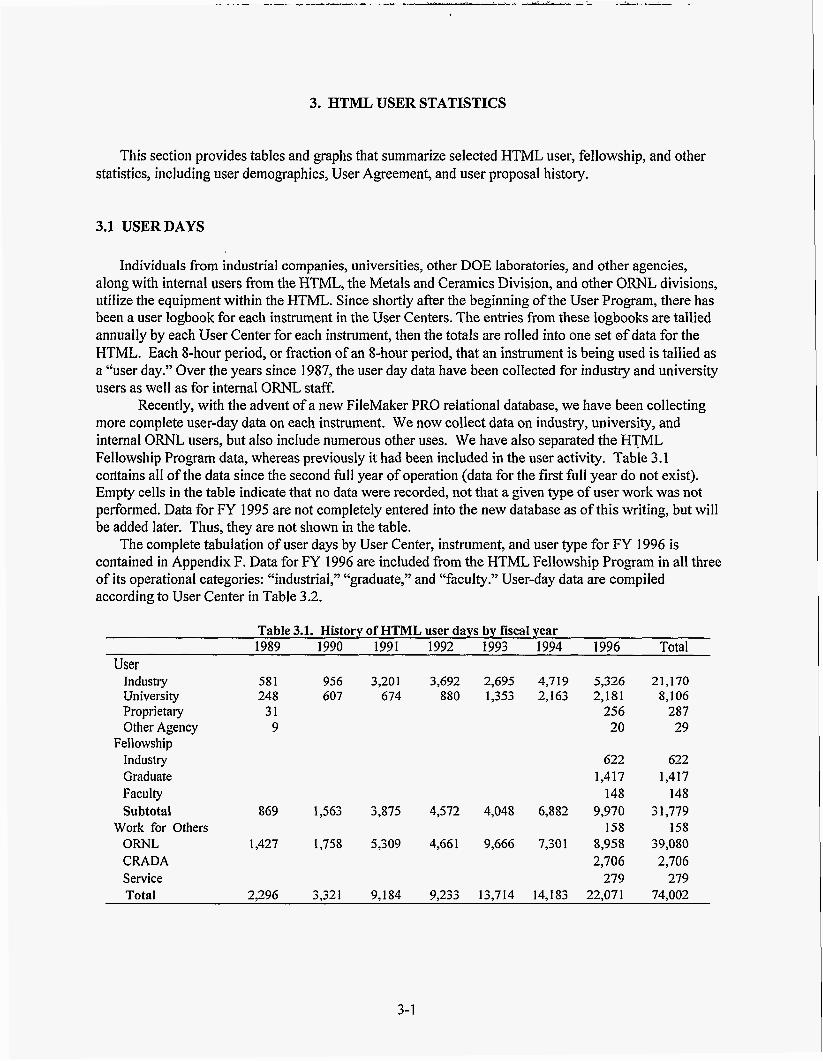
3.1 USERDAYS
Individuals from industrial companies, universities, other DOE laboratories, and other agencies, along with internal users from the HTML, the Metals and Ceramics Division, and other ORNL divisions, utilize the equipment within the HTML. Since shortly after the beginning of the User Program, there has been a user logbook for each instrument in the User Centers. The entries from these logbooks are tallied annually by each User Center for each instrument, then the totals are rolled into one set of data for the HTML. Each 8-hour period, or fraction of an 8-hour period, that an instrument is being used is tallied as a “user day.” Over the years since 1987, the user day data have been collected for industry and university users as well as for internal O W L staff.
more complete user-day data on each instrument. We now collect data on industry, university, and internal ORNL users, but also include numerous other uses. We have also separated the HTML Fellowship Program data, whereas previously it had been included in the user activity. Table 3.1 cofitains all of the data since the second full year of operation (data for the first full year do not exist). Empty cells in the table indicate that no data were recorded, not that a given type of user work was not performed. Data for FY 1995 are not completely entered into the new database as of this writing, but will be added later. Thus, they are not shown in the table.
contained in Appendix F. Data for FY 1996 are included from the HTML Fellowship Program in all three of its operational categories: “industrial,” “graduate,” and “faculty.” User-day data are compiled according to User Center in Table 3.2.
Recently, with the advent of a new FileMaker PRO relational database, we have been collecting
The complete tabulation of user days by User Center, instrument, and user type for FY 1996 is
Table 3.1. History of HTML user days by fiscal year 1989 1990 1991 1992 1993 1994 1996 Total
User Industry 581 956 3,201 3,692 2,695 4,719 5,326 21,170 University 248 607 674 880 1,353 2,163 2,181 8,106 Proprietary 31 256 287 Other Agency 9 20 29
Industry 622 622 Graduate 1,417 1,417 Faculty 148 148 Subtotal 869 1,563 3,875 4,572 4,048 6,882 9,970 31,779
Work for Others 158 158 ORNL 1,427 1,758 5,309 4,661 9,666 7,301 8,958 39,080 CRADA 2,706 2,706 Service 279 279 Total 2,296 3,321 9,184 9,233 13,714 14,183 22,071 74,002
Fellowship
3-1

. ..
~ ~ ~
Table 3.2. HTML user days for FY 1996 by User Center User Center“
DUC MAUC MCAUC MIRUC RSUC TPUC Total User Industry 25 217 4,561 27 356 140 5,326 University 324 218 1,192 5 396 46 2,181 Proprietary 81 142 0 0 9 24 256 Other Agency 0 0 0 0 0 20 20
Fellowship Industry 74 67 342 0 21 118 622 Graduate 168 330 40 91 128 660 1,417 Faculty 0 1 147 0 0 0 148
Work for Others 0 0 0 0 158 0 158 ORNL 40 1 93 1 6,445 54 1 544 96 8,958 CRADA 3 90 2,346 175 13 79 2,706 Service 5 0 0 0 20 1 73 279 Total 1,081 1,996 15,073 839 1,826 1,256 22,071
“DUC = Diffraction User Center MAUC = Materials Analysis User Center MCAUC = Mechanical Characterization and Analysis User Center MIRUC = Machining and Inspection Research Center IRUC =Machining and Inspection Research User Center RSUC = Residual Stress User Center TPUC = Thermophysical Properties User Center
The data for total, industrial, university, and internal ORNL user days are plotted in Fig. 3.1. As the figure shows, although there is some irregularity in the growth pattern, in general the HTML has seen a steady increase in the number of user days performed for each category. This is quite remarkable inasmuch as the HTML User Program budget has been roughly flat since the beginning of FY 1994.
The increase is partially attributable to continuing efforts towards providing lower-cost service (making the program more cost-effective). It is also attributable to the continuing commitment to customers exhibited by the HTML staff; by pleasing the customer we get repeat business (see Sect. 3.2), and we get new business because customers spread the word about us. Finally, the continued growth can be attributed to our ongoing marketing, in which we inform potential customers of our services through in-house visits, tours, and presentations at universities, conferences and expositions, and our World Wide Web site. To meet the continuing demand for some instruments, We have purchased duplicates (e.g., a second nanoindenter and several tensile test machines). However, we occasionally have to delay the user’s visit to HTML because of difficulties in scheduling our limited staff and equipment. We are close to or have reached a “saturation” in user day capability at the current budget level.
3.2 USER AGREEMENTS AND PROPOSALS
A “User Agreement” between LMER and the user institution is the legal vehicle that allows a user to perform work in the HTML; it specifies the handling of intellectual property. It specifies personal liability and the handling of intellectual property. The agreements are handled and tracked by the ORNL Office of Science and Technology Partnerships (OSTP), which provides a listing of all of the User Agreements within LMER.
3 -2

25000 Tot User Days
0 Ind User Days
20000 - 0 Univ User Days
A Int User Days
15000 d 2 tj 3 10000
5000
0 0 Q) z
N 0) 0) 7
co Q) Q) 7
co Q) 0 7
FISCAL YEAR
Fig. 3.1. A history of user days of research expended in the HTML since its inception.
A User Agreement allows a company or university access to any of the 15 user facilities at ORNL. The user completes another document, called a “technical proposal,” after both parties have signed the User Agreement. Technical proposals are handled and tracked by the HTML Program Office. Figs. 3.2 through 3.5 illustrate User Agreements received by OSTP and technical proposals received by the HTML (see the tables in Appendix B).
materials studies in the Metals and Ceramics Division. Most are written expressly for interaction with the HTML User Centers, although some were written for multiple-user facility access or for access to another materials-related facility, such as Metals Processing Laboratory Users Centers (MPLUS) or the Surface Modification and Characterization Facility (SMAC). After a quick rise in the numbers of User Agreements during HTML startup, the annual number stabilized at about 30, with approximately equal numbers of industrial and university agreements. The numbers have begun to increase recently because HTML program and research staff have been marketing the facility, because new customer interest in HTML has been stimulated by word of mouth, and because new User Centers at ORNL, such as MPLUS and SMAC, have brought in new users. The increased number of User Agreements bodes well for the future.
FY 1997. Industrial and university User Agreements are at an equal level.
Figure 3.2 illustrates the history of User Agreements received at OSTP which deal mostly with
Figure 3.3 shows the cumulative number of User Agreements; the total approaches 300 by the end of
3-3

--D- Total Agrecmnls
+ Industrial 40
University m + OtherAgcncy I
B : 20
‘5 30 0
L
E S Z
10
0
YEAR
Fig. 3.2. Numbers of materials-related User Agreements received by the ORNL Office of Science and Technology Partnerships.
300 -I- Cumulativc Total A p m c n l s
250 - --9- Cumulative Industrial Agrccmcnls
-0- Cumulativc University A p m c n l s
YEAR
Fig. 3.3. Cumulative number of User Agreements received by the ORNL Office of Science and Technology Partnerships.
3-4

The history of technical proposals is illustrated in Fig. 3.4. Like the User Agreements, proposals increased until about 1990 as the HTML programs were starting up. Since then, however, the rates for proposals have varied quite widely. The rate of receipt of user proposals has decreased noticeably since about 1993, especially industrial proposals, which have shown a steady 4-year decline. The possible reasons for this are numerous.
existing proposals. New proposals were not being written, and no specific means to close out old proposals existed. Meanwhile, companies maintained their presence at HTML, which caused a problem because the HTML user program is charged a quarterly fee for each “active” user clearance into ORNL. Therefore, money was sometimes being spent needlessly on clearances for projects that had been closed.
A new mechanism has recently been instituted to close out old proposals, cause new ones to be written, and eliminate the clearance costs for users who were no longer active. At the end of each year, a letter is sent to each user institution thought to be active, inquiring about its status and asking for a written summary if the work is completed (for our annual report) and to provide the publications that resulted from the work. In this way, we get a clear understanding of their project status, a summary, and a paper if the work has been completed. We expect that this action will increase the number of proposals submitted.
Democratic administration and its encouragement of CRADAS and other industry-laboratory interactions. Several companies “tested the waters” in 1993 and 1994, and as a result we saw an increase in the number of proposals. We are now returning to a steadier rate.
A third possible reason is that the staff members are concentrating their efforts on a few, relatively important projects as the HTML program approaches saturation. However, the number of proposals is not necessarily a critical metric. A better indicator is the increase in the number of user days, which shows that the HTML is fulfilling the needs of its customers by providing service.
number of proposals received has now exceeded 660. Universities narrowly lead industries in the submission rate.
Figure 3.6 depicts the cumulative history of HTML User Agreements and technical proposals received, illustrating that the ratio of proposals to agreements is 661:276, or about 2.4. This figure indicates that, on the average, users tend to come to the HTML about 2.4 times to perform research and development projects. This repeat business is evidence of the satisfaction HTML provides to its customers.
One factor we have determined is that many companies were continuing to work under previously
A second possible reason is that in 1993 companies took advantage of the new openness of the
Figure 3.5. presents a picture of the cumulative history of technical proposals, showing that the total
3-5

125
100
25
0
- Totalhposals
Indusuialhposals - university Proposals - Olhm Agency Pmposals
cu m m
YEAR
0 m m m m W
9 ,- 9 7
m Q m m 7
W m m 7
m m 9
Fig. 3.4. History of technical proposals received by the HTML.
TolalRoporals
--b- Industrial Proposals
* Ohm A g m y Proposals
m m m (D m
7 m s cu m m 7
m 0
m 7
m m m 7
(D m 7
m 7
m r-
YEAR
Fig. 3.5. Cumulative history of technical proposals received by HTML.
3-6

80C
600
0
--D- Total Proposals Received
--o-
(D CO a, a, a, a, a,
F T- T-
B 8 (D co 0 a3 co a, a, a, a, a,
T- 7- 7- T-
YEAR
Fig. 3.6. Cumulative technical proposals and User Agreements received.
3-7

4. HTML USER CENTERS
4.1 MATERIALS ANALYSIS USER CENTER
4.1.1 Staff and Current Capabilities
The Materials Analysis User Center (MAUC) uses electron microscopy and surface chemical analysis techniques to characterize the structure and chemistry of advanced structural materials. The information obtained from these characterizations is used to elucidate the mechanisms that control material performance.
along with the instruments for which they have primary operating responsibility: T. A. (Ted) Nolan is group leader of MAUC. Additional MAUC staff members are listed below,
0
Dr. L. F. (Larry) Allard-Hitachi HF-2000 field emission gun transmission electron microscope
D. W. (Dorothy) Coffey-Hitachi S-800 FEG scanning electron microscope (SEM) and S-4500 800
L. (Larry) Walker-EOL 733 electron microprobe (on loan from the LMES Y-12 Plant); Dr. I<. L. (Karren) More-JEOL 4000EX 4000EX high-resolution transmission electron microscope (HREM) and 2000FX analytical electron microscope and Topometrix scanning probe microscope; Dr. E. (Edgar) Volkl-electron holography, digital and remote microscopy.
(FEG-TEM);
FEG-SEM,
4.1.2 Highlights
4.1.2.1 Gatan Imaging Filter
A Gatan imaging filter (GIF) has recently been installed on the Hitachi HF2000 FEG-TEM in MAUC. The GIF produces energy-filtered electron images as well as electron diffraction patterns. Electron energy-loss spectra can also be acquired with the parallel electron energy-loss spectrometer (PEELS), which is an integral part of the GIF system. The PEELS spectra provide information about the different elements present (chemical composition), and the GIF “maps” show how the elements are distributed in the material. PEELS data can also provide information about specimen thickness, chemical binding, and atom-specific radial distribution of near neighbors in many materials. This is a new focus area for MAUC and will enhance our chemical analysis capabilities significantly. In addition to our current energy-dispersive spectroscopy (EDS) systems, PEELS will be used for light-element analysis (especially useful for B, N, C, and 0) in a variety of materials such as continuous-fiber-reinforced ceramic matrix composites and catalysts.
4.1.2.2 Remote and Digital Microscopy
Some time ago we recognized the value of a capability for our users to interact directly with the scientists and instruments in our laboratory by Internet connections during microscopy sessions. Therefore, the concept of “remote rnicro~copy~’ in a “virtual laboratory” was a natural next step to improve performance and to make our facilities available to a much-expanded user base. To this end, we have successfully developed control and image-processing algorithms for the digital imaging and control system of the Hitachi HF-2000 FEG-TEM, our “flagship” instrument.
4- 1

We have demonstrated our remote microscopy capability in recent months from CaIifornia, Washington, Nashville, and Detroit. Secretary of Energy Hazel O’Leary saw the demonstration in Washington. We recently established a connection with our first industrial firm, Lo-Tec Ceramics in Salt Lake City, and we will be undertaking a project with them in the near future. As part of a presentation by ORNL to a number of national media representatives organized by the members of PNGV (the Big Three automotive manufacturers and others), we demonstrated remote microscopy with the Focus: Hope Center for Advanced Technology in Detroit.
One of the recent thrusts of MAUC, aimed at facilitating and increasing usage of our expensive characterization equipment, is the development of digital imaging tools for microscopy. Our laboratory was the first electron microscopy facility of any size in the nation to become totally digital (we use no photographic film). Recently the JEOL Superprobe 733 electron microprobe was moved into the HTML and was added to the suite of instruments routinely available through the User Program. It was outfitted with a Macintosh-based image-acquisition system, and all image acquisiton and storage is now digital, thus eliminating the use of expensive Polaroid film along with its associated processing and waste- disposal costs.
Recent developments include tools that simplify and reduce the number of commands needed to control routine .functions of the microscope; for example, the illumination is automatically optimized to maintain a constant value when magnification is changed. Almost all of the variable parameters of the microscope can be controlled by the computer. We have chosen to develop our microscope control programs so that they run within the sophisticated camera-control and image-processing software provided by the manufacturer of our digital camera. This route, we feel, has the best chance to become the de facto accepted sfandard for remote operation in the microscopy field. The first demonstration of our remote operation capability was conducted at the Supercomputing ’95 Expo in San Diego, in December 1995.
DOE called DOE 2000 is under way; this initative seeks to develop and demonstrate ‘ccollaboratoryyy concepts such as remote instrument operation, electronic whiteboards and notebooks, and telepresence tools. We participated with Argonne and Lawrence Berkeley national laboratories in the submission of a proposal to MICS to perform a pilot project called the Materials Microcharacterization Collaboratory. This proposal was one of two selected for funding, and it should provide support for the continued development of remote microscopy for at least the next three years.
A new initiative sponsored by the Mathematics, Information, and Computation Division (MICS) of
4.1.2.3 Ex Situ Reactor for Catalyst Studies
Several companies-including Ford Research Laboratory, W. R. Grace Co., and AIIiedSignal-have expressed interest in reaction studies in which catalyst specimens could be examined without the possible contamination from exposure to the atmosphere, after exposure to certain conditions of atmosphere and temperature. To enable such studies we have designed and constructed a TEM specimen holder/ex situ reactor system. Design and construction were accomplished using funds provided by the recently completed catalyst research LDRD. The ex situ reactor system permits sensitive catalyst specimens to be mounted on a TEM specimen grid, installed in the reactor, and reacted with any chosen gas at atmospheric pressure and temperatures up to 1200°C; specimens can then be transferred into the Hitachi HF-2000 without exposure to the atmosphere. The Hitachi FEG-TEM. provides an optimum combination of image resolution (0.2 nm), analytical spot size (1 nm) and beam coherence (cold field emitter) to permit these materials to be studied by high-resolution imaging, electron holography, and high-spatial- resolution X-ray analysis. The reactor system design will permit direct imaging of the same specimen area after each of a series of reaction treatments, so that the progress of changes in the catalyst (such as coalescence and agglomeration of heavy metal species) related to catalyst deactivation mechanisms can be followed, with the assurance that the effects of atmospheric exposure between treatments are minimized.
4-2

The primary advantage of our system design is that it utilizes a low-thermal-mass specimen grid holder to be demounted from the specimen rod during the reaction treatment, then reinstalled in the specimen rod, where it is encapsulated and protected by an inert atmosphere during the few seconds of transfer from the reactor into the microscope. Commercially available systems for this purpose typically have the reactor as an integral part of the specimen holder. These systems suffer from specimen- instability problems, such as vibrations and thermal drifts, that preclude reaching the highest resolution capabilities of the microscope, which are critical for achieving the atomic-level information needed for understanding catalyst structure and deactivation mechanisms. Our design guarantees specimen stability and resistance to drift that will not compromise the resolution capabilities of the electron microscope.
4.1.2.4 Characterization of Electronic Materials
During this reporting period, we have made major contributions using auger electron spectroscopy (AES) and other techniques to solve materials problems brought in by industrial users from the electronics industry. Dr. Earl Winters with Coors Electronic Package Company, Chattanooga, Tennessee, has been an HTML Fellow and has utilized surface analysis extensively in working on problems associated with the production of electronic packages. Recently, experiments have been conducted to aid in the qualification of a new high-speed plating system recently installed at Coors. Careful chemical analysis of plating surfaces after plating and important heat treatments can be used to compare products made with the new high-speed system to older systems that have been proven through years of use. Understanding the details of how the plated layers behave chemically is vital to improvement of the product.
and solve a number of important production problems on its electrical resistorbproduction lines. This technique was used to identify an inadvertent change in composition of silver contact paste (by Vamistor’s supplier) that actually shut down the production line for three weeks. A E S was also used to determine the composition profiles of the Ni-Cr resistive films, enabling Vamistor engineers to start the development of new evaporation materials and procedures that, it is hoped, will reduce the amount of rejected product significantly. Surface analysis has also played an important role in projects dealing with chemical vapor depositon, fiber-matrix interfaces in composites, and metallurgical coatings.
Characterization of electronic materials has been identified as a new thrust area for MAUC. The preceding examples highlight how the use of our tools can have a beneficial impact on production and development problems in the electronics industry. Another collaboration is developing with Intel wherein we will use electron holography and remote microscopy to determine materials causes for defects in processor chips. Our electron holography capabilities provide yet another tool for the analysis of electronic components. Electron holography combined with unique electron lens configurations and special algorithms enables measurement of electric and magnetic fields with high spatial resolution quantitatively in free space and in suitably prepared electronic devices. We have demonstrated this technique by mapping the electrical field across pn junctions in semiconductor devices. This technique will also be used to map the magnetic features of digital recording media. Ours is the only laboratory in the nation capable of high-resolution electric and magnetic field imaging.
Surface analysis has also been used to help Vamistor Corporation, Sevierville, Tennessee, understand
4.2 MECHANICAL CHARACTERIZATION AND ANALYSIS USER CENTER
4.2.1 Staff and Current Capabilities
The Mechanical Characterization and Analysis User Center (MCAUC) is dedicated to the study of the mechanical performance of high-temperature materials. The group leader of MCAUC is Dr. Kristin Breder. Other staff and their areas of expertise are as follows:
4-3

Dr. Matt K. Ferber-characterization of creep, stress-rupture, and fatigue behavior of structural ceramics in tension, flexure, and special test configurations; data acquisition software and hardware; Timothy P. Kirkland-measurement of mechanical properties of structural materials; Dr. Edgar Lara-Curzio-characterization of macromechanical and micromechanical behavior of ceramic composites, fiber testing, and modeling of the constitutive equations for mechanical . performance in ceramic composites; Dr. Sundaram Raghuraman (until August 1996)-mechanical characterization, stress and fracture mechanics analysis, finite element modeling (FEM), and microstructure-property correlation; Laura Riester-micromechanical testing, atomic force microscopy, microscopy, and imaging; Dr. Andrew A. Wereszczak-characterization of the tensile creepfatigue behavior of structural ceramics, fracture toughness testing, finite element analysis (FEA), and life-prediction modeling; Jessie B. Whittenbarger-group administrative support; Mark J. Andrews-intern with the DOE Technical Leadership Development Program; performing mechanical characterization and analysis for the life prediction and mechanical reliability of candidate structural ceramic components for internal combustion engines (the research is the subject of a Ph.D. thesis in Mechanical Engineering from New Mexico State University).
4.2.2 Major Research Areas
4.2.2.1 Universal Mechanical Testing
The universal test facility currently consists of six pneumatic test frames, each having the capability of loading three flexure samples, a universal (electromechanical) test machine equipped with a high- temperature furnace, and a small universal test machine dedicated to RT testing of flexure specimens and C-rings. Users are able to conduct a number of standard mechanical property tests:
0
0
shear strength.
static fatigue (time to failure measured as a function of static stress), dynamic fatigue (fracture stress measured as a function of loading rate), cyclic fatigue (cycles to failure measured as a function of cyclic stress), fast-fracture tensile and compressive strength, and
Standard test fixtures as well as specially designed fixtures can be accommodated in these test
A rotary bend fatigue machine equipped with a small furnace capable of.testing small cylindrical machines.
specimens (-50 mm long x -10 mm diam) in fully reversed cyclic fatigue has been installed. The capability to perform this type of measurement is a valuable addition to the User Center and helps provide a complete set of capabilities for mechanical tests for input in reliability analyses.
Process engineers have used data generated from this facility to optimize and verify the mechanical performance of their materials. In addition, studies involving flexure (and C-ring) testing have focused on measuring the cyclic fatigue behavior of silicon nitride ceramics at room temperature, the effect of processing on the high-temperature behavior of aluminum nitride ceramics, and the evaluation of the time-dependent strength of Sic-Sic ceramic composites. Recently, compression creep of advanced refractories has been measured utilizing contact extensometry with straight cylindrical specimens. This contact extensometer has a resolution of -0.5 pm, and compressive creep rates at temperatures up to 1600°C at stresses as low as 0.2 MPa have been successfully obtained.
4-4

4.2.2.2 Tensile Testing
The tensile test facility consists of ten electromechanical test machines equipped with passive couplers and grips for accommodating either button-head tensile specimens or flat specimens, one electromechanical test machine fitted with fixed wedge-grips for flat composite specimens, and a servohydraulic test machine capable of tension-tension and tension-compression loading of button-head specimens. The operation of all test machines is controlled with integral electronic load controllers and function generators, which allow three principal test modes: ramp at a controlled rate, ramp and hold at a constant load, and tension-tension cyclic loading. All machines are also equipped with short (1 00 mm), resistance-heated furnaces capable of 1600°C maximum temperature or 1500°C for sustained testing in ambient air. Six machines are equipped with contacting capacitance extensometers that have resolutions of -0.1 pm at room temperature and -0.5 pm at 1500°C.
Eight tensile testing machines are designated for creep-stress rupture testing at long times. These are dead-weight creep machines that have been modified with an electronic load controller. The control signal and data acquisition are provided by computers running a specially designed Labview (National Instruments) program. The machines have water-cooled grips for accommodating button-head tensile specimens, and bending moments are minimized by using special load-train couplers with an alignment device. The machines are equipped with short two-zone furnaces capable of sustained maximum temperature of 1500°C. Creep deformation is measured using contact extensometers. These tensile- testing machines have been used to test monolithic silicon nitride specimens in creep for more than 10,000 h before failure. By testing for such long times and performing microstructural analysis of specimens and failure modes, we have been able to improve models describing the temperature and stress dependencies of rupture times. Evaluations are under way of the creep-stress rupture behaviors of several materials systems.
A constant strain stress relaxation experiment may be used to establish minimum creep rates in considerably shorter test duration than through the conventional tensile stress tests. A stress-relaxation testing facility has been acquired to complement the ongoing activities in tensile creep testing.. This facility consists of three tensile-test machines which are similar to the creep stress rupture machines and are equipped with furnaces capable of temperatures up to 1500°C.
4.2.2.3 Environmental Mechanical Testing
The first environmental test facility has a high-temperature clamshell furnace and a ceramic retort, and allows researchers to conduct both compression and flexure tests in air, inert gas, or vacuum to temperatures up to 1500°C. The second environmental test facility can accommodate high-temperature static, tension-tension cyclic, or dynamic loading in vacuum or inert environments up to 1600°C using the button-head tensile specimen geometry. The environmental tensile testing facility is a vacuum chamber mounted on an Instron 1380 (screw-driven) testing machine, a mechanical pump, a diffbsion pump, a regenerative gettering furnace, and a temperature controller. The vacuum chamber accommodates passive couplers for minimizing bending and has a sidecar attachment that houses a strain-measuring contact extensometer. The mechanical and diffusion pumps together can readily achieve a vacuum less than 10-5 torr, and the regenerative gettering furnace is used to purify inert gases to less than 1 ppm 02; its regenerative capability allows for a long-term, continuous gas supply without requiring the replacement of spent gettering media. A graphite hot zone is used; this hot zone achieves 1600°C with a temperature gradient of less than f 5°C across the 35-mm gage length of a standard button-head specimen. The Instron 1380 may be operated in load or displacement control and may be used for static loading, tension-tension cyclic loading (1 Hz maximum), and dynamic loading up to 35 kN.
4-5

The following question may be posed: If a material or component is mechanically stressed at high temperatures in an ambient environment, how and why can mechanical testing in vacuum or inert environments at high temperatures provide any representative or useful data or information? Mechanically stressing a material or component at elevated temperatures in an ambient environment frequently generates two different types of damage: that resulting from the applied stress (e.g., creep damage, cavitation) and that resulting from oxidation-associated corrosion (e.g., surface cracking). Conducting tests in both an ambient environment and a nonoxidizing environment allows the damage contribution from mechanical stressing and oxidation to be decoupled, thus providing insight into the evolution of each type of damage. This information is not attainable by testing only in air. Using this methodology, the MCAUC staff has successfully examined the evolution of creep damage and oxidation- associated damage in silicon nitride.
One universal pneumatic test frame has been modified to accommodate the addition of coal slag to C-ring specimens during the test. The purpose is to perform a combined corrosion/mechanical test for materials intended for use in advanced coal-fired power generation systems.
4.2.2.4 Micromechanical Testing
The micromechanical test facility has been instrumental in studying the mechanical behavior of thin films, thermal barrier coatings, polymers, and fiber-matrix interfaces in composites. This facility consists of the mechanical properties microprobe (or the nanoindenter) and the interfacial test system. The mechanical properties microprobe is a special microhardness tester capable of operating at loads in the microgram range (0-20 mN) a high-load range (0-650 mN) is also available.
Unlike conventional hardness testers, the micromechanical test facility does not require researchers to determine the area of an indent optically in order to calculate hardness. Instead, the height of the indenter relative to the surface of the specimen is constantly monitored with a sensitive capacitance gage, thus allowing the depth of an indent to be determined. The unique feature of the mechanical properties microprobe is its ability to measure indent depths to f 0.2 nm. The area of the indent is then calculated from the known geometry of the tip of the diamond indenter.
The load is also constantly monitored, with the result that hardness is reported as a function of displacement. Measurements of sample stiffness from unloading data permit a separation of the plastic and elastic components of displacement; the projected areas for indents can then be calculated on the basis of the plastic depth of the indents. The elastic moduli of samples can also be estimated from stiffness data.
Motion of the specimen stage in the x-y plane is also precisely controlled. The indenter can be positioned within 2 pm of any chosen point on the specimen, and a series of indents, separated by steps as small as 0.1 pm, may be made in any geometricaI pattern. The entire operation of the system is computer controlled; one or several series of indents may be specified and carried out without further operator intervention.
The user activity in the indentation area has remained high, and this year an additional mechanical properties microprobe (Nanoindenter 11) was installed in the MCAUC. With this indenter it is possible to switch to a continuous stiffness mode, in which a very small oscillation is applied, allowing for continuous sensing of sample stiffness while force is being applied. Additional indenter shapes have been acquired, and comparisons are under way of indentation in brittle and ductile materials using Berkovich, Vickers, and two diameters of spherical indenters.
The characterization of the micromechanical behavior of continuous fiber ceramic composites (CFCCs) often relies on the use of mechanical properties microprobe-based indentation techniques for the measurement of interfacial properties (including debond stress, interfacial shear stress, and residual stress). These techniques typically involve generating a load-displacement curve associated with sliding of individual fibers. The corresponding instrumentation is currently limited by its inability to test fibers exhibiting a wide range of diameters (5 to 100 pm). This limitation arises from insufficient load
4-6

capability, low spatial resolution of stages used to position the fiber with respect to the indenter, and insufficient resolution of the transducers used to measure fiber displacement.
The development of the interfacial test system represents a major effort to address these limitations. The interfacial test system is capable of measuring the load and displacement associated with both fiber push-in and push-through tests. The fibers are positioned using an x-y table capable of precise movement to greater than 0.5 pm. An optical microscope is used to locate fibers for indentation loading. A large- screen monitor connected to the microscope camera is used for easy viewing of the fibers. The indenter and load cell are mounted on a separate bracket adjacent to the stages. This bracket is designed to accommodate load cells covering a range of load capabilities. The indenter holder also accommodates several tungsten carbide and diamond flat-bottomed probes, as well as a standard Vickers indenter. The specimen is loaded into the indenter using a z-stage, which is mounted on top of the x-y table. During testing, the displacement is measured to 0.1 pm using an encoder mounted on the shaft of the z-stage. A personal computer controls the operation of the entire system, including data storage and analysis.
4.2.2.5 Testing of Continuous Fiber Ceramic Composites
The selection of CFCCs for energy-related industrial applications, where component service lives are measured in thousands of hours, will be determined in great part by the durability and reliability of the CFCC under thermal and mechanical loading in harsh environments.
To investigate the simultaneous effect of stress, temperature, and environment on the lond 0 term thermomechanical behavior of CFCCs, the DOE CFCC Program sponsored the development and construction of the Environmental Effects Testing Facility at ORNL. This facility consists of six in- house-developed small universal testing machines. Each test frame consists of an electromechanical actuator with 10,000 N of capacity and displacement resolution of 8 nm, igniter furnaces capable of 1 400°C, a load train with self-aligning capabilities, and a chamber for conducting the tests in a controlled environment. Although specimens with different geometries and gripping arrangements can be accommodated, typically 4-in.-long shoulder-loaded specimens are used. The test machines are interfaced to a personal computer for data acquisition and control.
Currently work is being performed in both fiber characterization and composite measurements. Strength tests of fibers and the subsequent statistical analyses are being performed. Knowledge of the fiber statistic is important for the design with CFCCs as well as for modeling fast-fracture and long-time mechanical behavior. Substantial amounts of work in this area have been performed in developing tests and test fixtures appropriate for ceramic composites. Successful developments of gripping arrangements have led to evaluation of strength and creep properties for several of these materials.
4.2.2.6 Stress and Reliability Analysis
A considerable effort is under way in the area of life prediction of monolithic ceramics. A work station is being utilized to perform finite element analysis (FEA) and reliability modeling work. Two life prediction algorithms have been installed and demonstration and verification of one of these has been performed using silicon carbide diesel exhaust valves as model components. The life prediction algorithm utilizes mechanical test data on standard specimens together with the FEA for the stress in the actual component to predict the probability of survival of the component in the given environment and stress level.
The expertise acquired in this area will be utilized in a new project involving the mechanical life prediction of electronic ceramics and components. The goals of this project are to gain an understanding of damage evolution and to promote the utilization of the life prediction codes with the intent of increasing the ability to predict failure probability and service reliability in electronic ceramics and ceramic components.
4-7

4.2.2.7 Resonant Ultrasound Spectroscopy
A resonant ultrasound spectroscopy (RUS) facility (NDI-502 by Quatrosonics) has been installed and tested in the HTML for characterizing and inspecting the mechanical integrity of ceramic specimens and components. RUS is based on the principle that the mechanical resonance of a component, which depends on its shape, density, elastic moduli, and defects, is sufficiently complex that measuring the resonant frequencies provides a signature unique to the component.
signature. The RUS system consists of a controller, a signal generator, two or more transducers, and a receiver. The resonance spectrum is generated by sweeping the frequency of an ultrasound signal applied to the component and by detecting the resonance frequencies of the component.
A major advantage of the RUS technique is its high sensitivity. Deviations as small as a few parts per million can be detected. Furthermore, the test is very fast, requiring as little time as a few seconds. The RUS technique can be applied to determining the full elastic constants of isotropic and anisotropic materials (such as single crystals, textured polycrystals, and composites) to a high accuracy. Because of the high sensitivity of this method, it is potentially suitable for characterizing and inspecting the mechanical integrity of ceramic specimens and components. The HTML is presently evaluating the RUS technique for characterizing creep damage in silicon nitride, thermal barrier coatings, and other ceramic materials.
Changes in the shape, density or elastic moduli, or introduction of defects lead to a variation of this
4.2.2.8 Thermal Cycling Furnace
The CM Rapid Temp furnace offers the capability of automated thermal cycling (with rapid heating and cooling) at temperatures of up to 1700°C. The furnace is bottom loading; the alumina specimen tray is translated in and out of the furnace hot zone by a screw drive. A Micristar controller allows programming of up to 50 segments with times of up to 18 h per segment. Fan cooling is available when the specimen tray is not in the hot zone. Currently, the furnace is being used to,cycle thermal barrier coating specimens, with cycles consisting of a 15-min ramp to 1 1 5OoC, a l-h hold at 1 1 50"C, and 30-min fan cooling to 90°C.
4.2.3 Major Activities in FY 1995 and 1996
The user activity in the indentation area has continued to be high, and the new mechanical properties microprobe has proven to be a valuable addition to this facility. The user work includes a wide variety of materials, composites, and thin films. A user from the University of Nebraska-Lincoln, has studied the hardness of the austenite and martensite phases in a series of steels with varying carbon content. The work has provided important results about the different behavior of these two phases. In a follow-on project from the University of Nebraska-Lincoln researchers used the Nanoindenter to investigate mechanical properties of nanocrystalline mechanically milled copper and copper-iron alloys. The change in properties of the milled copper and copper-iron alloys was measured as a function of milling time and annealing temperature. Elemental powders of copper and iron were mechanically milled up to 24 h, then annealed up to 600°C. Along with hardness and elastic modulus, the strain-rate sensitivity and stress- relaxation properties were measured.
ion-implanted amorphous carbon and were able to identify the optimal implantation conditions and to correlate the results with those obtained from Raman microprobe analyses.
Users from Virginia Polytechnic Institute collaborating with Ford Motor Company used the Mechanical Properties Microprobe to measure near-surface hardness in ground-steel camshafts. It has been postulated that the hardened surfaces experience tempering during the grinding process with a
Researchers from the Georgia Institute of Technology have studied surface-hardness enhancement in
4-8

resulting softening of the material in a layer up to 50 pm deep. Cross sections of specimens ground under various conditions were investigated; analyses of the results are ongoing.
to measure compressive creep in refractories used in their glass-melting furnaces. A contact extensometer was designed to measure the extremely small compressive creep strains seen in these materials, and measurements determining the steady-state creep rates at 1500 and 1400°C were completed.
Scientists from the Carborundum Company worked with MCAUC staff to measure compressive creep of a series of alumina-zirconia-silica ( U S ) refractories. The data were used to create a finite element model depicting cracking in these materials. The data are being further analyzed at the HTML.
High-temperature tests on CFCCs and single Nicalon Sic fibers have been performed in the new ceramic composites test facility. Structural analyses of CFCC test specimens of various geometries were performed using FEA. The analyses modeled inelastic stress-strain behavior, asymmetric tensile- compressive behavior, and interlaminar shear failure, which are typical of CFCC materials. The results were used to explain the large discrepancies found in strengths evaluated by flexure and tensile tests. The analyses provided guidelines for performing flexure tests, internal compression O-ring tests, and diametrical compression C-ring tests as well as for interpreting the experimental results.
were conducted on CFCCs at 1200°C and at different stress levels. These materials have been under development at Dow Coming as part of its participation in the CFCC Program. The objectives of this study were to determine the effect of filler concentration (used during densification) and new fiber coating compositions on the fatigue resistance of these materials. Much of this work was planned as a result of findings obtained during a previous user program project. Simultaneous data analyses at ORNL and Dow Coming are being carried out.
Researchers from Westinghouse conducted fast-fracture tensile tests at room temperature, 800°C and 1 100°C on NicalonVAlumina CFCCs. Some specimens had been subjected to static oxidation treatments at 800°C and 1 100°C prior to their tensile evaluation. Extensive work is now being directed towards addressing the intermediate temperature embrittlement exhibited by this material between 600°C and 800°C. The main objective of this project is to determine the durability of NicalonTM/alumina CFCCs at elevated temperatures.
successfully used to analyze the thermal shock damage introduced in a CFCC material. The RUS spectrum was measured for each specimen before and after thermal shock, and a correlations between quench temperature difference (8T) and the RUS spectrum changes were obtained.
In a project from University of Massachusetts-Amherst, investigation of the stress-transfer mechanisms in NicalonTM/BMAS (barium-magnesium-alumino-silicate) composites is being performed by conducting tests at different temperatures and stress conditions. Samples were prepared and have been evaluated using the interfacial test system, and extensive metallographic work has been conducted to perform crack-density measurements on this material.
A sizable effort is under way in testing and reliability analysis of ceramic valves. Strength results from flexure testing and tensile testing are being correlated to actual valve strength data. The strength data are being analyzed in terms of failure mechanisms identified by fractography; the data are combined with FEA in a newly developed reliability analysis code. This work is being performed in collaboration with researchers from AlliedSignal who developed the code. The work is further being coordinated with researchers at NASA Lewis to compare the results with its CARES reliability code, and in the user program similar work will be performed in collaboration with Saint Gobain Norton.
work and are discussed elsewhere. In a project funded by ORNL Seed Money, damage accumulation in TBCs arising from both isothermal oxidation and thermal cycling has been studied using the RUS system. The TBC specimens available for this experiment consisted of Waspalloy substrate, oxidation-
Researchers in the MCAUC have worked with Pittsburgh Plate Glass (PPG) researchers on an effort
As part of the most recent user agreement with Dow Coming, fast-fracture and cyclic-fatigue tests
In a project performed by researchers from the University of Cincinnati the RUS technique was
Several projects related to TBCs are ongoing in MCAUC. Two of these are related to the fellowship
4-9

resistant bond coat, and physical vapor deposition (PVD) zirconia top coat. The specimens were 7/8-in.- diam disks. To prevent premature coating failure, the top edges of the substrate specimens were rounded to a radius of 1/16 in. before coating. The specimens were coated on one side only. The substrate thickness was 1/8 in., the bond coat thickness was about 5 mil, and the top coat thickness was about 13 mil. Uncoated substrates were used as references. Thermal cycling was conducted using the drop-bottom thermal cycling furnace in air. Each thermal cycle consisted of a 15-min heating ramp from a low temperature to 1 15OoC, a 60-min hold at 1 15OoC, and a 30-min cooling ramp under a fan. After a specified number of cycles, the specimens were removed for examination and testing. Pictures were taken of the top surfaces of the coated specimens to record the degree and nature of coating damage. The weights of the specimens were measured to 0.000 1 g after loose oxidation scales on the uncoated substrate surfaces were removed.
The application of RUS to the study of damage evolution in TBCs led to several conclusions. First numerical analysis indicates that the RUS technique is sensitive to TBC degradation mechanisms. During isothermal holds, coating spallation led to an increase in frequency. Excessive weight loss during thermal cycling occurred because of rapid oxidation of the substrate. This effect masked changes in RUS spectra arising solely from the spallation of the top coat. To minimize this effect, future studies will use better substrate materials.
In a project entitled “Mechanical Simulation of Damage Evolution in TBCs” the idea is to utilize a simple mechanical four-point flexure test to simulate the TBC failure mechanism associated with thermal cycling. Most mechanical property studies of TBC failure in gas turbine applications involve a combination of isothermal oxidation and thermal cycling. Most researchers agree that the coating fails (spalls) as a result of damage generated during the cooling cycle, in which case the coating is under compression. Problems with these tests are (1) the. stress level during cooling is generally not known and (2) oxidation of the bond coat complicates the failure process. To overcome these limitations, a horizontal four-point flexure system mounted to the base of an optical microscope was constructed. This system allows one to load a TBC-coated flexure bar such that the coating is placed in either tension or compression. During loading the coating, bond coat, and substrate can be monitored at high magnification to assess the evolution of damage. Preliminary tests with the coating under compression have shown that the failure process is indeed similar to that which occurs under thermal cycling.
The mechanical loading technique may ultimately be used to study the effect of oxidation upon failure. By coupling the system with Raman microprobe one could even measure residual stresses at the microstructural level. The resulting insights would be used to establish a TBC failure model.
In a user project with Westinghouse’s Power Generation Division (Orlando, Fla.), high temperature stress relaxation testing of combustion turbine overlay/bond coatings (MCrAlY’s) from room temperature to 900°C has been performed. Two scientists conducted more than 40 stress relaxation tests during four visits last year. The bond coat material investigated is a candidate material for TBCs deposited on components for use in ground-based power generation gas turbine engines. Stress relaxation data were sought for a model developed by Westinghouse engineers that would allow them to representatively predict the residual stresses in TBC systems during service.
The tests that Westinghouse sought were not trivial to conduct; high-temperature “strain-controlled” testing was necessary to perform them. Load-controlled testing (e.g., creep, strength testing at a constant loading, or stressing rate) is easy to conduct experimentally because the feedback signal from the test frame’s load cell is typically a very stable signal and is easily used to control the test. Strain-controlled testing requires a feedback signal from the contact extensometer for control; however, this feedback signal may or may not be stable, depending on the extensometer’s near-environment (e.g., temperature fluctuations, drafts in the laboratory, or machine vibration). Procedures that were developed and alterations to the extensometer environment that were made on two test frames in the HTML permit routine and accurate strain-control testing.
A substantial amount of quantitative data was generated. Westinghouse first fabricated its MCrAlY bond coat material into “ORNL button-head” specimens. The high-temperature stress relaxation tests of
4-10

these specimens involved heating to a prescribed temperature (up to 900°C), then mechanically loading the specimen at a prescribed strain rate until a desired set point strain (up to 1%) was achieved. The imposed total strain was then maintained, and the stress decay as a function of time was monitored, generating a “stress-relaxation history.” The stress-relaxation history was measured as a function of several variables-temperature, strain rate during loading, and total strain.
of the TBC system during service. In service, the ductile MCrAlY bond-coat material forms a layer between a metal substrate and a yttria-stabilized zirconia top coat; therefore, stress relaxation in the bond-coat layer will control the stress transfer between the top coat and substrate. Predicting stress transfer and the residual stress state of the TBC system are important goals for Westinghouse en,’ oineers, and the stress-relaxation data generated in the HTML User Program will help them accomplish it.
A few user projects have been performed in collaboration with MIRUC, in which effects of different machining conditions on the subsequent strength and failure mechanisms have been studied.
In addition to the work in the User Center, researchers in MCAUC are performing extensive research in four other DOE programs: Ceramic Technology for Advanced Heat Engines, Advanced Turbine Systems, Continuous Fiber Ceramic Composites, and the Fossil Materials Program.
Westinghouse engineers will use the data they generated in this user project to model the stress state
4.3 THERMOPHYSICAL PROPERTIES USER CENTER
4.3.1 Background
The Thermophysical Properties User Center (TPUC) is dedicated to measuring thermophysical properties as a function of temperature and correlating these properties with the processing, microstructure, and performance of materials. Specifically, the TPUC staff work with users to determine thermophysical properties such as thermal diffusivity, thermal conductivity, specific heat, and thermal expansion and to characterize the thermal stability, high-temperature reactions and compatibility, and high-temperature oxidation and corrosion properties of materials. The materials studied include structural ceramics, engineering alloys, ceramic and metal matrix composites, superconducting materials, ceramic precursors, carbon materials, and carbon fiber composites.
4.3.2 Staff and Major Instruments
4.3.2.1 Staff - TPUC is one component of the Diffraction and Thermophysical Properties Group. Members of the
group with prime responsibilities for thermophysical properties activities include the following:
Dr. R. B. (Ralph) Dinwiddie -thermal transport; W. D. (Wally) Porter -thermal analysis; Dr. H. (Hsin) Wang -thermal transport; J. L. (Joy) Kilroy -group administrative support; and Dr. C.R. (Cam) Hubbard -group leader.
Dr. Hsin Wang is an ORISE postdoctoral appointee. He graduated from Alfred University’s College of Ceramics with research on measurement of properties of ZnO ceramics.
The major facilities of TPUC are divided into two areas: thermal analysis and thermal transport. With the addition of two laboratory modules, the thermal transport facilities have been collected in one
4-1 1
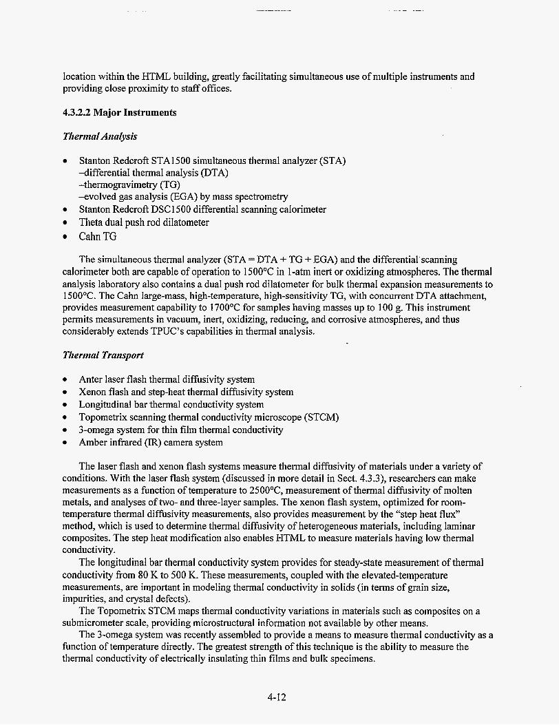
location within the HTML building, greatly facilitating simultaneous use of multiple instruments and providing close proximity to staff offices.
4.3.2.2 Major Instruments
Tlierntnl Aitnlysis
Stanton Redcroft STAl500 simultaneous thermal analyzer (STA) -differential thermal analysis (DTA) -thermogravimetry (TG) -evolved gas analysis (EGA) by mass spectrometry Stanton Redcroft DSC 1500 differential scanning calorimeter Theta dual push rod dilatometer CahnTG
The simultaneous thermal analyzer (STA = DTA + TG + EGA) and the differential’scanning calorimeter both are capable of operation to 1500°C in 1-atm inert or oxidizing atmospheres. The thermal analysis laboratory also contains a dual push rod dilatometer for bulk thermal expansion measurements to 1500°C. The Cahn large-mass, high-temperature, high-sensitivity TG, with concurrent DTA attachment, provides measurement capability to 1700°C for samples having masses up to 100 g. This instrument permits measurements in vacuum, inert, oxidizing, reducing, and corrosive atmospheres, and thus considerably extends TPUC’s capabilities in thermal analysis.
Tlierirtnl Traitsport
Anter laser flash thermal difisivity system Xenon flash and step-heat thermal diffusivity system Longitudinal bar thermal conductivity system Topometrix scanning thermal conductivity microscope (STCM) 3-omega system for thin film thermal conductivity Amber infrared (IR) camera system
The laser flash and xenon flash systems measure thermal diffUsivity of materials under a variety of conditions. With the laser flash system (discussed in more detail in Sect. 4.3.3), researchers can make measurements as a function of temperature to 25OO0C, measurement of thermal diffusivity of molten metals, and analyses of two- and three-layer samples. The xenon flash system, optimized for room- temperature thermal diffhivity measurements, also provides measurement by the “step heat flux” method, which is used to determine thermal diffusivity of heterogeneous materials, including laminar composites. The step heat modification also enables HTML to measure materials having low thermal conductivity.
conductivity from 80 K to 500 K. These measurements, coupled with the elevated-temperature measurements, are important in modeling thermal conductivity in solids (in terms of grain size, impurities, and crystal defects).
submicrometer scale, providing microstructural information not available by other means.
function of temperature directly. The greatest strength of this technique is the ability to measure the thermal conductivity of electrically insulating thin films and bulk specimens.
The longitudinal bar thermal conductivity system provides for steady-state measurement of thermal
The Topometrix STCM maps thermal conductivity variations in materials such as composites on a
The 3-omega system was recently assembled to provide a means to measure thermal conductivity as a
4-12

A high-speed IR camera for 2-D thermal difisivity and thermography is the newest instrument in TPUC. The camera was purchased by the Advanced Turbine Systems program of OIT to study thermal transport characteristics of TBCs on turbine blades and to assess its applicability to detection of defects (see Sect. 4.3.3).
Srrpportiitg Fnciliries
Five-cell helium pycnometer for density Sample preparation facilities, including the following: -diamond core drill -1ow-speed diamond cutoff saw -diamond band saw -vacuum deposition chamber -polisher
4.3.3 Developments and New Capabilities
4.3.3.1 Thermal Conductivity of Coatings
TPUC researchers completed assembly, development, and testing of instrumentation and software implementing the 3-omega technique to determine thermal conductivity of electrically nonconductive coatings. Coatings are being widely used to increase the performance life of gas turbine engine hot- section components, with a future goal of increasing operating temperatures and, hence, fuel efficiency. Thin films are also widely used as protective oxide coatings, wear-resistant coatings, and corrosion- resistant coatings, and as active elements in electronic components. A photolithographic method is used to deposit a small heater on the surface of the specimen. Using a variable-frequency ac power supply, a lock-in amplifier, and a furnace enables measurement of thermal conductivity as a function of both depth and temperature. The new 3-omega capability enhances HTML's ability to study the effects of processing conditions, thermal history, and microstructure on the thermal conductivity of high- performance coatings.
4.3.3.2 Laser Flash Thermal Diffusivity System
TPUC purchased a new laser flash thermal diffusivity system that significantly expands our thermal- transport measurement capabilities and replaces the failed laser flash system used previously. There was a period of approximately 9 months between failure of the previous system and delivery and acceptance of the new system. This highly flexible system can operate from RT up to 2500°C in vacuum or inert gas. Two furnaces are used to achieve this: one for the range from RT to 500°C and a carbon furnace for the 500 to 2500°C range. In addition, measurements of thermal diffusivity may be made in oxidizing or reducing atmospheres from 25 to 1700°C using an alumina tube furnace. Six-sample carousels on the two vacuumhnert-atmosphere furnaces greatly increase the number of tests that can be made in a single day. In addition to standard disc-shaped samples, the new system will also measure square plates, powders, molten metals, and coatings.
The quench furnace was funded by a CRADA program to provide thermal-transport data on metastable phases. The goal is to heat steel specimens to about 1000°C and then quench to about 450" to 550"C, where the tliermal-diffusivity data on the metastable bainitic phase can be obtained. The quench furnace should also permit in situ characterization of thermal shock damage to materials. Such experiments would take advantage of the fact that thermal diffusivity is quite sensitive to defects.
A quench furnace and dilatometer attachment were recently added to further expand the capabilities.
4-13

4.3.3.3 Thermophysical Properties of Molten and Semisolid Metals
After carefully assessing industry’s current and future needs for knowledge of thermophysical properties, TPUC expanded its focus to include measuring the properties of molten and semisolid metals. These data have recently become very valuable in the national efforts to model materials processes such as welding, casting, quenching, and hot forging or rolling. TPUC has contributed to several user projects needing properties of molten metals. The new laser flash thermal difisivity system has demonstrated the capability to determine the thermal diffusivity of difficult-to-measure molten alloys. TPUC also developed and applied techniques for determining the density of molten metals utilizing our existing dilatometer. These data are often coupled with studies on casting modeling.
4.3.3.4 Infrared Camera for Two-Dimensional Thermal Diffusivity Mapping and Thermography
TPUC has developed a system capable of producing quantitative thermal difisivity maps of test coupons, plates, and tubes, as well as thermal effusivity maps of components with complex shapes, such as turbine blades and vanes. This system is ideal for the study of composites and coatings. At the heart of the system is a high-speed, high-sensitivity IR camera with a 256 x 256-pixel focal plane array operating in snapshot mode. Each one of the 65,536 detectors that make up the focal plane array is exposed at the same time and for the same length of time. This allows for a straightforward pixel-to- pixel comparison in each image. The spatial resolution can be adjusted down to 7.5 pm, and the temperature resolution can be adjusted down to 0.015OC. The camera can operate at speeds up to 130 full frames per second, or up to 1480 images per second at a resolution of 64 x 64 pixels. The exposure time for each image can be adjusted down to 2 ps, allowing the study of very hot and/or fast-moving targets, such as cutting tools, boilers, and brake rotors, during operation.
During a typical test the sample or part is heated by 1000-W quartz lamps, a 1000-W xenon illuminator, or a 4800-W xenon flash lamp. The camera is then used to record the temperature response of the heated surface with time. In some cases the thermal response of the back side of the sample is recorded. Custom software is then used to calculate a thermal diffusivity or thermal effusivity for each point in the image. The result is a thermal diffusivity or effusivity map of the object under test. This data can be viewed in a variety of ways, including a spreadsheet format, a 2-D false-color image, or a 3-D surface plot. The camera can be calibrated for absolute temperature measurement and used in thermography applications. In addition to the measurement of temperature and thermal properties, the camera can also be used for the nondestructive evaluation of components.
demonstration of this portability was in a reverse fellowship with the Ford Scientific Research Laboratory. The purpose of this investigation is to simultaneously image hot spots on the inboard and outboard sides of a brake rotor during braking on a dynamometer. These hot spots result in localized thermal expansion of the rotor that cause the torque variations know as brake roughness or brake judder. During the three visits to Ford, the TPUC staff was able to record thousands of images of this hot- spotting phenomenon as a function of initial rotor temperature and speed, brake pad manufacturer and design, and braking behavior (Le., dragging or stopping). In addition to the qualitative images, which show the spatial evolution of the hot spots, a calibration was performed that allowed the quantitative measurement of temperature as a function of time and location.
These results have both short- and long-term benefits. In the short term, brake system components that are less likely to cause hot spotting can be selected for cars about to be introduced into the market in the near future. In the long term, the thermoelastic models that describe hot spotting may be refined and used to evaluate future designs before they go into production. Future visits to GM Delphi Chassis Systems and the University of Southern Illinois are currently being planned to do similar work on brake systems.
TPUC developed a portable camera control capability to allow off-site field work. The first
4-14

4.4 RESIDUAL STRESS USER CENTER
4.4.1 Background
User projects and DOE programs are increasingly concerned with life prediction and failure analysis of engineering structures. In many of these cases, knowledge of residual stress gradients (sign and magnitude) as a function of location at both the surface and throughout the volume of a component is critical information for failure analysis and life prediction models. The Residual Stress User Center (RSUC) was established to meet this need and to provide a facility for research into controlling residual stresses, either through modifying the forming and finishing processes, by changes in the design, or through stress-relief procedures. RSUC activities, which continue to expand, now include both the X-ray residual stress facility, the neutron residual stress facility (discussed in detail in Sect. 4.4.3), and the developing use of synchrotron radiation. These facilities can be utilized to measure macro (long-range) and micro (short-range) residual stresses in polycrystalline materials. The RSUC also characterizes the nonrandom grain distribution or texture in materials and relates this to directionally dependent materials properties. Texture is very common in materials subject to deformation and also in thin films, both areas of increasing importance.
4.4.2 Staff and Major Instruments
4.4.2.1 Staff
The neutron residual stress facility (NRSF) is operated in a team mode, with members of the Metals and Ceramics, Solid State, and Instrumentation and Controls divisions participating. Unless otherwise noted, the following staff members are from the Diffraction and Thermophysical Properties Group, Metals and Ceramics Division. At the end of FY 1996 two staff members took positions in industry; we are currently recruiting to replace them.
e
e
e
e
e
Dr. K. J. (Kris) Kozaczek-X-ray texture and residual stress-alloys (now with Advanced Materials Technologies, Inc., State College, Pa); Dr. E. A. (Andrew) Payzant-residual stress mapping, instrument specification (ORISE postdoctoral appointment); Dr. S . (Steve) Spooner-residual stress mapping by neutron diffraction (Solid State Division); Dr. X.-L. (Xun-Li) Wang -micro and macro residual stress by neutron diffraction; Dr. T. R. (Tom) Watkins -X-ray residual stress and grazing incidence diffraction; Dr. M. (Michael) Wright-instrumentation design for neutron strain mapping (Instrumentation and Controls Division); Dr. X. (Xiaojing) Zhu -residual stress mapping, data analysis codes (ORISE postdoctoral appointment; now with Materials Data, Inc., Livermore, Calif.); J. L. (Joy) Kilroy-group administrative support; and Dr. C. R. (Cam) Hubbard-group leader and NRSF project leader.
4.4.2.2 Major Instruments
Scintag PTS four-axis goniometer with 18-kW rotating-anode generator; Scintag PTS four-axis goniometer with 2-kW sealed-tube generator; neutron spectrometer with XY.2 mapping system for macroresidual stress mapping; neutron powder diffraction spectrometer and furnace for microresidual stress analysis; and
4-1 5

X14A beam line at the National Synchrotron Light Source (NSLS) [RSUC is a participating research team (PRT) member on this beam line].
Both of the neutron spectrometers are owned and managed by the Neutron Scattering Section of the Solid State Division, OWL. RSUC is provided a portion of the time on these instruments based on an agreement to establish the neutron residual stress effort between DOE’S Basic Energy Sciences (BES) and EE programs and ORNL’s Solid State and Metals and Ceramics divisions. The long-term goal is to establish a dedicated stress mapping instrument at the High Flux Isotope React& (HFIR).
4.4.2.3 Accessory Instrumentation
Grazing incidence optics; Strain gage capabilities;
Position-sensitive and Peltier Si(Li) X-ray detectors; Laser position sensor for X-ray polycrystalline-texture-stress (PTS) units;
Tensile load frame for use on the neutron diffraction, residual stress mapping facility; and Huber full-circle Eulerian cradle for use on the neutron diffraction, residual stress mapping facility.
4.4.3 New Capabilities
4.4.3.1 Grazing Incidence X-Ray Diffraction
Following an earlier demonstration of the application of GIXRD methods for depth-profiling residual stresses over a very shallow, near-surface region of specimens, the user interest in this technique has exceeded the speed at which we can make measurements on our laboratory systems. Numerous proposals and inquiries related to grinding-induced subsurface stresses and to stresses in thin coatings have been received. GIXRD employs low angles of X-ray incidence to control the depth of X-ray penetration. By approaching the angle of total external reflection, the depth of sampling can range from tens of angstroms to a few micrometers. With this technique, diffraction information about phase content, texture, and residual stress can be obtained as a function of sampling depth.
This year the application of this technique to nondestructive characterization of grinding damage in ceramics was tested and was demonstrated to be particularly promising. Of particular importance is the nondestructive measurement of strains induced by grinding and the range of depth profiling. RSUC continues to pursue projects to provide a scientific basis for aspects of this technique and to support further development of this technique and instrumentation. The particular limiting aspect is slow data collection, which limits the extent of user proposals we can address and further limits the number of specimens that can be studied. To address this shortfall we have assessed several options to increase the flux, instrument time, or develop alternate instrument access. These include multilayer X-ray mirrors, focusing capillary optics, and synchrotron radiation. We demonstrated that a 30-fold enhancement could be achieved with use of a multilayer X-ray mirror. A capillary optics device did not look so promising for this application. Tests using the ORNL X14A beam line at NSLS have been encouraging, and additional testing and optimization of the facilities there are under way.
4.4.3.2 Neutron Residual Stress Facility
A cooperative joint effort-signed in April 1994 between EE, OTT, and EWBES, Division of Material Sciences-established NRSF. As part of the HTML’s RSUC, NRSF is a collaborative effort to meet expressed industrial and academic needs for through-thickness strain mapping. This joint program is a direct result of a multiyear LDRD project proposed and led by HTML staff at HFIR. NRSF is
4-16

operated by a team consisting of staff from the HTML in the Metals and Ceramics Division, the Neutron Scattering Group of the Solid State Division, and the Instrumentation and Controls Division.
The goal of the joint program is to establish and operate user facilities for macro- and microresidual stress analysis in conjunction with the existing X-ray facilities of RSUC in HTML and the neutron scattering facilities program at HFR. We currently are meeting this goal by using a portion of the beam time on two Solid State Division spectrometers (HB-2 and Hl3-4). Another goal is to develop a dedicated instrument at HFIR optimized for macroresidual stress analysis, and thus to greatly expand both the capabilities and speed of measurement.
4.4.4 Major Activities
4.4.4.1 User Projects
In the reporting period, the residual stress facilities have also been used on a number of DOE projects, including stresses in clad boiler tubes, weld overlays, thermal barrier coatings, and depth profiling of stresses by neutron and X-ray methods in carburized; and quenched automotive gears. These projects have universally led to additional nonproprietary user projects as well as proprietary projects from industrial users. The NRSF was used in several proprietary projects during the period, and the staff is currently working with candidate users in conducting research and developing additional proposals.
4.4.4.2 Macroresidual Stress Mapping Instrumentation
The demand for macroresidual stress mapping by neutron diffraction continues to exceed the time available. We can schedule approximately 40 or more experiment days every three months (2 of every 3 fuel cycles at HFIR). However, we encountered a demand typically 50 to1 00% in excess of the available days. To meet this demand as soon as possible, we have given high priority to the development of a dedicated stress-mapping facility. This effort has been stretched out by several factors:
the decision by DOE to spread the capital funding over three years, design analysis that recommended a horizontal beam arrangement, Solid State Division's need to continue to use HB-2 and potentially split that beam and support four major research instruments (including the stress mapping), and most recently the proposal to build a thermal guide hall using HB-2 beam as the source.
In the guide hall plans the neutron-based residual stress program would have two stations on a thermal guide. This proposal has been rated as the number one proposal for upgrade of DOE's neutron facilities by an independent committee, but the proposal seems to be facing tough budgetary concerns.
the existing instrumentation and simultaneously plan for the future possibilities of the thermal guide hall or the fall back of a multi-instrumented HB-2. We have divided the new instrument development task into several components. The first component involves expanding the number of neutron detectors from one to seven to increase detection efficiency and produce data on the strain tensor without specimen rotation. The second component involves developing new monochromators that would deliver a significantly higher flux at the specimen. The third component is to specify and order new goniometers for use at HFIR and potentially the thermal guide hall. The fourth component involved assessing the requirements for a multi-instrumented HB-2 based on new shielding and monochromators. Progress on these is described in the following sections.
HTML and SoIid State Division staff have been working within this picture of uncertainty to improve
4-1 7

4.4.4.3 Seven-Detector Array for Neutron Residual Stress Mapping
One action we have taken to increase our measurement capacity is to expand the number of detectors from one to seven. A vertically stacked array of seven 1 -D PSDs was designed; the seven detectors, shielding, and electronics were installed; and software was developed. Testing demonstrates that the seven-detector array has increased our measurement capability by about fivefold; however, the current goniometer limitations at Hl3-2 prevent full utilization of this detector array. An improved design for shielding and stable detector mounting will be developed when we have acquired the new goniometer system.
spaced at 7' intervals on an arc having an 80-cm radius. Each detector can be rotated about the normal to the detector face to compensate for the apparent curvature of the Debye Scherrer cone at 28 angles away from 90'. A numerical model to correct the data for geometric errors and irregularities in the alignment of the detector array has been developed. Calibration data are collected on diffraction lines of a nickel powder standard. A least-squares fitting method is used to minimize the error between observed and calculated peak positions simultaneously in all seven detectors. The variables include sample-to-detector distance, spacing of the detectors along the array arc, tilt of the array from vertical, variation of the height of the array with 28,28 zero offset, and neutron wavelength. With profile fitting of the diffraction peak plus background, reproducibility of the peak position measurement of better than 0.003' of 20 has been demonstrated. For typical data, the calibration procedure provides measured 28s with an absolute accuracy of 0.02' for all detectors.
We also performed a test to estimate the necessary peak intensity for precise peak position determination and to assess the consistency of multiple measurements. We acquired the peak profiles of a standard nickel powder sample with increasing count times, repeating measurements seven times for each counting time. The estimated standard deviation of a peak position is less than 0.007' if the peak intensity is at least 100 counts over the background.
Each detector in the array has an active area of 4 x 10 cm and a linear resolution of 1 mm. They are
4.4.4.4 Neutron Monochromator Design for Stress Mapping
Neutron flux increases on the gage volume in a residual stress sample combined with improved diffraction peak resolution can be achieved simultaneously with the use of a curved perfect silicon monochromator, according to the calculations made for us by the University of Missouri (Columbia). Flux improvements as large as a factor of 7 have been predicted with the instrumental diffraction peak width reduced by 2. To achieve this increase would require an enlargement of the vertical beam dimension at HJ3-2. Without the taller beam a gain of a factor of 2 to 3 is expected. A doubly bent silicon monochromator that is elastically bent in the scattering plane and mechanically focused out of the scattering plane has been ordered and will be installed with its own monochromator plug at the HB-2 beam port in 1997. The monochromator is being built and tested by the University of Missouri. Preparations of drawings for the plug and associated hardware for the monochromator are under way. With higher neutron flux and the multiple detector system, submillimeter gage volumes for residual stress mapping can become common practice on this instrument.
4-1 8

4.4.4.5 New Goniometer Specifications
Specifications for new goniometers for use at HFIR for neutron residual stress mapping are currently being developed and are expected to be completed in 1997. The goals are to provide for larger specimens (- 2 x larger than currently possible to study), achieve higher accuracy in the rotational axes via use of absolute encoders, permit ready exchange of detector systems, and support various accessories such as tensile frames and furnaces. One of the two systems will have a sample orienter for studies of strain in single-crystal or highly oriented polycrystalline materials. This sample orienter will also permit texture-mapping experiments and the ability to characterize the variation of texture as a function of processing parameters throughout the volume of a specimen.
4.4.4.6 Dedicated NRSF Installation
If the thermal guide hall is not funded, the alternate plan is to design new shutter and shielding at HB-2 to support the various elastic scattering instruments of the Solid State Division and NRSF. The modified beam delivery concept will be to provide a dedicated location at HFIR for four elastic scattering instruments, including the NRSF, each sharing a larger-diameter beam than is currently available. Shielding calculations revealed the necessity for a shielding thickness of about 1 m on each side of the beam.
obtained. However, at the end of 1995 a proposal to upgrade the scattering facilities at HFIR through construction of a thermal neutron guide hall temporarily halted this work as it was realized that the shielding would be unnecessary if the upgrade was funded. The thermal guide hall upgrade proposal has many long-term advantages for the NRSF and if funded provides a superior basis for enhanced intensity and faster measurements of strain in engineering components.
Preliminary designs were developed that accommodated all four instruments, and a cost estimate was
4.5 DIFFRACTION USER CENTER
4.5.1 Background
The Diffraction User Center (DUC) uses room- and high-temperature X-ray and neutron difiaction methods to characterize crystalline phase(s) and stability of advanced structural ceramics, alloys, catalysts, and other industrially relevant materials. The data, obtained individually as a function of temperature and environment and frequently in conjunction with data from thermal analysis or electron microscopy, are used to relate materials processing and performance with phase transformations, reactions (solid-solid, liquid-solid, and gas-solid), lattice expansion, atomic structure, crystallization from the melt, and phase stability.
In addition to supporting users’ diffraction needs, the XRD facilities are extensively used by qualified staff in the Metals and Ceramics Division who are conducting a wide variety of ceramic and alloy R&D efforts. DUC also provides technical expertise in diffraction and materials science in support of a number of DOE-funded projects.
4-19

4.5.2 Staff and Major Instruments
4.5.2.1 Staff
DUC is a central part of the Diffraction and Thermophysical Properties Group. Members who had prime responsibilities for activities in this User Center during the reporting period include the following:
0
0
0
0
0
Dr. S . T. (Scott) Misture-RT & HTXRD, neutron diffraction, synchrotron 0. B. (Burl) Cavin-subcontractor, RT & HTXRD Dr. T. R. (Tom) Watkins-research staff member, RT & HTXRD J. L. (Joy) Kilroy-group administrative support Dr. C. R. (Cam) Hubbard-group leader
Mr. Cavin, who had been with DUC since the beginning of the HTML, retired at the end of September 1993. Fortunately, he has continued to participate in the operation of the X-ray facilities by supporting users and assisting ORNL staff members. After considerable effort to locate a suitable replacement, Dr. Scott Misture, a graduate of Alfred University with extensive experience in HTXRD and ceramics, joined the group in November 1994 under an ORISE postdoctoral appointment. Drs. Hubbard and Watkins, whose primary focus is the RSUC, helped fill the transition in User Center staff.
4.5.2.2 Major Instruments
0
0
Scintag 8-28 PAD V goniometer with Peltier cooled Si(Li) detector; Scintag 0-0 PAD X goniometer with Buehler high-temperature furnace system and a position- sensitive, liquid-nitrogen-cooled Ge detector; High-resolution neutron powder diffractometer (HB-4) at HFIR with furnace and cryostats; X14A beam line at the NSLS with Buehler high-temperature furnace system.
0
0
The neutron powder diffractometer facilities are part of the Neutron Scattering Research Facilities (NSRF) at HFIR sponsored by ER. HTML user projects that also require neutron powder diffraction are accommodated under a collaborative arrangement.
constructed with funding from the ER, ORNL, and industrial members of the PRT. As part of the PRT, we are working to develop high-temperature diffraction and stress analysis as well as add extended X-ray absorption fine structure (EXAFS) capabilities at X14A for research use by HTML users. The extremely high flux, several orders of magnitude greater than our laboratory-based systems, will enable users to study smaller specimens, to study rapid reactions and kinetics, and to resolve subtle phase transformations that cannot be determined with the laboratory-based systems.
DUC became a member of the PRT for the X14A beam line at NSLS. This beam line was
4.5.3 New Capabilities
4.5.3.1 Scanning Position-Sensitive Detector
The addition of a scanning PSD to the higli-temperature XRD system significantly enhanced our XRD facilities. This detector collects approximately an 1 1 O 20 portion of the diffraction pattern simultaneously and can scan over a large 20 range quickly. Coupling the diffraction angle information to the detector electronics allows the “windows” to be added together, giving a complete pattern. As such, the detector provides a five- to tenfold increase in data collection rate with modest loss of resolution. We
4-20

can now follow the kinetics of solid-state reactions and crystallization while at temperature. This system, delivered in FY 1994, was made operational in FY 1995 by Dr. Misture and has since been used on numerous user projects.
4.5.3.2 Rietveld Full-Pattern Refinement Method
The Rietveld full-pattern refinement method demonstrated previously has become a frequently requested data analysis method. The Rietveld method refines lattice parameters, profile shape function, atomic coordinates, thermal motion parameters, and instrumental aberrations. The User Center now has several codes operational for Rietveld refinement (GSAS, Rietan, RIQAS). Each code has different advantages and limitations, thus requiring mastery of several by DUC staff. With this tool, HTXRD users are able to accurateiy determine lattice parameters without use of an internal standard, thus avoiding possible chemical interactions between the standard and the sample. Simultaneously, the user can obtain accurate information on the volume fraction of each phase in a mixture, site occupancy, and even the atomic coordinates. Users can subsequently calculate bond distances and angles from the atomic coordinates. The Rietveld technique has become a heavily used tool in our support of users.
4.5.3.3 Hall-Williamson and Warren-Averbach Analysis Package
Use of the room-temperature diffraction facilities to characterize the coherent domain size (crystallite size) and root mean square microresidual stresses increased last year because of implementation of a Hall-Williamson and Warren-Averbach analysis package written by Drs. James Stewart and Camden Hubbard. This software has continued to be improved by Stewart and Hubbard in support of user projects and has been modified to run on PC computers as well as on the VAX. Efforts to fully document the revised codes were completed in FY 1996, and approximately 35 ORNL reports were distributed to interested groups, including HTML users.
4.5.3.4 Neutron Powder Diffraction
High-resolution neutron powder diffraction capabilities managed by the Neutron Scattering Group, Solid State Division, are now available to HTML users. This became possible by developing a cooperative understanding and referral process. When an HTML project would benefit by including neutron powder diffraction, users can include this request in the HTML proposal; members of the DUC team then will obtain the necessary additional review by the Solid State Division’s neutron powder diffraction staff. When the HTML staff receives a request for extensive neutron powder diffraction research, they forward this request to the Neutron Scattering Group for consideration under the Basic Energy Science’s Neutron Scattering Facilities Program. HTML and the Neutron Scattering Group have jointly acquired a high-temperature vacuum furnace (1 600°C) for neutron powder diffraction measurements and made if operational. We have jointly tested and demonstrated this furnace facility and successfully made it available to HTML and Neutron Scattering Group users at HFIR.
4.5.3.5 High-Temperature XRD Furnace for X14A
A Buehler high-temperature furnace and power supply essentially identical to the system used at HTML was donated to HTML for use at NSLS. Methods to attach the furnace and a temperature controller for the furnace have been developed and tested during one experimental cycle at NSLS. This preliminary experimental cycle was used productively with a user to study a phase with small distortions from a cubic lattice that could not be detected on conventional instruments. Detailed plans for further modification were developed from this preliminary effort and will be implemented in spring 1997.
4-2 1

4.5.3.6 Oxygen Partial-Pressure Monitor
To meet the research needs of users, an oxygen sensor and an oxygen gettering furnace were specified, ordered, and installed for the HTXRD atmosphere control system. These new features of the HTXRD instrument expand DUC’s capabilities and provide new research opportunities in oxygen- deficient materials. For example, in a proprietary project the unit cell symmetry and cell metrics of a complex oxide were determined for the phase at RT, while high temperature measurements showed that a phase transformation occurs during heating. The stability of the phases was determined at several oxygen pressures using the enhanced in situ HTXRD technique. Rietveld refinement of the high-temperature patterns yielded the thermal expansion coefficients of the low- and high-temperature phases as a function of oxygen partial pressure.
4.5.3.7 Advanced Data Collection and Analyses
. The XRD instruments in DUC and RSUC are supported by a MicroVAX 4200 minicomputer with terminal server connections to the instruments and eleven graphic terminals. Scintag software is used €or data collection and routine data analysis. Two networked Pentium-based PCs were added for advanced data processing using a variety of state-of-the-art powder diffraction software packages. Plans to convert this VAX-based system to Windows-NT workstation-controlled systems have been developed. To date, the RTXRD system is operating under Windows-NT control. The transition is expected to be completed by the end of 1997 and will enhance HTML’s data collection and analysis capabilities, keeping them state-of-the-art.
4.6 MACHINING AND INSPECTION RESEARCH USER CENTER
The Machining and Inspection Research Group, which was organized during 1995, combines the
Manufacturability Center (CMC). The Ceramic Machining User Center was renamed the Machining and Inspection Research User Center (MIRUC) to more closely match the new group name.
MIRUC provides basic facilities for investigation of grinding processes for high-performance ceramic materials, design and fabrication of mechanical property test specimens, and dimensional characterization of test specimens and ceramic and metal components. In addition, MIRUC assumed responsibility for research in the area of tribology during 1996.
Its purpose is to investigate and determine cost-effective machining processes for structural ceramic materials. CMC continues to exist as a separate entity because it deals with the application of R&D efforts to specific ceramics manufacturing problems, as opposed to the more basic studies performed by MIRUC.
technical staff and equipment resources of the former Ceramic Machining User Center and the Ceramic
CMC was created in 1992 as a partnership between DOE’S OTT, Defense Programs (DP), and ER.
4.6.1 Staff and Major Instruments
4.6.1.1 Staff
S . B. (Sam) McSpadden, leader of the Machining and Inspection Research Group, has overall responsibility for MIRUC. His technical specialty is dimensional metrology. Other group members and the equipment and technologies for which they have primary responsibility are as follows:
4-22

e
e
e
e
e
e
e
Dr. Peter Blau-a nationally recognized expert in the field of Tribology (friction, wear, and lubrication). Dr. Blau is responsible for all tribological research performed in h4IRUC. Numerous custom-designed friction and wear testing instruments, scratch testers, and repetitive-impact testers are now available for use by guest researchers. Tyler Jenkins-responsible for operation of the Harig surface grinders; coolant management; health, safety, and environmental issues. Tom Morris-a technical specialist in grinding and ceramics machining, principal investigator on numerous DOE DP-funded CRADAs involving cost-effective machining of ceramics. Lawrence O’Rourke-responsible for operation of the Weldon cylindrical grinder, Nicco creep-feed cylindrical grinder, grinding wheel management, and procurement. Randy Parten-responsible for dimensional metrology, with emphasis on programming and operation of the coordinate measuring machine (CMM), Mahr form tester, Rank-Taylor-Hobson profilometer, and the Rodenstock noncontact profilometer. Earl Shelton-responsible for operation and CNC programming of the Cincinnati Milacron centerless grinder and the Sabre vertical grinding center, with emphasis on support for projects of the CMC. Jessie Whittenbarger-group administrative support.
4.6.1.2 Major Instruments
MIRUC specializes in (1) machining ceramics and other materials, which employs fully instrumented machine tools, and (2) dimensional and surface characterization of machined ceramic components and test specimens, which employs metrology instruments. The following is a list of the tools and instruments in use at MIRUC:
e
e
e
Harig CNC surface grinder; Nicco CNC creep-feed surface grinder; Cincinnati Milacron Twingrip CNC centerless grinder; Weldon CNC cylindrical grinder with high-speed grinding spindle; Sabre CNC multiaxis vertical grinding center with high-speed spindle; Legend EMD, a precision, multisensor Ch4M with noncontact and contact scanning, video imaging, and moirk-fringe sensors; Computer-controlled stylus profilometer and a noncontact laser topography system; Mahr-Perthen geometric form measuring instrument; and Pentium-based computer workstation with design, analysis, and programming software.
4.6.2 Major Activities in FY 1995
Researchers used the instrumented Harig surface grinder to grind a series of modulus of rupture (MOR) bars. These data were then included in an International Energy Agency study for comparison of grinding and strength studies conducted on an international scale. Researchers from Ceradyne used the instrumented Nicco creep-feed grinder to perform studies that determined optimal grinding parameters for a specific ceramic material and grinding process. The work led to greatly improved wheel wear with a corresponding reduction in production costs, while maintaining required mechanical properties for the material.
MIRUC obtained an EMD Legend multisensor CMM with noncontact and contact scanning, video imaging, and moiri-fringe sensors. This machine replaced a Leitz CMM that was returned to Brown and Sharpe, Inc., at the conclusion of its CRADA. The new CMM was used in scanning mode to perform accurate measurements of a wear block, an artifact used to determine grinding ratios. Grinding ratio is a
4-23

comparison of the volume of workpiece material removed to the volume of grinding wheel consumed under well-defined grinding conditions. In the past, computation of grinding ratios has been very difficult in a laboratory environment because of the relatively small volume of grinding wheel material consumed when ceramic specimens are ground. Because the CMM is capable of continuous-path scanning, a much more accurate calculation of the change in wheel volume is possible.
added. This equipment adds the capability for grinding complex prismatic shapes that could not be produced on existing grinders at the HTML. This machine, along with the centerless grinder, was placed at the HTML as part of a CRADA with the Cincinnati Milacron Company. Because of the highly specialized nature of this equipment, it must be operated by HTML technical staff,and not by guest researchers. However, an agreement is being negotiated that will allow machining research to be conducted on the equipment under both the User and the Fellowship programs.
MIRUC obtained a new custom-designed abrasive-belt ceramic grindability test system that was developed built by Chand Kare Technical Ceramics (Worcester, Massachusetts). This instrument provides a simple, cost-effective method for evaluating and comparing the relative grindability of various ceramic materials.
MIRUC obtained a new multiaxis vertical grinding center to which instrumentation is currently being
\
4-24

5. HTML FELLOWSHIP PROGRAM
The HTML Fellowship Program was created in FY 1992 to
provide a mechanism for training of industrial and university researchers in state-of-the-art advanced characterization techniques, encourage research in areas of interest to DOE, improve the quality and output of DOE programs, and help make U.S. industry more competitive in a world market.
Four categories of fellowships currently exist: industrial, faculty, graduate, and postdoctoral. This program is administered for the HTML by Oak Ridge Institute for Science and Education. Research must relate to the following DOE Transportation Technology Program areas of interest:
e
e e e
e
e
0
0
0
e
processing of advanced materials; machining of hard materials; structure of materials; physical and thermophysical properties of materials; mechanical properties of materials; corrosion of materials; gas-phase reactions with solids; tribology of solid surfaces; characterization of materials for energy-related applications; and high-temperature structural materials (ceramics, composites, intermetallics, and metals).
5.1 INDUSTRIAL FELLOWSHIPS
5.1.1 Background
To apply for a fellowship, industrial researchers must submit an application to the HTML Fellowship program coordinator. While projects under the User Program are typically short-term and limited to two weeks of hands-on work at the HTML, the Fellowship Program provides an opportunity for longer-term research (which can be performed at intermittent intervals) and often covers more basic research studies. One advantage of a fellowship appointment is that travel, lodging, research expenses, and salaries (Graduate and Faculty Fellowships) are covered by the HTML Fellowship Program. Another mechanism that exists for industrial fellowships is the reverse fellowship. Using this mechanism, an HTML researcher can travel to a company or university to perform on-site research.
Fellowship applications are reviewed by the HTML director along with an external committee that represents university, industrial, and private sectors. The current committee members are Gary Fischman (Food and Drug Administration), Bob Powell (General Motors), Andy Sherman (Ford Motor Co.), Bob Bitting (Alfred University), Joe Panzarino (JNP, formerly of Norton), and Gene Haertling (Clemson University). As with the User Program, a standard nonproprietary user agreement must be in place before work can be performed in the HTML. Once a fellowship appointment has been made, HTML staff work with the respective fellow to schedule instrument time.
and 6 faculty). As of the end of FY 1996, a total of 29 HTML fellows have been appointed (14 industrial, 9 graduate,
5-1

5.1.2 Industrial Fellowships for FY 1995 and FY 1996
5.1.2.1 Jay A. Curtis, LoTEC, Inc., “Physical, Therrno-Physical, and Mechanical Properties of NZP Powders and Ceramics” [FEL95-32(24)-61]
0 b j ectives
Low-thermal-expansion NZP materials (NaZr2P30l2 and its isostructural compositions) have a unique crystal structure that permits almost unlimited ionic substitutions. Two of these NZP ceramics, BS-25 (Bal.25Zr4P5.5Si0.5024) and CS-50 ( C Q . ~ S ~ O . ~ Z ~ ~ P ~ O ~ ~ ) , have potential for use in applications such as port liners for diesel engines. The cost of the final product is largely dictated by the powder synthesis and processing. Alternatives to the conventional processing techniques (solid-state oxide reaction synthesis of powders) exist and could result in significant reduction in time and cost. However, NZP ceramics are quite sensitive to compositional purity and powder characteristics, which derive from the synthesis technique. Therefore, characterization of both powder and bulk ceramic properties is essential for selecting the most suitable low-cost processing method. Characterization of powder properties was completed at HTML in February and March 1996. Bulk properties were evaluated at HTML during November and December 1996.
Research
Eight NZP powders were evaluated at HTML. They were supplied by three manufacturers, each of which used a different processing technique. The areas of research at HTML were XRD (used to determine powder purity, phase content, and lattice parameters at both ambient and elevated temperatures); thermal analysis, comprising both STA and differential scanning calorimetry (DSC) (used to study phase stability); and SEM with EDS (used to study particle size and shape and to inspect for elemental impurity).
This powder analysis allowed LoTEC to select two synthesis methods from each of two powder manufacturers. The manufacturers then supplied LoTEC with larger powder samples, which were used to produce the bulk samples that were analyzed at HTML. Testing included heat capacity and thermal diffusivity to determine thermal conductivity, thermal expansion, modulus of rupture at both ambient and elevated temperature, and high-temperature elastic modulus.
Results
This research resulted in lowering production costs and increasing the understanding of NZP-type materials, thereby broadening their potential application.
PresentationsPublications
LoTEC presented results of powder evaluation research performed at HTML, along with research performed at LoTEC, at the Annual Ceramic Society Meeting in Cocoa Beach in January 1997. Results will be published as a proceedings paper. A similar presentation or publication is planned for either the bulk ceramic evaluation or for the combined powder and bulk evaluation.
5-2

5.1.2.2 Changsheng Guo and Ronald Chand, Chand Kare Technical Ceramics, “Determination of Dominant Factors Controlling Ceramic Grindability” [FEL96-44(29)-141]
0 b jectives
The objectives of this research include establishing correlations between ceramic grindabilities and their material properties (such as flexural strength, hardness, fracture toughness, and thermal conductivity); identifying dominant factors of ceramic grindability; and evaluating diamond wheels for grinding ceramics of higher grindabilities at higher removal rates.
Background 1
The ceramic grindability test system (CGTS), recently developed under a DOE grant, has experimentally verified what ceramic machinists have long suspected: that different ceramic materials grind differently. CGTS measurements show a clear difference in the grindability of commercially available technical ceramic materials. If ceramics of higher grindability could be machined at higher material removal rates in production grinding, then the cost of ceramic components could be greatly reduced. Furthermore, if a property or a characteristic of the ceramic material that affects its grindability could be identified, then ceramics of high grindability could be developed, and likewise, the cost of a ceramic component could be greatly reduced.
as fracture toughness and hardness, to the dominant factors that control grindability. We also ground ceramics of different grindabilities with different material removal rates to identify the technological barriers that prevent ceramics of higher grindability from being ground at a higher removal rate.
In this research, we studied the correlation between grindability and some mechanical properties, such
Proposed Research and Approach
The first part of the research jnvolved understanding and identifying the dominant characteristics of the ceramic material that control its grindability. We established correlations between ceramic grindability and other material characteristics such as fiacture toughness, hardness, elastic modulus, flexural strength, and wear coefficient. For this purpose, grindability, flexural strength, wear coefficient, elastic modulus, hardness, and fracture toughness of 62 different ceramics were measured at HTML. Microscopic observations were made of the surface on which the grindability and the wear tests were performed. Correlations between grindability and other characteristics of the material were established to identify the dominant factors yontrolling ceramic grindability.
The second part of the research had to do with grinding ceramics of high grindability with higher removal rates and identifying the technical barriers that prevent the implementation of higher material removal rate. For this purpose, a few ceramics of different grindabilities were ground at different material removal rates with resin bonded diamond wheels; the Nicco instrumented surface grinder was used. Attempts were made to grind ceramics of high grindability with removal rates proportional to individual grindability. Grinding forces, grinding power, specific energy, workpiece surface roughness, and wheel surface condition were used to evaluate the grinding process. Ceramic materials of high grindability that could not be machined at material removal rates proportional to their respective grindability were identified. Those technological barriers preventing the implementation of higher removal rates were brought to a diamond wheel manufacturer to develop some vitrified diamond wheels based on the materials’ grindability. The wheels were tested by grinding respective samples at higher removal rates.
5-3

Results
The research started in June 1996. At the reporting time, we have obtained 62 different kinds of ceramics, including silicon nitride, silicon carbide, alumina, and zirconia from various ceramics manufacturers. Those ceramics either were purchased by Chand Kare Technical Ceramics or were donated by ceramic manufacturers as support for the research. Test specimens were made at Chand Kare Technical Ceramics’ expense. Grindability measurements have been conducted for 40 of the total 62 ‘ ceramics. Density measurements were completed. Sample preparation was completed in November 1996, and measurements of hardness, fracture toughness, elastic modulus, and thermal diffussivity were made
5.1.2.3 James W. Fash, Ford Research Laboratory, Ford Motor Company, “Thermal Elastic Instabilities in Automotive Braking Systems” [FEL96-46(31)-161] (a reverse fellowship)
Thermal elastic instability (TEI) problems in automotive brake systems have been observed in collaboration with the IR thermal imaging expertise of the HTML staff. The observations made under this fellowship are providing insight into the occurrence of TEI in brake systems and direct the development of analytic models to assess design variables that may influence TEI behavior. The objective of the work undertaken in this reverse fellowship has been to develop experimental observation capability and to make an initial assessment of TEI behavior.
image camera and has built signal-processing electronics to observe the evolution of hot-spot behavior under standard brake test procedures. Tests have been performed on the Ford Research brake dynamometer.
Initial efforts focused on developing techniques to visualize a brake rotor during operation and on integrating the thermal measurement system with the brake dynamometer. The experimental techniques were developed during the first visit; modifications were made to the equipment based on findings during subsequent visits.
In the two subsequent visits the imaging capability was utilized to observe brake system behavior. Initial observations made on a brake system indicated the presence of TEI hot spots. Various test conditions were varied to observe the boundaries of TEI behavior for use in evaluating analytic models. Based on analytic predictions, a second brake system was tested, and predicted critical speeds were confirmed. These experiments have provided supporting observations and interpretations to traditional dynamometer transducer data that confirm the presence of TEI, and have helped to identify the conditions under which this behavior may be of concern.
The final stage of this fellowship was performed during a final visit by Dr. Dinwiddie to Ford in early April 1996. A final proof of concept for an improved system for observing thermal behavior was evaluated based on the knowledge gained in the imaging of TEI hot spots. The results were submitted for publication in the Iiiternational Journal of Tribology.
During three separate visits to Ford Motor Company, Dr. Dinwiddie has utilized the HTML thermal
5.1.2.4 K. Cynthia Hsieh, Caterpillar, Inc., “Particle Characterization of Modified S5 Tool Steels and B and/or V Treated Alloy Steels for Heavy Equipment Applications” [FEL96-45(30)-151]
It is believed that fine precipitates are important in improving the mechanical properties of Caterpillar’s developmental steels. Therefore, TEM analyses of particles and microstructural information are being sought. So far, composition, average particle size, and area densities have been obtained for six alloys (Table 5.1).
5-4

Table 5.1. Particle characterization of modified S5 tool steels Average size Area density
Composition (nm) (particles per pm2) Modified S5 tool steel“ 0.30C (Ti, V) C 20 1.37
0.37C Ti (C, N) 59 4.24
40B30 40B35
0155C (Ti, V) Ti (C, N)
Ti (C, N>
53 45 28
2.68 1.49 3.36
40B40 Ti (C, N) 70 , ’ 0.53 “The three modified S5 samples did not have the same etching time; therefore, the area densities cannot be compared directly with each other.
5.1.2.5 Nanu Menon, AlliedSignal Engines, “Tensile Cyclic Fatigue and Compression Creep Behavior of NT154 SiSN4” [FEL95-27(19)-51]
Cyclic Fatigue
Turbine blades are often subjected to cyclic loading in their applications. Crack growth under cyclic loading has been observed to be faster than that under static loading at intermediate temperatures. [C. J. Gilbert, R. H. Dauskardt, and R. 0. Ritchie, “Behavior of Cyclic Fatigue Cracks in Monolithic Silicon Nitride,” J. A m Ceram SOC. 78(9), 2291-2300, 1995.1 The objective of this part of the research is to understand the cyclic fatigue phenomenon in silicon nitrides.
This part of the research has not been started yet because of the problem of material availability. According to the original proposal, testing was to be conducted on NT154 silicon nitride manufactured by Norton Advanced Ceramics, East Granby, Connecticut. When they pulled out of the aerospace turbine engine market in the middle of 1995, test material for this part of the program was no longer available. Therefore, the material had to be changed to ASSOO. Fatigue specimens of the new material were manufactured at AlliedSignal Ceramic Components, Torrance, California, and will be delivered in FY 1997.
Compressive Creep
Compressive creep rates in Si3N4 are considerably lower than tensile creep rates. [M. K. Ferber, M. G. Jenkins, and V. J. Tennery, “Comparison of Tension, Compression and Flexure Creep for Alumina and Silicon Nitride Ceramics,” Ceram. Eng. Sci. Proc. ll(7-S), 1028-45, 1990.1
Therefore, compressive creep models are needed for accurate estimation of stress redistributions in Si3N4 components subjected to elevated temperatures. In addition, if compressive creep models are available, flexure creep can be modeled using finite element methods. Because flexure creep tests involve much lower cost than the tensile creep tests, a considerable cost saving could be realized in production-lot testing if flexure specimens were employed in place of the current tensile specimens as a benchmark to ensure that the right sintering conditions exist in product-lot testing.
The compressive creep testing is complete. A preliminary report is being published.
5-5

5.1.2.6 Bangalore A. Nagaraj, GE Aircraft Engines, “Thermal Barrier Coatings” [FEL94-12(8)-3I]
Thermal barrier coatings (TBCs) applied to the hot-gas components of turbine engines lead to enhanced fuel efficiency and component reliability. Understanding the mechanisms that control the thermal transport behavior of TBCs is of primary importance. The effect of high- temperature isothermal heat treatments on yttria-partially stabilized zirconia (yttria-PSZ) TBCs deposited by both air plasma spraying (APS) and electron beam-physical vapor deposition (EB-PVD) techniques have been studied. These results have been compared with previous results for yttria. APS and EB-PVD are the two most commonly used coating techniques. These techniques produce coatings with unique microstructures that control performance and stability. The density of the APS coatings was controlled by varying the spray parameters. The low-density APS yttria- PSZ coatings yielded a thermal conductivity that was lower than both the high-density APS coatings and the EB-PVD coatings.
Thermal aging data for both fully and partially stabilized zirconia were compared. The thermal conductivity of the coatings permanently increased upon exposure to high temperatures (T> 1 000°C). These increases were attributed to microstructural changes within the coatings. This increase in thermal conductivity can be modeled using a relationship that depends on both the temperature and the time of exposure. The EB-PVD coatings are less susceptible to thermal aging effects; however, results suggest that they typically have a higher thermal conductivity than APS coatings before thermal aging. The increases in thermal conductivity due to thermal aging for plasma-sprayed PSZ have been found to be less than those for plasma-sprayed fully stabilized zirconia coatings. Generally, for yttria-stabilized zirconia, the lower the as-fabricated thermal conductivity, the more susceptible the coating is to increases in thermal conductivity resulting from thermal aging above 1000°C.
Thin coatings are becoming an important class of TBCs in turbine engines. Thin TBCs offer weight and aerodynamic advantages over thicker coatings. However, thin coatings are very difficult and sometimes impossible to measure using the flash difisivity technique. Therefore, a new measurement technique, the 3-omega technique, was developed to measure the thermal conductivity of very thin coatings (less than 0.2 mm thick). The 3-omega technique has several advantages over the flash diffusivity technique used in the above-mentioned work. No prior knowledge of a coating’s specific heat or density is required because this technique measures thermal conductivity directly. Coatings may be measured on unknown substrates, and precise measurements of the coating thickness are not needed. Current heater designs allow measurements from liquid nitrogen at temperatures up to 300°C. Work is continuing on increasing the upper temperature limit.
5.1.2.7 Krishnan Narasimhan, Valenite, “Study of Physical and Metallurgical Properties of CVD Hard Coatings on Cutting Tools and Modeling of Response of Multilayered Coated Tools in Machining” [FEL96-39(23)-101]
Background
Valenite is developing coatings (monolayers and multilayers) formed by chemical vapor deposit‘ion (CVD) on cutting tools for various machining applications for a wide spectrum of materials. Cutting tools encounter severe adverse conditions during machining and are subjected to high stresses, deformation, thermal and mechanical stress cycling, and chemical reactions. Temperatures as high as 1000°C and high compressive and shear stresses are encountered at the cutting edge of the tool. Thus, CVD coatings on tungsten carbide tools, designed to minimize chemical and abrasive wear, demand significant mechanical, thermal, and physical integrity. Our goal is to measure all these properties at HTML.
5-6

Results
Hardness and fracture toughness of the coatings play a significant part in resisting abrasive wear. At HTML we have started evaluating the hardness and elastic modulus of various coatings using nanoindentation methods. Monolayer and multilayered coatings (>37 layers, 3-4 pm) of TiCN/TiN and polished cross-sectioned specimens were subjected to nanoindentations using Nan0 I. Figure 5.1 shows that significant hardness improvements can be achieved using thin multilayered CVD coatings. Valenite is currently involved in testing multilayered coatings in- house for steel and cast iron milling applications, where abrasive wear resistance and toughness of the coatings are crucial.
coatings have been generated for evaluating pin-on-disk abrasion indexes and friction coefficients.
Pin-on-disk samples with various TiCN, TiN, and AI2O3 monolayer and multilayered
OFiNL97-12%46%rh
I
20 30 40 50 60 70 80 90 100 110 Displacement (nm)
Fig. 5.1. Nanoindentation hardness profile (100-nm penetration depth).
5.1.2.8 Chaitanya K. Narula, Ford Motor Company, “Structural Characterization of Sol- Gel Processed Materials for Automotive Exhaust Reduction Catalyst” (FEL9533(20)-7I)
Sol-gel processed materials are generally high-surface area materials and are used in a variety of catalytic processes. Because beneficial surface properties are lost at high temperatures and because of the cost associated with processing, sol-gel materials are not used in automotive exhaust reduction catalyst devices. We have been investigating a high dispersion of lanthanides in alumina employing heterometallic alkoxides as single-source precursors. A detailed study of the hydrolysis intermediates and the structural characterization of the resulting gels suggested that a molecular distribution of lanthanides in alumina can be achieved. We also followed the structural changes on thermal treatment, which suggested that the lanthanides start to separate as fine particles (about 10 nm) at elevated temperatures. In the lanthanum-cerium-alumina system, we found indications of dissolution of lanthana in ceria. The electron microscopic studies carried out at HTML confirmed our earlier studies and provided insight into the distribution of lanthanides in the alumina matrix. The Ce02-A1203 materials showed small particles (1 0 nm) on the surface of amorphous alumina. The La1O3-AIz03 materials showed small particles of LaA103 on the surface of amorphous alumina. The La-,03-CeO-,-A1203 system showed small crystalline areas corresponding to (1 1 1) CeO-, lattices (Fig. 5.2). Some areas also showed a structure looking down
5-7

the 01 1 zone axis where 11 1 and 002 spacings of CeOl could be identified. The ratio of La203- CeOr varied in different areas of the same particle, but the structure remained that of CeOl. This suggested that La203 dissolves in CeOl preferentially.
characterization of the gels and the structural changes in gels on thermal treatment was submitted to the Journal of Materials Research. Further work on Ag/A1203 materials, which are important lean-burn NO, catalysts, is in progress.
A manuscript describing the hydrolysis studies on heterometallic alkoxides, the
Fig. 5.2. High-resolution electron microscopy image of La203-Ce02-A1203 particles. The La,Ce areas contain approximately equal amounts of La and Ce. Both La and Ce areas contain lanthanum and cerium. The La and Ce areas are dominated by La and Ce, respectively.
5.1.2.9 Chaitanya K. Narula, Ford Motor Company, “Ceramic Precursors for Zirconium Nitride Materials” [FEL95-33(20)-71]
In our previous work, we showed that a ceramic precursor, Me3SiNHTiCl3, can be converted to titanium nitride at relatively low temperatures. We also demonstrated that this precursor is suitable for the fabrication of thin films of TiN on ceramic substrates. The mechanical properties of TiN films prepared by this method were found to be comparable with the films obtained by a low-pressure CVD method. Furthermore, we have found that ceramic precursors for zirconium nitride can be easily prepared by the reaction of silylated amines with ZrCl4:
R(Me3Si)NH + ZrC4 + R(Me&)NH.ZrC14,
where the precursor R can be either Me3Si or t-Butyl. Thermogravimetrical infrared (TG/IR) studies show that the weight loss from the Me3Si
precursor is complete below 500°C and that the evolved gases are primarily Me3SiC1 and HCI. Further sintering is necessary to crystallize the zirconium nitride.
A sample prepared in vacuum at 900°C and examined by HREM showed that the particles were coated with a uniform, almost single-crystal layer of zirconium oxide (Fig. 5.3). This zirconium oxide was not detected by powder XRD methods. A manuscript describing this work is being submitted to Advanced Materials.
5-8

Fig. 5.3. High-resolution electron microscopy image of zirconium nitride prepared from the R(Me3Si) NH.ZrC14 precursor.
5.1.2.10 Chaitanya K. Narula, Ford Motor Company, “Laser-Assisted Photolytic Decomposition of Metal Amides and Preparation of Vanadium, Zirconium, and Niobium Nitrides and Carbidesrnitrides” [FEL95-33(20)-71]
Previously, we have shown that Ti[Nmef]4 undergoes multiphoton dissociation on exposure to 1.064 pm of radiation from a Nd-YAG laser. The decomposed product can be easily converted to TiN. This method is useful if the process can be extended to do TiN laser writing. However, we found that TiCI4, Ti(OR)4, Si(NMez)4, B(NMe&, and Y(NRz)4 did not decompose. This suggested that this phenomenon is limited to Ti(NMez)4. Now we have found that a variety of early transition metal amides [e.g., V(NEt2)4,Zr(NEt&, and Nb(NEt2)4] undergo photolytic decomposition on irradiation with 1.064-pm light from a Nd-YAG laser. We have converted these materials into the corresponding metal carbide nitrides and nitrides, depending on the pyrolysis conditions.
materials. The EDS of the sample shows some surface oxide and the (1 1 l} lattice of zirconium nitride could be seen (Fig. 5.4). The work is in progress, and a paper has been submitted to Cheiiiistiy of Materials.
Electron microscopic studies of the ZrN sample were undertaken to structurally characterize
5-9

Fig. 5.4. TEM image of zirconium nitride sample showing a (111) lattice and some surface oxide.
5.1.2.11 Earl Winters, Coors Electronic Packaging Company, “Characterization of the Microstructure, Diffusion Barrier, and Mechanical Properties of High-speed Gold Deposits Used in Ceramic Electronic Packages” [FEL95-18(10)-41]
This research was undertaken to provide information necessary for the’introduction of a high- speed Ni/Au electroplating system into the manufacture of metallized ceramic integrated circuit (IC) packages. A successful introduction of high-speed finishing processes will bring about major improvements in productivity, product quality, and costs. The goal is to achieve nickel and gold electrodeposition rates 10 to 50 times conventional rates, while maintaining or improving the quality and functional performance of the Ni/Au finishes.
packages depends upon its ability to act as a barrier to the grain boundary diffusion of nickel during heating. AES characterization of high-speed gold deposits, plated at eight to ten times the conventional rate using a variety of conditions and solution chemistries, demonstrated that some are capable of performing as well as conventional, low-speed deposits. RTXRD and SEM studies of these deposits have shown that there is a relationship between performance and microstructure of the gold. The best diffusion barriers are the high-speed deposits that (1) have a 4 1 1> preferred orientation (Fig. 5.5), (2) have the largest average small crystallite size (Fig. 5.6), (3) have large, faceted grains, (4) have been annealed, and (5) have been deposited on sintered nickel. Work is continuing at Coors to define a set of operating conditions in manufacture that will consistently produce deposits that perform as well as the best of those shown in Figs. 5.5 and 5.6.
The functionality (bondability, solderability, and sealability) of the plated gold layer on IC
5-10

ORNL 97-12646111r 50 I
50
40 - a2 0 a Ccl
Wl 30 - 2 3 E O 2 0 - z s .m
4 10-
40
30
20
10
No Anneal
0 0.4 0.45 0.5 0.55 0.6 0.65
1(200)/1(111)
Fig. 5.5. Relationship between the extent of nickel diffusion during heating for 5 min in air at 45OOC and the relative intensities of the (200) and (111) diffraction lines.
450°C Anneal
N m 3 In W * 01
0 8 8 8 8 8 8 9
Small Crystallite Size, t(pm)
Fig. 5.6. Relationship between the extent of nickel diffusion during heating in air for 5 min at 450°C and small crystallite size (Scherrer formula). ,
5-1 1

I_-- --
5.1.2.12 Jian Zhang, Caterpillar, Inc., "Characterization of Thin Film Coatings" [FEL95- 37(21)-181
The Caterpillar Technical Center is investigating thin film coatings for improving performance and reducing wear of diesel engine components operated under sliding, rolling, and mixed mode contact. Characterization of chemical and mechanical properties of thin film coatings is performed at HTML to establish the relationship between coating properties and deposition processes, performance, and failure mechanisms.
Composition profiles of 13 thin film coating samples have been measured by PHI 660 scanning auger microscopy (SAM). Figure 5.7 shows the composition profile of a nitride coating on steel substrate. To reduce sputtering and total analysis time, point composition analysis was conducted on the polished cross section of coatings thicker than 2 pm. Nanoindenter I was used to collect hardness and modulus data on nitride and other coatings. More than 20 specimens have been tested. Low-angle (about 1") mirror polishing was applied on a thin film coating sample to reduce data scattering. GIXD generated by the PTS goniometer with a rotating anode source was used to identify phases and measure residual stress in nine coating samples. The coating property data collected in HTML will be analyzed at Caterpillar Technical Center and used to. determine the optimal processing conditions and properties of thin film coatings with different applications.
1
h
8
00
80
60
40
20
0
i " ~ i " ' l " ' l " ' l " ' l " '
0 at% N c) at%O
- X
" Y X
0 0.2 0.4 0.6 0.8 1 1.2 1.4
Depth (Pm)
Fig. 5.7. Composition profile of a nitride coating on steel substrate.
5.2 FACULTY FELLOWSHIPS
5.2.1 Background
Faculty fellowships are intended for faculty departments accredited by the Accrediting Board for Technology (ABET) to conduct special problem research in the HTML. The research problem must be related to at least one of DOE'S areas of interest as defined for the fellowship program. The research application for faculty fellowships must be reviewed and approved by the HTML Fellowship Review Committee before the research can begin.
5-12

5.2.2 Faculty Fellows for FY 1995 and FY 1996
5.2.2.1 Chris Berndt, Stony Brook University, “Cracking Studies in Thermal Spray Coating Systems” [FEL95-20(12)-5F]
Thermal spray materials have a unique microstructure consisting of lamellae (or “splats”) oriented parallel to the substrate surface. The mechanical properties of thermal spray coatings are not well known or understood. More precise knowledge of thermomechanical properties (and property variation) within TBCs would enable (1) mechanical and physical models for TBC behavior and performance, (2) mechanical property responses to processing and revenue-service environments, and (3) life prediction capability (especially with respect to fatigue damage).
The numerical value of properties of TBCs depends on, among other factors, processing method [e.g., APS, vacuum plasma spraying (VPS), or high-velocity oxy-fuel] as well as pre- and post-treatment. It has also been established that TBCs formed by thermal spray deposition are anisotropic and that the physical properties change with respect to coating thickness.
protocol of 100,200,300, and 400 nm. Ten to thirty-five indents were performed for each sample. The materials tested and the prime results are listed in Table 5.2.
In the present work a Nan0 Indenter I1 was used under a four-load-displacement controlled
Table 5.2. Data acquired on materials tested using nanoindenter instrumentation“ E H
Materials GPa Std. Dev. GPa Std. Dev. Plasma sprayed alumina-13 wt. % titania
As sprayed 180 53.1 13.9 3.3 7.0 4.8 Annealed
NiCr-CrC coating Sprayed at 50°C Sprayed at 90°C
Sprayed at 5OoC Sprayed at 90°C
Molybdenum disilicide
NiAl coating
297 48.2
22 1 51.3 228 60.4
197 30.0 197 30.3
1.7 4.6 9.6 4.3
3.5 0.83 4.0 0.60
HIP (135OOC at 170 MPa) 415 30 15.2 1.8 HIP (condition 2) 47 1 28 16.8 1.9 Elemental HIP 477 33 15.2 1.8
Self-propagating high-temp. synthesis 440 30 15.3 1.3 Hot pressed (1600°C) 487 37 17.5 2.0 VPS (1 1 OOOC, 24 h) 46 1 43 16.5 4.4 VPS (as sprayed) 3 89 77 18.0 3.5
TBC with APS NiCrAlY bond coat In bond coat and close to substrate 220 35.1 4.4 0.57 In bond coat and close to YSZ 213 28.3 4.6 1.90 In YSZ and close to bond coat 189 36.0 11.6 3.48 Near surface of YSZ 207 30.8 13.4 2.3 1
In bond coat and close to substrate 277 12.9 5.6 0.38 In bond coat and close to YSZ 256 23.1 6.1 0.75 In YSZ and close to bond coat 208 25.9 12.3 2.75 Near surface of YSZ 197 35.3 12.3 3.47
“HIP-hot isostatically processed; VPS-vacuum plasma sprayed: APS-air plasma sprayed: TBC-thermal barrier
TBC with VPS NiCrAlY bond coat
coating.
5-13

5.2.2.2 K. K. Chawla, New Mexico Tech, “Mechanical Behavior of Oxide Fiber/Oxide Matrix Ceramic Composites” [FEL94-13(9)-3F]
Background
The work done during the fellowship was part of an ongoing project on oxide fiber-oxide matrix composites. Oxide/oxide composites are attractive for high-temperature applications in air. The main problem was to engineer the fiber-matrix interface to obtain a weak mechanical interface conducive to energy-absorbing mechanisms such as interface debonding, crack deflection, and fiber pullout. Use of interfacial coatings to tailor t‘he interface region was investigated in two oxide-oxide systems. The two systems investigated were (alumina + zirconia) fiber-glass and Nextel 480 (mullite)-glass. The coatings examined were SnOz in the former and BN in the latter.
Procedures and Results
Nanoindentation experiments were made on both the fiber-glass and the mullite-glass systems to measure fiber-matrix debond stress and interfacial shear strength. It appears that because of the rather large degree of fiber surface roughness of (alumina + zirconia) fiber, no debonding could be achieved to the maximum load capacity of the machine available at OWL. In the case of Nextel 480-BN-glass, interfacial debonding was obtained.
Effects were evaluated of interface roughness and processing-induced thermal stresses in (alumina + zirconia) fiber-glass matrix and (alumina+zirconia) fiber-tin dioxide-glass matrix composites. The interface roughness arises from surface roughness of the (alumina-t-zirconia) fiber. The thermal stresses arise from thermal expansion mismatch between the composites. The SnOl coating serves as a diffusion barrier between alumina and glass. Thermal stress analysis showed radial tensile stress components at the fiber-coating and coating-matrix interfaces.
A mullite fiber (Nextel 550), CVD coated with a thick BN coating, was incorporated in a mullite matrix by slurry infiltration. A powder synthesized in our laboratory via a diphasic gel route allowed consolidation by hot pressing at a relatively low temperature (13 10OC). The purpose of the BN coating was to provide a weak interface in this composite. A thick coating (1 pm) of BN was used to ensure the survival of the coating after the processing of the composite. An interfacial testing system with a flat-bottomed diamond indenter (approximately 5 pm diam) was used at the HTML to obtain the interface characteristics. Using a progressive debonding of the interface model, it was determined that the average interfacial shear sliding stress in this composite was 28 MPa. The range of interfacial shear sliding stress was rather large: from 1.3 to 64 MPa. This large variation in interfacial strength was attributed to variation in the thickness of the BN interfacial coating after processing of the composite. Fracture surfaces of these BN-coated composites obtained in a flexture test showed fiber pullout.
Large composite plates of alumina fiber-reinforced glass matrix and mullite fiber-reinforced mullite composites were processed by slurry impregnation at New Mexico Tech, followed by uniaxial hot pressing at the Oak Ridge Y-12 Plant. The idea was to use the large hot-pressing die available at the Y-12 Plant to obtain large samples suitable for tensile testing. Unfortunately, the composite sheets turned out to have rather large amounts of porosity. Plans were made to subject them to hipping to close a large part of this porosity.
Tin dioxide (SnOl) is an interesting and versatile material. It is used for making electrodes for aluminum electrolysis and in the processing of glass. It is also an n-type semiconductor, and considerable work has been done to characterize its optical and electrical properties. It can also be used as a gas sensor. Recently, another use of SnOl was discovered: as a fiber coating in alumina fiber-reinforced silica-based glass ceramic composite systems. In the case of the alumina-glass composite, an interlayer of SnOl between the alumina fiber and glass matrix serves as a diffusion
5-14

barrier and thus prevents a strong chemical bond between the two. Unfortunately, mechanical property data on Sn02 are hard to obtain. Characterization of sintered Sn02 samples was done by XRD, SEM, energy dispersive analysis of X-rays (EDAX), and determination of its elastic moduli by means of an RUS apparatus. The elastic constants of sintered, polycrystalline Sn02 were measured by RUS. The sintered material had a porosity of 5.4%. The elastic constants of this sintered SnOz were CII = 87.6 GPa and C44 = 289.1 GPa, from which a shear modulus, G = 87.6 GPa, a Young’s modulus, E = 224.7 GPa, and Poisson’s ratio, v = 0.283, were obtained. Mackenzie’s equation relating elastic modulus to porosity volume fraction was used to extrapolate the Young’s modulus and Poisson’s ratio to zero porosity. The computed elastic constants for a fully dense, polycrystalline SnOz were as follows: Young’s modulus, Eo = 25 1.6 GPa, and Poisson’s ratio, vo = 0.288. This paper was submitted for publication.
for the High Temperature Ceramic Composites Symposium, held during the fall 1994 meeting of the Materials Research Society, Boston.
K. K. Chawla also participated in organizational meetings with other OFWL staff members
5.2.2.3 W. Roger Cannon, Rutgers University, “Measurement of Crack Tip Stresses in Cracks Grown at High Temperatures” [FEL95-35(25)-llF]
Creep crack growth in ceramics at high temperatures usually takes place by linking damage created in the stress field ahead of the crack tip. There are three basic components of models for creep crack growth: (1) the driving force (i.e., the stress profile at the crack tip), (2) the rate of nucleation and growth of cavities, and (3) linking of cavities to the advancing crack. In this project the stress fields in front of the crack tip of creep-grown cracks in AD-999 alumina (Coors) are being measured using Raman microscopy. Stress is proportional to the frequency shift of the fluorescent peaks. Several models predict the rate of reduction of crack tip stresses due to creep, but experimental profiles have not yet been measured.
in double cantilever beam (DCB) specimens. Thus far, only half-penny-shaped cracks have been successfully propagated by creep. Fig. 5.8 compares the profile of a half-penny-shaped crack before and after creep for 1 h at 1300°C at K = 1.5 MPa mlR. The position of the visible crack under the microscope is at 0 pm. Stress intensification at approximately 60 pm shows the true position of the crack tip. Presumably, at shorter distances the crack opening is too small to detect the crack. Figure 5.8 shows that the stress intensification is eliminated by creep. Results, however, do not show the true stress profile because the crack front of a half-penny crack curves below the surface, and the depth of field for the stress measurements is very large and averages the stress over tens of microns in depth. Future measurements will use a confocal aperture (on order) to achieve tighter depth resolution.
Two types of cracks are being studied: half-penny-shaped cracks in bend bars and long cracks
5.2.2.4 Marija Gajdardziska-Josifovska, University of Wisconsin-Milwaukee, “High-Resolution Electron Holography of Oxide-Supported Metal Catalysts” [FEL95-2 1 (13)-6F]
Professor Marija Gadjdardziska-Josifovska spent the month of July 1995 in residence at HTML, employing electron holography to study the structure of polar and neutral ceramic surfaces. High-temperature annealing was used to prepare MgO (1 1 1) and MgO (1 00) surfaces, which were chosen as model ceramic surfaces. Electron holography was used because of its unique capability to record and retrieve the phase of the electron wave transmitted through the crystal under investigation. MAUC provided the holography and annealing capabilities with experiments being done in collaboration with Drs. Allard, Frost, and Volkl.
5-1 5

50
40
30 h m g 20 v) v)
g 10 v)
0
-1 0 -100 0 100 200 300 400 500 600
Distance from the Apparent Crack Tip (pm)
Fig. 5.8. Stress profile directly ahead of a half-penny-shaped crack in specimen F8-1 (uncrept) and specimen F4-1 (crept). (In F4-1 the position of the crack tip is not known.) K values refer to room-temperature values applied during measurement.
This ongoing research project has three major goals: (1) to investigate the question of surface faceting of polar surfaces, (2) to investigate the applicability of electron holography to surface science problems, and (3) to investigate novel surface structures in oxides and to use them for novel metal-supported catalysts, using platinum clusters deposited on MgO (1 1 1 ) surfaces as an example.
Progress was achieved on the question of faceting of MgO (1 1 1) surfaces, and a paper has been submitted to the Microscopy Society of America. The holographic phase images showed that the MgO (1 1 1) surface does not facet when annealed at high temperatures in oxygen. This result is contrary to the established ideas that polar surfaces facet into neutral crystallographic planes to minimize their surface energy. In addition to this transmission holography study, advances were made in establishing microscope conditions for recording the first reflection holograms on the HTML microscope. Future planned activities are to deposit nanosized platinum clusters on the MgO (1 1 1) surface and to study their three-dimensional shapes with holography.
In October 1995, Professor Gajdardziska was awarded a 5-year National Science Foundation Presidential Faculty Fellowship to establish a research program on structures of polar oxide surfaces. Continued access to the HTML User Facility was indispensable for the success of this research program.
5.2.2.5 Brian W. Sheldon, Brown University, “Interfacial Chemistry of Model Interfaces for Ceramic Matrix Composites” [FEL95-19(11)-4F]
The objective of this work was to measure the properties of thin, porous Al203 layers (1.5 pm thick). These layers have a grain size of 100 nm or less, and they are sandwiched between two larger pieces of dense polycrystalline alumina (Coors AD-995). The samples were fabricated by hot-pressing. This makes it possible to control the properties of the interfacial layers by varying the hot-press temperature and pressure. The fracture resistance of these interfacial layers was measured at Brown University, using the method developed by Charalambides et al. [P. G. Charalambides, J. Lund, A. G. Lund, A. G. Evans, and R. M. McMeeking, J. Appl. Mech.
5-16

56,77-82 (1989)l. In some cases, crack deflection was observed in samples in which the measured fracture resistance exceeds the theoretical threshold predicted by He and Hutchinson [M. Y. He and J. W. Hutchinson, Int. J . Solids Skuct. 25,1053-67 (1989)l. Our work at HTML focused on using nanoindentation to provide additional information on the mechanical behavior of these interfacial layers.
In general, the hardness and modulus of the porous layers decrease with increasing penetration depth (see Fig. 5.9). This apparently occurs because the material degrades, as the indentor tip penetrates it. These interface layers were intentionally designed to be relatively weak, and the observed degradation during indentation is probably correlated with their porous microstructure. The measurements shown in Fig. 5.9 were each compiled by averaging a large number of successful indents. This averaging was necessary because the measurements showed a significant amount of scatter, which we attribute to the microstructural inhomogeneity of the interlayer material. The four curves in Fig. 5.9 show that higher hot-pressing pressures produce harder materials. This is in good qualitative agreement with the fiacture-resistance measurements that were made at Brown.
We have completed measurements on additional samples; however, the analysis of these results is not yet complete. We plan to complete this analysis and to submit a paper on this work to the Journal of the Ainerican Ceraiiiic Society.
Average Hardness vs. Displacement 40
35
30
25
20
15
10
5 0 0 0 0 0 0
v) 0 v) 0 Vl 0
2 2 N N m m
Displacement
* __o_.
--Q--
*
12.15
13.35
12.45
12.35
Fig. 5.9. Hardness vs penetration depth based on continuous-stiffness nanoindentation. Samples were hot-pressed at different conditions: sample 12.15,1500 psi at 12OO0C,; sample 12.35,3500 psi at 1200OC; sample 12.45,4500 psi at 1200OC; and sample 13.35, 3500 psi at 1300°C.
5-1 7

5.3 GRADUATE FELLOWSHIPS
5.3.1 Background
For graduate students the following criteria are applicable:
0
0
the student must be a U.S. citizen and be studying in an engineering department having ABET accreditation of the undergraduate program, the candidate must be prepared to conduct a substantial part of his or her thesis research in residence at HTML, the candidate must have an undergraduate grade point average of at least 3.5 in a 4.0 system, and a standard nonproprietary user agreement must be in place.
The student’s thesis research progress is evaluated once a year by the HTML director, the HTML staff advisor, and the student’s professor to determine whether significant progress has been made and to establish future research goals. This meeting also serves as a mechanism to determine whether funding is to continue. An HTML staff member serves as an on-site advisor and is a member of the student’s dissertation committee at the university. Each graduate student receives a stipend of approximately $2 100 per month for the duration of the fellowship appointment.
5.3.2 Graduate Fellows for FY 1995 and FY 1996
5.3.2.1 Shawn Ailey, North Carolina State University, “Microstructural Characterization of Precious Metallsupport Interactions in Catalyst Systems via the Study of Metals Deposited on Thin Oxide Films” [FEL95-23(15)-12G]
The objective of this study is to use model catalyst systems to understand the interactions between catalyst metals and their supports and to relate this information back to a real catalyst system. To fully characterize and improve the performance of the catalyst, a complete understanding of the microstructure and composition at the atomic level is critical. However, as a result of the inherent difficulties in analyzing the interactions in real catalyst systems, model single-crystal systems such as ceria and alpha-alumina were used to aid in the determinatiOn of interactions that occur in real systems.
Films of (1 00), (1 lo), and (1 1 1) CeOz deposited by pulsed laser ablation were chosen as possible model support systems and were characterized through the use of TEM and X-ray pole figures. To aid in the determination of orientations of small metal catalyst particles such as Pt, Pt/Rh, or Pd with the single-crystal support material, computer modeling of the possible metal- oxide interfaces has been done to determine the most probable orientation relationships. Ongoing research is being conducted on the testing and setup of an environmental chamber designed by researchers in MAUC for gas reactions on TEM catalyst samples.
5.3.2.2 Alex Cozzi, University of Florida, “Theory and Application of Microwave Joining” [FEL93-04(2)-2G]
Microwave energy was used to join high-purity alumina. Alumina is widely used as a technical and structural material. Microwave processing offers the potential benefits of volumetric heating, accelerated heating rates, and inexpensive furnace equipment. This portion of the study employed a load frame and a microwave oven modified in FY 1995 to permit the
5-1 8

application of pressure on a specimen within a functioning microwave oven. A half-factorial experimental design was developed to vary several joining parameters commonly encountered during hot pressing. Joined specimens were machined into flexure bars and tested using four- point bending.
SEM and wavelength dispersive spectroscopy (WDS) were used to correlate the condition of the joining interface with the flexure strength of the specimens. Statistical analysis was performed to determine the influence of each of the joining parameters on the flexure strength. Specimens were also joined using conventional heating. A statistically significant difference between the microwave and conventionally joined specimens was identified at the 90% confidence interval. Figure 5.10 compares the flexure strength of the two heating methods. The flexure strength of the as-received material was 3 10 m a .
A postedpaper entitled “Microwave Joining of Alumina” was presented at the 20th Annual Conference on Composites and Advanced Ceramics, January 1996, and was awarded first prize in the student poster contest.
graduate school of the University of Florida, resulting in a Ph.D. in Materials Science and Engineering, October 1996.
A dissertation entitled “Theory and Application of Microwave Joining” was accepted by the
200 -
150-
100 -
Interaction Bar Chart Effect; Heating Dependent: MOR (MPa) With 90% Confidence Error Bars
50L 0
T
Conventional Heating
1
Microwave
Fig. 5.10. Effect of the heating method on the flexure strength of joined bars plotted with error bars at the 90% confidence interval.
5-19

5.3.2.3 Elizabeth Dickey, Northwestern University, “The Role of Interfaces and Residual Stress on the Fracture Behavior of Directionally Solidified Eutectics” [ FEL95-26( 18)-15G]
In situ oxide-oxide composites can be produced through directional solidification of pseudo- binary eutectic phases [e.g., NiO-Zr02(Yl03)]. The mechanical behavior of these directionally solidified eutectics (DSEs) has been the focus of several studies because of their potential applicability as high-temperature structural materials. Typically, DSEs show an increased work- to-fracture over that of the two constituent phases, but at room temperature they do not behave as classical composites in that little interface debonding occurs between the two phases. Because the two phases in a eutectic system have different thermal expansion properties, residual stresses may build up during processing as the sample cools from the solidification, or stress-free, temperature. Such residual stresses-compressive in one phase and tensile in the other-will certainly affect the mechanical properties of these in situ composites, so it is important to measure and understand the residual stress state.
Two aspects of NiO-ZrOz(Yz03) DSEs were addressed in research carried out under the HTML Graduate Fellowship program: (1) the interfaces between the two phases were studied on an atomic scale by various electron imaging and spectroscopy techniques, and (2) the residual stress and strain tensors of the two phases were measured by XRD techniques. From the two studies, conclusions were drawn about the role of the interface structure on interface bonding and its role in the accumulation of residual stresses in the composite system.
atomic scale by TEM techniques, including HREM performed at Northwestern University. Z-contrast scanning transmission electron microscopy (STEM) and electron energy loss spectroscopy (EELS) were performed in collaboration with the Solid State Division at ORNL. Figure 5.1 1 presents a Z-contrast image of the Ni0-Zr0,(Y203) interface with a structural model superimposed. The atomically abrupt transition between the two phases is facilitated by an oxygen plane at the interface that is shared by both NiO and ZrOz. EELS profiles taken across the
chemically abrupt with no significant mutual solid solubility. The interface atomic structure leads to electrostatic bonding between the cation and anion planes across the boundary and rationalizes the mechanical integrity of the interfaces.
In the second phase of the research, interlamellar residual stresses resulting from thermal expansion mismatches were measured in lamellar NiO-ZrOl(cubic) DSEs. The triaxial strain tensors of both phases were measured using single-crystal XRD techniques on isolated grains of the DSE. The stress tensors were calculated from the strain tensors, taking into account the full elastic anisotropy of the phases. The stress tensors indicate that very large compressive stresses accumulate in ZrOl while large tensile stresses build up in NiO parallel to the lamellae during the solidification process (see Figs. 5.13 and 5.14). The large magnitude of the stresses indicates that the interfaces between the lamellae are very well bonded and do not facilitate slip or other stress- relieving processes.
In the first phase of the research, the interface structure and chemistry were elucidated on an
interface in steps of interplanar spacing (see Fig. 5.12) indicate that the interface is also
5-20

Fig. 5.11. %contrast STEM image of NiO-Zr02(Y203) interface with structural model superimposed.
100
20
0
r
uxygm
Zirconium
Nickel
-1.0 -0.5 0 0.5 1 .o Distance from Interface (nm)
Fig. 5.12. Profiles of Ni-, Zr-, and 0-normalized EELS intensities taken across the NiO-ZrO2 interface in steps of interplanar spacing.
5-2 1

1000
800
600
2 400
&
h l8
v Lo
3 200 v)
0
-200
0 Grain1 El Grain2 0 Grain3
-400 ' I (5
11 (5
22 (5
33
Fig. 5.13. Normal stresses in NiO lamellae. 011 is perpendicular to the lamellae; o 2 2 and o33 are parallel to the lamellae.
I ... 0
-200 h g -400 E ;;r -600 3! X -800
-1000
-1200
-1400
v)
Grain1 (Y203 Stabilized)
El Grain2 w2O3 Stabilized)
0 Grain3 (CaO Stabilized)
Fig. 5.14. Normal stresses in Zr02(cubic) lamellae. cll is perpendicular to the lamellae; oz2 and 033 are parallel to the lamellae.
5-22

5.3.2.4 J. Allen Haynes, University of Alabama, Birmingham, “Oxidation and Degradation of Thermal Barrier Coating Systems” [FEL93-O9(5)-4G]
The oxidation and degradation of plasma-sprayed TBCs have been investigated utilizing the ATIKahn high-mass thermogravimetric analyzer, the automated thermal cycling furnace, and the microscopy facilities at the HTML. Oxidation of the MCrAlY bond coating has been identified as a major contributor to spallation of the TBC ceramic layer used to provide thermal protection to gas-turbine-engine hot-section components. A number of efforts are currently aimed at providing an increased understanding of the oxidation behavior of these systems. Isothermal oxidation rates of APS and VPS Ni-22Cr-lOAl-lY bond coatings have been measured at a temperature of 1 1 5OoC as a function of zirconia top-coating presence and thickness. Coatings and reaction products are being characterized by XRD, SEM, electron microprobe analysis, Raman infrared spectroscopy, and the XRD residual stress facility.
by EB-PVD over the temperature range of 950 to 1200OC.
of these complex systems and should aid in the design of improved coating systems and processes. The results of this study will also provide data that will improve TBC life-modeling capabilities.
The next phase of this study will evaluate.the isothermal oxidation of TBC systems deposited
These results are an important part of increasing the understanding of the oxidation behavior
5.3.2.5 Michael Lance, Rutgers University, “Piezospectroscopy of Ceramics” [FEL95-22 (1 4)- 1 1 GI
The objective of this research is to outline the theory and experimental technique necessary for measuring stress in any ceramic material using Raman or fluorescence spectroscopy. This technique will then be applied to a number of different materials under different stress conditions to demonstrate its utility.
During FY 1995, data were obtained from analysis performed on equipment at Rutgers University. The stress shift of a tetragonal zirconia Raman peak was calibrated in an equi-biaxial stress state so as to match the stress state in front of a crack tip. Other researchers have used a tetragonal peak at 643 cm-’ to measure stress in zirconia; however, it was found that this peak overlaps with a monoclinic peak at 629 cm-’. The resultant peak is a composite of the monoclinic and tetragonal peaks and shifts considerably (-10 cm-’) as the transformation goes from 0% to 100%. The expected peak shift from stress is very small (<0.1 cm-I); therefore, this tetragonal peak cannot be used to measure stress if the percentage of monoclinic is varying. The peak used in this research was at 260 cm-’ and had no overlap with neighboring monoclinic (or tetragonal) peaks.
The extent of transformation can also be measured using Raman microscopy. The relative Raman peak heights of the tetragonal and monoclinic phases are directly proportional to the percentage of monoclinic phase present. This means that both the stress and the transformation profile can be obtained simultaneously.
a maximum of 50% transformation at a crack tip. The grain size was 1 to 2 pm. DCB specimens were used to apply load to the crack tips. The spot size of the laser was -1 pm.
A stress intensity factor of 6.6 MF’a mlR was applied to the crack. Moving away from the crack tip, the stress first increased and then started to decrease at about 10 pm. The stress measurements were plotted against 142 II r)” to determine what K-field the crack was experiencing. Farther than 150 pm away from the crack tip the measured Kip was 6.4 MPa mlR (very close to the applied K). Closer than 150 pm, the K value decreased until, at 10 pm, the stress began to decrease.
A polycrystalline tetragonal zirconia stabilized with 2 wt % yttria was heat-treated to produce
5-23

These are important results because they show that the crack tip is not experiencing a stress singularity. Rather, the stress decreases at the crack tip because of the transformation. The monoclinic percentage was also measured in front of and around the crack tip. These data compared well with the FEA model devised by Dr. Kurt Stam.
5.3.2.6 Ron Ott, University of Alabama, Birmingham, “The Influence of Grinding Forces on the Mechanical Performance of a High-Strength Silicon Nitride” [FEL94-11(7)-6G]
It has been documented that creep feed grinding introduces less severe subsurface damage than does conventional surface grinding. This research has focused on creep feed grinding, trying to better understand the relationships between the machining process and the material’s response to the machining process. The subsurface damage that is a product of the machining process is a combination of microcracking and localized plastic deformation, which leads to compressive and tensile residual stresses in the near-surface region of the machined component.
A creep feed instrumented surface grinder was used to determine the influence that different machining parameters have on the mechanical performance of a high-strength Si3N4. The machining parameters of interest (down feed, table speed, wheel surface speed, and grit size) were systematically varied utilizing a central composite experimental design.
The subsurface damage was analyzed with the use of optical microscopy, SEM, and TEM. Fracture surfaces were examined to determine the size and geometry of flaws introduced by the machining process. Although the machining flaws were not observed directly, fracture mechanics was used to calculate the size of flaws that would cause failure. This was done by measuring characteristic fracture surface markings that were proportional to the flaw sizes. The residual stress was measured using a technique called grazing incident X-ray diffraction (GIXD), which is capable of measuring the microstrains within the material at different depths. Stresses can be determined from the microstrains at different depths from the machined surface. To augment the findings from the GIXD, TEM samples were prepared and analyzed to examine. the microstructure of the near-surface material and to determine how it has changed because of the mechanical stresses and temperatures associated with the machining process.
The most significant of the four machining parameters in controlling the strength and the machining forces was grit size. It was by far the most important machining parameter, as determined by analysis of variance (ANOVA). The depth of the compressive residual stress was determined to be within one grain layer at the machined surface. This is believed to be caused by a nonaccommodation of plastic flow within the material (i.e., the inability for dislocations to move across the grain boundaries). This was confirmed by the TEM results, which showed that the dislocations were all isolated to the first grain layer at the machined surface.
This study will lead to significant understanding of how creep feed grinding influences the mechanical performance of Si3N4. Once a better understanding of how subsurface damage is introduced into a machined ceramic component, then the strength and ultimately the life of the component can be accurately predicted. This will help in reducing the machining times necessary to remove bulk ceramic material, thus lowering the cost of the machining process, which can contribute up to 60% of the manufacturing cost.
silicon nitride. Figure 5.16 illustrates the effect the normal force has on the cross-over point from compressive to tensile residual stresses. As the normal force decreases the cross-over point lies deeper within the material but still within one grain layer. Also, as the normal force decreases the stresses are distributed over greater depths.
Figure 5.15 shows the strong influence of the grit size on the average flexure strength of the
5-24

I : e
i
Grit
Fig. 5.15. Graph of the average flexure strength vs the grit size. The coarser the grit (80 grit, 180 pm diam) the larger the diamond abrasive; the finer the grit (600 grit, 20 pm diam), the smaller the diamond abrasive.
400
200
( d o n a z - -200 zi 9 -400
3 -600 z 3 -800
Cn
v)
(d +
-1000
-1200
Z, depth from machined surface (pm)
Fig. 5.16. Residual stress depth profile for three different grinding conditions.
5-25

To date, flexure bars have been machined with the required machining parameters as outlined by the experimental design. The strengths and the Weibull moduli have been determined. The fracture surfaces were examined optically and with SEM to evaluate the fracture origins. TEM was used to evaluate the subsurface damage by measuring the amount of deformation caused by the machining process. The degree of subsurface damage is directly correlated to both the machining parameters and the machining forces to which the ceramic was subjected during the machining process.
5.3.2.7 Sharon Robinson, Rutgers University, “Microstructural Control of Silicon Carbide Via Liquid Phase Sintering” [FEL95-24(16)-13G]
The objective of this project is to control the microstructural development of Sic ceramics through liquid-phase sintering. The effects of changes in the microstructure are being related to the mechanical properties of the resulting material. Silicon carbide ceramics with various microstructures have been created by controlling the amount and composition of a Y 2 0 3 -A1203 liquid phase, the crystallographic phase of the starting powders, and the time and temperature of sintering and postsintering heat treatments. Alpha and beta Sic “seeds” have been used to control phase conversion and grain growth during sintering. It has been determined that alpha starting powders result in equiaxed grain structures and that beta starting powders lead to microstructures consisting of interlocking platelets. Alpha seeds can be added to the beta powders to control the scale of the microstructures. Improved fracture toughness has been observed in samples with microstructures consisting of elongated platelet grains. This is a result of an increase in the amount of bridging around these platelet grains that occurs in the wake of a propagating crack.
The facilities of MAG were utilized to analyze these samples.-The size distribution and the aspect ratio of the grains were determined through computer-assisted microstructural analysis on SEM images of polished and etched samples. The HF 2000 FEG-TEM has been used in conjunction with EDS to determine the distribution of the sintering aids in the grains and at the grain boundaries. The fracture toughness and hardness were measured by the indentation method to evaluate the relative effects of the microstructural variations on the mechanical properties. Fracture toughness values as high as 7.7 MPa’ ml’ have been measured for the samples with large-scale platelet microstructures.
It has recently been determined that the impurities and the initial oxygen and free carbon levels of the starting silicon carbide powders have a significant effect on the final microstructures of the samples. As a result, work is now focusing on investigating the influence of lot-to-lot variations in the starting powders on the final microstructures of the materials. The results of this ongoing project were presented at the 1996 Annual Meeting of the American Ceramic Society held in Indianapolis on April 14 through 17, in a poster entitled “Self-Toughening of Silicon Carbide,” by S. H. Robinson, D. J. Shanefield, D. E. Niesz, and K. L. More.
5.3.2.8 Matthew A. Stough, Pennsylvania State University, “Solid Solubility and Diffusivity in the Alumina-Zirconia Binary System” [FEL95-25(17)-14G]
Aluminum oxide (A1203) and zirconium oxide (ZrO2) are two very popular ceramic materials used in composite structures. Historically, the interface between them has been assumed ideal, and this assumption has proved adequate for some applications. However, a more thorough understanding of the solid state in this system is desirable as materials application and design approach nano-size dimensions (e.g., in thin-layered optical devices or corrosion-resistant layers).
5-26

Fiber-reinforced ceramic matrix composites and materials in advanced turbine systems are two examples of materials for which the interface between A1203 and ZrO2 can play a crucial role in the success of a product. The purpose of this study is to measure mutual difisivity and solid solubility between sapphire and a stabilized zirconia at 1200 to 16OOOC (common processing and service temperatures).
Diffusion couples were prepared from single crystals of 9.5 mol % Yr03 stabilized cubic . ZrO2 and A1203 (sapphire) and annealed at Penn State for 500 h at 1200,1400, and 1600°C. Also, ion-implanted samples of the same material, with the other’s cation as the implant, were annealed at the same temperatures for various times. Precipitation of ZrOz in the sapphire was seen at 1200°C using AEM. AEM and EDS are being performed at HTML. The solubility of aluminum in the cubic zirconia was determined (see Fig. 5.17) using EDS spectra from our samples and standard mineralogical specimens required for quantitative analysis. The solubility of zirconium in sapphire is currently being examined. In addition, HREM may be performed to determine preferred orientation in samples that exhibit precipitates. The calculation of diffbsion coefficients is under way using models developed at Penn State and while the researcher was in residence at HTML,. Roughly, diffusivities in this binary system appear to be on the order of l O-I5 to lo-” cm2/s across this temperature range.
1700
1600
1500 2 a cI 1400 e! a 5 1300
0
I-
1200
1100 0.5 0.4 0.3 0.2
weight percent AI
0.1 0 9.5molY0 Y,O,
cubic ZrO,
Fig. 5.17. Solubility of aluminum in stabilized cubic zirconia between 1200 and 1600OC. Ninety-five percent confidence intervals are shown.
5.3.2.9 Douglas J. Taylor, University of Arizona, “Structure and Properties of Laser- Fired, Sol-Gel-Derived Tungsten Oxide Films” [FEL93-10(6)-5G]
This investigation focused on the use of laser radiation to fire sol-gel-derived, tungsten oxide films. The main emphasis of this work was to make high-quality tungsten oxide films with good electrochromic properties. Laser firing was done with a carbon dioxide laser operated in continuous mode. The laser-fired tungsten oxide films were measured for density, composition, microstructure, and electrochromic behavior. Analytical tools included multiangle ellipsometry,
5-27

Fourier transform infiared spectorscopy, TEM, XRD, ultraviolethisible spectrophotometry and electrochemistry. The effect of process variables (laser power, spot size, and translation speed) on the extent of film densification and microstructural evolution was investigated because microstructure strongly influences the electrochromic properties of tungsten oxide films and is important in device design.
It is proposed that laser firing of sol-gel-derived films be used for optics, sensors, graded index materials, and electrochromic windows. The ability that laser firing affords to heat localized regions is advantageous for writing lines and patterns in these films. Windows with graded electrochromic properties can be made by dynamically changing the laser firing conditions as the beam rasters through a workpiece. Similarly, electrochromic signs can be written into a window; after the pattern is written by laser densification, the remaining film is etched away, leaving the pattern.
Laser firing was shown to be a feasible technique to make good quality electrochromic films. By precisely controlling the irradiation, we tailored the microstructure of tungsten oxide films to produce the desired electrochromic properties. High-resolution TEM micrographs showed film microstructures that varied from amorphous to fully crystalline. Corresponding optoelectrochemical measurements indicated an increase in electrochromism with network formation and densification, and a decrease in electrochromism with increasing crystallinity. Therefore, optimal firing conditions occurred at median firing conditions after network formation and before massive cryallization of the tungsten oxide films.
Samples were coated and laser-fired at the Arizona Materials Laboratory (AML), Department of Materials Science and Engineering, University of Arizona. Optical and electrochemical characterization was also performed at AML. TEM and sample preparation were done at HTML under HTML Graduate Fellowship Program. The support and technical assistance of HTML facilitated the microstructural analysis that completed both the research project and graduate studies. This fellow is now employed by TPL in Albuquerque.
5-28

APPENDIXA
STANDARD NONPROPRIETARY USER AGREEMENTS IN PLACE
(CUMULATIVE)
JULY 19874EPTEMBER 1996


Alabama
APPENDMA STANDARD NONPROPRIETARY
USER AGREEMENTS IN PLACE (CUMULATIVE) JULY 1987-SEPTEMBER 1996
Monarch Tile, Inc. (Florence) United Defense LP (Anniston) Southern Research Institute (Birmingham)
Arizona
. Advanced Ceramics Research, Inc. (Tucson) AlliedSignal Engines (Phoenix)
Connecticut
ABB C-E Services, Inc. (Windsor) Advanced Technology Materials, Inc.
Steven Winter Associates, Inc. (Norwalk) Torrington Co. (Torrington) United Technologies Pratt & Whitney (East
(Danbury)
Hartford)
Delaware California
AlliedSignal EMRC &os Angeles) AlliedSignal, Inc. (Torrance) Alzeta Corp. (Santa Clara) Amercom, Inc. (Chatsworth) Applied Materials, Inc. (Santa Clara) Ceradyne, Inc. (Costa Mesa) CERCOM, Inc. (Vista) FMC Corp. (Santa Clara) Guidance & Control SystemsLitton Ind.
(Woodland Hills) IBM Almaden Research Center (San Jose) Lockheed Martin Skunk Works (Palmdale) Membrane Technology Research
Northrop Corp. (Pic0 Rivera) Nuclear & Aerospace Materials Corp. (Poway) Rohr, Inc. (Chula Vista) Solar Turbines, Inc. (San Diego) SRI International (Menlo Park) Sullivan Mining Corp. (San Diego) Sundstrand Power Systems Corp. (San Diego) Ultramet (Pacioma)
(Menlo Park)
Colorado
Coors Ceramics Company (Golden) Golden Technologies Co. (Golden) Quantum Peripherals (Louisville) Schuller International, Inc. (Littleton)
E. I. du Pont de Nemours (Wilmington) E. I. du Pont de Nemours Fluorochemicals
Guidance & Control Systems-Litton, Inc. Institute for Defense Analyses '
Rodel, Inc. (Newark)
(Wilmington)
Florida .
Martin Marietta Elect. Info & Missile-LMES Pratt & Whitney (W. Palm Beach) Westinghouse Power Generation Business Unit
(W. Palm Beach)
Georgia
Advanced Engineered Materials, LLC (Atlanta) BRH, Inc.-LMES Ceradyne, Inc. (Scottdale) Ionic Atlanta, Inc. (Atlanta)
RCF Seals (Vidalia) Rolls Royce, Inc. (Atlanta)
IT1 MOVATS-LMES
Illinois
AlliedSignal (Des Plaines) Caterpillar, lnc. (Peoria)
A-3

.-
Indiana Missouri
AlliedSignal (South Bend) Allison Engine Co. (Indianapolis) Cummins Engine Co. (Columbus) Dana Cop. (Richmond) GM CorporatiodDelco Remy Division
(Andersonville)
McDonnell Douglas Corp. (St. Louis) SB&TD Business Systems
New Hampshire
FLUENT, Inc. (Lebanon) Miniature Precision Bearings (Keene)
Kentucky New Jersey
Florida Tile Industries (Lawrenceburg) Machining Research, Inc. (Florence)
Maryland
W. R. Grace & Co.-Conn. (Columbia)
Massachusetts
American Superconductor Corp. (Westborough) Ceramics Process Systems Corp. (Cambridge) Chand Kare Tech. Ceramics (Worcester) Foster-Miller, Inc. (Waltham) GTE Laboratories, Inc. (Waltham) Norton Co. (Northborough) Norton/TRW Ceramics (Northborough) Refkctory Testing Associates (Chestnut Hill) Textron Specialty Materials (Lowell)
Michigan
Chrysler Corporation (Highland Park) Detroit Diesel Corp. (Detroit) Dow Chemical Co. (Midland) Dow Corning Corp. (Midland) Eaton Corp. (Southfield) Energ Conversion Devices, Inc. (Troy) Ford Motor Company (Ann Arbor) GM AC-Rochester (Flint) GM Research & Development Center
Howmet (Whitehall) Metallamics, Inc. (Traverse) Valenite, Inc. (Troy)
(Warren)
Minnesota
FMC Naval Systems Division (Minneapolis)
AlliedSignal, Inc. (Morristown) AT&T Bell Laboratories (Murray Hill) Ceramic Magnetics, Inc. (Fairfield) ' Engelhard Corp. (Edison) Exxon Research & Eng. Co. (Annadell) INRAD (Northvale) Materials Tech., Inc. (Shrewsbury) Union Camp Corp. (Princeton)
New York
Advanced Refractory Tech., Inc. (Buffalo) CMP Industries, Inc. (Albany) Carborundum Co. (Niagara Falls) Corning, Inc. (Corning) Eastman Kodak Co. (Rochester) General Electric Co. (Schenectady)
North Carolina
Cree Research, Inc. (Durham) Selee Corp. (Hendersonville) Teledyne Allvac (Monroe)
Ohio
Applied Sciences, Inc. (Yellow Springs) Doehler-Jarvis Tech., Inc. (Toledo) Eaton Corp. (Willoughby Hills) Edison Welding Institute (Columbus) GE Aircraft Engines (Cincinnati) Goodyear Tire & Rubber Co. (Akron) Proctor & Gamble (Cincinnati) Sandusky Int'l. Western Envir. Corp.
Tosoh SMD, Inc. (Grove City) Universal Energy Systems, Inc. (Dayton)
(Sandusky)
Mississippi
Alpha Optical Systems (Ocean Springs)
A-4

Pennsylvania
Advanced Technology Materials, Jnc.
Alcoa Tech. Center (Alcoa Center) Aluminum Co. of America (Alcoa Center) Certainteed Corp. (Valley Forge) Concurrent Technologies Corp. (Johnstown) Leroy A. Landers (Philadelphia) PPG Industries, Inc. (Lancaster) Thermacore, Inc. (Lancaster) Westinghouse Science & Tech. Ctr. (Pittsburgh)
(University Park)
Rhode Island
Quadrax Corp. (Portsmouth)
Tennessee
Alliance Engines (Maryville) American Matrix, Inc. (Knoxville) Barrett Firearms Mfg., Inc. (Murf?eesboro) Computational Mechanics Corp. (Knoxville) CTI, Inc. (Knoxville) Cavin Consulting Services (Knoxville) Church & Dwight Co., Inc. (Knoxville) Coors Electronic Package (Chattanooga) DG Trim Products (Alcoa) Eastman Chemical Co. (Kingsport) Environmental Systems Corp. (Knoxville) Forged Performance Products, Inc.
Great Lakes Research (Elizabethton) IMTech Company (Knoxville) IntraSpec, Inc. (Oak Ridge) J. A. Martin (Knoxville) Jeffrey Chain Corp. (Morristown) Materials Eng. & Testing Corp. (Oak Ridge) Nan0 Instruments, Inc. (Knoxville) Oak Ridge Housing Authority (Oak Ridge)
(Oak Ridge)
Oxyrase, Inc. (Knoxville) ReMaxCo Technologies (Kingston) SENES Oak Ridge, Inc. (Oak Ridge) Tennessee Center for R&D (Knoxville) Third Millenium Tech., Inc. (Knoxville) Vamistor Corp. (Sevierville)
Texas
CarboMedics, Inc. (Austin) Electrospace Systems, Inc. (Richardson) Exxon Corp. (Houston) Southwest Research Institute (San Antonio)
Utah
LoTEC, Inc. (Salt Lake City) Mantic Corp. (Salt Lake City)
Virginia
B&W Nuclear Technologies (Lynchburg) Babcock & Wilcox (Lynchburg) Energy Recovery, Inc. (Virginia Beach) Institute for Defense Analyses (Alexandria) E. R. Johnson Associates, Inc. (Fairfax) Materials Technologies of Virginia (Blacksburg) Philip Morris (Richmond) Reynolds Metals Company (Richmond)
Washington
Kyocera Industrial Ceramics Corp. (Vancouver) Weyerhauser Co. (Tacoma)
Wisconsin
Waukesha Electric Systems (Waukesha)
A-5

Other Government Facilities
Naval Post-Graduate School (California) National Highway Traffic Safety (D.C.) NIST (Colorado) Idaho National Engineering Lab (Idaho) NIST (Maryland) U.S. Naval Academy (Maryland) Los Alarnos National Laboratory
(New Mexico)
Alabama
Univ. of Alabama (Birmingham &
Alabama A&M Univ. (Normal) Auburn Univ. (Auburn)
Tuscaloosa)
Arizona
Arizona State Univ. (Tempe) Univ. of Arizona (Tucson)
California
California Inst. of Tech. (Pasadena) California State Univ. (Los Angeles) Stanford Univ. (Stanford) Univ. of Calif. (Berkeley) Univ. of Calif. (Irvine) Univ. of Calif. (Los Angeles) Univ. of Calif. (San Diego) Univ. of Calif. (Santa Barbara) Univ. of Calif. (Santa Cruz) Univ. of S. Calif. (Los Angeles)
Colorado
Colorado School of Mines (Golden) Univ. of Denver (Denver)
Connecticut
Univ. of Connecticut (Storrs) Yale Univ. (New Haven)
Delaware
Univ. of Delaware (Newark)
Sandia National Laboratory (New Mexico) EG&G Mound Applied Tech. (Ohio) NASA Research Ctr. (Ohio) U.S. Bureau of Mines Albany Research Ctr.
NASA Langley Research Ctr. (Virginia) (Colorado)
Naval Research Laboratory (D.C.)
Universities
District of Columbia
Howard University
Florida
Florida A&M Univ. (Tallahassee) Florida Atlantic Univ. (Boca Raton) Florida International Univ. (Miami) Florida Solar Energy Center (Cape Canaveral) Florida State Univ. (Tallahassee) Univ. of Florida (Gainesville)
Georgia
Georgia Inst. of Tech. (Atlanta)
Hawaii
Univ. of Hawaii (Honolulu)
Illinois
Illinois Inst. of Tech. (Chicago) Northwestern Univ. (Evanston) S . Illinois Univ. (Carbondale) Univ. of Illinois (Urbana)
Indiana
Purdue Univ. Calumet (Hammond) Purdue Univ. (West Lafayette) Univ. of Notre Dame (South Bend)
Iowa
Iowa State Univ. (Ames)
A-6

Kansas
Kansas State Univ. (Manhattan)
Kintucky
Berea College (Berea) Eastern Ky. State (Richmond) Univ. of Ky. (Lexington)
Louisiana
Louisiana State Univ./A&M College Southern Univ. (Baton Rouge)
Maryland
Johns Hopkins Univ. (Baltimore) Univ. of Maryland (College Park)
Massachusetts
Boston Univ. Harvard Univ. (Cambridge) Mass. Inst. of Tech. (Cambridge) Mt. Holyoke College (South Hadley) Tufts Univ. (Medford) Univ. of Mass. (Amherst)
Michigan
Michigan State Univ. (East Lansing) Michigan Tech. Univ. (Houghton) Univ. of Michigan (Ann Arbor) Wayne State Univ. (Detroit) Western Michigan Univ. (Kalamazoo)
Minnesota
Univ. of Minnesota (Minneapolis)
Mississippi
Mississippi College (Clinton) Mississippi State Univ. (Miss. State)
Nebraska
Univ. of Nebraska-Lincoln (Lincoln)
Nevada
Univ. of Nevada-Reno (Reno)
New Hampshire
Dartmouth College (Hanover)
New Jersey
New Jersey Inst. of Tech. (Newark) Princeton Univ. (Princeton) Rutgers Univ. (Piscataway) Stevens Inst. of Tech. (Hoboken)
New Mexico
New Mexico Inst. of Mining & Tech. (Socorro) Univ. of New Mexico (Albuquerque)
New York
Clarkson Univ. (Potsdam) Cornel1 Univ. (Ithaca) N.Y. State College of Ceramics (Alfred) Polytechnic Univ. (Brookland) Rensselaer Polytechnic Inst. (Troy) Rochester Inst. of Tech. (Rochester) Univ. of Rochester (Rochester)
North Carolina
Appalachian State Univ. (Boone) Duke Univ. (Durham) North Carolina A&T State Univ. (Greensboro) North Carolina State Univ. (Raleigh) Univ. of North Carolina (Chapel Hill) UNC School of Dentistry (Chapel Hill)
North Dakota
Univ. of North Dakota (Grand Forks) Missouri
Lincoln Univ. (Jefferson City) Univ. of Missouri (Columbia) Univ. of Missouri (Rolla) Washington Univ. (St. Louis)
A-7

Ohio Tennessee
Case Western Reserve Univ. (Cleveland) Denison Univ. (Granville) John Carroll Univ. (University Heights) Kent State Univ. (Kent) Ohio State Univ. (Columbus) Ohio Univ. (Athens) Univ. of Cincinnati (Cincinnati) Univ. of Akron (Akron) Univ. of Dayton (Dayton) Wright State Univ. (Dayton)
Oklahoma
Oklahoma State Univ. (Stillwater) Univ. of Oklahoma (Oklahoma City)
Oregon
Oregon Graduate Institute of Sci. & Tech.
Oregon State Univ. (Corvallis) (Portland)
Pennsylvania
Carnegie Mellon Univ. (Pittsburgh) Lehigh Univ. (Bethlehem) Pennsylvania State Univ. (University Park) Univ. of Pennsylvania (Philadelphia) Univ. of Pittsburgh (Pittsburgh)
Rhode Island
Brown Univ. (Providence)
South Carolina
Clemson Univ. (Clemson) Univ. of S . Carolina (Columbia)
South Dakota
East Tennessee State Univ. (Johnson City) Jacksboro State Area Vocation School Maryville College (Maryville) Tennessee State Univ. (Nashville) Tennessee Tech. Center (Knoxville) Tennessee Tech. Univ. (Cookeville) Univ. of Memphis (Memphis) Univ. of Tennessee (Knoxville) Vanderbilt Univ. (Nashville)
Texas
Rice Univ. (Houston) Texas A&M Univ. (College Station) Univ. of Houston (Houston) Univ. of North Texas (Denton)
. Univ. of Texas (Arlington, Austin)
Utah
Univ. of Utah (Salt Lake City)
Virginia
VPI & State Univ. (Blacksburg) Univ. of Virginia (Charlottesville) Washington & Lee Univ. (Lexington)
Washington
Washington State Univ. (Pullman) Univ. of Washington (Seattle)
West Virginia
West Virginia Univ. (Morgantown)
Wisconsin
Marquette Univ. (Milwaukee) Univ. of Wisconsin (Madison)
S. Dakota State Univ. (Brookings)
A-8

APPENDMB
USER AGREEMENTS/ TECEINICAL PROPOSALS HISTORY


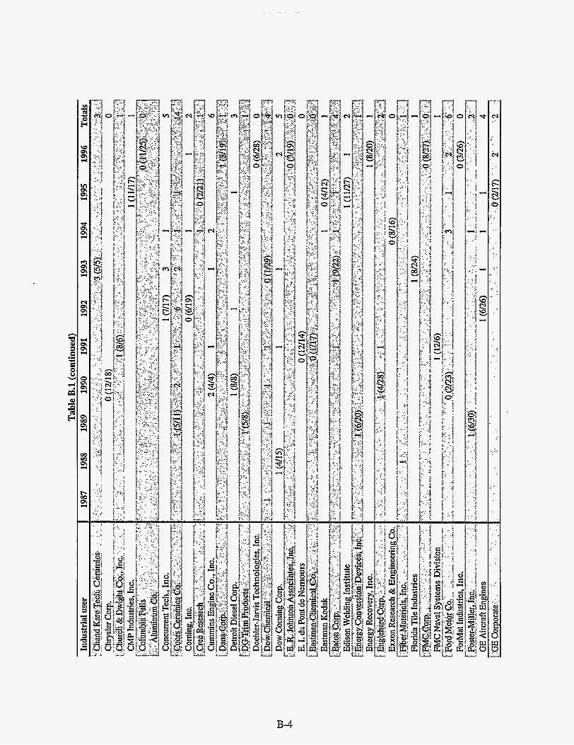

S l W U 9661 S661 P661 €661 2661 1661 0661 6861 8861 L861 (Panu!woa) T ' 8 a 1 q u
MNSM
vf a

E I 1 (zz/z> I
I
9 z z
0 (9Z/II)O
S1W.L 9661 S661 P661 €661 2661 1661 0661 6861 8861 L861 (Panu!luo4 T'ZI a1qw

United Tech. Research Ctr.
“User agreements are selected from the total list provided by the ORNL Office of Sqience and Technology Partnerships and include those companies or universities having an interest in materials. They are not necessarily agreements to work specifically with HTML.

i

1 2 2 5
2
New Jersey Institute of
Northwestern Univc

B-10

Universitv user . Table B.2 (continued)
1987 1988 1989 1990 1991 1992 1993 1994 1995 1996 Totals
1 (2/28) 1


8P 19 ES IS P9 ES IS 19 PL
I 0 I P E I I 0 E 0 0
- 661 ELI SPI 61 I L8 LS 9z S
SazEJaAV 9661 S661 P661 €661 2661 1661 0661 6861 8861 L861 , ~NJ ,H ~ t 3 sJasn ko)a!Jdo.Iduou I ~ O J , qqoJ,
uroij sIesodoJd JO 'ON

APPENDIX C
NONPROPRIETARY RESEARCH PROPOSALS
FY 1995-1996


Prop No*
Rev. 3
User center@ (* indicates lead if multiple user
Users Institution . (NO. of proposals from institution) Title of proposal (* indicates spokesperson) centers)
94-059
94-060 Rev. 1
,;,''. , ~ ~ I :, ?. ~,
94-055
94-061
. I
,~ , ~~ , I ~
~~ , 10/!?4:Review,Meeting ': , I , ' , < ' . . . , , ) I C , - I' 1 I , ' , ' ~ , , 1,' . ,
Rodel, Inc. (1) I Effects of Chemical Mechanical Polishing (CMP) on Anantha R. Sethuraman* I MAUC
94-062
McDonnell Douglas (5)
Westinghouse Electric Company (2)
94-063
94-064 94-065 Rev. I
Metal Interconnect Structures
Development of High Thermal Conductivity Carbon Fiber Composities Materials Property Evaluation of Combustion Turbine Overlay/Bond Coatings (MCrAIYs) From Room
94-066
North Carolina State University (IO)
Polytechnic University ( I )
Proposal (45) ART, Inc. (8)
94-067
Alumina Material iCarbo6ndum Monofrax M)
Electron Holography and Atom Probe Study of CoSi2- Coated and Diamond-Coated Si Field Emitters High Resolution TEM Investigation of Dislocations in Gamma Titanum Aluminides
Investigation of the Thermal and Mechanical Properties and Structural Characteristics of Diamond-Like
94-068 Rev. 1
Rev. 1
Rev. 1
94-069
94-070
94-071 Rev. 1
ART, Inc. (9)
Corning Incorporated (1)
University of Tennessee (38)
Golden Technologies Co. (1)
Alabama A&M University (2)
on the Elevated Temperature Properties and Performance of Self-Reinforced Silicon Nitrides Determination of the Physical and Chemical Characteristics of Titanium Nitride Whiskers Systhesized via a Novel Route Reliability, Fatigue, and Machining Damage Tolerance of Mica-Containing Glass-Ceramics Measurement of Stiffness and Hardness of Multiple Phase Intermetallics Analysis of Residual Stresses in GTCs Sintered Reaction Bonded Silicon Nitride (SRBSN)
Process Dependence of Orientation of Aromatic Ribbons (Fibrils) and Storage of Lithium in Glassy Carbon
I Temperature to 1650°F I Compressive Creep Testing of Fusion Cast Alpha-Beta PPG Industries (1)
I Nanocomposite (DLN) Thin Films I Characterization of the Effects of Manufacturing Processes University of Washington (2)
XRDUC
David A. Bowers*
Alfred A. Pallotta* MPUC
MPUC Dr. George A Pecoraro* Gary Hughes Dr. Michael Tenhover Dr. John Hren* MAUC Alline Frances Myers I Sung H. Whang* MAUC Zhong-Min Wang PROPRIETARY MPUC Arvind Goel* MPUC
I MAUC XRDUC
Michael G. Jenkins* MPUC MAUC XRDUC
Arvind Goel* MAUC Eric Groat
Dr. Kenneth Chyung* MPUC I MAUC
MPUC Peter K. Liaw* Jeffrey A. Cook MAUC Gamy J. Garvey* RSUC
XRDUC MPUC
Hossein Maleki* XRDUC D. Ila MAUC Gwyn M. Jenkins MPUC Lawrence R. Holland

Table C.l (continued)
Characterization Microstructure of Mechanically Alloyed Fe-N Powder
Effect of Thermal Exposure on Residual Stresses in TiAl
Thermal Diffusivitv Evaluation of Iron-Nickel
Prop No. _ _ _ ~ ._._
Dr. James C. Rawers* RSUC XRDUC MAUC MPUC
Jerry Allsman* RSUC Dr. Ash Thakker MAUC Dr. James J. Steman* PPUC
94-072 Rev. 1
Solution and Constriction on Polarization
Ceramic Materials Used in Aerothermodynamic Heating Determination of Heat-Transfer Properties for Glass-
94-073 Rev. 1
Rev. 1 94-074
94-075 Xunhu Dai Gregory M. Buck* PPUC 94-076
Rev. 1
94-077 Rev. 1
94-078 Rev. 1
Ceradyne, Inc. (1)
Westinghouse Electric Company (3)
Georgia Institute of Technology (22)
Carnegie Mellon University (3)
Oak Ridge National Lab (1); Metals and Ceramics Division
Phillip Morris, USA (1)
Cree Research, Inc. (1) Universal Energy Systems, Inc. (3)
Golden Technologies Company, Inc. (2)
Golden Technologies Company, Inc. (3)
94-079
Studies Evaluation of the Creepfeed Grinding Process for CMUC Improved Material Rates of Selected Ceramic Materials Dave Parmenter MPUC
Investigation of the Long-Term, High Temperature Evan M. Ludeman* MPUC Properties of a Commercially Available Continuous Ceramic Fiber-Reinforced Ceramic Matrix Composite Microstructural Characterization of Carbon-Carbon W. J. Lackey* MAUC Composites Produced by FCVI
Structural Characterization of Chemically Synthesized Prashant N. Kumta* XRDUC Cubic Spinel Phase of LiMn204 Akshay Waghray RSUC Thermal Expansion Behavior of Ceria-Stabilized Zirconia K. B. Alexander* RSUC
Robert Roy Baker*
Bijana Mikijelj
Garth B. Freeman Sundar Vaidyaraman
P. F. Becher S. Spooner Dr. Seetharama C.
John Edmond*
Rabi S. Bhattacharya*
Reaction Synthesis of FeSi2, NbSi, TiSSi3. CoSiz and a PPUC Composite of Silicideand Silicon Carbide Deevi * XRDUC TEM Analysis of Group I11 Nitrides on S i c Substrates MAUC
Surface Hardening of Polymeric Composites by High MPUC Energy Ion Irradiation Evaluation of Centerless Grinding a Cost Effective Jack Sibold* CMUC Production Process for Selected 'IT2 and SRBSN Marc Ritland CMC Components Creepfeed Grinding with COMMEC Assist of Selected Jack Sibold* CMUC CeramiclMetal Composites Marc Ritland CMC
94-080
94-08 1
94-082
94-083
94-084
94-085
94-086
Institution (No. of proposals from institution)
U.S. Bureau of Mines (2)
Rolls Royce, Inc. (1)
Martin Marietta Corporation (1)
University of Illinois at Urbana- Champaign (12) NASA Langley Research Center (3)
Title of proposal User center(s)
(* indicates lead if multiple user
centers)
Users (* indicates
spokesperson)
Electroform I Brian E. M c C l u ~ ~ I Oxygen Octahedra Distortion in Rhomhohedra PZT Solid I Dwight Viehland* PPUC

User center(s) (* indicates lead if multiple user
centers) 94-087 Eaton Manufacturing Tech Center Evaluation of Centerless Grinding a Cos! Effective Joseph A. Kovach* CMUC
(3) Production Process for SRBSN AT2 Components CMC 94-088 University of Massachusetts (2) Residual Stress Measurements in Residual Stress Karl Jakus* RSUC
Users
spokesperson) Institution Title of proposal (B indicates Prop No. (NO. of proposals from institution)
- ..- :\\ 2. ' , ' , ,,, ..- . .' ,', . ~ > , ' , .. . , .-
Strengthened Ceramic Materials .~, ~ ~ ' I 'k' , ,: : 1 I 2 s r l . .::'~'~+~ ~I <,, , 1 ld '~,,$2/94 RoView Meeting :~ , 'I ~. . . , . I ~ i( ~< ~ I~ :: I~ ,,1, ~
. _ . ;~ 1~ I I .'
I I PROPRIETARY MAUC I PROPRIETARY I MAUC
94-091 I Proposal (48) 94-092 I University of California - Berkeley F1u.x-Line Lattice Observation in Superconductors
PULLED FROM REVIEW CYCLE Investigation of Unstained Lightweight Materials by
XRDUC PROPRIETARY CMUC John Bonevich" MAUC John Clarke
MAUC David C. Joy* 94-093
I 94-095 I University of Alabama - Birmingham
(1) University of Tennessee (39)
I (7) I 94-094
I
94-096 University of Massachusctts (3)
University of Tennessee (40)
Measurement of Residual Stress Contributions to the Hardness of Ion-Implanted Alpha-Titanium Using the Nanoindenter Electron Holography and Nanoanalysis of Magnetic Thin Films of Co-Cr-Pt-P System for Hard Disk Technology HRTEM Study of Alumina Supported Bimetallic Catalysts
S. Suhanmupham XRDUC Alan W. Eberhardt" MPUC Rajesh Pandey
Changmo Sung* MAUC Ju-Hwan Choi Dr. Henry C. Foley* MAUC 94-097
1 94-100 I Advanced Refractory Technology
University of Delaware (5)
94-098 University of Delaware (6) Polyfurfuryl aicohol-Derived Carbogenic-Molecular Sieves Ultrafine-Particle Unsumorted Coal Liauefaction
Micheal S . Kane
Dr. Henrv C. Folev* MAUC 94-099
- - Electron Holography Sol-Gel Development for NicalodSiC Composites
I Bernard G. Frost I I Dr. Peter K. Liaw* PPUC
University of Delaware (7)
94-101
Made from Group 6&9 Organometallics I Te, Mure 1 HRTEM Study of Microstructure Development in I Dr. Henry C. Foley* MAUC
(10) Louisiana State University (1)
Silicon Nitride . Influence of Break Rotor Design and Heat Treatment on the Residual Stress of Gray Cast Iron Rotors
Structures of Magnesium Silicate Melts by High
Catalysts: Characteriza&n and Dispersibn I Stephen M. Case; I Thermal Conductivity Testing of AlN Fillers and AlN I ThomasMroz* PPUC
KunLi Dr. William Donlon* RSUC Dr. Gregory M. Vylete Dr. James W. Fash Subrata Ghose* XRDUC
Filled Polymers I I Measurement of Residual Stress Depth Profiles of Ground I D. T. Warren Liao* RSUC
94- 1 02 Ford Research Lab (3)
94- 103 University of Washington (3) Temperature X-Ray Diffraction Thermal Diffusivity of CeramidCeramic Composites Robert S. Kirk* PPUC
1 94-104 3M Company-The Ceramic
Textiles/ Composites Lab (1)

Table C.l (continued) I I I
94- 105 University of Washington (4)
Institution (NO. of proposals from institution)
High Temperature Investigation of Gadolinium Zirconate
Title of proposal
95-004 New Mexico Tech (5) Damage Evolution i n Metal Matrix Composites During ' Thermal Cycling
94-106 Philip Morris USA (2)
I (I,.,
, ,,~ , $$,* ,,$,! I ,y,' i.".':; ?;,>' ;<,;: =?;,$;;.yy :;,,.,/? ' 3 ' ' ' ' r,,jy'+ :>,: ?Y I,,,; $,'F ,,.,,,I ,
LI LI.
95-001 Universal Paintless Dent Repair Research & Development (UPDRR&D) (1)
95-002 University of Michigan (8)
95-003 Coors Electronic Package Co. (15)
95-005 AlliedSignal, Inc. (20)
Determination of Residual Stresses in the Cold Rolled Nickel Aluminide
Characteristics of Unbroken Paint on Dented Automobile Panels with Changes When Paintless Dent Repair is Used
, z . ,,' ;,<.* ' ,
', ,, I . ,,,,. ,,;,:,,;.;'; , 3/95'R&[&~M&tfnk ";;j;, '' :,!, ,i .;t$ ,,.. :<,,,I!,;,.
The Role of Cavitation and Other Grain Boundary Processes In Compressive Creep and Cyclic Fatigue of
Interfacial Wear of Continuous Fiber Ceramic Composites (CFCCs) due to Cyclic Fatigue Loading Characterization of the Microstructure, Diffusion Barrier, and Mechanical Properties of High-speed Gold Deposits
95-008
95-009
95-010 95-01 1
Composites by Resonant Ultrasound Spectroscopy (RUS) and Interfacial Test System Amorphous Phases in Nanostructured Materials Stevens Institute of Technology (1)
Penn State Univ. (18) High Resolution Electron Microscopy of the Heat Affected Zone of Aluminum Alloy 2195 (AI-4.0Cu-1.OLi-
Characterization of Two-Phase Boride Coatings Measurements of Surface and Near-Surface Residual
0.4Mg-0.4Ag) VPI &State Univ. (17) AlliedSignal, Inc. (21)
Richard P. Martukanitz
Eric Joseph Wuchina* M. Nanu Menon* David C. Wu
Joel D. Bumgardner*
Anthony J. Pedraza* Michael Strauss Siqi Cao
I I Close Loop Processed (CLP) NT154 Silicon Nitride 95-006 I University of Tennessee (41) I Residual Stresses in Metallic Films Deposited on Laser-
MAUC RSUC* MIRUC
MAUC
MAUC
I I Modified Alumina Substrate I Characterization of Thermal Shock Damage in Ceramic 95-007 1 University of Cincinnati (3)
95-012
95-013
. .
Surfaces STEM Analyses of Metallic Ions Released from Ni-based Alloys in Cultured Cells Laser-Enhanced Adhesion of Metallic Films to Ceramic Substrates
Mississippi State University (1)
University of Tennessee (42)
I I I Stresses in NT154 Silicon Nitride with Variously Prepared
(* indicates lead if multiple user (* indicates
Scott Meilicke I Setharama C. Deevi* PPUC
I MCAUC I XRDUC
Krishan K. Chawla* MCAUC*
David C. Wu
Anthony J. Pedraza* JaewonPark I Rai N. Sinnh* MCAUC* Umashankk 1 MIRUC Anandkumar
Traugott E. Fischer* PPUC I
Bemird Gallois I Jack Olsen I Paul R. Howell* MAUC

Q 4
GE Aircraft Engines (4)
Georgia Tech (23)
Prop No.
Determination of Residual Stresses in Single Crystal Sapphire (AI-203) Fibers Embedded in Ni-SOAI Matrix Study of Creep Deformation Zones Ahead of a Creep Crack Front Using the Nanoindenter
95-014
Tennessee State University (1)
Penn State (19)
Advanced Ceramics Research, Inc. (1) Advanced Ceramics Research, Inc. (2) Georgia Tcch (24)
Oregon Graduate Institute (2)
Oregon Graduate Institute (3)
AllicdSignal, Inc. (22)
Tuskegee University (5)
95-015
Measurement of Adhesion Strength of Coatings Using the Nanoindentation Technique
Neutron Diffraction Studies of a Variable Polarity Plasma Arc Weld (VPPAW) on Aluminum Alloy 2195 2195 (Al- 4.OCu-1 .OLi-O.4Mg-OAAg) The Thermal Diffusivity of Polymer Reinforced Fiber and Particulate Composites The Thermal Conductivity of Reaction Bonded SiUZrb2- Sic Interfacial Shear Strength Measurement of Unidirectional SiC/Si3N4 Composite Using the Nanoindenter Determination of Stainless Steel Thermophysical Properties for Use in Modeling of Pipe Girth Weldments Determination of Low Alloy Steel Thermophysical Properties for Use in Solidification Modeling of Castings Machining-Tolerant Ceramics
Fractographic Analysis of Advanced Composites Under Static and Dynamic Loading
95-016
95-017
VPI & State Univ. (1 8)
W. R. Grace & Co. (1)
95-0 18
Dynamic Characterization of the Crystallization Kinetics in Ba-Ga-Ge-0 Glasses Using High-Temperature X-Ray Diffraction Characterization of Deactivation Mechanisms in a Volatile Organic Carbon Catalyst System
95-019
95-020
95-021
95-022
95-023
95-024
95-025
95-026
95-027
Table C.l (continued) I
Institution (No. of proposals from institution) Title of proposal
PROPRIETARY
Users (* indicates
spokesperson) P. Kennard Wright*
Richard H. Norris* Ashok Saxena
M.G.S. Naylor* Suzanne Raebel Dilip K. Chaudhuri* Anathanarayanan Lakshmanan
Ding Xie Richard P. Martukanitz*
Kevin Stuffle* Hugh Denham Stephen Nowell*
Ashok Saxena* Fan Yang David G. Atteridge* Ming Li David G. Atteridge* - Ming Li Philip Whalen*
Shaik Jeelani* Peter Eshun-Dadzie Anwarul Haque Hassan Mahfuz Uday Vaidya Shyam S. Bayya*
Michael A. Peters* Cristian Libanati Douglas Tomczak
User center@) (* indicates'lead if multiple user
centers) RSUC
MCAUC
MAUC
MCAUC* MAUC
RSUC
PPUC
PPUC
MCAUC* MAUC
MCAUC PPUC
PPUC* _ _
MIRUC* MCAUC MAUC
XRDUC* PPUC
MAUC

Table C.l (continued)
Measurement of Residual Stresses in Fiber-Reinforced W/Kanthal and Particulate-Reinforced Alumina/ Aluminum Metal Matrix Composites SEM and TEM Investigations of Doped Glassy Carbon Materials SEM and TEM Investigations of Supported Metal Catalysts
Prop No.
95-028
95-029
95-030
95-03 1
95-032
95-033
95-034
. ..~ .___
Ani1 Saigal* RSUC* Gary G. Leisk XRDUC
Craig Barnes* MAUC
Craig Barnes* MAUC Martina Ralle Michael Plaver
Institution (No. of proposals from institution)
Neutron Diffraction Measurement of Residual Stress in Unirradiated Boiling Water Reactor Core Shroud Optimization of Grinding Ratio and Material Removal
Tufts University (1)
Yongsoon i h i n Stan Rosinski" RSUC
Earl Conabee* MIRUC
University of Tennessee (43)
High Resolution Microscopic Study of Copper-MFI Catalysts
University of Tenncssec (44)
Kevin W. Kirby MCAUC Jennifer Butler Haren Sakarial Gandhi* MAUC Hung-Wen Jen Cliff Montreuil Ron Baird
Sandia National Laboratory (2)
Ceradyne, Inc. (2)
Materials Thermal Conductivities of Plastic Crystals
Residual Stress Relaxation in TiAl Laminated Ceramic Composites
Multilayer Diamond Coatings
Hughes Research Labs (1)
Dhanesh Chandra" PPUC Vinod Kumar Gandikota Jerry Allsman* RSUC Krishan K. Chawla* MCAUC*
MAUC MIRUC
PPUC RSUC
MIRUC
J. Jag Kasichainula* MCAUC*
Ford Research Laboratory/Ford Motor Company (4)
'Me of proposal User center(s)
(* indicates lead if multiple user
centers)
Users (* indicates
spokesperson)
Rate for an IRBAS Material I RussRhodes I I Glenn P. Carr Glass, Ceramic, and Glass Ceramic Machining Study I J. A. Wysocki* I MIRUC*
95-036
95-037 95-038
95-039
University of Nevada-Reno (1)
Rolls Royce, Inc. (2) New Mexico Tech (6)
~~
North Carolina State (1 1)
,

Q W
Title of proposal Institution (NO. of proposals from institution) Prop No.
95-040 Louisiana State Univ. (2) Measurement of Residual Stress Profiles, Flexure Strength, and Surface Texture of Ground Ceramics
The Effects of Corrosion and Thermal Cycling. on Thermal
User center(s) (* indicates lead if multiple user
centers) T. Warren Liao* RSUC* Kun Li MAUC
MCAUC MIRUC
Users (* indicates
spokesperson)
Gary R. Pickrell* PPUC 95-041 Materials Technology of Virginia
95-042 Vanderbilt Univ. (13)
95-043
(01)
Univ. of Massachusetts (4) - NOTE ALREADY REVIEWED
95-04 Reynolds Metals Co. (01)
Study of Creep Induced Residual Stress Strengthening in Fiber Reinforced Ceramic Matrix Composites
Determination of Exfoliation Corrosion Mechanisms in 7XXX Aluminum Aircraft Alloys
~ Investigation into the Neutron Irradiation Effects on the 1
95-045 Renssclaer Polytechnic (04)
Rioardo Dommarco Karl Jakus MCAUC*
XRDUC RSUC
Mark Alan Cantrell* MAUC Chris Marks Don Steiner* MAUC
95-047 University of Illinois (13) Temperatures
Crystal Flake Reinforced Aluminum Matrix Composites Hardness Measurements of Mechanicallv Milled Nano-
Thermal Conductivity Measurement of AIBz Single
95-049 Advanced Engineered Materials, LLC (01)
Dr. Henry LaViers
Carl Deppisch Dr. William Weins* MCAUC
James Economy* PPUC
95-050 I The Carborundum Company (05) ~ Young's Modulus Determination on AZS Refractory
Properties of High Temperture Ceramic Matezals I YhgshengLu I Effect of Retained Austenite in Rolling Contact Fatigue I George T. Hahn* RSUC
MAUC Joel D. Tenney XRDUC
Dr. G.V. Srinivasan MCAUC
95-05 1 PROPRIETARY 95-052 Caterpillar, Inc. (04)
Microsiructure and Chemistry of SIC Fibers and CVD Sic I Matthew Osborne Novel Carbon-Ion Fuel Cell Electrolyte Phase Transition
I I Dr. E H. Cocks* XRDUC
Material
Residual Stress Management for Characterizing Material Response to Arc Welding
PPUC RSUC Margo E. Bubb* and
Howard W. Ludewig ..*, < , ,~ ,,:< .,, I ,;: '~ :::: ,,<,;~,~,~,,~ I *' ~ , . I ' * ~ ,I: :+ ,. ; , J I ~ I I ;, j ,u . ~ .
~ ; , ~ r $!> I, '< , I I , , ~ I _ A,,\, :, , ~:,,, S$/!&!Rcyiet%?nqctrnd.: , , , , , , ~, ,
95-053 ART, Inc. (1 3) Characterization of the Structural and Thermal Properties of Diamond-Like Nanocomposite (DLN) Thin Films
(PRE-REVIEWED) 95-054 ART, Inc. (14) Characterization of the Thermal and Mechanical
Properties of Diamond-Like Nanocomposite (DLN) Thin
Measurements of Intrinsic Film Stress, Crystallographic Texture and Crystallite Size in Sputtered Permalloy-based Thin Films
(PRE-REVIEWED) Films
(1) 95-055 Quantum Peripherals Colorado, Inc.
(PRE-REVIEWED)
Crystalline Copper Based Alloys I John D. Makinson I SHS Titanium Diboride Characterization MCAUC* I John R. Winters*
6 , ,( , .< 11,. .~ I,,, I , I t !.., ~ :< ' I e;;: ': t,<*;;:;:i:"&+ ' ; ~ , ~ ~ , , ' ; ' ~ ~ ~ ~ ; ~ ~ , ; ~ ~ " ~ ~ ~ ~ I , ~ , , , , ,, , , -- Arvind Goel* MAUC*
XRDUC Dr. Chandra Venkatraman
Arvind Goel* MAUC Dr. Daniel Kester MCAUC*
PPUC Dr. Joe Doyle* XRDUC Dr. Elliot Brown RSUC

Table C.l (continued)
Prop No* Institutlon
(NO. of proposals from institution) Title of proposal
95-056
95-057
University of Alabama (8) (PRE-REVIEWED) Films University of California-Santa
X-Ray Difraction Studies of Sputtered FeTaN and Thin
Grazing Incidence X-Ray Diffraction Study of Microstrain
95-058 Barbara University of Virginia (01)
Field Beneath GoldSapphire Fracture Surface Improved Thermoelectric Material for Catheters
I I
95-059
95-060
I pc
RCF Seals & Couplings, Inc. (01) Mechanical and Physical Characterization of an Elastomeric Material
Thermal Properties of Ion Beam Modified PPS, PMMA, Alabama A&M Univ. (03)
Dianne Zimnavoda Todd Parrish Dr. Robert Zimmerman* Dr. Daryush Ila
Dr. David A. Smith* Sanjay Mehta
Dr. Ying Qian*
PPUC MIRUC MAUC
MCAUC PPUC"
XRDUC MCAUC
MAUC*
95-061
95-062
95-063
95-064 95-065
Lehigh University (1) Evaluation of Hardness (as a Function of Grain Size) and Elastic Moduli of Electrodeposited Nanocrystalline Nickel by Nanoindentation Technique Ion-Beam-Induced Changes in the Optical Properties of M,O Chemical and Mechanical Characterization of Metal- Ceramic Coating Systems
Alabama A&M Univ. (04)
N.C. State Univ. (12)
PROPRIETARY Alabama A&M Univ. (05) Analysis of Ion Beam Modified PVDC and PE Polymers
95-066
(* indicates.lead if multiple user (* Indicates
Edison Welding Institution (01) Determination of Residual Stresses in Aluminum Weldment Using Neutron Diffraction Method
Lajos Varga- I Prof. David R. Clarke* I RSUC
95-067 Alabama A&M Univ. (06)
Don M. Lipkin Dr. William A. Jesser* I PPUC
TEM and XRD Analysis of Ion Implanted LiNb03
Martin H. Ettenberg Jack M. Kramer* MCAUC*
I
95-068 Louisiana State Univ. (03) Assessment of Wheel Conditions with Sensor Signals in Grinding of Advanced Ceramics
Daryush lla 1 XRDUC Dr. Robert Davis* XRDUC*
95-069
95-070
Kimberly Gruss Robert James
Dr. Daryush Ila* Leslie Evelyn MCAUC
'hfts Univ. (02) Microstructure-Mechanical Property Relationships in Forgins
Investigation Into Neutron Irradition Effects on the Microstructure of S i c Fibers and CVD S i c via Analysis of XRD Data by the Warren-Averbach Method
Rensselaer Polytechnic Institute (05)
I PPUC* Zhili Feng* RSUC Pan Michaleris
Charles E. Graham* Warren Liao MCAUC Kun Li I MIRUC* Ani1 Sainal* MAUC two students I MCAUC
I RSUC* Don Steiner* XRDUC
I Matthew Osborne
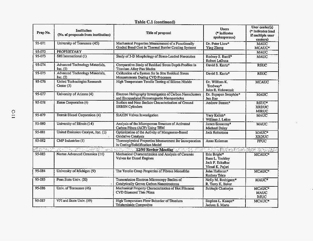
? c-, c-,
Table C.l (continued) I I I I User centerM
Prop No.
95-071
95-072 95-073
95-074
95-075
95-076
95-077
95-078
95-079
95-080
95-081
95-082
95-084
95-085
95-086
.. (* indicates lead Institution
(NO. of proposals from institution) Title of proposal
1 Advanced Technology Mat
MIRUC Detroit Diesel Corporation (4) SiAlON Valves Investigation Yury Kalish* MAUC
University of Illinois (14)
United Emission Catalyst, Inc. (1)
CMP Industries (1)
University of Michigan (9)
Analysis of the Microporous Structure of Activated Carbon Fibers (ACF) Using TEM Optimization of the Activity of Manganese-Based Oxidative Catalysts Thermopliysical Properties Mcasuremcnt for Incorporation in CastindSolidification Model
Mechanical Characterization and Analysis of Ceramic Valves for Diesel Engines
. I I
>,, . ; ,~ ',::~.;. ,;,:"y,,, :.;, :: ',:
The Tensile Creep Properties of Fibrous Monoliths
Penn State Univ. (20)
Univ. of Tennessee (46)
Transmission Electron Microscopy Studies of
Mechanical Property Characterization of Hot Filament CVD Diamond Thin Films
* Catalytically Grown Carbon Nanostructures
Wiliiam J. Lakso James Economy* MAUC Michael Daley Jack Robertson MAUC*
XRDUC Anne Koleman PPUC
Rodney Trice I Nelly M. Rodrinuez" MAUC* R. T&ry K. Bakcr I Subhaiit Chatteriee MCAUC*
I MAUC RSUC
Stephen L. Kampe* MCAUC* 95-087 VPI and State Univ. (19) High Temperature Flow Behavior of Titanium Trialuminide Composites Judson S. Marte

Prop No.
95-088 Study of Physical and Mechanical Properties of CVD Hard Coatings on Cutting Tools and Modeling of Mechanical Behavior of Multilayer Coated Cutting Tools in Machining Applications
Thermal Diffusivity of Advanced PVD Thermal Barrier Coatings
95-089 95-090
- _._ - -_ - MCAUC* Deepak G. Bhat*
Krishnan Narasimhan . MAUC PPUC RSUC
MIRUC PPUC*
Jeff Smith* PPUC* Albert Feuerstein Ken Miimhv
95-091 95-092
95-093 - - Channel Angular Extrusion
Thermal Conductivity of Porous, Nanocrystalline 3mol% Yttria Stabilized Tetragonal Zirconia High Temperature X-Ray Studies of Quasicrystalline Ti- Zr-Ni Alloys
Ceramic Materials
Green Machining of NZP Gel-Cast Parts
Microscopic Estimation of Structure-Transport Property in
Study of Crack Propagation Behavior as a Function of Mismatch in Matrix and Reinforcement Properties, Microstructure, and Loading Conditions Characterization of Fine-Fraction Mineralogy for Comparison with Magnetic Susceptibility Variations in
95-094
95-095
- Dr. R. Goforth Max Gibbs Dr. Merrilea J. Mayo* PPUC" Susanne M. Ferrell Ken Kelton* Rhonda Stroud Paul F. Johnson* PPUC*
MAUC graduate student MIRUC
Jack Jian Zheng* MIRUC* Brian Jaensch MCAUC Christy Smith MAUC Dr. Burton R. Patterson* MCAUC*
XRDUC*
Dr. Ellen A. Cowan* XRDUC* Stephanie Cartee
95-096
95-097
95-098
95-099
95-100
Institution (No. of proposals from institution)
Valenite, Inc. (3)
PROPRIETARY Howmet Corporation (2)
Univ. of Minnesota (3) Georgia Tech (25)
Texas A&M (2)
Penn State (21)
Washington Univ. (1)
Alfred Univ. (8)
LoTEC, Inc. (1)
Univ. of Alabama-Birmingham (9)
Appalachian State Univ. (I)
Clemson University (15)
Table C.l (continued)
Title of proposal User center(s)
(* indicates lead if multiple user
centers)
Users (* indicates
spokesperson)
X-Ray Diffractometry of Pharmaceutical Hydrates I Raj Suryanarayanan I XRDUC* The Effective Thermal Conductivity of Damaged I Dr. David McDowell* I PPUC* Composites I Samuel Graham I MAUC Texture in Cubic Metals Processed Through Equal I Dr. K.T. Hartwig* RSUC*
Glacial Marine Sediment Nanohardness of Carbon FiberEpoxy Composites
I Dr.-Neil E. Johnson I John M. Kennedy*
I MCAUC*

Prop No.
. ,
Institution (No. of proposals from institution)
User center@) Title of proposal (* indicates (* indicates lead if multiple user
centers)
Users
spokesperson)
96-002
96-003
96-004 96-005
96-006
96-007
96-008 96-009
96-010 96-01 1
University of Delaware (8) Micro-Mechanical Property Studies of Hard- CoatingISubstrate System using Nanoindentation
Microstructural Characterization of Bulk Nanocomposites Louisiana State University (4)
PROPRIETARY University of Kentucky (9)
Kansas State University (1)
Dow Corning Corporation (4)
Dctcrmination of Iron CarbidclOxide Phases Using HRTEM Compositional and Morphological Investigation of Diamond-Cubic Boron Nitride Alloys Characterization of CMC Materials after Oxidative Exposure
Heat Pipes for Material Processing at 2000°C Transmission Electron Microscopy of Nanometer-Scale Inorganic Components in Coal and Char Enriched in Selected Organic Microstructures PROPRIETARY Structural Stabilitv of CoDocr Based Nanocrvstalline Binarv
Thermacore, Inc. (3) Univ. of N. Dakota Energy and Environ. Res. Center (1)
Universitv of Nebraska (2)
96-012
Tsu-Wei Chou* Erik T. Thostensen Alex Hsieh Evan Ma* Li He
Burton H. Davis* Ram Srinivasan James H. Edgar* Zhiyong Xie Timothy E. Easler*
. _ Alloys Containing Gold, Nickel, and Iron Cryogenic Treatment of Tool Steels
- Purdue University- Calumet (1)
Joseph Bland* John Hurley* Chad G. Tomforde Frank R. Karner
Steve Axtell* John D. Makinson Harvey Abramowitz Dan Bly Mark Eningenburg Patricia Martinez Burton H. Davis* Ram Srinivasan Daryush Ila* Thomas Taylor
96-0 13
96-014
96-015
96-016 96-017
;,, , I ~ * A I _
PPUC* DUC
University of Kentucky (10)
Alabama A&M Univcrsity (7)
High Temperature X-Ray Diffraction Studies of Metals Promoted ZrOl X-Ray Study of MeV Ion Bombarded GaAdAlGaAs Quantum Layers.
Sol-Gel Derived Interfacial Coatings for NicalodSiC and NexteYSiC Composite Systems Optimization of Ni-Cr Films for Electrical Resistors Scanning Auger Spectroscopic Analysis of Grain Boundary Segregation in the Service Exposed Cr-Mo Steel Steam Piping Materials
University of Tenncssce (47)
Vamistor Corporation (1) University of Tennessee (48)
MAUC MCAUC*
MAUC*
MIRUC* MAUC*
MAUC*
MAUC* MCAUC PPUC MAUC* MAUC*
MAUC* PPUC* MCAUC DUC* RSUC
DUC*
RSUC* DUC MAUC
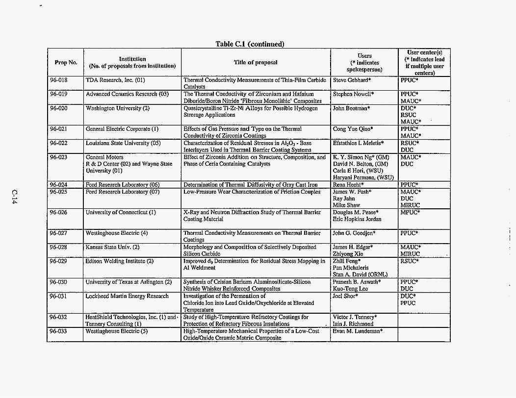
Table C.l (continued) I I I
96-018
96-019
Institution 1 Prop No' I (No. of proposals from institution)
TDA Research, Inc. (01)
Advanced Ceramics Research (03)
Thermal Conductivity Measurements of Thin-Film Carbide Catalysts The Thermal Conductivity o f Zirconium and Hafnium
Title of proposal
96-021
Strorage Applications
Effects of Gas Pressure and Type on the Thermal General Electric Corporate (1)
I I DiboriddBoron Nitride 'Fibrous Monolithic' Composites 96-020 I Washington University (2) I Quasicrystalline Ti-Zr-Ni Alloys for Possible Hydrogen
96-023
96-024 96-025
96-026
96-027
96-028
96-029
96-030
96-03 1
96-032
96-033
- . - Interlayers Used in Thermal Barrier Coating Systems Effect of Zirconia Addition o n Structure, Composition, and Phase of Ceria Containing Catalysts
General Motors R & D Center (02) and Wayne State University (01)
Ford Research Laboratory (06) Ford Research Laboratory (07)
Determination of Thermal Diffusivity of Gray Cast Iron Low-Pressure Wear Characterization of Friction Couples
University of Connecticut (1) X-Ray and Neutron Diffraction Study of Thermal Barrier Coating Material
Thermal Conductivity Measurements on Thermal Barrier Coatings Morphology and Composition of Selectively Deposited Silicon Carbide Improved do Determination for Residual Stress Mapping in AI Weldment
Synthesis of Celsian Barium Aluminosilicate-Silicon Nitride Whisker Reinforced Composites Investigation of the Permeation of Chloride Ion into Lead Oxide/Oxychloride at Elevated Temperature
Heatshield Technologies, Inc. (1) and. Study of High-Temperature Refractory Coatings for Tennery Consulting (1) Protection of Refractory Fibrous Insulations Westinghouse Electric (5) High-Temperature Mechanical Properties of a Low-Cost
Westinghouse Electric (4)
Kansas State Univ. (2)
Edison Welding Institute (2)
University of Texas at Arlington (2)
Lockheed Martin Energy Research
I I Conductivity of Zirconia Coatings 96-022 I Louisiana State University (05) I Characterization of Residual Stresses in A1203 - Base
I I I I OxlddOxfde Ceramic Matric Comiosite
Users (* indicates
spokesperson)
Steve Gebhard*
Stephen Nowell*
John Boatman*
Cong Yue Qiao*
Efstathios I. Meletis"
K. Y. Simon Ng* (GM) David N. Belton, (GM) Carla E Hori, (WSU) Haryani Permana, (WSU) Rena Hecht* James W. Fash* Ray Jahn M;ke Shaw Douglas M. Pease* Erickopkins Jordan
John G. Goedjen*
James H. Edgar* Zhiyong Xie- Zhili Fern* Pan Michaleris Stan A. David (ORNL) Pranesh B. Aswath* Kuo-Tong Lee Joel Shor*
Victor J. Tennery* Iain J. Richmond Evan M. Lundeman*
User center(s) (* indicates lead if multiple user
centers) PPUC*
PPUC* MAUC* DUC* RSUC MAUC* '
PPUC* MAUC* RSUC* DUC MAUC* DUC
PPUC* MAUC* DUC MIRUC MPUC*
PPUC'
MAUC* MIRUC RSUC*
PPUC* DUC DUC* PPUC

Table C.l (continued) I I I User center(s)
(* indicates lead if multiple user
centers) MPUC*
Prop No. Users
(* indicates spokesperson)
Institution (No. of proposals from institution) Title of proposal
96-034 Westinghouse Electric (6) Investigation of the Efect of Water Vapor and Sodium Slulfate on the Creep Rupture and Fatigue Behavior of
Evan M. Lundeman*
Heidi D. Allison Jose Escobar Norman L. Hecht* Ahmad H. Lubis Punit Boolchand* W. J. Bresser Xingwei Feng Richard G. Rateick, Jr. * Steve Daniewicz* Sean Cummings Pavadee Aungkavattana*
96-036 University of Dayton (4)
University of Cincinnati (04)
The Investigation of Selected Compositions from Sic-ALN Solid Solution An Atomic Scale Understanding of the Role of Alkali- Oxides in Softening Networks of Oxide Glasses
MAUC*
MCAUC* 96-037
96-038 96-039
AlliedSimal Inc. 123) Residual Stress in Bimetallic Hydraulic Rotors Characterization of a Water Peening Process
RSUC* RSUC* Mississippi State University (02)
Pennsylvania State University (22) 96-040 Crystallization Kinetics of PZT Thin Films by In Situ X- DUC*
I I Coatings Campero* Corporate Research & Development (2) University of Wisconsin at Milwaukee (3) Technology of Energy Corp. (1)
96-042
96-043
Residual Stress Analysis in Cryogentically Treated Steels Terry L. Barr* John J. Bruckner E. B. S. Pardue"
DUC*
DUC* Neutron Scattering Residual Stress Measurement of Reference Test Piece For Residual Stress Techniques
Derived Ceramic Matrix Composite I I PROPRIETARY I PPUC* 96-045
96-046 Dana Corp. (1) Treatment, and Finishing Method on the Friction and Wear Russ Hite - of Cam Shafts AIIOYS Life Determination of Thermal Barrier Coatings in Fatigue 96-047 Westinghouse Corp.
(7) 96-048 PROPRIETARY
High-Precision Grinding of 99.5 % Alumina Rotor With DUC*
Leif J. Hauge* MIRUC* 96-049 Energy Recovery, Inc. ( I )

r Prop No.
96-050
96-051 F 96-052
96-054
Institution (No. of proposals from institution)
Cercom, Inc. (2)
Caterpillar, Inc. (5 )
Southern Illinois University (2)
Michigan State University (2)
Corning, Inc. (2)
Scientific Ecology Group (SEG)
Table C.l (continued)
Title of proposal
Thermomechanical Properties of High-Purity, Hot Pressed Aluminum Nityride
Cost-Effective Machining of Silicon Titride Diesel Engine Components Determination of Near-Surface Mechanical Properties of Carbon Fiber Reinforced Carbon Using Nanoindentation Techniques Investigation of Flash Heating Penetration in Semitransparent Materials Measure Stress Gradients in Metal Refractorv Films on Glass Substrates Three-Body Abrasive Wear of Materials and Coatings for Use in a D j Journal Bearing
Users (* indicates
spokesperson) James Chienc Shih* Andre Ezis
Michael Harris Haselkom"
David Marx*
James V. Beck* Robert L. McMasters Hans J. Holland*
Jamcs Tilghmon Duncan* Jonathan David Lass Randall Martin Lott
User center@) (* indicates lead If multiple user
centers) MCAU* MAUC PPUC MIRUC*
MCAUC"
PPUC"
RSUC*
MIR:-FWA*
I
i

APPENDMD
RESEARCH PROJECT S U M M A R I E S
FY 1995-1996


D. RESEARCH PROJECT SUMMARIES
D.1 INDUSTRIAL USER PROJECTS
D.l.l Advanced Ceramic Research, Inc., “The Thermal Conductivity of Reaction Bonded SiC/ZrB2-SiC Fiber Composites,” S. Nowell, HTML No. 95-020
TPUC
Continuous fiber ceramic composite (CFCC) materials were developed at Advanced Ceramic Research, Inc. (ACR) for high-temperature applications in the aerospace industry. Thermal conductivity of the composites is very difficult to predict because of the uncertainties of the degree of reaction between the fibers and the matrix; it can also be reduced by matrix microcracking. ACR’s S ic fibedRBSiC-ZrB2 composite was used in this study. Thermal difisivity of monolithic samples and fiber composites with different fiber orientations were measured by laser flash technique.
thermal diffusivity using the room-temperature (RT) xenon flash system. The results were very consistent among duplicates. Thermal diffusivity of 35 vol % Sic fiber and 20 vol % RBSiC-ZrB2 was 0.1469 cm2/s when the fibers were perpendicular to the direction of heat flow; the difisivity value increased 25% to 0.1834 cm2/s when the fibers were parallel to the direction of heat flow. High-temperature thermal diffusivity measurements were conducted on the new laser flash system. Figure D.l shows the thermal diffusivity of two typical composites along with a graphite standard (SRM 8425). Measurements from 100 to 5OOOC were performed in the aluminum furnace and continued from 600 to 1500°C in the graphite furnace. The results showed that the laser flash technique can be used to monitor the quality of CFCC materials.
Monolithic RBSiC-ZrB2 samples and SiC/RBSiC-ZrBZ fiber composites were first characterized for
0.6
0.5
0.4
0.3
0.2
0.1
0
A A
0 500 1000 1500 2000
Temperature (“C)
A
Fig. D.l. Thermal diffusivity of two CFCC materials and a graphite standard
D-3
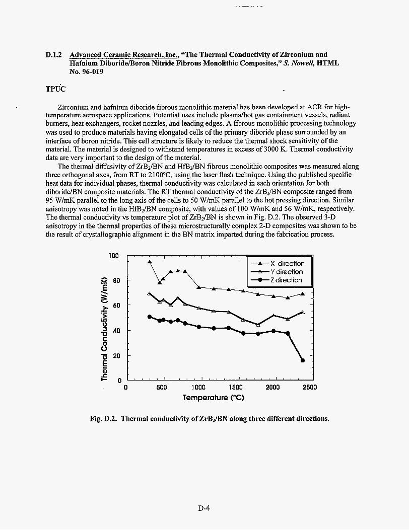
D.1.2 Advanced Ceramic Research, Inc., "The Thermal Conductivity of Zirconium and Hafnium Diboride/Boron Nitride Fibrous Monolithic Composites," S. Nowell, HTML NO. 96-019
TPUC
Zirconium and hafnium diboride fibrous monolithic material has been developed at ACR for high- temperature aerospace applications. Potential uses include plasmahot gas containment vessels, radiant burners, heat exchangers, rocket nozzles, and leading edges. A fibrous monolithic processing technology was used to produce materials having elongated cells of the primary diboride phase surrounded by an interface of boron nitride. This cell structure is likely to reduce the thermal shock sensitivity of the material. The material is designed to withstand temperatures in excess of 3000 K. Thermal conductivity data are very important to the design of the material.
three orthogonal axes, from RT to 2 1 OO'C, using the laser flash technique. Using the published specific heat data for individual phases, thermal conductivity was calculated in each orientation for both diborideA3N composite materials. The RT thermal conductivity of the ZrB2/BN composite ranged from 95 W/mK parallel to the long axis of the cells to 50 W/mK parallel to the hot pressing direction. Similar anisotropy was noted in the HfBz/BN composite, with values of 100 W/mK and 56 W/mK, respectively. The thermal conductivity vs temperature plot of ZrB2/BN is shown in Fig. D.2. The observed 3-D anisotropy in the thermal properties of these microstructurally complex 2-D composites was shown to be the result of crystallographic alignment in the BN matrix imparted during the fabrication process.
The thermal diffusivity of ZrB?/BN and HfB?/BN fibrous monolithic composites was measured along
- 0 500 1000 1500 2000 2500
Temperature ("6)
Fig. D.2. Thermal conductivity of ZrBJBN along three different directions.
D-4

D.1.3 Advanced Refractorv Technologies, Inc., “Investigation of the Thermal and Mechanical Properties and Structural Characteristics of Diamond-Like Nanocomposites (DLN) Thin Films,” A. Goel, HTML No. 94-065
Ambient and high-temperature X-ray diffraction (XRD) were used to characterize diamond-like thin films. The RTXRD experiments showed the expected amorphous phase, but high-temperature experiments were not effective for determining the crystallization behavior. Modification of the high- temperature instrument to allow grazing-incidence studies, which are particularly surface-sensitive, is planned for further investigation of the thin films.
D.1.4 AlliedSignal Engines, “Effect of Room and Elevated Temperature Proof Testing on the Elevated Temperature Dynamic Residual Strength of AS800 Silicon Nitride,” H. T. Fang, HTML Proposal No.’93-092
MCAUC
Because of the inclusion problems discovered in 1994 in Norton Powder and the later pull-out by Norton Advanced Ceramics in 1995 from the ceramic gas turbine market, the program has been delayed and will be switched to a new material, AS800. The specimens of this new material are expected to be delivered by the end of August 1996. The results will be used to develop a proof test methodology at AlliedSignal Engines for enhancing reliability of ceramic components in gas turbines.
D.1.5 AlliedSignal Engines, “The Influence of Surface Condition on Creep Rupture of Silicon Nitride,” M. N. Menon, HTML Proposal No. 94-042
MCAUC
A problem started with creep testing of CLP NT154 silicon nitride. Because of the Norton pull-out from the ceramic gas turbine components market, this testing was stopped. The remainder of the program will be completed with a new material, AS800. Since the specimens from this new material will be delivered in September 1996, the creep testing is expected to begin again in September 1996 and will be completed by December 3 1, 1997.
AlliedSignal turbine engines. The creep data on AS800 will be used for creep life prediction of AS800 components in the
D.1.6 AlliedSignal Engines, “The Role of Cavitation and Other Grain Boundary Processes in Compressive Creep and Cyclic Fatigue of Silicon Nitrides,” M. N. Menon, HTML Proposal NO. 95-005
MAUC
The objectives of this program are to (1) conduct SEM fiactography and TEM ceramography on samples tested under compressive creep loading in order to determine creep mechanisms, and (2) conduct SEM fractography on cyclic fatigue tested samples to explore the crack initiation phenomenon. The results will be used to model compressive creep and cyclic fatigue of silicon nitrides.
To date, a few samples tested under compressive creep loading have been examined in SEM. No cavitation has been observed. This is in contrast to the extensive cavitation observed under tensile creep in a previous user program, 9 1-03 1.
D-5

. _. .
D.1.7 Allison Enpine Company, “Metal Composition on Joint Microstructure for Titanium Brazed with Ti-Cu-Ni Materials,” J . Cliartg and C. Cadden, HTML No. 93-036
RSUC/DUC/MAUC
The objective of this study was to determine the phase composition within a braze joining two different aluminum-titanium alloys. The development of joining methods for these high-performance alloys will enable improved performance of gas turbine engines. The phases in several reaction and interdiffusion layers were identified. This information will be correlated with mechanical property and TEM measurements in an effort to understand observed variations in fatigue life of such joints with subtle changes in the braze composition.
D.1.8 Caterpillar, Inc., “Residual Stress Measurement for Characterizing Material Response to Arc Welding,” M. Bubb and B. Jones, HTML No. 95-052
RSUC
The purpose of this work was to use neutron diffraction techniques to measure the residual stresses associated with restrained and unrestrained weldments. The overall goal of this project was to obtain stress measurements in fillet welds by measuring the strain in the material after welding and comparing this to an unwelded reference material. The values obtained using neutron diffraction will then be compared to other methods of measuring residual stresses.
The industrial significance of this project becomes apparent when both the fabrication method of Caterpillar products (large earth-moving equipment) and the direction that Caterpillar wants to progress towards in the future are understood. First, constraint is an important consideration in welding large structures. In the initial stages of fabrication, there is very low constraint as welded subassemblies are put together with smaller piece parts. As the subassemblies become larger, there is more constraint during fabrication, as the assembly is less likely to give; hence, the necessity to look at residual stresses associated with both constrained and unconstrained welded assemblies. Once the assemblies have been welded, they have a final machining operation which brings them to their final dimensional specifications. To save time and fabrication costs, the ability to premachine the assembly prior to welding, with no further machining operation after welding, would be preferred. For the premachining concept to work, it is essential that the residual stresses associated with welding be known so that their effects can be accounted for in the fabrication process.
This study was accomplished by first welding four samples with various welding parameters and constraints. Two of the samples were unrestrained during welding-one made with one weld pass and the other made with three weld passes. The other two were restrained during welding-one made with one weld pass and the other made with three weld passes. The four samples were then individually loaded into the fxturing device, and neutron diffraction techniques were used to measure the normal, transverse and longitudinal strains associated with various points on the sample. A new setup was required for each of the three strain components. Five through-thickness strain measurements were taken at four locations, three of which were along the weld toe, and the fourth, 25 mm from the weld toe (see Fig. D.3).
The results obtained from the experiment consist of normal, transverse, and longitudinal strain measurements for the points described. Although analysis of these data is still under way at Caterpillar, preliminary results obtained at ORNL showed many of the trends that were expected. Tensile residual stresses were seen along the edge of the weld, while those seen in the reference material were quite low. Further analysis of the results will be done to determine actual stress values based on the strain data acquired using neutron diffraction techniques.
D-6

+ 25mm S b
I 0
weld
4-
e Ref. i
e
! A
3 ‘ 70mm
12mm
Fig. D.3. Layout of locations where strain data were measured. Neutron diffraction measurements were made at five depths (point A-2 mm apart) at four different places on the surface of the plate (points 1-4). Points 1-3 were along the weld, while point 4 was further away from the weld. Also, data were taken at a reference point toward the corner of the welded specimen.
D. 1.9 CMP Industries, “Thermophysical Properties Measurement for Incorporation in Casting/Solidification Model,” A. E. Kolntait, HTML No. 95-082
TPUC
CMP Industries performs casting of nickel-based dental alloys into cast-iron permanent molds. The alloys are cast in cylinder shape, then cut into individual pieces. Up to 25% of the cut pieces contain a
D-7
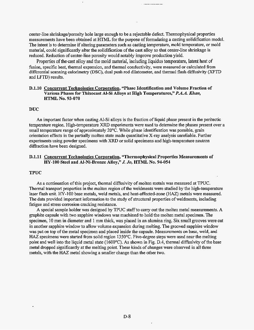
center-line shrinkage/porosity hole large enough to be a rejectable defect. Thermophysical properties measurements have been obtained at HTML for the purpose of formulating a casting solidification model. The intent is to determine if altering parameters such as casting temperature, mold temperature, or mold material, could significantly alter the solidification of the cast alloy so that center-line shrinkage is reduced. Reduction of center-line porosity would notably improve production yield.
fusion, specific heat, thermal expansion, and thermal conductivity, were measured or calculated from differential scanning calorimetry (DSC), dual push rod dilatometer, and thermal flash diffisivity (XFTD and LFTD) results.
Properties of thecast alloy and the mold material, including liquidus temperature, latent heat of
D.l.10 Concurrent Technologies Corporation, “Phase Identification and Volume Fraction of Various Phases for Thixocast Al-Si Alloys at High Temperatures,” P.A.A. KJzan, HTML NO. 93-070
DUC
An important factor when casting Al-Si alloys is the fraction of liquid phase present in the peritectic temperature region. High-temperature XRD experiments were used to determine the phases present over a small temperature range of approximately 2OOC. While phase identification was possible, grain orientation effects in the partially molten state made quantitative X-ray analysis unreliable. Further experiments using powder specimens with XRD or solid specimens and high-temperature neutron diffraction have been designed.
D.l . l l Concurrent Technologies Cornoration, “Thermophysical Properties Measurements of HY-100 Steel and Al-Ni-Bronze Alloy,” J . Jo, HTML No. 94-054
TPUC
As a continuation of this project, thermal diffisivity of molten metals was measured at TPUC. Thermal transport properties in the molten region of the weldments were studied by the high-temperature laser flash unit. HY-100 base metals, weld metals, and heat-affected-zone (HAZ) metals were measured. The data provided important information to the study of structural properties of weldments, including fatigue and stress corrosion cracking resistance.
A special sample holder was designed by TPUC staff to carry out the molten metal measurements. A graphite capsule with two sapphire windows was machined to hold the molten metal specimen. The specimen, 10 mm in diameter and 1 mm thick, was placed in an alumina ring. Six small grooves were cut in another sapphire window to allow volume expansion during melting. The grooved sapphire window was put on top of the metal spec.imen and placed inside the capsule. Measurements on base, weld, and HAZ specimens were started from solid region 1350°C. Five-degree steps were used near the melting point and well into the liquid metal state (1 6OOOC). As shown in Fig. D.4, thermal diffbsivity of the base metal dropped significantly at the melting point. These kinds of changes were observed in all three metals, with the HAZ metal showing a smaller change than the other two.
D-8

0.1 0
0.090
0.080 u)
N+ E 0.070 0 v 5 0.060 > 2 0.050
.-
.I
E n 0.040 I a E 0.030
E c 0.020
3
x X X
. 1350 1400 1450 1500 1550 1600
Temperature (“C)
Fig. D.4. Thermal diffusivity vs temperature of molten metal measurement of the base metal.
D.1.12 Coors Electronic PackaEe Company, “Characterization of Gold Microstructure to Limit Nickel Diffusion and Improve Functional Performance,” W. K. Baxter and E. D. Winters, HTML Proposal No. 93-098
MAUC/MCAUC/DUC
Multilayer ceramic packages for integrated circuits, such as those manufactured by Coors, commonly use thick-film tungsten metallization overlaid with a Ni/Au plated finish. The major problem with the Ni/Au finish is that, upon heating, Ni diffuses to the top surface of the gold, where it is subsequently oxidized. Nickel oxide on the gold surface can interfere with die-bonding, wire-bonding, lid sealing, and soldering. Because the rate at which nickel arrives at, and NiO forms on, the gold surface is relatively rapid compared with that predicted from bulk diffusion rates, a grain-boundary difision model for this transport of nickel through the deposited gold layer has been proposed and confirmed by other investigators. If grain-boundary diffusion is the predominant mechanism by which nickel is transported, the extent of grain boundary diffusion should depend upon the grain structure of the gold.
A higher density of grain boundaries should mean a greater density of paths for diffusion. On this basis, nickel should diffuse faster through a fine-grained structure than through a coarse-grained deposit, assuming that the degree of cohesion and misorientation between grains was equivalent.
In this study, the relationship between functional performance, nickel diffusion rate, and gold microstructure was examined. The extent of nickel diffusion through, as well as the distribution of NiO upon, several electrolytic and electroless gold finishes was determined by auger electron spectroscopy (AES). The results were correlated with differences in the gold microstructures determined by scanning electron microscopy (SEM), atomic force microscopy (AFM), and XRD.
D-9

This study determined that there are significant differences in performance and microstructure among the gold finishes examined. In general, deposits characterized by large, faceted, randomly oriented grains in the 1- to 5-pm range demonstrated the best performance. Direct evidence was obtained which showed that large grains of this type remain nickel-free during heating. The small ( ~ 0 . 1 pm) 4 1 I > crystallites present in all these deposits were also larger for the better performing finishes. Grain size alone, however, was not sufficient to explain all that was observed. The size of nickel-free gold regions identified by AES nickel distribution maps was in some cases larger than the estimated grain sizes found on the gold surfaces.
gold layer also influences the nickel and NiO distribution on the gold surface. Indeed, controlling grain boundary structure may be as important as grain size in producing a gold layer that will attenuate nickel diffusion and maintain good functional performance of the package finish.
packages that is capable of routinely meeting the functional requirements of bondability, sealability, and solderability. In the course of the investigation, a problem of poor adhesion of the plated Ni/Au layer was investigated. The cause of the problem was identified by AES and SPS as organic contamination (mounting wax) introduced during a process step prior to Ni/Au plating. Better maintenance of preplating cleaning processes eliminated the problem.
The results suggested that, in addition to grain size, the structure of the grain boundaries in the plated
This study resulted in the identification of a Ni/Au finishing process for multilayer ceramic IC
D.1.13 Advanced Industrial Materials Program, Office of Industrial Technologies, DOE Energy Efficiency and Renewable Enerm, “Composite Tube Project,” X L. Wang, E. A. Payzant, and C. R. Hubbard
DOE, RSUC
Black liquor recovery boilers are a critical component in Kraft pulp mills. They provide a means for the mills to recover chemicals used in the pulping process and to produce process steam, which generates a significant portion of the electricity required for mill operation. Metal tubes are an essential part of a recovery.boiler, composing the floor, walls, roof, and the superheater. Much of the metal tubing is carbon steel, but because the boiler atmosphere is quite corrosive, composite tubing of stainless steel on carbon steel is used in some areas to provide additional corrosion resistance. While the use of composite tubes has solved most of the corrosion problems experienced by carbon steel tubes, significant cracking has been reported in the stainless steel layer of composite tubes subjected to service.
Stress corrosion and thermal fatigue are being considered as the leading causes for the observed cracking. The residual stress task is to help identify the mechanism of cracking and provide input as well as validation for the finite element modeling task. Because the project is addressing such an important problem in the pulp and paper industry, it has received strong support not only from paper companies but also from boiler manufacturers and tubing suppliers. The participating paper companies include Weyerhaeuser, International Paper, and Georgia Pacific from the paper mills; Babcox & Wilcox and Combustion Engineering from the boiler manufacturers; and Sandvik and Welding Services from the tube suppliers.
Significant accomplishments achieved last year include the following: (1) developed an X-ray technique for high precision surface residual stress measurements in composite tubes, which may facilitate on-site residual stress measurements; (2) determined surface residual stresses in Sandvik composite tubes of different size and clad alloy combinations; (3) determined residual stresses in exposed tubes, which provided insight on the effects of service temperature and load; and (4) characterized the residual stress distribution in spiral weld overlay tubes (see Fig. D.5) and compared the results with those from finite element modeling (FEM).
Figures D.5 and D.6 show a highlighted accomplishment on weld overlay tubes. Spiral weld overlay tubing is being considered as a replacement for composite tubes. Large tensile residual stresses has been
D-10

found not only in the weld overlay layer but also in the heat-affected zone of the carbon steel. This result indicates that weld overlay tubes are susceptible to stress-corrosion cracking and may not be a good a candidate for applications in corrosive environments. As shown by Fig. D.6, the finite element modeling results are in satisfactory agreement with the experimental data, although the hoop stress, Dee, seems to have been overestimated by FEM.
Next year, we plan to carry out measurements in an as-welded composite tube panel to determine the residual stresses as a result of welding. A 20-ft, five-tube panel is being built, from which sections will be cut. One section will be used for residual stress analysis. X-ray and neutron diffraction measurements will be made at key locations suggested by FEM results. Another section will be subjected to thermal cycling under load. X-ray residual stress measurements will be made at the crown of the panel before the test and periodically during cycling testing to study the evolution of residual stresses due to exposure. The experimental data will also be used to validate the FEM currently being developed and provide guidance to improve the model. On-site X-ray measurements will also be pursued in this quarter.
The knowledge and measurement methodology developed here can be used to address residual stress problems in similar materials systems. In fact, a user proposal has been received calling for the study of residual stresses in thermally sprayed engine cylinders.
a a 3
P T a
I
- n I - t
Fig. D.5. Schematic of a spiral weld overlay specimen used for neutron diffraction residual stress measurements. Dimensions in mm.
600 . . . . . . . . . . . . . . . . . . . . . . . . . . . . . . . . . . . . . . 400
200
0
-200
-400 600
400
200
0
-200
BOO r . . , . . . . , . . . . , . . . . , . . . . , . . . . . . . . , . . . . , . I
200
-200 O G ]
-400 .5 4 -3 -2 -1 0 1 2
Fig. D.6. Residual stresses in the weld overlay tube. The dashed lines are calculations from a finite element analysis: o,, Gee, and err represent the axial, hoop, and radial stresses, respectively.
D-11

D.1.14 Advanced Industrial Materials Program, Office of Industrial Technologies DOE Enerq Efficiency and Renewable Energy, “FeAl Weld Overlay on Steel,” X. L. Wang and S. Spooner
DOE, RSUC
During FY 1996, a small portion of Neutron Residual Stress Facility’s (NRSF’s) beam time was allocated for the FeAl weld overlay project funded by the Advanced Industrial Materials Program of Energy Efficiency. FeAl alloys have been shown to exhibit outstanding high-temperature oxidation/ corrosion resistance and therefore have great potential for use as corrosion-resistant cladding in a variety of high-temperature structural applications. Recently, several FeAl alloys have been developed with improved mechanical behavior and weldability. However, producing a crack-free cladding on, for example, a steel substrate has proven to be a challenging task. In general, special preheat and postweld heat treatments are required. Earlier welding research revealed that, while there was no hot-cracking during welding, substantial cold-cracking occurred during cooling of the weld overlay. This observation points to the residual stresses that developed during cooling of the weld deposit. To understand the nature and development of these residual stresses, a systematic investigation combining nondestructive neutron diffraction measurements and FEM has been initiated. The goal is to develop a predictive model for estimation of residual stresses and for optimizing a welding process that would lead to reduced residual stresses.
A model system with a short single-pass FeAl weld deposited on a 2% Cr-1Mo steel substrate was studied (see Fig. D.7). Through-thickness measurements made at the center of the weld revealed large tensile residual stresses not only in the FeAl weld metal but also in the top surface layer of the steel substrate. Detailed strain maps were obtained at 2-mm depth in the steel substrate (see Fig. D.8). The measured residual strains exhibit a strong spatial dependence along the weld direction, especially in the vicinity of the weld ends. In addition, the strain profiles are asymmetric with respect to the midsection of the weld. These features cannot be described within the context of a conventional 2-D cross-sectional model. To model these experimental data, a 3-D finite element analysis had to be implemented. The 3-D FEM was based on an uncoupled formulation. Special user subroutines were developed to facilitate the simulation of continuous deposition of the filler metal during welding. Using this model, key features of the experimental data are well reproduced. One characteristic of the 3-D model is the prediction of a significant in-plane shear stress/strain near the weld ends. Subsequent neutron diffraction measurements made in these regions confirmed this prediction, providing further proof of the validity of this FEM. Nonetheless, the model needs improvement to achieve quantitative agreement with the experimentally determined strain values.
understanding and methods for strain tensor analysis developed in this study can also be used to address residual stresses in welding repair situations.
The problems encountered here are common in research of weld overlay applications. In addition, the
D.1.15 DOE-BES, Oak Ridge National Laboratow, “Materials Joining Project,” S. Spooner
RSUC
A direct attack on the fundamental understanding of residual stresses in welds combines spatial mapping of residual stresses with calculations, usually done with FEM. Because thermophysical properties must be interpolated over the complex conditions met in welding, experimental validation of residual stresses is an essential step in effectively bringing FEM calculations to bear on welding problems. In the course of investigating FeAl weld overlays on cast iron, FEM calculations pointed to significant shear stresses near the ends of the overlay weld pass. The measurement of shear stresses cannot be done directly by the diffraction method. A full tensor determination is required, which calls strain measurements beyond the three orthogonal strain set that is often used in weld analysis. In the
D-12

present case, FEM calculations indicated that the system was in a state of plane strain. The non-zero strain measurements lay in the plane of the plate. The strain mapping in the plate concentrated on points in the base metal near one end of the weld overlay. At each point, at least six diffraction vector orientations were used to define the planar strain components. The mapping was done at 2-mm and 4-mm depths, and no significant variations in the tensor with depth were found. The orientations for the maximum and minimum strains changed by nearly 90" in moving from the mid-weld position to the weld-end, and these observations were consistent with the calculated emergence of a large shear strain near the end of the
greatly improved the statistical accuracy of the strain measurements. weld pass, The neutron scattering measurements were carried out with the seven-detector array, which
Millmeters 0 10 20 30 u
Fig. D.7. Schematics of the weld overlay specimen used for residual stress analysis.
FEM Results
.So do io -io -io i i o io i i M x.m
-10 -5 0 5 10 Strain x1O.ooO
Fig. D.8. Longitudinal residual strain (E~.J distribution at 2 mm depth from the interface.
D-13

D.1.16 Eastman Kodak Company, “Residual Stress Measurement of Coated Photographic Product Using X Ray,” T. Blantun, HTML No. 94-050
RSUC
The objective of this study was to develop a methodology to analyze the residual stress in silver halide-gelatin emulsions and to determine how different drying conditions can affect these residual stresses in coated photographic emulsions. These stresses, caused by differences in humidity from the package to ambient air, cause bowing of the photographic film sheets, which then jam in the handling machines. Two specimens containing randomly oriented AgI0.03Bro.97 grains coated on polyethylene terephthalate (PET) were examined. One film was coated using gelatin (EN), the other with gelatin and latex (EIR-LX). Method development for residual stress determination in these samples was successful. Residual stress calculations found an equi-biaxial stress state in both EIR and EIR-LX of 55(*12) and 34(*4) MPa, respectively. The presence of latex reduces residual stress in these film specimens. A future
. visit is planned by Eastman Kodak to perform the remaining experiments required to complete the EIR and EIR-LX work.
D.1.17 Edison Welding Institute, “Determination of Residual Stresses in Aluminum Weldment Using Neutron Diffraction Method,” 2. Feng and P. Midtaleris, RTML No. 95-066
RSUC
The objective of this research was to understand the residual stress distribution in thick-section aluminum weldments. Computational modeling work was conducted at Edison Welding Institute (EWI) to investigate the residual stress fields in the welding fabrication of aluminum armored vehicles. Due to the use of undermatching filler metal and the metallurgical changes in the heat-affected zone and fusion zone during the multipass welding process, there were uncertainties in the calculated residual stress levels in the fusion zone. It was anticipated that the neutron diffraction strain measurements would assist EWI to improve the computational models.
A 1-in. thick AI-25 19 plate (24 in. long, 18 in. wide) welded in six passes using AI-221 9 filler metal was examined. Neutron diffraction measurements were conduced to determine the elastic strains (or the lattice strains) in the fusion zone, heat-affected zone, and base metal to characterize the residual stresses as a function of distance from the fusion line. Residual stress variations in the plate thickness direction were also investigated. Three orthogonal lattice strain components-the longitudinal, transverse (with respect to the weld direction), and normal (to the plate surface) strains-were mapped on a transverse cross-section plane around the middle span of the plate. The data in Fig. D.9 have been corrected for a shift in the stress-free interplanar spacing due to the compositional change in the fusion zone.
good agreement with those of computational analysis conducted at EWI. In particular, a double-peak feature across the weld center line predicted by the finite element analysis was clearly observed in the neutron diffraction test (see Fig. D.9). In addition, for the residual stress distributions on the surface of the welded plate, the neutron diffraction results compared very well with these independently measured at EWI using the blind-hole drilling technique. The magnitudes of the strains are very consistent between the finite element models and the neutron diffraction test for the regions away from the fusion zone. Based on the findings from the neutron diffraction test, EWI is currently modifying the calculation algorithms to obtain improved predictions of residual stresses in the fusion zone. A new proposal has been submitted to HTML for additional neutron diffraction measurements to further reduce the experimental error bounds in the fusion zone.
The general trend of the complex residual stress distributions as experimentally determined were in
D-14
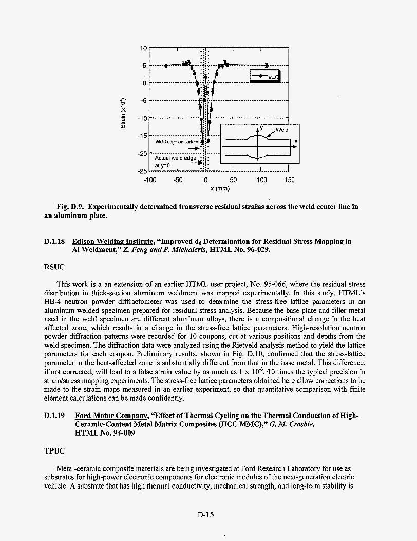
................-.. 0
-5
........................
....................................... I “ .......................
Weld edge on surface
h
z X c v
.- ?! m
-1 00 -50 0 50 100 150 x (mm)
Fig. D.9. Experimentally determined transverse residual strains across the weld center line in an aluminum plate.
D.1.18 Edison WeldinP Institute, “Improved do Determination for Residual Stress Mapping in A1 Weldment,” 2. Feng and P. Midialeris, HTML No. 96-029.
RSUC
This work is a an extension of an earlier HTML user project, No. 95-066, where the residual stress distribution in thick-section aluminum weldment was mapped experimentally. In this study, HTML’s HB-4 neutron powder diffractometer was used to determine the stress-free lattice parameters in an aluminum welded specimen prepared for residual stress analysis. Because the base plate and filler metal used in the weld specimen are different aluminum alloys, there is a compositional change in the heat affected zone, which results in a change in the stress-free lattice parameters. High-resolution neutron powder diffraction patterns were recorded for 10 coupons, cut at various positions and depths from the weld specimen. The diffraction data were analyzed using the Rietveld analysis method to yield the lattice parameters for each coupon. Preliminary results, shown in Fig. D.lO, confirmed that the stress-lattice parameter in the heat-affected zone is substantially different from that in the base metal. This difference, if not corrected, will lead to a false strain value by as much as 1 x lo”, .lo times the typical precision in straidstress mapping experiments. The stress-free lattice parameters obtained here allow corrections to be made to the strain maps measured in an earlier experiment, so that quantitative comparison with finite element calculations can be made confidently.
D.1.19 Ford Motor Company, “Effect of Thermal Cycling on the Thermal Conduction of High- Ceramic-Content Metal Matrix Composites (HCC MMC),” G. M. Crosbie, HTML NO. 94-009
TPUC
Metal-ceramic composite materials are being investigated at Ford Research Laboratory for use as substrates for high-power electronic components for electronic modules of the next-generation electric vehicle. A substrate that has high thermal conductivity, mechanical strength, and long-term stability is
D-15

required. High thermal conductivity is expected from coarse particle size composites, since the reduction of interfacial area can result in less thermal boundary resistance (Kapitza resistance). Thermal cycling is expected to cause microcracking and reduce thermal conduction. A set of 32 AI-Sic specimens were prepared at Ford using a factorial design of experiment approach that varies composition and processing parameters thought to influence the desired properties. Thermal diffusivity measurements were performed at HTML using the RT xenon flash system.
RT thermal diffusivity was measured by the xenon flash system for each of the 32 specimens. The specimens were then subjected to 1000 thermal cycles from -40 to 14OOC and subsequently remeasured. Fig. D. 1 1 shows the percentage changes of thermal difksivity after the thermal cycling. Thermal diffusivity of 28 samples shows an average reduction of 25%. However, samples showed increases (5 to 14%) in thermal difksivity. This data is being analyzed at Ford, along with other characterization results, to determine the optimal composition and processing condition of the composites.
X w"
20
15
10
5
0
-5 0 5 10 15 20 25 30
Position from Weld Center (m)
Fig. D.lO. Apparent lattice strain due to change in chemical compositions across the fusion zone.
D-16

50
s
i5 E 0 m
-50
Fig. D.ll. Changes in thermal diffusivity of AI-SIC composites after 1000 thermal cycles.
D.1.20 Ford Motor Company, “Residual Stresses in Gray Cast Iron Brake Rotors,” W. T. Donlon, G. M. Vyktel, J. W. Fasli, mdS. Spooner, HTML No. 94-102
RSUC
Ford Motor Company has used the neutron diffraction facilities of the HTML user center to investigate the effects of a heat treatment intended to reduce internal residual stresses in disk brake rotors. It is believed that residual stresses increase the rate of deformation of the disks during overheating caused by severe braking conditions. This deformation results in nonparallel surfaces on the brake disk, which generate objectionable vibrations during braking (“brake judder”). Brake judder is currently corrected by replacing the customer’s brake disks or remachining the disks to bring them within design tolerances. Minimizing brake judder in Ford products at a reasonable cost, without sacrificing vehicle handling is a major effort within the Ford Research and Ford Advanced Engineering Centers. To accomplish this goal the Ford engineers must know the magnitude and variations of the residual stresses due to the casting operations. Using the unique neutron diffraction facilities at RSUC, Ford researchers wereaable to quantitatively map out the residual stress distributions in two production disks and compare these results with a “stress-relieved” disk. Results from these neutron diffraction experiments suggested that residual stresses were reduced by factors of 5 to 10 by stress relieving. In a follow-up study, one of the previously characterized “production” brake disks was reexamined following a stress-relieving heat treatment at Ford. The nondestructive neutron diffraction strain mapping provided a quantitative measure of the reductions i,n residual microstrain, allowing quantitative evaluation of the effectiveness of the thermal treatment (see Fig. D.12). These results were presented at the ASM International Conference on Quenching and Control of Distortion in November 1996.
D-17

................... .
Fig. D.12. Radial strains measured in the inboard rotor before (lower curve) and after (upper curve) heat treatment, showing the reduction in strain from the annealing process.
D.1.21 Ford Motor Company, “High-Resolution Microscopic Study of Copper-MFI Catalysts,” H. .Gniidlri, HTML Proposal NO. 95-034
MAUC
Cu/MFI catalysts, when fresh, possess promising activities for lean-NO, reduction, but they deactivate quickly in the typical automotive exhaust environment. It is believed that the activity of the catalyst is strongly related to the coordination site of the copper in the zeolite and on the structure of the zeolite. Researchers from Ford Research Laboratory utilized the high-resolution transmission electron microscopy (HRTEM) capability of HTML to observe the structure of CdMET, and they evaluated the microbeam analysis capability of the field emission gun transmission electron microscope (FEG-TEM) for determining the copper distribution in the zeolite.
The Ford researchers prepared a series of Cu/MFI catalysts with varying degrees of activity by steam- aging an active catalyst and measuring the activity of the aged samples. When these samples were imaged in the HRTEM, no evidence for gross copper segregation was observed, but subtle changes in the zeolite structure were seen. The studies were hindered by the beam sensitivity of the zeolite materials. This beam sensitivity interfered with analytical measurements in the FEG-TEM, since the focused analytical beam seemed to disrupt the zeolite structure. Further HRTEM studies of the steam-aged zeolite structure are planned.
D-18

D.1.22 Ford Motor Company, “Determination of Thermal Diffusivity of Gray Cast Iron,” R. HecIit, HTML No 96-024
TPUC
The thermal transport properties of gray cast-iron alloys used for production and prototype brake rotors were measured at the HTML. The materials properties generated are being used in thermal distortion modeling at the Ford Research Laboratory. The goal of work was to determine thermal diffusivity as a function of temperature, graphite flake morphology, composition, and position in a finished product. Heat capacity was also measured in order to calculate thermal conductivity. RT thermal diffusivity was measured on the xenon flash system, and diffusivity from 200” to 500°C was measured on the laser flash system. Heat capacity was measured via DSC.
It was observed that the RT diffusivity increased with increasing carbon equivalent (CE), where CE = % C + 1/3 (“%I Si + % P), as seen in Fig. D.13. A 20% difference in thermal diflbsivity was observed between two currently available commercial rotors, labeled in the figure as “US #l” and “German.” Thermal diffusivity was also found to increase virtually linearly with increasing Type A graphite flake length. For all of the cast irons, thermal diffusivity decreased with increasing temperature; at 500°C the diffusivity typically decreased to less than 50% of its RT value.
D.1.23 GE Aircraft Engines, “Determination of Residual Stresses in Single Crystal Sapphire (A1203) Fibers Embedded in Ni-50Al Matrix,” P. K. Wright, HTML No. 95-014
RSUC
Metal matrix composites (MMCs) have the potential to make significant performance and weight improvements in aircraft engines due to their superior strength- and stiffness-to-weight ratios. Studies have demonstrated improvements for a wide range of components in commercial and military engines. However, residual stresses are generated in MMCs at both the local and macroscopic levels because of the thermal expansion mismatch between the fibers and matrix. Because of the varying degrees of constraint, geometry, and processing between different components, the residual stresses can vary significantly. These residual stress variations will influence the mechanical properties and will thus influence component life. This research program was undertaken to provide the understanding needed to account for the effect of residual stresses in MMCs.
The development and alteration of residual stresses was studied in a developmental MMC system, Ni-5OAI matrix reinforced by sapphire (single-crystal A1203) fibers. This system was seIected as a representative of a class of materials with significantly greater use-temperature capability than fiber- reinforced titanium. NASA-Lewis sponsored the GE research and supplied various samples of sapphire/NiAl MMCs subjected to different processing or thermomechanical loading histories to permit the correlation of residual stresses with processing.
Here, the neutron diffraction technique was selected for measuring residual stresses for its ability to measure stresses throughout the matrix and within the buried fibers, not just on the surfaces, as would be the case with XRD. Two different experimental techniques were required to do this. For the matrix, the powder diffractometer HI34 at HFIR was used. However, the single-crystal nature of the fibers required the greater flexibility of the triple-axis diffractometer H B 2 at HFIR. In both cases, samples were rotated in the neutron beam to reduce sampling errors, and diffraction scans were performed to accurately locate diffraction peaks in the MMC samples. Peak positions were compared with those for unstressed free- standing matrix and fiber samples to determine the differences in lattice parameters between stressed and unstressed materials; hence, the strain in the diffracting phase. Strains for the three principal material orientations were then converted to stresses using Hooke’s law and properties of elasticity.
The measured NiAl matrix residual stresses were significantly higher than previously measured. Comparison with measured sapphire fiber stresses did not result in a state of stress equilibrium, which
D-19

indicates some error in measurement of either or both constituents. Nevertheless, both the fiber and matrix stresses showed a consistent decreasing trend with post-fabrication processing. Slow cooling was not effective in reducing thermal stresses, but thermal cycling reduced stresses as the number of cycles increased. Neutron diffraction appears to be an effective method of assessing residual stresses in MMCs.
I " " U " " I " " I I
I I
I
I Step 3
I us I us #3 a
1
I
I
I a
I m I us#1 .
a
0.22
0.20
0.18
0.16
I
a 1
I
I- - 0.14
! k a2 E 0.12 L
Fig. D.13. Room-temperature thermal diffusivity shows an increase with carbon equivalence. Specimens were cut from front brake rotors. Error bars represent +lo.
The measurements performed for the sapphireNA1 system show that the effects of thermal expansion mismatch between the fiber and matrix are siinificant and can lead to high levels of residual stress. These high stresses support results from thermal cycling experiments that show large degradations in composite strength after thermal cycling to desired use temperatures. The residual stress results support the conclusion that fibedmatrix combinations with lower thermal expansion mismatch must be found if durable composites are to be fabricated.
D.1.24 General Electric, Corporate Research and Development, "Thermal Conductivity of Curved Zirconia Thermal Barrier Coatings," A. Mogro-Cumpero, HTML No. 96-041
TPUC
Thermal barrier coatings (TBCs) are typically applied to parts with various radii of curvature, such as nozzles and buckets. The deposition of zirconia coatings by air plasma spraying results in different microstructures of the coating, depending on the radius of curvature of the part. In turn, microstructure is known to affect thermal conductivity. Published values for thermal conductivity of zirconia TBCs are for planar samples. Values of thermal conductivity for curved samples and their variation with radius of curvature are much closer to application needs and thus more useful to designers.
To obtain thermal conductivity, standard values of specific heat from the literature will be used. The determination of density is more difficult than in the planar sample case, where dimensions and weight
The plan is to make measurements of thermal diffusivity of curved samples by the laser flash method.
D-20

provide good values. We have found that the Archimedes method can yield reasonable values, although of lower precision.
Before TBC samples are measured, the laser flash technique has to be tested to verify whether thermal conductivity of samples with the same microstructure but different radii of curvature give the same value. The best way to obtain these samples has been to tape-cast zirconia, starting with zirconia powder.
The first successful samples from tape casting were measured in the laser flash apparatus at HTML. These proved that reasonable data can be obtained for curved samples, but the samples were too thin to obtain reliable absolute values of diffusivity, so a verification of the hypothesis in the preceding paragraph was not possible.
same thermal conductivity is measured for samples of different radius of curvature, and to move on to actual TBC samples from curved surfaces.
The next steps are to improve the tape-casting method to obtain thicker samples, to verify whether the
D.1.25 Howmet Corporation, "Thermal Diffusivity of Advanced PVD Thermal Barrier Coatings, J . Smith, A. Feuerstein, and K. Murphy, HTML No. 95-090
TPUC
Advanced TBCs have been developed for aircraft and industrial gas turbines at Howmet by the electron beam-physical vapor deposition (EB-PVD) technique. Current single-layer YSZ TBCs typically have thermal conductivity values from 1.5 to 2 W/mK. For gas turbines, where higher thermal protection is desirable, a thicker coating must be used to achieve the designed operation temperature. (Lower thermal conductivity may be achieved by a multilayer technique.) Initial experimental efforts focused on alternating multilayers from different oxide materials such as Zr02/A1203.
specimens was measured at RT, 4OO0C, lOOO"C, 1135"C, and 1177°C using the laser flash technique. An IN-7 18 alloy specimen was measured to provide thermal difisivity of the substrate. The several hundred Zr02/AI2O3 layer pairs were treated as a single layer. Two-layer analysis developed by Taylor was used to calculate thermal diffusivity of the multilayers. Howmet provided specific heat data for the IN-71 8 alloy, alumina, and 7YSZ. The thermal conductivity of three types of coatings was measured, and the results at RT and 1 177°C are shown in Table D. 10. Thermal conductivity decreased over the measured temperature range. However, the overall thermal conductivity did not show a significant decrease compared with single-layer TBCs. The two-layer approximation used for calculation may be one reason for the high thermal conductivity. Because no studies have been reported for such multilayer materials, further study is warranted, and a model needs to be developed to calculate heat transfer through hundreds of layers.
Multilayer samples were prepared at Howmet on IN-71 8 substrate. Thermal diffusivity of the
Table D.lO. Thermal diffusivity (a) and conductivity (k) of multilayer samples at room temperature (23°C) and 1177°C"
23°C 1 177OC Sample a k a k IN718 0.03 12 11.25 0.0508 27.19 MLC657 0.0058 1.54 0.0037 1.43 MLC700 0.0046 1.23 0.0037 1.46 MLC705 0.0104 2.78 0.0049 1.92 "Thermal diffusivity (a) = cm% and thermal conductivity (k)=W/mK.
D-21

D.1.26 Idaho National Enpineering: Laboratory, “Residual Stress Mapping of Graded A1203-Ni Joints,” B. H. Rnbin, H. A. Bruck, nnd R. L. WiIIinmson, HTML No. 94-044
RSUC
The goal of this study is to establish a finite element model which can be used to control the distortion and residual stresses in layered (such as TBCs) or functionally graded materials through the selection of materials properties, geometries and processing parameters. In this study, a cylindrical A1103 joint was bonded to nickel with a composite interlayer of 40 vol ‘YO A1203-60 vol ‘YO Ni (see Fig. D.14). The specimen was fabricated by powder processing, and the residual stresses and strains in the specimen were measured experimentally using neutron diffraction and X R D methods. Experimental measurements were compared with FEM results obtained using a variety of different constitutive assumptions. The predicted residual strain distribution within the A1203 along the center of the specimen was in excellent agreement with neutron diffraction measurements (see Fig. D.15). Alternatively, the predicted peak strains and stresses within the A1103 along the specimen surface were significantly higher than those measured by XRD, suggesting that stress relief occurred near the free edge during cooling. The mechanisms of stress relief are uncertain; however, localized plasticity within the composite interlayer is believed to play a role.
D.1.27 National Center for Manufacturing Sciences (NCMS), “Residual Stress Round Robin,” K. J. Kozaczek
RSUC
RSUC participated in a round robin as a part of the National Center for Manufacturing Sciences (NCMS) Heat Treat Distortion CRADA with DOE. The tests were also conducted at several industrial and national laboratories. The objective was to dete-mine the precision, repeatability, and reproducibility of XRD residual stress measurements and determination of retained austenite. Stress and retained austenite depth profiles in 5 120 carburized gear steel were determined. These measurements were an essential part of validating a computer code that will be used by the automotive industry to improve the quality and production of transmission gears.
D.1.28 Norton Company, “Residual Stresses in Ground Components,” M. Tricnrdand nnd C. StnizJVOOd, HTML NO. 93-057
RSUC
The objective of this study was to compare residual stresses in one easy-to-grind steel (4340) and one hard-to-grind alloy (Inconel 7 18) generated at three different material removal rates. Chromium radiation was used to examine the (220) reflection of two Inconel samples. When the solid-state Peltier detector (high energy resolution) was utilized, a compressive residual stress of 250 MPa was found in one sample. In an attempt to reduce data-collection time and increase sample through-put, the position-sensitive detector (PSD) was utilized. However, meaningful residual stress measurements could not be obtained on the as-ground surfaces with the PSD because of the low signal-to-background intensity ratio of both the (200) and (220) peaks for the Inconel and steel. Grinding had also introduced plastic deformation (peak broadening) and texture and had reduced the crystallite size. These observations initiated a metallographic study to characterize the highly damaged surface layer. This work will continue after the metallographic study is complete and other background information is acquired by Norton.
D-22

--
I
z
0: 60% Ni - 40% N203 C Ni
0 & MlLLlMEERS
Fig. D.14. Schematic of the specimen used for neutron and X-ray diffractiopn measurements.
0 0
0 0,
7- x L L
W c .- E 5
0 2 4 6 8 10
Position from A1203 End (mm)
12 14
Fig. D.15. Radial strain distribution along the center line of the specimen determined by neutron diffraction. The curve is the result of the finite element calculations.
D-23

D.1.29 Philip Morris, USA, “Reaction Synthesis of FeSi2, Ni3Si, TigSi3, CoSi2, and a Composite of Silicide and Silicon Carbide,” S. C. Deev, HTML No. 94-082
TPUC/DUC
Philip Morris has begun an investigation of the experimental conditions required to synthesize single- phase transition metal silicides of Ni, Ti, Fe, and Co. Transition metal silicides and their composites have the potential to meet the oxidative, thermal, and mechanical requirements of high-temperature materials. To date, only Mo,Si - has been utilized commercially, and there is little if any data available on the thermophysical properties of the silicides under investigation in this study. The current work uses combustion synthesis to form silicides by utilizing the heat of reaction between elemental powders.
HTML’s high-temperature DSC was used to find conditions that result in single-phase silicides. The DSC runs were stopped at different maximum temperatures after the various reactions occurred, and the resulting phases were identified using RTXRD to determine the phase evolution from starting materials. The work is still in progress, with high-temperature XRD (HTXRD) planned to confirm the phase evolution sequence as a function of the heat treatment conditions.
D.1.30 Ouantum Peripherals Colorado, Inc., “Measurements of Intrinsic Film Stress, Crystallographic Texture, and Crystallite Size in Sputtered Permalloy-Based Thin Films,” J. Doyle and E. L. Brown, HTML No. 95-055
RSUC/DUC
As device technology advances, production tolerances become more stringent and demands upon material performance increase. Magneto-restrictive heads are often fabricated with Permalloy, which is a permanent magnet material. Thin films (4 pm) with a Permalloy-based composition are deposited in multilayer configurations for devices. Thus, crystallographic texture and residual stress all impact the magnetic properties of these thin films and are of concern to device fabricators. The objective of this research was to determine the orientation, intrinsic film stress, and crystallite size of NiFe-based sputtered thin films as a function of chemical composition and film thickness.
The residual stress and crystallographic texture of Ni-19 % Fe and Ni-16 % Fe-3.5 % Mo thin films on silicon wafers were determined as a function of film thickness. “Intrinsic” film stresses were measured in the 800 A films via the sin’y technique and were found to be compressive with a magnitude of 1 GPa. The NiFe film possessed a biaxial st,ate of stress, whereas the NiFeMo film possessed an equibiaxial state of stress. Pole figure measurements revealed a relatively strong -4 11> fiber texture normal to the film plane in all specimens, as well as a weak <loo> texture, which decreased as film thickness increased from 150 to 800 A. In the first use of ORNL’s X-14A beamline at the National Synchrotron Light Source (NSLS) at Brookhaven National Laboratory (see Fig. D. 16), thin-film multilayer specimens composed of various sequences of Permalloy (NiFe) and tantalum were also studied. Bragg-Brentano and asymmetric diffraction geometries were employed for phase identification and dieaction peak position determination. Rocking curves (omega scans) were then employed to establish the degree of preferred orientation within the tantalum and Permalloy layers. The degree of preferred orientation and phase type were correlated with deposition sequence (Le., substrate type). Use of the high-incident beam intensity available at NSLS greatly facilitated characterization of these films, in the range of 100 to 200 A in thickness. This information will be correlated with magnetic property and TEM measurements in an effort to understand and manipulate deposition conditions to obtain films with enhanced magnetic properties.
D-24

Fig. D.16. Drs. Gog, Misture, and Brown (L to R) mounting a coated silicon wafer at the X-14A beamline.
D.1.31 RCF Seals & Couplings, Inc., "Mechanical and Physical Characterization of an Elastomeric Material," J . Krtmter, HTML Proposal No. 95-059
MCAUC/TPUC/MIRUC
The long-term effects of brief exposures to +75OoF, +800°F air flow followed by ambient temperature air flow, coupled with rapid axial and angular displacements, were investigated at the HTML Mechanical Characterization and Analysis Group. RCF Seals & Couplings has developed an elastomeric composite, which had been selected as the principal pneumatic seal in bleed-air, anti-icing, and air conditioning systems for the new Learjet Model 45 airplane. The test program represented an accelerated profile of takeoff, flight, and cool-down that occur with normal flight conditions. The Mechanical Characterization and Analysis Lab constructed a test facility to accomplish this mission and provide structures, heat exchangers, valves, and actuators to operate and monitor the test as it progressed. Computerized analysis of thermal and leakage data were obtained and conveyed to RCF at designated intervals. The test concluded after 4 140 hours of test when leakage was observed. This is the equivalent of 2 years of airline service. Examination of the seals showed that thermal degradation was not the cause of the leakage; leakage was caused by slow evolution of compression set. The test results proved invaluable to RCF. They proved conclusively that our elastomer could operate continually well above the standard limitation of +400°F. It opened a new approach to high temperature valves, actuators, gaskets, ducting, and other devices needing elastomeric sealing material.
.
D-25

D.1.32 Rodel, Inc., ‘%ffects of Chemical Mechanical Polishing on Metal Interconnect Structures,” A. SetIiurnniaii, HTML No. 94-055
RSUC/DUC/MAUC
As the density of electronics implemented on the surface of silicon chips is increased, the size of the interconnect structure is decreased accordingly. Further, as the line widths in interconnect structures become smaller than 0.5 pm, which is beyond the depth of focus of lithographic instrumentation, the planarity of the surface becomes critical. Chemical mechanical polishing is currently the only process that can deliver a surface that possesses global planarity, facilitating further processing. The objective of this research was to determine the residual stresses due to the deposition processing, chemical mechanical polishing, and/or annealing on thin film layers of tungsten and Al-Cu interconnect structures.
The residual stresses were measured in the 1-ym-thick tungsten layer via the sin2y technique and were found to be biaxial. The stresses are highly tensile (>1 Gpa; see Fig. D.17) in all samples but varied
. with surface treatment. Since any high level of stress needs to be removed or reduced to prevent possible failure in the interconnect network or global warpage, X-ray characterization is critical to understanding this new polishing technique. The impact of the observed large tensile stresses is that further development of the fabrication techniques is needed to bring the stresses to lower levels.
Fig. D.17. Example of tensile residual stresses in action: Al-Cu film delaminated from %in. silicon wafer.
D.1.33 Rohr, Inc., “Simultaneous Thermal Analysis and Evolved Gas Analysis During Pyrolysis of Preceramic Polymers,” A. S. Gurney, HTML No. 94-048
TPUC
Rohr, Inc., researchers initiated a project to characterize the pyrolysis behavior of several classes of preceramic polymers. These materials have a wide variety of uses, including protective coatings for carbon-carbon composites, ceramics, metals, and polymer matrix composites. The polymers can be painted onto the surface of the composites, cured, and pyrolyzed. Previous experimentation by Rohr has
D-26

shown these coatings to be viable for high-temperature oxidation protection, atomic oxygen protection, and erosion resistance. The goal of the current project is to characterize the cure and pyrolysis reactions during processing of the preceramic polymers in the simultaneous thermal analyzer (STA15OOS). The identification of reaction steps and gaseous products should enable the processing schedule to be tailored to yield uniform, adherent, low-porosity coatings.
D.1.34 Rolls Royce, Inc., “Effect of Thermal Exposure on Residual Stresses in TiAI,” J . Allsnznn, arid D. Larseii, HTML No. 94-073
RSUC
The RT fatigue strength of thermally exposed TiAl is appreciably lower than that of the unexposed material. The presence of high compressive stresses in the surface of the as-machined sample may be responsible for the improved fatigue performance (Fig. D. 18). Residual stress measurements revealed that the advantageous high compressive stresses introduced by machining were relieved by the thermal exposure (1 000 h at 65OOC). Further study of the residual stress relief rate is under way. The determination of the stress relaxation will provide improved confidence in using these alloys for turbine blades and other critical rotating parts. In addition, it provides important information regarding the machinability of these alloys.
0
-200 n 0 0-
2 -400 8 9 t v)
- -600 9 -cr 8
-800 c!i
-1 000 1.5
/ a * * / : -0- as-received, axial - -0- - as-received, hoop - )t - oxidized, axial
oxidized, hoop I I I 1 I I I
2 2.5 3 3.5 4 4.5 5 5.5 Distance from surface (pm)
Fig. D.18. Distribution of subsurface residual stresses in ground and thermally exposed Ti- 45%A1.
D-27

D.1.35 Rolls Rovce, Inc., “Residual Stress Relaxation in TiAl,” J . AZZsmrm, HTML No. 95-037.
RSUC
Gamma-based titanium aluminides are being evaluated for use in high-temperature applications in gas turbine engines and airframes. The property combinations of low density and high specific strength provide an attractive alternative to some superalloys. The purpose of this investigation was to determine the residual stresses in as-received and heat-treated specimens of TiAl in order to quantify the time- and temperature-dependency of stress relaxation. These results will then be correlated with fatigue resistance and strength.
The specimens were made from a TiAl alloy, Ti45Al-2Nb-2Mn (at. %) + 0.8 vol % TiB2 XDTM, which was cast under 200 bars pressure, then HIP-processed at 1245OC/172 MPd4 h and heat treated at 995°C for 50 h, then cooled within the furnace. The rod-shaped fatigue specimens were machined from the blanks using low stress grinding (D x L = 16 x 200 mm; gage section diam = 5.1 mm). The specimens were thermally exposed at ambient pressure to 450,500, and 650°C for >50 h and allowed to cool within the furnace.
High compressive surface stresses measured by XRD (700-800 MPa) due to grinding in the as- received specimen were subsequently relaxed by thermal exposure. Possible errors due to a large sample curvature were minimized by employing a combination of x and o tilts. Pole figures showed no evidence of crystallographic texture due to processing of the specimens. The residual stresses were reduced after 50 h of thermal soaking to 70,35, and 18% of initial values for soaking temperatures of 450,500, and 65OoC, respectively (see Fig. D.19). Individual heat treatments at 650 and 550°C for 100 and 50 h, respectively, reduced the residual stresses at rates of 50-60 MPa/h, while soaking at 450°C for 10 h relieved stresses at much smaller rates. In addition to reducing the res’idual stresses, the thermal exposure relieved cold work and changed the atomic structure of TiAl (increased the tetragonality of crystallographic lattice). The impact of this work, combined with microscopy and fatigue strength data, will be to provide an understanding of the effect of thermal exposure on fatigue strength prior to fatigue testing.
0
-200 (d n 5 $ -400 E iij - 2 -600 0 u1
-800 2
-1 000 0 20 40 60 80 100 120
Thermal Soak Time (hours)
Fig. D.19. Evolution of axial residual stresses with time at temperature.
D-28

D.1.36 Sandia National Laboratorv, “Neutron Diffraction Measurement of Residual Stress in an Unirradiated Boiling Water Reactor Core Shroud,” S. T. Rosinski nndS. Spooner, HTML NO. 95-031
RSUC
Through efforts coordinated at Sandia National Laboratory, the DOE Office of Nuclear Energy is presently supporting the Boiling Water Reactor Vessel and Internals Project (BWRVIP) to address integrity issues arising from service-related degradation of reactor pressure vessels (RPVs) and RPV internal components. Experimental measurement of residual stresses is fundamental to the prediction of in-service stress corrosion crack growth in boiling-water reactor (BWR) components such as the core shroud, which is a welded stainless steel cylinder located inside the reactor pressure vessel that directs cooling water around the nuclear fuel. Welding fabrication residual stresses are the main loads on the material in this otherwise unloaded structure. Stress corrosion cracking occurs in BWR core-shroud welds due to the combination of sensitized material, harsh environment, and residual stress. In some instances, complete 360” circumferential cracks to a depth of 50% of the wall thickness have been observed. Realistic predictions of crack growth are required in order to optimize maintenance schedules and safety assessments. In this regard, information as to the residual stress present after fabrication is particularly important.
Residual strains in a 2-in.-thick 304L stainless steel plate were measured by neutron diffraction and interpreted in terms of residual stress. This curved plate was removed from a 20-ft-diam unirradiated BWR core shroud and included a multiple-pass horizontal weld that joined two of the cylindrical shells. These shells compose the core shroud. Residual stress mapping was undertaken in the heat-affected zone, concentrating on the outside half of the plate thickness (see Figs. D.20 and D.21). The variations in residual stresses were consistent with the case histories and in reasonable agreement with finite element calculations and experimental results from “hole drilling” measurements. The results were presented at the ASME Pressure Vessels and Piping Meeting in July 1996 and will appear in a Sandia National Laboratory report.
Axial Stress 400
300
.;a 200 n 5 100 ?! a 0 L
-100
-200 -20 -10 0 10 20
distance from centerline [mm]
Fig. D.20. A micrograph of a section through the weld showing the strain map locations (left).
Fig. D.21. Measured axial residual stresses in core shroud sample (right) at four different distances from the weld centerline.
D-29

_-
D.1.37 Westinghouse Electric Corporation, “Thermal Conductivity Measurements on Barrier Coatings,” K. Sloaii and E. Ludenian, HTML No. 96-027
RSUC
Thermal barrier coatings (TBCs) are currently employed in diesel and aircraft engines. A new application for TBCs will be in land-based turbine engines for power generation. Thus, TBCs will be required to withstand long times at high temperatures rather than high temperatures for short periods of time with a high number of cycles. This new requirement, coupled with higher operating temperatures, means that new materials problems and issues occur. TBC systems generally consist of a ceramic top coat, a metallic bond coat, and an alloy substrate. Although failure of the protective ceramic to coat usually occurs via spallation, phase transformations may also have a role in TBC failure. Thus, the purpose of this study is to explore methods to nondestructively characterize the phases present in plasma- sprayed and EB-PVD ceramic top coats of as-received and heat treated specimens.
The phases within the ceramic top coats deposited via EB-PVD and air plasma spray (APS) were nondestructively characterized using XRD. Although the kickoff visit was short (~2.5 days), both as- received and heat-treated samples were examined. Both tetragonal and cubic yttria-stabilized zirconia were identified. Further research and analysis are planned.
D.1.38 Westinghouse Electric Corporation, “Thermal Conductivity Measurements on Thermal Barrier Coatings,” J. G. GoeGeii, E. Ludentnn, nndK S. Slonn, HTML No. 96-027
TPUC
Thermal conductivity is a critical design parameter for TBCs used in industrial gas turbines. An accurate measurement of thermal conductivity at engine operating temperature is very important to optimize the efficiency and reliability of TBCs. Thermal ’aging of the TBC is also an important issue in the TBC design. An increase in thermal conductivity at temperatures above 1000°C as a function of time can significantly decrease the engine operating temperature and reduce the efficiency. APS and EB-PVD TBCs were prepared at Westinghouse. Thermal difisivity as a function of aging time was measured.
APS samples were prepared first. Thermal diffusivity of APS TBCs aged at different temperatures were measured by the high-temperature laser flash system up to 1450°C in nitrogen atmosphere. An as- received APS TBC was also measured for real-time aging test. A hyteresis was found in this specimen, indicating that thermal conductivity will increase after high-temperature exposure, as shown in Fig. D.22. These data provided valuable information for prediction of accurate temperatures of the gas turbine.
D.2 UNIVERSITY USER PROJECTS
D.2.1 Alabama A&M University, “Process Dependence of Orientation of Aromatic Ribbons (Fibrils) and Storage of Lithium in Glassy Carbon,” H. Maleki and D. IIa, HTML NO. 94-071
TPUCLDUC
Because of its biocompatibility and inertness, and its controlled porosity, permeability, and electrical resistivity, glassy polymeric carbon (GPC) is used for producing medical prostheses, drug delivery systems, components of lightweight lithium batteries, crucibles for crystal growth by induction heating, refractory heat exchangers, hollow ware for gas containment at high temperatures, and a host of other applications.
D-30

b .d
.d > m
0.004 n € 3
0 c B
0.002
1 --0--TBC I
Fig. D.22. Aging effect of an as-received APS TBC specimen. The time at each temperature is approximately 40 min.
Polymeric carbon articles are particularly difficult to make in thick sections. Heating rate, temperature, and sample thickness determine the outcome of carbonization of resin that leads to a glassy polymeric carbonware. Using wedge-shaped samples, Alabama A&M researchers found the maximum allowable thickness for various heating rates during gelling (300-360 K), curing (360400 K), postcuring (400- 500 K), and precarbonization (500-875 IS). Excessive heating rate causes failure. In postcuring the critical heating rate varies inversely as the fifth power of thickness; in precarbonization this varies inversely as the third power of thickness.
thermogravimetric, mass-spectrometric evolved gas analysis, and dilatometric studies were conducted at HTML. From thermogravimetric evidence the observed failures by blistering and crazing are attributed to low rates of diffusion of gaseous products of reactions occurring within the solid during pyrolysis. Mass spectrometry shows the main gaseous product is water vapor; some carboniferous gases are also evolved during precarbonization.
Ambient temperature XRD analysis of amorphous, partially crystallized, and fully crystalline specimens were made to determine the heat treatments necessary for devitrification of a new polymeric precursor. The XRD data show that molded specimens crystallized after heat treatment at SOO’C, while sprayed specimens did not crystallize after identical heat treatment. The research shows that the glassy polymeric precursor can be used effectively to form complex shapes that can later be heat treated successfully.
In an effort to understand the factors contributing to the observed heating rate dependencies,
D-3 1

D.2.2 Alabama A&M Universitv, “TEM and XRD Analysis of Ion Implanted LiNbO&” D. IZa and E. K. WiZZinm, HTML NO. 95-067
RSUC
Lithium niobate (LiNbO3) is an electro-optic material that can be used in optical systems to replace standard electrical systems in hazardous areas such as nuclear power plants. In addition, LiNbO, can be part of advanced sensing systems for military and commercial aircraft. The objective of this work is to measure changes in lattice parameters due to 3.0- and 5.0-MeV helium bombardment of LiNbO3 single crystals and to relate these changes to optical changes in the electronic damage region (ie., top 9 and 15 pm of material, respectively) of the implanted crystal. The impact of this work will be to improve stability and functionality of these electro-optical materials.
the as-received sample. Then the ion-implanted crystal was scanned again after a 200”C, 30-min partial anneal that removed the electronic stopping induced damage but not the nuclear stopping induced damage. The crystal was scanned a third time after a 400°C full anneal in argon. Regions at the ends of the implanted surface of the crystal delaminated after the 400°C anneal. The affected areas were shielded with lead foil for the final scans. Differences in 28of 0.15 to 0.2” were observed between the as-received and ion-implanted samples as well as between the implanted and annealed samples. The full width at half maximum decreased as the annealing temperature increased. The thickness of the delaminating layer was measured and found to be 15 pm, the same as the penetration depth of the helium ions.
After orienting the LiNbO3 single crystal, the peak positions of several reflections were measured on
D.2.3 Appalachian State University, “Characterization of Fine-Fraction Mineralogy for Comparison with Magnetic Susceptibility,” E. A. Coivnn, S. L. Cnrtee, and N. E. Joltnson, HTML NO. 95-099
DUC
Room-temperature XRD was used at HTML to identify the mineralogy of the silt and clay fraction of samples from sediment cores collected in Alaskan fjords. The qualitative description of mineralogy from sediments collected from several different source areas was used to determine how fine-fraction mineralogy was related to magnetic susceptibility measured directly from sediment cores. These results have been presented at the Geological Society of America National Meeting and will be submitted for publication to the Canadian Journal of Earth Sciences.
D.2.4 Carnegie Mellon Universitv, “Structural Characterization of Chemically Synthesized High Pressure Cubic Spinel Phase of ZnIn&,” P. N. Kunzta andA. Wagltray, HTML No. 93-105
DUC/RSUC
Chemical reactions conducted in solutions are known to generate solid precursors containing molecular units that help in formation of high-temperature phases. The structural units are created by controlling the molecular environments in solution, and as a result, phases that normally form and are stable at high temperature can be synthesized at low or moderately elevated temperatures. However, the application of chemical approaches for synthesizing phases that form at high pressure are relatively unknown. In this study, a simple RT aqueous chemical precipitation route has been used to synthesize the high-pressure spinel modification of ZnInlS4, which belongs to the family of ternary transition metal oxides in the MnO-Li20 system. The material exhibits several defect structures, of which the cubic spinel structure is the one relevant to the proposed research. Previous studies have shown that the cubic spinel phase can be synthesized at temperatures as low as 400°C using sol-gel routes. This approach is radically different from the conventional route, and the ZnIn& performance as a cathode will strongly depend on the cation distribution in the cubic cell. To characterize the structure and identify the exact distribution of
D-32

lithium and manganese atoms in the chemically synthesized cubic structure, a systematic high- temperature X-ray and neutron diffraction study, combined with Rietveld analysis, was conducted. The collected XRD pattern showed a predominant cubic phase; a small hexagonal phase was also identified. Successful refinement was obtained for all samples using a two-phase structural model. Results of refined structural parameters are discussed in terms of a proposed solution coordination model (P. H. McMichael, M. A. Sriram, A. Waghray, P. N. Kumta, S . Misture, and X. L. Wang, “Chemical Synthesis of the High- Pressure Cubic-Spinel Phase of ZnInrS4,” submitted to Phil. Mag). This study proved to be extremely beneficial to the understanding of the formation of such spinel phases. The present project was supported by the Eveready Battery Company, and the results provide strong evidence for obtaining continued support and also form the basis for a subsequent proposal to DOE.
D.2.5 Carnepie Mellon Universitv, “Structural Characterization of Chemically Synthesized Cubic Spinel Phase of LiMnzO4,” P. N. Kunzta and A. Waghay, HTML No. 94-080
DUC
LiMnrO4 is an important cathode material that has been intensely studied over the last couple of years for its use in 4-V rechargeable lithium batteries. The spinel form of the compound exhibits a theoretical capacity of 148 mAh/g, corresponding to the discharged state of y-MnrO4. In order to charge the battery, Li’ ions must migrate out of the LiMnrO4 spinel structure; the requirement for lithium di&sion is a normal spinel structure where all of the lithium is tetrahedrally coordinated. Both X-ray and neutron powder diffraction were used to determine the distribution of cations and the nature of the spinel structure. Rietveld refinements of the powder diffraction data for both types of radiation clearly showed that the material crystallizes in the normal spinel structure, and the agreement between the two measurements is excellent (Fig. D.23). In addition, HTXRD was used to describe the phase evolution of the LiMnz04 phase from a novel sol-gel precursor as a function of temperature. This HTXRD study showed that the spinel phase forms at temperatures as low as 350°C, much lower than synthesis from oxide precursors. The results of the work will be presented at the 97th American Ceramic Society meeting in April 1996 and also at the Electrochemical Society meeting in May 1996.
D.2.6 Duke Universitv, “Novel Carbon-Ion Fuel Cell Electrolyte Phase Transition Temperatures,” F. H. Cocks andH. LaVierse, HTML No. 95-046
DUC
The objective of this study was to determine whether the cubic high-temperature phase of several metal carbides could be stabilized to allow carbon diffusion, which might permit development of a carbon-based fuel cell. The phase purity of several doped metal carbides was determined at RT, and HTXRD was used to determine the tetragonal-to-cubic transformation temperature. The results indicate that the transformation is sluggish and occurs between 1200 and 14OO0C in CeG, depending on the dopant. Because standard XRD patterns for these materials are lacking, powder patterns for the low- and high-temperature phases have been collected and will be submitted for publication. This work is continuing with efforts at Duke to synthesize metal carbides with lower phase transition temperatures. If they are successful, then HTML facilities will again be used to characterize phase purity, transformation temperature, and the hoped-for defect structure.
D-33

Fig. D.23. Crystal structure of the normal spinel LiMnzOj determined by Rietveld refinement of X-ray and neutron powder diffraction data.
D.2.7 Georgia Institute of Technology, “Processing Variable Effects on the Composition and Texture of CCVD YBCO Thin Films,” W. B. Carter and G. W. Book, HTML Proposal No. 93-053
RSUC
The physical and mechanical properties of thin films are often different from the properties of bulk material and are dictated by the fildsubstrate orientation relationship, crystal anisotropy, and crystallographic texture of the film. XRD texture analysis provides information about preferential film growth and can be used for optimization of deposition parameters and prediction of properties of thin films. An X-ray back reflection technique using the Bragg-Brentano geometry with experimental corrections for absorption and defocusing was used to study the filmhbstrate orientation relationships of YBa2Cu30x (YBCO) superconducting thin films deposited via combustion chemical vapor deposition (CCVD) on single-crystal MgO and polycrystalline silver substrates (Fig. D.24). The as-deposited films on single-crystal (100) MgO substrates showed strong preferential growth with the basal plane parallel to the substrate surface (c-axis up growth). Texture analysis showed two in-plane alignment orientations of the film with respect to the substrate, with YBCO [ 1001 and [ 1 101 aligned with the [loo] MgO substrate. YBCO films deposited on cold-rolled polycrystalline silver displayed c-axis up growth, indicating that the orientation of the polycrystalline substrate (brass-type texture) did not induce detectable in-plane preferential growth of the YBCO.
D-34

1.51 ..
1.23
1.00 .82
Fig. D.24. Experimental (113) pole figure for YBCO deposited on silver substrate showing a strong C-type texture.
D.2.8 Louisiana State Universitv, “Measurement of Residual Stress Depth Profiles of Ground Silicon Nitride,” T. W. Lino nizd K. Li, HTML No. 94-101
RSUC
Grazing incidence X-ray diffraction (GIXD) was used to measure the depth profile of residual stresses in ground silicon nitride specimens. GIXD is a new capability in RSUC that uses low incidence angles on the surface of a material to control the depth of penetration of the X-rays. In this manner, stress, phase, and crystallographic texture information from a sample can be obtained as a function of depth. In the LSU study, the influence of wheel speed is being examined, and the results will be incorporated into a model that relates grinding variables to residual stresses.
The PTS goniometer with rotating anode source and parallel beam optics was used to collect the residual stress measurements. The phi-integral method provided data on the variation of stress parallel to and perpendicular to the grinding direction. In Fig. D.25, the uncorrected stress values (circles) represent an absorption-weighted average value of the stresses from the surface to the reported attenuation depth. Thus, as the X-ray penetration depth increases, the stresses typically average out to zero. The actual stress at a certain depth was obtained by an inverse transformation (solid line). A steep stress gradient exists near the surface of this sample, changing from about 1000 MPa compressive at -1 pm to a maximum tensile stress of 350 h4Pa at -3 pm. The subsurface tensile stress field ranges from 2 to 15 pm below the surface. Finally, this absorption-corrected curve was used to calculate a simulated uncorrected curve (dotted line) which compares well with the experimental data points. The maximum compressive stress was calculated to be about 1000 and 1200 MPa for two samples. As wheel speed decreased, the near- surface compressive residual stress increased, which is consistent with grit depth-of-cut kinematics. This knowledge of residual stress at the surface and in the near-surface region is required to establish the optimum grinding conditions and to understand and predict the mechanical behavior of these machined parts in service.
D-35

400 n 200 (d
0 a z v) -200 ’ -400 5 a -600 z v) -800
v)
- 3
a fx -1000
0 5 10 15 20 25 Depth (elm)
Fig. D.25. Residual stress as a function of depth for SisNJ (NCX-5102) ground at a wheel speed of 45 mls with a cross feed rate of 2.1 mmlpass and depth of cut of 0.75 mmlpass.
D.2.9 Louisiana State Universitv, “Measurement of Residual Stress Depth Profiles, Flexure Strength, and Surface Texture of Ground Ceramics,” T. W. Lino and K. Li, HTML NO. 95-040
RSUC
The objective of this study was to investigate the influence of machining operations on the residual stress, flexure strength, and surface roughness of ceramics. This study examines the influence of wheel speed on the residual stresses in alumina and is a continuation of a previous study. GIXD was employed to measure steep stress gradients in the near-surface region of the samples as well as compressive surface stresses. As before, GIXD utilizes low incidence angles on the surface of a material to control the depth of penetration of the X-rays. However, the large grain size (>25 pm) of the alumina samples introduced enough scatter in the data to make the results from the phi-integral analysis uncertain. Thus, a more robust method of calculating residual stress must be found or developed for large-grain materials. Finally, the results will be incorporated into a model that relates grinding variables to residual stress flexure strength and surface roughness.
D-3 6
D.2.10 New Mexico Institute of Mining: and Technolorn, “Laminated Ceramic Composites,” K. IC CJ~ada, HTML NO. 95-038
MAUC/MCAUC/RSUC
The objective of this project is to examine several possible oxide interphase materials in ceramic matrix composites (CMCs). The interphase in a composite can prevent catastrophic failure of a CMC if it forms a sufficiently weak interface with the matrix. A weak interface can deflect approaching cracks, thus leading to increasing fracture toughness. The project concentrates on toughening oxide/oxide ceramic composites because of their stability at high temperatures in air.
The HTML User and Fellowship Program provides a means of characterizing the interphase materials and composites. The nanoindenter and resonance ultrasound spectrometer supplied mechanical properties such as hardness, elastic modulus, and Poisson’s ratio for the interphase materials, properties that are not available in the literature. The electron microprobe has allowed quantitative mapping of composition across the interface, giving an insight to the solid-state reactions that occur at the interphase/matrix interface during processing.
So far, we have obtained only qualitative information on interfacial strength characteristics. Behavior of cracks, generated by Vickers indentations near an interface, was observed as the cracks approached the interface. These observations indicated the presence of some interphase results in crack deflection. Future plans include measurement of fracture toughness of the composites at both ambient and high temperatures.
information on the microstructure and microchemistry of interfaces. This understanding greatly Although the project is not yet complete, the facilities at the HTML have provided us with
contributes to our ultimate goal of identifying an all-oxide compos’ite that is chemically stable, strong, and tough at high temperatures.
D.2.11 North Carolina State Universiiv, “Multilayer Diamond Coatings,” J . KasicliainrrZa, HTML NO. 95-039
TPUC/MIRUC/RSUC
We are investigating the mechanisms of improvement in adhesion and wear resistance of multilayer diamond coatings on metal and ceramic substrates. In addition, we are determining the effective thermal conductivity of multilayer diamond coatings and comparing their performance as head spreaders with single-layer coatings. The residual stresses present in multilayer coatings are determined using the stress measurements made with a PTS goniometer with rotating anode. The effective thermal conductivity of *
the coatings is determined from temperature measurements of the substrate performed by an infrared (IR) camera. A wire heater is formed photolithographically, and temperature measurements are modeled using FEM analysis. This research is extremely useful in the development of hard, wear-resistant coatings and high-thermal-conductivity head spreaders for high-power, high-frequency power devices in electronic equipment.
D.2.12 North Carolina State Universitv, “Chemical and Mechanical Characterization of Metal- Ceramic Coating Systems,” K. A. Gruss, R. D. James, and R. F. Davis, HTML No. 95-063
RSUC
Chemically inert ceramic coatings such as ZrN and TiN are currently being investigated to extend the lifetime of metallic components operating in severe environments. These materials have been used for coatings on cutting tools because of their high hardness, their erosion and corrosion resistance, and their
D-37

adhesion to common tool-bit materials. However, new applications requiring different substrate materials, such as titanium and Incalloy alloys, pose new challenges.
One of the challenges to the use of such coatings in these applications is the extent of adhesion to the underlying structural material. Thus, the purpose of this work is to evaluate the adhesion of ZrN and TIN coatings deposited on Ti-, Fe- and Ni-based substrates. The residual stress states and crystallographic texture were determined in the as-deposited and heat treated coatings. Polycrystalline ZrN and TiN coatings were deposited by cathodic arc evaporation on titanium grade 12, Incalloy, and Hastelloy metal substrates. Equibiaxial stresses of -2.5, -3.9, and -3.7 GPa were calculated in the ZrN on the titanium, Incalloy, and Hastelloy substrates, respectively (see Fig. D.26). The residual stresses in the ZrN/Ti sample decreased from -2.5 to -1.2 GPa after an annealing treatment. The ZrN coating was essentially randomly oriented, while the TiN coating exhibited a strong (1 1 1) fiber texture. In TiN, the large residual stresses were also observed to be in equibiaxial compression (-3 to 5 Gpa). These data will be combined with other information to develop a model for adherence of these coatings to alloy substrates. This work will guide future research efforts for strong adhesion of hard ceramic coatings to metals and alloys that are of technological importance.
h 0 Y
m al CI
ir
122.50
122.00
121.50
- - + ZrNfincalloy
--O-ZrN/Ti
-
-
121.00 I' ' ' ' " " I " " I " " I " ' " " " 1 ' 1 ' ' 0 0.1 0.2 0.3 0.4 0.5 0.6 0.7
Sin2W
Fig. D.26. Two theta as a function of sin2Y showing the large compressive residual strains present in the samples.
D.2.13 Oregon Graduate Institute, "Effect of Weld Parameters and Groove Configuration on Girth Weld Residual Stress State,"M. Li, D. G. Atteridge, mdS. Spooner, HTML NO. 94-040
RSUC
A nuclear reactor piping system fabricated from AIS1 types 304 and 3 16 austenitic stainless steels was found to be susceptible to intergranular stress corrosion cracking. Cracking has been confined to the inner-surface heat-affected zone of pipe girth welds. Investigations of this cracking phenomenon clearly show that tensile residual stresses present on the inner surface of a pipe weldment are key contributors to the problem. Thus, one method for reduction and prevention of cracking is to control these residual stresses, which can be measured by neutron residual stress methods.
Neutron diffraction studies were conducted at RSUC to measure the residual strains along a line perpendicular to the multipass welds made in a 16-in. girth weld in a pipe of 1/2-in. wall thickness and a
D-38

2-in.-wide 12-in.-long strip cut at right angles from a similar 16411. girth weld. Results ofthese experiments indicated a significant difference in the spatial distribution of the strains between the two welds. Typical of steel welds investigated so far, the hoop (longitudinal), radial (normal), and axial (pansverse) strain components are tensile, compressive, and compressive, respectively, in the fusion and heat-affected zones (Fig. D.27). The strains in the 2-in. strip cut from the girth weld fall away more quickly with distance from the fusion zone, indicating the effect of removing the mechanical constraints by cutting the strip from the pipe. The axial strain variation is distinctly different, showing a compressive minimum in the pipe in the fusion zone and a modest tensile peak in the plate. The analysis of the results will be combined with finite element calculations done for the girth weld.
j I
Stainless Steel Pipe Two
15
10
5
s O x s e 7-5 -5
-10
5
?3 s 0
E -5 x s
-10
Stainless Steel Weld Strip
15
10
Fig. D.27. Hoop, radial, and axial residual strains as a function of distance (mm) from the fusion zone center for the AISI type 304 stainless steel 16-in. girth weld in a %in. wall pipe (left) and the 2-in. strip removed from the girth weld (right).
D.2.14 Orepon Graduate Institute of Science and Technolow, “Determination of Low Alloy Steel Thermophysical Properties for Use in Solidification Modeling of Castings,” D. G. Atteridge and M. Li, HTML No. 95-023
TPUC
Researchers from Oregon Graduate Institute (OGI) initiated an investigation of the high-temperature thermophysical properties of HSLA steels. This study is being sponsored by ESCO Corporation, of Portland, Oregon, a leading steel foundry specializing in heavy earth moving and construction equipment. It will contribute needed data for input into solidification modeling programs such as MAGMASOFT. The first phase of the study was conducted on AISI 4130 and 4320 steels and included the determination of the specific heat capacities, liquidus and solidus temperatures, and latent heat of fusion, using HTML’s high-temperature differential scanning calorimeter (DSC). The thermal expansion behavior of the alloys was determined using the dual-pushrod dilatometer. The expansion behavior of the two steels was similar, and the results for 4130 are shown in Fig. D.28. The influence of solid state phase transitions are easily seen in the curve at 300°C and 750°C during heating, and at 575°C during cooling. It is also apparent that the specimen is shorter after the thermal cycle than upon starting. These features illustrate the importance
D-3 9

of accurate and complete data for use in fabrication models, especially when dealing with materials, such as steel, that exhibit phase transitions and meta-stable behavior.
+ 25000
- -5000 .r . I . 1 , , , , I , , , , , . , , . , , . . / :
0 500 1000 1500 Temperature (deg C)
Fig. D.28. Thermal expansion of AIS1 4130 steel heated and cooled at 3’C/min.
D.2.15 Pennsvlvania State Universitv, “Residual Stress Profiles of Ausrolled 9310 Gear Steels,” R . A. Queeney nnd C. M. Pnlinni, HTML No. 94-013
RSUC
The ausrolling process is an advanced thermomechanical processing technique used to ausform only the critical surface layer of gears, producing a hard, tough, fine-grained martensitic product. By eliminating the need for deformation of the entire bulk of the gear, ausrolling brings.ausforming to a feasible and cost-effective option for gears. The superior martensitic product formed by ausrolling has been shown to improve the rolling contact fatigue resistance of 9310 gear steel and could also improve the bending fatigue resistance of the gear steel. Improvements in rolling contact and bending fatigue resistance (both of which are significant causes of gear failure), could result in improved gear life, smaller and/or lighter gears, and improved gear performance for industrial and defense gear applications.
This study compared the residual stress profiles of a marquenched specimen with both a moderately deformed ausrolled specimen and a heavily deformed ausrolled specimen in order to correlate the effects of residual stress with the improved fatigue properties in ausrolled 93 10 gear steel (carburized to 1 ‘YO carbon). The residual stress depth profiles were obtained by XRD in conjunction with material removal by chemical polishing. While no significant variation was observed between the residual stress profile of the marquenched specimen (no deformation) and the line-contact ausrolled specimen (moderate deformation), a significant increase in the amount of compressive residual stress was noted in the point- contact ausrolled (heavily deformed) specimen (see Fig. D.29). The maximum increase in compressive residual stress due to point-contact ausrolling was approximately 500 MPa when compared with the marquenched sample. This increased compressive residual stress will lower the effective shear stresses during rolling contact fatigue and would therefore explain some of the increase the rolling contact fatigue endurance of the point contact ausrolled specimens.
D-40

0
-100
-200
-300
-400
-500
-600
-700
-800
0 500 1000 Depth (microns)
1500 2000
Fig. D.29. Residual stress depth profiles showing the desired highly compressive hoop stresses caused by point-contact ausrolling.
D.2.16 Pennsylvania State Universitv, Applied Research Laboratory, “Neutron Diffraction Studies of a Variable Polarity Plasma Arc Weld on AI-Cu and Al-Cu-Li Alloys,” R. P. Martiikmtitz, R. Jail, aids. Spooner, HTML No. 95-018
RSUC
Although aluminum alloys are used extensively for welded structures in the aerospace industry, there is limited understanding of the relationships that exist between the microstructures exhibited throughout the weld area and the mechanical properties of the joint. This research was in support of broader activities to determine the fundamental mechanisms responsible for the development of strength and ductility in welds of aluminum alloys containing copper and lithium.
associated with variable polarity plasma arc welds (VPPAW) of alloys 2219 (AI-6.3 Cu) and 2195 (Al- 4.0 Cu-l .O Li-0.5 Mg-0.5 Ag). Results of these experiments indipated that the changes in lattice parameters in the welded region may be attributed in part to residual stress and in part to local changes in microstructure and matrix composition. The distribution of longitudinal and transverse stresses of welded panels show maxima of tension and compression, respectively, near the fusion zone interface, thus corroborating earlier analytical results (see Fig. D.30). The magnitude of these maxima are seen to be related to the yield strength of the base materials, with alloy 2 195 showing appreciably higher residual stress. Comparison of neutron diffraction measurements and microstructural analyses indicate a decrease in lattice parameters associated with the solid solution of the near heat-affected zone.
The original stress state of the welds obtained by neutron diffraction is being utilized to discern the effect of geometry and microstructural degradation on local instability across the weld under applied load. The unique capabilities of HTML are providing important weld characterization information to be used to improve the understanding of weld properties in aerospace structures. Results of this investigation were presented at the TMS Fall Meeting Symposium on Nondestructive Evaluation and Materials Properties in October 1996.
Neutron diffraction studies were conducted at RSUC to ascertain the level of residual stress

Alloy 2219 Corrected Strains
20
Alloy 2195 Corrected Strains
-56 -48 40 -32 -24 -16 -8 0
dstonce from weldline (mm)
6
0 0 0
Fig. D.30. Normal, longitudinal, and transverse residual stress as a function of distance from the weld metal boundary for Alloy 2219 and Alloy 2195 welded plates.
D.2.17 Pennsvlvania State University, “Thermal Conductivity of Porous, Nanocrystalline 3 mol % Yttria-Stabilized Tetragonal Zirconia,” S. M. Ferrrrll aitdM. J . Mayo, HTML NO. 95-094
TPUC
The goal of this research is to determine the effect of ultrafine grain sizes and pore sizes on the thermal conductivity of 3 mol % Y203-stabilized tetragonal ZrOz (3Y-TZP). Nanocrystalline zirconia behaves superelastically at higher temperatures and may therefore prevent spalling in thermal barrier coatings (TBCs). High porosity combined with nanocrystalline grains may further decrease the thermal conductivity of TBCs, since they act as additional phonon scattering centers. 3Y-TZP powders were prepared at Penn State, and commercial powders made by TOSOH were also used in this work. Compacts made from Penn State powder had grain sizes from 70 to 175 nm, and compacts made from TOSOH powder had grain sizes from 200 to 600 nm. The densities of the samples ranged from 75 to 100% dense.
RT thermal diffisivity measurements were performed to screen the samples. Thin graphite coatings were sprayed on both sides of the samples to prevent light from penetrating the specimen. The laser flash system was used to measure thermal diffusivities of 18 samples. The measurements were carried out in the aluminum furnace from 100 to 5OOOC and continued from 600 to 1000°C in the graphite furnace. All the measurements were performed in nitrogen atmosphere. Figure D.3 1 is a typical thermal difisivity vs temperature plot. The results are being analyzed at Penn State. A larger test matrix has been designed to further investigate the effect of nanocrystalline grains and porosity.
D-42

0.01
n 0.009
N+
0 E
2 0.008 Y
> u) .- $
2 E 0.007 - L 2 0.006 I-
0.005
f
1 1 1 ~ 1 1 1 ~ 1 1 1 ~ 1 1 1 ~ 1 1 1 - - - - - - A 1350°C, 3hrs
I t A - - - - - - L - - - - - - - - - - -
- A A - - - - - - - - - - - - - - - - -
1 1 1 1 1 1 1 1 1 1 1 1 1 1 1 1 1 1 1
t i A :
A t t
Fig. D.31. Thermal diffusivity vs temperature plot of a 3Y-TZP specimen.
D.2.18 Pennsylvania State University, “Crystallization Kinetics of PZT Thin Films by In Situ X-ray Studies During Annealing,” P. Auizgknvnttmn, HTML No. 96-040
DUC
In recent years, interest in ferroelectric thin films has grown rapidly with ongoing studies of compositions and of deposition techniques. Ferroelectric thin films have unique properties useful in applications such as microelectronic and optical devices, nonvolatile random access memories (RAMS), dynamic random access memories (DRAMS), integrated capacitors on silicon, nonlinear optical elements, and pyroelectric detectors. Among these ferroelectrics, lead zirconium titanate (PZT) is one of the best candidate materials for these applications because of its ferroelectric and dielectric properties. Previous investigations had demonstrated that it was difficult to prepare the preferred perovskite PZT thin films because of the evolution of the oxygen-deficient fluorite (pyrochlore) phase at temperatures as low as 350°C.
The pyrochlore phase has the centrosymmetric fluorite structure and thus does not possess the advantageous ferroelectric properties for nonvolatile storage and switching applications. Therefore, understanding the formation and crystallization kinetics of the pyrochlore phase is vital to the synthesis of the perovskite structure of superior ferroelectric thin films. It had been reported that the formation of the pyrochlore phase can be suppressed by the rapid thermal annealing (RTA) through the first crystallization temperature. The specialized HTXRD facilities at HTML were utilized to determine what heating rate was required to suppress, if possible, the formation of the pyrochlore phase.
Thin films of the lead zirconate titanate (PZT 52/48) were prepared by sol-gel processing onto platinum-coated silicon and MgO crystals, after which they were pyrolized at 300°C for 30 sec. Samples of these thin films were then heated at 5, 10,20, 50 and 1 OO°C/min while simultaneously collecting X-ray spectra from 27 to 33” 28at scan rates of 20 to 50°C/min, utilizing the DUC’s linear position-sensitive detector, which permitted these rapid scan rates. In this manner we were able to collect several spectra before the upper set limit of 700°C was reached. Integrated intensities of the strongest peaks of both the pyrochlore and perovskite phases, which occur within this range, were determined. In no sample was the
D-43

formation of the pyrochlore phase completely suppressed. This intermediate phase was observed to form at about 375OC and to reach a maximum peak intensity at about 435OC, at which temperature the perovskite phase began to form at the expense of the intermediate phase. Above about 530°C, no pyrochlore phase was present, and only single-phase perovskite was present.
D.2.19 Rensselaer Polvtechnic Institute, “Investigation into Neutron Irradiation Effects on the Microstructure of S ic Fibers and Chemical Vapor Deposition (CVD) S i c via Analysis of X-Ray Diffraction (XRD) Data by the Warren-Averbach Method,” D. Steiiter nnd M. Osborite, HTML Proposal No. 95-070
DUC
X R D data has been collected for unirradiated Sic fibers, Hi-Nicalon, and Dow Coming. The data has been put into the appropriate format for analysis. Instruction files have been created to reduce the data such that the programs XRAYL and CRYSIZ can recognize the data and make the desired calculations. These files need to be run to see if any debugging of the data files, the instruction files, or the main programs is necessary.
D.2.20 Tennessee State UniversiQ, “Measurement of Adhesion Strength of Coatings Using the Nanoindentation Technique,” D. K. CIznzrdIzuri, HTML No. 95-017
MIRUCMCAUC
At the present time there are no suitable standard test methods available for measuring the adhesioi strength of polymer coatings and paints. These coatings are of considerable interest to NASA for application on various structural components of the Space Station. Additionally, EPA was also interested in measuring the adhesion characteristics of polymer-based paints. In the present investigation, the HTML nanoindenter has been used to investigate the suitability of the indentation method for measuring the adhesion strength of polymer coatings.
Specimens coated with two proprietary materials were used in the indentation tests. A276 is an aliphatic polyurethane, resistant to impact, abrasion, and corrosion. 2306 is an aromatic polyurethane used as a thermal barrier coating for satellites at high altitudes or at lower orbits with short duration times. During the experiments a number of indentations were made on each specimen at varying loads (up to the available maximum) in an attempt to induce interfacial cracking. From observations of such cracks adhesion strength can be calculated using models developed for brittle coatings. However, in none of these tests could interfacial fracture be induced, leading us to the conclusion that these coatings exhibit a highly elastic behavior and that the indentation technique is not suitable for measuring the adhesion strength of this type of coating. Collaborative work is continuing with the HTML staff to use other tests (such as the pull test) on these coatings, which may yield the necessary scientific information.
D.2.21 Texas A&M University, “Identification of the Source of Ultrasonic Echoes Found in 4140-Steel Bars Used for an Oil Field Tool,” D. E. Bray, HTML Proposal 94-045
RSUC
Ultrasonic inspection of round 4140 steel bars found an easily identified anomaly within the material. Here, a detailed sectioning procedure combined with both angular and longitudinal ultrasonic beam probes, extensive metallurgical investigations, and XRD characterization showed that the 41 40 steel possessed a higher than expected density of manganese sulfides in regions where the spurious ultrasonic indications originated. As a result of this research, the overall ultrasonic inspection of the oil field tools
D-44

will be enhanced through a clear designation of critical flaw characteristics and revised inspection procedures.
D.2.22 Texas A&M Universitv, Summer Faculty Visit (1995), “Ultrasonic Measurements of Residual Stresses,” M. N. Srinivasan
RSUC
Residual stresses originating in manufacturing processes such as casting and forging can cause component distortion during subsequent material removal, which is a source of significant economic losses. An ability to measure residual stresses directly on the shop floor could reduce those loses and result in improved, more competitive casting and forging processes. Ultrasonics is a potential candidate for this type of testing, but development of applicability, calibration, and validation are needed. Ultrasonic equipment was set up in RSUC and used to measure the critically refracted longitudinal wave velocity in cast aluminum. The RSUC capabilities in X-ray and neutron diffi-action residual stress measurements were used to quantify the residual stress state for comparison with the initial acoustic measurements and will be used in the future for the calibration of the ultrasonic systems. The work will continue via the User Program, with studies of the effect of different types of microstructures, composition, and texture in aluminum-based alloys.
D.2.23 Texas A&M Universitv, “Texture in Cubic Metals Processed Through Equal Channel Angular Extrusion,” K. T. Hartwig nndM. Gibbs, HTML No. 95-093
RSUC
Equal channel angular extrusion (ECAE) is a material-processing technique that allows for intensive plastic deformation through simple shear while preserving the cross section of the billet material. By rotating the billet between passes, the experimenter j s able to vary the grain size and morphology to attain the microstructure that best fits the application. By varying the ECAE processing routes and number of extrusions, a developed texture or preferred orientation can be obtained. The ECAE method of deformation has great potential for the development of preferred textures in a material because of its ability to apply simple shear in specific work-piece directions. The goal of this project is to determine the textures that develop in body-centered cubic metals from ECAE processing.
investigation of pole figures from iron and tungsten indicates some general features of texture formation by ECAE processing. The different ECAE processing routes employed produced various textures in iron and tungsten, including a rolling texture, wire texture, and a shear or torsion texture. This work will guide future research efforts for developing or enhancing beneficial crystallographic textures in extruded metals of technological importance.
Using XRD, the textures were characterized by pole figure analysis (see Fig. D.32). An initial
D.2.24 Tufts Universitv, “Measurement of Residual Stresses in Fiber-Reinforced WKanthal and Particulate-Reinforced AlumindAluminum Metal Matrix Composites,” A. Snigal and G. G. Leisk, HTML No. 95-028
RSUC/DUC/TPUC
Ambient and high-temperature neutron powder diffraction measurements were particularly effective for determining the residual strain in fiber- and particulate-reinforced metal matrix composites. Measurements to determine strain as a function of volume fraction of fibedparticles and temperature will be compared to finite element models of the composite systems. The high-temperature measurements provided the stress-free temperature of a fiber-reinforced composite, which is required to accurately calculate the residual strain and predict the properties of the composite.
D-45

max.= 1.58
1.60
1.42
1.26
1.12
1.00
.89
.79
.70
2
log. scale
28-JfiN-97 -1
Fig. D.32. The (211) pole figure of tungsten processed by equal channel angular extrusion.
Thermal expansion measurements were conducted on several tungsten-reinforced Kanthal composites. The volume fraction and the orientation of the tungsten fibers were varied in the specimens tested and ranged from 10 to 70% fibers, with the fibers either parallel or perpendicular to the axis of the specimen. The effects of thermal cycling on the expansion behavior of the composites were also investigated. The results of the expansion tests will be used to develop the inputs to the model describing the residual stress in these composites (see Fig. D.33).
Successfully completing this user project has demonstrated the new high-temperature furnace capability for neutron powder diffi-action studies; further user proposals that require high-temperature neutron powder diffraction will be actively solicited.
D.2.25 Tufts Universitv, “Microstructure-Mechanical Property Relationships in Forgings,” A. SnignZ, HTML No. 95-069
RSUC
Forging is one of the most widely used bulk deformation processes. Professor Ani1 Saigal of Tufts University utilized the unique capabilities of the Neutron Residual Stress Mapping Facility of HTML to quantify the residual strains in titanium alloy forgings produced by GE Aircraft Engines, Rutland. The goal of this project was to develop models for microstructure-mechanical property relationships in forged products. Four T i 4 % A I 4 % V rings, which were hot-forged to 0,30,50, and 70% reductions in height, were examined as part of a study that also incorporated microstructural and property analyses.
Neutron diffraction studies were conducted at HTML to map the strains and derive the stresses within these forged rings. These measurements have been completed (see Fig. D.34). These data will be used to validate numerical simulations under development by the user, with the results presented at a future meeting. The data will also assist in the development of numerical models, which will be used in industry to establish and optimize forging processes.
D-46

0.0020
Fig. D.33. Stress-free temperature at -65OOC shown by in situ residual strain measurements.
i - a n t h a W H i
6.00
m .- 2
4.00
*-- I ..e*- ..- . .C*.
1 ...e' . Tungsten - 70% fibers . . --
s 2.00 0 0 0 r 0.00
-...--'"f ungsten - 20% fibers -0.0020
I . , . I . I . _ . 1 _ , _ . 1 , , , . I , . , , , , ,
x v
.E -2.00 E -4.00
d cn
-6.00
-8.00 -30 -25 -20 -1 5 -1 0 -5 0 5
linear position [rnrn]
Fig. D.34. Radial, hoop, and axial residual strain as a function of position from the outer diameter (left) to the inner diameter (right) for the 70% reduction forged ring sample.
D.2.26 Universitv of Alabama, Birmingham, "Crystallization of Ion Beam Sputter Deposited Hydroxyapatite," D. Rigiiey mtd A. Bock, HTML No. 94-053
DUC
Rietveld refinement of RTXRD data indicated that the apatite samples contained a large fraction of fluorine in solution with hydroxide. The thermal expansion of the material was measured using
D-47

standardless Rietveld analysis of HTXRD data. Measurements of the expansion provided accurate data for the anisotropy between the crystallographic a and c directions.
D.2.27 Universitv of Alabama, Birmingham, “Effects of Residual Stress on Hardness in T i 4 A 1 4 V Due to Ion Implantation,” R. Pnndey mtdA. K Eberltardt, HTML No. 94-095
MCAUC
The mechanical properties microprobe (nanoindenter) at HTML was used to quantify hardness changes in titanium alloy due to residual stresses induced by ion implantation. Ion implantation is known to harden metals through precipitate formation at the surfaces; however, it has been widely conjectured that compressive residual stresses induced by the process augment the hardness by countering the effects of subsurface shear stresses. This study was a first step in isolating and quantifying the residual stress effects on hardness, a topic that has remained a mystery for quite some time. If these effects are significant and can be predicted effectively, it may be possible to optimize the wear performance of T i 4 A14 V through the use of ion implantation.
Use of the nanoindenter was a large and essential part of the study. Ion implantation penetrates only the first 250 nm of the material. The nanoindenter was the only device that could accurately measure the hardness and elastic modulus of the material within the ion-implanted range. T i 4 A14 V specimens were ion-implanted at the ORNL Accelerator Laboratory with Ti’ ions to isolate residual stress effects due to hardness of the ion-implanted material at a depth of 100 nm. Each specimen was indented four times at this depth at different areas in the implanted region of the specimens. A load of 20 mN was used in each case. Nine specimens were tested, with fluences (stress levels) ranging from 0 to 4.0 x l O I 7 ions/cm’, in 0.5 x 10¹⁷ ionslcm’ increments.
predict the residual stresses through the implanted region. At the depth of indentation (1 00 nm), the predicted compressive stresses varied from 128 MPa (0.5 x 10¹⁷ ions/cm’) to 1022 MPa (4.0 x 1 017ions/cm’). A trend of increasing hardness with increasing compressive stress was seen (R’ = 0.68). However, there was not a significant (a = 0.05) increase in hardness until a fluence of 3.5 x 10’’ ions/cm’, where the predicted stress was 895 MPa. Interestingly, the hardness was significantly lower at the 1022-MPa stress level than at the 895-MPa stress level. It was later found through atomic force microscopy that blisters formed on (and were unique to) the surface of the highest-fluence specimen. The blisters could be indicative of local buckling, in which case residual stresses were relieved, thereby explaining the decrease in hardness. The elastic modulus did not change significantly from the unimplanted modulus at any fluence. This was important because the analytical model used to predict stresses did not account for a change in elastic modulus. Further study is warranted to explain the blistering phenomenon and to refine and enhance the analytical model. GIXRD (also available at HTML) can be used to validate the stress predictions. This may be the next step in our continuing and fruitful collaboration with OWL.
An analytical model of residual stresses induced by chemical concentration gradients was used to
D.2.28 Universitv of Alabama, Tuscaloosa, “Determination of the Texture and Residual Stress Distribution in Al-Li-Cu Alloy 2095 (Weldalite) and Associated Weldment,” G. 0. Rading aiidJ. T. Berry, HTML No. 93-054
RSUC
The objective of this study was to investigate the texture and residual stress effects on fatigue crack propagation in AI-Li welded structures. The material under investigation was supplied by Martin Marietta Astronautics Group and is the selected material for the fabrication of lightweight external fuel tanks for the space shuttle. Use of AI-Li alloys is projected to lead to savings of more than 8000 pounds in the fuel
D-48

tank, thus significantly increasing the payload. Modeling results have indicated that fatigue crack-growth characteristics are greatly influenced by the residual stress distribution in the weld metal and heat-affected zone and by the rolling texture in the base metal. The combination of X-ray and neutron mapping capabilities at HTML was a critical component in this study because residual stresses on the surface, as well as in the bulk of the weldment, could be determined. X-ray residual stress measurements allowed separation of the effects of machining and surface finish from those arising from welding, whereas X-ray texture measurements provided valuable insight into and understanding of the unexpected fatigue crack- propagation mode.
In neutron diffi-action experiments on an uncracked specimen, the residual stress distribution throughout the weldment was found to be consistent with theoretical predictions. In subsequent experiments, four specimens with successively longer cracks induced at a notch were examined. The measured residual stress distributions along the weld line were qualitatively similar to that in the uncracked specimen, except that the variations were more concentrated in the uncracked region, as if the entire stress profile was compressed as the crack was extended (see Fig. D.35). A journal publication describing these results is in preparation.
0 0 0 0
x z v
c .- E! z
5
0
-5
-1 0
-1 5
-20
0.0 5.0 10.0 15.0 20.0 25.0 30.0 35.0
Distance (mm)
Fig. D.35. The measured transverse strains along the weld line and within the weld metal of four AI-Li fatigue cracked specimens with successively longer crack lengths (A through D) show an increasing displacement and compression of the strain curves.
D.2.29 Universitv of Alabama, Tuscaloosa, “X-Ray Diffraction Studies of Sputtered FeTaN and Thin Films,” W. D. Doyle aid L. Varga, HTML No. 95-056
RSUC
The next-generation high-density recording heads for data storage will require materials with higher saturation magnetization than Permalloy but with the same soft magnetic properties. Two leading candidates for replacing Permalloy are FeTaN and FeAlN alloys. Although nitrogen is the most important variable in the optimization process for application purposes, the role of nitrogen in changing these materials’ magnetic properties is not well understood. Thus, knowledge of the dependence of crystalline anisotropy, magnetostriction, and grain size-the controlling factors of soft properties-as a function of nitrogen content is fundamentally necessary.
Techniques for growing and characterizing heteroepitaxial films of FeTaN were developed at the Center for Materials for Information Technology at the University of Alabama at Tuscaloosa. These
D-49

techniques allow one to obtain the crystalline anisotropy and magnetostriction constants as a function of nitrogen content. In the interpretation of the magnetic data, the knowledge of the structural properties is essential. The possible body-centered tetragonal (bct) deformation of the body-centered cubic (bcc) Fe lattice due to nitrogenation, the residual stress due to the growth process, and the quality of the epitaxial films as a function of nitrogen content all influence the thin films’ magnetic properties.
FeTaN thin films grown on (00 1) MgO single-crystal substrates by reactive sputtering technique: Two sets of measurements were carried out on the samples, which were heteroepitaxial(OO1) oriented
1. The determination of orientation distsibtitioi~ by pole figure measurements. In addition to the principal orientation of (001) FeTaN, a small fraction of grains possess a secondary orientation of (221) in the heteroepitaxial films due to twinning in the (211) planes, whose volume fraction is dependent upon the nitrogen content. The determination of the (002), (OII), (211) and (112) lattice spacings as a function of nitrogen content on as-deposited and annealed sanlples. The lattice parameters were accurately mapped as a function of nitrogen content, and upon nitrogen addition, the bcc FeTa lattice underwent a tetragonal deformation with the c-axis out of the sample plane. This can be explained by the nitrogen uniquely occupying the interstitial z-sites. The bct deformation disappeared with anneal, indicating that the nitrogen left the interstitial positions.
2.
.
The results obtained in HTML are essential in understanding the magnetic properties of these epitaxial thin films. The determination of the nitrogen’s position in the (001) oriented films helped us to reveal the reasons for the relative insensitivity of fundamental magnetic constants on nitrogen content. As a direct result, the growth of (1 10) oriented FeTaN films was initiated; in these films the distribution of nitrogen atoms among the interstitial sites and its influence on the magnetic properties may be different from those in the (00 1) oriented films.
D.2.30 Universitv of Arizona, “Electron Holography Investigation of Carbon Nanoclusters and Encapsulated Ferromagnetic Nanoparticles,” S. Sernpltin and J . Kino, HTML No. 95-077
MAUC
S . Seraphin and J. Jiao of the University of Arizona used HTML’s field-emission transmission electron microscope, HF 2000, to obtain a series of electron holograms of carbon nanoclusters produced by two different processes: the arc discharge and the catalytic CO disproportionation. Electron holography is a unique technique that provides detailed 3-D structure through the phase formation derived from the holograms.
occasional flat faceting of the tube walls is observed. The filaments produced by the catalytic CO disproportionation have irregular 3-D morphology due to a fishbone structure. A determination of whether the fishbone filament is hollbw or filled with amorphous carbon is under way. Additional calculations and modeling of the phase profiles are required in order to compare these with the experimental data.
Determining the magnetic structure domain of the encapsulated ferromagnetic nanoparticles using electron holography is not possible because the particles are too small to be observed when the objective lens current is turned off. The 3-D information from these samples is needed to better understand the growth mechanisms and physical properties of the carbon nanoclusters.
Preliminary results show that the arc-discharge carbon nanotubes are not always cylindrical;
D-50

D.2.31 Universitv of California, San Diego, “Deformation Simulations in High-Temperature Structural Materials,” R. J . Asaro and B. K. Kad, HTML Proposal 93-035
R$UC
Materials with low-symmetry crystal structures and highly anisotropic properties require a specific preferred orientation in order to obtain a particular design combination of strength and toughness. Efforts are under way to model the hot-deformation characteristics of promising titanium aluminides and to attempt to produce favorable textures to enhance fracture toughness. This study aimed to compare the predicted and actual textures obtained in TiAl as a function of various deformation conditions. The crystallographic textures of seven plastically deformed TiAl samples, each as-received and after forging at five different temperatures, were measured and compared with the theoretical textures. The samples did not exhibit a strong textural alignment; however, the agreement was satisfactory. The research will continue with studies of a second set of specimens with variations in deformation rates and with higher total deformation strain.
D.2.32 Universitv of Cincinnati, “Characterization of Thermal Shock Damage in Ceramic Composites by Resonant Ultrasound Spectroscopy and Interfacial Test System,” R. N. Sing11 and J. E. Webb, HTML No. 95-007
MCAUC
This study seeks to characterize the nature of thermal shock damage in continuous-fiber-reinforced ceramic composites as well as to investigate nondestructive evaluation (NDE) techniques for detecting thermal shock damage. Resonant ultrasound spectroscopy (RUS) was used to achieve both of these objectives. Small 3 x 6 x 12 mm 2-D Nicalon fiber-reinforced CVI Sic composite bars were quenched at quench temperature differences (ATs) ranging from 200 to 1000°C. Resonant ultrasound spectra with frequencies ranging from 100 to 900 hHz were obtained before and after quenching for each specimen. Several resonance peaks, corresponding to natural vibrational modes, were consistently identified on all the specimens. All of these resonance peaks shifted to lower frequencies as AT was increased. The peak shifts were observed at AT = 25OOC and higher. A strong correlation between AT and peak shift shows that this NDE technique could be used to quantify the severity of thermal shock damage. Peak shifts were more severe for some peaks than for others, indicating that there may be an anisotropic nature to the thermal shock damage. At high values of AT, a significant broadening of the resonance peaks was also observed. Internal friction associated with this peak broadening may be an important issue for fatigue applications of this composite. This study has clearly demonstrated the usefulness of RUS as an NDE technique and has led to a better fundamental understanding of thermal shock damage, with implications for applications involving thermal transients.
The experimental results of this RUS study were published as part of the Symposium on Ceramic Matrix Composites at the annual meeting of the American Ceramic Society, April 14-1 6, 1996, Indianapolis, Indiana. A journal article on this work is in progress and will include a more quantitative analysis of the peak shifts, which may give more insight into specific forms of thermal shock damage.
Studies using the interfacial tests system will investigate the effect of thermal shock damage on the fiber-matrix interface of these composite materials. This study is in the initial steps of specimen preparation.
D-5 1

D.2.33 Universitv of Connecticut, “X-Ray and Neutron Diffraction Study of Thermal Barrier Coating Material,” D. Pease and V, Krislisakumar, HTML No. 96-026
RSUC
Although many of the materials issues surrounding.therma1 barrier coatings are not well understood, TBCs are currently employed in numerous diesel and aircraft engines. However, as higher operating temperatures are desired, the lack of materials science can no longer be a side issue. TBC systems generally consist of a ceramic top coat, a metallic bond coat, and an alloy substrate. Failure of the protective ceramic top coat usually occurs via spallation. Here, the A1203 scale grows at the top coat- bond coat interface or within the bond coat,-effectively cracking the top coat and pushing it off. Since residual stresses have a major role in this failure, the purpose of this study is to explore methods to nondestructively characterize the long-range residual stresses in the ceramic top coat and the metallic bond coat in TBC-protected superalloy turbine blade specimens.
X-ray, synchrotron, and neutron methods were explored. Changes in composition as a function of depth in the bond coat was characterized by X-ray techniques, as were the polymorphs in the zirconia top coat, as a function of depth for both plasma spray and EB-PVD coatings. The bond coats were composed of platinum aluminide and MCrAlY (M = metal), respectively. All coatings studied were state-of-the-art coatings from industry. Determination of the residual stress in the bond coat while covered by a ceramic top coat was shown to be possible, though time consuming, by neutron diffraction methods. X-ray methods using high-energy penetrating X-rays were also investigated.
This study continued at the X-14A beamline within the National Synchrotron Light Source at Brookhaven National Laboratory. Here, proof of principle was sought to show that diffraction peaks from the bond coat could be observed in situ underneath 300 pm of yttria-stabilized zirconia. Both high flux and energy (or wavelength) tuneability were required in order to succeed. X-rays having an energy just below the absorption edge of zirconia were successfully used to observe diffraction peaks from the in situ bond coat.
D.2.34 Universitv of Dayton Research Institute, “An Investigation into the Sources of Instability of NTC Thermistors When Exposed to Elevated Temperature for Extended Periods of Time,” N. R. Osbourne, HTML No. 94-051
DUC
Structural studies were performed on Mn-, Ni-, and Fe-containing spinel materials that are widely used as thermistors. Long-term exposure of the thermistors to temperatures from 100 to 3OOOC causes a change in the current-voltage behavior of the materials that is not easily explained: prior characterization efforts have not revealed any major changes in the materials. X-ray photoelectron spectroscopy and transmission electron microscopy (TEM) both indicated that there may be some change in the coordination of the nickel within the spinel structure, so both X-ray and neutron powder diffraction were used in an effort to determine if structural changes occur-notably, whether the cation site occupancy changes after aging. Neither the X-ray nor the neutron measurements showed any appreciable changes in the structure after aging.
D.2.35 University of Delaware, “HRTEM Study of Alumina Supported Bimetallic Catalysts Made from Groups 6 and 9 Organometallics,” H. C. FoZey, HTML No. 94-097
MAUC
In this work, we sought to image rhodium in both the presence and the absence of molybdenum or alumina, materials used for catalytic reductions of CO. A series of catalysts was prepared by ranging the rhodium loading from 0.5 to 3 wt %, with fixed molybdenum content at 1.5 wt %. After use in the flow
D-52

reactor at 300°C and 300 psi (2.0 MPa) Co/Hz (l:l), the used catalysts were analyzed by chemisorption and by high-resolution transmission electron microscopy (HRTEM). The main question we wanted to answer was whether the rhodium particle size distribution would be smaller-that is, shifted to a lower range value vs the pure rhodium catalyst-when molybdenum was present at the alumina surface. Indeed, using the 200-KeV Hitachi HF-2000 field emission TEM, along with a Gatan CCD camera, we were able to show that average particle size was larger on the rhodium-only catalysts. This, along with other evidence, indicated that the rhodium was in fact stabilized against gross agglomeration by the oxidized molybdenum. This is crucial information in building a model for the stabilization mechanism.
A second, corollary question was also answered. In our H2 chemisorption experiments, we had observed that the rhodium-molybdenum catalysts were very stable, even after forcing treatments with CO. In contrast, the dispersion of the rhodium-only catalysts fell rapidly with CO treatment. This observation was not puzzling; however, based on their comparative hydrogen adsorption levels, the initial dispersions of the rhodium-only catalysts were always measurably higher than those for the rhodium-molybedenum catalysts. Taken crudely, this result would imply that the dispersion of the rhodium-molybdenum catalyst was lower than that of the rhodium-only catalyst. However, the electron micrographs show that that the rhodium-molybdenum catalysts were more highly dispersed that the rhodium-only catalysts. We could not have found this information by any other means available. The implication is that the lowered initial hydrogen chemisorption on the rhodium-molybdenum material is due to electronic effects that arise from the interaction between these two species. This work was written up as a significant portion of an invited article to J. Mol. Catal. 100 (1995), 129-45, with Dr. Lawrence F. Allard, HTML, as co-author.
D.2.36 Universitv of Delaware, “HRTEM Study of Microstructure Development in Polyfurfuryl Alcohol -Derived Carbogenic Molecular Stress,” H. C. Fuley, HTML No. 94-098
MAUC
Nanoporous carbons, or carbogenic molecular sieves (CMSs), are technologically useful materials. Among their many uses is the separation of nitrogen from air via pressure swing adsorption (PSA). The intriguing aspect of this separation is that PSA provides a low-energy alternative to cryogenic separation of air. Even more interesting is the fact that the separation is based upon the difference in size between oxygen and nitrogen, which amounts to only a 0.4 A- diam difference.
We had found that polyfurfuryl alcohol-derived CMS materials (PFA-CMSs) have very thermally sensitive physical properties and chemical structures. Because of this, it is possible to vary the adsorptive and molecular sieving properties of PFA-CMSs by controlling the fixed temperature of pyrolysis. For example, we have found that the diffusivity of COz in CMSs maximizes for materials prepared between 600 and 800°C and falls off at either lower or higher temperatures. In the same way, the diffisivity of nitrogen maximizes sharply for the 600°C CMSs, whereas that of oxygen is insensitive to these treatments. Despite a rich database of chemical and physical properties, we did not know what nanostructural changes led to this behavior.
Using the Hitachi HF-2000 field emission TEM and a CCD camera, it was possible to image these materials with 2.3 A resolution. In this transformation, structural pattern formation is archetypal of symmetry breaking in other dissipative systems. In this case, as energy is put into the solid, dihydrogen is evolved, creating an entropy pump that offsets patterns of reorganized structures that form in the solids. Thus, the 4OOOC PFA-CMS displays an essentially featureless pattern due to high disorder and high symmetry. By 8OO0C, the initial symmetry of the solid has broken to form small (1 0 to 15 A) tubelike segments. By 1 200”C, reticulation and involutions of the straight short, tubelike segments arise from local curvature. The curvatures are direct and corannulene-like (Le., the structures are puckered and bowl- shaped). With the same sample (1 2OOOC CMS), we observe a fullerene-like onion-skin domain consisting of imperfect concentric rings of carbon.
D-53

These data, for the first time, provide deep insights into the nature of the CMS structural transformations that arise due to thermal treatment, which give rise to such important variations in shape- selective properties. A paper has been prepared for submission to Science, and a full paper for Chemistry of Materials is under review. Dr. Lawrence F. Allard is co-author on both publications.
D.2.37 Universitv of Illinois, "Thermal Conductivity Measurements of AIB2 Single Crystal Flake Reinforced Aluminum Matrix Composites," C. Deppisclt and J . Economy, HTML NO. 95-047
TPUC
This research was focused on the effects of volume fraction and orientation of aluminum diboride (AIB2) flakes on the thermal conductivity of an A1-3.3% Cu alloy. AlBz flakes with aspect ratios (diameter/ thickness) between 20 and 200 were produced at the University of Illinois. These high-aspect-ratio flakes tend to align in a planar orientation as the concentration is increased. Thermal conductivity of the composite should become increasingly anisotropic. The objective of this work was to confirm that thermal conductivity in the plane of the flakes should be substantially higher than the thermal conductivity transverse to the flake orientation. .
comparison. The various volume fractions of AlB2 flakes were 4%, lo%, 15%, and 20%. Thermal diffusivity measurements were performed at RT using the xenon flash system. Significant changes were found between longitudinal (L) and transverse (T) specimens. The samples were then tested in the high- temperature laser flash system up to 500°C. As shown in Fig. D.36, at 20% AIBz concentration, thermal diffusivity values of longitudinal samples were approximately 50% higher than the transverse samples. The specific heat of the composites was also measured at TPUC using the DSC method. This composite showed promising thermal transport properties, which may be utilized in auiomobile brake systems.
Twenty-four samples were prepared for this study. Pure AI-3.3% Cu alloy samples were prepared for
+ 20%L1 0 20%D
20%L3
+- 20%T1 n 20%T2 0 20%T3
A 20%L4
V 20%T4
L
& 0.2 if
0 150 200 250 300 350 400 450 500 550
Temperature ("C)
Fig. D.36. Thermal diffusivity of eight specimens containing 20% AlBZ flakes.
D-54

D.2.38 Universitv of Massachusetts, “Residual Stress Measurements in Residual Stress- Strengthened Ceramic Materials,” K. Jakm and S. Wiaaja, HTML No. 94-088
RSUC
The objective of this study was to measure the residual stresses in a 2 x 2 mm impression region on A1203 (90% A1203, 10% glassy phase) and to compare the XRD results to those from indentation. The impression was created at 1000°C at 200 MPa pressure for 60 min and then cooled under load. Residual stresses were expected due to differential densification rates that should occur during the pressure-assisted sintering. Preliminary diffraction measurements at the center and inside edge of the impression indicated stress levels of -0 and -50 m a , respectively. These results are in rough agreement with the indentation measurements of -2’00 MPa (compressive) over the entire impression. The measurement of residual stress in the small indentation required use of a small collimator and long counting times. Even with use of the PTS goniometer with a rotating anode source, the spatial resolution was not considered fine enough to continue further work on this problem.
D.2.39 Universitv of Massachusetts, “Study of Creep-Induced Residual Stress Strengthening in Fiber-Reinforced Ceramic Matrix Composites,” K. Jakiis and S. Wiaaja, HTML NO. 95-043
RSUC
One of the mechanical characteristics of fiber-reinforced ceramic matrix composites is the proportional limit. The proportional limit is defined as the stress (load) obtained from O--E curve where nonlinear behavior begins, which is associated with the first matrix cracking. Here, creep-induced residual stresses were introduced into a NiCAlON fiber-reinforced glass ceramic with the aim of increasing the first matrix cracking stress at a temperature below the creep temperature. Therefore, the objective of this study was to evaluate possible strengthening effects in fiber-reinforced ceramic composites due to creep- induced residual stress.
Two dog-bone shaped samples consisting of a crystallized glass ceramic matrix [barium-magnesium- aluminum-silicate (BMAS)] reinforced with NiCAlON fibers were examined. The as-received sample had no further heat treatment after fabrication, while the “crept” sample was subjected to tensile loading at 1 100°C under a stress of 75 MPa for 12 h. Following the holding period of constant applied stress, the specimen was cooled under load and then unloaded at RT.
XRD analysis yielded three major phases in the BMAS composite matrix: barium osumilite [BaMg2A13(Si9A13030)], hexacelsian (beta-celsian with hexagonal structure, BaA12Si208), and mullite (3A1203-Si02). The NiCAlON phase was not identified in the pattern, primarily because of the nanocrystalline grain size of the fibers. However, a low-intensity hump was observed at -30’ of 28, which is believed to be attributed to the fibers. Due to the numerous low-symmetry phases, a Rietveld analysis was employed to calculate, refine, and then index the XRD pattern for each phase. The X-ray refinement indicated that in the high 28region (>looo) the pattern is almost entirely due to barium osumilite. Residual strains were measured along the length of the samples using the (5 2 14) reflection from barium osumilite. The residual stresses in the as-received and crept samples were found to be -53 . and -93 MPa, respectively. Therefore, the creep-induced residual stress had strengthened the composite matrix by 40 MPa. This result is in agreement with the increase of proportional limit of the crept sample after creep treatment, compared with the as-received sample. The RT proportional limit values obtained for the as-received and crept specimens are -40 MPa and -90 MPa, respectively. This work will provide fabricators with another technique for increasing the useful stress range for fiber-reinforced ceramic matrix composites.

D.2.40 Universitv of Michigan, “Interfacial Wear of Continuous Fiber Ceramic Composites (CFCCs) Due to Cyclic Fatigue Loading,” J. Holmes andN. CltawZa, HTML No. 95-002
MAUCMCAUC
In many potential applications, continuous fiber ceramic composites (CFCCs) will encounter cyclic fatigue loadings at high frequencies (75 Hz or higher). In CFCCs where the bonding between fiber and matrix is weak, repeated friction and sliding between fiber and matrix are responsible for a substantial temperature rise and wear at the fibedmatrix siding. A damage-tolerant CFCC with better fatigue properties can be obtained.
strain hysteresis characteristics, temperature rise behavior, and damage mechanisms operating in this composite have been documented. For the fiber pushout study, specimens were fatigued at a stress level where fatigue runout (determined as the stress level at which the specimen survived lo7 cycles) occurred. To obtain an understanding of the evolution of interfacial characteristics in the composite, specimens were fatigued for 1 O’, lo5, and lo7 cycles. Sample preparation for fiber pushout is currently under way. When completed, we hope that this study will prove that a strong fibedmatrix bond need not be detrimental to monotonic or fatigue properties.
To date, all fatigue testing conducted at the University of Michigan has been completed. The stress-
D.2.41 University of Nebraska, Lincoln, “Hardness Measurements of Mechanically Milled Nanocrystalline Copper-Based Alloys,” J . Makinson and W. N. Weins, HTML No. 95-048
MCAUC
The mechanical alloying group in the Center for Materials Research and Analysis at the University of Nebraska used the equipment and expertise at HTML to measure the hardness and elastic moduli of mechanically milled copper alloy powders as a function of milling time and annealing temperature.
Copper was alloyed with iron to stabilize the resulting nanostructure at elevated temperatures. During the mechanical milling process, a layered structure of copper and iron is produced; and with increasing milling time, the iron incorporates itself into the copper to form a mechanically milled metastable solution of Cu70Fe30. The group is also using TiN intermetallic with copper to stabilize the nanostructure. Copper with 30 at. % iron was mechanically milled for 6, 12, 18, and 24 h, then annealed for 1 h at 200,300,400, 500, and 600°C. Copper with 10 at. % TiN was mechanically milled for 6, 12, 18, and 24 h. Using the nanoindenter in the mechanical properties facility at HTML, along with the experienced personnel, hardness and elastic moduli measurements were made on the specimens. Maximum hardness of 3.6 GPa was reached with pure copper within 12 h of milling time. However, the addition of iron increased the hardness to 5.7 GPa at 24 h of milling. Upon annealing, the pure copper hardness decreased when annealed for an hour at 400”C, while the Cu-Fe alloy hardness started to decrease only at an annealing temperature of 600°C.
From these data, consolidated nanocrystalline copper and Cu-Fe bulk samples were fabricated. Currently at the University of Nebraska, compression testing, internal friction, XRD, SEM, and TEM are being performed on the consolidated samples. The second visit to HTML will yield hardness and elastic modulus data on the consolidated samples, in addition to characterization of a different milling process.
D-56

D.2.42 Universitv of Nebraska, “Thermal Diffusivity Measurements of Mechanically Milled Nanocrystalline Copper-Based Alloys,” J . D. Makinson, HTML 95-048
TPUC
The mechanical alloying technique has been used to develop high-strength and high-thermal- conductivity copper alloys. Nanostructure Fe-Cu particles were alloyed at elevated temperatures at the University of Nebraska. Mechanical milling of the particles produced a layered structure of copper and iron. With increasing milling time, a mechanically milled metastable solution of Cu-Fe can be formed. Cold-pressed Cu-Fe samples were prepared for thermal diffasivity measurements. Characterization of the thermal diffusivity as a function of iron content and annealing temperature was carried out at HTML.
As shown in Fig. D.37, thermal diffusivity deceased sharply with very small iron content additions and leveled off at high iron content. The presence of 5% iron is not detectable by SEM and TEM. Thermal diffusivity has been shown to be very sensitive to the addition of iron. The as-cold-pressed samples were annealed at the University of Nebraska and sent back to HTML for further measurements. As shown in Table D.2, the Cu-30% Fe alloy shows a steady increase of thermal diffusivity as a function of annealing temperature. A more complete study on thermal properties has been planned for these copper-based alloys.
Table D.2. Thermal diffusivity of Cu-30% Fe alloys annealed at different temperatures Annealing temp. RT (as-pressed) 2OOOC 300°C 400°C CL (cm2/s) 0.0135 0.0147 0.0171 0.0329
I I I I I l l 1 I l l 1 I i l l I I I I
A IJI 0.1
m+ - 0.08 E % > ‘5 0.06 t E 0.04
0.02
0
4- .-
.- m
E 0 10 20 30 40 50 60
Fe Content (“7)
Fig. D.37. Thermal diffusivity of mechanically milled Cu-Fe alloys.
D.2.43 Universitv of Tennessee, “Investigation of Unstained Lightweight Materials by Electron Holography,” D. C Joy, HTML No. 94-093
MAUC
B. Frost, A. Mohan, and D. Joy of the University of Tennessee’s EM Facility, have been using th’e unique capabilities of the HF 2000 field emission gun TEM at HTML to develop new imaging and structural characterization techniques for lightweight materials such as carbon fibers, polymer, and related
D-57

substances. Such materials are difficult to image in conventional transmission microscopy because they only weakly scatter electrons.
We have been able to develop new techniques that make it possible to form images from the phase shift suffered by electrons as they pass through these materials. By use of novel electron optical conditions, such images can be produced at low enough magnifications to study micrometer-size objects. This node reveals the projected thickness of the specimens and is an important step toward our ultimate goal of producing fully 3-D representations of our samples from multiple projected views (Le., electron tomography).
possible to perform phase imaging on TEMs not equipped with a field emission gun-for example, the JEOL 4000 at HTML,. Although the concept itself is not new, we have been able to use electron holography techniques on the HF 2000 to visualize phase shifts that allow this device to function. The development of this phase plate, when successfully completed, will add a significant new capability to materials characterization by TEM.
A parallel piece of work has been the development of an electron phase plate device that will make it
D.2.44 Universitv of Tennessee, “Sol-Gel Coatings Development of Nicalon/SiC Composites,” S. Siirrmiirgiiani and P. K. Lirrw, HTML No. 94-094
TPUC/DUC
Nicalon/SiC composites are being developed for high-temperature structural applications, especially in oxidizing environments. It is well recognized that the interface between the fiber and the matrix-plays a key role in determining the mechanical properties of the composite. Limitations of the status quo weak interfaces (like carbon and boron nitride) in continuous-fiber-reinforced ceramic matrix composites are their chemical instability at elevated temperatures in oxidizing environments. Hence, it is essential to identify and develop chemically stable interface materials. Generally, metal oxides possess good oxidation resistance at elevated temperatures in oxidizing environments; two oxides-alumina and mullite-were investigated to determine their potential as interfacial candidates for Nicalon/SiC systems.
In order to develop successful coating conditions for the interface materials, information regarding the crystallization temperature and weight loss/gas evolution from the respective precursor gels has to be understood. In order to generate this information, room- and high-temperature XRD and DSC studies of the precursor gels of alumina and mullite were conducted at the HTML user facility.
Initially, the DSC study was conducted on the precursor gels of alumina and mullite. From the DSC curves, we were able to identify the crystallization temperature of alumina and mullite. The DSC study identified the temperature range during which the volatile gases were generated. Room- and high- temperature XRD patterns were obtained from the precursor gels of alumina and mullite. The crystallization temperature of alumina and mullite obtained from the XRD studies corroborated our DSC results.
Based on the investigation conducted with the HTML facility, we were able to identify the coating conditions (temperature and time) that are required to obtain the desired phase from the precursor gel. We utilized the data to successfully develop a method of coating Nicalon tows with alumina and mullite. Furthermore, Nicalon/SiC with alumina and Nicalon/SiC with mullite interfacial coatings were successfully fabricated.
D-58

D.2.45 Universitv of Tennessee, “Scanning Electron Microscope (SEM) and Transmission Electron Microscope (TEM) Investigations of Doped Glassy Carbon Materials,” C. Barites, HTML No. 95-029
MAUC
Procedures for the preparation of normal and doped glassy carbon films were developed, and TEM investigations of several films were conducted with Dr. Karen More. Several meetings after the data collection were dedicated to data work-up. Based on these measurements, we have begun to construct a model for the pyrolysis process that ultimately yields conducting material. TEM experimentation showed that the unpyrolyzed polyalkyne precursors were mainly featureless, and no crystalline were detected. TEM investigations of unheated metal-doped samples did show the presence of cobalt, which was found to reside in crystalline domains of the adduct. Pyrolyzed films mounted on copper grids showed the intertwined, randomly oriented graphic ribbon structure characteristic of glassy carbon. Cpbalt-doped samples showed that in the pyrolysis process, aggregation of the metal occurs; and a fairly wide size distribution of cobalt metal particles was found in the glassy carbon matrix. We are currently completing elemental analyses energy-dispersive spectroscopy (EDS) of these samples. We plan to investigate samples pyrolyzed in intermediate temperatures to determine at what temperature the metal aggregation process begins. A TEM study of an actual doped electrode sample verified that the structure of the electrode is the same as that observed for the films. These studies allow us to correlate the catalytic reactivity with the composition and form of the metal dopant observed for samples, which have been made into electrodes (in ongoing parallel studies at UT).
D.2.46 Universitv of Tennessee, bbMechanical Property Characterization of Hot Filament Chemical Vapor Deposition (CVD) Diamond Thin Films,” A. G. Edward. and S. Chtterjee, HTML No. 95-086
RSUC
Adherence of vapor-deposited films and coatings to the selected substrate is a critical factor for the successful application of a material system. The purpose of this project is to determine the primary phases and residual stresses at the diamond filmhungsten carbide (WC) substrate interface and to correlate those results with film adhesion and deposition parameters. Here, the residual stress values will be regarded as a means of characterizing the quality of the diamond film adhesion.
The 5-pm-thick diamond coatings were deposited via hot filament chemical vapor deposition onto 6-mm-diam WC substrates. Preliminary measurements indicated a random crystallographic texture with reasonable peak intensity. The hoop stresses in the diamond and top surface of the WC were found to be -1.6 f 0.2 and -0.5 f 0.1 GPa, respectively. The residual stress and crystal lattice information will be correlated with the experimental growth parameters and with other studies examining the quality of the film adhesion. The impact of this study will be to help to determine the optimum experimental parameters for hot filament chemical vapor deposition of diamond on tungsten carbide and to fine-tune the deposition process to improve adhesion.
D.2.47 Universitv of Virginia, “Improved Thermoelectric Material for Catheters,” W. A. Jesser mid M. H. Ettenberg, HTML No. 95-058
TPUC
The thermal conductivity of (Bi?Te3)(Sb?Te3)(Sb?Se3) alloys has been measured in this study. These thermoelectric alloys are used to make catheters. The figure of merit, Z = a‘/kr, is a measure of quality of a thermoelectric device. The n-type alloys usually have smaller Z-values than thep-type alloys because the p-type alloys have lower thermal conductivities. The objective of this study is to convert the

conventionalp-type alloy to n-type by excessive doping with multiple n-type dopants. The new n-type alloy should have thermal conductivity similar to that of thep-type alloy. Therefore, the new alloy is likely to show an improved figure of merit.
system. More than 30 specimens were tested. Thermal diffisivity ranged from 0.0100 cm2/s to 0.0148 cm'/s. For high temperature applications, thermal conductivity was measured up to 350°C in the aluminum furnace of the laser flash system. Thermal difisivity was found to increase with temperature. Thermal conductivity curves of several different alloys are shown in Fig. D.38. The specific heat of the alloys was measured at TPUC by the DSC method. The calculated thermal conductivity data were compared with the results obtained at the University of Virginia using a different technique.
Thermal difisivity of alloys with different dopant concentrations was tested at RT by the xenon flash
-e- p=0.36 G e - - p=0.50 No dopant 0 10 - L.L p=0.60 Te+Sbl3 - a ...4..-- ~ ~ 0 . 8 6 Te+SblS
-m- p=l.70 Te+Sbl3 * p=l .OO Sb13 -
0 50 100 150 200 250 300 350 400
Temperature ("C)
Fig. D.38. Thermal conductivity of six thermoelectric alloys as a function of temperature @-type mixed).
D.2.48 Universitv of Washington, "High-Temperature Investigation of Gadolinium Zirconate," S. H d e mtd S. Meilicke, HTML No. 94-105
DUC
Rare-earth-yttrium-, and calcium-doped zirconates are the materials of choice for electrolytes in solid oxide fuel cells. The dopant in these materials serves not only to stabilize the cubic phase of zirconia, but also to introduce anion defects that presumably increase ionic conductivity. In order to understand the relationships among anion defect distribution, thermal history, and ionic conductivity, the structural properties of gadolinium zirconate, Gd2Zr207, were examined by HTXRD, using the DUC facilities. The material was ideal for such a structure-property-processing study, as it showed ordering of defects at lower temperatures (pyrochlore structure) and disordering at higher temperatures (defect fluorite structure). The experiments confirmed that the transition temperature lies between 1500 and 1 55OoC, with the transformation occurring most rapidly at temperatures just below the transition temperature. The absence of peak splitting in the partially transformed material suggested that the transformation was continuous. The results were presented and published in the proceedings of the fall meeting of the Materials Research Society.
D-60

D.2.49 Vanderbilt University, “Effect of Retained Austenite in Rolling Contact Fatigue,” G. T. Hnhn and R. Doniniarco, HTML No. 95-042
RSUC
Retained austenite is a metastable phase commonly present in bearing steels. A stress assisted or strain-induced transformation of retained austenite to martensite (y +a’) is possible and proceeds with a volume expansion, providing a very high and beneficial compressive residual stress. This benefit has not been fully exploited, namely, to utilize high retained austenite contents (>15 ~ 0 1 % ) in a shallow surface layer (-400 pm). Thus, the purpose of this project is to understand the influence of retained austenite on the failure mechanism under rolling contact fatigue loading in the near-surface region.
XRD was employed to determine the amount of retained austenite and martensite and the level of residual stress as a function of depth in SAE 52100 steel rods before and after heat treatment and rolling contact fatigue. Five sets of heat treatments were studied: martensite hardening plus tempering for 1.5 h at 160,200, and 240OC; carbonitride (high austenite); and carbonitride (high austenite plus carbides). In general, the residual stress profiles were similar for all samples studied. Prior to ball-rod rolling contact fatigue testing, the residual stresses and retained austenite levels were measured as a function of depth in the samples by an XRD/electropolishing technique. All five residual stress profiles were very similar, with -500 MPa of stress at the surface, due to machining and heat treating operations. This stress rapidly decayed to 0 MPa at a depth of 50 pm. The retained austenite levels were low (4 7%) for the martensite- hardened and -tempered sample relative to the carbonitride samples (>20%). During rolling contact fatigue testing, the residual stresses and retained austenite levels were also measured in the wear tracks as a function of lifetime (number of cycles) and depth. For all samples, the compressive residual stress increased with number of cycles and decreased with depth. For example, after 100 cycles, the residual stresses were 600 and 0 MPa at depths of 40 and 150 pm, respectively, while after 10 million cycles, the residual stresses were -1 000 and -200 MPa, respectively, for the same depths. The amount of retained austenite increased at all depths but was most dramatic at the surface (80% increase). These data will be correlated to resistance to rolling contact fatigue failure results and will impact the concept of utilizing a high retained austenite contents in a shallow surface layer to create large crack-inhibiting residual stresses.
D.2.50 Virginia Polvtechnic Institute and State University, “Dynamic Characterization of the Crystallization Kinetics in Ba-Ga-Ge-0 Glasses Using High-Temperature X-Ray Diffraction,” S. S. Bnyyn, HTML No. 95-026
DUC
Magnesium fluoride and sapphire, which are currently used as missile radome materials and IR windows, have limitations that include poor mechanical properties, poor IR transmission, and/or high cost of fabrication. Alternate materials with improved properties for these applications include GeO, containing glasses and glass-ceramics. While the glasses have improved IR transmission, the mechanical properties can be further improved by ceramization. The crystallization process must, however, be carefully controlled to optimize the final microstructure, which determines the optical and mechanical properties of the glass-ceramic body. Nucleation and growth of a single phase with a narrow grain size distribution around 100 nm is critical for minimizing scattering losses and improving the strength and fracture toughness.
nonisothermal and isothermal studies were performed in an effort to determine the phase evolution ’ sequence, transformation kinetics, and crystal growth rate for each composition. Diffraction measurements were made using bulk and powder specimens to differentiate between surface and bulk crystallization.
Three compositions of germanate glasses were studied using ambient temperature and HTXRD. Both
D-6 1

Phase evolution studies were performed on all compositions, two of which crystallized as expected; however, in powder form surface crystallization of an undesired phase occurs. Optimum heat treatment conditions were determined for the crystallization of these two glasses. The third glass composition crystallized in at least four distinct phases, none of which were isostructural with the desired quatenary phase. Although .the mechanical properties of this glass are excellent, multiphase glass-ceramics are undesirable because refractive index mismatches degrade the IR transmission.
Isothermal studies with very rapid data collection rates were performed to determine the crystal growth rates and transformation kinetics. Unfortunately, the crystal growth rate could not be determined because no systematic peak broadening was observed. This indicates that the nucleation and growth of crystallites to a size larger than 1000 A occurs very rapidly. The transformation kinetics studies were successful on one of the single-phase compositions that was run in powder form. Future experiments are planned to determine the kinetics of bulk specimens.
D.2.51 Washinzton UniversiQ, “High-Temperature X-Ray Studies of Quasicrystalline Ti-Zr-Ni Alloys,” K. F. KeIton and R. M. Stroud, HTML No. 95-095
DUC
Rapidly quenched Ti-Zr-Ni forms an icosahedral quasicrystal that undergoes a series of endothermic phase transformations upon heating. There are numerous scientific and technological reasons for the study of Ti-Zr-Ni-based alloys, including the kinetics of quasicrystal formation, hydrogen storage in quasicrystalline and crystalline alloys, glass formation, and shape-memory alloys. The first X-ray powder diffraction studies of in situ quasicrystal-crystal and crystal-crystal transformations were performed on this alloy system using the facilities of DUC. To avoid oxidation of these alloys, which was a particular concern, we used a combination of systems: gettered inlet gas, furnace chamber bakeout, active gettering within the chamber, and a preliminary moderate specimen heating.
Combined with DSC studies, three separate paths were found for the Ti-Zr-Ni quasicrystal-crystal transformation, the path depending on the alloy composition and level of environmental oxygen. The crystalline products included the T4Ni, Laves, alpha-Ti, and beta-Ti phases. In the absence of oxygen, the endothermic transformation of the quasicrystal demonstrates that it is the lowest free energy (i.e., most stable) phase. Oxygen stabilizes the Ti,Ni phase, eliminating both the quasicrystal and the Laves phases, at partial pressures as low as a few hundred parts per million. These results have been accepted for publication in the Journal of Materials Research.
D.2.52 Washington UniversiQ, “Quasicrystalline Ti-Zr-Ni Alloys for Possible Hydrogen Storage Application: High-Temperature Analysis,” K. F. KeIton, R. M. Stroud, and E. Majzoub, HTML NO. 96-020
DUC
Metal hydrides are increasingly important in the consumer market: the current generation of metal hydride batteries power most laptop computers; the next generation may power the electric cars of the future. Previous work had indicated that titanium-based quasicrystals could absorb comparatively large quantities of hydrogen without transforming the quasicrystal and often without the formation of hydride phases. Work conducted using the DUC HTXRD facilities demonstrated desorption of hydrogen from a Ti-Zr-Ni-H quasicrystal, with a desorption onset temperature less than 350°C. When the oxygen concentration was kept low enough, a reversible transformation between the quasicrystal and crystalline hydride phases was observed. This was the first evidence for a stable Ti-based quasicrystal and for reversible hydrogen storage in a quasicrystalline phase. The results have been published in Applied Physics Letters.
D-62

APPENDIXE
PUBLICATIONS AND PRESENTATIONS


E. PUBLICATIONS AND PRESENTATIONS
Note: Asterisks indicate HTML staff members.
E.1 PUBLICATIONS
Alexander, K. B., P. F. Becher, X. L. Wang,* and C. H. Hsueh, “Internal Stresses and the Martensitic Start Temperature in Alumina-Zirconia Composites: Effects of Composition and Microstructure,” J. ANI. Cerain. SOC. 78,291-96 (1995).
Bae, Y. W., W. Y. Lee, T. M. Besmann, P. J. Blau,* K. L. More,* and D. N. Braski,” “Self- Lubricating TiN-MoS2 Composite Coatings Produced by Simultaneous Deposition from Ti [(CH&N]~/NH~/MOF~H~S Gas Mixtures,” pp. 23 1-36 in Proceedings of the I994 MRT Fall Symposiuin, Boston, Vol. 363, ed. B. M. Gallois, W. Y. Lee, and M. A. Pickering, 1995.
Beck, J. V., and R. B. Dinwiddie,“ “Parameter Estimation Method for Flash Thermal Diffusivity with Two Different Heat Transfer Coefficients,” Proceedings of the 23rd International Thermal Conductivity Conference, Nashville, TN, October 29-November 2, 1995 (Technomics).
Blanton, T. N., T. R. Watkins,” and M. A. Howey, “The Effect of Gelatin on Silver Halide Strain in Photographic Films,” Book of Abstracts of the 45th Annual Denver X-Ray Conference, Denver, August 3-8,1996.
Braski,* D. N., and E. D. Winters, “Auger Electron Spectroscopy and X-Ray Photoelectron Spectroscopy Studies of Adhesion Failure of Ni/Au-Plated Contacts in Ceramic Electronic Packages,” J. Yac. Sci. Technol. A 14(3), May/June 1996.
Blau,* P. J., R. Martin, dnd L. Riester,” A Comparison of Several Surface Finish Measurement Methods as Applied to Ground Ceramic and Metal Suifaces, Ceramic Technology Project Report, ORNL/M-4924, January 1996.
Book, G. W., W. B. Carter, T. A. Polley, and K. J. Kozaczek,* “Preparation of YBa2Cu30x Superconducting Thin Films via Combustion Chemical Vapor Deposition,” Thin Solid Films 287, 32-35 (1996).
Bray, D. E., W. Tang, B. Bidigare, L. R. Cornwell, and K. J. Kozaczek,” ‘‘Identification of Source of Ultrasonic Echoes Found in 4140 Steel Bars Used for an Oil Field Tool,” submitted to Mater. Eval.
Breder,“ K., “Comparison of High Temperature Mechanical Properties of Two Monolithic Sic Ceramics and an A1203-SiC Composite,” pp. 45-56 in Proceedings of the Ninth Annual Coilference on Fossil Energy Materials, ed. N. C. Cole and R. R. Judkins, U.S. Department of Energy, Oak Ridge, TN, 1995.
Breder,“ K., J. M. Canon, and R. J. Parten,* “Strength and Corrosion Behavior of a SiC-Particulate Reinforced All03 Composite in Hot Coal Combustion Environments,” Ceram Eng. Sci. Proc. 17(4-5), 1996.
E-3

Breder,” K., and M. K. Ferber,” “Effect of Machining Conditions on the Strength of Silicon Nitride- Results from Research Performed in the USA.” The Intl. En. Agency Annex 11, Coop. Prograinme on Cer. for Adv. Engines and Other Conservation Applications, Subtask 7, 1966. Oak Ridge National Laboratory, Oak Ridge, TN, 1997.
Breder,“ K., and M. K. Ferber,” “Round-Robin Comparison on Fractography of Three Different Silicon Nitrides-U.S. Results,” Topical Reportdubtask 7, Oak Ridge NationaI Laboratory, Oak Ridge, TN, 1996.
Breder,” K., and J. R. Keiser, “Failure Analysis of an Sic Tube Subjected to Thermal Cycling in an Oxygen-Steam Atmosphere,” pp. 301-1 6 in Proceedings of Fractography of Glasses and Cerainics III, Ceramics Transactions, Vol. 64, ed. J. R. Varner, V. D. Frechette, and G. D. Quinn, American Ceramic Society, Westerville, OH, 1996.
Breder,“ K., and R. J. Parten,” “Strength and Corrosion Behavior of Sic-Based Ceramics in Hot Coal Combustion Environments,” pp. 53-62 in Tenth Annual Conference on Fossil Energy Materials, ed. N. C. Cole and R. R. Judkins, U.S. Department of Energy, Oak Ridge, TN, 1996.
Breder,” K., and A. A. Wereszczak,” “Fatigue and Slow Crack Growth,” in Mechanical Testing Methodology for Ceramic Design and Reliability, ed. D. Cranmer and D. Richerson, Marcel Dekker, NY, 1997.
Breder,“ K., A. A. Wereszczak,” V. J. Tennery, and T. J. Mroz, “Utilization of Fractography in the Evaluation of High-Temperature Dynamic Fatigue Experiments,” pp. 353-66 in Fractography of Glasses and Ceramics, III, July 9-12, 1995, NY State College of Ceramics, Alfred University, Alfred, NY, Cerainics fiansactions, Vol. 64, ed. J. R. Varner, V. D. Frechette, and G. D. Quinn, The American Ceramic Society, Westerville, OH, 1996.
Cai,” H., M. K. Ferber,“ J. E. Webb, and R. N. Singh, “Characterization of Thermal Shock Damage in a 2D-Woven Fiber CVI Sic Composite Using Resonant Ultrasound Spectroscopy,” presented at the American Ceramic Society 1996 Annual Meeting & Exposition, Indianapolis, April 14-17, 1996, to be published in the Proceedings of the American Ceramic Society.
Cofer, C. G., J. Economy, Y. Xu, A. Zangvil, E. Lara-Curzio, M. K. Ferber and K. L. More, “Characterization of Fiber-Matrix Interfaces in Composites with a Boron Nitride matrix,” Coiitp. Sci. Tech., 56, 8 (1996) pp. 967-75.
Daniel, A. M., K. P. Plucknett, and D. N. Braski,” “Interface Modification During Oxidation of a Glass-Ceramic MatridSiC Fiber Composites,” Proceedings of the 20th Annual Conference on Composities, Advanced Ceramics, Materials, and Structures, American Ceramic Society, Cocoa Beach, FL, 1996.
Daniel, A. M., A. Martin-Meizosa, K. P. Pluckett, and D. N. Braski,” “Interface Modification During Oxidation of a Glass-Ceramic MatridSiC Fibre Composite,” to be published in J. Ani. Ceram. SOC.
Dickey, E. C., V. P. Dravid, P. Nellist, and D. J. Wallis, “A Combined Techniques Approach to Studying Heterophase Interfaces Using H E M , Z-Contrast Imaging and EELS,” to be published in Mater. Res. SOC. Syiitp. Proc., 1997.
E-4

Dickey, E. C., V. P. Dravid, P. Nellist, D. J. Wallis, and S. J. Pennycook, “Structure and Bonding at Ni-23-02 (Cubic) Interfaces Formed by the Reduction of NiO-23-02 (Cubic) Composite,” A. Revcolevschi, to be published in Microscopy and Microanalysis.
Dickey, E. C., C. R. Hubbard,” and V. P. Dravid, “Phase-to-Phase Residual Stresses in Single Grains of NiO-ZrOz (Cubic) Directionally Solidified Eutectics,” submitted to J. Ani. Cerani. SOC.
Dickey, E. C., V. P. Dravid, P. Nellist, D. J. Wallis, and S. J. Pennycook, “Three-Dimensional Atomic Structure of NiO-ZrOz(Cubic) Interfaces,” submitted to Acta Materialia.
Dickey, E. C., “Interface Structure and Interfacial Phenomena in NiO-ZrO2 (Cubic) Directionally Solidified Eutectics,” Ph.D. dissertation, Northwestern University, 1997.
Dinwiddie,“ R. B., G. E. Nelson, and C. E. Weaver, “Effect of Sub-Minute High Temperature Heat Treatments on the Thermal Conductivity of Carbon-Bonded Carbon Fiber (CBCF) Insulation,” Proceedings of the 23rd International Thermal Conductivity Conference, NashvilIe, TN, October 29-November 1,1995.
Dinwiddie,“ R. B., S. C. Beecher,“ W. D. Porter,* and B. A. Nagaraj, “Effect of Thermal Aging on the Thermal Conductivity of Plasma-Sprayed and EB-PVD Thermal Barrier Coatings,” Proceedings of the Turbo Expo 96, Birmingham, England, June 10-14,1996.
Dinwiddie,* R. B., H. Wang,* C. R. Hubbard,“ P. J. Blau,? E. A. Payzant,” W. D. Porter,* S. Spooner, W. Donlon, J. W. Fash, R. Hecht, and G. M. Vyletel, “Brake System Improvements,” 1996 Automotive Technology Development Customers’ Coordination Meeting, Dearborn, MI, October 28-November 1, 1996, CCM Handbook. .
Dommarco, R. C., K. J. Kozaczek,* P. C. Bastias, G. T. Hahn, and C. R. Rubin, “Residual Stress and Retained Austenite Distribution and Evolution in SAE 52100 Steel Under Rolling Contact Loading,” Proceedings of the International Conference on Pressure Vessel Technology and 1996 ASME PVP Division Conference, Montreal, Canada, July 21-27, 1996.
Fan, W. D., R. B. Dinwiddie,* K. Jagannadham, and J. Narayan, “Multilayer Composite Diamond Heat Spreaders for Electronic Packaging,” Proceedings of the 1996 h4RS Fall Meeting, Boston, November 1 8-2 1,1996.
Feng, Z., S. Spooner,” G. M. Goodwin, P. J. Maziasz, C. R. Hubbard,* and T. Zacharia, “An FE Model for Residual Stress in Repair Welds,” Proceedings of the Welding-Induced Residual Stress in Pressure Vessels and Piping 1996 ASME PVP Conference, Montreal, Canada, July 21-26, 1996.
Feng, Z., X. L. Wang, S. Spooner,“ G. M. Goodwin, P. J. Masiasz, C. R. Hubbard,* and T. Zacharia, “A Finite Element Model for Residual Stress in Repair Welds,” pp. 1 19-26 in Procedings of 1996 ASME Pressure Vessels and Piping Conference, PVP-Vol. 327 (1 996).
Ferber,* M. K., K. Breder,“ and R. B. Schulz, “Implementing Agreement on High-Temperature Materials for Automotive Engines, Annex 11: Ceramics for Advanced Engines and Other Conservation Applications,” 1995-1 996 Annual Report. Oak Ridge National Laboratory, Oak Ridge, TN 1996
E-5

Fougere, G. E., L. Rester,” M. Ferber,” J. R. Weertman, and R. W. Siegel, “Young’s Modulus of Nanocrystalline Fe Measured by Nanoindentation,” Mater. Sci. Eng. A204 (1995).
Ghasemi-Nejhad, M. N., M. V. Chandramouli, and A. A. Wereszczak,” “Processing and Performance of SiC/BlackGlasn’ CFCCs Using Filament Winding,” Ceranz. Eng. Sci. Proc. 17(4), 449-58 (1 996).
Gibbs, M., K. Hartwig, L. Cornwell, and K. J. Kozaczek,” “Texture Developed in Body Centered Cubic Metals Processed Through Equal Channel Angular Extrusion,” Proceedings of the Gordon Conference on Physical Metallurgy, Holderness, NH, July 28-August 2, 1996.
Haynes, J. A., E. D. Rigney, M. K. Ferber,” and W. D. Porter,” ‘?sothermal and Cyclic Oxidation of an Air Plasma-Sprayed Thermal Barrier Coating System,” ASME Paper 96-GT-286, June 1996.
Haynes, J. A., E. D. Rigney, M. K. Ferber,” and W. D. Porter,” “Oxidation and Degradation of a Plasma-Sprayed Thermal Barrier Coating System,” Sur$ Coat. Technol., 86-87,O 12-1 08 (1996).
Haynes, J. A., M. K. Ferber,” C. C. Berndt, and E. D. Rigney, “Damage Accumulation in Interfacial Alumina Scales of a Plasma-Sprayed Thermal Barrier Coating System,” in preparation.
Haynes, J. A., M. K. Ferber,” C. C. Berndt, and E. D. Rigney, “Microstructural Evolution and Damage Accumulation During Thermal Cycling of a Plasma-Sprayed TBC at 1 15OoC,” in preparation.
Hecht, R. L., R. B. Dinwiddie,“ W. D. Porter,“ and H. Wang,” “Thermal Transport Properties of Gray Cast Irons,” 14th Annual SAE Brake Colloquium and Engineering Display, New Orleans, October 13-16, 1996, SAE Technical Paper Series, Paper 962126.
Hsueh, C. H., F. Rebillat, J. Lamon, and E. Lara-Curzio,“ “Analyses of Fiber Push-out Tests Performed on NicalodSiC Composites with Tailored Interfaces,” Conp. Eng. 5( 10-1 l), 1387- 1401 (1995).
Hubbard,” C. R., S. T. Misture,“ X. L. Wang,*A. Saigal, and G. G. Leisk, “Neutron Diffraction Measurements and Modeling of Residual Stresses in Metal Matrix Composites,” to appear in Adv. X-Ray Anal.
Hubbard,” C. R., B. Morosin, and J. M. Stewart, XRAYL: A Program for Producing Idealized Powder DifJiction Line ProJilesj?om Overlapped Powder Patterns, ORNLITM- 1 3272.
Hubbard,” C. R., B. Morosin, and J. M. Stewart, CRYSIZ: A Program for Computing Crystallite Size and Strainj?oni the Broadening of Powder Difiaction Lines, ORNLITM-13273. September 25, 1996.
Hubbard,” C. R., B. Morosin, and J. M. Stewart, “A Pair of FORTRAN Programs: XRAYL for Extracting Powder Diffraction Lies and CRYSIZ for Determining Crystallite Size and Strain from the Extracted Profiles,” Book of Abstracts, 45th Annual Denver X-Ray Conference, Denver, August 3-8,1996.
E-6

-. Hubbard,” C. R., E. A. Payzant,“ S. Spooner,” X. L. Wang,” and X. Zhu, ‘‘Neutron Diffraction-A
Nondestructive Tool for Mapping Residual Stresses Resulting from Metals Forming and Joining Processes,” Book of Abstracts, 45th Annual Denver X-Ray Conference, Denver, August 3-8, 1996.
Hubbard,” C. R., T. R. Watkins,* K. J. Kozaczek,“ X. L. Wang,” M. C. Wright, E. A. Payzant,” and X. Zhu, “X-Ray and Neutron Diffraction Strain Measurement Developments at
ORNL,” Proceedings of the International Union of Crystallography Congress, Seattle, August 9- 15, 1996.
Hubbard,” C. R., T. R. Watkins,” S. Spooner, X. L. Wang,“ E. A. Payzant,” and X. Zhu,” “Developments in X-Ray and Neutron Diffraction Facilities Relevant to Transportation Materials,’’ 1996 Automotive Technology Development Customers’ Coordination Meeting, Dearborn, MI, October 28-November 1,1996, CCM Handbook.
Hubbard,“ M., P. M. Whaley, M. Wright, R. Peasco,” D. Raine,” and R. Koehler, “Development of Three New NDE Tools Based on High Flux Neutron Sources,” Proceedings of the 2 1 st Annual Cocoa Beach Conference and Exposition, Cocoa Beach, FL, January 12-16,1997.
Jackson, T. B., A. V. Virkar, K. L. More,” R. B. Dinwiddie,” and R. A. Cutler, “The Effect of Thermodynamic, Kinetic, and Microstructural Factors,” J. Am. Ceram. SOC., Vol. 80, Issue 6, p. 1421, June 1997.
Jenkins, M. G., J. P. Piccola, and E. Lara-Cunio, “Influence of Bending, Test Mode, Test Rate, Specimen Geometry and Grip System on the Tensile Mechanical Behavior of CFCCs,” Presented at the Symposium on Thermal and Mechanical Test Methods and Behavior of CFCCs, Cocoa Beach Florida, January 8, 1996.
Jenkins, M. G., J. P. Piccola, and E. Lara-Cunio, “Influence of Bending, Test Mode, Test Rate, Specimen Geometry and Grip System on the Tensile Mechanical Behavior of CFCCs,” in Thermal and Mechanical Test Methods and Behavior of Continuous Fiber Ceramic Composites, ASTM STP 1309M, American Society for Testing and Materials, Philadelphia, PA 1996.
Jenkins, M. G., S. T. Gonczy, E. Lara-Curzio, N. E. Ashguagh, and L. P. Zawada, “Thermal and Mechanical Test Methods and Behavior of Continuous Fiber Ceramic Composites,” American Society for Testing and Materials, Philadelphia, PA. 1996
Jenkins, M. G., “Report of Foreign Travel by M. G. Jenkins to the Netherlands,” October 1996.
Johnston, D. C., T. Ami, F. Borsa, P. C. Canfield, P. Carretta, B. K. Cho, J. H. Cho, F. C. Chou, M. Corti, M. K. Crawford, P. Dervenagas, R. W. Erwin, J. A. Fernandez-Baca, A. I. Goldman, R. J. Gooding, Q. Huang, M. F. Hundley, R. L. Harlow, B. N. Harmon, A. Lascialfari, L. L. Miller, J. E. Ostenson, N. M. Salem, C. Stassis, B. Sternlieb, B. J. Suh, D. R. Torgeson, D. Vaknin, K. J. E. Vox, X. L. Wang,” Z. R. Wang, M. Xu, and J. Zarestky, pp. 61-82 in Recent Developiiieiits in High-Teiiiperature Superconductivity, ed. J. Klamut, B. W. Veal, B. M. Dabrowski, P. W. Klamut, and M. Kazimierski, Springer-Verlag, Berlin and Heidelberg (1 996).
\
E-7

Keiser, J. R., B. Taljat, X. L. Wang,“ P. J. Masiasz, C. R. Hubbard,* R. W. Swindeman, D. L. Singbeil, and R. Prescott, “Analysis of Composite Tubes Cracking in Recovery Boiler Floors,” in Proceedings of the I996 TAPPI Engineering Conference, pp. 693-704, TAPPI Press, Atlanta, 1996.
Keiser, J. R., B. Taljat, X. L. Wang, P. J. Maziasz, C. R. Hubbard, R. W. Swindeman, D. L. Singbeil, R. Prescott, “Analysis of Composite Tube Cracking in Recovery Boiler Floors,” in Proceeding of the 1996 TAPPI Engineering Coiferenee, Chicago, September 1996.
Kozaczek, K. J.,“ G. W. Book, T. R. Watkins,“ and W. B. Carter, “X-Ray Diffraction Characterization of Thin Superconductive Films,” presented at the Seventh International Symposium on Nondestructive Characterization of Materials, June 19-23, 1995, Prague, Czech Republic, and accepted for publication in Nondestructive Characterization of Materials VII, ed. R.E. Green, C.O. Ruud, and T. Bartos (Trans Tech Publications Ltd., Switzerland), in press.
Krup, E. R., E. Lara-Curzio, D. P. Stinton, R. A. Lowden and T. M. Besman, “CVI Processing of Minicomposites for Evaluation of Interface Coating Materials in Composites,” CVD XII, in Proceeding of the Thirteenth International Syinposiuin on Cheniical Vapor Deposition, Eds. T. M. Besmann, M. D. Allendorf, M. D. Robinson, and R. K. Urlich, The Electrochemical Society, Pennington, NJ (1 996).
Lara-Curzio, E., “Mechan,ical Characterization of CFCCs,” Presentation at CFCC Program Review Meeting, Washington DC, December 17, 1996.
Lara-Curzio,“ E., “Report of Foreign Travel by Edgar Lara-Curzio to Spain, France, and the Netherlands,” October 1996.
Lara-Curzio, E., “Review of Model of Progressive Fiber Debonding and Sliding,” Invited talk at the First International Workshop on Modeling of Continuous Fiber Ceramic Composites, Petten, The Netherlands, September 16-18, 1996.
Lara-Curazio, E., “Tensile Evaluation of Minicomposites,” at the 2nd Annual Meeting on Interfaces, Knoxville, TN, June 19-20, 1996.
Lara-Curazio, E., “Composite Systems,” Chapter 17, Section 1, in Handbook of Ceramic Engineering, Marcel Dekker, New York. In preparation (1997).
Lara-Curazio, E., and M. K. Ferber, “Determination of Interfacial Properties and Stresses in Continuous Fiber-reinforced Ceramic Composites by Means of Single-fiber Indentation Tests,” Chapter 12 in Nuinerical Analysis andModeling of Composite Materials, Ed. J. W. Bull, Blackie Academic & Professional (1995) pp. 357-399.
Lara-Curazio, E., and M. K. Ferber, “Shear Strength of Continuous Fiber Reinforced Ceramic Composites,” in Thermal and Mechanical Test Methods and Behavior of Continuous Fiber Cerainic Composites, ASTM STP 1309M, American Society for Testing and Materials, Philadelphia, PA 1996.
E-8

Lara-Curazio, E., and Christina M. RUSS, “On the Matrix Cracking Stress and the Redistribution of Residual Stresses in Brittle Matrix Composites,” Presented at the First International Workshop on Modeling of Continuous Fiber Ceramic Composites, Petten, The Netherlands, September 16-1 8, 1996.
Lara-Curazio, E., David Bowers, and M. K. Ferber, “The Interlaminar Tensile and Shear Properties of a Unidirectional C/C Composite,” J oflvuclear Materials, 230 (1996) pp. 226-32.
Lara-Curazio, E., M. K. Ferber, and P. F. Tortorelli, ‘Interface Oxidation and Stress-Rupture of NicalonVSiC CFCCs at Intermediate Temperatures,” Presented at CMCC 96, San Sebastian, Spain, September 9-12, 1996.
Lara-Curazio, E., M. K. Ferber, P. F. Tortorelli, and K. L. More, “Stress-Rupture of CFCCs,” Poster Presentation at CFCC Annual Program Review Meeting, San Diego, CA, September 1996.
Lara-Curazio, E., S. Raghuraman, J. Keiser, M. K. Ferber, J. Neogi, B. Harkins, and J. Simpson, “Thermomechanical Characterization of CFCC Tubular Components,” Presented at the Symposium on Thermal and Mechanical Test Methods and Behavior of CFCCs, Cocoa Beach, FL, January 8, 1996.
Lee, D. H., B. Park, Z. C. Feng, D. B. Poker, L. Riester,” and J. E. E. Baglin, “Surface Hardness Enhancement in Ion Implanted Amorphous Carbon,” J. Appl. Php. 80, 1480-84 (1 996).
Lee, W., E. Lara-Curzio, K. More, Y. W. Bae, D. P. Stinton, L. Kupp, and T. M. Besmann, “Processing and Characterization of CVD Oxide Interface Materials,” Presented at the 20th Annual Conference on Coiiposites and Advanced Cerainics, Cocoa, FL, January 1 0 (1 996).
Li, M., D. G. Atteridge, W. E. Anderson, C. R. Hubbard,” S. Spooner,” X. L. Wang,”and S. West, “An Experimental Analysis of Temperature and Stress Fields in Girth Welded 304L Stainless Steel Pipes,” Proceedings of the 4th International Conference on Trends in Welding Research, June 5-8, 1995.
Lin, H. T., and Kristin Breder,” “Creep Deformation in an Alumina-Silicon Carbide Composite Produced via a Directed Metal Oxidation Process,” J. Am. Cerain. SOC., 79(8), 22 18-20 (1 996).
Lin, H. T., P. F. Becher, and Mattison K. Ferber,” “Improvement of Tensile Creep Displacement Measurements,” J Am. Cerain. SOC. 77( 10) 2767-70 (1 994).
Makinson, J. D., W. N. Weins, R. Schalek, S. C. Axtell, T. A. Svoboda, H. Wang,” and R. B. Dinwiddie,” ‘cIsochronal Annealing Behavior of Mechanically Milled Nanocrystalline Copper-Based Iron Alloys,” Proceedings of the 3rd International Conference on Nano-Structural Materials, Kona, Hawaii, July 8-12, 1996, J. Nano-Struct. Mater, 1996.
Maleki, H., L. R. Holland, G. M. Jenkins, R. L. Zimmerman, and W. D. Porter,* “Maximum Heating Rates for Producing Undistorted Glassy Carbon Ware Determined by Wedge-Shaped Samples,” J. Mater. Res. 11(9), 1996.
E-9

Martukanitz, R. P., P. R. Howell, E. A. Payzant,” S. Spooner,“ and C. R. Hubbard,” “Neutron Diffraction Studies of Welds of Aerospace Aluminum Alloys,” Proceedings of the 1996 TMS Fall Meeting, Symposium on Nondestructive Evaluation (NDE) and Materials Properties (111), Cincinnati, October 6-1 0, 1996.
Misture, S. T.,” C. R. Hubbard,“ M. Fleming, and X. L. Wang,” “Advances in High Temperature X-Ray Diffraction for Lattice Thermal Expansion Measurement,” Proceedings of the 1 1 th International Thermal Expansion Symposium, October 1 1-14, 1995, Pittsburgh.
Misture, S. T.,“ C. R. Hubbard,” M. Fleming, and X. L. Wang,* “Advances in High Temperature X-Ray Diffraction for Lattice Thermal Expansion Measurement,” submitted to Powder Dzflaction.
Misture, S. T.,” E. A. Payzant”, and C. R. Hubbard,” “Systematic Error Corrections for Bragg- Brentano High Temperature X-Ray Diffractometers,” Book of Abstracts, 45th Annual Denver X-Ray Conference, Denver, August 3-8,1996.
Misture, S. T.,” C. R. Hubbard,” A. Saigal, and G. G. Leisk, “Ambient and High Temperature Neutron Diffraction Measurements of Micro Residual Stresses in Metal Matrix Composites,” Boolc of Abstracts, 45th Annual Denver X-Ray Conference, Denver, August 3-8, 1996.
Mogro-Campero, A., C. A. Johnson, P. J. Bednarczyk, R. B. Dinwiddie,“ and H. Wang,” “Effect of Gas Pressure on Thermal Conductivity of Zirconia Thermal Barrier Coatings,” Proceedings of the International Conference on Metallurgical Coatings and Thin Films ICMCTF 97, San Diego, April 21-27,1997.
More, K. L., E. Lara-Cunio, H. T. Lin, P. F. Tortorelli, R. Shinavski, and W. S. Steiffer, “Multilayered Sic Fiber Coatins in NicolonTM Fiber-Reinforced Ceramic.
Narula, C. K., and L. F. Allard,” “Novel Zirconium Nitride Precursors: Synthesis, Decomposition Mechanism, and Pyrolysis of R (Me&) NH.ZrCI4, R = ‘Buy Me&,” submitted to Adv. Mater.
Narula, C. K., “Advanced Materials for Automobiles,” CHEMTECH, November 1996, pp. 48-60.
Paliani, C. M., K. J. Kozaczek,“ and R. A. Queeney, “Residual Stress Depth Profiles of Ausrolled 93 10 Gear Steel,” presented at the Seventh International Symposium on Nondestructive Characterization of Materials, June 19-23, 1995, Prague, Czech Republic, and accepted for publication in Nondestructive Characterization of Materials VIIL ed. R. E. Green, C. 0. Ruud, and T. Bartos (Trans Tech Publications Ltd., Switzerland), in press.
Pasto,“ A. E., and B. J. Russell,“ “HTML Department of Energy HTML User Program” (brochure).
Pasto,“ A. E., “Advanced Materials Characterization,” Proceedings of the Defense Manufacturing Conference 96, December 2-5,1996.
Payzant,” E. A., S. Spooner,“ X. Zhu,” S. T. Rosinski, and J. Dowicki, “Experimental Determination of Residual Stress by Neutron Diffraction in a Boiling Water Reactor Core Shroud,” Proceedings of the 1996 ASME Meeting on Pressure Vessels and Piping, Montreal, Canada, July 20-27, 1996.
E-10

Pennycook, S. J., P. D. Nellist, M. F. Chisholm, N. D. Browning, D. J. Wallis, and E. C. Dickey,
- “Determination of Atomic Structure at Surfaces and Interfaces by High-Resolution STEM,” to be published in Proceedings of the Materials Research Society Symposium 1997.
Porter,” W. D., R. B. Dinwiddie,“ C. R. Hubbard,“ and S. Viswanathan, “Metal Casting, Modeling, and Validation,” 1996 Automotive Technology Development Customers’ Coordination Meeting, Dearborn, MI, October 28-November 1, 1996, CCM Handbook.
Rabin, B. H., R. L. Williamson, T. R. Watkins,” X. L. Wang,“ C. R. Hubbard,” and S. Spooner, “Characterization of Residual Stresses in Graded Ceramic-Metal Structures: A Comparison of Diffraction Experiments and FEM Calculations,” pp. 209-14 in Proceedings of the 3rd bitesnutional Symposiuiii on Stsuctural and Functionally Graded Materials, ed. B. IIschner and N. Cherradi, Presses Polytechniques et Universitaires Romandes, Lausanne, Switzerland, 1995.
Raghuraman, S., J. F. Stubbins, M. K. Ferber,” and A. A. Wereszczak,* “Crack Propagation in SiCf/SiC Matrix Composite Under Static and Cyclic Loading Conditions,” J. Nucl. Mater. 212-15, 84044 (1 994).
Raghuraman,“ S., J. F. Stubbins, M. K. Ferber,” and A. A. Wereszczak,” “Stress-Oxidation Tests in SiCf/SiC Composites,” pp. 1015-1 026 in Advances in Cerainic-Matrix Composites, II, 1996, New York.
Raghuraman, S., E. Lara-Curzio, and M. K. Ferber, “Modeling of Flexural Behavior of CFCCs using Finite Element Analysis,’’ Presented at the 20th Annual Conference on Composites and Advanced Ceruinics, Cocoa Beach, FLY January 8 (1 996).
Rao, G. R., L. Wester,” and E. H. Lee, “Depth-Dependent Hardness Improvements in Ion Irradiated Polystyrene,’’ MRS Symp. Proc. 354,1995.
Riester,” L., and M. K. Ferber,“ “Investigation of Depth-Area Relationships Associated with Nanoindentation,” p. 185 in Plastic Deformation of Ceramics, ed. R. C. Bradt, C. A. Brookes, and J. L. Routbort, Plenum Press, 1995.
Ruiz, C. N., S. S. Mysore, L. A. Jackman, R. B. Lal, and A. A. Wereszczak,* “Creep Behavior of Fine Grain, Low Carbon Allvac 71 8,” pp. 523-34 in Superalloys 718, 625, 706, and Derivatives, Pittsburgh, June, 1994.
Ryazanov, A., D. N. Braski,“ H. Schroeder, M. Trinkaus, and H. Ullmaier, “Modeling the Effect of Creep on the Growth of Helium Bubbles in Metals During Annealing,” J. Nzrcl. Muter., October 1996.
Saigal, A., G. G. Leisk, C. R. Hubbard,” S. T. Misture,” and X. L. Wang,” ‘Weutron Diffraction Measurements and Modeling of Residual Stresses in Metal Matrix Composites,” Proceedings of the 20th Annual Cocoa Beach Conference & Exposition on Composites, Advanced Ceramics, Materials, and Structures, American Ceramics Society, January 7-1 1 1996. .
Saigal, A., G:G. Leisk, S. T. Misture,“ and C. R. Hubbard,” “Neutron Diffraction Measurements of Residual Strains in Tungsten Fiber-Reinforced Kanthal Composites,” Scripta Materialia (1 996).
E-] 1

Sergo, V., X. L. Wang,” D. R. Clark, and P. F. Becher, “Residual Stresses in AlumindCeria-Stabilized Zirconia Composites,” J. Am. Cerain. SOC. 78,2213-14 (1995).
Shanmugham, S., P. K. Liaw, D. P. Stinton, T. M. Besmann, K. L. More,” A. Bleier, W. D. Porter,” and S. T. Misture,” “Development of Sol-Gel Derived Coatings for Nicalon/SiC Composites,” Proceedings of the 20th Annual Cocoa Beach Conference & Exposition on Composites, Advanced Ceramics, Materials, and Structures, American Ceramics Society, January 7-1 1, 1996.
Shanmugham, S., K. L. More,” D. P. Stinton, C. R. Hubbard,“ 0. B. Cavin,“: W. D. Porter,“ T. J. Henson,” and S. Y. Limaye, “Powder Synthesis, Sintering; and Characterization of Bal +xZr4P6-2xSi2~024-A Low Thermal Expansion System,” Scr. Metall. Mater. 32( 12), 1967- 72 (1995).
Spooner,“: S., E. A. Payzant,” X. Zhu,“ W. T. Donlan, and G. M. Vyletel, “Neutron Scattering Residual Stress Measurements on Gray Cast Iron Brake Rotors,” Book of Abstracts, 2nd International Conference on Quenching & Control of Distortion, November 4-7, 1996.
Spooner, S., E. A. Payzant,” X. Zhu,“ and C. R. Hubbard,” “Residual Stress Measurements Performed on the Grand Gulf Power Station Reactor Core Shroud-Neutron Diffraction Technique,” ASME Proceedings.
Spooner, S., and X. L. Wang,” “Diffraction Peak Displacement in Residual Stress Samples due to Partial Burial of the Sampling Volume,” J. Appl. Cryst. (in press). 1997.
Srinivisan, G. V., J. Gibson, S. K. Lau, A. A. Wereszczak,” and M. K. Ferber, *“The Origin of Strength Limiting Defects in a Toughened Sic (Hexaloy SX-Sic),” pp. I 8 1-92 in Fractography of Glasses and Cerainics, III, July 9-12, 1995, NY State College of Ceramics, Alfred University, Alfred, NY.
Srinivisan, G. V., J. Gibson, S. K. Lau, A. A. Wereszczak,” and M. K. Ferber, *“The Origin of Strength Limiting Flaws in a Toughened Sic (Hexaloy SX-Sic),” pp. 181-92 in Fractography of Glasses and Cerainics, III, Ceramic Transactions, Vol. 64, edited by J. R. Varner, V. D. Frechette, and G. D. Quinn, American Ceramic Society, Westerville, OH, 1996.
Strobel, T. M., J. P. Hurley, K. Breder,” and J. E. Holowczak, “Coal Slag Corrosion and Strength Degradation of Siliconized Silicon Carbide,” Cerartz. Eng. Sci. Proc. 16(5), 91 1-1 8 (1995).
Stroud, R. M., A. M. Viano, P. C. Gibbons, K. F. Kelton, and S. T. Misture,” “Hydrogen Desorption and the Thermodynamic Stability of the Ti45Zr38Ni 17-H Quasicrystal,” submitted to Appl. Phys. Lett.
Stroud, R. M., A. M. Viano, P. C. Gibbons, K. F. Kelton, and S. T. Misture,”: “Stable Ti-Based Quasicrystal Offers Prospect for Improved Hydrogen Storage,” Appl. Phys. Lett. 69(20), 1 1 (November 1996).
Stroud, R. M., K. F. Kelton, and S. T. Misture,”: “High Temperature X-Ray and Calorimetric Studies of Phase Transformation in Quasicrystalline Ti-Zr-Ni Alloys,” J. Mater. Res. (in press).
E-12

Taljat, B., X. L. Wang,* J. R. Keiser, T. Zacharia, Z. Feng, and M. J. Jirinec, ‘‘Numerical Analysis of Residual Stress Distribution in Tubes with Spiral Weld Overlay,” submitted to Welding J.
Taylor, D. J., D. Z. Dent, D. N. Braski,“ and B. D. Fabes, “Boron Loss in Furnace- and Laser-Fired, Sol-Gel Derived Borosilicate Glass Films,” to be sumitted to J. Mater. Res.
Uslu, C., D. H. Lee, Y. Berta, B. Park, D. B. Poker, and L. Riester,‘ “Enhanced Surface Hardness in Nitrogen-Implanted Silicon Carbide,” Nucl. Instrum. Methods in Phys. Res. B, 1995.
Varga, L., W. D. Doyle, T. Klemmer, P. J. Flanders, and K. J. Kozaczek,” “Magnetostriction Constants of Sputtered FeTaN Single Crystal Thin Films,” Proceedings of the Intermag 96, Seattle, April 1-5, 1996.
Voelkl,” E., L. F. Allard,” T. A. Dodson, and T. A. Nolan,* “Digital Image Acquisition, Processing, Storage, and Their Access in Networks in the Modern Electron Microscopy Laboratory,” submitted to Hitachi Instrument News, 29th Edition, 1996, p. 5-1 1.
Voelkl,* E., F. Lenz, Q. Fu, and H. Lichte, “Density Correction of Photographic Material for Further Image Processing in Electron Microscopy,” Ultrainicroscopy 55,75-89 (1 994).
Voelkl,* E., L. F. Allard,” and T. A. Nolan,* “Electron Holography Applied to the Study of Ceramic Materials,” Ceraiii. Trans. 38,641-5 1. 1993.
Voelkl,“ E., L. F. Allard,” A. Datye, and B. Frost, “Advanced Electron Holography: A New Algorithm for Image Processing and a Standardized Quality Test for the FEG Electron Microscope,” Ultrainicroscopy 58, 97-1 03 (1 995).
Vrol, I., H. Ludewig, E. Bubb, B. Jones, X. Zhu,“ and C. R. Hubbard,” “Distortion and Residual Stress Measurements in Thick Section Welds,” presented at the AWS 1997 Annual Meeting, Los Angeles, to be published in proceedings.
Waghray, A., P. N. Kumta, G. E. Bloom, M. P. Setter, S. T. Misture,“ and X. L. Wang,” “Structural Characterization of LiMn204 Spinel and Correlation to Electrochemical Properties for Rechargeable Lithium Batteries,” Proceedings of the 98th Annual Meeting & Exposition of the American Ceramic Society, Cincinnati, April 27-May 2, 1996.
Waghray, A., P. N. Kumta, G. E. Blomgren, M. P. Setter, S. T. Misture,” and X. L. Wang,* “Structural Characterization and Electrochemical Properties of LiMn204 Spinel for Rechargeable Lithium Ion Batteries,” Book of Abstracts, The Electrochemical Society Inc., 189th Meeting, Los Angeles, May 5-1 0, 1996.
Wang,” H., and R. B. Dinwiddie,“ “Thermal Imaging of Advanced Composite Materials,” Proceedings of the 1996 Annual American Ceramic Society Meeting, Indianapolis, April 14-1 7, 1996.
Wang,* H., R. B. Dinwiddie,* and P. S. Gaal, “Multiple Station Thermal Diffusivity Instrument,” Proceedings of the 23rd International Thermal Conductivity Conference, Nashville, October 29- November 1,1995.
E-13

Wang,“ H., R. B. Dinwiddie,” and P. S. Gaal, “Multiple Station Thermal Diffusivity Instrument,” Theriiial Conductivity 23,119-26.
Wang,” H., and R. B. Dinwiddie,” “Thermal Diffusivity Mapping of Carbon-Carbon Composites,” Proceedings of the American Ceramic Society, January 12-16, 1997.
Wang,” X. L., J. A. Fernandez-Baca, C. R. Hubbard,” K. B. Alexander, and P. F. Becher, “Transformation Behavior in A1203-Zr02 Ceramic Composites,” Physica B213-14,824-26 (1 995).
Wang,” X. L., J. A. Fernandez-Baca, Z. R. Wang, D. Vaknin, and D. C. Johnston, “Neutron Diffraction Study of the Magnetic Ordering in BaCu02+,,” Physica B213-14,97-99 (1995).
Wang,’ X. L., C. R. Hubbard,” K. B. Alexander, P. F. Becher, J. A. Fernandez-Baca, and S. Spooner, * “Neutron Diffraction Measurements of the Residual Stresses in Al2O3-ZrO2 Ceramic Composites,” J Ani. Ceraiii. SOC. 77, 1569-75 (1 994).
Wang,” X. L., C. R. Hubbard,“ S. Spooner,” S. A. David, B. H. Rabin, and R. L. Williamson, “Mapping of the Residual Stress Distribution Within a Brazed Zirconia-Iron Joint,” Mater. Sci. Eng. A211,45-53 (1996).
Wang,“ X. L., E. A. Payzant,” B. Taljat, C. R. Hubbard,” and J. R. Keiser, “Experimental Determination of the Residual Stresses in a Spiral Weld Overlay Tube,” submitted to Mater, Sci. Eng. (in press).
Wang,” X. L., E. A. Payzant,“ B. Taljat, C. R. Hubbard,“ and J. R. Keiser, “Experimental Determination of the Residual Stresses in a Kraft Recovery Boiler Tube,” Proceedings of the 1997 ASME PVP Conference, Orlando, July 27-3 1, 1997.
Wang,” X. L., B. H. Rabin, R. L. Williamson, H. A. Bruck, and T. R. Watkins,” “Residual Stress Distribution in an A1203-Ni1 Joint Bonded with a Composite Layer,” Mater. Res. SOC. S’nlp. Proc. 434,177-82 (1 966).
Wang,“ X. L., S. Spooner,” Z. Feng, C. R. Hubbard,” P. J. Maziasz, and G. M; Goodwin, “Residual Stress in a Single-Pass FeAl Weld Overlay on Steel,” Proceedings of the 1996 MRS Fall Meeting, Boston, November 18-21, 1996.
Wang,“ X. L., S. Spooner,” and C. R. Hubbard,” “Peak Shift Anomaly Due to Partial Burial of the Scattering Volume in Neutron Diffraction Residual Stress Measurements,” submitted to J Appl. Crust. (in press).
Wang,” X. L., S. Spooner,” C. R. Hubbard, P. J. Maziasz, G. M. Goodwin, Z. Feng, and T. Zacharia, “Residual Stress Distribution in FeAl Weld Overlay on Steel,” Muter. Res. SOC. Syinp. Proc. 64, 109-1 4 (1 995).
Wereszczak,” A. A., M. K. Ferber,“ Breder, K.,” T. P. Kirkland,“ and P. Khandelwal, “High Temperature Dynamic Fatigue Performance of a Hot Isostatically Pressed Silicon Nitride,” Mater. Sci. Eng. A191,257-66 (1995).
E-14

Wereszczak,” A. A., M. K. Ferber,” T. P. Kirkland,” and C. K. J. Lin, “Effect of Cyclic Loading on the Creep Performance of Silicon Nitride,” Proceedings of the ASME Turbo Expo 95 Conference, Houston, June 5-8, 1995.
Wereszczak,” A. A., M. K. Ferber,“ T. P. Kirkland, M. R. Foley, and R. L. Yeckley, “Evolution of Stress Failure Resulting from High Temperature Stress-Corrosion Cracking in a Hot Isostatically Pressed Silicon Nitride at Elevated Temperatures,” J. Am. Ceram. SOC. 78(80), 2129-40 (1995).
Wereszczak,” A. A., M. K. Ferber,“ T. P. Kirkland,” E. Lara-Cunio,” V. Parthasarthy, and T. T. Gribb, “Stress Relaxation of Silicon Nitride at Elevated Temperatures,” Ceraiii. Eng. Sci. Proc. 16(4), 5 19-28 (1995).
Wereszczak,” A. A., M. K. Ferber,” T. P. Kirkland,“ and C. K. J. Lin, “Effect of Cyclic Loading on the Creep Performance of Silicon Nitride,” J. Eng. Gas Turbines and Power, Transactions of the ASME, 118(2), 251-56 (1996).
Wereszczak,” A. A., M. K. Ferber,” T. P. Kirkland,“ and K. L. More,” “Evolution of Oxidation and Creep Damage Mechanisms in HIPed Silicon Nitride Materials,” pp. 457-66 in Plastic Deforiiiation of Cerainics, ed. R. C. Bradt, C. A. Brookes, and J. L. Routbort, Plenum Press, New York, 1995.
Wereszczak,” A. A., T. P. Kirkland,” and M. K. Ferber,* “Differences in Creep Performance of a HIPed Silicon Nitride in Ambient Air and Inert Environments,” Ceraiii. Eng. Sci. Proc. 16(5), 901- 9 (1995).
Wereszczak,“ A. A., T. P. Kirkland,” and M. K. Ferber,* “Reverse Cyclic Fatigue of a HIPed Silicon Nitride at 137OoC,”J. Mater. Sci. 31,6541-53 (1996).
Wereszczak,” A. A., T. P. Kirkland,” M. K. Ferber,” T. R. Watkins,” and R. L. Yeckley, “The Effects of Residual a-Phase on the Creep Performance at 137OOC of Yttria-Doped HIPed Silicon Nitride,” J. Am. Cerani. Soc.
Wereszczak,” A. A., E. Liu, V. Heng, T. P. Kirkland,“ and M. K. Ferber,’” “High Temperature Compressive Strength of Non-Oxide Ceramic Foams,” Mater. Sci. Eng. A219( 1-2),’224-28 (1 996).
Wereszczak,“ A. A., A. Parvizi-Majidi, and M. K. Ferber,“ “Directional Dependence of Fracture Toughness in Hot-Pressed Sic-Whisker Reinforced Alumina at Room and Elevated Temperatures,” submitted to J. Conipos. Mater.
Williams, J. M., S. M. Gorbatkin, R. L. Rhoades, W. C. Oliver, L. Riester,” and T. Y. Tsui, “High- Energy Ion Processing of Materials for Improved Hard Coatings,” Proceedings of the TMS Annual Meeting, Las Vegas, February 12-16, 1995.
Williams, J. M., L. Riester,” R. Pandey, and A. W. Eberhardt, “Properties of Nitrogen-Implanted Alloys and Comparison Materials,” Sui$ Coat. Technol. 88, 132-38 (1996).
E-15

Winters, E. D., W. K. Baxter, D. N. Braski,” and T. R. Watkins, “Au Microstructure & the Functional Properties of Ni/Au Finishes on Ceramic IC Packages,” Proceedings of the Annual American Electroplaters and Surface Finishers (AESF) Technical Conference, SUR/FIN 95-Baltimore, Technical Proceedings, June 26-29, 1995, Session F-Electronics Finishing I, pp. 169-94.
Zhu,“ X., and C. R. Hubbard,“ “Calibration Procedure for a Position Sensitive Detector Used in . Neutron Residual Strain Mapping,” Book of Abstracts, 45th Annual Denver X-Ray Conference, August 3-8, 1996.
Zhu,* X., 2. Feng, X. L. Wang,* C. R. Hubbard,* and P. Michaleris, “Mapping of Welding Residual Stresses in a GMAW Aluminum Plate Using Neutron Diffraction,” Book of Abstracts, 45th Annual Denver X-Ray Conference, August 3-8, 1996.
E.2 PRESENTATIONS
Berndt, C. C., L. Riester,” and M. K. Ferber,” “Micromechanical Responses of Thermal Spray Materials,” poster presentation, AVS Meeting, San Diego, April 1996.
Blau,“ P. J., “Triboscience-Fact or Fiction,” USAF Wright Laboratories, Materials Directorate, Dayton, OH, April 16, 1996.
Blau,” P. J., “Recent Tribology Research on Advanced Materials and Coatings at Oak Ridge National Laboratory,” USAF Wright Laboratories, Materials Directorate, Dayton, OH, April 16, 1996.
Braski,” D. N., and E. D. Winters, “AES and XPS Study of Plated-Contact Adhesion Failures in Electronic Packages,” National AVS Meeting, October 16-20, 1995, Minneapolis. (Also published in J. Vac. Sci. Technol.; see Sect. E.l.)
Breder,“ K., V. J. Tennery, and M. G. Jenkins. “A Study of Fracture Strength and Location Relations for 450 Silicon Nitride Specimens.” American Ceramic Society Annual Meeting, 1995, Paper no. sxx-20-95.
Breder,“ K., J. P. Hurley, T. M. Strobel, and J. E. Holowczak “Coal Slag Corrosion and Strength Degradation of Siliconized Silicon Carbide,” American Ceramic Society Annual Conference on Composites and Advanced Ceramics, 1995.
Breder,“ K., “Comparison of High Temperature Mechanical Properties of two Monolithic Sic Ceramics and an A1203-SiC Composite,” Ninth Annual Conference on Fossil Energy Materials, U.S. Department of Energy, Oak Ridge, TN, 1995.
Breder,” K. and V. J. Tennery “Comparison of Weibull Modulus and Flexure Strength for an Si3N4 Determined in 10 U.S. Laboratories with Monte Carlo Predictions,” American Ceramic Society Annual Meeting, 1995, Paper no. SXX-17-95.
Breder,” K., M. K. Ferber, “Effect of Different Machining Parameters on the Strength of a Silicon Nitride: An International Collaboration Under IEA,” Cost-Effective Ceramic Machining Review, Oak Ridge, TN, 1995.
Breder,“ K. and J. R. Keiser , “Failure Analysis of an a-Sic Tube Subjected to Thermal Cycling in an Oxygen-Steam Atmosphere,” Fractography of Glasses and Ceramics 111, Alfred, NY, 1995.
E-16

Breder,” K., “Material Support for HITAF,” Tenth Annual Coal Preparation, Utilization, and Environmental Control Contractors Conference, 1995.
Breder,” K., J. M. Canon, and R. J. Parten, “Strength and Corrosion Behavior of a SiC- Particulate Reinforced AI203 Composite in Hot Coal Combustion Environments,” American Ceramic Society Annual Conference on Composites and Advanced Ceramics, 1996.
Breder,” K., “Strength and Corrosion Behavior of Sic-Based Ceramics Exposed to Coal Combustion Environment,” Tenth Annual Conference on Fossil Energy Materials, U.S. Department of Energy, Knoxville, TN, 1996.
Breder,” K., “Tensile Strength of a Silicon Nitride Measured by Ten Laboratory Groups in the United States” (with V. J. Tennery and M. K. Ferber). American Ceramic Society Annual Meeting, 1995, Paper no. SXX-18-95.
Breder,” K., “Utilization of Fractography in the Evaluation of High-Temperature Dynamic Fatigue Experiments” (with A. A. Wereszczak, V. J. Tennery and T. J. Mroz), Fractography of Glasses and Ceramics 111, Alfred, NY, 1995.
Breder,” K., M. K. Ferber,” and R. D. Ott, “Characterization of Machining, Machined Surfaces, and Resulting Strength of Structural Ceramics,” American Ceramic Society 1996 Annual Meeting & Exposition, Indianapolis, April 14-17, 1996.
Cai,” H., M. K. Ferber,“ A. A. Wereszczak,” and S. K. Watson, “Nondestructive Evaluation of Creep Damage Using Resonant Ultrasound Spectroscopy,” presented at the American Ceramic Society 1996 Annual Meeting & Exposition, Indianapolis, April 14-17, 1996.
Lara-Cunio, E., and M. K. Ferber, “Shear Strength of Continuous Fiber Reinforced Ceramic Composites,” Presented at the Symposium on Thermal and Mechanical Test Methods and Behavior of CFCCs, Cocoa Beach, FL, January 8,1996.
Dickey, E. C., V. P. Dravid, and C. R. Hubbard,“ “Interlamellar Stresses in NiO-ZrO,(Cubic) Directionally Solidified Eutectics,” to be presented at the 99th Annual Meeting of the American Ceramic Society, Cincinnati, 1997.
Dickey, E. C., V. P. Dravid, P. Nellist, and D. J. Wallis, “Z-Contrast STEM Imaging and EELS Studies of Ni-23-02 (Cubic) Interfaces Formed by the Reduction of NiO- 21-02 (Cubic) Composites,” ASU Winter Workshop on Atomic Structure of Interfaces, Tempe, AZ, 1997.
Dickey, E. C., V. P. Dravid, P. Nellist, and D. J. Wallis, “A Combined Techniques Approach to Studying Heterophase Interfaces Using H E M , Z-Contrast Imaging, and EELS,” Materials Research Society 1996 Fall Meeting, Boston, 1996.
Dickey, E. C., V. P. Dravid, P. Nellist, and D. J. Wallis, “Atomic Structure Determination of NiO- ZrOz(Ca0) and Ni-ZrOz(Ca0) Interfaces Using Z-Contrast Imaging and EELS” (with N. Browning and S. J. Pennycook), 54th Annual Meeting of the Microscopy Society of America, Minneapolis, 1996.
E-17

Dickey, E. C., and V. P. Dravid, “Rigid-Body Translation (RBT) in a NiO-Zr02(Cubic) Bicrystal and Its Implications for Interface Atomic Structure,” 54th Annual Meeting of the Microscopy Society of America, Minneapolis, 1996.
Dickey, E. C., and V. P. Dravid, “Prospects of Z-Contrast Imaging STEM for Ceramic Science” (with S . J. Pennycook, P. D. Nellist, and N. D. Browning), 98th Meeting of the American Ceramic Society, Indianapolis, 1996.
Dinwiddie,“ R. B., G. E. Nelson, and C. E. Weaver, “Effect of Short Duration Heat Treatments on the Thermal Conductivity of Carbon-Bonded Carbon Fiber (CBCF) Insulation,” Materials Science Department, University of Illinois, Urbana, November 30, 1995.
Hecht, R. L., R. B. Dinwiddie,” and W. D. Porter,” “Thermal Transport Properties of Gray Cast Irons,” 1996 SAE Brake Colloqium, New Orleans, October 14-16, 1996.
Hendrix, W., J. P. Erauw, K. A. Drusedau, T. Hollstein, M. Mizuno, Y. Nagano, L. Carlsson, K. Breder,“ and M. K. Ferber,” “Round-Robin Comparison on Fractography of Three Different Silicon Nitrides-Topical Report, Subtask 7,” Oak Ridge National Laboratory, Oak Ridge, TN, 1996.
Hubbard,“ C. R., S. Spooner,” X. L. Wang,” T. A. Dodson,” and M. Wright, “Development of Neutron Residual Strain Mapping Facilities at Oak Ridge National Laboratory,” European Powder Diffraction Conference, Chester, England, July 10-15, 1995.
Hubbard,“ C. R., and T. R. Watkins,“ “User Facilities Available to U.S. Industry at the High Temperature Materials Laboratory,” Allison Corp. and Praxair Corp., Indianapolis, IN; Cummins Engine Co., Columbus, OH, April 14 and 19, 1996.
Hubbard,“ C. R., T. R. Watkins,“ K. J. Kozaczek,” S. Spooner,” X. L. Wang,“ E. Z. Payzant,“ and X. Zhu,“ “X-Ray and Neutron Diffraction Strain Measurement Developments at ORNL,” Internal Union of Crystallography Congress, Seattle, August 9-1 5, 1996.
Kirkland,“ T. P., A. A. Wereszczak,” and M. K. Ferber,” “Mechanical Performance of a Candidate SiALON Ceramic for Diesel Engine Application,” poster presentation, 1996 Annual American Ceramic Society Meeting, Indianapolis, April 14-1 7, 1996.
Kozacaek,* K. J., A. Sinharoy, C. 0. Ruud, and A. R. McIIree, “Modeling of Stresses at Grain Boundaries with Respect to Occurrence of Stress Corrosion Cracking,” EPRIINRC Meeting, Improving the Understanding and Control of Corrosion on the Secondary Side of Steam Generators, Airlie, VA, October 9-1 3, 1995.
Lara-Cunio,“ E., S. Raghuraman,” M. K. Ferber,“ and J. Neogi, “High Temperature Tensile Evaluation of Ceramic Fibers,” 1996 Annual American Ceramic Society Meeting, Indianapolis, April 14-17, 1996.
Lara-Curzio,“ E., S. Raghuraman,“ M. K. Ferber,” and J. Neogi, “Analysis of the Internal Pressurization Test of CFCC ‘0’-Rings,” 1996 Annual American Ceramic Society Meeting, Indianapolis, April 14-1 7, 1996.
E-18

Makinson, J. D., W. N. Weins, R. J. DeAngelis, M. K. Ferber,” L. Riester,“ and R. V. Lawrence, “Mechanical Characterization of Retained Austenite Using Nanoindentation Techniques,” TMS 1996 Materials Week, Cincinnati, OH.
Makinson, J. D., W. N. Weins, R. J. DeAngelis, M. K. Ferber,” L. Riester,” and R. V. Lawrence, “Mechanical Characterization of Martensite Phase Using Nano-Indentation Techniques,” poster presentation, International Conference on Displacive Phase Transformations and Their Application in Materials Engineering, University of Illinois, Urbana, May 8-9, 1996.
McHargue, C. J., D. L. Joslin,* and C. W. White, “Ion Beam Mixing of Chromium or Zirconium Films with Sapphiere,” Surface Modification of Materials by Bion Beam-95, San Sabastian, Spain, September 4-8, 1995.
McHargue, C. J., S. Ren, B. N. Lucas, T. Y. Tsui, L. F. Allard,” and J. Hunn, “Hardness and Elastic Modulus of Nanocomposites of Iron in Sapphire Prepared by Ion Implantation and Annealing,” 1995 Fall TMS Meeting, ASM Materials Week, Cleveland, October 29-November 2, 1995.
More,” K. L., D. L. Joslin,” D. Monroe, D. W. Coffey,” and T. S. Geer,* “Microstructural Evaluation of Phosphorous Poisoning as a De-activation Mechanism in Automotive Catalysts,” General Motors, Detroit, February 22, 1996.
Pennycook, S. J., P. D. Nellist, M. F. Chisholm, N. D. Browning, D. J. Wallis, and E. C. Dickey, “Determination of Atomic Structure at Surfaces and Interfaces by High-Resolution STEM,” Materials Research Society 1996 Fall Meeting, Boston, 1996.
Riester,” L., and M. K. Ferber,* “Artifacts in Nanoindentation Procedures,” poster presentation, International Conference on Metallurgical Coatings and Thin Films, San Diego, April 21-26, 1995.
Srinivasan, M. N., and K. J. Kozaczek,” “A Comparative Study of Residual Stress Measurements Using Ultrasonic Diffraction Techniques,” poster presentation, Fourth European Conference on Residual Stresses, Societe Francaise de Metallurgie et de Materiaux, Cluny, France, June 4-6, 1996.
Waghray, A,, P. N. Kumta, G. E. Blomgren, M. P. Setter, S. T. Misture,” and X. L. Wang,” “Structural Characterization and Electrochemical Properties of LiMn204 Spinel for Rechargeable Lithium Ion Batteries,” Electrochemical Society 189th Meeting, Los Angeles, May 5-10, 1996.
Wang,” X. L., “Characterization of Residual Stresses Using Neutron Diffraction,” Materials Department, University of California, Santa Barbara, April 12, 1995.
Wang,” X. L., “Residual Stress Determination in Selected Engineering Materials by Means of X-Ray and Neutron Diffraction,” Sandia National Laboratory, April 10, 1995.
Wang,” X. L., S. Spooner, C. R. Hubbard,” and Z. L. Feng, “Residual Stress Distribution Due to the Deposition of a Short Length Weld Metal,” Neutron Scattering Satellite Meeting, XVII IUCr Congress, Gaithersburg, MD, August 5-7, 1996.
Watkins,” T. R., “Developments in Strain Measurement Via X-Ray Diffraction,” General Electric R&D Center, Schenectady, NY, March 14, 1996.
E-19

Watkins,” T. R., X. L. Wang,” C. R. Hubbard,” B. H. Rabin, R. L. Williamson, and H. A. Bruck, “Residual Stresses in Functionally Graded A1203-Ni Joints,” American Ceramic Society 98th Annual Meeting & Exposition, Indianapolis, April 14-1 7, 1995.
Wereszczak,” A. A., M. K. Ferber,” and T. P. Kirkland,” “Creep Performance of Candidate Si3N4 and Sic Materials for Land-Based, Gas Turbine Engine Components,” IGTUASME Turbo Expo, Birmingham, England, June 10-13,1996.
Williams, J. M., and L. %ester,* “Ion Implantation of Orthopedic Alloys,’7 20th Annual Meeting of the Society for Biomaterials, April 5-9, 1994, Boston.
Yang, F., A. Saxena, T. L. Starr, L. Riester,” and M. Ferber,“ “Oxidation and Fracture in a SiC/Si3N4 Composite at Elevated Temperature,” 1 1 th Technical Conference on Composite Materials, Atlanta, October 1996.
E-20

APPENDIX F
HTML USER PROGRAM INSTRUMENT SUMMARY


HTML User Program Instrument Summary Day Totals for the period 10/1/95 th rough 9/30/96
industrlal University LMIORNL Prop. Other Gov. Ind Fellow Grad Fellow. Fac Fellow WFO CRADA Service Total 22071 5326 2.1 81 8958 256 20 622 1417 148 158 2706 279
Ind Univ ORNL Prop. 0 Gov. I Fel G Fel F Fel WFO CRADA Ser. Total
User Center DUC 25 324 401 81 0 74 168 0 0 3 5 1081
Instrument
High-Temperature XRD 0
PTSITube 0
Room-Temperature XRD 25
228
0
96
137
0
250
15
0
66
33
0
41
50
3
115
468
3
596
Synchrotron High-Temp 0 0 14 0 0 0 0 0 .O 0 0 14
User Center MAUC Inst rument
Hltachi HF-2000 TEM
Hltachl S-4500 SEM
Hitachi S-800 SEM
Image Analysis
JEOL 2OOOFX TEM
JEOL 4000EX TEM
JEOL 733 Probe
PHI 660 SAM
PTSlTu be
21 7 21 8 931 142 0
82 54
32 40
56 48
0 7
0 2
0 33
10 2
37 32
0 0
208
149
31 1
2
9
15
143
94
0
26
32
1
0
0
2
64
17
0
0 .
0
0
0
0
0
0
0
0
67 330 1 0 90 0 1996
0
1
4
0
0
0
0
62
0
125 1
51 0
63 0
3 0
19 0
54 0
14 0
0 0
1 0
37
7
11
2
0
3
4
26
0
0
0
0
0
, o 0
0
0
0
533
31 2
494
14
30
107
237
268
1
User Center MCAUC 4561 1192 6445 0 0 342 40 1 47 0 2346 0 15073
Instrument
ATS Env. Univ. Test 0 7 99 0. 0 0 0 0 0 0 0 106

CFCC Tester #1
Corrosion Furnace
Creep Frame 1F
Creep Frame 2F
Creep Frame 3F
. Creep Frame 4F
Creep Frame1 F
Flexure Rig #I Flexure Rlg #2
Flexure Rig #3
Flexure Rlg #4
Flexure Rig #5
Flexure Rig #6
lnstron Electromech Sys
lnstron Servohydraulic
Interfacial Test System
MTS Servohydraulic
Nan0 #l
Nan0 #2
Room Temp. Univ. Test
RUS
Tensile Test #I Tensile Test #2
Tensile Test #3
Tensile Test #4
Tensile Test #5
Tensile Test #6
Ind
0
0
728
3
51 4
736
3
0
0
0
1
0
0
31 9
327
4
0
0
4
5
0
25
290
0
479
40
526
Univ
0
0
0
0
0
0
0
2
0
0
0
0
0
0
9
20
0
8
456
3
4
3
0
0
0
0
0
ORNL
3
464
0
0
0
0
0
21 5
0
0
129
359
69
1
0
131
0
205
200
13
10
885
1245
1835
102
81
225
Prop. 0 Gov.
0
0
0
0
0
0
0
0
0
0
0
0
0
0
0
0
0
0
0
0
0
0
0
0
0
0
0
0
0
0
0
0
0
0
0
0
0
0
0
0
0
0
0
0
0
0
0
0
0
0
0
0
0
0
I Fel
0
0
0
0
0
0
0
0
0
0
. o 0
0
0
54
0
170
51
43
0
0
0
12
0
0
0
0
G Fel
0
0
0
0
0
0
0
0
2
2
0
0
0
0
0
0
0
0
36
0
0
0
0
0
0
0
0
F i e i
0
0
0
0
0
0
0
0
0
1
0
0
0
0
0
0
0
0
146
0
0
0
0
0
0
0
0
WFO
0
0
0
0
0
0
0
0
0
0
0
0
0
0
0
0
0
0
0.
0
0
0
0
0
0
0
0
CRADA
0
0
0
1097
0
0
0
31 4
0
0
0
0
0
0
0
19
0
0
0
0
0
0
3
0
440
186
0
Ser.
0
0
0
0
0
0
0
0
0
0
0
0
0
0
0
0
0
0
0
0
0
0
0
0
0
0
0
Total
3
464
728
1100
51 4
736
3
531
2
3
130
359
69
320
390
174
170
264
885
21
14
91 3
1550
1835
1021
307
75 1

I n d Unlv O R N L Prop. 0 Gov. I Fel G Fel F Fel WFO CRADA Ser. Total
Tensile Test #7 24 680 3 0 0 0 0 0 0 287 0 994
Tensile Test #8 533 0 171 0 0 12 0 0 0 0 0 716.
User Center MlRUC Instrument
27 5 541 0 0 0 91 0 0 175 0 839
CM Centerless 0 0 2 0 0 0 0 0 0 91 0 93
CM Sabre 0 0 54 0 0 0 0 0 0 0 0 54
CMM EOlS Sensor 0 0 9 0 0 0 0 0 0 0 0 9
CMM Video Sensor 0 1 2 0 0 0 0 0 0 0 0 3
CNC Harig 0 1 139 0 0 0 0 0 0 0 0 140
Formtester 0 0 17 0 0 0 0 0 0 6 0 23
Image Analyzer 0 0 1 0 0 0 0 0 0 0 0 1
Instrumented Harig 0 0 59 0 0 0 0 0 0 8 0 67
Legend CMM 0 0 119 0 0 0 0 0 0 10 0 129
NC Harlg 0 0 35 0 0 0 0 0 0 0 0 35
Nikon Comparator 0 1 3 0 0 0 0 0 0 0 0 4
Rodenstock RM600 0 0 49 0 0 0 0 0 0 0 0 49
Stylus 0 0 1 0 0 0 0 0 0 0 0 1
Stylus Profllometer 0 0 6 0 0 0 4 0 0 0 0 10
Nicco 0 0 18 0 0 0 67 0 0 0 0 105
Plint TE-53 16 0 0 0 0 0 0 0 0 0 0 18
Talysurf I O 9 2 4 0 0 0 0 0 0 0 0 15
Weldon 0 0 23 0 0 0 0 0 0 60 0 83
RSUC 356 396 544 9 0 21 128 0 158 13 201 1826 User Center Instrument
Neutron Microstress 0 0 3 0 0 0 0 0 57 0 0 60
Neutron Stress Mapping 101 57 301 0 0 0 0 0 3 13 0 475

Ind Univ ORNL P r o p . 0 Gov. I Fei G Fei F Fel WFO CRADA Ser. Total
PTSl Roatating Anode 163 124 198 3 0 21 113 0 71 0 152 845
PTSlRoatating Anode #I 0 0 0 0 0 0 2 0 0 0 0 2
PTSlTube 86 21 5 33 6 0 0 13 0 27 0 23 403
Synchrotron High-Flux 6 0 9 0 0 0 0 0 0 0 26 41
User Center TPUC Instrument
3-Omega Thermal
Diff. Scanning Calorimeter Dual Push Rod Dilatometer
High Mass TGlDTA
IR Camera
Laser Flash Thermal
Scannlng Thermal Cond.
STAlMass Spectrometer
Xenon Flash System
140
5
26
30
0
5
37
6
4
27
46 96 24
0 0
15 10
0 13
0 0
0 28
6 18
0 5
1 5
24 17
20 118
0
16
0
0
59
7
0
13
23
660
0
6
0
651
0
3
0
0
0
0 0 79 73
0 0
54 20
23 51
0 0
0 0
0 0
0 0
2 2
0 0
1256
5
155
117
651 ’
99
86
11
30
102

1. 2-3. 4. 5. 6. 7. 8. 9.
10. 11. 12. 13. 14. 15. 16. 17. 18. 19. 20. 21. 22. 23. 24. 25. 26. 27. 28.
ORNL/TM-13431
INTERNAL DISTRIBUTION
Central Research Library 29. D. Joy Laboratory Records-OSTI 30. M.A.Karnitz Laboratory Records-RC 31. M.Lance S . Ailey 32. E. Lara-Curzio K. B. Alexander 33. GailLudtka L. F. Allard 34. S. B. McSpadden P. Angelini 35. P. A. Miller B. R. Appleton 36. W. H. Miller Jr. J. B. Ball 37. K.L.More R. L. Beatty 38. T.A.Nolan T. M. Besmann 39. R. Ott
E. E. Bloom 43. E. A. Payzant R. A. Bradley 44. W. D. Porter D. N. Braski 45. L. Riester K. Breder 46. S. Robinson D. F. Craig 47-347.B. J. Russell R. B. Dinwiddie 348. A. C. Schaffhauser L. B. Dunlap 349. S. Spooner M. K. Ferber 350. J. 0. Stiegler R. G. Gilliland 351. M. Stough H. W. Hayden 352. E.Voelkl A. Haynes 353. H.Wang L. L. Horton 354. x-L.Wang C. R. Hubbard 355. T. R. Watkins M. A. Janney 356. A. A. Wereszczak D. R. Johnson 357. R. E. Ziegler
P. J. Blau 40-42. A. E. Pa to
EXTERNAL DISTRIBUTION
358. 3M Company, The Ceramic Textiles/Composites Laboratory, Building 207-18-23, St. Paul, MN 551 16
Mr. Robert S. Kirk
359-361. Advanced Ceramics Research, Inc., 841 E. 47th St., Tucson, AZ 85713
Mr. Hugh Denham Mr. Kevin Stuffle
Mr. Stephen Nowell
362-363. Advanced Engineered Materials, LLC, 3 18 Bell Park Drive, Woodstock, GA 30188-1661
Mr. John R. Winters Mr. Joel D. Tenney

364-367. Advanced Refractory Technologies, Inc., 699 Hertel Avenue, Buffalo, NY 14207
Mr. Arvind Goel Mr. Thomas Mroz
Dr. Daniel Kester Dr. Chandra Venkatraman
368. Advanced Technology Materials, Inc., c/o Materials Research Institute, Rm. 1 15, University Park, PA 16802
Mr. David S . Kurtz
369-374. Alabama A&M University, Center for Irradiation of Materials, P. 0. Box 1447, Normal, AL 35762- 1447
Dr. Daryush Ila Dr. Ying Qian Mr. Eric Williams
Ms. Leslie Evelyn Mr. Thomas Taylor Dr. Robert L. Zimmerman
375.
376.
377.
378.
Alfred University, NYS College of Ceramics, 2 Pine Street, Alfied, NY 14802
Mr. Paul F. Johnson
Allison Engine Co., 2001 Tibbs Avenue, MS W06, Indianapolis, IN 46206
Mr. Jerry Allsman
Allison Engine Company, Speed Code W05, P. 0. Box 420, Indianapolis, IN 46206
Mr. Charles Cadden
AlliedSignal Aerospace Equipment Systems, AlliedSignal, Inc., 71 7 N. Bendix Dr., South Bend, IN 46620
Mr. Richard G. Rateick, Jr.
379-380. AlliedSignal Engines, M/S 93-77/301-227, 11 1 S. 34th Street, P. 0. Box 52181, Phoenix, AZ 85072-218 1
Dr. M. Nanu Menon Mr. David C. Wu
381-382. AlliedSignal, Inc., Box 1021, Morristown, NJ 07962-1021
Mr. Chien-Wei Li Mi. Philip Whalen
383-385. Appalachian State University, Department of Geology, Boone, NC 28608
Ms. S . Cartee Dr. Neil E. Johnson
Dr. Dr. Ellen A. Cowan
386.
387
Brown University, 7 Irving Ave., Providence, RI 02906
Dr. Brian Sheldon
The Carborundum Company, P.O. Box 832, Niagara Falls, NY 14302
Dr. G. V. Srinivasan

388.
389.
390-393.
394-396.
397-399.
400-40 1.
402.
403-404.
405.
406.
407.
408-409.
410-41 1.
Carnegie Mellon University, Department of Materials Science and Engineering, Pittsburgh, PA 15213
Dr. Prashant N. Kumta
Caterpillar, Inc., Tech Center, Bldg E, P. 0. Box 1875, Peoria, IL 61656
Mr. Michael Harris Haselkom
Caterpillar Inc. TC-K, P. 0. Box 1875, Peoria, IL 61656-1875
Ms. M. Budd Mr. H. W. Ludewig
Brett Jones Michael J. Readey
Ceradyne, Inc., P.O. Box 925, Church Street, Scottdale, GA 30079
Mr. Glenn P. Carr Mr. Russ Rhodes
Cercom, Inc., 1960 Watson Way, Vista, CA 92083
Mr. Richard Brennan J. C. Shih
Mr. Earl Conabee
A. Ezis
Clemson University, Department of Mechanical Engineering, Clemson, SC 29634-092 1
Dr. John M. Kennedy Ms. Jenny Yuan
CMP Industries, 41 3 N. Pearl Street, Albany, NY 1220 1
Ms. Anne Koleman
Concurrent Technologies Corporation, 1450 Scalp Avenue, Johnstown, PA 15904
Mr. Jin-myun Jo Dr. A. A. Khan
Coors Electronic Package Co., 5 1 1 Manufacturers Road, Chattanooga, TN 37405
Mr. Clinton Johnson
Coors Electronic Package Co., 923 W. Sawmill Road, Quakertown, PA 1895 1
Dr. Earl Winters
Corning, Inc., Sullivan Park, SP.FR. 18, Corning, NY 1483 1
Mr. Hans J. Holland
Dana Corporation, 1400 Dana Parkway, Richmond, IN 47374
Mr. R. Hite Mr. Ken Kaiser
Detroit Diesel Corporation, 13400 Outer Drive West, Detroit, MI 48239
Mr. Yury Kalish Mr. William J. Lakso

412.
413-414.
415-41 7.
41 8-420.
421.
422-423.
424.
425.
426-427.
428.
429.
DOE, Office of Assistant Secretary for Defense Programs, Forrestal Building, 1000 Independence Avenue, Washington, DC 20585
D. Byrd
DOE, Office of Assistant Secretary for Energy Efficiency and Renewable Energy, Office of Transportation Technologies, EE-30, Forrestal Building, 1000 Independence Avenue, Washington, DC 20585
T. J. Gross A. Hegnauer
DOE, Office of Assistant Secretary for Energy Efficiency and Renewable Energy, Office of Transportation Technologies, Office of Advanced Automotive Technologies, EE-32, Forrestal Building, 1000 Independence Avenue, Washington, DC 20585
D. Haught P. Patil
T. Markchaux
DOE, Office of Assistant Secretary for Energy Efficiency and Renewable Energy, Office of Transportation Technologies, Office of Heavy Vehicle Technologies, EE-33, Forrestal Building, 1000 Independence Avenue, Washington, DC 20585
S. Diamond R. B. Schulz
J. Eberhardt
DOE, Office of Assistant Secretary for Energy Research, Forrestal Building, 1000 Independence Avenue, Washington, DC 20585
T. Vojnovich
DOE, Oak Ridge Operations Office, P.O. Box 2008, Oak Ridge, TN 3783 1-6269
E. G. Cumesty M. H. Rawlins
Dow Corning Corporation, MS 500,3901 Saginaw Road, Midland, MI 48686
Dr. Ronald P. Boisvert
Dow Corning Corporation, Advanced Ceramics Department, 3901 S. Saginaw Road, Midland, MI 48686-0994
Dr. Timothy E. Easler
Duke University, Department of Mechanical Engineering and Material Science, P. 0. Box 90302 Hudson Hall Room 144A One Science Drive, Durham, NC 27708-0302
Dr. F. H. Cocks
Eastman Kodak Company, Kodak Park B-49, Rochester, NY 14652-3712
Dr. Thomas N. Blanton
Dr. H. LaViers
Eaton Corporation, P. 0. Box 766,26201 Northwestern Hwy., Southfield, MI 48027
Mr. Andrew Suman

430-43 1.
432.
433.
434-438.
439.
440.
44 1-443.
444-445.
446.
447-450.
45 1-452.
453.
Edison Welding Institute, 1100 Kinnear Road, Columbus, OH 43212
Mr. Zhili Feng Mr. Pan Michaleris
Energy Recovery, Inc., P. 0. Box 65 157, Virginia Beach, VA 23467-5 157
Mr. Leif J. Hauge
Ford Motor Company, Scientific Research Laboratories, h4D 3 182, Dearborn, MI 48121-2053
Dr. William Donlon
Ford Motor Company, 20000 Rotunda Drive, Dearborn, MI 48121
Mr. Ron Baird Mr. Hung-Wen Jen Mr. D. Ron Liu
Mr. Haren S . Gandhi Mr. C. Montreuil
Ford Research Lab, P. 0. Box 2053, Dearborn, MI 48121-2053
Dr. Gary M. Crosbie
Ford Research Laboratory, Materials Science Department, MD 3 182, SRL, Dearborn, MI 48 121 - 2053
Ms. Rena Hecht
Ford Motor Scientific Research Laboratory, 20000 Rotunda Drive, MD 3 182, RM 2024A-SRLY Dearborn, MI 48 121 -2053
Mr. James W. Fash Mr. Mike Shaw
Mr. Ray Jahn
GE Aircraft Engines, 1 Neumann Way, G50, Cincinnati, OH 4521 5
Dr. Bangalore Nagaraj Dr. P. Kennard Wright
GE CRD, Ceramics Laboratory, P. 0. Box 8, K1-1C43, Schenectady, NY 12301-0008
Dr. Antonio Mogro-Camper0
Georgia Institute of Technology, Atlanta, GA 30332-0245
Dr. W. B. Carter Dr. Ashok Saxena
Dr. Richard H. Norris Mr. Fan Yang
Georgia Institute of Technology, Woodruff School of Mechanical Engineering, 41 05 MRDC, Atlanta, GA 30332-0405
Dr. David McDowell Dr. Samuel Graham
Heatshield Tech. Inc., 113 Newel1 Lane, Oak Ridge, TN 37830
Dr. Victor J. Tennery

454-455
456-45 8.
459-460.
461-462.
463-465.
4 6 6 -4 6 7.
468.
469-470.
471.
472-473.
474.
475.
476-477.
Howmet Research Center, Surface Technology, 1500 S. Warner, Whitehall, MI 49461-1 895
Mr. Jeff Smith Mr. Ken Murphy
Hughes Research Labs, 301 1 Malibu Canyon Rd., Malibu, CA 90265
Ms. J. Butler Mr. J. A. Wysocki
Mr. K. W. Kirby
Kansas State University, Department of Chemical Engineering, Durland Hall, Manhattan, KS 66506-5 102
Dr. James H. Edgar Mr. Zhiyong Xie
Lehigh University, Department of MS&E, Whitaker Laboratory, Bethlehem, PA 1 80 15
Mr. Sanjay Mehta Dr. David A. Smith
LoTEC, Inc., 18 1 West 1700 South, Salt Lake City, UT 84 1 15
Mr. Santosh Limaye Ms. Christy Smith
Mr. Brian Jaensch
Louisiana State University, Department of Mechanical Engineering, 25 13 CEBA, Baton Rouge, LA 70803
Dr. Evan Ma
Louisiana State University, 1 17 Davis Boyd Hall, Baton Rouge, LA 70803
Dr, Charles E. Graham
Louisiana State University, 3 128 CEBA, IMSE Dept., Baton Rouge, LA 70803
Mr. L. He
Mr. Kun Li Dr. T. Warren Liao
Louisiana State University, 2508 CEBA, Mechanical Engineering Department, Baton Rouge, LA 70803-641 3
Efstathios I. Meletis
Michigan State University, Engineering Services, Physical Plant, East Lansing, MI 48824
Dr. James V. Beck Robert L. McMasters
Millennium Materials, Inc., 120 Sherlake Drive, Knoxville, TN 37933-1 714
Mr. Samuel C. Weaver
Mississippi State University, Box 9632, Mississippi State, MS 39762
Dr. Joel D. Bumgardner
Mississippi State Univ., 210 Carpenter, P. 0. Drawer ME, Mississippi State, MS 39762
Dr. Steve Daniewicz S. Cummings
478. New Mexico Institute of Mining and Technology, Campus Station, Socorro, NM 87801
Dr. Krishan K. Chawla
479-48 1. North Carolina State University, Box 7907, Raleigh, NC 27695-7907
Dr. Robert F. Davis Mr. Robert James
Ms. Kimberly Gruss
482. North Carolina State University, Department of Materials Science and Engineering, Box 79 16, Burlington Labs., Raleigh, NC 27695-791 6
Dr. J. (Jag) Kasichainula
Norton Advanced Ceramics, 10 Airport Park Road, East Granby, CT 06026 483-485.
Mr. Eric Bright Dr. V. Pujari
Dr. B. McEntire
486. Norton Company, 1 New Bond Street, MS 420-101, Worcester, MA 01615
Mr. Marc Tricard
487-488. Oregon Graduate Institute of Science and Technology, P. 0. Box 91000, Portland, OR 97291- 1000
Dr. David G. Atteridge Ming Li
489-490. The Pennsylvania State University, Ceramic Science Program, Department of Materials Sci. & Eng., University Park, PA 16802
P. Aungkavattana Dr. Susan Trolier-McKinstry
491. The Pennsylvania State University, 227 Hammond Building, University Park, PA 16802
Dr. Richard A. Queeney
492-494. The Pennsylvania State University, 220 Steidle Building, University Park, PA 16802
Ms. S. M. Ferrell Dr. Merrilea J. Mayo
Dr. Paul R. Howell
495.
496.
The Pennsylvania State University, P. 0. Box 30, State College, PA 16804-0030
Mr. Richard P. Martukanitz
Philip Morris, USA, Research and Development Center, 4201 Commerce Road, Richmond, VA 23234
Dr. Seetharama C. Deevi

497-500. Purdue University Calumet, Department of Engineering, Hammmond, IN 46323-2094
Dr. Harvey Abramowitz Mr. Mark Eeningenburg
Mr. Day Bly Ms. Patricia Martinez
501. Quadroid Engineering, 255 Via Linda Vista, Redondo Beach, CA 90277
Ronald H. Walecki
502-503. Quantum Peripherals Colorado, Inc., 2270 South 88 Street, Louisville, CO 80028-81 88
Dr. Elliot Brown Dr. Joe Doyle
504-506. RCF Seals & Couplings, Inc., P. 0. Box 642,320 Commerce Loop, Vidalia, GA 3Q474
Mr. Jack M. Kramer Ms. Dianne Zimnavoda
Mr. Todd Parrish
507.
508.
509.
Rensselaer Polytechnic Institute, NES Building, Tibbets Avenue, Troy, NY 12 180
Dr. Don Steiner
Reynolds Metals Company, P. 0. Box 27003, Fourth and Canal Streets, Richmond, VA 23219
Mr. Mark Alan Cantrell
Sandia National Laboratories, MS 0741, Albuquerque, NM 871 85-074 1
Dr. Stan Rosinski
Scientific Ecology Group (SEG), 1560 Bear Creek Road, QCEP Operations, West Gate, Oak Ridge, TN 3783 1
5 10-512.
513.
Mr. James Tilghmon Duncan R. M. Lott
Southern Illinois University, Center for Advanced Friction Studies, Carbondale, IL 6290 1-4343
Dr. David Thomas Marx
J. D. Lass
5 14-5 15. SRI International, 333 Ravenswood Avenue, Menlo Park, CA 94025
Mr. Robert LaDuca
5 16-5 18. Stevens Institute of Technology, Hoboken, NJ 07030
519.
Dr. Traugott E. Fischer Mr. Jack Olsen
Dr. Rod Ruoff
Mr. B. Gallois
Stonybrook University, 105 Old Engineering Ave., Stonybrook, NY 1 1794-2275
Dr. Chris Berndt

520-521.
522.
523-525.
526-529.
530.
531.
532-533.
534-538.
539.
540-54 1.
542-544.
545-546.
TDA Research Inc., 12345 W. 52nd Avenue, Wheat Ridge, CO 80033
Mr. Michael E. Karpuk
Technology for Energy Corp., 10737 Lexington Drive, Knoxville, TN 37932
Ms. E. B. S . Pardue
Tennessee State University, Mechanical Engineering Dept., 3500 John Merritt Blvd., Nashville, TN 37209
Dr. Dilip K. Chaudhuri Mr. Ding Xie
Texas A&M University, Department of Mechanical Engineering, College Station, TX 77843-3 123
Dr. Don E. Bray Mr. Max Gibbs
Thermacore Inc., 780 Eden Road, Lancaster, PA 17601
Mr. Joseph Bland
TPL, 3768 Hawkins St. NE, Albuquerque, NM 87109
Dr. Douglas J. Taylor
Tufts University, Anderson Hall, Department of Mechanical Engineering, Medford, MA 02 155
Mr. Gary G. Leisk
Tuskegee University, Tuskegee, AL 36088
Dr. P. Eshun-Dadzie Dr. Shaik Jeelani Dr. U. Vaidya
United Emission Catalyst, Inc., 1 10 Catalyst Drive, Canton, NC 28716
Dr. Jack Robertson
United Technologies Research Center, 41 1 Silver Lane - MS 24, East Hartford, CT 06108
Mr. J. E. Holowczak
University of Alabama at Birmingham, Materials Science and Engineering, BEC 360, Birmingham, AL 35294-4461
Dr. Alan W. Eberhardt Dr. E. Douglas Rigney
University of Alabama, Center for Materials for Information Technology, Box 870209, Tuscaloosa, AL 35487-0209
Mr. Steve Gebhard
Mr. A. Lakshmanan
Dr. R. Goforth Dr. K. T. Hartwig
Dr. Ani1 Saigal
Dr. A. Haque Dr. H. Mahfuz
Dr. William K. Tredway
Dr. Burton R. Patterson
Professor Bill Doyle Mr. Lajos Varga

547-548.
549.
550-55 1.
552-554.
555-556.
557.
558-560.
561.
562-564.
565-567.
568-569.
570.
The University of Arizona, The Dept. of Materials Sci. and Eng., Tucson, AZ 85721
Mr. Jun Jiao
University of California - San Diego, Department of AMES, Mail Code 041 I , La Jolla, CA
Dr. Supapan Seraphin
92093-04 1 1
Dr. Bimal K. Kad
University of California, Materials Department, Building 446, Santa Barbara, CA 93 106-5050
Professor David R. Clarke Mr. Don M. Lipkin
University of Cincinnati, Dept. of ECECS, Cincinnati, OH 45221-0030
Dr. P. Boolchand X. Feng
W. J. Bresser
University of Cincinnati, PO Box 210012, Cincinnati, OH 45221-0012
Dr. Raj N. Singh Mr. U. Anandkumar
University of Connecticut, Department of Physics, Storrs, CT 06269
Dr. Douglas M. Pease
University of Dayton Research Institute, 300 College Park, Dayton, OH 45469-0172
Dr. Norman L. Hecht Dr. Nora R. Osborne
A. H. Lubis
University of Delaware, Center for Catalytic Science and Technology, Department of Chemical Engineering, Newark, DE 197 16
Dr. Henry C. Foley
University of Delaware, Center for Composite Materials, Newark, DE 197 16
Dr. Tsu-Wei Chou Mr. Alex Hsieh
Mr. Erik T. Thostensen
University of Illinois, Metallurgy and Mining Building, 1304 W. Green Street, Urbana, IL 6 180 I
Mr. Michael Daley Dr. James Economy
Mr. Carl Deppisch
University of Kentucky, Center for Applied Energy Research 3572 Iron Works Pike, Lexington, KY 4051 1-8433
Dr. Burton H. Davis Mr. R. Srinivasan
University of Kentucky, Chem. & Mat. Eng. Dept., 177 Anderson Hall, Lexington, KY 40506- 0046
Dr. Elizabeth Dickey

571.
572.
573.
University of Massachusetts, Mechanical Engineering Department, Amherst, MA 0 1003
Dr. Karl Jakus
University of Massachusetts, Center for Advanced Materials, One University Avenue, Lowell, MA 01854
Dr. Changmo Sung
University of Massachusetts, Center for Advanced Materials, One University Avenue, Lowell, MA 01854
Dr. Changmo Sung
574-575. The University of Michigan, 2206 G. G. Brown Building, Ann Arbor, MI 48109
Professor John W. Holmes Mr. Nik Chawla
576-577. The University of Michigan, Materials Sci. and Eng. Dept., 2300 Hayward Street, Ann Arbor, MI 48 105-2136
Dr. John Halloran Mr. Rodney Trice
578. University of Minnesota, Department of Pharmaceutics, 308 Harvard Street SE, Minneapolis, MN 55455
Dr. Raj Suryanarayanan
579-58 1. University of Nebraska-Lincoln, Lincoln, NE 68588-0656
Dr. Steve Axtell Dr. William Weins
Mr. John D. Makinson
582-583. University of Nevada, Department of Chemical and Metallurgical Engineering, Mackay School of Mines, Mail Stop 170, Reno, NV 89557
Dr. Dhanesh Chandra Mr. V. K. Gandikota
584-586. University of North Dakota, Energy and Environmental Research Center, 15 North 23rd Street, P.O. Box 9018, Grand Forks, ND 58202-9018
Dr. John Hurley Mr. Frank R. Karner
Mr. Chad G. Tomforde
587-590. The University of Tennessee, Knoxville, TN 37996-1600
Dr. Craig Barnes Ms. M. Ralle
Mr. M. Player Mr. Yongsoon Shin
59 1. The University of Tennessee, Department of Industrial Engineering, 133 Alumni Memorial Building, Knoxville, TN 37996-1506
Dr. Subhajit Chatterjee

592-598. The University of Tennessee, Department of Materials Science & Engineering, 434 Dougherty Eng. Bldg., Knoxville, TN 37996-2200
Mr. Siqi Cao Dr. Anthony J. Pedraza Mr. S . Shanmugham h4r. Ying Zhang
Dr. P. K. Liaw Dr. Cong Yue Qiao Mr. Michael Strauss
599-600. University of Texas at Arlington, Materials and Science and Engineering Program, P. 0. Box 1903 1 , Arlington, TX 760 19
Dr. Pranesh B. Aswath Mr. Kuo-Tong Lee
571. University of Massachusetts, Mechanical Engineering Department, Amherst, MA 0 1003
Dr. Karl Jakus
572. University of Massachusetts, Center for Advanced Materials, One University Avenue, Lowell, MA 01854
Dr. Changmo Sung
573. University of Massachusetts, Center for Advanced Materials, One University Avenue, Lowell, MA 0 1854
Dr. Changmo Sung
574-575. The University of Michigan, 2206 G. G. Brown Building, Ann Arbor, MI 48109
Professor John W. Holmes Mr. Nik Chawla
576-577. The University of Michigan, MaterialsSci. and Eng. Dept., 2300 Hayward Street, Ann Arbor, MI 48 1 05-2 1 3 6
Dr. John Halloran Mr. Rodney Trice
578. University of Minnesota, Department of Pharmaceutics, 308 Harvard Street SE, Minneapolis, MN 55455
Dr. Raj Suryanarayanan
579-58 1. University of Nebraska-Lincoln, Lincoln, NE 68588-0656
Dr. Steve Axtell Dr. William Weins
Mr. John D. Makinson
582-583. University of Nevada, Department of Chemical and Metallurgical Engineering, Mackay School of Mines, Mail Stop 170, Reno, NV 89557
Dr. Dhanesh Chandra Mr. V. K. Gandikota
584-586. University of North Dakota, Energy and Environmental Research Center, 15 North 23rd Street, P.O. Box 90 18, Grand Forks, ND 58202-90 18
Dr. John Hurley Mr. Frank R. Karner
Mr. Chad G. Tomforde
587-590. The University of Tennessee, Knoxville, TN 37996-1 600
Dr. Craig Barnes Ms. M. Ralle
Mr. M. Player Mr. Yongsoon Shin
591. The University of Tennessee, Department of Industrial Engineering, 133 Alumni Memorial Building, Knoxville, TN 37996-1 506
Dr. Subhajit Chatterjee

592-598.
599-600.
601-602.
603.
604.
605.
606-607.
608.
609.
610-611.
612.
The University of Tennessee, Department of Materials Science & Engineering, 434 Dougherty Eng. Bldg., Knoxville, TN 37996-2200
Mr. Siqi Cao Dr. Anthony J. Pedraza Mr. S . Shanmugham Mr. Ying Zhang
Dr. P. K. Liaw Dr. Cong Yue Qiao Mr. Michael Strauss
University of Texas at Arlington, Materials and Science and Engineering Program, P. 0. Box 1903 1, Arlington, TX 7601 9
Dr. Pranesh B. Aswath Mr. Kuo-Tong Lee
University of Virginia, Department of Materials Science and Engineering, Thornton Hall, Charlottesville, VA 22903-2442
Mr. M. H. Ettenberg Dr. William A. Jesser
University of Washington, Department of Geological Sciences, Seattle, WA 98 195
Dr. Subrata Ghose
University of Washington, Department of Materials Science and Engineering, 302 Robert Hall, Seattle, WA 98 195
Dr. Sossina Haile
University Of Wisconsin-Milwaukee, Dept. of Physics, P. 0. Box 413, Milwaukee, WI 53201
Dr. Maria Gajdardiska-Josifovska
University of Wisconsin at Milwaukee, 3203 North Downder Ave., Mitchell Hall, Milwaukee, WI 53201
Dr. Tery L. Barr J. J. Bruckner
Valenite, Inc., External Technology Evaluation, 171 1 Thunderbird Street, Troy, MI 48084-5465
Dr. Krishnan Narasimhan
VAMISTOR Corporation, 144 River Bend Drive, Sevierville, TN 37876-1 942
Mr. John M. Boatman
Vanderbilt University, Mechanical Engineering Department, P. 0. Box 1592 - Station B, Nashville, TN 37205
Mr. R. Dommarco Dr. George T. Hahn
Virginia Polytechnic Institute and State University, Blacksburg, VA 24061-01 1 1
Dr. Shyam S . Bayya

6 13-6 14.
615-61 8.
6 19-62 1.
622-624.
625-628.
629.
630.
Virginia Polytechnic Institute and State University, Dept. of Materials Sci. and Eng., 301 Holden Hall, Blacksburg, VA 24061-0256 .
Dr. Diedre A. Hirshfeld
Virginia Polytechnic Institute and State University, Materials Science and Engineering, 2 13 Holden Hall, Blacksburg, VA 24061-0237
Dr. Eric J. Wuchina
H. D. Allison Dr. Stephen L. Kampe
W. R. Grace & Co. - Conn., Research Division, Washingon Research Center, 7379 Route 32, Columbia, MD 21044
Mr. C. Libanati Mr. D. Tomczak
Washington University, One Brookins Drive, St. Louis, MO 63 130
Dr. Ken Kelton Eric Majioub Ms. R. Stroud
Wayne State University, Department of Chemical Engineering, 5050 Anthony Wayne Drive, Detroit, MI 48202
Dr. K. Y Simon Ng Ms. Carla E. Hori
Westinghouse Electric Corporation, 4400 Alafaya Trail, Orlando, FL 32826-2399
Dr. John G. Goedjen
Westinghouse Power Generation, 4400 Alafaya Trail MC 303, Orlando, FL 32826
Dr. Evan M. Lundeman
Dr. R. W. Hendricks Mr. J. S. Marte
Mr. Michael A. Peters
Mr. David N. Belton Mr. Haryani Permaria
63 1. Westinghouse Savannah River, 108 1 Waltons Place, Evans. GA 30809
Alex Cozzi