
nita ry - ERIC
506
BD 105 315 TITLE IINSTITUTION REPORT NO PUB DUE 'NOTE EDRS PRICE DESCRIPTORS IDENTIFIER S DOCOMENT IMPS HP* CZ 024 757 Opticalman 3 E 2, Naval.' Education and Tralning Command Rate 'Training Manual and Nonresident Career Course. Revised, 1979*. Naval Educat.4. on and Training Program tevelopment Center, Pensacola', Fla. NAVEDTRA-71020.-B /9 510p. Small type in diagrams will not reproduce well. MF02/PC21 Plus Postage: *curriculum: arguipment Mainenance: Independent Stird-y: -L-earning nita ry Training: Navigation:.*Optics: *Repair; Spectioscopy *Navy: Opticalmen ABSTRACT' This Zocument contai,ns a U.S. Navy Rate Tre:±ning 'Manual and Nonresident Career Cou'rse which form a self-study package to teach, the theoretical knowledge and mental skills,peeded by the Opticalman Third Classand Oilticalman Second Class. (Cpticalmens maintain, repair,, and overhaul telescopic alidades, azimuth and bearing cirqlesetlinoculars, compasses, gunsights, sextants, . hand-held 'tangefiltders,. night vis4_on equipment, submarine periscopes and other precision instruments.) !information in the .Fate Training Manual (RTM) is divided into the following twelve charters: (1) Advancement: (2) The Nature of Light: (3) Mirrors and Prisms; (4) Lenses: (5) Basic OpticaleSystems: (6) Design and Construction; (7) Maintenance Pro eduresPart I: (B) Maintenance Procedures--Paxt II,; . 409y Machine Too Operations: (1.0) Optical and Navigation Pquipment: .' -(11) Might Visu 1 Sights and Gunsights: .and (12) Stbmarine ). Periscopes. A U.S. Custdmarv and Metric System Units of Measurement ,table is appended. The Nonres!dent Career Coirse (NFCC) follows the . RTM index of key terms The NFCC contains a set of assignients keyed st to _reading fissignments in the sate Training Manual,. It s recdamended tilt this training package be combined with'on-the- joii( aining, for greater effectiveness. (BM) 40' A , .* Reproductions supplied by EDRS are the best that can be .0ade * . . * from the original' docutent. 4 . , It . % *
-
Upload
khangminh22 -
Category
Documents
-
view
1 -
download
0
Transcript of nita ry - ERIC

BD 105 315
TITLE
IINSTITUTION
REPORT NOPUB DUE
'NOTE
EDRS PRICEDESCRIPTORS
IDENTIFIER S
DOCOMENT IMPS HP*
CZ 024 757
Opticalman 3 E 2, Naval.' Education and TralningCommand Rate 'Training Manual and Nonresident CareerCourse. Revised, 1979*.Naval Educat.4. on and Training Program tevelopmentCenter, Pensacola', Fla.NAVEDTRA-71020.-B/9510p. Small type in diagrams will not reproducewell.
MF02/PC21 Plus Postage:*curriculum: arguipment Mainenance: IndependentStird-y: -L-earning nita ryTraining: Navigation:.*Optics: *Repair;Spectioscopy*Navy: Opticalmen
ABSTRACT'This Zocument contai,ns a U.S. Navy Rate Tre:±ning
'Manual and Nonresident Career Cou'rse which form a self-study packageto teach, the theoretical knowledge and mental skills,peeded by theOpticalman Third Classand Oilticalman Second Class. (Cpticalmensmaintain, repair,, and overhaul telescopic alidades, azimuth andbearing cirqlesetlinoculars, compasses, gunsights, sextants, .
hand-held 'tangefiltders,. night vis4_on equipment, submarine periscopesand other precision instruments.) !information in the .Fate TrainingManual (RTM) is divided into the following twelve charters: (1)Advancement: (2) The Nature of Light: (3) Mirrors and Prisms; (4)Lenses: (5) Basic OpticaleSystems: (6) Design and Construction; (7)Maintenance Pro eduresPart I: (B) Maintenance Procedures--Paxt II,; .
409y Machine Too Operations: (1.0) Optical and Navigation Pquipment: .'
-(11) Might Visu 1 Sights and Gunsights: .and (12) Stbmarine ).Periscopes. A U.S. Custdmarv and Metric System Units of Measurement,table is appended. The Nonres!dent Career Coirse (NFCC) follows the .
RTM index of key terms The NFCC contains a set of assignients keyed stto _reading fissignments in the sate Training Manual,. It s recdamendedtilt this training package be combined with'on-the- joii( aining, forgreater effectiveness. (BM)
40'
A
,
.* Reproductions supplied by EDRS are the best that can be .0ade *. .
* from the original' docutent. 4
., It
.
% *

,tt-if..4, 1- ,, .; , ,''' , , ,..,.., ,,,,,,.,,,r,,,, ,,,,,
rtritytkotric .,%in ,1t N WILL
*4.. Atigilkli pirctuti Of , ; -s,11611,04MM
' S tuAtINT HAS, *iiN tok k
.A4 VIk AvglitTA:ttivo, vtWVr OP 011
it t ajkit A -01-, 41 tisikto t. I iAftote 0 10164 ' _ItAKICV , ,,
`-'4',' ..il''''

A
A
Ms.
4
The words "he," "Itis." and "him" mayappear occasionally . in this publication foreconomy in communication. Their usage is notintended to indicate gender nor to affront nor to .
diseriminate -against anyone studyingOpticalman 3 & 2, NAVFDTRA 10205-13.
A
A
AP

1
..
This Rate Training Manual and Nonresident Career Course (RTM/NRCC)form a self-study package to teach the theoretical knowledge and ,mentalskills needed by the Opticalman Third Class and Opticalinan Second Class.To most effectively train Opticalmen,, this package mayebe combined withon-the-job training to provide the necessary elements of practicalpiperienceand observation of techniques demonstrated by more seMorOptrealmen.
Completion of the NRCC provides the usual way of satisfying therequirements for-completing the RTM. The set of assignments in the NRCCincludes learqing objectives bnd supportinik questions designed to help thestudent learn the material in the RTM. N
This RTMwas revised by P1CM K. B. Ferguson, and final preparation ofthe tex4 and MCC for printing was.done by OMC L. T. Stagg of the NavalEducation and Training Program 'Development Center, Pensacola, Florida,f r the Chief of Naval Educa$ion and Training.
Revised 1979
Stock Ordering No.0502-LP-051-0260
- Published byNAVAL EDUCATION AND TRAINING PROGRAM
DEVELOPMENT CENTER
UNITED STATES ht
GOVERNMENT PRINTING OFFICEWASHINGTON, D. C.:1979

THE UNITED STATES NAVY
GUARDIAN OF OUR COUNTRYThe bilited Stites Navy .14 responsible for maintaining controtof -the.sea and is a ready force on watch at home and overseas, copable ofstrong action to preserve the peace or of inStant offensive action 'towin in war.
lt is upon the maintenance of this control that our country's glorious .
future depends; the United States Navy exists to make it so.
WE SERVE WITH HONOR
Tradiiion, valor, and victory are the Navy's heritage from the past. fo,these may be added dedication, discipline, aria vigilance ai .thewatchwords of the present and the future.
-At home or on distant stations we serve with pride, confident in therespect of our country, our shipmates, and our families.
Our responsibilities sober us; our adversities strengthen us.
Service to God and Country is our special privilege. We serve with -honor.
THE FUTURE OF THE NAVY
The Navy will always employ new weapons, new techniques; andgreater power to protect and defend the United States on the sea,uhder the sea, and in the air.
Now and in the future, control of the sea gives the United States hergreatest advantage for the maintenance of peace and for victory inwar.
Mobility, surprise, dispersal, and qffensive power are the keynotes ofthe new Navy.. The roots of the Navy lie in a strong belief in thefuture, in eontinued dedication to our tasks, and in reflection on ourheritage from the past.
Never have our opportunities and our responsibilities been greater.
r-k.)

C. CONTENT-S
CHAPTER.
I. Advancement
Page
I-1
2. The Nature of Light 2-1
3. Mirrors and Prisms 371
4_ Lenses 4-1
S. Basic Optical Systems '5-1
*6. Design and Construction 6-1
7. Maintenanee ProceduresPart I 7-1
,8. Maintenance ProceduresPart II 8-1
9, Machine Tool Operations 9-1
10. Optical and Navigation Equipment 10-1
1 1 . Night Visual Sights and Gunsights 11-1
12. Submarine Periscopes 12-1
'APPENDIX
I. U.S. Customary and Metric System Units ofMeasurement AI-1
INDEX I-1
Nonresident Career Course follows Index
6

CREDITSo
The illustrations indicated beloW are' included in this edition ofOpticalmtm 3A 2 through the courtesy 'of. the designated companies.publishers, and asociations. Permissi to use these illustrations is gratefullyacknowledged.' Permission to repr dute these iltustrations and othermaterials in this ptiblication should b obtained from thesource.
Source
South Bend Lathe Works'Figures
9-12, 9-13,9-18, "9-19, 9-20,9-23, 9-24, 9-25,9-35, 9-36, 9-38,9-41, 9-42, 9-46,9-49, 9-50, 9-52,9-57,' 9-58, 9-60,9:65, 9-66
1.4
c Reed-Prentice Corporation 9-14
Brown & Sharp Manufacturing 9-54, 9-57, 9-58,4
Company k 9-63, 9-66, 9-65
Cincinnati Milling Machine Co. 9-56
Cleveland Twist Drill Co. 9-5, 9-6
iv
9-15, 9-1'6,9-21,9-26, 9-32,9-39, 9-40,9-47, 9-48,9-53, 9-54,9-61, 9-63,
9-60, 9-61,
*or
CHAPTER-1
ADVANCEMENT
,This training manual is designed to help youialcrease 'your knowledge in the various asrectsof the Opticalman rating and to help youadvance in rating ...to' 0M3 and 0M2. Yotircontribution ,to the Navy depends on yourwillingness and ability to accept increasingreVonsibilities as you advance in rate. When youassume the duties of an Opticalman, you beginto accept certain responsibilities for the work of.others. As you advance in your career, 'youacopt responsibiljties in military matters as wellas in the occupational requirements of theOpticalmap rating.
OPTICALMAN RATING
Opticalmen maintain, repair and, overhaul. telescopic, alidades, nimuth and bearing circles,
b I n ocylars, compasses, gunsights, sextants,- hand-held rahgefinders, night vision equipment,subtflarine periscopes and other precisioninstruMents. This includes inspection, casualtyanatysis,Isirsassembly, . repair, replacement ormanufacture of parts, cleaning, reassembly,collimation, sealing, drying, gassing, andrefinishing pf surfaces.
The Qpkicalman rating is a general rating.The work of an' Opticalman requires a high
, degree of intelligence and *mechanical aptitude..Optical instruments are technical in 'nature,
. expensive, and delicate. For these reasons, justanyone cannot perform satisfactorily the workof an Opticalman. lntelligenCe is required tounderstand the principles of operation, andmechanical aptitude is necessary to repair andadjust the instruments.
Opticalmen generally are ass(gned duty' inoptical shops aboard repair ships or tenders andlb stateside or overseas ship repair facilities.
Occasionally, however,. they are assignedduty ashore as instructors in Optic!ilman
, schools. Some Opticalmen are assigne4 torecruiti duty; others are assigned ' to NavalReserv raining units.
A the third or second clan level,Op ticalmen generally do not have theresponsibility for administering an optical shop;but an Opticalman 2 is responsible for preparingcasualty analysis inspection sheets forinstruments and also for the Maintenance ofrecords and logs in the, shop. Opticalmen onduty at the 3 or 2 level should therefore observethe work of Opticahnen at the 'first class andchief levels sand learn as much from them aspossible about the work of a shop supervisor.This is the only way to develop to the maximumyour usefulness to:the Navy as an Opticalman.Be Prepared for, greater responsibility when it isassigned to you.
.
Shop safety is something you should alwaysemphasize. When using tools and operatingmachines, it is easy to injure yourself. This notonly causes personal discomfort but results in a
,nionetary loss to the Navy during your absencefrom work. Opticalmen should keep the shop inexcellent working shape and- hazard-free andwork individually and collectively in a mhnnerwhich minimizes personal injury.
This manual is organized to give you asystematic understanding of your job. Theoccupational standards %used in preparing thetext are contained in the Manua/ of Navy$nlisted Manpower and Personnel Classificationsand Occupational qtandards, NAVPERSI 8068-0. We recom1nend that you study. theOpticalman section of NAVPERS 18068-0 togain an understandhig of the skills required of anOpticalman. Then, study the subject matter

OPTKALMAN A & 2
carefully. TIN knowledge you gain will enableyou to becoffie a more proficient repairman andthe Navy will profit from yourskills.
NAVY ENLISTEDCLASSIFICATION C?DES
The Opticalman rating s a sRtirce of two.Navy Enlisted tlaSsiTiCiition Codes .(NErs).
NEC'S reflect special knowledge and skill incertain ratings. The NEC coding system is a formof management coutrol over 'enlisted skills. Itidentifies skills and training required for specifictypes of operations or equipment. The Chief ofNaval Personnel details personnel who haveacewired those skills to fill billets that requirethe skilTs. The NEC's that Opticalmen may earnat certain grade levels are granted uponsatisfactory completion of an applicable courseof instruction at a Navy school. Your personneloffice will have complete information on NEC'sand qualificatioh procedures.
THE NAVY ENLISTEDADVANCEMENT,SYSTEM
Some of the things you gain throrighadvancement are easy, to see. You get morepay,Your job assignments becoMe more interestingand more challenging. You are regarded withgreater respect by officers and enlistedpersonnel. You enjoy the satisfaction of gettlngahead in Your chosen Navy career.
But the advantages of advancing in ratligrenot ..yours alone. The Navyt also profits. flaktrained pelionnel are essential to the functioningof the Navy. By each advancement, you increaseyotkr value to the Nayy in two ways. First, youbecome more valuabfe as a specialist in yourown rating. And second, you become morevaluabk as a person who can' train others andthuS make far-reaching -contributions to theentire Navy.
The basic ideas behind the lidvancementsystem have remained stable for many years, butspecific portions may -change rather rapidly. It isimportant that you know the system and followChanges carefully. BUPERS NotiCe 1418 willnormally keep Y'ou up-to-date..
1-2
The normal system of advancethent may beeasier to understand if it is _broken into twoparts.
I. Those requirements that 'must be metbefore you may be considered for advancement.
2. Those factors that actually determinewhether you will be advanced.
-61JALIFYING -FOR. ADN4NICEIVIENT
In general, to qualify (be considered) foradvancement, you must:
1. Have a certain amount of time inpaygrade
2. Demonstrate 6iowledge of materiar inyour mandatory Rate Training Manuals byachieving a suitable scose on your commansl'stest, by successfully completing the appropriateNRCC's or, in some cases; by successfullycompleting an appropriate Navy, school.
3. Demonstrate ability to perform thePersonnel Advancement Requirements (PAR),NAVPERS 1414/4.
4. ,Be recommended by your commandingofficer..
5:" For petty officer third class and seconddass candidate, ONLY, demonstrate kndwledgeof military subjects by passing a locallyadministered military/leadership examinationbased on the naval standards for advancement(from NAVPERS 18068 series).
6. Demonstrate knowledge of the technicalaspects of your rate by passing a Navywidea d va n ce m jt examination based on theoccupational standards applicable to your rate(from NAVPERS 18068 series, thoSe standardslisted at and below your rate level).
Figure I-I is a detailed view of therequirements for advancement of active dutypersonnel and figure 1-2 is similar informationfor inactive duty personnel. Remember that theoccupational standards can change. Check withyour division office'r or training officer to besure that you know the most recent standards.
'If you meet all of the abOve requirementssatisfactorily, 'you become . a member of thegroup from which advancements will be Mape.
9

Chapter 1 :.ADVAVEMENT
REQUIREMENTS*
,
El to E2 F2 to E3
6 mos.
/
E3
to E4E4
to E5E5
to E6.
tE6
to E7..
tE7
to [8tE8
to ET
TIME INGRADE
......___4_
6 mos. 9 mos..
12 mos. 36 mos.
.
., .
36 mos. 36 mos.
-
.
36.mos.
.
, .--
SCHOOL
.
.'.)
RecruitTraining.-(C.O.
may ad-vance upto 10%of grad-yatingclass
::
v....
..,....
Y
: .
: ....... ._.__.".
ClasS Afor PR3,DT3,IS3,AME3,HM3,FTB3,
MT3,MU3,EW3, CT3
Naval
JusticeSchoolLN2
!
.....-.....---.............
-.-..-...-::::
..;...:....-"..............
_._._._._._._._._._.....--.%w......:...._._._._.........-......_....._.
-....---%..,.............=
..".......--
Schoolfor AGC,MUC
Assist-antBand-leaderCourseMUCS
AssistantBandleaderCourseMUCA ,
.
PERSONAELADVANCEMENTREQU1REMENT(PAR)
NAVPERS1414/4
-:::::::::.-:._..........-,:::,.-::....
-:::=
._.
,
7:-..:
'%
..:.-..::.
Personnel Advancement Requ ement(PAR) must be completed foradvancement to E-4 through E-7.
tN. .
.
. .....
.
.
.
._._.__. .
.-.v....-
. .
. .
.
.
PERFORMANCETEST r
:.....-.=........_.-...--...%
-'.'..Y.'...
:...,.........:
-._.-.-._:-......:..:.............
:.=..... .......::....".....:
_._._._._
Specified ratings must completeapplicable performa nce tests be-fore taking examinations.
..- - .
'..TI.,'"...
.......-...............=
......."..............
in
. .. '.-
_.
advanceMent.
ENLISTED. AsPERFORMANCEEVALUATION
used tfwhen appadvanc
Locallypreparedtests,
COvingt.
------:-:::-:=Counts toward performance factor creditmultiple.
EXAMINATIONS** Seebelow.
.
Navywide examinations required for..,
: Plus selectionMilitary leader- 1
V
%hip exam required: is' E-7, E-8,1 1
for E.:4 apd E-5. 1
for E-3 ind all PO klvancementsbecause of scho comple-
need ndt be repeated if identicalalready been completed. See
10052 (current edition)..
all PO advancements..14.
board fjrand E-9.
'Nonresident careercourses and a
,
recommended reading.See NAHDTRA 10052current edition).
-----
RATE TRAININGMANUAL (IN-CLUDINGMILITARYREQUIREMENTS)
"....:::: -:......::.-...
-......_.
.'-'.:..
........':............_._.
...y............., :NAVEDTRA_._._ .
Requiredunless waivedtion, butcourse has
AUTHORIZATION GommandingOfficer
NAVEDTRAPRODEVCEN
*A11 advancements require commanding officer's recommendation.t2 years obligated service required for E-7, E-8, and E-9.(**For E-2 to)E.-3, NAVEDTRAPRODEVCEN exams or locally prepared tests may be used.
Figure 1-1.--Activ duty .advancement rtquirements.
1-3
1
4

OPT1CALMAN 3 & 2A
REQUIREMENTS*
.
TOTAL TIME'IN ()RADE
..
El toE2
6 mos.
,
14 days.
E2 toEl
6 mos.-
.. ..
14 days
E3 toE4
9 mos.
14 aays
E4 toE5
,
mos.
14 days
E5 toE6
36 mos.
E6 toEl
. ___36 mos.
E7 to[8
-
'36 mos.
E8 tOE9
_.
36 MQS.
TOTAL TRAINING.DUTY IN GRADE!. 28 days
,
42 days 42 days
.
28 days
'PERFORMANCETESTS
,...,.: .......,....._._ . _ ____ ._
.......-.
.........".
.
Specified ratings must complete applicableperformance tests before taking examination.
/DRILLPARTICIPATION
'4ft.
Satisfactory participation as a member of a drill unit inaccordance with BUPERSINST 5400:42 series. .
- .
PERSONNEL'ADVANCEMENTREQUIREMENT (PANAVPERS 1414/4
.. ....... .. :...v.w.v.v.v.%v.- -.-.- v.--:v.v.w.....'''''''. -............,..........:....y:,..:..
- .-...."......_
.............._.":::..T.:.:.:.v::..._._._._..v.-.....v.v.v.v.v.._._._.,._. .
Vs'....... "...V' .. ".........V............W.....................
, .
Personnel Advancement Require-.ments (PAR) NAVRERS 1414/4 must'be completed for advancement toE4 through E7
..
. ................v.v:::::::::::..=...............w......:.v
v.........v...?...v.v...v......
......"....".".
.-.........". "......"."
. ..........40..Amo...0.::74
0 . 4 . o . ..X.X.:.
RATE TRAININOMANUAL (INCLUDINGMILITARY REQUIRE-MENTS) .
EXAMINATOIONS"
r.
...._ ._
AUTHORIZATION
Completioservice
Locallypreparedtests.
_.__
CommandingOfficer
'-1
of applicabled.
-- .-
Seebelow..
.
%.,
course or
Navywide examinationsments.
Military leader-ship, exam re-quired for E-4and E-5.
.
courses must be entered in
required
,
.
for
t
Plus selectionE-7, g-8,
.
all PO advance-
board forand E-9.
.
--
.
NAVEDTRAPRODEVCEN1
.
,
,<
*Recommendation by commanding officer required fbr all adyancements.tActive duty periods may be substituted for training d y.
4*For E-2 to E-3, NAVEDTRAPRODEVCEN exams or locally pfepared tests may be used.
Figure 14.Inectiye duty uirements.
1-4

a.
Os.
Chapter 1 -ADVANCEMENT
WHO WILL BE ADVANCED?
Advancement is not autOmatic. Meeting allof the requirements makes you eligibk but doesnot guarantee your advancement. Some of thefactors that determine which persons of all ofthose qualified, will actirally be advanced in rateare:
-The score, made on the advancementexamination. .
2. The length of time in service.3. The performance inark earned.4. The number of vacancies available in a
given rate.
If the number of vacancies in a ,given rateexceeds the number of qualified personnel, thenall of those qualified will be advanced. Moreoften, there ate more,qualified people than thereare vacancies. When this happens, the Navyadvances thoss. who are BEST qualified bycombining thrOE personnel .evaluation systems:
1. Merit rating system (semiannual'evaluation and copmanding officerrecommendation). t .
2. Personnel testing system (advancement.,examination scorewith some credit forpassing
previons advancement exams).I Longevity (seniority)- system (time in
rate and time in service)..
'Simply stated, each individual is given creditr what he or she has achievedgjD the threeles of performance, knowledge, diid.seniority.
A composite, known as. the final multiple score,is derived from these three factors. 'All of the
'6andidates who hav passed the 'examination4mfrom a given advaneement population are thenAs.laced on one list. Based on the final Multiple
score, the person with.the highest multiple scoris 'ranked first, and so on, down to the personwith the lowest multiple score. Advancementauthorizatigos are then issued for candidates'forE4,-E5, and E6,.beginning at the top of the list,for the eumber of persons needed to fill theexisting vacancies. Candidates for El .whose finalMultiple scores are high enough will bedesignated .PASS SELBD EL1G (Pass SelectionBoard Eligible). Their names will be placed
1-5
before the Chie(Petty Officer Selectiori Board, aDUPERS board charged with considpring: allso-designated eligible candidates forradvancement to CPO.. Advaneementauthorizations. for those being advanced to CPOare issued by this board.%
Who, . then, are the IndiViduals who areadvanced? Basically, they are the ones whoachieved the most in preparing foradvancement.
171,
TheY were not content to just equdify; theyexpended extra effort in their traininr Throughthat training and their work experience theydeveloped greater skills, learned more, andaccepted more responsibility.
While it cannot guarantee that any meperson will .pe advanved',.. the advancementsystem .49,gs guarantee that all persons within apartii:niar rating .compete equally fot thevacancies that exist.
HOW TO PREPARE '-FOR.ADVANCEMENT
What must you do - to prepare for,advitncemen t?
#
I. Learn the naval standards for yourpaygrade
2. Learn how to perform the work definedbythe occupational standards for your rating.
3. Work on the Personnel AdvancementRequirement (PAR) Progrlim for your rating;
4. Study the required rate training manuals'for your rating.
5. Study other niaterial applicable foradvancement in yout rati4g such as shown in,theBibliography for Advancement Study.,NAVEDTRA 10052. (NOTE: If you areworking fore advancement to .second class,remember that you may be examined on third.
'class standariis,:as well as on second classstandards.
-4;
The following sections describe these fiveand give you somb practical suggestions
on how ,to use them in preparing foradvan'cement.
Naval Standards
Navil sttindards are requirenlents that' applyto all ratings rather than to any one 'particular

OPTICALMAN 3 & 2
rating. .Naval requjremerrts for advancerient tothird class and second clas' petty officer ratesdeal with inilitary COnduct, naval organization,
,justice, grcurity, watdistanding. and'other .spbjtNts whichAre required of petty4ficers in Ml ratings.
You are. required to': pass a Navy,wfdemilitary/leadership examina-tiOn for *E-14 oras appropriate, before yoei take the professional-exa in I n at i ons: The m i lit ax}, e a4e its hipexaminativS are administered 6n a scheduledatermMedN by. your commanding officer.Cindidates are required to pass the applicableMilitary/leadership examination only once. 'Eachof .these examinations consists Of 100 questionsbase'd on information contained in MilitaryRequirerments fro- Petty Officers 3 & 2,NAVEDTRA 10056 (current edition) and inother publications listed in the Bibliography fyrAdvancement 'Study, N A VEDTRA 100'52(current edition).
4.
Occupational Standards
Occupational Standards are requirements'that are directly related to the work of eachrating.
'iloth the naval standards and theOccupational standards are divided into subject'matter groups.
TheManual of Ndry Enl)sted Manpower andPersonnel Classifications and OccupationalStandards, NAVPERS I 8068-D has replaced thequals manual" and the NEC manual. Section Icontains the occupational and naval standardsfor advancement to each paygrade in eachenlisted rating. Section II contains the.avyEnlisted Classification Codes.
Advancement Examinations
The Navywide advanCemerit examinationsfor paygrades E-4 -and E-5 contain 150 questionsrelated to the occupational areas of your rating.
On the day you take your advancementexamination, your examination proctor willannounce that you are to remove the4last sheetof your test booklet and give it to him. This lastpage of your booklet is the Ex'am InformationSheet, shown in figure 1-3, and on the reverse
the Profile Form InforMation Sheet,
we.
-shown in, figure 1-4. When you tum. in 'yourexaminatico, the,sheet will be returned lbr youto keep.
Several' weeks'after your exai ination, Jonshould 'receive' a rofil9 card similar to the: oneshown inside the black framej,itf`Iigure 1-4..Sup-pose your profile card (fig..1;4) shows a
-.. on section 5 (see the'arrow) of tye examination;you should then refer pack to Ow ExamInformation 5heet, figure if- you thencompared sedion $ on the profile card to thesection of figure 1-3 marked by the matginalarrow, you would tine the suliject, Telescopes.Since you had received a "P" for 'ppor on thissection, studi, would appear necessary on thatsubject and standards before ypur nex texamination.
-Your Education seivices Officer 'should beable to furnish 'you viiith a standards andbibliography sheet jiat each examination you areto take. This bibliography will. cite "thepublications used in examination deve1opmen0`These sheets' along with your profile card andExam Information 'Sheet will help you plan yourstudy for examinations.
PERSONNEL ADVANCEMENTREQUIREMENT (PAR)PROGRAM, NAVPERS 1414/4:
17,6
The Personnel Advancenient Requirement(PAR) is a new sYstein of evaluation thatreplaces the Record of Practical Factors,NAVEDTRA 1414/1. The PAR is based on thenew occupational standards and is presented intask ,statements, whereas the old Record .ofPractical Factors was stated in tens of practicalfactors and knowledge factors which requiredlengthy and detailed cljetkoff. The PARallows a command to evaluate the overallSilities of an individual in a day-to-day worksituation.
The E-8 and. E-9 paygrades are exempted,from the program because there are other meansof selection for advancement tb these paygrades.Also, the Et3 apprenticeships are so broad that itis impractical to develop a single PAR for thispaygrade.
The' PAR for each rating lists therequirements for advancement to paygrades E4through E-7 in one pamphlet. The PAR is

*
'hapter 1ADVANCEMENT
GIVE THIS SHEET TO YOUR PROCTOR,ow EXAM
. EXAM INFORMATION. EUBJEcT-MATTER' AECTION
IEIENTIFICATIONHUSE STANDARDS ARE FROM SECTION I, NAVY ENLISTED OCCUPATIONAL STANDARDS, OF :IHE MANUALor NAVY ENLISTED MANPOWER AND HVIIIONTAL CLASSIFICATIONS AND OCCUPATIONAL STANDARDS
PA NAVPERS g3068-0 INCtUDING CHANGE 7
THE BASIC BIBLIOGRAPHY FOR THIS EXAMINATION IS CONTAINED INBIBLIOGRAPHY FOR ADVANCEMENT STUDY (NAVEDTRA 10052 -A A)
FOR ALL EXAMINATIONS win' SERIAL NUMBERS FROM88 0 0 0 1 TO 88 9 9 9 9
I. ThIs xamination was divided into SUBJECT-MATTER SECTiONS. The titles of these sectionsare general in nature and represent the occupatfonal requirements of this rate. The chartbelow shows both die sectionarbreakdown for THIS examination and the standards from TheManual gf Navy Enlisted Manpower and Personnl Classifications and Occupational Standards(NavPars 18060-0) used to support the questions.
2. 1he basic biblidtraphy for THIS examination is contained in Bibliography for AdvancementStudy (NAVEDTRA 1005 -AA). It should be remeMbertd that the publications listed for a givenrating and paygrade may have suggetted reading lifts or may make specific references to othrpublications. These reading lists and other specific referrals must be considered as part ofUlf TOTAL bibliography.
3. This SUBJECT-MATTER SECTION IDENTIFICATION SHEET is to be used with the PROFILE ANALYSISFORM (explained on the back of this sheet) to identify a candidate's strengths and weaknessesin terms of subject-Matter foe this particufir examinatlon.
4. uSNR,II usage of the PROFILE ANALYSIS FORM issoveredAby separate correspondence.
ExAMiNATIONSECTION,'
SUBJECT-MATTER SECTION.
TITLE
A-STANDARDS SUPPOR IND THEOUESTIONS
(FROM NAVP At 11040 110.
.
1
>
1
.
.
t
.
1
2
3
4
5
7'
''
.
.
pplICAL THEORY.
MACHINE SHOP
MAINtENANCE AND REPAIR .
BASIC INS UMENTS
TtLESCOPES
PERISCOPES
ADMINISTRATIONl
. -,
' '.
72002,
40002,
72002.
72002,
Z,2002,
72006.
5062,54654
720171 i
40003,40004,
72003, 72008,
72009
72005, 72001
72007, 72012
50928, 50960,
.
i
40005, 50005
72015//7900I
.
54015, 54643,
,
t
.
.
54644,
.,
4111
,
_THIS SHUT MUST DI USED WITH THR MANUAL Of NAVY MASTED MANINYHERANDPIRSONMIL AND OeCUPATION.H. STANDARDS RIAVINIWS IMMO
Figure 1-3.7Exam Infon7istion Sheet.
s
137.554

OrklICALMAN 3 .& 2.__
FOR- OFFICIAL USE ONLY.
6111- THIS WET TO YOUR 'PROCTOR.
UNCLASSIFIED UPON REMOVALFROM EXAMINATION BOOKLET
21"
P.ROF11,1 FORM INFORMATION
NITIIA 1544444 4111 DEPARTMENT OF THE NAVYNAVAL IOLKATION AND TRAINING PROGRAM
ORVILOPMINT COMM540M COSISTANDI NG OP SIMS PINtAcolA.PLORIDA mNall .
To (YOUR NAME WILL APPEAR HERE)
SOSO SAMNA DON IIDOSI LI !NS °GOA T ION ..SIAM /OATS
(YOUR )(API-ArtIAL NUMBER ANDTHE DATE WILL APPEAR.HERE)
TOW IFOOFIATATION FGOVIDSCI 511401% IS A PROMS OF YOU% 1111lATIve STANDING TOTH Alt, OTNIFIS IN YOUR RATS IN SACTIOUSJIICTFAAT7115 SICTION ON INFORMATION IS TO SI OS WITH TNI SUSIICT MAnIC lospritricArtoro won Poo He SIAMTNATION 05115 INISTGATO STANOINGS ARS SAND ON OVIS 10% At URNS NO SIGNIFICANT CHATIGI WITH Alt. MOTOWN IN
TOM MINI11 MAMMA TOON
STATUS SINAI. MAotapopter.0 ® 0 CTION a
STANDING A A HA EMU LA PI IT SAGS
1111111111111111M111111tTSF AT P6,40% 301,
COPYTO VMA s 16.4.4.41-~N SO% retoddl. 11.1.1.0. solpoppote fonspolte.Artoi ..1 SIM LA Kew AloP440:4.4. 40% VP IV*, PIPIPI.HAm 111%
YOU MAY CONTACT YOUR RIO POD DATA um FOG TOUR TAULTIPle COMFOTATION
INSTRUCTIONS
A. The EXAMINATION PROFILE INFORMATION FORM is prepared at ttle Naval EducatiOn andTraining Program Development Center to help Och candidate nalyse his strengthsend weakdesses.
E. The information on the EXAMINATION PROFILE INFORMATION FORM is generally self-explanatory. The ci?cled numbers above will have entries:as follows:
1. Your PASS/FAIL status and Navy Standard Score attained.
2. Your final multiple unless you &re designated as a discrepancy or failthe examination. The letter C precedes-your final multiple if you havebeen determined to be an Early advancement candidate.
3. The final multiple required for advancement or selection boarde ligibility unless you are designated as a discrepancy or fail thee xamination. For ratings which are all advance ratings, the word "PASSwill appear in this block. An E precedes the final multiple required ,
advancement of iarly candidates,
I. SECTION/STANDING entries. The numbered boxes refer to those subject-matter sections shown on the reverse side of this sheet for thee xamination which you took. The STANDING line will show letter codesindicating how you, individually, performed in each subject-mattersection compared with all other candidates takiiiiThis same examination
"5. Previous cycle PNA point information. Current cycle points earned ifeligible are included.
*APPLICABLE TO PAY6RADES E4-6 ONLY.
NOM Since subject-matter sections vary in the number of questions, this profilecannbt be used to compare overall xamination performance between candidatesand ikvalid only for section-by-section comparison.
FOR OFFICIAL USE ONLY
Num 1-4.Profilo Form Information She*t.
it-4. t
137.555

Chapter 1.--AUVANICEMENT__
comprised .of three sections which .Acontaindescriptive information. instructions foradministration, special rating requirements, andadVancement requirements.
,Section I Administration Requirenwnts -contains the, individual's length cif service, timein paygrade;and a checkoff for thvhaving, passed the L-4/1.-5 military/le.adership*examination.
Sectibn Schdol and TrainingRequirements-contains a checkoff entry for theindividual's having completed the MilitaryRequirements Navy Training Course and theapplicable Navy Training Course for the rating.
Section 111- Occupational and MilitaryAbility Requirementsis a cheekoffAist of taskstatements. Items in this section are to beinterpreted broadly and do not demand actualdemonstratiln of the item nor completion ofalternate local examination, althoughdemonstration is a command prerogative.Individuals are evaluated by observation of theirability to perform tasks in related areas bytraining received or, if desired, bydemonstration.
PAR form are stocked in the Navy SupplySystem.
PERSONNEL QUALIFICATIONSTANDARDS
'The Personnel Qualification Standard is adocument which describes the knowledge andskills a trainee must have to correctly performcertain duties. It will speed up learning progresssince each person will know exactly whatinformation to obtain to qualify for increasinglycomplex duties. It individualiies learning so thateach person may -take advantage 'ofopportunities to learn on the job. It places theresponsibilities for learning on the learner andencourages self-achievement. By providing aconvenient record of accomplishment, it offers ameans whereby supervisors can check individualspeed and manner of performance.
Since the Personnel Qualification Standardshave, been assembled by groups of experiencedofficers and 'petty officers, they attempt, torepresent the guiflance which would be
....furnished if each person had an indiVidualThstructor throughout each step. 4-
Personnel Qualification Standards aredesigned to support advancement in ratingreggirements as stated in the Navy EnlistedManpower and Personfiel Classificatio s andOccupational StandarA (NAVPERS 8068series.)
Eyoy Personnel Qualification Standardcontains the following sections:
I. Introduction2. Glossary of Qualification Standard
Terms3. Table of Contenti4. 100 series Theory5. 200 series Systems6. 300 series Watchstanding7. 400 series Qualification Cards8. Bibliography9. Feedback Forms
PURPOSES, BENEFITS, ANDLIMITATIONS OF THE PLANNED
MAINTENANCE SYSTEM
PURPOSES
The Planned Maintenance System (PMS) wasestablished for several purposes:
*
1. To reduce complex maintenance tosimplified procedures that are easily identifiedand managed at all levels.
2. To define the minimum plannedmaintena4e required to §chedule and :control.PMS performances.
3. To describe the methods and tools to beused.
4. To provide for the detection andprevention of impending casualties.
5. To forecast and plan manpower andmaterial requirements.
6. To plan and schedule maintenance tasks.7. IC) estimate and evaluate material
readiness.8. To detect areas oquiring additional or
improved personnel training and/or improvedmaintenance techniques or attention.
9. To provide increased readiness of theship.
:I .

'OPTICALMAN 3 8L 2
BENEFIT'S
PMS is a tot)! of. command. By using PMS.the Commanding -Officer can readily determinewhethq the ship 'is being.properly maintained.Reliability is intensified. Preventive maMtenzIncereduces the need for major correctivemaintenance, increases economy, and saves the
. cost af repairs:pms assures hetter records, containing more
da,ta that can be useful to the shipboardffiaintenance manager. The flexibility of thesysteml allows for programming of inevitablechange's( in employment schedules, thereby.helping to better plan preventive maintenance.
Better leadership and Management can berealized by reducing frustrating breakdowns' andirregular hours of wotk. PMS offers a means ofimproving morale ,and thus enhances theeffectiveness of both enlisted personnel andofficers.
LIMITATIONg OF PMS
The Planned Maintgnance Sy.stem is notself-starting; it will not automatically producegood results; considerable professional guidanceis required. Continuous direction at clickechelon must be maintained, and onein.dividuallmust be assigned both the authority and theresponsibility at vach level of the system'soperation.
Trai ing in the maintenance steps as well asin the s tem will be necessary. No system is asubstitute for thc actual' technical abilityrequired of the officers and enlisted personnelwho difect and perform upkeep of theequipment.
SOURCES OF INFORMATION
One of the most useffil things you can learnabout a subject is how to find out more about it.No single publication can give you all theinformation you need to perform the duties ofyour rating. You should learn where to look foraccurate, authoritative, .up-to-datie informationon all subjects related to the naval requirementsfor advancemetit and the occupationarstandardsof your rating.
In this section we shall discuss most. of theptiblications you will use. The detailedinformation you need for' ailvancement and foreveryday work is contained in them. Some are.subject to Mange or revlstv from time totimesome at regular interv)ts, others ps theneed arises.. When using pig publication that issubject to change or selisioh, be sure that youhave the latest edition. When itsing . anypublication that is kept current by means ofchkinges, b4 sure you have a copy in which allofficial changes have been made. Studyingcanceled or obsolete information will not helpyou to do your work or to ,lidvance in rate. At.best, it is a waste ot tiMe; at worst, it is likely tobe dangerously mislerng.
N AVEDTR A PUBLICATIONS
Rate training manuals, nonresident careercourses and other. ttaining texts and courses tohelp you become more knowledgeable in yourcart& field are prepared by the Naval Educationand 'Training Program Development Center.Since this center is a field activity of the Chiefof Naval Education and Training, these trainingmaterials .are designated as NAVEDTRApublications. Sbme training materials still aredesignated as NAVPERS or NAVTRApublications, but as they are updated theirdeAignations will be changed to NAVEDTkA.
The naval 'training publications describedherein include some that are absolutely essentialfor, anyone seeking advancement and some that,although not essential, are extremely helpful.
NAVEDTRA 10052
Bibliography f:or Advancement Study,NAVEDTRA 10052 is )a very4iwportant pub-lication for any enlisted perSon preparing foradvancement. It lists require :nd recommendedrate training mantlals an#.c, other referencematerials to be used by pe.- onnel working foradvancement. Especially i rtant'are the listedmanufacturer's technical in uals.
NAVEDTRA 10052 is revised and issuedannually by the Chief of Naval Education andTraining. Each revised edition is identified by aJetter following the NAVEDTRA number. When
1-10 I 7/

Chapter I iVANCEMENT
using this publkaion, be sure that you have themost recent edition.
If exte0ive changet in- standards occur inany rating betlyeen the annual revisions ofNAVEDTRA 10052, a sup.plementary "list ofstudy material may be,issued in the form otNa,.BUPERS Notice.,: ien you are preparing foradvancement, Ace \to see whether changes havebeen made in the standards fot your rating Ifchanges have been Made, see whether a BUPERSNotice has been issued to supplementNAVEDTRA 10052 for your'rating.
The required. and recommended referencesare listed by paygrade in NAVEDTRA 10052. It'you are working for advanceMent to third class,study the material that is listed for third class. Ifyou are 1working for advancement to secondClass, study the material that is listed for secondclass, but remember tbat you are alsoresponsible for the references listed al the thirdclass level. .
In ising NAVEDTKA 10052, you willnotice ttiat some rate training manuals aremarked with an asterisk (*). Any manualmarked in this -way. is MANDATORYthat is,you must complete it at the indicated rate levelbefore you can be eligible to take the Navy wideexamination for advancement. Each mandatorymanual may be completed by (1) passing- theappropriate nonresident career course that- isbased on the mandatory training Manual; (2)passing locally prepared tests based, on theinformation given in the training manual; or (3)in some cases, successfully completing anappropriate naval school.
Do not overlook the section of NAVEDTRA10052 which lists the , required andrecommended references relating to the navalstandards for advancement. Personnel of ALL.ratings must complete the mandatory militaryrequirements training manual for theappropriate rate level before they are eligible toadvance.
The references in NAVEDTRA 10052 whichare reCommended but not mandatory shouldalso be studied carefully. All references listed inNAVEDTRA .10052 may be used as sourcematerial for the written examinations, at theappropriate rate levelg. ..
Besides training manuals, NA TRA.10052 lists official publications on which you
may b.e examined. YOu should not .only studythe sections required, but should becomefainiliar as possible with all publications you use.
Rate Training Manualse
There are two general type,s of rate trainingmanuals. RATING manuals (such as this one)are prepared for most enlisted ratings. A ratingmanu.al .gives information that is directly; relatedto the occupational Itandards .of One rating.SUBJECT MATTER manuals or BASIC manuals .
give information that applies to more than onerating. .
Rate training manuals are revised from timeto time to keep them up-to-date teclinically. Therevision of a rate training manual is identified bya letter following the NAVEDTRA'number. YQUcan tiot whether any particular copy of atrainia manual is the latest edition by checkingthe NAVFDTRA number and the letterfollowing this number in the most recent editionof .List of' Training Manuals and correspohdenceCourks, NA VE DTR A .1 0061. (N AV E DTRA10061 is .actually a catalog that lists all currenttrafifing' manuals and courses; you will find thiscatalog:Useful in planning your study program.)
Each. time a rate training manual is revised, itis brought into conformance with the ofpublications and directives on which, it isHowever, during thelife of any edit on otraining manual, changes Will be iade to theoffic-410ources and discrepancies will arise. Inthe 139-fat-mance of your duties, you should,alWays. refer to the appropriate officialpublication or directive. If the offidial source islisted in NAVEDTRA 10052, the NavalEducapon and Training Program DevelopmentCenter' uses it as a source of queqiong, infireparing the fleetwide examinations foradvauceihent. In case of discrepancy betweenany publications listed in NAVEDTRA 10052fora.'giVen rate, the examination writers Will use-the Mostrecent material.
Rate, training manuals are designed to helpyou- prepare for advancement. The followingsuggestions ihay help you to make the'best use,of this manual .and other Navy trainingpuNications when you prepare for advancement.
sed.a rate
1.. Study the naval standards and theoccupational standards for your rating .before

.4 OfTICALMAN 3 & 2
- -1
you study the training manual.aild refer to thestandards frequently as you study. Rememt4er,you .are studying .the smanual iirimarily to meetthese standards.
2. Set up 'a regular study plan. Itprobably be easi'er for you to stick )to a schedukif you can plan to study at the same time each.day. If possible, schedule your studying for atime of day when you wilt not have too manyinterruptions or distritctions.
3. Before 'you begin to7stutly any part ofthe manual intensiveW, become familiar with theentire. book. Read the preface and the table ofcontents. 'Check through' the index. ThuMbthrough the. book without any particular plan:Look at the illustrations and readsbits here andthere as you see things that interest you. A table_on conversion to the metric system appears inAppendix I for your convenience.
4. Look at the training manual in moredetail to see how it is organized. Look at Thetable of contents again. Then, chapter bychapter, read the Mtroduction, the headings, andthe subheadings. In this manner you will get apretty clear picture of the scope and cbutent ofthe book. As you look 'through *116 book, askyourself some questiont
What do I need 49 learn -about this?What do I already, know about this?How 4s th,is information related to
in formation given in. other chapters'?How this- information related to the
C occupatiohal standards?
5. When you haVe a general idea of what isin the training Manual and herw it is organized,fill in the ,details by intensive study. In eachstudy period, try to cover a complete unititMay be a chapter, a section of a chapter, or asubsection. The Amount of material that you cancover at one time will vary. If you know thesubject- well, or if the material is easy, you can
4
4
cover \cOte a lot at one. tite. Difficult or aAnfamiliar material will require more study time.
b. In staking any one unitchapter,section, or subsection write down the questionsthat occur to you. Many people find it helpfillto, make a written outline of the unit as theystudy, or at least tos write down the mostimportant ideas.
'you study, relate the information inthe training manual to the knowledge youalready have. When you read about a process, askill, or a situation, try to see how thisinformation ties in with your own pastex perience.
8. When you have finished studying a unit,take time out to See what you have learned.Look back .over your notes and questions.Maybe some of your questions have beenanswered, but perhaps you still have some thatare not answered. Without looking at thetraining manual, write down the main ideas dudYou have gotten from'studying this unit. Don'tjust quote the book. If you can't give these ideasin your own words, the chances are that you..have not really mastered the information.
9. Use nonresident career coursis wheneveryou can. The courses are based onlItato trainingmanuals br on other appropriate texts. Asmentioned before, ctamplqion of a mandatoryrate training manual canike..accomplishedpassing a nonresident career course based on therate training manual. You will probably find ithelpful to take other courses, as well as thosebased on mandatory ninuals. Taking a coursehelps you to master the infor ation given in thetraihing manual and also helps you 'to see hoWmuch you have learned.
10.,Think of your future as you study ratet ra i n ing manuals. You are working foraClvaneement to third class or second class rightnow, but some day you will be working towardhigher. rates. Anything extra that you can learnnow will also help you later.
1
CHAPTtR 2
1-HE NATURE OF LIGHT
Since the -dawn of civilization, 'the realnature of light and the way it travels has arousedcuriosity. The answer to the 'question, "What IsLight?" has changed several, times in the past300 years and we are still . experimenting,looking for the sciehtifiC facts that will give- atrue answer.
There is no single theory that explains all.ofthe characteristics of light. Because of simceliniitation, we. can discuss only some of the,theorieS and known facts of light behavior, butenough to. give You an idea of their impact onthe development of event aleories.
THEORIES OF LIGHT
Scientists throughout the centuries havedeveloped various theories concerning light. Theancient Greeks, for example', believed that lightwas generated by streams of particles ejeqedfrotu the eyes and was then reflected back into.the eyes from objects they struck. This was thetheory of generated particles which did not lastlong because it did not explain why a personcould not see as well by night as by day.
) .
PARTICLES AND WAVESa'
In the latter part of the eighteenth century,two new ,Khools of thought emerged. IssacNewton believed light to be a flight of materialparticles originating from a source of slight.Christian Huygens and other physicists belieVedthe theory that light energy was a product ofwave motion. The ,argument between supportersof the particles theory and,. supporters of thewave theorx has continued into our moderntimes.
,Corpuscular Theory
fi
In I 704, Newton published a hip*OPTICKS. in which he described light as astream of particles called corpuscles. From this,his theory became known as tile corpusculartheory. One of the primary arguments whichsupported the particle theory of light was thatlight travels in a .straight line. Since wavescTated on water cause a disturbance around .anobstacle and since .soond can be heard aroundthe corner of a building, particle supporters°would ,not believe that light was a waire.phenomenon.
Ether Theory
Huygens is generally considered the founderof .the wave theory of light, and his basicconcept is still very useful in predicting thebehavior of light. Altholigh Huygens' theory ofwave motion appeared, to be the logicalexplanation .for some phases of light behavior, Itwas not aaepted for many years. Huygens couldexplain the. passage of waves through water, buthe Could not explain how light waves frOm the-sun passed through space. To explain thismystery, he proposed .that light passed through aMedium That occupied all space which' he calledETHER. He assumed that ether even occupiedsplice that was already. occupied, by matter.
About 50 years after Huygens annotinced histheory of wave motion of light, Thomas, Young,Fresnel, and others supported the wave, theory,.and Newton's corpuscular theory was virtuallyabandoned. These three scientists accepted theether theory and assimed that light was wavesof energy transmitted by an elastic mediumdeSignated by Huygens as ether.-
2-1 29,

4OPTICALMAN 3 & 2
ELECTROM AGNETIC THEORYsr.
Three other scientists ( J3oltzmann,and Maxwell) conducted experiments whititproved- drat light and electricity areradiation and speed. As a ivsuLt of .theirexperiments, they developed- 'theelect roma gmet ie theory. They producedalternating electric .currents with shortwavelengths whi'ch were Ondbubtedly ofelectromagnetic origin and had all tho propertiesof light waves. This theory, sometimes called.theMaxwell theory, held that energy was given offcontinuously by The radiating body.
For sonie years after the introduction of theMaxwell theory of light; scientists thought- thepuzzle of light was definitely .solved. In- 1900.however, Max Plan,ck rejected theelectromagnet-ic theory, He did mit believe thatenergy from a radiating body was given offcontinuously. ,He contended that the radiatingbody contaiMd a . large number of tiny,oscillators, possibly resulting from electricalaction of atoms within the body; his idea wasthat the energy given off-by the body could beof high frequency and have high energy valife,with all possible frequencies represented. Planckargued that the higher the temperature of theradiating body; the shorter would be thewavelengths of mos_t energetic radiation.
QUANTUM THEOR
To account for ihe manner in , whichradiation from a warm, blackbody is distributedamong the- di fferint wavelengths,. Plan ck foundan equation to fit thegexperimental curves,which 'were based on leitwaves of differentlengths..He concluded that the small particles ofradiated %energy were -GRAINS of energy likegrains of sand. He therefore' called -these unitsquanta and named his theory the quantumtheory. He assumed that when quanta were setfree they moved front their source in.waveS.
k
Five years later, Albert Einstein backed upPlanck with some -Tomplex mathemalicalequations. He showed that quantk somehowmanage to have a frequency, like wailis. Biit thequanta ate particles, just the same.
2-2
Fxperiments 'bY R. A. Milliknn proved thatFinstetn's equations were correct. In 1,921, A. H.compton studied the motion of the electron andthe light quantum,' both before and after theircollision. He found That particles of light hawemomentum and kinetic energy, just like particksof matter, whicA .brings us right bac to' thecotpuscillar theory again. . .
knowledge gained later by scientist fromthe study of diffraction, interference,polarization, and velocity (discussed later)proved the corpuscular theory of lightuntenable. More recently. however, phenonienaof light have been discovered which are notaccounted for by the wave theory, so Manyscientists now accept Maxwell's electromagnetictheory.
Spectroscopy and the laser have givenscientists valuable tools with which toexperiment, and the results of these experiments
sate causing scientists to review all prelimstheories of light. Although not conclusive, thereis strong evidence Oa support the belief that lightis a combination of the quantum theory and theelectromagnetic theory..
Before a theoly concerning light propagationcan be accepted, it must prove all thephenomena of light propagation. Since we lack aproven theory, we have no choice but to acceptthe theory that best explains the passage of lightthrough an optical instrument. This is the wavetheory which will be used for all.discussions oflight in this manual.
SOURCES OF LIGHT
All of our lives we have been aware that thesun -js our greatest source of light. The sun andall other sources of light, regardless of theamount that they give off, are considered to beluminous bodies because they emit energy in theform of visible light. All luminous bodies areplaced in one of two categories, natural orartificial.
NATURAL
Th E! only sources of natural light are the.sun,which is, 9'3,00000 miles away, and the stars.Even th-Zugh lightning, volcanic activity, and

1,
Chapter 2-- THE ,NATURE OF LIGHT
certain vegetable or iasect luminescence 'areactually natural light, they are not relevant tothe study of onti$7s. A
ARTIlkCjIAL:`-,
Prom the pre'viousIstatement, you can easilyunderstand that all ljght which does not comefrom_tlivsunLorAhe_stars_is_artificiaLligla_This_covers all light from .the first fire on earth tothemodern laser. Man has made many artificial lightsources since Thomas Edison invented the firstincandescent bulb, and* with today's neon andfluorescent lights, we ;have a wide variety ofcolors and intensities from which to choose.
Illuminated Bodies
Any objeci that we are able to see, becauseof the light energy reflected from its surface, iscalled an illuminated body. The moon, becauseit reflects light from the sun, is an illuminatedbody. The book that you are now reading is anilluminated body because it reflects light energY,whether it is from a natural source or anartificial source.
Intensity of Illumination
Illumination is simply the act of casting lightenergy. "The intensity of the amount of lightenergy that is given off is a major factor indetermining how well we are able to see anobject. We know very Well that at night, whenthere is little light available, it is difficult todistinguish objects. z
In determining the int4sity of illumination,we measure the light energy coming from theluminous or illuminated bodY. One way to dothis is with the *exposure meter used byphotographers (fig. 2-1). All you need to do isturn the miter toward a light sourCe or anilluminated body and observethe movement of-the hand. Afthough ghe meter has no internalsource of ower and the indicating needle has aspring act g against it, the needle will movewhen list strikes the sensing element. This ,js agood indibation cif the energy of light.
The unit used for measuring the intensity oflight is caliedtANDLEPOWER, or LUMEN. If aluminous source, for example, gives times as
,
;
2.3
137.3Figure 2-1.Elsetele ixposiui motor..
much illumination as a standard candle, it hasthe intensity of If) candlepower. n
Because of the difficulty in getting exactmeasuremeAts with a standard stich as a caddie,the Natione Bureau of Standards maintains ,agroup of incandescent electric lights which fulfillcertaih cOnditions as standards of measurement.Secondary standards can be calibrated fromthese standard lamps by any laboratory,
The amount of light which falls on anonluminótts source is generally measured inFOOT-CANDLES,or Inminous flux. .
The surface of an objecti011uminated byfoot-candle 'when iti light soutce is I
-445;::'
3
OPTICALMAN 3%& 2
11
OP 137.12Figure 2-2.The inverse square law of light.
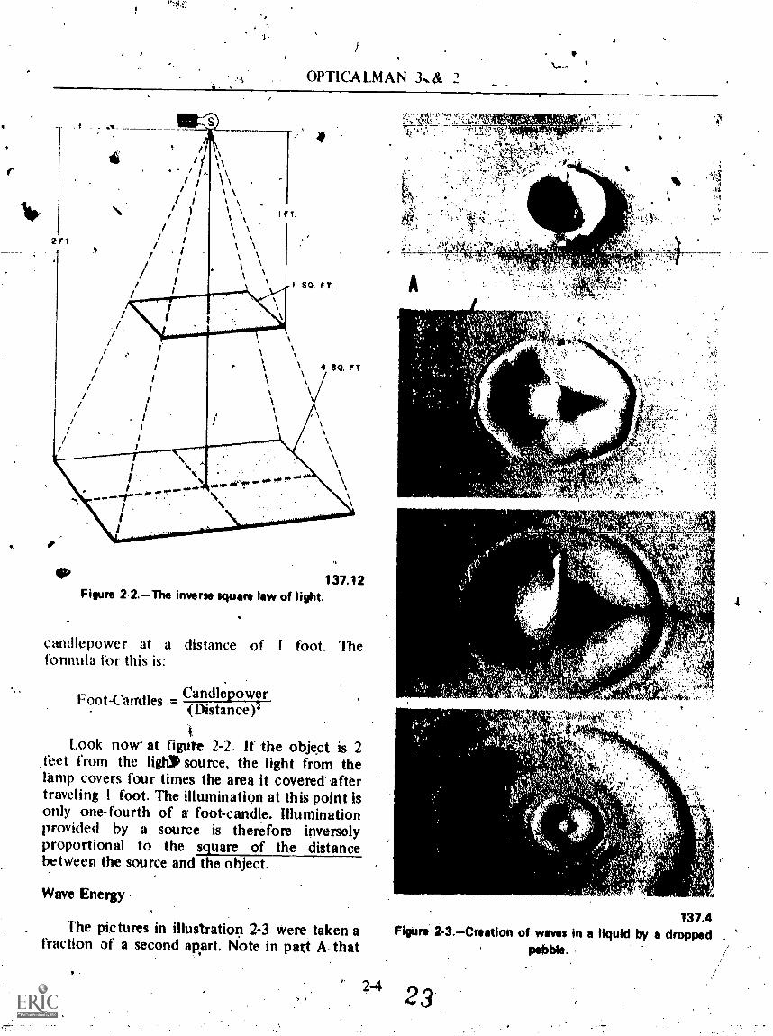
candlepower at a distance of I foot. Theformula for this is:
Foot_canxIles = Can.dlepower
(Distance)3
Look now at figure 2-2. If the object is 2sleet from the light source, the light from thelamp covers four times the area it covered aftertraveling I foot. The illumination at this point isonly one-fourth of a foot-candle. Illuminationprovided by a source is therefore inverselyproportional to the square of the distancebetween the source and the object.
Wave Energy
The pictures in illustration 2-3 were taken afraction of a second apart. Isiote in pad A that
'C' i 4
.;ikr4t,
-qo .
150'
137.4Figure 2-3.--Creation of waves in a liquid by a dropped
pebble.
23

Chapter '2 THE NATURE OF LIGHT
the pebble made a dent in the solution (milk):1)0(.1i it(1)iiiii t mtil(iie rrifsaicnies isparietc e sriiinogwsi tsthnliattutrhael
surface of the milk has begun to rise and thatthe original wave is beginning to spread. Energyis spreading out in the form of little waves onthe surface of the milk from the soijrce of thedisturbance caused by th'e pebble; The waves arecircles which get bigger and bigger As the mountof energy (wave motion) created by the pebblecauses them to ex Oand the bigger the pebble,.
&the greater the site of theves and circles.When all the energy produced on the milk bythe pebble is absorbed by the waves, they stopforming, as illustrated.
During, the latter part of the 18th century,,scientisk. found that radiation From hot bodiesconsists of- electroniagnetic waves (notmechanical). This type radiation is calledthermal radiation. Thermal radiition of lightwaves are of the same nature andexhibit similarproperties.- Like light waves, thermal radiationnormally travels in straight lines and can beJetlected front a mirror or polished metal.
,
Thermal radiation is not heat; iGs4nergy in theform of wave motion.
Luminous light sources such as the sun orthe glowing filaent of an electric light bulb actas oscillators in radiating energy in the form oflight waves, and these waves spread out in alldirections' from ,their sources. The sun poursforth radiant enetgy from its surface at the rateof 70,000 horsepower for every square yard. ofits surface.
Because light travels outwiird in alldirec ohs from its source, the waves take theform f growing spheres (fig. 2-4),.the luminous
(,
's.---..;,. point of which fs the center.
TRANSMISSION OF LIGHT .,We know now that all forms of light obey
the same general laws. When light travelsthrough a medium or substance of cobstantoptical densijy, it travels in waves in straightlines and at a constant speed. When light strikesa different medium from the one through whichit is -traveling, it is either reflected frolm, orenters, the medium. Upon entering a transparentmedium, the speed of light is slowed down if the
137.7Figure 2-4.Light waves created by a light.
medium is MORE dense, or increased if theMedium is LESS dense. Sortie substancei ofmoderate density have abnormal opticalproperties and, for this reason, they may bedesignated as olitically dense. If the light strikes,the medium on an angle, its course is bent(refracted) as it enters the medium. (Note:Reflection and refraction are discussed fullylater in this chapter. However, in discussing thecharacteristics of light, we must use termspossibly unknown to you and explain them onlyto the extent necessary for you to understandthe discussion.).
After yOti--Igi'n the characteristics of lightand the types and functions. of variouS opticalelements, you will then experience less difficultyin understanding image formation=the primepurpose of optical instruments.
LIGHT RAYS.
A basic problem in the deSign of opticalsystgns is the calculation of was4 surfaces asthey progress through the various optical media.In optics, the calculation of wave surfaces isapproached by taking a small number of raysand tracing these rays through the system.
2-5 24k

6
eP
t,)
OPTICALMAN 3 & 2
TH-A
RADIIOR
L I GMT'
RAYS
137.8Figure 2-5.Direction of travel of light waves.
11r
137.10Figure 2-6.Waves and radii from a distant light.
&Ogle rays of light do not exist; but theterm light ray is used throughout this manual forthe sake of clarity and convenience in showingthe direction of travel of the wave front. Light isipdicated by one, two, or more representativelight rays in white lines (with arrowheads toindicate the direction of travel.
2-6
137.11Figuns 2-7.Light rays creating an-image on the film of a
pinhole camera.
Refer again to figure 2-4 and note that lightis moving in all directions from the light bulb.Then study figure 2-5 which shows lines witharpowheads to indicate that the direction oftravel of the light is along the radii of the.sphereof light waves and at right angles to the fronts ofthe waves. The light which travels along thesemdii is designated as light rays.
A wave front radiating from a light source isextremely curved near the light Source which,causes' the radii of the sphere of the waves todiverge, or spread. As the wave front moves/outivard, however, it becocus less curved thefarther, it travels from the light source an geventually appears to be almost straight, asindicated in figure 2-6. After traveling a distance ,
of 2,000 yards from their light sources, radii areconsidered to be parallel to each other.
A pinhole camera (fig. 2-7) gives a goodexample of the manner in which light travelsoutward from its source: Such a camera ismerely a box with a sheet of film at one end anda tiny pinhole instead of a lens at the other end.Note that the camera is taking a -picture usinglight reflected froin the arrow in/frónt V tiecamera and thit each point on the arri)w isreflecting light rOs in a dispersed manner. Oneray pf light from each point on the arrow entersthe pinhole in the front of the camera and landsupon the film. Since Tight travels in straightlines, no light reaches a-given point on the filmexcept the ray which comes from thecorresponding point on the arrow. The rays oflight which tiass through the pinhole of thecamera form an inverted arrow on the film.
9Lw

Chapter 2 --TI4E NATURE 'OF LIGHT
WAVEI:ENGTH AND FREQUENCY
The action of waves on .the surface of aliquid (fig.. 273) has explained the wave motionof light, but to understa0 fully the speed atwhich light travels, you must comprehend thelength Qf a wave and its freOency:
A wavelvngth is the distance betvette, fr'tnr-~-crest on .one wave and the crest of the next(adjacent) wave, as illustrated in figure 2-8. Thebest way to measure a wavelength is by theFRF,QUENCY -the number of wiwes which passa point in I second. To determine frequency,put a stake in water and count the number ofwaves which pass the stake per second (fig. 2-9).
If waves ore movingot a speed of 3 feet persecond and have a frequency of. 6 _waves persecond, you can determ.ine the wavelength byusing the formula. that the relationshipbetween the speed, frequency, and wavelength.
The formula is: c = fX
where c = speed of light in a vacuum
f = frequency of waves
X = wavelength (Greek letter,lainbda)
By applying the formula to the above problem,you get
3.= 6X
X = 3/6 = .54
Light waves, in contrast with waves onwater, are rtiuch too short to be measured ininches or millimeters. (A millimeter is about1/25th of .an inch.)" A light wavelength issometimes measured in microns, represented in
/ formulas by p. A micron is one-thousandth Oamillimeter. For measuring' a shorter waVelengthof light, a smaller unit than a micron must beused. This unit is the M1LIAJWCRON, whichrepresents one thousandth of a micron and is.abbreviated mg.
Another important unit used for measuringwavelength is the ANGSTROM (AU), whiCh is1./10th of a millimicron, or one ten-millionth of
a millimeter. Because these units are stillsinonveniehtly long for measuring the shortest
2-7
4
137.14Fi re 28.Measurement of a wevillength.Ne
FREQUENCY- NUMBER OFWAVES PASSING GIVENPOiNT PER SECOND
137.15Figure 2-9.Determination of wave frequency.
electromagnetic waves, the X-ray unit is used forthis purpose. lt is ones one-thousandth of anAngstrOM unit.
ELECTROMAGNETIC SPECTRUM
The electromagnetic 'Spectrum miy bedivided into nine major regions of radiation;

OPTICALMAN 3 & 2
depending on the general character of the waves:(1) long eleetric waves, (2) radio waves. (3)radar, (4) infrared, (5) visible light, (6)ultraviolet, (7) X-rays, (8) gamm,a, and (9)cosmic rays. Together, all of these form theelectromagnetic spectrum, illustrated in figure2-10. The visible portion of the electromagneticspectrum consists of wavelengths from .00038to .00066 millimeters. The different wavelengthslepresent different colors of light. Note the.arrows which point to the wavelengths of thecolors'of the rainbow in the spectrum. Observealso that the wavelengths in this part ,of thespectrum (vision and photography)abare inmillimicrons of wavelengths. Wavelengths in theelectromagnetic spectrum (extreme lei.° are innticrons. .
In illustration 2-10 note that thewavelengths we call lieu' are between 400 and700 nip; each sRectral colo( has its own smallrange of wanlengths. For example, if light witha wavelengthlround 660 nip reaches your eyes,you see RED (sensation of red on the retina).Around 400_mp the wavelengths of light whichreach your eYes are BLUE; so the red waves aretherefore much longer than the blue waves.
When light with a wavelength Of 300 mpreaches your eyes, you regeive no sensation ofcolor. Radiation of this wavelength is generally
"called ULTRAVIOLET LIGHT: Ultraviolet rays(radiation) from .the sun cause sunburn andsometimes blisters. CAUTION: All shortwaveradiations can do some damage if you get toomuch of them. A prolonged dose of strongX-rays, for example, catty irreparable danIfigeto the body. Gamma ray*are deadly shortwaveradiation given off by atomic particles. Notethiit the infrared.. light raysware between lp and100p in the electromagnetic spectrum. Theserays are called HEAT rays. We -cannotseeinfrared rays; but if we could see them,everything would look different. Study figure2-11 which shows a photograph taken by visiblelight and figure 2-12 which shows a -photographof the scene taken with infrared film with a red
'filter over the lens.Infrared light. is .used also for signaling
between ships at night. In aerial reconnaiskince,too, we use infrared' photography to get more'and better detaili of the area photographed. Acamouflaged 'object, for example, may. blend
witli its surroundings and be invisible from theair; but if it does not reflect the' same amount ofinfrared as its surroundings, an infraredphotograph will make the camouflage stand outclearly.
During 'World War II, SNOOPER'sCOPESwith powerful spotlights, which sent forthbeams of invisible infrared light, were used towatch the enemy at, night. When the infraredbeamssent-out by the spotlight struck an objectand reflected it back to the snooperscope, thescope changed the infrared CO visiblewavelengths. SNIPERSCOPES used on rifles inthe Pacific during the war work on the sameprinciple as the snooperscope.
Observe in figure 2-10 that RADAR wavesare -.adjacent to the infrared rays in theelectromagnetiespectrum and have wavelength alittle longer than infrared. We know that thesewavelengths travel at the same speed as lightbecause they have been sent to the moon andreflected back in'about 2.6 seconds. Because thedistance of the moon from the earth isa p p rox im ately 240,000 miles (in roundnbmbers), 2 X 240,000 2.6 seconds184,615, the speed of .radar in miles per second.
SPEED OF LIGHT
The difference in the speed of light throughair, glass, and other substances accounts for thebending of light rays. Without this characteristicof light, a glass lens coula not bend light rays toa focus, as you will learn later in this text. Th'length of all waves in the electromagneticspectrum is also connected to correspondingfrequencies and the speed of light.
Because light travels at such high velocity, itwas years before anyone could measure itsspeed. Galileo tried to measure it by having twomen in towers on hills some distance apart flashlights at each other. Each person flashed his lightas soon as he saw the light signal of the other.Galileo thought he could determine the speed,oflight by dividing the total distance of light.traveled by the time required for thetransmission Of signals.. His experimenrwas notsuccessfttl; he concluded that the speed,of, lightwas too great to be measured by this method.His final thought ontle..speed of light was that
2-82 7

.Chapter 2-d-THE NATURE OF LIGHT
WAVE LENGTHN4 MICRONS
10" COSMICRAYS WAVE MOMS
10-* GAmmA WI NOWMICRONERAYS(DEEP
10-4 1 X-RAY UNIT THERAPY)100 (10' MICRON)
10-, 100 X-RAY UNIT
10 -4 1 ANOSTRdm UNIT
10-,
10
I mottirmatoN
10 MILLIMKRONS
too mItumatoNi
1 1 MICRON
.10 10 MICRONS I
10' 100 MICRONS
10' 1.mILWABIER
104 1 tENTIMETER
10' 10 CligIMETERS
106 1 METER
10' 10 METERS
MI. 100 METERS
106 1. KILOMETER
. 10 KROMITINS
10" 100 KitOMIteRS
1000 KnOmItIRS
1000)0tometilt$
INFRARED. (SPACE
HEATING)
HEATZIANWAVES
ARADAR)
RAVDr;/ESTELEVISION)
TRICAL -
LATIONSJR) a
VIOLET.0000134401 0003S - mm
.000017.04C M.00013. In44,
300 % ktiflmx .00046. moil
OWEN.000020. INCH .00031
move...,..,.....00150234404 .00056.mm
ORANGE.000024.01,401.0006144M
pp% RID.000026.1P4C=.00064 NUN
(I.MICRON).
(VISION &PHOTOGRAP
NOTItt THE SYMBOL 103 INDICATESTHE 'NUMBER IWO (OR 10X10X10),THE SYMBOL 1011 INDICATES THEFRACTION Q.001 (OR 1. ).
fox16x10
Rpm 240.-4sotromspies toretrum.
ft
137.10'tc:
tiEktai4,4*.imvitogeghLoor.#tfittLikrzie&--4414

I.
trt
OPTICALMAN 3 & 2
SLIT
ENS LIGHT REFLECTED FROMOCTAGONAL MIRROR
MOUNT
137.111Figure 2-11.Photogreph of scene in illustration 2-12
taken by visible light.
137.17Figure 2-12.Photograph taken by infrared INK,
its transmission through space was perhapsinstantaneous.
ROEMER'S MEASUREMENT
In 1674 Olais Roemer, a DanishIntrodoineri ealtulati the speed of light byobserving the imogiilarities in the times betweensuCceuive iclipses of the inionnost moon ofJupiter by that planet.
LIGHT RAY FLECTEDLtNS FROM-THE-MIRRO
MOUNT SAN ANTONIOEYE
137.13Figure 2-13.Miehelson's mirror method fo-r measuring
the speed of light.(-V
Roemer observed the position of Jupiter'smoons revolving around the planet. The moons
sappeamd on one side and then moved across infront of the planet and aisappeared behind it.He could calCulate accurately when one of themoons would be eclipsed by the planet. When hetried to calculate ahead six months, however, helearned that the moon eclipse occurred about 20minutes later than he had calculated. Hetherefore concluded that the light had taken thisamount of time to cross the diameter of theEarth's orbit, which is approxiMately186,000,000 :miles. The difficulty was thatRoemer did not correctly, evaluate the speed oflight; later measurements showed that the timewas about 1,000 seconds, which gave 186,000miles peisecond as the velocity of light.
MICHELSON'S MEASUREMENTS
The most accurate measurements of thespeed Of tight were m5de about 1926 by A. A.Michelson, a distinguished American physicistand his Colleagues. Michelibri used in octagonalmirror in an apparatils ilIustreted in flgweHe measured the ipeed Of light In sir over theexact distance between lit? Wilson soil Mt. SakiAntoOlo, California. The light source, octagofialmirror, and the telescope were-located on Mt.Wilson and the .concave, end plane if fOr$ werelocated on Mt. San Antonio about 22,milesdistant.
Stidy the illustration. Mirror (M) isestationary; Michloon owed a pencil bflight
2-1 0
74.4
Chapter 2 THE NATURE OF LIGHT
through a slit and a lens to the octagonal mirrorat I. (NOTE: A pencil of light is a narrow groupof light rays which come from a point source oflight.) Mirror (M) then reflected the light to theconcave mirror and mirrtyr M1 which'rellects thepencil of light back to point 3 on the octagonalmirror (M). The octagonal mirror was next putinto motion and increased in speed enough tomove position 2 on the octagonal mirror intothe position formerly occupied- Iv position 3during the time required for the light to travelfrom position -Von the octagonal mirror to Mt,San Antonio and return. After several yeah ofobservation with his apparatus, Michelsonconcluded that the speed of light in 'air is299,700 kilometers (a kilometer is .6214 mile)per second.
Sometime later, Michelson tfled anevacuated tube I mile long to measure the speedof light in a VACUUM. The vactkum tuberemoved variations in air density an&haze fromthe test, and the experiment showed that thespeed of light in a vacuum was sli tly -higherthan in air. The velocity of light i vacuum isgenerally accepted as 300,000 k ometers persecond, or 186,000 miles per secon
Modern physicists compute the peed oflight with great accuracy. Some of their'measurements are based on light interference.For all practical purposes, however, the speed oflight in air or in a vacuum is considered as186,000 miles per second. In media more densethan air, the speed of light is slower, 'as indicatedby the speed .at which yellow light passesthrough the following substances:
Quartz 1 I 0,000 piles per second
Ordinary crown glass
Rock salt
Boro-silicate crownglass . .
Carbon disulfide
Medium flint glass
Ethyl alcohol
Water
Diamond
.122,691 miles per second
11 0,000 miles per second
.122,047 miles per second
.114,000 miles per second
. . 114,320 miles per second
137,000 miles per second
140,000 miles Per second
77,000 miles per second
NOTE: All colors of light travel at the samespeed in b9th air and empty space. la moredense media, the velocity of light varies fordifferent colors depending on the wavelengths.
COLOR OF LIGHT
Because sunlight includes the whole range ofwavelengths between 400 inteand 700 nip, it Is imixture of all visible colors between red andviolet. Figure 2-14 shows how you can provethis. When the sun is shining, put a prism on atable in a room with one window. Cover thewindow with dark paper or cloth. Then cut ahorizontal slit about I inch long and 1/16 inchwide in the paper to admit a small quantity oflight. Hold the prism close tb the slit to ensurepassage of sunlight onto one of the long faces ofthe prism. (Lenses and prisms are discussed indetail in chapters 3 and 4.) At the same time,hold a ground glass screen or a sheet of whitepaper on the other Ade of the prism, 6 to 8inches away. When the sunlight passes throughthe pristn, wavelengths of various colors willrefract at different angles toward the.base of theprism and prbduce the colors of sunlight (therainbow) on the glass screen or sheet of whitepaper. This breaking up of white light into itscomponent colors is called .DISPERSION.vaiN tice that the red light, with a longer
elength, is bent less than the violet which.hasort wavelength.
SELECTIVE REFLECTIONAND ABSORPTION
It' you look at a piece of red paper in thesunlight, you see red; but this does not meanthat the paper is making red light. What it doesmean is that the paper is reflecting a highpercentage of the red light which falls on it andis absorbing a high percentage of all other colors.
When you look through yellow glass, you seeyellow because the glass is transmitting yellowlight and is absorbing most of the other colors.Usually, yellow glass absorbs violet, blue, andsome green, but it transmits yellow, orange, andred./When yellow, ,orange, red, and a little greenall enter your eye at the same time, howeveri thecoler you see is yellow.
2-11
.30
'7

,
,,,,,._ .
1.1-41.1.1.-U4*.11
.
OPTICALMAN 3 8i/2
137.19Figura 2-14.--Dispersion of light into a spectrum by prism.
Selective absorption of light is what takesplace when a color filter is used on an optkalinstrument. An iniage may be blurred by laze orfog, but when a yellow filter is put Intof9Te lineof sight ,the image becomes sharper. Th Ironfor this is that a thin haze permits mo )of thelight to pass through; but it scatters son? of theblue and violet light in all direcli6iis. Haze istherefore visible because of the scattered 'blueand violct colors. The yellow filter absorbs blueand violet ,and the haze becomes Almostinvisible. Filters made in any particular colorWjII transtnit light of longer wavelength than thecolor' of the 'filter, but will absorb light ofshorter wavelengths.
COLOR VISION
A pure ipectral color is composed of light ofone wavelength, or .a very harrok :band ofwavelengthp. When this light enters your eyes, itgives a sensation of color; but you cannot judgethe wavelength of light from color sensation.
""' Most of the colors yOu see Itie not pure spectralcolors Nit mixtures of these) colors. Thesensation you get hom these inixtures istherefOre not idWays.what you may expect.
V1rSIBILITY OF OBJECTS'
To fully understand the ability to see anobject, you must understand what light is andhow it reacts with matter. To be" sure youunderstand, review. the 15 items listed belowwhich you have studied:
1. Light is a form of eneiiy.2. Experiments show Outt light has the
nature of particles and is dispIrsed in waves.3. Luminous objects are a'source of light.4. Nonluminons objects reflect light from
another soure. ,5. Visible objects reflect light that enters
our eyes.6.4Light travels in straight lines as rays of
ligh t.7. Only the energy of a wave travels.8. The intensity, of light is measured in
candlepower (or lumens).9. Wavelength is the distince between two
successive waves.10. Frequency is the number of waves
passing a fixed point in 1 second,1 I; Visible light la a relatively small range of
.the electromagnetic spectrum.
161

Chapter 2THE NATURE-.OF LIGHT
the shell at difThrent angles; t1i.. ou n t of lightreflected from any surface depends uPon theangle of incidence (explained later) at which therays oflight strike the shell.
137.24RV 2-15.Vitual *termination of difference between
oblate.
1,2. The speed of all electromagnetic waves isthe same, even In a vacuum.
13. Thee speed in more de;se media is lessand varies with the wavelength.
6
14. White light is made up of a mixture ofwavelengths between about 400 find 700 mp.
15. When an object reflects some of thewavelengths of light, but absorbs others, it givesa sensation of color.
We see things because of reflected light.Objects look differently because they reflectlight in a differer4 manner. The difference in theintensity of light or the texture of a surfacemakes a differettce in the visibility of an object.Color, likewite, makes a difference in thevisibility, of objects: If one object absorbs twiceas much colcir as another object, you have nodifficultif in differentiating between them. Yo.0can therefore judge the size and -shape of adobject because, td the 4Ifference in color orintensity of reflected light'.
Refer now to figure 2-15, one part of whichis an igg and the other pert a piece of whitecartlbdord cut to the approximate dimensions ofthe. egg. You can `easily Aistinguish betweentheM by the way light is reflected from them.All 'parts of the cardboard tetlect light equally,becaUse SII rays of light fall on it at the sameangle. Rays of light,sm the egg, however, strike
Another way to tell the difference betweenthe 'egg and the, piece of cardboard is by theshadoWs cast by the egg Observe the right sideof the- egg. Because of the difference in theangles-, at which theligh-t§ttikes the youcan th.detect roughness in e shell. This rou nessindicates texture, which caUses an object toshow-minute differnces in color or shape allover the surface.
-For the sake of convenience, we can divideobjects into three classes, according to thereaciion of light when, it falls upon them:opaque, translucent, and transparent.
OPAQUE
AU the light which falls upon an opaqueobjectis either reflected or absorbed--none ofthe light passes. through. This is important,
.becaUse. most objects are opaque. No object,howeier, is completely opaque. If it is thinenough, you can see through anything. Evenheavydnetals such as silver and gold allow somelight -.to pass through them when they arepainted in a thin film on glass.
Tubes that hold lentes.and prisms in optical,syitems are opaque to prevent entrance of lightinto' the. system except through the frorit lens.These tubes are painted a dull 9r Pat-black colorinside' so that they will absorb and not reflect.light which falls upon them.
TRANSLUCENT
When ll4i t falls !von a translucent object,.
sonw-of.it is bsortoe'd and refletted, but boost ofthe light passes through the object and diftlisetior scatters in all directions. This is whathappeni; fOr example, when light passes throughground glass plate, stained glass windows, or *ttthin sheet of paper. If you hold these items 10
,. front olla strong light, you can see thatinuch ofthe light passes . through eve* though you treunable kr tee itlear image, of the Souttie of light,
32a ,.,/,/,',7%;";.;;;Jii::j/6.7V.,.7.il
OPTICALMAN 3 & 2
.1
137.25Figure 216.Reflection of a beam of light beck on its
normal or perpendicular.
TRANSPARENT
A transparent object reflects and absorbs asmall amount qf the light which strikes it, butpermits most of the rays to pass through.
Reflection and absorption are prime factorsin determining the quahty fin the manufacture of Indiscussed in greater detail
A window pane is a gootransparent object: Clear glass'ishe transparent, but the thickergreater its loss of transparency.
0 glass usedis will be
nanual.example of aconsidered tothe glass, the
REFLE
You know from experience that a mirrorreflects light. It you experiment 'with a planemirror in a* dark \worn with a window throughwhich ydu can adinit light, you *ill find thatyou can reflect a beam of light to almost anyspot in the room. When you hOld a niirrorperpendicular to a beam of light, yot_i can reflectthe beam back along the same path ..by which itentered the room, as shown in figure ',2-16.
137.26'Figure 2-17,--Reflection of beams of light at; different
angles.
If you shift the mirsor to an angle from itsperpendicular position, the rellqcted beam isshifted at an angle from the incoming beamtwice as great as the angle by which.you shiftedthe mirror. Study figure 2-17. It' you hold,themirror at a 45° angle to the incoming beam:thereflected beam is pppjected at an angle of 900 to,the kncoming beam. Remember this,characteristic of light.
The simple experiments just discussedillustrate one of the dependable actions of light.You can reflect light precisely to the pointwhere you want it, because any kind' of, lightreflected from a smooth, polished surface acts inthe stime manner. This property of light is usedin many types of fire control instniments.
Refer now to figure .2-18. The ray of lightwhich strikes the mirror is ialled the INCIDENTRAY, and The ray which bounces oft' the mirroris known as the- REFLECTED RAY. Theimaginary line perpendicular to the mirror at thepoint where the ray strikes is called theNORMAL or PERPENDICULAR. The kmglebetween the incident ray and the .normal ietheANGLE OE' INCIDENCE: the angle betwpen thetvflected ray and the normal is thc,,ANGLE OFREFLECTION.
2-14 33

Chapler 2 II ll NTURE OF LRAIT
'Of
ANGLE Or INCIOENCI
-t NtiR MAL OR- - - - - - - -ANGLE OF REFLEC r ION
RPE NOICUI. AR
MIRROR
110.30Figure 2-18.Terms used for explaining reflected light.
LAW OF REF 1. -HON
rite law of ref Ice t i on ic covered by threebasic statements:
I . e angle of ik...flection equals the angleof incidence.
2. !be incident r:ty and the-reflected raylie on opposite sides_ot'the normal.
3. The incident ray. the reflected ray, andthe normal all he in the same plane.
..By applying the law of reflection, you cansee that in all cases of reflection the angle ofreflection can be plotted if th'e angle ofincidence is known, or vice versa. To illustrate,study figure 2-19. In this instance you desire toput the No. 4 ball in the nearest pocket, butyour.cue ball is behiiid the 8 ball: lf you are anexpert p401 player, you know where to strikethe right side of the pool table with the cue ballin order to'.have it reflect on a linewhich willenable it to hit the No. 4'ball and piit it in thepocket'Angle b must etjual angle a.
REGULAR RVFLECTION
Mirrprlike reflection in 'which the angle ofreflection is equal to the angle of incklence iscalled specular _reflection which is commonlyknown ts regular reflection. Specular reflectiortcan come only 'from a piano polished surface,and, if the incident light is parallel: the-refleetedlight will be parallel as shown in figure 2-20.
137.29Figure 2-19.Application of the law of reflection on a
pool table.
DOTTED LINESNORMAL
2-15 34
Figure 2-20.Regular reflection.137.30

OPT1CALMAN 3 & 2
DOTTED L1NESNORMAL
Figure 2-21.Diffuse reflection.
_LIGHTRAY
WAVEFR-ONT
14,
DIFFUSE REFLECTION
The opposite_of specular reflection is difOsereflection, and it will occur when liht is
reflected from a rough ...surface. Diffuserellectiod is defined as a random distribution ofincluded angles for a series of rays traveling fromthe same source. As shown in figure 2-21,diffuse reflection is a scattering of the reflectedlight- and it accoutirt tor our ability -to -seeallnonluminous obje4s,..as well as to distinguishshape and texture. TAe surface of the paper inthis manual is essentially rough and the lightthat is.rellected from it is diffused.
REFRACTION
As you .study the meaning of refraction,refer to figure 2-22 which shows what happens
137.31 to rays of light as they pass through a sheet ofglass. Both plane surfaces of this glass plate are
NORMAL
Figure 2-22.Refraction of light beams by a shoot of glass. .
2-16 35
13732
`4.
Chapter 2 THE NATURE OF LIGHT
parallel, and air contacts both surfaces. Glassand air arc transparent, hut the glass is opticallymore dense than air:, therefore, light travelsapproximately one-third slower in glass than inair. -
Observe the dotted line4 (N N') in theillustration. These are the normals erected forthe incident and refracted rays. When a light ray(wave front ) strikes .the surface of the glass atright angles (parallel to the normal), it is notbent as It passes through the glass. This is truebecause each wave front strikes the surfacesquarely. The wave front is slowed down when itstrikes the surface of the glass, but it continuesin the same direction it was going before strikingthe glass. When it squarely strikes the othersurface of th e. glass. it passes straight throughwithout deviation from its courSe and resumesits original sp..ed.
If a wave front strikes the first surface of' theglass at an angle, as illustrated in part B of figure2-22. the leading edge of the first wave frontarrives at the surface an instant before the otheredge: the leading edge is slowed down as itenters the more dense medium before thesecond edge enters. Observe that the secondedge also continues to travel at the same speeduntil yt strikes the surface of the glass. Thisslowing down of one edge of the wave frontbefore the other edge slows .down causes thefront to pivot tyward the normal.
The information just given about the way awave front strikes a glass plate applies to ANYFREELY MOVING OBJECT. When one side ofan object is Mowed down as it hits something,the other side continues to move at the samespeed and direction until it also hits something.This action causes the object t'q pivot in thedirection of the side which hits first and to slowdown. Unlike light:which is a form of, energy,freely moving objects do not resume theiroriginal speed without the application of powerof some sort. Pivoting or bending of light rays(wave fronts) as just explained, is calledREFRACTION: and the bent (pivoted) rays arecalled REFRACTED RAYS.
If the optical density of a medium '(glass inthis ease) remains -constant, the refracted lightrays continue to travel in a straight lint, asshown in part B of figure(2-22, until the surfacefrom which they emerge (glass-to-air surface)
causes interference. At this point. an oppositeeffect occurs to a wave front. As the leadingedge of the front reaches. the surface(glass-to-air), it leaves the surface 'and resumesoriginal speed (18(,000 miles per second, atwhich it entered the glass).
Speeding up of one edge of a wave frontbefore the other edge_ speeds up causes the frontto pivot agaith_ but this time it pivots toward theedge bf the front which has not yet reached thesurface of the glass. Again, this bending orpivot ing of t he wave front is calledREFRACTION.
If the glass plate has piirallel surfaces, theemergent light ray (ray refracted out of theglass) emerges from the second surface at anangle equal to the angle formed by the incidentray as it entered the glass. If you draw a dottedline along the emergent light ray Ifig. 2-22)straight back to the apparent source of th;: ray,you will find that the emergent ray is parallel tothe incident ray.
If the optical density of a medium enteredby a light ray .(wave front) is constant, the lightfollows its course in a direct line, as illustrated inpart B of illustration 2-22.
LAWS OF REFRACTION
You should understand thoroughly all lawsof refraction. Briefly stated, they are as follows: .
I. When light travels from a medinm oflesser density to a medium of greater density,the path of the light is bent toward the normal.
2. When light travels frpm a mediuin ofgreater density to a medium of lesser density,the path of the light is bent away from thenormal.
3. The incident ray, the normiil, and 'therefracted ray all lie in the same plane.
4. The incident ray lies on the opposite sideof the normal from the refticted ray.
Study illustratiOn 2-23 and then reviewcarefUlly all laws of refraction. Note the normal,the angle of incidence, and the 'angle ofre fraction .
2-17 36

OPTICALMAN 3 & 2
ANMQF INcIDENO
NORMAL
ANGUE,OF REFRACTION
.REFRACT 'RAY-
MAL
Flom 2-23.Torms used for d0crIbing refraction.
The amount of refraction is dependent uponthe angle at which light strikes a medium andthe density of the new mediuinthe greater theangle of incidence and the more dense the newmedium, the greater the angle of refraction.. Ifthe faces of the medium are parallel,the bendingof light At the two faces is always the same. AsIllustrated in figure 2-23, the bAam which leavesthe optically moro dense Mednun is parallel tothe incident beam. An important thing to keepin mind in thi* respect, however, is that theeniergent beam must emery from the moredense medium into a medium of the same indexof refraction * the one in which,. it wasosiginally traveling: that is, air to glass .to air,NOT air to glass to water (as an example);
You can visually demonstrate refraction byplacing the straisitt ed of a sh*t of paper atan 04111 under the edses of a Os piste lieldVertically (fI& 2424). Olbserve that the straight,,
4.
12.233
248,
i
faiStAi,T;eLltaL3Let;t1:VatiLl'.,-Z

Chap4er 2 THE NATURE OF LIGHT
edge ol the sheet of paper appears to have a jogin it directly under the edge of theglass plate.the portion )1 the paper on the other side ofthe .glass appeat-s displaced as a Nti lilt ofwit-action. II you move the sheet of paper andchange the :Ingle of its straight edge, the amountof refraLtion is increased.
Study figure 2-25, which shows a straightstick in a _glass of water. Note that the stickappears bent at the surface of.the water.cWhatyou see is an optii!al illusion created byrefraction. When a ray of light passes from airinto water, it' bends; and when it passes from thewater into the air, it also bends. This illustrationshows why a fish in water is not where it seemsto be; it is much deeper.
Now observe figure 2-26. This illustrationshows how light is, affected by a medium whoseentrance and emergence faces are not parallel toeach other. As shown in the illustration, ihI lawsof refraction still apply.
The.angle between the wfracted ray of lightand a straight extension of the incident ray oflight through the medinm is called THE ANGLEOF .DEVIATION. This is the ang0 through-which the refracted ray is bent from its originalpath by the optical density of the refracting
1
ENT RAYSSTRIKING
FRONT FACRAYS EMERGING
FROM REAR FACE
oee
.0
ee.e
0.EVIATION
°'
110.32Figure 2-26.Passage of light rays through a prism.
medium and the angle between the entranceandemergent faces.*
INDEX OF REFRACTION
As you read earlier in this chapter, the speedof light in a vacuum is about 186,000 miles persecond. Its speed through ordinary glass,hOwever,, is about 120,000 miles per second.This ratio between the speed of light in a
. vacuum and the speed of light in a transparentmedium is known as the INDEX .OFREFRACTION for that medium. On opticaldrawings and in optical textbooks, the index ofrefraction is designated by the letter n: It iswritten as a ntimber and applies to the relationbetween ie speed of tight in a vacuum
e, compared w the speed of light in, the mediumunder consider1ion.
The index bet een two media is called the137.33 RELATIVE INDEX while the index between a
Figure 2-25.Ciptical illusion caused by refraction, medium and a vacuum is called the ABSOLUTE
2-19 38

OPTICALMAN 3 8(.. 2
,INI)EX. The ind4 of refraction . expressed intables is the Asolute index, while in practice therelative index is figured. When working withoptical drawings of instruments, the relativeindex must be figured because you will havelight passing from one medium to anothyr (air to'glass, glass to glass, and gas to glass).
To determine the absolute index the formulais:
Velocity in VacuumIndex of refraction =Velocity in Medium
Now apply the .formulato figure the absoluteindex of a diamond in which light travels at77,000 miles per second.
186,000n = 77,000 2.415
If yoti need to determine the relative index of adiamond in water, you need only substitute thevelocity in water for the velocity in a vacuum.
140,00077,000
Following is a list of absolute indices ofrefraction for some mikteri*:
Vacuum 1 000'.
Air 1 0003
Wa,t47 1 33
FuSed quartz 1 46
kCrown glass, 1 52
Canada balL, 1 53
Light flint glass 1 57
NOTE: For most coAputations the index of airis considered to be the same as vacuum (1.000).
Since the index of refraction of transparentmaterials of high purity shows a constantrelatiOnship, to the physical. properties of. thematerials, you can determine the identity 'of
transparent materials by fneasuring their indicesof refraction.
ANGLE OF REFRACTION
The amount that a ray of light is refracted(angle of refraction) in a transparent mediumdeinnds on two factors:
I. The angle at which light strikes thesurface (angle of incidence)
2. The density of the medium (index ofrefraction)
When light from the same source strikes twodifferent media at the same angle, the lightstriking the medium with the highest index ofrefraction is refracted The most.
,In 1621, Willebrord Snell, a Dutchastronomer and mathematician at the Universityof Heyden, found the correct relation between.the angle of incidence and the angle ofrefraction. Snell developed a, formula foredetermining the angle of refraction frown asSNELL'S LAW.
n sine 0 = n' sine B' i1.
In this formula, n is the index of refractionin the first medium, n' is the indelx for thesecond medium, sine is a trigonometric function,and 0 (the Greek letter theta) refers to the firstangle, while 0' refers to the second angle..
Simply stated, Snell's law says:
The index of refraction of the fustmedium times the sine of the angle o incidenceis equal to theo index of refraction of he secondmedium times the sine of the angle Of graction,
NOTE: In order to finlithe sine of an angle, youmust refer to a tat leiTenatural trigonometric
.4.functions.
A very important thing for thb reader toremember is always 'mlasure the angle ofincidence between the incident ray and thenormal; likewist, measure the. angle of refractionbetween the normal and the refracted ray.
39zao

Chapter 2 -THE NATURE OF .LIGHT'
In order to apply the formula to a practical.problem let's assume that the ray of light infigure .;-23 is contacting, at an angle of 450, aplate eif *hiss whose index Of refraction is 1.500.Accorditig tO Snell's law, the index of refraction(n). of the first medium (air = 1.000) times thesine of the angle of incidence (450 = .7071)equals the index of refraction (n') of the secondmedium (glass = 1.500) time% the sine of theangle of refraction,
1.000 X .7071 = 1.500 X sine 0'
.7071 = 1.560 X sine 0'
.70711.500 = sine 0
.4714= sine 0'
By referring once again to the naturaltrigonometric tables, you will firil that .4714 isthe value of the..angle 28°7'30", the angle ofrefraction in the second medium.
If you now reverse the direction of, ic lightray to where the first medium is glass, esecond medium is air, and the angle of incidenat the surface of the glass is 28°7'30", you wilfind .the angle of refraction is 45°. This mayseem strange, but by application of Snell's lawthe formula will be:
1.500 X .4714c 1.000 X sine te
.7071 = 1..000 X sine 8'
.,,707 . I.. 1.000 = sine 0
.7071 = 45°
What you have just proitd by solving thelast equation' is known as the LAW OFREVERSIBILITY, something you shouldremember. The. law' means that if the directionof a ray of light at any point in an 'opticalsystem is reversed, the ray retraces its path backthrough the system, regardless of the number ofprisms, mirrors, or lenses in the system. .
e.
REFLECTION ANDREFR ACTION COMBINED
Smooth glass reflects about 4% of the lightwhich falls upon it (more if the angle ofincidence is-large), but most of the light whichenters the glass is refracted. Figure 2-27 shows a
ray of light passing through plate. glass. Thedotted lines are the normak The white(upward). arrow to -the right of the first normal'line indicates reflected light. The line of lightwhich extends upward from IV second nornialrepresents the amount of light reflected backinto the glass when the light strikes the lowersurface. This is called INTERNALREFLECTION. An internally reiletted ray oflight is refracted at the upper surfaceof the glassand emerges parallel to the raffectioh from theincklent ray. .
Study illustration 2-28,, which showsreflections from both surfaces of a glass plate.NOte the two images. If you have several platesof glass in a stack Aiiith thin layers of-air betwlignthe plates, you can see twice as many reflectionss the number of plates of gla%. NOTE: You
, will occasionally find a condition'such as this inoptical instruments.
137.35 .
fkiguri 227.flefiection and refraction oombined.
2-21
4 0

OPTICALMAN 3 & 2
137.38.
Figure 228.Reflection from the surfaces of a glasipiste.
If there are 5 lenses in a system, there are 10faces; and each face reflects part of the light..The image you see when you look through theinstfument is formed only by the light whichpaises. through all the lenses. A complexinstrument such as a submarine periscope mayhave many surfaces which reflect part of thelight4ind the optical elements must have a filmor coating applied to them to eliminaterefledion and prevent loss of light in theinstrument.
You know that optical glass is highlytransParenf, but it is still visible becaitse,.:01reffic* light . from its surface. Othef?-glass-objects are visible partly, because of refraction,YOu cant sed part of tht background through .the
but ihe glass bends the., rays from thebit' round before they reach, your eyes. Inup) ance with the angle at which it strikes the .
OrfaCe of the glass;.eachrraY bends at a differentangle. The backgrOund, therefore, appeart:diatorte a. when you see it through the glass,* inNO , 2-29, The glass rod, however, is clearlyvisible.because of refraction cauied by the shapeOf the rod and reflection of 'light from thetittfice,of the 418103A
Figtite .2,30 $ the same as figure 2-29 Figure 240,Effact. of visibirliy. Sy 'ha *mien, et. , .
EtpeOt,-that.`'water has been 'plit into the glass,,....,
.,
r.
(lk
137.37Figure 2-29.Visibility resifting irom combined refio.
tion and retraction.
41, "
7
reflOtIon inn re-fraction,

Chapter 2 -THE NATURE OF LIGHT
beaker, and the part of the glass rod in thewater appears different from the part out of thewater. The reason for this is that the index ofrefraction between the two- media-is now muchsmaller, so there is less eeflection but a largeramount of refraction due to the curved surfaceof the water in-the beaker: This curved surfag.Caus Zs a varied amount of refraction so the trdin the water appears larger.
If the water in the beaker is replaced with .a'solution having the saniCiiideX-of refraction-asthe glass, there will be no reflection or refractiontaking place between the surface of the rod andthe solution. See figure 2-31.
Reflection can take place ONLY at a surfacebetween two media with *fferent indicps of
4* refraction. Because the rod in figuie 2-29 is inthe air, the difference between the-two media isfairly large and the rod is visible. This same ruleapplies to refraction, as you can Prove by Snell'slaw. If the indices of refraction of the two mediaare identical, the angle of incidence equals theangle of refraction add there is NO refraction.
137.39Figure 2-31.Elimination of visibility by eliminating
reflection and refradion.
TOTAL INTERNAL REFLECTION
You 'have learned that a Small amount ofreflection occurt when light passes from onetransparent medium to another as in figure 2-27.Wken,1 light passes from a More dense medium toa less dense mediUM there is ono special angle ofincidence which will not.produce refraction norreflection as we have thus far studied. This
.special aigle of. _incidence is aka__ the__CRITICAL ANGLE and, when an incident raystrikes the surface between the two media at thisangle, it will be transmitted along the media'ssurface as shown in figure 2-32.
Should ray of light strike the surface at anangle of incidence greater than the critical angle,total inteitial reflection will occur (fig. 2-32).This phçnornena of tcital internal reflection isvery use l and Will be discussed further withprisms i hapter 3.
Study figure 2-32 carefully. This shows thatrays bf light from an underwater source areincident at various angles to the surface. Youwill notice that as the angle of incidenceincreases, .the angle of refraction becomesproportionately greater, until you reach thecritical angle. When you reach the critical angleand the ray is refracted along the surface, `theangle of refraction is 900 to the normal. Alwaysbear in mind that the critical angle can only beshown when light is traveling from a:more denseto a less dense medium. Remember that for all
AIR
WATERTOTALLY
REFLECTED RAY
CRITICAL ANGLE
rIts-I NORMAL
137.40"Figure 4t-32.Angles of light rays from an undenVatei
H 42
SOWN.

6PTICALMAN 3 & 2
angles of incidence greater tharl the criticalangle, total reflection will result.
The actual critical angle f an opticalmedium depends upon the index Of refraction ofthat medium. The higher the index of refraction,the smaller the critical auk.
Suppose you Want to calculate the criticalangle of a medium when the other .medium is
Flow can you do This? Me water as onemedium, as an example, and air as the other;then make proper substitutuions in the formula(Snell's law) and solve the equation. The indexof refraction of water is 1.333; when the angleof incidence is the critical angle, the angle ofrefraction is 90°. The procedure for solving theproblem follows:
n sine 0 = n' sine 0
1.333 sine 0 = 1.000 sine 900(The sine of 90° is 1.000)
1.333 sine 0 =1.000 X 1.000
1.000sine 0 = 0-7.0- = .75018" <
0 = 48°36'
Critical angles for various substances (whenthe external medium is air) art; as follows:
Water 48°36'
Crown glass 41018'
Quartz 40°22'
Flint glass 37°34'1
Diamond
The small critieal angle of a diamondaccounts for its brillance, provided it is a wellcut diamond The brilliance is due to totalinternal reflection of light; the light is reflectedbackand forth many times bbfore it emerges roproddce bright, multiple reflections.
One example of total internal reflection atMe surface of water is shown in figure 2-33.Rays of light from the fish strike the uppersurface of the water at an angle greater than thecritical angle and are reflected dOwnward intothe water. The reflected rays, however, strikethe end of the aquarium at leAs than the criticalangle, so they pass through and you can see animage of the fish reflected by the upper surfaceof the water. The path of a reflected ray is
ATMOSPHERIC REFRACTION
At a surface which separates two media ofdifferent indices of refraction, the direction ofthe path of light changes abruptly When it passesthrough the surface. If the index of refwtion ofa single medium changes gradually as the lightproceeds from point to point, the path of lightalso changes gradually and is curved.
Although when air is most dense it has arefractive index of only 1..000292, the index issufficient to bend light rays from the sun towardthe earth when these rays strike the atmosphereat an angle.
The earth's atmosphere is a medium whichbecomes more dense toviard the surface of theearth. As a result, a ray ot' light traveling through
137.41Figure 233.Total internal reflection at the surface of
vater.
2-24 43 0

Chapter 2 THE NATURE OF LIGHT
137.42Figure 2-34.-Effect of total internal reflection on light rays.
the atmosphere toward the earth at an angledoes not travel in a straight line but is refractedand follows a curved path. Prom points near thehot-imp, in fact, the bending of light is so greatthat the setting sun 'is visible even after it isbelow the horizon (fig. 2-35).
Mirages
Over large, areas of heated sand or waterthere are layers of air which differ greatly intemperature and refractive indices. Under suchconditions, erect or inverted (sometimes much
do.
ft
\\\.%
1 //e.<_PP.HORIZON
.°"---...447-4":7---- ACTUAL POSITION OF SUN
APPARENT POSITION OF SUN
,.144,,
Iwo%
a
. 04
Figur. 2-35.Visibility of the sun below the hot
2-24 4
c
n as a result of refracted light.137.44

r
OPTICALMAN 3 & 2
. 7tr
4;0'0'4 fpf, '4161fr
asii&'of
'4
Figur. 2-35.Pictur of a mirage in a desert.
distorted), images are formed which are visiblefrom great distances.. T ese- images areNil RAGES.-
Observe the apparent laket of water in adesert in illustration 2-36. This looks like .a reallake but it is ONLY a mirage caused by therefractiOn of light over the hot sand. The sandheatS the'air directly above it, though the air at ahigher level remains comparatively cool. Ilecausecool air is. more Onse than hot air, the index ofrefraction is- fairly low at the surface andgradually increases at higher and higheraltitudes.
Study illustration 2-37 to learn whathapPens to light rays in' a Mirage. Light rays intvol air do not bend, as shown, but the raywhich, travels downward toward the hot, aircurves upward. When an observer looks at anobject along the hot air ray, he thinks, he sees italong the dotted line in the illustration,
You perhaps have observed mirages onasphalt higkways on clear, hot days. When the
'
.,.
2.26
137.45
137,46..Figur. 2-37.Path of lighi rays in a mirage.
highway rises .in front of-you and then flattensout, its surface forms a .small angle with yourline of sight, and YoU see reflections of the sky:These' reflection's look like puddles of Water inthe .road. Under proper ceinditions of the
A. .. .. .
, .
. ' ' -...-'---.- -'''-' ^ -` "-- ' o.'" ."- '--'" `''' ....- -4:4 ,v4-,..- k3:.:1-441i4, ,:,,i;44:. s." _,= ,-%:';':.

. Chapter 2-blE NATURE OF LIGHT
atmosphere and light, you can even see anapproaching car reflected in the mirage.
toonting
Looming is th l! exact opposite of a mirage.S h i ps , light ho uses, objects, and islands-sometimtloom they appear to hang in the skyabove their real locations. On some bodies ofwater (Gulf bf California and Chesapeake Bay,for eiramptc) loom-htvis common. Figtif .-21-3-g-sbows the path of light rays'in looming.
The reason for looming is that air is cooledat4thc water's surface and index of refraction ofthe aft decreases higher up causing the rays oflight to bend downward, as shown in theillustration. This explains why a lighthousesometimes appears to havg in the sky.
Heat Waves
On a hot day the columns of heated airwhich rise from the earth are optically different
C.
137.47Figure 2-38.Peth of light rays from a loominjj object.
ti
,
from the surrounding air and. rays of light areirregularly refracted. The air is turbulent, andconditions under which observations are madechange constantly, An object viewed throughsuch layers Of air therefore appears to be inmotion and the air is boiling; or the image isdancing because of heat waves. This congition isparticularly bad for using a high-powered .telescope of more than 20 power. The -heatwaves _are_ caused by the refract ion of-light wavesat various angles, thereby creating a distortion.
Rainbows
The .formation of a rainbow is a goodexample of refraction, reflection, and dispersionall coMbined. Before you can see a rdinbow,however, several conditions must be ideal. Firstof all, you must be looking toward a pointwhere the atmosphere holds millions of drops ofwater, either in the fore of mist or falling rain.The sun must be shining from a point behindyou and it must be fairly ,low in the sky. (Whenstanding on the ground, you can rarely see anatural, rainbow at noon). .
Figure 2-39 illustrates what takes place in,the formation of a rainbow. Qf course, it takesmillions...of drops of water mid you see sevencolors, liut, for 'gimplicity,. the diagram onlyshows Thive drops of water ahd three motors.Rays of light are striking at litany points on thesurrace of each drop., but theqays that strike atcertain points, as shown in the diagram, are theonly 'ones that can be seep When. the ray entersthe drop of watey, it is immediately refractedand dispersed. The light is then reflected backtoward the surface due:to inttrnal reflection andis refracted-again as it leaves' the drop of water,
, eontinuing to be dispersed into spectral color asit enters the atm(Oiere again.
2-27
2..

OPTICALMAN 3 & 2
Figure 2-39.Formation of a rainbow.
.4111111100
472-28
137.48

CHAPTER 3
MIRRORS MD- PRISMS
This chapter is devoted primarily todescriptions of plane mirrors and prisms and theeffect they have on light transmission. However,before you get into the discussion of mirrors andprisMs, you should be familiar with two basicfactorsmeasuremeht systems used in optics andimage descriptions.
MEA9UREMENTS IN OPTICS
An Opticalman at various times works withat least four systems of measurement: theEnglish system, metric system, degree system,and mil system. You are already familiar withthe English system where the basic unit, thefoot, can be converted to smaller or larger unitsby multiplying or dividing by known conversionfactors: The English system is not entirelysatisfactory for optical measurements because itis complicated and cumbersome. The lack ofsimple 4elationships between units makes it verydifficult to carry out computations. Hence,other systems of measurement are sometimesmore desirable.
METRIC SYSTEM
Shortly after the French Revolution, nearthe end of the 18th century, the NationalAssembly of France decided to appoint acommission to develop a more logical measuringsystem than those in use at that time. Theptoduct of that commission was the "metricsystem," which has been adopted by mostindustrialized countries except the United
3-1
4
States. The United States is beginning a slowconversion to the metric system.
In 1960, the International Conference onWeights and Measures adopted a modernizedversion of the metric system called theInternational System of Units, (SI). SI wasestablished by international agreement toprovide a logical interconnected framework forall measurements in science, industry, andcommerce. The six base units 'of measure underSI are:
Length = meter (m)Mass = kilogram (k)Temperature = kelvin (K)Time = second (s)Electric current = ampere (A)Luminous intensity = candela - cd
In your work as an Opticalman, you will usethe metric system of measuring as well as theEnglish system. The diameter and focal length oflenses are usually stated On optical drawings, Totexample, in millimetersnot In inches. Inaddition, with some experience, you will findthe metric' system much easier to use than theEnglish system.
Decimals are basic in the me stem .ofmeasurement. You can easily convert TOunit another. Suppose you know that anobject is 0.67 meter long and you need to knowthe length in decimeters. All you need do ismultiply by 10 to find that it is 6.7 decimetersin length,. If you wish the length in centimeters;multiply( by 100, and you get 67 cm; For the

OPTICALMAN 3 & 2
length in millimeters, multiply by 1,000 and youget 670 min.
Suppose you are using the English systemand need to convert the measurement of anobject which is' 0.67 yard long into feet. Youmust multiply by 3 to get the answer in feet andby 36 to get the answer in inches.
What, then, is the difference between usingthe_ English and _metric system of measurement?The English system has several conversionfactors, whereas, .in the metric system, all youneed do is move the decimal. point.
The unit of length in the metric sYstem is ameter which is equal to 39.37 inches. A meter isdivided into 100 equal parts called centimeters;and each centimeter is divided into ten partscalled millimeters because each millimeter is1/1,000 part of a meter. All units of linearmeaiurement of the metric system are multiplesor fractiona4 parts of a meter in units of 10,
Following is a table of metric units, withtheir equivalents in inches, yards, or miles:
1 millimeter .03937 inch
10 millimeters = 1 centimeter .3937 inch
10 Centimeters 1 decimeter 3.937 inches
10 decimeters - 1 meter 1.0936 yards
10 meters 1 dekameter 10.936 yards
10 dkameters 1 hectometer 109.36 yards
10 hectometers a 1 kilometer .6214 miles
The names of multiples in the metric systemare formed by adding the Greek prefixes: deka(ten), hecto (hundred), kilo (thousand), andmega (million). Submultiples of the system areformed by adding Latin prefixes: deci (tenth),centi (hundredth), milli (thousandth), and micro(milliOnth).
For quick, approximate conversion frominches to the metric system units, or vice versa,refer to a metric unit-inch conversion table,which your optical shop will have. For more
exact conversion, and for conversion of largeunite, use the following table:
Frqm To Multiply,
meters Inches
Inches Milli-_ meters
Meters Inches
Meters Yards
Inches Meters
Yards Meters
Kilo- Kilo-meters Miles meters by A6214
Miles Kilo-meters Miles by 1.609
The unit of volume in the metric system is aLITER which is the volume of a cube 1/10th ofa meter on each -side. A liter Is equal to 1,000 .cubic centimeters which is equivalent to 1.057quarts.
The unit of mass in the Metric system is aGRAM which is the weight of 1 milliliter (m1) ofdistilled water at 4°C. For all practical purposes,a gram may be considered as the weight of 1cubic centimeter of water.
The three standard units of the metricsystem (meter, liter, and gram) have decimalmultiples and submultiples which make it easyto use for all purposes. Every unit of length,volume, or mass is exactly 1/10th the size of thenext larger unit.
Standard abbreviations for principal metricunits are:
Milli-meters by .03937
Inches by 26.4
Meters by 39.37
Meters by 1.0936
Inches by .0254
Yards by .9144
MeterCentimeterMillimeterLiter 1
Milliliter mlCubic centimeter cm 3
GramKilogram kgMilligram mg
3-2 4 9

Chapter 3-MIRRORS AND PRISMS
DEGREE SYSTEM
The degree system is a means of measuringand designating angles or arcs. A degree is 1/360of the circumference of a circle, or the value ofthe angle formed by dividing a right angle into,90 equal parts. Each degree is divided into' 60parts called minutes, and each minute is dividedinto 60 parts called seconds.
NAVY MIL
A Navy mil is a unit of measurement forangles, much smaller than a degree-1/6,400 ofthe circumference of a circle.
A mil is the value of the acute angle of atriangle whose height is 1,000 times its base. Forexample, when you look at an object 1,000meters distant and 1 meter wide, the objectintercepts a visual angle Of 1 mil. Another wayto say this is: A mil is an angle whose sine ortangent is 1/1,000. NOTE: For very smallangles, the sine and tangent are practically the
a
IMAGE 'DESCRIPTION.4
An image is. I representation or opticalcounterpart of an object produced by Means oflight rays. -An image-forming optical . elementforms an image by collecting a bundle of lightrays which diverge from an object point andtransforming them into a bundle of rays.whicheither converges or diverges from another point.If the beam actually converges to a point, a "realimage" of the object is produced. If the beamdiverges from .a point,' it produces a "virtualimage" of the.object.
REAL IMAGE
4 A real hnalle is one that 'actually exits and isproduced when the rays of light coming from anotkject converge at a comman point. The imageformed by the lens of * camera on the ground
piste as illustrated in figure 3-1, is the realA 4111 image can,be projected on a sateen
movie project*. ,
.Refor now. to (*Ore 3,2 ind trace the.incident lightrays from the objeCt to the ground
Figure image at e saitot on photographlePlats,
glass of the camera where th real image isformed. The plane in which kIrnage lies Iscalled the linage -plane-Lwhefi- all cif 'theconverging tight rays intersect.
VIRTUAL IMAGE,
A virtual imp is so called becaUse it doesnot have a real existence. It exists 'only in the,mind and is apparent:A*1y to the eyes of theobseiver. A good example is the virtual linageseen by the sailor in figure '3-3. The image of thesailor, looking into the mirior rOpears to be, on .
the other side othe mirror, a distance equal tothe distance bet 5en the sailor and the mirror.
A virtual image exists only when it Is iiewedby the eye, in cOntrait, the resit image thatactually exiits and can béSteproduced by flfm orprojected on a screen,
NAGE ArnTuDE
One of the most import' featurei.a designermist, consider when designing an optical systeinis "'mese attitude."In fact, the position of theimage in relation to. ,the object is often:AhePrimary room fbr tiaing eh. Optic& system.? II)
7.1.

e
OPTWALMAN 3 & 2
Figure 3-2.--Formation of a real image by a positive camera lens.
137.50Figure 33.VIrtual image of a sailor as seen in a mirror.
describing image . attitude, we use the termsinvett and revert. Invert means to turn over, orupside down. Thus, for object R, the invertedimage is II . Revert means to turn, the oppositeway so that right becomes left and vice versa.Thus, for object R, the reverted image is A . AniMportant point to remember when you describeany image, is to always compare the actualappearance of an object with the alteredappearance produced by an optical element.
To describe an image, you can say that it is:
I. Real or virtual2.. Erect or inverted3. Normal or reverted
3
137.494
4. Of the same size as the actual object orenlarged or diminished.
Normal and Erect
If the image has the identical attitude as theobject, it is said to be normal and erect. This'isillustrated by the letter F shown in figure 3-4A.The image could be larger or smaller than theactual object in this or the following threesituations.
Reverted and Erect
When you look in a mirror, as the sailor infigure 3-3, you don't see yourself as others seeyou because your image is reverted. If you helda cut out of the letter F.up to a mirror, it wouldbe reverted and erect as illustrated in figure3-4B.
Normal and Inverted
The image of an object that is uPside downonly is termed normaf and inverted (fig. 3-4C).An example of how an image can be normal yetinverted 'is shown in figure 3-5, where you view abuilding reflected on the surface of water.
Reverted and Inverted
Refer again to illustration 3-1. The image ofthe sailor in this illustration is formed on aphotographic plate (ground glass) by the lens ofa camera. The image is inverted, (upside-down)and reverted (left to right). You know this is
A
^

Chapter 37MIRRI)ItS AND PRISMS
7.k
Nun 34.Vorlous, imago ottitudse of the letter "F."
4
' 7
142.243Noun 3-5044Orrool sod kwortod rollostod
true because the sailor is the object, which iserect; and his picture on the ground 'glass is theimage Aupside-down). NOTE: ALWAYSCOMPARE ME IMAOE WITH ME AcruAL.oluEer.
The -,rule for describing an image, in.comparisOn with the object which fanned -it, isas folloWs:' Stand' hetiveen the optical elementand the.i3Object end look at: the object. Then*stand ea-that:you May view the int' Which isfbtmed'. and compare the 'attitude o -the imagewith the way the object looks.:
Now atudy part 'A of figure 3-6 which shows-you 'where to stand to -view object in, a. .
,.
137.52
mirror: Note the position of the object and alsothe positiow of the virtual image, which isseemingly behind the mirror. -
Part B of figure 345 shows you where tostahd to view an object and where to stand toview, on plate glass or a screen, the image of thatobject created by a positive lens: e(The straightline through the center of the lens is the opticalaxis.) VLCflSeS are dismissed in detail in chapter. 4.
IMAGE TRANSMISSION
Image transmission by use of a mirror orprism is, in fact, light reflection and.refractionput to practical use. The mirror or prism ismounted so that it will-transmit light froin an .,
object to whatever point is desired, Remernber,mirrors and prisms do not produCe images, theirmerely alter the path of light and the attitude ofobjects viewed through these optical. elements.'MANE MIRROR'S V
.
Elva dark room,' if you view a tiny point oflight in a mirror, the point .of light appears to belocated behind the mirror and on the other sideof the foom from where It-actually is. YOu see-, .
along the path of the refleOted'ilay to:the pointwhere the incident ray, is reflected by the mirror'(ewe "A," fig. 3-7). Ytiur line of tight isextended in your mind in a d line throu0and beyond the mirror. The aparent. position of.,,the point of light in the Jmirro it located::directly across-the' rooin t!6m:the t source

411.11POPTICALMAN 3 & 2
APPARENT POSITION
I. OF OBJECTI VIRTUAL IMAGE /
3°-///
\.\1,STAND
HERE TOVIEW OBJECT
17)1FP7
STAND HERE TOVIEW rEfLECTION
'MS
(OBJECT)
IEDs STANG HERE TO\VIEW OBJECT__
THEN
POSITIVELENS
is
B
\ , sI
i\1\ ( IMAGE )/
STAND %ERE TOVIEW IMAGE
A. POSITION TO STAND FOR VIEWING AN OBJECT ITSELF AND THE POSITIONTO STAND FOR VIE#ING THAT OBJECT IN A MIRROR.
B. POSITION TO STANb FOR VIEWING AN OBJECT AND THE POSITION TO STANDFOR VIEWING THE IMAGE OF 1.1AT OBjECT CREATED BY A POSITIVE LENS .
J
Figure 34Viewing objects and linage attitude altered by optical elements.
3-6 53
137.52

Chapter 3MIRRORS- AND PRISMS
3-7.Apperent positions of a point of light reflected 6y a plant mirror.
and at the um* distance behind the mirror asthe light source is in front of the mfrrOr.
As long as you can see the Oflection of thepoint of light in plc: mirror, regardless of yourlocation in the room, its apparent position isunchanged. Ottserve the line of sight of eye "B'in figure 3-7. The point of light (object) is
,
.137S3
reflected, and the lipparent position of itsreflection is changed Only when the position cifthe object or the mirror is changed.
If you replace the poini of light (source)with a letter ccivered with huninous paint (P,3-8), light from every point on.the letter sendsout incident nips which are refleeted by the
47414
,
;

f'sr
OPTICALMAN 3 & 2
mirror, Each incident ray and/or reflected yayobeys the laws of reflection and their paths canbe plotted accordingly, The entire object is seenas a combination of an infinite limber ofindividual points of light, consequently reflectedto your ciye. As you look along the pfghs of thereflected rays, you see the object seemingly.backof the mirror and in an erect, reverted;attitude.
A -singk- -mirror-On- be-so-mounted- that itwill reflect light for a practical purpose. Anadjustable mirror on a car fender is a goodexample of such reflection. If the object cannotbe reflected satisfactorily with a single mirror, asecond mirror can be so placed that it willreflect light from the first mirror and retransmitit. Figure 3-9 shows how mirrots.can be arrangedso that they will change the line of sight.
Eftf
137.56Figure 3-9.Attitude of an object produced by two
. plane mirrors placed at right 'angles.
The two mirrors shoWn in figure 3-9 areplaced (mounted) together, in such a manlierthat they form a 900 angle. Light from an object(F) strikes the reflecting surface of One mirrorand is refleeted by the first mirror tothe secondmirror, which reflects them again in yays parallelto the original rays. The light reflected by the-two mirrorS is, therefore, reflected a total of180.°. Also, since the two mirrors are mounted sothat-you are louktag -at -tIre- bwk- 0 r -thibjec(F), the image attitude is unchanged in relationto the object. It' you were to stand bvween themirrors and the object (17), the object wpuldappear as (9), which is exactly what is seen as aresylt of the two reflections from the niirrors.
NOTE: Review the information given earlierin this chapter concerning the comparison ofimages with their objects.
REFRACTING PitISMS
A prism is a piece of glass whose surfaces areflat, but at least two of the surfaces are notparallel. Prisms are generally -- made fromboroSilicate crown glass, because it has high,.resistance to abrasiOn tufa damage by .
atmospheric elements. Some prisms are used forboth refraction and reflection in inilitary opticalingrumentsi Much of yotir repair work in tileoptical shOp concerns them and, therelom,4oushould understand fully how prisms adt ,. incontrolling the direction of light.
Unlike a fens, a prism, is a, block .of glassconstructed with plane surfaces, and it can be.designed to refract and reflect light in numerqusways. The use of priSms in optical instruments,therefore, permits variations in design whichotherwise Would 'be impossible. Plane mirrors,for example, ate sometimes:used, to chtinge theangles of light rays, but the 'silvered surfacestarnish and cause loss of light which bqeouiesmoreAserious as the instrument becomes okkr..A.priSm, on the other hand, can be monnted in asimpler 'and moreopermancnt mount and usedfor the same purpose.
The 'surfaces of a. prism are not easilydisturbed, and a pri'§in can produce morenumerous reflection paths than a mirror. Prismsare used singly or in pairs for changing the ,
", ChaPter 3MIRRORS ND PRISMS,
direction of light Rom a few seconds of aro(measuring wedges) to as much as 360 degrees.
Review figure 2-27 which shows how light isrefracted by a prism. Note that the incident rayof light is bent itowara the NORMAL of thefront face and aWay from the normal of the rearface (surface). Observe, also, the angle ofdeviation which is a measure of the amount ofchange in direction of a light ray caused by aprism.
Wedge
Prisms with the two plane surfaces at slightangles, which divert the paths of light throughangles by refraction instead of reflection, arecalled optical wedges. Optical wedges are used infire control instrinnents; they may be usedwhere the angle of deviation required is a. mattePof fractions,of seconds.
The Apgle at which .a wedge diverts a path oflight depends ,'upon the angle between theentrance and emergence faces and the index ofrefraction of the glass.
Some wedges used in fire controlinstruments appear to be' disks or plates of glasswith parallel surfaces, because the angle between
137.112.flji 3-10.Direction Of light changed by a rotatingZ1, rwed011e
referred to as ROTATING WEDGES.. orROTA ING COMPENSATING WEDGES.Figure 3tiU shoWs how light is refracted .bywedges in thre different positions'.
the surfaces is so slight it cannot be detectedexcept by actual measurement. Alivedges cause Print DioPtera certain amount of deviation' in the path of
_light which passes thrOUgh them. someThe.. dioptric. strength of a prism is ainstruments which- use wedges are therefore
measurement of.,,tXdistance the refracted iay ofdesigned to create, a definite amount of initial .
light deviates frOntihe path of the incident raydeviation Of a ray of light when it leaves theat 1 meter from the prism. Study.figUre 342. Awedge. This deviation is Used to ()Correct for.prism of 1 diopter bends light to sUch an eitqtterrors in the path of light occurring in an opticalthat wheh a refracteli raY travels I rneter'beyottdsystem:the prism it deviates a distance of 1 cm from the-It is possible to change the t'path of lightpath a. the incident y. If a prigni has a powerpassing through a wedge by rotating the wedge.
See of 2 diopters, for exa ple, the deviation of thefigure 3-10 . The solid path of lightrefracted light passing hrough it is 2 om al arepreSents the deviation of light in the originaldistance of 1 meteerom the pfism, and so on.position. The dOtted' path is the result 'of
rotating the wedge 1800. The extent to which a .
wedge° diverts the path of light may also bevaried by changing the position of the wedge inrelation to the other elements of the topticalsystem, es shbwn in figure 3-11A.
Another nethoctibr changing the Path oflight by prisms is through the use of paih ofwedges gpared to rotate opposite directiens.Two or four elements are used and they are .
1
REFLECTING PRISMS -
Most of Ihe prisms used in optical systeMSare reflecting prisms., Deviation of 'light by ,ttreflecting prism is brought about by internal,
. regular reflection. Sortie of theAnost commontypes 'of reflecth$ PriSMS are discUssed' in thefollowing pages.
3o9 .
$6. ..

OPTICAI N1AN &
Figure 3-11.Path of light changed by pairs of prisms rotating in opposite directions.

Chapter 3 MIRRORS AND PRISMS
Right-Angled PrisM
From i side view. the shape of a right-angledprism (fig. 3-13). resembles an isoscelesright-angled triangle. Prisms with this basic shapeare used in many ways in optical instruments.
The nanie of a right- ngle prism in,iplics thatit gives reflections 01 Q(1, (ink hUt Me prismcan actually be used to givc lencolons at a greatnuMther of angles:di. a right,anftl prism is rigidlymounted and only rays of 147tht parallel to thenormal On a side Opposite the hypotenuse al\.'permitted to enter, the rays are not -refractedupon entering and leaving the prism they aremerely reflected by the hypotenuse at a true 90`"angle. When the prism is nsed in thk manner,incident light slrikes the reflecting surface at an
CI E T A
(.
A RE LEC
137.115Figure 3-13.Right-angled reflecting prism.
angle greater than the critical angle so totalinternal reflect km occurs. Therefore t hereflecting surface does not need to be silvered.
When a right-angled prism is mounted sothat the reflecting hypotenuse can be tilted atvarious angles, it can .be used to elevate anddepress the line of sight' Its illustrated in figure3-14. This arrangement is used in gunsights andperiscopcs, and .tbe angular displacement of theIiHe of sight is double the.angular tilt of theprism. Also, notice the refraction of light thattakes place at the entrance and emergence facesof the .-prism. With the prism used in thismanner, the incident light may strike thereflecting surface at an angle less than thecritical angle and emerge aom the prism. Forthis reason, the reflecting surface is silvered sothat all light striking the reflecting surface willbe usable.
If you hold a right-angle prism so that yourline of sight is deviated to the left or right, allthe objects you observe will appear erect andreverted (ylection in 4he horizontal plane).When you hold the right angle prism so thatyour line of sight is deviated up or (town, all
30°ELEVATIONOF LINE OF SIGHT
_ L.. mow.
15°PRISM ROTATION
.01
137.495Figure 3-14.Illightangled prism as elevation prism.

OVTICA AN. 3 & 2
objects that you observe will appear normal andinverted (reflection in the vertical plane).
Porro Prism
A porro prism is actnally a right-angledpris5...used in a different manner. When thehypotenuse of a right-angled prism is used toreceive incident rays of light and exit the samerays a ft erthe- othertwofaeesotheprismreflect them, the prism is called a porro prism.
Review figure 3-9 and study. figure 3-15;observe that the line of sight is reflected a totalof 1800. Note also that the letter F appearsreverted; but when you apply the image attitnderule, you find that it is normal, You can provethat this is true by the following experiment.Hold a book so the printed pages are facingaway from you. Hold a porro prism in thehorizontal plane ain figure 3-1 5A and lay thehypotenuse face on a page so that half the prismis extended over the edge of the book. Whenyou look into the exposed face of the prism, theprinting you see is completely normal. Nowrotate the prism 90° so that half the prismextends over the top of' the book. When youview the printing in this manner everythingappears to you inverted and reverted,
Porro prisms are never used 'singly, they aremounted- ih pairs as shown in figure 3-15B. Thisarrangement is.called a porro.prism .cluster, andan object .viewed through it will appear inverted.and reverted. yhd porro prism cluster is usedeffectively M. an erecting system in many opticalinstruments such as binoculars and gunsights.The reflecting surfaces do not require a silvercoating becaUse the angle at which light strikesthem is greater than_ the critical angle of thematerlal from which the prisms are made.
Dove Prism
A dove prism (fig. 3-16) resembles a. ript-angled prism with its 900 angle sliced off.
tight rays which enter one end of the prism arerefracted to the longest face and reflectedio theopposite face,. from which they are refracted outf te prism in the same direction they were'
tag before they etttered the prism.An object viewed through a dove prism,
when the base (reflecting surface) is down, will
137.110Figure 3.15.Objeat viewed throUgh single porro Prism
sod porro prim cluster.
3-12 59

nChapter 3 -MIRRORS AND PRISMS
11
Nzt
IP
.3
Figure 3-16:Dove prism,
apPear inverted. When the prism is roiated 900tn either direction, the same object will appearerect and reverted. If the prism is then rotated900 so the base is up, the object will againappear inverted.: Notice that the prism has been-rotated through 180? and at the same time theattitude of the object has changed 360'. Anyobject viewecl through a rotating dor prism willappear to rotate twice as fast in the samedirection. To provide the best possible view ofan object, the '. reflecting surface of the doveprism is silvered.
RHOMBOID PRISM
A rhomboid prism is a parallelogram withthe upper and lower opposite faces cut at anangle of 45° and parallel to each other. Studyfigure 3-17.
The rhomboid prism has two parallelreflecting surfaces which provide two reflectionsin the same plane and transmit the line of sightunchanged. (The reflecting surfaces are not.silvered.) It does NOT invert or revert the objector change .the direction of light rays, but itOFFSETS The light rays from their originaldifection.
Regardless of the manner in which you holdor rotate ..a rhomboid prism about, the line of
,
' 3-13
137.117
sight, the attitude of an object viewed isALWAYS. erect and normal. The only purposethis prism_ serves is to offset the line Of sight tomake a new line of sight parallel to the old lineof sight.
PENTA PRISM
4enta prism, shown in figure 3-18, reflectslight from two reflecting surfaces by an amountequal to twice the angle between the reflectingsurfaces. See figure 3-18B. If, the angle betweenthe silvered surfaces is 45°-- (prism angle), thedeviation wfll be 90°; -if the iirisin angle is 43°,then the deviation of the& prism is 86°...(Remember that deviation is measured fromwhpre the incident light would have gone to,where the erging light4oes.) When a penprism is hel so that rffikction takes place in thehorizontal pla or vertical plane, all objectsviewed will be normil and,erect. The prism mayeven be rdtated slightly without changing theapparent position of the object Vkwed. This iscalled CONSTANT DEVIATION. There will be.a slight amount ofrefraction at yie entrat d'ndemergenct faces, but the refraction is eq landin the same direction.. Theifefore, the line ofsight between the target and observer does notchange. The constant deviation feature of the
*A

OPTICALMAN 3 & 2
Figur* 3.17.Rhombold prism.
OBJ ECT
RHOMBOID PRISM
1371
137.119

Chapter 3M1RRORS AND PRISMS
penta prism is very useful in rangefinders whichrely on optical wedges to precisely measure thedeviation-of the line of sight.
Itonf Edge Prism
You will easily understand the constructionof .. a .roof. e_dge' prism by rekrring_ to_ .figtife-k3-19A. Light enters perpendicular to dnesurface, reflects left to right and right to leftfrom the roof edge, and is. also reflected toemerge perpendicular to the second surface.Light reflected from the roof edge in this
manner will cause objects to appear inverted andreverted.
A roof edge prism may be ground so thatdeviation of the line of sight is 900 (fig. 3-19B)or 600 (fig. 3-19C) A 900 roof edge prism issometimes called. an Amid prism. Whatever thedeviation of the prism, light will always enterand leave the prism perpendicular to theentrance -and .emergence
The reflecting surfaces are not silvered, butthe roof edge must be protected againstchipping. Any chips on this edge will show up inthe line of sight.
A
Figure 3-19.Roof edge prism.137.496
Figure 3-20.1-Schmidt prism.
3-15 6 9
137.559

OPTICALMAN 3 & 2
Schmidt Prism
A Schmidt prism, illustrated in figure 3-24),is used to erect and deviate the path of light insmall navigation instruments. Its function isquite similar to the rail edge prism.
Light enters perpendicular to the entranceface and is reflected down to the roof edge fromthe back surface of the prism. At the roof edge,
light reflects left to right Ind'tight -to -left andisthen directed toward the entrance face, Where itis again reflected, and emerges perpendicular tothe emergence surface.
The reflecIng surfaces of a Schmidt prismare not silvered because all reflection takes placeat an'angle greater than the critical angle.
Prism Defects'
For a prism to perform its tlinction in anoptical system, it must first be produced fromthe correct type of glass, and it must be free ofstrain internal defects. Secondly, thesurfaces of the prism must be perfectly flat andground to precise angles so that the path of lightis directed' in the exact directiOfi desired.
Any differences in the density of glasifromwhich a prism is constructed will causedistortion of the line of sight. Likewise, bubblesor foreign objects in the glass can producedistortion or reduce light transmission.
3-16 63

CHAPTER 4
LENSEt
The basis for the construction of any opticalinstrument is to control.the light traveling froman object so that the object is viewed moreeffectivelywith the instrument than with thenaked eye. Of all the various optical den-cents,used to control light, lenses are the most,important and most widely used. Like theprisms and mirrors you studied in the previouschapter, lenses are made from high qualityoptical glass.
PROPERTIES OF,GLASS
Ordinary and* optical glass differ greatly intheir chemical composition and also in thendmufacturing process. The only *commoncharacteristic of all glass is that it isAMORPHOUS. This means that glass does nothave a definite or Crystalline form as solid bodiesdo.
PHYSICAL PROPERTIESOr GLASS
The properties of,glass. are explainable onlyif we 'assume that they have tbe same moleculararrangement as a LIQUID. When a crystallinebody passes from a liquid to a solid state, thetransition takes place at a definite temperatureadd is-accompanied by considerable heat whichtemporarily halts solidification. With glass, onthe other 'hand, the transition from the liquidstate-is-so-continuous and gradual that the mostdelicate instruments have failed to record eitherevolution Of heat or retardation of the
solidifying process, which is' a gradual stiffeningwithout change of structures. All glass, however,asSumes a crystalline structure (devitrification)if, while in the vitreous state, the temperature ismaintained too long at the critical state(crystallization point). Crystalline glass gives
. DOUBLE refraction, and a lens made from itforms two separate images at the same time.
. Since glass has no melting point, when heatis applied to it gradually, it gets soft and can bemolded into a thread; whenjt is red hot, it flowsin a thick mass. A te*erature of severalthousand degreei will turn glass into a fluid.
In a fluid state, glass is a mixture of certainchemicals in solution. The most commonchemicals used for this purpose are the silicatesand borates. Under ordinary conditions ofcooling, these chemical solutions remainmutually dissolved.
Although glass is a liquid, it is also a solid.Solids are characterized by definite shape andvolume. Crystalline solids, for example, have aregular arrangement of particles; amorphoussolids, on the other hand', have a random
-arrangement of particleslarge, long-chainentangled molecules.
1,
You ,perhaps wonder how anything as solidas glass can be a liquid or in an amorphous state.The reason Or this condition of glass is that themolecules are held together in crystals by Vander Waals feates, which means that the electric-field of the_atoms of one _molecule_causes asimilar vatiation -in the electrical field of theatoms of another molecule to generateattraction between them.
4-1
64

OPTICALMAN 3 & 2
To prove that glass is amorphous', place athin-walled glass tube approximately 5 feet longon two nails driven into the bulkhead of yourshop equidistant from The deck and observe thebend in the tube during a 5- or 6-months'period, Hold the glass tube against the bulkheadmid Mark its original position with a pencil, sothat you will'be able to measure the amount ofbend which develops during the period.
One interesting thing about this test is thatwhen you first place the tube of glass on thenails it shows a slight bend, which immediatelydisapKars if you then remove it from the nails.At the Z,Trif of your test, however, the bend willremain in the tube when you remove it from thenails because the liquid glass has actually flowedto its new position.
OPTICAL QUALITIES
The purely optical characteristics whichdirectly influence light as it paSses through glassinclude: (1) homogeneity, (2) transparency, (3)freedom from color, (4) refraction, and- (5)dispersion..
Homogetwity is the most imPortant quillityof optical glass. If you examine a thick pieceordinary glass, you 'will find that the layers ofdifferent densities show clearly in the form ofinternal irregularities,. known as VEINS orSTRIAE, whichare little streaks with a higher orlower index of refraction (bending) than theother part of the glass. Many times the striae areso small that they cannot be detected until theyglah is ground (as a lens, 'for example) andpolished.. Beepuse striae affect the sharpness ofan image formed by the lens, this type of glasscannot be used in an optical instrument..
You can test a lenS for striae in the mannerillustrated in figure 4-1. If you place, a light (S)behind a screen,wiih ahole in it directly in front
__-of-tht light and then hold a lens (L) with onehand and a knife blade (C) at the pointindicated in the other hand, you can look alongthe optical axis (central point) of the lens anddetect the absence or presence of striae, If the
4-2
lens has no strii&, the field appears dark (part B,fig. 4-1); if the striae are present, they show asbright lines (part C,
To be homogenous, a lens must also be freeof dust, dirt, and bnbbles. A few bubbles In alens stop the passage of light through the lens attheir location, but they do not hurt the qualityof the. image. The best lenses may have-one -or-two bubbles, but inspectors of precision lensesreject lenses with more than three bubbles; theyalso reject a lens with only one bubble if thebubble is as big as half a millimeter in diameter.
The degree of absorption of light by glassvaries with the color of the light. Optical,glassmust be free frAm color. When white light passesthrough glass, the glass absorbs more of one ofits component colors than of the other colors,thus causing the emergent light to have 'a slightcolor tint:. In thick pieces, purest and whitestglasses always show a distinct blue or green tint.
65
A
A. Testing procedureB. No striae presentC. Striae present (white line)
Figvra 4-1.--Tasting a lens for striae.137.1

Chapter 4 LENSES
. Refraction and dispersion Of light are two ofthe most important properties of any opticalelement. Refraction is the bending of a ray oflight. When it enters a lens or prism; dispersion isthe separation of light into its Component colors
jt passes throu0 a prism or lens. Dispersiondccurs in an uncotrected lens or prism, because
is refracted diffiiiently for each wavelength.
Sheinicat stability is tin esSential feature ofoptical glass, because the best lenses would, soonbe useless if they were atTected by moisture andtraces ot' chemical fumes 'in the atmosphere.Condensed moisture on glass absorbs carbondioxide and forms carbonic acid, which dissolvesglass. Distilled water, for example, must be keptin specially made glass containers _or bottlesbecause it dissolves ordinary glass. High-qualityoptical glass (HARD CROWN and BORO-SILICATE CROWN) resists chemicals and istherefore durable.
AtIotherimportant feature of optical glass isMECHANICAL HARDNESS (generallyaecompanied by a low refractive index).becauselenses must be hard enough to resist. the effectsof cleaning which must be accomplished asnetessary. The differenceAin degree of hardnessis a result of the elements used by themanufacturer to get desired optical qualities in sthe glass.
Another problem with optical glass whichmust be_ avoided is STRAIN. Strain can occurduring the manufacturing process if the moltenglass is not cooled (annealed) properly. Whenglass cooK it contracts; if the cooling takesplace too rapidly, the surface will cool while thecenter remains hot. This uneven annealing causesinternal stress 'which can make the lens shatterduring grinding and polishing, or while mountedin an instrument.
Although desirable, entire freedom fromstrain is essential only for special opticalpurposes. Glass manufacturers know fromexperience .the amount of strain permitted inglass intended for various uses.
You can test for strain in optical glass bydoing the following: ( I) mount two polaroid
1
. 4-3
tilters-irt line with a light, I inch apart; (2) lookthrough the filters toward the light and turn oneof the filters until the field is dark; and (3) whilelooking into the dark field, hold the test glassbetween the two polaroid filters. If the fieldremains dark, the glass is free from strains.Strained glass, on the other hand, rotates theplane of polarization, causing you to see rings orbands of colored light.
Raw materials ,used in making optical glassmust be practically free from impurities becausethe transparency of glass allows you to seedefects in the COLOR and QUALITY of thefinished products. Although volatile andcornbustible substances are usually completelyeliminated by high temperature during themelting step, all.fixed (stable) substances, whichcompose the mixture, appear iii the finishedglass. The selection of raw materials for opticalglass is therefore most important.
One thing to remember about optical glasscomponents is ,that the greater the amount oflead used, the higher will be the index ofrefraction of the glass. For example: CROWN.GLASS (fairly low index of refraction anddispersion) contains phosphorus, barium, orboron, but no lead; FLINT GLASS (higherindex of refraction and dispersion than crowpglass) may contain a Small quantity of barium orboron, but it does contain lead.
LENSES
A lens is a transparent optical element thathas two polished major surfaces opposite eachotherone surface is CONVEX or CONCAVE inshape and is usually. spherical.
Lenses are grouped into,three categories: (1)thin lenses; (2) thick lenses; and (3). compoundlenses. Basically stated, a THIN lens is soconstructed that its thickness is not important inmeasuring, the .distances from the lens to theimage and to the object. With THICK lenses,however, because of their thickness, you mustmake allowances when measuring the distances
66

OPVCALMAN 3 "& 2
SO the image and the object. A COMPOUND lensis composed of two or more separate lenws.
'There are several, more technicalconsiderations made in the grouping of lensiS-,but we will discuss only those afrecting yourwork as an optical repairman.
Some types of% thin lenses are illustrated infigure 42. Note the shapes of the opposingSiCiTaCes of 'these lenses- and also observe thatthey are divided intc, converging lenses anddiverging --lenses. A _convergent lens addsconvergence to incident light rays by refraction.Convergent lenses ar t! thicker at die center thanat the edge and are called positive lenses. Adivergent lens adds divergence to incident lightrays. Divergent lenses are always thicker at theedge than at the center and .bre called negativelenses.
DOUBLE CONVEX
DOUBLE CONCAVE
(
One important rule to remember whendescribing a lens is: READ THE SURFACES OFTHE LENS ACCORDING TO THEDIRECTION OF THE INCIDENT LIGHT. Inttiis manual, we always illustrate the path oflight as going from left to riiht. In ourdiscussion you will assume that light travels thesame way.
LENS TERMINOLOGY
Before we go on with the study of lenses,you must understand some of_ the terms andphrases that apply to lenses and their use inopties. Refer frequently to the illustrations thatare listed in these discussions.
PLANQ CONVEX
CONVIRGING LENSES
PLANO CONCAVE
DIVIRG1NG LINKS
Figur. 4-2.--Types of thin lenses.
CONVEXO CONCAVEMENISCUS CONVERGING
CONCAVO CONVEX .4tMENISCUS DIVEGING
137.09

.
.,
Chapter 4 LENSES
CURV ATURE
Curvature., as applied to lenses, is theamoont Of departure from a flat surface. Referagain to figure 4-2 and'note the..curvature of thelens surfaces. The surfaces appear to be onlycurved lines but, in effect, lens surfaces arespherical in shape, To visualize more clearly thesurface*of a lens, Idok at figure 4-3 which showsa segment-- of zr. sphere.. Tht curvature-of a' te-nssurface is described as convex, piano, orconcave. Convex surfaces are rounded like theexterior surface of zt sphere; piano surfaces areflat; and concave 'surfaces are rounded inward,like the interior surface of a sphere. 744,youconsider ttie segment at the top as a lens, youwould describe ons sui=face as being piano on theflat surface ;Ind the other as convex.
RADIUS (*CURVATURE
In optics the term "radias of ctirvaturet describes the arrount of curvature of 'a lens
137.497Figure 4-3.Sptiere end segment.
surface. The radius is a line segment extendingfrom the center of the sphere to the curvedsurface. FigUre 4-.1 illustrates a sphere .with adiameter of 3 inches. The line segment,measured from theoienter of the sphere, is 1.5inches and the ,radius of curvature is alsomeasured as 1.5 inches. The radius of curvatureis the primary factor. in determining therefracting ability of a lens. The. smaller theradius ar cutvature, the more .1Aght WM-1)Cre frac ted
FOCAL LENGTH
The focal length of all lenses is in thedistance from the principal focus to the oi?ticatcenter. Figure 4-4 shows the fOcal lengths 4 aconvergent lens: figure 4-5 shows .the Pocal
# length, of a divergent lens. ..
You can- determine the aPProximato focallength of a*copvergent lens by holdiag the lensin a position to locus the imagkl of an objtvct atinfinity .011 a sheet of paper or, ground' glAs.When the image is clear and sharp, you havereached the point -of principal focus; if you thenmeasure the distance from the image to the'
_Ioptic.al center of the lens, you w I get the focallength.
4-5
Optical Axis
Line AB in figure 4-6 is the optical axis,which is an imaginary straight line Oassingthrough ..the centers of curvature ot' bothsurfacelif a leus. Point A is the center ofcurvature of the year surface of the lens; point Bis the center of durvature of the front surface ofthe lens.
Principal Plane .Both thin _and thick lenses have two
principal planes which are imaginary planes atthe point where the incident ray, if-prolonged,would interSect the prolonged emergent ray. Infigure 4-6 this plane is represented by line CD.Notice that incident ray B, parallel' to the opticalaxis, is refraeNd upon entering and leaving thelens. If both the incident ray and the emergentray re extended, as indicated by the dottedlii , they would intersect at `s`d" on the

_
OPTICALMAN 3 & 2
PARALLEL RAYS
,14 *
POINT OF -.-PRINCIPAL FOCUS A-
---
rt,NIL
POINT OFPRINCIPArlOCUS
PARALLEL RAYS
FOCAL LENGTH f FOCAL LENGTH f
Figure 4-4.--Focal lengths of a convergent lens.
PRINCIPALjoe---PLANE
POINT OF 'OPTICALPRINCIPhL If CENTER
PAIN IPALFOCALet.ANE'
1-0,--FOCAL LENGTH f
I
!PRINCIPALFOCAL
I PLANE
137.77
principal plane.. In a thin lens with, equalcurvatures; the piincipal planes coincide. Inthick lenses, or lenses with kinequal curva,ures,there will be two definite principal Planes whichcan be located by using lines B-W and C-C' aishown in figure 4-6.
Optical Center.
The point in a lens through whicNight rayspass without deviation . is the optical center..Ithin lenses the optical center is-located on theoptical axis, halfway between 'the two curvedsurfaces of .the lens. This is indtpated by theletter "0" in figure 4-6; in a thin lens the opticalcenter will be intersected by the principal plane.
,
Principal Focal Point(Principal Focus)
,
The principal focus is the point ,wher.eparallel incident rays converge after they passthrough a convergent lens. Every convergent lens
137./8:* has .tigp points of principal focus, one on eaclFigure 45,-Focal length of,a divergent lens. side. illhe point of principal focus on the left sidofp the lens is the PRIMARY FOCAL POINT:*(F, in fig. 4-6); the point of principal focus ou
4-6.)f

k
Chapter 4--LENSES
A 2F1 4 0
kFOCAL LENGTH,S 11.FOCAL LENGTH
1PD
2 F B
B'
C'
1 FOCAL LENGT14 2 FOCAL LENGTHS
Figure 4-6.7-Lens terminology.
the right of the lens is the SECONDARYFOCAL POINT (12 ). Tht. -incident ray B isparallel to the optical axis and, 4ifter it isrefracted by the lens, passos through theSECONDARY focal point.. F2. Ray C passesthrou-gh the optical, axis at the prithary focalpoint F , is refracted by the lens, and emerges.v,.parallel to the axis.
This -may seem confusing but, if you referback tochapter 2 where you studied the Law ofReversibility, you will understand that a lens canhave two pr)-mcival focal points.
Principal Focal ne e.
I.
The princikal focal planes are imaginary linesand. /111') perpendicular to the optical axis at
thefl points of principal focus (fig. 4-6). Eventhough a lens has. two principal focal . planes,there are Other points where an image can. beformie. Image formation.will be fully.explained.latee Wthis chapter:
4-7
POSITIVE LENSES
137.76
Refer again to the group of converging lensesin figure 4-2. Iliese lenses are called positivelenses bbcause they will always copverge light,regardless of surface curvature, aelong aS the .lens is thicker jn the center than at the edges.Look at figure 4-7 (Parts A, B, and C). Noticehow a series of prisms can be arranged to refractlight to a common focus.
If you apply the law of refraction to the rayin figure 4-8, yoU will understand what happenswhen it passes through a convergent lens. Whenan incident light ray entets a.conVergent lens (amediuth more dense than air), it bends towardthe .normal; when the refracted ray (emergent.ray) goes baok into the air,, it bends away fromthe normal. All parts of the surface of the lensbehave in the same manner. Look again at figure4-7 (A, B, C).
NEGATIVE LENSES
The diverging lenses shownlin. figure 4-2 arecalled negatiVe lenpes because they .always

OPTICALMAN 3 & 24t,
a---
III..
\''
, A.
____osemiiisigpliul
-araikligAN-is1111111Mmort
Wir.
t
-,...
. 1=12,
e
Ivye
c
,t..
4.
V Way \ ------:,lwie
Illow
, , -,
- . . .
,i -
- .' ', ~ k 4 2
s
1111111 AIMNiseemsr.
411111414k
4 E.
137.100Figure 4-7. onset constructed from prisms varying in number, size, and shape (principle of refraction shown).
RAY BENTTOWARDNORMAL
RAY BENTAWAY FROM
NORMAL
diverge light, regardless Of surface curvature, aslong as the lens is thinner in.the center than atthe edges. Figure 4-7 (D, E, F) illUstrates thepath of light through a series of prismsassembled to duplicate a negative lens. 'Figure4-9 shows how a single ray of light is refractedwhen it passes through a neiative lens.
A positive lens converges incident light to afocal point which can be measured. A negativelens will not produce a real iinage; to determineits focal length, you must extend theCmergent'rays back through the ,lens to establish the
137.71 imaginary focal length,. (fig. 4-:7, parts EFigure 4-8.Refraction Of light rays by a convergent s. and F).
4-8 71

-('hapter 4 LENSES
FilAGL. 1. 0 RM 1JON
Iolto,k,, light t .ryN enmate from allpoints oil An obik%-t 5ind pass through a positivelen, A() .1 point 1 k: c behind the lens.I'iii Ti(')int the image point when theobjeo i dt a 11,i:wee greater than the- focallength ot the lens.
i-ooiv-ititt- it I tv,utt.' 4 to sve how thegawsolieti.k-tion Ina\ be" applied to plot'the path ofall1 11,4.11 t i.i t hrough Ally type of lens. Then,stud 4- It) which shows how light rays.p.> (hi ott,-'h oh\ enNnt len and converge at asingk
Nlillion; 11.,,ht rays may l:owe from everypoint H htHIt On an obiect, but in figure 4-1.0 weuse onl thiee s1ft:1 1,1\ tO show how. they PassthrQu,li a k:oh verv,elit lens. As you learnedprevionsl III till> chapter, the light rays, whichstrike .1 eons t.1 !,en I kils on caller side of theoptk:al axis. tel Fact to.wanl the thickest part ofthe lens. and re frak:t further when t hey emerge[min it. As, shown in the illustration, theyeonver:,e to .1.single point.
A hglit w that passes along the optical axison01* a L.'n not bend because it strikes
the surlaces H the lens at the normal.i
INCIDENT
RAY,e01\4-$\--
b
.1
RAY,i3ENTTOWARDNOR MAL
RAY BENTAWAY FROM
NORMAL
137.74
.mtFigure 4-.4.--Application of the law of refraction to's
divergent lens.
"---..........._\/Study figure 4-1 0.carefully. The central ray
ifasses through the optical center of the lens and,even though it is not on the optical axis, doesnot deviate. Any ray of light passing through theoptical center of a lens will actually be offset,but the deviation is so slight it is ignored.
Part A of figure 4-1 0 shows how three raysof light from object F are refracted to reproducethat point op the image :1 ..Every point on_theobject forms its p int of light on the image inthe same manner. Rays from the object formvoillts of light on the corresponding imagtwhich is t ran sposed diametrically andsymmetrically across the optical axis from theobject. This image is real, inverted, reverted, anddiminished,
Principal Light Rays
Refer to t,he four principal rays of light infigure 4-1 1 . These rays are used to plot imageformation in any 19ns, thick or thin. When theselight rays pass through a lens, they ALWAYSfollow definite rides. Line XY in the illustrationis the optical axis of the lens. Notice that rays. A,B, C, and 1) do not follow . the law of refractionas shown in figure 4-8. This is done.to simplifyplotting image kirmation and to illustrate that
4efraetion appears to take place in a lens at theprincipal plane (dotted linc perpendicular to theoptical axis).
LI611T RAY A.Any incident ray passingthrough the optical center (0 in figure 4-11) of alens and enterging from the lens withoutdeviation from'the path it was following beforeentering the lens.
IxIGHT RAY B.--Any incident light rayiich travels parallel to the oPtical axis of a
lens, strikes the lens, and' is refractA't,o-thqprincipal focal point F2 behind the lens.
LIGHT RAY C.Any ray which vpaSses.through the principal foCal.point FL, strikes thelens, is refracted, and elmergesvarallel to' the,optical axis. NOTE: The Cray is opposite of the:B ray.
. .-- LIGHT RAY ray Whiai passesthrough, a point two focal lengths.in front of. a

OPTICALM AN 3 & 2
OBJECT LIGHT CONE Id
4eftriro,atilt POINT OF
PRINCIPALFOCUS
LENGTHFOCAL
Od 4
y I
-0OPTICAL CENTER
SCHEMATIC DIAGRAM-CONJUGATE FOCI
IMAGE
OBJECT
CONVERGENT LEN
REAL IMAGEINVERTED ANtI
REVERTED
Figure 4-10.--Image formation by a convergent lens. -137.79
PRINCIPAL PLANE
Figure 4:11.Principei light rays.
4-10 -'73
. 137170
4

a
Chapter 4-- LENSES
lens, strikes the lens, is refracted, and convergesto a point two focal lengths behind the lens. Inaccordance with the Law of Reversibility, thisray (rd all other rays) could be reversed indirect ion.
The four principal light rays just discussedcan travel to thelens from any angle as long asthey follow the rules which pertain individuallyto .them.
Positive Lenses
When an object at a great distance(infinity), incident rays of light from it areparallel and the image is real, inverted, reverted,and diminished; the image is formed by the lightrays 'at the secondary focal point.
If the object is at a distance beyond twofocal lengths but lesS than infinity (lig. 4-12), areal, inverted, reverted, diminished image isformed between the secondary focal point and2F on the opposite side of the lens. Note thesize of the image in figures 4-12 through 4-17 asconipared to the object. When an object isbrought closer to a lens, the images formedbecome larger th9n images formed by the objectat greater distances from the lens.
In figure 4-13 you see an object placed twofocal lengths in front of the lens. The image thelens forms of this object is real, inverted,reverted,.equal in size, and located at 2F on theother side _of the lens.
Whe,n an object is at a distance between oneand two focal lengths from a lens, as illustratedin figure. 4-14, the image is real, inverted,reverted, and larger than the object, and at adistante of 3F on the other side of the lens.
Figure 4-15 shows an object at the principalfocus of a lens; the emerging light from the lensis parallel and therefore cannot converge to forman image. The image in the illustration is in--transition at infinity. A searchlight is an exampleof this type of image formation.
When an object is closer to a lens than theprincipal focus, divergence of the incident lightis so great that the lens cannot converge or makeit parallel. The emerging light from the lens ismerely less divergent than the incident light, andthe rays appear to come from a greater distancethan the actual distance of the object. See figure4-16. These rays appear to converge behind theobject to produce an erect, normal, enlarged,and virtual image located on the same side of thelens as the object.
From this discussion of images created by'objects, you will understand that (1) as youmove an object closer to a lens, the imagecreated by the object moves away from the lens,and (2) it becomes increasingly larger as itmoves. When you move the object to theprincipal focal point of the lens, the imagebecomes Virtual and is formed at infinity. Whenthe object is located between the principal focal
137.80Figure 4-2.Position of an image formed by a,convax lns when the object is more thah two focal lengths distant.
4-11
''
OPTICALMAN 3 & 2
0
, 137.81Figure 4-13.-7Position of an image fortded by a convergent lens when the object is at a distance equal to twice thefocal length.
2F
137.82Figure 4-14.Position of an image formed by a convex lens when the object is between the first and secondfocal lengths.
IMAGE IN +TRANSITION
137.400Figure 4-15.Imaga formetion by a convergent lens wheb the ob}eat is doeer to the lens than the focal point.
4-12 kyr-

Chapter 4LENSES 1.
2
137.84Figure 418.Formation of a virtual image by a convex lens when the obiect is closer to the lens than the focal point.
point and tith lens, the lens becomes amagni fying glass.
Negative Lenses
The point of principal focus, focal points,and focal planes resulting from the nearness.ofan object or light source to a simple divergentlens are located on the side of the lens towardthe light source or object. The point of principalfocus and other focal points are located wherethe emergent rays should intersect on the opticalaxis if they were extended backward -asimaginary lines toward the side of the lens onwhich the light strikes. 'Review figure 4-5 for'terminology pertaining to a simple divergentlens.
If Au use a page of this book as anobj?ctat arm's lengthand look at it through adivergent le/ns, this is what happens:
I. When the lens is in contact with the page(Object), the image you see is erect, normal,virtual, and slightly smaller than the object.
137.118Figure 4-17.Imege formation by divergent lens.
4-13 76

OPTICALMAN 3 & 2
2. If you move the lens away from thepage, the image becomes even smaller.
3. When You have the lens quite close toyonr eye, you can see only a blur, regardless ofthe position in which you hold the object.
To .see how a negative lens functions,Telerto figure 4-17. The three arrows (03, 02, 01)on the optical aXis represent a far, intermediate,and close object. The ray of light parallel to theoptical axis is common to all three arrows, andseparate rays are drawn from the arrows to passthrough the 'optical center of the lens. Thedotted line is an extension of the emergent ray.Arrows II, 12, and 13 show how objects 01, 02,kind 03 would look if you were observing theththrough the lens.
. Refer to figure 4-11. Notice that the B rayand A ray were used to p1ot image formatiai inpositive lenses discussed previously. Those tworays were also used to plot the virtual images infigure 4-17.
CYLINDRIC1 LENSES
A cylindrical lens is an optical elementwhose surfaces (one or both) are portions of acylinder rather then being ground as a portion ofa sphere. See figure 4-18. Cylindrical lenses canbe positive (A) or negative (B).
The positive cylindrical lens converts a pointsource of light (0 in figure 4-18A) into a narrowsline of light. This is useful in some optical
(A)
omingni.luinimill1111111111ii111r
(B)
Figure 4-18.Cylindric., lenses.137.98

Chapter 4LENSES
instruments as an indicating mark. The negativecylindrical lens converts a point of light into abroad band 4of lesser intensity. This lens issonletimes used to provide illumination using asmall light bulb.
Positive and negative cylindrical lenses areoften used in eyeglasses to correct vision defects(discussed later in the chapter).
SPHERICAL MIRRORS
You perhaps have been at an amusementpark where a building designated as "FunHouse" used curved mirrors to make you lookridiculously tall or disgustingly fat. Convexrear-view mirrors are also used on automobilesand trucks to give the drivers a wide view (fieldof vision).
A spherical mirror either converges ordiverges light. A positive (convex) mirror willdiverge light striking it, and a negative (concave)'mirror will converge light to a focus.
018
A
'Qs
Concave Spherical Mirrors
1
lt is important at this time that you learnthe terms pertaining to a concave mirror. Referto figure 4-19 as frequently as necessary duringyour study of the following disciSssion.
The degree of curvature of a spherical mirrorvaries according to the purpose for which it -isintended. The procedure for making this kind ofmirror must be by a specific formula.
Line CV in figure 4-19 is' theradius of tbesize of a circle needed to produce the reflectingsurface of the mirror. Point F, the focal point ofthis .mirror, is located halfway .between thecenter of curvature C and the mirror surface V.Parallel light rays A and B strike the mirrorsurface and converge to a common focps. Thenormals at the points of incidence are quitesimple to accurately locate since they arenothing more than the radius of the circle usedto construct the mirror.
CONCAVE MIRROR
CENTER Of CURVATURE
REFLECTING SURFACE
Figure 4-19.Construction of a concave mirror.
4-15
137.58

OPT1CALMAN 3 & 2
OPTICAL , Ilik,
OPTICAL
re....AXIS
-44111111141.. \AXIS ,
4
OBJECT AT INFINITY. OBJECT BETWEEN INFINITYAND CENTER OF CURVATURE.
D0
NOAPXTIISCAL 11111\OPTICAL
1000. AIL414111k \AXIS
OBJECT .AT THE CENTER.
,p,-I .\4OBJECT BETWEEN CENTER OF, CURVATURE AND FOCAL,POINT.
../ , I)
, ,, ,.
F
-1-
111OPTICAL
OPTICALAXIS --i , I
AXIS
N: \IIMAGE
"al
INTRANSITION
N
OBJECT AT FOCAL POINT...
OPJECT BETWEEN FOCAL POINTAND REFLEPTING 'tURFACE. 4
..
137.59Figure 4-20.Position of image formed by concise': mirror.
4-167,9

Chapqr 4--LENSLS
TO II rtit and how images are formed undera variety of situations using a concave mirror,refer to figures 4-12 through 4-16. Then studyfigure 4-20. It should soon be obvious that aconcave mirror affects light rays just like apositive lens.
To understand the images formed byconcave mirrors illustrated in figure 4-20, first
figure 3, which shows trow--to compareobfects and their corresponding Unages.
Concave mirrors will form real images undermost circumstances, but you must rememb,:r Weare dealing with reflected light rather thanrefracted light. "[Therefore, when an object islocated beyond the center- of curvature of aconcave mirror, the image attitudes will be real,invefted, normal, and diminished (fig. 4-2013).As the object moves closer to, the mirror, theimage size increases but image attitude remaiiisthe same.
When the object is located at the focal point4-201.1), no image is formed because the
reflected light is parallel.With t he object located between the focal
point and the mirror surface, the image will bevirtual, erect, reverted, and enlarged.
Concave spherical mirrors are used inreflecting telescopes which will be explained inchapter 5. They arc also used as reflectors formost external automobile lig:its and flashlights.
Parabolic Reflectors
The image formations illustrated in figure4-20 represent ideal situations which seldomexist.-
If a very small luminous source is located atthe principal point of focus of a concavespherical mirror, light rays are almost parallelafter they reflect from a mirrorprovided thecurvature of the mirror is very slight. The raysactually have a slight convergence, particularlythose reflected near the edges of the ritirror (fig.4-21). For this reason, a parabolic mirror is usedwhenever parallel reflected rays are desired.
Study figure 4-22. A parabolic mirror is aconcave mirror ilgth the form of a specialgeometrical surfacea paraboloid of revolution.tight rays which emanate from a small source atthe focal 'point of a parabolic mirror are parallelafter they reflect from its surface.'
t
SPHERICAL MIRROR
137.653Figure 4-21.Convergence of light rays produced by a
point source of light.
PARABOLIC REFLECTOR
137.564Figura 4-22.Parallal light produced by a point source.
The source of light (usually a filament orare) is locate'd in the principal point of focus,and the rays diverge. All, rays that strike theparabolic mirror (except those which arediffused or scattered) reflect from the mirrornearly parallel with each other; therebyproviding for the formation of a powerful beamof light which diverges only slightly.
Convex Mirror
Study fignre 4-23, which shows three objects(arrows 01 , 02 , 'and 03) of the same size but of
4-17 80

OPTICALMAN & 2
\13
41
137.68igtne 4-23.ima formation by a convex mirror.
different listances from a convex sphericalmirror. The ray of light which passes along thetips of the three arrows strikes the mirror aml isreflected in the manner indicated by arrow AF.The dotted extension of this line behind themirror contacts the optical axis at the focalpoint.
Rays of .light from the three arr.owheads tothe center of curvature locate the virtual imagepositions ilroduced by the three arrows. ObjectO crtates I, , and so forth. Note that the size ofthe image is larger when the object whichformed it is moved nearer to the mirror,t but animage can never hecOme as large as its object.
As you can see, theSe images are virtual,reverted, erect, reduced in size, and locatedbehind the mirror between the principal focusand the surface.
The radius of curvature of' a convex mirror is-negative and the image is always virtual. Thefocal length (F) and the image distance (Di) aretherefore negatixe quantities.
LENS FORMULAS
-So far in this ctiapter.,. we have been
concerned primarily with del4ibing lenses- andspherical mirrors and how tlwy form images. Atthis point, we will discusg the formulas that areused to .determine focal length, magnification,image size, image distance, object size, Objectdistance, magnifying power, dioptric strength,and relative aperture.
FOCAL LENGTH
We have previously discussed a way toapproximate the focal length of a convergentlens by measuring the distance from the lens to'the real image formed with an object at infinity.The relationship between the image and thefocal length of a lens is expressed in a formulacalled the lens law.
4-18

-
Chapter 4 -LENSES
, focal length
D = Distance of object
= DIstimce of inuige
irf
If xyou flaw a lens with a focal length of 4inches and the object is at infinity (oo), youwould substitute in' thc following manner.NOTE: mihen dire, distance or the object is
infinity too), is consiNted'as 0.
ThuS, You have just proven that with an objectat infinity the focal length of the lens is thesame as the image distance.
CakuhitingImage Pmition.
. Now use the tens formula to calculate thepositions of the image in figure 4-I 2...Assumethat F = 2 inches, D 5 inches and substitu'tein the lens law.
'1 I
5.+-U;
5Di =.2D+ If)
3D1 = to
= 3.33 in.
Now try the formula on a. situation likefigure 4-16, Remember,' thl image is fOrmed 'onthe sathe side of' the lens as the object, therefore,the image distance (Di) will be negtktriv6.Substitute your own numbers-for F and D; andsee what happens.
When .you work with a negative lens (fig,4-17), you nwst - deal with tWo negativequantities. The focal length (F)..is negative since
,e
it is on the same side of the lens..as (he objeciy,likewise, the huge distance (l)i), is negative..Given, an objcert DO of 2 inches and a focallength of -2 inches, find Di.
1 1 1
-1 2 Di
Di 7: 21,
2l)i = -2
Di = -1
Tht, image distance for arrow 02 ii figure 4-17is -I in,
The lens law formula will work for any lensor mirror, positive or.negative, liwg, as youknow two of the three terms.. al the formula:You also must remembktr. under -.whichconditions .the foeal length:and image djvtanqeare negative to obtain a coriect solution.. Whenyour figures are correct, you derOrmine image.
%distance tO be a negative quantity, thelMageyjrtnal, (See (he two previous exaniple5).
MAGNIFICATION
Magnification is the apparent enlargeMent0'an _object by an optical element. Ysiu,,san _More
asily understand -magnifteition. ft ton,e6iisidera single posi tive le us used. i-s .a..simple magnifier.
Apositive Jens works its a magnifier becauseit nthkes the,light rays_subtend a larger angle at-your eye thanisspossible with 'flie tipaided eye..Figure 4-24 illUstiltips: an object!viewed byfinunaided eye (A), atjd an objoet yiewed through a s.
agn ifier (B).
The anima. of magnification apparent indealing with lenses-or thirtors depends on imageand object size and image and object distance.The'formula is expressed as:
Si"M orM = "5:
o mulerstand the lens law formula and theformulas dealing, with magnification, yow canactually draw the examples presented next. Ifyour drawings are accurate and if you use theprincil rays *tiling with image formation
4-19 84?
4

OilTICALMAN 3 & 2
2
s: 4
.t
properly- 4 fig. 4-I you can prov'ê that theformua 'works..
Dt-aW a convergent kins triat is 3 inches high.and us-e dotted hne to shOw the optical axis andthe principal plane. Next, measure off 2 inchesalong the, itx-i4Vn each side of the opical centerand mark them witlkthe letter "F" to 'remindyou that they'are the focal points. Now, draw anarrow I inch high with its taU on the optical axis
rnand placed 3. inches to..the left.of the principalOnle.
;To find the irntige of the arrowhead, -draw aray from 'the..arrowheiid to the.principal plane ofthe lens, and make the ray paraliel to the opticalaxis. What ilO.weknow about rajis.p'arallel to the.oPttical axis"?1 We -1('how, that flicY bend-as they
, paess througltihe'lers, and after Ilrey reave thelens 014 .pass (hrough the pilincipal focal pb.irlteln th0. 4110-side. .)in the ifoiiit.4vihereyOurfirst ray meets the principal plane, it will passthrough the sei',7ond focal point. So' add- thatrefracted rayto your thaWing. We kriolv that the
..hirage of the ariowhead is sônvkrheitalong thatray.
.
* -for your olher ray use the Riled thatpasse. .through tbre. first, foCal polut. Draw-a ray
. from- ths arroWhead. 'thrdugli the first focald-conthtue the ray until it meethe
principal ,,plane ..oT the lens.- (11, .0.1s Line goeshelow .4.he lettlipu have *dtaWtlf.ddtft, 4rryat)duf it. This 'Plotting ',:tr(ettitilt.anYway. rugt mitiripe theArte that repreSent
Figure 4-24.Objeet viewed with thefk through a magnifier.
117.502unaided'eye and
1P
s,
eN ,̀
p,tst ,'
the principal plane until it meets the ray.) Whatdo we knOw about Jays paSsing through the4)01 point? WeInow- that they bend when theypass through the lens, and that they emergeparallel to the Ikis. So, froin the point whereyour second ray meets- the principal plane, drawtie refracted ray on the right side of the lens,
-and- make 14- parallel- to- -its- op-t-kal rxis. littimage of the arrowhead is at the .point wherethat ray crosses.the first one you drew. ,
There is another ray you can plot, a- you,
want to., Any ray passing through the optical.'et:!nter of the lens Wilr.be refracted, at eachsurface funle: the ray is traveling along theaxis). But the wo refractipns will be equal, and,.
they yin be in oPposite directiorrs. Por a ray" .,
passin'g. through the **optical cenyr, the totaldeviation is zero. When plotting intages, you (jai)draw any ray that passes through the opticalcenter of a lens as if it went through the lens in' astraight line, Now, add this third ray to yourdrAdlig!' Draw a line from the arrowhead to the, -opticaj . tter, and continue it in a straight lineOn th'e!" Ar *side of the lens. -11 you have madeAwir dra*ing'carefully, all three rays 'will meet
. . .,at.the image point,.
You h' ve found the iinage of the arrowhead., of course, that the laage of the tailoptical axis, because'rays traveling
y/fRi knois. on Alialong the axis are not refracted. Since the arrowis at a.right angle to the is, the image will be ata right angle to.A..,the axi tqo. So, draw a liteftrom the iinaWrof the rrowhead to the arlrisi,.and there *is itiur image- of the arrow. Yourdrawing should400k like figure 4-14. .
If you lliivd;nuide the drAing cfirefutly,_nyocan use it' jo shecl the formulas for image Isizeadd distanee. In the drawthg,you have wA object
MO high, 3 inches from a lens,of 1-ineNfocalalength. Use' the. lens _lay/ to f ind the imagedisonce% forinula is: :
4 - 0
t ",414° t ;-I
,) 1-1--5-
,
3. ,
3D; = 2D1 ± 6
e 's
,
0 "

Chapter 4- LliNSFS
In the drawing, the image shoukl be 6 inchesfrom the lens. Measwe to see if it is. Hold theruler on the optical zris, or parallel to the axis,and measure the distance from the image to the'principal plane of, the lens. The more carefulyour drawing, the closer the distance will be to 6inches. r
Now .1-me the --s-a-me- drawirig todieCV flie7formulas for magnification. Th,e formula ist,
...substitutteJr\
. 1-04.3
M=
The image is twice the size of the object.Now use the 'other formula for
magnification.
Si,substitine ,
s, = -
Again,- the. im'age is proved to be twicp the s14eof the object. -.Therefore, the magnification is 2.
Now, try it again.' USe the same focal length,2 inches, but this tiMe put the arrow 4 incke s. tothe left Of She principal' plane.. This tinie.makethe arrow .1. inches lowg. To locate thefin.d the point ...that is the image 'of the -arrowhead, and thZ'n find the p6int ,that is theimage of. the tail. When you connea the two,
,there.is the image of ydur arrow. ReMember; foreach poittt tlWre are three different rays ydu Can.plot.- Any two of them will locate the imaie.
You. When yo.0 have finished youi: drawing, itshould look som'ething like figure 4-13.
USc-I-1(e lens l'avifortnulteto detertnine imagethe' Iwo formulas. for
work is correct; the intageObject. dOnsegtiently,..the
tile whichever two rays are tilost converfient for
,,'isne l'ormulas for magnification will work forany situation dealing with image formation, evennegative lenses or concave mirrors. All you haveto do is kinember winch situations involvenegative focal le-agth or image distance.
Just for practice, construct some .ex.amplelike figures 4-12,-i4-.16, anti zind solve formagnification.
So far, we have talked about objucts a shortdistance outside the focal point of Jhe. lens.Before going on, let us work. out a moreiractical problem.. Suppose you are looking ut aship through a telescope. The rAtective lens ot'your telescope (the one in :rout 'Rile one nearestthe object) is a convergent kris. Assume that theobjective rens has a focal length of 10 inches andthat the ship you are looking at is.200 yardslong .and is 5,000 yards from your fterestope.Then' liovi far from the objective lens of thetelescope is tht image. of the Aip? And how longis the image? Before you can s-ubstitute in theNfoimula, you must get all the distances in theSmile units. Since you want the answer to be inilehes, you must 'convert the othur units into.(1inches. The skip is 200 X 36 inches longliar7,200, inches long: Its range is 5,000 X 36, or170 NO lifehes: Now use the lens law.
St
Alga
substitute .
;.solye
I 1 I
11 15-0,
180,000 -15;
4
.tepo 180,600
'.'17,999 =.180,000
10.0005
The distane of the imaq is just a trifle over510 inches. And the focal length of the lens is 10
.'Ninches. So you. Can see that the, image .ofdistant object Is practically in the p5incival focalplane.
.
Whatobout the M7,6 of the image? You knewthe ottteCt is 7,200 inches long, so you cati uSethe'forMihis Toc Magnificiition to detjrmine the',size of e
distance, .then .Use,
magnificatidn. I- is the same size as tker- .
magnification is I.
41'
a °
4-21
s.
OPTICALION 3 & 2:
therefore
substitute
solve for Si
I), S,
M or
A
Di Si
D
Si180000 7,200
180,000 S, s= 72,000
72 000,180,090
Si = .4 inches .
You may not believe that an image only .4'inch long is practical, but yokk ,are using a
. telescope, so the small image will be magnifiedby an eyepiece.
MAGNIFYING POWER
To understand magnify:Mg power, first reecall .-
.hoW an optical element.' affects the size 'of,_animage: As you .ktiow, image size depends onfoCal length, object size, .and objegt distance.The focal, Ingth of 'any patticular -opticalelement is:conitant, b age size% dtpendingon object distance, is le, An image can be'
'
,any Size from a mere point of light.uplo one solarge that there will not be .enotigh light. tqreproduce the image dfstingtly..
When you want to Make an obbect'ippearlarger, you can either use a magnifying lens ormove the object closerto your eyes:If you briligobjects closer, your- eyes must. accommodateconstantly (change refractive power) for you toclearly:focus on ,the object. Theie is a limit lohowvlote an objecttan be and still allow clearxisicrt. This minimunl dittance is generallyionsktered to. be 10 inches and is called thediitance of distinct ziAkon. ,
.11.%.fMaghifying 'power V, therefore, a consta 4factor depending on how an objector image will -
appear if it is examined from a distance. of 10incfies.': Thus', for an t,o.ptical flement, the.
.
f ,
o
4-22
.1
magnifying 'power is tha,yRACT1CAL LIMITOF MitIslIFICikTION.
. . .
Whoi computing the 'malens, the formula is
10 inchesMP .
IL inches_
ing power' of a
If you hove a lens with 5 inch IL, the MP will`be
10MP =5
MP = 2.
Since most lens computations use the metricsystem, always remember to convert 10 inchesto the same metric unit used to express fL.
LENS DIOPTER
A lens diopter (gAerally called diopteD) isthe unit of measure of the REFRACTIVEPOWER (dioptric strength) of a lens .lar a lenssyStem. It - is based on the .metric system ofmeasurement and is directly related to focallength.
A lens with a focal length of I me r has therefraCtive 'power of l' diopter. Study- ure 4-25:The refractive power of a converging lens ,ispoSitive; the refractiverpower of a diverging lensis negative.
,, The refractive power Of lenses, whicli do not
have focal lengths of I. meter, is the reciprocal ofthe focal lengths In 'Meters, and .gy viriesinversely as the focal length. This mens that aconverging lens with a focal, length- of 20centimetert (1/5 meter). has- a power of +5-diopters; whereas, a 9liverging lens with a focallengtly of 50 centimeteys (142 meter) has apower of -2 disipters. The lens with the shortestfocal length has the greatest positive ;41.1. negativedioptric strength.
To find the dioptric strength of irlens with afocal length of 25 centimeters, use the following
1-85

,44
Chapter 4 -LENSES
FOCAL LENGTH
1 METER
Figure 4-25.Lens diopter,
formula: (Remeinher that 25 centimeters equals.25 meters):
-jtIn meters)
.Diopters = .5-3.meters,
Diopters 4
) Another farmula fOr '-determining thedioptric streng,th of a lens when its -rocal lengt4iis in millimeters is: ,
1,000 Inillimeters (mm)-Dioptric strehgthF (in Millimeters)
lf the focal letigth .of a lens is in iitches, theformula is:
Dioptric serength 39 37 or 40(in Inc les)
c RELATIVE APERTUR
137,86
image. The light-gathering ability of a lens is.detertnined by :41) its aperture and (2) its focallength.
Look tu tlfe kpses in figure 4-26, both ofwhich have the sank dtameter but not the samefocal length: The arrows on the left (thetitirects)have the same size, and both lenses receive thesame amount'of light from the objeots becausetheir apertures are equal.
'The bottom lens in The ilhAtration, however,has a longer focal- length than the top lens and,therefore, Makes a, larger image of theNarrowbecause the kiiklit it, receives Is ipread. oifer arlarger area. Since the diameters.of the tANo lenses-are equal, the lens with the shorter focal leng4will fonn a bfighter image than thelenS With thelonger foca,1 length, because the light it rikeives
'w is contentrated in a-smaller area.
The aperture of a lens is the largest Iliamete?ihrOugh which light can enter a lens toorman
A
'.
To find the relative aperture of a lens,slividezits focal length by its aiorntttr. For example, theformula for finding the relative aperture of alens Witlt a diameter of 2 Oldies and a focallength of a inehes is.:
gtlative aperture = 4diameter z.
Of .
S.

OPTICALMAN 3 & 2
147.97Figure 4-26.Brighter image formed by short focal
length lens.
The relative apertike of this lens is therefore,generally written fls 1:4.
Next, study figure 4-27 which Shows tWolensjs :With the same focal length but differentdiatieters. The larger lens at the top forms abrighter image of the objecrlicause it has'agreater aperture than the bottom lens andTeceittes more light from the object to.form theimage.
4
RE LATi V EIMAGE BRIGHTNESS
.7 4
, ..When you compare the light-gathering
ability of one lens with another, consider therelative aperture, (focal length elividelopitiy4ameter) of both,lenges. - If
i . - , -,4
.,,f/.. If you have two lenses'with different relative. .
,..:. apertures, you can tell, which one .will form tliebrighter image by using a formUla:Suppbse, f6r
-example; -that you tave two lenses with relativetwertutes of, f4 .and f:2, respelively. If both
lenges MINT' The' same diameter,..Me fOctil letigthof ithe 64. lens, is twice :that of the f:2 lens(similartofig.-4-26).
%,,.,t ,
4
137.98figUre. 4-27.lmaga 'biightness increated by enlarged-
lens aperture.
It' the. focal lengths- of ,these- two lenses weteequal, the f:2 lens would be twice the diameteroLtlte f:4 Idns (stmilat to fig. 4-27y.
In both examples, the f:2 lens forms thebrighter image, because brightness of the ithageis proportional to the light-gathering ability ofthe lens, and the mlative image brightness of twolenseg is inversely proportional tp -the' squate oftheir relative apertures:
The relatrve image brightness .of the twolenses just cotTsiaered (f;2 and f:4). may bedetermined by using the formula-, as follows:
.Relative imaoe brightnes = g-t4 = 4-= 4k 41
This means that the image formed by thip2lens is four times as bright at the inmge..fortnedby the f:4 lens.
4 Suppose you want to purch;se kcamera and'have narrowed'our §earch &yin to two models.One has an f: 1.9 lens; the ether 11â1s al:346 lens.Which camera will forM th&brighter image, an&how Much brighter- will it -be? Vie the formulato find out.
42487. o .
-

Chapter 4- LENSES
LENS ABERRATIONS
An aberration is any defect in an imageproduced by an optical system or individualelement. For various reasons, an optical elementor system cannot reproduce the true image of anobject. Some aberrations are caused by enotfi in
grinding or defects in the glass, others ared-ue ,to the basic nature of light.. The generaltype:s of aberrations are (1) chromatic, (2)spherical, (3) coma, (4) astilfmatism, (5)curvattive of the field, apd (6) distortion.
CHROMATIC A4ERRAT1ON
. .
You learned in- chapter 2 that when _whitelight is refracted, through a prism it disperses the,light into rays'Of different wavelengths to fOrm aspectrum. Dispersion also occurs in a lens whenlight passes through it, as shown in figure 4-28.Dispersion in a lens 'produces an optical defectknown aichromatic abecration, which is presentin every uncorrected single lens., The violet raysfocus nearer tO the lens than the red rays, and.the other...ray focus at intermediate points. Thelens' therefore has different focal lengths fordifferent colors of light, and an image created bythe lens is fringed with color.
Chromatic aberration may be corrected byproper spacing between lenses and also byadjusting the curvaturesof the, lenses. See part A
,rV1OLET
.1 I iBLUE1., 1.. r-GREEN
(YELLOW .
1 1 r-ORtiNGE1 (RED
t.., 4)
,
+." . .'
II 04
\ 137.101 "- "137.6*, Figure 441.Corrtction Of chromatic abetration in ai 'Figure 4-28.-aChromatic aberration in 'a rens:
.*4t,".i.* . , `7. ' lent.
c
of figure 4-29 Which shows how a portion of theaberration can be diminished by egnalizing iledeviation at the two surfaces of a lens. Part B ofthis illustration shws how chromatic aberrationin a lens can be corrected by a compound lens,one part of which is positive (convergent) andthe other part of which is negative (divergent).As you learned earIkr in this training con-rse-,.11---lens with positive dioptric strength is made ofcrown glass, and a lens with negative schoptricstrength is mape of flat 'glass.
^CROWN GLASS A
ANGLE 2
ANGLE 1 = ANIA.E 2FOR LEAST CHROMATICABERRATION'
. , B '',4".,
- A. CORRECTION let§R LEAST CHRO-._..
..* MATIc ABERRATION BY CURVATURE. OF.THE LENS .
. 8.''C lAteCTION FQR,CHROMATIC ABER-.
RATION BY A COMPOUND LENS..
, 4-2t

OPTICALMAN 3 & 2
S i nee c rown glass is more stronglyconvergent for blue rays than for red rays andthe f1t glass rs more stmngly divergent for bluetayS than for red rays, the high color dispersionof tile Chia( divergent lens is sufficient tocomOensate (or the lower eolor dispersion.of thecrowll convergent lens, without completeneutraliption of its refractive power. Note inOrfittil- figure 4-2() that the two rays come to afocus. A compound lens designed in this manneris called an achromatic doublet.
SPHERICAL ABERRATION
6 Spherical aberration is a conItnon huh in allsimple lenses. In a convergent lens, refractedlight rays through its center do not intersect rays.
. refracted through other portions of the lens at asingle point on the optical axis.
The outer rays of _light in figure .4-30intersect the optical axis, closer to the lens; themore central rays intersect the optical axis at agreato. distance from, the lens. Failure of therefracted ray passing through the lens tointersect the )tical axis at. a central pointcauses a. blurred image. The image will be infocus inthe center or at the edges, but a
AediiIpletely.focused'image i not possible. 'Look now at 'figure 4-31. and note the rays
of light passing 'througha divergehHens and the, imaginary extenskin .of the refracWd, rays..
137.103Figure 4-31.Sphericai aberration (n a divergent lens.
Intersection .of outer and inner rays of light onthe optical axis of this lenS is opposite that,ofrefracted raykftfrom a convergent lens.
Ths!' amount- of spherical aberration in eithera convdrgent or divergent len.; is influenced ,byI I) thickness of the .lens and (2) its focal length.A thin lens with a long focal 'length has less'aberration than a thick len§ with a short focallength. .
One _me t h od o f red ue ing sphericalaberration, at the expense of light intensity, is totest a lens to find out how much of the areaiirOnnd the optical axis (where the lens is' most
:free of aberration) may tie used to forma sharpimage. Then, use a field stop to mask out all ray's
' which pass through the lens beyond this,circle(fig. 4-32A). Note the rays blopced-by the fieldstop, The field stop is a flat ring or diaphragm.. made of meta (or. other suitable opailue
'material) to mAk the outer portion of.the lenS.The sfop prevents rays frail striking the lens andthus reduces the lirrioupt ()Might which passesthrOugh it. e
Spherical aberra,tion in a lens can'"aesominimized, by bending ,the lens, which C'ii.n.bé
41, accomplished by increasing the curyature of onesufface and decreasing the curvature of theothexsurface. This process retains the same,' focallength. but' reduces the amount of aberrations
137.10i (fig. 4-42B)..liftelescbp'es, spherickUberration is..4.30.Spherical AlerratiOn in ensinlergent lens. 'reduced by placing the geater cUrvsture oSeach
4,26
St4
,AIR
*
V

t
A.
'Chapter 4LENStS
FIELD STGP. A
NORMAL
IF ANGLE I = ANGLE e SPHERICALABERRATION IS MINIMIZED
1*1154Figure 4-32.Reduction of a spherical aberration by a
Reid lens.
-
lens toward the parallel rays to mailk the-deviation of the rays at each surface neartyequal. To reduce the' amount of sphericalaberration to a minimum, the angle of-emergence of a ray (e) must equal its angle .ofittidence (1).'InIsegping with this rule, telescOpe.objectives are assembled with the crown., sitefacing forward.
. Spherfc,al aberration in fire controlinstrutifents 'is generally eliminated by avompound fens. (fig. 4-33) The concave curvesof the ;divergent lens neutralize' the spherical .,aberration of the convex 'curves of theconvergent lens..'Proper refractive pOier of theCompound lens; however, is retained by -selectingtwo single lenses with correct .imlices",of,:
;it
;I
iy
tritrFigure 4-33.Elimination of spherical aberrat n by a
compound lens.
refraction to form the compound lens. Noticethat this method of eliminating sphericalaberration is quite similar to the correction fotchromatic aberration.
COMA-
Coma is caused by unequal refracting-powerof concentric ring surfaces or various zonesoflens for rays of light which come from a point toa distance off the optical axis. Rays from varioussurface&come to a focus at slightly differentpoint(resulting in 'a lack of superimposition ofthe rays. Cotita appears ai blurring of the imagefor points off the optical axis.
The image of a point of light isloltned by a-ce:tie of light rays refracted through a relativelywide portion of a lens, For them to torm ashag* defined point of light,, the rays whichpass through- the concentric circu,lar zones (orcings of varying thickness of the lens)-must cometo a focus at exactly the satne'place in the focalRhine.
In a lea which is producing conip, rays of.light, originating its a point located oft the.optical axis and refracted through the innerzone, forM a well-defined image of the.point.Rays refracted through the next zone, howfter,forth a larger, less well-defined .imake o thepoint Whiah ig offset4 slightly &opt the first..Thea ,
.0i
..

OPTICALMAN 3 & 2.
inhir.k. 11,1 it cd h .1 MI\ tCY'd C /one largers111-d taithei trom the
minal pollti tt h-ht. a, illustrated in (art A ofriguw i I 1)1,,pla,einctit t.1 thc successiveunal.A. 4\ !II .1 till C lit til to%% JId r away from the,cknuei thc ItIK
I 11c fill ,11 lilt' 1)01111 011,0 from theQ0.Ral. .1\1.\ MX> L`i d blot in anN of a .widevarlet \ Cd pat tem peal. OF L'Ottlet. See part
rigui C 4 3.1 I he name "coma- conies fromthe re,,emblankc ol I he Nur nt a comet.
IC\k,,d ti utdu st nuk-to.,:opes a point oflight hill h\ Ast 111,1\ have a verytan tst.( it. ;hare a, a IC\IIit n I I lie effects of alltypes ol abeilation iipon U Because comaiatl\C\ roIll()11%, 110111k ol 1101( to Overlap
ik-allt Hint cd of objects inth.c portion ol thc tiold al I ckled by coma.
.,111 be corrected with compound, rnade iI thc hInper t,. pc of glass for eachpat t and with oult.ct cur% es of (he faces. A lenswhich ha. beksh Col rected 'ior chromatic andsphdical aberration, ylus oun(ra. is called anAPLAN FR' t I NS
ASTIGM A FISNI
,Astignim,m I\ d It'll\ ;thorration whichmakes it Impossible to obtain 'equally sharp
Tz
images. of lines when the lines run at angles toeach other. This optical defect is found inpractically all lenses except some relativelycomplex lenses designed to eliminate thiscondition.
A perfect lens will refract rays from ,a pointof light to a sharply defined point.of light on theimag,e. Rays of light which form thc im-age- arerefracted.as a cone (fig. 4-35). Cross sections ofthese cones are circular, and/STicce.sive circlesbecome smaller and smaller until the )cal point(illustrated) is reached.
A lens with properly,. groundgiphern.,plane faces does not show astigmatism for pointsnear the optical axis, but it will showastigmatism for points at a considerable distancefrom the axis because the face of the lens is thenat an oblique angle to incoming light rays. Theimage formed by a lens which shows astigmatismconverts a cone of light to an elongated oval inone plane, Vhich compresses to a circtilarbundle, then becomes oval again in the oppositeplane; Study figure 4-36 carefully. Between thetwo focal planes (horizontal ind vertical) is anarea .knowA as the CIRCLE OF LEASTCONFUSION, in which.. plane the mostsatisfactory image is formed.
A. FOrmationB. Appearance after forriia0ou
Figure 4-34.Corne: .
137.106
A
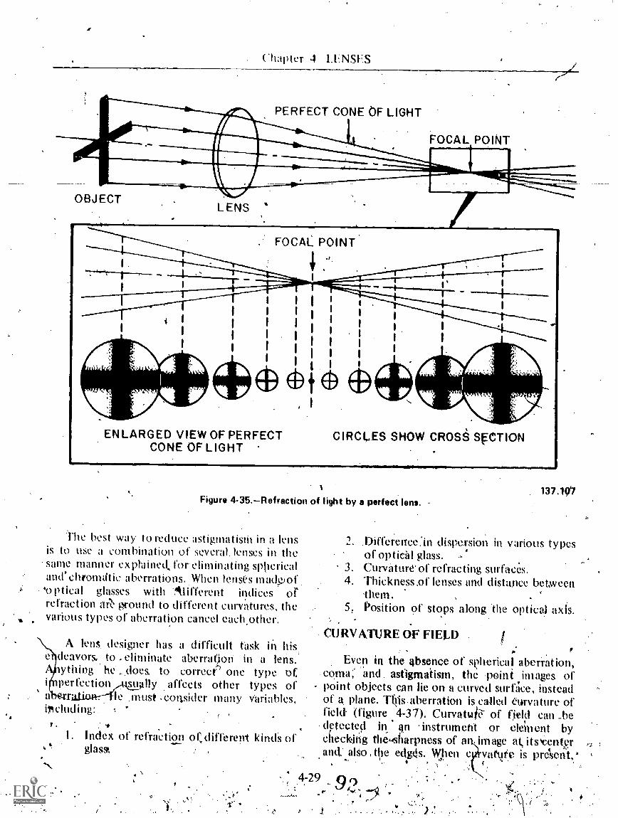
. Chapter 4 LENSES
PERFECT CONE OF LIGHT
11111,211101FOCAL POINT
OBJECTLENS ,*
ENLARGED VIEW OF PERFECTCONE OF LIGHT
\
CIRCLES SHOW CROSe SFCTION
Figure 4-35.Refraction of light by a perfect lens.
The best way to reduce astigmatisiii in a lensis to use a Combination of several, lenses in thesame manner explaMed, for- dimhiating sphericaland' chromatic a berrations..When lenses inadpof'optical glasses with Alifferent indices orrefraction ee ground to different curvatures, thevarious types of aberration cancel each,other.
. .
A lens designer has a difficult task in his,e deavors.. to ,ehminate aberrat4on in a lens.
wthing he ...does. to correct one type a.perfection su. fly affects other tYpes of
a le .must ,conskler -many variables,irciuding:
?..
I. Index of refraction or, different kinds ofgIass
137.10
2. Difference:in dispersion in various typesof optical glass.
3. Curvature of refracting surfaces.4, Thickness,of lenses and distance between
them.5. Position of stops along The optical axlS.
CORVATURE OF FIELD
Even in the absence of spherical aberration,co.ma;' and . astigmaiism, the :point images ofpoint objects can lie on a curved surGee, hmteadof a. plane. This-aberration is f,called curvature ofield- (figure 4-37)1 CurvatuP7 of field can bedetected in 'instrument or element bychecking the.sharpness of at im age at, itstenteran& also , the edg4s. When c varute is present,:
.4-29 op,r

I It
OBJECT
OPTICALMAN 3 & 2
LENS IMPERFECT CONE OF LIGHTfia,nunimenHORIZONTAC VERTICAL
FOCAL PLANE FOCAL PLANESPHERICALSURFACE
CIRCLE OF LEASTCONFUS 10 N
HORIZONTAL . CIRCLE OFEASTFOCAL PLAVIE - CONFUSTON VE TICAL
. FOCAL PLANEENLARGED VIEW OF IMPERFECT CONE OF LIGHT
OVALS SHOW CROSS SECTION
Figure 4-36.--Astigmatic refraction of light.I.
1
the center of.the image will he sharp, and theedges will be ),Aurred. Conversely,'If we adjhstthe element to kispg"the'edges info sharp focus,the center will th; blurred. ,
The most comtlioti mefhod of correcting thisaberration is to use a suitable combination oflenses, called field flatteners, which produce anopposite curvature of, the fiekl to cancel this.defect. -4
'DISTORTION
All of the other aberrations affect thesharpness of the itimige,. but an image can beperfectly 4sharp in all respects and 'still be
137.108
distorted. Imperfect centration or irrbgularity of'o p t i ca 1 su rfaces produces a change inmagnification -from the centdr of the field to- anyother point in the field, as measured in a radialdirection, Thus, objects off the optical axis willhave a different magnification than objectslhthe optical axis.
It' 'magnification is less for objects -off theaxis, you have BARREL distortion (fig. 4-38A).If magnification increases as you leave the axis,y9u have PIN CUSHION distortion (lig. 4-38C).
A.single, thin lens will form.an undistortedimage, but when you -must put a diaphragm inthe system, You will introduce distortion.Placing the:diaphragm in front of' the lens will
4-303

Chapter 4 LENSES
r
VIRTUALIMAGE
-"
OBJE,CT
A. CURVATURE OF REAL IMAGE:B. CURVATUREJOF VIRTUAL IMAGE .
Figure 4-37.Curvature of the image.
,cause the image to have barrel distortion, andplacing the diaphragm behind the lens will causepin cushion distortion. When a diaphragm mustbe used in an instrument, the manUfacturer willUse a compound lens with the diaphragmplaced
.between the two elements,, letting thedistortions cancel each other..
NEWTON'S RINGS
If convergent and dipergent lenses of slightlyunequal curvature are pressed against each Other,irregular 91ored bands or patches of color 'willappear between surfaces. ,See 4-39., Thepattern you see. in this illustration Is Called
7,31i
S. y
137.111
Newton's rin6s, after Sir Isaac Wcwto.h, who.firstcalled attention to it. Thege rings constitute adefect in a compound len,: but- the-tingssan beused advantageously 'for Jesting accuracy ofgrinding and polishing durMg lens hiantifacttire.
Light waves from an object' never focusperfectly at a corresponding point on .an image.They form, instead, a diffused image With a `central white spot surrounded 1).3/ a series ofcon9entric lings of light which fall off rapidly inintettsity. This is called ,11 DIFFRACTIONPATTERN (fig. 4-40). Diffraction sets the finallimit to the sharpness Of the image formed by alens, r sulfink from the natural spreildingtendenc of light Nitraves. It occurs in images
91 r
,

OPTICALMAN
(A)
(A) IMAGE HAS BARREL OR NEGATNE DISTORTION(B) IMAGE IS FREE FROM DISTORTION(C) IMAGE HAS 'CUSHION OR POSITIVE DISTORTION
(C)
137.506Figure 4-38.--Distorted images formed by a lent
137.109Figure 4-39.Newton's tings.
4-32
137.135Figure 4.40.Diffraction pattern (greatly magnified).

-Chapter 4 I.FNSES
tormed by all lenses. regardless ot the perfectionWIlh which they ate k:onstructed,
THICK UNSFS
thus tai our discussion on lenses .has ((teal(wIth thin lenses. It Is now important that wQe\PLIM the path cif light through a thick lens.
Because light is refracted at both surfaces ofa LiaN, all lenses have two principal planes, whichwere discussed earlier in this chapter. A lens isconsidered thiek when its amal thickness is sogreat that the principal planes and Optical centercannot be considered ds coinciding at a singlepoint on the-a \
Hie Na. \.11sestIhree t-pes oF thick lenses:
Single !hick lensesCompound lenses
wo thin lenses combined to make a
thick lens
two eqttlegrpik.x k iis tç. illustratedfigure. 4-4 ) BOth knses have thr....aine index ofrefraction and radius Of eurlature: theirdiameters are -equal. but their thieknistes areunequal.
As you know: an A ray is anyray whicpasses through the optical center of a lens andemerges tioin AK lens parallel to the incident,ray Without deviatiop.Thimule applies to botltthick and thin lenses. But note the difference insthe A rays through the two lenses in illustration4-41. In the thin lens in part A. the A ray istraveling toward the optical ceuter and passesdirectly theough without refractiJn or deviation,
For a- ray of ligfit to pass 'through a thickleit's without deviation, it must travel along th,eoptical aNis, or travel as shown in part B offigure '4-41. When .the ray strikes the kns, it isrefracti:d in accordance with tilt! laws of.'refraction and passes through the optical center.Upon emerging froin the second surface, the ray:ippetirs to have cotne from the second principalppint. (A') and is paralld to the incident ray,slighq.soffset (not deviated) . from its originalpath.. :-
-When converging incident light strikes a'thick -lens, an,undesirable result could.occ\tr. Ifthe lens is thick enough, the light cotikl colwerge
4
'
to a roots On tly.vseeond surflice, or within the,lens itself. .------- . ..
.Ohs.ctrve that the refraction of the B rays inthe'two lenses in figure 4-4J -is the same. but,t heray in the thick s travels a greater distance .
than the ray in the inner lens. Observe alsothat the principal plane P2) of the B tay is nowlocated to the right of t e optical-ccntr- of -the:thick lens.
Now compare the C rays of the two lenses.The refracted ray in the thin lens appears to herefriiilsd at the same . plane where the 13 rayreirTred, but ray C of the thick lens does notappear to be refracted at the same point as the 13.ray it traveled a greater dii,tanee than in thethin lens. The location of 'the .prinCipal Mane1111 for tbe C ra to the left of the opticalcenter. Apparent refraction, therefore', does notnike place in the exact center of Abe thick lens asit does in thin lenses. .
Bccause the, principal plves of a thin lenscoincide, we measured the focal lenelth as thedistanc . front the surface:of the lens to ihe(
principi focus.. As shown in figure 4-41, theprincipal planes of' a thick lens.do not coincide.We' must consider the focal length as .threeseparate factbrs: (I ) front focal length: (2)equivalenf , focal length: 'and (3) back fcicallength:
\'K,RONT.FOSAL GTH('
_Abbreviated FFL, the diStance mvasuredfrom the principal focal point on the left to thevertex of the .front surface is the front focalrength (F1 to V in fig. 4-4))..
EQUIVALENTFOCAL LENGTH
A.bbi:eviated EFL, the Oistaitee measured'froma .principal plane to itt correspqnMgprincipal focal k point 'is the equivalent focallength (PI to !frand P2 to F2 inliguril 4-41).
BACK FOCAL LENGTH
Abbreviated BFL., the distance...medsured:from the. verteX; of' the back sprface of 4he lens
403 9r

4$
to the focal point on the right is the back focallength (V' to F2 in fig. 4-41).
COMPOUND ,LENSES
OPTICALMAN 3 &
k.Figure 4-41.A thin lens end a ;Ingle thick lens.
.3
t
GEOMETRICCENTER',
P 1
Because an optically perfect lens cannot be4. produced as a single lens, twO or more lenses
made from different types ot glass . arefrequently combined as a unit to control defects
4-34
131.90
that are present in a single lens. These are calledcompound lenses; they . will often bp thickenough to be classified as a thick l9ns (fig. 4-42).
Two elements that are cemehted togetherWith their, optical axes'in alignment are called aDOUBLET. -Three elements cemented together*re called a.TRIPLET.
Cementing the contact surfaces of lensesused in a Fom pound lens isgenerally.considored

Chapter 4LENSES
DOUBLET DIALYTE
Figure 4-42.--Compound ionses.
desirable, because it helps to maintain the tWoe)ements in alignment under shatp blows, keepsout dirt, and decreases the. loss of light as aresult of reflection where the surfaces meet.
NOTE: The lenses of doublets too large' indiameter to be cemented together (even if theirinner surfaces match) form a lens combinationcalled an AIR-SPACED or UNCEMENTEDDOUBLET, cOmmonly known as a dialyte lens.
In a dialyte, compound lens, the innersurfaces of the two elements do not have the
/ same curvature, which means they cannot becemented together. The two lenses are separatedby a thin spacer 'ring, .or tinfoil shims, and aresecured in a threaded cell ortube.
LENS COMBINATIONS
If you arrange two thin lenses in properposition, they will perform as a single thick lens.Study figure 4-43 which illustrates twosymmetrical thin lenses used-as a thick lens. Allthe laws of refraction apply bere as they did infigure 4-41. The only variation in the twosystems is the way you measure focal distances.Because the two lenses are very thin, theprincipal planes of each lens, lies in thegeometrical center. For this reaion we m'easurethe focal distance for each lens from theindividual principe-planes. The 'equivalent focallength is measured from the principal plane ofthe combination.
Wheh thin lenses used in combination areidentical in optical characteristics, FFL.and BFL
TRIPLET
137.95
are equal; but, if tIke focal length Of one lens-differs fl.om that of the other, the FrL and BFLare .unequal.- When the- thin lenses differoptically, the equivalent focal length on eachside will still be equal because the EFL iscalculated froni the principal planes in. thqcombination.
The formulas for computing the three focaliftlistances are:
FFL ( i X F2) - (S X F1)Fl +r2 -S
(F1 X F2) - (S X F2)+ F2 - S
EFL.'Fl + F2 - S
Fl = focal length of lens X (in combination)
F2 = focal length-of lens Y (in combination)
S = separation of the two lenses (X & Y, orleft and right) in a combination,measured from their principal planes
Referagain tO figures 4-41 and 4-43. Noticehow the C ray is kised to establish the firstprincipal plant (P1) and the B ray establishes thesecond' principal plane (P2). In figure 4-43, thefirst principal plane is to the right of the secondprincipal plane. This is entirely correct and quitecommon in two lens combinations. Remember,when you measure EFL, measure from F 1 tO P1or F2 to P2. The distances will be the same
4-3598
41
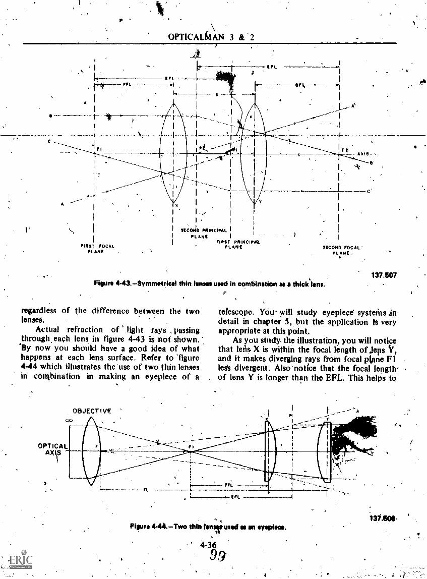
OPTICALMAN 3 &
-,*- IF I
Irk
I f
...
A
1'
FIS FOCALPL ARE
-sccoodo PRINCIPAL I
IDL ANCFIRST PRINCIFilt
PLANE SECOND FOCALPL ARE .
Figure 443.Symmet!ical thin lenses used in combination as a thick lens.r
regardless of the difference between the twolenses.
Actual refraction of light rays , passingthrough each lens in figure 4-43 is not shown. ".'By now you should have a good idea of whathappens at each lens surface. Refer to 'figure4-44 which illustrates the use of two thin lensesin conibination in making an eyepiece of a
S.
137.507
telescope. You- will study eyepiece systeins .indetail in chapter 5, but the application ts veryappropriate at this point,
As you study. the illustration, you will noticethat leti& X is within the focal length of jepsand it makes diverging rays from focal plane F 1legs divergent. Also notfce that the focal length.of lens Y is longer than the EFL. This helps to
Figure 4-44.Two thin loner used et en eyepiece.
4-369,9
i37.8041.
Is

0
Chapter 4LENSES
qlusttate that each thin lens in a combinationhas a definite focal length, but, when usedtogether, the resulting EFL of tile combinationis shorter than the fotal length of either lens.
'MISCELLANEOUSOPTICAL ELEMENTS
tn liddition- to -the opticat elementg you hafestudied thus far there are three otherelements that affect light transmission in aninstrument. These elements are. reticles, colorfilters, and polaroid filters:.
Reticles
Mogt reticles used in optical instruments areglass disis with plane parallel surfaces on whichappropriate markings are engraved or etched:Insome instances, a planoconvex or plano6oncavelens is necessary at the point where a reticle isgenerally mounted, and, the markings aretherefore engraved on the piano surface. Thefunction of a reticleis to superimpose referencemarks On the image of a target.
X pellicle, which is similar to a reticle, issometimes used to superimpose a reference mark
t
-
Nia
on a ta4tiet image. kt is usually mounted at anangle so that the main line of sight is transmittedthrough the pellicle while in auxiliary line ofsight is reflected from it into the eye of theobserver.
Colmed Filters-
Filters (sometimes called ray filters) arecolored glass disks (with plane parallel surfaces)pjaced in the line of sight in optical instrumentsto reduce glare and light intensities. Separateelements- may be attached or detached (fig.4-45A), filters may be swung in or out of theline of sight gig. 4-45Q), or they may bemounted on a rotating" disk which makesinsertion and removal from the path of lighteasy. Figure 4-45C shows a 'disk with threecolored and one-clear filter,mounted.
Some of the different types of colored filtersused in optical instruments to improve visibility,are amber, blue, green, red, smoke, and yellow.Red, yellow, and amber filters are generally usedunder varying conditions qf fog or haze to filterout the scattered blue and 'green light which
, reduce visibility if unfilAg. Red filters areused to improve contrast a target is against
Figure 4.48.Color filtsr mountings.
0
St
,,,.< 14r 5 t ;f.
,SAdat
137.122
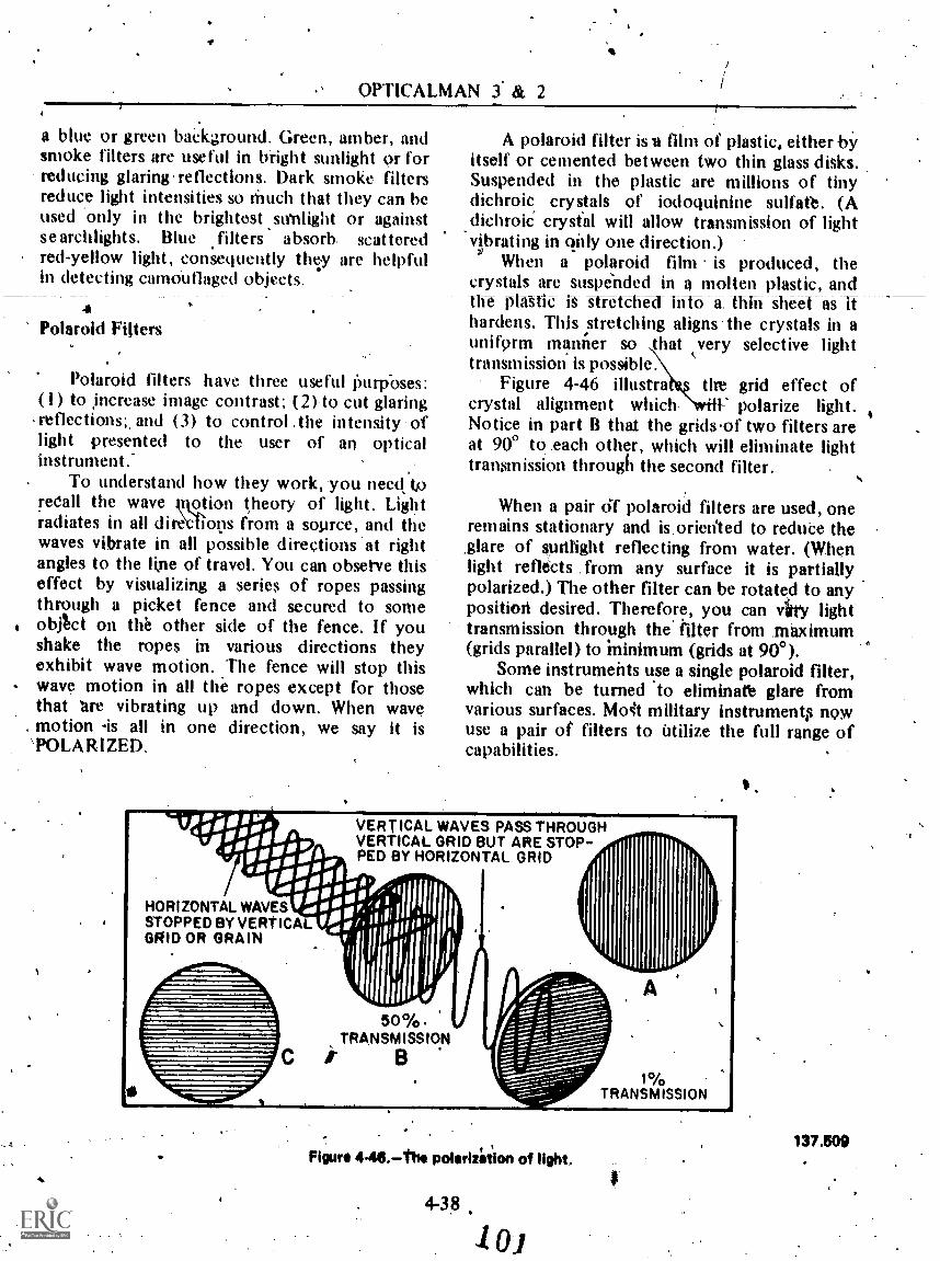
OPTICALMAN 3. & 2
a blue or green baCkground. Green, amber, andsmoke filters are useful in bright sunlight or forreducing glaring .reflections. Dark smoke filtersreduce light intensities so Much that they can beused only in the brightest sstrnlight or againstsearchlights. Blue filters absorb. scatteredred-yellow light, consequently thv are helpfulin detecting camdullaged objects.
4Polaroid Fitters
Polaroid filters have three useful litirpbses:(1) to increase image contrast; (2).to cut glaringretlections;, and (3) to control .the intensity oflight presented to the user of an opticalinstrument.-
To understand how they work, you needs tg.recall the wave motion theory of light. Lightradiates in all dire`dlops from a source, and thewaves vibrate in all possible directions .at rightangles to the line of travel. You can observe thiseffect by visualizing a series of ropes passingthrough a picket fence and secured to someobjtct on the other side of the fence. If youshake the ropes in various directions theyexhibit wave motion. The fence will stop thiswave motion in all the ropes except for thosethat are vibrating up and down. When wavemotion -is all in one direction, we say it is
'POLARIZED.
,,Pog;14010
,o11:011g
STOPPED BY VERTICALHORIZONTAL WAVESf;444P:i4i1111
11/1GRID OR GRAIN rill
1161111
A polaroid filter is film of plastic, either byitself or cemented between two thin glass disks.Suspended in the plastic are millions of tinydichroic crystals of iodoquinine sulfate. (A
sdichroiC crystal will allow transmission of lightvibrating in only one direction.)
When a polaroid film is produced, thecrystals are suspended in a molten plastic, andth plastic- is- tretchM info a. thin sheet as ithardens. This stretching aligns the crystals in auniform manner so that very selective lighttransmission is possible.
Figure 4-46 iIlustrat tire grid effect ofcrystal alignment which. polarize light.Notice in part B that the grids.of two filters areat 900 to .each other, which will eliminate lighttransinission through the second filter.
When a pair d-f polaroid filters are used, oneremains stationary and is.oriented to redute the,glare of sunlight reflecting from water. (Whenlight reflects . from any surface it is partiallypolarized.) The other filter can be rotated to anyposition desired. Therefore, you can Arty lighttransmission through the' filter from .maximum(grids parallel) to Minimum (grids at 900).
Some instruments use a single polaroid filter,which can be turned to eliminatt glare fromvarious surfaces. Mo4t military instrument nowuse a pair of filters to utilize the full range ofcapabilities.
VERTICAL WAVES PASS THROUGHVERTICAL GRID BUT ARE STOP-PED BY HORIZONTAL GRID
50%.TRANSMISSION
ir
-
Figure 446.the polarizfoiion of light.
4-38
1% .
TRANSMISSION
137.500
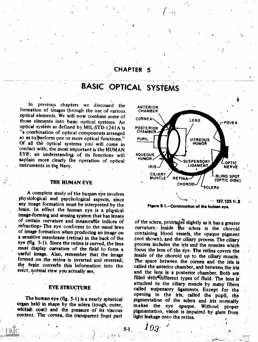
CHAPTER 5
BASIC OPTICAL SYSTEAAS
In previous chapters we discussed theformation of iinages through the use of variousoptical elements. We will now combine some ofthose elements into basic optical systems. Anoptical system as defined by MIL-STD-1241A is"a combination of optical components arrangedso as tc4erform 9ne or more optical tlinctions."Of. all the optical systems yoti will come incontact with, the most important is the HUMANEYE; an understanding of its functions willexplain more clearly the operation of opticalinstruments in thc Navy.
THE HUMAN EYE
A complete study of the human iye involvesphysiological, and psychological aspects, sinceany image formation must be interpreted by thebrain. In .effect the human eye is a pltysicalimage-forming and sensing system that has lensesof certain curvature and measuratlle indices ofrefraction The eye conforms to the usual lawsof image formation when producing an image ona sensitive membrane (retina) in the back of theeye (11g. 5-1). Since the retina is curved, the lensmust display curvature of the field to form auseftil image. Also, remember that the imageformed on the retina is inverted and reverted;the brain converts this information into theerict, normal view you actually see,
EYE STRUCTURE
The human eye (fig. 5-1) is a nearly spheriCalorgan held in shape by the sclera (tough, outer,whitish coat) and the pressure of its viscouscontent. The cornea, the transparent front part
5-1
ANTERIORCHAMBER
CONNEA LENSFOVEA
POSTERIORCHAMBER
PUPIL
AQUEOUSHUMOR
IRIS
VITREOUSHUMOR
'SUSPENS9RY,LIGAMENT
CILIARYMUSCLE RETINA
CHOROID
__OPTICNERVE ,
BLIND SPOT(OPTIC DISK)
SCLERA
137.123.1:2Figure &I.Construction of tho huinan eye.
of the sclera, protruslet slightly as it has a greatercurvature.. Inside the sclera is the choroidcontaining blood vessels, the opaque pigment(not shown), and the ciliary process. The ciliaryprocess includes the his and the muscles whichfocus the lens of the eye. The retina covers theinside of the choroid up to the ciliary muscle.The space between the cornea and the iris iscalled the anterior chamber, and between_ the irisand the lens is a posterior chamber. Both are,filled *itlAlifferent types of fluid: The lens isattached to the ciliary muscle by many fiberscalled susiaensory ligaments. Except for theopening in the iris, called the pupil, thepigmentation of the sclera and iris normallymakes the .eye vague. Without properpigmentation, vision is impaired by' glare fromlight leakage onto the retina.
:1 0:3
h

OPTICALMAN 3 &
IRIS FUNCTION
. - .. .Built into tIlis optical system named the eye,
_.
ii an adjustable dilphragm (iris). It acts as an*enure stop for .the lens, the same as thediaphragm of a camera (fig. 5-2). The iris opensand cl o'se s at the pupil all toma tically,-c o ntracting- undff-"-T031 Wright Tight and
. expanding in dim light. The size of the pupil willvary in young eyes from 8 mm in dim light, toabout 24 mm in 'bright light, The opening andclosing of the iris tentls to hold the illuminationon, the refit a constant regardless of externalbrightness.
REFRACTING MEHANISM
The cornea arid the lens act together as aconvergent lens syste,m to form a real image onthe retina of the eye. The cornea (fig. 5-1) is thefirst refraetiug surface for, light entering the eyeand. 'is responsible for aboqt 75% of the
refracting powqr of the eye. The two surfaces.ofthe cornea usually are of similar curvatureswhiCh renain constant.
The lens is a transparent elastic body with adense inskle core and a less dense outer layer.The lens clionges curvature, to focus light fromnear and._ fijr_ points Onto the retina, when the
. ciliary musclechanges the tension of thesuspensory ligaments. Figure 5-3 shows theciliary process in detail; the eye is focused pn afar objeckin B and on a near object in C. Noticethe difference in the curvilture of the two leilses..Th'e process of changing focus from a near point'to a far.pointjs referred to as accommodation.A -ifeimal eye has the ability to focus,on aftobject at a near Point of about 5.9 inches and afar point of infinity.
As mentioned in chapter. 4, the distance ofdistinct viscon is considered to be 10 inches.Although most people can accommodate closerobjects, they must strain their eyes to do so. Theability to accommodate decreases with age, as aresult of loss of elasticity of the lens.
Figure 8.2.Iris and diaphragm of a camera.40.183
7.11-

Chapter 5BASIC OPTICAL SYSTEMS
SUSPENSORY LIGAMENTSOF CILIARY BODY
A
AN OPTICALINSTRUMENT
RIS
CRYSTAL-LINE LENS
CORNEA
.J°
FAR OBJECT NEAR OBJECT
C
Figure 54,Suppension end action of the lop.
,. A German astrOnomer, Johannes Kepler, is
credited With being the first man to compare theeye to an instrument like a camera. In 1604 hewrotv, "Vision is brought about by pictures ,ofthe thing seen tring formed on the whiteconcaveaufface of the retina." The eye harbeencompared to the camera in numerous textbooksthroughout the world. This comparison has beenmisleading and often has, given the wrongimpression of how the eye functions.
Figure 5-4 illustrates the human eyesuperimposed on a camera. The camera is acompletely mechanical optical instrument thatforms an image on sensitized film'which, whenprocessed, becomes a 'photograph. Theformatiott of an image by the hunfan eye is aphysical process. After an- image is formed onthe retina of the eye, the process of seeing ispsychological, deaIin with nerve impulses and ,.the brain. The only mparison of physicalproperties of the eye that can be made with the :.
137.123
camera are- lens with lens, iris with diaphragm,and sclera with lightproof housing.
,VISION ( \
Light energy striking the retina of the eyeenables us to see, but the optical image formedon the' retina is only the starting pciint of acomplicated process of visual perception andvisual memory. The fact is, you do not see theretinal image, the incoming light forms a patternthat provides information to the nervous system.This information is then used by the viewer toguide his movements, to anticipate events, andto construci a mental 'experienee. The visualprocess is then supplemented by our memorywhich stores the information in the btin. Theimages on the retina are constantly ch nging inposition, site, and shape as the viewer moves hiseye, orlthe. object being viewed is moved.
Ustially, we are not aware of oUr eyemovements as thby are moved by thecontraction of one or more pairs of opposedmuscles triggered by the nervous system. Sucheye movements are necessary because the area of
194 .111.

t,
t. OPTICALKAN 3 & 2
LENS
LENS
01APHRAGM
IRIS
SCLERA ANDCHOROID
LIGHTPROOFHOUSING
Figure 5-4.--Comparison of the eye and camera.
clear vision available to the station ry eye issexerely limited. To see this fOr rself, tlxybur eyes on a point of some some unfainiliarpictgre or printed page. Only a small regionaround the fixation point will be clear. Most ofwhat you are vieWing will be hazily visiblebecause ,of the structure of the retina an4 theplacemqnt of its sensitive elements.
The retina, which covers most of the areabehind the ciliary process, translates light aprgy
Into the nerve impulses and contains thnirstcoordinating nerve cells in the visual system. Thefiont part, facing the lens,*is composed of bloodvessels, nerve cells,.verve fibers, and connective.tissues.
Figure 5-5 shows a cross section,. of thehuman retina magnified about 500 times. In thispicture, light enters from: the left. Thelight,sensitive eleinents are two different kindsof specially developed cells. Because of theirshape, we call them RODS and CONES. Thelight-sensitive layer of rods and cones lies at theback. of the retina, Before light,cab reach thatlayer, it mtqt pass through several layers oftissue' containing a network 'Of nerve fibers and
,
41,
137.126
RECEPTOR LAYER
CONESRODS
137.123.1:1Figure 5-5.Section of the human retina (500X).
'blood vessels. These layers are extremely thin, sothey do not absorb much light. nut, they doaffect the sharpness of the image.
In some of the lower animals, the sensi)ivelayer is at the front of the retina, with the nerveand blood supply behind it. These animalsprobably see more clearly than we can, but thehuman' retiqa has this advantage: the sensitivelayer is in contact with the rickblood supply ofthe choroid which helps to ksep the efficiency
5-4

Chanter 5 -BASIC OP*ICAL SYSTINS
of the retina at a high level oter a long period oftime.
The entrance of the optic nerve (fig. 5-1)forms a disk where there are no light sensitivecells. This is a "blind spot" where no visualsensatidns are stimulated7 The retina thins at thefovea because there ar. no blood vlssels or nervefibe rs directly op sip e the lens. Consequently,the- .fovea. isthe-most sensitive -area of the retina.The fovea contains onls: cones that are longer,thinner, and more densely packed than coneselsewhere in the retina. From here to the edge ofthe retina the nuinber of cones per unit areadecreases and the number of rods increases. Thesensitivity of,various atlas of the retina to lightvaries, and, since the fovea is the most scpsitive,it is used fcir fine detail and color per&Ttion.The cones of the fovea are individuallyc:Onneeted to single nerve aers which have adirect,path into the optic nerve.
The structure of tlre rods and cones iscomplex and the exact mechanism of vision isnot fully known. We do know that the reqhalrods containA red photosensitive pignint calledRHODOPS1N which is bleached when exposedto light. The process of thisibleaching stimulates .the nerve cells in thetbeye, making the rodssensitive to very 'small amounts of light.
The retinal cones contain a violetphotosensitive pigment called IODOPSINwhichis similar to rhodopsin but more respoliSive to.physical . change. Even., though cones respondmore quicklx to light than rods, it takes agreater iliterVity to trigger .this response. Anexa.mPle of the change 'taking place in tlfe eye iswtiri a person goes from bright- sunlight into adarkena room. It takes the eye ieveral minutesto adjust to the lower illumination level becausethe retinal rods, even though more sensitive tolow illumination, do not respond.as quickly asthe cones. The reverse procedure hol4 truewhen we again emerge from a darkened roorninto bright sunlight, since normal vision returnsquite rapidly.
./Night ViSion
Cones appear to be a factor in acute. vision,as the eye tends to rotate in order to bring theimage nearer to the area where cones are mostconcentrated. It also aPpears that the rpds in the
5-5
retina tire associated with night vision. Animalsthat hunt at night and sleep in the daytime (suchas the opossum) have retinas composed almostentirely pf rods Animals that go to sleep as soonas it gets dark (most birds). have retinas
.composed almOst entirely of cones: Humanbeings who get around both day and .ilight hoveretinas coMposed of both.
Color Vision
A normal human eye can match any colorwith a. mixture of three prima6 colors', red,green, and The brightness of color in etieobjects that we see depends on the radiantenergy in the light.
We know that white light is a combinationof all the wavel ths of the visual spectrum.andthat a color d object is reflecting or emittingwayes of a certain Jange. These differentwavelengths stimulate the iodopsin in varyingamounts to produce the different colorsensations.
Although the cone cells are less sensitive tolight than' the rods., the . cones are the moresensitive cells in color vision. At very low levelsof illumination all radiation, regardless ofwavelength, is distinguished only as varyingshades of gray and black.
Color Blindness
The inability of a person to distinguiShcolors, that is, having only gray visual sensations,is called color blindness and is very rare inhumans. More common is the condition ofdeficient color vision. One in 10 men and .1 in100 evomen- have varying degrees of colordefieffincies. The most common deficiency ispoor red-green discrimination; relatively raredefects are in blue-Alow vision.
With a color deficiency, one is unable todistinguish certain colors. The type of colorconfusion indicates the kind of irregularity. Aperson who has red deficiency sees red, brown,dull green, and bluish-green as the.same colorwhen they have the. same brightness. A personwith .green deficiency 'conflises purplish-red,browni. 'olive, and green. A mild deficiency isonly small handicap and may not even beknovhf by the persOn. Mediimr deficiency will

4
OPTICALMAN 3 & 2
exclude a person from working where mediumcolor discrimination is important. Seriouslydeficient individuals shopld he excluded trom alloccupations which require color recognition.
VISUAL ACUITY
'The overall.conditiop of the eye determinesTh"e degree Of SkirpheSs or viSiOn. Printed chart;consisting of letters/ qf differont sizes are usfor measuring the shlrwess Of viSion, cvisual acuity. The standard is a 5-minuteletter, the individual Aetails of thesubtending at the observer's eye 1 minute of arc(fig. ;5-6). The reference line on the chart isnormally viewed at 20 feet. Other lines on thech.art have graded sizes of letters for differentdistances. For example, the line marked 40 feetwoukl subtend an angle of 1/2 minute, and theline marked 10 feet woukl subtend an angle of 2minutes,
Vim.ial acuity is exproessed as a fractionthenumerator is, the design distance for the chart,and denominator is the line which can be read atthat distance. With sue.h.a chart, 20/20 vision isnormal, 20/1S is better than normal, and 207,30is subnormal..4Vision 20/30 means that the /observer can read at 20 feet the line normatly/read at 30 feet; 20/15 vision means the observ4can read at 20 feet the line normally read at 15feet.
er
Resolving Power
.4141,
The resolving power of the eye, or an opticalsystC:m., is its ability to distinguish between tWo
I MINUTE OF ARC
i>_---r ----- 7...--,,
5 MINUTES ,OF'ARC I
20 FEET
137.510Figure 5-6.Standard 5-minute square litter.
adjacent poilfts. It is offen expiesset .as theability to ilistinguish baween fine ti es andsmall: angles.. Rssolving power is an i1nortantpropettyOf anyboptical iystem..After al whatgood would an instrument be to the Navy if.w,e,had e Magnified istriBe, but we' coul9 iot.i-dktintmish anS7 of the details in the irmige
Figure 5-7 illusfrates,what is 1111.'1w:11y two'adjacent paints fortyling an angle w131( Me eye.:The average eye can resolve details sObtending 1minute of arc; an iniage falls on:the retina andstimulates- more than , one , cone, '-withseparatibn of at least one unstiniiklateci ,eonebetween, them: Therefore a normal, eye candist.inguish tntweett-two equally bright objects,separated by an angle of only I minute.
The'rods and cones give the-retina a mosaicstructure which t e r ines resolution.Maximum resolution &ponds on three 'factors:
1. Retinal location .of the image: The imagemust fall on the fovea 'Of the retina,where visionis most acute. The resolvi* power of 'the eyedecreases as' the -iniage moves away from thefovea. .
2. Nature the Its brightness.Brightness is the light necessary to stiMulate theretina. The. smallness .of a light or bright spotthat can be seen will depend solely on itsbrightness.
3. Adequate, time for stiniulation: Aniniage must fall on the retina long enouoi tocause stimulation of the nerve'C'ellis. Brightobjects will.stimultite quicker than dim objects.. )s
,
.
Vou can fully appreciate these three factorswhen-you look out, to sea at night. 1f you see asmall but very, bright -light, you have quickstimulation and the light is very noticeable. If;when looking out, you see a dim light, you mustconcentrate for if much longer.time to discern it.
STEREOSCOPICVISION I..
Having two e'yes to guide us Ta decidedadvantage in seeing, and both eyes act as a teamto feed information to the brain where it isfused into a ingle mental 'image. Both eyesusually operate under the same light conditionsand converge on the same object for binocular.

A
. Chamer, 57-BASIC OPTICAL SYSTEMS4.
.
o-a
-.1 POINTS
2
st
- NEAR --01PECT --
. ,
AAPPARINV SIZE
.RPT(NAL'iMAGE`:.'sAmE SIZE
(FOR 'EACH OklECT(
s
:-1 'tit
=m4tLEAST ?NGULAR .SEPARATION
110
111-1.1tA$T ANGULAR SIP:AltisTION
Figure 5-7.yisual
vision. One of the advantages of tw.o eyes, .drbinoeular vision, ,is the ,apparent iqcrease inbrightness of about .20%.above.that of an objectviewed with just oil eye. Figure 5-8 'shows the
,normal field, of view .With each eYe and -also the
i .,. , ,. ,
,. ,
MINUTE OF ARC
itetions.137.127
inoculaVfield. The..fiela of view with both eyesis normally ahoui 160° on 'the horiiontal .pn(I700 on the vertical. The ..0eld includes the areaseen by the left '..eYe, ihe right eye,-.and botheyes, The binOculai field ekiSts' only. in the area,of' thi field,_ of view white the fieldS of. theseparate' yeS,Overlap..
Another, 'more imnortatit advan tage ofbinocular . the experii0e Of 'depth,-which is sailed stereotcopii yision. 'the/ basis. of
.;§tereo'scopic vision is horfmntal dissimilaritY ofe.retinal' itnages on correspronding points of, the
two. retinas,. Figure 5-.9 -Mows 'tube' denronslrittingethe
steroosco0c effect when you look at a nearobje'ct. In SItidying this illu*fition'yoU can Seethe.'difference in' tlie retinal images On the .twoeyeS. Thii: difference is bititight' about byjihespicing of,your:eyes, Which allows 'you to-sdes-objvct$ :froth nightly.. different. 'angles. The:4iacing tiOweeithe human pyes is mposured
Figure 114.41old of view with two:iris. 7 from the'..olpil aad.is catted IN1 IFUI1 LLARV.

V
a
to
OPTICALMAN 3 &
..""
ROTH EyESC
137.120Nun 54.Stereeeeopie
DISTANCE (1PD), normally about 64millimeters. Stereoscopic vision can be stated as
.the ability' to see in depth, or in threedimension. When you 4iiew an object in threedimension, you see height, width, and depth.
In a like manner, when you obServe twoobjects simultaneously, stereoscopic visionenables you to judge the relative distance of one:object from the other, in the directi\AWAYFROM YOU.
Your ability, to distinguish the relative, position of two objects stereoscopigally deperids
upon the interpupillary distance Of yaw eyes,the distance of-the objects from you, and theirdistance-/ from each other (fig. 5-10). Otherfactors of depth perception being equal, theWider yotr interpupillary distance, the iletterthe depth perception you secure thyough -sterethision, For you to distinguish the position"of two objects stereoscopically, the distance of ,
the iiecorid object froni th e. first object must beiriately equal to 'the distance of the fhit
t from .yom
.
Fignre 5-10.DletingubNng the - distanoi betweentwo objects. .
137.130
When you look at two objects and attemptto determine which is farther away, the lines ofsight from both eyes converge to form angles ofconvergence on both objects. If the angles ofconvergence to bd objects are identical, the"objects appear to b the same distance away; butif there is a fference 'in the angles of .
convergence. to thefl Iwo' objects, one object< appears more distant than the other.
Even though the distance between angles. ofconvergence is slight, the brain has the ability to.distinguish the difference. -Your ability to' seestereoscopicallY,. 'therefore, depends upon your .
capacity to discern the differenCe between these...anglet..... Figure. 5-.11A shows the differencebetween Ile angles of convergence, shown infigure .5-10.
.
. Angles Of convergence; beCOme .sinaller, and:the .. differenee' between them becomes less

a
Chapter 5 BASIC 'OPTICAL SYSTEMS
a
, SUBTRACT TO OBTAINDISCERNIBLE DIFFERENCE OF
CONVERGENCE ANGLES
NEL.'
A GRAPHIC VIEW OF DIFFERENCE BETWEEN CONVERGENCEANGLES SHOWN IN X AND Y
A.
THE ANGULA DIFFERENCE BETWEENANGLE OF CONVERGENCE A AND, ANGLE OF` CONVERGENCE a
IS KNOWN AS THE
ANGULARDISCERNIBLEDIFFERENCE
OBJECT, OBJECT
CONVERGENCE ANGLES IN STEREOSCOPIC VISION
. B
Figure 5-11.Angular discernibip difference.
disce;nible as the objects are moved fartherawaytLfrom you, or as the distance between them
.decreased. This difference is known asDISCERNIBLE DIFFERENCE OFCONVERGENCE ANGLE (fig. 5-11B). It ismeasured in fiactions of minutes and seconds ofarc. Stereoscopic vision for th4 unaided eye iseffective up to only 500 yards\ This distance,
lioweler, can be inCreased through the use ofbinoculars or rangefinders/ which increase. the
RIGHTEYE
LEFTEYE
o
137.131
interpupillary diktince between the eyes andtherefore increase stereoscopic vision.
STEREO ACUITY, in contrast with visualaglity, is sharpness of sight in three dimensions,or the ability to gage klisfance by perception ofthç smallest discernible, differeficeS ofcolvergence angles. The, minimum differencewinch you can discern between two angles ofconvergence is dependent upon your quality of
5-914 oefted".

rt
OkTICALMAN 3 & 2
eisi6n, your .training, ana conditions whichaffect visibility.
A. well-trained observer can discern anaverage difference of about I 3 seconds of arc, attimes, Under excellent cond itions of .o bs,erva tion .
This .difference may be reduced to 4 seGonds ofarc fOr a ,series of obsqvations. An average,untrained observer should 'be able to distinguish
-a- minimum difkrenee- of 30 seconds of arcbetIkeen . two angles of convtrgence undernormal visibility conditions.
ABERRATIONSOF THE EYE
The optical system of the eye- suffer fromsome, of the same aberrations as an opticalsystem made up of glass lenses. The eye is partlycorrected for spherical aberration because itsrefracting. surface, especially the front surface ofthe lens, is parabolic.
. he chromatic aberration in the hmilan eye-is much worse than you might think; i.e2, whenyou lgok 'at an object, you automatically focusthe green and yellow light on your retinas, butthe1 blue light falls short of the retina, and thered light falls beyond it. If you have a divergentlens of about minus 2 diopters and a good bluelight, it is very easy to -demonstrate theChromatic aberratioh in your eyes. Just turn outall but the blue light in _the .room; any objectappears to be wrapped in a fuzzy blue blanket.Because of the chromatic aberration in youreyes, you cannot focus the short blue rays, andthe image falls short of your retinas. Now lookat' an object through the divergent lens and seehow much clearer the object is.
NEAR-SIGHTED
The normal aberrations of the eye do notcause ally significant problems in life, but thereare three chief defectsastigmatism, myopia,and .hyperopiathat must be corrected witheyeglasses for comsfortathe visioh. ,
Astigmatism
Astigmatism in the 0'e is caused bya &feetof the cornea whereby the surrace is morelstrongly curved in one plane than in another.'For an example, let's say that your cornea has anormal curve in the vertical plane, but is morestrongly curved in the horizontal plane. -You willbe abN to focus clearly on vertical lines, but thehorizontal .lines will be refracted too much andtheir image will fall in frOnt of the retina.
,Corrective eyeglasses for astigmaticconditions must be - worn constantly forcom fortable vision.
Myopia
in nearsightedness, or myopia, the imagefrom far objects i formed in front of the retinabecause the refrticting mechanism of the-eye istoo stropg. ClOse objects, however, can beaccOmmodated. Figure 5-12A shows ifow theimage plane fails to fall on the retiqa. The defectis corrected4:1 placing a negative lens in front ofthe eye as shown in figure 5-12B.
Hypertipia
Farsightedness, or hyperopia (fig. 5-13A), iscaused when the refracting mechanism is tooweak, and the image from close objects fallsbehind the retina. Distant objects can be viewed
CORRECTED NEAR-SIGHTED
Figure 5-11Nearsighted vision and correction.
/ /. 5-10 41'
137.511

Chapter 5- BASIC .OPTICAL SYSTEMS
e' A
CORRECTED FAR-S1GHTED
'Figure 5-13.--Farsighted vision and correction.
normally. Hyperopia is corrected by placing, in-front of the eye, a positive leg of properstrength to position the image on the retinagig. 5-12B).
Usually, if you are nearsighted or farsighted,you will remove your eyeglasses when using anoptical instrument and refocus it to correct foryour eye deficiency. Focusing eyepieces shouldhave sufficient range to lake care of this defect.
4k range of pins. 2 to minus 4 diopters will coverabout 98% of eyeglass prescriptions.
'Eye Strain
Eye strain or fatigue is usually caused byimproper tin./ of your 'eyes, or in other words,trying to make your eyes do or see sometliingwhich they cannot possiblOo. This problem ischaracterized by a tense..lor tired feeling,blinking, and sometimes headaches. If youconcentrate too long on an interesting book, tryto examine a small object by bringing it tooclose to your eyes, .or. use an improperlyadjusted optical instrument, you will feel eyestrain. If you must wear'corrective lenses, youare all too familiar with this prof:dem espedallywhen you forget your glasses. The human traintries to adjust all the muscles that control visionto force the eyes to see what it knows to becorrect, putting an unnatural burden on thosemuscles and causing them to become tired. .
You can avoid eyestrain by wearing ?lasses ifyou need them or . by resting yout eyesoccasionally. To rest the eyes, simply look awayfrom what'you are concentrating On and glanc&at a distant scene or object. The.eye is in itsmost relaxed state when looking into the
1177":77.'
137.512
distance. If you do this too often, however,people may accuse you of daydreaming.
EYEPIECE SYSTEMS
4As you learned in chapter 4, a positive lens
forms a seal image at its focal :plane byconverging 'the light rays to a focus. This imageis rather small and usually too close to the eyeto be clearly seen. Thus we must add extralenses tO magnify the objective image and forman .image suitable for comfortable viewing. Theadded lens or combination of lenses is called the
eyepiece system of the instrument. The eyepieceworks satisfactorily. if it will form a virtual imagebetween the point of.the most distinct vision ofthe eye (usually 10 in.) and infinity. Figure 5-14shows the construction of a simple telescopewith the eyepiece placed in a position where thefocal plane of the objective and the focal planeof the eyepiece coincide, .
BASIC FUNCTION
In general, the eyepiece has three basicfunctions in an optical instrument.
1. It must, with the objective, form a goCid, aberration-free image of the object being viewed.
2. It must serve at a magnifier.3. It must be designed so that the
observer's, eye can be placed at the exit pupil.Hence, the exit pupil mtist be located at least 1clto 12 mm away from the last glass surface, thisbeing the nearest the normal dye can approachthe eStepiece surface with comfort.
5-11
41.2
4,4
(

s
OPTICALMAN 3 & 2
OBJECTIVEFIELD EYELENS LkNS
EYE ,
DISTANCE
EXITEYEPIECE PUPIL.
Figure 5-14.-1Basic vivito. function.
The objective brings nearly parallel lightfrom a distant object to a focus, turning it intodiverging rays. The eyepiece directs thesediverging ray% as a parallel beam into the pupilof the eye. Since most eyepieces are adjustable(focusing), the operator can focus the eyepieceto obtain a comfortable view of the iniege.
Magnification of the image is accomplishedin the following manner: Parallel light (soliidlines in fig. 5-14)enters the objective, comes tb
focus, then exits the eyepiece as a parallelb'eam. The dotted lines represent light, comitigfroin a point on the target a distance off theoptical axis. The angle of light entering theobjective (abc) indicates the convergence .anglepresented to the unaided eye. The-angle ABCrepresents the- convergence angle increased bythe eyepiece..
Optiial instruments may be classified as: (I)monocular, for use by one eye o.r (2) binocular,for use by both eyes.- BeCause opticalinstruments:4 affect functioning of the eyes,certain adjustments must be made to theinstruments to accommodate them ha each eye.Most people have a dominant eye (onc which isUsed more than the other) so the eyepiece on amonocular instrument iS designed to allow theoperator to use either eye.
-Adjustment of a binocular opticalinstrument requires that the two optical systemsof the unit bekproperly aligned with bitch other,
137.555
conform to the interpupillary dkstance of theeyes of the obsorvet, and allow for focusing ofeach individual eyepiece.
REMEMBER: You can sometimes bring theviewed object within focus on your retinas by .accommodation of your eyes, as well as -byadjusting the eyepiece of the instrument. Aserious error often made by a novice is forcingthe eye to fjocus.
When you allow your eyei to accommodateon an object before the instrument is set forproper focusing, your eyes will be under aconstant strain. The correct way to focus aninstrument with.an adjustable eyeiiiece is:
1. Allow your eye to become completelyrelaxed by viewing a distant area.
2. Move the eyepiece to Ihe extreme PLUSdiopter position, (all the way ol)t).
3. After placing theviewing position, move thuntil the image of the taIf you go past the point
e in a comfortableeyepiece slowly inis sharply .defined.arp definition to a
point where the image becomes blurred, DONOT attempt to refocus from this position.Instead, back the eyepiece put again to the full
"PLUS position andstart over.

eA
Chapter 5 BASIC `pPTICAL SYSIVAS
4. When fukusing an 'instrument, IX) NOTsquint your eye at in iiny way put a strain on itsmuscHts: If you do, errors in setting the eyepiecewill result in'eye strain the entire- time you areusing the instrumept.
Because teles'opes with a mdgnification \Of,.
4X, or less prvit, a slit ficiently wide range ofa c c om modation, sin_gle-focus a!t.ting issatisfactory for most users. These telescopeshaVe a fixed-focus eyepiece, which cannot beadjusted during operation: hence the nameFIXED-FOCUS TELESCOPES, usually with aminus 3/4'to minus I dioptric setting.
NOMENCLATURE
Eyepieces in .general iise in military opticalinstruments may consist of ove, tw'os or threelenses, of which, any or all may be compoundlenses. The field lens is. the front element of theeyepiece, and the eyelens is the real- element.
Thk area behind the eyelens, where thediagonal bundle of light crosses the optical axis(dotted 'line, fig. 5-14) establishes the EYE.DISTANCE and EXIT PUPIL. Figure 5-15illustrates the path of marginal and axial raysthrough two types Of eyepieces.
The field lens collects light fiom theobjective image pkine s. which would otherwise be
FIELD LENS EVELENS.
IMAGE
4 1
b-Tai
/ FOCAL PLANEAARGINAL OF OBJECTIVE
RAYA
lost, iind iiresents it to the eyekns. If a nerdelement is used, it is called the intermediate otcenter-lens, and it functions in coMunctibn withthe field lens.
TYPES
General types of eyepieces used in opticalfire control instruments will be discussed in the...following paragraphs. However, yOu mustrymember that when working on an opticalinstrumenl you will often find modifications tothese eyepieces. The designer of instruments willuse the basic types as they are shown in thischapter, but he will often find it necessary tomake some changes to 'produce a isqualityinstrument. One of the prime concerns of aninstrument designer is tO eHminate aberrations inthe instrument. The proper design and use of theeyepiece can be very useful in this function andwIll be discussed under the separate types ofeye*ces.
Huygens
The,Huygens eyepiece (fig.' 5-16) is made oft4 two 'single, lenses. (Usually they are both'
_ cieiexo-plano, and both are made of crownglass.) T:he diagram shows three rays convergingtogard a real image. The field lens deviates these
IMAGE
FIENLENS EYELENS
\. .
FOCAL,FLANts"4,`OF OBJetTIVE .
Figura 5-15.Peth of light through eyepiece lenses.
1.
MARGINAL RAY
13P.137
I.

I.
OPTICALMAN 3 & 2
.011110
I A
1 IMAGEREAL
EYELENS
FIELD LENS SHIFTS IMAGE
FIELD LENS
.1
Figure 5- 16. Huccipenien eyepiece:
rays slightly and sends them toward the'eyepiece. You can see that Without the fieldlens, some rays miss the eyelens entirely.The field lens ensures that all the light passing4:
through the_ system will be used to form ,thefinal image.
_The Huygens eyepiece minimizes chromaticaberration, in a way we mentioned in an Tarlierchaptetv by making the distance between thetwo let*e equal to half the sum of their focallengths. The Huygenk eyepiece has somespherical aberration, but it is not very noticeablelit relative apertures less than about f:7. If you
' want to use it at an aperture-greater than.f:7,,you must overcorrect . the objective tocompensate for,thy spherical aberratibn of theeyepiece.
The Huygens. eyepiece can be made entirelyfree from coma. It shows, some pin-cushiondistortion, Which in many. instruments is notobjectionable. It has a NEGATIVE-astigmatismwhich helps Correct the astigmatism of theobjective. ,
This eyepiece has one outstandingdisadvantage: since the' itnage iinside theeyepiece, you cannot use a reticle. Theaberrations of the ocular as. a whole arecorrected, but those of the eyelens alone aren?t..tiSo if you put a reticle in the image plane,
Iits mage will be distOrted and -Mow colorfringm
The magnifying power of the Huygensejfepiece is Winked to about 10X. (1.f you makethe focal length .shorter than about] .inch, theelit pupil is too close to the eyelens.)
Ramsden
EYE
N.i.m.M1101m
137.141
Figure 5-17 shows the Ramsden eyepieis made of two plano-convex lenses offocal length. The distance between them Ito about two-thirds of that length. Thethe real image formed by the objectiveyou can see, the eyepiece forms an enlargedvirtual image at infinity.
The Ranksden eyepiece has one outstandingdisadvantage: chroniatic aberration is rather'serious. It has no coma, and all the otheraberrations are less than those of the Huygens
e. Itequalequalro* iss. As
eyepiece. Besides controle xcept color, the R
. advantage over the Huy
'ng all the aberrationssden has another
ens: you can put areticle in the image plane sinte the real igiage Isoutside the eyepiece.
Except for chromatic aberration, theRadisden is s desirable ,pyepiece. For any givenfocal length, the eye distance iS about 1.5 timesthat of the Iluygens, so yOu can use a higher
REAL IMAOEAND RETICLE
FIEL LESSEYcLINE
UPIL
f 4401/3 t EITHER Ms EYE DISTANCE-01
Figure 15:174Rimuisn oyephoo.137.138

CCiapter 5-11(kSiC OPTICAL SYSTEMS
magnifying power. The hbertations of the.Ramsden are increakd less than- those of theEluygem by slight variations..in the focal lengthof the -kjective. .But the only way you caneliminate the chromaiic aberration is by formingthe image inside the eyepiea, and th.en youcannot use a _reticle.
L(ellnei
. The Kellner eyepiece (fig. ,5-18)- is ain odification of the Ramsslen, the onlydifference being that the Kellher eyelens is adoublet. The Kenner has most of the advantagesel the Ramsden and requces the chromaticaberration. Spherical aberration is sligNtlygreater, but distortion is less. To eliminate thechromatic aberration (lompletely, you wouldhave to Put the field lens in the plane of the real
a.
image, but then yo i could not use a, reticle.Molt instruinents use the Kenner typeeyellbce have the fie d lens t short distancebeyond the image plane. They sacrifice dpart 91'
the color correction in Order to use a retialtt.
Symmetiricaland Two Dfmblet
Syminetrical and -two-dobblet eyepieces are'eonstrucred of two cemented, achromaticdoublets (fairly close I together) with thejrpositive elements facing each other (figure 5-19).If the doublets _are identical in every respect(diameters, focal lengths, thickness, and index of
'refraction), the eyepiece is symmetrical. I fçthedoublets differ in one respect or anot er,however, theY are considered a two-doubeyepiece. The eyelens of tlie two-double
FIELD LENSEYELENS
Figure 5-18.--Keliner eyepiece.
EEYE DISTANCE
4
,.
figure 15-19.Symmetricel eyepiece.
5-15
137.140
EXIT PUPIL
1. I -
. EYE DISTANCE
137.142

OPT1CALMAN 3 & 2' 4*
eyepiece is generally slightly smaller in diameterahd has shorter focal length than the field lens.
Symmetrical and twoAloublet eyepilces areoften used in fire coiltrol instrumedis Whichrecoil. Tt.te eye distance on these instrumentsintst iw fairly long to prevent the eyepiece fromstriking the gunner's eye. Thest eyspiecesprovide the- necessary eye relief as welt as a largeoskil Pupil at moderate magnification.. For thisreason, lymmetrical eyepieces,. along with )k ellner -a re used extensively in optical \i nstruments, particularly rifle scopes andbinoculars.
Orthoscopie
"the orthoscopic eyepiece is illustrated infigure 5-20. It employs a planoconvex tripletfield lens and a single planbeonvex eyelens withthe curved surfaces of both elements facing eachother. It is free from distortion and is 'useful inhigh-power Njescopes because it gives a wide .
field and high magnification with sufficient eye'rilief. It is also a very useful eyepiece forrangefinders because it permits the use of anypart of the field. It was 'named orthoscopicbecause of its freedom from distortion.
Internal Focusing
Very often it is mandatory that aninstrument be completely sealed to keep outmoisture and dirt. To do this and still be able toacCommodate for the 'visual variations betweendifferent obseryets, there are Several types ofinternal focusing eyepit!ces that can be used.These usually consist ot' three eleMents. One
EXIT PUPIL
REALIMAGE
FIELD LENS EYELENSEYE
DISTANCE
# 137.143Figure 5.20.Orthoscopic eyepiece.
5-16
type is illustrated 'in figure 5-2 L. The eyepiecehas a field lens, intermediate ltms, 1114 eyelens,all of which are cemented dot blets.
The field lens and .intermediate lens aremounted in a cell which van be movedlongitudinally by rotation of the foeu. knob.The cy$1ens is 4:ixed and acts as .a sea fox theoyepieee, Figure .5-2-2 is a mcchanint art w iha-ofthe focusing operation.
Internal focusing eyepieeeA are not limitedto the three-doublet combination as shown infigure 5-21. For example, the 1t,2 Mod 3telescope has a triplet field 1eh.s, doublet
FIELD INTERMEDIATE -I-
LENS LENS EYE 'EXIT PUPILLENSwer. 4,111
LIPP viz --EYE
DISTANCE
137.513Figure 5-21.Internel focusing eyepiece.
EYELENSFOCUSING CELL
AS SE MBLY
ACTUATINGI PLATE FOCUS SHAFT
1
FOCUS KNOB ASSEMBLY
FOCUS KNOB.]
137.514Figure 5-22.Mechanical schematic of internal focUsing
'eyepiece.
I.

Chapter 5 BASIC .OPTICAL SYSTEMS
inteimedia4, and siliglet eyelens. The basicprinciple is the same in all coin binandns, thefield lens cOnverges !Olt rays which otherwise
Avould miss tht intermediate Jens, and theintermediate,lens conv&rges light which wouldotherwise bfiss the eyelens. The eyelensconverges light to Me exit pupil. `
SIMPLETELESCOPES
A telescope is an optical instniment4containing a system of lenses or mirrors, sualry:but .not always, havlbg magnificatioi ,reaterthan unity, which renders distant objects moreclearly visible by enlarging their images on the
Krtell1TT- of the eye. In its simplest form, a
telescope consists of two parts: a lens, or mirror,called the objective, and an eyelens, or eyepiece.
The function. of the objective is to gather asmuch light as possible from the object andconvergi it to form a real image of that object.lit some telescopes, the objective does not forma real image; this will be explained later in thechapter.
ASTRONOMICAL
The ancient, astronomers had only the nakedeye to.observe and record the relative positionsof the moon, sun, stars, and planets. Theinvention of the telescope about 1600 A.D; wasa major breakthrough which has led to thehighly technical instruments that amused today.
In the process of refraCtion and reflection bya telescope system, the image becomes inverted.With astronomical bodies, it makes littledifference whether or not the object is viewedupside down.. Telescopes that site the obseperan inverted vieW are called astronomicaltelescopes.. Since they 4wed no erecting system;they are optically more simple. For this reasonwe study 'them first in our attempt tounderstand the generarnature of tile telescope.
Reflecting
.1n chapter 4 ypu ktudied the effect thatconcave mirrors have on lighi. In mostastronomical telescopes, especially the big ones,
5-17
the objective is a concave, mirror inst,ead of alens, There are several reasons for this. Whenyou are looking at distant stars, you want theimage to be as bright as possible. The brightness -
of an image depends on .the diameter of themirror tApt .forms it. There is nd light lost due topassage Through optical elements. ,
There is a practical limit to the diametet of alens. The biggest refracting telescope we knowabout is at the Yerkes Observatory; the .diameterof its objective is 40 inches. A lens tnuch biggerthan that cbuld not be mounted in a telescopebarrel. In the first place, it would not be easy tocast a big enough pjece of good optical glass. Inthe second place, a lens bigger than 40 incheswould sag under its own weight, (Reme4ber,glass is a liquid.) The lens would have' to beextremely heavy, and it could be supported onlyat its edges. It may easily' sag 20 or 30 millionthsof an inch, which is all the sag you need to ruinthe image.
Another thing: an objective lens must haveat least two elements to correct aberrations,which means you must grind and polish at leastfour surfaces. With a mirror, you have only onesurface to grind and polish. And of course, amirror haS no chromitic aberration.. Since thelight does hot pass through the mirror; the glassdoes not need to be optically perfect all the waythroup.
At one time, the biggest reflecting telescopein the world was' in the Observatory on Mt.Palomar, in southern California..Its objective is aconcave mirror .200 inchesatout 1,7, feet indiameter. The Corning Glass Company atCorning, New York made the blank for it fromPyrex glass. (Pyrex expands and contracts leisthan ordinary glass when the temperafurechanges.) To keep it from developing strains, themirror was annealed in an electric furnace. Itstemperature was reduced just I° each day.lntevestingly enough, the Cohocoton River runsright beside the glass works, and in 1936 the.river flooded. The water did not reach themirror, but it took out the power line andcooled the annealing furnace. They had to startall over with a new mirror.
The California Institute of Technology hadspent 4 years irhyling the mirror when they.

OPTICALMAN 3 & 24
were interruthed by World Wart!. After the warthqy fitiished the grinding and pqlishing andplated the reflecting surface with a/thin film ofaluminum. They also completed the telescopemount. ll'he,motint supports .the weigiit of theAective. and the platform the Observer standson. It autotatically. -and very accuratelytracksthe stars as they move across the sky.
Figures 5-23 and 5-24.illustrate.twO tYpes of.reflexting telescopes. Notice that a reflectingelement is placed in the path ot' incident light inboth exaniples. Since the. concave migors arerather large, and since incident light comes fromsuch a great distance, the placement of a small
137.147Figure 5-23.--Newtonien reflecting telescope.
FOCUS OF CONCAVEMIRROR it 'HE .RAY$WERE NOT INTEREERREDWITH BY THE CONvE XMIRROR
CONVEX MIRROR
prism or mirror in the path of light will have noadverse effect on the final image. Also noticethat the images formed are located 'outside thebod y of the telescgpes, allowing directobservation of celestial targets or substitution ofa photographic plate for the eyelAece.
Refracting
Figure 5-25 shows a simple astrlomicaltelescope. We will use this illustration to explainvarious optical principles common to morecomplicAd arrangements presented later. Not'cthat the parallel ligh rays entering the objectivelens are refracted an fiverge to a focal plane.(The image plane and the focal plane coincidewhen parallel rays are refracted by any lens,) Inthe focal plane' of the objective lens a real,inverted, reverted, diminished image of theobject is formed. The eyepiece is so placed thatthe 'image formed by the objective lens is locatedat the primary focal point of the eyepiece. Thediverging rays, diverging from the real image,enter the eyepiece, are refracted, and emergeparallel to the optical axis of the telescope. Theeyepiece acts as a magnifying lens fo magnifythe real image. If you look through the telescopeeyepiece, you see a virtual, inverted, reverted,enlarged image wilich is formed at infinity.
CONCAVE MIRROR
EYEPIECE
137.148Figure 6-24.Cessegranion refloating telescope.
. i,1 7 Q
5-18 ' ' -

Olt
Chapter 5BASIC OPTICAL SYSTEMS
6-5 FdAirr
OBJECTIVE
f o
11,004"-j"
fe' EYE'
IISTANC
All....ravai I ri7fAIEW
.'"°411111801111"I.
0°' EYELENS
Figure 5-25.Simple astronomical telescope.,
In an astronomical telescope in which thefowl points of the opjective lens and' theeyepiece lens coincide, the length of thetelescope is the sum of the focal lengths of thetwo lenses;
, .
Before you can fully understand the,telescope, you must(have a thorotyh knowledgeof several other optical-terms.
FREE APEIZTORE: A term that denotes tlieentrance 'pupil of the objective which is limitedby the inside diameter,of the objective mount orthe inside diameter of the objective lens retainerring,(FA: in figure 5-25). The entrance pupil canbe vievkd as suth from the objective, end of theinstrument, and it can .be . measured with krulerdirectly across the objective.
EXIT PUPIL: The term' given the diameterof the bundle alight leaving an optical system.You can see this small circle, or disk of light, bylooking at the eyepiece of an instrument that isdirected at asi illuminated area. The exit pupil isactually a real image of the objective lensaperture. The diameter of the exit pupil is equalto the diameter of the entrancq pupil divided by#the magnificatidn of the instrument. The exitpupil is designated EP in figure-5-25.
EYE DISTANCE: Often called eye relief,the term giyen to the numerical measur or thedistance from the rear surfa'ce of the rear eyelensto the fixed position of the exit .pupil (fig. 5-26).
ii
137.159
TRUE FIELD: Thtiwidth of the target area,Or field, that can be v' ed. More specifically, itis the maximum cone or fan of Pays, subtendedat the entrance pupil, that is transmitted by theinstrument to form a usable image (fig. 5-27).
APPARENT FIELD: The size of the field ofview angle as it appears to the eye. It isapproximately equal to the magnification of the
EYELENS
ilk.1 PLANE OF THEEXIT PUPIL
EYE .
I (EYE RELIEF) I
137.515Figure 5,28.Eye distance and exit pupil plane.
0

. OPTICALMAN 3 & 2
TRUE FIELD OF VIEW OFINSTRUMENT LIES WITHIN
THIS ANGLE
OBJECTIVE
APPARENT
(EYEPIECE)EYELENS
instrument5-27).
iI
t FOCAL LENGTH 'LENGTH 14 ' I
I
i OF OBJECTIVE ------t-o-' OF 16.-1I EYELENS1 ' .
EYELENS
137.514Figure 5-27.Truo field and apparent field.
times theongle ot the true field (fig.(
TERRESTRIALTELESCOPES
A ttrrestrial .telescope gets its name from theLatin word terra, which means earth. Aterrestrial telescope is used to view objects asthey actually appear on earth, normal aid erect.
Galilean Telescope
The simplest form of terrestrial telescopewas invented by the scientist Cloitteo. His firsttelescope had a power of 30 (fir 5r28A). Itseyepiece consists of a negative eyelenspotitioned a distance equal to its fouil length (f. ,fig. 5-28B) in front of the objective focal point.Such positioning of the negative eyelens makesconverging rays from the objective divergebefore they form, a real image; therefore, no yea]image exists in this optical system. If you lookthrough tile eyelens ypu see an enlarged, erect,virtual image of the object, which appears to be
a at a point between 10 inches and infinity.
5-20
The relation of the optical elements in aGalilean telescope (fig. 5-28B) is referred to asthe ZERO DIOPTER SETTING, which meansthat all light rays from any point source locatedat infinity emerge from the eyepiece parallel. Ifthe eyelens is moved in and out, however, theemergent light tors converge or diverge and theinstrument can therefore be adjusted for eitherfarsighted or nearsighted eyes and also forobjects at various distances.
In a Galilean telescope, the diameter of g6eobjective controls the field of view becau'se theobjective is both the field stop and the freeaperture. No exit pupil is f9rmed because thereis no real image plane in this system.Magnification in a Galilean telescope issicconiplished by increasing the visual angle, asshown by the dash line in figure 5-28A.,
LensErecting Systems
,Any astronomical elescope can beconverted to a terrestrial tel cope by inserting alens between the eyepiece dnd the objective toerect the image. Figure 5-29 shows the opticalelements of the pasic form of terrestrial
(

I'
I.
Chapter --BASIC OPTICI: SYSTEMS .
1"It.111"1110,111,11MIN/ hr.*.
471 r
N
I /A
OBJECTIVE
OBJECTIVE
NEGATIVLI111'URI NS
EMERGENT RAYSPARALLEL AT ZERO' DIOPTER SETTING
4 (MI,NUS SETTINGILLUSTRATED)
,e4f!tc.3
f *f 0 (08)(eTI1) (EVELENS)
- Figure 5.28.Goliloon tIescope
. FIRSTIMAGE PLANE
SECONDIMAGE PLANE
E REBTORN41
EYE LENS
.137.1.14.
Figur. 5:29,Th basic teryastrial telescope.
5-2422
qc
.41
1 7,516

OPTICALMAN 3 & 2
telescopes. Note the position of the REALIMAGES.
In addition to erecting the image, properpositioning of the erector system can also have adirect effect on the magnification of theinstrument. The possible arrangement of opticalelements in a single erector telescope isillustrated in figure 5-3.0. Note that the parallelrays entering the objective lens from an infinitytarget -aterefracted to fuint a real-inverted-iMagein the focal plane of the objective lens. Rayswhich leave the real image diverge as though theimage itself were an object. When you .place anerector lens behind the objective image, theerector receives the diverging rays and refracts
them to form an image 'behind the erector. Theimage fbrmed by the erector is then magnifiedby the eyelens.
In figure 5-30A, the erector is 2 focal lengthsfrom the objective image plane, and the imagethe erector forms is 2 'focal lengths from theerector. As you recall from chapter 11, the twoimitges will be ,the same .size. Consemtently, themagniffeation. of this telescope will depend onthe focal length of the objective (f.) divided bythe focal length of the eydlens (f.).
fo
1441111) 413f 0, A 1 M.
Figure 5-30.One ervetotlescops..
5-21 23
137.152

7
Chapter 5BASIC OPTICAL SYSTEMS
Now refer to figure 5-308. Notice that theerector is located . 3 focal lengths from theobjective image plane and that it forms an image1 1/2 focal lengths behind the lens. In this case,the erector will change the size of the imagepresented to the eyelens.
Remember the formula magnificationexplained in chapter 4:
If Do is 3 focal lengths and pi is I 1/2 focallengths, then:
I 5m 53
the image formed by the erector is only half thesize of the objective image.
WI at will this do to the magnification of the,telesco ? Assume the objective focal length(f.) is 4 inches, and the eyelens focal length (fe)
iis I inch:I
f 4M =--I = 4 power
te .
46 -Now, multiply vthe basic telescope
magnification (4) by th magnification of' theerector (.5): ,
. 4 X .5= 2 power
Figure '5-30C shows the position of theerector lens revirsed in relation to figure 5.-308.,How will this affect the magnification of thetelescope? (Use the same figures as in theprevious example).
Erector magnification equals:
Basic telescope magnification equals:
(
Total magnifiCation equals:
4 X 2 7 8
Figure 5-30A illustrates a basic terrestrialtelescope with a magnification of 4 (sometimesshown as 4X). Depending on the position of theerector lens, magnification can be changed .to 2X(figure 5-3011) or 8X (figure 5-30C). What wehave demonstrated is -achange of power,-orchange bf magnification system.
Change of power in an optical, Ostemdepends on the law of reversibility. Kigure 5-31shows the conjugate points' (A and B) whichcorrespond with lens positions (C and D). One isjust the rev&se of the other.
The image planes (---Ar B) do not changewhen the lens is in positldn C or D (fig. 5-31).For any other position of the lens, the observercould not focus on the final image with theeyepiece. Therefore, the erector must be at oneor the other position to take advantage ot theconjugate poipts.
Two-Erector
Refer to figure 5-32 to see how a terrestrialtelescope with two erecting lenses isconstructed. The erectors shown areSYMMETRICAL: that is, they are identical inevery respectdiameter, thickness, index ofrefraction, and focal lengths. ASYMMETRICALerectors (with different focal lengths) may alsobe used in this type of telescope for designpurposes or to help' increase magnification,
&which the objective and eyepiece alone could'not do.
137.153FigOre 531.Conju;ot. points.
5-23 24

OPT1CALMAN 3 & 2
OBJECTIVE ERECTORSEp EYEPIECE
1E1 fE2
Figur 5-32.Two rector telescope.
The erecting lens is positioned 1 focal lengthfrom the objective focal plane. The divergentrays which enter the erecting lens are refractedand emerge parallel to the optical axis.
Since the rays that emerge from the firsterecting lens are parallel, the second erectinglens may be placed at any reasonable distancefrom the first erector, because the rays whichenter the second erecting lens are alwaysparallel, regardless of the amount of lensseparation. Separation of the erectors / infixed-power telescopes is generally the sum oftheir focal lengths.
Parallel riys which enter the second erectinglens are refracted ond converge to the focalplane to form a real, erect image.
The eyepiece of the/ telescope is againpositioned as necessary to have the image of thesecona erector at its focal plane. If You lookthrough the eyepiece of the telescope, you see avirtual, erect,Anlarged image.
A two-erector telescope can also beconstructed as a change of power ipstrument bymoving the erectors together as # unit in thesame direction (with their, separation fixed).Their distance from the real image formed bythe objective lens must be 1 1/2 EFL, or 3 EFLof the erecting lens combination. The two
fE2
137.155
erecting lenses function together as a single thicklens to produce an image in the same manner asthe single erector lens used for the samepurpose.
Most optical systems are designed tomagnify a target. An important fact toremember about magnification is that whenpower (magnification) is increased,, the field ofview decreases; you can see details of the targetbetter when magnified, but you cannot see asmuch of the target.
When uSing a hand held optical instrument,any movement you make will be increased in
.direct proportion to the power of thqinstrument. For this reason, hand heldinstruffients are ustially limited to about 6X. TheNavy does use several typei of telescopes at 1.0Xand 16X, but they are very difficult to hold ontarget.
Variable Power
With a variable power telescope you canchange the magnification continuottsly betweentwo limits. If you look through a variable powerinstrument and gradually increase itsmagnification, you will get the same effect thata television or movie cameraman gets //hen hezooms in on an object. It appears as if thecamera is moying toward the subject while the
5121

Chapter 5- BASIC OPTICAL SYSTEMS
action is going on. Even simple home .movie-"cameras have -this feature.
In the change of power telescope (fig. 5-30),there are only two positions of the erecting lensfor which the two image planes are conjugate;that is you cannot vary the power continuouslybecause the image will be out of focus when theerecting lens is in an intermediate position. Theonly way to. keep the two image planesco-njugaTe throughout ihe travel of the 6-rectotlens is to change its focal length continuouslywhile you move it.
It is impossible to change the focal of a lens,but, if two lenses are used in combination(figure 5-33), you can vary the EFL of thecombination and still maintain the same focalplane.
In figure 5-33, the object is theAbjectiveimage plane. At the low power position (fig.5-33A), there is little difference betweim the sizeof the two images. In figure 5-33B, Noth lensesare moved different distances toward theobjective, and a significant enlargement of theimage is produced by the erector ombination.Notice that the image plane rem s stationary.
,At any position between the d highpower positions of the erectors, the image willbe in sharp focus if the mechanism that movesthe erectors is properly designed. A variablepower system will usually provide three to fourtimes as much magnification in the high powerposition than in the low power (3X to .9X or 6Xto 24X rifle scopes). .
A lIt
OBJECTASYMMETRICAL ERECTORS
r IN LOW-POWER POSITION
IMAGE
LARGE IMAGEOBJECT
ASYMMETRICAL ERECTORS FORWARDAND CLOSER TOGETHER
137.156Figure. 5-33.-Variable magnMoation In two erector
telescope.
Prism Erecting Systems
Thus far, we have discussed telescopes withone or two erecting lenses and a straight line ofsight to the target. The Navy uses many typesofinstruments which must present an erect image,but prisms are used as erectors.
Figure 5-34 illustrates-a teleseepe-witt-two-porro prisms placed within the focal length ofthe objective lens. As you recall from Chapter 3,
. two porro prisms invert and revert the line ofsight. Thus, they- cancel the inverted,. revertedobjective image and the observer views an erect,norm al i in age.
15-25
A porro prism cluster used in this mannerwill provide a very compact instrument. Tracethe path of light through the prisms, thenimagine how much longer the instrument wouldbe if an erector lens were used.
The line of \siert through an instrumentusing a prism cluster will be offset but still willbe considered a.straight line telescope.
In figure 5-35., a 900 roof edge or Amiciprism is used as an erector. Some similarinstruments use a 600 roof edge prism. In eithercase, the line of sight is deviated but the
server views an erect, normal iniage.
4014OBJECTIVE IMAGE PLANE
-1OBJECTIVE
LENS
PORROPRISMS
EYEPIECELENS SYSTEM
137.556Figure 5-34.-Porro PrIsni erecting system.
.1 9C

OPTICALMAN
EVE.LENS
OBJECTIVE IMAGE PLANE
OBJECTIVE LENS AMICI PRISM
137.557Figure 5-35. Amici prism erecting system.
Various other combinations of.
prisms.Mirrors, and lenses are used in military opticalinstruments, most of which you will see later.The optical system toed in any partkularinstrument depelids on how the instrument willbe used and where it will be mounted.
GUNSiGHT TELESCOPES
The Navy uses a wide variety of' terrestrialtelescopes as gunsight, some of which are verycOmplex in their construction. This section willgive .you a basic understanding of the functionand design principles of the telescope used as afire' control instrument. Some of' the simplegunsight telescopes are covered in, more detail inanother chapter of this book. Anytime anOpticahnan engages in .repair or overhaul of aparticidar .gunsight, or any optical instrument,
, he must ALWAYS use the technical manual thatapplies to that instrument.
The gunsight telescope is used to improvethe view of distant targets as follows:
I. It gathers and concentrates a greaterquantity of light from the target 'than the
unaided eye can gather, thus renderim; the targetmore distinct.
2. It erects the target image andsuperimposes a 'reticle upon it, thus sharplydefining the line of sight to the target.
3. It magnifies the target image so that thedistant target appears closer.
In m ny instanceR, the eyepiece of gunsight-telescopes is inclined at n-angle with-wspect -tothe line o sight. so hat the obs'erver cancomfortably view largets at various angles.
Reticles, such as those shown in figure 5-36,used in fire control instruments to
superimi)ose inarkings or a predeterminedpattern df range and deflection graduations on atarget. When the reticle is placed in the center ofthe field of view, it represents the axis of thegunsight and then. can be aligned with the axis ofthe bore of the weapon for short range firing, orit cn be fixed at a definite angle to the bore forlong ange firing. A reticle is used as a referencefor si ng or aiming, or it can be designed tomeasure angular distance between. too points.Since the reticle is placed in the same focal planeas a real image, it- appears superimposed on thetarget. In a gunsight that has a lens erectingsystem, the reticle can be placed either in theobjective image plane or in the erector focalplane. It the erecting .4ystem increasesmagnification, when the reticle is placed in theimage plane .of the objective, the reticle lines willappear wider than if they were placed at thefocal point of the eyepiece. Therefore, thereticle usually is placed behind the erectingsystem.
Parallax ,
Parallax in an optical instrument is a defectof primary importance. In a correctly adjustedinstrument, the image of the viewed object isformed in the same plane as that in which thereticle lies. If this does not occur (fig. 5-37),parallax is present. You can.detect parallax bymoving your eye back and forth across theeyepiece of the instrument. The appearance ofrelative motion between the reticle and the fkldof view indicates the presence of parallax (fig.
5-26127 .

(.'hapter 5 BASIC OPTICAL SYSTEMS
I F !LAMENT OF WIRESPIDER WEB ETC
A-SIMPLE CROSSHAIR IN RETICLE HOLDER
C-STADIA LINES FORANGULAR MEASUREMENT
B-RETICLE PATTERN ETCHED ON GLASS
0-ITCHED DESIGN WITH NUMERP&S
Figure 5-36.Examples of reticle patterns.
To correa for parallax, shift the opticalelenients of thettelescops until the reticle lies inthe precise plane of the fc al image. The technicalmanual for earl) type of instrument givesdetailed procedures for making this adjustment.
TELESCOPEMAGNIFICATION
In our explanation of various types Oftelescopes, we have discussed magnification, and
137.139
the various methods of determining the powerlof aii optica . system. It is appropriate that we
now reView and amplify these procedures.To det rmine .the power of a telescope
WITHOUT A LENS ERECTING SYSTEM, thereare three methods which can be used:
I. Divide the focal length of the objectiveby the focal length of the eyepiece (EFL):
M

OPTICAUAAN 3 &
IMAIR rORMIO IN FRONT QC RETICLEPARALLAX EXISTS
ve-ttaAvr mimeo ammo RET1CLE
PARALLAX EXIETE
MAO( FORMED IN SAMS LANE AS Runct.tNO PARALLAX
figure 5-37.--Optical parallax.137.517
2, Divide the apparent field by the trilefield:
3. Divide the objective lens opening (freeaperture) by the size of the exit pupil:
kA FA' EP .
To determine the power of a telescope witha lens erecting system, you must multiply theformula (fo /fo) by the magnification producedby the erector lens system (Di/D0
fo D.M X
to Do
RETICLEAND
IMAGECOINCIDENT
VilgOra SatRotative motion of parallax.
51'29
I MAGE
RETICLE
\r.PARALLAX
6.747"
,137.188
c
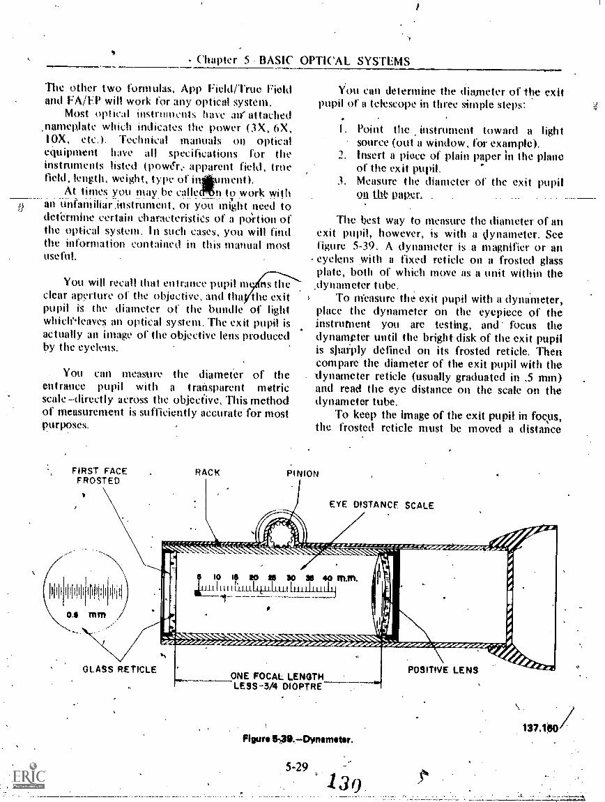
- Chapter 5 BASIC OPTICAL
The other two formulas, App Field/True Fieldand FA/EP will work for any optical system,
Most Optical instrinnents have an' attached.nameplate which indicates the power (3X, OX,10X, etc.). Technkal manuals on opticalequipment have all specifications for theinstruments listed (pow&,, apparent field, truefield, length, weight, type of intiument).
At times you maybe calleeMn to work withan unfamiliar instrument, or you might need todefermhic certain characteristies of a po'rtion ofthe optical system. In such cases, you will findthe information contained in this manual mostuseful.
You will recall that entrance pupil m ns theclear aperture of the objective, and the, the exitpupil is the diameter of the bundle of lightwhichAeaves an optical system. The exit pupil isactually an image of the objective lens producedby the eyelens.
. You can measure the diameter of theentrance pupil with a transparent metricscaledirectly across the objective. This methodot' measurement is sufficiently accurate' for mostpurposes.
FIRST FACEFROSTED
RACK
SYSTEMS
l/ou can determine the diameter of the exitpupil of a telescope in three simple steps:
I. Point the instrument toward a lightsource (out a window, for example).
2. Insert a piece of plain paper in the planeof the exit pupil.
3. Measure the diameter of the exit pupilon Olt Pam .
The best way to measure the diameter of anexit pupil, however, is with a klynameter. Seefigure 5-39. A dynameter is a magnifier or aneyelens with a fixed reticle on a frosted glassplate, both of which move as a unit within the
dynameter tube,To nieasure the exit pupil with a dynameter,
place the dynameter on the eyepiece of theinstrument you are testing, and focus thedynampter until tile bright disk of the exit pupilis slim:ply defined on its frosted reticle. Thencompare the diameter of the exit pupil with thedynameter reticle (usually graduated in .5 mm)and read the eye distance on the scale on thedynameter tube.
To keep the image of the exit pupil in focus,the frosted reticle must be moved a distance
PINION
EYE DISTANCE SCALE
......
10 15 tO NS 30 36 40 InnWjjiULLLLLL4JJ:LLUJhiLLIIIUhjj
9,r,r,r
'N. N.... ,..,../.,.:.....111.1:
.16410:0i0rAle .010.40:00:01. Iare 40:416/%700:00110:10:0"..Oraleolnesoi40:10140.:070:00:00/p0'e r./.,'
GLASS RETICLEONE FOCAL LENGTHLESS-3/4 DIOPTRE
Figure 549.Dvnamtor.
5-29
130
POSITIVE LENS
137100
A

OPTICALMAN 3 & 2
equal to the ey,e distance of the instrument ,being tested.
You ave already learned that the true fieldh
of an optical instrument is the angular area of atarget which can be transmitted through theObjective of an instrument to form an image.The apparent field is.the ;Itnount this small angleis magnified by the eyepiect system.
You can approximstite the actual amount ofapparent and true field of an instrument byusing the following proceklure:
Point the instrument you are testing towarda prominent target and adjust it to a sharp focus.Observe some distinetive feature of the target atthe extreme left and rigHt sides of the field. Now
:by a plastic protractor on a table or windowsill'and put a small straight pin throughThe center,Using the pin as a sight, place a card on the.curvej.edge of the protractor and align the pin,card edge, and one edge of your selected target.Next, .vithout moving your head or theprotractor, align another card with the oppositeside of yourselected target. You can read theapproximate true field, in degrees, from theprotractor. If you are very careful, you may beaccUrate to within 1/2 degree.
To determine the apparent field, turn theinstrument,around, look at a target through theobjective lens, and align the extreme edges ofthe field with some easily distinguishedlandmarks. Now, repeat the procedure with theprotractor to determine the size of the apparentfield angle.
Remember, it' you are using a telescope of6X to lo9k at a target through the objective end,the target will only be 1/6 as large as it appearsto y.our unaided eye. Therefore, you must selectvery prominent features at the edges of the fieldif you attempt to measure apparent field in thismanner.
THE MICROSCOPE
An instrument thit is used to produce anenlarged image Of very small nearby objects is
called a microscope. Microscopes are of twot y pes, simple and compoUnd. A simplemicroscope produces but one image of an objectand consists of- a convergent lens locataat thefirst focal plane of the eye..In effect, this is justa simple magnifying lens as covered in diapter 4.In a compound microscope, the objective lensforms a primary imagv which is furthermagnified by the eyepiece.
You perhaps,Ased a compound microscopeto look at minpttplants and animals when youwere in high school. Such an optical instrumentso magnifies small objects that it increases the.
usefulness of the eyes lit short distances. Theeyes, by nature, are long-range opticalinstruments of high acuity.
Refer now to figure 5-40, which shows oneof the simplest types of compound microscopes.Study all details and the nomenclature. Note theposition of the eye, the eyepiece, the objective,and the object. Then observe tilt ositibns ofthe real and vairtual images. I illustrationshoukl clarify much of the information you havesthdied concerning image fornuition,magnification, and the relationships betweenfocal length and image and object distance'.
. To find the maggification of a. compoundmicroscope, you must .do two things: First,determine the magnification of the' objective;then multiply by the magnifying power of theeyepiece.
Suppbose the objective has the followingcharacteristics:
then:
= .5 Di = 6 inches
mau = 6= 1
.5
If .the eyepiece has a focal length of .5,-then:
5-30131
10 10MP= = 20

Chapter 5BASIC OPTICAL SYSTEMS
"IIN..1011161,11114:-..."
14,7.01.
eftimmo
41404 gift -
OBJECTIVE
.O_BIE_CTREAL IMAGE FORMED
OBJECTIVE-
II% EYEPIECE"I'"11111111111 EE
P:11. 614 Fehf
rifia 02,11.
Pr
411%
tadFINALVIRTUALIMAGE
.001TiowAS+
to..-4100'woo"
1,
600.O.. I des*.
10°. II..000. oggl.
sw.e* 111"4...00
.01000'MO.
MINIMUM: 10 INCHES (NEAR POINT OF. EYE)
Figure 5-46.bnage collation by a aompounci miartmoopo.
The magnification of the microscope istherefore:
12 X 20= 240 power
Magnification in a microscope depends uponthe focal lengths of the objective and the
eyepiece and the distance between these twooptical elements. A compound microscope canmagnify an object about 2,000 times(diameters), but little, if any, increase .in thedetails of an object is obtained after the objecthas been magnified 400 times.
1-.311 3 ()
e
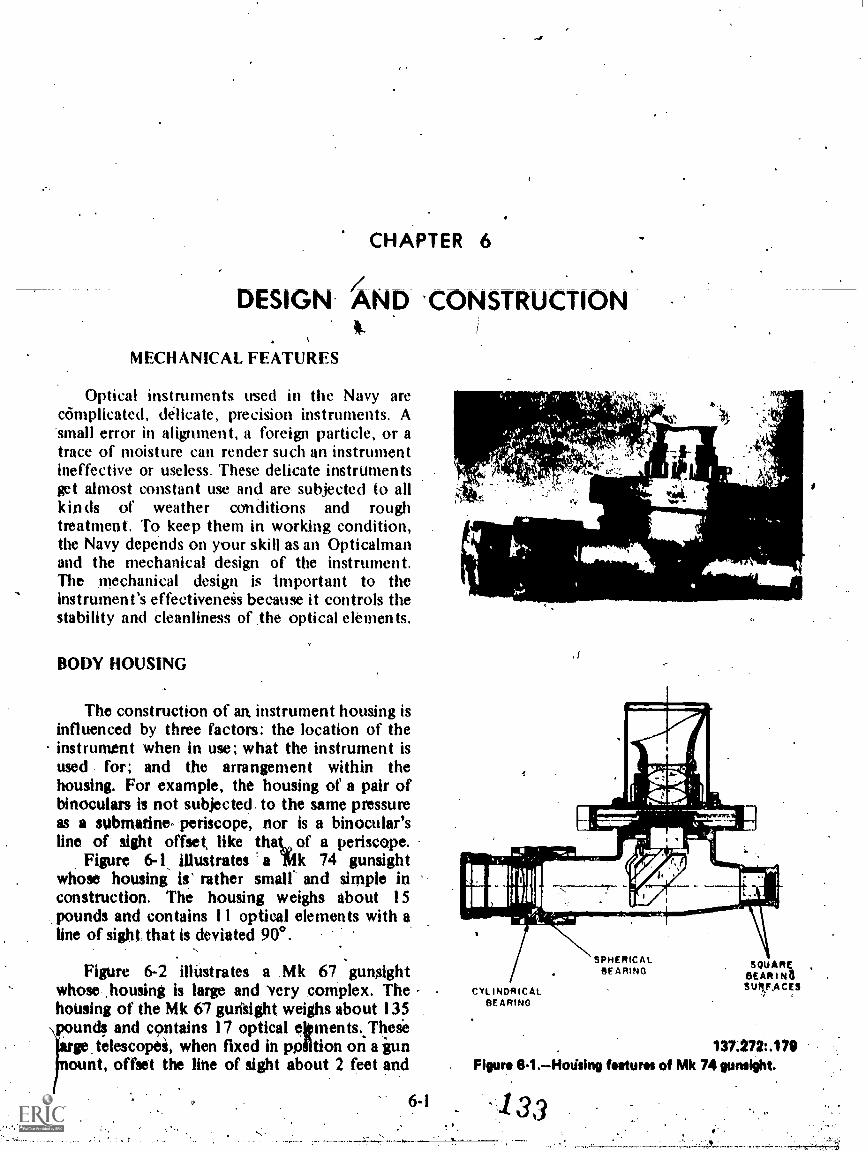
CHAPTER 6
DESIGN AND 'CONSTRUCTION
MECHANICAL FEATURES
Optical instruments used in the Navy arecomplicated, delicate, precision instruments. A-small error in alignment, a foreign particle, or atrace of moisture can render such an instrumentineffective or useless. These delicate instrumentsget almost constant use and are subjected to allkinds of weather conditions and roughtreatment. To keep them in working condition,the Navy depends on your skill as an Opticalmanand the mechanical design of the instrument.The mechanical design is important to theinstrument's effectiveneis because it controls thestability and cleanliness of .the optical elements.
BODY HOUSING
The construction of an. instrument housing isinfluenced by three factors: the location of theinstrument when in use; what the instrument isused for; and the arrangement within thehousing. For example, the housing of a pair ofbinoculars is not subjected to the same pressureas a submarine periscope, nor is a binocular'sline of sight offset, like thaL of a periscope.
Figure 6-1, illustrates a iiik 74 gunsightwhose housing is' rather small and simple inconstruction. The housing weighs about 15pounds and contains 11 optical elements with aline of sighi that is deviated 900.
Figure 6-2 illUstrates a Mk 67 gunsightwhose ,housing is large and 'very complex. The ,housing of the Mk 67 gunlight weighs about 135pounds and contains 17 optical eitments. These'arge when fixed in ppiltion on a gun
ount, offset the line of sight about 2 feet and,
6-1
1 h4, i 1
Ar 4J.
ii
.
: -..A I.: . 4, 's,t.
SfAt - ill A.
CYLINDRICALBEARING
SPHERICALSE A RING
SQUARkSEAR I NaSUIVACES
131.272: .1 79Figur* el .Hotising futures of Mk 74 gunaight.
133

OPTICALMAN 3 & 2
DOuSLE EYE LENS
POULE FIELD LENS
SEALING PLATE
EYEPIECE PRISM
ERECTING LENS(REAR )
COLOR FILTERS(VARIASLE
DEN,ITY SHOWN)
DEFLECTION DRIVEHOUSING
ERECTING LENS(FRONT)
ILLTINATOR LAMP
ILLUMINATOR WINDOW 0111JECTIVE LENS
CROSSLINE LENS ERECTING PRISM
AXIS OF ROTATION(DEFLECTION)
CROSSLINE LENS
PIEAO PRISM
WINDOW
WINDOWWIPER COLOR FiLTER-MOTOR GOX KHOO WIPER
WINDOW
-v
WIPER RODDE ICER
ELEVATIONINPUT SHAFT
VERTICALMOUNTING PADS
HORIZONTALMOUNTING PADS .
Fleury 41-2.The Mirk 17, tok000pi.
6,2
/
141.139 k.

Chapter 6 DESIGN AND CONSTRUCTION
enable you to'follow fast-moving targets withoutchanging body position. The line of sight iselevated and deflected by rotating prisms thatare driven by shafts _WI gears in the sightmechanism.
Note the differences in the housings infigures 6-1 and 6-2, and note the location of theoptical elements in the two gunsights.. All ofthese elements must be positioned and securedin -the housing so that-they-will remain in placeunder normal circumstances and will not impairthe effectiveness of the instrumint throughunwanted movement.
Material
The material used to construct the bodyhousing is selected with reference to the specificinstrument. If the instrument is to be hand heldand portable, the material must be lightweightyet strong enough to withstand the shock andabuse it may be subjected to. Cast -aluminumand magnesium alloys are usually used forbinocular bodies and some portable straight linetelescopes.
Gunsight telescopes are mounted directly onturrets and gun mounts where they receiveconsiderable ,shock. Most housings of gunsighttelescopes' are made from 'cast bronze of steelalloys which are strong enough to support andprotect the optical and mechaniCal componentsof the telescope. The material specifications fora telescope housing are shown on theapvahate drawing, and an Opticalman should-know the tyrke of material he will be workingwith before he attempts any repairs to thehousing.
Arrangement
The location of the optical and mechanicalcomponents of an instrument is a prime factorin determining how a housing must beconstructed:
Figure 6-3 is a cutaway view of the Mk 102Mod 2 telescope, showing the complexity andimportance of a .housing arrangement. Refer tothis figure, often as you study the descriptionthat follows
6-3
The telescope housing assembly is castbronze fnd finish-machined with great precision.It is opin at-the front and back. The front of thehousing is closed by a window and the rear by ametal cover plate. The interior of the housing isdivided by an irregular vertical wall into anoptical chamber and a servochamber. Thegastight optical chamber is in front of tkedividing wall and the watertight servochamber isto the 'teat A square bok-ShaPed Section risesfrom the top rear of the housing to position andsupport the headrest assembly, optical tube, and,focusing assembly. The housing is cast with fourmounting pads, two on each side, which providea vertical mounting-surface, and four mountingpads on the bottom which pro'vide a horizontalmounting 'surface. Both ot' these mountingsurfaces are precision machined to provideaccurate alignment or the telescope on the gunmount.
The front window of the telescope is securedby a window retainer and sealed by two gaskets.Stuffing tubes on the right side of the housingallow for passage of electrical cables withoutlosing the watertight seal in the servochamber.The focusing knob and filter knob are sealed bya packing gland where the shaft passes throughthe housing.
The optical tube assembly is a brass cylinderwhich houses the objective lens, filter assembly,and reticle in position within the body housing.
The elevation mirror, traverse prism, andskew penta prism assemblies are positioned inthe Optical chamber by brackets. Twoservoassemblies mechanically connected to themirror and traverse prism. allow the line of sightto be elevated and deflected.
Access and Adjustmenf
*k
You have seen how Ole design of a housing isaffected by the poitioning of the 'instrumentcomponents. Another problem that a designermust consider is accessibility. A body housingmust be made in such a way that all of the partsenclosed in the instrument can be assembled and

OPTI('ALMAN 3 &
HEADREST ASSEMBLY
FOCUS4 NOBASSAIBLY
FILTER ASSEMBLY OPTICAL TUBEASSEMell
FRONT WINDOW ASSEMBLY
OPTICAL TUBEHOUSING
SKEWPENTA PRISMASSEMBLY
C LEANINO HOLE,COVERS %IA
FILTER KNOBASSEMBLY
SERVOCHAMBER
TRAVERSE SERVOASSEMBI V
ELEVATION, SERVO TELE SCOP CASE TRAVERSE PRISM
ASSEMBLY DIVIDING WALL , ASSEMBLY ELEVATION MIRROR ASSEMBLY)
OPTICAL CHAMBER
Figur. 63.Tolosoopo,Mk 102 Mod 2; cutaway view.137.618

Chapter 6DESIGN AND CONSTRUCTION
adjusted in a convenient manner. A number ofaccess holes and cover plates are provided forthis purpose. The number of openings in anyinstrument housing OA always kept to a bareminimum because each opening is a source forgas to escape and moisture or dirt to enter theinstrument.
WADES AND-CAPS-
When an optical instrument is not is use, itshould be placed in a case that will protect theexposed optical elements. If the instrument ismounted in such a manner that using a case isnot feasiblt, some ther form of protection isprovided.
Lens Caps
A lens cap' is a very effective and convenientway to protect an eyelens or objective lens.These caps are made of metal with a friction fitover the area to be proteeted, or they arethreaded onto the telescope. Part A in figure 6-4illustrates a slip-on objective cap for an azimuthtelescope, and _Part B shows a threaded cover fora ship's telescope eyepiece, When a ship Is at sea,the external optical surfles are exposed tosaltwater spray, stack soot, direct sunlight, andgrime which will damage optical elements veryeasily. For these 'reasons, the protective capsshould always be in place when the instrument i§not in iise.
Sunshades
%. An optical instrument that is usedextensively in sunlight has a sunshade to reduceglare from sunlight directly striking the outerface of the objective lens. Sunshades, asillustrated in figure 6-4, am 'usually - tabular
ctions of Metal fitted around the objective. Asunshitdi also protects the objective from fallingrain and heat from the sun that would harm "thecement used to cement elements of anachromatic objective.
6-5
OBJECTIVE CAPA
. SUNSHADE'
EYEPIECE COVER
37.2 #.Figur* 64.Lens cops.
Eye Guards
Eye guards similar to those illustrated Infigure 6-5 are d extensively on opticalinstruments. Th guards, made of plastic orrubber, protect t observer's eye from gunfireshock or similar d turbahces. An eye guard alsomaintains,: proper eye distance and keeps outstray light rays.
DIAPHRAGMS
Diaphragms are rings of opaque materialplaced iii an optical system so that the passageof light is limited to thefi 'center. When adiaphragm is used in this manner, it is referredto as a stop. Refer to figure 6-6 as you study thevarious stops in the following sections.
*

OPTICALMAN 3 & 2
Field Stop
A field stop is a diaphragm' that limits thefield of an instrument to the area which is mostilluminated. A field stop is placed at the imageplaike and helps to produce a shavply focusedimage by eliminating the peripheral rays whichcause poor imagery because of aberrations.Placing the field stop at the image_plane notonly limits the field, but also sharply defines theedge of the field and prevents the observer fromviewing the inside of the instrument. When afield stop is used at each image plane, the secondand succeeding field stops are larger than theimage of the cfirst so that slight inaccuracy in sizeor positioning will not conflict with the sharplydefined imp of the first.
ApertureTItop
An apetture stop is a 'diaphragm that limitsthe size of the aperture of a lens. In mosttelescopes this is usually the objective lensmount or retainer ring as there is no reason forreducing the size of the aperture of the singlecompoimd objective- lens used in such aninstrument. A stop in close proximity to a tingleCompound objective will reduce only theilluMination and exit pupil size without reducinglens aberratiohs. In the event the objective of aninstrument is So complex that two or more
37.1:45.311 separate lenses. are used, an . apertUte stopbetween the elements may reduce aberrations.Figure 04-4y* guards onlostruments.
IMAGE PLANE011/11CTM RECTORS IMAGE PLANE
...
;;,;;.6.' ,
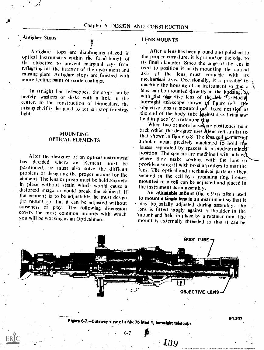
4.Chapter 6 DSIGN AND CONSTRUCTION
Antiglare Stops
Antiglare stops are diaphragms placed inoptical instruments within the focal length ofthe objective to prevent marginal rays fromrellatieting off the interior of the instrument andcausing glare. Antiglare stops are finished withnonreflecting paint or oxide coatings.
In straight line telescopes, the stops can bemerely washers or disks with a hole in thecenter. In the construction of binoculari, theprisms shelf is designed to act as a stop for straylight
MOUNTINGOPTICAL ELEMENTS
After the 'designer of an optical instrumenthas decided where an element must bepositioned, he must also solve the ,difficultproblem of designing the proper mount for theelement. The lens or prism must be held securelyin place without strain which would cause adistorted image or &mid break the elerhent. Ifthe element is to be adjustable, he must designthe mount o that it can be adjusted withoutlooseness or play. The following discussioncovers the most common mounts with whichyou will be working as an Opticalman.
Iitt
LENS MOUNTS
After a lens has been ground and polished tothe proper curvature, it is ground on the edge toits final diameter. Since the edge of the lens isused to position it in its mounting, the opticalaxis of the lens must coincide with itsmechamal axis. Occasionally, it is possible to ;machine the housing_of an instrumtaaso_that_a_lens can be mounted direetly in the h sing,with vthe oMective lens of th. 5 ModboreSight teleseope shown figure 6-7. T eobjective lens is mounted a fixed posit+ atthe end of the body tube gainst a seat ring andheld in place by a retaining ng.
When two or more lense, are positioned neareach other, the designer uses lens cell similar tothat shown in figure 6-8. The k flubular metal precisely machined to hold ti elenses, separated by spacers, in a predetermineposition. The spacers are maChined with a bevewhere they make contact with the lens toprovide a snug fit with no sharp edges to mar thelens. The optical and mechanical parts are thensecured in the cell by a mtaining ring. Lensesmounted-in a cell can be adjusted and placed inthe instrument ds an, assembly.
An adjustable mbunt (fig. 6-9) is often usedto mount a single lens in an instrument so that itmay be axially adjusted during assembly. Thelens is fitted snugly against a shoulder in the
'mount and held in place by a retainer ring. Themount is externally threaded so that i( can be
iloCUM
BODY TUBE
2,1 .Oszame dcroiefOrkiki,fe'qu'":" I it' :
3;111VCNM44rg.c- 4
4-164"itio teuigithwagiosiw,---*ppviimsampimmow
4414 00 vim.
. I iitmow;mok.o4.".NIWIRO111 flo
'111011101.1111
114111101PniRAMINati
A OBJECTIVE LENS
Figure 6-7.-Cutaway view of a Mk 75 Mod 1, boresight telescope.
6-7
109
111
84.207
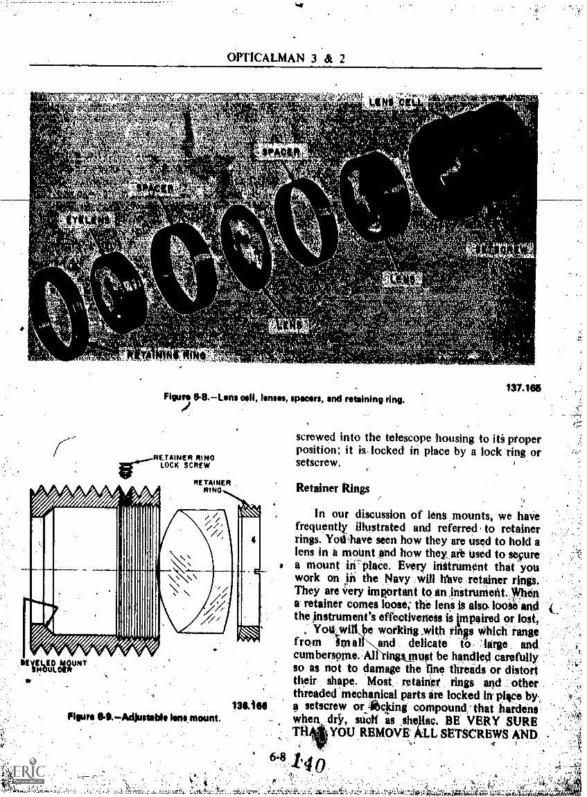
OPTICALMAN 3 s& 2
-"t15"- .."r..6,': .,h1-1
....-,. -,, ',7, . - 4 I ,-..". ;!.. -Te-0
, '' eikis4
41i
t,
"1":
14PACMIC
sc4,
4
kvio'r
Figure 8-8.Lens pH, lenses, spacers, and retaining ring.
RE,TMNER RINGLOCK SCREW
"UltArt* .
11
RETAINER .
RINO
131066Figure SA AO/stable Nns mount.
1.`
,1;
137.166
screwed into the telescope housing to iti properposition; it is. locked in place by a lock ring orsetscrew.
Retainer Rings.,
In our discussion of lens mounts, we havefrequently illustrated and referred to retainerrings. Yod-have seen how they are used to hold alens in h mount and how they are used to securea mount in place. Every initrument that youwork on iit the Navy will Ifave retainer rings,They are 4ry imRortant to an ,initrument.yhena retainer comes loose; the lens is also loose andthe zinstrument's effectiveness is impaired or lost,
Yottwi l'ItNworking _with rin§s which rangefrom im al and delicate to large andcumbersome. All ingsffiust be handled carefUllyso as not to damage the fine threads or distorttheir shape. Most retainer rings and otherthreaded mechanical parts are locked in phice by,a setscrew or cking compound: that hardenswhen diY, such as sheEac. BE VERY SURETflAJYoU REMOVE ALL SETSCREWS AND .
6-8
:7.,

Chaptet 6 bl:SIGN AND CONSTRUCTION
LOCKING COMPOUNDS BITORE TURRINGTUE RING, If not, you will damage the thiPadson the mount and the retainer, causing addedrepair work or loss of the part. Note thesetscrews which lock the retainer in figures,6-8and 6-9. Not all locking screws are soprominently . located- so examine the partscarefully for hidden lock screws.
&i**Adjusting Mounts
Occasionally an element must be adjustedafter the instrument has been assembled. In suchcases you win find a screw adjusting mountsimilar to that illustitated in figure 6-10. Thismount has four adjusting screws at 90° intervalsfor adjusting horizontally and vertically. Theadjusting screws extent) through the telescopebody and can be either a slotted head(illustrated) or a thumb screw type. By lettingout on one screw and taking up on t e other,you can position the element wi. great
137.520Figure 6-10.Adjustable reticle mount.
6-9
a'ccuracy. Be earefuL:,when tightening the screwsso that no undue strain is placed on qie mountor element.
Eccentric Mount
You have learned that the optical axis of aninstrument must coincide with its mechanicalaxis if the .instruitient_is to _be in alignment. To -assure alignment, lenses arc sometimes placed ina n. adjustable eccentric mount to allowmovement of the lens and its optical axis,in aplane perpendicular to the axis of iheinstrument. Figure 614 illustrates the eccentricobjective mount of a binocular; refer' to it as youread the following description. The !cps mounthas a machined. bearing surface that offsets itfrom the mechanical axis of the mount(eccentric). A ring whose inner and outer
RING-41
BEARINGSURFACE`41...
MOUNT-46-
A. TOP VIEW
B. SIDE VIEW
137.521Figure 6-11. Eccentric lens mount assimbly.

OPTICALMAN 3 & 2
surfaces are eccentric to each other is placedover the beanng surface of the mount to act as 3bushing to hold the assembly 'in the binoculanbbdy. By rotating the entire assembly oL byrotating the outer ,ring aromid the moult, youcan move the optical axis of the lens to anydesired point within a relatively large area. You'can obtain some additional movement byrotating the objective lens in its mount sincemost lenses Ilavc! somtinherent eccentricity, The-objective assembly is then locked in place' by asetscrew or retainer ring, or both.
PRINM. MOUNTS
As with other optical elements, a prism in anoptical instrument must be correctly positionedwith respect to all other elements in the system.The problem of positioning a prism is
'compounded by the bulkiness and the 'variedshapes of prisms. Since practically all lenses areround, designers use tubular mounts for mostlenses. However, prism mounts must beindividually designed to fit the shape. of aparticular prism. Space does not permit a fulldescription of all prism mounts used in Navyinstruments, but we will briefly explain a few..
'Rooledge
ThAooledge prism mount, shown in part AoC figure 6- I 2, consists bf a right-angled bracketon which the prism rests. Shoulders ground onthe friXted sides of the prism act as mountingsurfes which are used to secure the phism inthe bracket.
Two prism straps, one on each side, arei-he -prism shoirldtrs mitt *urea
by screilS to the bracket. The bracket is fastenedto the telescope body with four screws whichcan be-loosened to adjust the prism mount'. PartB of the illustration shows disassembled pa'rts.
Righ t 7,An gled
Motints for right-angle prisms vary in designin accOrdance with needs. One monnt (fig. 6-13)holds Ole silvered, or -reflecting, surfaces ofprisms-iecurely in place and properly aligned onbearint pads which prevent the surfaces fromtouching- the base of the mount. Four prismstraps, two on each side, hold the prisms inpOsition. The straps also contain bearing padswhich help to keep the prisms properly ,alignedwithoutchipping during the shock of gunfire. ,
.Figur. 11-12.Roof-ildo prismInquot.
6-10 ), 1,4,2
137.171

Ch 'pier 6 -DESIGN AND CONSTRUCTIONelm111101
Figur* 6-13.Rioht-ongled Prism mount.
Porro Prism Mounts
A porro -prism mount (lig, 6-14) consistsprimarily of a flat, metal plate shaped to theinterior of a telescope body. It is machined tohold one prism on each side of the plate. The-hypotenuse surfaces of the prisnis are mountedparallel to each other, and they are set overhales machined in the plate to allow light to passfrom one prism-to the other. t .
To maintain the APEX surfaces of the twomounted prisms at 90' angles ttivich other, arectangular metal adjustment rid. (Prism collar)is placed sttugly around each Prism. IT the tWo,prisms are NQT at 9tr, 'angles to ea') other,LEAN is created in the. prism/eh:Isar. Leanmeans that an ,o.bject viewed thrdugh the prismclutter appears to lean at an angle- whencompared with the actual object.
Each prism is secUred M the mount with ,ttspins cliP .01* prism straP, s-pressed against, the
137.172
apex of the prism. The strap. Itself is 'secured totwo posts, one on each side of the prism; theposts, in turn, are scre,wed into the prism plate,A metal shield placed over each prism under theprism strap prevents stray light from enteringthe other prism surfaces; The*, shields must not,touch the reflecting \surfaces of the prisms; if.:they touch, total internal. reflection does nOttake pike and some of the light is refractedthrough the reflecting Surface and absorbed' bythe light shields. .
FOCUSINGARRANGEMENTS
The, majority of focusing arrangements withwhkh an Opticalman comes in contact areeyepiece assemblies, since most initruntents..must be .adjustable to -the individual observer%eye.

`
01;TICALMAN 3 & 2
4,
1. Prism clip. 8.2. Prism clip screw. 9.3. Prism shield. 10.4. Prism clip pad. 11..05. Porro prism. 12.6. Prism collar. 13.
'4 7. Prism collar screw. 14 .
Prism post A.Prism post B.1Prism post C.Prism post D.Left prism plate and dowel pins.Right prism plate and dowel pins.Prism plate dowel pin.
Figur* 6-14.Porro prism mount.
Lenses in an eyepiece usually are secured ina tubular type Mount. The field lens and theeyelens may be fastened separately, each with aretainer ling, or they may be secured togetherby the same retainer ring with a spacer placedbetweeri the field lens and the eyelens to holdboth at the correct distance from each other.
The distance between the reticle and theeyepiece in an optical instrument must beadjusted to the observer's eye so that the reticleand image of the object are sharply defined,eliminating eye fatigue. To provide thisadjustment, the lenses (two or more) of the
137.170
eyepiece are mounted in a single lens cell, ortube, whose distance from the reticle (also focalplane of the objective) can de adjusted by a rackand pinion, a draw tube, or by rotation of theentire eyepiece during adjustment of the focus.
Some of the focusing arrangements used oneyepieces are shown in figure 6%15.
Draw Tube
A. draw tube focusing arrangement (fig.6-15E) ctonsists of a metal tube which containsthe lenses and their retainer ring. The tube. is

_Chapter 6DESION _AND CONSTRUCTION
NOM 615.2roousing irrangtment.
focused manually by sliding it forward Orbackward in a guide tube at the rear 'Of thetelescope body or housing. The draw., tube. canbe secured to the guide tube :or withdrawnconvietely from This type of eyepiecefocusing arrangement, however, is not widelyused by the Navy because the draw tube focus,can be 'disturbed by a slight )ar.
VW'(Helical) keyway
-. A spiral keyway foOnoing' arrangement (fig:.6-16) 'is a modification of a draw , tnbe: It Is'oindlof In conetructicat to a dravi tubt.with theOditional folloieingconiponenp: a fotuaing kei
!,
137.173
or shoe, a focusing ring, a retainer ring, and adiopterling scale.
A Striight. slot, Which gUides 'the focusingkey, is COfthrough 'the eyepieae-adaPter parallelto the optical axis of the telescOpe. The focusingkey. is fastened to the' draw' tubet,,protrudes.through the' straight oloi, atO holds the focuoing'shoe whiOh engsgeo a spiral,groove.Or keyWay inthe focusing ring. TItelOOUSIng ring tUrns On'the-eYepiece 'depict bui Is oreve4tikl frOth moirialong- the opticaf axis, by- a ihOulder on theadapter and the stop ring On the oppoOte side. ,
The dippter ring is moUnted oh' the-1110'04er ofthe eyepiece atitptei; it sitinst an Indio(Mirk Oh the &citing ring: 0014 Parts 'of thia-
. .
643
.111.:1!
N.
xWW

OPTICALMAN 3 & 2
1. Eyeguard.2. Eyeguard clamp.3. Eyeguard clamp ring screw.4. Eyepiece collective retaining ring.5 Eyepiece collective lens.6. Eye lens tetaining ring.7. Cemented doublet eyelens.8. Eyepiece focusing assembly.9. Focusing ring stop ring.
0. Stop ring lock screw.I. Knurled focusidg ring.2. Focusing shoe. W3. Focusing key.4. Focusing key screw.5. Eyepiece draw tube.6. Diopter ring. ,\7. Diopter ring lock screw.8. Eyepiece adapter.
Figure 8-16.Spiral keyway focusing arrangement.
type focusing arrangement must fit snugly toeliminate lost motion, yet allow smoothmovement.
The diopter scale graduated on either sideof 0 diopter to read fro plus to minus diopters.The number of glu or minus dioptergraduations depends tipo the design of theinstrument, but it usually s from +2 to -4diopters. More adjustment is vided on theminus diopter side because most le focusthe diverging rays more comfortably. n thefocusing ring is turned either way, th focusingshoe follows the spiral keyways add noves thedraw tube in or out to focus tha eyepiece. Asthe operator, you Isom the eyepiece to yoUr eyeand note the diopter scale reading; you can save
6-14
137.174
time by adjusting to that reading each time youuse the optical instrument.
Multiple Lead Tlir,ead
A multiple thread etyepiece (fig. 6-17) istubular with external 'multiple lead threads. Itscrews into a guide tube ot eyepiece adapterwith matching.threads. When the eyepiece cell isscrewed all the way into the adapter, it isstopped by the focusing ring. A stop ring isscrewed into the top of the adapter, whichprevents extraction of the eyepiece cell whenthe threads reach the stop ring as the mount isscrewed all the way out. A focusing ring with a

r
C ptcr 6 I ES1GN AND CONSTRUCTION
4
1. Eyepiece cap.2. Collective lens retaining ring.3. Collective lens.4. Eyepiece lens spacer.5. Cemented doublet eyelens.6. Eyepiece clamp ring.
7. Eyepiece clamp ring lock screw.8. Knurled focusing ring.9. Right cover and eyepiece adapter
assembly:10. Eyepiece stop ring.11. Eyepiece lens cell.
Figure 6-17.Multiple-thread eyepiece len, mount.111%
diopter scale engraved on it is attached to' thetop of the 'eyepiece cell and held in place by aclamp ring.
iniernal Focusing Mount
An internal focusing eyepiece mount (fig.6-18) consists of a housing secured arid sealed tothe rear of the telescope, body, Thy housingcontains an eyelens, secured by a. retaining ring.
137.175
A mqvable lens mount or cell containing thenerd lens and an intermediate lens is free tomove forward or backward when the focusingknob and shaft are activated. As the focusingknob rotates,. it turns the focusing shaft androtates an .3centrically mounted actuating platewhich, in turn, slides the movable lens mounttoward or ,away from the eyelens duringfocusing for individual eye corrections. Thedioptric scale is on the focusing knob, and theindex matk is on the focusing shaft housing.
6-15 1
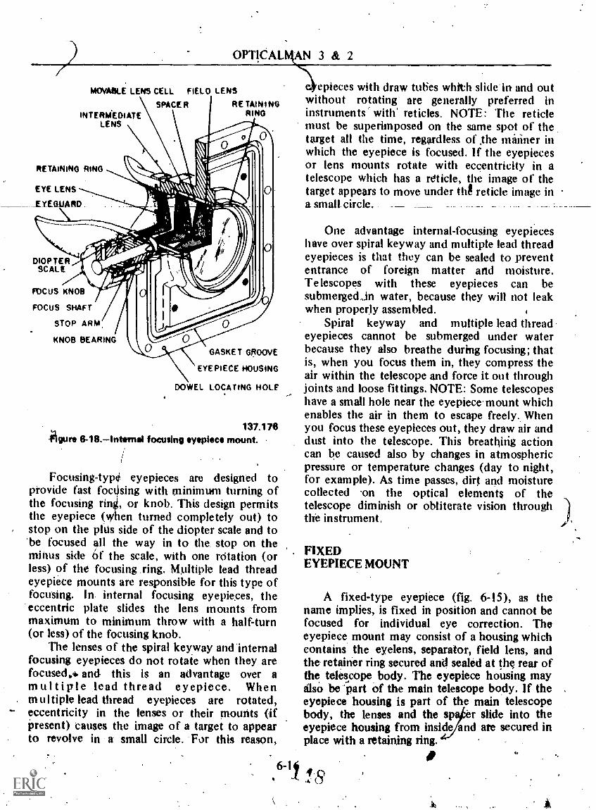
OPTICAL
MOVABLE LENS CELL FIELD LENS
SPACER RETAININGRINGINTEROAEDIATE
LENS
RETAINING RING
EYE LENS
EYEG_UARD
DIOPTERSCALE
FOCUS KNOB
FOCuS SHAFT
STOP ARM.
KNOB BEARING
GASKET GROOVE
EYEPIECE HOUSING
DOWEL LOCATING HOLE
137.176Agure 6-18.Intemal focusing eyepiece mount.
Focusing-type eyepieces are designed topiovide fast foctising with minimum turning ofthe focusing ring, or knob. This design permitsthe eyepiece (when turned completely out) tostop on the phis side of the diopter scale and to'be focused all the way in to the. stop on theminus side tif the scale, with one rdtation (orless) of the focusing ling. Multiple lead threadeyepiece mounts are responsible for this type offocusing. In. internal focusing eyepieces, the
'eccentric plate slides the lens mounts frommaximum to minimum throw with a half-turn(or less) of the focusing knob.
The lenses of the spiral keyway andinternalfocusing eyepieces do not rotate when they arefocused.. and this is an advantage over amultiple .lead thread eyepiece. Whenmultiple lead thread eyepieces are rotated,eccentricity in the lenses or their mounts (ifpresent) causes the image of a target to appearto revolve in a small circle. For this reason,
AN 3 & 2
epieces with draw tubes whith slide in and outwithout rotating' are generally preferred ininstruments with' reticles. NOTE: The reticlemust be superimposed on the same spot of thetarget all the time, regardless of .the mariner inwhich the eyepiece is focused. If the eyepiecesor lens mounts rotate with eccentricity in atelescope which has a reticle, the image of thetarget appears to move under thg reticle image ina small. circle.
One advantage internal-focusing eyepieceshave over spiral keyway and multiple lead threadeyepieces is that they can be sealed to prevententrance of foreign matter and moisture.Telescopes with these eyepieces can besubmergednin water, because they will not leakwhen properly assembled.
Spiral keyway and multiple lead threadeyepieces cannot be submerged under waterbecause they also breathe during focusing; thatis, when you focus them in, they compress theair within the telescope and force it out throughjoints and loose fittings. NOTE: Some telescopeshave a small hole near the eyepiece-mount whichenables the air in them to escape freely. Whenyou focus these eyepieces out, they draw air anddust into the telescope. This breathing actioncan be caused also by changes in atmosphericpressure or temperature changes (day to night,for example). As time passes, dirt and moisturecollected -on the optical elements of thetelescope diminish or obliterate vision throughthe instrument.
FIXEDEYEPIECE MOUNT
A fixed-type eyepiece (fig. 6-15), as thename implies, is fixed in position and cannot befocused for individual eye correction. Theeyepiece mount may consist of a housing whichcontains the eyelens, separator, field lens, andthe retainer ring secured and sealed at the rear ofthe telescope body. The eyepiece housing mayOw be 'part of the main telescope body. If theeyepiece housing is part of the main telescopebody, the lenses and the sp er slide into theeyepiece housing from inside and are secured inplace with a retaining ring.
6-16t 04.u
,
Ier

Chapter 6-DESIGN AND CONSTRUCTION
Because this eyepiece cannot be focustd forindividual eye correction, the light rays.whichleave it are slightly divergent with a value of -3/4or -1 1/ 2 diopters. This fixed minus diopter'seteing is used because the majority of operatorsset focusing eyepieces slightly on the minus sideof the dioptric scale.
BEARINGS/
1
-When A -shaTt US mounted in a device to holdit during rotation, frictiot develops at thecontact point between the s tat and the device.Friction develops heat. fTherefore, .frictionproduced in a shaft housit g must be kept to aMinimum for gatisfacto performance andlonger life of the shaft. Devices which reduce theamount of friction produced by shafts in theirhousings are called bearings.
Except for .;imple types, optical instrumentshave manY moving parts. Movement of theseparts, however, must be so restricted thatmotion takes place only in the direction desired.Movable parts of an optical instrument musttherefore be supported' and retained by somesuitable means, sp that friction-free movementin a specific direction may be obtained.
Before we get Onto the _discussion ofdifferent types of bearings, it is a good idea toexplain the different types of loads which
,bearings must carry:
NOkMAL LOAD: A load applie owardand perpendicular to the bearing surfadé
RADIAL LOAD: A load directed away froma surface, the opposite of a normal load.Rotation of a ,wheel or object on an axis is anapplication of radial load.
AXIAL LOAD: A loag directed along theaxis of rotation or surface °Ran object.
ANGULAR LOAD: i4 load which is acombination of the other loads just described.
Bearings are generally classified as lidingsurface and rotational (sometimes called tollingcontact bearings).
;
Sliding Surface,Bearings
A sliding surface Nearing usually has astationary member which forms the base onwhich its moving part slides. A lathe, forexample, has this tyPe of bearing in the hailingand guiding of the carriage and tailstock on thelathe bed. Sliding surfaces.are not always flat;they may be square, angular, spherical, .orcircular. The pig.on ..and_ _cylinder _bore of aninternal-combustion engine constitute a circularsliding surface bearing.
Square and spherical sliding surface bearingsare used to mount some of the smaller gunsightsin order that they may be"easily boresighted(aligned with the gun). Refer 'to figure 6-19which-shows these two bearings as used on an
. instrument. The spherical bearing is secured inits mating mount which is firmly attached to anadapter or gun mount. ,The spherical bearingholds the front of the histrument securely and atthe same time allows radial motion of the body.
The square bearing (quadrangular) provides asurface for bearing pads and adjusting screwswhich can accurately lock the instrument in anydesired position. The bearing surfaces in thisinstance are subjected to normal loads by fouradjusting screws in an adjusting-screw mount.Each adjusting screw exerts pressure '?)n itsrespecti e bearing surface. By loosening andtightening opposing screws, as necessary, youcan bore 'ght the -telescope. Adjusting-screwmounts ar4 also good for holding and adjustingreticle mou'rits..
Although not a sliding surface bearing, thesquare bearing is used as it locating bearingsurface, with little if any sliding motion exertedupon 1it. When accurately Machined, a squarebearing is used as a bearing pad for holding largegunsights in gun Mounts and directors and forlocatiqg and holding parts inside optical.instruments. During overhaul of a gunsightIelescope, bearing pads are reference surfaces foraligning optical elements.
Rotational Bearing
A. rotational bearing generally lias astationary member for holding the' rotating
6,4711,9

OPTICALMAN 3 IC2
Nun, 6-19.Cy1indriaal bearing and square bearing in an instrument isrmbly. .
4ft
member. The stationary inernber is called thesleeve. The rotationmember iS usually in theform of a shaft, To/hose precision-finishedsurfaces are called trunnions.
,
Trunnion bearings (fig. 6-1311, such as thoseon the ends of a MK 61 telescci5e right-angledprism mount, art used on many kinds oftelescopes to keep the optical axis 6( a telescopeor prism mount in a true vertical plane duringelevation gr depression of the line of sight.
Bell Bearings
liecause rolling friction is much less thansIlding friction, precision tiall bearings are usedeftensively in opticil instruments. Precision ballbearings in self-cqntained units are classified inticordanqawith design.. Differences in design inbill bearingi are generally not -apparentexternally. In making a design of these. bearfngs,the outer race, the inner face, and the steel balls,(which foil. ,between the .,,races) must be takenOtto cOnaidOition.
As' you studi?. the vost common designs ofselflOhtained peicisioti ball bearings in the871loivhig paragraphs, re(er,. to figures 6-20 asl6-21 to determine their differences. 11
N4.
137.171
Radial ball bearings (fig. 6-20A) ore designedto carry loads applied t. : plane perpendicularto the axis of rotatio in order to preventmovement of the shaft in a radial direction,Thrust ball bearing; i;. 6-20C) are designed totake loads appli n the same direction as theaxis of the ,sha t in order to prevent endwisemovement.
Radial and thrust bearings are thereforedesigned to citify loads 'in a specific direction:perpendicular 61c parallel to the axis ofsuppOrted shafts.
An angular tall bearing (fig. 6;20B) supportsiMgular loada !mit which has components
,It radial and axial thrillt4id it is exemplifiedby the bearing in the front 'wheel of a. bitycle.Angular ball bearihgs are normally used in pairs,infir manner which. enablet .the angular contactsurfaces of one bearing 'to oppose thecorresponding surfices of the other. Thisarrangement of bearings provides a techniqueknown is PRELOADING, whkh removes whatis caHed giye or softness before the. bearfngs aresubjected, to their normal loads.. .
The .principle of preloading %illustrated inre 6-21, Preloading can be obtained (and
ormally is)* subjecting the inner rapes to abrust directed -axially toward the. angular
conta Vices of the outer races.
648I 50
,

Chapter 6DES1GN AND CONSTRUCTION
RADIAL
oRiA
RADIAL
OUTIRAC
CAGE
ANGULARCONTACT
14444
ANGULARCONTACT
INNERRACE
BALL
Figure 6-20.Different types of ball bearings.
In some cases, individual precision steel ballsare ,used as a bearing between 'Iwo parts; theparts themselves act as thebearing races with the'desired number of steel, balls rolling betweenthem. Such a bear* is used betweeh polaroidfilter plates in optical instruments to securesmo9th and free rotation.
CAUTION: Dry metallic surfaces tinder anappreciable load, though smoothly thachined,will not slide over each pther without abrasion;they must be kept covered 'CONTINUALLYwith an approved lubricont. If properly
vis
THRUST
THRUST
77:66
lubricated, precision-made ball bearings earvery little. When wear does occur baUbearings, replace them. Adjustment A.impossible.
OPTLCALINSTRUMEN1PGEARS-.
An instrument designer must know whattype of .gears to use for a specific function inorder to provide the type of motion and speedrequired. BecaUse you Must work with these
6-19 15j

OPTICALMAN 3 & 2
.4"lk4:111
eee/ofee
V 4
137.180Figure 6-21.---Preloading produced by pairs of angular
ball bearings.
gears in optical shops, knowledge concerning thebasic types will be beneficial to you.
Spur Gears
.The spur gears shown in figure 6-22.are froma Mark 74 gunsight. Spur gears are used morethaii any other type .of gear .in Optical
Figure 6-22.Types of spiv gears.
r4,Z'
5.2R.1
instruinents to transmit power from one shaft toanother.
Teeth on spur gears vary in size (inaccordance 'with requirements) and are stated interms. of PITCH, or DIAMETRAL PITCH(number of teeth per inch of pitch diameter). Aspur gear with 16 pitch and a pitch diameter ofI inch has 16 teeth, and so forth.
Speed. ratios betwcon shafts havillg- -spur-gears is important and is defined me s the
I reciprocal of the ratio of the quantity of teethof the two gears. For instance: if two matinggears have 40 toeth and 10 teeth respectively,the ratio is 4 to 1. The speed of the 10-toothgear will be 4.iimes that of ill 40-tooth gear.
Metals generally used in small spur gears arebrass, aluminum, and steel; but cast iron iswidely used in large spur gears. Spur gears,however, itre also made of nonmetallicsubstances.
Bevel Gears
Bevel gears used in optical instruments canbe put on shafts whin intersect at desiredangles, provided the angle of the teeth is correctin relation to the shafts.
When one component of a pair of gearswhich mesh together is bigger than the other (A
B in fig. 6-23), the bigger component isusually called tle GEAR and the smallercomponent is called the PINION.
Bevel gears are made with straight or curvedteeth, but they CANNOT be ihterchanged withspur gears. By using different size bevel gears asshown in figure 6-23, you can obtain a differentspeed ratio, aS,desired. When these gears are thesame size, they are 'called MVER GEARS.NOTE: If lApped pairs of bevel gears are used inan optical instrument, almost perfect quietnessof operation is obtained:
The shape of bevel gears, especially thosewith spiral teeth, causes them to exertconsiderable trut. For this reason, the end of ashaft whic! y contains the gear is generallysupported by an angular ball bearing, aild theother end has a radial ball bearing.
6.-201 52.

Chapter 6DESIGN AND CONSTRUCTION
A. SPIRAL BEVEL GEAR
Figure 8-23.Types of Inv& gears.
Worm and SectolFears
Study figure 6:24. The top part is called aWORM, and the . bottom, part is calledSECTOR GEAR.
If a worm has only one continuoils thread, itis called a SINGLE-THREAD worm. More thanone thread may be cut on a worm: A worth withtwo continuous threads is called aDOiBLE-THREAD worm; a worm with threecontmuous threads is called a TRIPLE-THREADworm. On a worm with a single thread, lead andpitch are equal, but the lead is tWice the pitchon a double-thread WoLtn and three times thepitch on a tripie-threacr worm. Therefore if a,single lead worm is Used, one revolution Of theworm advances the sector one tOoth. With adoUble or triple-thread wont, the sector willadvance two or three teeth with each revolutiOnof the *Om.
As you can see froni figure 6-24, therotation 'of the sector is limited toapproximately 90°, If the'secto6were made withteeth all the way around Jo, rotation),
I.
Figure 8-24. or gear and worm.'5.22.9
then the arrangement would be called a wormand worin gear..
HELWAL.GEARS
Helical gears are closely related to wormgears in function and general arrangement,except that mating helical gears are usually' of .the same thickness, and teeth are cut at a 450angle to the axis of rotation.
-With a worm and sector or worm and worm
gear, .the worm is the driving member; the wormcauses the gear or sector to revolve, but not viceversa, With helical gears, even those of differentdiameters,, either gear can drive.the other. .
Rack and Pinion
re optical instruments use a rack andpini such as the one illustrated in figure 6-25.The rack gear moves in a linear motion, asindicated; and it is simply a straight bar intowhich the gear teeth have been cut The pinion,of course, moves in a rotary motion.

OPTICALMAN 3 & 2
Figure 0-26.Rack and pinton.
INSTRUMENTSEALING METHODS
To maintain the cleanliness of the optics inoptical' instruments', the instrument bodies fire ..
sealed to keep out moisture and dirt. All optical ,, inStruments are sealed but they are not
neeessarily waterproOfed to stand submersion inwater.. .
All openings in optical instruments aresealed with sealing compound or gaskets. Acombination -of both is often used. The gasketSmay be made of rubber, plastia, or lead.
lnVrumen re waterproofed by using. gaskets on all side joints or, where a gasket
cannot be used, because of physical limitatiOns,sealing conipound. A welkletisned waterproofinstrument Will have gaskets far all, seals exceptfor such small; nonflexing joints ai a setscrew,gOing through a body.
5.22.13
, The primary lob of waterproofing or sealingmust be done by the designer. Yourresponsibility as a repairman is to do, your job ofseal4ng with care and precision. The standardtechniques for performing .waterproofing andsealing operations are set forth in the followingparagraphs.
SEALING COMPOUND
Sealing procedurei for using rubbercompounds fall into two categories: sealingoptidal elements and sealing mechanical parts.The following procedure Oplies TarmjienseSand windows. The shape is not important. Thecommoti elemint in all claSies of tbis work is thejoint of glass to a metal shOulder in a mechanicalpart.
The sealing coMpoun used is a jelly-likerubber called RTV which. sets into a tough,flexible consistency after being exposed to air
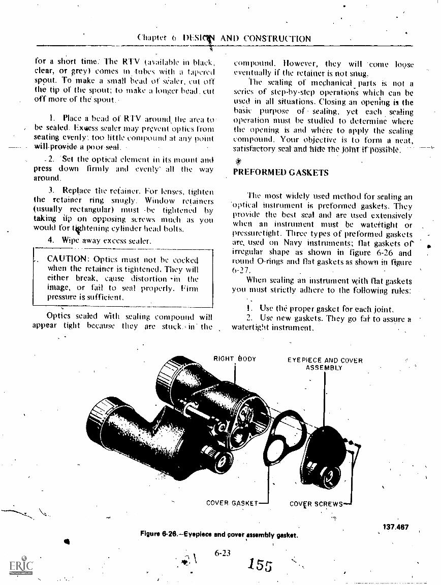
Chaptet 6 DESIM AND CONSTRUCTION
for a short time: The RTV (available in black,clear, or grey) comes in.tubes with a t aperedspout. To make a small bead of sealer, cut off
.
the tip of the spout; to make a longer bead, cutoff more of the' spout.
I. Place a bead of RTV around, the area (0., be sealed. Extaess sealer may prevent optics from
seating evenly: too little compound at any pointprov-kle- a poor se-al .
2. 'Set the optical element in its mount andpress down firmly and evenly all the wayaround.
3. Replace the re(ainer. For lenses, tightenthe retainer ring snugly. Window retainers(usually rectangular) must .he tightened bytaking Up on opposing screws much as youwould for ttlitening cylinder head bolts,
4. Wipe away excess sealer.
CAUTION: Optics must not be cockedwhen the retainer is tightened. They willeither break, ca,use distortion -in theimage, or fail to seal properly. Firmpressure is sufficient.
Optics sealed with sealing compound willappear tight because they are stuck., in- the
compound. However, they will 'come looseeventually if the retainer is not snug.
'The sealing of mechanical parts is not aseries of step-by-step operations which can beused in all siquations. Closing an opening is thebasic purpose of sealing, yet each sealingOperation must be studied to determine wherethe opening is and where to apply the sealingcompound. Your objective is to form a neat,satisfactory scar and bide the joint itpossibk.
PREFORMED G ASKETS
The most widely used method for sealing an'optical instrument is preformed gaskets. Theyprovide the best seal and are used extensivelywhen an instrument must be watertight orpressuretight. Three types of preformed gasketsare, used on Navy instruments; flat gaskets orirregular shape as shown in figure 6-26 andround 0-rings and flat gaskets as shown in figure6-/7.
When scaling an instrument with flat gasketsyou !mist strictly adhere to the following rules:
1. Use thi proper gasket for each joint.2. Use new gaskets. They go fai to assure a
watertight instrument.
RIGHT. BODY
COVER. GASKETJ
EYEPIECE AND COVERASSEMBLY
COVVI SCREWS
Figure 6-26.Eyepiece and cover assembly gasket.
sr,6-23
15
137.467

OPTICALMAN 3 a
'EYEPIECEb0"RINGMOUNT
PfGHTRIGHT COVER
EYEPIECELENS MOUNT
EYEPIECE"0" RING
EYEPIECE LENSMOUNT GASKET
4.
137.523Figure 6-27.Eripiece 0-ring teal.
3. Be sure the gasket surface of the partand the gasket itself are cleats. Foreign mattermay rause a- gapin the seal.
4. Place the gasket in the correct .positionand make sure it will be flat against the part it issealing.
5. Tighten the parts be sealedsufficiently to squeeze the asket; however,excess pressure may cut the gasket.
6. Examine a gasket joint; if postIble, afterit has been reassembled to dheck the gasket forproper posi t
(i-RINGS
ATI70-rinig seal on an. optical instrument isengineered t8 meei a set of standards that applyto all 0-ring seals. All 0-rings are molded andtrimmed tsx .ex_tremdy_. _close ...tolerances- incrosg-sectional area, inside diameter, and outsidediameter. An 0-rini, is generally fitted into arectangular groove machined in the mechanismto be .sealed. The dimensions of the 0-tinggroove (seat) aid the size of the 0-ring must heextict if the seal is to function pioperly. Unlike aflat gasket which seals as a result of the squeezefrom 14.twp parts, the 0-ring seals as a resat ofdistOrtiO caused by pressure. Notice figure 6-28which Shows the proper installation of an 0-ring.The clearance for the 0-ring in its seat is lessthan the free outer diameter, .and the 0-ring issliglrtly squeezed 'but of round (fig. 6-28).
When pressure is applied, the 0-ring movesaway frouilhe pressure into the path of leakage,thus completely sealing the passage (fig..,6-28B).
-Thegreater the piessure applied, the tighter the. seal becOrites. When the pressure 'is decreased,the rcsiliency and elasticity of the-seal returnsthe 0-ring40- its natural shape. Due 'to age andtemperature variations, 0-rings ban_become set(lOss of resilience) and fail to perform as .a seal.
0-rings are an excellent means for sealingshafts iirojecting through an optical instrumentody housing_ and for psealing windows,inspeetion plates, and various other fittingsattached to optical in'StruMents. When 0-rings
6-24
Figure 6-28.Properly installed 0-ring137124' ""

Chapter 6 DESIGN AND CONSTRUCTION.. ..
are usesl, the seating surfaces mitst be clean andabsolutely free of dents or scratches. The 0-ringmust be in perfect eondition, and the correct04111g for each sealing application must be used.
$ Because of the requirements for perfectSeating surfaces, 0-rings are removed andinstalled with wooden dowels or with specialbrass toots. Careful use of these tools will
i preven-t damage which causes unnecessary wasteof -tVe'and material-..--"
Although an 0-ring 'may *pear perfect atfirst glance, slight surface flaws may exist. Theseare often capable of preventing satisfactory0-ring performance.
..By rolling the ring on an inspection cone or
dowel, you can check .the inner diameter surfacefor small cracks, particles of foreign material,and other irregularities that will cause leakage orshorten the life of 0-rings. The slight stretchingof the ring when it is rolled inside out will helpto reveal some defects not, otherwise visible.Make a further- check ofpach 0-ring bystretching it betw4en your finvirs, but be carefulnot to exceed tO elastic limits of the rubber,Following these inspection pric ices will proveto be a maintentinee ..econoni , t is far more'desirable to take care in I identifying andinspecting 0-rings: than t,d ripeatedly overhaulcomponents because 'of. faultfitak If an 0-ring.. .has any defect, discard ir /
The probl,n of. -tioSitiyily identifying the,coVect 0-ring to use -is lade,.more difficultbee-ause many of these seils appear identical., insize and color, but are intended for diffexent4applications. For this rqiison, 0-rings are sealedin envelopes with a lOel which indicates partnumber, size, and life/expectancy. Always keep0-rings in their origiOl package until ivady foruse, and determine eixactly which seal to use foreach appheation. i
. V
PACKING
As used in mechanics, the term packingrefers to the material used to seal an openingwhere the two component parts move in relationto each other. The 'type of material useddepends on Several factors such as temperature,Pressure, and type of %motion. h9k4. mostcommonty- used packing mhterials fors cipticalinstruments are natural rubber, plastics, flax.
nl sy iii het ics such as neoprene and koroseal.SC packing materials come in wide ranges of
tic n.i usi Ic st,,rength, and shape. Packing canbc in either prelbrmed shapes, as shown in figure6-29; or nt bulk sheet and--spools.r .
Un fortunately, the length of time that a sealwill function properly depends on tnany factOrs;many of them unpredictable. Therefore, it isalmost impossible to say th#La seal will wear outwithin 'a spasifitd time- .47-1-
Each tune a component or unit isdisassembled , the seals should be carefullyinspected. If there is any doubt as to theircondition, they should be replaced. In mostcases, -automatic replacement of the seal isstandard procedure. The manufacturer'srecommendations, along with the previousexperience of the personnel repairing the unit orcomponent., should be the main criteria fordetermining 'when to replace a specific seal.Installation of seals should be carried out asspecified in the . maintenance manual,manufacturer's _publication, or Naval Ships'Technical Manual.
It has been .found from experience thatpackings deteriorate with age. Therefore,knowing and understanding packing shelf lifewill save you many hours of unnecessary toil inreptitking a unit and having it still leak becauselthe packing-was,defectiVe due to age.
V -RING
FLAT RING
U -RING
5.35(137A)AL7 noire 6-29.-Packing rings.
6-25
,:..0-20 / 5 '7

OPTICAL\MAN 3 & 2
Prior to installing natural and syntheticrubber packings, you rnust check to deterininewhether these parts are acceptable for, use. *Allnatural. and synthetic rubber packing containersare marked to facilitate an age control prOgram.This information is available for all packingsused, regardless of whether the packing isstocked on shipboard, at stock distribution-points, or furnished as an integral part of a
nnionent_. Positive identification, indicatingthe source, cure date, and expiration date must rbe Made,of packings.
Cure, 'date means the time the packing wasmanufactured, and is designated by the quarterof the year and the year of manufacture..Packings manufactured during any given quarterare considered one-quarter old at the end of the
or purposes explainingsucceeding quarkthe coding used I) anufacturers to designatethe cure date, each is divided into quartersastbllows:
First (-)uarter: January, February, and MarchSecond Quarter: April,.May, and JuneThird Quarter: July, August, and SeptemberFourth Quarter:. October, November, and
December
Expiration date is the date after which apacking CANNOT be used in service, and timeof delivery means the date of acceptance by thepurchaser. All packing must be scrapped if not'put into use by the time of the expiration date.
Packing is packaged by the manufacturerwith a code which indicates year and quarter ofmanufacture and the expiration date.
EXAMPLE 1076 Expiration Date: March 78
This code indicates the packing was producedduring the first three months of 1976, and itshould be used before March of 1978.
If a package does not have a legibleexpiration date, reject it. Likewise, if anypacking is' not in its original package, do not useit,
Packing should always be stored away fromsunlight and in a low-humidity area. Storage areatemperatures are also important. A range from60° to 100°F is usually satisfactory, and in nocase should the temperature ftceed I 25°F.
LUBRICATION--V
Proper lubrication, using only authorizedlubricants, is an important part of opticalinstrument repair. It is a matter which has beenregarded too lightly in the past, the theory beingthat any grease or oil would do. Experienceproves that such an idea is detrimental to thebest performance of the instrument.
A lubricant may work perfectly in temperatezones, but stiffen up. f6 the extent of renderingthr instrument useless in colder climates.Likewise, a lubricant suitable for use intemperate and, cold 'climates may be entirelyunsatisfactory for use in hot regions, where theheat could soften the lubricant to the point of,flowing into locations where its presence wouldimpair the functioning of the instrument.
The foregoing facts are particularly of, importance in the case of optical instrumentswhere eVen a very thin film'of grease or oil on anoptical surface would render the instrumentabsolutely useless. Since the Navy mnst use- itsoptical instruments in climates from one
elyextreme to the other, the lubricar used. mustperform properly .under wi varying?conditions and in no way impede thefunctioning of the instruMent.
An excessive amount of lubricant is a waste,and often is as bad as, or worse than, notenough. Where closely mated 'parts that requireonly a very thintThn of lubricant are concerned,an excess can introduce errors in the reading ofthe instrument.
The primary purpose of lubricants in opticalinstruments is to provide smoothness of action.Lubrication is not used to prevent wear, as is oil
an automobile engine. Thus; only a little willgo a long way.
The Navy buys readymade lubricants whichhave been found to be satisfactory for use onoptical instruments. These recommendedlubricants are manufactured in different grades
6-26t.)

Chapter 6-DESIGN AND CONSTRUCTION
adaptable to all types of applications andtemperature ranges,
As an optical repairman you should alwaysfollow the specifications of technical manualswhen lubricating an optical i_nstrument. Whenspecific instructions are not available, ask yourshop supervisor which lubricants to use.
APPLICATIONOF LUBRICANTS
To apply grease to a surface, use a roundhardwood stick which has a chisel point on oneentl. Dip the end of the stick into the containerand piek up a small amount of grease on theend.
Apply the grease to the surface tp begreased, smoothing it out with the stick so that
a.
y
1-^
the entire bearing surface is covered with a thinfilm of thergrease.
Fit the greased parts together and run themin; or in the ekse of a screw, turn it in and out afew times to diltribute the grease evenly over itsentire working arca. Then remove the excessgrease that is forced out, using the stick to pickoff the bulk of the unneeded lubricant.
Wipe grease -from- -areas -where. none -shoutd/remain, using a clean, lintless cloth moistened
witWsolvent.
Keep the oils in small individual instrumentoiol cans fitted with a cap for protection againstdirt. Greases must be kept in clean jars or cansand kept covered when not in use to preverntcontamination by dust, grit, and dirt. Allcontainers should be properly labeled with thename of the lubricant and also the materialspecification number.
, 627 1
lj

/
41'
CHAPTER 7
MAINTENANCE PROCEDURES-----PART I.
This chapter provides information on repairand maintenance of optical instruments. We willstress the importance of careful handling andcleanliness of the instruments you will maintainand the tools you will use.
Optical insfiu-ments are expensive;precision-built . devices, and we cannotoveremphasize the care in maintaining thein, Ifan instrument is handled roughly or dropped,the shock May result in misalignment orbreakage of the optical and mechanical parts.When this happens, you have only onechoiceREPAIR. You must unseal theinstrument, disassemble it, make repairs,reassemble, and collimate. This amounts to a lotof work caustd by thoughtlessness andnegligence in handling.
Optical instruments are shipped in speciallyconstructed containers designed for adequateprotection ,during transportation. When youreceive optical ,instruments in the shop, checkthe containers for damage and cleanliness; then,
# if you do not start to work on the instrument atonce, stow thern in clean storage cabinets or'spaces provided for them. CAUTION: When you
ust move an initrument from one location to\ another, if possible, move it in its container.\
Most containers for optical instruments haveches or locks to secure the instruments inWon.' When you put ari instrument into its
co tainer, place it gently in position andcaref.ully close the lid. DO NOT TRY TOFORCE AN INSTRUMENT INTO ITSCONTAINER NOR SLAM THE COVER SHUT.
1 If the instrument does 'not- tlip- easily into itsi case, check fol ixtended draw-tubee or
something else which is hindering smooth
entrance into proper position. CAUTION:Always secure the cover of the container withthe qtches installed by the,manufacturer.
INSPECTION AND TESTING
Your duties as an Opticalman will alwayscall for you tq inspect and test opticalinstruments. The inspection may be held aboardship before the instrument is delivered .to the
d it just before you beginshop, or you mathe repair work. In an cfil, the inspection andtesting of an optical it driment are vital, andyou should have a thoro igh knowledge.of theinstrument and procedures used to inspect it. Ifan instrument is unfamiliar to you, study allinformation concerning it in OrdnancePamphlets (OP's), NavOrd publications,N a vShips Manuals, and blueprints. Neverattempt to disassemble and repair an instrumentuntil you fully understand it.
10
INSPECTION OF INSTRUMENTS
There may be occasions when you will b'egiven full responsibility for inspecting all opticalinstruments aboard a ship. By carefully locatingall deficiencies, you will be able to save yourselfand your repair activity considerable work.
CAUTION: When you inspect an opticalinstrument in use aboard ship and follow upwith minor repaIrs,, do NOT DISTURB' theoptical system unless it is required.
During predisassembly inspection of aninstrument, use a casualty analysis inspection
7-I -1

OPT1CALMAN 3 & 2
sheet and record all your findings on t. Asample casualty analysis sheet is shown in figure7-1.
Mechanical Condition
Carefully examine mechanical controls, and-cheek- geaT mull-art-Mt; ror slack or exCessivetightness. If the instrument is mounted onbearings, check them for dents, gouges, andcorrosion,.
.ITY the focusing action of the eytTieec tofind out if you can focus it (in and out) withoutbinding or dragging. If binding or draggingexists, the eyepiece is damaged or improperlylubricated
7-50 BINOCULAR
CASUALTY ANALYSIS SHEET,
Mark Mod Serial
Optical Condition
External Cleanliness
Internal Cleanliness
Moiiture
Mechanical Condition
Focusing Action
Hinge Tension
Eye Caps
Paint
Collimation
Step
Lean
LEFT
Coating
Cement
Chips
RIGUT
I.P.O. Scale
Objective Caps
c9vering,-,
0ivergence
0 ()looters
RERA I RMAN
137.586Figure 7-I.Binocular casualty analysis sheet.
Backlash in the focusing action of an *eyepiece is usually caused by a loose stop orretainer ring, but it .may be caused by a loosekey in a.spiral keywty assembly.
Check .the mechanicitl 0 diopter setting ofthe eyepiece to determine whether the indexmark points to 0 diopters when the eyepiece isat midthrow (halfway M.anstlalfway 1:m4The--focusMg action should bti such that the indexmark clears all graduations (plus and minus)during full travel of the foeus.knob.
If the instrument has a ray filter assembly,check the action of the control knob. If rotationof the ray filter shaft does not turn the colorfilters in or out of the line of sight, the cause ismost likely improper meshing of gears ordetachment of the gear itself from the shaft. Ifthe shaft does not rotate,. it is corroded or bent.
All .mechanisms must move freely withoutbinding, slack, backlash', or lost motion. Movingparts should be just tight enough to .keep themin proper position.-
Check for missing or broken partsretainerrings, setscfews, and so forth. You can locateloose or broken internal parts by shaking theinstrument.
If the instrument is gas sealed, check its gaspressure by attacking a pressure gage to the gatinlet fitting. Then crack thp valve screw iiikreadthe pressure on the gage. Correct pressure innitrogen-charged optical instruments is indicatedin the manufacturer's technical manual for eachparticular instrutnent. If the gage indicates nopressure in Ihe instrument, there is a bad gasket,a loose fitting, or a loose screw. Check for all ofthese defects when you disassemble a gas-filledoptical instrument.
Optical System
13pcause optical elements constitute theheart of an optical instrument, inspection of theoptical system is V41; important, and you mustlearn to do this phase 1(your work well. Whenyou first examine an o tical system, you may
7-2 si

('liapter 7 .MAINTENANCE PROCEDURESPART. I
have difficulty in distinguishing one' elementfrom another. With' experience. however, youwill be able to.see each element in the system,and you will be able to pinpoint defects.
The best method for inspecting the opticaliyitem of an instIlliment is to point it toward anilluminated area iind look for the following:
v
Dirt and Dust: Dirt, and dust show up- asdank spots (specks) on the surface of an opticalelement,.
Scratche. Breaks: These defects in anoptical element show up as bright, star-likespecks, scratches, or large bright areas when lightis retleyted from'ffiem..
Grease or Oil: Grease or oil on .an opticalelement 'is indicated by streaked, clouded, or
/nebulous areas, with an occasional bright,translucent spot.
Moisture: MoOure shows up as a sharplydefined nebulous area, with brilliant' reflectionor a diffused. clotided appearance when the areais not illuminated.
Fungus or Watermatks;. Brown or greenpatches, or stains, indicate the presence Offungus or .watermarks. Deposits of salt cause agrainy, milky color similar to, that of frostedglass.
Deteriorated Balsam: Deterioration ofCanada balsam used to cement lenses together isindicated by a dark yellow color, or areasbetween the elements appear milky colored _oropaque. When the cement just begins toseparate, bubbles orsplotches shaped like oakleaves appear between the elements. If there arebrightly colored bands or rings (Newton's Rings)between the elements, the lenses are under strainin their mounts, or the elements havecompletely separated.
I-lazy or Clouded Image: Foreign matter onthe objectifie lens, the erectors, or the prisms ofan optical system cause a hazy or clouded image.
You can examine color filters in an opticalsystem, if they are within the focal length of the
eyepiece.7.i)y 'holding one eye-a. feW ineheS frOinthe eyepiece and turning the ray filter shaft.Defects on a filter show up when it rotates inand out of the line of sight.
o If the field of vi'ew (true field) is notperfectly round, there is a loose diaphragmwithin the Instrument or the color filter plate isnot properly engaged with the detent ball orTOW.
411'Modern optical instruments have a
transparent metallic coating on optical elementsto improve light ,transmission through theinstrument. With uricoated optics, there will bean approkimate 5% loss Of incident light at eachair-glass surface due to surface reflection. Whenmagnesium fluoride is correctly applied toOptics, this loss of incident light is reduced toabout 1%.
The magnesium fluoride coating is depositedon 'optics to a depth ot' 1 /4 the wavelength ofyellow-green light. This amounts to fourmillionths of an inch (.000004). You do notneed to actiially measure this coating when youperform an inspection. If you view an opticalelement under a _strong white light, properly_coated optics will show a reddish-purplereflection. If the-reflection frOm coated optics isyellow, green, or deep blue, the coating is ofincorrem thickness, and light . transmissionthrough the instrument will be reduced. This iscause for rejection ,of the element.
A fdw scratches on the coating of an opticalelement will have no effect I on lighttransmission; however, if most of the baating hasbeen removed through improper cleaning orchemical action, the element should be replaced.
Reticles or other optics that are located atan image plane aro neVer coated since scratchesor other defects in the coating would be visibleand very undesirable.
'The mating surfaces of cemented lenses arenot. coated since there is no air-glass surface,therefore, surface reflection is not a problem.Reflecting surfaces of prisms are not coated forthe same reason:
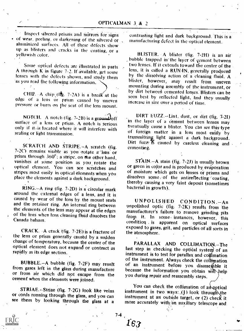
OPTICALMAN 3 & 2<
Inspect silvered prisins and mirrors for signsof wear, peeling, or darkening of the silvered otaluminized surfaces. All of thew defects showup as bliSters and cracks in the coating, or ayellowish color.
Some optical defects are illustrated in partsA through K in figure 7-2. If available, get somelenses with the defects shown, and study themas you read flw following information,
A chip.(ftg. 7-2A) is a brea at theedge of a lens or prism caused by unevenpressure Of burrs On the seat of the lens mount.
NOTCH. A notch (fig. 7-2B) is a grauaollsurface of a lens or prism. A notch is seriousonly if it,is located where it will interfere withsealing or light transmission.
SCRATCH AND STRIPE.A scratch (fig.7-2C) remains visible as you -rotate alms orprism through 360'; a stripe, on the other hand,vanishes at mime position as you rotate theoptical element. You can see scratches andstripes most easily in optical elements when youPlace the elements against a dark background.
RING.A ring (fig. 7-21)) is a circular markaround the external edges of a lens, and it iscaused by wear of the lens by the mount seatsand the retainer ring. An internal ring betweenthe elements of the lens may appear at the edgesof the lens when lens cleaning fluid dissolves theCanada balsam.
('RACK. -A crack (fig. 7-2E) is a fracture ofthe lens or prism generally caused by a suddenchange of temperatur9, because the center of theoptical eleMent does not expamf or contract asrapidly as its edge section.
BUBBLE.A bubble (fig. 7-2F) may resultfrom gases left in the glass during manufactureor from air which did not escape from thecement when the elements were joined.
STRIAE.Striae (fig. 7-2G) look like veinsor cords running through the glass, and you cansee them by looking through the glass at a
contrasting light and dark background. This is amanufacturing defect in the optical element.
BLISTER..- A blister (fig. 7-2H) is an airbubble trapped in-the layer of cement betweentwo lenses. If it extends toward the center of thelens, it is called a RUN-1N, generally prodpeedby the dissolving action of a cleaning. fluid. A .
blister, however may result from uneven__mounting during assembly of the instrument, orby dirt betweeii cemented lenses.' Blisters can beseen best by reflected light, iind they usuallyincrease in size over a period of time.
DIRT liUZZ.Lint, dust, or dirt (fig. 7-21)'in the layer of a Cement between lenses mayeventually cause a blister. You din see thislypeof foreign matter in a lens most: easily bytransmittink light against a dark background..Dirt furtrl§ caused by careless cleaning andcementing.
ST-AIN.--A stain (fig. 7-2J) is usually brownor green in co)or and is produced by, evaporationof moisture which gets on lenses or prisms anddissolves some,-,of the antireflecting-'coating,thereby causing a very faint deposit (sometimesbacterial in growth).
UNPOLISHED CONDITION.Anunpolished optic (fig: 7-2K) results from themanufacturer's failure to remove grinding pitsfro9i it. In some, instances, hoWever, thiscondition . is apparent on optical surfacesexposed to pses, grit, and particles of all sorts inthe atmosphere.
PARALLAX AND COLLIMAT18 Thelast step in checking the optieal systet of aninstrument is to test for parallax and co nationof the instrument. Always check the col ationof an instrument before you disasse ble itbecause the information you obtain wi helpyou during repair and reassembly steps.
You can check the collimation of a ticalinstrument in two ways: ,() ) look througl theinstrument at all- outside target, or (2) check itmore accurately witk:-an auxiliary telescope and
7-4
-146

t
Chapter 7 -MAINTENANCE PROCEDUKSPART
SCRATCHAND
STRIPE
X
UNPOLISHED(GRINDING PITS)
Figure 74.Optical defects.
7-5
1).137.181

OPTICALMAN 3 & 2
a cAhmator. The fiest intthod, however, isgenerally used when quick results are necessary.
4. Focus the instrument on a-distant target andcheek .for parallax by moving the eye from sideto. side and up and down, If parallax is present,,the reticle (crossline) will appear slightly out offocus and seem tO move back and forth or upand down over tPire target. If parallax is nota-present; the- reticle- -will-- be In- sharp- lcic us wag,the target and remain superimposed in one spoton the target, regardless of rthe direction inwhich you move your eye behind flip eyepiece.
010 PT F. R S E TT I N G. -To check theeyepiece diopter setting, focus the.,instrument
. oi au infinity target and observe the position ofthe index mark on the diopter scale. If the indexmark is not pointing to your personal dioptersetting, 0 diopters-is incorrect.
LEAN. -If the instrument has a porrô prismerecting system, chack the optical, system forlean by looking-through the instrument with oneeye at a vertical target (flag pole or side ofbuilding) and by looking directly- at, the targetwith theother eye. If the two images-are not)PERFECTLY parallel, there is lean in the opticalsystem; that. is, the image through theinstrument appears to lean -in relation to theimage observed with tbenaked eye. The reasonfor this lean is that the porro prisms are not4 mounted at 90° to each other.
TESTING OF INSTRUMENTS
iAs yon know, good performance of- anoptical instrument is Obtained only .when the'images it creates are free of aberrations. OptkalpeOrtnancels basically a function of 4esign ofthe instrument, and catinot be varied unless thecharacteristics of thet optical elements ,are.chatied. There are sever.al possible servicedefects, however, which can change the opticalqualities of one or more elements. An opticalefeme'nt under strain by mechanical paits, forexaMple, 9r tilted and improperlSt Positioned
:,elements (faulty mounting), badly matched
recemented optics, and even incorrect optics allcause poor image infidelity.
Image Fidelity
The accuracy of reproduction in an imageand the absolute clarity of an it age are termedimage fidelity. When you jheck the- imagefidelity of an optical instrun ent, check for t_w_othings: CENTRAL RESOLUTION andCENTRA I-ASTIGMATISM .
Take a close look at figure 7-3, whichshowsa Standard test 0110 for testing image fidelity inoptical instruments, and figure 7-4, which is thetest pattern for astigmatism. Mese test chartsare available through naval supply channels.
.1
NAYIONAL BUREAUIOF STANDARDS,,TEST CHART I 25 X
Figure 7-3.Intage fidelity test chart.
fi.if 7-6 1 65
ititiur
137.54(Figure 7-4.Astigmatism pattern.

Chapter 7MAINTENANCE PROCEDURES-- PART I
Image fidelity test chart values (fig. 7-5) listthe sbace between the centers of adllicent lines
..as lines per inch, the .distance from-which youshoukl view the chart, anti the resolutionrequirements in terms of angle in the field foreach class of inStrument. The correspondingpattern for the astigmatism test is also given interms of the number of lines p.er inch. These areselected .h_r convenienl viewing_ al the samedistance prescribed for the resolution test,
The 'angular limit of resolution is relatedinv+ely to the diameter of the objective lens,which means that it is advisable to have largeobjeetives for sharp definition. A target shooterwould choose a scope with a I I /4-inchobjective (diameter), or even larger. A pair of7 X 50 binoculars provides good fesolutionbecause of the large size of the Objective (50 mmin diameter), and for this reason, it is better thana pair of '7 X 35 binoculars, with a 35 mm
mbjective.
To test the image fidelity ot' any particularinstrument, select the proper pattern from thechart (fig. 7-5), locate the pattern at the distancespecified, and focus the instrument on thepattern. If you do not get a clear, undistortedimage of the -test pattern, image fidelity is poor.
Although th esolving power of the humaneye is equal to I inn de of arc, it is reduced to'2or 3 minutes of a c by eye fatigue aftercontinuous ation. For continuousoperation, therefore, you need an instrument ofgreater power to get the same definition youwould get with a lOwer-power telescope used forshort intervals.
PROCEDURE FOR TESTING ANOPTICAL INSTRUMENT FORASTIGMATISM:
I. Use the proper test chart and set it at thedistance given in the listing ot' values. Sight thetest pattern with the instrument to be tested,and line up the center of the astigmatiOm patternin the center of the fiejd,of view.
2. Place an auxiliary telescope to theeyepiece of the instniment undergoing the testand' adjust it to bring the' horizontal set of linesinto sharp focus. Note the diotiter reading onthe auxiliary telescope. CAUTION: The focusingadjustment ot' ,the primary instrument (oneundergoing the test) muSt NOT BE CHANGEDafter you perform the preceding operation.
.
Instilment
eResolution win.
Limit in Secondsof
Arc
Resolution1
*046_ -7-Lines
per inch
Din
feet .
AstigmatismiS ,
Linesper inch
7 x 50Binocular .
Telescopic' .'Alidada
hip. ,Oescope .
AsimuthTelesco0e
§extantTelescope
, 4
11
.
8,
18
,
.
:
'.
.
.
56
40
56
4Q,.
40
i 77
39
77.
54
24
. .
28
20.
28
20
20:
Flpre sest chart values,
7-71 SG
137:183

OPTICALMAN 3 & 2
3. Check the vertical set oi lines for focusIf it is not sharp, astigmatism is resent. To putthe vertical set of lines in sharp t cus, adjust theauxiliary telescope diooter ring Observe thediopter reading.
4. The maximum allowable differencebetween the horizontal and vertical lines is 0.15diopters for the primary instrument beingtested. Divide the .diopter difference found inthe aukiliiiry telescope, steps 2 and 3, by thesquare of its power to' arrive at theeorrespondMg change that would be found inthe primary instrumtmt without the auxiliarytelescope. For example, the diopter change inthe primary instrument equals:
Diopter Change in Auxiliary Telescope (DCA)
(Power of Auxiliary Telescope 2 )
As you can see, the auxiliary telescope increasesthe sensitivity of the test- by the square of itsPower. The maximum allowable dioRterdifference for typical auxiliary telescopes is as
'follows:
Power of Maximum AllowableAuxiliary Telescope Diopter Difference
3456
41.352.403.755.40
5. If the horizontal and vertical lines are infocus within the allowable tolerance, repeatsteps 2 and 3 for the diagonal sets of lines. Thesame tolerance prevails.
NOTE:»Excessive astigmatism may be caused_by a defectiye or poorly mounted lens. Checkthe objective lens first and then the reflectingsurfaces of the prisms (objective, prism first).These surfaces must be. optically flat to close"'tolerances.
Poor resolution is caused bj, defectiveobjective lenses and prisMs. Always replace theobjective lens first. Mitplaeed, unmatched, andshifted prisms cause trouble because they
""7-8
displace the Hneaof sight. A bad reflecting faceon a prism also chses poor resolution.
To check an optical instrument for flaresand ghosts, point it toward a small, bright objectagainst a dark background and focus sharply. Ifyou observe rings or streaks of light, or one ormore faint ghost images, the instrument has
. excessive. -in ternal-- .refleetion These- --defe&sindicate that the optics need recoking gar thatthe' interior of the instrument needs anonreflecting- coa ting.
Illumination and Contrast
Reproduction of an image depends upon theamount of light received by ,the objective andthe effective transmission of this light throughthe instrument. For maximum efficiency at anygiven light intensity, the exit pupil of an opticalinstrument must equal the 'entrance pupil-of theeye under the same conditions. Opaque foreignsubstancesdust, oil, or lint, for exampjeonany optical surface reduce illumination in thesystein and adversely' affect tile contrastbetween light and 'dark shadea 'areas 'of the.target.
To test for illumination and contsast in anoptical instrument, focus the instrument on adistant object and chteck the clarity of theimage. The image should, be nearly as bright andwell defined astthe object appears to the nakedeye. If the image is dim or indefinite, look fordirty, stained, or uncoated optical surfaces,darkened mirrors or cement, or damp or oilyoptics.
Spherical Aberration
To test an optical instrument for sphericalaberration, cover the outer half of the objectivewith a ring of black paper, focus sharply on adistant object:and read the diopter scale. Thenremove the ring of paper and cover' the inner
-half of the objective with a black disk. Refocusthe instrument and read the diopter scale again.
S.7

Np. Chapter 7MAINTENANCE PROMURESPART I
jhe amount of' movement of the eyepiece forfiusing is very small, theinstrument is wellcorrected for spherical aberration.
Chrolratic Aberration
To test an optical instrument for chromaticaberration:
1. Set up a white idisk against a blackbackground, far enough away so that you canfocus the instrument sharply. Wben the image isin focus, it should have no color fringes.
2. Focus in.a short distance and look for alight-yellow fringe around the image of the disk.
.3. Refocus' and then focus out a short111r,_ distance, at which point the image should be
fringed with pale purple..
The t wo fringes around the image(light-yellow and pale-purple) constitute theSECONDARY SPECTRUM of the opticalsystem, and they show that the system is wellcorrected for primary chromatic aberration (redand blue).
4
Coma
Focus the 'instrument sharply on a 4111,round, whi,te object near the edge of the fieldand 'study -the image produced. If the image iscircular and flareless, file instrument is free of
Coma.
NOTE: Test for coma at five or six differentpoints arodnd the outer edge of the field.
Distortion
To test an optical instrument for distertion:
Rule a pattern of vertical and horizontal.4,- lines on a, large sheet of cardboard and putrit
A
where the pattern nearly fills the field of view ofthe instrument.
2. Focus the instrument sharply and checkthe image, which should be composed entirelyof straight lines. If any of the lines appearcurved, the image is distorted.
OVERHAUL AND REPAIR
As an Opticalman, you have a complicatedjob. To repair and overhaul optical instruments,you pill use a wide variety of tools; you,willneed special skills and a lot of information onmany subjects. Only by careful eractice can youdevelop skill in using your haildsYou will neverdo it just by reading a book. Tlie vest wt can doin this chtipter is to try to get yot started-right.
We will give y,ou a brief introduction tosubjects like these: the use of handtools;soldering and silver brazing; handling chemicals;the use of blueprints; heat treating metals;cleaning and painting optical instruments; andcleaning and cementing optics, We will introduceyou to your tools, tell you what they are for,
- And give you a few tips that will save you timeand trouble. The rest is'up to you. Stay alert,look around you, and ask questions. Learn allyou can , about each job, Then, when youunderstand it, try it for yourself.
Keep your working space, your clothes, yourtools, and your hands strictly clean. It is a goodidea to cover the top of your workbench with alarge sheet of clean, light-colored paper leftreOscu begin to work- You can keep your handsfrohl sweating 'by washing them frequently incool water. Any fingerprints you leave on-an,'optical element will etch the surface and destroythe optic.
The old saying "a place for everything'andeverything in its place" ikelpecially true in theoptical shop, You cannot do, an efficient repair .
job if you hive to stop and look around kr .
ev,qryz.tool you need. KeeRe1101 tool inits place,whether. it 'is in 'your toblbox or the shop
7-910-4 4;
1 6 s

OPTICALMAN 3 & 2
toolroom. When you have finished with it, donot put it back until you have cleaned it. Youwill do better work, with less effort, if you keel)your tools in good shape ind use them only forthe jobs they aro intended to do.
COMMON TOOLS
Many of the tools used in optical repairwork are common handtools which aret horoughly discussed in Basic Haridtools,NAVEDTRA 10085 Series. .1-lowever, thequality of the tools and their condition are vitalto the work done on precision opticalinstruments. When you select a tool for use inthe optical shop, be certain that it is the highestquality tool available and that it is 'in goodcondition. Your skill in selecting, maintaining,-and handling tools is a measure of your e.xprin the OM rating.
SPECIAL TOOLS
A
Of all the various tools used by anOpticalman the most vital are. special toolswhich are use(' specifically for optical work.These special tools may be manufactured by- therepairman himself, or on rare occasions,purchased through normal supply channels.When yOu must manufacture a special tool, thesame qtiality standards that ,apply to(all opticalinstruMents must be used to eniure that the toolis properly made.
The l\cret step in manufacturing a tool is tomake a s tch which shows exact dimensionsand the type of material that is to be used. Ifyen are in \doubt about the procedure to'followor which machinery to use in making the tool gothe shop sUperviaor for guidance. Remember:NEVER opOrate any machinery .until you arethoroughly familiar with the operatinginstructionsind safety piecautions,
Some of he special tools used conttantly inoptical rep. work are discussed in the0311ov/ins pars phs.
137.185Figure 7-8.Retafiiing ring wrenchei.
Pin Wrenches a.Study the different types of wrenches,hown
in part A of figure 7-6. These Wreptha areknown as adjustable spanner or pth wrenchesand -are manufactured by the repairman. Part Bof figure 7-6 shows an Opticalman using theblade poilion of a pin wrench to rotate a slottedretainer Ting in a lens mount: A retainer ringmay be made with two small holes (instead ofslots) spaced 1800 apart, in which case thqpointed tips 9f the wrinch are used to turn ithering. This special toOl is adjustable, and it caiTheuSed to remove or tighten retaining rings ofvarious sizes.
,
CAUTION: Slippage of a' pin ,Orench dtiringuse can damage unprotected optical surfaces, &s-well as the retainer ring and mount. To preventany damage, be very careful when you use 'thewrench; be sure it fits properly in the slots orholes of the retainer ring, and protect optical
.

t
Ch'apter 7MAINTENANCE PROCEDURESPART I
4.
surfaces with rubber, blotting paper, or cleancardboard disks.'
Grip Wrenches
Figure 7-7 shows a grip wrench (part A) andthe procedure for using it (part 8). A gripwrench is made of fiber with holes in steps of1/16 inch, ranging in size from 1/2 inch to about
nch, and then at T/8 inch intervals up to sizesof about 4 inches.
When you use a grip wrench, select thesmallest size, which meets a specific need,without forcing it onto the part you must turn.CAUTION: Grip wrenches can exert tremendouspressure. Most optical parts are, by necessity,thin and light. To prevent crushing the parts, tryto use the gri wrench over the portion of a tubereinforced w h a retainer ring or lens mount.
Li
Figure 7-7.Grip *meth end procedure.137.194
Hinge Pin Pul
Some sp, " ools are useful for only onepurpose a are used on only one type ofinstrumen . A binocular hinge pin puller is anexample if such a tool. Figure 7-8 shOws a crosssection of a hinge pin puller with which you canpull and install a tapered binocular hinge pinwithout damaging other components of thehinge.
Figure 7-9! Nnoeuler hinge pin puller.137,1117
,
,;111.;1_

OPT1CALMAN 3 & 2
AUXILIARY WINDOWRETAINER RING WRENCH
(Protecting Tape)
8
TELESCOPE BODYMK 2, Mod 3
(Prorecting Tape)
137.187Figure retainer ring 4trenehes.
Special Retainer Wrenches
Take a look now at part A of figure 7-9which shows a special wrench used to remove ortighten a retainer ring. Part B shows anothertype of retainer ring wrench which you will Use.occasionally for making and holding auadjustment with ihe Center wrench, whiletightening the lock ring with the outer wrevh.
Bench Block
Figure 7-10 shows a bench block. It is usedto support mechanical parts for center punchingand for driving out taper pins or similarretainers. You will manufacture this particulardesign yourself, or you caw-tnake a bench blockof any style to suit your purposes.
Thread Chaser
The thread chaser is an indispensable toolused for removing dirt, corrosion, and burrsfrom threaded parts. There are two basic types
7-12
1 7
Figure 7-10.Bench block.137.525
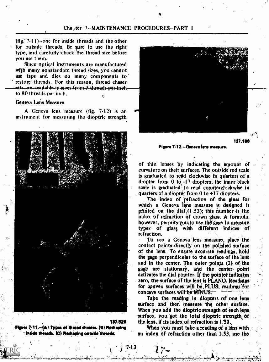
Cha,,ter 7-MA1NTENANCE PROCEDURES-PART 1
(fig: 7-11 )-one for inside threads and the otherfor outside threads, Be rre to use the righttype, and carefully 'ateck the thread size beforeyou use them.
Since optical instruments are manufacturedwilh many nonstandard thread sizes, you cannotuse taps and dies on many ciim ponents torestore threads. For this reason, thread chaser
sets-44re-available-in-sizes4rom-3-threads-per-inol,to 80 threads per inch,
Geneva Lens Measure
A Geneva lens measure (fig. 7-12) is aninstrument for measuring the dioptric strength
Figure 7,12.eirneva lens menu*.137.11011
of thin lenses by indicating the amount ofe, curvature on their surfaces. The outside red scale
is graduated to restd clockwise lb qtiarters of adiopter from 0 to, -17 diopters; the inner blackscale is graduated to read counterclockwise in_quarters of a diopter frdm 0 to +17 diopters.
The index of \refraction of the glass forwhich a Geneva lens measure is designed isprinted on the dial \ (1.53); this number -is theindex of refraction df crown glass. A formula,however, permits xouIto use the gage to measuretypet of glasg with diffetent 'Indices ofrefraction.
To use a Geneva lens measure, place theconiact points directly on the polished surfaceof the lens. To ensure accurate readings, holdthe gage perpendicular to the surface of the lensand in the center. The outer poi* (2) of thegage ire stationary, and the center. Pointactivates the dial pointer.: 4. the pointer indicateszero, the surface of the lens is PLANO. Readings .for eonvex surfaces will be, PLUS; readingslOrconcave surfaces will-hi-MINUS:
Take the reading in dioptirs of one lenssurface and then measure. the) other surface.When you add the dioptric strength.of each lens,surface, you 'get the total dioptric strength Of
131328 the lens, if its index of refraction. is .1..153.-Plow t11.-(a) 'Paw of thread chasers. (5) Radioing When you must take a reading of a lens with
Inside threads. ICI Reshen1na outride "three& an index of refraction other than 1,53, use the .
7-13.

o:
OPTICALMAN 3 & 2
following formula: (n = index of refraction oflens)
nTrue DP of Lens Surface = X reading of0.53lens surface with the gage
To. use this fOrmula, take a reading of thefitst lens surTace atid transpose its dioptricstrength into the formula to get the true dioptricstrength of the first surface. Then, take a readingof the second lens surface, put Our results inthe formula, and solve it for the true dioptricstrength of. the second surface, -The sum .of thetwo answers you got by solving tlAe formula isthe total dioptric strength of the lens.
Remember that the dioptric strengths of thetwo lenses have opposite signs; that is, thepositive lens has a positive dioptric value and thenegative lens has a negative dioptric value. Youmust account for this when you add the twovalues.
Because a compound lens i constructed of a'positive and a negative lens of different indices,you caunot use a Geneva lens measure to obtainits dioptric strength. But if-the two elements ofthe lens are separated, you can get the dioptricstrength of the individual elements and add bothresults to get the didptric strength of thexombinations.
Since a Geneva leps measure is designed tomeasure the curvature of a dens' surfaces, use aGeneva lens ' measte to make certain that the'positive lens surface matches the negative lenssurface when cementing compound lenses.
DISASSEMBLY
Before you do any repair work on opticalinstruments, clean' your work space and geteverything ready- and in position. Clean theoutside metal and painted surfaces with a clean,soft cloth (used for this purpose only). If asolvent is required to remove grease or foreignmatter, use only an approved cleaning agent.'
If your casualty inalysis indicates that .theinstrument must be partially, or comPletelydisassembled to effect necessary repairs, follow.the procedure discussed next.
1.
Procedure
If you do not fully uriderstand aninitrument you must overhaul, get a disassemblysheet and follow ,it or follow the disassemblyprocedure in the applicable naval publication(NavShips manual; Ordnance Pamphlet). Theseauthentic ources provide information ontroubksom. lreas pertaining to disassembly,and----they also lis the precautions you should take..
CAUTION: Before you disassemble- anyoptical instrument, determine whether it is apressure-tight type. If it is gas filled, release thegas pressure slowly by opening the gas outletvalve. NEVER begin disassembly until thepressure is fully released.
In the interest of production, experienced .Viol repairmen work on more than oneinstrument at a time, especially when all theinstruments 'requireV Major 'overhaul. If youmast work on more than one instrument at a.particular time, keep the parts of eachinstrument in separate containers, and \label theparts t'or easy identification. One of the surestand best ways to label parts is to scribe eachmetal part with an identifying mark.
When you are giving four pairs' of binocularsa general overhaul, for example, you can labelthe parts, of the first binocular #1, the parts ofthe second binocular #2, and so on. Tosatisfactorily identify the parts 'for right and leftbarrels, add an R (right) or an L (left), asappropriate.- Your markings on the parts for theright and left barrels, would then be #IR, or#3L, and so forth. Be careful to scribe thesemarks where they will not be covered with paintlater and where they will not. affect theperformance of the instrument.
Other markings which you may be requiredto make: or check during disassembly areASnMBLY MARKS. When a manufacturermakei an optical instrument, he fits/certain partsby -hand ands, if there is danger iof incorrectassembly of these parts during a later overhaul,he marks them with a small punch mark or ascribe line (on each pirt of an assemblyk;Whenyou disassemble an optical inst-Went,therefore, look for thesb assembly marks; if theyare missing, make appropriate marks of your
7-1 4 1 :713

1
Chapter 7 -MAINTENANCE PROCEDURES-PART 1
own. Figure 7-13 shows the procedure formarking a rart.
Optical ekments (glass) require anothermarking teflinique, which must meet two'requirements: l ) the direction the optic mustface when reassembled, and (2) the function theoptic serves in the optical system.
You can identify the function of the opticby..writin& on the frosted portion the.fonowinglObj. (objective lens), #1 Er, ,( first erector). #2Er. (second erector), and-so on until you markthe last element in the system. The tivacrectorreceives the light from the objective and shouldtherefore be numbered first. Use a soft-kadpencil or an instant-drying marking pen.
The accepted method for dctermining thedirection an optical element must' face in a
system is to mark an arrow on the frosted edgeof a lens or prism, the tip of which indicates thedirection of light through the instrument.
MALE CENTER
MALE CENTERTHER
REASSEMBLYGUIDE MARK
FEMALECENTER
SCRIBING TOOL
INDex MIRRORBASE AND 'SCALEAt ASSEMBLY FEMALE CENTER,
137.188Figure 7-13.Soribing an assembly mark.
7-15
11' you presimie a lens in a system is facingthe wrong direction, study the diagram for thatparticular instrument (MARK and MOD) as youremove the lens. You 'can also use a Geneva lensmeasure to check the curvatures of the_ lensagainst those listed on the optical diagram.
StArt your disassembly of an opticalinstrament by removing exterior parts whichhinder further disassembly or. by removing anexterior retainer ring, cover cap, or access plate(secured by screws). These exterior parts mayoccasionally .be frozen because they have beenexposed to the wearher. That is, metal parts inclose contact become stuck together as a resultof corrosion, electrolytic action, or naturalaffinity for each other. Aluminum-to-aluminumjoints have the greatest tenileney to freeze (alsocalled seize). Salt-laden atmosphere enhances thetendency of metal parts of navigationalinstruments to seize together. If the moistureseal of the instrument is faulty, salt-ladenmoisture will most likely cause seizing inside theinstrument
Frozen Parts
To remove frozen parts:
I. Apply penetrating oil or, when timfpermits, soak frozen joints in penetrating oil.
2. To prevent damage to parts which comeoff easily (especially optics), remove them first.
3. Use proper tools, and do not crush partswith wrenches.
4. It' you cannot remove a lens, cover itwith a pad of blotting paper, or a rubber disk ofthe same size.
5.. Use shaped wooden blocks to hold a partin a vise. Powdered,rqsin on the blocks helps tohold a part and prevent, it from slipping out ofposition. Then uge a pin wrench or grip wrenchof tifterproper size to attempt to remove...thefrozen part.
6. If a joint is still frozen after you havesoaked it a reasonable time in penetrating oil,proceed as follows:
ra. -Remove the part from the vise and.
tap the joint sharpy with a rawhide mallet whileturning the part.

OPTICAEMAN 3 & 2
h kip all around the joint several (Oneswith the mallet. !he sharp blows, combinedwith die penetrating od, will often free the.joint.
c. Replace the part in the shapedblocks in the vise. then use the proper wrench toseparate the parts.
d. II the parts do not break free afteryou use Ihe rawhide mallet, apply heat to thejoint, Do OM Usc so much heat that you burnthe paint; you. merely want to expand the outerportion of the joint. Now try the wrench again.
C. If the parts arestill frozen,.applyinure penetrating oil to the hot joint. You mayneed to otse impact 40 try to separate the parts.Hold your wrench firmly and strike the wyenchsharply with a mallet. Several sharp blows willusually free a stubborn retainer.
CAUTION: Use extreme care,and patiencewhen you apply heat and pressure to frozenjoints, lest you cause distortion (twisting and'bending) of etal parts and breakage of opticalelements you could not remove at the outwt.
7. 11 .frozen parts do not yield to theprocedures just outlined, salval;e the Mostexpensive part or .parts by. carefully cutting,breaking, or machining away the other frozenpart or parts. When a retainer ring is frozen, forexample, drill a hole down through it towardsthe lens; but use care, do. NOT drill too deeplyand ruin the lens with the drill. The diameter ofyour drill should. be slightly less than thethickness ofthe ring.
Aftet you weaken the ring by drilling thehole, carefully bend the ring out .at that pointand remove the free ring and lens.
NOTE: Sonie retainer rings are kept in place(made vibration . proof) by trn application of'shellac or a similar substance on the threads of'the mount and the edge of the ring. You cansoften this compound by pepeated applicationsof lacquer thinner or alcohol.
8. To remove screws and setscrews withstripped slots or heads twisted off, proceed asfollows:
a. If a screw if' frozen in a .hole as aryt of corrosion, loosen it with penetrating oil
7-16
and hk..at. NOTE: Do this before you try toremove the screy by any other means.
b. If the body of a 'screw protrudesabove the surface of a part, tile in a newscrewdriver slot with a small swiss slotting fileand remove the screw with a screwdriver ofproper size. Yon can often remove someprotruding screws with parallel motion pliers.
c. If a .screw js deep.in a tapped hole,use a sharp scribe tip and, if possible, make anmy slot in the screw. This process is slow andrequires patience and care.
d. If the procednres just described donot work, use one of the ('ollowing proceduresto drill the screw out:
(I) For very small screws, use a drillslightly smaller in diameter than the minordiameter of the screw and drill l'irough thescreW. The outer shell and threads of the screwwill remain, and you can run a tap of correctsize through the hole to finish the jobs
.( 2) On sertws of larger size, drill.ahole of' proper size in the- screw and remove itwith a screw extractor.' (Each extractor has adrill of reconunended size to use with it.)
REMEMBER THAT PATIEN.CE ANDCAREFUL, INTELLIGENT, WORKMANSHIPARE REQUIRED TO REMOVE FROZENPARTS FROM AN OPTICAL INSTRUMENT,but do not spend more time On an instrumentthan it. is worth. Consult your shop supervisorwhenever you are in doubt.
After you remove all frozen parg, continuewith the disassembly. Remember to mark alloptical and mechanical parts. Before you turnoff a retainer ring or try to unscrew or §lide alens mount, remove the setscrews'Which .!ctirethem. Some of these screws may be hidden
_under sealing compound, so check, for themearefully. Failure to remove these setscrews mayruin a )tirt.
Be extremely careftil when you iremoveotticaf element and gear assemblies throughopenings in the optScal chamber. These parts canbe easily.damaged by striking other parts.or theehamber housing. Why you remove a partwhich exposes the interior of the opticalchamber of an instrument, make sure you tape

Chapter 7 AINTENANCE PROCEDURES -PART I
the opening or close it in. some Manner to keep-,out toreign matter.
As you remove parts and assemblies fromthe interior of an instrument, check them fordamage not previously 'noted, and write yourfindings on thecasualty analysk sheet for futurereference.
I h us far, with few exceptions, ourdiscussion of disassembly of an optical
-ingrunrent has covered mostlY mechanical partsbecause this is the proper sequence for
,d s as se in bhng instrument. As youdisassemble an instrument, remove each lensmount and cell and set. it aside for furtherdisassembly after you complete the majordisassembly of mechanical components.
Lewes from Mounts
The teOniques we will discuss .for removinglenses from mounts axe primarily for lensesmounted with a sealing compound., but they arealso applicable to the 'removal of optics difficultto disassemble. The procedures to follow (and
.,precautions to use) when you disassembleoptical elements from their mounts cannot befornmlated as step-by-step* instnictions. Theinformation which you should keep in mindwhen doing this' work may be classified asfolloWs.
Although optical glass is easily chippedor cracked and easily damaged by shock, steadypressure within limits does not ordinarily crtek alens if the thickness of the glass is sufficient.
NOTE: Removal of the eyepiece and theobjective lens is usually more difficult thanremoval of other optics, because these twolenses are usually sealed in their mounts with asealing compound or gasket. Also, these lensesare often doublets, which means thot excessiveor uneven pressure on ,the lenses can causedamage to the cement used to put themtogether, or 9use, the thin planoconeave flintelement of the eyepiece to break.
2. Shearing action caused by unevenpressure is the greatest enemy of cementbetween optical elements', therefore, to force aCompound kns out of its mount, press down
squarely and evenly over a large part of its area.A device similar to that in figure 7-14 may beused to support the lens. Note the name of thisdevice, LENS VIIUCK AND CLEANINGHOLDER. It is a cylindrical brass tube with tileedges at one end beveled to match the curvatureof the lens. By esxerting even pressureion the lensmount, you can break the seal. ObsAve that theword PRESS in the illustration .i.ndicates the_points where you should apply pressure.
3. An application of heat to a lens mounthelps to loosen it from the lens in two ways:
a. The metal expands more than thelens.
PRESS
LENS
PRESS
LENS CHUCKAND CLEANING
HOLDER
FOR DISASSEMBLY
LFNS.MOUNT
LENS CHUCKAND CLEANING
HOLDER
(TOP OF CHUCKCURVED TO.FIT
LENS)
FOR CLEANINGAND REASSEMBLY
137.189Figure 714.Lens chuck and cleaning holder.

6PTICALMAN .3 & 2
b. Most sealing,, compounds are softenedby moderate temperature.
CAU HON A temperature of 125° to 140"Fsoftens Canada balsam used to cement theelements of compound lenses together. If a
compound lens does not yiekl to pressure and anapplication of heat at low temperature. theC;mada balsam probably incited previously and
't 4.
solvents. whidi/ ;may be slightly, toxic andirritatiiig .yciiir skin, must be used in vellventilated spaces?only. Avoid prolonged contactof your hands with the solvent. The best policy(safest) is to use solvents only in a spacespecified for their use.
A .Cleaning machine of the*, tyc shown infigure 745 is., excelle'nt for el_Laning_.small_ _
ra-n- o-urt. betweo.n the elements of the lens and the .-.1nechanical pails of optical instruments. Anmount and hardened a second time. When this -.,--electric motor the machine revolves a baskethappens, a temperature of about 300°1: is in two cleaning solutions and a:rinserequired to soften the cement. " The machine also .dries the part,s by
blowing hot air through the basket.4. When you remove a lens front its int um,
protect its surtaces with a clean cloth or h .suepaper. 1)0 NOT. MUCH POLISHED GLASS0IMCAl, SURFMTS WITH YOUR FINGERS.lie sure to mark the path,of light through thelens to ensure that you reassemble it correctly:then wrap the lens in lens tissue (severalthicknesses) ant( place it where the mechanicalparts cannot damage it.
5. When you cannot push a lens out fromthe back, as iS sometimes the case, use a smallsuction cup or piece of masking tape to grip thelens and then ouSe it out of the mount.
CAUTION: Large thin lenses have atendency to twist diagonally (cock) as ypu tryto remove them. so use care to prevent cocking..To loosen a cocked lens, tap lightly on the edgeof the mount on the side where the lens is stuck.As you tap the mount, hold it so that the lenswill eventually drop out into your hand. If youaccidentally touch the lens with your fingers,clean it thoroughly at once to remOve salts andacids deposited by your fingers.
RErAIR;PROCEDURE
When you start to overhaul and repair anoptical instrument, refer to the notations youmade on the casualty analysis sheet prior to andduring disassembly. Use this inforniation as youproceed, with the repair process.
Cleaning and Inspecting Parts
Tiy.first phase of overhaul.of the instrumentis cleaning the mechanical parts. Cleaning
_. Another type of instrument cleaningmachine consistof a tank of solvent agitated bylow-pressure air. The newest types of cleaningmachines use ultrasonic sound to act on anapproved liquid cleaning agent to degrease andclean the parti.
NO"IV: When you use a cleaning machine,follow the instructions listed in themanufacturer's technical manual. If you do nothave this manual, consult your shop supervisor.
If your shop does not- hike a cleaniagmachine, use a stiff-bristle brush to cleaninstrument parts in a cOntainer of cleaningsolvent. This is one of thb--p6t methods forcleaning large yr very dirty.;Varts, Solvents leavean, viily rctitt'tre op clean parts, and you mustremove it q rinsing the parts in an approveddegreasing agent, or by scrubbing the rarts inhot soapy water. (Traces of oil on the interior ofan optical instrument may later get on the lensesand affect imag.s fidelity.)
After you clean iii)strilmAt parts, inspectjhem for traces of lubricants, grease, sealing
Ccompound, or dirt. 'Scrape off dirt and greasenot removed during the cleaning process.
CAUTION: Do NOT scrap&bearing surfaces.As you examine each cleaned part, look fordefects previously hidden by dirt, wax, orgrease. Also check them for coirosion. Replacebadly corroded parts. ,
1-18

Chapter 7MA1NTENANCE PROCEDURESPART 1
,
1
1
Figure 7.i15.inotrumont dogging moohino.
Place. the cleaned parts in a suitably cleancontainer and Cover the cOntainer to protect thparts from dust and dirt.
-,
these categories is--discussed in sckmejletail in thefollowing sections.'
Repair bltegories
Nqw that you have clejaned and inspeCtedthe parts of the inaruineni undergohig repair,proceed immediately with the repairs. ThelePairprocess generally- consists of three methods: (1)repair and refitting of old parts, (2) using a newpart (replacement) froni stop*, and (3)manufacturing.gqd refitting a new Part. Each of
REPAIRING OLD"PARTS.Repair reusableId parts, as necessary, and refit them into the
instruments from which you removed them.If a part must be straightened or re-formed
to its original shape, strike it carefully with asoft-faced- hammer. 'CAUTION: Give the partnecessary support before you strike it to avoidfurther damage.
When you discover 'stripped or damagedthreada, in a tapped hole, drill the hole outwheneler poss0 and retap it for a screw of

(04
.1*
OPTICALMAN 3 & 2
larger siliif(,cliCrC"-T)no Irtr-eyer two screw sizeslarger' thin the ceiginal size;.':stated on theblueprint mit.'.be exactly as'Stated tinOp blueprint, proceed as follows:
On ,steel, bronze, and brass pails, drillan4 tap the hole two or three serew sizes lifterthalT original;-13lug fhTi1 itlia screviorcorcespondi4 metal. Use silver sOlder to securethe plug; tha file the plug flush with the siirfaceof the part,.and drill and retkp a hole of corre4size.'
. 2. Repair' .alumaiim parts' Oith strippedthreads iii the slime manner as you repair parts'made vf 'other n'tetals. It is difficult to solderaluminum parts, however, -and it .ks best to ask
-the shOpfsupervisor, to have the soldering done in.:-., ancither (acility,,if possible. ,When the soldered
parts is,retdrned to you, dress the soldered area,:and redrill and taPhe hole to the site'specifiedcm the Iftepriik
Dress up scratched, .burred, and dented.'Nails, hi, :accordance with prescribed_ . ihop'procedures...,
Be caretul when you repair parts to preventdamage tq precision bearing surfaces machined
AK on them. Use a stone ora bearing scraper toremoye *buirs from.a bearirig surface, and be
"Carefurto remoye only the burr. Do NOT file abearinesurface, for-filing may completely tan
- it.When you complete rerAiirs ati instruthent
,
-part, refit.lhe part dR;the instrament arid checkid action'!and/or,.operation r oy. accuracy: Ifnecessary ,ascrap.p: dCf a slight lamount of:a:surface,
..to make a''part frtl3roperly...*Rediltundersqedholes and make otheiN necesSar chatges toyourrepair job to 'Make the part fit correctly. Aft,i;:k
'. you fit `a part, DO.NOV.FORGETto make anAssembly ITT* 'dn it to iindicate diregtion- 'of
; Anst ltatiori'<.-' .,,' .. 1 ; : the catise. of .pialfunctioning is note readily
AUTIOW Reassembly. of 'an fristrumeni ... .,..apparent, Ppkeed as follows.' '
.10
replaced with a new part. One souree "Ofreplenishment is from stock.
When you receive a replacement part fromstock, try it for proper fit in the instrument or'assembly. If ij does not fit, take necessaryactiom including machining. A minufacturerffor ex'ample does not drill dowel stin.and screw
Coles; so you .must drill them to correct sizewherever; required. A manufacturer also makesbearing parts slightly oversized, so that, you canfit them' _properly by hand. Do not forget tomake assembly marks on the new patts after youfit thein,..to ensure correct fitting. into theiktrument la,ter. .
MANU.FACTURED 'PARTS,OccasiOnaliy,yolk shop supervisw. can have parts made bysubMitting an intershop pb order. tTherealso be times when you will be reqUired 'tomanufacture parts. The procedure for doing thisis as follows:
. iilformation on the old part, or iisnaini,,b..14.1te the blueprint Folio"( btheprintitniefi$5ns to illifufacture the part.
2. -Ira blueprint caniiot be located, use thepart aS a sample to obtain dimensions.
I'Miscellaneous Repairs
ivhen you, eVpredisassemblyil: inspe
an 'instrumenik aioriyou may pote
'undamaged., oving p t.ts in the instrumentwhich are ; tight; grinding, or -FolAgp in.actiOn. Yon. 'Will find some instances acombinati6n bf these malfunetiops, evenRthers not mblitioned here.
. When you make rniscelfaneokis tiveaiits 'to anAnstrument, look for -all typeg' of troübles andrived.y them ,*. inchidrqg -,lack of Or dirty144100d/1, excessive or-, insufficieneclearances,incorttct aligtim'eniInir improper assembly..If
,coot,. ing impfoi)eriY, fitted. paiivmay regairelitteri'disassemblY of part' or all .Of . the cl. Clean4.tristrtiffient*
t,Nfake
N 4
'
REPLACAARTS,Spoletilktes: '104rt Lir;''clarhaged to such an .extent -that it ilfu..4 be"
5
all mating parts.a trial asgerOly, but do not force .
4-
i.
s., .
3 theck 'for; prOper clearanceO deterneiner d.
.the cause of...binding or excehivelost motion,*
.4r
'ti
55' .5 -\' ,
7-20-r7i9 '?"

Chapter '7 MAINTENANCE PROCE1VRES- PART I
When cleaning, I ubrication tind properalignment of parts fail to correct casualtiesand/or malfunctIoning,,take the action discussedin the following paragraphs.
INSUFFICIENT CLEARAN('E.- If there isan insufficient amount of clearance on such
' -par-ts-as-ta-pered.Aeeve-bearings., -batl and-suck-etbearings, and multiple-lead thread eyepieces, dothis:
a 'thin solution of pumice andst all anKiii0 of puinice at first) anti
-little of the solt'jtioli on the parts.as you. ..remsembleithe bearing.
:2: Wol=k the parts back and forth, or'rotatetc..m,. until their movement"' is of desired-freedOm.
3: Disassemble the parts and wash out all:%traces of pumice and oil.
4.. Reasseihble and lubricate with theproper type of-lubricant, and check the motion.
Follow* the procedure just described un tilyou obtainthe desired fit.
When there is insufficient cledrance on a flat,sliding-surface bearing,.do the following:
). 1. Put u thin coat of prussian blue
-(machinist's 'Iye) on a surface plate and rub theoversized portion Of the pyaring assembly oyerthe prussian
2. Carefully sCrape away the high apots on" the.bearing indicated by the prussian blue.
excessive clearance with shims or if the bearingdoes not have some means by wlAch it can beadjusted, replace i-cwith a new one. If there issonic way to 'adjust the bearing, however, adjustit as necessary to get a tight tit and then removehigh spots in the manner described for obtainingsufficienclearance.
; NOTE: AlwaYs mkk bearing parts to.ensureproper assembly after you hand fit them in themanner just described.
SOLDERING AND BRI1NG
As an Opticalman, you may occasionalyneed to join metals by either soft soldering,silve1 soldering, or brazing. 'Sbft soklering isdone at temperatures .below 800°F With readalroy soldert-Silyer soldering and brazing requirea. temperature above 800°F to melt -the silversolder or.brazing rod.
Coptical instruments" and related fittings andte4 equipment are manufactured from brass, c' \
\hrojize, 'cast iron, steel, stainless- steel, Aalmninum. Information on the repairdamaged aluminum' components is outside thescoperOf thig manual. However, we shalidiscuss:.the joining---61 other metals which you can (11 ins'
. alb opttcal sh'op.
, SOFT Sala!?
CAUTION: Rembve only a small amounta:metal at a time, and make a trial assembly at&you remove each amout1t. The important thing.is to prevent the reMoval Of too inikeb -metalfrom the bearing. "%
. Another method for removing eXits4'meta1from a 'sliding-suff-ace.bearipg is to spread a smallportion of 'a thin mixture of pumice apd clocK
. oil ove.r fhe surface of a flat .lap.and rub the.highpaFt,. of the bearing 'over the, surfkice 61" thecoated flat lap. ,Use i Sweeping 'figure-eightmOtion' to ensure uniform removal oe tip:metal:.(5b NOT rethove tob ntuch TOM:. .
A.
. 0
, EXCESSIiiE CLPARANCE.-Of there is nba ,
tlitay to adjust the desired fit' 'by rembving,
.
-
. r a
A
Man' tical nstr9m entsktse .switchwiring , 'of electrical pr electronic cireuit§-'
oPes.contained in the instruments. To make reOirs,or repliiii,delékti've ,components, you will npedto knbw how, to make or' remove, solderedconnections.: t .
It is also 'likely that you can Use soft solderto m'anufacture special fittings or to .'repair adaMaged jr-istrilment ,coniponent.. Tools ,andTkeir Uses, (NAVEDTRA 10P85 Series)'showlcte tailed prOcedyres for Oft soldering.operätigns'.
MILNER SOLDERJING AND BRAZI4G
A
whilk$06:soldering caii:Pe done with a sthall -torcli-m solde.ring gun, a oxyagitylene torch isv
Sri
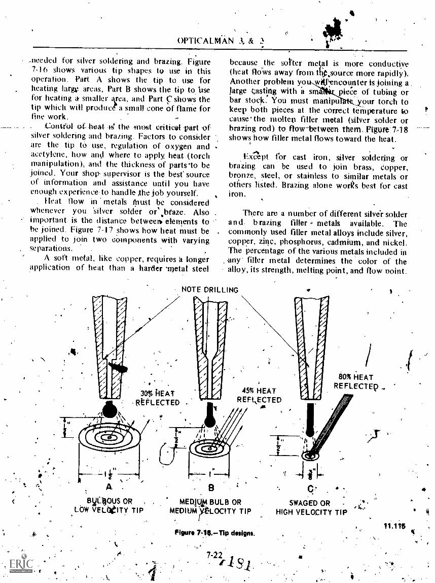
c.
OPTICALMAN 3 &
_needed for silver soldering and brazing. Figure7-16 shows various tip shapes to use in thisoperation. Part A shows the tip to use forheating large areas, Part B shows the tip to. Ilsefor heating a smaller krea, and Part ç shows thetip which will produce a small cone of flame forfine work.
. Control of heat the -most critiea1 -part ofsilver soldering and brazing. Factors to considerare the tip tO use, regulation of oxygen andacetylene, how and where to apply heat (torchmanipulation), and the thickness of parts 'to bejoined. Your shop, supervisor is the best sourceof information and assistance until you haveenough experience to handle ,the job yourself.
Heat flow in metals firiust be consideredwhenever you 'silver solder or%braze. Alsoimportant is the distance betweem elements tobe joined. Figure 7-17 shows how heat must beapplied to join two components with varyingseparations.
A sort metal, like copper, requires a longerapplication of heat than a harder 'metal steel
\
because othe sotter metal is more conductiye(heat flows away from t4source more rapidly).Another problem yoti,wiVencounter is joining a .
large tasting with a snIçpkce of tubing orbar stock.° You must mnanipt tkour torch tokeep both pieces at the correct temperature tocauseihe molten tiller metal (silver solder orbrathg rod) to flow-between them..Figure-.748shows-how filler metal flows toward the heat.
Ex-Apt ror cast iron, silver soldering orbrazing can be used to join brass, Copper,bronze, steel, or stainless to similar metals orothers listed. Brazing alone works best for cast
There are a number of different silve-r solderand. brazing filler metals available. Thecommonly used filler metal alloys include silver,copper, zinc, phosphorus, cadmium, and nickel.The percentage of the various metals included inny- filler metal determines the color of thealloy, its strength, melting point, and flow point.
NOTE DRILLING
30% kEATREFLECTED
45% HEATREFI.,ECTED
BO% HEATREFLECTEp
i
A .
syL4ous OR
Lbw VELberry TIPMENUIA BULB OR
MEDIUM ALOCITY TIP
Figure 7-.14.,TIP design..
7-22
C..
SWAGED OR -
HIGH VELOCITY TIP
41
! :

Chapter 7-MAINTENANCE PROCEDURES-PART I
,FLUXES
All silt soldering and brathig operationsrequire the use of a flux. The flux preventso3idatiop .of the metal surfaces 'and removesOxides already present. Flux also increages' theflow. of .th-e.filler metal and increases its abilityto adhere td the base.metal. It brings the fillermetal into immediate contact with the .metalsbeing joined and permits the filler tO-penetratterthe pores of tfie metal, thus forming a strongjoint. Prior to applyi g flux tcrZy joiitts, be'sure the parts are thor ughly.clearied, degreased,and polished.
The flukes used b the Navy are-selected inaccordance with specificpions to- meet the.
.
A
FLOW OF HEAT
PIECES SEPARAIED
Ittloi" GAOBETWEEN PLATES
FLOW OP NEAT
HEAT DIRECTED ON A.NO CHANCE FOR EN6i/GH HEATTO GET TO e THROUGH SPACETO NEAT IT SUFFICIENTLY FOR
__BRAZING.
TO BRAZE PIECES A AND D.TORCH MUST BE DIRECTED ONBOTH -PIECE A AN') PIECE TOBRING THEM i-OjME, NECESSARYBRAZING TEMPBAAVURE.
a
NOTE: WAVY ARROWS DENOTE PATH OF HEAT THROUGH PARTS
A
..PIECES IN CLOSE CONTACT
HEAT FLOWS FROM TORCH TOPIECE B AND TAN THROUGHTHE TIGHT CONTACT OF BOTHA 414D I TO PIECE A.
Figur* 7-17.Flow of heat.
,
. 7-23
NOTEt %ow...WAVY ARROWS INDICATE PATH OF HEAT
. NEATAPPLIED HIRE
TQRCH
PILLERM'ET M.
FLOW OF.NRAT
Rim.* 7-18,Flow of moitIM.fillfirJ.
1 8.)C.
now op.FILLER metm.

OPTICALMAN 3 & 2r,)
requirements for using various alloys. ror bestresults, a flux must betome active at atemperature slightly below the melting point ofthe filler metal and must. remain fluid at thebrazing t ure. If you use the wrong fluxwith az filler metal, you couldpossible overhe ie flux and destroy theadhc_rence of the 'filler metal.
Flux comes in three forms: liquid, paste, andpowder. When used either -in paste form or inliquid form, the flux is applied with a brush toboth parts of the joint; best results are obtainedwhen the filler metal also is given a coat. Use acircular motion in brushing it on, and let theflux extend outside the joint or fitting. Brushingthe flux on with a circular motion .gives auniform -coating and lessens the possibility" of'bare spots . tliat will oxidize during heating.Fluxing the filler.metal can be done by beatingthe filler rod and dipping it into the !Aux.Sufficient flux to do the job vol stick to theltotrod.
When applying float or assembling the parts,avoid handling the polished parts of the joint oryou will defeat the purpose of cleaning.. Fluxshould always be applied as soon as a joint areais- leaned even', though it will not be joinetlirnii1lediately..
L V ER BRAZIN6 TECHNIQUES
The process by which hept flows frommolecule to molecule through a inetalfs called
,CONDUCTIOV. Conduction takes place quiterapidly in irant Metals, tItit air is a very .poorconductor of heat. Therefore, if two pieces ofmetal that are ,to be joined are not insontactwith each other, each. piece must- be heatedseparately. lithe tvVo pieces are in amtact'with,
_each other, you can heat them botb by applyingtreat to one ot them; the secOnd 1piece wuilbeheated by conduction. When two pieces ofdifferent, metals are to be joineil by silverbrazing, the difference in heat ,cowluctialp ofThe two tietals must be considered.
The fillex metal and the.-fluk- used in silverbrazing cannot occupy the same space at thesame time, Therefore, a clearance mnst beprovided., in the *tup of ,the joint so that 'the ,filler metal can'flow in and the flux can flow outwhen 'the filler . petal .reachelt the- bondingteinperifure, ,
"The STICK-FEED METHOD, shownstep-by-step in figure 7-1 9, is most often used inthe optical shop.
In this method, the judgment ot' tlwindividual performing the job determines whenboth parts are properly heated and when to feedthe filler metal. If is also len tO his judgment todetermine when sufficient -filler metal has-beenfed into the joint to completely fill the spacebetween the two parts being joined. Skillfultorch manipulation is necessary to apply heat tothe proper component at the correct time toform a perfect joint. Overheating will burn outthe flux and destroy the jdipt. After joining issatisfactorily completed, flush the joint withwarm Water to remove the flux residue.
HEAT TREATINGAND TEMPERING'
As an Opticalman, you will work with'metalS at variotii tides while working on opti6finstruments. Thus, you should be familiar witht-ypes of metals, the properties of metals, and
, the heattreating processes for the most commonmetals.
-The m'etals% with which yoll, work can be(rgded into two general classifications, ferrousand. nonferrous. FERROUS metals are thosethat are composed primarily of -iron.NONFERROUS metals are those that arecomposed primarily of some element or,elements other than iron. Nonferrous metals oralloys sometimes contain-a small amount of ironasan alloying element' or.as an impurity.
Met* and 'alloys vary widely .in theircharacteristics or properties. Chemical properties'involve the' hehavibr of the metal in contact withthe atmosphere, taltwater, or otherenvironments:.!"; Physical properties relate tocOlor, density and' weight, magnetic qualities,electrical conductivity or resistance, and. Jieatconductivity. Mechanical properties relatCto-load carrying ability,' wear resistance, andelasticity.
. The various properties of .Metals and alloyshave been datprmined .laboratorieS ofmanufacturerS and ari taqulated and indexed byvarious . engineering' socWies inferegted ip
,.metaliurgical developinent. arts Which give. .
7-24

Chapter 7 :-MAINTENANCE PROCEDUKES PART I
PILL CLEARANCE AREA WITH FLUX
NVQNh.101NIAW1HEAT PIPE AT "A" TO SWELL IT UP AAND 11pING SURFACE IN COILTACTWITH INSIDE SURFACE OF FITTING.
'CLEARANCE AREA CLOSES.
FILLER METAL
\d°
HEAT FITTING PROM "B" TO "C"CLEARANCE AREA 'OPENS UP, AND
PILLER METAL IS APPLIED AT EDGEAS FLUX FLOWS OUT.
CONTINUE HEATING AT "BIITO AA.LOW FILLER METAL .TO FLOW IN. .
4/.ommieLlialumbmNaNhute
HEAT OVINE JOINT TO COMPUTEBOND IIIETWEEM TIPE MO PITTING,'
t. MAKING SMOOTUILITAT At THEEDOE.
.
properties pertaining to a particAr metal oralloy arc published in suclueference books asthe Metals lianNbook. The charts proyideinformation on the physical and mechanic:alproperties Which leave been deterMined.
What are the properties an Opticalmin teedsto understand about the metals most eom nlyused ? include the ;mechanical proper s:of...(1 ) hardness, (2, toughness., (3) ductility, (4)malleability, (5) brittleness, and (6) tensilestrength. Followini is 'aik, explanation of themeaning of these ternts;"The -HAKDNESS of a metal is the prop erty
that resists scratching, denting, L.cattirrg, orerosion. It may,also be defined as the ability of.the metaj to resist pinetration. A piece of lead,for example, can easily be scratched veith aknife. But it would be difficulfto, mark a pieceof steel in thts manner. The reason is that steelpossesses the property of hardness whichprovides resistance to scratching and cutting.
TOUGHNESS is the property of a metal thatwithstands shock loading without breaking. It isthus related -to strength and to ductility.Usually, the hardness of a metal increases as thetoughness decreases.
DUCTILITY is the property that renders ametal capable of being drawn into wire form. Inother wolds, when the metal is stretched, itelongates rather than breaking.
MALLEABILITY is the property of .metalthat permits it tii.Ve rolled, forged, or hammeredinto sheets without cracking or bieaking.
BRITTLENESS is the lendpncy of a metalto break with littlb or no .prior deformation-..Hard materials are often brittle, but a metal oralloy which is properly heat treated' can be hard:without brittlehess. "
TENSILE STRENGTH is the property of a.metal which resists forces that tend to pull Themetal apart'. It is measured in terms 'of poundsper square inch will represents the, pull thatmust be exerted on crOss-sectionel area tot i res the metal. il
A CORROSION RESISTANCE, though not a.mech at- -prdperty, la also of primary
iliwortan . Corrosion resistance is the propertythat withstands chemical or electrochemical
1 r attack by air, moisture, toil, or other agents,..`,1% 1101.124, . ' ' The variilys mechanical,properties desCribed
, Figure 7.19.feed4M method 04 silver brazing. may, be, desirable at times and undesirable atP
': '... r I. , !I.N . .
4
#

k
OPTICALMAN 3 & 2
other times, depending on the purpose for whichthe metal is to be used. But resistance to
. corrosion is always a highly desirablechartNeristic.
FERROUSIMETALS
A few examples uf ferrous metals are piglst_iron, ingot -iron; And wrought iron-.
'Carbon steel and the ,various alloysteels-structural as well as tool steel-- are alsoconsidered as ferrous metals since they areComposed of iron to which relatively smallpercentages of carbon and other elements havebeen added as alloys.
'the term cast iron may be applied to anyiron in which the carbon alloy is more than1,7%. Cast iron has high compressive strength
. and good wear-resistance, hut it lacks ductility,tiAd impact strength.
Of all the different metals and materialswhich you will use whilo in the Navy, steel is by.far the most important. Steel is manufacturedfrom., pig iron by decreasing the amount ofcarbon and other-impurities present. About 15pounds of manganese, an indispewable addition-in the productioft of steel, is added to each ton
. of pig iron.Most of the steel you Ilse willrbe in the form
of structural shapes, such as sheet, tube, and bar.The types of structural steel aret. mild steel,medium steel, high tensile steel, special treatedsteel, and stainless steel,.
Mild steel is used 'when structural strength,isof no great importance and'when a groat deal offlanging, shaping, and other shop operations areinvolved.
Medium steel is similar to mild steel in itsworkability. But it is harder and stronger thanmild steel and is ii.wd when structural strength isrequired,
Hig,h tensile steel, usually referred to as RT.%5ontains small additions o( various alloys thatgiv e. the steel eXtra hardness and toughness.
-Special treated steel, known as STS, containsa small percentage of chromiunt-nickil.. it hag'been specially treated to obtain -*hardness and
,..
St ain less is an alloy containing I 8% ,,ellroiniumand 81- nickel.
NONFERROUS METALS
As tm Optiealman, .you may work .wittfvarious types of nonferrous metals. Some of nibmajor types and their uses are disussed in thissection.
,!?
Copper and &Alper alloys rank high amongcomtnercia6 metals with respect to desirableproperties. Copper is ductile, malleable; hard,tough, strong, wear resistant, machinable, 'andweldable. Also, it has high tensile : strength,-fatigue strength, and thermal and electricalconductivity. Copper is easy to -Work and,although it becomes -hard when worked, it caneasily be softened (aimealed) by, heating it to acherry red and °then letting it cool. Annealing isthe only heattreating procedure that iS appliedto copper.
Zinc is used often as a protective coating,known as galvanizing, on steel and iron. Zini isalso used in soldering fluxes, in die castings, Indas an Alloying element in mak0g.brass and somebronze. , .
Tin has many important tises as an alloyingelement. Remember that it can be alloyed withlead to produCe soft ,solders. Alloyed withcopper, it produces bronze. Tin base alloys havea high resistance to corrosion; they also have a
low fatigue strength, and a compressive strengthwhich will accommodate light or 'medium, but"mirneaVy loads.
. .
. Tin, like lead, posseiees a good resistance tocorrosion. .1t has the added advantage of- being4' noripoisonous. But when subjectixt b extremelylow temperatures, tin has a. ndency todecompose, "
Aluminum fsircito to'sVork anai has a goodappearance. A/though light-Jri' weight, it has a
high strength. per 'unit weight, ,but Its tensilestrength is only r/3'thit of iron'', and 1?5 that ofannealed, mild steel..In its pure state, ttluniinusis soft and has a strong- affinity for giirs. fir ...... .
-
use of alloying elements overcomes- t4esedisadvamtages. ` .-.
.- .
True brass is an alloy of cop r., and zinc.Additional elenientsalinninumo. le old tin', iron,
eadld to
toughness.;StkinlesS steel., refoRed is -as SST, is
generally de;ignatet1 the,' percentage of *Manganese, ors-phosphoruupaychromium and nickel. For dAampip, an 184 'give the allcW'Speclfit-Vroperties.
\
7-26 tA J

Chapter 7 MAINIFNANCE PROCVDURES PART
Bronre made yr 84'4 copper and 16' tinWm the beSt metal availahlv before steelmAingtiatniques were'. developed. Many complexbronze alloys, containing additional: elements-such as zinc, lead, iron, atummuni, silicon, andPhosphorus are now available.
Monel is an alloy in which nickel thematos. dement, 14 contains .from -to. 6i)s-4--
'nickel, about 30"1 copper, anZI small percentagesof. iron. manganese, and cpbalt.. It is harder andstronger than either nickel or copper and has'high ductility. Monet has many of the qualitiesof stainless steel, whicfi it resembles inappearance, and its strength and 'high restanceto 'atmospheric yOrrosion Make it an acceptahlesubstititte. for steel in a system or seikvice where-'atmospheric k:orrosion resistance- is of -primaryimportance..
not only effect changes in physical properties,but also alter the surface composition of themetal.
Fur all metals, time and temperature are theimportant factols in the heattreating operation.Usually,- the atmosphere surrounding the metalduring. heating. or (luring heating and cooling, isalsb
If
Annealing ,
!_
Two than; Pnrposes (lf annealing ar(T-( I ) tore icie niternal strains, and (2) to nitike a metalsoft enough for machining. Practically all inefids,ferrous and nonferrous, may be annealed, at d
. no elaborate equipi tent is essential; lt,is ssib e'to produce good anneals by usini4 a .heating-lorch or a furna e. The.basic process consists ofheating the irr tal to a specific temperature.,N,holding it at that temperature for a specifiM:rlength of time (soaking-) and then cooling it.torootw tempprature. Both the temperature of theoptratidn and the rate'of cooling depend upon
'the metal '. being* treated . and the !pur_pose for!which it is to be used..
Cast iron ordinarily .must be lieated to .'a! point between 1400°. and 1500° F.. PuretrIumintikcan be amiealed at temperattires from-625°. to 7049F, buraluminum alloys require
, ! somewhat higher temperatures, depending upontheir comeogitioh. Pure copper can be annealMat twiperatUres from '800° to I200°F. Most
Commow forms. Used by the Navy. include!: ',brasses leopper-zine alloys require .annealing.' atThealit'ig northalizing, hardening. tempering; . t e mp e rat ures of '' from . 475° to '650°Ri- ianif Akins relieving. The particular process tyed . -Nickel,chromiuni alloys,. which cati withstand!
is -determined.. not' .only by the- .phygical ( catremely-. high temperaitures without.properties to be deVtiloped or modified, but also :' "iWpieciable daniage, thustbe heated to annealingby the eonf.Position of the metal. Ferrous Metals temperatutes_between 1800° and l950°F.
onuiy. be: hardened. temperedannealen, and Nre aluminitiit can be cookd in aicr;. pure:norinalized. Ma§t nonferrous Metals 'city be. copper cfrti he ,coOled M -air, or quenched in, annealed 'and'inany can be harde.ned,'hut they '''- , Water. Steel muit be ft'image-cdoled, and the. ,
opting rate must' .be' kept slow 'to prodiicec--taki m lief tnes§,
At*
HEATTREATING PROCESSES
MetAs .in a' solid "stateskin be heated andcooled. to change or improve a physical ormeehanicaL nt:operty or a. combination ofproperties.,A metal part is heat treated to Take't softer, more dUcitile, stronger, harder, or marefoNs(.4,..itant to weac These properties are developedas needed to tinprove.the usefulness end "aftlyof ''a part for a definite purpose. No Oneheattreating operation can produce ,all thesecharacteristics,° .and the improveMent of someproperties is gained. 'at the'. expeitse of"otherK6Orties.
.
Thew are different. fonns, of. heattreating.
rict:
are', ,NWER -tempered . or .norpiiiied. (Fornonftrrous ;metals, the hardening process isusually referred toitiriply as'Ittät.treatment.)
Wilde all heattreatingt)rtreelltre.similar.
I..hat they, involve heating Ond cOoling, they*'differ in tiie temperatures to .Which the metals --are heated, the ire of cpoting, linCthe'eopling..rnediuth.,14 addition, s,onrt, of these -pro.yesses
1.
\ in 'a ali)g, avoid overheating t:Ile metalb ing treated. Overh,eating will 'cause "inicreasedgr. lin size, There is Os° "danger of burning the'm tal lanit, in ferrous metal's, decarburik g the'su 'aCe' ff. a 'protective attnosphre, notPikiidcth
,
' '
+IA

OPTICALMAN 3 & 2.
Norma Wing
Normalizing is heattreating process similarto annealing, hut it is applied to ferrous metalsonly. Normalizing refines internal grain structureand rtheves stresses and strains caused by
elding, forging, uneven cooling of castings,machining, and bendmg, When sted is to_ behardened, it is advisable to normalize it first: lowcarbon steels . generally do not requirenormalizing, hut a normalizing treatment will
---N.c:nise'no harmful results.The process of normalizing like other heat
treatment processes consists of three steps:heating fhe metal to a specified temperature,soaking it (that is, holding it at thistemperature), and cooling it. The holding time
-4pends upon the thickness Qf the metal, butmust he long enough to allow for uniformheating throughout. The rnetal should bealloweil to cool evenly to room temperature instill air.
Hardening and Tempering
-,The prima ry purposes of In dkehingopeiations are to harden metal Ind, at th sametime, increase the tensile strength. InII owever, the adening process increasesbrittlenes?, and the tapid cooling of the metalfrom, the hardening temperature seis up s9vereinternal stresses. To reduce brittleness and torelieve internal stresses, steel must' be tmperedafter it has been hardened. Although hardeningand tempering tare separate steps in the heattreatment of a tool steel, the value of eachprocetive d4ends upon (he other.
The hardening treatment for most ste0sconsists of heating.. to the sorrecntemperatureand then rapidly cooling in' oil, watet, orbrine. A point \to remember is that top rapid a
cooling rate wilk increase the danger of 'c'racking- or Warping. Th addition of allbys permits a .
slower rate o cooling, and several steels(high-speed tool steels) may be cooled in air..Cooling (quenchi ig) in-oil, freshwater, or brine,
, firmly fixes th structural changes . whichoccurred durii g. lieating, and thus causes themetal .to retrin Mrti.
4.,
If allowed to cool too slowly, somiN metalswill lose their hardness. On the other hand, toprevent .too rapid quenching which wouldresult in w arping and cracking -it is sometimesnecessary to use oil instead of freshwater orbrine foil high carbon and alloy steels.' (NOTE:Water or brine gives a faster quench but does notnecessarily inereaw hardness. --Hardness is-
(lepemknt upon the, type of steel used with thecorrect quenching medimn: an oil hardeningsteel will not be harder it' quenched in brine.)
hi cOoling, you have to bring carbon steel toa temperature somewhat below 1000°F in less-than I 'second. From this point iiownward, a.rapid cooling rate imist still be maintained%Alloys added to steel increase this I-second limitfor lowering thie_teruperaturel therefore, alloysteels-can .he hardened in a AMC r quenchingmedium.
TEMPERING, als6 called DRAWING, is aprocess generally applied to steel to reducebrittleness mid relieve stresses developed duringt he hardening process. Tempering alwaysfollows, never precedes, hardening. It differsfrom annealing, normalizing, and hardening inthat the temperatures are always BELOW thered iot point.
As it reduces brittleness, the temperingprocess also softens the steel. One property mustbe saerificed to some extent so that anotherprop-MY may be improved. High-speed steel -isan exception, since tempering high-speed steelinoeases its hvdness to a limited extent.
Tempering is done by heating the hprdenedsteel -toia temperature below the efitic l range,holding this temperature for a sufficien time topenetrate the whole piece, and then coaling thepiece rapidly in water, oil, or air. The temperingtemperature for hardened steel is determined bythe degree of hardness and toughness desired.
ToolS with cutting edges are not temperedabove 65.0°F. The hardness required for.penekation is lost if a hardened steel is heated
:beyond this temperature. however, thetdtighness ,and shock resistance of thq,..steelimproves as it is reheated beyond 6S0°F Whenrebeats b4ond 4509 F-are uSed, the operation isfrequently'called TOUGHENING. You will soonlearn, by trial, the temperature at which a toolmust be tempered.
7-28,,
8'41
at*

4
Chapter 7 MAINTENANCE.. PROCLDURES-PART
!he' tollowwig. gtve t he temperature tortempering Various plain carbon steel tools as wellas the'eolor ot the heat
Fool
Hammer faces, iwichuieVutting toOls
taps and dies
Punches, reamers, dies,knives
Twist drills
Drift pins, punches
Cold chisels
Screwdrivers, springs
Ileat Color
Pale yellow 400
Lightstrilw 460Dark yellow 480
Brown yellow. 500tiro wnpvrp le 510
540Dark purple 550
The following description of a commonmethod used to harden and temper chisels will
. . .help to clarity the Meaning of hardening andtempering:- Bring .2 If 2 to 3 inches oe the cuttingedge of the tool up to hardening teMperattire(red hot). Then, using tags to hold the chisel,quench. bv plunging I, L/2 to .2 inches of the'heated end into the quenching medium. -.lig&
_the fo'ol rapidly using An tip-ana-down,forward-and-backward motion, and zis you domake sure yott keep the point immersed 1,12inch in the iuenching medium
When' the metal has COUled to a black-heat(900' to 9501: in about I second.), remove thetool from ,the quench tank: quickly 'polish thetapered end.with an emery board, and watch the-temper eolor "nm out!' until the desired- colorappear (usually purple to, dark blue). 'Thenquench the enti're tooko
lt is well to remember that t\very chisel yousee is not a water-har4ened chisel! Many aremanufactured from silecial alloys anid .areoit-hardened. .Most chisels of this type 'have-
% directions for trVating,sfamped on the shank asfollows: 1350W 400 or lop 0..The.first Meansto heat to 1350°F, quenchin Miter and temperat 40Q°E. The second means to -11'eat to I600°F,and quehcf-fin oil. 4t. is not nedessary to temPorthis tool:. as it is a 'special aloy 'Otherchisels will have different, directions staMped onIhe shank. Generally,. It is safe to assume that antinmarked thigellis eatthon.steel wittet-hardened.fool:
Stress Relieving
Stress relieving s a heattreating process inwhich uniform heating is essenhal, but the.tenverature to which the part is raised is not ashi gll as t hat required for annealing andnormalizing. The purpose of .stress relieving, asthe naine jmplies, is to_ relieve stresses.deyelopedin metals during mechanical working orsolidi(ication from a molten mass.
Stress relieving is done by -heating the metalslowly and uniforniiy to a predeterminedtemperature. The ratef heating should not be
, less than 400°F per hour for most metals: When, the metal -attains.the desired. temperature, hold
or soak it at this temperature no less than I hourfor each inch of thickness of- the thickestsection.- Then- allow the part to cool very slowlyto rootn temperature. The cooling rate shouldnot exceed 200°F per ,hour for any metal. Sincethe majority of stress relief occurs during the\first hour after the part attains the propertemperature,. it is essential that you count.thehold time itom the time the metal, not thefurnace, reacht; thestress relieving temperature.Remember, slow cooling is essential. If the part
cooled rapidly, new internal stresses develop,defeating the purpose, of the treatment. Typicalpractices for stress relieving common tvretals arepresented in table 74.
Tabte 7-1.;--Stress Relieving Dbta
. Material'lsemper-:,
MU IVHold time
(hours per inchthickness)
C, ray east iLou carbon steel . .
C trebon.- molybdenurnsteel
9501,150
1,250'
.12
(Iromniuru-olvI,cnuni steel:(0,5 Cr-0.5 Mo) . . 1,1250 2(2 Cr-0.5 Mo) . 1,35 2(9, (r-1 M(.1) . 1,400 3
Copper '300 1/2Brass:
.(70 Cu-30 7.n) . 500 1 4
9.n) .
111,0114k ::175 , 4.1/2
, 0.0 Cu-10 Sn) c. :17:5 ' 1talnleSs steelg , . . 2Monet
. 550
Orl'ICALM AN 3 & 2
CLEANING AND PAINTIN6
. !laving completed all repairs to yourinstrument, you are now ready to do theessential Cleaning prior to painting. 'Reclean allparts On which you Illatk repairs to remove
-) traces of moisture, dirt, met al. Alps, grease, and.corrosion. If a part does not require painting.put it in the contamer with other cleaned partsof the in,s(nonent.
Before you can successfully paint any metalobject, you must get it thoroughly clean: If thesurface is covered with rust, dirt, or grease, thepaint cannot reach the metal. It forms a 1 )secOat that cliips or peels off. If ou paint ergrease or oil, it will probably mix -with yourpaint, and the mixture will dry very slowly, ornot at all.
CORROSION REMOVAL
When a part is corroded, thoroughly clean itso the paint! will.adhere and give a good finish.Use approved coipmercial compounds. Alwaysfollow the manufacturer's instructions when youuse these products. --and protect yourself byfollowing safety precautions.
If you do not have an approved corrosionremoval conwound, you can make some (fordifferent metals) by using, the followingformulas:
.1
CAUTION 0o,NOT handle,chemicals untilyou understa,uNhe safety prec:autions whichpertain to them, NEVER' USE CORROSION',REMOVAL, COMMUNDS ON BEARINGS ORGEAR TEETH.
,0
I. To make a corrosion removal compoundfor cast iron and steel, use -a 50% solution ofsulfuric acid and distilled water (about I 50(T).Then dip the-corroded metal Parts in the warm .
acid for about 5. seconds, and wash them 'immediately in several Changes of hot water.
,4
2. You can make a corrosion removalcompound for brass by using the followingformula:
Water (pure, distilled) VI ccSulfuric acid (concentrated) 435 ccNitric acid (concentratvd) 72 cc
-Hydrochloric acid (coneen(rated) 2 cc
If a corroded brass surface is bright in spots,it was trobably polished and protected withclear lacquer. Siibmerge the<!part in paiptremover and then rinse it with hot water,.Continue by dipping the: part ill the ,correctamount of the' corrosion removal solution for 4or -5 seconds, rinsing it in water, dryingthoroughly With an airhose, and applying at leastone coat of clear laNuer before tli.c surfaceoxidizes. NOTE: Do NOT use lacquer it the partis to be painted and not polished, -
3, To clean avrosion from alum inutin,dip
it for .S to 10 seconds in a 10% solution of.sodium hydroxide (lye) at a temperature ofabout 1501-: and wash the lye off immediatelywith hot water.
You can. also use some nonchemical.methodsfOt removing corrosion and giving a bright,smooth finish to metal parts. These methodsinvolve wire brushes, buffing wheels, andabrasive cloth,
REMOVING CORROSION WITH A WIRBRUSH.-There are two types of -wire brusheswhich ..alre used. to remove corrosion frommetal --rotaryepower and hand.
CAUTION: To prevent damage to your.eyes;-always wear goggles to protect them from 0/1,t1gwire. Do NOT up a power ,driVen brush
. abearing surface,oehn engrred part/ .
TO use a rotary-power wire 'brush, maintainenongh pressure to force the Moving wirebristles into the corrosion, and, use a slow, evenmovement. Start in the center' of the part andmove toward the edges to ensure .thoroughcleaning of the edges. Use a fine Mind wire brush
74-30 (1

On delicate parts andirs}gular pieces.
7, MAIN ITNANCE PROCEDURES PART I'N
e inside cornets of
R F M ()V I N(; ('O K R )SION W TM ABUFFING Will+ L. A bu ting wheel gives apart a brighter, polished finish than a wire brushor emery clotlk, but it wilj no remow heavycorrosion. Fo speed tip the butting process,clean the parts first in a corrosion 'remover orliSe a wire brush. Do not use these wheels onlarge areas, but use them to polish smallirregularly shaped metil parts which mustreniain bright.
Use a polishing compound on the huffingwheel. and polish a 1)art hum! you have thedesired finish. Then remove the remjn.sof thepolishing ,:onlpoond with a so lvel ry t e partthoroughl,, and appl, at least o'lle clearlacquer. _
- CAUTION: Ae-buft'ing wheel turns at highspeed, so use light pressure to avoid the heat pffriction.' Also, remember that a buffing wheelcan pull parts opt of your hand and propel themacross the woTk space at high speed. It is alsoimportant to remember thA-power brushes andMiffing wheels will reniove metal and leave lowspots on the work if you do not use stelidymovement and pressure.
R EM.0 I NG COR ROSION WITHABRASIVE CLOTH. You can removecorrosion from metal with an abrasive "doth in
31" .the following manner:
Polish Hat pieces by hand using variousgrades of emery cloth Iaid on a Workbench.
2. Polish irregular pieces in a vise. Usewood or, metal in the jaws of a vise to protectthese pieces and secure. them ONLY as tightly asnecessary. It.is often beneficial to wrap abrasivecloth around a tile for this,operation.
3. !kit small, round parts of an instrumentin the collet of a lathe and (with the ,lathertonVig at high speed) touch the parts lightlywith emery cloth or crocus clotit just enough toget the polish deSired.
NOTE: Aandpaper of various grades is,usedto finish tv6od surfaces. Metal is polished withemery cloth, crocus cloth, oil' wet or dry
abrasives. Lmery cloth is available in grades frZ)in60 (very coarse);, to 320 (line). Wet or dryabrasives usually span 320 _to 600 grit (mostoften used in auto paint and body shops).Crocus cloth has about the same abrasive qualityas the finest metal polish.
SAFETY PRECAUTIONS-FOR USING CHEMICALS
You probably learned a great deal aboutsafety precautions in basic mival training coursesyou studied previously. The safety precautionsdiscussed in the next section are particularlyimportant to Opticalmvn and should berepeated. Study the folloWing rules when youwork with all kinds of. chemicals. If youremember them, you may be 'able to preventinju& or death.
I. DIRECTIONS FOR USE! Study thedirections on the container before using anychemical. Do not mix chemicals improperly, orin incorrect proportions; they may e"xplode orrelease deadly fumes.
WARNING: NEVER MIX CHEMICALSAT RANDOM, OR PLAYFULLY, JUSTTO FIND OUT WHAT HAPPENS. IFYOU DO, YOU MAY NOT LIVE LONGENOUGH TO SATISFY YOURCURIOSITY. ALWAYS WORK WITHCHEMiGALS EI4 A WELLVENTILATED AREA 'TO AVOID
^. BREATHING DANGEK,CoUS --FUMES.
2., LABELS: 'Keep labels on Oontainers ofchemical. intact. If you notiee that a' label iscoming loose, glue it back in place. Then coatthe label.
WARNING:* _NEVER USE ACHEMICAL FROM AN UNLABELEDCONTAINER-DISPOSE. OF ITIMMEplATELY.
1 90.
r
.4
# .

OPTICALMAN 3 & 2
3. WATER AND A.C.ID: If you must mixwater and acid, POUR THE ACID VERYSLOWLY INTO THE WATER. If you pouriewater into acid,. the Mixture will boil over andburn everything it touches.
4. 'CLEANLINkSS: Keep chemicals andtheir containers cleaii, as well as all equipment,supplies, and spaces you use when handling
Is. -E. v-en ti sm rt-If a mount ofcontamination may ruin your work.
S. CHEMICAL POISONING: Manychernicals are poisonous, and some of them canburn your clothes and skim. CAUTION: Wearrubber gloves, a rubber apron, and gqggleswhenever you work with chemicals. Reinemberthe antidotes for poisoning and chemical hurus.This knowledge may save a life. Even after youadminister an antidote or nentraliN a chemical,report to sick bay.
TREAT ACID BURNS AS QUICKLY ASPOSSIBLE. . Wash off tit\ acid with anabundance of water, and then wash your handsunder a spigot it' they were involved. Continueby neutralizing all remaining acid with limewater (calcium hydroxide), a mixture etf equalparts of lime water and riw linseed oil, or apasie of baking soda and water, REMEMBERTHIS: Baking soda is a base and it neutralizesacids. If acid gets in your eyes, wash it out withcold water and then wash your eyes with weaklime water.
WASH ALKALI BURNS WITH PLENTYOF COLD. WATER; then neutralize remainingportions of the alkali with vinegar or lemonjuice. Weak acids, such as viffegar or lemon juiceneutralize bases (alkalies) or caustics such as lye.
Antidotes for Poisons
Study these antidotes carefully; better still,- memorize as.many as possible.
ACETIC ACIP.---Use an emetic to cause.vomiting. Magnesia,. chalk, Cap, oil, mustard,and salt are emetics; A quick ifielhod for .makinga good emetic is to 'stir a 'tablespoon of salt ormustard into a glass of wahn water,
HYDROCH.LORIC, NITRIC, ANDPHOSMORIC. ACID.Use milk of magnesia,
raw egg white,' cracked ice, Or a mixture ofbaking so a and water as an antidott., forpoisoning tI y these acids.
CARBOL r ACID. -Sonie good antidotesfor ea.rbolic acid are: egg white, lime water, oliveOr castor oil with magnesia suspended in it. Zincsulfate in water, cracked ice, pore alcohol, orabout-4 ounus -of camphorated oil, Rerneffib&particularly egg white, lime water, and crackedice 'Isqt-they'will most likely be readily availabl6.
LKALIES (SODIUM OR POTASSIUMHY.DROX IDE). Good antidotes for poisoningby::strong alkalies are vinegar, lemon juice,orange juice, oil, or milk. You can easilyremember these antidotes.
.0
DENATURED ALCOHOL- Antidotes fortioisoning by denatured alcohol are emetics,milk, egg white, and flour and water. Ifbreathing stops, give artificial respiration.
IODINE. --Oive emetics or plenty of starchor flour qirred in water.
PAINT REMOV AL
When you are to repaint a -slirface t iSalready painted, you will usnally need to ?Movethe old paint' first (stripPing): Apply acommercial paint remover by brushing it ontothe painted surface. (After you have used abrush for paint remover, do not use it again forat other purpose.) Brush-on paint removerdi 'solves synthetic-bristle brushes, so use anatural.-bristV brush.
Leave the paint remover on the part as longas necessafy for it to dissolve the paint, thenrinSe off the loosened paint in running water. To .
remove., all traces of . paint remover, whichsometimes leaves a waxy film, scrub the parts instrong soapy water, rinse in hol water, and blowdry. Because it is -diffipult t wipe brush-onpaint remover out of holes and corners, you wilexperience some 'difficulty in 1,ising t.
If an .instrument has a good paint job exceptfor a few chips on the corners, you cansometimes dress the chipped areaS With fineemery cloth, scrub and dry the surfaces, andthen paint thelinstrument.
7-32' L91

Chapter 7MA1NTENANCE PROCEDURES:TART I .Immersion type paint and carbon removers
are ayailable through Navy supply channels, andalso commercially. They are designated asSUPER cleaners., Besides stripping paint, theyremove heavy carbon, grease, varnish, and stickygums.
You will get best results with a paint andcarbon remover by putting at least I 0 gallons ina iiinlss sted tank mid soaking the parts in it
}..as lon.g as necessary. Then wash each part withhot water, remove the water with a Compressedairhose, and bake it briefly in an oven. It is thenready for painting.
TYPES OF PAINT
Many bluminum parts have a very smooth,hard finish whieb appears to be painted. Thisfinish iS called ANODIZE, and it is deposited byan electrochemical process. If an anodized finishbecomes scratched, corrosion will start and thepart will( require painting after the corrosion isremovetf.!ik,
The paiixt you will be ti4pg is usually eitkrgray or black, it lcavailahle. dull, semigloss,gl'oss, and also wrinkle finish. Lacquers an6enamels are preierred. Dull, flat blackvaint is
, used to cut5down surface reflection% anitsit isalso used to kill internal reflections on the insrof optical instruments. Paints which ,give, asemi'gloss, appearance and a hard, durable finishare used on parts which receive considerablehandling and on such small articles as eyepiecefocusing rings, knobs, handles, and. pointers.You will generally use .a semigloss black finish'paint on mast optical instruments.
Grey or black wrinkle paintis.often uSed onbody castings of large instruments or_ on smallerportable nayigation instruments. Wrinkle paintoffers.the most durable finikh available.
. AiWays use clear lacquer on parts subject tocorrosion, but which are not painted, to protecttheir, high polish. z
CAUTION: gevereover enamel with lacquer..because the lacquer loosens the enamel &omitsbase and causes it to bliSter. ,
4.
cannot be subjested to hot a baking oven.Acrylic enameig, sprayed from aerosol cans arewidely.used in optical shops. Re$ults are not sogood as enamels sprayed .from a gun, but suchpaints are. sat sfactory for most instrumentfinishes, ancl they am, asy to use.
Lacquers ha one outstandingcharacteristic: they dry ittickly, but thcy cannotresist chemicals and are therefore not as durabfl !as enamels.
PlUARING PAINT
Prepare lacquer, enathel: or wrinkle paint in-the sanw manner for use in a spray gun, asfollows:
1. Stir the paint thoroughly to mix the-pigment back into the liquid used to suspend it.Unless you do -this, the point will not &vet,surfaces with uniform luster or color.
2. Thin thick paint before you put it into a,spray gun.: otheirwise, it will clog the gun or.giveyou an unacceptably thick finish. Follow themanufacturer's instructions When you thin thepaint.
Do not iidd more than 20% of thinner to thepaint, lest:you get it so thin that it will not .Ckoverproperly. It is best t4d 'add 'small, amountS ofthinner anew' ioroughly Until the desiredconsistency is re ied. pip a pencil vertically
'into the spaint d theq withdraw .it. If theOnsisteali. is correct for.spraying, the paint willrun off the pencil in''a smooth, thin stream,
3. When you have the paint' prdperlythinned 'for spraying, 'strain it through several
'thicknesses of cheesecloth or medical gauze toeliminate lumps of undifiolved pigment, dirt,and any other particles Which could clog the
1 4 spray gun and produce apoorfinfsh.
-
A baking enamel of Iiigh quality gives a, hard,durable finish, but air-dried enamel is good kW;touching up qr painting an instrument 4thich
I.9
,Paints' and their thinners tiré flammablk and
. .smile are,explosive; so ust a spraY bobth with ane x pi osion-proof exhaust fan, To pre4ntspontaneous combustion, put rags used formiping paints, oils, thinners, e(c. in a containerwith a .self-closing 'cover, and dispose of themcompletely as soon' As ,practical. Stow paint
.mqterials in a locker which will not tip over, Andat a temperature less, than 95°P hut above.fieezing.
192,
;
'

ft
OPTICA AN 3 & 2
CAUTION: Per Mit no smoking in theskayroom, and have a C,07 fire eNtinguisheravailable.
INSTRUMtNr PAINTING c/
The three reasons for painting metal parts ofoptical instrumen e as follows (in order of)mportance):
I. To protect the metal from rust andcorrosion. This is most important forinstruments used aboard ship, where salt sprayand damp, sa ty air quicklir corrode unprotectedmetals,. t
2. To kill reflections. The glare of baremetal in the sunitght is very annoying to the userof an .optical instrument, and under someconditiptis a brilliant reflection from a metalsurface mv reveal th bserver's presence to an.1/4..
.enemy,3. To improve appearance. A good-looking
optical instrument creates a good impression onall who see and use the itistrument.,
Once a surfte is clean and otherlPse madyfor painting-1v must mask areas where paint isnot desired, such as bearing surfaces, screwthreads, and the interior of the instrument. Be
-ty careful when masking these areas. Youmust NOT touch ft preparecesurface with yourfingers. Be sure to trim excess masking tapewitha razor blade !Sharp knife., . .
To paint rewheads! punch small holes.in a'cardboard box, and insert the screws. This notonly keeps paint off the body of the screw, butalso helps you *void losing these small parts.
Other small parts 0 be painttd can either belaid on Dieces of cardboard or you can suspendthem frOmfiVire hooks, .'
REMEMBER: Once a part is clean, you donot want to touch it or allow it to touchanything else until after the paint is dry.
Before, you use a spray gun for the first time,seek good informatio'n concerning its operation)or closelyjollow the manufacturer's instructionsfor its use. Check the spray gun for cleanliness.If it is dirty or has old paint on the inside,disassemble it completely and soak ,the inetal
parts in a paint remover. Clean the gaskets inlacquer' thinner. CAUTION: ,Paint remover will!Inn the gaskets. When you reassemble the spraygun, lubricate all moving parts and make surethe gun is clean:
NOTE: Your air supply should have an airpressure and reducing valve with a water and oiltrap (and filter) which works properly all thetime. Drain the trap regularly. If water and/oroil get into your spray gun and paint, it will ruinthe appearance of your work.
The air pressure to use for spray paintingshould be from 10 to 25 Pounds per square inch.The pressure to, use depends on the. type andconsistency of the paint ifild size of parts Ao bepainted: Your ipray gun can be adjusted toprovide a .cone-shaped, spray or a horizontal orvertical fan spray. YOU' toin also control theamount of paint containeein the spray with afluid. needle .
For small or airregularly shaped parts, use alight cone-shaped spray. For larger pads, adjustthe gun to provide a heavier, vertical fan-shapedspray.
Hold the spray gun about 10 inches fromyour work and keep it moving smoothly backand forth. Be sure.to carry each swing of the gunout past the end of the work before you startback to prevent, piling up the paint near theedges of the -wwk, which causessagging;Start atthe top of a surface and work down, and cover
, the last old lap with about half of your new lap.If you follow this procedurei your paint willuniformly cover the entire surface.
Do not apply the paint too thickly. In thefirst place, a thick co ting will not' be as durableas several thin coa condly, a thick. coatingwill sag or actuall* p Qff the surface, whichwill destroy the appe ance of your paint job.
When each part is painted, hang 'it in theoven or in.a protected area for air drying: Even aspace as clean as the oPtical shop will have somedust or lint in the air. If.these toreign pariiclesend up on a painted surface, you may have tostart all over again.
After You, finish a paint job with a spraygun, wipe any paint out,of the vent hole for thepaint cup: You can hang the gun up .with paintin It if it it to'be used several moreAtinies durihg
-0
'7-34 193

Chapter 7MAINTENANCE PROCEDURESPART I
the day. At the end of the day', or if the gun willnot be used again. 8'ompletely disassemble thegun and wash all parts in lacquer thinner. Thendry, lubricate, and reassemble ft so that therewill be no delay when you start the next day'swork.
,
BAKING PROCEDURE
Alifays follow the paint Inamifacturer'sinstructthnis on baking and drying the paint thatyou use. When you do not have specificinstructions, a good itne of thumb is to bake for2 1/2 hours at 2500 F.
When you intend 'to paint and bakeinstrument.parts, remove all masking tape beforeyou put the parts in the oven. If you cannotremove the tape before you bake the parts,remove it immediately upon taking the parts outof the &en. This is also a good time to applyengraver filler, commonly called MONOFILL (asoft, wax-base compoiind generally in crayonform) to fill in and accentuate engraved inAexlines cid numbers% While the part is hotlThefiller flows easily into an. engraving. When thepart cools, wipe off the excess (iger with a soft
'cloth.
FINISH DEFECTS
Following it a list of 4ifficulties sometimesexperienced in spray painting, with the reasonfor each difficulty given.
FINISH REFUSES TO DRY: You neglectedto remove the oil and grease from the metalsurfaces of your work, or from your air supply._
FINISH SHOWS OCCASIONAL ROUGHSPOTS: There was too much dust or lint in theair or on the piece being painted.
FINISH. HAS SMALL CIRCULARMAAKINGS: There was water in the Ikrhose orwater dripped or condensed )46 the work beforeit was completely:dry.
FINISH.SHOWS HORIZONTAL STREAKS:Your spray was too. fine and the last lap hadStarted to clxy before you applied the next one,or you fotgot to cover half of each Old lap withthe following lap (common with lacquer). -
FINISH IS UNIFORMLY GRAINY: Thespray was too fine, or you held the gun trio far
.
_from the work, and the droplets began to drybefore they hit the'work,
THE FINISH' HAS LUMPS OR BLOBS: Thespray gun or air line was dirty or you foriot tostrain theyaint,
'THE FINISH RUNS: The consistency of .4hepaint was too thin.
THE FINISH SAGS: You moved the guntoo slowly,__ held it too close la_the _work, o_adjusted the gun improperly. Generally, the coatwas too keavy.
THE FINISH SHOWS ORANGE-PEELEFFECT: The consistency of the paint Was toothick, your spray was too fine, and you held thegun too far from the work.
LENS CLEANINGAND CEMENTING
The Navy's standard for cleaning opticalelements is: OPTICS MUST BE CLEANED, TOABSOLUTE PERFECTION.
Bear in mind that an optical instrument withcomponents of the highest quality, arranged inthe best design possible, is of little or no value ifvision through it is obsctired by dirty .optics.This'statement does not mean grime or mud; ITMEANS THE SMALLEST VISIBLE SPECK OFDUST. Even a speck on a reticle may obscuresome detail of an image, and a fingerprint dr
ok, oil will most .likely blur the overall, image.
For the reasons.just giveb, you must leaihproper technique for cleaning optics, and
you inust then apply them with patience, cam,_and_thoroughnessKnowledge-of-prQcedurevplusappreciation for quality work,'will enable you to
. attain the absolute perfection required.
CLEANING EQUIPMENT
The equipment you need for cleaning opticalelements includes a rubber or Metal bulbsyringe, several small camel hair brushes,.medically pure acetohe, lens tissue (soft, lintlesspaper), absorbent cotton, wrooden swab sticks,stoppered containers for I acetone, and acontainer to keep the cotton absolutely clean.
I n7-35 c...T

OP11ALM16.14 3 dt 2
Pure alcohol is 'sometimes used I1S a pitcleaner(before using'acetone). To this List you mity alsowish to Ildd i special tintless cloth for cleanoptics, the bist type Of which is SELVYTCLOTH..
You can make a leni-cleaning swab withcotton or lens tissue. To makp a cotton swab,use the end of I wooden swab stick to pick upthe top fibers of the cotton. Thrust the stick -
lift The maierTaT and- rotite the stick until somefibers catch on it;. then pull the rcaplwed fibersloose from the, mother material. Repeat thtsprocess as often as necessary until you have a
ARROW SHOWS.DIRECTION TO FOLDEND
swab of desired size. Shape th swab by rotatingit against a clean cloth or lens tissue.
CAUTION:* DO NOT touch the tip or theswab witit yotir. fingers or lay it down on thebench top where* it wilt pick up dirt. Do NOTuse commercial cotton-tipped swabs (Q-tkps);they use 'an' acihesive- that acetone dissolves..Figure 7-20 shows the step tly step procedure(or making a swab out of lens tissue. Swainmade 'in this manner are useful fix pickini up
specks'of dirt from a lens or reticle,'usins acetone as a cleaner. Make a supply of
LENS TISSUE STRIP; (FOLDED,OVER STICK TIP)
PEG-WOODSTICK
ARROW sHows DIRECTION TO ROLL-PEG.WOOD STICK
°C1531..i'SWFINAI:HTEIDP
METHOD FOR OBTAININa A *IDECHISEL TIP ON END OF SWAB
-numb 7.20.PrOooduylos making a Ws-time swab.
7-30
137.190
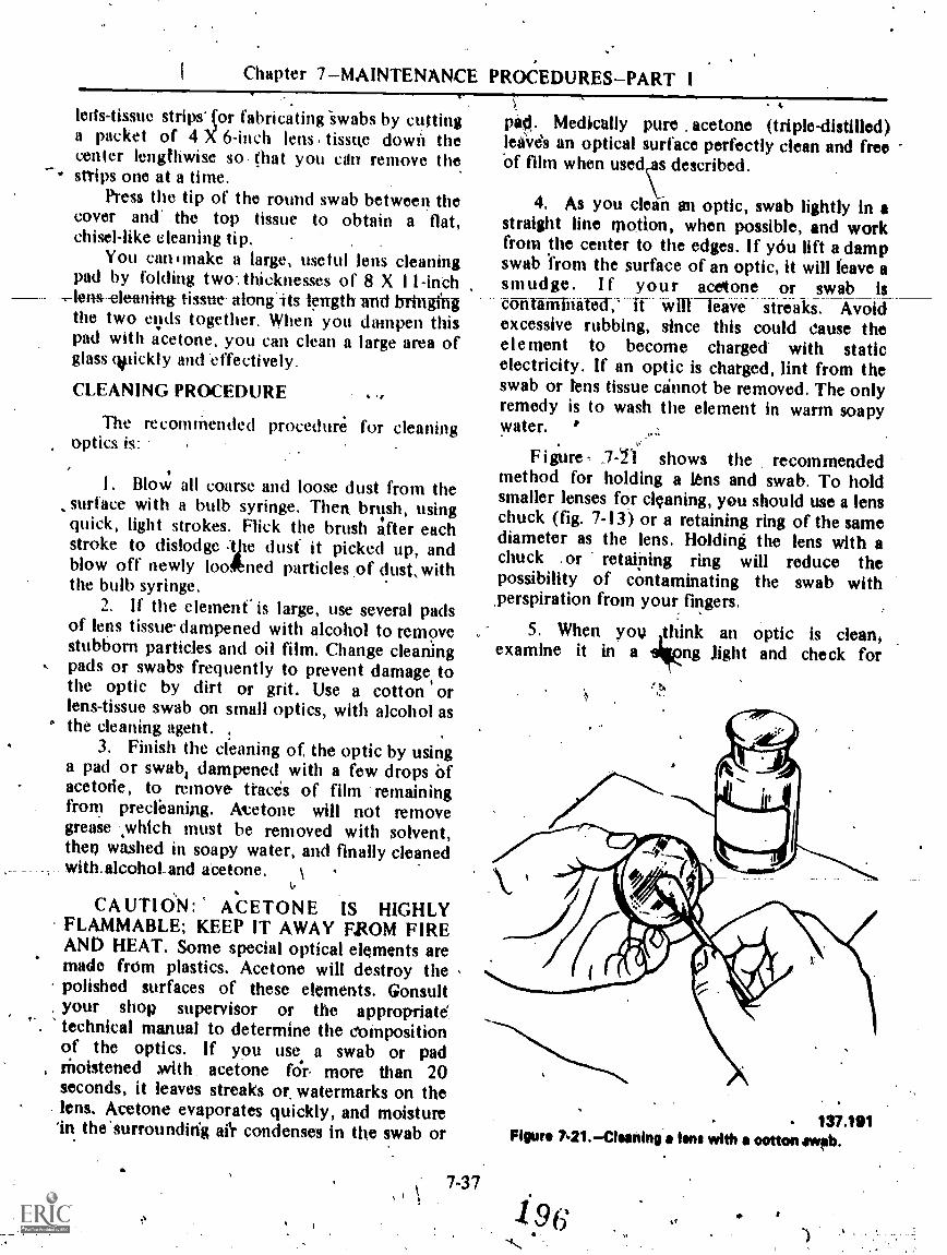
Chapter 7MAINTENANCE PROCEDURESPART I
kits-tissue strips* (or fabricating -swabs by cuttinga packet of 4 X 6-inch lens tissue down thecenter lengthwise so. (hat you clin remove the
* snips one at a time.Press the tip of the round swab between the
cover and .. the top tissue to obtain a flat,chisel-like cleaning tip. .
You can smake a large, useful lens cleaningpad by folding two.. thicknesses of 8 X 11-inch
lens-cleaning tissue- along'its length and bringfngthe two eyds together. When you dampen thispad with acetone, you can clean a large area ofglass colickly and 'effectively.
CLEANING PROCEDURE .9
The recomthended procedure' for cleaningoptics is:
I. Blow all coarse and loose dust from thesurface with a bulb syringe. Then brush, usingquick, light strokes. Flick the brush 4fter eachstroke to dislodge ;tile dust it picked up, andblow off newly loo4bned particles of dustswiththe bulb syringe.
2. If the element' is large, use several padsof lens tissue dampened with alcohol to removestubborn particles and oil film. Change cleaningpads or swabs, frequently to prevent damage, tothe optic by dirt or grit. Use a cotton orlens-tissue swab on small optics, with alcohol as
° the cleaning agent.3. Finish the cleaning of, the optic by using
a pad or swab; dampened with a few drops Ofacetode, to remove traces of film remainingfrom precleaning. Atetone will not removegrease -which must be removed with solvent,then washed in soapy water, and finally cleanedwith.alcohot and aCetone. \
CAUTION: ACETONE IS HIGHLYFLAMMABLE; KEEP IT AWAY FROM FIREAND HEAT. Some special optical elements aremade frOm plastics. Acetone will destroy thepolished surfaces of these elements. Gonsultyour shop supervisor or the appropriatetechnical manual to determine the compositionof the optics. If you use a swab or pad
, Moistened xvith acetone for more than 20seconds, it leaves streaks or, watermarks on thelens. Acetone evaporates quickly, and moisture'in the'surroundirfg dr condenses in the swab or
7-37
4.
pad. Medically pure . acetone (triple-distilled)leaves an optical surface perfectly clean and freeOf film when useds described.
4. As you clean an optic, swab lightly In astraight line motion, when possible, and workfrom the center to the edges. If ydu lift adampswab from the surface of an optic, it will leave asmudge. I f your acetone or swab istaltirunTlhitiWd: If willIeave streaks. Avoidexcessive rubbing, since this could cause theelement to become charged with staticelectricity. If an optic is charged, lint from theswab or lens tissue cannot be removed. The onlyremedy is to wash the element in warm soapywater. '
Figure , 7-T1 shows the recommendedmethod for holding a lens and swab. To holdsmaller lenses for cleaning, you should use a lenschuck (fig. 7-13) or a retaining ring of the samediameter as the lens. Holding the lens with achuck .or retaining ring will reduce thepossibility of contaminating the swab with,perspiration from your fingers.
5. When you think an optic is clean,examine it in a ng Jight and check for
137,191Figure 721.Cisaning a ons with a cotton awab.
1 96t.
tt
OPTICALMAN 3 & 2
smudges. and streaks. -Reclean if necessary.Sometimes a smudge is caused by fungus growthon the glass. This can be removed by rubbing theaffected area with a soft cloth dipped in a pasteof precipitated chalk pi even cigarette ash. Rubjust enough to remove the fungus. Do, notremove more, of the magnesium fluoridecoating than necessary.
6. If you are Satisfied, that an element is-perfee4y-t4ealti -wrap- -it in lens tissue until- vat]are ready to reasseMble the instrument.
CEMENTING EQUIPMENTAND MATERIALS
,
When a lens requires recementing, set up allthe equipment that you need in a clean, .convenient area. In addition to,the nraterial forcleaning the lens, you will need a lens centeringmachine or two matched, V-blocks, an electrichotplate with controlled heat, sheet asbestos toctwer the hotplate, black paper, a rubber-tippedtool, tongi or brass tweezers for handling warmoptics, a small glass bell jar or similar cover forthe optical elements, and Canada balsam orother approved lens cement. Canada balsam isnsually available in prepaTd form in metaltubes, through Navy supply channels.
Most lenses with a diameter over 2 1/2'inches are not cemented together; they areair-spaced. The elements of the lenses are madeof glass with different rates of expansion whichcauses separation of the, cement duringtemperature changes. Some large lenses are alsogound with different curvatures on-their matingsurfaces, which makes joining by cementimpossible.
The --reasons for joining the elements of alens by cement are:
1. Cementing keeps the elements optically
2. Cementing reduces the number of glasssurfaces exposed to the sir, which serves thesame purpose as a film on opticsto reducesurface reflection and improve lighttransmission. Since the index of refraction ofCaillada balsam is about the 'same as that ofcrown glass, there is practically no reflectionwhen two cro'wn glass elements are cemented,
together, and very little reflection when a crownglass is cemented to flint glass.
. 3. Because a soft glass (hydroscopic) hasspecial optical properties, a lens designer maysometimes desire to use. it. This type of glass,however, is unstable and quickly deteridrateswhen used alone; but it can be usedsatisfactorily when cemented in place betweentwo srable-elehienTS.
.You will occasionally find a lens doublet(genetally From a gunsight) that will not seParatewhen heated. If the elements of a compoundlens do not separateld a temperature of 300°F,they were probably demented together with athermosetting plastic, which a inanufacturersometimes uses for two reasons: (1) It resiststemperature changes better than balsam, and (2)it speeds up lens prodnction:
, When you have .reason to believe that lenselements have been secured together with athermosetting plastic; check the lens underultraviolet light .for FLUORESCENCE. If thecement between the elements is a thermosettingtype, there will be little or no fluorescence; ifthe cement is, balsam, you will see a definite,hazy-white fluorescende. Wheti in doubt aboutthe cement used in lenses, consult yoursugervisor.
Separating Cemented Eleinents
Turn your hotplate on LOW, or set it for300°F, and place a piece of 3/8-inch asbestos ontop, over which you place a piece of black paperwhich serves as a 'temperature indicator. Put thelens on the paper and cover it with the bell Jar orcardboard box. Watch the black paper for'signsof scorching, whin shows that the hotplate istoo hot and more asbestos is needed, or thetemperature should be tedviced.
Witen thb lens is hot enough (between 275'and 300°F), gently slichz the elements of the lensapart with your rubber-tipped tool and allowthem to cool slowly. When the temperature ofthe separated elements is approximately equal tothat of the room, remove old balsath from them
7-381 9 A;

z
Chapter 71--MAIIVTENANCE PROCEDURESPAR'i I
with alcohol, and then clean thenx thoroughlywith acetone. If the elements do not separate at300°F, the lens is probably cemented withthermosetting plafitic. A singlo-edge razor blade'inierted .between the elements will usuallyseparate them, and acetone will Clean off 'theplastic cement.
ReceMentinh
PI
.Put the clean lenses on the 'hotplate, withthe surfaces to Ile cemented together facingupward. Inspect them for duit or dirt whichmay have fallen on them since they weretleaned, cover with the bell jar, and turn on thehotplate.
When the elements are hot enough, put alittle balsam on the concave element,, pick upthe positive element with your tweeters, andjoin the two elements. Then use yourrubbei-tipped tool to work the top element overthe lower one as much as necessary to squeezeout all sir bubbles. The black paper on thehotplate makes air bubbles in the elementsappear bright.
Use the lens-centering instrument (fig. 7-22)to center (align optical axes) the elements. This
Figure 7-22.Lemoentsring instrument.137.192
instrument consists of\' AA upper astronomicaltelescope with a crossline and focusing eyepieceand a lower collimator telescope mountea on acommon sta'nd. The Objective lens of oneinstrument feces the objective lens of the otherinstrument. The, crossline mount of thecollimator telescope moyes in a threaded mount,which' enables you to bring the image of its
_crosiline, into _focus with-- the- -image of thastronomical telescope, _regardless of the sizelens mounted between., .1he telescopes. A lenschuck on the lower telescope grips t.10, elementbeing centered. The entire lower telescope canbe freely rotated to check for eccentricity. Tosave time when centering a cemented doublet,you should place the lens in the centeringinstrument and focus the two telescopes prior toseparating,the lens.
Heat the chuck jaws-with a small torch or ahot piece of metal and then transfer the hot lensto the chuck. NOTE: 'Cold chuck jaws maycrack one orboth elements of the lens. Mountthe hot, fleshly cemented lens in the warmchuck, which grips ONLY the negative elthentsof the lens.
Sight through the eyepiece while you rotatethe Iower telescope, and, observe the eccentricmovement of the lower. crossline. Move theupper element of the cemented lens over thelower one, as necessary, to remove alleccentrrcity as the lower telescope is rotated.
The insert in figure 7-22 shows the crosslinepattern of the two telescopes: The plain diagonalcrossline itlhe image from the lower telescope.This crossline must stay within the small circleas the lower telescope is rotated; however,perfect coincidence is more desirable.
Allow the lens to cool for a few minutes inthe machine and recheck the alignment, removethe ,asbistos sheet from the hotplate, and placethe lens on the asbestos sheet. Then cover thelens with the bell jar (or box) and allow the lens
. adequate time for 'cooling. When cool,, removethe, bell _lir and scrape eXcess, balsam from the
, edge of the lens with a razor blade, after whichthe k lens is ready for final Cleaning andinspection.
NOTE: Ifs you do not have a lens-centeringmachine, use V-blocks in the following manner
7.3 4.9,
198j'i010
14.

OPTICALMAN 3 & 2
to align the bptical axes of a 'compound lens:Heat the V-blocks on the hotplate while you arccementing the leds elements. When you have theeleinents joined, slide the V-blocks against theedges 9f the lens from opposite directions. Then
A
lb
11
turn off the hotplate, cover the lens andV-blocks, and allow the Ipombination to coolskmultAneously. NOTE: Elements whosedi1tmeters differ cannot be cemented in thismanner.
/.997-40

CHAPTER 8
MAIINTENANCE',PROCEDURES PART Ii
REASSEMBLY
Now that you have .done.t he essential repairsto instrument parts., the necessary refinishing,the required cementing of optical elements, andeverything is perfectly clean, you are riady toreassemble the instrument.
If you have accomplished your repair andoverhaul well, reasse!nhly. will be smooth andeasy. Unless you know tile ingrument on whichyou are working very wells f llow a reassemblysheet. Because 'reassembly i . different for eachinstrument, no set procedure can be given in thismanual: The reassembly tips presented in thenext few pages, however, will tie helpM.
REPLACINC; LENSES
Before mounting lenses in their cells ormounts, you must be sure that all dirt andforeign matter has been.cleaned from the cell. Ifthe*interior of the ea is partigUlarly long orhai.d to clean., you. clin remove most particles bythis simple method: First, cover the Open endsof the.cell with masking tape. Then'with the eellheld in an upright position, tap pn the exteriorwith a small 2- or 3-ounce liber mallet. The dirtwill loosen from the cell and drop to the end of
.the cell where it will stick to the tape. You.canuse this proCedure also on large body tubes andcastings.
All of your dean opfics should havebeenwrapped in.lens tissue. When you Unwrap lensesprior to replacement in flit* mounts, you will
8-1
usually find. a few pieces of lint from the lenstissue adhering to the lenses. Blow this lint offwith an air bulb before replacing the lens in itsmount. If you are replacing an objective lens oreyelths, make sure the gasket :is properly inpositiam in the mount to maintain the seal.
To avoid putting fingerprints on the edge ofa lens, hold the lens on its retainer -ring or use alens 'chuck as you insert ,the lens in the mount.%Be sure the lens is facing the proper direction, oryou will have to disassemble the' instrument
. later. The lens must be fully seated, withoutbeing cocked, and the retainer ring must besnugly tightened. If the retaiger is loose,collithation be impossible, and the seal maynot hold..11 the retainer. is tob tight, there is therisk of:distortion or cracking.
REPLACING PRISMS
After you assemble all lenses in their cells.and mounts, assemble the prism clusters, orprism mounts (if any). secure the prisms in theirmounts by straps and/or collars, which must rit,snligty enough tp hold the prisms WI not sotight that they may cause strain. A collitr shouldfit over a prism with a slight press, If The fit istoo tight, strain and breakage usually result: ifthe fit is too loose, the prism may shift positionand throw the instrument out of adjustinent.
When you assemble 4 porro prism cluster,$jieek the assembly for lean before you put itinto, the instrument. In a prism erecting system,lean results when the prisms are not orientedexdctly 900 to each other. Figure 8-1 shows how
200

. OPtICAIMAN 3 & 2 etr
:. .-"-
137.558,Figur 8-1.Porro prism clustor squaring.
appears. Any deviation from a perfect 900orientation will result in twice the amount ofdeviation, as you view a target through thecluster. .
Various adjustments are PçovIded , on prismplates to remove lean. So e ave collars whichfit the prism tightly. These collars have fouroversize holes for the secaing screws, whichallow slight movement in any direction. Othersuse eccentric' washers, or tapered washers whichbeat against the.edges of the pristh.
When you assemble porro prism clusters,plate the prism in the center of *milled outdepression in the prism plate, tig the strapOver the top of the prism, then snug theadjusting screws. Be careful not to touth thepolished surf4ces at any time while adhsting aprism cluster.
"To remove lean from a prism cluster, look
.,through the chfster with one eye and at a:prominent vertical or horizontal refettnce (such
as a stanchion, door fiame,or graph paper) with'the other. By shifting one prism slightly, youcan align the inverted-reverted reference you seethrough the cluster with the normal referenceyoti see with your otherieVe. This Procedure willrequire.' some.practice since you must train your
,eyes to see two different objects at the sometime. If adjusting one prism does not removelean, you may have to adjust the other prism orreverse a prism on the prism plate. After lean Isremoved, tighten the prism strop ;and check tobe sure the adjusting screws are tight.
During assembly_and_adjustment-of-a-prismcluster, it is easy to cock a prism. You canremove lean with a cocked prism, but the prismmay chip, deviating the line of sight through thecluster too much to allow collimation, .
1' 8-2
,4='. .fcs s ifs
ASSEMBLINGMECHANICAL PARTS
*Asyou assemble parts in an instrument, be
.sure to match all assembly marks; otherwise,you will need to. disassemble the instrume.nt,make corrections, and reassemble it.
Check each part as you reassemble it ,forfragments of foreign matter clinging to it. Eachpart MUST BE IMMACULATELY CLEANbefore you assemble it in the instrument. Keep
'openings to the interior of the instrument closedwith masking tape, and remove it only when youmust make additional installations. Follow thisprocedure as you. reassemble each part, until youmake the final closure.
As you replace components and parts in aninstrument, try to Work from the top downwardto prevent unnecessary work over_ an opticalelement, and perhaps damage to it.
boinot forcq a part into place in an,opticalinstrument; use a light press with your fingers. Ifa part must be fitted in position by force it Mustbe done in accordance with specifications. Ifthere is a bind, detelmine the duce.
You can make some adjustment to parts akyou assemble them in an initrument. Wheneverpossible, Akese adjustments should be Madeduring coMmation. In some Instances anadjustment is impossible after reassemblybecause of inaccessibility of parts.
-Threads on ret4ining rings, lens mounts, .caps, screws, 'and. setscrews are extremely' fine
4

it
k
Chapter '8 MAINTENMICE I;ROCEDURES PART II
and can be cross-threaded easily. When youassemble themi, turn in a counterclockwisedirection until the threads snap into place: thenfurn.dockwise..
Lubricate components, as necessary, withapproved lubricants during assembly. Uselubricants sparinglyryou not want tocontaminate an othiTrwise clean Optic with a
Imudge-of-greast. no an anti-seize compound onexternal screw threads and threaded portions ofbody tubes. Silicone grease is an excellentantiseize. -It will not melt .or run and it will-prevent corrosion. Do NOT use any grease on alens retainer ring.
COLLIMATION
One the final steps in overhaul and repairof an optical instrument is collimation, which is-the alignment of the optica) 'axis, of theinstrument to its mechanical axis. In simplerterms, collimation is directing all the lenses in an.
COLLIMATOR TELESCOPE
.7.COLOMATOR TELESCOPE SUPPORT
optical systemcoincide with eTparallel to the
n such in an ner t fiat t heyeh other in a straight line andeehanical axes of the bearing
su r fa c es ("t elescope's mount ing pads, forextimple)0 Collimation also consists of adjuMifigthe focus of individual lenses and assemblies sothat the target (and crossli-Re It' iticluded) will be
perfect focus.
COLLIMATION EQUIPMENT
Collimators are precision instruments (withboth optical and mechanical elements) whichprovide an infinity larget suitable for use inaligning and adjusting the optical andmechanical components of optical instrumentsso that they will perlbrm accurately.
3.1;;1' colhmators .may vary in designand/or construction, they all operate on thesame principle. Figure 8-2 shows the Mk 4 Mod0 colliniator used on small telescopes, gunsights,and nayigational instruments. It has a steel baseseveral .feet long with a precision, flat bearingsurface machintxl.on its entire top. A keywIty is
KEYWAY FOR SUPPORT FIXTUREg
COLLIMATOR ElAa
Figure 8=2.-CoMmetck Mk 4 Mod 0.
8-3-
131.206

OPTICALMAN 3 2
01\
p.
TAMMY ASSEMOLY
v.
Figur* 8-3.Auxillary topport fixtures.
011JECTIVE LENS
TESTIMMINENT
atomi_ STAND
ASE PLATE
r.
Figura 8-44Mk 6 binocular collhnator.,
- 1 -
/'P
41,
137.202
148.232
Ty..
.Lir,P:W.Z.' 3T;;:..0.

TI
A
Chapter 8 --MAINTENANCE PROCVIIURES:-PART
cut down the center of the bearing surface, asshown, for aligning support fixtures.
The COMMA or t elescotild is secured to thebearing surface on a V-block support with t.wosquare keys holding the collimator telescopesupport in alignment with the base. Thecollnnator telescope can' be rotated hyshiind tochange the orientation of the crossline. I
t
CARBbN RODADJUSTING MECHANISM
.SFOCUSING LEN
TARGET 'ASSEMBLY
Figure 8-3 sho;vs two auxiliary supportfixtures which are used- with the Mk 4 Mod 0collimator. The fixtures differ because of thepl ysical configurations of thettelescopes forw1Ich they i are designed, yet both fixtures fit*.he Mk 4 Mod 0 coliihiator. .
Figures -8-4 and 8-5 show .two. entirelY'different collimators used to align .hand-bel0binoculars. The- mounting stand shown itaigure
TARGETSCREEN
*
OBJECTIVELENS
COLORED.,DISCS
t
PENTA PRISM .
ADJUSTING MECHANISM... t
OBJECTIVE LENS
tiPTICAL ifiDGE
*'.
Figure 84-1111k 1tbinooulir collimator.
8-5
204,
148,240
S..
1.
11,
-1""-
OPMALMAN*3 ..2 ,
ELEVATION.A0JUSTMENT
SCREW
DEARING. ADJUSTMENT
SCREW
148.234'Figure 84.Test instrument mounting stand.
V
13-
84.) fits the Mk 5 collimator", which it adapts tohinoctilus, sext:ints, and stadimetgrs. The Mk 13collimator will accept4 only binoculars. The,oPticaWstem of the Mk 13 collimatcy is shown
.Large tilting prisfltT11ights are collimated
on the. Mk"9 coil n Thr (fig. 8-8). Thisinstrument tS 'rather large and bulky, since Illsdesigned to. pCcept large funsights, but it iS aye ryprevisioninstrumentThesupportj:flate,
. which can be rotated, ltas numerous tappedholes which are -used to secure a variety oftelescope supports that hold all types ofgUnsights. Notice tike doubk bank of collimatortele4opes. This teatime allows the collimation ofboth single e.yepiece and binodhlar typegunsights: These collimator telescopes are
. n3ounted tft -25°. '0°; .+M°, and.+90° so thatgunsiglits can be adjilsted through the full rangeof elevat ion a nd depreSSion..
The c'ollimator telescope used bn the Mk.9collimator is Shown; in. figtqe 8-9. Itis normallyused- with the mirrOr (to, reflect light .andilluminate ;he erosslinb). For special purpbses;such as establishing'htrue line olsight between
RIGHT ANGLE PRISMVOCUSING ,LENS
Pipes 61.Mit 13 billowier. eollimetor+operationsi.saitemeticOf optic.) system:
: ,4 - ;
/ .
148.23.

.44
:.0
Chapto MAINTENAgrE PROCEDURE'S-PART II.
ity
a
Figur. 8-8.-CoIlimotor Mk V.
.
EYE LENS SEPARATOR CROSSLINXLENS SEARING
SURFACE
CK RINGBODY TUSt
ogARING 010JECTIVE NOUN'TStiNFAct
011jECTIVE LENS.
ACTUATINORING
MOUNTEYEPIECE 'L
SUPPORT
111:k_LIMPF"1--
DIFFUSING PLATA, ONOSSLINE ANS
ADJUSTING SCPtii
148.248
CROSSLINE LENS
pIELD LENSAMORMOUNT
;, MINNOltSRACKEY
RETAINING RING
Myst 114,-,CoMmetait Ws-stops Mk 8 Mod 1 with aux ory oyoplook, mirror MOunt, and diffusing platt-totavoy.,

OPTICALMAN 3 & 2
two tollimator telescopes, it is available .with aneyepiece.
For further information on c011imators,consult OP 141 7 , Collintators fbr OptkqlInstruments.
Collimatio% of submarine periscopespresents two unique problems-the length of theinstruments_and,_ the-neefor---an-Aljustabletargtt. Figure 8710A shows the collimatorMounted in .the horizontal position on theperiscope _rail. Part B of' figure 8-16 shoWs aeloseup or the c:ollimator. The periscope railshown is about 45 feet long. The slidingV.blocks support the periscope to preventsagging of the tube.
-
Of all the tools you will use as %anOpticalman, the auxiliary teleseo0 is the mostcommon for adjusting most of the instrumentsfor which you are responsible.
Auxiliary Telescope
Figure 8-1; illustrates the auxiliary teigscopewith a rhomboid prism iittaehment. With thisattachment you can look through An instrunientand see a magnified imoge of a collimator, whileat the same time you can see a reduced image ofthe-collimator superimposed on the main !inept`sight. The rhomboid prism attachment flips overthe objective end of the auxiliary telescoPe-when needed.
The ituxiliary telescope is 'a three-powerastronomical teWscope (inverted reverted image)with a focusing Kellner eyepiece. Its mainpurpose is to correct 'for, and neutralize,inherent eye defects you May have and toslithtly magnify so that you can adjust anoptical system more accurately.
k
flaurell;10.-Pwisoapa paIll.rnator and rall.148.253(2114)
I.

Chapier 8 MAINTENANCE PROCEDURES-PART LI ,
RHOMBOID PRISM .)ATTACHMENT
LINE Of SMUTOPENING
RHOMBOID PRISM
AUXILIARY TELESCOPE
Figure 8-11.AuxiHary-telescope Mk 1 with rhomboid prism attachmentcutaway.
To determine the dioptric setting of youreyes, focus the auxiliary telescope from plus tominus on an infinity target", or on a collimatortelescope crosslirm jintil the image is sharplydefined. For best rekilts, take five readings anduse the .reading whieh appears most during thereadings. Remember to keep your eyes relaxedwhile focusing.
After you get this dioptric setting, do NOTchange the focus until you check your settingagain to adjust for'eye fatigue or strain.
You can use-1mi nuxiliary telescope for thefollowing collimation operations: .
I. To set focusing eyepieces to theNORMAL or ZERO diopter setting.,
2. To set fixed-type eyepieces to th.eirrequired diopter setting.
.3. To check for and . aid in removingparallax in an instrument:
The auxiliary telescope increases th'Paccuracy ofthese adjustments by a factor of three. If you are
148.2111
adjulting , a six.:power instrument with anauxiliary, the final magnification of thecollimator image wig be 18X. (3X auxiliarymultiplied by 6X telescope).
NOTE: Alwliys use an auxiliary telescopeduring collimation procedures.
LLIMATOR ADJUSTMENT
Alignment of a collimator serves twopurposes. It establishes parallelism between thebase and the optical line of sight, and it sets lipthe collimator to correspond with alignmentspec ifica t ions for the instrument beingcollimated.
F igure 8- I 2 -shows the Mk 4. Mod 0collimator and 'the equipment necessary tosquare the collimator crossline. Light leaving thecollimator is parallel. An auxiliary objective witha 10- to 15-inch focal length is placed near the
8-9 298I.

a
OPTICALMAN 3 & 2
Figur. 8-12.Squaring collimator Cnissline.
collimator. An adjustable auxiliary eyepiece ispositioned behind the auxiliary objective so thatyou can see-Ji -6harp. image .of the collimatorcrossline. Now place a machMist's square in theiMage plane ,of the . auxiliary objective. Youshould see .the 'collimator crosshne. and Ve edgeor the thachinist's square in sharp focuOimplyrotate the collimator telescope to AM thevertical line 'with the edge of the square. Nofurther illignMent is necessary on the Mk 4"collimator.
Some collimators must be aligned with'special, iingle-purpose equipment. Others can bealigned to accommodate a variety of differenttekeseopes by using a checking telescope.
The Mk 7 checking telescope (fig. 8-13) hasgraduated dial and, Vernier indtix so that you
.',can set the telesOpe at any angle Of eleVatioR ordepression. The eyepiece prisM is fullyrotatiohal so that you can comfortably view thetarget.from any position.
.To align a collimator using the Mk 7Check ing telescope; mount the checking.teleScope on the ,appropriate support fixture, set'Ott dial:to the specified elevation., and.adjust ,theeollimatpr telescope to align with the checking
`la137.208
telescope. (The checking telescope is theprimary.reference.)
Adjust the collimator immediately prior tocollimating an optical instrument. In some cases,.you wilt4 need to make readjustment duringcollimation because temperature changes willaffect alignment of the collimator.
4
COLLIMATION PROCEDURES
Collimation procedures varY for differenttypes. Of optickil instruments. While one type ofinstrument May require several hours of.
complicated adjustment, another can be, completed in a few minutes. You will encounter,situptfons when makjng one adjustment willchange a .iprevioto ustment, and .someinstruments will nee to Iavc subassemblies'collimated he,t'or eU can collimate the.CoMplete telescope. tilting 'priim gunsigtits,you may have to tin or scrape mountingsUrfaces to obtain p per tracking of the line ofsight:
Tot obtain detailed procidurei for. collimation of any Particular instrument .you
plug, consult a job sheet or technical manual.
7-
.

Chaptei 8--MAiNTEVANCE PROCEPURESPART II
Maui* 8-13.Mk 7 ohiold, tolucope.
a
he following general intormation will apply tomost optical instruments, in the ordefin 'whichit shOuld be performed.
". 1: Collimate the collimator.2. Remove parallaX.,3. Squart and superimpose the crostline.4. Set zero diopteri.
4onOyall of Parallqx
To check for parallax in an instrument, pfacean auxiliary telescope .on the eyepiece .of the-rinstrument, sight through the auxiliary'telescsitie, and, focus the eyepiece, of theinstfunient until the linage of the collimptorcropline, or the crossline of the: instrument
8-11
21 o

OPTICALMAN 3 & 2
( whichever conies Imo view first), is sharplytr
.enneq. It parallax is resent, one of Me twocrosslines will come into focus first; if there isno parallax, tioth croAlities will i)e in locus atthe same time To dirtermine the amount ofparallaX, focus the eyepiece of the instrument inuntil tlie first crosulme is sharply defined, andobserve the.diopter reading tb which the indexmarker points. Contiime to roctrti until.the othercrosslime Is- sharply 'defined and observe .thepoint of tlw index mark on the diopter scale.Also note the number of diopters betv.ieen theposition of clarity of the first crosslinc and thepoint of clarity Of ihe second Crossline. if theInstrument's crosSline, for cx ample: came intofoeus at +2 diopters otr the diopter scale and thecollimator's crossline cattle Mao focus at -3diopters On the diopter scale. the total amountof parallax is 5 dioptcrs.
If the instrument's crossline komes, intofocus before the collimator's crossline, theobjective lens is too far Im the erossline. If thecollimator's crossline comes into focus beforethe instrument's crossline, the objeCtive lens' istoo close to the crossline.
P r (+le in now. 'is to pl:tee theinstrument's ctossline in the focal plane of the'objective lens, in one of two Wa ys:
1. Move thy instrument's crossline forwardor aftlaxial,ly until it is in the'focal plane of theobjective lens.
2: Move the objective lens until its focalOhne, is in t lie same plane as .the instrument'serossline. This method is preferred for removingparallax. The objective lens is usually mountedin a threaded mount which can be moved axially'along the interior of the instrument. When theobjective lens mount is moved any amount, theimage of the collimator's crossline moves in ihesame direction in the same amount as theobjectivelens.
In some instruments spacers or separators4re placed in front of, and behind, the'objeetivelens mount (not threaded externally) to allow
' for elimination of-parallax by trial and error.There is NO tolerance for parallaX in any opticalinstrument.
;Continue adjusting the instrument until both'erosslines are'in perfect feicus.at the same time.
8-I
Squaring andSuperimposing the Crossline
-Co square the .instrument crossline to l'he.collimator crossline
I. Loosen the crossline retainer ring.2. Rotate,t he crossline with a rubber tipped
tool.When the crosslines are aligned, tightenthe retainer.
The crossline may turn past the desired position.This procedure can sometimes be quitefrustrating, bin it must be done carefully andaccurately. As you make adjustments to thecrossline, it could become sikidged or dirty.You will have to remove and clean the crosslineagain,. THE CROSSLINE MUST BEABSOLUTELY CLEAN.
, Once the instrument crossline is perfectlysquared, and clean, superimpose it on thecollimator crossline. Instruments are designed in.a variety of ways to accomplish this adjustment.One design is to shift the prism erecting system(whiai may cause lean), another is to adjust thecroSsline lens mount (screw adjusting mount).The most common design is the' ase of aneccentric objective mount. With propermanipulation of :. he eccentric rings, you canvary the line of lit of the instrument'to giveperfect alignment, ,
Eccentric rings are locked in positiOn withsetscrews, lock rings, or both. When you lockthe eccentrics; your adjustment may be thrownoff slightly, so be sure to check it. If full throwof the objective is no( enough to superimposethe two crossline, you may need to shift prisms,'recheck for lean, and try again. Whey you havedifficulty superimposing the collimator andi nst F u me n t erosslines, try t he followingprocedures:
I. Check the collimator ttlignin&it.2. Check the instrument mounting surfaces.3. Disassemble the instrument and look for
.cocked lenses, prisms, or mounts.
, After you have squared and superimposedthe erosslines, recheck for parallax,
211

Setting Zero Diopteis
Chapter 8 IAINTINANCY PROCEDURESPART
01.
Instruments with a foeusing eyepiece arc setzero diopters with an auxiliary telescope, 'so
t ha t anyone using the instnink.nt canautomatically 'set the ej,epiece at his or her Owndiopter setting without wasting any st.imefocusing. During reassembly of spiral keywayeyepieces. you will set the index Jnark atmechanical inidthroW (/ero diopter position)and iidjust lenses dtiring coljjimition to establisha perfect focus at zero diopteis.
ro set optical zero diopt . use .1 11 auxiliarytelescope set to yoiir eye correction, and focusthe instrument being tested until the colhmatoris in sharp focus. NOTI.:: Always focus from theplus side (out) to the minus side (in).
When. you removed parallax, the instrumentcrossline and collimator target were in focus atthe same time. This common focus may notcorrespond with the iero mark on theinstrument eyepiece. For instance, if bothcrosslines are in focus at -2 diopters. the finalimage ,plane in too far. On the other hand, ifboth crosslines are in focus at diopler, thefinal image plane is out too far.
To establish a perfect zero diopter focus in a
two erector telescope, simply move the rearerector in the same .direetion you want theimage plane to move. For instrmnentS with asingle erector, move the motor in the oppositedirection you want the image to" move(rernember, the optical theory discussed in earlierchapters).
In instruments without a. crOssline, using aPrism erecting system,' the focal length of thegbjeelivez lens or the axial positioning of theobjective lens will determine the zero' dioptersetting.
*,The collimation procedures just discussed
generally cover fixed prism gunsights andstraight-line telescopes without crosslines.InstruMents with elevatiOn and defleet ion prismsor mirrors must be checked against a properlyadjusted collimator for .true horizontal andmerlical tracking as well as mechanical backlash.
Moderii gunsights. a,re precisionmanufact(IrM40 fine tolerances to keep possiblemisalignment to a minimum. However, damageor incorrect reassembly can cause proNems. The,technical manual for each type, of instrumentfully covers,the correct overhaul and collimation
'procedure and lists the tolerimces for errors inelevation, del)ectionl and backlash. As, a' rule,the line of sight ean vary no more than I or 2minutes of lire frOm the desired plan ofmovement, and backlash is field to 30 seconds,or less. Proper adjustments include shimthing,scraping. or replacing machined spacers, asspecified in the technical manual.
SEALING, DRYING AND CHARGING
'After you collimate`an optical instrumt(nt,the last step in overhaul is to seal theinstrument_ remove any moisture present, andcharge the instrtiment with a dry, inert gas whenappropriate. Much of the sealing' process isusually acconiplished during reassembly, except'for areas needed (or access during collimation.
Optical instruments are designated as (I)moisture-tight, (2) gas-tight, .or (I)pressure,tight. Methods used kir sealing, drying,and charging'vary with the type of instniment'being overhauled
MOISTURE-TIGHT;
Hand-held optical instruments, or those notpermanently motmted on a ship's weather deck,are. elassWd .as moisture-tight. They ItaVefocusing 'type eyepieces and are sealed againstthe entrance or moisture by gaskets, sealingcompound. and grease (in the eyepiece focusingmechanism). These instrumen.ts are'sealed in theoplical shop at normal atmospheric pressure.They will withstand mist or light. rain, butcannot be submerged in water.
GAS-TIGHT
Instruments which are permanently exposedto the weathOr must be sealed with,a positive gaspressure of 2. to 5 psi. They have fixed focus.orinternal fpcusing eyepieces, and all -joints' and
8-1:3 4,?,/

f
OPTICALMAN
optics are sealed with gaskets. Since theseanstruments use control shafts passingUhroughthe body casting, the shafts' are sealed withpatoking. The packing holds internai pressure andWill alkm the control shafts to be rotated.
PRESSURE-TIGHT
Instruments which must withstand highes ernal water (hydrostatic) .pressure forextended periods of (MIe are sealed with 0-rings;packing, and gaskets. They will also be chargedwith inert gas at a pre),sure of 5 to 7.1/2 psi. Theprimary purpose of scaling, drying, and chargingan optical instrument with gas is to preventmoisture from.getting into the instrument andcondensing on parts, thereby rendering themuseless.
, A gas-tigt t instrument may be charged withd ry nitroget or helwni. A pressure-tightinstrument should be charged with dry nitrogenONLY. Dry nitrogen and dry helium art used tocharge instruments because they are inert gases:that is. they do not react aemically to cause orsupport corrosion,
Gas \used to charge optical instruments is'normally not completely free of moisture andforeign matter. You must cleap the gas beforeyou use- it. Force the gas through an opticalinstrument dryer, winch is actually a filtercontaining a. quantity of sihca gel to absorbmoisture from the gas as it passes through. Thesilica gcl used in Ihstrutncnt- dryers isimpregnated wiilt cobalt chloride, which servesas a moisture indicator. When the silica gel iscompletely dry, it is deep blue. When the silicagel contains moisture, it is lavender; when it
; contains 50`X moisture, it is pale pink.' At a.saturation of almost I 00`4/ with moisture ,. silicagtO is decidedly.pink.
You can check the color of the silica gelthrbughAa window on the side of the cylinder.When ir changes to pink, remove it from thecylinde?: place it in a container, and bake it inan oven atm- temperature of 3000 to 3500 F for aminimhm of 4 hours, after which its colOrshould be a deeP blue. If silica gel turns brown,replace it. While the silica gel is being baked,clean the inside of the dryer ith the filters,
:The, use of nun-igen and helium forressure-t cst ing gas-t igh t and pressure-t igth
instruments, as prescribed in the various-instrument mantials, requires you to be familiarw i t sa fe i andling pract ice} concerninghigh-pressure gases and siorage cylinders.
7SAFETY PROCEDURES FOR -
HANDLING CYLINDERS
You must strictly thservc the folkiwing rulest'o r st6rage , handling, a se cylinders.
Avoid abusing *cylinders, They arecarefully checked at the charging plant for safecondition. Abusemay easily yender them unsafe.
Re sure the cylinder contains the proper gas,and do NOT tamper with the ideoilying code!numbers and markings on the cylinders.
Store t ylinders in an approved verticalsto age rack where they cannot be knocked over
damaged by passing or falling objects. If acylinder falls .over, it may crack and explode,since a full cylinder contains pressiire of 1800pounds per square inch. If the cylinder valve isbroken, the cylinder will take off like a mcket.Cylinders should be kept away from stoves,radiators furnaces and other heat sources.
While moving cylinders, prevent themfrom being knocked over or from falling. Use asuitable handcart with retaining devices.
Keep cylinders from being knocked overwhile in use. Use a rack to hold the cylinder in.an upright position.
Use full cylinders in the order in whichthey are received from the charging plant.
Never allow cylinder to come in contactwith live wires and ground wires of electsicalequiOmetft.
8-14
213
ow

Chapter 8 -MAINTENANCE. 'PROCFDURES PART' II
Alwaysaelose, the. cylinder 'valve whenwork is finNhed. Always close valves of emptycyhmkrs,wbile.in storage' before returning themto the charging plant.
jAeturn empty cylinders promptly.
NEVER _use a cylinder that contains lessthan .400- pounds of pressure. Gits cylinderscontain impurities which could enter andcontaminate an instrument if the Silinder isem ptied.
CHARGING PROCEDURES
Figure 8-14 shows a typical setup forpurgiv, pressure-testing, and charging an opticalinstrument. In this illustration, a rangefinder isbeing charged with helium, but the sameequipment is also used with nitrogen and onQther instruments.
Plastic hose must be used from the dryer to(he instrument. Rubber hoses are not clean.
tNLET SCREW FITTING
VALvE BODY
AIRVALVESCREW
REGULATED PRESSURE
Thev tend to "shed" foreigil matter: It is alsoadvisaNe to ue a plastichose from the regulatorto the filter.
The following procedure shall .be kolloved.piescribed to protect you and the
eripment.
.-0 -;iet a cylinder of nitrogen in a rack in a
vertical position. cJbserve the safet-Y proceduresfor handling cylinders. Make sure the cylindercontains nitrogen.
..41/
With the cylinder firmly in the rack,unscrew the valve protection cap from the topof the cylinder.
Open the cylinder valve one-quarter turnand then close it immediately. (Do NOT stand infront of the outlet pipe: stand behind it.) Thisprocedure will clear the valve and the outlet pipeof dust and dirt that may have beenaccumulated during storage and shipment.OtherWise, such dirt might be blown into therjegulator and damage it.
PRESSURE GAUGEFOR BOTTLE
LEFT HANDTHREAD ADAPTER
1
PRESSUREREDUCTIONVALVE
\.WINDOW
RANGE FINDER
PNEUMATIC HOSEINSTVMENT DRYERMARK II
HELIUM BOTTLE
Figure 8-14.Setup for charging.11.96(137A)'

OPTICALMAN 3 A 2 .41^
WARNING
60 NOT USE A WRENCH ON THECYLINDER VALVE. IT SHOULDOPEN TO _HAND PRESSURE. IF ITWILL :NOT YIELD TO HANDPRESSURE, REPLACE THE VALVEPROTECTION CAP ANp _.RETURN
THE CYLINDER TO THE CHARGINGPLANT.. WITH AN EXPLANATIONATTACHED.
Assemble the pressure-reducing regulatortos the cylinder-. Tighten the union-joint nutsecurely.
Turn ace pressure-adjusting controlscrew of the regulator counterclockwise (to thekft) until it ispose to protect the regulator andits gages from possitile damage when thecylinder is bpened.
Stand to one side of the front_of theregulator and open the cylinder valve sightly. Ifthe cylinder is opened quickly, the sudden rushof gas might damage the regulator. Open thevalve only enougli to make the cylinder pressuregage indicare A slow riSe in pressure. When theneedle of the gage stops, open the cylinder valvean the way.
WARNING
IF TItERE IS A LEAK BETWEEN"I4HE CYLINDER AND 'THEREGULA.TOR, CLOSE THECYLINDER VALVE BEFORETIGHTENING THE COUPLING ORBEFORE DOING ANYTHING ELSE.
Connect the hoses and the instrumentdryer together as in figure 8-14. Make sure thehose from the fegulator is attached to the inletside of the dryer.,
Turn the pressure adjusting contiolscrew of the regulator ckockwise until 'theregulated pressure gage reads 5 pounds to blowout the filter and i 11..
Reduce the presSure again. The system isnow ready for use.
Testing for Leaks
When an instrument is to be tested for leakslitre general procedure is:
Connect the hose from the outlet side ofthe dryer to the charging valve screw fitting (thesmall scryw) on the optical instrument (fig.8-1 SA).
137.207Figure 81 15.Attaching hose to instrument chiming
valv.
8-16215

Olt" Chapter .8 MAINTENANCE PROCEDURESPART II
Open the gas inlet screw (large screw) ongthe valve.
Tighten the, gas outlet screw on theoppmite,end of the optical instrument.
Turn on the nitrogen supply until thepressure gage on the instrument dryer readsapproximately 5, pounds per square inch (fig.8- I 5 BY
. While you maintain this pressure, brush asoapsuds .solution around all fittings, gaskets.,screws, the objective ;window, and the reareyelens to check for lyks. See figure 8-16.
If you find leaks, mark them witha softlead pencil, white crayon, or chalk: turn off theair supply: disconnect' the hose from theinstrument:and then repair the leak(s).
After you repair the leaks, connect thehose to the instrument and apply the samepressure test and check again for leaks withsoapsuds.
After the instrunorft passes the soapsudstest, maintain 5 pounds Of-pressure and close thegas valve screw on the inlet valve.
Submerge the instrument in a tank ofwater.
1411.33
Num R-16.Testint tor leiks.
Check for slow-rising bubbles 'Mich mayrwear anywhere on the instrument. A, fewMurs may elapsebefore any bubbles are visible.
Mark the leak1s) as soon as yOu removethe instrument from the tank: then Topair them.Follow up by appying 5 psi test pressure. andsubmerge the instrument in the tank again todouble check for leaks.
When you are eerrarn there -a-re no leaks inthe instrument, remove it from the tank, dry theexterior with a clean, soft clots, an/I-recharge itto exactIA 5 pounds. Twenty-four hours later,attach a pressure gage to the gas inlet valve ofthe instrument and check as pressure. If it hasdropped,, repeat either the soapsuds test or thetank test as often as necessary until you find theleak(s). Then make necessary repairs. Theinstrument is no ready for drying and aarging.
Drying and Charging
To dry and charge the instrument withnitrogen:
Reconnect the outet hose from Jhedryer to the inlet valve ,on the instrument.
Open the out et valve of the instrument.
Turn on thInitrogen at 5 pounds ofpressure and let it cycle through the entireinstrument.
Purge the 'instrument by holding a fingerover the outlet valve. When the gage on thedryer shows a pressure up to, but not exceeding5 pounds, remove your finget from the outletvalve and allow, the gas to escape from theinstrument. At about 5-minute intervals, duringa period of approximately I /2 hour, repeat the
ISurging operation.
8-17
When you have the instrumenteurged(completely free of moisture), replace the, outletvalve screw, and let the pressure on the dryerbuild up to approximately 2 pounds ;,. or- asindicated in the overhaul manual for theinstrument.

OPTICALMAN 3 & 2
When the pressure reaches the specificamount, close and secure the gas valve screw(lal.ge 'one) on the gas inlet valveand disconnect .
the hose from the optical instrument. Turn offthe nitrogen bottle and replace the snmll, inletscrew in the cfiarging valve.
,.t his 'point the control set-6i/ will no longer beloose. This aids in kngthening the.- life of thevalve seat. Before the regulator is used again,- thec.ontrol screwy miist be loosened as prescribed inthe scIting up procedure..
Pressure Testing andCharging RangefindersSome inoisture-tight instruments bave inlet
And outlet strews (not valves) which can be usedfor purging the instrument, but not for pressure Pressure. testing and charging rangefinderstesting.
4 are quit .sijuilar to procedures described forg a s-t ight instrumenm, with the followingPressure-tht instruments mpst undergo 0 exceptions:
special testing procedure. Check with your'''.4tructor or shop supervisor for the instructions
and specifications applicable to a particularpressure-tight instrument.
4
Securing the Equipment
A special procedure must be followed forsecuring t he equipment. Mt followingprocedure is intended to protect both you andthe equipment .
nose the cylinder valve. The pressurereadings on both gages should drop to zero it' the'hose line is open.
Turn the pressure-adjust ing controlscrew counterclockwise until it is loose.
Disconnect the hoses to tlw instrume;itdryer from the regulator.
Disconnect the cylinder froni the*regulator by unscrewing the union-joint nut onthe coupling. Then replace the cap on thenitrogen cylinder.-1
.5 If a regulator is to'De out of service forseveral weeks or longer, screw in thepressure-adjusting control screw just -enough torelieve the spring pressure on the valve seat. At
Only helium is, used to charge and testrangefinders. The inlet and outlet valveslocatednext to each other, are painted orange or yellowto indicate helium.
The rangefinder is too large to besubmerged to test for leaks, so be extremelyobservant when using soapsuds on all fittings,access covers, and optics.
A large volume ot helium must be usedduring the purging operation, so be sure youhave a sufficient supply on handy/
Adjust the regulator to allow '7-I0pounds of pressure to flow, from the heliumbottle. Observe the gage on the instrument dryerto allow no more than 5 pounds of pressure inthe rangefinder during pressure testing orpu rging.
After the rangefindef hiren purgedfor 112 hour, use a helium -mail indicator totest the percentage of helium in the instrument.See figure 8-17.
a
To use the indicator, run heliUm directlyfrom the gas cylinder through the indicator.Adjust the pointer to show a reading of 100%while helium is flowing directly from the
r

11.99%100(148)BFigure 11-17.Rwming helium through the rangefinder end the puririinditatoi. . -
cylinder. Now re-attach the--167e77Thfrm thehelium cylinder to the instrument dryer, andettaCh u hose from the outlet valve on therangefinder to the helium purity indicator.Continue purgingti rangefinder until thehelium purity itn icator shows 97.5% helium,then secure the charging. operation. Seal therangefinder with 2 poutids.of pressure.
In 'all cases of handling compressed gas,follow the rules outlined herein and alwaysexercise caution'.
Charge All gas- and pressure-tight instrumentswith .gases and presiures specified for them, atthe times stated below:
1. .Prior to the conclusio 'of. each ship's'overhaul.
2, When inspection indicates condensationon internal optleai surface)k
. 3. Immediately after completion: of anoverhaul ofAO ,Optical instrument.
\
. \
, 4.
General Safety Procedures
At .the completion. Of twaJve months 'ofservice, T
Some general rules to follow when yourecharge anQpticarinstrument are:
NEVER recharge an optical instrumerktwhen the timperature is below 32°F. ,
. NEVER charge an instrument with nitrogen.or helium after the pressure in the bottle4r tankfalls below 400:pounds per squareinch.*
Recharge each instrument with only. the7".
type ol; gas and ; pressure specified for thatparticular instrunient. If in doubt., use nitrogen,and pressuffi.thiiinstrument to 2 pounds:- .
When .the inlet valve. or the aiea neat it is,painted ORANGE or. YELLOW, al*ays chargethe instrument withlIELIUM..
(1.
. . : 6.',172

2,HAFtvER 9
MACHINE T 01 OPERATION
It has long been recognized tha optical andmechanical problems are Oio phases in the singleproblem of repairing optical' instruinents.Machine tool operation requires a knowledge ofcertain mechanical prindples that apply to allmachine work These are the principles ofcutting tools, cutting speeds, and feeds, andactions of gears', screws, and cams. All of theseprintkles are applied in the construction ofmadiines and used during various machineoperations. The mechanical principles may befeVr, but there is no end to the methods of'application in machine tool work.
As an Opticalman *1 the Navy, you willbe working on vital instruments with no
avadable replacement parts iind special tools.When this situation arises, 14:)u must be preparedto manufacture the part or tool you need.
This chapter gives, a description of. themachine tools common to optical shops, and itwill help you to gain a working Ripwledge ofthe machining (*rations you will be required toperform. .First and foremost, you mustreniember:
NO JOB IS SO IMPORTANT AND NOSERVICE, IS SO URGENT THAT YOUCANNOT TAKE TIME TO PERFORMYOUR yfrORK SAFELY.
GRANDERS
Grinding is the removal of metal by thecutting action of an abrasive. Offhand grinding is
a term that d cribes the Manual holding andmanipulation I a workpiece that is 'beingground. To ind accurately and safely, usingthe offhand method, you must haveexperience. In addition, you must know howto select and install grinding wheels and howto sharpen or dress them. You MUST have aknowleelge of . the safety precautionsconcerning grinding.
To properly grind small handtools,single-edged cutting tools, and twist. drills, youmust understand the terms used to describe theangles and surfaces of the tools, you must knowfor which operations each tool is used, and youmust know the composition of the tool materialand the abrasive wheel.
Bench grinders are relatively simplemachines. The main components of thesegrinders arae: a Motor with an extended shaft formounting grinding wheels, a mounting base forthe motor, grinding Wheel guards mounted overthe grinding wheel as a safety feature, aprovision for coolants, an adjustable toolrest tosteady the workpiece, and a shield fastened to,the wheel guards to protect the operator fromflying chips.
Figure 9-1 shows a representative ..benchgrinder. The grinding wheel on the left is usuallya coarse, general purpose wheel used for roughwork or for removing large amounts of metal.The wheel on the right is a title, iThishing wheelwhich will produce a polished appearing surface.Grinding wheels up to 8 inches in diameter ,and*1 inch in thiekness are normally used on benchgrinders.
9-1 21 9
A
k.

OPTICALMAN 3 &
A GRINDING ABRAStVE WHEELB - LEFT HAND WHEEL GUARD ASSY
- EYE SHIELD BRACKETO - CAP-SCREWE - RIGHT HAND WHEEL CLAMP NO).F TOGGLE SWITCHG - NAMEPLATEH - HEX-HD CAP SCREW
J - LEFT HANDT00.1.. REST
GRINDING SAFETY .
Figure 9-1.---Be ch grinder.
Sincetthe grinding wheel is a fragile etattgtool which operates at WO speeds, we mnstplace great emphasis on the safe operation ofgrinders. Observance of safety precautions.posted on or near all grinders used by the Navy.is mandatory for the safety of the opethtor andthe safety of personnel in the Vicinity.
What are the most doinnion sources of injuryduring grinding operation? Grit, generated by
7. the grinding process is the mast cOmmon sourceand causes the most seriohs injurieseye injury.
-Bodily contact with the wheel causes abrasions.which ate quite painful and can be seriousi-Segments .of an. eieplOded wheel or a tool"'Aick d" away from the 'wheel cause cuts and
.44.61
-.bruises which can become infected if not'protected from 'grit and dust from the grinding.
Safety in using grinders is primarily a matterof using common sense and concentrating on thejob at hand. Each time you start to grind a tool,stop briefly to conskler how observance ofsafety precautions and the use of safeguards
, protect you from . injury. Consider howhandicapped you would be if you lost your sightor lost or mutilated an arm or hand,
I. Read posted safety precautionsBEFORE you start to use a machine.
/ Secure all loose clohing and removerings or other jewelry.
9-2 227)

Chapter 9 -MACHINE TOOL O,PERATION
3. Inspe0 the grinding wheel, wheel guards,toolrest, and other safety .devices to ensure thatthey art! in good cQndition and are positionedproperly. Set the foolrest so that it is within 1/8inch of the wheel face and level with the centerof the wheel. For small work, the rest can bepositioned within 1/16 itch of the wheel.
,
4. Cle i the transparent shields on .thegrinder, an1 put Qn goggles_, Transparent. shidds_:ire NOT a substitute for goggles. Dust and gritmay get around .a shield, but goggles give full eyeprotection. WEAR GOGGLES AT ALL TIMESduring grinding operations.
5. When starting the grinder, solid asideuntil operating speed is 're ached to preventinjury in case the wheel explodes from a defectthat has not been noticed.
6. Use light pressure when. beginning a job.Too much pressure oil a cold wheel may ,causefailure.
7. Grind only on the face or periphery of agrinding wheel, unless the grinding wheel isspecifically designed for side grinding.
8. Use the coolant frequently whilegrinding. Dip the work often in water to preventoverheating and loss of temper (in most metalsyou will grind): Dipping also keeps the workcool enough to hold in your hand.
9. The primary purrose of the benchgrinder in optical shops is to sharpen steelcutting tools and form special handtools fromferrous metals. It i$ NOT used to grind anynonferrous metal because the wheel 01 collectthe ground metal, causing accidents and spoilagewhen used to grind steel. Nonferrous metals likealuminum, brass, or Monet collect in the wheeland actually force themselves into the pores ofths,wheel. If this metal is allowed to build up, itcnd crack the wheel, causing it to disintegrateat operating speed. ALWAYS-check the wheel ofany grinder to be stfrelhat 11.6 metal has adheredto the whea When metal has collected on thewheel of a grinder, the wheel shOuld be dresseddown with a proper dressing tool until it iscompletely free ot' foreign particles.
9-3
GRINDING WHEELS
*le abrasive particles in a grinding wheelprovide thousands of small cutting edges thatremove metal chips from the stock beingground. For most efficient use of a grindingwh5e1, you must select the correct wheel andensure that it is installed properly.
The two basic elements of a grinding wheelare the abrasive and the bond. The abrasiveperforms the cutting action, and the bondcements the abrasive grains into a wheel shape.Approximately 40% of the_ composition of agrinding wheel is made up of the abnisive andanother 40% of the bond. The remaining 20% isempty space between abrasive grains.
Abrasives
There are two types of abrasives: natural anmanufactured. Natural abrasives, such as emery,corundum, and diamond are used only in honingstones and in special types of grinding wheels.The common manufactured abrasives arealuminbm oxide and silicon carbide. They havesuperior qualities and are more economical thannatural abrasives. Aluminum oxide (designatedby the letter A). is used for grinding steel andsteel alloys and for Iran/ duty work .such ascleaning steel castings. Silicon carbide(designated by the letter C), which is harder but'not as tough as ahiminum oxide, is used mostlyfor grinding nonferrobs metals and carb,ide tools.
Bond
The bond determines the strength of thewheel. The most common types of bonds are thevitrified and the silicate. The vitrified bOnd(designated by V) is most °common. It is aglasslike substance that makes a strong rigidgrinding wheel which is porous, free cutting, andunaffected by temperature, oils, water, andacids. The silicate bond (designated by the letterS) is softer (releases abrasive grains more readily)

,OPT CALMAN 3 & 2
than the vitrified bond. Sihcate bond is usedwhen heat generated in the grinding processmust be kept to a minimum, as.in grinding edgedtools.
In genera I , the softer m tite ria Is to be groundrequire harder bonds and coarse grain size, andthe harder materials require softer bonds andfine grain size. A proper bond for a specificgrinding application should retain the abrasivegrains-tmtit They beConi-e
Grain Size, Grade,aml Structure
Other terms used in refation to grindingwheels are grain size, grade, a structure. Thegrain size (from 24 to 600) indicates the size ofthe abrasive grains in a Wheel, It is determined
by the size of inesh of a sieve Yhrough which thegrains can pass.
The grade (designated phabetically A to Z,soft to hard) of a grinding heel is he term thatdesignates the ability of th 0 retain theabrasive grains in the wheel. In the grindingoperation, a soft grade bond releases the abrasivegrains relatively easily as compared to a hardgrade bond.
The structure (designated numerically fro1 to t5, dense to porous) indicates the spaeibetween the abrasive grains.
A standard wheel marking combining theletter and number symbols given in thepreceding paragraphs, is used for selection. Forexample:
A 36 ,K
Abrasive type
Grain size
Grade
?Structure
Bond type
10 V
For more detailed information relating .togrinding wheels, refer to Thols and Their Uses,NAVEDTRA 10085 series.
GRINDING WHEELINSTALLATION
The wheel of a bench_grinder must- -be-properly installed; otherwise, accidents Mayoccur and the wheel will not operate properly.Before installing a wheel, inspect it for visibledefects, and "sound" it by tappsing lightly with apiece of hardwood to determine .whether it hasinvisible cracks. A good wheel gives a clearringing sound when tapped; a cracked wheelgives a dull thud. ,
Ensure that tlie wheel fits on the spindlewithout play. Do not use force, however, as thismay cause the wheel to crack when placed inoperation, or it may cause the wheel to beslightly out of axial alignment. Recessed flanges(fig. 9-2) mtAt be used on both sides of thewheel to kpfead the pressure of the securing nut.The flanges should be at least one-third thediameter of the wheel. Use thin cardboard Orrubbei washers between the flanges and thewheel to ensure- even pressure on the wheel andto dampen vibratioif between the wheel andshaft when the grinder is in operation. Tightenthe securing nut enongh to hold the wheel.firmly; tightening .too much may damage thewheel.
4,04
NOTE: The right end of a grinder shaft usesa right-hand thread. The left end has a lefi-handthread.
SOFT PAPER CUSHION
SHAFT
OWING SURFACE
28.62Figure 9-2.--Method of mounting a grinding

;
Chapter 9--MACHINE 001 OPERATION
GRINDING WHEELMAINTENANCE
Like other cutting tools, the cutting surfacesof grinding wheels require frequentreconditioning to perform efficiently. Dressing isthe term that describes the process of cleaningthe periphery .of winding wheels. Dressingbreaks away dull abrasive grains and smooths thesurfaFe. so- that- -there-- tire-ne-groeves-. Truhig. is-the te6 that describes the dreSsing of thecutting face of the. wheel so that tlie resultantsurface runs absolutely true to the grindingwheel shaft.
The wheel dresser (fig. 9-3) is used fordressing grinding wheels. To dress a wheel withthis tool, start the grinder and let it come up tospeed. Set the wheel dresser on the rest as shownin figkire 9-3, and bring it in firm contact withthe wheel. Move the wheel dresser across theface of the wheel until the surface is clean andsquare with the sides of the:wheel.
If grinding wheels get out of balance becauseof out-of:roundness, dressing the wheel willusually remedy the condition. After dressing awheel, reset the clearance between the wheeland toolrest. If the wheel gets out of balanceaxially, it prObably will not affect the efficiencyof the wheel on bench and pedestal grinders.This unbalance may be 'remedied. simply byremoving the wheel and cleaning the shaft,spindle, and spindle hole in the wheel and theflanges.
SAFETY HOOD.7.WHEEL
k DRESSER
Figure 0-3.-Using a grinding wheel droner.28.63
GRINDING METHODS
SucceSsful offhand grinding requirespatience,. concentration, and a light touch.Practice, on noncritical grinding job will 4evelopyour skill and increase your confidence so thatyou can handle anyjob Tequired.
The-way-youl-stand-- whip- -INgrind Is- veryimportant. You s iould keep your feet slightlyspread, with weight evenly diStributed, so youcan comfortably move in any direction and stillsee the work and the action of the grindingwheel.
The tOolrest should be square and level withthe face of the grinding wheel, with no dents ornicks on the edge or surface. In many grindingoperations, you slide the work" across the top ofthe rest or across the edge, so there can be noreltrictions to free movement.
Coordination is esseirtitil in precisiongrinding. One hand holds the work to applysteady pressure against the wheel, while theother hand guides the work to produce the.desired contour. At the same time, you shouldmove the work back ancl forth across the face ofthe wheel to prevent grboving. Since any type ofgrinding produces heat, you must frequentlyquench the work in water. When you' resume A
grinding, .you must, develop a "feel" for thework to pick, up where you left off and avoiddestroying previouf efforts. Methods forgrinding various toolS are illustrated in Tools andTheir Uses, NAVEDTRA 10085 series.
4
DRILL PRESSES
Although drilling machines or dtill pressesare commonly used by untrained personnel, Youcannot assume that operating these machinesproficiently is simply a matter of inserting thpproper size drill and starting the machine. As anOpticalman, you will be required to performdrilling operations with a . great degree ' ofaccuracy . e'.. You must be well acquainted with thmachine and the methods of operation of drillpresses and drills found in Navy'shops.
9-5 3.
-4-
0

OPTICALMAN 3 & 2
The sensitive drill press (fig. 9-4) is used fordrilling small holes in work under conditionswhich make it necessary for the operator to"feel" what the cutting tool is doing. The tool isfed into the work by a very simple device -alever, a pinion and shall, and a racR whichengages the pinion. These drills are nevrly alwaysbelt ..driven because the vibration caused bygearing would be undesirable. Sensitive drillnresset are used in drilling . hoks_Aess than--one-half inch in diameter. The high-speed rangeof these machines and the holding devices usedmake them unsuitable for heavy work.
IMAM)
.taatikL::POINTTI
'PM Lump
4
Figure 9-4.Drill press.
'149 bs1514.P.
694M"4
4 ,
'!ta .t
,_ ,
DRI L LS
In figure 9-5 you see the principal parts of atwist drill: the BODY, the SHANK, and thePOINT. The portion of the LAND behind theMARGIN is relieved to provide BODYCLEARANCE. The body clearance assists in thereduction of friction during drilling. The LAP isthe_ cutting --edge, -And lhe-area-behind-Jhelip isground away to provkle lip cloprance which
LIP ORCUT fiNG
EDGE
POINT, MARGIN
L ANDBODYCLEARANCE
AXISOF
DRILL
4.29 ;14.20(11)Figure 945.The parts of a twist drill.
9-6
29dz

Chapter 9 MACHIN!: TOOL OPERATIOIJ
allows the drill to advance into the work. TheCHISLL POINT is the sharp edge located at thetip of the drill, which separates the two cuttingedges. The Will of the drill is the metal columnwhich separates the flutes-, It runs the entirelength of the body between the flutes andgradually increases in thickness toward, theshank, giving additional rigidity to the drill.
.the TANG is found only Oil tapered shank(trills. It fits into a slot in the spindle of the drillpress and bears a portion of the driving strain.Its principal purpose is to make it easy toremove the drill frontiTie socket with the aid of.a drill drift. I NINER Ilse a file 'or screwdriver todo (his job.) ,
The SHANK fits into the spindle, or chuck,of the drill press. There are several types ofshanks, the most common of which are shown infigure 9-6.
Twist drills are made of cobalt alloy orhigh-speed steel, and they are capable of cuttingany metal softer than that from which they aremade. For cutting extremely hard materials,carbide insert9 are silver soldered to the cuttinglips of a drill.
Figure 9-7 shows a typical plastic cuttingdrill and a _ typical, metal. -c.utting drill Witr,the-smaller point angle on the drill used.for workingwith plastics.
Figure 9-8 shows the standard dimensionsand clearances or a twist drill. You can redticethe point angle and increase clearanee forsoft metals and plastics, or incOase the pointangle and reduce lip clearances for metals whichare difficult to drill.
Drill 'sizes are indicated in three ways: byinches, letter, and number. The nominal inchsizes run from 1 PA inch 10.4 inches ot larger, inI/64-inch steps. The letter siresAun from "A" to
Figur, 9-6.Four popular shanks.
2 t9-7
44.20(11)

FOR PLASTICS
OPTICALMAN 3 & 2
Speeds and FeedsFOR METAL
44.20(11)Figu. 'I.Comparison of a twist drill for plastics with
one for metals.
DRILL POINTANGLE
CUTTING UP
LIP'CLEARANCE
, ANGLECHIVAITE
44.206Figure 9-8.Specificetions for grinding a regular point
twist drill.
"Z" (0.234 inch to 0.413 inch). The numbersizes run from No. 80 to No. 1 (0.0135 inch to0.228 inch). Number size drills are used mostoften in optical shops.
DRILUNG OPERATIONS
The drill press is the first machine tool youwill learn to operate. It is relatively simpler tooperate and understand than other machinetools) in the shop, but skill and accuracy in itsuse are just as important as for any machine.The drill press and'hand held drills are used byan Opticalmtin more than all other machinetool; combined. The skill that you detrelop in*using a drill will often determine whether anoptical instrument is made serviceable or isscrapped.
Experience will help you in selecting thebest feeds and speeds for piling. While you arelearning, it is best to part slowly and use thefollowing suggestions.
The yorrect cutting speed for a job depends __upon the degree of machinability of the metal,the size of the drill, the speed, and the type of'drill used. The following cutting speeds arerecommended for using high-speed drills.
Metal fpm
Alloy steel 50-70
Machine steel 70-100
Cast iion 70-150
Brass 200-300
The cutting speed of a drill is expressed infeet per minute (fpm), computed by multiplyingthe- circumference of the drill (in inches) by therevolutions per minute (rpm) of the drill. Theresult is divided by 12. For example, a 1/2-inchdrill with a circumference of approximately1 1/2 inches turning at 100 rpm has a cutting,speed of approximately I 3 feet per minute.
t- 0
- circumference X speed (rpm)12
fpm (3.14 X 0.5) X 10012
157fpm = T2- - 13:0$
This cutting speed is quite low co4ared .with the table above. Work the formula using aspeed of 400 rpm.and see what happens.

Chapter 9MACHINE TOOL OPERATION.
The FEED of a drill is the rat'e ofpenetration into the work for each revolution.Feed is expressed in-Thousandths of an inch perrevolution. In general, the larger the drill, theheavier the teed that may be used. 'Alwaysdecrease feed pressure as the drill breaks throughthe bottom of the work to prevent drill breakageand rough edges on The work. The rate of feedalso depends on the size and speed of the drill,
th-e- mntthl beliilht;äidtherigid1tyorflesetup.
Drill presses used in the optical shop arenormally limited t6 four to six different spindlespeeds (controlled by V-belts and step pulleys).The deciding factor in selecting a particularspindle speed is the size of the drill and therecommended cutting speed of the metal beingdrilled. If your drill press is capable of operatingat 5504 1500, 2100, and 2700-rpm, what speedwould you select to drill brass with a 1/4-inchdrill?
.g.14 X 0.250) X (rpn3112
DRILLING HINTS
Many factors contribute to successfuldrilling. Among these,are spindle speeds, rate offeed, selecting a properly sharpened drill,clamgfing of the work, and the basic accuracy ofthe drill chuck.
I. Before any drill can start a hole, the spotto be drilled must be center Ounched. The centerpunch mark will keep the point of the drill from"walking away" and at the same time provide adepression tbr the cutting lips to bite into.
2: Sekct the correct size drill,.forthe holeyou wish to make. For small holes (I74 inch orless) you can Am, the same size drill. For largerholes, or when eXtreme accuracy is necessary,use a smaller pilot drill followed by the finipedsize drill. At ,times,6. you can improve theaccuracy of a hole by starting the hole with acenter drill (fig. 9-9). Even a perfectly sharpeneddrill will produce a hole several thouiandths ofan inch oversize. When a drill has been groundwith unequal length cutting llp, you may end
41111E"..11.11.7.1.11.1"1111111410te
28.67XFrispure 9-9.Combined drill end countersink (center
drill).
itp' with -41-105-- TO .MS-inch oversii -hole Withsmall
3. ChuclAhe drill securely in Me drill pressand turn your machine on and off to check forrunout (eccentricity). If the drill wobbles:therecould be a burr on the drill shank, chips in thechuck or drill press spindle, ar a bent drill. Tocorrect the condition, first exafttine the drillshank. Small burrs can be filed or grotina awayand the drill can still be used. Next clean thechuck and -drill press spindle hole. If the drillstill wobbles, you Probably have a bent drill.The working parts (fluted) of, a drill are brittle,but the shank is usually iipfter and can becarefully tapped into alignifflInt. with a hammerhandle.
4. You are now ready to clamp your workfor drilling. Work can be clamped directly to thetable with straps and holddown bolts; it can beheld in a machinist's vise, or clatni5ed toV-blocks. Always mount the work so the drillwill ,not touch the table or vise when it goesthrough the work:
The Work must be secured to preventspinning and to prevent the work from jumpingas the drill passes through the bottom. Eitherevent could be disastrous to the operator orbystanders. No one should be willing to take the4thance of losing several fingers or having.a chestslashed by a piece of rotating metal, or by being
.hit with a flying vise.
As you are clamping the work, pbsition thecenter punch mark directly'under the drill-point.Small, light pieces tend to center themselves ifyou bring the drill down to the punch Mark. Forheavier stock, check the drill head on and 900either left or right as you set the 'point on thepunch mark. If the drill behds, tip the Work intoalignment with a mallet; then clamp it down.
NOTE:. Always Wear eye protectiOn whendrilling.
9-9

OPTICALMAN 3 tit, 2
Now start the drill press and lightly touchthe work with the drill. Check for pettectalignment and make any corrections necessarybefore proceeding with the hole.
5. As pteviously mentioned, when using a
sensitive drill press, you Jan feel what the drill isdoing. Generally, .fingerfip pressure is sufficientfor most small drilling operations. Pay attentionto sound, vibration, and chirs produced. Let .t hedrttE dO -the- work..if you -force a sift-iin drill tograpidly into the work. overheating will be thelehst of your problems. You do not want,to haveto explain to your shop supervisor why a $500component is ruined because you broke a $1drill in a hole.
lf the drill squeaks while in use, you areoperating it at too high a speed, metal has builtup on the margin. Ow drill is dull, or there isinsufficient lip clearance. When you hear asnapping sound while using a small drill, the drill
-is turning too slowly, or there is too much lipclearance.
6. For drilling brass or steel, the drillcutting edge should be modified as shown infigure 9-10. Grinding the cutting lip surfaceparallel with the axis of the drill strengthens thecutting surface, prevents digging in, and greatlyreduces the possibility of chipped lips or brokendrills.
After a drill has been-sharpened,repeatedly.the chisel point will become wider due to thetapered web construction. When this happens, itis difficult to start a drill in a center punchedhole. :Me web thickness can be reduced by
A
Figura $.10.Grinding a twist drill for brass or steel.-44.20AA.1
grinding as shown in figure 9-10 except that thedrill should be held at a slight angle fromvertical.
Cutting Lubricants
Lubricants serve several impOrtant.functionsduring drilling. They reduce heat and friction,carry ch ips ()tit of the work, and provide asmoother hole.. Some shallow drilling can be(lone dry with a sharp 011, especially in brassand aluminum; however, cutting il is essential.with hard steel. Brass and aluminum tend tobuild up on the margin of a drill during drydrilling. This will cause galling which ruins thedrill and the hole. For best results, use alubricant. A thin solution of soluble oil is veryeffective .
LATHES
An engine lathe such as the one shown_ infigure.9- H. or one similar to it, is found in everyoptical shop; however small. It is usedprincipally for turning, boring, facing, andthread cutting, but it may also be used fordrilling, reaming. knurling, and grinding. Thework held in the enginelathe can be revolved ata nuil)ber of different speeds, and the cuttingtool can be accurately controlled by hand orpo we r for longitudinal and crossfeed.(Longitudinal feed is movement of the cuttingtool parallel to the axis of thelathe; crossfedd ismovement of the cutting tool perpendicular tothe axis of the lathe.)
Lathe size is determined by twomeasurements: ( ) diameter of work willswing over the bed and (2) length of the bed.For example, a 14-inch X 6-foot lathe will\stwingwork up to 14 inches in diameter and has a bed6 feet long. Engine lathes 4re built in vatiousSiZCS, ranging from small bench lathes with aswing of 6 inches to very large lathes for turningwork of large diameter, such as large turbinerotors. The average size of lathes found inoptical shops is 8 to 16 inches.
9-10228

Chapter 9--MACH1NE TOOL OPERATION
0
. "4: "
111111111111M-
i4.41
"I
2L-
') a
0.ck
,
nt
.rr,c
Figure 941:An Who:
PRINCIPAL PARTS
To learn the operation 'of a lone, you mustMit btcome familiar with the names anditictions of the princisal ,parts. In studying theprincipal parts in .detail, remember that lathes ofdifferent manufacture differ somewhat in detailsof construiction, tnit all arc built to provide thetame general Nnctions. M you .read thedescriptiOn oleic* part, find its location On'thelathe by referring 'tO. figure _9%1 I. For Specificdetails on the features or constructign andoperating techniques, refer, to .themenu facturer's technict manual .for themachine you are using.
e4Y
Bed
The bed is the base or' foundation of theworking parts of the lathe. Its main features arsthe ways which are formed on fts upPer surface,and run theftill length of the bed., Ways proVidethe meins ibr mahltaining the . tailstock andcartiage;which slide on them, in aligarnent withthe headstovk, Oath is permanently secured bybolts.
4isure 9-12 shows the ways of *.typicallattie. The inverted Viltaped way*, t and4and the flat 'way 2, are accurately machineparallel, to the axis of the spindle and to Nthother. The V-ways are guides that allow
, 9-11 229
-44%tiM40:44,AkWK -

OPTICALMAN 3 & 2
c.
1.
.
Figure 9-12.Rear view of tathe.
moviment over them in a longitudinal directiononly. The headstock and tailstock are aligned bythe V-ways. The% flat way, number 2, takes mostof the downward thrust. The carriage slides onthe otitboard V-ways (1 and 4), which, becausethey are parallel to number 3i keep -it. inalignment, with the headstock and tailstock at alltiniesan absolute .necessity if. accurate lathework is to, be accoinplished. 'Some lathe bedshave two V-ways and tWo flat ways while someothers have four V-ways.
For satisfactorY Performage a lathe must beItept ,in good condition. A. common tault ofcaretesa machinists is to use the bed as an anvil
*rot dri*Ing arbors, or as a shelf for hammers,wianChesi and .chticks. NEVER allow anything;to strike' the ways or damage their finishedsurface in any way. Keep them clean and free of
A
211.70X
emery- dust And chip's. Wipe them off daily withan oiled rag to help preserve their polishedsurface. .
Headstock
The headstock CilfrieS the headstock spindleand' the mechanism for driving it. In thebe t -driven . tyPe (fig. 9-13) the drivingmechanism consist; merely of a step pulley thatdrives the spindle directlY or through back gear.When being drive.% directly, the spOidle revolves .
with the Miley; when being driven through theback* gem, the spindle revolves more slowlythin thp pulley,. Which, in this case turns, freelyon the spindle. Thus twci speeds are obtainablewith each position of the belt on the pulliy; ifthe ,pulley hat four steps as illustrated: eightspinfdle speeds can be obtained.

Chapter 9MACHINE TOOL OPERATION
211.71Xflaunt 2.13.-11,1t-driven type hesditock.
The seared headstock (fig. 9-14) is morecomplicated but more -convenient to operate,beicause speed can be changeil by the mereshifting of gears. It is similar to an automobile
nsmission except -that it has more gear shiftcombinations-and therefore a greater number ofspeed changes. -A speed index plate attached tothe headstock indicates the -lever positions forthe different spindle speeds: Always stop thelathe when shifting gears to avoid possibledamage to gear teeth.
The headstock cosh's Is filled with oil lotlubricating- the gears and shifting mechanismcontained withWt. Those parts notImmersed inthe till are lUbricated by the splash produced bythe revolving gears. You niUst keep the oil up tothe leVel iMicated on the oil gage and drain andreplace it %yhen it becomes dirty ot gummy.
The headstock spindle is the rotating^element of the-lathe artd is directly connected to
tt.
the work which (evolves with it. The spindle issupported n boarings ,pt each end of theheadatock .t rough whicfi it projects. The noseof the ipin e hOlds the ativing plate, foceplate,
. or chuc e spindle is hollow throughout itsngt so that"-bars Or rods can be passed through
it and held in a chuck at the nose. The chuckend of the spindle. is bored to a Morse taper toreceive the live center. A gear at the other end ofthespindledrivesthe-Aedandserewtting---mechanism through a gear .train located on theleft-end of the lathe.
t- the spindle is subjected to considetabletorque because it not only drives the workagainst the resistance of the cutting fix)l but alsodrives the Corr* that. feeds. the tool into thework. For ,that reason adequate lubrication andaccurately adjusted bearings are absolutelynecessary. cr(Bearing adjustment shoulk: beattempted only Icy an experienced latherepairman.)
Tailstock
The primary purpose of the tailstock9-15) is td hold The dead center to support oneend of work being machined. However, it canalso be used to hold tapered shank drills,reamers, and drill .chucks. It is movible on .theways :along the length of the bed toaccomModate work of vorying lengths and Onbe damped in the 'desired position by thetailstqck Clamping nut (13).
The dead center (11) is held in a taperedhole (bored to a Morse toper) in the tailstoekspinalb (6). You can, move the spindle back andforth in the toilstock barrel for longitudinaladjustment by the handwheel (9); which turnsthe spindle-adjustingscrew. () in a tapped. holeIn the ipindle It (8)4 The *Ind% is kept fromrevolving .by a key at (4) that fits t,spline.orkeyway (5) cut Along the bottom of the.spindlias; shown. *,;,$10ing clamp (10) locks .-the-spindle in pliaceifter final adjustment. *.
The tailstook body is made in two parts. Thebottom or bise (1) is fitted 'to the ways; the top(2) is .capabkr of lateral Movement on its base.Setecre*s provide close adjustment for thislateral movement Zero mirks scribed' on thebase and tOpindicate the center position.
9.13
tui,
N. 4 . ,rr. ..`
1 I.

I.
AiX
OPTICALMAi4 3 & 7
Firm 9-14.11dine ever type headstock,
\NN\':1\NNN ri.110,\:11...401., w` \
er ,i,,,. .,/ /WV / , - (//: ,
'4 .?..-41 1111 t--, ,,,, 4 /. /4 /,/,,,/ . , /V///4 .fe?,%7/,
411=1MJIN WIMINIM es/\ \ 1. .NOMMI \
a a N`
1. Tailetock base3. Tailetock top
Vailetock nut
1. Key. Keyway (in spindle)S. Spindle,7. Tidlotook screwS. htternal thread' in spindle
.
91 Handwheel10i Spindle binding clatinp
Diod,,coriter ,
12. and ottailitool; WTI*13. Tailstoek Clamp nUt14. Tailotock eet..dtteris, For Oiling 4
IS. Toilet** clamp bOt
Num 0.14....Crowleetion of e'tellotook;f
211.72X'
,r-
4
3
v
311.711X, f:
.1
4 . 1423 4)
4:11
, .1,.r%*.
,s. -", , ,-,
nycitt'H.,:#4k}::11,, ,:31Z , 1: re.LoM14.o..1,714 ih.lohr211, o

S.
Chapter 9 MACHINE TOOL OPERATION
Before inserting a dead center, dnill; orreamer, carefully clean the lapered shank andwipe out .the tapered hole of the Spindle. Whenholding drills or reamers in the tapered hole of aspindk, be sure they are tight enough so theywill not revolve. If allowed to revolve, they willscore the taPered hole and destroy its accuracy.
Quick-Change Gears
To do .ilway with 'the inconvenience and lossof time involved in removing and replacingchange gears,. most modern lathes ilre equippedwith a self-contained change gear mechanismconim only called the OUR'K-ClIANGEGEARBOX. ere .are a number of types usedon differen lieS but theY are all similar inprinciple (fig. -16).
The mechanism consists of a cone-shztpedgroup of change gears. You can instantlconnect any single geAr in the gear train b a
ttimbler gear controlled by a lever hiscone of gears is-keyed to a shaft which drives thelead §crew diri:ctly or through an-intermediateshaft. Each gear in the' cluster has a. different
number, of teeth and produces a different gearratio when connected in the train. To increasethe range, other changes in the gear train can bemade by. sliding ,gears ,which multiply thenumber of different ratios obtainable with thecone of change gears described above. Allchanges are made by shilting,appropriate levers"or knobs. An index plate, or chart, mounted onthe gear box' indicates the position for placing
theAeerg_to-obtain-the-neeessary-gettr-ra-tio-tocut the thread or produce the feed desired.
Carriage
,The primary duty i)1 the carriage assembly isto support the cutt4 tool and move it withextreme accuracy in whatever direction requiredto machine a piece" of work. The accuracy of_cts made parallel to the lathe bed is dependentupbn the trueness of the ways; the accuracy ofcross and angular cuts depends upon theprecision that is..built into the carriage.
.Figure 9-17 Shows the construction of acarriage and the major components of thecarriage : -saddle, cross-slide, apron andcomilound rest.
SADDLE. --The saddle, when viewed fiomthe top, is shaped like the letter 1-1. The twoarms have inverted V's imicbined in them whichfit over the ways and guide the movement of thecarriage along the ways.
C RO , LI DE.- The cross-slide of thecarriage m es the cutting tOol at right angles tothe ways. le 'crcAs-slide is mounted to the top
, oF ttie sa dle by a dovetail which allowsmoi,ement across the carriage but prevents sideplay,
APRON.Attached to the nt of t4carriage is the apron. Itvontains gearing andmechanism for controlling the movement of thecarriage for longitudinal feed and thread cutting
28.87X and the lateral movement of the cross-slide. YouFigure 11.18.-Cluick.chango gearbox. should ihoroughly understand the apron before
9-15 2334.

OPTICALMAN 3 & 21
FRICTION CLUTCHES operate by levers onthe apron to engage or disengage the power feedmechanism. Most lathek have separate clutchesfor longitudinal fred and crossfeed, while'somelathes hew a single clutch for both.
There is a. feed change lever for selectingpower crossfeed, longitudinal feed or, in thecenter position, for cutting threads.
A HALF-NUT CLOSURE LEVER engagesand dist pgage.s the lead screw for cuttingthreads. The half-nuts fit the thread of the leadscrew, which turns id' them when they areclamped over it.
TCOMPOUND7 REST.The compound rest9-18)1is fitted on the top of the cross-slide
o a swiirel for cutting small tapers and feedinge cutting tool at any angle desired. The top,of
the-compound rest also moves on a dovetail likethe cross-slide
The tootpost, which holds varioustoolholders, is held in the compound rest by aT-slot.
211.101710X ATTACHMENTSFigure 917.Front view of carriage assembly., AND ACCESSORIES
attempting to operate the lathe. Study figure9-17 very closely as we describe the. main partsOf the apron.
" in general, a lathe apron chtains thefollowing:
A longitudinal feed HANDWIlpiL tormoving the carriage by hand along the bed, Thishandwhoil turns a pinion that meshes with a
" tick *gear secured .to the lathe bed, Veer trainsdriven by the ,leed tiaew transmit' powet ,from
tad agif.w 10 MOvi 'the carriage eking theWays (iongitudal. 1000) Sad the crotsosliae
the ways. ( (eed), 'thus proVidingwe/0d longitudinal fled ind °rotated.'
The variety of accessories, or attachinents,to a lathe makes it the most versatile machinetoOl in the shop, In the -,.mailufacturer'sinitruction .,bookt ail associated equipthent- willbe listed 'for theparti64lar lathe installed, In.thisseetion we wilt describe the most common'partsthat ag Opticalman uses..
.
Chtick$
The lathe chUA is.e device for liblding lathewOrk,' It ,JA- motinted on the 110Se Of OtOri0(110.The-Wlitk. is held by jaWs Whiah can be Moved inradial slots toWard the 'center to clamP down orithesidefof the Work. the jaw* ate MOVed Ii) ahd
by screws turne4 by.a chuck wrench apPliede sockets:at the_outer ends,6t thestOtt

Chapter..9---MACIIINF. TOOL OPERATION
5
Cross-slide.2. CoMpound rest swivel.3. Compound rest top.4. Compound rest nut.5. Compound rest feed
screw handle.
6. Crossfeed nut.7. Chip guard .
8. Swivel securing bolts.9. Toolpost,
10. Toolpost setscrew.11. Toolpost rocker..
Figure 9-18.Compound rut.
-The 4,-jaw independent lathe, chuck (fig.9-I9A) is the most practical. chuck for general
. work. It provides the most clamping power. Thefour jaws are adjusted one at a time, making itpossiblekto hold work of various shapes and toadjust the center of the work to coincide withthe center of the lathe. The jaws are reversiblefor inside or outside-clamping.
The 3-jaw universal, or, scroll, chuck (fig.9-I9B) can be used only for holding round orhexagonitl work. It has matched sets of insideand outside jaws. All three jaWs are moved inand out together in one operation as .the chuckwrench is turned. This chuck is easier and fasterto operate than the four-jaw type, but wben itsparts beet)* worn its accuracy in centeringcannot be relied upon. Runout is quite oftenfroth .001 to .030 inch. Proper lubrication ahdconstant care in use are necessary to ensure
12. Toolpost ring.I 3. Toolholder.14. Cutting tool.I 5: Micrometer collar.16. Tool clamp bolt.
28.88X
When you need to hold small diameter worksuch as screw's, pins, and small rods on a lathe, asmall drill chuck such as that shown in figure9-20 will usually be better suited Tor the jobthan the larger chucks previously described. Thistype of chuck has a Morse taper shank that willfit both the head spindle and the tailstock of thelathe. The drill chuck has universal self-centeringjaws that will automatically center, the workwhen it is clamped.
The drill chuck is lised to hold center drillsand straight shank drillS in the tailstock fordrilling operations on ti lathe.
Collets.
The best way to accurately hold small workin a lathe is with the draw-in collet. Figure 9-21shows the collet assembled in place in the lathespMdle. The collet is a self-centering holding
235

,' '
OPTICALMAN 3 & 2
4;01%
4:11.
-,--;%vt.f0V,, titofiwk, ..,, c ,-.4 qS':r
... ,---,.....,,. ,
.- --..,tiv.,. , ,,e1`.11
, '6 *1.!;',:f:-.%';`:,.. , .4.4.' %..,. ,.,-,%.,-
Figure 919.A. Four4a* chuck. B. Their** Aiwa.
device that is very accurate and Most often usedfor precision work in the optical shop. , Thecollet is a split cylinder with an Outaide taper.%it fits Mto a matching tapered closing sleeveend screws into the threaded end of a. hollowdraw bar. Turning the hardwheel of the hollowd)aw bar pulls the collet into the tapered sleeve,thereby closing the collet firmly around theWork and centering it in the head spindle. The
; *se of the center hole determines the .diameterof the work that can be held. Collets are made .
Figure 940. Drill chuck.28.92X
with center hole size ranging from 1/64 inch upand graduated in 1/64-inch steps. The bestresults ate obtained when the diameter of thework is the same size as the dimension stampedon the collet.
To ensure accuracy of the work when usingthe draw-in collet, be sute that the contactsurfaces of the collet and closing sletve ate freeof chips, dirt, and burrs.
Taper Attachment
The taper attachtnelit (fig. 9-22) is used forturning and boring. tapers. It 'moves thecross-slide laterally ' as the carriage moveslongitudinally, causing the cutting tool to moveat ari angle to the axis of the work to produce ataper.
1 /
The-angle of the taper desired is set on the,elide bar of the attachment. Qne end of the batis marked in degrees; the Other end is marked.ininches of taper per foot. The guide bar supportis clainped to therlathe bed. Since the cross-slideIs conntcted to a shOe that slidef on the guidebar, thf;tool follows along a lint parallel to theguide bar at in angle to the work axiscorresponding tO lhe desired taper.
-$--;
{
;.1;,';.

Chapter 9MACHINE TOOL OPERATION
2
-
Figur* 9-21.drawfin collet chuck.
t
r.4
26.91X
< .
-a
1^,
, c

OPT1CALMAN 3 & 2
The operation and application of the taperattachment will be explained further in thesection on taper turning.
Center Rest
'The center rest, also called the steady rest, isused for the following purposes:
I. To provide an intermediate support or_rest.. ior._..long_ __slender- barsor- -shaftsbeing-
. maghined between .centers. It prevents themfrom springing undercut or sagging as a resuli oftheir otherwise unsupported weight.
2. To support and provide a center,bearingfor one end of work being bored or drilled fromthe end when it is too long to be supported by achuck alone.
The center rest is clamped in the desiredposition on the bed on which it is properlyaligned by the ways, as illustrated in figure 9-23.
28.96XFigure 9- 23.Center rest.
The jaws (A) must be carefully adjusted andlubricated to allow the work (13) to turn freelyand at the same time keep it accurately centeredon the axis of the lathe. The top half of theframe is hinged at C for easy positioning withoutremoving the work from the centers or changingthe position of the jaws. To set up a center rest,turn a short piece of stock to the,same diameteras the work to be supported. Adjust the jaws tobear evenly on the stocI5, then chuck the, actualworkpiece and MOW the teAu tp the desiredlocation on the lathe bed.
Follower.Rest
The follower rest backs up work of small.diameter to keep it from springing under thestress .of cutting. It is named for its function -itfollows the cutting tool along the work. Asshown in figure 9-24, it is attached directly t6the Saddle by bolts (b). The adjustable jaws beardirectly on the. finished diameter'of the workopposite the cutting tool. As with the centerrest, lubrication is ;necessary to prevent marringof the work.
.
9-20"
j 238
Figure 9-24.Follower rest.28.97X

Chapter 9--MACHINE TOOL OPERATION
Thread Dial Indicator
The thread dial indi tor (fig. 9-25)eliminates reversing the lathe to return thecarriage to the starting point to catch the threadat the beginning of each successive .ctit4he dial,which is geared to the lead screw, indicates whento clamp the half-nuts on the lead screw for thenext cut.
The threading dial consists of a worm wheelattached tothe- lowertild of a shift and meshedwith the lead screw. The dial is the upper end ofthe shaft. As the lead screw revolves, the dialturns and the graduations on the dial indicatepoints at which the half-nuts may be engaged.
e
Carriage Stop
You can attach the carriage stop to the bedat any point whim you want the carriage tostop. It is used mainly for ?tuning, facing, orboring duplicate parts, as it eliminates repeatedmeasurements of the same dimension. Inoperation, you set up the stop at the pointwhere you want to stop the feed. Just beforereaching' this point, shut off the automatic feed
Figaro WM.Thread dial Indicator.211.99X
9-21
and careffilly run the carriage up against thestop. Carriage stops come with or withoutmicrometer adjustment. Figure 9-26 shows amicrometer carriage stop.
NOTE: Some carriages have a stop whichautomatically stops the carriage by disengagingthe feed or stopping the lathe. This type of stopis called AUTOMATIC CARRIAGE STOP, andit is,e0ually a buittAn feature of the lathe-design.
.
Lathe Centers
The 60° lathe centers, shown in figure 9-27,holdl the work between points so it can beturned accurately on its axis. The headstockspindle center is called the LIVE center becauseit revolVes with the work. The tailstock center iscalled the bEAD center because it does notturn. A dead center, mounted in ball bearings, is
28.100Figure 9-26.Micrometer carriage stop.
le POINTS
tAPOND IHANK (MOM TAMt T TAME) !HAP* NOME TAM
LlYs Meat DEAD MTV
Figure 9.27.-60° lathe centers.
239
28.93

OPTKALMAN 3 & 2
available for most lathes, fhis i:enter does turnwith the work. Both live and dead centers haveshanks turned -to a Morse taper to lit the taperedholes in the spindles both have points finishedto an angle of 600. They differ only in that thedead center is hardened and tempered to resistthe wearing effect of .the work revolving on it.The live center revolves with the work, and it isusually left soft. The dead center and live centermust never be interchanged.
NOTE: There is a groove around thehardened tail center to distinguish it from thelive, center.
The centers fit snugly in the tapered holes ofthe headstock and tailstock spindles. If chips,
-dirt, or burrs prevent a perfect fit in the.spindles, the centers will not run true.
To remove the headstock center, insert abrass rod through the spindle hole and tap thecenter to jar. it loose: you can then pick it outwith Our hand. To remove the tailstock center,run the spindle back as far as it will go byturning the handwheel to the left. When the endof the tailstock screw bumps the back of thecenter, it will be forced out of the tapered hole.
Mandrels
As an Opticalman, very often you willmachine a Part that must have all its finishedexternal surfaces running trne with a hole whichextends through it. You can best accomplish thisoperation by holding the part to be machined ona mandrel. There are several types of mandrelsused by machinists, .but the most commonmandrel used in the optical shop is theexpansion mandrel (fig. 9-28). The expansion
SHILL
28.116Figure 9.28.A split-shell expansion mandrel.
9-22
mandrel is composed of two parts: a taperedpin, which is turned between centers, and a splitshell, which is tapered on the inside to fit thetapeied pin. As the tapered pin is pressed intothe sPlit shell, the shell expands evenly to gripthe work firmly. Be very cautious when pressing'in the.tapered pin, so that you do not exert toogreat a pressure on the work.
CUTTING TOOLS
It would be extremely difficult to name oneparticular part or accessory of a lathe as beingthe most important to overall lathe operation. Itis, however, very easy to realize that the cuttingtool most affects the quality of the work doneon a lathe. You mustt keep the cutting tools'sharp and have them ground properly, or thefinished product will be of inferior quality, andin most cases, useless. .
Most of the functions connected withoperating a lathe are automatic features builtinto the design of the machine. The cutting toolis not one of these features. Yon must acquirethe knowledge to design the proper tool and theskill to grind cutting tools from tool blanks. Themajor factors in designing and grinding a cuttingtool are the properties of the material to be cut,the type of cut to be taken, and the compositionof the cutting tool:
The majority of machine work done inoptical shops is a special setup/one-pieceoperation, so the cutting tools are usually madeof' high-speed steel.
You shotild remember that a metal cuttingtool actually "pushes" the metal apart. As aresult, the pressures exerted on the cutting toolat its cutting edge are extremely high, and thepressure increases as the rate of feed and depthof cut increase. The pressure causes frictionwhich in Itirrt causes heat to be generated.
The pressure. exerted on the cutting tool isnecessary because it makes the cutting actionpossible. The objective, therefore, is to producea cutting tool with tin edge that will require aminimum amount of pressure to force it throughthe metal an0 still withstand the cutting pressurewithout brdaking or wearing. To follow thisdiscussion on grinding cutting tools,i4you must

dlapter 9MACHINE TOOL OPERATION
have a Nil understanding of the terminologyused o describe the cutting tool.
Cutting ToolNomenclature
A tool blank is an unground piece oftoolstock. After it is ground, it is called a toolbit. Tool blanks are available in sizes from 1/8 to1 inch square and in proportional lengths from
-abou-t-2- to-8 Inc 1 tt. The part dribe tool belundthe .cuttihg edge is called the shank. The termsright-hand tool and. left-hand tool are applied totool bits in relation tO the direction they moveacross the work piece. If a tool cuts whilemoving from right to left (as you see it, standingin front of the machine), it is a right-hand tool.A left-hand tool is just the opposite.
Figure 9-29 shows the application of anglesand surfaces used in discussing single-edge orsingle-point cutting tools.
SIDE RAKE ANGLE
ANGLEOF
Kt INNISSSIM MILIGP ANGLE
Nese
Side rake (fig. 9-29A) is the angle at which7the face of the tool is ground way with respectto the top surface of the tool bit. The amount ofside rake influences to some extent the size ofthe angle of keenness. It causes the chip to"flow" to the side of the tool away from thecutting. edge. .For cutting aluminum, increasingthe side rake angle will produce better results.Steel is easier to machine when the side rake isdecreased.
The side relief gig. 9-29A) is the angle atwhich the side 'or flank,of the tool is ground sothat the cutting edge leads the flank surfaceduring cutting.' The total of the side rake andside relief subtracted from 900 equals the angleof keenness. A tool with proper side clearanceconcentrates the side -thrust on the cutting edgerather than on the flank of the tool.
The end relief (fig. 9-298) is the angle at'which the end surface of .the tool is ground so
BACK RAKE ANGLE
END RIIiIP ANGLE
END CUTTING EDGE ANGLE
IS
SIDE CUTTING EDGE ANGIE ----ar
Figure 9.29.Appliestions of tool terminology.
9'23 211
28.64

OPTICALMAN 3 & 2
that the end face edge of the tool clears thework being turned.
The back rake (fig. 9.-29B) is the angle atwhich the 'face is ground with respect to a planeparallel with the top surtlice of the tool. It isground primarily to cause the chip cut .by thetool to "flow" back toward the shank of thetool and away from the work. Back rake may bepositive or negative; it is positive if it is slopeddownward from the nose or the tool toward the-shanIc -and negative -If the- angle 8 reveised.When you grind a tool bit, you must hold thetool blank against the grinding wheel so that youform the side rake and back rake, at the sametime.
Most toolholders you will use position the, tool bit at a 16 112° angle from horizontal. You
must take this factor into account when grindingback rake. In some-cases you will have to grind anegative back rake on the tool bit to achieve thecorrect overall rake.
The side cutting edge angle (fig. 9-29C) isground to prevent the point of the tool fromdigging into the yiorkpiece which wouldprobably result in pulling the tool into theworkpiece deeper than intended. The endcutting edge angle'is eiound so that the end faceedge of the tool does not drag over themachined surface.
.1
Note the radius on the tool nose in figure9-29C. For rough turning, a radius of 1164 inchIs effective for most optical shop applications; aradius of 1/32, inch for both rough and finishwork is quite satisfactory.
Tool Grinding Procedure
The following steps apply to all types oflathe tool bits,
j. Form the side cutting edge angle andside relief.
2. Grind the end cutting edge angle, noseradius, and end relief.,
3. Grind the side rake andback rake angles.
NOTE: Tool bits are extremely hard, soconsiderable grinding will be necesSary. Quenchthe tool frequently to prevent overheating.
4. After caretblly grinding all faces of thetool bit, hone the cutting surfaces withan oilstone. This stop enstires smoothercutting action and prolongs tool life.
Figure 9-30 shows a variety of commonlyused lathe toor bits and their applications. Thetool design preferred for most 'turningoperations, however, is one similar to thatshown in figure-949,
Figure 9-31 shows the toolholders used inoptical shops. Either left-hand or right-hand toolbits and threading tools can be held in thestraight shank toolholder. The left-handtoolholder is used for right-hand bits, theright-hand toolholder is used with left-hand bits.
KNOWLEDGE OF.OPERATION
Before attempting to operate any lathe, besure you know .how to run it. Read all operatinginstructions that come with the machine. Learnthe location of the various controls and how tooperate them. When you are satisfied that youknow how they work, Itheek to see that thespindle clutch and the power feeds aredisengaged and start the motor. Then becomefamiliar with all phases of operation, as follows:
I. Shift the speed change levers into thevarious cembinations; start and stop the spindleafter each change. Get the feel of this operation.
2. Before engaging either of the powerfeeds, operate the hand controls to be sure thatthe parts involved are free for running. With thespindle. running at tts slowest speed, try out theoperation of the power feeds, and observe theiraction. .Be, careful not to .run the carriage toonear the limits of. its travel, and NEVER allowthe compound rest to run into a rotating chuck.Learn how to reverse the direction of feeds, howto disengage 'them quickly, and how to stop the-spindle quickly.
3. Try out the operation of engaging thelead screw for thread cutting, Remember thatyou must disengage the Cartiage feed mechanismbefore you can close the half-nuts on the leadScrew,
9-24
2.44;,i

Chair 9 MACIIINE TOOL OPERATION
LATHE TOOL HOLDER-STRAIGHT SHANK
_CUTTER BIT-NOT GROUND CUTTER BIT-GROUND TO FORM
111A C.
LEFT HAND ROUND NOSE RIGHT HAND LEFT HAND THREADING RIGHT. HAND PARTINGTURNING-TOOL TURNIVTOOL TURNING-TOOL FACING-TOOL TOOL FACING-TOOL TOOL
L. H.TURNINGTOOL (A)
R. H.TURNINGTOOL (B)
R. H.TURNINGTOOL (C)
L. HFACING
TOOL (D)THREADINGTOOL (E)
/1/740.0.4.0,9
PARTINGTOOL (G)
:ORME
BORINGTOOL
R. H.FACING
TOOL (F)
I7/ """leWeelOW1111;1!illi11111111111
/I1111111111111
Figure 9-30.Lathe tools and Abair applications.
9-25
3
INS)DETHREADING
TOOL
28.03

OVIR:ALMAN 3 a 2
,) IMMO )3HANK TOOLHOLOIM
jIAPT HANDTOOLOOLDtIR
$1111AMM1' CUT-OFF ToOl
20.67Figure 9-31.--Common typ of toolholdnrs.
4. Practice making changes. with thequick-change gear mechanism by referring to thethread and feed index plate on the lathe youintend to operate. Remember that you can make
-,changes in the gear box with the lathe runningslowly, but you must stop the lathe for spindlespeed changes.
Do not/ treat your machine roughly. Whenyou shift gears for changing speed or feed,remember that you are putting solid gear teethinto meshi with each other: feel the gears into.engagemerit. Disengage the clutch and stop thelathe twfOre shifting.
5./ Always wear eye protection whenoperating a lath.
Speeds and Feeds
CUTTING SPEED is the rate at which thesurface of the work passes the point of thecutting tool. It is expressed in feet per minute.
..*To find the cutting speed, multiply thecircumference of the work (in hrehes) by t1Wnumber of revolutions it makes per minute'(rpm) and divide by 12 (circumference =diameter X 3.1416). The result is the peripheralor Cutting speed in feet per minute (Ipm). For
A
I., I)
9-26
example, a 2-invh diatveter piece turning at 100rpm will produce a cutting speed of
(2 X 3:1416) X 100 5 .)3612
FEED is the amount the tool* advances ineach revolution 'of thip work. It is usuallyexpressed in thousandths of an inch perre-v-olution-of-the-spindle7The index-phrte- on thequick-change gear box indicates the setup forobtaining the feed desired. The amovnt of feedto use is best determined from experience.
Cutting speeds and tool 'feeds are de terminedby a variety of methods: the hardness andtoughness of the metal being cut;. the quality,shape, and sharpness of the cutting tool; thedepth of the cut; the tendency of the work tospring away from:the tool; and the Strength. andpower of the lathe. Since conditions vary, it isiood practice to find out what the tool andwork will stand, and then select the mostpractical and efficien4 speed and feed consistentwith the finish desired.
It' the cutting speed is too slow, the job takeslonger than necessary and often the workproduced is unsatisfactory. On the other hand, ifthe speed is too great, the tool edge will dullquickly and frequent grinding will be necessary.
The cutting speeds pOssible are greatlyaffected by the use of a suitable cuttinglubricant. For example, steel which can be rotighturned dry at 60 fpm can be turned at.about 80fpm when flooded with a good cutting lubricant.
Some of the recommended, approximate,cutting speeds for various .metals, usinghigh-speed steel bitS; are shown below.
Metal
CzIst ironMachine steelTool steelBrassBronzeAluminbm. 2
R9ughing Finishingcut cut
(Ipm) (fpm). ,
60 80100 150 .
50 75150 1 200901 100
400idP
Thread-cutting(fpm)
2
3
502550

Chapter 9- MACHINE TOOL OPERATION
Rough Cuts
When roughing parts down to siies use thegreatest depth of cut and feed per revolutionthat the workc, the machine, and the tool willstand at the highest' metkal speed. On many.pieces-, when tool failure is the limiting factor inthe size of roughing cut, it is usually possible toreduce the speed slight y and increase the feedto s_ .pohlt the_ udat_removed is_ much-greater. This prol ng tool life. Consider thisexample t he depth of cut is 1/4.inch, the feed is.020' inch per revolu ion, and the speed IS 80fpm. If the tool will not permit sdditional feedat this speed, it is t wally possible to drop' thespeed_to 60 1pm and increase the Iced to about.040 inch per revolution without havindigoltrouble. The speed is, therefore, reduced-31%but the feed increased 100%, so that the actualtime required to complete the work is less withthe second setup.
Finish Cuts,
On the finish turning operation a very lightcut is taken, since most of the stock has beenremoved on the roughing cut. You can usuallyuse a fine feed, making it possible to run at ahigher surface speed. A SO% increase in speedover the roughing speed is commonly- used. Inany event you should run the work as fast as thetool will withstand to obtain the maximumspeed-in .this operation. Be sure to use a sharptool when finish turning.
Lubricants
A cut ting lubricant serves two mainpurposes-it cools the' ,tool by absorbing aportion of the friCtion heat produced by thecutting action, arid it lubricates the cutting edgeto prevent a buildup of metal. A cuttinglubricant also keeps the chips flushed away fromthe tool.
The best lubricafits for cutting metal mustoften be determined by experiment. Ordinarypetroleum base oil is often used, but soluble oilmixed with varying'amounts of Nya* are usuallysuitable for most metals-espeCially whencoolant action rather than lubrication is desired.Other cutting lubricants marketed under various
names, are also used, "but these are expensive ahduied mainly in Manufacturing wherehigh-cuttirig speeds are the rule.
The usual lubricants for turning metals are:
Metal
Cast iron
Mild steel
Hard steel
Monel metal
Bronze
Brass
Aluminum
Ltibrical#
Ustially worked dry
Oil or 5% solution of .solubleoilMineral 'lard oil or 10%Solution orsoluble oil'Mineral lard oil or 20%solution of soluble oilDry or 5% solution of solubleoilDry jkerosene is sometimesused on the hard composition)
,Dry or icerosene or a 5%solution of soluble oil
For threading, a lubricant is more importantthan for straight turning. Mineral lard oil isrecommended for threading in all steels and ;Iistiron, and kerosene mixed with oil for aluminumand brass.
Maintenance
Maintenance is an important part ofoperational procedure for lathes. The primaryrequisite is PROPER LUBRICATION. Make it a
point to oil your lathe daily where oil holes areprovided. Oil the ways daily-not only forlubrication but to protect their scraped surfaces.Oil the lead screw often while it is in use topreserve its accuracy. A worn lead screw lacksprdcision in thread . cutting. Be sure theheadstock is filled Up to the oil level; drain outand replace the oil when it becomes djrty orgummy. If your lathe has an automatic oiling'system for some parts, be sure all those parts aregetting oil. Make it a habit to CHECK frequentlyfor lubrication of all moving parts:
Do NOT neglect the motor just because itmay be out of sight; check its lubrication. If itdoes not run properly, notify the 'Electrician'sMate whose duty it is to care for it: He willcooperate with you to keep it in good condition.In a machine that has a belt drive from the
9-27
4

OPTICALMAN 3 & 2
motor to the lathe, avoid getting oil or grease onthe bdt when oiling the lathe or motor,
Keep your lathe CLEAN. A clean and orderlyt machine is an indication .of a good mechanic,
Dirt and chips on the ways, on the lead screw,and on the crossfeed screws will cause serious-wear and impair the accuracy of the machine.When yOu polish work on a lathe with em6ycloth, protect the s with rap or paper.
NEVER put wrenches, files1 Or other toolson ,the ways.
NEVER use the bicd or carriage as an anvil.Remerber that the laThe is a precision machine
;nopiing should be allowed to destroy itsccuracy.
LATHE OPERATION
The basi`c function of a lathe is to removemetal, by means 61'.a suitable cutting tool, froma. piece of' work which is securely supported andmade to revolve. This basic funetion is appliedto general !at* operations for straight turning,taper turning,Aoring, facing, drilling, and threadcutting.
The wide range of operations that can heperformed on a lathe makes it the most valuablemachine tool available. Up to this point, youhave studidd the construction of a lathe, theaccessories and the various tools used on it. Nowyou :will be given additional information tocombine' the tools and the machinery foreffective applications.
It is important that yoU study the blueprintof the piece, to be manufactured before yolibegin machining. Check over the dithensions antinote the points or surfaces from which they arelaid out. Plari the steps of your work in advanceto determine the best procedure. Be sure thatthe stock you intend to use is large enough forthe job.
Mounting Work
Accurate machining cannot be performed ifWork is impropdly imiunted. Requirements forproper mounting are:
I . The, work centerline must be aicuratelycentered with the axis of the lathe spindle.
2. The woh m bo rigidly hekl, whilebeing turnett.
3. The work must tot be sprung out ofshape by the holding device.
4.. The work must be adequately supportedagainst any sagging caused by its own weight andagainst springing caused .by the action of ,thetutting tool.
_There ere three general inethgds-forwork in the lathe for optical shop purposes: (1 )between centers. (2) on a mandrel, and (3) in achuck. The most common chuck useleforgeneral optical shop maChining is the thre awyiniversal. 'When accurate centering or holdingpower is not critical, and a rapid setup is desired,thc three jaw_chuek will be satisfactory for allapplica tions.
Whenever you change chucks, .threads andmating surfaces must be perfectly clean and freeof chips. AlWaYs use a block of wood to coverthe ways when installing or r6noving a chuck.
it' a chuck is to be used for holding work, besure enough stockutends so you do not have torechuck the,work.
Centering the Work
When additional machining is to be done onround stock w hich is turned to finished size, themost practjcal method of holding the work is touse a collet. Collets are extremely accurate andneed no centering tiajustments. If the stock is anodd si7e ver if it will not fit any available collet,use a 4-jaw chuck and dial indicator as shown infigure 9-32. t -
Place copper or aluminum `shiins betweenthe stock and chuck jaws to prevent marring ofthe work, then lightly, tighten the 'jaws. NOTE:Never operate a lathe until you remove the.'chuck wrench.
Be sure the end of the stock is resting on theface of the chuck if the stock is larger than thecenter hofe in the chuck. Place the point of thindicator on the stock, 'aria spin the chuslowly to note the amount and direction.runout. The chuck jaws are numbered to Inflicethis task easier. When you determine which woyto move the stock, remember toloosen the jaWon one side before tightening the opposing jaw.,
Olisn.check runou-t again. 6
94:2 s,

Chapter 9MACH1NE TOOL OPERATION
20.120XFigure 9-32.Cantaring Work with a dial indicator.
Centering worli jn a 4-jaw chuck is generallyby trial and error, but with a little practice youcan usually eliminate runout with just a, fewadjuspnents.,
Once the work is running true, take upevenly, on all 4 jaws'and CheCk runout again. Thework must bi chucked tightly, but not so tightlyas to distort it,
Centet.Drillint
A Jitter hole must be drilled if the'end of apiece of stock is to be'drilled or if it is to be heldin a center. Figure 9-33, shows .thc method forcenter drilling a short !haft. Figure 9-34 shows along shaft supported with a center rest.
Figur* 944.Work mountod in a chuck and cantor mt.
A correctly formed center hole must sub'rtthe center and allow clearance for the centerpoint, as shown in figure 9-35A. The dead centeris subjected to considerabe friction and pressureSo it must be properly lubrkated, It centerdrilling is too deep (fig. 9-35B4 or incoireCtlyshaped (fig. 9-35C) the work will .not beadequtitely supported.
Figure 9-36 shows the .dorrect size centerdrills to use for various stock diameters.
Turning Between Centers
When it is not pi*ctical pt desired, to -clampwork in a chuck, or if you are rachining a pieceheld on a triOndrel, tOning betWeen centers willbe necessary. Always align the 'Centers as shownin figure 9-37 prior to- moun ng the work.NEVER _assume that the cent are alreadyaligned. Even a slight 'amount niisalignment
OPTICALMAN 3 &
MADSTOCK
GOMBINtD DRILL 84 COUNTERSINK
NO.OFCOMB.DRILLAND COUNTERSINK
DIA.OF WORKW
LARGE DIAMETER &COUNTERSUNK HOLE0
DIA. OF DRILL0
DIA. OF BODYF
1 3/ 'TO 1 v 14e,
3,2 , /Iss,
/321 ..
. .716 1"3 4...I l/4 TO 2" ' I/4"
1/Q
/32
41.6,
116.4
1 is .
. 2 74 TO 4" /16
Figure 9-38.--Correct sire of center. holes.
TAILSTOCK
.M06Figure 9-37.Aligning lathe centers.
will produce a, taper rather than a consistentdiameter.
Notice the setup in figure 9-38. A lathe dogis clamped to the shaft near the headstock. Aprojection on the dog rests in a slot in thefaceplate,. thereby 'turning the shaft. Also noticethat a follower rest is used to prevent the shaftfrom springimoway from the cutting tool.
Before turning accurate work, ,YOU shouldtest the mandrel on centers before placing anywork on. it The best test for runout is madewith ttn indicator. The indicator is mounted onthe toplpost and applied to the mandrel_as it isturneduslowly.between centqrs. Any runout willthen be registered on the dial which is graduatedin thousandths of an inch. If there is ranout andyou .cannot correct it .by'cleanitig the live center
t.
9-30
28.113X
28.127XFigure 938.Follower rest supporting wdrk turned
between centers.
and headstock_ spindle, the mandrel itself is atfault (assuming that the lathe centers are' true)and cannot be used: The countersunk holes mayhave been damaged, or the mandrel may havebeen bent by careless handling. Be sure toalways "prottct the ends of the mandrel whenpressing or diPrin it into the work.
When taking roughing cuts on a piece ot'work mounted on a mandrel, you must have atighter press fit than fort. finishing. Therefore,you should remove thin vailled Metal from themandrel after the roughing cut, and reload it

Chapter 9 --MACHINE TOOL OPERATION
lightly on the mandrel before taking the finishcut.
Setting the Cutting 'Tool
The first requirement for setting the tool isto have it rigidly mounted. Ue sure the tool setssquarely in the toolpost and that the setscrew istight. Reduce overhang as much as possible to
_ Aitev_ent .springing what cutting. ... Li -the tool hastoo much spring, the point of the tool will catch'in the work causing chatter and damage to bo hth e. tool and the work. The distances represcnttWby A and B in'figure 9-39 show the corre toverhang for the tool bit and the holder.
The point of the tool must be correctlypositioned on the work. Place the Cutting edgeslightly above the center for straight turning ofsteel and cast iron, and\exactly on the center forall other..work and metals. To set.the tool at theheight desired, poSition the rocker under thetoolholder. By placing the tool point oppositethe tailstock center point, you. can adjust thesetting accurately.
If you are unaware of the- meaniog of theword "antler," you will learn all too soon whileWorkingwith-it machine tool, of any description.Briefly, hatter is vibration, M either the tool orthe work which causes a grooved or lined finishinstead of the smooth surface that iS to beexpected. The vibration is set up by a weaknessin the work, work Support, tool, or tool support
28.110XFigure 9-39.--Toot ovorhong.
and iS about the hardest thing to find in theentire field of machine work. As a general rule,strengthening the various parts of -the -tOolsupport train will help, or you may need toregrind the tool bit. Also, rou should supportthe work with a center rest,or follower rest.
Machine adjustments may be the cause ot'chatter. Gibs may be too loose or bearings maybe worn after a long period of heavy service. Ifthe machine-is in perfect condition, the fatilt-will be in the tool or tool setup. Grind tho toolnose to a, smaller radius and avoid a wide, roundleading edge on the tool. See that the workreceives proper support for the cut, and, aboveall, do not try to turn at a surface speed that istoo high. Excessive speed is probably thegreatest cause of chatter, and the first thing youshould correct when chatter occurs.
Turning
Turning is the. machining of 'excess _stockkom the periphery of the workpieee to reducethe diameter. In most.machining operittions thatrequire removal .of large amounts of stock, a
series of roughing cuts is taken to remove moNtof the excess stock; then .a finishing cut is takento accurately 'size" the workpiece.- The propertool should be selected for taking a heavy but.The speed of the work and the amotint of feedof the tool should be as great as the tool willstand.
-When taking a roughing cut on steel, castiron or _any other metal that has a scale upon itssurface, be sure to set the tool deep enough toget under the scale in the first cut. Unless youdo, the scale on the metal will dull the point ofthe tool.
Figure 9-40 shows the position of the toolfOr taking a heavy cut on large work. The toolshould be set so that if anything occurs duringmachining to change the position of the tool, itwill not dig into the work, but will move it). thedirection of 'the arrow,-away from the work.Setting the tool in this positioft sometimesprevents chatter. .
Regardless of how the work ilehejd in thelathe, the tool should feed toward theheadstock. In this way most of the pressure ofthe cut will '.be exerted on the workhOldingdevice and spindle thrust bearings, When it is
9-31
2 4 9,

OPTICALMAN 3' & 2
28.132XFlours 9-40.Position of tool for heavy cut.
necessary to feed the cutting tool toward thetailstock, take lighter cuts at reduced feeds.
The work should be rough machined toalmost the finished size; then be careful inmeasuring.
Bear in mind that the diameter of the workbeing turned is reduced by on amount equal totwice the depth of the cut; thus, if you want toreduce the diameter of a piece by .010 inch, you .
must remove .005 inch from the surface.When the work has been rough;tuyned to
within. about 1/32 inch of the finished size, takea finishing cut. A fine feed, the proper -lubricant,.and above all a keen-edged tool are necessary toproduce a smooth finish. Measure carefully to beSure that you are machining the work to tbeproper dimension. Stop the lathe whenmeasuring.
Where very close limits ar'e to be- held, besure that the work is not hot when you take thefinish cut. Cooling of the piece will leave itundersized if it was turned to the exact sizewhile hot.
Perhaps the most difficult operation for abeginner in machine work * to make accuratemeasurements. So much depends on Hieaccuracy_of the work that you should makeriery ef i -. t to become proficient in the use ofineasuri : struments. A certain "feel" in theuse of micrometers is developed throughexperience alone; do not be discouraged if yourfirst offorts do not Produce perfect results.Practice taking micrometer measurements onpieces of known dimensions. You will acquireskin if you are-persistent.
A
Machining to a shoulder is often done bylocating the shoulder 'with a parting tool asshown at "P" in figure 9-41. Insert the partingtool about 1/32 inch from the shoulder line, andenter the work to within 1/32 inch of thefinished diameter of the. work. Then machinethe stock by taking heavy cuts up to theshoulder thus Made. Shouldering eliminatesrepeated measuring and speeds up production.
_Then _ you-van- take -a --finishingGO -to- accuratemeasurement.Facing
Facing is the machining of the end surfacesand shoulders of a workpieee. In addition tosquaring the ends of the work, facing provides ameans of accunitely cutting the work to length.Generally, in facing the workpiece, only light.cuts are needed as the work will Jeave been cutto approximate length or rough machined to theshoulder
Figure 9-42 shows the methods of facing theend of a shaft. A right-haild tool is used asshown, and a light cut is taken on the end of thework, feeding the tool (by hand Or powercrossfeed) from the center toward the-outsiS.One or two cuts are taken to remove sufficientstock to true tlw work.
Figure, 9-43 showsturning tool in finishing
9-32
A
the application of aa shouldered job that
28.133XFigure 9-41.Machining to a shoulder,
28.129XFigure 9-42.Faoing the end of a shaft.

Chapter MACHINE TOOL OPERATION'
28.130XFigure 9-43.Facing a shoulder.
has a fillet corner. A finish cut is taken on thesmall diameter, and the fillet is machined with a
-light cut. Then the tool is used to face from thefillet to the outside diameter of the work.
In facing large surfaces the .carriage shouldbe locked in position, since only crossfeed isneeded to transverse the tool across the work.With the compound rest set at 900 (parallel tothe axis of the lathe), the micrometer collar canbe -used tO feed the tool to the proper depth ofcut in the face. For grgater accuracy in obtaininga _given size in finishing a face, the comPoundrest may be set at 30°. In this position,one-thousandth of 'an ineh movement of thecompound rest will tuove the tool exactlyone-half or a thousandth of an inch into thework. (In a 30°-60° right triangle, the length ofthe side oppOsite the 30° angle is eqtial toone-half the length of the hypotenuse.)
Boring
Boring is the salne as turning, except ihatcuts are taken from the insidt surface of thework. If the outside surface is running true, abored hole will be perfectly concentric. Stock tobe bored can be held. in a 'chuck, or Collet, andlong pieces should be !lupported with a centerrest.
Figure 9,44 shows a boring bar ind.holderwith insert type tootbiti used in the boring bat,al wilt 'as the applicatcon of the ,horing bar forinternal threading and. boring. If. the -hole. does
28.135Figure 9414.ApplioatIon of boring fisfholder.
not go through the work, set the toolAbit as"sildw n so you can. face off the bottom'"of thehole to-Proper depth.'
.In most boring setups, you *ill need to drilla hole in the workpiece to provide clearance forthe boring bar and tool bit:Start the hole with a.center drill, Mr use as .many drills of increasing;-size as necessary to approach the finished, sizedesited.' When 'drilling deep holes, use -a coolant-and completely' withdraw the drill frequently'iOclear. chips. . '
When a. piece .of work Must be reamed to:exact size and the correct drill is not available,'boring is the only' solution. Bore, the -work .
within 1 /64 inch of finished size,, reduce speed:by_ 5_0%,_ then use_ a_coolani tO reatnIhe
One problem you will eneounter with boringis that host holes be slightly were&eapecially deep:hOleS. This is caused by "spring"in the boring.bat You can bore the hole frue'hytaking a series of. vkry light cuts as you near the .
'finished size. You tan also bore into the work,reverie feed, and take a cut coming out of..the

OPT1CALMAN 3 & 2
work without changing the depth of cut..However, you will need a specially ground toolforlIns operation or you may encountrr chatter.
Tapering
'raper is defined.as the gradual reduction indiameter of an object toward one end. Formachine operation, taper j_s_e,,kpress_ed as sheamount of change in diameter over 1 foot ofkngth, regardless of the length of the object.The following formula.a`pplies:
DI Ds. X 12 taper per foot (TPF)
Where: DI is the larger diameterDs is the smaller diameterL is the length
Example h Find the taper iwr foot of apiece 2 inches, in ,diameter at the MO end, 1
inch in diameter at the small end, and 2 incheslong. (See figure 9-45.)
X 12 = 6-inch TPF2
IX, NO. 1
I
_ -
Bain* .2: Find ale taper .per foot of apiT 2 inches in dameter at the large end, 1inch in .diameter at the small end, and 6 filcheslong, figuir 9-45.)
4 -) 21
X 12 =6
In the foregoing examples, notice that theactual amount _of tapes in bath pieces _is .1 -inch(difference in size of large and small ends), butthe degree of taper in a certain length isimportantlin establishifig the TM
Tapers are also expressed as an angle. Theineln,d6.d angle of a tapered piece is twice theangk that.a cutting kool must make with the axisof a lathe to produce that taper. For instance, ifyou want to cut a 600 lathe center, you must setthe-compound rest at 30°.
There are 'several standard tapers in commonusage" for machine 'tools. (Morse, Jarno, andBrown & Sharpe). This standard usage makes itpossible -to interchange parts and attachments.Taper pins- have a I /4-inch TPF aiid pipe threadshave a 3/4-inch TPF.
If .you are ever required to make a specialfitting for a machine, simply refer to theMachinist 's Handbook for all necessarydimensionsfl
To produce a taper, you must either cause4 the cutting toot to move at an angle in relation
to the a xis of .t he lathe (taperattachment-compound rest), or you must mountthe work at an Ungle (tunstock setover),
. As stated earlier, Ousting screws allow youto move the tailstock top laterally on its base, In'straight turning, you win recall that you usedthese ad ng screws to align the dead centerwit i t live center by moving the tailstock tobrit ,pn the centerline. In taper turning, you
mcoee:tlib tailstock off center, andthe t you mqve it determines the taperproduced. You*.can wt.the approximate amountof setoverby. using the zerQ lines inscribed Onthe base and. top of the tailsfock. Then, for finaladjustment, measure the setover with a rulebetween center points, as ,illustral. in figure946.,
In turning a taper by this Method, the. 28,137 distance between centers is of tamost
importance. To ilhistrate, figure 9-47 shOws.two
ft 1" pan FOOT__T!!!! --- .. -----
Figure 9-45,Tapars.
9-34
. 25,2

Chalpter 9 -MACHINE TOOL OPERATION
28.140XFigure 946.Measuring setoter_of dead outer.
28.141XFigure 9-47. So r of tailstook showing importance
, of nsidering length of work.
very different tapers produced by the sameamoun4 of setover of therfrt ilstock. The closerthe dead center is to the ge center, the steeper
, the taper produced. Tapers produced by thismethod are less 'accurate-than by other methodsbecause you cannot completely sitt -thec,entersin the cenlbr holes.
Tlw compound resr is, generally. used. forshort, steep tapers. Such jobs are often 5eferredto as working to an angle rather than, as taperwork. The length of taper that can be machinedby this method is necessarily short because oflimited travel of the compound rest.
The 'graduations marked on ,the compotindrest allow you to set, the angle you need quickly.When set at zero, the compound rest fs
perpendicular to the lathe axis. When set at 90°on either side, the compound rest is parallel tothe lathe axis.
On the other hand, when the angle to be cutis measured from the cenlerline, the- setting ofthe compound rest corresponds to thecomplement of that angle (the complement ofan angle is that anglt% which, when added to it,makes a right angle). For examtile,lo machine a500 included angle (25° angl7- with thecenterline), set the coppound rest at 900 - 25°,ot 65°.
414n.k.k.04,
When you must make a very accurate settingof the compound rest to a fraction of a degree,run the carrjage up to the chuck, and set thecompound -rest with a vernier bevel protractorset to the required angle. Hold the blade of theprotractor on the flat surface of the chuck, andhold the base against the finished side of thecompound reit.
For turning and boring long tapers_withaccuracy,. the_taper _attachment_isindispensable.It is especially usetkil in duplicating work; youcan turn . and bore identical tapers with onesetting on the taper guide bar.
When- preparing to use the taper attachment,position the carriage approximately in themiddle of the lengih of the work to be tapered,and move the cutting tool nearly up to the workwith the cross-slide liandwheel. Set the desiredtaper on the guide bar. NOTE; You must set thetool bit exactly on center for, taper turning.
. Now remove the chip guard from the-cross-slide and disengage the crossfeed nut (fig.9-18). Position the taper guide bar even with theends of the saddle and clamp the holdingbracket to the. ways (fig. 9-22). Attach theslotted guide to the cross-slide, then tighten thehand clamp on top. Lateral movement of the
&tool bit is now controlled by the -taperattachment. Adjustments for depth of out willbe made irfth the compound rest.
Carefully eliminate any mechanical backlashin the setup for each cut you take by moving thecarriage so the cutting tool goes past the end ofthe work prior to engaging longitudinal feed. Ifyou neglect this step, a short section of the workwill be turned straight, rather than tapered, untilslack is taken up.
In making a blind tapered hole, such as maybe required in drill sockets, -it is best to drill thehole carefully to the correct depth with a drill ofthe same size as specified for the small end Ofthe hole. This gives the advantage of boring tothe right size without having to remove metal atthe extreme bottom of the bore, which is ratherdifficult, particularly in small, deep holes.
Precision plug and socket gages (fig. 9-48)are used to test the size and accuracy ofstandard tapers. For nonstandard tapers, thematimi part is used. After taking several cuts,rahoyf chips from the work and make a chalk,.mark the' full length of the male taper. Then fit
--- 9-35
25301,

OPTICALMAN 3 & 2
Figure 9.48.-,Morse.taper -socket-28.144X
nd Pp11904t.
the parts together and twist slightly to mark thechalk. If the parts do not bear evenly the funkngth Of the chalk mark, you must make _aslight adjustment on the taper guide hay. Takeanother cut. chalk and tit the parts. and makeanother adjuMment until the taper is correctbefore turning to required size.
Threading
Most of the machine work done by anOpticalman is limited 'to V-form threads, eventhough normal duties will bring you in contactwith acme threads (fig. 9-49) and square threads(fig. 9-50).
Edch of these thread forms is used forspecific applications. V-form threads arecommonly used on fastening devices such asbolts and nuts as well as on machine parts. Acmescrew threads are generally used for transmittingmotion such as that between the lead screw andlathe carriage. Square threads are used toincrease mechanical advantage and to providegood clamping ability as in the screw jack or visescrew.
There are many terms used in describingscrew threads and screw thread systems whichyou must know before you can calculate andmachine screw threads. Figure 9-51 illustratesthe application of some of the following terms:
EXTERNAL THREAD: A thread on theexternal surface of a hollow cylinder.
,
1NtERNAL THRLAD: A thread on theinternal surface of a hollow cylidder.
28-.147XFigure 9-49. ACM4 thread.
28.149XFigure 9-50. 8quare thread.
RIGHT-HAND THREAft. A thread which,When viewed'axially, winds in a clockwise andreceding direction
LEFT-HAND THREAD: A thread which,when viewed axially, winds in acounterclockwise and receding directioi).
LEAD: The distance a threaded part movesin one complete revolution.
PITCH: The distance between correspondingpoints on adjacent threads.
SINGLE THREAD: A single (single start)thread which has a lead equal to the pitch.
MULTIPLE THREAD: A multiple (multiplestart) thread has a lead which is equal to thepitch multipied by the number of starts.
CLASS OF THREADS: Classes of threadsare distinguished from eaCh other by the amountof clearance between mating parts (nut andbolt). A I /2-inch bolt with 13 threads could be ashrink fit (class 5) through a loose fit (class 1).
4' 9-36 <54

AXIS
Cluipter 9-MACH1NE TOOL OPERATION
HEIGHT ORDEPTFI OF THREAD-
FLANKSCREST PITCHROOT W.if/r14
Mit
11111 IWA TAA l'51AITATHRE\ EXTERILL HREADS IASCR E
ANGLE INTERNAL THREADS
Figure 9-51.Screw thread nomenclature.
:THREAD FORM: The cross section profileof a thread.
'FLANK: The side of the thread.
MAJOR DIAMETER: The diameter of acylinder tfiat bbunds the crest of an externalthread or the root of an internal thread.
MINOR DIAMEFER4 The diameter of acylinder that bounds the root of an externalthread or the crest of an internal thread.
CREST: The top of the thread (bounded bythe major diameter on external threads; by theminor diameter on internal threads).
ROOT: The bottom of the thread (boundedby the minor diameter on external threads;' bythe major diaineter on internal threads).
THilEAD' ANGLE: The\ angle formed byadjacent flanks of a thread.
HEIGHT OF THREAD: 'Me distNce fromthe crest to the root of a thread measuredperpendicular to the axis ot' the threaded piece(also called depth of thread).
CREST
ROOT
28.145
SLANT DEPTH: The distance from the crestto the 'root of a thread measured along he flankof the thread.
THREAD SERIES: Groups ofdiameter/pi t ch co m binations which aredistinguished from each other by tN-rtumber ofthreads per inch to a specific diameter. The_common thread series are the coarse %ries andthe fine series (1/4-20bc-I /4-280).
The Naval Sea Systems Command and navalprocurement activities use American Standard 10,Unified threading systems whenever possible;this system is recommended for use by all navalactivities. The American Standard thread is aunified series of threads 4vhich permits the U.S.to interchange standard thread fastening devices.manufactured in the United States, tanada; andthe United Kingdom.
V-FORM SCREW THREAD.-3-To cut a..V-form thread; you need to kno,W (.1) fhe pitchof the thread, (2) the straight depth of the /thread, (3) the slant depth of the thread, and (4)the width of the flat at the root of the thread.
9-37 r) r-J

OPTICALMAN 3 & 2
Pitch.The pitch of a thread is the basis forcalculating all other dimensions and is equal to 1divided by the nUmber of threads pin inch.
Straight Depth.Twic. the straight depth ofan internal thread subtracted from the outsidediameter ot' the externally threaded WOdetermines the bore diameter of a mating part tobe threaded internally.
Slant Depth.,--When the thread.-cuttirIg toolis fed into the workpiece at one-half of theincluded angle of the thread, the slant depthdetermines how far to feed the tool into thework,
, Width of the Flat.The point of thethreading tool must have a flat equal to thewidth of the flat at the root of the thread(external or internal thread, as applicable). If theflat at the point of the tool is too' wide, theresulting thread will 12e too thin if the cuttingtool is fed in the correct amount. If the .flat istoo narrow, the thread will be too thick.
The following formulas will provide youwith the information you need to know forelating V-form American Standard UnifiedThreads.
Pitch = 1 number of threads per inch, Orli
Depth of external thread = 0.61,343 X pitch
Depth of 'internal thread = 0,54127 X pitch
Width of flat at point of tool for externalthreads = 0.166 X pitch
Width of tlat at point of tool for internalthreads = 0.125 X pitch ,SlazU depth of external thread = 0.708 X pitch
Slant depth of internal thread = 0.625 X pitch
To produce the correct thread profile" thecqtting tool must be accurately ground to 0°
---criA it baciunike (fig. 9-52A). Also the cuttingtool must be set in the correct poiition.
a
28.148XFigure -9-62.Threeding tie setup for V-form threads.
Use a center gage or a thread-tool gage tocheck the exact angle. The top of the tool isusually ground flat. However, for cutting threadsin steel, side rake is sometimes used.
Set the threading tool square with the work,as sbown in 13 and C of figure 9-52. Usel thecenter gage' to position the point of thethreading tool. Of course, if you do not set thethreading tool perfectly square Hith thework,the anile of the thread will be incorrect.
For cutting external,Qr internal threads,place the top of the threading tool exactly on
9-38
256'

. Chapter 9 IN ACTIINE TOOL OPERATION
center as shown in D of figure .9-52. Note thatthe top of the tool is ground flat and is in exactalignment with the lathe center.
Size of the threading tool for cutting aninternal thread'is important. The tool head nhistbe small enough to be backed out of the threadand still leave enough- clearance to be drawnfrom the threaded hok without injuring thethread. However, the boring bar which holds thethreading tool for_internat_threading_should beboth as large as possible in diameter and as shortas possible to prevent its springing away fromthe work during cutting.
USING A LATHE FOR CUTTINGTHREADS. -For cutting screw threads, theheadstock spindle4of the lathe is connected tothe lead screw by a series of gears to obtain apositive carriage feed; the lead screw is driven atthe required speed 'with relation to theheadstock spindle. The gearing between theheadstock spindle and lead screw can bearranged .to cut any desired pitch. For example,if the lead screw has 8 threads per inch and thegears are arranged so that the headstock spindlerevolves lour times while the lead screw revolvesonce, the thread cut Will be four times.as fine asthe thread on the lead screw, or 32 thrleads.per.inch. The quick-change gear box allows you tomake the proper gearing arrangement quicklyand easily by placing the. levers, as indicated anthe ink x plate, for the threat desired.,.
Until :you become very' -.proficient atthreading, always put the lathe in back gear andturn the headstock at apProximately 60 rpm.
When threading work in the lathe, be surethe chuck jaws are tight and the work 0 wellsupported. Never remove Ole work from thechuck until the thread is finished.
When threading long slender shafts, use afollower rest. Use the center rest to support oneend of long work that you are threading on1heinside.
To cut external V-form threads,, it is
customary to place the cpmpound rest of thelathe at an angle of 29°, as shown in part A off1gure-9=53,- 'With the compbund rest set in thisposition, and the compound rest screw adjustedto the depth of cnt, most of the metal will beremoved by the left side of the threading tool (Bof fig. 9-53). The chip will curl out of the way'
A
28.150XFigure 9-63.Compdund rest set at 29°.
better than if the tool is fed straight in. Also, thethread. will not tear. Since the angle on the sideof the threading tool is 30°, the right side of thetool will shave the thread smooth and produce abetter finish, although it does not removeenough metal to interfere with the main chip.
To cut internal V-form threads', set .thecompound rest at 29° in' the opposite directionand back the tool hito the work for each cut.
To prepare for the first threading cut,position the carriage so you can feed the tool inwith dilie cross-slide handwheél to contact thework. Then, loosen the locks on the cross-slideand coppound rest micrometer collars and setthe collars to zero. Be sure to tighten themfcrometer collar lock screws. MovVhe carriageso the threading tool is tipproximately 1/2 inchfrom the end of the work.
To cut threads on a lathe, clamp thehalf-nuts- (threading lever) over the lead Screw toengage the 'threading, feed. At the end of the cutrelease the threading feed with the threadingleyer. Use the threading dial (fig. 9-25),.discassed earlier in this chapter, to determinethe time to engage the threading lever so thatthe cutting tool follows the same path duringeach cut. Align the index mark on the threadingdial with the witness mark on the housing, thenengage the threading lever. For some threadpitches, however, the threading lever can beengaged . only. . when certain index marks arealigned with the witness mark. You can engage.the threading lever on most lathes as follows:
I. Fo'B even-numbered threads per inch,close the threading lever at any line on the dial.
9-39
3

OPTICALMAN 3 &
2. For all odd-npmbered threads per inch,close the threading lever at any numbered lineon tIli dial.
3. For all threads involving one-half of athread in each inch, such as 11 1/2, close thethreading lever at any odd-numbered line.
1§.0
With the lathe set up as previouslyexplained. Aou ase now ready to take a very
.tripl cut.T Start.: the lathe,.. watch thethreading dial, and engage the threading lever.When the threading tool comes to the end f thelength of thread deqired, you must do two thingsat once: ) Disengage the threading lever, and(2) back the crossfeed out one revolution. Thisis particularly important in threading to ashoulder of the bottom of a hole.
NoW stop the lathe and- check the threadproduced with a screw pitch gage. The gageconsists of a number of sheet metal plates inwhich are Cut the exact form of threads of thevarious pitches. Each plate is stamped with thenumber of threads per inch for which it is to be,used.
Compare ..the appropriate gage with thethread you just cut to be sum you have thequick change gear box set properly.
If the thread Is correct, proceed. with thethreading. Move the carriage past the start of thework, return the crossfeed to zero, feed thecompound rest in a few thousandths, and takeanother cut. NOTE: Always use the correctcutting lubricant when threading.
You do not have to stop the lathe after eachcut. After you disengage the threading lever andbacjc out the crossfeed, move the carriage paststart, reset the crossfeed, feed the compoUnd-rest a few more thousandths, apply lubricant,and 'continiie until you reach the predetermineddepth for your thread.
. Make the final check for fit, using themating part for which yOu are machining thethtead. You will usually want a snug fit withoutbinding. If' the thread is too tight take anotherlight cut. If the fit is too loose, you have madesome incorrect calculations or adjustments andhave' wasted time and material. Do not bediscouraged if your first attempts at threading'are not perfect. Just do not make the samemistakes again.
If the threading tool must be sharpenedduring operation br il' you are chasing apreviously cut thread, you can reset the lathe tocatch the thread in the following manner.
Use a center gage to check the angle of thetool and to set the tool square with the work.Also be sure the tool is again on center. Thenwith the tool a few thousandths of an inch awpyfrom- the -workpiete; start The' machine-atidengage the threading mechanism; then stop thelathe.
Adjust the compound rest slide 'forward orbackward so that the tool moves along the axisof the work as well as toward or away from thework. When the point of the tool coincides withthe original thread groove, use the crossfeedcrew to bring the tool point directly into thegroove. When you get a good fit between thecutting VA .and thread groove, set themicrometer collar on the crossfeed screw onzero. Set the micrometer collar on thecompound rest feed screw to the depth of etaprevioUtly taken or to zero, as required. NQWback. the .Cross-slide out, move the carriage pastthe start ;of the thread, and proceed with thecutting.
SAFETY PRECAUTIONS
You have studied the lathe and its operatingprocedures, but before you cah appty thisknowledge, you must understand and observethe principles of safety. Thought, guided bycommon sense, is the surest safeguard againstaccidents.
Moving machinery is always.a danger, andwhen associated with a sharp cutting tool, thehazard greatly increases. Treat a machine withrespect and there will be no need to fear it.
When operating a lathe or any machinetool,be sure that the area is free of personnel andobjects that could make the job more hazardous.Your responsibility, as the operator, is to lookout for others as well as yourself when chips areflying and your machine is in motion.
9-40
253..

Chapter 9 MACHINE TOOL OPERATION
Safety precautions for all machinery in theshop are posted in the-work area, so never beginan operation without reading these precautions.The posted precautions give detailed instructionsthat apply to the machine you are operating. Inthis chapter we can list only the general safetyrules that apply.
I. Always protect your eyes and your limbsfrom chips and 'moving parts--bFwearing safetylooks. Do notwear any loose clothing that canget caught in' re:volving parts.
2. Never apempt to clean, repay, or adjusta moving machine.
3. Before starting a machine, ensure nailchuck keys and loose tools have been removedfrom the machine.
-4. Be sure that all gear covers and .safetyguards are in place.
, S. Never lean agaitut a, moving, machine orattempt to stop a -moving machine by any meansother than the proper control levers.
THE MOST IMPORTANT THINGTHAT AN OPERATOR CAN LEARNABOUT A LATHE OR ANY OTHERMACHINE TOOL IS THE SAFETYPR KA UTIONS.
MILLING MACHINES
A milling machine removes metal with arevolving cutting tool called a milling cutter.With various attachments, milling machines canbe used for boring, broaching, circular milling,dividing, and drilling; for cuttirrg keyways, racks,and gears; and for fluting taps and reamers.
To advance in rating you must demonstrate, the ability to set 'up and perform basic'operations usingi.the milling machine. To set upand- operate' a milling machine, you mustcoMpute feeds and speeds, select and mount theproper holding device, and select and mount theproper cutter to handle the job.
Like other machines in the shop, millingmachines have both manual and power feedsystems, a selective spindle speed range, and acoolant system.
KNEE AND COLUMN TYPE
The knee and-column type milling.machineis the most commonly used by the Ntiv'y.Becauseof --its .easo- of setup and its--versatility,-----this machine is more tfficient than other types.The main casting consists of an upright column,to which is fastened a bracket, or "knee," whichsupports the table. The knee can be adjus,ted to
'raise or lower the table to accommodate varibussizedipieces of work.
You can take vertical cuts by feeding thetable up ordown. You can move the table in thehorizontal plane in two directiohs: either atright angles to the axis of the spindle or parallelto the axis of the spindle. Therefore, you canmount work at practically any location on thetable.
Knee and column milling machines are madein three designs; plain, universal, and verticalspindle'.
Plain Milling Machine
As in all milling machines of this type, yotican' move the table of the plain milling machinein three directions: longitudinal (at right anglesto' the spindle), transverse (parallel to, theSpindle), and vertical (up and down). Themachine's 'chief value results from its rigidconstructionit can take heavy cuts at fastspeeds with coarse feeds.
Universal Milling Machine
The universal milTin [whine (fig. 9-54) hasall the principal features of the other types ofmilling machines. It can handle practically allclasses of milling work. Its main' advantage overthe plain mill is that you can swivel the table onthe saddle so that it Moves at an angle to thespindle on a horizontal .plane. This machine isused to cut most types of gears, milling cutters,and twist drills and is used for various kin'ds ofstraight and tiper work.
9-41
. 259

OPTICALMAN 3 & 2
028.197)
Figur* 9.64.universal mining 'mom&,
A. vertical milling attachment can bemounted in place of the overarms so that thespindle is vertical, rather than horizontal asshown. The basic design of the universal mill,coupled with a variety Of,rattachments, makesthis the most versatile of aft milling machines.
Vertical SpindleMilling Machine
The vertical spindle milling machine (fig.9-55) has the spindle in a vertical position and issimilarin design and operation to the plain anduniversal milling machines." The vertical spindlecan also be positioned up to 900 left or right ofverticaj. Since you can sae both the cutter and,the surface being cut, you can do face millingand end milling more easily on the verticalspindle milling machine than on mills of ethertypes.
Vertical spindle mills embody thi principlesof the drill press. The sitindle and table bothbave a vertical movement, and the table also has
longitudinal and transverse movement, You MIuse this type of machine for face milling,p ro fi I n g, and die sinking, and variousodd-shaped jobs; You can also use it for boringholes.
Although knee and column milling machinesvary slightly in design, depending .orl themanufacturer, the components labeled in figure9-54 are common to most milling machines.
machihes hasa standard internal taper. Driving keys, oritigs,on the face of the spindle nose drive, the cutterdirectly, or drive an arbor or adapter on whichthe cutter is mounted (fig. 9-56). The overarms,yokes, and overarm supports are used foraccurate alignment and to stipport artiors. Youcan retract or extend the soverarmik from ,thecolumn to any length needed to ,support thearbor. The overarm supports are ethemelyhelpfld in supporting thii cutter for taking heavycuts., The overarm supports 4re used with theyokes iind overarms.
STANDARD EQUIPMENT
r's
%.
Standard equipment for milling-machines inNalry ships includes *Toil-holding devices,spindle attachments, cutters and arbors, and anyspecial tools needed for letting up the machine
Thls equipMent permits holding andcutting the- great variety of millingjobs round inNavy repair Work.
4te8The 'vises commonly used on milling
'machines are the flanget plain vise, the swivelvise, and the toolmakers universal ,vise (fig.9-57). .
.
A flanged Vise provides &rigid work-holdingsetup when the *face to 'be machined must beparallel to the surface seated in the viSe.
A swivel 'vise is used sithilarly tO a flangedvise, but, the setup is less rigid, allowing theworkplece to be swiveled in a. horizontal Planeto any reiluired angle.
, A Alt/takers universal vise is.used when theworkpiece must be set up at a complex angle inrelation to the axis of the spindle and to, thetable surface,
Jr,

Chapter 9-MAC4INE" TOOL OPERATION .
moroir:
intOpt-
J4 Le' 000(0'
T
A DLE-L,
90
.. . ,
igyro 9-55 ..- mall- Vertical spindle mining, machine.
,
dett
v N :tiro
tsw.a0(211D)
OPT1CALMAN 3 & 2
f
,Vat**~Wftvj k ,Nii.tc
29.204XFigure 946.Arbors, deem, and *wild. adapters.
' Index lierid
indexing equipMent (fig. 9-58) is used forholding and turning Hu; workpiece to make anumber of accurately spaced cuts (gear teeth,for example). The workpiece is held in a chuck,attached to the index head spindie. The centerrest can be used to support long slendeftork.The center of thb .footstock ,.may be raised orlowered to set up tapered.workpieces.
The basic 'components of an indek head areshown in figure 9-59. The ratio between thewotim and gekris 40 to 1. One Win of the woini
dfrotatles. t40 spindle. 1/40 of a. revolution. Theitindex pl Which have A series of. concentriccircles 0 les, permit aCcurate gaging of partialturns of t e worm ihaft and allow the pindle to
ler than1 /40 of a .revolution itoi* also easy t convertspindle totation to an angular value in degreesand minutes."The index plate may be secured tothe index head housing or to the worni shaft.You can adjust the crankpin radially for useinany circle of holes. You can set the skictor anns
Ito span any number of holei in the index plate, 11.
be tUrned acOrately in amounts sm
28.199XFigure 9-57.-Milling machine viol.
tO provide k guide for rotating the index crankfor partiarturns.
You can tUrn the index head spiridle by. hands by the index crank through the worm and
wortn-: gear, or -by the 'fable -feed Mechanisinthrough a gear train; The 'first two methods are
94,.
.

Chapter 9MACHINE L OPERATION
1.
Figure 9.511.Index head and assoastedittengs.
Figuie Nod meihaniri..
I.
21200X
for indexing, while the third is for rotating theworkpiece (while it is being cut) to make helicalcuts.
'Universal Milling Attachment
The universal Milling (head) attachment (fig.9-60) is clamped to the column of de millisgmachine. The cutter 'can be secured in tspindle of the attachment and sit by two rotairswivels so that it will cut at any angle to thbhorizthital or the vertical Om. The spindle orthe attachment ks driven by gearinrconnected tothesmilligg machine spindle.
9-45 .
293

;11.202XFigure 940.Circular milling atiachmcnt and universal
(head) attachment.
Circular 1lling Attachment
fee
The circular milling attachment, or rot'arytable, shown in figure 9-60, is used to set upwork which must be rotated in a horizontalplane. The worktable is graduated (1/2° to
111P 3600) around its circumference. You can turnthc table by hand or by the table feedmethanism through a gear train. An 80 to 1
worm and gear drive in the rotary table andindex plate arrangement makes this device usefulfor accurate indexing of horizontal surfaces.
MillintCutters
The variety -of cutters used with milling_ machines adds to the versatility of the mill.
Figure 9-61 shows a small saint:4e of cutterscomntonly used. The cutters, used with otherattachments, provide an endless list of,
jt- applications.:
9-462ItI
. .
End mills are used for facing, slotting,boring, and cutting various angles on work.Formed cutters (2 and 10) are used for cuttinggears and racks. The other cutters shown areused for slitting, heavy facing or slottingt and forheavy slab cuts.
End mills are held. in the milling, machinespindle either in 914ol1ets or special adapters. Theother cutters are inounted on an arbor (fig.9-62)and are usually prevented from turning on thearbor by a key and keyway. You Can mount asingle cutter on the arbor, as shown, or you canmount several cutters and spacers to takemultiple cuts with one setup.
Figure 9-63 shows how a dovetail or 1-slotfor holddown bolts is cut. First, rotigh out thehole with an end mdl, then use the appropriateformed cutter. In fact, with a milling machine, ifyou ever need a specially shawl cutter you canmake it yourself.
A word of caution concerning end mills.You can use two-lip end mills carefully to boreholes since' the cutting edge extends the fullwidth of the end (#8 in fig. 9-61), Four-lip millends are relieved in the center so only the outerhalf of each lip can cut (#11 in fig. 9-61). DoNOT use a four-lip end mill for boring; it Couldshatter, causing serious injuries.
As a general rule, -.the more teeth a cutterhas, the smoother the finished surface will be.pod teeth wilt also .produce a 'very smoothcut. Coarse cutters.and stagger-tooth cutters arenormally used for 'roughing cuts. The distancebetween teeth allows- ample room for chipclearance and coolant flow so heavy feeds can beused efficiently.
o
MILLING MACHINE OPERATION4
A mill is'more ctimplicated Io`Operate than a'lathe, . mainly because of the :*.*arious
tta.chments, aPpliCations, and planes ofmorment .,ayailable,. If .You, Ohm your work
appreciate the liMitations. -of theMachine, and use. reasonable .Caution, no one willget hurt, and the fob should be.successful
You must 'becolni, thoroughly' famikarisviththe . controls for table -feeds. Since the table
'Mors thiiXdfrectibns, engiging the wrong _lever ..
, .. could be disaitsous.

Chapter 9MACIIINIi TOOL OPERATION
1. Motel slitting sew1
2. Involute spur gear cutter-(undercut teeth),3. Spiral end mill, tiPar shank* 11vo-lipped spiral mill, taper shank11. Metal staggered-tooth slitting saw.* Long two-lIppedend mill, singki endit Long spiral end mills, double end -
11.k Two-lipped spiral end mill, cern-locking11 Corner rounding outter
10. Involute form otter11. \Four-lipped spiral end mill, oem-locking12. ong two-lipped spiral end mill, double pnd13. spiral end mill, single end14. tide milling cutter* Zovden cotter16. ruff kayseit cutter
_
17. Metal slitting sew19. Concave cutter19. Bell end mills -
TS Long single-end end mill11- Double-end end mills22. TWo-lipped long single-end end mill23. Screw slotting cutter24. two-lipped spiral end mill, straight shank26. Angular cutter26. _Sahel end mill, straight shank27. Plain heavy duty spiral milling outter'29. Staggered-tooth side mink. cutter29. Side milling cutter .-30. Wiwi plain milling cutter31. Shell end mill for use, with shell and mill arbor
Plaire4-61.-11.11ing machine cutters.211.205X
-ks.t

DRAW-IN SOLT
OPTICALMAN .3 & 2
SPINDLE NOSE CUTTE11
AR OR
ARBORSUPPORT
BE ARINg
f14 IPA
10I
1/704 NEP/NV AV
DOVETAIL CUTTER
Figure 9-63.--Application on T-slot and dovetail cutters.
Setup Procedures
SPACERS
Figure 0-62.--Standerd arbori
ot4,
rirqiiI 1: '
1-SLOT CUTTER
28.206X
Cutting tools and work holding devices mustbe TIGHT. With all components held securely,you avoid the- possibility of vibration or oflaunching a piece of work across the shop.Mating surfaces mutst be absolutely clean andfree of chips so that you can pPoperly mount thework, cutter, and .attachments.
A dial indicator is absolutely necessary formost setups. It is used (1) for squaring the tableof a universal mill or the jaws of a swivel vise,(2) Lor trueing the spindle of a vertical mill.orvertical attachment, (3) for,checising runout of.
ARBOR NUT
28.211
work held in an index head, and (4) for levelingother setups.
Once you are sure the cutter and work areproperly mounted and are true and square,proceed with positioning the cutter. Figure 9-64shows various methods for positioning cutters tomill round stock. These same methods are alsoused for all other shapes.
On a milling machine the crossfeed,longitudinal feed, and vertical feed handles havemicrometer collars to aHoiv very precisepositioning.
The method shown in figure 9-64A is themost accurate method to position a cutter andshould be used when possible.
I. Move the workpiece into position, asshown in the auxiliary view figure 9-64A, withthe -cutter about .0.010 inch away from theworkpiece.
2. Insert p strip of paper (0.003 inch thick)between the cutter and the side of theworkpiece and hold in place.
3.. Start the cutter turifing slowly and feedthe workpiece toward the cutter until the cutter,tears the paper strip; feed the table toward thecutter another 0.003 inch (thickness of thepaper): The cutter will, now be in very lightcontact with .the side of the workpiece.
-9-48

Chapters 9-MACHINE TOOL OPERATION
.
oTTER
MN .
io
I,
T-1/ AUXILIARY VIEW
.1 IPAPER STRIP
a ow
Erf
.
---
, 'W
owawwoma CUTTER1
K/ /
RULE
SQUARE
PAPER STRIP
WORKPIECE-1
I
f
i
.
011111111
,.I
1111CUTTER ,
.
CtIT1ERARBOR
IN
MIMIIP
ROUND STOCKIOVAL-SHAPED CUT
,TAILSTOCK
C
Figur* 9-84.-Methods of positioning cutter.
NOTE: Be very careful to keep your hands clearof the cutter when using the paper.
4. If you intend to slot the top of thework, lower the table so that the cutter willclear the top of the worktiiece.
5. Set the micrometer collar on thetransverse feed handwheel to zero. .
6. Move the worktable transversely by anamount .equal to one-half the thickness of thecutter plus one-half the diameter of theworkpiece. The cutter k now centered on theaxis of the shaft.
The method just described works equallywell with tdfid mills or artior type cutters.
If the cutter is so small that the arbor orspindle nose touches the workpiece, you canalign the cutter with some degree of accuracy byusing squares on each side of the work and
9-49
28.212
centering the cutter with a 6-inch rule (fig.9-64B).
Mgure 9-64C shows the method'for aligninga cutter with the footstock center, if the work.isto be held between centers.
Figure 9-64D shows a light trial cut takenwith a perfectly Centered cutter.
Direction of Cutter Rikation
In selecting the direction of cutter rotationand table travel, the conventional millingpractice is to make the cutter revolve against theadvancing table to cut up into the work (fig.9-65). In milling deep slots or in cutting off thinstock with a. metal slitting cutter, anothersystem, known as the CLIMB MILLING process,is used. In this process you rotate the cutterwfth the direction of table feed, making thecutter cut down into the work. With the-latter

OPTICALMAN 3 & 2
CONVENTIONAL MILLING CLIMB MILLING
28.213XFigure 9-85.Conventional and climb milling..,
system there is less chance of the cutter beingdrawn to one side, producing crooked slots.
When the work moves with the cutter, youmust carefully eliminate any looseness and lostmotion in the table by setting' the table gibssnugly. If ypu fail to eliminate looseness, thecutter teeth may draw the work in. The resultmay be .a sprung arbor, a badly damaged cutter,a ruined piece of work, or serious personalinjury..
Before you start any cutting, be sure thespindle is rotating in the proper direction, Youwill not remove much metal if the cutter is
.revolving backwards....
Feeds arid Speeds
The spindle speed of milling machines usuallyranges from 25 to 2,000 rpm, and the feedranges from 1/4 inch to 30 inches per minute(ipm). Since th,e feed is independent of thespindle rotation, a workpiece can be fed at anylate, in the feed range regardless of the spindlespeed. Some of the factors concerning theselection of appropriate feeds and speeds formilling are discussed'in the following paragraphs.
SPEEDS.You can regulate the heatger4rated by friction between the cutter andwork by using the proper speed, feed, andcutting coolant. Heat regulation is veryimportant because the cutter, will be dulled oreven made useless by overheating. It is almost
CS,
9,-50
impossible to set down any fixed rules to governcuttiAkspeeds because conditions vary from jobto job. Generally speaking, you should select acutting speed which gives the best compromisebetween maximum production and. longest lifeof the cutter. In any particular operation,consider the following factors in determining theproper cutting speed:
. . .
liardnesS of the material being cut: Theharder and tougher the metal .being cut, theslower should be the cutting speed.
Depth of. cut and desired finish: Theamount of friction heat produceq is .directlyproportional to the amount of material beingremoved. Finishing cuts may often be inade at aspeed 40% to 80% higher than that used inroughing since the depth of cut is less.
Cutter material: Carbide tooth cuttersmay be operated from 50% fo 100% faster thanhigh-speekl steel cutters because carbide cuttershave better heat resistant properties.
Type of cutter teeth: Cutters withundercut teeth cut more freely than those wallaradial face (gear cutters and .concave and convexcutters); .therefore, cutters with undercut teethmay be run .at higher speeds.
'Sharpness of cutter: A sharp cutter maybe run at a much higher speed than a dull cutter.
Thickness of the cutter: Cutters like 27and 30 in figure 9-61 put considerable strain onthe mathine; consequently, they should turn a.little slower.
Use of .ceolant: Sufficient 'coolaht willusually, cool, the -cutter so that it will notoverheat even at relatively high speeds. The samecoolants used for lathe work are appropriate for
Use the approxiinate cutting speeds listedbelOw as a guide in selecting the proper cuttingspeed for high-speed steel cutters. If you find

th pter 9 MACHINE TOOL OPERATION
that the machine, the cutter, or-the work cannotbe suitably. operated at the suggested speed,make immediate readjustment. It is usually
When selecting the feed, you should consider thefollowing factors:
advisabk to reduce tht spindledecrease the depth of cut.
speed and Forces- exerted against the work. thecutter, and their holding devices during thecutting process: The force exerted, varying
Rough Finish directly with the amount of metal removed, can(ft/min)
Cast iron:
(ft/min) be re tillited by the feed and depth of cut. Thefeed i1 ilepth of cut, therefore, are interrelatedand i, turn arc dependent upon the rigidity and
Malleable 90 100 power of the machine, Machines are limited byHard Castings 15 20 the power they can deVelop to turn the cutter
Annealed tool steel 40 50 and by the amount of vibration they canLow Carbon steel 60 70 withstand when coarse feeds deep cuts areBrass, 200 250
.andbeing used.
Aluipinum 700 900
The proper cutting speed (1pm) for variousdiameter milling cutters turned atspindle speeds (rpm) is:
TrD X rpmIpm =12
available
This fOrmula should be famijiar to you bynow, since you used it to compute drillingspeeds and lathe cut fing speeds.
Example: What spindle speed should you useto turn a 1/2-inch end mill to produce a cuttingspeed of 45 fpm?
Or
3:14 X 0.5 X rpm45 fpm =I ..
540 = 1.57 X rpm
540rpm
Example: What is the cutting speed of a2 1/4-inch end mill turning at .204 rpm?
3.14 X 2.25 X 204fpm = 12
1441fpm TT = 120
FEEDS.--The rate Of feed is the rate .atwhich the workpi6ce travels past the cutter.
The feed and depth of cut also dependupon the type of cutter being used. Forexample, deep cuts or coarse feeds should not beattempted with. a sinall diameter. end mill, asslich an attempt will spring or break the cutter.Coarse cutters with strong cutting teeth can befed at a relatively high rate of feed because thechips will be washed out easily by the cuttinglubricant.
Coarse feeds and deep cuts should not beused on a frail piece of work or on workmounted in such a way that the holding devicewill spring or bend.
The desired degree or finish affects theamount of feed. When a fast feed is used, metalis removed rapidly and the finish will not bevery smooth. However, a slow feed rate and ahigh cutter speed will produce a finer finish. Forroughing, you shoUld use a comparatively .loWspeed and a coarse feed. More mistakes are madeby overspeeding the cutter than by overfeedingthe work. Overspeeding produces a squeaking,scraping sound. If chatter occurs- in the- millingmachine during the cutting process, reduce thespeed and increase the feed. Excessive cutterclearance, poorly supported work, or a badlyworn machine gear are also common causes of
d' chattering.
Indexing
Direct indexing, sometimes called rapidindexing, is done with the 24-hole direct index
9-51
269 ist.t

OPT1CALMAN 3 & 2
plate which is mounled just baCk of the work onthe imlex head spindle fig. 9-6()). Disengage theindex crank worm front the index head spindleso y4)u 11 rotate simultaneously by hand thedirect index plate, spindle, and work. Anindexing pin, entering the index plate front therear, locks the assembly and prevents unwantedrotation. Yon can produce any number ofdivisions, evenly divided into 24 (2, 3, 4, O. 8,12.. 24). by this. method- Ilyou !wed to divide apiece of work into () equal parts, for instance,divide () into 24. the result, 4, is the number ofholes to advance the index place tvr each cut.
In any indexing operation ALWAYS startcounting from the hole adjacent to the crankpin.During heavy cutting operations, lock thespindle with the clamp screw to relieve strain onthe index pin.
Plain indexing, using the universal indexhead, is governed by the number of times theindex crank must be turned to cause the work tomake one revolution. Index heads are availablewith ratios of 4: I, 5:1, and 40: I. The 40:1index head is most common, so formulas basedon this ratio are explained next. If youencounter an index head with a different ratio,just stibstitute that ratio for 40.
Figure 9-66.Direct index plate.28.209X
4
The number of turns of the index crankrequired to index a fractional part of arevolution is determined by dividing 40 by thenumber of divisions required. For exampk, ifyou are required to make 40 divisibns on a pieceof work, t ide 40 by 40, indicating that one .
complete tt rn of the index crank is reOired foreach .divisio . If 10 divisions arc required, divide40 by 10; -complete turns of .the index crankwill he required for diviSiOn. Thecalculation for determining 800 divisions whenan index plate with 20 holes is available, is asfollows:
40800 20
or I hole on the 20-hole circle
Suppose you need to make 9 divisions:
40 4(7-
or 4 turns and 4 holes in a 9-hole (Ade.
You will not be able to. find a 9-hole circle,
so you must multiply the numerator anddenominator of the above fraction by the samefactor to correspond with an available plate. Ifyou have a plate with a 27-hole circle, yourproblem is solved since 9 divides into 27 threetimes, therefore:
40 3A
3120 A
,12279 27
or 4 turns aa t2 holes in a 27-hole plate
Occasionally, you may make a number ofdivisions that may lead to some complications,52 for instance.It is doubtful that you will beable to find/a-Plate with a 52-hole circle so youcould reduc6;your fraction:
40 .20\ '52 26
9-52

Chapter 9 --MACHINE TOOL OPERATION
This will work if you have an available 26-hokcir0e. If not, you will need some furthermanipulation of the basic problem. Try dividingby a CO111111011 factor:
No I 3-hole plate either? Then multiply theresult by a common factor:
10 3 3013 3 -\39
.You have a 39-hole plate so, as odd as it mayseem; 30 holes in a 39-hole circle will produce52 graduations.
-When indexing is necessary, do,not becomediscouraged by strange looking fractions. Youcan divide numerator and denominator by anumber which divides evenly into both to findan appropriate index plate With a smallernumber of holes, or you can multiply both by acommon factor to correspond with an indexplate-with a larger number of holes. .
To avoid the Confusion of counting holeseach time you index your work, be sure you setthe sector arms (fig. 9-59) before starting.Advance the rear arm up to the index pin; thenset the lead arm to span the correct number ofholes. You can novi lock the sector arms so theymove together, but not independenty. Whenyou index your work and set the indek pin nextto the lead arm, simply slide the back arm up tothe pin in preparation for your next indexing.
Angular .indexingz although quite si ilar toplain indexing, is applied differently. therthan dividing a workpiece into a numbe ofevenly spaced sections, index your work toachievie a certain angular relationship between.'-surfaces. Since the index head rotates at a 40:1 .
ratio, one turn of the index crank revolves thework 1/40 of 360°, or 90. Therefore, 90becomes the. basis for computing requiredangles.
Suppose you .need to produce severalsurfaces at an angle of 15° to each other. Simply.divide the angle desired by 9:
15 69 9
You need to rotate the index crank one -revolution and 6 hales.in._a. Mak circle. You_will not find a 9-hole circle, but an index platewith 54 holes is common. Therefore, mOtiplyby a common factor to corresmV with anavailable plate:
6 6 369 6 54
One turn and 36 holes in a 54-hole circle willresult in a 15° advance of the index head.
Now ti),- this one: You need to producesome surfaces at 85° to each other, and youwant to use a 27-hole circle:
_851_ 9' 4 129 9 27.
Thor 9 turns and 12 holes in a 27-bole circle.
What will happen if a rotation of 250 10' iscalled for? First of all, convert, the 9° basicfigure to minutes:
9 X 60 = 540'
Then convert 2 5°10' to minutes:25 X 60 = 1500 plus 10' = 1510. Now proceedas in previous examples-.
1510 430-.2540 540
You may have already guessed that an indexiplate with 540 holes is going .to be rather rare.How about reducirtg the fraction Py a commonfactor.?
430 10 43540 10 54
There it is. Two turns and 43 holes in a 54-hole, circle.:
41,
9-53

OPTK'ALMAN 3 & 2
MILLINi; MACHINEPRECAUTIONS
A milling macliine operator's firstconsideration sjiould be for safety, and youshould attempt nothing that may endangeryourself or others. CARELESSNESS andIGNORANCE ve the two great hazards topersonal. safety. .Milling machines are notptayttnngs- and must be accorded the fts-Net- Lineany machine tool.
For everyone's safety , observe the followingprecautions:
1. NUVER attempt to operate'a machineunless you are sure you thoroughly understandit.
2. Do NOT throw an operating leverwithout knowing in_ advance the outcome.Before you attempt to operate any millingmachine, study its controls thorotighly so that,if an emergency arises during operation, you canstop it immediately.
4
3. Do NOT play with control levers or idlyturn the, handles of a milling machine, eventhough it is not running.
4.. Do NOT, take a cut without being surethat the work is secure in the vise or fixture andthat the hokling member is rigidly fastened tothe machine table.
5. -NEVER lean against or rest your handsupon a moving table..If it is necessary to touch amoving paft7TiLi certain you know in advance thedirection in which it is moving.
6: There is always clanger to your eyes fromflying chips. You MUST,Krotect your eyes withgoggles and keep then out of line of the cuttingaction.
7. ALWAYS remove chips with a brush orotlijr .-qiiistable agent NEVER with your fingersor hands.
8. Above all, KEEP CLEAR OF YHECUTTERS. Do NOT touch a cutter, even whenit is stationary, unless there is a good reason fordoing so. It' you must touch it, be very carefid.
)9-54

CHAPTER 10
.,OPTICAL AND Ilt.,:tylqATION EQUIPMENT
This clapter will cover most of the .Shiat_instruments you will be required to work on.as.an Opticalman. We will explain the complete,repair procedure t'or some of these instruments
O because there is no supporting 'technical manual.We will describe other instruments only brieflybecause technical mlinuals will be available toyou at your duty station.
The instruments range from strictlymechanical tnavigation instruments to simple ,
. optical/meclanical devices through complicatedprecision optical instruments. Regardless of thesimplicity or complication involved, you willhave the opportunity to put to practical use allof the information contained in previouschapters of this book.
137.567Figure motiOn protractor (bends
removed).
PARALLEL MOTION PROTRACTOR DISASSEMBLY
The parallel motion protractor (PMP) is amechanical device used by the navigator to plotpositions and courses (fig. 10-1). A transparent
.plastic scale is attached to 'a protragtor .head(360? graduations), which oan be rotated a full3600 and locked in any position. Rtgardlets ofNo/hire yog position the protractor head, the twoarms, or the elbow joint, the scale will remainparallel to the original position 1as you move itover a chart. This parallel motion is obtained bysingle pulleys at the head and bracket and adouble pulley at the elbow', fitted with steelbands (shown removed in figure 10-1).
The Msk 3 Mod 3 PMP (illustrated) is quitelarge. Each arm is approximately 18 inches lqng,and the protractor head is 7 inches in diameter,,The fleet also uses smaller instruments which'are Similar. The repair procedures that followwill generally apply to most types of PMP's.
104
Prior to disassemlifing a PMP, or any otherinstrument, thoroughly inspect the mechanicp1operation, function, and appearance, and notedefects on an inspection sheet. Although we willcover complete overhaul in this manual, it is notpractical to disassemble an instrument furtherthan necessary to make -repairs and adjustmentsto restore the device to normal operatingcondition. Refqr frequently to the ,numbereditems in figure 10-2 (see foldout at end ofchapter) as we explain the disasseMblyprocedure.
1. Remove three screws (59) from thehandle (38) and lift off the handle. NoWunscrew the scale lock "L" nut (6) and removethe spring (8). While holding the base plate.(3),remove nut (63) with a socket wrench: then lift
273

OPT1CALMAN 3 ..S1 2
the head off the bench and tap the end of thesPindle unit (4) With a fiber mallet to drive it .
out _of the head. Notice that a pin through thespindle engages a slot in the witness plate (31') sowhen the scale is unlocked, the base plate (3)turns the witness plate. Remove the protractorlock (I) and "L" nut shim (40). Now you canremove the brake screw (46) from the protractorlock plate (2) and separate the protractor (32)
andthewitness-plater (31 )Stip the- scaleto-etc--screw (7) away front .the friction plate riveted tothe protractor.. NOTE: -Do. not mix up thecomponent .parts of the 'scale lock andyrotractof lock.
2. Remove the four band covers (45) (if soequipped). These covers are made from thinformed steel and are friction fitted between theuppeeand lower elbow brackets (9) and the forkbracket (28) and head _bracket (37). The coversare U-shaped (open on the bottom) Grasp Omcover seveial inches from the elboklnacket;squeeze slightly, and slide the cover into theelbow bracket until -the other 'end clears thehead or fork bracket. Then lift 'the cover freeand slide it out of the elbow bracket. NOE!'Donot crimp or bend the covers.
3. Remove tension on the bands by turtAngthe upper (47) and lower ($0) tubes clockwise.The pins (49) provide a finger hold. Thrustscrews (57) in the tubes are 'slotted,' so you-can'insert a pin punch or small screw driver in hofes N
in the upper and lower elbiiw-4ackets (9), tohold the.screws while rotating theitubes.
4. . Remove the head pulley band. lf;,theband is not loose enough to slip over the pulley.(33), repeat step 3. Once ,the band is removed,pull the head 'bracket (37) away from the lOwerlUbe. (50) and remoVe the tube. Do not lose the.-two thrust plugs (56). Use a .socket t remove --nut .09) from the spindle bushhig (34iout the spindle bushing from the bottom'fiber mallet. (This will separate the head intofmajor-components shown in figure 10-3).
5. Remove the /band from the Mass pulley(27). See step 3 if the band is too tisht to slipoff. Pull the elbow bracket (9) away from theupper tube (47) and remove theltibetand thrustA
plug (16). Notice that the upper and lower tubesary not interchangable.
d tiph ahe
---4+tfri
137.509Figura 10.3.PirOal motion prot4otor bead oom-
Pc;n4nti
6. To disasfemble, the elbow brackeremove the brake. knOb (11). This will free -thtlower brake Shaft (13) and plate -(14) and theupper biake ( 16). tyv.i? socket wrenches,unscrew the elbow nut (19) from., thespindle (17). This wilt five the' tiPper anditower. .
elbow brackets (9), the-tipper and lower brakelinings (15) ahd disc (18), and the elbow pulley(10). (See figure 10-4.) NbTE: Protect altcomponents from possible damage ,from nicks orbendflig.
-
,eis.. S.
137.570Figure 104.Pare0.1 motion protractor elbow oom.
ponrnts,.
102 410
:7

'Chai)terAOLOPTICAL AND NAVIGATIQN EQUIPMkNT
emOve the,bra e knob (11) and. brake'.(16) from the forls brackct (28). Unscrew theelhqw mitt (19) with 'a sockft, freting the brake,.d* (18) and lining .(15). Now remove 'screws(68),.(71) and (70' tottnnove the tube support ,
(58) atid 'fork bracket (28), Remove the hingemounling mast Screw . (42) from ,the hingemounting (21),'Tu-d-t pull out the mast (44). Thedisassent44. components 114*. shown in figure.10-5.
,8. It is usuref unnecessary to disassemble
the PMP An); furffter unless it i to be, strippedand painted or unless damaged bearings are to be'replaced. ChOk bearings by rotating them withyour fingers. They should rollmoQthly without,catcking, jumping, or binding. If you note arty'
,---defebts, the beltrings must be replaced. You cancaiefiay preis out' and replace bearings either by,uS.N. a bencblyise and two spckets asshowti in .
-Figur. 1014-7Parallol motip prriirloogy bearing renovate
\
137672
fignre lO6, oi by UsingAn arbor preis.4, , 4,4
INSPECTION, CLEANING, '
REPAIR, REAS,SEMBLYC.
re
MOst defects in the PMP can. be detect dduring the pre-disassembly inspection anverified upon disassembly. Perhaps the' mostseriouk. casualty is, a damaged pulley. There capt.bet, no niekt, burrs, or e9oentricity, and allpulleys must be exactly, the satnediameter to
(
proVide Parallel motion pf the scale attached to.sk4 -the base plate,' ,
itprefvfly, Mask parts that require repainting.so that..no. pairri touchei. beating
(..sulTaces, brake comppnents, threads, or spindles.Black is preferred, and mostdurable, for all., parts except those which areengraveft Semiglo6 enamel. is used on thesecomponenAs, fallovited - with .a .
application on :markingSk''
'Clean NAP. with paint 'thinirr art'. Atosimilar lolvint to. moie oil and dirt. Mow drY,the slearie parts nd .1kftw them' witIto.clean,lintyfree bandt,,and brakes
i:17.must absblutely freeofoll or gliase.
utc,asionallya. PMP belseitt to.,the shop .%
...-easy to remove, but you canAwcIrk: m oa.with' a broken 'cii.j.kintced bald': toilet are. not.,
, sUrface plate or. 'o.ther,...sniorith iurface Aiiith a;'.flber mallet. If '1,06;kirils. i0evere, 'altt out thekain,aied porlion and grind the ends square.
' frtw smile :Orotedure is used't§r a.broken.band.).01116e . th)!:.* 'Onds' ate the bandtogetril4r;,,using the 'welding attachirie4 -op'bandsa,W. After welding, dress. the' seerh 'dowttwith a' fine .aititening stone. Theoba4ds used.ons
. . .
.
Awe
1 t.
iv.43 ,:z.V,',...... : .,.. .
a ,,PMP do: licit heed tp be the SW*. length. to.137471 , function *properly. 'They, do h#0,0e tO be . king
sParaIl.I 111900...itoiactbie,:fork's. icse\n. enough, to allow retnNal, girt`
.7
5
< .
'1;, C.
r.;
' .'
le*
;
!,V I;CI ;:41!,.. ,
- * ' 41,

11
OPTICALMAN 3 8t, 2
Prior to assembly, Aeck all threads fordamage T Restore damaged-areas or, it' necessary,replaee.the parts. Also check brake componentsfor damage and replace unsuitable parts.
Reassembly of the PMP is done in . thereverse order of disassembly. Beyings, spindles,and threads should be lightly lubficated.
NOTE: Do not allow any grease on brakes,bands, or pulleys.
When you adjust the PMP bands,. they6,400 should be-tight epough to "ping" when pluckeds
They must be 'tight enough to-.prevent slippingno the pulleys but not so tight as .16 be strained,After the bands have thp proper tension, turn
the tube4ghtening pihs (49) so they lire parallelwith the work bench. -
After the PMP is assembled, the 'scale lockand protractof lock should be in the positionshowd n figure 10-2 wheb they are locked..lfthis condition is-not met, remove the "L".nuts(P.) and turn a 16-32 screw into the "L" nttoremove the threaded bushing. Turn the bushiAgs
snugly back on the braice screw (46) and/or scalelock screw (7), then_tap_ the "L" nuts on to thebushings, in the proper noAtion, with a fibermallet..n
. NOTE: Support the protraCtor dihrectlyunder the "L"Aut with a blbck wdod .whilereseating the "L" nuts.
The br es on the elbow bracket and fo'rkbracket are merely friction brakes. to preyentunwanted thovemnt while the !PMP is in
Place a large sheet of clean paper on yourworkbench under fhe PNIP scale. With the PMPin- the' position Shown in figure 10-1, draw a lineon the paper .along the scale. Manipulate thePMP so the elbow bracket is on the left side andthe scale is in the approximate original position.Using the rule, now draw another line parallel to.the 1Lltqe ines _are -paral-kl,--yourrepair and Indjustment have been accomplishedcorrectly. If the lines are not parallel, the scalelock could haVe_ been loose, the bands may notbe tight enough, they may be dirty, or therqmay be some misalignment or looseness in the'PMP. Another commouause pf nonparallelistnis that the bands may nlf be seated in the pulleygrooves. Recheck all phases of assembly Andadjustment until parallel lines are produced.
MAGNETIC COMPASS
The -Naiiy has equipped $11 its ships."witlfGYROCOMPASSES, but the large' ships alsohave MAGNETIC COMPASSES 'similar ,ifbk that,-shown in figure 10-7. Ships' bOat64eOend
\ (
use--they do not lock these braaets....For fir.T1 adjustmen't of .the PMP, mount the
hinge mounting (21) on' the anchor plate (25), 's
and tighten and. lock the .inclior screw -(26).Mount any cOnvenient scale. on the _base platet(3) arid swing the scale to see if it PasSes_freelyunder the elbow: bracket. 'to inake tisadjustment: turn -set screw 23).84(1 lock\theadjustment with jam nut 04). If-the top 'of theelbow pulley (10) Is not 'aligned with-the mast-pulley (27), 41tertiately loosen and .tightenscrews (71 Land ,(14.) to.raile or .1Ower ;the tut}esupport (50. Then' socbdck Seth 'clearance
-Under the elbow bracket:-;
,
-r10-4
vb-
tyy
flguvp 10-7.U.. 45.5915169)
7 Vilncii magnetic Compass."4
o,

,
;-
Chapter 10-OPTICAL AND .NAVIGATION EQUMENT
46.23.
10.6.Stondartl 4-ioth boat compass:
entirely on the magnetic coinpass shown infigure 10-8.
The size of a compass is designated by thediameter of the compass card. The large7 1/2-inch compass shoWn in figure 10-7 iscomplete with gimbal ring, and the 4-ifich boatcompass, in figure 10-8 has.. the gimbal ring
f
A
BEZEL RING
,rempved. When a magnetic compass is mountedin` a ship or boat:kite gimbal ring arringementkeeps the ccimpassvel re.gardless of the motionpf the vessel.'
For a completexaiilnat1on of comps%nomenclature, refer t llge 1.0-9. The compassbowlomplotely-filled-with-varsol-(mineralspirits) or a mixture of 45% alcohol (190 proof)syl 55% distilled water. For obvious reasons,ilie coinpass fluid must not freeze. By using afluid filled compass, Ole flpat assembly (float,compass card, and maghetk) is stabilized againstvitiration, pitching, and rolling.. Also- since theflqat assembly is lighter Mien submerged., it is
'more sensitive to magnetic attraction of theEarth's poles. (The float assembly of a
/2-inch compass weighs 3,060 grains in airand 90 grains submerged.)..
The compass bowl is Made of cast brass orbronze (nonmagnetic). The top is machined toaccept a thick cover glass, a gasket recess, and abezel ring to hold the glass and compress thegasket. The bezel ring is secured with 8 to 11screws, depending on the size of tho compass.NOTE: Except for the magnets, a compass mustbe constructed of nonmagnetic paterials.
:COVERtLASS
Ai. Viell-t. iiimernmerawridmmurevammatmtingnarril', ,,,,,, CARP \
IRLE T. SC RE*FILLE,R PL'UG
*
GASKET
FLOAT '
a.
-liar
irermomi- ,.13QUID
7,7
mavoimm art tune ma 'warm,o11110f,Irtz.
IO EE
PLAtE,
Ibe
koNe TS
ure 104.-Nomencleture of a.
. .n,.
.
7
BOWL
J.
*BrANS1ON .
1. CHAMBER

OPTICALMAN 3 & 2
IThaf is a h011ow, sealed chamber withmagnets soldered to the bottom, a syvntlicticsapphire pivot jewel__ held in the center, and acompass , card riveted to the outside. Thecompass card is 'very thin and fragile. Markingson the compass card (fig. 10-8) are stamped outof the card.
Rather than having four bar magnets, the-compass has magnets -that -a-re actuatly bun-Mos
%VI small magnetic wires. This arrangement'provides more magnetic attraction than solidbars. -4
. A tough metal pivot ts attached to .theexpansion chamber to support. The floatassembly and to hold it in the center of thecompass bowl. Tlie pivot tip is formed .with avery small radius to reduce friction- against thepivot jewel. You ma.\,,- ..suspect by now that thefloat .assembly must be balanced in order 10function. properly. Balancing is accomplished byadding or removing solder on the bottom of thefloa t.
An expansion chamber is secured to thebottom of the compass:bowl and protected by abase plate. The expansion chamber is a thinmetal (+chows which -compenSates for expansionand contraction 115 compAs liquid caused bytemperatUre changes. The compass in figure 10-9uses a. sealed hollow chamtwr which issurrounded by liqCikl. You will run acrosscompasses that have the expansion chamberorrotmdtfit by air but are open to the compass
'bowl liquid.,
INSPECTION AND DISASSEMBLY
hen a compass-is senttto the opt ical shoii,for Cepair, a carefid iiisPection will usuailbiindicate probable defects pilot to disasseMbly.The following list of defects/cauSes,should bebeneficial.
le
If the coMpass cantis Jekel and.there is alarge bUbble under the glass lover, licwid isleaking around the cover glass or filler piitg, orthere' is a lea or apd, the expansionChamber,_
.1f the c passeard is tilted and a largebubble is.under ie glass cover, theres probably
%a leak in the float. -
If there is no bubble under the Cover,*glass but tluf card is tilted, the magnets haveshifted, or the balancing.6older has falle'n off thefloat, or the float has jumped"off its pivot.
Put the compass on a level workbenchand turn it until the north 'point on the card is atthe lubber's line (verticalline in the bowl). Witha Magna, deflect the compass card, exactly 110
.and then quekly remove the magnet:The cardwill then swing hack; as the zero. mark -crossesthe lubber's line, stall a stopwatch. Mt zeromatk will relieh, the end of its swing arid startback; A it crosks. the lubberls line the secondtime, stop your.stopwatch and read it. The timeyou reiid is ME PERIOD OF TI1E COMPASS,and iiishould be 10 seconds or less. If it is longerthan,. 1# seconds, the magnets are weak, or thepivot point is in poor condition.
If the float does not swing freely underthe influence of a magnet, the pivot point or thejewel is broken.
The recommended procedure 1(ztdisassembling a magnetic compass is as follows:
. ,
I Remove the filler plug and drain out asmall quantity of' the liquid to prevent spilltige
1when trying to handle.a.full compass bowl. Titenr ieplace th'e ller plug. Save the_tiquid you drewout.
2. Mark the lip of' the bowl and the edge ofthe bezel ring, because you.must put the bezelring, back in the s.ame position it occupied beforeremoval.
j. Itomovserews from the bezel ring. .
( . . .
CAUTION: Looseireach screw Aide dt a.Sime,in rota,tion or opposite each oth,er, to pre. ent
:tilting of the bezel rit* and p6ssible ()tea age ofthe,glass.
.
, .. -_-
. . 4. I:Aft off the bezel ring arld then removeand discard the rubber gasket.
5. With. a .suction. gripper (fig. 10210); liftthe eta. CAUTIOX: The .glpss is lievOed to ,athin-edge and chip 'easilY. ,
, 6.. Test the. oat for leaks. Push down on. one side of- thiT1oat, as shown in figure 10-i I,
hold it down for sevv.al seconds, ,and then

Chapter 10OPTICAL AND NAVIGATION EQUIPMENT
el`
137299Figure 10,10.Removing the cover glass.
),
,T; ,
. 137.299Figure 10-11.7-Testing the floatlor leaks. tf
c\V,
. 1
ielease it. Reivat. this t st at,-thtee 161ifferentpoints afound the card. If 1te float stays downat each of the three positioni, it containsliquid.If the flpat stays down,at only one position, theproblem is caused by loss of balaRce: ,
i---\..- 7. With a piece of wire bent to fonn two'hooks (fig. 10-1.2), lift the float ouli,_
.,8. Pour °the remaindeP:Of thilikiiid fromthe bowl, and filter.' it through tiger. paper or
- absorbent cotton into a Clean bottle for futureUse.
9. To remove the-pivot, fit a socket wrenchOyer tit hexagonal base and turncounter'clockwise. CAUTION: Be sure the center'kola Of the, wrench ks Pep errougli_ to providecleirange for thefivot po'nt:
z
137.290Figure 1012.Removing the float assembly..
,
10..Turn the bowl over and, with a punch,make light register marks on the bowl and thebase plate to guide you in reassembling the baseplate in its origins) position. Remove the screwsfiom the base plate and lift it off..
11. Figure 10-13 shows a typical method ofsecuring the expansion chamberto the compassbowl. Beneath the lock nut is a brass frictionwasher, and under this washer is a lead washer. 'IvBetween the chamber and the .bottom of thebowl is another_lead washer. When these washersare pilt under pressure, they Seal the opening in .
the bottom oE thebowl. Turn the bowl.over and -
BRASSWAtel R
'
LOCKNUT
LEADWASHERS
.11151111111111111
tetttlettntis
ASS
WASHER
117.2924 4 . 4Figure 10-13.evantion oftembor mound to bottom of
.\`compasslowl. o
10-7<
At ,
.
1
S.

OPTICALMAN 3 & 2
remove the expansion chamber lock nut with asocket wrench. CAUTION: Do not .set thecompass ilown on the expansion Chamtier.
12. Remove the expansion. chamber from.the bowl and inspect it for leaks or otherdamage.
REPAIR ,AND ASSMBLY
Inspection of parts, repair, and reassemblyof a magnetic compass are discussed toirtherstep by step, as follows:
1. If the expansion chamber is in goodcondition, ireassemble it. CAU.FION: Do NOTforget the lead ,vasher between the expansionchamber and .the bottom of the bowl. If thiswasher is not in perfect condition, replace,it.
2. -Replace the second lead washer, nasidethe bowl, and replace tht brass friction washer.If necessary, .use a new washer. Start thehexagonal lock nut by hand and tighten it with asockci .1wrench. NO1-1.: Use enough tension toseal the lead washers,
3.,Ilut the base Plate back into position;thep- rt`pIace the base 'plat`e screws and tightenthem. UTION: Be sure to line up the marksyou made during disussembly; otherwise, thecompass will be out of balance.
4. With a magnifying glass, inspect' thepiy.ot point for wear. Study figure 10-14. Themagnified pivot in part A is badly worn androhnded. The pivot i,ui part B is properly shaped.
1111=arA
.
-1
4V.,
NOTL .A badly worn pivot point makes acompass sluggish.
5. If the pivot point is worn. Nit it_inlathe And reshape it with it fine carborundumstone (fig. /0-15). Then polish it with a hardArkansas oilstone and inspect again for corrck.tshape. The tip of the pivot should have a radiusof .005 inch.
Remove titre screw fiOni th'e top of thi4 .float and use a piece of pegwood with a roundedend to push t hi jewel and its spaerr out, of thefloat. 5Study figure 10-16. CAUTION,: :Beextremely 'careful at allotimes,when handling' thefloat to avoid 'damage to the compass card. llonea steel nee.dle tq a sharp point on an oilstone andrest it on your fingernail (lig. 10-17). If it slidesunZler its own weight, it is NOT sharp enough; ifit catches on your thumbnail, it has correctsharpness. Now slide the needle under its ownweight bver tl whole bearing surface of the,jewel, as sho n in figure I 0-18. If the surface ofthe jewel hz a crack or a pit, it will snag the tinep int of, he needle. Non: 44' the jewel Isdel , replace it.
7. Test the float for leaks by submerging.itin warm water (120°F). The heat will expandthe air inside the float; if there are leaks in thefloat, air will bubble out through them. Use apencil to mark the position of leaks.
rk'11 . 117.293 137.294
. Figure 10.15.Shapiefg a worn Writ point.. .
it .
Figute 10-14.Pivot points.:,14!
SI
1018,4)

4
Chapter 10 OPTICAL AND NAVIGATION tQUIPM ENT
'1.1k,i 11 1 ,
137.295Figure 10-16.Ftemoving the lewel from the float.
137.296Notr re 10-17.1-Testing aneettle for sharpness., ,;e
.
If the float has a leaki. drill a sEnalkvelet hole.;ib it', drainotit the liquid, and dry the float inai
15(rE. :Wien *rape -the 'float down to'lmse Metal at .'"eacti.:.lialc'J clean the tliptals 'andsolder all .leik*. Sgatie the, W704, arcitind'the. vept. k
hole and close the hole with Solder: .
' 4.
137.297Figure 10-18.Testing a pivot iewel with a needle.
-Put the float hack into warm water andrecheck for leaks. NOTE: Leaks ip the conesectim of the float are difficult to lose; if youcannotseal them, reptace the float.
8. Use a- pegwood stick with a gat end tOpress the jewel and its-spacer back into the float,as shown in figure 10-19. Then replace theretaining screw and tighten it. CAUTION: DoNOT use force; too mUch pressure will crack thejewel.
10-9
1.Figure:11)40Rephit}iigOvid jewel 'end wooer.,
IN

OPTICALM#N 3 & 2*
0 Figure 10-20,Equipi1ent for, testing float balance.
9, Vhen you repair a flat or replace a.jewel, you generally destroy the balance oP. the
-11/4 float and must rebalance it. Materials re-quiredfor making a float balance :test are shown infigun, .10-20.
10. To remove bubbles from udder thecompass Card and the cone section of the float;iminerse the float edgewise in the codtpass liquidIn the jar, as illustrated in figure 10-21. Thenease the 'float onto the pivot.
_11. Set the point of your sighting rod at the- L same, heigh't as the compass card and spin the
float with a magnet. See figure 10-2V As thecard spins, com6are its level with the sighting
' rod. If the float is balanced, the c4rd will staylevel while' it is spinning. If the foe is out ofbalance, it will wobble as it turns.. .Re0ove the flpat and scrape A clean'spot ohits edge at -the high point. Then apply- a small' ,
amount of solder at this,spqt: Put the float backon the pivot aikl retest for, balance, and keepAciding solder and retesting until you have thefloat in perfect balance. NOTE: If you applyloo
i, much soldpr, scrape sornP.\of it off with a' /rife.,
12. Injpect the seats for ,tlie.cover glass and, . . s \ I 13..300.The rub.er, rigttset., If itiey are corroded, scrape, , figure.110.21.Miwnting the film for a lobe test.). ,et ' 1,,, ;
. 10-10. -.4. r
a
:
r t4r s .1 4*. . . . . .,.. 4.. ( I i ''.4ali ."*4 49' - %.. °
'1'.00 1 41, 'i.1.11,1:' ,1,. , :. )1.'4, .4 s'... ' iit ,, ,T.,',.._, . NI. ,; .'....;;Axi,,--',; " \I.:v..... . .
137.299
7

-Chapter 10OPTICAL AND NAVIGATION EQUIPMENT
137.301Figure 10-22.Making the balance test.
them by hand or Ettnove the corrosion on alathe. Then clean the surfaces thoroughly withan approved cleaner. NOTE: These surfacesmust be perfectly flat and.smooth.
13. Ihspect the beveled edge of the glass--Cover. NOTE: The side which seats against thebowl has the larger diameter. If there are anychips on this edge, ;is shbwn in figure 10223,,replace the miter glass.
.1)
, 137.305Figaro' 10423.thsptctIon.d. stOvist 'lass.
14. Clean the compass bowl with a softbrush to rethove lint or other foreign particles,then blow out with low-pressure air.
15. Fill the expansion chAber withcompass liquid, using a rubber syringe. When thechamber is filled in this manner, trapped air willbe forced out.
16. Replage_th_t_! pkat_and_tighten_it_with_asocket wrench.
17. At several points, measure the distancefrom the rim of the bowl to the tip of the, pivot.NOTE: The pivot point should be eXactlycentered in the bowl. If necessary, bend thepivot with a pair of pliers. Be careful to avoiddamaging the pivot point.
18. With wire hooks, lower the float ontothe pivot. Check the distance between tip edgeof the card and the inner rim ol' the bOwl. If it-isnot the same all the way around, remove tliefloat and readjust the pivot.
19. Remove the float and fill the bowt withc-oftipass liquid to a level one-hatf inch below"thecover glass seat.
20. Replace, the float and, with a pegwoodstick-sharnened to a chisel point, carefully placethe glass in position. Be sure the inside of theglass is clean.
21. Fit a new rubber gasket around the'edgeof the cover glass. The gasket material comes ipa roll, and it must be cut to size fot eacitcompass. Cut the ends square with a razor bladeso the ends butt perfectly together whenproperly installed.
22. Replace tlie bezel ring, insert the screWs,and turn them tight with your fingers. Thpn usea screWdriver to tighten all s ws, one-hag turnat a time in rotation, until th ring is secure.
TESTING ANp ADJUSTING
The procedure for testing and adjusting yourreassembled compassivas followl ) %.
/ .
1. Jo test for leaks arounp the bezel ring, ,..,or expansion chamber, make 4 screw to fit thefiller hole and drill a small ole through thecenter of the screw. Insert th screw in the fillerhole and fit a piece. of rubb r tubing over the 'screw: Su* on the tube to pull a slight.vacuum
, ,I , ,
...,, 1,041 .° i .

OPTICALMAN 3 & 2
137.309Figure 10-24.Testing for leaks around the bezel ring.. ,
and then pitk.' h (fig, 10-24). Roll 'thecompass slowly from side to side to see it' anybubbles appear around the bezel ring. Set thecompass on its base and see if any bubbfes risefrom the bottom. All such leaks must bestopped-before you 1111 lhe compass.
2. With- a rub* bulb syringe, finish fillingthe bowl with 'liquid; then replace the filler plugand-secure it.
3. Put the compass%n a warm place and letit stand for 24' hours with the filler hole up. Thisamount of time allow'S' trapped bubbles to rise
".. ,;'137.310
elours'10-23.Equipiviont for tlestingbonipass belanCo:'
Figure 10-26.ftestoring compass balance.137.312
and dissolved air to come. out. of the compassliquid. NOTE: Less time is satisfactory if the 'air c
is fairly warm. Remove bubbles by adding moreliquid and then replace the plug.
. 4. Retest the period of the compass asexplained 'at the beginning q,the inspection anddisassembly section.
5. Balance the compass using theequipment shown in figure, 10-25. The compassmust balanee on its lugs, and the eompais andgimbal, ring must balance as a unit. When youplace the.spirit level on the comptss cover glass,be sure it is centered so you do not get a falsebalance.
10-1 2,
. t
-4123,fisscs. 10-27.-01iiislimilonoe toot.
t : -4

Chapter 10OPTICAL AND
It your compass does not balance, file thelugs to move the bearing edg,e over toward theheavy side (fig. 10-26). Make a light -cut withyour Ilk and test the Nilance. Repeat thisprocess until the balance, is perfecIN on thecompass and the compasS and gimbal ring. Seefigure 10-27.
:11'3
4..
t
1,X,
ffi6-
tt;
xprek
w4,4W,k?.
'Li1r1:11A'
-
A, CounterweightB. Front sightC. Black mirror
:D. Rear sight °
o
't4`i
4
NAVIGATION EQU1PMEN1
AZIMUTH AND BEARINGCIRCLES
The -azimuth and bearjpg circles, shown*figure 10-28, are used on the bridge of ships toaid in navigation: These instrumerits are
E. Pante prismF. Pante spirit levelG:Hind knob
. H. Curved mirror
1011......mae
I. Right-angled prismassembly
.I. Right-angled spirit,level
FigUre 10-28.--Mark 3 Mod 2 Azimuth circle and all* 1 Mod 2 bearing circle.,
-10-13 285
85.122

OPT1CALMAN 3 & 2
constructed entirel uonmagnetic materialssince they are used gyrOcompass repeaters or7 112-ineh magnetic cc mpasses.
True and relative bearings of terrestrialobjects and the azimuth of celestial objects canbe measured With the sights mounted at 0° and180° on both insyuments. The inov4ble mirrorand right angle prrism ;tssembly on the azimuthcircle (900-2700) are used to measure theazimuth of the sun.
The graduations on the bearing ring of bothinstruments run counterclockwise. To measure a
relative bearing When the sights are 6ligned withan object, merely read the bearing aligned with alubber's line engraved on top of the compass orrepeater. If the -true bearing is needed, read itdirectly from the compass card.
Notice the spirit levels on the 0°-180° and90°-270° sights. lithe instruments are not levelwhen a sighting is made, the azimuth or bearivg
AZIMUTH OW/BEARING CIRCLE
RING
IMP
reading will be inaccurate. Likewise, since theseinstruments .are basically a small mechanicalsighting device,' you must adjust them perfectlyduring overhaul to obtain accurate readings.
CONSTRUCTION ITATURES
The azimuth or bearing circle ring (fig..10-29) is common to both instruments. Theonly difference is the additional set of sights(90°-270°.) on'the azimuth circle. The ring mustbe perfectly flat and concentric, otherwiseaccurate_readings would be impossible. Threespringsletents (120°'-apart) hold 4he ring firmlyon a compass or repeater.
J The rear sight assemhly, showy in figure10-28, consists of a brackerheld to the bearing
i ring with screws aligned wit \; 1 dowel pins. Thevertically slotted sight leaf p vots on a frictionpin through the sight and bracket.
,
COUNTERWEIGHT
. DETENT SPACER
DETENT SPACER SHIM
BALL DETENT
DETENT SCREW 11111110110.11-,
Figure 10-29.Atimuth or bee;ing circle ring,
, . 2U
COUNTERWEIGHT-SCREW
137.573

Chapter 10OPTICAL AND NAVIGATION EQUIPMkNT
The completg front sight assembly (fig.10-30) consists pf various subassemblie4ine tothe nature of Me construction of-this assemblyninnerous adjustments can be made to aligpcomponents during collimation. The front sightwire is miarfrom .01I-inch brass If loose, itcan be tightened; when kinked or, broken, itmust be replaced. The pins that the-front sightand black mirror pivot on should be tightenough to hold these elements in any positibn.but still allow them to be moved. Durin0,..::collimation, you must adjust the black mirrot-
SPIRITLEVEL
CAP
4
FRONT SIGHT BRACKET SCREW
PENTASPIRIT_LEVEL ASSEMBLY
PENTASPIRITLEVELMOUNT
"-41Nits
SPIRITLEVEL
SPIRITLEVEL
CAP
LEVELTUBE
WADDING
LEVELTUBE
WADDING
LEVELTUBELINER
frcit sight, bottom sight wire, and. spirit (evel ton perfectly with a plane passing through thy
0 80° graduatimis and perpendicular to thecollirnatorstand.
AI exploded view of thc right, angle prismassembly is shown in figure 10731. Alignmentadjustments are provided on the spirit levelassembly, prism bracket, and :slotted bottomcover. This assembly, located on the azimuthcircle ring at 900, is used in conjunction with thecurved mirror t fig. k0-32) moon led at 270°the azimuth circle ring. When properly adjust, ,
FRONT SIGHT AND'BLACK MIRROR ASSEMBLY
FRONT SIGH'TBRACKET SCREW
PENTA PRISM.BOX TOP COVER.
PENTAPRISMBOX
FRONT'SIGHTDOWEL
PIN
BOTTOM
BOTTOM.
FRAMESIGHT
SIGHTASSEMBLY BOTTOM
SIGHTWIRE
BOTTOM FRAME SCREW-4
10 T A PRISMSIDE SHIM
PENTA PRISM
PENTA PRISMFRONT SHIM
PENTASKIR1TLEVEL
ASSEMBLY
PENTA SPIRITLEVEL MOUNT
SCREW
137.574Figure 1030.Front sight assembly.
10-15
.287

OPTICALMAN 3 & 2
7
RIGHT-ANGL ETOP COVER --
SCREW
RIGH t -ANGLETOP COVER R1GH T-ANGL E RIGHT,-ANGLE RIGHT-ANGLE
PRISM ,P.14ZrT L E V E L LEVEL MOUNTASSOABLY SCREW
RICH T-ANGL EP FOSM BOX
BRACKE T-TO-BOXSCREW
%so,
RIGHT-ANGL EPRISM BRACK E T
CYLINDRICAL L ENS
SPIRIT t!EVEL CA.P
LEVEL TUBE WADDI.NG
RIGHT-ANGLESPIRITLEVELMOUNT
SPIRITLEVEL
SPIRIT.RIGHT-ANGLE LEVfl.
BO T TOV COVERAPRIGHT-ANW
BOTTOM COVERLEVEL TUBESCREW LEVEL TUBE LINER WADDING
CURVED MIRROR,t FRAME
,,-Figure.10:31.Right angle prism housing assembly.
CURV.ED MIRRORBACKING PL ATE
1CURVEDMIRRORPLATESCREWS
CURVED MIRROR .
.CURVED MIRROR'BRACKET
'Figure 10-32.Curved mirror asseMbly.7
CURVEDMIRROR
BEARIN9SCREWS
137.578
-
..
e
137.p75
NIhtroethe reflectio of the sun is directed toward theslot M the lit of,',the right-angle prism box.Th*,PAim ellects this wide band of, lighlto the.cylincirical lens which focuks a narro band oflight onto the compass card..The spirit levelmuSt indicate a true level, ahd all reflection and.refraction Must take place in a plane passingthrough the, 900-2700. gradOtiOns *andperpendiodar to lhe uollimator stand.
,
REPAIR AND ADJUSTMENT'.
. .
A thorotigh predisaAembly inspeaion willusually pinpoint areai where work is needed.Check all opiics for chips', scratches, and where ,
appropriate, deterioralec.1 silvetig. Look for;missing paint and corrosioh, on metal surfaces,and be sure. the graduation marks are .readable.Check the 'action ot. movable Componeitts- todetect bilding or lgoseness. .
,

Chapter 10,OPTICAL AND NA
Whom damage. to sigWs caused by .
carelessness or accidental droppirig is easy todetect, but a warped bearing ring can only bechecked and straightened on a special circlereptiir ring (which you. can manufaaure ifnecessary).
SHADMY OFREAR SIGHT
IGATION EQUIPMENT
A typical collimation setup is shown infiginv 10-33. Virst, level the c011imittor stand,then place a machinist's square on the standwith its vertical edge touching'one of. the dumb,lines engraved 'on the stand. Turn on theartificial sun and rotate the stand until the'
REAR SIGHT
A-R-TIRCIALSUN,
I G.
DUMBLINE
,*
HRINT ".
T UGHSLOT
.141111:°41WPSREAR SIGHT
L;
ft
AZIMUTH CIRCLEASSEMBLY
A
4111111111111111111.1
Figure 40-33.Azirnueli and/ bossing circle lloimator.
10-17
.289
C.
AZIMUTH AND BEARINGCIRCLE COLLIMATOR,
137.397 .

tars
OPTICALMAN 3 81.2/
V.
Q.
Pipers 10-34.-11w Fisk *teamster.
1. PIINI4 I. %Ojai TILIIICOPI 11001 111. MICIONIRIM WMt mcsam *mos APO IAN 4 meal Ano* moo it UMW WSW It NM NM* Wil-t 11011111044 IMO11011 OWN T. WOG 11. CAMIAM UMW HUT IL NM WOOS MUM
S. WA MONT4. WNW NAM TAM 11. iroilaut* ,
Rpm 10-31-Conetmot1on 0 a Fisk ateamster.
shadow cast by the machinist's squire Ms on STADIMEMthe duMb line. Then lock the stand in,position.Wh*n collimating.41m0 .atimuih.!or. bearing
eiSlei Check all .adjashnents by observhig the'light or shadow east On the..tqlliMator Stand by
!Um NAVSHIPS 2506624-7tiontaina complete overhaulitiformation for.theaaimuth.ant bearing Circler-
,
58.784
_
:
137.3111e,
,The stadimeter Ii a small, hand. .held
navigation ihtittuMent shovin in figures 10-34and lp-35. It tilled, to'rnessure range betweenships or to Orominent .hindmarks (ftoni 200 to1000: d), *Olin 'the heiiiht of the: objeCtisknOwn tWeem 54 *Ad -200. ft), When proPeriY

Chapter 10-:-OPTICAL .ND NAVIGATION EQUIPMENT
adjusted and cuefully used, the distance taobjects up to 2;000- yards can be measured withan accuracA of 4%. Beyond 2,000 yards,accuracy rapidly decreases.
CONSTRUCTION
A small two power Galilean telescope isscrewed. Itito_..a_bricket attached -to -the frame-With this slight magnificatiOn, there, is a betterview of the target. j
A rectangular index mirror (1 174 by 1 1/2inch) is mounted on, and turns with, the indexarm. The horizon. mirror (I IV 3/4 inch) isheldin the lower half of ah open frame which ismounted on a turntable attached to the'stadimeter frame. Both the index and horizondiirror can be tipped slightly fore and aft fromvertical, and the rotating base of the horizonmirror allows for parallelism adjustment of thetwo mirrors.
Sihce the stadimeter is a split imagerangefinder, one line of sight from the targetpasses through the open half of the hotizonmirror frame directly to the telescope. The otherline af sight frani the target gtrikes the movablelndex mirror, reflects to the horizon mirror,' andis directed to the telescope.
The index arm with height scale pivo6 on atapered male bearing within a matching femalebearing held in the stadimeter, frame. Tomaintain the limited accuracy of thisinstrument, the pivot axis must be perpendicularto the plane of the frame. A leaf spring bearsagainst the index arm to 'hold it in positiop.Wear or damage to the index arm will reduceaccuracy of ranges taken.
The 'complete carriage assembly is shown.infigure 10.16. The carriage is held snugly,in thestadimeter frame with just eqough clearance toallow it to move smoothly up and dowki theframe 'when, the carriage screw is turned.Looaeness bet ween the carriage and carriagescrew is unimportant, but looseness of thecarriage in the frame or betWeen the drum screwand split halves of the carriage will causeinaceurate range readings.
0'
CARRIAGETYPE II
DRUM INDEXARM SCREW
CARRI1GETYPE I
GUIDEPLATESCREW
DRUM.SCREW
SOCKET
, INDEXPLATE
INDEXPLATESCREW
DRUM INDEXRM
RANGEKDRUM °\41.41,eigDRUM.CLAMP
PLATE
DRUM ,CLAMPPLATE SCOW
DRUMSCREW
a
e
137.577Nur. 10-35:=-Stadinwter carriage asismbiy.
REPAIR AND ADJUSTMENT
The mott serious casualties that can occurto h stadimeter are:
Any shifting of the male 'and femaleindex arm bearings from an axisperpendicular to the frame.
10-19
291t

.OPTICALMAN 3 8t- .2
Bending of the index arm.
Bending or ,warping of the stadimeterframe.
The index arm, with a matched set ofbearings, can-be replaced. However, if the frameis warped, you nifty hav.e to survey theingrlituent_
For this instrument to function properly,the frame must be perfectly flat and true, themirrors must.be prpperly aligned, slop betweenthe carriage and frame and between the carriageand drum screw must be eliminated, and the_index arm must be parallel with the slot in theframe when the range drum is set at infinity.'Parallelism between the. index arm and carriageguide slot is measured with a dial indicator.,Allowable error is ±.0005 inch. Any vaiiatioil
over this tolertnt:e is corrected by scraping thehigh spots on the index arm.
Coinplete overhaul procedures for thestadimeter are contained in NAVSHIPS250-624-6.
SEXTAN-T
The sextant is a hand held navigationinstrument somewhat larger, and much moreaccurate, than the stadimeter. As you cm see infigure 10-37, the sextant .and,M'adimeter sharesome 'basic features. Namely, the application oftwo mirrors, ,a movable index,:_,arm, and a low
.power telescope. There the..shMlarity ends. Thestadimeter measures a hinge, when Ow height ofthe object is lut3wn, with limited accuracy; thesextant measures the angle above the horizon ofa celestial body. The angle is read in degrees,
4.
Figure 10-37.David White endless' tangent screw (ETS) sextant.
10-20 . 292
it`4q,'Kg,1
/4,
'`, \'"
29.268 ,
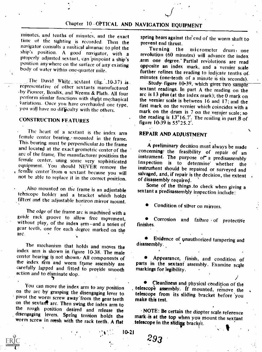
Chapter 10-OPTICAL AND NAVIGATION EQUIPMENT
minutes, and tenths of minutes. and the exacttime of the sighting is recorded, Then thenavigator consults a muitical almanac to plot theship's position. A good navigator, with aproperly adjusted sextant, .con 'pinpoint a ship'sposition anywhere on the surface olany existingbody of water within one-quarter mile.
The David nite_ seAant _10-3 ) is.representative of other sextants manufactured
. by Pioneer, Bendix. and Weems & Math. All fourperform siinilar functions with sligljt mecha9icalitariations. Once you have overhauled one type,you will have no difiiculty with the others.
CONSTRUCTION FEATURES
The heart of a sextant is the index armfemale center bearing,. mounted in the frame.This bearing must be perpendicularAo the frameand located at the exact geometric center of thearc or the frame; The manufacturer positiOns thefemale center, using some very sophisticatedequipment. 'You should NEVER remove thefemlle center 'from it sextant because you willnot be able to replace it in the correct position.
Also mounted on the frame is an adjustabletetescope holder and a bracket which holdsfilters and the adjustable horizon mirror mount.
The, edge of the frame arc is machineCI with aguide rack groove to allow free mpvement,without play, of the index arm -and a series ofgear teeth, one for each degree marked on thearc.
The mechanism that holds and moves theindex arm is shown in figure 10-38. The malecenter beariqg is not shown: All components ofthe index drm and worm frame assembly arecarefully lapped and fitted to provide smoothaction and to eliminate slop.
You can move the index arm to any positionon the arc by grasping the disengaging lever topivot the worm screw away 'from the gear teethon the sextarit arc. Then swing the index arm tothe rough position desired and release thedisengaging levers. Spring tension holds theworm screw in mesh with the rack teeth. A flat
11
spring bears against the'end of the worm shaft toprevent end thrust.
Turning the micrometer drum, onerevolution (60 minutes) will advance the index.arm one degree." Partial revOlutions are readapposite an index mark, and a vernier scaleffirther refines the reading to indicate tenths of.minutes (one-tenth of a minute is six seconds),
-Study-figure .1-0-39; -which --gives--two sifffiplesextant readings. In part A the reading on thearc is 13 plus (at the index mark); the 0 mark onthe vernier scale is between 16 and. 17; and thefirst mark on the vernier which coincides with amark on the drum is 7 on the vernier scale; sothe reading is 13°16.7'. The reading in part.B offigure 10-39 is 55°25.2',
' 10-2.1
REPAIR AND ADJUSTMENT
A preliminary decision must always be madeconcerning,' the feasibility of repair of aninstrument. The purpose or a predisassemblyinspection is to determine whether theinstruthent should be repaired or surveyed andsalvaged, and, if repair is the decision, the extentof disassembly required.
Some of the things .to check when giving asextant a predisassembly inspection include:
Condition of silver on mirrors.
Corrosion and faihire of protectiliefinishes.
Evidence of ynauthorized tampering anddisassembly..
Appearance, finish, and condition ofparts in the sextak assembly. Examine scalemarkings for legibility.
Cleanliness and physical condition of thetelescope assembly. if mounted, remove thetelescope from its sliding bracket before 'youmake this test.
NOTE: Be certain the diopter scale referencemark,is at the top when you mount the sex!anttelescope in the slidip brackt.
293

OYTICALMAN & 2
RETAINER BLOCK'SCREW
SPRING SUPPORTBLOCK SCREW
WORM FRAMEPIVOT SCREW
LOCK NUT
V.
4
WORMFRAME
INDEX ARM
SPRING S F'PORTBLOCk
DISENGAGINGLEVER PIVOT
SCREW
WORM FRAME PIVOTCLAMPING SCREW
END THRUST SPRING
END THRUSTSPRING SCREW
0
WORM RR AM EPIVOT SCREW,
WORM FRAME'
HOLDING SPRINGSTOP SCREW
RETAINER BLOCKDOWEL PIN
WORM FRAMERETAINER BOCK
END THRUSTSCREW
WORM FRAME PIVOTSCREW TENSION WASHER
WORM FRAMEPIVOT SCREW
DISENGAGiNGLEVER SHOE
DISENGAGINGLEVER END
THRUST NUT
DISENGAGING LEVERPIVOT SCREW DISENGAGING
BUSHING LEVER
Figura 10-38.Indox NM and worm frame-numbly.'
`It
137.578
Action of the focusing ri g. It should be caused by dirt or moisture between thesmooth over the entire diopter sc le range, but it individual &tastes of each filter.should be fairlystight.
Polaroid filter assemblies. There should. NOM: Polaroid filters must have abe no cracks or chips, cloudiness, or dark spots protective coating on their-edges.
10-22 294s.
t`.

Chapter 10OPTICAL AND NAVIGATION tQUIPMENT
29.269189)Figure 10-39.Examples of sextant readings.
Rack guide slot. The index arm shouldmove freely over the entire sextant frame. If youfeel any binding, examine the guide slot with aneye loupe to check for burrs.
Endless tangeni worm and arc gear teeth.A sextant's accuracy also depends upon faultlessengageratnt of the worm thread with the arcgear teeth. Careffilly drtss, down any burrsiornicks to prevent bitfaipg and incorrect readings.
NOTE: Do,NOT lubricate the worm thread .and arc gear teeth. Lubricants pick up.duse andother foreign particles which destroy accuracy.
Collimation of the sextant is relatively easy.The index arm and micrometer drum aremechanicallk set to read 0°0', then the indexand hoizon mirrors are adjusted until they areperpendieu-lar- to. plane-of-the-are-and-paraltelto each other. Complete pverhaul inforination
- for the sextant is contalhed in NAVSHIPS250-624-10.
DOD AND QM SPYGLASSES
The OOD and QM spyglasses are 'hand held,straight line of sight, simple terrestrialtelescopes. Figure 10-40 shows two variations ofthe QM glass and one OOD glass. Theseinstrumcnts are basically the same, except forthe larger, longer focal length objective used inthe QM glass. To account for varying focallengths between replacement objective lenses,the objective mount of the QM glass has variousspacers on each side of the lens. The objective_lens of the °on glass uses no - spacers.Charactetistics of the two instruments are asfollows:
s Magnification
OOD QM
10 X 16X
True field 5°30' 3°30'Apparent field 550 56°
Eye distance' 294 mm '28,0 mmExit pupil 3.5 mm 4.0 mm
'10-23
CONSTRUCTION FEATURES
The eyelens, objective lens, ,threaciedexternal tube sections, and setscrews are sealedwith sealing coMpound to eiclude moisturefrom the inside of the Instrument. Focpsing is bya spiral keyway arrangement which is lubricidedwith medium-heavy grease to assist with sealing.
A series of diaphragms is locatedpermanently in the body tube to control
2 95

'14 t44,-%.,411
OPTICALMAN 3 & 24
Float 1040.An OOD spyglass and two OM spyglasses.
aberrations and prevent stray Mil* Anadjustable diaphragm is mounted in the eyepiecedraw tube to codtrol aberrations and frame thefinal image plane. .
Excipt for the objective lens, all optics aremounted in tube sections which thread together.I9gure 10.41 shows a schematic of the opticalkystem (nadrawn to scale).
OILIECTIVE COLL ECTIVEI. NS L ENS
37.3
,. . .The positive. lich.t'csmatic doublet objective
lens forms a' teal, inverted, diMinished image,just beyond the rear Jitirfaee...pf, lie collective
, lens.. I .
/
3
. II, . . 3
, The convex-platio colleitivelens. gathersmarginal rays of light, which vould,otherwise be
, lost, and directs them to the erector. By using ii,
CRIME.LENS
SIALINOWINDOW
TTIO.DOUDLIT.EYEPIECE
AIM
4
I OW eillECTOR SI EN WON
Figur* 1041.Optlesi elements for OOD aitd OM spyglass,., ('4..t 1014
4 ert.(EYEPIECE)
a
. .

Chapter 10OPTICAL ANI$AWAVIGATION EQUIPMENT%.1
collectivejens in this position, you can obtain afairly good field of view with a brlia image.
A doublet erector lens is loCatedapproximately two focal lengths from the
( objective image plane. The greatest curvature of,. this lens is on 'the outer surface of the negative
element, which faces the emiece. The erectorforms a real, diminished, erect image within thefocatiength_ofiht_eyepiece_
A plano-parallel sealing window is shown infigure 10-41, located within the back focaldistance of the elector. Most spyglasses you willwork on have had this4indow removed.
Spyglasses use a two-doublet eyepiece, asshown. The eyelens is slightly smaller than thefield lens, and the rear edge is beveled to provide
.space for sealing compound. The eyepiecepresents a virtual, enlarged, erect image of atarget to the observer.
Two gassing screws on the telescope bodyare used to purge these instruments, since theyare not designed to hold pressure. One screw islocated at the forward erid of the eyepieceMount supiaort tube, the other is hind theobjective.
DISASSENO3LY
Priot to .disassembly, check and inspect theQM and the 001) spyglasses in the same manneras for. any other. optical instrument. Wrii oUrfindings on an ipspection aheet and proce iththe disassemblf, oy consult your shop supe isorfor advice concerning, overhaul of theinstrtiments. N,
1. Remove the setscrew which secu)res theeyepiece mount support tube in the body. tube(fig. I 0-42).. Then unscrew the eyepiece mountsupport tube and Olin it from the body tube.,. ,
.c
2. Remove the setscrew which secures theeyepiece mount to the eyeOiece motint supporttube, and unscrew and separate the eyepiecemount from, the eyepiece. Mount support tube(fig. 1.43).
w .
.137194A;j1-,
'\:\Ftittlf0 1042.--ReleMitle the avealto rnounli:T,tub. setscrew.
,' ,
.1. :ye;,
137.247Figure 1043..Removhtg .the .y*44* motint from the:
eyepieee meant support. tube. I
3. The knurled.focusing ring held on theeyepiece mount so it can be rota3/4ed 4o focus,but unwanted end play is. preiented by twothreaded rings.' One acts as a retainer for thefocusing ring and the other IS a. lockring for theretainer. Remove Ole setscrew from thelockring(fig. 10-44). ,Onscrew the lockring and then theretainer ring from the' eyepiece Mount. Notice'that thee°. tWo rings ale not identical..The
1.025
2,;.:.;41k11:titi:
:..
ki

ORTICALMAN 3 & 2
137.246Figure 1044.Ctemoving the focusing ring lockfing
screw.
lockring has a bevel on each side and the retainer, ring has only one bevel. You may need to uo a"grip wrench to remove the lockring.
, 4. Unscrew the eyepiece cap from theeyepiece drawtube, and slip off the lock and
64 ltetainer rings.
5. Remove the knurled focusing ring byrotating it counterclockwise to disengage it fromthe focusing key, then slide it from the eyepiece
_
137.250Figure 10-45.Runoving the fowngli' key Wows,
6. ReMove the focusing key. 'It is alignedwith two dowel pins and stcured With twoscrews. After rentoving the screws (fig. 10-45);lift the focusing key from the longitudinal slotwith a pair of,tweezers. The dowel pint ihould
. come out with the focusing key; if they do not,remove them from the efeplece drawtube with apair of tweezers. The drawtube L pow' freeWithin the pyepiece mount; remove it by pitllingstraight out.
7. With an adjustable retainer rhig wrench,lo9sen the diaphragm lockring, (fig. 10.46) justienough so that it turns ,freely. Do not 'use theMWrench to remove the lockring completely fromthe drawtube; the wrench may damage the fine**lids on the inner wall of the drawtubc. Vs a
Figure 1040.Removing the diaphragm lookring.A
ip wood stick to remove the Waring. Measurea d record the distance the diaphragm is in the
rawtube. NOTE: The. position' of theiaphragm is very important; it controls
chro aberration.) *Move the diaphragm41 tle same manner you removsits !oaring.
8. Reme the lockring which secures theeyepiece ', lenses . and their spacer.
10-26..
.
J'et,...0k1ACt
e,

Chapter 10OPTICAL AND' NAVIGATION EQUIPMENT
Figure 10-47.Removing the-collective4reetor support tube setscrew.
CAUTION: When you remove the lockring, the. ,Oeld lens and spacer are loose and can easily fall/Out. Thii lockring isalmost the same diameter as
'the diaphragm lockring; do not get these ringsmixed:
9. With a pipe of lens tissue on the planosuifacek of the field lens arid the eyelens, turnthe eyepiece drawtube over and let the field lensand -spacer slide out into yout hand. The rearsurface of the eyelens is sealed, so apply a littlepressure wkth your thumb to brAikhe seal. The-clearance between the lenses andlrit innei wallof the drawtube is so small that iou need topress out the lenses. When you remove the lensesand .spacers from the drawtube, mark them toincliCpte 'the.'direction they face in the drawtube.There is only qne covect way for them to fitOen assembled. Wrap the lenses in lens tissue
,r. 041 stow them in a safe place, away from themetal- parts of the instrument. :
10. Remove the Icrew which secures thecollective.erector mount support tube in heeyepiece mount tube (fig. 10-47) and ullstraight out on the tube to remove it fro theeYeplece Mount
11. Coosa the collective,'less mo nt
lockrIng and unscreW the colactive lens mo ntfrkom the support tube. Remove the Collecti elena`lockring and the collective lón. Then wra
b.
r
137.253
it in lens tissue. NOTE: if this lens has pits,\ scratches, or chips, replaee it. The lens Ismaar
the focal plane of the objective lens; any defecton the collecti've lens is velir apparent In thefield.
12. Remove the erector lens mount lockringfrom the support tube. Be careful to preventdamage to the-fine ihreads on the inner wall of.the suppOrt iube. Remove the erector lensmount from thi support titbe (NOTE: Theerector lens moiint may.corne out of the supp9rttube in reverse of that shownin figure 10-48'.' To .
facilitate c011imatioil,.;this Mort can bemounted either way.) .ReMove the- erector leni
137.204'.Figuro *4Rimy hie thoorlator 110:1110Uftt frosi
0-27
its support tubs.: .

OPTICALMAN 3 & 2
lockring and then the erector lens. Note that theexposed surface of its negative element has thegreatest amount of curvature. Mark the lens andwrap it in lens tissue.
.1.3 Loosen and remove the sealing windowlockring in the eyepiece end of the eyepiecemount support tube. The window is sealed withsealing compound. It' necessary. apply teat to-soften the wax and use a suctioq cup pressedtightly against the window to help break theseal.
14. Loosen the objoctive mount of the OODspyglass with a grip wrench and remove themount. Now remove the objective lockring .andthe objective lens from the inside of the Mount..(NOTE: No setscrew secures the objectivemount to the body tuber The objective monntof-a QM spyglass is pad of the body tube andcannot be removed. The !oaring, spacers, andobjective lens are removed from the front of thebody tube.)
15. Remove the two gassing screws and besure both 'gassing screw odfices aret free ofobstruct ions.
-You have now completed disissembly -of the
QM or OOD spyglass.
REPA1R4EASSEMBLY,AND COELIMATION
.00D and QM spllasses usually needfinishing due to mistreatment and salt.. age. Follow the procedures outlined in
pter 7 if you repaint or cerrkentlenses:'"' .
C6rr4.,c1 Meets noted during disassemblywhich. were not appare,rit -when.you inspectedthe itilstrumenr.". Pay particular attention tothreked support tube sections, Iczckring threads,and retainetring threads. Remove any nicks or-- #
. damage with thread chasers. Clean thesecomponents with a eiean brush and fit them.together to be sure they turn smoothly beforecleaning and mpuntinroptics.
Before replacing the lenses in th0 eyepiecedrawtube, assemble the foctising mechanism toset 0 diopters at mechanical Micithrow. At .thistime you also remove% any play between, thefoctising key and spiral keyway.
With the focusing ring retaining ring midlockring properly tightened to allow Abe-focusing ring-to turn Without e-nd play-,- turnfocusing ring slightly in both directions and'observe the drawtube. If the draw,tube movesWhen the focusing ring is turned,,,the foeusingkey is correct. If any play is evident, you, willhave to spread the ends of the focusing key bytapping lightly with a prick minCh (peeping). Avery slight,...,.amount of peenin`g is ustu.illy,stifficient-do- nOtoverdait. Fit and try until The_focusing-action is smooth and- positiye. ,
*
To -check mechanical Midthrow, turn Ciefocusing ring t& Move the drawtube all lije way,in, then measure the height of the assembly:Now turn the drawtube all-the_ way andmehsurt! again: Position the drawtube fway1between these twp meaSurements-and o seryethe -alignment between the 0 mark oh thediopter ring and the Wei( mark on the focusingrhig. If .they are not perfectly aligned, you willhave to carefully drill and tap a new hole for the,diopter ring lockscrew. k
Disassemble the focusing mechanism againand be sure the components are clean. Place athin bead of.sealing compound around theeyelens seat .and replace the two lenses, spacer,and lockring: Tighten; the lockring enough- toensure 'that the eyelens is 'sealed and seatedproperly. Replace the diaphragm.in its originalposition. .To check for proper -placement of Thediaphragm,lookihrough the eyelens and.look atthe edge of the diaphiagin. You will nOcefringe of :yellow around thiS edge if the..diaphragm is located coritctly when' .theeyepiece) is set to 0 diopters. If not, tura thediaphragm in or out until this condition is Met,then install the diaphragm lockring.
'Now reassemble the collective and erectorlenses and the various internal tube sections.Lubricate ' and reassemble the fottangmechanism, then seal and install the eyepiecemount on the eyoropiece mount support tube.
10-28 .j00

Chlipter 10-OPTICAlt AND -NAVIGATION NUIPMENT
NOTE: If a spaling window is used, replaceand s'eal it- prior -to installing the .eyepiece
P.
mount.4
4 Replace and seal' the objectWe lens mailmount of the- OOD sPyglass. Do not seal-theobjective of the QMglass it 'this tinle,. You may.need tO reposition this lens durintg collimation
_by_shifting spacers. . . . .
Place a piece of fine wire through the holes&hind the collective lens, pull the wire tight,'and twist the ends together to hold it tightly inposition. Now screw, .0e eyepiece mountsuPPort tube into the teieScope body, NOTE:Do not seal the joist at this-time.
.
Place the assembled telescope in V-blocks onany convenient collimator and- use an auxiliarytelescope set to your eyc correction to cheek forparallax between the collimatortarget andauxiliary wire. Remove parallax iy sCrewing thecollective lens mount in- or ou of the supporttube.
When you assemble the eyepiece mountsupport tube and telescope body after each
'adjustment, be sure the joint is tight. If you donot have enough movement on the collectivelens mount of a QM glass, now is .the time toshift objective spacers. Move the lens the samedirection you want the collimator image tomove; thee -Sal the QM glass objective.
After eliminating paraltix, set optical zerodiopters .by adjusting the el.ector lens mount.Use an auxiliary telescope to determinelvhichWay the final image. plane must move so theimage will be is.sharp focus at mechanical zero
Ilijopters.
These are single erector telescopes, so youmust move the erector in the opposite directionyou want the image plane to move. Remember,you can reverse the erector lens and mount ifnecessary: Just be sure the lens is facilig the tightway, or y ou will introduce unwantedaberrations.
With parallax removed and optical zerodiopters set, make sure /till c011eotive mount
lOckring,.erector, lockring, and collective erectorsuPport tube setscrew are tight. Make'a finalcheck for paraliax, thqn remove the aiixi4arywiie. Now you.tan 'seal the eyepiece mountsupport tube.a 'd replace and seal the setscrew'in
flie, telescope body. Ilurge thst4nStrument as'explained In C apter 8 and reflace and seal the.. .,
gassing screws. .1
. .
a1 ,
When the -instrument "passes' a----- -final-- .
inspection for cleanliness, collimation, focusingaction, and appearance -your work is finished,
U.
StlIP TELESCOPE
The ship telesvope (fig.10-49) is a change ofpower observition instrument with a porroprism erecting sysiem. It is 'mounted on theopen bridge of still's in 'a yoke that allows it tobe elevated within practical limits and trained inany direction. Change of Power is provided by'four 'interchangeable eyepieces of I3X, 21X',25X, and 32X. The12IX eyepiece is orthctiscopic,while the others are Kenn& types. Since thisinstrument is exposed to salt spray and all typesof weather, all joints and lenses are sealed withsealing compound to exclude moisture. There isno provision to gas or purge the ship telescope.
CONSTRUCTION-FEATURES
The optical syotem and 'basic mechanicalassembly are shown in figure 10.60. These arerelatively simple telescope44 with fewadjustments. However, yoy will come acrosssome instruments in such poor condition. that
4hey will tax your skill as an Opticalman.
.10-29
. 'itoY
^
The objective mount is threaded externallyso it can be attached td and positioned in .thebody tube. A' lockring hOlds the mount inposition and a sunshade screws on to theoutboard side of the mount. The front sightvane functions as a lock screw for the objectivemount.
Since the objective lens is too large tocement, the elements are separated by three
3 oi

OPTICALMAN 3 & 2
V.
A. Sunshade esegnblyB. Sighting vansC. [Hooter moleD. Eyepiece assembly
E. Filter shaft knobF. thip handleG. Eyepito osierH. Yoke assembly
Figure 1049.Merk 1 Mod 0 ship teiescope.
equalljr,' spaced tinloil shims .001 to .002 inch. thick. A sPring ring backed by a retainer ringholds the lens in thi mount.
. All other Conlponents of the sh)p tplesCopeare rAounted on a prism box which threads intothe iloody tube (fig.10-51). A lockring holds,this,
..
37.2
prism box in position and the rear sight vaneserves% a setscrew.
rA filter plate, controlled by a s,haft througti
the prilim box, is located within the objectivefocal letigth. A. clear piano parallel compensator.(to 0minate a. change in Objective focal

Chapter 10OPTICAL AND NAVIGATION EQUIPMENT
SIGH TING VANE
FOCUSING RING(DIOPTER SCALE)
COLLECTIVE LENS
13X EYEP ECE
SIGHTING VANE EYk LENS
PRISM CLUSTER
FOCAL PLANE OFOBJECT IMAGE
OBJECTIVE LENSASSEMBLY
(TWO INDIVIDUAL LENSES)
FIL T ER6
BALL DETENT FILTER SHAFT KNOB
Oigure 10-50.Optical system of Mk 1 Mod 0, ship telescope.
RAY FILTER ASSEMBLY
4
EYEPIECE FOCUSINGASSEMBLY
Figure 10.51.:-Prism box, filter, and eyepiece foousing assemblyexploded view.
A-3
303
37.5
4.
137.529

OPTICALMAN 3 & 2
distance), -a light blue filter, and a single darkpolarokt filter are mounted in the filter plate.The polaroid filter is oriented to reduce glarywhen it is'in the line'of sight.
The porro pfism cluster, as usual, can beadjusteh to remove lean. Fins Ilx, .the multiplelead focusing mechanism is sectired to theoutside of the prism box. The four matchedeyepieces screw info .thet focusing tube sO the
-operator-ean-easily-changelhem
REPAIR AND ADJUSTMENT
The ship 'telescope is mostly constructedfrom aluminum. Even yogr best efforts to sealjoints may_ eventually fail and allow saltcorrosion, making disassimbly difficult. Sincethe sunshade and body are quite thin, you willneed to make fitted wooden clamp blocks tohold the telescope securely without crushing.cluring disagembly.
.
Complete overhaul- and collimatiokhinstrucions are fo d in NAVSHIPS 250-624-3.
The 'only unusual departure from. normal repairand collimation rocedures is parfocalizing thetotor eyepiecee Each eyepiece must focus withCt 1/4 chopter of the otherf. To do this, machinea predetermined amount of metal flrom themounting shoulder of the eyepiece(s) inerror.
TELESCOPE ALIDADE
The telescopic alidade is a .portablanavigational instrument used by personnelaboard ship to accurately measure the bearing ofdistant objects. When in use, a telescopic alidade.is plated over the ship's Magnetic compass orgyro repeater, and the observer sees a magnifiedimage of 'the target (6X) aligned with a verticalwire, combined with an linage of a level vial andcompass card in the upper part of the field.
The two instruments shown in figure 10-52are identical, except for the size of theidapterring which fits different gyro repeater* orcompasses.
45.39Nu 10452.--Mavk 6 add 7 Mown* alidgdos.
CONSTRUCTION FEATURES
The Mk 6 and Mk 7-alidades are sastight,aluminum bodied, dual. line &light instrumentswith an inteenal focusing eyepiece which focusesthe main, -and auxiliary oplical systems. Theoptical,schematic i,s shoWn innigure 10-53.
The main optical system consists of anobjective lens, a filter assembly, a Schmidt prism

\
Chapter '10OPTICAL 'AND NAVI6ATION 'EQUIPMENT
I. EYEPIECE LENS 8. OIVECTIVE2. EYEPIECE CENTER LENS 97. WINDOW (SEALING)3. EYEPIECE EYELENS 10. AUX O.S. ERECTOR LENS11. SCHMIDT plush+ II. AUX O.S. COMBANNER LENS5. AUX O.S. VISION 12. AUX 0.5. COMB. OUTER LENS6. POLARIZING.FIL TER 13. FRONT SURFACE MIRROR7, COMPENSATOR 14. LEVEL VIAL
0
MAIN OPTIcAL SY TEMLINE Or SIGHT
13
Onpi
V
AUX. OPT AL SYS.LINE SIGHT
0 MASK a arrieut.WIRE (IMAGE PLANE
op
leli,FILTERROTATIONAL. riCENTER
I I 0
1r
A. JROTATEDPOSITION
4
0 0
0
0
Figure 10-53.General optical arrangement Mk 6 and 7 alidade.
(erects the image and directs it toward theeyepiece at a 45° angle), and the eyepiecesystem. The filter assembly consists of a fixedand, movable polaroid and clear compensator.'A large knob on the right side of the alidadedrives the filter assembly (in br out of Ihe line ofsight), while a Smaller knob through the center.of the large knob controls 'polaroid density.
The 6bjective lens is adjitstable along theoptical axis to correct for parallax between thetarget and crosswire. \
The Schmidt prisni is bonded io a postwhich is held to the prisiti mounfing plate withthree screws. Tbe screws lave enough clearanceso-the prism post 6ati be adjusted up br down,fore and aft, or rotated slightly in a verticalplane.
The auxiliary optical system consists of asealing window (-9), a front surface aluminized
t.
MASK & RETICLE"WIRE- AY IMAGE-PLANE
EYEPOINT
137.535
mirror (13), an inner and outer objective (11,12), two identical erector lenses (10), and theauxiliary system prism.
The auxiliary mirror is bonded to a threadedplug which screws in or out of the alidade body,This alloWS you to raiSe or lower the compasscard image in the auxiliary field of view and tocorrect for tilt orlean in the auxiliary field.
The two objectives share a common cell, asdo the-erectors, and both cells are threaded foradjustment along the auxiliary axis.
The auxliary prism (5) is. Mounted andadjusted in the same manne as the main prism.
A metal plate and ne crosswire aremounted at the commodfmage plane of themain and auxiliary optical ystems.
The itnagc of the level via) (14) will alWaysbe slightly out of, focus since i is positioned
10-3J
'305

e
OPTICALMAN 3 & 2
approximately I _MO above the compass or,repeater.
IMPAIR AND' ADRISTMVNT
. After you have acquired some experience' repairing.optical in malts, you will proVablydiscover that the M 6 and Mk 7 alidades aremade to be replace , rather thaw repaired. Thisis-unneceMitify ek pensive, and frustrating to agood repairman.
The complete overhaul procedure, as well asdrawings and parts lists, is contained in
PLANE OF REAL IMAGE FORMEDBy OBJECTIVE LENS
NAVSHIP$ 324-0488. Basically, collimationconsists of aligning a collimating stand on thecollimatot (Mk 4b adjusting the main opticalsystem, and adjusting the auxiliary opticalsystem.
Once the instrument is collinlated andsealed, you must test for leakS, dry the interioiwith nitrogen, and charge it to 4 psi pressure.
BINOCULARS
Everyone knows whit binoculars are, but. now you will learn something about them. We
EYE LENS COLLECTIVE'LENS(CEMENTED DOOLET)
PORROR PRISMS
HINGE
LIFTTELESCOPE
OBJECTIVE LENS(CEMENTED DOUBLtr
Figure 1044.Croes section of a binocular system.
10-34
,\08
RIGHTTELESCOPE
137.4.5

Chapter 107OPTICAL AND NAVIGATION EQUIPMENT
will discuss two basic types', the hand hekl7 X 50 and the mounted 10 X 120. Thenumbers 7 and .20 refer to Magnification, and SOand 1.20 indicate the, $ize of the objective -lensopening in millinteters.
7 X 30 BINOCULARS
The optical 4,stem and- mechanicalarrangement, shown in figure 10-54, aregenerally common to all current hand held.binoculars. In effect, ther,e are two separate,prfsm erected telescopes joined by a hinge sopeople with dilferent eye separations can use theinstruments comfortably. 7X has beendetermined to be about the highest practical .
magnification .for han4 held binoculars. Anymore power would cause excessive targetmotion, and any less would not, bring outsufficient detail on the target. The .50-Mmoblective lens has very good light gathering
OBJECTIVE G.AP
OBJECTIVE LOCK MG
OBJECTIVE ECCENTRICRING LOCK SCREW
ability under all .weather conditions. In fact,bimiculars used by the Navy can be usedeffectively half an hour before sunrise and halfan hour after sunset. The wide separationbetween. the objective lenses increases youref feet iv e i nterpupillary distance, therebyincreasing your range of stereoscopic vision.-(Stereoscopic vision is directly related to yourability to judge relative distance . betweenObjects.)
CONSTRUCTION FEATURES
The Mk 28 and Mk 29 binoculars arepractically identical, except that the Mk 39 has a
reticle mounted on the right plism plate (fig.10-55). These two instruments are sealed againstmoisture by sealing compound in lens mountsand joints between body and covers, and byheavy ,grease on the eyepiece cell. The prismplates i`fre miunted on lugs inside the body and
OBJECTIVE LOCK RINGSST SCREW
OBJECTIVEGASKET RING
' IOBJECTIVE CASKET
\
OBJECTIVE ANDMOUNT ASSEMBLY,
4:,
LFFT BODY
RIGHT BODY
iiRETICLE MOUJNT
POST
iS
RIGHT PRISM CLUSTER
RETICLE MOUNT
E---.SPRING
RETICLE.ASSEMBLY
PRISM PLATESCREW
RETICLE MOUNTSPRING .
Figure 10416.Binocular objective end prism clutter Mk 28 and reticle nimbly Mk 39.
. \10735 307
137.471

OPTICALMAN 3 & 2
the objective assembly slips into a recess in thefront.of the body.
The Ail( 32 has several changes; mainly toUnprove sealing the instrument. ,It also has anobjective adapter which screws into, thebinocular body. See figure 10-56.
Two types of eyepiece assemblies are shown.in figure 10-57. Again the major differencebetween the Mk 28 and Mk 39 and thv Mk 32 isin the prov ision_ for sealing the instruments.
An exploded view of a prism cluster,common to the Mk 28, Mk 32, amr yk 39 isshown in figure 10-58.
The hinge is the heart of a,pair of binoculars.It must operate smoothly but provide enoughtension to hold the two bodies in position. Itforms the. mechanical axis of the instrummt.
OBJECTIVE CAP
OBJECTIVE LOCK ZINO
OBJECTIVE
Figure 10-59 shows tilt hinge mechanistic usedon the binoculars disculted so far. The taperedhiilge axle is kept from turning b), splines which)mate with the upper left body lug. Yot willencounter some variations that use two dowelpins rather than splines between the hinge axleMid the body lug.
When a hinge is ploperly assembled, theheight Or the TWo bodiis must_b<Lequal. Theremust be .004-inch greaseo:.learancetween thehinge axle and the tapered hinge tube- (rightbody), These factors -are controlkd by theseating depth of the axle in the left body lug(upper) and various thickness hinge washersbetween the body lugs. The seating depth of thehinge axle is determined by the upper and loweraxle screws.
Improper lubrication, incorrect adjustment,or grit or burrs on hinge components can causeproblems with the hinge action.
MOUNT-TO-ADAPTERGASKET
OBJECTIVE ANDMOUNT ASSEMBLY
OBJECTIVE LOCK, WINGSET SCRE4
OBJECTIVE ECCENTRICRING LOCK SCREW
L EF T BINOCUL ARASSEMBLY
,ccetil
,
OBJECTIVEADAPTER
NINNY
OBJECTIVETO-BODYGASkV
'1
I.
RIGHT.BODY
Figur* 10-etExploded view Mk 32 binocular.
t
10-36, 308
EYEPIECE AND COVERASSEMBLY
COVER SCREWWASHER 'A"
COVE,R SCREW'WASHER -11*
COVER GASKET - COVER SCREWS,
137,.373
4

. Chapter I Q-OPTICAL AND NAVIGATION ebUIPMENT
EYEPIECE CAP
.CLAMP RING
EYEPIECE
EY EP1ECESTOP RING
EYEPIECELENS MOUNT
RIGHT COVER
CLAmP RINGLOCK -SCR-fri
KNURL EDFOCUSING
RING
RIGHT, COVER
ANDEYEPIECE
MOUNTASSEMBLY
EYEPIECELENS SPACER
EYE LENS
tOLLECTIVELENS
COLLECTIVE LENSRETAINER RING
Mk 32
EYEPIECE CAVA
EY EPIECECLAMP 14)/NG
EYEPIECESTOP RING
COVER PLATENECK GASKET
EYEPIECELENS MOUNT
RIGHT COVER
CLAMP RI GLOCK SC
KNURLEDFOCUSING
RING
' EYEPIECESE'AI IN G. RING
EYE LENS
COLLECTIVELENS
%AO
RIGHTOVERAND
EYEPIECEMOUNT
ASSEMBLY
EYE` LENSGASKET
EYE LENS14.ttETAINER RING
COLLECTIVELENS
F4ETAINER RING
Mic 28 and Mk 39
Nun 1047.Eyopione end cover asomblies Mk 28 and Mk 39 and Mk 32.
I 0-37;
137.880

OPTICALMAN 3. & 2
, .
PRISM CLIP
.PRISM POST
RISM CLIPCREW
PRISM CLIPPAD
PRISMCOLLARSCREW
PRISMPLATEDOWEL.
PIN - -
PRISM SHIELD
°ORRO PRISM
PRISM COLLAR
RIGHT PRISMPLATE
PRISMCOLLAR
PRISMCOL L ARSCREW
PRISM CLIPPAD
PRISM POST "C"
PRISM CLIP .
SCR.EW
PORRCPRISM
PRISMSHIELD
PRISM POST"D"
PRISM CLIP
137.581Figure 10.89;Porro prism duster Mk 29, Mk 32, Mk 39..
INTERPUPILLARYDISTANCE SCALE
UPPER HINGEWASHERS
UPPER AXLE(CELLULOSEAC TE) SCREW
INTERPUPILL'ARYSCALE RETAINER
SCREW
F4JRIRIGHT BODYHINGE LUG- (UPPER)
LEFT BODYHINGE LUG
(UPPER)
HINGEAXLE
(TAPERED)
HINGEAXLE
(TAPERED)
HINGE GREASERESERVOIR
LUBRICANTFILM,
LEFT BODYHINGE LUG
(LOW,ER)
LOWER AXLESCREW
RIGHT BODYHINGE LUG
(LOWER)
LOWER HINGEWASHERS
(CELLULOSEACETATE)
137.454.Figure -10-50.Hinge mechanism (Mk 28, 32, and 39
binoculars).
10-38 ,) 0, I

-Chapter . OPTICAL AND
Where the Mk 28, Mk 32, and Mk 39binocuiars *, share ,some common mechanicalfeatures, the mk As binocular is completelydifferent intonstruction ( fig. 10-60). The designof the Mk 45 makes it practically waterproof.There are many reported instances when these
%instruments were submerged to depth of 100'feet and did not leak.
The Mk 45 eyepiece assembly (fig. 10-61) issomewhat similar to the Mk 32, but the prismcluster (fig. 10-62) is entirely different. Alsonotice that the prism Cluster of the Mk 45mounts on posts on the 'underside of the coverplates. 1:dur prism locating shoes are used to
-locate and adjiist each prism.The hinge assembly of the Mk 45 is also very
different (fig. 10-63). Instead of using a tapered
OBJECTIVE CAP
NAVICkATION EQUIPMENT,
OBJECTIVE MOUNTGASKET
OBJECTIVE ANDMOUNT ASSEMBLY
OBJECTIVEADAPTEROV ECTIve
LOCK RING
OBJECTIVE MOUNTGASKET RING
40BJECTIVESET SCREW
hinge axle, split bronze bearings sere* onto eachend of a straight hinge axl,e. As those bearingscontact brass hinge thrust washers, furtherrotation 'forces them to expand and contactbearing surfaces machined in the right hingeIngs. Correct lubrication, tension' adjpstment,and corrosion preVention are essential to'smoothoperation of the Mk 45 hinge.
OVERIttAlfkir
As an Opticalman, you will wo on morebinoculars Alian all other instruments combined.Some binoculars will be setit to the optical shopin excellent condition, others will be basketcases. A good casualty analysis will indicate theextent of repair and disassembly necessary. Donot disturb any mOre than necessary to do a
OBJECTIVE-TO-BODYGASKET
Morro 1040.Mk 45,,7 X 50 binocular numblyexplodedview.
,10-\S9
31
137.541

OPTICALMAN 3 & 2
CLAMP RINGLOCK SCREW
I
EYEPIECE CAP
EYEPIECECLAMP RING
'EYEPIECESTOP RING
EYEPrECEGASKET RING
RIGHTCOVER
EYEPIECE .
LENS MOUNT
EYE LENS
COLLECTIVELENS
KNURLEDFOCUSING
RING
EY EPI ECE"0" RING
PRISMSHIELD
PRISM CLIPSCREW
PRISM CLIPPAD
0
'PRISM SHOESCREW
PRISM (LOCATINQ
SHOE
EYEPIECEL EMS MOUNT
GoVSK ET PORRQPRISM
RIGHTCOVERAND
EYEPIECEMOUNT
ASSEMBLY
EYEPIECEGASKET
. EYE LENS' RETAINER RING
COLLECTIVELENS
RETAINER RING
PRISM SHOEECCENTRIC°
WASHER
PRISM CLIPPAD
PRISM CLIPSCREW .
PRISMSHIELD
PRISM CLIP
137.583Figure 1882.-Mk 45 binocular prism cluster.
typical outstanding overhaul. It does not makeany difference whether you disassemble theobjectives or the eyepiece and cover assembliesfirst, but save the hinge for last. Likewise, if youmu st co mpletely disassemble a pair ofbinoculars, reassemble and adjust the hingebefore instalting optics.
NOTE: The hinge of hand held binoculars131.582 receives considerable wear; therefore the hinge
Figure 10-81.Mk 45 binocular eyepiece and covar of each pair of binoculars sent to the shopshould be checked, lubricated, and -readjusted..
164031
aseembly.
,

6
1
. -Chapter 10 OPTICAL AND NAVIGA ION EQUIPMENT.
HINGE IN TERPUPILLARYLOCK DISTANCE SCALE
GASKIT
HINGEE.X P AN ID IN G
BEARING
HINGELOCK
LEFT BODYHINGE LUG
(UPPER)
HINGEBEARINGTHRUSTWASHER
HINGETUBE
LEFT BODYHiNGE LUG(LOWER)
RIGHT BODYt HINGE LUG
(UPPER)
SPLINE
HINGEAXLE
RI9HT BODYHINGE LUG(LOWER)
HINGELOCK
GASKET
HINGEEXPANDING
BEARING
HINGEBEARINGTHRUSTWASHER
HINGEGREASE FITTING LOCK
137.640Figure 1063.Mk 45 hinge mechanism.
Aiwa reptace gaskets, where attropriate,and never iterchange optics or mechanical partsbe t woen bodies. Bintoculars can be,temperamen al if you start switching parts, V10use a compa trdented parts box to- keep themseparated. Eve with excellent quality control,dimensions of 1 echanical compon6ts will varyslightly, lenses will have 'minor focal lengthdifferencgs, and prisms will. pot always. beidentical. Use a ns centering instrument tocheck focal length of lenses, and make a sidevisu al inspection to de termine variationsbetween mechanical components. The seatingdepth ot' objective len es in their mounts can betroublesome at times, eapecially if different sizeprisms are used in each telescope.
To compare prisms fo size, place them in aV-block protected by a she t of' lens tissue. Theentrancelemergence face ot he larger prism willbe higher than the correspon s ing surface of theother -prism. Replacing any p ism in a pair ofbinoculars, with one of larger si es will lower theeyepiece in that telescope. The onverging lightfrom the objectiw has to travel urther in thelarger prism, therefore it comes to a focusfarther from the eyepieee (see figure 10-54), andyou' have to turn the eyepiece in t focus theimage.
Cleanliness is just as important in .bi oeularsas it is in any other instrument. Dust or masersmudges willreduce light transmissions-and hesedefects can be seen on the optics. The colleLtive .
lens is very close to the objectiveimage plane soany specks or lint will be magnified and yeobvious. *Remove grease from all lens mountbefore you attempt to replace the lenses.
When ,you. remove the eyepiece cells fromthe cover plates, mark the _relationship betweenthese parts so you can reassemble, then) Milliesame positionespecially if focusing actioi isequal between them. If focusing actiofi is notequals, try a different lead on the multiple lepdthread. Eyepiece cells of the Mk 28, 32, and 3,9are removed from the top'. The Mk 45-should beremoved from the bottom-.
Apply- lubrication to the eyepieces andobjective eccentric rings during final assembly.
10-41

. -OPTIcALMAN 3 & 2
Likewise, use antiscize on cover screw threads,objective cap threads, :and. threads of theobjective adapters (where appropriate).
Oft.
COLLIMATION
-5
Prism cltister assembly is a very importantpart of binocular collimation. If this is nOf doneproperly, you May not bcoble.to collimate' yourbinocularS without disassembling one or.. bothclusters to find the problem. Porro prisni clusteradjustments were disclissed in Chapter 8.
The assembled 4inocular (except forobjective sears lockrings, and objective caps) ismounted on a Mk. 5 collimator, as shown infigure 10-64. Notice that the binocular ismounted upside down, and the right hinge lug isclamped in the fixture so thOeft body is free tomove.
Using an auxiliary tele. .ope with thomboidatkochment, focus both f eyepieces on the
vollimator target and set thi) focusing ringsfto)..ero diopters (within ±1/4 dioptef of eachothea At this time. the eyepieces should be Ofequal height, within 1/16 inch. (Cheek with astraightedge.) Also.check for lean by ComparingthF magnified collimatqr target, seen throughthe eyepieces, with the Adler collimator targetpicked up by the rhomboid attachment. Correct.any.problenis noted beforeproceeding.
To align both lines' of -sight with the hingeaxis, rise the taii-of-arc method; explained next.
I. Siwing the left body alt-thc..-way up toshow approximately 58 mm on the IPb scale.Using the anxiliary telescope, adjust the screwson the collimator fixture to align the normal andmagnifta target image. See figure 10-65.
2. Now swing thelat body down to obtainthe widest separaticat betweeit 'ey es(74 mm). What you see through the auxi arytelescope shoilld be shnilar to figure 10-66. Thesmaller target *(A) is a stationary ft ference
MK 5 COLLIMAJOR
--`efegsfr.
AUXILIARY TELESCOPE
a.
Figure 10-64. Mark 5 binoculaV collimator,
10-42 31 /
1.
137.489

Chapter 10OPTICAL AND NAVIGATION EQ6IPMENT
1.4 137.490 ,
Figure 10-85.Collimator croulines superimposed at58 mm interpupillary distance.
avt-_
picked uplsy the rhomboid. the magnifiedtarget (B), seen through the left barrel, showshow far the line of Aight deviates fromparallelism with they hinge. NOTE: To makecollimation easier, the objective eccentric ringsshould be set for minimum displacement whenassembled.
3. To adjusi the line of sight, firt,construct an imaginaryzyquilateral triangle'shown by points A. B, anef C in figure 10-66.Point C must always be figured in a clockwisedirection from point B, regardless of where theMagnified crossline ends up after swinging theleft body. NOTE: The small crOssline Mayappear tO mov,e.
, 4. With the left telescope still at 74 mm1PD, Manipulate the objective eccentrics to placethe mignified target _tillage (B) in the tkrea ofimaginary point (C). Try to make thisadjustment without disturbing the binocular onthe c011imator fixture. NOTE:. First, rotate theentire objectiVe assembly (inner and outereccentric). If this does not move the magnifiedtarget to point C, throw some eccentricity into
1043
I I I 1 1
137.492Fi9ure 10-86.Preliminary step in binocular tail-Of-arc
collimation
the objective and rotate the complete assemblyagain.
5. After you are-satisfied that the crosslineis near point C, swing the left body back to54 mm IPD and adjust the collimator fixture tosuperimpose the two crosslines (fig. 10165).Repeat steps.. 2 through .5 until there is nodisplacement of the magnified crossline whenyou swing the left barrel from 54 mm to 74 mm. ;
, If you find there is not enough eccentricityin the lett objective to satisfy colliinationrequirements, you will have to shift prisms.After shifting prisms, check zero diopters, equaleyepiece height, . and lean again beforerecollimating.
6. Once the left body is collimated, swingthat body, down to .approximately 64 mitt*,realign the two crosslines, by adjusting thecollimator fixture, and adjust the right objeetiveto superimpose the two crosslines seen throughthe anxiliary telescow. Recheck 'the left andright bodies to be sure you hive -perfectlysuperimposed the erosslines. NOTt: If, you *

QPTICALMAN 3 & 2
Cannot superimpose the line of sight with theright objective eceentrics, shift prisms andproceed as Mdicated in step 5 above.
7. Tighten the eccentric lock screws,.replace gaskets and rings, replace arid lock theobjective lockring, and replam the objectivecaps. NOTE: Tightening the eccentric lockscrews ahd the objective lock rings may throwc.041thiation off. Recheck and adjust asnecessary.
Collimation tolerance for both lines of sightM a binocular are specified as (a) 2' step (verticaldisplacement), 09 4' divergence (outwardseparation), and (c) 2' convelrgence. Thesetolerances represent government performancestandards for binoculars. You Will not find anoptical shop . supervisor who will accept thesesloppy tolerances. If your collimation is notperfect, it is-not good enough.
Complete overhaul infgrmation for_ Navyhand 4eld binoculars is found in NAVSHIPS250-624-2.
At this point w.;5 must warn you, abputdifferences in importVd.binoculars. U.S. militarybinoculars are the best in the world, and *theycost about $350 each. If you pay $35 to -$120for an import, the cost is.comparable to quality.Optically, imported prismatic binoculars areexcellent, but collimation is difficult due toloose tolerahces, no eccentrics on somp models,and sloppy prism mounting. In fact, prisms ateglued in some theaper models. Power is alsoexcessive, sometimes as hikh as 20X in a handheld instrument.
Another cheap shortcut found in manyimports is .the use of a center focusingarrangement, rather Plan individual focusingeyepieces. In this system, a -large focus knobmounted on top of the hinge drives a multiplelead shaft up or down inside the hinge. Attachedto the top of the shaft by another hinge are thetwo eyepieces which slide up or down on tubesscrewed into the top cover plates. To accountfor differences in diopter settipg between theleft and right eye, the right eyepiece is focusedin titosilittfirmanner.
The mikior sitortcoming of ceniter focusbinoculars is that close fitting of slidingcomponents is not possible if the focusingmechanism is going to work at all. The loosefitting eyepieces,- combined with highmagnification and sloppy prism mounting, willbe the ultimate test of yoUr skill and patience ifyou ever at terript to repair such binoculars.
SHIP MOUNTED BINOCULAR
A completed ship binocular is shown infigure 10-67. The optical arrangement is similarto hand held binoculars except that polaroidfilters and clear compensators are provided, andthe ship binocular uses an internal focusingeyepiece. Characteristics of the ship binocularfollow:
Magnificatiou 20 power
Clear aperture of objective . . . . 120 mmTrue field of view 3°30'Eye distance at zerodiopters 22 5 mm
Apparent field (approx ) 70°Exit pupil 6 mm
Interpupillary distance 56-74 mm
Ovetall binocular length(sunshade extended) 20 375 inches
kverall binocular width 22.5 inches
Construction Features
The Navy uses three similar types of ship'. binoculars, the Mk 3 Mod 1, Mk 3 Mod 2, and
the Mk 3 Mod 4. An exploded view of the Mk 3Mod 4 is shown in figure 10-68. This instrumentmay look like a nightmare, but it really isn'tverY complicated.
Most ship binoculars are sealed with 0-rings,packing, .and sealing compound to maintain aninternal pressure of 2, psi. Two shafts extendthrough the eyepiece housing. One controls the.

Chapter 10OPTICAL AND NAVIGATION EOUIPMENT
1. BINOCULAR ASSEMBLY
2, CARRIAGE ASSEMBL Y
3. BUL K HE AD BRACK E T
4. PEDESTAL ASSEMBL
5. SWIVELLING EYEBOLTS
Firm 10-117.Ship binocular.
filter assembly, the other moves both:eyepiecesto set the user's IPD. NOTE: As you can see infigure 10.68, there is no hinge connecting thetwo telescopes of -a ship binocular. The twoeyepieces are gear driven to move in oppositedirections.
411.
59.18
The two elements of each objective, areseparated by a spacer. Various spacers, seals, andlockrings fit into the,objective tube to completethe objectife assembly. The major differencebetween the Mk 3 Mod 1 and Mk 3 Mods 2, 3,
. and 4 is the means for adjusting the objectives
1045
3V7

OPTICALMAN & 2
during collimation. In tbe Mk 3 Mod 4(illustrated) eceentric buttons (30) are used toshift the objective assembly. 'Fhe Mk 3 Mod Iuses eceentric rings. Complete information onoverhaul, adjustment collimation, sealing ,. anddrying is found in NAVShIPS 324-0516 andNAVSEA S9421-AA-MMA-010.
BORESIGIIT TELESCOPES
k
As the name implies, a boresight is used toaccura yy ahgn the point of aim of a naval gunwith associated sighting eq uipment andmechanisms. A typical setup is shown in figure
410
FOCUSING
10-69. The boresight is mounted on a breechbar, which centers it* in the breech, and a closefifted muzzle disc, with centered peep hole, isslipped in the muzzle. The boresight can beadjusted to center a crossline on the muzzle disc,then the boresight can be focused on a selectedexternal target so associated equipment can bealigned to the gun bore on the same target.
CONSTRUCTION FEATORES
Two similar initruments are shown incutaway form in figures 10-70 and 10.-71. Eventhough there are some optical and nwchanicaldifferences, the horesights are interchangeable infunction.
RING
PARALLAX-ADJUSTING RING
BREECH OAR
TELESCOPE TUBE
LOOKINS RING
ROTATINGRING
OUTSIDEADJUSTING TUBE
SPEECH BAR
BORESIGHT TELESCOPE
SPHERICALSEARING
FLOATING SHOE
ADJUSTINGSCREW
REECH OF GUN
MUZZLE DISC
110,e0Figure 10-89.Typical boresighting.tquipment.
10-4631

Chapter 10OPTICAL AND NAV1C, T1ON EQU1PMENt
SPIRAL SLEEVE REARSCREW ERECTING
LENEYEPIECE
COLLECTIVELENS__
EYELENS
EYEGUARD
EYEPIECEFOCUSING RING
ROTATINGRING
FRONT CROSSLINE LENS TELESCOPEERECTING ADJUSTING SCREW LOCK RINGL NS
CROSSLINE LENS
ERECTING SYSTEMTELESCOPE
ADAPTOR OBJECTIVE DRAW TUBE
OBJECTIVE/ LENS
BODY TUBE
DRAW TUBE7 SPIRAL OBJECTIVE ADJUSTINGKEY FOCUSING RING SCREW ADJUSTING SCREW HOUSING
A. CUTAWAY VIEW
YELENS COLLECTIVE LENS CROSSLINE LENS OBJECTIVE LENS
V
REAR ERECTING LENSFRONT
ERECTING LENS
B. LENS SYSTEM
PLAN VIEW OF CROSSLINES
.
Figuri 1,0-70.Optical and mechanical system of a Mk 8 Mod 6 boresight.'
CtOtical characteristics of the two boresightsarc listed below:
Mk 8 Mod
Magn i fica t ion 9.0X
Field 2°30'
Exit pupil 2.3 mm
Eye distance 11.0 mm
Mk 75 Mod I
Magnification 8X
Field 30 20'
Exit pupil 2.5 mm
Eye distance 19.4 mm
Notice that these boresights havb .a smallfield angle and a tiny exit pupil. Consideringthat they are used only for infrequent alignmentpurposes, these features are not objectionable.
137.270(271)
10-47
2V

.OPTICALMAN 3 &
ERECTINGEYEPIECE LENSES
COLLEtTIVE LENS
EYELENS
DIOPTERSETTING RING/
KEY
CROSSLINELENS
_
TELESCOPELOCK RING
DIAPHRAGM
REAR FRONT
EYELENS EYELENS
KEY D AW CioSSLINE ,
TUBE LENS MOUNTTELESCOPE
A9APTOR
FOCUSINGRING TELESCOPE ADJUSTING SCREW
A. CUTAWAY VIEW
FRONTERECTI LENS
ROSSLINE LENSOBJECTIVE LENS
OBJECTIVELENS
BODY TOBE
REAR ERECTING LENS
6 mm
6 mm
PLAN VIEW OF CROSSLINES
B. LENS SYSTEM.
, Figura 10-71.Opticai and machanical systam of a Mk 75 Mod 1 boresight.
Another necessary characteristic for aboresight is the ability to focus on objects atvarious distances: The Mk 8 Mod 6 can focus onobjects' from 6 *feet tit infinity. This isaccomplished by mountingihe objective lens ina draw tube so it can be moved in relation to afixed eroesline to provide a parallax-free view ofthe target. The eyepiece system .of the Mk 8MOd 6 is alsd in a fixed position. Focusing ispeovided by mounting the erecting system in adraw 'tube.,
The Mk 75 Mod 1 boresight is capable 'offocusing on objects between 10 feet andinfinity. In this telescope, the objective is fixed
10-48
84.207(137.257)
and the crossline and erectors are mounted in adrawtube. It is also a focusing eyepiece,
As you can see in figures 10-70 ahd 10-71both telescopes have` a spherical bearing on thebody- tube which fits ,a socket in the telescope ,4"'dadapter. When the telescope adapter is screwedinto a fixture and secured with the telescopelockring, the four telescope adjusting screws canbe manipulated to accurately position ihe line of .
sight.Notice in figure 10-72 the Mk 8 Mod 6
boresight has a rotating ring and crosslineadjusting screws. This feature allows you to

Chapter 10 --OPTICAL AND NAVIGATION EQUIPMENT
remove eccentricity between the target andcrossline. The Mk 75 Mod I does not have thisFeature because the crossline lens is accuratelyground to be perfectly concentric with thecrossline and the mounts and body tubes.
REPAIR AND ADJUSTMENT
Boresight telescopes are sturdy but delicate.Th4. -are stored in a protective box most athetime. However, accidents do happen. Usually,
they are sent to the optical shop only fordeving and lubrication,
In a boresight, screws are small, threads arevery fine, the lenses are sinall, and mating partsare closely fitted. Yod must be very careful
. when disassembly is necessary to avoid damagingor deforming any parts. It would be advisable tomake some special tools for removing lockrings.
The complete description and overhaulProCediires for the Mk .8 Mod 6 and Mk 75 Mod1.boresights is contained in OP 1449.
10-49 321

PC,
NAME
11. PROTRACTOR LOCK2. PROTRACTOR LOCK PLATT3. BASE PLATE4. SPINDLE UNITS. SKID surrON6. "L" NUT7. SCALE LOCK SOU W8. "L" NUT SPRIN(;9, ELBOW BRACKET
10. ELBOW PULLEYI I. BRAKE KNOB
-127-BRAKE-KNOB-INSERT .
13. LOWER BRAKE SHAFT14. LOWER BRAKE PLATEIS. BRAKE LINING16. UPPER BRAKE17. ELBOW SPINDLEHE BRAKE DISC19. ELBOW NUT20. BRACKET SUPPORT21. IIINGI MOUNTING22. PIN
23. SET SCREW (COMM. IMAM. ESS)
24. JAM NUT25. ANCHOR PLATE26. ANCHOR SCREW27. MAST PULLEY28, FORK BRACKET29. ANCHOR PIVOT30. LOCK NUT31. WITNESS PLATE32. PROTRACTOR33. HEAD PULLEY34, SPINDLE BUSH INGIS. BRACKET PLATEM. SPINDLE PIN37. HEAD BRACKET./& HANDLE39. LOCK NUT40. "1" NUT SHIM41. SPII9DLE BUSHING SIHM42. HINGE %MINI ONG M AST SCRW43. FRICTION PLATE44. MAST43, BANDCOVER46. BRAKE SCREW47. UPPER TUBE411. TUBE BUSHING49. TUBE TICIITENIN( ; PIN$O. LOWER TUBE
I. BAND$3. THRUST WASHER .
$3. HINGE MOUNTING WRENCII34.CHUCK WRENCH$5. CHUCK WRENt11 PIN$6. THRUST PLUG$7. THRUST; SCREW
SUPPORTSTEEL TUBE
C. 'PARTS LIST
BISHOPS DWG NO,
52407 '5 117 29IS II
II
IS
II
II
52407 '5 337 30if 15
IIIIIIIISI
IS
SI
28 X 1" LONC.
1/4 28S2407.5337 32S2407,5 33731
II IIII IS
II .
5240713 317 32
II II
S2407:5 337 33II II
SI
59. MACH. SCREW (OVAL PHILLIPS)60. WOOD SCREW (OVAL HD.)
8 32 X 1 LONG
10 X 1 4i" LONG
61. MACH. KREW (OVAL 111).) .10 - 32 X 2" LONO
1-11 -5.-" RD 1113-:'62. RIVET. 32 X I
63. HEX NUT VA" 28
64. am:1mq SCREW (EIILISTER HD.) 2 36 X 124-,' LONG
65. HEX NUT10 32
4.
66. ALLEN WRENCH (NO. 110
IT:BEA Kir- EN 1 R 20
82407/5 3)7 33
EA 1,2,C24(1.244___.
68. MACH. SCREW (RD, IID.) 8-32 X I" LONG
69. LOCK PLATE SCREW S24071333733
70. BEARING FAFNIR T201C2-KDDA
71. MACH. SCREW (OVAL IID.)72. "L" NUT BUSHING73. RIVET74. MACH. SCREW (RD. 111).) 8-32 X Vi LONG
8-32 X 35" LONGS2407/333711
75. SCALE (32ND & 50T11)76. SCALE (I6TH & 201II)77. S(ALE (32ND & 40111)78. SCALE CHUCK7). SCALE CHUCK SCREW80. SCALE SCREW8k,, SCALE CHUCK BUSHING82. NAMEPI.ATE (CARRYING CASE)
83. PIN (EscurcHEON)
84. CARRYING CASE
52407/5 33734DI II
18 X 4-11 LONGa
S2407/333734
DRAFTING MACHINE
( PARALLEL:MOTION PROTRACTOR TYPE )
MARK 3 MOD.3GENERAL ASSEMBLY
S240711 /53372811
. .
Figure 10-2.-Parefiel motion protractor parts identification.

323
324

:1
I. PLATE, IDENTIFICATION(ATTACHING PARTS)
2. SCREW3. KNOB, HEADREST4. PINS. PIN1. PLATE, RETAINING7. SCREW8. SHAFT9. HINGE. HEADREST
10. PIN1 I. PLATE, CLAMP12. STRAP, RETA`INING13. SCREW14. WASHER15. HEADREST16. MN, HINGE17. PIN18. GRIP19. HANDLE;O. PIN21. SHAFT, PIVOT22. SCREW23. VISOR, BINOCULAR24. SCREW25. WASHER26. CLAMP, OBJECTIVE27. SCREW20- CELL OBJECTIVE29. SEAL30. SHAFT, ECCENTRIC31. SCREW32. WASHER33. WASHER34. PACKING35. VALVE, GAS36. 'SIGHT. FRONT37. BRACKET, CARRIAGE38. SCREW39.40.41.42.43.44.45.
PINDOVETAIL LHDOV ETAI L RHSCREWPINHOUSING, MAIN,HOUSING, FILTER
46. SCREW47. PIN
48.49.50.51.52.53;54.
. 55.56.57.58.59.60.61.62.63.64.65.66.67.68.69.70.7 1.72.73.74.75.76.77.
'78.79.
O.tr.I
82.83.84.05.86.87.88.89.90.91.92.
0? 93.94.95.
' SEALGEAR, IDLER, FILTER
196.
97.SCREW,PIN
SCREW 98. PACKINGWASHER , 99. PRISM ASSEMBLY LHPLATE, ACTUATOR 100. PRISM ASSEMBLY RHSCREW 101. SCREWSHAM IDLER GEAR 02. WASHERRING, RETAINING 1 103. WASHERFILTER ASSEMBLY SPACER, SLEEVE, RETICLESPRING, liETENT ARM OS. CLAMP, RIM'RING, RETAINING 06. SCREWARM, [WENT 07. HOUSING, RETICLEROLLER, DETENT 08. WINDOW, COMPENSATORPIN, DETENT ARM 09. PLUG, ACCESSRING, RETAINING 10. SCREWPIN, PIVOT I I. WASHERGROOVPIN 12. WASHERGEAR, FILTER ADJUSTSCREW
13.14.
PACKINGKNOB, DIOPTER ADJUST 0
KNOB, FILTER 15. SET SCREWPIN, SPRING 16. PINSHIM, WASHER 17. PACKINGSHAFT, ADJUSTING 18. BEARING, SLEEVEPACKING 19. SCREWBEARING, SLEEVE 20. PACKINGSCREW 21. SHAFT, DIOPTER ADJUSTWASHER 22. CAM, CONTROL, DIOPTERPACKING 23. PACKING C.
GEAR, SECTOR 24. SHIM, WASHERSCREW 25. CLAMP, LOOP, EYEGUARDBEARING, SLEEVE 26. EYEGUARDKNOB, INTEROCULAR ADJUST 27. HOUSINd, EYELENSPIN, SPRING - 28. SCREWSHIM, WASHER 29. PACKINGGEARSHAFT, INTEROCULAR 30. RING, RETAINING, EYELENSPACKING 31. LENS, EYEPIECEBEARING, SLEEVE 32. HOUSING, LENS, EYEPIECESCREW 33. RING, RETAINING .WASHER 34. LENS, TRIPLET, EYEPIECEPACKING 35. LENS, DOUBLET, EYEPIECESPACER, STOP 36. SPACER, LENS, EYEPIECESCREW, FIL 11D, SLOTBUTTON, STOPHOUSING, PRISM LHHOUSING, PRISM RHSEALHOUSING, EYEPIECE UIHOUSING, EYEP1tCE RH
3 2 5

38
o
COVER,OBJEC T IVE
52 95
26
71
75
3 2, 6
Puve 10,88.-8hIp binocular mann* Mk 3 Mod 2.
3 2 7

CHAPTER 1 1
1.
NIGHT VISION SIGHTS AND GUNSIGHTS
You might think it ,strange to combine twoseemingly different types of instruments in, onechapter, but there are some similarities to justitYthis action. In the first place, several of the nightvision sights being discussed are actually used asgunsights. Secondly, both categories ofinstruments combine conventional optics withsome electrical or electronic application.
This chapter, therefore, is an introduction toelectro-optical instruments.
NIGHT VISION SIGHTS
Thus far, you have been exposed to opticalinstruments that function in bright light or relyon a luminous or illtiminated target to form ato,eful image. Night vision sights areelectro-optical devices which are designed foruse when there is not enough light for aceinventional telescope tO form an image.
We will discuss- three passiVe instrumentswhich 'emit no light during operation;consequently, they ,cannot be detected. Thesedevices electronically amplify available light35,000 to 50,000 times So the operator canclearly digtinguish objects. We will also describean infrared teleacope, considered an activeinstrument since it generates a beam of infraredto illuminate targets: Infreted is not visible tothe' unaided eye, but the enemy, tidinginfrared-sensitive instruments, .can detect ouroperators.
COMPONENTS.o
A nigh,t yision sight (NVS) consists of threeOptical assemblies: the objective elements, the
$
Jr
imap intensifier tube (I,IT), and the eyepiecesystem. The objective assembly, consisting ofmultiple lenses (or mirrors), focuses availablelight on the first stage ot' a three-stage IIT. TheIIT amplifies the light through a process ofelectron emissions from phosphor screens, then,presents this lien., to .a focusing eyepiece forfinal magnification. A very basic schematic of atypical NVS system is shown in figure 11-1.
Two types bf IlT'are in current usagelhandthey can be used in all three night vision sightsbeing discussed. The older type IIT could nottolerate bright light without Overloadini. Toomuch exposure would burn out the unit. A newautomatic brightness Control (ABC) IIT canaccept Nigher light leVels and will also turn Welt'off to prevent damage.-
MK. 36 NVS
:The Mk 36 NVS (fig. I l-?) is a lightweight(6 pounds) 4-power instniment which can behand held or mounted on various light rifles ormachineguns. It has an objective assembly whichcan be focuSed on objects from 4 yards toinfinity.
MK 37 NVS
The Mk 37 NVS (fig. 11-3) is abridge-mounted sight ,with a 'Power of 5.5 or 7.5,depending. on die eyepiece used. The objectiveassembly can focus on objects 'from 50 yards to
I I-I328
'fp
<tle+

OPTICALMAN 3 & 2
LENSCAP
FIBER OPTICS PHOTOCATHODE FIBER OPTICS PHOTOCATHODE PHOSPHOR SCREEN
IMAGEINPUT
TARGET
UTPUTIED
EYE
OELIECTIVELENS
PHOSPHOR SCREEN FIBER OPTICSPHOSPHOR SCREEN
POWERSWITCH
Figure 11-1.image intensifier diagram.
EYEPIECEFOCUS RINO
(OIOPTER SCALE)
RANGEFOCUS
RING
137.548AFigure 11-2.Night vision sight Mk 38.
CREW SERVED WEAPONSIGHT (CSWS)
The. CSWS (fig. 11-4) is a 7-powerinStrument with two types of illuminatedreticles. This NVS is mounted on heavymachineguns, recoilless fines, or 20-mm cannon.Objetiove focus range is the same aS the ,Mk 37.The resight mount assembly shown is alsoused on the Mk 36 NVS.
A. representative power supply assembly isshown in figure 11-5. A mercury battery (6.8VDC) powers an oscillator which converts thelow d.c: voltage to 2800 VAC. This higher a.c.voltage is further boosted by tHe IIT toapproximately 45,000 V during the process ,oflight amplification. The Mk 36 and Mk 37 are
EYEPIECEENS
FIBER sPTICS
137.559
also supplied with a converter so 115-VACpower can be used in place of the battery.
METASCOPE
The infrared telescope (mitascope) is shownin ,figure 11-6. The receiver portion, whichdetects other infrared sources, is . a 1.1Xtelescope, with focusing eyepiece and objective(adjustable for targets from 12 inches toinfinity). A thercury battery . (1.34 VDC)activates a power supply which, steps the voltageup to 11,500 VDC.- The power supply outputenergizes a single-stage image tube . whichfunctions similarly to the IIT in a NVS. Thelight source of the metascope is nothing Anorethan a two-cell flashlight with an infrared filter 1,over the reflector. With the light source attachedto the receiver, and activated, the target isbathed in invisibl frared light which isconverted to a visibl age by the image tube inthe receiver.
REPAIR.AND: ADM MENT
The primary safety consideration in workingwith an NVS is the high voltage in the -IITassembly, This voltage must be discharged, asspecified in tIP 40671 BEFORE you attempt anyinternal repairs. It is also important to avoiddamaging .the IIT. The coating on the phosphorscreen is toxic. You must not inhale it nor allowit to come in contact with your mouth or anyopen wounds.
29 .

gm*.Chapter -11NIGHT VISION SIGHTS AND GUNSIGHTS
)c)1"411rBATJERY CAP
ADAPTER ASSEMOL
. Figure 114.NIght vision sight-Mk.37. 137.544.
tt1a3
v " , 41,5_ ,,,At4, tf0-,.1.,1141: .1 V,47.11,

orOPTICALMAN 3 & 2
SAT TIRY CAP IS OSCILLATOR CAPTERI, SPRING 44 soistkrol
SATTER), It OSCILLATOR4 0.14IN4 IP4C4I0d4) IR WALIN4 7C0EWI 40*I4 SUROLY nOuSIIIS It WIRE
MARINO MKI IivuTC41 ILLIAND II TENNINAL
LOCKWASP6II 10 SNITCHA NUT El **MONS SEAL10 AROUND CLIPS KRIIIt COPINIOTOR 11 LOC WASHERIt 0. RIND (PACIIIN I
Repairs to night vision sights are limited tocontinuity ..checks of switches andrep lacement of defective electrical components,cleaning external optics, replacing various seals,and replacement (turn-in) of tlamaged orunserviceable optical components. Furtherrepair or disassembly is not normally authorized.
Limited repair procedures for night visionsights are contained in oy 4067. A deScriptionof detailed overhaul of night vision sights can be'RAM in -Chiiiiter 5 of Opt kcthpzcw. 1 C,NAVTRAKI020*series.
GUNSIGHT TELESCOPES
Gunsight telescopes vary from small, fixedline of sight instruments to large servocontrolledtilting prism sights. The small sights are mountedon open gun mounts, larger sights are fotmd inclosed twin mounts, and the moderninstruments are mounted on gunfire directors orin gun mounts. . .
Older gunsights were designed so one person137.551 could sight the target and control elevation
Figure 11-5.Power supply assembly, exploded view, while another person, using a similar siO.t,would train the gip. Range to a target wasdetermined by rangefinder or radar, and thepointer and trainer would observe the effect of
BATT RSES ft) MICHLAMP REFLECTOR gu n fi re a nd adjust train and elevation
AND FILTER aeãordingly,Large guns, in closed mounts, used several
different' types of sights which weremechanically connected to the elevation/trainmechanism. With this arrangement, theoperators could observe the effects of gunfirewithout changing position. Aiming of the gunsand sights was normally controlled from thedirector, but local control could be used ifnecessary.
This section will dealwith only one type ofolder gunsight. If additional information isneeded, refer to OP 582. IN
CA. LIGHT SOURC
SNAPFASTENERS (Et IMAOE
TUBEEYEPIECE
EYESNIELD
1Ck)ATTERY
SVATC11ASSEMBLY
POWERSUPPLY
RECEIVER
Figure 114.Metascopi components.137.560
MK 67 AND MK.68GUNSIGHTS
The Mk 67 gunsight -(fig. 11-7) is a 6X,tilting prism gunsight about 4 feet long andweighing approximately 180 pounds. 'The Mk 68telescopeis esset!tially a mirror imaVe of the Mk67. The optical system is shown in figure 11-8.
114 331#

Chapter 1 1 NIGHT VISION SIGHTS AND GUNSIGHTS
DE-ICER UNITS WINDOW-WIPER ATTACHMENT
FLEXIBLEDRIVE SHAFT
WINDOW-WIPER MOTOR SOX
ELEVATION.DRIVEDENSITY I HOUSING
KNOB
ILLUMINATOR
OeSERVER'S EYE
PLANE
EYEPIECE
OAS INLET VALVE
MOUNTING PADS ' DEFLECTION DRIVE SHAFT
FON 11-7.Telmopo Mk 67. 137.561
OPTICAL SYSTEM [
ERECTOR CROSSLINE LENS
4titteilk
.'l.
I I 1 AO.S././
'111% OS S
1.141VICIRMOiy, i
1 I
I 4
1P4
111114-gm% inii
DEFLECTIONPRISM
ROOF PRISM
HEAD PRISM
-
-
FILTER 08JECTIVE LENS

OPTICALMAN 3 & 2
Three of these instruments are found in a 5inch-38 twin mount, one each for the pointerand checker (Mk 67), and one for the trainer(Mk 68)..
The line of sight, controlled by suitableshafts and gears, is movable from +85° to -15° inelevation, with maximum deflection of 200 leftor right.
Various coVer plates and windows, sealed byflat gaskets, allow access td the optical and
----mechanical components fa diiagieitiblY andadjustment. It is very importanrthat you usescribe lines and punch marks (bench marks)during disassembly and reassembly of the Mk 67and Mk 68 telescopes.
The crossline and rear erector are mountedin, an inner optical tube which is secured in theouter optical tube. The objective lens is threadedinto the outer end of the outer optical tube. Therear erector is squ_red in a mount threaded intothe body casting.14otiee that the filter assemblyis located between the erecting lenses;consequently, no clear compensator is 9ecesakry.
Collimatjon of a gunsight must- be vTryaccurate for obvious reasons. Accuracy ispossible only if you properly adjust the Mk 9collimator and follow the collimation stepsoutlined in OP 582 in sequence.
There is nq tolerance for parallax. Deflectionbacklash niust be held to 30" and elevationbacklash must be no 'more than I'. The line ofSight,in full left or right deflection, must be in ahorizontal plane within 2' (vertical separation of.the horizontal crosslines). Elevation of the lineof sight can vary from a true vertical plane by nomore than 2' at 900 (horizontal separation ofthe vertical crosslines).
NOTE: Horizontal or vertical displacementis determined . by comparing the telescopecrossline with the collimator crossline. Anyvariation from perfect superimposition isdisplacement.
MK 97 TELESCOIPE
The Mk 97 is the first of a line of roughlysimilar director-mounted sights. Although it ismuch smaller than the Mk 67 or Mk 68., itweighs T90 pounds. The Mk 97 is an 8Xterrestrial binocular with a front surface
I 1-6
aluminized mirror which, provides elevation yofthe line of sighs from -25 to +95°. A reticle,consisting of two concentric circles, is located inthe right eyepiece system (internal-focusing).
The optical system (fig. 11-9) is somewhatunusual,- especially the shape of the roof prisins,but easy to understand. You can rotate the leftrhomboid prism and eyepiece assembly forinterpupillary adjustment.
Figure 11-10 shows an exploded view ofmajor components of the Mk 97 telescope. Themirror tilt drive 'assembly Is very precise for sucha bulky looking instrument; one degree of inputshaft rotation must move the mirror.
Reference surfaces for collimation of the Mk97 consist of the bottom surfaces of themounting feet and the left vertical edges of theleft mounting feet. Once you have niounted thecdllimator fixture on the Mk 9 collimator andadjusted the collimator, all other adjustmentsyou make are made to tIlese surfaces. Ne.edlessto say, you must haiidle the instrumentscarefully to avoid marring the mounting feet.
Colliniation of Mk 97
Collimation of the Mk 97 telescope consistsof leveling the mirror, setting zero diopters, andadjusting the objective eccentrics to align bothlines of sight with the collimator.
To level the mirror, install the mirror tiltdrive assembly and the mirror in the telescopebody. Then clean the mountifig feet and set thetelescope on a large surface plate. Use a surfacegage and sensitive dial indicator (.0001-inchgraduations) to establish parallelistri between thesurface plate and mirror. NOTE: Since thismirror is front-surface aluminized, use extremecaution when cleaning and leveling. The dialindicator shofild contact the,mirror only at theextreme edges.
Operate the mirror ,tilt drive input shaft toestablish parallelism between the surface plateand front-rear mirror surfaces. If you note anyerror, between the left-right surfaces, you mustcareftilly scrape the mirror mount to eliminatethe error. The tolerance for mirror parallelism is0.00075 inch.
a

Chapter 11NIGHT VISION SIGHTS AND GUNSIGHTS
WINDOW
L A P
AETICLE
WINDOW;ILLUMINATION
OBJECTIVE
MiRROR
PR ISM,ROOF
COMPENSATOR PLATE
POL ARIZING PL ATESPRISM, ANOM11040"41'
LENS, EYEPIECE, FIELDLENS, EYEPIECE, VENTER-"LENS, EYEPIECE,EYE
_
Figure 11-91Mk 97 optical system.
Use standard techniques to setzeroalioptersnnd equal focusing of both eyepieces. -Use a
stereo comparator when adjusting the objectivesto align both lines of sight with the collimator.
Complete procedures for overhaul,collimat'on, and sealing/drying of the Mk 97telescotkare found in OP 1857.
MK 100 TELESCOPE
The Mk 100 telescope is similar to the Mk97, except that,it has a change of magnificationfeature (6X and 10X). In the lox position,shown in figure 11711,- the auxiliary lenses areout of the line of sight: When the auxiliary,len;es are in the line path, overall magnificationis reduced to 6X.
NOTE: The rear and middle auxiliaryobjectives are eccentric-mounted so the 6X line
r
. 148.308
of sight can be made to correspond with the10.X, line of sight. The front auxiliary objectivesare in threaded cells for focus adjustment.
. 4
For more detailed information on die Mk100 telescope, refer to OP 19A9.
'MK 102 AND MK 116 .
TELESCOPES .
-You may have Iliought that just when youhave things figured out, we throw somethingnew into the game. The Mk 116 and variousMods of .the Mk 102 fall into this category.These 8X, single-eyepiece sights are located on,,singl,'ripid-fire gun mounts. Dependin on thegun .mount and fire control systein involved,one or two sights could be used.
4n, these sights, elevation (from -20° to +85°)and deflection (300 left or right) of the line ofsight-Is controlled by a synchroservo mechanism
11-7 .
.134

OPTICALMAN 3 & 2
1.Input Drive ShaftAssembly
2. Lamp Socket Mk 9 Mod 03. Lane4. ScrewS. Illumination Rheostat
Subsommbly& Gesket7. Screw
S. Pia
11, Headrest StippurtBracket
10. Rata lain; !MgI I. lisadreet KnobU. Haadiest Spacerl& He14. Headrest aamping Shaft14 Pia
16. Headrest Support17. Headrest Adjusting Shaft18. Screw19. Hesdrest20. Screw21. Faceplateit Gasket 0-ring and COVel
Assembly23. Screw24. Nut25. Hinge26. Covet27. Nuta Wats*29. Handle3¢ hcking, strip31. Screw32. Betel
33.34.35.36.37.38.
39.40.
41.42.43.43.44.45.46,47.
GasketWindowGasketScrewLight ShieldObjective MountAssemblyScrewShield RivetingAgoembly-Left/RightPin and Mirror AaserablyScrewCounterweight, leftCounterweight, rightScrewaampGasketScrew
11,10.-TelesoOpe Mk 97 MeV, exploded view.
11-8 35
,b5 6
48. Space/49. WuherSO. BoltS I. Packing52. Mirror53. Screw54, CoverSS. Gower Gasket56. Screw37. Cover Plate58. Gasket59. I/S-Inch Drain Plug60. Gasket, 0-Ring61. Body Casting (Mirror Tilt
Drive is attached; not pertof 61)
62. Screw63. Name Plats
137.592

Chapter 11.--NIGHT VISION SIGHTS AND GUNSIGHTS
ROOF PRISM
MAIN OBJECTIVELENS ASSEMBLY
REAR AUXILIARYOBJECTIVE LENS ASSEMBLY
MIDDLE AUXILIARYOBJECTIVE LENS
FIL,LERFIELD LENSASSEMBLY
INTERMEDIATELENS ASSEMBLY,
FRONT AUXILIARYOBJECTIVE LENS
ASSEMBLY
OBJECTIVE MIRROR
RHOMBOID PRISM EYE LENS
RETICLE PLATE
Figure 11-11.Mk 100 tolescope, optical schematic.
fed by signalsirom the gun director. There is, nomechanical connection between the gun position.and the line of sight In an emergency, or whendesired, the gun mount can be locally controlledelectrically.
WINDOW
137.563
An explanation of synchroservo function isavailable in Chapter 6, Opticalman 1 & C',NAVTRA 10206-series.
The optical system of the Mk 116 and Mk102 Mods 5 and 6 is shown-in figure 11-12. The
INTERMEDIATE LENS
FIELD LEN,
PETIOLE PLATE
COMPENSATING PLATE
OBJECTIVE 1E1'4
EVE LENS
EVEPOINT
RETICLE ILUJMINATIOWWINDOW
LAMP HOUSING%MOO"
POLANUING FLUNG RETICLE LUIMINATIONLAMP .
SKEW .PENTA PRISM
DEFLECTION PRISM
EL EVATION MIRROR
GROUND GLASS
Figure 11.12.Telsscopa Mk 102 Mods 5 and 6 and Mk 116, optical diagrant
11-933.6
A
148.312

OPTICALMAN 3 & 2
optical system of the Mk 102 Mod 3 is shown infigure 11-13. These telescopes perform the sametlinction, but the optical system is quitedifferent. For more data on the Mk 102 Mod 3,consult.OP 1858.
Functionally, the Mk 102 Mods 5 and 6 andthe Mk 116 are interchangeable. You will noticesome mechanical .and electrical differences when
theseinstruments..
Figure 11-14 shows a cutaway view of arepresentative telescope. The optical chamberand Ay() chamber are separated by an airtightbulkhead, with suitable penetration provided forelevation and traverse shafts. The opticalchamber is sealed and pressurized witlunitrogen;the servo chamber is sealed but not charged.This arrangement allows access to the servochamber for adjustment and replacement , ofcomponents, without disturbing the seal of themore durable optical system. As with the Mk 97telescope, mounting surfaces machined on thebody of these telescopes establish referencesurfaces for optical and mechanical adjustments.
PORRO PRISM
I
Although you follow a prescribedcollimation procedure dtifing overhaul, you canmake minor adjustment to the line of sight onthe iun mount, using the autocollimator (fig.
Each telescope has an autocollimator,located on the inside of the servo chambercover. The autocollimator consists of afroM-surfaee -aluminized mirror- and -a. -suitablyshaped mount, which fits over the opticalchamber window.
To use the autocollimator, attach it to thetelescope, energize the telescope, and turn onthe reticle illumination.
NOTE: It may be necessary to cover thetelescope with a dark cloth to exchide brightlight.
When you look into the telescope eyepiece,you will see the illuminated reticle and a
EYE I NT
'MIXT .EYELENSDOUBLET COLLECTIVE LENS
TRIPLET FIELD LENSRETICLE LENS
COMPENSATING PLATE
THIRD OBJECTIVE LE
SECOM OBJECTIVE LE
FIRST OBJECTIVE LENS TMNSLUCENTPLASTIC
ROD
ARIZING RED FILTERFILTERS WINDOW
RETICLEILLUMINATION
LAMP
WIN W
PENTA PRISM
DEFLECTION PRISM
ELEVATION PRISM
Figure 11-13. Telescope Mk 102 Mod 3, optic& diagram.
i 1 -10 .33
148.314
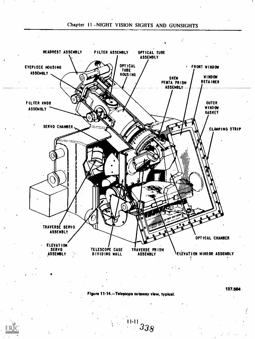
Chapter 11 NIGHT VISION SIGHTS AND GUNSIGHTS
HEADREST ASSEMBLY
EYEPI ECE HOUSI NG
ASSEMBLY
F I LTER ASSEMBLY
OPT I CAL
TUBEMOUS I HO
-OPT I CAL TUBE
ASSEMBLY
FRONT W NDOW
SKEWPE NTA PR ISM
ASSEMBLY-
WINDOWRETA I NER
F 1LTER KNOB
ASSEMBLY
OUTERWINDOWGASKET
SERVO CHAMBERCLAMPING STRIP
TRAVERSE SERVOASSEMBLY
ELEVAT IONSERVO
ASSEMBLY
4
TELESCOPE CASE TRAVERSE PR ISMDIVIDING WALL ASSEMBLY
Figure 11-14. Teloacepo CUtaway view, typical.
1.
OPT ICAL CHAMBER
E I.EVAT ION M IRR OR ASSEMBLY
137.564

OPTMLMAN 3 & 2WIRING DIAGRAM
AUTO COLLIMATIONMIRROR
148.313Figure 11-15.--Reer cover, inside view.
11.
reflected image of the reticle which wastransmitted through the optical system, to theautocollimator, and back.
If the reflected image is superimposed on thereticle, .there is no problem. If the reflectedhnage is slightly displaced in any direction, youwill need to adjust the elevatioji or.traverse (orboth) mechanism to establish coincidence.
. _Complete._ . _coverage of technical- dataconcerning the Mk 102 Mods 2, 5, and 6 and theMk 116 can be found in one or more of thefollowing publications: OP 1858, OP 3651, andOP 4239. -
These Ors are updated periodically, and thetrend seems to be to change the number of theOP. Even though the information .contained inthe older OP may be valid, you should alwaystry to use the most recent edition.
i-12
339

OAPTER 12
SUBMARINE PERISCOPES
Sinkt.t the,iirst'atteml ts to guild and operateunderwater craft, there ha' been a need for theoccupant(s) to have some way to see out ofthese watertight vessels. rious names havebeen used for the devices, b t we will use theterm "perisCope" in this many
The first periscope, develovd in 1854, wasnothing more than a. pipe with irrors at eachend to allow the-operator to se out. As thescience of optics became more e act and thetechnical mans to prOduce precision lenses weredeveloped, periscopes becat e moresophisticated. By the time of the first orld war,periscopes were quite efficient, and d ring the1930's some -real .progress was realize Theseperiscopes contained a split image rant finderand a change of fpower mechanism.' jitad wasadded a few yearOater.
In 1958: ommunications antennas andseveral improve. 1. radar antennas were' ad ed,along with a /gynchroservo mechanism- w challowed the periscope to be used for as alnavigation Ake a sextant. Nowadays, it isdifficult 'to .-keep up with the electronic miracl sbeing added to periscopes.
THEORY AND DESIGN
Basically, the periscope is a tube withref1ecti4 elements at the top and bottom toraise tU observer's line of sight. But the actualdesign is not that simple. The periscope designer,mUst solve several 'special problems Ibroughtabout by the design of other opticalinstruments. Compromises Must be matle
between conflicting requirements. Here are someof the problems:
First of all, the Oriscope has to be relativelylong, as yeru can see in figure 12-1. It must belong enough to rise above the surface while thesubmarine is still far enough below to beinvisible to surface craft. Optical lengths ofperiscopes run from 36 to 43 feN.
Another important requirement is that theupper head sectionthe part that -sticks out ofthe waterbe as slender as possible to escapedetection by the enemy and to create aminimum wake. The wake of the periscope, ifseen by the enemy, would not only reveal thesubmarine's presence, but also wbuld indicate itscourse. The main outer tube must also be ofsufficient size to contain the optics and inner,tube sections. Our periscopes are 75 inches indiameter with a wall thickness of 1/2 inch.
. When the periscope is not in use, it islowered for protection into a well (fig. 124).But when the submarine is maneuvering intoattack position, it will use the periscope Sullyraised, while underway submerged. Theperiscope, despite its slender construction, mustbe rigid enough to resist the bending effect ofthe water pressure that results from its owndrag, and the optical system must be designed sothe bending effect will, not distort or displacethe target image.
Another requirement is that the, periscopehave some means for sweePing through 360° andfor eleitating the line of sight to check foraircraft. With a modern perisco e, the submarinecaptain sweeps the horizon by rotating theentire instrument. Elevati is provided by amovable righfangle prism, i the head section:
02-1
340:

OPTICALMAN 3 & 2
STEADYBEARINGS
IN SAIL
.RODS
HULL GLAND
CONNINGTOWER
148.91flours sectIOn through a submarine, with
periseope elevated.
Since the periscope must be raised, lowered,and rotated, it must pass throuih an opening inthe hull. The design and packing bf that openingcreates another serious probletii. The paekingmust admit no water into the/submarine, evenunder tremendous pressures, )e.t it must all w
*the periscope to be freely raised, lowered,, arotated within it.
The periscope itself must be completely\waterproof: The head window and its bezel and
the joint by which the head is secured to the.,,upper part of the tube are in direct contact withthe sea, so the possibility of leakage throughthem must be zero,. Since the submarine is sodependent on its periscope, the internal optical*surface must not fog up. A pressure of 7 1/2 psiof dry nitrogen In the periscope maintains afog-free condition.
The problems we have listed so far have beenmai* meehanicak -But there are---o-ptirillproblems, too. The optical system must presenta normal, erect image, bright enough to beuseful. The field of view must be reasonablywide so the observer can find the target quickly.There must also be some means to determine thezme to a target.
he problem of image orientatibn is not toodifficult. Since we' need a prism at each end ofthe optical system to see out, one prism invertsand the other reverts. Then' by using I suitablecombination of terrestrial ihd astronomicaltelescope systems in the periscope, the finalimage will be normal and erect.
Obtaining a suitable field of view is a majorproblem, especially when yoti consider thedesired length of a periscoper in Telation to theentrance pupil which' is usutilly only severalinches wide. This obstacle was overcome byplacing an upper astronomical telescope. in thesyStem backward with a lower telescope in thenormal position. (Objective toward the target.)
Suppose the power of the upper telescope is4X, but the telescope is backward. Its actualpower is 1/4X. If an 8° cone of light were ableto enter the upper telescope, the 8° field wouldbe reduced to 20 by the reversed telescope
app(Mag A 2° cone of light catt pass throught he periscope tube for )i considerabledistanceapproximately 12 feet. The objectiveof the lower telescope must be placed to takeadvantage of this cone of light if the lighttransmission of the periscope is to be effeOtive.
If the power of the lower telescope is 24X,the 2° true field becomes a 48° apparent field
--myr). Now to determine the overall
poWer of the periscope, combine themagnification of the upper and lower telescopes.
12-2 311,
1/4X 24X 6X

:.
Chapter. 12SUBMARINE PERISCOPES
The periscope has fairly good .magnification(6X) and a reasonably true field (8°).
Ve length of a periscope is usually figuredas thiee times the distance,between the upperand lower telescope objectives (12 feet):
12 X 3 = 36 feet
Thirty feet is an impressive length for an opticalinstrument, but -for- an-attack- periscope it- shouldbe a little longer to give the submarine a bettermargin of safety. Qne Way to increase length isto. increase the power reduction of the uppertelescope, thereby reducing the true field so itcan- pass through the tube for a greater distance.This, was not considered practical because ofseveral other design considerations: (1) the headsection of the peri4cope must be very small; and(2) there must be sortie: means to determinetarget range. Both, problems were .solved byadding two more astronomical telescopes abovethe upper telescopeli
Those two telesabpes were small in diameter(about 1 inch) and were l'X. (In a IX telescope,the objective and eyepiece focal longths.are thesame, and they have no effect pn the true fieldof the periscope.) A crossline _Was placed in theupper auxiliary telescope to asSist with ranging.
NOTE: In a periscope, the crossline lens is calleda telemeter, Lines'are etched on the telemeterwith.'a known angular .separation so ranges canbe estimated.
Now we have a periscope about 42 feet long,with,a telemeter and a small head sectiod. Withthe telemeter placed in the Upper auxiliarytelescope, even though the tube vibrates whenthe submarine is moving, the target image andtelemeter will move in- unison .-
We're not finished yet. Range estimationusing a telemeter is fine if either the target orobserver is reasoqably stationary and if there isilrplentys,Of ammunition. A submarine can carryonly a limited number of torpedos, and thesubmarine and target are -usually moving atangles to each other. Each shot must count.
The accurate ranging problem was solved bysplitting the objective of 'the lower maintelescope vertically so both halves would moveequally in opposite directions. The observer nowhas two images of the same object. Figure 12-2shows the optical principal involved.
The ranging pechanism of a periscope iscalled a stadimeter,, It is attached to the bottomof the scope and consists of-a range dial, heightscale, and suitable gearing to drive the range dialand split lens gear. To take a range, .set the .
C.
10
OM.
INTEROBJECTIVE CENTRAL PUPIL CONVERGES AT CTO FORM IMAGE OF CENTER OF TRUE FIELD.
e. .
HATCHED AREAS SHOW THE PORTIONS OF THE INTEROBJECTIVE PUPIL WHICH AREPICKED UP BY THE OBJECTIVE HALVES TO FORM IMAGES OF THE CENTEP OF FIELDAT CA AND C.
A.
MON 12-ILower ) objEttivAens nay diegrim.6
1 2-3342
137.530

OPTICALMAN 3 .8c. 2
height of the target .(waterline to masthead) onthe height scale, then operate the staditneteidrive to split the target image. When themasthead of one image is displaced to thewaterline of the other image, read the targetrange opposite the height scale pointerA
As you recall from the beginning, of thissection, the main portion of the outer Vbe of aperiscope is 7 1/2 inches in diameter.. Takinginto account the tube thickness.and_the_need for-inner Aube sections to hold the optics, thediameter of the upper objective is- about 5 1/2inches. Since the lower objective is split andmust move in opposite directions to provideranging, the lens can be only about 4 inches indiameter. Some light is lost as a result, but youstill have a reasonably bright image: .,.
--The designer has one more small problem tosolve; namely, the addition of a change of powermechanism. This is gained by .adding a Galileantelescope above upper atixiliary telescope.This Galilean telescope is 4X, but, when it is inthe line of sight, it is backwards. 'In high power(6X) the Galilean is out of the line of ,sight.When rotated into the line of sight, the overallpower of the periscope becomes
1/4 X6= 1.5X
which also Provides a true field of 32° in the lowpower position.
Our submarine& now has a long attackperiscope with- a Ary' small head section, adaCcurate 'range mechanism, and a choice of 1.5Xor 6X. Low power is iilways used to quickly scanthe horizon and air space above, whileThighpower is used to make the attack.
Another factor of periscope design andtheory which affects the repairman, andcontributed to designer headtches, ts that apefiscope is charged with. nitrogen. Nitrogen hasa different index bf refraction than . air;consequently, light comes to a focus furtherfrom a lens when it is in a nitrogen atmosphere.
To fix a periscope, you have to take it.apart.Before you take it apart, you,haven to release
.nitrogen pressure. When you reassemble andcollimate a periscdpe it is done in air, notnitrogen. Therefore, you must,. make allcollimation adjustments .carefully on suitabletargets so the completed instrument will
perform, as designed, when it is' charged toservice pressure.
If you think the problems in periscopetheory and design are hard to understand, justimagine how difficult it Was for engineers toperform all the necessary optical calculations tocome up with a compatible optical systemcomposed of five telescopes. This was done inthe 1920's without the aid of comnputers. Exceptfor- t-he -theoretical-problems-involved , perisCopesin .use since 1958 bear no resemblance to thedesign explained in the preceding paragraphs.
The optical system common to' modernperiscopes (fig. 12-3) is a general purposeperiscope with no ranging mechanism. _Attackperiscopes use' the same optical arrangementexcept for a different mounting for the 5therector and the absence of a sun filter. NOTE:Modern attack periscopes use a solid lens andsplit lens mounted. in a cube so the split lens canbe rotated in or out of the line of sight whenneeded.
Instead of using either three or fivetelescopes to transmit light and provide ad' erectimage, modern design uses a series of opticalrelays composed of erectors and collectors.Parallel light passes between thi erectors, andthe collectors control aberrations and focusavailable' light to the various image planes orerectors. By varying the separation betweenerectors, a periscope of any desired length canbe produced:
These periscopes still use a Galileantelescope for change of power ..(1.5X and .6X),but this new design will not adapt to .the verysma1,1 head sections required for olderperis(Copes. Since 'submarines are much fasterthan before and weapons systems are moreaccurate, the small head section is no longernecessary.
The 6th erector, shown in alternate positionin figure 12-3, has a dual puipose. It cat bemoved along the optical axis approximately 10inches. In..the upper position, shown by solidlines, it is moved u down slightly to focusthe periscope. When otographs ;are takenthrough a periscope, the piece is removedand the 6th erector is .,,moved down to thecamera position, shown, by dash lines. Thismoves the image plane outside.-the periscope tocorrespond with the filimplane of a camera;
12-431 3

,Citapter 1 2SUBMARINE PERISCOPES
a
AtAvxsnat
WWASO WV\ .MUM I
\ii\
azet,.olos lasuoy,
yegg:`:
-c,1004%.0m.oy.z.4tkw
a EYE PIECE...
2ndERECTOR
1stCOLLECTOR
3rd.ERECTOR
VP
4 thERECTOR
2ndCOLLECTOR
5thERECTOR
AthERECTOR
(ithERECTORCAMERA POSITION.
EYE PIECEPRISM
,EYE PIECE.WINDOW
HtAP1)1115M
HEAD WINDOW
9ow mat;flia ,41.5110: sto,
GALILEANTELESCOPE
-*OW" tilt
Figure 12.3.Generai arrangement of mitioe.
. 1'2-5 344
SUN FILTER
OBJECTIVE
FIELD FLATTENER
TELEMETER
1st. ERECTOR
141053

OPTICALMAN 3 & 2
PERISCOPE IDENTIFICATIQN
Periscopes are not identified by Mark andMo:.d as other optical instruments. They, all haveindividual serial numbers (called registrynylmbers), but major identification betweendifferent types is by a Design Designation asshown below. .
121 KN 364;34(23K A 43.3/HA
The first set of numbers (121 or 123) is anidentifying number pertaining to the type ofperiscope (121 8B, 1 23 2D). The first letter(K) refers to the manufacturer, in this caseKollinorgen. The second letter designates the useof the periscope (N for night or observation, Afor attack use). The second set of numbers (36or 43.3) refers to the optical length of thesystem. HA in the Type. 21) design designationmeans high angle (with the- periscope in lowpower, at the edge of the field you can seedirectly, above you).
The periscopes you will encounter are asfollows:
8B8C8D
I5B15D18B181)
2D2E2F
Observation periscopes(radak, ECM, communicationsantennas)
Attack periscopes(with stadimeter)
Alsubmarines use two periscopes, one forgeneral observation or night use and the otherfor attack purposes. They may be mounted foreadd aft or side by side, depending on the class ofsubmarine. The number ()IF periscope (usuallythe attack scope) is either Nearer the bow or onthe starboard side.- The number two scope(observation) is second in line or on the portside.
PERISCOPE HANDLING,
As an Opticalman, you 'will bi responsiblefor preparing periscopes for removal; pulling
them from the submarine, transporting them toyour shop, performing necessary repairs,returning them to the submarine, and installingand hooking them up. Considering ..that aperiscope is. a 2,000-pound, 40-foot long,greased pole that costs anywhere from 90thousand to half a.million dollars, that is a lot ofresponsibility, and a challenging job. Thissection will discuss the correct methods inhandling periscopes-.
Before getting into.any detail, look at figures12-4 and 12-5 to become familiar with some
NOR. LINE
OF MONT
OUTER HEAD
-OUTER TAPERTUSE
0--EYEPIECE
OUTER TUBE
TRAINING HAtiOLE
1,2-6345
L* OPTICAL LENGTH20- 43' 3"2E - 38'
SPLIT RINGGROOVE
rocusiNO WOG
STAOIMETER ASSEMILY
Figure 124.Atteck periscope.134.101

Chiptoi 12SUBMARINE PERISCOPES
STUBANTENNA
HOISTINGYOK E
EYEPIECEBOX
E S EADAPTE
HOR. IrNE
Dr- SIGHT
* OPT CALLENGTH
FORWARD
HEAD
OUTER TAPER TUBE
-MAIN BODY TUBE
EYEPIECE
Figure 12-0.Generai purpose perlicope.
31612-7
* OPTICAL. LENGTH
se - 36'
8C 28'158D - 36'
FOCUSING KNOB
TELEMETER ILLUMINATIONRHEOSTAT
-TRAINING HANDLE?1,
a
194.101

OPTI('AIAIAN 3 & 2
characteristics' of attack and general purposeperiscopes. .
Before pulling a-periscope from a submarine,remove all fittings or accessories which ptojectbeyond the 7 1/2-inch diameter of the outertube. While you are doing this, tools, cap screws,and even the fittings themselves, tend to jumpout of your hands and head for' the periscopewell. You do not want that to happen. People.wil1 yell at you, you will be embarrassed, andeven worse, you must retrieve the lost pieces.
The weight of k periscope is supported by ahydraulic system and hoisting yoke similar to,that shown in 'figure 12-6. (The hoisting yoke isshown in position in figure 12-5.) Types 21), 2E,and 21: periscopes use a larger yoke which has a
SETSCREW
(:0.1)11-3C0v E R
.e"
YOKE
-'1)ddri SPLI TOP' RINGs f-
t
FEUPPER RAJE-
HYDRAULICRODS
z
11ID 6
- BRACKETCONNECTORS
137.540Figure 12-6.Hoistiog yoke.
e c It a n ism that transmits target bearinginformation as the periscope is trained. Theyoke is basically a housing for a twitring and raceassembly ( I , 2, 3). Split rings (4) fit in a splitring groove in the outer tube. (See fig. 12-4.) Ashoulder in the upper race. fits tightly aroutia thesplit rings, holds them around the scope, and, inconjunction witlt the yoke and lower race, holdsthe scope up. A cover (5) screws into the top oftbe yoke to 'lock iii the assethbly. NOTE: .Youneit a special wrench to install or remove theyoke cover. Notice the setscrew (6). Alwayscheck for setscrews.
The hydraulic rods (7) are secured ineccentiic bracket connectors (8) which arelocked into the yoke (9). The bracketconnectors are eccentric to allow for minorvariations in the separation of hydrauliccylinders installed in some submarines.
Although it is not shown in any of theillustrations in this section, some submarineshave a streamlined easing which surrounds theperiscope to reduce drag when the scope israised. This wing shaiied casing is. called aFA !RING.
Fairings are approximately 12 to 15 feetlong, and they can either be attached to theperiscope (dependent) or raised and loweredseparately (independent). Inside, both types arecylindrical bearings to prevent rattling. Teflonbearing blocks fore and aft, located at variouspoints in the sail, cushion the fairing externally.The bearing blocks allow the Wring to .be raisedand lowered gnietly and still take the full force
.01 water pressure when the scope and fairing areraised while underway submerged.
Independent fairings will not usually causeyou zwy difficulties. Dependent .fairings, sincethey allt wcured to a scope, take specialhandling when you remove or replacea scope.
PERISCOPE REMOVAL
All operations dealing with the removal orinstallation of perikopes must be done in asheltered harbor. Movement .of the submarine,while's periscope is partially supported tbesteady beatings in the sail, ,:an cause severe,damage to both the scope and the submarine. Ifa tender is doing the job, the sub can sometimesbe moved to the lee side. If it is not possible to

Chapter 12 WBMARINE PERISCOPES
offer protevtion in this manner, the job mayhave to wait for more favorable condition's.However', many times it is absolutely necessryto pull or install a scope regardless of wind orwilter conditions. When this situation conies up,a very experienced Man must be in charge.
You must follow the sequence of eventsfisted below when removing a periscope:
Notify the submarine duty officer thatyou are tgoing to pull the scope. When apefiscope is removed, there is a 7 1/2-inch holein the hull, putting the subifiarine out ofcommission until the hole is filled. Also,,thehydraulic power may be temporarily secured.The, duty officer will take steps to provideVdraufics so the scope can be raised and willsolve any other 'problems hindering your scopejob.
K_ 'sure the Sail area is clear beforeraising the scope; you do not want to startle orinjure anyone. Cycle the scope up and downseveral times to be sure the hydraulic system isfunctioning.smoothly; then stop the scope-in theobserving positfon.
NOTh: Killing a sZope is usually a two- orthree-person job; therefore, several of thefollowing steps can be performed af/the sametime. One or two people cari be on the sailclamping the.scope,, while one or two more areip the control room stripping external fittingsfrom the scope. 'Teamwork and communicationbetween the sail and control rooM ar4 essentialto- preventerromor omissions.
CAUTION: You must wear .an approvedsafety harness whenever you do any work ,ontop of the sail. Attach the short, heavy line onthe harness to any convenient permanent fixtureon the sail to keep you from falling.
With the periscope in the observingposition, enough outer tube ex1ends above thesail to provide a, suitable area for clamping, inany event the hoisting clamps should be 18
r. inches or-more from the tapered portion of the.outer" tube. Clean all traces of.grease or foreignmatter from ttie Outer tube iry-the area to:beclamped. Mace two sheets of 150 or 180 grit
emery cloth aromid the scope, smooth sidetoward the tube.
Figure 12-7 helps to explain the next step.Securely bolt a forged steel "hoisting clamp (I)and two safety clamps (2) above it.to the scope.See figurt .12-7. Place the first safety clamp at a45° angle to the split of the hoisting clamp, andAwe the..second. safe_ty.AJamp 90° to_ the.first.Attach the slings (3) to a spreader (4) and thehoisting clamp with sturdy shackles.
All equipment used in handling periscopes(shackles, slings, clamps, etc) must be regularlyinspected anti weight tested to verify safety andcondition. After inspection, it is tagged tocertify that it passed test and inspection:
EADER
SUNOS
re"MINIMUM
SAFETYCLAMP
'irk o r 148300Figure 12-7.Clampe and !Op attached, to the outer
'12-9 ,10 34
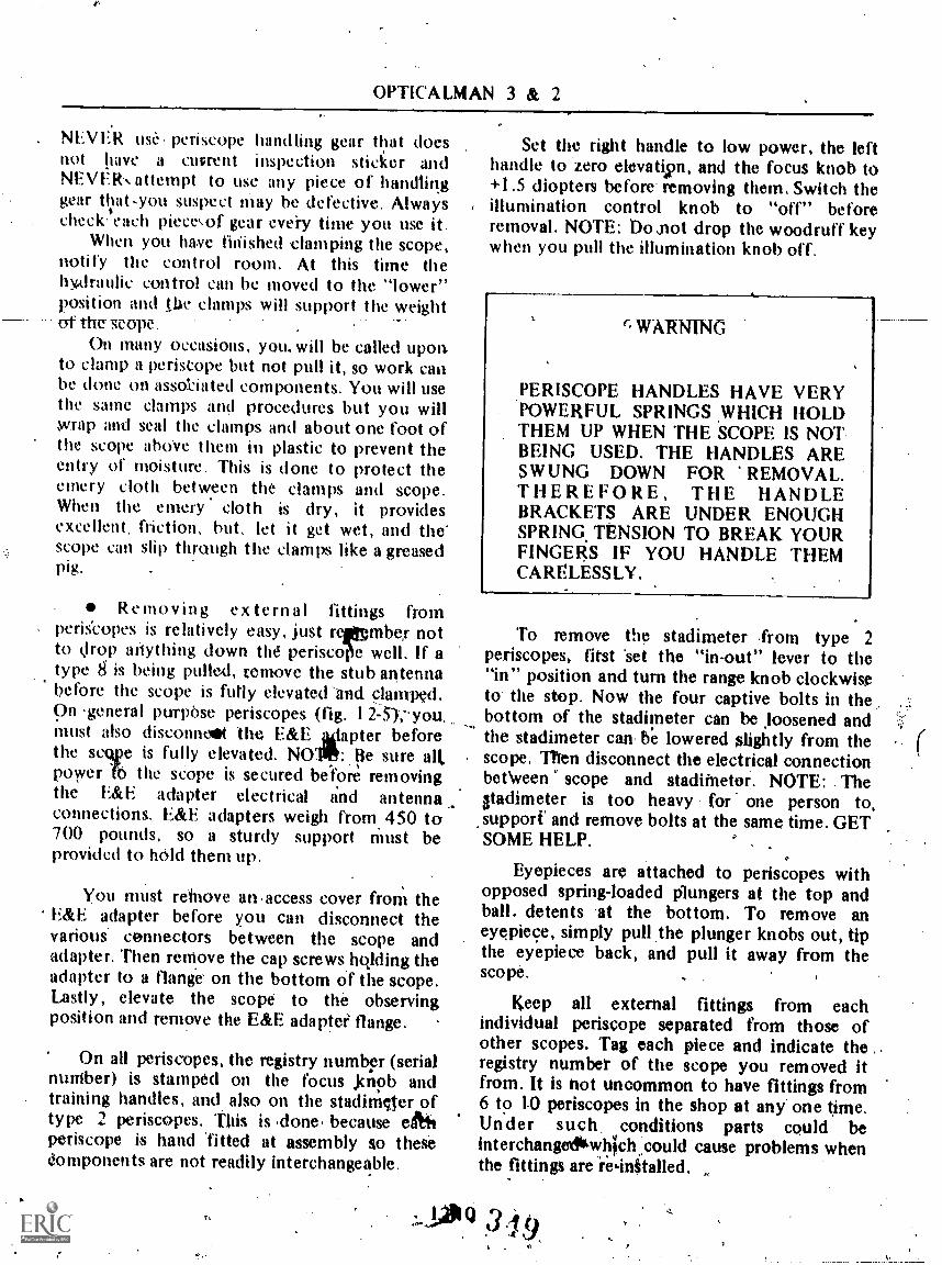
OPTICALMAN 3 & 2
NEVER use, periscope ithndling gear that doesnoi have a cuvrent inspection sticker andNEVEIh attempt to use any piece of handlinggear that-you suspect may be defective. AlwayschecCeach pieceof gear eveiy time you use it.
When you have finished damping the scope,notify the control room. At this time thehy,drauhc control can be moved to the "lower"position and tbe clamps will support the weightof the vcope .
On many Occasions, you. will be called uponto clamp a periscope but not pull it, so work canbe done on assobated components. You will usethe same clamps and procedures but you willwrap and seal the clamps and about one foot ofthe scope abOve them in plastic to prevent theentry of moisture. This is done to protect theemery cloth between the clamps and scope.When the emery cloth is dry, it providesexcellent, friction, hut, let it get wet, and the"scope can slip through the clamps like a greasedpig.
Remo v in g external fittings fromperis'copes is relatively easy, just rermber .notto drop anything down thd periscqe well. If atype g is heMg pulkd, temove the stub antennal?efore the scope is fully elevated-and, clamped.On .general purpose periscopes (fig. I 2-5),- you.must also disconneot the E&E aiapter beforethe scive is fully elevated. NUM,: Be sure alt,power ft) the scope is secured before removingthe E&E .adapter electrical and antennaconnections. E&E adapters weigh from. 450 to700 pounds, so a sturdy support must beprovided to hOld them up.
You must reinove an.access cover from theE&E adapter before you can disconnect thevarious connectors between the scope andadapter. Then remove the cap screws.hojding theadapter to a flange on the bottom of the scope.Lastly, elevate the scope to the observingposition and remove the E&E adapter flange.
On all periscopes, the registry number (serialnuniber) is stamped on the focus .knob andtraining handles, and also on the stadimeter oftype 2 periscopes. This is .done, because egtitperiscope is hand 'fitted at assembly so thesedomponents are not readily interchangeable.
Set the right handle to low power, the lefthandle to zero elevatism, and the focus knob to+1.5 diopters before- removing them. Switch the
, illumination control knob to "off" beforeremoval. NOTE: bosnot drop the woodruff keywhen you pull the illumination knob off.
r.WARN1NG
PERISCOPE HANDLES HAVE VERYPOWERFUL SPRINGS WHICH HOLDTHEM UP WHEN THE 'SCOPE IS NOTBEING USED. THE HANDLES ARESWUNG DOWN FOR REMOVAL.THEREFORE, THE HANDLEBRACKETS ARE UNDER ENOUGHSPRING TENSION TO BREAK YOURFINGERS IF YOU HANDLE THEMCARELESSLY.
To remove the stadimeter -from type 2periscopes, first 'set the "in-out" lever to the"in" position and turn the range knob clockwiseto the stop. Now the four captive bolts in thebottom of the stadimeter can be Joosened andthe stadimeter can he lowered slightly from thescope. Then disconnect the electrical connectionbetWeen scope and staditnetor. NOTE: Theatadimeter is too heavy for one person to,
,supporf and remove bolts at the same time. GETSOME HELP.
Eyepieces are attached to periscopes withopposed spring-loaded plungers at the top andball. detents at the bottom. To remove aneyepiece, simply pull .the plunger knobs out, tipthe eyepiece back, and pull it away from thescope.
keep all external fittings from eachindividual periscope separated from those ofother scopes. Tag each piece and indicate theregistry number of the scope you removed itfrom. It is not uncommon to have fittings from6 to 1-0 periscopes in the shop at any one time.Under such conditions parts could beinterchange*wh'ich.,could cause problems whenthe fittings are re,in§talled.

Chapter I 2SUBMARINE PERISCOPES
With all fittings off and the scope resting Qflthe clamps, remove the hoisting yoke, (See fig.12-6). On general purpose scopes, unscrew theyoke coier, then slowly lower the yoke awayfrom the scope hydraulically. The upper racewill usually remain in place and must be tappedoff the split rings with% fiber mallet, Carefullypry the split rings away from the scope, thenlower the yoke cover off the scope. The bearingsand races are now taken to the shop for ckaningeand inspection.
Removing the yoke/target bearingtransmitter (TBT) from an attack scope issimilar to the above procedure with thefollowing exception. A keywayrit milled in theouter tube of the scope just below the split ringgroove. A key is inserted which drives the TBTwhen the scope is, trained. You must remove thiskey before you lower the yoke/TBT away fromthe 'scope. ,
After the hoisting yoke is lowered awayfrom the scope, hydraulie power to the systemmust be secured and ,the controls must be taggedto prevent operation. If the scope is an attacktype, the yoke is usually secured level with thetop of the periscope well. For genenj1 purposescopes, the yoke is either secured in a raisedposition or lowered to the E&E adapter, Wherethe yoke is. secured depends 'On- Whether or not
-the EBLE adapter needs work.
The scope is noukfree to be pulled fromthe submarine. The submarine must be on. aneven keel so the periscope will be as nearlyvertical as possible to avoid damage to the scopeor steady bearings in the sail. Spot the cranehook directly over the scope, with slings andspreader attached as shown in fig. 12-7. As thecrane pulls the scope, one person remains on thesail to attach a steady line around the split ringgroove when the scope clears the sail. Someoneon the pier or tender handles the other end ofthe steady line to keep the scope from swingingas the crane moves.
AUXILIARY HANDLING EQUIPMENT
You already know that periscopes are long;heavy, and expensive. You should also knowthat they are a precision instrument and must becarefully handled to avoid bumps, shocks, or
bending. It takes a lot of moving around to haulperiscopes between the submarine and yourshop or from storage to the submarine.Coordination', training, and proper equipmentare necessary.
At some point in' the handling procedure, apesiscope must be shifted from the vertical to ahorizontal position or vice versa. A hingecarriage, similar to that in figure 12-8, is used tomake_ _this transition. The_:_earriage. cam. -ba-clamped on a scope when it is in a horizontalposition, as shown, or as the scope is loweredvertically toward the deck or pier.-
The bottom of the carriage is merely acushioned socket to protect the eyebox. Therigid frame has provision .for a. split; hingedclamp which fits around the scope at the split'dng groove. When the clamp is tightened aroundthe scope, a split ring or other suitable devicekeeps the carriage in poSition. With the hoistingclamp attached and slings . and spreader inposition, the scope can be lowered to horizontalor raised to vertical by the crane withoutdamaging the eyebox.
-Whenever a periscope is in the horizontalposition, it should be resting on at least twoV-blocks located at the quarter points. (Quarterpoints are 114 the length of the periscope outertube, measured from cacti end). The V-blockscan be plain wood, padded metal, or specialwheeled dollies. The blocks must be tall enoughso the wheels of the hinge carriage will clear the
4.
2,1' I
4
. .
,
148.102Figure 12-8.. Hinge carriage at horizontal position,

OPTICALMAN 3 & 2
deck when the scope is in the horizontalposition.
To MAIM periscopes in or out of the_ shop, orstorage boxes, a strongback similar to thatshown in figure 12-9 is used. The strongback is arigid I-beam approximately 10 feet long withsturdy. split clamps at each end. In the figur0the strongbaek is shown attached to chain hoistsat each end. Normally, a single hoist or cranehook is attached to an eye in the middle of thestrongbaek; When a strongback.is uged; all Otherclamps should be removed and the scope shouldbe balanced before tightening the strongback-clamps.
If a periscope is to be moved any distancewith the strongback, from pier to tender forinstance, steady lines:must be attached to bothends of the scope to control movement.
While on the subject of handling periscopes,we,must comment on storage or shipping boxes,
'When scopes are transferred, or in some casesstored, speCial shipping containers are used.
These shipping containers are constructed ofheavy. gage aluminum, stiffly braced, andprovided _with heavy wooden skids on thebottom_ A tightlifsealed lid, composed of twoto four 'interlocking sections, protects theperiscope from dust or moisture. The periscope'rests on five. or six rubber padded semicircularbrackets built into-the .box. A padded clamp,bolted to each bracket, prevents the scope frombouncing or sliding during transport.
Paddyes for lifting scope boxes with slingsare welded at the quarter points of the boxes.Two 'areas for using fork lifts are prominentlymarked on the boxes. To prevent damage to theboxes and periscopes, never move a shipping
container by any method other than thoseprovided,
Periscopes are often transported by flatbedtruck. Since the shipping container is longerthan most truck beds, the eyebox end of thecontainer must be to the front of the truck toallow the lighter taper section of the scope tohang over the end. If the truck driver exercisesreasonable ciire and misses bumps, the scope willbe safe.
When a periscope is shipped, the designdesignation and registry number of the scope atemarked on the outside of the box at the eyebokend. Also, all external fittings for the scope arewrapped and secured in the box. (Except for theE&E adapter on general purpose periscopes.)
PERISCOM PACKING
The method for sealing a periscope and hullopening is .shown in figure 12-10. By using thisparticular arrangement, the periscope can beraised, lowered, and trained while the submarine'is submergedwith little possibility of leakage.In fact, if all components are properly arrangedand perfectly aligned, more:water will enter theboat if it is on the surface in a rainstorm than ifit were de. I submerged. -
Chevron pac ing is preformed (molded)._synthetic rubber available in several sizes(standard and oversize steps). The different Ozes,are used to take care of variations in the insidediameter of the hull casting. To provide thenecessary seal, there éan be no cracks or otherblemishes 'anywhere on the surface of theindividual rings of chevrOn packing.
OVERHEAD RAIL
Figura 12-8.Periseope supportad by strong back and chain hoists.
12-1235.1.
DECK
148.104

Chapter 12SUBMARINE PERISCOPES
1
rAm
PACKING RING
HULL CASTING
LOWERSTEADY BEARING
0
16 CLEARANCE
CHE VRONPACKING
LANTER4 RING
;4EVRON
/gra PACKING
PACKING RING
PILLER RING
EXTENSIONRING
148.106Figure 12-10,--Periscone packing assembly.
Other factors which affect the scal-of thepacking assembly are concentricity of thepacking rings, filler ring, and lantern ring;alignment of the kmer steady bearing wkth allother !sail steady bearings; and the clearancebetween the top packing ring and the bottom ofthe lower steady bearing. The clean:me must bebetween 1/16 filch and 3/32 inch. Seawaterpressure acting on the top of the tdp packingting through this clearance compresses theengine packing assemlly. The deeper you go, the
'more the pressure; the higher the pressure, thetighter the seal. If any of the bronze rings in thepacking assembly are out oik-round, however,high O.-Cs:SO-re will- distort the chevron Paekipgand probably cause a leak. This causes a wee bit
of panic in the submarine and usually results inan optical shop representative waiting on thepier when the boat returns to port.
When a periscope is pulled, the packing mustbe removed since the scope would tear up theassembly when it is reinstalled. With the scopeand packing removed, you have an excellentopportunity to check alignment of the steadybearings and the condition of the hull casting._
Many problems with periscope leakage ordifficulty with training are blamed on thepacking. The real culprit, however, is usuallymisalignment of sail steady bearings. The opticalshop usually performs-this alignment.
-Packing can be removed with the scope inplace, but this is not the easiest jo\b-i.kte world.You have to Jaise the scope to the bserving-position, clamp and strip it, then loosen andcarefully drop the hull gland. The metalcomponents of the packing assembly are fairlyeasy to remove; the chevron packing causes theproblems. If it will not slide out easily, you mustdig it out with a tool sitnilaUp a corkscrew.
127-13
PERISCOPE INSTALLATION
Replacing a periscope is NOT the reverse ofremoving it. In this description we will skip allthe steps involved with moving the icope out ofthe shop and on deck or on the pier. Theequipment used has been explained in thischapter; the methods to use vary withconditions present on different tenders.
The krst step in replacing a periscope iscoordination between the shdp, crane crew, andsubmarine. It takes no more than 15 minutes toget a scope out of your shop and ready toinstall. Proper scheduling is necessary to be surethA boat is ready to receive the scope and toassure uninterrupted use of the crane. Due tovarious drills, other priority crane usage, andwork by other shops. on the submarine, it isoften necessary to replace scopes early. in themorning or after working hours. The-importantconsideration is to finish the job once it isstarted.
352

OP:TICALMAN 3 A '2
With all necessary preparations made(submarine informed, external fittingsaisembled, yoke and packing componentsready), the periscope is )ifted to a verticalposition by the hoisting clamp. NOTE: Locationof the hoisting clamp is.critical. Different .typesOf periscopes vary in length, and the distantebetween the control room and sail variesbetween classes of submarines. You have toknow exactly where to clamp the scope sp. the
-eyebox -will extend the proper- distabce into thecontrol room.
When the periscope is held vertically, aspecially made tapered plug called a bullet isbolted to the bottom of the eyebox. The bulletguides the scope through the \ sail or fairingbearings. At the same time, a steady line issecured around the split ring groove and passedto a person on the sail. NOTE: If you are on thesail, do NOT forget your iafety harness.
The person on the sail has an important job:to help the crane operator spot the scopedirectly over the hole in the sail, to guide thescope in, and to apply a medium coat ofapptoved grease to the outer tube as the Scope islOwered, As you may suspect, this part of yourjob is dangerous. You do not have any Place tostand, the boat is usually moving, and your
. hands will be covered with grease. That is whyyou must wear a safety harness.
Once the scope is lowered completely. andresting on the clamp, unhook the slings and gohelp out in the coritrol room.
REPACKING THE PERISCOPE
Repacking the periscope is the next task.The procedure is the same whether you justreplaced a scope or are renewing packing inplace. At this point, all Orthe metal rings havebeen cleaned and checked for concentricity anddings. The chevron packing has been inspected,and the height -of the assembled Packing hasbeen -measured.
NOTE: When the packing assembly is inplace, there muit be 1/16 to 3/32 inch clearance
between the lower steady bearing and upperpacking ring. The clearance is the, differencebetween the depth of the hull gland and thestack height of the packing assembly. To obtainthis clearance, vary ttie thickness of the fillerring or substitute differeht rings of chevronpacking.
At least two people are needed to repack aperiscope, and you will need several packingsticksv The packing sticks are- about 3 or-4 feetlong, I inch wide, and 3/4 inch thick. Withoutpacking sticks, there is no way you can slip themetal rings or chevron packing into the cavitybetween the scope and hull casting.
First, slip the upper packing ring around thescope, followed by the top ring of chevronpacking. Then use the packing sticks to slidethese two components into the hull casting.NOTE: When you slip chevron packing intoplace, be sure-it does not hang up on thi lowerlip of the-hull casting. The lip could be _sharpenough to damage the packing.
Now coat the cavity of the lantern ring withgrease and slide it into position. ,Next slip thetwo lbwer rings of chevron packing into the hullaland. There Illay be enough friction betweenthe, scope, chevron packing, and hull casting to
-keep the partial packing assembly in position_while you siip the lower packing ring, fillerring,and hull gland into place.if riot, Use the packingsticki.
12-14
After bolting the hull gland into place, use along .006-inch feeler gage to check clearancebetween the scope and hull gland. If the feelergage will not pass freely arourid the scope,something is wrong. You may need to drop thepacking to fihd the difficulty, or, ifyou arelucky, you can install the yoke and raise andlower the scope several times to properly seatthe packing assembly. In any evettift-theminimum clearance of .006 inch is necessary toprovide proper alignment of the scope, packingassembiy, and steady bearings.
The final step...in repacking a scope is tohydrostatically, test the hull grand. To make this
07%test, one person ust crawl into the sail andattach a cofferd around the scope and upperpart olthe hull casting;
353

Chapter 12SUBM
NOTE: The cofferdam is. a special fittingabout I Winches tall and made in two halves. Agroove is machined in all mating surfaces toaccept a quick-drying sealant.
When the halves of the cofferdam are boltedt9gitther, a smal*mount of water is pouredin--Olen a high-présswe airhose can be attached.This air pressure, aating on the water in thecofferdam duplicates the actiOn of sea'Araterpressure on the periScoPe Packing 'when the boatis submerged.
EXTERNAL FITTINGS REPLACEMENT
After the ship's force has restored hydraulicpower, very slowly Move the control lever to"lower," and cycle the yoke down and upseveral times to remove trapped air in thehydraulic system. NOTE: Perform Oils step justbefore replacing a periscope.
Now slip the yoke cover on the outer tube,above the split ring groove, and replace the splitrings. With a conventional yoke, slip the upperrace on the scope and tap it onto the split rings.Pafek the lower race and bgarings with approved
,grease imd replace these components in theyoke. Very slowly, raise the yoke into positionon the scdpe until the scope is raised severalinches. NOTE: When raisiug the' yoke, you mayhave to guide it over the bottom of the eyebox.If the yoke hits the eyebox, it could bend ahoist rod'. With the yoke in position, pack theyoke cavity with grease and secure the yokecover.
On a TBT, you do not need to worry about'bearings or grease, but you must be sure thekeyway on the scope is aligned with the TBT sothe key can be reinstalled. Once the yoke is vp,tighten the yoke cover the same as aconventional yoke.
Now, remove the bullet from the eyeboxand clean all traces of grease from the eyeboxand visible area olthe outer tube. Then carefullyclean the eyepiece window with acetone. Also,remove the clamps at this time.
As you recall from a previous section of thischapter, the external fittings of a periscope were
RINE PERISCOPES
set at specific positions when they were removed(except for the eyepiece). The scope controlshafts and external fittings must likewise bematched to facilitate rfplacement. fie sure thefittings are from the scope you are working on;hen replace, secure, and test the fittings.
maianCOM
WillcomplSomeadjutti
P4RISCoPE REPAIR
As an 0M3, you will be responsible for theitenance of all periscope external fittings. As
M2, you will be responsible for thelete overhaul of submarine periscopes. Weot go into the detailed procedures for.ting an overhaul, but we will explAinf the finer points of construction andent.
EXTER AL FITTING OVERHAUL
The pair_ and adjustment of external-fittings are just as important as the maintenanceof internal optics and mechanical systems. Ifexternal co ponents are out of adjustment ordamaged, th periscope is essentiallY useless.
The foil wing fittings for type 2, 8 and 15periscopes a e practically identical: left, traininghandles, eye ieces, blinder attachments, variabledensity filte assemblies, pressure gage and valveassemblies nd focusing knobs. The righttrining han les of attack scopes are so similarto left trai ing handles they will not needexplanation. Right training handles of type 8and 15 scope are identical.
Since e*ternal fittings receive considerablehandling and some abuse, proper lubrication isessential for performance, and 'durable paint iSnecessary for appearance and protection.. The
.preferred lubricant for moving parts isLubriplate in several grades. Your shopsupervisor will specify the type and amount touse on various fittings. The recommended paintis a good grade of semigloss baking enamel. Ifproperly applied, this paint is very durable andwill provide an attractive finish.
12-15

OPT1CALMAN 3 & 2
Periscope Eyepieces
An exploded view of an eyepiece andfaceplate assembly is shown in Figure 12-11.The eyeguard adapter (8) is free to rotate on thefaceiflate. Three screws ( I ) keep the adapterfrom coming off, and a detent assembly holds itin position.
. A spring-loaded plunger assembly ( 16through 20) holds the faceplate on the scopeeyebox..(Only one phiner is shown.) Part-9- is aself-contained spring loaded detent (only oneshown), which holds the faceplate snugly to theeyebox. This arrangement allows the bottom ofthe faceplate to be pulled away from theeyebox, while pivoting on the detent plungers,so the eyepiece window can be cleaned.
, SETSCREW
COMPRESSION.SPRING
THRUST IP
DISC
BALL
WASHER
EYE-GUARD+ADAPTER
FACEPLATE
Not shown in figure 12-11 is an eyepieceheater ,which is built into the faceplate. Theheater consists of an electrical contact, whichreceives power from a power supply pin on theeyebox, and eight turns of resistance wire whichare wound inside the faceplate kens cell and*s.ealed with epoxy resin. The heater preventsmoisture from condensing on the eyepieceoptics.
The two eyelens elements (14, 15) and thefield lenS. (I2) are held in the faceplite byretainer rings. When it is.necessary to remove thelenses, new shims must be placed- between thetwo eyelens elements. Four shims of 0.001- to0.002-inch tin foil evenly spaced around theedge provide the required 0.037-inch spacing ofthe elements.
FLINTEYELENS
EYELENSLOCKRING
EYEF:IECELOCKRING
EYEPIEDEFIELD LENS
e
CROWN,VELENS
PLUNGER ROD
CONTACT LUG
SETSCREW KNOBCOMPRItSSION
SPRING
BALL PLUNGER
'Figure 12-11.Eyepiece and faceplate 'assembly..
1.2-1355.
SETSCREW
KNOB
137.541

Chapter 12 SUBMARINE PERISCOPES
When the eyetpiece and faceplate assembly isready for reassembly, use a drop of Locktite onall threads. . This compound prtvents thethreaded parts. from backing out but does notinake future disassembly difficult. Also, whenyou replace the three screws that retain theeyepiece adapter, screw them in tightly mid thenback them out 1/8 of a turn to provide freedomof wtation without binding.
Minder AskiiThty
Me blinder assembly (fig. 12-12) is anattachment that tits over two studs on theeyeguard adapter showtp in figure 12-11.1QVrubber cyeguards provide the proper eyedistance for viewing through the periscope, and
one eyeguard i mounted on a slide toa cc o in m oda te the viewer's in terpupillarydistance. Since the eyepiece adapter is rotationaland dgtented, simflly by 'turning the 'blinderassembly 1800 -the user can view through theperiscope with either& left or right eye.
The most common defects found withblinder assemblies' are missing, immovable, ordeteriorated eyeguards, or frozen or brgkenfinger lever springs. Since this assemblysimple, disassembly and function of componentscan be easily understobd by studying theillustration.
Proper lubrication of the .finger levers awl.springs and between the base plate (13) andblinder retainer (7) will usually resultin longertrouble-free service.
'BASE PLATE
BINDER RETAINER
LEAF SPRING
CLAMP PLATE
EYEGUARD CLAMP
EY EG UAR
LEFT LEVERCLOCK SPRING
STUD
MACH,SCREW
I..I - ' , , ' '
("1\/ I
SCREW
.1,
lpEY
111.-2")
EGUARD
.
,..)
1
EYEGUARD
PIN
SCREWPi N
SPRINGCLOCK
,.
RIGHT LEVER.VAMP
Figure 12-12.Blincler attachment assembly.
12-17
356
137.542
.4.

OPTICALMAN 3 & 2
Variable Dfnsity Filter Attachment
As you can see from comparing figures12-12 and 12-13, the arrangement Of fingerlevets and method of attachment of the blinder4ssembly and variable density filter are identical.%rice, the construction and" operation of thefilter assembly is mort complicated, however, itcan cause you problems if you are not careful.
way or another-i -most- of-- -thecodiDonents of the filter assembly are attachedto or move 4r)ound the socketliousing (18).Fixed filter (..0) and its retainer (19) screw intothe front of -the socket housing. The movable
I SCREW 1 3.
2. EYEGUARD 1 4.
3, EYEGUARD MOUNT 1 5;
4. SCREW PIN ,1 6..
5. SCREW PIN 1 7,
6 LEFT LEVER 1 8.
7. CLOCK SPRING 19.8. RIGHT LEVER 20.9, CLOCK SPRING10. BASE PLATE . f.
11. KNURLED SLEEVE-12. SPRING
14
. 15 .
17
filter (17) and its retainer (16) are screwed intothe cradle '( 15) which slips into the sockethousing. Screw (13) passes through the_L ,lot inthe socket housing and is attached to the. crIale.The slot in the sockbt housing allows the filter.(1 7) to Th.?. rotated 99° to change lighttransmission from minimum to m num.
The actuator sleeve (11) i free to rotateja when the socket housing is screwed into the-babe-9' plate. -(1-0-).- -When -the- actuatur sleeveTs- -glippetL
oyer the socket housing, the head of screw (13r'must engage the slot in the actuator sleeve, andthe friction spring (12) must be depressedsitghtly to allow the parts to mate.
SCOTTED HEAD SCREW
,FACE RINGCRAbLEFILTER CLAMP.RINGPOLAR1ZING FILTERS,OCK.ET
FILTER CLAMP RING
POLARIZINGFlLTER
16
18
12
19
Figure 12-13.Variable dem ty filter attachment assembly.t. 2-18
l)
137.641

Chapter I2SUBMARINE PERISCOPES
The face ring (.14) screws into the rear of theso'eket housing and retains the ci/Idle andmovable filter, .but allows the cradle -to rotate.the eyeguard mount (3) and vyeguard, whenthey ate secured in the face ring, complete theassembly.
If an eyeguard is in poor condition, reoveit by pulhng it away from the eyeguard mount.To replace an eyeguard, carefully pry open
-(toward- the cerffer) The equally spaced clipsbefore inserting the new eyeguard. NOTE: Theclips, *Inch are an integral part of the eyeguardmount, are made of brass. Therefore they can bebent only once or twice brfore breaking. It iscommon practice, to pry the clips apart .jtistenough to accept t new eyeguard and then pressit in plaue in the eyeguard mount
As you can see in figure 12-13, there is ahorizontal and vertical slot' at the top andbottom of the eyeguard mount (3). At theintersection of the slots, there are tapped holesto accept bevel head friction screws ( ). Thesescrews are installed from the rear, as shown infig. 12-13, but are not tightened until theeyeguard mount is slipped into the face ring.The shoulder on the face ring prevents access tothe screwheads, softhe ends of these screws areslotted for the jeweler's screwdriver. When theeyeguard is properly oriented, turn the frictionscrews counterclockwise from the front tospread the skits in the eyeguard mount tosilockthe eyeguard mount in the face ring.
Now that you are Samiliar with the functionand relationship of parts of the filter assemblyyou need a few more hints to properly assemblethe filter.$)-, .Both the fixed. and movable filterhave short lines scribed at the top and bottom toindicate Athe .0ropel orientation, of the axis ofpolarization; BOth filters should be assembledwitht these inarksikard the periscope eyebox.When filte assembly is1 completelyassembled(Aind .the index marks of both filteare aligned vertically, Maximum lightransmission wilt be iealized and glare will bereduced, Turn the aetuating sleeve clockwise.The movable filter .kiould rotate 900 and reducelight transmisSion to zero. Proper orientation ofthe fixed filter is quite easy; but you may ,need,to paitially disassemble the whole filter.,assembi i. to establish the proper relationship
between the movable filter, cradle, and sockethousing.
The moving parts of the filter assembly arequite closely fitted. Any burrs or distortionwould be detrimental to smooth operation.Apply just enough lubricant to mating parts toprovide_ smooth operation, but not so much thatit will eontatninate the filters.
. _ .
Pressure Gage and Valve Assembly
The pressure gage and valve assembly (fig.12-14) is common to all modern scopes exceptfor some of the earlier type 8 periscopes. theassembly is secured to the inside of. tie lowerdoor on the eyebox 00 be shown later). Notshown in the figure are the 12 screw holes-whichare factory drilled through the flanged portionof the gage housing (16).
This assembly is quite sturdy and usuallytroublefree, but the gage (6) does eventuallywear out, and leaks can develop around thevarious Olings. The most common sonrce ofleakage is ft)ein the shutoff valve(13Y.
The pressure gage reads from 0 to 30 psi:butperiscopes are pressure tested to SO psi.Therefore, the shutoff valve must be used'quiteoften to secure pressure to the gage before it isdamaged by excessive pressure.
Now. Whenever you must disassembte thisassembly, replace all 0-rings. You must also beextremely careful' during disassembly and inremoving old 0-rings to avoid damage to 0-ringseating surfaces.
Focusing Knob Assembly \
The focusing knob (fig. 12-15) is morecomplicated than you might expect, but it does-more than provide a focus range of +1.5 to -3diopters. Since the 6th erectot(focusing erector)
'of a periscope can be moved lbout 10 inches,the focusing knob must be able to provide thenecessary movement, with suitable internal stopsto prevent overtravel or damage to relatedcomponents.
12.!19 . 45o

OPTICALMAN 3 & 2
FLATHEADSCREW
0-RING
WINDOW
GAGE AND VALVE HOVING
9-RINO
PRESSURE GAGEMECHANISM ASSEMBLY
GASKET
RETAINING'RING
PLUG
0-RING
SCREW
GAS INLET VALVE
RETAINING RING
Figure 12-14:Pressure gage and valve assembly.
SETSCREW
2. DOWEL PIN3. RELEASE KNOB4. DowEL PIN5. SLEE vE
6. SPRING
2817
7
8.
9
10.
11
12.
13.
14.
15.
PLUNGERPINSPRINGsPACERPINHANDLEARMRETAININGRINGTAKE-UP NUT
0-RING
SHUTOFF VALVE
BALL
137.544
16. SETSCREW17 DLOPTER SCALE18. DOWEL PIN19. FOCUSING KNOB)20, FLATHEAD SCREW21. RETAINER22. DOWEL PIN23. FOCUSING STOP24. FOCUSING NUT25. CAMERA STOP26. FOCUSING SHAFT27. DOWEL PIN28. SLEEVE29. FOCUSING KNOB HOUSING .
Figure 12-15.:Focusing knob assembly.
12-20 359s I
137.545

111.
Nif
Chapter 12--SUBMARINE PERISCOPES
A As a starting point in understanding thisAsemb1y, you will need to". know the limits oftravel available. With the focus knob turned allthe way to the stop, clockwise, the diopter scaleshould read +1.5 diopters. With the knob turneda ppniNimately 2600 counterclockwise, thediopter scale should read -3. Now pull out thedetent plunger .( 2 through 7) to disengage thefocusing stop: turn the focus knobCOuntercTockwise to .a stop, which cranks the
-6th erector down to camera position. NOTE:From the +1.5 diopter stop to the camera stoptakes approximately 6 1/2 to 6spring-loaded handk (shown inbe extended to provide rapidOperation.
3/4 turns.) The'(lash lines) canaction for this
To disassemble the focusing knob, there isno spedlied strirting point. Use the followingsteps as a guide.
1. Remove the detent plunger, assembly bybacking out screw I. which also secures bugling5 in the focusing knob housing (29). Furtherd isassembly of the plunger assembly, ifnecessary, is apparent in fig. 12-15,
2. Turn the focusing knob clockwise to thestop, extend the handle (13)aand back the nut(15) out to contaFt the retainer ring (14). The
' i'inside of the .focusing knob has a tapered socketwhich matches the tapered end of the focusing-shaft (26). Backing nut 15 out against theretainer should separate the focusing knob fromthe focusing shaft. If not, tap the focusing knobwith a abet mallet tt) release it.
3. Remove the six screws from the retainer(21) and withdraw the focusing shaft and stopsas a unit (22, 23, 24, 25, 26). DO not disturb.therelationsKip of these parts unless repair isnecessary.
The focusing shaft' (26) is machined with aleft hand thread. The focusing stop (23) ispinned to the foobsing shaft. The camera stop(25)-is positioned against the shoulder on thefocusing . shaft. When this assembly IS alltogether, pin 18 in the focusing knob engagesthe s42t M the camera stop. Consequently, when
"the Wcusing knob is turned, parts 23, 25, and 26
turn together. The focusing nut (24) rides upand down the focusing shaft and is preventedfrom turning by a tab which engages a slot in thefocusing knob housing (29).
For the stops to function properly, thelength of the camera stop (25) is critical, as is'the initial placement of the focusing nut (24). Ifyou Teplace any .component of the focusingshaft or stops, you will need to do somemachining to obtain the proper travel andengagement of the focusing nut. Also, machinethe tab on the focusing nut to prolfride at least.040-inch engagement with the ti.j) o,n the camera
Notice that the short threaded section of thefocusing shaft (26) is slotted for a screwdriver.This feature allows you to make some externaladjustment of the stops when the focus knob isattached to the periscope. Simply by backingnut 15 against stop,ring 14 to release the focusknob, you can hold the knob and turn thefocusing shaft with a screwdriver to properlyplace the stops. Then reseat the focusing knob.If the diopter, ring (17) does not align with theindex mark after the previous adjustment,
.loosen setscrew 1.6 and .reset the diopter ring:MOTE: Anytime you make repairs to tinyportion of tIr focusing mechanisnf, either in theperiscope- of focusing knob assembly, you mustmake the, focus knob adjustment just explainedas part of the scope collimation procedure,
Left Training Hindle Assembly
The training handle shown in figure 12-16 isgenerally representative of left training handlesfound on ty pe 2, 8, and 15 perisCopes. Anydifferences between handles used on the variousperiscopes are usually found in ,pivot bushings (3through 7) and in the handle stops and detents(26, 28, 31). NOTE: The handle shown is fromthe type 15 periscope. s
Complete disassembly of the 'training handleis §elOpm necehary,1t,is Jn.uch more sensible todisassetnble only tO the extent necessary. 'to'
_make 'needed repairs.' ComMon wear points,
11 , 121'2)
360

OPT1CALMAN 3 & 2
1H
25
21
20
36
12,
5 6
,
47
4 4 46
45
37
36
35 ----
33,N2
14
13
-----c
SCREW0SELF-LOCKING 12.
2. COVER, LEFT TRAINING 13.
HANDLE 14.
3. SCREW 13.
4. CAP 16.
5. RING, RETAINING 17.
6, PIN, PIVOT
7. BUSHING
8. GEAR, CLUTCH BEVEL
(INNER)
1210
A
48,49
4143
o 4 I2
40\38
39
14
11
SPRING, CLUTCH
TAPER PIN
COLLAR, SHAVE
WASHER, THRUST
NUT, SELF-LOCKING
WASHER
18. KEY, WOODRUFF'
19. WASHER, THRUST
20. WASHER
21. BALL PLUNGER9. 'RACKET, t.H. TRAINING 22.
HANDLE 23.
10. SCREW
II, GEAR, CLUTCH BEVEL 24.
SCREW, ROUND HEAD
BAND, GRADUATED,LEFT IIANDGRIP, LEFT TRAINING
(OUTER) HANDLE
40
25. SHAFT, CONTROL
26. STOP RING, INTER:
MEDIATE
27. SCREW, ELI HEAD28. STOP RING'
29. SCREW, SELF-LOCKING
30. SETSCREW
31. DETENT BUSHING
32. BEARING, NYLINER33. SCREW, SELFL'OCKING
34. COVER, TRAININGHANDLE
35. SCREW, SPECIAL
36. WASHER, LOCK
37. BLOCK, SPRING RETAINER
Figure 12-18.4reining handle assembly.
12-22 36i
40
38. PIN, DOWEL
39. RING, RETAINING40. WASHER, THRUST
41. ROLLER
42. BEARING
43. SHAET, CAM FOLLOWER4-4 RING LEAF ASSEMBLY45. L AF SPRING, BOTTOM46, LEAF SPRING, MIDDLE
47. LEAF SPRING, TOP
48. BRAt3KI.IJEAF SPRING49. RIVET
50. HINGE, LEFT TRAIN!HANDLE
137.548

Chapter 12 SUBMARINE PERISCOPES
include the inner and outer bevel gears (8. II),(he pivot pins ,antt btishings (6, 7), and theelevation stops and &tent bushing (26, 28, 31),
If it is necessary to separate the hinge (50)from the handle bracket (9) you In ust releasetension on the spring leaf assembly (44).Remove the cover (34) and back off evenly onthe four screws (35) which secure the springretainer block (37). When replacing ,the leafspring assembly, you must torque the specialscrews (35) to no more than 40 inch-pounds.NOTE: When working on 'a periscope haridlewith the leaf spring as'sembly in place, beextremely careful that the handle bracket doesnot snap shut on your fingers.
"Pie relationship of parts in the left traininghandle and disassembly sequence is readilyapparent in figure 12-16. If you replace theinner or outer bevel gears, or any component ofthe elevation sfbps. you will need to replace thehandle on the periscope to check for proper .operation and adjustment as needed.
Right Training Handle Assembly
Right training hand* of type 2 periscopesare so similar to the4left handle that noillustration will be prdented. After makingrepairs tp the right handle. you must be surethat shafts" and gears are properly aligned andthat stops are set, sc) that the periscope shiftsproperly between high and low power. The stopsare very important. Overtravel of the handle canstretch the steel tapes that Vift thepalilean lenscubes, and undvrtravel can partially shift thecubes and block out part of the field of view.
The right training handle common to types 8and 15 periscopes is shown in figure 12-17. Thishandle does more than chat* power.A sextantmark switch (60) activates a remote recorder torecord the elevation of celestial objects, and twoswitches on the switch actuator assembly (38)activate a torque motar in the ElltE adapter toassist with training the periscope. Pushing oneswitch with your thumb turns the scope to the'Oght, pulling the other switch with your indexanger turns the scope left.
12-23
Also. included on the switch aduattirassemble is the high power filter release. Whenthe scope is in high power, the release can bepushed toward the scope, and the grip can beturned- slightly to.drop a very daik filter into theline of sight. The filter enables the operator touse the sun asa navigation aid.
A wiring tilirness assembly (11), secured- tothe handle bracket. contains a receptacle and allthe necessary wiring to connect ihe variousswitches in the handle to a mating plug on theperiscope eyebox.
The mechanical portion of the right traininghandle is essentially the same as a left handle, soit should not be a problem. You will need amultimeter to check wiring and switch function,however. If you are not familiar withmultimeters, once your shop supervisor explainstheir function, you can learn to troubleshoot avariety of problems in a short time.
Stadimeter Dial and Drive Assembly
A very simplified schematic of thestadimeter attached to the bottom of type 2periscopes is shown in figure 12-18. Thestadimeter is heavy but very preciSe. Shafts andgears are supported by preloaded thrust bearingsto prevent end shake, and the special couplingsbetween the stadimeter and eyebox compensatefor misalignment between the shaft axes. Anadjustable stop on the stadimeter drive shaftallows full travel of ,the split lens and range dialbut prevents overtravel.
A wiring harness in the stadimeter proviillumination to the dials, but the stadimeter sstrictly mechanical. The insideof the sthdimeteris packed with grease to provide lubrication andto prevent the entry of moisture. If repairs arenecessary, this grease can be quite messy,
Since ,clearances and adjustments to thestadimeter and split lens cube (5th erector) arevery critical,' you should follow the repairprocedure outlined in NAVSHIPS 324 0487 ifyou perform any work on either the 5th.erectorassembly or stadimeter. During periscopecollimatiou, you must attach the stadimeter tc5the scope to be absolutely' certain that all
362

0111('ALMAN 3 & 2
8
( 6
6---. -A)
-k(q4 52 40.
49- 4
5 657
58
20/ 25
38
__- 2
59
I. SCREW, SE LELOCKING 15.
2. SCREW, SELF-LOCKING 16.
3. COVER, RIGHT TRAINING
HANDLE4. SCREW, FLAT HEAD 18,
5, CM' 19,
6. RING, RETAINING 20.
7, PIN, PIVOT 21.
$. BUSHING 22.9. SCREW, CAP 23.
10. WASHER, LOCK. 24.
II. WIRING HARNESS 25.
XSSEM BEY with 26.
PLUG, FEM ALE 27.
12. PIN, DOWEL 28.
13. GEAR, CLUTCH BEVEL 29.
(INNER)14. BRACKET, TR AININGa" 30.
HANDLE, RH 31.
23
845
29
SCREW
GEAR, CLU ICH BEVEL
(OU IER)SPRING, CLUTCHTAPER PIN
COLLAR, SHAF rWASHER; THRUST
NUT, SELF-LOCKINGWASHER
KEY, WOODRUFF
W ASHER, THRUST
BEARING, NYLINERWASHER
SHAFT, CONTROL
SCREW
BAND., GRADUATED,POWER CHANGE
SCREW, CAP
WASHER
4742
428--
333034
31
32. STOP, INDEXING
33. PIN, DOWEL
34. PIN, DOWEL
35. SETSCREW, SELF-LOCKING
36, GRIP, RIGHT TH
37. SCREW, SELF-LOCK1NG
38. SWITCH ACTUATOR
ASSEMBLY
39. PIN, DOWEL
40. SCREW, PAN HEAD
41. SWITCH, MICRO
42. SCREW, SELF-LOCKING 59.
43. COVER, TRAINING HANDLE 60.44. SCREW, SPECIAL
45. WASHER, LOCK 61.
46. BLOCK, SPRING RETAINER 62-
47. PIN, DOWEL
48. SPRING, LEAP
49. RING, RETAINING
36
50. WASHER, THRUST
51. ROLLER52. BEARING53. SHAFT, CAM
FOLLOWER
54. SCREW, FILL HEAD55, WASHER, LOCK
56.,SWITCH, PUSH
57, NUT (Part of.56)
58. WASHER, LOCK
(Part of 56) "PLATE, SWITCH
HOUSING, SWITCH(Part of 56)
FILTER, MARK SWITCHFILTER, FORWARD ANDREVERSE SWITCHING
HINGE;RIGHT TRAININGHANIALE
Figure 12-17.--Right training handle Numbly.
12-24 353137.547

Chapter 12 -SUBMARINE PERISCOPES
COUPLING TO SPLIT LENS
LEAD SCREW TYPE LIMIT STOP
COUPLING TO 5THERECTOP CUAE
STADIMETER AND"OUT"
-,.. _.---,OUT -----. SET TRAVEL FOR138°
SIP /HEIGHT IN FEET
(FIXED)
RANGE IN YARDS
-H P. EX L P RANGE MARKS( MANUALLY ROTATED)
Figure 12-18.---Stadimeter dial and drive assembly.
components of the ranging mechanism arefunctioning properly.
PERISCOPE MAINTENANCE
Since a periscope is a very complicatedinstrument, and because there are numerousdifferent types, we /cannot possibly offerdetailed repair procedures in this teXt. Even anexpertenced repairman;- must use job sheets orthe appropriate technical manual for thesbtasks.
The first step in periscope rep-air is toperform a casualty analysis check to determine
exactly what is wrong with the instrument toestablish a practical extent of disassembly. Eachtype periscope (2, 8, 15) requires a differentcasualty*nalysis procedure due to the differentoptical, inechanical, and electronic componentsin each system. Casualty analysis sheets are notnecessarily standard either. Each ship or shorerepair facility usually produces its own. Theimportant ,consideration is that all checks mustbe in a logical sequende as thoroughly as possibleto detect any defect ordeficiency.
ARROWS ON STAD DRIVEINDICATEDECREASINGRANGE
148.352
The most essential factor in periscope repair,other than correct procedures, is cleanliness.You have learned from previous pages thatexternal components can be greasy ,and dirty.However, 'once a scope is opened, the
, environment must be scrupulouslY clean. Anoptical shop is traditionally one of the cleanestspaces in a ship,,but, during some cleaning andassembly opeptions, a sukr Clean area isrequired.
The "Clean Room" should be located asclose as practical, to the periseope rail wheredisassembly/reassembly is accomplished. Theroom can be large enough for one or, morepeople to work comfortat4y, and it will containelectrical outlets, excileotjighting, and, in somecases, running water`rand compressed air lines.The primary requirement for the clean room is a
,constant suPply of. filtered Air delivered at apressure slightly higher than the rest of thqoptical shop. The positive air pressure preventsentry of dust or other foreign particles.
At least two filters are used In the cleanroom air supply. One is similar to a householdheating or air-conditioning filter. The final stage
12-25 364

OPT1CALMAN 3 & 2
filter must be a cellulose-glass absolute filtercapable of trappMg particles as small as 0.5micron (a micron is 1/1000 millimeter). Inaddition to the' positive pressure filtered airsupply, workers in the clean room should wearlint free uniforms and head covering. Needless tosay, smoking is prohibited in the clean room.
The methods for cleaning optical andiliechanical components of optical instruments,which vvere disdissed in previous chapters,generally apply to periscope maintenance. Theonly difference is that much more care must betaken in working on a periscope since it is somuch more 'difficult to remove from asubmarine, disassemble, repair, reassemble,cycle, and install. Your objective is to do the jobcorrectly and carefully the first time.
Inner Tube Removal
Once you have determined the problems in aperiscope, you can begin disassembly. Thefollowing steps, While not complete in all details,will serve as a general guide.
Release gas pressure.
On type 8 and type 15 periscopes,disconnect the various antennas from the headsection before pulling the inner tube,
Roll the scope so the head window isfating up. Set the scope in low power with thehead prism at zero elevation.
Cheek the brass main coupling betweenthe eyebox and Outer tube for setscrews.Remove setscrews and unscrew the couplingwith a' special main coupling wrench. NOTE:Threads on the outer tube are right hand,threads on the eyebox are left hand, andcorresponding threads are machined in thecoupling. When the coupling is rotatedcounterclockwise, viewing from the bottom ofthe eyebox, the inner tube is withdrawn fromthe outer tube approximately ,3 inches. A key is
t attached to the eyebox just above the threaded
_portion. The key mates with a keyway in theinner tube to assure alignment of the inner andouter tubes at assembly7
When you unscrew the main coupling, attacha chain hoist to.the eyebox to prevent the innertube from sagging as it is withdrawn. NOTE:Figure 12-ftrIhrs a few sections of inner tubeand the arranre.. ent of control shafts and tams .
of a type 2 -ivriscope. The type8 and type 15inner tube structure is similar except for theabsence of the split lens mechanism and theaddition of' various waveguides and antennacables.
While smoothly withdrawing the inner tubefrom the outer tube, support the inner tube atvarious points to prevent sagging and binding.This lupport can be in the form of individualstraps and chain hoists, but most shops uselightweight strong backs similar to that shown infig. 121-9. Place the straps around the inner tubewithoth binding tapes, control shafts, orelectric/electronic components.
When the inner tube is dear of the outertube, set it on a periscope rail alongside the.railholding the outer tube or, as in most_ ships, setthe outer tube in blocks on deck to make room(or _the inner tube. NOTE: As the inner-tube isbeing shifted to the -periscope rail, it must behandled very carefully to avoid springing orbumping. At least three people are needed tomove the inner tube, and absolute coordinationof movement is essential. .-
Just before setting the inner tube on theperiscope rail, position V-blocks under six toeight flanged joints between inner ttibe sectionsto safely support the inner tube.
As sOon as the' inner tube is pulled fromthe out& tube, cover the opening in the outertube with masking tape to prevent entry of lintor dust. NOTE: In some rare instances, aperiscope can be repaired without pulling theinner tube, if the defect is in the upper tubeSections. This is possible because- the taperedsection of the outer tube is joined with a,coupling similar to the .main coupling at theeyebox.
12-26 f)t," 0 5

Chapter 12SUBMARINE PERISCOPES
COL LECTOR
SPL I TERECTOR
meg Mil
ERECTOR
POWERSHIFTTAPES
UNIVERSJ_OINT
iTi.eCTOR
STABLE
IP e
INNERTUBE 06
ALTISCOPECONTROLSHAF T
STADIME TERLENSMECHANISMASSEMBLY
INNERTAW 07
FOCUSINGERECTORASSEMBLY
17"
-1
STADIME TERIN-OUTSHAFT
LOWERTAPERTUBE
STADIME TERRANGESHAFT
TAPEENSIGN
ADJUSTMENT
POWER SHIFT.CONTROLSHAFT
qa
Figure 12-lg.General arrangement of inner structure.
12-27
66
FOCUSINGCONTROLSHAF T
EYEPIECEBOX
137.648

OPTICAIMAN 3 & 2
Disassembly and Repair
Periscopes seldom wear out; they are justtoo well made. Entry of moisture, carelessmaintenance, oil vapor on optics, failure ofelectrical/electronic componehts, unauthorizedtampering, and misuse in service are thepredominant causes of failure. Periscopes havebeen used for iee pieks and can openers w-fthdisastrous results, and, if subjected to excessivespeeds while raised, a good portion of inner tubedisassembly may take place automatically:DiseOunting all problems caused by "the otherguy," periscopes require an annual overhaul as apreventive measure.
It is hard to imagine the degree of precisionin periscope construction unless you haveactually worked on these instruments. Forinstance, when the left (elevation) handle isrotated slightly, the rotation is transmittedthrough 4 spur gears, 2 sets ot' bevel gefirs,numerous universal joint's, 35 to 40 feet ofshafting, a self-centering coupling to a worm andsector attached to the, head prism mount, Whenthe handle is turned, the head vrisin moves; lostmotion or backlash is practically nonexistent.
You must use the same degree of care andskill in your work on periscopes as themanufacturer- used in designing and constructingthe instruments. The ,way to obtain this skill isthrough experience in assisting with periscoperepair jobs..,
Periscope repair is seldom possible by anindividual..You need three handsor you needto be in two places at once. A team 61 three or\four people usually strips an inner tube. Nostarting point is specified, but the followingsteps need to be performed before inner tubesections can be separated. *
On type 8 and 15 periscopes, remOye theretainers Which secure the radar wavegukle' andvarious antenna cables or conduits to the innertube flanges. These copponents are usuallylifted' off as a unit and set in racks uhder theperiscope rail, NOTE: Portable, cOmpartmentedparts trays hold the various huts, bolts, washers,and retainers.
Remove electrical wirittg from terminalblocks on appropriate inner tube sections andplace the wiring harness in racks on theperiscope rail.
Remove shafting for the focusing erectorand head prism. On type 2 periscopes, removesplit lens in-out shaft and range shaft.
INTOTE Many of the Limponents listedabovelare shown in figure 12-19.
CAUTION: Shafts are separated at universaljoints. The shaft and joint sections are heldtogether with taper pins or, in some cases, a keyand keyway. You must firmly support theU-joint while tapping out the taper pin. Tape the-pin to the U-joint if it is to be reused.
I 2-28
Release tension on the power shift tapes.(See fig. 12-19.) Remove the tapes from thepower skift licks above t,he eyebox and at thehead section. Now, you can pull the tapes fromthe inner tube guides and roll them carefully in a6- or 7-inch roll.
Now, you can separate the various inner;tube sections, as necessary, to gain, access to theoptics and focusing erector, skeleton head, and,in the type 2, the split lens mechanism.
Inner tubes are held together with sixself-locking. socket head cap screws per section.Support assembled sections' in .V-hloots, as youremove the shorter sections, to avoid droppingany portion of the inner tube structure, Anysudden drop, even though it may only be 3inches, is often enough to chip a. $200 lens. Asyou pull each inner _kube section apart, cover theopen ends with niasking tape to keep out lint ordust.
Inner f tube sections are numbered to showtheir location in the periscope, 5inee some ofthem are so similar, that improper reassembly ispossible. The .shop that performs the firstoverhaul on a` scope. numbers the inner tube'sections prior to disassembly.
Carefully remove and mark .the variouslenses: (Xefer fo fig. 12-3.) The high power
4

4Chap er 12SUUMARINE PERISCOPES
objective and (lectors are mounted in adjustablecells. The telemeter, field flattener, andcollectors are retained in their respective tubesections. NOTE: The sixth erector (focusingerector) is a sewate unit. The fifth erector intype 2 periscopes is the split lens mechanism.
Disassemble the eyehox componentasrnthly. A type t5 eyebolt is shown in figure12-20, which is quite similar to the type 8.Components of the type 2 eyebox are somewhatdifferent since attack periscopes do not have asynchro mechanism or antenna waveguide andcables. The type 2 eyebox also has provision fortwo additional control shafts. (Split lens driveand stadimeter in-out drive.)
Be extremely careful when removing thestuffing box assemblies (47, 59, 95, 1,07) sincethey can be withdrawn only from the inside ofthe eyebox. Do not damage any 0-ring seats.
Disasse mble t he focusing erectorassembly. The exploded view shown in figure12-21 .is common to all periscopes. If there is nodamage to the focusing erector assembly, or iflubrication or adjustment is not necessary, youcan remove the lenses for cleaning withouttaking the entire mechanism apart.
Remove the screw (44) from the housing(46) and raise the lens mount (43) by turningthe universal joint (2) until the setscrew- (37) isvisible through the housing. After loosening thesetscrew, remove the lenses in the usual manner.
14f complete disassembly is required for anyreason, remove the upper and lower bearingplates, retainers, and clamps. Slide the rest ofthe assembly out the bottom of the housing.Mark all components you remove, it' notdamaged, so you can replace them in theiroriginal positions.
Notice the extensive use of dowel pins in thefocusing erector mechanism. The (towelsmaintain alignmectil of the three lead screws (35)throughout the full travel of the lens mount(43), which is over 10 inches. If the lead (crewswere not perfectly parallel with each other, thelens mount would bind, and, if the lead screws
were not parallel with the outer housing, the lineof sight would not correspond with theinqhanical axis of the.periscope.
Other alignment problems occur because themultiple lead threads are machin9d on the leadscrews. When the lead screws are inserted intothe lead screw nuts (36), you must catch thecorrect lead so the -pinion gears (29) wiTh meshproperly with the drive gear (19). Also3 bear inmind that the shoulders on the pinion /earsshould be equidistant from the sface of the drivegear when the unit is assembled.'
(--
Clamp the stops (33) to one lead Screw tolimit travel of the lens mount and to prevent thelens mount from being turned off the ends ofthe lead screws. Set the lower stop about twothreads from the -end face of the leadthreads, and clamp the upper stop about 1 inchfrom the upper end of the lead screw. Finalpositioning of the upper stop is done duringfinal assembly and collimation.
If you replace any parts in the focusingerector assembly, test the entire unit for bindingor excessive play by assembling tile tinit, usingsetscrews to secure components. Once youverify proper operation, drill and install dowelor taper pins.
Disassemble the skeleton head assembly.The skeleton head Shown in figure 12-22 is froma type 2 scope. The skeleton heads used on type8 and 15 periscopes are similar in function butdifferent in detail, and about three times larger.
As you can see in figure 12-22, a periscopeskeleton head is somewhat more complicatedthan the average snap-together model kit..Fortunately, it is seldom necessary tocompletely disassemble one of -these units,except when seawater enters and contaminatesthe assembly, or when a head prism breaks,spreading fine glass particles through themechanism. Any opticalthan can replace headprisms and Galilean eyelenses or objectives, butonly a highly skilled repairman can accomplish acomplete disassembly.
All rotating or pivoting elements of theskeleton head are supported by ball bearings
12-29 3

3 .

A
.
fit t1. SeRmv,2. NAMEPLATE, PERISCOPE3. BLINDER ATTACHMENT
ASSEMBLY4. EYEPIECE AND FACE-
PLATE ASSEMBLY5. BOLT, HEX IWAD6. WASHER7. STOP
LEFT TRAINING HAN-DLE ASSEMBLY
9. PIN, DOV4L10. BOLT 7--
11:WASHER12. STOP13. RIGHT TRAINING iv-.
DLE ASSEMBLY,, 14. PIN . t`
15. SCREW, CAP16. WASHER, Wk.17. FOCUSING KNOB ASSEMBLY.18. PIN, DOWEL
ACCVSORY PLATE ASSII..N-; BLYrlth"A. 19. RAY FILTER ASSEMIILY_
(RED) and t20. RAY FILTER ASkPMBLY
(GREEN)21, RAY FILTER ASSEMBLY
(YELLOW) ^ "RAY FILTER (YELLOW)MOUNT, FILTER LENSCLAMP RING
22. PIN, ANellOR23. PLATE, ACCESSORY ,
MOUNTING24. MAGAZINf, RAY FILTER25. PAD
4'. 26. COVER, MAGAZINE27. PAD28. SCREW29. VARIABLE FILTER ATTACH-
MEN'T ASSEMBLY30. RETAINER, PLUG
31. PLUG, SEALING32. 0-RING33. SCREW, SPECIALS4. o-gING35. PIN, DOWEL36. VALVE, GAS INLET
PLUG, Air vent inktBODY *SCREW, Air ValveBALL, 3/16 CRES
37. SCREW, CAP-08..PRESSURE GAUGE AND VALVE
ASSEMBLY39. 0-RING40. LOWER DOOR ''41.110SE, FLEXIBLE42. 0-RING43. PIN, `DOWEL44. SETSCREW45. LOCKRING'46.p-R1NG47RIGHT TRAINING HANDLE,
STUPF1NG PDX ASSEMBLt48. KEY, WOODRUFF49. POWER CHANGE SHAFT50. SETSCREW . .51. LOCKRING i
,
52, WASHER, LOCK .
53. 0-RING.\
54. ELE,CTRICAL PLUG A55. PIN .
68. INSULATOR CAP69. CONTACT SPRING ASSEMBLY70. SCREW71. 0-RING72. SCREW FLAT HEAD73. C P _
74.' :REW.75. (.. IP . .
176. SCREW, FILL HEAD77. WASHER, FLAT78. PIN, DOWEL79. SCREW, FLATIHEM),80. CLAMP81. CLAMP82. SETSCREW
,. 83. PAD,84. SCREW, FLAT HEAD
85. CLAMP86. CLAMP.
/ 81. EYEPIECE PRISM88. EYEPIECE PRISM MOUNT89. MINIATURE RECEPTACLE90. STAUIVIIING PLATE ASSEMBLY91. PIN -,,92. SETSCREW93. LOCKR1NG .
94. 0-RING95. FOCUSING KNOB STUFFING
BOX ASSEMbLY96. KEY .
56. SETSCREW57. LOCKR1NG 1101;*
973 SCREW, FILL. HEADOrk .VIL WASHER, LOCK
99. KNOB100. KEY, WOODRUFF101. SCREW, FILL HEAD102. PLATE, TE1LEMETER
RHEOSTAT103. PIN, DOWEL104. SETSCREW105,,LOCKNUT196. 0-RING107. TELE
INC BOK1P940CREW,101:WAS1IER,
- 58. 0-RING59. LEFT TRAINING HAN E
STUFFING BOX 'ASSEMBLY60. KEY ,61 ALT1SCOPE SHAFT (Lower taper)62. SETSCREW'63. I.00KRING64. WASHER65. 0-RIKG66.,PLUG, EPB67. SCREW, PLAT HEAD
R RHEOSTAT gruFF-RABIN
_,
.414;
75
;Nur. 12-20.-Eyep4o-e, box Component emblV,
r
;
40. NUT, HEXAGON1 1 1. ADAPTER, WAVEGU1DE112. RETAINER COUPLING113. WUPLING, HOSE114. SCREW, CAP.115. WASHER, LOCK-116. BRACKET, WAVEGU1DE117,GASKET118:SCREW, CAlr119. WASHER, LOCK120. PIN, DOWEL121. BOTTOM FLANGE, EYPIRCE
BOX', 122. GASKET
123. CABLE ASSEMBLY, WAVE-GUIDE , ,
CONNECTOR, CABLECONNECTOR, CABLECABLE, WAYEGU1DE
124. SCREW, FILL. HEAD125. WASHER, Lax126. HOUSING, ADAPTtR127.0-RING ,
128. LOWER CABLE ASSEMBLY129. RETAINING WASHER130. LADNNECTOR, PRESSURE
TY*131. LOWER COMMUNICATION%
CA SLE ASSEMBLY132. LOWER CABLE ASsAMBLY133. LOWER,CABLE ASSEMBL1''134. LOWER CABLE ASSEMBLY.E35. EYEPIECE BOX WIRING
HARNESS ASSEMBL16136. SETSCREW137. RING, RETAINING138. 0-RING%139. PIN, DOWEL140 SETSCREW141. LOWER COUPLING142. 0-RING
.114443: °.'SCRIRZWG*,
'445. RtY44-
f46. EYEPIECE BOX
0
5: ,
,
El
37.1;49
mcs
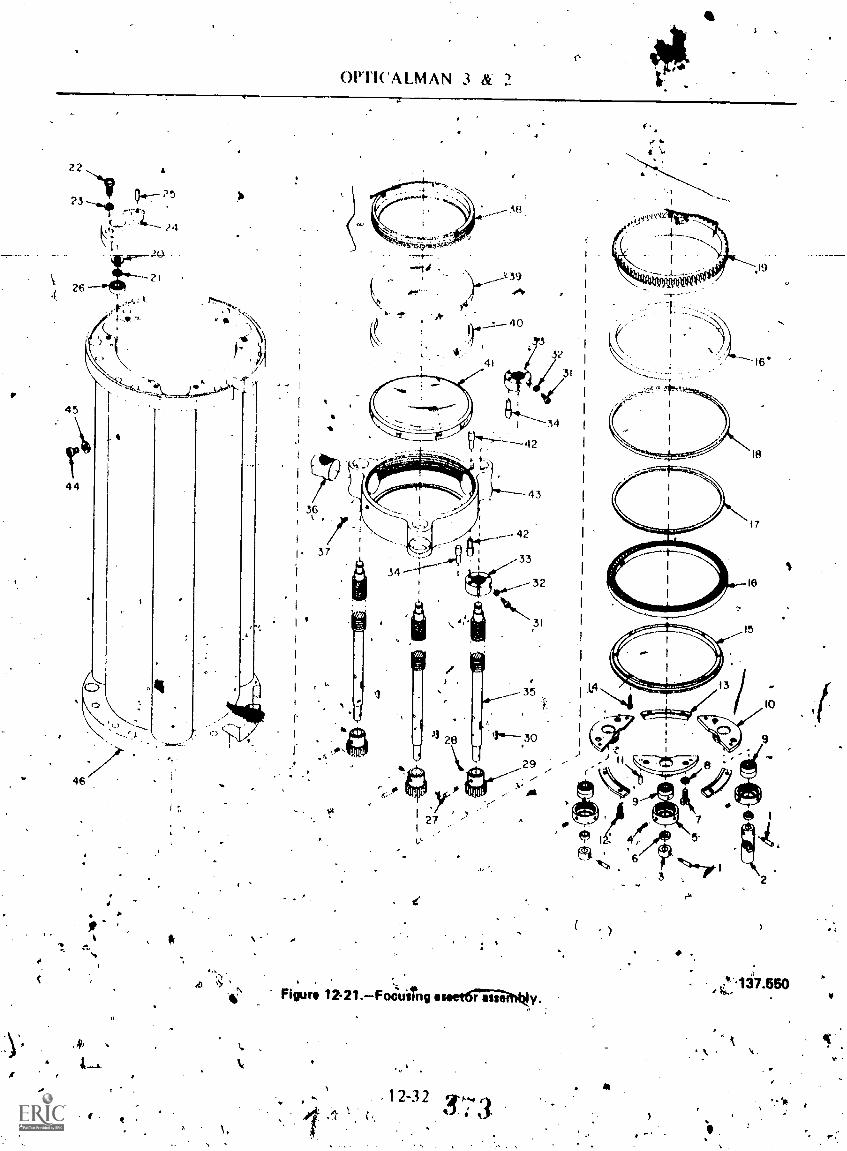
C.
OPT1CALMAN 3 It 2
44.
Figure 12-21.Focusing eseetairsaffq
. 12-32 3(
)
Z.137.550
- ,
v,

Chapter 1 2 SUBMARINE PERISCOPES
-.ire.-
1, TAPER PIN.2. JOINT, UNIVERSAL3. COLLAR, SHAFT -4. SETSCREW5. CAP, BEARING6. SPACER7. SCREW, FILL. HEAD8. WASHER, LOCK9. BEARING, DUPLEX
-10.---RETAINER, .11E ARING11. PIN, DOWEL12. SCREW, SELF-LOCK1NG13. CLAMP, BEARING14. SCREW, SELF-LOCKING15. CLAMP, RING16. BEARING17. SPACER, BEARING:
-Inner race18. SPACER, BEARiNG:
Outer race19. GEAR, DRIVE20. RING, RETAINING21. SPACER22. SCREW, FILL. HEAD23. WASHER, LOCK
Legend for figure 12-21.
which provide friction kr-inoVement. Thesebearings, are either slightly preloaded ormachined to aro clearance to eliminate any endplay. Cleanliness and prciper !imbrication ofbexings. -and bearing surfaces are essential totmaintain 'the precision of th e. skeleton head.
Siirk.t the Galile4n telescope shiTts in and out. of the line of sight, the Galilean eylens cube(79) has several adjustments to align _thelow-powerjine 'of -sight with the high-powersystem. TR) Galilean eieleils (84) is held in alens mount (85) which screws in and out oc-an-adjusting nut (8.1) to provide- a parallaxOtustment: The screw holes in the atljusting nut(81) pre elongated so the adjusting nut can hepilioted left aud right around.a dowel Pin (80) toeliminate displaootient of ihe line of sifght wivnthe periscope is shifted from high pcfyda to lowpower. Detent' springs (70) hold the Avo cubesin either the high-pow r or loW-p0,pr positions.
The basic elevatioi mechanismiremipenentsin the skeleton7 head sonsist of a siia ft (67 ),_coupling (59), and nn, and -Arm gearassembly (37). Assoc ted. evings, .spacers,
knd retainers can readily:be seen.in.12-22. It is important .to nate thpt .the worm .and
er
24, PLATE, DEARING25. PIN, DOWEL26. BEARING27. 'I'APER PIN28. SETSCREW29. GEAR, PINION30. KEY, WOODRUFF31. SCREW, ROUND HEAD32. WASHER, LOCK33.-CLAMP-,-STOP34. PIN, STOP35. LEAD SCREW36. NUT, LEAD SCREW37. SETSCREW38. LOCKRING39. ERECTOR, CROWN40. SPACER, LENS41. ERECTOR, F1,INT42. PIN, STOP43. MOUr, LENS44. SCAM, BIND. HEAD45. WASHER, LOCK46. HOUSING, FOCUSING
ERECTOR
worm gear (3w) make up a matched set, and-must be replaced, if necessary., with another set.The elevation stops in the skeleton head consistof a nut (60), Stops (56), and coupling (59). Thestops (.56) are pinned to a coupling (59) which isTi-ee to rolite. Rotation of the couplinarives anut (60) up or down until it contacts the upperor lower stop. A nut guide (63) engages a slot in
. he nut to prevent it from rotating, Theelevation stops in the type q'skeletott head areset to provide 1/4° 91 eleyation overtravel at+74° and -1 0° To preVent damage to thisdelicate mechanism/the stOs in the lert,,trainirlhandle should engagp b.efore 'the stops in theskeleton 'bead
After reassembling the- skeleton .hea40`,11type. 8 and 'type 15 periscopes, y,ott most makeseveral other important tests. Since-th ese. ssopesare iiuSed for celestial navigation, the zero --elevation position of' the hei0 prism must litestablishod; Aha. head syncliro muSt ,be aligned
,electriyally, to Nad zem elevation, 'and .tabacklash test .must 10..er,cun on the elevation -
mechanism.these tests IQ adjustment§ are necessary so
that the haVigator of the subniailne will know
12=33 .
3 74
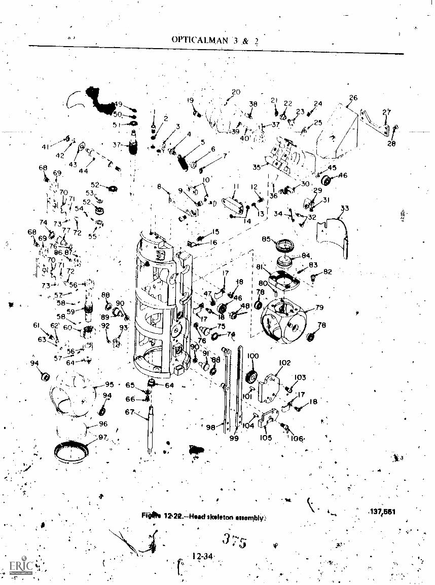
,
et 1
OPT1CALMAN .8r
26
--4 I /4.
4 2
4 3 /68 4 419-
/1 5270 53Li54
,71 52 ``,4
'&411 \toy,.4 Alt
74 7 3 '174
68 7 7 72 5c169 -crt'4
r. 70
7ki
73.4 456-.0).5 7--." I ,
5 8 8 9 -C4)frl61 62' 1011 ,3\A,
63 -A114
I.
6457
94
"It ,r .
95-) 9f,1 66-1:
2--", di 6796
r
a.
12,22.Heed skeleton essenibli
12-34-
3 e's'e-%
4.
4
1371551
44.

Chapter I 2 -SUBMARINE PERISCOPES
I. Screw 28. &sew 55. Collar 81. Nut, Adjusting2. %Ot, Lock . 29, Retainer, Prism 56. Stop 82. ScreVi3. Bracket, Spring 30. Retainer. Prism 57. Pin, 'raper 83. Screw, Set4. Shaft, Spring 31. Screw 58. Pin,,Taper 84, Eyepiece, Galilean5. Spring, Extension 32. Pin 59. Coupling 85. Mounts Lend6. Retainer, Spring 33. Shade, Sun 60. Nut 86. Screw7, Ring, Retaining 34. Wire, Prism Shade 61. Screw 87. Pin, Stop8. insulator 35. Mount. Mad Prism 62. Lockwasher 88. Ring, Retaining9. Screw 36. Pin, Taper 63. Guide nut 89. Pin, Cnbe Pivot
10. Terminal 37. Worm & Worm ( ;eat A'ssy 64. Bearing, Flanged Nylon 90. SpacertlillSwitelt Thermo Mk Screw 65: Washer 91:Pin, Cube Pivot12. Scree,13. Spring. Compression
39. Screw, Set40. Pin, Taper
66. Screw67. Shaft, Coupling
92. Screw93. Pln,'Stop
14. Wather15. Screw
41. king, Retaining42. Spacer, Shim
4, 68. Screw69. Stcip, Cube
&94. Daring .
95. Cube, Galilean Objeclive16. itetelneWire 43. Bearing 70. Spring, Cube 96. Objective, Galilean17. Retainer Win,18. Screw19. Screw
44. Shaft, Prism Pivot45. Spacer,46. Bearing
71. Pin72. Pin73, Pin, Dowel
97:Retainer, Lent98. Cube Shifting Rack Assy99. Rack, Cube Shifting ,s
10. Conn terwifigtit 47. Spacer 74, Ring, leetaiping 100. Pinion21. Ring, Retaining 48, Locknu t 75. Pin. Cube Pivot 101. Pin,'Dowel -4722. Retainer, Spring. 49, Ring. Retaining 76. Spacer 102. Bracket, Pinion23, Shaft, Spring 50. Spacer, Shim 77. Pin, Cube Pivot 103. Screw.24. Screw. 51. Bearing 78. Bearings 104. Pin, Dowel25. Bracket. Spring 52. Bearing, Flanged 79, Cube, Galilean Eyepiece l05. Retainer, Rack26. Prism, Ilead 53. Spacer 80. Pin, Dowel 106. Screw27. Rettiner, Prism 34. Pin, Taper
Legend for figure 12-22.
how much error to expect for any angle ofelevation. You will find tabks and proceduresfor conducting the elevation tests andadjustments in the appropriate periscopetechnical manuals and in NAVSHIPS 0.924 0010000 cAltiscope Angle Comparator).
. Disasgr inble thy stadimeter lensmejlitinisin assembly. Remember, the stadimcterassembli, (fig. I 2-23.).. is found only on type 2periscopes. The precision of machining-and fitwhich was necessary in the skeleton head alsoapplies to this mechanism. Mark all the partsyOu remove as an .aid to reassembl.
Seven/ problem of mechasnical and optical-alignment are unique, to thk assembly..First of
bevpl gears are used to operate the spill lensi titilA to shift' from split lens to s9lid erector.
hips- or these gears must be perfect toelit'ninate backlash, Secondly,,) When theshifted' from..solid to splitNens thid yi6p versa;;disOlke'tnent of the line of sight mist not,exceed 15. minutes-hi' tirc.Pthirdly, thelpStienS ,and solid ereJtor must be parfocaliFd,lengths, of the lensK .mot be. pomp' within
N c .
. -
.
411,
fa 5 mm of focal length. Since the 'split lens ismore expensive and more complex, adjustMentis made by machhling spacers in the solid erectoror by replacing both solid erector elements:4Finally, and most,. difricult, when the cam gear(21) is turned tO":operate the split lens, arotation of a set number'of degree's must resultin a rigidly specified .moveinent.of the two splitlenses. The tolerance kljowed for this movementmust be within 10.0003 inch.
There is nothing simple. about any workpeiformed on .tbe stadimeter lens mechanismassembly. You will needà high degree' ofanli patience to disassemble, repair, reassemble,and adjust this unit..You muSt strictly adhere to,the "step by Step., piocedure outlined infIAVSHIPS 324-0487.
pleaning-
:some, cleaning of optics and mechankal,-componnts, such as skeleton head, 6th erector,eyepiece box,, anti' 'split lens, is done during- therept*: aitd reqssembly phase of overhaulingin-Oiidual. periscope Asemblies. lt is aOsolutely
81 esse'n dal,' Oaf 1:a1.1 poss e tortns of.
A
12-3S3 ,6?,
*
,
.e

OrTiCALMAN 3 & 2
42
41:
46
61 4460.
5351
45 -----....'iii\47.-.......kat 4
4 \, -." 1- .rify
12,401
1t V 5646 55"
57
1-- 2
2324
2560
61
,..44 , 5
1' 7... !
14 k. N15---V 8r\I\ - /
12 13't..'16 .i...-. 4 1----Th., ----'1.
ri-..11. -6e4C
;,, ;
.). % - - 14 ,4) .atti_ 17 .,-' 19
lk'9 vil-IF',681(,19--28r,.._____20/-' 38
214,-.(<1%;$ 26 Ic, , 27
1
;
78 8076 I .79
II7 1
8687t4 --
6633
;
- . 131-4-
L 3f)..: 29 if.'4\\ \,'N58 2834 64 1.
#
62 63 65 82
84
Figure 12-23.Stailimetertens mechanism assembly.
contamination be eliminatsd i reparing'04riseope for reassembly. Lubricat n must beapplieq sparingly; mechanical assem hes should \'slide togethr smoothly to avoid formsition oe!Metal shavings, timer tube sectiohs .must bethoroughly, cleaned to remove particles whichcould fall .on oVcs.
11', During disassemblk, *hen ieps mounts *me
relnoved, the open ends of inner tube'sectionswere covered with4miskingliipe. To clean the
$.
A
1.
85
137.552
insides of these sectio9s, suspend them fromwire:oil a nylon line jn the same position theywould be in an .assembled scope. Tap the4puter, .
'surface of the stispended inner tube gettious*with a fiber mallet; working from thp top down,.
to 'dislodge trapped particles. The loosenedcontamination is trapped -on the masking.tape.
Reinove the -in' asking tape, apply fresh tape;and prepeat... thOin'g until no .morecontamination can- be seat on thp,apel Rotape.
248
46.

Chapter 12 -SUBMARINE PltRISCOPES-11r
1. Stow 24. Bearing, Flanged 46. Bracket, Detent 68. Washer, Lock2. diiior, Lens Mount 25. Bracket, pinion 47. Stud, Roller 69. Screw3. Erector, Split, Flint 26. Pin, Tepar 48. Spaceo 70. Spacer4. Erector, Split Crown 27. Joint, Universal 49. Pin, Taper 71. Bearing5. Screw 28. Dowel, Locating 50. Bearing 72. Screw6. Pin, Dowel 29. Screw 51. Ring, Retaining 73. Specer, Bearing7. Mount, Lens 30. Joint. Universal 52. Pin, Spring 74. Screw8. Mount, Lens 31. Pin Japer 53. SpringExtension 75. Gear, Driving9. Clip, Lens 32. Shaft 54. Pinion, Went 76. Pin, Dowel
10. Clip, Lens 33. Bearing, Flanged 55. Pin, Taper 77. Pin, Dowel11. Screw 34. Plate, Bumper 56. Spacer 78. Gear, Bevel12. Screw 35. Stop 57. Bowing, Flanged . 79. Retainer, Bearing13. Pin, Dowel 36. Ring, Retaining 58. 80. Screw14. Rail 37. Piste, Stop J t, Unitierall 81. Stop15. Support, Mount 38. Screw 60. Screw 82. Spacer, Lens16. PinTaper 39. Pin, Dowel 61. Pivot 83. Erector, Crown17. Retainer, Cam, 40.11ing, Retaining 62. Washer 84. Spacer18. Guide, Mount. 41, Shaft 63. Screw 85. Erector, Flint19. Follower, Cam 42. Bearing 64.- Pin, Dowel 86. Spacer, Lens Co3.ee7.:20. Shoe 43. Adapter 65. Gear, Detent 87. Cover, Lens21. Gear, Cam 44. Screw, 66.11in, Dowel 88. Screw22. Pinion, Bevel 45. Pin, Taper 67. Mount, Stad. 89. Skeleton, Stadimeter23. Spacer, Pinion
Legend for figure 12-23.
the tube sections until you are ready to installthe lens mounts.
The procedure for cleaning lenses pascovered in Chapter 7 of this manual. Cleaning,pergc'ope optics presents several other problems.
The erectors are quite large and acetonewill leave streaks if' you are not careful.
' Since the optics lire stacked up, any dirtin the tube sections will fall on the lenses and bevisible.
* Due to thetravel of the focusing erectorithe surface of all lenses in the scOpe can be.seenat various times when the erector is beingcranked from normal viewing position to. cameraposition.
The telemeter must be super spotless--noscratches, no. streaks, no lint-absolutecleanliness iS the minimum requiremelit. Even inthe clean* room, it can ta ywherv from15
a.
minutes to a whole day to.satisfactorily cleantbe telemeter.
The telemeter lens mount for a type 15periscope is shown in figure 12-24. Thisarrangement is similar to that used on the type 2and 8 *it pes. Parts 3 and 5 are the two elementsof the field flattener. They are located in thetelemeterjens mount. A sealing window (10) isfound only on. type 15 periscopes.
The telemeter lens .mount must be.scruptilously clean if you hope to end up with aclead telemeter when the scope is assembled.Part r6 in figure 12-24 is a fine mesh air filter.Since nitrogen must be free to cirdilate around'all optics in the scope, the filter allowscirculation but prevents entry of dust or lint.
Reassemblylind Collimation
A stibmarine periscope has many separatecollimation requirements, including the coin onrequirements, such as parallax, Ordiop rs,
, squareness:of the telemeter, and elevation o the
.ro
i)

4
OPTICALMAN 3 & 2
1. LOCK RING, FIELD LENS2. RETAINER, FIELD LENS3. FLATTENER. FIELD4. SPACERJIELD LEN'S5. FLATTENER, FIELD6. SETSCREW7. RETAINER, TELEMETER
LENS MOUNI-8. LOCKRING, TELEMETER
LENS9. RETAINER, SEALING
PLATE
8
10. SEALING PLATE,TELEMETER'
11. MOUNT, SEALING?LATE
12. SETSCREW .
13. RETAINER, TELEMETER, t, LENS
114. TELEMETER LENS15. FILTER, RED'N. FILTER, AIR
.17. MOUNTAIR FILTER18. MOUNT, TELEMETER
LENS
Figur* 12.24.1Tilennter line mount *nimbly.
.14
40.
137.553

Chapter I2SUBMARINE PERISCOPES
late of sight. It also has a few uncommoncollimatibn requirements, such as nitrogencompensation, relay system collimation,stadi meter collimation, and displacement.Collimation of various subassemblies is doneduring and in conjunction with reassembly.
submarine- periscope ..collimator isdesigned to reproduce .the various collimationdistances-optically. 'Place the collimator targetin a threaded tube so you can move the target inrelation to the collimator objective. A scaleengraved On the collimator body shows thevarious available. distances. Use the distancesshown below in collimating the variousperiscopes in, air to compensate for the
, introduction of nitrogen%
Periscope Distance (feet)(HP) (LP)
2y, 2V.,, 2F 3,171 498n, 8C, 158, l5D 3,171 52
Keep in mind that these distances shown applyonly to -the assembled periscope, the procedure--for collimating subassemblies-will follow.
FIRST ERECTOR AND HIGH POWEROBJECTIVE.With the high power objective,field flattener, telemeter, and first erectorinstalled, in the first and second inner tapertubes, place the tubes on the eteriseope rail inline with the perisdope collimator, as shown infigure 12-25. With an auxiliary telescope set to
Figur 12-25.Primery
12-39 3So
1118.35,0

, OPCALMAN 3 14. 2
your eye, move the first erector until thetelemeter appears sharply de fined.! Set theperiscope collimator to the prescribed distancefor high power collimation of tfre particular ypeof periscope you are working on." Adjust thehigh power objective so. that imliges of thecollimator retick and telemeter appear in thesame pkine (no parallax). NOTE:. For propermagnification of the high potver system (andoptimu91 accuracy of the ranging mechanism),the focal lengths Of the first and second erectorsmust not differ more than I% ( I 2 min), and thefocal length of the third and fourth erectorsmust not differ more than 1`,4,(1 2 nun).
To, provide the correct image planereferences for cOhmating in air, use a special-crosswire fixture iiuilar to that shown in figure12-26. Specifications for making these fixturesfor different periscopes are in the appropriateperiscope technical manual.
SF.COND ERECTOR, Replace the firstcollector lens .mount with the appropriateerOsswire fixture. With the second erector-installed, reconnect the first and sec nd innertubes. Sighting. through the second ere, to withan auxiliary teltscope, move the ei 'etc toremove parallaX between the collimator
.Figure 12-28.-7Typical crosswire fixture.
148.359
telescope reticle (set at 'infinity) and thecrosswire.
TkIIRD ERECTOR. -Install the third erectorin the lower end of the third inner 'tube and theappropriate crosswirefixture in the upper end ofthe third inner tube. Sighting through the thirderector wall the auxiliary, move- the erector to;remove parallax (collimator setsat
VOURT1-1 ERECTOg.- lns&all the fourtherector in the lower end of the fourth innertube. Install the appropriate crosswire fixture itSthe lower end of inner tube No. S. Sight throught he fourth erector and remove parallax(collimator set at infinity).
-szFIFTH ERECTOR.--Install the attropriate
crosswire fixture into the top of the Moth innertute. Place the tube and the stadimeta lensmechanism assembly on the periscope trail sothat the fifth erector- is adjacent to the loWerend of the sixth inner tube. Sighting through thefi-fth erectoz, with the collimator sei at infinity.remove parallax on the crosswire by shifting theentire split len§ mechanism closer topr fartherfrom the lower end of the sixth inner tdte.When parallax' is relboved, accurately measurethe distance betweenthe flanges of inner tubeNo. 6 and the-stadimeter lens assembly.
STADIMETER SPLIT LENS.--The fiftherector and 'the stadimeter split leni must .be-parfocaliZed (have their focal planes at the sameipoint) to the point established 'by the crosswirefixture .at the upper end of the sixth inner tube.Use ,the sante setup as Ibr the fifth erector,except that the split lens is in the line of sight.Remove parallax again by shifting the stadi eter'lens mechanism back and forth. Measure hedistance betweep the flanges. lt sho Idcorrespond, withfh ±0:5 mm, to the distanc4measured for the fifth erector. If it does not,
,,shift the fifth erector in its mount until thelneasurements correspond. These measurementsdetermine the size of the spacer between theflanges of the sixth inner tube and thestadimeter lens mechanism. NOTE: t Theforegoing procecipre for the 5tH 'erector/splitlens applies only to type-2 periscopes. Th'e fifth,
12:40
3Si

pulpier 12 SUBMARINE PERISCOPES
ereptor on type 8 and-A5 Periscopes iscollimated like the upper erect rs.
When each of the erecto s IN collimated,remove the crosswire fixtures hnl seal the openends of the tube sections with masking tape. Setthe sections aside until ready for final assembly,
CORRRT DIOPTER SETTINC. Assemblethe focusing erector assembly, lower taper tube,eyepiece box, and eyepiece on the periscope railand focus sharply on the collimator (at infinity),using an auxiliary telescope. This is the 0-dioptersetting in air and must be_adjusted for 0-diopterswhen the periscope is charged with nitrogen.Make the adjustment by moving the 6th erectora specified distance towltly collimator. Thedistance will vary with each type of periscope.New, set the upper stop of the focusing erectorassembly to allow +1.65 diopters focus trgvelwhen. The periscope is charged. Adjust the stopas specified in the appropriate technical manual.Check the lower stop position also at this time.Adjust the focus. knob, if necessary, to read0-diopters,
SQUARE THE TELEMETER. AND CHECKTRAVEL OF THE 'HEAD PRISM.--On- type 2periscopes, assemble all tube sections from thesplit lens mechanisM through the eyebox. YounoW 'have to align the'split lens to the eyebox.Place a leveled transit at the end.of the periseoperail so you can sight the sp1i4 lens. Place a'machin,ist's square on the eyebox staunchingplate (90 in fig. 12-20). With the transit, sightthe vertical edge of the square and rotate theeyebox to align the square with the transitcrossline. Now, swing the transit down and focuson 'the split lensIf the split lens is not perfectlyaligned with the transit crossline, rotate the splitlens mechanism or inner tube sections to.obtainalignment, NOTE: Do not disturb the positionof the eyebox.
When you have aligned the split lens withthe eyebox, secure all tialegitctions and installdowel pins.
On all types of periscopes, after you havecoltimated the individual erectors, assemble thereMaining inner tube sections, replace Theshafting, install the skeleton head,,eplace .thepoWer shift tapes, and install the handles.NOTE: If new tapes Ware used, they must he
1 '-41
prestressed as specified in the appropriaietechnical manual to prevent unwanted stretchingwhile in service.
When squaring the telemeter of a type 2periscope, operate the sPlit lens mechanism toopen the split lens. If the telemeter is notsquared, you will have duplication of tke verticalline of the telemeter, as seen in figure -l-2-27A:Loosen the screws which secure the telemeter
A. DUPLICATION OFVERTICAL CROSSLINE
B. NO DUPLICATION
14.367Fiiure 12-27.Duplication chock.
8,2

OPTICALMAN 3 &
mount and rotate the telemeter mount until,.duplication is etminatekl (fig. 12-278). Secure'the telemeter ;ind return the split lens to itsoriginal position.
To check the travel of the head prism, setthe collimator to the HP distance discusse4 inthe section on reassembly and collimation andalign, the collimator with Ow skeletan..head. (Resure the periscope is set in high power.) Nowrotate the collimator 45° and align theintersection of the collimator crosslines with thetelemeter vertical line as shown in figure 12-28.By elevating and depressing the line of,sight tothe extreme edges of the collimator field, checkto see that the int4..rsection of the: collimatortarget. remains perfectly aligned with thetelemeter vertical line. If the collimator targetappears to track to either side of the telemetervertical line at opposite edges of, the field, therotational axis of the head prism is not properlyoriented. NOTE: Make this check with anauxiliary telescope to magnify the telemeter andcollimator images so you can more accuratelydetermine if a possible error can be made.
If you do not have perfect tracking of theline.of sight, reposition the skeleton head and/orinner tube sections above the telemeter by
148.363Figure 12-28.Collimator in rotated positiod(HP).
1.
renking owel pins and loosening the securing'bolts/ bet een sections. After , rOtating the
kskeleton he d----slighTly, recheck the tracking ofthe -line of sight. Continue to reposition theskeleton head and check tracking until perfectcointidence of the collimator and telemeter isevident-through. the full visible travel of the lineof sight: NOTE: If- you eannot----obtain -the-necessary coincidence by rotating comtiOnents
, . .. -
abOviOhe telemeter, loosen sone or more jointsbelctik the Jelemeter. If you must loosen thejOilits, you will need to square the telemeter totho split lens again before you check tracking oftheline of' sight.
After obtaininiiproper tracking of .the lineof sight, secure all tube sections and replace the
%dowel pins..
For typel and type 15 periscopes, set aleveled transit below the eyebox in line with theaxis of the periseope. 'Set a machinist's square onthe eyebox staunching plate and rotate theperiscope until the edge of the square is alignedwith the transit crosslint. Now shift the line ofsight and- focuson the edge of the head,prism. If
-1)the prism edge aligns with the ansit crOsSline,there is no protilems If perfect al gnnient is notapparent, proceed With repositioning theskeleton head as was done in the tie 2periscope. , ....
After you have properly oriented the headprism to the staunching plate, square thetelemeter to the travel of the head prism byobserving the tracking of the .collimator targeton the telemeter vertical line. It' perfect trackingis not, evident, simply rotate the telemetermount and recheck. When the collimatorcrossline remains perfectly superimposed on thetelemeter vertical wire, secure the telemeter.
ELEVATION OF THE LINE OFSIGHT.LBefore making the check, align(boresight) the collimator so thitt its line of sightcoincides with the periscope's, and square the.collimator target to the telemeter.
The elevation/depression check may not beaccurate if the collimator is not aligned becausethe pivot point of the head prism mo,y_not bethe- same as the pivot point of 'the collitnator.Since the collimator pivot is an eccentric, it canbe adjusted ko the same height above theperiscope collimation rail as that of the' heade.

Chapter 12SUOMARINE PERIZ'OPES
prism pivot shaft. See figure 12-25. Once 'thepivoa points coincide, make the elevation anddepression tests.
Swing the collimator to the proper amountof elevation for your periScope (60 for 8 and15; 740 for 2). The periscope must elevate sothat the horizontal- crossline touches theintersection of the colhmator.crosslnies. Depressthe colliMator to -10°. The periscope- must beable to depress to -100. If the periscope will notelevate or depress as reouiredv. 'adjust thecorresponding stop. Also adjust the leflt traininghandle at this time so the handle graduationscorrespond widi the line of sight.
LOW POWER P.ARALLAX.Parallak will beintroduced when the Galilean telescope isshifted intd the line of sight if the Galileaneyepiece lens mount is not properly adjusted. Toremove parallax in the low power system, firstadjust the -periscope collimator to the distancespecified jor the periscope. Loosen the Galileaneyelens Sefitow and screWlie, eyepiece in orout A'. the ''inkiunt, as reqUited, to remeeparallax. There is no tolerance'N r parallax; MOWER
remove any that is detectable. NOT .,..pse an COLLIMATOR
auxiliary telescope.
VERTICAL AND HORIONTALDISPLAcc.MENT- OF THE CROSSLINETheline of sight, of the Galilean telescope must:coincide with the line of sight orthe rest of the',periscope. If not, the position of the image willchange when the periscope is shifted from highto low .power or vice versa. Theiresultis an errorin azimuth or bearing when you hange fromone power to.the other.
To check for displacement, superimpose thereticle (with the.periscope in high power) on thecrosslMe of the collimator. Now shift theperiscope' into low power and set the collimatorto the 'low power position for the periscope youare wOrking on. Figure 12:29 shows Correct andincorrect collimation for displacement.Horizontal or vertical displacement, or both,May apspear in any .quadrant .6f the reticler,NOTE:: The telemeter, of type 2 perikopes does'not, have a horizontal line as dO "type 8iand.type15 telemeters.;,Compare figure 12-27 and 12-29.
To reniove horizontal or verticaldisplacement, loosen the screws -securing the.'
,
Fiore 12-
--HORIZONTALDISINACEMENT
CFVERTICAL
lINt
- VERTICAL .
04PLITCEM4 NT
HORIION1 INE
DisplaciOnen1 chock.
Galilean eyepiece mount and shift the Galileaneyepiece laterally and/or vertically to place itsline of sight in coincidenceswith that of the highpower system. The maximum allowable error fordisplacement is two minutes' horizOntaldisplacement Of the ',/rtical crossline and tenminutes' vertical displacement Of the horizontalcrossline. There is no reason Jot you not to'eliminate all displacementk.. ' ;-
adjust the right training handle so...the.deteht and index marks are prqperly placed. Tpetape tension adjustment (figure 12-19) can bó .ofbenefit in adjusting ttie handle,
,
148.361
V
StaClimeler Collimation
'During reassembly of the split. 'lensmechanism; you tested the. as§ernbly fOr propertravel and baoldash". .Nolv, with the periscope

.OPTICALMAN
inner tubes assembled, eliminate anydisplacemept evident after shifting from thesolid 5th erector to the split lens, and make arange check.
A Replace the stadimeter on the bottoM of theeyebox and test the' in-out drive and the rangeknob. Set the collimator and periscope 'in highpower .and see if there is any displacement inshifting_ the Removedisplacement by filing or building up the cubedetent (65 in fig. 12-23).
Prior to maki g a range check, reinove anyduplication of h zontal or verticallines on thetelemeter, Simpl cover the collimator withseveral sheets o lens tissue to bloac thecollimator target, a'nd yet have tIlummation.NOTE: Move one split lens half at right angles tothe split, which will adjust duplication ofvertical line's. Move thc other.... allel to the splitwhich will adjust,duplication o iorizontal lines.
hyre are two methods to check the. tangingaccUracy of the stadimeter. One is to.operate thesplit lens to obtain coincidence of successivedarks on the telemeter vertical ladder. (See fig.12-30.) The other is ti obtain coincidence ofsuccessive .marld on thcollimator target:"(Seefig. 12-31.) In the first 'method, set the heightscale on the stadimeter dial for 100 feet. Usingthe second method, set the height vale at 20feet to obtain range readings. NOTE: All rangechecks are made with the periscope in highpower.
Overlap of the' comator targei, the secondmethod, is the preferred method for making arange check. As you ca. n see by comparing theranges in figures 12-30 and 12-31, the collimatorranges cover, a much wider available area.,.,with aremitting increasein expected accuracy. 4..
Accuracy of oVitrlap ranges must be within±2% at each step in the check. If for.any reasonranges do not check out cOrrectly or irduplication cannot be removed, .you may need.to .repeat the overhaul procedure for the splitlens mechanism.
Astembly
When all collimation requirements have beenfilet, secure the wiring harnessekand, in the type-8 and type 15, the waveguide and antennacables. Also, make a finalicheck of all tube
s
section Joint fasteners, shaftingatniversal joints,and all screws visible on the inner tube.
Insert the inner tube in the outer tube withthe eyepiece facing down and the head prismfacing up with the scope in low power, zeroelevation. The inner tube must be perfectlyaligned With the outer tube and evenlysupported to prgvent sagging. As you earefullyin sert-t-he- inn er-tu be- in --thi-outer-tub-eTwiptTdinner tube sections and flanges with acetone anda lint-free cloth.
; Take particular care -with the last foot ofinne'r tube as it enters the \outer tube. The0-rings which seal the scope are in this area; thethreacls of the tnain coupling must not bedamaged; am) tlie inner tube keY must remainaligned with the outer tube keywa.
As the inner and outer tubes come together,rotate the main coupling.4by handcounterclockwise until you feel two jumps. Thisindicates ,the starting leads of the threads. Oneperson now pushes the irOttom of the eyetIoxand maintains alignment between the inner andouter tubes, while another tightens the maincoupling.
When you have rotated the coupling fwo orthree times, measure the distance between the rcoupling and tubegthe distances should bewithin 1/16 inch. If the measurement is notcorrect, you did not catch the eyebox or outertube threads at the same time the main ooupling'was started. When the coupling engagement i§Correct, tighten the cdupling with the,specialspinner and slug it tight with a mallet
The final step in periscope assembly. andcollimation is to establish a true optical, tero
'elevation. lh the type 8 and pe 15 periscopes,the head sylichro was elec ly aligned withthe mechanical zero of thiv 'ad prism, but no-such check is made on the t e 2 scopes. Also,due to the thickness and mounting angle oTperiscope head Ivindows, som# opticaldisplacement will be present and 'tiSust becompensated for.
It is especially important tO set' the trueoptical Zero position on type 8 and type 15periscopes since they are used for navigation. Afine synchro (36X) on the skeleton, headafid acoarse synchro (2X) in the eyebox areconnected to the elevation shafts an0 gee* sdthat they transmit continuous electrical
12.44
385 ,

*v.
Chapter 12SUBMARINE PERISCOPEg , 4
Nun 12-30.Tdometst von. references.
12-45
148.316
:

.
OPTICALMAN 3 8(..
p
r
11000- 2'A
2500- 20
1
v
k
Figur* 12-3'I.-Collimator
12-46
1000
500-20
new Nterinoes.
400-20-
148.366
4

Chapter 12SUBMARINE PERISCOPES
,
It would be difficidt to say that any one stepin periscope repair is more important than anyother. However, if a wok leaks or fogs up inservice, it is.uselesi.
During the overhaul procedure, all sealingsurfaces were carefully inspected and 4ny
, 0-rings on removed components were replaced.Mien 4hese steps have been taken carefully andconsdentiously, The posibility of4as leakage orentry of seawater is greatly,reduced.
elevation .information to j.a. remote recorder.After true optical zero is found, the electrical
'signal is adjusted to read zero elevation in therecorder.
To find optical -zero, mount either twotransits or two Mk 8' collimator telescopes (witheyepieces) at right angles to the periscope facingeach other. Adjust the transits or collimators to'alignthe Treasslineur Dv! --iTiWilrne-iit withtheorossline of the opposite instrument. Check backand forth between both instruments untilperfect coincidence is established.
Position tre periscope so you cansuperimpose the telemeter on the crossline ofone alignment instrument.
Roll the periscope and sight the .crossline ofthe opposite instrument. Note the amount ofdisplacement and direction of displacementfrorn the first sightthg. NOTE: You shouk1 beconcerned only with displacement between thehorizontal line of the telemeter and the verticalline of the alignment instrument crossline. .
To correct displacemenL -remove half theerror with the scope elevatidrhandle, then alignthe test instfument 'with the telemeter. Nowadjust the opposite test instrument to the firstinstrument. Superimpose the telemeter on onetest instrument and roll the scope again.
Continue checking one lest instrumipt thenthe odier, making adjystmqnts as necessary,unlir perfect coincidence of the horizontal linesis established.
The electrical output signal of the synchroscan now be read and recorded t o the final zeroelevation information can be corrected'after theperiscope is installed.
s For type 2 periscopes, once zero ilevation isestablished, adjust the zero elevation' detent inthe left training handle.
Perisc ope Cycling
The final step iii periscope overhaul is *topresgure.:test the instrument and check for leaks,pull a high vacuum on the scope to remove any
. moist ure present, and then charge theinstrument with dry nitrogen. This' entireprocess is called "cycling." Any periscope thatexhibits internal foggi* ,vhen no otherproblems are present, is also cyded,in the same
a manner.
PRESSURE TESTING,.We discussedprocedur6 and precautions concerning the useof nitrogen bottlei and charging equipment inChapter 8 of this nianual. NOw, we'will explainpressure testing thetbods culiar to periscopes.
Purge the cha ging hose before youattach it to the air inlet fitting:
Attach a pressure gage to the periscope..to check internal ptessure 0 to 100 psi).
Set the regulator to 0 (no flow ofnitrogen) and attach the char g hose.
Open the air inlet valve and the nitrogenbottle valve and set, the- flowmeter forapproximately 3 to 5 cubic feet per minute flowrate. If a flowineter.ii not available, increase theregulator pressure in 4 psi steps pvery 5 minutes.It will usually take about 1 hour to buildpressure in the periscope to the maximum testpressure of 50 psi.
.NOTE: NEVER al)ow a surge of pressure toenter the periscope. Any- rapid increase coulddamage the scope and till stir up dust or othex--undesirable particles. Be sure you secure the'eyebox pressure gage before internal pressurereaches 30 psi.
As pressure is building in the scope,check all foipts, packing glands, and windowswith a soap solution and soft brush. Verycarefully observe each possible area of leakagefor small Nibbles. When using soap for det9ctingleaks,, check the scope at least four times duringpressure buildup, since a leak Could be evident at15 psi but nOt at 45 psi. Make sure the bottle is ,
secured when internal' pressure reaches 50 psi.
1247 389
r

otr
OPTICAINAN ,3 ,
NOTE: The preferied Method for. detectingleaks is to sobmerge the periscopein a tank ofwater. However, this is not usually practical on titender, and impossibk on a submarine,
If leaks occur around a shaft, tighten thepacking gland. Leakage at any other joint can bestopped only by removing the affected-component amtl no placing 0-Angs..
After a satisfactory pressure test, releaseinternal 'pressure slowly, usually I hour, ttt avoidstirring up any dust in the scope.
At sonic repair facilities, a hydrostaticpressure test of the outer head and tapertube/outer tube joint is mandatory. This test isconducted by slipping a specially comstructedtank over the head section and upper portion ofthe outer tube.
The tank is sealed around the outer' tube bya packing assembly similar to the hull gland:Long rods between 'the lank and a heavy plateq the bottom of tlie. scope eyeb6x hold theunit in. poSition during the test.
To condutt the test, fill the tank with waterand apply a specified air pressure to:duplicateseawater pressure at the required depth.
If the periscope has been. reassembledcorrectly anti it' there are no hidden defects, theinstrument will pass the hydrostatic' test. If a
leak occurs, you now have the problem of aflo(xted periscope to contend with, which willinvolve complete, disasseMbly down to the lastscrew.
small omottnt moisture present. Therefore,'vacuums ob t out 4 mm are usually satisfactory,
NOTE: Do not attempt to dry a periscope inif the outside tthiperature is belowa submarine
.,450° F.
To assist with drying the periscope underv u U m a heafer_blan kat_ h__afte -used-onA heperiscope tb raise the temperature,. whichimproves he vaporization of moisture. Thehearer blanket is a heavy duty, rubherized,electric blanket long enough to cover fife outertube.
The following procedure applies to all typesof;periscopes;
.5 Position the,
on.'
4ttach the Nap vactium hose to thescope air outlet. Keep hoses as short, as possible.Turn on the pump and allow it to run for severalminutes before opening the air valve. Applyvacuum sealing wax (Apiezon) to all putnp and.,hose fittings to eliminate possible vacuum leaks.
heater blanket and turn it'
NOTE: The powr supply to the vacuumpumil Mist be on a circu4 which automaticallyreceives emergency power in case of a generalpower failure. If for any reason pawpr is lost
/ while pulling a vacuum, oil \could be -suckedfrom the pump into the periscobe.
. .DRYING.To remove traces of mois tire,-
usually caused by the relative humidity n, theoptical shop, pull a vacuum on the sc e afterreleasing tek -. piessure. Under 'a tvacuum,
1 mpisture vaporizes (boils) at a low temperat4<___and can lie easily withdrawn by a vacuum pump., The vicuum pump is ..a rotary.,pOsitive-displacement, laboratory quality devicecapable of pulling a 0.01-mm 'vacuum. ACENCO HYVAC pump is the type usually usedin'optical shops.
Although the pump is capable of pullingvery low vacuums on small areas, a periscope .
contains a large volume of empty space, with a
,
1.2-48
. Connect a vacuum gage to the tieriscppeso you, caq constantly monitor the degree ofvacuum, Bourdon tube vatuum gages can beused, but electronic gages are prefeAd since ahigher accuracy can be obtained.
Open the air "outlet valve and---preceewith pumpiqg until a. vacuum of, 4 mm.reached. Thisimay take fromi21 to 4 hours.
When the desired vacuum, is reached,secure the air outlet valve, remove tkie vacuumhose, then secure the pump. Allow the periscopeto sit for at least 3 hours under vacklum withheater bjanket od; then rechecitc the vacuum, Achanged (raised) vacuum, reading usuallyindicatea the of moisture vapor.which
3s9
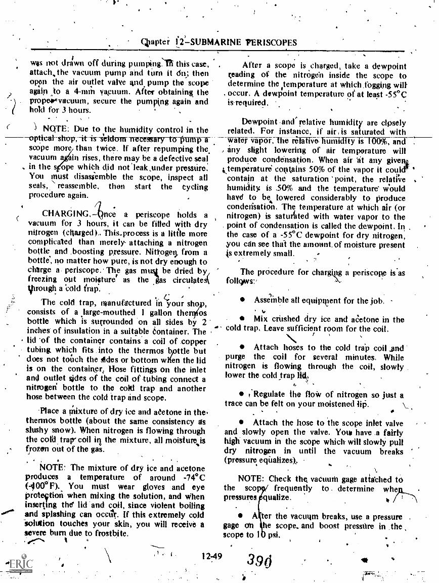
Ckapter i_2)SUBMARINE PERISCOPES
was not dawn off during pumpingl'h this case,attach,the vacuum pump and turn it dii,; thenoppn the air outlet valve And, pump the scopeagain :to a 4-mm ya,cuum. After obtaining thepropesevacuum, secure the pumping again andhold for 3 hours.
NOTE: Due to the humidity control in the-is-s'eldurrynecessary to Pump
scope more than twice. If after repumping the,vacuum a in rises, there may be a defective seal
, in the s ope which did notleak,under pressure.You must disassemble the scope, inspect allseals,.' reassemble, then start the cyclingprocedure again.
CHARGING. nce a periscope holds avacuum for 3 hours, it can be filled with dryniirogen (cliarged).. This.process is a Mile morecomplicated than merely- attaching a nitrogenbottle and boosting pressure. Nittoget). from abottle', no matter how pure, is not dry enough tocharge a periscope.. The gas musit be dried by,freezing out moisture as the *gas circulatestohrough a 'cold frap.
r. A
The cold trap, manufactured in your shoconsists of a large-mouthed 1 gallon the osbottle which is surrounded on all sides by 2inches of insulation in a suitable tontainer. Thelid 'of the container contains a coil of coppertubing which fits into the thermos bpttle butdoes not touch the Ades or bottom Olen the lidis on the container, Hose fittings on the inletand outlet sjdes of the coil of tubing connect anitrogen` bottle to the colti trap and anotherhose between the cold trap and scope.
-Place a mixture of dry ice and eetone in the,thermos bottle (about the same consistency asslushy snow). When nitrogen is flowing throughthe cold. trap-coil ill the mixture, all moisturefrozen out of the gas.
NOTE: The mixture of dry ice and acetoneproduces a temperature of around -74°C(1000P)., You must wear gloves and eyeproteftion when mixing the solution, and Wheninserting the' lid and coil, since violent boilingand splashing can occiir. If this extremely cold'solution touches your skin, you will receive asevere burn due to frostbite.
1
After a scope is charged, take a dewpointreading of the nitrOgen inside the scope todetermine the temperature at which.fogging willoccur. A dewPoint temperature of at least -55°Cis.required.
Dewpoint .and relative humidity are clpselyrelated. For instance, if air is saturated withwater vapor, The relativo 1iuñiTdTi5fs 100%, and
, any slight lowering of air temporature willproduce condensation. When air "at any give%
ktemperature contains 50% of the vapor it coulercontain at the saturation point, the relatevehumidity is 30% and the temperature' wlouldhave to be lowered considerably to producecondetisation. The temperature at which air (ornitrogen) is saturtited with water vapor to thepoint of condensation is called the dewpoint. Inthe case of a -55°C dewpoint for dry nitrogen,you can see thal the amount, of moisture present
extremely small.
The procedure for chargt.pg a periscope is'asfolk)ws:.
AsseMble all equipment for the job.%.
Mix crushed dry ice and aCetone in thecold trap. Leave sufficient room for the coil.
Attach hoses to the cold trtip coil _andpurge the coil for several minutes. Whilenitrogen is flowing through the coil, slowlylower the cold_trap lid,
Regulate the floW of nitrogen so just atrace can be felt on your moistened 145.
Attach the hose to the scope inlet valveand slowly open the valve. Yota have a fairlyhigh vacuum in the scope which will slowly pulldry nitrogen in until the vacuum breaks(pressure. equalizes);
NOTE: Check the vacuum gage atia'ched tOthe sco frequently to determine wheppressures. qualize. * /
A ter the vacuqm breaks, use a pressure .
gage on khe scop& and boost pressnre in thescope to 10 psi,
12-49 390'

OPTICALMAN 3 & 2
NOTE: Use a flowmeter set for 3 to 5-cubicfeet per minute., or boost a regulator in 4-pound.steps every 5 minutes.
Whett pressUre reaches 10 psi, se re thecharging valve and remove the cold hose.Pull the coil out of the cold tra allow a
'slight flow of nitrogen to run th h the coiluntil_the cotl_reaches-room-tem-perature-.
Run a dewpoint check of the gas in the-periscope.
NOTE: To conduct this test, use anelectronic instrument (AO4OR- DEWPOINTER).Follow the procedure ontlined in the testinstrument booklet. Tne procedure is (Ante
It
6
simple. After ninning this test several times, youproblibly.will not need to use the booklet again.
When a 'satisfactory dewpoint is obtained(-55°C or below), bleed the internal pressure ofthe periscope to 7.5'psi.
ROTE; At! periscopes are charged to 7.5 psi'40d-F . Pressure s-wilh,ary-from 7 I psi .sit -61r
to 7 :9-ipsi at. 80° F.
The cycling procedure is now complete.Secure all equipment 7
NOTE: All periTscopes shoula have adewpoint check made every 6 monthc eventhough no fogging has been noticed..
-
39/12-50
;14.

11
2.
1
A
APPENDIX I
U. S. CWOMARY. ANDUNITS OF MEASU
THESE PREFIXES
,A
0,
I
METRIC SYSTEMREMENn
'BE APPLIED
TO ALL SI UNITS _,,',$-- .4.';` . . ,
Multipiss md Sobmwittpies , Profiles 30 '---- 7----,
I °wood 000 000 iondoo 000 000 = los
/7 000 000 log
1 000 =-. 10'
100 = 10'
10 = 10= 10-'
=
'."= .10-2
001 = 104o.000 000 ooi io4
0.000 obo 00000k 1107
0.000000 000 Oooo.000 000 000 000 oi4A,rn
d
Most commonly Wed
AI-1
tera (Hey) T
giga (ji'go) G
mega*igea) M*kiô(ki6):....hecto (hilk;t6)
deka (dek'o) dm
deci (desii) d
centi (sin* c*milli (mil% remicro (m1'10-0
nano (nlin'6) n
i)ico (pVkó) p
,femfo (Rim** f'alio (lit'tó) a
\
'

1 OPTICALMAN 3 & 2
),(ENGLISH AND .-METRIC SYSTEM UNITS OF MEASUREMENT
COMMON EQUIVALENTS AND CONVERSIONS
Approximate dottifkr Equivalents
inch.footyardmiletsquare inchsquare footsquare yaacrecubic inctib)c fobt
vd.(416 yard.,TqAtirt (1q,)
s .
;ounce (avdp)!'pound (avdp)
1 horsepOwerppund Pii1ssue inch
A,milli ter; . "T.metermeter.. ,
kilometersquare ,centimetersqqare meter,.*nue meter
...4hectarectibic centimkercubic metercubic meter .
litercubic metergramkilOgramkilowattkilogram per squatecentimeter.. e
= 25 millimeters= 0.3 meter=40.9 meter= 1.6 kilometers= 6.5 square centitneters= 0.09 square meter= 0.8 square meter= 0.4 hectare= 16 cubic centimeters= 0.03 cubic ineter="0.8 cubic meter
, ==0.004 cubic meter= 28 grain's \= 0,45k4ii Mpgra= 0.75 owatt_ .
,;z0.07 kilogram ikel0".tetd"::.t::1centimeter 1.
= 0.04-inch= 3.3 feet=1.1 yards -.?'
= 0.6 utile.= '0.16 square= 11 square fee
,= 1.2 square yards- -.."
= 2.5 acres ,
= 0.06 cubic inchs,,= 35 cubic feet .
= 1.3 cubic yards= 1 quart (lg.)= 250 gallons=.0.035 ounces,(Avdp)= 2.2 pounds (avdp)= 1.3 horsepower= 14,2 pounds per square
.t nautical ,mile = 1.852 kilometers
.AI-2
3
Conversions Accurate to Parts Per Million(units stated in abbreviated form)
Number X Factor
in X 25.4*ft X 0.3048*yd X 0.9144smi X 1.60934
X 6.4516.!ft2 X 0.0929036ye X 0.836127acres X 0.404686in3 X 16.3871ft3 X 0.0283168yd3 X 0.764555qt (Jq.) X 0.946353gal X 0.00378541oz (avdp) X 28.3495'lb (avdp) X 0.453592hp ç 0.745700psi X 0.0703224
ram X 0.0393701m X 3.28084m X 1.09361km X 0.621371cm'. X 0.155000m2 X 10.7639m2 X 1.19599ha X.4,2.47105.cm3 X 0.0610237m3 X 35.3147m3 X 1.30795/ X 1.05669m3 X 264.172
X 0.0352740kg X 2.2'0462kW X-1..34102kg/ci112 X .14.223226
* exaet
= 111111
= Mm
=; km= cm2
m2m2
= ha-:- C111
3
= m3= m3=1= In 3= g
= kg= kW= kg/cm2
== ft= yd= mi= in?= ft'= yd= acres= m 3
=
yd3r qt (1.q.)= gal= oz (avdp)= lb (avdp)= hp= psi \

F.
Aberration, lens, 4-25 to 4-33astigmatism, 4-28, 4-29chromitic, 4-25, 426coma, 4-27, 4-28curvature of field, 4-29,64-30distortion, 4-30, 4-31 .
Newton's rings, 4-31, to 433spherical, 4-26, 4-27
Aberrations of the eye, 5-10, 5-11astigmatism, 5-10eye strain, 5-11hyperopia, 5-10myopia, 5-10
Advancement, .1-1 to 1-12 -iisitwy Enlisted Advancement System, the,
1-2 to 1-9Navy Enlisted Classification Codes, 1-2Opticalman rating, 1-1, 1-2Personnel Advancement Requirement (PAR)
program, NAVPERS 1414/4, 1-6 to 1-9Personnel Qualification Standards, 1-9purposes, benefits, and limitations of the ,
Planned Maintenance System, 1-9, 1-10sources of information, 1-10 to 1-12
Aperture, relative, 423, 4-24Assembling mechanical partst 8-2, 8-3 .
Mtigmatism, 4-28, 4-29
Astronomical telescopes, 5-17 to 5-20reflectini, 5-17, 5-18refracting, 5-18 to 5-26
Atmospheric refraction, 2-24 to 2-27heat waves, 2-27looming, 2-27mirages, 2-25 to 2-27rainbows, 2-27
'
1DEX
Attitude, image, 3-3 to 3-5normal and erect, 3-4normal and inverted, 3-4reverted and erect, 3-4reverted and inverted, 34, 3-5
Azimuth and bearing cilyles, 1013 to 10-18consflttTion katura, 10-14 to 10-16repfair and idjustment, 10-16 to 10-18
B
Basic optical systems,.5-1 to 5-31
eyepiece systems, 5-11 to 5-17basic function, 5-11 to 5-13nomenclature, 5-13types, 513 to 5-17
eye structure, 5-1 to 5-11aberrations of the eye, 5-10, 5-11.iris function, 5-2optical instrumint, 5-3refracting mechanism, .5-2stereoscopic via*, 5-6 to 5-10vision, 5-3 to 5-6visual acuity, 5-6
human eye, the, 5-1simple telescopes,5-17 to 5-31
astronrical, 5-17 to 5,20 .-gOn elescopes, 5-26, 5-, -,
HO 5-27 to 5-30microscope, -30, 5-31terrestrial tel scopes, 5-20 to 5-26
Bearingi, 6-11 to 6-19ball bearings, 6-18i 6-19rotational bearing, 6-17, 6-1 8%tiding surface bearings, 6-17
Bed, lathe, 9-11, 9-12
r

Est
OPT1CALMAN 3 & 2
Binoculars, 10-34 to 10-46 -
collimation, 1042 to 10-44-construction features, 10-35 to 10-39overhaul, 10-39 to 10-427 X 50 binoculars, 10-35ship mounted binoculars, 10-44 to 10-46
Blinder assembly, periscopes, 12-1.7Boresight telescopes, 10-46 to 10-49
constructicin features, 10-46 to 10-49repair-and-adjustment-, -10-49
Brazing and soldering, V41 to 7-24
6
Design and construction, optical instruments,6-1 to 6-27
lubrication,26, 6-27-mechanical features, 6-1 Co 6-7
body housingr41 to 6-5'diaphragms, 6-5 to 6-7shades and caps, 6-5
mounting-uptical-elements,-6-7-tobearings, 6-17 to 6-19fixed eyepiece mount, 6-16, 6-17focusing arrangements, 6-11 to 6-16helical gears, 6-21instrument sealing methods, 6-22lens mounts, 6-7 to 6-10optical instrument geps, 6-19 to 6-210-rings, 6-24, 6-25packing, 6-25, 6-26preformed gaskets, 6723, 6-24prism mounts, 6-10, 6-11sealing compound, 6-22, 6-23
Disasembly and repair, Periseopes,.12-28 to12..35
Dioprer, lens, 4-22; 4:23Distorti)r, 4-30, 4-31Drill presses, 9-5 to 9-10Drying, charging and sealing, 8-13 to 8-19
Carriage, 9-15, 9-16Cementing and cleaning, lens, 7-35 to 7-40Charging procedures, dptical instrnments, 8-15
to 8-19drying and charging, 8-17, 8-18general safety precautions, 8-19pressure'testing and charging rangefinders,
8-18, 8-19.securing the equipment, 8-18
Charging, sealing andtdrying, 8-13 to 8-19Chromatic aberrations, 4-25, 4-26Cleaning and painting', 7-30 to 7-35
baking prodedure, 3-35corrosion removal, 7-30, 7-31-finish defects, 7-35instrument painting, 7-34, 7-35paint removal, 7-32, 7-33preparing paint, 7-33, 7-34safety precautions for using chemicals,
7-31, 7-32types of paint, 7-33
Cleaning, p6risCopes, 12-35 to 12-37Collimation, 8-3 to 8-) 3
adjustment, 8-9, 8-10equipment, 4-3 to &.9procedures, 8-10 to 8-13
Color of light, 2-11, 2-12Coma, 4-27, 4-28.Compass; magnetic, 10-4 to 1 13Construction and design, op c instruments,
6-1 to 6-27Corrosion removal, 7-30, 7-31Crew Served Weapon Sight (CS(VS),Curvature, lens, 4-5Curvatursof field, 4-29, 4-30Cutting tools,9-22 to 9-24Cylindrical lenses, 4-14, 4-15
4 r6
E
Eye structure, 51 to 5-11aberrations s the eye, 5-10, 5-niris Ntiction, -2optical instru nt, 5-3refracting mech nism, 5-2stereosgepic visi e , 5-6 to 5-10vision,. 5-3 to 5-6visual acuity, 5-6
Eyepiece systemp, 5-11 tbasic function, 5-11 5-13'nomenclature, 5-13types, 5-13.to 5- 7
1
Final assembly, periscop s 12Fixed eyepiece.mount, 616, 6-1Fluxes, 7723; 7NFocal length, lens, 4-5 to 7 4-18, 4-19
f-'to 1247
395

INDEX
Focusing arrangements, 6-11 to 6-16thaw tube, 6-12, 6-13internal focusing.mount, 6715, 6-16multiple lead thread, 6-14, o-15 ,
spiral (hOcal) keyway, 6-13, 6-14Focusing knob assembly, perisCopis, 12-19
to 12-21Formulas, lens, 4-18 to 4-24Freque.ncy and wavelength, 2- , 2-8
,
Gaskets, preformed, -6-23, 6-24'Gas-tight instruinen , 8-13, 8-14Gears, optical instru tent, 6-1 9 to 6:21Glass, properties of, 1 to 4-3Grinders, 9-1 to 9-5Gunsight telescopes, 26, 5-27Gunsights and night vis on sights, 11-1 to 11-12
Headstoc , 9-12 , 9-13Heat trea ng and temper g, 7-24 to 7;29
ferr us materials, 7-heat treating process, 7-,27 to 7-29-nonferrous materials, -26, 7-27
Helical gears', 6-21Human eye, the, 5T1
Image description, 3-3 fo 3-5image attitude, 3-3 to 3-5real image, 3-3virtual image, 3-3 .1 ,
age formation, 4-9 to.414formation, sources of, 1-10 ,t .1-12 .ner tube removal, periscopes, 12-26 to 12-27
,:.
Inspection and testing, 7-1 Ur 7-9. , \chromatic aberration, 7-9,coma, 74- " .distortion, 7-9illumination and contrkst, 7-8image fidelity, 7 6 to 7:8 .mechanical cowl tion, 7-2optical system, -2 to 7-6spherical abitglion, 7-8, 7:9
kis funetioa, 5-2
4 k4
Knee and column type milling machines, 9-41,9-42
Lathes94-10"to 9-41attachments and accessories, 9-16.to 9-22
carriage stop, 9-21center rest, 9-20collets, 9-17, 9-11follower test, 9-2Tlathe centerst.9-3i , 9-22rnandvels, 9-22taper attiOment, 9-18 to 9-20thread dial indicator, 9-21
cutting fools, 9-22 tQP.-?4finish.cutt,'9-27
knOitledge of operation, 9-24 to 9-28, lubricants, 9-27. -
maintenance, 9-2, 9-28rough cuts, 9-27speeds and feeds, 9-26
operation, 9-28 to 9-40boring, 9-33, 9-34center drilling,.9-29
- centering the viork, 9-28, 9-29facing, 9-32, 9-33mounting work, 9-28setting the cutting tool, 9-31tapering, 9-34 to 9-36threading, 9-36 to 9-40turning, 9-31, 9-32turning between centers 9-29 to 9-31
.
principal parts, 9-11 to 9-16Jrc119-11, 942q(arriage, 9-15, 9-16
headstock, 9-12, 9-13quick-change gears, 9-15tailstOck, 3 to 9-15.
safety precaUtions, 940, 9-41
Left training handie, assembly, periscopes, 12-21 ,to -12-23
#
,
Lens cleaning and .ceenti'ng, 7-35, to-740ceMinting equiptilent and materials, 7-38
-,tO 7-40 .
cleaning equipment 7-35 to 7-37cleaning-Orocedure, 7-38
\ ,
\1.
A
. 4.

,
OPTICALMAN 3 a, .
Lens mounts, 6-7..to 6-10ec4eentfic tivunt, 6:9,15-.10retainer thigs,'6-8, 6:9screw adjusttpg nivunts; 6-9,
, Lens replalcem'ent, 8-1Lenses, 41 to 4-38 ,
. aberrations, 4-25 to 4:33astigmatism, 4-2g."coma,4-27, 4-28Ghromatic,4-255 4-2e- -
curvature of Qeld, 4-29, 4-30distortion, 4-30, 4-31 -Newton's rings, 4-31 to 4-33spherical, 4-26, 427
formulas, 4- l 8k to 4-24 .
focal length, 4-18, 4-19lens diopter, 4-22, 4723magnification, 4-19 to 4-22magnifying power, 4-22relative aperture, 4-23, 4-24relative image' brightness, 4-24
properties of glass,. 4-1 to 4-3optical qualities,, 4-2, 4-3physical Properties, 4-11 4-2
termindlogy, 4-4 to 4-18curyature, 4-5cylindrical lenses, 4-14, 4-15fotal lengpi, 4-5 to 4-7image fol6ation, 4-9 to 4-14negative lenses, 4-7, 4-8positive lenses, 4-7radius of curvature, 4-5sphericai mirrors;"4-15 to 4-18
thick lenses, 4-33 to 4-38back focal length, 4-33, 4-34compound lenses, 4-34, 4-35equivalent focal length, 4:33front' focal length, 4-33lenS combinations, 4-35 to 4-37miscellaneous optical elements, 4-37,
4-38Light, the nature-of, 2-1 to 2-28Lubrication, 6-26, .6-27
Machinelool operation-7Cont1nued,
lathes; 9-1Q to,9-41attachmefits,and accessories, 9:16
to 9,22tutting tomi, 9-22 to 9-24knowledge of operattd.w.124 to 9-28operation, 9-28 to 9N)tirincipal parts; 9,11 td 9-16safety precatitions, 940,9-41
milling machines, 9-41 to 9-51!, knee and column iype, 9-41, 9-42
operation, 9-46 to 9-53precautions, 9-54strdard equipment, 9-42 to 9-46
Magnetic compass, 10-4'to 1013inspection and'clisasstimbly, 10-6 to 10-8repair and assembly, 10-8 to 10-0testing 'and adjusting, 10-11 to 10-13
Magnification, 4-19 to 4-22 -
Magnification, telescope, 5-27 to 5-30
Maintenance procedurespart 1, 7-1 to 7-40clean14 and painting, 1-10 to 7-35heat treating and tempgring, 7-24 to 7-29inspection and testing, 74 to 7-9lens cleaning and .cemerfting, 7-35-to 7-40overhaul and repair, 7-9 to 7-21soldering and brazing, 7-21 to 7-24
Maintenance procedfuresz-part 11, 8-1 to )3-19
t
gle
Machine tool operation, 9-1 to 9-54drill presses, 9-5 to'-9-10g/inders, 94 to 9-5 fit
collimation, 8-3 to 8-134 adjustment', 8-9, 8-10
equipment, 8-3 to 8-9procedures, 8-10 to 8-13
reassembly, 8-1 to 8-3assembling mechanical rrts, 8-2, 8-3'replacing lenses, 8-1' .
replacing"prisms, ti-1, 8-2
'sealing, drying, and charging, 8-13 to 8-19charging procedures, 8-15 ,to 8-19gas-tight, 8-13, 8-14'moisture-tight, 8-13pressure-tight, 8-14'safety procedures for handling
cylinders, 8-14, 8-15
Measurements in optics, 3-1 to 3-3degree system, 3-3
. metric system, 3-1, 3-2Navy mil, 3=3
<
1-4 3ow
l

INDEX.
' Mechanical features,,optical instrunlents, 6-1to 6-7
body housing, 6-1 to 6-55diaphragths,-.6-5 to 6-7shades pnd caps, 6-5 -
- M4tascdpe, 1-7Microscope The, 5-30:5-31
Miffing mac10e, 9-41 tknee and column type, 1, 9-42-operation,9-46 to 9-53
direction of cutter rtation.. 9-49, 9-50feeds and speeds, -50, 9-51indexing, 9-51 to 9-53setup procedures, 9-48, 9-49
precautions, 9-54
standard equipnient, 9-42 to 9-46.
circular milling attachment, 9-46index head, 9-44, 9-45milling cutters, 9-4'6 .
universal iniTIMg attachment, 9-45vises, 9:42
Mirrots and Prisms, 3-1 to 3-16 .
image description, 3-3 toimage attitude, 3-3 to 3-5real image,. 3-3 .
virtual iniitge,
image transmission, 3-5 tO 3,16penta prism, 313 to 3-16plane mirrors, 3-5 to 3-8reflecting prisms, 3-9 torefracting prisms, 3-8., 3-9rhomboid prism, 3-13
measurement's in optics, 3-.1 to 3-3degree system, 3-3 .metric system, 3- t, 3-2Navy mil, 3-3
Mirrors) spherical, 4-15 to 4-18
,Mk 36 NVS, 11-1.
Mk 37 NVS, 11,1
Mk 67 and Mk 60 gunsights, 11-4 to 11-6
Mk 97 telesyope, 11-6, 11-7 \Mk.100 telescope, 11-7
Mk 402 anti Mk 1161elescopes, I 1-7 to 11-12'.
Moisture-tight instruments, 8-13
Mounting optical elements, 6-7 to 6-26bearings, 6-1718.6-19fixed eyepiece mount, 6-16, 6-.17focusing arrangements, 6-11 to 6-16helical gears, 6-21instrument sealing methods, 6-2'2lens'mounts, 6-7 to 6-10oPtical instrument gears, 6-19 to 6;210-rings,.6-24, 6-25packintt, 6-25, 6-26preformed gasketS,.6-23, 6-24prism mounts, 6-10, 6-1.1sealing compound, 6-22, 6-23
"Nature of light, the, 2-1 to 2-28Ccolor of light, 2-11, 2-12reflection, 2-14 to 2-16refraction, 2-16 to 2-28sources of light, 2-2 to 2-5speed of light, 2-8 to 2-11theories of light, 2-1, 2-2transmission of light, 2-5, 2-6visibility of objects, 2-12 to 2-14wavelength and frequency, 2412-8
NAVEDTRA 10052, 1-10 fa 1-12NAVEDTRA publications, 1-10Nawigation and optical equipment, 10-1 to W-48Navy Enlisted Advancement System, the, 1-2
to 1-9how to prepare for advancement, 1-5, 1-6Personnel Advancement Requirement
(PAR) program, NAVPERS 1414/4,1-6 to 1-9
qualifyinkfor advaniement, 1-2who will be advanced?, 1-5
NaCy Enlisted Classification Codes, 1,-2Negative lenses,44-7, 4-8NeWton's rings, 4-31 to 4-33Night 4ision sighis and gunsights, 11-1 to 11-12
componehts, 11-1Crew Served Weapon Sight (CSWS), 11-2
rtgunsight telescopes, 11-4 to .11-12Mk 97 telescope, 11-6, 11-7Mk 100 telescope, 11-7Mk 102 and Mk 116 telescopes, 1 1t7
. to 11-12Mk 67 and Mk 68 gttnsights, 11-4
to 11-6metascope, 11-2
*.;
I-5. .

OPT1CALMAN 3 &
Night vision iights and gunsiOts- ContinuedMk 37 NVS, 11-1 .
tkik 36 NVS, 11-1repair and adjustment. 11-2 to 11-4
-it
OOD and QM spyglasses, 10-23 to-I0-29construction- features,:.1-0---134o .14)-25disassembly, 10-25 to 1'0-28repair, reassembly;and collimation, .10-28,
10-29.Optic measurements, 3-1 to 3-3 .
Optical and navigation &luipment, 10-1 to 10-49azimuth and bearing circles, 10-13 to 10-18binoculars, I 0-34:to 10-46boresight telescopes, 10-46 to 10-49magneticUmpass, 10-4 to 10-13OOD and QM spyglasses, 10-23 to 10-29parallel motion protractor, 10-1 to 10-4sextant, 10-20 to 10-23ship telescope, 10-29 to 10-32stadimeter, 10-18 to 10-20telescope alidade, 10-32 to 10-34
Optical systems; basic, 5-1 to 5-31 .
Opticalman rating, 1-1, 1-20-rings, 6-24, 6-25Overhaul and repak, 7-9 to 7-21
common tools, 7-10disassembly, 7-14 to 7-18repair procedure, 7-18 to :7-21special tools, 7-10 to 7-14
Packing, 6125, 6-26Painting and cleaning,.7-30 to 7-35
Parallel motion protractor, 10-1 to 10-4disassembly, 10-1 to 10-3inspection, cleaning, repair, reassembly,- 10-3, 10-4
.13rita prism, 3-13 to 346-prism defects, 3-16roof edge prism, 3-15Schmidt prism, 3-16
Periscope cycling, .12-47 to 12-50Periscope eyepieces, 12-16
1-6
Periscopes, submarine, 12-1 to 12=50handling, 12-6 to 1 2-1 5
auxiliary handling equipment, 12-11external fittings replacement, 12-15installation, 13-13packing; 12-12removal, I 2-8 to 12-11 .repacking, 12-14
repair, 12-15 to 12-50-external-fitting-overhant; 12-15
to 12=25maintenance, 12-25 to 12-50
theory and design, 121 to 12-5Personnel Qualification Standards, 1-9 -Plane mirrors, 3-5 to 3-8Positive lenses, 4-7Preformed gaskets, 6-23, 6-24Keparing foradvancement, how .to", 1-5I -6Pressure gage tu)d valve assembly, periscopes,
12-19Prism mounts, 6-10, 6-11
porro prism mounts, 6-11igh t-angled , 6-10
roofedge, 6-10Prism replacement,S-1, 8-2Prisms and mirrors, 3-1 to 3-16Purposes,,benefits, -and limitations of the
Planned Maintenance System, 1-9, 1-10
QM and OOD spyglasses, 10-23 to 10-29Quick-change gears, 9-15
Real image, 3-3Reassembly and collimation, periscopes, 12-37
to 12-43Reassembly, instrument, 8-1 to 8-3
assembling mechanical parts, 8-2, 8-3 -replacing lenses, 8-1
. reOlacing prisms, 8-1; 8-2 'Reflecting prisms, 3-9 to 3-13
dove prism,'3-12, 3-13porro prism, 3-12right-angled prism, 3-11, 3-12
Reflection, 2-14 to 2-16difftilse, 2-16law of, 2-15regular, 2-15
39Alt

1
INDEX
Retracking prisms, 3-8, 3-9pPism chapter, 3-9wedge, 3-9
Refraction; 2-R) to 2-28.angk of, 2-20, 2-21`atmospheric refraction,
heat waves, 2-27looming, 2-27mirages, 2,-25 to 2-2'7rainbows-, .2-17.
index of, 2-19, 1.20laws of, 2-17 to 2-19reflection and refraction combined
to 2-23total.internal reflection, 2-23, 2-24
Relative image brightness, 4-24Repair and overhaul, 7-9 to 7-21Rhomboid prism, 3-13Right training handle assembly, periscopes,
1 2-2'3, 12-24
Sealing, drying arid charging, 8-13 to 8-19, `chargirig procedures, 8- to 8-19gas-tight, 8-13, 8-1f4moisture-tight, 8-13pressure-tight, 8-14 -sesafety procedures for handling cylinders,
8-14, 8-1 5Sealing methods, instrume22.Sextant, .10-20 to 10-23 .
construction features, 10-21repair and adjustMent, 10-21 -to 10-23
Ship telesCope, 10-29 to 10-32construe 1 features, 10-29 to 10-32
s pa d adjustinent,110-32Sojde and brazing, 7-21 to.7-24
. fluxes, 7-23, 7-24silver brazing techniques, 7-24silver soldering and brazing, 7-21, 7-22scift soldering,.7-2I
Sources of light, 2-2 to 2-5artificial, 2-3 to 2-5natural, 2-2, 2-3
Speed of light, 2-8 to 2-11Michelson's measurements, 2-10, 2-11Roemer's measurement, 2-10
Spherical aberrae li, 4-26, 4-27Spherical mrris, 4-1.5 to 4-18
Stadimeter, 10-18 to 10-20construction, 10-19Tc,pair lind adjustment, 10-19, 10-20
Stadinteter collimation, periscopes, 12-43Stadimeter dial and drive assembly, periscopes,
12-23, 12-25Stereoscopic vision, 5-6'to 5-10Structurepf the eye, 5-1 to 5-11Submarine periscopes, 12-1 to 12-50
ire-rfstow IraildhAVI-2=6-TO-r2-1auxiliary handling equipment, 12-11external fittings replacement,.12-15periscope installation, 12-13periscope packing, 12-12removal, 12-8 to 12-11repacking the perisape, 12-14
periscope identification, 12-6periscope repair, 12-1 5 to 12-50
external fitting overhaul, 12-15 to12-25
maintenance, 12-25 to l 2-50theory and design, 12-1 to 12-5
Tailstock, 9-13 to 9-15Telescope alidade, 10-32 to 10-34
construction features, .10-32 to 10-34repair and adjustment, 10-34
Telescope, ship, 10-29 .to .10-3 1Telescopes, baresight, 10-46 to 10-49Telescopes, gunsight, 11-4 to 11-12
Mk 97 telescope, 1P-6, 11-7Mk 100 telescope, 11-7Mk 1102 and Mk 11 6 telescopes, I I-7.to
1 112MR 67 and Mk 68 gunsights, 11
Telescopes, simple, 5-17 to 5-31astronomical, 5-17 to 5-20gunsight telescopes, 5-26, 5-27magnification, 5-27 to 5-30microscope, 5730, 5-31terrestrial telescopes, 5-20 to 5-26
Tempering and heat treating, 7-24 to 7-29Terminology,. lens, 4-4 to 4-18Terrestrial telescopes, 5-29 to 5-26
Galilean telescppe, 5,'20lens erecting systems, 5-20 to 5-23prisin erecting systems, 5-25, 5-26two-erector, 5-23, 5-24variable power, 5-24, 5-25
I-7 400
o 11-6

a
I (4.
OPT1CALMAN 3 & 2 .9
Testing and inspeAign. 7-1 to 7-9Theories of light/,' 241, 2-2
electromagnetic theory, 2-2-t particles hnd waves, 2-1
quantunytheory, 2-2Thick lenses, 4-33 to 4-38Transmission of images,.3-5 to 3-16
penta prism, 3-13 to 3-16. plane mirrors, 3-5 td 3-8
relling prisms, 3-4 to 3-1-3-refracting'prisms, 3-8,.3-9rhomboid prism, 3-13
Transmissioh,e light, 2-5, 2-6
us. Customary and Metric System Units ofMeasurements, A1-1, Al-2
Variable' density filter attachment, periscopes,2-1-8
4
'Virtual Image, 3-3
Visibility of obje.cts, 2-12 to 2-14opaque,. 2-13translucept, 2-13'transparent, 2-14
Vision, 5-3 to 5-6'color blindness, 5-5, 5-6color vision, 5-5;night vision, .5-5
Visio , color, 2- 1 2
Wavelength and frequency, 2L7, 2-8
Wheels, grinding, 9-) to 9-5abrasives, 9-3bond, 9-3, 9-4grain size, grade, and structure, 9-4iiistallation, 9-4maintenance, 9-5

p.
.
OPTICALMAN 3 &NAVEDTRA 10205-8
PrePared by:the Waval tducation and Training Program QevelopmentCenter, Pensacola, Fldrida 0
YoUr NPCC dontalns a set of assign-ments and self-pcoiing anpwer sheets{packaged separately). The Rate TrainingManual, Opticalmhn 3t2NAVEDTRA l0205-B , is your textbook forthe NRCC. If an errata sheet comes withthe WACO, make all indicated changes orcorrections. Do not change or correctthe textbook or assignments in any otherway.
HOW TOCOMPLETE THISCOURSE SUCCESSFULLY
Study the textbdok pages given atthe beginning of each assignment beforetrying to answer the itemp.'Pay attintionto tell, and illustrations as they
*lc'scontlin lot of intormation. Making yourown drawi can help you understand thesubject matter. Ala0, read the learningoblectives that precede the sets of itemsThe learning objectives and items arebased on the subject matter or studymaterial in the textbook. The objectivestell you what you should be able to doby itudying alsigned textual material -.and answering the itims%
At tbis.
point yon should be ready.Atovanswer the items kn the assignment. ,
Read each item 'cavafully. Select theBEST ANSWER for each item, consultingyour textbook when necessary. Se sureto select the BEST ANSWER from the'subject matter in the text
kook. You may
ldiscuss difficult points An e coursewith others. However, the ans e r youselect must tbe your own. Use only theself-scoring answer sheet designatedfor your assignment. Fol),ow, the scoringdirections given on the answer sheetitself and elsewhere in ehis course. .
, Your NRCC will be administered byyour command or, in the case of smallcommands, by the Navel Education andTraining Program Development Center.No stetter who administers your courseyou can complete it successfully byearning grades that average 3%2 or
higher. 1Y yoy are on fictive duty, theaverage of your,grades in all.assign-manta must be at least 3.2. If you are'NOT on active dut Y, the average of yourgrades in all assignments of each,creditable unit must be at least 3.2.The unit breakdown of the course, ifany, is shown later undei Naval ReserveRetirement Credit.
WHEN YOURCOURSE ISADMINISTEREDBY LOCALCOMMAND
As soon as you have finished anassignment, submit the completed self-scoring answer sheet to the officer.designated to administer it, He willcheck the accuracy of your score anddiscuss with you the items that you do,not understand. You may wish to record.'your score on the assignment itself sincethe self-scoring answer sheet is notreturnlsd."'
(jV; If you are completing this NRCC totecome eligible to take the fleetwide.advancement examination, follow a.0hedule that will enable you to .complete7411 aasignments in time. Your scheduleshouid call for the comPletion of atleast one assignment per month.
ough you complete thea coursesuccessfully, the Naval Education andTraining Program Development Center will&it issue you a letter of satisfactory,cOmpletion. Your command will make a noten your service record, giving you creditfOr-your work.
WHINYOURCOURSIMADMINiSTiRED .
BYTHENAVALEDUCNIIONANDTRAININGPRPGRAMDEVELOPMENTCENTER
Alter finishing,
an assignment, goofi to the nxt.. Retain each completedeelffooring answer sheet until yOufiniih all the assignments in a unit (orin the course if it is not divided intounits). Using the envelopes provided,
RI
I.

1
a
,.
mail your self-a-cored answer sheetsto the
elopment Cectsr where the s doee s willOPNaval Faducation and Traini v rogramDev
,
be verified and recprded. Make sure allblanks 't the.top of ow:3h answer stieetare filled in- lnless you furnish all tAe
)informatiOn r uired, it will beImpossible to give you credit for you];work. Yeou may wish tp record your scoreson the assignme'llts since,.the self-scbringanswpr sheets Are not returned. N
The Naval Educationnd TrainindProuxaniDevelupillexit.Cemtui. will issue a .
letter of satisfactory cOmpletion tocertify succesnful completion of thecourse (or a creditable mit of the -
course)L, To reeive a Couiseitompletionletter, follow the dire,cl :ons given oathe couree-cOmpletion toil.: in the backof thie NRCC.
. '.
You may lcop the textbook andassignments fo-i-this cour.c-2. PeLurn thenonly in the event.you distnroll from thecourse or otherWise tali to complete thecourse. Diro:CtionsoTor returning thetextbmok and assignMents are given on thebook-return form in the back of thisNRCC.
.
PIMPAR1INIG FOR yOUR Any ANCUAITNTEXAMINATION
Your'examination for advanceMent is'based on the Manual ot-Navy ErqcstedManpower and Personnel Clalsifipations-L---.and Occupational Standards (NAVPERS18068). The sources of questions in k
this examination are given in theBlbliography for-Advancement Study(NAVEDTRA 10052) . SIfice y.our NRCG andtextbook are/amontj the sources listedin this bibliography, be sure to studyboth in preparinTto take your advancd-ment exaMination. The qualificationsfor your raeing may have,changed sinceyour course and textbook were printed,so refer to the.latest editions oil.NAVPERS 18068 and NAVEDTRA 10052.
NAVAL RESERVE RETIREMENT CREDIT
'his codrso is evaluated at 32.11avalReserve retirement points. These pointsare creditable to personnel eligible toreceive thenvunder cupgrent directivesgoverning eflirement cif Naval Reservepbrsonnel. Points wIll be credited in°units .as follows:
Unit 1: 12 poirijis upon satisfactorycOirfiTetion of*ssignments 1 through 6.
Un1t_2: 12.points 6pon satisfactorycompletion of Assignments 7 through 12.
Uni6t 3: 8 points upon satisfactoryco*letion of Assignments 13 through 16.
r
COUVE OBJECTIVE
By obtaining the coivect answers tothe queStions in this course you willhave, developed your abiiity to overhaul,repair, calibrate, "and perform othermaintenance operations on the followingtypes of optical equipment:
TelescopesBinocularsNavigation instrumentsGunsightsRangefihdersPeriscopesNight vision' equiprnent
While working on this nonresiclientcareer course, you may refer freely tothe text. You may seek advice and instruc-tion from others on problems arising in.the course, but the solutions submittedmust be the result your own work anddecisions. You'ar6 prohibited from ce-ferring tib or copying the solutions ofOthers, or giving completed solutions toanyone else taking the same course.
4
3
I.

1111MI--
111
MUNI11511
4
,,
it* ..
swNaval nonOesident career courses may include a variety of items-- mafiple-choice, true-false,matOpng, etc. The items are not grouped by type; regardless of type, they are prerefited.in the samegeneekil sequence as the textbook material upon whic6.1hey are based. This presentation. Is designed,
: to preserve contipdity af thought, permitting step-Witep de lopment Of Vleas. Some coOses usemany toes of items, others only a few. The student can read ly identify the type of each item (and . .the acti( l required of him) through inspection of the sample given beldw.
L,
MU1TtNiCHOIC ITEMS ...
.
, Each item contains several alternatives4 one ofh1W.provides the best aAswer to the item.SeLect fhe best alternhtive iici erase the appropriate box an the answer sheet. -
s-1. The first person.to be appointed Sunder the Nat,ional Security Act of1. George Marshall2...James Forrestal3. Chester Nimitz4. William Halsey
'
SAMPLEetary 571ffefense The erasure of a correct answer is in-947 was dicated in this way on the answer sheet:
TRUE-FALSE ITEMSDetermine if the.statement is true or false. If any part of the statement is false the state-
ment i5 to be considered false. Erase the appropriate box on the answer sheet as inOcated below.
SAMPLEs-2.,Any naval officer is authorized to correspond
officially with a bureau of the Nsvy epartmentwithout his commnding officer's end rsement.
MATCHING ITEMS H 111111"
Ea.ch set of items Consists of two d1umns. each listing wor p rases or sen ences. The tas*.is to select the ijiLem in-column B which is the best match for the item in column A that is beingconsidered. Items 7n column D may be uS'ed once, more than once, or not at all. Specific instructionsare given.with each set of items. Select the numbers idgntifying the answers and erase theappropriate boxes on the answer sheet. '
The erasure of a correct answer is alsoindicated in this way on the answersheet:
SAMPLEIn items .s-3 through s-6, match the name 31717e shipboard affilcer in column A by selecting from
column B the name of the department in which the officer functions.
. A. Officers B. Departments The erasure of a correct answer is in-. dicated in this way on the answer sheet:
,
s-3. Damage Control Assistant 1. Operations.Department
s-4. (IC Officer . '
2. Engineering Department
's-5,, Assistant for Disbursing 3-. Supply Department
s-6. Communications Officer
Idio To Score Your Imes:Hale Knowledge of Results'iti<OR) AOswer.Sheets
Total the number of in- 'Sample onlcorrect erasures (those.that show page nuMbers)for each item and, placein the blank space atthe end of each item.
Now TOTAL the column(s) pf.incorrecterasures and find your score in the Table at the,bottom of EACH answer sheet.
NOTICE: If, on erasing, a page number appears, review text (starting on that page) and erase againuntil "C", "CC", or "CCC" appears. For courses administered by the Center, the Meximumnumber of points, (or incorrect erasures) will be deducted from each item which does NOT havea "C", "CC", or "CCC" uncovered (i.e., 3 pts. for-75g.EFOice. items, 2 pts. for.three,choiceOtems,'and I pt. for T/F items).
Number of boxeserased incorrectly 0-2
Your score 4.0
e.
PDD-107 4
4

Assignment 1Advancutpent and rhe Nature,of !Ask.
.10
TextboOk Aasignment: Paglm I-I through 272
401
s
, In Otte course you will d emonstrate that learning has takeh place,by coyrectly answeringtrainitig Items. The mere physical act of fndicating a choice on an answer sheet iW not in itselfimportant; it is the ment.al achietement, in whatever form it may taite, priOT to the phy al Actthat ia important and toward which 'coutee learnihg obj ectives are directed, The selecti of thecorrect' choice for h comrse train4ng item indicates that pp have TulfIlled, at least in art..the stated objective(S).
,
The accompliahment of certain objectives, for ex4Mple, a physical act such as drafting amemo, cannot readil y. be determined.by means of objective type couree items; however, you candemonetrate by means of answers to training items tha u have acquired tkie requisite knowledgeto-perform the physical act! The accomplishment of ert in other learning objectives, forexample, the mept_al acts of comparing, recognizing, eval ating, choosing, seleCting, etc., maybe readily demonstrated in a course-by indicating the c rrect answers to training items.
The comprehens ive objective tor this course has already been given. It States the purpoaeof the course in terms of what you will be able to do as you complete the course.
The detailed objeceives inseach assignment state what you should accomplish as you progressthrough thA course. They may appear singly or in clusters of closely related,objectives, as
-appropriate; they/tre followed by items which will enable you to indicate your accomplishment.
1.
.
All olfjectives in this course are learning objectives and items are teachinK iteme. Theypoint out important things, they anaist in leforning,^and they should enable you to do a betterjob for the Navy.
- ..,
This self-study cour.se is only one part of the total Navy training Program; by its verynature it can take you only part of the way. to a training goal. Practical dxperience, schools,selected reading, And the desire to accomplish are arso'necessary to round out a fully meaningfultraining program.
Learning Objective: Identify the twooverall types.of ratings, duties andresponsibilities of an Opticalman andthe purpose and sources of informationpertaining-to advancement. Textbookpaged 1-1 througl, 1-9.
1-1. Study of the Opticalman rating includes'.learning which of the following operations?
I. Collimation, sealing, pnd drying2. Inspection,.disassembly, and repair3. Replacement or manufacture of parts4. . All of the above
1-2 What is the lowest Opticalman rating thatcauies'responsibility for the maintenanceof records and logs in Ohe ehop?
I. 0143
2. 0142
3. OM1
4., OMC
IMP
1-3. ResPonsibility for administering anoptical shop generally begins at the
level2. sE-5 level3. E-6 level
E-7 level
1-4( As you advance in the Opticalman rating,you will be given greater responsibilityand one wety to prepare for this is byobserving the work of Opticalmen at :
higher levels.
1-5. When should ihop safety4be emphasized?
I. Occasionally2. When working with power tools
. 3. Always4. When working with junior personnel
1, 405

,1-6. The rate training manual Is organized' 1-11. Which of the folloling factor4-4"0T. s
'
around the.skills of an Optfcalman. .),.alwa)4 a requirement to qualify for
Which document devribea the minimum \ .
advancement to 0M3?'skills required Oran Opticatman? \
\f ' .
\ l. Completion of A specified nonresidentcareer course
2. Passing a written examination3. Length of time in grade'4. meth of time in serviCe
1. NAVPERS .1808-4), Manual 'of NavyEnlisted Manpowe and PersonnelClls,sifications and OccupationalStandhrds
2. BUPERS Votice L4183. NAVEDTKA 10052, Bibliogrhphy for
Advancement Study4. NAVV.DTRA l0056, Military Requirements
. fur Vett.* A
Who detafls personnei who have acquiredOpticalman skills to fill billets thatrequire these skills?
1. Chief of Navsaf..Personnel2. Deputy C11i.ef of Naval Operations
(Manp3. Enlist Personnel Distribution
Officers4. Chief of Naval Operations
(
1-8. Your advancement in rate is importantto you and to the Navy. What is theprimary reason the Navy wishes you toadvance?
1. You become more valuable as a trainer2. ,You become more valuable as a
specialist3. You become el.igible for.shore patrol4. Your Job becomes more interesting
1-9. -14MIch publication will normally keep youup-to-date on changes in the advancementsystem?
1. NAVPERS l8068-D, Manual of NavyEnlisted Manpower and. PersonnelClassificatiOns and OccupationalStandards
2. BUPERS Notice 14183. NAVEDTRA 10052, BibliogKaphy.for
AdvOcement Study4, NAVEDTRA 10056, Military RequireMonts
for Petty Officer 3&2
1-10. Which of the following best expresses theadvantages of advancement?
1. An increase in pay2. :More interesting and challenging
assignmentsSelf-satisaction that comes withincreased responsibility
4. All of the above
2
i
1- 2. AnN0M3 preparing for the servicewide.
. examination foriadvancement to 0M2 should
exeect, to fie t,,ested on the ,.
1. nali/ary requirements and prcefee-s1on4 qualifications fer 0M2
2. militakcy requirements for 0M3 and 0M2and the\professionat qualificationsfor 0M2 \ ,
3. professional qualifications for 0M3and 0M2 and the military requirementsfor 0112
4. military requirements and professionalqualifications for 0M3 and 0112
1-13. Where can you find a current list ofthe naval standards for advoncement?
1. BUPERS Notice 14182. NAVEDTRA 10052, Bibliography for
Advancement Study3. NAVPERt 18068-D, Manual of Navy
.Enlisted Manpower and PasonnelClassifications and Occupational.Standards
4. NAVEDTRA 10056, Military Requirementsfor Petty Officer 3612
1-14. What factor(s) determine(s) your finalmultip.lascore? t.
1. Your score on advancement examinarion2. Your length of time in service3. Yourperformince marks4. All of the above
1-15. For.you to make 0M2 you must have.hnwmuch time in service?
1. 18 mos2. 2 yrs3. 3 yrs4. 30 mos
A
1-16. How much time in service is required foradvancement to 0113?.
1. 1 yr2. 2 yrs3. 18 mos4. 30 mos

I.
f
N:
1-17. Peirsoenel Advancemeet Requirements (PAR)must Jul (Iompleeed'for Avancement to
V. F-VaIrmigh F77E-4Virough E-9E-1 through E-7E-1 through F-9
V=18. Thefdommandfng Officel- mdy advanceh'whatpeireentage of gradusfes of recruit.tealning?
. .-
1: 10%
1.. Lil20%
-4..7 25X
How much obligated service ia required.fer advancements to E-7 through E-9?
1,p 18 mos2i .2 yrs
.1t 10 mos4. 3 yrs
\ 1-20, 'Candidates for yhich rates must demon-\
strate know1edg4 of military subjectsby passing a iocally a inisteredmllitary/ljadership exa ination.basedon navni standards?
I. POs l&C2. PO$ 2E11
' 3. POs 3 through C4. POs 162
01-21. 1.f the number of-vacancies in a rate
mbre thatv:the-number of qualified-personnel,'what will happen? ,
I. \The best qualified.will be advanced2. \,ength of servile requirements will
be waived3. T me tn rate requirements will be
waived4. Th se qualified will be advanCed
1-22. Whaf/ar the areas in which peraonnefseeking dvancement are given credit?
1. Senio ay, age, and performance2. Prese t 4uty, age, and performance3. Perfor ance, knowledge, and
aeniQr ty:4. Scope o bttes, education, and,
perform nce
1-23. How many fac ers go to make up the finalmultiple scor'?
I. FiVe2. Two3. Three4. Four
3
1.24. Advancement authorizationa are issued byNAVEDTRAPROREVCEN for personnel beingadvanced to naygrades
's
L. E-3 througli
2. E-4 through E-7
3. E-4 through E-36
4. E-3 through E-6
1-25. What does the advancement ayatemguarantee?
1. A certain percentage of perscpnoIIn alt_rating9.7.441-. ba71-11dvan
2. Certain-personnel will he ad anced3. All pet=sons within 7aAating will
compete equally -
Personnel with the highest examscores will ho advanced
1-26. Who schedules the Itilitnry leaOrshlpexaminations?
1. Chief, of Naval Personnel ,
2. Commanding Officer
4 3. Division Officer4. Education Services Officer
-x11,
1-27 To find the required and recommendedtraining courses to study for advance-,ment in rating, what publication shoul'dVou study?
1. Navy E4isted wer and PersonnelClassificatio OccuOationalStandards, NAVPERS 18 68
2. Bibliography for Advancement Study,..NAVEDTRA 10052
3. Guidelfor Enlisted Classification:.4. Shipboard Tr ining Manual
1-28. Where are (&4avl Standards and (h)Occupational Standards found inNAVPERS 18068?
I. (a) Section I (b) Section II2. (a) Sectioo II (b) Section I3. (a) Section 1 (b) Section I ,
4. (a) Section II (b) Section II.
1-29. How do you get hold of your copy of theExam Information Sheet?
I. Request it-from the proctor2. Get it from the Education Services
Officer' 3. Go\to the personnel office for it
4. 10011 be turned over to you whenyou turn in your Exam
407,

tot
1-30 Your Profile Form Information Sheet helpsyou identify your strong and weak areasin an examination.
.-31. How do you get cvpies of the etandarde\and bibliography sheet for youriratieg?\
I. Check with the personnel officer2. See your division officer3. Consult the exam proctor4. Contact your ESO
1-32 What paygrades, if any, are exemptedfrom the Personnel Advancement Require-ment (PAR) program?
I. E-3 apprenticeships, E-8, and E-92. E-8 and E-9 only3. E-3 apprenticeships only4. None
1-33. Which of the following documents-
replsces the Record of PracticalFactoka?
1. PerS7e1 Qualifications kandards2. Engin ering Operations Sequencing
System\3. Personne4,Advancement Requirement
(PAR) Pi-6gram4. Occupation 1 Standards
. Thi PAR is' made
1. One. Two. Three
Four '
t-37. Successful completion of the E-4/E-5military/leadership exam is entered'in tich section of the PAR?
Alo/-
1-38. Which of the following functions is NOTserved by the Personnel QualificationsStandards?
1. Describing the knowledge- and- skill*a trainee muit have to performduties correcllyProviding a Matty officer to teschthe learner in each step of work
. Individualizing learning4. lacing responsibility for learning
o the learner
of how many sections?
1-35. \Wh are E-3's exempt fr7 the PARro ram?
1 Navy.has other wa4 of examining'th
2. The pprenticeships are oo broad3. The Oppulationcs! E-3's ik too large4. They Work with the equival nt of PAR'S
in "Anachool '
1-36. What infor6ation is found in Sect on IIr'.of the PAR? \
e
1. Formal Scho 1 and Requ !ce-ments
2. Administrati n Requireffients3. Occupational equirements4. Military Abili y Requirements
5 \
1-39. Which o these PQS series numbers isincorrec y matched with its title?
1. 100 se ies Ttjory2. 200 ser es -- P6rposes3. 300 seri:- Watchstandink4. 400 eerie -- Qualification Cards
1-40. Personnel Quellsupport the advarequirements whic
icatione Standardscement in rating
are given in the
1. Basic Military equirements, WAVTRA10054rD
2. Bibliography for vanceinent Study,NAVEDTRA 10052 se es
3. Navy Enlisted Manp wer and PersonnekClassifidationS and OccupationalStandards, NAVPERS 1 068 series
4. Persohnel Advancement Requirement(PAR) Program, NAVfER 1414/4
1..41. Which subject section is NO containedin the Personnel Qualificati n Standar4if-
1. 100 series - Theory2. 300 series - Watchstanding3. Feedback forms4. Maintenance
Learning Objective: .Identify thepurposes,.benefits, and limitationof the Planned Maintenance System.Textbook page 1-10.
I s

v,
1-42. Which of the following is NOT a purposeof the Planned Maintenance System?
1. 'I'o.deecribil the methods and tools. to be used, 40
. 2. To plan and schedule maintedhncetask,
3. To provide increased readinese ofthe ship 4
4. To defihe the maximum planned mainte-nave rewired to schedule and con-t PMS Iter rmanc e
Planned-biaintananGe-System (PRS) doesNOT include which of the followingfunctions?1010v
I. Administering examinations on mainte-nance theory
2. 'Providing for detection and proven-ltion of impending casualtiea
.3e Describing rethods and toolsrto beused
4. Estimating and evaluatinlolaterialreadiness
Which of the following is NOT a benefitof PMS?
I. Intensif*d reliability2. Increased economy3. Better recorde4. Eliminates major corrective
maintenance
\1-45. The flexibility oI the 1:MS system allows
for changes to employMent schedales.
1-46. Which of the following actions is NOTrequired for the Planned MaidienanceSystem to be'successful?
I. Professional gaidanceyrom severalavailable sourCes
2. Obtaining a deg ee in management. 3. DirectAon at ea h echelon of the
organLtation4. Training in the aintenance steps
and in the syst
Learning Objective: ;ndi e studyingtechniques and othertion needed to preTextbook pages 1-1
sourcWa 9f informa-ar for extmination.
ough 1-12.
147. In atudylng for a J.anatment, iihicW of
,
the i"ollowing eubI dtions will behindethice?
I. NAV$EA Journal .
. 2. Blueprint Reading a11 Navhl Ship,s lechnic
d Sketching1 Manualmanualst4. Oheolete rate trainin
16 extensive changes in etabetween annual revisions of
i0052, a supplementary liar of studywill.be'published in Training InformsProcedures for'Ef3Ots---(T-IPS-)--NAVEDTRA-3
This publication of the Naval EducatinnTraining Program Development Center ispublished quarterly to provide a ctirrentof NAVEDTRA publications and other informato update training materials.
411"
dards occurVEDTRAaterialion
and
istion
1-48. If extensivk changes in the OFcupation 1Standards f4r your rating require anupdating of rhe Bibliography forAdxancement Study, where will thisrevised reading list be published?
I. Naval Sea Systems Notices2. TIPS1. The NAVEDTRA monthly magazine4. The NAVPERS montbly magazine
1-49. How often is NAVEDTRA 10052 revised?.
I. Every 6 months2. Every year3. Every quarter4. Every 2 years
Ifyou are working for advancement tosecond class, ydu need to 'study onlythe material listed at the second clads
-51. Once you have a copy of NAVEDTRA 10052.in hand, the first thing you should doin preparing for advancement is to.
1. check the table of contents. make sure you have the current
edition. zero in on the staddards that apply
to your ratingreview the standards at lowerpaygrades
0
5

.,.
1.\ 1,, .
,
A 5
'\
11
1
1-52,.. Which of the cotirses listed tn NAVEDTRA In Items 1-56 tbrough 1-58, select tkle publIca-.10052 for your rating must you complete' i Ulan from colume 8 that is a source of the,\ sto be.eligible to take the advancement information in column A
'-'.fn rating exim4nations?
I. Ale courses listed for the occupa-tional field 4
2. All courses...listed for.the nexthigher rate .
-,s .
3. Courses mnrked with an asterisk atthe next hieler rate
4. Undarked'coursos listed for tliaLjuncLhiiber rate .
1-51. an ffinfidatilfy Manual 'listed in NAVEDiitA.
.o052- may ,be completed' in one of how
.
ways? .
1. rive2. 1*
4
3. The. Fou
1-54.. You are prepaeing.ttytake theexaminatIonfor 0M2. tillich courses-and references inNAVEDTRA L 52 will you he examined on?
A
.
es and re eilrences listed for5 fdr th OM ratinglisted-for E-5 shipgroup ratingsed with an asterisk forn the OM rating1 witti an astertisk for
All courE-4 and
2. All coursmaintenanc
3. Courses marE-5 and -E-6
4. Couises markeF-5' group 4 ra tings
1-55. Alow many types of rate training manualsare there?
4.
itt7.!k"
1. One .
2. Two3. Tkree4. Four
A. iniumation
1-56. Ybowledge andskills applicahleto each paygradewilthin the OM
raiing .
1-57. _Latest_ ed.illona given Rate 2
Training,Manual
References used '
'foç source materialfor advancement 3
examinations
B..
-
NAVEDTRA.Publjtatimt
Navy EnliatedManpower andPersonnelClassifitntionsand QccupationalStandards
Bibliographyfor AdvancementStudy, NAVEDTRA10052 jierlen
List of TrainingManuals andCorrespondenceCOurse, NAVEDTRA10061 seiies
4. -rhe Metric.Syseem, NAVEDTRA .
475-10172-1
1-59. Each rate-training manual contains,information.relating directly to tlipoccupational qualificatfons of sev0Valratings.
1-60. Which of the following hints for studyingshould helP you get the most from yourNavy training course?
1. Devote your time exclusively toimportant military top4ca
2. Try not to cover a complete unit inany one study period
3. Omit easY material; study, only themost difficult and the unfamiliar
4. make nOtes as you study, puttifig themain fileas'lln your own words; thenreview your notes
1-61, As you study A Navy training course, :what study liractice should you follow?
1, Set-up a fixed2number of pagee to'stUdy in each and every study period.
2. Tie in new information with thingsyou know alrefdy
1. Meporize as much as you can from achapter and repeat it lo a shipmate.
' 4. Slap over the illuatrations andsave thep until.the pnd of' yourcourse
6
Il

Learning Objective: Identifyorikinators of the vari,A.stheories of light and thecharacteristics and sourcesof light. Textbook pages 2-1through 2-2.
1-62. What theory of light was believed bythe ancient Greeks?
1. Generated particles2. Abaniute-WractIDn3. Expostulating hyperthermia4. Positive-negative photon
1-63. Newton's corpuscular theory describedlight as a .
I. stream of raeticles2, wav.elof energy
3. refltacted energy4. wave motion
1-64. The wave motion theory of the reflectionand refraction of light was developed byM4
IN Newton2. Thomas3. Huygens4 Fresnel
1-65. Particle suppo ters believed that lightwas a wave p nomenon.
,
1-66. One of the/primary arguments whichsupported the particle theory of lightwas that
1. 'light was a wave phenomenon2. sound can be heard around the
qprner of a building3. light travels in.a straight 14vé4. waves creimd on water cause r6
disturbandWaround an obstacle '
1-67. Huygens could not explain'how'light Imovet,through
I. water2. earth3. obstacles4. space
1-68. Which of these concepts was most foreignte Huygen's theory of light?
r..1._Corpuscles2. Elastic medium .
3. Ether4. Waves
1-69. An the electromagAtic theory, what did. .
Maxwell's theory 11old?
%.
1,. . Energy was given off intermittently.
by a radiating body2. Light was waves of energy t ansmitted
by an electric medium call d ether3. Energy was given off comb ously .
by a radiating body .1
4. Alternating electric currents withshort wavelengths are of electro-magnetic origin I
1-70. In rejecting the electromagneticCh-eory, PlanCk'proposed AZI-EXCEPT-which of the following ideas?
1. A radiating body contains a largenumber of tiny oscillators
2. The higher the temperature of theradiating body, the shorter thewavekengths of most energeticradiation
3. Energy from a radiating body isgiven off continuously
4. Electrical action within the bodyis due to atoms within the body
1-71. In Plank's Quantum Theory, light isdefined as
I. small particles of matter emittedfrom a source and propagated out-ward in straight lines
2, a train of waves with fronts perpen-dicular to the'pathe of light rayspropagated from a source
3. energy radiating continuously froma soece and propagated outward aselectromagnetic waves
4. small particles of energy radiatedfrom a source and propagated outwardin waves
1-72. What discovery in Compton's experimentsbrought the study of the theory of lightback again to the cdrpuscular theory?
1. Lightwaves of different lengths2. Small particles of radiated energy
are grains of energy3. Quanta set free move from their
source in waves4. Particles of light hilve momentum and
kinetic energy like particles ofmatter
411

1-71, What discovery caused many scientilla to 1-74. What theory of light is used in allaccept Maxwell'icearlier rejected discussions in thAs manual?electromagnetic theory?
1. Phenomena of light pot accounted forby the wave theory
2. Particles of light with momentum andkinetic ehergy
1. Lightwaves of different lengths4. Quanta have frequencies'like waves
.
1. Quantum2. Wave3. Electromagnetic4. Corpuscular
1-75, Which celestial objects are sources ofnatural light?
1. Sun and comets2. Moon, sun, and stars3. Sun and stars4. Moon pad sun
tt

Assignment 2
The Natmut of Light (ContinuaD
7)
Textbook Assig ent: Pages 2-2 through 2-21
Learning Objective: Recognise thecharacteristics of light, illumine- 4
tion, and radiation. Textbook pages2-1 through 2-5.
2-1. Which of these sources of light is
considered "natural" in the study ofoptics?
1. Volcanic activity2. Insect luminescenee3. Stars4. Lightning
2-2. Which of the following examples is anartificial source of light?
I. Lightning2. Vegetable luminescence3. Fluorescent light4. Volcanic activity
. 2-3. Any object that can be seen due to lighenergy reflected-from its surface iscalled a/an
I. illuminated body2. luminous body3. absorbent body4. radiant body
2-4. Illumination means tlie act of
I. casting light energy2. receiving light energy3. holding light energy4. creating light energy
2-5. Which of the following meters is used tomeasure the intensity of illumination?
1. Electrician's =attester-2. Photographer's xposui Meter
.3. Alpha meter Mk 104.. Pocket dosimeter IM 9
4
2-6. The illumination on,a table top at rightangles to.and at a fixed distance from apoint source is measured in units of
1. watts2. candles3. foot-candles4. intensity
2-7; What is the degree ot illumination on asurface 20 feet directly below a pointsource compared to the degree of illu-mination on S surface 2 feet directlyabove the same sotirce?
1. 1/10 as great2. 1/20 as great3. 1/40 as great4. 1/100 as great
2-8. If the plane in figure 2-2 of the textis 3 feet from the light source, theillumination is
1. 1 foot-candle2. 1/3 foot-candle3. 3 foot-candles4. 1/9 foot-candle

A
t4 4
4
. CO,
1,3?9
Figure 2A 4*
2-9. Which part of figure 2A best defoictalight energy traveling outward fp1m apoint source?
1. A2. B
3. C
4. 1)
2-10. What is thermal radiation?
1. Mechanical electromagnetic waves2. Energy in the form of wave motion3. Heat4. The same ea night energy
Learning 014ective: Identify thecharacteriptics of light transmission,its uses, and olve conversionproblems. Textbook pages 2-5 through
2-12. How far do wave fronts move from asource of light before they areconaldered to be parallel to eachother?
1. 1,000 yd
2. 1,500 yd3. 2,P00 yd4. 2,500 yd
2-13. A pinhole camera takes a picture of aT-shaped object. The -image formed onthe film in the camera looks like
T2. I
2-14. If waves are moving at a ppeed of 4feet per seoond and 14%4 a frequencyof.12 waves per second, what in thewavelength?
1: 0.33 ft2. 0.50 ft3. 0.66 ft
. 4. "0.75 ft
2-15. About how min), millimeters are in aninch?
1. 39
2. 25
3. 14
4. 8
A2-16 A millimeter contains how many microns?.
4
1. 10
2. ..._100
" 3. r70004. 10,000
. ,
2-11.. 2-17. How many millimicrons are in a micron?
2-11. What is the main purpose of opticalinstruments?
1. Image formation2. Light reflection3. Light refraction4. Light absorption
10
1. 10
2. 1003, 1,0004. 10,000
2-18. How many angstroms are in a millimicron?
1. .10
2. ' 1003. 1,0004. 10,000
a-

2-19. flow many X-rays units are in an 2-26 Sunburn comea from which type of rays?nngstr7j4ntt?
IQz. 100 .
1. 1,0004. 10,000
2-20. The regions of the lectromagnottcspeiqrum immediate!. urroundingvisible light nre
1. radar and gamma2. i-.adio and infrared
AniMir and-radio4. infrared and ultraviolet
2-21. Tho visible portion.of the electro-magnetic spectrum consists of wave-lengths from
1. 0.000015 to 0.000026 inch2. 0.000015 to 0.000038 inch3. 0.000038 to 0.000066 inch4. 0.000026 to 0.000066 inch
2-22. Wavfelengthit that we,use to see by arebetween
1. 200 and 300 aui2. 300 and 50Q mu3. 400 and 600 mp4. 400 and 700 mp
2-23. Which of these colors has the shortestwavelength?
1. Indigo. 2. Green -
3. Orange4. Red
2-24. Which of these colors has the longestwavelength?
1. Violet2. Blue3. Green4. Orange
-
2-25. What kind of rays are given off byatomic particles?
4. Alpha2. Beta3. Gamma4. Delta
11
1. X-ray2. Cosmic1. Gamma4. Ultraviolet
2-27. What part of the electromagneticspectrum ia used for confidentialsignalling between shipn at night?
Radio2. TV
3. Ultraviolet4. Tnred
2-28. What is the principle upon which aSnooperscolm or Sniperscope works?
1. Gamma raya are directed at an objectand reflected back to a device whichchanges the reflected rays to X-raysand then to visiblo light
2. Infrared light is directed at anobject and reelected back td a devicewhich changes the reflected light tovisible wavelengths
3. Ia6ared light of a given wavelengthis directed at an object andreflected back to a device whichdetecta any change in the navelengishof the reflected light
4. Radar waves are directed at an objectand reflected back to the wave sourcewhere the reflected waves are changed
\\i) to visible light
2-29. How long does it take for radar to reachthe moon?
1. 1.0 sec2. 1.3 sec3. 2.0 sec4. 2.6 patc
2-30 What accounts for thibending of lightrays?.
1. The 'length of waves in the electro-magnetic spectrual
2. IThe difference of h4at in the mediathrough which light travels
3. The difference in the speed of lightthrough different media
4. The different laws of optics
415

2 jt. 'mat difficulty prevented Roemer fromfinding the exacj speed of light?
1. H. thoughtt
that the speed of light\
wks instantaneous-. HeNcould not accurately calculate
when one of the moons would beeclipsed by Jupiter
3. -He calculated a 1,200-second delayinstead of a 1,000-second'delay inthe predicted time of eclipse
4. He tried to calculate too far ahead
2-32. Which, if any, of the following itemsProfessor-tlichation rise TO Wibasuile
the speed of light?
I. A round mirror mounted on top ofone mountain reflecting a ray oflight to a photoelectric sensingdevice located 20 miles away
2. An ootagonal mirror located on topof a mountain reflqcting a ray oflight to another mirror located onanother mountain 20 miles away
3. An octagonal mirror, lenses, lindlight source mounted on top of onemountain and a concave and planemirror located Qn top of ano0ermountain 22 miles away
4. NonOof the above
2-33. .The speed of light is fastest in
I. air2. ordinary crown glass-3. water4. medium flint glans
2-34. Of the media given, the speed of yellowlight is slowest in
2.
rock esltquartz
'3. carbon disulfide4. diamopd
1.. I
2-35. !What, ifnything, happens to the speed,..of light is it travels from air into'water? a
1. Increases0-,2. 'Decreases
--' 3. Increal6d and tken decreased4. Nothing: it remains unchanged
Learning Objective: Identifyoharacteriseics of light whichdetermihe its variations of color.Textbook pages 2-11 and 2-12.
2-36. The process of breaking white light intoits colorn in called
I. dispersion2. fragmentation3.. reflection4. refraction
i
2-37. ilhy do 'you see red whenyou 1 ok at apiece of red paper in the sun ight?
-1. Tbe paper is absorbing a lot of rad2. The paper is reflecting a lgt of red3. The paper is dieperSing a lot at red__
-A. Me paper is refracting a lot of ced
2-38. Why do some of the stripe's in ournational flag appear as red stripesvhen light straw§ them?
I. They reflect all colors except red2. They reflect red light only3. They absorb red light only4. They absorb all colors with wave-
lengths smaller ehan the wavelengthof red light
2-39. :When you look through a yellow glass,you see yellow because the glass is
1. reflecting yellow2. dispersing yellow3. refracting yellow4. transmittinv yellow
2-40. Usually, yellow glass transmits whichof the following other colors?
1, Red2. Violet3. Blue4. Green
2-41. If yellow, red, orange, and a littlegreen enter yoOr eye at once, whatcolor(e) will you see?
1. A mixture2. Yellow3. Orange
- 4! Green
2-42. Which of these colors are mainlyresponsible fbr making haze visible?
'1. Red and orange2. Red and.violet3. Blue and violet4. Yellow and red

Learning Objective! Determine howlight is affected as it passesthrough various media. Textbookpages 2-13 and 2-14.
2-10. What type of light enablen,up to seethings?
1. Refracted2. ,Roflecied3. Absorbed4: Dtspersied
2-44. 'What ar the three class., of objectsaccording to the ection of light asit falls upon them?
1. Opaque, translucnt, and bransparent2. Refracted, diffracted, ant.dispersed3. Diffused, subfweed, and obfused4. Refracting, reflecting, and trans-
mitting
2-45. Tubes that hold lenses and prtsms inoptical Oystems to prevent entrance oflight are classified as
1. opaquee 2. translucent
3. transparent4. textured
2-46. If all the light that falls on an objectis either reflected or absorbed, thatobject is said to b.
1. tritnsparent2. translucent3. opaque4. textured
2-47. When light fall slucentobject, how much any, letransmitted through it
1. Host of the light2. Very little3. Almost half4. None
2-48. What occurs if a piece of rough texturdstained glass. is placed between a lightsource and the viwer?
1, Very little light mime through theglees, and the light sourc is barelyvisible
2. WO of the light passes ehrough theglass, andlthe light sourc can b.seen clearly
3. Much light passe. through, but aclear image of the light cannbt b.seen
4. Very little light passes through thaglass, and the light source is notvisible
2-49. Reflection and absorption are primefactors in determfiling the quality ofwhich type of glass?
1. Window.
2.. Optical3. Tempered
'4. Silvered
In items 2-50 through 2-53, select ehei;ype ofobject from column lit that matches the descrip-tion listed in column A.
A. Description B. Type of object
2-50. An object that 1. Opaqueabsorbs orreflects all 2. Translucernt/1light whichfalls upon tt 3. Transparent
2-51. An object that 4. Reflectingreturns a -4t
,light beamback at thesame angleas the incomingbeam
2-52. An object thatpermits most lightrays to pas. throughit
2-53. An object thatcause& light tobe iiffused orscattered in alldirections
13

In textbook figure 2-22, the spe\ngbetween the parallel wave fronts is an
indication of the speed of light as lightpasses through a transparent medium or from
.
one medium to another. When Irght travels ina medium of constant optical, density or betweenmedia of equal optical density, its speed isconstant and is indicated by equal spacing ofwave fronts; when light passes from one mediumInto another of different optical density, itsspeed changes and the change is indicated byeither wider or narrower spacing.- the wavefronts--wider for increase in s andnarrower for decrease in speed.
....,_
Refer to figure 28 and the'precedinginformation in anawering item 2-54.
a, WATER
.1111.11.1.9.
FLINT GLASS
FLINT GLASS
Figure 28
CROWN GLASS
1,380
2-54. What can you infer about the speed oflight through water, flint glass, andcrown glass?
1. Light travels faster through waterthan through either flint glass orcrown ilass .
travels taster throqkh flintthan *rough oitherleater orglasstravels faster through flintthan through crown glfestravels faster through crownthan through water
2. Lightglasscrown
3. Lightglsos
4. Lightglass
Learning Objectivet Identify thelaws of reflection and refraction.Textbook`pagos 2-14 througb 2-21.
10 Refer to figure 2-17 of the textbook toanswer Items 2-55 and 2-56.
2-55. If you shift a mirror to anyrangle fromits perpendicular position, what, ifanything,.happens to the reflected beam?
1, It le-shiftsd-at an-angta-frowttio-ipcoming beam throe times as greatas the angle bY which you shiftedthe mirror
2. It is shifted at an angle from theincoming beam half as great as theangle by which you shifted themirror
3. It is shifted at an angle from theincoming bum twice ai great as theangle by which you shifted themirror
4. It is not changed, but it is!reflected back along its beams
7-56. If you shift a mirror 30' from aperpendicular incoming beam, thereflacted beam is projected at what-angle to the incoming beam?
1. 40'2. 50'3. 60°4. .70'
- 2-57. A line drawn prpengLicular to a flatreflecting surface in the same planeand at the point where a beam of lightstrikes the surface represents the
14
1. incident ray2. reflected ray3. normal to the surface4. normal to the path of the'reflirted
ray
2-58. The angle formed an incident ray andits reflecteeray is equal to the
1. angle ?Lincidence2. angle of reflection3. .average of the angles of incidence
and reflection4, sum of the angles of incidence and
ieflection

2-59. If a beam of light is reflected from aflat mirror at an'angle of 21' to thenormal, the angle of incidence to
I, 0'2. 11 1/2'3. 23'
4. 46'
2-60( In figure 2-19 of the text, if angle ale 30', then angle b must be
1. 15'2. 22 1/2'
30'4. 45'
2-61. Supilose that unlight is being reflectedfrom a flat irregular urface, Which ofthe following conditions exists?
1. Light rays incident to the enrfaceare not parallel
2. Light raya rkf1ected from thesurface are pot parallel
3. Light rays reflected from,theurface converge at a point on thenormal
4. Light rays incident to.the surfaceconverge at a point on the no 1
2-62. A ray of light can pass from aglass without being refracted ifangle,of incidence is
1. 0'2: 45'3. between 45' and 90'4. 90".
2-63. When a wave front of light angles fromair into a heet of plats glass, whydoes the path of the wave front pivottoward the normal?
1. The last edge of the wave fronk eoenter the glass decreases in speedwhile the first edge increases inspeed
Z. The last edge of the wave front toenter the glass increasee in speed
3. The first edge of the wave front toenter the glass decreases in speed
4. The first edge of the wave front toentif-t$i aims inereaeee in speed
2-64. In part J1gure 2-22'in your tekt-book, assume that the wave front entersthe glass at a 30' angle and that thesurfaces of the glass plate are parallel.What is the angle at which the frontemerges fro, the glassy
( . 1. 15'2. 30'3. 45'4. 60'
2-65. What angle in figure 2C is designated asthe angle of refraction?
1-. C2. D3. E4. F
Figure 2C
15
419

2-66: What anglesequal/
1. A and F2. A and R3. C and R4. C and D
in figure 2C ate necessarily
1,362
Figure 20
2-67. Four light rays are shown passing .throughthe triangular prism of. figure 21). Whichray is shown correctly?
1. A2. B
.3. C
4. D
2-68. In a prism, the angle of deviation isf measured between the emergent ray andwhich ray or normal?
2-71. The absolute indexes of refraction art*considered to be the same for
1. air and vacuum2. vacuum and water3. water and air4. fused quartz and crown glees
2-72. \ghat is the approximate index ofrefraction of a transparent medium ifthe speed of light through the mediumis 75,000 miles per second?
1. 1.25.7. 1./93. 2.134. 2.50
2-73. In the formula for Snell's law.,Lhatdoes n` mean?
1. Index of refraction of the firstmedium
2. Index of refraction of the secondmedium
3. Angle of incidence4. Angle of refraction
24-.74. When measuring the angle of incidence,what are your two references?
1. Incident ray and refracted ray2. Refracted ray and normal .3. Incident ray and normal4. 'Emergent ray and normal
2-75. In figure 2-23 of the text, wh4n thelight ray is reversed through the medium,what will be the new designation of theoriginal refracted ray?
1. Incident ray1. Emergent ray2. Refracted ray2. Refracted ray3. Emergent normal3. Incident ray4. Incident normal4. Normal
2-69. The index of refraction for a medium44,1 the ratio between the speed oflight in a Vacuum and the speed oflight in a/an
1. transparent medium2. translucent suaditm3. opaque medium4. diffracted medium
2-70. In optical drawings'the index ofrefrartion is indicated by the letter
1. n2. o3. p4.
16
4 o

Assignment 3
MirYnra and Priam
Textbook Assignment: Pages 2-23 thrOugh 3-16
Learning Objective: Solve problemsinvolving refraction of light.Textbook pages 2-23 through 2-27.
3-1. In figure 2-32 of ihe text, when youreach the critical angle and the ray isrefracted along the surface, what is theangle of refraction to the normal?
1. 22 1/2°2. 30°3. 45°4. 90°
3-2. At which angle is a 30° incident tayrefracted on entering a flat surfaceof water from air?
1. 1Z°2. 22°3. 32°4. 42°
c
1-3. At approximately what angle of incidencedoes a'beem of light strike the interfacebetween air and lifht flint glass if theangle of refraction produced is equalto le?
1. 14'2. 16'
3. 23'4. 26'
17
In 4sma 1-4 Orough J-7, match'the substancein ;column A with the critical angle in columnB. [ The external medium in air.
A. Substance
1-4. Water
3-5. Quartz
3-6. Diamond
3-7. Crown glass
B. Critical Angle
1. 48°36'
2. 41°18'
3. 40°22'
4. 24°26'
3-8. What makes the sun visible below thehorizon?
1. Light rays in cooler air2. Less dense air toward the surface
of the earth3. The-refractive index of the surface
of the atmosphere4. The bending of light through the
atmosphere
3-9. Whet atmospheric phenomenon is theopposite of a mirage?
1. Rainbow2. Heat wave3. Looming4. Reflection and dispersion combined
3-10. At which of these times is it easiest tones a rainbow?
1. 16002. 13003. 12004. 1100
421

Learning ObjectiVe: Recognize. basic principle. and methods ofusing metric, English, Navy mil,and degree systems for opticalmeasurements. Textbook pagen3-1 through 3-3.
3-11. The Opticalman uses all EXCEPT which ofthe following systems of meaeurements?
I. Troy system2. H.tric system3. Mil system, ,
Degree system
1-12. What factor makes the English syetemof measurement hard to usel
1. Lack of decimale2. Lack of simple relationships between
units3. No metric equivalent4. No acceptance universally
In Items 3-13 through 3-16; select from column8 the abbreviation for the unit of measurementin column A.
A. Unit of measure- B. Aare-via-ment' tion
3-13. Temperature
3-14. Luminous Intensity
3-15. Time
3-16. Mass
1. cd
2.
3.
4. s
3-17. What is. the basic metric Unit ofmeasurement for length?
1. Centimeter2. Millimeter3. Meter4. Kilometer
3-18. Which of Ale following is the mostcommonly used metric unit of amssurementfor Mass?
1. Cubic centimetex2. Centigram:3. Decagram4. Kilogram
4
3-19. The diameter and focal length ot Laneseare usually stated in
1. millimeters -
2. centimeters3. inches4. tenths of inches
3-20. What is a quick An8 easy way to deter-mine bow many millimeters.equal 81.9decimeters?1
T, Multiply by 102 Divide hy_103. Move the decimal point two di*its
to the right4. Move the decimal point one digit
to the left
3-21. The basic conversion factor in themetric system consists of
1. fractions2. integers3. decimals4. roots
3-22. -How many'conversion factors does themetric system have?
1. One2. Two3. Three4. Four
3-23. Which one Of the following lengths isNOT equal to the other three?
1. 6 mete:42. 60 decimeters3. 60 milliMeters4. 600 centimeters
\
3-24. Which of the fo1lowing ieasures isisrethe equivalent 0 ten thousand milli-meters?
1. 1 dekameier2. 10 meters3. 100 decimeters4. All of the above
3-25. An example of a Greek prefix is
1. deci2. micro3. kilo4. milli
18
f

.4
3-26. An example of a Latin prefix is' 3-34. If a.quart of milk costs 50 cents, a
liter costs1. deka2. hecto3. mega4. centi
3-27. How many kilometers acefien 50 yards?
1. 0.0045 km2. 0.045 km3. 04914 km4. 4.5 km
-3-241;-14dor mar-yards are-fn 50 muFrai
1. 45 yd2. 54 yd3. 61 yd4. 64 yd
3-29. How many millimeters are in 3/4 inch?
1. 0.029 mm2. 2.95 mm3. 19.05 im4. 33.80 mm
3-30. How many inches are in 35 millimeters?
1. 1.02 in.2. 1.38 in.3. 1.944. 2.03
1-31, How,many yards a're ih 42 1/2 meters?
1. 38 yd2. 42 yd
. 3. 46 yd4. 48 yd
1-32. A liter is the volume Of a cube thatmeasures how many inches on each side?
.
sic\ 1. 39.37- in.
2. 3.937 in.
3. 0.3937 in.4. 0.03937 in.
Row many liters are in gallon?
1. 3.784 liters2. 1.057 liters3. .37.84 liters4. 10.57 liters
WS.
,
4
19
1. 47 cents2. 53 cents3. 56 cents
- 4. 60 cents
3-35. One gram equals*. weighcontained In 1 cubic
1. decimeter2. centimeter3. micrometer4. millimeter
of'water
3-36. Meter, liter, and gram are hbrevtatedrespectively as
1. mm, 1, and g2. m, and g3. m, ml. d
4. çn, 1, and m
3-37. How many minute, are in 90
1. 602. 3603. 5404. 5400
3-38. How many mils mak a circumference?
1. 3602. 3600 ,
3. 6404. 6400
a3-39. If an object 5,000 meters distent
produces a visual angle of 1 mil,how long is that object?
1. .1 meter2. 5 maters3. 10.maters4. 50 meters
Learning Objective: Point outcharacteristics of images and theeffects prisms and mirrors haveon thee.° Textbook pages 3-3through 3-15.
\
.4 . What are theirtxpffiipoef images?
1. Real and viilcUar\ 2. Synthetic and virtual\ 3. Unreal and rill\/\
. Unreal Old vtrtual
423A
4

1-41. An image that cannot be forated on asereen is called a
1. false image2. virtual image3. reverted image
real image
1-42. What type of image can be-reproducedby film? V
1. False2. Virtuel3, Reverted4: ?Nal a
06 JEC
E\
\ 1,363
Figure 3A
3-43: Which of the images in figu4 3A i a a'norma4, inverted imago of the objecillustrated?
3-45. Accordik to figure 3-6 in the text,where should you tand to describp animage of an object formed by a lens?
1: Between the optical element and theimage, looking at the image
2. Between ihe optical lement and theobject, looking at the object
3. Behind the optical element, lookingat the image
4. Behin the optical element, lookingat th object
.146: A. mirror-wi
changes thuh-s-amoothr'llat-surfaceirection of ltght by
refractio2. refrectio3. reflection4.. refraction r reflection
and reflection
3-47. Which of the fol ow$ng I. NOT a functionof mirrors?
1.2.
3.
4.
A
3-44. An image formed by a.plane mirror isdescribed as.,
1. real, virtual, and:erect2. Virtual* inverted, and reverted30, roWerted, root, Oa virtual4. rect, reverted, and real ,
74
1. Produce images2. Alter the path f light
-3. Alter the attit de of abjeCis4. Transmit light fom an object.to
the point desire
What I. the attitude f iho F in theapparent position of the object infigure 3-8 of the text?
1. Erect and reverted2. Erect and inverted3. Normal and invereed4. Normal and reverted
HoW teeny degrees is an object reflectedif two mirrors aral;laced at rightangles? '
1. 360'2t,' 140°
go°.,4. 45°
3-50. Icfigure 3-9 rf thbetween the miftorswhat attitucte wo Id
1. root and no I2. 1 and ihv rte3. In rt.d and re or d4. Rove Od ina not. 1
text, g you stoodAd the objeofit e objeCt assume?

0-3L. Which of the following is/are anadvantage Of prisms ovr silveredmirrors?
-* 1, Prisms are not easily disturbed
2.. Prisms can produce more numerout.;reflecting paths
3. 'Prisms are not affected by.old age4. All of the above
3-52: At least how many surfaces of A prismare NOT Oarallel?
1. One2. Ttio
3. Three4. Four
3-53. Prisms are generally made from
1. borosilicate crown glassQ. plain crown glass3. silic ,crown glass4. monos te crown glass
3-54. What kind o surfaces do prisms have?
1. Plane2. Convex3. Concave4. Plano-convex
3-55. Optical wedges direct light by
1. reflection'2. refraction3. reflection and refraction4. either reflection or refraction
3-56. Which prism is used when the angle ofdeviation is a matter of fractions ofseconds?
1. Porto2. lAnta3. .Rhomboid41 Optical wedge
1g57. The dioptric strength of a prism is thedistance 1 meter away from the prismbetween the
1. AWlected and refracted rays2. 'reflected and incident rays3. incident and refracted rays4. incident and deviated rays
4
3-58. If the deviation of the light passing '
through a prism is 3 cm at 1 meter fromthe prism, the'dioptric strength of theprism is
1. 0.332. 0.67
EN I. 3
4. 6
3-59. Most of the .prisms in'optical.systsgsare of what type?
1. Reflecting
.3. Deviating114. Compensate
3-60. A four-diopteeprism at a ddstance ot1/2 meter will neviate the path of,light
1. 0.5 cm2. 2 cm3. 8 cm4. 4 .cm
3-61. If a right-angle prism is rigidly'mounted and only rays of light parallelto the normal on a side opposite thehypotenuse are permitted to enter, fhe
...rays are reflected at a true angle of
1. 45°2. 90°3. 135°4. 4.80°
3-62. 'If a silvered righe'-angled prism isused to elevate the line of sight 84°,'how much should the prism be tilted?
1. 21°2:1 42°3. . 84°
4. 168°
3-63. Some righ ngled prisms have their.reflecti rfaces silliered to
1. make u4able all light that strikesthe retracting surface
2.. reduce late and light intensities3. decree the amount of light entering. the prism4. reduce absorption and increase
.refraction

3-64. Which prism is a right-angle prism usedto bend a beam of light through 180'?
1. Dove2. Porro3. Petite
4. Rhomboid
3-65. An object viewed through a porro prismcluster hah an attitude that A1. inverted and reverted.2. inverted and erect .
3. reverted and erect-ly. normst imwr er ict
3-66. What is the attitude of an object viewedthrough a dove prism?
1. Inverted2. Re4erted3. Either inverted o0.evorted4. Inverted, reverted, and normal
3-67. When a dove prism is rotated 90° ineither direction, the same object willappear
1. inverted and reverted2. rect and reverted3. normal and rect4. reverted ahd normal
348: Which prism is like-a parallelogram?
1. Dove2. Porro3. Rhomboid4., Ponta
3-69. Which prism offsets a beam of lightwitho changing the attitude of tobjec or the directioncof the beam?
1. Rhomboid2. Dove9. Ponta4. Poreo
3-70. Which prisms do NOT have silveredreflecting surfoices?
1. Rhomboid2. Burro ,
3. Ponta4. Dove
3-71. Which type of prism can be usd to benda beam of light through 90' withoutchanging the attitude of the object?
1. Right-angle2. Penta3. Dove4. Porro
3-72. If the angle between the reflectingsurfaces of'a penta prism is 30°,the devilation will be
1. 30°2. 371X/2°3. 45'4. 60°
3-73. When a pents prism is.held so thatreflection takes place in the horizontalor vertical plane, all objects viewedwill assume what attitude?
1. Normal and erect2. Normal and reverted3. Inverted and erect4. Inverted and reverted
3-74. In figure 3,19A of the text, lightreflected from the roof edge in thismanner will cause objects to appear
1. normal and erect2. inverted and erect3. inverted and reverted4. reverted and normal
3-75. Whai angle does an Amici prima
1: 45° /2. .60°
3. 90°4. 135'
I .
reflect?

Assignment 4
Lenses
Textbook Assignment: Pages 4-1 through 4-19
Learning Objective: Point out thepropert4es of glass. Textbook pagei4-1 and 4-2.
4-1. What optical elements are the mostimportant and the most widely used tocontrol tight?
I. Prisms2. Mirrors3. Lenses4. _Telescopes
4-2. What is the only common characteristicof all glass?
l. It has a definite shape2. It has a crystalline form3. It is transparent4. It is amorphous
4-3. The physical properties of glass areexplainable only if we assume that theyall have the same molecular arrangementAM a
I. liquid2. gas3. solid4. crystal
4-4. What is devitrification?
1. A transition from a liquid to an, amorphous state
2. A change to crystalline itructure3. A double refraction4. A single refraction
.4
4-5, In a liquid state, glass is a mixture--of-chstlicati in solution, the most*commoffof which are
I. silicates and borates2. sulfates and nitrates3. nitrates and borates4. silicates and nitrates
4-6. Although glass is a liquid, it is &Laoa/an
1. crystal2. solid3. gas4. ether
4-7 The electric field of the atoms of onemolecule causes A similar variation inthe electric field of the atoms ofanother molecule to generate attractionbetween them. This condition is causedby
I. molecular attraction2. polaric generity3: (Van der Walls forces4. serendipity
4-8. The bend that developed in the glasstube placed against the bulkhead is partof an experiment to show that glass is
I. of definite shape2. a solid3. neither a liquid nor a solid4. amorphous
Learning Objective: Lientify theoptical qualities of glass. Text-book pages 4-2 through 4-4.
VIP23

4-9. What is the most important quality ofoptical glass?
I. Refraction2. Freedom from color3. Transparency4. Homogeneity
4-16. The separation of light into itscomponent colors as it passes througha prism or Ions is the definition of
1. abstraction2. refraction3. diffraction4. dispersion
4-10. Veins or striae are defect* in thecharacteristic of glass.callod 4-17. Condensed Moisture on Ors absorbs
carbon dioxide and forms1. hetdrogeneity2. homogeneity3. refraction4. transparency.
4-11. Veins or striae are little streaks inglass which interfere with what quality?
1. Refraction2. Transparency3. Dispersion4. Translucency
4-12. How many bubbles are allowed iT4 the bestlenses?
1. One or two2. Two or three3. Three or four4. Four or five
I. carbon monoxide2. sulfuric acid
hydroch-lor-te -acid4. carbonic acid
4-18. Strain in glass is, caused by
I. improper cleaning2. inordinate wear3. improper annealing4. inordinate polishing
4-19. Which of these types of raw materialsappears in optical glass?
I. Stable2. Volatile3. Combustible4. Corrosive .
4-13. What limit is placed on the size of a. 4-20. Crown glass contains nobubble for glass to be used in precisionlenses? I. barium
' 2. leadI. 1 aam 3. phosphorus2. 1/2 oft 4. boron.3. 1 cm4. 1/2 cm 4-21. The more lead used in optical glass the
higher the index of4-14. The degree of absorption of light in a
given piece of glass can be changed byvarying the
1. number of bubbles in the glass2. size of the bubbles in the glass3. color of the light4. color of the glass
4-15. The bending of a light ray when it entersa lens or prism defines
1. dispersion2. diffraction3. refraction4. abstraction
24
I. diffraction2. refraction3. dispersion4. homogeneity
4-22. Flint glass has a higher index ofrefraction than does crown glass becauseflint glass contains
I. phosphorus2. barium3. lead
.4. boron
4-23. The three physical categories6of lensesare
I. thin, thick, and complex2. simple, complex, and compound3. thin, simple, and compound4. thin, %pick, and compound
4'28

4-24. Which of theee lenses is/are a conveigent(positive) lens(es)?
I. Plano-convex2. Plano-concave
. 3. Double concave4. All of the above
425. Which of these lenses is alOaya adivergent (negaSive) lens?
1. )Plano-concave2. Plano-convex3. Convexo-concave4. Doubre convex
Learning Objective: Indicate iensterminology by defining terms usedIn the study of lenses. Textbookpages 4-5 through 4-7.
4-26. Curvature means the amount of departurefrom a
I. convex surface2.. concave surface3. flat surface4. double concave surface
4-27. /A line segment extending from the centerof a sphere to the curved surface iscalled the
1. diameter of curvature1r2. .sphere of influence
, 3.. arc of determination ,4. radius of curvature
4-28. The primary factor in determining therefracting ability ot a lens I. the
.1. radius of curvature2. sphire of influence3. arc of determination4. diameter of curvature
44-29. The distance from the principal focus,to
the opt cal center is the definition ofthe
L. radium of curvatureJ. focal length3. focal curvature4. optical was
25
4-30. What is the imaginary straightclinepassing through the centers ofcurvature of *11 surfaces of a lens?
1. Focal liangth2. Radius of curvature3. Optical center4. Optical axis
4-31. Imaginary planes at the point where theincident ray, if prolonged, would intr-sect the prolonged emergence ray arecelled the
1. focii pIenes2. radius pfanes3. optical axis.4.. principal plfines
4-32. At what point in a lens do light rayspose without deviation?
1. Optical center2. Principal focal point3. Radius of curvatuee4. Principal plahe
4'.-33. Where do parallel incident rays .
converge after they pass through aconvergent lens?
I. Optical axgs2. Optical center3. Principal focal point4. Principal Orme
4-34: How many points of principal focus. is/are on one side of a convergent lens?
1. One2. Two3. Three4. Four'
v,
4-35. In figure 4-6 of the text, the points ofprincipal focus are
1. 2r and F12. IF and 2F3. F1 and F24. F1 and .1F
4-36. In figure 4-6 of the text, HI and H'I'are called the
I. principal foetid. planes
2. principal focal points3. optical mxes4. optical centers
4 ef?, 9

Learning Objective: Identify the.characteristics of positive andnegative lenses; and recognizethe elements of image formation.Textbook pages 4-7 through 4-13.
4-42. Which ray te NOT refracted7
I. D2. C
3. B
4. A
4.43. Which ray runs paraltel tp the opticalaxis until it strikes the Ione?
4-37. Since a nogettlfe lens will not produce leroil image, what must you do to establishthe imaginary focal length?
1. Extend the emergent rap; back_through___.-ffe-lans
2. Extend the incident rays back throughthe lens
3. Extend hot.11 the emergent and incidentraye beck.through the lone
4. Bend the emergent and incident reysback toward normal
4-38. What is the source of light ray emanationfrom nn object?
1. From only the divergent points2. From only the convergent points3. From all points on the object4. From all points within the object
4-39. Figyre 4-10 of the text shows the realimage to be
I. inverted nnd reverted2. reverted and augmented3. inverted and augmentpd4. reverted and diminished
4-40. Why does a light ray that passes alongthe optical axis through a lens NOT bend?
I. It stiikes the surfaces of thq lensperpendicular to the normal
2. It strikes the surfaces of the lensparallel to the normal
3. It passes through the lens at thenormal
4. It passes through the optical centerand'deviates
4-41-. In figure 4-10 of the text, what opticalfunction is at work to produce the image?
1. Diffraction2. Refraction3. Homogeneity4. Heterogeneity_
111In answering Items 4-42 through 4-45,refer to figure 4-11, in the text.
1 . A
2 . B
3 . C
4-44._ Which ra'e emerges parallel to theoptical axif?
1. A
2. B
'3. C4. D
4-45. yhich ray passes through a point twoocal lengths in front of clhe lens?'
1. A2. B
3. c4. D
4-46. When an object is at infinity, incAdent .
rays of light from it are parallel andthe image is of what type?
f. Weal, inverted, reverted, anddiminished
.-2. Real; erect, reverted end-; diminished-1. Real, inverted, reverted, and
enlarged4. Real, erect, reverted, ahd enlarged
4-47. If an object is at a diekpnce beyondtwo focal lengths but less thaninfinity, what type of image is formedbetween the secondary'focal point and2F on the opposite side of the lens?
1. Real, erect, reverted, end' diminished"2. Real, inverted, reverted,,and
enlarged3. Real, inverted, reverted; and
diminished4. Real, erect, reverted, and enlarged
\
.4-48. In figure 4-13 of th text, you see an
object placed two foca engthe in frontof,the lens. The imaga t lens formsof this objeet i. rami inve ad,
reverted, and
1. twice the size2. half the size3, equal in size4. just less than equal in size
4-49. As you'see In figure 4-14 of the text,an object at a distanee between one and .turo focal' lengths from a lens producesan Object efiat T. reaL Inverted;reverted, and
1. smaller than the object2. the same size as the object3. half the *Lee of the object4. larger than the object e
4-50. When an object in closer to a lima thanthe principal focue, the rays appearto converge behind the object toproduce an image that is
CV
I. erect, normal enlarged, and virtual2. real, invertea, reverted, and
virtual3, real, normal, inverted, and reverted4. erect, normal, virtual, and inverted
4-51. The lens becomes a magnifying glass whenthe object is between the
I. auxiliary focal point and the lens2. principal focal pdint and the lens
3. auxiliary focal point and the image4. principal focal point and the image
4-52. When a negative lens I. in contact withan Object, how do you see the image?
1. Erect, normali virtual, and. slightlylarger than the object
2. Real, inverted, reverted, and equalin size to the object
3. Reel, inverted, reverted, andsmaller in size than the object
4. Erect, normai, virtual, and,slightlymaller than the object
Learning Objective: Recognize tbepurpose and use ot cylindricallenses and spherical mirrors.Textbook pages 4-,I4 through 4-17.
#
,27
4-53. Figure 4-I8A of the text shows what typeof lens?
I. Positive cylindrical2. Negative cylindrical3. Pomitive spherical4. Negative spherical
4-54. How many types of cylindrical lenses arethere?
I. One2.. Two3. loorte
4. 016ur
4-55. A positive cylindrical lens converts apoint source of light into a
1. 4e band of light2. narrow band of light3, narrow line of light4. wide line of light
4-56. A negative cylindrical lens.convertsa point of tight into al
I. narrow band of lesser intensity2. broad band of greater intensity3. narrow band of lesser intensity
.4. broad band of lesser intensity
4-57. Which of the following types oflens(es) is/are often used in eYaglasseeto corpect vision defects?
1. Positive and negative cylindrical2. Positive and negative parabolic3. Only negative cylindtical4. Only positive cylindrical
4-58. What type of rearview mirror is used onautomobiles and trucks to give thedrivers a wide field of vision?
Concave2. Convex3. Plano-convex4. Double convex
4-59. What is line CV in figure 4-19 of thetext?
1. Arc of a circle2. Diameter of a circle3. Circumference of a circle4. Radius of a circle

4-60. Concave mirrors will form real imagesby treating the Light from the ivage inwhat way?
1. Refracting t.2. Diffracting ft3. Reflecting It4. Redirecting it
4-61. When an object is located beyond thecenter of curvature of a concave mirror,the image attitudes will be what type?
Learning Objective: Solve problem.related to lone formulas. Textbookpage 4-19.
4-65. Which of the following le NOT a factorin the focal length Ormula?
1. Real, inverted, ormal,_anci_enlargRd___h 1-(TeiiiT, am diminished
3. Real, I. erted, reverted, anddimin hed
4. Real, inverted, normal, anddiminished
4-62. With the object located between thefocal point and the concave mirrorsurface, the image will be what type?
1. Virtual, erect, reverted, andenlarged
2. Real, inverted, normal, and .
diminfiqhed3. Virtuai, erect, normal, and
dimiAished4. Real, inverted, reverted, and
enlarged
4-63. What type of mirror is used as reflectorson most external automobile lights?
I. Convex spherical2. Concave spherical3. Convex cylindrical4. Concave cylindrical
4-64. All rays which strike a parabolic mirrorreflect from the mirror nearly parallelwith each other and form a beam of lightwhich diverges
1. slightly2. moderately3. considerably4. profusely
4-66. If you have a lens with a focal lengthof 2 inches and tho object is atinfinity, what is the distance of theimage? .
I. Infinity2. 2 in.3, 1/2 in.4. 4 tn.
4-67. Use the lens formula to determine Di whenF 3 inches and Do 5 inches.
1. 2.5 in.2. 5.0 in.3. 7.5 in.4. 10.0 in.
4-68. Given Do of 2 inches and a focal lengthof -3 inches, find Pi.
1. -6 in.2. +6 in.3. +1.2 in.4. -1.2 In.
`411.

Assignment 5.
Lonste (cuntinuod)i Beek Optical Systems
. Textbook Assignment: Pages 4-19.through 5-6
Learntng Objective:. Solve problemsby working with the magnificationformula. Textbook pages 4-19 through4-22.
/
5-1. When used As a magnifying lens, a positivelens
1. makes the light rays subtend a largerangle at an observer's eye than ispossible with the unaided eye
2. makes the light rays subtend a smallerangle at an observer's eye than ispossible with the unaided eye
3. uses the principle of optical Illusion4. tends to bring objects closer to the
unpided eye
5-2. If the image distance is.4 inches and theobject distance is 2 inches, what Is themagnification?
1. 1
2. 2
3. 8'4. 4
5-3. .You have an object 2 inches high, 3 inchesfrom a lens of 2-1nch.focal length. Whatis the magnification?
1. 1
2. 2
3. 3
4. 4
5-4. What is the magnification if the image isthe same size as the object?
5-5. A camera lens has a focal length of5 inches. Ite object beitig Wotographedis a ship 100 yards long and 3,000 yardsfrom the scope. What la the.rength ofthe image on the film?
1. 0.21599 in.2. 0.00005 in.3. 0.18 in.
4. 1.4 in.
5-6. What is conaide ed to be the distance ofdistinct vision
I. 6 in-2. 8 in.3. 9 in.4. 10-in.
5-7. What is the magnifying power of apositive lens with. a 10-inch fL?
1. 0.012. 0.13. 1.04. 10
5-8. What is the metric equivalent of 10inchea?
1. 25.4 dm2. 0.0254 m3. 2.54 cm4. 0.254 m
Learning Objective: Identify theprinciples of the lens diopter andcalculate dioptric strength andrelative aperture. Textbook pages4-22 through 4-24.
1.
2.
3.
4.
1
0
-1
1/2
5-9. What kind of power is measured by alonediopter?
'T
29
4. Refractive2. Diffractive3. Attractive4. Distractive
433

5-10. A lenh wtth a focal length of l meter-hae * refractive power of
1. 1 diopter2 diepters
3. 3 diopters4. 4 dloptera
5-lt. A convergent len* wtth a focal length of40 centimeters has a power of
1. -2 dloptere2. -2.5 dioptere3. 2.0 dioptere4. 2.5 dioptera
1.-`
5-12. A divergent lens with a focal length of20 centimeters has a power of
l. -2.5 diopter's2. -2.0 dloptere3. -5.0 diopteri4. 5.0 dtopters
5-1.3. What Is the dioptric strength of a lenswith n focal length of 5 inches?
L. 16
2. 2
3. 84. 4
5-14. What is the name for phe largest diameterin an optical system through which lightcan enter A tells tO form an image?
I. Clarity2. Intensity3. Aperture4. yocal length
5-15. A lens with a diameter of 50 mm and afocal Length of 100 mm will have arelative aperture of
1. 0.52. 1.5
3. 2.04. 0.2
5-16. A Lens having a diameter of 50 mm and afocal length of 100 mm will transmit howmuCh light compared to a lens with a .
diameter of 100 mm and a focal length of200 mm?
1. One-fourth as much2. One-half as much3. The same amount4. Twice As much
5-17. A lens with a 50 mm diameter and a 100mm focal length will transmit how muchlight compared to a lens of the samefocal length and1/1 100 mm diameter?
I. One-fourth as much2. One-half as much3. The same amount4. Twicm an much
5-18 How much brighter an image will acamera with an f:1.9 lens form whencompared to an f3.6 lens?
-1, -l1-89X
2. 3.6X3. 0.52X4. 0.28X
Learning Objective: Identify theproblems associated with lonaaberrations and the methods usedto correct them. Textbook pages4-25 through 4-28.
.5-19. Any defect in an image produced by anoptical system or individual element is'called &lens
1. asymmetry2. aberration3. error4. fault
5-20. In chromatic aberration, which ray&focus nearest to the lens?
1. Violet2. Red3. Orangm4. Indigo'
5-21. Crown glass is more strongly convergentfor blue-rays than for
1. violet rays2. red rays3. indigo rays4. green rays
5-22. The amdunt cif spherical aberration ineither a coovirgentoor divergent lensle influenced by th4 thickness of thelens and its
30.
1. refraction2. transparency3. homogeneity4. focal length,

5-23. How; if at all, does bending a luneaffect focal length?
I. It reduces focal length2. it increases Focal length3. It doubles focal length4. It &lee not change the focal length
5-24, To reduce spherical aberration in atelescope, objectives are assembled with .
the crown side facing
I. forward2, rearwarda- downward4, upward
5-25. Spherical aberration in fire controlinstruments is usually eliminated by 'theuse of a
, I. bont lens2. field stop3. compound lens4. thicker lens
5-26. What causes coma?
l Refracted light rays through thecenter of a lens do not intersectrays refracted through othet portionsof th`e lens a; a single point on theoptical axis .
2 Unequal refracting power of'concentricring surfaces of,a lens for rays oflight which come from a point to adistance off the optical axis
3 Rays from varioua surfAea come to afocus at the same point
4 Blurring of the image
5-27. A lens corrected for chromatic andspherical aberration, plus coma ts'Called a/an
I. achromatiC doublet2. chromatic doublet
aplanatic lens4. planatic lens
Learning Objective: Identifyastigmatism, curvature of field,and distortion; and show howthese aberrations are controlled.Textbook pages 4-28 through 4-31.
31
S.
5-28. If equally sharp iMages of lines cannotbe obtained when the lines run at.anglesto each other, the problem is billed
1. astigmatism2, achromatic aberrationi. chromatic aberration4, spherical aberration
5-79. How is the image formed by a lens whichshows astigmatism?
-
I. It converts a done of light to anelongated oval in one plane, then.comprasses it_ to_ & circular bundle,and then It. becomep oval again inthe opposite plane
2. It converts a cOne of light into anelongated oval in both planes
3. It converts a cone.of light to ncircular bundle in both planes
4. It converts a cone oE light to acircular bundle in one plane, thencompresses it to an oval, and thenlt becomes circular again in theopposite plane
5-30. What is the best way to recluce astigma-tism in a lens?
1. Use a single bent lensQ. Use a compound bent lens3. Use an achromatic lens4. Use several lenses
5-31. If the point images of point objects canlie on a curved surfaCe instead ofplane, the aberration is called
I. spherical2. coma3. astigmatism4. curvature of field
5-32. Gurvature of field is commonly correctedby using
I. field distorters2. field flatteners3. image distorters4. image flattenera
5-33. Imperfect centration or irregularity ofgptical surfaces causes
'1. coma,2. distortionAl. astigmatism/4. curvature of field

5-34. If magnification is less for objecty offthe axis, what kind of distortion do youhave?
1. Barrel2. Pin cushion3. Correlated4. Disiusct.ive
5-35. What kind of Ikons does a manufactureruse to let distoftions cancel eachother?
I. Single2. ChromaElc1. Achromatic4. Compound
5-36. If converw;nt and divergent lenses ofslightly unequal curvature are pressedagainst each other, irregular coloredbands or patches of color appear betweenthe surfaces. What is this defectcalled?
I. Dicipter rings2. Newton's rings3. Astigmatism4. Curvature of flqld
Learning Objective: Trace the'path of light through a thicklens and identify the factorspeculiar to thick lenses. Text-book pages 4-33 through 4-35.
5-37. How many tyjoes of thick lensee will yoube concernOd with in the Navy?
.1. One ;
2. Two3. Three i4. Four ,
In answering Items 5-38 through 5-41,refer yo figure 4-41 in the text.
5-38. What type are the two lenses shown?
1. Equiconcave2. Equiconvex3. Chromatic4. Achromatic
5-39. The lenses differ in their
1. index of refraction2 ...radius of curvature3.* diameter4. thickness
p.
5-40. What typot of ray pessis through thooptical center of the lenses and emergesfrom the lens parilleil els the incidentray without deviation?
5-41. How doss the refraction of the 8 ray,compare in the two lenses?
I. AiMost the same2. Essont-Istty-different3. The same4. No resemblance
5-42 The front focal length (FFL) is definedas the distance measured from.theprincipal focal point
1. on the left to the vertex of thefAnt surface
2. on the right to the vertex of thefront surface
3. in the middle to the vertex of thefront surface
4. in the middle to the vertex of therear surface
5-43. The distance measured from a principalplane to its corresponding principalfocal point is called the
1. front focal equivalent2. rear focal equivalent3, front focal length4. equivalent focal length
5-44. Two elements cemented togetherwith theiroptical axis in alignment art called a
1, compound lens2. reinforced single lens3. doublet4. double thicklet
5,-45. The lenses of douEleta too large indiameter to be cemented together form alens combination called a/an
I. compound doublet2. air-spaced doublet3. twin coublet4. complex. doublet

5-46. In a dialyte compound lens, the innersurfaces of the two lements do NOThave the same
I. refraction2.,,diffraction3. curvature4. dielectris
T-.
Learning Objective: Rec'gnize theuses of reticles, color filters, and .
dichroic.orystals. Tax book Odges4-37 and 4-38.
5-47. What is the fpnction f a reticle?
I. To serve as a ve nier gage2. To superimpose r ference marksion
a target image !
3. To engrave reference marks onpiano surface
4. To reflect the line of sight intothe eye of the observer , 1
a
5-48. What cotor filters are generalin fog or haze to filter out sblue and green Light?
y usedNattered
I. Green, amber, and smoke2. Green, yellow, and amber ,
3. Blue, yellow, and amber4. Red, yellow, and amber
5=49. What color filters are useful in brightsunlight to reduce glare?
5-50.
I. Green, yellow, and amber2. 'follow, amber, and smoke3. Amber, smoke, and green4. Smoke, green, and red
A dichrolc crystal allows transmissionof light vibrating in how manydirections?
1. Orie2. Two3. Three '4. Four
Learning Objective: Idontifyparts and functions of the human
ye. Textbook paw 5-1 through 5-5.
5-51. A cqsbination of optic: componentsarr nged to perform one or moreoptical functions is till definitionof an optical
eystemlement
3. order4. input
5-52. On which part of the human is theimage produced?
I. Cornea2, Rot-ina-
3. Pupil '
4. Sclera
5-53. The human eye is held in shape oyt the
I. retina and the ciliary musOl2. ciliary muscle and sclera3. sclera and pressure of its
viscous content4, iris and muscles
5-54. In the human eye, what focuses theeyelens?
\I. Pupil2. Retina3. Posterior chamber4. Ciliary process
5-155 The anterior chamber of the human eyeis 4 space betwen the
I. cornea and iris2. cornea and sclera3. iris and sclera4; .iris and lens 1\\'
5-56. The function of the sugpensory ligdmdn-is to attach the lens to the
I. cornea2. ciliary muscle .3. vitreous humor4. sclera
=7"
41
5-57. What part of the human eyd acts like thediaphragm of a camera?
33 4
1. Retina2. Sclera3. Iris)4. Pupil
I!

5-58. What is the first refracting surfacefor light entering the eye?.
I. Cornea2. 'Iris4
3.,, Pupil4. Lens '
.5-59. A transparent elastic body with a dens)øinside core and a lees dense oiler layerI. the dpfinitton If the
1. cornea2. retina3. pupil4. . Iens
5-60.. What is the name Of the process when youreye changes focue from a near point to afar point?
I. Acclimation2. Refraction3. Accommodatiop4. Illumination
5-61. A normal eye has the ability to focus onan object at a near point of about
5.0 in.
5.\;,) in.
3. r7.Gt in.4. 8.9 in.
5-62. The eye is the same as a cameira only inrespect to which of these,components?
1. Lens2. Iris3. Sclera4. All of the above
5-63. How'ii the ppocess described after animage is formed on the retina of theeye?
1. Mechanical2. Phislcal3. Sensitized4. Psycholdgical
5-64. With what part of a camera may the irisof the eye be compared?
I. Retina2. Lena3. Aperture4.- Diaphragm
5-65. 'Which of these statementpart the process ef viol
1. You ego the retinal2. Light enerièy otrikin
4 of the eye s the tein vision
.
3. 'The retinel \maw/ fothat provtdee infonervous Ostell
ts. We are aware Of our
5-66. If you fix iOur eyes onunf iliar picture or p
-of hat-you-are-viewing
t. invisible2. barely visible3. in sharp focus4.. magnified
5-67. Liliht-sensitive elan ts of the eye areof two kinds, namely
101precribes int?
magathe retinainal point
ms a'pat%erntlon to the
yo movements
a point of someinted page, most
1. rods and cohes2. nerve tissue an fiber,3. nerve fibere a d blood 'vessels4. tissues and Ve seis
5-68. Whatiis the most sensitive area of therettna?
1. Blind spot2. Fovea3. Optic nerve4. Choroid
Learning Objective: Recognize theelements of good vision as wallasdefects in Aortal and night villon.Textbook pages 5-5 and 5-6.
5-69. What is rialopsin?
1. A violet photteeneitive pigment in:4. the retinal,cdhes2. A red photosensitive pigment in the
retinal rods3. A violet photosensitive pigment in
the retinal rods4. A red photosensitive pigment in the
retinal cones
5-70. What part of the eye has the most to dowith night vision?
(
I. Pupil2. Sclera3. Cones4. Rods
,
34$
4369
/t.
5-71. Which of these are primary colors?
I. Red, white, and blue2. Green, yallow, end .blue3. Rod, green, and blue4. Blue, ted, and yellow
5-72. What is the most common folorodeficiencyin humans?
I. Red-green2. Green-blue3. Blue-yellow4. YellOw-greel,
.o >
-
3-73. What is visual acuity?
I. Percentage of rods in the retina2. Percentage of cones in the retina3. Sharpness of vision4. Ability to see at night .
0.11,
35
5-74. The standard for measuring visualacuity is the
I. 5-minuts square2. 10-minute square). 20-minute square4. 40-minute'square
letierletterletterletter
5-75. A vision of 2Q/20 means that at adistance of 20 feet, the person canread a line of letters on a chart whichis
1. 20 mm hight. -wrmally-read at-10 feet-3. 20 mile high4. normally read at 20 feet
439.
tt
-

-
,
Assignment 6
Basic Optical 8yetems (Continued)
Textbook Assignment; Pages 5-6 throUgh 5-31
Learning Objective; Indicatefunctions'of the normal eytt.Textbook pagea5-6 and 5-7.
6-1, What is meant by the resolving powec ofthe eye?
1. The ability to distinguish colors2. The ability to distinguish distances3. The ability of the eye to revolveA. The ability to distinguish betweee
'adjacent points
6-2. The normal eye can distinguish betweenequally bright objects separated by anangle of only
1. 1 minute2. 2 minutes3.. 3 minutes4. 4 minutes
6-3. Resolution of an.image depends upon allEXCEPT which of the following factors?
I. Retinal "location of the image2. Density of the image3. Brightness of the-lhage4. Adequate time for stimulition
6-4. About how much brighter does'an objectstem when viewed with two eyes as whenviewed with just onet
1. 50%2. 20%3. 30%4. 40%
Learning Objective: indicatecharacteristics of normal visiOnas well as abnormal vision. Text-book pages 5-7 though 5-12.
6-5. The fie14,of view with both eyes iinormally about
I. 1600 on the horizontal and 700 onthe vertical
2. 70° on the horizontal and 160° onthe vertical
-3. 80° on the horizontal and 1500 onthe vertical
4. 150° on the horizontal and 80° on
IP the vertical
6.6. What is the basic characteristic of
36
stereoscopic vision?
1 'The difference in focal points ofthe NO eyes
2. Both eyes forming an identical image3. The overlapping area seen by both eyes4. .The difference in the images formed
on the two 'retinas
6-7.1 the distance between the pupils is called
I. intetlinear distance2. interpupillary distance3. interdimensional distance4. interetereoecopic distance.
'6-8: If your interOupillary distance 18,60 mm,and other factors of depth perception areequal, your stereoscopic Vision wouldimprove if 'the d1stanc4e between your pupil.exceeded
1. 34 mm2. 44 mm3. 54 ma4. 64 mm
6-9. How do binoculars affect your stereoscopicvision?
1. They reduce the interpupillarydistance
2. Theyincreise the interpupillarydistance
3... They reduce the distance of theobject from the eie
4. They increase the.angles ofconvergence

61.0. Under excellnt conditions of observe-tion, a well-trained observer candiscern nn average minimum differenceof about
1% 50 seconds Jor arc
2. 40 seconds of arc3. 24 seconds of arc4. 12 seconds of arc
6-11. Because of chromatic aberration whichcolors are automatically focused onyour retina?
0-reen and yillow2. Yellow and blue3. Blue and red4. Red and green
6-12. What is the name of the defect wherebythe surface of the eye is more stronglycurved in one plane than in another?
1. Hyperopia2. Myopia3. Astigmatism
4. Cataract
6-13. If the refracting mechanism of the eyeis too strong, the eye suffers from
I. hyperopia2. myopia3. astigmatOm4. dyspepsii
6-14. What viori defect is characterized if'the refracting mechanism is too weak?
I. Hypitopia2. Myopia3. Astigmatism4. Dyspepsia
6-15. What is a good wayl'to rest your eyes?
I. Rub your eyes for a while2. Obtain stronger ye glasses3. Look at smell objects for a while4. Look at distant objects for a while
6-16. What is the distance of the most distinctvision of the eye?
1. 6 in.2. 8 in.3, 10
4. 12 in.
37
6-17. Which of these choices is.NOT a basicfunction of an 4epiece?
1. Forming an aberration-free image2. Magnifying3. Allow the observer's eye to be
placed at the exit pupil4. Removing parallax
6-18. What is the nearest the normal eye canapproach an eyepiece surface withcomfort?
1. 8 to 10 mm^ 2. ICY to -12 mm
3. 12 to 14 mm4. 14 to 16 mm
6-19. Optical instruments may be classified as
1. monocular or binocular2. objective or subjective3. divergent or convergent4. magnifying or aberration-free
6:-20. What is meant by a dominant eye?
1. One that magnifies more than theother
2. One that is used more than the othpr3. One that is abefration-free4. One that is more'accommodating
6-21. When focusing an instrument with anadjustSble eyepiece, your first teplpf to .
1. move the eyepiece slowly in untilthe target image is sharply defined.
2. move the eyepiece to the xtrme'plus diopter position
3. allow your eye to relax completely4. move the eyepiece slowly out until'
the target image is harply defined
Learning Objective.: Identify'thetypes and makeup of eyepieces usedin the Navy. Textbook page 5-13through 8-17.
6-22. Telescopes provide a sufficiently wideringe of accommodation if the magnifi-cation is
I. 10X or.less2. 8X or leas
. 3. 6X. or lesst 4. 4X or less
4ij

6-2). Eyepieces in military optical instrumentsconsist of
1. one, two, or three lenses2. two, three or four lensee3. three, four, or five lenses4. four, five, or six lenses
6-24. If the third element to used, what isit called?
I. The tertiary klem.nt2. The intermediate lens3. The backup lens
s 4. The field lens
6-25. What is the makeup of the Huygens eye-piece?
I. One convexo-plano and one concavo-piano lens
2. Two concavo-plano lenses3. Two-convexo-plano lenses4. Two convexo-plano and one
concavo-plano lens
6-26. One feature of the Huygens eyepiece isthat it
I. has no chromatic aberration2. has no sphericaK aberration3. can be made free of coma4. can have positive astigmatism
6-27. The Ramsden eyepieCe is made of
1. one plano-convex lens2. two plano-concave lenses3. two plano-convex lensee4. one piano- and one plano-convex lens
6-28. The outstanding disadvantage of theRamsden eyepiece is its
0. serious spherical aberration2. extensive coma3. serious chromatic aberration4. relatively low magnifying power
6-30. What characteristic(s) of componentlenses make(s) an eyepiece symmetrical?'
I. Identical diameters2. Identical diameters, focal lengths,
thicknesses, and indexes of refraoltion
3. Identical diameters and focal.lengths4. Identical diameters, focal lengths,
and indexes of refraction
6-31. What type of eyepieces are usedaextensively in rifle scopes?
I. KtilInor,ind Ramsdell2. Huygens and Kellner3. Huygens and symmetrical4. Symmetrical and Kellner
6-29. What advantage does the Kellner eyepieceenjoy over the Ramadan?
I. Less spherical aberration2. The eyelet is a doublet3. Less chromatic aberration4. Reduced coma
38
6-32. A planoconvex triplet field lens and asingle planoconvox eyelens are part ofthe
1. Ramadan eyepiece2. Huygens eyepiece3. Kellner eyepiece4; Orthoecopic eyepiece
6-33. The orthoscopic eyepiece is so calledbecause it is free of
1. distortion2. chromatic aberration3. spherical aberration4. coma
6-34. Wh4ch lens converges light whichLother-wise would miss the intermediate lens?
1. Triplet2. Singlet3. Field lens4. Eyelens
Learning Objective! Recognise themakeup and construction of the simple,telescope. Textbook Imes 5-17thrOugh 5-19.
6-35. In its simplest form a telescopeconsists of a/an
1. lens and a mirror2. mirior and'an objective3. objective and a diaphragm4. objective and an eyepiece
4
':e

6-361g in the process of refraction and ref1A- 6-42. What kind of imege is formed in thetion by a telescope ysiem, the image .focal plane of the objective lens inbecome. figure 5-25 of the text?
I. refracted2. reflected3. reverted4. inverted
6-37. What kind of telescopes give the vieweran inverted view?
1. Astronomical2. Field3. time-re-inn
4. Oblective
6-38. Why is it NOT practical to design atelescope lens bigger than 40 inches?
I. Cost of good glass2. Weight and physical character of i
glees3. Material is not available4. Mounting would be too massive
6-39. At least how many elements must anobjective lens have to correctaberrations?
I. One2. Two
3. Three4. Four
6-40. How much chromatic aberration does amfrror have?
6-41. Why. did the Corning Glass Company usePyrex rather than ordinary glass inmaking the objective for the Mt. Palomartelescope?
1. Real, inverted, reverted, and"diminlihed
2. Real, inverted, reverted, andenlarged
3. Virtual, inverted, reverted, anddiminished
4. Virtual, inverted, revrted, enddiminished
6-43. The diameter of the bundle of lightieuvitywn-otwar system Ts thi'definition of the
1. free aperture2. exit pupil3. eye distance4. true field
6-44. The numerical measure of the distancefrom the rear surface of the rear eye-lens to the fixed position of the exitpupil defines what optical term?
I. Free aperture2. Exit pupil3. Eye distance4. True field
6-45. The maximum cone or fan of rays,. subtended at the.entrance pupil, that
is transmitted by the instrument' toform a usable image is the definitionof the
I. A little I.
2. None 2.3. Moderate 3.4. Ext'ensive 4.
I. Pyrex xpands and cOntracts lessthan ordinary glass
2. Pyrex expands less but contractsmore than ordinary glass
3. Pyrex expands mOre but contractsless than ordinary glass
4. Pyrex 4xpands and contracts more_than ordinary glass
4. 39
free apertureexit pupilapparent fieldtrue field
.1
Learning Objective: Identify thefeatures of_the Galilean telescopeand compute magnification whengiven formulas to uee. Textbookpages 5-20 through 5-25.
6-411 Which of the following features we* NOTpresent in Galileo's first. telescope?
413
1. Negative eyalens2. Converging rays3. Objective4. Real image
`. ,

6-47. What was the power of Calileo's firsttelescope?
1. 30
2. . 20
3. 104. 5
41.
6-48. The terrestrial telescope is used toview obiects au normal and
1. diminished2. reverted3. Inverted
.erect
6-49. What diopter etting is used if alllight rays from any point sourcelocated at infinity emerge from theeyepiece parallel?
I. Zero2. `163. ±14. -L/2
6-50. In a Ikililean telescope, what controlsthe field of view?
1. Diameter ol the objectIVe2. Field stop3. Free aperture4. Exit pupil
6-51. Any.astronrical telescope can be'converted to a terreetriel telescopeby inserting a lens between the eye-piece and the objective to
I. increase the visual angle and magnify2. erect the image and magnify3. refract and magnify4. diverge and magnify
6-52. In the magnification formula, if Do is3 focal lengths Dt is 2 focal lengths,then M equals 0
l. 0.52. 0.663. .1.54. 0.33
6-53. If the objective focal length is 4inches, and the eyelens focal length is2 inches, then M equals
1. 0.52. 1.03. 1.54. 2.0
46-54. If the basic telescopeimagnification is
6 and the magnificatioe et,the erectoris 0.5, then the masnification Of thetelescope tp
1. 1.. power .
2. 2 power3. 3 power4. 4 power
,6-55. What teethe magnification infigure5-30C of the text?
I. 2X2. AX3. 8X4. 16X
6-56. If -two erecting lenses have the samediameter, thickness, and index ofrefraction,.but have-different focallensths, then these lenses are rleferredto as
. -
I. symmetrical2. identical3. asymmetrical'4. -dissimilar
6-57. .In figure.5-32 of the text, what happensio the rays as they enter the ist erector?
'1.; They are refracted2. They are diffracted3. Theyare diffused4. They are auheended
6r58. In figure 5-32 of the text, raYt whichenter the 2nd.erector are always
I. suiiusedparallel
3. fixed4. diffused
-
6-5 . What,.if anyehing, happAe to the fieldof view as magnifigation increases?
1. It tncreases2. It decreases3. It blurs4. Nothisng; it remains unchanged
A-6-60. Why are nd held Ie.lescopes usUally
limited to-"W -
1. To reduce eye strain2. To increase fine detail3. :fo reduce weight4. To control apparent target movement'

6-61. How many stages of magnification are.thorti btiten two limits of a variablepower,telescope
1. 6
2. 8
3. 10
4. Unlimited
6-62. In the.changs of power telescope, forhow many positions of the erecting lensare the two image planes conjugate?
1. Ono2. Two3. Throe4. Four
6-63. In a variable power system, high powerprovides how much more magnificationthan low power?
I. One to two times2. Two to three times
. 1. Three to four times4. Four.to five times
6-64. elf two porro prisms are placed withinthe focal length of the objective lens,what kind of image doetk the viewer see?
I. Inverted and reverted2. Erect and oormal3. Erect and reverted4. Inverted and.normal
Learning Obfective: Inaltate_theconstruction and uses of thegunaightlielescope and themicroscope. Textbook Wes
le 5-26 through 5-30.
6-65. A gunsight telescope improves the views Pof distant targets but can NOT do whichof the following?
I. Concentrate a greater quantity oflight from the target than theunaided eye can gather
2. Erct the target image3. Superimpose a reticle upon the
target4. Indicate the relative dtstance of the
target
a
6-66. In a gunsight that has a lens-orectingsystem, in how many places can, thereticle be placed?
I. One2. Two3. Three4. Four
6-67. Parallax occurs becaus what two elements,do NOT line up?
I. Field of view and reticle2. Reticle and erector focal plans3. DbpiCitv.imwgw filifft -Add- At'Sb-tff
focal plane4. Field of view and erector focal
plane
6-68. Which of these methods can be used toftnd the Rower of a telescope?
1.fe
2. M fe
ro
' EP3.
4 M
-FA
true field.
apparent fietd
6-69. For measuring the diameter of an exitpupil, what is the best technique?
1. .Use a dynameter2. Focus on a piece of paper3. Measure the eyepiece
4.4. Divide the focal length of the .
instrument by.the diameter of theobjective
41
6-70. The dynameter reticle it graduated in
1. 0.5 mm2. 0.750 mm3. 1.0 mm4. 1.25 mm
6-71. What term is defined at the angulararea of a targ6t which can be transmittedthrough the objective of an instrumentto form an.image?
I. Apparent field2. Induced field3. True field -
4. Hypothetical field
415S.

m6-/1. What are the two types of microacopos? 6-74. Given 1) as 0.5 nnd 01. so 8 inches, M
equais1. Unaided aria electronic2. Biological and microbiological f. 161. Aided nnd unaided 2. 124. Simple and compound 3. 8
4. -46-71. Microscopes increase the usefulnvss of
the eye, because the eye is
I. a short-range optical instrumentof high acuity
2. a long-range optical instrumentof low acuity
1-8_11Ingrange optic-al inst-rumentof high acuity
4. a short-range optical instrumentof low acuity
4 2
416

Assignment 7
Deign and Construct Joni_ Maintenance Procedures Part I
Textbook Assignment: Pages 6-1 through 7-3
Learning Objective: Recognize themechanical features of opticalinstruments used in the Navy.Textbook pages 6-1 through 6-6.
4
7-1. Which of the following factorsinfluences the design of an opticalinstrument?
1. Nameplate data2. Use or applicition of the instrument3. Location of the instrument when not
in use4. Who is going to repair the instrument
7-2: Bfnocuiar bodies are. usually made of
k. cast bronzo2. cdst iron3. cast atuminum4. -steel alloys
7:3. The housini-of niost gunsight telescopes,is made of which of the followingmaterials?
I. Ctst bronze2, Cast iron3. Casealuminum4. Magnesium alloy
1
7-4. What is the main factor considered,in thedesign arrangement of a housing?
1. Accessibility of optical andmechanical components
2. Location of optical and mechanicalcomponenti
3. Materiel Irom which the,body ismade
4. Type of prism mount to be used.
-What-44/are the funttlon04 of-themachined mounting pads used rut gunsight'housings?
1.. To provide accurate alignment2. To provide vertical mounting surfaces3. To provide horizontal mounting sur-
faces4. To provide 011 of the above
7-6. An ipstrument housing is designed withacces d. holes and cover plates for whichof the following purposes?
I. For,ease_ in aasembling and adjustingencl'IMOrd parts
2. For reading the instrument3. For an escape route of trapped gases4. For all of the above purposes
7-7. What is he function of,a lens cap?
1, To reduce glare caused by sunlight2. To protect t'he observer's eyes3. To protect the eyelens bt objective
lens4. To limit the passage of light
7-8. What is/are the function(s) of the eyeguards?
A. To protect the observer's eye'2. To keep out atray light rays3. To maintain proper eye distance4. To do all of the above.
O'
7-9. Where ls'a field stop normally placed inan optical instrumeilt?
1. At, the image planeAt the entrance pupil
3. At the exit puptl. "
4. Between the erectors

7-l0. A component kocated to limit the size ofthe entrance pupil to calLed.a/an
I. aperture ntop2. antiglare stop3. field stop4. lone stop
Learning Objective: Recognize theproblem* of' designing the propermounts for optical instrdments.Textbook pages 6-7 through 6-10.
7-1.1. Antiglare stops are lotated ithin the
L. front focal lungth.of the objectivelens
2. back focal Length of the objectiovulens
3. front focal Length of the erectorlens
4, back focal length Of the'erector lens
7-12. Why do lona spacers have machine beveledends where they contact the lenses?
/
L. To separate the lenses2. To it in the tens cell3. To fit the retaining ring4. To provide a snug fit with no sharp
edges
7-13. How arp most retainer rings held inplace?
1. By a 'tight fit-2. By a setscrew3. By a lock watiher4. By another retainer ring
7-14. Axial-adjuatment of a single lens in aninstrument is normally accomplished bymeans of a/an
1. burnished mount4
2. eccentric mount3. externally adjusted lens4. .extevnally threaded mount
f'..15. How, if at all, can you obtain additionalmovement of the optical Asia other than,
Nthat provided by the'ecceiitric ring and)sount? .*
.1. Replace the eccentric rings.2: Reverse .the lens3. Rotate the lens in its mount4. You cannot obtain additional movement
IftLearning Objectives indicate thetypos of mounting prisme.used inNavy optical instruments. Textbook'PoRne 6-10 through 6-12.
In items 7-16 through 7718, select from columnB the type of mount that fits the descriptionin column A.
44
A. Descriptioq
746: COncOntrie bonrIñgsurface machinedoffaut from themecthanical axis
7-17. Right anglebracket on whig%the prism rdats
7-14. Flat metal planeahaped.to fit the'interior of ahousing
B. Type tof _Mount
POri.O.prism mOunt
2. Roofedge prismmount
k3. Right angleprism mount
4. Eccentric motiht
7-l91. Lean exists in prism clusters when the.pripms are at right angles to each other.
7-20. What device is used 1. a porro prism.
cluster to prevent ii ay light rays ,froMentering the prism surfaces?
1. A metal shield over the prism. 2. A metal shield over the prism strap
3.. A prism collar4. A spring clip
7-21. Adjust-ments of the distaAce between areticle and eyeptece in an opticalinstrument may be accomplished by whichof the following devices?
1.- Rack and pinion2. Draw tube3. Rotatable eyepiece4. All of the above
Learning Identify thefocusing attangeme i with whichan Opticalman will work and themakeup of eyepiece mounts'. Text-book pages 6-12 through 6-17.

-22. Which of these focusing arrangementsconsists of a metal tube which con-
k..thine'the- ipPees and theifr retainerring and cantbe secureCto the guidetube or withdrawn from it?
I. Draw tubeSpiral keyway yepluce
3. Fixed eyepiece4. Multiple lead thread
7-23. Which focusing ArfArtgement is a modifi-cation of the drawe,tithe?
r
I. Spiraf. kertIW:yapiece2. Fixed eyepieci3. Internal-focusing eyepiece-4. Multiple lead thread,Oepiece
7-24. In which focueing ar,;tangament,dorts theeccentric plate s11 Ole -.Unlit mountsfrom maximum to minimum throw with ahalf-turn or 1mA-of the focusing knob?
- -
I. Spiral keyway eyepiece2. Fixed eyepiece3. Internal-focnsing eyepiece4. Draw tube
Which type of eyepiece is generally.lirkerred in instruments with reticles?
U. Internal-focusing
3. Mulififirrikif-ihread! "4. Draw tube.
7-28. In an optical instrument, what is thefunction of * bearing?
I. To reduce friction2. To Olde and support reciprocating
elements3. To act as a locking device4. To act as A braking device
. 7-29. What type of belring load directs theload along the surfaci of an object?
1. Normai,2, Radial3. Axial4. Angular
-4
7-30. Sliding surface bearings are used in'which of the following equipment/
I. On a lathe2. In a car engine3. On gunsights4. All of the abOve
7-31. What is the purpose of the sqUare,..surface bearing used in optiinstruments?
I. To support adjuiting 'drew*2. To act as a locating bearing
, 3. -To hold parts inside the inetrument4. To do all Fhe above !.
p 1
(-In items'7-32 *fhroughTh- .1 select from columnthe type of ball bearin used for carrying
7-26. Which eyepieces can be sealed to/pi-Tient #he shaft load ip column A.entrance of foreign matter and Mbistbrat_
I. Spfral keyvity,2. Multiple lead thread3. Draw tube4 . Int erne 1 -foc u sing
7-27. Which of the following items best.describes the light rays leaving an '
instrument which has a fixed-typeeyepiece?
I. Slightly convergent2. Parallel3. Slightly divergent4. All of the above
Learning Objective: Indicate ,thetypes and funttions of bearingsused, in Navy optical gear. Textbookpages 6-17 through 6-19,
Ar.
S. 7-3'vk
A. Shaft Load
2. Loads appliid to eplane perpendicularto the axis ofrotation
7-33.
45
Loads applied in thesame direction as theaxis of the shaft
7-34. *-Lbade..-bectdmg both
radial and axial.'thrust
B. Type of BallBearing
1. Angular
2. Trunnion
4 -3. Radial
Tbrust
7-35. Preloading is the arrangement df.-1.
'10''of angular ball bearings so tha0 ,4 ,:,.
angular contact surfaces of thce r- "1.444.1.1. 4. 0... 01. . . -..9.-
and inner races of one bearing e .(- <I,
P\ii force which opposes the oute:.?r-
../-inner races, of the other bee..,!,
i. ..,,
.1
- ,

7-36. To compensate for wear in ball bearings,what must you do?..
I. Replace them2. Adjust them3. Wee more lubricant4. Use heavier lubricant
Learning Okjective: Identify thetyp s and 1Linctions of gears usedin Navy optical equipment. Text-book pages 6-10 and 6-21.,
7-37. What is the most common type of gearused in optical instruments to transmitpower?
I. Bevel gear2. Spur gear3. Miter gear4. Rack anA pinion
7-38. Small spur gears are usually made of allEXCEPT which of the foltdwtpg metals?
1. Brass2. Aluminum3. Steel4. Cast iron
7-39. A miter gear is used to
I. increase the speed of a beel gear2. decrease the upeed of a bev 1 gear
-t 3. change the ditection of mot T on 900with a decrease in speed -'
4. change the direction pf moti(4f 90°with no change in speed
e.74...1
.1';-
7-40. When a double-PSad worm is turned--;,,,revolutions, how many teeth will t*4'sector advance?
..::
A-
11' Six2. Two3. Three4. oFour
7-41. Which of the following gears is mated at45 angles?
1. Bevel2. Spur
3. Worm4. Helical
46
Learning Objective: Recognize thetypes and uses of sealing compounds,gaskets, 0-rings, and other sealingdevices used in optical instrument's.Textbook pages 6-22 throUgh 6-26.
7-42. Why are optical instrument bodiessealed?
1. To withstand immersion in water2. To maintain cleanliness of the
_
pt C15_
' '1. To maintain internal nitrogenAi pressure
4. To do all the above
7-43. Which of the following characteristicsbest describes modern sealing compounds?
1. Hard to work with2. Require short cure time3. Require long cure time4. Nonflexible
7-44. If the proper amount of sealant is used,,lenses can be left cocked in theirmounts.
7-45. The primary reason for sealing opticalinstruments is to
I. close all openings2. hide ail jointa3. hide all setacrews4. mak6 your instrument,look neat
7-46. For economy_rglegone, you shouldjeplace-dc--only-those flat gaskita-thet-Aredefective.
7-47. An 0-ring preVents internal and externalleakage by distorang under presaure,thereby flowing intq, filling, andsealing a passage to prevent fluid flow.
.
7-48. 07rings may wear out due to age andtemperature changes.
7-49. 0-rings may be installed with wpodendowels.
7-50. Prior to installing a new 0-ring, youshould check tfie package to determinethe
. 1, 'expiration date of'the old 0-r1ng2. cure date3. manufacturer of the 0-rifig4. 'proper lubricant to use on the 0-ring
5 0
I'
F
1--20 80 Expiration Date: May 82
Figure 7A J
Y-51. In the above figure, the 2 stands for
L. February2. two irk the package -3. the second quarter4. the expiration month
Learning Objektive: indicete thetype and use of lubricants inoptical instrument repair. Text-book pages 6-26 and 6-27.
7,-57, The main consideration in selecting theproper lubricant is the temperature zonein which the instrument is to be used.
7-53. What is the primary purpose for usinggrease or dil in an oireNical instrument?
1. To prevent'wear ,
2. .To snug the fit3. To provide a smooth action4. To seal the instrument
7-54. Which of the following features is/arerequired of vease edntainers?
1. They should be fitted with a. cap2. They should be covered when not
in use3. They should be labeled properly
' 4. All of the above
t
,1
Learning Objective: Indicate the !
procedures for inspecting optical f
instruments. Textbook pages 7-1 :
and 7-2.
7-55. If an optical instrumene is in a shippingcontai;per which will not close completely,!!!hat'Snould you do?
- 1. Siam.the lid closed2. Throw the container away3. Examine the instrument and container
to identify the cause4. Use the instalied catches to close
the container
7-56. The purpose of optical instruinentinspection is to
I. increase the skills of repairmen2. determine the cause,of defects3. maintain a constant shop workload4. ieduce excess work caused by
unnecessary repairs.
' 7-57. When should you record all findings ona casualty analysis inspection sheet?
47
1. During predisassembly inspection2-T During-poet-d-isaivembly-trispec-titer3. Before predisassembly.inspection4. After post disassembly inspection
7-58. Backlash in the focusing eyepiece isusually caused by a
1. tight stop or retainer ring2. 'loose atop or retainer ring-,3. distorted stop or retainer ring4. defective stop or retainer ring
7-59. During inspection of an instrument, youfind that the focus adjustment binds.This V-ouble is probably caused by
I. a ttght seal,2. improper lubrication3. improper gear mesh4. excessive internal pressure'
7-60. -When the eyepiece is at midthrowc theindex marks will point to
1. 15 diopters2. 10 diopters3. 5 diopters4. 0 di ters
,
.7-61. If the col, r filters of an instrumentdd not,move in anct outelof the line ofeight and t filter shift cannot beturned, whatAis the probable cause?
\
1. au slipping2.. A gear has., ecome detached from
the shaft3. The shaft is\ ent or corroded4. The shaft is roken
7-62. Ldose or broken int rnal parts in asmall optical instr ent can mosteasily be detected b
1. sending the instrt ent to thefaCtory
2. X-raying the instru ent0 3. shaking the instruM tzt and
listening for rattli g sounds4. disassembling the in rument

7:63. When there is no pressure in a gas-sealed imstrueont, the problem couldbe causeti by
I. sAefoctive pressure2. defective gaskets3. badly corroded bearing surfaces4. loose pules*
gag*
Learning Objective: Distinguishelements within an optical system,and pofnt'out defects within theelements. Texttwok
4
7-64. Contamination or.dark spots on opticsare caussd,by
7-65. Brown or green patches on lensesindicat, the presence of
I. fungus or watermarks.2. chips or scratohes3. treas. or oil%. dirt or dust
7-66. Irregularly shaped splotches between. elements of a lens indicate
1. separated balsam2. fungus3, moisture_ 1-4. chiPs
7-67. If you'view an optical element under astrong white light, properly coatedoptics will show a
I. scratc.hes I. deep blue reflection2.' moisture 2. green reflection ,
3. oil 3. reddish purple reflection4. dust ' 4. yellow reflection
48
/

4.
Assignment 8
;14aintenance Procedures ,7 Part I (Continued)
TxtboOk AseignMent: 1-3 th.rough 7-24
HPLearning Objective! Recognizedefects within the elements ofan-optical system. Textbookpages 7-3 and 7-4.'
8-1. Why are reticles NEVER coited?
1. Coating would distort the reticlepattern
2. The color of the coating ybul d beobjectionable
3. The coating would be in an imageplane and flaws would be visible
4. For all the above reasons
go.
8-5. The optical defect which appears an aground off surface of a lens is a
1. chip2. notch3. scratch4. stripe
8-6. If an optical defect appears visible asyou rotate A lens completely, thatdefect is known as a
1.. chip2. scratch). notch4. stripe
8-7. A fracture of a lens caused by a sudden8-2. Wear or peeling of the silvered surface change of temperature is known as aof mirrors shows up as a
1. Acligdish color2. bluish color3. greenish color4. yellowish Color
1. chip2. crack3. notch4. scratch
8-8. Veins or cords running through the glass8-3. Which of these Dins defects is'the are calledleast objectiohable?
1: Ring2. Ch4p3: Notch4. Crack
8-4. What oftical defect appears-as a bretkatthe edge of a lens caused by unev4n.pressure on the seat of the lens mount?'
1.. Scratch2 Stripe3. Chip4. Notch
^
49
1. striae2. chips3. scratches4. cracks
8-9. Which of these defects is NOT causedby a problem with the glass?
1. Scratch2. Crack3. Blister,4. Strfae
4.53

8-10. Blisters in lenses may be caused bywhich of the following?
1. Poor workmenship in cement4pglenses
2. Chips3.. Cracks4. Defective glass used in lens
manufacture'-
8-11. Bacterial growth can cause a lenadefect known as
1. blisters2. stains3. rings
-, 4. bubbles
Learning Objective: Recognizethe stages.of tteiting an optical .
system for parallax, collimation,image fidelity, and astigmatism.Textbook pages 7-4 through7t-7.
8-12. A rapid collimation check san beobtained with the aid of a/an -
. 1. collimator2. dynamotor3. auxiliary telescope4. outside target
8-713. Lean may be present in optical instru-ments if they have
1. crosslines2. lens-erecting Systems3. prism-erecting system'
-4. parallax
14. The clartty and accuracy of an image-pranced by an optical instrument is
.called image
1. fidelity2. Ntating8. re)oroduction4. resoiLd'ion
The reso1 11, requirement's in termsof angle i the field for the telescopic.alidade are
8-16. What size is the objective in a pairof 7 X 50 binoculars?
1. 1 1/4 in.2. 35 mm3. 1 172 tn.4. 50 mm
8-17. The resolving power of the eye faequal, to
1. 1 minute of arc2. 2-minutes of arc3-j-44:antes-of-arc-4. 4 minutes of src
8-18. Why is it better to use a high magnifi-cation instrument if you are going to-'use the instrument for a song time?
1. Righ-power instruments are free ofaberrations
2. Effects of eye fatigue will bereduced
3. High-power instruments produj abrighter imaie
4. A wider focusing range is available
Learning Objective: Indicate theprocedure for testing an opticalsystem for astigmatism and otheroptical defects. Textbook pages7-7 through 7-9.,
8-19. What ta the maximuth allowable'difference
hetween the horizontal mid verticallines for thq instiument being'tested?
1. 0.60 diopters2. 0.45 diopters
sew 3. 0.30 diopters4. 0.15 diopters
8-20. The-reason for using an auxiliarytelescope during an astigmatiam festis that the auxiliary
1. 562. 403. 364 20
.feb.1
1. doubles the accuracy of the test2. multiplies the accuracy of the test
by a factor equal to its magnifi-cation
3. compensates for any astigmatismin the eyes of the repairman
, 4. increases tbe accuracy by a factorequal to the square of its power
451
,

8-21. What is the maximum allowable diopterdifference for a 5-power auxiliarytelescope?
1. 1.352. 2.403. 3,754. 5.40
8-22. How do you check an optical instrumentfor flares or ghosts?
1. Point it toward a small, brightobject agatnsr-a-dsrk hmkgratindand focua sharply
2. Adjust the auxiliary telescopediopter ring
, 3. Check the optical surfaces forclose tolerances
4. Sight the test pattern with theinstrument to be tested
8-23. If an object appears brighter whenviewed'with the naked eye than whenviewed with a telescope, this difference itcould be caused by
liner
1*-
1. changing light conditions2. an oil film on the optics3. sharply contrasting areas of the
target4. exCessive light transmission
Learning Objective: Identifythe skills and tools needed tooveOkeul and repair opticalinsefitments. Textbook pagea7-9 through 7-,14.1.
tr8-a4. A fingerprint is especially trouble-
+ on an optic because it-
I. reduces light transmission2. ts hard to remove3. will etch the glass4. distortd images
8-25. The lost critical tools used in opticalrepair work are those classified as
t. expensive2. precision3, .handtools4. special Cools
P. Vtele
8-26. The first step lAnaking a tool is to
1. make. sketch to show exact dimen-sions sad the material to be used
2, secure a template of the tool tobe made
3. transcribe dimensions from asimilar tool
'4. check the machine opt thdroughlyon which the tool vill 1)0044
8-27. To remove or install various type ;andsizes of retainer rings, a pin 41enchii-desighiA to
N 1
1. be adjustable2. have interchangeable tips3. grip the outer surface of the ring4. function without slipping
8-28. Which of these casualties could resultfrom improper use of a pin wrench?
1. Damaged optics2. Burred thread;3. Stripped retainer ring slots4. All of the above
8-29. Proper use of a grip wrench requiresyou to
1. select a size that will be a forcefit
2. squeeze the wrench as much aspossible to remove a part
3. place the wrench 6n reinforcedtube section when possible
4. force it trite the part,to be turned
8-30. Which of these tools can be used onlyfor a specific task?
1. Bench bid-a2, Hinge pin puller3. Grip wrench4. Pin wrench
8-31. A lens cell that has 64 threads perinch and is 1/2 iitdh deep has burredthreads which can be restored by using
51
455
1. lapping compound2. a 32-pitch inside thread chaser3. a 64-pitch outside thread chaser4. a 64-pitch bride thread chaser

`10
8-32. Thread chaser :tool are available insizes from
I. 5 threada to 20,t1Ireads per inch2. 8 threads to 40 threads per inch3. ) threads to 80 threads par inch4. 4 threads to 80 threads per inch
8r314b,.. , The outside rakd acale of the Genevalens measure is graduated to read
1. counterclockwise in quarters from0 to +17 dioptere
Z. clockwise-in-quarters Urom 0 to,+17 dioptars
3. counterclockwise in quarters from0 to -17 diopters
4. clockwise in quarters from 0 to-17 diopters
8-34. A crown glass lens has one surfacereading +9 and the other reading -3as obtained with a Geneva lens measure.What is the dioptric value of the lens?
1. +62. +123. -64. -12
8-35. The dioptric strength of one-lens is+1.46 and the other lens has adioptric strength of -1.46. What isthe total dioptric strength.of thelens?
1. 0:87'4'
2. 0.663. 4.644. 4.11
8-36. What.is the sum of +8 plus -8?
1, 0
2. -83. +8
4. 16
Learning Objective: Indicate theprocedure for disassemb1ing opticalInstruments. Textbook pages 7.44through 7-18.
8-37. You are preparing to disaasemble an.instrument that contains 3 psi internalpreasure. What is.the correct sequence?
1. Prepare the work space, clean theoutside of the instrument, andrelease gas pressure
2. Prepare the work apace, follow thediaassembly procedure, and performcasualty analysis
3. Reduce gas pressure, clean theinstrument, and prepare the workspace
4. Glean the outside of the-instrumentprepare the work space, and usegas pressure to break the seal ofthe instrument
8-38. When disassembling an optical instru-ment, what should you do if you findmissing assembly marks?
1. Get another part with the aseemblymark on it
2. Make appropriate marks of your own3. Continue disassembling and mavk
when you begin assembly4. Check the factory manual for the
next step
8-39. What should you use to mark the functionof the optical element?
1. Hard-lead pencil or an instant-drying marking pan
2. Soft-lead pencil or en instant-drying marking pen -
3. Hard-lead pencil or a slow-dryingmarking pen
.4, Sofp-lead pencil or a slow7dryingsafking pen
8-40. While disassembling an unfamiliarinstrument, you feel that markingson the edge of the lens db not matchthe correct placement of that lens.What should you do?
1. Study the optical diagram forothetinatrnment
2. Use'a Geneva lens measure to coOarefeedings you make with the.optical'diagrifin
3. Both 1 and 2 above4. Make your own markings on the edge
of the lens
s,

8-41. Which of these combinations of metalewill cause an Opticalman the moettrouble at diseeeembly?
Steel and steel2. Aluminum and aluminum3. Aluminum and stool4. Aluminum and braae
8-42. What lubricant should you use o loosenfrozen parts tn optical instruments?
I. IOW oil2. T0-=30VT 011
3. Vaseline4. Penetrating oil
8-43. If mechanical components of an instru-ment will not separate after you haveused heat, tapping, or penetrating oil,what should you do next?
L. Support the instrument and useimpact
2. Cut or break the.least expensivecomponents away
3. Apply more penetrating oil animpact
4. Ose more heat and apply a eteadtlyincreasing pressure
8-44. You can soften shellac on the threadsof the mount and the edge of the ringwith
1. lacquer thinner or alcohol2. alcohol or penetrating ()it3. pepetrating oil or lac.querthtnner4. sohp solution or alcohol
8-45. The retainer rings and lens mountp ofan Optical instrument may be difficult
v to remove because of which of thefollowinglactore?
1. Threads being frozen in place2. Setscrews hidden by sealing
compound3. Setscrews With stripped slots4. All of the above problems
8-46. 4ince uneven pressure can shearcemented optical elements Apart, howshould you remove a compound lens fromits mount?
1. By use of penetrating oil2. By use of heat3. By A combination of heat And
pressure4. 'BY using * lens chuck and cleaning
holder
/13
8-47. Canada baleam that cements the elementsof compound lensee together is softenedat a temperature of
1. 900 to 105°F2. 105° to 120°F3. 125° to 140°F4. 140° to 160°F
8-48. Which of the following materials shouldbe used to protect a lens removed from'ite mount?
1. Newsprint2. lAins tissue3. Paper toweling4. Lightly oiled clothi
8-49. When you cannot push a lona out fromthe back, what should you use to gripthe lens?
1. Small tweezers2. Small auction cup3. Scotch tape
Adhesive tape
8-50. How shou140 you loosen a cocked lens?
1. Untwist the lens2. Heat the lens and then remove the
twist3. Tap lightly on the edge of the
mount on tilt-side where it isstuck
4. Tap lightly on the edge of themount opposite the side where itis stuck
.0
Learning Objective: Recognize_46procsdure used to repair opticalinstruments. Textbook pages 7-18through 7-21.
8-51. Atter disassembly, which of the follow-, ing should be done first in overhauling
an optical instrument? .
1. Islentify ail parts2. Clean the mechanical parts3. .Fill out a casualty analysis sheet4. Clean the optical parts
8-52. If your shop does not hake cleaningmachine, what should you use to cleanmechanical instrument parts?
1. A soft-bristled brush2. A hard.0bristled brush3. A herd tag4. A soft rag

8-51. Which of the following is NOT 8 repaircategory for iaatrument parts?
1, Damian ut new parte,'.. Repair of old parte1. Ulm of a now part from atock4. Making and refitting a new part
8-54. The blueprint for an instrumentspecifies a 4-48 screw in a certainlocation. If the tapped hole is badlydamaged, what :Would you do?
I. Force a 5-44 acrew in. the_hole.7. Clean the threads with a 5-44 tap
and solder the screw on the hole3, Plug the hole, solder the plug,
and then drill and retap to 4-484. Drill the holb'and rettO to tw
or three n(7.en larger
.8-55. What Is the firat thing you should tryto do when you have to make a newpart?
1. Find the blueprint2. Use the old part am a sampleI. Match the material of the old part4. Use the material specified on the
blueprint
8-56, If you eltnnot find the canoe for amalfunctioning part, what should youdo first?
1. Make a trial assembly2. Clean the mating parts3. Check for,proper clearance4. Check foe improper assembly
8-57. If there is not enough clearance on atapered aleeve beating, you shouldfirst
1. put.a solution of pumice and clockoil on the part
2. work the parts back and forth'3. disassemble the parts4. lubricate the parte with. the proper
lubricant
8-58. Prussian blue is used by an Opticalmant 0
I. lap in binding parts2. find high spots oh bearinga.1.. lubricate tight bearings4. . remove corrosion from bearing
murfaces
_
54
8-59. To remove excess metal from a sliding-surface hearing, what kind of motionshould you,ose to rub a mixture ofpumlca nnd clock oil on the bearing?
l. Straight up and down2. Circular
Rectangular4. Sweeping figure-eight
Learning Objective: Identify theutillca in joining metals by aolderihp,and brazing. Textbook pages 7-21through 7-24.
8-60. Which of the following publicationaoffers detailed stew) for softsoldering?
. Tools and Their Uses, NAVEDTR.K.10085 Series
2. Blueprint Reading and Sketching,NAVEDTRA 10077 Series
3. Basic Machinea, NAYEDTRA 91230Series
4. Basic Military Requirements,NAVEDTRA 10054-D Series
8-61. What is the most critical part ofsilver soldering and brazing?
1. The tip used2. The control of heat3. Where to apply heat4. How to apply heat
8-62. What size soldering tip is uaed forheating large areas?
1. Medilim bulb or medium velocity2. Bulbous or low velocity3. -Swaged or high velocity4. Bulbous or high velocity
8-63. Why does popper require 'a longerapnlication of heat than ateel?
1. Molecules are closer together incopper
2. Molecules are farther apart incopper
'3. Heat flaws.from copper more quickly4. Heat flows into copper more quickly
4 5 5

8-64. A flux used for brazingoor silvereoldering serves to
1. reduce the amount oi,hest requiredto join the parts
2. form oxides which aid the so1daring.or brazing.process
3. prevegA tht formation of oxideswhich may hinder the Joining ofmetals
4. clean parts to be loined bybrazing or silver noldering
ct IrbilcMpTt101ta rii bo jonod-by8
1, silver soldering only2. brazing or silver soldering only3. brazing, silver soldering, or
eoft soldering4. brazing only
8-66: Flux should be applied to the joint/ICOR am soon as
8-67. If two pieces of metal contact eachother, you can heat them both byapplying hoot to one of them aThesecond piece of metal is heatea by
1. convection2. conduction3. radiation4. polnrization
8-68. In the stick-feed method, whatdoterminea when both parts areproperly heated and when to feedth6-fI11er metal?.
I. A meter2. The color of the metals3. A.timer4. Tho Judgment of the worker
8-69. WhItt will overheating do hi' the stick-feed method?
1.
2.
3.
4.
,
the base metal becomes red hotthe filter metal stalls to meltthe loint area 'surfaces have bIrngleanedthe joint is hot enough to meltthe flux
1.
2.
3.
4.
Flush the joint -
Drive the flux back inBur4 out the fluxRemove the flux redldue

Assignment 9
Milintenance Procedures - Part I (Conttnued)
Textbook Assignment: Pages 7-24 through 7-35
Learning Objective: Identify thetypes of metals and the propertiesof metals. Textbook pages 7-24through 7-27.
9-1. Pig iron fells into which of the twogeneral classifications of metals?
1. Ferrous2. Nonferrous3. Cast4. Structural
9-2. The physical properties of a metalinclude
4
I. weight, electrical resistance,andcorrosion resistance
-2. magnetic influence, conduction, anddensity
3. color, wear resistance, and reactionto chemicals
4. elastic conductivity, weight, andmagnetic influence"
In Items 9-3 through 9-6 match the descriptionof the metail in column A with the property ofthe metal in column B.
B. Property ofA. Description Metal
9-3. Ability to be drawninto wire
119-4. Resistance toscratching', denting,and cutting
9-5. AbAkity o be rolledintb sheets
9-6. Resislance to shockloading
1. Ductility
2. Hardness
3. Malleability
4. Toughness
9-7. 'Which property of a metal resistsforces that tend to pull it apart?
41011111
56
1. Toughness2. Tensile strength3. Hardness4. Ductilelstrength
9-8. Which Property of metal protects against ,
effects of air?
1. Ductility2, Tensile strength3. Malleability ,
4'. Corrosion resistance
9-9. Any iron in wh1Ch the carbon contentexceeds 1.7111s called
I. pig iron'2, cast iron3. ingot iron4. wrought iron
9-10. Cast iron has high
I. compressive strength2. ductility
6,3. malleability4. impactostrength
9-1.1. What is the source of steel?
1. Cast iron2. Pig iron3. Ingot iron4. Wrought iron
9-12. What kind of steel is used when struc-, .
tural strengthlas of ',little matter?
1. Mild2. Medium3. Stainless4, Special treated
16e)

9-1 1. What kind of steel Ls generallydesignated by a percentage of chromiumand nickel?
I. Mild2. Medium3. Stainless4. Special treated
9-14. What is the main ingredient in Monel?
1. Nickel2. Copper.3.- tr9n4. Manganese
9-L5; An acceptable substitute for ateel undercorrosive conditions is
1. bronze2.' brass1. Monel4. aluminum
Learning Objective: Recognize thetypes of heattreating, such asannealing, normalizing, hardening,tempering, and stress relieving.Texebook pues 7-27 through 7-29.
9-16. Other than alloying, what process isused to improve a physical or mechanicalproperty of a metar
I. °Holding2. Heat treatment3. Purifying4. Machining
9-17. Which of these metals can NOT betempered?
I. Carbon steel2. Wrought iron3. ingot iron4. Copper
9-18. What are the most important factors ofhent treatment?
1. Time and temperature2. Purity and time3. Atmoaphere and time4. Temperature and oxygen content
too,
57
9-19. Which of these alloys requires thehighest annealing'temporature?
I. Nickel chromium2. Copper,3. Cast iron,4. Aluminum
9-20. How does normalizing differ from'anneal-ing?
1. N rmalizing is for almost all metals2. AieaLing is for ferrous metals alone3. 11r111g-fa for nonterrous-werwts
alone4. Annealisg is for almost all metals
9-21. When a high carbon steel is to behardened, which of these heattreatingprocesses ahould be applied first?
1. finnealing2. Cooling3. Tempering4. Normalizing
9-42. -What treatment requires that metal be1 heated, soaked, and slowly cooled in
air?
1. Annealing2. Normalizing3. Hardening4. Tempering
9-23 When steel is cooled more rapidly thanspecified, there is a risk of
1. destroying the alfloying elements2. overheating the quenching medium3. annealing the steel4. cracking the steel
9-24. To be hardened, pilin Carbon steel hasto be cooled from red hot to a tempera-ture of less than 1000°P in less than1 second. What is done to increase thetime?
1. Water is used as a quenching medium2. 011 is used as a quenching medium3. Alloys art added to the steel4. Temperatures of the quenching
mediums are changed
9-25.41, The process of reducing the brittlenessproduced during a hardehing operation iscalled either tempering or
1. stress relieving-2. carburizing3. normalizing4.. drawing
GI

l9-26. In which heat treats a Are temperatubelow the red hot point?
I. Tempering2. Annealing3. Normalising4. HANN:ling
9-27. What is the difference, if any, betweentempering and toughening?
1. Toughening is done at lower tempera-tures than tempering
2. Temperatures used for tougheningAre sIlgT:tiy hfiher than thoseused for tempering
3. Toughening requires heat and- ..
hammering r-4, There is no difference
9-28. What physical property of metal issacrificed in tempering?
I. Brittleness /2. Hardness3. Toughness4. Ductility
9-29. Wbich of these tools requires the highesttempering temperature?
I. Drift pins and punches2. Twist drills3. Taps and dies4. Maehine gutting tools
9-30. Whet is the sequence of steps used inhardening and tempering chisels?
I. Harden, quenche, polish, and temper2. Polish, harden, quench, and temper3. Temper, quench, polish, and harden4. Quench, harden, polish, and temper
9-31. If e chisel is unmarked, what is areasonaple assumption?
I. It is made from special alloys2. It is oil-hardened3. It is water-hardened4. It does not have to be tempered
9-32:- In stress relieving, what is the topcooling ret$ per hour for any metal?
I. 250.1r
2. 200°P300'Ir
400'P
58
9-33. In stress relieving, how does theheating rate compare with the coolingrate?
I. The cooling rate is lose thanone-half ihe heating rote
2. The heating rate is less-thanone-half the cooling rate
3. The cooling and heating rates arethe same for the first hour oftreatment
4. The cooling rate is always fasterthan the heating rate
9-34. Which of these metals requires thehighest temperature in stress relieving?
I. Stainless steel2. Mohel3. Chromium-molybdenum steel4. Carbon-molybdenum steel
Learning Objective: Identify thesteps in Cleaning optical instru-
. ments before they are painted, andthe safety precautions used withchemicals necessary to the cleaningprocesses. Textbook pages 7-29through 7-32.
9-35. If mechanical parts of an instrument areNOT thoroughly cleaned and corrosion freebefore painting, what-will happen to thepaint? j
I. The palmt will not dry2. The paint will dry too rapidly3. The pain,will not adhere to the
parts4. The paint 011 cover any defective
areas
9-36. Corrosion can be removed from steel by a.
1. hot sulfuric acid solution2. warm sulfuric acid solution3. warm 10% lye solution4. commercial paint remover
9-37. If bright spot, ara on brass partsbefore corrosion 4repoval, what is theprobable cause?
I. The parts had been dipped in a lyesolution -
2. The parts had been protected withpaint remover
3. The parts had been protected withclear lacquer
4. The pirts had been dipped in an acid. .
solution
62

9-38. Cdrrosion removal compounds should NOTbe used to remove corrosion from whichof the following parts?
1. Large castings2. Small polished parts3. Aluminum housings4. Bearing surfaces
9-39. When using a power-driven wire brush,always wear
I. glasses2. gloveA3. goggles4. ear plugs
9-40. Which of the following methods is theproper use of a buffing wheel?
I. Use light pressure, a polishingcompound, and'a steady movement
2. Use small pieces, a grindingcompound, and a heavy pressure
3. Use little movement, a low speed,and a polishing compound
4. Use high temperatures, fast speeds,and small pieces
9-41. A fine, hand held wire brush isespecially useful for removingcorrosion from
I. painted surfaces2. delicate parts3. outside.edges4. rough casting
9-42. What should you do to put a high polishon a small, round instrument part?
I. Place the part in a padded vise anduse fine emery cloth to polish thepart
2. Hold the part in your hand and usea buffing wheel
3. Place the part in a lathe colletand use fine saftdpaper
4. Place the part in a lathe collet\. and Woe crocus cloth
9-43. Which of these statements about.the useof chemical* in an optical shop is/aretrue?
I. Chemicals shoulA be considereddangerous
2. Proper attention to safety pre-cautions can prevent injury
3. Even if you are familiar with acertain chemical, you should readthe directions for its use
4. All of the above
9-44. What precaution should you observe whendiluting acids?
I. Pour 'acid and water together intoa separate container
2. Add water to acid'slowly with aneyedropper
3. Pour acid into the water slowly4. Heat the acid to the boiling point
and then add water
9-45. Which of these statements applies CI)acids and bases?
_
59
I. Acids and bases neutralize each other2. Acids can burn your skin while bases
are safe to handle3. Lime wntet will neutralize any
alkali4. Vinegar is an effective eyewash for
acid burns
9-46. What does an emetic do?
I. Makes you vomit2. Makes you cry3. Makes you resume breathing
- 4. Makes you sweat
9-47. Whetle a fast, usually available, easyto, rs1çember emetic for acetic acid?
I. A\tablespoon of milt in a glass ofweter
2. Aily amount of vinegar and water3. Semi,
4. Alkali
9-48. Milk is a good antidote'for which.ofthe following types of poisonink? '
I. Denatured alcoholic and alkalies2. Acetic acid3. Nitric acid4. Hydrochloric and phosphoric acid
Learning Objective: identify theprocedures used to prepere surfacesfor painting, such as paint removal;indicate the types of paint anOpticalman needs to know,and theSteps of prepal-ing paint for uie,tho stops of painting opticalinstruments, and the bakingrocedure. Textbook pages 7-32Iiirough 7-35.
4

Ii
9-49. After using it commercial pattfit remover,
why-should you scrub A partMth strongoap and weter?
1. To remove traces of solvent fromholes or corne.r_e_,
2. To remove aLl traces of paint lefton the part
3. To rough up the surfece of the part4. To remove nny waxy.residue from the
part
9-50. What type of paint is used on eyepiecefocusing rings?
I. Dull, flat paint2. Wrinkle-finish paint3. Semigloss paint4. High gloss paLnt.
9-51. If it is necessary to paint the insideof an instrument, what type of paintshould you use?
I. Flat black enamel2. Semigloss enamel3. Black wrinkle4. Glossy enamel or Lacquer
9-52. Why should you NEVER'cover enamel withlacquer?
1. The mixture brings on corrosion2. The two serve the same purpose3. Lacquer loosens enamel and makee
it blister4. Enamel Loosens lacquer and makes
it blister
9:53. -What is the outstanding feature oflacquers?
1. They are abundant2. They are economical3. They are durable4. They are quick drying
9-54. When preparing paint for spraying, you. can avoid the possibility of lumps ordirt by
, I. stirring the paint thoroughly2. allowing the paint to settle befoYe
spraying3. straining the paint before putting
it in the spray gun4. discarding leftover paint to avoid
contaminat ion
60
9-55. When paint 19 thoroughly stirred priorto painting, you can expect the finishto be
I. durable2. uniformly rough3. evenly colored4. too thin
9-56. Phint and thinner stored in a suitablelocker should be kept at temperaturesbetween
I, 75° end OL2. 1000 and 32°F3. 95° and 0°F4. 95° and 35°F
9-57. What is the primary reason for paintingexternal metal parts of opticalinstruments?
L. To kill reflections2. To control refractions3. To protect from rust and corrosion4. To improve appearance
9-58. When a spray gun is covered with oldpaint, what should you do?
1. Coat all surfaces with paint temoverand then rinse and dry the gun
2. Soak the gun in lacquer thisrer andclean the gaskets with paint remover
3. LubricOte the gaskets and thin thepaint
4. Use lacquer thinner on the gasketsand paint remover on the metalpart
9-59. Small Instrument parts are beft paintedby adjusting the spray to provide a
I. dense cone spray2. fine horizontal fan epray3. light cone spray4. denge vertical fan spray
9-60. What way of using the pray gun willresult in a good-looking, durable paintjob?
I. Use a vertical fan, spray, hold thegun 10 inches from the work-, and becareful not to overlap the paint
2. Use a cone-sheped spiay, hold thegun 10 inches from the work, andpaint the edges first
3. Adjust the spray to suit the shapeand size of thp work, hold the gun10 inches from the work, and moveslowly to assure i heavy first coat-
4. Adjust thespray to silit the shapeand sipe of the work, hold the gun10 inches from the work, and cover thepreceding lap with half the next lap'
"
4

9-61. Wheti fhoUld a spray gun be cleaned?
1. Before starting the day's work2. After the last use for the day1. After each person uoes the gunt. Whenever the paint cup ie empty
;
9-62, A go d rule of thumb for baking paintis t bake for
1. 1 hours at 250°F2. 4 hours at 200°F3. '2 1/2 hours at 250°F4. .1 hours At 350°F
9-63. What is the function of monofill?
l. to make masking tape easier toremove after baking
2. to make masking tape stick better(luring baking
3. To fill in and accentuate engravedIndex lines and numbers
4. to improve the appearance of the,paint After baking
9-64. Which of the followlng is the Mostlikely cause for a paint finish torefuse to dry?
l. Paint too thin2. Paint too lumpy3. Spray gun or air line dirty4. 011 or grease in the spray gun
air supply
6
61
9-265. If your paint finish has circularmarkings what is the probable caws
L. A spray too fine2. Air ip the airhose.1. Water In the airhose4. A Orty apraygun or airline
9-66. A grainy finish on a painted instrum nindicates that
I. a lap had started to dry b,efore henext lap was sprayed
2. the gun was top close to he wor3. dirt or lint was on the work4. the spray was too fine
A. sagging paint finish is generallycaused by
I. thinning the paint toQ much2. oil on the work3. moving the gun too slowly4. lumps in the paint
9-68 All EXCEPT which of the following f ctorscould cause a paint finish to show norange-peel effect?
dr
I. Paint was too thick2. Paint was too thin3. Spray Waf too fine4. Gun wiA held too far from the
465
la

Assignment 10
Maintenance Procedures Part 1 Tontinued); Maintenance t'rocedurre - Part Il
Texthpok Assignment: Pages 7-35 through 8-12
Learning Objective: Recognize theproper materials.and techniquesfor cleaning and cementing lenses.Textbook pages 7-35 through 7-40.
10-1. What is selvyt cloth used for?
I. Cleaning optics2. Lubricating mechanical gear3. Spraying equipment4. Touchup work
10-2. Why should you make your own swabsrather than use the already made 0-tips?
I. 0-tips are too expensive2. 0-tips use an adhesive that
dissolves in acetone3. 0-tips will not hold acetone4. 0-tipq leave lint
10-3. What should you use to clean largeoptical elements effectively?
L. Several sheets of folded lenstissues dampened with acetone
2. Cotton on lens tissue swabsdampened with solvent
3. SoLvehtp, spap and water, nnd camelhair brushes
4. Several sheets of lens tissuedampened with alcohol-And acetope
10-4. Which of the following procedures should.you ,titte when cleantng lenses?
I. Preclean the lens with soap anl wateso final cleaning can be done in lesiC
1than 20 seconds3. Rub the lens vigorously with a pad
or swab to loosen any dtrt on the.lens surface
3. Change pads or swabs frepuently toavoid leaving a lilm on the opticsbeing cleaned
,4. Move the swab in circles,.starting inthe center of a lens, so lint end ,
dirt will move to the edges
10-5. Most lenses are alr-spat.eA it theirdiametewis or exceeds
I. 1 in.2: 1 1/2 4n.3. 2 in.4. 2 1/2 in..
fc10-6. Why ar some lenses. ln an.optical system
cement ?
..
I. To improve light transmisPlonthrough the-instrument - #
2. To make mountinOof theeiements.
.easier. ,.
i. To protect speolal:types of brittle'.glass -.
..
4. To make disassembly of ehe tnstrumenteasier
10-7., What is the disadvantage of.a, soft glassused alone as a tens?
I. .Inadequate reflection2. Inadeqdate refraction3. Quickly deteriorates4. TuYns hard, under use
-104, USing ultravioiet,light-, how tan 'you.tell.if lenses have .beenA!'emented together'
. -
with thermopetting pfastic?
I. They will be opaque2, The-lenses chenge'eoi.or.3. Little O.rjto.,fluorescence will appeti4. Considerable. fluoraicenCe will appear
-10-9. How can you iell if ihe'hotffilate is too-hot, when cementing.lenees?
,
I. Check theAial on the hotplate2. Watch the asbestos for signs of,
scorching3. Watch the lens for discoloration4. Watch the, black paper for signs of
scorching
_

A610-I0Airthat should you do if,Aenses do notTn. segviatLyt.246:4..ieted to 300°F?
1. Reject them '
2. RaiatiSthe'temperaure3.; 1,ower.the temperateee4. Insert 4 single-edge razor blade
between theM
Howlihould,you proceen to recemehttenses? f
4
Oement, pick up theTositiveelement with your tweezers, andloin the 6.6 efEments
2. .Put a. liktle balsam en the'condaveelementlind oe the 'Bther'e1ement ind then join the twoelements
.3. Put.4. little 61sam on the concayeelelent, pick up/h9positive ,
'element with your tweezers, and'join them '
Join'them first for fit 4ind'thenuse the tatsam'and tweezefs torejce9 them
10-12% When the elements\of n'lens have beenrecemented. shout*, they be workedt6gether?
1.o Tq remove excess cement4: 'To align the-axes of the elements,I. To remove eccentricity ,
'41 Toeliminate bubbled
10-13. The-chuck jaws oe e lens-centeringinstrument 4-ip the.
1. lower ielescope,2. pOsittue element.3. negative elemeet4. combined elements
11
'.' 10-14. ',Eccentpicity in a,freshly cemented lens'N 48 eliminated by moving the " ,
,.- 1. ,
.
1, 'croS,
iine of the ,upper telestOpe..4
2, 'crosstine of the 16Wer telescope..,. ti '3y negative Clement' in tbe lens chuck°
4. positi,ve ilemint'agaiiiat tile.
..
nagative-elenitent
v'*.
.31
,
4
Learthhg Objeativel Recbghizi theOteps of reass.b1y in rephacinglenses or,prisis andidentlfy,commonrisks-fn reassembly.. Textbook,pages1f-1 and
116.P.:1 V
10-15. What' is the first thini to do in thereaseembly of lenees?,
1. dot your tools ready.2. Get your parts ready and on hand34, Remove dirt and foreign matter
from the lens cells and body tubeA. Blow lint out the body tube'
Hviw can you,clean the inside of a lenscell thnt is long or hard fo clean?
I
,
I. -Fo-rc-e i/T-through-1T-6 cellq. Tap the outside with a small fiber
mallet,
3, Alse4a long-bandled camel's hair!- .brush .
, 4. Purge /he ihside with a strongstream of. wftter
, 4110-17.. What happens to the particles'cleaned
from the...Ineide of a cell? .
I. They ar"carried Away, with theforced air
-c;qt
2.. They stick Wthe masking tape 'you placed over the pgen end
.3. They collect on 'the camel's hairbrush
4. They are dgrried away witb thesyream of water
diek10-18:.*16w. should.
401.
10-19.
you protect clean optics?
,1:. Spray,A prOtictive solution on
them2. Dip them in a lint nepellenta. Wrap'them in len0 tiasue4. ,Install- them right awaY
How dotissue
1you rem ve-lint from the lensfrom 1,e ses?
Ali
1." W64 it of .with the recommend*,,cfsaner .
'2. WKIp it, off 17iith a soft clothr .
,
3. ek it off with fine tweezere'4.,/ ii,bw it off with ap ai'v;
P/
, /. ,,
JO-2p.. Hbw do, you aveid.fingerprints- on the. .
0 cifd ,,4"edge ofb a lens? ..1
V', eeR .,.
1,.,,Hold the ;ens by,iti edges-; .2. Hold.the-1e4 oh its retainer-ring
(,3.1, Seize the lens by. msing lens tlisue :tr I4. 6eeie ebction cup.
,
r,
63
4-
f0.721. What'typs ef damage do ypu elstrif yoi%.144OWifighteh: a v'etiliner?
-..,
.1. .DistdTtion2. Strath.3 . Poor Collimation4. ImpossibleecalliMation 4.
g"

10-22. A shifting prism after reamsemblycaused by a
in 10-28. 414.8 you reaseemble optical instruMenta.
you shoutd cro_which of the following? ,
L. prlsm in the yrong sequence 1. Align assembly maeks2, missing priam mount 2. Reep.all openings closed when3. prism collar too tight not in use4. prismcollar too loo.se' 3. Do not force parts together
4. Do all of the above10-23. in a prism-erecting system, how must
vhe prisms be oriented to avo1d lean?
,o v
- 10-25. How can you avoid lean during
3 reassembly of a prism?
I. Use the adjustment provided by thedesigner
3. Replace the°collar' 1. Select a smaller collar
-4. Choose a larger colliir
10-26. What unusual ability-must you have ifyou are to remove lean frym a.prismcluster?
I. Patience2. Vertigo3. Seeing two ttfferent objectl;'af
the same time4: Imagining the horizontal to be
vertical '
L. 45° to each other2. 60E1D--eaeh-ot-her3. 75° to each other4. 90°.to each other.
10-29. During redhsembly you run up againsttwo parts that bind... What should beyour next step2
4
ou'have a porro prism cluster thattIVout of alignment by I. l/2°, how muChlean will:you hake as you view a tarketthrough the chister?
U. 0.5°.2. 1.5°
3 3 0%6_4. 4.0°
.#
.
10-27. What is theiisk in trying to remov.çlean from a ocked prism? .-
I. Begin reassembly all over2, Check with a senior OM3. Find the cause of the bind4. Use slightly more than.finger
pressure to overcome the bind
10-30. Adjustments always eeem te neededwhileyou are assembling AA' instrument.When should you try to make theseadjestments?
''.
threaded with little effort. How elm ON
S, you avoid this.hazard?' ,/ \
t r/1. Seat the threads in a clockwise AP 1 (
,
' Manner gentlyv2. 'Use no more than thumb pressure to
_.:,seat the threads in a clockwise, ,!
y
- maKner - , ..A! .
3. Mlle, no pressure aa you rotate the!thread in a clockwise dkrection.
4: 1Nrw.tkem in a counterclockwirie, . ,
. :,.. Alrection to click into niece- , ..Y,
. ,t : .
10 w732. Tri'vent CorroSion, wha, t antiseize'cOMpdund shoul"ou usewon extellta,l,
.
scnew Areads Mid threaded'portions of ;,..,
ody tubes?,
I. Before final reasSembly2. During collimation3. During reassembly4. After collimation
Threads on retaining rings, lens mounts,and the like are fine and can be cross:-
I. Chipped prtsm, :2. Re;rersed prism3. Cracliliti prism
'
4. Distorted prism
Learning Objective: Identifythe details of assembling. .
. mechanical parts. Textbookpages 8-2-and 8-3. '
4
iie, Fine greaseSilicone grease
3. Machinv oil4. Graphite powder
.
10-33. Why is the antiseize compound la thepreceding questjon the best one tp use?
.
I. It is cheap and iclafta
AIN2! It Is always available.3:. It won't run and it prevents corro-
, siow4:1 It la thi only lubricant /allowed
on a lens retainer ringP k
'
64
468

10-34. What is the definition of collimation?14
i. The final step in the overhauland repair of an optical instru7ment
2. Thu proper application of an4optical Instrument,
1., The aligntnant of the optical./'axis of an instrument wAth Its
. mechanical aids4. The targee'and crosaltne are
placed in perfect focus
Learning Oblective: Identity theelements of collimation and the .
coltimation techniques appliedto different instruments. Text-'book pages 8-3 through 8-10.
10-35. What parb of the collimator In figure8-2 of the textbook. is optical?
L. Base2. Keyway3. Telescope4. Telescope support
10-36. The collimator shown in figure 8-2 ofthe text is NOT designed for u-se.wlthwhich of the following instruments?
1. Large telescopes2. SmIll telescopes,3. Gunsighte
, 4. Navigational,inatruAents
10-37. What holds: the collimator telescopesupport aljgned with the base?
1:411-block2% SqUare OM*3. Keyway4. Support fixtvres
r
I
10-38. The auxiliary support APatureW infigure 8-3 oil' the textbohk flt the-Mk 4, Mod _
callimator2. 2,collimator3. 3 collimator4. 0 collimator
_
10-394 The mounting stand 1.6 'figure 8-6 of. e'
' the textbook fits 'which of 61e follow rAng collimators? °I. Mk 1.3
/. s
c
Mk 7 '"^1
. Mk 5 441
4. 'Mk 4
,
16'
10-40. Which collimator *Me. t] oqly for
binoculars?
I. .Mk 4,
(,.
Mod 02. Mk 5 ;3. Mk 9
4. Mk 13
10-41, How many telescopes a,jihe Mk 9collimator?
.1. Six.
,2. Two'
lc Eight4: Nirfe
10-42: My./ many collimator telgscopes on thiiMk,9 are Mounted at 00?
I. One2.' Two3, Three
Four
10-43. Which telescope is used with the Mk 9collimator?
I. Mk 132, Mk 93. ,Mk 5 Mod 04. Mk 8 Mod 1
10-44. In which af theefollowing publicationswill you find more details on colli-mators than this text offers?
I. ,NAVTRA 10206-A, Opticalman l&C2. OP 1417, Collimators for Optical
Instruments3. NAVEDTRA 10052 Series, Blblipgraphy
'for Advanceeent Study4. lpe peitinent Personal Qua fication
Standard .
1045. WINat unique preiblems exist withcollimation of submarine periscopes)?
11 length of thcpinstrument and theneedfor an,adjusfable target
2. Skill of the OM and number of GM's3. Availabiltty of submarine peri-
scopes and* friquency of coLlimation4. Cost and secrecy of submarine
periscope &animation
10-46. What is the MOst cormon rt'Ool used by,an Optica1man to adjust most instrrments? )
,,
.. . .
1. Auxiliary te/escOpe2. Mk 5 collimator
MK 9 collimator13 collimator
65
9
44,

.
10-47. .What LA the magnifient1on of theeuxilliiry telescope?
I. 6X2. 5X
. 3X
4. 4X
10-48. What is the main purpose of theauxiliary telescope?
To correct for eve defec_ta In the. _ . . .
tNe repairman. 2. To reduce magnification
1. TO determine one's dloptric serti'ng4. To adjust an.optical system
.'1.0-49. To get the best results in finiAng thedioptric setting of your eyes, takefive readings and use the
1. average of the tesults2. most frequent reading3. last reading4. third reeding
. .10-50: Once you have found the dloptric
setting of your eyes, wader whatcircumstances should you changeNkhesetting?
I. When setting a focusing eyepieceto zero dlopters
2. When settilop....144ted eyepiece todzero iopte
3. When eye strain or' fatigue haschanged your eye's characteristics
4. When using a Misaligned collimator
10-51. .An auxiliary telescope is suitable forall.-but which of the following?
Che ki4, for parallax and. settingfeJ\ype and focusing eyepieces
2. tncteasing the power of another.telescope
3. Use as a subtltitpte sextant telescope4.. Collimating hand.hela .14noculars_
with the aid of prism attachment,
.LelF.52 When colitmatinw7 X 50 binoc ular4 Withan rluxlItary telescppe, what will bethe magnification of the Collimator
A
image'?
1: 3(
2. 7X,3. 18X4 21X
ea
10-53. When using it machinist's square toalign 1he Mk 4 collimator. whatfunction ore you performing?
I. Establishing parallelism betweenthe base and the optical dxis
2. Squaring the collimator croaaline3. Reforming parallax4. Setting zero diopters
10-54. Which checking telescope la equippedwIthe. graduated. dlal and -a-vernier--index?
1. Mk 72. Mk 83. Mk 94. Mk 1 3
Learning Objective: Recognizethe proeedures of collimation.TextbAluipages 8-10 through 8-12.
. 10-55. Which of these operations ahould you--perform first in collimating opticalinstrnments?
66-
I. Set the zero diopters2. Shim or scrape the mounting3. Remove parallax4. Square and superimpose the.cross-
line
10-5G. Which. of .these operationa should youperform-last in collimating opticalinstruments?
I. Set thb zeto dioptera2. Shim or scrape the mounting
. 3, Remove parallax4. Square and superimpose'the cross-
line
10-57. -Which Instrument'is required 6' check.for pwrallax? 2
L. Auxiliary(telescOpe2. ,Mk 7 -checking telescope3. Parallax,meter4. DitAmeter
l0-58. If the instrument's croshline cameinto foeds at 43 diopters.bn. the
.
diopter scale And the collimet00bcrbssline came into focus At -4diopters Co the dlopter scale, what is -,..the.total amount of pdrallax?.
1. ,+7 dioptere2. -7 dioptors3. +3 diopters.4. -4 d1opters.
.°V.
t'11,1

nr
10-59. If tha-colitmator!tt crossline comesinto focus after 6142 instrument's
'crossline, you should nniye thy
1. instrumont's.crosatine awnY fromthe oblectiye
ctiye lens t'ownrdthe eollt-or oblectiye
-\4, ob e toward -the cronsline.or
the-crossli toward the oblvetiye
or toward-the cronsline
Now much par41.18 s normally allowedin nn optical instrument?
4I. rAtenslye2. Moderato1. Slight4. None
0
. 4
1.0-61.. What part' has to- be.loosened to square
tge instrument crossline?
I. Objective Ions mount2. Crossline retainer ring(
Croesline lens mount4. Eceentric rings
10-62. What is the most common means ofsuperimposing the crouslines?
1. Shift prisms2. /Vilest screws3. Use eccentric objective mounts4. Use eccentric objective lens
10-63. Aftey baying superimposed the crossline,you must recheck for,
I. zero,diopters2. squareness of the crossline3. lean
parallax
67
4 7i f
i,,
4
4

Assignment 11
Maintenance Procedures - Part II (continued)i_Machin;Oool.Operation
Textbook Assignment: Pages 8-12 through 9-8
:beaming Ohlective: Identlfy theprocedures in setting-zero dtoptern,controlling, backlash, and control-ling the lione of .sight. Textbookpage '8-11.
ll-I. To set optical zero diopters with anauxiliary teleseppe, always focus from
e the .
I. .minus side /0 the plus-side2...-p1ua-side to the minus Aide3. ',tut) side to the bottom side4. bottdM side ,to the top side
,11-2. If both crossItnes,are in focus at +1
, diopter; What happens to the final'Image plane?' .
1. At is in too far2. It ls lig too high3. It is out tooMfan-4.. It is down tob low
1_1-5. In
11-3.' Ta set %zero dtopters on'a gunsighttelescoOl! Jith two ei.ector 1enRee,-ober should yop do/
'1, Move the 2objectIve in or..out2. Move the 'near ob)ective in the
opposire3. Mnve the front erector In-the direc-'
tabb)-yOU want the image plane to-move4. Move the rear prector in the
direction you want the image,0/ane to move
11-4. Optical instruments thet:pse deflectionpriamA br_mtrr'ora must be checked FOY
r
.1- true horteontal trackingtonly2:' i"rue vertical tracking only3. mechanical backlash Only14. true horizonealakrAcking, true
vertical :tracking, and mechanIcalbacklash, :-t
sok.
I
s's
".4
2.
3.
4,
4
gunsights, hag,k1as11 must 'be held "o
-10.4050
60
secondssecondssecondssecands
or less,Or lessor lossor lees
11-6. in gunsights what is the maximumvariance allowed in the Lino of sight?
1, 0.25 or 0.50 minutes of arc2. 0.25 or 0.50 seconds of arc3. 0.50 or 0.75 minutes of arc4. 1 or 2 minutes of arc,
St
-Pk
Learning Objective: Recognize thesteps in sealing and drying opticalinstruments. Textbook pages 8-13through 8-15.-
1J.:!-71:'. Which of die following is NOT considereda designation of optical instruments?
Moistureght2. 611st-tight3. Gas-tight,4: 'Pressure-tight
In answering Items'11-8 throne 11-10, match'the instrument in column A with its classifica-tion 4n column B.- -
.,
A ..._:Inet...r_unletg.
4.11-8V Hand held
It-p% Br4 0-mounte&bit. tilers
11-10. Submarine' pert-scOpe
4 4
aq6.
68P.- . .
64.
4.
4.
*
ClaSsification
t.. Moisturt-tiglit
2 . i./iat her-,t ight
3. . Preaeure-tight'Or G.A4, Gas-tight;
4.
e
I

,
,
1 A pressure-tight instrument should be 11-19. Silica gel ehould be baked at lamacharged with
...i
.
,
,
t .. 1. 1 hourL. helium 2. 2 hours2. dry nitrogen 3. 3 hours
,Illb 3. oxygen , 4. 4 hours4. wftter-pumped nitrogen t
11-12. Al optical inslrument dryer has %Thattype of filterkeg agent?
1. Silica gel
2. CharcAlal3. Alumina powder4, Powdered graphite
11-20. A full cylinder of inert gas contains apressure of A o
1. 1500 psi
2. 1600 psi -
3. 1804 psi 4-
4. 2000 psi
11-21. For charging instruments, NEVER Apie a1.1-13. What serves as a modature indicator cylinder with less preseure than
in an instrument dryer?
1. Cobalt magnesium2. Cobalt chloride3. Sodium chloride4. Sodium magnesium
11-14. To dry silica gel, you bake it until itbecomes
1. 400 pet2. 600 psi.
3. 800 psi4. 1000 psi
11-22. Which of the following is bad practicewhen you handle gas cylinders?
1. Keep cylinders secpred In pieceI. pink 2. Return depleted cylinders2. brawn 3. Bleed empty cylinders slowly3. red 4. Returned cylinders should have4. blue 400 psi of gas left in them
11-15. Silica gel should be removed from itscylinder'when it turns '
I. blue-2.- red
. 3. pink4. green
fi
4'
Learning Objective: Identify the-techniques used in dila-gingoptical instruments. Textbookpages 8-16 through 8-19.
11-23. _Open the valve of the cylinder preseure11-16. -Replace ellica gel when ICturns gage only enough to indicate a,
1. white2. graq3. green4. brown
11-17. Whet color is eilica gel when it holds50% moisture? .
1. Egg.white2. Pale pink'
. 3. Crimson red4. Water green
11-18, SIAM 'gel saturated nearly 100% withmoisture hoe hat color?
445.f. Strong pi Air
2. Deep blue3. Pale redk. Leaf green
ye -
,e41.
4
I. sudden rise in Treasure2. slow rise in pressure3. fast rise 16 pressure4.1. moderate rise in pressure
11-24. How much pressure from the regulator willblow out the filter and lines?
_1. 5 lb2. 7 lb3. 8 lb4. ,9 lb
11r25 Whee an optics,. instrument:is beingcharged, what should the gage on the-inatroment.dryer read?
I. About 2 pal2. About,5 psi3. Abeut 7 psi_4. About 400 psi
9.
3 4
(

11-26. To ftnd leaks around fittings, gasketm,crews, or the objectiverwindow, youshout.d uee which of the following temtm?
L.. Brush with soapeuds '
2. Submerge in water3. Charge it to 5 psi for 24 hours4. Do all of the above
11-27. For about how long should the purgingoperation be repeated?
I. 10 man2. 45 min3. 30 min4. 2 hr
11-28. What is-ehe purpose-of the purgingoperation?
L. To remove all motsture from theLnstrument
2. To blow out dd.st nod dirt3. to seal leaks4. To establish a positive presaure
inside the instrument
11-29. When you have the instrument free ofmoistureo replace the outlet valve screwand let the pressure on the dryer build
' up to abdut
1. 1 lb
2. 2 lb3. 3 lb4. 4 lb
11-10. WAth the cylinder valve closed, thepressure reading should drop to
1. 1 tb2. 2 lb3. 3 lb4. zero
11-31. What gas'is used to charge and testrangefinders?
011-32,
0
I. Helium2. Oxygen .
3. Hydrogen4. Nitrogen.
A helium purity indicator is used totest the percentage of helium in Oerangefinder after the lnstrnment has .been purged for
11-33* A rangefinder will seal with apressure of
L. 5 lb
2. 2 lb
3. 7 lb
4. 10 lb
11-34. The rangefinder should be purged untilthe helium purity indicator shows
L. 99.9% helium2. 98.9%-he1lum3. 97.5% helium4. 95.7% helium
11-35. Alwayssharge nn instrument with heliumwhen the 'inlet valve la painted
I. red2. blue3. gray4. yellow
11-36. If in doubt about which type of to
charge an instrument, use
1. nitrogen2. oxyged3. hydrogen4. helium
11137. If an inlet valve were painted orange,4 you would knor4
1. how much pressure to nse2. whartype of gas to use3. the instrument should not be
purged.4. what temperature should prevail
for charging
Learning Objective: Identify the,..4.-principles and methods of apOli-
cation in grinders. .Textbook page*9-1 through 9-5.
11-3B. Why should an Opticalman study machinetool operation?
1. To.gain,knowledge to become amachinist,
2. To gain insight into the Machinist'srating
3. To gain basic knowledge of theOpticalthan's profession
1. 1 hr 4...do gain ability to make needed2: 2 hr glikeplacement parts and tools3. 3 ' hr .4. 1/2 hr
A.4
tr..
rp,
704
O
(.*AP ty
4
1
fait._":"

p.70:
It-39. or these performance facbors, which isthe most important for an Optic:amen?
I. Cet jobs out by their priority2. Confliie work to that of the
Opticaiman rating3. Take time to perform the work
safely4. Reduce costs wherever possible
11-40. The removal 0( metal by the cuttingaction of an abrasive in called
grindiogpolishing
I. honing4. burnishing
11-4 . What Is the process of manuallYholding and manipulating a workplecefor grinding?
I. Carving2. Cutting
Offhand grinding4. Offhand finishing
ll-42. What part of a bench grinder protectsthe operator from flying chips? .
Right-hand,wheel guard2. Wheel guard mounted shieldI. Left-hand wheel guard4. Wheel guard mount
11-43. what are the agst common and mostserious hazards in working"With-grinding machines?
11-46. What type of pressure should you-usewhen beginning a job on a grindingwheel?
I. Heavy2. Moderate3. Moderate to heavy4. Light
11-47. The bench grinder is designed tosharpen tools made of which of thesemetala?
I. Aluminum2. Brass3. Steel4. Mone!
11-4 . What should you do to a bench grinderwheel clpgged with metal?
I. Dress it down2. Apply a lubricant3. Wash it down4. Cet a new wheel
11-49.. About what percentage of a grindingwheel is abrasive?
1. 50%2: 20%3. 30%4. 40%
11-50. Which 'of these examples is a naturalabrasive?
I. Aluminum oxide2. Silicon carbide
1. Abrasions 3. Emery2, Foreign particles in the eye 4. Monel3. Cuts4. Shocks
11-44. What are the main ing edients ofsafety in using grind rs?
1. Common sense and concentration2. Speed and accuracy.3. Concentration and speed4. Accuracy and concentration
.comet from its
11-51. Which abrasive should be used forgrinding carbide tools?
1. Silleon carbide2. Aluminum oxide3. Corundum4. Monel
11-52. The strength of the grinding wheel
1.1-45. What is the minim, distance betweenthe toolrest -and Wiceel face regardlessof work?
1. 1/4 in.
2. 3/8 in.
3: 1/16 in.4. 1/32 in.
71
<, 4 5
1. size2. abrasive3. bond4. weight
le
4 ,
t.

11-53. The letters A to Z are used in grindingwheels to show the
1. .grade of the abrasive2. size of the abrasive3. weight of the abrasive4. structure of the abrasive
11-54. The numbers 1 to 15 apply to whatfeature of an abrasive?
1. Grade____2. Structure
3. Size4. Weight
11-55. How do.You "sound" a grinding wheel?
t. Spin It slowly2. Spin it fast3. Listen SS it grinds at'high speed4. Tap it lightly with a piece of
bardwood.and listen for the sound
11-56: In a grinding wheel installation, whatts the purposeiof the recessed flange?
1. To spread the pressure of thesecuring nut
2. To ensure even pressure on the wheel3. To dampen the vibration,between the
wheel and shaft4. To align the grinding wheel axially
11-57. What is the process of removing materialfrom the cutting face of the wheel?
I. Cleaning2. Dreseing3. Truing4. Both 2 and 3 above
11-58. On bench and pedestal grinders, what isthe effect, if any, if a grindingwheel is out.of balance axtally?
I. The grinding will be faulty2. The wheel will wear too fast3. The wheel will epin off its axis4. There is no effect
11-59. How should you tahd when grinding?
1. Feet together,and weight shiftedslightly to 9ne foot
2. Faet spread slightly with weightevenly distributed
3. Feet spread slightly with weight,shifted slightly to ohs toot
4. Feet together With Wight evenlydistributed,
2 Learning Objective: -Develop afamiliarity with drill pressesanti identify the methods andtechniques of operatiOn of drillpresses and drills found in Navyshops. Textbook pages 9-5
Athroug4 9-8.
11-60. Why is a sensitive drill press nearlyalwayn drlien bY.
1: Belts allow more freedom ofoperation
2. Vibration by gearing would beundesirable
3. Belt-driven presses cost less4. Geared drill presses are too
dangerous.
11-61. Sensitive drill presses are designed fordrilling holes less %hen
1. 1 in.
2. 3/4 in.
3. 1/2 in.
4. in.
11-62. What part of a drill allows it toadvance 'into the work?
1. Chisel2. Point3. Web4. Lip clearance
11-6 . What part of a drill runs the lengthof the body between the flutes?
1. Shank2, Ting3. Web4. Chisel
11-64. What part of a drill fits into thechuck of .the drill press?
1. Shank2. Flute.3. Body4. Tang
11-65. In figure 9-8 of the text, what is theangle of the drill point?
1. 118°2. 120°3. 135°4. 12°
72)
t)
LI
-*

11-66. if you hays to drill a hard metal, how . 11-68. An OptIcalman refers to-a twist drill
shouid you modify the twist drill? most often by ito size in
l. Increase both the poillt angle I. inches
and the lip clearance 2. letters
2. Reduce the point angle and 3. numbers
increase the lip clearance 4. metrics
3. Reduce both the point angle and to
the lip clearance 11-69, What is the recommended cutting speed4. Increasesthe point angle and for alloy steel?
reduce the lip clearance.
SO-:70 fOth
When drills are graduated In fract.i.ons 2. 70-100 fpm
of an inch, what size increment or 3.. 70-150 fpm
step to used? 4. 70-200 fpm
110.
1.
2.
3.
4.
1/64
1/321/16
1/8
In.
in.
in.
in.
-t
S.
4
.1
a

,-1
Machine Tool Operation c.Continued)
Assignment 12
Textbook Asstgnment: Pages 9-8 through.9-33
Learning Ob)ective: identifydfill sizes, cutting speeds,and probloms.in nsing drills.Textbook page.s 9-8 through9-10.
12-t. You have a drill with a circumferenceof l 1/2 inches turning at 400 rpm.What is the cutting speed?
1,, 11.08 fpm2. 26.00 fpm3. 39.22 fpm4. 30.00fpm
12-2. Having found tho cutting speed in theprevious problem, which type of metalare you drtiling at that cutttng speed?
Machine steel2. Alloy steel
'3. Cast iron4. Brass
12-3. How is drill feed expreised?
1. In tenths of an inch per revoluticin2. In hundredths of /an Inch per
revolution3. In thousandths o'f an inch per
revolution4, In ten-thousandths of an inch Per
revolution
12-4. If your drill press can operate at550 rpm, 1500 rpm, 2100 rpm, ond 2700rpm, what speed should you select todrill brass with a 1/4-inch drill?'
1. 550 rpm2. 1500 rpm3. 2100 rpm.4. 2700 rpm
12-5. What size drill should you use tostart a 1/4-inch hole?
1, 1/82. 3/163. 1/4
4. 5/16
a
13-6. A drill with unequal length cutting li.psproduces-
,.
1. undersize holes2. oversize holes3. rough edges on the top of the hole.4. rough edges on the bottom of the
hole
12-7. What should you do first if a drillwobbles?
1.- Turn the machine on and dff tocheck for turnout
2. Examine the drill abank3. Clean 4he chuck and drill pressf
spindle hole4. StraighCen the bent.drill
12-8. What safety precaution must you,observejust before you start the drill press?
1. Put on gloves2. Put on an apron3. Lightly touch the dr111 with the
work4. Put on goggles
12-9. What type of Oteastire iS generally usedfor most small drilling?
1. The pressure of the drill bit alone2. 'Fingertip pressure
-3. Normal pressure of one hand4. Nortfial pressure of two_hands
4

12-11F. If you.hear snApOng sounds while usinga small drill, which of the followingis usuaLly the trouble?
I. Drill speed is tou high2. Drill speed is too low'I. Drill is dull4. Drill has not enough lip clearaece
kik
12-11. What, if anything, should you do to thedrill cutting edge when driiling beansawl steel?
I. Grind it slightly flat2. Harden it3. Sharpen it4. Leave it alone
12-12. What le the cure for galling?'
I. Use a.lubricant2. Use no lubricant3. Reduce the size of the drill4. Select a bigger drill
Learning Objective: Name and findthe principal parts of the enginelathe and be able to.work withthe lathes in Navy shops. Text-book pages 9-10 through 9-16.
12-13. In an engine lathe, longitudinal feedis movement of the cutting tool inwhat direction?
1. Up and down2. In and out3. Left and right4. Diagonally
12-14. Lathe size ia determined by
I. Only the diameter of work tt willswing over the bed
2. only.the length of tle bei3. both the length of tl4 hied and
the diameter of work t will
swing over the bed4. diameter of material be worked"on
12-15. What in'the first thing, you shouldlearn in the operation of a lathe?
1. Names and function of main parts2. Types of jobect e done3. Safet a ures-.4. Cons ruction features
12-16. What in,the main part of the lathe bed?
I. Ways2. stock3. Carriagt.t.
4 Headetock
12-17." Of the. four ways shown in figure 9-12of the text, which way takes most ofthe downward thrust?
1. 1
2. 2
, .3, 3
4. 4
1248. How many speeds are obtainable witheach position Of the belt on theheadstock pulley?
I. One2. Two
1. Three4. F9ur
12.-19. When using a gear-driven headstock, whatshould you nrways do to avoid striPpinggear teeth?
I. Use the clutch2. Handle ft like the eransmission in
a/Car3. *shift from neutr 14. Stop 'the lathe befo shifting 'gears
12-20. Wo should make bearing adjustments ont e engine lathe?
I. ,e]tperienced lathe renairman2. TI maker of the lathe3. An ipper echelon naval repair
act vity4. Cont act repair and adjustment
faci ities
12-21. What is t e main function of the'tailstock
1. To ho d tapered shank drills2. To actommodate work of varying
s
3. To h'Id the dead center.to supportone nd of the work being machined
4. 'To s rye as a drill chuck
.12-22. The dee center is tuild in a tapered' hole in what component?
1. handwheel2. Ti spindle-adjusting knob3.11 T e keyway
4. T e tailstock spindle
7,5
The quikk-change gearbox consiltsmainly of a
41I. cone-shaped gr up ofchange gears2. diamond-shaped group of change
gears3. helical gear arrangement4. spur gear arrangement
12-114. rhe carriage of a lathe has how manyme)or components?
.1. One'2, Two1. Three4. Four
1,n Items 12-25 through 12-27 match the functions.in column A with the components in column B.
A. Function
12725. Moves Ihe cuttingtool at right anglesto the ways
B. Component
1., Half-nutclosurelever
4127.26. Contains the gears 2.. Saddleand mechanism forcontrolling the 3. ,Apron
--',M411Vement of the
car04.440 for 4. Cross-814detudirtai fig-gni-and
thread cuttiog.
"12-27. EnaRges and dis-engeges the leadscrew when cuttingthreads
'41secg
12-29. Mich lathe chuck Is the most practical.for general work as wolsi as providingthe most,elamping power?
A. -3-1nw scroll2. 4-jaw scroll1. .3-law independent4. 4-in pendent..."
12-10. Which.chuck can u used for holding. onlY roor10 or h Renal work?
1. 1-jaw2. 2-jaw
O. 3-jaw4. 4-)nw
12#111i'What is n common fault with the 3-jawchvck?
Id
12-28. tn the carriage assembly Apron, how-.many positions are available on thefeed change lever?
Onelwo
3. Three4. Four
Learning Objective: .Recognite, and be able to select and use
attachments.and accessories;vital to succ4r4ful opera-tion Of the engine lathe.rextbook pages 9-116 throagh9-22.
#
SI
-1-
.
76
I: Runout2. Easily broken.3.- Fast wear.
.4. Slow operation
12-32. What As the best chuck fOr holdingsmall diameter work?
I. Dr111. chuck2. Collet3. 3-jaw4. 4-jaw
12-3-3. As the carriage moves longitudinally,the taper attachment moves the cr*ss-slide
1, loultudinally2. atompot3. forward4.. perpen ilarly,
Wiiireattachment ts Awed to provide an,intermediate Aupport for long slenderbars being machined between centers?
I. Taper attachmentColiet
3. Drill chuck,' 4. Center'rest
12-35. What attachment id Osed'to, back upworkof small diameter 0 teep it fromspringing uniier the stresteofcuttfht/
1, Follower rest2. Centering rest3. TaperattachMent4. 'Collet
()
,
V
R.

12-36. 'Which attachment lndicateints atwhich the halfrnuts pwiy be gaged?
1. Carriage stop2. Follower rest3. Center rept4. fiehrelk&ial indicator
A
12-37. Repeated Traauremente of the samedimension are eliminated by the use
the
1. thread dial indicator-2. center rest3. follower,reat4. carriage stop
12-38. Whatpoinon I
vice holds the work betweens so it t'An be turned accuratelya axis?
I. read (Val indicator2. L14he center3. Follower rest4. Center rest
12-39. How can yOu tell'40ive center from adead center?
I. Only the dead center has a groovearound the hardened tail
2. Only the dead center revolyves with .
the work3. Only live center does,not'turn
'with tti ',work
4: 'Only the'live center has a pointfinished to an angle of 60°
12-40. You are machininga partipthat requiresall finished exterrial surfaces to runtrue with a hole which extends throughthe part. Which device will you need?
I. Nand 1
2. Center rest3. Follow rest4. Lathe center
.
Legtning'00jective: Identify thefeatu4ps and.functions of cuttingtoo1s7built into the lathe whenit was designed, anddescribethe process of grinding cuttingtbois from tool blanks. Text-book pages 9-22.through 9-28.
.0
A
12 4 . Which of the following I. NPT a majórfactor in designing and grinding acating tool?
,
I. Property of the material to be cut- 2. Type of cut to be taken
3. Composition of the cutting tool4. Desigd and shape of tool blanks;
12-42. Row does a metal-cutting tool do itsjob?
1. It rips the metal apartTt-puihiirt-WiRffill- apart-
3. It wears the metal down4. It melts the metal .
12-43. The'Part of the tool behind the cuttingedge is called the .
I. bit,
2. blank1, 'shank
. 4. rake
In Itqims 12-44 through 12-47 Maimi the term incolumn A with the definition in cElumn B.
A. Term
12-44. Back rake
12-45. Side rake
12-46. Side relief
12-47. End relief
77. 4 81
a
B. Deighition
I. The angle at whichthe face of the toolis ground.away withreepte:t to the tOpsurface of fhe tool'
- bit,
'2 The angle that theside or flank of thetool is ground sothat the cuttinvedge leads thm flanksurface duringcuttinA
3. The angle at which ,
the end surface of t
the tool is'eroundNo that the end face
ge of the toolcleers tho workbeing turned
4. The angle at whichehe'face is groundwith respect to aplane paeillel With'the( top surface ofthe tool
.t,

a
12-48. What radius on the Cool nose is'satisfactory for rough tut-v/140 in mostoptical shops? ?
A2-54. If steel can'be rough turned dry at60' fpm; flooding ic witkp a good cuttinglubricant will increase ite turning
1. 1/64 in..speed by
2. 1/32 in.1. 10 fpm
3. 1/16 in.2. .20 fpm
4. 1/83., 30 apm4. 40 fpm
12-49, .The steps'in the tool grindingprocedure art: ,
A. Grind the and cutting edge angle,poweErlistie-1;- and- en4- reITof..
/11. 'Form the sicke cutting edge angleand side relief.
C. .Hope the cutting urfaces with an.oilstone.
D. Grind the side rake and back rakeangles.
What is the correct sequence of the'sesteps?
1. 8, A, D, C2. A, B, C, D3. A, D, C, B4. 8, C, D, A
12-50. The rate at which the surface of thework passes the point of the cuttingtool is called the
1. cutting speed2. cutting rate3. cutting feed4. tool feed
4
12-51. What is the cutting speed for a 3-inchdiameter piece turning at 100 rpm?"
1% 52 fpm'2. '523 fpm3. 78 fpm4. 785.fpm
12252. the amoUnt.the tool advances ineachrevolution of the work is the definitionlor e
1. feed2. work3. input4. cut
12-53. Feed is usually expressed in ,
12-55. Which orthese metals.has the slowestrough cutting speed with a high-speedstee411t2
4. Aluminum2. Brass.31 Machine steel4. Bronze
12-56. To increase productivity when you roughparte down'to size, you should
a
1. use the greatest depth of cut andfeed per reyolution that the jobwill allow .-
2. use the least depth of cut and feedper revolution that the job willallow
3. use tools that permit higher feedat the same speed
4. reduce.the time to complete the Joh.
12-57. A finish turning operation uses ahigher sut:face speed than a roisghturning operation. How much higher?
1. 25%2. 35%3. 50%4. 60%
12-581 Whiit age ehe main reasons forusing acutting lubricant?
1. To cool and lubricate2. yo polish and hone3. To lubricate and moderate4. To cool,and govern
12-59. What is the recommended lubricant forthreading in all steels and cast iron?
1. Kerosene mixed With oil2. Mineral lard oil3. 5% solution of soluble oilO. 10% solution of soluble oil -
1.
2.
3.
4.
hundredths of an ifich per revolutionof the spindle
thousandths of an inch per revolutionof the spindletenths of an'inch pe r olution
A?Pir
of the spindle
ten-thousandths of an nch per.
12-60. HoW often should lathe ways be oiled?
1. Monthly2. Weekly3. Every other day4.. Daily
revolution of the spindle'

Learning Objective: Traceelements of lathe operation,such aselounting work, centeringthe-woe-p, and turning betweencantors. Textbook pages 9-28
and 9-29r
. t
12-64. What is likely the greatest cause,ofchatter in machine tooling?
s 11 # .
12-61. Before yOU begin to machine, study theblueprint of the piece to be made. .
.
The blueprint will tellio6 all EXCEPTwhichrof the pllowing factors? ,
l. Diptvisions
2. Referene points3. Best procedure .
4. Size of stock needed
12-62. Whed more machinfng is to be done onround stack turned to rininhed size,the most practical method of hold19gthe work is to use- a .
1. collet2. lathe center3. center rest4. follower rest
12-63. The diameter of the Coudtersunk holefor stock 1 1/4 to 2 inches should be
1/8 in.
2. 3/16., in.
3. 1/4 in.
4, 5/16 in.
Learning Objective: Recognize theregUirements and.steps An settingthe tool in lathe operation, Text-book pages 9-29 through 9-33.
t. Insufficient lubrication2. Too little speed3. Too much.cut4. Too much speed
2-65. ,If you want'to reduce the diameter ofa piece by .015 inch, you Must removehow mucb from the wurface?
1. .0050 in.
2. .06b in,
'3: .0075 fn.
4. .0100 in.
12-66.'. You should take a finishing cut.whenthe stock has been turned towithinhow much of the finished size?.
1. 1/16 ln.2. 1/32 in.3. 3/64 in.4. 3/32 in.
12-6p. ?icing is the machining of the
. 1. end surfaces add shoulders Of aworkpiece
2. sides of a workplace3. top of a workpiece4. diameter of a workpiece
'12-68. For greater accuracy in. obtaining Agiven size in finishinA a face, thecoMpound rest may be set at 30*..In this position, one-thousandth ofan inch will move the tool how muchinto the work?
1.
2.
3.
'4.
.00054001
.002
.05
in.
in.
fn.
in..
4
4834,

Assignment 13
Michins Tool Operation (Continued) Optical and Navigation Eqpipment
Textbook AssignMent: Pages 9-13 through 10-20
t-
Limrning Objective: Identifythe ctitical steps in boring,paeticulartf.the aspects of asuccessful taper, and solvesimple matheMatical problemsrelated to boring and taperingoperations'. Texebook pages9-33 through 9-36.
13-1. When a piece of work must be reamed to'exact size and tbe correct drill is not'avallable,-borint should be done towithin how much of the finished size?
1. 1/32 in.2, 1/64 in.3. 3/64 in.4. 3/32 In.
13-2. For machine operation, taper isexpressed am the amount of.change.in diameter over what length,,regard-
. less'of the length of the objecr
1. 6 inches2. I inch.O. 25 centimeters4. 1 foot
13-3. Find the taper per foot3 inches in diameter at2 inches in diameter atand 2 inches long.1
1. 6 in. TPF2. 2 in. TPF3. 3 in. TPF4. 4 in. TPF
of a'piecethe large end,00, small end,'
13-4. If you want to cut a 60° lathe center,-you must set the compound rest at
1. 30°2. 45°3. 70°4. 901
Learning Objective: Define theterms used in describing screwthreads and screw'thread systemsan& identily the procedures_used to calculate and machinescrew threads. Textbook pages9-36'through 9-40.
13-5. What type of th ad is ueed on boltsand nuts?
1. Square2. V-focm3. Round,
4. Acme
13-6. Which type of screw thread can you-useto Increase*echanieal, advantage andprovide good clamping, as in a screwjack?. '
1. Acme,2. Squire3. Round4. V-form
80
1377. The distance a threaded part move* ihone revolution defines thread
tA. lead2. pitch3. clasa4. form

13-8. To What clams of threads do shrink fitebelong?
X
13-14. To cut threade.rith 13 1/2 threads perinch, close the half-nuts at any
.
1 1. line on the dial
2. 2 2. even-numbered line on the dial
3. 3 3. odd-numbered line on the dial
4.- 5 4. 1/2 line on the dial
13-9. To cut a V-form screw thread, you needto know the width of the flat at the.root of tile thread, the straight depthof the thread, tho slant depth of thethread-and--the-thread
1. pitch
2% root
3. enlist
. 4. series
13-10. What characteristic of a thread is thebasis for finding all other threaddimensions?
I. Series2. Form,
3. Pitch4. Root a
13:11, X( the number of threads per inch is12, what is the depth of the externalthread?
1. 12 X 0.613432. 12 X 0.541273. 1/12 X 0.54127A. 1/12IX 0.61343
11-12. To produce the correct thread profile,the cutting tool must be ground to
1. 45 with 0' back rake2. 60' with 0' back rake3. 45' wlith.10' back rake4. 60' wig' 10' back rdke
13-13. An Opticalman not very proficientat threading should lways put thelathe in back gear and turn the'headstock at about
Learning Objective: Recognize,theprecautions applicable to safeoperation of the lathe. Textbookpages-9-4040-9.41,
13-15. When (*Crating machine tools, what isyour rellponsibility toward personnelobserving your operation?
1. Remove personnel to 111 afe distance
2. Ensursothat they do not distract you3. Both 1 and 2 above4. Notify them that you are not
responsible for their safety
13-16. Which of these is/are unsafe?
, 1. Stopping a machine with thecontrol switch
2. Maintaining a machine in adjustment3. Making fine adjhstments while a.
machine is in operation4. All of the above
13-17. Where should gear covers and safetyguards be kept?
.1. Store them to keep them available2, Remove them but for certain
operations1, Make sure they are in place4. Use them just for novice machine
operators
Learning Objective: Identify thetypes, purposes,'and functions ofmilling machines and the etandardequipment provided with millingmachines in Navy ships. Textbook
1. 30 rpm pages 9-41 thrbugh 9-46. '
.2. 45 rpm3.. 60 rpm4. 75 rpm 13-18. When .the workplace must be set up at a
complex angle ln relation to the axisof the spindle and'to the table urface,which type of vise should be used?
1. Swivel2. Flanged plain3. ,Toolmaker's swivel
, 4. Toolmaker's universal
81
4 9et)

-13-19. What is the purpose of the concentriccircles of holes in the index plater.
1. To control rotary dynamics2. To provide balance to the index
pla *3. To invert rotary to angular value4. To- it gaging of partial turns
of the worm shaft\
13-20. What is the value of the wiliestgrachatfon on the worktable shown in_figure 9,-60 of- the tex-0-
.
1. l'
2. 1/2'3. 1/4'4. 0'
Learning Objective: Identify theprinciples and procedures ofmilling machine operation; recognisethe various attachments, applica-tions, and planes of movementavailable; and recognise milling
'machine safety precautions. Text-, book pages 9-46 through.9-54.
13-21. In how many directions does the millingmachine table move?
1. One2. Tvo3. Six4. Four
,t
13-)2. 'Which methodji ustrated in figure 9-64of the text i the most accurate forpositioning a ler?.
1. A2. B3. C
N4. D
13-23. Which safety precaution should youpractice as you use method A infigure 9-64 of the text?
1. Insert a strip of paper betweenthecutter and the side of:the
. workpiece2. Staft the cutter turning slowly3. Novo the. workpiece into position
as shown4. Keep your handi elear of the cutter
when using the paper
82
13-24. All EXCEPT which of thelolloWing is efactor in finding the correct cutterspeed?'
1. The harderthe metal being cut, the ,
slower the cutting epeed2. Carbide tooth cutters may be
operated 50% to 100X faster than1411h-speed stoma cutters
3. Cutters with a radial face cui' more freely than thos with undercut
teeth
.--Shif0 cutters may be run withhigher speed. than dull cutters
13-25. Why do carbide tooth cueters tolerateihigher speeds than high-speed steel mcutters?
1. They have harder teeth2. They have mote teeth3. They have a radial face4. They resist heat bettex.
13-26. Which of the following metals has the -
highest surface cutting speedi/
'1. Brass2. Aluminum ,
3. Malleable'cast iron4. Low carbon stel
13-27. What is the cutting speed of a 2 d4-inch end mill turning at 150 rpm?
' 1. 88 fpm2. 120 fpm3. 344 fpm4. 662 fpm
13-28. How do you reduce chatter'ib the millingmachine during the cutting process?
1. Reduce the speed and increasethe feed
2. Reduce Both the spebd and feed3. Increase both the speed and feed4. Increase,the speed and reduce the
feed
13-29. 11.h division can NOT be found indirect indexing?
1. 6
2. 83. 9
4. 12
4%

13-30. If ynu need to divide a piece of workinto eight equal parts, using rapidindexing, whet I. the numbyr of holesto adVance tbs index for each cut?
1. Six2 Righ,t
3. Tbree
4,Four .
13-31. If eight divisions are yequirod, using4
plain indexing, how many complete turnsirf-the index trank-ere needed-for -eachdivision?
.1.
2. 8
3. 10
4. 4
13-32. Simplify 48/72,
,13-36. PMP band covers are held between theelbow brackets and the head bracketand the fork bracket by
1. lockscrews2. crosspins3. friction4. formed steel retainers
13-37. Before releasing tension on the bandskf a PMP, which of the following stepsshould you take?
I. Unlock the protractor2. Squeeze the band covers3. Turn the upper and lower tubes4. Hold the thrust screws
.13-38. When the elbow bracket is disassembled,the bearings (part 70 in figure 10-T2C -
14 of the text) will remain on the
upper and lower elbow braetselbow pulleylower brake shaftelbow spindle
1. 6/9 I.
2. 2/3 2.
3. 3/2 3.
4. 12/18 4.
13-33. What is the constant when you convert- degrees to minutes?
1: Time-- 2. Distance
3. Rate4. 60
413-14. Convert 35'15' to minutes.
1: 35 1/4'2. 35 1/4' X 60'3., 2100'4. 2115'
Learning Objective: Identifythe principles ot construction,disassembly, inspection, cleaning,repair and reassembly of theparallel motion protractor (PMP).Txtbook pages 101 through 10-4.
13-35. On a parallel motion protractor (PMP)the components of the scale lock nd
the,protractor lock ar interchan able.
I
83
13-39. How, if.at all, are PMP bearingsinspected.?
13-40.
1. By a visual cheek only2. By rolling them with your fingers3. By rolling them on their spindles4. No inspection it necessary;
bearings miry always replaced
Which of"the following defect; canaffect parallel motion ofsihe PMPscale?
I. Differeni size pulleys2. An eccenttid pulley3. Both 1 and 2 above '
4. A loose elbow brake
13-41. What should you do to restore abroken PMP band?
I. Select a new ziatchini,band from%stock '
2. Break the,other band, tim bothto matching length, and re-weld
3. Square the broken ends, weld thebreak, and dress the weld
4. Dream the broken ends, overlap the'band, and silver older the bind
13-42. After cleaning and p nting a RIP, youshoup lightly lubricate all metalcomponents.
497
1 It

a
13-43. If the scale lbck and/or protractorlack is not properly positioned whenlocked, what action should you take?
1. Remove the "L" nut,.roseat-the.
bushing, and reseat the "L" nut'2. Remove the "C" nut, replace
tho bushing with a 10-32 screw andreseat the "L" nut
3. Remove the "L" nut and bushingand replace the scale lock with10-32 cr44
4 Resume_ the_ '112' nut-and bushing-
and shim or machine the scale lock
13-44. The final 'check for accuracy of aPMP involves comparing the paralleliamof lines drawn with the elbow bracketin two different positions.
Learning Objective: Name andidentify parts of the Navy'smaghstic Compass; and recognizeSteps in the inspection, dis-assembly, repair and assembly,and tasting and adjustment ofthe magnetic compass. Textbookpages 10-4 through 10-12.
13-45. What is the purpose of the\fluid ina compass bowl?
1. Increa(ses the weight of thefloat assembly
2. Stabilizes the float assembly3. .Increasea the effectivress of
the magnets. 4. Both 2 and 3 above
13-46. What components are located on thefloat assembly of a magnetic compass?
I. Float, compass card, pivot,magnets
2. Compase card, magnets, expansionchamber, pivot jewel
5
3. Bar magnets, pivot tip, compasscard, expansion chamber
../
. 4. Pivot fewel,.float, compass card,magnets
1-3-47. 'The expansion chamber on a compass ia'always sealed and surrounded by liquid.
A
9
13-48. If a compass card is tilted and there -
i4 no bubble under the cover glass,what is the probable cause of theproblem?
1. A leaking eipansion 'chamber2. A leaking float3. Shifted magnets '
4. Shifehd compass card
13-49. While you are testing the period ofa compass, the card stops in theiIdRilng.Wha could causethis problem?
13-50.
I. The compass pivot is worn2. The magnets are weak1. The Rivot jewel is broken4. The expansion chamber has a leak
When removing the bezel ring from aCompass, why should you loosenopposing screws?
1. To prevent breaking the bezel edge2. To prevent spilling the compass
liquid3. To prevent warping of,the compass
bowl4. To prevent breaking the cover glass
13-51. How is the expansion chamber sealedto the compass bowl?
.1 A b a liead washer on top2. Two eed washers3. Two brass waelprs4. A metal cover'held with screws
13-52. The.Covei that,protects the xpansivnchamber should be replaced in itsoriginal position to maintain thebalance of the compass.
13-53. What should you do to recondition acompass,pivot point?
1. Shape with a file and polish witha stone to,a radius of 0.00 inch
2. Shape and-polish the poiniewithstones to'a 0.001-inch ridius
3. Cut the point down on a lathe endpolish the point with 0.005 gritemery cloth
4. Sharpen the pivot to a needlepoint with an oilstone
13-54. A compass float can be tested forleaks by submerging it in watercooled to 42*F.
1
84
, 1

13-55. If a compass float has leaks, the leaksshould npt be eoldered until the Lloat
)( is dry nd the surfac, has beenprepare jI I
13-56. A compas float can hel balanced byadding or xemoving solder.
13-Al. What condition(*) must be met before'tho cover glass be replaced on acompass?
The --s-eaT Tor The. moat -he
smooth2. The seat,for the gasket must be
clean and dry.3. The gasket end glass seating
surfacas must be clean, flat, andsmooth
4. The glass and gasket must bescraped'anepolished
[
13-58. The compass card is made concentriCwith the inside of the compass bowl by
I. measuring the distance from the\ pivot to the edge of the bowl2.. bending the comOass card supports3. adjusting the.pivot eccentric nut4. bending the.pivot
13-59. In what con4it6-is Ehe rea ambled
compass when yoU test for le4ke aroundthe bezel ring?
I. The compass is itivrteled in warmwater to check for bubbles
2. The bowl s completely filled andseated under a vacuumThe bowl is slightly pressurized tocheck for leaking fluid
4. The bowl is nearly full of liquidand you have a slight vacuum in thiair space
511i
13-60. Even though a compass bowl ,completelyfilled with liquid after as ly, anair bubble may appear due'to
1. tomperatuYe changes2. a leaking float3. thpped air in the liquid4. a leaking expahsion chamber
Learning Objective: .Identify.theconstruction features of azimuthana bAring circles, and recolatizethe steps in repairing andadjusting these instruments usedin navigation. Textbook pages10713 through 10-18.
8 5
13-61. The true hearing of an object sightedwith a bearing circle can be readdirectly from the bearing ring.
13-62. Inaccurate readings taken with anazimuth circle could bel caused bywhich of the fpllowing errors?
1. An eccentric bearing ring2. Improper adjustment during overhaul3. An incorrectly leveled instrument4. All of the above
13-63. The front sight and black mirror of anazimuth circle pivot on
1. a common friction fitted pin2. two tapered pins attached to
the ponta prism box3. two pins attached to the front
sight bracket4. dowel pins through 'the penta
prism box
13-64. A cylindrical lens is used on theazimuth circle at
I. , 9Q: to
2. 180° to
3. 120° to
4. 360° to
1# '
the rear sight vanethe rearisight vansthe rear' eight vanethe rear sight vans
13-65. Prior to collimating an azimuth orbearing circle, th collimator standmust be levelled and the dumb linemust be pointing directly at the lightsource.:,
' Learning Objective: Ldentifythe construction features of astadimeter, and outline theprocedures for repairing endadjusting the stadimeter. Text-,bookyages 10718 through 10-20.
13-66. What condition of the horison andindex mirror allows for aligningthe mirrors of a stadimeter parallelto each other?
1. The index and horizon mirrorscan both be tipped and rotated
2. The index mirror can be tipped .
and the horizon milrror can berotated
3. The two mirrors can be rotatedbut only the horizon mirror canbe tipped
4. The two mirrors can be tipped,but only the horizon mirror canbe rOtaied
.

13-67. What factor(s) affect(s) the accuracyof a stadimeter?
'
L. Perpendicularity of the Wm(arm pivot axis
2. A snug fit between the index armand frame
3. A snug fit between the carriageblock and carriage screw
4. All of the above
86
13-68. If the index arm and carriage do not ,
run true within 0.0005 inch, the index'arm bearihg set must be replaced.
4,.
4,20
7
t

Aisignment 14
Optical ant Navigation Egutpment (Continued); Night Vision Sights sn gmnsight.
, Textbook.Assignment; Pages 10-20 through 117124
Learning Objective: Indicathow the sextant is built, nits parts, and be able torepair and adjust this instrument.Textbook pages 10-20 through 10-23.
14-1. For what reason(s) should you NEVERremove the female center from a sextantframe?
1. The index arm will bind in theframe guide slot
2. You will not be able to re-centerthe bearing in the frame
3. You will not be able to make thecenter perpendicular to tbe frame
4. Both 2 and 3 aboveAO
14-2. How is the sextant worm screw held irkmesh with the rack teeth?
1. By the weight of titie index arm andworm frame
2. By a flat au earine againstthe end of the .rm shaft
3. By spring tansion'between the indmkarm and worm frame
4. By finger pressure on the dis-engaging levers
14-3. Turning the micrometer drum exactly3 4/10 revolutiona wIll move the indexarm how fir? ''
1. 204'2. 102'
3. 312'4. 300'
.0"
14.-4.' What principle must be obserVed withrespect to lubricant on the sextantworm and arc teeth?
1. Lubricant must be applied sparingly2. Use light oil rather than grease
., 3. Lubrica t does mdte harm than good4. Lubri nt must be renewed each
overh 1 ul .
Learning Objective: Identify theparts and construction of the OODand QM spftlassps; identify theprocedure used in disassembling,repairing, reassemblying, andcollimating these spyglasses.Textbook pages10-23 through 10-29.
14-5. The OOD spyglass is made moisture tight
1. setscrews and sealing compound2. sealing compound and grease3. threaded tube sections and sealing
compound4. thrladed tubes, grease, setscrews
and sealing Compound
14-6. The positive achrbliatic doublet objec-tive lens forms a real, erect, anddiminished image.
14.4, .The lenses used in the eyepiece of theOOD or qm glass are not interchangssble.
014,8. The focusing ring of an OOD telescope
is held on the eyepiece mount by
67.
4 91
1. a setscrew2. two lock ilngs3, two retaining ringq,4, a lock ring and retiVOing ring

14-9. How is,the focusing key, of the clob orQM apyglsea secured to the eyepiecedrewtubst
1. Screws and dowel pins2. A longitudinal slot in the eyepiece
mount3, Two screws4. Two dowel pins
14-10. ilight scrietchea or pitting can betolerated on any len, in-a-spyglassEXCEPT the
1. colleEtive lens2. objective lens3. erector lens4: yelens
14-11. The spyglass erector lens can bemounted either way in the opticalsystem:
+' -,-1, .
+ .414-15. Opticallieid didPters-, ir sdit'ist
shi-OOD'or spyglaas-b,%.
":
1. -adjusting etector end:objeCtIlvs,2, movidg-the4rector.lhejeee'dir$0,
tion the. /Sege 'Ofeiktiust,'Isbee3. adSustilg:the-cpAscfive
erecev4. moving Ithe treaker.th: oppTitte
direction the, bug, platte.00St,-MOVe
14-12. How is mechanical midthrow of the..spyglass focusing mechanism set?
1. RepositIoning the focusinkkey.2. Measuring the midpoint of eyepiece
drawtube travel- , 3. Repoiritioning the diopter ring to
align the 0 mark with the focusintring index
4. Doing both 2 and 3 above
14-1"). During reassembly of the OOD or QMspyglass, when is the eyepiecelubricated and reassembled?
1. When ettihe the midthrow positionof the eyepiece
2. When adjusting the fit of the"focusing key.
3. After setting the position of thediaphragm and replacing the lenses
4. After setting the midthrow positionof the eyepiece
14-14. A fine wire ieplaced behind thecollective during collimation of theOOD spyglaseto assist with.
0
1. positioning the objective lens2. removing parallax3. 'setting optical 0 diopfers4. sealing the objeetive
,ar
4.
eve
88
.j4
,. _ , ,
Learning Objective:. Andigetet, hogthe ship telescope 'Add 'etide4e areput together, an4-idefttiO in I ,
..
repairing mid aAjus.1!ing..thee nstru- .. - : ..."0
emantle. Textbook :page!' Ib-29r.,,. .
. .
- .
A,
through, 10-14.
.
.
14-I6...." 'Wet 4ype(114.41t eYepiecoft) 10401- ' .., .
..
used dh the e100 tekscopel 1.ga-, a r6., .
. .
..- S4--, '..,-4
-',.-
1. Reversible / . a
1. Variable power . i,:. :...-
-
3. Internal focusing '.
4. Orthoscopic ot Ketlher-...-
Ph -.... o ,..-
. .
14-17. If the objectivtr,ora.#hip te cOOSIt needs to be repositioned, d -,
this be accomplished? '-. , '
-,1. ReMOVID the lens add use'thic9ef.
. "-; . 'i or thinner shims ..
. - '
2. Shift Spacers from front: to 404'..
or vice versa % 4.3. Remove the front sight vane, --
, loosen the'lbCkring,-strew themount in or out . , -.7 4-.4. Recement the.lens elSSents
,
.
- , %
14-18. Which of the following'components'
mounted on the-prism box of a ship ,
telescope?
1. Porro prism cluster; fil4erassembly, and focusing assembly
. 2. Filter assembly and porro prismcluster
3. Eyepiece and porro prism cluster4. Rear sight, eyepleee, and porro
priem cluster
14-19. Tho clear filter oiled in a'ship telen, scope helps to improve target contrast.

.
14-20N. Parfocalizing the et of eyepieces usedwith a shir telescope I. accomplihedby,
1. .th 011erito2., shimming3.; Redlining4. collimptio
A telescopic a dada' tan be used to.-measur the,renge to...distant objicta.
14-22. The auxiliary field of fhe Mk 6 or 7alaade is sen by the operator asbeing
1. focused independently froi themain optical system
2. superimposed on !he main field ofview
3. ,visible in the upper portion ofthe miin field
4. .tvisihle in the lower portion ofthe main field
14-21..
14-23. How many objectiVe lenses are used inthe Mk 6'or Mk 7 elided. opticalsystem?
1.2.
3.
4.
OneTwo
Three'
Folr
14-24. If the.imege of the compass card isnot properly aligned with th* mainfield, what optical element in theMk 6 or Mk 7 elided& should be adjusted?
1. The auxiliary prism :
2. The main.prism3. The reticle mask4. The au*iliary mirror
.
14725. In th!t, Mk 6 or Mk 7 alidade, if thetaiga of the level"vtml le slightlyout of focus, what' adjustment, if any,should you make?
1:L. Screw the auxiliary objectimes in:or out
2. Reposition tho main objective,3. Adjust.the auxiliary erectors IC4. Hione, no adlUitment is possible
4
'47iN
Leerning Objecilve.: Identify theconstruction of binocular'', hip-mOunted binoculars, and boresight.tekescopest and be.preparedoNferhael or repair and maintain,these igstruisents: -Tioctbook.
pags 10-34 throu -49.
14-26. What leature.of hand held'binoculars'Mims user, with dithitAnt_inter-pupillary distences to use thee%instruments?
401. Widely spaced objective lenses2. A hinge between the two telescopes3. porro prism erecting system4. Fotusing yepieced
14-27. What characteristic of 7 X 50 Einoc-;ulars allows us of these instrumentsin a Itarist# of light conditions?
A
1. Large objective lenss 102. Wide15, separated objectives3. Reasonably low magnification4: Coated optics
14-28. Of the following binoculars, which iffithe best to use in heevy weather?
1. tfk 28-
2. Mk 393. Mk 321
14-29. The mechanical axis of I pan ofbinoculars is esteblished by the
1. hingeprism clusters
3,; eyepieces and objectives4. left and righ% bodies
14-30. Frieze in,the Mk 45 binocular tinpositioned by
11 9 3
1. adjusting the prism lo9ating those2. hifting the prism clips3. shifting the prism collar4. adjusting the prism shield*
=
.4

'01.
14-31, Size comparison of binoculoar prismsis made by
1, eheeking.the height of the reflect- .
ing surfaces oe adjacent prisms2. measuring the lepgth of individual
prisms3. 'measuring the focal length of
individual prisms'by using a lenscentering instrument.
4. checking the height ofiOntrance/emergence faces of adjfient pristris
14-32. Eyepiece'cells of.cofilignly used. Navy_binoculars are removed from their coverplatnes in'the same milliner.
14-33- !hieing collimation of a pair ofbinoculars, you notice that the righteyepiece is 3/32 inch higher than theleft when both images are in sharpfocus. How can you correct thisinerniality?
1. 'Use a larger prism in the rightbarrel
2. Use a smaller prism, in the left.tbarrel
3. Either 1 or 2 above, 4. Use'a spprter focal length objec-'
tive in the left barrel
7
-Collimation of a binocutar is accom-plished by a combination of opticalinstruments to the binocular andmechanical adjustments to theCollimator fixture.
/
What tolerances should you a6ply tobinocular collima6.on?
1. 2' divergence, 2' step,4' convergence
2. 2' convergence step,2' divergence! ;
3; 2' step, 4' convergence,4' divergence
4. 0' step, 0' divergence,0' convergence
14-36. Interpupi1lary adjustment of the sniPbinocular is accomplished by
1. rotating rhomboid prisms in opposite-. directions .
2. rotating the eyipieces in oppositedirections
3. sliding the eyepieces in oppositedirections
4. using a hinge between the eyepleces
7b.
90
14-37.
bl
Collimation of the Mk 3, mod 2 shipbincicular wales from a hand heldbinocular due to the method used foradjusting the objectives.
-
14-38. How should a boresight be used?
1. Centered in the movie disc,-focused on a,breech bar, thenfocused on an external target
2. Centered in the breech, focused ona muzzle disc, then focused on aninternal target
ceatered-im thA-ViWech, AlIgnedwith a muzzle disc, then tocusedon an external target
4. Focused on a breech bar and alignedwith an external target
14-39. How is the Mk 75 borestght adjusted toprovide a parallax-free view of atarget?
1. The objective focuses on targetsbetween 10 feet and infinity andthe eyepiece focuses the finalimage
2. The erectors focus on targetsbetween 10 feet and infinity andthe eyepiece focuses the finalimage
3. The objective focuses on targetsbetween 6 feet and infinity and theeyepiece focuses the final image
4. The erectors focusbetween 6 feet and i nity and 'the eyepiece fbcuses Ae finalimage
14-40. On the Mk 8 and Mk 75 boresights, whatis the functiOn of the spherical bear-,,ings?
k. To remove eccentricity 14tween the'crossline and telescope body
2. To center the objective in theboresight fixture
3. To allow adjustment of the line ofsight
4. To square the boresight crossline
14-41. To prevent damage to threaded tubesin a beiresight, you shduld manufacturespecial retainer ring wrenches.
4 9,7

learning Objective: Recognize,the principles.of opetation ofnight vistin sights. TextbooXpages 11-1 through 11-4. I
14-42; A passive instrumene in one that emito
1. no 1ig00but can be detected2. no light and cannot be detected3. light but cannot be detected4. light and can be detected
14-43. How manytimes do passive ,instrumentsamplify available light?
.
1. 5,000 to 10,0002. 20,000 to 30,0003. '35,000 oil 50,0004, 50,000 to 75,000
14-44. Why is an infrared telescope'conaiderqd%ctive instrument?
1. It generates bead: of infrared toilluminate targets
2. It cgn be detected by the enemyeven without infrared-sensitiveinstruments
3. It cannot be detected by the enemy4. It amplifies available light
14-45. A passive telescope consists of whichof the following pirts?
1. Image intensifier2. Eyepiece net=3. Objective system -
4. All of the above
14-46. How many stages does the imageintensifier tube have?
1. One2. Two3. Three4. Four
14-47. What weakness Was present In the oldertype of IIT?
1. It did not Amplify enough2, It Could not be used on all three
NVS3. It waktoo heavy for many usei4. It would burn out from too much
exposure
14-48. What is the closest distance on whichthe Mk 36 NVS can focns?
1. 1 yd2. 7 yd3. 3 yd4. 4 yd \
14-49. What is the focusing range of IheMk 37 NVS?
1
1. 3g yards to infiniiy2. 40 yards to infinity3. 50 yards to infinity4. 60 yards to infinity
14-50. In the IIT, a.c. voltage is boostedto about how many volts?
1. 2,800 VAC2. 11,500 VDC3. 45,000 VAC4. 45,000 VDC
14-51. What paYt of the metascope' convertsen invisible infrared light to avisible image?
1. Collective lens2. Power amplifier3. EyePiece4., Image tube in the receiver
14-52. To protect the repairman fromelectric shock when diseSsemblingan NVS, the voltage in the IITassembly must be discharged.
Learning Objective: Identify theparts and describe the systems andfunctions of various gunsight tele-scopes. Textbook lieges 11-4through 11-12. '
14-53. What is the magnification of the Mk 67gunsight?
, .
1. Six2. Five3. Three4. Four
14-54. A 5 1nch2.38 twi,n mount has'how many
. Mk 67 gunsights?
49195
1. Seven2. Two
- 3. Three4. Four

)
14-56. The retiCle of the Mk-67 gunsight isPocated in the A
1. first image Plane2._ second imege plane3. image plane of 'the eyepieie4. image plane of second erector
14r55. The line of sight in the Mk 67 gunsiglitis movable through how many degreesin elevation?
1. 15 degrees2. In degrees
' 3. 90 degrees4. 100 djorees
14-57., What is the allowable displacement ofthe horizontal line of-a Mk 67telescope at 900 elevation?
e
14-58.
1. l'
2. 2'
3. 30"4. 90°
What part of the MU 97 telescope isrotated to provide an lnterpupillaryadjustment?
1. Reticle2.. Objective3. Left rhomboid prism and eyepiece
assembly4: Cbmpensator plate4
14-59. The Mk 97 telmscope fircollimated toits mechanicml axis.
14-60. What is the tolerance for the Mk 97mirror parallelism?
In items 14-61 through 14-64,)soloct fromcolumn B the optical component that fits thetelescope in column A.
A. Telescope
14-61. Mk 100
.14-62 Mk 102 Mod 5
*-63. sMk 102 Mod 3
14-64: -Mk 16
B. Optical
Cogonent
1. Skew pent&prism
2. Auxiliryobjec ve
3. PbrY6. prism
14-65. What is the magnification of the Mk 102telescope?
1. 6X2. 7X3. 8X4. 9X
14-66. How many prisms does the Mk 102 Mod 3telescope have?
1. Five2. Two3. Thrge4. Foui
14--,67. The entire Mk 116 or Mk 102 teleacopeis sealed and pressurized.
14-68. When an autocollimator is msed on aMk 116 telescope, which ef the .follow-ing conditions must exist before youcan see the reflected image of thetelescope crossline?
1. 0.0075 ierh.,0 1. The test Must be conducted in2. 0.075 inch. bright light3. 0.00075 inch . 2. The,elevation or traverse mechanism4. 0.000075 inch must be adjusted
.3. Reticle illuminition must.be onS. The servo chedsber 4ust be covered
with a dark cloth
+4,
92
4964

Assignment 15.
. , .
Submarine Periscopt
Textbook Assignment: Pages 12-1 through 12-21
-
Learning Objective: Expoundthe theory and identify theproblems and'solutions in thedeHign of the submarine peri-scope. Textbook pages 12-1 ,
through 12-4.
. .
25-1. Which of the following features is/arenecessary in a periscope if a submarinehope. to remain undetected while usingthe peristope?,
L. Reflecting elements at the top and.
bottom2. Sufficient length3. A slender head section4. Both 2,add 3Aabove
15-2. How is the periscope protected against.the bending effect of motion'throughtthe water when,the periscope ie not %11use?
I. By iti rigid construction2. By its large diameter tube3. By lowering the scope4. By using a flexible optical system
15-3. The Possibility of internal fogging in aperiscope.is prevnged by making theperiscope completely waterprOof.
15-44 How is'a sultabli field.of view obtained'in a periscope?
1. By using an upper telescopebackwards in the system
2. By usingsa large head prism
1
3. By using a lower telescope batkwardsemin the syst
4. By reveAing an upper and lovertelescope in thm system
,
.15,-5. If a periscoPe is designed with anupper telescope of 5X and a lowertelescope of 25X, what is the overallpower of the instrument?
I. 1/5X2. 5X
3. 25X4. 6X
15-6. Whpt feature of periscope design allowsuse of a periscope underway withoutapparent target vibration?
1. A small diameter head section2. Placing the telemeter in the lower
auxiliary telescope3. Placing the telemeter in the upper
auxiliary 'telescope4. haeing-the telemeter above the
auxiliary telescopes
15-7. The device'for measuring ranges with aperiscope is called a
1. telemeter2. rangefinder3. Split lens4. stadimeter
15-8.-- How much more power is available in aperiscope 14 high power than in low power/
1. 1/4 as much2. 1.5 times3. 6 times4. '4 times
13,-V. When a periscope is *barged with nitrogen, .
light mill focus farler from thevarious lenses.
197 ,
to.

5-10. What 60 tor of modern periscope design' allows the manufacture of a scope of
uny.r14eonable length?
. I. Optical relay components can be: added of removed .
2. A variable power upper .telescopefa used
k. -
3. Theseparatiop between erectorlenees c,an be varied
4. A riable power lower tejescope'.i0 jed
15-11. What fqnction does the 6th erector of amodern perkscope tertle?
I. It is the focusing elemept of thescope
6. It can be moved to bring-the 'finalSN% image plane,outside the scope
3. Both 1 and 2 above -
4. It is. one of the components ofthe scope ranging mechanism
Learning Objective: Identifyperiscopes. Textbook page12-6.
15-L The combination of numbers and letters,123KA 43.3/HA, is used to describe aperiscope's
1. serial number2. design dislgnation3. registry numbert4
. design number
15-13. A type 88 periscope can be used to'observe the area directly 'above a
submarine.,
15-14. A type 15B Oriscope can be found
I. socoild in.1101 or on the port stife2. second in line or ol the starblid
side3. first in line or'on the port Side
first in line or on the starboardside
Learning Objective: Recognise thecorrect methods of handling peri-scopes. Textbook pages 12-6through 12-9.
14
15-15. The weight of a periscope is supportedby'
94
1. a hoisting yoke2. a hydraulic yoke
f 3. the external fittings4. the periscope.well bumper
15-16. .In a peciscopelloisting yoke, the scope.. and yoke aro connected by the
.
I. cover rtng.2. hoist rods3. split rings4. hoist yoke
15-17. When a submarine is underway submerged,how can the drag of a raised periscopebe reduced? '
I. Stramline the periscope2. Streamline the sail3. Lower the periscope o
4. Raise the fairing
15-18. A dependent fairing will not cause anyproblems when a periscope is removedfrom a submarine.
4
15-19. When a periscope must he removed froma submarine, the job can proceed withoutfurther contact with submarine personnel.
.15-2
f. How many-optical shop personnel are
usually involved in preparing aperiscope for removal?
1. lOne2. Six3. Three4. Four
la
Learning Objective: Identifythesequence of events required to
- remove a periscope. Tfixtbookpages 12-9 through 12-1f!
15-21. You have boarded a submarine to raisea periscope. After notifying thesubMarine4uty officer, what should
, you do first?
1. Inform your division officer2. Have enough personnel to-do the job
k 3. Attach a safity harness to the scope4. Make sure the sail is clear

r
Jib
15-22. When'a eariecope is being clamped, whereshould the clampsbe located?
1. At least 18 jechen from the outer, tapered tube
2. No more than 18 inches helot, theputir tapered tube
3. At least 18 inches from theObserving poeition
4, No more than 18 incheu above theouter tapered tube
t5--J21. In.what 6rder arnuld'rtamps he st-timhedto a perescope?
1. Two safety clamps first, then thehoisting clamp
2. Hoisting clamp first, th6n twosafety claMps
3. Safety clamp, hoisting clamp,safety clamp
4. Hoisting clamp,,safety clamp,hoisting clamp
15-24. .Even.though periscope handling equipmentti regulaely tested, 4nd inspected, you
- should NOT use any gear until you aresatisfied that tt 1s in good workingorder.
15-25. When, if ever, should a Chtmeed pert-,
scope be protected with a wraPiing ofplastic?
1. Every kime'a scope ts pulled2. When emery cloth id used between
the scope and clamps3. When the scope.must remain cramped
while you work on associatedequipmentNever.
***
15-26. What muit you do before clampidg andelevating a general purpose periscope?
41
I. Remove xteinal fittings2. Disconnect the E&E adapler3. Remove the stub antenna4. 8Oth 2 and,3 above
15-27. How, if at all, do you match externalfittings with any particular periscope?
A
I. The serial number is stamped onthe fittings
k 2. The regletry number is stampedOn the yepiece
' 3. Punch maiks are aligned,betweenscop and fittings
4. Matching is not necesearyi externalfittings are interchangeable f)
15-28. A pet-is:cope stadiMeter le hold to the'oyebox with
j, lockring2. an electrical connection3. spring-loaded plungerm4. four captive beats
15-29. After removing the hoist yoke. 'from ascope, how should you remove the upperbearing race?
I. Lift-WOut.of fhe.2. Pry the split rings out and remove
the rac3. Tap the a off the split rings4 ylmove the aetscrews and remove
the ram
15-30. When all preparationa.for pulling ascope have been completed, theperiecope should be pulled regardlessof the trim of the.submarine.
Learning Objective: Indicatethe elements of coordinatpn,training, and proper auxiliaryequipment in periscope handling.,Textbook pages 12-11 and 12-12.
15-31. What purpose does ii hinge carriagesA.ve?
1. It counterbalances the scope2. It protects the scope.split
.ring groove3. It protectiLthe outer tube 9f
the perisoWe4. it allows .the scope to be safely
lowered to a horizontal position
15-32. If the outer tube of a scope is 32 feet., long, where should V7blocks be located :
when a scope is in a horizontalposition? .
.4 .1
0 v
1. 8 feet from each end2. 10 feet apart3. 12 feet from the centr4. 4 feet from each end
15-33. A etiOng back is used on a periscope.
before the clamps or hinge carriage isremoved.
95 .
,\ I 99
JO,
ri--.--.472.?

15-34. When a periscope in a shipping container-is to be transported by truck which ofthe following should be done?
1. The eyebolt end should be to the rearof the truck
2. A truck longer than the shippinpcontainer should be used
3? The taper section should be to therear of the truck
4. External fittitigs should bepeckaged separately
g Objective: Indicate theapproved method of packing aperiscope.. Textbook pages 12-12
.
nd 12213.
loft
15-35. Even though the area of a submarine hullaround a scope myerbe tightly sealedagainst ,entry of teawater, the scope isstill free to turn.
15-36. What factors affect the seal betweenthe periscope and hull casting of ssubmarine?
I. Concentricity of packing assemblycomponents
2. Well formed chevron packing3. Both 1 and I above4. Seawdeer pressure-on the periscope
outer tube
15-37. What is the purpose of a slightclearance between the lower :toadybearing and upper packink ring of a'periscope packing assembly? .
I. To compensate for swelling of thechevron paCking
2. To provide a space for lubrtcation3. To allow water pressure to compress
the packing '
4. To Align the packing with the hullcasting. "
1 5-38. Any inaccuracy of the mot.0 camponentsin a packing assembly can be die-regaTded eince the chevron packingwill.compensate for such error*.
15-39. When hould the packing assembly be '
removed from a subearine?
1. 'As the scope ls being pulled24 Before the scope is Pulled3. .After the scope is installed4. After the scope is removed
'a
1
15-40. Periscope pa4ing can be removed withoutpulling the scope.
Learning Objective: Recognizethe steps in installing andrepacking perlecopes. Textook.pages 12-11 through 12-15. '
15-41. Which of the, following conditions is,
the molt importatt 'consideratión inreplec-ing-a-poriscope?
1. Time of day2. Time to complete the job3. Proper-scheduling4. Other work in the shop ;
15-42. IC a periscope is being repiCced witha longer one, the new scope sh4uld beclamped
I. lower than the original scope2. higher than the original scope3. In the same location a,s the
original scope4. 18 inches lrom the outer taper
section
15-43. 'As a periscope is being lowered into asugmarifie, the person on the sail-performs which of the followingfunctions?
1. 'Forces the periscope into alignmentwith the hole in the sail
(-2.. Coats the periscope with grease3. Secures the,periscope with a safety
harness4. Unhooks the perisCope.from the
slings
15-44. What is the maxdum amount of clearanceallowed between the lower steadybearing and top packing ring?
1/16 inA.2.- 1/32 inch3. 3/16 inch4. 3/32 inch
4
. 15-45. Why are packing stiCksdnecessary inrepaCking the periscope?
1. .For.greasing theyackingressembly%2. For inserting packing assembly
component* into tho hull casting3.' Foi Measuring the clearance between
the assembled pecking and lowersteady bearing
4. Por raiping the yoke coyer ringinto poeition

/15-46. Wholl you are- installing various rings
'of dheirron packing, you should takesome precautions to avoid damaging thepacking.
15-47. What is the required clearance,betwoenthe periscope and installed packingassembly?
1. 1/16 inch2. 1/32 inch3. 0.006 inch4. 0.012 inch
0-48. Once a packing job.has been completed'and the scope has been cycled up anddown several times, no.ferther testingof the packing is necessary.
15-49.. When the periscope yoke is being raisedinto position, you should guide it overthe eyebox:to
1. align it with the upper race2. align it with 'the yoke cover3. avoid catating a twist rod
. 4. preventcatching the eyebox
Lzarning Objective: Identifyt-he features of maintainingperiscope external fittings.Textbook pages 12-15 through12-21.
15-50. What components hold the eyeguardadapter on a periscope faceplate?
1. Detent plungers2. Lockrings3. Three screws .
4. Tension springs
S.
15-51. What is the ragu-ired, spacing between theeyelens elements of a periscope eyepiece?
I. 0.001 inch2. 0.002 inch3. 0.037 inch4, 0.400 inch
)
15-5/. What should you do to threaded sectionsof an eyepiece assembly as it is beingreassembled?
4
1: Use.a thread locking compound2. Lubricate the threads lightly3.e Secure the part, then back it out
1/8 turn4. Securirthe part, then back it out
1/4 rn'
15-53: Alit components of a blinder attaChMentwould you normally expect to repair?
f. byekuard adaptei studs2. Broken finger lever springs3. Deteriorated eyeguards
. 4. Both 2 and 3 above
15-54. 66th filter elements pf the variabledansity filter assembly a free torotate.
15-5. What'component of the vari ble densityfilter attaQhment causerl_therotate?
1. The face ring2. A screw attached to the cradle3. The actuator sleeve4. Both 2 and 3 above
15-56. How is the eyeguard mount secured inthe face ring_of a variable densityfilter attachment?.
I. Friction screw tension2. Thread sealing compound3. Spring tension4. Spring detents
15-57. When the variable density filterattachment is properly assembled,,theindex marks of the filters should be .
in which of the following positions,And why?
1. Aligned vertically to provideminimum light.transmission
2. Aligned horizontally to provideminimum light transmission
3. Aligned verticapy to reduceglare with maximuntlight trans-assion
4. At 90' to each other to reduceglare with.maximum light trans-miesion'
15-58. To provide maximum light transmissionthrough a variable density filterassembly, the actuator sleeve is
rned co nterclockwiso.
15-59. t is t e most important.precautionto erv when fou overhaul a pressuregage and valve assembly?
I. Replace the gage during eachperiscope overhaul
2. Avoid damaging 0-ring seatingsurfacing
3. Avoid damaging 0-rings4. Replace only worn 0-,rings
-
t

15-60.- A perisc9pe focusing knob provides afocus range of +1.5 10 diopters:
15-61, lefore a awe focusing knob core crankthe 6th erector into c'emera position,what must-you do?
1. iurn the knelt) to the stop,clockwise
W.0 Extend the spring-loaded hanAle3. rull out the detent plunger4. All of the above '
c-62. What holds the focusing -knob on thefocusing stutfet
1. A retainer ring2. A retaining nut3. Friction4. Both 2 and 3 above
-
15-63. What components of qua focustok knobassembly roeate.when the knob is
'-turned?
98
1. Focusing shaftr camera stop,focusing stop
2. Focusing nut, focus knob, focusstop
3. Camerastop, focusing nut,.focusin, stopDiopter ring; focus knob, focusing.nut
Replacement parts for the focusing knob.assembly arSintifaingeable and n9adjustment is necessary.
15-65. The end of the focusing shaft is slottedto Wow
1. focusing without using the(/focus
knob2. tightening the focus shaft and knob3. removal of the focus shaft4. adjustment of the stops while the
focus knob assembly is on the.scope
. .

"Aio.'?
4
Submarine Feriecopes
,
(Continbed)
Assignment 16
Textbook Assignment: Pages 12-21 through 12-50 Cy.
1
Learning Objective: Recognize thestepe in assembling the left andright training handle aasembliesof periecopes. Textbook pages12-21 through.12-23.
16-1. If the bevel gears or stops on the lefttraining handle of a scope have beenrenewed, tho handle operation shouldNOT be checied until the handle isreplaced on the scope.
16-2. Incorrect-adjustment of the righttraining handle of a type 2 periscopecan cause which of the followingproblems?,
1. Incorrect elevation and depression2. Stretched shifting tapes3. Insufficient lens cube travel4. Both 2 and 3 above
16-3. Which of the following periecopes usea sextant mark switch in the righttraining handle?
1. Type 2, type tyPe 152. Type 2 and type 83. Type 15 and type 84. Type 15 and type 2
16-4. In addition to attbatibg a motor toassist Mph training-i perisCppeOlowmany other functions are incorporatedin a type 15 scope right traininghandle?
1. Five2. Two3. Three4- Four
99
16-5. In a type 15 right handle, fat deviceis needed to check the correct'electrical function?
1. Micrometer,2. Wiring harness3. Multimetee
' 4. Electrical troubleshooter
16-6. What feature of the stadimeter dialand drive assembly allows.the repairmanto obtain full travel of,the splitlens?
1. Special couplings between theatadimeter and ope
2. An adjustable std on the stadimeterdrive shaft
3. An adjustable stop on the stadimeterin-out lever
4. Special couplings on the stadimeterdrive shaft
'Learning Obj ctive: Identify theprtmedures peFiscope maintenanceand r.pajp Textbook pages 12-.25through 12-37.,
16-7. What is the first step in repairinga periscope?
1. Disassemble externals2. Perform a casualty \check analysie3. Release gas pressure4. Roll the scope and listen fbr
loose screws
16-8. Whatlis the prime requirement of theopticcil shop once the scope is opened?
1. The shop must,be scrupulously
2. 'crh:a:hop must be dust free3. Thelihop must be air conditioned'4. The ohop must bal pressurized
5 3
a

16-9. Before removing the inner tube of aperiscope froa the outer tube, whatshould you do first?
1. Release gm* Pressure2. Disconnect all antennas3. Set the head prism at zero
elevation4. Roll the scope so. the head window
is facing up
16-10. What assures alignment of the innertube and outer tube?
One setscrew -
2. Two setscreits3. A key4. A coupling
16-11. In removing the inner tube from theouter tube, attach a chain hoist tothe eyebox when
1. you start the couplidg action2. the main coupling has been unscrewed3. the key is in view
° 4. the eyebox is free of the outertube
16-12. When the inner tube has been removed,and placed on the rail, it la supportedby
1. straps2. wedges3. V-blocks4. bolts
416-13. What is done to keep dirt out of the
outer tube?
.1. Stand it on end2. Put rags in the ends3. Tapa ends with masking tape4. Plug ends with DC plugs
16-t4. In,disassembling a type 15 inner tube,you must first-remove the
1. waveguide2. shafting3. head prima4. eyebox
16-15. Shafts in a periscope are connectedby which of the following moans?
1. Universal joints4 2. Keyed joints
3. Taper pins4. ,All of the above
100
P.
16-16. Each Um. the inner tube isdisassembled, the tube sections Mustbe renumbered.
(at16-17. Which of the following is one differ-
ence between a type 2 and a type 15 .eyetgix?
1. Type/ has a synchro mechanism2. Type 2 has an antenna waveguide
and cables1. TYpe 15 has two more control shaftsA. Type 2 has two more control shafts
16-18. W.causeohe simple construction ofthe focusing erector assembly, youshould A/assemble it for easy accessto clean he lens.
16-19. The focusing assembly has how manystops?
1. One2. Two3. Three4. Four
16-20. Where is the upper stop in, the focusingassembly positioned during preliminaryaseembly?
1: One thread lead from top2. Two thread leads from top3. 1 inch from the top4. 2 inches from the top
16-21. After the focusing assembly has beenassembled, the unit should then be
L. drilled and tapped2. drilled and dowel pinned3. foaled with risking tape4. tested for binding
16-22. What olement(s) of the skeleton heedls/ars easily replaced?
1. Head prism2. Gelilean oyelensos3. Galilean objectives4. Ail of the above
16-23. What means is provided to removeparallax in low power?
1. Setscrews2. A threaded lens cell3. Elongated screw holes4. Eccentric screw holes
.1

16-24. What keeps the cubes in the desiredposition?
1. Positi n stops- 2. Tight eating./ 3. Detent springs
4. Detent retainers
16-25. The sletration stops in the skeletonhead are positioned to provide
1. 1)11° overtravel2. 85° total travel\1. 19 overtravel4. an exact elevation angle
A16-26. Why are the skeleton heads of type 8
and 15 periscopes optically andelectrically aligned?
1. So the scopes can be used forattack
2. So the scopes can be used fornavigating
3. To determine the amount oferror in elevation
4. Both 2 and 3 above
.16-27. What 10 the allowable displacementshifting from the split lens to thesolid erector?
1. 0.0001.inch2. 5 lam of focal length3. t5 min. of arc4. 0°
16-28. If the solid erettor it;replaced,how can 4it be parfocalized with,thesplit liens?
1. By increasing Or decreasingspacer thickness of the solidlens
2. By increasing or decreasing spacerthickness of the etadimeter lens
3F-21By positioning the solid lens4. By replacing both lenses
16-29. The inner tubes are rapped with aMoft hammer to.remoVe dirt..
What'lene is used to cbeck thecleanlinees of an asieMbled periscope?
Eyelens3rd ere r5th ere tor
ctor
16-31. Outhe typt. 15 periscope, tha telemeter .ill located betWben the field flattenerand the
1. first erector2) sealingwindow3. Calllead objectiveA. objective
16-32. What keeps the telemeter clean whenthe scope is gassed?
1. Shop environment2. cluvest cloth3. An air filter4. Nitrogen
Learnidg Objective: Indicate thesteps ifi collimating subaaaembliesof periscopes. Textbook pages12-37 through 12-44., f
16-3 In collimating a periscope, yop mustalso compensate for the.chargihg gas.
In collimatinethe scope, what mustyou focuS first?
1. The objective on the telemeter2. The'objective_on the collimator3. The first erector on the collimator4. The first erector on the telemeter
i6-34.
N.
16-35. What is_the purliose for adjusting thehigh 'power objective?,
16-36
4
-
L.1
1. To focus on the collimator reticle.2. To focus on.the telemeter3. To remove parallax.betweeri
- collimator reticle and tele eterlens
4. To re6ove parallax between theobjective and telemeter lens
What I. the allowable fool lengthvariation between the fiTst pair oferectoria
1. 1%-2. 2%
3. 3%
4. 4%

16-37. When collimating the second, third.%. and fourth erectors of a type 15
scope, at what setting should you set 7
'the collimator?
16-44. What must you do before you can check'the eleAtion and dOpression of thIdline of sight?
4
1.1. 3,171 ft 2.2. 49 ft 3.3. 52 ft4. Infinity. *
4.16-38. Whey parallavilas been removed from
the focusing erector, the settehg-----L,wilt be 0 diopters when the scopeis charged.
.16-39. Which of the following stePa,ietequired to align the split lens withi.the eyehox/
1. Square the4ransit to the eyebox2. Square the-eyebox to the transit3. Rotate the elope.to align the
wplit bruin* the transit4. All orthe above
\- 16-40. After all the erectors have beeir,_collimated, which of tlAl
1.1
components should la installed?111R
1. Skeleton head2. Inner tubes3. Power shifting tapes4. All of the above
11
16-41. When squaring the telemeter of atype 2 periscope, what ahoulq you useas a reference?
I. Telemeter2. Copimator3. Square4. Transit (
16-42. If the collimator appears to move.toeither side of veitical as the headprism is being elevated or depressed,what should you rotate to correct thedisplacement?
1. Telemeter2. Skeleton head3. Head prism4. 'Split lens
16-43. Before squaring the head prism of atypa 8 or 15 scopesto the telemeter,you must do which of the following?
1. Position the splitAsaa2- Square the tsuaching plate to
the transit3. Square the eyebo* to the skeleton
head4. Square the split, lens to the.
eyebox
1144;'',
102
Blevate the scopeRotate the scope ,
Adjust the center of rotation ofthe collimator to align vitt) therotation of the head prismDepress the ewpe
16-45; The head prism muet travel-throughhow many degrees on n. type 15 scope?
I. 45°2. 60°3. 701'
4. 90'
16-46. 'How much parallax ie allowed when youshift'from high to low power?
0 diopterAi 2. 1/4 diopter
3. 2 diopters4. 3 diopters
16-47. Why is it necesawry to remolie thehorizontal and vertical dis011aeeme41whenic shift power?
1. To keep the crossline squairei2.- To prevent the need to retrein
the scope3. To kgpep the image from jumping4. To eep the reticle from jupping
16-48. Which scope has just a vertical ereference telemeter?
1. Type 2
Type '3,3. Type 8'4. Type 15
16-49. Wfiat is the,Ereferred *mount ofdisplacement'of the vertical andhorizontal crosslines when youshift power?
1. 2' horizontal 10' vertical2. 10' horizontal 2' vertical3. 2' horisontal 2' vertical4. 0' horixOntal 0' vertical
16-50. On the type 2 scope, displacementbetween the split lens and fiftherector le removed by adjusting the
, 1. Olit lens eta)) .
( -2. cube detent3.. focusing erector
. 4. stops in the stadimeter
4

[
16-51. When using the preferred metmaking a range check with t e otadim-etor, which of the following procedures
. should you follow?
1. Set the height scale at 20 ft2. Set the scope in high power3. Use successive marks on the colli-
mator4. All of the above
1.6-52. Accuracy of the stadimeter in theranging tests must'be within
1. Ill.\ '
2. i'121
3. t3%4. 351
Learning Ob'ective: Recognize theelements of periscope final assemblyand cycling. Textbook psged 12-44through 12-50.
16-53. In the final assembly of the scope,*which of the follawing .steps must you
take prior to inserting tht innertube into the outer tube?
1. Attach the wiring.harness2. Make a final check of all joints3. Rotate the sc'ope o that the,head
prism is facing up4. All of the above
16-54. The distance between the eyebox andthe coupling and between the outertube and the coupling shguld be within
1. on6 thread2. two threadsT. 1/16 inchA. 1/8 inch 1141
,4$16-55. What is the sequence of cycling a
periscope?
1. PressUrize, vacuumize, and charge.2. Vacuumize, pressurize, and charge3. Charge, pressuiize, and vacuumize4. Pressurize, charge, and vacuumize
16-56. When a periscope is being charged, theflow rate should be
1. 3vto 5 psi every 5 min.2. 50 psi
3. 5 psi every 4 min4. 3 to 5 cubic feet per min
* U.S. 3OVERN4NT PRINTING OFFICE! 1980-640-266/40
16-57- As the periscope is being charged,you should make several soap solutionchecke for leaks.
16-58. How tong should it take to releasethe internal pressure after peessuretesting a periscope?
1. 30 min2. 45 min3.. 60 min4. 90 min
16-59. After prepeure testing, moiature.1s.removed from the periscope by whatprocess?
1. Packing with silica gel2. Freezing with dry ice3. Pulling a,wacuum on it4. All of the above
16-60. If elactrical power to the vacuum pumpis lost while drawing a vacuum, its( oil
4 will be sucked into the periscope.
16-61. he periscope should.hold how muchvacuum for how long?
103
1. 3 mm for 4 hrs2. 2 mm for 3 hra3. 3 mm for 3 hrs4. 4 mm for 3 hrs
16-62. ,What lafety precautions must you' observe when handling the dry ice and
-,NNcetone mixture?
1. Wear gloves2. Wear eye protection3. Protect the skin against frostbite.4. All of the above
16-63. The dewpoint. of a periscope should be
1. -50°P2.
1. -,5°C-4. -60°C
16-64. How often should periscopes be cycled?
1. Every 6 months2. When fogging is noticed3. Both 1 and 2 above.4. During each upkeep.'
597 k

COURSE DISENROLLMENT
All study materials must be roturnd. On disenrolling,fill out only the upper part of this page and ttochit tq the inside front cover of the textbbok for thiscourse. Mail your study materials to the NavalEducation and Training Program Development Center.
NAIRDTRA Number
10205-B
PRINT CLEARLY
COURSE TITLE
OPTICALMAN 3&2
treFO Last Pirst kiddie,)
Rank/Rate Designator Social ecurity Number
COURSE COMPLETION
Letters of satisfactory completion are issued only topersonnel whose courses are administered by the NavalEducation and Training Program Deltelopment Center. Oncompleting the course, fill out the lower part of thispage and enclose it with your last set of-eelf-scoredanswer sheets.. Be sure mailing addresses are complete.
=Mail to the Naval Education and Training Program45Developmtnt Center.
tiAVEDTRA 10205-B7 OPTICALMAN 1&2
NAME"
ZIP CODE-1
MY SE ICE RECORD IS HELD BY:,
Act iv i ty
*fin
Adaretb VIP ram
.§Ignatur of nrolle.
POD Form 111

A FINAL QUESTION: What did you think of this oouxsf Of Cho text material Usedwith the course? Comments and recommendations received from enrollees have beena major source of course improvement. You and your command art urged to submit yourconstructive criticisms and your 'recommendations. This tear-out form lttr isprovided for your convenience. Typewrite if possib1e, but legible handwriting isacceptable.
FroM:
grip
Dates,
ZTP CODE ,
To: Naval Education and:Training Program Development Center (PD4)Blinding 2435Pensacola, Florida 32509
suki: NRCC Opticalman 3&2 NAVEDTRA I0205-B
1. The following commUts are hereby submitted:
4

(Fold along dotted lin and staple or tape)
s
(Fold along dotted lin and staple or tap*)
S.
DEPARTMENT OF THE NAVYNAVALIOUCATIOM ARO TRAINING PROGRAM
DIVILOPMONT MITER PO 4)PRMSACOLA, FLORIDA 32109
OFFICIAL EUSINESSPENALTV FOR PRIVATE USE. 111100
a
0411A111 ANA PINS *Ate
NAVY SOPANTSHINT
0001111
NAVAL IDUCATION AND TRAINING PROGRAM DIVILOPMMT CINTIRWILDING 1431 (PD 4).
PINSACOLA, FLORIDA 31$00
a.
7,


![f]]RY 3RcRURc e` YVRU 2WXYR_ 8`ge - Daily Pioneer](https://static.fdokumen.com/doc/165x107/63222e66887d24588e041ddf/fry-3rcrurc-e-yvru-2wxyr-8ge-daily-pioneer.jpg)