
NWMC-2011 Proceedings
161
-
Upload
khangminh22 -
Category
Documents
-
view
0 -
download
0
Transcript of NWMC-2011 Proceedings
NWMC – 2011 (FUN-MAT)
i
Proceedings of DAE-BRNS
National Workshop on Materials Chemistry (Functional Materials)
NWMC-2011 (FUN-MAT)
Bhabha Atomic Research CentreMumbai, India
December 7-8, 2011
Organised by
Society for Materials Chemistry, India &
Chemistry Division Bhabha Atomic Research Centre
Trombay, Mumbai - 400 085 India
Sponsored byBoard of Research in Nuclear Sciences
Department of Atomic EnergyGovernment of India


NWMC – 2011 (FUN-MAT)
iii

NWMC – 2011 (FUN-MAT)
iv
NWMC – 2011 (FUN-MAT)
v

NWMC – 2011 (FUN-MAT)
vi
NWMC – 2011 (FUN-MAT)
vii

NWMC – 2011 (FUN-MAT)
viii
NWMC – 2011 (FUN-MAT)
ix
NWMC – 2011 (FUN-MAT)
Patrons
Dr. S. BanerjeeDr. P. Rama RaoDr. R. K. SinhaDr. T. Mukherjee
Chairman, AEC, Mumbai Chairman, BRNS, MumbaiDirector, BARC, MumbaiDirector, CG, BARC, Mumbai
Advisory Committee
Dr. T. Mukherjee BARC, Mumbai Dr. S. Chattopadhyay BARC, Mumbai
Dr. K. L. Ramakumar BARC, Mumbai Dr. G. K. Dey BARC, Mumbai
Dr. D. Das BARC, Mumbai Dr. S. L. Chaplot BARC, Mumbai
Dr. S. Kailas BARC, Mumbai Dr. S. G. Markandeya BARC, Mumbai
Dr. A. V. R. Reddy BARC, Mumbai Dr. K. Bhanumurthy BARC, Mumbai
Dr. S. K. Sarkar BARC, Mumbai
Workshop Organizing Committee
Dr. D. Das BARC, Mumbai (Chairman) Dr. G. Kedarnath BARC, Mumbai
Dr. P. A. Hassan BARC, Mumbai (Convener) Dr. S. Nigam BARC, Mumbai
Dr. (Ms.) A. Banerjee BARC, Mumbai (Co-convener) Dr. C. G. S. Pillai BARC, Mumbai
Dr. S. Varma BARC, Mumbai (Secretary) Dr. (Ms.) Sangeeta BRNS,BARC, Mumbai
Dr. (Ms.) V. G. Gupta BARC, Mumbai (Treasurer) Dr. V. Sudarsan BARC, Mumbai
Ms. S. Banerjee BARC, Mumbai Dr. A. K. Tripathi BARC, Mumbai
Dr. (Ms.) M. Basu BARC, Mumbai Dr. A. K. Tyagi BARC, Mumbai
Dr. (Ms.) S. R. Bharadwaj BARC, Mumbai Dr. R. K. Vatsa BARC, Mumbai
Dr. V. K. Jain BARC, Mumbai

NWMC – 2011 (FUN-MAT)
x
NWMC – 2011 (FUN-MAT)
Sub-committees
Accommodation Dr. V. Sudarsan - ConvenerMr. Pradeep SamuiMr. Suresh ChopadeMr. D. ChattarajMr. J. Nuwad
Exhibition & BannersDr. (Ms.) Aparna Banerjee - ConvenerDr. Sandeep NigamMr. Rakesh ShuklaMr. Amey WadawaleMr. A. N. ShirsatMr. Suresh ChopadeMr. J. Nuwad
Auditorium Dr. Ratikant Mishra- ConvenerMr. N. ManojMr. Ameya WadawaleDr. P. P. PhadnisMr. R. K. MishraMr. Rohan Phatak
PublicationDr. A.K. Tripathi- ConvenerDr. Sandeep NigamDr. (Ms.) Gunjan VermaDr. Kanhu C. BarickMr. A. M. BanerjeeMr. Suhas PhapaleMr. D. Chattaraj
CateringDr. Pramod Sharma - ConvenerMs. Seemita BanerjeeMr. N. ManimaranMr. Siddhartha KolayMr. Kamal Chaudhury
RegistrationDr. (Ms.) Manideepa Basu - ConvenerDr. (Ms.) M. R. PaiDr. Sandeep NigamMr. Soumitra DasMr. Deepak TyagiMs. Alpa ShahMr. A. D. ParmarMs. Vishakha SahasrabudheMr. Yogesh DharmameherMr. G. R. Santosh
NWMC – 2011 (FUN-MAT)
xi
PREFACE
Design and development of materials with tailored properties assumes great significance in
our everyday life and are crucial to modern technologies. Chemistry has had a tremendous
role in developing several need based materials by integrating multiple functionalities. The
year 2011, being recognised as the International Year of Chemistry by the UNESCO, assumes
further significance for material chemists. In view of the renowned interest in advanced
functional materials, the Society for Materials Chemistry, India together with Chemistry
Division, BARC has taken an initiative to organise this National Workshop on Materials
Chemistry (NWMC-2011) under the theme “Functional Materials (FUN-MAT)”. NWMC-
2011 aims to provide a forum for young researchers to interact with experts involved in
synthesis, processing and applications of various advanced functional materials. In particular,
recent developments and future prospects of magnetic, electronic and optical materials,
glasses, ceramics, soft materials, materials for sensors, materials for hydrogen production
and storage etc. will be addressed in this workshop. This two days workshop will consists
of eighteen lectures encompassing seven diverse sessions. We hope that the deliberations in
this workshop will be an asset to the youngsters and give ample opportunity to expand their
understanding of the subject.
The organising committee expresses its gratitude to the invited speakers who wholeheartedly
agreed to share their valuable time and knowledge, in spite of their busy schedule. Financial
support from BRNS is gratefully acknowledged. We are grateful to the patrons and members
of the Advisory Committee and Local Organising Committee for their valuable suggestions
and untiring efforts. We take this opportunity to thank all members of the Local Organising
Committee/sub-committees and Chemistry Division staffs for their dedicated efforts towards
organising this event.
We wish all the participants a pleasant stay at Anushaktinagar and fruitful deliberations
during the workshop
(P. A. Hassan) (D. Das) Convener, NWMC-2011 Chairman, NWMC-2011

NWMC – 2011 (FUN-MAT)
xii

NWMC – 2011 (FUN-MAT)
xiii
NWMC-2011 (FUN-MAT)DAE-BRNS
National Workshop onMaterials Chemistry (Functional Materials)
Bhabha Atomic Research Centre, Mumbai, IndiaDecember 7-8, 2011
Scientific Programme
7th Dec 2011 (Day 1)8:30 - 9:30 Registration9:30 - 10:15 Inauguration10:15 - 10:45 High Tea10:45 - 13:00 Session I – Magnetic Materials10:45 - 11:30 (IL-01)
11:30 - 12:15 (IL-02)
12:15 - 13:00 (IL-03)
Dr. J. V. Yakhmi, BARC Mumbai Molecular Materials for Magnets
Dr. D. Bahadur, IIT Mumbai Magnetic Hydrogels and Hybrids for Drug Delivery and Cancer Therapy
Dr. S. M. Yusuf, BARC, Mumbai Understanding of Novel Phenomena in Functional Magnetic Materials
13: 00 - 14:00 Lunch14:00 - 16:15 Session II – Glasses and Glass Ceramics14:00 - 14:45 (IL-04)
14:45 - 15:30 (IL-05)
15:30 - 16:15 (IL-06)
Dr. G. P. Kothiyal, BARC, Mumbai Functionality in Glass and Glass-ceramics
Dr. G. K. Dey, BARC, Mumbai Glass Formation and Crystallization in Zr based Alloys
Dr. C. P. Kaushik, BARC, Mumbai Glass : A candidate engineered material for management of high level nuclear waste
16:15 - 16:30 Tea16:30 - 18:00 Session III- Hydrogen Production and Storage16:30 - 17:15 (IL-07)
17:15 - 18:00 (IL-08)
Dr. S. K. Kulshreshtha, AEEC, Mumbai Hydrogen Storage: Some Issues
Dr. A. K. Tripathi, BARC, Mumbai Hydrogen Production Processes: an Overview
18:45 - 20:00 Society for Materials Chemistry - Annual General Body Meeting20:00 onwards Dinner

NWMC – 2011 (FUN-MAT)
xiv
8th Dec 2011 (Day 2)9:30 - 11:00 Session IV- Materials Synthesis9:30 - 10:15 (IL-09)
10:15 - 11:00 (IL-10)
Dr. V. K. Jain, BARC, Mumbai Research and Development on High Purity Materials: Challenges and Opportunities
Dr. A. K. Tyagi, BARC, Mumbai Synthetic Chemistry: A Cradle of Functional Materials
11:00 - 11:15 Tea11:15 - 12:45 Session V – Electrical Materials 11:15 - 12:00 (IL-11)
12:00 - 12:45 (IL-12)
Dr. A. R. Kulkarni, IIT Mumbai Super Ionic Conductors: Basics, Materials and Experimental Tools
Dr. S. K. Deshpande, UGC-DAE CSR, Mumbai Dielectric Spectroscopy: Principles and Applications
12:45 - 13:45 Lunch13:45 - 15:45 Session VI – Sensors and Soft Materials13:45 - 14:30 (IL-13)
14:30 - 15:05 (IL-14)
15:05 - 15:45 (IL-15)
Dr. D. K. Aswal, BARC, Mumbai Molecule Sniffers: Sensors and Electronic Nose
Dr. (Ms.) C. A. Betty, BARC, Mumbai Biochemical sensors: An introduction
Dr. P. A. Hassan, BARC, Mumbai Soft Condensed Matter: Properties and Applications
15:45 - 16:00 Tea16:00 – 17:15 Session VII- Optical Materials16:00 - 16:40 (IL-16)
16:40 - 17:15 (IL-17)
Dr. V. Sudarsan, BARC, Mumbai Optical Materials
Dr. (Ms.) D. Dutta , BARC, Mumbai Optical Materials for Application in Solid State Lighting
17:15 - 17:30 Concluding Session17:30 High Tea

NWMC – 2011 (FUN-MAT)
xv
ContentsMagnetic Materials
IL-01 Molecular Materials for Magnets J. V. Yakhmi
3-4
IL-02 Magnetic Hydrogels and Hybrids for Drug Delivery and Cancer Therapy D. Bahadur
5-6
IL-03 Understanding of Novel Phenomena in Functional Magnetic Materials S. M. Yusuf
7-17
Glasses and Glass CeramicsIL-04 Functionality in Glass and Glass-ceramics
G. P. Kothiyal18-23
IL-05 Glass Formation and Crystallization in Zr based Alloys G. K. Dey
24-27
IL-06 Glass: A candidate engineered material for management of high level nuclear waste R. K. Mishra & C. P. Kaushik
28-38
Hydrogen Production and StorageIL-07 Hydrogen Storage: Some Issues
S. K. Kulshreshtha39-48
IL-08 Hydrogen Production Processes: An Overview A. K. Tripathi
49-54
Materials SynthesisIL-09 Research and Development on High Purity Materials: Challenges and
Opportunities V. K. Jain
55-62
IL-10 Synthetic Chemistry: A Cradle of Functional Materials A. K. Tyagi
63-67
Electrical MaterialsIL-11 Super Ionic Conductors: Basics, Materials and Experimental Tools
A. R. Kulkarni 68-75
IL-12 Dielectric Spectroscopy: Principles and Applications S. K. Deshpande
76-79
Sensors and Soft MaterialsIL-13 Molecule Sniffers: Sensors and Electronic Nose
D. K. Aswal80-83
IL-14 Biochemical sensors: An introduction C. A. Betty
84-90
NWMC – 2011 (FUN-MAT)
xvi
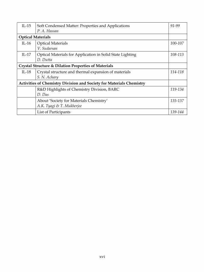
IL-15 Soft Condensed Matter: Properties and Applications P. A. Hassan
91-99
Optical MaterialsIL-16 Optical Materials
V. Sudarsan100-107
IL-17 Optical Materials for Application in Solid State Lighting D. Dutta
108-113
Crystal Structure & Dilation Properties of MaterialsIL-18 Crystal structure and thermal expansion of materials
S. N. Achary114-118
Activities of Chemistry Division and Society for Materials ChemistryR&D Highlights of Chemistry Division, BARC D. Das
119-134
About ‘Society for Materials Chemistry’ A.K. Tyagi & T. Mukherjee
135-137
List of Participants 139-144

NWMC – 2011 (FUN-MAT)
1
Invited Lectures

NWMC – 2011 (FUN-MAT)
2
NWMC – 2011 (FUN-MAT)
3
NWMC – 2011 (FUN-MAT)
2
NWMC – 2011 (FUN-MAT)
3
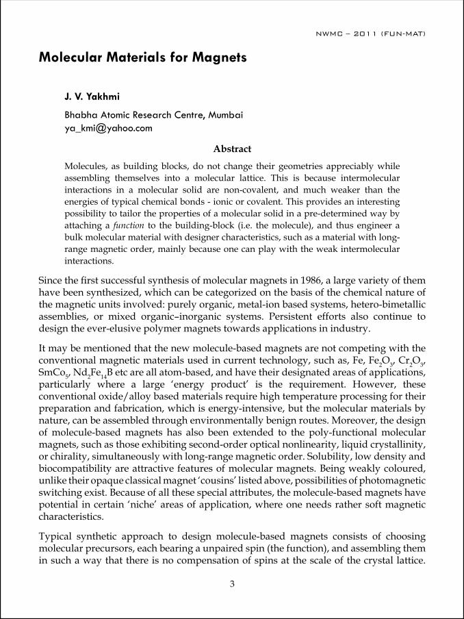
Molecular Materials for Magnets
J. V. Yakhmi
Bhabha Atomic Research Centre, Mumbai [email protected]
AbstractMolecules, as building blocks, do not change their geometries appreciably while assembling themselves into a molecular lattice. This is because intermolecular interactions in a molecular solid are non-covalent, and much weaker than the energies of typical chemical bonds - ionic or covalent. This provides an interesting possibility to tailor the properties of a molecular solid in a pre-determined way by attaching a function to the building-block (i.e. the molecule), and thus engineer a bulk molecular material with designer characteristics, such as a material with long-range magnetic order, mainly because one can play with the weak intermolecular interactions.
Since the first successful synthesis of molecular magnets in 1986, a large variety of them have been synthesized, which can be categorized on the basis of the chemical nature of the magnetic units involved: purely organic, metal-ion based systems, hetero-bimetallic assemblies, or mixed organic–inorganic systems. Persistent efforts also continue to design the ever-elusive polymer magnets towards applications in industry.
It may be mentioned that the new molecule-based magnets are not competing with the conventional magnetic materials used in current technology, such as, Fe, Fe2O3, Cr2O3, SmCo5, Nd2Fe14B etc are all atom-based, and have their designated areas of applications, particularly where a large ‘energy product’ is the requirement. However, these conventional oxide/alloy based materials require high temperature processing for their preparation and fabrication, which is energy-intensive, but the molecular materials by nature, can be assembled through environmentally benign routes. Moreover, the design of molecule-based magnets has also been extended to the poly-functional molecular magnets, such as those exhibiting second-order optical nonlinearity, liquid crystallinity, or chirality, simultaneously with long-range magnetic order. Solubility, low density and biocompatibility are attractive features of molecular magnets. Being weakly coloured, unlike their opaque classical magnet ‘cousins’ listed above, possibilities of photomagnetic switching exist. Because of all these special attributes, the molecule-based magnets have potential in certain ‘niche’ areas of application, where one needs rather soft magnetic characteristics.
Typical synthetic approach to design molecule-based magnets consists of choosing molecular precursors, each bearing a unpaired spin (the function), and assembling them in such a way that there is no compensation of spins at the scale of the crystal lattice.

NWMC – 2011 (FUN-MAT)
4
Magnetism being a co-operative effect, the spin–spin interaction must extend to all the three dimensions, either through space or through bond. Specific occurrence of spin delocalization and spin polarization in molecular lattices, unlike in the case of ionic/metallic compounds, is helpful in bringing about ferromagnetic interaction by facilitating necessary intermolecular exchange interactions. A powerful strategy, pioneered by O. Kahn, to build a molecule-based magnet is based on the use of ferromagnetic chains containing alternating spins of unequal magnitude, SA≠ SB, and assembling them in such a way that there is a net spin, leading to a long-range magnetic order in the lattice. We shall discuss this for the synthesis of magnets, as well as the synthesis of Prussian Blue Analogues (PBA) from molecules. PBAs are fascinating because they exhibit a variety of functionalities such as reversible photomagnetism, second harmonic generation and magnetization-induced second harmonic generation, ferroelectric ferromagnetism, humidity-sensitive magnetism, high ionic conductivity, and spin-ionics, a coupling between ionic conduction and magnetic ordering. Using LB technique, one can grow micro-crystals of PBA, at the air-water interface. We shall describe the design of molecular magnets and show examples of their applications in sensors, for switching, and for magnetocaloric effects, etc.
Besides providing new and attractive features for applications as magnets, the use of molecules to assemble magnets has also led to new inputs to the Physics of Magnetism, such as in the emerging areas of Single-Molecule Magnets, Single-Chain Magnets, and Molecular Spintronics, making this subject a favourite hunting ground for physicists.
Reference1. J.V. Yakhmi, Bull. Mater. Sci., Vol. 32, No. 3, June 2009, pp. 217–225.
Dr. J. V. Yakhmi (b. 1946), is a graduate from 9th batch of BARC Training School (1965-66), and a Ph.D. in condensed matter physics from Bombay University. After a research career spanning 44 years at BARC, of which 35 years in Chemistry Division, and 8 years as Head, TPPED, he recently retired as Associate Director, Physics Group. Broad areas of research of interest to him have been magnetism and superconductivity. Over the years, he has specialized in interdisciplinary areas of soft matter, such as Molecular Magnets, Self-assembly, Polymers, Nano-phase materials, Surfactants,
and Liquid Crystals, and more recently sensors and Molecular Electronic Devices. He has published over 400 papers in refereed journals, or as Review articles and book Chapters, some of which have been cited heavily. He is a Fellow of National Academy of Sciences.

NWMC – 2011 (FUN-MAT)
5
Magnetic Hydrogels and Hybrids for Drug Delivery and Cancer Therapy
D. Bahadur
Department of Metallurgical Engineering and Materials Science, Indian Institute of Technology, Mumbai-400076, E-mail: [email protected]
Nano particulates (NPs) with different shapes, composites, hybrids, core shell structure and magnetic fluids have been developed by various soft chemical methods. Magnetic nanostructures with sufficient biocompatibility are the best candidates for several therapeutic and diagnostic applications such as treatment for cancer through hyperthermia, targeted and sustained drug delivery, as contrast agents and other bio sensing applications. We discuss here some of these aspects based on the work carried out in our laboratory. In addition, we discuss development of multifunctional magnetic hybrid nanostructures, which may be used for a combined therapeutic and diagnostic approach. For efficient delivery of magnetic nano paticulates with drug to the diseased site, magnetic fluid based release systems will be discussed with different possibilities of thermo sensitive and pH sensitive polymers, gels, liposomes and dendrimers as carrier. These encapsulates of chemotherapeutic drug, MNPs and tagging targeting moiety (like folic acid) on the surface have been investigated.
Poly(NIPAAm)-CS based nanohydrogels (NHGs) and iron oxide (Fe3O4) nanoparticles encapsulated magnetic nanohydrogels (MNHGs) were synthesized by free radical polymerization of N-isopropylacrylamide (NIPAAm) in presence of chitosan (CS) to make these magnetic nanohydrogel both temperature and pH sensitive. It has been observed that CS not only served as a cross linker during polymerization but also plays a critical role in controlling the growth of NHG and enhancement in lower critical solution temperature (LCST). The LCST of oly(NIPAAm) was found to increase in presence of Fe3O4 and with increasing weight ratio of CS to NIPAAm. Temperature optimized NHG and MNHG were fabricated having LCST close to 42oC (hyperthermia temperature). The MNHG shows optimal magnetization, good specific absorption rate (under external AC magnetic field) and excellent cytocompatibility with L929 cell lines, which may find potential applications in hyperthermia treatment of cancer and targeted drug delivery. We investigated for its biodistribution, biocompatibility and in vitro and in vivo hyperthermia experiments and observe the inhibition of growth of tumor during in vivo magnetic hyperthermia in fibrosarcoma tumor bearing swiss mice.
The deliberate design of nanohybrids and nanohydrogel for biological applications has been enabled by new advances in synthetic proceedures through different soft chemistry routes. Such nanostructures when properly functionalized, can be used as effective

NWMC – 2011 (FUN-MAT)
6
vehicles for biological entities in vivo. The mechanism of cell death during controlled experimental conditions for hyperthermia treatment of cancer will be discussed.
Dr. Bahadur is at present an Institute chair professor at IIT Bombay. He worked for his Ph.D degree at IIT Kanpur between 1973 and 1977. He was a visiting fellow of the Royal Society London-INSA exchange programme and worked at Cavendish Laboratory 1985-86. He was also a visiting scientist at Department of Physics Dalhousie University Halifax,NS Canada between 1987 and 1988 and guest scientist at Forshungzentrum Juelich,Germany several times between 1995 and 2002. During the period 2006-2007 he was at CNRS
laboratory ICMCS Bordeaux,France and served as Associate Director, Research. Prof. Bahadur has several honors and awards to his credit. Some of these are medals of the Materials Research Society of India. 1996, fellowship Royal Society London –INSA exchange program (1985). He recently received the MRSI-ICSC award for the year 2011. He authored more than 225 publications in international journals, 2 books and 4 patents. He is now a expert member of Project advisory committee of section materials, minerals and metallurgy of DST Govt. of India and also an expert member of 11th plan committee on materials of Department of Atomic Energy, Govt. of India.

NWMC – 2011 (FUN-MAT)
7
Understanding of Novel Phenomena in Functional Magnetic Materials
S. M. Yusuf
Solid State Physics Division, Bhabha Atomic Research Centre, Mumbai 400 085 Email: [email protected]
We present novel magnetic properties of various functional magnetic materials, such as high magnetocaloric materials, hexacyanide based molecular materials, core-shell type magnetic nanoparticles, and colossal magnetoresistancemanganites. We have carried out neutron diffraction experiments on these systems, and a microscopic understanding of the observed magnetic phenomena has been achieved.
Functional magnetic materials are a group of materials having important and interesting physical properties with functional characters. These are also called the smart magnetic materials of future. Some important results of our studies, carried out on various functional magnetic materials such as, high magnetocaloric materials, hexacyanide based molecular materials, magnetic nanoparticles, and colossal magneto resistance (CMR) manganites are presented here. These materials have the potential for their use in information storage and processing, spintronics, cooling technology, etc. The results of neutron diffraction study have been presented to reveal a microscopic understanding of the observed magnetic phenomena.
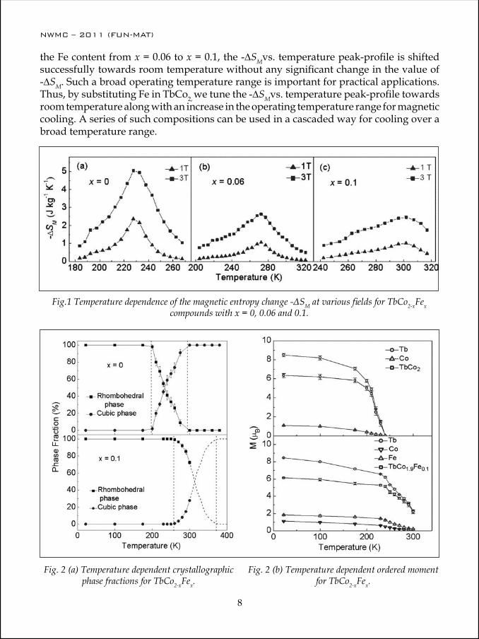
Materials with high Magnetocaloric EffectThe magnetocaloric effect (MCE) is the change in magnetic entropy of a magnetic material when external magnetic field is applied. A large change of magnetic entropy across a magnetic ordering temperature of a material can have an application in magnetic refrigerators.The magnitude of the magnetic entropy variation (-∆SM) depends strongly on the nature of the magnetic phase transition. The current research in literature aims in achieving new functional materials which show giant magnetocaloric effect (GMCE) with a small change in magnetic field near room temperature. We have studied a wide class of magnetic materials that show large MCE [1-5]. In this article, we present the structural and magnetic properties of the interesting high magnetocaloric materials TbCo2-xFex [1] in view of their usefulness in magnetic cooling at room temperature.
The variation of -∆SM with temperature for the samples with x = 0, 0.06 and 0.1 is shown in Fig. 1. The maximum value of ∆SM is found to be around TC [1]. ∆SM increases with the increase in the applied magnetic field. At a field variation of 3 T, -∆SM values are found to be 5.0, 2.6 and 2.5 J kg-1 K-1for x = 0, 0.06, and 0.1, respectively. On increasing
NWMC – 2011 (FUN-MAT)
8
NWMC – 2011 (FUN-MAT)
9
the Fe content from x = 0.06 to x = 0.1, the -∆SMvs. temperature peak-profile is shifted successfully towards room temperature without any significant change in the value of -∆SM. Such a broad operating temperature range is important for practical applications. Thus, by substituting Fe in TbCo2, we tune the -∆SMvs. temperature peak-profile towards room temperature along with an increase in the operating temperature range for magnetic cooling. A series of such compositions can be used in a cascaded way for cooling over a broad temperature range.
Fig.1 Temperature dependence of the magnetic entropy change -ΔSM at various fields for TbCo2-xFex compounds with x = 0, 0.06 and 0.1.
Fig. 2 (a) Temperature dependent crystallographic phase fractions for TbCo2-xFex.
Fig. 2 (b) Temperature dependent ordered moment for TbCo2-xFex.
NWMC – 2011 (FUN-MAT)
8
NWMC – 2011 (FUN-MAT)
9
We have employed neutron diffraction technique to understand the nature of magnetic phase transition. A magnetostructural coupling is evident from the Rietveld analysis of the temperature dependent diffraction patterns where both crystallographic and magnetic phase transitions are observed (Fig. 2).
Hexacyanometallates showing magnetization reversal phenomenonThe metal hexacyanides or hexacyanometallates, An[B(CN)6]m.zH2O where A and B are the 3d and 4d transition metal ions, are the most studied compounds in the category of inorganic molecular magnets. Such materials have the clear advantage of low density, excellent structural integrity and enhanced functionalities which make them suitable for new and advanced magneto-electronic device applications. The biggest advantage of the ambient temperature flexible synthesis is an easy incorporation of various molecular functionalities e.g. photo-activity, electrical conductivity, polarizability, transparency, etc. into these magnetic compounds. We have investigated magnetic properties of a large number of such compounds [6-20].
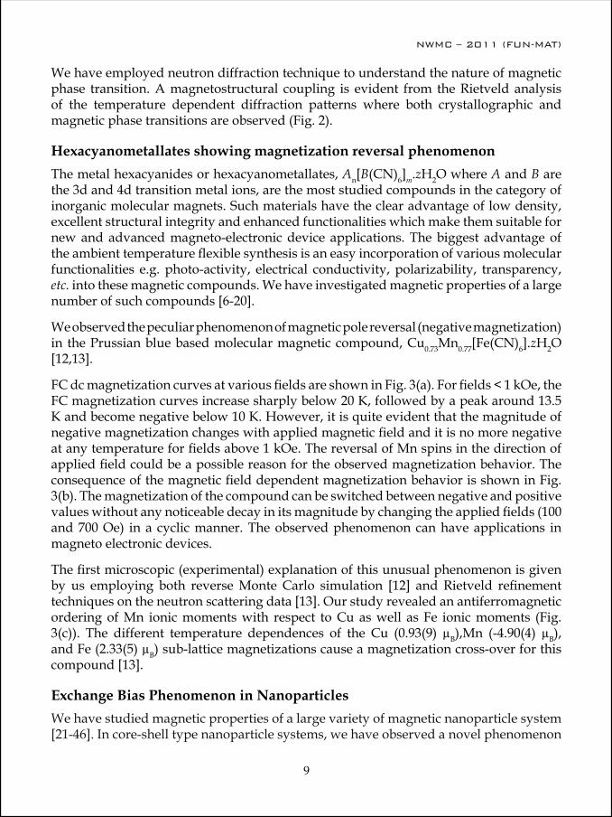
We observed the peculiar phenomenon of magnetic pole reversal (negative magnetization) in the Prussian blue based molecular magnetic compound, Cu0.73Mn0.77[Fe(CN)6].zH2O [12,13].
FC dc magnetization curves at various fields are shown in Fig. 3(a). For fields < 1 kOe, the FC magnetization curves increase sharply below 20 K, followed by a peak around 13.5 K and become negative below 10 K. However, it is quite evident that the magnitude of negative magnetization changes with applied magnetic field and it is no more negative at any temperature for fields above 1 kOe. The reversal of Mn spins in the direction of applied field could be a possible reason for the observed magnetization behavior. The consequence of the magnetic field dependent magnetization behavior is shown in Fig. 3(b). The magnetization of the compound can be switched between negative and positive values without any noticeable decay in its magnitude by changing the applied fields (100 and 700 Oe) in a cyclic manner. The observed phenomenon can have applications in magneto electronic devices.
The first microscopic (experimental) explanation of this unusual phenomenon is given by us employing both reverse Monte Carlo simulation [12] and Rietveld refinement techniques on the neutron scattering data [13]. Our study revealed an antiferromagnetic ordering of Mn ionic moments with respect to Cu as well as Fe ionic moments (Fig. 3(c)). The different temperature dependences of the Cu (0.93(9) µB),Mn (-4.90(4) µB), and Fe (2.33(5) µB) sub-lattice magnetizations cause a magnetization cross-over for this compound [13].
Exchange Bias Phenomenon in Nanoparticles We have studied magnetic properties of a large variety of magnetic nanoparticle system [21-46]. In core-shell type nanoparticle systems, we have observed a novel phenomenon
NWMC – 2011 (FUN-MAT)
10
NWMC – 2011 (FUN-MAT)
11
Fig. 3(a) Field cooled magnetization curves of Cu0.73Mn0.77[Fe(CN)6].zH2O
compound at various fields.
Fig. 3(b)Magnetization switching for Cu0.73Mn0.77[Fe(CN)6].zH2O compound
under 700 and 100 Oe cyclic fields.
Fig. 3(c) Magnetic structure of Cu0.73Mn0.77[Fe(CN)6].zH2O.

NWMC – 2011 (FUN-MAT)
10
NWMC – 2011 (FUN-MAT)
11
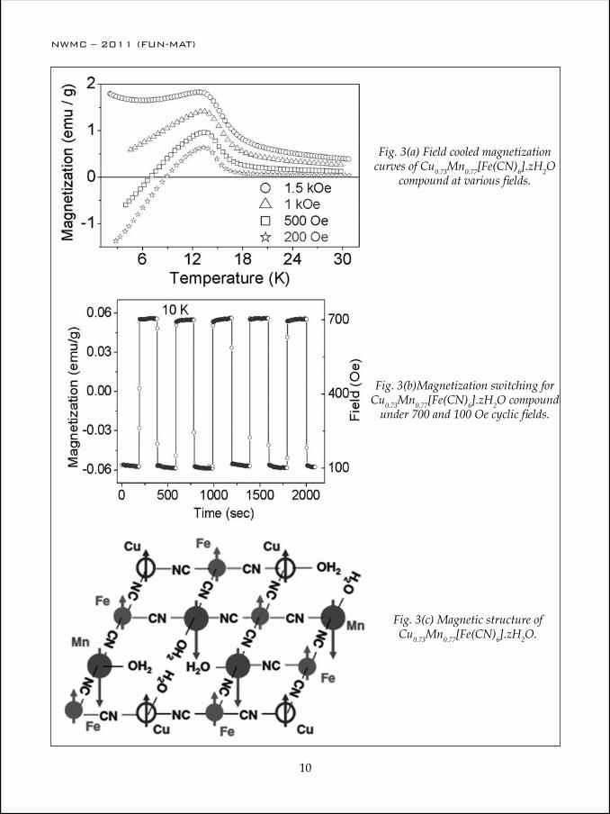
of exchange bias (EB). The phenomenon of EB has attracted a lot of attention both from theoretical and technological points of view. EB phenomenon is in the backbone of designing magnetic memory elements. The main indications of the presence of EB are normally identified as, (i) shift of field-cooled (FC) hysteresis loop along the magnetic field (μ0H) axis, and (ii) enhancement of coercivity (μ0HC) compared to the zero field cooled (ZFC) case. We have studied exchange bias in several systems including the multiferroic BiFe0.8Mn0.2O3 (BFMO) nanoparticles with an antiferromagnetic core (Fig. 4) and a diluted antiferromagnetic shell [21-22].
Fig. 4.Rietveld refined neutron diffraction pattern of BiFe0.8Mn0.2O3 nanoparticles as a function of the magnitude of the scattering vector Q [= (4π/λ) sinθ] at 300K, showing the presence of superlattice mag-netic Bragg peak (indicated by arrow) due to the antiferromagnetic core of the nanoparticles. Open circle
and solid line indicate the observed and the calculated patterns, respectively. Solid lines at the bottom show the difference between observed and calculated patterns.
The BFMO nanoparticles show a shift in FC-hysteresis loop along μ0H as well as magnetization axes (Fig. 5 (a)). The observed FC-loop shift arises due to an interface exchange coupling between core and shell, and the intrinsic contribution of the DAFF shell to the total loop shift is zero [21]. Interestingly, we have observed a significant value of EB with respect to both field μ0Heb and magnetization Meb in the present multiferroic BFMO nanoparticles at room temperature (Fig. 5(b)).
Colossal Magnetoresistance (CMR) Manganites
The phenomenon of colossal change in the electrical resistance of a material under the application of magnetic field is called colossal magnetoresistance (CMR) effect. The basic understanding of the CMR effect offers opportunities for the development of new technologies such as data-storage devices with increased data density and reduced power
NWMC – 2011 (FUN-MAT)
12
NWMC – 2011 (FUN-MAT)
13
Fig. 5(a) Zero field cooled (ZFC), and field- cooled (FC) M vs. μ0H curves at 5 K. The
FC curve was recorded under 1 T cooling field. Inset shows the shift of the FC-loop at 300 K
under 1 T cooling field.
Fig. 5(b) Temperature (T) depen-dence of -μ0Heb, μ0H and Meb.
requirements. The oxide compounds of ABO3type (A: rare earths, Ca, Sr, Ba, etc. and B: transition metal ions) exhibit a variety of structural, electronic and magnetic properties. We have studied the structural and magnetic properties of a large number of such mixed perovskite manganites[ 47- 65].
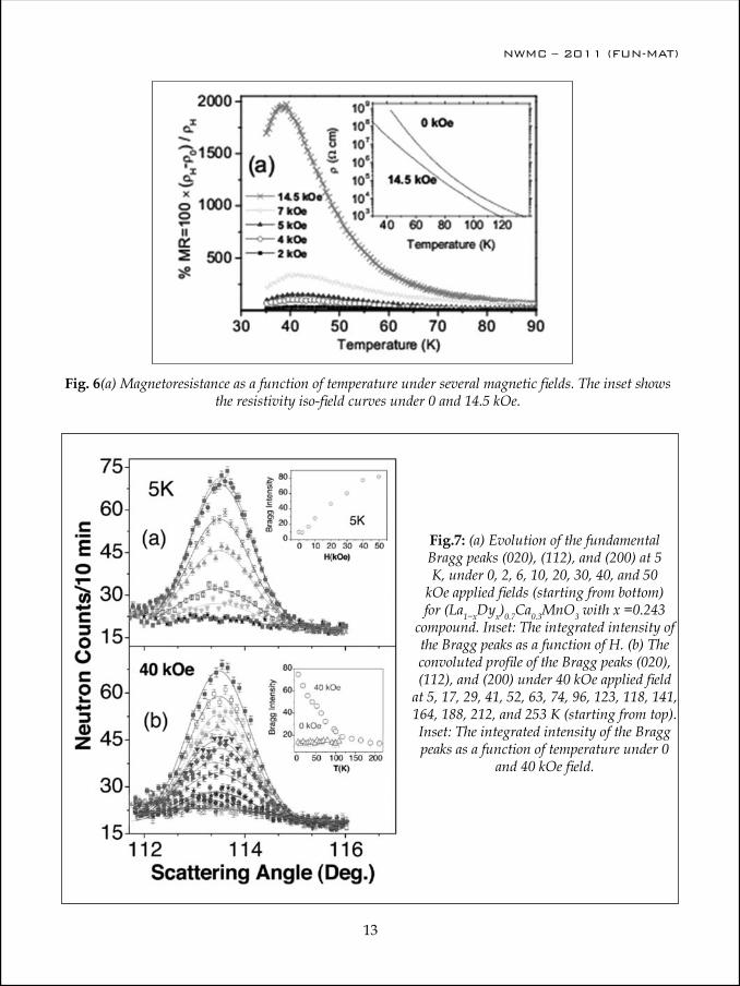
Fig. 6 shows the observed magnetoresistance (MR) for the (La1−xDyx)0.7Ca0.3MnO3sample with x =0.243 [51-52]. The MR is strongly enhanced as the magnetic field increases, reaching 2000 % at 14.5 kOe, which is a typical value for CMR effects.
Neutron diffraction study provides an understanding of the observed magneto resistance behaviour. Fig. 7(a) shows the field dependence of the peak profile at 5 K of the (020), (112), and (200) fundamental Bragg peaks. Magnetic Bragg intensity appears for H ≥ 6 kOe giving a direct evidence for the development of a static long-range ferromagnetic order at these higher fields. The width of the magnetic Bragg peaks was found to remain
NWMC – 2011 (FUN-MAT)
12
NWMC – 2011 (FUN-MAT)
13
Fig. 6(a) Magnetoresistance as a function of temperature under several magnetic fields. The inset shows the resistivity iso-field curves under 0 and 14.5 kOe.
Fig.7: (a) Evolution of the fundamental Bragg peaks (020), (112), and (200) at 5 K, under 0, 2, 6, 10, 20, 30, 40, and 50
kOe applied fields (starting from bottom) for (La1−xDyx)0.7Ca0.3MnO3 with x =0.243
compound. Inset: The integrated intensity of the Bragg peaks as a function of H. (b) The convoluted profile of the Bragg peaks (020), (112), and (200) under 40 kOe applied field
at 5, 17, 29, 41, 52, 63, 74, 96, 123, 118, 141, 164, 188, 212, and 253 K (starting from top). Inset: The integrated intensity of the Bragg peaks as a function of temperature under 0
and 40 kOe field.
NWMC – 2011 (FUN-MAT)
14
NWMC – 2011 (FUN-MAT)
15
unaltered and limited by the instrumental resolution indicating a true long-range magnetic order for all fields down to 6 kOe. This result demonstrates that magnetic field can induce a ferromagnetic transition. The temperature dependence of the Bragg peak profiles under 40 kOe applied field, shown in Fig. 7(b), indicates that at that large magnetic field the paramagnetic to ferromagnetic phase transition occurs at ~ 118K (= TC, the Curie temperature). Under higher H, a long-range ferromagnetic order develops at finite temperature for H> 3 kOe giving a CMR effect [52].
Summary and Conclusion Novel magnetic phenomena of various functional magnetic materials viz., high magnetocaloric materials, hexacyanide based molecular materials, magnetic nanoparticles, and colossal magneto resistance (CMR) manganitesare described in this article. In particular, the magnetic properties of high magnetocaloric materials viz., TbCo2-xFexcompounds have been presented in view of their usefulness in magnetic cooling at room temperature. The importance of magnetic pole reversal phenomenon in magnetoelectronic devices such as magnetic memory has been revealed. An exchange bias effect at room temperature, important in magnetic information storage technology, in the core-shell type nanoparticles has been presented. The role of magnetic field in establishing a CMR effect in the Dy substitutedLa1-xCaxMnO3manganiteshas been brought out.
AcknowledgmentThe article is based on several collaborative research works. The author acknowledges the valuable contributions of his collaborators.
References1. M. Halder, S. M. Yusuf, M. D. Mukadam, and K. Shashikala, Phys. Rev. B 81, 174402 (2010).2. M. D. Mukadam and S. M. Yusuf, J. Appl. Phys. 105, 063910 (2009).3. M.D. Mukadam, S.M. Yusuf, Physica B: Condensed Matter 405, 686 (2010).4. M.D. Mukadam, S.M. Yusuf, BARC Newsletter, 312, 28 (2010)5. P. Sarkar, P. Mandal, A. K. Bera, S. M. Yusuf, L. S. Sharath Chandra, and V. Ganesan, Phys.
Rev. B 78, 012415 (2008) and references therein.6. P. Bhatt and S. M. Yusuf, Surface Science 605, 1861 (2011)7. S. M. Yusuf, N. Thakur, A. Kumar and J. V. Yakhmi, J. Appl. Phys. 107, 053902 (2010)8. A. Kumar, S. M. Yusuf, and J. V. Yakhmi, Appl. Phys.A 99, 79 (2010).9. N. Thakur, S. M. Yusuf, and J. V. Yakhmi,Phys. Chem. Chem. Phys, 12, 12208 (2010).10. P. Bhatt, S. M. Yusuf, M. D. Mukadam and J. V. Yakhmi, J. Appl. Phys.108, 023916 (2010).11. P. Bhatt, S. M. Yusuf, M. D. Mukadam and J. V. Yakhmi, AIP Conf. Proc. 1313, 186 (2010).12. S. M. Yusuf, A. Kumar, and J.V. Yakhmi, Appl. Phys. Lett. 95, 182506 (2009).13. A. Kumar, S. M. Yusuf, L. Keller, and J.V. Yakhmi, Phys. Rev. Lett. 101, 207206 (2008).
NWMC – 2011 (FUN-MAT)
14
NWMC – 2011 (FUN-MAT)
15
14. M. D. Mukadam, Amit Kumar, S. M. Yusuf , J. V. Yakhmi, R. Tewariand G. K. Dey, J. App. Phys 103 123902 (2008).
15. A. Kumar, S. M. Yusuf, L. Keller, J. V. Yakhmi, J. K. Srivastava and P. L. Paulose, Phys. Rev. B 75, 224419 (2007).
16. A. Kumar, S. M. Yusuf and L. Keller, Physica B 385-386, 444 (2006).17. N. Bagkar, A. Widmann, H. Kahlert, G. Ravikumar, S. M. Yusuf, F. Scholz and J. V. Yakhmi,
Phil. Mag. B 85, 3659 (2005).18. A. Kumar andS. M. Yusuf, Physica B 362, 278 (2005).19. A. Kumar, S. M. Yusufand L. Keller, Phys. Rev. B 71, 054414 (2005)20. A. Kumar and S.M. Yusuf, Pramana- J. Phys. 63,239 (2004).21. P. K. Manna, S. M. Yusuf, R. Shukla, and A. K. Tyagi, Phys. Rev. B83, 184412 (2011).22. P. K. Manna, S. M. Yusuf, R. Shukla, and A. K. Tyagi, Appl. Phys. Lett. 96, 242508 (2010).23. S. S. Shinde, Sher Singh Meena, S. M. Yusuf, and K. Y. Rajpure, J. Phys. Chem. C 115, 3731
(2011).24. T. Sarkar, A. K. Raychaudhuri, A. K. Bera, and S. M. Yusuf, New J. Phys. 12, 123026
(2010).25. M. Basu, A.K. Sinha, S. Sarkar, M. Pradhan, S. M. Yusuf, Y. Negishi, and T. Pal, Langumuir26,
5836 (2010).26. S.M. Yusuf, M.D. Mukadam, J.M. De Teresa, M.R. Ibarra, J. Kohlbrecher, A. Heinemann, A.
Wiedenmann, Physica B: Condens. Matter 405 1202 (2010).27. S. Sarkar, S. Pande, S. Jana, A. K. Sinha, M. Pradhan, M. Basu, S. Saha, S. M. Yusuf, T. Pal Journal of Physical Chemistry C 113 6022 (2009).28. R. Shukla, Vinila. Bedekar, S.M. Yusuf, P. Srinivasu, A.Vinu and A.K. Tyagi, J. Nanoscience
and Nanotechnology 9, 6747 (2009).29. D. P. Dutta, Garima Sharma, P. K. Manna , A. K. Tyagi and S. M. Yusuf, Nanotechnology
19, 245609 (2008).30. P. Dey, T. K. Nath, P. K. Manna and S. M. Yusuf, J. Appl. Phys. 104 (2008) 103907.31. M. D. Mukadam, S. M. Yusuf, and R. Sasikala, J. Appl. Phys. 102, 103902 (2007).32. D. P. Dutta, Garima Sharma, A.K. Rajarajan, S.M. Yusuf , G.K. Dey, Chem. Mater.19 (2007) 122133. S. M. Yusuf, J. M. De Teresa, M. D. Mukadam,J. Kohlbrecher, M. R. Ibarra, J. Arbiol, P.
Sharma, and S. K. Kulshreshtha, Phys. Rev. B. 74, 224428 (2006).34. M. D. Mukadam, S. M. Yusuf, R. Sasikala, and S. K. Kulshreshtha, J. Appl. Phys. 99 034310
(2006).35. A. Bharde, D. Rautaray, V. Bansal, A. Ahmad, I. Sarkar, S. M. Yusuf, M. K. Sanyal, M.
Sastry, Small 2,135 (2005).36. M.D. Mukadam, S.M.Yusuf, P. Sharma, S.K. Kulshreshtha and G.K. Dey, Phys. Rev. B 72,
174408 (2005).37. N. K. Prasad, D. Panda, S. Singh, M. D. Mukadam, S.M. Yusuf and D. Bahadur J. Appl.
Phys. 97, 10Q903 (2005).38. M. Mandal, S. Kundu, S. K. Ghosh, S. Panigrahi, T. K. Sau, S. M. Yusuf and T. Pal, J. Colloid
and Interface Science, 286, 187 (2005).
NWMC – 2011 (FUN-MAT)
16
NWMC – 2011 (FUN-MAT)
17
39. R. D. Ambashta, S. M. Yusuf, M. D. Mukadam, S. Singh, P. K Wattal and D. Bahadur, J. Magn. Magn.Mater.293, 8 (2005).
40. S. Karmakar, S. M. Sharma, M. D. Mukadam,S. M. Yusuf and A. K. Sood, J. Appl. Phys. 97, 054306 (2005).
41. R. Vijayalakshmi, S.M. Yusuf and S.K. Kulshreshtha, J. Phys. & Chem. Solids 65, 975 (2004).42. M. D. Mukadam, S. M. Yusuf, P. Sharma, and S. K. Kulshreshtha, J. Magn. Magn.Mater.272-
276, 1401 (2004).43. M.D. Mukadam, S.M. Yusuf, P. Sharma and S. K. Kulshreshtha, J. Magn. Magn.Mater.269,
317 (2004).44. M. Mandal, S. Kundu, T. K. Sau, S.M. Yusuf and T. Pal, Chem. Mater. 15, 3710 (2003).45. M. Mandal, S. Kundu, S. K. Ghosh, T. K. Sau, S. M. Yusuf and T. Pal, J. Colloid Interface
Science, 265, 23 (2003).46. S. M. Yusuf, K. R. Balakrishnan and J. V. Yakhmi, International Patent Application No.:
PCT/IN2010/000123 dated 03.03.2010.47. M. Viswanathan, P. S. Anil Kumar, VenkataSrinuBhadram and ChandrabhasNarayana,
A.K. Bera and S. M. Yusuf, J. Phys: Condens. Mater.22, 346006 (2010).48. A. Das, M. Sahana, S.M. Yusuf, L. MadhavRao, C. Shivakumara and M.S. Hegde, Mat. Res.
Bull. 35, 651(2000).49. S.M. Yusuf, R. Ganguly, K. Chakraborthy, P.K. Mishra, S.K. Paranjpe, J.V. Yakhmi and
V.C. Sahni, J. Alloys & Compounds 326, 89 (2001). 50. S. Röβler, U. K. Röβler, K. Nenkov, D. Eckert, S. M. Yusuf, K. Dörr, K –H. Müller, Phys.
Rev. B 70, 104417 (2004).51. S. M.Yusuf, K. Chakraborthy, S.K. Paranjpe, R. Ganguly, P.K. Mishra, J.V. Yakhmi and
V.C. Sahni, Phys. Rev B 68, 104421 (2003). 52. S. M. Yusuf, J. M. De Teresa, C. Ritter, M. R. Ibarra, J. V. Yakhmi and V.C. Sahni, Phys. Rev.
B 74, 144427 (2006).53. S. M. Yusuf, J. M. De Teresa, P. A. Algarabel, J. Blasco, M. R. Ibarra, A. Kumar, C. Ritter,
Physica B 385-386 (2006) 401. 54. J. M. De Teresa, C. Ritter, P. A. Algarabel, S. M. Yusuf, J. Blasco, A. Kumar, C. Marquina,
and M. R. Ibarra, Phys. Rev. B 74, 224442 (2006). 55. P. Sarkar, P. Mandal, A. K. Bera, S. M. Yusuf, L. S. Sharath Chandra, and V. Ganesan, Phys.
Rev. B 78 012415 (2008).56. P. Sarkar, P. Mandal, K. Mydeen, A. K. Bera, S. M. Yusuf, S. Arumugam, C. Q. Jin, T. Ishida,
and S. Noguchi, Phys. Rev. B 79, 144431 (2009).57. S.M. Yusuf, R. Ganguly, K. Chakraborthy, P.K. Mishra, S.K. Paranjpe, J.V. Yakhmi and V.C.
Sahni, J. Alloys & Compounds 326, 89 (2001). 58. S. M. Yusuf, K. R. Chakraborty, R. Ganguly, P. K. Mishra, S. K. Paranjpe, J. V. Yakhmi and
V. C. Sahni, J. Magn. Magn. Mater. 272-276, 1288 (2004).59. J. S. Srikiran, A. Kumar and S.M. Yusuf , J. Magn. Magn. Mater. 295, 168 (2005).60. J.S. Srikiran and S.M. Yusuf, J. Alloys and Compounds 390, 26 (2005). 61. S. M. Yusuf,Pramana- J. Phys. 63, 133 (2004).
NWMC – 2011 (FUN-MAT)
16
NWMC – 2011 (FUN-MAT)
17
62. D.K. Aswal, A. Singh, C. Thinaharan, S. M. Yusuf, C.S. Viswanatham, G.L. Goswami, L.C. Gupta, S.K. Gupta, J.V. Yakhmi and V.C. Sahni, Phil. Mag. B 83, 3181(2003).
63. S. M. Yusuf, M. Sahana, K. Dorr and K. H. Mueller, Appl. Phys. 2002 A 74, S622(2002).64. S. M. Yusuf, M. Sahana, M.S.Hegde, K.Dörr and K.-H. Müller, Phys. Rev. B 62, 1118 (2000).65. S. M. Yusuf, M. Sahana, K. Dorr, U.K. Röβler and K. H. Müller, Phys. Rev. B 66, 064414
(2002).
Dr. S. M. Yusuf received his M. Sc degree in Physics from VisvaBharati University in 1987 and Post M. Sc diploma in Physics from Saha Institute of Nuclear Physics in 1988. He joined the Magnetism Section of Solid State Physics Division, Bhabha Atomic Research Centre (BARC), Mumbai in 1989 after graduating from 32nd batch of BARC Training School.
He was instrumental in setting up of the neutron polarization analysis spectrometer at Dhruva reactor, BARC for magnetic scattering studies and
a low temperature laboratory for magnetization and magnetotransport studies in BARC. He is the first person to have established and used neutron depolarization technique in India.
Dr. Yusuf acquired Ph. D (Physics) degree from University of Mumbai in 1997 and he was a post-doctoral fellow at Argonne National Laboratory, USA during 1997-1998. He also worked as a visiting scientist in the Institute of Materials Science, Zaragoza, Spain during 2004-2005. He is an active user of various international neutron scattering facilities, such as ILL-Grenoble, PSI-Switzerland, LLB-Saclay and HMI-Berlin.
He has authored/co-authored over 130 research publications in high impact international journals. His current research interests are in the field of magnetic nanoparticles, multifunctional molecular magnetic materials, low dimensional magnetic materials, and high magnetocaloric materials.
In recognition of his significant research contribution, he was conferred the RashtriyaGaurav Award by India International Friendship Society, New Delhi (2011), the DAE Group Achievement Award 2009, Homi Bhabha Science and Technology Award (2008), the Material Research Society of India (MRSI) Medal (2008), DAE Science Research Council Outstanding Research Investigator Award (2005), the Indian Physical Society’s First Best Young Physicists Award (1996) and the Indian Physics Association’s N. S. Sathya Murthy Memorial Award (1996).
Presently he has been guiding five candidates for their Ph. D. He is an acclaimed teacher in advanced solid state physics at BARC Training School, Mumbai. He is a Ph. D guide of (i) University of Mumbai, (ii) Homi Bhabha National Institute (HBNI), and (iii) University of Pune (Co-guide). He is also a member of several professional bodies including editorial advisory boards. He is a regular referee of various prestigious journals like Phys. Rev. Lett. and Phys. Rev. B. Presently, he is heading the Magnetism activities in Solid State Physics Division of BARC, Mumbai.
NWMC – 2011 (FUN-MAT)
18
NWMC – 2011 (FUN-MAT)
19
Functionality in Glass and Glass-ceramics
G. P. Kothiyal
Glass and Advanced Ceramics Division, Bhabha Atomic Research Centre, Mumbai-400 085, India Email: [email protected]; [email protected]
Functional glasses/glass-ceramics, in the broadest sense, are materials possessing certain useful combinations of properties, which make them suitable for specific applications [1]. The extent of order of atoms and molecules in a material decides its nature in terms of crystalline, polycrystalline or glassy. A glass is defined as an amorphous material having order limited to few atomic distances (short range order). In this lecture I will discuss the processes related to formation of glass and the requirements for preparation of different types of glasses, various preparation methods and techniques with their merits/demerits in general and choice of techniques for special functional glasses. Properties of glass depend on the nature of glass melts, their processing and various additives [2]. The presence of additives modifies the properties of the glasses allowing the establishment of new functionalities The improvement in various glass properties on conversion to glass-ceramics is an importance aspect in relation with new functionalities [3-4]. There are different properties like optical and optoelectronic, thermal, mechanical, electrical and magnetic, biological, chemical etc, which give rise to various functionalities in these materials. In particular we shall discuss applications related to optical fibres, window panes/ architectural materials, optical components, host for laser emitter, windshields, machinability, sealants, biomedical, matrices for the containment of radioactive waste etc. For this it is essential to develop a thorough understanding of structure property correlations to functionalize a material.
Glass-ceramics offer numerous advantages compared to parent glasses such as improved thermo-physical properties, higher strength, wear resistance etc. often making them better suited than glasses for various applications. While crystallization in glasses is undesirable, controlled crystallization of glasses can result in a kind of polycrystalline material possessing improved properties. Glass-ceramics by definition are the micro- or nano-crystalline materials produced by controlled crystallization of glasses. In a sense therefore, glass-ceramics are a composite of a crystalline phase embedded in a glassy matrix.
In a number of ways, glasses and more recently glass-ceramics have been able to combine a number of qualities that include transparency, chemically inertness, environmental compatibility and high strength. These properties could be inherent to the glass itself such as photo-chromicity, transparency or could be a result of modifications in structure and microstructure arising from processing techniques. The example of the later is bullet

NWMC – 2011 (FUN-MAT)
18
NWMC – 2011 (FUN-MAT)
19
proof glass, which comprises several layers of laminated glass and polymers. While other classes of materials can match or even surpass glasses (and glass-ceramics) in individual properties, it would be difficult to find a material that performs as well as glass over a range of functionalities at a reasonable cost. As an example, polymeric compounds can match the transparency of glass but cannot match its durability or function at high temperature [4].
In a popular and basically correct conception, a glass is considered to be a liquid that has lost its ability to flow: any liquid with sluggish crystallization kinetics will become structurally arrested, hence glassy-like [5]. At the same time, the glassy state is not unique. The specific glassy ‘state’ attained depends upon the thermal history of the melt. There are certain binary compounds (oxide or non-oxide) that may be good glass formers. However, to improve their suitability to various applications, other constituents are usually incorporated. Therefore, in addition to the primary glass former (e.g. P2O5, SiO2 , B2O3, etc.), technical glasses contain conditional network formers (Al2O3, ZnO etc.), modifiers (Li2O, Na2O etc.) and sometimes refining agents such as As2O3 that are useful for fining the melt and minimize bubbles in the final glass. The role of various additives and oxides is well discussed in the literature [6]. Without going into details on the specificity of glassy compounds, a good glass former can be defined as a system in which non-crystalline packing modes of the molecules are intrinsically at low energy and different modes are separated by high energy barriers. The crystalline state is always at lower energy, and the probability of germinating a crystal instead of a glass during the vitrification process is negligible. Therefore an essential prerequisite for glass formation is to establish the processing conditions like cooling rate to be sufficiently high to prevent crystallization. In a nucleation event a small but critical number of unit cells of the stable crystal state combine on a given characteristic time scale, the nucleation time Tnuc. In a good glass former, the number of molecules involved in the nucleation must be much larger than the number of molecules cooperating in the structural relaxation of the glass phase (composing what is called a cooperative rearranging region - CRR), yielding, in this way, a nucleation time much longer than the structural relaxation time, Teq [7]. A large nucleation time means that the probability that a fluctuation takes place, allowing a critical number of unit cells to form a crystal, is low. The reasoning presented is applicable to all types of glass ranging from the tradition silicate to more recently developed metallic glasses. In the recent years there have been some efforts to produce metallic glasses. These have gained prominence because their nono-crystalline atomic arrangement imparts many useful and unusual properties to these metallic solids [8]. Though these have been produced for the last four decades, the necessity of rapid solidification at cooling rates of 105K/sec. or higher for their production have restricted their geometry to thin ribbons and prevented their application to many areas despite their excellent properties. It has been shown in recent investigations that many Zr based multi-component alloys can be obtained in glassy state by cooling at much lower rates typically 102 to 103 K/sec. This has enabled production of these alloys in the glassy state in bulk. The glass transition, time-temperature-transformation (TTT) diagram, nucleation
NWMC – 2011 (FUN-MAT)
20
NWMC – 2011 (FUN-MAT)
21
and growth of crystals in undercooled melt of bulk glass forming alloys are important aspects need attention in dealing with glasses/glass-ceramics.
There are many types of glasses encompassing silicates, phosphates, silico-phosphates, borates, halides, chalcogenides, alkaline-earth based, metallic, polymeric, germanates, orthophenyl etc and depending on the glass system a number of techniques are available for their preparation [9]. Among the various glass preparation techniques Melt quenching is the oldest method of producing bulk glasses, which is still being widely used. This process is made up of calcination and glass melting in suitable crucibles/pots ( Pt-Rh, alumina etc) followed by pouring of the melt and annealing for stress relief. In this technique the melt is cooled sufficiently fast to preclude nucleation and crystal growth. Rates of cooling required for glassy phase formation are different for different materials. For example, certain good glass formers such as B2O3, P2O5 etc. will form glassy phase even under conditions of slow cooling (1K/s) whereas to get metallic glass cooling rates of the order of 102-106 K/s are required. There are other techniques such as thermal evaporation, sputtering, glow discharge decomposition, chemical vapour deposition, sol-gel method, electrolytic deposition, radiation bombardment etc. to prepare glassy/amorphous materials.
Glasses and glass-ceramics can be characterized in terms of various properties such as thermo-physical, mechanical, structural, wetting, optical, chemical etc. The behaviour of glass and glass-ceramics determining the functionalities are governed to a large extent by their crystallographic, bonding, micro-structural properties. We have a number of techniques to study these properties. However, a few important techniques are X-Ray diffraction, optical transmission, Fourier transform IR spectroscopy (FTIR), Raman spectroscopy, solid state NMR spectroscopy (magic angle spinning (MAS) NMR, Cross polarization (CP) NMR), Scanning electron microscopy etc.
While the control of composition and processing govern the glass properties, there are additional parameters like formation of new phases and microstructure, among others which determine the functionalities of glass-ceramics. Based on these properties/parameters they demonstrate functionalities starting from a simple coloured glass beads to most advanced technological applications like bio-compatible/active materials for implants or a plasma display panel. The important ones are optical and optoelectronic, thermal, mechanical, electrical and magnetic, biological, chemical, environmental compatibility and ease of recycling etc. these lead to some important functionalities such as optical fibres [10], window panes- architectural materials, windshields [11], host for laser emitter [12], , machinability [13], sealants [14-18], biomedical uses [19], matrices for the containment of radioactive waste [20] etc.
In conclusion we may say glass formation is an enigmatic phenomenon, which is still not properly understood. The glass transition with its associated thermodynamics and kinetics remains an area of active scientific inquisition. The extent of order of atoms and molecules in a material decides its nature in terms of crystalline, polycrystalline
NWMC – 2011 (FUN-MAT)
20
NWMC – 2011 (FUN-MAT)
21
or glassy. Properties of glass depend on the nature of glass melts, their processing and various additives introduced for creating new functionalities. Accordingly a variety of glasses are now available for many novel applications. Transformation of glass to glass-ceramics through controlled crystallization of glasses producing tailored microstructure and crystalline to glassy phase ratio have opened up with enormous possibilities of new and improved functionalities. There are glasses/glass-ceramics based on oxides, chalcogenides, fluorides, polymers etc and they show properties like insulators, semiconductors and metals. We have different properties like optical and optoelectronic, thermal, mechanical, electrical and magnetic, biological, chemical etc giving rise to various functionalities in these materials. In particular we have discussed applications related to optical fibres, window panes/ architectural materials, optical components, host for laser emitter, windshields, machinableility, sealants, biomedical, matrices for the containment of radioactive waste, Zr-based metallic glass. The composite glass-ceramic materials can show a variety of useful properties based upon the nature, morphology and quantity of the crystalline phases. The possibility of nano-crystallization has enabled several novel applications in optics and memory storage. A better understanding of the structure property correlations in glasses would allow novel functionalities in various fields such as energy storage, structural and construction applications as well as biomedical applications. Despite competition from various alternatives, glasses are important functional materials. They occupy certain niches where they are uniquely suitable and therefore difficult to displace.
References:1. Wang, Z. L. and Kang, K. C. (1998). “Functional and Smart Materials: Structural Evolution
and Structure Analysis”. Plenum Press, NewYork.2. Pye, D. L. (2005). Glass forming melts. In, “Properties of Glass-Forming Melts”, (D. L. Pye,
J. Innocent and M. Angelo, Ed.), pp 7-9. CRC Press, 2005. 3. Bach, H. and Krausse, D. (1999). “Analysis of the Composition and Structure of Glass and
Glass Ceramics”. Springer Verlag, Germany. 4. Holland, W. and Beall, G. H. (2002). “Glass-Ceramic Technology”. The American Ceramic
Society, Westerville, Ohio. 5. Leuzzi, L. and Nieuwenhuizen, T. M. (2008). “Thermodynamics of the Glassy State”. pp 15,
Taylor and Francis group LLC, Florida. 6. Kingery, W. D. and Bowen, H. K. and Uhlmann, D. R. (1976). “Introduction to Ceramics”.
Wiley, NewYork. 7. Adam, G. and Gibbs, J. H. (1965). On the temperature dependence of cooperative relaxation
properties in glass-forming liquids. J. Chem. Phys. 43, 139-146. 8. Inoue A. (2000). Stabilization of Metallic Supercooled Liquid and Bulk Amorphous Alloys.
Acta Mat. 48, 279-306. 9. Shelby, J. E. (2005). “Introduction to glass science and technology”. 2nd Edition CRC Press.10. Tanabe, S. (2002). Rare-earth-doped glasses for fiber amplifiers in broadband telecommu-
nication. Comptes Rendus Chimie 5 (12), 815-824

NWMC – 2011 (FUN-MAT)
22
NWMC – 2011 (FUN-MAT)
23
11. Amstock, J. S. (1997). “Handbook of glass in construction”. pp 120, McGraw Hill Publishers, New York.
12. Ehrmann, P.R., Carlson, K., Cambell, J. H., Click, .A. , Brow, R. K.,(2004). Neodymium fluorescence quenching by hydroxyl groups in phosphate laser glasses. J. Non- Cryst. Solids 349, 105-114.
13. Goswami, M., Sarkar, A., Mirza,T., Shrikhande, V. K., Sangeeta, Gurumurthy, K. R. and Kothiyal, G. P. (2002) Study of some thermal and mechanical properties of magnesium alumium silicate glass-ceramic, Ceramics International 28, 586.
14. Kumar, R., Arvind. A, Goswami, M., Bhattacharya, S., Shrikhande, V. K. and Kothiyal, G. P. (2009). The effect of NiO on the phase formation, thermo-physical properties and sealing behaviour of lithium zinc silicate glass-ceramics, J. Mater. Sci. 44 (13), 3349-3355.
15. Ananthanarayanan Arvind, Rakeh Kumar, Bhattacharya Shovit , Shrikhande V.K., Kothiyal G.P.,(2008), Some properties of lithium aluminum silicate (LAS) glass-ceramic-to-metal compressive seal for vacuum applications, J. Phys.: Conference Series 114 , 012042
16. Haanappel, V.A.C., Shemet, V., Vinke, I.C., Quadakkers, W.J., (2005), A novel method to evaluate the suitability of glass sealant–alloy combinations under SOFC stack conditions., J. Power Sources 141, 102-107.
17. Tiwari, Babita, Dixit, A, Kothiyal, G. P. (2011), Study of glass/glass-ceramics in the SrO-ZnO-SiO2 system as high temperature sealant for SOFC applications, International Journal of Hydrogen Energy, 36, (2011)15002-15008.
18. Ananthanarayanan, A., Kothiyal, G.P., Montagne, L., Tricot G. and Revel,B., The Effect of P2O5 on the Structure, Sintering and Sealing Properties of Barium Calcium Aluminum Boro-Silicate (BCABS) Glasses Mater. Chem. Phys., (2011), DOI information: 10.1016/j.matchemphys.2011.08.003, online
19. Singh, R. K., Kothiyal, G. P. and Srinivasan, A. (2008). Magnetic and structural properties of CaO-SiO2-P2O5-Na2O-Fe2O3 glass-ceramics. J.Magn. Magnetic Materials. 320, 1352-1356.
20. Mishra, R. K., Kaushik, C. P., Sengupta, P., Tyagi, A.K., Kale, G.B., Raj, K., (2007) , Studies on immobilization of thorium in barium borosilicate glass, J. Nuclear Mater. 360. 143-150.
NWMC – 2011 (FUN-MAT)
22
NWMC – 2011 (FUN-MAT)
23
Dr. G. P. Kothiyal, Head, Glass and Advanced Ceramics Division, Bhabha Atomic Research Centre (BARC) is an active researcher from13th batch (Physics) of BARC Training School. He has contributed very significantly in both science and technology areas. While spearheading the programme on special glasses and glass-ceramics, he has produced them with designed/tailored properties and delivered for use in nuclear, laser, defence and space applications. He has specialization in the area of crystal growth, thin films including the extensive work with MBE. As regards development of
indigenous technologies and materials he has made an outstanding contribution by developing PbS infrared detector with acceptable performance to a level of batch production, machinable glass-ceramics based on magnesium-aluminium-silicate, lithium zinc silicate and lithium aluminium silicate glass-ceramics for vacuum tight seals. He has published more than 125 research papers in peer reviewed journals. In addition he is Principal Collaborator (Indian Side) of an Indo –French Project (IFCPAR-Project 4008-1) on “Study and development of high temperature sealant based on phosphate containing glass and glass-ceramics” for the period July 2009- June 2012 and Principal Collaborator of a BRNS Mega Project on the Topic “Development and Supply of Nd, Yb, and Er: laser glass rods and slabs for laser application” at S. V. University, Tirupati for the period 2010- 2012. He is reviewer for many International Journals.
He is recipient of several awards including DAE Group Achievement Award 2009, INS science Communication Award for the year 2009, MRSI Medal lecture Award 2002. He is an Associate member of International Glass commission(ICG), MRSI Subject Group Chairman for Ceramics and Glass and secretary MRSI Mumbai Chapter. He has organized several National and International conferences, chaired scientific sessions and delivered talks. He has visited many overseas Laboratories in USA, France, Germany, Portugal, China, Singapore, Spain, Italy etc.
NWMC – 2011 (FUN-MAT)
24
NWMC – 2011 (FUN-MAT)
25
Glass formation and crystallization in Zr based alloys
G. K. Dey
Materials Science Division, Bhabha Atomic Research Centre, Trombay, Mumbai 400085
Metallic glasses have come in to prominence in recent times because their noncrystalline atomic arrangement imparts many useful and unusual properties to these metallic solids. Though these have been produced for the last four decades, the necessity of rapid solidification at cooling rates of 105 K/sec or higher for their production, have restricted their geometry to thin ribbons and prevented their application to many areas despite their excellent properties. It has been shown in recent investigations that, many Zr based multicomponent alloys can be obtained in glassy state by cooling at much lower rates, typically 102 to 103 K/sec. This has enabled production of these alloys in the glassy state in bulk. By now, bulk metallic glasses have been produced in Mg, Ln, Zr, Fe, Pd-Cu, Pd-Fe, Ti and Ni- based alloys. Production of these glasses in bulk has opened avenues for their application in many areas where their excellent mechanical properties and corrosion resistance can be exploited. The transformation of the amorphous phase in these alloys to one or more crystalline phases, is an interesting phase transformation, and can lead to formation of crystals in a variety of morphologies and a wide range of crystal sizes, including nanometer size crystals or nanocrystals. The bulk amorphous alloys exhibit higher fracture stress, combined with higher hardness and lower young’s modulus than those of any crystalline alloy. The Zr- and Ti-based bulk amorphous alloys exhibit high bending and flexural strength values which are typically 2.0 to 2.5 times higher than those for crystalline counterparts. The composites of bulk metallic glasses containing crystalline phases have been found to have special properties. This has been demonstrated in the case of composites of bulk metallic glass and tungsten wires with the glass forming the matrix. Such a composite has a very high impact strength and is especially suitable for application as an armour penetrator in various types of shells used in the defence. The bulk metallic glasses have already found application in the form of sporting goods. Since the elastic strain shown by the bulk metallic glass is about twice that of the best crystalline spring material, the energy stored in the elastic region of the metallic glass is about four times.
The reasons for extensive work carried out in the field of non-crystalline zirconium-based alloys are: (i) ability to form metal – metal metallic glasses (ii) ability to form glass in wide composition ranges and (iii) interesting glass to crystal transformation modes shown by these amorphous alloys. Many of the Zr-based glasses undergoes transformation to crystalline phases of the same composition. These alloys provide opportunities for examining the effect of atomic arrangement alone on properties without any interference

NWMC – 2011 (FUN-MAT)
24
NWMC – 2011 (FUN-MAT)
25
from change in chemistry of the phase. Zr based alloys have also acquired considerable significance because of the fact that these can form bulk metallic glasses. In the partially crystalline microstructures, the amount of crystalline phase, the identity of the crystalline phase and the morphology of the crystalline phase has been examined. Whereas the amount of crystalline phase is an indication of the glass forming ability, the identity gives a clue about the nature of the crystalline phase competing with glass formation and the morphology gives a very valuable insight into how the solidification had taken place.
The rapidly solidified variety has been studied for a very long time and the arrangements are in place for making wide ribbons of commercial quality in a reproducible manner in fairly large quantities in Fe and Zr based alloys. Glass forming ability, crystallization, mechanical properties and corrosion behavior of these have been examined in considerable detail and published in the form of journal publications over the years. The bulk glasses have also been examined in considerable detail in terms of the same aspects. Techniques like fluctuation microscopy, positron annihilation and EXAFS have been used for understanding the short range order and the medium range order in these alloys. These techniques were also used on the same bulk amorphous alloy for understanding the state of order in amorphous alloy and the nature of defects in the amorphous alloys. This is a first effort in which so many complimentary techniques have been used for probing the structure of the same amorphous alloy. These techniques have permitted a systematic correlation between cooling rate and its effect on the structure. It has also been possible to explain the effect of cooling rate on structure and subsequently on the properties of the amorphous phase. The facilities for making bulk glass have been created and these have been in place for quite some time now to produce bulk glass in reproducible manner.
It has been shown that a composite of amorphous phase and crystalline phases or fibres may have better mechanical properties than the fully amorphous alloy. With this in view, composites of tungsten fibre and amorphous phase have been created and these have been found to have excellent mechanical properties, particularly impact behaviour. In addition to the synthesis of the amorphous phase, composites of the aforementioned type have also been synthesized. The technology for making composites of this type has been developed for the first time and such composites have been tested on thick steel plates successfully for their penetration ability.
Structure of the amorphous phase in different parts of bulk metallic glass (BMG) of composition Zr52Ti6Al10Cu18Ni14 and specimens of the same alloy in the form of rapidly solidified amorphous ribbons has been probed by high resolution electron microscopy (HREM), fluctuation microscopy and positron annihilation. These investigations were aimed at looking at free volume and its distribution, nanovoids and the nature of medium range order (MRO) and their variation in different parts of the specimen. The deformation behaviour vis-à-vis shear band formation behaviour of the aforementioned has been probed by ultra-nanoindentation. Specimens have been deformed up to 18% by rolling.

NWMC – 2011 (FUN-MAT)
26
NWMC – 2011 (FUN-MAT)
27
The change in the structure of the glasses and the associated mechanical properties due to this extent of deformation has been probed by the aforementioned techniques. On the average, the free volume was higher in the as-solidified rapidly solidified ribbon (RSR) as compared to the as-solidified BMG. In the BMG, the central part had higher MRO and the lower free volume than the peripheral region. After deformation, the RSR had highest MRO and the lowest free volume than other deformed samples. In deformed BMG, the peripheral region had higher MRO and lower free volume, and the central region had lowest MRO and highest free volume. The BMG and the RSR were found to differ in their structure after deformation in that the free volume was found to increase in the former where as it was found to reduce in the latter after 18% of deformation. This has led to substantially different mechanical properties after deformation in the RSR and the BMG. This could be explained on the basis of local free volume and MRO and the fact that above a critical value, the free volume does not necessarily increase with deformation. In fact, the free volume is found to decrease, showing work hardening behaviour rather than work softening.
Glass formation in Zr52Ti6Al10Cu18Ni14 has been examined in terms of crystal nucleation and growth in the under-cooled melt and compared with that in the same composition after rapid solidification by melt spinning. Quenched in nuclei, single crystals and crystal aggregates were found embedded in the amorphous matrix of the melt quenched structures. The nature of the phases competing with glass formation and the variation in morphology of these has been examined and compared in order to achieve an improved understanding of the process of solidification and the nature of phase transformations during post solidification cooling. Bulk glass has been made in two alloys with different oxygen content. Melt spinning of the same alloy has been carried out. The difference in molar free energy (∆Gc) between liquid and crystalline phases has been determined from experimentally evaluated quantities. The viscosity of the alloy has been evaluated by hot hardness estimation at different temperatures. ∆Gc along with viscosity has been used for evaluation of transient nucleation time, steady state nucleation rates and the overall rate of crystal formation. The glass forming ability has been evaluated by making use of the avoidance of crystallization approach. The structure of the amorphous phase obtained by the two techniques has been probed by fluctuation microscopy and by positron annihilation.
Crystallization kinetics of the three types of glasses has been compared. The role of the quenched in nuclei in the crystallization process has been evaluated. The crystallization behaviour of the two types of glasses has been compared with formation of nanocrystalline phases in view. The nanocrystalline microstructure has been examined with a view to understanding the nature of crystallographic defects present. The coarsening behaviour of the nanocrystals has also been examined. Glass formation as well as crystallization has been studied in this alloy and compared with other Zr based glass forming alloys, where the beta phase of Zr is competing with glass formation.
NWMC – 2011 (FUN-MAT)
26
NWMC – 2011 (FUN-MAT)
27
Dr. Gautam Kumar Dey obtained his B. Tech in Metallurgical Engineering in 1979 from the Institute of Technology, Banaras Hindu University. He was awarded the Vaisandas Basil Gold Medal (BHU, 1979) for securing first position in B. Tech.
He joined the 23rd batch of Training School in Bhabha Atomic Research Centre (BARC) and was awarded the Homi Bhabha prize for standing first in his discipline. On completion of training, he joined Metallurgy Division of BARC. He obtained his Ph. D degree from Banaras Hindu University in
1988. He was a postdoctoral fellow at University of Cincinnati from 1994 to 1996. He has been Visiting Scientists at University of Osaka, Japan and Institut fur Festkorperforschung (IFF), Juelich, Germany. He has won several awards for his scientific contributions. Of these mention can be made of the Young Scientist award of Indian National Science Academy (1989), Young Metallurgist Award given by Ministry of Steel and Mines (1989), MRSI Medal given by Materials Research Society of India (2001), Metallurgist of the year award given by Ministry of Steel (2003), the Vasvik Award (2005) and the G. D. Birla Gold Medal (2011) by the Indian Institute of Metals. He is a fellow of the Indian National Academy of Engineering (INAE), Indian Academy of Science (IASc) and Electron Microscopy Society of India (EMSI). He is associate editor of Transactions of the Indian Institute of Metals. Areas of his research interest are Phase Transformation in Zirconium and Nickel Base Alloys, Amorphous Alloys, Rapidly Solidified Crystalline and Quasicrystalline Alloys, Electron Microscopy and defect Characterization and High Resolution Electron Microscopy. He has more than 250 scientific publications to his credit. He has been designated a Professor in the Homi Bhabha National Institute and is currently the Head of Materials Science Division, BARC.
NWMC – 2011 (FUN-MAT)
28
NWMC – 2011 (FUN-MAT)
29
Glass: A candidate engineered material for management of high level nuclear waste
R. K. Mishra & C. P. Kaushik*
Waste Management Division, Nuclear Recycle Group, Bhabha Atomic Research Centre, Trombay, Mumbai *Corresponding author: [email protected]
AbstractWhile the commercial importance of glass is generally recognized, a few people are aware of extremely wide range of glass formulations that can be made and of the versatility of this engineered material. Some of the recent developments in the field of glass leading to various technological applications include glass fiber reinforcement of cement to give new building materials, substrates for microelectronics circuitry in form of semiconducting glasses, nuclear waste immobilization and specific medical applications. The present paper covers fundamental understanding of glass structure and its application for immobilization of high level radioactive liquid waste. High level radioactive liquid waste (HLW) arising during reprocessing of spent fuel are immobilized in sodium borosilicate glass matrix developed indigenously. Glass compositions are modified according to the composition of HLW to meet the criteria of desirable properties in terms. These glass matrices have been characterized for different properties like homogeneity, chemical durability, thermal stability and radiation stability.
IntroductionWith increasing demand of energy, Indian Atomic Energy Program has gained momen-tum to solve the energy crisis of the country. India, therefore, has gone for closed end fuel cycle, where spent fuel is reprocessed to recover valuables such as uranium and plutonium. Reprocessing of spent fuel ends up with small volume of high level radioac-tive liquid waste (HLW), which need to be solidified in suitable matrix for isolation of radiocontaminants from geosphere for extended periods of time.
In India, three step strategies have been adopted for management of HLW. The steps are (i) conditioning of high level liquid waste resulting in the immobilization of the waste oxides in stable and inert solid matrix, (ii) interim retrievable storage of the conditioned waste under cooling and constant surveillance to ensure substantial dissipation of decay heat and also the integrity of the waste product and (iii) ultimate disposal of the waste in suitable geological repository ensuring isolation of the waste product in the biosphere for extended periods of time [1].
NWMC – 2011 (FUN-MAT)
28
NWMC – 2011 (FUN-MAT)
29
While selecting the matrix for immobilization of HLW, priority is given to the simple, reliable and robust technologies and equipment over complex and sensitive equipments. A number of solid matrices, such as polymer, cement, glass, glass ceramics, sodium zirconium phosphate, synroc etc. have been studied for the purpose, but glass matrix turns out to be most acceptable because of its attracting features like glasses chemically incorporate all elemental constituents of waste into their structure and have a very high leach resistance [2], glasses are tolerant to compositional deviations and therefore not very sensitive to waste compositional variations, compared amenability for remote control processing in shielded hot-cells, easily availability of raw materials, its good thermal, mechanical and radiation stability.
Development and characterization of glass matrix In an ideal vitrified Waste Product (vWP), all the waste components should be fully dissolved in the matrix and the product should be completely amorphous and homogeneous. Such a product is likely to provide the best possible performance in a long term disposal situation. However, when the solubility limit of a particular waste component in the borosilicate glass matrix used for HLW vitrification is exceeded, the tendency for the glass to partially devitrify during cooling is increased. If the crystalline phase formed in this situation has a higher aqueous solubility than the rest of the matrix, there is an increased risk of radionuclide migration into the biosphere if the waste form comes into contact with groundwater in the repository. Therefore, knowledge of composition of waste for development of glass matrix is essential. Secondly, the development of glass is based on plant processing conditions and product characteristics. The plant processing conditions include type of melter, heating method of melter, material of construction of melter, volatility of radionuclide, process flow sheet, off gas route etc. The product characterization includes properties like pouring temperature, chemical durability, homogeneity, thermal stability, radiation stability etc. to ascertain its product acceptability criteria. For adjustment of all these parameters the glass composition is modified.
Structure of glassIt is useful to consider the structure of glasses in relation to the three states of matter namely, solid, liquid and gaseous. By solid we normally mean a crystalline solid in which the atoms are arranged in a regular fashion. Because of this, the diffraction pattern arising from the scattering of X-rays, electron or neutron consists of sharp maxima resulting from the presence of regularly spaced planes of atoms. A gas on the other hand gives no such maxima, because here the atoms have no regularity of arrangement. Perhaps, as might be expected, the diffraction pattern of a liquid suggests an intermediate situation while the sharp diffraction maxima are absent, diffuse maxima are found in the diffraction pattern. The implication is that the structure of a liquid lacks long – range order; that is there is no regularly repeating pattern as in the case of crystals. The occurrence of diffraction maxima indicates however the presence of inter atomic spacing of a fairly
NWMC – 2011 (FUN-MAT)
30
NWMC – 2011 (FUN-MAT)
31
well defined dimensions. These two observations are not irreconcilable. They simply mean that while small group of atoms are disposed with regard to one another these groups are not arranged together in a repeating pattern. Thus while a liquid lacks long range order it can posses short range order. Diffraction experiments on glasses yield results that most closely resemble those for liquids. This suggests that glasses possess a liquid type structure. In fact we can regard glasses as liquids of such enormously high viscosity that at normal temperatures they are for practically purpose solids.
Sometimes, glass is regarded as a super cooled liquid because there is no first order phase transition as it cools. In fact there is a second order transition between the super cooled liquid and the glass state, so a distinction can still be drawn. The transition is not as dramatic as the phase change that takes from liquid to crystalline solids. There is no discontinuous change of density. Glasses are best understood with reference to a volume vs temperature plot, (Fig.1). Consider a solid which has been heated to well above its melting point. When such a melt is gradually cooled its volume decreases continuously down to its freezing point, Tc. At Tc, the volume generally decreases abruptly due to crystallization. Upon further cooling the volume again decreases continuously but with a reduced slope, which is a characteristic of a crystalline solid. On the contrary if the melt is cooled very fast so as to bypass crystallization, the volume below Tc continues to decrease as the same rate. Change in slope occurs below Tc and the viscous melt solidifies resulting into an amorphous material called glass. The temperature of a change of slope is known as glass transition temperature (Tg). But this Tg is not a unique temperature and it depends on the rate of cooling. The lower the cooling the lower the Tg. From Fig.1, it can also been seen that the volume of glass is slightly higher than that of the parent crystal and this is almost always the case.
Fig.1: Volume versus temperature plot
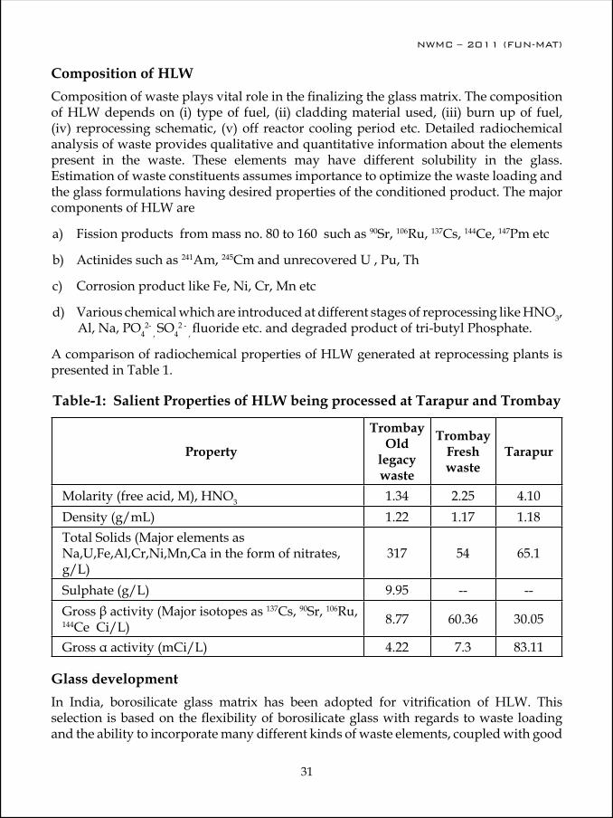
NWMC – 2011 (FUN-MAT)
30
NWMC – 2011 (FUN-MAT)
31
Composition of HLW Composition of waste plays vital role in the finalizing the glass matrix. The composition of HLW depends on (i) type of fuel, (ii) cladding material used, (iii) burn up of fuel, (iv) reprocessing schematic, (v) off reactor cooling period etc. Detailed radiochemical analysis of waste provides qualitative and quantitative information about the elements present in the waste. These elements may have different solubility in the glass. Estimation of waste constituents assumes importance to optimize the waste loading and the glass formulations having desired properties of the conditioned product. The major components of HLW are
a) Fission products from mass no. 80 to 160 such as 90Sr, 106Ru, 137Cs, 144Ce, 147Pm etc
b) Actinides such as 241Am, 245Cm and unrecovered U , Pu, Th
c) Corrosion product like Fe, Ni, Cr, Mn etc
d) various chemical which are introduced at different stages of reprocessing like HNO3, Al, Na, PO4
2- , SO4
2 - , fluoride etc. and degraded product of tri-butyl Phosphate.
A comparison of radiochemical properties of HLW generated at reprocessing plants is presented in Table 1.
Table-1: Salient Properties of HLW being processed at Tarapur and Trombay
Property
Trombay Old
legacy waste
Trombay Fresh waste
Tarapur
Molarity (free acid, M), HNO3 1.34 2.25 4.10Density (g/mL) 1.22 1.17 1.18Total Solids (Major elements as Na,U,Fe,Al,Cr,Ni,Mn,Ca in the form of nitrates, g/L)
317 54 65.1
Sulphate (g/L) 9.95 -- --Gross β activity (Major isotopes as 137Cs, 90Sr, 106Ru, 144Ce Ci/L) 8.77 60.36 30.05
Gross α activity (mCi/L) 4.22 7.3 83.11
Glass developmentIn India, borosilicate glass matrix has been adopted for vitrification of HLW. This selection is based on the flexibility of borosilicate glass with regards to waste loading and the ability to incorporate many different kinds of waste elements, coupled with good

NWMC – 2011 (FUN-MAT)
32
NWMC – 2011 (FUN-MAT)
33
glass-forming ability, chemical durability, mechanical integrity and excellent thermal and radiation stability. The exact compositions of nuclear waste glasses are tailored for easy preparation and melting, avoidance of phase separation and uncontrolled crystallization and acceptable leaching resistance. One of the limitations of glass matrix is its limited solubility with respect to different waste constituents. Compositional site-specific diversity of waste often necessitates modification in the glass matrix. For instance, vitrification of sulphate containing HLW is a challenging task since solubility of sulphur in the form of sodium sulphate is very less (< 1% wt) in normally deployed borosilicate melts for vitrification of HLW. At higher sulphate concentration, a separate phase of alkali sulphate is formed. Its presence in glass is not desirable as this phase is enriched with 137Cs and has high solubility in water. Suitable modifications to this basic matrix have been developed in order to take care of specific chemical species like sulphate and sodium. Barium-based borosilicate glass matrix (SB-44) has been developed to accommodate sulphate in the glass matrix [3]. Barium–based borosilicate glass matrix is able to contain sulphate upto 2.5 wt % without impairing the properties of the conditioned product. Similarly, some modifications in the glass compositions (GM-33) were carried out for vitrification of fresh HLW generated at Plutonium Plant, Trombay and HLW generated at PREFRE, Tarapur.
Before adoption in the plant, conditioned products are evaluated for various properties like product melt temperature, waste loading, homogeneity, thermal stability, radiation stability and chemical durability. In these studies, advanced analytical instruments are used e.g., Scanning Electron Microscope, Electron Microprobe Analyzer, X-ray Diffractometer, Inductively Coupled Plasma Spectrometer, Raman Spectroscopy, Infra Red (IR), Photo Luminiscence (PL), Positron Annihilation Spectroscopy (PAS), Electron Paramagnetic Resonance (EPR) and Thermal analysis system. Compositional details of the glass formulations adopted for vitrification of HLW at Trombay and Tarapur are presented in Table 2.
Table 2: Details of various glass compositions in use at Trombay and Tarapur (Wt %)
Oxide AVS,Tarapur Wt%
WIP Trombay (SB-44) Wt% (SB-44 sulphate bearing)
WIP Trombay (GM-33) Wt%
SiO2 36.48 30.5 34.0
B2O3 19.76 20.0 20.0
Na2O 8.74 9.5 12.0BaO -- 19.0 10.0TiO2 7.22 -- 1.0Fe2O3 3.8 -- --Waste Oxide 24.0 21.0 23.0

NWMC – 2011 (FUN-MAT)
32
NWMC – 2011 (FUN-MAT)
33
Product CharacterizationDetailed evaluation of the Vitrified Waste Product (VWP) is carried out during inactive vitrification runs with simulated waste. Based on the desired product quality, various process parameters are standardized. Conditioned products are evaluated for various properties like product melt temperature, waste loading, homogeneity, thermal stability, radiation stability and chemical durability using advanced analytical instruments.
Glass forming and pouring characteristics
This is one of the most important characteristics with respect to glass formulation as it has direct impact on the glass melter design and various other parameters like viscosity, volatilization of radio-nuclides and total waste loading. The knowledge of viscosity of a glass is needed with respect to its pouring characteristic and fluidity. Viscosity of 50 to100 dPa.sec was found within the temperature range of 900oC to 1150oC for selected glass compositions. At this viscosity, glass is free-flowing and is suitable for pouring through an orifice. The glass formulation selected for immobilization of HLW at WIPs, Trombay using induction heating metallic melter have glass melting temperature in the rage of 950-1000ºC. However, with the advent of new technologies like Joule Heated Ceramic Melters (JHCM) and Cold Crucible Induction Melters (CCIM), it is possible to process glass formulation with higher glass meting temperatures to enable higher waste loading and resultant improved product characteristics.
HomogeneityHomogeneity of vitrified waste product is an important parameter in terms of product durability. As we know glass is an amorphous material, checking the homogeneity of vWP in this context include a) checking amorphous nature of vWP by X-ray diffraction (XRD) b) checking homogeneous distribution of glass forming and waste constituents by Electron Probe Micro Analyzer-Wavelength Dispersive X-ray Spectroscopy (EPMA-WDS) and c) carrying out chemical analysis of glass products from different batches for the elemental concentration using spectroscopic techniques to know the distribution of constituents within the matrix. Typical optical and BSE images of base glass ( SB-44 base glass, Table 2) sample are shown in Fig. 2.(a-b). Both the images show that the base glass is homogeneous in composition. The Si Kα, B Kα and Ba Kα X-ray images (Fig. 2 c-e) also clearly show that these elements are homogeneously distributed in the glass.
Glass-Transition Temperature
Estimation of glass transition temperature for a vitrified waste product is important with respect to the limit of radioactivity which can be incorporated so that the decay heat because of different radionuclides does not increase the temperature more than the glass transition temperature. Glass transition temperature of the glass product (SB-44) has been evaluated by DTA as given in Fig. 3.
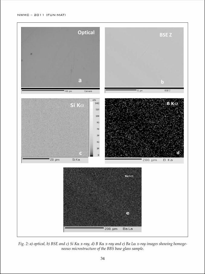
NWMC – 2011 (FUN-MAT)
34
NWMC – 2011 (FUN-MAT)
35
Fig. 2: a) optical, b) BSE and c) Si Kα x-ray, d) B Kα x-ray and e) Ba Lα x-ray images showing homoge-neous microstructure of the BBS base glass sample.

NWMC – 2011 (FUN-MAT)
34
NWMC – 2011 (FUN-MAT)
35
Fig. 3 : DTA pattern of barium borosilicate glass (SB-44)
Fig. 4: Leaching pattern of barium borosilicate glass.

NWMC – 2011 (FUN-MAT)
36
NWMC – 2011 (FUN-MAT)
37
Chemical durability of glass
Leaching test The chemical durability of the glass is the most important characteristics among all the product characteristics from the point of view of the environmental impact of disposal of HLW. For the screening of various formulations, standard leach test in boiling water conditions under reflux is employed to estimate the leach rates of major elements like Na, B, Si. Leaching of vitrified waste products (SB-44) made using barium borosilicate glass on sodium loss basis has been studied for a period of 710 days. The leaching behaviour of vWP is presented in Fig. 4.
Radiation stability of glassAs the glass experiences continuous irradiation by α, β and γ radiations from the radioactive components of HLW, the glass experiences radiation damage and hence, alteration in the glass structure may occur. Understanding of these structural evolutions of the nuclear waste glasses under irradiation is crucial to secure long term disposal and predict their behavior. To simulate the alpha effects, heavy ion 12C irradiation study has been carried out, since a 12C atom can be considered as a cluster of alphas, whereas the electron beam irradiation can simulate the effects of β irradiation to a great extent. Also vitrified waste product was irradiated by gamma radiation to different doses and change in the structure was studied by spectroscopic techniques like Raman Spectroscopy, IR, PAS, EPR , PL etc. After these studies, it can be inferred that, due to irradiation upto dose of 105 Gy to 108 Gy, though there is formation of various defect centers in the glass, the major volume of the glass remains unaffected at these dose ranges.
The salient properties of vitrified waste product produced in Tarapur and Trombay are summarized in Table 3.
Table 3: Properties of various vitrified waste products
PropertiesAVS Tarapur WIP Trombay
(SB-44 sulphate bearing)
WIP Trombay (GM-33)
Fusion temperature (oC) 875 850 875
Pouring temperature(oC) 950 925 950
Thermal conductivity at 100oC (W/m/oK) 0.925 0.92 --
Coefficient of thermal expansion (oC-1) 103 x 10-7 98 x 10-7 99 x 10-7
Glass transition temperature (oC) 540 496 515
NWMC – 2011 (FUN-MAT)
36
NWMC – 2011 (FUN-MAT)
37
Impact strength (RIAJ) -- 0.85 --
Average leach rate on sodium loss basis at 100oC (gm/cm2/day) 8 x 10⁻⁵ 2.32 x 10⁻⁶ 1.02 x 10⁻⁵
Density (g/cm3) 2.8 3.2 2.8
Conclusions:Immobilization of HLW in inert solid matrix is a primary requirement for management of HLW. Suitable glass matrix has been developed for different types of HLW. Borosilicate glass matrix has been suitably modified for incorporation of historic waste, HLW from power reactor reprocessing, etc. These glass compositions have been characterized for various properties like homogeneity, chemical durability, thermal stability, radiation stability etc. All the properties evaluated for different glass compositions were found to be suitable to meet the product acceptation criteria and adopted on plant scale at BARC, Trombay & Tarapur.
References:1. K. Raj, K.K. Prasad, N.K. Bansal, Nucl. Eng. Design 236 (2006) 914–930.2. M. I. Ojovan and O. K. Karlina, Radiochim. Acta. 34 (1992) 97.3. C.P. Kaushik, R.K. Mishra, P. Sengupta, Amar Kumar, D. Das, G.B. Kale, Kanwar Raj, J.
Nucl. Mater. 358 (2006)129
Dr. R. K. Mishra is associated with Process Control Laboratories of Waste Management Facilities, Trombay for providing analytical support to the waste immobilization plant. He is engaged in preparation and characterization of glass/glass ceramics matrices for immobilization of high level radioactive liquid waste generated during reprocessing of spent fuel from PHWR, FBR and AHWR. Other areas of his research experience cover separation and recovery of valuables from radioactive waste for industrial application, corrosion study of different alloys with nitric acid as well as
molten glass matrix, synthesis and characterization of nano materials for decontamination of low level radioactive liquid waste. He has more than 75 publications to his credit. He is a recipient of DAE Special Contribution Award – 2008 and Group Achievement awards in the year 2010 for his valuable contribution in the field of Nuclear Science and Technology and to the programmes of Dept of Atomic Energy. During his Ph D, he has extensively worked on different types of borosilicate glasses for the purpose of immobilization of nuclear waste and based on this outstanding work, he has been bestowed with Prof. H. J. Arnikar best Ph. D thesis Award in the year 2011.
NWMC – 2011 (FUN-MAT)
38
Dr. C. P. Kaushik, joined Waste Management Division in 1985 after successful completion of 28th batch of BARC Training School. Presently he is shouldering the responsibility of Superintendent ( Labs, Training & Safe-ty) at Waste Management Facility, Trombay. He is engaged in development of matrices for treatment/conditioning of different type of radioactive waste and its implementation in plant scale for more than two decades. He is also responsible for characterization of waste and waste forms for their requi-site properties like leaching, homogeneity, thermal stability and long term
durability of vitrified waste product under repository conditions. Other areas of his research experience cover- characterisations of buffer and backfill materials for use in Near Surface Disposal Facilities and Geological Repositories, design and setting up of the radio analytical laboratories, separation and recovery of valuables from radioactive waste for industrial ap-plication, screening and identification of microbes and plants with bioremediation potential for removal / concentration of radionuclides, material issues in the field of radioactive waste management and management of radioactive organic waste. He has more than 150 publica-tions in journals, national and international conferences to his credit. He is a recipient of INS gold medal award in the year 2005 and Group Achievement awards in the year 2006 & 2010 for his outstanding contribution in the field of nuclear waste management.

NWMC – 2011 (FUN-MAT)
39
Hydrogen Storage: Some Issues
S. K. Kulshreshtha
Atomic Energy Education Society Western Sector, Anushaktinagar Mumbai-400 094 India E-mail: [email protected]
World wide the demand for energy is growing at an alarming rate. Currently, this increased demand is being met largely by reserves of fossil fuels. These reserves are diminishing and they will become increasingly expensive as the oil, coal, and natural gas supplies cannot be replenished. Emissions from fossil fuel usage significantly degrade air quality all over the world and substantially change the world climate. Further, most of the people who consume fossil fuels do not live at places where these fuels are extracted. This situation creates enormous economic motivation for the consuming nations to try to exert control over the regions that supply the fuels. Fossil fuel, particularly crude oil, is confined to a few areas of the world and continuity of its supply is governed by political, economic and ecological factors. These factors conspire to force highly fluctuating and often high fuel prices while, at the same time, environmental policy is demanding a reduction in greenhouse gases and toxic emissions. To over come these energy challenges, a coherent energy strategy is required to addresses both the energy supply and demand taking account of the whole energy lifecycle including fuel production, transmission and distribution, energy conversion and the impact on energy equipment manufacturers and the end-users of energy systems. The current energy economy is unsustainable and significant attempts are being made to search for alternate renewable sources of energy. Hydrogen is the Ideal replacement for fossil fuels. Hydrogen based energy has been proposed as an alternative as it is the only gaseous fuel which is not chemically bound with carbon, hence no pollution, no greenhouse gases and environmentally benign. Hydrogen produces only water as the waste product, which can be recycled for the production of hydrogen. However, the major issue is how to get hydrogen in gaseous state. Most hydrogen in nature is chemically bound as water, carbohydrates or hydrocarbons and significant energy is required to separate hydrogen from oxygen or carbon. The hydrogen produced from methane, gasoline, biomass, and coal results into different amounts of pollution and global warming depending upon the resource. Hydrogen production by water splitting using different methods has been suggested as one of the sustainable source of energy as it is independent of petroleum products and nonpolluting. Hydrogen is not a primary energy source like coal and gas. It is an energy carrier with highest gravimetric energy density among all known gaseous fuels [143 GJ/tone]. Harnessing of hydrogen energy needs its safe, efficient and economical storage and transport in solid state. A variety of metal hydrides have been developed for the efficient storage, transport and
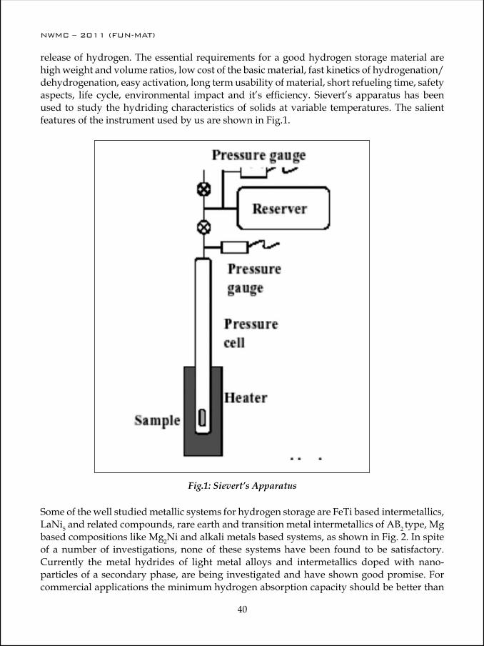
NWMC – 2011 (FUN-MAT)
40
NWMC – 2011 (FUN-MAT)
41
release of hydrogen. The essential requirements for a good hydrogen storage material are high weight and volume ratios, low cost of the basic material, fast kinetics of hydrogenation/dehydrogenation, easy activation, long term usability of material, short refueling time, safety aspects, life cycle, environmental impact and it’s efficiency. Sievert’s apparatus has been used to study the hydriding characteristics of solids at variable temperatures. The salient features of the instrument used by us are shown in Fig.1.
Fig.1: Sievert’s Apparatus
Some of the well studied metallic systems for hydrogen storage are FeTi based intermetallics, LaNi5 and related compounds, rare earth and transition metal intermetallics of AB2 type, Mg based compositions like Mg2Ni and alkali metals based systems, as shown in Fig. 2. In spite of a number of investigations, none of these systems have been found to be satisfactory. Currently the metal hydrides of light metal alloys and intermetallics doped with nano-particles of a secondary phase, are being investigated and have shown good promise. For commercial applications the minimum hydrogen absorption capacity should be better than

NWMC – 2011 (FUN-MAT)
40
NWMC – 2011 (FUN-MAT)
41
6.5%. With the use of light weight elements and their alloys in nanoform, it is possible to achieve this capacity.
Fig.2: Status of Hydrogen Absorption
FeTi based intermetallics have been exhaustively investigated for their hydriding and dehydriding characteristics because of their very simple CsCl type cubic structure. The saturation composition for FeTi hydrides is FeTiH2 and hydrogen atoms occupy the octahedral interstitial sites formed by Fe and Ti atoms and depending on the value of H/M, three different hydride phases namely alpha, beta and gamma have been reported for this system. Pure FeTi needs high pressure of hydrogen for absorption and weight percentage of hydrogen is very poor. The saturation composition formed is FeTiH2, as can be seen from Fig.3. The absorption pressure can be decreased substantially by incorporating either excess Ti in FeTi system or part of the Fe is replaced by other transition metal elements like V and Mn. The recent past we have investigated the The hydrogenation behavior of V and Cr substituted FeTi, which has shown significant improvement in its hydrogen storage capacity and lower absorption pressure. The detailed investigations have been carried out at variable temperatures with a view to evaluate the thermodynamic parameters like ∆H and ∆S, associated with hydrogen absorption process and the release behavior of hydrogen from these intermetallics. For example Ti0.85VFe0.15 absorbs upto a maximum of 3.53 hydrogen atoms per formula unit and the P-C-T diagrams show very low absorption plateau pressure. The material with a composition Ti0.6VFe0.4 readily absorbs hydrogen without any activation. Unlike this, the Cr-substitution brings down the hydrogen storage capacity marginally but

NWMC – 2011 (FUN-MAT)
42
NWMC – 2011 (FUN-MAT)
43
the the decomposition temperature for Cr substituted hydrides is lower as compared to Cr-free Ti-V-Fe systems.
Fig.3: Hydrogen absorption by FeTi
Recently we have also investigated the hydrogen absorption characteristics of Ti0.85VFe0.15 modified by Zr substitution (5 at%) at V site. The crystal structure, maximum hydrogen absorption capacity and the hydrogen desorption properties of Ti0.85V0.95Fe0.15Zr0.05 have been compared with those of Ti0.85VFe0.15. The kinetics of hydrogen uptake of both the alloys has been carried out and they are found to be comparable. The pressure–composition isotherms have been studied at room temperature and 373 K for both the alloys. Zr substituted composition is found to have better hydrogen absorption properties. Ti0.85VFe0.15 is found to absorb a maximum of 3.83 H atoms/formula unit (3.7 wt%) to form a hydride with a composition Ti0.85VFe0.15H3.83, while Ti0.85V0.95Fe0.15Zr0.05 absorbs a maximum of 3.74 H atoms/formula unit to form a hydride with a composition Ti0.85V0.95Fe0.15Zr0.05H3.74 (3.5 wt%) at room temperature. From the temperature programmed desorption studies of the saturated hydrides the hydrogen desorption temperatures have also been estimated. Figs. 4 – 6, present these results.
The LaNi5 based compounds have shown excellent hydrogenation characteristics at room temperature but the cost of basic material is very high and hydrogen storage capacity is
Equi
libri
um p
ress
ure
(atm
H2)
x in FeTiHx

NWMC – 2011 (FUN-MAT)
42
NWMC – 2011 (FUN-MAT)
43
very poor. These hydrides also degrade with repeated use of the material and their storage capacity and kinetics of hydrogenation is significantly retarded with use. The saturation composition achieved for this intermetallic is close to LaNi5H6.5.
Fig.4: Pressure composition absorption curves for Ti1-xVFex for x = 0, 0.1, 0.15, 0.2 and 0.4 alloys at room temperature.
Fig. 5: Pressure composition absorption curves for Ti0.85VFe0.15 alloy at 298, 323, 373, 423, 523 K.
Fig. 6: Thermal desorption profile of (a) Ti0.9VFe0.1H3.65 and (b) Ti0.9VFe0.1D3.65.
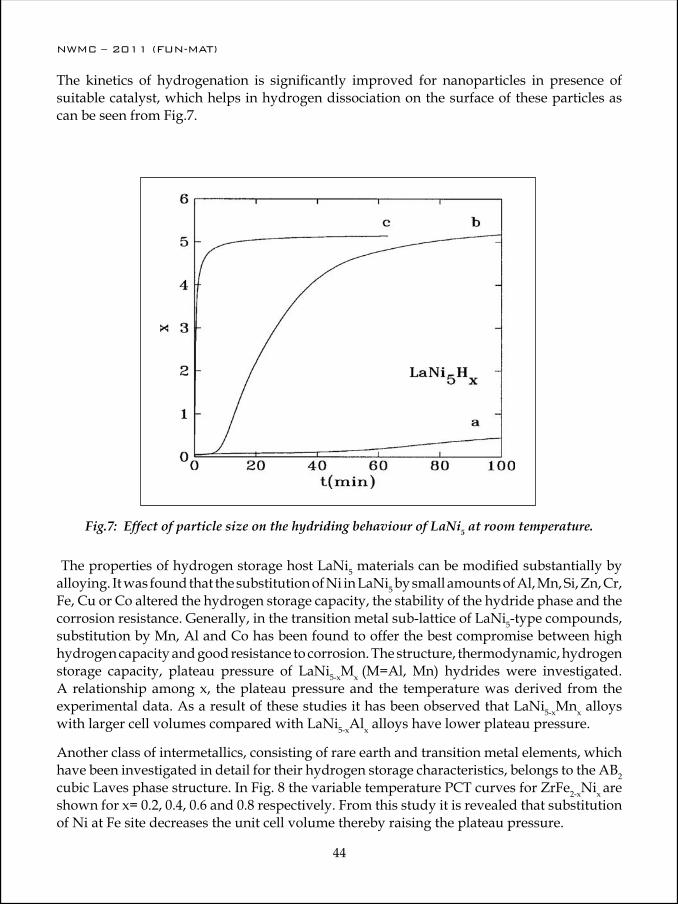
NWMC – 2011 (FUN-MAT)
44
NWMC – 2011 (FUN-MAT)
45
The kinetics of hydrogenation is significantly improved for nanoparticles in presence of suitable catalyst, which helps in hydrogen dissociation on the surface of these particles as can be seen from Fig.7.
The properties of hydrogen storage host LaNi5 materials can be modified substantially by alloying. It was found that the substitution of Ni in LaNi5 by small amounts of Al, Mn, Si, Zn, Cr, Fe, Cu or Co altered the hydrogen storage capacity, the stability of the hydride phase and the corrosion resistance. Generally, in the transition metal sub-lattice of LaNi5-type compounds, substitution by Mn, Al and Co has been found to offer the best compromise between high hydrogen capacity and good resistance to corrosion. The structure, thermodynamic, hydrogen storage capacity, plateau pressure of LaNi5-xMx (M=Al, Mn) hydrides were investigated. A relationship among x, the plateau pressure and the temperature was derived from the experimental data. As a result of these studies it has been observed that LaNi5-xMnx alloys with larger cell volumes compared with LaNi5-xAlx alloys have lower plateau pressure.
Another class of intermetallics, consisting of rare earth and transition metal elements, which have been investigated in detail for their hydrogen storage characteristics, belongs to the AB2 cubic Laves phase structure. In Fig. 8 the variable temperature PCT curves for ZrFe2-xNi x are shown for x= 0.2, 0.4, 0.6 and 0.8 respectively. From this study it is revealed that substitution of Ni at Fe site decreases the unit cell volume thereby raising the plateau pressure.
Fig.7: Effect of particle size on the hydriding behaviour of LaNi5 at room temperature.

NWMC – 2011 (FUN-MAT)
44
NWMC – 2011 (FUN-MAT)
45
It s also found that these alloys does not undergo any structural change upon hydrogenation. The enthalpy of the alloys for hydrogen absorption was found decreasing with increase in Ni content. Thus the Ni substitution in this system makes these alloys to form less stable hydrides, which is good for practical applications. In general the intermetallics based on AB2 type structure have very poor hydrogen absorption capacity (≈1.8% by weight) and
Fig.8: Variable temperature PCT curves for ZrFe2-xNi x are shown for (a) x= 0.2, (b) 0.4 ,(c) 0.6 and (d) 0.8 respectively.
attain a saturation composition close to AB2H4. These materials also need very high annealing temperature for their activation for hydrogen absorption.
The Mg based alloys have good hydrogen storage capacity but very poor kinetics for hydrogenation/ dehydrogenation even after extensive activation at 4000C and above. The
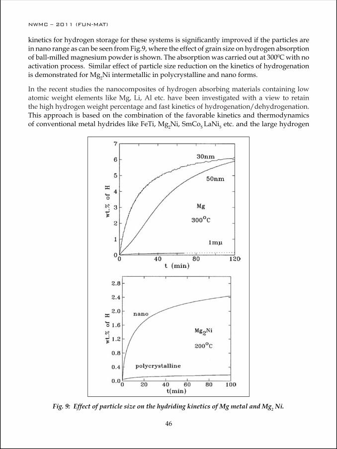
NWMC – 2011 (FUN-MAT)
46
NWMC – 2011 (FUN-MAT)
47
kinetics for hydrogen storage for these systems is significantly improved if the particles are in nano range as can be seen from Fig.9, where the effect of grain size on hydrogen absorption of ball-milled magnesium powder is shown. The absorption was carried out at 3000C with no activation process. Similar effect of particle size reduction on the kinetics of hydrogenation is demonstrated for Mg2Ni intermetallic in polycrystalline and nano forms.
In the recent studies the nanocomposites of hydrogen absorbing materials containing low atomic weight elements like Mg, Li, Al etc. have been investigated with a view to retain the high hydrogen weight percentage and fast kinetics of hydrogenation/dehydrogenation. This approach is based on the combination of the favorable kinetics and thermodynamics of conventional metal hydrides like FeTi, Mg2Ni, SmCo5 LaNi5 etc. and the large hydrogen
Fig. 9: Effect of particle size on the hydriding kinetics of Mg metal and Mg2 Ni.
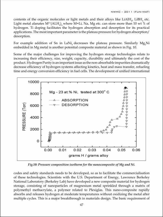
NWMC – 2011 (FUN-MAT)
46
NWMC – 2011 (FUN-MAT)
47
contents of the organic molecules or light metals and their alloys like LiAlH4, LiBH4 etc. Light metal alanates Mn+(ALH4)n where M=Li, Na, Mg etc. can store more than 10 wt % of hydrogen. Ti doping facilitates the hydrogen absorption and desorption for its practical applications. The most important parameter is the plateau pressure for hydrogen absorption/ desorption.
For example addition of Sn in LaNi5 decreases the plateau pressure. Similarly Mg2Ni embedded in Mg metal is another potential composite material as shown in Fig. 10.
Some of the major challenges for improving the hydrogen storage technologies relate to increasing their efficiency, size, weight, capacity, durability and ultimately the cost of the product. Hydrogen Purity is an important issue as the non-absorbable impurities dramatically decrease efficiency of hydrogen systems affecting kinetics, heat and mass transfer, refueling time and energy conversion efficiency in fuel cells. The development of unified international
codes and safety standards needs to be developed, so as to facilitate the commercialisation of these technologies. Scientists with the U.S. Department of Energy, Lawrence Berkeley National Laboratory (Berkeley Lab) have developed a new composite material for hydrogen storage, consisting of nanoparticles of magnesium metal sprinkled through a matrix of polymethyl methacrylate, a polymer related to Plexiglas. This nano-composite rapidly absorbs and releases hydrogen at moderate temperatures without oxidizing the metal after multiple cycles. This is a major breakthrough in materials design. The basic requirement of
Fig.10: Pressure composition isotherm for the nanocomposite of Mg and Ni.
NWMC – 2011 (FUN-MAT)
48
a good hydrogren storage material is high storage capacity at relatively lower temperature with fast kinetics for absorption and desorption. Significant attempts are being made to develop suitable nanocomposites of metals and graphenes to develop high quality hydrogen storage materials with the desired quality and capacity.
Dr. S. K. Kulshreshtha, after his basic education from Agra University, Joined the BARC training school in 1966 in chemistry discipline and after completion of his training, he opted to join the Chemistry Division of BARC in 1967. Dr. Kulshreshtha had been mainly working in the area of Mate-rial Science and had extensively used a variety of characterization tech-niques such as Powder X-ray diffraction, Mossbauer, NMR, IR, UV-VIS TOF-Mass Spectrometry etc. for the structural studies of different types of materials and has published 223 Research papers in refereed International
Journals and few review articles to his credit. He was appointed as Head of Novel Materi-als and Structural Chemistry Division in BARC in 2002. Subsequently, he was promoted as Associate Director of Chemistry Group and Head Chemistry Division in 2005. As as-sociate Director, he steered the programs of both Chemistry and Analytical Chemistry Divi-sions of BARC. He had the Teaching experience of about 24 years at BARC Training School. Dr. Kulshreshtha also worked as the Convener of the Board of Studies for Chemical Sciences of the recently formed Homi Bhabha National Institute, a deemed university and was also the member of its academic council. Dr. Kulshreshtha also worked as the Senior Professor in this institute. He also worked as the Guest Scientist at the University of Erlangen & Nurnberg, Germany for two years (1981-82) at The Institute of Physical and Theoretical Chemistry.

NWMC – 2011 (FUN-MAT)
49
Hydrogen Production Processes: An Overview
A. K. Tripathi
Chemistry Division, Bhabha Atomic Research Centre, Trombay, Mumbai, 400 085 E-mail: [email protected]
Hydrogen, the most abundant element in the universe, does not occur freely on our planet. However, it is predominantly present on earth in combination with oxygen as water and with carbon and other elements as fossil fuels, hydrocarbons, and biomass. Production of hydrogen from these sources is an energy intensive process. Hydrogen production processes can be broadly classified into three general categories: thermal, electrolytic, and photolytic. At present about 96 % of world’s hydrogen is produced from fossil fuels using thermal processes like steam methane reforming, partial oxidation, and gasification of coal or biomass while remaining comes from electrolysis of water. Most of the hydrogen produced is primarily used in the chemical industry. More recently hydrogen is perceived as a clean, renewable energy carrier for sustainable energy supply in the future especially when issues like growing concern about global warming due to emission of green house gases and depletion of fossil fuel resources have become paramount. In association with the fuel cell technology, hydrogen appears to be a promising alternative to the fossil fuels for transport applications.
Thermal ProcessesThermal processes for hydrogen production can be further classified in to two types: one in which energy is used to release hydrogen from various resources, such as natural gas, coal, biomass, liquid fuels, while in other heat (500 - 2000°C), in combination with closed-chemical cycles, produces hydrogen from renewable resources such as water. Steam methane reforming, partial oxidation, autothermal reforming and gasification of coal/biomass primarily constitute the first type of thermal processes and they account for about 96 % of world’s hydrogen production today even though they suffer from a major drawback such as emission of CO2, a green house gas. The second type of thermal processes, also known as thermochemical cycles are in developmental stage. More than 200 thermochemical cycles have been reported. Notable among these are iodine-sulfur cycle, hybrid sulphur cycle, Copper-chlorine, Calcium-bromine, ZnO/Zn chemical cycle. Heat required for high-temperature water splitting is supposed to be provided by high temperature nuclear reactor (up to about 1000°C) or solar concentrators (up to about 2000°C). The major advantage with the thermochemical cycles is that they produce hydrogen with near-zero green house gas emissions. Countries like USA, Japan, France, Italy, UK, Korea, China and India are pursuing S-I cycle for large scale production of hydrogen using high grade nuclear heat while Canadians have focused their efforts on Cu-Cl cycle.
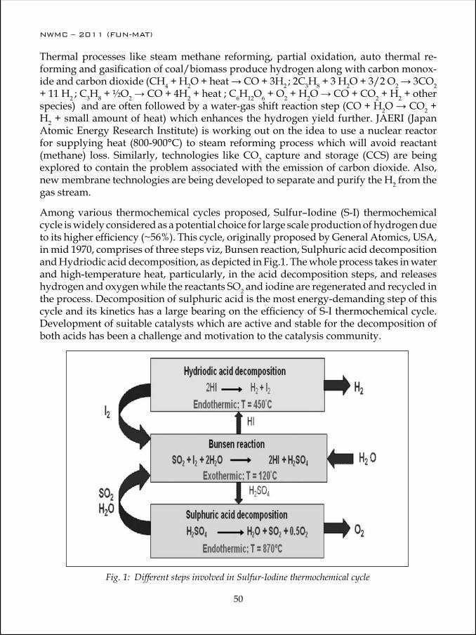
NWMC – 2011 (FUN-MAT)
50
NWMC – 2011 (FUN-MAT)
51
Fig. 1: Different steps involved in Sulfur-Iodine thermochemical cycle
Thermal processes like steam methane reforming, partial oxidation, auto thermal re-forming and gasification of coal/biomass produce hydrogen along with carbon monox-ide and carbon dioxide (CH4 + H2O + heat → CO + 3H2 ; 2C3H8 + 3 H2O + 3/2 O2 → 3CO2 + 11 H2 ; C3H8 + ½O2 → CO + 4H2 + heat ; C6H12O6 + O2 + H2O → CO + CO2 + H2 + other species) and are often followed by a water-gas shift reaction step (CO + H2O → CO2 + H2 + small amount of heat) which enhances the hydrogen yield further. JAERI (Japan Atomic Energy Research Institute) is working out on the idea to use a nuclear reactor for supplying heat (800-900°C) to steam reforming process which will avoid reactant (methane) loss. Similarly, technologies like CO2 capture and storage (CCS) are being explored to contain the problem associated with the emission of carbon dioxide. Also, new membrane technologies are being developed to separate and purify the H2 from the gas stream.
Among various thermochemical cycles proposed, Sulfur–Iodine (S-I) thermochemical cycle is widely considered as a potential choice for large scale production of hydrogen due to its higher efficiency (~56%). This cycle, originally proposed by General Atomics, USA, in mid 1970, comprises of three steps viz, Bunsen reaction, Sulphuric acid decomposition and Hydriodic acid decomposition, as depicted in Fig.1. The whole process takes in water and high-temperature heat, particularly, in the acid decomposition steps, and releases hydrogen and oxygen while the reactants SO2 and iodine are regenerated and recycled in the process. Decomposition of sulphuric acid is the most energy-demanding step of this cycle and its kinetics has a large bearing on the efficiency of S-I thermochemical cycle. Development of suitable catalysts which are active and stable for the decomposition of both acids has been a challenge and motivation to the catalysis community.

NWMC – 2011 (FUN-MAT)
50
NWMC – 2011 (FUN-MAT)
51
The technology of solar- and nuclear-driven high-temperature thermochemical water splitting cycles is in early stage of development and has to overcome several challenges like material of construction, heat transfer medium, development of next generation of nuclear reactor technology, thus requires considerable research efforts.
Electrolytic ProcessesElectrolytic processes use electricity to split water into hydrogen and oxygen in an electrolyser without emission of greenhouse gases, provided the source of the electricity used is either a renewable source or a nuclear one. Electrolytic generation of hydrogen is a preferred choice when high purity hydrogen is required. Three different types of electrolysers being used/under development are alkaline, proton exchange membrane (PEM) and solid oxide electrolyte cells (SOEC). The first two are basically low temperature electrolysers which operate at around 80°C while the operating temperatures in case of SOEC lie in range 500-1000°C. Salient features of each electrolyser are presented in Table-1. In alkaline electrolyser hydrogen needs to be removed from the water at cathode side through dehumidification while pure hydrogen can be obtained without further separation in PEM electrolyser. On the other hand, hydrogen can be separated from the steam in another stage after leaving the SOEC. Extensive research is on to identify the best materials for use in SOECs. In the meanwhile, materials used in solid oxide fuel cells (SOFCs) are being utilized as the starting point as the SOECs are essentially SOFCs operating in reverse. Similarly efforts are on to integrate electrolyser with power generators such as, nuclear, wind and solar power. SOEC technology has to overcome the challenges such as, corrosion, seals, thermal cycling.
Table-1 : Characteristics of different type of electrolysers
Parameters Alkaline PEM SOECOperating Temperature
(°C)70 - 90 < 100 500-1000
Electrolyte KOH(aq), NaOH(aq) Sulfonated poly-mers like Nafion
Yttria stabilized zirconia (YSZ), Scandia stabilized
zirconiaConducting ion OH- H+ O2-
Cathode material Ni with Pt catalytic coating
Pt black, IrO2, RuO2
Ni-YSZ cermet
Cathode reaction 2H2O + 2 e- → H2 + 2OH-
2H+ + 2 e- → H2 H2O + 2 e- → H2 + O2-
Anode material Ni or Cu-coated with metal oxide
Pt black, IrO2, RuO2
Perovskite oxides like lanthanum manganate
Anode reaction 2OH- → ½ O2 + H2O + 2e-
H2O → ½ O2 + 2H+ + 2 e-
O2-→ ½ O2 + 2 e-
Status Commercial Pre-commercial Developmental

NWMC – 2011 (FUN-MAT)
52
NWMC – 2011 (FUN-MAT)
53
Photolytic ProcessesPhotolytic processes use light (sunlight) energy to split water into hydrogen and oxygen. They can be further divided in to photoelectrochemical and photobiological water split-ting. Though the photolytic processes are in the very early stages of research, but they have long-term potential for sustainable hydrogen production with low environmental impact.
Researchers became interested in photoelectrochemical water splitting after the famous experiments of Fujishima and Honda in 1972, where photolysis of water in an electrochemical cell was demonstrated using n-type semiconducting TiO2 (rutile) anode exposed to sunlight and connected to a platinum electrode. In this process, absorption of light with energy larger than the band gap of TiO2 leads to generation of electrons and holes in the conduction and valence bands, respectively. The photogenerated electrons and holes cause redox reactions. Water molecules are reduced by the electrons to form H2 and oxidized by the holes to form O2, leading to overall water splitting. The width of the band gap and the potentials of the conduction and valence bands are important. The bottom level of the conduction band has to be more negative than the reduction potential of H+/H2 (0 V vs NHE), while the top level of the valence band has to be more positive than the oxidation potential of O2/H2O (1.23 V) as shown in the Fig. 2.
Fig. 2: Photoelectrochemical splitting of water on a typical photocatalyst
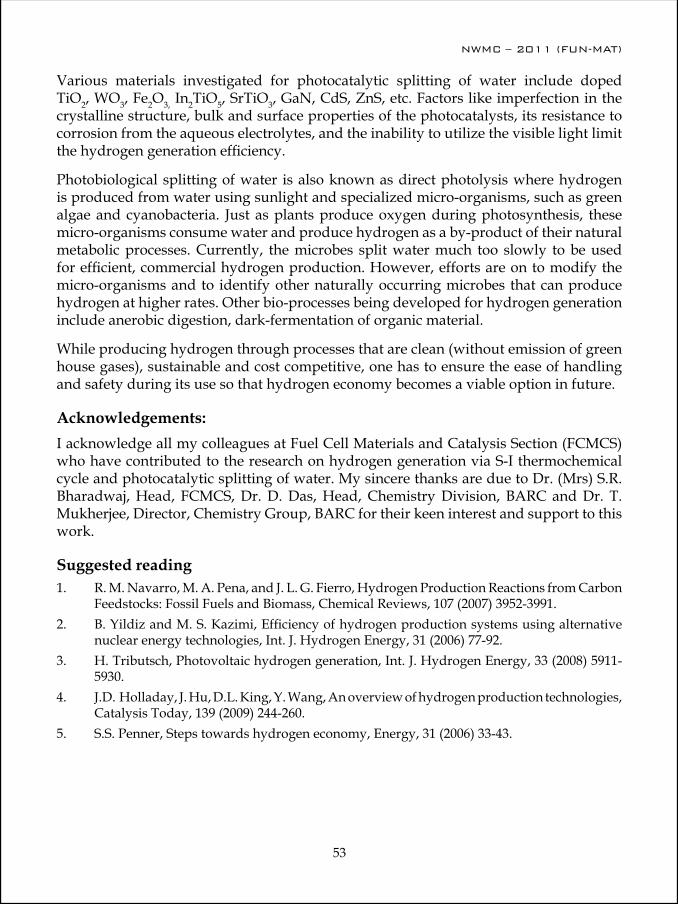
NWMC – 2011 (FUN-MAT)
52
NWMC – 2011 (FUN-MAT)
53
Various materials investigated for photocatalytic splitting of water include doped TiO2, WO3, Fe2O3, In2TiO5, SrTiO3, GaN, CdS, ZnS, etc. Factors like imperfection in the crystalline structure, bulk and surface properties of the photocatalysts, its resistance to corrosion from the aqueous electrolytes, and the inability to utilize the visible light limit the hydrogen generation efficiency.
Photobiological splitting of water is also known as direct photolysis where hydrogen is produced from water using sunlight and specialized micro-organisms, such as green algae and cyanobacteria. Just as plants produce oxygen during photosynthesis, these micro-organisms consume water and produce hydrogen as a by-product of their natural metabolic processes. Currently, the microbes split water much too slowly to be used for efficient, commercial hydrogen production. However, efforts are on to modify the micro-organisms and to identify other naturally occurring microbes that can produce hydrogen at higher rates. Other bio-processes being developed for hydrogen generation include anerobic digestion, dark-fermentation of organic material.
While producing hydrogen through processes that are clean (without emission of green house gases), sustainable and cost competitive, one has to ensure the ease of handling and safety during its use so that hydrogen economy becomes a viable option in future.
Acknowledgements: I acknowledge all my colleagues at Fuel Cell Materials and Catalysis Section (FCMCS) who have contributed to the research on hydrogen generation via S-I thermochemical cycle and photocatalytic splitting of water. My sincere thanks are due to Dr. (Mrs) S.R. Bharadwaj, Head, FCMCS, Dr. D. Das, Head, Chemistry Division, BARC and Dr. T. Mukherjee, Director, Chemistry Group, BARC for their keen interest and support to this work.
Suggested reading1. R. M. Navarro, M. A. Pena, and J. L. G. Fierro, Hydrogen Production Reactions from Carbon
Feedstocks: Fossil Fuels and Biomass, Chemical Reviews, 107 (2007) 3952-3991.2. B. Yildiz and M. S. Kazimi, Efficiency of hydrogen production systems using alternative
nuclear energy technologies, Int. J. Hydrogen Energy, 31 (2006) 77-92.3. H. Tributsch, Photovoltaic hydrogen generation, Int. J. Hydrogen Energy, 33 (2008) 5911-
5930.4. J.D. Holladay, J. Hu, D.L. King, Y. Wang, An overview of hydrogen production technologies,
Catalysis Today, 139 (2009) 244-260.5. S.S. Penner, Steps towards hydrogen economy, Energy, 31 (2006) 33-43.

NWMC – 2011 (FUN-MAT)
54
A.K. Tripathi joined Chemistry Division, BARC in 1984 after graduating from 27th Batch of BARC Training School as a Chemistry Trainee. He started his research activity in the area of heterogeneous catalysis and has contributed to the development of a catalyst based gas recovery system for the sealed-off cw-CO2 lasers. His research interests include supported metal catalysts, host-guest chemistry in micro/mesoporous molecular sieves hosts, entrapment of nanosized oxides in mesoporous materials and evaluation of their catalytic/photocatalytic behavior towards reactions of environmental
importance. Presently, he is engaged in studies related to catalyst development for various steps of S-I thermochemical cycle for hydrogen production. He has authored/co-authored about 40 research papers published in national/international Journals.
Dr. Tripathi has been actively associated in various capacities with the Mumbai chapter of the Catalysis Society of India and Society for Materials Chemistry.

NWMC – 2011 (FUN-MAT)
55
Research and Development on High Purity Materials: Challenges and Opportunities
Vimal K. Jain
Chemistry Division Bhabha Atomic Research Centre Mumbai-400085 Tel: (022) 2559 5095; email: [email protected]
The quest for newer materials has always been of paramount importance to human civilization. The technical, economic and social progress has depended strongly on indentifying appropriate materials and improving their properties. Over a period, we have learnt the art and science of transforming materials from one form to another. The materials spectrum of today has enormous diversity and complexity, exploiting purity for electronics, atomic energy and several other uses, size (nano- and supra-) and shape for a variety of applications. The preparation, characterization and application of high purity materials constitute a relatively new and dynamically growing domain in modern materials science. Van Arkel and E. Smekal first realized the connection between purity and properties in 1930’s.
Ideally, a high purity material is comprised of atoms of the basic substance, which are arranged in a perfect, periodically repeated structure without any disturbances. This means such a perfect crystal is free from extrinsic and intrinsic defects, vacancies, stacking faults, dislocations, interstitial atoms, etc. In contrast, a real crystal is referred to a highly pure substance if there is no difference between its properties and those of the ideal crystal. Thus in practice the definition of ‘high purity’ depends on the sensitivity and the limit of detection of tests and analytical methods. Compositional characterization of matrix is often referred to purity levels. However, materials can also be evaluated with respect to the property of interest (scheme 1).
Need for high purity materialsIt is now well known that even trace amounts of impurities may significantly affect physical and chemical properties of a material. There are a number of properties, which are sensitive to the presence of even trace amounts of foreign elements in the base matrix. These properties can be optical, mechanical, electrical or magnetic. For instance properties of phosphors are strongly dependent on the nature of defects and dopants. While desired dopants improve luminescence, impurities like Co, Fe, Ni inhibits luminescence. Electrical properties of metals are very sensitive to the presence of impurities even in ppm level. In superconducting materials properties like magneto-resistivity change drastically with
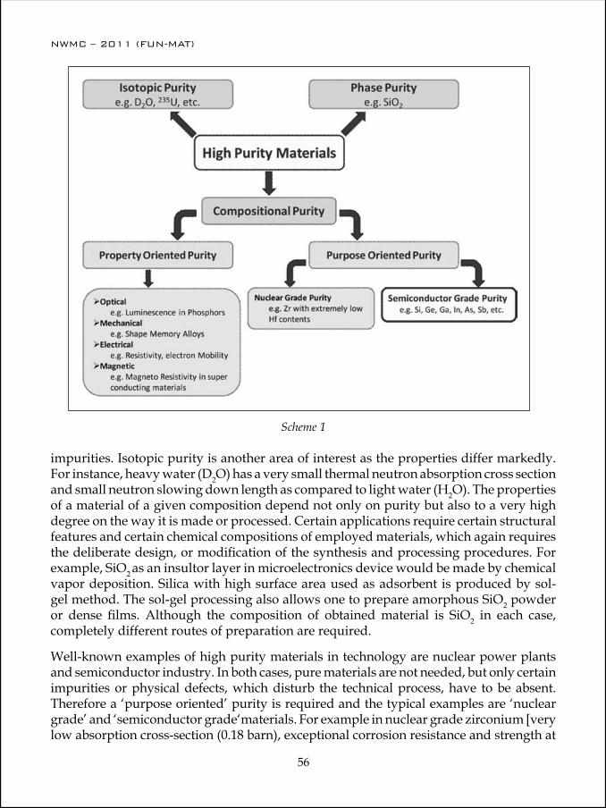
NWMC – 2011 (FUN-MAT)
56
NWMC – 2011 (FUN-MAT)
57
Scheme 1
impurities. Isotopic purity is another area of interest as the properties differ markedly. For instance, heavy water (D2O) has a very small thermal neutron absorption cross section and small neutron slowing down length as compared to light water (H2O). The properties of a material of a given composition depend not only on purity but also to a very high degree on the way it is made or processed. Certain applications require certain structural features and certain chemical compositions of employed materials, which again requires the deliberate design, or modification of the synthesis and processing procedures. For example, SiO2 as an insultor layer in microelectronics device would be made by chemical vapor deposition. Silica with high surface area used as adsorbent is produced by sol-gel method. The sol-gel processing also allows one to prepare amorphous SiO2 powder or dense films. Although the composition of obtained material is SiO2 in each case, completely different routes of preparation are required.
Well-known examples of high purity materials in technology are nuclear power plants and semiconductor industry. In both cases, pure materials are not needed, but only certain impurities or physical defects, which disturb the technical process, have to be absent. Therefore a ‘purpose oriented’ purity is required and the typical examples are ‘nuclear grade’ and ‘semiconductor grade‘materials. For example in nuclear grade zirconium [very low absorption cross-section (0.18 barn), exceptional corrosion resistance and strength at
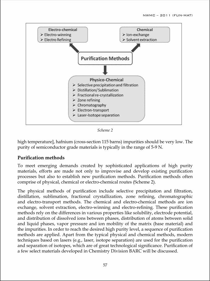
NWMC – 2011 (FUN-MAT)
56
NWMC – 2011 (FUN-MAT)
57
Scheme 2
high temperature], hafnium (cross-section 115 barns) impurities should be very low. The purity of semiconductor grade materials is typically in the range of 5-9 N.
Purification methodsTo meet emerging demands created by sophisticated applications of high purity materials, efforts are made not only to improvise and develop existing purification processes but also to establish new purification methods. Purification methods often comprise of physical, chemical or electro-chemical routes (Scheme 2).
The physical methods of purification include selective precipitation and filtration, distillation, sublimation, fractional crystallization, zone refining, chromatographic and electro-transport methods. The chemical and electro-chemical methods are ion exchange, solvent extraction, electro-winning and electro-refining. These purification methods rely on the differences in various properties like solubility, electrode potential, and distribution of dissolved ions between phases, distribution of atoms between solid and liquid phases, vapor pressure and ion mobility of the matrix (base material) and the impurities. In order to reach the desired high purity level, a sequence of purification methods are applied. Apart from the typical physical and chemical methods, modern techniques based on lasers (e.g., laser, isotope separation) are used for the purification and separation of isotopes, which are of great technological significance. Purification of a few select materials developed in Chemistry Division BARC will be discussed.

NWMC – 2011 (FUN-MAT)
58
NWMC – 2011 (FUN-MAT)
59
Scheme 3
Purity evaluationOnce a high purity materials is produced, there is always a question how to evaluated the purity level. In most cases a typical range of ultra high purity in 6-7N, implying a total impurity concentration of the order of 100-1000 ppb in mass. Thus the sensitivity of the analytical method has to be extremely high (usually of the order of 1-10 ppb).
A systematic analysis of the largest possible number of impurities is required to express the purity of a matrix. Atomic Absorption Spectrometry (AAS), Inductively Couple Plasma Mass Spectrometry (ICP-MS) are convenient methods of analyzing metallic impurity elements. Spark Source Mass Spectrometry (SSMS) and Glow Discharge Mass Spectrometry (GDMS) provide virtually complete analysis of high purity metals. The method is based on irradiation with γ-rays, charged particles of neutrons; the latter are often utilized for activation purposes.
Significance of Purity to material’s propertySince the inception of transistor in 1948 at Bell Telephone Labs, silicon semiconductor technology has grown at exponential rates in performance, reliability and productivity. Currently, silicon comprises 95% of the semiconductor industry despite of its poor operating speed, noise and efficiency as compared to other compound semiconductors like GaAs. As electronic devices becoming smaller, so the challenge of maintaining their electrical properties grows. Ultra pure semiconductor materials are required in VLSI
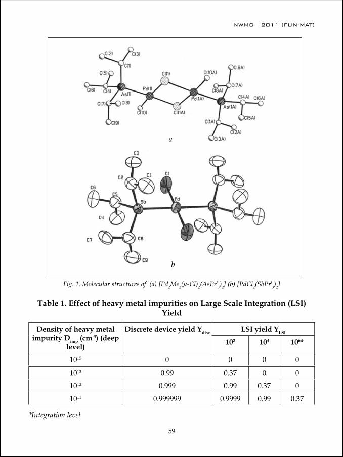
NWMC – 2011 (FUN-MAT)
58
NWMC – 2011 (FUN-MAT)
59
Fig. 1. Molecular structures of (a) [Pd2Me2(µ-Cl)2(AsPri3)2] (b) [PdCl2(SbPri
3)2]
a
b
Table 1. Effect of heavy metal impurities on Large Scale Integration (LSI) Yield
Density of heavy metal impurity Dimp (cm-3) (deep
level)
Discrete device yield Ydisc LSI yield YLSI
102 104 106*
1015 0 0 0 0
1013 0.99 0.37 0 0
1012 0.999 0.99 0.37 0
1011 0.999999 0.9999 0.99 0.37
*Integration level
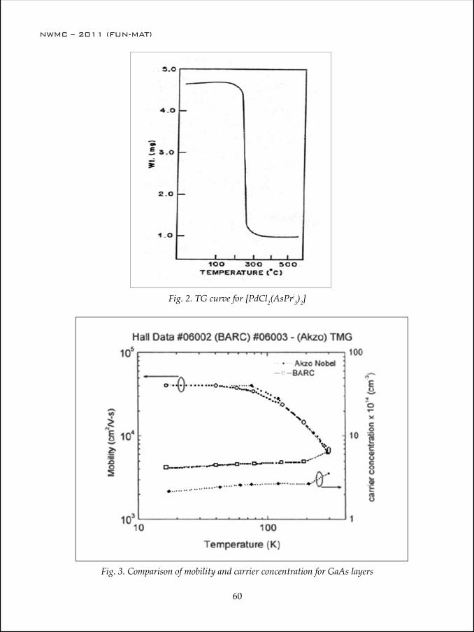
NWMC – 2011 (FUN-MAT)
60
NWMC – 2011 (FUN-MAT)
61
Fig. 2. TG curve for [PdCl2(AsPri3)2]
Fig. 3. Comparison of mobility and carrier concentration for GaAs layers
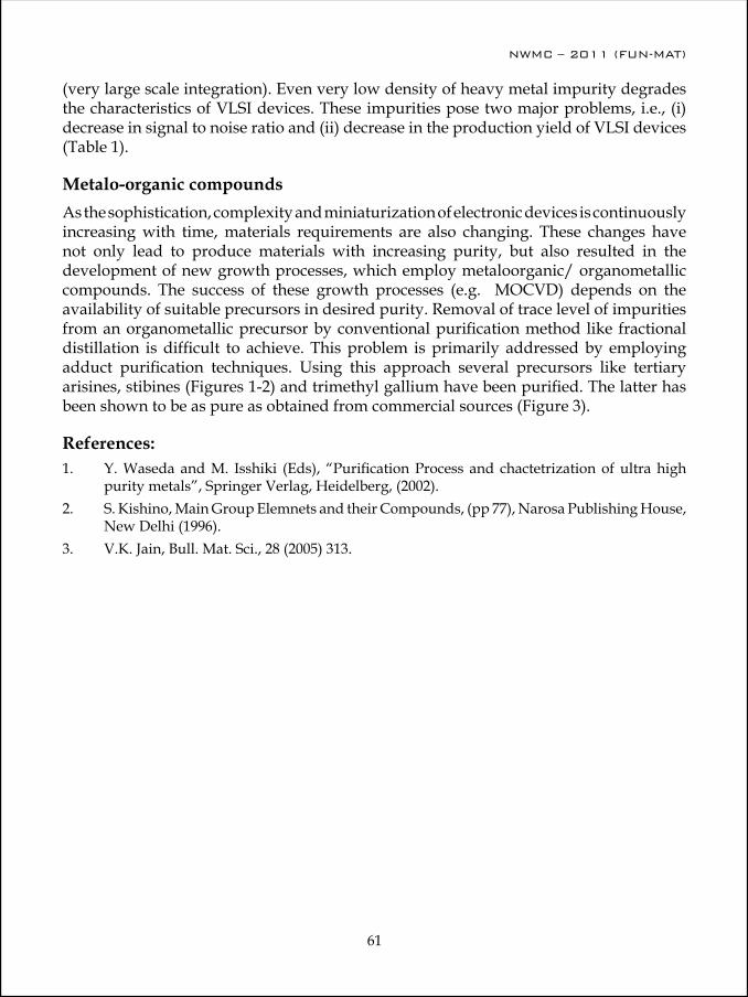
NWMC – 2011 (FUN-MAT)
60
NWMC – 2011 (FUN-MAT)
61
(very large scale integration). Even very low density of heavy metal impurity degrades the characteristics of VLSI devices. These impurities pose two major problems, i.e., (i) decrease in signal to noise ratio and (ii) decrease in the production yield of VLSI devices (Table 1).
Metalo-organic compounds As the sophistication, complexity and miniaturization of electronic devices is continuously increasing with time, materials requirements are also changing. These changes have not only lead to produce materials with increasing purity, but also resulted in the development of new growth processes, which employ metaloorganic/ organometallic compounds. The success of these growth processes (e.g. MOCVD) depends on the availability of suitable precursors in desired purity. Removal of trace level of impurities from an organometallic precursor by conventional purification method like fractional distillation is difficult to achieve. This problem is primarily addressed by employing adduct purification techniques. Using this approach several precursors like tertiary arisines, stibines (Figures 1-2) and trimethyl gallium have been purified. The latter has been shown to be as pure as obtained from commercial sources (Figure 3).
References:1. Y. Waseda and M. Isshiki (Eds), “Purification Process and chactetrization of ultra high
purity metals”, Springer Verlag, Heidelberg, (2002). 2. S. Kishino, Main Group Elemnets and their Compounds, (pp 77), Narosa Publishing House,
New Delhi (1996). 3. V.K. Jain, Bull. Mat. Sci., 28 (2005) 313.
NWMC – 2011 (FUN-MAT)
62
Dr. Vimal K. Jain is currently working at Bhabha Atomic Research Centre, Mumbai as a Scientific Officer (H+) and Head, Synthesis and Pure Materials Section. He is an honorary Professor of Chemistry at Homi Bhabha National Institute (deemed University). He obtained his M.Sc. degree in organic chemistry from Agra University (1976) and Ph.D. from Rajasthan University, Jaipur in 1981 under the guidance of Prof. R. C. Mehrotra. After his Ph.D. he moved to Canada in 1981 where he was a post-doctoral fellow at the University of Guelph, Ontario with Prof. H. C. Clark. In 1984,
he was appointed as Scientific Officer (SD) in Chemistry Division, BARC.
His research interests include: organometallic and metalloorganic chemistry of platinum group metals and main group elements, design and synthesis of molecular precursors for inorganic materials (like semiconductor nanoparticles), and multinuclear NMR spectroscopy. He is author/ co-author of about 275 research papers and review articles published in international peer reviewed Journals. He has supervised the thesis work of 15 Ph.D. and 6 masters’ degree students. He has received several awards in recognition of his work, including:
“Bruker NMR Award for the Young Scientist (1989)”.
“International Scientific Exchange Award” (1993) of NSERC, Canada.
(iii) “Homi Bhabha Science and Technology Award (1996)” of Department of Atomic Energy.
(iv) “Royal Society of Chemistry Journals Grants” (1999) for International Authors to visit Oxford University.
(v) “Prof. S. S. Sandhu Award (1999)” of the Indian Chemical Society.
(vi) “Chemical Research Society of India Medal (2001)”.
(vii) “Prof. Priyadaranjan Ray Memorial Award (2006)” of the Indian Chemical Society.
(viii) “Group Achieve Award (2009)” of Department of Atomic Energy as a group leader for Process development of high purity strategic materials.
In 1995, he was elected Fellow of the National Academy of Sciences, India and was the Young Associate of the Indian Academy of Sciences (1988-1991). He was a National representative of IUPAC, a member of Project Advisory Committees of DST and is member of Editorial boards of a number of scientific journals and a Fellow of IUPAC and Royal Society of Chemistry (U.K.).
NWMC – 2011 (FUN-MAT)
63
Synthetic Chemistry: A Cradle of Functional Materials
A. K. Tyagi
Chemistry Division Bhabha Atomic Research Centre Mumbai - 400 085 (Email: [email protected])
It is well know that the 21st century is belongs to materials. The fascinating and ever growing world of materials extends from soft materials to super-hard materials, insu-lators to superconductors, extended solids to molecular solids, self assembled materi-als, catalysts, materials with low or negative thermal expansion, composites and hybrid materials, ceramics & glasses, metals, intermetallics, drugs and drugs delivery systems, polymers, bio-materials, nuclear materials, optical materials, fast ionic conductors and nano-materials and so on. The quest of human beings for developing better and more ef-ficient materials is never ending. Material science has played a vital role in the develop-ment of society. Of late, the focus of research is being shifted to multi-functional materi-als i.e., the materials which can perform two or more than two synergistic or antagonistic functionalities. The unusual materials belong yet another upcoming class of materials, which are unusual in terms of unusual crystallographic structure or morphology or un-usual oxidation states or due to the presence of unusual properties. The chemistry of ma-terial (synonymous with synthesis) assumes an unprecedented role in this endeavour, which will be the main focus of this talk.
Two of the most common material synthesis routes are: (i) ceramic method and (ii) soft chemical methods. The latter classes of methods are low energy synthesis methods which are often used under ambient or slightly above ambient conditions. Of late, the soft-chemical methods such as combustion synthesis, metal nanocrystals by reduction, template method, coprecipitation, arrested precipitation, radiation assisted synthesis, polyol method, sono-chemical, miceller methods, impregnation, microwave assisted synthesis, hydro & solvothermal methods, xero-gel method and solid state metathesis etc. have gained tremendous momentum. By these methods it is possible to have an excellent control on shape and size of nanomaterials. Both the classes of methods will be discussed in this talk, with more emphasis of contemporary solution methods, which usually yield materials in their nano-form.
The nano-ceramics are potential candidates for a variety of technological applications and hence their commercial value is increasing tremendously. Depending up on the final application, oxide ceramics are used in the form of sintered body having the desired shape, size and microstructure. Hence, the synthesis of powder with controlled and required characteristics is of the utmost importance. The shape, size, extent of agglomeration and
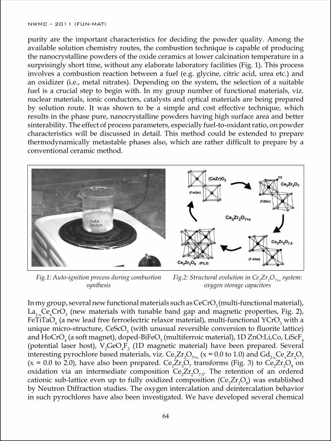
NWMC – 2011 (FUN-MAT)
64
NWMC – 2011 (FUN-MAT)
65
purity are the important characteristics for deciding the powder quality. Among the available solution chemistry routes, the combustion technique is capable of producing the nanocrystalline powders of the oxide ceramics at lower calcination temperature in a surprisingly short time, without any elaborate laboratory facilities (Fig. 1). This process involves a combustion reaction between a fuel (e.g. glycine, citric acid, urea etc.) and an oxidizer (i.e., metal nitrates). Depending on the system, the selection of a suitable fuel is a crucial step to begin with. In my group number of functional materials, viz. nuclear materials, ionic conductors, catalysts and optical materials are being prepared by solution route. It was shown to be a simple and cost effective technique, which results in the phase pure, nanocrystalline powders having high surface area and better sinterability. The effect of process parameters, especially fuel-to-oxidant ratio, on powder characteristics will be discussed in detail. This method could be extended to prepare thermodynamically metastable phases also, which are rather difficult to prepare by a conventional ceramic method.
Fig.1: Auto-ignition process during combustion synthesis
Fig.2: Structural evolution in Ce2Zr2O7+x system: oxygen storage capacitors
In my group, several new functional materials such as CeCrO3 (multi-functional material), La1-xCexCrO3 (new materials with tunable band gap and magnetic properties, Fig. 2), FeTiTaO6 (a new lead free ferroelectric relaxor material), multi-functional YCrO3 with a unique micro-structure, CeScO3 (with unusual reversible conversion to fluorite lattice) and HoCrO4 (a soft magnet), doped-BiFeO3 (multiferroic material), 1D ZnO:Li,Co, LiScF4 (potential laser host), V2GeO4F2 (1D magnetic material) have been prepared. Several interesting pyrochlore based materials, viz. Ce2Zr2O7+x (x = 0.0 to 1.0) and Gd2-xCexZr2O7 (x = 0.0 to 2.0), have also been prepared. Ce2Zr2O7 transforms (Fig. 3) to Ce2Zr2O8 on oxidation via an intermediate composition Ce2Zr2O7.5. The retention of an ordered cationic sub-lattice even up to fully oxidized composition (Ce2Zr2O8) was established by Neutron Diffraction studies. The oxygen intercalation and deintercalation behavior in such pyrochlores have also been investigated. We have developed several chemical

NWMC – 2011 (FUN-MAT)
64
NWMC – 2011 (FUN-MAT)
65
methods which showed potential in isolating these unusual compounds, which could not be prepared by the conventional synthesis methods. High pressure-high temperature (HP-HT) synthesis is another versatile method to prepare crystallographically unusual compounds as the crystallographic limits can be considerably extended by applying pressure.
The chemical methods have been extended for fabrication of thin films of functional materials also. Among these methods, the inkjet printing technology is a simple and low cost method, which has recently become an attractive technique of patterning and printing of functional materials. Its versatility to deliver small volumes of inks with spatial accuracy and direct-writing ability in a non-contact deposition mode makes it a novel patterning technique. One can use dispersion or solution based inks for this purpose. However, dispersed particles can often cause agglomeration, which cause clogging of the print head. This clogging problem can be overcome by formulating solvent based precursor inks, which form crystalline nanoparticles on the substrate after printing and annealing. Recently fabrication of inkjet printed films and patterns (dots, lines and junctions) of ZnO and Zn0.98Mn0.02O on Si and polyimide substrates was reported using their precursor based solvent inks (Fig. 4) that have been fine tuned to match the desired viscosity, surface tension and adhesive property by adding suitable additives.
In this talk, I intend to touch upon chemistry aspects of various functional materials. However, there are many more methods and materials, which may not be possible to cover due to paucity of time. The primary aim was to give a flavor to various preparative chemical methods. Perhaps the participants may read some of our recent publications on functional materials.
Fig. 3: Functional materials in La1-xCexCrO3 series with tunable band gap and magnetic properties
Fig. 4: Scheme representing the Ink-jet printing of ZnO based functional materials
in LaCrO3
NWMC – 2011 (FUN-MAT)
66
NWMC – 2011 (FUN-MAT)
67
Acknowledgements: I acknowledge all the colleagues and students who have contributed to the research on functional-materials reported in this article. I also wish to thank Dr. D. Das, Head, Chemistry Division, BARC and Dr. T. Mukherjee, Director, Chemistry Group, BARC for their keen interest in and support to this work.
Some recent publications on functional materials from my group1. Sm2-xDyxZr2O7 pyrochlores: Probing order-disorder dynamics and multifunctionality
Farheen N. Sayed, V. Grover, K. Bhattacharyya, D. Jain, A. Arya, C. G. S. Pillai, A. K. Tyagi, Inorg.Chem. 50 (2011) 2354
2. Piezoelectric inkjet printed films and patterns of ZnO and Mn doped ZnO: Formation of bifunctional Zn0.98Mn0.02O films O. D. Jayakumar and A. K. Tyagi, J. Mater. Chem. 21 (2011) 12246
3. A rare defect free 3D ZnO rod structure with strong UV emission O. D. Jayakumar, N. Manoj, V. Sudarsan, C.G.S. Pillai and A. K. Tyagi Cryst Eng Comm 13 (2011) 2187
4. Rare examples of fluoride-based multiferroic materials in Mn- substituted BaMgF4 systems: Experimental and theoretical studies Farheen N. Sayed, B. P. Mandal, O. D. Jayakumar, A. Arya, R. M. Kadam, A. Dixit, R. Naik and A. K. Tyagi, Inorg. Chem. (2011) In Print
5. Inter-conversion of Perovskite and Fluorite Structures in Ce-Sc-O System R. Shukla, A Arya and A. K. Tyagi, Inorg. Chem 49 (2010) 1152
6. Crucial role of reaction conditions in isolating several metastable phases in Gd-Ce-Zr-O system, B. P. Mandal, R. Shukla, S. N. Achary, A. K. Tyagi Inorg. Chem. 49 (2010) 10415
7. Enhancement of ferromagnetic properties in Zn0.95Co0.05O nanoparticles by Indium codoping: An experimental and theoretical study O. D. Jayakumar, C. Sudakar, C. Persson, H. G. Salunke, R. Naik and A. K. Tyagi, Applied Physics Letters 97 (2010) 232510
8. Effect of doping on the morphology and multiferroic properties of BiFeO3 nanorods Dimple P. Dutta, O. D. Jayakumara, A. K. Tyagi, K. Girija, C. G. S. Pillai, G. Sharma, Nanoscale 2 (2010) 1149
9. Experimental and theoretical investigations on magnetic behavior of (Al,Co) co-doped ZnO nanoparticles O. D. Jayakumar, S. N. Achary, C. Sudakar, R. Naik, H. G. Salunke, Rekha Rao, X. Peng, R. Ahuja, and A. K. Tyagi, Nanoscale 2 (2010) 1505
10. Theoretical and experimental evidence of enhanced ferromagnetism in Ba and Mn co-substituted BiFeO3 O.D. Jayakumar, S. N. Achary, K. G. Girija, C. Sudakar, G. Lawes, R. Naik, J. Nisar, X. Peng, R. Ahuja and A. K. Tyagi Appl. Phys. Lett. 96 (2010) 032903
11. On the chemical synthesis, structural and magnetic properties of dispersible Co-and Ni-doped ZnO nanocrystals Anshu Singhal, S. N. Achary, J. Manjanna, S. Chaterjee, P. Ayyub and A.K. Tyagi, J. Phys. Chem. C 114 (2010) 3422.
12. Tunable Ferromagnetism accompanied by Morphology Control in Li doped Zn0.97Ni0.03O, O. D Jayakumar, C. Sudakar, C. Persson, V. Sudarsan, R. Naik and A. K. Tyagi, J. Phys. Chem. C 114 (2010) 17428

NWMC – 2011 (FUN-MAT)
66
NWMC – 2011 (FUN-MAT)
67
Dr. A. K. Tyagi is presently Head, Solid State Chemistry Section, Chemistry Division, Bhabha Atomic Research Centre (BARC), Mumbai and also a Professor (Chemistry) at Homi Bhabha National Institute (HBNI). He joined BARC, Mumbai in 1986 through BARC-Training School. Since then he has been working in the field of Chemistry of nanomaterials, functional materials and nuclear materials. He was a Max-Planck Fellow at MPI, Stuttgart, Germany during 1995-96. He has to his credit a large number of publications, one patent and two books. In
recognition of his work, Dr. Tyagi has been conferred with several prestigious awards such as Homi Bhabha Science & Technology Award, Gold Medal of Indian Nuclear Society, MRSI Medal, CRSI Medal, Dr. Laxmi Award by ISCAS, Rheometric Scientific-ITAS Award, IANCAS-Dr.Tarun Datta Memorial Award, Rajib Goyal Prize in Chemical Sciences, and DAE-SRC Outstanding Researcher Award. He is a Fellow of Royal Society of Chemistry, UK (FRSC), National Academy of Sciences, India (FNASc) and Maharashtra Academy of Sciences (FMASc). Recently, CRSI has selected him for the Prof. C. N. R. Rao National Prize for Chemical Sciences, which will be conferred on him on Feb 3rd, 2012.
13. Intercalation/deintercalation of oxygen: A sequential evolution of phases in Ce2O3/CeO2-ZrO2 pyrochlores S. N. Achary, S. K. Sali, N. K. Kulkarni, P. S. R. Krishna, A. B. Shinde, A. K. Tyagi, Chem. Mater. 21 (2009) 125
14. Multi-functional Nano-crystalline CeCrO3: Antiferromagnetic, Relaxor and Optical Properties, R. Shukla, A. Bera, S. M. Yusuf, S. K. Deshpande , A. K. Tyagi, W. Hermes,M. Eul, R. Pöttgen, J. Phys. Chem. C 113 (2009) 12663
15. 1D morphology stabilization and enhanced magnetic properties of Co:ZnO anostructures on co-doping with Li:A template free synthesis O.D. Jayakumar, C. Sudakar, C. Persson, V. Sudarsan, T. Sakuntala, R. Naik and A. K. Tyagi, Crystal Growth and Design 9 (2009) 4450
16. La1-xCexCrO3 (0.0 ≤ x ≤ 1.0): A new series of solid solutions with tunable magnetic and optical Properties, R. Shukla, J. Manjanna, A. K. Bera, S, M. Yusuf, A. K. Tyagi, Inorg. Chem. 48 (2009) 11691
17. FeTiTaO6: A New Lead-Free Relaxor Ferroelectric Based on the Rutile Structure R. Mani, S. N. Achary, K. R. Chakraborty, S. K. Deshpande, Joby E. Joy, A. Nag, J. Gopalakrishnan, A. K. Tyagi, Advance Materials 20 (2008)1348

NWMC – 2011 (FUN-MAT)
68
NWMC – 2011 (FUN-MAT)
69
Super Ionic Conductors: Basics, Materials and Experimental Tools
A. R. Kulkarni
Department of Metallurgical Engineering and Materials Science Indian Institute of Technology-Bombay, Powai Mumbai 400076
Superionic conductors are solids that conduct electricity by the passage of ions. Usually, only one type of ion (either cation or anion) is predominantly mobile and conducts electricity in a solid. The room-temperature conductivity (σ25°C), for these solids, is often greater than 10-2 - 10-3 S/m and hence these are called fast ion conductors, solid electrolytes or superionic conductors. In 1834, Faraday was the first to report the existence of such materials. Faraday observed that, when heated up, PbF2 could become an excellent electrical conductor. That was due to the mobility of F- ions in the PbF2 lattice. Over the last 30 years, research in the area of solid electrolytes has shown considerable growth. Solid electrolytes receive such a wide attention for their applications in solid state electrochemical devices such as batteries, fuel cells, electrochromic displays, super capacitors and sensors. Furthermore, ion conduction in the solid state is now being combined with the emerging nanotechnology to produce new knowledge and applications. Li+ and Na+ ion conducting solid electrolytes have been developed for energy conversion and storage devices such as high energy density batteries because of their light weight and high electrochemical potential. Similarly O2-, F- and H+ ion conducting solid electrolytes are useful candidates for fuel cells and solid state gas sensors
Classification of Ionic ConductorsA large number of solid- state materials that exhibit ionic conductivity are known today, and significant effort has been made in understanding the mechanism of conduction of electricity at the molecular level. Fast ion conductors are classified according to the nature of conducting species such as cationic conductors (Li+, Na+, Ag+, H+) and anionic conductors (O2-, F-).
Various attempts have been made in order to realize the fast ion conduction in different phases, compositions and microstructure of solids They include (i) stabilization of high conducting structure and characteristics of crystalline materials at ambient temperatures by substituting different cations and anions (ii) synthesis of nano structured materials (iii) glassy electrolytes: arresting the disorder phase of normal ionic conductors in the presence of glass formers and glass modifiers (iv) polymer electrolytes: a solvent free polymeric system obtained, due to the interaction of polymer host with the metal salts (v)
NWMC – 2011 (FUN-MAT)
68
NWMC – 2011 (FUN-MAT)
69
dispersed solid electrolytes: dispersion of insulating, insoluble inert particles of oxides such as Al2O3, SiO2 in ionically conducting materials.
This presentation brings together a cross-section of research advances and it highlights the diversity of basic and applied topics in the development of ionic conductors. It includes details on structures, morphologies, defects and essential experimental techniques required to screen various materials for possible use in an electrochemical devices. The talk ends with discussion on opportunity and challenges the field of solid state ionics offers to young researchers looking to enter the interdisciplinary field of solid state ionics.
General featuresFor a material to be useful as a solid electrolyte it should exhibit following general char-acteristics
1. A large number of the ions of one species should be mobile. This requires a large number of empty sites, either vacancies or accessible interstitial sites. Since empty sites are needed for ions to move through the lattice.
2. The empty and occupied sites should have similar potential energies with a low activation energy barrier for jumping between neighboring sites. Since high activa-tion energy decreases carrier mobility, very stable sites (deep potential energy wells) lead to carrier localization.
3. The structure should have solid framework, preferable 3D, permeated by open channels. This means the migrating ion lattice should be “molten”, so that a solid framework of the other ions is needed in order to prevent the entire material from melting.
4. The framework ions (usually anions) should be highly polarizable. Such ions can deform to stabilize transition state geometries of the migrating ion through covalent interactions.
AgCl and PbF2 are two examples wherein molten sublattice concept can be demon-strated. This behavior can be seen in part from the entropies of the observed phase transitions, where the Ag (and F respectively) sublattice melts prematurely. (poor ionic conductor) β-AgI → α-AgI (excellent ionic conductor) T = 146 ºC
Materials with other defect structure or morphology Doping to create defects large number of defects is another is a possibility. However the doping conditions are very stringent and difficult to control on a large scale since a small deviation leads to large changes in the desired properties and makes impractical for large scaling. It was also realised that solids with open structure shows more conductivity and it raised the possibility that inorganic glasses which inherently possess open structure

NWMC – 2011 (FUN-MAT)
70
NWMC – 2011 (FUN-MAT)
71
and provide easier conduction pathways. Further glasses possess following advantages over crystalline counterparts:
1. Isotropic properties
2. Absence of grain boundaries,
3. Flexibility of size and shape at satisfactory cost
4. Possibility of continuously changing composition without substantial change in property
A large number of inorganic glassy systems have been reported in the literature with required levels of conductivity for electrochemical application. The interest in these materials is twofold – technological applications as pointed out and secondly possibility of studying ion dynamics in these materials. The latter is still being pursued; however, these materials performance in the devices remained unsatisfactory mainly due to its poor mechanical properties. In electrochemical devices, volume changes occur at electrodes/electrolyte interface and these results in the mechanical failure of the interface. The search therefore continued for new materials that would accommodated all the volume changes in addition to possess required levels of conductivity
Ionic conductivity is certainly the most important concern for polymer electrolytes. After incorporating plasticizers, conductivities of various systems have been elevated by several orders of magnitude. From the numerous observations in recent years, achieving a high ionic conductivity is no longer a major problem. Ideally, an electrolyte would have the electrical properties of a liquid and the mechanical properties of a solid. Such

NWMC – 2011 (FUN-MAT)
70
NWMC – 2011 (FUN-MAT)
71
Fig.1 Picture of PVDE gel electrolyte.
an electrolyte would serve both as electrolyte and separator and provide the battery with mechanical flexibility, a property unattainable in cells with conventional liquid electrolytes. In this regard, gel electrolytes that possess the advantageous properties of liquid and solid electrolytes have been targeted as viable electrolytes for lithium batteries. Owing to their unique hybrid network structure, gels always possess, simultaneously, both the cohesive properties of solids and the diffusive transport properties of liquids. This duality enables the gel to find a variety of important applications. Gels can be obtained as a result of either a chemical or a physical cross-linking process. The use of substantial amounts of plasticizers in gel electrolyte gave rise to a few problems like mechanical strength, and exudation of solvent which subsequently leads to thermal, chemical and electrochemical instability. In Gel electrolytes: polymer matrix is solvated by a large amount of the trapped solvent. Polymer acts like a support while high high value of conductivity through solvent at room temperature is (10–2–10–4 S/cm),
Important experimental tools for conductivity measurementsHaving understood the need for appropriate materials class and properties let us now turn our attention to screening of the materials based on the most important property that is electrical conductivity. Only two techniques will be discussed here. Impedance spectroscopy that allows accurate determination of DC conductivity and polarisation techniques that allow is to determine transport number of conducting ion and also low level leakage current.
The most useful parameter of a solid electrolyte is its DC Conductivity as a function of temperature. This parameter determines the mass transport rate through the solid and thus also influences the power production of an electrochemical device, of which the solid electrolyte forms a part.

NWMC – 2011 (FUN-MAT)
72
NWMC – 2011 (FUN-MAT)
73
Impedance Spectroscopy/ac measurementsTwo methods have been generally used to measure the electrical conductivity of solid ionic conductors: One technique utilizes direct current and the other uses alternating current. In a DC measurement problems with electrodes are frequent. A space charge is often set up in the glass-electrode interface because of partial blocking of the ionic current by the electrodes, when the current decreases rapidly with time and its value must be extrapolated to zero time if an accurate value of conductivity is desired. To avoid this electrode polarisation some authors have used reversible electrodes. However, since the conducting species are ions and not atoms, oxidation – reduction reaction must occur sufficiently rapidly at both the electrodes, and if these reactions are slow uncertainties appear in the measurements. Moreover, under DC conditions, faradaic current flows if reversible electrodes are used. To avoid these electrode problems an alternating current is usually used, often with the angular frequency of 104 Hz (corresponding to an applied frequency of 1592 Hz) at which both ions and electrons move.
The single frequency method is the most popular method to get first hand information about the conductivity range of the materials or in other words it is a screening technique for solid electrolytes. But this method is not adequate for their complete characterization. In a solid electrolyte to there are various factors which contribute towards the ultimate electrical impedance. The contribution due to movement of ions through the bulk of the electrolyte, electrode – electrolyte interface impedance, charge transfer across the interface and resulting double layer capacitance and lead impedance are all summed up in single frequency measurements. All these electrical and electrochemical parameters are functions of applied frequency and their responses are quite different in the different frequency due to their widely different relaxation times. Therefore ac methods are applied that in turn allows extraction of dc properties and enable grain boundary (intergranular) and bulk (intragranular) impedances to be separated and identified. The principle and experimental method will be presented which allows the investigation of impedance, admittance, permittivity and electric modulu of the sample over a large
NWMC – 2011 (FUN-MAT)
72
NWMC – 2011 (FUN-MAT)
73
temperature range at frequencies ranging from mHz to the MHz. In the simple case of the “ideal solid electrolyte”, the equivalent circuit contains a single RC element. For real solid electrolytes there is usually a distribution of relaxation times (combination of many RC or R and C components), in which case the maxima in the impedance and modulus spectra no longer coincide. An assignment of peaks in these more complex spectra is possible in principle, since the modulus spectrum effectively suppresses information concerning grain boundary (and electrode) effects. The four formalisms of data analysis allows us to construct electrical microstructure of the solid that could be combined with the microstructure of the materials to make changes in processing conditions and design new morphologies that attain desired level of ionic conduction.
Transport number determinationThe use of solid electrolytes in practical devices usually requires that they exhibit little or no electronic conductivity. It is simple to express conductivity as the sum of the ionic and electronic components.
Total Conductivity = ionic conductivity + electronic conductivity
The transport number ti of a particular specie ‘i’ is defined as the fraction of the total charge carried by that specie. In solid electrolytes the ion transport number is desired to be 1 so that any reaction between anode and cathode does not take place through the electrolytes ( no short circuit through the cell). There are nine different methods that could be adopted to estimate the transport number of conducting ion
Polarisation MeasurementPolarisation measurements have been used in order to deduce the partial conductivities of the electronic and ionic charge carries in mixed conductors. There are essentially two basic methods which are currently being used. One has been originally developed by Wagner and has been extended by Patterson.
In Wagner’s asymmetric polarisation method the mixed cation conductor (MX) is placed between a virtually reversible electrode (M) and an irreversible inert electrode, eg graphite or platinum to form a cell as given below.
(-) M/MX/inert electrode (+)
When a DC potential lower than the decomposition potential of the electrolyte is applied to the cell with negative pole on the left electrode, ionic migration occurs until the concentration induced chemical potential gradient balance the applied field. At the steady state, the cell is polarised and a residual current, flows because of electron and/or/hole migration across the electrolyte and the interfaces.
Wagner’s theory has been based on two implicit assumptions:

NWMC – 2011 (FUN-MAT)
74
NWMC – 2011 (FUN-MAT)
75
1. The electronics resistance is a function of the polarisation potential and
2. The ionic resistance is not a function of polarisation potential.
The method is favour for determining the electronic conductivity in solid electrolytes due to its accuracy.
Opportunities and ChallengesBefore concluding this lecture, I would like to point out that the field of ionics still has a lot to offer in terms of materials development, theoretical understanding (ion dynamics), techniques for characterisation of materials and fabrication and performance evaluation of the devices. Last but not the least how to design ionic conductors in nano sizes to achieve fast ion conduction at nano levels where diffusion lengths are quite small.
Further, the application of solid electrolytes is currently limited because they attain practically useful conductivities (10−2 S cm−1) only at 50–80 °C, which is one order of magnitude lower than those of organic liquid electrolytes. It is still a challenge to attain in experiment the theoretical value, σ25°C ≈10+4 S/m, in any solid ionic conductor. Detail study by various techniques and understanding of the mobile ion dynamics, with respect to the host network of a solid as a function of temperature, composition, etc. could pave the way for optimizing σ25°C of known ionic conductors and also provide guidelines for discovering new ionic conductors.
References/Suggested reading1. P. Hagenmuller “Solid Electrolytes--General Principles, Characterization, Materials,
Applications” Academic Press, 1978 2. E. C. Subbarao “Solid Electrolytes and Their Applications” Publisher: Plenum Press 19803. A.R. West – “Solid State Chemistry and it’s Applications”, Chapter 13, Wiley (1984)4. C.N.R Rao and J. Gopalakrishnan “New Directions in Solid State Chemistry”, Cambridge
(1997)5. J.C. Boivin & G. Mairesse “Recent Material Developments in Fast Oxide Ion Conductors”,
Chem. Mater. 10, 2870-2888 (1998).6. D M F Santos and C A C Sequeira “Polymer electrolytes Fundamentals and applications”
Woodhead Publishing Limited Cambridge 20107. S. Hull “Solid Electrolytes: Materials, Properties and Applications” Canopus Academic
Publishing Limited, UK 2011
NWMC – 2011 (FUN-MAT)
74
NWMC – 2011 (FUN-MAT)
75
Ajit Kulkarni studied at the Dharampeth Science College, Nagpur during 1974-1977 and Department of Physics, Nagpur University during 1977-1979. He obtained his Ph.D. in Materials Science in 1984 from the Indian Institute of Technology-Kharagpur, In 1984, he joined Solid State Physics Laboratory at Delhi and in 1985 moved to Purdue University as a Research Associate in Department of Chemistry. He studied Ion dynamics in disordered materials through Mechanical and electrical relaxations. He joined IIT Bombay as a Faculty Member in
1987, where he is presently Professor. He worked in the EKM (Elektronische Korrelationen und Magnetismus) Division at the Universitaet Augsburg in Southern Bavaria during 1997-1998 on a Alexander von Humboldt Research Fellowship. He was a visiting Professor at IMRAM, Tohoku University Sendai in 2005. He has developed ammonia sensors based on Polymer electrolytes and has four patent Polymer gel electrolytes for batteries and on Infrared transmitting fluoride glasses. He has over 120 publications in the International and National Journals.
NWMC – 2011 (FUN-MAT)
76
NWMC – 2011 (FUN-MAT)
77
Dielectric Spectroscopy: Principles and Applications
S. K. Deshpande
UGC-DAE Consortium for Scientific Research, R5 Shed, BARC, Mumbai 400085
The complex dielectric constant (permittivity) is an important property of all materials. It reflects the underlying dynamical and transport processes. Dielectric spectroscopy (DS) is the technique that allows the determination of this parameter as a function of the frequency of applied electric field. Over the past few years, rapid advances have been made in developing new functional materials having physical properties tailored for desired technological applications, and the search continues for better and more suitable materials for improvement in performance and widening the scope of applications. In this scenario, DS has achieved greater importance due to its ability not only to provide information about the dependence of the dielectric constant and loss on temperature, applied frequency and composition, but also to probe the molecular relaxations in a wide variety of materials like liquids, gels, polymers, composites, liquid crystals, solid electrolytes, glasses, multiferroics, relaxor ferroelectrics, etc. DS is complementary to rheology, NMR, quasielastic neutron scattering (QENS), and scattering techniques like DLS, SANS, and SAXS. Depending on the type of study, it is also referred to as Impedance Spectroscopy, Electrochemical Impedance Spectroscopy, Dielectric Relaxation Spectroscopy, etc.
Dielectric spectroscopy is essentially the study of the interaction of electromagnetic radiation with matter over a frequency of 1011 to about 10-6 Hz. In this sense, it can be thought of as an extension of optical spectroscopy to lower frequencies. The technique of DS involves measurement of the electrical parameters of a sample in response to an applied oscillating electric field. Usually, the complex impedance (i.e. amplitude and phase of the current) of the sample is measured as a function of the frequency of applied field. Physical parameters like dielectric constant and loss, a.c. and d.c. conductivity, electric modulus, etc. can be deduced from the impedance data.
When an electric field is applied to a material, in addition to conduction processes, the material gets polarized due to relative displacement of positive and negative charge centres. If there are permanent electric dipoles in the material, these will align with the applied field. In the presence of an oscillating electric field, the polarization lags behind the field, leading to dielectric relaxation. The molecular entities respond to the applied field only below a certain characteristic frequency- the relaxation frequency-which depends on the mechanism of polarization. The different mechanisms of polarization are: electronic, atomic, orientational/dipolar rotation, and interfacial polarization. Each of

NWMC – 2011 (FUN-MAT)
76
NWMC – 2011 (FUN-MAT)
77
these occurs at different ranges of frequency of applied field. Along with the conduction processes, these mechanisms give rise to the observed dispersion in the permittivity. Thus, different molecular processes at different time-scales can be probed by DS, making it a powerful technique for studying dynamics and transport in a variety of materials. At present, very accurate measurements are possible over frequencies from 10-6Hz to 109Hz.
The behaviour of electric field inside matter is governed by the well-known Maxwell equations. The polarization P (the net dipole moment per unit volume in a material) is related to the applied electric field E through the relation
When an electric field is applied to a material, in addition to conduction
processes, the material gets polarized due to relative displacement of positive and
negative charge centres. If there are permanent electric dipoles in the material, these will
align with the applied field. In the presence of an oscillating electric field, the
polarization lags behind the field, leading to dielectric relaxation. The molecular entities
respond to the applied field only below a certain characteristic frequency- the relaxation
frequency-which depends on the mechanism of polarization. The different mechanisms of
polarization are: electronic, atomic, orientational/dipolar rotation, and interfacial
polarization. Each of these occurs at different ranges of frequency of applied field. Along
with the conduction processes, these mechanisms give rise to the observed dispersion in
the permittivity. Thus, different molecular processes at different time-scales can be
probed by DS, making it a powerful technique for studying dynamics and transport in a
variety of materials. At present, very accurate measurements are possible over
frequencies from 10-6Hz to 109Hz.
The behaviour of electric field inside matter is governed by the well-known
Maxwell equations. The polarization P (the net dipole moment per unit volume in a
material) is related to the applied electric field E through the relation
EP 0)1*( εε −=
Here, "'* εεε i−= is the complex relative permittivity of the material (e' and e'' are the
dielectric constant and loss, repectively) and e0 is the permittivity of free space. The
permittivity is thus related to microscopic quantities like dipole moment and
polarizability. The well-known Clausius-Mossotti equation for apolar molecules (induced
dipole moments) is an example of this relationship. For the case of an oscillating or time-
dependent electric field, the polarization P(t) is estimated using the linear response
theory. In the simplest case, the rate of change polarization can be assumed to
proportional to the initial polarization, leading to an exponentially decaying polarization
with a single relaxation time. This leads to the well-known Debye equations for
permittivity:
221)('
τωεεεωε
+−+= ∞
∞s , 221
)()("
τωωτεεωε
+−
= ∞s
Here,
When an electric field is applied to a material, in addition to conduction
processes, the material gets polarized due to relative displacement of positive and
negative charge centres. If there are permanent electric dipoles in the material, these will
align with the applied field. In the presence of an oscillating electric field, the
polarization lags behind the field, leading to dielectric relaxation. The molecular entities
respond to the applied field only below a certain characteristic frequency- the relaxation
frequency-which depends on the mechanism of polarization. The different mechanisms of
polarization are: electronic, atomic, orientational/dipolar rotation, and interfacial
polarization. Each of these occurs at different ranges of frequency of applied field. Along
with the conduction processes, these mechanisms give rise to the observed dispersion in
the permittivity. Thus, different molecular processes at different time-scales can be
probed by DS, making it a powerful technique for studying dynamics and transport in a
variety of materials. At present, very accurate measurements are possible over
frequencies from 10-6Hz to 109Hz.
The behaviour of electric field inside matter is governed by the well-known
Maxwell equations. The polarization P (the net dipole moment per unit volume in a
material) is related to the applied electric field E through the relation
EP 0)1*( εε −=
Here, "'* εεε i−= is the complex relative permittivity of the material (e' and e'' are the
dielectric constant and loss, repectively) and e0 is the permittivity of free space. The
permittivity is thus related to microscopic quantities like dipole moment and
polarizability. The well-known Clausius-Mossotti equation for apolar molecules (induced
dipole moments) is an example of this relationship. For the case of an oscillating or time-
dependent electric field, the polarization P(t) is estimated using the linear response
theory. In the simplest case, the rate of change polarization can be assumed to
proportional to the initial polarization, leading to an exponentially decaying polarization
with a single relaxation time. This leads to the well-known Debye equations for
permittivity:
221)('
τωεεεωε
+−+= ∞
∞s , 221
)()("
τωωτεεωε
+−
= ∞s
is the complex relative permittivity of the material (ε′ and ε′′ are the dielectric constant and loss, repectively) and ε0 is the permittivity of free space. The permittivity is thus related to microscopic quantities like dipole moment and polarizability. The well-known Clausius-Mossotti equation for apolar molecules (induced dipole moments) is an example of this relationship. For the case of an oscillating or time-dependent electric field, the polarization P(t) is estimated using the linear response theory. In the simplest case, the rate of change polarization can be assumed to proportional to the initial polarization, leading to an exponentially decaying polarization with a single relaxation time. This leads to the well-known Debye equations for permittivity:
When an electric field is applied to a material, in addition to conduction
processes, the material gets polarized due to relative displacement of positive and
negative charge centres. If there are permanent electric dipoles in the material, these will
align with the applied field. In the presence of an oscillating electric field, the
polarization lags behind the field, leading to dielectric relaxation. The molecular entities
respond to the applied field only below a certain characteristic frequency- the relaxation
frequency-which depends on the mechanism of polarization. The different mechanisms of
polarization are: electronic, atomic, orientational/dipolar rotation, and interfacial
polarization. Each of these occurs at different ranges of frequency of applied field. Along
with the conduction processes, these mechanisms give rise to the observed dispersion in
the permittivity. Thus, different molecular processes at different time-scales can be
probed by DS, making it a powerful technique for studying dynamics and transport in a
variety of materials. At present, very accurate measurements are possible over
frequencies from 10-6Hz to 109Hz.
The behaviour of electric field inside matter is governed by the well-known
Maxwell equations. The polarization P (the net dipole moment per unit volume in a
material) is related to the applied electric field E through the relation
EP 0)1*( εε −=
Here, "'* εεε i−= is the complex relative permittivity of the material (e' and e'' are the
dielectric constant and loss, repectively) and e0 is the permittivity of free space. The
permittivity is thus related to microscopic quantities like dipole moment and
polarizability. The well-known Clausius-Mossotti equation for apolar molecules (induced
dipole moments) is an example of this relationship. For the case of an oscillating or time-
dependent electric field, the polarization P(t) is estimated using the linear response
theory. In the simplest case, the rate of change polarization can be assumed to
proportional to the initial polarization, leading to an exponentially decaying polarization
with a single relaxation time. This leads to the well-known Debye equations for
permittivity:
221)('
τωεεεωε
+−+= ∞
∞s , 221
)()("
τωωτεεωε
+−
= ∞s
where ω is the angular frequency of applied field, εs is the static permittivity, ε∞ is the permittivity in the high-frequency limit, and τ is the relaxation time. However, real materials rarely show such simple behaviour, and several phenomenological models are used to mimic observed behaviour, like the Cole-Cole, the Cole-Davidson, and the most general Havriliak-Negami model. Each of these represents a characteristic distribution of relaxation times, and the dynamics of systems can be studied by fitting these models to the experimental data. In the complex plane plots of permittivity, also known as the Cole-Cole plots, the Debye behaviour shows up as a semi-circular arc, while the other models give arcs with some broadening or asymmetry.
The permittivity is experimentally determinied by placing the material between two parallel electrodes, forming a parallel plate capacitor, and measuring the amplitude and phase of the complex impedance when an oscillating electric voltage of small magnitude is applied across the sample. Different instrumental techniques are used to carry out these measurements, the choice depending mainly on the range of frequencies and precision required. The auto-balancing bridge impedance analyzer (10Hz to 107Hz) and the frequency response analyzer (10-6Hz to 107Hz) are most commonly used. For higher frequencies, co-axial line reflectometry (106Hz to 1010Hz), network analysis (106Hz to
NWMC – 2011 (FUN-MAT)
78
NWMC – 2011 (FUN-MAT)
79
1011Hz) or Quasi-optical techniques (1010Hz to 1012 Hz) are used. In addition to these, measurements in the time-domain can be carried out, though the accuracy is less.
The analysis of the experimental data is carried out by fitting the different relaxation models as described above. The dielectric spectrum consists of contributions from different polarization mechanisms like fluctuations of dipoles, propagation of mobile charges, separation of charges at interfaces, etc. Each of these gives rise to specific features in the dielectric spectra. The conductivity and electrode polarization contributions are separated by fitting to appropriate models, and the intrinsic dielectric parameters are then determined using the relaxation models.
Since the response of materials to time-dependent electric fields can also be well-approximated by assuming them to consist of combinations of resistors and capacitors, the experimental data is often analyzed through equivalent circuit analysis. In particular, since most real dielectrics show some leakage current, a combination of resistance and capacitance in parallel reproduces their behaviour. Each polarization mechanism can be approximated by an equivalent parallel R-C combination. Thus, contribution to the overall response from grains, grain-boundaries, electrode-sample interfaces, etc. can be well-separated. The bulk and grain boundary d.c. conductivity can be separately obtained either from the analysis of the complex-plane impedance plots, or by using the Universal Dielectric Response model to fit the a.c. conductivity data. This is the approach usually adopted when the electrical conductivity appears to dominate the data. Another useful approach-the modulus framework- uses the electric modulus, which is the reciprocal of the complex permittivity. In this framework, the high frequency data are preferentially weighted and peaks in the modulus spectrum allow determination of the d.c conductivity and relaxation time. Since the modulus is related to the time-dependent polarization through a Fourier transform, this formalism is also useful in studying the dynamics of mobile charge carriers.
The temperature-dependence of the relaxation time or of the d.c conductivity can yield important information like the activation energy for hopping conduction (Arrhenius behaviour) and mobile charge-carrier concentration.
Some typical applications shall also be described during the talk, using several results from our studies as well as from literature. These include a.c conductivity studies on ion-conducting glasses, dielectric studies on pyrochlores, studies of relaxor ferroelectrics and multiferroics, studies of polaron dynamics in some rutile-type materials, low temperature dielectric relaxations in organic glass formers, polymers, etc.

NWMC – 2011 (FUN-MAT)
78
NWMC – 2011 (FUN-MAT)
79
Name: Sudhanshu K. Deshpande Date of birth: January 5, 1965 Place of birth: Pune Present affiliation: UGC-DAE Consortium for Scientific Research, R5 Shed, BARC, Mumbai 400085 Designation: Scientist-F Email: [email protected] / Number of journal publications: 37
I have obtained my M.Sc. in Physics from University of Pune in 1988, and my Ph.D. in Physics from University of Pune in 1994. My Ph.D. thesis involved the development of a laboratory EXAFS (Extended X-ray Absorption Fine Structure) spectrometer and its application to local structural studies. I have briefly worked at the Institute for Plasma Research, Gandhinagar on tokamak plasma diagnostics, and also taught at the Department of Physics, University of Pune as a lecturer. For the past thirteen years, I have been working at the Mumbai Centre of UGC-DAE CSR, where I was initially involved in the development of a neutron beamline and diffraction facility at the Dhruva reactor. My present research activities include materials characterization by dielectric relaxation spectroscopy and thin-film X-ray diffraction.

NWMC – 2011 (FUN-MAT)
80
NWMC – 2011 (FUN-MAT)
81
Molecule Sniffers: Sensors and Electronic Nose
D. K. Aswal
Technical Physics Division, Bhabha Atomic Research Center, Mumbai 400085, India (Email: [email protected])
In 1914, Graham Bell made the following statement, indicating that it is difficult to measure a smell. “Did you ever measure a smell? Can you tell whether one smell is just twice strong as another? Can you measure the difference between one kind of smell and another? It is very obvious that we have very many different kinds of smells, all the way from the odour of violets and roses up to asafetida. But until you can measure their likeness and differences, you can have no science of odour. If you are ambitious to find a new science, measure a smell.” However, no such science of odor materialised until 1950s and it is only after that any real progress was made. The first development in this direction was finding a sensor, which converts the gas concentration into a measurable signal (electrical, optical, mass, etc.). Table 1 summarizes different types of gas sensors developed so far along with their working principles. Among these, semiconductor-based chemiresistor sensors are most investigated and widely used for detection of combustible and toxic gases owing to their low cost and relative simplicity. The chemiresistive gas sensors work on the principle of a change in electrical resistance due to an interaction between the semiconductor and the gas. Other advantages of semiconductor sensors are high sensitivity to a range of gases, operating speed and small sizes.
In the first part of the talk, I will present an overview of various aspects of chemiresistor gas sensors [1]. We will begin with the basics of chemiresistor gas sensors and, experimental determination of various sensor parameters, such as, sensitivity, selectivity, response and recovery times. A review on the various chemiresistor materials, namely metal-oxides and non-oxides, such as, carbon nanotubes, conducting polymers, elemental semiconductors will be presented. Methods adopted for fabrication of selective gas sensors will be discussed. In particular the success strory of SnO2:CuO thin films based H2S sensors (see Fig. 1), which were deployed in Heavy water plant, Manuguru, will be highlighted. The gas sensing mechanism(s) using electronic band structures will be described. An overview of various factors influencing the sensing properties of a chemiresistor will be discussed.
In the second part of the talk, I will discuss the electronic nose [2], as shown in Fig. 2. The e-nose attempts to emulate the mammalian nose by using an array of sensors that can simulate mammalian olfactory responses to aromas. The odour molecules are drawn into the e-nose using sampling techniques, such as, headspace sampling, diffusion methods, bubblers or pre-concentrators The odour sample is drawn across the sensor array and induces a reversible physical and/or chemical change in the sensing material, which
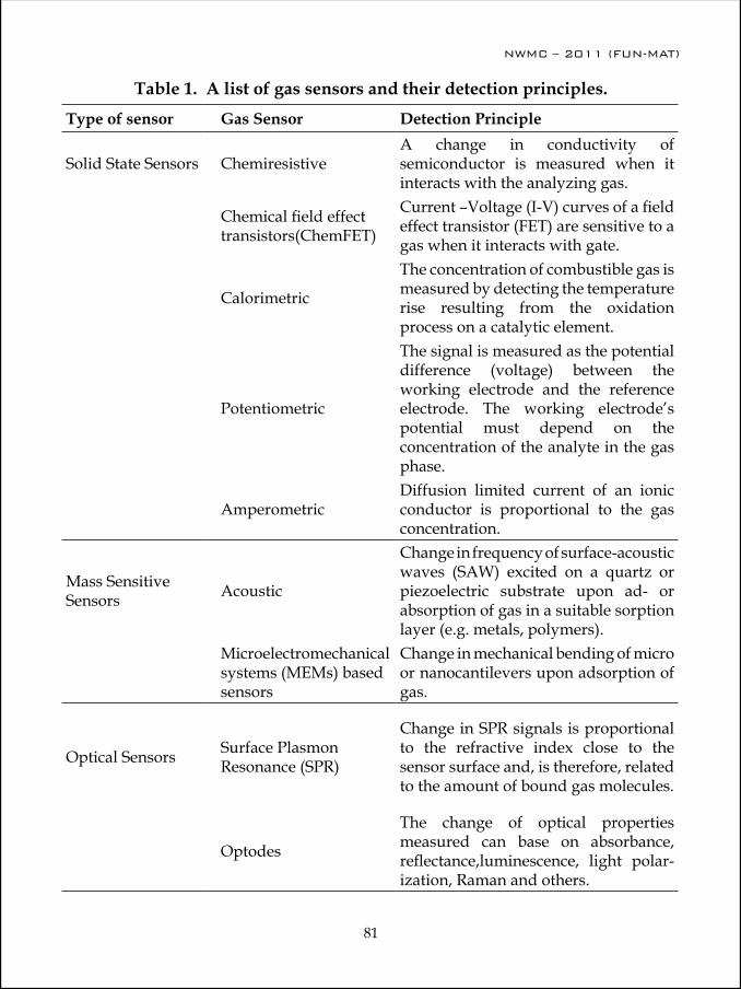
NWMC – 2011 (FUN-MAT)
80
NWMC – 2011 (FUN-MAT)
81
Table 1. A list of gas sensors and their detection principles.
Type of sensor Gas Sensor Detection Principle
Solid State Sensors ChemiresistiveA change in conductivity of semiconductor is measured when it interacts with the analyzing gas.
Chemical field effect transistors(ChemFET)
Current –Voltage (I-V) curves of a field effect transistor (FET) are sensitive to a gas when it interacts with gate.
Calorimetric
The concentration of combustible gas is measured by detecting the temperature rise resulting from the oxidation process on a catalytic element.
Potentiometric
The signal is measured as the potential difference (voltage) between the working electrode and the reference electrode. The working electrode’s potential must depend on the concentration of the analyte in the gas phase.
AmperometricDiffusion limited current of an ionic conductor is proportional to the gas concentration.
Mass Sensitive Sensors Acoustic
Change in frequency of surface-acoustic waves (SAW) excited on a quartz or piezoelectric substrate upon ad- or absorption of gas in a suitable sorption layer (e.g. metals, polymers).
Microelectromechanical systems (MEMs) based sensors
Change in mechanical bending of micro or nanocantilevers upon adsorption of gas.
Optical Sensors Surface Plasmon Resonance (SPR)
Change in SPR signals is proportional to the refractive index close to the sensor surface and, is therefore, related to the amount of bound gas molecules.
Optodes
The change of optical properties measured can base on absorbance, reflectance,luminescence, light polar-ization, Raman and others.

NWMC – 2011 (FUN-MAT)
82
NWMC – 2011 (FUN-MAT)
83
Fig. 1 Photographs of SnO2:CuO based H2S sensors developed by Technical Physics Division, Bhabha Atomic Research Center. Left: Sensor assembly hooked to a stainless steel casing, Right: Set of sensors.
Fig. 2. Comparison of the mammalian olfactory system and the electronic nose system
causes an associated change in electrical properties, such as conductivity. Each “cell” in the array can behave like a receptor by responding to different odours to varying degrees. These changes are transduced into electrical signals, which are preprocessed and conditioned before identification by a pattern recognition system. The e-nose system is designed so that the overall response pattern from the array is unique for a given odour in a family of odours to be considered by the system. We will describe the applications of the e-nose in various fields, including in quality control laboratories, health (e.g. early detection of cancer, tuberculosis etc. by breath analysis), food (to identify when food

NWMC – 2011 (FUN-MAT)
82
NWMC – 2011 (FUN-MAT)
83
has started to rot), crime prevention (drug identification) and security (bomb detection), environmental monitoring etc.
References 1. Science and Technology of Chemiresistive Gas Sensors, by D.K. Aswal and S.K. Gupta, ova
Science Publisher, NY, USA, 2007.2. Electronic noses: principles and applications, by J. W. Gardner, P.N. Bartlett, Oxford press,
1999
Dr. D.K. Aswal joined BARC in 1986 through 30th Batch of Training School after completing M.Sc. (Physics) from Garhwal University. His area of scientific research is condensed matter physics, specializing in device-oriented research leading to hybrid molecule-on-Si nanoelectronics, organic solar cells, thermoelectric devices, and gas sensors. He has made several original contributions in the fields of high-temperature superconductors, colossal magnetoresistive manganites, metallic-multilayer grown by mo-lecular-beam-epitaxy and thermoelectric devices. He is a recipient of several
international fellowships including, JSPS fellowship, Japan (1997-99), IFCPAR fellowship, France (2004-05), BMBF fellowship, Germany (2006) and CEA fellowship, France (2008). He also had visiting Professor positions at Shizuoka University (Japan), University of South Florida (USA), University of Paris VI (France), and Weizmann Institute of Science (Israel). He is recipient of several awards, including “Homi Bhabha Science and Technology Award-2007”, “DAE-SRC outstanding research investigator award-2008”, and “Paraj: Excellence in Science Award, 2000”. He has edited three books and published more than 150 scientific publications in peer reviewed international journals.
NWMC – 2011 (FUN-MAT)
84
NWMC – 2011 (FUN-MAT)
85
Biochemical sensors: An introduction
C. A. Betty
Chemistry Division, B.A.R.C., Mumbai-85, [email protected]
A sensor is a device that measures a physical quantity and converts it into a signal which can be read by an observer or by an instrument. Sensors can be classified based on the types of active layer used for detection or by the method of signal transduction. Sensor consists of sensing element intimately attached or integrated within the transducer which helps in signal transduction/detection (by optical absorption/fluorescence, electrochemical, field effect, piezoelectric, heat, electrical etc.) of a primary signal. This signal can be amplified and subsequently processed eventually to take automatic remediation actions. Important specifications for sensors are: sensitivity, range, accuracy, linearity, response and recovery times, size, packaging and cost effectiveness, resistance to chemical and physical contaminants, interchangeability and long-term stability. The sensitivity, selectivity, quantification, and time response of these sensors are functions of the substrate material, specialized surface coatings and signal-transduction methods used. A complete description of sensor response behavior requires systematic measurements of resistances (and/or work functions, carrier mobilities, catalytic conversions, temperature changes, optical changes etc., as additional independent parameters of signal transduction) for certain partial pressures, temperatures and modes of operation of a given system. Additional spectroscopic data lead to an atomistic understanding of target molecule-sensor surface interaction.
Among the various signal transduction methods used, optical instrumentation even-though highly sensitive, is cumbersome and expensive. Electrochemical devices allow generation of clinically acceptable data with inexpensive pocket sized instruments suitable for over-the-counter sales. These sensors allow one to design portable units, conduct field trials, on-line measurements with multi-analytic analysis, direct, cheaper and faster measurements. Since all the sensors are fabricated with an idea of small size, rapid and easy handling, low cost, greater sensitivity and selectivity, they are increasingly becoming popular in many fields. Advantage of miniaturization and automation is very useful in biological implants, biochemical detectors, environmental and pollution monitoring. The need for a cheaper, reliable, and ultra sensitive sensor continues to grow as the complexity of the application areas increases.
Biochemical sensors and sensing systems are currently active areas of research as they pertain to design and fabrication of devices that allow simple and rapid real time detection of biological or chemical molecules with high selectivity and sensitivity in complex samples. Application areas of these sensors span healthcare, biotechnology,

NWMC – 2011 (FUN-MAT)
84
NWMC – 2011 (FUN-MAT)
85
environmental monitoring, biochemical warfare, process control, explosives detection and other related processes. A biochemical sensor is a measuring device which uses chemical species (oxidizing or reducing gases, volatile organic compounds etc.) or biological reactions (antibody, enzyme, receptor, cell, etc.) to detect or quantify the specific analyte or an event. Presently, biochemical sensors are based on various types of transducers, and are capable of working in combination with different materials like enzymes, antibodies, whole cells, etc and can detect toxic gases, solvents or explosives besides biochemicals.
Most critical step in a biosensor fabrication is to attach a biological receptor onto an electrode surface. Success of immobilization is linked to improved operational and storage stability, fast response time, wide dynamic range as well as good sensitivity and reproducibility. Simplest procedure is physical adsorption. But it leads to poor stability. Best is covalent linking with byfunctional reagents. Catalytic biosensors make use of the catalyst (enzyme) for conversion of a nondetectable substrate into an optically or electrochemically active product. These sensors allow the detection of the substrates, products, inhibitors and modulators of the catalytic reaction. So far, for the realization of biosensors adsorption of proteins on a variety of electrodes such as, Si/SiO2, electrodes coated with organic films to more complex structures including conductive polyelectrolytes, nanostructured materials and mesoporous films have been tried. For detection of multiple agents, an array of sensors is needed where the elements of the array receive a variety of surface coatings, each specialized to allow detection of a specific chemical or biological agent.
Many of the biosensor devices involve the formation of a recognition complex between the sensing biomaterial and the analyte in a monolayer or thin film configuration on the electronic transducer. The build-up of the sensing biomaterial film on the conductive or semiconductive support alters the capacitance and resistance properties of the solid support-electrolyte interface. Impedance spectroscopy is a very powerful tool for the analysis of changes in interfacial properties (capacitance/ resistance changes) of modified electrodes upon biorecognition events occurring at the modified surfaces. Thus, impedance spectroscopy, including non-Faradaic impedance measurements resulting in capacitance sensing, is becoming an attractive electrochemical tool to characterize biomaterial films associated with conducting or semsiconducting surfaces. Faradaic impedance spectroscopy allows analysis of kinetics and mechanisms of bioelectrocatalytic reactions at the modified electrode surfaces providing important information for the development of amperometric biosensors.
Nanostructured materials possess better tunability of their properties compared to their bulk counterparts. These properties have opened up new avenues for fabricating highly sensitive, miniaturized and cost effective devices. Porous silicon obtained by electrochemical etching of polished silicon is a versatile material for nanodevice applications due to its tunable pore size, porosity, thermal and mechanical properties, optical and electrical properties, biocompatibility, biodegradability, and most importantly, compatibility
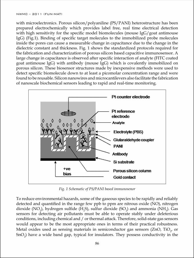
NWMC – 2011 (FUN-MAT)
86
NWMC – 2011 (FUN-MAT)
87
with microelectronics. Porous silicon/polyaniline (PS/PANI) heterostructure has been prepared electrochemically which provides label free, real time electrical detection with high sensitivity for the specific model biomolecules (mouse IgG/goat antimouse IgG) (Fig.1). Binding of specific target molecules to the immobilized probe molecules inside the pores can cause a measurable change in capacitance due to the change in the dielectric constant and thickness. Fig. 1 shows the standardized protocols required for the fabrication and characterization of porous silicon based capacitive immunosensor. A large change in capacitance is observed after specific interaction of analyte (FITC coated goat antimouse IgG) with antibody (mouse IgG) which is covalently immobilized on porous silicon. These biosensor structures made by inexpensive methods were used to detect specific biomolecule down to at least a picomolar concentration range and were found to be reusable. Silicon nanowires and microcantilevers also facilitate the fabrication of nanoscale biochemical sensors leading to rapid and real-time monitoring.
Fig. 1 Schematic of PS/PANI based immunosenor
To reduce environmental hazards, some of the gaseous species to be rapidly and reliably detected and quantified in the range few ppb to ppm are nitrous oxide (NO), nitrogen dioxide (NO2), hydrogen sulfide (H2S), sulfur dioxide (SO2) and ammonia (NH3). Gas sensors for detecting air pollutants must be able to operate stably under deleterious conditions, including chemical and / or thermal attack. Therefore, solid-state gas sensors would appear to be the most appropriate ones in terms of their practical robustness. Metal oxides used as sensing materials in semiconductor gas sensors (ZnO, TiO2, or SnO2) have a wide band gap, typical for insulators. They possess conductivity in the

NWMC – 2011 (FUN-MAT)
86
NWMC – 2011 (FUN-MAT)
87
Fig. 2 Transient capaciatnce for substrate bias 0.5V, frequency 1 kHz. Goat antirabbit IgG is nonspecific protein.
range of semiconductors due to point defects in the crystal structure which causes physisorption or chemisorptions of surface species, such as water vapor and oxygen. Over the past few decades solid state gas sensors based on polycrystalline SnO2 thin films have become predominant for gas alarms in domestic, commercial and industrial premises. SnO2 thin films are known to detect reducing gases with high sensitivity and reversibility at high temperature. Detection of target gases is generally carried out by measurement of dc resistance. Traces of foreign gases (H2S, NH3, CO, NO2) affect the adsorbed oxygen coverage, which lead to a change in film resistance. Surface adsorbed species on SnO2 thin/ thick film surface interact with reducing gases at high temperature leading to desorption of oxygen resulting in an increase in the conductivity of the film. With oxidizing gases conduction band electrons are further removed resulting in a decrease in the conductivity of the film.
It is well known that sensor selectivity can be fine-tuned over a wide range by varying the SnO2 crystal structure and morphology, dopants, contact geometries, operation temperature or mode of operation, etc. Selective and specific detection of certain gases can be achieved by using arrays of differently doped sensors, by monitoring different sensor properties of the same sensor (conductivity and work function, temperature, etc.) or by using the same sensor in different modes of operation (pulsed temperature or AC frequency). All cases require subsequent pattern recognition.
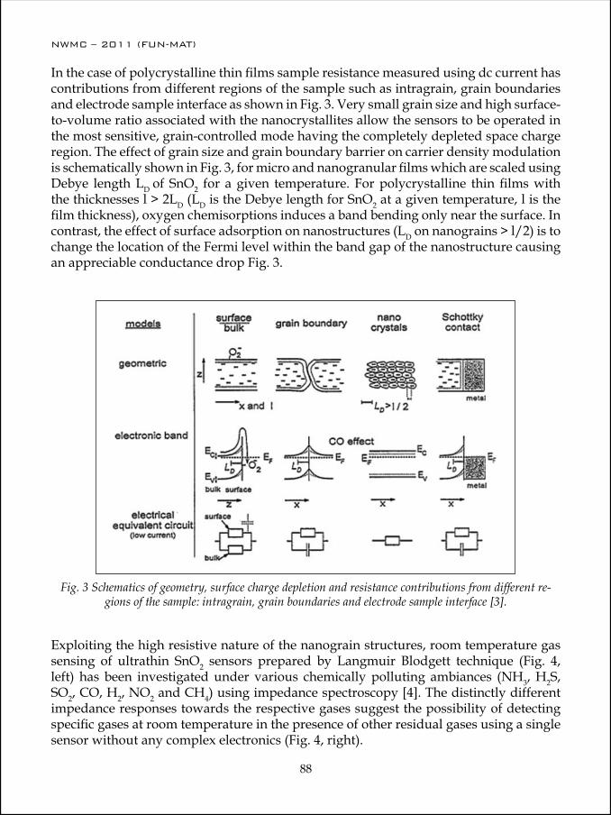
NWMC – 2011 (FUN-MAT)
88
NWMC – 2011 (FUN-MAT)
89
In the case of polycrystalline thin films sample resistance measured using dc current has contributions from different regions of the sample such as intragrain, grain boundaries and electrode sample interface as shown in Fig. 3. Very small grain size and high surface-to-volume ratio associated with the nanocrystallites allow the sensors to be operated in the most sensitive, grain-controlled mode having the completely depleted space charge region. The effect of grain size and grain boundary barrier on carrier density modulation is schematically shown in Fig. 3, for micro and nanogranular films which are scaled using Debye length LD of SnO2 for a given temperature. For polycrystalline thin films with the thicknesses l > 2LD (LD is the Debye length for SnO2 at a given temperature, l is the film thickness), oxygen chemisorptions induces a band bending only near the surface. In contrast, the effect of surface adsorption on nanostructures (LD on nanograins > l/2) is to change the location of the Fermi level within the band gap of the nanostructure causing an appreciable conductance drop Fig. 3.
Fig. 3 Schematics of geometry, surface charge depletion and resistance contributions from different re-gions of the sample: intragrain, grain boundaries and electrode sample interface [3].
Exploiting the high resistive nature of the nanograin structures, room temperature gas sensing of ultrathin SnO2 sensors prepared by Langmuir Blodgett technique (Fig. 4, left) has been investigated under various chemically polluting ambiances (NH3, H2S, SO2, CO, H2, NO2 and CH4) using impedance spectroscopy [4]. The distinctly different impedance responses towards the respective gases suggest the possibility of detecting specific gases at room temperature in the presence of other residual gases using a single sensor without any complex electronics (Fig. 4, right).

NWMC – 2011 (FUN-MAT)
88
NWMC – 2011 (FUN-MAT)
89
Fig. 4. Schematic (left) and selective gas sensing (right) of ultrathin SnO2 film sensor. The re-sponse of the sensor is measured at frequency 477 Hz.
Thus it can be seen that gas sensing mechanism involves the various interfaces wherein the crystallite size dependent intragrain and/or grain boundary properties of electrode dominates. Moreover, the physical properties limiting sensor devices fabricated in polycrystalline thin film can be readily overcome by exploiting nanoscale structures.
References:1. Eugenii Katz, Itamar Willner, Electroanalysis 15, No. 11, 2003, 913.2. C.A. Betty, R. Lal, D.K. Sharma, J.V. Yakhmi and J.P. Mittal, Sensors and Actuators B.
Chemical, 97, 2004, 334-343. 3. W. Gopel, K.D. Schierbaum, Sensors and Actuators B. Chemical, 26-27, 1995, 1-12. 4. Sipra Choudhury, C.A. Betty, K.G. Girija and S.K. Kulshreshtha, Applied Physics Letters,
89, 2006, 071914.

NWMC – 2011 (FUN-MAT)
90
Dr. (Mrs.) Betty C.A. received M.Sc. degree in Physics from Cochin uni-versity of Science and Technology, in 1987. She joined the 32nd batch of B.A.R.C. Orientation Course for trainee officers in Physics in 1988. After successful completion of the course she joined Chemistry Division B.A.R.C. in 1989. In the initial years she has worked on radiation effects on diodes, transistors and operational amplifiers. Her Ph. D work was on fabrication and characterization of Capacitive Immunosensors based on porous silicon. She received her Ph. D. (Microelectronics) in 2003 from Electrical Engi-
neering Dept., I.I.T. Bombay. Her research interests include semiconductor device physics, fabrication and characterization of sensors using various nanostructures: porous silicon, poly-aniline thin films, SnO2 ultrathin films etc. She is a post graduate teacher for Physics and Chemistry at Homi Bhabha National Institute, Anushaktinagar, Mumbai.
NWMC – 2011 (FUN-MAT)
91
Soft Condensed Matter: Properties and Applications
P. A. Hassan
Chemistry Division, Bhabha Atomic Research Centre, Trombay, Mumbai-400 085 Tel : + 91 22 25595099; Email: [email protected]
AbstractSoft condensed matter encompasses materials that can be easily deformed by external forces. They are composed of mesoscopic entities, i.e. typical sizes of 1nm – 1000 nm, held together by interaction energies comparable to thermal energy. They possess shear modulus three to six orders of magnitude smaller than atomic solids. Colloids, polymers, liquid crystals, surfactants etc. are typical examples that form soft materials under appropriate conditions. The existence of a finite, yet small value of shear modulus put them at a state intermediate between that of true solids and liquids and hence can be visualised as “soft” solids. In recent years, this field has emerged as an identifiable area in material science that possesses substantial scientific challenges and industrial applications. This lecture will discuss the basic principles governing the generation of soft materials, their characterization and typical applications with special reference to colloids, polymers and surfactants.
Introduction to soft matterThe principal quantity that tells how “hard” or “soft” a material is its shear modulus. Rheological measurements provide information about this property and it depends on the time scale at which it is being probed. Rheology deals with the response of the materials when it is subjected to some external forces; the details of the technique can be found elsewhere. In general, the two limiting cases of rheological properties of a fluid (i.e, liquid and a solid) can be generalized in terms of flow and elasticity respectively. Flow is an irreversible deformation which is the characteristic of a liquid while elasticity is a reversible deformation characteristic of a solid. These are two ideal cases and their behavior can be best illustrated by a simple shear experiment as shown in figure 1.
Consider a fluid contained between two parallel plates each of which having an area, A (figure 1). If a force F is applied to the upper plate such that it move with a velocity,v relative to the lower plate. If the displacement of a given element located at dx is dy, then the shear strain g and the shear rate g are defined as
γ = dy/dx and g = dg/dt=dv/dx (1)
The force F acting at the upper plate produces a shear stress, σ = F/A
yx

NWMC – 2011 (FUN-MAT)
92
NWMC – 2011 (FUN-MAT)
93
Figure 1. Geometry for a simple shear along y – direction with a velocity gradient along x
In the case of a liquid the rate of deformation or shear rate, g is proportional to the shear stress σ as shown by the Newton's equation,
σ = ηg (2)
The proportionality constant η is called the viscosity of the liquid. The above relationship is not true in the case of an elastic solid in which the shear stress,σ is proportional to the strain,g as given by the Hooke's law,
σ = Gg (3)
The proportionality constant, G is called the rigidity modulus or shear modulus. In practice, the Newton's law and the Hooke's law are two limiting cases of the response of a material under shear. The behavior of many materials, especially soft matter, cannot be described by either Newton's law or Hooke's law but they exhibit both viscous and elastic responses. Such materials are designated as viscoelastic materials. The term linear viscoelasticity is applied to the study of viscoelastic properties under small deformations where the strain varies linearly with the stress. This implies that the stress, strain and their time derivatives are related by a linear differential equation with constant coefficients. The stress-strain relationship for a general viscoelastic fluid can be described by a linear differential equation
Figure 1. Geometry for a simple shear along y – direction with a velocity gradient along x
Consider a fluid contained between two parallel plates each of which having an area, A (figure 1). If a force F is applied to the upper plate such that it move with a velocity,v relative to the lower plate. If the displacement of a given element located at dx is dy, then
the shear strain γ and the shear rate γ.
are defined as
γ = dy/dx and γ.
= dγ/dt=dv/dx (1)The force F acting at the upper plate produces a shear stress, σ = F/A
In the case of a liquid the rate of deformation or shear rate, γ.
is proportional to theshear stress σ as shown by the Newton's equation,
σ = ηγ.
(2)The proportionality constant η is called the viscosity of the liquid. The aboverelationship is not true in the case of an elastic solid in which the shear stress,σ isproportional to the strain,γ as given by the Hooke's law,σ = Gγ (3)The proportionality constant, G is called the rigidity modulus or shear modulus. Inpractice, the Newton's law and the Hooke's law are two limiting cases of the responseof a material under shear. The behavior of many materials, especially soft matter,cannot be described by either Newton's law or Hooke's law but they exhibit bothviscous and elastic responses. Such materials are designated as viscoelastic materials.The term linear viscoelasticity is applied to the study of viscoelastic properties undersmall deformations where the strain varies linearly with the stress. This implies that the stress, strain and their time derivatives are related by a linear differential equation withconstant coefficients. The stress-strain relationship for a general viscoelastic fluid canbe described by a linear differential equation
1 1 2
2
2 0 1 2
2
2+ + +
= + + +
α ∂
∂α ∂
∂σ β β ∂
∂β ∂
∂γ
t t t t.. .. (4)
where the coefficients αi and βi are material parameters.
Shear modulus and the energy densityThe elastic properties of an ideal solid can be understood if one considers theintermolecular interactions in the solid. Let us consider a perfect cubic crystal having a
F
y
x
V = 0
V= v
where the coefficients αi and βi are material parameters.
Shear modulus and the energy densityThe elastic properties of an ideal solid can be understood if one considers the intermolecular interactions in the solid. Let us consider a perfect cubic crystal having
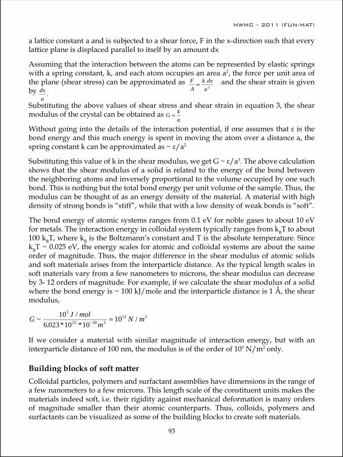
NWMC – 2011 (FUN-MAT)
92
NWMC – 2011 (FUN-MAT)
93
a lattice constant a and is subjected to a shear force, F in the x-direction such that every lattice plane is displaced parallel to itself by an amount dx
Assuming that the interaction between the atoms can be represented by elastic springs with a spring constant, k, and each atom occupies an area a2, the force per unit area of the plane (shear stress) can be approximated as
lattice constant a and is subjected to a shear force, F in the x-direction such that everylattice plane is displaced parallel to itself by an amount dx
Assuming that the interaction between the atoms can be represented by elastic springswith a spring constant, k, and each atom occupies an area a2, the force per unit area of the
plane (shear stress) can be approximated as FA
k dxa
∝ .2 and the shear strain is given by
dxa
.
Substituting the above values of shear stress and shear strain in equation 3, the shear
modulus of the crystal can be obtained as G ka
≈
Without going into the details of the interaction potential, if one assumes that ε is thebond energy and this much energy is spent in moving the atom over a distance a, thespring constant k can be approximated as ~ ε/a2
Substituting this value of k in the shear modulus, we get G ~ ε/a3. The above calculation shows that the shear modulus of a solid is related to the energy of the bond between the neighboring atoms and inversely proportional to the volume occupied by one such bond. This is nothing but the total bond energy per unit volume of the sample. Thus, themodulus can be thought of as an energy density of the material. A material with highdensity of strong bonds is “stiff”, while that with a low density of weak bonds is “soft”. The bond energy of atomic systems ranges from 0.1 eV for noble gases to about 10 eVfor metals. The interaction energy in colloidal system typically ranges from kBT to about 100 kBT, where kB is the Boltzmann’s constant and T is the absolute temperature. Since kBT ~ 0.025 eV, the energy scales for atomic and colloidal systems are about the sameorder of magnitude. Thus, the major difference in the shear modulus of atomic solids and soft materials arises from the interparticle distance. As the typical length scales in softmaterials vary from a few nanometers to microns, the shear modulus can decrease by 3-12 orders of magnitude. For example, if we calculate the shear modulus of a solid where the bond energy is ~ 100 kJ/mole and the interparticle distance is 1 Å, the shear modulus,
G J molm
N m~ /. * *
/106 023 10 10
105
23 30 312 2
− ≈
If we consider a material with similar magnitude of interaction energy, but with aninterparticle distance of 100 nm, the modulus is of the order of 103 N/m2 only.Building blocks of soft matter
Colloidal particles, polymers and surfactant assemblies have dimensions in the
range of a few nanometers to a few microns. This length scale of the constituent units
makes the materials indeed soft, i.e. their rigidity against mechanical deformation is
many orders of magnitude smaller than their atomic counterparts. Thus, colloids,
polymers and surfactants can be visualized as some of the building blocks to create soft
materials.
and the shear strain is given by
lattice constant a and is subjected to a shear force, F in the x-direction such that everylattice plane is displaced parallel to itself by an amount dx
Assuming that the interaction between the atoms can be represented by elastic springswith a spring constant, k, and each atom occupies an area a2, the force per unit area of the
plane (shear stress) can be approximated as FA
k dxa
∝ .2 and the shear strain is given by
dxa
.
Substituting the above values of shear stress and shear strain in equation 3, the shear
modulus of the crystal can be obtained as G ka
≈
Without going into the details of the interaction potential, if one assumes that ε is thebond energy and this much energy is spent in moving the atom over a distance a, thespring constant k can be approximated as ~ ε/a2
Substituting this value of k in the shear modulus, we get G ~ ε/a3. The above calculation shows that the shear modulus of a solid is related to the energy of the bond between the neighboring atoms and inversely proportional to the volume occupied by one such bond. This is nothing but the total bond energy per unit volume of the sample. Thus, themodulus can be thought of as an energy density of the material. A material with highdensity of strong bonds is “stiff”, while that with a low density of weak bonds is “soft”. The bond energy of atomic systems ranges from 0.1 eV for noble gases to about 10 eVfor metals. The interaction energy in colloidal system typically ranges from kBT to about 100 kBT, where kB is the Boltzmann’s constant and T is the absolute temperature. Since kBT ~ 0.025 eV, the energy scales for atomic and colloidal systems are about the sameorder of magnitude. Thus, the major difference in the shear modulus of atomic solids and soft materials arises from the interparticle distance. As the typical length scales in softmaterials vary from a few nanometers to microns, the shear modulus can decrease by 3-12 orders of magnitude. For example, if we calculate the shear modulus of a solid where the bond energy is ~ 100 kJ/mole and the interparticle distance is 1 Å, the shear modulus,
G J molm
N m~ /. * *
/106 023 10 10
105
23 30 312 2
− ≈
If we consider a material with similar magnitude of interaction energy, but with aninterparticle distance of 100 nm, the modulus is of the order of 103 N/m2 only.Building blocks of soft matter
Colloidal particles, polymers and surfactant assemblies have dimensions in the
range of a few nanometers to a few microns. This length scale of the constituent units
makes the materials indeed soft, i.e. their rigidity against mechanical deformation is
many orders of magnitude smaller than their atomic counterparts. Thus, colloids,
polymers and surfactants can be visualized as some of the building blocks to create soft
materials.
Substituting the above values of shear stress and shear strain in equation 3, the shear modulus of the crystal can be obtained as
lattice constant a and is subjected to a shear force, F in the x-direction such that everylattice plane is displaced parallel to itself by an amount dx
Assuming that the interaction between the atoms can be represented by elastic springswith a spring constant, k, and each atom occupies an area a2, the force per unit area of the
plane (shear stress) can be approximated as FA
k dxa
∝ .2 and the shear strain is given by
dxa
.
Substituting the above values of shear stress and shear strain in equation 3, the shear
modulus of the crystal can be obtained as G ka
≈
Without going into the details of the interaction potential, if one assumes that ε is thebond energy and this much energy is spent in moving the atom over a distance a, thespring constant k can be approximated as ~ ε/a2
Substituting this value of k in the shear modulus, we get G ~ ε/a3. The above calculation shows that the shear modulus of a solid is related to the energy of the bond between the neighboring atoms and inversely proportional to the volume occupied by one such bond. This is nothing but the total bond energy per unit volume of the sample. Thus, themodulus can be thought of as an energy density of the material. A material with highdensity of strong bonds is “stiff”, while that with a low density of weak bonds is “soft”. The bond energy of atomic systems ranges from 0.1 eV for noble gases to about 10 eVfor metals. The interaction energy in colloidal system typically ranges from kBT to about 100 kBT, where kB is the Boltzmann’s constant and T is the absolute temperature. Since kBT ~ 0.025 eV, the energy scales for atomic and colloidal systems are about the sameorder of magnitude. Thus, the major difference in the shear modulus of atomic solids and soft materials arises from the interparticle distance. As the typical length scales in softmaterials vary from a few nanometers to microns, the shear modulus can decrease by 3-12 orders of magnitude. For example, if we calculate the shear modulus of a solid where the bond energy is ~ 100 kJ/mole and the interparticle distance is 1 Å, the shear modulus,
G J molm
N m~ /. * *
/106 023 10 10
105
23 30 312 2
− ≈
If we consider a material with similar magnitude of interaction energy, but with aninterparticle distance of 100 nm, the modulus is of the order of 103 N/m2 only.Building blocks of soft matter
Colloidal particles, polymers and surfactant assemblies have dimensions in the
range of a few nanometers to a few microns. This length scale of the constituent units
makes the materials indeed soft, i.e. their rigidity against mechanical deformation is
many orders of magnitude smaller than their atomic counterparts. Thus, colloids,
polymers and surfactants can be visualized as some of the building blocks to create soft
materials.
Without going into the details of the interaction potential, if one assumes that ε is the bond energy and this much energy is spent in moving the atom over a distance a, the spring constant k can be approximated as ~ ε/a2
Substituting this value of k in the shear modulus, we get G ~ ε/a3. The above calculation shows that the shear modulus of a solid is related to the energy of the bond between the neighboring atoms and inversely proportional to the volume occupied by one such bond. This is nothing but the total bond energy per unit volume of the sample. Thus, the modulus can be thought of as an energy density of the material. A material with high density of strong bonds is “stiff”, while that with a low density of weak bonds is “soft”.
The bond energy of atomic systems ranges from 0.1 eV for noble gases to about 10 eV for metals. The interaction energy in colloidal system typically ranges from kBT to about 100 kBT, where kB is the Boltzmann’s constant and T is the absolute temperature. Since kBT ~ 0.025 eV, the energy scales for atomic and colloidal systems are about the same order of magnitude. Thus, the major difference in the shear modulus of atomic solids and soft materials arises from the interparticle distance. As the typical length scales in soft materials vary from a few nanometers to microns, the shear modulus can decrease by 3- 12 orders of magnitude. For example, if we calculate the shear modulus of a solid where the bond energy is ~ 100 kJ/mole and the interparticle distance is 1 Å, the shear modulus,
lattice constant a and is subjected to a shear force, F in the x-direction such that everylattice plane is displaced parallel to itself by an amount dx
Assuming that the interaction between the atoms can be represented by elastic springswith a spring constant, k, and each atom occupies an area a2, the force per unit area of the
plane (shear stress) can be approximated as FA
k dxa
∝ .2 and the shear strain is given by
dxa
.
Substituting the above values of shear stress and shear strain in equation 3, the shear
modulus of the crystal can be obtained as G ka
≈
Without going into the details of the interaction potential, if one assumes that ε is thebond energy and this much energy is spent in moving the atom over a distance a, thespring constant k can be approximated as ~ ε/a2
Substituting this value of k in the shear modulus, we get G ~ ε/a3. The above calculation shows that the shear modulus of a solid is related to the energy of the bond between the neighboring atoms and inversely proportional to the volume occupied by one such bond. This is nothing but the total bond energy per unit volume of the sample. Thus, themodulus can be thought of as an energy density of the material. A material with highdensity of strong bonds is “stiff”, while that with a low density of weak bonds is “soft”. The bond energy of atomic systems ranges from 0.1 eV for noble gases to about 10 eVfor metals. The interaction energy in colloidal system typically ranges from kBT to about 100 kBT, where kB is the Boltzmann’s constant and T is the absolute temperature. Since kBT ~ 0.025 eV, the energy scales for atomic and colloidal systems are about the sameorder of magnitude. Thus, the major difference in the shear modulus of atomic solids and soft materials arises from the interparticle distance. As the typical length scales in softmaterials vary from a few nanometers to microns, the shear modulus can decrease by 3-12 orders of magnitude. For example, if we calculate the shear modulus of a solid where the bond energy is ~ 100 kJ/mole and the interparticle distance is 1 Å, the shear modulus,
G J molm
N m~ /. * *
/106 023 10 10
105
23 30 312 2
− ≈
If we consider a material with similar magnitude of interaction energy, but with aninterparticle distance of 100 nm, the modulus is of the order of 103 N/m2 only.Building blocks of soft matter
Colloidal particles, polymers and surfactant assemblies have dimensions in the
range of a few nanometers to a few microns. This length scale of the constituent units
makes the materials indeed soft, i.e. their rigidity against mechanical deformation is
many orders of magnitude smaller than their atomic counterparts. Thus, colloids,
polymers and surfactants can be visualized as some of the building blocks to create soft
materials.
If we consider a material with similar magnitude of interaction energy, but with an interparticle distance of 100 nm, the modulus is of the order of 103 N/m2 only.
Building blocks of soft matterColloidal particles, polymers and surfactant assemblies have dimensions in the range of a few nanometers to a few microns. This length scale of the constituent units makes the materials indeed soft, i.e. their rigidity against mechanical deformation is many orders of magnitude smaller than their atomic counterparts. Thus, colloids, polymers and surfactants can be visualized as some of the building blocks to create soft materials.

NWMC – 2011 (FUN-MAT)
94
NWMC – 2011 (FUN-MAT)
95
A colloidal system consists of uniformly distributed dispersion of one phase in a dispersion medium (continuous phase). The colloidal regime (~ 1nm to ~1000nm) deals with an intermediate length scale between true solutions and bulk materials. This length scale comes from the requirement that they are significantly larger than the molecules of the dispersion medium and the upper limit ensures that the particles’ Brownian motion is dominated by external forces such as gravitational settling. One important aspect of colloids as compared to bulk form of materials is that their surface to volume ratio is very large. For example, when a spherical particle of radius 1 cm is divided into several particles of radius 100 nm, there is 105 times increase in the total surface area. The large interfacial area associated with colloidal particles put them in a thermodynamically unfavorable condition, as the interface always possess a positive contribution to free energy. Due to the high interfacial free energy associated with it, colloids are susceptible to agglomeration and growth and hence needs to be stabilized by other means (kinetically). Some of the most common methods involve electrostatic (charge) stabilization or steric stabilization achieved by the addition of various additives such as surfactants, organic ligands or polymers. These stabilizing agents provide an energetic barrier to the agglomeration of particles either through Coulombic or Steric repulsion between the particles.
A polymer is a macromolecule composed of repeating structural units typically connected by covalent chemical bonds. Due to the wide range of properties accessible in polymeric materials and polymer solutions, they play an essential role in everyday life from plastics and elastomers on the one hand to natural biopolymers such as DNA and proteins that are essential for life on the other. The physical properties of polymer solutions are significantly different from those of low molecular weight electrolyte solutions. The main reason for this difference is the large molar volume ratio of solute to solvent together with the large number of consecutive segments that constitute each single molecule of the polymer chains present as solute. The fundamental difference between the physical chemistry of a small molecule and that of a macromolecule is that the latter can adopt a large number of conformations. Conformation refers to different spatial arrangement of atoms in a molecule, arising from free rotation about a single bond. At a given temperature, any individual polymer molecule constantly fluctuates among these conformations and the populations must be characterized and analyzed in terms of a distribution. Almost all experimental measurements on polymers, either thermodynamic or hydrodynamic, yielded averaged behavior of the whole population distribution. These measurements have validated the statistical theory of polymer conformations and have provided much important information about a wide range of both synthetic and biological polymers.
If we consider a polyethylene chain, the free rotation around the C-C bond offers large number of conformations. The minimum energy conformation i.e. the equilibrium conformation at T=0, will be the rectilinear all-trans conformation. At higher temperature, the polymer adopts other conformations as per the Boltzmann distribution. The variation

NWMC – 2011 (FUN-MAT)
94
NWMC – 2011 (FUN-MAT)
95
in the potential energy of butane molecule as a function of the dihedral angle is shown in the following figure (figure 2).
Surfactants are molecules that possess two groups of opposing solubility tendencies, typically a water soluble polar group commonly called the ‘head group’ and an oil soluble hydrocarbon or fluorocarbon group designated as the ‘tail group’. This hydrophilic-hydrophobic combination makes it unique in its properties and hence often called as amphiphilic molecules. One general way of classification of surfactants is based on the nature of the hydrophilic group. Depending on the chemical structure of the head group, surfactants are classified as anionic, cationic, non-ionic or zwitterionic. Above a narrow range of concentration which is characteristic of each solvent-solute system , the amphiphilic molecules associate themselves to form aggregates called micelles and this concentration above which appreciable amounts of micelles are formed is termed ‘critical micelle concentration’ (CMC). There is a sudden, well defined change in some of the physico-chemical properties of aqueous surfactant solutions above CMC. Some of the important physical properties which have been found to exhibit this behavior are the interfacial tension, equivalent conductivity, tubidity, osmotic pressure, self diffusion coefficient, solubilization and viscosity. This sudden change in their bulk properties corresponds to the formation of micellar aggregates and hence is used to determine the CMC of surfactant solutions. However, it is worth mentioning that this change occurs over a narrow concentration range rather than at a precise point and the magnitude of the CMC obtained depends on the property being measured.
Figure 2. The conformational energy of butane as a function of dihedral angle

NWMC – 2011 (FUN-MAT)
96
NWMC – 2011 (FUN-MAT)
97
Much of the natural materials are product of organized molecular assemblies and humans are the best example of it. Understanding the microstructure and dynamics of molecular self assembly is important for its applications in creating other functional materials and devices. Surfactant molecules (amphiphiles) can spontaneously assemble into a gamut of spatially organized structures, in both aqueous and non-aqueous solvents. Figure 3 shows schematic representation of a few self assembled structures of surfactants in a suitable solvent.
The aggregation of amphiphiles into various structures such as micelles, bilayers, vesicles etc. arise from the interplay of two opposing forces. The ‘hydrophobic effect’ of the hydrocarbon tails tends to bring the molecules closer together so as to avoid any contact with water, i.e., minimizing the area-to-volume ratio. On the other hand, the repulsion between the hydrophilic headgroups tends to maximize the area-to-volume ratio. The repulsive interactions arises form the ‘solvation’ of the head groups which will tend to keep the hydrophilic part away from each other. In the case of ionic surfactants, there is an additional contribution from the electrostatic repulsion of the head groups which will further increase the effective head group area per molecule. The shape of the aggregate that best satisfies the above two demands depends primarily on three factors, namely, the volume of the hydrophobic part, length of the hydrophobic chain and the effective head group area of the surfactant molecule.
The electrostatic contribution to the free energy of formation of micelles can be influenced by the addition of electrolytes or cosurfactants. As a result, the characteristics of the aggregates can be easily controlled by the changes in the solution conditions such as
Figure 3. Schematic representation of a few self assembled structures of amphiphiles formed in aqueous/non-aqueous solvents.
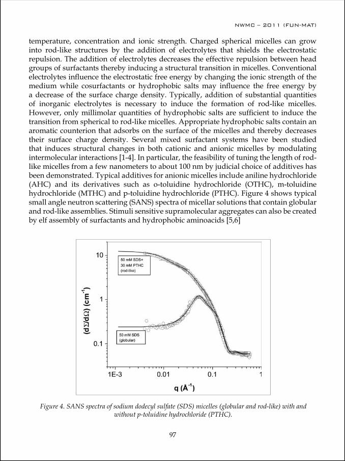
NWMC – 2011 (FUN-MAT)
96
NWMC – 2011 (FUN-MAT)
97
temperature, concentration and ionic strength. Charged spherical micelles can grow into rod-like structures by the addition of electrolytes that shields the electrostatic repulsion. The addition of electrolytes decreases the effective repulsion between head groups of surfactants thereby inducing a structural transition in micelles. Conventional electrolytes influence the electrostatic free energy by changing the ionic strength of the medium while cosurfactants or hydrophobic salts may influence the free energy by a decrease of the surface charge density. Typically, addition of substantial quantities of inorganic electrolytes is necessary to induce the formation of rod-like micelles. However, only millimolar quantities of hydrophobic salts are sufficient to induce the transition from spherical to rod-like micelles. Appropriate hydrophobic salts contain an aromatic counterion that adsorbs on the surface of the micelles and thereby decreases their surface charge density. Several mixed surfactant systems have been studied that induces structural changes in both cationic and anionic micelles by modulating intermolecular interactions [1-4]. In particular, the feasibility of tuning the length of rod-like micelles from a few nanometers to about 100 nm by judicial choice of additives has been demonstrated. Typical additives for anionic micelles include aniline hydrochloride (AHC) and its derivatives such as o-toluidine hydrochloride (OTHC), m-toluidine hydrochloride (MTHC) and p-toluidine hydrochloride (PTHC). Figure 4 shows typical small angle neutron scattering (SANS) spectra of micellar solutions that contain globular and rod-like assemblies. Stimuli sensitive supramolecular aggregates can also be created by elf assembly of surfactants and hydrophobic aminoacids [5,6]
Figure 4. SANS spectra of sodium dodecyl sulfate (SDS) micelles (globular and rod-like) with and without p-toluidine hydrochloride (PTHC).
NWMC – 2011 (FUN-MAT)
98
NWMC – 2011 (FUN-MAT)
99
Applications of soft matterSoft materials are important in a wide range of technological applications. Some everyday examples of soft matter include detergents and cosmetics, paints, food additives, gels, lubricants and fuel additives and so on. Stimuli-responsive materials that can change their structure in response to external environments such as pH, temperature etc. have attracted great attention during the last decade due to their versatile applications in pharmaceutical, biomedical and related fields [7-10]. For example, surfactant assemblies have a unique structure in which hydrophilic and hydrophobic compartments with a dimension of a few nanometers to tens of nanometers are dispersed in a solvent. The issue most frequently addressed in pharmaceutical products by these systems is solubility. A low solubility and poor dissolution characteristics of many drugs reduces their bioavailability. Other issues such as drug payload, protection against degradation by endogenous enzymes and excretion of active ingredient by the immune system are also addressed with the help of novel drug delivery systems. It appears that the structural features of amphiphilic assemblies can be advantageously utilized to overcome the drug delivery challenge. Redkar et al reported that multilamellar vesicles (onion phases) that are capable of drug encapsulation can be prepared from a biodegradable surfactant PEG-8 Distearate (PEG-8-DS) [11]. Sumatriptan succinate (SS), a potent antimigraine drug is encapsulated in the aqueous layers of vesicles. Drug loaded vesicles were prepared by shearing lyotropic lamellar phases of the surfactant in presence of drug. The onion phases were characterized by polarized microscopy and small angle neutron scattering (SANS). The bilayer spacing of the vesicles of PEG-8-DS was observed to be 72 Å from SANS spectra. SANS study of the drug encapsulated vesicles reveals that upon encapsulation of drug, the bilayer spacing is increased to about 79 Å. Self assembled drug delivery systems with suitable surface functionalities have also been prepared through electrostatic complexation of anticancer drug doxorubicin [12,13].
ConclusionIn conclusion, soft matter is composed of units or structures at the mesoscopic length scale (1nm – 1000nm). Colloidal particles, polymers and surfactant assemblies have dimensions in the range of a few nanometers to a few microns. This length scale of the constituent units makes the materials indeed soft, i.e. their rigidity against mechanical deformation is many orders of magnitude smaller than their atomic counterparts. Apart from their traditional applications, soft materials are opening exciting new doors in the fundamental physics and chemistry of materials and biotechnological applications.
AcknowledgementsI am thankful to Drs. Gunjan Verma, Jayita Bhattacharjee, P. Koshy, V. K. Aswal, K.C. Barick and other collaborators for their respective contributions. Thanks are also due to Dr. D. Das, Head, Chemistry Division and Dr. T. Mukherjee, Director, chemistry Group for their encouragement and support.
NWMC – 2011 (FUN-MAT)
98
NWMC – 2011 (FUN-MAT)
99
References1. G. Garg, P. A. Hassan, V. K. Aswal and S. K. Kulshreshtha, J. Phys. Chem B, 109(2005)340.2. Koshy, P., Verma, G., Aswal, V.K., Venkatesh, M., Hassan, P.A. Journal of Physical
Chemistry B 114 (32), pp. 10462-10470 (2010)3. P. A. Hassan and J. V. Yakhmi Langmuir, 16(2000)7187.4. Koshy, P., Aswal, V.K., Venkatesh, M., Hassan, P.A. Soft Matter 7 (2011), 4778-47865. G. Verma, V. K. Aswal, S. K. Kulshreshtha, P. A. Hassan and E. W. Kaler Langmuir
24(2008)683. 6. G. Verma, V. K. Aswal and P. Hassan, Soft Matter, 5(2009)2919 7. Y. Wan, D. Zhao Chem. Rev. 107(2007)2821. 8. P. A. Hassan, S. N. Sawant, N. C. Bagkar, and J. V. Yakhmi Langmuir, 20(2004)4874, 9. C. Ni, P. A. Hassan, E. W. Kaler Langmuir, , 21(2005)3334.10. C. Pichot. Curr Opin Colloid Interface Sci 9(2004) 213.11. M. Redkar, P. A. Hassan, V. K. Aswal, P. Devarajan J. Pharm. Sci. 96(2007)2436 12. J. Bhattacharjee, G. Verma, V. K. Aswal, P. A. Hassan . Pramana - Journal of Physics 71
(2008) 991. 13. Bhattacharjee, J., Verma, G., Aswal, V.K., Date, A.A., Nagarsenker, M.S., Hassan, P.A.
Journal of Physical Chemistry B 114 (2010), 16414-16421
P. A. Hassan earned his M. Sc. Degree in Chemistry from Mahatma Gandhi University, Kottayam, Kerala in 1991 securing first rank with distinction. In 1992, he joined the prestigious Bhabha Atomic Research Centre (BARC) Training School and currently, he is Head of the Thermal & Interfacial Chemistry Section, Chemistry Division. He was a visiting researcher at the Laboratory of Complex Fluids, University of Louis Pasteur, Strasbourg, France in 1995. He received his Ph.D. degree in Chemistry from University of Mumbai in 1998 and pursued his post-doctoral research
at the Department of Chemical Engineering, University of Delaware, USA in 2000-2002. He visited the National Centre for Neutron Research, NIST, Maryland, USA. He has authored or co-authored about 71 peer-reviewed papers and delivered invited lectures at national and international conferences. His notable contributions include vesicle-to-micelle transition in surfactant mixtures, design of viscoelastic gels through self-assembly, nanomaterials synthesis in micelles, microrheological measurements using light scattering and interfacial engineering for immunoassays and drug delivery.

NWMC – 2011 (FUN-MAT)
100
NWMC – 2011 (FUN-MAT)
101
Optical Materials
V. Sudarsan
Chemistry Division, Bhabha Atomic Research Centre, Trombay, Mumbai 400085
Optical materials are broadly defined as the materials whose function is to alter or control electromagnetic radiation. Such materials can be used to refract, reflect, transmit, disperse, polarize, detect and transform light (electromagnetic radiation). At the microscopic level, atoms and their electronic configurations in the material interact with the electromagnetic radiation (photons) to determine the materials macroscopic optical properties such as transmission and refraction. These optical properties are functions of the wavelength of the incident light, the temperature of the material, the applied pressure on the material and in certain instances the external electric and magnetic fields applied to the material. There is a wide range of substances that are useful as optical materials. Most optical elements are fabricated from glass, crystalline materials, polymers, or plastic materials. In the choice of a material, the most important properties are often the degree of transparency and the refractive index, along with each property’s spectral dependency. In addition to this, the uniformity of the material, strength and hardness, temperature limits, hygroscopic nature, chemical resistivity, may also need to be considered. In the following section different types of optical materials and their applications are discussed.
Different types of optical materialsOxide and Chalcogenide glasses are the oldest materials used for different optical applications. An example such material is the fused silica, which transmits to about 180 nm and is well suited for applications in the UV-Visible-near-infrared regions. The need for inexpensive, unbreakable optical components that could be easily mass-produced resulted in the introduction of plastic optics in the mid-1930s. The light scattering due to microscopic defects and birefringence (resulting from stresses) are inherent properties of plastics, which must be considered before using them for any technological application. Latter plastics are replaced by organic synthetic polymers and they are emerging as key materials for information technology applications. Polymers often have an advantage over inorganic materials because they can be designed and synthesized into compositions and architectures not possible with crystals and glasses. They are found to be durable, optically efficient, reliable and inexpensive. Currently they are used in light-emitting diodes, liquid-crystal–polymer photo-detectors, polymer-dispersed liquid-crystal devices (for projection television), optical-fiber amplifiers doped with organic dyes (rhodamine), organic thin-film optics, and in electro optic modulators.
NWMC – 2011 (FUN-MAT)
100
NWMC – 2011 (FUN-MAT)
101
Although most of the early improvements in optical devices were due to advancements in the production of glasses, the crystalline state has taken an increasing importance. Synthetic crystal-growing techniques have made available single crystals such as lithium fluoride (of special importance in the ultraviolet region, since it transmits at wavelengths down to about 120 nm), calcium fluoride and potassium bromide which are useful as prisms for wavelengths up to about 25 μm in the infrared region. Many alkali-halide crystals are important because they transmit into the far-infrared region of the electromagnetic spectrum.
Following the invention of transistors, germanium and silicon ushered in the use of semiconductors as infrared optical elements or detectors. Polycrystalline forms of these semiconductors can be fabricated into windows, prisms, lenses and domes by casting, grinding and polishing. Compound semiconductors such as gallium arsenide (GaAs), ternary compounds such as gallium aluminum arsenide (Ga1−xAlxAs) and quaternary compounds such as indium gallium arsenide phosphide (InGaAsP) now serve as lasers, light-emitting diodes, and photo-detectors.
In the following section the parameters used to characterise an optical material have been defined and briefly discussed. The basic parameters are dielectric constant, refractive index, absorption coefficient. In addition to this for non-linear optical materials, parameter like nonlinear refractive index, nonlinear absorption coefficients etc., are also used to characterise the material. They are briefly explained below.
Optical parameters
Refractive index (n)Refractive index of a material or medium is defined as the ratio of the velocity of light in vacuum (c) to that in the medium or a material (v). It can be represented as n = c/v. Large electron clouds around the nucleus of an atom decreases the speed light propagating through it, thereby increasing the refractive index. Refractive index is a function of the wavelength of light and can also be expressed by the relation n = ck/ω, where ω is the angular frequency and k is the wave vector [1]. The wave vector k is a complex quantity and is related to the dielectric constant through the expression, k2 = εµ0ω2. Here ε is complex dielectric constant, µ0 is the vacuum permeability and ω is the angular frequency. As k is related to the complex dielectric constant, the refractive index is also a complex number and can be expressed by the n = n0 + i·n2, where n2 is the imaginary part of the reactive index and n0 the real part. Both n0 and n2 are the optical properties of the materials and are functions of the angular frequency (ω). The relation between n and n2 is known as the dispersion relation. Dispersion relations can be obtained by measuring and analyzing the reflectance or transmittance over a wide wavelength region.
Absorption coefficient (α)When a sample is irradiated with light, the intensity of light at a distance x from the

NWMC – 2011 (FUN-MAT)
102
NWMC – 2011 (FUN-MAT)
103
surface of the sample can be expressed by the relation I = I0exp(-αx), where I0 is the intensity of the incident light and I is the intensity at a distance x from the surface of the material. This is also known as the Lambert’s law. Absorption of light by a material can also expressed by the following terms/equations.
Optical density or the absorbance (A) = -log I/I0
Absorptivity: (I0-I)/I0 x 100, Where I0 is the incident intensity and I transmitted or reflected intensity.
Absorbance can be represented by the equation A = εCl, where ε is the molar absorptivity, C is the concentration and “l” is the path length.
The absorption coefficient is expressed by the relation α = 2ωқ/c, where ω is the angular frequency of the incident light, қ is the material property known as the extinction index of the material and c is the velocity of light [1]. The absorption coefficient is related to a variety of parameters which are conventionally used in various optical terminologies. They are Absorption cross-section, α/N, where N is the number of absorbing centres per unit volume, absorptivity ((I0-I)/I0. 100) and molar extinction coefficient
Reflectivity and transmitivityReflectivity is the ratio of the intensity of the light reflected to the intensity of light incident. It is related to the optical constants “n” and “қ” as,
Reflectivity = R0 = [(n-1)2+қ2]/[(n+1)2+қ2], where “n” is the refractive index and “қ” is the extinction index. Similarly transmitivity is the ratio of the intensity of light transmitted to the intensity of light incident on the sample.
Intensity of lightIntensity of light is defined as the energy transmitted per second through unit area perpendicular to the direction of light.
Based on the above properties/parameters, optical materials can be broadly classified into following categories
1. Transparent materials
2. Translucent material
3. Opaque materials.
The transparent materials have relatively small absorption coefficient and little reflection. For translucent materials light is scattered with in the material and for opaque materials relatively little transmission is observed.
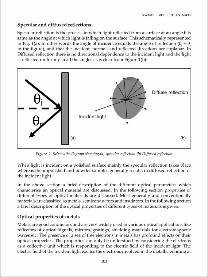
NWMC – 2011 (FUN-MAT)
102
NWMC – 2011 (FUN-MAT)
103
Specular and diffused reflectionsSpecular reflection is the process in which light reflected from a surface at an angle θ is same as the angle at which light is falling on the surface. This schematically represented in Fig. 1(a). In other words the angle of incidence equals the angle of reflection (θi = θr in the figure), and that the incident, normal, and reflected directions are coplanar. In Diffused reflection there is no directional dependence to the incident light and the light is reflected uniformly in all the angles as is clear from Figure 1(b).
Figure. 1. Schematic diagram showing (a) specular reflection (b) Diffused reflection
(a) (b)
When light is incident on a polished surface mainly the specular reflection takes place whereas the unpolished and powder samples generally results in diffused reflection of the incident light.
In the above section a brief description of the different optical parameters which characterise an optical material are discussed. In the following section properties of different types of optical materials are discussed. Most generally and conventionally materials are classified as metals, semiconductors and insulators. In the following section a brief description of the optical properties of different types of materials is given.
Optical properties of metalsMetals are good conductors and are very widely used in various optical applications like reflectors of optical signals, mirrors, gratings, shielding materials for electromagnetic waves etc. The presence of a sea of free electrons in metals has profound effects on their optical properties. The properties can only be understood by considering the electrons as a collective unit which is responding to the electric field of the incident light. The electric field of the incident light excites the electrons involved in the metallic bonding at
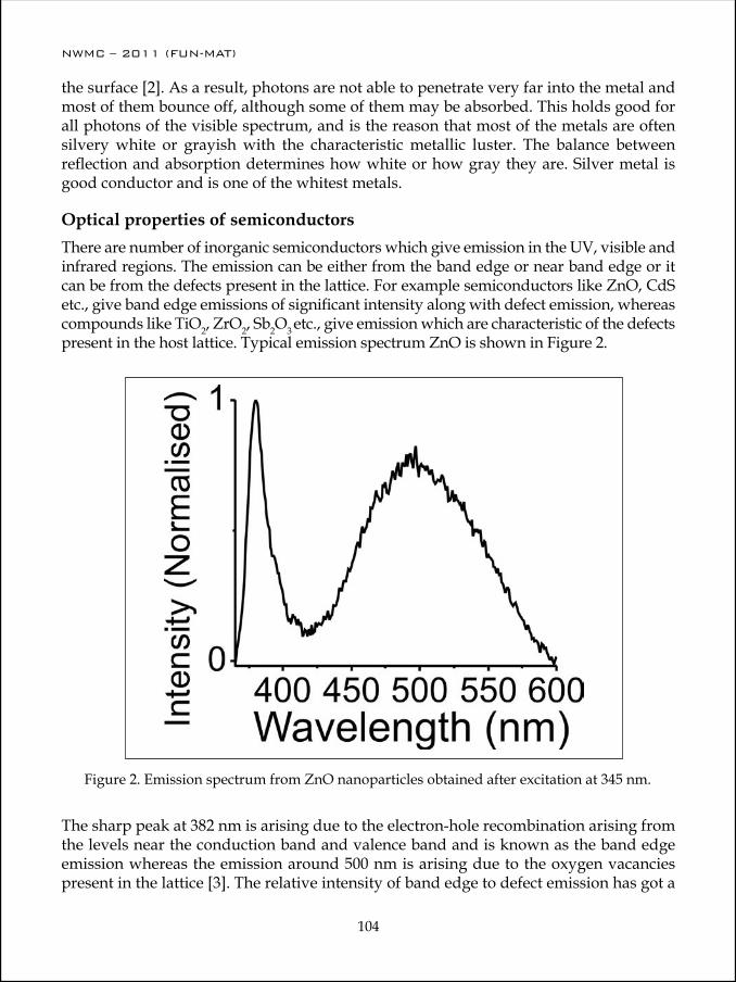
NWMC – 2011 (FUN-MAT)
104
NWMC – 2011 (FUN-MAT)
105
the surface [2]. As a result, photons are not able to penetrate very far into the metal and most of them bounce off, although some of them may be absorbed. This holds good for all photons of the visible spectrum, and is the reason that most of the metals are often silvery white or grayish with the characteristic metallic luster. The balance between reflection and absorption determines how white or how gray they are. Silver metal is good conductor and is one of the whitest metals.
Optical properties of semiconductorsThere are number of inorganic semiconductors which give emission in the UV, visible and infrared regions. The emission can be either from the band edge or near band edge or it can be from the defects present in the lattice. For example semiconductors like ZnO, CdS etc., give band edge emissions of significant intensity along with defect emission, whereas compounds like TiO2, ZrO2, Sb2O3 etc., give emission which are characteristic of the defects present in the host lattice. Typical emission spectrum ZnO is shown in Figure 2.
Figure 2. Emission spectrum from ZnO nanoparticles obtained after excitation at 345 nm.
The sharp peak at 382 nm is arising due to the electron-hole recombination arising from the levels near the conduction band and valence band and is known as the band edge emission whereas the emission around 500 nm is arising due to the oxygen vacancies present in the lattice [3]. The relative intensity of band edge to defect emission has got a
NWMC – 2011 (FUN-MAT)
104
NWMC – 2011 (FUN-MAT)
105
profound influence on the synthesis conditions, annealing temperatures and annealing atmospheres. For example annealing the ZnO nanomaterials under oxygen environment leads to the decrease in intensity of the oxygen vacancies whereas that in hydrogen leads to the generation of oxygen vacancies leading to their increase in intensity of defect emission. The defect emission at 500 nm can also be due to the Zn2+ vacancies present in the lattice.
Optical properties of insulatorsLead silicate glasses are good insulating materials and are technologically important. They are potential candidates for making electron multipliers, ultra low loss wave guides, glass-to-metal seals, infrared transmitting devices and optical gratings [4-7]. Optical properties like refractive index and extent of transmission in the UV–visible region can be modified by incorporating suitable additives, subjecting the samples to optical irradiation at different wavelengths, treatment under hydrogen environment, etc. [8–9]. For example Eopt values of PbO–P2O5 glasses can be reduced by incorporating Sb2O3 in the glass [8] and the refractive index of lead silicate glasses can be significantly changed either by heat treatment in hydrogen or irradiation with a laser light (266 nm) [9,10]. In the following section effect of PbO addition on the optical properties of (PbO)x[(Na2O)0.25(SiO2)0.75]1-x glasses have been discussed
Figure 3 show the emission and excitation spectra for (PbO)x[(Na2O)0.25(SiO2)0.75]1-x glasses containing different amounts of PbO. For (PbO)x[(Na2O)0.25(SiO2)0.75]1-x glasses having 10 mol % PbO, a broad emission peak around 400 nm is observed, on excitation at 290 nm (Fig. 3(left)). Based on the reported luminescence studies of alkali silicate glasses, the peak around 400 nm can be assigned to the luminescence of the localized centers also known as the L-centres present in the glass [11]. With increase in PbO concentration, the line width of the emission peak systematically increases and the peak maximum systematically shifts to higher wavelengths. For the purpose of comparison, emission spectrum from a representative binary glass sample, (PbO)0.25(SiO2)0.75, is shown in Fig. 3(e). No luminescence has been observed from this sample. The excitation spectra corresponding to these samples are also shown in Fig. 3 (right). The excitation peak maxima appear in the range of 290 – 330 nm. With increase in PbO content in the glass the excitation peak maxima shifts to higher wavelengths along with increase in the line width, similar to what has been observed in the case of emission spectra.
The emission and excitation peaks have been attributed to the optical transitions characteristic of colour centre (L-centre) present in the glass. The colour centre mainly arises due to the presence of Si-O- Na+ type of linkages in the glass. In binary Na2O-SiO2 glasses, the ground state of the L-centre corresponds to the ionic bonding between the non-bridging O- ion and Na+ ions. Excited state is originated form the transfer of an electron from O-to Na+, resulting in O0……..Na covalent bond. The excited state can be either a singlet or a triplet and a triplet to singlet transition in the excited state is associated with decrease in the lifetime of the emitting state (triplet state). With increase in PbO
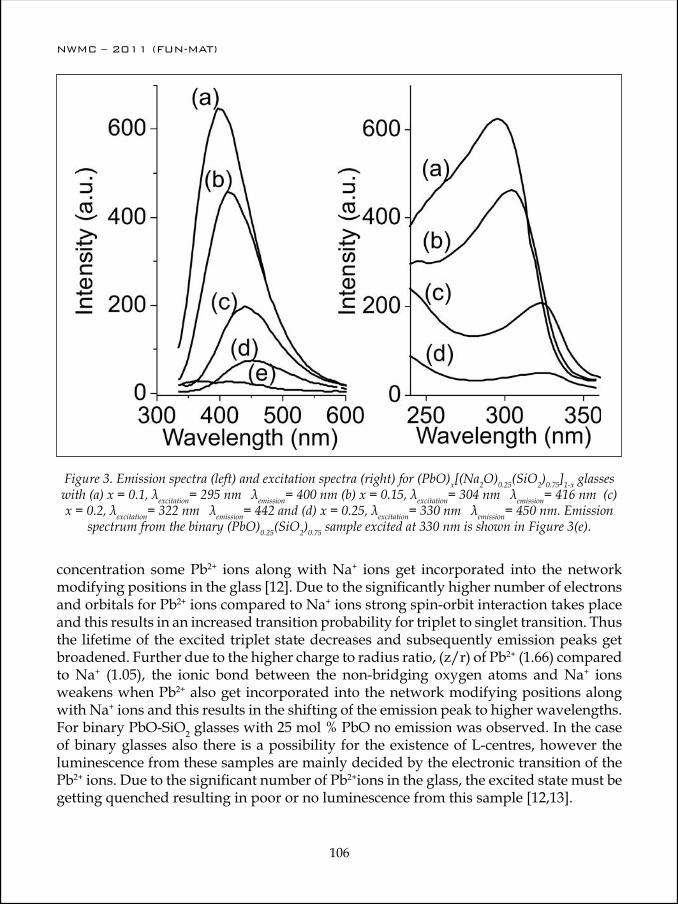
NWMC – 2011 (FUN-MAT)
106
NWMC – 2011 (FUN-MAT)
107
Figure 3. Emission spectra (left) and excitation spectra (right) for (PbO)x[(Na2O)0.25(SiO2)0.75]1-x glasses with (a) x = 0.1, λexcitation= 295 nm λemission= 400 nm (b) x = 0.15, λexcitation= 304 nm λemission= 416 nm (c) x = 0.2, λexcitation= 322 nm λemission= 442 and (d) x = 0.25, λexcitation= 330 nm λemission= 450 nm. Emission
spectrum from the binary (PbO)0.25(SiO2)0.75 sample excited at 330 nm is shown in Figure 3(e).
concentration some Pb2+ ions along with Na+ ions get incorporated into the network modifying positions in the glass [12]. Due to the significantly higher number of electrons and orbitals for Pb2+ ions compared to Na+ ions strong spin-orbit interaction takes place and this results in an increased transition probability for triplet to singlet transition. Thus the lifetime of the excited triplet state decreases and subsequently emission peaks get broadened. Further due to the higher charge to radius ratio, (z/r) of Pb2+ (1.66) compared to Na+ (1.05), the ionic bond between the non-bridging oxygen atoms and Na+ ions weakens when Pb2+ also get incorporated into the network modifying positions along with Na+ ions and this results in the shifting of the emission peak to higher wavelengths. For binary PbO-SiO2 glasses with 25 mol % PbO no emission was observed. In the case of binary glasses also there is a possibility for the existence of L-centres, however the luminescence from these samples are mainly decided by the electronic transition of the Pb2+ ions. Due to the significant number of Pb2+ions in the glass, the excited state must be getting quenched resulting in poor or no luminescence from this sample [12,13].
NWMC – 2011 (FUN-MAT)
106
NWMC – 2011 (FUN-MAT)
107
References1. W. M. Yen, S. Shionoya, H. Yamamoto (Eds.), “Phosphor Hand Book,” CRC press, Boca
Raton (2007), pp.12-13 2. J. H. Simmons and K. S. Potter (Eds.), “Optical Materials,” Academic Press, San Diego,
2000, p 573. A. B. Djurisic, Y. H. Leung, K. H. Tam, Y. F. Hsu, L. Ding, W. K. Ge, Y. C. Zhong, K. S. Wong,
W. K. Chan, H. L. Tam, K. W. Cheah, W. M. Kwok and D. L. Phillips, Nanotechnology 18 (2007) 09570.
4. C. C. Wang, Phys. Rev. B 2 (1970) 2045.5. J. L. Wiza, Nucl. Instrum. Methods 62 (1979) 587.6. J. P. Burger, P. L. Swart, S. J. Spammer and P.V. Bulkin, SPIE 2507 (1995)53.7. T. Augustsson, J. Lightwave Technol. 16 (1998) 1517.8. V. Sudarsan and S. K. Kulshreshtha, J. Non-Cryst. Solids 286 (2001)99.9. H. Jia, G. Chen and W. Wang, J. Non-Cryst. Solids 347 (2004) 220.10. Z. Pan, D.O. Henderson and S.H. Moragn, J. Non-Cryst. Solids 171 (1994) 134.11. X. Liu, D.B. Hollis and J. McDougall, Phys. Chem. Glasses 37 (1996) 160.12. A.N. Trukhin, J. Non-Cryst. Solids 189 (1995) 1.13. V.K. Shrikhande, V. Sudarsan, G.P. Kothiyal and S.K. Kulshreshtha, J. Non-Cryst. Solids
353 (2007) 1341.
V. Sudarsan joined Chemistry Division of BARC in the year 1994 after graduating from the 37th batch of the training school. He received his Ph. D degree in Chemistry from Mumbai University in the year 2002 for his work on the structural aspects of inorganic glasses. Currently he is working on the optical properties and structural aspects of nanoparticles and glassy materials.
NWMC – 2011 (FUN-MAT)
108
NWMC – 2011 (FUN-MAT)
109
Optical Materials for Application in Solid State Lighting
Dimple P. Dutta
Chemistry Division, Bhabha Atomic Research Centre, Mumbai 400 085, India
Abstract
Artificial lighting is so seamlessly integrated into our daily lives that we tend not to notice it until the lights go out. This ubiquitous resource, however, uses an enormous amount of energy and results in emission of millions of tons of carbon dioxide in the atmosphere. However, there is ample room for reducing this energy and environmental cost. Solid-state lighting (SSL) deals with the direct conversion of electricity to visible white light using semiconductor materials and has the potential to be an energy-efficient lighting technology. Whereas LEDs and OLEDs emit light of a single color in a narrow band of wavelengths, we need white light for a huge range of applications, including home and office lighting, and obtaining white light from LEDs and OLEDs presents a challenge. There are various ways of obtaining white light from inorganic LEDs. Some of these involve the use of colored LEDs coated with phosphors. This talk will essentially cover the basic aspects of solid state lighting, the role phosphors play in it, synthesis of phosphors and tuning of their luminescence properties. A few specific examples of white light emitting phosphors will be also discussed.
Conventional vs. Solid State LightingThe human eye is sensitive to light with a wavelength between only about 400 nm and 700 nm, with a distinct sensitivity peak at 555 nm. A high-efficiency source suitable for general lighting applications should have a wavelength distribution that is as wide as possible but contained within the maximum luminous efficacy curve. Light outside the wavelength range of the luminous efficacy curve represents wasted energy. Moreover, a substantially narrower or non-centered wavelength distribution results in a light perceived as colored, and objects illuminated with such a source will not have their true colors “well-rendered.” Indeed, a standard measure in the lighting industry is the color rendering index (CRI), which basically quantifies how well a light source renders colors compared to an ideal light source. The CRI is a number between 0 and 100, with 100 signifying best color rendering capability. The artificial lighting we take for granted is extremely inefficient primarily because all these technologies generate light as a by-product of indirect processes producing heat or plasmas. Incandescent lamps (a heated tungsten wire in a vacuum bulb) convert only about 5% of the energy they consume into visible light, with the rest emerging as heat. Fluorescent lamps (a phosphor-coated gas discharge tube, invented in the 1930s) achieve a conversion efficiency of only about 20%.

NWMC – 2011 (FUN-MAT)
108
NWMC – 2011 (FUN-MAT)
109
New materials designed to convert electricity directly to visible light at room temperature without the generation of heat would allow far higher lighting efficiency at high CRI, perhaps approaching the theoretical limit. Such materials were originally demonstrated in the early 1960s in inorganic and organic crystals. In both cases, subsequent development led to a range of colored light sources known as light-emitting diodes (LEDs) and organic light-emitting diodes (OLEDs). The efficiency of these single color devices now exceeds that of filtered incandescent and even fluorescent lamps and there does not appear to be any fundamental physical reason why they could not span the visible with near-100% efficiency. The prospect of inexpensive, 100%-efficient SSL for general illumination is a compelling new horizon for reducing energy use and greenhouse gas emissions.
Lighting is used in a wide range of applications, each with different requirements for color, brightness and directionality. Single-color lamps are suitable for applications such as status indicators, including traffic signals, where LED arrays are already replacing filtered incandescent lamps with large resulting savings in energy and maintenance cost. The largest energy impact, however, lies in general illumination for buildings, and this requires high-quality white light. Neither OLEDs nor LEDs can produce acceptable white light from a single material today. This leads to scientific challenges that are unique to lighting applications. Most solid-state white-light devices can be made by a combination of two, three, or even four single-color sub elements, either side by side or in a vertically stacked geometry, or use of a blue or UV device to stimulate fluorescent or phosphorescent light emission of a different color in other materials. Both approaches face challenges, the former will require efficient LEDs over the full range of visible wavelengths, while the latter must overcome energy losses associated with the wavelength down-conversion.
Materials for Solid State LightingSSL materials fall into three broad categories, namely inorganic materials, organic materials and hybrid materials. Conventional semiconductor electronics is almost exclusively comprised of inorganic materials, the most common being silicon. Elemental semiconductors such as silicon, however, have indirect bandgaps, making it hard to use these materials to generate photons without heat. In contrast, many compound semiconductors have direct band-gaps, making photon production far more efficient. The most efficient visible light-emitting materials today are drawn from three-and-four component systems such as aluminum indium gallium phosphide or nitride (AlInGaP or AlInGaN). Light-emitting devices (most commonly diodes) made from these and other inorganic materials are known as light-emitting diodes, or LEDs. The number of possible light-emitting three- and four-component semiconductors is daunting. It is possible, perhaps even likely, that a superior SSL material remains undiscovered. Two key characteristics of LEDs based on inorganic materials are small size and high brightness. Organic semiconductors are carbon-based solids that may be discrete molecules, often called “small molecules” although the molecular weight typically exceeds 400, long chain polymers or dendrimers. The properties of organic semiconductors are very different from those of inorganic semiconductors. Charge carrier mobilities are orders

NWMC – 2011 (FUN-MAT)
110
NWMC – 2011 (FUN-MAT)
111
of magnitude lower and are strongly voltage and temperature dependent. Conduction and valence bands have little meaning for charge transport and are replaced by lowest unoccupied and highest occupied molecular orbitals (LUMO and HOMO, respectively). Given the seemingly unbounded versatility of carbon chemistry, an enormous diversity of molecules can be synthesized and integrated to optimize charge transport, light emission, color-tunability or other desirable properties. Two key characteristics of OLEDs based on organic materials are large size and moderate brightness. Hybrid combinations of inorganic and organic materials may also play a role in SSL. For example, inorganic semiconductors have excellent carrier transport properties (e.g., high electron and hole mobilities), while organic semiconductors have excellent light-emission properties (e.g., high luminescence quantum yield and color tunability). Hence, one might imagine a structure within which charge injection and transport occur first in an inorganic material, followed by charge transfer to an organic material, followed finally by luminescence and light extraction.
Phosphor MaterialsLight-emitting diodes (LEDs) based on wide-bandgap semiconductor materials such as GaN/InGaN produce UV/blue light (380–460 nm) and provide the basis for most current solid-state lighting (SSL) applications. The emission from such LEDs can be converted into lower energy radiation by using the luminescent properties of photon conversion materials [1, 2]. For example, the first commercially available white LED was based on an InGaN chip emitting blue photons at around 460 nm combined with a Y3Al5O12:Ce3+ (YAG) phosphor layer that converted blue into yellow photons with an emission peak at ~540 nm [2]. Other combinations of LEDs with phosphors can also be used to produce white light sources; for example, a blue LED can be combined with a mix of green and red phosphors, or a UV LED can be used with a blend of three phosphors, red + green + blue (RGB) [3, 4]. The properties expected from photon conversion materials are high quantum efficiencies, excitation spectrum well matched to LED emission wavelengths and linewidths, fast photoluminescence lifetimes (to avoid saturation at high excitation intensities), chemical tunability of excitation and emission wavelengths, thermal and photochemical stability consistent with long-term SSL goals, including operation for up to 100,000 hours under 100 W/cm2 UV irradiation and at temperatures up to 200oC (designs that use remote phosphors relax the temperature requirements), stable color (position on the CIE chromaticity diagram over this range of excitation and temperature), absence of thermal quenching at operating temperature, non toxic and ease of manufacture and low cost. While most current work is focused either on yellow or on combined green and red phosphors that can be excited by a blue LED, novel red, green, and blue phosphors that can be excited by a UV LED are also possibilities for future generations of white LEDs.
In typical linear fluorescent lamps, the phosphor conversion (from Hg radiation) efficiency is ∼ 80%. However, in typical white LEDs, the phosphor conversion effciency (from either blue or UV LED radiation) ranges from 40-60% depending upon the LED package and the phosphor selection. In the past few years, some phosphors have been
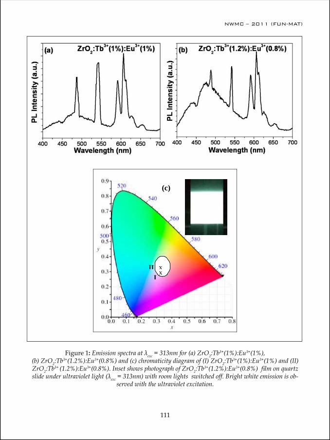
NWMC – 2011 (FUN-MAT)
110
NWMC – 2011 (FUN-MAT)
111
Figure 1: Emission spectra at λexc = 313nm for (a) ZrO2:Tb3+(1%):Eu3+(1%), (b) ZrO2:Tb3+(1.2%):Eu3+(0.8%) and (c) chromaticity diagram of (I) ZrO2:Tb3+(1%):Eu3+(1%) and (II) ZrO2:Tb3+ (1.2%):Eu3+(0.8%). Inset shows photograph of ZrO2:Tb3+(1.2%):Eu3+(0.8%) film on quartz slide under ultraviolet light (λexc = 313nm) with room lights switched off. Bright white emission is ob-
served with the ultraviolet excitation.
xx
III
Figure 1: Emission spectra at λexc = 313nm for (a) ZrO2:Tb3+(1%):Eu3+(1%), (b)ZrO2:Tb3+(1.2%):Eu3+(0.8%) and (c) chromaticity diagram of (I) ZrO2:Tb3+(1%):Eu3+(1%) and (II)ZrO2:Tb3+ (1.2%):Eu3+(0.8%). Inset shows photograph of ZrO2:Tb3+(1.2%):Eu3+(0.8%) film on quartz slide under ultraviolet light (λexc = 313nm) with room lights switched off. Bright white emission is observed with the ultraviolet excitation.
References
1. Nakamura, S., G. Fasol, The Blue Laser Diode : GaN Based Light Emitters and Lasers,Springer, Berlin (1997); S. P. DenBaars, in Solid State Luminescence Theory, Materialsand Devices, edited by A. H. Kitai, Chapman, and Hall, London (1993).2. P.Schlotter, R. Schmidt, J. Schneider, “Luminescence Conversion of Blue LightEmitting Diodes,” Appl. Phys. A64, 417 (1997).3. Mueller-Mach, R., G. O. Mueller, M. R. Krames, T. Trottier, IEEE J. Sel. Top.Quantum Electron 8, 339 (2002).4. G. O. Mueller, Proc. SPIE 3938, 30 (2000).5. D. P. Dutta and A. K. Tyagi, “Inorganic phoshor materials for Solid State white light generation” in book titled “Synthesis, characterization and properties of nanostructures,”Solid State Phenomena, Vol.155, p113-144, Trans Tech Publishers, (2009).6. V. Bedekar, D. P. Dutta, M. Mohapatra, S. V. Godbole, R. Ghildiyal and A. K. Tyagi, Nanotechnology 20 (2009) 125707 (9pp).7. D. P. Dutta, S. Warrier, R. Ghildayal, G. Sharma and A. K. Tyagi, J. NanoscienceNanotech. 9 (2009) 4715-4720.8. D. P. Dutta, R. Ghildiyal and A. K. Tyagi , J. Phys. Chem. C 113 (2009) 16954–16961.9. V. Bedekar, D. P. Dutta and A. K. Tyagi, J. Nanoscience Nanotech. 10 (2010) 8234-8238.10. D. P. Dutta, N. Manoj and A. K. Tyagi, J. Lumines. 131 (2011) 1807–1812.
(c)
NWMC – 2011 (FUN-MAT)
112
NWMC – 2011 (FUN-MAT)
113
developed specifically for SSL (as opposed to fluorescent lighting or display) applications. Most of these are based on either Eu2+ or Ce3+ activator ions as they are the only common rare earth ions for which the excitation and emission bands in the visible region involve 4f↔5d transitions that are parity-allowed and, therefore, intense. Also, the involvement of the 5d energy levels facilitates tuning of the excitation and emission wavelengths by modification of the crystal field environment. Lastly, the 4f↔5d transitions are characterized by broad lines (FWHM between 50 and 100 nm) that are well-matched to LED emissions and give access to higher CRI values by mimicking the broad emission of incandescent bulbs and/or the solar spectrum.
Many of the needs for new LED phosphors have been met by the discovery and development of new phosphors over the past 10 years [6-10]. During this time, the field of LED phosphors has moved from a single family of phosphor compositions—the Ce3+-doped aluminate garnets—to a variety of silicate, aluminate, nitride, oxynitride, sulfide, and fluoride compositions, leading to commercial LEDs that cover a full range of white CCTs. Conventional phosphors obtained by solid state sintering method has lower concentration quenching threshold due to non-uniform doping. Nanophosphors in size from tens to hundreds of nanometers that are smaller than the light wavelength can reduce scattering. Soft chemical routes to synthesize these nanophosphors can improve uniformity of doping and lift the concentration quenching threshold. Some soft chemical techniques are also capable for massive production at low cost. We have developed phosphors like Gd2O3:RE (RE = Eu, Dy, Tb), ZnAl2O4:M and ZnGa2O4:M (where M = Dy3+, Tb3+, Eu3+ and Mn2+), CeO2:RE (where RE = Dy3+, Tb3+and Eu3+), ZrO2:RE (where RE = Tb3+and Eu3+), etc. which can emit which light on UV excitation. The nanophosphors have been synthesized using soft chemical techniques like sonochemical method or polyol route. The PL spectra and corresponding CIE diagram for ZrO2:Tb3+(1%):Eu3+(1%) and ZrO2:Tb3+(1.2%):Eu3+(0.8%) is shown in Figure 1(a-c). These phosphors showed white luminescence in powder form and also when dip coated on quartz substrate. This talk will briefly discuss these various LED phosphors with some of their advantages and drawbacks.
References1. Nakamura, S., G. Fasol, The Blue Laser Diode : GaN Based Light Emitters and Lasers, Springer,
Berlin (1997); S. P. DenBaars, in Solid State Luminescence Theory, Materials and Devices, edited by A. H. Kitai, Chapman, and Hall, London (1993).
2. P.Schlotter, R. Schmidt, J. Schneider, “Luminescence Conversion of Blue Light Emitting Diodes,” Appl. Phys. A64, 417 (1997).
3. Mueller-Mach, R., G. O. Mueller, M. R. Krames, T. Trottier, IEEE J. Sel. Top. Quantum Electron 8, 339 (2002).
4. G. O. Mueller, Proc. SPIE 3938, 30 (2000).5. D. P. Dutta and A. K. Tyagi, “Inorganic phoshor materials for Solid State white light generation”
in book titled “Synthesis, characterization and properties of nanostructures,” Solid State Phenomena, Vol.155, p113-144, Trans Tech Publishers, (2009).
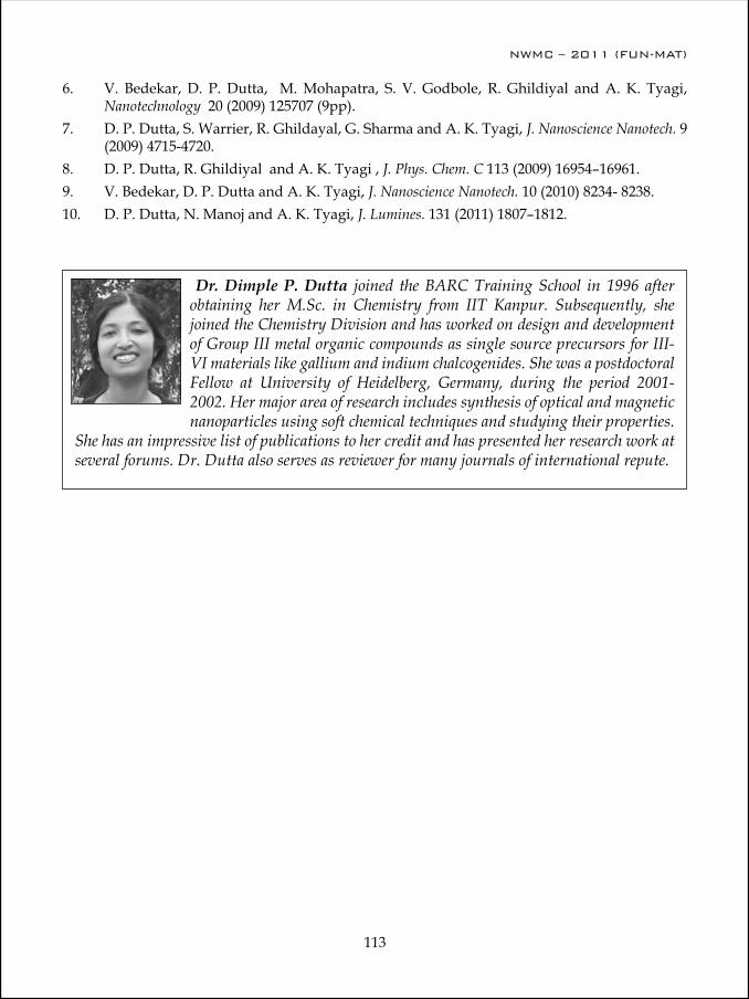
NWMC – 2011 (FUN-MAT)
112
NWMC – 2011 (FUN-MAT)
113
6. V. Bedekar, D. P. Dutta, M. Mohapatra, S. V. Godbole, R. Ghildiyal and A. K. Tyagi, Nanotechnology 20 (2009) 125707 (9pp).
7. D. P. Dutta, S. Warrier, R. Ghildayal, G. Sharma and A. K. Tyagi, J. Nanoscience Nanotech. 9 (2009) 4715-4720.
8. D. P. Dutta, R. Ghildiyal and A. K. Tyagi , J. Phys. Chem. C 113 (2009) 16954–16961. 9. V. Bedekar, D. P. Dutta and A. K. Tyagi, J. Nanoscience Nanotech. 10 (2010) 8234- 8238.10. D. P. Dutta, N. Manoj and A. K. Tyagi, J. Lumines. 131 (2011) 1807–1812.
Dr. Dimple P. Dutta joined the BARC Training School in 1996 after obtaining her M.Sc. in Chemistry from IIT Kanpur. Subsequently, she joined the Chemistry Division and has worked on design and development of Group III metal organic compounds as single source precursors for III-VI materials like gallium and indium chalcogenides. She was a postdoctoral Fellow at University of Heidelberg, Germany, during the period 2001-2002. Her major area of research includes synthesis of optical and magnetic nanoparticles using soft chemical techniques and studying their properties.
She has an impressive list of publications to her credit and has presented her research work at several forums. Dr. Dutta also serves as reviewer for many journals of international repute.
NWMC – 2011 (FUN-MAT)
114
NWMC – 2011 (FUN-MAT)
115
Crystal structure and thermal expansion of materials
S. N. Achary
Chemistry Division, Bhabha Atomic Research Centre, Mumbai – 400 085 Email: [email protected]
AbstractThe close correlation of thermal expansion and crystal chemistry of materials have been determined for a number of technological important materials. The role of the structural features, like bonding and their spatial arrangements, packing or ions and polyhedral volume are briefed on selected case studies. In particular the materials with anomalous thermal expansion behavior are emphasized in this communication.
The information on thermal expansion and stability are important properties considered for any material to be used in non ambient temperature. Often the thermal expansion of the material placed in thermal gradient caused undue stress on the other materials and that may result in the failure of assembly. Materials with tuned thermal expansion coefficients are desired for nullifying such detrimental effects. In addition, such materials have wide applications in electronic devices either in the form of substrate or packaging materials, precisely aligned optical instruments, bioceramic materials, like artificial bones, dental implants etc. to common household items. Also such materials have a wide application potential in nuclear industry, viz. nuclear waste immobilization, heat exchangers joints. Tuned thermal expansion material with high radiation resistant are desired for such nuclear technology applications. After the discovery and understanding of negative thermal expansion behavior of ZrW2O8 [1], a large number of exploratory studies in phosphates, tungstates, molybdates, vanadates etc. led to the discovery of newer materials with low or negative thermal expansion coefficients as well as understanding the mechanism of expansion behavior. The search for newer low and negative thermal expansion materials for application in wider temperature and stressed conditions as well as to tune the expansion coefficients is an open research area.
In view of this we have investigated a large number of materials with wider range of composition and structure to understand the structure and thermal expansion relations [2,3]. The results of some of these studies are presented here.
M2(XO4)3 type molybdates and tungstatesA2(MO4)3 (A = trivalent cation and M = Mo6+ or W6+) type compositions exists in variety of lattice types, namely tetragonal, orthorhombic, monoclinic etc depending on nature

NWMC – 2011 (FUN-MAT)
114
NWMC – 2011 (FUN-MAT)
115
Fig. 2. The % linear thermal expansion of Nd2-xYx(WO4)3 compositions with temperature.
Fig. 1. Variation of V/Z of monoclinic and orthor-hombic Cr2(MoO4)3 with temperature.
and ionic radii of trivalent counter cations. Detailed thermal expansion behavior of A2(MoO4)3, for A = heavier rare-earth ions and other trivalent ions like, Cr3+, Fe3+ and Al3+ has been studied in detail. At ambient temperature A2(MoO4)3 for A = Al3+, Cr3+ and Fe3+ materials have monoclinic structure and transforms to orthorhombic phase at higher temperature. These materials show a significantly higher thermal expansion coefficient in monoclinic phase while appreciably lower expansion in orthorhombic phase. As a typical case, thermal expansion behavior of Cr2(MoO4)3 is shown in Fig 1. The volume of lattice increases significantly at the transition temperature which results in a loosely packed lower density structure at higher temperature. The drastic expansion of unit cell volume at the transition temperature lower the expansion coefficient for the high temperature phase.
Similar to A2(XO4)3 type molybdates, the analogous tungstates have also been investigated by us. The closely related composition with rare-earth ions show two types of structures, viz. for rare-earth ions of larger ionic radii (La3+-Eu3+) show monoclinic (C2/c) structure while ions of smaller ionic radii (Gd3+-Lu3+, Y3+ and Sc3+) show orthorhombic (Pnca) structure. These two types of structure show opposite thermal expansion behaviors and thus tunable thermal expansion ceramic materials can be easily achieved with them. Dilatometric study on sintered bulk ceramic sample of Nd2(WO4)3 shows a

NWMC – 2011 (FUN-MAT)
116
NWMC – 2011 (FUN-MAT)
117
positive thermal expansion coefficient (αl = 7.9 × 10⁻⁶ /K) while that of Y2(WO4)3 show an appreciable negative thermal expansion coefficients (αl = -5.8 × 10⁻⁶ /K). A tunable thermal expansion behaviors could be obtained with Nd2(WO4)3 and Y2(WO4)3 (Fig. 2)
Cristobalite type AlPO4 and GaPO4
A series of compositions Al1-xGaxPO4 has been studied by HTXRD in the temperature range of 25-1000°C. At ambient temperature, both AlPO4 and GaPO4 have orthorhombic lattices. All the Al1-xGaxPO4 compositions undergo reversible and non quenchable displacive structural transition to cubic structure at elevated temperature. The phase transition is accompanied by a significant increase in unit volume leads to the formation of a less dense structure at higher temperature. The variation of unit cell volume with temperature for each composition shows that the orthorhombic phase has a significantly larger thermal expansion than the cubic (high temperature) phase. Typical coefficient of volume thermal expansion for both low and high temperature phases are given in Table 1.
α-AMo2O8 (A = Zr and Hf)The structure of Trigonal (α) HfMo2O8 and ZrMo2O8 consists of three dimensional framework of corner sharing AO6 and MO4 polyhedra, where each of the tetrahedral molybdate group shares three of the corner oxygen atoms with the three different AO6 octahedra. The fourth oxygen atom in the MO4 tetrahedra is non-bridged and points to the interlayer region. Thus, the trigonal MX2O8 produces a layered structure along c-axis and enables large amplitude rocking motion of MO4 tetrahedra and anisotropic vibration at the non-bridged oxygen atoms. The variations of the unit cell parameters of trigonal Hf/ZrMo2O8 show negative expansion along a- and b-axes but with a large positive expansion along c-axis. The typical coefficients of thermal expansion in different regions are given in Table 2. The large positive thermal expansion coefficients of the c-axis can be attributed to the weak van der Wall attraction between layers stacked along this axis. It can be mentioned here that the apex of the MoO4 units points the space between the layers and thus there is a strong O-O repulsion, leading to a weak interaction between the layers. The negative expansion along other direction can be attributed to the transverse vibration of the bridging oxygen MoO4-HfO6 frame of the layers.
Perovskites (AXO3) Anomalous or negative thermal expansion behavior has also been reported in some perovskite type materials. In such materials the thermal expansion behaviors are related with the XO6 octahedral tilts and distortions. Some of the perovskite A2MgWO6 (A = Ba2+, Sr2+ and Ca2+) type compounds have been studied and the results are explained here. At ambient temperature, Ba2MgWO6, Sr2MgWO6 and Ca2MgWO6 have cubic (Fm3m), tetragonal (I4/m) and monoclinic (P21/n) lattices, respectively. The details of the unit cell parameters of the three compounds at ambient and higher temperatures are obtained from the diffraction data and the coeffiencts of thermal expansion of these three phases
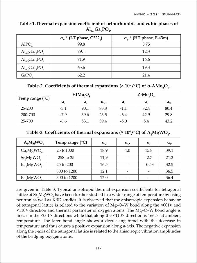
NWMC – 2011 (FUN-MAT)
116
NWMC – 2011 (FUN-MAT)
117
Table-1.Thermal expansion coefficient of orthorhombic and cubic phases of Al1-xGaxPO4.
αV * (LT phase, C2221) αV * (HT phase, F-43m)AlPO4 99.8 5.75
Al0.8Ga0.2PO4 79.1 12.3
Al0.5Ga0.5PO4 71.9 16.6
Al0.2Ga0.8PO4 65.6 19.3
GaPO4 62.2 21.4
Table-2. Coefficients of thermal expansions (× 106 /ºC) of α-AMo2O8.
Temp range (°C)HfMo2O8 ZrMo2O8
αa αc αV αa αc αV
25-200 -3.1 90.1 83.8 -1.1 82.4 80.4200-700 -7.9 39.6 23.5 -6.4 42.9 29.825-700 -6.6 53.1 39.4 -5.0 5.4 43.2
Table-3. Coefficients of thermal expansions (× 106 /ºC) of A2MgWO6.
A2MgWO6 Temp range (°C) αa αb, αc αV
Ca2MgWO6 25 to1000 18.9 4.0 15.8 39.1
Sr2MgWO6 -258 to 25 11,9 - -2.7 21.2Ba2MgWO6 25 to 200 16.5 - - 0.53 32.5
300 to 1200 12.1 - - 36.5Ba2MgWO6 300 to 1200 12.0 - - 36.4
are given in Table 3. Typical anisotropic thermal expansion coefficients for tetragonal lattice of Sr2MgWO6 have been further studied in a wider range of temperature by using neutron as well as XRD studies. It is observed that the anisotropic expansion behavior of tetragonal lattice is related to the variation of Mg–O–W bond along the <001> and <110> direction and thermal parameter of oxygen atoms. The Mg–O–W bond angle is linear in the <001> directions while that along the <110> direction is 166.5° at ambient temperature. The later bond angle shows a decreasing trend with the decrease in temperature and thus causes a positive expansion along a-axis. The negative expansion along the c-axis of the tetragonal lattice is related to the anisotropic vibration amplitudes of the bridging oxygen atoms.
NWMC – 2011 (FUN-MAT)
118
Acknowledgements Author thanks Dr. A. K. Tyagi, Dr. D. Das (Chemistry Division, BARC) for the support to this study. Also, author thanks all the collaborators in these studies.
References
1. T. A. Mary, J. S. O. Evans, A. W. Sleight and T. Vogt, Science, 272, (1996) 902. A. K. Tyagi and S. N. Achary, J. Chinese Ceram. Soc. 37 (2009) 703.3. A. K. Tyagi and S. N. Achary, “Diffraction and thermal expansion of solids” Ch. 6, in
“Thermodynamic properties of Solids: Experiments and Modeling” Wiley Interscience Ltd. Germany. Edited by S. L. Chaplot, R. Mittal and N. Choudury.
Dr. S. N. Achary, Scientfic officer (F) has joined Chemistry Division, BARC in 1995 after completing the 38th Batch Orientation course on Nuclear Science and Engineering of BARC Training School. Since, then he has been worked in several frontier research areas in solid state and materials science, namely, synthesis, crystal chemistry under non ambient conditions, thermal expansion, compressibility, spintronics and multi-ferroic materials. He has been extensively investigated in crystallographic and phase transition of materials under non ambient conditions, like high/low temperature and high
pressure. A number of novel materials and their crystal structure have been investigated by him. He has over 100 papers published in various international reputed journals and similar numbers published in various national or international symposium or conference proceedings. Presently he is involved in studying the structural aspects of ionic conductor, ferroelectric and multiferroic materials.

NWMC – 2011 (FUN-MAT)
119
Activities of Chemistry Division &
Society for Materials Chemistry

NWMC – 2011 (FUN-MAT)
120

NWMC – 2011 (FUN-MAT)
121
R&D Highlights of Chemistry Division, BARC
D. Das
Chemistry Division, Bhabha Atomic Research Centre, Mumbai 400 085, India [email protected]
Chemistry Division with its basic and applied research activities in materials chemistry carries out important mandates of Chemistry Group, Bhabha Atomic Research Centre. Under the XI five year plan, the Division has been contributing to nuclear reactor materials, materials for hydrogen generation and storage, multiferroic and spintronics materials, nanomaterials for societal applications, catalysts, synthetic inorganic chemistry, ultrapure materials, soft condensed matter, thin films and sensors, atomic/molecular clusters etc. While most of the programs are being executed within this Division, there are some ongoing collaborative projects with different research groups in BARC and other DAE units, Universities/ National Institutes under BRNS schemes and with other countries (USA, Germany, Sweden, Japan and Russia etc.).
Chemistry Division with its present scientific and technical strength of 75 and with additional manpower of research associates and doctoral students have been contributing significantly to the above mentioned programs.
Nuclear materialsPreparation, characterization and handling facility of alloy fuel materials
Commissioning of the inert atmosphere glove box to be used for handling atmosphere sensitive U and Th based metallic alloys was completed. Appropriate vacuum tight couplings for (a) primary vacuum in the sample insert tunnel, (b) gas feed lines and (c) electrical feed-through were fabricated and fixed. A small weighing balance and a hand press for pelletizing the powders were installed inside the glove box. Entire gas flow line including appropriate valves, flow meter, moisture traps, and metallic uranium based oxygen getter trap were installed and tested. Preliminary analysis of oxygen content of high-purity argon gas in gas cylinder and also at the outlet of glove box was carried out.
Few modifications were made in the existing arc melting set up to adapt Th and U based metals. Initial experiments were carried out with pure uranium metal and U-10wt.% Zr alloys before taking up thorium. Uranium metal pieces were cut, chemically cleaned and further handled inside the glove box for polishing and weighing. The arc melted alloys were characterized by powder XRD and SEM & EDAX analysis. These amorphous alloys were vacuum annealed and found to return (slowly) to crystalline phase as revealed by XRD analysis.
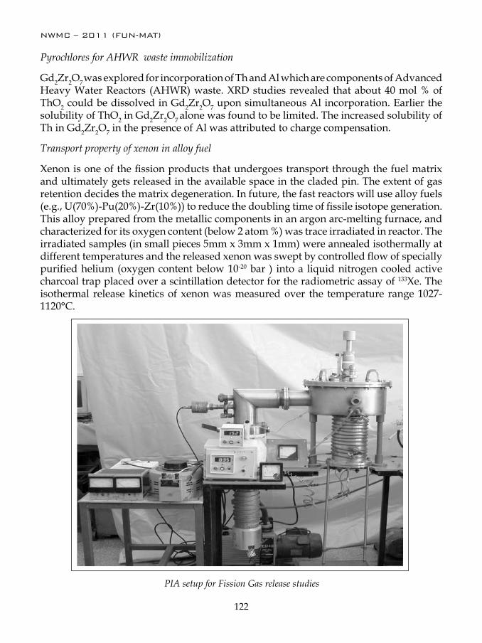
NWMC – 2011 (FUN-MAT)
122
Pyrochlores for AHWR waste immobilization
Gd2Zr2O7 was explored for incorporation of Th and Al which are components of Advanced Heavy Water Reactors (AHWR) waste. XRD studies revealed that about 40 mol % of ThO2 could be dissolved in Gd2Zr2O7 upon simultaneous Al incorporation. Earlier the solubility of ThO2 in Gd2Zr2O7 alone was found to be limited. The increased solubility of Th in Gd2Zr2O7 in the presence of Al was attributed to charge compensation.
Transport property of xenon in alloy fuel
Xenon is one of the fission products that undergoes transport through the fuel matrix and ultimately gets released in the available space in the claded pin. The extent of gas retention decides the matrix degeneration. In future, the fast reactors will use alloy fuels (e.g., U(70%)-Pu(20%)-Zr(10%)) to reduce the doubling time of fissile isotope generation. This alloy prepared from the metallic components in an argon arc-melting furnace, and characterized for its oxygen content (below 2 atom %) was trace irradiated in reactor. The irradiated samples (in small pieces 5mm x 3mm x 1mm) were annealed isothermally at different temperatures and the released xenon was swept by controlled flow of specially purified helium (oxygen content below 10-20 bar ) into a liquid nitrogen cooled active charcoal trap placed over a scintillation detector for the radiometric assay of 133Xe. The isothermal release kinetics of xenon was measured over the temperature range 1027-1120°C.
PIA setup for Fission Gas release studies

NWMC – 2011 (FUN-MAT)
123
Hydrogen generation, mitigation and catalysis
Hydrogen generation via sulfur-iodine thermochemical cyclea. Studies on Sulfuric acid decomposition over chromium substituted iron oxide catalyst
Studies on catalytic decomposition of sulfuric acid were carried out. Long-term activity evaluation of chromium substituted iron oxide catalyst (4-6 mm near spherical granules) for H2SO4 decomposition reaction showed no deterioration in the catalyst performance during 100 h run at 800°C with a WHSV (weight hourly space velocity) of ~ 3.3 g acid/g catalyst/hr. The SO2 yield (~78%) was found to be close to thermodynamic limit and it is higher than that of the unsubstituted sample (~ 70%).
b. Development of catalysts for sulfuric acid decomposition
Spinel ferrites (AB2O4; A = Cu, Co, Ni, B= Fe) were synthesized by gel combustion route as catalyst for sulfuric acid decomposition and were evaluated in the temperature range from 600-825°C using a H2SO4 + N2 mixture (1: 2). All ferrite samples were found to be active for the decomposition reaction with copper ferrite being the most active (SO2 yield ~78 % at 800°C). Spent catalyst characterization by XRD, FTIR and SEM showed the presence of sulfate species and the evolution of SO2 occurred at lowest temperature on used copper ferrite sample as revealed by the evolved gas analysis. Based on these results a plausible mechanism for decomposition of sulfuric acid over these ferrites was proposed.
Indegeneously developed H2SO4 decomposition setup
NWMC – 2011 (FUN-MAT)
124
c. Speciation studies on Bunsen reaction of S-I process
Speciation studies on Bunsen reaction of S-I processes by various analytical techniques including polarography, conductivity, cyclic-voltammetry, Raman spectroscopy, UV-Visible spectroscopy revealed the existence of poly-iodide species, like I3
- and I5- in both
KI + I2 and HI + I2 solutions with different ratio KI/HI : I2 (1:1 to 1:10) in concentrations range from 2x10⁻⁴ M to 1M. Addition of sulfuric acid (up to a concentration of ~ 1M) did not influence the nature of poly-iodide species much.
H2 generation via photo catalytic splitting of water
Various catalysts were investigated for photo catalytic splitting of water. Synthesis of photocatalysts involved methods like gel combustion, solvothermal method using CTAB as well as Pluronic 123 as templates, etc. Nickel, platinum and palladium were used as co-catalysts while methanol was employed as a sacrificial agent in these studies. Hydrogen yields in case of Nd2Ti2O7 were ~495 µmoles/g during 4 h run when irradiated with a 400 W medium pressure mercury arc lamp. Pt co-catalyst deposition on Nd2Ti2O7 enhanced the H2 yield by two fold (~1189 micromoles/g for 4h).
Titania based photocatalysisWork continued on photocatalytic oxidation of ethylene over V-doped titania catalyst dispersed in mesoporous matrix like MCM-41. In situ FTIR studies were undertaken to investigate the mechanism involved in the gas phase photo-oxidation of ethylene in air over Ti0.95V0.05O2 /MCM-41 which was found to be more active than the bulk Ti0.95V0.05O2. As compared to the case of Ti0.95V0.05O2, the photo oxidation of ethylene over the dispersed sample occurs differently under UV and visible irradiations. Thus under UV irradiation the adsorbed acetaldehyde so formed undergoes aldol condensation over the Lewis acid sites leading to the formation of crotonaldehyde which is subsequently oxidized to acetate and consequently to CO2. In case of visible irradiation labile ethyl acetate is produced either by the Tischenko reaction or by the reaction between the labile acetic acid and the unreacted ethoxy groups. The ethyl acetate produces acetic acid monomer which is oxidized to CO2.
Nanorods and nanotubes of titania (diameter, 4-20 nm) were prepared by a novel and simple hydrothermal route using a commercially available anatase and rutile titania powder and 10 M NaOH. The temperature of hydrothermal synthesis had strong influence for the formation of the resulting nanotitania. Thus, material synthesized at lower temperature of 100°C was in tubular form while that at 200°C was in rod form. All of them were found to be photocatalytically active, resulting in the complete oxidation of ethylene to CO2 and H2O. The anatase phase synthesized at 100°C was found to be most active among all the samples.

NWMC – 2011 (FUN-MAT)
125
Hydrogen storage materials
Experimental results on intermetallic compounds and other materialsa. Hydrogenation studies on substituted Ti-Cr-V system
Ti0.32Cr0.43-xSnxV0.25 (x = 0 and 0.02) were prepared by arc melting and characterized by XRD. Their hydrogen storage behavior studied in the pressure range of 0.02 to 20 atm. The hydrogen storage capacity was found to be in the range of 3 to 3.3 H/formula unit for 5, 10 and 20 wt.% TiMn2 doped samples. Thermal desorption studies showed a two stage desorption mechanism in the temperature range from 673 to 973 K for both 10 and 20 wt.% TiMn2 doped composite hydride.
b. Hydrogen absorption studies on TiCr2V system
Pure TiCr2V alloy as well as Zr doped TiCr1.95VZr0.05 were taken up for their hydrogen storage studies. The arc melted alloys and their hydrides were phase characterized by XRD. The PCT isotherms were studied both at room temperature and 323 K. The alloy TiCr2V absorbs maximum 4.37H/ formula unit at room temperature. Whereas pure alloy showed hydrogen absorption without any incubation time, the Zr doped alloy exhibited poor absorption behavior. The alloys were found to have a maximum storage capacity of 4.3 and 3.7 H/formula units for pure alloy and 5 at.% Zr doped alloy, respectively at room temperature. The fast kinetics of hydrogen absorption in TiCr2V alloy was evident from attaining the saturation value within 290 seconds.
Fuel cell materialsRare earth doped barium cerates and zirconates (BaM0.8Y0.2O3-δ; M = Ce, Zr and Ba(Ce0.4Zr0.4)Y0.2O3-δ) were synthesized by solid state reaction, gel combustion and citrate routes for solid oxide fuel cell applications. The citrate route yielded homogeneous nano-sized (~15 nm) materials at relatively lower temperature (~1000°C) as compared to the other two routes. Ionic conductivity of these samples was measured by Impedance Spectroscopy while their chemical stability was evaluated under different atmospheres using XRD and thermogravimetry. Thermal expansion behavior of this material was found to be compatible with that of reported solid oxide fuel cell components. AC impedance technique was employed to ascertain its ionic conductivity and also the activation energy for conduction across grain and grain boundary. As an anode material, nanocomposites of NiO and BaZr0.8Y0.2O3 (BZY) were prepared by calcination of NiO and BZY at 900°C for 120 h. Temperature programmed reduction (TPR) studies indicated three different types of interaction of NiO with BZY in the nanocomposite. A homemade SOFC test cell with Ar/Pt/YSZ/Pt/O2 (0.2 atm) configuration and inter component sealing with cement material for gas tightness was operated at 800°C for 2 h. A 35 mm diameter and 200 micron thick YSZ wafer with 30 mm dia. anode and cathode coating was used for this purpose. The steady open circuit potential was found to be ~840 mV which is in agreement with the expected value of 834 mV.
NWMC – 2011 (FUN-MAT)
126
Organometallics and high purity materials
Chemistry of platinum group metalsA number of mono and binuclear complexes of platinum have been synthesized and characterized for their molecular structures. Reactions of metalated tri-tert-butylphosphine and 1, 5-cyclooctadiene platinum complexes with several anioinic ligands have been investigated. Both mono and binuclear complexes of platinum are obtained. Thermo-gravimetric analyses of the complexes shows that they undergo either one or two step decompositions depending on the nature of ligand used, leaving behind platinum powder. Thermolysis of complexes in diphenylether and hexadecylamine (HAD) as capping agents yields platinum nanoparticles.
Binuclear aryl palladium complexes were synthesized by reacting equimolar amount of Ar3Bi with palladium complexes. Potential intermediates of the C-C cross coupling reactions have been identified from molecular structural studies on the products.
A number of organometallic complexes comprising of both platinum and tellurium metals were synthesized by reaction of dipyridyltellurides with platinum complexes. Their molecular structures were established by single crystal X-ray diffraction studies. The calculated NICS indices and ELF functions clearly show that the compounds are aromatic in the region defined. Some selenium and sulfur containing carborane ligands were also synthesized.
Chemistry of main group elementsThe chemistry of 2-seleno and 2-telluropyridines with groups I, II, III and V metal compounds has been explored with reference to develop single source molecular precursors for semiconductor nano-materials. Thin films of copper selenide and telluride nano-crystals have been prepared by the decomposition of [Cu(SepyMe)] and [Cu(Tepy)]n in HDA/TOPO mixture at different temperatures. Copper telluride nanorods have been prepared using the precursor, [Cu(Te-pyMe)]4 in hot HDA/TOPO mixture. Themolysis of these complexes gave metal selenides. Indium, antimony and bismuth complexes have been used for the preparation of nanostructures of metal selenides (M2Se3) including nano-rods (when M = Sb). Theses precursors have also been used for deposition of thin films of M2Se3 on glass substrate.
Chemistry of organoselenium compoundsDimethyl pyrazole (dmpz) based organoselenium compounds have been prepared and characterized by NMR and structures of dmpzCH2CH2Se(CH2)nCOOH (n = 1 or 2) have been established by X-ray diffraction analysis. Glutathione peroxidise like catalytic activities of these compounds were evaluated in a model system. Antioxidant capacity (ABTS.+ radical cation decolorization assays) of the complexes has been evaluated by spectrophotometric analyses. The antioxidant capacities of DMPz based organoselenium compounds were compared with the standard thiol antioxidants like glutathione (GSH),

NWMC – 2011 (FUN-MAT)
127
N-acetyl cysteine (NAC) and dithiothreitol (DTTred). It was observed that the antioxidant capacities of the synthesized organoselenium compounds were poorer than that of the standard thiol antioxidants. NADPH-GSSG reductase coupled assays were carried out to study the initial rates of the reactions catalyzed by the selenoethers of type Se(CH2CH2X) (X = COOH, OH and NH2).
Ultrapurification of elementsPurification method of CsI was developed and it involved recrystallization of commercial CsI followed by zone refining of the recrystallized product. Purified CsI (2Kg, 5N purity) has been supplied to end-users in BARC. Zone refining unit was refurbished for purification of germanium and other elements. Germanium (1 Kg, 5N purity) and gallium (6N) have been supplied to end users in BARC.
Indigenously developed zone refining unit
Functional materials
Development of detector grade diamond thin filmsR&D efforts towards the development of diamond thin film based radiation detectors with particular emphasis on alpha particle detectors in highly corrosive and radioactive environments is an important activity this division. Extensive work had been carried out last year towards the optimization of growth parameters to deposit detector grade diamond films using the MPCVD system and well oriented films with DC resistivity > 1012 ohm-cm were successfully prepared and their alpha particle sensing was tested in air using electroplated 241Am source.

NWMC – 2011 (FUN-MAT)
128
Multiferroic materialsMultiferroic materials are important class of materials which are characterized by presence of two or more mutually exclusive properties like ferromagnetism, ferroelectricity and ferroelasticity in the same sample. In continuation of the research program on BiFeO3 based multiferroics, magnetic and ferroelectric properties of BiFeO3-BaTiO3 system were investigated. The composition 0.5BIFeO3-0.5BaTiO3 shows coercivity 475 Oe and remanence 0.009 emu/g which are significantly higher then all other compositions in this system. However, 0.9BiFeO3-0.1BaTiO3 shows higher remanent polarizations (0.21µC/cm2) than all other compositions. Also, a double perovskite type material, La2NiMnO6 (LNMO) was synthesized. A cation ordered monoclinic lattice was confirmed by neutron diffraction studies. The sample prepared in air shows a relaxor type behavior with a dielectric anomaly near the ferromagnetic transition while samples annealed in oxygen or inert atmosphere show normal dielectric behavior. A new elpasolite type orthorhombic (NH4,K)3VO2F4 compound was synthesized and thoroughly characterized. The orthorhombic phase shows a clear ferroelectric hysteresis loop and significant conductivity due to involvement of protonic species.
MPCVD system
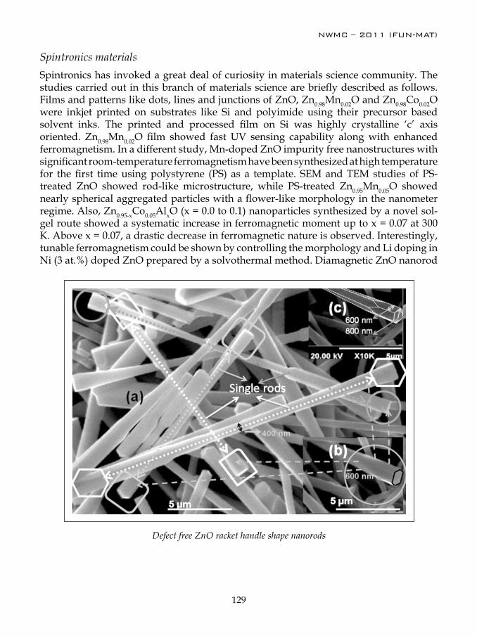
NWMC – 2011 (FUN-MAT)
129
Spintronics materialsSpintronics has invoked a great deal of curiosity in materials science community. The studies carried out in this branch of materials science are briefly described as follows. Films and patterns like dots, lines and junctions of ZnO, Zn0.98Mn0.02O and Zn0.98Co0.02O were inkjet printed on substrates like Si and polyimide using their precursor based solvent inks. The printed and processed film on Si was highly crystalline ‘c’ axis oriented. Zn0.98Mn0.02O film showed fast UV sensing capability along with enhanced ferromagnetism. In a different study, Mn-doped ZnO impurity free nanostructures with significant room-temperature ferromagnetism have been synthesized at high temperature for the first time using polystyrene (PS) as a template. SEM and TEM studies of PS-treated ZnO showed rod-like microstructure, while PS-treated Zn0.95Mn0.05O showed nearly spherical aggregated particles with a flower-like morphology in the nanometer regime. Also, Zn0.95-xCo0.05AlxO (x = 0.0 to 0.1) nanoparticles synthesized by a novel sol-gel route showed a systematic increase in ferromagnetic moment up to x = 0.07 at 300 K. Above x = 0.07, a drastic decrease in ferromagnetic nature is observed. Interestingly, tunable ferromagnetism could be shown by controlling the morphology and Li doping in Ni (3 at.%) doped ZnO prepared by a solvothermal method. Diamagnetic ZnO nanorod
Defect free ZnO racket handle shape nanorods
NWMC – 2011 (FUN-MAT)
130
changed to ferromagnetic particles on doping with 3 at.% Ni in ZnO. Addition of Li (3 at%) showed improved ferromagnetism. In another study, nano-Zn1-xTMxO where x = 0 to 0.07 for TM = Co and x = 0.02, 0.03 for TM = Ni were synthesized by nonhydrolytic alcoholysis esterification elimination reaction at 220 oC. Magnetic studies indicated that Co-and Ni-doped zinc oxide nanocrystals are ferromagnetic at room temperature (RT).
Optical materials
Solid-state lighting (SSL) in the form of light emitting diodes (LEDs) is an upcoming research area. These environment friendly materials are a possible alternative to the existing lighting technologies, from the point of view of energy savings and reduced operating expenses. The availability of high quality phosphors is of prime importance for better performance of such LEDs.
Nanocrystalline water dispersible REF3 systems (RE: Y, Gd) doped with activator rare earths viz. Tb3+, Eu3+, Dy3+ and Sm3+ (singly-doped as well as co-doped) were synthesized using ethylene glycol as the solvent. In the GdF3 system, the steady state and time resolved luminescence studies confirmed efficient energy transfer from the host (GdF3) to dopant (activator) RE3+ ions. Optimum luminescence is observed for 5 mol% Eu3+ and 2.5 mol% Tb3+. GdF3 triply doped with 2 mol% each of Tb3+, Eu3+ and Dy3+ had impressive CIE co-ordinates and correlated color temperature (CCT) very close to broad day light. Our experiments showed labeling of Tb3+ doped GdF3 nanoparticles in human breast carcinoma cells (MCF-7). The fluorescence intensity was found to be dependent on the surface modifying/coating agent. Also, YF3 doped with 2.5 mol%Ce3+, 2.5 mol%RE3+
(RE3+: Tb3+, Eu3+, Dy3+ and Sm3+) were synthesized with the aim of obtaining nanocrystals that should be excited at a single wavelength. There is found to be an efficient energy transfer from Ce3+ to activators. The results thus provide a practical basis for the design of white light illumination sources or multicolor sources for various applications by blending this kind of phosphors with an appropriate excitation source.
In another study, nanocrystals of Tb3+ doped yttrium oxide have been prepared and the thermoluminescence (TL) properties have been investigated as a function of dopant concentration. It was concluded that the phosphor is usable for radiation dosimetry in the range 20 mGy to 1 KGy. The optical properties of rare earth ions (Dy3+, Tb3+) and also Mn2+ ions doped phosphor materials viz. Gd2O3, ZnAl2O4 and ZnGa2O4, which have been synthesized using polyol and sonochemical techniques. The highlight of the work is the synthesis of a novel composition of nano-crystalline Gd2O3 :RE (RE = Dy, Tb) phosphor which simultaneously emits blue and yellow light from its active region on exciting the host. The chromaticity coordinates for these samples were calculated and gave an emission very close to white light. Spin coated films these on quartz substrates gave bright white luminescence under UV excitation. In case of the spinel host materials, the CIE coordinates of ZnGa2O4:Dy3+(2%):Tb3+(0.5%):Mn2+(2.5%) and ZnAl2O4:Dy3+(1.5%):Tb3+(0.25%):Eu3+(0.25%) nanophosphors were found to lie in the white light region of the chromaticity diagram

NWMC – 2011 (FUN-MAT)
131
Lanthanide ions doped Sb2O3, CePO4, YPO4, SbPO4, Y2Sn2O7 , YVO4, GdVO4 and Gd2O3 etc., with different shapes like nano-rods, ribbons and spherical particles were synthesized at relatively low temperature and their luminescence properties were investigated by both steady state and time resolved luminescence techniques. Representative lanthanide ions like Eu3+ and Tb3+ were incorporated as dopant ions in these hosts to understand the structural environment around lanthanide ions by probing their luminescence properties. Methods to improve the luminescence properties like forming doped core covered with un-doped shell, dispersing the nanoparticles in inert matrices etc., were also investigated. Luminescence studies on phosphate and silicate glasses helped to understand the different types of luminescent centres and their dynamics (L-centres) in the glassy matrices incorporated with luminescent nanoparticles. In yet another study,
SnO2 nanoparticles were prepared by microemulsion route. It was found that these SnO2 nanoparticles show selective sensing of H2S gas down to 1 ppm level at room temperature.
Nano-material for societal applicationsNanomaterials offer many potential health and environmental benefits as a result of novel properties and behavior which these materials exhibit at the nanoscale. In this direction, certain studies were undertaken. A highly selective sensor based on organic-inorganic hybrid material was developed for Pb2+ sensing. Several nanocrystalline were prepared for selective removal of Pb2+ and F- ions from drinking water. (In collaboration with ACD, BARC)
Nanostructured oxides of Ti and Zr have been synthesized to evaluate their efficacy as sorbent matrices for the preparation of radionuclide generator. These oxides, were shown to have potential to improve the efficiency of the generator by providing better selectivity and enhanced capacity for 188W-188Re, 99Mo-99mTc and 68Ge-68Ga generators that arises from higher surface area, surface energy and surface charge. (In collaboration with RPhD, BARC).
Nanocrystalline Nickel sulphide was synthesized by different routes and coated on Polymethyl metha acrylate beads to form a composite material. It was subjected to its performance evaluation for uptake of 106Ru from low level radioactive liquid waste (LLW) stream. The effect of various parameters viz. pH, ionic strength, temperature, time etc towards uptake of 106Ru was investigated. (In collaboration with WMD, BARC).
An environmentally benign synthetic route to nanocrystalline silver sol under ambient conditions has been developed. It involves room temperature reduction of AgNO3 by cysteine in aqueous phase without any additional stabilizing agent. Formation of silver nanoparticles is confirmed from UV-Vis spectrum of the sol and XRD and EDAX studies on dried precipitate. Suitably prepared sol remains stable for even months together. These samples were evaluated for anti-bacterial efficacy (In collaboration with NABTD, BARC).
NWMC – 2011 (FUN-MAT)
132
Functional materials through interfacial routeUnder the Interfacial Chemistry research, investigation was made on the structure, dynamics and surface characteristics of a number of self assembled surfactants and block copolymers. Further, self assembly route has been employed for the development of thin films that are of relevance to applications in sensors for biomolecules or toxic gases. Stimuli sensitive assemblies for encapsulation of proteins or drug molecules were developed using this route. A pH sensitive micellar system has been developed using hydrophobic amino acid as a mimic. A four orders of magnitude increase in the zero shear viscosity of the fluid could be achieved by a slight change in the pH of the solution. This demonstrates the use of hydrophobic amino acids in creating pH-sensitive assemblies of amphiphiles.
Several functional nanostructures for encapsulation of drug molecules were prepared through self assembly route. Encapsulation of anticancer drug, doxorubicin, in PEG modified micelles were achieved through electrostatic binding of drug and surfactant. The microstructure and intermicellar interactions in reverse micelles comprising TODGA in dodecane was studied by scattering techniques. These studies suggest that though the interaction between the TODGA reverse micelles is indeed attractive in nature, it is well short of the critical value required to induce a gas-liquid type phase transition. Langmuir-Blodgett deposition technique was successfully employed for the formation of thin films comprising polymers, metal oxides etc. through self assembly. The self-assembled Langmuir–Blodgett films of polydiacetylene (PDA) or its derivatives are sensitive to external stimuli in the form of mechanical stress, temperature, pH or prolonged UV-irradiation and undergo a color change from blue to red. An optical glucose sensor has been developed using glucose oxidase immobilized PDA Langmuir-Blodgett (LB) film. The specificity of the glucose sensor was studied using sugar compounds structurally similar to glucose such as sucrose, galactose, mannose and sorbitol. These sugars showed very low colorimetric response as compared to glucose. Thus the sensor film is specific to glucose and can be used for colorimetric detection of glucose in the physiological concentration range. A polyaniline based electrochemical sensor for detection of the pesticide Lindane has been developed. Polyaniline thin films were deposited on gold interdigitated electrodes by electropolymerisation. The recombinant E. coli Lindane biodegrading strain, EcLb cells were entrapped in the polyaniline matrix and lindane was sensed at the modified electrode using pulsed amperometry. The sensor was found to be specific to lindane and did not respond to other aliphatic and aromatic chlorides. The shelf life of the biosensor was about 15 days when stored at 4°C in dry state.
Modified substrates for biosensors were also developed by suitable deposition techniques. Porous silicon/polyaniline (PS/PANI) heterostructure was prepared electrochemically which provides label free, real time electrical detection of model biomolecules (mouse IgG/goat antimouse IgG) with high sensitivity and specificity. The space charge layer in the PS/PANI channels get modified by the surface charge changes created by the analyte-antibody binding. It was found that a substrate bias in the accumulation region of
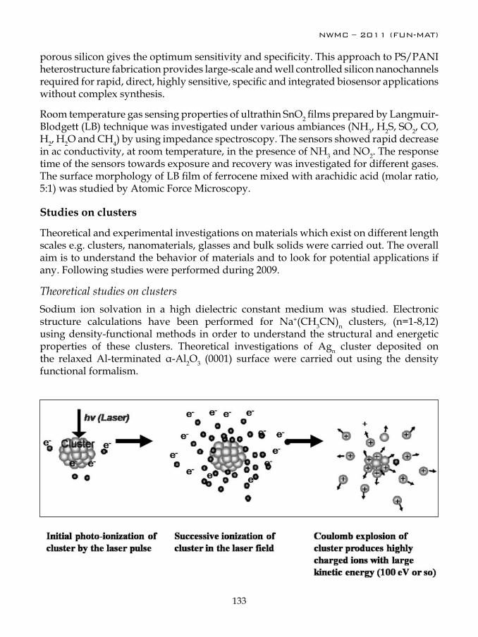
NWMC – 2011 (FUN-MAT)
133
porous silicon gives the optimum sensitivity and specificity. This approach to PS/PANI heterostructure fabrication provides large-scale and well controlled silicon nanochannels required for rapid, direct, highly sensitive, specific and integrated biosensor applications without complex synthesis.
Room temperature gas sensing properties of ultrathin SnO2 films prepared by Langmuir-Blodgett (LB) technique was investigated under various ambiances (NH3, H2S, SO2, CO, H2, H2O and CH4) by using impedance spectroscopy. The sensors showed rapid decrease in ac conductivity, at room temperature, in the presence of NH3 and NO2. The response time of the sensors towards exposure and recovery was investigated for different gases. The surface morphology of LB film of ferrocene mixed with arachidic acid (molar ratio, 5:1) was studied by Atomic Force Microscopy.
Studies on clusters
Theoretical and experimental investigations on materials which exist on different length scales e.g. clusters, nanomaterials, glasses and bulk solids were carried out. The overall aim is to understand the behavior of materials and to look for potential applications if any. Following studies were performed during 2009.
Theoretical studies on clustersSodium ion solvation in a high dielectric constant medium was studied. Electronic structure calculations have been performed for Na+(CH3CN)n clusters, (n=1-8,12) using density-functional methods in order to understand the structural and energetic properties of these clusters. Theoretical investigations of Agn cluster deposited on the relaxed Al-terminated α-Al2O3 (0001) surface were carried out using the density functional formalism.
NWMC – 2011 (FUN-MAT)
134
Experimental studies on clustersIn order to understand the mechanism, studies on Coulomb explosion of molecular clusters were performed. In this work, effect of wavelength, polarization and doping was studied in the case of methyl iodide cluster. Observation of higher charged states at 563 nm (upto I+5 ) as compared to 532 nm (up to I+3) for Coulomb exploded atomic ions supports the proposition of enhanced inverse Bremsstrahlung heating of the ionized cluster system at this wavelength. When water was doped in methyl iodide clusters and irradiated at 563 nm, highly charged atomic ions of oxygen along with carbon and iodine were observed.
In order to get a deeper understanding of the phenomena, absolute charge density of the interaction zone was measured in ethyl bromide system. Coulomb explosion, leading to generation of multiply charged atomic ions, occurs in most clustered region and a charge density of ~7 x10¹¹/cc was measured. In contrast, predominantly monomer region where no Coulomb explosion was observed, has a charge density of ~10 8 /cc. From this data, it has been validated that the charge density in most clustered region qualifies for weakly ionized plasma which in turn helps in extracting energy from optical field of laser light. On the other hand, lower charge density of least clustered region is incapable in extracting the energy from optical field under these laser intensities.
Dr. D. Das did his post graduation in chemistry from the University of Calcutta and joined BARC Training School in 1974. After completion of the one year course of Training School he began his research career in the field of high temperature thermochemistry studying the thermodynamic properties of uranium and its alloys and addressing to containment problems in uranium vapor processing. He obtained his Ph.D. from University of Mumbai in 1984. He was deputed to KFA Julich, Germany, for 15 months during 1993-94. With his
expertise in materials chemistry at high temperature, Dr. Das worked for sometime in the development of high power electron guns for evaporation purpose, and in the thermodynamic analysis of cell components in High Temperature Solid Oxide Fuel Cell. In the last few years, Dr. Das has focused his effort on thermochemical characterization of thoria based fuels for the Advanced Heavy Water Reactors. He has large number of research publications in refereed journals. Presently, he is serving as Head Chemistry Division, ARC and looks after a number of activities in the field of materials chemistry.

NWMC – 2011 (FUN-MAT)
135
About ‘Society for Materials Chemistry’
The importance of materials can be gauged by the fact that various ages of the mankind have been named based on the materials used by the humans. With ever increasing population and depleting natural resources, there is a growing need to develop advanced materials for alternative energy sources such as hydrogen generation and storage, for solar and fuel Cells, sensor materials, super capacitors, optical materials. Some other important materials are in the field of drug delivery systems, soft-matter, multi-ferroics, spintronics and high purity materials. The advent of nanomaterials has brought the new concepts of size and shape dependent functionalities of materials. Likewise, there is a need to develop new materials for Nuclear Fuel Cycle also, in particular from the point of view of new generation reactors such as Advanced Heavy Water Reactor, Compact High Temperature Reactor, Accelerator Driven sub-critical systems and Fast Reactors with shorter doubling time.
Materials Chemistry has been playing significant role in search of novel materials for advanced applications. Novel functional materials emerge as a result of concerted effort of chemists, physicist and materials scientists in general using the basic information in optimization of the structure through compositional as well as particle size variation for improved characteristics for a particular application. The latest trend in Chemistry is to use soft-chemical methods instead of conventional high temperature methods. The nature has been synthesizing a large number of compounds at ambient or very close to ambient conditions using self-assembly.
In view of this, it was felt since long that there is a need to found a society primarily dedicated to Materials Chemistry, but encompassing other disciplines also such as Condensed Matter Physics and Life Sciences. The idea of Society for Materials Chemistry was first germinated during National Workshop on Materials Characterization (NWMC) organized by Chemistry Division, BARC in Sept. 2004. This was further strengthened during Ist DAE-BRNS International Symposium on Materials Chemistry (December, 2006) organized by Chemistry Division BARC. In the valedictory function of ISMC-2006, several delegates supported the need of such scientific interactions for augmenting materials chemistry research in India. With these initial efforts, SMC was founded in early 2008. We are happy to inform you that through our persistent efforts the “Society for Materials Chemistry (SMC)” has been registered under the Mumbai registration act. This society hopes to provide a common platform to young researchers and active scientists in the area of material chemistry to exchange their ideas and share costly instruments / techniques. SMC will also provide linkages with university researchers and other national laboratories with Department of Atomic Energy. The 2nd and 3rd DAE-BRNS International Symposia on Materials Chemistry (December, 2008 and December, 2010) were organized by Chemistry Division, BARC in association with SMC. The Department of Atomic Energy has kindly approved the organization of ISMC series biennially. The next ISMC will be held in Dec. 2012. It was also decided to organize biennial National Workshops on Materials Chemistry (NWMC) under the auspices of SMC. The first NWMC workshop is being held during 7-8 Dec. 2011 at BARC with on theme “functional materials”. During 2011, SMC also initiated series of lecture various contemporary topics, by eminent scientists.

NWMC – 2011 (FUN-MAT)
136
The current life membership of the society stands at about 540 scientists from different institutes of India. We do hope for further enrichment of the strength and activities of the society and look forward for active participation of researchers in materials chemistry.
(Dr. A. K. Tyagi) Secretary
(Dr. T. Mukherjee) President
NWMC – 2011 (FUN-MAT)
137
Society for Materials Chemistry(Reg. No. - Maharashtra, Mumbai/1229/2008/GBBSD)
Society for Materials Chemistry was mooted in 2007 with following aims and objectives:to help the advancement, dissemination and application of the knowledge in the field of materials chemistry,(a) to promote active interaction among all material scientists, bodies, institutions and industries interested in achieving (b) the advancement, dissemination and application of the knowledge of materials chemistry,to disseminate information in the field of materials che mistry by publication of bulletins, reports, newsletters, (c) journals.to provide a common platform to young researchers and active scientists by arranging seminars, lectures, (d) workshops, conferences on current research topics in the area of materials chemistry,to provide financial and other assistance to needy deserving researchers for participation to present their work in (e) symposia, conference, etc.to provide an incentive by way of cash awards to researchers for best thesis, best paper published in journal/(f) national/international conferences for the advancement of materials chemistry,to undertake and execute all other acts as mentioned in the constitution of SMC.(g)
PresidentDr. T. MukherjeeBhabha Atomic Research CentreTrombay, Mumbai, 400 [email protected]
MembersDr. P.R. Vasudeva RaoIndira Gandhi Centre for Atomic ResearchKalpakkam, 603102 (TN)[email protected]
Dr. S.K. KulshresthaAtomic Energy Education SocietyWestern Sector, AEES-6Anushaktinagar, Mumbai, 400 [email protected]
Dr. V.K. JainBhabha Atomic Research CentreTrombay, Mumbai, 400 [email protected] Dr. C.G.S. PillaiBhabha Atomic Research CentreTrombay, Mumbai, 400 [email protected]
Dr. S.R. BharadwajBhabha Atomic Research CentreTrombay, Mumbai, 400 [email protected]
Dr. Manidipa BasuBhabha Atomic Research CentreTrombay, Mumbai, 400 [email protected] Dr. Sandeep NigamBhabha Atomic Research CentreTrombay, Mumbai, 400 [email protected]
Co-opted MembersDr. Aparna BanerjeeBhabha Atomic Research CentreTrombay, Mumbai, 400 [email protected]
Dr. A.K. TripathiBhabha Atomic Research CentreTrombay, Mumbai, 400 [email protected]
Prof. S.D. SamantInstitute of Chemical TechnologyMatunga, Mumbai-400 [email protected] Prof. G.P. DasIndian Association for the Cultivation of Science (IACS) Jadavpur, Kolkata-700 032,[email protected]
Prof. Ashok K. GanguliIndian Institute of TechnologyHauz Khas, New Delhi 110 016 [email protected]
Vice-PresidentsDr. D. DasBhabha Atomic Research CentreTrombay, Mumbai, 400 [email protected]
Dr. K. NagarajanIndira Gandhi Centre for Atomic ResearchKalpakkam, 603102 (TN)[email protected]
SecretaryDr. A.K. TyagiBhabha Atomic Research CentreTrombay, Mumbai, 400 [email protected]
TreasurerDr. R.K. VatsaBhabha Atomic Research CentreTrombay, Mumbai, 400 [email protected]
Contact addressSociety for Materials Chemistry
C/o Chemistry Division, Bhabha Atomic Research CentreTrombay, Mumbai, 400 085, India
Tel: +91-22-25592001, E-mail: [email protected]
Executive Committee (2010-2012)

NWMC – 2011 (FUN-MAT)
138
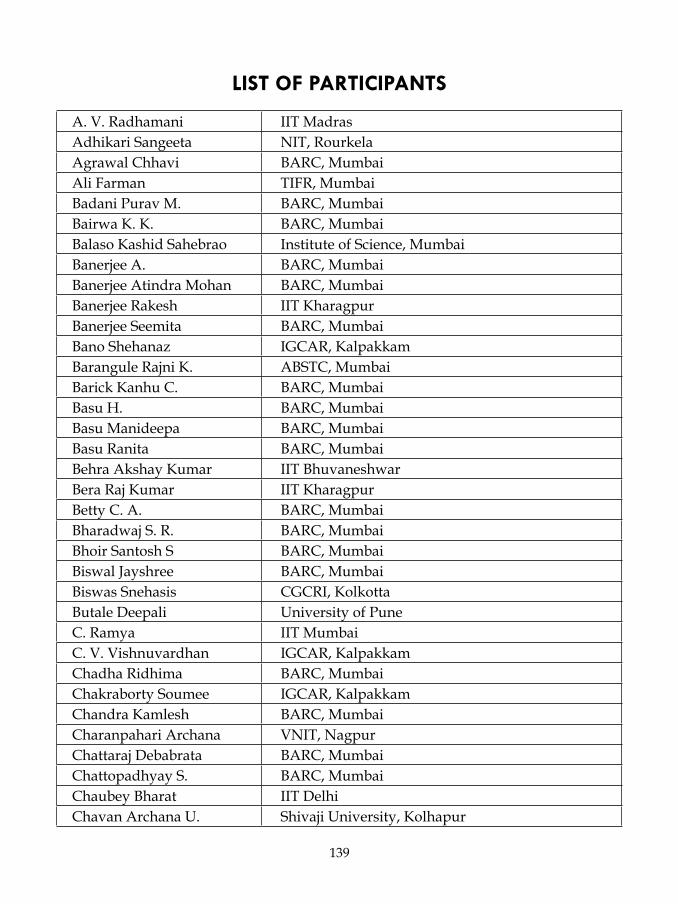
NWMC – 2011 (FUN-MAT)
139
LIST OF PARTICIPANTS
A. V. Radhamani IIT MadrasAdhikari Sangeeta NIT, RourkelaAgrawal Chhavi BARC, MumbaiAli Farman TIFR, MumbaiBadani Purav M. BARC, MumbaiBairwa K. K. BARC, MumbaiBalaso Kashid Sahebrao Institute of Science, MumbaiBanerjee A. BARC, MumbaiBanerjee Atindra Mohan BARC, MumbaiBanerjee Rakesh IIT KharagpurBanerjee Seemita BARC, MumbaiBano Shehanaz IGCAR, KalpakkamBarangule Rajni K. ABSTC, MumbaiBarick Kanhu C. BARC, MumbaiBasu H. BARC, MumbaiBasu Manideepa BARC, MumbaiBasu Ranita BARC, MumbaiBehra Akshay Kumar IIT BhuvaneshwarBera Raj Kumar IIT KharagpurBetty C. A. BARC, MumbaiBharadwaj S. R. BARC, MumbaiBhoir Santosh S BARC, MumbaiBiswal Jayshree BARC, MumbaiBiswas Snehasis CGCRI, KolkottaButale Deepali University of PuneC. Ramya IIT MumbaiC. V. Vishnuvardhan IGCAR, KalpakkamChadha Ridhima BARC, MumbaiChakraborty Soumee IGCAR, KalpakkamChandra Kamlesh BARC, MumbaiCharanpahari Archana VNIT, NagpurChattaraj Debabrata BARC, MumbaiChattopadhyay S. BARC, MumbaiChaubey Bharat IIT DelhiChavan Archana U. Shivaji University, Kolhapur

NWMC – 2011 (FUN-MAT)
140
Chopde Suresh M. BARC, MumbaiChoudhary Kamal BARC, MumbaiChowki Srikanth IIT BhubneshwarDalvi Dhanaji Shivaji University, KolhapurDas Amrita BARC, MumbaiDas D. BARC, MumbaiDas Debasish CGCRI, KolkottaDas Priyanka BARC, MumbaiDas Raja NCL PuneDas Soumitra BARC, MumbaiDatta Niyanta BARC, MumbaiDawar Anit Delhi University, New DelhiDeb S.B. BARC, MumbaiDey Debabrata IIT KharagpurDey G. K. BARC, MumbaiDey Jahar NEHU, ShillongDubal Snehal Uttamrao Shivaji University, KolhapurDutta D. BARC, MumbaiDutta Sujan IIT KharagpurEdiga Umesh Babu IIT MadrasGhosh S. K. BARC, MumbaiGhosh Saptarshi Jadavpur Universty, KolkottaGhugal Sachin G. VNIT, NagpurGoswami A. BARC, MumbaiGoswami A. BARC, MumbaiGuleria Apurav BARC, MumbaiGupta Sheetal Vikram university, UjjainGupta Vinita G. BARC, MumbaiHassan P. A. BARC, MumbaiJadhav Rahul ABSTC, MumbaiJadhav Swati Tanaji Shivaji University, KolhapurJain Dheeraj BARC, MumbaiJain V. K. BARC, MumbaiJamale Atul P. Shivaji University, KolhapurJaybhaye Sandesh Birla College, KalyanJoshi Aparna M. University of PuneK. R. S. Chandrakumar BARC, Mumbai

NWMC – 2011 (FUN-MAT)
141
K. Srinivasu BARC, MumbaiK. Uma Mahendra Kumar IGCAR, KalpakkamKaity Santu BARC, MumbaiKatari Vasundhara BARC, MumbaiKaushik C. P. BARC, MumbaiKeny S. J. BARC, MumbaiKesarla Mohan Kumar VIT University, VelloreKhadilkar Hemlata V. BARC, MumbaiKini Harshad R. ABSTC, MumbaiKishore Sangeeta M S University, VadodaraKolay Siddhartha BARC, MumbaiKoley S. BARC, MumbaiKothiyal G. P. BARC, MumbaiKulkarni S. G. BARC, MumbaiKumar Arvind BARC, MumbaiKumar Asheesh BARC, MumbaiKumar Sumit BARC, MumbaiKushwah Nisha BARC, MumbaiKuttan Juby BARC, MumbaiLavand Atul Bhausaheb Institute Of Science, MumbaiLenka R. K. BARC, MumbaiLenka Sangita Dhara BARC, MumbaiLohakane Vinod A. J.J.T. University, RajasthanMadolappa Shivanand Gulbarga University, GulbargaMajeed Jerina BARC, MumbaiMali Sawanta Shivaji University, KolhapurMalkar Vishwabharati V. BARC, MumbaiMandal Sandip NIT, RourkelaMandal Satish Kumar IIT KharagpurMande Hemant Malhari M S University, VarodaraMankad Venu Bhavnagar University, BhavnagarManna Biswajit BARC, MumbaiMishra Nilanjal BARC, MumbaiMishra R. K. BARC, MumbaiMishra Ratikant BARC, MumbaiMisra Archana BARC, MumbaiMistry Chirag B. Veer Narmad South Gujrat University, Surat

NWMC – 2011 (FUN-MAT)
142
Mocherla Pavana Sri Vamsi IIT MadrasModak B. BARC, MumbaiMohapatra Manoj BARC, MumbaiMukherjee T. BARC, MumbaiN. Manoj BARC, MumbaiN. Praba Anna University, ChennaiNaik Shrikant R. Goa University, PanjimNair S. R. BARC, MumbaiNalawade Pradnya P. BARC, MumbaiNandi Chiranjit BARC, MumbaiNandotaria Reshma Veer Narmad South Gujrat University, SuratNavik Alok J Veer Narmad South Gujrat University, SuratNigam Sandeep BARC, MumbaiNuwad Jitendra BARC, MumbaiP. Maheshwaran BARC, MumbaiP. S. Ramanjaneyulu BARC, MumbaiPable Yogita BARC, MumbaiPal Manojkumar BARC, MumbaiPandit Jyoti A. MIT College, PunePatel Dinesh Kanji BARC, MumbaiPatel Gaurang M S University, VadodaraPatel Pratiksha A. Veer Narmad South Gujrat University, SuratPatil Sarika P. Shivaji University, KolhapurPatra G. D. BARC, MumbaiPhapale Suhas B. BARC, MumbaiPhatak Rohan BARC, MumbaiPillai C. G. S. BARC, MumbaiPrabhu Sugosh R. BARC, MumbaiPrakash Bhanu BARC, MumbaiQuazi Arif Islam CGCRI, KolkottaR. Manimaran BARC, MumbaiRamakumar K. L. BARC, MumbaiRamgir Niranjan BARC, MumbaiRamgir Niranjan BARC, MumbaiRana Suman BARC, MumbaiRath Madhav C. BARC, Mumbai
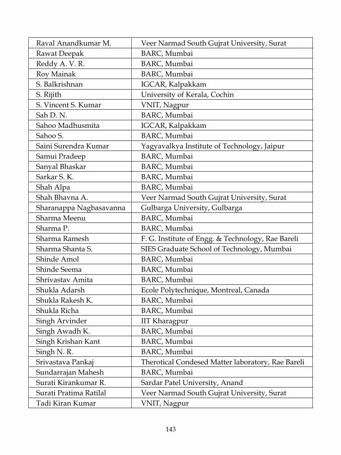
NWMC – 2011 (FUN-MAT)
143
Raval Anandkumar M. Veer Narmad South Gujrat University, SuratRawat Deepak BARC, MumbaiReddy A. V. R. BARC, MumbaiRoy Mainak BARC, MumbaiS. Balkrishnan IGCAR, KalpakkamS. Rijith University of Kerala, CochinS. Vincent S. Kumar VNIT, NagpurSah D. N. BARC, MumbaiSahoo Madhusmita IGCAR, KalpakkamSahoo S. BARC, MumbaiSaini Surendra Kumar Yagyavalkya Institute of Technology, JaipurSamui Pradeep BARC, MumbaiSanyal Bhaskar BARC, MumbaiSarkar S. K. BARC, MumbaiShah Alpa BARC, MumbaiShah Bhavna A. Veer Narmad South Gujrat University, SuratSharanappa Nagbasavanna Gulbarga University, GulbargaSharma Meenu BARC, MumbaiSharma P. BARC, MumbaiSharma Ramesh F. G. Institute of Engg. & Technology, Rae BareliSharma Shanta S. SIES Graduate School of Technology, MumbaiShinde Amol BARC, MumbaiShinde Seema BARC, MumbaiShrivastav Amita BARC, MumbaiShukla Adarsh Ecole Polytechnique, Montreal, CanadaShukla Rakesh K. BARC, MumbaiShukla Richa BARC, MumbaiSingh Arvinder IIT KharagpurSingh Awadh K. BARC, MumbaiSingh Krishan Kant BARC, MumbaiSingh N. R. BARC, MumbaiSrivastava Pankaj Therotical Condesed Matter laboratory, Rae BareliSundarrajan Mahesh BARC, MumbaiSurati Kirankumar R. Sardar Patel University, AnandSurati Pratima Ratilal Veer Narmad South Gujrat University, SuratTadi Kiran Kumar VNIT, Nagpur

NWMC – 2011 (FUN-MAT)
144
Thakur Bhawana N. BARC, MumbaiThakur Gohil S. IIT DelhiThakur Neha BARC, MumbaiTomar B. S. BARC, MumbaiTripathi A. K. BARC, MumbaiTyagi A. K. BARC, MumbaiTyagi Adish BARC, MumbaiTyagi Deepak BARC, MumbaiV. Sudarsan BARC, MumbaiVarma Salil BARC, MumbaiVats Bal Govind BARC, MumbaiVatsa R. K. BARC, MumbaiVekariya Rohit L. Sardar Patel University, AnandVerma Gunjan BARC, MumbaiWadawale Amey P. BARC, MumbaiYadav K.K. BARC, MumbaiYadav Rama Shanker Barkatullah University, BhopalYusuf S. M. BARC, Mumbai


![[Acronym] Proceedings - UFG](https://static.fdokumen.com/doc/165x107/631430486ebca169bd0abf4b/acronym-proceedings-ufg.jpg)