A numerical study on interface crack growth under heat flux loading
Numerical Simulation of Slip flow
Heat Transfer in a Microtube
Thesis submitted in partial fulfillment of the requirements for the degree of
Master of Technology
in
Mechanical Engineering(Specialization: Thermal Engineering )
by
S R Akhil Krishnan
Department of Mechanical EngineeringNational Institute of Technology Rourkela
Rourkela, Odisha, 769008, IndiaMay 2014
Numerical Simulation of Slip flow
Heat Transfer in a Microtube
Dissertation submitted in
May 2014
to the department of
Mechanical Engineering
of
National Institute of Technology Rourkela
in partial fulfillment of the requirements for the degree of
Master of Technology
by
S R Akhil Krishnan(Roll 212ME3306 )
under the supervision of
Prof. A.K. Satapathy
Department of Mechanical EngineeringNational Institute of Technology Rourkela
Rourkela, Odisha, 769008, India
Department of Mechanical EngineeringNational Institute of Technology RourkelaRourkela-769008, Odisha, India.
Certificate
This is to certify that the work in the thesis entitled Numerical Simulation
of Slip flow Heat Transfer in a Microtube by S R Akhil Krishnan is
a record of an original research work carried out by him under my supervision
and guidance in partial fulfillment of the requirements for the award of the de-
gree of Master of Technology with the specialization of Thermal Engineering in
the department of Mechanical Engineering, National Institute of Technology
Rourkela. Neither this thesis nor any part of it has been submitted for any degree
or academic award elsewhere.
Place: NIT Rourkela Prof. A K SatapathyDate: May 2014 Professor, ME Department
NIT Rourkela, Odisha
Acknowledgment
I would like to express my sincere gratitude and respect to my supervisor Prof. A
K Satapathy for valuable suggestion and excellent guidance , support and help ex-
tended to me in every phase of my project work and without whose untiring efforts
this project would not have been a success. He has constantly encouraged me to re-
main focused on achieving my goal. And also his views helped me to establish the
overall direction of the research and to move forward with investigation in depth. .
I extend my thanks to our HOD, Prof. K P Maity and to all the professors of
the department for their support and encouragement.
I am really thankful to my batchmates especially Sudhakar, Bright who helped
me during my course work and also in writing the thesis . Also I would like to
thanks my all friends particularly Shaibu, Anindya and Prerna for their personal
and moral support. My sincere thanks to everyone who has provided me with
kind words, a welcome ear, new ideas, useful criticism, or their invaluable time, I
am truly indebted.
I must acknowledge the academic resources that I have got from NIT Rourkela.
I would like to thank administrative and technical staff members of the Depart-
ment who have been kind enough to advise and help in their respective roles.
I feel pleased and privileged to full fill my parents ambition and I am greatly
indebted to them for bearing the inconvenience during my M Tech. course.
S R Akhil Krishnan
212ME3306
Abstract
The isothermal wall convective heat transfer characteristics of the model fluid
flow in 2-D micro tube under hydro dynamically fully developed conditions was
investigated. In which it covers the slip flow regime 0.01 < Kn < 0.1, where
Kn , the Knudsen number is defined as the ratio of molecular mean free path
and the hydraulic diameter of the micro tube . So in case of velocity-slip flow
regime solving the fluid flow and heat transfer governing equation can no longer
be sufficient for simulating the flow. We will require incorporating slip velocity and
temperature jump boundary conditions. Slip velocity and temperature boundary
conditions were derived by Maxwell and Smoluchowski respectively.
Investigation has been done in a commercial CFD package FLUENT slip and
temperature jump boundary condition is taken into account through program
called udf (User Defined Function). The validity of UDF is done by forward
backward approach in which outcome of the UDF is considered as the input for
the FLUENT inbuilt shear stress slip model. The error calculated in slip velocity
by forward-backward approach is 1.485
The main interest is to determine effect of Knudsen number on various flow
variable. Also the heat transfer rate , skin friction coefficient ,axial wall shear
stress , slip velocity , Nusselt number , heat transfer coefficient and wall fluxes
with varying Knudsen Number and Reynold Number is also studied.
Contents
Certificate ii
Acknowledgement iii
Abstract iv
List of Figures vii
List of Tables viii
Symbols and Abbreviations viii
1 Introduction 2
1.1 Background . . . . . . . . . . . . . . . . . . . . . . . . . . . . . . . 2
1.2 Motivation and Application . . . . . . . . . . . . . . . . . . . . . . 3
1.3 Slip boundary conditions . . . . . . . . . . . . . . . . . . . . . . . 4
1.4 Literature Review . . . . . . . . . . . . . . . . . . . . . . . . . . . 5
2 Mathematical Model 15
2.1 Theory: . . . . . . . . . . . . . . . . . . . . . . . . . . . . . . . . . 15
2.2 Governing Equations: . . . . . . . . . . . . . . . . . . . . . . . . . . 18
2.3 Boundary Conditions: . . . . . . . . . . . . . . . . . . . . . . . . . 20
2.4 Slip Velocity: . . . . . . . . . . . . . . . . . . . . . . . . . . . . . . 20
2.5 Temperature Jump: . . . . . . . . . . . . . . . . . . . . . . . . . . . 21
2.6 Analytical Result: . . . . . . . . . . . . . . . . . . . . . . . . . . . . 22
2.7 Analytical Conclusions: . . . . . . . . . . . . . . . . . . . . . . . . . 22
3 Problem Formulation 25
3.1 Problem Description . . . . . . . . . . . . . . . . . . . . . . . . . . 25
3.1.1 Simulation Approach : . . . . . . . . . . . . . . . . . . . . . 26
v
3.1.2 Velocity Simulation . . . . . . . . . . . . . . . . . . . . . . 27
3.2 Temperature Simulation . . . . . . . . . . . . . . . . . . . . . . . 29
3.3 Program Validation . . . . . . . . . . . . . . . . . . . . . . . . . . 30
4 Results and Discussion 33
4.1 Grid Test . . . . . . . . . . . . . . . . . . . . . . . . . . . . . . . 33
4.2 Effect of Slip . . . . . . . . . . . . . . . . . . . . . . . . . . . . . . 33
4.2.1 Slip velocity . . . . . . . . . . . . . . . . . . . . . . . . . . 34
4.2.2 Axial Wall Shear Stress . . . . . . . . . . . . . . . . . . . . 34
4.2.3 Skin Friction Coefficient . . . . . . . . . . . . . . . . . . . . 35
4.2.4 Surface Nusselt Number . . . . . . . . . . . . . . . . . . . . 35
4.2.5 Surface Heat Transfer Coefficient . . . . . . . . . . . . . . . 36
4.2.6 Centreline Temperature . . . . . . . . . . . . . . . . . . . . 36
4.3 Effect of Knudsen Number . . . . . . . . . . . . . . . . . . . . . . . 37
4.3.1 Slip velocity . . . . . . . . . . . . . . . . . . . . . . . . . . 37
4.3.2 Axial Wall Shear stress . . . . . . . . . . . . . . . . . . . . 37
4.3.3 Heat Transfer Coefficient Behaviour . . . . . . . . . . . . . 38
4.3.4 Surface Nusselt Number . . . . . . . . . . . . . . . . . . . . 38
4.4 Effect of Reynolds Number . . . . . . . . . . . . . . . . . . . . . . . 39
4.4.1 Slip Velocity . . . . . . . . . . . . . . . . . . . . . . . . . . 39
4.4.2 Axial Wall Shear stress . . . . . . . . . . . . . . . . . . . . 39
4.4.3 Heat transfer Coefficient Trend . . . . . . . . . . . . . . . . 40
4.4.4 Surface Nusselt Number Trend . . . . . . . . . . . . . . . . 40
4.4.5 fRe Vs Axial distance . . . . . . . . . . . . . . . . . . . . . 41
4.5 Conclusion . . . . . . . . . . . . . . . . . . . . . . . . . . . . . . . . 46
4.6 Future work . . . . . . . . . . . . . . . . . . . . . . . . . . . . . . . 47
Bibliography 48
List of Figures
2.1 Fluid Modelling Classification . . . . . . . . . . . . . . . . . . . . . 16
3.1 Physical Geometry of Problem . . . . . . . . . . . . . . . . . . . . . 26
3.2 Complete Meshed Geometry . . . . . . . . . . . . . . . . . . . . . . 27
3.3 Convergence Of Residuals . . . . . . . . . . . . . . . . . . . . . . . 27
3.4 Velocity Contour . . . . . . . . . . . . . . . . . . . . . . . . . . . . 28
3.5 Velocity Vectors Colored by Static Temperature . . . . . . . . . . . 29
3.6 Slip Velocity comparison for Code validation . . . . . . . . . . . . 31
3.7 Velocity profile comparison for Code validation . . . . . . . . . . . 31
4.1 Slip Velocity at Kn 0.045 . . . . . . . . . . . . . . . . . . . . . . . . 34
4.2 Axial wall shear stress comparison . . . . . . . . . . . . . . . . . . . 34
4.3 Skin Friction Coefficient . . . . . . . . . . . . . . . . . . . . . . . . 35
4.4 Surface Nusselt Number . . . . . . . . . . . . . . . . . . . . . . . . 35
4.5 Surface Heat Transfer Coefficient . . . . . . . . . . . . . . . . . . . 36
4.6 Centreline Temperature . . . . . . . . . . . . . . . . . . . . . . . . 36
4.7 Slip Velocity Comparison at different Knudsen Number . . . . . . 37
4.8 Axial Wall Shear stress Comparison at different Kn no. . . . . . . 37
4.9 Surface Heat Transfer Coefficient at different Kn no. . . . . . . . . 38
4.10 Surface Nusselt Number at Different Knudsen Number . . . . . . . 38
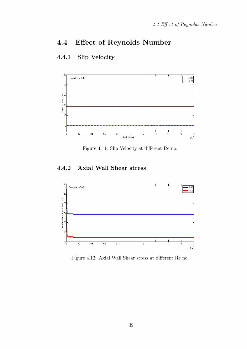
4.11 Slip Velocity at different Re no. . . . . . . . . . . . . . . . . . . . . 39
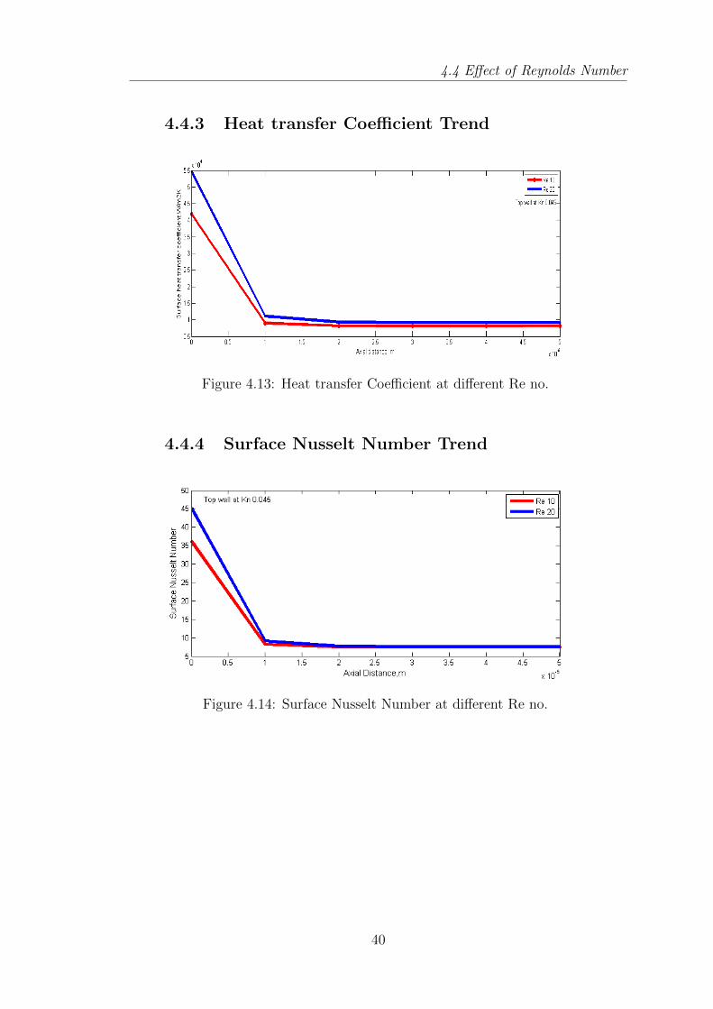
4.12 Axial Wall Shear stress at different Re no. . . . . . . . . . . . . . . 39
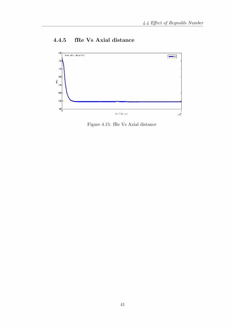
4.13 Heat transfer Coefficient at different Re no. . . . . . . . . . . . . . 40
4.14 Surface Nusselt Number at different Re no. . . . . . . . . . . . . . 40
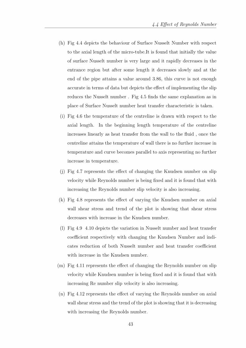
4.15 fRe Vs Axial distance . . . . . . . . . . . . . . . . . . . . . . . . . 41
vii

List of Tables
2.1 Knudsen number Regimes . . . . . . . . . . . . . . . . . . . . . . . 17
2.2 Fully Developed Conditions , Laminar flow Nu values[35] . . . . . . 22
4.1 Grid Independence Test Results . . . . . . . . . . . . . . . . . . . . 33
viii

Listof Abbreviations
α : Thermal Diffusivity
λ : Free mean path
θ : Dimensionless Temperature
µ : Dynamic Viscosity , kg/m-s
ν : Kinematic viscosity . m2/s
σ : Molecular diameter ,m
ρ : Density ,kg/m3
a : Velocity of sound , m/s
Br : Brinkman number
Cp : Specific heat , J/kg-K
d : Diameter ,m
Dh : Hydraulic diameter, m
h : Heat transfer coefficient, W/m2K
k : Thermal conductivity, W/m-K
Kn : Knudsen Number
L : Length of pipe, m
Ma : Mach number
Nu : Average Nusselt number
P : Pressure, Pa
R : Tube radius , m
r : Radial coordinate , m
Re : Reynolds Number
T : Fluid Temperature, K
Ti : Fluid inlet temperature , K
u : Axial velocity , m/s
ui : Slip velocity , m/s
x : Axial coordinate ,m
Fm : Momentum accommodation coefficient
FT : Thermal accommodation coefficient

Introduction
Chapter 1
Introduction
1.1 Background
In last two decades study of compact devices has been emphasized . We all
are aware of the fact that heat generated in compact devices possessing high flux
may cause damage of the various components of devices. To avoid the damage of
component there must be incorporation of heat removal mechanism.
Modern technologies capable of increasing the energy efficiency in form of trans-
portation, housing, and appliance systems, by reducing energy consumption and
positively impact the global environment
Micro devices having dimensions of the order of micron are being designed for
use in cooling of integrated circuits, biochemical applications , micro electro me-
chanical system and cryogenics. The trend of miniaturization has significantly en-
hanced the problem associated with overheating of ICs. It require effective cooling
which is used to remove the heat generated from a relative low surface area. This
require effective thermal design increasing sales of circuit integration of electronic
component accompanied which in turn reduces the size of IC chips tremendously
which leads to larger increment of heat generation dissipation . And also the im-
plementation of efficient cooling techniques for integrated circuit IC chips is one
of the important applications of micro scale heat transfer.
2
1.2 Motivation and Application
Micro tube heat sinks are the ultimate solution for removing these high amounts
of heat. The removal of heat is done by forced convection generally using liquid
flow . Numerical methods using fluent code are reported for predicting the flow
and temperature of working fluid ,which is useful for designing of thermal chips.
1.2 Motivation and Application
Micro scale heat transfer has drawn much attention due to their high poten-
tial for cooling high power microelectronic and application in biomechanical and
aerospace industries. Heat released from micro devices is now becoming a cutting
edge field since the performance of the device used in primarily determined by
flow and temperature fields. The benefit of using micro tube heat sinks is that
its having high heat transfer area per unit volume. Heat transfer in a micro scale
mainly takes place via conduction and convection modes.
The construction of the tube have a greater influence on the convective heat
transfer characteristics. Hence , to design effective micro tube heat sinks , design
parameters like pressure required circulating the cooling fluid , flow rate ,hydraulic
diameter of the tube , temperature of the fluid and the tube wall and the number
of tube has to be considered. To make the system effective and cheaper ,these pa-
rameters have to be optimized. The use of convective heat transfer in micro tubes
to cool electronic chips . Both analytical and experimental works were being done
to determine the heat transfer at micro scale for liquids and gases . However ,none
of them has been able to come to a general conclusion. Experimental studies in
the literature have showed that many micro channel flow and heat transfer phe-
nomena cannot be governed by classical theories of transport phenomena.e.g. , in
micro tube transition from laminar flow to turbulent flow occurs much earlier (Re
=200) ; the relationship between the friction factor and the Reynolds number for
microtube flow are very different from that in classical theory of fluid mechanics.
3

1.3 Slip boundary conditions
Study of gaseous flow done and it showed that although continuum assump-
tion is invalid for the phenomena of rarefaction for slip flow conditions . It is
also found that gas velocity not exactly zero and there is a finite amount of tem-
perature jump between wall and adjacent gas , which is contemporary to fluid
flow in macro tube.Current problem incorporate Slip velocity and temperature
jump boundary conditions derived by Maxwell and Smoluchowski. Based upon
this boundary condition code is written and hooked into FLUENT . Now we can
simulate microtube and also design them for these micro applications .
1.3 Slip boundary conditions
The slip phenomena plays an important role in modelling liquid flow through mi-
cro channel. Helmoltz and Von Piotrowski had found the slip between a solid and
liquid surface and later Brodman verified their results. Analytic slip-flow studies
have traditionally been used on the continuum form of Navier -Stokes equations
and energy equation with the slip-flow effects concentrated in the additional terms
in the tangential velocity and temperature conditions.
These conditions were representing the velocity slip and temperature jump con-
ditions at the gas surface interface .Slip flow condition have been well elaborated
by by introducing the concept of slip length,which is the distance behind the solid-
liquid interface at which the velocity extrapolates to zero. Liquid flow in a micro
channel becomes fully developed after a short entrance length so that it can be
modified as a two dimensional flow .
The slip velocity at the wall as given by Navier is
Vx = Ls ∗ (∂Vx∂η
)wall (1.1)
Where Ls is the slip length ; n is the normal coordinate pointing inward from
the channel wall.
4

1.4 Literature Review
Slip velocity boundary condition as derived by Maxwell is :
Ufluid − Uwall =2− Fv
Fv
∗ λ ∗ (∂U
∂Y)wall (1.2)
the above condition is valid for both gas as well as liquid flow. Where the Fv is
the momentum accommodation coefficient . is the mean free path and (U/Y )
is velocity gradient. We can model the slip from various correlation given in
different literature but present study is completely based upon Maxwell derived
slip formulation.
1.4 Literature Review
The literature survey is giving a brief description of the analysis performed in
single phase forced convection in microtubes.
1. Orhan Aydin ,Mete Avci : They analyzed analytically laminar forced con-
vection heat transfer of a Newtonian fluid in a micro-channel between two
parallel plates. Current investigation includes viscous dissipation effect ,
velocity slip effect and temperature jump at the wall. Analysis is done un-
der hydro-dynamically and thermally fully developed condition. Either hot
wall or cold wall condition is discussed for constant heat flux and constant
wall temperature .The relative variation of Nusselt number with respect to
Knudsen number and Brinkman number are analytically revealed .
2. Nicolas G. Hadjiconstantinou ,Olga Simek : Their findings covers the slip
flow regime for isothermal wall convective heat transfer characteristic of
a gaseous flow in a 2 D micro and nano channel , where flow is hydro-
dynamically and thermally fully developed. They use axial heat conduction
to calculate the nusselt number .Incorporation of the phenomena of axial
heat conduction in the continuum model is necessary since small scale in-
ternal flows are typically The characterisation of finite Peclet number is
incorporated by phenomena of axially heat conduction in the continuum
model . Investigation explores that the prediction is matching with the
5

1.4 Literature Review
DSMC results for slip flow. It is revealed in the study that with increasing
Knudsen number Nu number decreases in hydro dynamically and thermally
fully developed condition in both slip flow and transition flow regime . At
Kn=50 Nusselt number is found to increase by axial heat conduction. They
have also investigate a micro tube and found qualitatively similar predic-
tion for slip flow heat transfer in circular tube. This investigation gave new
amplitude to slip flow convective heat transfer in a micro and nano channel.
3. Gokturk tunc , Yoldiz Bayazitoglu : They have also investigated slip flow
convective heat transfer in a rectangular micro-channel under thermally and
hydro-dynamically developed flow condition. The H-2 boundary condition
condition is applied at the walls of the channel. The velocity profile for
rectangular is unknown for the slip flow condition the momentum equation
is used for solving the velocity and then the obtained velocity profile is
incorporated in the energy equation . Integral transform technique is used
two times once for determining velocity and second for temperature.
4. Chien-hsin , chen : They included the viscous dissipation which is not con-
sidered by many researchers. They analyzed forced convection flow in a
microchannel with isothermal condition at the wall, as their investigation
lies in slip flow regime (0.001 < Kn < 0.1) incorporation of both velocity
slip and temperature condition at the wall are necessary , hence they in-
cluded the velocity slip and temperature jump at the wall. Energy equation
was solved for developing temperature field with the help of finite integral
transform .And also increasing Knudsen number is indicating increasing slip
velocity at the wall surface in turn to reduce the friction factor. Effects of
parameter like Kn , b and Brinkman number on the heat transfer charac-
teristic are mentioned .By fixing Br the Nusselt number may be either lower
or higher than those of the continuum regime depending upon the effects
of Knudsen number and b. At a known Kn the variation of surface Nus-
selt number increases when b becomes large which results into a shortening
of the thermal entrance length. Thermally fully developed nusselt number
6
1.4 Literature Review
decreases with increasing b irrespective of Knudsen number .
5. Ho-Eyoul Jeong , Jae-Tack Jeong : In their work hydro dynamically devel-
oped convective flow through a micro-channel with isothermal wall or con-
stant heat flux boundary condition is considered. They analyzed extended
Graetz problem in micro channel with Eigen function expansion for solving
the energy equation .The effects of slip velocity and temperature boundary
condition on the micro channel wall are explored . Stream wise conduction
and viscous dissipation are also taken into consideration. The dependence
of Nusselt number distribution on dimensionless number like Peclet number
, Brinkman number and Knudsen number also analyzed in their work . The
fully developed nusselt number for both boundary conditions is computed
in terms of dimensionless numbers like Reynold number , Peclet number ,
Knudsen number ,Brinkman number etc
6. Tuckerman and Pease : They reported that 790W/cm2 heat flux dissipation
is possible from the water cooled micro-channel heat sink without a phase
change . They predicted that h for laminar flow via micro-channels might be
higher than for turbulent flow through conventionally sized micro-channels.
7. Wu and Little : They have done experiments to determine flow and heat
transfer characteristics of gaseous flows in micro-channels. They found a
difference from the data obtained by experiments and also transfer of flow
from laminar to turbulent is occuring at lower Reynold number and it results
in improving heat transfer.
8. Pfahler : Experimentally investigated the fluid flow in rectangular micro-
channels with cross section of 80 to 7200micro − m2 .Their aim was to
determine the length scales at which the continuum assumptions breakdown.
They relate that large flow channels are relating with the predictions of the
Navier-Stokes equations ,.And for the smallest of their channels, a significant
deviation from the Navier-Stokes predictions was observed . They founded
out the h for Nitrogen gas in micro tubes with dia of 3 to 81 m for the case
7

1.4 Literature Review
of laminar and turbulent flows. In turbulent flow the measured h were larger
than the macro tubes.The experimentally determined values for turbulent
flow heat transfer coefficients is seven times larger than the ones which are
obtained by the relations for turbulent flows in macro-channels.
9. Randall f.Barron , X.M.Wang and Roberto Warington : The conventional
problem thermally developing heat transfer in laminar flow through a cir-
cular tube formulated by Graetz to include effect of slip flow occurring in
low pressure gases in a micro tube at ordinary pressure is considered. A
different method was used to determine the Eigen value . Eigen values were
determined for Knudsen number lying in the range 0 to 1. Correlations were
made to show the effect of slip flow on h. Integral transforms technique was
incorporated to solve heat transfer for hydro-dynamically developed laminar
, steady state flow in micro-tube with constant heat flux and isothermal wall
jump are considered. For both fluid heating and cooling case effect of viscous
heating is investigated. Prandtl number investigation has explored that as
we enhance the Pr the temperature jump effect disappears when Nu number
increases . In other way for higher Prandtl number fluid temperature jump
can be neglected.
10. Orhan Aydin , Mete Avci: In current study cases of Hydro dynamically and
thermally fully developed flow is determined for two different thermal bound-
ary condition. Constant heat flux and Constant wall temperature. Either
wall cooling or wall heating case is considered. Analytically it is determined
that Nu=f(Br,Kn) .Here Br dependence on Nu number was discussed in
terms of energy balance.
11. Wang and Peng : They investigated the influence of liquid flow, thermal
parameters , generalized size and structure on the single phase forced con-
vection characteristics for methanol and de-ionized water through micro-
channels with rectangular cross section . The convective heat transfer coef-
ficient was found to be highly associated with liquid flow. They got that in
8
1.4 Literature Review
the transition region for single phase heat transfer coefficient exists beyond
it is nearly independent of the wall temperature.
12. Bestok et al.: The high order velocity slip and temperature jump boundary
condition were determined :
ug − uw =2− σVσV
∗Kn ∗ (∂u
∂η)s +
(Kn)2
2∗(∂2u
∂2η
)s
+(Kn)
3
6∗(∂3u
∂3η
)s
(1.3)
Tg−Tw =2− σTσT
∗ 2γ
γ + 1∗ 1
Pr∗Kn∗(∂T
∂η)s+
(Kn)2
2∗(∂2T
∂2η
)s
+(Kn)
3
6∗(∂3T
∂3η
)s
(1.4)
13. Peng et al. : Rectangular micro-channels with hydraulic diameter ranging
from 133 to 367 micro-meters were used in the experiments . Steady state
and fully developed flow conditions were investigated. They found that tur-
bulent flow is initiated at smaller Reynold number and the transition range
is not as wide in conventional channels. Transition starts at Re =200-700
and the transition Re decreases with decreasing hydraulic diameter. Flow
friction also decreases with decreasingDh until the aspect ratio equals to 0.5.
Else decreasing the channel size results in higher friction values . Experimen-
tal Nusselt number values for laminar flow were smaller than the predicted
and they were dependent on the Reynolds number , Re proportional to
Nu0.62 , unlike conventional channels. h for both laminar and turbulent flow
changes significantly for different values for hydraulic diameter and aspect
ratio. They reported an optimum value of aspect ratio as 0.75 for laminar
and 0.5-0.75 for turbulent flows.
14. Peng et al .(1994 a,b) : They done experimentally the forced convection
characteristics of H2O flowing micro-channels of rectangular shape with di-
ameters of 0.133-0.3667 mm and aspect ratios in the range of 0.333-1. Two
thermocouples were used for testing Tf and 3 thermocouples were used for
measuring Tw . For all their test conditions , their dimensionless distance
was such that the flow was fully developed . A h is calculated for the micro-
channel , defined as
h = q/(Tw − Tfin) (1.5)
9
1.4 Literature Review
where Tw is the value measured at the downstream end. They relate their
data in the with the Sieder Tate equations for laminar flow. But it did not
match well with quantitatively with their experimental data , they suggest
a new correction and compared with their data. However neither their new
correlation nor this equation qualitatively agree with the unusual behaviour
of Nu/Pr0.33 receding with increasing Re , exhibited by their experimental
data. They also measured the flow friction to analyze the heat transfer
regimes , and to explore the physical aspects of convection. Their data
analysis revelaed that the geometric parameters , plays a very important role
on the heat transfer characteristics. For the laminar heat transfer regime ,
Nu is proportional to Re0.62 ,while the turbulent heat transfer case exhibited
the typical relationship between Nu and Re , but with a different empirical
constant . The empirical constants for both these regimes were tabulated as
a function of the geometric parameters.
15. Peng et al.(1995a): They also tested microgrooves having rectangular shape
built into stainless steel plates with methanol as a working fluid to deter-
mine the effects of aspect ratio, fluid velocity and temperature and channel
configuration.It was observed that , due to the large heat fluxes , liquid
temperature along the channel changes significantly , which causes a signifi-
cant thermo physical property variation. In this case , the Reynolds number
was different at the exit than that at the inlet. This directly influenced
the transfer of flow from from laminar to turbulent and thus the amount of
heat transfer. Liquid velocity is another important factor that improves the
cooling capacity.
16. Peng and Peterson : They informed experiments to understand the physics
of the single-phase convective heat transfer in micro-channels of varying size.
The influence of the flow characteristics , thermo fluid conditions and chan-
nel geometry was analyzed. Their experiments showed a Nusselt number
reduction with Re increases in the laminar flow regime, for which they did-
not give an explanation. In the turbulent flow regime , Nu increased with
10

1.4 Literature Review
increasing Re .Liquid inlet temperature and velocity also has a significant
influence on the h .In general , a small inlet temperature and a large veloc-
ity result in higher heat transfer coefficients .For the same temperature and
velocity values , different sized channels cause different flow modes , heat
transfer regimes and therefore different heat transfer capacities.
17. Orhan Aydin and Mete Avci : In another study of them a theoretical analy-
sis is presented for hydro dynamically developed , thermally developing and
steady laminar forced convection heat transfer of a Newtonian fluid in the
entrance region of a micro tube. Present work also includes viscous dissipa-
tion effect. Velocity slip and temperature jump at the wall , two different
boundary conditions are taken into account a) The constant heat flux (H-1
type) and b) the constant wall temperature(T type).
18. V.P . Tyagi and K.M.Nigam : Present work for steady state heat transfer in
slug flow in a circular tube uses both Laplace transform in axial coordinate
and Gaierkins technique with constant physical properties and negligible
axial heat conduction. Calculation reveals that the 2nd approximation is
relating with the known exact analytical solution
19. Antonio Barletta and Enzo zanchini : Current work deals with the slug flow
in a circular duct. Effect of viscous dissipation is considered in thermal en-
trance region.. Current work deals with the boundary condition a) Uniform
wall heat flux b) a linearly varying wall heat flux c) an exponentially vary-
ing wall heat flux. In wall heat flux situation it is explored that viscous
dissipation inversely relates with Nu number , which indicates Nu number
decreases with increasing viscous dissipation . In linearly or exponentially
increasing wall heat flux viscous dissipation affect the local Nu number only
on the thermal entrance region and become negligible in the fully developed
region.
20. A. Haji-Sheikh , Donald E.Amos and J.V. Beck : This paper deals with
conjugate heat transfer where conduction is also included with convective
11
1.4 Literature Review
heat transfer . Computed analytical result reveals that close to thermal
entrance region heat conduction dominates and the local heat flux becomes
independent of velocity.
21. Kalkac and Yener : With increasing Kn, the Nusselt number goes on de-
creasing. And in the slip flow regime , Nusselt was reduced to forty percent
. They also determined that the rarefaction is increasing with the increase in
entrance length , that denotes that the thermally fully developed flow cant
be achieved so fastly in case of conventional channels. The following formula
shows the relationship between the and the and Kn :
22. Xu et al. (1999) : Experimentally and analytically the investigation of
liquid flow in micro-channels were done. Micro-channels with diameters of
50 and 300 micrometre laminar case and Reynold numbers of 50 and 1500
was considered.It was found that the results were deviating for diameters
less than 100 micrometre from Navier Stokes predictions. And also found
that this deviation was independent on the Reynolds number and also they
suggested the use of a slip boundary conditions ,which can estimate the
velocity of fluid at the wall by the velocity gradient at the wall.
23. Yu and Ameel (2001) : Studied laminar slip flow forced convection in micro-
channels which are rectangular in shape analytically by deploying an integral
transform technique which can solve the energy equation , assuming hydro
flow dynamically fully developed flow. Results are given in terms of the
fluid mixed mean temperature , both local and fully developed mean Nusselt
numbers. Due to effects of rarefaction and the fluid/wall interaction heat
transfer is found to increase , decrease or remain unchanged compared to
non slip flow conditions.
24. Toh et al. (2002) :In this work 3 D fluid flow and heat transfer phenomena in-
side heated micro-channels is investigated by using a finite volume method .
And it is checked by comparing the predicted local thermal resistances with
available experimental data.. It was obtained that at the lower-Reynolds
12

1.4 Literature Review
number , the heat input lowers the frictional losses and also water tempera-
ture increases , which leads to smaller frictional; losses and also decrease in
the viscosity.
13

Mathematical Model
Chapter 2
Mathematical Model
2.1 Theory:
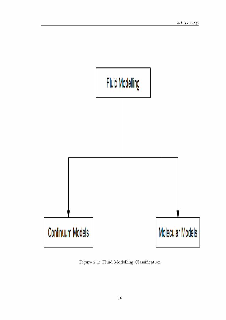
There are basically two ways of fluid modelling .i.e. Molecular Models and Con-
tinuum models . In Molecular Models , the fluid really is a collection of molecules
and in case of Continuum models there is continuous matter and indefinitely di-
visible. The Molecular Modelling is subdivided into deterministic methods and
probabilistic ones , while in the Continuum models the velocity , density , pressure
etc are defined at every point in space and time , and conservation of mass , energy
and momentum is leading to a set of nonlinear partial differential equations(Navier
Stokes ).
Navier stokes based fluid dynamics solvers are often inaccurate when applied
to MEMS . This inaccuracy stems from their calculations of molecular transport
effects ,such as viscous dissipation and thermal conduction and also mean velocity
and temperature which are the bulk flow quantities. This approximation of micro-
scale phenomena with macro-scale information fails as the characteristic length of
the gaseous flow (L) approaches the average distance travelled by molecules be-
tween collisions ( mean path ,) .The ratio of these quantities is known as Knudsen
number.
Kn = λ/Dh
where λ =KT√
2Pσ23.147
15
2.1 Theory:
Figure 2.1: Fluid Modelling Classification
16

2.1 Theory:
This is valid for an ideal gas model as rigid sphere , is the molecular diameter
and k is Boltzmann constant . Generally the traditional continuum approach is
valid with boundary conditions as long as Kn is less than 0.1.
Table 2.1: Knudsen number Regimes
Knudsen Number Regimes
Kn <0.001 Continuum
0.001<0.1 Slip flow
0.1<10 Transition
Kn>10 Free Molecule
The Navier-Stokes equations can be taken into account when λ < L . And if
it is violated , then the flow is no longer near equilibrium and the no-slip velocity
condition are no longer valid. Similarly , the linear relation between heat flux
and temperature gradient and the no-jump temperature condition at a solid-fluid
interface are no longer accurate when mean free path is not much smaller than L.
The fluid is considered to be continuum when the Kn < 0.001,and , the fluid is
considered to be a free molecular flow when the Knudsen number is greater than
equal to 10 . For (0.001 < Kn < 0.1) is the near continuum region. Knudsen
number can also be expressed in terms of two important dimensionless numbers
of fluid mechanics .
Kn =
√3.14yMa
2Re
Re=ρV L
µ
And the Mach Number is the ratio of flow velocity to the speed of sound.
Ma=V
a
Where V is the characteristic velocity of the fluid.
17
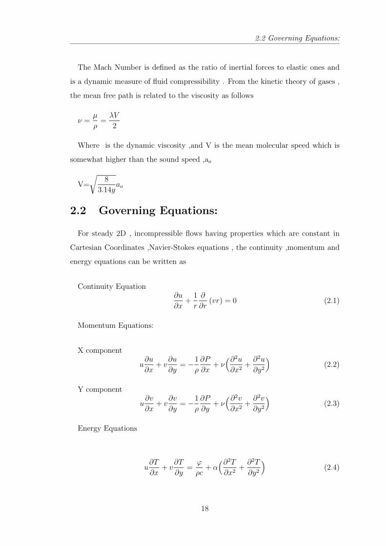
2.2 Governing Equations:
The Mach Number is defined as the ratio of inertial forces to elastic ones and
is a dynamic measure of fluid compressibility . From the kinetic theory of gases ,
the mean free path is related to the viscosity as follows
ν =µ
ρ=λV
2
Where is the dynamic viscosity ,and V is the mean molecular speed which is
somewhat higher than the sound speed ,ao
V=
√8
3.14yao
2.2 Governing Equations:
For steady 2D , incompressible flows having properties which are constant in
Cartesian Coordinates ,Navier-Stokes equations , the continuity ,momentum and
energy equations can be written as
Continuity Equation∂u
∂x+
1
r
∂
∂r(vr) = 0 (2.1)
Momentum Equations:
X component
u∂u
∂x+ v
∂u
∂y= −1
ρ
∂P
∂x+ ν(∂2u∂x2
+∂2u
∂y2
)(2.2)
Y component
u∂v
∂x+ v
∂v
∂y= −1
ρ
∂P
∂y+ ν(∂2v∂x2
+∂2v
∂y2
)(2.3)
Energy Equations
u∂T
∂x+ v
∂T
∂y=
ϕ
ρc+ α
(∂2T∂x2
+∂2T
∂y2
)(2.4)
18
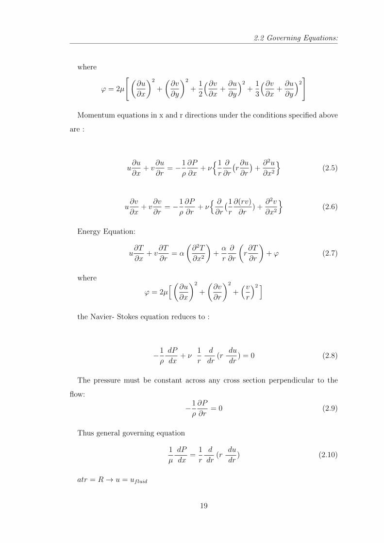
2.2 Governing Equations:
where
ϕ = 2µ
[(∂u
∂x
)2
+
(∂v
∂y
)2
+1
2
(∂v∂x
+∂u
∂y
)2+
1
3
(∂v∂x
+∂u
∂y
)2]
Momentum equations in x and r directions under the conditions specified above
are :
u∂u
∂x+ v
∂u
∂r= −1
ρ
∂P
∂x+ ν{1
r
∂
∂r
(r∂u
∂r
)+∂2u
∂x2
}(2.5)
u∂v
∂x+ v
∂v
∂r= −1
ρ
∂P
∂r+ ν{ ∂
∂r
(1
r
∂(rv)
∂r) +
∂2v
∂x2
}(2.6)
Energy Equation:
u∂T
∂x+ v
∂T
∂r= α
(∂2T
∂x2
)+α
r
∂
∂r
(r∂T
∂r
)+ ϕ (2.7)
where
ϕ = 2µ[(∂u
∂x
)2
+
(∂v
∂r
)2
+(vr
)2 ]the Navier- Stokes equation reduces to :
−1
ρ
dP
dx+ ν
1
r
d
dr(r
du
dr) = 0 (2.8)
The pressure must be constant across any cross section perpendicular to the
flow:
−1
ρ
∂P
∂r= 0 (2.9)
Thus general governing equation
1
µ
dP
dx=
1
r
d
dr(r
du
dr) (2.10)
atr = R→ u = ufluid
19

2.4 Slip Velocity:
atr = 0→ u = finite
where us represents slip velocity Energy Equation reduces to
u∂T
∂x=α
r
∂
∂r
(r∂T
∂r
)+ν
cp
(du
dr
)2
(2.11)
at r = R → T = Tfluid
at r=0 → ∂T∂r
= 0
at x=0→ T = T(i)
2.3 Boundary Conditions:
In practice , the no-slip/no-jump condition leads to fairly accurate predictions
as long as Kn is less than 0.001 (for gases ). Beyond that , the collision frequency
is simply not high enough to ensure equilibrium and a certain degree of tangential
velocity slip and temperature jump must be allowed
2.4 Slip Velocity:
When rarefaction of gases comes into role no slip boundary condition at the wall
are no longer sufficient . Rarefaction of gases directly depends upon Knudsen
number with increase in the Knudsen Number .Rarefaction effect increases and
the no-slip assumption are invalid in those circumstances. Hence application of
slip at the wall becomes necessary at higher rarefaction in turn at higher Knudsen
number .Maxwell derived slip velocity correlation as :
Ufluid − Uwall =2− Fv
Fv
∗ λ ∗ (∂U
∂Y)wall (2.12)
Here Fv is Tangential Moment Accomodation Coefficient and for air is equal to
1.
20
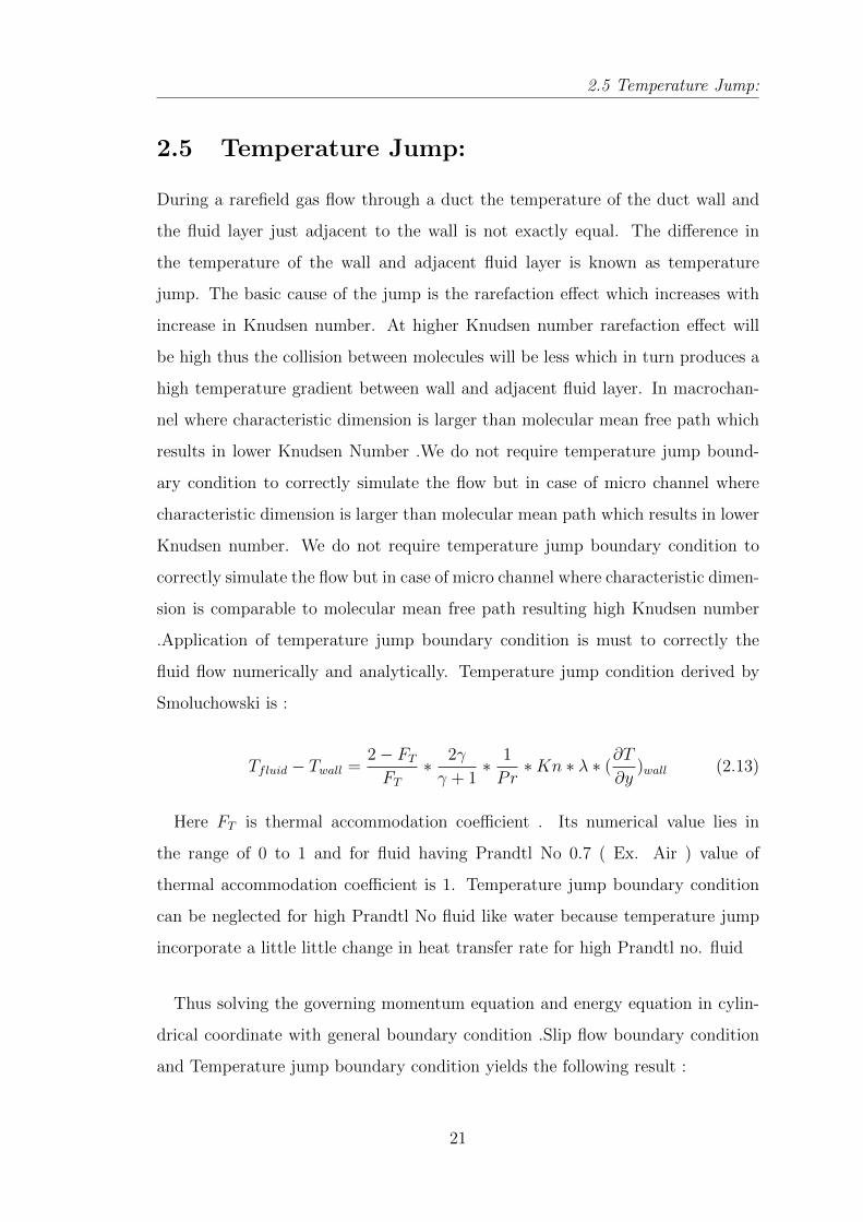
2.5 Temperature Jump:
2.5 Temperature Jump:
During a rarefield gas flow through a duct the temperature of the duct wall and
the fluid layer just adjacent to the wall is not exactly equal. The difference in
the temperature of the wall and adjacent fluid layer is known as temperature
jump. The basic cause of the jump is the rarefaction effect which increases with
increase in Knudsen number. At higher Knudsen number rarefaction effect will
be high thus the collision between molecules will be less which in turn produces a
high temperature gradient between wall and adjacent fluid layer. In macrochan-
nel where characteristic dimension is larger than molecular mean free path which
results in lower Knudsen Number .We do not require temperature jump bound-
ary condition to correctly simulate the flow but in case of micro channel where
characteristic dimension is larger than molecular mean path which results in lower
Knudsen number. We do not require temperature jump boundary condition to
correctly simulate the flow but in case of micro channel where characteristic dimen-
sion is comparable to molecular mean free path resulting high Knudsen number
.Application of temperature jump boundary condition is must to correctly the
fluid flow numerically and analytically. Temperature jump condition derived by
Smoluchowski is :
Tfluid − Twall =2− FT
FT
∗ 2γ
γ + 1∗ 1
Pr∗Kn ∗ λ ∗ (
∂T
∂y)wall (2.13)
Here FT is thermal accommodation coefficient . Its numerical value lies in
the range of 0 to 1 and for fluid having Prandtl No 0.7 ( Ex. Air ) value of
thermal accommodation coefficient is 1. Temperature jump boundary condition
can be neglected for high Prandtl No fluid like water because temperature jump
incorporate a little little change in heat transfer rate for high Prandtl no. fluid
Thus solving the governing momentum equation and energy equation in cylin-
drical coordinate with general boundary condition .Slip flow boundary condition
and Temperature jump boundary condition yields the following result :
21
2.7 Analytical Conclusions:
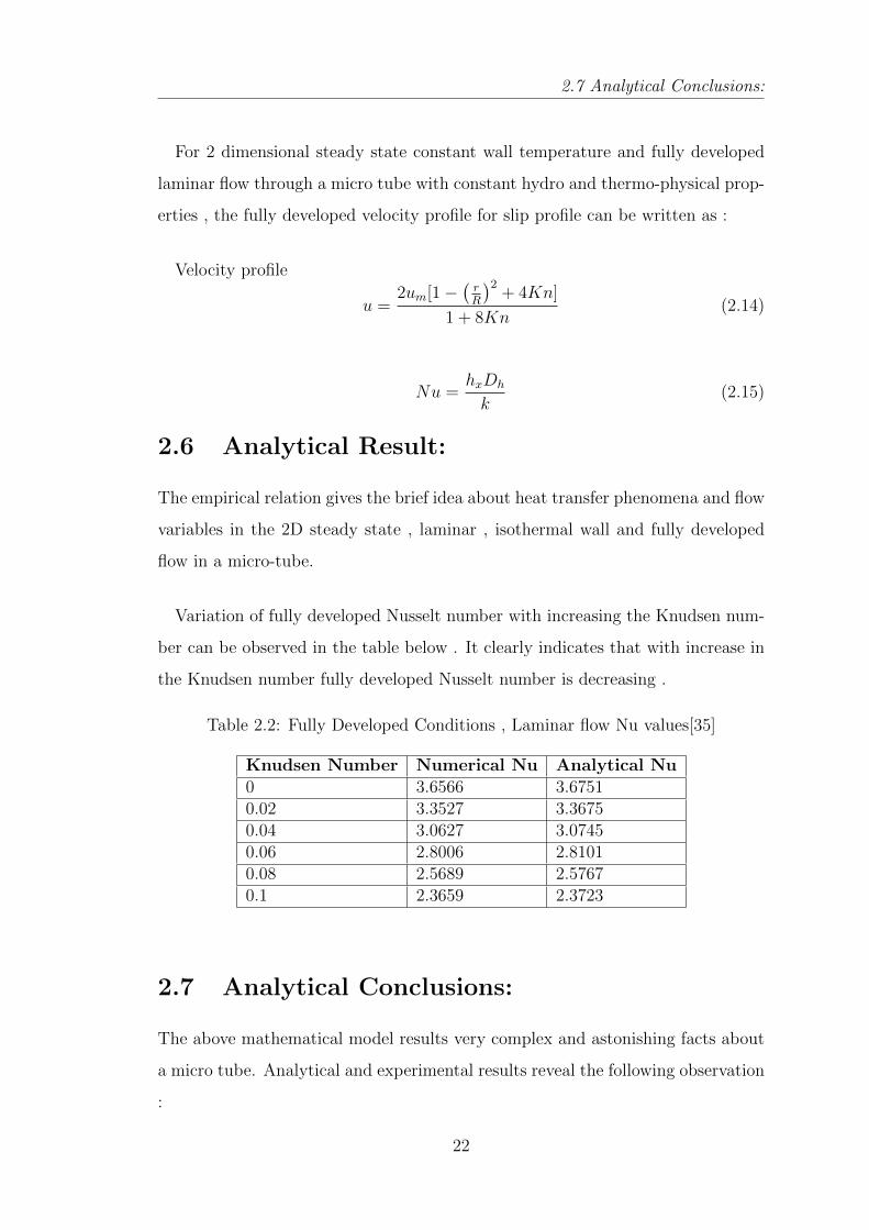
For 2 dimensional steady state constant wall temperature and fully developed
laminar flow through a micro tube with constant hydro and thermo-physical prop-
erties , the fully developed velocity profile for slip profile can be written as :
Velocity profile
u =2um[1−
(rR
)2+ 4Kn]
1 + 8Kn(2.14)
Nu =hxDh
k(2.15)
2.6 Analytical Result:
The empirical relation gives the brief idea about heat transfer phenomena and flow
variables in the 2D steady state , laminar , isothermal wall and fully developed
flow in a micro-tube.
Variation of fully developed Nusselt number with increasing the Knudsen num-
ber can be observed in the table below . It clearly indicates that with increase in
the Knudsen number fully developed Nusselt number is decreasing .
Table 2.2: Fully Developed Conditions , Laminar flow Nu values[35]
Knudsen Number Numerical Nu Analytical Nu0 3.6566 3.67510.02 3.3527 3.36750.04 3.0627 3.07450.06 2.8006 2.81010.08 2.5689 2.57670.1 2.3659 2.3723
2.7 Analytical Conclusions:
The above mathematical model results very complex and astonishing facts about
a micro tube. Analytical and experimental results reveal the following observation
:
22

2.7 Analytical Conclusions:
1. Solving the momentum equation and energy equation with proper slip bound-
ary condition is required to correctly model the flow in microtube where
Knudsen number is high in comparison to macro tube.
2. Pr number plays a significant role in micro -tube analysis as it directly
affects the temperature jump magnitude. With increase in Pr number tem-
perature gradient temperature gradient between the wall and fluid decreases.
Hence high Pr number fluid diminishes the applicability of temperature jump
boundary condition with small inaccuracy in the prediction of flow variables
and dimensionless number.
3. The fundamental correlation for macro-tube is not applicable in micro-tube.
Transition of laminar zone to turbulent zone cannot be predicted by funda-
mental correlation of macro-tube. It has been observed that the transition
of laminar to turbulent flow takes place at lower Re value (Re=200) in com-
parison to the conventional size tube where transition takes place at higher
Re number (Re=2300-4000).
4. Pr number being fixed Knudsen number affects the prediction of dimen-
sionless number and variable up to a larger extent. It has been found tha
the nusselt number inversely relates with the Nusselt number which reveals
that with the increase in the Knudsen number Nu number is decreasing
23

Problem Formulation
Chapter 3
Problem Formulation
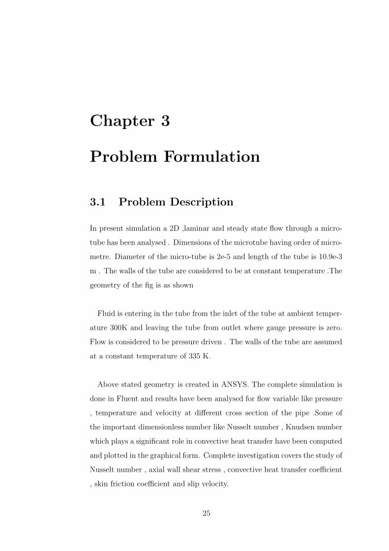
3.1 Problem Description
In present simulation a 2D ,laminar and steady state flow through a micro-
tube has been analysed . Dimensions of the microtube having order of micro-
metre. Diameter of the micro-tube is 2e-5 and length of the tube is 10.9e-3
m . The walls of the tube are considered to be at constant temperature .The
geometry of the fig is as shown
Fluid is entering in the tube from the inlet of the tube at ambient temper-
ature 300K and leaving the tube from outlet where gauge pressure is zero.
Flow is considered to be pressure driven . The walls of the tube are assumed
at a constant temperature of 335 K.
Above stated geometry is created in ANSYS. The complete simulation is
done in Fluent and results have been analysed for flow variable like pressure
, temperature and velocity at different cross section of the pipe .Some of
the important dimensionless number like Nusselt number , Knudsen number
which plays a significant role in convective heat transfer have been computed
and plotted in the graphical form. Complete investigation covers the study of
Nusselt number , axial wall shear stress , convective heat transfer coefficient
, skin friction coefficient and slip velocity.
25
3.1 Problem Description
Figure 3.1: Physical Geometry of Problem
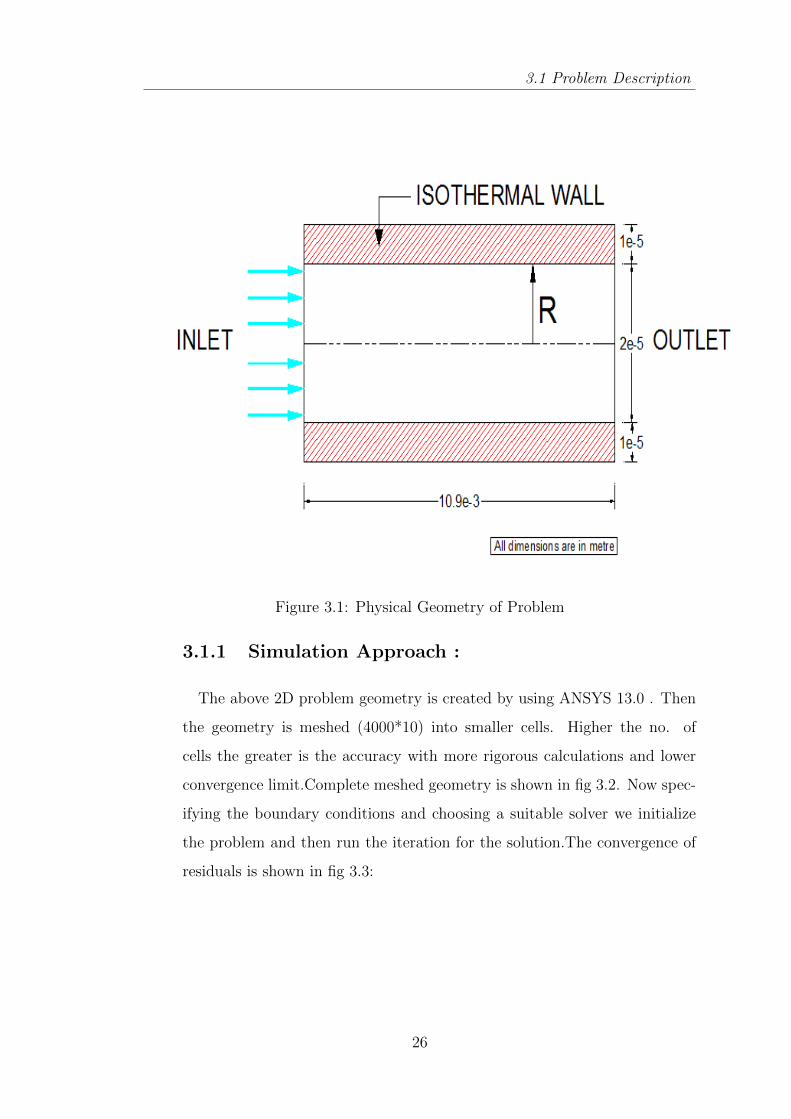
3.1.1 Simulation Approach :
The above 2D problem geometry is created by using ANSYS 13.0 . Then
the geometry is meshed (4000*10) into smaller cells. Higher the no. of
cells the greater is the accuracy with more rigorous calculations and lower
convergence limit.Complete meshed geometry is shown in fig 3.2. Now spec-
ifying the boundary conditions and choosing a suitable solver we initialize
the problem and then run the iteration for the solution.The convergence of
residuals is shown in fig 3.3:
26
3.1 Problem Description
Figure 3.2: Complete Meshed Geometry
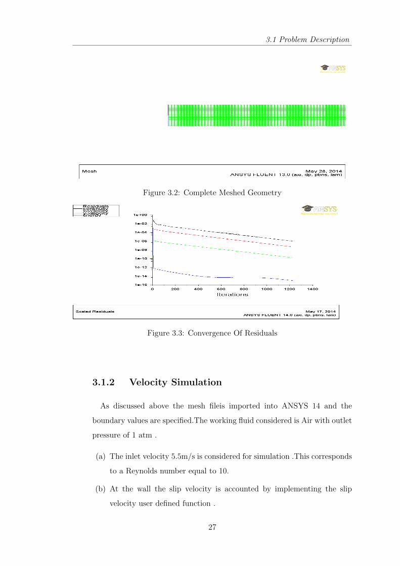
Figure 3.3: Convergence Of Residuals
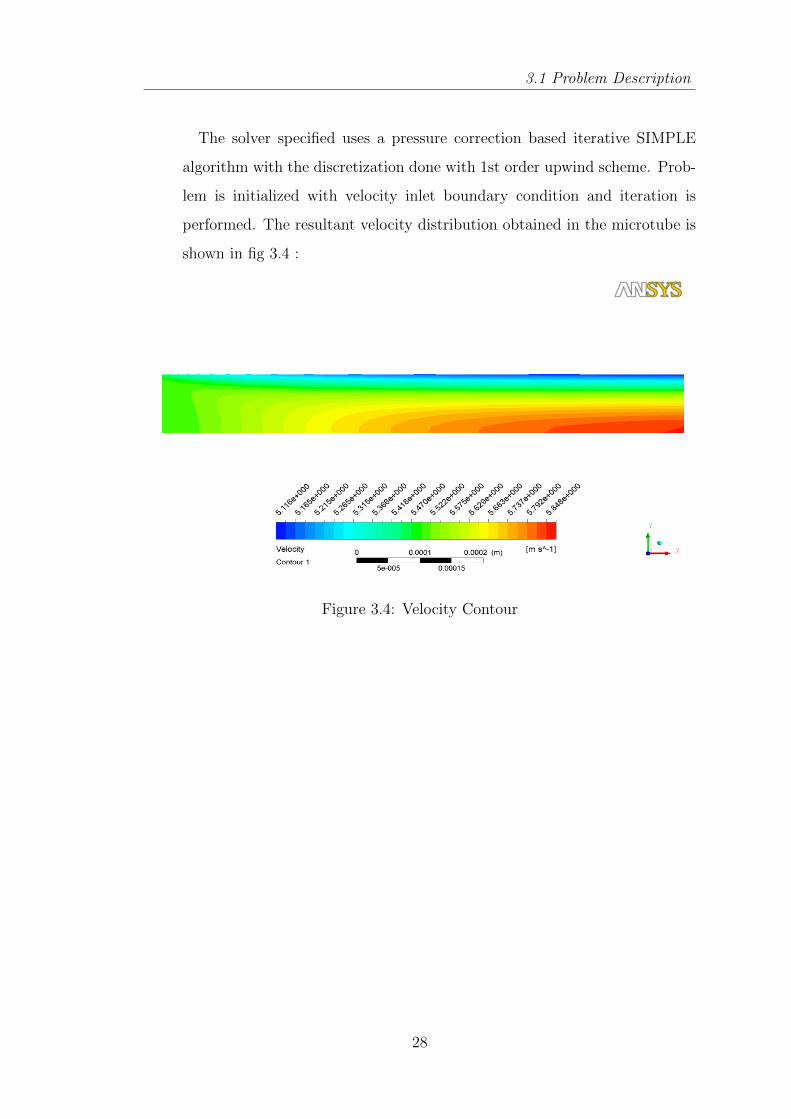
3.1.2 Velocity Simulation
As discussed above the mesh fileis imported into ANSYS 14 and the
boundary values are specified.The working fluid considered is Air with outlet
pressure of 1 atm .
(a) The inlet velocity 5.5m/s is considered for simulation .This corresponds
to a Reynolds number equal to 10.
(b) At the wall the slip velocity is accounted by implementing the slip
velocity user defined function .
27
3.1 Problem Description
The solver specified uses a pressure correction based iterative SIMPLE
algorithm with the discretization done with 1st order upwind scheme. Prob-
lem is initialized with velocity inlet boundary condition and iteration is
performed. The resultant velocity distribution obtained in the microtube is
shown in fig 3.4 :
Figure 3.4: Velocity Contour
28
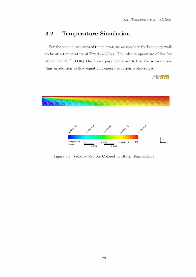
3.2 Temperature Simulation
3.2 Temperature Simulation
For the same dimensions of the micro-tube we consider the boundary walls
to be at a temperature of Twall (=335k). The inlet temperature of the free
stream be Ti (=300K).The above parameters are fed to the software and
thus in addition to flow equation , energy equation is also solved.
Figure 3.5: Velocity Vectors Colored by Static Temperature
29
3.3 Program Validation
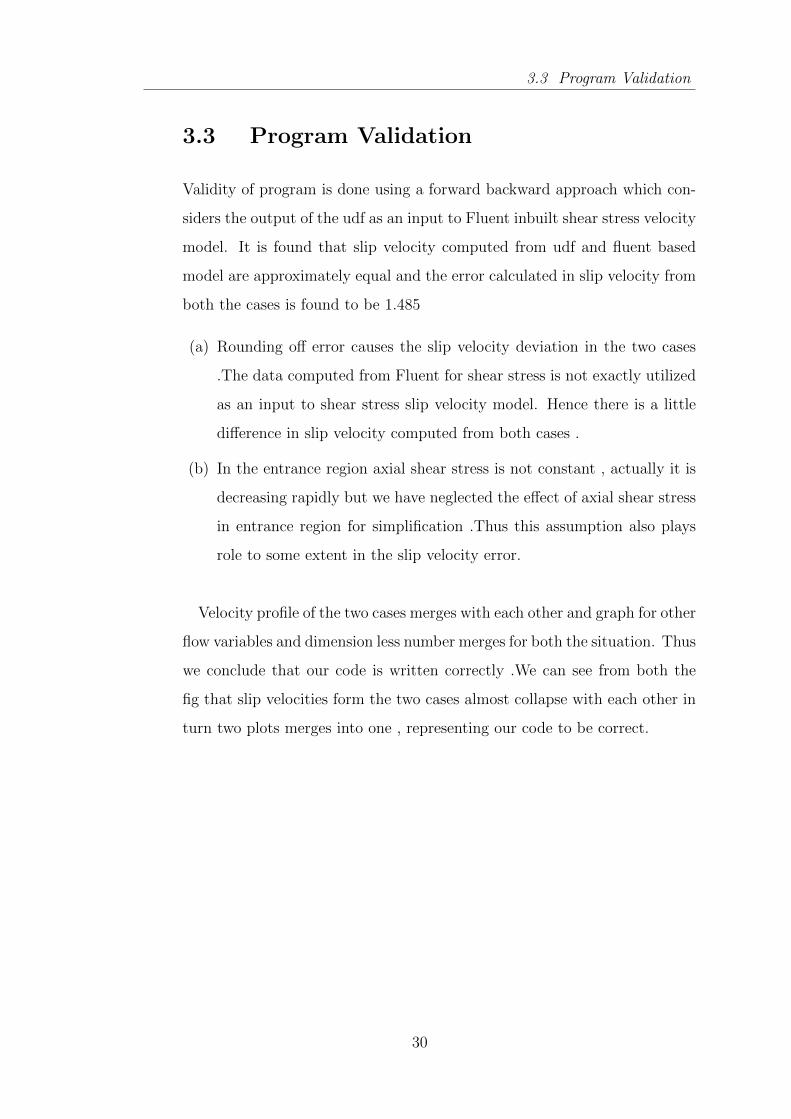
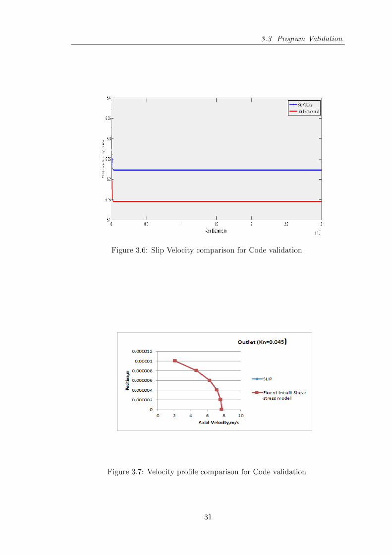
3.3 Program Validation
Validity of program is done using a forward backward approach which con-
siders the output of the udf as an input to Fluent inbuilt shear stress velocity
model. It is found that slip velocity computed from udf and fluent based
model are approximately equal and the error calculated in slip velocity from
both the cases is found to be 1.485
(a) Rounding off error causes the slip velocity deviation in the two cases
.The data computed from Fluent for shear stress is not exactly utilized
as an input to shear stress slip velocity model. Hence there is a little
difference in slip velocity computed from both cases .
(b) In the entrance region axial shear stress is not constant , actually it is
decreasing rapidly but we have neglected the effect of axial shear stress
in entrance region for simplification .Thus this assumption also plays
role to some extent in the slip velocity error.
Velocity profile of the two cases merges with each other and graph for other
flow variables and dimension less number merges for both the situation. Thus
we conclude that our code is written correctly .We can see from both the
fig that slip velocities form the two cases almost collapse with each other in
turn two plots merges into one , representing our code to be correct.
30
3.3 Program Validation
Figure 3.6: Slip Velocity comparison for Code validation
Figure 3.7: Velocity profile comparison for Code validation
31

Results and Discussion
Chapter 4
Results and Discussion
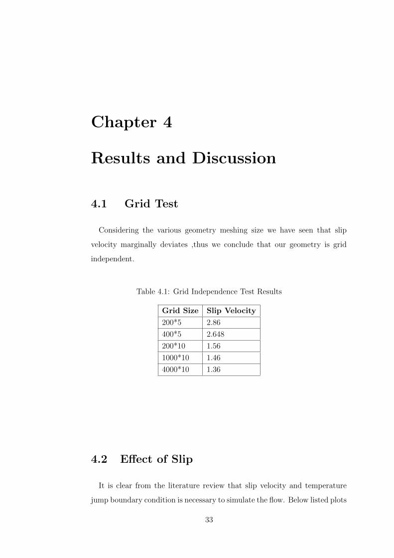
4.1 Grid Test
Considering the various geometry meshing size we have seen that slip
velocity marginally deviates ,thus we conclude that our geometry is grid
independent.
Table 4.1: Grid Independence Test Results
Grid Size Slip Velocity
200*5 2.86
400*5 2.648
200*10 1.56
1000*10 1.46
4000*10 1.36
4.2 Effect of Slip
It is clear from the literature review that slip velocity and temperature
jump boundary condition is necessary to simulate the flow. Below listed plots
33
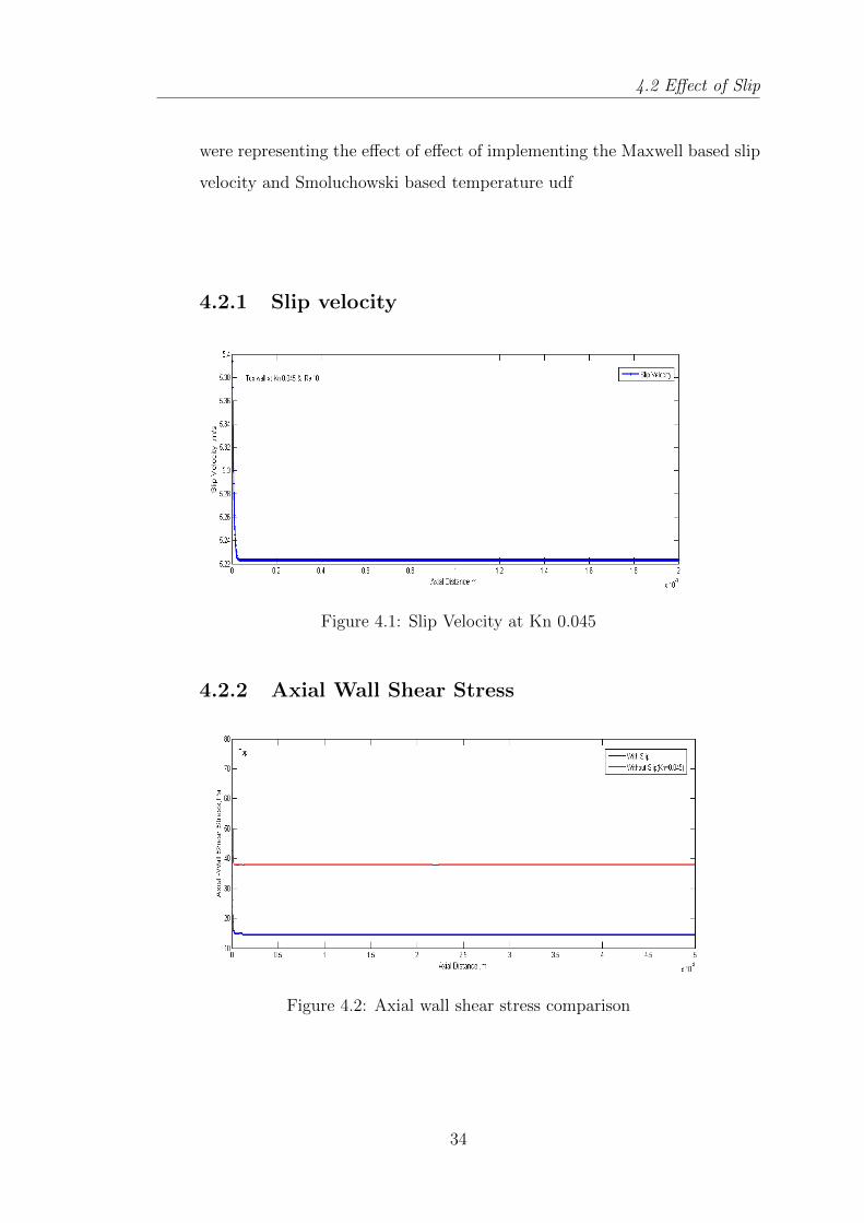
4.2 Effect of Slip
were representing the effect of effect of implementing the Maxwell based slip
velocity and Smoluchowski based temperature udf
4.2.1 Slip velocity
Figure 4.1: Slip Velocity at Kn 0.045
4.2.2 Axial Wall Shear Stress
Figure 4.2: Axial wall shear stress comparison
34
4.2 Effect of Slip
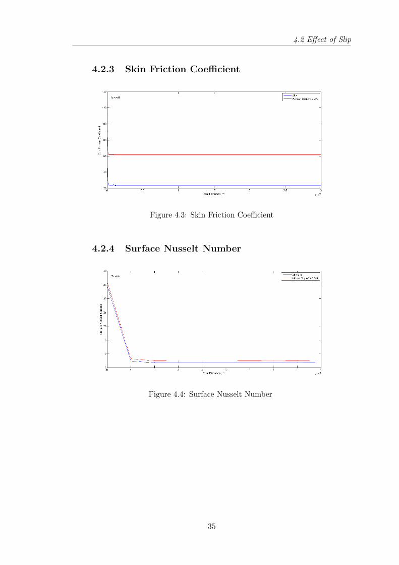
4.2.3 Skin Friction Coefficient
Figure 4.3: Skin Friction Coefficient
4.2.4 Surface Nusselt Number
Figure 4.4: Surface Nusselt Number
35

4.2 Effect of Slip
4.2.5 Surface Heat Transfer Coefficient
Figure 4.5: Surface Heat Transfer Coefficient
4.2.6 Centreline Temperature
Figure 4.6: Centreline Temperature
36
4.3 Effect of Knudsen Number
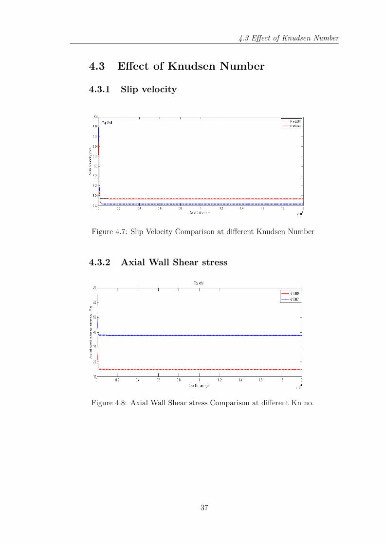
4.3 Effect of Knudsen Number
4.3.1 Slip velocity
Figure 4.7: Slip Velocity Comparison at different Knudsen Number
4.3.2 Axial Wall Shear stress
Figure 4.8: Axial Wall Shear stress Comparison at different Kn no.
37
4.3 Effect of Knudsen Number
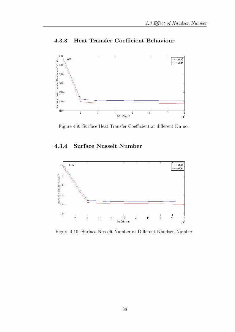
4.3.3 Heat Transfer Coefficient Behaviour
Figure 4.9: Surface Heat Transfer Coefficient at different Kn no.
4.3.4 Surface Nusselt Number
Figure 4.10: Surface Nusselt Number at Different Knudsen Number
38
4.4 Effect of Reynolds Number
4.4 Effect of Reynolds Number
4.4.1 Slip Velocity
Figure 4.11: Slip Velocity at different Re no.
4.4.2 Axial Wall Shear stress
Figure 4.12: Axial Wall Shear stress at different Re no.
39
4.4 Effect of Reynolds Number
4.4.3 Heat transfer Coefficient Trend
Figure 4.13: Heat transfer Coefficient at different Re no.
4.4.4 Surface Nusselt Number Trend
Figure 4.14: Surface Nusselt Number at different Re no.
40
4.4 Effect of Reynolds Number
4.4.5 fRe Vs Axial distance
Figure 4.15: fRe Vs Axial distance
41

4.4 Effect of Reynolds Number
(a) Velocity contour shown in fig 3.4 clearly indicates that velocity is high-
est at the centre and it is decreasing continuously as we move from axis
to the wall ,AT the entrance region velocity is changing at axis but
once the flow is developed it remains constant throughout the tube.
(b) Fig 3.5 is showing the distribution of temperature inside the micro-tube.
It is clear that the temperature vector plot that heat is transferring from
wall to fluid hence temperature of wall is increasing and at the end of
the micro tube whole fluid attains the temperature of the wall.
(c) Fig 3.6 represents the slip velocity computed from two different method
i.e through slip velocity udf and through fluent inbuilt shear stress
model which do not have capability of varying Knudsen number .It is
clear from the graph that slip velocity that slip velocity plot merge
together indicating our code to be right.
(d) In Fig 3.7 velocity profile computed from two models is compared and
it is found that two plot overlap one over other which validates our code
to be right.
(e) Here in fig 4.1 ,effect of implementing the user defined function is shown
. Without slip the velocity at the wall comes out to be zero but as we
implemented the slip user defined function initially velocity at the wall
is high and then decreases rapidly and attains a constant value very
quickly.
(f) Fig 4.2 represents the Axial wall shear stress in y coordinate and axial
length of micro tube in x coordinate is considered .Here we can judge
that the trend of the plot is similar to the slip velocity plot . It is
indicated by the present fig that as we implement our udf of slip axial
wall shear stress is reducing as shown with the red curve.
(g) Fig 4.3 represents the skin friction coefficient and it is found that the
trend of the plot is similar to the slip velocity and applying the udf
reduces the skin friction coefficient as represented by red curve.
42
4.4 Effect of Reynolds Number
(h) Fig 4.4 depicts the behaviour of Surface Nusselt Number with respect
to the axial length of the micro-tube.It is found that initially the value
of surface Nusselt number is very large and it rapidly decreases in the
entrance region but after some length it decreases slowly and at the
end of the pipe attains a value around 3.86, this curve is not enough
accurate in terms of data but depicts the effect of implementing the slip
reduces the Nusselt number . Fig 4.5 finds the same explanation as in
place of Surface Nusselt number heat transfer characteristic is taken.
(i) Fig 4.6 the temperature of the centreline is drawn with respect to the
axial length. In the beginning length temperature of the centreline
increases linearly as heat transfer from the wall to the fluid , once the
centreline attains the temperature of wall there is no further increase in
temperature and curve becomes parallel to axis representing no further
increase in temperature.
(j) Fig 4.7 represents the effect of changing the Knudsen number on slip
velocity while Reynolds number is being fixed and it is found that with
increasing the Reynolds number slip velocity is also increasing.
(k) Fig 4.8 represents the effect of varying the Knudsen number on axial
wall shear stress and trend of the plot is showing that shear stress
decreases with increase in the Knudsen number.
(l) Fig 4.9 4.10 depicts the variation in Nusselt number and heat transfer
coefficient respectively with changing the Knudsen Number and indi-
cates reduction of both Nusselt number and heat transfer coefficient
with increase in the Knudsen number.
(m) Fig 4.11 represents the effect of changing the Reynolds number on slip
velocity while Knudsen number is being fixed and it is found that with
increasing Re number slip velocity is also increasing.
(n) Fig 4.12 represents the effect of varying the Reynolds number on axial
wall shear stress and the trend of the plot is showing that it is decreasing
with increasing the Reynolds number.
43

4.4 Effect of Reynolds Number
(o) Fig 4.13 and 4.14 depicts the variation in heat transfer coefficient and
Nusselt number respect with changing the Reynolds number and indi-
cates enhancement of both Nusselt number and heat transfer coefficient
with increase in Reynolds number.
(p) Fig 4.15 is representing the effect of varying the fRe along the axial
distance and the trend of the plot is showing that it is decreasing with
the increase in the axial distance.
44

Conclusion and Future Work
4.5 Conclusion
4.5 Conclusion
Present work provides the trends of flow variable and dimensionless
number by varying the Reynolds number and Knudsen number .Ob-
serving the plots for various parameters and comparing them with the
analytical solution it is concluded that flow variable are correctly pre-
dicted in terms of data and trend but dimensionless number and pa-
rameters derive from flow variable are correct in terms of nature and
trend but do not accurately predict the exact data value. The complete
essence of current work can be summarized as follows:
i. Effect of UDF section represents implementing the UDF reduces
the heat transfer phenomena and Surface Nusselt Number .Imple-
mentation of Slip decreases the slip flow regime where value of
Knudsen number is high.
ii. Effect of Knudsen Number reveals the fact that increasing the
Knudsen number increases the slip velocity at the wall but de-
creases the axial wall shear stress, heat transfer coefficient and
Surface Nusselt number . Centerline temperature is find to increase
linearly and then attaining a constant value.
iii. Effect of Reynolds Number : It reveals the fact that increasing the
Reynolds number enhances the heat transfer and parameter related
to heat transfer like surface Nusselt number and Heat transfer co-
efficient.
46
4.6 Future work
4.6 Future work
The geometric parameters of the tube have a significant influence on
the convective heat transfer characteristics. Hence , to design effective
micro tube heat sinks , design parameters like pressure required cir-
culating the cooling fluid , flow rate ,hydraulic diameter of the tube
, temperature of the fluid and the tube wall and the number of tube
has to be considered. To make the system effective and cheaper ,these
parameters have to be optimized .
i. It is observed that temperature jump effect is almost negligible in
high Prandtl number fluid like water (Pr =14).Deviations in the
flow and convective heat transfer characteristics have been observed
for ionic fluids in micro-channels , the reasons is due to the presence
electrostatic charge difference between the surface and the fluid.
So the presence of the electrostatic force field and the double layer
is found to influence the velocity field and this influence is to be
incorporated in the analysis of the flow of ionic fluids in micro-
tube and this can be done by introducing an additional term which
represents the electric body force due to the electric double layer ,
in the momentum equations .
ii. Study of thermal creep is an important phenomenon which in-
creases or decreases slip velocity depending upon heating or cooling
of fluid .
iii. Change in thermo physical property with temperature and pres-
sure can be included by writing the UDF.
47
Bibliography
[1] Aydn, Orhan, and Mete Avc.Heat and fluid flow characteris-
tics of gases in micropipes. International Journal of Heat and
Mass Transfer 49.9 (2006): 1723-1730.
[2] Hadjiconstantinou, N. G., Simek, O. (2002). Constant-wall-
temperature Nusselt number in micro and nano-channels.
Journal of Heat Transfer, 124(2), 356-364.
[3] Tunc, Gokturk, and Yildiz Bayazitoglu. Heat transfer in rect-
angular microchannels. International Journal of Heat and
Mass Transfer 45.4 (2002): 765-773.
[4] Chen, Chien-Hsin. Slip-flow heat transfer in a microchannel
with viscous dissipation. Heat and mass transfer 42.9 (2006):
853-860.
[5] Jeong, H. E., Jeong, J. T. (2006). Extended Graetz problem
including streamwise conduction and viscous dissipation in mi-
crochannel. International Journal of Heat and Mass Transfer,
49(13), 2151-2157.
[6] Tuckerman, D. B., and R. F. W. Pease. Optimized convec-
tive cooling using micro-machined structures. Journal of the
Electrochemical Society. Vol. 129. No. 3. 10 SOUTH MAIN
STREET, PENNINGTON, NJ 08534: ELECTROCHEMI-
CAL SOC INC, 1982.
[7] Pfahler, J., et al. Liquid and gas transport in small channels.
ASME DSC. Vol. 19. No. 1. 1990.
48
Bibliography
[8] Choi, S. B., R. F. Barron, and R. O. Warrington. Fluid flow
and heat transfer in microtubes. ASME DSC. Vol. 32. 1991.
[9] Tunc, Gokturk, and Yildiz Bayazitoglu. Heat transfer in mi-
crotubes with viscous dissipation. International Journal of
Heat and Mass Transfer 44.13 (2001): 2395-2403
[10] Rahman, Muhammad M., and Fulin Gui. Experimental mea-
surements of fluid flow and heat transfer in microchannel cool-
ing passages in a chip substrate.The ASME International Elec-
tronics Packaging Conference, Binghamton, NY, USA, 09/29-
10/02/93. 1993.
[11] Wang, B. X., and X. F. Peng. Experimental investigation on
liquid forced-convection heat transfer through microchannels.
International Journal of Heat and Mass Transfer 37 (1994):
73-82.
[12] Beskok, Ali, William Trimmer, and George Em Karniadakis.
Rarefaction and compressibility effects in gas microflows. Jour-
nal of Fluids Engineering 118.3 (1996): 448-456.
[13] Peng, X. F., G. P. Peterson, and B. X. Wang. Heat transfer
characteristics of water flowing through microchannels. Exper-
imental Heat Transfer An International Journal 7.4 (1994):
265-283.
[14] Peng, X. F., G. P. Peterson, and B. X. Wang. Frictional
flow characteristics of water flowing through rectangular mi-
crochannels. EXPERIMENTAL HEAT TRANSFER An In-
ternational Journal 7.4 (1994): 249-264.
[15] Peng, X. F., et al. Experimental investigation of heat trans-
fer in flat plates with rectangular microchannels. International
Journal of Heat and Mass Transfer38.1 (1995): 127-137
[16] Peng, X. F., and G. P. Peterson. The effect of thermofluid
and geometrical parameters on convection of liquids through
49
Bibliography
rectangular microchannels.International Journal of Heat and
Mass Transfer 38.4 (1995): 755-758
[17] Kavehpour, Hossein Pirouz, Mohammad Faghri, and Y.
Asako. Effects of compressibility and rarefaction on gaseous
flows in microchannels. Numerical Heat Transfer, Part A Ap-
plications 32.7 (1997): 677-696.
[18] Aydn, Orhan, and Mete Avc. Analysis of micro-Graetz prob-
lem in a microtube. Nanoscale and microscale thermophysical
engineering 10.4 (2006): 345-358.
[19] Tyagi, V. P., and K. M. Nigam. On closed-form analytical
solution for circular duct, thermally developing slug flow under
mixed boundary condition.International Journal of Heat and
Mass Transfer 18.11 (1975): 1253-1256.
[20] Barletta, Antonio, and Enzo Zanchini. Forced convection in
the thermal entrance region of a circular duct with slug flow
and viscous dissipation”.International journal of heat and
mass transfer 40.5 (1997): 1181-1190.
[21] Barletta, Antonio. Slug flow heat transfer in circular ducts
with viscous dissipation and convective boundary conditions.
International journal of heat and mass transfer 40.17 (1997):
4219-4228.
[22] Haji-Sheikh, A., Donald E. Amos, and J. V. Beck. Axial heat
conduction in a moving semi-infinite fluid. International Jour-
nal of Heat and Mass Transfer51.19 (2008): 4651-4658.
[23] Haji-Sheikh, A., Donald E. Amos, and J. V. Beck. Temper-
ature field in a moving semi-infinite region with a prescribed
wall heat flux. International Journal of Heat and Mass Trans-
fer 52.7 (2009): 2092-2101.
[24] Morini, Gian Luca, Marco Lorenzini, and Marco Spiga. A cri-
terion for experimental validation of slip-flow models for in-
50
Bibliography
compressible rarefied gases through microchannels. Microflu-
idics and Nanofluidics 1.2 (2005): 190-196.
[25] Gui, Fulin, and Roperto P. Scaringe. Enhanced heat transfer
in the entrance region of microchannels. Intersociety energy
conversion engineering conference. Vol. 2. AMERICAN NU-
CLEAR SOCIETY, 1995
[26] Randall, Tim A. Ameel Xianming Wang, and F. Barron
Robert O. Warrington Jr. Laminar forced convection in a cir-
cular tube with constant heat flux and slip flow. Microscale
Thermophysical Engineering 1.4 (1997): 303-320.
[27] Kakac, Sadik, Yaman Yener, and Anchasa Pramuanjaroenkij.
Convective heat transfer. CRC press, 2013.
[28] Adams, T. M., et al. An experimental investigation of single-
phase forced convection in microchannels. International Jour-
nal of Heat and Mass Transfer41.6 (1998): 851-857.
[29] Xu, B., et al. Liquid flow in microchannels. Proceedings of
the 5th ASME/JSME Joint Thermal Engineering Conference.
1999.
[30] Iwai, H., and K. Suzuki. Effects of velocity slip and temper-
ature jump conditions on backward-facing step flow in a mi-
crochannel. Proceedings of the 5th ASME/JSME Joint Ther-
mal Engineering Conference. 1999.
[31] Ezquerra Larrod, Francisco, Christos Housiadas, and Yannis
Drossinos. Slip-flow heat transfer in circular tubes. Interna-
tional Journal of Heat and Mass Transfer 43.15 (2000): 2669-
2680.
[32] Yu, Shiping, and Timothy A. Ameel. Slip-flow heat transfer in
rectangular microchannels. International Journal of Heat and
Mass Transfer 44.22 (2001): 4225-4234.
51
Bibliography
[33] Toh, K. C., X. Y. Chen, and J. C. Chai. Numerical compu-
tation of fluid flow and heat transfer in microchannels. In-
ternational Journal of Heat and Mass Transfer 45.26 (2002):
5133-5141
[34] Qu, Weilin, and Issam Mudawar. Analysis of three-
dimensional heat transfer in micro-channel heat sinks Inter-
national Journal of heat and mass transfer45.19 (2002): 3973-
3985.
[35] Sun, Wei, Sadik Kakac, and Almila G. Yazicioglu. A numerical
study of single-phase convective heat transfer in microtubes
for slip flow International Journal of Thermal Sciences 46.11
(2007): 1084-1094.
52
Copyright © 2022 FDOKUMEN