Numerical study of thermal enhancement in micro channel heat sink with secondary flow
8
Numerical study of thermal enhancement in micro channel heat sink with secondary flow Navin Raja Kuppusamy a , R. Saidur a,⇑ , N.N.N. Ghazali a , H.A. Mohammed b,⇑ a Department of Mechanical Engineering, University of Malaya, 50603 Kuala Lumpur, Malaysia b Department of Thermofluids, Faculty of Mechanical Engineering, Universiti Teknologi Malaysia, 81310 UTM Skudai, Johor Bahru, Malaysia article info Article history: Received 10 April 2014 Received in revised form 19 June 2014 Accepted 24 June 2014 Available online 17 July 2014 Keywords: Micro channel heat sink Numerical analysis Secondary flow Slanted passage Heat transfer enhancement abstract Secondary flow is employed in micro channel heat sink (MCHS) by introducing slanted passage in the channel wall between the adjacent channels in alternating orientation. The intervallic passage causes disruption in the hydrodynamic boundary layer and redevelopment at the leading edge of the following wall. This phenomenon decreases the average thermal boundary layer thickness, thus enhances the heat transfer performance with minor pressure drop due to combined effect of thermal boundary layer re-development and flow mixing. The data presented in comparison of simple MCHS. The results showed that the overall performance of MCHS with alternating slanted passage (MASP) increased by 146% and thermal resistance reduced to 76.8% when compared with simple MCHS. It has to be highlighted that contradicting from the usual phenomenon where improvement in heat transfer accompanied with incre- ment in pressure loss, thermal enhancement in present study comes together with reduction in pressure drop up to 6% compared to the simple one. Ó 2014 Elsevier Ltd. All rights reserved. 1. Introduction With the rapid increment of heat dissipation from various electronic components such as central processing unit (CPU) and graphic card in computers, there is an imperative demand for supe- rior cooling technology. Micro channel heat sink MCHS is one of the widely used devices for the cooling of tiny but extremely heated electronics components. There are several advantages in MCHS such as compactness, light weight and higher heat transfer surface area to fluid volume ratio which makes it more attractive favorable compared to macro-scale systems. The first idea of MCHS was introduced by Tuckerman and Pease [1] in 1981. The silicon MCHS has a very small volume and can achieve a heat flux of 7.9 10 6 W/m 2 with the maximum temperature difference of 71 °C between the substrate and inlet water. However, the penalty of pressure drop was very high; 200 kPa and 380 kPa using plain micro channels and pin fin enhanced micro channels respectively. Numerous reaches were conducted from thereon to study the thermal and flow performance of the MCHS. The analyses were focused on optimizing the geometry of the micro channel such as the height, width and aspect ratios [2–4]. Besides, the micro channel is also analyzed using various shapes such circular and trapezoidal channel [5–11]. Nonino et al. [12] conducted on numerical investigation on the difference type of cross-sectional shapes of micro channel for their flow behavior and wall heat flux. Morini [13] reviewed the experimental results of single phase heat transfer in micro channel. It was also observed that numbers of numerical study was to investigate the developed flow behavior in micro channel. Lee et al. [14] experimentally investigated rect- angular micro channel to validate the classical correlations and it was found that the numerical results matched well with the exper- imental data. Liu and Garimella [15] proposed five approximate analytical models for predicting the convective heat transfer in micro channel heat sinks. A modified thermal boundary condition is proposed to correctly characterize the heat flux distribution in the end. Tao et al. [16] suggested a few methods such as shortening the thermal boundary layer; increasing flow interruptions and increas- ing the velocity gradient near the heated surface for the single- phase heat transfer enhancement. Sui et al. [17] revealed that Dean Vortices were generated when liquid coolant flows through the wavy micro channel that significantly enhance the heat transfer with acceptable pressure drop. In the review of enhancement in single phase heat transfer, Steinke and Kandlikar [18] recommended that placing smaller sec- ondary channels with an angle between the mainstream channels in micro channel application will induce the secondary flow that will move from one channel to another through these channels. http://dx.doi.org/10.1016/j.ijheatmasstransfer.2014.06.072 0017-9310/Ó 2014 Elsevier Ltd. All rights reserved. ⇑ Corresponding authors. E-mail addresses: [email protected], [email protected] (R. Saidur), [email protected] (H.A. Mohammed). International Journal of Heat and Mass Transfer 78 (2014) 216–223 Contents lists available at ScienceDirect International Journal of Heat and Mass Transfer journal homepage: www.elsevier.com/locate/ijhmt
-
Upload
independent -
Category
Documents
-
view
0 -
download
0
Transcript of Numerical study of thermal enhancement in micro channel heat sink with secondary flow

International Journal of Heat and Mass Transfer 78 (2014) 216–223
Contents lists available at ScienceDirect
International Journal of Heat and Mass Transfer
journal homepage: www.elsevier .com/locate / i jhmt
Numerical study of thermal enhancement in micro channel heat sinkwith secondary flow
http://dx.doi.org/10.1016/j.ijheatmasstransfer.2014.06.0720017-9310/� 2014 Elsevier Ltd. All rights reserved.
⇑ Corresponding authors.E-mail addresses: [email protected], [email protected] (R. Saidur),
[email protected] (H.A. Mohammed).
Navin Raja Kuppusamy a, R. Saidur a,⇑, N.N.N. Ghazali a, H.A. Mohammed b,⇑a Department of Mechanical Engineering, University of Malaya, 50603 Kuala Lumpur, Malaysiab Department of Thermofluids, Faculty of Mechanical Engineering, Universiti Teknologi Malaysia, 81310 UTM Skudai, Johor Bahru, Malaysia
a r t i c l e i n f o
Article history:Received 10 April 2014Received in revised form 19 June 2014Accepted 24 June 2014Available online 17 July 2014
Keywords:Micro channel heat sinkNumerical analysisSecondary flowSlanted passageHeat transfer enhancement
a b s t r a c t
Secondary flow is employed in micro channel heat sink (MCHS) by introducing slanted passage in thechannel wall between the adjacent channels in alternating orientation. The intervallic passage causesdisruption in the hydrodynamic boundary layer and redevelopment at the leading edge of the followingwall. This phenomenon decreases the average thermal boundary layer thickness, thus enhances the heattransfer performance with minor pressure drop due to combined effect of thermal boundary layerre-development and flow mixing. The data presented in comparison of simple MCHS. The results showedthat the overall performance of MCHS with alternating slanted passage (MASP) increased by 146% andthermal resistance reduced to 76.8% when compared with simple MCHS. It has to be highlighted thatcontradicting from the usual phenomenon where improvement in heat transfer accompanied with incre-ment in pressure loss, thermal enhancement in present study comes together with reduction in pressuredrop up to 6% compared to the simple one.
� 2014 Elsevier Ltd. All rights reserved.
1. Introduction
With the rapid increment of heat dissipation from variouselectronic components such as central processing unit (CPU) andgraphic card in computers, there is an imperative demand for supe-rior cooling technology. Micro channel heat sink MCHS is one ofthe widely used devices for the cooling of tiny but extremelyheated electronics components. There are several advantages inMCHS such as compactness, light weight and higher heat transfersurface area to fluid volume ratio which makes it more attractivefavorable compared to macro-scale systems. The first idea of MCHSwas introduced by Tuckerman and Pease [1] in 1981. The siliconMCHS has a very small volume and can achieve a heat flux of7.9 � 106 W/m2 with the maximum temperature difference of71 �C between the substrate and inlet water. However, the penaltyof pressure drop was very high; 200 kPa and 380 kPa using plainmicro channels and pin fin enhanced micro channels respectively.
Numerous reaches were conducted from thereon to study thethermal and flow performance of the MCHS. The analyses werefocused on optimizing the geometry of the micro channel such asthe height, width and aspect ratios [2–4]. Besides, the microchannel is also analyzed using various shapes such circular and
trapezoidal channel [5–11]. Nonino et al. [12] conducted onnumerical investigation on the difference type of cross-sectionalshapes of micro channel for their flow behavior and wall heat flux.Morini [13] reviewed the experimental results of single phase heattransfer in micro channel. It was also observed that numbers ofnumerical study was to investigate the developed flow behaviorin micro channel. Lee et al. [14] experimentally investigated rect-angular micro channel to validate the classical correlations and itwas found that the numerical results matched well with the exper-imental data. Liu and Garimella [15] proposed five approximateanalytical models for predicting the convective heat transfer inmicro channel heat sinks. A modified thermal boundary conditionis proposed to correctly characterize the heat flux distribution inthe end.
Tao et al. [16] suggested a few methods such as shortening thethermal boundary layer; increasing flow interruptions and increas-ing the velocity gradient near the heated surface for the single-phase heat transfer enhancement. Sui et al. [17] revealed that DeanVortices were generated when liquid coolant flows through thewavy micro channel that significantly enhance the heat transferwith acceptable pressure drop.
In the review of enhancement in single phase heat transfer,Steinke and Kandlikar [18] recommended that placing smaller sec-ondary channels with an angle between the mainstream channelsin micro channel application will induce the secondary flow thatwill move from one channel to another through these channels.

Nomenclature
a ratio of width of secondary passage to total width of thechannel
b ratio of longer width of the wall to total width of thechannel
cp heat capacityDh hydraulic diameterh heat convection coefficientH height of the channelHc depth of the channelf friction factork thermal conductivityL length of the channel_m mass flow rate
Nu Nusselt numberP perimeter of the channelDP pressure dropq00 heat fluxR thermal resistanceRe Reynolds number
T temperatureum mean flow velocityW overall width of MCHSWc width of MCHS
Symbolsc channelf fluidin inletout outlet
Greek symbolsa width of the secondary passageb length of the longer width of the wallq densityh angle of the secondary passage that of longer width of
the walll viscosity
N. Raja Kuppusamy et al. / International Journal of Heat and Mass Transfer 78 (2014) 216–223 217
Besides, a venturi can be also used to produce secondary flowwithout outer power usage. Aside of that, flow disturbance canbe generated by creating grooves, protrusion and fins. For instance,Colgan et al. [19] compared various offset in fin geometries fromthe experimental results and shown that the 75 or 100 lm pitchsilicon micro channel with staggered fins achieve excellent heattransfer performance. Danish et al. [20] investigated numericallythe thermal-resistance and pumping-power characteristics ofMCHS with a grooved structure optimized the shape using amulti-objective evolutionary algorithm. Decline in thermal resis-tance and increment in Nusselt number is observed in a groovedmicro channel compared to a smooth MCHS with a small incre-ment of pumping power. Abouali and Baghernezhad [21] numeri-cally analyzed the heat transfer and flow characteristic in MCHSwith groove on the side wall on MCHS. A geometrical configurationset was developed to analyzed the parameter of the groove and itwas found that the heat flux enhance drastically in MCHS withgrooves compared simple MCHS. Xia et al. [22] numerically studiedthe thermal enhancement in MCHS with fan-shaped cavity andinternal ribs and found that the performance enhanced up to 3times although the friction factor increased until 6.3 times depend-ing on the Reynolds number. Besides, the entropy generation wasobserved reduced in MCHS with cavities and ribs compared tothe simple channel with increment of Reynolds number [23]. Inanalysis of interrupted MCHS with rectangular ribs in the trans-verse micro chambers, Chai et al. [24] found that heat transferenhanced greatly depending on the geometrical parameter andthe Reynolds number.
Tentatively, very little experimental data has been published onthe secondary flow effect in heat transfer and pressure drop in themicro/mini channels. Lee et al. [25] utilized methods suggested in[18], by creating smaller branching channels through cutting obli-quely along the fins. This structure could enhance heat transferperformance significantly with negligible pressure drop penalty.In the analysis of cylindrical oblique fin minichannel heat sink[26], the average Nusselt number increased up to 75.6% whilethe total thermal resistance decreased up to 59.1% compared toconventional straight fin minichannel heat sink.
Based on the previous literatures, it is clear that flowobstruction and the secondary flow can significantly enhance thethermal performance with additional pressure drop. However, toauthors’ best knowledge there is no researches have been done
on secondary flow with alternating direction from on channel toanother. Besides, researches most focused on the thermal enhance-ment even though it comes together with some pressure drop. Thisidea initiated the present research to develop a MCHS with second-ary passage alternating directions that could enhance the thermalenhancement without pressure loss or at most with minimal pres-sure drop. The present paper focuses on numerical study of convec-tion heat transfer in micro channel heat sinks with secondary flowin alternating slanted passage (MASP). A conjugate three dimen-sional computation is conducted to study the laminar convectiveheat transfer in MASP. The aim of the paper is to identify the heattransfer enhancement and pressure drop reduction mechanisms ofthe proposed micro channel heat sink.
2. Numerical investigation
The following assumptions were made in modeling the heattransfer in MCHS in the present study in order to simplify the anal-ysis: (1) steady state, (2) laminar flow, (3) incompressible fluid, (4)negligible axial conduction and viscous dissipation (5) constantfluid properties, (5) negligible radioactive and natural convectiveheat transfer from the micro channel heat sink.
A 3D conjugate heat transfer numerical simulation is performedon the fluid flow and the silicon substrate. Fig. 1(a) shows theMCHS with the alternating slanted secondary passage. A singlewall in the separated channels was taken as the computationaldomain in order to simplify the numerical calculation. Fig. 1(b)shows the detailed view of the computational domain where thefluid flows in the main channel and the secondary flow.
The overall dimension of both simple MCHS and MASP can befound in Table 1. The thin adiabatic wall is considered on the sideand top on the fluid to assume that there are no fluid flow and heattransfer across the periodic boundary surface. Computational gridsfor both the solid and fluid regions were generated using hex-mapscheme in GAMBIT v2.4. The standard SIMPLE algorithm isemployed for the pressure–velocity coupling method. Standarddiscretization and second order upwind discretization schemeare selected respectively for the pressure equation and bothmomentum and energy equations.
The governing equations along with the associated boundaryconditions were solved using the general purpose finite volume

Fig. 1. (a) Schematic diagram and (b) detailed view of the computational domain of MASP.
Table 1Dimension of the MCHS.
Dimension Value (mm)
L 10H 0.45W 0.30Hc 0.30Wc 0.20
Fig. 2. Detailed view of the wall of the channel with its design variable.
Fig. 3. Computational domain of MCHS with
Table 2Comparison data of MCHS with single channel and single wall.
MCHS R (10�5 K/W) Nu E^
MCHS with single channel 8.99527 8.99954 36.9301MCHS with single wall 7.66674 10.06295 29.94187
218 N. Raja Kuppusamy et al. / International Journal of Heat and Mass Transfer 78 (2014) 216–223
based CFD software package, FLUENT. The governing equations forthe incompressible fluid flow are as following:
(a) continuity equation
single (a
r � ðm*Þ ¼ 0 ð1Þ
(b) momentum equation
r � ðq m*
m*Þ ¼ rP þr � ðlr m
*Þ ð2Þ
(c) energy equations
r � ðq m*
cpTÞ ¼ r � ðkrTÞ ðliquidÞ ð3Þ
r � ðkrTÞ ¼ 0 ðsolidÞ ð4Þ
) channel (CD 1) (b) wall (CD 2).

Fig. 4. Validation of present result with Kandlikar et al. [26] for Nu(x).
Fig. 5. (a) Variation of (a) Nu and DP (b) E^
an
N. Raja Kuppusamy et al. / International Journal of Heat and Mass Transfer 78 (2014) 216–223 219
The Nusselt number is calculated as follows:
Nu ¼ hDh
kfð5Þ
where h, Dh and kf are the heat convection coefficient, hydraulicdiameter and thermal conductivity.
The hydraulic diameter of the MCHS can be defined asfollowings
Dh ¼4AP¼ 2WcHc
ðWc þ HcÞð6Þ
where A, P, Wc and Hc represents the cross sectional area, perimeter,width and height of the channel respectively.
The thermal resistance of the MCHS can be determined asfollows:
R ¼ Tw;out � Tf ;in
qLWcð7Þ
where Tw,out, Tf,in, q and L are the outlet wall temperature, inlet walltemperature, heat flux at the bottom surface and length of theMCHS.
d R (c) Nunor, DPnor, E^
nor and Rnor with a.
220 N. Raja Kuppusamy et al. / International Journal of Heat and Mass Transfer 78 (2014) 216–223
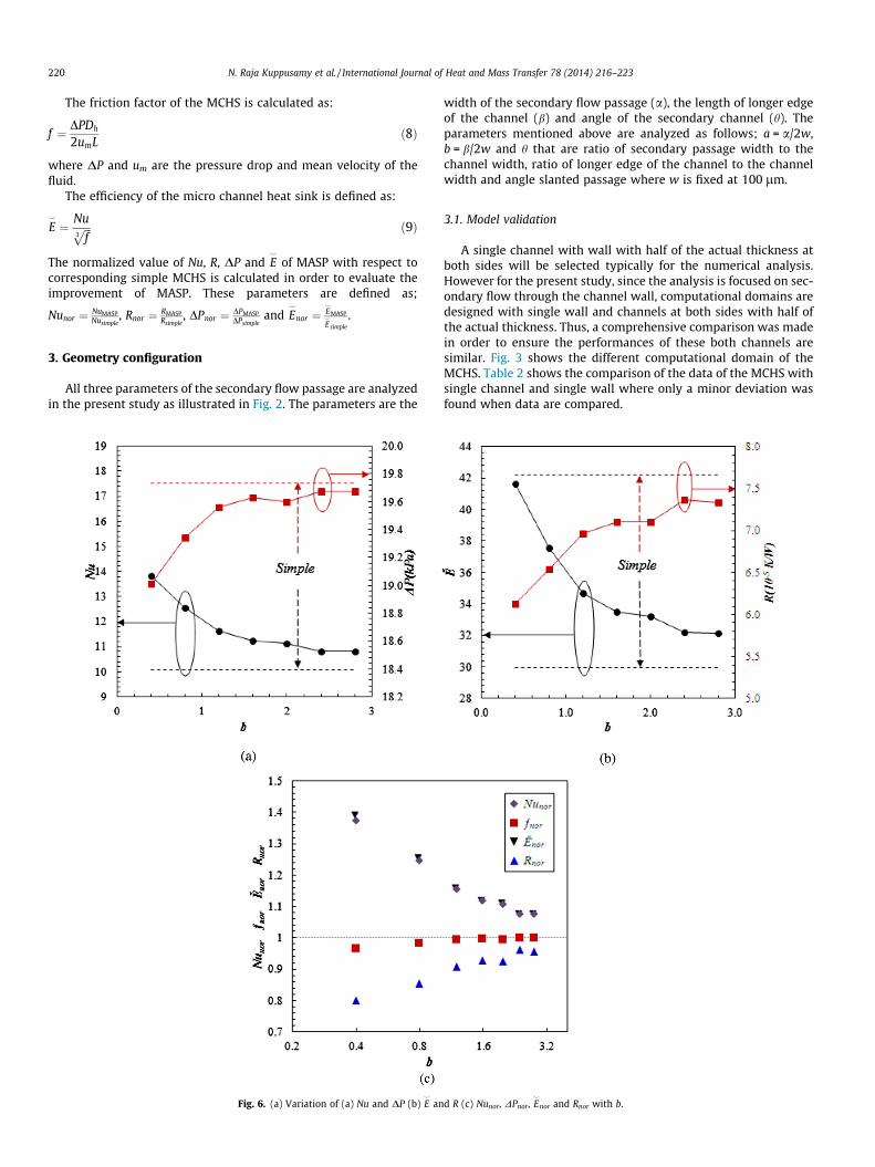
The friction factor of the MCHS is calculated as:
f ¼ DPDh
2umLð8Þ
where DP and um are the pressure drop and mean velocity of thefluid.
The efficiency of the micro channel heat sink is defined as:
E^
¼ Nuffiffiffif3
p ð9Þ
The normalized value of Nu, R, DP and E^
of MASP with respect tocorresponding simple MCHS is calculated in order to evaluate theimprovement of MASP. These parameters are defined as;
Nunor ¼ NuMASPNusimple
, Rnor ¼ RMASPRsimple
, DPnor ¼ DPMASPDPsimple
and E^
nor ¼ E^
MASP
E^
simple
.
3. Geometry configuration
All three parameters of the secondary flow passage are analyzedin the present study as illustrated in Fig. 2. The parameters are the
Fig. 6. (a) Variation of (a) Nu and DP (b) E^
an
width of the secondary flow passage (a), the length of longer edgeof the channel (b) and angle of the secondary channel (h). Theparameters mentioned above are analyzed as follows; a = a/2w,b = b/2w and h that are ratio of secondary passage width to thechannel width, ratio of longer edge of the channel to the channelwidth and angle slanted passage where w is fixed at 100 lm.
3.1. Model validation
A single channel with wall with half of the actual thickness atboth sides will be selected typically for the numerical analysis.However for the present study, since the analysis is focused on sec-ondary flow through the channel wall, computational domains aredesigned with single wall and channels at both sides with half ofthe actual thickness. Thus, a comprehensive comparison was madein order to ensure the performances of these both channels aresimilar. Fig. 3 shows the different computational domain of theMCHS. Table 2 shows the comparison of the data of the MCHS withsingle channel and single wall where only a minor deviation wasfound when data are compared.
d R (c) Nunor, DPnor, E^
nor and Rnor with b.

N. Raja Kuppusamy et al. / International Journal of Heat and Mass Transfer 78 (2014) 216–223 221
Both models are then validated with the available analyticalequation for local Nusselt number, Nu(x) for three-side heatingprovided by Kandlikar et al.[27]. Fig. 4 shows that data obtainedfrom the both present model matched with the analytical equation.
4. Results and discussion
Thermal and hydraulic performance as well as the overallenhancement of MASP for variation of the geometrical parametersis presented in terms of Nu, DP, R and E
^
together with performanceof simple MCHS. Besides, the normalized improvement factor ofNu, DP, R and E
^
compared to simple MCHS are presented in termsNunor, DPnor and E
^
norand reduction factor of Rnor.
4.1. Analysis of design variable a
The thermal and hydraulic performance of MASP with variationof a is shown in Fig. 5. The boundary condition was set as follows;q00 = 106 W/m2 and _m = 10�3 kg/s. Fig. 5(a) shows the trend of Nuand DP with comparison of simple MCHS. It is found that Nuincreased considerably from a = 0.4 to 1.6 with a fluctuation at
Fig. 7. (a) Variation of (a) Nu and DP (b) E^
an
a = 0.6. For DP, a gradual reduction is observed from a = 0.4 to1.0. The value of DP became equivalent with simple MCHS ata = 1.08. From a = 1.08 to 1.6, DP reduce drastically. It is knownthat thermal enhancement normally accompanied by additionalpressure loss. However for this analysis, increment of Nu pressuredrop comes together with reduction in DP.
Fig. 5(b) demonstrates the tendency of E^
and R with incrementof a. A tremendous increment is observed in E
^
considering the factthat creation of slanted passage gain benefit of enormousincrement Nu and decline of DP. Besides R decreased greatly withincrement of a especially from a = 1.4 to 1.6.
The normalized enhancement factor of both thermal and flowperformance is plotted in Fig. 5(c). It can be seen that Nunor andE^
norincrease and DPnor and Rnor reduce drastically. It has to be also
highlighted that Nunor and E^
norare in similar, however since DPnor
reduce with increment of Nunor, E^
noris higher than Nunor from
a = 1.4 to 1.6. The total increment of Nunor and E^
norare 1.25 and
1.24 respectively. The total reduction of DPnor and Rnor for this anal-ysis is 0.98 and 0.74 respectively. It can be inferred for the resultsthat the thermal performance enhances with increment of thewidth of the secondary passage encourage more fluid to divertfrom the mainstream channel results in greater heat transfer.
d R (c) Nunor, DPnor, E^
nor and Rnor with h.

222 N. Raja Kuppusamy et al. / International Journal of Heat and Mass Transfer 78 (2014) 216–223
4.2. Analysis of design variable b
The analysis of dimensionless parameter b is conducted witha = 1.6 that obtained from the previous analysis and h isconstrained at 45�. Fig. 6(a) portrays the trend of Nu and DP withvariation of b. The variation can be divided into two sections; sec-tion 1: 2.8 > b > 1.2 and section 2: 0.4 < b < 1.2. In Section 1, it canbe seen that Nu increases gradually with reduction of b. Similar toanalysis a dimensionless parameter a, DP reduce with increment ofNu as b decline. Besides, as shown in Fig. 6(b), R is also foundreduced with reduction of b with similar trend of DP. Consideringtremendous enhancement of Nu and reduction of DP, E
^
is alsofound increase enormously with reduction of b.
Since DPnor < 1 for all values of b, the value of E^
noris higher com-
pared to Nunor for all values of b. In fact the incremental rate of E^
noris
slightly higher compared to Nunor and this improvement becomesvigorous from b = 1.2 to 0.4. As observed Fig. 6(c), E
^
nor= 1.39 com-
pared to Nunor b = 1.37 at b = 0.4. Aside of the declined drasticallywith reduction of b with a minor fluctuation at b = 2.0.
As mentioned earlier, the reduction b reflects the reduction ofthe length of constant cross sectional area in MCHS. Consequently,the numbers of the secondary passage also increase. These two fac-tors results in increment of frequency of boundary layer ruptureand redevelopment, diversion of fluid from the main stream chan-nel, vortices generated in the secondary channel and interface areof the fluid and solid substrate that ultimately enhance the heattransfer.
4.3. Analysis of design variable h
Fig. 7 portrays the trend of Nu and DP with variation of h while aand b constrained at 0.16 and 0.4 respectively. Fig. 7(a) increasedslightly with increment of h. Similar to previous analyses, theincrement of the Nu comes together with reduction in DP. In addi-tion, it is also found that R reduced dimly with reduction of h. Asimilar trend observed for Nu, R and E
^
with a small fluctuation ath = 48�.
Fig. 8. (a) Pressure contour plot, (b) isotherms and (c) streamlines of MASP
Similar to variation of b, E^
noris observed to be consistently higher
compared to Nunor. Aside of that, the growth of E^
noris higher com-
pared to Nunor. Ultimately, Nunor and E^
norreached to 1.43 = 1.46 as
the final result. Besides, DPnor and Rnor is also observed to reducefaintly with reduction of h.
The increment of thermal performance with reduction of h canbe explained as follows; reduction of h provides larger diagonal/entry length at the diversion area of the fluid from the mainstreamchannel. Besides, fluid tends to divert with smaller angle and thusreduction of h encourage larger volume of fluid to enter into thesecondary channel from the mainstream channel.
4.4. Detailed analysis of thermal and hydraulic characteristic in MASP
The thermal and hydraulic characteristic of MASP is analyzed indetail and presented in terms of pressure, contour plot and stream-lines in order to understand the reason of enormous thermalenhancement together with reduced pressure drop.
The streamline in the secondary passage is shown in Fig. 8(a).The fluid vortices is basically generated when the flowing fluidexperience interruptions. In this case, fluid in one of the two paral-lel flowing channels is diverted into another one. Therefore, vorti-ces are generated in the secondary passage. It can be seen that twovortices are induced in the secondary passage; the upper vortices isthe large one create by the fluid diversion from the upper mainstream channel and lower one is the vortices generated from thefluid diverted from the upper vortices bounded by fluid flow inthe bottom mainstream channel.
The stagnation point in the secondary passage (highlighted as Bin pressure contour plot in Fig. 8(b) happen due to the factor thatfluid travels in three different directions at that point. Firstdirection is the fluid diverted from the upper vortices to the lowervortices (�x direction). Second direction is the remaining fluidfrom the upper vortices together with some fluid from the uppermainstream travel to the lower mainstream channel (+y direction).The last direction is where the fluid leaves from the lower vorticesto the lower mainstream channel (+x direction).
(a = 0.16, b = 0.40 and h = 37.5�) at x = 0.48–0.52 mm and y = 0.3 mm.

N. Raja Kuppusamy et al. / International Journal of Heat and Mass Transfer 78 (2014) 216–223 223
It can be also observed that in the isotherms in Fig. 8(c) the tem-perature of the fluid in the secondary passage especially in area ofthe vortices is in the medium range compared to the mainstreamfluid and wall temperature whereas a large temperature gradientis observed in the peripheral area of the vortices. This suggeststhe vortices created a great fluid mixing and heat absorption fromthe wall.
5. Conclusion
A numerical simulation is conducted on the convective singlephase heat transfer in Micro channel heat sink with alternatingslanted passage. The geometrical configuration of the secondaryis analyzed and it can be concluded that:
1. The thermal performance enhances with increment of thewidth of the secondary passage. This suggests that more fluiddiversion from the mainstream channel results in greater heattransfer. Besides, the performance enhances enormously withreduction the length of the wall between the slated passageand number of the secondary slanted passage increases. Conse-quently more secondary flow and boundary layer redevelop-ment occurs. Finally, reduction in the angle of the slantedpassage enhances the performance greatly as smaller diversionangle enables fluid to divert into the secondary passage easily.
2. With optimum geometrical configuration, the secondary pas-sage in micro channel heat sink enhance the thermal perfor-mance greatly due to these reason; more fluid diversion intothe secondary passage, vortices generation in the secondarypassage, redevelopment of boundary layer and increment ofinterface area between solid and fluid.
3. Converse from general phenomenon, thermal enhancement forthe present study accompanied with reduced pressure drop andtherefore the overall performance enhancement becomeshigher than the thermal enhancement. This fact has multipliedthe benefits of introducing the secondary passage in microchannel heat sink.
Conflict of interest
None declared.
Acknowledgements
The authors would like to acknowledge the Ministry of HigherEducation of Malaysia and the University of Malaya, Kuala Lumpur,Malaysia for the financial support under the project UM.C/HIR/MOHE/ ENG/40.
References
[1] D.B. Tuckerman, R. Pease, High-performance heat sinking for VLSI, IEEEElectron Device Lett. 2 (5) (1981) 126–129.
[2] X.F. Peng, G.P. Peterson, Convective heat transfer and flow friction for waterflow in microchannel structures, Int. J. Heat Mass Transfer 39 (12) (1996)2599–2608.
[3] M.M. Rahman, F. Gui, Experimental measurements of fluid flow and heattransfer in microchannel cooling passages in a chip substrate, in: The ASME
International Electronics Packaging Conference, Binghamton, NY, USA, 09/29-10/02/93, 1993, pp. 685–692.
[4] G. Gamrat, M. Favre-Marinet, D. Asendrych, Conduction and entrance effectson laminar liquid flow and heat transfer in rectangular microchannels, Int. J.Heat Mass Transfer 48 (14) (2005) 2943–2954.
[5] Y.S. Muzychka, Constructal multi-scale design of compact micro-tube heatsinks and heat exchangers, Int. J. Therm. Sci. 46 (3) (2007) 245–252.
[6] W. Owhaib, B. Palm, Experimental investigation of single-phase convectiveheat transfer in circular microchannels, Exp. Therm. Fluid Sci. 28 (2) (2004)105–110.
[7] J.P. McHale, S.V. Garimella, Heat transfer in trapezoidal microchannels ofvarious aspect ratios, Int. J. Heat Mass Transfer 53 (1–3) (2010) 365–375.
[8] H. Yong, L. Yong Jiun, Z. Xiaowu, Trapezoidal microchannel heat sink withpressure-driven and electro-osmotic flows for microelectronic cooling, IEEETrans. Compon. Packag. Manuf. Technol. 3 (11) (2013) 1851–1858.
[9] Y. Chen, C. Zhang, M. Shi, J. Wu, Three-dimensional numerical simulation ofheat and fluid flow in noncircular microchannel heat sinks, Int. Commun. HeatMass Transfer 36 (9) (2009) 917–920.
[10] A. Barba, B. Musi, M. Spiga, Performance of a polymeric heat sink with circularmicrochannels, Appl. Therm. Eng. 26 (8–9) (2006) 787–794.
[11] M. Sohel, R. Saidur, M.F.M. Sabri, M. Kamalisarvestani, M. Elias, A. Ijam,Investigating the heat transfer performance and thermophysical properties ofnanofluids in a circular micro-channel, Int. Commun. Heat Mass Transfer 42(2013) 75–81.
[12] C. Nonino, S. Savino, S. Del Giudice, L. Mansutti, Conjugate forced convectionand heat conduction in circular microchannels, Int. J. Heat Fluid Flow 30 (5)(2009) 823–830.
[13] G.L. Morini, Single-phase convective heat transfer in microchannels: a reviewof experimental results, Int. J. Therm. Sci. 43 (7) (2004) 631–651.
[14] P.-S. Lee, S.V. Garimella, D. Liu, Investigation of heat transfer in rectangularmicrochannels, Int. J. Heat Mass Transfer 48 (9) (2005) 1688–1704.
[15] D. Liu, S.V. Garimella, Analysis and optimization of the thermal performance ofmicrochannel heat sinks, Int. J. Numer. Methods Heat Fluid Flow 15 (1) (2005)7–26.
[16] W.Q. Tao, Y.L. He, Q.W. Wang, Z.G. Qu, F.Q. Song, A unified analysis onenhancing single phase convective heat transfer with field synergy principle,Int. J. Heat Mass Transfer 45 (24) (2002) 4871–4879.
[17] Y. Sui, C.J. Teo, P.S. Lee, Y.T. Chew, C. Shu, Fluid flow and heat transfer in wavymicrochannels, Int. J. Heat Mass Transfer 53 (13–14) (2010) 2760–2772.
[18] M.E. Steinke, S.G. Kandlikar, Single-phase heat transfer enhancementtechniques in microchannel and minichannel flows, in: ASME 2004 2ndInternational Conference on Microchannels and Minichannels, AmericanSociety of Mechanical Engineers, 2004, pp. 141–148.
[19] E.G. Colgan, B. Furman, A. Gaynes, W. Graham, N. LaBianca, J.H. Magerlein, R.J.Polastre, M.B. Rothwell, R.J. Bezama, R. Choudhary, K. Marston, H. Toy, J. Wakil,J. Zitz, A practical implementation of silicon microchannel coolers for highpower chips, in: Semiconductor Thermal Measurement and ManagementSymposium, 2005 IEEE Twenty First Annual IEEE, 2005, pp. 1–7.
[20] D. Ansari, A. Husain, K. Kwang-Yong, Multiobjective optimization of a groovedmicro-channel heat sink, IEEE Trans. Compon. Packag. Technol. 33 (4) (2010)767–776.
[21] O. Abouali, N. Baghernezhad, Numerical investigation of heat transferenhancement in a microchannel with grooved surfaces, J. Heat Transfer 132(4) (2010). 041005-041005.
[22] G. Xia, Y. Zhai, Z. Cui, Numerical investigation of thermal enhancement in amicro heat sink with fan-shaped reentrant cavities and internal ribs, Appl.Therm. Eng. 58 (1–2) (2013) 52–60.
[23] Y.L. Zhai, G.D. Xia, X.F. Liu, Y.F. Li, Heat transfer in the microchannels with fan-shaped reentrant cavities and different ribs based on field synergy principleand entropy generation analysis, Int. J. Heat Mass Transfer 68 (2014) 224–233.
[24] L. Chai, G. Xia, M. Zhou, J. Li, J. Qi, Optimum thermal design of interruptedmicrochannel heat sink with rectangular ribs in the transversemicrochambers, Appl. Therm. Eng. 51 (1–2) (2013) 880–889.
[25] Y.J. Lee, P.S. Lee, S.K. Chou, Enhanced thermal transport in microchannel usingoblique fins, J. Heat Transfer 134 (10) (2012). 101901-101901.
[26] Y. Fan, P.S. Lee, L.-W. Jin, B.W. Chua, A simulation and experimental study offluid flow and heat transfer on cylindrical oblique-finned heat sink, Int. J. HeatMass Transfer 61 (2013) 62–72.
[27] S.G. Kandlikar, Chapter 3 – single-phase liquid flow in minichannels andmicrochannels, in: S.G. Kandlikar, S. Garimella, D. Li, S. Colin, M.R. King (Eds.),Heat Transfer and Fluid Flow in Minichannels and Microchannels, ElsevierScience Ltd, Oxford, 2006, pp. 87–136.