DENETÇİ BAĞIMSIZLIĞINI SAĞLAMADA DENETÇi ROTASYONUNA DÜŞEN ROLLER
Upload
independentCategory
view
5download
0
ELSEVIER Wear 195 ( 1996) 53-65
WEAR
Non-Newtonian EHL model for traction evaluation in a roller-inner ring contact in a roller bearing
J. Seabra a,*, A. Sottomayor b, A. Campos b a Departamento de Engenharia Meccinica e Gemio Industrial, Faculdade de Engenharia da Universidade do Porto, Rua do.7 Bragas, 4099 Porto codex,
Portugal h CETRIB-INEGI, Faculdade de Engenharia da Universidade do Porto, Rua dos Bragas, 4099 Port0 codex, Portugal
Received 16 November 1994; accepted 25 August 1995
Abstract
This work is concerned with the evaluation of the friction coefficient in an EHD roller-inner ring contact, in a roller bearing for a jet engine application, considering a non-Newtonian behaviour of the lubricant.
In order to simplify the analysis, of this complex problem, the elastohydrodynamic contact is simulated by a dry Hertzian contact, whose surfaces are separated by a thin lubricant film. The film thickness is corrected by a thermal factor that takes into account the inlet viscous shear heating.
The lubricant behaviour inside the EHD contact is represented by two rheological laws, respectively the viscous and the viscoelastic models, both with a Ree-Eyring fluid. All the analytical expressions for the definition of both models are presented and developed.
Two piezoviscosity and thermoviscosity laws for the lubricant are considered, respectively the Barus and the Roelands expressions. Numerical models are developed for the initialization and calculation of the tangential traction inside the EHD lubricant film, for both
rheological models. Some preliminary results are presented.
Keywords: Elastohydrodynamic lubrication; Roller bearing; Traction; Non-Newtonian behaviour; Lubrication
1. Introduction
The lubrication of heavily loaded contacts, like those found in rolling bearings and gears, is characterized by the presence of high contact pressures, which modify the lubricant behav- iour and elastically deform the contacting surfaces. This is a rather complex problem because several phenomena are involved in such analysis.
Thus, the most simple solutions must, at least, take into account the lubricant flow between the contacting solids, the piezoviscosity of the lubricant, the elasticity of the solids and the load equilibrium of the system. In these ‘simple’ solutions the temperature is considered as being constant (isothermal), the surfaces are smooth, the lubricant behaves in a Newtonian way and the contact is fully flooded with lubricant.
These simple solutions have been considered quite accept- able, at least for the determination of film thickness and nor- mal pressure distribution inside an EHD contact.
When someone becomes interested in other aspects of the EHD contact behaviour, like the tangential stresses inside the
* Corresponding author.
0043.1648/96/$15.00 0 1996 Elsevier Science S.A. All rights reserved XSDIOO43-1648(95)06775-2
lubricant film, and the correspondent friction force in the contact, the lubricant heating between the inlet and outlet of the contact, the sliding speed between the contacting surfaces, the starvation effects, or the surface waviness or roughness, these simple solutions are no longer satisfactory.
In this case, other aspects, like the rheological behaviour of the lubricant, the energy equilibrium of the system, or the micro geometry of the contacting surfaces, become very important, and must be considered.
It is obvious that the numerical solution of an EHD lubri- cation problem, taking into account all the phenomena men- tioned above, is very complex and time consuming. In order to avoid these inconveniences, a simulation of the EHD lubri- cation problem is proposed.
2. Model of the roller-inner ring EHD contact
2.1. Problem characterization
The main objective of this analysis is the determination of the shear stress distribution inside the roller-inner ring con- tact, for a jet engine roller bearing application.

54 J. Seabru et al. / Wear 195 (1996) 5365
The roller-inner ring contact will be analysed as a three- dimensional contact (two dimensions contact surface), con- sidering the real contact geometry in the rolling and transverse directions.
In a roller bearing, for jet engine application, the rolling speeds can be very high (over 100 m s-l) and the slide to roll ratio is generally smaller than 10%.
The loads applied to the roller bearing generate maximum Hertzian pressures, inside the roller-inner ring contact, that can reach more than 2 GPa.
Taking into account these characteristics, a simulation of the EHD lubrication problem is proposed.
2.2. EHD simulation model
The analysis of the traction behaviour of an EHD point contact presented in this work is done using a simulation model, schematically presented in Fig. 1.
This EHD simulation model is divided into several stages. Considering the surface geometry and the surface roughness or waviness, of the contacting solids, the dry Hertzian contact problem is solved, allowing the determination of an elastic
1 fy 1 EHD Contact:
121 hei. Pehdn Tehd. Pehd
I I
r-7 Contact Geometry: b-4 - - roller I inner ring contact
surface curvature and surface roughness
I 1 1 I
I n I -Pela.tle Dry HertzIan contact:
Lubricated Hertzian contact (EHD contact): - Pehd = Pelasllc
- hew = blastic + 6r.b h, - Centre tilm thidmess (Dowson). 41, - Thermal reduction factor.
P = ‘vv -
- Viscoelastic lubricant
t - Lc+L” =
’ , u 2-Y
Local friction coefficient -
Fig. 1. EHD simulation model.
kiTJ = .lwL Pehd
pressure field, pelasuo and an elastic deformed geometry of the contact, helasuc.
In the following step the contacting surfaces are separated by a constant film thickness, ho, calculated according to the Dowson’s expression, and corrected by a thermal factor, 4,. This parameter takes into account the slide to roll ratio which produces inlet shear heating in the contact and the consequent lubricant viscosity reduction and film thickness reduction. It is considered that the EHD normal pressure is equal to the elastic pressure (pchd =Pelastic) and that the lubricant film geometry is defined as:
These simulated EHD normal pressure distribution and EHD lubricant film geometry depend on the macro and micro geometry of the contact, the kinematics of the surfaces (rolling and sliding), the applied load and lubricant characteristics.
In the next step these normal pressure and lubricant film geometry are used to evaluate the tangential shear stress dis- tribution inside the lubricant film, rehd, considering the lubri- cant behaves like a viscous or a viscoelastic fluid.
The shear stresses are used to evaluate the local friction coefficient inside the EHD contact, pehd, and the global fric- tion coefficient, p.
In this way a global overview of the contact is obtained, relating the shear stress field inside the lubricant film with the operating conditions: load, macro and micro geometry, kin- ematics, lubricant properties, etc.
2.3. Contact geometry and surface waviness
The model accepts all types of contact geometries: elliptic contacts, line contacts, or more complex geometries like the roller-inner ring contact in a roller bearing or the gear teeth contact.
Any type of surface waviness or roughness might be con- sidered, for instance longitudinal oriented waviness in roller- inner ring contact or transverse oriented waviness in a gear teeth contact. A sinusoidal surface waviness might also be considered, defined by its amplitude and wavelength.
2.4. Pressure distribution and deformed geometry of the contact
Considering the variational formulation of the normal con- tact problem between two elastic solids, and supposing that the two solids behave as elastic half-spaces, the solution of the Hertzian contact problem is reduced to the following two equations [ 1 ] :
u,(x) +h,(x) r0 on r,
a,(x) 20 on r,
where r, is the contacting surface. According to Boussinesq and Cerruti [ 11, the normal dis-
placement difference, u,, is given by

.I. Seabra et al. / Wear 195 (1996) 53-45 55
Fig. 2. Normal pressure distribution and deformed surface.
I-v 1 u,(x) =-
E J Ix-x’P.W) &I’ b’
I;
with E and Y defined as
1 l-tv, 1+v, -=- +- E E, -%
v (I+r+,+U+%)% -= E E, E2
The numerical solution of the Hertzian contact problem is presented in detail in ref. [ 11. The pressure distribution and deformed geometry of a roller-inner ring waved contact are shown in Fig. 2. They were obtained from the solution of the Hertzian dry contact problem described before.
There are two important differences between the deformed geometry and the pressure distribution considered and the corresponding EHD real ones. The contact geometry doesn’t present the characteristic film thickness restriction near the outlet boundary, nor does the pressure distribution show the corresponding pressure spikes.
2.5. Kinematics of the contact
The model considers that the two contacting surfaces can only move along the x direction (VI = V,=O). The rolling and sliding speeds are defined, respectively, as U= ( U, f U,) /2 and US = I U, - U2 I, and the slide to roll ratio, V,, is given by V, = U,/2U.
Only small slide to roll ratios were considered ( V, 5 10%). For larger values the thermal effects become very significant, deeply affecting the film thickness and the rheological behav- iour of the lubricant.
2.6. Film thickness
The two surfaces are separated by a constant film thickness, ho. For a line contact Dowson’s formula states that [ 21
ho= 1.949( 770Ua,)0.7R0.364E0.091Wh0.09'
This Newtonian, isothermal, smooth and fully flooded film thickness is corrected by a thermal factor, &, defined as [ 31:
&.= [l+o.l[(l+ 14.8V!p3)P641 }-*
where
v = I&--r+I e
and L= %(Ul +u2)2770 *I +u2 K
The thermal factor, c#+, due to the viscous shear heating in the inlet of the EHD contact, is very useful in this analysis, since the isothermal, smooth and fully flooded formulation of the EHD contact problem, doesn’t take into account the slide to roll ratio, V,.
Beside this thermal correction, another one, due to the surface waviness or roughness, could be considered. Never- theless, previous results [4] for a longitudinally waved (or rough) contact, showed that this correction is not very significant.
2.7. Tangential shear stresses and friction coeflcient
The tangential shear stress distribution, 7, essentially depends on lubricant rheology. This will be analysed in detail in Section 3.
The local friction coefficient is the ratio between the tan- gential shear stress and normal pressure at each point of the EHD contact, ,..&d = r&d/&h&
The tangential load, F,, is the integral of the tangential pressure distribution, and the global friction coefficient, /.L, represents the ratio between tangential and normal loads.
2.8. Limitations and advantages of the EHD simulation model
The main limitation of this EHD simulation model is that it is isothermal, and thus lubricant and surface temperature variations cannot be considered. Thus high slide to roll ratio contacts (V, > 10%) cannot be analysed, because in such contacts the temperature variations are very important, with very significant influences on the lubricant behaviour.
Another important limitation of this model is that the elastic deformation of the surfaces waviness only depends on the elastic properties of the materials, on load and waviness geometry. It should also be a function of the kinematics and lubricant film thickness, since it is known that when the roll- ing speed increases, the film thickness also increases, and the elastic deformation of the surface geometry decreases.

56 J. Seabra et al. /Wear 195 (1996) 5345
The main advantage of this model is that it is simple to implement, being able to consider both the surface waviness and the non-Newtonian behaviour of the lubricant.
Another advantage is that, besides the global friction, which can be compared with experimental traction results, the model also evaluates local friction coefficients.
Finally the local normal pressures and tangential shear stresses can be used to evaluate the subsurface stress field, and relate it to the operating conditions.
3. Lubricant rheology
The friction force in an EHD contact is a function of the rheological law considered, and of the lubricant pressure and temperature dependence (piezo and thermoviscosity)
Several rheological laws might be considered in order to describe the lubricant behaviour in an EHD contact. These equations always depend on some lubricant parameters, like the shear modulus G, the reference shear stress rr or the dynamic viscosity r). The lubricant properties are generally pressure and temperature dependent, and sometimes they might even depend on other parameters, for instance the roll- ing speed. Thus, the friction force in an EHD contact is a function of the rheological law considered, and of the lubri- cant characteristics, but it also depends on the rolling and sliding speeds and on surface roughness or waviness, since they affect both the pressure and the film thickness in an EHD contact.
In this work, the viscous and the viscoelastic rheological laws were considered, both for a Ree-Eyring fluid with a reference shear stress, TV. The corresponding equations for the shear stress were obtained.
3. I. Viscous model with a Ree-Eyringjuid
Generally, in a thin film of a viscous fluid, the shear stress, T,, is related to the shear rate, q, by = -jl= T,/r), where T, = F( 7,) [ 51. In the linear viscous case, T, = T,, and the lubricant fluid is designated as Newtonian. In the non-linear viscous case [ 51, T, =f( 7,) , in particular for a Ree-Eyring fluid,
where TV is the Ree-Eyring shear stress and rc is the equivalent shear stress.
When sliding occurs in two directions, the shear rate at any point of the lubricant film is defined by [ 51:
r T +.. = z e
c (2)
By the definition of shear rate in a viscous film, -j: = (au/ az) and _jly = (&/a~), and replacing these equations in the -j: and -& definitions, the Eq. (2) can be written as
T c rl
1
(3) T 2
az Tc v J Considering the equilibrium of a lubricant fluid element,
the velocity field across the film thickness and the surface speeds (boundary conditions), the tangential shear stresses can be defined by the following system of two equations (see Appendix B ) :
27)(U2- WI) hr, =
(4)
2r)(V*-V,) hr, =
In the system of Eq. (4)) T,.. and TVZ are the two unknowns, and they correspond to the Couette shear stress component, along the x and y directions.
To find the value of TX, and T,,, the following method was used: 1. calculate the integrals by the Gauss method; 2. calculate the unknowns by the Newton-Raphson method
for a system of equations. For each point of the lubricant film, the orthogonal shear
stress depends on several parameters, such as the film thick- ness, the sliding speed, the local viscosity and the local ref- erence shear stress. These two last parameters are pressure dependent, and thus they will be a function of the local pres- sure, which is influenced by the surface waviness or roughness.
Thus, the friction force and the friction coefficient will depend on all these parameters.
3.2. Viscoelastic model with a Ree-Eyringjuid
If the lubricant is considered linear elastic, by the definition of elastic shear stress [ 31, it can be written that, ?/e = 7,/G.
The elastic shear rate can be obtained using the derivative to time of the elastic shear stress, Jo, = i,/G.
If the lubricant is considered as viscoelastic, there is the superposition of an elastic and a viscous deformation. If the viscous deformation is non-linear, it can be written [ 61:
(5)

J. Seabra et al. /Wear 195 (1996) 5345 51
This equation corresponds to the Maxwell model, for a Ree- Eyring fluid.
When sliding occurs in two directions, Eq. (5) has to be replaced by the following system of equations,
Taking into account that the tangential shear stress equa- tions are three-dimensional functions, and evaluating their derivative to time, the following system of equations is obtained (see Appendix B) :
U r,(x - Ax) +X(x) +E Ax =7,(x)
U r,,(x - Ax) ?$(x) +z *x =7,(x)
(7)
Dividing the second by the first equation, a new parameter C is defined,
U rr(x - Ax) ?Y(‘) +E Ax
-7yo_f- U r,(x-Ax) r,(x) -
i;(x) +E Ax
Introducing the parameter C in the definition of the equiv- alent shear stress (Eq. (6(c) ), one finds
7, = r,(x) d1+ c* (9)
Replacing the definition of the equivalent stress Eq. (9), a function of r,(x) and C, in the first Eq. (7) and rearranging all terms, it can be written that
u U -7x(x) - GAx
-7,(x- Ax) GAx
7r
-&i-z -i;(x) =o (10)
Defining:
U -=A GAx
Gh=C,
j,(x) +AGt,(x- Ax) = C,
r,(x) =x
the Eq. (10) might be rewritten as
F(X) =O=AX+$sinh 5 -C, I 0
(11)
Eq. ( 11) is an equation with only one unknown, r,(x) ; the other shear stress component, 7,(x) can be calculated by the definition of C Eq. (8), once r,(x) is known.
4. Numerical methods
4.1. Viscous model
In this model, the calculation of the global shear stress can only be made after the Couette shear stresses, TX, and Tyz, are obtained from the system of Eq. (4).
Applying the Gauss numerical integration, and rearranging all terms, in order to obtain a system of equations where the Newton-Raphson method can be implemented [5,7], Eq. (4) can be rewritten as:
-
-
with rei/r, defined as
where II is the number of Gauss points, pi is the weight of the Gauss point and z, is its coordinate.
The Newton-Raphson method for a system of two equa- tions states that [ 5,7],

58 J. Seabru et (11 /Wear 195 (1996) 53-6s
where J, the Jacobian matrix, is defined as
J=
wil B = C. The inverse of the Jacobian matrix is
-B A II
obtaining in the end
that is
with A, B, C and D (B = C) defined in Appendix D.
4.2. Viscoelastic model
The viscoelastic model leads to the following non-linear equation [ 6,7] :
F(X) =O=AX+$sinh i -C, I 0
Applying the Newton method
-I x” F(X)
where
-&F(x) =-$AX) +$[~sinh($)l$(d
that is (see Appendix D) ,
&F(x) =A+$cosh f -0 I 0
Finally,
X.-‘=Xn-[A+-&,cosh($$o)
5. Lubricant parameters
In order to be able to apply the viscoelastic rheological model to the problem under analysis, several parameters char- acterizing the physical properties of the lubricant must be determined.
These parameters, the viscosity, 7, the shear modulus, G, and the reference shear stress, TV (considering the lubricant viscous non-linear component as a Ree-Eyring fluid), are strongly dependent on the pressure and temperature to which they are submitted inside an elastohydrodynamic contact (piezoviscosity and thermoviscosity).
The usual way of obtaining the values for those parameters is the curve fitting of experimental results, and those are not available for all lubricants. This situation is even more diffi- cult when very severe operating conditions are considered, leading to the extrapolation of the lubricant rheological pat- ameters outside the range for which they were obtained.
5. I. Viscosity
The variation of the lubricant viscosity with pressure and temperature can be established considering several types of expressions. Among these, two of the most common ones, the Barus and the Roelands piezoviscosity and thermovis- cosity laws, were considered.
Barus piezoviscosity and thermoviscosity relationship states that [ 81:
77=~“exp[a,p-6,(T-T,,)J
or
Roelands piezoviscosity and thermoviscosity relationship states that [S] :
rl = rlo exp [ q*Pl
where
a,*P = [ ln( qo) + 9.671
with
z= 0.196 x 10⁹a,
In q. + 9.67
and
s ”
= UT- 138) In Q + 9.67

J. Seabra et al. /Wear 19.5 (1996) 5345 59
5.2. Shear modulus
The shear modulus depends on pressure and temperature as follows [ 91:
5.3. Ree-Eyring reference shear stress
The Ree-Eyring reference shear stress depends on pressure and temperature as follows [ 91:
6. Typical results
The algorithm developed was applied to the contact between the roller and the inner ring in a roller bearing, for a jet engine application. The geometry, operating conditions and full results are presented elsewhere [ 10,111.
Here some typical results are presented, showing the capa- bilities of the algorithm developed. The influences of the rheological model, of the operating conditions and of the surface waviness are put into evidence.
Fig. 3 shows typical distributions of the tangential shear stresses inside the lubricant film, for the EHD contact considered, for the case of a viscous fluid with Roelands piezoviscosity.
In general the tangential shear stress distribution has the same shape of the corresponding normal pressure distribution inside the contact. The geometry of the roller [ 71 introduces some overloading in the border of the contact ( ‘edge effect’), which is also present in the tangential shear stress distribution.
For an equivalent maximum Hertzian pressure of 1 GPa, a rolling speed of 46 m s- ‘, and a slide to roll ratio of 5%, which are typical values for a jet engine roller bearing appli- cation, the maximum tangential shear stress in the smooth surface case is about 30 MPa. When a waved contact is con- sidered the local tangential shear stress reaches much higher values, in this case 80 MPa, which is 2.7 times more. Because of the surface waviness of the contacting surfaces, the tan- gential shear stress distribution shows several spikes, pro- ducing a global increase of the mean tangential shear stress.
Fig. 4, shows the tangential shear stresses inside the lubri- cant film, for the same EHD contact and the same operating conditions, but for a viscoelastic fluid with Roelands piezoviscosity.
For this viscoelastic case, the tangential shear stress distri- bution is not symmetrical in regard to the rolling direction (OX), presenting it’s higher values towards the outlet of the contact. Another significant difference is that the tangential shear stress level in the viscoelastic case is about four times smaller than for the viscous case. The ‘edge effect’, intro- duced by the roller geometry is still present.
For the operating conditions considered the maximum tan- gential stress in the smooth surface case is now 8 MPa. When a waved contact is considered the local tangential stress reaches higher values, in this case 20 MPa, which is 2.5 times
Fig. 3. Tangential shear stress distribution considering a smooth and a waved contact, for the viscous rheological model with Roelands piezoviscosity
Fig. 4. Tangential stress distribution considering a smooth and a waved contact, for the viscoelastic rheological model with Roelands piezoviscosity.
60 .I. Seabra et al. /Wear 195 (1996) 5345
-*-Wad,'J.5GpP -+-Wawd.lGPa
om OR? 004 om om 0.10 0.12 Iy-yI/Iq+u21
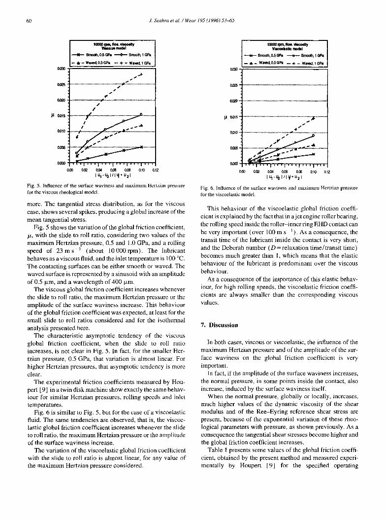
Fig. 5. Influence of the surface waviness and maximum Hertzian pressure for the viscous rheological model.
more. The tangential stress distribution, as for the viscous case, shows several spikes, producing a global increase of the mean tangential stress.
Fig. 5 shows the variation of the global friction coefficient, p, with the slide to roll ratio, considering two values of the maximum Hertzian pressure, 0.5 and 1 .O GPa, and a rolling speed of 23 ms-’ (about 10 000 rpm) . The lubricant behaves as a viscous fluid, and the inlet temperature is 100 “C. The contacting surfaces can be either smooth or waved. The waved surface is represented by a sinusoid with an amplitude of 0.5 pm, and a wavelength of 400 pm.
The viscous global friction coefficient increases whenever the slide to roll ratio, the maximum Hertzian pressure or the amplitude of the surface waviness increase. This behaviour of the global friction coefficient was expected, at least for the small slide to roll ratios considered and for the isothermal analysis presented here.
The characteristic asymptotic tendency of the viscous global friction coefficient, when the slide to roll ratio increases, is not clear in Fig. 5. In fact, for the smaller Her- tzian pressure, 0.5 GPa, that variation is almost linear. For higher Hertzian pressures, that asymptotic tendency is more clear.
The experimental friction coefficients measured by Hou- pert [ 91 in a twin disk machine show exactly the same behav- iour for similar Hertzian pressures, rolling speeds and inlet temperatures.
Fig. 6 is similar to Fig. 5, but for the case of a viscoelastic fluid. The same tendencies are observed, that is, the viscoe- lastic global friction coefficient increases whenever the slide to roll ratio, the maximum Hertzian pressure or the amplitude of the surface waviness increase.
The variation of the viscoelastic global friction coefficient with the slide to roll ratio is almost linear, for any value of the maximum Hertzian pressure considered.
OrnO-
0025.
OmJ-
fl Olm'
ODlO -
oiJ%*
OCCO-
. . . . . . . . . . . . . . . . . . . . . . . . . . . . . . . . . . . . . . . . . . . . . . . . . . . . . . . . . . . . . I . . . . . . . . . . . . . .
_ f i /- . . . . . . . . . . . . . . . . . . . . . . . . . . . . . . . . . . . . . . . . . . . . a . . . . . . . . . . . . . . . . . . . . . . . . . . . . . . . .----&s& -4 . . . . . . . . . . ~.bw?. . . . . . . . . . . . . . . . . . . .
om oa? 0.06 0.06 O.C4 0.10 0.12 Iy-yI’Iy’u21
Fig. 6. Influence of the surface waviness and maximum Hertzian pressure for the viscoelastic model.
This behaviour of the viscoelastic global friction coeffi- cient is explained by the fact that in a jet engine roller bearing, the rolling speed inside the roller-inner ring EHD contact can be very important (over 100 m s ~ ’ ) . As a consequence, the transit time of the lubricant inside the contact is very short, and the Deborah number (D = relaxation time/transit time) becomes much greater than 1, which means that the elastic behaviour of the lubricant is predominant over the viscous behaviour.
As a consequence of the importance of this elastic behav- iour, for high rolling speeds, the viscoelastic friction coeffi- cients are always smaller than the corresponding viscous values.
7. Discussion
In both cases, viscous or viscoelastic, the influence of the maximum Hertzian pressure and of the amplitude of the sur- face waviness on the global friction coefficient is very important.
In fact, if the amplitude of the surface waviness increases, the normal pressure, in some points inside the contact, also increase, induced by the surface waviness itself.
When the normal pressure, globally or locally, increases, much higher values of the dynamic viscosity of the shear modulus and of the Ree-Eyring reference shear stress are present, because of the exponential variation of these rheo- logical parameters with pressure, as shown previously. As a consequence the tangential shear stresses become higher and the global friction coefficient increases.
Table 1 presents some values of the global friction coeffi- cient, obtained by the present method and measured experi- mentally by Houpert [9] for the specified operating


J. Seabra et al. /Wear 195 (1996) 5345
. (Bl) au ap I T, _=_ az
z--+A,17, ay v 7C 77 7,
By the definition of shear rate in a viscous film, yx = (au/ az) and i, y = (aulaz) , and replacing these equations in the r, and $ definitions, the Eq. (B 1) can be written as
b (B2)
The speed is obtained by integration of the preceding equa- tions in z, and is defined as:
(B4)
B.2. Equilibrium of a lubricantfluid element
Considering the fundamental law of dynamics for a film flow, and assuming that [ 51: ?? the film thickness in the z direction is very small when
compared with the dimensions in the x and y directions; ?? the flow is laminar; 0 the inertia and mass forces effect can be neglected when
compared to forces due to viscosity; the following equilibrium equations can be obtained,
aP a --z-7 ax az G
aP a -=-_7. aY az y*
ap -0 az-
which after integration along z give
aP ~yZ=-z+A, ay
1
> (B3)
B.3. Lubricant velocity field
Introducing the rheological model in the dynamic equa- tions of the lubricant film, that is, replacing the preceding Eq. (B3) in Eq. (B2), the speed gradient can be defined as a function of the pressure gradient and of the equivalent stress [51.
B.4. Boundary conditions
The boundary conditions of the problem are shown in Fig. 7, and they are [ 51
z=zl-u=ul v=v,
z=z~=u=u* v = v-2
Applying these boundary conditions to Eq. (B4), it is possible to say that C, = Ui, and C, = V,.
For z = z2, replacing the constants of integration C, and C, and rearranging Eq. (B4), it can be written:
A,= JX
and
v*-v,-21
A,= aY y
Jy where
Wa)
Wb)
and h = ( z2 - zi) , being the film thickness of the lubricant.
Fig. 7. Kinematics of the contacting surfaces.

J. Seabra et al. / Wear I95 (1996) 5345 63
B.5. Tangential shear stresses
Replacing Eq. (B5 (a) ) and Eq. (B5 (b) ) in the definition of the tangential shear stress Eq. after rearranging the equations:
Replacing I,, J,, Z, and J, in Eq exchange,
Z*_z-zi z--zz zz-z1 z1-7-2
and so
Zl -z2 z=;z*+y
and designating the terms
by TX, and
v,- vi
hT,
;
(B3), it can be written [5]
(B6)
(B6), applying the variable
by T,,, which represent the Couette shear stresses, the tan- gential shear stress equations at any point of the lubricant film can be written as:
ap h
‘yz d&* +Tyz
ay 2
. (B7)
B.6. Couette tangential shear stresses
In order to obtain the value of the Couette stresses, TX, and Tyz, and taking into consideration Eq. (B3), Eq. (B4) can be rewritten in the following way [ 51:
Making the variable exchange shown previously, in order to change the integration limits from [ z2, z, ] to [ - 1, 11, to prepare the equations for a numerical integration by the Gauss method, and replacing rXZ and 7yZ Eq. (B7), the equations can be written as:
27-/(&-U,) h
= j(;$z*+TXZ)2dz*
27-/(u*-%) h
3 dz* 7, -1
W)
Eq. (B8) is a system of two equations with two unknowns, TX, and TYz, since
re= m
that is
B. 7. Ree-Eyring model
Admitting that the behaviour of the lubricant under anal- ysis can be represented by the Ree-Eyring model [ 51,
T, =f( 7,) = TV sinh 0 3 Q-r
replacing T, in Eq. (B8), it can be written
hap T
2rl(U2- VI)
1 -_z”+z
27, ax Tr hq = sinh 2 dz*
7, 0 7r -1 - 7r
(B9) hap T
2rl(V2-V,) = , _-z*+t
27 ay rr sinh 3
h7r 7, 0 rr dz*
-1 - rr
Appendix C. Viscoelastic model with a Re+Eyring fluid
If the lubricant is considered as viscoelastic, there is the superposition of an elastic and a viscous deformation. When sliding occurs in two directions, the following system of equations is obtained:

64 J. Seabra et al. / Weur 195 (1996) 53-65
?? T?(X) + shear stress 7yz at the point x; ?? r,, (x - Ax) + shear stress T,,~ at the point (x - Ax) ; obtaining, after replacing in Eq. (Cl )
The tangential stress equations are three-dimensional func- tions, therefore, using the derivative chain rule for functions with more than one variable, it can be written that
+x(x, y, z>
If rolling only exists in the OX direction,
;x=u,o f
iy=“=(l +Lt) I f
implying that
+,(x7 y7 z) = V&x, y, z> x
‘a _
KX
;Y I
a
iz f _
C.I. Tangential shear stress
Defining
a 77,(x, y, z) = lim
TAX, Y, z> - TAX- Ax, Y, z) x AX-r0 Ax
when Ax is small the limit can be approximated by the finite ratio
TAX, Y, z> - TAX- Ax, y, z) Ax
and so
+x(x> y, z> = u 7x(x, y, z> - 7x(X- Ax, y, z) Ax
by a similar procedure
iyk y, z) = u T,(x, Y, z) - TJX- Ax, y, z) Ax
Considering that: ?? T,(X) -+ shear stress 7xz at the point x; ?? T,(X - Ax) -+ shear stress 7xz at the point (x - Ax) ;
Grouping the common terms and rearranging the equa- tions. it becomes
u 7,(X- Ax) _jl,(x) +z Ax = r,(x)
u T,,(X - Ax) Y”(X) +E Ax =7,(x)
Appendix D. Jacobian matrix
A=
sinh(:) ($-$+$)
(:) + (z)
=c

J. Seabra et al. / Wear 195 (1996) 53-65 65
D=
=;$@i 1 sinh(z) ($--zi+$r
(:) + (j
L
X
Appendix E. Newton method
z&X) =$W) +E c a [ “, sinh@] -$(d
That is:
(a) $(AX)=$ & =A ( )
Cb) $(c sinhE))
= sinh@i($+c&( sinhE))
a =ax
&[ sinh@]=cosh($)i
$ [c sinh(
=OXsinh($)+~[cosh@~]=~cosh@
(c) -$~~=-$~(x) +Ar,(x-Ax) =0
Thus,
References
[ 1 ] J. Seabra and D. Berthe, Influence of surface waviness and roughness on the normal pressure distribution in the Hertzian contact, ASME J. Tribal. 109 ( 1987) 462 - 470.
[2] D. Dowson and G. R. Higginson, Elastohydrodynmnic Lubrication, S.I. edn., Pergamon Press, Oxford, 1977,236~~.
[3] R. Gohar, Elastohydrodynamics, series in Mechanical Engineering, Ellis Horwood, Chichester, 1988.
[4] J. Seabra and D. Berthe, Elastohidrodynamic point contacts. Part II - Influence of surface speeds, surface waviness and load on the contact behaviour, Wear, 130 (1989) 319 - 335.
[ 51 F. Vergne, Le contact elastohydrodynamic pontuel lubrifie par un fluid visquex lineaim ou non, ThPse de Docteur, no. 13-89, I.N.S.A. Lyon, 1989.
[ 61 L. Houpert, Fast numerical calculation of EHD sliding traction forces; application to rolling bearings, ASME J. TriboZ., 107 (1985) 234-240.
[7] J. Seabra, A. Campos, A. Sottomayor and L. Ferreira, Analysis of a roller/ring contact in a roller bearing, Final Report of the ERITE- EURAM Project, Bearing with minimum lubrication, contract Aero- 0007-A(c), CETRIB, DEMEGI, Faculdade de Engenharia da Universidade do Porto, July 1993.75~~.
[8] L. Houpert, New results of tractions force calculations in elasto- hydrodynamic contacts, ASME J. Tribal., 107 ( 1985) 241-248.
[9] L. Houpert, Contribution a l’etude du frottement dam un contact elastohydrodynamic, Thbse de Docteur, no. ID1 3-8019, I.N.S.A. Lyon, 1980.
[ IO] J. Seabra, A. Sottomayor and A. Campos, Influence of the rheological model on the traction behaviour of an EHD contact in a roller bearing. Wear, submitted.
[ 111 J. Seabra, A. Sottomayor and A. Campos, Influence of the surface waviness in traction evaluation inside an EHD contact in a roller bearing. Wear, submitted.
Copyright © 2022 FDOKUMEN