25 in. Swing Roller Bearing Gap Bed. - archives.dcemulation.org
Upload
khangminh22Category
view
0download
0
Design Rol ler Bl indsProduct Manual
Rol ler Bl inds
1704
Design Rol ler Bl indsProduct Manual
Rol ler Bl inds

Contents
Mechanism Line-up
Options
MYTEC SEEZ Laser Cut
Product Overview—MYTEC Ser ies
Product Overview—FORTE LOOP
Rol l-up Diameter Guide
Product Overview—VISIC Ser ies
Product Overview—LACOUCHE
How to Order
. . . . . . . . . . . . . . . . . . . . . . . . . . . . . . . . P. 03
. . . . . . . . . . . . . . . . . . . . . . . . . . . . . . . . . . . . . . . . . . . . . . . . . P. 07
. . . . . . . . . . . . . . . . . . . . . . . . . . P. 09
. . . . . . . . . . . P. 13
. . . . . . . . . . . . . P. 51
. . . . . . . . . . . . . . . . . . . . . . . . . . P. 53
. . . . . . . . . . . . . . P. 57
. . . . . . . . . . . . . . . P. 63
. . . . . . . . . . . . . . . . . . . . . . . . . . . . . . . . . . . . . . . . . P. 69
Design Rol ler Bl indsProduct Manual
Rol ler Bl inds
01 02
Typ
e
・Mec
hani
sm
For Ordinary Windows For Ordinary Windows For Small Windows For Bathroom For Skylight Windows Double Type
Feat
ures
Rising the Screen, automatically
when pulling down the cord.
Recommended for an ordinary
window or a little partition.
High decorative roller blind, with
the Blind Box.
You can choose from six styles.
Compact spring type for small
w i n d o w . M o s t s u i t a b l e f o r
simple coordinates.
Available to water consumed places
such as a bathroom, etc. Screen is
removable and washable. Screw
unnecessary Tension Bar (optional)
is also available.
Available to slope window of up to
90 degrees. Can be attached to the
skylight window horizontal.
Two screen with one mechanism for
Night and Day. Recommended for
waist height windows.
Allo
wab
le S
ize Product Width: 300–2,400 mm
Product Height: 100–3,000 mm Ratio (W : H): 1 : 3 (limit) *Differs from Screen to Screen
Product Width: 300–2,000 mm Product Height: 100–3,000 mm Ratio (W : H): 1 : 3 (limit) *Differs from Screen to Screen
Product Width: 200–1,200 mm Product Height: 100–1,600 mm Ratio (W : H): 1 : 5 (limit) *Differs from Screen to Screen
Product Width: 500–2,000 mm Product Height: 100–2,200 mm Ratio (W : H): 1 : 3 (limit) *Differs from Screen to Screen
Product Width: 400–2,000 mm Product Height: 100–2,000 mm Ratio (W : H): 1 : 3 (limit) *Differs from Screen to Screen
Product Width: 400–2,000 mm Product Height: 200–2,800 mm Ratio (W : H): 1 : 3 (limit) *Differs from Screen to Screen
Ava
ilab
le
Col
ors
228 colors 200 colors 173 colors 8 colors 16 colors 196 colors
Par
t C
olor
White (Standard type) Beige Brown
White (Standard type)White × Light WoodBrown × Dark Wood
White White White [Standard] White / Brown[With Pelmet] White White × Light Wood Brown × Dark Wood
Typ
e
・Mec
hani
sm
For Ordinary Windows For Ordinary Windows For Small Windows For Bathroom For Bathroom Double Type
Feat
ures
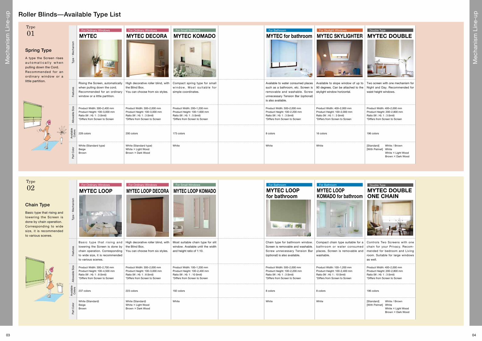
B as i c t yp e t ha t r i s i ng and
lowering the Screen is done by
chain operation. Corresponding
to wide size, it is recommended
to various scenes.
High decorative roller blind, with
the Blind Box.
You can choose from six styles.
Most suitable chain type for slit
window. Available until the width
and height ratio of 1:10.
Chain type for bathroom window.
Screen is removable and washable.
Screw unnecessary Tension Bar (optional) is also available.
Compact chain type suitable for a
bathroom or water consumed
places. Screen is removable and
washable.
Controls Two Screens with one
chain for your Privacy. Recom-
mended for bedroom and Living
room. Suitable for large windows
as well.
Allo
wab
le S
ize Product Width: 300–2,700 mm
Product Height: 100–4,500 mm Ratio (W : H): 1 : 8 (limit) *Differs from Screen to Screen
Product Width: 300–2,000 mm Product Height: 100–3,000 mm Ratio (W : H): 1 : 8 (limit) *Differs from Screen to Screen
Product Width: 100–1,200 mm Product Height: 100–2,400 mm Ratio (W : H): 1 : 10 (limit) *Differs from Screen to Screen
Product Width: 500–2,000 mm Product Height: 100–2,200 mm Ratio (W : H): 1 : 3 (limit) *Differs from Screen to Screen
Product Width: 100–1,200 mm Product Height: 100–2,400 mm Ratio (W : H): 1 : 10 (limit) *Differs from Screen to Screen
Product Width: 400–2,000 mm Product Height: 200–2,800 mm Ratio (W : H): 1 : 3 (limit) *Differs from Screen to Screen
Ava
ilab
le
Col
ors
237 colors 223 colors 192 colors 8 colors 8 colors 196 colors
Par
t C
olor
White (Standard) Beige Brown
White (Standard) White × Light WoodBrown × Dark Wood
White White White [Standard] White / Brown[With Pelmet] White White × Light Wood Brown × Dark Wood
Roller Blinds̶Available Type List
Spring Type
Chain Type
A type the Screen rises a u t o m a t i c a l l y w h e n pulling down the Cord. Recommended fo r an o rd inary w indow or a little partition.
Basic type that rising and lowering the Screen is done by chain operation. Corresponding to wide size, it is recommended to various scenes.
Type
01
Type
02
MYTEC
MYTEC LOOP MYTEC LOOP KOMADO MYTEC LOOP for bathroom
MYTEC LOOP KOMADO for bathroom
MYTEC LOOP DECORA
MYTEC DECORA MYTEC KOMADO MYTEC for bathroom MYTEC SKYLIGHTER MYTEC DOUBLE
MYTEC DOUBLE ONE CHAIN
03 04
Mec
hani
sm L
ine-
up
Mec
hani
sm L
ine-
up

05 06
Mec
hani
sm L
ine-
up
Mec
hani
sm L
ine-
up
One-touch Chain Type
As for the large window, it is actually more convenient of chain operation. But rolling up the Screen would like to be done automatically. To meet such a request, it is an automat ica l l y ro l l i ng up chain type operation.
Cord Type
Cord type is appropriate f o r l a r g e w i n d o w s . O p e r a t i o n i s e a s i l y possible even in the heavy weight of Screen such as Sudare Screen (natural woven Screen).
Type
04Type
03
Roller Blinds̶Available Type List
Design Roller Blinds̶Available Type List
Typ
e
・Mec
hani
sm
Chain Type Chain Type Chain Type Chain Type Chain Type
Feat
ures
VISIC LIGHT, features of the simple design. It is recom-mended when you want to show simply the Screen only.
V I S I C D E C O R A S e r i e s , features of the wood grain decorat ion . I t matches a variety of spaces in abundant color variations.
V ISIC KOMADO, type for small windows. Its compact mechan ica l des ign has a good compatibility not only for the s idel ight- l ike win-dow, but also for the ordi-nary window.
Coverless type Roller Blind, Lachouche, can control natural lighting with friendly appear-ance like a curtain. Available attached to large window, and recommended when attaching to the curtain box.
Natural light control, simple operation feel ing, fr iendly appearance like a curtain, it can produce a comfortable space. Pelmet is a decorative cover type.
Allo
wab
le
Siz
e
Product Width: 300–2,000 mm Product Height: 300–2,800 mm Ratio (W : H): 1 : 8 (limit) *Differs from Screen to Screen
Product Width: 300–2,000 mm Product Height: 300–2,400 mm Ratio (W : H): 1 : 8 (limit) *Differs from Screen to Screen
Product Width: 100–1,200 mm Product Height: 100–2,400 mm Ratio (W : H): 1 : 10 (limit) *Differs from Screen to Screen
Product Width: 300–2,400 mm Product Height: 300–2,800 mm Ratio (W : H): 1 : 5 (limit) *Differs from Screen to Screen
Product Width: 300–2,000 mm Product Height: 300–2,400 mm Ratio (W : H): 1 : 5 (limit) *Differs from Screen to Screen
Ava
ilab
le
Col
ors
35 colors 24 colors 31 colors 6 colors 6 colors
Par
t C
olor
White (Standard) Brown
White (Standard) White × Light WoodBrown × Dark Wood
White White (Standard) Brown
White (Standard) White × Light WoodBrown × Dark Wood
Typ
e
・Mec
hani
sm
For Ordinary Windows For Ordinary Windows For Bathroom
Feat
ures
Automat ical ly ro l l ing up the
Screen by just lightly pulling down
the Chain. Recommended to
large sliding doors. Left and right
rep lacement o f the cont ro l
position is also available.
High decorative roller blind, with
the Blind Box.
You can choose from six styles.
One-touch chain type for bath-room window that can be left and right replacement of the control position. Screen is removable and washable. Screw unnecessary Tension Bar (optional) is also available.
Allo
wab
le S
ize Product Width: 310–2,000 mm
Product Height: 100–3,000 mm Ratio (W : H): 1 : 3 (limit) *Differs from Screen to Screen
Product Width: 310–2,000 mm Product Height: 100–3,000 mm Ratio (W : H): 1 : 3 (limit) *Differs from Screen to Screen
Product Width: 500–2,000 mm Product Height: 100–2,200 mm Ratio (W : H): 1 : 3 (limit) *Differs from Screen to Screen
Ava
ilab
le
Col
ors
205 colors 200 colors 8 colors
Par
t C
olor
White (Standard) Beige Brown
White (Standard) White × Light WoodBrown × Dark Wood
White
Typ
e
・Mec
hani
sm
For Larger Windows
Feat
ures
Suitable for the wide window
f rame. You can l i f t -and-fa l l
smoothly even the wide-and-
heavy Screen such as Sudare
Screen (natural woven Screen).
Allo
wab
le S
ize Product Width: 800–3,000 mm
Product Height: 500–5,000 mm Ratio (W : H): 1 : 5 (limit) *Differs from Screen to Screen
Ava
ilab
le
Col
ors
33 colors
Par
t C
olor
WhiteUmber
MYTEC ONE-TOUCH LOOP
MYTEC ONE-TOUCH LOOP for bathroom
FORTE LOOPMYTEC ONE-TOUCH LOOP DECORA
VISIC LIGHT VISIC DECORA LACOUCHE DECORALACOUCHE LIGHTVISIC KOMADO

Available for MYTEC, MYTEC LOOP and MYTEC ONE-TOUCH LOOP
1,000 Yen only for this optional part order.
800Yen only for this optional part order.
800 Yen only for this optional part order.
Be sure to specify when ordering.
Options
Optional Choice 【Hook Rod Set】 950 Yen for one set (tax excluded)
Available type: MYTEC
The following parts are available for three colors・Hardware part・Pull Ball Set
Available type: MYTEC
The following parts are available for three colors・Pull Ball, Grip Set・Pull Grip
Select your blind color from the following three.
Part Color
No additional charge
MYTEC and MYTEC LOOP have the following options. Choose from options.
Operating Options
No additional charge
MYTEC and MYTEC LOOP can change the Screens for a wrapp ing s ty le to a non-wrapping style.
Weight Bar
No additional charge
*Screens for a non-wrapping style, however, have no option to change to a wrapping style.
A little freely, a little seriously.Even in the same roller blinds, you will be able to put in a change in the window by
adding a bit of preference to detail. Because the TOSO's roller blinds are possible to
change each parts and parts colors, you would be fun to coordinate and be selected.Use the Hook Rod when you choose the Pull Grip and the rolled-up blind is out of your reach.
【Wrapping Style】
【Pull Ball Set】
White (Standard)
Metallic
1,000 Yen only for t h i s o p t i o n a l p a r t order.
800Yen only for this optional part order.
800Yen only for this optional part order.
600Yen only for this optional part order.
【Pull Grip Set】
Metallic Brass White Brass Brown
【Grip Cover】
Brass White
Light Wood Dark Wood Metallic
Available type: MYTEC LOOP
The following parts are available・Ball Chain
【Metal Ball Chain】
Beige Brown
【Non-wrapping Style】White (Standard) Beige Brown
Available types: MYTEC / MYTEC LOOP /
MYTEC ONE-TOUCH LOOP
The following parts are available for three colors・Weight Bar
Available type: MYTEC
* T he p ic tu re shows how i t looks like when a wrapping style has been changed to a non-wrapping style.
(No additional charge required.)
*Grip Cover is available only for a wrapping style.
【Non-wrapping Style】
White Beige Brown
Available types: MYTEC LOOP / MYTEC ONE-TOUCH LOOP
The following parts are available for three colors・Hardware part・Ball Chain
White (Standard) Beige Brown
Option Installation Aid
See the following prices only when ordering the Curtain Track Fitting.
120 Yen for two pieces (tax excluded) with 2 Bracket Fastening Screws,
180 Yen for three pieces (tax excluded) with 3 Bracket Fastening Screws,
Bracket Spacer 12
190 Yen for one piece (tax excluded) with 2 pan head 3.5 x 40 screws
380 Yen for two pieces (tax excluded) with 4 pan head 3.5 x 40 screws
570 Yen for three pieces (tax excluded) with 6 pan head 3.5 x 40 screws
Bracket Spacer 22 *
200 Yen for one piece (tax excluded) with 2 pan head 3.5 x 50 screws
400 Yen two pieces (tax excluded) with 4 pan head 3.5 x 50 screws
600 Yen for three pieces (tax excluded) with 6 pan head 3.5 x 50 screws
*Lay one spacer on the other before fitting
Use this when unable to attach the Brackets to the window frame.
Installation Aid 12
Use this when you need to clear the window frame for an outside mount.
Curtain Track Fitting Bracket Spacer
No additional charge
Use this when fitting a roller blind on a curtain track.
*With this fitting, a roller blind fits on a metal track such as a C-type track and a square-type track.
500 Ye n f o r t w o p i e c e s (tax excluded) w i t h 8
Bracket Fastening Screws
90
14.5
14.5
1622
916
12.5 12.515
7
122640Bracket
Bracket
40
90
Curtain Track Fitting
Cap
Curtain Track
Roller
Bracket Fastening Screw
12
6
17
14
8.5
5
Bracket
Curtain Track Fitting
Cap
Curtain Track
Roller
Bracket Fastening Screw
12
6
17
14
8.5
5
Bracket
(Unit: mm)(Unit: mm)
(Unit: mm)
Bracket
Bracket screw
Bracket SpacerWindow frame
10
12 45
25
Bracket Sapcer 12
20
22 45
25
Bracket Sapcer 22
07 08

MYTEC SEEZ Laser Cut
Sunlight spilling from the hole of the laser cut will portray a rich sight to a life with transience of time.
While looking a scene of the window where the light fluctuates, please feel seasonal wind.
MYTEC SEEZ, light and shadow create a rich sight.
MY
TEC
SEEZ Laser Cut
4 steps for MYTEC SEEZ
Select the cutting design type.
“MYTEC SEEZ” laser cutting has 24 cutting designs.
Each cutting design reflects an impressive shadow
into the room. And, for TYPE 01 and 10, the same
designs as ones for vertical blinds are available.
Each cutting design has the suitable window we
recommend to use.
Select your Screen.
10 series with 126 colors are available for laser
cutting. Choose from 24 cutting designs as you like.
7 series are also available for Vertical Blinds.
Select your operating type.
3 types are available: spring type, chain type and
one-touch chain type.
Refer to the price.
Refer to the MYTEC SEEZ price tables since prices
differ from Screen to Screen.
1
2
3
4
09 10

[Patterned on All Over]Patterned all over the Screen. Creates the
rhythm of light on the large monotonous
Screen.
[Patterned on Center]Patterned vertically in the center. Creates
a modern, simple look on the relatively
small Screen.
[Patterned on One Side]Patterned vertically on one side of the
Screen. Asymmetric pattern can create a
pleasant surprise on the Screen (either
side is available).
[Patterned on the Top or the Bottom]Patterned vertically on the top or the bottom of the
Screen. It provides an unique horizontal design and
also private protection, yet allows light into the
room.
[One Single Design]An eye-catching design put on the Screen. An
un ique des ign encourages a sense o f fun ,
accentuating the blind.
[Patterned on the Top and the Bottom or both side]Patterned Vertically on the top and bottom or both
side. It provides an unique horizontal design or
vertical Blind.
TYPE 10, 23, 29, 32, 35
TYPE 24 TYPE 28, 31, 34
TYPE 33TYPE 14, 25 TYPE 26
Large sliding doors
1,800 × 2,000 mmRecommended sizes
Ordinary windows
1,500 × 1,500 mmRecommended sizes
Small/sidelight-like windows
500 × 1,200 mmRecommended sizes
◎
◎
△ ◎
○
○
◎
◎
○
◎ △◎TYPE 26TYPE 25TYPE 14
◎ ◎◎ ◎TYPE 24 TYPE 33
TYPE 10, 23, 29, 32, 35 TYPE 28, 31, 34
TYPE 10, 23, 29, 32, 35 TYPE 28, 31, 34
TYPE 10, 23, 29, 32, 35 TYPE 28, 31, 34
◎ ◎○ ○TYPE 24 TYPE 33
△ △△ ×TYPE 24 TYPE 33
◎ ◎○TYPE 26TYPE 25TYPE 14
◎ ◎△TYPE 26TYPE 25TYPE 14
TYPE 01
Japanese CatalogP.034
TYPE 05
Japanese CatalogP.038
TYPE 04
Japanese CatalogP.036
TYPE 17
Japanese CatalogP.046
TYPE 09
Japanese CatalogP.040
TYPE 18
Japanese CatalogP.048
TYPE 19
Japanese CatalogP.050
TYPE 21
Japanese CatalogP.054
TYPE 20
Japanese CatalogP.052
TYPE 10
Japanese CatalogP.042
TYPE 14
Japanese CatalogP.044
TYPE 24
Japanese CatalogP.058
TYPE 23
Japanese CatalogP.056
TYPE 26
Japanese CatalogP.062
TYPE 25
Japanese CatalogP.060
1 “MYTEC SEEZ” laser cutting has 24 cutting designs.
Each cutting design has the suitable window we recommend to use.
Select the cutting design type.
210 plain series with a wide range of color variation available for“MYTEC SEEZ”. See the following page of each series to confirm.
Select your Screen. 3Select your operating type from the following three.
■ MYTEC SEEZ → Pull cord type ■ MYTEC LOOP SEEZ → Chain type ■ MYTEC ONE-TOUCH LOOP SEEZ → One-touch chain type
Select your operating type. 4See the corresponding price table of
each Screen for the MYTEC SEEZ.
*Allowable height for laser cutting, TYPE
10, 14, 25, 28, 31 and 34 is 810 mm or
over.
*Allowable width for laser cutting, TYPE
33 is 800 mm or over.
Price.
Re
co
mm
en
de
dW
ind
ow
s
MYTEC SEEZ Cutt ing Design Line-up/Avai lable Screen
Available Screen (9 series) *See the corresponding page of the roller blinds Japanese catalog.
Screen NumberTR-3001–3020TR-3401–3420
TR-3021–3060TR-3421–3460
TR-3061–3066 TR-3067–3081TR-3098–3112TR-3498–3512
TR-3113–3120 TR-3121–3124 TR-3125–3130 TR-3168–3175 TR-3228–3231
Available Colors 20 colors 40 colors 6 colors 15 colors 15 colors 8 colors 4 colors 6 colors 8 colors 4 colors
Japanese Catalog Page P.072 P.076 P.080 P.082 P.092 P.096 P.098 P.100 P.120 P.160
Design Line-up
Design Features
TYPE 27
Japanese CatalogP.064
TYPE 30
Japanese CatalogP.066
NEW
TYPE 29
Japanese CatalogP.064
NEW
TYPE 32
Japanese CatalogP.066
NEW TYPE 35
Japanese CatalogP.068
NEW
TYPE 28
Japanese CatalogP.064
NEW TYPE 31
Japanese CatalogP.066
NEW
TYPE 33
Japanese CatalogP.068
NEW TYPE 34
Japanese CatalogP.068
NEWNEW
11 12

①
Pull toward youBracket
Set Bar
①
Pull toward you
With the release button pressed
With the release button pressed
Bracket
①
Pull toward youBracket
Set Bar
①
Pull toward you
With the release button pressed
With the release button pressed
Bracket
MYTEC[Spring Type for Ordinary Windows]
Dimension
■ Allowable Size
*Allowable size differs from Screen to Screen.*For ordering, round down the nearest 5 mm in width and 10 mm in height.
■ Pull Cord Length (Including the Pull Ball length)
● Ceiling mount inside the window frame
Subtract approx. 10 mm from both the actual inner width and height of the window.
Specify the actual outside sizes, both width and height, for finished dimensions.
● Outside mount covering the window frame
Product width (W)
Productheight (H)
Product Width (W) 300–2,400 mm
Product Height (H) 100–3,000 mm
Ratio (W : H) 1 : 3 (limit)
Product Height (H) Pull Cord Length
100–2,500 mm 800 mm
2,510–3,000 mm 1,200 mm
Pull Cord length
■ Side View
■Bracket
●Wall installation● Ceiling installation
*The product height (H) is from the top of the Roller Pipe to the bottom of the Weight Bar.*( ) shows the size of the Side Holder L.*The two Side Holders have a different length. We use one of Holders, depending on the Screen thickness and the product height. See page 53 for details.
■ Product Width and Screen Width
■ Structure Drawing
Product Overview
■ Operation Method
●Raising the Screen● Lowering the Screen
Roll-up Diameter Guide⇒ page 53–
[In case TR-3067–3081] Product width 1,000 mm × Product height 1,000 mm: 1.8 kg
Product width 2,000 mm × Product height 2,000 mm: 3.4 kgProduct Weight Guide
Components Materials
① Side Holder Set stainless steel press forming, plastic molded
② Bracket stainless steel press forming, plastic molded
③ Set Bar aluminum extrusion
④ Roller Pipe aluminum extrusion
⑤Weight Bar Cap plastic molded
⑥Weight Bar aluminum extrusion
⑦ Pull Ball plastic molded
⑧ Pull Cord synthetic fiber
⑨ Screen Materials differ depending on types.
The Number of Brackets
Parts
– 1,400 1,405 –2,000 2,005 –
Bracket 2 3 4
Pull down the Pull Ball and release your hand to stop.
Pull down the Pull Ball a little (approx. 5 to 6 cm) and release your hand to roll it up.
③
⑥
④
⑦
⑧
⑨
Product width (W)
Screen width
⑤
②
①
Product height (H)
Product width
Scree width
14 mm
( ) shows the length when the product width is 2,005 mm or more.
14 (17) mm
*Refer to the corresponding page of each Screen series.
Non-wrapping Style
3. Removing the main unit① Pull the Set Bar toward you
whi le pressing the Bracket release button.② Remove the main unit from
the temporal hook.
Bracket
4–7 cm
4–7 cm 4–7 cm
4–7 cmBracket
▲Wall installation▲ Ceiling installation
▲ Ceiling installation
Bracket
Bracket
Bracket Bracket
▲Wall installation
Interior side
Exterior side
▲ Ceiling installation ▲Wall installation
Product width (mm)
*For raising and lowering the Screen, be sure to locate the Pull Ball in the center of the Bottom Rail and operate the Pull Ball vertically.
②Fit the Bracket with accompanying screws.①Position of Brackets: appropriate to locate the Bracket in a position 4-7 cm inward from each end. If three or more Brackets are required, install the Brackets in between at equal intervals.
How to Take Measurements
Installation Method
1. Bracket installation
2. Installing the main unit① H o o k t h e S e t B a r o n t h e
temporal hook of the Bracket.② Push in the main unit until it
clicks into place.
27
52
73(83)
27
22
29
31
18
7
73
52
27(83)
7
Product height (H)
Product height (H)
27
52
73(83)
27
22
29
31
18
7
73
52
27(83)
7
Product height (H)
Product height (H)
Interior side
Exterior side
Height (H)
Width (W)
Height (H)
Width (W)
Height (H)
Width (W)
Height (H)
Width (W)
Set Bar
①
②
Bracket
①
②
With the Set Bar hung on the temporal hook Push all the
way in
With the Set Bar hung on the temporal hook
Push all the way in
Bracket
Set Bar
①
②
Bracket
①
②
With the Set Bar hung on the temporal hook Push all the
way in
With the Set Bar hung on the temporal hook
Push all the way in
Bracket
Interior side
Exterior side
52
25
1827
13 14

Screen Screen
Screen Screen
Screen Screen
Screen Screen
*When installing the blind in a higher position than its product height, specify the Chain length in 10 millimeters.
Product Height (H) Ball Chain Length
–800 mm 650 mm
810–1,000 mm 750 mm
1,010–1,200 mm 900 mm
1,210–1,400 mm 1,100 mm
1,410–1,600 mm 1,300 mm
1,610–1,800 mm 1,400 mm
1,810–2,200 mm 1,600 mm
2,210–2,600 mm 1,800 mm
2,610–2,800 mm 2,000 mm
Product Height (H) Ball Chain Length
2,810–3,000 mm 2,200 mm
3,010–3,200 mm 2,400 mm
3,210–3,400 mm 2,600 mm
3,410–3,600 mm 2,800 mm
3,610–3,800 mm 3,000 mm
3,810–4,000 mm 3,200 mm
4,010–4,200 mm 3,400 mm
4,210–4,400 mm 3,600 mm
4,410–4,500 mm 3,800 mm
■ Ball Chain Length
*The product height (H) is from the top of the Roller Pipe to the bottom of the Weight Bar.*( ) shows the size of the Side Holder L.*The two Side Holders have a different length. We use one of the Holders, depending on the Screen thickness and the product height. See page 45 for details.
Components Materials
① Side Holder Set stainless steel press forming, plastic molded
② Bracket stainless steel press forming, plastic molded
③ Set Bar aluminum extrusion
④ Roller Pipe aluminum extrusion
⑤Weight Bar Cap plastic molded
⑥Weight Bar aluminum extrusion
⑦ Chain Connector plastic molded
⑧ Ball Chain plastic molded, synthetic fiber
⑨ Screen Materials differ depending on types.
⑩ Lower Limit Connector* plastic molded
⑪ Safety Tassel plastic molded
Pull down the Ball Chain in back.
14 (17) mm Operational side 22 mm
*Lower Limit Connector is a part to protect a reverse winding.
*Bundle the Ball Chain.
Safety Device
15
22
15
6050
*Bundle the Ball Chain.
Safety Tassel
Color: White
Safety TasselThis is a device for bundling the Ball Chain.This device will reduce the risk of an accident by bundling it to keep out of children’s reach.
突起部分突起部分
Fixed Plastic Fitting
Gear Box Cover
突起部分突起部分
Fixed Plastic Fitting
Gear Box Cover
■ How to convert ceiling installation to wall installation Pull out the Fixed Plastic Fitting and turn the Gear Box Cover 90 degrees.
▲Wall installation▲ Ceiling installation
Pull down the Ball Chain in front.
■Bracket
MYTEC LOOP[Chain Type for Ordinary Windows]
Dimension ■ Allowable Size
*Allowable size differs from Screen to Screen.*For ordering, round down the nearest 5 mm in width and 10 mm in height.
Product Width (W) 300–2,700 mm
Product Height (H) 100–4,500 mm
Ratio (W : H) 1 : 8 (limit)
■ Side View ●Wall installation● Ceiling installation
■ Structure Drawing
Product Overview
③
⑥
④
⑦
⑩
⑧⑨
Product width (W)
Screen width
⑤
②
①
Product height (H)
⑪
2752
73(83)
24
22
7
52
2773(83)
11
7Product height (H)
Product height (H)
2752
73(83)
24
22
7
52
2773(83)
11
7Product height (H)
Product height (H)
■ Product Width and Screen Width
Product width
Scree width
( ) shows the length when the product width is 2,005 mm or more.
*Refer to the corresponding page of each Screen series.
Non-wrapping Style
The Number of Brackets
Parts
– 1,400 1,405 –2,000 2,005 –
Bracket 2 3 4
Product width (mm)
■ Operation Method
●Raising the Screen● Lowering the Screen
● Ceiling mount inside the window frame
Subtract approx. 10 mm from both the actual inner width and height of the window.
Specify the actual outside sizes, both width and height, for finished dimensions.
● Outside mount covering the window frame
How to Take Measurements
Height (H)
Width (W)
Height (H)
Width (W)
Height (H)
Width (W)
Height (H)
Width (W)
①
Pull toward youBracket
Set Bar
①
Pull toward you
With the release button pressed
With the release button pressed
Bracket
①
Pull toward youBracket
Set Bar
①
Pull toward you
With the release button pressed
With the release button pressed
Bracket
3. Removing the main unit① Pull the Set Bar toward you
whi le pressing the Bracket release button.② Remove the main unit from
the temporal hook.
Bracket
4–7 cm
4–7 cm 4–7 cm
4–7 cmBracket
▲Wall installation▲ Ceiling installation
▲ Ceiling installation
Bracket
Bracket
Bracket Bracket
▲Wall installation
Interior side
Exterior side
▲ Ceiling installation ▲Wall installation
②Fit the Bracket with accompanying screws.
Installation Method
1. Bracket installation
2. Installing the main unit① H o o k t h e S e t B a r o n t h e
temporal hook of the Bracket.② Push in the main unit until it
clicks into place.
Interior side
Exterior side
Set Bar
①
②
Bracket
①
②
With the Set Bar hung on the temporal hook Push all the
way in
With the Set Bar hung on the temporal hook
Push all the way in
Bracket
Set Bar
①
②
Bracket
①
②
With the Set Bar hung on the temporal hook Push all the
way in
With the Set Bar hung on the temporal hook
Push all the way in
Bracket
Interior side
Exterior side
Product width (W)
Chain length
Productheight (H)
Roll-up Diameter Guide⇒ P. 53–
[In case TR-3067–3081] Product width 1,000 mm × Product height 1,000 mm: 1.8 kg
Product width 2,000 mm × Product height 2,000 mm: 3.4 kgProduct Weight Guide
52
25
1827
①Position of Brackets: appropriate to locate the Bracket in a position 4-7 cm inward from each end. If three Brackets are required, install the Brackets in between at equal intervals.
15 16

Product Height (H) Ball Chain Length
–800 mm 650 mm
810–1,000 mm 750 mm
1,010–1,200 mm 900 mm
1,210–1,400 mm 1,100 mm
1,410–1,600 mm 1,300 mm
Product Height (H) Ball Chain Length
1,610–1,800 mm 1,400 mm
1,810–2,200 mm 1,600 mm
2,210–2,600 mm 1,800 mm
2,610–2,800 mm 2,000 mm
2,810–3,000 mm 2,200 mm
■Bracket
*When installing the blind in a higher position than its product height, specify the Chain length in 10 millimeters.
■ Ball Chain Length Product width (W)
Chain length
Productheight (H)
MYTEC ONE-TOUCH LOOP[One-touch Chain Type for Ordinary Windows]
Dimension
■ Allowable Size
*Allowable size differs from Screen to Screen.*For ordering, round down the nearest 5 mm in width and 10 mm in height.
Product width (W) 310–2,000 mm
Product height (H) 100–3,000 mm
Ratio (W : H) 1 : 3 (limit)
*The product height (H) is from the top of the Roller Pipe to the bottom of the Weight Bar.*( ) shows the size of the Side Holder L.*The two Side Holders have a different length. We use one of the Holders, depending on the Screen thickness and the product height. See page 45 for details.
■ Side View ●Wall installation● Ceiling installation
■ Structure Drawing
Product Overview
Non-wrapping Style
Pull down the Ball Chain in back.
P u l l d o w n t h e B a l l Chain in back approx. 5 to 6 cm and release your hand to roll up
■ Operation Method
●Raising the Screen● Lowering the Screen
18 mm Operational side 18 mm
■ Product Width and Screen Width
Product width
Scree width
*Bundle the Ball Chain.
Safety Device
15
22
15
6050
*Bundle the Ball Chain.
Safety Tassel
Color: White
Safety TasselThis is a device for bundling the Ball Chain.This device will reduce the risk of an accident by bundling it to keep out of children’s reach.
Components Materials
① Side Holder Set stainless steel press forming, plastic molded
② Bracket stainless steel press forming, plastic molded
③ Set Bar aluminum extrusion
④ Roller Pipe aluminum extrusion
⑤Weight Bar Cap plastic molded
⑥Weight Bar aluminum extrusion
⑦ Chain Connector plastic molded
⑧ Ball Chain plastic molded, synthetic fiber
⑨ Screen Materials differ depending on types.
⑩ Lower Limit Connector* plastic molded
⑪ Safety Tassel plastic molded*Lower Limit Connector is a part to protect a reverse winding.
The Number of Brackets
Parts
– 1,400 1,405 –2,000
Bracket 2 3
Product width (mm)
③
⑥
④
⑦
⑩
⑧⑨
⑤
②
①
⑪
Product width (W)
Screen widthProduct height (H)
2752
73(83)
24
22
7
52
2773(83)
11
7
Product height (H)
Product height (H)
2752
73(83)
24
22
7
52
2773(83)
11
7
Product height (H)
Product height (H)
Roll-up Diameter Guide⇒ page 53–
[In case TR-3067–3081] Product width 1,000 mm × Product height 1,000 mm: 1.8 kg
Product width 2,000 mm × Product height 2,000 mm: 3.4 kgProduct Weight Guide
● Ceiling mount inside the window frame
Subtract approx. 10 mm from both the actual inner width and height of the window.
Specify the actual outside sizes, both width and height, for finished dimensions.
● Outside mount covering the window frame
How to Take Measurements
Height (H)
Width (W)
Height (H)
Width (W)
Height (H)
Width (W)
Height (H)
Width (W)
突起部分突起部分
Fixed Plastic Fitting
Gear Box Cover
突起部分突起部分
Fixed Plastic Fitting
Gear Box Cover
■ How to convert ceiling installation to wall installation Pull out the Fixed Plastic Fitting and turn the Gear Bov Cover 90 degrees.
▲Wall installation▲ Ceiling installation
①
Pull toward youBracket
Set Bar
①
Pull toward you
With the release button pressed
With the release button pressed
Bracket
①
Pull toward youBracket
Set Bar
①
Pull toward you
With the release button pressed
With the release button pressed
Bracket
3. Removing the main unit① Pull the Set Bar toward you
whi le pressing the Bracket release button.② Remove the main unit from
the temporal hook.
Bracket
4–7 cm
4–7 cm 4–7 cm
4–7 cmBracket
▲Wall installation▲ Ceiling installation
▲ Ceiling installation
Bracket
Bracket
Bracket Bracket
▲Wall installation
Interior side
Exterior side
▲ Ceiling installation ▲Wall installation
②Fit the Bracket with accompanying screws.①Position of Brackets: appropriate to locate the Bracket in a position 4-7 cm inward from each end. If three Brackets are required, install the Brackets in between at equal intervals.
Installation Method
1. Bracket installation
2. Installing the main unit① H o o k t h e S e t B a r o n t h e
temporal hook of the Bracket.② Push in the main unit until it
clicks into place.
Interior side
Exterior side
Set Bar
①
②
Bracket
①
②
With the Set Bar hung on the temporal hook Push all the
way in
With the Set Bar hung on the temporal hook
Push all the way in
Bracket
Set Bar
①
②
Bracket
①
②
With the Set Bar hung on the temporal hook Push all the
way in
With the Set Bar hung on the temporal hook
Push all the way in
Bracket
Interior side
Exterior side
52
25
1827
ScreenScreen ScreenScreen
*Refer to the corresponding page of each Screen series.
17 18

Bracket
Set Bar
② Pull toward you
①With the release button pressed
②
①With the release button pressed
Bracket
Pull toward you Set Bar
Bracket
Set Bar
② Pull toward you
①With the release button pressed
②
①With the release button pressed
Bracket
Pull toward you Set Bar
Bracket
With the Set Bar hung onthe temporal hook
①
Push all the way in②
Set Bar
Bracket
Set Bar
Push all the way in
② ① With the Set Bar hung on the temporal hook
■Bracket
■ Product Width and Screen Width
■ Operation Method
●Raising the Screen● Lowering the Screen
Pull down the Pull Ball and release your hand to stop.
*For raising and lowering the Screen, be sure to locate the Pull Ball in the center of the Bottom Rail and operate the Pull Ball vertically.
*A Screen roll-up and a stop come alternately.
Pull down the Pull Ball a little (approx. 3 to 4 cm) and release your hand to roll it up.
③
⑥
④
⑧⑦
⑨
⑤
②
①
*The part color is white.
24
11.5
39
Bracket
Bracket
Bracket
Bracket
Product width (W)
MYTEC KOMADO[Spring Type for Small Windows]
Dimension
■ Allowable Size
*Allowable size differs from Screen to Screen.*For ordering, round down the nearest 5 mm in width and 10 mm in height.
■ Pull Cord Length (Including the Pull Ball length)
Product Width (W) 200–1,200 mm
Product Height (H) 100–1,600 mm
Ratio (W : H) 1 : 5 (limit)
Product Height (H) Pull Cord Length
100–1,600 mm 600 mm
Product width (W)
Productheight (H)
Pull Cord length
Roll-up Diameter Guide⇒ page 53–
[In case TR-3067–3081] Product width 1,000 mm × Product height 1,000 mm: 1.2 kgProduct Weight Guide
■ Side View ●Wall installation● Ceiling installation
■ Structure Drawing
Product Overview
Screen width
Product height (H)
*Depending on the Screen material, it is non-available for the wrapping style.
Non-wrapping Style
Components Materials
① Side Holder Set stainless steel press forming, plastic molded
② Bracket stainless steel press forming, plastic molded
③ Set Bar aluminum extrusion
④ Roller Pipe aluminum extrusion
⑤Weight Bar Cap plastic molded
⑥Weight Bar aluminum extrusion
⑦ Pull Ball plastic molded
⑧ Pull Cord synthetic fiber
⑨ Screen Materials differ depending on types.
Product width
Scree width
10 mm 10 mm
*The product height (H) is from the top of the Roller Pipe to the bottom of the Weight Bar.*( ) shows the size of the Side Holder L.*The two Side Holders have a different length. We use one of the Holders, depending on the Screen thickness and the product height. See page 45 for details.
The Number of Brackets
Parts
– 1,200
Bracket 2
Product width (mm)
34
3
17
47(51)
3417
47(51)
3
19
φ18
23
9.5
Product height (H)
Product height (H)
34
3
17
47(51)
3417
47(51)
3
19
φ18
23
9.5
Product height (H)
Product height (H)
● Ceiling mount inside the window frame
Subtract approx. 10 mm from both the actual inner width and height of the window.
Specify the actual outside sizes, both width and height, for finished dimensions.
● Outside mount covering the window frame
How to Take Measurements
Height (H)
Width (W)
Height (H)
Width (W)
Height (H)
Width (W)
Height (H)
Width (W)
▲ Ceiling installation ▲Wall installation
Interior side
Exterior side
②Fit the Bracket with accompanying screws.①Position of Brackets: appropriate to locate the Bracket in a position 4-6 cm inward from each end.
Installation Method
1. Bracket installation
4–6 cm 4–6 cm
Bracket
3. Removing the main unit① Pull the Set Bar toward you
while pressing the Bracket release button.
② Remove the main unit from the temporal hook.
▲Wall installation▲ Ceiling installation
▲ Ceiling installation ▲Wall installation
2. Installing the main unit① H o o k t h e S e t B a r o n t h e
temporal hook of the Bracket.② Push in the main unit until it
clicks into place.
Interior side
Exterior side
Bracket
With the Set Bar hung onthe temporal hook
①
Push all the way in②
Set Bar
Bracket
Set Bar
Push all the way in
② ① With the Set Bar hung on the temporal hook
Interior side
Exterior side
19 20

③
⑥
④
⑦
⑧
⑨
Product width (W)
Screen width (W)
⑤
⑩
②
①
⑪Product height (H)
*The product height (H) is from the top of the Roller Pipe to the bottom of the Weight Bar.*( ) shows the size of the Side Holder L.*The two Side Holders have a different length. We use one of the Holders, depending on the Screen thickness and the product height. See page 45 for details.
■Bracket
35
47(58)
3517
17
47(58)
3
3
φ17φ17
Roll-up Diameter Guide⇒ page 53–
[In case TR-3067–3081] Product width 1,000 mm × Product height 1,000 mm: 0.9 kgProduct Weight Guide
MYTEC LOOP KOMADO[Chain Type for Small Windows]
*When installing the blind in a higher positon than its product height, specify the Chain length in 10 millimeters.
Product Height (H) Ball Chain Length
–800 mm 650 mm
810–1,000 mm 750 mm
1,010–1,200 mm 900 mm
1,210–1,400 mm 1,100 mm
Product Height (H) Ball Chain Length
1,410–1,600 mm 1,300 mm
1,610–1,800 mm 1,400 mm
1,810–2,200 mm 1,600 mm
2,210–2,400 mm 1,800 mm
■ Ball Chain Length
Dimension
■ Allowable Size
*Allowable size differs from Screen to Screen.*For ordering, round down the nearest 5 mm in width and 10 mm in height.
Product Width (W) 100–1,200 mm
Product Height (H) 100–2,400 mm
Ratio (W : H) 1 : 10 (limit)
Product width (W)
Chain length
Productheight (H)
■ Side View ●Wall installation● Ceiling installation
■ Structure Drawing
Product Overview
*Depending on the Screen material, it is non-available for the wrapping style.
Non-wrapping Style
■ Product Width and Screen Width
Scree width10 mm 11 mm
Product width
*Bundle the Ball Chain.
Safety Device
15
22
15
6050
*Bundle the Ball Chain.
Safety Tassel
Color: White
Safety TasselThis is a device for bundling the Ball Chain.This device will reduce the risk of an accident by bundling it to keep out of children’s reach.
Components Materials
① Side Holder Set stainless steel press forming, plastic molded
② Bracket stainless steel press forming, plastic molded
③ Set Bar aluminum extrusion
④ Roller Pipe aluminum extrusion
⑤Weight Bar Cap plastic molded
⑥Weight Bar aluminum extrusion
⑦ Lower Limit Connector* plastic molded
⑧ Chain Connector plastic molded
⑨ Ball Chain plastic molded, synthetic fiber
⑩ Screen Materials differ depending on types.
⑪ Safety Tassel plastic molded*The part color is white.*The product height and/or the screen spec. decide which Side Holder is used.*Lower Limit Connector is a part to protect a reverse winding.
Screen Screen
Screen Screen
Screen Screen
Screen Screen
Pull down the Ball Chain in back.
Pull down the Ball Chain in front.
■ Operation Method
●Raising the Screen● Lowering the Screen
Product helght (H)
Product helght (H)
41
23
11
The Number of Brackets
Parts
– 1,200
Bracket 2
Product width (mm)
Height (H)
Width (W)
Height (H)
Width (W)
Height (H)
Width (W)
Height (H)
Width (W)
● Ceiling mount inside the window frame
Subtract approx. 10 mm from both the actual inner width and height of the window.
Specify the actual outside sizes, both width and height, for finished dimensions.
● Outside mount covering the window frame
How to Take Measurements
Bracket
Bracket
Bracket
Bracket
▲ Ceiling installation ▲Wall installation
Interior side
Exterior side
②Fit the Bracket with accompanying screws.①Position of Brackets: appropriate to locate the Bracket in a position 4-6 cm inward from each end.
Installation Method
1. Bracket installation
4–6 cm 4–6 cm
Bracket
Bracket
Set Bar
② Pull toward you
①With the release button pressed
②
①With the release button pressed
Bracket
Pull toward you Set Bar
Bracket
Set Bar
② Pull toward you
①With the release button pressed
②
①With the release button pressed
Bracket
Pull toward you Set Bar
Bracket
With the Set Bar hung onthe temporal hook
①
Push all the way in②
Set Bar
Bracket
Set Bar
Push all the way in
② ① With the Set Bar hung on the temporal hook
3. Removing the main unit① Pull the Set Bar toward you
while pressing the Bracket release button.
② Remove the main unit from the temporal hook.
▲Wall installation▲ Ceiling installation
▲ Ceiling installation ▲Wall installation
2. Installing the main unit① H o o k t h e S e t B a r o n t h e
temporal hook of the Bracket.② Push in the main unit until it
clicks into place.
Interior side
Exterior side
Bracket
With the Set Bar hung onthe temporal hook
①
Push all the way in②
Set Bar
Bracket
Set Bar
Push all the way in
② ① With the Set Bar hung on the temporal hook
Interior side
Exterior side
21 22

*The product height (H) is from the top of the Roller Pipe to the bottom of the Weight Bar.*( ) shows the size of the Side Holder L.*The two Side Holders have a different length. We use one of the Holders, depending on the Screen thickness and the product height. See page 53 for details.
③
⑥
④
⑧
⑦
⑨
⑤
②
①
1,130
● Grip Cover
● Hook Rod SetFor Pull Grip Set. Use this (the Hook Rod) when the rolled-up blind is out of your reach.
*800 Yen only for this optional part. *600 Yen only for this optional part.
No additional charge No additional charge
Brass White Brass White
MYTEC for bathroom[Spring Type for Bathroom]
Dimension
■ Allowable Size
*For ordering, round down the nearest 5 mm in width and 10 mm in height.
■ Pull Cord Length (Including the Pull Ball length)
Product width (W)
Productheight (H)
Product Width (W) 500–2,000 mm
Product Height (H) 100–2,200 mm
Ratio (W : H) 1 : 3 (limit)
Product Height (H) Pull Cord Length
100–2,200 mm 800 mmPull Cord length
■ Side View ●Wall installation● Ceiling installation
■ Structure Drawing
Product Overview
Product width (W)
Screen width
Product height (H)
*The Weight Bar is non-wrapping and the part color is white.
(Not available to choose a wrapping style.)
27
7
52
73(83)
27
22
24
22
11
73
52
7
27(83)
Product height (H)
Product height (H)
27
7
52
73(83)
27
22
24
22
11
73
52
7
27(83)
Product height (H)
Product height (H)
Components Materials
① Side Holder Set stainless steel press forming, plastic molded
② Bracket stainless steel press forming, plastic molded
③ Set Bar aluminum extrusion
④ Roller Pipe aluminum extrusion
⑤Weight Bar Cap plastic molded
⑥Weight Bar aluminum extrusion
⑦ Pull Ball plastic molded
⑧ Pull Cord synthetic fiber
⑨ Screen Materials differ depending on types.
■ Product Width and Screen WidthProduct width
Scree width
14 mm 14 mm
Roll-up Diameter Guide⇒ page 53
[In case TR-3176–3181] Product width 1,000 mm × Product height 1,000 mm: 1.8 kg
Product width 2,000 mm × Product height 2,000 mm: 3.3 kgProduct Weight Guide
■ Operation Method
●Raising the Screen● Lowering the Screen
Pull down the Pull Ball and release your hand to stop.
Pull down the Pull Ball a little (approx. 3 to 4 cm) and release your hand to roll it up.
*For raising and lowering the Screen, be sure to locate the Pull Ball in the center of the Bottom Rail and operate the Pull Ball vertically.
■Bracket
The Number of Brackets
Parts
– 1,400 1,405 –
Bracket 2 3
Product width (mm)
52
25
1827
Option
● Pull Grip Set
■Optional Parts for Operation
■Operating Option 2
● Ceiling mount inside the window frame
Subtract approx. 10 mm from both the actual inner width and height of the window.
Specify the actual outside sizes, both width and height, for finished dimensions.
● Outside mount covering the window frame
How to Take Measurements
Height (H)
Width (W)
Height (H)
Width (W)
Height (H)
Width (W)
Height (H)
Width (W)
Width: Subtract approx. 10 mm from the actual inside width for specifying. Height: Susbtract approx. 50 mm from the actual inside height for specifying. The Tension Bar length or the product width is the same as the actual inside width. *For ordering, round down the nearest 5 mm in width and 10 mm in height.
● Ceiling mount inside the window frame with the Tension Bar (inside ceiling mount)
Width: Add 50 mm or more to the actual ins ide width for specifying. Height: Specify more than the actual outs ide height. The Tens ion Bar length o r the product width is the same as the actual inside width. *For ordering, round down the nearest 5 mm in width and 10 mm in height.
● Outside mount covering the window frame with the Tension Bar (outside wall mount)
Tension Bar length
Tension Bar(Top view)
SpacerFill a gap between the roller
blind body and the wall.
Bracket
Tension Bar
Tension Bar Tension Bar
Tension Bar length
Tension Bar
Height (H)
Width (W)
Height (H)
Width (W)
Tension Bar length
Tension Bar(Top view)
SpacerFill a gap between the roller
blind body and the wall.
Bracket
Tension Bar
Tension Bar Tension Bar
Tension Bar length
Tension Bar
Height (H)
Width (W)
Height (H)
Width (W)
● Tension Bar
Useful in installing in a place such as a bathroom where almost impossible to screw on the tile wall.
*For the product size, round down the nearest 5 mm.*Two Spacers attached to the Tension Bar, with which MYTEC for bathroom converted to a wall mount.
*The Tension Bar length or the product width is the same as the actual inside width.
* The Tens ion Ba r i s des igned to ins ta l l MY TEC fo r bathroom for an inside ceiling mount and an outside wall mount. Do not use this for an inside wall mount: it may cause a fall.
①Do not use this for walls with rough surface such as textured wallpaper, mud wall, sand wall, cloth wall.②Install on the surface that has solid framework underneath; e.g. wood, tile. if not, due to its weakness, the bar does not
give enough tension to support, which may cause a fall. if installed in a fabricated bathroom with a hollow structure, strong tension may damage PVC sash. Do not use for such a place.
③Before installation, remove stains, oil or waterdrops on the wall and dry excess moisture. The remaining stains and waterdrops will reduce the adhesive power of double-sided tape, which may cause a fall.
④When installing on tiles, avoid attaching the Cap Plate to the joint between the tiles. If placed on the joint, the double-sided tape may come off, which could result in a fall.
⑤ Be sure to fit the Cap Plate evenly. If not installed evenly, the product may have a risk of a fall.
33
25
Tension Bracket(without spring inside)
Spacer
Tension Bracket(witht spring inside)
Double-sided tape
Double-sided tape
Cap Plate
Cap Plate
32
38
35
9
34
33
25
Tension Bracket(without spring inside)
Spacer
Tension Bracket(witht spring inside) Double-
sided tape
Double-sided tape
Cap Plate
Cap Plate
3238
35
11
34
Caution
Length Price300–1,200 mm 6,000 Yen
1,205–2,000 mm 8,000 Yen
2423

MYTEC for bathroom[Spring Type for Bathroom]
Gap
Dial
GapGap
Back side
Spacer
*Slide in the Spacer as illustrated. (The Spacer is bilaterally symmetric.)
Cap Plate
Pushing it in
Support Plate
CapPlate
Cap Plate
[Ceiling installation]With the arrow facing down, stick the Cap Plate closely to the ceiling, eliminating a clearance.
[Wall installation]• With the arrow facing you, adjust the edge of the Cap
Plate to the window frame.• Set the Cap Plate closely to the ceil ing with no
clearance
*The f igure shows a wa l l instal lat ion. For a cei l ing i n s t a l l a t i o n , a t t a c h t h e Brackets for the roller blind facing downward
Dial
Pushing it in
①Peel off the release paper of the Cap Plate and stick the plate on the place to fix the bar.
④Rotate the dial of the Support Plate with spring in the direction of arrow until it is tightly fastened so that the product is securely fixed.
①For wall installation, slide the Spacer into the back side of the roller blind. *For a ceiling installation, no need to use the Spacer.②Hook the outer groove of the Set Bar on the temporal hook (on the Bracket
release button side) (①) and, while keeping the condition, push it in until the Set Bar clicks in place (②).
①Remove the roller blind. *Push the Bracket release button while holding the main unit and remove the Set
Bar from the Brackets.
②Remove the Tension Bar. 1) Rotate each dial of both sides in the
opposite direction of arrow to loosen.
2) While pushing the Tension Bracket (with spring inside), remove the Support Plate from the opposite Cap Plate.
3) While grasping the Cap Plate with one hand, pull down the double-sided tape just downwards to peel it of f. (It can extend up to 30 cm or so.)
②While pushing the Support Plate of the Tension Bracket (with spring inside) into the Cap Plate, push the opposite Support Plate into the other Cap Plate for a temporal fixing.
③Rotate the dial of the Support Plate without spring in the direction of arrow and adjust the gaps equally on both sides.
3. Installation inside the window frame / on the wall 4. Installing the main unit
5. Removing the main unit
Caution• Before installation, remove stains, oil or waterdrops on the wall and dry excess moisture. The remaining
stains and waterdrops will reduce the adhesive power of double-sided tape, which may cause a fall. • When installing on tiles, avoid attaching the Cap Plate to the joint between the tiles. If placed on the
joint, the double-sided tape may come off, which could result in a fall. • Be sure to fit the Cap Plate evenly. If not installed evenly, the product may have a risk of a fall. • Be sure to stick the Plate Cap properly since sticking place and angle are different from an installation
method to another.*The bond strength of the Cap Plate drops after peeled off. Do not use a peeled-off Cap Plate since it
may cause a fall.
Caution• After installing the main unit, be sure to see that the Support Plate is securely fixed and that the dial is
tightly fastened. If not fastened, the product may have a risk of a fall.
Caution• If pushing the Bracket release button while not holding the main unit, the product may have a risk of a fall.
Caution• When loosening the dial, be sure to support the product
with your hand. *When loosening the dial, do not apply too much force to
the product, which may result in a fall.
Caution• If not grasping it, the Cap Plate may bounce, which can cause an injury. *Do not reuse the peeled-off double-sided tape.• When removing the Cap Plate, pull down the double-sided tape just downwards. If pulling down in the
other direction, the tape may damage the mounting surface or the tape itself be torn. • Peel it off slowly little by little. If peeling it off violently, the tape may damage the mounting surface or
the tape itself be torn. *When peeling off the double-sided tape, some wallpapers may also be peeled off.
Caution• Set the Cap Plate with the main body grasped.*Do not apply too much force to the Cap Plate while fixing temporarily. The product may have a risk of a fall.
[Wall installation]Tension Bar
Tension Bar
Bracket
Bracket
[Ceiling installation]
With the release button pressed
With the release button pressed
Set Bar Pull toward you
Pull toward you
Cap PlateCap Plate
Release paper
as illustrated, rotate the dial until the notches located at the foot of the dial become invisible.
Notches
Dial
Bracket
Tension Bar
With the Set Bar hung on the temporal hook
BracketTension Bar
Set Bar Push all the way in
Push all the way in
[Ceiling installation] [Wall installation]
②
②
①
①
With the Set Bar hung on the temporal hook
4–7 cm 4–7 cme.g. 3 brackets
Installation Plate
Installation Plate
Tension Bracket
Tension Bar
Projection
90°
Projection
Bracket for the roller blind
①
Pull toward youBracket
Set Bar
①
Pull toward you
With the release button pressed
With the release button pressed
Bracket
①
Pull toward youBracket
Set Bar
①
Pull toward you
With the release button pressed
With the release button pressed
Bracket
3. Removing the main unit① Pull the Set Bar toward you
whi le pressing the Bracket release button.
② Remove the main unit from the temporal hook.
Bracket
4–7 cm
4–7 cm 4–7 cm
4–7 cmBracket
▲Wall installation▲ Ceiling installation
▲ Ceiling installation
Bracket
Bracket
Bracket Bracket
▲Wall installation
Interior side
Exterior side
▲ Ceiling installation ▲Wall installation
②Fit the Bracket with accompanying screws.①Position of Brackets: appropriate to locate the Bracket in a position 4-7 cm inward from each end. If three Brackets are required, install the Brackets in between at equal intervals.
①Loosen a screw in the center of the Installation Plate, slide it to the place where fixing the Bracket for the roller blind and tighten the screw securely. Position of Brackets: Appropriate to locate the Bracket in a position 4-7 cm inward from each end of the frame. If three Brackets are required, install the Brackets in between at equal intervals.②Screw the Bracket for the roller blind into a hole of the installation Plate.
*For wall installation, use the lowest hole of the four to fix the Bracket.
[Wall installation]No need to turn. The Tension Bar has already been set for wall installation.[Ceiling installation]①Pull out the Tension Brackets from both sides of the Tension Bar.②Tilt the Tension Bar downward (rotate it 90 degrees) and reinsert the Tension
Brackets with the projection of the Bracket downward.
Installation Method
1. Bracket installation
1. Bracket fitting on the Tension Bar 2. Tension Bar adjustment
2. Installing the main unit① H o o k t h e S e t B a r o n t h e
temporal hook of the Bracket.② Push in the main unit until it
clicks into place.
Interior side
Exterior side
Set Bar
①
②
Bracket
①
②
With the Set Bar hung on the temporal hook Push all the
way in
With the Set Bar hung on the temporal hook
Push all the way in
Bracket
Set Bar
①
②
Bracket
①
②
With the Set Bar hung on the temporal hook Push all the
way in
With the Set Bar hung on the temporal hook
Push all the way in
Bracket
Interior side
Exterior side
■Tension Bar (optional) Installation Method
2625

*The product height (H) is from the top of the Roller Pipe to the bottom of the Weight Bar.*( ) shows the size of the Side Holder L.*The two Side Holders have a different length. We use one of the Holders, depending on the Screen thickness and the product height. See page 45 for details.
Product Height (H) Ball Chain Length
–800 mm 650 mm
810–1,000 mm 750 mm
1,010–1,200 mm 900 mm
1,210–1,400 mm 1,100 mm
1,410–1,600 mm 1,300 mm
1,610–1,800 mm 1,400 mm
1,810–2,200 mm 1,600 mm
MYTEC LOOP for bathroom[Chain Type for Bathroom]
Dimension
Product width (W)
Productheight (H)
Chain length
*When installing the blind in a higher position than its product height, speci f y the Cha in length in 10 millimeters.
■ Ball Chain Length ■ Allowable Size
*For ordering, round down the nearest 5 mm in width and 10 mm in height.
Product Width (W) 500–2,000 mm
Product Height (H) 100–2,200 mm
Ratio (W : H) 1 : 3 (limit)
■ Side View
●Wall installation● Ceiling installation
■ Structure Drawing
Product Overview
*The Weight Bar is non-wrapping and the part color is white.
(Not available to choose a wrapping style.)
③
⑥
④
⑧⑦
⑩
⑨
⑤
②①
⑪
Product width (W)
Screen widthProduct height (H)
52
2773
(83)
11
7
2752
73(83)
24
22
7
Product height (H)
Product height (H)
52
2773
(83)
11
7
2752
73(83)
24
22
7
Product height (H)
Product height (H)
■Bracket
The Number of Brackets
Parts
– 1,400 1,405 –
Bracket 2 3
Product width (mm)
52
25
1827
Components Materials
① Side Holder Set stainless steel press forming, plastic molded
② Bracket stainless steel press forming, plastic molded
③ Set Bar aluminum extrusion
④ Roller Pipe aluminum extrusion
⑤Weight Bar Cap plastic molded
⑥Weight Bar aluminum extrusion
⑦ Chain Connector plastic molded
⑧ Ball Chain plastic molded, synthetic fiber
⑨ Screen Materials differ depending on types.
⑩ Lower Limit Connector* plastic molded
⑪ Safety Tassel plastic molded*Lower Limit Connector is a part to protect a reverse winding.
*Bundle the Ball Chain.
Safety Device
15
22
15
6050
*Bundle the Ball Chain.
Safety Tassel
Color: White
Safety TasselThis is a device for bundling the Ball Chain.This device will reduce the risk of an accident by bundling it to keep out of children’s reach.
Roll-up Diameter Guide⇒ page 53–
[In Case TR-3176–3181] Product width 1,000 mm × Product height 1,000 mm: 1.8 kg
Product width 2,000 mm × Product height 2,000 mm: 3.3 kgProduct Weight Guide
14 mm Operational side 22 mm
■ Product Width and Screen Width
Product width
Scree width
Screen Screen
Screen Screen
Screen Screen
Screen Screen
Pull down the Ball Chain in back.
Pull down the Ball Chain in front.
■ Operation Method
●Raising the Screen● Lowering the Screen
Width: Subtract approx. 10 mm from the actual inside width for specifying. Height: Susbtract approx. 50 mm from the actual inside height for specifying. The Tension Bar length or the product width is the same as the actual inside width. *For ordering, round down the nearest 5 mm in width and 10 mm in height.
Width: Add 50 mm or more to the actual inside width for specifying. Height: Specify more than the actual outside height. The Tension Bar length or the product width is the same as the actual inside width. *For ordering, round down the nearest 5 mm in width and 10 mm in height.
● Ceiling mount inside the window frame
● Ceiling mount inside the window frame with the Tension Bar (inside ceiling mount)
● Outside mount covering the window frame with the Tension Bar (outside wall mount)
Subtract approx. 10 mm from both the actual inner width and height of the window.
Specify the actual outside sizes, both width and height, for finished dimensions.
● Outside mount covering the window frame
How to Take Measurements
Tension Bar length
Tension Bar(Top view)
SpacerFill a gap between the roller
blind body and the wall.
Bracket
Tension Bar
Tension Bar
Tension BarTension Bar
Height (H)
Width (W)
Tension Bar length
Height (H)
Width (W)
Tension Bar length
Tension Bar(Top view)
SpacerFill a gap between the roller
blind body and the wall.
Bracket
Tension Bar
Tension Bar
Tension BarTension Bar
Height (H)
Width (W)
Tension Bar length
Height (H)
Width (W)
Height (H)
Width (W)
Height (H)
Width (W)
Height (H)
Width (W)
Height (H)
Width (W)
Option
● Tension Bar
Useful in installing in a place such as a bathroom where almost impossible to screw on the tile wall.
*For the product size, round down the nearest 5 mm.*Two Spacers attached to the Tension Bar, with which MYTEC for bathroom converted to a wall mount.
*The Tension Bar length or the product width is the same as the actual inside width.
* The Tens ion Ba r i s des igned to ins ta l l MY TEC fo r bathroom for an inside ceiling mount and an outside wall mount. Do not use this for an inside wall mount: it may cause a fall.
①Do not use this for walls with rough surface such as textured wallpaper, mud wall, sand wall, cloth wall.②Install on the surface that has solid framework underneath; e.g. wood, tile. if not, due to its weakness, the bar does not
give enough tension to support, which may cause a fall. if installed in a fabricated bathroom with a hollow structure, strong tension may damage PVC sash. Do not use for such a place.
③Before installation, remove stains, oil or waterdrops on the wall and dry excess moisture. The remaining stains and waterdrops will reduce the adhesive power of double-sided tape, which may cause a fall.
④When installing on tiles, avoid attaching the Cap Plate to the joint between the tiles. If placed on the joint, the double-sided tape may come off, which could result in a fall.
⑤ Be sure to fit the Cap Plate evenly. If not installed evenly, the product may have a risk of a fall.
■Operating option 2
33
25
Tension Bracket(without spring inside)
Spacer
Tension Bracket(witht spring inside)
Double-sided tape
Double-sided tape
Cap Plate
Cap Plate
32
38
35
9
34
33
25
Tension Bracket(without spring inside)
Spacer
Tension Bracket(witht spring inside) Double-
sided tape
Double-sided tape
Cap Plate
Cap Plate
3238
35
11
34
Caution
Length Price300–1,200 mm 6,000 Yen
1,205–2,000 mm 8,000 Yen
2827

4–7 cm 4–7 cme.g. 3 brackets
Installation Plate
Gap
Dial
GapGap
Back side
Spacer
*Slide in the Spacer as illustrated. (The Spacer is bilaterally symmetric.)
Installation Plate
Tension Bracket
Tension Bar
Projection
90°
Projection
Cap Plate
Pushing it in
Support Plate
CapPlate
Bracket for the roller blind
Cap Plate
[Ceiling installation]With the arrow facing down, stick the Cap Plate closely to the ceiling, eliminating a clearance.
[Wall installation]• With the arrow facing you, adjust the edge of the Cap
Plate to the window frame.• Set the Cap Plate closely to the ceiling with no
clearance
*The f igure shows a wa l l instal lat ion. For a cei l ing i n s t a l l a t i o n , a t t a c h t h e Brackets for the roller blind facing downward
Dial
Pushing it in
MYTEC LOOP for bathroom[Chain Type for Bathroom]
突起部分突起部分
Fixed Plastic Fitting
Gear Box Cover
突起部分突起部分
Fixed Plastic Fitting
Gear Box Cover
■ How to Convert Ceiling Installation to Wall Installation Pull out the Fixed Plastic Fitting and turn the Gear Box Cover 90 degrees.
▲Wall installation▲ Ceiling installation
①
Pull toward youBracket
Set Bar
①
Pull toward you
With the release button pressed
With the release button pressed
Bracket
①
Pull toward youBracket
Set Bar
①
Pull toward you
With the release button pressed
With the release button pressed
Bracket
3. Removing the main unit① Pull the Set Bar toward you
whi le pressing the Bracket release button.
② Remove the main unit from the temporal hook.
Bracket
4–7 cm
4–7 cm 4–7 cm
4–7 cmBracket
▲Wall installation▲ Ceiling installation
▲ Ceiling installation
Bracket
Bracket
Bracket Bracket
▲Wall installation
Interior side
Exterior side
▲ Ceiling installation ▲Wall installation
②Fit the Bracket with accompanying screws.①Position of Brackets: appropriate to locate the Bracket in a position 4-7 cm inward from each end. If three Brackets are required, install the Brackets in between at equal intervals.
①Loosen a screw in the center of the Installation Plate, slide it to the place where fixing the Bracket for the roller blind and tighten the screw securely. Position of Brackets: Appropriate to locate the Bracket in a position 4-7 cm inward from each end of the frame. If three Brackets are required, install the Brackets in between at equal intervals.②Screw the Bracket for the roller blind into a hole of the installation Plate.
*For wall installation, use the lowest hole of the four to fix the Bracket.
[Wall installation]No need to turn. The Tension Bar has already been set for wall installation.[Ceiling installation]①Pull out the Tension Brackets from both sides of the Tension Bar.②Tilt the Tension Bar downward (rotate it 90 degrees) and reinsert the Tension
Brackets with the projection of the Bracket downward.
①Peel off the release paper of the Cap Plate and stick the plate on the place to fix the bar.
④Rotate the dial of the Support Plate with spring in the direction of arrow until it is tightly fastened so that the product is securely fixed.
①For wall installation, slide the Spacer into the back side of the roller blind. *For a ceiling installation, no need to use the Spacer.②Hook the outer groove of the Set Bar on the temporal hook (on the Bracket
release button side) (①) and, while keeping the condition, push it in until the Set Bar clicks in place (②).
①Remove the roller blind. *Push the Bracket release button while holding the main unit and remove the Set
Bar from the Brackets.
②Remove the Tension Bar. 1) Rotate each dial of both sides in the
opposite direction of arrow to loosen.
2) While pushing the Tension Bracket (with spring inside), remove the Support Plate from the opposite Cap Plate.
3) While grasping the Cap Plate with one hand, pull down the double-sided tape just downwards to peel it of f. (It can extend up to 30 cm or so.)
②While pushing the Support Plate of the Tension Bracket (with spring inside) into the Cap Plate, push the opposite Support Plate into the other Cap Plate for a temporal fixing.
③Rotate the dial of the Support Plate without spring in the direction of arrow and adjust the gaps equally on both sides.
Installation Method
1. Bracket installation
1. Bracket fitting on the Tension Bar 2. Tension Bar adjustment
3. Installation inside the window frame / on the wall 4. Installing the main unit
5. Removing the main unit
2. Installing the main unit① H o o k t h e S e t B a r o n t h e
temporal hook of the Bracket.② Push in the main unit until it
clicks into place.
Interior side
Exterior side
Set Bar
①
②
Bracket
①
②
With the Set Bar hung on the temporal hook Push all the
way in
With the Set Bar hung on the temporal hook
Push all the way in
Bracket
Set Bar
①
②
Bracket
①
②
With the Set Bar hung on the temporal hook Push all the
way in
With the Set Bar hung on the temporal hook
Push all the way in
Bracket
Interior side
Exterior side
■Tension Bar (optional) Installation Method
Caution• Before installation, remove stains, oil or waterdrops on the wall and dry excess moisture. The remaining
stains and waterdrops will reduce the adhesive power of double-sided tape, which may cause a fall. • When installing on tiles, avoid attaching the Cap Plate to the joint between the tiles. If placed on the
joint, the double-sided tape may come off, which could result in a fall. • Be sure to fit the Cap Plate evenly. If not installed evenly, the product may have a risk of a fall. • Be sure to stick the Plate Cap properly since sticking place and angle are different from an installation
method to another.*The bond strength of the Cap Plate drops after peeled off. Do not use a peeled-off Cap Plate since it
may cause a fall.
Caution• After installing the main unit, be sure to see that the Support Plate is securely fixed and that the dial is
tightly fastened. If not fastened, the product may have a risk of a fall.
Caution• If pushing the Bracket release button while not holding the main unit, the product may have a risk of a fall.
Caution• When loosening the dial, be sure to support the product
with your hand. *When loosening the dial, do not apply too much force to
the product, which may result in a fall.
Caution• If not grasping it, the Cap Plate may bounce, which can cause an injury. *Do not reuse the peeled-off double-sided tape.• When removing the Cap Plate, pull down the double-sided tape just downwards. If pulling down in the
other direction, the tape may damage the mounting surface or the tape itself be torn. • Peel it off slowly little by little. If peeling it off violently, the tape may damage the mounting surface or
the tape itself be torn. *When peeling off the double-sided tape, some wallpapers may also be peeled off.
Caution• Set the Cap Plate with the main body grasped.*Do not apply too much force to the Cap Plate while fixing temporarily. The product may have a risk of a fall.
[Wall installation]Tension Bar
Tension Bar
Bracket
Bracket
[Ceiling installation]
With the release button pressed
With the release button pressed
Set Bar Pull toward you
Pull toward you
Cap PlateCap Plate
Release paper
as illustrated, rotate the dial until the notches located at the foot of the dial become invisible.
Notches
Dial
Bracket
Tension Bar
With the Set Bar hung on the temporal hook
BracketTension Bar
Set Bar Push all the way in
Push all the way in
[Ceiling installation] [Wall installation]
②
②
①
①
With the Set Bar hung on the temporal hook
3029

Option
*The product height (H) is from the top of the Roller Pipe to the bottom of the Weight Bar.*( ) shows the size of the Side Holder L.*The two Side Holders have a different length. We use one of the Holders, depending on the Screen thickness and the product height. See page 53 for details.
Width: Subtract approx. 10 mm from the actua l inside width for specifying. Height: Susbtract approx. 50 mm from the actual inside height for specifying. The Tension Bar length or the product width is the same as the actual inside width. *For ordering, round down the nearest 5 mm in width and 10 mm in height.
Width: Add 50 mm or more to the actual inside width for specifying. Height: Specify more than the actual outside height. The Tension Bar length or the product width is the same as the actual inside width. *For ordering, round down the nearest 5 mm in width and 10 mm in height.
● Tension Bar
Useful in installing in a place such as a bathroom where almost impossible to screw on the tile wall.
*For the product size, round down the nearest 5 mm.*Two Spacers attached to the Tension Bar, with which MYTEC for bathroom converted to a wall mount.
*The Tension Bar length or the product width is the same as the actual inside width.
* The Tens ion Ba r i s des igned to ins ta l l MY TEC fo r bathroom for an inside ceiling mount and an outside wall mount. Do not use this for an inside wall mount: it may cause a fall.
①Do not use this for walls with rough surface such as textured wallpaper, mud wall, sand wall, cloth wall.②Install on the surface that has solid framework underneath; e.g. wood, tile. if not, due to its weakness, the bar does not
give enough tension to support, which may cause a fall. if installed in a fabricated bathroom with a hollow structure, strong tension may damage PVC sash. Do not use for such a place.
③Before installation, remove stains, oil or waterdrops on the wall and dry excess moisture. The remaining stains and waterdrops will reduce the adhesive power of double-sided tape, which may cause a fall.
④When installing on tiles, avoid attaching the Cap Plate to the joint between the tiles. If placed on the joint, the double-sided tape may come off, which could result in a fall.
⑤ Be sure to fit the Cap Plate evenly. If not installed evenly, the product may have a risk of a fall.
For the details of Installation Method, refer to page 29.
■Operating option 2
Roll-up Diameter Guide⇒ page 53–
[In case TR-3176–3181] Product width 1,000 mm × Product height 1,000 mm: 1.8 kg
Product width 2,000 mm × Product height 2,000 mm: 3.3 kgProduct Weight Guide
MYTEC ONE-TOUCH LOOP for bathroom[One-touch Chain Type for Bathroom]
Product Height (H) Ball Chain Length
–800 mm 650 mm
810–1,000 mm 750 mm
1,010–1,200 mm 900 mm
1,210–1,400 mm 1,100 mm
1,410–1,600 mm 1,300 mm
1,610–1,800 mm 1,400 mm
1,810–2,200 mm 1,600 mm
Dimension
Product width (W)
Productheight (H)
Chain length
■ Ball Chain Length ■ Allowable Size
*For ordering, round down the nearest 5 mm in width and 10 mm in height.
Product Width (W) 500–2,000 mm
Product Height (H) 100–2,200 mm
Ratio (W : H) 1 : 3 (limit)
Components Materials
① Side Holder Set stainless steel press forming, plastic molded
② Bracket stainless steel press forming, plastic molded
③ Set Bar aluminum extrusion
④ Roller Pipe aluminum extrusion
⑤Weight Bar Cap plastic molded
⑥Weight Bar aluminum extrusion
⑦ Chain Connector plastic molded
⑧ Ball Chain plastic molded, synthetic fiber
⑨ Screen Materials differ depending on types.
⑩ Lower Limit Connector* plastic molded
⑪ Safety Tassel plastic molded*Lower Limit Connector is a part to protect a reverse winding.
*Bundle the Ball Chain.
Safety Device
15
22
15
6050
*Bundle the Ball Chain.
Safety Tassel
Color: White
Safety TasselThis is a device for bundling the Ball Chain.This device will reduce the risk of an accident by bundling it to keep out of children’s reach.
■Bracket
The Number of Brackets
Parts
– 1,400 1,405 –
Bracket 2 3
Product width (mm)
52
25
1827
18 mm Operational side 18 mm
■ Product Width and Screen Width
Product width
Scree width
Pull down the Ball Chain in back.
Pull down the Ball Chain in back approx. 5 to 6 cm and release your hand to roll up.
■ Operation Method
●Raising the Screen● Lowering the Screen
■ Side View ●Wall installation● Ceiling installation
Product Overview
■ Structure Drawing③
⑥
④
⑧⑦
⑩
⑨
⑤
②①
⑪
Product width (W)
Screen width
Product height (H)
*The Weight Bar is non-wrapping and the part color is white.
(Not available to choose a wrapping style.)
52
2773
(83)
11
7
2752
73(83)
24
22
7
Product height (H)
Product height (H)
52
2773
(83)
11
7
2752
73(83)
24
22
7
Product height (H)
Product height (H)
● Ceiling mount inside the window frame
● Ceiling mount inside the window frame with the Tension Bar (inside ceiling mount)
● Outside mount covering the window frame with the Tension Bar (outside wall mount)
Subtract approx. 10 mm from both the actual inner width and height of the window.
Specify the actual outside sizes, both width and height, for finished dimensions.
● Outside mount covering the window frame
How to Take Measurements
Height (H)
Width (W)
Height (H)
Width (W)
Height (H)
Width (W)
Height (H)
Width (W)
33
25
Tension Bracket(without spring inside)
Spacer
Tension Bracket(witht spring inside)
Double-sided tape
Double-sided tape
Cap Plate
Cap Plate
32
38
35
9
34
33
25
Tension Bracket(without spring inside)
Spacer
Tension Bracket(witht spring inside) Double-
sided tape
Double-sided tape
Cap Plate
Cap Plate
3238
35
11
34
Caution
Tension Bar length
Tension Bar(Top view)
SpacerFill a gap between the roller
blind body and the wall.
Bracket
Tension Bar
Tension Bar
Tension BarTension Bar
Height (H)
Width (W)
Tension Bar length
Height (H)
Width (W)
Tension Bar length
Tension Bar(Top view)
SpacerFill a gap between the roller
blind body and the wall.
Bracket
Tension Bar
Tension Bar
Tension BarTension Bar
Height (H)
Width (W)
Tension Bar length
Height (H)
Width (W)
ScreenScreen ScreenScreen
*When installing the blind in a higher position than its product height, speci f y the Cha in length in 10 millimeters.
Length Price300–1,200 mm 6,000 Yen
1,205–2,000 mm 8,000 Yen
3231

Components Materials
① Side Holder Set stainless steel press forming, plastic molded
② Bracket stainless steel press forming, plastic molded
③ Blind Box aluminum extrusion
④Weight Bar Cap plastic molded
⑤Weight Bar aluminum extrusion
⑥ Screen Materials differ depending on types. ⑦ Pull Cord synthetic fiber
⑧ Pull Ball plastic molded
■Bracket
*The product height (H) is from the top of the Bracket to the bottom of the Weight Bar.
■ Product Width and Screen Width
③
⑦
⑥
①
⑤
④⑧
②
56
1615
18
3586
9
■Available Screen Table
Available Screen (30 series in total): inverted index of the Japanese catalog
TR 3001–3020 P.072 TR 3098–3112 P.093 TR 3153–3156 P.112 TR 3196–3199 P.134
TR 3401–3420 P.072 TR 3498–3512 P.093 TR 3157–3163 P.114 TR 3137–3142 P.136
TR 3021–3060 P.076 TR 3113–3120 P.096 TR 3164–3167 P.116 TR 3214–3219 P.150
TR 3421–3460 P.076 TR 3121–3124 P.098 TR 3168–3175 P.120 TR 3614–3619 P.150
TR 3061–3066 P.080 TR 3125–3130 P.100 TR 3176–3181 P.122 TR 3082–3092 P.152
TR 3067–3081 P.082 TR 3131–3136 P.102 TR 3576–3581 P.122 TR 3220–3222 P.156
TR 3082–3092 P.086 TR 3137–3142 P.104 TR 3184–3191 P.128 TR 3223–3227 P.158
TR 3093–3097 P.088 TR 3148–3152 P.108 TR 3192–3195 P.132 TR 3228–3231 P.160
■Option Parts Color
6 color line-up
White (Standard) White × Light Wood Brown × Dark Wood
Option
Release button
Release button
Bracket
Bracket
Bracket Spacer
MYTEC DECORA[Spring Type with Blind Box]
Dimension
■ Allowable Size
*Allowable size differs from Screen to Screen.*For ordering, round down the nearest 5 mm in width and 10 mm in height.
■ Pull Cord Length (Including the Pull Ball length)
Product width (W)
Productheight (H)
Product Width (W) 300–2,000 mm
Product Height (H) 100–3,000 mm
Ratio (W : H) 1 : 3 (limit)
Product Height (H) Pull Cord Length
100–2,500 mm 800 mm
2,510–3,000 mm 1,200 mm
Pull Cord length
■ Side View ●Wall installation● Ceiling installation
■ Structure Drawing
Product Overview
Product width (W)
Screen widthProduct height (H)
*For MYTEC standard specification.
Non-wrapping Style
[In case TR-3067–3081] Product width 1,000 mm × Product height 1,000 mm: 2.4 kg
Product width 2,000 mm × Product height 2,000 mm: 4.3 kgProduct Weight Guide
Product width
Scree width
14 mm 14 mm
■ Operation Method
●Raising the Screen● Lowering the Screen
Pull down the Pull Ball and release your hand to stop.
Pull down the Pull Ball a little (approx. 3 to 4 cm) and release your hand to roll it up.
*For raising and lowering the Screen, be sure to locate the Pull Ball in the center of the Bottom Rail and operate the Pull Ball vertically.
*A Screen roll-up and a stop come alternately
The Number of Brackets
Parts
– 1,200 1,205 –2,000
Bracket 2 3
Product width (mm)
Height (H)
Width (W)
Height (H)
Width (W)
Height (H)
Width (W)
Height (H)
Width (W)
No additional charge
● Ceiling mount inside the window frame
Subtract approx. 10 mm from both the actual inner width and height of the window.
Specify the actual outside sizes, both width and height, for finished dimensions.
● Outside mount covering the window frame
How to Take Measurements
Bracket
4–7 cm
4–7 cm 4–7 cm
4–7 cmBracket
▲ Ceiling installation ▲Wall installation
Interior side
Exterior side
②Fit the Bracket with accompanying screws.①Position of Brackets: appropriate to locate the Bracket in a position 4-7 cm inward from each end. If three Brackets are required, install the Brackets in between at equal intervals.
Installation Method
1. Bracket installation
2. Installing the main unit 3. Removing the main unit① Hook the outer groove of the Set
Bar on the temporal hook (on the Bracket release button side)
② Push in the main uni t unt i l i t clicks into place.
① With the Screen rolled-up, grasp the main unit and, while pressing the release button of the Bracket, pull it toward you.② Remove the main unit from the
temporal hook.
① With the Set Bar hung on the temporal hook
② Push all the way in
Set Bar
Bracket① With the
release button pressed
Pull toward you
Set BarBracket
98 98
54 54
16
15
35 27
27 27
22 22
29
83 83
9
18
31
45
Productheight (H)
Productheight (H)
98 98
54 54
16
15
35 27
27 27
22 22
29
83 83
9
18
31
45
Productheight (H)
Productheight (H)
3635

Components Materials
① Side Holder Set stainless steel press forming, plastic molded
② Bracket stainless steel press forming, plastic molded
③ Blind Box aluminum extrusion
④Weight Bar Cap plastic molded
⑤Weight Bar aluminum extrusion
⑥ Screen Materials differ depending on types.
⑦ Lower Limit Connector* plastic molded
⑧ Chain Connector plastic molded
⑨ Ball Chain plastic molded, synthetic fiber
⑩ Safety Tassel plastic molded
89 98
45 54
4516
15
35 18
24 24
9
22 22
83 83
*Lower Limit Connector is a part to protect a reverse winding.
MYTEC LOOP DECORA[Chain Type with Blind Box]
Product Height (H) Ball Chain Length
–800 mm 650 mm
810–1,000 mm 750 mm
1,010–1,200 mm 900 mm
1,210–1,400 mm 1,100 mm
1,410–1,600 mm 1,300 mm
Product Height (H) Ball Chain Length
1,610–1,800 mm 1,400 mm
1,810–2,200 mm 1,600 mm
2,210–2,600 mm 1,800 mm
2,610–2,800 mm 2,000 mm
2,810–3,000 mm 2,200 mm
*When installing the blind in a higher position than its product height, specify the Chain length in 10 millimeters.
■ Ball Chain Length Product width (W)
Chain length Product
height (H)
Dimension
■ Allowable Size
*Allowable size differs from Screen to Screen.*For ordering, round down the nearest 5 mm in width and 10 mm in height.
Product width (W) 300–2,000 mm
Product height (H) 100–3,000 mm
Ratio (W : H) 1 : 8 (limit)
■ Side View ●Wall installation● Ceiling installation
■ Structure Drawing
Product Overview
14 mm Operational side 22 mm
■ Product Width and Screen Width
Product width
Scree width
[In case TR-3067–3081] Product width 1,000 mm × Product height 1,000 mm: 2.2 kg
Product width 2,000 mm × Product height 2,000 mm: 4.2 kgProduct Weight Guide
*Bundle the Ball Chain.
Safety Device
15
22
15
6050
*Bundle the Ball Chain.
Safety Tassel
Color: White
Safety TasselThis is a device for bundling the Ball Chain.This device will reduce the risk of an accident by bundling it to keep out of children’s reach.
Screen Screen
Screen Screen
Screen Screen
Screen Screen
Pull down the Ball Chain in back.
Pull down the Ball Chain in front.
■ Operation Method
●Raising the Screen● Lowering the Screen
■Bracket
56
1615
18
3586
9
The Number of Brackets
Parts
– 1,200 1,205 –2,000
Bracket 2 3
Product width (mm)
Product height (H)
Product height (H)
*For MYTEC standard specification.
Non-wrapping Style
⑩
③
⑦
⑨
Product width (W)
Screen width
⑥
①
⑤
④
⑧
②
Product height (H)
*The product height (H) is from the top of the Bracket to the bottom of the Weight Bar.■Option Parts Color
6 color line-up
White (Standard) White × Light Wood Brown × Dark Wood
Option
Release button
Release button
Bracket
Bracket
Bracket Spacer
No additional charge
Bracket
4–7 cm
4–7 cm 4–7 cm
4–7 cmBracket
▲ Ceiling installation ▲Wall installation
Interior side
Exterior side
②Fit the Bracket with accompanying screws.①Position of Brackets: appropriate to locate the Bracket in a position 4-7 cm inward from each end. If three Brackets are required, install the Brackets in between at equal intervals.
Installation Method
1. Bracket installation
2. Installing the main unit 3. Removing the main unit① With the Screen rolled-up, grasp
the main unit and, while pressing the release button of the Bracket, pull it toward you.② Remove the main unit from the
temporal hook.
① With the Set Bar hung on the temporal hook
② Push all the way in
Set Bar
Bracket① With the
release button pressed
Pull toward you
Set BarBracket
● Ceiling mount inside the window frame
Subtract approx. 10 mm from both the actual inner width and height of the window.
Specify the actual outside sizes, both width and height, for finished dimensions.
● Outside mount covering the window frame
How to Take Measurements
Height (H)
Width (W)
Height (H)
Width (W)
Height (H)
Width (W)
Height (H)
Width (W)
■Available Screen Table
① Hook the outer groove of the Set Bar on the temporal hook (on the Bracket release button side).
② Push in the main uni t unt i l i t clicks into place.
Available Screen (33 series in total): inverted index of the Japanese catalog
TR 3001–3020 P.072 TR 3098–3112 P.093 TR 3153–3156 P.112 TR 3137–3142 P.136
TR 3401–3420 P.072 TR 3498–3512 P.093 TR 3157–3163 P.114 TR 3214–3219 P.150
TR 3021–3060 P.076 TR 3113–3120 P.096 TR 3164–3167 P.116 TR 3614–3619 P.150
TR 3421–3460 P.076 TR 3121–3124 P.098 TR 3168–3175 P.120 TR 3082–3092 P.152
TR 3061–3066 P.080 TR 3125–3130 P.100 TR 3176–3181 P.122 TR 3220–3222 P.156
TR 3067–3081 P.082 TR 3131–3136 P.102 TR 3576–3581 P.122 TR 3223–3227 P.158
TR 3082–3092 P.086 TR 3137–3142 P.104 TR 3184–3191 P.128 TR 3228–3231 P.160
TR 3093–3097 P.088 TR 3143–3143 P.106 TR 3192–3195 P.132 TR 3241–3243 P.164
TR 3148–3152 P.108 TR 3196–3199 P.134 TR 3244–3248 P.166
3837

89
45
35 18
24
22
83
Components Materials
① Side Holder Set stainless steel press forming, plastic molded
② Bracket stainless steel press forming, plastic molded
③ Blind Box aluminum extrusion
④Weight Bar Cap plastic molded
⑤Weight Bar aluminum extrusion
⑥ Screen Materials differ depending on types.
⑦ Lower Limit Connector* plastic molded
⑧ Chain Connector plastic molded
⑨ Ball Chain plastic molded, synthetic fiber
⑩ Safety Tassel plastic molded
MYTEC ONE-TOUCH LOOP DECORA[One-touch Chain Type with Blind Box]
Product Height (H) Ball Chain Length
–800 mm 650 mm
810–1,000 mm 750 mm
1,010–1,200 mm 900 mm
1,210–1,400 mm 1,100 mm
1,410–1,600 mm 1,300 mm
Product Height (H) Ball Chain Length
1,610–1,800 mm 1,400 mm
1,810–2,200 mm 1,600 mm
2,210–2,600 mm 1,800 mm
2,610–2,800 mm 2,000 mm
2,810–3,000 mm 2,200 mm
*When installing the blind in a higher position than its product height, specify the Chain length in 10 millimeters.
■ Ball Chain Length Product width (W)
Chain length
Productheight (H)
Dimension
■ Allowable Size
*Allowable size differs from Screen to Screen.*For ordering, round down the nearest 5 mm in width and 10 mm in height.
Product width (W) 310–2,000 mm
Product height (H) 100–3,000 mm
Ratio (W : H) 1 : 3 (limit)
■ Side View ●Wall installation● Ceiling installation
■ Structure Drawing
Product Overview
⑩
③
⑦
⑨⑥
①
⑤
④
⑧
② Product width (W)
Screen widthProduct height (H)
*For MYTEC standard specification.
Non-wrapping Style
Product height (H)
98
54
4516
15
9
24
22
83
Product height (H)
■Bracket
56
1615
18
3586
9
The Number of Brackets
Parts
– 1,200 1,205 –2,000
Bracket 2 3
Product width (mm)
*The product height (H) is from the top of the Bracket to the bottom of the Weight Bar.
*Bundle the Ball Chain.
Safety Device
15
22
15
6050
*Bundle the Ball Chain.
Safety Tassel
Color: White
Safety TasselThis is a device for bundling the Ball Chain.This device will reduce the risk of an accident by bundling it to keep out of children’s reach.
*Lower Limit Connector is a part to protect a reverse winding.
■ Product Width and Screen Width
14 mm Operational side 18 mm
Product width
Scree width
[In case TR-3067–3081] Product width 1,000 mm × Product height 1,000 mm: 2.4 kg
Product width 2,000 mm × Product height 2,000 mm: 4.4 kgProduct Weight Guide
Pull down the Ball Chain in back.
P u l l d o w n t h e B a l l Chain in back approx. 5 to 6 cm and release your hand to roll up
■ Operation Method
●Raising the Screen● Lowering the Screen
■Option Parts Color
6 color line-up
Option
Release button
Release button
Bracket
Bracket
Bracket Spacer
No additional charge
Bracket
4–7 cm
4–7 cm 4–7 cm
4–7 cmBracket
▲ Ceiling installation ▲Wall installation
Interior side
Exterior side
②Fit the Bracket with accompanying screws.①Position of Brackets: appropriate to locate the Bracket in a position 4-7 cm inward from each end. If three Brackets are required, install the Bracket in between at equal intervals.
Installation Method
1. Bracket installation
2. Installing the main unit 3. Removing the main unit① Hook the outer groove of the Set
Bar on the temporal hook (on the Bracket release button side).
② Push in the main uni t unt i l i t clicks into place.
① With the Screen rolled-up, grasp the main unit and, while pressing the release button of the Bracket, pull it toward you.② Remove the main unit from the
temporal hook.
① With the Set Bar hung on the temporal hook
② Push all the way in
Set Bar
Bracket① With the
release button pressed
Pull toward you
Set BarBracket
● Ceiling mount inside the window frame
Subt rac t approx . 10 mm f rom both the actual inner width and height of the window.
Specify the actual outside sizes, both width and height, for finished dimensions.
● Outside mount covering the window frame
How to Take Measurements
Height (H)
Width (W)
Height (H)
Width (W)
Height (H)
Width (W)
Height (H)
Width (W)
■Available Screen Table
ScreenScreen ScreenScreen
White (Standard) White × Light Wood Brown × Dark Wood
Available Screen (28 series in total): inverted index of the Japanese catalog
TR 3001–3020 P.072 TR 3098–3112 P.093 TR 3157–3163 P.114 TR 3196–3199 P.134
TR 3401–3420 P.072 TR 3498–3512 P.093 TR 3164–3167 P.116 TR 3137–3142 P.136
TR 3021–3060 P.076 TR 3113–3120 P.096 TR 3168–3175 P.120 TR 3214–3219 P.150
TR 3421–3460 P.076 TR 3121–3124 P.098 TR 3176–3181 P.122 TR 3614–3619 P.150
TR 3061–3066 P.080 TR 3125–3130 P.100 TR 3576–3581 P.122 TR 3082–3092 P.152
TR 3067–3081 P.082 TR 3131–3136 P.102 TR 3184–3191 P.128 TR 3220–3222 P.156
TR 3082–3092 P.086 TR 3137–3142 P.104 TR 3192–3195 P.132 TR 3228–3231 P.160
TR 3093–3097 P.088 TR 3153–3156 P.112
4039

MYTEC DOUBLE[Double Spring Type]
Dimension
■ Allowable Size
*Allowable size differs from Screen to Screen.*For ordering, round down the nearest 5 mm in width and 10 mm in height.
■ Pull Cord Length (Including the Pull Ball length)
Product width (W)
Productheight (H)
Product Width (W) 400–2,000 mm
Product Height (H) 200–2,800 mm
Ratio (W : H) 1 : 3 (limit)
Product Height (H) Pull Cord Length
200–2,500 mm 800 mm
2,510–2,800 mm 1,200 mm
Pull Cord length
Product Overview
Non-wrapping Style Non-wrapping Style
③
⑦
⑥
⑦
⑥
⑤
⑧
②①
Screen widthProduct height (H)
Product width (W)
④
Screen width
Product width (W)
③②①
⑤
⑧
④
Product height (H)
③
⑦
⑥
⑦
⑥
⑤
⑧
②①
Screen widthProduct height (H)
Product width (W)
④
Screen width
Product width (W)
③②①
⑤
⑧
④
Product height (H)
■ Side View [Standard Type] ●Wall installation● Ceiling installation
■ Side View [With Pelmet] ●Wall installation● Ceiling installation
Components Materials
① Side Holder Set stainless steel press forming, plastic molded
② Bracket stainless steel press forming, plastic molded
③ Blind Box aluminum extrusion
④Weight Bar Cap plastic molded
⑤Weight Bar aluminum extrusion
⑥ Pull Cord synthetic fiber
⑦ Pull Ball plastic molded
⑧ Screen Materials differ depending on types.
[In case of TR-3067–3081 + TR-3153–3156] Product width 1,000 mm × Product height 1,000 mm: 3.2 kg
Product width 2,000 mm × Product height 2,000 mm: 4.4 kgProduct Weight Guide
24 24
2222
22
27
22
27
76 97
76
381516
52
52
134 134
427
42
7
24 24
2222
22
27
22
27
76 97
76
381516
52
52
134 134
427
42
7
22
27
22
27
76 105
4
7652
52
134134
34
24
22
24
22
7
27
381516
22
27
22
27
76 105
4
7652
52
134134
34
24
22
24
22
7
27
381516
Product height (H)
Product height (H)
Product height (H)
Product height (H)
■ Operation Method
Separate operation of the front and the back Screen is possible.
52
25
1827
Bracket L-angle for wall installation
*With the Bracket.
*L-angle for wall installation is wall attachment only.
■Bracket
14 mm 14 mm
Product width
Scree width
The Number of Brackets
Parts
– 1,000 1,005 –1,500
1,505 –2,000
L-angle for wall installation
2 3 4
Bracket 2 3 4
Product width (mm)
2 color line-up 3 color line-up
White (Standard) White (Standard) White × Light WoodBrown Brown × Dark Wood
[Standard Type] [With Pelmet]
●Raising the Screen● Lowering the Screen
Pull down the Pull Ball and release your hand to stop.
Pull down the Pull Ball a little (approx. 5 to 6 cm) and release your hand to roll it up.
*For raising and lowering the Screen, be sure to locate the Pull Ball in the center of the Bottom Rail and operate the Pull Ball vertically.
■Option Parts Color
Option
No additional charge
②
①②
①
L-angle for wall installation
BracketBracket
Bracket
4–7 cm
4–7 cm 4–7 cm
4–7 cmBracket
▲ Ceiling installation ▲Wall installation
Interior side
Exterior side
②Fit the Bracket with accompanying screws.①Position of Brackets: appropriate to locate the Bracket in a position 4-7 cm inward from each end.
Installation Method
1. Bracket installation
2. Installing the main unit 3. Removing the main unit① Hook the outer groove of the Set Bar on the temporal
hook (on the Bracket release button side).② Push in the main unit until it clicks into place.
① With the Screen rolled-up, grasp the main unit and, while pressing the release button of the Bracket, pull it toward you.
② Remove the main unit from the temporal hook.
With the release button pressed
With the release button pressed
With the release button pressed
With the release button pressed
Pull toward you
Pull toward you
Pull toward you
Set Bar
Bracket
②①
②①
[Standard Type]
[With Pelmet] [With Pelmet]
[Standard Type]
Bracket
Interior side
Exterior side
Interior side
Exterior side
▲ Ceiling installation
▲ Ceiling installation
②①
②
①With the Set Bar hung on the temporal hook
With the Set Bar hung on the temporal hookPush all
the way in
Push all the way in
Set Bar
Bracket
Bracket
Interior side
Exterior side
▲ Ceiling installation ▲Wall installation ▲Wall installation
②
①
②
①With the Set Bar hung on the temporal hook
With the Set Bar hung on the temporal hookPush all
the way in
Push all the way in
Set Bar
Bracket
Bracket
Interior side
Exterior side
▲ Ceiling installation ▲Wall installation ▲Wall installation
Set Bar
Pull toward you
Bracket
Bracket
● Ceiling mount inside the window frame
Subtrac t approx. 10 mm from both the actual inner w id th a nd he igh t o f the window.
Specify the actual outside sizes, both width and height, for finished dimensions.
● Outside mount covering the window frame
How to Take Measurements
Height (H)
Width (W)
Height (H)
Width (W)
Height (H)
Width (W)
Height (H)
Width (W)
■Product Width and Screen Width
■ Structure Drawing [Standard Type] ■ Structure Drawing [With Pelmet]
4241

③
⑦ ⑦
⑥
⑤
⑧⑧
②① ③②①
⑥
Product width (W)
Product width (W)
④
⑤
④
Product height (H)
Product height (H)Screen width
Screen width
③
⑦ ⑦
⑥
⑤
⑧⑧
②① ③②①
⑥
Product width (W)
Product width (W)
④
⑤
④
Product height (H)
Product height (H)Screen width
Screen width
MYTEC DOUBLE ONE CHAIN [Double Chain Type]
Product Height (H) Ball Chain Length
–800 mm 650 mm
810–1,000 mm 750 mm
1,010–1,200 mm 900 mm
1,210–1,400 mm 1,100 mm
1,410–1,600 mm 1,300 mm
Product Height (H) Ball Chain Length
1,610–1,800 mm 1,400 mm
1,810–2,200 mm 1,600 mm
2,210–2,600 mm 1,800 mm
2,610–2,800 mm 2,000 mm
*When installing the blind in a higher position than its product height, specify the Chain length in 10 millimeters.
■ Ball Chain Length Product width (W)
Chain length
Productheight (H)
Dimension
■ Allowable Size
*Allowable size differs from Screen to Screen.*For ordering, round down the nearest 5 mm in width and 10 mm in height.
Product width (W) 400–2,000 mm
Product height (H) 200–2,800 mm
Ratio (W : H) 1 : 3 (limit)
Product Overview
Non-wrapping Style (Standard) Non-wrapping Style (Standard)
■ Side View [Standard Type] ●Wall installation● Ceiling installation
■ Side View [With Pelmet] ●Wall installation● Ceiling installation
[In case of TR-3067–3081 + TR-3153–3156] Product width 1,000 mm × Product height 1,000 mm: 3.2 kg
Product width 2,000 mm × Product height 2,000 mm: 6.4 kgProduct Weight Guide
7152
137
27
24
22
7
9571
52
2224
4
137
39
381516
7152
137
27
24
22
7
9571
52
2224
4
137
39
381516
137
7152
27
24
22
7
101
71
524
22
24
137
33
381516
137
7152
27
24
22
7
101
71
524
22
24
137
33
381516
Product height (H)
Product height (H)
Product height (H)
Product height (H)
■Product Width and Screen Width
14 mm 23 mm
Product width
Scree width
■ Structure Drawing [Standard Type] ■ Structure Drawing [With Pelmet]
Components Materials
① Side Holder Set stainless steel press forming, plastic molded
② Bracket stainless steel press forming, plastic molded
③ Blind Box aluminum extrusion
④Weight Bar Cap plastic molded
⑤Weight Bar aluminum extrusion
⑥ Ball Chain plastic molded, synthetic fiber
⑦ Screen Materials differ depending on types.
⑧ Safety Tassel plastic molded
*Bundle the Ball Chain.
Safety Tassel
Color: White
Safety TasselThis is a device for bundling the Ball Chain.This device wil l reduce the r isk of an accident by bundling it to keep out of children’s reach.
②
①②
①
L-angle for wall installation
BracketBracket
Bracket
4–7 cm
4–7 cm 4–7 cm
4–7 cmBracket
▲ Ceiling installation ▲Wall installation
Interior side
Exterior side
②Fit the Bracket with accompanying screws.①Position of Brackets: appropriate to locate the Bracket in a position 4-7 cm inward from each end.
Installation Method
1. Bracket installation
2. Installing the main unit 3. Removing the main unit① Hook the outer groove of the Set Bar on the temporal
hook (on the Bracket release button side).② Push in the main unit until it clicks into place.
① With the Screen rolled-up, grasp the main unit and, while pressing the release button of the Bracket, pull it toward you.
② Remove the main unit from the temporal hook.
With the release button pressed
With the release button pressed
With the release button pressed
With the release button pressed
Pull toward you
Pull toward you
Pull toward you
Set Bar
Bracket
②①
②①
[Standard Type]
[With Pelmet] [With Pelmet]
[Standard Type]
Bracket
Interior side
Exterior side
Interior side
Exterior side
▲ Ceiling installation
▲ Ceiling installation
②①
②
①With the Set Bar hung on the temporal hook
With the Set Bar hung on the temporal hookPush all
the way in
Push all the way in
Set Bar
Bracket
Bracket
Interior side
Exterior side
▲ Ceiling installation ▲Wall installation ▲Wall installation
②
①
②
①With the Set Bar hung on the temporal hook
With the Set Bar hung on the temporal hookPush all
the way in
Push all the way in
Set Bar
Bracket
Bracket
Interior side
Exterior side
▲ Ceiling installation ▲Wall installation ▲Wall installation
Set Bar
Pull toward you
Bracket
Bracket
2 color line-up 3 color line-up
White (Standard) White (Standard) White × Light WoodBrown Brown × Dark Wood
[Standard Type] [With Pelmet]
■Option Parts Color
Option
No additional charge● Ceiling mount inside the window frame
Subtract approx. 10 mm from both the actual inner width and height of the window.
Specify the actual outside sizes, both width and height, for finished dimensions.
● Outside mount covering the window frame
How to Take Measurements
Height (H)
Width (W)
Height (H)
Width (W)
Height (H)
Width (W)
Height (H)
Width (W)
Pull down the Ball Chain in front.
Pull down the Ball Chain in back.
●Raising the Front Screen
●Raising the Back Screen
● Lowering the Front Screen
● Lowering the Back Screen
P u l l d o w n t h e B a l l Chain in front approx. 5 to 6 cm and release your hand to roll up
P u l l d o w n t h e B a l l Chain in back approx. 5 to 6 cm and release your hand to roll up
52
25
1827
Bracket L-angle for wall installation
*With the Bracket.
*L-angle for wall installation is wall attachment only.
■Bracket
The Number of Brackets
Parts
– 1,000 1,005 –1,500
1,505 –2,000
L-angle for wall installation
2 3 4
Bracket 2 3 4
Product width (mm)
■ Operation Method
4443

MYTEC DOUBLE [Price List for Free Selection]
Width (mm)
Height (mm)400
– 500505
– 800805
– 1,2001,205
– 1,6001,605
– 2,000200 – 800 30,400 35,500 40,400 45,400 50,300810 – 1,200 33,700 39,500 44,700 49,800 55,100
1,210 – 1,600 37,000 43,500 49,000 54,300 59,8001,610 – 2,000 - 47,500 53,200 58,800 64,6002,010 – 2,400 - 51,400 58,000 64,000 70,3002,410 – 2,800 - - 62,700 70,200 76,700
㉒B×E
● Ratio (W:H), Limit 1:3
● TR3121-3124 Maximum height: 2500 mm
Width (mm)
Height (mm)400
– 500505
– 800805
– 1,2001,205
– 1,6001,605
– 2,000200 – 800 29,700 34,700 39,800 44,800 49,800810 – 1,200 32,900 38,900 44,200 49,600 55,100
1,210 – 1,600 36,100 43,100 48,700 54,500 60,3001,610 – 2,000 - 47,300 53,200 59,300 65,5002,010 – 2,400 - 51,400 58,500 65,000 71,6002,410 – 2,800 - - 63,800 70,700 77,700
⑯A'×F
● Ratio (W:H), Limit 1:3
Width (mm)
Height (mm)400
– 500505
– 800805
– 1,2001,205
– 1,6001,605
– 2,000200 – 800 29,300 34,200 39,000 43,800 48,700810 – 1,200 32,400 38,200 43,300 48,500 53,600
1,210 – 1,600 35,600 42,300 47,500 53,200 58,6001,610 – 2,000 - 46,400 51,800 57,800 63,5002,010 – 2,400 - 50,500 56,900 63,200 69,3002,410 – 2,800 - - 61,900 68,600 75,100
⑮A'×E
● Ratio (W:H), Limit 1:3
● TR3121-3124 Maximum height: 2500 mm
Width (mm)
Height (mm)400
– 500505
– 800805
– 1,2001,205
– 1,6001,605
– 2,000200 – 800 28,800 33,800 38,500 43,300 48,000810 – 1,200 31,900 37,700 42,700 47,600 52,700
1,210 – 1,600 34,900 41,600 46,900 52,000 57,3001,610 – 2,000 - 45,500 51,100 56,400 62,0002,010 – 2,400 - 49,400 55,400 61,200 67,4002,410 – 2,800 - - 59,800 67,000 73,400
㉑B×D
● Ratio (W:H), Limit 1:3
Width (mm)
Height (mm)400
– 500505
– 800805
– 1,2001,205
– 1,6001,605
– 2,000200 – 800 27,800 32,400 37,100 41,800 46,400810 – 1,200 30,600 36,400 41,300 46,300 51,300
1,210 – 1,600 33,500 40,400 45,500 50,900 56,1001,610 – 2,000 - 44,400 49,600 55,400 60,9002,010 – 2,400 - 48,400 54,300 60,500 66,4002,410 – 2,800 - - 58,900 65,500 71,800
⑭A'×D
● Ratio (W:H), Limit 1:3
Width (mm)
Height (mm)400
– 500505
– 800805
– 1,2001,205
– 1,6001,605
– 2,000200 – 800 27,800 32,600 37,300 41,900 46,600810 – 1,200 30,500 36,400 41,400 46,200 51,200
1,210 – 1,600 33,300 40,200 45,500 50,500 55,7001,610 – 2,000 - 44,000 49,500 54,800 60,3002,010 – 2,400 - 47,800 53,700 59,400 65,5002,410 – 2,800 - - 57,900 65,000 71,300
⑳B×C
● Ratio (W:H), Limit 1:3
Width (mm)
Height (mm)400
– 500505
– 800805
– 1,2001,205
– 1,6001,605
– 2,000200 – 800 26,700 31,300 35,900 40,400 45,000810 – 1,200 29,300 35,200 39,900 44,900 49,700
1,210 – 1,600 31,900 39,100 44,000 49,400 54,5001,610 – 2,000 - 43,000 48,100 53,800 59,2002,010 – 2,400 - 46,900 52,600 58,700 64,5002,410 – 2,800 - - 57,000 63,500 69,700
⑬A'×C
● Ratio (W:H), Limit 1:3
Width (mm)
Height (mm)400
– 500505
– 800805
– 1,2001,205
– 1,6001,605
– 2,000200 – 800 28,400 32,700 37,100 41,500 45,800810 – 1,200 31,000 36,700 41,300 45,800 50,600
1,210 – 1,600 33,700 40,700 45,500 50,200 55,3001,610 – 2,000 - 44,700 49,600 54,600 60,1002,010 – 2,400 - 48,700 54,000 59,300 65,2002,410 – 2,800 - - 58,400 64,100 70,300
⑲B'×B'
● Ratio (W:H), Limit 1:3
Width (mm)
Height (mm)400
– 500505
– 800805
– 1,2001,205
– 1,6001,605
– 2,000200 – 800 26,200 30,300 34,300 38,400 42,500810 – 1,200 28,500 34,100 38,300 42,700 47,200
1,210 – 1,600 30,900 37,900 42,300 47,000 51,8001,610 – 2,000 - 41,700 46,300 51,300 56,5002,010 – 2,400 - 45,500 50,600 55,900 61,5002,410 – 2,800 - - 54,900 60,600 66,500
⑫A'×B'
● Ratio (W:H), Limit 1:3
Width (mm)
Height (mm)400
– 500505
– 800805
– 1,2001,205
– 1,6001,605
– 2,000200 – 800 26,100 30,400 34,400 38,400 42,400810 – 1,200 28,500 33,900 38,200 42,200 46,600
1,210 – 1,600 31,000 37,300 42,000 46,000 50,8001,610 – 2,000 - 40,700 45,800 49,800 55,0002,010 – 2,400 - 44,100 49,400 54,000 59,9002,410 – 2,800 - - 53,100 60,100 66,000
⑱B×B
● Ratio (W:H), Limit 1:3
Width (mm)
Height (mm)400
– 500505
– 800805
– 1,2001,205
– 1,6001,605
– 2,000200 – 800 25,000 29,100 33,000 36,900 40,800810 – 1,200 27,300 32,600 36,800 40,900 45,200
1,210 – 1,600 29,600 36,100 40,600 44,900 49,5001,610 – 2,000 - 39,700 44,400 48,900 53,9002,010 – 2,400 - 43,200 48,300 53,200 58,9002,410 – 2,800 - - 52,200 58,600 64,400
⑪A'×B
● Ratio (W:H), Limit 1:3
Width (mm)
Height (mm)400
– 500505
– 800805
– 1,2001,205
– 1,6001,605
– 2,000200 – 800 33,000 38,500 44,000 49,500 55,100810 – 1,200 37,000 43,600 49,600 55,500 61,400
1,210 – 1,600 41,000 48,600 55,200 61,500 67,8001,610 – 2,000 - 53,600 60,800 67,500 74,1002,010 – 2,400 - 58,700 66,600 74,100 81,1002,410 – 2,800 - - 72,400 80,600 88,000
⑰A'×J
● Ratio (W:H), Limit 1:3
Width (mm)
Height (mm)400
– 500505
– 800805
– 1,2001,205
– 1,6001,605
– 2,000200 – 800 24,000 27,800 31,600 35,400 39,200810 – 1,200 26,100 31,400 35,400 39,600 43,700
1,210 – 1,600 28,200 35,000 39,200 43,700 48,3001,610 – 2,000 - 38,600 43,000 47,900 52,9002,010 – 2,400 - 42,200 47,200 52,500 57,8002,410 – 2,800 - - 51,300 57,000 62,700
⑩A'×A'
● Ratio (W:H), Limit 1:3
Width (mm)
Height (mm)400
– 500505
– 800805
– 1,2001,205
– 1,6001,605
– 2,000200 – 800 23,900 28,000 31,700 35,400 39,100810 – 1,200 26,100 31,200 35,300 39,100 43,200
1,210 – 1,600 28,300 34,400 38,900 42,800 47,3001,610 – 2,000 - 37,700 42,500 46,500 51,3002,010 – 2,400 - 40,900 46,000 50,600 56,2002,410 – 2,800 - - 49,500 55,600 61,200
③A×B
● Ratio (W:H), Limit 1:3
Width (mm)
Height (mm)400
– 500505
– 800805
– 1,2001,205
– 1,6001,605
– 2,000200 – 800 28,500 33,600 38,400 43,300 48,100 810 – 1,200 31,700 37,500 42,700 47,800 53,100
1,210 – 1,600 34,800 41,400 47,000 52,400 58,000 1,610 – 2,000 - 45,300 51,300 57,000 62,900 2,010 – 2,400 - 49,200 56,200 62,400 68,900 2,410 – 2,800 - - 61,100 67,800 74,500
⑧A×F
● Ratio (W:H), Limit 1:3
Width (mm)
Height (mm)400
– 500505
– 800805
– 1,2001,205
– 1,6001,605
– 2,000200 – 800 21,700 25,500 28,900 32,300 35,800 810 – 1,200 23,600 28,500 32,300 36,000 39,800
1,210 – 1,600 25,500 31,600 35,800 39,600 43,700 1,610 – 2,000 - 34,600 39,200 43,200 47,700 2,010 – 2,400 - 37,700 42,600 47,200 52,500 2,410 – 2,800 - - 46,000 51,200 56,500
①A×A
● Ratio (W:H), Limit 1:3
Width (mm)
Height (mm)400
– 500505
– 800805
– 1,2001,205
– 1,6001,605
– 2,000200 – 800 26,600 31,300 35,800 40,200 44,700 810 – 1,200 29,400 35,000 39,800 44,500 49,300
1,210 – 1,600 32,200 38,700 43,700 48,800 53,800 1,610 – 2,000 - 42,400 47,700 53,100 58,400 2,010 – 2,400 - 46,100 52,000 57,800 63,700 2,410 – 2,800 - - 56,300 62,600 68,600
⑥A×D
● Ratio (W:H), Limit 1:3
Width (mm)
Height (mm)400
– 500505
– 800805
– 1,2001,205
– 1,6001,605
– 2,000200 – 800 22,800 26,600 30,300 33,900 37,500 810 – 1,200 24,800 30,000 33,900 37,800 41,800
1,210 – 1,600 26,800 33,300 37,500 41,700 46,000 1,610 – 2,000 - 36,600 41,100 45,600 50,300 2,010 – 2,400 - 39,900 44,900 49,800 55,100 2,410 – 2,800 - - 48,700 54,100 59,600
②A×A'
● Ratio (W:H), Limit 1:3
Width (mm)
Height (mm)400
– 500505
– 800805
– 1,2001,205
– 1,6001,605
– 2,000200 – 800 28,200 33,000 37,700 42,300 47,000810 – 1,200 31,200 36,800 41,800 46,700 51,600
1,210 – 1,600 34,200 40,600 45,800 51,100 56,3001,610 – 2,000 - 44,400 49,900 55,400 60,9002,010 – 2,400 - 48,200 54,600 60,600 66,6002,410 – 2,800 - - 59,200 65,700 72,000
⑦A×E
● Ratio (W:H), Limit 1:3
● TR3121-3124 Maximum height: 2500 mm
Width (mm)
Height (mm)400
– 500505
– 800805
– 1,2001,205
– 1,6001,605
– 2,000200 – 800 25,000 29,100 33,000 36,900 40,800810 – 1,200 27,300 32,600 36,800 40,900 45,200
1,210 – 1,600 29,600 36,100 40,600 44,900 49,5001,610 – 2,000 - 39,700 44,400 48,900 53,9002,010 – 2,400 - 43,200 48,300 53,200 58,9002,410 – 2,800 - - 52,200 57,600 63,400
④A×B'
● Ratio (W:H), Limit 1:3
Width (mm)
Height (mm)400
– 500505
– 800805
– 1,2001,205
– 1,6001,605
– 2,000200 – 800 31,900 37,400 42,700 48,000 53,300 810 – 1,200 35,800 42,100 48,100 53,700 59,400
1,210 – 1,600 39,700 46,900 53,500 59,400 65,500 1,610 – 2,000 - 51,600 58,900 65,100 71,600 2,010 – 2,400 - 56,400 64,400 71,400 78,400 2,410 – 2,800 - - 69,800 77,700 84,900
⑨A×J
● Ratio (W:H), Limit 1:3
Width (mm)
Height (mm)400
– 500505
– 800805
– 1,2001,205
– 1,6001,605
– 2,000200 – 800 25,600 30,200 34,500 38,900 43,300 810 – 1,200 28,100 33,800 38,400 43,100 47,700
1,210 – 1,600 30,500 37,400 42,300 47,300 52,200 1,610 – 2,000 - 41,000 46,200 51,400 56,700 2,010 – 2,400 - 44,600 50,300 56,000 61,800 2,410 – 2,800 - - 54,400 60,600 66,500
⑤A×C
● Ratio (W:H), Limit 1:3
Screen No. Price Lank
TR3001-3020 B'
TR3021-3060 A'
TR3061-3066 D
TR3067-3081 D
TR3082-3092 D
TR3093-3097 F
Screen No. Price Lank
TR3098-3112 C
TR3113-3120 D
TR3121-3124 E
TR3125-3130 F
TR3131-3136 F
TR3137-3142 F
Screen No. Price Lank
TR3143-3147 —
TR3148-3152 J
TR3153-3156 A
TR3157-3163 B
TR3164-3167 E
TR3168-3175 E
Screen No. Price Lank
TR3176-3181 —
TR3182,3183 —
TR3184-3191 E
TR3192-3195 E
TR3196-3199 E
TR3137-3142 F
Screen No. Price Lank
TR3200-3202 —
TR3203-3205 —
TR3206-3210 —
TR3211-3213 —
TR3214-3219 D
TR3220-3222 —
Screen No. Price Lank
TR3223-3227 —
TR3228-3231 F
TR3401-3420 B
TR3421-3460 A
TR3498-3512 B'
TR3576-3581 —
■Screens for MYTEC DOUBLE
■Price
4645

Width (mm)
Height (mm)400
– 500505
– 800805
– 1,2001,205
– 1,6001,605
– 2,000200 – 800 34,100 39,900 45,500 51,100 56,700810 – 1,200 38,200 44,800 51,100 56,900 62,800
1,210 – 1,600 42,400 49,700 56,700 62,700 69,0001,610 – 2,000 - 54,700 62,300 68,400 75,2002,010 – 2,400 - 59,600 67,800 74,800 82,1002,410 – 2,800 - - 73,300 82,100 89,600
㉔B×J
● Ratio (W:H), Limit 1:3
Width (mm)
Height (mm)400
– 500505
– 800805
– 1,2001,205
– 1,6001,605
– 2,000200 – 800 30,700 36,100 41,200 46,300 51,400810 – 1,200 34,200 40,100 45,600 51,000 56,500
1,210 – 1,600 37,600 44,200 50,100 55,600 61,5001,610 – 2,000 - 48,300 54,600 60,300 66,5002,010 – 2,400 - 52,400 59,600 65,800 72,6002,410 – 2,800 - - 64,600 72,200 79,300
㉓B×F
● Ratio (W:H), Limit 1:3
Width (mm)
Height (mm)400
– 500505
– 800805
– 1,2001,205
– 1,6001,605
– 2,000200 – 800 28,400 32,700 37,100 41,500 45,800810 – 1,200 31,000 36,700 41,300 45,800 50,600
1,210 – 1,600 33,700 40,700 45,500 50,200 55,3001,610 – 2,000 - 44,700 49,600 54,600 60,1002,010 – 2,400 - 48,700 54,000 59,300 65,2002,410 – 2,800 - - 58,400 64,100 70,300
㉕B'×B'
● Ratio (W:H), Limit 1:3
Width (mm)
Height (mm)400
– 500505
– 800805
– 1,2001,205
– 1,6001,605
– 2,000200 – 800 28,900 33,800 38,600 43,500 48,300810 – 1,200 31,800 37,900 42,900 48,000 53,200
1,210 – 1,600 34,600 41,900 47,200 52,600 58,0001,610 – 2,000 - 46,000 51,400 57,100 62,8002,010 – 2,400 - 50,100 56,000 62,100 68,2002,410 – 2,800 - - 60,600 67,000 73,500
㉖B'×C
● Ratio (W:H), Limit 1:3
Width (mm)
Height (mm)400
– 500505
– 800805
– 1,2001,205
– 1,6001,605
– 2,000200 – 800 31,500 36,600 41,800 46,900 52,000810 – 1,200 34,900 40,900 46,200 51,600 57,000
1,210 – 1,600 38,300 45,200 50,700 56,400 62,1001,610 – 2,000 - 49,400 55,100 61,100 67,1002,010 – 2,400 - 53,700 60,300 66,600 73,0002,410 – 2,800 - - 65,400 72,200 78,900
㉘B'×E
● Ratio (W:H), Limit 1:3
● TR3121-3124 Maximum height: 2500 mm
Width (mm)
Height (mm)400
– 500505
– 800805
– 1,2001,205
– 1,6001,605
– 2,000200 – 800 30,000 34,900 39,900 44,800 49,700810 – 1,200 33,100 39,100 44,200 49,400 54,700
1,210 – 1,600 36,200 43,300 48,600 54,100 59,6001,610 – 2,000 - 47,500 53,000 58,800 64,6002,010 – 2,400 - 51,600 57,700 63,900 70,1002,410 – 2,800 - - 62,500 69,000 75,600
㉗B'×D
● Ratio (W:H), Limit 1:3
Width (mm)
Height (mm)400
– 500505
– 800805
– 1,2001,205
– 1,6001,605
– 2,000200 – 800 31,900 37,200 42,500 47,800 53,200810 – 1,200 35,400 41,600 47,200 52,800 58,500
1,210 – 1,600 38,900 45,900 51,800 57,700 63,8001,610 – 2,000 - 50,300 56,500 62,700 69,1002,010 – 2,400 - 54,700 61,900 68,400 75,3002,410 – 2,800 - - 67,300 74,200 81,500
㉙B'×F
● Ratio (W:H), Limit 1:3
Width (mm)
Height (mm)400
– 500505
– 800805
– 1,2001,205
– 1,6001,605
– 2,000200 – 800 35,200 41,000 46,800 52,600 58,400810 – 1,200 39,500 46,200 52,600 58,700 64,800
1,210 – 1,600 43,700 51,400 58,400 64,700 71,3001,610 – 2,000 - 56,700 64,200 70,800 77,8002,010 – 2,400 - 61,900 70,100 77,500 84,8002,410 – 2,800 - - 76,000 84,100 91,800
㉚B'×J
● Ratio (W:H), Limit 1:3
Width (mm)
Height (mm)400
– 500505
– 800805
– 1,2001,205
– 1,6001,605
– 2,000200 – 800 29,500 34,800 40,100 45,500 50,800810 – 1,200 32,500 39,000 44,500 50,200 55,700
1,210 – 1,600 35,600 43,200 48,900 55,000 60,7001,610 – 2,000 - 47,400 53,200 59,700 65,6002,010 – 2,400 - 51,500 58,000 64,800 71,1002,410 – 2,800 - - 62,700 70,000 76,600
㉛C×C
● Ratio (W:H), Limit 1:3
Width (mm)
Height (mm)400
– 500505
– 800805
– 1,2001,205
– 1,6001,605
– 2,000200 – 800 30,500 36,000 41,400 46,800 52,200810 – 1,200 33,900 40,200 45,800 51,600 57,200
1,210 – 1,600 37,200 44,500 50,300 56,500 62,3001,610 – 2,000 - 48,800 54,800 61,300 67,3002,010 – 2,400 - 53,100 59,700 66,600 73,0002,410 – 2,800 - - 64,600 72,000 78,700
㉜C×D
● Ratio (W:H), Limit 1:3
Width (mm)
Height (mm)400
– 500505
– 800805
– 1,2001,205
– 1,6001,605
– 2,000200 – 800 32,400 38,200 44,000 49,800 55,600810 – 1,200 36,100 42,700 48,800 55,000 61,000
1,210 – 1,600 39,900 47,200 53,500 60,100 66,5001,610 – 2,000 - 51,600 58,300 65,200 71,9002,010 – 2,400 - 56,100 63,900 71,200 78,2002,410 – 2,800 - - 69,500 77,200 84,600
㉞C×F
● Ratio (W:H), Limit 1:3
Width (mm)
Height (mm)400
– 500505
– 800805
– 1,2001,205
– 1,6001,605
– 2,000200 – 800 32,100 37,700 43,300 48,900 54,500810 – 1,200 35,700 42,000 47,800 53,800 59,600
1,210 – 1,600 39,300 46,400 52,400 58,800 64,7001,610 – 2,000 - 50,800 57,000 63,700 69,9002,010 – 2,400 - 55,100 62,300 69,400 76,0002,410 – 2,800 - - 67,600 75,100 82,000
㉝C×E
● Ratio (W:H), Limit 1:3
● TR3121-3124 Maximum height: 2500 mm
Width (mm)
Height (mm)400
– 500505
– 800805
– 1,2001,205
– 1,6001,605
– 2,000200 – 800 35,800 42,000 48,300 54,600 60,800810 – 1,200 40,200 47,400 54,200 60,800 67,400
1,210 – 1,600 44,700 52,700 60,100 67,100 74,0001,610 – 2,000 - 58,000 66,000 73,400 80,5002,010 – 2,400 - 63,300 72,100 80,200 87,7002,410 – 2,800 - - 78,100 87,100 95,000
㉟C×J
● Ratio (W:H), Limit 1:3
Width (mm)
Height (mm)400
– 500505
– 800805
– 1,2001,205
– 1,6001,605
– 2,000200 – 800 31,600 37,100 42,600 48,100 53,600810 – 1,200 35,200 41,500 47,200 53,100 58,800
1,210 – 1,600 38,800 45,800 51,700 58,000 63,9001,610 – 2,000 - 50,200 56,300 62,900 69,0002,010 – 2,400 - 54,600 61,400 68,400 74,9002,410 – 2,800 - - 66,500 74,000 80,800
㊱D×D
● Ratio (W:H), Limit 1:3
Width (mm)
Height (mm)400
– 500505
– 800805
– 1,2001,205
– 1,6001,605
– 2,000200 – 800 33,500 39,400 45,300 51,200 57,000810 – 1,200 37,500 43,900 50,100 56,400 62,600
1,210 – 1,600 41,500 48,500 55,000 61,600 68,1001,610 – 2,000 - 53,100 59,800 66,800 73,6002,010 – 2,400 - 57,600 65,600 73,000 80,1002,410 – 2,800 - - 71,400 79,200 86,700
㊳D×F
● Ratio (W:H), Limit 1:3
Width (mm)
Height (mm)400
– 500505
– 800805
– 1,2001,205
– 1,6001,605
– 2,000200 – 800 33,100 38,800 44,500 50,200 55,900810 – 1,200 37,000 43,300 49,200 55,200 61,100
1,210 – 1,600 40,900 47,700 53,800 60,300 66,4001,610 – 2,000 - 52,200 58,500 65,300 71,6002,010 – 2,400 - 56,700 64,000 71,200 77,9002,410 – 2,800 - - 69,500 77,100 84,100
㊲D×E
● Ratio (W:H), Limit 1:3
Width (mm)
Height (mm)400
– 500505
– 800805
– 1,2001,205
– 1,6001,605
– 2,000200 – 800 36,800 43,200 49,500 55,900 62,300810 – 1,200 41,600 48,600 55,500 62,300 68,900
1,210 – 1,600 46,300 54,000 61,500 68,600 75,6001,610 – 2,000 - 59,400 67,500 75,000 82,2002,010 – 2,400 - 64,800 73,800 82,000 89,6002,410 – 2,800 - - 80,000 89,100 97,000
㊴D×J
● Ratio (W:H), Limit 1:3
Width (mm)
Height (mm)400
– 500505
– 800805
– 1,2001,205
– 1,6001,605
– 2,000200 – 800 34,600 40,500 46,400 52,300 58,200810 – 1,200 38,800 45,100 51,200 57,400 63,500
1,210 – 1,600 43,000 49,600 55,900 62,600 68,8001,610 – 2,000 - 54,200 60,700 67,700 74,1002,010 – 2,400 - 58,800 66,500 74,000 80,8002,410 – 2,800 - - 72,400 80,200 87,400
㊵E×E
● Ratio (W:H), Limit 1:3
● TR3121-3124 Maximum height: 2500 mm
Width (mm)
Height (mm)400
– 500505
– 800805
– 1,2001,205
– 1,6001,605
– 2,000200 – 800 35,000 41,100 47,200 53,200 59,300810 – 1,200 39,300 45,700 52,100 58,600 64,900
1,210 – 1,600 43,600 50,400 57,000 63,900 70,5001,610 – 2,000 - 55,100 62,000 69,200 76,1002,010 – 2,400 - 59,700 68,200 75,800 83,1002,410 – 2,800 - - 74,300 82,300 90,000
㊶E×F
● Ratio (W:H), Limit 1:3
● TR3121-3124 Maximum height: 2500 mm
Width (mm)
Height (mm)400
– 500505
– 800805
– 1,2001,205
– 1,6001,605
– 2,000200 – 800 38,300 44,900 51,400 58,000 64,600810 – 1,200 43,400 50,400 57,500 64,500 71,300
1,210 – 1,600 48,400 55,900 63,600 70,900 78,0001,610 – 2,000 - 61,400 69,700 77,400 84,8002,010 – 2,400 - 66,900 76,300 84,800 92,6002,410 – 2,800 - - 83,000 92,200 100,400
㊷E×J
● Ratio (W:H), Limit 1:3
● TR3121-3124 Maximum height: 2500 mm
Width (mm)
Height (mm)400
– 500505
– 800805
– 1,2001,205
– 1,6001,605
– 2,000200 – 800 38,700 45,500 52,200 58,900 65,700810 – 1,200 43,800 51,100 58,500 65,600 72,700
1,210 – 1,600 49,000 56,700 64,700 72,200 79,8001,610 – 2,000 - 62,300 71,000 78,900 86,8002,010 – 2,400 - 67,900 77,900 86,600 94,9002,410 – 2,800 - - 84,900 94,300 102,900
㊹F×J
● Ratio (W:H), Limit 1:3
Width (mm)
Height (mm)400
– 500505
– 800805
– 1,2001,205
– 1,6001,605
– 2,000200 – 800 35,400 41,700 47,900 54,200 60,500810 – 1,200 39,800 46,400 53,100 59,700 66,400
1,210 – 1,600 44,100 51,200 58,200 65,200 72,2001,610 – 2,000 - 55,900 63,300 70,700 78,1002,010 – 2,400 - 60,700 69,800 77,600 85,4002,410 – 2,800 - - 76,200 84,400 92,600
㊸F×F
● Ratio (W:H), Limit 1:3
Width (mm)
Height (mm)400
– 500505
– 800805
– 1,2001,205
– 1,6001,605
– 2,000200 – 800 42,000 49,300 56,500 63,700 70,900810 – 1,200 47,900 55,700 63,900 71,500 79,100
1,210 – 1,600 53,800 62,200 71,300 79,300 87,3001,610 – 2,000 - 68,600 78,700 87,100 95,4002,010 – 2,400 - 75,100 86,100 95,600 104,4002,410 – 2,800 - 81,600 93,500 104,200 113,300
㊺J×J
● Ratio (W:H), Limit 1:3
4847

Available Screen (4 series in total): inverted index of the Japanese catalog
TR 3148–3152 P.108 TR 3220–3222 P.156 TR 3241–3243 P.164 TR 3244–3248 P.166
①With the white projection pressed, pull it toward you
①With the white projection pressed, remove it
BracketSet Bar
Bracket
Set Bar
①With the white projection pressed, pull it toward you
①With the white projection pressed, remove it
BracketSet Bar
Bracket
Set Bar
Bracket
Set BarSet Bar
①With the Set Bar hung on the temporal hook
① With the Set Bar hung on the temporal hook
Push all the way in
②
② Push all the way in
Bracket
Bracket
Set BarSet Bar
①With the Set Bar hung on the temporal hook
① With the Set Bar hung on the temporal hook
Push all the way in
②
② Push all the way in
Bracket
Bracket
Bracket
Bracket
Bracket
Lift Cord
Stopper
■ The Screen slacks when closed. Minimize the slack by giving tention.①After installation, fully close the Screen and fix it with
the Stopper.②Turn the dial on the right end of the Pipe to tighten
the Screen.
Caution
Because of the Screen weight, the slack can not be eliminated thoroughly. Do not turn the dial excessively, which may result in a malfunction.
■ Lift Cord Length (Length from Weight Bar to Pull Ball)
In case a headrail-to-floor height not specified
In case a headrail-to-floor height specified
■ Allowable Angle■ Attachments
*The product height (H) is from the top of the Roller Pipe to the bottom of the Weight Bar.
Bracket
Length when the Screen is rolled up to the top (mm)
Length when the Screen is rolled down to the bottom
3,500ーProduct width 3,500ーProduct width+(Product height×2)
Headrail-to-floor height (mm)
Length when the Screen is rolled up to the top (mm)
Length when the Screen is rolled down to the bottom
–2,000 7,500ーProduct width+(Product height×2) 7,500ーProduct width
–3,000 8,500ーProduct width+(Product height×2) 8,500ーProduct width
–4,000 9,500ーProduct width+(Product height×2) 9,500ーProduct width
–5,000 10,500ーProduct width+(Product height×2) 10,500ーProduct width
Components Materials
① Side Holder Set stainless steel press forming, plastic molded
② Bracket stainless steel press forming, plastic molded
③ Set Bar aluminum extrusion
④ Roller Pipe aluminum extrusion
⑤ Guide Wire nylon-coated stainless steel
⑥ Weight Bar aluminum extrusion
⑦ Side Guide Set plastic molded
⑧ Wall Fixing Plate steel press forming
⑨ Bottom Frame aluminum extrusion
⑩ Lift Cord synthetic fiber
⑪ Pulley Guide plastic molded
⑫ Stopper plastic molded
⑬ Pull Ball plastic molded
⑭ Screen Materials differ depending on types.
Parts Quantity
Braket Product width to 1,000 mm: 3, Product width to 1,005 mm: 4
Corner Aid 2
Cord End 2
Wall Fixing Plate Product width to 1,000 mm: 3, Product width to 1,005 mm: 4
Side Pulley Guide 2
Pulley Guide 2
Stopper 115 mm 15 mm
③
⑥
④
⑧
⑦
⑨
⑭
⑩⑪
⑫
⑬
⑤
②①
*The Weight Bar is non-wrapping and the part color is white
Corner Aid
Side Pulley Guide
Cord End
Pulley Guide
Wall Fixing Plate
Stopper
Dial
DialDial
Dial
Operation Method
How to Take Up the Screen Slack
①Position of Brackets: appropriate to locate the Bracket in a position 5-7 cm inward from each end. If three Brackets or more are required, install the Bracket in between at equal intervals.
5–7cm 5–7cmBracket
1. Bracket installation
Pull the Lift Cord in the direction you find it
easier to operate.
Change the Stopper either for right hand or
for left hand control.
Cord End holds the
Lift Cords neatly.■Opening, closing and holding the Screen● Pull down the Cord to close
● Release the Cord to open
● To hold the Screen halfway, pull the Cord right or
left and put it in the groove.
■Available Screen Table
Guide Wire
Hole Cap
Screw for the Wall Fixing Plate
Frame Bracket
Tension Adjusting Screw
Wall Fixing Plate
Screw for direct attachment
Lift Cord
Bottom Frame
②Fit the Bracket with accompanying screws.
2. Installing the main unit① Hook the Set Bar on the temporal hook of the
Bracket.② Push in the main unit until it clicks into place.
3. Removing the main unit
4. Bottom Frame installation
5. How to adjust the Guide Wire tension
① Pull the Set Bar toward you while pressing the white projection.
② Remove the main unit from the temporal hook.
Fix the Frame Brackets inside the Bottom Frame at the fixing holes and cover them with the Hole Caps.
*For wall installtion, install the Wall Fixing Plate on the wall, first, and, then, fit the Bottom Frame on the Plates.
Turn the Tension Adjusting Screw to give enough tension. Note that excessive tension may cause a malfunction.
MYTEC SKYLIGHTER[Sprig Type for Slope and Skylight Windows]
Dimension ■ Allowable Size
*Allowable size differs from Screen to Screen.*For ordering, round down the nearest 5 mm in width and 10 mm in height.
Product Width (W) 400–2,000 mm
Product Height (H) 100–2,000 mm
Ratio (W : H) 1 : 3 (limit)
Product width (W)
Productheight (H)
Lift Cord length
Roll-up Diameter Guide⇒ page 53–
[In case TR-3220–3222] Product width 1,000 mm × Product height 1,000 mm: 2.7 kg
Product width 2,000 mm × Product height 2,000 mm: 5.0 kgProduct Weight Guide
■ Product Width and Screen Width
Product width
Screen width
90 degrees or less
45
18
24
32
33
7
1023
45
35
25
22
15
5
35
15
10.532 13
12
1812
20
■ Side View ●Wall installation● Ceiling installation
■ Structure Drawing
Product Overview
Product width (W)
Screen widthProduct height (H)
43
21.5
683
18
3015
25
25φ
25
4368
3
35
2210
12.5
12
21.5
Product height (H)
Product height (H)
● Ceiling mount inside the window frame
Subtract approx. 10 mm from both the actual inner width and height of the window.
Specify the actual outside sizes, both width and height, for finished dimensions.
● Outside mount covering the window frame
How to Take Measurements
Height (H)
Width (W)
Height (H)
Width (W)
Pulley Guide
Corner Aid
Side Pulley Guide
Stopper
1
2
Cord End
Installation Method
Interior side
Interior side
Interior side
Exterior side
Exterior side
Exterior side
▲ Ceiling installation ▲Wall installation
▲ Ceiling installation ▲Wall installation
▲ Ceiling installation ▲Wall installation
5049

Installation Method
■Bracket
◆ Weight Bar
●TR-3223–3227, TR-3241–3243, and TR-3244–3248: Wrapping style
●(Bamboo weave) Sudare Series: Non-wrapping Style
*( ) shows the size of the Bracket 85.
Bracket Operation-side Bracket
Components Materials
① Side Bracket Cover plastic molded
② Bracket stainless steel press forming, plastic molded
③ Roller Pipe aluminum extrusion
④ Operation-side Bracket steel press forming, plastic molded、zinc die-cast
⑤ Lift Cord synthetic fiber
⑥ Weight Bar Cap plastic molded
⑦ Weight Bar aluminum extrusion
⑧ Screen Materials differ depending on types.
⑨ Safety Tassel plastic molded
Light Brown Dark Brown
*The product height (H) is from the top of the Roller Pipe to the bottom of the Weight Bar.*( ) shows the size of the Bracket 85.*The two Brackets have a different size (65 or 85). We use one of the Brackets, depending on the Screen thickness and the product height. See page 45 for details.
Height (H)
Width (W)
Height (H)
Width (W)
4315
Pelmet for Sudare
200
65 (8
5)
110
(130
)
70
78Operation Cord
Operation-side Bracket65 (85)
34
Lock Dial (locked)
Lock Dial (unlocked)
Click
Pull down the Cord in back a bit hard
ScreenScreen ScreenScreen
Option
Operation Method
①Put on the Bracket positioning tape.
⑤Fit the Bracket Cover into place.
③Insert the Screen on the plug side into the shaft of the Operation-side Bracket
④Push up the Screen on the opposite side and snap the center pin into the Bracket. Insert it securely so that the locking latch prevents it from falling.
②With the Bracket positioning tape on, screw each Bracket of both sides f irmly. Be a w a r e t h a t b o t h B r a c k e t s f a c e e a c h o t h e r c o r r e c t l y.
*The Bracket positioning tape has the same length as the product width. af ter f i t t ing the Brackets, take of f the Bracket positioning tape.
Positioning tape
Bracket
Bracket Cover
Center pin
Latch
Plug size
Positioning tape
Bracket
Operation-sideBracket
The length of the Bracket positionings(Be in a horizontal)
Bracket
Bracket Cover
Center pin
Latch
Plug size
Positioning tape
Bracket
Operation-sideBracket
The length of the Bracket positionings(Be in a horizontal)
Bracket
Bracket Cover
Center pin
Latch
Plug size
Positioning tape
Bracket
Operation-sideBracket
The length of the Bracket positionings(Be in a horizontal)
Bracket
Bracket Cover
Center pin
Latch
Plug size
Positioning tape
Bracket
Operation-sideBracket
The length of the Bracket positionings(Be in a horizontal)
*( ) shows the size of the Bracket 85.
■ Optional Style
■ Option Installation Aid
● Pelmet for SudareCeiling mount is only available.
● Installation Aid 13 (2 pices)
Use aid when you install the Bracket on the narrow surface.
After installation, take the following procedures, first. Pull down the Cord in back a bit hard. With a click sound, the initial spring load becomes unlocked, and the Balancer begins to work, making ready to operate.
*For lifting and lowering the Screen, be sure to use the Cord.
Bracket
Operation-side Bracket
FORTE LOOP[Loop Type for Larger Windows]
*When installing the blind in a higher position than its product height, specify the Cord length in 10 millimeters.
Product Height (H) Cord Length
–800 mm 650 mm
810–1,000 mm 750 mm
1,010–1,200 mm 900 mm
1,210–1,400 mm 1,100 mm
1,410–1,600 mm 1,300 mm
1,610–1,800 mm 1,400 mm
1,810–2,200 mm 1,600 mm
2,210–2,600 mm 1,800 mm
2,610–2,800 mm 2,000 mm
2,810–3,000 mm 2,200 mm
Product Height (H) Cord Length
3,010–3,200 mm 2,400 mm
3,210–3,400 mm 2,600 mm
3,410–3,600 mm 2,800 mm
3,610–3,800 mm 3,000 mm
3,810–4,000 mm 3,200 mm
4,010–4,200 mm 3,400 mm
4,210–4,400 mm 3,600 mm
4,410–4,500 mm 3,800 mm
4,510–4,700 mm 4,000 mm
4,710–5,000 mm 4,200 mm
■ Cord Length Dimension ■ Allowable Size
*Allowable size differs from Screen to Screen.*For ordering, round down the nearest 5 mm (Sudare/bamboo weave: 10 mm) in width and 10 mm in height.
Product Width (W) 800–3,000 mm
Product Height (H) 500–5,000 mm
Ratio (W : H) 1 : 5 (limit)Product width (W)
Cord length
Productheight (H)
*Bundle the Ball Chain.
Safety Device
15
22
15
6050
*Bundle the Ball Chain.
Safety Tassel
Color: White
Safety TasselThis is a device for bundling the Ball Chain.This device will reduce the risk of an accident by bundling it to keep out of children’s reach.
*A standard color for the system, TR-2276-2280, TR-2294–2296 and TR-2300–2303, is white, and TR-2304 is black.
Roll-up Diameter Guide⇒ page 53–
[In case TR-3203–3213] Product width 2,000 mm × Product height 2,000 mm: 8.7 kg
Product width 2,700 mm × Product height 3,000 mm: 14.0 kgProduct Weight Guide
■ Structure Drawing
Product Overview
③
⑥
④
⑧
⑦
⑤
①②
⑨
Product width (W)
Screen widthProduct height (H)
■ Product Width and Screen Width
30 mm Operational side 35 mm
Product width
Scree width
■ Side View ●Wall installation● Ceiling installation
The Number of Brackets*Wth Bracket cover
Parts
– 3,000
Bracket 1Operation-side Bracket
1
Product width (mm)90
(11
0)
7040
70
110(
130)
90(
110)
7040
70
110(
130)
110(130)
70
34 18
12
100
7034
(120)
18
24
24
Productheight (H)
Productheight (H)
110(130)
70
34 18
12
100
7034
(120)
18
24
24
Productheight (H)
Productheight (H)
● Ceiling mount inside the window frame
Subtract approx. 10 mm from both the actual inner width and height of the window.
Specify the actual outside sizes, both width and height, for finished dimensions.
● Outside mount covering the window frame
How to Take Measurements
50
34
50
34
10
10
10
3015
5
8
4
10
12
30
34
50
34
92
5034
5034
10
10
103015
5
8
4
1012
3034
50
34
92
●Raising the Screen● Lowering the Screen
Pull down the Ball Chain in front.
Pull down the Ball Chain in Back.
200
92
50 30
5251

● MYTEC, MYTEC LOOP, MYTEC ONE-TOUCH LOOP, MYTEC for bathroon, MYTEC LOOP for bathroom, MYTEC ONE-TOUCH LOOP for bathroom, MYTEC DOUBLE, MYTEC DOUBLE ONE CHAIN
[When the product width is 2,000 mm and less]
Product Height
A B C D E F G H I J K L M N O P Q
400 43 44 44 45 45 45 46 46 46 46 47 47 48 49 49 49 52
800 44 46 46 47 47 48 48 48 49 50 50 51 51 53 53 54 58
1,200 46 48 49 49 50 51 51 51 52 53 54 54 55 57 57 59 64
1,600 47 50 50 51 52 53 54 54 55 56 57 58 59 61 61 63 69
2,000 48 52 52 53 54 55 56 56 57 58 60 61 62 65 65 67 74
2,400 49 53 54 55 56 58 58 59 60 61 62 64 65 68 68 70 79
2,800 51 55 56 57 58 60 61 61 62 64 65 66 68 71 71 74 -
3,200 52 56 58 59 60 62 63 63 65 66 68 69 71 75 75 77 -
3,600 53 58 59 61 62 64 65 65 67 68 70 72 73 78 78 80 -
4,000 54 60 61 63 64 66 67 67 69 71 72 74 76 81 81 - -
4,500 55 61 63 65 66 68 69 70 72 73 75 77 79 - - - -
*Side Holder L applies to the area shown in and Side Holder S applies to the other. *When the product width of 2,100 mm or more, use Side Holder L, for TR-2001–2040 and TR-2206–2219.*The diameters above are calculated ones. They might have a certain margin of error.
● MYTEC SKYLIGHTER
Product Height
A B C D E F G H I J K L M N P
400 37 38 38 39 39 40 40 40 40 41 41 42 42 43 44
800 39 40 41 42 42 43 43 43 44 44 45 46 47 48 50
1,200 40 43 43 44 45 46 46 46 47 48 49 50 51 53 54
1,600 41 45 45 46 47 48 49 49 50 51 52 53 54 57 59
2,000 43 47 47 49 50 51 51 52 53 54 55 57 58 61 63
2,400 44 48 49 51 52 53 54 54 56 57 58 60 61 65 67
2,800 45 50 51 53 54 56 56 57 58 60 61 63 64 68 71
3,000 46 51 52 54 55 57 58 58 60 61 63 64 66 70 72
*The diameters above are calculated ones. They might have a certain margin of error.
*Allowable dimensions differ from Screen to Screen. See the corresponding page for details.*These numbers are only for your reference and might be slightly different, depending on how the Screen is rolled up.
[When the product width is 2,005 mm or more]
Product Height
C E G H I J K L P
400 48 49 49 49 50 50 50 51 53
800 50 51 52 52 52 53 54 54 57
1,200 52 53 54 54 55 56 57 57 61
1,600 54 55 57 57 58 59 60 61 65
2,000 56 57 59 59 60 61 62 64 69
2,400 57 59 61 61 63 64 65 66 73
2,800 59 61 63 64 65 66 68 69 76
3,000 60 62 64 65 66 67 69 70 78
*Side Holder L applies to the area shown in and Side Holder S applies to the other. *The diameters above are calculated ones. They might have a certain margin of error.
● MYTEC KOMADO
Product Height
A B C D E F G H I J K L N O
400 29 31 31 32 32 32 33 33 33 34 34 35 36 36
800 31 34 34 35 35 36 36 37 37 38 39 40 42 42
1,200 33 36 37 38 38 39 40 40 41 42 43 44 47 47
1,600 35 39 39 40 41 43 43 43 45 46 47 48 - -
*Side Holder L applies to the area shown in and Side Holder M applies to the other. *The diameters above are calculated ones. They might have a certain margin of error.
● MYTEC LOOP KOMADO, MYTEC LOOP KOMADO for bathroom
Product Height
A B C D E F G H I J K L N O
400 31 32 32 33 33 33 34 34 34 35 35 36 37 37
800 33 35 35 36 36 37 37 38 38 39 40 40 43 43
1,200 34 37 38 39 39 40 41 41 42 43 44 45 48 48
1,600 36 39 40 41 42 43 44 44 45 46 48 49 53 53
2,000 38 42 43 44 45 46 47 47 49 50 51 52 57 57
2,400 39 44 45 46 47 49 50 50 52 53 54 56 61 61
*Side Holder L applies to the area shown in and Side Holder S applies to the other. *The diameters above are calculated ones. They might have a certain margin of error.
■ Fitting Detail Drawing
● MYTEC DOUBLE, and MYTEC DOUBLE ONE CHAIN
■ Roll-up Diameters
Side Holder
Length a Product Style Length b
MYTECS 52 Pull Ball Set 31
L 62 Weight Bar Cap 24
MYTEC LOOPS 52
Weight Bar Cap 24L 62
MYTEC ONE-TOUCH LOOPS 52
Weight Bar Cap 24L 62
MYTEC for bathroom S 52 Pull Ball Set 31
MYTEC LOOP for bathroom S 52 Weight Bar Cap 24
MYTEC ONE-TOUCH LOOP for bathroom S 52 Weight Bar Cap 24
MYTEC KOMADOM 35
Pull Set 19L 39
MYTEC LOOP KOMADOS 35
Weight Bar Cap 18L 46
MYTEC LOOP KOMADO for bathroomS 35
Weight Bar Cap 18L 46
MYTEC SKYLIGHTER M 52 Side Guide Set 29
FORTE LOOP65 65
Weight Bar Cap 2485 85
(Unit: mm)
(Unit: mm)
Installation Inside Curtain Box
Installation Inside Curtain Box
Installation Inside Curtain Box
Ceiling Installation
Ceiling Installation
Ceiling Installation
Wall Installation
Wall Installation
Wall Installation
■ Screen Classification Table
Roll-up Diameter GuideMYTEC Series
A B C D E F G H I J K – X Y Z
Screen thickness (grouping)
← thin thick →
A = a +Roll-up diameter
2
A = a’ +Roll-up diameter
2
Group
Group
Group
Group
Group
(Unit: mm)
(Unit: mm)
(Unit: mm)
(Unit: mm)
(Unit: mm)
Screen Number Series Group
[Standard]
TR-3001–3020 ルノプレーン F
TR-3022–3060 コルト G
TR-3061–3066 アーブル G
TR-3067–3081 セレト E
TR-3082–3092 トリアス プレーン E
TR-3093–3097 ディグニ G
[Blackout]
TR-3098–3112 コルトシークル J
TR-3113–3120 ツィード J
TR-3121–3124 ニーム L
TR-3125–3130 プレート H
TR-3131–3136 オーブ I
TR-3137–3142 クーヴェル J
TR-3143–3147 セラーレⅡ B
[Sheer]
TR-3153–3156 コルトシフォン B
TR-3157–3163 ハルカ B
TR-3164–3167 ヒュージ B
[Kitchen / Bathroom]
TR-3168–3175 リペレント C
TR-3176–3181 ティーナ E
TR-3182, 3183 浴室遮光 F
Screen Number Series Group
[Print]
TR-3184–3191 コンテ E
TR-3192–3195 オーディー E
TR-3196–3199 マイセマ E
[Natural / SUDARE]
TR-3200–3202 ライネン O
TR-3203–3205 竹すだれ(生粋) R
TR-3206–3210 竹すだれ(山嵐) T
TR-3211–3213 竹すだれ(舞誇) S
[Energy-saving / Contract]
TR-3214–3219 コルトエコ(遮熱) E
TR-3148–3152 ジーア遮熱 D
TR-3220–3222 セイバー A
TR-3223–3227 プロシャイン G
TR-3228–3231 ポルティエアップ I
TR-3232–3234 コンプレ10 K
TR-3235–3237 コンプレ05 J
TR-3238–3240 コンプレ01 M
TR-3241–3243 カイト G
TR-3244–3248 エクセル H
[Standard]
[With Pelmet]
Roll-updiameter
2
Roll-updiameter
2
A
a’
a
A
a’
a
b
+
b’
Front screen roll-up dia.
Back screen roll-up dia.
Front screen roll-up dia.
Back screen roll-up dia.
Roomside
Windowside
Front screen roll-up dia.
2
Back screen roll-up dia.
2+86
Roll-updiameter
2
Roll-updiameter
2
A
a’
a
A
a’
a
b
+
b’
Front screen roll-up dia.
Back screen roll-up dia.
Front screen roll-up dia.
Back screen roll-up dia.
Roomside
Windowside
Front screen roll-up dia.
2
Back screen roll-up dia.
2+86
Roll-updiameter
2
Roll-updiameter
2
A
a’
a
A
a’
a
b
+
b’
Front screen roll-up dia.
Back screen roll-up dia.
Front screen roll-up dia.
Back screen roll-up dia.
Roomside
Windowside
Front screen roll-up dia.
2
Back screen roll-up dia.
2+86
Roll-updiameter
2
Roll-updiameter
2
A
a’
aFront screen roll-up dia.
Back screen roll-up dia.
Roomside
Windowside
Front screen roll-up dia.
2
Back screen roll-up dia.
2+86
A
a’
a
b
b’
Front screen roll-up dia.
Back screen roll-up dia.
Roll-updiameter
2
Roll-updiameter
2
A
a’
aFront screen roll-up dia.
Back screen roll-up dia.
Roomside
Windowside
Front screen roll-up dia.
2
Back screen roll-up dia.
2+86
A
a’
a
b
b’
Front screen roll-up dia.
Back screen roll-up dia.
Roll-updiameter
2
Roll-updiameter
2
A
a’
aFront screen roll-up dia.
Back screen roll-up dia.
Roomside
Windowside
Front screen roll-up dia.
2
Back screen roll-up dia.
2+86
A
a’
a
b
b’
Front screen roll-up dia.
Back screen roll-up dia.
Installation Length a Length a' Product Style Length b Length b'
MYTEC DOUBLE
MYTEC DOUBLE ONE CHAIN
Ceiling Installation
47 111 Weight Bar Cap 45 30
Wall Installation
49 113 Weight Bar Cap - -
a
Roll-updiameter
2
Roll-updiameter
A
b
Roll-up diameter + 70 mm
Roll-updiameter
a
A
Roll-updiameter
2a
Roll-updiameter
2
Roll-updiameter
A
b
Roll-up diameter + 70 mm
Roll-updiameter
a
A
Roll-updiameter
2a
Roll-updiameter
2
Roll-updiameter
A
b
Roll-up diameter + 70 mm
Roll-updiameter
a
A
Roll-updiameter
2
5453

A = a +Roll-up diameter
2
● FORTE LOOP φ40 mm
Product Height
G H L R S T U
400 45 45 46 53 55 61 63
800 48 48 50 60 62 71 74
1,200 50 50 54 67 69 80 84
1,600 53 53 57 73 76 88 93
2,000 55 56 60 78 82 96 101
2,400 58 58 63 83 87 103 108
2,800 60 60 66 88 92 109 115
3,200 62 62 69 92 97 115 122
3,600 - - - 97 102 121 128
4,000 - - - 101 106 127 134
4,400 - - - 105 110 132 140
4,800 - - - 109 115 137 145
5,000 - - - 110 117 140 148
*For the following Screens, a pipe with a diameter of 40 mm limits the width to 2,500 mm and the height to 3,000 mm: TR-2276–2280, TR-2294–226 and TR-2300–2304
*The diameters above are calculated ones. They might have a certain margin of error.
● FORTE LOOP φ50 mm
Product Height
G H L
400 54 54 -
800 57 57 -
1,200 59 59 -
1,600 61 61 -
2,000 63 64 -
2,400 65 66 -
2,800 67 68 -
3,200 69 70 75
3,600 71 72 78
4,000 73 73 80
*For the following Screens, a pipe with a diameter of 50 mm limits the width to 2,505 mm and the height to 3,000 mm, and the height to 3,010–4,000 mm: TR-2276–2280, TR-2294–226 and TR-2300–2304
*The diameters above are calculated ones. They might have a certain margin of error.
● FORTE LOOP φ65 mm
Product Height
G H L
400 - - 70
800 - - 73
1,200 - - 75
1,600 - - 78
2,000 - - 80
2,400 - - 82
2,800 - - 85
3,200 81 82 87
3,600 83 83 89
4,000 84 85 91
4,400 86 86 93
4,800 88 88 95
5,000 88 89 96
*For the following Screens, a pipe with a diameter of 65 mm limits the width to 2,505 mm and the height to 3,010–5,000 mm, and the width to 2,500 mm or less and the height to 4,010–5,000 mm: TR-2276–2280, TR-2294–226 and TR-2300–2304
*The diameters above are calculated ones. They might have a certain margin of error.
● VISIC LIGHT
a b c d e f g
400 44 45 46 47 48 48 51
800 46 48 49 50 52 52 56
1,200 48 50 52 54 56 56 61
1,600 49 53 55 57 59 60 66
2,000 51 55 58 60 62 63 71
2,400 53 57 60 63 66 67 75
2,800 54 59 63 66 69 70 79
*The diameters above are calculated ones. They might have a certain margin of error.
● VISIC KOMADO
a b c d e
400 32 33 34 35 36
800 34 37 39 40 42
1,200 37 40 42 44 46
1,600 39 43 46 48 50
2,000 41 46 49 52 54
2,400 43 48 52 55 58
*The diameters above are calculated ones. They might have a certain margin of error.
● LACOUCHE LIGHT
a
400 50
800 53
1,200 56
1,600 59
2,000 62
2,400 64
2,800 66
*The diameters above are calculated ones. They might have a certain margin of error.
Side Holder Length a
VISIC LIGHTS 52
L 62
VISIC KOMADOS 35
L 46
LACOUCHE LIGHTS 52
L 62
Screen Number Group
TR-3701–3709 c
TR-3710–3713 d
TR-3714–3717 f
TR-3718–3722 b
TR-3723–3726 d
TR-3727–3732 d
TR-3733–3735 c
Screen Number Group
TR-3736–3741 —
a b c d e f g
Roll-up Diameter GuideVISIC / LACOUCHE LIGHT Series
Roll-up Diameter Guide
■ Roll-up Diameters
■ Fitting Detail Drawing
Ceiling Installation
Ceiling Installation
Wall Installation
Wall Installation
aA
Roll-updiameter
Roll-updiameter
2
a
A
Roll-updiameter
Roll-updiameter
2aA
Roll-updiameter
Roll-updiameter
2
a
A
Roll-updiameter
Roll-updiameter
2
(Unit: mm)
(Unit: mm)
(Unit: mm)
■ Screen Classification Table
Screen thickness (grouping)
← thin thick →
■ Roll-up Diameters
GroupGroup
Group
(Unit: mm) (Unit: mm)
(Unit: mm)
Product Height
Product Height
Product Height
Group
Group
Group
● VISIC LIGHT
● VISIC LIGHT
● LACOUCHE LIGHT
● LACOUCHE LIGHT
a
Roll-updiameter
Roll-updiameter Roll-up
diameter 2
A
a
ARoll-up
diameter 2
a
Roll-updiameter
Roll-updiameter Roll-up
diameter 2
A
a
ARoll-up
diameter 2
5655

③
⑥
④
⑦
⑧
⑨
⑤
⑩
②
①
⑪
Product width (W)
Screen width (W)Product height (H)
MYTEC LOOP KOMADO for bathroom[One-touch Chain Type for Bathroom]
Roll-up Diameter Guide⇒ page 53–
[In case TR-3176–3181] Product width 1,000 mm × Product height 1,000 mm: 0.9 kgProduct Weight Guide
*When installing the blind in a higher positon than its product height, specify the Chain length in 10 millimeters.
Product Height (H) Ball Chain Length
–800 mm 650 mm
810–1,000 mm 750 mm
1,010–1,200 mm 900 mm
1,210–1,400 mm 1,100 mm
Product Height (H) Ball Chain Length
1,410–1,600 mm 1,300 mm
1,610–1,800 mm 1,400 mm
1,810–2,200 mm 1,600 mm
2,210–2,400 mm 1,800 mm
■ Ball Chain Length
Dimension
■ Allowable Size
*For ordering, round down the nearest 5 mm in width and 10 mm in height.
Product Width (W) 100–1,200 mm
Product Height (H) 100–2,400 mm
Ratio (W : H) 1 : 10 (limit)
Product width (W)
Chain length
Productheight (H)
*The Weight Bar is non-wrapping and the part color is white.
(Not available to choose a wrapping style.)
35
47(58)
3517
17
47(58)
3
3
φ17φ17
■ Side View ●Wall installation● Ceiling installation
■ Structure Drawing
Product Overview
Product helght (H)
Product helght (H)
*The product height (H) is from the top of the Roller Pipe to the bottom of the Weight Bar.*( ) shows the size of the Side Holder L.*The two Side Holders have a different length. We use one of the Holders, depending on the Screen thickness and the product height. See page 53 for details.
■Bracket
41
23
11
The Number of Brackets
Parts
– 1,200
Bracket 2
Product width (mm)
*Bundle the Ball Chain.
Safety Device
15
22
15
6050
*Bundle the Ball Chain.
Safety Tassel
Color: White
Safety TasselThis is a device for bundling the Ball Chain.This device will reduce the risk of an accident by bundling it to keep out of children’s reach.
Components Materials
① Side Holder Set stainless steel press forming, plastic molded
② Bracket stainless steel press forming, plastic molded
③ Set Bar aluminum extrusion
④ Roller Pipe aluminum extrusion
⑤Weight Bar Cap plastic molded
⑥Weight Bar aluminum extrusion
⑦ Lower Limit Connector* plastic molded
⑧ Chain Connector plastic molded
⑨ Ball Chain plastic molded, synthetic fiber
⑩ Screen Materials differ depending on types.
⑪ Safety Tassel plastic molded*The part color is white.*The product height and/or the Screen spec. decide which Side Holder is used.*Lower Limit Connector is a part to protect a reverse winding.
■ Product Width and Screen Width
Scree width10 mm 11 mm
Product width
Screen Screen
Screen Screen
Screen Screen
Screen Screen
Pull down the Ball Chain in back.
Pull down the Ball Chain in front.
■ Operation Method
●Raising the Screen● Lowering the Screen
Height (H)
Width (W)
Height (H)
Width (W)
Height (H)
Width (W)
Height (H)
Width (W)
● Ceiling mount inside the window frame
Subtract approx. 10 mm from both the actual inner width and height of the window.
Specify the actual outside sizes, both width and height, for finished dimensions.
● Outside mount covering the window frame
How to Take Measurements
Bracket
Bracket
Bracket
Bracket
▲ Ceiling installation ▲Wall installation
Interior side
Exterior side
②Fit the Bracket with accompanying screws.①Position of Brackets: appropriate to locate the Bracket in a position 4-6 cm inward from each end.
Installation Method
1. Bracket installation
4–6 cm 4–6 cm
Bracket
Bracket
Set Bar
② Pull toward you
①With the release button pressed
②
①With the release button pressed
Bracket
Pull toward you Set Bar
Bracket
Set Bar
② Pull toward you
①With the release button pressed
②
①With the release button pressed
Bracket
Pull toward you Set Bar
Bracket
With the Set Bar hung onthe temporal hook
①
Push all the way in②
Set Bar
Bracket
Set Bar
Push all the way in
② ① With the Set Bar hung on the temporal hook
3. Removing of the body① Pull the Set Bar toward you
while pressing the Bracket release button.
② Remove the main unit from the temporal hook.
▲Wall installation▲ Ceiling installation
▲ Ceiling installation ▲Wall installation
2. Installation of the body① H o o k t h e S e t B a r o n t h e
temporal hook of the Bracket.② Push in the main unit until it
clicks into place.
Interior side
Exterior side
Bracket
With the Set Bar hung onthe temporal hook
①
Push all the way in②
Set Bar
Bracket
Set Bar
Push all the way in
② ① With the Set Bar hung on the temporal hook
Interior side
Exterior side
3433

Set Bar
①
②
Bracket
①
②
Set Bar
①
②
Bracket
①
②
21
27 A
51 51
52
7
20
73(83)
27 52
7
Product height (H)
■ Ball Chain Length
Product Height (H) Ball Chain Length
300–740 mm 750 mm
750–1,640 mm H-15 mm
1,650–2,800 mm H-300 mm
■Bracket
●Wall installation
*( ) shows the size of the Side Holder L.
Components Materials
① Side Holder Set stainless steel press forming, plastic molded
② Bracket stainless steel press forming, plastic molded
③ Set Bar aluminum extrusion
④ Roller Pipe aluminum extrusion
⑤ Weight Bar Cap plastic molded
⑥ Weight Bar aluminum extrusion, plastic molded
⑦ Chain Connector plastic molded
⑧ Ball Chain plastic molded, synthetic fiber
⑨ Screen polyester 100%⑩ Lower Limit Connector* plastic molded
⑪ Safety Tassel plastic moldedProduct Height Length A
1,000 mm 26
2,000 mm 28
2,400 mm 30
*Lower Limit Connector is a part to protect a reverse winding.
*When installing the blind in a higher position than its product height, specify the Chain length in 10 millimeters.
①
Pull toward youBracket
Set Bar
①Pull toward you
①
Pull toward youBracket
Set Bar
①Pull toward you
Bracket
Bracket
VISIC LIGHTDimension
Product width (W)
Chain length
Productheight (H)
■ Allowable Size
*Allowable size differs from Screen to Screen.*For ordering, round down the nearest 5 mm in width and 10 mm in height.
Product Width (W) 300–2,000 mm
Product Height (H) 300–2,800 mm
Ratio (W : H) 1 : 8 (limit)
■ Side View ● Ceiling installation
■ Structure Drawing
Product Overview
21
2752
20
48
73(83)
2752
7
48
7
Product height (H)
*Bundle the Ball Chain.
Safety Device
15
22
15
6050
*Bundle the Ball Chain.
Safety Tassel
Color: White
Safety TasselThis is a device for bundling the Ball Chain.This device will reduce the risk of an accident by bundling it to keep out of children’s reach.
[In case TR-3710–3713] Product width 1,000 mm × Product height 1,000 mm: 2.1 kg
Product width 2,000 mm × Product height 2,000 mm: 4.2 kgProduct Weight Guide
14 mm Operational side 26 mm
■ Product Width and Screen Width
Product width
Scree width
The Number of Brackets
Parts
300 –
1,4001,405 –2,000
Bracket 2 3
Product width (mm)
(Unit: mm)
(Unit: mm)
*VISIC becomes fully open when it reaches the product height. Be aware of that when specifying the product height.
● Ceiling mount inside the window frame
Subtract approx. 10 mm from both the actual inner width and height of the window.
Specify the actual outside sizes, both width and height, for finished dimensions.
● Outside mount covering the window frame
How to Take Measurements
Height (H)
Width (W)
Height (H)
Width (W)
Height (H)
Width (W)
Height (H)
Width (W)
Operation Method
●Raising the Screen● Lowering the Screen
Pull down the Ball Chain in front.
Pull down the Ball Chain in Back.
ScreenScreen ScreenScreen
▲ Ceiling installation ▲ Wall installation
Bracket
Bracket
Interior side
Exterior side
② Fit the Bracket with accompanying screws.①Position of Brackets: appropriate to locate the Bracket in a position 4-7 cm inward from each end. If three Brackets are required, install the Brackets in between at equal intervals.
Installation Method
1. Bracket installation
4–7cm 4–7cm
Bracket
▲ Ceiling installation ▲ Ceiling installation▲ Wall installation ▲ Wall installation
2. Installing the main unit① Hook the Set Bar on the temporal hook of the Bracket.② Push in the main unit until it clicks into place.
Interior side
Interior side
Exterior side
Exterior side
3. Removing the main unit① Pull the Set Bar toward you while pressing the
Bracket release button.② Remove the main unit from the temporal hook.
■Option Parts Color
2 colors line-up
White (Standard) Brown
Option
No additional charge
52
25
1827
⑨
④
⑪
⑤
⑦
⑧
⑩
③
①②
⑥
Product height (H)
Product width (W)
Screen width
57 58

Operation Method
⑩
⑤
⑧
⑦
⑨
①
②
③
④
⑥
Product width (W)
Screen widthProduct height (H)
チェーン長さ
製品幅(W)
製品高さ(
)H
■Bracket
*1 Chain Connector can work the upper limit.*2 Lower Limit Connector is a part to protect a reverse winding.
Components Materials
① Side Holder Set plastic molded
② Bracket stainless steel press forming, plastic molded
③ Blind Box aluminum extrusion
④ Screen polyester 100%⑤ Weight Bar Cap plastic molded
⑥ Weight Bar aluminum alloy
⑦ Chain Connector *1 plastic molded
⑧ Ball Chain plastic molded, synthetic fiber
⑨ Lower Limit Connector *2 plastic molded
⑩ Safety Tassel plastic molded
86
122
Product height (H)
98
45
32
78 78
89
45
8625
16
15
35 18
98
45
8689
●Raising the Screen● Lowering the Screen
Pull down the Ball Chain in back.
Pull down the Ball Chain in front.
VISIC DECORA
Product width (W)
Chain length Product
height (H)
Dimension
■ Allowable Size
*For ordering, round down the nearest 5 mm in width and 10 mm in height.
Product width (W) 300–2,000 mm
Product height (H) 300–2,400 mm
Ratio (W : H) 1 : 8 (limit)
Product Height (H) Ball Chain Length
–800 mm 650 mm
810–1,000 mm 750 mm
1,010–1,200 mm 900 mm
1,210–1,400 mm 1,100 mm
Product Height (H) Ball Chain Length
1,410–1,600 mm 1,300 mm
1,610–1,800 mm 1,400 mm
1,810–2,200 mm 1,600 mm
2,210–2,600 mm 1,800 mm
*When installing the blind in a higher position than its product height, specify the Chain length in 10 millimeters.
■ Ball Chain Length
■ Side View ■ Structure Drawing
Product Overview
[In case TR-3710–3713] Product width 1,000 mm × Product height 1,000 mm: 2.3 kg
Product width 2,000 mm × Product height 2,000 mm: 5.1 kgProduct Weight Guide
The Number of Brackets
Parts
300 –
1,4001,405 –2,000
Bracket 2 3
Product width (mm)
*Bundle the Ball Chain.
Safety Device
15
22
15
6050
*Bundle the Ball Chain.
Safety Tassel
Color: White
Safety TasselThis is a device for bundling the Ball Chain.This device will reduce the risk of an accident by bundling it to keep out of children’s reach.
10 mmOperational side 25 mm
■ Product Width and Screen Width
Product width
Scree width
■Option Parts Color
3 colors line-up
White (Standard) White × Light Wood Brown × Dark Wood
Option
No additional charge
Screen ScreenScreen Screen
▲ Ceiling installation ▲ Wall installation
② Fit the Bracket with accompanying screws.① Position of Brackets: appropriate to locate the Bracket in a position 4-7 cm inward from each end. If three Brackets are required, install the Brackets in between at equal intervals.
Installation Method
1. Bracket installation
2. Installing the main unit 3. Removing the main unit① Hook the Set Bar on the temporal hook of the Bracket.② Push in the main unit until it clicks into place
① Pull the Set Bar toward you while pressing the Bracket release button.
② Remove the main unit from the temporal hook.
● Ceiling mount inside the window frame
Subtract approx. 10 mm from both the actual inner width and height of the window.
Specify the actual outside sizes, both width and height, for finished dimensions.
● Outside mount covering the window frame
How to Take Measurements
Height (H)
Width (W)
Height (H)
Width (W)
Height (H)
Width (W)
Height (H)
Width (W)
*VISIC becomes fully open when it reaches the product height. Be aware of that when specifying the product height.
Release button
Bracket
Release button
Set Bar
Bracket
①
Bracket
②Set Bar
Temporal hook
①②
Bracket
Release button
Bracket
Release button
Set Bar
Bracket
①
Bracket
②Set Bar
Temporal hook
①②
Bracket
Release button
Bracket
Release button
Set Bar
Bracket
①
Bracket
②Set Bar
Temporal hook
①②
Bracket
Release button
Bracket
Release button
Set Bar
Bracket
①
Bracket
②Set Bar
Temporal hook
①②
Bracket
4–7 cm 4–7 cm
Bracket
Interior side
Exterior side
Interior side
Interior side
Exterior side
Exterior side
59 60

■ Product Width and Screen Width
*The standard part color is white*The product height and/or the Screen spec. decide which Side Holder is used.*Lower Limit Connector is a part to protect a reverse winding.
Components Materials
① Side Holder Set stainless steel press forming, plastic molded
② Bracket stainless steel press forming, plastic molded
③ Set Bar aluminum extrusion
④ Roller Pipe aluminum extrusion
⑤ Weight Bar Cap plastic molded
⑥ Weight Bar aluminum extrusion
⑦ Lower Limit Connector * plastic molded
⑧ Chain Connector plastic molded
⑨ Ball Chain plastic molded, synthetic fiber
⑩ Screen Materials differ depending on types.
⑪ Safety Tassel plastic molded
47
35
51
*( ) shows the size of the Side Holder L.
3735
3
47
3
47(58)
1735
50
20
21
■Bracket
4123
11
チェーン長さ
製品幅(W)
製品高さ(
)H
Bracket
Bracket
VISIC KOMADODimension
Product width (W)
Chain length
Productheight (H)
■ Allowable Size
*For ordering, round down the nearest 5 mm in width and 10 mm in height.
Product Width (W) 100–1,200 mm
Product Height (H) 100–2,400 mm
Ratio (W : H) 1 : 10 (limit)
Product Height (H) Ball Chain Length
100–740 mm 750 mm
750–840 mm 900 mm
850–1,640 mm H-15 mm
1,650–1,840 mm H-200 mm
1,850–2,400 mm H-300 mm
*When installing the blind in a higher position than its product height, specify the Chain length in 10 millimeters.
■ Ball Chain Length
■ Side View ● Ceiling installation
● Ceiling installation
●Wall installation
●Wall installation
■ Structure Drawing
Product Overview
Product height (H)
20
3517 29
21
3
47(58)
Product height (H)
The Number of Brackets
Parts
– 1,200
Bracket 2
Product width (mm)
[In case TR-3710–3713] Product width 1,000 mm × Product height 1,000 mm: 1.2 kgProduct Weight Guide
*Bundle the Ball Chain.
Safety Device
15
22
15
6050
*Bundle the Ball Chain.
Safety Tassel
Color: White
Safety TasselThis is a device for bundling the Ball Chain.This device will reduce the risk of an accident by bundling it to keep out of children’s reach.
Scree width10 mm 11 mm
Product width
*VISIC becomes fully open when it reaches the product height. Be aware of that when specifying the product height.
● Ceiling mount inside the window frame
Subtract approx. 10 mm from both the actual inner width and height of the window.
Specify the actual outside sizes, both width and height, for finished dimensions.
● Outside mount covering the window frame
How to Take Measurements
Height (H)
Width (W)
Height (H)
Width (W)
Height (H)
Width (W)
Height (H)
Width (W)
Operation Method
●Raising the Screen● Lowering the Screen
Pull down the Ball Chain in front.
Pull down the Ball Chain in Back.
ScreenScreen ScreenScreen
4–7 cm 4–7 cm
Bracket
▲ Ceiling installation ▲ Wall installation
Interior side
Exterior side
② Fit the Bracket with accompanying screws.①Position of Brackets: appropriate to locate the Bracket in a position 4-7 cm inward from each end.
Installation Method
1. Bracket installation
P . 7
P . 7
① With the Set Bar hung on the temporal hook.
① With the Set Bar hung on the temporal hook.
②Push all the
way in.
②Push all the way in.
Set Bar
Set Bar
Bracket
Bracket
Interior side
Exterior side
▲ Ceiling installation ▲ Wall installation
2. Installing the main unit① H o o k t h e S e t B a r o n t h e
temporal hook of the Bracket.② Push in the main unit until it
clicks into place.
3. Removing the main unit① Pull the Set Bar toward you
wh i le p ress ing the Bracket release button.
② Remove the main unit from the temporal hook.
① With the release button pressed
Pull toward you
Pull toward you
① With the release button pressed
Set Bar
Set BarBracket
▲ Wall installation▲ Ceiling installation
Bracket
Interior side
Exterior side
①②
③
⑦
⑧
⑨
④
⑩
⑪
⑥
⑤
Product height (H) Screen width
Product width (W)
61 62

スクリーンスクリーン
スクリーンスクリーン
*1 Chain Connector can work the upper limit.*2 Lower Limit Connector is a part to protect a reverse winding.
LACOUCHE LIGHTDimension
■ Structure Drawing
Product Overview
Components Materials
① Side Holder Set plastic molded
② Bracket stainless steel press forming, plastic molded
③ Set Bar aluminum extrusion
④ Roller Pipe aluminum extrusion
⑤ Weight Bar Cap plastic molded
⑥ Weight Bar aluminum extrusion, plastic molded
⑦ Chain Connector *1 plastic molded
⑧ Ball Chain plastic molded, synthetic fiber
⑨ Screen polyester 100%⑩ Lower Limit Connector *2 plastic molded
⑪ Safety Tassel plastic molded
*Bundle the Ball Chain.
Safety Device
15
22
15
6050
*Bundle the Ball Chain.
Safety Tassel
Color: White
Safety TasselThis is a device for bundling the Ball Chain.This device will reduce the risk of an accident by bundling it to keep out of children’s reach.
■ Product Width and Screen Width ■Option Parts Color
2 colors line-up
White (Standard) Brown
Option
No additional charge
Set Bar
①
②
Bracket
①
②
Set Bar
①
②
Bracket
①
②
①
Pull toward youBracket
Set Bar
①Pull toward you
①
Pull toward youBracket
Set Bar
①Pull toward you
Bracket
Bracket
▲ Ceiling installation ▲ Wall installation
Bracket
Bracket
Interior side
Exterior side
② Fit the Bracket with accompanying screws.①Position of Brackets: appropriate to locate the Bracket in a position 4-7 cm inward from each end. If three Brackets are required, install the Brackets in between at equal intervals.
Installation Method
1. Bracket installation
4–7cm 4–7cm
Bracket
▲ Ceiling installation ▲ Ceiling installation▲ Wall installation ▲ Wall installation
2. Installing the main unit① Hook the Set Bar on the temporal hook of the Bracket.② Push in the main unit until it clicks into place.
Interior side
Interior side
Exterior side
Exterior side
3. Removing the main unit① Pull the Set Bar toward you while pressing the
Bracket release button.② Remove the main unit from the temporal hook.
*VISIC becomes fully open when it reaches the product height. Be aware of that when specifying the product height.
● Ceiling mount inside the window frame
Subtract approx. 10 mm from both the actual inner width and height of the window.
Specify the actual outside sizes, both width and height, for finished dimensions.
● Outside mount covering the window frame
How to Take Measurements
Height (H)
Width (W)
Height (H)
Width (W)
Height (H)
Width (W)
Height (H)
Width (W)
Operation Method Light Control Method
●Raising the Screen● Lowering the Screen
Screen ScreenScreen Screen
Pull down the Ball Chain in back.
Pull down the Ball Chain in front.
Screen Screen
●Opening the Screen (light control method)
●Closing the Screen
Pull down the Ball Chain in front to close the Screen in a tilting state. The Screen will close. Pull it down a bit more, and the Screen will go up.
Screen Screen
While the Bottom Rail is in the lowest position, pull down the Ball Chain in back to open the Screen for tilting.
■Bracket
The Number of Brackets
Parts
– 1,200 1,205 –2,000
2,005 –2,400
Bracket 2 3 4
Product width (mm)
52
25
1827
14 mm Operation Side: 22 mm
Product width
Scree width
■ Ball Chain Length
*When installing the blind in a higher position than its product height, specify the Chain length in 10 millimeters.
Product width (W)
Chain length
Productheight (H)
■ Allowable Size
Product Width (W) 300–2,400 mm
Product Height (H) 300–2,800 mm
Ratio (W : H) 1 : 5 (limit)
⑧
⑪
⑩
⑦
①
⑥⑤
⑨
④
③
②
Product height (H)
Screen width
Product width (W)
*The product height (H) is from the top of the Bracket to the bottom of the Bottom Rail.*Cushion tape is attached to the bottom of the Bottom Rail.*The product height is set when the Screen is closed.
■ Side View ●Wall installation● Ceiling installation
73(83)
5227
57
13
7
Product height (H)
57
13
272752
73 (83)
Product height (H)
*The Bottom Rail becomes put in backward when the Screen rolled up .
* To avo id touch ing the window frame or the wall, leave a gap of 48 mm.
● Dimension guide while tilting the Screen
●When the Screen rolled up
73(83)
7
2752
(64)
272752
73 (83)
A
(56)
73(83)
7
2752
(64)
272752
73 (83)
A
(56)
Product
heightA length
1,000 mm 28
2,000 mm 31
2,800 mm 33
7
27
44
52
73(83) 2727
52
73 (83)
44
Product height (H)
+8 Product
height (H)+8
73(83)
5227
57
13
7
Product height (H)
57
13
272752
73 (83)
Product height (H)
Product Height (H) Ball Chain Length
–800 mm 650 mm
810–1,000 mm 750 mm
1,010–1,200 mm 900 mm
1,210–1,400 mm 1,100 mm
1,410–1,600 mm 1,300 mm
Product Height (H) Ball Chain Length
1,610–1,800 mm 1,400 mm
1,810–2,200 mm 1,600 mm
2,210–2,600 mm 1,800 mm
2,610–2,800 mm 2,000 mm
Product width 1,000 mm × Product height 1,000 mm: 2.8 kg
Product width 2,000 mm × Product height 2,000 mm: 5.5 kgProduct Weight Guide
*The product height is set when the Screen is closed. *Fully opened, it is 8 mm lower than the product height. (However, the Bottom Rail drops by approx. 15 mm maximum from the product height while tilting. Although it may interfere with the window frame or the floor, there is no hindrance to the tilting.)
*For ordering, round down the nearest 5 mm in width and 10 mm in height.
63 64

チェーン長さ
製品幅(W)
製品高さ(
)H
*The product height (H) is from the top of the Bracket to the bottom of the Bottom Rail.*The product height is set when the Screen is closed.
*The Bottom Rail drops by approx. 8 mm while tilting and goes back to the original product height after tilting.
Components Materials
① Side Holder Set stainless steel press forming, plastic molded
② Bracket stainless steel press forming, plastic molded
③ Head Rail aluminum extrusion
④ Bottom Rail aluminum extrusion
⑤ Bottom Rail Cap plastic molded
⑥ Screen Materials differ depending on types.
⑦ Lower Limit Connector * plastic molded
⑧ Chain Connector plastic molded
⑨ Ball Chain plastic molded, synthetic fiber
⑩ Safety Tassel plastic molded
*Lower Limit Connector is a part to protect a reverse winding.
*The Bottom Rail becomes put in backward when the Screen rolled up .
■Bracket
56
1615
18
3586
9
● Lowering the Screen
Pull down the Ball Chain in back.
●Raising the Screen
Pull down the Ball Chain in front.
●Opening the Screen (light control method)
While the Bottom Rail is in the lowest position, p u l l d o w n t h e B a l l Chain in back to open the Screen for tilting.
●Closing the Screen
Pull down the Ball Chain i n f r o n t t o c l o s e t h e Screen in a tilting state. The Sc reen w i l l c lose . Pull i t down a bit more, and the Screen wi l l go up.
Operation Method
Light Control Method
③
⑦
⑨⑥
①
⑤④
⑧
②
⑩
Screen width
Product width (W)
Product height (H)
LACOUCHE DECORA
*When installing the blind in a higher positon than its product height, specify the Chain length in 10 millimeters.
Product Height (H) Ball Chain Length
–800 mm 650 mm
810–1,000 mm 750 mm
1,010–1,200 mm 900 mm
1,210–1,400 mm 1,100 mm
Product Height (H) Ball Chain Length
1,410–1,600 mm 1,300 mm
1,610–1,800 mm 1,400 mm
1,810–2,200 mm 1,600 mm
2,210–2,400 mm 1,800 mm
■ Ball Chain Length Dimension ■ Allowable Size
*The product height is set when the Screen is closed. *Fully opened, it is 8 mm lower than the product height. (However, the Bottom Rail drops by approx. 15 mm maximum from the product height while tilting. Although it may interfere with the window frame or the floor, there is no hindrance to the tilting.)
*For ordering, round down the nearest 5 mm in width and 10 mm in height.
Product Width (W) 300–2,000 mm
Product Height (H) 300–2,400 mm
Ratio (W : H) 1 : 5 (limit)
Product width (W)
Chain length Product
height (H)
● Dimension guide while tilting the Screen●When the Screen rolled up
■ Structure Drawing
Product Overview
■ Side View ●Wall installation● Ceiling installation
The Number of Brackets
Parts
– 1,200 1,205 –2,000
Bracket 2 3
Product width (mm)
Screen
Screen
Screen
Screen
Screen
Screen
Screen
Screen
Screen
Screen
Screen
Screen
Screen
Screen
Screen
Screen
● Ceiling mount inside the window frame
Subtract approx. 10 mm from both the actual inner width and height of the window.
Specify the actual outside sizes, both width and height, for finished dimensions.
● Outside mount covering the window frame
How to Take Measurements
Height (H)
Width (W)
Height (H)
Width (W)
Height (H)
Width (W)
Height (H)
Width (W)
■ Product Width and Screen WidthProduct width
Screen width
Operation side 22 mm14 mm
*Bundle the Ball Chain.
Safety Device
15
22
15
6050
*Bundle the Ball Chain.
Safety Tassel
Color: White
Safety TasselThis is a device for bundling the Ball Chain.This device will reduce the risk of an accident by bundling it to keep out of children’s reach.
Product width 1,000 mm × Product height 1,000 mm: 3.4 kg
Product width 2,000 mm × Product height 2,000 mm: 6.5 kgProduct Weight Guide
Screen
Screen
Screen
Screen
9854
2735
83
57
13
9854
83
13
57
9
161516
4515
Product height (H)
Product height (H)
9845 9
(44)
45 9
Product height (H) + 8
65 66

How to Correct Improper Winded Screen
A light-control type roller blind is delivered after having adjusted winding. But improper winding may occur if you do not use the blind properly.
● When improper winding occurs as shown in Illustration 1
① Lowering the Screen (the Bottom Rail) to the lowest position.
② Adjust the location of the Balance Weight on the back side of the Bottom Rail, following the steps shown in
Illustration 2.
③ After having adjusted the location of the Balance Weight, raise the Screen to see if the blind rolls up properly.
④ If the Screen does not roll up properly, readjust the location of the Balance Weight by taking the same steps again.
● Illustration 2: How to adjust the location of the Balance Weight
① The Balance Weight is located on the back side of the Bottom Rail. Loosen the fixing screw of the Weight
Holder. You find the Weight Holders on both side of the Balance Weight.
② After the Weight Holders loosened, slide the Weight Holders and the Balance Weight approx. 2cm to the
opposite side that the improper winding occurs.
③ After the Balance Weight adjusted, tighten the fixing screw of it again to securely be fixed.
■Cause(s) of Improper Winding
The Screen has been set before shipment.
Should improper winding occur, however, correct it by adjusting the Balance Weight.
■How to Correct Improper Winding
Improper winding
Balance Weight
Balance Weight
Weight Holder
Weight Holder
Illustration 1
Pull toward you
① With the release button pressed
Set BarBracket
●When the product not installed horizontally ●When the Brackets not fitted in a proper location
▲ Ceiling installation ▲ Wall installation
▲ Ceiling installation ▲ Wall installation
Interior side
Bracket
Bracket
Bracket Spacer
Release button
Release button
Exterior side
② Fit the Bracket with accompanying screws.①Position of Brackets: appropriate to locate the Bracket in a position 4-7 cm inward from each end. If three Brackets are required, install the Brackets in between at equal intervals.
Installation Method
1. Bracket installation
4–7 cm 4–7 cm
Bracket
2. Installing the main unit
3. Removing the main unit
① Hook the outer groove of the Set Bar on the temporal hook (on the Bracket release button side).
② Push in the main unit until it clicks into place.
① With the Screen rolled-up, grasp the main unit and, while pressing the release button of the Bracket, pull it toward you.
② Remove the main unit from the temporal hook.
① With the Set Bar hung on the temporal hook.
②Push all the way in
Set Bar
Bracket
■Option Parts Color
6 color line-up
White (Standard) White × Light Wood Brown × Dark Wood
Option
No additional charge
LACOUCHE DECORA
67 68

Weight Bar
■ Date of Production:■ Product Name:
■ Serial Number:
TR-**** 1660 × 890ProductName
Color No. Product Width
ProductHeight
Made in Japan
This shows you the date of production.
This shows you the following information:
**, **, ****
TR-**** 1660×890************
MYTEC
MYTEC
How to Order
How to Order
For the product dimensions (width and height), specify to round down the nearest 5 mm in width and 10 mm in height
*A width-to-height ratio differs, depending on products and on Screens. See the lower part of each corresponding Screen page.
e.g.) Width: 800 mm, Height: 1,000 mm
8
MYTEC ordering guide.Follow ordering steps shown below.
Choose your type of MYTEC. e.g.) MYTEC LOOP
Specify your Screen number. e.g.) TR-3001
Specify the quantity.
*Indicate “pattern matching required” when several blinds fit side by side and when you want to have the Screen patterns matched.
e.g.) 1 blind
Read the following if you need optional parts.
■ Option Installation Aid
*See the corresponding page of this Product Manual.
Necessary optional parts differ from product to product. Be sure to refer to the corresponding product page of this Product Manual.
■ Optional Parts for Operation
No additional charge required for the optional parts.If you specify when ordering, Pull Grip or Grip Cover is available for MYTEC and the Metal Ball Chain is also available for MYTEC LOOP.*See the corresponding page of this Product Manual.
e.g.) Pull Grip Set etc.
e.g.) Bracket Spacer, Curtain Track Fitting, 、Installation Aid 12, etc.
Specify which installation method you choose: ceiling installation or wall installation. e.g.) Ceiling installation
Select your part color. e.g.) Beige
Specify the control position (right or left viewed from the interior side).
*Specify the control position when you order the following: MYTEC LOOP, MYTEC ONE-TOUCH LOOP, MYTEC LOOP KOMADO, MYTEC LOOP DECORA, MYTEC ONE-TOUCH LOOP DECORA, MYTEC LOOP for bathroom, MYTEC ONE-TOUCH LOOP for bathroom, MYTEC LOOP KOMADO for bathroom, FORTE LOOP
*For Chain or Cord length, refer to the corresponding (product) page of this Product Manual. *When installing the blind in a higher position than its product height, specify the Chain or Cord length in 10 millimeters.
e.g.) Right hand coltrol
For the product dimensions (width and height), specify to round down the nearest 5 mm in width and 10 mm in height*VISIC becomes fully open when it reaches the product height. Be aware of that when specifying the product height.
e.g.) Width: 800 mm, Height: 1,000 mm
Specify the control position (right or left viewed from the interior side).
*When installing the blind in a higher position than its product height, specify the Chain length in 10 millimeters.
e.g.) Right hand coltrol
VISIC ordering guide.Follow ordering steps shown below.
Choose your type of VISIC. e.g.) VISIC LIGHT
Specify your Screen number. e.g.) TR-3701
Specify the quantity.
*For Installation Aids, please order when necessary.
e.g.) 1 blind
Specify which installation method you choose: ceiling installation or wall installation. e.g.) Ceiling installation
How to Order
For the product dimensions (width and height), specify to round down the nearest 5 mm in width and 10 mm in height
Specify the control position (right or left viewed from the interior side).
*When installing the blind in a higher position than its product height, specify the Chain length in 10 millimeters.
e.g.) Right hand coltrol
Specify which installation method you choose: ceiling installation or wall installation. e.g.) Ceiling installation
LACOUCHE ordering guide.Follow ordering steps shown below.
Specify your Screen number for LACOUCHE. e.g.) TR-3736
Select your part color.
Select your part color from White, White×Light Wood, White×Dark Wood, Brown, Brown×Light Wood and Brown×Dark Wood. *We choose white if not specified.
e.g.) White×Light Wood
e.g.) 1 blindSpecify the quantity.
MYTEC LACOUCHE
VISIC
*Select your part color from white, beige and brown. (White is only available for MYTEC KOMADO) We choose standard color, white, if not specified.
*The product height is from the top of the Bracket to the bottom of the Bottom Rail when fully opened. *The Bottom Rail drops by approx. 7 mm while tilting and goes back to the original product height after tilting.
e.g.) Width: 800 mm, Height: 1,000 mm
Maintenance Sticker
● For preventive maintenance, a maintenance sticker attached to the product you bought. Please refer to the sticker in case you need to contact us or repair the blind.
●With the bar code reader of your mobile phone, you can read a 2-dimensional bar code on the sticker and access our site to get the product information.*Attention: you may not be able to read the bar code if the sticker gets dirty or damaged.
69 70
Copyright © 2022 FDOKUMEN