
Investigation on the mechanical behavior of planetary roller ...
24
Investigation on the mechanical behavior of planetary roller screw with the effects of external loads and machining errors Xing Du, Bingkui Chen*, Zhengding Zheng The State Key Laboratory of Mechanical Transmissions, Chongqing University, Chongqing 400030, China Abstract: Planetary roller screws are the key mechanical components used in linear motion and could be subjected to radial and axial loads in application. However, the effect of radial force on load distribution and fatigue life has not been considered in previous studies. This paper exactly establishes the connection between planetary roller screw internal deformation and external load, the load distribution models are based on equivalent contact deformation and contact force, and amended by considering radial loads, machining errors and corrections under tension-compression or tension-tension working state. Then, the numerical calculations point out the influences of configurations, external forces, machining accuracy and corrections on load capacity, deformation coefficient and fatigue life of planetary roller screw. The results reveal that when the planetary roller screw is applied with radial force, the contact loads reduces periodically with the growth of thread number. Moreover, with the increase of machining errors, the deformation coefficients and contact forces change dramatically at a certain load. After proper modification, the fatigue life and the uniformity of load capacity are remarkably improved. The proposed approach and analytical results show load characteristics of planetary roller screw and thereby proffer the fundamental insights needed to guide the design, installation and use of planetary roller screw. Keywords: planetary roller screw; load capacity; deformation coefficient; fatigue life; machining error 1. Introduction Planetary roller screw mechanisms (PRSM) are considered as the key component of linear motion in engineering applications. With the ever-increasing development of electric aircrafts, automobile, robots, and other fields, the heavy load, high accuracy, high power-to-weight ratio, extreme temperature and long lifetime are strongly demanding for the PRSM. These requirements lead to greatly large contact stress, high sliding velocity, and instantaneous temperature in the PRSM, which are easy to surpass the endurance limit. In such situations, the accuracy, stability, durability and reliability of the PRSM will be a significant challenge. Therefore, it is extremely important to accurately calculate the load distribution and predict fatigue life of the PRSM. Over the past decades, many excellent works have been done in the literature, which mainly target the geometry, kinematics, load capacity, friction, lubrication, dynamics, thermal and fatigue life [1-9]. Sandu et al. [1], [2] proposed an efficient method for analyzing thread geometry and predicting contact ellipses. Jones and Velinsky [3] analyzed the accurate kinematics of the roller migration because of pitch deviation. Abevi et al. [4] presented a fundamental approach considering the axial resilience and bending flexibility of the roller, and predicted the load capacity and static stiffness of the roller in the different configurations. Ma et al. [5] researched the contact characteristic with the tangential friction and normal pressure, and derived the relative velocities at the screw-roller and roller-nut interfaces. The results revealed that sliding
-
Upload
khangminh22 -
Category
Documents
-
view
1 -
download
0
Transcript of Investigation on the mechanical behavior of planetary roller ...

Investigation on the mechanical behavior of planetary roller
screw with the effects of external loads and machining errors Xing Du, Bingkui Chen*, Zhengding Zheng
The State Key Laboratory of Mechanical Transmissions, Chongqing University, Chongqing 400030, China
Abstract:
Planetary roller screws are the key mechanical components used in linear motion
and could be subjected to radial and axial loads in application. However, the effect of
radial force on load distribution and fatigue life has not been considered in previous
studies. This paper exactly establishes the connection between planetary roller screw
internal deformation and external load, the load distribution models are based on
equivalent contact deformation and contact force, and amended by considering radial
loads, machining errors and corrections under tension-compression or tension-tension
working state. Then, the numerical calculations point out the influences of
configurations, external forces, machining accuracy and corrections on load capacity,
deformation coefficient and fatigue life of planetary roller screw. The results reveal that
when the planetary roller screw is applied with radial force, the contact loads reduces
periodically with the growth of thread number. Moreover, with the increase of
machining errors, the deformation coefficients and contact forces change dramatically
at a certain load. After proper modification, the fatigue life and the uniformity of load
capacity are remarkably improved. The proposed approach and analytical results show
load characteristics of planetary roller screw and thereby proffer the fundamental
insights needed to guide the design, installation and use of planetary roller screw.
Keywords: planetary roller screw; load capacity; deformation coefficient; fatigue life;
machining error
1. Introduction
Planetary roller screw mechanisms (PRSM) are considered as the key component
of linear motion in engineering applications. With the ever-increasing development of
electric aircrafts, automobile, robots, and other fields, the heavy load, high accuracy,
high power-to-weight ratio, extreme temperature and long lifetime are strongly
demanding for the PRSM. These requirements lead to greatly large contact stress, high
sliding velocity, and instantaneous temperature in the PRSM, which are easy to surpass
the endurance limit. In such situations, the accuracy, stability, durability and reliability
of the PRSM will be a significant challenge. Therefore, it is extremely important to
accurately calculate the load distribution and predict fatigue life of the PRSM.
Over the past decades, many excellent works have been done in the literature,
which mainly target the geometry, kinematics, load capacity, friction, lubrication,
dynamics, thermal and fatigue life [1-9]. Sandu et al. [1], [2] proposed an efficient
method for analyzing thread geometry and predicting contact ellipses. Jones and
Velinsky [3] analyzed the accurate kinematics of the roller migration because of pitch
deviation. Abevi et al. [4] presented a fundamental approach considering the axial
resilience and bending flexibility of the roller, and predicted the load capacity and static
stiffness of the roller in the different configurations. Ma et al. [5] researched the contact
characteristic with the tangential friction and normal pressure, and derived the relative
velocities at the screw-roller and roller-nut interfaces. The results revealed that sliding
contact and rolling contact were the main contact methods for screw-roller and roller-
nut interface, respectively. Xie et al. [6] proposed the mixed-lubrication model, and
found that the speed and surface roughness had significant influences on film thickness,
friction coefficient and contact-area ratio. Jones et al. [7] presented the accurate
dynamic equations with viscous friction based on Lagrange’s Method, and showed that
the dependence of slip velocity on the lead and contact angle of the screw. Qiao et al.
[8] analyzed the thermal characteristics of the PRSM under mutative working
conditions, and found that the speed, grease and external load played significant roles
in temperature rise level and thermal failure. Lemor [9] proposed a basic method to
predict the fatigue life of the PRSM.
For the investigation of the mechanical behavior of the PRSM, how to exactly
establish the connection between the internal deformation and the external load is a
significant problem. Yang et al. [10] analyzed the load distribution law based on Hertz
theory. Ma et al. [11] established a load capacity model with errors, and revealed that
the load distribution was remarkably affected by the axial force, contact angle, helix
angle, etc. Zhang et al. [12], [13] found the load distribution was greatly sensitive to
pitch deviation and proposed an improvement method to make load distribution
uniform. Abevi et al. [14] presented the contact deformations under different working
state by numerical analysis, and founded that the machining errors and position errors
had great influences on the number of effective contacts.
All of the above studies have helped researchers have a better understanding of
the mechanical behavior over threads of the PRSM. However, the mechanical behavior
of PRSM is affected by many factors, such as radial loads, machining errors, corrections
and so on. Existing models barely have an overall consideration of these factors. Their
works mentioned above aimed at analyzing the load distribution and fatigue life only
subjected to axial loads. Recently, many scholars paid more attention to the ball screw
considering radial loads, which was partially similar with the PRSM. Zhen and An [15]
established the analytical model of ball screw to investigate the contact stress and
fatigue life, and showed that the sensitivity of the load distribution and fatigue life with
the dimension errors of balls. Zhao et al. [16] analyzed the influence of turning torque
and geometric errors on the ball screw performance, and revealed that the different
effects of ball’s accuracy and axial load on the ball screw of load distribution, position
precision and fatigue life. However, the contact deformation of the PRSM has not been
adequately performed by the method of ball screw, mainly because of the accumulative
axial deformations of threads.
In this study, an explicit mechanical model readily and rapidly available to analyze
the load distribution and predict the fatigue life of a PRSM is built with respect to
external loads (axial load and radial load), machining errors, configurations and
corrections. Firstly, the axial force of each roller is estimated by the equivalent contact
load and deformation. Then, the deformation compatibility equation is amended by
considering external loads and machining errors under the tension-compression (T-C)
or tension-tension (T-T) working state. Further, the load capacity, deformation
coefficient and fatigue life are analyzed due to the effects of axial loads, radial loads
and machining errors. Finally, based on load coefficient of the PRSM, the corrections

of roller are presented in order to improve the uniformity of load capacity and increase
lifetime.
2. Mechanical model
2.1. Initial assumptions
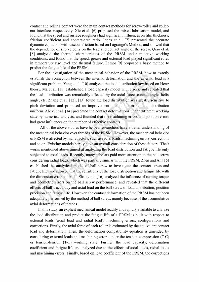
Fig. 1 shows a scheme of the PRSM. For the purpose to obtain a practical
analytical model and reduce ambiguity, the necessary hypotheses should be made:
1) All contact deformations are considered as elastic deformations, which only occur
in the contact area and conform to the Hertz contact theory;
2) Centrifugal force and gyroscopic moment are negligible due to the low rotation
speed of the screw;
3) The top roller is 1#, and the sequence number increases clockwise;
4) The separation angle of any roller i# with respect to 1# roller is φi, which could be
calculated by:
2 ( 1)
( 1,2,..., )i
ii n
n
(1)
where n is the total number of rollers.
2.2. Contact load and deformation analysis
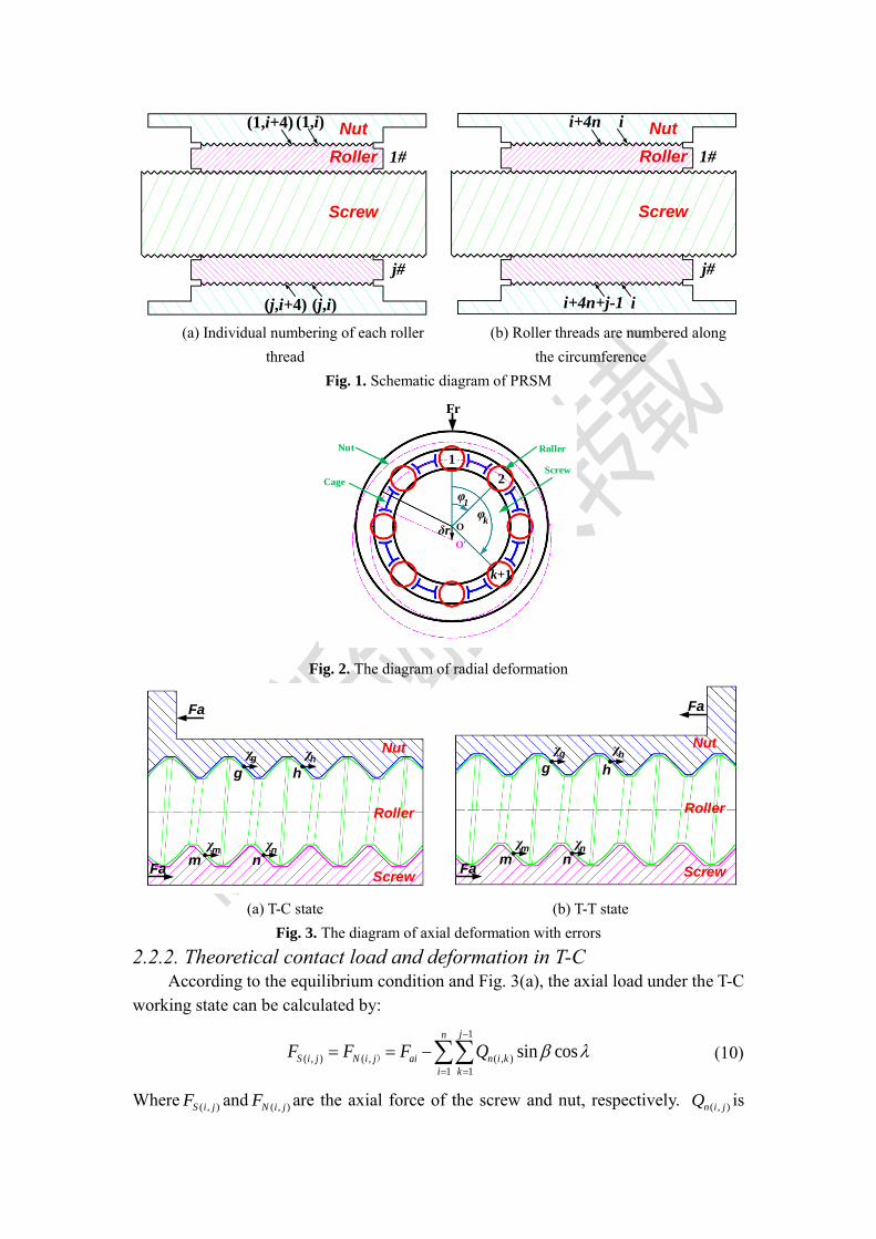
2.2.1. Equivalent contact load and deformation As shown in Fig. 2, when the PRSM is subjected to radial load, the radial contact
deformation at different position angle is generated. Fig. 2 shows the solid circle
represents the initial position of the nut, and the dotted circle denotes the new position
of the nut under external loads. According to Ref.[6], [11], for the purpose to obtain
the load capacity, the axial load of each roller is given as an input parameter and the
contact deformations and contact forces are solved. However, when the PRSM is
subjected to both axial and radial loads, the axial load of each roller is not the same.
Furthermore, it’s also extremely difficult to calculate the normal contact deformations
of all threads in accordance with geometry relationship. Hence, in order to get the axial
load of each roller, it is firstly assumed that the axial deformation δa(i,j) of all threads
are identical, and the radial deformation of i# roller can be described by[15]:
( , ) cosr i j r i (2)
i is the position angle of i# roller and can be written by:
i i (3)
by varying θ, the radial deformation of any thread can be known.
Therefore, the equivalent contact deformation ( , )
E
n i j of screw-roller and nut-roller

interface in the normal direction can be calculated by:
( , ) ( , ) ( , )sin / cos cos cosE
n i j a i j r i j i (4)
Where β is the contact angle; λ is the helix angle of roller.
And then, the equivalent contact load ( , )
E
n i jQ in the normal direction can be
obtained according to the load-deformation relationship of the PRSM:
( , )3/2
( , ) ( , )
( , )
1, 0( )
0, 0
E
n i jE E
n i j n i j E
n i j
Q K
(5)
where the index γ = 1 denotes that the thread couple are contacting, while γ = 0
represents that the thread couple are not in contact. The symbol K is total contact
stiffness coefficient in the screw-roller and nut-roller interface, which depends on the
design parameters of the PRSM. It can be determined by:
1
rn rs
KK K
(6)
where Krs and Krn are the contact stiffness of screw-roller interface and nut-roller
interface, respectively, and which are expressed as[6]:
2
3
2
3
(3 )
4
(3 )
4
sesrs
as
nenrn
an
EKK
m
EKK
m
(7)
where Kes and Ken are the complete elliptic integral of the first kind of screw-roller and
roller-nut interface, respectively; mas and man are the major semi-axis coefficients of the
contact ellipse of the screw-roller and roller-nut interface, respectively; E represents the
effective Young moduli; ∑ ρs and ∑ ρ
n are the curvature sum of screw-roller and
roller-nut interface, respectively.
According to Eqs. (1) ~ (7), the equilibrium equations of equivalent contact load
of the PRSM with axial load and radial load are obtained by:
( , )
1 1
( , )
1 1
sin cos 0
cos cos 0
n tE
r n i j
i j
n tE
a n i j i
i j
F Q
F Q
(8)
where Fr and Fa are the radial load and axial load on the PRSM, respectively; t is the
total thread number of any roller.
Hence, the axial contact load of any roller can be calculated by:
( , )
1
cos cost
E
ai n i j i
j
F Q
(9)
Nut(1,i)(1,i+4)
Roller
Screw
(j,i)(j,i+4)
1#
j#
Nutii+4n
Roller
Screw
ii+4n+j-1
1#
j#
(a) Individual numbering of each roller
thread
(b) Roller threads are numbered along
the circumference
Fig. 1. Schematic diagram of PRSM
1
2
k+1
Nut
Cage
Roller
Screw
Fr
O
O
δr
φk
φ1
Fig. 2. The diagram of radial deformation
Screw
Roller
Nut
m nχm χn
g h
χg χh
Fa
Fa Screw
Roller
Nut
Fam n
χm χn
g h
χg χh
Fa
(a) T-C state (b) T-T state
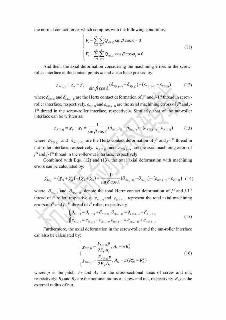
Fig. 3. The diagram of axial deformation with errors
2.2.2. Theoretical contact load and deformation in T-C According to the equilibrium condition and Fig. 3(a), the axial load under the T-C
working state can be calculated by:
1
( , ) ( , ( , )
1 1
sin cosjn
S i j N i j ai n i k
i k
F F F Q
) (10)
Where( , )S i jF and
( , )N i jF are the axial force of the screw and nut, respectively. ( , )n i jQ is
the normal contact force, which complies with the following conditions:
( , )
1 1
( , )
1 1
sin cos 0
cos cos 0
n t
r n i j
i j
n t
a n i j j
i j
F Q
F Q
(11)
And then, the axial deformation considering the machining errors in the screw-
roller interface at the contact points m and n can be expressed by:
( , ) ( , 1) ( , ) ( , 1) ( , )
1( ) ( )
sin cosS i j m n S i j S i j S i j S i j
(12)
where( , )S i j and
( , 1)S i j are the Hertz contact deformation of jth and j-1th thread in screw-
roller interface, respectively.( , )S i j and
( , 1)S i j are the axial machining errors of jth and j-
1th thread in the screw-roller interface, respectively. Similarly, that of the nut-roller
interface can be written as:
( , ) ( , 1) ( , ) ( , 1) ( , )
1( ) ( )
sin cosN i j g h N i j N i j N i j N i j
(13)
where ( , )N i j and
( , 1)N i j are the Hertz contact deformation of jth and j-1th thread in
nut-roller interface, respectively. ( , )N i j and
( , 1)N i j are the axial machining errors of
jth and j-1th thread in the roller-nut interface, respectively
Combined with Eqs. (12) and (13), the total axial deformation with machining
errors can be calculated by:
( , ) ( , 1) ( , ) ( , 1) ( , )
1( ) ( ) ( ) ( )
sin cosi j m g n h n i j n i j n i j n i j
(14)
where ( , )n i j and
( , 1)n i j denote the total Hertz contact deformation of jth and j-1th
thread of i# roller, respectively. ( , )n i j and
( , 1)n i j represent the total axial machining
errors of jth and j-1th thread of i# roller, respectively.
( , ) ( , ) ( , ) ( , 1) ( , 1) ( , 1)
( , ) , ) ( , ) ( , 1) ( , 1) ( , 1)
,
,
n i j S i j N i j n i j S i j N i j
n i j S i j N i j n i j S i j N i j
(
(15)
Furthermore, the axial deformation in the screw-roller and the nut-roller interface
can also be calculated by:
( , ) 2
( , )
( , ) 2 2
( , )
,2
, ( )2
S i j
S i j S S
S S
N i j
N i j N oN N
N N
F pA R
E A
F pA R R
E A
(16)
where p is the pitch; AS and AN are the cross-sectional areas of screw and nut,
respectively; RS and RN are the nominal radius of screw and nut, respectively. RoN is the
external radius of nut.

According to Eq. (16), the total axial deformation can also be calculated by:
( , )
( , )
( )
2
N i j S N
i j
S S N
F p A A
E A A
(17)
Based on Eqs. (14) and (17), the recursive equation with machining errors can be
obtained by:
( , 1) ( , )
2 2
( , )
( , 1) ( , ) 12/3 2/3
sin cos ( )( )sin cos
2 ( )n i j n i j
n t
n i k s n
i j i j i k j
rs rn s s n rs rn
Q p A A
Q QK K E A A K K
(18)
2.2.3. Theoretical contact load and deformation in T-T According to the equilibrium condition and Fig. 3(b), the axial load under T-T
working state can be revised by:
1
( , ) ( , )
1 1
( , ( , )
1 1
sin cos
sin cos
jn
S i j a n i k
i k
jn
N i j n i k
i k
F F Q
F Q
)
(19)
where Qn(i,j) complies with Eq. (11).
According to Fig. 3(b), the axial deformation in the screw-roller interface can also
be expressed by Eq. (12), while that of the nut-roller interface can be amended as:
( , ) ( , ) ( , 1) ( , ) ( , 1)
1( ) ( )
sin cosN i j g h N i j N i j N i j N i j
(20)
Combined with Eqs. (12) and (20), the total axial deformation with machining
errors can be calculated by:
( , ) ( , ) ( , ) ( , 1) ( , ) ( , 1) ( , )
1( ) ( )
sin cosi j S i j N i j n i j n i j n i j n i j
(21)
With Eqs. (16) and (19), the total axial deformation can also be calculated by:
( , ) ( , )
1
( , )
( ) sin cos
2 2
n t
n i k S N n i j S
i k jai j
N S N
Q A A Q A pF p
EA EA A
(22)
According to Eqs. (21) and (22), the recursive equation with errors in T-T can be
obtained as:
( , 1) ( , )
( , 1) ( , )2/3 2/3
2 2
( , ) ( , )
1
( )sin cos sin cos
2 ( )
( ) sin cos
2 ( )
n i j n i j
i j i j a
rs rn s n rs rn
n t
n i k s n n i j s
i k j
s s n rs rn
F pQ Q
K K E A K K
Q A A Q A p
E A A K K
(23)
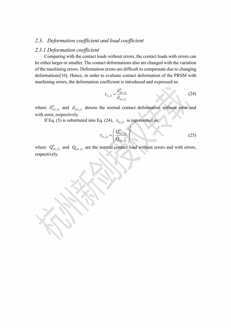
2.3. Deformation coefficient and load coefficient
2.3.1 Deformation coefficient Comparing with the contact loads without errors, the contact loads with errors can
be either larger or smaller. The contact deformations also are changed with the variation
of the machining errors. Deformation errors are difficult to compensate due to changing
deformations[16]. Hence, in order to evaluate contact deformation of the PRSM with
machining errors, the deformation coefficient is introduced and expressed as:
0
( , )
( , )
( , )
n i j
i j
n i j
(24)
where 0
( , )n i j and ( , )n i j denote the normal contact deformation without error and
with error, respectively.
If Eq. (5) is substituted into Eq. (24), ( , )i j is represented as:
20 3( , )
( , )
( , )
n i j
i j
n i j
Q
Q
(25)
where 0
( , )n i jQ and ( , )n i jQ are the normal contact load without errors and with errors,
respectively.
Calculate the radial contact deformation δr(i,j) and
the equivalent normal contact deformation
Calculate the axial load Fai
Use Eqs.(11)~(18) to calculate
normal contact load Qn(i,j)
Input structural parameters and load condition
Assume the initial value and convergence precision
Output maximum contact stress σmax and fatigue life L
Start
End
Yes
No
Yes
( , )
1 1
( , )
1 1
sin cos
cos cos
n tE
a n i j
i j
n tE
r n i j j
i j
F Q acc
F Q acc
3/2
( , ) ( , )( / ( ))E E
n i j n i j rs rnQ K K
( , ) 0E
n i j ( , ) 0E
n i jQ
T-C
or
T-T
Use Eqs.(19)~(23) to calculate
normal contact load Qn(i,j)
No
T-T
T-C
( , )
E
n i j
Equivalent contact
load and deformation
Theoretical contact load
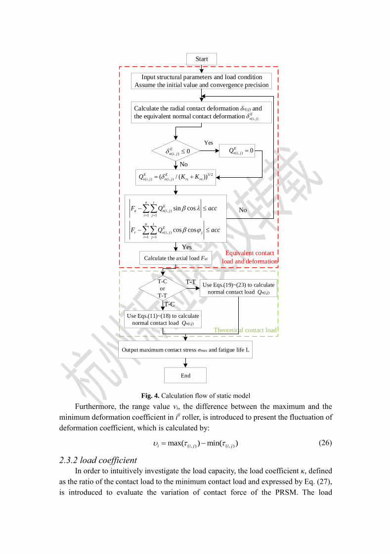
Fig. 4. Calculation flow of static model
Furthermore, the range value νi, the difference between the maximum and the
minimum deformation coefficient in i# roller, is introduced to present the fluctuation of
deformation coefficient, which is calculated by:
( , ) ( , )max( ) min( )i i j i j (26)
2.3.2 load coefficient In order to intuitively investigate the load capacity, the load coefficient κ, defined
as the ratio of the contact load to the minimum contact load and expressed by Eq. (27),
is introduced to evaluate the variation of contact force of the PRSM. The load
coefficient varies with the contact load variation. Thus, the coefficient directly reveals
the nonuniformity of load capacity.
0
( , )
( , ) 0
( , )min( )
n i j
i j
n i j
Q
Q (27)
2.4. Fatigue life analysis
Fatigue life is one of the most important performance of the PRSM in practical
applications. In this part, the fatigue life of the PRSM is discussed based on the previous
analysis. According to the stress-life approach, the lifetime of the PRSM is determined
by contact stress and rotate speed. Commonly, the basis for formulating fatigue life of
the PRSM is the maximum contact stress, which can be obtained by:
maxmax
3
2
nQ
ab (28)
where Qnmax denotes the maximum contact force in normal direction, the major semi-
axis a and minor semi-axis b of the contact ellipse can be calculated by[17]:
max max
3 3
3 3,
2 2
n na b
Q E Q Ea m b m
(29)
where mb is expressed as:
32
2 ( )
π(1 )b
K em
e
(30)
And then, the fatigue curve of material can be written as:
0
m
HN k N (31)
where N0 is the circulation base of the material. kσ represents the stress ratio between
contact fatigue limit σ0 and maximum contact stress σmax and is written by:
0
max
k
(32)
Furthermore, the absolute rotating speed of the roller around the screw can be
expressed as[18]:
( 2)
2( 1)
S m mR
m
k k
k
(33)
where km denotes the ratio between screw nominal diameter dS and roller nominal
diameter dR and is expressed by:
S
m
R
dk
d (34)

Therefore, the fatigue life in hour is estimated by[15]:
( 1)
60 ( 2)
H m
s m m
N kL
k k
(35)
Based on the above analysis, the entire calculation process for the fatigue life and
contact forces of the planetary roller screw is shown in Fig. 4.
3. Numerical examples and discussion In order to verify the validity and accuracy of the proposed model, some numerical
examples are presented by the specific parameters. These examples cover contact loads,
fatigue life and deformation coefficients considering the effects of configurations,
external loads, machining errors and corrections. Table 1 and Table 2 show the detail
parameters of the PRSM. In this example, there are 24 threads in a roller and 192 threads
in all rollers.
Table 1.
Design parameters of the PRSM
Roller Screw Nut
Parameters (Unit) Symbol Values Symbol Values Symbol Values
Nominal radius (mm) Rr 4 Rs 12 Rn 20
Contact angle (◦) β 45 β 45 β 45
Starts Sr 1 Ss 5 Sn 5
Helix angle (°) λr 4.55 λS 1.52 λn 0.91
Pitch (mm) Pr 2 Ps 2 Pn 2
Number nr 8 ns 1 nn 1
External radius (mm) / / / / Ron 27.5
Table 2.
Material parameters of the PRSM
Parameters (Unit) Symbols Values Parameters (Unit) Symbols Values
Young moduli (Pa) E 2.12×10¹¹ Poisson’s ratio μ 0.29
Circulation base N0 2.5×10⁸ hardness of parts HRC 62
contact fatigue limit
(N/mm2)
σ0 2450 point contact index
of the steel
m 6
3.1. Effects of external loads
Fig. 5 depicts the load capacity under the T-T and T-C working state when
machining errors are zero, and the PRSM is assumed that under the next two conditions:
1) the axial load Fa = 30kN and the radial load Fr = 3kN; 2) the axial load Fa = 30kN
and the radial load Fr = 0kN. In Fig. 5, the load capacity without radial load is
represented by the dotted line, while that with radial load is denoted by the full line.
Square, circle, upper triangle, lower triangle and diamond markers are the load capacity
of 1#, 2# and 8#, 3# and 7#, 4# and 6#, 5# roller with radial load, respectively.
As shown in Fig. 5(a), it can be observed that the load capacity curves of all rollers
are superimposed when the PRSM is not subjected to radial force. With the increase of
the thread number, the contact loads monotonically decrease, but the slopes of the
curves increase. This is notably consistent with the observation from Ref. [13].
Nevertheless, the load distribution curves vary when the PRSM is applied with radial
force. In a lead, the contact forces of the 8 pairs of thread contact couple are no longer
the same, but are either larger or smaller. Moreover, for the position angle from 0° to
180°, the contact loads from 1# roller to 5# roller gradually decrease with the decrease
of radial load. For the position angle from 180° to 360°, the contact loads from 5# roller
to 1# roller gradually increase with the growth of radial load. This is mainly due to the
fact that increasing or decreasing radial load of rollers makes the Hertz contact
deformation larger or smaller at different position angle, which results in the variation
of contact loads. Moreover, the load capacity curves of 3# and 7# rollers with radial
force are the same as that of any roller without radial force, and they may also be
considered as the mean of all rollers with radial force. And then, Fig. 5(b) shows the
load capacity under the T-T state. Comparing Fig. 5(b) with Fig. 5(a), the contact forces
do not always decrease with the growth of thread number, but first decrease and then
increase. This phenomenon occurs mainly because under the T-T state, the axial load is
applied near the first thread of roller in screw-roller side and the last thread in the roller-
nut side, so that the load distribution can become slightly uniform.
Fig. 6 shows the contact loads of 1# roller in the cycling process. For the T-C and
T-T case in Fig. 6, it can be notably found that under the same thread, the contact loads
of the PRSM without radial force don’t change in the cycling process while those vary
periodically under radial load. The changing trend of contact force is similar with the
ball screw of Ref.[15]. Moreover, the contact forces under the same position angle
reduce obviously with the increase of thread number in Fig. 6(a) and Fig. 6(b), while
that in Fig. 6(c) and Fig. 6(d) decrease at first and then increase. That is well confirmed
by Fig. 5. Because the changing tendency of load capacity is similar with each roller,
this part takes 1# roller as an example.
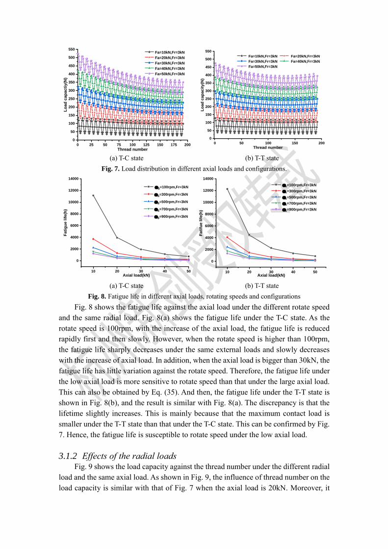
3.1.1 Effects of the axial loads Fig. 7 represents the variation of load capacity against thread number under the
same radial load and the different axial load. As the T-C case shown in Fig. 7(a), the
PRSM with different axial load shows the different load distribution curves. The contact
forces over threads are undoubtedly increased with the growth of axial loads.
Meanwhile, with the increase of thread number, the contact force reduces periodically.
And then, Fig. 7(b) shows the load capacity for the T-T case. We can find that the peak
value of contact force and the downward trend of the load distribution curve under the
T-T state is smaller than Fig. 7(a) under the same external load. Furthermore, the contact
forces decrease at first and then increase periodically. Thus, it can be concluded that the
load capacity becomes more even under the T-T state, and the uniformity of that cuts
down with increase of axial load.

0 5 10 15 20 25
150
200
250
300
350
Lo
ad
cap
ac
ity
(N)
Thread number
1# roller with radial load
2#&8# roller with radial load
3#&7# roller with radial load
4#&6# roller with radial load
5# roller with radial load
all rollers without radial load
0 5 10 15 20 25
150
200
250
300
350
Lo
ad
cap
ac
ity
(N)
Thread number
1#roller with radial load
2#&8# roller with radial load
3#&7# roller with radial load
4#&6# roller with radial load
5#roller with radial load
all rollers without radial load
(a) T-C state (b)T-T state
Fig. 5. Load capacity in different configurations
(a) No radial load under the T-C state (b) With radial loads under the T-C state
(c) No radial load under the T-T state (d) With radial loads under the T-T state
Fig. 6. Load capacity of 1# roller in cycling in different configurations and external loads.
0 25 50 75 100 125 150 175 200
0
50
100
150
200
250
300
350
400
450
500
550
Lo
ad
cap
ac
tiy
(N)
Thread number
Fa=10kN,Fr=3kN
Fa=20kN,Fr=3kN
Fa=30kN,Fr=3kN
Fa=40kN,Fr=3kN
Fa=50kN,Fr=3kN
0 50 100 150 200
0
50
100
150
200
250
300
350
400
450
500
550
Lo
ad
cap
acit
y(N
)
Thread number
Fa=10kN,Fr=3kN Fa=20kN,Fr=3kN
Fa=30kN,Fr=3kN Fa=40kN,Fr=3kN
Fa=50kN,Fr=3kN
(a) T-C state (b) T-T state
Fig. 7. Load distribution in different axial loads and configurations.
10 20 30 40 50
0
2000
4000
6000
8000
10000
12000
14000
Fati
gu
e lif
e(h
)
Axial load(kN)
s=100rpm,Fr=3kN
s=300rpm,Fr=3kN
s=500rpm,Fr=3kN
s=700rpm,Fr=3kN
s=900rpm,Fr=3kN
10 20 30 40 50
0
2000
4000
6000
8000
10000
12000
14000
Fati
fue lif
e(h
)
Axial load(kN)
s=100rpm,Fr=3kN
s=300rpm,Fr=3kN
s=500rpm,Fr=3kN
s=700rpm,Fr=3kN
s=900rpm,Fr=3kN
(a) T-C state (b) T-T state
Fig. 8. Fatigue life in different axial loads, rotating speeds and configurations
Fig. 8 shows the fatigue life against the axial load under the different rotate speed
and the same radial load. Fig. 8(a) shows the fatigue life under the T-C state. As the
rotate speed is 100rpm, with the increase of the axial load, the fatigue life is reduced
rapidly first and then slowly. However, when the rotate speed is higher than 100rpm,
the fatigue life sharply decreases under the same external loads and slowly decreases
with the increase of axial load. In addition, when the axial load is bigger than 30kN, the
fatigue life has little variation against the rotate speed. Therefore, the fatigue life under
the low axial load is more sensitive to rotate speed than that under the large axial load.
This can also be obtained by Eq. (35). And then, the fatigue life under the T-T state is
shown in Fig. 8(b), and the result is similar with Fig. 8(a). The discrepancy is that the
lifetime slightly increases. This is mainly because that the maximum contact load is
smaller under the T-T state than that under the T-C state. This can be confirmed by Fig.
7. Hence, the fatigue life is susceptible to rotate speed under the low axial load.
3.1.2 Effects of the radial loads Fig. 9 shows the load capacity against the thread number under the different radial
load and the same axial load. As shown in Fig. 9, the influence of thread number on the
load capacity is similar with that of Fig. 7 when the axial load is 20kN. Moreover, it
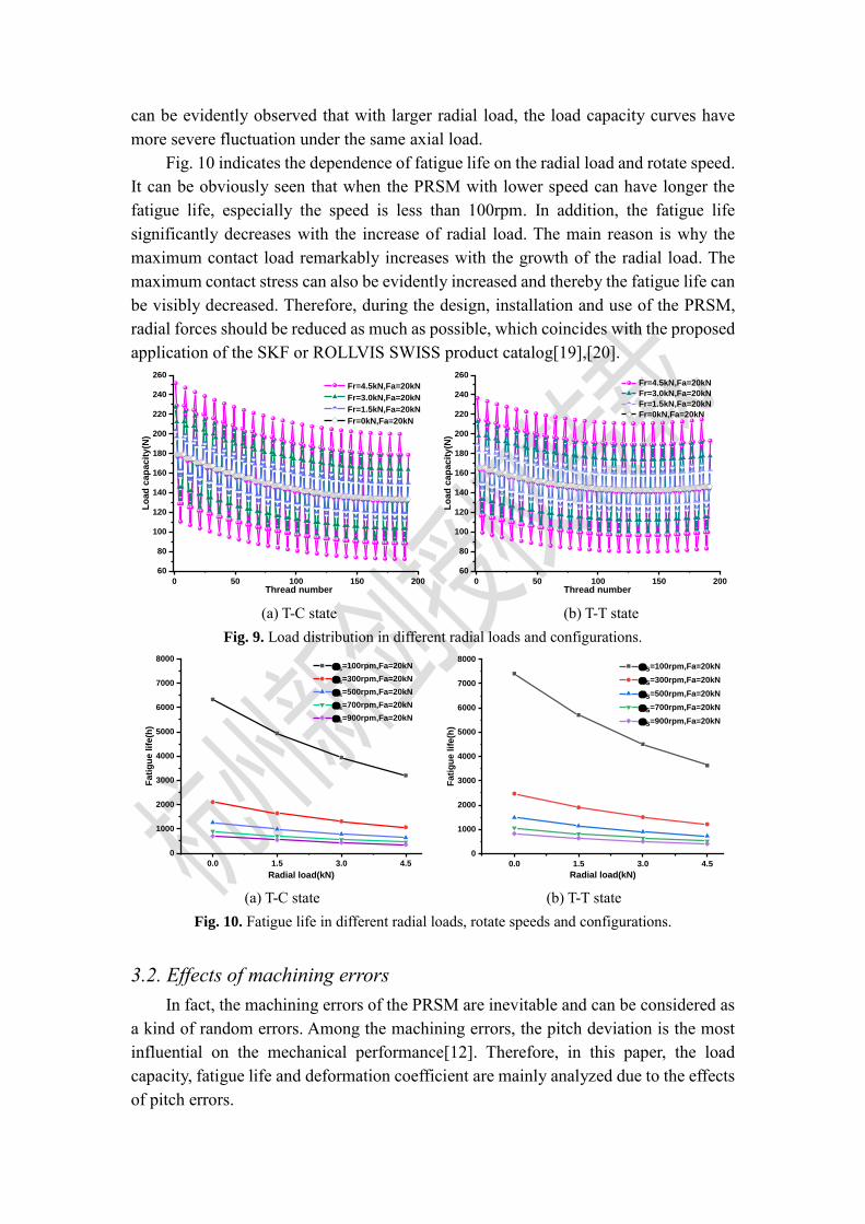
can be evidently observed that with larger radial load, the load capacity curves have
more severe fluctuation under the same axial load.
Fig. 10 indicates the dependence of fatigue life on the radial load and rotate speed.
It can be obviously seen that when the PRSM with lower speed can have longer the
fatigue life, especially the speed is less than 100rpm. In addition, the fatigue life
significantly decreases with the increase of radial load. The main reason is why the
maximum contact load remarkably increases with the growth of the radial load. The
maximum contact stress can also be evidently increased and thereby the fatigue life can
be visibly decreased. Therefore, during the design, installation and use of the PRSM,
radial forces should be reduced as much as possible, which coincides with the proposed
application of the SKF or ROLLVIS SWISS product catalog[19],[20].
0 50 100 150 200
60
80
100
120
140
160
180
200
220
240
260
Lo
ad
cap
ac
ity
(N)
Thread number
Fr=4.5kN,Fa=20kN
Fr=3.0kN,Fa=20kN
Fr=1.5kN,Fa=20kN
Fr=0kN,Fa=20kN
0 50 100 150 200
60
80
100
120
140
160
180
200
220
240
260
Lo
ad
cap
ac
ity
(N)
Thread number
Fr=4.5kN,Fa=20kN
Fr=3.0kN,Fa=20kN
Fr=1.5kN,Fa=20kN
Fr=0kN,Fa=20kN
(a) T-C state (b) T-T state
Fig. 9. Load distribution in different radial loads and configurations.
0.0 1.5 3.0 4.5
0
1000
2000
3000
4000
5000
6000
7000
8000 s=100rpm,Fa=20kN
s=300rpm,Fa=20kN
s=500rpm,Fa=20kN
s=700rpm,Fa=20kN
s=900rpm,Fa=20kN
Fati
gu
e lif
e(h
)
Radial load(kN) 0.0 1.5 3.0 4.5
0
1000
2000
3000
4000
5000
6000
7000
8000
Fati
gu
e l
ife
(h)
Radial load(kN)
s=100rpm,Fa=20kN
s=300rpm,Fa=20kN
s=500rpm,Fa=20kN
s=700rpm,Fa=20kN
s=900rpm,Fa=20kN
(a) T-C state (b) T-T state
Fig. 10. Fatigue life in different radial loads, rotate speeds and configurations.
3.2. Effects of machining errors
In fact, the machining errors of the PRSM are inevitable and can be considered as
a kind of random errors. Among the machining errors, the pitch deviation is the most
influential on the mechanical performance[12]. Therefore, in this paper, the load
capacity, fatigue life and deformation coefficient are mainly analyzed due to the effects
of pitch errors.
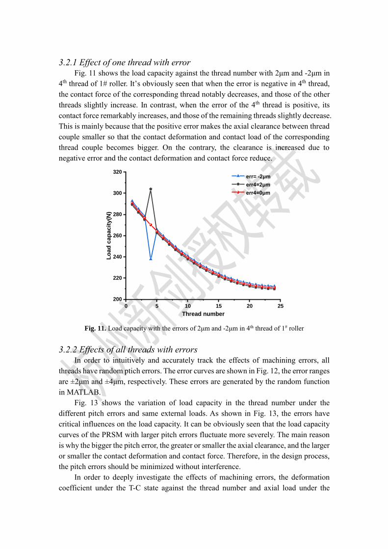
3.2.1 Effect of one thread with error Fig. 11 shows the load capacity against the thread number with 2μm and -2μm in
4th thread of 1# roller. It’s obviously seen that when the error is negative in 4th thread,
the contact force of the corresponding thread notably decreases, and those of the other
threads slightly increase. In contrast, when the error of the 4th thread is positive, its
contact force remarkably increases, and those of the remaining threads slightly decrease.
This is mainly because that the positive error makes the axial clearance between thread
couple smaller so that the contact deformation and contact load of the corresponding
thread couple becomes bigger. On the contrary, the clearance is increased due to
negative error and the contact deformation and contact force reduce.
0 5 10 15 20 25
200
220
240
260
280
300
320
Lo
ad
cap
acit
y(N
)
Thread number
err= -2μm
err4=2μm
err4=0μm
Fig. 11. Load capacity with the errors of 2μm and -2μm in 4th thread of 1# roller
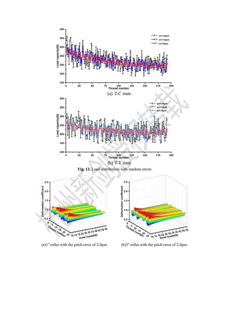
3.2.2 Effects of all threads with errors In order to intuitively and accurately track the effects of machining errors, all
threads have random ptich errors. The error curves are shown in Fig. 12, the error ranges
are ±2μm and ±4μm, respectively. These errors are generated by the random function
in MATLAB.
Fig. 13 shows the variation of load capacity in the thread number under the
different pitch errors and same external loads. As shown in Fig. 13, the errors have
critical influences on the load capacity. It can be obviously seen that the load capacity
curves of the PRSM with larger pitch errors fluctuate more severely. The main reason
is why the bigger the pitch error, the greater or smaller the axial clearance, and the larger
or smaller the contact deformation and contact force. Therefore, in the design process,
the pitch errors should be minimized without interference.
In order to deeply investigate the effects of machining errors, the deformation
coefficient under the T-C state against the thread number and axial load under the

different pitch errors and the same radial load of 1kN. As shown in Fig. 14, both the
axial loads and pitch errors evidently change the deformation coefficient. Obviously,
comparing the deformation coefficient of ±2μm with that of ±4μm for given axial loads,
there is a larger fluctuation of deformation coefficient under ±4μm. This is mainly
because that the larger the pitch errors, the bigger the variation of contact force and
deformation. This is well confirmed by Fig. 13. In addition, with the growth of axial
load, the deformation coefficient reduces rapidly at first and then slowly for ±4μm case.
It can be observed that the deformation coefficient under the low axial load is more
sensitive to machining errors than that under the large axial load. Therefore, the PRSM
can properly reduce the machining accuracy under heavy loads.
The fatigue life under the T-C state against machining errors shown in Fig. 15 and
Fig. 16. Fig. 15 depicts the fatigue life against the axial load and accuracy under the
same radial load of 1kN and the same feed rate of 300 rpm. As shown in Fig. 15, for
given a specific accuracy, the PRSM with the lager axial load can possess a shorter
lifetime than that of the PRSM with smaller axial load. This agrees well with Fig. 8(a).
Furthermore, the fatigue life with a stable axial load has a clear downward trend with
the reduction of the machining accuracy. This is mainly accounts for the lower the
machining accuracy, the more uneven the distribution, and the maximum contact force
increases as Fig. 13 illustrates. And then, Fig. 16 represents the variation of fatigue life
in radial load and machining accuracy under the same axial load of 30kN and rotate
speed of 300rpm. It can be interestingly noted that when the machining accuracy is
stable, the fatigue life tends to remarkably decrease with the growth of radial load. This
is consistent with Fig. 10. Furthermore, the change of fatigue life with radial force and
machining accuracy is almost the same as that of the axial force.
Table 3
Roller’s pitch error with different accuracy (unit μm)
Accuracy A0 A1 A2 A3 A4 A5
Dimension error 0.5 1 2 3 4 5
0 50 100 150 200
-4
-2
0
2
4
Err
or(
μm
)
Thread number
err=±4μm
err=±2μm
Fig. 12. Random pitch errors of all roller threads
0 25 50 75 100 125 150 175 200
100
150
200
250
300
350
400
Lo
ad
cap
acit
y(N
)
Thread number
err=±4μm
err=±2μm
err=0μm
(a) T-C state
0 25 50 75 100 125 150 175 200
100
150
200
250
300
350
400
Lo
ad
cap
acit
y(N
)
Thread number
err=±4μm
err=±2μm
err=0μm
(b) T-T state
Fig. 13. Load distribution with random errors
(a)1# roller with the pitch error of 2.0μm (b)3# roller with the pitch error of 2.0μm

(c)1# roller with the pitch error of 4.0μm (d)3# roller with the pitch error of 4.0μm
Fig. 14. Deformation coefficient in different pitch errors and axial loads
Fig. 15. Fatigue life in different machining
accuracy and axial loads
Fig. 16. Fatigue life with machining accuracy
and radial loads
3.3. Effects of form correction of rollers
From Section 3.2 we can find that when the threads have errors, the contact forces
of the corresponding threads increase or decrease. Therefore, in order to achieve
uniform load distribution and improve lifetime, the thread forms of rollers are modified.
The modification is based on the load coefficient. According to Eq. (18), the recursive
equation with corrections can be revised by:
( , 1) ( , )
2 2
,
2/3 2/3
( , 1) ( , )
sin cos ( )1
[ ( )]2 ( )n i j n i j
t
n ij s n
j i
i j i j
rs rn s n rs rn
n Q p A A
Q Q cK K A A K K
(36)
where c is the modification factor.
As shown in Fig. 17, it indicates that the amount of modification of roller thread
under the T-C state is inversely proportional to the load coefficient. It can also be found
that the greater the contact load, the larger the amount of modification. Furthermore,
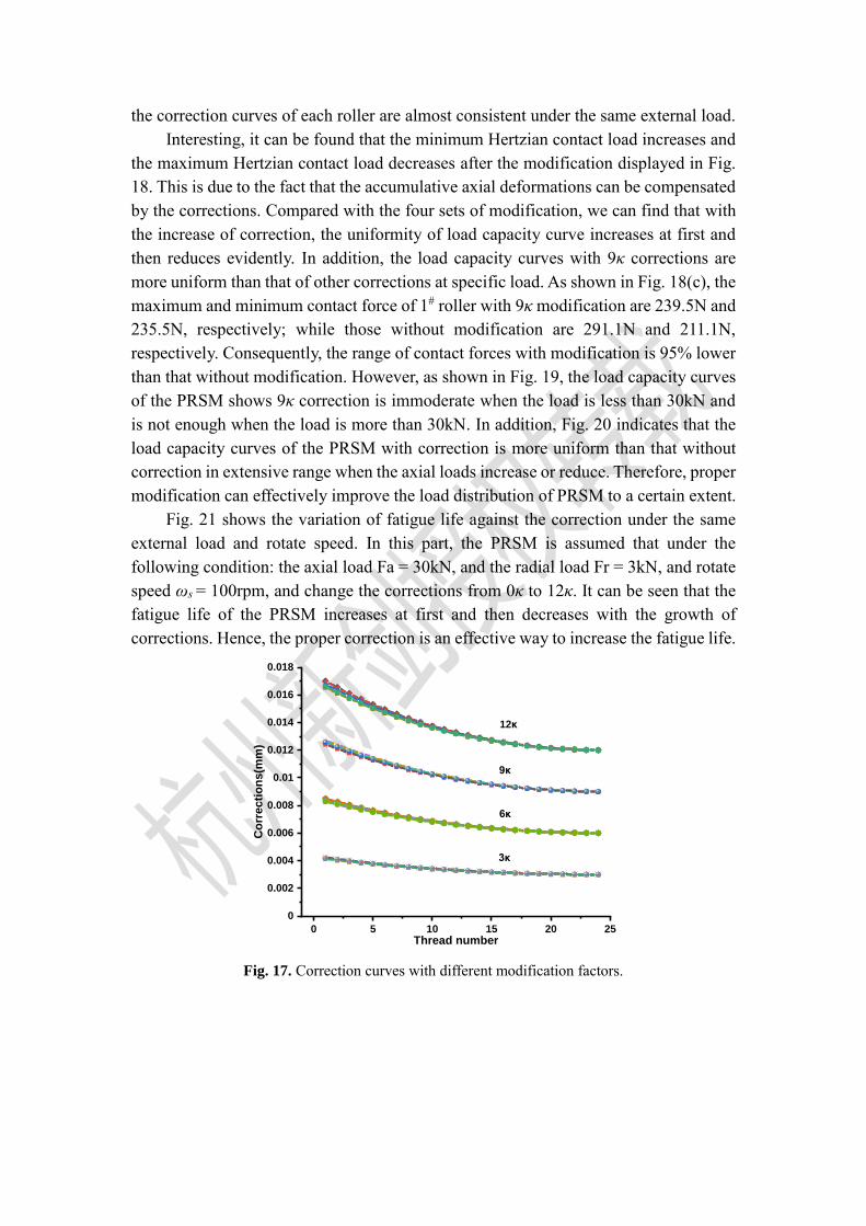
the correction curves of each roller are almost consistent under the same external load.
Interesting, it can be found that the minimum Hertzian contact load increases and
the maximum Hertzian contact load decreases after the modification displayed in Fig.
18. This is due to the fact that the accumulative axial deformations can be compensated
by the corrections. Compared with the four sets of modification, we can find that with
the increase of correction, the uniformity of load capacity curve increases at first and
then reduces evidently. In addition, the load capacity curves with 9κ corrections are
more uniform than that of other corrections at specific load. As shown in Fig. 18(c), the
maximum and minimum contact force of 1# roller with 9κ modification are 239.5N and
235.5N, respectively; while those without modification are 291.1N and 211.1N,
respectively. Consequently, the range of contact forces with modification is 95% lower
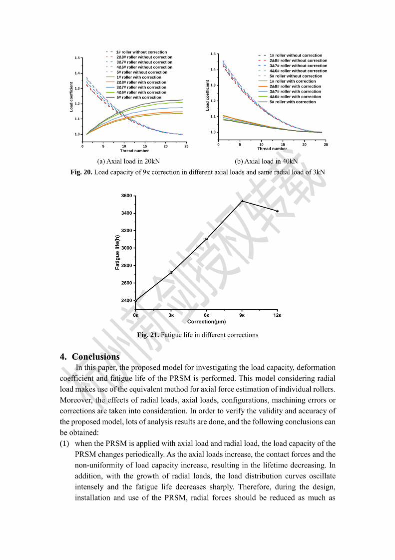
than that without modification. However, as shown in Fig. 19, the load capacity curves
of the PRSM shows 9κ correction is immoderate when the load is less than 30kN and
is not enough when the load is more than 30kN. In addition, Fig. 20 indicates that the
load capacity curves of the PRSM with correction is more uniform than that without
correction in extensive range when the axial loads increase or reduce. Therefore, proper
modification can effectively improve the load distribution of PRSM to a certain extent.
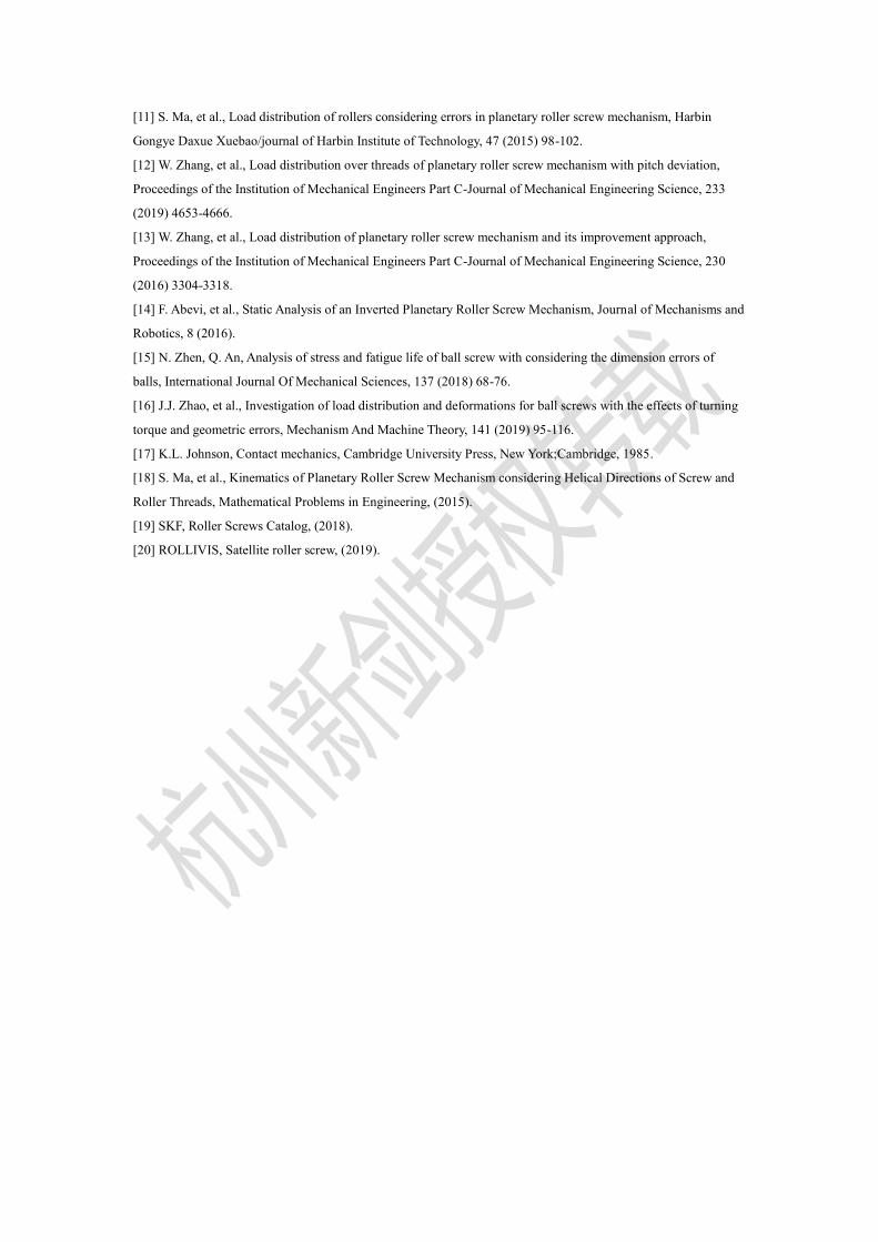
Fig. 21 shows the variation of fatigue life against the correction under the same
external load and rotate speed. In this part, the PRSM is assumed that under the
following condition: the axial load Fa = 30kN, and the radial load Fr = 3kN, and rotate
speed ꞷs = 100rpm, and change the corrections from 0κ to 12κ. It can be seen that the
fatigue life of the PRSM increases at first and then decreases with the growth of
corrections. Hence, the proper correction is an effective way to increase the fatigue life.
0 5 10 15 20 25
0
0.002
0.004
0.006
0.008
0.01
0.012
0.014
0.016
0.018
Co
rrecti
on
s(m
m)
Thread number
12κ
9κ
6κ
3κ
Fig. 17. Correction curves with different modification factors.

0 5 10 15 20 25
180
200
220
240
260
280
300
Lo
ad
cap
acit
y(N
)
Thread number
1#roller, no correction
2#&8#roller, no correction
3#&7#roller, no correction
4#&6#roller, no correction
5#roller, no correction
1#roller, with correction 3κ
2#&8#roller, with correction3κ
3#&7#roller, with correction 3κ
4#&6#roller, with correction 3κ
5#roller, with correction 3κ
0 5 10 15 20 25
180
200
220
240
260
280
300
Lo
ad
cap
ac
ity
(N)
Thread number
1#roller,no correction
2#&8#roller,no correction
3#&7#roller,no correction
4#&6#roller,no correction
5#roller,no correction
1#roller,with correction 6κ
2#&8#roller,with correction 6κ
3#&7#roller,with correction 6κ
4#&6#roller,with correction 6κ
5#roller,with correction 6κ
(a) 3κ correction (b) 6κ correction
0 5 10 15 20 25
180
200
220
240
260
280
300
Lo
ad
cap
ac
ity
(N)
Thread number
1#roller,no correction
2#&8#roller,no correction
3#&7#roller,no correction
4#&6#roller,no correction
5#roller,no correction
1#roller,with correction 9κ
2#&8#roller,with correction 9κ
3#&7#roller,with correction 9κ
4#&6#roller,with correction 9κ
5#roller,with correction 9κ
0 5 10 15 20 25
180
200
220
240
260
280
300
Lo
ad
cap
acit
y(N
)
Thread number
1#roller,no correction
2#&8#roller,no correction
3#&7#roller,no correction
4#&6#roller,no correction
5#roller,no correction
1#roller,with correction 12κ
2#&8#roller,with correction 12κ
3#&7#roller,with correction 12κ
4#&6#roller,with correction 12κ
5#roller,with correction 12κ
(c) 9κ correction (d) 12κ correction
Fig. 18. Load capacity in different corrections
0 5 10 15 20 25 30 35
1.00
1.05
1.10
1.15
1.20
1.25
Lo
ad
co
eff
icie
nt
Thread number
20kN in1# roller
20kN in 2&8# roller
20kN in 3&7# roller
20kN in 4&6# roller
20kN in 5# roller
30kN in 1# roller
30kN in 2&8# roller
30kN in 3&7# roller
30kN in 4&6# roller
30kN in 5# roller
40kN in 1# roller
40kN in 2&8# roller
40kN in 3&7# roller
40kN in 4&6# roller
40kN in 5# roller
Fig. 19. Load capacity of 9κ correction in different axial loads
0 5 10 15 20 25
1.0
1.1
1.2
1.3
1.4
1.5
Lo
ad
co
eff
icie
nt
Thread number
1# roller without correction
2&8# roller without correction
3&7# roller without correction
4&6# roller without correction
5# roller without correction
1# roller with correction
2&8# roller with correction
3&7# roller with correction
4&6# roller with correction
5# roller with correction
(a) Axial load in 20kN (b) Axial load in 40kN
Fig. 20. Load capacity of 9κ correction in different axial loads and same radial load of 3kN
0κ 3κ 6κ 9κ 12κ
2400
2600
2800
3000
3200
3400
3600
Fati
gu
e l
ife
(h)
Correction(μm)
Fig. 21. Fatigue life in different corrections
4. Conclusions In this paper, the proposed model for investigating the load capacity, deformation
coefficient and fatigue life of the PRSM is performed. This model considering radial
load makes use of the equivalent method for axial force estimation of individual rollers.
Moreover, the effects of radial loads, axial loads, configurations, machining errors or
corrections are taken into consideration. In order to verify the validity and accuracy of
the proposed model, lots of analysis results are done, and the following conclusions can
be obtained:
(1) when the PRSM is applied with axial load and radial load, the load capacity of the
PRSM changes periodically. As the axial loads increase, the contact forces and the
non-uniformity of load capacity increase, resulting in the lifetime decreasing. In
addition, with the growth of radial loads, the load distribution curves oscillate
intensely and the fatigue life decreases sharply. Therefore, during the design,
installation and use of the PRSM, radial forces should be reduced as much as

possible.
(2) The configurations affect load capacity and fatigue life. Comparing the T-T with
the T-C state, the contact force slightly become uniform and the fatigue life slightly
increases.
(3) The machining errors have great influences on load capacity, deformation and
fatigue life. As the error of a thread is negative, the corresponding thread contact
force decrease, but the rest increase. In contrast, the positive error makes contact
load of the corresponding thread increase, while the others decrease. Moreover, the
deformation coefficient varies dramatically with increasing errors, and decreases
rapidly at first and then slowly through increase of axial load. Hence, the load
distribution of large axial load isn’t particularly sensitive to the effect of machining
accuracy. Furthermore, for given an external load, the fatigue life of PRSM has a
decrease trend with the decrease of machining accuracy.
(4) The minimum Hertzian contact load remarkably increases and the maximum
Hertzian contact load significantly decreases after the roller threads are corrected.
Comparing the modified PRSM with the PRSM without modification, the contact
forces over threads becomes more even and the fatigue life of PRSM is notably
improved.
Acknowledgments This work was supported by the National Key Research and Development
Program of China (Grant No. 2017YFB1300704).
Reference [1] S. Sandu, et al., An efficient method for analyzing the roller screw thread geometry, Mechanism and Machine
Theory, 126 (2018) 243-264.
[2] S. Sandu, et al., Analytical prediction of the geometry of contact ellipses and kinematics in a roller screw
versus experimental results, Mechanism and Machine Theory, 131 (2019) 115-136.
[3] M.H. Jones, S.A. Velinsky, Kinematics of Roller Migration in the Planetary Roller Screw Mechanism, Journal
of Mechanical Design, 134 (2012).
[4] F. Abevi, et al., Static Load Distribution and Axial Stiffness in a Planetary Roller Screw Mechanism, Journal of
Mechanical Design, 138 (2016).
[5] S. Ma, et al., Modelling of static contact with friction of threaded surfaces in a planetary roller screw
mechanism, Mechanism and Machine Theory, 139 (2019) 212-236.
[6] Z. Xie, et al., Mixed-lubrication analysis of planetary roller screw, Tribol. Int., 140 (2019) 105883.
[7] M.H. Jones, et al., Dynamics of the Planetary Roller Screw Mechanism, Journal of Mechanisms and Robotics,
8 (2015).
[8] G. Qiao, et al., Thermal characteristics analysis and experimental study of the planetary roller screw
mechanism, Applied Thermal Engineering, 149 (2019) 1345-1358.
[9] P.C. Lemor, Mechanical drives combine efficiency and reliability, 69 (1997).
[10] J. Yang, et al., Calculation of load distribution of planetary roller screws and static rigidity, journal of
huazhong university of science and technology(natural science edition), 39 (2011) 1-5.
[11] S. Ma, et al., Load distribution of rollers considering errors in planetary roller screw mechanism, Harbin
Gongye Daxue Xuebao/journal of Harbin Institute of Technology, 47 (2015) 98-102.
[12] W. Zhang, et al., Load distribution over threads of planetary roller screw mechanism with pitch deviation,
Proceedings of the Institution of Mechanical Engineers Part C-Journal of Mechanical Engineering Science, 233
(2019) 4653-4666.
[13] W. Zhang, et al., Load distribution of planetary roller screw mechanism and its improvement approach,
Proceedings of the Institution of Mechanical Engineers Part C-Journal of Mechanical Engineering Science, 230
(2016) 3304-3318.
[14] F. Abevi, et al., Static Analysis of an Inverted Planetary Roller Screw Mechanism, Journal of Mechanisms and
Robotics, 8 (2016).
[15] N. Zhen, Q. An, Analysis of stress and fatigue life of ball screw with considering the dimension errors of
balls, International Journal Of Mechanical Sciences, 137 (2018) 68-76.
[16] J.J. Zhao, et al., Investigation of load distribution and deformations for ball screws with the effects of turning
torque and geometric errors, Mechanism And Machine Theory, 141 (2019) 95-116.
[17] K.L. Johnson, Contact mechanics, Cambridge University Press, New York;Cambridge, 1985.
[18] S. Ma, et al., Kinematics of Planetary Roller Screw Mechanism considering Helical Directions of Screw and
Roller Threads, Mathematical Problems in Engineering, (2015).
[19] SKF, Roller Screws Catalog, (2018).
[20] ROLLIVIS, Satellite roller screw, (2019).