Crossed Roller Slides - Automotion Components
222
165 Crossed Roller Slides ov-crossed-slides-divider - Updated - 18-09-2017
-
Upload
khangminh22 -
Category
Documents
-
view
1 -
download
0
Transcript of Crossed Roller Slides - Automotion Components

165
Crossed Roller Slides
ov-cro
ssed-slid
es-divid
er - Up
dated
- 18
-09
-20
17

LinearGuideways
Tel: 01483 26 67 74 Web: automotioncomponents.co.uk Fax: 01483 26 67 75 a website from Automotion Components
Linear Rail SetsOverview
Standard cross roller rail setsL1000 & L1001• Seven rail profi les (Sizes 1-12)• Lengths: 20mm to 1 metre• L1000 standard rail set• L1001 corrosion resistant rail sets
Deep groove and anti-creep rail setsL1002 + L1003• 3 x load capacity of standard rail sets
(due to deep V groove)• Two rail profi les (Sizes 4 & 6)• Lengths 50mm to 400mm• Anti-creep versions for high acceleration applications
Needle roller rail setsL1004• Heavy load ratings and needle rollers are
used• Five rail profi le size• Lengths: 200mm to 1.2 metres
Anti-friction coated rail setsL1005 & L1006• Same profi le as needle roller rails but
contact face Tefl on coated.• Ideal for harsh, dirty conditions• Vibration damping characteristics
ov-cro
ssed-slid
es-overview
- Up
dated
- 18
-09
-20
17

LinearGuideways
Tel: 01483 26 67 74 Web: automotioncomponents.co.uk Fax: 01483 26 67 75 a website from Automotion Components
Linear Cross Roller Rail SetsAccuracy overview
Expected life calculation:
Life (Km) L = (C/P)3.3 X 1.15 x 105m
C = eff ective dynamic load (N)P = equivalent load (N)
Working life calculation:
Lh (hours) = L x 106
L = Life (Km), see above Ls = Stroke Length (mm)n = Number of operations/min
• Close tolerance ±5μ• Speeds up to 50 m/min• Temperature range -40°C to +80°C up to +250°C if applying a temperature factor• Through hardened to 60 ±2 HRC• Acceleration up to 50 m/sec2
• Typical 0.003 coeffi cient of friction dependent on mounting surface accuracy
(Ra 0,2 μm)
Parallelism
2 x Ls x n x 60
Our cross roller rail sets are of the highest quality.
Accuracy Specifi cation:
w
h
A
B
Accuracy level
Parallelism of rolling plane A&B graph below
Allowable height tolerance (h) ±0,02
Paired mutual height tolerance (h) 0,01
Allowable width tolerance (w) +0, -0,02
Straightness
Length (mm)Straightness (μ)
Above Below
0 50 2,0
50 100 2,0
100 160 3,0
160 310 3,0
310 510 4,0
510 600 4,0
Par
alle
lism
(µ
)
0200 400 600 800 1000
2
4
6
8
Rail length (mm)
Lubrication: The units are lubricated with lithium soap lubricant. Relubricate if required.
ov-cro
ssed-slid
es-accuracy-o
verview - U
pd
ated - 1
8-0
9-2
017

LinearGuideways
Tel: 01483 26 67 74 Web: automotioncomponents.co.uk Fax: 01483 26 67 75 a website from Automotion Components
Cross Roller Rail SetsTechnical Information
p
w
h
d
L
L
Lr
s/2
s/2
s (stroke)
Load capacity depends on: • Rail size• Number of rollers in cage• Load rating = number of rollers x load rating/roller• Number of rollers (Nr) = cage length (Lc) / pitch p• Cage length aff ects the stroke and travel of the system
Load calculationsCalculations of retainer length and number of rollers:
Lr = L - S
Worked example:Assume L1000.09-400 with a stroke of 250mm:Cage length = 400 - (250/2) = 275mmRoller Ø = 9mm with a pitch (see table) of 18mm:Number of rollers = 275/18 = 15Load rating of system = load/roller* x no. of rollers(a pair of rollers) = 2420N x 15 = 36,300N
*See product table for allowable load per roller. Allowable load rating with a 3x safety factorcompared to static load
L1008.###-PR-xxxPlastic cage with steel rollers,for horizontal and vertical use.
Plastic cage Steel cage
L1008.###-AA-xxxSteel cage with steel rollers,
for horizontal use only.
Lr = distance between two rollers in ends of retainer (mm)L = rail length (mm)S = stroke length (mm)
Order no. d p h w Cage material
L1008.020-PR-xxx 2 3,9 5 0,75 Plastic - black
L1008.030-PR-xxx 3 5,0 7 1,00 Plastic - black
L1008.060-PR-xxx 6 8,5 14 2,00 Plastic - black
L1008.090-PR-xxx 9 14,0 20 3,00 Plastic - black
L1008.020-AA-xxx 2 4 5,5 0,80 Steel
L1008.030-AA-xxx 3 5 7,5 0,50 Steel
L1008.060-AA-xxx 6 12 14 0,80 Steel
L1008.090-AA-xxx 9 18 19,5 1,00 Steel
L1008.120-AA-xxx 12 22 25 1,20 Steel
2
ov-cro
ssed-slid
es-techn
ical-info
- Up
dated
- 18
-09
-20
17

LinearGuideways
Tel: 01483 26 67 74 Web: automotioncomponents.co.uk Fax: 01483 26 67 75 a website from Automotion Components
Linear Rail SetsRoller elements & end pieces
p
d
w
h
w
p
h
d
Type GA • For horizontal applications, most used.
Type GB • For horizontal or vertical applications.
Type GC • For horizontal or vertical applications.• Mount on longer rail only.
The more rollers the greater the load capacity* Allowable load is 1/3 of max. static load/roller, to allow a safety factor in calculations of 3.
Plastic cage (type PR)
Steel cage (type AA)
End pieces
End screws
Roller load ratings (per roller)
Rail size
Max. dynamic load Co N
Max. static load C N
Allowable* load N
1 125 144 48
2 290 290 95
3 630 760 250
4 1230 1170 390
6 2570 2630 870
9 7190 7270 2420
12 14700 13100 4300
Rail h d1 d2 d3 l1 l2 A/F
3 3 M3 2,3 5 12 5 2,5
6 5 M5 3,9 8 20 8 4
9 6 M6 4,6 8,5 30 12 5
12 8 M8 6,25 11,3 40 17 6
Type
Rail size GA l GB l GC l
1 1,5 - -
2 2 3 -
3 2 2 3
6 3 3 5
9 3 4 6
12 3 5 8
l
l
l
h
d1
l1
l2
d3
d2
A/F
ov-cro
ssed-slid
es-roller-elem
ents - U
pd
ated - 1
8-0
9-2
017
LinearGuideways
Tel: 01483 26 67 74 Web: automotioncomponents.co.uk Fax: 01483 26 67 75 a website from Automotion Components
Cross Roller Rail SetsInstallation
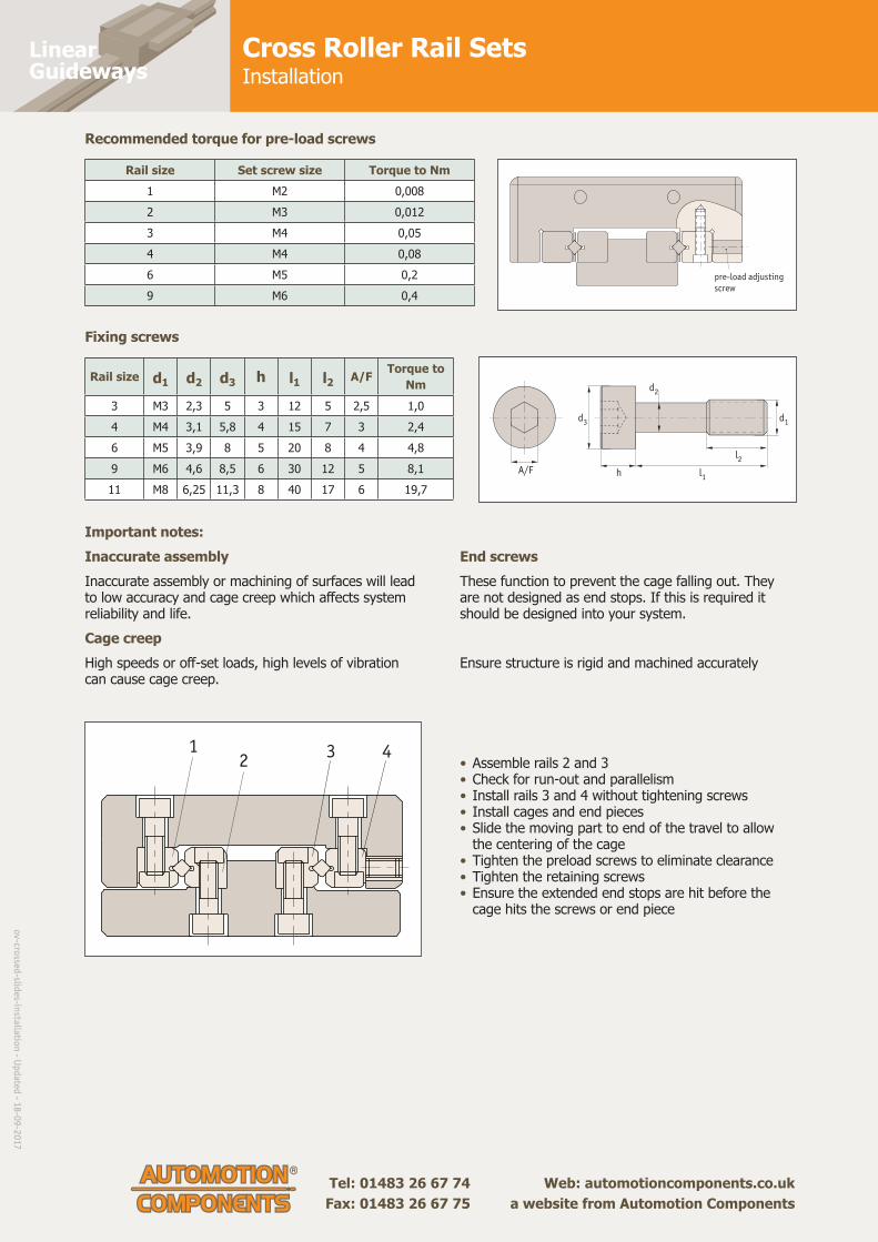
Rail size Set screw size Torque to Nm1 M2 0,0082 M3 0,0123 M4 0,054 M4 0,086 M5 0,29 M6 0,4
Rail size d1 d2 d3 h l1 l2 A/F Torque to Nm
3 M3 2,3 5 3 12 5 2,5 1,04 M4 3,1 5,8 4 15 7 3 2,46 M5 3,9 8 5 20 8 4 4,89 M6 4,6 8,5 6 30 12 5 8,111 M8 6,25 11,3 8 40 17 6 19,7
Recommended torque for pre-load screws
Fixing screws
A/F
l2
h l1
d2
d3 d1
pre-load adjusting
screw
Important notes:Inaccurate assemblyInaccurate assembly or machining of surfaces will lead to low accuracy and cage creep which aff ects system reliability and life. Cage creepHigh speeds or off -set loads, high levels of vibration can cause cage creep.
End screwsThese function to prevent the cage falling out. They are not designed as end stops. If this is required it should be designed into your system.
Ensure structure is rigid and machined accurately
12
3 4• Assemble rails 2 and 3• Check for run-out and parallelism• Install rails 3 and 4 without tightening screws• Install cages and end pieces• Slide the moving part to end of the travel to allow the centering of the cage• Tighten the preload screws to eliminate clearance• Tighten the retaining screws• Ensure the extended end stops are hit before the
cage hits the screws or end piece
ov-cro
ssed-slid
es-installatio
n - U
pd
ated - 1
8-0
9-2
017

LinearGuideways
Tel: 01483 26 67 74 Web: automotioncomponents.co.uk Fax: 01483 26 67 75 a website from Automotion Components
Linear Motion Slide Rail SetAssembly
1
2 3
4
assembly position of gauge
pre-load adjustable
screw
adjustable side
assembly position of
pre-load adjusting screw O X
roller retainer
O
roller retainer
X
roller retainer
OX X
1. Apply a low viscosity oil on contact surface, fi x rail (1,2 & 3) lightly.
2. Temporarily fi x the rail in adjusted side (4)
3. Disassemble end screw from one end, and carefully insert roller retainer to nearly the centre of the rail. Replace the end screw.Slowly move table back and forth to the rail end, and adjust roller retainer position to rail centre.
4. Fix gauges both in centre and the side of the table.
5. Move the table to one end and adjust pre-load screw slightly.
6. Move table to the other end and repeat.
7. Return the table back to centre and lock the pre-load adjusting screw slightly. Adjust the clearance of table to zero. For fi nal adjustment of preload, set correct torque value with a torque wrench and prepare to lock the rail fi xing screw.
7. Finally surely lock the rail.
: Loading on to pre-load adjusting screw: Loading off to pre-load adjusting screw
O
X
1
23
4 4
3
1
C
A
B
Installation surfacesAll burrs, dents, dust, etc. on the table and base need to be reduced.
Pre-load adjustment; too much preload can cause damage & reduced life. We recommend to used no or a small amount of pre-load.
Adjusting screw
Clamp
Taper block
Assembly process
ov-cro
ssed-slid
es-assemb
ly - Up
dated
- 18
-09
-20
17

Linear Rail SetsCrossed Roller Rail Sets
Tel: 0333 207 4498
Created 2021-11-12
Email: [email protected]
Web: automotioncomponents.co.uk
L1000
Material
Alloy steel rail and roller (DIN
1.2842), through hardened to 60± 2
HRC.
Stainless steel roller retainer (AISI
304).
Technical notes
Supplied in sets of 4 rails (with 2
roller cages and 8 end screws as
standard). See table for number of
rollers in each cage.
Crossed roller cages can be cut to
length to alter stroke - but this
affects load rating, please see
technical pages.
Order No. l1
Stroke
max.w
1
h1
+0, -0,3
h2
h3
l2
l3
l4
d1
d2
d3
w2
No.
of roll
ers
Max.
dyn.
load C
kN
Max
static
load C0
kN
XKg
L1000.01-020 20 13 4 8,5 3,9 1,8 10 5 1,3 1,65 3,0 M 2 1,4 5 0,63 0,72 0,01
L1000.01-030 30 21 4 8,5 3,9 1,8 10 5 1,3 1,65 3,0 M 2 1,4 7 0,88 1,00 0,01
L1000.01-040 40 29 4 8,5 3,9 1,8 10 5 1,3 1,65 3,0 M 2 1,4 9 1,13 1,30 0,02
L1000.01-050 50 37 4 8,5 3,9 1,8 10 5 1,3 1,65 3,0 M 2 1,4 11 1,38 1,58 0,02
L1000.01-060 60 45 4 8,5 3,9 1,8 10 5 1,3 1,65 3,0 M 2 1,4 13 1,63 1,88 0,02
L1000.01-070 70 53 4 8,5 3,9 1,8 10 5 1,3 1,65 3,0 M 2 1,4 15 1,88 2,16 0,03
L1000.01-080 80 61 4 8,5 3,9 1,8 10 5 1,3 1,65 3,0 M 2 1,4 17 12,1 2,45 0,03
L1000.02-030 30 24 6 12 5,5 2,5 15 7,5 1,5 2,55 4,4 M 3 2,0 5 1,47 1,46 0,03
L1000.02-045 45 30 6 12 5,5 2,5 15 7,5 1,5 2,55 4,4 M 3 2,0 8 2,34 2,34 0,04
L1000.02-060 60 44 6 12 5,5 2,5 15 7,5 1,5 2,55 4,4 M 3 2,0 10 2,93 2,92 0,05
L1000.02-075 75 58 6 12 5,5 2,5 15 7,5 1,5 2,55 4,4 M 3 2,0 12 3,52 3,50 0,06
L1000.02-090 90 72 6 12 5,5 2,5 15 7,5 1,5 2,55 4,4 M 3 2,0 14 4,10 4,09 0,08
L1000.02-105 105 86 6 12 5,5 2,5 15 7,5 1,5 2,55 4,4 M 3 2,0 16 4,69 4,67 0,09
L1000.02-120 120 100 6 12 5,5 2,5 15 7,5 1,5 2,55 4,4 M 3 2,0 18 5,27 5,26 0,11
L1000.02-135 135 106 6 12 5,5 2,5 15 7,5 1,5 2,55 4,4 M 3 2,0 21 6,15 6,13 0,12
L1000.02-150 150 120 6 12 5,5 2,5 15 7,5 1,5 2,55 4,4 M 3 2,0 23 6,74 6,72 0,13
L1000.02-165 165 134 6 12 5,5 2,5 15 7,5 1,5 2,55 4,4 M 3 2,0 25 7,33 7,30 0,14
L1000.02-180 180 148 6 12 5,5 2,5 15 7,5 1,5 2,55 4,4 M 3 2,0 27 7,91 7,88 0,16
L1000.03-050 50 34 8 18 8,3 3,5 25 12,5 2,0 3,3 6,0 M 4 3,1 7 4,47 5,33 0,92
L1000.03-075 75 54 8 18 8,3 3,5 25 12,5 2,0 3,3 6,0 M 4 3,1 10 6,38 7,61 0,14
L1000.03-100 100 74 8 18 8,3 3,5 25 12,5 2,0 3,3 6,0 M 4 3,1 13 8,29 9,89 0,18
L1000.03-125 125 104 8 18 8,3 3,5 25 12,5 2,0 3,3 6,0 M 4 3,1 15 9,57 11,4 0,23
L1000.03-150 150 124 8 18 8,3 3,5 25 12,5 2,0 3,3 6,0 M 4 3,1 18 11,5 13,7 0,27
L1000.03-175 175 144 8 18 8,3 3,5 25 12,5 2,0 3,3 6,0 M 4 3,1 21 13,4 16,0 0,32
L1000.03-200 200 164 8 18 8,3 3,5 25 12,5 2,0 3,3 6,0 M 4 3,1 24 15,3 18,3 0,36
L1000.03-225 225 184 8 18 8,3 3,5 25 12,5 2,0 3,3 6,0 M 4 3,1 27 17,2 20,6 0,41
L1000.03-250 250 204 8 18 8,3 3,5 25 12,5 2,0 3,3 6,0 M 4 3,1 30 19,1 22,8 0,45

Linear Rail SetsCrossed Roller Rail Sets
Tel: 0333 207 4498
Created 2021-11-12
Email: [email protected]
Web: automotioncomponents.co.uk
Order No. l1
Stroke
max.w
1
h1
+0, -0,3
h2
h3
l2
l3
l4
d1
d2
d3
w2
No.
of roll
ers
Max.
dyn.
load C
kN
Max
static
load C0
kN
XKg
L1000.03-275 275 224 8 18 8,3 3,5 25 12,5 2,0 3,3 6,0 M 4 3,1 33 21,1 25,1 0,49
L1000.03-300 300 244 8 18 8,3 3,5 25 12,5 2,0 3,3 6,0 M 4 3,1 36 23,0 27,4 0,54
L1000.04-080 80 54 11 22 10 4,5 40 20 2,0 4,3 7,5 M 5 4,1 8 9,84 9,36 0,25
L1000.04-120 120 92 11 22 10 4,5 40 20 2,0 4,3 7,5 M 5 4,1 11 13,5 12,9 0,36
L1000.04-160 160 130 11 22 10 4,5 40 20 2,0 4,3 7,5 M 5 4,1 14 17,2 16,4 0,38
L1000.04-200 200 154 11 22 10 4,5 40 20 2,0 4,3 7,5 M 5 4,1 18 22,1 21,1 0,60
L1000.04-240 240 192 11 22 10 4,5 40 20 2,0 4,3 7,5 M 5 4,1 21 25,8 24,6 0,71
L1000.04-280 280 230 11 22 10 4,5 40 20 2,0 4,3 7,5 M 5 4,1 24 29,5 28,1 0,83
L1000.04-320 320 254 11 22 10 4,5 40 20 2,0 4,3 7,5 M 5 4,1 28 34,4 32,8 0,95
L1000.04-360 360 292 11 22 10 4,5 40 20 2,0 4,3 7,5 M 5 4,1 31 38,1 36,3 1,06
L1000.04-400 400 330 11 22 10 4,5 40 20 2,0 4,3 7,5 M 5 4,1 34 41,8 39,8 1,18
L1000.04-440 440 354 11 22 10 4,5 40 20 2,0 4,3 7,5 M 5 4,1 38 46,7 44,5 1,40
L1000.04-480 480 392 11 22 10 4,5 40 20 2,0 4,3 7,5 M 5 4,1 41 50,4 48,0 1,41
L1000.06-100 100 80 15 31 14 6 50 25 2,0 5,3 9,5 M 6 5,2 7 18,0 18,4 0,58
L1000.06-150 150 108 15 31 14 6 50 25 2,0 5,3 9,5 M 6 5,2 11 28,3 29,0 0,87
L1000.06-200 200 154 15 31 14 6 50 25 2,0 5,3 9,5 M 6 5,2 14 36,0 36,9 1,16
L1000.06-250 250 200 15 31 14 6 50 25 2,0 5,3 9,5 M 6 5,2 17 43,7 44,7 1,44
L1000.06-300 300 246 15 31 14 6 50 25 2,0 5,3 9,5 M 6 5,2 20 51,4 52,6 1,73
L1000.06-350 350 274 15 31 14 6 50 25 2,0 5,3 9,5 M 6 5,2 24 61,7 63,2 2,01
L1000.06-400 400 320 15 31 14 6 50 25 2,0 5,3 9,5 M 6 5,2 27 69,4 71,1 2,30
L1000.06-450 450 366 15 31 14 6 50 25 2,0 5,3 9,5 M 6 5,2 30 77,1 79,0 2,59
L1000.06-500 500 412 15 31 14 6 50 25 2,0 5,3 9,5 M 6 5,2 33 84,8 86,9 2,87
L1000.06-550 550 458 15 31 14 6 50 25 2,0 5,3 9,5 M 6 5,2 36 92,5 94,8 3,16
L1000.06-600 600 486 15 31 14 6 50 25 2,0 5,3 9,5 M 6 5,2 40 103,0 105,0 2,55
L1000.09-200 200 158 22 44 20,2 9 100 50 3,5 6,8 10,5 M 8 5,2 9 64,7 65,5 2,54
L1000.09-300 300 246 22 44 20,2 9 100 50 3,5 6,8 10,5 M 8 5,2 13 93,5 94,6 3,78
L1000.09-400 400 306 22 44 20,2 9 100 50 3,5 6,8 10,5 M 8 5,2 18 129,0 131,0 5,02
L1000.09-500 500 394 22 44 20,2 9 100 50 3,5 6,8 10,5 M 8 5,2 22 158,0 160,0 6,27
L1000.09-600 600 482 22 44 20,2 9 100 50 3,5 6,8 10,5 M 8 5,2 26 187,0 189,0 7,51
L1000.09-700 700 570 22 44 20,2 9 100 50 3,5 6,8 10,5 M 8 5,2 30 216,0 218,0 9,26
L1000.09-800 800 658 22 44 20,2 9 100 50 3,5 6,8 10,5 M 8 5,2 34 245,0 247,0 9,83
L1000.09-900 900 746 22 44 20,2 9 100 50 3,5 6,8 10,5 M 8 5,2 38 273,0 276,0 11,05
L1000.09-1000 1000 805 22 44 20,2 9 100 50 3,5 6,8 10,5 M 8 5,2 43 309,0 311,0 12,20
L1000.09-1100 1100 894 22 44 20,2 9 100 50 3,5 6,8 10,5 M 8 5,2 47 337,0 341,0 13,50
L1000.09-1200 1200 982 22 44 20,2 9 100 50 3,5 6,8 10,5 M 8 5,2 51 366,0 371,0 14,70
L1000.12-200 200 160 28 58 26,9 12 100 50 3,5 8,5 13,5 M10 8,2 7 103,0 92,3 4,23
L1000.12-300 300 216 28 58 26,9 12 100 50 3,5 8,5 13,5 M10 8,2 11 162,0 145,0 6,32
L1000.12-400 400 308 28 58 26,9 12 100 50 3,5 8,5 13,5 M10 8,2 14 206,0 185,0 8,39
L1000.12-500 500 400 28 58 26,9 12 100 50 3,5 8,5 13,5 M10 8,2 17 250,0 224,0 10,49
L1000.12-600 600 492 28 58 26,9 12 100 50 3,5 8,5 13,5 M10 8,2 20 294,0 264,0 12,520
L1000.12-700 700 548 28 58 26,9 12 100 50 3,5 8,5 13,5 M10 8,2 24 353,0 317,0 15,47
L1000.12-800 800 640 28 58 26,9 12 100 50 3,5 8,5 13,5 M10 8,2 27 397,0 356,0 17,66
L1000.12-900 900 732 28 58 26,9 12 100 50 3,5 8,5 13,5 M10 8,2 30 441,0 396,0 18,52
L1000.12-1000 1000 824 28 58 26,9 12 100 50 3,5 8,5 13,5 M10 8,2 33 485,0 435,0 20,40
L1000.12-1100 1100 916 28 58 26,9 12 100 50 3,5 8,5 13,5 M10 8,2 36 529,0 474,0 22,60
L1000.12-1200 1200 972 28 58 26,9 12 100 50 3,5 8,5 13,5 M10 8,2 40 588,0 527,0 24,70

Linear Rail SetsStainless Crossed Roller Rail Sets
corrosion resistant
Tel: 0333 207 4498
Created 2021-11-12
Email: [email protected]
Web: automotioncomponents.co.uk
L1001
Material
Stainless steel rail and rollers (AISI
304, 1.4301), Ni plated apart from V
groove. Hardness 60± 2 HRC.
Stainless steel roller retainer (AISI
304).
Technical notes
Supplied in sets of 4 rails (with 2
roller cages and 8 end screws as
standard). See table for number of
rollers in each cage.
Crossed roller cages can be cut to
length to alter stroke - but this
affects load rating, please see
technical pages.
Order No. l1
Stroke
max.w
1
h1
+0, -0,3
h2
h3
l2
l3
l4
d1
d2
d3
w2
No. of
rollers
Max.
dyn.
load C
kN
Max
static
load C0
kN
XKg
L1001.01-020 20 13 4 8,5 3,9 1,8 10 5 1,3 1,65 3,0 M 2 1,4 5 0,63 0,72 0,01
L1001.01-030 30 21 4 8,5 3,9 1,8 10 5 1,3 1,65 3,0 M 2 1,4 7 0,88 1,01 0,01
L1001.01-040 40 29 4 8,5 3,9 1,8 10 5 1,3 1,65 3,0 M 2 1,4 9 1,13 1,30 0,02
L1001.01-050 50 37 4 8,5 3,9 1,8 10 5 1,3 1,65 3,0 M 2 1,4 11 1,38 1,58 0,02
L1001.01-060 60 45 4 8,5 3,9 1,8 10 5 1,3 1,65 3,0 M 2 1,4 13 1,63 1,88 0,03
L1001.01-070 70 53 4 8,5 3,9 1,8 10 5 1,3 1,65 3,0 M 2 1,4 15 1,88 2,16 0,03
L1001.01-080 80 61 4 8,5 3,9 1,8 10 5 1,3 1,65 3,0 M 2 1,4 17 12,1 2,45 0,03
L1001.02-030 30 24 6 12 5,5 2,5 15 7,5 1,5 2,55 4,4 M 3 2,0 5 1,47 1,46 0,03
L1001.02-045 45 30 6 12 5,5 2,5 15 7,5 1,5 2,55 4,4 M 3 2,0 8 2,34 2,34 0,04
L1001.02-060 60 44 6 12 5,5 2,5 15 7,5 1,5 2,55 4,4 M 3 2,0 10 2,93 2,92 0,06
L1001.02-075 75 58 6 12 5,5 2,5 15 7,5 1,5 2,55 4,4 M 3 2,0 12 3,52 3,50 0,07
L1001.02-090 90 72 6 12 5,5 2,5 15 7,5 1,5 2,55 4,4 M 3 2,0 14 4,10 4,09 0,08
L1001.02-105 105 86 6 12 5,5 2,5 15 7,5 1,5 2,55 4,0 M 3 2,0 16 2,50 4,34 0,10
L1001.02-120 120 100 6 12 5,5 2,5 15 7,5 1,5 2,55 4,4 M 3 2,0 18 5,27 5,26 0,11
L1001.02-135 135 106 6 12 5,5 2,5 15 7,5 1,5 2,55 4,4 M 3 2,0 21 6,15 6,13 0,13
L1001.02-150 150 120 6 12 5,5 2,5 15 7,5 1,5 2,55 4,4 M 3 2,0 23 6,74 6,72 0,14
L1001.02-165 165 134 6 12 5,5 2,5 15 7,5 1,5 2,55 4,4 M 3 2,0 25 7,33 7,30 0,15
L1001.02-180 180 148 6 12 5,5 2,5 15 7,5 1,5 2,55 4,4 M 3 2,0 27 7,91 7,88 0,17
L1001.03-050 50 34 8 18 8,3 3,5 25 12,5 2,0 3,3 6,0 M 4 3,1 7 4,47 5,33 0.10
L1001.03-075 75 54 8 18 8,3 3,5 25 12,5 2,0 3,3 6,0 M 4 3,1 10 6,38 7,61 0,15
L1001.03-100 100 74 8 18 8,3 3,5 25 12,5 2,0 3,3 6,0 M 4 3,1 13 8,29 9,89 0,20
L1001.03-125 125 104 8 18 8,3 3,5 25 12,5 2,0 3,3 6,0 M 4 3,1 15 9,57 11,4 0,24
L1001.03-150 150 124 8 18 8,3 3,5 25 12,5 2,0 3,3 6,0 M 4 3,1 18 11,5 13,7 0,29
L1001.03-175 175 144 8 18 8,3 3,5 25 12,5 2,0 3,3 6,0 M 4 3,1 21 13,4 16,0 0,34
L1001.03-200 200 164 8 18 8,3 3,5 25 12,5 2,0 3,3 6,0 M 4 3,1 24 15,3 18,3 0,38
L1001.03-225 225 184 8 18 8,3 3,5 25 12,5 2,0 3,3 6,0 M 4 3,1 27 17,2 20,6 0,43
L1001.03-250 250 204 8 18 8,3 3,5 25 12,5 2,0 3,3 6,0 M 4 3,1 30 19,1 22,8 0,48

Linear Rail SetsStainless Crossed Roller Rail Sets
corrosion resistant
Tel: 0333 207 4498
Created 2021-11-12
Email: [email protected]
Web: automotioncomponents.co.uk
Order No. l1
Stroke
max.w
1
h1
+0, -0,3
h2
h3
l2
l3
l4
d1
d2
d3
w2
No. of
rollers
Max.
dyn.
load C
kN
Max
static
load C0
kN
XKg
L1001.03-275 275 224 8 18 8,3 3,5 25 12,5 2,0 3,3 6,0 M 4 3,1 33 21,1 25,1 0,53
L1001.03-300 300 244 8 18 8,3 3,5 25 12,5 2,0 3,3 6,0 M 4 3,1 36 23,0 27,4 0,57
L1001.04-080 80 54 11 22 10 4,5 40 20 2,0 4,3 7,5 M 5 4,1 8 9,84 9,36 0,26
L1001.04-120 120 92 11 22 10 4,5 40 20 2,0 4,3 7,5 M 5 4,1 11 13,5 12,9 0,39
L1001.04-160 160 130 11 22 10 4,5 40 20 2,0 4,3 7,5 M 5 4,1 14 17,2 16,4 0,51
L1001.04-200 200 154 11 22 10 4,5 40 20 2,0 4,3 7,5 M 5 4,1 18 22,1 21,1 0,64
L1001.04-240 240 192 11 22 10 4,5 40 20 2,0 4,3 7,5 M 5 4,1 21 25,8 24,6 0,76
L1001.04-280 280 230 11 22 10 4,5 40 20 2,0 4,3 7,5 M 5 4,1 24 29,5 28,1 0,89
L1001.04-320 320 254 11 22 10 4,5 40 20 2,0 4,3 7,5 M 5 4,1 28 34,4 32,8 1,01
L1001.04-360 360 292 11 22 10 4,5 40 20 2,0 4,3 7,5 M 5 4,1 31 38,1 36,3 1,14
L1001.04-400 400 330 11 22 10 4,5 40 20 2,0 4,3 7,5 M 5 4,1 34 41,8 39,8 1,27
L1001.04-440 440 354 11 22 10 4,5 40 20 2,0 4,3 7,5 M 5 4,1 38 46,7 44,5 1,39
L1001.04-480 480 392 11 22 10 4,5 40 20 2,0 4,3 7,5 M 5 4,1 41 50,4 48,0 1,51
L1001.06-100 100 80 15 31 14 6 50 25 2,0 5,3 9,5 M 6 5,2 7 18,0 18,4 9,62
L1001.06-150 150 108 15 31 14 6 50 25 2,0 5,3 9,5 M 6 5,2 11 28,3 29,0 0,93
L1001.06-200 200 154 15 31 14 6 50 25 2,0 5,3 9,5 M 6 5,2 14 36,0 36,9 1,24
L1001.06-250 250 200 15 31 14 6 50 25 2,0 5,3 9,5 M 6 5,2 17 43,7 44,8 1,55
L1001.06-300 300 246 15 31 14 6 50 25 2,0 5,3 9,5 M 6 5,2 20 51,4 52,6 1,85
L1001.06-350 350 274 15 31 14 6 50 25 2,0 5,3 9,5 M 6 5,2 24 61,7 63,2 2,16
L1001.06-400 400 320 15 31 14 6 50 25 2,0 5,3 9,5 M 6 5,2 27 69,4 71,1 2,47
L1001.06-450 450 366 15 31 14 6 50 25 2,0 5,3 9,5 M 6 5,2 30 77,1 79,0 2,77
L1001.06-500 500 412 15 31 14 6 50 25 2,0 5,3 9,5 M 6 5,2 33 84,8 86,9 3,08
L1001.06-550 550 458 15 31 14 6 50 25 2,0 5,3 9,5 M 6 5,2 36 92,5 94,8 3,38
L1001.06-600 600 486 15 31 14 6 50 25 2,0 5,3 9,5 M 6 5,2 40 103,0 105,0 3,69

Linear Rail SetsCrossed Roller Rail Setsdeep groove version
Tel: 0333 207 4498
Created 2021-11-12
Email: [email protected]
Web: automotioncomponents.co.uk
L1002
Material
Alloy steel rail and roller (DIN
1.2842), through hardened to 60± 2
HRC.
Cross rollers retained in delrin cage.
Technical notes
Supplied in sets of 4 rails (with 2
roller cages and 8 end screws as
standard). See table for number of
rollers in each cage.
Crossed roller cages can be cut to
length to alter stroke - but this
affects load rating, please see
technical pages.
Tips
This rail set type has improved load
carrying capacity, typically 3x that of
standard L1000 type sets (as they
have a deeper V groove).
Order No. l1
Stroke
max.h
1w
1l2
l3
h2
h3
w2
d1
d2
d3
d4
l4
No. of
rollersXKg
L1002.04-050 50 40 19 9 25 12,5 9 3,5 2,7 4,5 M3 2,65 5,5 2,5 4 0,06
L1002.04-075 75 62 19 9 25 12,5 9 3,5 2,7 4,5 M3 2,65 5,5 2,5 6 0,09
L1002.04-100 100 81 19 9 25 12,5 9 3,5 2,7 4,5 M3 2,65 5,5 2,5 9 0,13
L1002.04-125 125 102 19 9 25 12,5 9 3,5 2,7 4,5 M3 2,65 5,5 2,5 11 0,16
L1002.04-150 150 121 19 9 25 12,5 9 3,5 2,7 4,5 M3 2,65 5,5 2,5 13 0,19
L1002.04-175 175 143 19 9 25 12,5 9 3,5 2,7 4,5 M3 2,65 5,5 2,5 16 0,20
L1002.04-200 200 161 19 9 25 12,5 9 3,5 2,7 4,5 M3 2,65 5,5 2,5 18 0,23
L1002.04-225 225 183 19 9 25 12,5 9 3,5 2,7 4,5 M3 2,65 5,5 2,5 20 0,25
L1002.04-250 250 201 19 9 25 12,5 9 3,5 2,7 4,5 M3 2,65 5,5 2,5 23 0,28
L1002.04-275 275 223 19 9 25 12,5 9 3,5 2,7 4,5 M3 2,65 5,5 2,5 25 0,31
L1002.04-300 300 242 19 9 25 12,5 9 3,5 2,7 4,5 M3 2,65 5,5 2,5 27 0,33
L1002.06-100 100 83 25 12 25 12,5 12 5,0 3,2 6,5 M4 3,30 7,0 3,0 6 0,18
L1002.06-150 150 120 25 12 25 12,5 12 5,0 3,2 6,5 M4 3,30 7,0 3,0 10 0,28
L1002.06-200 200 162 25 12 25 12,5 12 5,0 3,2 6,5 M4 3,30 7,0 3,0 14 0,37
L1002.06-250 250 203 25 12 25 12,5 12 5,0 3,2 6,5 M4 3,30 7,0 3,0 17 0,46
L1002.06-300 300 241 25 12 25 12,5 12 5,0 3,2 6,5 M4 3,30 7,0 3,0 21 0,55
L1002.06-350 350 282 25 12 25 12,5 12 5,0 3,2 6,5 M4 3,30 7,0 3,0 24 0,64
L1002.06-400 400 324 25 12 25 12,5 12 5,0 3,2 6,5 M4 3,30 7,0 3,0 28 0,74

LinearGuideways
Tel: 01483 26 67 74 Web: automotioncomponents.co.uk Fax: 01483 26 67 75 a website from Automotion Components
‘Deep V’ Cross Roller Rail SetsOverview
• Deeper V groove allows a greater load capacity/roller.• Typically 2-3 times that of standard rail sets.• Two rail sizes 4 & 6.• One rail set: 4 rails, 2 rolling elements and 8 end stops.
L
L
Lr
s/2
s/2
s (stroke)
Load capacity depends on: • Rail size• Number of rollers in cage• Load rating = no. of rollers x load rating/ roller• No. of rollers (Nr) = cage length (Lr) / pitch (p)• Cage length aff ects the stroke and travel of the system
Caged rolling elements
End screws Mounting screws
d
p
d1
l1
Part no. For rail size p d
Allowable load/
roller (N)L1002.BN04 4 6,5 4,5 850L1002.BN06 6 8,5 6,5 1800
Order no. For rail size d1 l1
L1002.FS04 4 M2,5 12L1002.FS06 6 M3 16
Type NBUsed for 90% of uses - horizontal or vertical applications.
To mount rails to structure.
Suitable for horizontal + vertical applications.
Type NCUsed where rails of diff erent lenghts are used. Only mount to longest rail.
Load calculationsCalculations of retainer length and number of rollers:
Lr = L - S
Lr = distance between two rollers in ends of retainer (mm)L = rail length (mm)S = stroke length (mm)
2
ov-cro
ssed-slid
es-deep
-v-overview
- Up
dated
- 18
-09
-20
17

Linear Rail SetsAnti-Creep Crossed Roller Rail Setscorrosion resistant
Tel: 0333 207 4498
Created 2021-11-12
Email: [email protected]
Web: automotioncomponents.co.uk
L1003
Material
Stainless steel rail and rollers (AISI
440C), Ni plated apart from V groove.
Hardness 60±2 HRC. Stainless steel
rollers in brass retainer with special
anti-creep mechanism (stainless
304).
Technical notes
Supplied in sets of 4 rails (with 2
roller cages and 8 end screws as
standard). See table for number of
rollers in each cage and technical
pages for load calculations (based on
number of rollers).
Tips
These rail sets are designed for high
acceleration applications, or systems
with significant moment loads.
Order No. l1
Stroke
max.h
1w
1l2
l3
h2
h3
w2
d1
d2
d3
d4
l4
l5
No. of
rollersXKg
L1003.02-030 30 22 12 6 15 15 55 2,5 2 2,6 4,4 M3 Ø2 7,5 1,5 5 0,03
L1003.02-045 45 18 12 6 15 15 55 2,5 2 2,6 4,4 M3 Ø2 7,5 1,5 9 0,04
L1003.02-060 60 40 12 6 30 15 55 2,5 2 2,6 4,4 M3 Ø2 7,5 1,5 10 0,06
L1003.02-075 75 52 12 6 30 15 55 2,5 2 2,6 4,4 M3 Ø2 7,5 1,5 12 0,07
L1003.02-090 90 74 12 6 45 15 55 2,5 2 2,6 4,4 M3 Ø2 7,5 1,5 13 0,08
L1003.02-105 105 78 12 6 45 15 55 2,5 2 2,6 4,4 M3 Ø2 7,5 1,5 16 0,10
L1003.02-120 120 100 12 6 60 15 55 2,5 2 2,6 4,4 M3 Ø2 7,5 1,5 17 0,11
L1003.02-135 135 106 12 6 60 15 55 2,5 2 2,6 4,4 M3 Ø2 7,5 1,5 20 0,12
L1003.02-150 150 127 12 6 75 15 55 2,5 2 2,6 4,4 M3 Ø2 7,5 1,5 21 0,14
L1003.02-165 165 140 12 6 75 15 55 2,5 2 2,6 4,4 M3 Ø2 7,5 1,5 23 0,15
L1003.02-180 180 144 12 6 90 15 55 2,5 2 2,6 4,4 M3 Ø2 7,5 1,5 26 0,16
L1003.03-050 50 34 18 8 25 25 8,3 3,5 3,1 3,3 6 M4 Ø3 12,5 2 8 0,10
L1003.03-075 75 50 18 8 30 25 8,3 3,5 3,1 3,3 6 M4 Ø3 12,5 2 12 0,15
L1003.03-100 100 76 18 8 50 25 8,3 3,5 3,1 3,3 6 M4 Ø3 12,5 2 15 0,19
L1003.03-125 125 100 18 8 55 25 8,3 3,5 3,1 3,3 6 M4 Ø3 12,5 2 18 0,24
L1003.03-150 150 125 18 8 75 25 8,3 3,5 3,1 3,3 6 M4 Ø3 12,5 2 21 0,29
L1003.03-175 175 150 18 8 80 25 8,3 3,5 3,1 3,3 6 M4 Ø3 12,5 2 24 0,34
L1003.03-200 20 166 18 8 100 25 8,3 3,5 3,1 3,3 6 M4 Ø3 12,5 2 28 0,38
L1003.03-225 225 182 18 8 105 25 8,3 3,5 3,1 3,3 6 M4 Ø3 12,5 2 32 0,43
L1003.03-250 250 208 18 8 125 25 8,3 3,5 3,1 3,3 6 M4 Ø3 12,5 2 35 0,48
L1003.03-275 275 216 18 8 130 25 8,3 3,5 3,1 3,3 6 M4 Ø3 12,5 2 40 0,52
L1003.03-300 300 248 18 8 150 25 8,3 3,5 3,1 3,3 6 M4 Ø3 12,5 2 42 0,57
L1003.04-080 80 62 22 11 40 40 10 4,5 4,1 4,3 7,5 M5 Ø4 20 2 8 0,26
L1003.04-120 120 92 22 11 50 40 10 4,5 4,1 4,3 7,5 M5 Ø4 20 2 12 0,39
L1003.04-160 160 134 22 11 80 40 10 4,5 4,1 4,3 7,5 M5 Ø4 20 2 15 0,51
L1003.04-200 200 164 22 11 90 40 10 4,5 4,1 4,3 7,5 M5 Ø4 20 2 19 0,63
L1003.04-240 240 194 22 11 120 40 10 4,5 4,1 4,3 7,5 M5 Ø4 20 2 23 0,76

Linear Rail SetsAnti-Creep Crossed Roller Rail Setscorrosion resistant
Tel: 0333 207 4498
Created 2021-11-12
Email: [email protected]
Web: automotioncomponents.co.uk
Order No. l1
Stroke
max.h
1w
1l2
l3
h2
h3
w2
d1
d2
d3
d4
l4
l5
No. of
rollersXKg
L1003.04-280 280 236 22 11 130 40 10 4,5 4,1 4,3 7,5 M5 Ø4 20 2 26 0,88
L1003.04-320 320 252 22 11 160 40 10 4,5 4,1 4,3 7,5 M5 Ø4 20 2 31 1,01
L1003.04-360 360 308 22 11 170 40 10 4,5 4,1 4,3 7,5 M5 Ø4 20 2 33 1,14
L1003.04-400 400 338 22 11 200 40 10 4,5 4,1 4,3 7,5 M5 Ø4 20 2 37 1,26
L1003.04-440 440 355 22 11 210 40 10 4,5 4,1 4,3 7,5 M5 Ø4 20 2 42 1,39
L1003.04-480 480 396 22 11 240 40 10 4,5 4,1 4,3 7,5 M5 Ø4 20 2 45 1,51
L1003.06-100 10 86 31 14 50 50 14 6 5,2 5,3 9,5 M6 Ø6 25 2 7 0,62
L1003.06-150 150 118 31 14 65 50 14 6 5,2 5,3 9,5 M6 Ø6 25 2 11 0,93
L1003.06-200 200 168 31 14 80 50 14 6 5,2 5,3 9,5 M6 Ø6 25 2 14 1,24
L1003.06-250 250 212 31 14 115 50 14 6 5,2 5,3 9,5 M6 Ø6 25 2 17 1,55
L1003.06-300 300 260 31 14 120 50 14 6 5,2 5,3 9,5 M6 Ø6 25 2 20 1,85
L1003.06-350 350 292 31 14 165 50 14 6 5,2 5,3 9,5 M6 Ø6 25 2 24 2,17
L1003.06-400 400 340 31 14 160 50 14 6 5,2 5,3 9,5 M6 Ø6 25 2 27 2,46
L1003.06-450 450 388 31 14 215 50 14 6 5,2 5,3 9,5 M6 Ø6 25 2 30 2,77
L1003.06-500 500 436 31 14 200 50 14 6 5,2 5,3 9,5 M6 Ø6 25 2 33 3,08
L1003.06-550 550 484 31 14 265 50 14 6 5,2 5,3 9,5 M6 Ø6 25 2 36 3,38
L1003.06-600 600 516 31 14 300 50 14 6 5,2 5,3 9,5 M6 Ø6 25 2 40 3,69
LinearGuideways
Tel: 01483 26 67 74 Web: automotioncomponents.co.uk
Fax: 01483 26 67 75 a website from Automotion Components
Needle Roller Rail SetsSpecifi cation
36
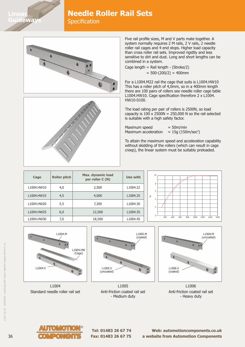
Five rail profi le sizes, M and V parts mate together. A system normally requires 2 M rails, 2 V rails, 2 needle roller rail cages and 4 end stops. Higher load capacity than cross roller rail sets. Improved rigidity and less sensitive to dirt and dust. Long and short lengths can be combined in a system.
Cage length = Rail length - (Stroke/2)
= 500-(200/2) = 400mm
For a L1004.M22 rail the cage that suits is L1004.HW10 This has a roller pitch of 4,0mm, so in a 400mm length there are 100 pairs of rollers see needle roller cage table L1004.HW10. Cage specifi cation therefore 2 x L1004.HW10-0100.
The load rating per pair of rollers is 2500N, so load capacity is 100 x 2500N = 250,000 N so the rail selected is suitable with a high safety factor.
Maximum speed = 50m/minMaximum acceleration = 15g (150m/sec2)
To attain the maximum speed and acceleration capability without skidding of the rollers (which can result in cage creep), the linear system must be suitably preloaded.
Cage Roller pitchMax. dynamic load
per roller C (N)Use with
L1004.HW10 4,0 2,500 L1004.22
L1004.HW15 4,5 4,000 L1004.25
L1004.HW20 5,5 7,300 L1004.30
L1004.HW25 6,0 12,500 L1004.35
L1004.HW30 7,0 18,500 L1004.45
L1004
Standard needle roller rail set
L1005
Anti-friction coated rail set- Medium duty
L1006
Anti-friction coated rail set- Heavy duty
µ
0200 400 600 800 1000 14001200 1600
2
4
6
8
10
L1004.V
L1004.M
L1004.HW(Cage)
L1005.M(coated)
L1004.M(uncoated)
L1005.V(uncoated)
L1006.V(coated)
ov-cro
ssed-slid
es-need
le-roller-sp
ecifi cation
- Up
dated
- 12
-01
-20
17

Linear Rail SetsNeedle Roller Linear Cages
Tel: 0333 207 4498
Created 2021-11-12
Email: [email protected]
Web: automotioncomponents.co.uk
L1004.HW
Material
Steel rollers (100Cr6, hardened to 60
HRC), aluminium retaining cage
(apart from L1004.HW10 - steel).
Technical notes
When ordering please specify the
length required (must be a multiple
of pitch, p).
Supplied in max. 1 metre lengths.
Ordering example:
L1004.HW15-030 is a 3mm diameter
roller strip 45mm long with 30 rollers
(as 10xp = 45mm).
Tips
See technical pages for load rating
calculations - based on rail size and
number of rollers in the system
cages.
Order No.d
± 0,001
p w h
Max. dyn.
load C N
/pair of rollers
To suit
rail
L1004.HW10-xxx 2,0 4,0 10 4,8 2,500 L1004.22
L1004.HW15-xxx 2,0 4,5 15 6,8 4,000 L1004.25
L1004.HW20xxx 2,5 5,5 20 9,8 7,300 L1004.30
L1004.HW25-xxx 3,0 6,0 25 13,8 12,500 L1004.35
L1004.HW30-xxx 3,5 7,0 30 17,8 18,500 L1004.45
Linear Rail SetsNeedle Roller Rail Sets - M railhigh load capacity
Tel: 0333 207 4498
Created 2021-11-12
Email: [email protected]
Web: automotioncomponents.co.uk
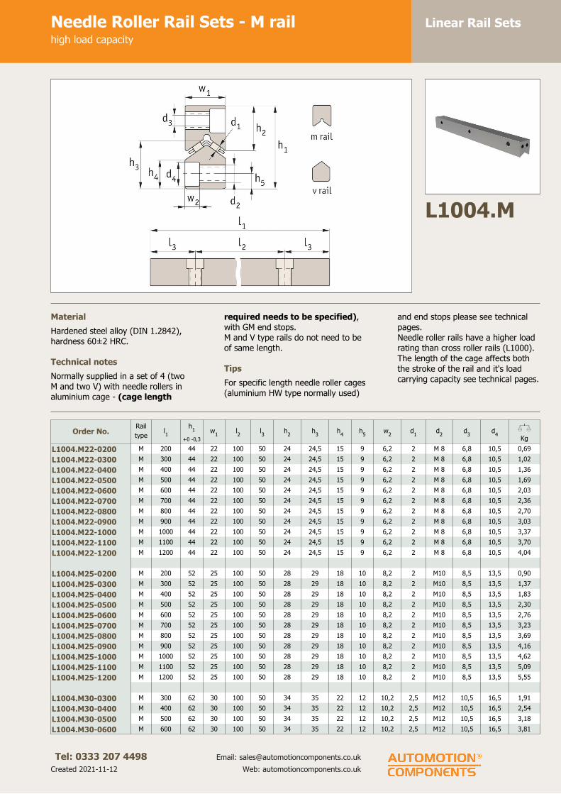
L1004.M
Material
Hardened steel alloy (DIN 1.2842),
hardness 60± 2 HRC.
Technical notes
Normally supplied in a set of 4 (two
M and two V) with needle rollers in
aluminium cage - (cage length
required needs to be specified),
with GM end stops.
M and V type rails do not need to be
of same length.
Tips
For specific length needle roller cages
(aluminium HW type normally used)
and end stops please see technical
pages.
Needle roller rails have a higher load
rating than cross roller rails (L1000).
The length of the cage affects both
the stroke of the rail and it's load
carrying capacity see technical pages.
Order No.Rail
typel1
h1
+0 -0,3
w1
l2
l3
h2
h3
h4
h5
w2
d1
d2
d3
d4
XKg
L1004.M22-0200 M 200 44 22 100 50 24 24,5 15 9 6,2 2 M 8 6,8 10,5 0,69
L1004.M22-0300 M 300 44 22 100 50 24 24,5 15 9 6,2 2 M 8 6,8 10,5 1,02
L1004.M22-0400 M 400 44 22 100 50 24 24,5 15 9 6,2 2 M 8 6,8 10,5 1,36
L1004.M22-0500 M 500 44 22 100 50 24 24,5 15 9 6,2 2 M 8 6,8 10,5 1,69
L1004.M22-0600 M 600 44 22 100 50 24 24,5 15 9 6,2 2 M 8 6,8 10,5 2,03
L1004.M22-0700 M 700 44 22 100 50 24 24,5 15 9 6,2 2 M 8 6,8 10,5 2,36
L1004.M22-0800 M 800 44 22 100 50 24 24,5 15 9 6,2 2 M 8 6,8 10,5 2,70
L1004.M22-0900 M 900 44 22 100 50 24 24,5 15 9 6,2 2 M 8 6,8 10,5 3,03
L1004.M22-1000 M 1000 44 22 100 50 24 24,5 15 9 6,2 2 M 8 6,8 10,5 3,37
L1004.M22-1100 M 1100 44 22 100 50 24 24,5 15 9 6,2 2 M 8 6,8 10,5 3,70
L1004.M22-1200 M 1200 44 22 100 50 24 24,5 15 9 6,2 2 M 8 6,8 10,5 4,04
L1004.M25-0200 M 200 52 25 100 50 28 29 18 10 8,2 2 M10 8,5 13,5 0,90
L1004.M25-0300 M 300 52 25 100 50 28 29 18 10 8,2 2 M10 8,5 13,5 1,37
L1004.M25-0400 M 400 52 25 100 50 28 29 18 10 8,2 2 M10 8,5 13,5 1,83
L1004.M25-0500 M 500 52 25 100 50 28 29 18 10 8,2 2 M10 8,5 13,5 2,30
L1004.M25-0600 M 600 52 25 100 50 28 29 18 10 8,2 2 M10 8,5 13,5 2,76
L1004.M25-0700 M 700 52 25 100 50 28 29 18 10 8,2 2 M10 8,5 13,5 3,23
L1004.M25-0800 M 800 52 25 100 50 28 29 18 10 8,2 2 M10 8,5 13,5 3,69
L1004.M25-0900 M 900 52 25 100 50 28 29 18 10 8,2 2 M10 8,5 13,5 4,16
L1004.M25-1000 M 1000 52 25 100 50 28 29 18 10 8,2 2 M10 8,5 13,5 4,62
L1004.M25-1100 M 1100 52 25 100 50 28 29 18 10 8,2 2 M10 8,5 13,5 5,09
L1004.M25-1200 M 1200 52 25 100 50 28 29 18 10 8,2 2 M10 8,5 13,5 5,55
L1004.M30-0300 M 300 62 30 100 50 34 35 22 12 10,2 2,5 M12 10,5 16,5 1,91
L1004.M30-0400 M 400 62 30 100 50 34 35 22 12 10,2 2,5 M12 10,5 16,5 2,54
L1004.M30-0500 M 500 62 30 100 50 34 35 22 12 10,2 2,5 M12 10,5 16,5 3,18
L1004.M30-0600 M 600 62 30 100 50 34 35 22 12 10,2 2,5 M12 10,5 16,5 3,81

Linear Rail SetsNeedle Roller Rail Sets - M railhigh load capacity
Tel: 0333 207 4498
Created 2021-11-12
Email: [email protected]
Web: automotioncomponents.co.uk
Order No.Rail
typel1
h1
+0 -0,3
w1
l2
l3
h2
h3
h4
h5
w2
d1
d2
d3
d4
XKg
L1004.M30-0700 M 700 62 30 100 50 34 35 22 12 10,2 2,5 M12 10,5 16,5 4,45
L1004.M30-0800 M 800 62 30 100 50 34 35 22 12 10,2 2,5 M12 10,5 16,5 5,08
L1004.M30-0900 M 900 62 30 100 50 34 35 22 12 10,2 2,5 M12 10,5 16,5 5,72
L1004.M30-1000 M 1000 62 30 100 50 34 35 22 12 10,2 2,5 M12 10,5 16,5 6,35
L1004.M30-1100 M 1100 62 30 100 50 34 35 22 12 10,2 2,5 M12 10,5 16,5 6,99
L1004.M30-1200 M 1200 62 30 100 50 34 35 22 12 10,2 2,5 M12 10,5 16,5 7,62
L1004.M35-0400 M 400 74 35 100 50 42,5 40 25 14 12,2 3 M14 12,5 18,5 3,66
L1004.M35-0500 M 500 74 35 100 50 42,5 40 25 14 12,2 3 M14 12,5 18,5 4,58
L1004.M35-0600 M 600 74 35 100 50 42,5 40 25 14 12,2 3 M14 12,5 18,5 5,49
L1004.M35-0700 M 700 74 35 100 50 42,5 40 25 14 12,2 3 M14 12,5 18,5 6,41
L1004.M35-0800 M 800 74 35 100 50 42,5 40 25 14 12,2 3 M14 12,5 18,5 7,32
L1004.M35-0900 M 900 74 35 100 50 42,5 40 25 14 12,2 3 M14 12,5 18,5 8,24
L1004.M35-1000 M 1000 74 35 100 50 42,5 40 25 14 12,2 3 M14 12,5 18,5 9,15
L1004.M35-1100 M 1100 74 35 100 50 42,5 40 25 14 12,2 3 M14 12,5 18,5 10,07
L1004.M35-1200 M 1200 74 35 100 50 42,5 40 25 14 12,2 3 M14 12,5 18,5 10,98
L1004.M45-0500 M 500 78 45 100 50 45 45 25 14 12,2 3,5 M14 12,5 18,5 6,17
L1004.M45-0600 M 600 78 45 100 50 45 45 25 14 12,2 3,5 M14 12,5 18,5 7,41
L1004.M45-0700 M 700 78 45 100 50 45 45 25 14 12,2 3,5 M14 12,5 18,5 8,65
L1004.M45-0800 M 800 78 45 100 50 45 45 25 14 12,2 3,5 M14 12,5 18,5 9,89
L1004.M45-0900 M 900 78 45 100 50 45 45 25 14 12,2 3,5 M14 12,5 18,5 11,13
L1004.M45-1000 M 1000 78 45 100 50 45 45 25 14 12,2 3,5 M14 12,5 18,5 12,37
L1004.M45-1100 M 1100 78 45 100 50 45 45 25 14 12,2 3,5 M14 12,5 18,5 13,61
L1004.M45-1200 M 1200 78 45 100 50 45 45 25 14 12,2 3,5 M14 12,5 18,5 14,85
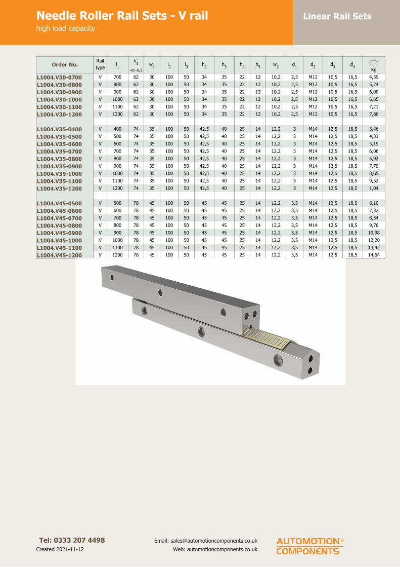
Linear Rail SetsNeedle Roller Rail Sets - V railhigh load capacity
Tel: 0333 207 4498
Created 2021-11-12
Email: [email protected]
Web: automotioncomponents.co.uk
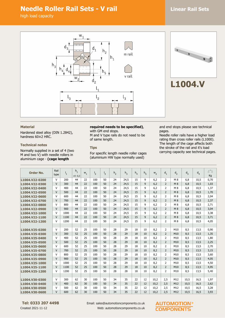
L1004.V
Material
Hardened steel alloy (DIN 1.2842),
hardness 60± 2 HRC.
Technical notes
Normally supplied in a set of 4 (two
M and two V) with needle rollers in
aluminium cage - (cage length
required needs to be specified),
with GM end stops.
M and V type rails do not need to be
of same length.
Tips
For specific length needle roller cages
(aluminium HW type normally used)
and end stops please see technical
pages.
Needle roller rails have a higher load
rating than cross roller rails (L1000).
The length of the cage affects both
the stroke of the rail and it's load
carrying capacity see technical pages.
Order No.Rail
typel1
h1
+0 -0,3
w1
l2
l3
h2
h3
h4
h5
w2
d1
d2
d3
d4
XKg
L1004.V22-0200 V 200 44 22 100 50 24 24,5 15 9 6,2 2 M 8 6,8 10,5 0,70
L1004.V22-0300 V 300 44 22 100 50 24 24,5 15 9 6,2 2 M 8 6,8 10,5 1,03
L1004.V22-0400 V 400 44 22 100 50 24 24,5 15 9 6,2 2 M 8 6,8 10,5 1,37
L1004.V22-0500 V 500 44 22 100 50 24 24,5 15 9 6,2 2 M 8 6,8 10,5 1,70
L1004.V22-0600 V 600 44 22 100 50 24 24,5 15 9 6,2 2 M 8 6,8 10,5 2,04
L1004.V22-0700 V 700 44 22 100 50 24 24,5 15 9 6,2 2 M 8 6,8 10,5 2,37
L1004.V22-0800 V 800 44 22 100 50 24 24,5 15 9 6,2 2 M 8 6,8 10,5 2,71
L1004.V22-0900 V 900 44 22 100 50 24 24,5 15 9 6,2 2 M 8 6,8 10,5 3,04
L1004.V22-1000 V 1000 44 22 100 50 24 24,5 15 9 6,2 2 M 8 6,8 10,5 3,38
L1004.V22-1100 V 1100 44 22 100 50 24 24,5 15 9 6,2 2 M 8 6,8 10,5 3,71
L1004.V22-1200 V 1200 44 22 100 50 24 24,5 15 9 6,2 2 M 8 6,8 10,5 4,05
L1004.V25-0200 V 200 52 25 100 50 28 29 18 10 8,2 2 M10 8,5 13,5 0,90
L1004.V25-0300 V 300 52 25 100 50 28 29 18 10 8,2 2 M10 8,5 13,5 1,35
L1004.V25-0400 V 400 52 25 100 50 28 29 18 10 8,2 2 M10 8,5 13,5 1,80
L1004.V25-0500 V 500 52 25 100 50 28 29 18 10 8,2 2 M10 8,5 13,5 2,25
L1004.V25-0600 V 600 52 25 100 50 28 29 18 10 8,2 2 M10 8,5 13,5 2,70
L1004.V25-0700 V 700 52 25 100 50 28 29 18 10 8,2 2 M10 8,5 13,5 3,15
L1004.V25-0800 V 800 52 25 100 50 28 29 18 10 8,2 2 M10 8,5 13,5 3,60
L1004.V25-0900 V 900 52 25 100 50 28 29 18 10 8,2 2 M10 8,5 13,5 4,05
L1004.V25-1000 V 1000 52 25 100 50 28 29 18 10 8,2 2 M10 8,5 13,5 4,50
L1004.V25-1100 V 1100 52 25 100 50 28 29 18 10 8,2 2 M10 8,5 13,5 4,95
L1004.V25-1200 V 1200 52 25 100 50 28 28 18 10 8,2 2 M10 8,5 13,5 5,40
L1004.V30-0300 V 300 62 30 100 50 34 35 22 12 10,2 2,5 M12 10,5 16,5 1,97
L1004.V30-0400 V 400 62 30 100 50 34 35 22 12 10,2 2,5 M12 10,5 16,5 2,62
L1004.V30-0500 V 500 62 30 100 50 34 35 22 12 10,2 2,5 M12 10,5 16,5 3,28
L1004.V30-0600 V 600 62 30 100 50 34 35 22 12 10,2 2,5 M12 10,5 16,5 3,93
Linear Rail SetsNeedle Roller Rail Sets - V railhigh load capacity
Tel: 0333 207 4498
Created 2021-11-12
Email: [email protected]
Web: automotioncomponents.co.uk
Order No.Rail
typel1
h1
+0 -0,3
w1
l2
l3
h2
h3
h4
h5
w2
d1
d2
d3
d4
XKg
L1004.V30-0700 V 700 62 30 100 50 34 35 22 12 10,2 2,5 M12 10,5 16,5 4,59
L1004.V30-0800 V 800 62 30 100 50 34 35 22 12 10,2 2,5 M12 10,5 16,5 5,24
L1004.V30-0900 V 900 62 30 100 50 34 35 22 12 10,2 2,5 M12 10,5 16,5 6,00
L1004.V30-1000 V 1000 62 30 100 50 34 35 22 12 10,2 2,5 M12 10,5 16,5 6,65
L1004.V30-1100 V 1100 62 30 100 50 34 35 22 12 10,2 2,5 M12 10,5 16,5 7,21
L1004.V30-1200 V 1200 62 30 100 50 34 35 22 12 10,2 2,5 M12 10,5 16,5 7,86
L1004.V35-0400 V 400 74 35 100 50 42,5 40 25 14 12,2 3 M14 12,5 18,5 3,46
L1004.V35-0500 V 500 74 35 100 50 42,5 40 25 14 12,2 3 M14 12,5 18,5 4,33
L1004.V35-0600 V 600 74 35 100 50 42,5 40 25 14 12,2 3 M14 12,5 18,5 5,19
L1004.V35-0700 V 700 74 35 100 50 42,5 40 25 14 12,2 3 M14 12,5 18,5 6,06
L1004.V35-0800 V 800 74 35 100 50 42,5 40 25 14 12,2 3 M14 12,5 18,5 6,92
L1004.V35-0900 V 900 74 35 100 50 42,5 40 25 14 12,2 3 M14 12,5 18,5 7,79
L1004.V35-1000 V 1000 74 35 100 50 42,5 40 25 14 12,2 3 M14 12,5 18,5 8,65
L1004.V35-1100 V 1100 74 35 100 50 42,5 40 25 14 12,2 3 M14 12,5 18,5 9,52
L1004.V35-1200 V 1200 74 35 100 50 42,5 40 25 14 12,2 3 M14 12,5 18,5 1,04
L1004.V45-0500 V 500 78 45 100 50 45 45 25 14 12,2 3,5 M14 12,5 18,5 6,10
L1004.V45-0600 V 600 78 45 100 50 45 45 25 14 12,2 3,5 M14 12,5 18,5 7,32
L1004.V45-0700 V 700 78 45 100 50 45 45 25 14 12,2 3,5 M14 12,5 18,5 8,54
L1004.V45-0800 V 800 78 45 100 50 45 45 25 14 12,2 3,5 M14 12,5 18,5 9,76
L1004.V45-0900 V 900 78 45 100 50 45 45 25 14 12,2 3,5 M14 12,5 18,5 10,98
L1004.V45-1000 V 1000 78 45 100 50 45 45 25 14 12,2 3,5 M14 12,5 18,5 12,20
L1004.V45-1100 V 1100 78 45 100 50 45 45 25 14 12,2 3,5 M14 12,5 18,5 13,42
L1004.V45-1200 V 1200 78 45 100 50 45 45 25 14 12,2 3,5 M14 12,5 18,5 14,64
LinearGuideways
Tel: 01483 26 67 74 Web: automotioncomponents.co.uk Fax: 01483 26 67 75 a website from Automotion Components
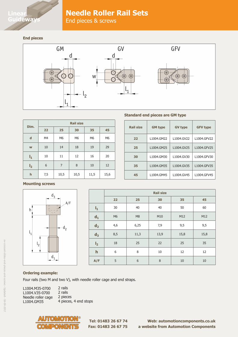
Needle Roller Rail SetsEnd pieces & screws
GV GFVGMd d
l1
l1l2
w
Ordering example: Four rails (two M and two V), with needle roller cage and end straps.
L1004.M35-0700 L1004.V35-0700Needle roller cageL1004.GM35
Standard end pieces are GM type
End pieces
Mounting screws
Rail size GM type GV type GFV type
22 L1004.GM22 L1004.GV22 L1004.GFV22
25 L1004.GM25 L1004.GV25 L1004.GFV25
30 L1004.GM30 L1004.GV30 L1004.GFV30
35 L1004.GM35 L1004.GV35 L1004.GFV35
45 L1004.GM45 L1004.GV45 L1004.GFV45
Dim.Rail size
22 25 30 35 45
d M4 M6 M6 M6 M6
w 10 14 18 19 29
l1 10 11 12 16 20
l2 6 7 8 10 12
h 7,5 10,5 10,5 11,5 15,6
Rail size
22 25 30 35 45
l1 30 40 40 50 60
d1 M6 M8 M10 M12 M12
d2 4,6 6,25 7,9 9,5 9,5
d3 8,5 11,3 13,9 15,8 15,8
l2 18 25 22 25 35
h 6 8 10 12 12
A/F 5 6 8 10 10
h
d1
l1
l2
d3
d2
A/F
2 rails2 rails2 pieces4 pieces, 4 end stops
ov-cro
ssed-slid
es-end
-pieces-an
d-screw
s - Up
dated
- 18
-09
-20
17

LinearGuideways
Tel: 01483 26 67 74 Web: automotioncomponents.co.uk Fax: 01483 26 67 75 a website from Automotion Components
Anti-Friction Coated Rail SetsLoad rating information
L1006.V coated - V rail
Load ratings
L1005.M coated - M rail
• Small rail sizes• 4 widths. Lengths to 1200mm• Use with L1005.V rails
• Large rail sizes• 5 widths. Lengths to 600mm• Use with L1004.M rails
• Minimises vibration • Improves rigidity • Tolerant to dirt and particles • Max. speed 20m/min • Max. temp 50°C
Part No. Width of bearing surface (cm) Dynamic load rating/cm2 C (N) Static load rating/cm2 C0 (N)
L1006.V22 1,05 4500 7500
L1006.V25 1,15 4500 7500
L1006.V30 1,50 4500 7500
L1006.V45 1,75 4500 7500
L1006.V55 2,45 4500 7500
L1005.M03 0,30 4500 7500
L1005.M06 0,60 4500 7500
L1005.M09 1,20 4500 7500
L1005.M12 1,60 4500 7500
Load ratings: Load/cm2 (see table above) (N)Width of bearing surface (cm)Length of rail (cm)C= rating x width x length
Load calculation example: Take L1006.V30-600 Length of rail 600mm (60cm) Width of bearing surface (cm) - see table 1.50cm
Dynamic load rating (N) 4500 x (60 x 1.5) = 405,000 N = 405 kN
Static load rating (N) 7500 x (60 x 1.5) = 675,000 N = 675 kN
Zedex coating Zedex coating
ov-cro
ssed-slid
es-load
-rating
-info
rmatio
n - U
pd
ated - 1
8-0
9-2
017

Linear Rail SetsAnti-friction Coated M Railmedium load capacity
Tel: 0333 207 4498
Created 2021-11-12
Email: [email protected]
Web: automotioncomponents.co.uk
L1005.M
Material
Hardened steel alloy (DIN 1,2842),
coated with anti-friction material
(Zedex 100).
Technical notes
These are similar in size to the L1000
rails but are primarily used as
dirt-proof units, to reduce system
vibration and improve rigidity.
Working temperature must be less
than 50°C.
Load capacity per unit (cm2) = 4500N
(dynamic), 7500N (static).
For total load capacity take
width of bearing surface (in cm)
x length (in cm) x load capacity
(above).
Tips
Use with V rail L1005.V.
Order No.Rail
typel1
h1
+0 -0,3
w1
l2
l3
h2
h3
w2
d1
d2
d3
Bearing
surface
width
(cm)
XKg
L1005.M03-0050 M 50 18 8 25 12,5 9 3,5 3,1 M 4 3,3 6 0,3 0,02
L1005.M03-0075 M 75 18 8 25 12,5 9 3,5 3,1 M 4 3,3 6 0,3 0,03
L1005.M03-0100 M 100 18 8 25 12,5 9 3,5 3,1 M 4 3,3 6 0,3 0,04
L1005.M03-0125 M 125 18 8 25 12,5 9 3,5 3,1 M 4 3,3 6 0,3 0,05
L1005.M03-0150 M 150 18 8 25 12,5 9 3,5 3,1 M 4 3,3 6 0,3 0,06
L1005.M03-0175 M 175 18 8 25 12,5 9 3,5 3,1 M 4 3,3 6 0,3 0,07
L1005.M03-0200 M 200 18 8 25 12,5 9 3,5 3,1 M 4 3,3 6 0,3 0,09
L1005.M03-0225 M 225 18 8 25 12,5 9 3,5 3,1 M 4 3,3 6 0,3 0,10
L1005.M03-0250 M 250 18 8 25 12,5 9 3,5 3,1 M 4 3,3 6 0,3 0,11
L1005.M03-0275 M 275 18 8 25 12,5 9 3,5 3,1 M 4 3,3 6 0,3 0,12
L1005.M03-0300 M 300 18 8 25 12,5 9 3,5 3,1 M 4 3,3 6 0,3 0,13
L1005.M06-0100 M 100 31 15 50 25,0 16 6,0 5,2 M 6 5,3 10 0,6 0,15
L1005.M06-0150 M 150 31 15 50 25,0 16 6,0 5,2 M 6 5,3 10 0,6 0,22
L1005.M06-0200 M 200 31 15 50 25,0 16 6,0 5,2 M 6 5,3 10 0,6 0,29
L1005.M06-0250 M 250 31 15 50 25,0 16 6,0 5,2 M 6 5,3 10 0,6 0,36
L1005.M06-0300 M 300 31 15 50 25,0 16 6,0 5,2 M 6 5,3 10 0,6 0,44
L1005.M06-0350 M 350 31 15 50 25,0 16 6,0 5,2 M 6 5,3 10 0,6 0,51
L1005.M06-0400 M 400 31 15 50 25,0 16 6,0 5,2 M 6 5,3 10 0,6 0,58
L1005.M06-0450 M 450 31 15 50 25,0 16 6,0 5,2 M 6 5,3 10 0,6 0,65
L1005.M06-0500 M 500 31 15 50 25,0 16 6,0 5,2 M 6 5,3 10 0,6 0,73
L1005.M09-0200 M 200 44 22 100 50,0 24 9,0 6,2 M 8 6,8 11 1,2 0,64
L1005.M09-0300 M 300 44 22 100 50,0 24 9,0 6,2 M 8 6,8 11 1,2 0,96
L1005.M09-0400 M 400 44 22 100 50,0 24 9,0 6,2 M 8 6,8 11 1,2 1,27
L1005.M09-0500 M 500 44 22 100 50,0 24 9,0 6,2 M 8 6,8 11 1,2 1,59
L1005.M09-0600 M 600 44 22 100 50,0 24 9,0 6,2 M 8 6,8 11 1,2 1,90

Linear Rail SetsAnti-friction Coated M Railmedium load capacity
Tel: 0333 207 4498
Created 2021-11-12
Email: [email protected]
Web: automotioncomponents.co.uk
Order No.Rail
typel1
h1
+0 -0,3
w1
l2
l3
h2
h3
w2
d1
d2
d3
Bearing
surface
width
(cm)
XKg
L1005.M09-0700 M 700 44 22 100 50,0 24 9,0 6,2 M 8 6,8 11 1,2 2,22
L1005.M09-0800 M 800 44 22 100 50,0 24 9,0 6,2 M 8 6,8 11 1,2 2,53
L1005.M09-0900 M 900 44 22 100 50,0 24 9,0 6,2 M 8 6,8 11 1,2 2,85
L1005.M09-1000 M 1000 44 22 100 50,0 24 9,0 6,2 M 8 6,8 11 1,2 3,16
L1005.M12-0200 M 200 58 28 100 50,0 33 12,0 8,2 M10 8,5 15 1,6 1,13
L1005.M12-0300 M 300 58 28 100 50,0 33 12,0 8,2 M10 8,5 15 1,6 1,69
L1005.M12-0400 M 400 58 28 100 50,0 33 12,0 8,2 M10 8,5 15 1,6 2,25
L1005.M12-0500 M 500 58 28 100 50,0 33 12,0 8,2 M10 8,5 15 1,6 2,81
L1005.M12-0600 M 600 58 28 100 50,0 33 12,0 8,2 M10 8,5 15 1,6 3,37
L1005.M12-0700 M 700 58 28 100 50,0 33 12,0 8,2 M10 8,5 15 1,6 3,93
L1005.M12-0800 M 800 58 28 100 50,0 33 12,0 8,2 M10 8,5 15 1,6 4,49
L1005.M12-0900 M 900 58 28 100 50,0 33 12,0 8,2 M10 8,5 15 1,6 5,05
L1005.M12-1000 M 1000 58 28 100 50,0 33 12,0 8,2 M10 8,5 15 1,6 5,61
L1005.M12-1100 M 1100 58 28 100 50,0 33 12,0 8,2 M10 8,5 15 1,6 6,18
L1005.M12-1200 M 1200 58 28 100 50,0 33 12,0 8,2 M10 8,5 15 1,6 6,74

Linear Rail SetsAnti-friction Coated Rail SetV rail - uncoated
Tel: 0333 207 4498
Created 2021-11-12
Email: [email protected]
Web: automotioncomponents.co.uk
L1005.V
Material
Alloy steel rail and roller (DIN
1.2842), through hardened to 60±2
HRC.
Technical notes
These are similar in size to the L1000
rails but are primarily used as
dirt-proof units, to reduce system
vibration and improve rigidity.
Working temperature must be less
than 50°C.
Load capacity per unit (cm2) = 4500N
(dynamic), 7500N (static).
For total load capacity take
width of bearing surface (in cm)
x length (in cm) x load capacity
(above).
Tips
Use with V rail L1005.M.
Order No.Rail
typel1
h1
+0 -0,3
w1
l2
l3
h2
h3
w2
d1
d2
d3
Bearing
surface
width
(cm)
XKg
L1005.V03-0050 V 50 18 8 25 12,5 10,8 3,5 3,1 M 4 3,3 6 0,3 0,03
L1005.V03-0075 V 75 18 8 25 12,5 10,8 3,5 3,1 M 4 3,3 6 0,3 0,04
L1005.V03-0100 V 100 18 8 25 12,5 10,8 3,5 3,1 M 4 3,3 6 0,3 0,05
L1005.V03-0125 V 125 18 8 25 12,5 10,8 3,5 3,1 M 4 3,3 6 0,3 0,06
L1005.V03-0150 V 150 18 8 25 12,5 10,8 3,5 3,1 M 4 3,3 6 0,3 0,08
L1005.V03-0175 V 175 18 8 25 12,5 10,8 3,5 3,1 M 4 3,3 6 0,3 0,09
L1005.V03-0200 V 200 18 8 25 12,5 10,8 3,5 3,1 M 4 3,3 6 0,3 0,10
L1005.V03-0225 V 225 18 8 25 12,5 10,8 3,5 3,1 M 4 3,3 6 0,3 0,12
L1005.V03-0250 V 250 18 8 25 12,5 10,8 3,5 3,1 M 4 3,3 6 0,3 0,13
L1005.V03-0275 V 275 18 8 25 12,5 10,8 3,5 3,1 M 4 3,3 6 0,3 0,14
L1005.V03-0300 V 300 18 8 25 12,5 10,8 3,5 3,1 M 4 3,3 6 0,3 0,16
L1005.V06-0100 V 100 31 15 50 25,0 19,3 6,0 5,2 M 6 5,3 10 0,6 0,18
L1005.V06-0150 V 150 31 15 50 25,0 19,3 6,0 5,2 M 6 5,3 10 0,6 0,26
L1005.V06-0200 V 200 31 15 50 25,0 19,3 6,0 5,2 M 6 5,3 10 0,6 0,35
L1005.V06-0250 V 250 31 15 50 25,0 19,3 6,0 5,2 M 6 5,3 10 0,6 0,44
L1005.V06-0300 V 300 31 15 50 25,0 19,3 6,0 5,2 M 6 5,3 10 0,6 0,53
L1005.V06-0350 V 350 31 15 50 25,0 19,3 6,0 5,2 M 6 5,3 10 0,6 0,61
L1005.V06-0400 V 400 31 15 50 25,0 19,3 6,0 5,2 M 6 5,3 10 0,6 0,70
L1005.V06-0450 V 450 31 15 50 25,0 19,3 6,0 5,2 M 6 5,3 10 0,6 0,79
L1005.V06-0500 V 500 31 15 50 25,0 19,3 6,0 5,2 M 6 5,3 10 0,6 0,88
L1005.V09-0200 V 200 44 22 100 50,0 28,0 9,0 6,2 M 8 6,8 11 1,2 0,64
L1005.V09-0300 V 300 44 22 100 50,0 28,0 9,0 6,2 M 8 6,8 11 1,2 0,96
L1005.V09-0400 V 400 44 22 100 50,0 28,0 9,0 6,2 M 8 6,8 11 1,2 1,27
L1005.V09-0500 V 500 44 22 100 50,0 28,0 9,0 6,2 M 8 6,8 11 1,2 1,59
L1005.V09-0600 V 600 44 22 100 50,0 28,0 9,0 6,2 M 8 6,8 11 1,2 1,90

Linear Rail SetsAnti-friction Coated Rail SetV rail - uncoated
Tel: 0333 207 4498
Created 2021-11-12
Email: [email protected]
Web: automotioncomponents.co.uk
Order No.Rail
typel1
h1
+0 -0,3
w1
l2
l3
h2
h3
w2
d1
d2
d3
Bearing
surface
width
(cm)
XKg
L1005.V09-0700 V 700 44 22 100 50,0 28,0 9,0 6,2 M 8 6,8 11 1,2 2,22
L1005.V09-0800 V 800 44 22 100 50,0 28,0 9,0 6,2 M 8 6,8 11 1,2 2,53
L1005.V09-0900 V 900 44 22 100 50,0 28,0 9,0 6,2 M 8 6,8 11 1,2 2,85
L1005.V09-1000 V 1000 44 22 100 50,0 28,0 9,0 6,2 M 8 6,8 11 1,2 3,16
L1005.V12-0200 V 200 58 28 100 50,0 35,5 12,0 8,2 M10 8,5 15 1,6 1,13
L1005.V12-0300 V 300 58 28 100 50,0 35,5 12,0 8,2 M10 8,5 15 1,6 1,69
L1005.V12-0400 V 400 58 28 100 50,0 35,5 12,0 8,2 M10 8,5 15 1,6 2,25
L1005.V12-0500 V 500 58 28 100 50,0 35,5 12,0 8,2 M10 8,5 15 1,6 2,81
L1005.V12-0600 V 600 58 28 100 50,0 35,5 12,0 8,2 M10 8,5 15 1,6 3,37
L1005.V12-0700 V 700 58 28 100 50,0 35,5 12,0 8,2 M10 8,5 15 1,6 3,93
L1005.V12-0800 V 800 58 28 100 50,0 35,5 12,0 8,2 M10 8,5 15 1,6 4,49
L1005.V12-0900 V 900 58 28 100 50,0 35,5 12,0 8,2 M10 8,5 15 1,6 5,05
L1005.V12-1000 V 1000 58 28 100 50,0 35,5 12,0 8,2 M10 8,5 15 1,6 5,61
L1005.V12-1100 V 1100 58 28 100 50,0 35,5 12,0 8,2 M10 8,5 15 1,6 6,18
L1005.V12-1200 V 1200 58 28 100 50,0 35,5 12,0 8,2 M10 8,5 15 1,6 6,74

Linear Rail SetsAnti-friction Coated V Railhigh load capacity
Tel: 0333 207 4498
Created 2021-11-12
Email: [email protected]
Web: automotioncomponents.co.uk
L1006.V
Material
Hardened steel alloy (DIN 1,2842),
coated with anti-friction material
(Zedex 100).
Technical notes
These are similar in size to the L1004
rails but are primarily used as
dirt-proof units:- to reduce any
system vibration and improve rigidity.
Working temperature must be less
than 50°C.
Load capacity per unit (cm2) = 4500N
(dynamic), 7500N (static).
For total load capacity take
width of bearing surface (in cm)
x length (in cm) x load capacity
(above).
Tips
Select the anti-friction coated rail and
combine with any length of standard
L1004.M type rail.
Used where speed is relatively low
(20m/minute max.).
Order No.Rail
sizel1
h1
+0 -0,3
w1
l2
l3
h2
h3
w2
d1
d2
d3
Bearing
surface
width
(cm)
XKg
L1006.V22-0200 22 200 44 22 100 50 24 9 6,2 M 8 6,8 10,5 1,05 0,70
L1006.V22-0300 22 300 44 22 100 50 24 9 6,2 M 8 6,8 10,5 1,05 1,03
L1006.V22-0400 22 400 44 22 100 50 24 9 6,2 M 8 6,8 10,5 1,05 1,34
L1006.V22-0500 22 500 44 22 100 50 24 9 6,2 M 8 6,8 10,5 1,05 1,70
L1006.V22-0600 22 600 44 22 100 50 24 9 6,2 M 8 6,8 10,5 1,05 2,04
L1006.V25-0200 25 200 52 25 100 50 28 10 8,2 M10 8,5 13,5 1,15 0,90
L1006.V25-0300 25 300 52 25 100 50 28 10 8,2 M10 8,5 13,5 1,15 1,35
L1006.V25-0400 25 400 52 25 100 50 28 10 8,2 M10 8,5 13,5 1,15 1,80
L1006.V25-0500 25 500 52 25 100 50 28 10 8,2 M10 8,5 13,5 1,15 2,25
L1006.V25-0600 25 600 52 25 100 50 28 10 8,2 M10 8,5 13,5 1,15 2,70
L1006.V30-0300 30 300 62 30 100 50 34 12 10,2 M12 10,5 16,5 1,50 1,97
L1006.V30-0400 30 400 62 30 100 50 34 12 10,2 M12 10,5 16,5 1,50 2,62
L1006.V30-0500 30 500 62 30 100 50 34 12 10,2 M12 10,5 16,5 1,50 3,28
L1006.V30-0600 30 600 62 30 100 50 34 12 10,2 M12 10,5 16,5 1,50 3,93
L1006.V35-0400 35 400 74 35 100 50 42,5 14 12,2 M14 12,5 18,5 1,75 3,46
L1006.V35-0500 35 500 74 35 100 50 42,5 14 12,2 M14 12,5 18,5 1,75 4,33
L1006.V35-0600 35 600 74 35 100 50 42,5 14 12,2 M14 12,5 18,5 1,75 5,19
L1006.V45-0600 45 600 78 45 100 50 45 14 12,2 M14 12,5 18,5 2,45 7,32
L1006.V45-0500 45 500 78 45 100 50 45 14 12,2 M14 12,5 18,5 2,45 6,10

Linear Rail SetsLinear Cage - Ball
Tel: 0333 207 4498
Created 2021-11-12
Email: [email protected]
Web: automotioncomponents.co.uk
L1007
Material
Ball steel (100Cr6 to DIN 5401, class
3), ball cage plastic (PA 12).
Can also be supplied with corrosion
resistant stainless balls (AISI 304)
balls, plastic balls (POM) or ceramic
balls.
Technical notes
When ordering please specify the
length required (must be a multiple
of pitch, p).
Supplied in max. 1 metre lengths.
Tips
Ordering example:
L1007.030-020 is a 3mm diameter
ball strip length 84mm with 20 rollers
(as 20xp = 84mm).
Order No. d1
h w p d2
L1007.020-xxx 2,0 5,0 0,75 3,0 2,1
L1007.030-xxx 3,0 7,0 1,00 4,2 3,2
L1007.040-xxx 4,0 6,3 1,30 5,8 4,2
L1007.050-xxx 5,0 8,0 1,50 6,8 5,2
L1007.060-xxx 6,0 9,0 1,60 7,8 6,2
L1007.080-xxx 8,0 12,0 2,00 12,0 8,2
L1007.090-xxx 9,0 15,0 2,00 11,5 9,2
L1007.100-xxx 10,0 13,2 2,50 12,5 10,2
L1007.110-xxx 11,0 13,7 2,50 14,0 11,2
L1007.120-xxx 12,0 15,0 2,50 15,0 12,2
L1007.160-xxx 16,0 20,0 3,50 20,0 16,2

Linear Rail SetsLinear Cage - Crossed Rollerplastic or steel cage
Tel: 0333 207 4498
Created 2021-11-12
Email: [email protected]
Web: automotioncomponents.co.uk
L1008
Material
Steel rollers (100Cr6, class 3,
hardened to 60 HRC) retaining cage
plastic (PA 12) or steel.
Stainless version - stainless rollers
(440C), stainless cage (AISI 304).
Technical notes
When ordering please specify the
length required (must be a multiple
of pitch, p).
Supplied in max. 1 metre lengths.
Tips
Ordering example:
L1008.030-PR-010 is a 3mm diameter
roller strip 50mm long with 10 rollers
(as 10xp = 50mm).
Important notes
For load ratings calculations the
maximum recommended load is 1/3
of the max. static load.
Order No.d
+/- 0,001
p h wMax. dyn.
load C N
Max. static
load C N
L1008.020-PR-xxx 2 3,9 5 0,75 290 295
L1008.030-PR-xxx 3 5,0 7 1,00 630 760
L1008.060-PR-xxx 6 8,5 14 2,00 2500 2600
L1008.090-PR-xxx 9 14,0 20 3,00 7100 7200
L1008.015-AA-xxx 1,5 3 3,75 0,2 125 144
L1008.020-AA-xxx 2,0 4 5,50 0,3 290 295
L1008.030-AA-xxx 3,0 5 7,50 0,4 630 760
L1008.040-AA-xxx 4,0 7 9,80 0,5 1100 1170
L1008.060-AA-xxx 6,0 9 14,00 0,8 2500 2600
L1008.090-AA-xxx 9,0 14 20,50 1,0 7100 7274
L1008.120-AA-xxx 12,0 18 26,50 1,2 12700 13200
L1008.015-SS-xxx 1,5 3 3,75 0,2 125 144
L1008.020-SS-xxx 2,0 4 5,50 0,3 290 295
L1008.030-SS-xxx 3,0 5 7,50 0,4 630 760
L1008.040-SS-xxx 4,0 7 9,80 0,5 1100 1170
L1008.060-SS-xxx 6,0 9 14,00 0,8 2500 2600
L1008.090-SS-xxx 9,0 14 20,50 1,0 7100 7274

Linear Rail SetsLinear Cage - Needle Roller
Tel: 0333 207 4498
Created 2021-11-12
Email: [email protected]
Web: automotioncomponents.co.uk
L1009
Material
Needle roller, steel (100Cr6 to
DIN5401, grade 28, class 3),
retaining cage plastic (PA 12).
Technical notes
When ordering please specify the
length required (must be a multiple
of pitch, p).
Supplied in max. 1 metre lengths.
Tips
Ordering example:
L1009.050-030 is a 5mm diameter
roller strip 225mm long with 30
rollers (as 30xp = 225mm).
Order No. d l h w p
L1009.015-xxx 1,5 7,8 10 1,1 2,9
L1009.025-xxx 2,5 13,8 18 2,0 4,8
L1009.030-xxx 3,0 15,8 20 2,5 5,2
L1009.040-xxx 4,0 23,8 30 3,0 7,0
L1009.050-xxx 5,0 5,0 10 2,5 7,5
L1009.051-xxx 5,0 15,0 23 3,5 8,0
L1009.052-xxx 5,0 27,8 35 3,5 9,0
L1009.100-xxx 10,0 10,0 16 2,5 13,0
L1009.120-xxx 12,0 30,0 40 5,0 16,0
L1009.160-xxx 16,0 16,0 28 4,0 22,0

LinearGuideways
Tel: 01483 26 67 74 Web: automotioncomponents.co.uk Fax: 01483 26 67 75 a website from Automotion Components
Linear GuidewaysOptions
Linear guideways optionsWe have four types of linear guideway. The standard ball type linear guideways are the L1016 range.Other types are miniature, aluminium or heavy duty roller versions.
L1016Standard
linear guideways
L1010 and L1012Standard miniaturelinear guideways
L1018Aluminium
linear guideways
• Seven rail profi les, 15, 20, 25, 30, 35, 45, 55• Retained ball technology
• Low profi le miniature rails standard & wide versions• Stainless steel
• Very precise and heavy duty due to needle rollers • Sizes 25, 35, 45, 55, 65
L1017Heavy-duty rollerlinear guideways
WEB O
NLY
• Three rail profi les 15, 20, 25• Rail is interchangeable with steel linear guideways• 60% lighter than steel guideway
Flanged
Flanged
Flanged
Standard
Unfl anged
Unfl anged
Unfl anged
Wide
ov-cro
ssed-slid
es-op
tion
s - Up
dated
- 18
-09
-20
17

163
Linear Tables
ov-lin
ear-tables-d
ivider - U
pd
ated - 1
8-0
9-2
017

Tel: 01483 26 67 74 Web: automotioncomponents.co.uk Fax: 01483 26 67 75 a website from Automotion Components
Linear Tables Linear StagesSelecting a stage...
Size + Weight
For light/mediumloads
L1020-L1037
For heavyduty loads and
motorised
L3000-L3500
Ball roller versions Needle roller & dovetail stage
Motorised stagesCross roller versions
Stainless steel versions Micrometer driven stages
L1020 - L1026
L1024 - L1038
L1022 - L1023
L3500 - L3510
L3170 - L3194
L3100 - L3123
ov-lin
ear-tables-selectin
g-a-stag
e - Up
dated
- 18
-09
-20
17

Tel: 01483 26 67 74 Web: automotioncomponents.co.uk Fax: 01483 26 67 75 a website from Automotion Components
Linear TablesLinear TablesOverview
Factors aff ecting stage selections...• Size and weight of load• Moment loads• Stroke required• Accuracy required• Usage conditions of water, chemicals, shock loads etc.
The stroke is centred on the mid point of the slides (i.e. 50% of the stroke each way).
A selection...
Crossed roller tablesL1020
Flanged ball slide tables - precisionL1034
Cross roller table Ball slide tablesL1022/23 L1024
Precision ball slide tablesL1028
Anti-creep ball slide tablesL1038
Crossed roller slide tablesL1026
Precision crossed roller tablesL1029
Non-magnetic ball slideL1039
With fl angeaccuracy to 1μ.
Aluminium, accuracy typically 3μ.
Non-magneticaccuracy typically 3μ.
Aluminium, accuracy typically 3μ.
Special anti-creep function preventscage misalignment.
Steel and aluminium, accuracy typically 5μ.
Aluminium, accuracy typically 5μ.
Stainless Steel, accuracy typically 3μ.
Aluminium, accuracy typically 12μ.
Generally ball slides are less expensivebut cross roller slides can carry 8 to 10 times
the load of ball slides.
S/2S/2
Stroke S
ov-lin
ear-tables-o
verview - U
pd
ated - 1
8-0
9-2
017

Tel: 01483 26 67 74 Web: automotioncomponents.co.uk Fax: 01483 26 67 75 a website from Automotion Components
Linear Tables
W
Cross Roller Linear TablesOverview
L (Km) = ( Ft . C )3.33 x 100
Fw Pc
Ft FwC Pc
• Standard steel / cast iron
• Stainless steel (440C+Ni) corrosion resistant
• Height ±100µ• Motorised parts ±10µ • Strokes from 10 to 950mm• Loads to 48kN
• Lower weight, lower profi le• Good for high accelerations
Steel - L1020
Stainless steel - L1022 + L1023
Height tolerance:
Load factor Fw
Rated life
Aluminium - L1021
= temperature factor= load factor= basic dynamic load (kN) see tables= radial load (kN)
Shock Speed Fw
None Very slow 1.0 - 1.2Small Slow 1.2 - 1.5
A1A
Temperature on Rail Surface (°C)
Tem
per
atu
re F
acto
r F t
1.0
0.9
0.8
0.7
0.6
0.5
150100 300
Fw P)
cPc
ov-lin
ear-tables-o
verview-2
- Up
dated
- 18
-09
-20
17
Tel: 01483 26 67 74 Web: automotioncomponents.co.uk Fax: 01483 26 67 75 a website from Automotion Components
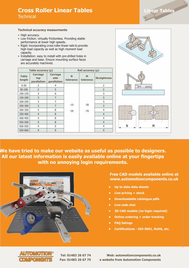
Linear TablesCross Roller Linear TablesTechnical
• High accuracy.• Low friction: virtually frictionless. Providing stable performance at lower high speeds. • Rigid: incorporating cross roller linear rails to provide high load capacity as well as high moment load capacity.• Installation: easy to install with pre-drilled holes in carriage and base. Ensure mounting surface faces are accurately machined.
N M
Table accuracy (μ) Rail accuracy (μ)
Table length
Carriage top
parallelism
Carriage side
parallelism
N tolerance
M tolerance Straightness
0-50 2 4
-15
-35
-30
-70
250-100 2 5 2100-150 3 6 3150-200 3 7 3200-250 3 7 3250-300 3 7 3300-350 4 8 4350-400 4 8 4400-450 4 8 4450-500 4 8 4500-550 4 9 4550-600 4 9 4
Technical accuracy measurments
We have tried to make our website as useful as possible to designers. All our latest information is easily available online at your fi ngertips
with no annoying login requirements.
Free CAD models available online atwww.automotioncomponents.co.uk
• Up to date data sheets
• Live pricing + stock
• Downloadable catalogue pdfs
• Live web chat
• 3D CAD models (no login required)
• Online ordering + order tracking
• FAQ listings
• Certifi cations - ISO 9001, RoHS, etc.
ov-lin
ear-tables-tech
nical - U
pd
ated - 1
8-0
9-2
017

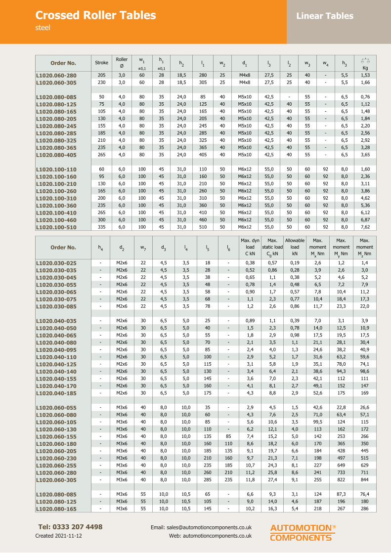
Linear TablesCrossed Roller Tablessteel
Tel: 0333 207 4498
Created 2021-11-12
Email: [email protected]
Web: automotioncomponents.co.uk
L1020
Material
Body carbon steel (S50C) nickel
plated. Rail and rollers carbon steel
(100Cr6), retainer stainless steel
(AISI 304).
Technical notes
Base and carriage with standard hole
pattern. The top can be machined as
required, taking care to disassemble
first and ensure no dirt ingress.
Alternatively we can machine any
extra holes required (additional cost).
Recommended allowable load is 1/3
of max. static load giving a safety
factor of over 3.
Tips
Stroke is centred on the mid-point of
the slides (ie 50% of total stroke
each way).
Order No. StrokeRoller
Ø
w1
±0,1
h1
±0,1
h2
l1
w2
d1
l3
l2
w3
w4
h3
XKg
L1020.030-025 12 1,5 30 17 11 25 10 M2x4 12,5 - 12 - 2,5 0,04
L1020.030-035 18 1,5 30 17 11 35 10 M2x4 12,5 10 12 - 2,5 0,05
L1020.030-045 25 1,5 30 17 11 45 10 M2x4 12,5 10 12 - 2,5 0,07
L1020.030-055 32 1,5 30 17 11 55 10 M2x4 12,5 10 12 - 2,5 0,08
L1020.030-065 40 1,5 30 17 11 65 10 M2x4 12,5 10 12 - 2,5 0,10
L1020.030-075 45 1,5 30 17 11 75 10 M2x4 12,5 10 12 - 2,5 0,12
L1020.030-085 50 1,5 30 17 11 85 10 M2x4 12,5 10 12 - 2,5 0,13
L1020.040-035 18 2,0 40 21 14 35 15 M3x6 17,5 - 16 - 3,4 0,09
L1020.040-050 30 2,0 40 21 14 50 15 M3x6 17,5 15 16 - 3,4 0,13
L1020.040-065 40 2,0 40 21 14 65 15 M3x6 17,5 15 16 - 3,4 0,17
L1020.040-080 50 2,0 40 21 14 80 15 M3x6 17,5 15 16 - 3,4 0,21
L1020.040-095 60 2,0 40 21 14 95 15 M3x6 17,5 15 16 - 3,4 0,25
L1020.040-110 70 2,0 40 21 14 110 15 M3x6 17,5 15 16 - 3,4 0,30
L1020.040-125 80 2,0 40 21 14 125 15 M3x6 17,5 15 16 - 3,4 0,34
L1020.040-140 90 2,0 40 21 14 140 15 M3x6 17,5 15 16 - 3,4 0,38
L1020.040-155 100 2,0 40 21 14 155 15 M3x6 17,5 15 16 - 3,4 0,42
L1020.040-170 110 2,0 40 21 14 170 15 M3x6 17,5 15 16 - 3,4 0,46
L1020.040-185 120 2,0 40 21 14 185 15 M3x6 17,5 15 16 - 3,4 0,50
L1020.060-055 30 3,0 60 28 18,5 55 25 M4x8 27,5 - 40 - 5,5 0,29
L1020.060-080 45 3,0 60 28 18,5 80 25 M4x8 27,5 25 40 - 5,5 0,43
L1020.060-105 60 3,0 60 28 18,5 105 25 M4x8 27,5 25 40 - 5,5 0,57
L1020.060-130 75 3,0 60 28 18,5 130 25 M4x8 27,5 25 40 - 5,5 0,71
L1020.060-155 90 3,0 60 28 18,5 155 25 M4x8 27,5 25 40 - 5,5 0,84
L1020.060-180 105 3,0 60 28 18,5 180 25 M4x8 27,5 25 40 - 5,5 0,98
L1020.060-205 130 3,0 60 28 18,5 205 25 M4x8 27,5 25 40 - 5,5 1,12
L1020.060-230 155 3,0 60 28 18,5 230 25 M4x8 27,5 25 40 - 5,5 1,25
L1020.060-255 180 3,0 60 28 18,5 255 25 M4x8 27,5 25 40 - 5,5 1,39
Linear TablesCrossed Roller Tablessteel
Tel: 0333 207 4498
Created 2021-11-12
Email: [email protected]
Web: automotioncomponents.co.uk
Order No. StrokeRoller
Ø
w1
±0,1
h1
±0,1
h2
l1
w2
d1
l3
l2
w3
w4
h3
XKg
L1020.060-280 205 3,0 60 28 18,5 280 25 M4x8 27,5 25 40 - 5,5 1,53
L1020.060-305 230 3,0 60 28 18,5 305 25 M4x8 27,5 25 40 - 5,5 1,66
L1020.080-085 50 4,0 80 35 24,0 85 40 M5x10 42,5 - 55 - 6,5 0,76
L1020.080-125 75 4,0 80 35 24,0 125 40 M5x10 42,5 40 55 - 6,5 1,12
L1020.080-165 105 4,0 80 35 24,0 165 40 M5x10 42,5 40 55 - 6,5 1,48
L1020.080-205 130 4,0 80 35 24,0 205 40 M5x10 42,5 40 55 - 6,5 1,84
L1020.080-245 155 4,0 80 35 24,0 245 40 M5x10 42,5 40 55 - 6,5 2,20
L1020.080-285 185 4,0 80 35 24,0 285 40 M5x10 42,5 40 55 - 6,5 2,56
L1020.080-325 210 4,0 80 35 24,0 325 40 M5x10 42,5 40 55 - 6,5 2,92
L1020.080-365 235 4,0 80 35 24,0 365 40 M5x10 42,5 40 55 - 6,5 3,28
L1020.080-405 265 4,0 80 35 24,0 405 40 M5x10 42,5 40 55 - 6,5 3,65
L1020.100-110 60 6,0 100 45 31,0 110 50 M6x12 55,0 50 60 92 8,0 1,60
L1020.100-160 95 6,0 100 45 31,0 160 50 M6x12 55,0 50 60 92 8,0 2,36
L1020.100-210 130 6,0 100 45 31,0 210 50 M6x12 55,0 50 60 92 8,0 3,11
L1020.100-260 165 6,0 100 45 31,0 260 50 M6x12 55,0 50 60 92 8,0 3,86
L1020.100-310 200 6,0 100 45 31,0 310 50 M6x12 55,0 50 60 92 8,0 4,62
L1020.100-360 235 6,0 100 45 31,0 360 50 M6x12 55,0 50 60 92 8,0 5,36
L1020.100-410 265 6,0 100 45 31,0 410 50 M6x12 55,0 50 60 92 8,0 6,12
L1020.100-460 300 6,0 100 45 31,0 460 50 M6x12 55,0 50 60 92 8,0 6,87
L1020.100-510 335 6,0 100 45 31,0 510 50 M6x12 55,0 50 60 92 8,0 7,62
Order No. h4
d2
w7
d3
l4
l5
l6
Max. dyn
load
C kN
Max.
static load
C0
kN
Allowable
load
kN
Max.
moment
Mx
Nm
Max.
moment
My
Nm
Max.
moment
Mz Nm
L1020.030-025 - M2x6 22 4,5 3,5 18 - 0,38 0,57 0,19 2,6 1,2 1,4
L1020.030-035 - M2x6 22 4,5 3,5 28 - 0,52 0,86 0,28 3,9 2,6 3,0
L1020.030-045 - M2x6 22 4,5 3,5 38 - 0,65 1,1 0,38 5,2 4,6 5,2
L1020.030-055 - M2x6 22 4,5 3,5 48 - 0,78 1,4 0,48 6,5 7,2 7,9
L1020.030-065 - M2x6 22 4,5 3,5 58 - 0,90 1,7 0,57 7,8 10,4 11,2
L1020.030-075 - M2x6 22 4,5 3,5 68 - 1,1 2,3 0,77 10,4 18,4 17,3
L1020.030-085 - M2x6 22 4,5 3,5 78 - 1,2 2,6 0,86 11,7 23,3 22,0
L1020.040-035 - M2x6 30 6,5 5,0 25 - 0,89 1,1 0,39 7,0 3,1 3,9
L1020.040-050 - M2x6 30 6,5 5,0 40 - 1,5 2,3 0,78 14,0 12,5 10,9
L1020.040-065 - M2x6 30 6,5 5,0 55 - 1,8 2,9 0,98 17,5 19,5 17,5
L1020.040-080 - M2x6 30 6,5 5,0 70 - 2,1 3,5 1,1 21,1 28,1 30,4
L1020.040-095 - M2x6 30 6,5 5,0 85 - 2,4 4,0 1,3 24,6 38,2 40,9
L1020.040-110 - M2x6 30 6,5 5,0 100 - 2,9 5,2 1,7 31,6 63,2 59,6
L1020.040-125 - M2x6 30 6,5 5,0 115 - 3,1 5,8 1,9 35,1 78,0 74,1
L1020.040-140 - M2x6 30 6,5 5,0 130 - 3,4 6,4 2,1 38,6 94,3 98,6
L1020.040-155 - M2x6 30 6,5 5,0 145 - 3,6 7,0 2,3 42,1 112 111
L1020.040-170 - M2x6 30 6,5 5,0 160 - 4,1 8,1 2,7 49,1 152 147
L1020.040-185 - M2x6 30 6,5 5,0 175 - 4,3 8,8 2,9 52,6 175 169
L1020.060-055 - M3x6 40 8,0 10,0 35 - 2,9 4,5 1,5 42,6 22,8 26,6
L1020.060-080 - M3x6 40 8,0 10,0 60 - 4,3 7,6 2,5 71,0 63,4 57,1
L1020.060-105 - M3x6 40 8,0 10,0 85 - 5,6 10,6 3,5 99,5 124 115
L1020.060-130 - M3x6 40 8,0 10,0 110 - 6,2 12,1 4,0 113 162 172
L1020.060-155 - M3x6 40 8,0 10,0 135 85 7,4 15,2 5,0 142 253 266
L1020.060-180 - M3x6 40 8,0 10,0 160 110 8,6 18,2 6,0 170 365 350
L1020.060-205 - M3x6 40 8,0 10,0 185 135 9,1 19,7 6,6 184 428 445
L1020.060-230 - M3x6 40 8,0 10,0 210 160 9,7 21,3 7,1 198 497 515
L1020.060-255 - M3x6 40 8,0 10,0 235 185 10,7 24,3 8,1 227 649 629
L1020.060-280 - M3x6 40 8,0 10,0 260 210 11,2 25,8 8,6 241 733 711
L1020.060-305 - M3x6 40 8,0 10,0 285 235 11,8 27,4 9,1 255 822 844
L1020.080-085 - M3x6 55 10,0 10,5 65 - 6,6 9,3 3,1 124 87,3 76,4
L1020.080-125 - M3x6 55 10,0 10,5 105 - 9,0 14,0 4,6 187 196 180
L1020.080-165 - M3x6 55 10,0 10,5 145 - 10,2 16,3 5,4 218 267 286

Linear TablesCrossed Roller Tablessteel
Tel: 0333 207 4498
Created 2021-11-12
Email: [email protected]
Web: automotioncomponents.co.uk
Order No. h4
d2
w7
d3
l4
l5
l6
Max. dyn
load
C kN
Max.
static load
C0
kN
Allowable
load
kN
Max.
moment
Mx
Nm
Max.
moment
My
Nm
Max.
moment
Mz Nm
L1020.080-205 - M3x6 55 10,0 10,5 185 105 12,5 21,0 7,0 280 442 466
L1020.080-245 - M3x6 55 10,0 10,5 225 145 14,6 25,7 8,6 343 660 690
L1020.080-285 - M3x6 55 10,0 10,5 265 185 16,6 30,4 10,1 405 922 957
L1020.080-325 - M3x6 55 10,0 10,5 305 225 18,6 35,0 11,7 467 1128 1269
L1020.080-365 - M3x6 55 10,0 10,5 345 265 20,5 39,7 13,2 530 1577 1623
L1020.080-405 - M3x6 55 10,0 10,5 385 305 22,3 44,4 14,8 592 1970 1918
L1020.100-110 15 M4x8 60 11,5 10,0 90 - 13,9 21,0 7,0 315 252 221
L1020.100-160 15 M4x8 60 11,5 10,0 140 - 16,5 26,3 8,7 394 394 434
L1020.100-210 15 M4x8 60 11,5 10,0 190 90 21,6 36,8 12,2 552 773 828
L1020.100-260 15 M4x8 60 11,5 10,0 240 140 26,2 47,3 15,7 710 1279 1207
L1020.100-310 15 M4x8 60 11,5 10,0 290 190 30,7 57,8 19,3 868 1910 1823
L1020.100-360 15 M4x8 60 11,5 10,0 340 240 35,0 68,4 22,8 1026 2688 2565
L1020.100-410 15 M4x8 60 11,5 10,0 390 290 39,1 78,9 26,3 1184 3552 3434
L1020.100-460 15 M4x8 60 11,5 10,0 440 340 41,1 84,2 28,0 1263 4042 4168
L1020.100-510 15 M4x8 60 11,5 10,0 490 390 45,1 94,7 31,5 1421 5115 5257

Linear TablesCrossed Roller Tablesaluminium
Tel: 0333 207 4498
Created 2021-11-12
Email: [email protected]
Web: automotioncomponents.co.uk
L1021
Material
Body aluminium alloy, black
anodised. Rail and rollers carbon steel
(100Cr6), retainer stainless steel
(AISI 304).
Technical notes
Base and carriage with standard hole
pattern. The top can be machined as
required, taking care to disassemble
first and ensure no dirt ingress.
Alternatively we can machine any
extra holes required (additional cost).
Recommended allowable load is 1/3
of max. static load giving a safety
factor of over 3.
Tips
Stroke is centred on the mid-point of
the slides (ie 50% of total stroke
each way).
Order No. StrokeRoller
Ø
w1
±0,1
h1
±0,1
h2
l1
w2
d1
l3
l2
w3
w4
h3
XKg
L1021.030-025 12 1,5 30 17 11 25 10 M2x4 12,5 - 12 - 2,5 0,09
L1021.030-035 18 1,5 30 17 11 35 10 M2x4 12,5 10 12 - 2,5 0,12
L1021.030-045 25 1,5 30 17 11 45 10 M2x4 12,5 10 12 - 2,5 0,16
L1021.030-055 32 1,5 30 17 11 55 10 M2x4 12,5 10 12 - 2,5 0,19
L1021.030-065 40 1,5 30 17 11 65 10 M2x4 12,5 10 12 - 2,5 0,23
L1021.030-075 45 1,5 30 17 11 75 10 M2x4 12,5 10 12 - 2,5 0,27
L1021.030-085 50 1,5 30 17 11 85 10 M2x4 12,5 10 12 - 2,5 0,30
L1021.040-035 18 2,0 40 21 14 35 15 M3x6 17,5 - 16 - 3,4 0,20
L1021.040-050 30 2,0 40 21 14 50 15 M3x6 17,5 15 16 - 3,4 0,29
L1021.040-065 40 2,0 40 21 14 65 15 M3x6 17,5 15 16 - 3,4 0,38
L1021.040-080 50 2,0 40 21 14 80 15 M3x6 17,5 15 16 - 3,4 0,46
L1021.040-095 60 2,0 40 21 14 95 15 M3x6 17,5 15 16 - 3,4 0,55
L1021.040-110 70 2,0 40 21 14 110 15 M3x6 17,5 15 16 - 3,4 0,64
L1021.040-125 80 2,0 40 21 14 125 15 M3x6 17,5 15 16 - 3,4 0,73
L1021.040-140 90 2,0 40 21 14 140 15 M3x6 17,5 15 16 - 3,4 0,82
L1021.040-155 100 2,0 40 21 14 155 15 M3x6 17,5 15 16 - 3,4 0,91
L1021.040-170 110 2,0 40 21 14 170 15 M3x6 17,5 15 16 - 3,4 1,00
L1021.040-185 120 2,0 40 21 14 185 15 M3x6 17,5 15 16 - 3,4 1,08
L1021.060-055 30 3,0 60 28 18,5 55 25 M4x8 27,5 - 40 - 5,5 0,66
L1021.060-080 45 3,0 60 28 18,5 80 25 M4x8 27,5 25 40 - 5,5 0,96
L1021.060-105 60 3,0 60 28 18,5 105 25 M4x8 27,5 25 40 - 5,5 1,26
L1021.060-130 75 3,0 60 28 18,5 130 25 M4x8 27,5 25 40 - 5,5 1,57
L1021.060-155 90 3,0 60 28 18,5 155 25 M4x8 27,5 25 40 - 5,5 1,87
L1021.060-180 105 3,0 60 28 18,5 180 25 M4x8 27,5 25 40 - 5,5 2,17
L1021.060-205 130 3,0 60 28 18,5 205 25 M4x8 27,5 25 40 - 5,5 2,47
L1021.060-230 155 3,0 60 28 18,5 230 25 M4x8 27,5 25 40 - 5,5 2,77
L1021.060-255 180 3,0 60 28 18,5 255 25 M4x8 27,5 25 40 - 5,5 3,07

Linear TablesCrossed Roller Tablesaluminium
Tel: 0333 207 4498
Created 2021-11-12
Email: [email protected]
Web: automotioncomponents.co.uk
Order No. StrokeRoller
Ø
w1
±0,1
h1
±0,1
h2
l1
w2
d1
l3
l2
w3
w4
h3
XKg
L1021.060-280 205 3,0 60 28 18,5 280 25 M4x8 27,5 25 40 - 5,5 3,37
L1021.060-305 230 3,0 60 28 18,5 305 25 M4x8 27,5 25 40 - 5,5 3,68
L1021.080-085 50 4,0 80 35 24,0 85 40 M5x10 42,5 - 55 - 6,5 1,69
L1021.080-125 75 4,0 80 35 24,0 125 40 M5x10 42,5 40 55 - 6,5 2,50
L1021.080-165 105 4,0 80 35 24,0 165 40 M5x10 42,5 40 55 - 6,5 3,31
L1021.080-205 130 4,0 80 35 24,0 205 40 M5x10 42,5 40 55 - 6,5 4,11
L1021.080-245 155 4,0 80 35 24,0 245 40 M5x10 42,5 40 55 - 6,5 4,91
L1021.080-285 185 4,0 80 35 24,0 285 40 M5x10 42,5 40 55 - 6,5 5,72
L1021.080-325 210 4,0 80 35 24,0 325 40 M5x10 42,5 40 55 - 6,5 6,51
L1021.080-365 235 4,0 80 35 24,0 365 40 M5x10 42,5 40 55 - 6,5 7,32
L1021.080-405 265 4,0 80 35 24,0 405 40 M5x10 42,5 40 55 - 6,5 8,13
L1021.100-110 60 6,0 100 45 31,0 110 50 M6x12 55,0 50 60 92 8,0 3,48
L1021.100-160 95 6,0 100 45 31,0 160 50 M6x12 55,0 50 60 92 8,0 5,10
L1021.100-210 130 6,0 100 45 31,0 210 50 M6x12 55,0 50 60 92 8,0 6,70
L1021.100-260 165 6,0 100 45 31,0 260 50 M6x12 55,0 50 60 92 8,0 8,32
L1021.100-310 200 6,0 100 45 31,0 310 50 M6x12 55,0 50 60 92 8,0 9,94
L1021.100-360 235 6,0 100 45 31,0 360 50 M6x12 55,0 50 60 92 8,0 11,53
L1021.100-410 265 6,0 100 45 31,0 410 50 M6x12 55,0 50 60 92 8,0 13,15
L1021.100-460 300 6,0 100 45 31,0 460 50 M6x12 55,0 50 60 92 8,0 14,76
L1021.100-510 335 6,0 100 45 31,0 510 50 M6x12 55,0 50 60 92 8,0 16,36
Order No. h4
d2
w7
d3
l4
l5
l6
Max. dyn
load
C kN
Max.
static
C0
kN
Allowable
load
kN
Max.
moment
Mx Nm
Max.
moment
My Nm
Max.
moment
Mz Nm
L1021.030-025 - M2x6 22 4,5 3,5 18 - 0,38 0,57 0,19 2,6 1,2 1,4
L1021.030-035 - M2x6 22 4,5 3,5 28 - 0,52 0,86 0,28 3,9 2,6 3,0
L1021.030-045 - M2x6 22 4,5 3,5 38 - 0,65 1,1 0,38 5,2 4,6 5,2
L1021.030-055 - M2x6 22 4,5 3,5 48 - 0,78 1,4 0,48 6,5 7,2 7,9
L1021.030-065 - M2x6 22 4,5 3,5 58 - 0,90 1,7 0,57 7,8 10,4 11,2
L1021.030-075 - M2x6 22 4,5 3,5 68 - 1,1 2,3 0,77 10,4 18,4 17,3
L1021.030-085 - M2x6 22 4,5 3,5 78 - 1,2 2,6 0,86 11,7 23,3 22,0
L1021.040-035 - M2x6 30 6,5 5,0 25 - 0,89 1,1 0,39 7,0 3,1 3,9
L1021.040-050 - M2x6 30 6,5 5,0 40 - 1,5 2,3 0,78 14,0 12,5 10,9
L1021.040-065 - M2x6 30 6,5 5,0 55 - 1,8 2,9 0,97 17,5 19,5 17,5
L1021.040-080 - M2x6 30 6,5 5,0 70 - 2,1 3,5 1,1 21,1 28,1 30,4
L1021.040-095 - M2x6 30 6,5 5,0 85 - 2,4 4,0 1,3 24,6 38,2 40,9
L1021.040-110 - M2x6 30 6,5 5,0 100 - 2,9 5,2 1,7 31,6 63,2 59,6
L1021.040-125 - M2x6 30 6,5 5,0 115 - 3,1 5,8 1,9 35,1 78,0 74,1
L1021.040-140 - M2x6 30 6,5 5,0 130 - 3,4 6,4 2,1 38,6 94,3 98,6
L1021.040-155 - M2x6 30 6,5 5,0 145 - 3,6 7,0 2,3 42,1 112 111
L1021.040-170 - M2x6 30 6,5 5,0 160 - 4,1 8,1 2,7 49,1 152 147
L1021.040-185 - M2x6 30 6,5 5,0 175 - 4,3 8,7 2,9 52,6 175 169
L1021.060-055 - M3x6 40 8,0 10,0 35 - 2,9 4,5 1,5 42,6 22,8 26,6
L1021.060-080 - M3x6 40 8,0 10,0 60 - 4,3 7,6 2,5 71,0 63,4 57,1
L1021.060-105 - M3x6 40 8,0 10,0 85 - 5,6 10,6 3,5 99,5 124 115
L1021.060-130 - M3x6 40 8,0 10,0 110 - 6,2 12,1 4,0 113 162 172
L1021.060-155 - M3x6 40 8,0 10,0 135 85 7,4 15,2 5,0 142 253 266
L1021.060-180 - M3x6 40 8,0 10,0 160 110 8,6 18,2 6,0 170 365 350
L1021.060-205 - M3x6 40 8,0 10,0 185 135 9,1 19,7 6,6 184 428 445
L1021.060-230 - M3x6 40 8,0 10,0 210 160 9,7 21,3 7,1 198 497 515
L1021.060-255 - M3x6 40 8,0 10,0 235 185 10,7 24,3 8,1 227 649 629
L1021.060-280 - M3x6 40 8,0 10,0 260 210 11,2 25,8 8,6 241 733 711
L1021.060-305 - M3x6 40 8,0 10,0 285 235 11,8 27,4 9,1 255 822 844
L1021.080-085 - M3x6 55 10,0 10,5 65 - 6,6 9,3 3,1 124 87,3 76,4
L1021.080-125 - M3x6 55 10,0 10,5 105 - 9,0 14,0 4,1 187 196 180
L1021.080-165 - M3x6 55 10,0 10,5 145 - 10,2 16,3 5,4 218 267 286

Linear TablesCrossed Roller Tablesaluminium
Tel: 0333 207 4498
Created 2021-11-12
Email: [email protected]
Web: automotioncomponents.co.uk
Order No. h4
d2
w7
d3
l4
l5
l6
Max. dyn
load
C kN
Max.
static
C0
kN
Allowable
load
kN
Max.
moment
Mx Nm
Max.
moment
My Nm
Max.
moment
Mz Nm
L1021.080-205 - M3x6 55 10,0 10,5 185 105 12,4 21,0 7,0 280 442 466
L1021.080-245 - M3x6 55 10,0 10,5 225 145 14,6 25,7 8,5 343 660 690
L1021.080-285 - M3x6 55 10,0 10,5 265 185 16,6 30,4 10,1 405 922 957
L1021.080-325 - M3x6 55 10,0 10,5 305 225 18,6 35,0 11,7 467 1128 1269
L1021.080-365 - M3x6 55 10,0 10,5 345 265 20,5 39,7 13,2 530 1577 1623
L1021.080-405 - M3x6 55 10,0 10,5 385 305 22,3 44,4 14,8 592 1970 1918
L1021.100-110 15 M4x8 60 11,5 10,0 90 - 13,9 21,0 7,0 315 252 221
L1021.100-160 15 M4x8 60 11,5 10,0 140 - 16,6 26,3 8,7 394 394 434
L1021.100-210 15 M4x8 60 11,5 10,0 190 90 21,6 36,8 12,2 552 773 828
L1021.100-260 15 M4x8 60 11,5 10,0 240 140 26,2 47,3 15,7 710 1279 1207
L1021.100-310 15 M4x8 60 11,5 10,0 290 190 30,7 57,9 19,3 868 1910 1823
L1021.100-360 15 M4x8 60 11,5 10,0 340 240 35,0 68,4 22,8 1026 2688 2565
L1021.100-410 15 M4x8 60 11,5 10,0 390 290 39,1 78,9 26,3 1184 3552 3434
L1021.100-460 15 M4x8 60 11,5 10,0 440 340 41,1 84,2 28,0 1263 4042 4168
L1021.100-510 15 M4x8 60 11,5 10,0 490 390 45,1 94,7 31,5 1421 5115 5257

Linear TablesBall Slide Assembliesstandard precision
Tel: 0333 207 4498
Created 2021-11-12
Email: [email protected]
Web: automotioncomponents.co.uk
L1024
Material
Aluminium carriage clear anodized,
base black anodized.
Hardened steel shafts and balls, mild
steel end caps.
Technical notes
Straight line accuracy: 13µ/25mm
travel.
Positional repeatability: 5µ.
Coefficient of friction 0,003 typical.
Tips
Stroke is centred on the mid-point of
the slides (ie 50% of total stroke
each way).
Order No. StrokeMax. load
Kgw
1l1
h1
l2
w2
h2
w3
l3
Xg
L1024.010-008 8 0,34 9,5 13,3 5,8 6,0 4,0 3,4 4,0 6,0 2
L1024.010-013 13 0,68 9,5 19,0 5,8 13,0 4,0 3,4 4,0 10,0 3
L1024.010-025 25 0,68 9,5 32,0 5,8 26,0 4,0 3,4 4,0 20,0 4
L1024.010-038 38 0,68 9,5 44,0 5,8 37,0 4,0 3,4 4,0 30,0 7
L1024.014-013 13 2 14,2 27,0 8,0 15,0 6,0 4,7 6,4 19,0 9
L1024.014-025 25 4 14,2 52,0 8,0 41,0 6,0 4,7 6,4 35,0 14
L1024.014-050 50 5 14.2 78,0 8,0 66,0 6,0 4,7 6,4 60,0 23
L1024.014-075 75 6 14,2 103,0 8,0 92,0 6,0 4,7 6,4 86,0 31
L1024.014-100 100 8 14,2 128,0 8,0 117,0 6,0 4,7 6,4 89,0 34
L1024.014-127 127 8 14,2 154,0 8,0 142,0 6,0 4,7 6,4 114,0 43
L1024.019-013 13 4 19,0 27,0 10,4 15,0 9,0 6,3 9,5 19,0 11
L1024.019-025 25 5 19,0 52,0 10,4 41,0 9,0 6,3 9,5 35,0 26
L1024.019-050 50 5 19,0 78,0 10,4 66,0 9,0 6,3 9,5 60,0 37
L1024.019-075 75 6 19,0 103,0 10,4 92,0 9,0 6,3 9,5 86,0 48
L1024.019-100 100 7 19,0 128,0 10,4 117,0 9,0 6,3 9,5 89,0 60
L1024.019-127 127 8 19,0 154,0 10,4 142,0 9,0 6,3 9,5 114,0 71
L1024.025-013 13 5 25,4 40,0 12,7 32,0 10,0 6,3 12,7 32,0 34
L1024.025-025 25 5 25,4 65,0 12,7 57,0 10,0 6,3 12,7 57.0 48
L1024.025-038 38 6 25,4 78,0 12,7 65,0 10,0 6,3 12,7 65,0 54
L1024.025-050 50 7 25,4 90,0 12,7 82,0 10,0 6,3 12,7 82,0 62
L1024.025-075 75 8 25,4 116,0 12,7 108,0 10,0 6,3 12,7 108,0 142
L1024.027-019 19 7 26,9 40,0 13,4 32,0 10,0 7,9 12,7 28,0 37
L1024.027-038 38 8 26,9 65,0 13,4 57,0 10,0 7,9 12,7 54,0 65
L1024.027-050 50 9 26,9 90,0 13,4 82,0 10,0 7,9 12,7 79,0 85
L1024.027-075 75 11 26,9 116,0 13,4 102,0 10,0 7,9 12,7 82,0 147
L1024.027-100 100 14 26,9 152,0 13,4 140,0 10,0 7,9 12,7 102,0 170
L1024.027-150 150 16 26,9 203,0 13,4 190,0 10,0 7,9 12,7 127,0 198
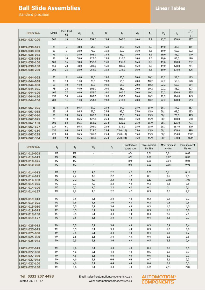
Linear TablesBall Slide Assembliesstandard precision
Tel: 0333 207 4498
Created 2021-11-12
Email: [email protected]
Web: automotioncomponents.co.uk
Order No. StrokeMax. load
Kgw
1l1
h1
l2
w2
h2
w3
l3
Xg
L1024.027-200 200 18 26,9 254,0 13,4 240,0 10,0 7,9 12,7 178,0 227
L1024.038-025 25 7 38,0 51,0 15,8 35,0 16,0 8,6 19,0 37,0 82
L1024.038-050 50 9 38,0 76,0 15,8 60,0 16,0 8,6 19,0 60,0 122
L1024.038-075 75 11 38,0 102,0 15,8 85,0 16,0 8,6 19,0 85,0 170
L1024.038-088 88 14 38,0 127,0 15,8 110,0 16,0 8,6 19,0 85,0 190
L1024.038-100 100 16 38,0 152,0 15,8 136,0 16,0 8,6 19,0 100,0 232
L1024.038-150 150 20 38,0 203,0 15,8 186,0 16,0 8,6 19,0 128,0 261
L1024.038-200 200 25 38,0 254,0 15,8 238,0 16,0 8,6 19,0 178,0 326
L1024.044-025 25 9 44,0 51,0 19,0 35,0 20,0 10,2 22,2 38,0 113
L1024.044-038 38 14 44,0 70,0 19,0 55,0 20,0 10,2 22,2 55,0 170
L1024.044-050 50 19 44,0 83,0 19,0 65,0 20,0 10,2 22,2 65,0 184
L1024.044-075 75 24 44,0 102,0 19,0 85,0 20,0 10,2 22,2 85,0 227
L1024.044-100 100 27 44,0 152,0 19,0 140,0 20,0 10,2 22,2 100,0 335
L1024.044-150 150 34 44,0 203,0 19,0 190,0 20,0 10,2 22,2 126,0 445
L1024.044-200 200 41 44,0 254,0 19,0 240,0 20,0 10,2 22,2 178,0 553
L1024.067-025 25 14 66,5 67,0 25,4 54,0 35,0 15,9 38,1 54,0 283
L1024.067-038 38 16 66,5 67,0 25,4 42,0 35,0 15,9 38,1 42,0 283
L1024.067-050 50 28 66,5 102,0 25,4 75,0 35,0 15,9 38,1 75,0 425
L1024.067-075 75 40 66,5 127,0 25,4 100,0 35,0 15,9 38,1 100,0 590
L1024.067-100 100 54 66,5 152,0 25,4 125,0 35,0 15,9 38,1 125,0 771
L1024.067-127 127 61 66,5 203,0 25,4 175,0 35,0 15,9 38,1 187,0 879
L1024.067-150 150 68 66,5 229,0 25,4 75,0 (x2) 35,0 15,9 38,1 178,0 498
L1024.067-228 228 84 66,5 305,0 25,4 75,0 (x3) 35,0 15,9 38,1 254,0 1318
L1024.067-304 304 93 66,5 381,0 25,4 75,0 (x4) 35,0 15,9 38,1 330,0 1644
Order No. d1
d2
d3
h3
Counterbore
screw size
Max. moment
Mx Nm
Max. moment
My Nm
Max. moment
Mz Nm
L1024.010-008 M2 M2 - - n/a 0,01 0,01 0,02
L1024.010-013 M2 M2 - - n/a 0,01 0,02 0,03
L1024.010-025 M2 M2 - - n/a 0,01 0,04 0,04
L1024.010-038 M2 M2 - - n/a 0,01 0,05 0,06
L1024.014-013 M2 2,2 4,0 2,2 M2 0,06 0,11 0,11
L1024.014-025 M2 2,2 4,0 2,2 M2 0,1 0,5 0,5
L1024.014-050 M2 2,2 4,0 2,2 M2 0,17 0,98 1,02
L1024.014-075 M2 2,2 4,0 2,2 M2 0,2 1,5 1,6
L1024.014-100 M2 2,2 4,0 2,2 M2 0,2 2, 2,1
L1024.014-127 M2 2,2 4,0 2,2 M2 0,3 2,6 2,7
L1024.019-013 M3 3,5 6,1 3,4 M3 0,2 0,2 0,2
L1024.019-025 M3 3,5 6,1 3,4 M3 0,2 0,5 0,6
L1024.019-050 M3 3,5 6,1 3,4 M3 0,3 1,0 1,0
L1024.019-075 M3 3,5 6,1 3,4 M3 0,3 1,5 1,6
L1024.019-100 M3 3,5 6,1 3,4 M3 0,3 2,0 2,1
L1024.019-127 M3 3,5 6,1 3,4 M3 0,4 2,6 2,7
L1024.025-013 M4 3,5 6,1 3,4 M3 0,3 0,4 2,4
L1024.025-025 M4 3,5 6,1 3,4 M3 0,3 1,0 1,0
L1024.025-038 M4 3,5 6,1 3,4 M3 0,4 1,2 1,2
L1024.025-050 M4 3,5 6,1 3,4 M3 0,4 1,5 1,6
L1024.025-075 M4 3,5 6,1 3,4 M3 0,5 2,3 2,4
L1024.027-019 M4 4,6 8,1 4,4 M4 0,4 0,5 0,5
L1024.027-038 M4 4,6 8,1 4,4 M4 0,5 1,2 1,3
L1024.027-050 M4 4,6 8,1 4,4 M4 0,6 2,0 2,1
L1024.027-075 M4 4,6 8,1 4,4 M4 0,7 3,1 3,3
L1024.027-100 M4 4,6 8,1 4,4 M4 0,4 5,1 5,3
L1024.027-150 M4 4,6 8,1 4,4 M4 1,01 7,51 7,89

Linear TablesBall Slide Assembliesstandard precision
Tel: 0333 207 4498
Created 2021-11-12
Email: [email protected]
Web: automotioncomponents.co.uk
Order No. d1
d2
d3
h3
Counterbore
screw size
Max. moment
Mx Nm
Max. moment
My Nm
Max. moment
Mz Nm
L1024.027-200 M4 4,6 8,1 4,4 M4 1,2 10,3 10,9
L1024.038-025 M4 4,6 8,1 4,4 M4 0,6 0,7 0,7
L1024.038-050 M4 4,6 8,1 4,4 M4 0,8 1,4 1,4
L1024.038-075 M4 4,6 8,1 4,4 M4 1,0 2,3 2,4
L1024.038-088 M4 4,6 8,1 4,4 M4 1,2 3,7 3,9
L1024.038-100 M4 4,6 8,1 4,4 M4 1,5 5,5 5,8
L1024.038-150 M4 4,6 8,1 4,4 M4 1,9 9,1 9,6
L1024.038-200 M4 4,6 8,1 4,4 M4 2,3 13,6 14,3
L1024.044-025 M4 4,6 8,1 4,4 M4 1,0 0,9 0,9
L1024.044-038 M4 4,6 8,1 4,4 M4 1,4 2,0 2,1
L1024.044-050 M4 4,6 8,1 4,4 M4 2,0 3,3 3,5
L1024.044-075 M4 4,6 8,1 4,4 M4 2,5 4,7 4,9
L1024.044-100 M4 4,6 8,1 4,4 M4 2,9 10,0 10,0
L1024.044-150 M4 4,6 8,1 4,4 M4 3,6 15,2 16,0
L1024.044-200 M4 4,6 8,1 4,4 M4 4,3 22,3 23,4
L1024.067-025 M5 5,8 10,0 5,3 M5 2,5 1,9 2,0
L1024.067-038 M5 5,8 10,0 5,3 M5 2,9 1,9 2,0
L1024.067-050 M5 5,8 10,0 5,3 M5 5,11 6,9 7,2
L1024.067-075 M5 5,8 10,0 5,3 M5 7,2 12,5 13,1
L1024.067-100 M5 5,8 10,0 5,3 M5 9,7 20,5 21,5
L1024.067-127 M5 5,8 10,0 5,3 M5 11,1 32,0 33,6
L1024.067-150 M5 5,8 10,0 5,3 M5 12,3 40,3 42,3
L1024.067-228 M5 5,8 10,0 5,3 M5 15,2 61,4 64,5
L1024.067-304 M5 5,8 10,0 5,3 M5 16,8 81,0 85,1

Linear TablesCrossed Roller Slidesstandard precision
Tel: 0333 207 4498
Created 2021-11-12
Email: [email protected]
Web: automotioncomponents.co.uk
L1026
Material
Aluminium carriage and base (black
anodized).
Hardened steel rods and rollers,
stainless steel end caps.
Technical notes
Straight line accuracy: 3µ/25mm of
travel.
Positional repeatability: 3µ.
Coefficient of friction: 0,003 typical.
The slides are lightly lubricated
during assembly.
Additional lubrication is required for
speeds above 30m/min and is
advisable at lower speeds where high
loads are applied in continuous duty
applications.
The slides should be mounted on flat
surfaces to provide full support to the
base.
At rated load capacity and moderate
speeds, expected life is 250km of
travel. At half the rated load the
expected life is 2,500km.
Tips
Stroke is centred on the mid-point of
the slides (ie 50% of total stroke
each way).
Order No. StrokeMax. load
Kgw
1l1
h1
l2
w2
h2
w3
l3
Xg
L1026.014-013 13 14 14,2 27,0 8,0 15,0 6,0 4,7 6,4 19,0 11
L1026.014-025 25 25 14,2 52,0 8,0 41,0 6,0 4,7 6,4 35,0 17
L1026.014-050 50 30 14,2 78,0 8,0 66,0 6,0 4,7 6,4 60,0 26
L1026.014-075 75 32 14,2 103,0 8,0 92,0 6,0 4,7 6,4 86,0 34
L1026.014-100 100 36 14,2 129,0 8,0 117,0 6,0 4,7 6,4 89,0 37
L1026.014-127 127 41 14,2 154,0 8,0 143,0 6,0 4,7 6,4 114,0 45
L1026.019-013 13 22 19,0 27,0 10,4 15,0 9,0 6,3 9,5 19,0 14
L1026.019-025 25 35 19,0 52,0 10,4 41,0 9,0 6,3 9,5 35,0 28
L1026.019-050 50 42 19,0 78,0 10,4 66,0 9,0 6,3 9,5 60,0 40
L1026.019-075 75 44 19,0 103,0 10,4 92,0 9,0 6,3 9,5 86,0 51
L1026.019-100 100 47 19,0 129,0 10,4 117,0 9,0 6,3 9,5 89,0 62
L1026.019-127 127 49 19,0 154,0 10,4 142,0 9,0 6,3 9,5 114,0 74
L1026.025-013 13 32 25,4 40,0 12,7 32,0 10,0 6,3 12,7 32,0 37
L1026.025-025 25 35 25,4 65,0 12,7 57,0 10,0 6,3 12,7 57,0 51
L1026.025-038 38 35 25,4 78,0 12,7 65,0 10,0 6,3 12,7 65,0 57
L1026.025-050 50 38 25,4 90,0 12,7 82,0 10,0 6,3 12,7 82,0 65
L1026.025-075 75 41 25,4 116,0 12,7 108,0 10,0 6,3 12,7 108,0 79
L1026.027-019 19 50 26,9 40,0 13,4 32,0 10,0 7,9 12,7 28,0 40
L1026.027-038 38 60 26,9 65,0 13,4 57,0 10,0 7,9 12,7 54,0 68
L1026.027-050 50 100 26,9 90,0 13,4 82,0 10,0 7,9 12,7 79,0 88
L1026.027-075 75 120 26,9 116,0 13,4 102,0 10,0 7,9 12,7 82,0 150
L1026.027-100 100 129 26,9 152,0 13,4 140,0 10,0 7,9 12,7 102,0 173
L1026.027-150 150 135 26,9 203,0 13,4 190,0 10,0 7,9 12,7 127,0 204

Linear TablesCrossed Roller Slidesstandard precision
Tel: 0333 207 4498
Created 2021-11-12
Email: [email protected]
Web: automotioncomponents.co.uk
Order No. StrokeMax. load
Kgw
1l1
h1
l2
w2
h2
w3
l3
Xg
L1026.027-200 200 145 26,9 254,0 13,4 240,0 10,0 7,9 12,7 178,0 232
L1026.038-025 25 59 38,0 51,0 15,8 35,0 16,0 8,6 19,0 37,0 85
L1026.038-050 50 79 38,0 76,0 15,8 60,0 16,0 8,6 19,0 60,0 128
L1026.038-075 75 79 38,0 102,0 15,8 85,0 16,0 8,6 19,0 85,0 176
L1026.038-089 89 95 38,0 127,0 15,8 111,0 16,0 8,6 19,0 85,0 196
L1026.038-100 100 139 38,0 152,0 15,8 136,0 16,0 8,6 19,0 100,0 238
L1026.038-150 150 163 38,0 203,0 15,8 186,0 16,0 8,6 19,0 127,0 266
L1026.038-200 200 187 38,0 254,0 15,8 238,0 16,0 8,6 19,0 178,0 332
L1026.044-025 25 59 44,0 51,0 19,0 35,0 20,0 10,2 22,2 38,0 116
L1026.044-038 38 68 44,0 70,0 19,0 55,0 20,0 10,2 22,2 55,0 173
L1026.044-050 50 79 44,0 83,0 19,0 65,0 20,0 10,2 22,2 65,0 187
L1026.044-075 75 79 44,0 102,0 19,0 85,0 20,0 10,2 22,2 85,0 232
L1026.044-100 100 139 44,0 152,0 19,0 140,0 20,0 10,2 22,2 100,0 343
L1026.044-150 150 170 44,0 203,0 19,0 190,0 20,0 10,2 22,2 127,0 454
L1026.044-200 200 204 44,0 254,0 19,0 240,0 20,0 10,2 22,2 178,0 561
L1026.067-025 25 102 66,6 67,0 25,4 54,0 35,0 15,9 38,1 54,0 292
L1026.067-038 38 119 66,6 67,0 25,4 42,0 35,0 15,9 38,1 42,0 292
L1026.067-050 50 158 66,6 102,0 25,4 75,0 35,0 15,9 38,1 75,0 454
L1026.067-075 75 198 66,6 127,0 25,4 100,0 35,0 15,9 38,1 100,0 635
L1026.067-100 100 198 66,6 152,0 25,4 125,0 35,0 15,9 38,1 125,0 816
L1026.067-127 127 215 66,6 203,0 25,4 175,0 35,0 15,9 38,1 187,0 936
L1026.067-150 150 317 66,6 229,0 25,4 75,0 35,0 15,9 38,1 178,0 1089
L1026.067-228 228 336 66,6 305,0 25,4 75,0 35,0 15,9 38,1 254,0 1366
L1026.067-304 304 354 66,6 381,0 25,4 75,0 35,0 15,9 38,1 330,0 1729
Order No. d1
d2
d3
h3
Counterbore
screw size
Max. moment Mx
Nm
Max. moment My
Nm
Max. moment Mz
Nm
L1026.014-013 M2 2,2 4,0 2,2 M2 0,43 0,81 0,85
L1026.014-025 M2 2,2 4,0 2,2 M2 0,71 2,66 2,79
L1026.014-050 M2 2,2 4,0 2,2 M2 0,95 4,92 5,17
L1026.014-075 M2 2,2 4,0 2,2 M2 1,01 7,59 7,97
L1026.014-100 M2 2,2 4,0 2,2 M2 1,15 10,1 10,6
L1026.014-127 M2 2,2 4,0 2,2 M2 1,30 13,0 13,7
L1026.019-013 M3 3,5 6,1 3,4 M3 1,05 1,30 1,37
L1026.019-025 M3 3,5 6,1 3,4 M3 1,53 3,80 3,99
L1026.019-050 M3 3,5 6,1 3,4 M3 2,06 7,05 7,36
L1026.019-075 M3 3,5 6,1 3,4 M3 2,15 10,6 11,2
L1026.019-100 M3 3,5 6,1 3,4 M3 2,28 13,2 13,8
L1026.019-127 M3 3,5 6,1 3,4 M3 2,37 15,6 16,4
L1026.025-013 M4 3,5 6,1 3,4 M3 1,98 2,63 2,77
L1026.025-025 M4 3,5 6,1 3,4 M3 2,20 6,35 6,66
L1026.025-038 M4 3,5 6,1 3,4 M3 2,20 7,05 7,40
L1026.025-050 M4 3,5 6,1 3,4 M3 2,33 8,20 8,61
L1026.025-075 M4 3,5 6,1 3,4 M3 2,54 11,4 12,0
L1026.027-019 M4 4,6 8,1 4,4 M4 3,18 3,71 3,55
L1026.027-038 M4 4,6 8,1 4,4 M4 3,83 8,35 8,77
L1026.027-050 M4 4,6 8,1 4,4 M4 5,68 17,4 18,2
L1026.027-075 M4 4,6 8,1 4,4 M4 6,96 27,3 28,7
L1026.027-100 M4 4,6 8,1 4,4 M4 8,26 48,3 50,7
L1026.027-150 M4 4,6 8,1 4,4 M4 8,60 63,9 67,1
L1026.027-200 M4 4,6 8,1 4,4 M4 9,30 83,2 87,3
L1026.038-025 M4 4,6 8,1 4,4 7,0 M4 5,5 6,7
L1026.038-050 M4 4,6 8,1 4,4 10,0 M4 6,3 9,5
L1026.038-075 M4 4,6 8,1 4,4 16,4 M4 7,3 15,6

Linear TablesCrossed Roller Slidesstandard precision
Tel: 0333 207 4498
Created 2021-11-12
Email: [email protected]
Web: automotioncomponents.co.uk
Order No. d1
d2
d3
h3
Counterbore
screw size
Max. moment Mx
Nm
Max. moment My
Nm
Max. moment Mz
Nm
L1026.038-089 M4 4,6 8,1 4,4 27,4 M4 8,8 26,1
L1026.038-100 M4 4,6 8,1 4,4 49,1 M4 12,8 46,8
L1026.038-150 M4 4,6 8,1 4,4 76,9 M4 15,0 73,2
L1026.038-200 M4 4,6 8,1 4,4 107 M4 17,2 102
L1026.044-025 M4 4,6 8,1 4,4 7,0 M4 6,3 6,7
L1026.044-038 M4 4,6 8,1 4,4 10,7 M4 7,2 10,2
L1026.044-050 M4 4,6 8,1 4,4 14,0 M4 8,5 13,4
L1026.044-075 M4 4,6 8,1 4,4 16,3 M4 8,5 15,6
L1026.044-100 M4 4,6 8,1 4,4 49,1 M4 14,8 46,8
L1026.044-150 M4 4,6 8,1 4,4 80,0 M4 18,0 76,3
L1026.044-200 M4 4,6 8,1 4,4 117 M4 21,6 111
L1026.067-025 M5 5,8 10,0 5,3 14,9 M5 18,5 14,2
L1026.067-038 M5 5,8 10,0 5,3 18,8 M5 21,5 17,9
L1026.067-050 M5 5,8 10,0 5,3 37,6 M5 28,7 35,8
L1026.067-075 M5 5,8 10,0 5,3 62,6 M5 35,9 59,7
L1026.067-100 M5 5,8 10,0 5,3 78,3 M5 35,9 74,6
L1026.067-127 M5 5,8 10,0 5,3 117 M5 38,9 112
L1026.067-150 M5 5,8 10,0 5,3 175 M5 57,4 167
L1026.067-228 M5 5,8 10,0 5,3 258 M5 60,9 245
L1026.067-304 M5 5,8 10,0 5,3 323 M5 64,2 308

Linear TablesLow Profile Crossed Roller Tablealuminium/steel
Tel: 0333 207 4498
Created 2021-11-12
Email: [email protected]
Web: automotioncomponents.co.uk
L1027.AL
Material
Aluminium body, black anodised
carriage.
Hardened chrome steel crossed roller
rail set.
Technical notes
Straight line accuracy: 3µ/25mm of
travel.
Positional repeatability: 3µ.
Coefficient of friction: 0,003 typical.
Tips
Stroke is centred on the mid-point of
the slides (ie 50% of total stroke
each way).
Order No.Stroke
l1
Max. load
Kgl2
h1
± 0,1
w1
± 0,1
h2
w2
No. carr
holesl3
l4
No. base
holesl5
L1027.020-012-AL 12 23 25 8 20 4 6,6 4 3,5 1x18 2 3,5
L1027.020-018-AL 18 32 35 8 20 4 6,6 4 3,5 1x28 2 5,0
L1027.020-025-AL 25 47 45 8 20 4 6,6 4 12,5 1x20 4 3,5
L1027.020-032-AL 32 54 55 8 20 4 6,6 4 12,5 1x30 4 3,5
L1027.020-040-AL 40 60 65 8 20 4 6,6 6 12,5 2x20 4 5,0
L1027.020-045-AL 45 73 75 8 20 4 6,6 4 22,5 1x30 4 5,0
L1027.020-050-AL 50 79 85 8 20 4 6,6 6 12,5 2x30 4 5,0
L1027.030-018-AL 18 40 35 12 30 6 12,0 4 3,5 1x28 2 5,0
L1027.030-030-AL 30 63 50 12 30 6 12,0 4 3,5 1x43 2 7,5
L1027.030-040-AL 40 75 65 12 30 6 12,0 4 17,5 1x30 4 5,0
L1027.030-050-AL 50 95 80 12 30 6 12,0 4 17,5 1x45 4 5,0
L1027.030-060-AL 60 105 95 12 30 6 12,0 6 17,5 2x30 4 5,0
L1027.030-070-AL 70 120 110 12 30 6 12,0 4 32,5 1x45 4 7,5
L1027.030-080-AL 80 130 125 12 30 6 12,0 6 17,5 2x45 4 7,5
L1027.040-030-AL 30 126 55 16 40 8 16,0 4 7,5 1x40 2 7,5
L1027.040-045-AL 45 183 80 16 40 8 16,0 4 7,5 1x65 4 6,0
L1027.040-060-AL 60 220 105 16 40 8 16,0 4 27,5 1x50 4 7,5
L1027.040-075-AL 75 275 130 16 40 8 16,0 4 27,5 1x75 4 7,5
L1027.040-090-AL 90 310 155 16 40 8 16,0 6 27,5 2x50 4 7,5
L1027.040-105-AL 105 355 180 16 40 8 16,0 4 52,5 1x75 4 7,5
L1027.040-130-AL 130 375 205 16 40 8 16,0 6 27,5 2x75 4 7,5
Order No. l6
l7
w3
h3
h4
d1
d2
d3
Max.
moment Mx
Nm
Max.
moment My
Nm
Max.
moment Mz
Nm
L1027.020-012-AL 18 - 14 3,5 2,5 M2 3,9 2,6 0,80 1,29 1,33
L1027.020-018-AL 25 - 14 3,5 2,5 M2 3,9 2,6 1,04 2,59 2,71
L1027.020-025-AL 38 25 14 3,5 2,5 M2 3,9 2,6 1,51 4,55 4,79
L1027.020-032-AL 48 29 14 3,5 2,5 M2 3,9 2,6 1,74 5,36 5,63

Linear TablesLow Profile Crossed Roller Tablealuminium/steel
Tel: 0333 207 4498
Created 2021-11-12
Email: [email protected]
Web: automotioncomponents.co.uk
Order No. l6
l7
w3
h3
h4
d1
d2
d3
Max.
moment Mx
Nm
Max.
moment My
Nm
Max.
moment Mz
Nm
L1027.020-040-AL 55 31 14 3,5 2,5 M2 3,9 2,6 1,94 8,16 8,33
L1027.020-045-AL 65 35 14 3,5 2,5 M2 3,9 2,6 2,27 11,5 12,1
L1027.020-050-AL 75 40 14 3,5 2,5 M2 3,9 2,6 2,55 13,9 14,6
L1027.030-018-AL 25 - 22 5,5 3,8 M4 6,1 4 2,35 3,06 3,21
L1027.030-030-AL 35 - 22 5,5 3,8 M4 6,1 4 3,71 6,49 6,80
L1027.030-040-AL 55 33 22 5,5 3,8 M4 6,1 4 4,41 9,92 10,4
L1027.030-050-AL 70 40 22 5,5 3,8 M4 6,1 4 5,58 15,3 16,1
L1027.030-060-AL 85 45 22 5,5 3,8 M4 6,1 4 6,17 20,0 21,0
L1027.030-070-AL 95 50 22 5,5 3,8 M4 6,1 4 7,05 26,4 27,7
L1027.030-080-AL 110 55 22 5,5 3,8 M4 6,1 4 7,64 32,4 34,1
L1027.040-030-AL 40 - 30 7,5 5,2 M5 8,3 5,2 9,87 14,8 15,5
L1027.040-045-AL 68 43 30 7,5 5,2 M5 8,3 5,2 14,4 31,0 32,6
L1027.040-060-AL 90 55 30 7,5 5,2 M5 8,3 5,2 17,2 48,5 50,9
L1027.040-075-AL 115 65 30 7,5 5,2 M5 8,3 5,2 21,5 74,7 78,4
L1027.040-090-AL 140 95 30 7,5 5,2 M5 8,3 5,2 24,2 100 105
L1027.040-105-AL 165 85 30 7,5 5,2 M5 8,3 5,2 27,8 136 142
L1027.040-130-AL 190 90 30 7,5 5,2 M5 8,3 5,2 29,4 158 166

Linear TablesLow Profile Crossed Roller Tableanti-corrosion, nickel plated
Tel: 0333 207 4498
Created 2021-11-12
Email: [email protected]
Web: automotioncomponents.co.uk
L1027.SS
Material
Steel body (S50C), nickel plated.
Nickel plated cross roller rails and
fasteners, steel rollers, stainless steel
roller cages.
Technical notes
Straight line accuracy: 3µ/25mm of
travel.
Positional repeatability: 3µ.
Coefficient of friction: 0,003.
Tips
Stroke is centred on the mid-point of
the slides (ie 50% of total stroke
each way).
Order No.Stroke
l1
Max. load
Kgl2
h1
± 0,1
w1
± 0,1
h2
w2
No. carr
holesl3
l4
No. base
holesl5
L1027.020-012-SS 12 23 25 8 20 4 6,6 4 3,5 1x18 2 3,5
L1027.020-018-SS 18 32 35 8 20 4 6,6 4 3,5 1x28 2 5,0
L1027.020-025-SS 25 47 45 8 20 4 6,6 4 12,5 1x20 4 3,5
L1027.020-032-SS 32 54 55 8 20 4 6,6 4 12,5 1x30 4 3,5
L1027.020-040-SS 40 60 65 8 20 4 6,6 6 12,5 2x20 4 5,0
L1027.020-045-SS 45 73 75 8 20 4 6,6 4 22,5 1x30 4 5,0
L1027.020-050-SS 50 79 85 8 20 4 6,6 6 12,5 2x30 4 5,0
L1027.030-018-SS 18 40 35 12 30 6 12,0 4 3,5 1x28 2 5,0
L1027.030-030-SS 30 63 50 12 30 6 12,0 4 3,5 1x43 2 7,5
L1027.030-040-SS 40 75 65 12 30 6 12,0 4 17,5 1x30 4 5,0
L1027.030-050-SS 50 95 80 12 30 6 12,0 4 17,5 1x45 4 5,0
L1027.030-060-SS 60 105 95 12 30 6 12,0 6 17,5 2x30 4 5,0
L1027.030-070-SS 70 120 110 12 30 6 12,0 4 32,5 1x45 4 7,5
L1027.030-080-SS 80 130 125 12 30 6 12,0 6 17,5 2x45 4 7,5
L1027.040-030-SS 30 126 55 16 40 8 16,0 4 7,5 1x40 2 7,5
L1027.040-045-SS 45 183 80 16 40 8 16,0 4 7,5 1x65 4 6,0
L1027.040-060-SS 60 220 105 16 40 8 16,0 4 27,5 1x50 4 7,5
L1027.040-075-SS 75 275 130 16 40 8 16,0 4 27,5 1x75 4 7,5
L1027.040-090-SS 90 310 155 16 40 8 16,0 6 27,5 2x50 4 7,5
L1027.040-105-SS 105 355 180 16 40 8 16,0 4 52,5 1x75 4 7,5
L1027.040-130-SS 130 375 205 16 40 8 16,0 6 27,5 2x75 4 7,5
Order No. l6
l7
w3
h3
h4
d1
d2
d3
Max.
moment Mx
Nm
Max.
moment My
Nm
Max.
moment Mz
Nm
L1027.020-012-SS 18 - 14 3,5 2,5 M2 3,9 2,6 0,80 1,29 1,33
L1027.020-018-SS 25 - 14 3,5 2,5 M2 3,9 2,6 1,04 2,59 2,71
L1027.020-025-SS 38 25 14 3,5 2,5 M2 3,9 2,6 1,51 4,55 4,79
L1027.020-032-SS 48 29 14 3,5 2,5 M2 3,9 2,6 1,74 5,36 5,63

Linear TablesLow Profile Crossed Roller Tableanti-corrosion, nickel plated
Tel: 0333 207 4498
Created 2021-11-12
Email: [email protected]
Web: automotioncomponents.co.uk
Order No. l6
l7
w3
h3
h4
d1
d2
d3
Max.
moment Mx
Nm
Max.
moment My
Nm
Max.
moment Mz
Nm
L1027.020-040-SS 55 31 14 3,5 2,5 M2 3,9 2,6 1,94 8,16 8,33
L1027.020-045-SS 65 35 14 3,5 2,5 M2 3,9 2,6 2,27 11,5 12,1
L1027.020-050-SS 75 40 14 3,5 2,5 M2 3,9 2,6 2,55 13,9 14,6
L1027.030-018-SS 25 - 22 5,5 3,8 M4 6,1 4 2,35 3,06 3,21
L1027.030-030-SS 35 - 22 5,5 3,8 M4 6,1 4 3,71 6,49 6,80
L1027.030-040-SS 55 33 22 5,5 3,8 M4 6,1 4 4,41 9,92 10,4
L1027.030-050-SS 70 40 22 5,5 3,8 M4 6,1 4 5,58 15,3 16,1
L1027.030-060-SS 85 45 22 5,5 3,8 M4 6,1 4 6,17 20,0 21,0
L1027.030-070-SS 95 50 22 5,5 3,8 M4 6,1 4 7,05 26,4 27,7
L1027.030-080-SS 110 55 22 5,5 3,8 M4 6,1 4 7,64 32,4 34,1
L1027.040-030-SS 40 - 30 7,5 5,2 M5 8,3 5,2 9,87 14,8 15,5
L1027.040-045-SS 68 43 30 7,5 5,2 M5 8,3 5,2 14,4 31,0 32,6
L1027.040-060-SS 90 55 30 7,5 5,2 M5 8,3 5,2 17,2 48,5 50,9
L1027.040-075-SS 115 65 30 7,5 5,2 M5 8,3 5,2 21,5 74,7 78,4
L1027.040-090-SS 140 95 30 7,5 5,2 M5 8,3 5,2 24,2 100 105
L1027.040-105-SS 165 85 30 7,5 5,2 M5 8,3 5,2 27,8 136 142
L1027.040-130-SS 190 90 30 7,5 5,2 M5 8,3 5,2 29,4 158 166

Linear TablesBall Slide Assembliesprecision
Tel: 0333 207 4498
Created 2021-11-12
Email: [email protected]
Web: automotioncomponents.co.uk
L1028
Material
Aluminium carriage and base.
Hardened stainless steel balls, shafts
and preload gibs.
Technical notes
Straight line accuracy: 3µ/25mm of
travel.
Positional repeatability: 1µ.
Coefficient of friction: 0,002.
Tips
Stroke is centred on the mid-point of
the slides (ie 50% of total stroke
each way).
Order No. StrokeMax. load
Kgw
1l1
h1
l2
l3
w2
h2
w3
l4
Xg
L1028.025-025 25 5,4 25,4 65,0 12,7 57 - 10 6,4 10,2 57 57
L1028.025-050 50 9,1 25,4 90,4 12,7 83 - 10 6,4 10,2 83 79
L1028.025-075 75 10,0 25,4 115,8 12,7 108 - 10 6,4 10,2 108 102
L1028.045-025 25 9,1 44,5 50,8 19,0 35 - 20 10,2 22,1 38 113
L1028.045-038 38 15,0 44,5 69,9 19,0 54 - 20 10,2 22,1 54 154
L1028.045-050 50 20,0 44,5 82,6 19,0 65 - 20 10,2 22,1 65 186
L1028.045-075 75 25,0 44,5 101,6 19,0 85 - 20 10,2 22,1 85 227
L1028.045-100 100 28,0 44,5 127,0 19,0 115 - 20 10,2 22,1 115 286
L1028.067-025 25 16,0 66,5 66,5 25,4 54 - 35 15,5 38,1 54 295
L1028.067-050 50 29,0 66,5 101,6 25,4 75 - 35 15,5 38,1 75 453
L1028.067-075 75 42,0 66,5 127,0 25,4 100 - 35 15,5 38,1 100 567
L1028.067-100 100 55,0 66,5 152,4 25,4 125 - 35 15,5 38,1 125 680
L1028.067-125 125 63,0 66,5 203,2 25,4 175 - 35 15,5 38,1 187 794
L1028.067-150 150 70,0 66,5 228,6 25,4 150 75 35 15,5 38,1 178 1021
L1028.127-075 75 42,0 127,0 127,0 25,4 100 50 100 15,5 98,3 100 1021
L1028.127-125 125 64,0 127,0 177,8 25,4 150 75 100 15,5 98,3 150 1474
L1028.127-175 175 77,0 127,0 228,6 25,4 200 100 100 15,5 98,3 200 1928
Order No. d1
d2
d3
h3
Max. moment Mx
Nm
Max. moment My
Nm
Max. moment Mz
Nm
L1028.025-025 M4 3,5 6,1 3,4 0,34 0,98 1,02
L1028.025-050 M4 3,5 6,1 3,4 0,60 2,03 2,67
L1028.025-075 M4 3,5 6,1 3,4 0,78 3,19 3,69
L1028.045-025 M4 4,6 8,1 4,4 0,96 0,90 0,95
L1028.045-038 M4 4,6 8,1 4,4 1,44 2,03 2,14
L1028.045-050 M4 4,6 8,1 4,4 2,02 3,32 3,49
L1028.045-075 M4 4,6 8,1 4,4 2,50 4,70 4,94
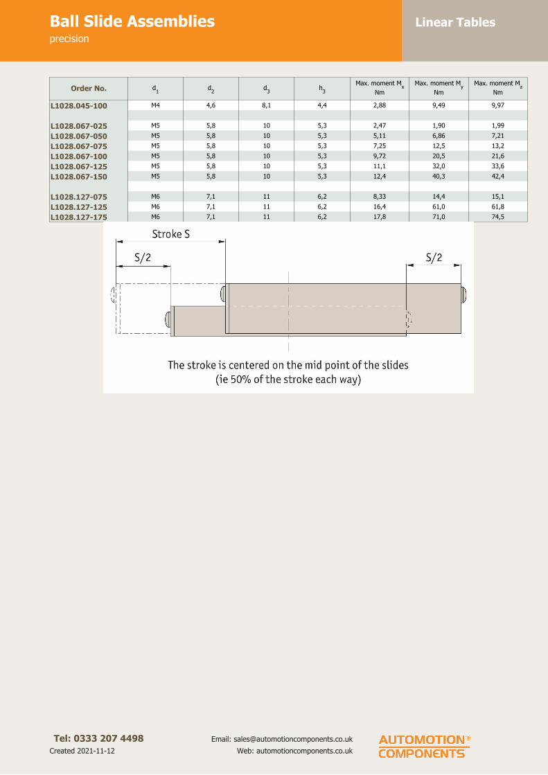
Linear TablesBall Slide Assembliesprecision
Tel: 0333 207 4498
Created 2021-11-12
Email: [email protected]
Web: automotioncomponents.co.uk
Order No. d1
d2
d3
h3
Max. moment Mx
Nm
Max. moment My
Nm
Max. moment Mz
Nm
L1028.045-100 M4 4,6 8,1 4,4 2,88 9,49 9,97
L1028.067-025 M5 5,8 10 5,3 2,47 1,90 1,99
L1028.067-050 M5 5,8 10 5,3 5,11 6,86 7,21
L1028.067-075 M5 5,8 10 5,3 7,25 12,5 13,2
L1028.067-100 M5 5,8 10 5,3 9,72 20,5 21,6
L1028.067-125 M5 5,8 10 5,3 11,1 32,0 33,6
L1028.067-150 M5 5,8 10 5,3 12,4 40,3 42,4
L1028.127-075 M6 7,1 11 6,2 8,33 14,4 15,1
L1028.127-125 M6 7,1 11 6,2 16,4 61,0 61,8
L1028.127-175 M6 7,1 11 6,2 17,8 71,0 74,5

Linear TablesCrossed Roller Slidesprecision
Tel: 0333 207 4498
Created 2021-11-12
Email: [email protected]
Web: automotioncomponents.co.uk
L1029
Material
Aluminium carriage and base.
Hardened stainless steel rollers,
shafts and preload gibs.
Technical notes
Straight line accuracy: 3µ/25mm of
travel.
Positional repeatability: 1µ.
Coefficient of friction: 0,002.
Tips
Stroke is centred on the mid-point of
the slides (ie 50% of total stroke
each way).
Order No. StrokeMax. load
Kgw
1l1
h1
l2
l3
l4
w2
w3
h2
Xg
L1029.045-025 25 36 44,5 50,8 19,0 35 38 - 20 22,1 10,2 127
L1029.045-050 50 54 44,5 82,6 19,0 65 65 - 20 22,1 10,2 209
L1029.045-075 75 59 44,5 101,6 19,0 85 85 - 20 22,1 10,2 254
L1029.045-100 100 64 44,5 127,0 19,0 115 115 - 20 22,1 10,2 286
L1029.067-025 25 95 67 66,5 25,4 54 54 - 35 38,1 15,5 299
L1029.067-050 50 109 67 101,6 25,4 75 75 - 35 38,1 15,5 454
L1029.067-075 75 154 67 127,0 25,4 100 100 - 35 38,1 15,5 567
L1029.067-100 100 173 67 152,4 25,4 125 125 - 35 38,1 15,5 680
L1029.067-125 125 186 67 203,2 25,4 175 187 - 35 38,1 15,5 907
L1029.127-075 75 100 127 127,0 25,4 100 100 50 100 6,2 15,5 1021
L1029.127-125 125 109 127 177,8 25,4 150 150 75 100 6,2 15,5 1474
L1029.127-175 175 118 127 228,6 25,4 200 200 100 100 6,2 15,5 1928
Order No. h3
d1
d2
d3
Max. moment Mx
Nm
Max. moment My
Nm
Max. moment Mz
Nm
L1029.045-025 4,6 M4 4,6 8,1 4,44 4,68 4,9
L1029.045-050 4,6 M4 4,6 8,1 5,92 9,35 9,8
L1029.045-075 4,6 M4 4,6 8,1 6,91 10,9 11,4
L1029.045-100 4,6 M4 4,6 8,1 7,66 12,1 12,7
L1029.067-025 5,3 M5 5,8 10 18,1 15,0 15,8
L1029.067-050 5,3 M5 5,8 10 24,1 30,1 31,6
L1029.067-075 5,3 M5 5,8 10 30,2 50,1 52,6
L1029.067-100 5,3 M5 5,8 10 45,9 62,6 65,8
L1029.067-125 5,3 M5 5,8 10 41,3 72,0 75,6
L1029.127-075 6,2 M6 7,1 11 19,3 72,2 73,8
L1029.127-125 6,2 M6 7,1 11 21,2 79,4 81,1
L1029.127-175 6,2 M6 7,1 11 23,0 92,8 97,4

Linear TablesCrossed Roller Slidesprecision
Tel: 0333 207 4498
Created 2021-11-12
Email: [email protected]
Web: automotioncomponents.co.uk

Linear TablesLow Profile Ball Slide Assemblieshigh precision
Tel: 0333 207 4498
Created 2021-11-12
Email: [email protected]
Web: automotioncomponents.co.uk
L1030
Material
Aluminium carriage and base.
Hardened stainless steel balls, shafts
and preload gibs.
Technical notes
Straight line accuracy: 1µ/25mm of
travel.
Positional repeatability: 0.5µ.
Coefficient of friction: 0,002.
Carriage surface flat to 3µ/25mm.
Carriage and base ground to optical
flatness.
Tips
Stroke is centred on the mid-point of
the slides (ie 50% of total stroke
each way).
Order no. StrokeMax. load
Kgw
1l1
l2
h1
l3
w2
h2
w3
l4
Xg
L1030.025-013 13 3,6 25,4 25,4 31,8 12,7 15 CL 6,1 10,2 20 27
L1030.025-025 25 6,8 25,4 44,5 50,8 12,7 35 CL 6,1 10,2 40 50
L1030.025-038 38 11 25,4 63,5 69,9 12,7 54 CL 6,1 10,2 57 73
L1030.025-050 50 14 25,4 82,6 88,8 12,7 70 CL 6,1 10,2 75 91
L1030.045-025 25 11 44,5 50,8 57,2 19,0 35 20 10,2 22,1 40 127
L1030.045-038 38 14 44,5 69,9 76,2 19,0 54 20 10,2 22,1 57 172
L1030.045-050 50 19 44,5 82,6 88,9 19,0 65 20 10,2 22,1 70 209
L1030.045-075 75 23 44,5 101,6 108,0 19,0 85 20 10,2 22,1 90 254
L1030.067-025 25 33 66,5 66,5 66,5 25,4 54 35 15,7 38,1 54 299
L1030.067-050 50 38 66,5 101,6 111,0 25,4 75 35 15,7 38,1 85 454
L1030.067-075 75 46 66,5 127,0 136,4 25,4 100 35 15,7 38,1 110 567
L1030.067-100 100 60 66,5 152,4 161,8 25,4 125 35 15,7 38,1 135 680
L1030.067-125 125 66 66,5 203,2 212,6 25,4 178 35 15,7 38,1 190 907
L1030.089-050 50 59 88,9 101,6 114,3 34,9 50 50 15,7 50,3 65 907
L1030.089-075 75 64 88,9 146,1 158,8 34,9 95 50 15,7 50,3 110 1306
L1030.089-125 125 73 88,9 203,2 215,9 34,9 150 50 15,7 50,3 175 1814
L1030.089-165 165 79 88,9 260,4 273,1 34,9 210 50 15,7 50,3 225 2327
L1030.089-225 225 91 88,9 355,6 368,3 34,9 305 50 15,7 50,3 320 3175
L1030.146-125 125 68 146,1 209,6 222,3 50,8 150 100 24,9 94,0 175 4536
L1030.146-175 175 82 146,1 304,8 317,5 50,8 250 100 24,9 94,0 275 6586
L1030.146-250 250 102 146,1 381,0 393,7 50,8 330 100 24,9 94,0 350 8233
Order no. d1
d2
d3
h3
Max. moment Mx
Nm
Max. moment My
Nm
Max. moment Mz
Nm
L1030.025-013 M3 3,5 6,1 3,4 0,28 0,38 0,40
L1030.025-025 M3 3,5 6,1 3,4 0,40 1,03 1,08

Linear TablesLow Profile Ball Slide Assemblieshigh precision
Tel: 0333 207 4498
Created 2021-11-12
Email: [email protected]
Web: automotioncomponents.co.uk
Order no. d1
d2
d3
h3
Max. moment Mx
Nm
Max. moment My
Nm
Max. moment Mz
Nm
L1030.025-038 M3 3,5 6,1 3,4 0,55 1,76 1,85
L1030.025-050 M3 3,5 6,1 3,4 0,74 2,61 3,72
L1030.045-025 M4 4,6 8,1 4,6 0,96 0,90 0,95
L1030.045-038 M4 4,6 8,1 4,6 1,44 2,03 2,14
L1030.045-050 M4 4,6 8,1 4,6 2,02 3,32 3,49
L1030.045-075 M4 4,6 8,1 4,6 2,50 4,70 4,94
L1030.067-025 M5 5,8 10,0 5,3 4,56 3,76 3,98
L1030.067-050 M5 5,8 10,0 5,3 6,92 9,30 9,77
L1030.067-075 M5 5,8 10,0 5,3 8,40 14,5 15,3
L1030.067-100 M5 5,8 10,0 5,3 10,9 23,0 24,1
L1030.067-125 M5 5,8 10,0 5,3 11,9 34,4 36,1
L1030.089-050 M5 5,8 10,0 5,3 11,1 32,0 33,6
L1030.089-075 M5 5,8 10,0 5,3 12,4 40,3 42,4
L1030.089-125 M5 5,8 10,0 5,3 14,1 52,6 53,7
L1030.089-165 M5 5,8 10,0 5,3 15,2 61,5 64,5
L1030.089-225 M5 5,8 10,0 5,3 16,9 81,1 85,1
L1030.146-125 M6 7,1 11,0 6,2 16,2 60,5 61,8
L1030.146-175 M6 7,1 11,0 6,2 17,5 70,7 74,2
L1030.146-250 M6 7,1 11,0 6,2 19,4 93,2 97,9

Linear TablesLow Profile Crossed Roller Tablehigh precision
Tel: 0333 207 4498
Created 2021-11-12
Email: [email protected]
Web: automotioncomponents.co.uk
L1032
Material
Aluminium carriage and base.
Hardened stainless steel rollers,
shafts and preload gibs.
Technical notes
Crossed roller design greatly
increases load capacity.
Straight line accuracy: 1µ/25mm of
travel.
Positional repeatability: 0,5µ.
Coefficient of friction: 0,002.
Carriage surface flat to 3µ/25mm.
Carriage and base ground to optical
flatness.
Tips
Stroke is centred on the mid-point of
the slides (ie 50% of total stroke
each way).
Order No. StrokeMax. load
Kgw
1l1
l2
h1
l3
w2
h2
l4
Xg
L1032.045-025 25 41 44,5 50,8 57,2 19,1 35 20 10,2 40 127
L1032.045-038 38 52 44,5 69,9 76,2 19,1 54 20 10,2 57 172
L1032.045-050 50 59 44,5 82,6 88,9 19,1 65 20 10,2 70 209
L1032.045-075 75 64 44,5 101,6 108,0 19,1 85 20 10,2 90 254
L1032.067-025 25 100 66,5 66,5 66,5 25,4 54 35 15,7 54 299
L1032.067-050 50 114 66,5 101,6 111,0 25,4 75 35 15,7 85 454
L1032.067-075 75 159 66,5 127,0 136,4 25,4 100 35 15,7 110 567
L1032.067-100 100 177 66,5 152,4 161,8 25,4 125 35 15,7 135 680
L1032.067-125 125 191 66,5 203,2 212,6 25,4 178 35 15,7 190 907
L1032.089-050 50 118 88,9 101,6 114,3 44,5 50 50 15,7 65 907
L1032.089-075 75 127 88,9 146,1 158,8 44,5 95 50 15,7 110 1306
L1032.089-125 125 145 88,9 203,2 215,9 44,5 150 50 15,7 175 1814
L1032.089-165 165 159 88,9 260,4 273,1 44,5 210 50 15,7 225 2327
L1032.089-225 225 182 88,9 355,6 368,3 44,5 305 50 15,7 320 3175
L1032.146-125 125 136 146,1 209,6 222,3 60,03 150 100 24,9 175 4536
L1032.146-175 175 163 146,1 304,8 317,5 60,03 250 100 24,9 275 6586
L1032.146-250 250 204 146,1 381,0 393,7 60,03 330 100 24,9 350 8232
Order No. d1
d2
d3
w3
h3
Max. moment Mx
Nm
Max. moment My
Nm
Max. moment Mz
Nm
L1032.045-025 M4 4,6 8,1 22,1 4,6 5,04 5,31 5,58
L1032.045-038 M4 4,6 8,1 22,1 4,6 5,61 8,29 8,58
L1032.045-050 M4 4,6 8,1 22,1 4,6 6,73 10,6 11,2
L1032.045-075 M4 4,6 8,1 22,1 4,6 7,85 12,4 13,0
L1032.067-025 M5 5,8 10,0 38,1 5,3 17,9 14,9 15,6

Linear TablesLow Profile Crossed Roller Tablehigh precision
Tel: 0333 207 4498
Created 2021-11-12
Email: [email protected]
Web: automotioncomponents.co.uk
Order No. d1
d2
d3
w3
h3
Max. moment Mx
Nm
Max. moment My
Nm
Max. moment Mz
Nm
L1032.067-050 M5 5,8 10,0 38,1 5,3 20,4 25,4 26,7
L1032.067-075 M5 5,8 10,0 38,1 5,3 28,4 47,1 49,5
L1032.067-100 M5 5,8 10,0 38,1 5,3 37,6 65,6 68,9
L1032.067-125 M5 5,8 10,0 38,1 5,3 43,3 75,5 79,2
L1032.089-050 M5 5,8 10,0 50,3 5,3 19,5 56,1 58,9
L1032.089-075 M5 5,8 10,0 50,3 5,3 21,6 70,6 74,1
L1032.089-125 M5 5,8 10,0 50,3 5,3 24,6 92,01 94,0
L1032.089-165 M5 5,8 10,0 50,3 5,3 26,7 108,0 113,0
L1032.089-225 M5 5,8 10,0 50,3 5,3 29,6 142,0 149,0
L1032.146-125 M6 7,1 11,0 94,0 6,2 28,3 106,0 108,0
L1032.146-175 M6 7,1 11,0 94,0 6,2 30,7 124,0 130,0
L1032.146-250 M6 7,1 11,0 94,0 6,2 34,0 163,0 171,0

Linear TablesFlanged Ball Slide Assemblieshigh precision
Tel: 0333 207 4498
Created 2021-11-12
Email: [email protected]
Web: automotioncomponents.co.uk
L1034
Material
Aluminium carriage and base.
Hardened stainless steel balls, shafts
and preload gibs.
Technical notes
Flange base allows easy mounting
and extra stability.
Straight line accuracy: 1µ/25mm of
travel.
Positional repeatability: 0,5µ.
Coefficient of friction: 0,002.
Carriage surface flat to 3µ/25mm.
Carriage and base ground to optical
flatness.
Tips
Stroke is centred on the mid-point of
the slides (ie 50% of total stroke
each way).
Order No. StrokeMax. load
Kgw
1l1
l2
l3
l4
h1
h2
h3
Xg
L1034.025-013 13 3,6 25,4 25,4 15 20 31,8 19,1 12,7 3,4 36
L1034.025-025 25 6,8 25,4 44,5 35 40 50,8 19,1 12,7 3,4 64
L1034.025-038 38 11,0 25,4 63,5 54 57 69,9 19,1 12,7 3,4 91
L1034.025-050 50 14,0 25,4 82,6 70 75 88,9 19,1 12,7 3,4 118
L1034.045-025 25 11,0 44,5 50,8 35 40 57,2 26,2 17,3 4,6 172
L1034.045-038 38 14,0 44,5 69,9 54 57 76,2 26,2 17,3 4,6 236
L1034.045-050 50 19,0 44,5 82,6 65 70 88,9 26,2 17,3 4,6 277
L1034.045-075 75 23,0 44,5 101,6 85 90 108,0 26,2 17,3 4,6 340
L1034.067-025 25 33,0 66,5 66,5 54 54 66,5 34,9 25,4 5,3 413
L1034.067-050 50 38,0 66,5 101,6 75 85 111,0 34,9 25,4 5,3 635
L1034.067-075 75 46,0 66,5 127,0 100 110 136,4 34,9 25,4 5,3 794
L1034.067-100 100 60,0 66,5 152,4 125 135 161,8 34,9 25,4 5,3 953
L1034.067-125 125 66,0 66,5 203,2 178 190 212,6 34,9 25,4 5,3 1270
L1034.089-050 50 59,0 88,9 101,6 50 65 114,3 44,5 25,0 5,3 1134
L1034.089-075 75 64,0 88,9 146,1 95 110 158,8 44,5 25,0 5,3 1628
L1034.089-125 125 73,0 88,9 203,2 150 175 215,9 44,5 25,0 5,3 2268
L1034.089-165 165 79,0 88,9 260,4 210 225 273,1 44,5 25,0 5,3 2908
L1034.089-225 225 91,0 88,9 355,6 305 320 368,3 44,5 25,0 5,3 3969
Order No. w2
w3
d1
d2
d3
Max. moment My
Nm
Max. moment My
Nm
Max. moment My
Nm
L1034.025-013 CL 19 M3 6,1 3,5 0,28 0,38 0,40
L1034.025-025 CL 19 M3 6,1 3,5 0,40 1,03 1,08
L1034.025-038 CL 19 M3 6,1 3,5 0,55 1,76 1,85
L1034.025-050 CL 19 M3 6,1 3,5 0,74 2,61 3,72

Linear TablesFlanged Ball Slide Assemblieshigh precision
Tel: 0333 207 4498
Created 2021-11-12
Email: [email protected]
Web: automotioncomponents.co.uk
Order No. w2
w3
d1
d2
d3
Max. moment My
Nm
Max. moment My
Nm
Max. moment My
Nm
L1034.045-025 20 33 M4 8,1 4,6 0,96 0,90 0,95
L1034.045-038 20 33 M4 8,1 4,6 1,44 2,03 2,14
L1034.045-050 20 33 M4 8,1 4,6 2,02 3,32 3,49
L1034.045-075 20 33 M4 8,1 4,6 2,50 4,70 4,94
L1034.067-025 35 52 M5 10,0 5,8 4,56 3,76 3,98
L1034.067-050 35 52 M5 10,0 5,8 6,92 9,30 9,77
L1034.067-075 35 52 M5 10,0 5,8 8,40 14,5 15,2
L1034.067-100 35 52 M5 10,0 5,8 10,8 22,9 24,1
L1034.067-125 35 52 M5 10,0 5,8 11,9 34,4 36,1
L1034.089-050 50 70 M5 10,0 5,8 11,1 32,0 33,6
L1034.089-075 50 70 M5 10,0 5,8 12,3 40,3 42,3
L1034.089-125 50 70 M5 10,0 5,8 14,0 52,5 53,7
L1034.089-165 50 70 M5 10,0 5,8 15,2 61,4 64,5
L1034.089-225 50 70 M5 10,0 5,8 16,8 81,0 85,1
L1034.146-125 100 127 M6 11,0 7,1 16,1 60,4 61,7
L1034.146-175 100 127 M6 11,0 7,1 17,5 70,6 74,2
L1034.146-250 100 127 M6 11,0 7,1 19,4 93,2 97,8

Linear TablesFlanged Crossed Roller Slideswide base, high precision
Tel: 0333 207 4498
Created 2021-11-12
Email: [email protected]
Web: automotioncomponents.co.uk
L1036
Material
Aluminium carriage and base.
Hardened stainless steel rollers,
shafts and preload gibs.
Technical notes
Flanged base with cross rollers offers
the ultimate in accuracy, capacity and
stability.
Straight line accuracy: 1µ/25mm of
travel.
Positional repeatability: 0,5µ.
Coefficient of friction: 0,002.
Carriage surface flat to 3µ/25mm.
Carriage and base ground to optical
flatness.
Tips
Stroke is centred on the mid-point of
the slides (ie 50% of total stroke
each way).
Order No. StrokeMax. load
Kgw
1l1
l2
h1
l3
w2
h2
l4
Xg
L1036.045-025 25 41 44,5 50,8 57,2 26,2 35 20 17,3 40 172
L1036.045-038 38 52 44,5 69,9 76,2 26,2 54 20 17,3 57 236
L1036.045-050 50 59 44,5 82,6 88,9 26,2 65 50 17,3 70 277
L1036.045-075 75 64 44,5 101,6 108,0 26,2 85 20 17,3 90 340
L1036.067-025 25 100 66,5 66,9 66,5 34,9 54 35 25,4 54 413
L1036.067-050 50 114 66,5 101,6 111,0 34,9 75 35 25,4 85 635
L1036.067-075 75 159 66,5 127,0 136,4 34,9 100 35 25,4 110 794
L1036.067-100 100 177 66,5 152,4 161,8 34,9 125 35 25,4 135 953
L1036.067-125 125 191 66,5 203,2 212,6 34,9 178 35 25,4 190 1270
L1036.089-050 50 118 88,9 101,6 114,3 44,5 50 50 25,0 65 1134
L1036.089-075 75 127 88,9 146,1 158,8 44,5 95 50 25,0 110 1628
L1036.089-125 125 145 88,9 203,2 215,9 44,5 150 50 25,0 175 2268
L1036.089-165 165 159 88,9 260,4 273,1 44,5 210 50 25,0 225 2908
L1036.089-225 225 182 88,9 355,6 368,3 44,5 305 50 25,0 320 3969
L1036.146-125 125 136 146,1 209,6 222,3 60,3 150 100 34,3 175 5443
L1036.146-175 175 163 146,1 304,8 317,5 60,3 250 100 34,3 275 7893
L1036.146-250 250 204 146,1 381,0 393,7 60,3 330 100 34,3 350 9870
Order No. d1
d2
d3
w3
h3
h4
Max. moment
Mx
Nm
Max. moment
My
Nm
Max. moment
Mz Nm
L1036.045-025 M4 4,6 8,1 33 4,6 7,1 5,04 5,31 5,58
L1036.045-038 M4 4,6 8,1 33 4,6 7,1 5,61 8,29 8,29
L1036.045-050 M4 4,6 8,1 33 4,6 7,1 6,73 10,6 11,2
L1036.045-075 M4 4,6 8,1 33 4,6 7,1 7,85 12,4 13,0
L1036.067-025 M5 5,8 10,0 52 5,3 9,4 17,9 14,9 15,6
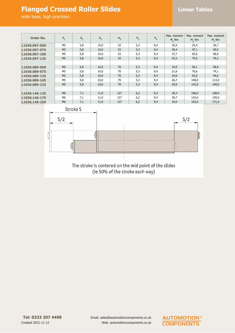
Linear TablesFlanged Crossed Roller Slideswide base, high precision
Tel: 0333 207 4498
Created 2021-11-12
Email: [email protected]
Web: automotioncomponents.co.uk
Order No. d1
d2
d3
w3
h3
h4
Max. moment
Mx
Nm
Max. moment
My
Nm
Max. moment
Mz Nm
L1036.067-050 M5 5,8 10,0 52 5,3 9,4 20,4 25,4 26,7
L1036.067-075 M5 5,8 10,0 52 5,3 9,4 28,4 47,1 49,5
L1036.067-100 M5 5,8 10,0 52 5,3 9,4 37,7 65,6 68,9
L1036.067-125 M5 5,8 10,0 52 5,3 9,4 43,3 75,5 79,2
L1036.089-050 M5 5,8 10,0 70 5,3 9,4 19,5 56,1 58,9
L1036.089-075 M5 5,8 10,0 70 5,3 9,4 21,6 70,6 74,1
L1036.089-125 M5 5,8 10,0 70 5,3 9,4 24,6 92,0 94,0
L1036.089-165 M5 5,8 10,0 70 5,3 9,4 26,7 108,0 113,0
L1036.089-225 M5 5,8 10,0 70 5,3 9,4 29,6 142,0 149,0
L1036.146-125 M6 7,1 11,0 127 6,2 9,4 28,3 106,0 108,0
L1036.146-175 M6 7,1 11,0 127 6,2 9,4 30,7 124,0 130,0
L1036.146-250 M6 7,1 11,0 127 6,2 9,4 34,0 163,0 171,0
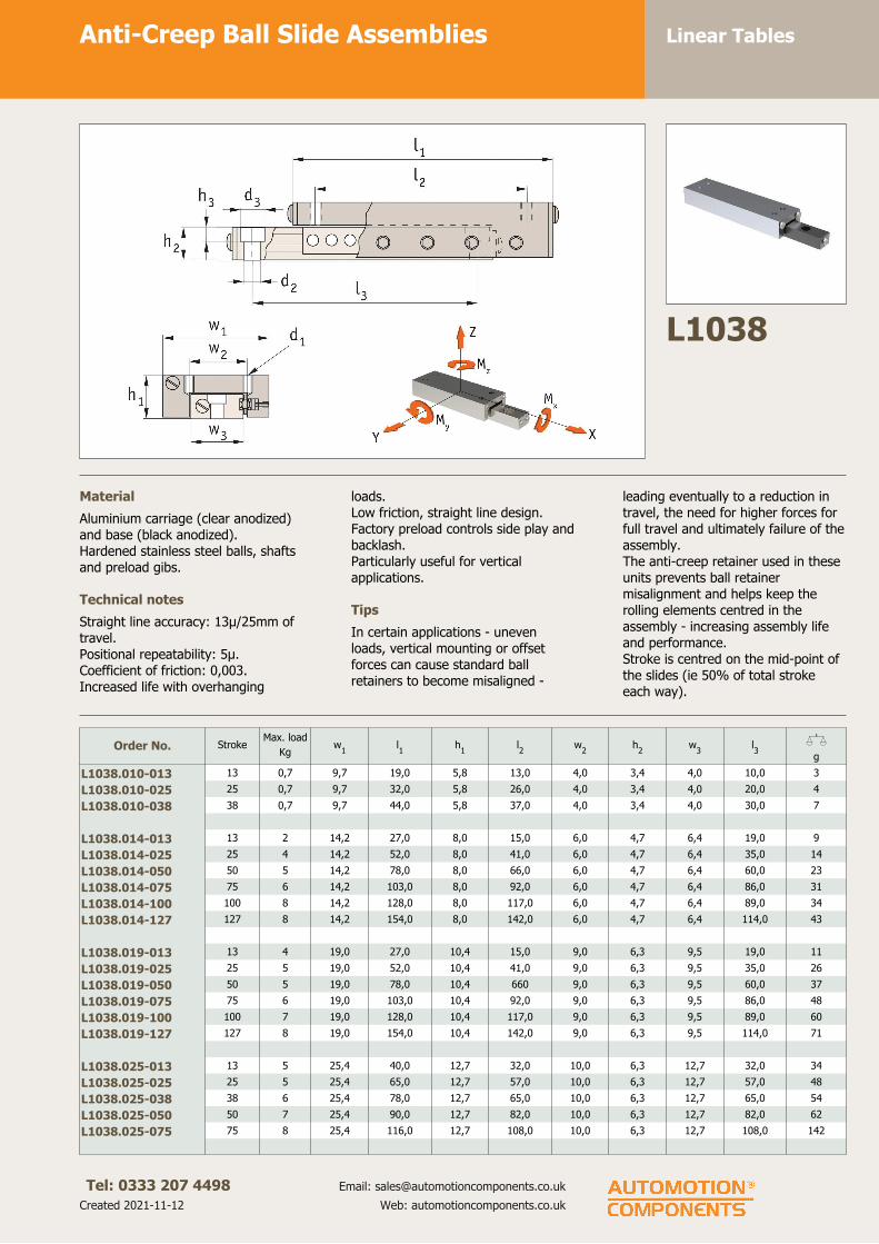
Linear TablesAnti-Creep Ball Slide Assemblies
Tel: 0333 207 4498
Created 2021-11-12
Email: [email protected]
Web: automotioncomponents.co.uk
L1038
Material
Aluminium carriage (clear anodized)
and base (black anodized).
Hardened stainless steel balls, shafts
and preload gibs.
Technical notes
Straight line accuracy: 13µ/25mm of
travel.
Positional repeatability: 5µ.
Coefficient of friction: 0,003.
Increased life with overhanging
loads.
Low friction, straight line design.
Factory preload controls side play and
backlash.
Particularly useful for vertical
applications.
Tips
In certain applications - uneven
loads, vertical mounting or offset
forces can cause standard ball
retainers to become misaligned -
leading eventually to a reduction in
travel, the need for higher forces for
full travel and ultimately failure of the
assembly.
The anti-creep retainer used in these
units prevents ball retainer
misalignment and helps keep the
rolling elements centred in the
assembly - increasing assembly life
and performance.
Stroke is centred on the mid-point of
the slides (ie 50% of total stroke
each way).
Order No. StrokeMax. load
Kgw
1l1
h1
l2
w2
h2
w3
l3
Xg
L1038.010-013 13 0,7 9,7 19,0 5,8 13,0 4,0 3,4 4,0 10,0 3
L1038.010-025 25 0,7 9,7 32,0 5,8 26,0 4,0 3,4 4,0 20,0 4
L1038.010-038 38 0,7 9,7 44,0 5,8 37,0 4,0 3,4 4,0 30,0 7
L1038.014-013 13 2 14,2 27,0 8,0 15,0 6,0 4,7 6,4 19,0 9
L1038.014-025 25 4 14,2 52,0 8,0 41,0 6,0 4,7 6,4 35,0 14
L1038.014-050 50 5 14,2 78,0 8,0 66,0 6,0 4,7 6,4 60,0 23
L1038.014-075 75 6 14,2 103,0 8,0 92,0 6,0 4,7 6,4 86,0 31
L1038.014-100 100 8 14,2 128,0 8,0 117,0 6,0 4,7 6,4 89,0 34
L1038.014-127 127 8 14,2 154,0 8,0 142,0 6,0 4,7 6,4 114,0 43
L1038.019-013 13 4 19,0 27,0 10,4 15,0 9,0 6,3 9,5 19,0 11
L1038.019-025 25 5 19,0 52,0 10,4 41,0 9,0 6,3 9,5 35,0 26
L1038.019-050 50 5 19,0 78,0 10,4 660 9,0 6,3 9,5 60,0 37
L1038.019-075 75 6 19,0 103,0 10,4 92,0 9,0 6,3 9,5 86,0 48
L1038.019-100 100 7 19,0 128,0 10,4 117,0 9,0 6,3 9,5 89,0 60
L1038.019-127 127 8 19,0 154,0 10,4 142,0 9,0 6,3 9,5 114,0 71
L1038.025-013 13 5 25,4 40,0 12,7 32,0 10,0 6,3 12,7 32,0 34
L1038.025-025 25 5 25,4 65,0 12,7 57,0 10,0 6,3 12,7 57,0 48
L1038.025-038 38 6 25,4 78,0 12,7 65,0 10,0 6,3 12,7 65,0 54
L1038.025-050 50 7 25,4 90,0 12,7 82,0 10,0 6,3 12,7 82,0 62
L1038.025-075 75 8 25,4 116,0 12,7 108,0 10,0 6,3 12,7 108,0 142

Linear TablesAnti-Creep Ball Slide Assemblies
Tel: 0333 207 4498
Created 2021-11-12
Email: [email protected]
Web: automotioncomponents.co.uk
Order No. StrokeMax. load
Kgw
1l1
h1
l2
w2
h2
w3
l3
Xg
L1038.027-019 19 7 26,9 40,0 13,4 32,0 10,0 7,9 12,7 28,0 37
L1038.027-038 38 8 26,9 65,0 13,4 57,0 10,0 7,9 12,7 54,0 65
L1038.027-050 50 9 26,9 90,0 13,4 82,0 10,0 7,9 12,7 79,0 85
L1038.027-075 75 11 26,9 116,0 13,4 102,0 10,0 7,9 12,7 82,0 147
L1038.027-100 100 14 26,9 152,0 13,4 140,0 10,0 7,9 12,7 102,0 170
L1038.027-150 150 16 26,9 203,0 13,4 190,0 10,0 7,9 12,7 127,0 198
L1038.027-200 200 18 26,9 254,0 13,4 240,0 10,0 7,9 12,7 178,0 227
L1038.038-025 25 7 38,0 51,0 15,8 35,0 16,0 8,6 19,0 37,0 82
L1038.038-050 50 9 38,0 76,0 15,8 60,0 16,0 8,6 19,0 60,0 122
L1038.038-075 75 11 38,0 102,0 15,8 85,0 16,0 8,6 19,0 85,0 170
L1038.038-088 88 14 38,0 127,0 15,8 110,0 16,0 8,6 19,0 85,0 190
L1038.038-100 100 16 38,0 152,0 15,8 136,0 16,0 8,6 19,0 100,0 232
L1038.038-150 150 20 38,0 203,0 15,8 186,0 16,0 8,6 19,0 128,0 261
L1038.038-200 200 25 38,0 254,0 15,8 238,0 16,0 8,6 19,0 178,0 326
L1038.045-025 25 9 44,0 51,0 19,0 35,0 20,0 10,2 22,2 38,0 113
L1038.045-038 38 14 44,0 70,0 19,0 55,0 20,0 10,2 22,2 55,0 170
L1038.045-050 50 19 44,0 83,0 19,0 65,0 20,0 10,2 22,2 65,0 184
L1038.045-075 75 24 44,0 102,0 19,0 85,0 20,0 10,2 22,2 85,0 227
L1038.045-100 100 27 44,0 152,0 19,0 140,0 20,0 10,2 22,2 100,0 335
L1038.045-150 150 34 44,0 203,0 19,0 190,0 20,0 10,2 22,2 126,0 445
L1038.045-200 200 41 44,0 254,0 19,0 240,0 20,0 10,2 22,2 178,0 553
L1038.067-025 25 14 66,5 67,0 25,4 54,0 35,0 15,9 38,1 54,0 283
L1038.067-038 38 16 66,5 67,0 25,4 42,0 35,0 15,9 38,1 42,0 283
L1038.067-050 50 28 66,5 102,0 25,4 75,0 35,0 15,9 38,1 75,0 425
L1038.067-075 75 40 66,5 127,0 25,4 100,0 35,0 15,9 38,1 100,0 590
L1038.067-100 100 54 66,5 152,0 25,4 125,0 35,0 15,9 38,1 125,0 771
L1038.067-127 127 61 66,5 203,0 25,4 175,0 35,0 15,9 38,1 187,0 879
L1038.067-150 150 68 66,5 229,0 25,4 75,0 35,0 15,9 38,1 178,0 498
L1038.067-228 228 84 66,5 305,0 25,4 75,0 35,0 15,9 38,1 254,0 1318
L1038.067-304 304 93 66,5 381,0 25,4 75,0 35,0 15,9 38,1 330,0 1644
Order No. d1
d2
d3
h3
Counterbore
screw size
Max. moment Mx
Nm
Max. moment My
Nm
Max. moment Mz
Nm
L1038.010-013 M2 M2 - - - 0,12 0,21 0,22
L1038.010-025 M2 M2 - - - 0,12 0,32 0,34
L1038.010-038 M2 M2 - - - 0,12 0,48 0,51
L1038.014-013 M2 2,2 4,0 2,2 M2 0,51 0,96 1,01
L1038.014-025 M2 2,2 4,0 2,2 M2 1,22 4,48 4,70
L1038.014-050 M2 2,2 4,0 2,2 M2 1,53 8,64 9,07
L1038.014-075 M2 2,2 4,0 2,2 M2 1,79 13,4 14,1
L1038.014-100 M2 2,2 4,0 2,2 M2 2,04 17,9 18,8
L1038.014-127 M2 2,2 4,0 2,2 M2 2,30 23,0 24,2
L1038.019-013 M3 3,5 6,1 3,4 M3 1,55 1,92 2,01
L1038.019-025 M3 3,5 6,1 3,4 M3 1,94 4,80 5,04
L1038.019-050 M3 3,5 6,1 3,4 M3 2,33 8,64 9,07
L1038.019-075 M3 3,5 6,1 3,4 M3 2,72 13,4 14,1
L1038.019-100 M3 3,5 6,1 3,4 M3 3,10 17,9 18,8
L1038.019-127 M3 3,5 6,1 3,4 M3 3,49 23,0 24,2
L1038.025-013 M4 3,5 6,1 3,4 M3 2,50 3,33 3,50
L1038.025-025 M4 3,5 6,1 3,4 M3 3,00 8,64 9,07
L1038.025-038 M4 3,5 6,1 3,4 M3 3,25 10,4 10,9
L1038.025-050 M4 3,5 6,1 3,4 M3 3,75 13,2 13,9
L1038.025-075 M4 3,5 6,1 3,4 M3 4,50 20,2 21,2
L1038.027-019 M4 4,6 8,1 4,4 M4 3,85 4,50 4,73

Linear TablesAnti-Creep Ball Slide Assemblies
Tel: 0333 207 4498
Created 2021-11-12
Email: [email protected]
Web: automotioncomponents.co.uk
Order No. d1
d2
d3
h3
Counterbore
screw size
Max. moment Mx
Nm
Max. moment My
Nm
Max. moment Mz
Nm
L1038.027-038 M4 4,6 8,1 4,4 M4 4,62 10,8 11,3
L1038.027-050 M4 4,6 8,1 4,4 M4 5,31 18,0 18,9
L1038.027-075 M4 4,6 8,1 4,4 M4 6,41 27,5 28,9
L1038.027-100 M4 4,6 8,1 4,4 M4 7,70 45,0 47,3
L1038.027-150 M4 4,6 8,1 4,4 M4 8,98 66,5 69,8
L1038.027-200 M4 4,6 8,1 4,4 M4 10,3 92,0 96,6
L1038.038-025 M4 4,6 8,1 4,4 M4 6,30 5,56 6,00
L1038.038-050 M4 4,6 8,1 4,4 M4 12,6 7,38 12,00
L1038.038-075 M4 4,6 8,1 4,4 M4 21,0 9,23 20,00
L1038.038-088 M4 4,6 8,1 4,4 M4 34,7 11,07 33,00
L1038.038-100 M4 4,6 8,1 4,4 M4 51,5 12,92 49,00
L1038.038-150 M4 4,6 8,1 4,4 M4 85,1 16,61 81,00
L1038.038-200 M4 4,6 8,1 4,4 M4 127,1 20,30 121,00
L1038.045-025 M4 4,6 8,1 4,4 M4 8,40 8,51 8,00
L1038.045-038 M4 4,6 8,1 4,4 M4 18,9 12,76 18,00
L1038.045-050 M4 4,6 8,1 4,4 M4 30,9 17,86 29,40
L1038.045-075 M4 4,6 8,1 4,4 M4 43,7 22,11 41,60
L1038.045-100 M4 4,6 8,1 4,4 M4 88,2 25,52 84,00
L1038.045-150 M4 4,6 8,1 4,4 M4 141,8 31,89 135,00
L1038.045-200 M4 4,6 8,1 4,4 M4 207,9 38,27 198,00
L1038.067-025 M5 5,8 10,0 5,3 M5 17,6 21,87 16,80
L1038.067-038 M5 5,8 10,0 5,3 M5 17,6 25,52 16,80
L1038.067-050 M5 5,8 10,0 5,3 M5 63,8 45,20 60,76
L1038.067-075 M5 5,8 10,0 5,3 M5 116,4 64,15 110,88
L1038.067-100 M5 5,8 10,0 5,3 M5 190,8 86,02 181,72
L1038.067-127 M5 5,8 10,0 5,3 M5 297,7 98,42 283,50
L1038.067-150 M5 5,8 10,0 5,3 M5 374,9 109,35 357,00
L1038.067-228 M5 5,8 10,0 5,3 M5 571,1 134,87 543,90
L1038.067-304 M5 5,8 10,0 5,3 M5 753,4 149,45 717,50

Linear TablesNon-Magnetic Ball Slide Assemblies
Tel: 0333 207 4498
Created 2021-11-12
Email: [email protected]
Web: automotioncomponents.co.uk
L1039
Material
Base and carriage aluminium.
Titanium shafting gib strips, silicone
nitride ceramic balls, brass fasteners.
Technical notes
Straight line accuracy: 13µ/25mm
travel.
Positional repeatability: 5µ.
Coefficient of friction 0,003 typical.
Tips
Non-magnetic and no lubrication
required due to the self-cleaning ball
bearing design.
Stroke is centred on the mid-point of
the slides (ie 50% of total stroke
each way).
Order No. StrokeMax. load
Kgw
1l1
h1
l2
w2
h2
w3
l3
Xg
L1039.014-013 13 0,5 14,2 27,0 8,0 15,0 6,0 4,7 6,4 19,0 9
L1039.014-025 25 1,1 14,2 52,0 8,0 41,0 6,0 4,7 6,4 35,0 14
L1039.014-050 50 1,6 14.2 78,0 8,0 66,0 6,0 4,7 6,4 60,0 23
L1039.014-075 75 1,9 14,2 103,0 8,0 92,0 6,0 4,7 6,4 86,0 31
L1039.014-100 100 2,2 14,2 128,0 8,0 117,0 6,0 4,7 6,4 89,0 34
L1039.014-127 127 2,5 14,2 154,0 8,0 142,0 6,0 4,7 6,4 114,0 43
L1039.019-013 13 1,1 19,0 27,0 10,4 15,0 9,0 6,3 9,5 19,0 11
L1039.019-025 25 1,4 19,0 52,0 10,4 41,0 9,0 6,3 9,5 35,0 26
L1039.019-050 50 1,6 19,0 78,0 10,4 66,0 9,0 6,3 9,5 60,0 37
L1039.019-075 75 1,9 19,0 103,0 10,4 92,0 9,0 6,3 9,5 86,0 48
L1039.019-100 100 2,2 19,0 128,0 10,4 117,0 9,0 6,3 9,5 89,0 60
L1039.019-127 127 2,5 19,0 154,0 10,4 142,0 9,0 6,3 9,5 114,0 71
L1039.025-013 13 1,4 25,4 40,0 12,7 32,0 10,0 6,3 12,7 32,0 34
L1039.025-025 25 1,6 25,4 65,0 12,7 57,0 10,0 6,3 12,7 57.0 48
L1039.025-038 38 1,8 25,4 78,0 12,7 65,0 10,0 6,3 12,7 65,0 54
L1039.025-050 50 2,1 25,4 90,0 12,7 82,0 10,0 6,3 12,7 82,0 62
L1039.025-075 75 2,5 25,4 116,0 12,7 108,0 10,0 6,3 12,7 108,0 142
L1039.027-019 19 2,1 26,9 40,0 13,4 32,0 10,0 7,9 12,7 28,0 37
L1039.027-038 38 2,5 26,9 65,0 13,4 57,0 10,0 7,9 12,7 54,0 65
L1039.027-050 50 2,7 26,9 90,0 13,4 82,0 10,0 7,9 12,7 79,0 85
L1039.027-075 75 3,4 26,9 116,0 13,4 102,0 10,0 7,9 12,7 82,0 147
L1039.027-100 100 4,1 26,9 152,0 13,4 140,0 10,0 7,9 12,7 102,0 170
L1039.027-150 150 4,8 26,9 203,0 13,4 190,0 10,0 7,9 12,7 127,0 198
L1039.027-200 200 5,4 26,9 254,0 13,4 240,0 10,0 7,9 12,7 178,0 227
L1039.038-025 25 2,1 38,0 51,0 15,8 35,0 16,0 8,6 19,0 37,0 82
L1039.038-050 50 2,7 38,0 76,0 15,8 60,0 16,0 8,6 19,0 60,0 122

Linear TablesNon-Magnetic Ball Slide Assemblies
Tel: 0333 207 4498
Created 2021-11-12
Email: [email protected]
Web: automotioncomponents.co.uk
Order No. StrokeMax. load
Kgw
1l1
h1
l2
w2
h2
w3
l3
Xg
L1039.038-075 75 3,4 38,0 102,0 15,8 85,0 16,0 8,6 19,0 85,0 170
L1039.038-088 88 4,1 38,0 127,0 15,8 110,0 16,0 8,6 19,0 85,0 190
L1039.038-100 100 4,8 38,0 152,0 15,8 136,0 16,0 8,6 19,0 100,0 232
L1039.038-150 150 6,1 38,0 203,0 15,8 186,0 16,0 8,6 19,0 128,0 261
L1039.038-200 200 7,5 38,0 254,0 15,8 238,0 16,0 8,6 19,0 178,0 326
L1039.044-025 25 2,7 44,0 51,0 19,0 35,0 20,0 10,2 22,2 38,0 113
L1039.044-038 38 4,1 44,0 70,0 19,0 55,0 20,0 10,2 22,2 55,0 170
L1039.044-050 50 5,7 44,0 83,0 19,0 65,0 20,0 10,2 22,2 65,0 184
L1039.044-075 75 7,0 44,0 102,0 19,0 85,0 20,0 10,2 22,2 85,0 227
L1039.044-100 100 8,2 44,0 152,0 19,0 140,0 20,0 10,2 22,2 100,0 335
L1039.044-150 150 10,2 44,0 203,0 19,0 190,0 20,0 10,2 22,2 126,0 445
L1039.044-200 200 12,3 44,0 254,0 19,0 240,0 20,0 10,2 22,2 178,0 553
L1039.067-025 25 4,1 66,5 67,0 25,4 54,0 35,0 15,9 38,1 54,0 283
L1039.067-038 38 4,8 66,5 67,0 25,4 42,0 35,0 15,9 38,1 42,0 283
L1039.067-050 50 8,5 66,5 102,0 25,4 75,0 35,0 15,9 38,1 75,0 425
L1039.067-075 75 12,0 66,5 127,0 25,4 100,0 35,0 15,9 38,1 100,0 590
L1039.067-100 100 16,1 66,5 152,0 25,4 125,0 35,0 15,9 38,1 125,0 771
L1039.067-127 127 18,4 66,5 203,0 25,4 175,0 35,0 15,9 38,1 187,0 879
L1039.067-150 150 20,5 66,5 229,0 25,4 75,0 35,0 15,9 38,1 178,0 498
L1039.067-228 228 25,2 66,5 305,0 25,4 75,0 35,0 15,9 38,1 254,0 1318
L1039.067-304 304 28,0 66,5 381,0 25,4 75,0 35,0 15,9 38,1 330,0 1644
Order No. d1
d2
d3
h3
Counterbore
screw size
Max. moment Mx
Nm
Max. moment My
Nm
Max. moment Mz
Nm
L1039.014-013 M2 2,2 4,0 2,2 M2 0,02 0,03 0,03
L1039.014-025 M2 2,2 4,0 2,2 M2 0,03 0,15 0,15
L1039.014-050 M2 2,2 4,0 2,2 M2 0,06 0,30 0,30
L1039.014-075 M2 2,2 4,0 2,2 M2 0,06 0,45 0,48
L1039.014-100 M2 2,2 4,0 2,2 M2 0,06 0,18 0,63
L1039.014-127 M2 2,2 4,0 2,2 M2 0,09 0,78 0,81
L1039.019-013 M3 3,5 6,1 3,4 M3 0,06 0,06 0,06
L1039.019-025 M3 3,5 6,1 3,4 M3 0,06 0,15 0,18
L1039.019-050 M3 3,5 6,1 3,4 M3 0,09 0,09 0,30
L1039.019-075 M3 3,5 6,1 3,4 M3 0,09 0,45 0,48
L1039.019-100 M3 3,5 6,1 3,4 M3 0,09 0,18 0,63
L1039.019-127 M3 3,5 6,1 3,4 M3 0,12 0,78 0,81
L1039.025-013 M4 3,5 6,1 3,4 M3 0,09 0,12 0,72
L1039.025-025 M4 3,5 6,1 3,4 M3 0,09 0,09 0,09
L1039.025-038 M4 3,5 6,1 3,4 M3 0,12 0,36 0,36
L1039.025-050 M4 3,5 6,1 3,4 M3 0,12 0,45 0,48
L1039.025-075 M4 3,5 6,1 3,4 M3 0,15 0,69 0,72
L1039.027-019 M4 4,6 8,1 4,4 M4 0,12 0,15 0,15
L1039.027-038 M4 4,6 8,1 4,4 M4 0,15 0,36 0,39
L1039.027-050 M4 4,6 8,1 4,4 M4 0,18 0,18 0,63
L1039.027-075 M4 4,6 8,1 4,4 M4 0,21 0,93 0,99
L1039.027-100 M4 4,6 8,1 4,4 M4 0,04 1,53 1,59
L1039.027-150 M4 4,6 8,1 4,4 M4 0,09 2,25 2,37
L1039.027-200 M4 4,6 8,1 4,4 M4 0,36 3,09 3,27
L1039.038-025 M4 4,6 8,1 4,4 M4 0,18 0,21 0,21
L1039.038-050 M4 4,6 8,1 4,4 M4 0,24 0,42 0,42
L1039.038-075 M4 4,6 8,1 4,4 M4 0,09 0,69 0,72
L1039.038-088 M4 4,6 8,1 4,4 M4 0,36 1,11 1,17
L1039.038-100 M4 4,6 8,1 4,4 M4 0,45 1,65 1,74
L1039.038-150 M4 4,6 8,1 4,4 M4 0,57 2,73 2,88
L1039.038-200 M4 4,6 8,1 4,4 M4 0,69 4,08 4,29

Linear TablesNon-Magnetic Ball Slide Assemblies
Tel: 0333 207 4498
Created 2021-11-12
Email: [email protected]
Web: automotioncomponents.co.uk
Order No. d1
d2
d3
h3
Counterbore
screw size
Max. moment Mx
Nm
Max. moment My
Nm
Max. moment Mz
Nm
L1039.044-025 M4 4,6 8,1 4,4 M4 0,30 0,27 0,27
L1039.044-038 M4 4,6 8,1 4,4 M4 1,1 0,60 0,63
L1039.044-050 M4 4,6 8,1 4,4 M4 0,60 0,99 1,05
L1039.044-075 M4 4,6 8,1 4,4 M4 0,75 1,41 1,47
L1039.044-100 M4 4,6 8,1 4,4 M4 0,87 3,00 3,00
L1039.044-150 M4 4,6 8,1 4,4 M4 1,08 4,56 4,8
L1039.044-200 M4 4,6 8,1 4,4 M4 1,29 6,69 7,02
L1039.067-025 M5 5,8 10,0 5,3 M5 0,75 0,57 0,6
L1039.067-038 M5 5,8 10,0 5,3 M5 0,87 0,57 0,6
L1039.067-050 M5 5,8 10,0 5,3 M5 1,53 2,07 2,16
L1039.067-075 M5 5,8 10,0 5,3 M5 2,16 3,75 3,93
L1039.067-100 M5 5,8 10,0 5,3 M5 2,91 6,15 6,45
L1039.067-127 M5 5,8 10,0 5,3 M5 3,33 9,60 10,08
L1039.067-150 M5 5,8 10,0 5,3 M5 3,69 12,09 12,69
L1039.067-228 M5 5,8 10,0 5,3 M5 4,56 18,42 19,35
L1039.067-304 M5 5,8 10,0 5,3 M5 5,04 24,3 25,53

Linear TablesTilt Stagesthumbscrew
Tel: 0333 207 4498
Created 2021-11-12
Email: [email protected]
Web: automotioncomponents.co.uk
L3310
Material Aluminium body blackened, steel
knob.
Order No. l1
h1
Travel/revTravel
distance
Max. load
Kg.l2
l3
d1
d2
d3
d4
h2
L3310.030 30 15 1° 25' ± 2° 2,0 24 - - M 6x1 M2 2,5 2
L3310.060 60 20 0° 40' ± 2° 4,0 50 - - M16x1 M4 4,5 4
L3310.090 90 23 0° 24' ± 2° 5,0 50 - 114 M16x1 M4 4,5 4
L3310.125 125 30 0° 15' ± 2° 5,0 50 25 114 M16x1 M4 4,5 4

Linear TablesMagnetic Bases
Tel: 0333 207 4498
Created 2021-11-12
Email: [email protected]
Web: automotioncomponents.co.uk
L3314
Material Aluminium body blackened, steel
knob.
Order No. l1
h1
Holding
force KgfParallelism l
2l3
l4
l5
d1
d2
d3
h2
L3314.045 45 20 17,0 0,015 12 - 3 14,5 - M 6x1 M2 1
L3314.065 65 20 20,0 0,020 25 - 4 18,5 - M16x1 M4 1
L3314.090 90 20 25,0 0,020 25 - 6 28,0 114 M16x1 M4 1
L3314.125 125 25 100,0 0,020 50 25 8 35,5 114 M16x1 M4 1

Linear TablesMagnetic Baseslow height
Tel: 0333 207 4498
Created 2021-11-12
Email: [email protected]
Web: automotioncomponents.co.uk
L3315
Material Aluminium body blackened, steel
knob.
Order No. l1
w1
h1
Holding
force KgfParallelism l
2l3
l4
w2
w3
w4
w5
d1
h2
L3315.038 38 51 12 1,0 0,015 12,5 8,5 12,5 35 15 5 16 M3 0,5
L3315.052 52 63 12 3,3 0,020 17,0 12,5 12,0 50 15 5 18 M3 0,5
L3315.066 66 80 12 3,8 0,020 17,0 12,5 10,0 50 15 5 19 M3 0,5

Micrometer Positioning Stages
ov-m
icrom
eter-po
sition
ing
-stages-d
ivider - U
pd
ated - 1
8-0
9-2
017

Positioning Stages
Tel: 01483 26 67 74 Web: automotioncomponents.co.uk Fax: 01483 26 67 75 a website from Automotion Components
Positioning Stages - Micrometer DriveOptions
Front drive micrometer positioning stages
Side drive micrometer positioning stages
X Stage
X Stage
XY Stage
XY Stage
XYZ Stage
XYZ Stage
There are two diff erent load ratings for these stages.Ball slides:These have precision steel balls rolling in the tracks. They are the least expensive, loads up to 28Kg.
Cross roller slides:These have the same dimensions but have rollers allowing the slide to carry large loads and absorb greater moment loads up to 54Kg.
Locking optionsPosi-lock:Allows locking of the carriage in place with a friction locking mechanism.
ball slide
crossed roller
Locking micrometer:Locking of the micrometer to fi x the micrometer setting.
Also available in stainless steel.
ov-p
ositio
nin
g-stag
es-op
tion
s - Up
dated
- 18
-09
-20
17

Manual PositioningStages
Positioning Stages - Front MicrometerX Stage, main dimensions
Tel: 0333 207 4498
Created 2021-11-12
Email: [email protected]
Web: automotioncomponents.co.uk
L3100
Material
Aluminium carriage and base, black
anodised steel fixing, hardened steel
shafts and balls and roller elements.
Technical notes
Ball roller versions recommended for
light loads. Cross roller versions for
heavier loads and moment loads.
Straight line accuracy 12µ/25mm
travel. Repeatability 3µ.
Spring loaded micrometer allows
precise repeatable adjustments with
low friction and zero backlash.
Micrometer increments 0,01mm.
For further fixing and mounting
hole dimensions please see part
number L3100.FH.
Tips
Other options:
- LM (locking micrometer). Not
available for .0101, .0201 and .0301
sizes.
- PL (posi-lock carriage lock)
For XY and XYZ axes see
L3106-L3113.
Important notes
Stroke is centred on the mid-point of
the slides (ie 50% of total stroke
each way).
3D CAD available.
Order No. Type Travel l1
w1
l2
h1
Throug
h
hole d
Ø
Max. load
X & XY
Kg.
Max. load
Z Kg.
Max. X
moment
load Nm
Max. Y
moment
load Nm
Max. Z
moment
load Nm
XKg
L3100.0099-B Ball 6 19,1 19,1 57,9 13,5 - 2,3 0,7 0,11 0,11 0,11 2,3
L3100.0101-B Ball 13 31,8 31,8 82,6 9,7 - 1,8 0,7 0,19 0,18 0,18 1,8
L3100.0201-B Ball 13 44,5 44,5 95,3 9,7 - 1,8 0,7 0,28 0,27 0,27 1,8
L3100.0301-B Ball 13 38,1 38,1 88,9 15,7 8 5,4 0,9 0,50 0,50 0,50 5,4
L3100.0450-B Ball 13 44,5 44,5 111,3 19,1 - 9,1 0,9 0,96 0,96 0,96 9,1
L3100.0451-B Ball 25 44,5 44,5 149,4 19,1 - 9,1 0,9 0,96 0,96 0,96 9,1
L3100.0453-B Ball 13 44,5 44,5 111,3 19,1 13 9,1 0,9 0,96 0,96 0,96 9,1
L3100.0750-B Ball 13 66,5 66,5 133,4 25,4 - 27,2 0,9 4,94 4,94 4,94 27,2
L3100.0751-B Ball 25 66,5 66,5 171,5 25,4 - 27,2 0,9 4,94 4,94 4,94 27,2
L3100.0753-B Ball 13 66,5 66,5 133,4 25,4 25 27,2 0,9 4,94 4,94 4,94 27,2
L3100.0401-B Ball 13 50,8 44,5 117,3 19,1 - 9,1 9,0 0,96 0,96 0,96 9,1
L3100.0501-B Ball 13 82,6 44,5 148,8 19,1 - 19,0 9,0 2,02 2,02 2,02 19,0
L3100.0502-B Ball 25 82,6 44,5 188,2 19,1 - 19,0 9,0 2,02 2,02 2,02 19,0
L3100.0701-B Ball 13 101,6 66,5 168,1 25,4 - 27,2 9,0 4,94 4,94 4,94 27,2
L3100.0702-B Ball 25 101,6 66,5 209,6 25,4 - 27,2 9,0 4,94 4,94 4,94 27,2
L3100.1201-B Ball 25 79,2 79,2 184,2 23,1 - 13,6 13,6 2,05 1,95 1,95 13,6
L3100.1203-B Ball 25 79,2 79,2 184,2 23,1 25 13,6 13,6 2,05 1,95 1,95 13,6
L3100.2201-B Ball 25 104,6 104,6 209,6 23,1 - 13,6 13,6 3,21 3,04 3,04 13,6
L3100.2202-B Ball 50 104,6 104,6 260,4 23,1 - 13,6 13,6 3,21 3,04 3,04 13,6
L3100.2203-B Ball 25 104,6 104,6 209,6 23,1 38 13,6 13,6 3,21 3,04 3,04 13,6
L3100.2204-B Ball 50 104,6 104,6 260,4 23,1 38 13,6 13,6 3,21 3,04 3,04 13,6
L3100.3201-B Ball 25 130,2 130,2 235,0 23,1 - 13,6 13,6 4,25 4,05 4,05 13,6
L3100.3202-B Ball 50 130,2 130,2 285,8 23,1 - 13,6 13,6 4,25 4,05 4,05 13,6
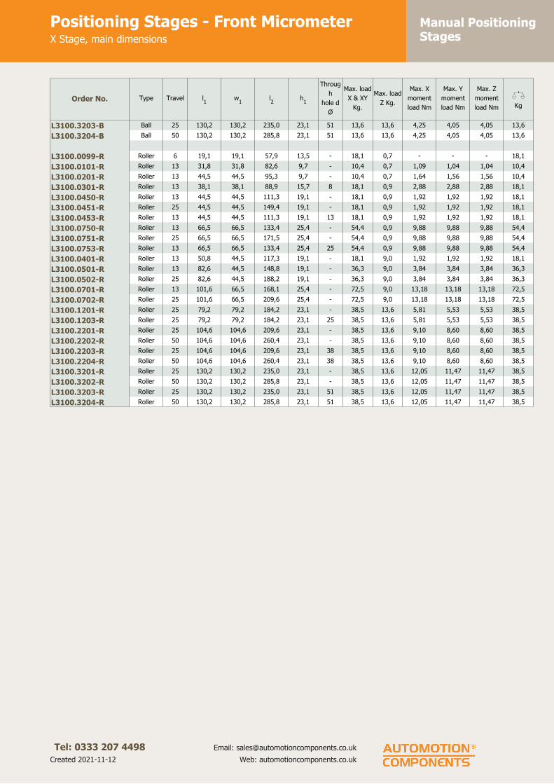
Manual PositioningStages
Positioning Stages - Front MicrometerX Stage, main dimensions
Tel: 0333 207 4498
Created 2021-11-12
Email: [email protected]
Web: automotioncomponents.co.uk
Order No. Type Travel l1
w1
l2
h1
Throug
h
hole d
Ø
Max. load
X & XY
Kg.
Max. load
Z Kg.
Max. X
moment
load Nm
Max. Y
moment
load Nm
Max. Z
moment
load Nm
XKg
L3100.3203-B Ball 25 130,2 130,2 235,0 23,1 51 13,6 13,6 4,25 4,05 4,05 13,6
L3100.3204-B Ball 50 130,2 130,2 285,8 23,1 51 13,6 13,6 4,25 4,05 4,05 13,6
L3100.0099-R Roller 6 19,1 19,1 57,9 13,5 - 18,1 0,7 - - - 18,1
L3100.0101-R Roller 13 31,8 31,8 82,6 9,7 - 10,4 0,7 1,09 1,04 1,04 10,4
L3100.0201-R Roller 13 44,5 44,5 95,3 9,7 - 10,4 0,7 1,64 1,56 1,56 10,4
L3100.0301-R Roller 13 38,1 38,1 88,9 15,7 8 18,1 0,9 2,88 2,88 2,88 18,1
L3100.0450-R Roller 13 44,5 44,5 111,3 19,1 - 18,1 0,9 1,92 1,92 1,92 18,1
L3100.0451-R Roller 25 44,5 44,5 149,4 19,1 - 18,1 0,9 1,92 1,92 1,92 18,1
L3100.0453-R Roller 13 44,5 44,5 111,3 19,1 13 18,1 0,9 1,92 1,92 1,92 18,1
L3100.0750-R Roller 13 66,5 66,5 133,4 25,4 - 54,4 0,9 9,88 9,88 9,88 54,4
L3100.0751-R Roller 25 66,5 66,5 171,5 25,4 - 54,4 0,9 9,88 9,88 9,88 54,4
L3100.0753-R Roller 13 66,5 66,5 133,4 25,4 25 54,4 0,9 9,88 9,88 9,88 54,4
L3100.0401-R Roller 13 50,8 44,5 117,3 19,1 - 18,1 9,0 1,92 1,92 1,92 18,1
L3100.0501-R Roller 13 82,6 44,5 148,8 19,1 - 36,3 9,0 3,84 3,84 3,84 36,3
L3100.0502-R Roller 25 82,6 44,5 188,2 19,1 - 36,3 9,0 3,84 3,84 3,84 36,3
L3100.0701-R Roller 13 101,6 66,5 168,1 25,4 - 72,5 9,0 13,18 13,18 13,18 72,5
L3100.0702-R Roller 25 101,6 66,5 209,6 25,4 - 72,5 9,0 13,18 13,18 13,18 72,5
L3100.1201-R Roller 25 79,2 79,2 184,2 23,1 - 38,5 13,6 5,81 5,53 5,53 38,5
L3100.1203-R Roller 25 79,2 79,2 184,2 23,1 25 38,5 13,6 5,81 5,53 5,53 38,5
L3100.2201-R Roller 25 104,6 104,6 209,6 23,1 - 38,5 13,6 9,10 8,60 8,60 38,5
L3100.2202-R Roller 50 104,6 104,6 260,4 23,1 - 38,5 13,6 9,10 8,60 8,60 38,5
L3100.2203-R Roller 25 104,6 104,6 209,6 23,1 38 38,5 13,6 9,10 8,60 8,60 38,5
L3100.2204-R Roller 50 104,6 104,6 260,4 23,1 38 38,5 13,6 9,10 8,60 8,60 38,5
L3100.3201-R Roller 25 130,2 130,2 235,0 23,1 - 38,5 13,6 12,05 11,47 11,47 38,5
L3100.3202-R Roller 50 130,2 130,2 285,8 23,1 - 38,5 13,6 12,05 11,47 11,47 38,5
L3100.3203-R Roller 25 130,2 130,2 235,0 23,1 51 38,5 13,6 12,05 11,47 11,47 38,5
L3100.3204-R Roller 50 130,2 130,2 285,8 23,1 51 38,5 13,6 12,05 11,47 11,47 38,5

Manual PositioningStages
Front Micrometer Stagesfurther fixing holes detail
Tel: 0333 207 4498
Created 2021-11-12
Email: [email protected]
Web: automotioncomponents.co.uk
L3100.FH
Material
Aluminium carriage and base, black
anodised steel fixing, hardened steel
shafts and balls and roller elements.
Technical notes
For main dimensions and load ratings
please see product page then refer to
this information for detailed hole
fixing data.
These tables simply show additional
mounting and fixing hole information.
Dimensions l6
and w7
relate to
optional posilock device.
Important notes
Stroke is centred on the mid-point of
the slides (ie 50% of total stroke
each way).
3D CAD available.
Order No. l3
l4
l5
l6
w2
w3
w4
w5
w6
w7
d2
d3
for
L3100.0099-X 13,5 14,3 7,9 - 13,5 7,9 - 14,3 - M2 M2
L3100.0101-X 25,4 25,4 17,5 32,1 25,4 12,7 - 23,9 17,5 5,7 M2 M2
L3100.0201-X 38,1 38,1 30,2 38,5 38,1 25,4 - 36,6 30,2 5,7 M2 M2
L3100.0301-X 30,1 30,1 0,0 29,5 0,0 30,1 - 22,2 - 6,1 M3 M3
L3100.0450-X 33,3 25,4 - 45,0 25,4 - - 22,2 - 6,1 M4 M4
L3100.0451-X 33,3 25,4 0,0 60,7 25,4 16,7 - 22,2 - 6,1 M4 M4
L3100.0453-X 33,3 25,4 - 45,0 25,4 16,7 - 38,1 - 6,1 M5 M5
L3100.0750-X 50,8 50,8 35,9 45,5 22,2 - - 38,1 - 6,1 M5 M5
L3100.0751-X 50,8 50,8 35,9 60,7 22,2 - - 38,1 - 6,1 M5 M5
L3100.0753-X 50,8 50,8 ? 45,5 22,2 - - 38,1 - 6,1 M5 M5
L3100.0401-X 41,1 25,4 - 45,0 22,2 - - 22,2 - 6,4 M4 M4
L3100.0501-X 69,9 56,0 28,0 45,0 22,2 - - 22,2 - 6,4 M4 M4
L3100.0502-X 69,9 56,0 28,0 60,7 22,2 - - 22,2 - 6,4 M4 M4
L3100.0701-X 85,9 50,8 - 45,0 31,8 - - 38,1 - 6,4 M5 M5
L3100.0702-X 85,9 50,8 - 60,7 31,8 - - 38,1 - 6,4 M5 M5
L3100.1201-X 66,7 54,0 31,5 44,5 66,7 54,0 31,5 - - 5,9 M5 M5
L3100.1203-X 66,7 54,0 31,5 44,5 66,7 54,0 31,5 - - 5,9 M5 M5
L3100.2201-X 92,1 79,4 31,5 57,2 92,1 79,4 31,5 - - 5,9 M5 M5
L3100.2202-X 92,1 79,4 31,5 57,2 92,1 79,4 31,5 - - 5,9 M5 M5
L3100.2203-X 92,1 79,4 31,5 57,2 92,1 79,4 31,5 - - 5,9 M5 M5
L3100.2204-X 92,1 79,4 31,5 57,2 92,1 79,4 31,5 - - 5,9 M5 M5
L3100.3201-X 117,5 104,8 31,5 69,9 117,5 104,8 31,5 - - 5,9 M5 M5
L3100.3202-X 117,5 104,8 31,5 69,9 117,5 104,8 31,5 - - 5,9 M5 M5
L3100.3203-X 117,5 104,8 31,5 69,9 117,5 104,8 31,5 - - 5,9 M5 M5
L3100.3204-X 117,5 104,8 31,5 69,9 117,5 104,8 31,5 - - 5,9 M5 M5
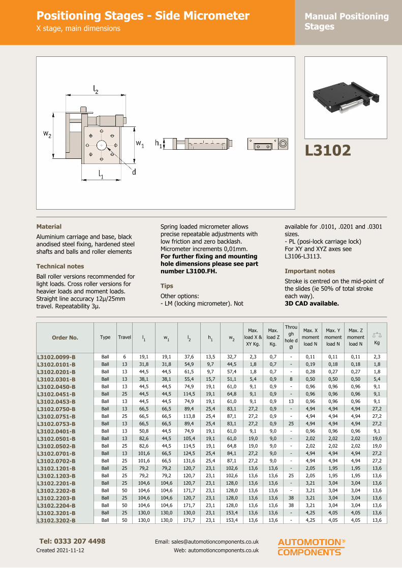
Manual PositioningStages
Positioning Stages - Side MicrometerX stage, main dimensions
Tel: 0333 207 4498
Created 2021-11-12
Email: [email protected]
Web: automotioncomponents.co.uk
L3102
Material
Aluminium carriage and base, black
anodised steel fixing, hardened steel
shafts and balls and roller elements
Technical notes
Ball roller versions recommended for
light loads. Cross roller versions for
heavier loads and moment loads.
Straight line accuracy 12µ/25mm
travel. Repeatability 3µ.
Spring loaded micrometer allows
precise repeatable adjustments with
low friction and zero backlash.
Micrometer increments 0,01mm.
For further fixing and mounting
hole dimensions please see part
number L3100.FH.
Tips
Other options:
- LM (locking micrometer). Not
available for .0101, .0201 and .0301
sizes.
- PL (posi-lock carriage lock)
For XY and XYZ axes see
L3106-L3113.
Important notes
Stroke is centred on the mid-point of
the slides (ie 50% of total stroke
each way).
3D CAD available.
Order No. Type Travel l1
w1
l2
h1
w2
Max.
load X &
XY Kg.
Max.
load Z
Kg.
Throu
gh
hole d
Ø
Max. X
moment
load N
Max. Y
moment
load N
Max. Z
moment
load N
XKg
L3102.0099-B Ball 6 19,1 19,1 37,6 13,5 32,7 2,3 0,7 - 0,11 0,11 0,11 2,3
L3102.0101-B Ball 13 31,8 31,8 54,9 9,7 44,5 1,8 0,7 - 0,19 0,18 0,18 1,8
L3102.0201-B Ball 13 44,5 44,5 61,5 9,7 57,4 1,8 0,7 - 0,28 0,27 0,27 1,8
L3102.0301-B Ball 13 38,1 38,1 55,4 15,7 51,1 5,4 0,9 8 0,50 0,50 0,50 5,4
L3102.0450-B Ball 13 44,5 44,5 74,9 19,1 61,0 9,1 0,9 - 0,96 0,96 0,96 9,1
L3102.0451-B Ball 25 44,5 44,5 114,5 19,1 64,8 9,1 0,9 - 0,96 0,96 0,96 9,1
L3102.0453-B Ball 13 44,5 44,5 74,9 19,1 61,0 9,1 0,9 13 0,96 0,96 0,96 9,1
L3102.0750-B Ball 13 66,5 66,5 89,4 25,4 83,1 27,2 0,9 - 4,94 4,94 4,94 27,2
L3102.0751-B Ball 25 66,5 66,5 113,8 25,4 87,1 27,2 0,9 - 4,94 4,94 4,94 27,2
L3102.0753-B Ball 13 66,5 66,5 89,4 25,4 83,1 27,2 0,9 25 4,94 4,94 4,94 27,2
L3102.0401-B Ball 13 50,8 44,5 74,9 19,1 61,0 9,1 9,0 - 0,96 0,96 0,96 9,1
L3102.0501-B Ball 13 82,6 44,5 105,4 19,1 61,0 19,0 9,0 - 2,02 2,02 2,02 19,0
L3102.0502-B Ball 25 82,6 44,5 114,5 19,1 64,8 19,0 9,0 - 2,02 2,02 2,02 19,0
L3102.0701-B Ball 13 101,6 66,5 124,5 25,4 84,1 27,2 9,0 - 4,94 4,94 4,94 27,2
L3102.0702-B Ball 25 101,6 66,5 131,6 25,4 87,1 27,2 9,0 - 4,94 4,94 4,94 27,2
L3102.1201-B Ball 25 79,2 79,2 120,7 23,1 102,6 13,6 13,6 - 2,05 1,95 1,95 13,6
L3102.1203-B Ball 25 79,2 79,2 120,7 23,1 102,6 13,6 13,6 25 2,05 1,95 1,95 13,6
L3102.2201-B Ball 25 104,6 104,6 120,7 23,1 128,0 13,6 13,6 - 3,21 3,04 3,04 13,6
L3102.2202-B Ball 50 104,6 104,6 171,7 23,1 128,0 13,6 13,6 - 3,21 3,04 3,04 13,6
L3102.2203-B Ball 25 104,6 104,6 120,7 23,1 128,0 13,6 13,6 38 3,21 3,04 3,04 13,6
L3102.2204-B Ball 50 104,6 104,6 171,7 23,1 128,0 13,6 13,6 38 3,21 3,04 3,04 13,6
L3102.3201-B Ball 25 130,0 130,0 130,0 23,1 153,4 13,6 13,6 - 4,25 4,05 4,05 13,6
L3102.3202-B Ball 50 130,0 130,0 171,7 23,1 153,4 13,6 13,6 - 4,25 4,05 4,05 13,6

Manual PositioningStages
Positioning Stages - Side MicrometerX stage, main dimensions
Tel: 0333 207 4498
Created 2021-11-12
Email: [email protected]
Web: automotioncomponents.co.uk
Order No. Type Travel l1
w1
l2
h1
w2
Max.
load X &
XY Kg.
Max.
load Z
Kg.
Throu
gh
hole d
Ø
Max. X
moment
load N
Max. Y
moment
load N
Max. Z
moment
load N
XKg
L3102.3203-B Ball 25 130,0 130,0 130,0 23,1 153,4 13,6 13,6 51 4,25 4,05 4,05 13,6
L3102.3204-B Ball 50 130,0 130,0 171,7 23,1 153,4 13,6 13,6 51 4,25 4,05 4,05 13,6
L3102.0099-R Roller 6 19,1 19,1 37,6 13,5 32,7 18,1 0,7 - - - - 18,1
L3102.0101-R Roller 13 31,8 31,8 54,9 9,7 44,5 10,4 0,7 - 1,09 1,04 1,04 10,4
L3102.0201-R Roller 13 44,5 44,5 61,5 9,7 57,4 10,4 0,7 - 1,64 1,56 1,56 10,4
L3102.0301-R Roller 13 38,1 38,1 55,4 15,7 51,1 18,1 0,9 8 2,88 2,88 2,88 18,1
L3102.0450-R Roller 13 44,5 44,5 74,9 19,1 61,0 18,1 0,9 - 1,92 1,92 1,92 18,1
L3102.0451-R Roller 25 44,5 44,5 114,5 19,1 64,8 18,1 0,9 - 1,92 1,92 1,92 18,1
L3102.0453-R Roller 13 44,5 44,5 74,9 19,1 61,0 18,1 0,9 13 1,92 1,92 1,92 18,1
L3102.0750-R Roller 13 66,5 66,5 89,4 25,4 83,1 54,4 0,9 - 9,88 9,88 9,88 54,4
L3102.0751-R Roller 25 66,5 66,5 113,8 25,4 87,1 54,4 0,9 - 9,88 9,88 9,88 54,4
L3102.0753-R Roller 13 66,5 66,5 89,4 25,4 83,1 54,4 0,9 25 9,88 9,88 9,88 54,4
L3102.0401-R Roller 13 50,8 44,5 74,9 19,1 61,0 18,1 9,0 - 1,92 1,92 1,92 18,1
L3102.0501-R Roller 13 82,6 44,5 105,4 19,1 61,0 36,3 9,0 - 3,84 3,84 3,84 36,3
L3102.0502-R Roller 25 82,6 44,5 114,5 19,1 64,8 36,3 9,0 - 3,84 3,84 3,84 36,3
L3102.0701-R Roller 13 101,6 66,5 124,5 25,4 84,1 72,5 9,0 - 13,18 13,18 13,18 72,5
L3102.0702-R Roller 25 101,6 66,5 131,6 25,4 87,1 72,5 9,0 - 13,18 13,18 13,18 72,5
L3102.1201-R Roller 25 79,2 79,2 120,7 23,1 102,6 38,5 13,6 - 5,81 5,53 5,53 38,5
L3102.1203-R Roller 25 79,2 79,2 120,7 23,1 102,6 38,5 13,6 25 5,81 5,53 5,53 38,5
L3102.2201-R Roller 25 104,6 104,6 120,7 23,1 128,0 38,5 13,6 - 9,10 8,60 8,60 38,5
L3102.2202-R Roller 50 104,6 104,6 171,7 23,1 128,0 38,5 13,6 - 9,10 8,60 8,60 38,5
L3102.2203-R Roller 25 104,6 104,6 120,7 23,1 128,0 38,5 13,6 38 9,10 8,60 8,60 38,5
L3102.2204-R Roller 50 104,6 104,6 171,7 23,1 128,0 38,5 13,6 38 9,10 8,60 8,60 38,5
L3102.3201-R Roller 25 130,0 130,0 130,0 23,1 153,4 38,5 13,6 - 12,05 11,47 11,47 38,5
L3102.3202-R Roller 50 130,0 130,0 171,7 23,1 153,4 38,5 13,6 - 12,05 11,47 11,47 38,5
L3102.3203-R Roller 25 130,0 130,0 130,0 23,1 153,4 38,5 13,6 51 12,05 11,47 11,47 38,5
L3102.3204-R Roller 50 130,0 130,0 171,7 23,1 153,4 38,5 13,6 51 12,05 11,47 11,47 38,5

Manual PositioningStages
Side Micrometer Stagesfurther fixing holes detail
Tel: 0333 207 4498
Created 2021-11-12
Email: [email protected]
Web: automotioncomponents.co.uk
L3102.FH
Material
Aluminium carriage and base, black
anodised steel fixing, hardened steel
shafts and balls and roller elements
Technical notes
For main dimensions and load ratings
please see product page then refer to
this information for detailed hole
fixing data.
These tables simply show additional
mounting and fixing hole information.
Dimensions l7
and w7
relate to
optional posilock device.
Important notes
Stroke is centred on the mid-point of
the slides (ie 50% of total stroke
each way).
3D CAD available.
Order No. l3
l4
l5
l6
w2
w3
w4
w5
w6
w7
d2
d3
for
L3102.0099-X 13,5 14,3 7,9 - 13,5 7,9 - 14,3 - M2 M2
L3102.0101-X 25,4 25,4 17,5 15,5 25,4 12,7 - 23,9 17,5 5,7 M2 M2
L3102.0201-X 38,1 38,1 30,2 15,5 38,1 25,4 - 36,6 30,2 5,7 M2 M2
L3102.0301-X 30,1 30,1 0,0 16,0 0,0 30,1 - 22,2 - 6,1 M3 M3
L3102.0450-X 33,3 25,4 - 25,6 25,4 - - 22,2 - 6,1 M4 M4
L3102.0451-X 33,3 25,4 0,0 25,6 25,4 16,7 - 22,2 - 6,1 M4 M4
L3102.0453-X 33,3 25,4 25,6 25,4 16,7 - 38,1 - 6,1 M5 M5
L3102.0750-X 50,8 ? ? 26,1 50,8 35,9 - 38,1 - 6,1 M5 M5
L3102.0751-X 50,8 ? ? 38,2 50,8 35,9 - 38,1 - 6,1 M5 M5
L3102.0753-X 50,8 ? ? 38,2 50,8 35,9 - 38,1 - 6,1 M5 M5
L3102.0401-X 41,1 25,4 - 25,6 22,2 - - 22,2 - 6,4 M4 M4
L3102.0501-X 69,9 56,0 28,0 25,6 22,2 - - 22,2 - 6,4 M4 M4
L3102.0502-X 69,9 56,0 28,0 38,2 22,2 - - 22,2 - 6,4 M4 M4
L3102.0701-X 85,9 50,8 - 26,1 31,8 - - 38,1 - 6,4 M5 M5
L3102.0702-X 85,9 50,8 - 38,2 31,8 - - 38,1 - 6,4 M5 M5
L3102.1201-X 66,7 54,0 31,5 44,5 66,7 54,0 31,5 - - 5,9 M5 M5
L3102.1203-X 66,7 54,0 31,5 44,5 66,7 54,0 31,5 - - 5,9 M5 M5
L3102.2201-X 92,1 79,4 31,5 55,6 92,1 79,4 31,5 - - 5,9 M5 M5
L3102.2202-X 92,1 79,4 31,5 55,6 92,1 79,4 31,5 - - 5,9 M5 M5
L3102.2203-X 92,1 79,4 31,5 55,6 92,1 79,4 31,5 - - 5,9 M5 M5
L3102.2204-X 92,1 79,4 31,5 55,6 92,1 79,4 31,5 - - 5,9 M5 M5
L3102.3201-X 117,5 104,8 31,5 69,9 117,5 104,8 31,5 - - 5,9 M5 M5
L3102.3202-X 117,5 104,8 31,5 69,9 117,5 104,8 31,5 - - 5,9 M5 M5
L3102.3203-X 117,5 104,8 31,5 69,9 117,5 104,8 31,5 - - 5,9 M5 M5
L3102.3204-X 117,5 104,8 31,5 69,9 117,5 104,8 31,5 - - 5,9 M5 M5

Manual PositioningStages
Positioning Stages - PlainX Stage, main dimensions
Tel: 0333 207 4498
Created 2021-11-12
Email: [email protected]
Web: automotioncomponents.co.uk
L3103
Material
Aluminium carriage and base, black
anodised steel fixing, hardened steel
shafts and balls and roller elements
Technical notes
Ball roller versions recommended for
light loads. Cross roller versions for
heavier loads and moment loads.
Straight line accuracy 12µ/25mm
travel. Repeatability 3µ.
These plain units are supplied with no
micrometers, no micrometer brackets
and no springs.
For further fixing and mounting
hole dimensions please see part
number L3100.FH.
Tips
-PL after part shows option with
posi-lock feature.
Important notes
Stroke is centred on the mid-point of
the slides (ie 50% of total stroke
each way).
3D CAD available.
Order No. Type Travel l1
w1
h1
Through
hole d Ø
Max. load
X & XY Kg.
Max. X
moment
load Nm
Max. Y
moment
load Nm
Max. Z
moment
load Nm
XKg
L3103.0101-B Ball 13 31,8 31,8 9,7 - 1,8 - - - 1,8
L3103.0201-B Ball 13 44,5 44,5 9,7 - 1,8 - - - 1,8
L3103.0301-B Ball 13 38,1 38,1 15,7 8 5,4 0,50 0,68 0,71 5,4
L3103.0451-B Ball 25 44,5 44,5 19,1 - 9,1 0,96 1,13 1,19 9,1
L3103.0452-B Ball 25 44,5 44,5 19,1 13 9,1 0,96 1,13 1,19 9,1
L3103.0751-B Ball 25 66,5 66,5 25,4 - 27,2 4,94 5,75 6,04 27,2
L3103.0752-B Ball 25 66,5 66,5 25,4 25 27,2 4,94 5,75 6,04 27,2
L3103.1202-B Ball 50 79,2 79,2 23,1 - 13,6 2,89 1,95 2,05 13,6
L3103.1204-B Ball 50 79,2 79,2 23,1 25 13,6 2,89 1,95 2,05 13,6
L3103.2205-B Ball 75 104,6 104,6 23,1 - 13,6 4,80 3,04 3,21 13,6
L3103.2206-B Ball 75 104,6 104,6 23,1 38 13,6 4,80 3,04 3,21 13,6
L3103.3205-B Ball 100 130,2 130,2 23,1 - 13,6 4,80 3,04 3,21 13,6
L3103.3206-B Ball 100 130,2 130,2 23,1 51 13,6 7,11 4,05 4,25 13,6
L3103.1202-B-PL Ball 50 79,2 79,2 23,1 - 13,6 2,89 1,95 2,05 13,6
L3103.1204-B-PL Ball 50 79,2 79,2 23,1 25 13,6 2,89 1,95 2,05 13,6
L3103.2205-B-PL Ball 75 104,6 104,6 23,1 - 13,6 4,80 3,04 3,21 13,6
L3103.2206-B-PL Ball 75 104,6 104,6 23,1 38 13,6 4,80 3,04 3,21 13,6
L3103.3205-B-PL Ball 100 130,2 130,2 23,1 - 13,6 4,80 3,04 3,21 13,6
L3103.3206-B-PL Ball 100 130,2 130,2 23,1 51 13,6 7,11 4,05 4,25 13,6
L3103.0101-R Roller 13 31,8 31,8 9,7 - 10,4 - - - 10,4
L3103.0201-R Roller 13 44,5 44,5 9,7 - 10,4 - - - 10,4
L3103.0301-R Roller 13 38,1 38,1 15,7 8 18,1 1,67 2,26 2,37 18,1
L3103.0451-R Roller 25 44,5 44,5 19,1 - 18,1 1,92 2,26 2,37 18,1
L3103.0452-R Roller 25 44,5 44,5 19,1 13 18,1 1,92 2,26 2,37 18,1

Manual PositioningStages
Positioning Stages - PlainX Stage, main dimensions
Tel: 0333 207 4498
Created 2021-11-12
Email: [email protected]
Web: automotioncomponents.co.uk
Order No. Type Travel l1
w1
h1
Through
hole d Ø
Max. load
X & XY Kg.
Max. X
moment
load Nm
Max. Y
moment
load Nm
Max. Z
moment
load Nm
XKg
L3103.0751-R Roller 25 66,5 66,5 25,4 - 54,4 9,88 11,50 12,07 54,4
L3103.0752-R Roller 25 66,5 66,5 25,4 25 54,4 9,88 11,50 12,07 54,4
L3103.1202-R Roller 50 79,2 79,2 23,1 - 38,5 8,19 5,53 5,81 38,5
L3103.1204-R Roller 50 79,2 79,2 23,1 25 38,5 8,19 5,53 5,81 38,5
L3103.2205-R Roller 75 104,6 104,6 23,1 - 38,5 13,60 8,60 9,10 38,5
L3103.2206-R Roller 75 104,6 104,6 23,1 38 38,5 13,60 8,60 9,10 38,5
L3103.3205-R Roller 100 130,2 130,2 23,1 - 38,5 13,60 8,60 9,10 38,5
L3103.3206-R Roller 100 130,2 130,2 23,1 51 38,5 20,15 11,47 12,05 38,5
L3103.1202-R-PL Roller 50 79,2 79,2 23,1 - 38,5 8,19 5,53 5,81 38,5
L3103.1204-R-PL Roller 50 79,2 79,2 23,1 25 38,5 8,19 5,53 5,81 38,5
L3103.2205-R-PL Roller 75 104,6 104,6 23,1 - 38,5 13,60 8,60 9,10 38,5
L3103.2206-R-PL Roller 75 104,6 104,6 23,1 38 38,5 13,60 8,60 9,10 38,5
L3103.3205-R-PL Roller 100 130,2 130,2 23,1 - 38,5 13,60 8,60 9,10 38,5
L3103.3206-R-PL Roller 100 130,2 130,2 23,1 51 38,5 20,15 11,47 12,05 38,5
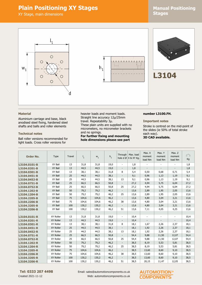
Manual PositioningStages
Plain Positioning XY StagesXY Stage, main dimensions
Tel: 0333 207 4498
Created 2021-11-12
Email: [email protected]
Web: automotioncomponents.co.uk
L3104
Material
Aluminium carriage and base, black
anodised steel fixing, hardened steel
shafts and balls and roller elements
Technical notes
Ball roller versions recommended for
light loads. Cross roller versions for
heavier loads and moment loads.
Straight line accuracy 12µ/25mm
travel. Repeatability 3µ.
These plain units are supplied with no
micrometers, no micrometer brackets
and no springs.
For further fixing and mounting
hole dimensions please see part
number L3100.FH.
Important notes
Stroke is centred on the mid-point of
the slides (ie 50% of total stroke
each way).
3D CAD available.
Order No. Type Travel l1
w1
h1
Through
hole d Ø
Max. load
X & XY Kg.
Max. X
moment
load Nm
Max. Y
moment
load Nm
Max. Z
moment
load Nm
XKg
L3104.0101-B XY Ball 13 31,8 31,8 19,0 - 1,8 - - - 1,8
L3104.0201-B XY Ball 13 44,5 44,5 19,0 - 1,8 - - - 1,8
L3104.0301-B XY Ball 13 38,1 38,1 31,8 8 5,4 0,50 0,68 0,71 5,4
L3104.0451-B XY Ball 25 44,5 44,5 38,1 - 9,1 0,96 1,13 1,19 9,1
L3104.0452-B XY Ball 25 44,5 44,5 38,1 13 9,1 0,96 1,13 1,19 9,1
L3104.0751-B XY Ball 25 66,5 66,5 50,8 - 27,2 4,94 5,75 6,04 27,2
L3104.0752-B XY Ball 25 66,5 66,5 50,8 25 27,2 4,94 5,75 6,04 27,2
L3104.1202-B XY Ball 50 79,2 79,2 46,2 - 13,6 2,89 1,95 2,05 13,6
L3104.1204-B XY Ball 50 79,2 79,2 46,2 25 13,6 2,89 1,95 2,05 13,6
L3104.2205-B XY Ball 75 104,6 104,6 46,2 - 13,6 4,80 3,04 3,21 13,6
L3104.2206-B XY Ball 75 104,6 104,6 46,2 38 13,6 4,80 3,04 3,21 13,6
L3104.3205-B XY Ball 100 130,2 130,2 46,2 - 13,6 4,80 3,04 3,21 13,6
L3104.3206-B XY Ball 100 130,2 130,2 46,2 51 13,6 7,11 4,05 4,25 13,6
L3104.0101-R XY Roller 13 31,8 31,8 19,0 - 10,4 - - - 10,4
L3104.0201-R XY Roller 13 44,5 44,5 19,0 - 10,4 - - - 10,4
L3104.0301-R XY Roller 13 38,1 38,1 31,8 8 18,1 1,67 2,26 2,37 18,1
L3104.0451-R XY Roller 25 44,5 44,5 38,1 - 18,1 1,92 2,26 2,37 18,1
L3104.0452-R XY Roller 25 44,5 44,5 38,1 13 18,1 1,92 2,26 2,37 18,1
L3104.0751-R XY Roller 25 66,5 66,5 50,8 - 54,4 9,88 11,50 12,07 54,4
L3104.0752-R XY Roller 25 66,5 66,5 50,8 25 54,4 9,88 11,50 12,07 54,4
L3104.1202-R XY Roller 50 79,2 79,2 46,2 - 38,5 8,19 5,53 5,81 38,5
L3104.1204-R XY Roller 50 79,2 79,2 46,2 25 38,5 8,19 5,53 5,81 38,5
L3104.2205-R XY Roller 75 104,6 104,6 46,2 - 38,5 13,60 8,60 9,10 38,5
L3104.2206-R XY Roller 75 104,6 104,6 46,2 38 38,5 13,60 8,60 9,10 38,5
L3104.3205-R XY Roller 100 130,2 130,2 46,2 - 38,5 13,60 8,60 9,10 38,5
L3104.3206-R XY Roller 100 130,2 130,2 46,2 51 38,5 20,15 11,47 12,05 38,5

Manual PositioningStages
Micrometer Positioning XY, XYZ Stagesfront drive, small sizes
Tel: 0333 207 4498
Created 2021-11-12
Email: [email protected]
Web: automotioncomponents.co.uk
L3105
Material
Aluminium carriage and base, black
anodised steel fixing, hardened steel
shafts and balls and roller elements.
Technical notes
Ball roller versions recommended for
light loads. Cross roller versions for
heavier loads and moment loads.
Straight line accuracy 12µ/25mm
travel. Repeatability 3µ.
Spring loaded micrometer allows
precise repeatable adjustments with
low friction and zero backlash.
Micrometer increments 0,01mm.
Tips
Other options:
- LM (locking micrometer).
- PL (posi-lock carriage lock).
Important notes
Stroke is centred on the mid-point of
the slides (ie 50% of total stroke
each way).
3D CAD available.
Order No. Type Travel l1
w1
l2
h1
h2
h3
l3
XKg
L3105.0101-XYB XY Ball 13 31,8 31,8 82,6 9,7 19,0 - - 1,8
L3105.0201-XYB XY Ball 13 44,5 44,5 95,3 9,7 19,0 - - 1,8
L3105.0101-XYR XY Roller 13 31,8 31,8 82,6 9,7 19,0 - - 10,4
L3105.0201-XYR XY Roller 13 44,5 44,5 95,3 9,7 19,0 - - 10,4
L3105.0101-XYZB XYZ Ball 13 31,8 31,8 82,6 9,7 19,0 98,3 9,7 1,8
L3105.0201-XYZB XYZ Ball 13 44,5 44,5 95,3 9,7 19,0 111,0 11,3 1,8
L3105.0101-XYZR XYZ Roller 13 31,8 31,8 82,6 9,7 19,0 98,3 9,7 10,4
L3105.0201-XYZR XYZ Roller 13 44,5 44,5 95,3 9,7 19,0 111,0 11,3 10,4
Order No. Max. load X & XY Kg. Max. load Z Kg. Max. X moment load Nm Max. Y moment load Nm Max. Z moment load Nm
L3105.0101-XYB 1,8 0,7 0,19 0,18 0,18
L3105.0201-XYB 1,8 0,7 0,28 0,27 0,27
L3105.0101-XYR 10,4 0,7 1,09 1,04 1,04
L3105.0201-XYR 10,4 0,7 1,64 1,56 1,56
L3105.0101-XYZB 1,8 0,7 0,19 0,18 0,18
L3105.0201-XYZB 1,8 0,7 0,28 0,27 0,27
L3105.0101-XYZR 10,4 0,7 1,09 1,04 1,04
L3105.0201-XYZR 10,4 0,7 1,64 1,56 1,56
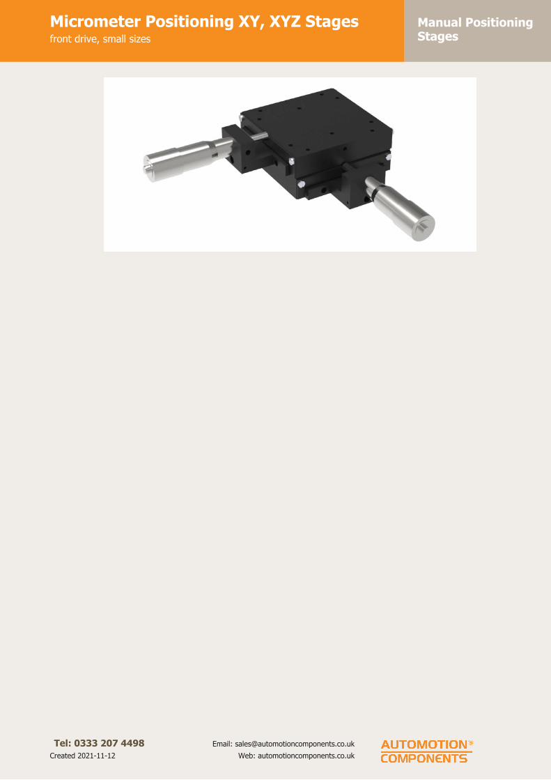
Manual PositioningStages
Micrometer Positioning XY, XYZ Stagesfront drive, small sizes
Tel: 0333 207 4498
Created 2021-11-12
Email: [email protected]
Web: automotioncomponents.co.uk

Manual PositioningStages
Micrometer Positioning XY, XYZ Stagesfront drive, medium sizes
Tel: 0333 207 4498
Created 2021-11-12
Email: [email protected]
Web: automotioncomponents.co.uk
L3106
Material
Aluminium carriage and base, black
anodised steel fixing, hardened steel
shafts and balls and roller elements.
Technical notes
Ball roller versions recommended for
light loads. Cross roller versions for
heavier loads and moment loads.
Straight line accuracy 12µ/25mm
travel. Repeatability 3µ.
Spring loaded micrometer allows
precise repeatable adjustments with
low friction and zero backlash.
Micrometer increments 0,01mm.
For further fixing and mounting
hole dimensions please see part
number L3100.FH.
Tips
Other options:
- LM (locking micrometer).
- PL (posi-lock carriage lock).
Important notes
Stroke is centred on the mid-point of
the slides (ie 50% of total stroke
each way).
3D CAD available.
Order No. Type Travel l1
w1
l2
h1
h2
h3
l3
XKg
L3106.0301-XYB XY Ball 13 38,1 38,1 88,9 15,7 31,8 - - 5,4
L3106.0450-XYB XY Ball 13 44,5 44,5 111,3 19,1 38,1 - - 9,1
L3106.0451-XYB XY Ball 25 44,5 44,5 149,4 19,1 38,1 - - 9,1
L3106.0453-XYB XY Ball 13 44,5 44,5 111,3 19,1 38,1 - - 9,1
L3106.0750-XYB XY Ball 13 66,5 66,5 133,4 25,4 50,8 - - 27,2
L3106.0751-XYB XY Ball 25 66,5 66,5 171,5 25,4 50,8 - - 27,2
L3106.0753-XYB XY Ball 13 66,5 66,5 133,4 25,4 50,8 - - 27,2
L3106.0301-XYR XY Roller 13 38,1 38,1 88,9 15,7 31,8 - - 18,1
L3106.0450-XYR XY Roller 13 44,5 44,5 111,3 19,1 38,1 - - 18,1
L3106.0451-XYR XY Roller 25 44,5 44,5 149,4 19,1 38,1 - - 18,1
L3106.0453-XYR XY Roller 13 44,5 44,5 111,3 19,1 38,1 - - 18,1
L3106.0750-XYR XY Roller 13 66,5 66,5 133,4 25,4 50,8 - - 54,4
L3106.0751-XYR XY Roller 25 66,5 66,5 171,5 25,4 50,8 - - 54,4
L3106.0753-XYR XY Roller 13 66,5 66,5 133,4 25,4 50,8 - - 54,4
L3106.0301-XYZB XYZ Ball 13 38,1 38,1 88,9 15,7 31,8 130 8,1 5,4
L3106.0450-XYZB XYZ Ball 13 44,5 44,5 111,3 19,1 38,1 162,1 0 9,1
L3106.0451-XYZB XYZ Ball 25 44,5 44,5 149,4 19,1 38,1 200,2 0 9,1
L3106.0453-XYZB XYZ Ball 13 44,5 44,5 111,3 19,1 38,1 162,1 0 9,1
L3106.0750-XYZB XYZ Ball 13 66,5 66,5 133,4 25,4 50,8 199,9 1,5 27,2
L3106.0751-XYZB XYZ Ball 25 66,5 66,5 171,5 25,4 50,8 238 1,5 27,2
L3106.0753-XYZB XYZ Ball 13 66,5 66,5 133,4 25,4 50,8 199,9 1,5 27,2
L3106.0301-XYZR XYZ Roller 13 38,1 38,1 88,9 15,7 31,8 130 8,1 18,1
L3106.0450-XYZR XYZ Roller 13 44,5 44,5 111,3 19,1 38,1 162,1 0 18,1
L3106.0451-XYZR XYZ Roller 25 44,5 44,5 149,4 19,1 38,1 200,2 0 18,1
L3106.0453-XYZR XYZ Roller 13 44,5 44,5 111,3 19,1 38,1 162,1 0 18,1

Manual PositioningStages
Micrometer Positioning XY, XYZ Stagesfront drive, medium sizes
Tel: 0333 207 4498
Created 2021-11-12
Email: [email protected]
Web: automotioncomponents.co.uk
Order No. Type Travel l1
w1
l2
h1
h2
h3
l3
XKg
L3106.0750-XYZR XYZ Roller 13 66,5 66,5 133,4 25,4 50,8 199,9 1,5 54,4
L3106.0751-XYZR XYZ Roller 25 66,5 66,5 171,5 25,4 50,8 238 1,5 54,4
L3106.0753-XYZR XYZ Roller 13 66,5 66,5 133,4 25,4 50,8 199,9 1,5 54,4
L3106.0301-XYZLB XYZ Ball Lo 13 38,1 38,1 88,9 15,7 31,8 100,1 25,4 5,4
L3106.0450-XYZLB XYZ Ball Lo 13 44,5 44,5 111,3 19,1 38,1 128,8 28,4 9,1
L3106.0451-XYZLB XYZ Ball Lo 25 44,5 44,5 149,4 19,1 38,1 166,9 28,4 9,1
L3106.0453-XYZLB XYZ Ball Lo 13 44,5 44,5 111,3 19,1 38,1 128,8 28,4 9,1
L3106.0750-XYZLB XYZ Ball Lo 13 66,5 66,5 133,4 25,4 50,8 150,9 38,1 27,2
L3106.0751-XYZLB XYZ Ball Lo 25 66,5 66,5 171,5 25,4 50,8 189 38,1 27,2
L3106.0753-XYZLB XYZ Ball Lo 13 66,5 66,5 133,4 25,4 50,8 150,9 38,1 27,2
L3106.0301-XYZLR XYZ Roller Lo 13 38,1 38,1 88,9 15,7 31,8 106,4 25,4 18,1
L3106.0450-XYZLR XYZ Roller Lo 13 44,5 44,5 111,3 19,1 38,1 128,8 28,4 18,1
L3106.0451-XYZLR XYZ Roller Lo 25 44,5 44,5 149,4 19,1 38,1 166,9 28,4 18,1
L3106.0453-XYZLR XYZ Roller Lo 13 44,5 44,5 111,3 19,1 38,1 128,8 28,4 18,1
L3106.0750-XYZLR XYZ Roller Lo 13 66,5 66,5 133,4 25,4 50,8 150,9 38,1 54,4
L3106.0751-XYZLR XYZ Roller Lo 25 66,5 66,5 171,5 25,4 50,8 189 38,1 54,4
L3106.0753-XYZLR XYZ Roller Lo 13 66,5 66,5 133,4 25,4 50,8 150,9 38,1 54,4
Order No. slotThrough
hole Ø
Max. load X & XY
Kg.Max. load Z Kg.
Max. X moment
load Nm
Max. Y moment
load Nm
Max. Z moment
load Nm
L3106.0301-XYB - 8 5,4 0,9 0,50 0,50 0,50
L3106.0450-XYB - - 9,1 0,9 0,96 0,96 0,96
L3106.0451-XYB - - 9,1 0,9 0,96 0,96 0,96
L3106.0453-XYB - 13 9,1 0,9 0,96 0,96 0,96
L3106.0750-XYB - - 27,2 0,9 4,94 4,94 4,94
L3106.0751-XYB - - 27,2 0,9 4,94 4,94 4,94
L3106.0753-XYB - 25 27,2 0,9 4,94 4,94 4,94
L3106.0301-XYR - 8 18,1 0,9 2,88 2,88 2,88
L3106.0450-XYR - - 18,1 0,9 1,92 1,92 1,92
L3106.0451-XYR - - 18,1 0,9 1,92 1,92 1,92
L3106.0453-XYR - 13 18,1 0,9 1,92 1,92 1,92
L3106.0750-XYR - - 54,4 0,9 9,88 9,88 9,88
L3106.0751-XYR - - 54,4 0,9 9,88 9,88 9,88
L3106.0753-XYR - 25 54,4 0,9 9,88 9,88 9,88
L3106.0301-XYZB 10x22 8 5,4 0,9 0,50 0,50 0,50
L3106.0450-XYZB 13x25 - 9,1 0,9 0,96 0,96 0,96
L3106.0451-XYZB 13x25 - 9,1 0,9 0,96 0,96 0,96
L3106.0453-XYZB 13x25 13 9,1 0,9 0,96 0,96 0,96
L3106.0750-XYZB 25x38 - 27,2 0,9 4,94 4,94 4,94
L3106.0751-XYZB 25x38 - 27,2 0,9 4,94 4,94 4,94
L3106.0753-XYZB 25x38 25 27,2 0,9 4,94 4,94 4,94
L3106.0301-XYZR 10x22 8 18,1 0,9 2,88 2,88 2,88
L3106.0450-XYZR 13x25 - 18,1 0,9 1,92 1,92 1,92
L3106.0451-XYZR 13x25 - 18,1 0,9 1,92 1,92 1,92
L3106.0453-XYZR 13x25 13 18,1 0,9 1,92 1,92 1,92
L3106.0750-XYZR 25x38 - 54,4 0,9 9,88 9,88 9,88
L3106.0751-XYZR 25x38 - 54,4 0,9 9,88 9,88 9,88
L3106.0753-XYZR 25x38 25 54,4 0,9 9,88 9,88 9,88
L3106.0301-XYZLB 10x22 8 5,4 0,9 0,50 0,50 0,50
L3106.0450-XYZLB 13x25 - 9,1 0,9 0,96 0,96 0,96
L3106.0451-XYZLB 13x25 - 9,1 0,9 0,96 0,96 0,96
L3106.0453-XYZLB 13x25 13 9,1 0,9 0,96 0,96 0,96
L3106.0750-XYZLB 25x38 - 27,2 0,9 4,94 4,94 4,94
L3106.0751-XYZLB 25x38 - 27,2 0,9 4,94 4,94 4,94
L3106.0753-XYZLB 25x38 25 27,2 0,9 4,94 4,94 4,94
L3106.0301-XYZLR 10x22 8 18,1 0,9 2,88 2,88 2,88
L3106.0450-XYZLR 13x25 - 18,1 0,9 1,92 1,92 1,92
L3106.0451-XYZLR 13x25 - 18,1 0,9 1,92 1,92 1,92

Manual PositioningStages
Micrometer Positioning XY, XYZ Stagesfront drive, medium sizes
Tel: 0333 207 4498
Created 2021-11-12
Email: [email protected]
Web: automotioncomponents.co.uk
Order No. slotThrough
hole Ø
Max. load X & XY
Kg.Max. load Z Kg.
Max. X moment
load Nm
Max. Y moment
load Nm
Max. Z moment
load Nm
L3106.0453-XYZLR 13x25 13 18,1 0,9 1,92 1,92 1,92
L3106.0750-XYZLR 25x38 - 54,4 0,9 9,88 9,88 9,88
L3106.0751-XYZLR 25x38 - 54,4 0,9 9,88 9,88 9,88
L3106.0753-XYZLR 25x38 25 54,4 0,9 9,88 9,88 9,88
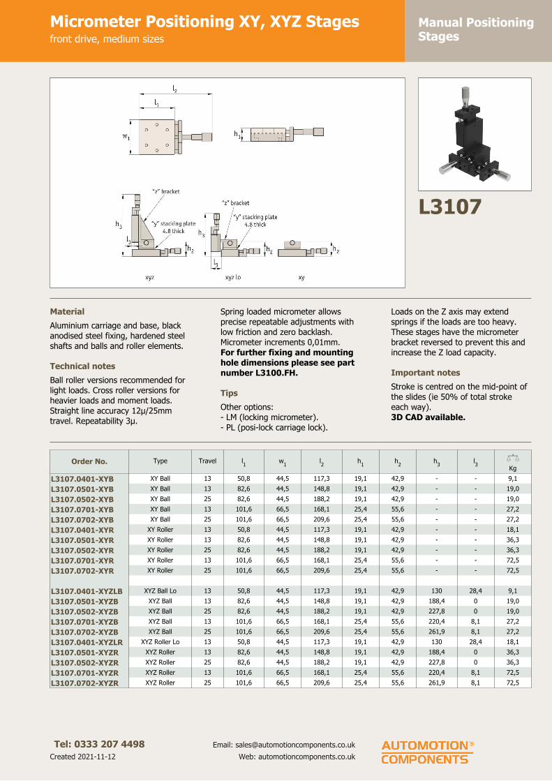
Manual PositioningStages
Micrometer Positioning XY, XYZ Stagesfront drive, medium sizes
Tel: 0333 207 4498
Created 2021-11-12
Email: [email protected]
Web: automotioncomponents.co.uk
L3107
Material
Aluminium carriage and base, black
anodised steel fixing, hardened steel
shafts and balls and roller elements.
Technical notes
Ball roller versions recommended for
light loads. Cross roller versions for
heavier loads and moment loads.
Straight line accuracy 12µ/25mm
travel. Repeatability 3µ.
Spring loaded micrometer allows
precise repeatable adjustments with
low friction and zero backlash.
Micrometer increments 0,01mm.
For further fixing and mounting
hole dimensions please see part
number L3100.FH.
Tips
Other options:
- LM (locking micrometer).
- PL (posi-lock carriage lock).
Loads on the Z axis may extend
springs if the loads are too heavy.
These stages have the micrometer
bracket reversed to prevent this and
increase the Z load capacity.
Important notes
Stroke is centred on the mid-point of
the slides (ie 50% of total stroke
each way).
3D CAD available.
Order No. Type Travel l1
w1
l2
h1
h2
h3
l3
XKg
L3107.0401-XYB XY Ball 13 50,8 44,5 117,3 19,1 42,9 - - 9,1
L3107.0501-XYB XY Ball 13 82,6 44,5 148,8 19,1 42,9 - - 19,0
L3107.0502-XYB XY Ball 25 82,6 44,5 188,2 19,1 42,9 - - 19,0
L3107.0701-XYB XY Ball 13 101,6 66,5 168,1 25,4 55,6 - - 27,2
L3107.0702-XYB XY Ball 25 101,6 66,5 209,6 25,4 55,6 - - 27,2
L3107.0401-XYR XY Roller 13 50,8 44,5 117,3 19,1 42,9 - - 18,1
L3107.0501-XYR XY Roller 13 82,6 44,5 148,8 19,1 42,9 - - 36,3
L3107.0502-XYR XY Roller 25 82,6 44,5 188,2 19,1 42,9 - - 36,3
L3107.0701-XYR XY Roller 13 101,6 66,5 168,1 25,4 55,6 - - 72,5
L3107.0702-XYR XY Roller 25 101,6 66,5 209,6 25,4 55,6 - - 72,5
L3107.0401-XYZLB XYZ Ball Lo 13 50,8 44,5 117,3 19,1 42,9 130 28,4 9,1
L3107.0501-XYZB XYZ Ball 13 82,6 44,5 148,8 19,1 42,9 188,4 0 19,0
L3107.0502-XYZB XYZ Ball 25 82,6 44,5 188,2 19,1 42,9 227,8 0 19,0
L3107.0701-XYZB XYZ Ball 13 101,6 66,5 168,1 25,4 55,6 220,4 8,1 27,2
L3107.0702-XYZB XYZ Ball 25 101,6 66,5 209,6 25,4 55,6 261,9 8,1 27,2
L3107.0401-XYZLR XYZ Roller Lo 13 50,8 44,5 117,3 19,1 42,9 130 28,4 18,1
L3107.0501-XYZR XYZ Roller 13 82,6 44,5 148,8 19,1 42,9 188,4 0 36,3
L3107.0502-XYZR XYZ Roller 25 82,6 44,5 188,2 19,1 42,9 227,8 0 36,3
L3107.0701-XYZR XYZ Roller 13 101,6 66,5 168,1 25,4 55,6 220,4 8,1 72,5
L3107.0702-XYZR XYZ Roller 25 101,6 66,5 209,6 25,4 55,6 261,9 8,1 72,5

Manual PositioningStages
Micrometer Positioning XY, XYZ Stagesfront drive, medium sizes
Tel: 0333 207 4498
Created 2021-11-12
Email: [email protected]
Web: automotioncomponents.co.uk
Order No.Max. load
X & XY Kg.
Max. load
Z Kg.Max. X moment load Nm Max. Y moment load Nm Max. Z moment load Nm
L3107.0401-XYB 9,1 9,0 0,96 0,96 0,96
L3107.0501-XYB 19,0 9,0 2,02 2,02 2,02
L3107.0502-XYB 19,0 9,0 2,02 2,02 2,02
L3107.0701-XYB 27,2 9,0 4,94 4,94 4,94
L3107.0702-XYB 27,2 9,0 4,94 4,94 4,94
L3107.0401-XYR 18,1 9,0 1,92 1,92 1,92
L3107.0501-XYR 36,3 9,0 3,84 3,84 3,84
L3107.0502-XYR 36,3 9,0 3,84 3,84 3,84
L3107.0701-XYR 72,5 9,0 13,18 13,18 13,18
L3107.0702-XYR 72,5 9,0 13,18 13,18 13,18
L3107.0401-XYZLB 9,1 9,0 0,96 0,96 0,96
L3107.0501-XYZB 19,0 9,0 2,02 2,02 2,02
L3107.0502-XYZB 19,0 9,0 2,02 2,02 2,02
L3107.0701-XYZB 27,2 9,0 4,94 4,94 4,94
L3107.0702-XYZB 27,2 9,0 4,94 4,94 4,94
L3107.0401-XYZLR 18,1 9,0 1,92 1,92 1,92
L3107.0501-XYZR 36,3 9,0 3,84 3,84 3,84
L3107.0502-XYZR 36,3 9,0 3,84 3,84 3,84
L3107.0701-XYZR 72,5 9,0 13,18 13,18 13,18
L3107.0702-XYZR 72,5 9,0 13,18 13,18 13,18

Manual PositioningStages
Micrometer Positioning XY, XYZ Stagesfront drive, large sizes
Tel: 0333 207 4498
Created 2021-11-12
Email: [email protected]
Web: automotioncomponents.co.uk
L3108
Material
Aluminium carriage and base, black
anodised steel fixing, hardened steel
shafts and balls and roller elements.
Technical notes
Ball roller versions recommended for
light loads. Cross roller versions for
heavier loads and moment loads.
Straight line accuracy 12µ/25mm
travel. Repeatability 3µ.
Spring loaded micrometer allows
precise repeatable adjustments with
low friction and zero backlash.
Micrometer increments 0,01mm.
For further fixing and mounting
hole dimensions please see part
number L3100.FH.
Tips
Other options:
- LM (locking micrometer).
- PL (posi-lock carriage lock).
Loads on the Z axis may extend
springs if the loads are too heavy.
These stages have the micrometer
bracket reversed to prevent this and
increase the Z load capacity.
Important notes
Stroke is centred on the mid-point of
the slides (ie 50% of total stroke
each way).
3D CAD available.
Order No. Type Travel l1
w2
l2
h1
Through
hole d Øh
2h
3XKg
L3108.1201-XYB XY Ball 25 79,2 79,2 184,2 23,1 - 46,2 - 13,6
L3108.1203-XYB XY Ball 25 79,2 79,2 184,2 23,1 25 46,2 - 13,6
L3108.2201-XYB XY Ball 25 104,6 104,6 209,6 23,1 - 46,2 - 13,6
L3108.2202-XYB XY Ball 50 104,6 104,6 260,4 23,1 - 46,2 - 13,6
L3108.2203-XYB XY Ball 25 104,6 104,6 209,6 23,1 38 46,2 - 13,6
L3108.2204-XYB XY Ball 50 104,6 104,6 260,4 23,1 38 46,2 - 13,6
L3108.3201-XYB XY Ball 25 130,2 130,2 235,0 23,1 - 46,2 - 13,6
L3108.3202-XYB XY Ball 50 130,2 130,2 285,8 23,1 - 46,2 - 13,6
L3108.3203-XYB XY Ball 25 130,2 130,2 235,0 23,1 51 46,2 - 13,6
L3108.3204-XYB XY Ball 50 130,2 130,2 285,8 23,1 51 46,2 - 13,6
L3108.1201-XYR XY Roller 25 79,2 79,2 184,2 23,1 - 46,2 - 38,5
L3008.1203-XYR XY Roller 25 79,2 79,2 184,2 23,1 25 46,2 - 38,5
L3108.2201-XYR XY Roller 25 104,6 104,6 209,6 23,1 - 46,2 - 38,5
L3108.2202-XYR XY Roller 50 104,6 104,6 260,4 23,1 - 46,2 - 38,5
L3108.2203-XYR XY Roller 25 104,6 104,6 209,6 23,1 38 46,2 - 38,5
L3108.2204-XYR XY Roller 50 104,6 104,6 260,4 23,1 38 46,2 - 38,5
L3108.3201-XYR XY Roller 25 130,2 130,2 235,0 23,1 - 46,2 - 38,5
L3108.3202-XYR XY Roller 50 130,2 130,2 285,8 23,1 - 46,2 - 38,5
L3108.3203-XYR XY Roller 25 130,2 130,2 235,0 23,1 51 46,2 - 38,5
L3108.3204-XYR XY Roller 50 130,2 130,2 285,8 23,1 51 46,2 - 38,5
L3108.1201-XYZB XYZ Ball 25 79,2 79,2 184,2 23,1 - 46,2 249,7 13,6
L3108.1203-XYZB XYZ Ball 25 79,2 79,2 184,2 23,1 25 46,2 249,7 13,6
L3108.2201-XYZB XYZ Ball 25 104,6 104,6 209,6 23,1 - 46,2 287,8 13,6

Manual PositioningStages
Micrometer Positioning XY, XYZ Stagesfront drive, large sizes
Tel: 0333 207 4498
Created 2021-11-12
Email: [email protected]
Web: automotioncomponents.co.uk
Order No. Type Travel l1
w2
l2
h1
Through
hole d Øh
2h
3XKg
L3108.2202-XYZB XYZ Ball 50 104,6 104,6 260,4 23,1 - 46,2 338,6 13,6
L3108.2203-XYZB XYZ Ball 25 104,6 104,6 209,6 23,1 38 46,2 287,8 13,6
L3108.2204-XYZB XYZ Ball 50 104,6 104,6 260,4 23,1 38 46,2 338,6 13,6
L3108.3201-XYZB XYZ Ball 25 130,2 130,2 235,0 23,1 - 46,2 313,2 13,6
L3108.3202-XYZB XYZ Ball 50 130,2 130,2 285,8 23,1 - 46,2 364,0 13,6
L3108.3203-XYZB XYZ Ball 25 130,2 130,2 235,0 23,1 51 46,2 313,2 13,6
L3108.3204-XYZB XYZ Ball 50 130,2 130,2 285,8 23,1 51 46,2 364,0 13,6
L3108.1201-XYZR XYZ Roller 25 79,2 79,2 184,2 23,1 - 46,2 249,7 38,5
L3008.1203-XYZR XYZ Roller 25 79,2 79,2 184,2 23,1 25 46,2 249,7 38,5
L3108.2201-XYZR XYZ Roller 25 104,6 104,6 209,6 23,1 - 46,2 287,8 38,5
L3108.2202-XYZR XYZ Roller 50 104,6 104,6 260,4 23,1 - 46,2 338,6 38,5
L3108.2203-XYZR XYZ Roller 25 104,6 104,6 209,6 23,1 38 46,2 287,8 38,5
L3108.2204-XYZR XYZ Roller 50 104,6 104,6 260,4 23,1 38 46,2 338,6 38,5
L3108.3201-XYZR XYZ Roller 25 130,2 130,2 235,0 23,1 - 46,2 313,2 38,5
L3108.3202-XYZR XYZ Roller 50 130,2 130,2 285,8 23,1 - 46,2 364,0 38,5
L3108.3203-XYZR XYZ Roller 25 130,2 130,2 235,0 23,1 51 46,2 313,2 38,5
L3108.3204-XYZR XYZ Roller 50 130,2 130,2 285,8 23,1 51 46,2 364,0 38,5
Order No. l3
Max. load
X & XY Kg.
Max. load
Z Kg.
Max. X moment load
Nm
Max. Y moment load
Nm
Max. Z moment load
Nm
L3108.1201-XYB - 13,6 13,6 2,05 1,95 1,95
L3108.1203-XYB - 13,6 13,6 2,05 1,95 1,95
L3108.2201-XYB - 13,6 13,6 3,21 3,04 3,04
L3108.2202-XYB - 13,6 13,6 3,21 3,04 3,04
L3108.2203-XYB - 13,6 13,6 3,21 3,04 3,04
L3108.2204-XYB - 13,6 13,6 3,21 3,04 3,04
L3108.3201-XYB - 13,6 13,6 4,25 4,05 4,05
L3108.3202-XYB - 13,6 13,6 4,25 4,05 4,05
L3108.3203-XYB - 13,6 13,6 4,25 4,05 4,05
L3108.3204-XYB - 13,6 13,6 4,25 4,05 4,05
L3108.1201-XYR - 38,5 13,6 5,81 5,53 5,53
L3008.1203-XYR - 38,5 13,6 5,81 5,53 5,53
L3108.2201-XYR - 38,5 13,6 9,10 8,60 8,60
L3108.2202-XYR - 38,5 13,6 9,10 8,60 8,60
L3108.2203-XYR - 38,5 13,6 9,10 8,60 8,60
L3108.2204-XYR - 38,5 13,6 9,10 8,60 8,60
L3108.3201-XYR - 38,5 13,6 12,05 11,47 11,47
L3108.3202-XYR - 38,5 13,6 12,05 11,47 11,47
L3108.3203-XYR - 38,5 13,6 12,05 11,47 11,47
L3108.3204-XYR - 38,5 13,6 12,05 11,47 11,47
L3108.1201-XYZB 8,4 13,6 13,6 2,05 1,95 1,95
L3108.1203-XYZB 8,4 13,6 13,6 2,05 1,95 1,95
L3108.2201-XYZB 13,2 13,6 13,6 3,21 3,04 3,04
L3108.2202-XYZB 13,2 13,6 13,6 3,21 3,04 3,04
L3108.2203-XYZB 13,2 13,6 13,6 3,21 3,04 3,04
L3108.2204-XYZB 13,2 13,6 13,6 3,21 3,04 3,04
L3108.3201-XYZB 27,7 13,6 13,6 4,25 4,05 4,05
L3108.3202-XYZB 27,7 13,6 13,6 4,25 4,05 4,05
L3108.3203-XYZB 27,7 13,6 13,6 4,25 4,05 4,05
L3108.3204-XYZB 27,7 13,6 13,6 4,25 4,05 4,05
L3108.1201-XYZR 8,4 38,5 13,6 5,81 5,53 5,53
L3008.1203-XYZR 8,4 38,5 13,6 5,81 5,53 5,53
L3108.2201-XYZR 13,2 38,5 13,6 9,10 8,60 8,60
L3108.2202-XYZR 13,2 38,5 13,6 9,10 8,60 8,60
L3108.2203-XYZR 13,2 38,5 13,6 9,10 8,60 8,60
L3108.2204-XYZR 13,2 38,5 13,6 9,10 8,60 8,60
L3108.3201-XYZR 27,7 38,5 13,6 12,05 11,47 11,47
L3108.3202-XYZR 27,7 38,5 13,6 12,05 11,47 11,47
L3108.3203-XYZR 27,7 38,5 13,6 12,05 11,47 11,47
L3108.3204-XYZR 27,7 38,5 13,6 12,05 11,47 11,47

Manual PositioningStages
Micrometer Positioning XY, XYZ Stagesfront drive, large sizes
Tel: 0333 207 4498
Created 2021-11-12
Email: [email protected]
Web: automotioncomponents.co.uk

Manual PositioningStages
Micrometer Positioning XY, XYZ Stagesside drive, small sizes
Tel: 0333 207 4498
Created 2021-11-12
Email: [email protected]
Web: automotioncomponents.co.uk
L3110
Material
Aluminium carriage and base, black
anodised steel fixing, hardened steel
shafts and balls and roller elements
Technical notes
Ball roller versions recommended for
light loads. Cross roller versions for
heavier loads and moment loads.
Straight line accuracy 12µ/25mm
travel. Repeatability 3µ.
Spring loaded micrometer allows
precise repeatable adjustments with
low friction and zero backlash.
Micrometer increments 0,01mm.
For further fixing and mounting
hole dimensions please see part
number L3100.FH.
Tips
Other options:
- LM (locking micrometer).
- PL (posi-lock carriage lock).
Important notes
Stroke is centred on the mid-point of
the slides (ie 50% of total stroke
each way).
3D CAD available.
Order No. Type Travel l1
w1
l2
h1
w2
Through
hole d Øh
2XKg
L3110.0101-XYB XY Ball 13 31,8 31,8 54,9 9,7 44,5 - 19,0 1,8
L3110.0201-XYB XY Ball 13 44,5 44,5 61,5 9,7 57,4 - 19,0 1,8
L3110.0101-XYR XY Roller 13 31,8 31,8 54,9 9,7 44,5 - 19,0 10,4
L3110.0201-XYR XY Roller 13 44,5 44,5 61,5 9,7 57,4 - 19,0 10,4
L3110.0101-XYZB XYZ Ball 13 31,8 31,8 54,9 9,7 44,5 - 19,0 1,8
L3110.0201-XYZB XYZ Ball 13 44,5 44,5 61,5 9,7 57,4 - 19,0 1,8
L3110.0101-XYZR XYZ Roller 13 31,8 31,8 54,9 9,7 44,5 - 19,0 10,4
L3110.0201-XYZR XYZ Roller 13 44,5 44,5 61,5 9,7 57,4 - 19,0 10,4
Order No. h3
l3
Max. load
X & XY Kg.
Max. load
Z Kg.
Max. X moment
load Nm
Max. Y moment
load Nm
Max. Z moment
load Nm
L3110.0101-XYB - - 1,8 0,7 0,19 0,18 0,18
L3110.0201-XYB - - 1,8 0,7 0,28 0,27 0,27
L3110.0101-XYR - - 10,4 0,7 1,09 1,04 1,04
L3110.0201-XYR - - 10,4 0,7 1,64 1,56 1,56
L3110.0101-XYZB 77,1 9,7 1,8 0,7 0,19 0,18 0,18
L3110.0201-XYZB 83,7 11,2 1,8 0,7 0,28 0,27 0,27
L3110.0101-XYZR 77,1 9,7 10,4 0,7 1,09 1,04 1,04
L3110.0201-XYZR 83,7 11,2 10,4 0,7 1,64 1,56 1,56

Manual PositioningStages
Micrometer Positioning XY, XYZ Stagesside drive, medium sizes
Tel: 0333 207 4498
Created 2021-11-12
Email: [email protected]
Web: automotioncomponents.co.uk
L3111
Material
Aluminium carriage and base, black
anodised steel fixing, hardened steel
shafts and balls and roller elements
Technical notes
Ball roller versions recommended for
light loads. Cross roller versions for
heavier loads and moment loads.
Straight line accuracy 12µ/25mm
travel. Repeatability 3µ.
Spring loaded micrometer allows
precise repeatable adjustments with
low friction and zero backlash.
Micrometer increments 0,01mm.
For further fixing and mounting
hole dimensions please see part
number L3100.FH.
Tips
Other options:
- LM (locking micrometer).
- PL (posi-lock carriage lock).
Important notes
Stroke is centred on the mid-point of
the slides (ie 50% of total stroke
each way).
3D CAD available.
Order No. Type Travel l1
w1
l2
h1
w2
Through
hole d Øh
2XKg
L3111.0301-XYB XY Ball 13 38,1 38,1 55,4 15,7 51,1 8 31,8 5,4
L3111.0450-XYB XY Ball 13 44,5 44,5 74,9 19,1 61,0 - 38,1 9,1
L3111.0451-XYB XY Ball 25 44,5 44,5 114,5 19,1 64,8 - 38,1 9,1
L3111.0453-XYB XY Ball 13 44,5 44,5 74,9 19,1 61,0 13 38,1 9,1
L3111.0750-XYB XY Ball 13 66,5 66,5 89,4 25,4 83,1 - 50,8 27,2
L3111.0751-XYB XY Ball 25 66,5 66,5 113,8 25,4 87,1 - 50,8 27,2
L3111.0753-XYB XY Ball 13 66,5 66,5 89,4 25,4 83,1 25 50,8 27,2
L3111.0301-XYR XY Roller 13 38,1 38,1 55,4 15,7 51,1 8 31,8 18,1
L3111.0450-XYR XY Roller 13 44,5 44,5 74,9 19,1 61,0 - 38,1 18,1
L3111.0451-XYR XY Roller 25 44,5 44,5 114,5 19,1 64,8 - 38,1 18,1
L3111.0453-XYR XY Roller 13 44,5 44,5 74,9 19,1 61,0 13 38,1 18,1
L3111.0750-XYR XY Roller 13 66,5 66,5 89,4 25,4 83,1 - 50,8 54,4
L3111.0751-XYR XY Roller 25 66,5 66,5 113,8 25,4 87,1 - 50,8 54,4
L3111.0753-XYR XY Roller 13 66,5 66,5 89,4 25,4 83,1 25 50,8 54,4
L3111.0301-XYZB XYZ Ball 13 38,1 38,1 55,4 15,7 51,1 8 31,8 5,4
L3111.0450-XYZB XYZ Ball 13 44,5 44,5 74,9 19,1 61,0 - 38,1 9,1
L3111.0451-XYZB XYZ Ball 25 44,5 44,5 114,5 19,1 64,8 - 38,1 9,1
L3111.0453-XYZB XYZ Ball 13 44,5 44,5 74,9 19,1 61,0 13 38,1 9,1
L3111.0750-XYZB XYZ Ball 13 66,5 66,5 89,4 25,4 83,1 - 50,8 27,2
L3111.0751-XYZB XYZ Ball 25 66,5 66,5 113,8 25,4 87,1 - 50,8 27,2
L3111.0753-XYZB XYZ Ball 13 66,5 66,5 89,4 25,4 83,1 25 50,8 27,2
L3111.0301-XYZR XYZ Roller 13 38,1 38,1 55,4 15,7 51,1 8 31,8 18,1
L3111.0450-XYZR XYZ Roller 13 44,5 44,5 74,9 19,1 61,0 - 38,1 18,1
L3111.0451-XYZR XYZ Roller 25 44,5 44,5 114,5 19,1 64,8 - 38,1 18,1
L3111.0453-XYZR XYZ Roller 13 44,5 44,5 74,9 19,1 61,0 13 38,1 18,1

Manual PositioningStages
Micrometer Positioning XY, XYZ Stagesside drive, medium sizes
Tel: 0333 207 4498
Created 2021-11-12
Email: [email protected]
Web: automotioncomponents.co.uk
Order No. Type Travel l1
w1
l2
h1
w2
Through
hole d Øh
2XKg
L3111.0750-XYZR XYZ Roller 13 66,5 66,5 89,4 25,4 83,1 - 50,8 54,4
L3111.0751-XYZR XYZ Roller 25 66,5 66,5 113,8 25,4 87,1 - 50,8 54,4
L3111.0753-XYZR XYZ Roller 13 66,5 66,5 89,4 25,4 83,1 25 50,8 54,4
L3111.0301-XYZLB XYZ Ball Lo 13 38,1 38,1 55,4 15,7 51,1 8 31,8 5,4
L3111.0450-XYZLB XYZ Ball Lo 13 44,5 44,5 74,9 19,1 61,0 - 38,1 9,1
L3111.0451-XYZLB XYZ Ball Lo 25 44,5 44,5 114,5 19,1 64,8 - 38,1 9,1
L3111.0453-XYZLB XYZ Ball Lo 13 44,5 44,5 74,9 19,1 61,0 13 38,1 9,1
L3111.0750-XYZLB XYZ Ball Lo 13 66,5 66,5 89,4 25,4 83,1 - 50,8 27,2
L3111.0751-XYZLB XYZ Ball Lo 25 66,5 66,5 113,8 25,4 87,1 - 50,8 27,2
L3111.0753-XYZLB XYZ Ball Lo 13 66,5 66,5 89,4 25,4 83,1 25 50,8 27,2
L3111.0301-XYZLR XYZ Roller Lo 13 38,1 38,1 55,4 15,7 51,1 8 31,8 18,1
L3111.0450-XYZLR XYZ Roller Lo 13 44,5 44,5 74,9 19,1 61,0 - 38,1 18,1
L3111.0451-XYZLR XYZ Roller Lo 25 44,5 44,5 114,5 19,1 64,8 - 38,1 18,1
L3111.0453-XYZLR XYZ Roller Lo 13 44,5 44,5 74,9 19,1 61,0 13 38,1 18,1
L3111.0750-XYZLR XYZ Roller Lo 13 66,5 66,5 89,4 25,4 83,1 - 50,8 54,4
L3111.0751-XYZLR XYZ Roller Lo 25 66,5 66,5 113,8 25,4 87,1 - 50,8 54,4
L3111.0753-XYZLR XYZ Roller Lo 13 66,5 66,5 89,4 25,4 83,1 25 50,8 54,4
Order No. h3
l3
Max. load
X & XY Kg.
Max. load
Z Kg.
Max. X moment
load Nm
Max. Y moment
load Nm
Max. Z moment
load Nm
L3111.0301-XYB - - 5,4 0,9 0,50 0,50 0,50
L3111.0450-XYB - - 9,1 0,9 0,96 0,96 0,96
L3111.0451-XYB - - 9,1 0,9 0,96 0,96 0,96
L3111.0453-XYB - - 9,1 0,9 0,96 0,96 0,96
L3111.0750-XYB - - 27,2 0,9 4,94 4,94 4,94
L3111.0751-XYB - - 27,2 0,9 4,94 4,94 4,94
L3111.0753-XYB - - 27,2 0,9 4,94 4,94 4,94
L3111.0301-XYR - - 18,1 0,9 2,88 2,88 2,88
L3111.0450-XYR - - 18,1 0,9 1,92 1,92 1,92
L3111.0451-XYR - - 18,1 0,9 1,92 1,92 1,92
L3111.0453-XYR - - 18,1 0,9 1,92 1,92 1,92
L3111.0750-XYR - - 54,4 0,9 9,88 9,88 9,88
L3111.0751-XYR - - 54,4 0,9 9,88 9,88 9,88
L3111.0753-XYR - - 54,4 0,9 9,88 9,88 9,88
L3111.0301-XYZB 93.5 8,0 5,4 0,9 0,50 0,50 0,50
L3111.0450-XYZB 93,5 0 9,1 0,9 0,96 0,96 0,96
L3111.0451-XYZB 93,5 0 9,1 0,9 0,96 0,96 0,96
L3111.0453-XYZB 93,5 0 9,1 0,9 0,96 0,96 0,96
L3111.0750-XYZB 113,3 7,6 27,2 0,9 4,94 4,94 4,94
L3111.0751-XYZB 137,7 7,6 27,2 0,9 4,94 4,94 4,94
L3111.0753-XYZB 113,3 7,6 27,2 0,9 4,94 4,94 4,94
L3111.0301-XYZR 66,6 8,0 18,1 0,9 2,88 2,88 2,88
L3111.0450-XYZR 92,4 0 18,1 0,9 1,92 1,92 1,92
L3111.0451-XYZR 132,0 0 18,1 0,9 1,92 1,92 1,92
L3111.0453-XYZR 92,4 0 18,1 0,9 1,92 1,92 1,92
L3111.0750-XYZR 113,3 7,6 54,4 0,9 9,88 9,88 9,88
L3111.0751-XYZR 137,7 7,6 54,4 0,9 9,88 9,88 9,88
L3111.0753-XYZR 113,3 7,6 54,4 0,9 9,88 9,88 9,88
L3111.0301-XYZLB 66,6 25,4 5,4 0,9 0,50 0,50 0,50
L3111.0450-XYZLB 92,4 28,5 9,1 0,9 0,96 0,96 0,96
L3111.0451-XYZLB 132,0 28,5 9,1 0,9 0,96 0,96 0,96
L3111.0453-XYZLB 92,4 28,5 9,1 0,9 0,96 0,96 0,96
L3111.0750-XYZLB 113,3 38,1 27,2 0,9 4,94 4,94 4,94
L3111.0751-XYZLB 137,7 38,1 27,2 0,9 4,94 4,94 4,94
L3111.0753-XYZLB 113,3 38,1 27,2 0,9 4,94 4,94 4,94
L3111.0301-XYZLR 66,6 25,4 18,1 0,9 2,88 2,88 2,88
L3111.0450-XYZLR 92,4 28,5 18,1 0,9 1,92 1,92 1,92
L3111.0451-XYZLR 132,0 28,5 18,1 0,9 1,92 1,92 1,92

Manual PositioningStages
Micrometer Positioning XY, XYZ Stagesside drive, medium sizes
Tel: 0333 207 4498
Created 2021-11-12
Email: [email protected]
Web: automotioncomponents.co.uk
Order No. h3
l3
Max. load
X & XY Kg.
Max. load
Z Kg.
Max. X moment
load Nm
Max. Y moment
load Nm
Max. Z moment
load Nm
L3111.0453-XYZLR 92,4 28,5 18,1 0,9 1,92 1,92 1,92
L3111.0750-XYZLR 113,3 38,1 54,4 0,9 9,88 9,88 9,88
L3111.0751-XYZLR 137,7 38,1 54,4 0,9 9,88 9,88 9,88
L3111.0753-XYZLR 113,3 38,1 54,4 0,9 9,88 9,88 9,88

Manual PositioningStages
Micrometer Positioning XY, XYZ Stagesside drive, medium sizes
Tel: 0333 207 4498
Created 2021-11-12
Email: [email protected]
Web: automotioncomponents.co.uk
L3112
Material
Aluminium carriage and base, black
anodised steel fixing, hardened steel
shafts and balls and roller elements
Technical notes
Ball roller versions recommended for
light loads. Cross roller versions for
heavier loads and moment loads.
Straight line accuracy 12µ/25mm
travel. Repeatability 3µ.
Spring loaded micrometer allows
precise repeatable adjustments with
low friction and zero backlash.
Micrometer increments 0,01mm.
For further fixing and mounting
hole dimensions please see part
number L3100.FH.
Tips
Other options:
- LM (locking micrometer).
- PL (posi-lock carriage lock).
Loads on the Z axis may extend
springs if the loads are too heavy.
These stages have the micrometer
bracket reversed to prevent this and
increase the Z load capacity.
Important notes
Stroke is centred on the mid-point of
the slides (ie 50% of total stroke
each way).
3D CAD available.
Order No. Type Travel l1
w1
l2
h1
w2
Through
hole d Øh
2XKg
L3112.0401-XYB XY Ball 13 50,8 44,5 74,9 19,1 61,0 - 42.9 9,1
L3112.0501-XYB XY Ball 13 82,6 44,5 105,4 19,1 61,0 - 42.9 19,0
L3112.0502-XYB XY Ball 25 82,6 44,5 114,5 19,1 64,8 - 42.9 19,0
L3112.0701-XYB XY Ball 13 101,6 66,5 124,5 25,4 84,1 - 55.6 27,2
L3112.0702-XYB XY Ball 25 101,6 66,5 131,6 25,4 87,1 - 55.6 27,2
L3112.0401-XYR XY Roller 13 50,8 44,5 74,9 19,1 61,0 - 42.9 18,1
L3112.0501-XYR XY Roller 13 82,6 44,5 105,4 19,1 61,0 - 42.9 36,3
L3112.0502-XYR XY Roller 25 82,6 44,5 114,5 19,1 64,8 - 42.9 36,3
L3112.0701-XYR XY Roller 13 101,6 66,5 124,5 25,4 84,1 - 55.6 72,5
L3112.0702-XYR XY Roller 25 101,6 66,5 131,6 25,4 87,1 - 55.6 72,5
L3112.0401-XYZB XYZ Ball 13 50,8 44,5 74,9 19,1 61,0 - 42.9 9,1
L3112.0501-XYZB XYZ Ball 13 82,6 44,5 105,4 19,1 61,0 - 42.9 19,0
L3112.0502-XYZB XYZ Ball 25 82,6 44,5 114,5 19,1 64,8 - 42.9 19,0
L3112.0701-XYZB XYZ Ball 13 101,6 66,5 124,5 25,4 84,1 - 55.6 27,2
L3112.0702-XYZB XYZ Ball 25 101,6 66,5 131,6 25,4 87,1 - 55.6 27,2
L3112.0401-XYZR XYZ Roller 13 50,8 44,5 74,9 19,1 61,0 - 42.9 18,1
L3112.0501-XYZR XYZ Roller 13 82,6 44,5 105,4 19,1 61,0 - 42.9 36,3
L3112.0502-XYZR XYZ Roller 25 82,6 44,5 114,5 19,1 64,8 - 42.9 36,3
L3112.0701-XYZR XYZ Roller 13 101,6 66,5 124,5 25,4 84,1 - 55.6 72,5
L3112.0702-XYZR XYZ Roller 25 101,6 66,5 131,6 25,4 87,1 - 55.6 72,5

Manual PositioningStages
Micrometer Positioning XY, XYZ Stagesside drive, medium sizes
Tel: 0333 207 4498
Created 2021-11-12
Email: [email protected]
Web: automotioncomponents.co.uk
Order No. h3
l3
Max. load X & XY
Kg.Max. load Z Kg.
Max. X moment
load Nm
Max. Y moment
load Nm
Max. Z moment
load Nm
L3112.0401-XYB - - 9,1 9,0 0,96 0,96 0,96
L3112.0501-XYB - - 19,0 9,0 2,02 2,02 2,02
L3112.0502-XYB - - 19,0 9,0 2,02 2,02 2,02
L3112.0701-XYB - - 27,2 9,0 4,94 4,94 4,94
L3112.0702-XYB - - 27,2 9,0 4,94 4,94 4,94
L3112.0401-XYR - - 18,1 9,0 1,92 1,92 1,92
L3112.0501-XYR - - 36,3 9,0 3,84 3,84 3,84
L3112.0502-XYR - - 36,3 9,0 3,84 3,84 3,84
L3112.0701-XYR - - 72,5 9,0 13,18 13,18 13,18
L3112.0702-XYR - - 72,5 9,0 13,18 13,18 13,18
L3112.0401-XYZB 124,2 14,6 9,1 9,0 0,96 0,96 0,96
L3112.0501-XYZB 154,7 0 19,0 9,0 2,02 2,02 2,02
L3112.0502-XYZB 163,8 0 19,0 9,0 2,02 2,02 2,02
L3112.0701-XYZB 189,5 9,3 27,2 9,0 4,94 4,94 4,94
L3112.0702-XYZB 196,6 9,3 27,2 9,0 4,94 4,94 4,94
L3112.0401-XYZR 124,2 14,6 18,1 9,0 1,92 1,92 1,92
L3112.0501-XYZR 154,7 0 36,3 9,0 3,84 3,84 3,84
L3112.0502-XYZR 163,8 0 36,3 9,0 3,84 3,84 3,84
L3112.0701-XYZR 189,5 9,3 72,5 9,0 13,18 13,18 13,18
L3112.0702-XYZR 196,6 9,3 72,5 9,0 13,18 13,18 13,18

Manual PositioningStages
Micrometer Positioning XY, XYZ Stagesside drive, large sizes
Tel: 0333 207 4498
Created 2021-11-12
Email: [email protected]
Web: automotioncomponents.co.uk
L3113
Material
Aluminium carriage and base, black
anodised steel fixing, hardened steel
shafts and balls and roller elements
Technical notes
Ball roller versions recommended for
light loads. Cross roller versions for
heavier loads and moment loads.
Straight line accuracy 12µ/25mm
travel. Repeatability 3µ.
Spring loaded micrometer allows
precise repeatable adjustments with
low friction and zero backlash.
Micrometer increments 0,01mm.
For further fixing and mounting
hole dimensions please see part
number L3100.FH.
Tips
Other options:
- LM (locking micrometer).
- PL (posi-lock carriage lock).
Loads on the Z axis may extend
springs if the loads are too heavy.
These stages have the micrometer
bracket reversed to prevent this and
increase the Z load capacity.
Important notes
Stroke is centred on the mid-point of
the slides (ie 50% of total stroke
each way).
3D CAD available.
Order No. Type Travel l1
w1
l2
h1
w2
Through
hole d Øh
2XKg
L3113.1201-XYB XY Ball 25 79,2 79,2 120,7 23,1 102,6 - 46.2 13,6
L3113.1203-XYB XY Ball 25 79,2 79,2 120,7 23,1 102,6 25 46.2 13,6
L3113.2201-XYB XY Ball 25 104,6 104,6 120,7 23,1 128,0 - 46.2 13,6
L3113.2202-XYB XY Ball 50 104,6 104,6 171,7 23,1 128,0 - 46.2 13,6
L3113.2203-XYB XY Ball 25 104,6 104,6 120,7 23,1 128,0 38 46.2 13,6
L3113.2204-XYB XY Ball 50 104,6 104,6 171,7 23,1 128,0 38 46.2 13,6
L3113.3201-XYB XY Ball 25 130,0 130,0 130,0 23,1 153,4 - 46.2 13,6
L3113.3202-XYB XY Ball 50 130,0 130,0 171,7 23,1 153,4 - 46.2 13,6
L3113.3203-XYB XY Ball 25 130,0 130,0 130,0 23,1 153,4 51 46.2 13,6
L3113.3204-XYB XY Ball 50 130,0 130,0 171,7 23,1 153,4 51 46.2 13,6
L3113.1201-XYR XY Roller 25 79,2 79,2 120,7 23,1 102,6 - 46.2 38,5
L3113.1203-XYR XY Roller 25 79,2 79,2 120,7 23,1 102,6 25 46.2 38,5
L3113.2201-XYR XY Roller 25 104,6 104,6 120,7 23,1 128,0 - 46.2 38,5
L3113.2202-XYR XY Roller 50 104,6 104,6 171,7 23,1 128,0 - 46.2 38,5
L3113.2203-XYR XY Roller 25 104,6 104,6 120,7 23,1 128,0 38 46.2 38,5
L3113.2204-XYR XY Roller 50 104,6 104,6 171,7 23,1 128,0 38 46.2 38,5
L3113.3201-XYR XY Roller 25 130,0 130,0 130,0 23,1 153,4 - 46.2 38,5
L3113.3202-XYR XY Roller 50 130,0 130,0 171,7 23,1 153,4 - 46.2 38,5
L3113.3203-XYR XY Roller 25 130,0 130,0 130,0 23,1 153,4 51 46.2 38,5
L3113.3204-XYR XY Roller 50 130,0 130,0 171,7 23,1 153,4 51 46.2 38,5
L3113.1201-XYZB XYZ Ball 25 79,2 79,2 120,7 23,1 102,6 - 46.2 13,6
L3113.1203-XYZB XYZ Ball 25 79,2 79,2 120,7 23,1 102,6 25 46.2 13,6
L3113.2201-XYZB XYZ Ball 25 104,6 104,6 120,7 23,1 128,0 - 46.2 13,6

Manual PositioningStages
Micrometer Positioning XY, XYZ Stagesside drive, large sizes
Tel: 0333 207 4498
Created 2021-11-12
Email: [email protected]
Web: automotioncomponents.co.uk
Order No. Type Travel l1
w1
l2
h1
w2
Through
hole d Øh
2XKg
L3113.2202-XYZB XYZ Ball 50 104,6 104,6 171,7 23,1 128,0 - 46.2 13,6
L3113.2203-XYZB XYZ Ball 25 104,6 104,6 120,7 23,1 128,0 38 46.2 13,6
L3113.2204-XYZB XYZ Ball 50 104,6 104,6 171,7 23,1 128,0 38 46.2 13,6
L3113.3201-XYZB XYZ Ball 25 130,0 130,0 130,0 23,1 153,4 - 46.2 13,6
L3113.3202-XYZB XYZ Ball 50 130,0 130,0 171,7 23,1 153,4 - 46.2 13,6
L3113.3203-XYZB XYZ Ball 25 130,0 130,0 130,0 23,1 153,4 51 46.2 13,6
L3113.3204-XYZB XYZ Ball 50 130,0 130,0 171,7 23,1 153,4 51 46.2 13,6
L3113.1201-XYZR XYZ Roller 25 79,2 79,2 120,7 23,1 102,6 - 46.2 38,5
L3113.1203-XYZR XYZ Roller 25 79,2 79,2 120,7 23,1 102,6 25 46.2 38,5
L3113.2201-XYZR XYZ Roller 25 104,6 104,6 120,7 23,1 128,0 - 46.2 38,5
L3113.2202-XYZR XYZ Roller 50 104,6 104,6 171,7 23,1 128,0 - 46.2 38,5
L3113.2203-XYZR XYZ Roller 25 104,6 104,6 120,7 23,1 128,0 38 46.2 38,5
L3113.2204-XYZR XYZ Roller 50 104,6 104,6 171,7 23,1 128,0 38 46.2 38,5
L3113.3201-XYZR XYZ Roller 25 130,0 130,0 130,0 23,1 153,4 - 46.2 38,5
L3113.3202-XYZR XYZ Roller 50 130,0 130,0 171,7 23,1 153,4 - 46.2 38,5
L3113.3203-XYZR XYZ Roller 25 130,0 130,0 130,0 23,1 153,4 51 46.2 38,5
L3113.3204-XYZR XYZ Roller 50 130,0 130,0 171,7 23,1 153,4 51 46.2 38,5
Order No. h3
l3
Max. load X & XY
Kg.Max. load Z Kg.
Max. X moment
load Nm
Max. Y moment
load Nm
Max. Z moment
load Nm
L3113.1201-XYB - - 13,6 13,6 2,05 1,95 1,95
L3113.1203-XYB - - 13,6 13,6 2,05 1,95 1,95
L3113.2201-XYB - - 13,6 13,6 3,21 3,04 3,04
L3113.2202-XYB - - 13,6 13,6 3,21 3,04 3,04
L3113.2203-XYB - - 13,6 13,6 3,21 3,04 3,04
L3113.2204-XYB - - 13,6 13,6 3,21 3,04 3,04
L3113.3201-XYB - - 13,6 13,6 4,25 4,05 4,05
L3113.3202-XYB - - 13,6 13,6 4,25 4,05 4,05
L3113.3203-XYB - - 13,6 13,6 4,25 4,05 4,05
L3113.3204-XYB - - 13,6 13,6 4,25 4,05 4,05
L3113.1201-XYR - - 38,5 13,6 5,81 5,53 5,53
L3113.1203-XYR - - 38,5 13,6 5,81 5,53 5,53
L3113.2201-XYR - - 38,5 13,6 9,10 8,60 8,60
L3113.2202-XYR - - 38,5 13,6 9,10 8,60 8,60
L3113.2203-XYR - - 38,5 13,6 9,10 8,60 8,60
L3113.2204-XYR - - 38,5 13,6 9,10 8,60 8,60
L3113.3201-XYR - - 38,5 13,6 12,05 11,47 11,47
L3113.3202-XYR - - 38,5 13,6 12,05 11,47 11,47
L3113.3203-XYR - - 38,5 13,6 12,05 11,47 11,47
L3113.3204-XYR - - 38,5 13,6 12,05 11,47 11,47
L3113.1201-XYZB 186,2 8,4 13,6 13,6 2,05 1,95 1,95
L3113.1203-XYZB 186,2 8,4 13,6 13,6 2,05 1,95 1,95
L3113.2201-XYZB 198,9 13,2 13,6 13,6 3,21 3,04 3,04
L3113.2202-XYZB 249,9 13,2 13,6 13,6 3,21 3,04 3,04
L3113.2203-XYZB 198,9 13,2 13,6 13,6 3,21 3,04 3,04
L3113.2204-XYZB 249,9 13,2 13,6 13,6 3,21 3,04 3,04
L3113.3201-XYZB 208,2 27,7 13,6 13,6 4,25 4,05 4,05
L3113.3202-XYZB 249,9 27,7 13,6 13,6 4,25 4,05 4,05
L3113.3203-XYZB 208,2 27,7 13,6 13,6 4,25 4,05 4,05
L3113.3204-XYZB 249,9 27,7 13,6 13,6 4,25 4,05 4,05
L3113.1201-XYZR 186,2 8,4 38,5 13,6 5,81 5,53 5,53
L3113.1203-XYZR 186,2 8,4 38,5 13,6 5,81 5,53 5,53
L3113.2201-XYZR 198,9 13,2 38,5 13,6 9,10 8,60 8,60
L3113.2202-XYZR 249,9 13,2 38,5 13,6 9,10 8,60 8,60
L3113.2203-XYZR 198,9 13,2 38,5 13,6 9,10 8,60 8,60
L3113.2204-XYZR 249,9 13,2 38,5 13,6 9,10 8,60 8,60
L3113.3201-XYZR 208,2 27,7 38,5 13,6 12,05 11,47 11,47
L3113.3202-XYZR 249,9 27,7 38,5 13,6 12,05 11,47 11,47
L3113.3203-XYZR 208,2 27,7 38,5 13,6 12,05 11,47 11,47
L3113.3204-XYZR 249,9 27,7 38,5 13,6 12,05 11,47 11,47

Manual PositioningStages
Stainless Micrometer X Stagesfront drive
Tel: 0333 207 4498
Created 2021-11-12
Email: [email protected]
Web: automotioncomponents.co.uk
L3120
Material
Stainless steel (440C) with electroless
nickel plating.
Technical notes
Straightness accuracy 5µ.
Spring loaded micrometer allows
precise repeatable adjustments with
low friction and zero backlash.
Micrometer increments 0,01mm.
Important notes
Stroke is centred on the mid-point of
the slides (ie 50% of total stroke
each way).
3D CAD available.
Order No. l1
TravelMax. load
Kg.h
1l2
l3
l6
l6
l6
l7
h2
L3120.040-SS 40 13 10,0 16,0 58,5 16 - 32 26 20,5 19,0
L3120.060-SS 60 13 20,0 16,0 58,5 25 32 50 36 20,5 19,0
L3120.080-SS 80 25 27,0 20,0 80,0 35 50 70 55 24,5 24,3
L3120.100-SS 100 25 35,0 20,0 80,0 45 70 90 67,5 24,5 24,3
Order No. h3
h4
d1
d2
d3
d4
d5
w1
w2
L3120.040-SS 10,5 4,5 M3 - 4 13 10 20 11,5
L3120.060-SS 10,5 5,0 M4 M3 4 13 10 20 11,5
L3120.080-SS 16,8 6,5 M4 M4 4 13 10 24 11,2
L3120.100-SS 16,8 6,5 M4 M4 4 13 10 24 11,2

Manual PositioningStages
Stainless Micrometer XY Stagesfront drive
Tel: 0333 207 4498
Created 2021-11-12
Email: [email protected]
Web: automotioncomponents.co.uk
L3121
Material
Stainless steel (440C) with electroless
nickel plating.
Technical notes
Straightness accuracy 5µ.
Spring loaded micrometer allows
precise repeatable adjustments with
low friction and zero backlash.
Micrometer increments 0,01mm.
Important notes
Stroke is centred on the mid-point of
the slides (ie 50% of total stroke
each way).
3D CAD available.
Order No. l1
TravelMax. load
Kg.h
1l2
l3
l4
l5
h2
h3
h4
L3121.040 40 13 9,7 32,0 98,5 58,5 16 32 35,0 29,0 26,5
L3121.060 60 13 19,6 32,0 118,5 58,5 25 50 35,0 29,0 26,5
L3121.080 80 25 26,1 40,0 160 80,0 25 70 44,3 36,8 34,5
L3121.100 100 25 33,6 40,0 180 80,0 25 90 44,3 36,8 34,5
Order No. h5
h6
l6
l7
w1
w2
w3
d1
d2
d3
H7d
4d
5
L3121.040 13,0 10,5 15,5 32 26 20,5 21 M3 - 4 13 10
L3121.060 13,0 10,5 16,5 50 36 20,5 20 M4 M3 4 13 10
L3121.080 16,8 14,5 24,5 70 55 24,5 24 M4 M3 4 13 10
L3121.100 16,8 14,5 24,5 90 67,5 24,5 24 M4 M4 4 13 10

Manual PositioningStages
Stainless Micrometer X Stagesside drive
Tel: 0333 207 4498
Created 2021-11-12
Email: [email protected]
Web: automotioncomponents.co.uk
L3122
Material
Stainless steel (440C) with electroless
nickel plating.
Technical notes
Straightness accuracy 5µ.
Spring loaded micrometer allows
precise repeatable adjustments with
low friction and zero backlash.
Micrometer increments 0,01mm.
Important notes
Stroke is centred on the mid-point of
the slides (ie 50% of total stroke
each way).
3D CAD available.
Order No. l1
TravelMax. load
Kg.h
1l2
l3
l4
l5
l6
h2
h3
L3122.040-SS 40 13 10,0 16,0 23,7 16 - 32 26 10,5 9
L3122.060-SS 60 13 20,0 16,0 13,8 25 32 50 36 10,5 9
L3122.080-SS 80 25 27,0 20,0 32,5 25 50 70 55 14,5 10,8
L3122.100-SS 100 25 35,0 20,0 17,5 25 70 90 67,5 14,5 10,8
Order No. h4
d1
d2
d3
d4
d5
w1
w2
L3122.040-SS 4,5 M3 - 4 13 10 18,5 12
L3122.060-SS 5,0 M4 M3 4 13 10 18,5 12
L3122.080-SS 6,5 M4 M4 4 13 10 23,5 17
L3122.100-SS 6,5 M4 M4 4 13 10 23,5 17

Manual PositioningStages
Stainless Micrometer XY Stagesside drive
Tel: 0333 207 4498
Created 2021-11-12
Email: [email protected]
Web: automotioncomponents.co.uk
L3123
Material
Stainless steel (440C) with electroless
nickel plating.
Technical notes
Straightness accuracy 5µ.
Spring loaded micrometer allows
precise repeatable adjustments with
low friction and zero backlash.
Micrometer increments 0,01mm.
Important notes
Stroke is centred on the mid-point of
the slides (ie 50% of total stroke
each way).
3D CAD available.
Order No. l1 TravelMax. load
Kg.h
1l2
l3
l4
l5
l6
l7
h2
L3123.040 40 13 9,7 32,0 82,3 16 - 23,8 18,5 12 25,0
L3123.060 60 13 19,6 32,0 92,3 25 32 13,8 18,5 12 25,0
L3123.080 80 25 26,1 40,0 136 25 70 32,5 23,5 17 30,8
L3123.100 100 25 33,6 40,0 141 25 90 17,5 23,5 17 30,8
Order No. h3
h4
h5,.
d1
d2
d3
d4
d5
w1
L3123.040 26,5 9 10,5 M3 - 4 13 10 75
L3123.060 26,5 9 10,5 M4 M3 4 13 10 73,75
L3123.080 34,5 10,8 14,5 M4 M4 4 13 10 123,7
L3123.100 34,5 10,8 14,5 M4 M4 4 13 10 128,7
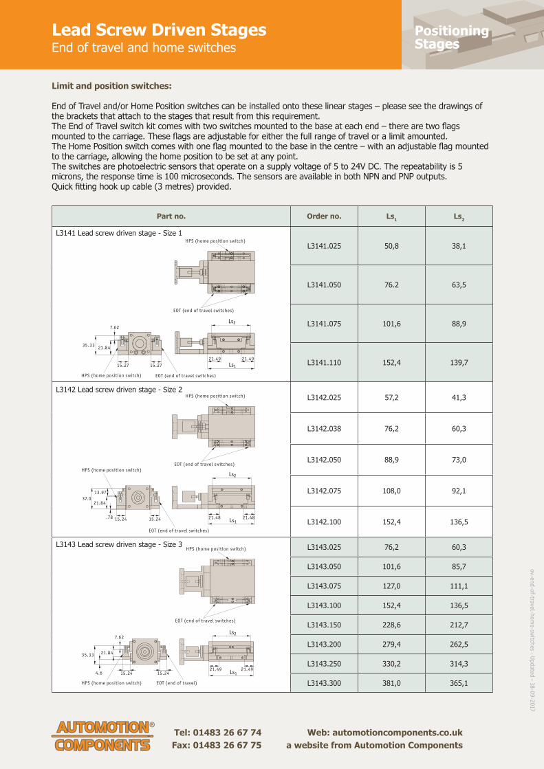
Positioning Stages
Tel: 01483 26 67 74 Web: automotioncomponents.co.uk Fax: 01483 26 67 75 a website from Automotion Components
Lead Screw Driven StagesEnd of travel and home switches
Part no. Order no. Ls1 Ls2
L3141.025 50,8 38,1
L3141.050 76.2 63,5
L3141.075 101,6 88,9
L3141.110 152,4 139,7
L3142.025 57,2 41,3
L3142.038 76,2 60,3
L3142.050 88,9 73,0
L3142.075 108,0 92,1
L3142.100 152,4 136,5
L3143.025 76,2 60,3
L3143.050 101,6 85,7
L3143.075 127,0 111,1
L3143.100 152,4 136,5
L3143.150 228,6 212,7
L3143.200 279,4 262,5
L3143.250 330,2 314,3
L3143.300 381,0 365,1
L3141 Lead screw driven stage - Size 1
L3142 Lead screw driven stage - Size 2
L3143 Lead screw driven stage - Size 3
Limit and position switches:
End of Travel and/or Home Position switches can be installed onto these linear stages – please see the drawings of the brackets that attach to the stages that result from this requirement.The End of Travel switch kit comes with two switches mounted to the base at each end – there are two fl ags mounted to the carriage. These fl ags are adjustable for either the full range of travel or a limit amounted.The Home Position switch comes with one fl ag mounted to the base in the centre – with an adjustable fl ag mounted to the carriage, allowing the home position to be set at any point.The switches are photoelectric sensors that operate on a supply voltage of 5 to 24V DC. The repeatability is 5 microns, the response time is 100 microseconds. The sensors are available in both NPN and PNP outputs.Quick fi tting hook up cable (3 metres) provided.
Ls2
EOT (end of travel switches)
EOT (end of travel switches)
HPS (home position switch)
HPS (home position switch)
Ls1
21.49
35.33
15.27 15.27
21.84
7.62
21.49
Ls2
EOT (end of travel switches)
EOT (end of travel switches)
HPS (home position switch)
HPS (home position switch)
Ls1
37.021.84
15.24 15.24.78
13.97
21.4821.48
Ls2
EOT (end of travel switches)
EOT (end of travel)
HPS (home position switch)
HPS (home position switch)
Ls1
35.33
7.62
21.84
15.24 15.244.621.4921.49
ov-en
d-o
f-travel-ho
me-sw
itches - U
pd
ated - 1
8-0
9-2
017

Manual PositioningStages
Lead Screw Driven Stagessize 1 light duty, prepared for motor
Tel: 0333 207 4498
Created 2021-11-12
Email: [email protected]
Web: automotioncomponents.co.uk
L3141
Material
Black anodised aluminium. Hardened
cross roller or ball slides, lead screw
with anti-backlash nut.
Technical notes
Driven by lead screw 4.3mm
diameter 0.5mm pitch lead with
anti-backlash nut and zero backlash
flexible coupling for 5mm motor
shaft.
Cross roller versions are heavier duty.
Ready to accept Nema 14 motor.
Max. 1200 rpm.
Accuracy 3µ/25mm, repeatability 3µ.
Tips
Supplied without motor. We can
quote to supply motors or can also
supply with a handwheel for manual
operation.
Available in XY and XYZ
combinations.
Important notes
We can also offer end or travel
and/or home position switches,
normally open or normally closed,
with 3 metre cables.
-EHP = end-of-travel and home
switches, PNP.
-EHN = end-of-travel and home
switches, NPN.
Order No. Type Travel
Lead
screw
pitch
Max. load
Kg.l1
l2
l3
l4
l5
Max.
moment
Mx
Nm
Max.
moment
My
Nm
Max.
moment
Mz Nm
L3141.025B-X Ball 25 0,5 3,6 103,4 50,8 52,6 35 37 0,6 0,6 0,7
L3141.050B-X Ball 50 0,5 4,5 128,8 76,2 52,6 60 60 0,8 1,3 1,4
L3141.075B-X Ball 75 0,5 6,8 154,2 101,6 52,6 85 85 1,0 2,2 2,3
L3141.100B-X Ball 100 0,5 9,1 211,3 152,4 58,9 135 100 1,4 5,5 5,8
L3141.025R-X Roller 25 0,5 6,8 103,4 50,8 52,6 35 37 5,5 6,6 7,0
L3141.050R-X Roller 50 0,5 9,1 128,8 76,2 52,6 60 60 6,3 9,5 10,0
L3141.075R-X Roller 75 0,5 13,6 154,2 101,6 52,6 85 85 7,3 15,6 16,3
L3141.100R-X Roller 100 0,5 18,1 211,3 152,4 58,9 135 100 12,8 46,7 49,1

Manual PositioningStages
Lead Screw Driven XY & XYZ Stagessize 1 light duty, prepared for motor
Tel: 0333 207 4498
Created 2021-11-12
Email: [email protected]
Web: automotioncomponents.co.uk
L3141.XY
Material
Black anodised aluminium. Hardened
cross roller or ball slides, lead screw
with anti-backlash nut.
Technical notes
Driven by lead screw 4.3mm
diameter 0.5mm pitch lead with
anti-backlash nut and zero backlash
flexible coupling for 5mm motor
shaft. Cross roller versions are
heavier duty.
Ready to accept Nema 14 motor.
Max. 1200 rpm.
Accuracy 3µ/25mm, repeatability 3µ.
Tips
For other fixing and mounting hole
dimensions refer to the X stage
layout. Supplied without motor. We
can quote to supply motors or can
also supply with a handwheel for
manual operation.
Available in XY and XYZ
combinations.
Important notes
We can also offer end or travel
and/or home position switches,
normally open or normally closed,
with 3 metre cables.
-EHP = end-of-travel and home
switches, PNP.
-EHN = end-of-travel and home
switches, NPN.
Order No. Type Travel
Lead
screw
pitch
Max.
load
Kg.
l1
l2
l3
l4
l5
l6
l7
Max.
moment
Mx
Nm
Max.
moment
My
Nm
Max.
moment
Mz Nm
L3141.025B-XY XY Ball 25 0,5 3,6 103,4 50,8 52,6 35 37 30,20 7,87 0,63 0,68 0,71
L3141.050B-XY XY Ball 50 0,5 4,5 128,8 76,2 52,6 60 60 17,52 20,57 0,83 1,36 1,42
L3141.075B-XY XY Ball 75 0,5 6,8 154,2 101,6 52,6 85 85 25,15 34,04 1,04 2,26 2,37
L3141.100B-XY XY Ball 100 0,5 9,1 211,3 152,4 58,9 135 100 25,15 58,67 1,46 5,54 5,81
L3141.025R-XY XY Roller 25 0,5 6,8 103,4 50,8 52,6 35 37 30,20 7,87 5,50 6,68 7,02
L3141.050R-XY XY Roller 50 0,5 9,1 128,8 76,2 52,6 60 60 17,52 20,57 6,29 9,55 10,03
L3141.075R-XY XY Roller 75 0,5 13,6 154,2 101,6 52,6 85 85 25,15 34,04 7,34 15,59 16,37
L3141.100R-XY XY Roller 100 0,5 18,1 211,3 152,4 58,9 135 100 25,15 58,67 12,84 46,77 49,11
L3141.025B-XYZ XYZ Ball 25 0,5 3,6 103,4 50,8 52,6 35 37 30,20 7,87 0,63 0,68 0,71
L3141.050B-XYZ XYZ Ball 50 0,5 4,5 128,8 76,2 52,6 60 60 17,52 20,57 0,83 1,36 1,42
L3141.075B-XYZ XYZ Ball 75 0,5 6,8 154,2 101,6 52,6 85 85 25,15 34,04 1,04 2,26 2,37
L3141.100B-XYZ XYZ Ball 100 0,5 9,1 211,3 152,4 58,9 135 100 25,15 58,67 1,46 5,54 5,81
L3141.025R-XYZ XYZ Roller 25 0,5 6,8 103,4 50,8 52,6 35 37 30,20 7,87 5,50 6,68 7,02
L3141.050R-XYZ XYZ Roller 50 0,5 9,1 128,8 76,2 52,6 60 60 17,52 20,57 6,29 9,55 10,03
L3141.075R-XYZ XYZ Roller 75 0,5 13,6 154,2 101,6 52,6 85 85 25,15 34,04 7,34 15,59 16,37
L3141.100R-XYZ XYZ Roller 100 0,5 18,1 211,3 152,4 58,9 135 100 25,15 58,67 12,84 46,77 49,11

Manual PositioningStages
Lead Screw Driven Stagessize 2 medium duty, prepared for motor
Tel: 0333 207 4498
Created 2021-11-12
Email: [email protected]
Web: automotioncomponents.co.uk
L3142
Material
Black anodised aluminium. Hardened
cross roller or ball slides, lead screw
with anti-backlash nut.
Technical notes
Driven by lead screw 6.3mm
diameter 2mm pitch lead with
anti-backlash nut and zero backlash
flexible coupling for 5mm motor
shaft. Cross roller versions are
heavier duty.
For other lead screw pitches replace
-02X with -01X (for 1mm) and -03X
(for 3mm).
Ready to accept Nema 17 motor.
Max. 1200 rpm.
Accuracy 3µ/25mm, repeatability 3µ.
Tips
Supplied without motor. We can
quote to supply motors or can also
supply with a handwheel for manual
operation.
Available in XY and XYZ
combinations.
Important notes
We can also offer end or travel
and/or home position switches,
normally open or normally closed,
with 3 metre cables.
-EHP = end-of-travel and home
switches, PNP.
-EHN = end-of-travel and home
switches, NPN.
Order No. Type Travel
Lead
screw
pitch
Max. load
Kg.l1
l2
l3
l4
l5
Max.
moment
Mx
Nm
Max.
moment
My
Nm
Max.
moment
Mz Nm
L3142.025B-02X Ball 25 2 4,5 124,0 57,2 66,8 35 38 0,9 0,9 0,9
L3142.038B-02X Ball 38 2 6,8 143,0 76,2 66,8 55 55 1,4 2,0 2,1
L3142.050B-02X Ball 50 2 9,1 155,7 88,9 66,8 65 65 2,0 3,3 3,5
L3142.075B-02X Ball 75 2 11,0 174,8 108,0 66,8 85 85 2,5 4,7 4,9
L3142.100B-02X Ball 100 2 14,0 219,2 152,4 66,8 140 100 2,8 9,5 9,9
L3142.025R-02X Roller 25 2 9,1 124,0 57,2 66,8 35 38 6,3 6,6 7,0
L3142.038R-02X Roller 38 2 14,0 143,0 76,2 66,8 55 55 7,0 10,4 11,1
L3142.050R-02X Roller 50 2 18,0 155,7 88,9 66,8 65 65 8,4 13,3 14,0
L3142.075R-02X Roller 75 2 23,0 174,8 108,0 66,8 85 85 9,9 15,6 16,3
L3142.100R-02X Roller 100 2 27,0 219,2 152,4 66,8 140 100 14,8 46,7 49,1

Manual PositioningStages
Lead Screw Driven XY & XYZ Stagessize 2 medium duty, prepared for motor
Tel: 0333 207 4498
Created 2021-11-12
Email: [email protected]
Web: automotioncomponents.co.uk
L3142.XY
Material
Black anodised aluminium. Hardened
cross roller or ball slides, lead screw
with anti-backlash nut.
Technical notes
Driven by lead screw 6.3mm
diameter 2mm pitch lead with
anti-backlash nut and zero backlash
flexible coupling for 5mm motor
shaft. Cross roller versions are
heavier duty.
For other lead screw pitches replace
-02X with -01X (for 1mm) and -03X
(for 3mm).
Ready to accept Nema 17 motor.
Max. 1200 rpm.
Accuracy 3µ/25mm, repeatability 3µ.
Tips
For other fixing and mounting hole
dimensions refer to the X stage
layout. Supplied without motor. We
can quote to supply motors or can
also supply with a handwheel for
manual operation.
Available in XY and XYZ
combinations.
Important notes
We can also offer end or travel
and/or home position switches,
normally open or normally closed,
with 3 metre cables.
-EHP = end-of-travel and home
switches, PNP.
-EHN = end-of-travel and home
switches, NPN.
Order No. Type Travel
Lead
scre
w
pitch
Max.
load
Kg.
l1
l2
l3
l4
l5
l6
l7
Max.
moment
Mx
Nm
Max.
moment
My
Nm
Max.
moment
Mz Nm
L3142.025B-02XY XY Ball 25 2 4,5 124,0 57,2 66,8 35 38 41,91 6,35 0,93 0,90 0,95
L3142.038B-02XY XY Ball 38 2 6,8 143,0 76,2 66,8 55 55 32,39 15,88 1,44 2,03 2,14
L3142.050B-02XY XY Ball 50 2 9,1 155,7 88,9 66,8 65 65 26,04 22,23 2,02 3,32 3,49
L3142.075B-02XY XY Ball 75 2 11,0 174,8 108,0 66,8 85 85 16,51 31,75 2,50 4,70 4,94
L3142.100B-02XY XY Ball 100 2 14,0 219,2 152,4 66,8 140 100 45,09 53,98 2,88 9,49 9,97
L3142.025R-02XY XY Roller 25 2 9,1 124,0 57,2 66,8 35 38 41,91 6,35 6,34 6,68 7,02
L3142.038R-02XY XY Roller 38 2 14,0 143,0 76,2 66,8 55 55 32,39 15,88 7,06 10,42 11,12
L3142.050R-02XY XY Roller 50 2 18,0 155,7 88,9 66,8 65 65 26,04 22,23 8,46 13,36 14,03
L3142.075R-02XY XY Roller 75 2 23,0 174,8 108,0 66,8 85 85 16,51 31,75 9,86 15,59 16,29
L3142.100R-02XY XY Roller 100 2 27,0 219,2 152,4 66,8 140 100 45,09 53,98 14,80 46,77 49,11
L3142.025B-02XYZ XYZ Ball 25 2 4,5 124,0 57,2 66,8 35 38 41,91 6,35 0,93 0,90 0,95
L3142.038B-02XYZ XYZ Ball 38 2 6,8 143,0 76,2 66,8 55 55 32,39 15,88 1,44 2,03 2,14
L3142.050B-02XYZ XYZ Ball 50 2 9,1 155,7 88,9 66,8 65 65 26,04 22,23 2,02 3,32 3,49
L3142.075B-02XYZ XYZ Ball 75 2 11,0 174,8 108,0 66,8 85 85 16,51 31,75 2,50 4,70 4,94
L3142.100B-02XYZ XYZ Ball 100 2 14,0 219,2 152,4 66,8 140 100 45,09 53,98 2,88 9,49 9,97
L3142.025R-02XYZ XYZ Roller 25 2 9,1 124,0 57,2 66,8 35 38 41,91 6,35 6,34 6,68 7,02
L3142.038R-02XYZ XYZ Roller 38 2 14,0 143,0 76,2 66,8 55 55 32,385 15,88 7,06 10,42 11,12
L3142.050R-02XYZ XYZ Roller 50 2 18,0 155,7 88,9 66,8 65 65 26,035 22,23 8,46 13,36 14,03
L3142.075R-02XYZ XYZ Roller 75 2 23,0 174,8 108,0 66,8 85 85 16,51 31,75 9,86 15,59 16,29

Manual PositioningStages
Lead Screw Driven XY & XYZ Stagessize 2 medium duty, prepared for motor
Tel: 0333 207 4498
Created 2021-11-12
Email: [email protected]
Web: automotioncomponents.co.uk
Order No. Type Travel
Lead
scre
w
pitch
Max.
load
Kg.
l1
l2
l3
l4
l5
l6
l7
Max.
moment
Mx
Nm
Max.
moment
My
Nm
Max.
moment
Mz Nm
L3142.100R-02XYZ XYZ Roller 100 2 27,0 219,2 152,4 66,8 140 100 45,085 53,98 14,80 46,77 49,11

Manual PositioningStages
Lead Screw Driven Stagessize 3 medium duty, prepared for motor
Tel: 0333 207 4498
Created 2021-11-12
Email: [email protected]
Web: automotioncomponents.co.uk
L3143
Material
Black anodised aluminium. Hardened
cross roller or ball slides, lead screw
with anti-backlash nut.
Technical notes
Driven by lead screw 10mm diameter
2mm pitch lead with anti-backlash
nut and zero backlash flexible
coupling for 8mm motor shaft. Cross
roller versions are heavier duty.
For other lead screw pitches replace
-02X with -03X (for 3mm) and -20X
(for 20mm).
Ready to accept Nema 23 motor.
Max. 1200 rpm (for 2mm pitch) and
600 rpm for 3mm and 20mm lead
screw pitch options.
Accuracy 3µ/25mm, repeatability 3µ.
Tips
Supplied without motor. We can
quote to supply motors or can also
supply with a handwheel for manual
operation.
Available in XY and XYZ
combinations.
Important notes
We can also offer end or travel
and/or home position switches,
normally open or normally closed,
with 3 metre cables.
-EHP = end-of-travel and home
switches, PNP.
-EHN = end-of-travel and home
switches, NPN.
Order No. Type TravelLead screw
pitch
Max. load
Kg.
Max. moment
Mx
Nm
Max. moment
My
Nm
Max. moment
Mz Nm
l1
l2
L3143.025B-02X Ball 25 2 14 2,47 1,9 2,0 143 76
L3143.050B-02X Ball 50 2 16 5,11 6,8 7,2 168 102
L3143.075B-02X Ball 75 2 18 7,25 12,5 13,1 194 127
L3143.100B-02X Ball 100 2 20 9,72 10,5 21,5 219 152
L3143.150B-02X Ball 150 2 25 12,35 40,3 42,3 321 229
L3143.200B-02X Ball 200 2 27 13,84 49,9 53,9 397 279
L3143.250B-02X Ball 250 2 34 16,03 71,1 75,1 473 330
L3143.300B-02X Ball 300 2 41 16,89 81,0 85,1 549 381
L3143.025R-02X Roller 25 2 27 21,54 17,9 18,8 143 76
L3143.050R-02X Roller 50 2 32 28,72 35,8 37,5 168 102
L3143.075R-02X Roller 75 2 36 35,91 59,6 62,6 194 127
L3143.100R-02X Roller 100 2 41 42,75 74,5 78,3 219 152
L3143.150R-02X Roller 150 2 50 57,45 167,0 175,4 321 229
L3143.200R-02X Roller 200 2 54 64,35 206,8 223,3 397 279
L3143.250R-02X Roller 250 2 68 74,54 294,6 311,2 473 330
L3143.300R-02X Roller 300 2 82 78,78 324,4 352,7 549 381
Order No. l3
l4
l5
l6
l7
l8
l9
l10
l11
l12
L3143.025B-02X 67 55 13,0 10,5 60 - - 8,0 5 52
L3143.050B-02X 67 75 26,0 13,5 60 85 8,5 21,0 17 40
L3143.075B-02X 67 100 38,5 13,5 60 110 8,5 33,5 30 27
L3143.100B-02X 67 125 51,0 13,5 60 135 8,5 46,0 43 14

Manual PositioningStages
Lead Screw Driven Stagessize 3 medium duty, prepared for motor
Tel: 0333 207 4498
Created 2021-11-12
Email: [email protected]
Web: automotioncomponents.co.uk
Order No. l3
l4
l5
l6
l7
l8
l9
l10
l11
l12
L3143.150B-02X 92 - 89,5 39,5 100 175 27,0 64,5 81 -24
L3143.200B-02X 118 - 114,5 27,0 150 225 27,0 64,5 106 -49
L3143.250B-02X 143 - 140,0 15,0 200 275 27,5 65,0 132 -75
L3143.300B-02X 168 - 165,5 40,5 250 325 28,0 65,5 157 -100
L3143.025R-02X 67 55 13,0 10,5 60 - - 8,0 5 52
L3143.050R-02X 67 75 26,0 13,5 60 85 8,5 21,0 17 40
L3143.075R-02X 67 100 38,5 13,5 60 110 8,5 33,5 30 27
L3143.100R-02X 67 125 51,0 13,5 60 135 8,5 46,0 43 14
L3143.150R-02X 92 - 89,5 39,5 100 175 27,0 64,5 81 -24
L3143.200R-02X 118 - 114,5 27,0 150 225 27,0 64,5 106 -49
L3143.250R-02X 143 - 140,0 15,0 200 275 27,5 65,0 132 -75
L3143.300R-02X 168 - 165,5 40,5 250 325 28,0 65,5 157 -100

Manual PositioningStages
Lead Screw Driven XY & XYZ Stagessize 3 medium duty, prepared for motor
Tel: 0333 207 4498
Created 2021-11-12
Email: [email protected]
Web: automotioncomponents.co.uk
L3143.XY
Material
Black anodised aluminium. Hardened
cross roller or ball slides, lead screw
with anti-backlash nut.
Technical notes
Driven by lead screw 10mm diameter
2mm pitch lead with anti-backlash
nut and zero backlash flexible
coupling for 8mm motor shaft. Cross
roller versions are heavier duty.
For other lead screw pitches replace
-02X with -03X (for 3mm) and -20X
(for 20mm).
Ready to accept Nema 23 motor.
Max. 1200 rpm (for 2mm pitch) and
600 rpm for 3mm and 20mm lead
screw pitch options.
Accuracy 3µ/25mm, repeatability 3µ.
Tips
For other fixing and mounting hole
dimensions refer to the X stage
layout. Supplied without motor. We
can quote to supply motors or can
also supply with a handwheel for
manual operation.
Available in XY and XYZ
combinations.
Important notes
We can also offer end or travel
and/or home position switches,
normally open or normally closed,
with 3 metre cables.
-EHP = end-of-travel and home
switches, PNP.
-EHN = end-of-travel and home
switches, NPN.
Order No. Type TravelLead screw
pitch
Max. load
Kg.
Max. moment
Mx
Nm
Max. moment
My
Nm
Max. moment Mz
Nml1
l2
L3143.025B-02XY XY Ball 25 2 14 2,47 1,90 1,99 143 76
L3143.050B-02XY XY Ball 50 2 16 5,11 6,86 7,21 168 102
L3143.075B-02XY XY Ball 75 2 18 7,25 12,53 13,15 194 127
L3143.100B-02XY XY Ball 100 2 20 9,72 10,53 21,56 219 152
L3143.150B-02XY XY Ball 150 2 25 12,35 40,34 42,35 321 229
L3143.200B-02XY XY Ball 200 2 27 13,84 49,94 53,92 397 279
L3143.250B-02XY XY Ball 250 2 34 16,03 71,14 75,16 473 330
L3143.300B-02XY XY Ball 300 2 41 16,89 81,07 85,12 549 381
L3143.025R-02XY XY Roller 25 2 27 21,54 17,90 18,79 143 76
L3143.050R-02XY XY Roller 50 2 32 28,72 35,79 37,58 168 102
L3143.075R-02XY XY Roller 75 2 36 35,91 59,66 62,64 194 127
L3143.100R-02XY XY Roller 100 2 41 42,75 74,57 78,30 219 152
L3143.150R-02XY XY Roller 150 2 50 57,45 167,04 175,39 321 229
L3143.200R-02XY XY Roller 200 2 54 64,35 206,81 223,29 397 279
L3143.250R-02XY XY Roller 250 2 68 74,54 294,61 311,25 473 330
L3143.300R-02XY XY Roller 300 2 82 78,78 324,41 352,70 549 381
L3143.025B-02XYZ XYZ Ball 25 2 14 2,47 1,90 1,99 143 76
L3143.050B-02XYZ XYZ Ball 50 2 16 5,11 6,86 7,21 168 102
L3143.075B-02XYZ XYZ Ball 75 2 18 7,25 12,53 13,15 194 127
L3143.100B-02XYZ XYZ Ball 100 2 20 9,72 10,53 21,56 219 152
L3143.150B-02XYZ XYZ Ball 150 2 25 12,35 40,34 42,35 321 229

Manual PositioningStages
Lead Screw Driven XY & XYZ Stagessize 3 medium duty, prepared for motor
Tel: 0333 207 4498
Created 2021-11-12
Email: [email protected]
Web: automotioncomponents.co.uk
Order No. Type TravelLead screw
pitch
Max. load
Kg.
Max. moment
Mx
Nm
Max. moment
My
Nm
Max. moment Mz
Nml1
l2
L3143.200B-02XYZ XYZ Ball 200 2 27 13,84 49,94 53,92 397 279
L3143.250B-02XYZ XYZ Ball 250 2 34 16,03 71,14 75,16 473 330
L3143.300B-02XYZ XYZ Ball 300 2 41 16,89 81,07 85,12 549 381
L3143.025R-02XYZ XYZ Roller 25 2 27 21,54 17,90 18,79 143 76
L3143.050R-02XYZ XYZ Roller 50 2 32 28,72 35,79 37,58 168 102
L3143.075R-02XYZ XYZ Roller 75 2 36 35,91 59,66 62,64 194 127
L3143.100R-02XYZ XYZ Roller 100 2 41 42,75 74,57 78,30 219 152
L3143.150R-02XYZ XYZ Roller 150 2 50 57,45 167,04 175,39 321 229
L3143.200R-02XYZ XYZ Roller 200 2 54 64,35 206,81 223,29 397 279
L3143.250R-02XYZ XYZ Roller 250 2 68 74,54 294,61 311,25 473 330
L3143.300R-02XYZ XYZ Roller 300 2 82 78,78 324,41 352,70 549 381
Order No. l3
l4
l5
l6
l7
l8
l9
l10
l11
l12
h1
h2
h3
L3143.025B-02XY 67 55 13,0 10,5 60 - - 8,0 5 52 95 - 8
L3143.050B-02XY 67 75 26,0 13,5 60 85 8,5 21,0 17 40 95 - 8
L3143.075B-02XY 67 100 38,5 13,5 60 110 8,5 33,5 30 27 95 - 8
L3143.100B-02XY 67 125 51,0 13,5 60 135 8,5 46,0 43 14 95 - 19
L3143.150B-02XY 92 - 89,5 39,5 100 175 27,0 64,5 81 -24 104 10 44
L3143.200B-02XY 118 - 114,5 27,0 150 225 27,0 64,5 106 -49 104 10 70
L3143.250B-02XY 143 - 140,0 15,0 200 275 27,5 65,0 132 -75 104 10 95
L3143.300B-02XY 168 - 165,5 40,5 250 325 28,0 65,5 157 -100 104 10 121
L3143.025R-02XY 67 55 13,0 10,5 60 - - 8,0 5 52 95 - 8
L3143.050R-02XY 67 75 26,0 13,5 60 85 8,5 21,0 17 40 95 - 8
L3143.075R-02XY 67 100 38,5 13,5 60 110 8,5 33,5 30 27 95 - 8
L3143.100R-02XY 67 125 51,0 13,5 60 135 8,5 46,0 43 14 95 - 19
L3143.150R-02XY 92 - 89,5 39,5 100 175 27,0 64,5 81 -24 104 10 44
L3143.200R-02XY 118 - 114,5 27,0 150 225 27,0 64,5 106 -49 104 10 70
L3143.250R-02XY 143 - 140,0 15,0 200 275 27,5 65,0 132 -75 104 10 95
L3143.300R-02XY 168 - 165,5 40,5 250 325 28,0 65,5 157 -100 104 10 121
L3143.025B-02XYZ 67 55 13,0 10,5 60 - - 8,0 5 52 95 - 8
L3143.050B-02XYZ 67 75 26,0 13,5 60 85 8,5 21,0 17 40 95 - 8
L3143.075B-02XYZ 67 100 38,5 13,5 60 110 8,5 33,5 30 27 95 - 8
L3143.100B-02XYZ 67 125 51,0 13,5 60 135 8,5 46,0 43 14 95 - 19
L3143.150B-02XYZ 92 - 89,5 39,5 100 175 27,0 64,5 81 -24 104 10 44
L3143.200B-02XYZ 118 - 114,5 27,0 150 225 27,0 64,5 106 -49 104 10 70
L3143.250B-02XYZ 143 - 140,0 15,0 200 275 27,5 65,0 132 -75 104 10 95
L3143.300B-02XYZ 168 - 165,5 40,5 250 325 28,0 65,5 157 -100 104 10 121
L3143.025R-02XYZ 67 55 13,0 10,5 60 - - 8,0 5 52 95 - 8
L3143.050R-02XYZ 67 75 26,0 13,5 60 85 8,5 21,0 17 40 95 - 8
L3143.075R-02XYZ 67 100 38,5 13,5 60 110 8,5 33,5 30 27 95 - 8
L3143.100R-02XYZ 67 125 51,0 13,5 60 135 8,5 46,0 43 14 95 - 19
L3143.150R-02XYZ 92 - 89,5 39,5 100 175 27,0 64,5 81 -24 104 10 44
L3143.200R-02XYZ 118 - 114,5 27,0 150 225 27,0 64,5 106 -49 104 10 70
L3143.250R-02XYZ 143 - 140,0 15,0 200 275 27,5 65,0 132 -75 104 10 95
L3143.300R-02XYZ 168 - 165,5 40,5 250 325 28,0 65,5 157 -100 104 10 121

Manual PositioningStages
Ball Screw Linear Tables20mm shafts
Tel: 0333 207 4498
Created 2021-11-12
Email: [email protected]
Web: automotioncomponents.co.uk
L3149.20
Material
Hardened steel shafts.
Aluminium alloy bearing block and
end supports.
Self-aligning linear ball bearings,
hardened and ground steel body with
resin retainers.
Steel ball screw and nut.
Technical notes
Self-aligning linear ball bearings are
used as standard to ensure that the
balls are permanently in contact with
the shaft, even if the shafts bend
slightly due to the load put on the
table.
Different stroke lengths available on
request.
Tips
Handwheels to suit are available (see
part number L1455)
Bellows protection of the lead screw
and shaft is available, add -B suffix to
the part number.
We strongly recommend you add
50mm to your required.
Order No. Stroke l1
w1
h1
l2
l3
l4
l5
l6
l7
l8
l9
l10
w2 X Kg
L3149.20-0100 100 250 130 48 130 115 20 20 49 25 18 3 1,8 108 6,4
L3149.20-0150 150 300 130 48 130 115 20 20 49 25 18 3 1,8 108 9,6
L3149.20-0200 200 350 130 48 130 115 20 20 49 25 18 3 1,8 108 12,8
L3149.20-0250 250 400 130 48 130 115 20 20 49 25 18 3 1,8 108 16,0
L3149.20-0300 300 450 130 48 130 115 20 20 49 25 18 3 1,8 108 19,2
L3149.20-0350 350 500 130 48 130 115 20 20 49 25 18 3 1,8 108 22,4
L3149.20-0400 400 550 130 48 130 115 20 20 49 25 18 3 1,8 108 25,6
L3149.20-0450 450 600 130 48 130 115 20 20 49 25 18 3 1,8 108 28,8
L3149.20-0500 500 650 130 48 130 115 20 20 49 25 18 3 1,8 108 32,0
L3149.20-0550 550 700 130 48 130 115 20 20 49 25 18 3 1,8 108 35,2
L3149.20-0600 600 750 130 48 130 115 20 20 49 25 18 3 1,8 108 38,4
L3149.20-0650 650 800 130 48 130 115 20 20 49 25 18 3 1,8 108 41,6
L3149.20-0700 700 850 130 48 130 115 20 20 49 25 18 3 1,8 108 44,8
L3149.20-0750 750 900 130 48 130 115 20 20 49 25 18 3 1,8 108 48,0
L3149.20-0800 800 950 130 48 130 115 20 20 49 25 18 3 1,8 108 51,2
L3149.20-0850 850 1000 130 48 130 115 20 20 49 25 18 3 1,8 108 54,4
L3149.20-0900 900 1050 130 48 130 115 20 20 49 25 18 3 1,8 108 57,6
L3149.20-0950 950 1100 130 48 130 115 20 20 49 25 18 3 1,8 108 60,8
L3149.20-1000 1000 1150 130 48 130 115 20 20 49 25 18 3 1,8 108 64,0
Order No. w3
d1
d2
d3
d4
d5
d6
h2
h3
h4
h5
h6
Ball Screw
Ø x lead
Max. static
load N
L3149.20-0100 72 6,8 11 M8x18 11 18 10 24 2 8,5 13,5 7,5 16x05 6750
L3149.20-0150 72 6,8 11 M8x18 11 18 10 24 2 8,5 13,5 7,5 16x05 6750
L3149.20-0200 72 6,8 11 M8x18 11 18 10 24 2 8,5 13,5 7,5 16x05 6750
L3149.20-0250 72 6,8 11 M8x18 11 18 10 24 2 8,5 13,5 7,5 16x05 6750
L3149.20-0300 72 6,8 11 M8x18 11 18 10 24 2 8,5 13,5 7,5 16x05 6750
L3149.20-0350 72 6,8 11 M8x18 11 18 10 24 2 8,5 13,5 7,5 16x05 6000
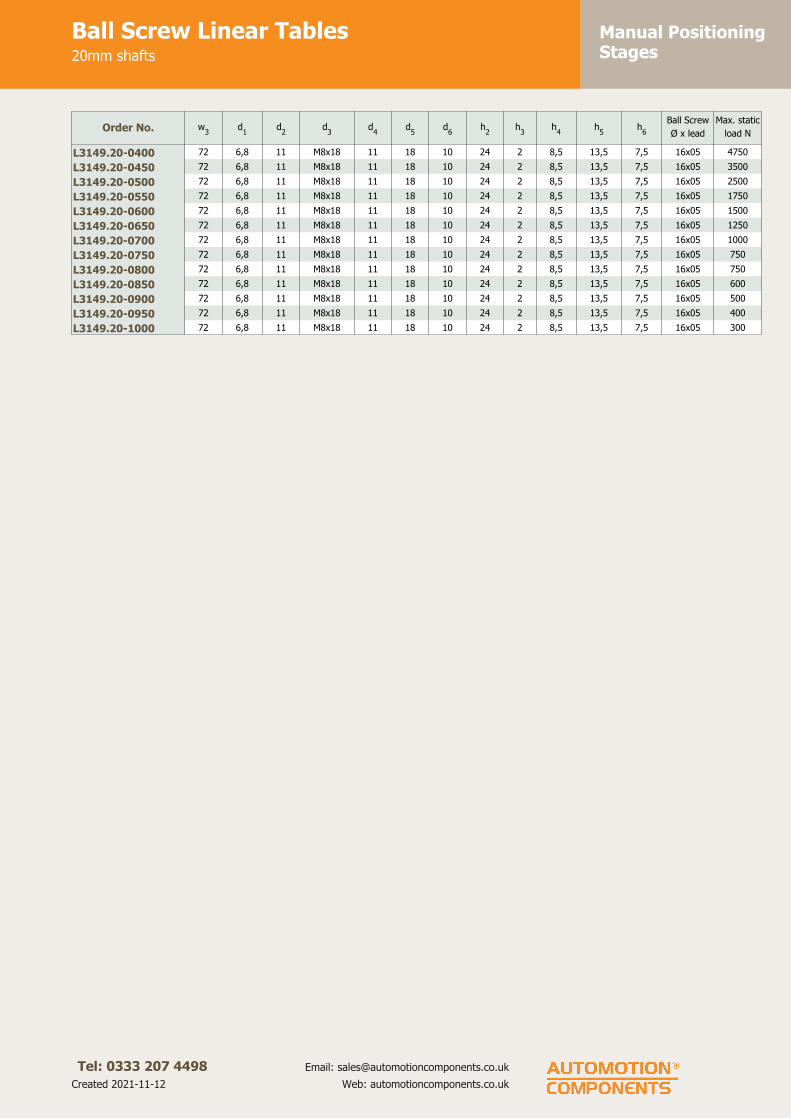
Manual PositioningStages
Ball Screw Linear Tables20mm shafts
Tel: 0333 207 4498
Created 2021-11-12
Email: [email protected]
Web: automotioncomponents.co.uk
Order No. w3
d1
d2
d3
d4
d5
d6
h2
h3
h4
h5
h6
Ball Screw
Ø x lead
Max. static
load N
L3149.20-0400 72 6,8 11 M8x18 11 18 10 24 2 8,5 13,5 7,5 16x05 4750
L3149.20-0450 72 6,8 11 M8x18 11 18 10 24 2 8,5 13,5 7,5 16x05 3500
L3149.20-0500 72 6,8 11 M8x18 11 18 10 24 2 8,5 13,5 7,5 16x05 2500
L3149.20-0550 72 6,8 11 M8x18 11 18 10 24 2 8,5 13,5 7,5 16x05 1750
L3149.20-0600 72 6,8 11 M8x18 11 18 10 24 2 8,5 13,5 7,5 16x05 1500
L3149.20-0650 72 6,8 11 M8x18 11 18 10 24 2 8,5 13,5 7,5 16x05 1250
L3149.20-0700 72 6,8 11 M8x18 11 18 10 24 2 8,5 13,5 7,5 16x05 1000
L3149.20-0750 72 6,8 11 M8x18 11 18 10 24 2 8,5 13,5 7,5 16x05 750
L3149.20-0800 72 6,8 11 M8x18 11 18 10 24 2 8,5 13,5 7,5 16x05 750
L3149.20-0850 72 6,8 11 M8x18 11 18 10 24 2 8,5 13,5 7,5 16x05 600
L3149.20-0900 72 6,8 11 M8x18 11 18 10 24 2 8,5 13,5 7,5 16x05 500
L3149.20-0950 72 6,8 11 M8x18 11 18 10 24 2 8,5 13,5 7,5 16x05 400
L3149.20-1000 72 6,8 11 M8x18 11 18 10 24 2 8,5 13,5 7,5 16x05 300

Manual PositioningStages
Ball Screw Linear Tables30mm shafts
Tel: 0333 207 4498
Created 2021-11-12
Email: [email protected]
Web: automotioncomponents.co.uk
L3149.30
Material
Hardened steel shafts.
Aluminium alloy bearing block and
end supports.
Self-aligning linear ball bearings,
hardened and ground steel body with
resin retainers.
Steel ball screw and nut.
Technical notes
Self-aligning linear ball bearings are
used as standard to ensure that the
balls are permanently in contact with
the shaft, even if the shafts bend
slightly due to the load put on the
table.
Different stroke lengths available on
request.
Tips
Handwheels to suit are available (see
part number L1455)
Bellows protection of the lead screw
and shaft is available, add -B suffix to
the part number.
We strongly recommend you add
50mm to your required.
Order No. Stroke l1
w1
h1
l2
l3
l4
l5
l6
l7
l8
l9
l10
w2
Xg
L3149.30-0100 100 322 200 70 200 184 22 22 80 45 36 5 3 178 17,1
L3149.30-0150 150 372 200 70 200 184 22 22 80 45 36 5 3 178 25,6
L3149.30-0200 200 422 200 70 200 184 22 22 80 45 36 5 3 178 34,2
L3149.30-0250 250 472 200 70 200 184 22 22 80 45 36 5 3 178 42,7
L3149.30-0300 300 522 200 70 200 184 22 22 80 45 36 5 3 178 51,3
L3149.30-0350 350 572 200 70 200 184 22 22 80 45 36 5 3 178 59,8
L3149.30-0400 400 622 200 70 200 184 22 22 80 45 36 5 3 178 68,4
L3149.30-0450 450 672 200 70 200 184 22 22 80 45 36 5 3 178 76,9
L3149.30-0500 500 722 200 70 200 184 22 22 80 45 36 5 3 178 85,5
L3149.30-0550 550 772 200 70 200 184 22 22 80 45 36 5 3 178 94,0
L3149.30-0600 600 822 200 70 200 184 22 22 80 45 36 5 3 178 102,6
L3149.30-0650 650 872 200 70 200 184 22 22 80 45 36 5 3 178 111,1
L3149.30-0700 700 922 200 70 200 184 22 22 80 45 36 5 3 178 119,7
L3149.30-0750 750 972 200 70 200 184 22 22 80 45 36 5 3 178 128,2
L3149.30-0800 800 1022 200 70 200 184 22 22 80 45 36 5 3 178 136,8
L3149.30-0850 850 1072 200 70 200 184 22 22 80 45 36 5 3 178 145,3
L3149.30-0900 900 1122 200 70 200 184 22 22 80 45 36 5 3 178 153,9
L3149.30-0950 950 1172 200 70 200 184 22 22 80 45 36 5 3 178 162,4
L3149.30-1000 1000 1222 200 70 200 184 22 22 80 45 36 5 3 178 171,0
Order No. w3
d1
d2
d3
d4
d5
d6
h2
h3
h4
h5
h6
Ball ScrewMax Static
Load N
L3149.30-0100 130 6,8 11 M8x18 13 20 16 36 2 8,5 14 15 32x05 11500
L3149.30-0150 130 6,8 11 M8x18 13 20 16 36 2 8,5 14 15 32x05 11500
L3149.30-0200 130 6,8 11 M8x18 13 20 16 36 2 8,5 14 15 32x05 11500
L3149.30-0250 130 6,8 11 M8x18 13 20 16 36 2 8,5 14 15 32x05 11500
L3149.30-0300 130 6,8 11 M8x18 13 20 16 36 2 8,5 14 15 32x05 11500

Manual PositioningStages
Ball Screw Linear Tables30mm shafts
Tel: 0333 207 4498
Created 2021-11-12
Email: [email protected]
Web: automotioncomponents.co.uk
Order No. w3
d1
d2
d3
d4
d5
d6
h2
h3
h4
h5
h6
Ball ScrewMax Static
Load N
L3149.30-0350 130 6,8 11 M8x18 13 20 16 36 2 8,5 14 15 32x05 11500
L3149.30-0400 130 6,8 11 M8x18 13 20 16 36 2 8,5 14 15 32x05 11500
L3149.30-0450 130 6,8 11 M8x18 13 20 16 36 2 8,5 14 15 32x05 11500
L3149.30-0500 130 6,8 11 M8x18 13 20 16 36 2 8,5 14 15 32x05 10800
L3149.30-0550 130 6,8 11 M8x18 13 20 16 36 2 8,5 14 15 32x05 9000
L3149.30-0600 130 6,8 11 M8x18 13 20 16 36 2 8,5 14 15 32x05 7000
L3149.30-0650 130 6,8 11 M8x18 13 20 16 36 2 8,5 14 15 32x05 5750
L3149.30-0700 130 6,8 11 M8x18 13 20 16 36 2 8,5 14 15 32x05 4800
L3149.30-0750 130 6,8 11 M8x18 13 20 16 36 2 8,5 14 15 32x05 4000
L3149.30-0800 130 6,8 11 M8x18 13 20 16 36 2 8,5 14 15 32x05 3500
L3149.30-0850 130 6,8 11 M8x18 13 20 16 36 2 8,5 14 15 32x05 3000
L3149.30-0900 130 6,8 11 M8x18 13 20 16 36 2 8,5 14 15 32x05 2500
L3149.30-0950 130 6,8 11 M8x18 13 20 16 36 2 8,5 14 15 32x05 2250
L3149.30-1000 130 6,8 11 M8x18 13 20 16 36 2 8,5 14 15 32x05 2000

Manual PositioningStages
Lead Screw Linear Stagessingle carriage
Tel: 0333 207 4498
Created 2021-11-12
Email: [email protected]
Web: automotioncomponents.co.uk
L3147.S
Material
Aluminium body (anodised), with die
cast zinc end plates. Steel lead screw
with bronze nut. Stainless steel dust
cover (AISI 304).
Technical notes
Uses a 14 trapezoidal lead screw with
3mm pitch.
Rigid, economical and light-weight.
Can be used as a single in series, or a
single or double unit in parallel,
(connected via pulleys and belt
drive).
Ideal for slide adjustment on
conveyors, fixtures, packing machines
etc.
Tips
Often used in conjunction with one
touch lock spindles, position
indicators, handwheels etc.
Order No. Travel l1
Rotation
directionl2
XKg.
L3147.S150-L 150 Counter-clockwise 250 1,7
L3147.S200-R 200 Clockwise 300 1,9
L3147.S200-L 200 Counter-clockwise 300 1,9
L3147.S300-R 300 Clockwise 400 2,0
L3147.S300-L 300 Counter-clockwise 400 2,0
L3147.S150-R 150 Clockwise 250 1,7
L3147.S250-R 250 Clockwise 350 2,0
L3147.S250-L 250 Counter-clockwise 350 2,0
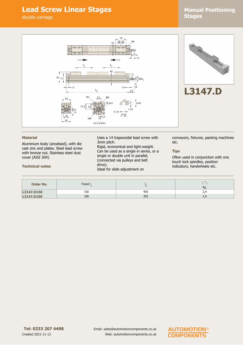
Manual PositioningStages
Lead Screw Linear Stagesdouble carriage
Tel: 0333 207 4498
Created 2021-11-12
Email: [email protected]
Web: automotioncomponents.co.uk
L3147.D
Material
Aluminium body (anodised), with die
cast zinc end plates. Steel lead screw
with bronze nut. Stainless steel dust
cover (AISI 304).
Technical notes
Uses a 14 trapezoidal lead screw with
3mm pitch.
Rigid, economical and light-weight.
Can be used as a single in series, or a
single or double unit in parallel,
(connected via pulleys and belt
drive).
Ideal for slide adjustment on
conveyors, fixtures, packing machines
etc.
Tips
Often used in conjunction with one
touch lock spindles, position
indicators, handwheels etc.
Order No. Travel l1
l2
XKg.
L3147.D150 150 455 2,4
L3147.D100 100 355 2,4

Manual PositioningStages
Ball Screw Linear Tables12mm shafts
Tel: 0333 207 4498
Created 2021-11-12
Email: [email protected]
Web: automotioncomponents.co.uk
L3149.12
Material
Hardened steel shafts.
Aluminium alloy bearing block and
end supports.
Self-aligning linear ball bearings,
hardened and ground steel body with
resin retainers.
Steel ball screw and nut.
Technical notes
Self-aligning linear ball bearings are
used as standard to ensure that the
balls are permanently in contact with
the shaft, even if the shafts bend
slightly due to the load put on the
table.
Different stroke lengths available on
request.
Tips
Handwheels to suit are available (see
part number L1455)
Bellows protection of the lead screw
and shaft is available, add -B suffix to
the part number.
We strongly recommend you add
50mm to your required stroke.
Order No. Stroke l1
w1
h1
l2
l3
l4
l5
l6
l7
w2
w3
XKg
L3149.12-0100 100 198 85 31,5 85 73 12 14 23 8 73 45 2,2
L3149.12-0150 150 248 85 31,5 85 73 12 14 23 8 73 45 3,3
L3149.12-0200 200 298 85 31,5 85 73 12 14 23 8 73 45 4,4
L3149.12-0250 250 348 85 31,5 85 73 12 14 23 8 73 45 5,5
L3149.12-0300 300 398 85 31,5 85 73 12 14 23 8 73 45 6,6
L3149.12-0350 350 448 85 31,5 85 73 12 14 23 8 73 45 7,7
L3149.12-0400 400 498 85 31,5 85 73 12 14 23 8 73 45 8,8
L3149.12-0450 450 548 85 31,5 85 73 12 14 23 8 73 45 9,9
L3149.12-0500 500 598 85 31,5 85 73 12 14 23 8 73 45 10,10
Order No. d1
d2
d3
d4
d5
d6
h2
h3
h4
h5
h6
Ball ScrewMax Static
Load N
L3149.12-0100 5,2 10 M6x12 5,5 10,7 4 15 1,5 5,5 5,7 7,5 8x2,5 3900
L3149.12-0150 5,2 10 M6x12 5,5 10,7 4 15 1,5 5,5 5,7 7,5 8x2,5 3100
L3149.12-0200 5,2 10 M6x12 5,5 10,7 4 15 1,5 5,5 5,7 7,5 8x2,5 2500
L3149.12-0250 5,2 10 M6x12 5,5 10,7 4 15 1,5 5,5 5,7 7,5 8x2,5 1500
L3149.12-0300 5,2 10 M6x12 5,5 10,7 4 15 1,5 5,5 5,7 7,5 8x2,5 1200
L3149.12-0350 5,2 10 M6x12 5,5 10,7 4 15 1,5 5,5 5,7 7,5 8x2,5 1000
L3149.12-0400 5,2 10 M6x12 5,5 10,7 4 15 1,5 5,5 5,7 7,5 8x2,5 900
L3149.12-0450 5,2 10 M6x12 5,5 10,7 4 15 1,5 5,5 5,7 7,5 8x2,2 750
L3149.12-0500 5,2 10 M6x12 5,5 10,7 4 15 1,5 5,5 5,7 7,5 8x2,5 500

Positioning Stages
Tel: 01483 26 67 74 Web: automotioncomponents.co.uk Fax: 01483 26 67 75 a website from Automotion Components
Heavy Duty Linear StagesOverview
Z
Y
X
My
Mz
Mx
Heavy duty linear stages
Moment loads
XYθ stage Motorised stage XY stage
Plain stages Lead screw & handle Lead screw & knob
All loads shown in tables are based upon an evenly distributed load with slide in centre position. All loads apply to a single slide.
Available with the following sliding elements:Cross roller: For medium loads, low friction.Dovetail: Less expensive, higher friction, higher loads.Needle roller: Highest loads, low friction, more expensive.
ov-h
eavy-du
ty-stages-o
verview - U
pd
ated - 1
8-0
9-2
017

Positioning Stages
Tel: 01483 26 67 74 Web: automotioncomponents.co.uk Fax: 01483 26 67 75 a website from Automotion Components
Precision Linear StagesOverview
Crossed roller Dovetail Needle roller
Width 30-300mm 30-400mm 100-400mm
Stroke 12-950mm 10-600mm 50-800mm
Load capacity 29 kN 33 kN 59 kN
Max speed 20 m/min 15 m/min 20 m/min
Coeffi cient of fi ction 0,003 0,1 0,003
Straightness of travel (μ) Stroke up to Slide type Slide length up to
Parallelism (μ)
a b c d
2 3 50 Cross roller & Needle roller 100 12 103 4 100 Cross roller & Needle roller 200 18 155 6 200 Cross roller & Needle roller 300 21 186 8 300 Cross roller & Needle roller 400 25 228 10 400 Cross roller & Needle roller 600 32 3010 14 500 Cross roller & Needle roller 800 45 4012 17 600 Cross roller & Needle roller 1000 60 5015 20 700 Cross roller & Needle roller 1210 80 6018 25 800 Cross roller & Needle roller3 5 50 Dovetail 100 15 125 8 100 Dovetail 200 22 188 12 200 Dovetail 300 28 2510 15 300 Dovetail 400 35 3014 20 400 Dovetail 600 50 4018 25 500 Dovetail 800 60 5020 30 600 Dovetail 1000 80 6520 30 600 Dovetail 1210 100 80
b
a
b
a
a
c
d
Height tolerance for roller and dovetail slides± 0,01mm. DIN 7168 medium is the dimensional variations of the sliders. Closer tolerances upon request.
Rectangularity of XY-tables± 0,005mm per 100mm slide length
ov-p
recision
-linear-stag
es-overview
- Up
dated
- 18
-09
-20
17

Positioning Stages
Tel: 01483 26 67 74 Web: automotioncomponents.co.uk Fax: 01483 26 67 75 a website from Automotion Components
Heavy Duty Linear StagesStandard mounting holes
Carriage Base
w1 l1 la lb ha da wa l2 lc ld wb da ha50 76 36 - 4 4xM4 24 50 20 - 37 4xM4 450 102 62 - 4 4xM4 24 76 36 - 37 4xM4 450 152 112 - 4 4xM4 24 101 61 - 37 4xM4 475 102 62 - 5 4xM5 34 76 36 - 56 4xM5 575 127 87 - 5 4xM5 34 101 61 - 56 4xM5 575 152 112 - 5 4xM5 34 101 61 - 56 4xM5 5100 152 112 - 6 4xM6 52 126 86 - 74 4xM6 8100 203 163 - 6 4xM6 52 152 112 - 74 4xM6 8100 254 214 - 6 4xM6 52 203 163 - 74 4xM6 8100 305 90 265 6 8xM6 52 228 188 - 74 8xM6 8150 203 163 - 6 4xM8 95 152 112 - 120 4xM8 12150 305 90 265 6 8xM8 95 203 163 - 120 8xM8 12150 406 240 366 6 8xM8 95 304 90 264 120 8xM8 12150 406 240 366 6 8xM8 95 253 213 - 120 8xM8 12200 457 240 417 8 8xM10 120 304 90 264 155 8xM10 8200 610 190 570 8 8xM10 120 406 190 366 155 8xM10 8300 410 190 370 15 8xM10 200 308 90 268 255 8xM10 15300 610 190 570 15 8xM12 200 408 190 368 255 8xM12 15300 710 290 670 15 8xM12 200 408 190 368 255 8xM12 15300 910 290 870 15 8xM12 200 508 290 468 255 8xM12 15300 1010 490 970 15 8xM12 200 508 290 468 255 8xM12 15300 1210 490 1170 15 8xM12 200 608 190 568 255 8xM12 15
w1
wb
wa
lb
l1
la
da
ha
wb
wa
ld
l2
lc
ha
da
Carriage - Standard holes Base - Standard holes
ov-stan
dard
-mo
un
ting
-ho
les - Up
dated
- 18
-09
-20
17
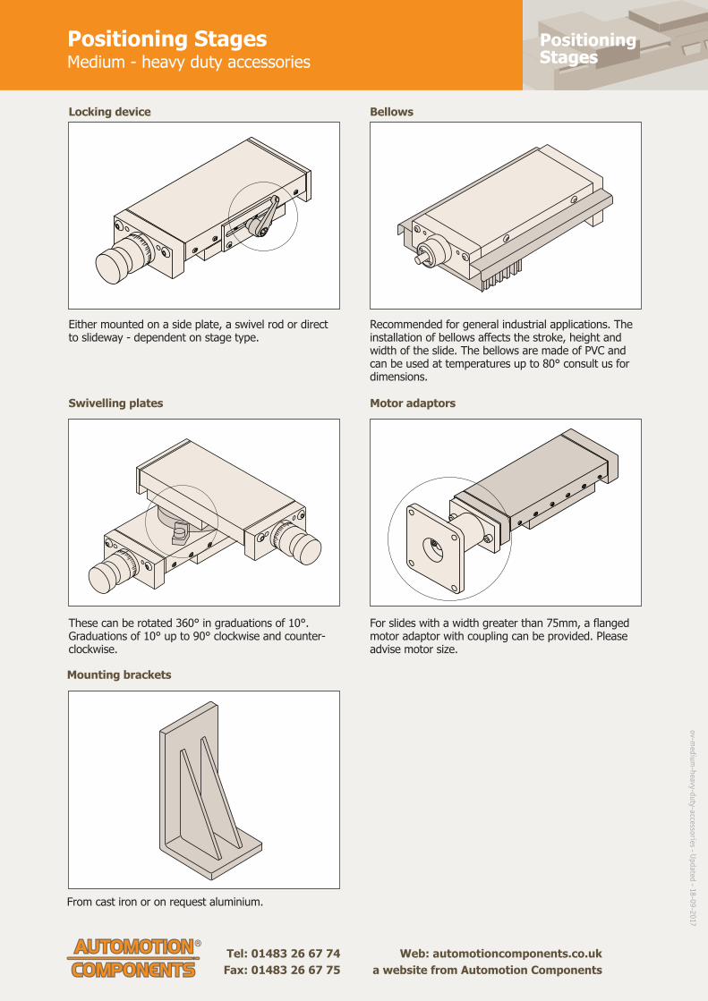
Positioning Stages
Tel: 01483 26 67 74 Web: automotioncomponents.co.uk Fax: 01483 26 67 75 a website from Automotion Components
Positioning StagesMedium - heavy duty accessories
Locking device
Swivelling plates
Bellows
Motor adaptors
Mounting brackets
Either mounted on a side plate, a swivel rod or direct to slideway - dependent on stage type.
These can be rotated 360° in graduations of 10°. Graduations of 10° up to 90° clockwise and counter-clockwise.
From cast iron or on request aluminium.
Recommended for general industrial applications. The installation of bellows aff ects the stroke, height and width of the slide. The bellows are made of PVC and can be used at temperatures up to 80° consult us for dimensions.
For slides with a width greater than 75mm, a fl anged motor adaptor with coupling can be provided. Please advise motor size.
ov-m
ediu
m-h
eavy-du
ty-accessories - U
pd
ated - 1
8-0
9-2
017

Manual PositioningStages
Plain Positioning Stagescross roller
Tel: 0333 207 4498
Created 2021-11-12
Email: [email protected]
Web: automotioncomponents.co.uk
L3170
Material
Cast iron body (ENGJL-250), with
hardened cross roller linear rail set.
Can also be supplied with an
aluminium body when lighter weight
stages are required (approx. 50% of
weight of standard slides and have
50% of the load capacity).
Technical notes
Suitable for horizontal and vertical
applications requiring smooth
movement, long life and high load
capacity. Other versions are also
available - dovetail slides (L3480) for
vibration damping, and needle roller
slides (L3490) for even higher load
ratings. Load ratings are based on
even surface loading with the slide in
the centre position, and apply to a
single slide.
Coefficient of friction 0,003.
Tips
With no lead screw drive.
Replace -* with
-X for X axis stage
- XY for X,Y axes stage
-XYT for X,Y,. stage
Centre mounting of compound slides
is standard. Please advise dimensions
w2
and l5
when off-centre mounting
is required.
Important notes
See technical pages for straightness
and parallelism accuracy and
standard carriage and base fixing
holes - other fixing holes can be
machined on request.
3D CAD models available.
Order No. w1
StrokeMax.
load kNl1
h1
l2
l3
l4
l5
XKg
L3170.050-022-* 50 22 0,34 76 25 50 88 6 13,0 0,6
L3170.050-025-* 50 25 0,59 102 25 76 114 6 26,0 0,8
L3170.050-050-* 50 50 0,74 152 25 101 164 6 51,0 1,1
L3170.075-025-* 75 25 0,59 102 32 76 114 6 13,5 1,8
L3170.075-026-* 75 25 0,84 127 32 101 139 6 26,0 2,0
L3170.075-050-* 75 50 0,74 152 32 101 164 6 38,5 2,5
L3170.100-025-* 100 25 1,08 152 37 126 164 6 26,0 4,0
L3170.100-050-* 100 50 1,23 203 37 152 215 6 51,5 4,7
L3170.100-051-* 100 50 1,72 254 37 203 266 6 77,0 6,1
L3170.100-075-* 100 75 1,82 305 37 228 317 6 102,5 7,0
L3170.150-050-* 150 50 2,60 203 50 152 219 8 26,5 10,0
L3170.150-100-* 150 100 3,20 305 50 203 321 8 77,5 13,2
L3170.150-101-* 150 100 5,43 406 50 304 422 8 128,0 18,0
L3170.150-150-* 150 150 3,82 406 50 253 422 8 128,0 16,5
L3170.200-150-* 200 150 5,03 457 58 304 473 8 128,5 30,0
L3170.200-200-* 200 200 6,64 610 58 406 626 8 205,0 40,0
L3170.300-100-* 300 100 8,38 410 75 308 430 10 55,0 59,0
L3170.300-200-* 300 200 10,4 610 75 408 630 10 155,0 80,0
L3170.300-300-* 300 300 8,38 710 75 408 730 10 205,0 91,5
L3170.300-400-* 300 400 10,4 910 75 508 930 10 305,0 110
L3170.300-500-* 300 500 8,38 1010 75 508 1030 10 355,0 125
L3170.300-600-* 300 600 10,4 1210 75 608 1230 10 455,0 145

Manual PositioningStages
Plain Positioning Stagescross roller
Tel: 0333 207 4498
Created 2021-11-12
Email: [email protected]
Web: automotioncomponents.co.uk
Order No. w2
h2
h3
h4
Max. moment
Mx Nm
Max. moment
My Nm
Max. moment
Mz Nm
L3170.050-022-* 0,0 50 - - 12 5,7 6,4
L3170.050-025-* 13,0 50 - - 20 17 19
L3170.050-050-* 25,5 50 - - 25 26 29
L3170.075-025-* 0,5 64 82 18 32 18 19
L3170.075-026-* 13,0 64 82 18 45 37 39
L3170.075-050-* 13,0 64 82 18 40 27 29
L3170.100-025-* 13,0 74 92 18 67 41 48
L3170.100-050-* 26,0 74 92 18 76 52 62
L3170.100-051-* 51,5 74 92 18 106 104 124
L3170.100-075-* 64,0 74 92 18 112 118 141
L3170.150-050-* 1,0 100 120 20 220 104 123
L3170.150-100-* 26,5 100 120 20 270 157 186
L3170.150-101-* 77,0 100 120 20 460 460 545
L3170.150-150-* 51,5 100 120 20 324 220 260
L3170.200-150-* 52,0 116 136 20 705 445 455
L3170.200-200-* 103,0 116 136 20 935 798 815
L3170.300-100-* 4,0 150 180 30 3190 800 825
L3170.300-200-* 54,0 150 180 30 3950 1205 1245
L3170.300-300-* 54,0 150 180 30 3190 800 825
L3170.300-400-* 104,0 150 180 30 3950 1205 1245
L3170.300-500-* 104,0 150 180 30 3190 800 825
L3170.300-600-* 154,0 150 180 30 3950 1205 1245

Manual PositioningStages
Plain Compact Positioning Stagescross roller
Tel: 0333 207 4498
Created 2021-11-12
Email: [email protected]
Web: automotioncomponents.co.uk
L3171
Material
Cast iron body (ENGJL-250), with
hardened cross roller linear rail set.
Can also be supplied with an
aluminium body when lighter weight
stages are required (approx. 50% of
weight of standard slides and have
50% of the load capacity).
Technical notes
Other versions are also available -
dovetail slides (L3480) for vibration
damping, and needle roller slides
(L3490) for even higher load ratings.
Load ratings are based on even
surface loading with the slide in the
centre position.
Coefficient of friction 0,003.
Important notes
See technical pages for straightness
and parallelism accuracy and
standard carriage and base fixing
holes - other fixing holes can be
machined on request.
3D CAD models available.
Order No. w1
StrokeMax.
load kNl1
h1
w2
d1
h2
l2
l3
l4
XKg
L3171.030-012 30 12 0,16 25 17 18,4 4,3 9,0 1xl3
10 7,5 0,1
L3171.030-018 30 18 0,28 35 17 18,4 4,3 9,0 2xl3
10 7,5 0,1
L3171.030-025 30 25 0,36 45 17 18,5 4,3 9,0 3xl3
10 7,5 0,1
L3171.030-032 30 32 0,44 55 17 18,6 4,3 9,0 4xl3
10 7,5 0,2
L3171.030-040 30 40 0,52 65 17 18,7 4,3 9,0 5xl3
10 7,5 0,2
L3171.030-045 30 45 0,60 75 17 18,8 4,3 9,0 6xl3
10 7,5 0,2
L3171.030-050 30 50 0,72 85 17 18,9 4,3 9,0 7xl3
10 7,5 0,3
L3171.040-018 40 18 0,29 35 21 25,0 6,0 11,0 1xl3
15 10 0,2
L3171.040-030 40 30 0,41 50 21 25,0 6,0 11,0 2xl3
15 10 0,3
L3171.040-040 40 40 0,59 65 21 25,0 6,0 11,0 3xl3
15 10 0,3
L3171.040-050 40 50 0,71 80 21 25,0 6,0 11,0 4xl3
15 10 0,4
L3171.040-060 40 60 0,89 95 21 25,0 6,0 11,0 5xl3
15 10 0,5
L3171.040-070 40 70 1,01 110 21 25,0 6,0 11,0 6xl3
15 10 0,6
L3171.040-080 40 80 1,19 125 21 25,0 6,0 11,0 7xl3
15 10 0,7
L3171.060-030 60 30 0,70 55 28 39,0 8,0 14,5 1xl3
25 15 0,6
L3171.060-045 60 45 1,0 80 28 39,0 8,0 14,5 2xl3
25 15 0,8
L3171.060-060 60 60 1,40 105 28 39,0 8,0 14,5 3xl3
25 15 1,0
L3171.060-075 60 75 1,70 130 28 39,0 8,0 14,5 4xl3
25 15 1,3
L3171.060-090 60 90 2,10 155 28 39,0 8,0 14,5 5xl3
25 15 1,5
L3171.060-105 60 105 2,40 180 28 39,0 8,0 14,5 6xl3
25 15 1,7
L3171.060-130 60 130 27,0 205 28 39,0 8,0 14,5 7xl3
25 15 2,0
L3171.100-060 100 60 2,05 110 45 64,0 11,0 23,5 1xl3
50 30 3,1
L3171.100-095 100 95 3,20 160 45 64,0 11,0 23,5 2xl3
50 30 4,5
L3171.100-130 100 130 4,37 210 45 64,0 11,0 23,5 3xl3
50 30 5,9
L3171.100-165 100 165 5,20 260 45 64,0 11,0 23,5 4xl3
50 30 7,2
L3171.100-200 100 200 6,40 310 45 64,0 11,0 23,5 5xl3
50 30 8,6
L3171.100-235 100 235 7,28 360 45 64,0 11,0 23,5 6xl3
50 30 10,0

Manual PositioningStages
Plain Compact Positioning Stagescross roller
Tel: 0333 207 4498
Created 2021-11-12
Email: [email protected]
Web: automotioncomponents.co.uk
Order No. w1
StrokeMax.
load kNl1
h1
w2
d1
h2
l2
l3
l4
XKg
L3171.100-265 100 265 8,45 410 45 64,0 11,0 23,5 7xl3
50 30 11,4
L3171.145-130 145 130 6,90 210 60 98,0 15,0 32,0 1xl3
100 55 11,8
L3171.145-180 145 180 11,5 310 60 98,0 15,0 32,0 2xl3
100 55 17,3
L3171.145-350 145 350 12,2 410 60 98,0 15,0 32,0 3xl3
100 55 22,8
L3171.145-450 145 450 14,5 510 60 98,0 15,0 32,0 4xl3
100 55 28,3
L3171.145-550 145 550 17,6 610 60 98,0 15,0 32,0 5xl3
100 55 33,8
L3171.145-650 145 650 19,9 710 60 98,0 15,0 32,0 6xl3
100 55 39,3
L3171.145-750 145 750 23,0 810 60 98,0 15,0 32,0 7xl3
100 55 44,8
L3171.145-850 145 850 25,3 910 60 98,0 15,0 32,0 8xl3
100 55 50,3
L3171.145-950 145 950 28,3 1010 60 98,0 15,0 32,0 9xl3
100 55 55,8
Order No.
Max.
moment
Mx Nm
Max.
moment
My Nm
Max.
moment
Mz Nm
Hole
patternla
lb
wa
da
db
dc
L3171.030-012 1,4 0,4 0,4 1 3,5 1x18 22 2,3 2,4 4,3
L3171.030-018 2,4 1,2 1,3 1 3,5 1x18 22 2,3 2,4 4,3
L3171.030-025 3,0 2,1 2,4 1 3,5 1x38 22 2,3 2,4 4,3
L3171.030-032 3,7 3,3 3,7 2 3,5 1x10 / 1x28 / 1x10 22 2,3 2,4 4,3
L3171.030-040 4,4 4,7 5,2 2 3,5 1x10 / 1x38 / 1x10 22 2,3 2,4 4,3
L3171.030-045 5,1 6,6 7,3 2 3,5 1x10 / 1x48 / 1x10 22 2,3 2,4 4,3
L3171.030-050 6,1 9,3 10 2 3,5 1x10 / 1x58 / 1x10 22 2,3 2,4 4,3
L3171.040-018 3,8 1,3 1,5 1 5,0 1x25 30 3,5 3,4 6,0
L3171.040-030 5,4 2,9 3,2 1 5,0 1x40 30 3,5 3,4 6,0
L3171.040-040 7,7 5,9 6,6 1 5,0 1x55 30 3,5 3,4 6,0
L3171.040-050 9,2 9,1 10 2 5,0 1x15 / 1x40 / 1x15 30 3,5 3,4 6,0
L3171.040-060 11 14 15 2 5,0 1x15 / 1x55 / 1x15 30 3,5 3,4 6,0
L3171.040-070 13 18 21 2 5,0 1x15 / 1x70 / 1x15 30 3,5 3,4 6,0
L3171.040-080 15 25 28 2 5,0 1x15 / 1x85 / 1x15 30 3,5 3,4 6,0
L3171.060-030 12 5,1 5,6 1 10,0 1x35 40 4,5 4,5 8,0
L3171.060-045 18 11 13 1 10,0 1x60 40 4,5 4,5 8,0
L3171.060-060 25 23 25 1 10,0 1x85 40 4,5 4,5 8,0
L3171.060-075 30 36 40 1 10,0 1x110 40 4,5 4,5 8,0
L3171.060-090 38 54 60 2 10,0 1x25 / 1x85 / 1x25 40 4,5 4,5 8,0
L3171.060-105 43 73 81 2 10,0 1x25 / 1x110 / 1x25 40 4,5 4,5 8,0
L3171.060-130 49 91 101 3 10,0 2x25 / 1x85 / 2x22 40 4,5 4,5 8,0
L3171.100-060 59 28 33 1 10,0 1x90 60 6,5 6,6 11,0
L3171.100-095 93 70 83 1 10,0 1x140 60 6,5 6,6 11,0
L3171.100-130 127 131 156 2 10,0 1x50 / 1x85 / 1x50 60 6,5 6,6 11,0
L3171.100-165 152 200 235 2 10,0 1x50 / 1x140 / 1x50 60 6,5 6,6 11,0
L3171.100-200 186 295 350 2 10,0 1x50 / 1x190 / 1x50 60 6,5 6,6 11,0
L3171.100-235 210 395 470 3 10,0 2x50 / 1x140 / 1x50 60 6,5 6,6 11,0
L3171.100-265 245 530 635 3 10,0 2x50 / 1x190 / 1x50 60 6,5 6,6 11,0
L3171.145-130 270 180 210 1 55,0 1x100 90 8,5 9,0 15,0
L3171.145-180 455 500 590 1 55,0 1x200 90 8,5 9,0 15,0
L3171.145-350 485 575 680 2 55,0 3x100 90 8,5 9,0 15,0
L3171.145-450 575 855 1010 2 55,0 1x100/1x200/1x100 90 8,5 9,0 15,0
L3171.145-550 695 1240 1465 2 55,0 5x100 90 8,5 9,0 15,0
L3171.145-650 790 1635 1930 3 55,0 2x10/1x200/2x100 90 8,5 9,0 15,0
L3171.145-750 910 2155 2545 2 55,0 7x100 90 8,5 9,0 15,0
L3171.145-850 1000 2665 3150 3 55,0 3x100/1x200/3x100 90 8,5 9,0 15,0
L3171.145-950 1125 3320 3920 2 55,0 9x100 90 8,5 9,0 15,0

Manual PositioningStages
Manual Lead Screw Stagescross roller
Tel: 0333 207 4498
Created 2021-11-12
Email: [email protected]
Web: automotioncomponents.co.uk
L3172
Material
Cast iron body (ENGJL-250), with
hardened cross roller linear rail set.
Hardened and ground lead screw,
pitch accuracy ± 0.02mm/300mm.
Can also be supplied with an
aluminium body when lighter weight
stages are required (approx. 50% of
weight of standard slides and have
50% of the load capacity).
Technical notes
Suitable for horizontal and vertical
applications requiring smooth
movement, long life and high load
capacity. Other versions are also
available - dovetail slides (L3480) for
vibration damping, and needle roller
slides (L3490) for even higher load
ratings. Load ratings are based on
even surface loading with the slide in
the centre position, and apply to a
single slide.
Coefficient of friction 0,003.
Tips
Replace -* with
-XH for X axis stage with handle
-XK for X axis stage with knob
-XYH for X,Y axes stage with
handle
-XYK for X,Y axes stage with
knob
-XYTH for X,Y,. stage with handle
-XYTK for X,Y,. stage with knob
Important notes
See technical pages for straightness
and parallelism accuracy and
standard carriage and base fixing
holes - other fixing holes can be
machined on request.
3D CAD models available.
Order No. w1
StrokeMax.
load kNl1
h1
l2
l3
l4
l5
l6
l7
l8
XKg
L3172.050-022-* 50 22 0,3 76 25 50 156 60 6 14 138 42 0,6
L3172.050-025-* 50 25 0,6 102 25 76 182 60 6 14 164 42 0,8
L3172.050-050-* 50 50 0,7 152 25 101 232 60 6 14 214 42 1,1
L3172.075-025-* 75 25 0,6 102 32 76 193 70 6 15 170 47 1,8
L3172.075-026-* 75 25 0,8 127 32 101 218 70 6 15 195 47 2,0
L3172.075-050-* 75 50 0,7 152 32 101 243 70 6 15 220 47 2,5
L3172.100-025-* 100 25 1,1 152 37 126 243 70 6 15 222 49 4,0
L3172.100-050-* 100 50 1,2 203 37 152 294 70 6 15 273 49 4,7
L3172.100-051-* 100 50 1,7 254 37 203 345 70 6 15 324 49 6,1
L3172.100-075-* 100 75 1,8 305 37 228 396 70 6 15 375 49 7,0
L3172.150-050-* 150 50 2,6 203 50 152 334 107 8 16 297 70 10,0
L3172.150-100-* 150 100 3,2 305 50 203 436 107 8 16 399 70 13,2
L3172.150-101-* 150 100 5,4 406 50 304 537 107 8 16 500 70 18,0
L3172.150-150-* 150 150 3,8 406 50 253 537 107 8 16 500 70 16,5
L3172.200-150-* 200 150 5,0 457 58 304 588 107 8 16 551 70 30,0
L3172.200-200-* 200 200 6,6 610 58 406 741 107 8 16 704 70 40,0
L3172.300-100-* 300 100 8,4 410 75 308 607 166,5 8 20 538 97,5 59,0
L3172.300-200-* 300 200 10,4 610 75 408 807 166,5 10 20 738 97,5 80,0
L3172.300-300-* 300 300 8,4 408 75 408 907 166,5 10 20 838 97,5 91,5
L3172.300-400-* 300 400 10,4 910 75 508 1107 166,5 10 20 1038 97,5 110,0
L3172.300-500-* 300 500 8,4 1010 75 508 1207 166,5 10 20 1138 97,5 125,0

Manual PositioningStages
Manual Lead Screw Stagescross roller
Tel: 0333 207 4498
Created 2021-11-12
Email: [email protected]
Web: automotioncomponents.co.uk
Order No. w1
StrokeMax.
load kNl1
h1
l2
l3
l4
l5
l6
l7
l8
XKg
L3172.300-600-* 300 600 10,4 1210 75 608 1407 166,5 10 20 1338 97,5 145,0
Order No. l9
w2
h2
h3
h4
h5
d1
d2
Lead
screw
Max.
moment
Mx Nm
Max.
moment
My Nm
Max.
moment
Mz Nm
L3172.050-022-* 13,0 0,0 12,5 50 - - 50 23,9 M 6x1 12 5,7 6,4
L3172.050-025-* 26,0 13,0 12,5 50 - - 50 23,9 M 6x1 20 17 19
L3172.050-050-* 51,0 25,5 12,5 50 - - 50 23,9 M 6x1 25 26 29
L3172.075-025-* 13,5 0,5 16,0 64 82 18 56 31 M 6x1 32 18 19
L3172.075-026-* 26,0 13,0 16,0 64 82 18 56 31 M 8x1 45 37 39
L3172.075-050-* 38,5 13,0 16,0 64 82 18 56 31 M 8x1 40 27 29
L3172.100-025-* 26,0 13,0 18,0 74 92 18 56 35 M 8x1 67 41 48
L3172.100-050-* 51,5 26,0 18,0 74 92 18 56 35 M12x1 76 52 62
L3172.100-051-* 77,0 51,5 18,0 74 92 18 56 35 M12x1 106 104 124
L3172.100-075-* 102,5 64,0 18,0 74 92 18 56 35 M12x1 112 118 141
L3172.150-050-* 26,5 1,0 24,3 100 120 20 106 48 M12x1 220 104 123
L3172.150-100-* 77,5 26,5 24,3 100 120 20 106 48 M20x1 270 157 186
L3172.150-101-* 128,0 77,0 24,3 100 120 20 106 48 M20x1 460 460 545
L3172.150-150-* 128,0 51,5 24,3 100 120 20 106 48 M20x1 324 220 260
L3172.200-150-* 128,5 52,0 28,3 116 136 20 106 48 M20x1 705 445 455
L3172.200-200-* 205,0 103,0 28,3 116 136 20 106 48 M20x1 935 795 815
L3172.300-100-* 55,0 4,0 35,0 150 180 30 125 68 Tr26x4 3190 800 825
L3172.300-200-* 155,0 54,0 35,0 150 180 30 125 68 Tr26x4 3950 1205 1245
L3172.300-300-* 54,0 54,0 35,0 150 180 30 125 68 Tr26x4 3190 800 825
L3172.300-400-* 305,0 104,0 35,0 150 180 30 125 68 Tr26x4 3950 1205 1245
L3172.300-500-* 355,0 104,0 35,0 150 180 30 125 68 Tr26x4 3190 800 825
L3172.300-600-* 455,0 154,0 35,0 150 180 30 125 68 Tr26x4 3950 1205 1245

Manual PositioningStages
Manual Lead Screw Stagescompact, cross roller
Tel: 0333 207 4498
Created 2021-11-12
Email: [email protected]
Web: automotioncomponents.co.uk
L3173
Material
Cast iron body (ENGJL-250), with
hardened cross roller linear rail set.
Hardened and ground lead screw,
pitch accuracy ± 0.02mm/300mm.
Can also be supplied with an
aluminium body when lighter weight
stages are required (approx. 50% of
weight of standard slides and have
50% of the load capacity).
Technical notes
Suitable for horizontal and vertical
applications requiring smooth
movement, long life and high load
capacity. Other versions are also
available - dovetail slides (L3480) for
vibration damping, and needle roller
slides (L3490) for even higher load
ratings. Load ratings are based on
even surface loading with the slide in
the centre position, and apply to a
single slide.
Coefficient of friction 0,003.
Tips
Replace -* with
-XH for X axis stage with handle
-XK for X axis stage with knob
-XYH for X,Y axes stage with
handle
-XYK for X,Y axes stage with
knob
Important notes
See technical pages for straightness
and parallelism accuracy and
standard carriage and base fixing
holes - other fixing holes can be
machined on request.
3D CAD models available.
Order No. w1
StrokeMax.
load kNl1
h1
l2
l3
l4
l5
l6
XKg
L3173.060-025-* 60 25 0,4 80 28 55 160 142 6 14 0,8
L3173.060-050-* 60 50 0,6 130 28 80 210 192 6 14 1,2
L3173.060-075-* 60 75 1,0 205 28 130 285 267 6 14 1,9
L3173.060-100-* 60 100 1,2 255 28 155 335 317 6 14 2,3
L3173.100-025-* 100 25 1,6 135 45 110 226 205 6 15 3,3
L3173.100-050-* 100 50 2,3 210 45 160 301 280 6 15 5,9
L3173.100-075-* 100 75 3,1 285 45 210 376 355 6 15 7,5
L3173.100-100-* 100 100 3,8 360 45 260 451 430 6 15 9,5
L3173.100-150-* 100 150 4,3 460 45 310 551 530 6 15 11,4
L3173.100-175-* 100 175 5,1 535 45 360 626 605 6 15 13,8
L3173.100-200-* 100 200 5,8 610 45 410 701 680 6 15 14,5
L3173.145-050-* 145 50 6,4 260 60 210 391 354 8 16 13,0
L3173.145-100-* 145 100 5,3 310 60 210 441 404 8 16 14,2
L3173.145-150-* 145 150 8,5 460 60 310 591 554 8 16 19,3
L3173.145-200-* 145 200 7,5 510 60 310 641 604 8 16 23,0
L3173.145-250-* 145 250 10,1 660 60 410 791 754 8 16 26,8
L3173.145-300-* 145 300 9,1 710 60 410 841 804 8 16 30,0
Order No. l7
l8
l9
w2
h2
h3
d1
d2
Lead screw
Max.
moment
Mx Nm
Max.
moment
My Nm
Max.
moment
Mz Nm
L3173.060-025-* 142 42 10,0 0,0 14 56 50 23,9 M 6x1 12 5,5 6,1

Manual PositioningStages
Manual Lead Screw Stagescompact, cross roller
Tel: 0333 207 4498
Created 2021-11-12
Email: [email protected]
Web: automotioncomponents.co.uk
Order No. l7
l8
l9
w2
h2
h3
d1
d2
Lead screw
Max.
moment
Mx Nm
Max.
moment
My Nm
Max.
moment
Mz Nm
L3173.060-050-* 192 42 35,0 10,0 14 56 50 23,9 M 6x1 18 11 12
L3173.060-075-* 267 42 72,5 35,0 14 56 50 23,9 M 6x1 30 36 40
L3173.060-100-* 317 42 97,5 47,5 14 56 50 23,9 M 8x1 36 49 54
L3173.100-025-* 205 49 17,5 5,0 21 90 50 35,0 M 8x1 76 47 56
L3173.100-050-* 280 49 55,0 30,0 21 90 56 35,0 M 8x1 110 104 124
L3173.100-075-* 355 49 92,5 55,0 21 90 56 35,0 M12x1 152 193 230
L3173.100-100-* 430 49 130,0 80,0 21 90 56 35,0 M12x1 186 295 350
L3173.100-150-* 530 49 180,0 105,0 21 90 56 35,0 M12x1 210 380 455
L3173.100-175-* 605 49 217,5 130,0 21 90 56 35,0 M12x1 245 520 620
L3173.100-200-* 680 49 255,0 155,0 21 90 56 35,0 M20x1 275 685 815
L3173.145-050-* 354 70 57,5 32,5 26 120 106 48,0 M20x1 365 325 385
L3173.145-100-* 404 70 82,5 32,5 26 120 106 48,0 M20x1 300 225 265
L3173.145-150-* 554 70 157,5 82,5 26 120 106 48,0 M20x1 485 575 680
L3173.145-200-* 604 70 182,5 82,5 26 120 106 48,0 TR26x4 425 440 520
L3173.145-250-* 754 70 257,5 132,5 26 120 106 48,0 TR26x4 575 855 1010
L3173.145-300-* 804 70 282,5 132,5 26 120 106 48,0 TR26x4 515 685 815
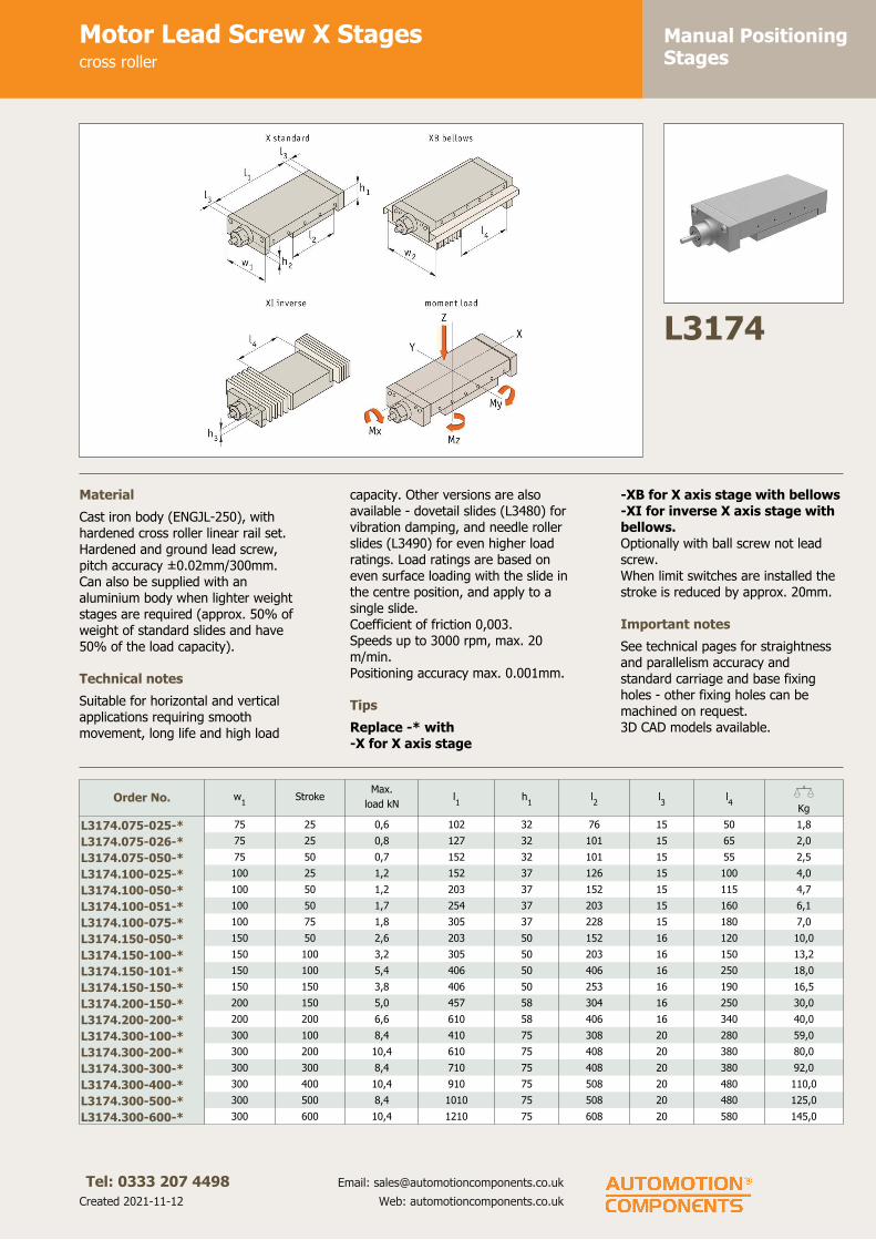
Manual PositioningStages
Motor Lead Screw X Stagescross roller
Tel: 0333 207 4498
Created 2021-11-12
Email: [email protected]
Web: automotioncomponents.co.uk
L3174
Material
Cast iron body (ENGJL-250), with
hardened cross roller linear rail set.
Hardened and ground lead screw,
pitch accuracy ± 0.02mm/300mm.
Can also be supplied with an
aluminium body when lighter weight
stages are required (approx. 50% of
weight of standard slides and have
50% of the load capacity).
Technical notes
Suitable for horizontal and vertical
applications requiring smooth
movement, long life and high load
capacity. Other versions are also
available - dovetail slides (L3480) for
vibration damping, and needle roller
slides (L3490) for even higher load
ratings. Load ratings are based on
even surface loading with the slide in
the centre position, and apply to a
single slide.
Coefficient of friction 0,003.
Speeds up to 3000 rpm, max. 20
m/min.
Positioning accuracy max. 0.001mm.
Tips
Replace -* with
-X for X axis stage
-XB for X axis stage with bellows
-XI for inverse X axis stage with
bellows.
Optionally with ball screw not lead
screw.
When limit switches are installed the
stroke is reduced by approx. 20mm.
Important notes
See technical pages for straightness
and parallelism accuracy and
standard carriage and base fixing
holes - other fixing holes can be
machined on request.
3D CAD models available.
Order No. w1
StrokeMax.
load kNl1
h1
l2
l3
l4
XKg
L3174.075-025-* 75 25 0,6 102 32 76 15 50 1,8
L3174.075-026-* 75 25 0,8 127 32 101 15 65 2,0
L3174.075-050-* 75 50 0,7 152 32 101 15 55 2,5
L3174.100-025-* 100 25 1,2 152 37 126 15 100 4,0
L3174.100-050-* 100 50 1,2 203 37 152 15 115 4,7
L3174.100-051-* 100 50 1,7 254 37 203 15 160 6,1
L3174.100-075-* 100 75 1,8 305 37 228 15 180 7,0
L3174.150-050-* 150 50 2,6 203 50 152 16 120 10,0
L3174.150-100-* 150 100 3,2 305 50 203 16 150 13,2
L3174.150-101-* 150 100 5,4 406 50 406 16 250 18,0
L3174.150-150-* 150 150 3,8 406 50 253 16 190 16,5
L3174.200-150-* 200 150 5,0 457 58 304 16 250 30,0
L3174.200-200-* 200 200 6,6 610 58 406 16 340 40,0
L3174.300-100-* 300 100 8,4 410 75 308 20 280 59,0
L3174.300-200-* 300 200 10,4 610 75 408 20 380 80,0
L3174.300-300-* 300 300 8,4 710 75 408 20 380 92,0
L3174.300-400-* 300 400 10,4 910 75 508 20 480 110,0
L3174.300-500-* 300 500 8,4 1010 75 508 20 480 125,0
L3174.300-600-* 300 600 10,4 1210 75 608 20 580 145,0

Manual PositioningStages
Motor Lead Screw X Stagescross roller
Tel: 0333 207 4498
Created 2021-11-12
Email: [email protected]
Web: automotioncomponents.co.uk
Order No. h2
h3
w2
Lead
screw
Max. moment
Mx Nm
Max. moment
My Nm
Max. moment
Mz Nm
L3174.075-025-* 11,5 14 110 8x1 32 18 19
L3174.075-026-* 11,5 14 110 8x1 45 37 40
L3174.075-050-* 11,5 14 110 8x1 40 27 29
L3174.100-025-* 13,5 14 135 8x1 67 41 48
L3174.100-050-* 13,5 14 135 8x1 76 52 62
L3174.100-051-* 13,5 14 135 8x1 106 104 124
L3174.100-075-* 13,5 14 135 8x1 112 118 141
L3174.150-050-* 19,0 24 205 15x2 220 104 123
L3174.150-100-* 19,0 24 205 15x2 270 157 186
L3174.150-101-* 19,0 24 205 15x2 460 460 545
L3174.150-150-* 19,0 24 205 15x2 320 220 260
L3174.200-150-* 21,5 24 255 15x2 705 445 455
L3174.200-200-* 21,5 24 255 15x2 935 795 815
L3174.300-100-* 26,0 32 375 23x4 3190 800 825
L3174.300-200-* 26,0 32 375 23x4 3950 1205 1245
L3174.300-300-* 26,0 32 375 23x4 3190 800 825
L3174.300-400-* 26,0 32 375 23x4 3950 1205 1245
L3174.300-500-* 26,0 32 375 23x4 3190 800 825
L3174.300-600-* 26,0 32 375 23x4 3950 1205 1245

Manual PositioningStages
Motor Lead Screw XY Stagescross roller
Tel: 0333 207 4498
Created 2021-11-12
Email: [email protected]
Web: automotioncomponents.co.uk
L3175
Material
Cast iron body (ENGJL-250), with
hardened cross roller linear rail set.
Hardened and ground lead screw,
pitch accuracy ± 0.02mm/300mm.
Can also be supplied with an
aluminium body when lighter weight
stages are required (approx. 50% of
weight of standard slides and have
50% of the load capacity).
Technical notes
Suitable for horizontal and vertical
applications requiring smooth
movement, long life and high load
capacity. Other versions are also
available - dovetail slides (L3480) for
vibration damping, and needle roller
slides (L3490) for even higher load
ratings. Load ratings are based on
even surface loading with the slide in
the centre position, and apply to a
single slide.
Coefficient of friction 0,003.
Speeds up to 3000 rpm, max. 20
m/min.
Positioning accuracy up to +/-
0.015mm.
Tips
Replace -* with
-XY for XY axis stage
-XYB for XY axis stage with
bellows
-XYI for inverse X axis stage
with bellows.
Optionally with ball screw not lead
screw.
When limit switches are installed the
stroke is reduced by approx. 20mm.
Important notes
See technical pages for straightness
and parallelism accuracy and
standard carriage and base fixing
holes - other fixing holes can be
machined on request.
3D CAD models available.
Order No. w1
StrokeMax.
load kNl1
h1
l2
l3
h2
h3
h4
XKg
L3175.075-025-* 75 25 0,6 102 32 76 15 11,5 64 79 1,8
L3175.075-026-* 75 25 0,8 127 32 101 15 11,5 64 79 2,0
L3175.075-050-* 75 50 0,7 152 32 101 15 11,5 64 79 2,5
L3175.100-025-* 100 25 1,1 152 37 126 15 13,5 74 89 4,0
L3175.100-050-* 100 50 1,2 203 37 152 15 13,5 74 89 4,7
L3175.100-051-* 100 50 1,7 254 37 203 15 13,5 74 89 6,1
L3175.100-075-* 100 75 1,8 305 37 228 15 13,5 74 89 7,0
L3175.150-050-* 150 50 2,6 203 50 152 16 19,0 100 125 10,0
L3175.150-100-* 150 100 3,2 305 50 203 16 19,0 100 125 13,2
L3175.150-101-* 150 100 5,4 406 50 406 16 19,0 100 125 18,0
L3175.150-150-* 150 150 3,8 406 50 253 16 19,0 100 125 16,5
L3175.200-150-* 200 150 5,0 457 58 304 16 21,5 116 141 30,0
L3175.200-200-* 200 200 6,6 610 58 406 16 21,5 116 141 40,0
L3175.300-100-* 300 100 8,4 410 75 308 20 26,0 150 185 59,0
L3175.300-200-* 300 200 10,4 610 75 408 20 26,0 150 150 80,0
L3175.300-300-* 300 300 8,4 710 75 408 20 26,0 150 150 92,0
L3175.300-400-* 300 400 10,4 910 75 508 20 26,0 150 150 110,0
L3175.300-500-* 300 500 8,4 1010 75 508 20 26,0 150 150 125,0
L3175.300-600-* 300 600 10,4 1210 75 608 20 26,0 150 150 145,0

Manual PositioningStages
Motor Lead Screw XY Stagescross roller
Tel: 0333 207 4498
Created 2021-11-12
Email: [email protected]
Web: automotioncomponents.co.uk
Order No. h5
h6
h7
w2
Lead screwMax. moment
Mx Nm
Max. moment
My Nm
Max. moment
Mz Nm
L3175.075-025-* 15 79 15 110 8x1 32 18 19
L3175.075-026-* 15 79 15 110 8x1 45 37 40
L3175.075-050-* 15 79 15 110 8x1 40 27 29
L3175.100-025-* 15 89 15 135 8x1 67 41 48
L3175.100-050-* 15 89 15 135 8x1 76 52 62
L3175.100-051-* 15 89 15 135 8x1 106 104 124
L3175.100-075-* 15 89 15 135 8x1 112 118 141
L3175.150-050-* 25 125 25 205 15x2 220 104 123
L3175.150-100-* 25 125 25 205 15x2 270 157 186
L3175.150-101-* 25 125 25 205 15x2 460 460 545
L3175.150-150-* 25 125 25 205 15x2 320 220 260
L3175.200-150-* 25 141 25 255 15x2 705 445 455
L3175.200-200-* 25 141 25 255 15x2 935 795 815
L3175.300-100-* 35 185 35 375 23x4 3190 800 825
L3175.300-200-* - 185 - 375 23x4 3950 1205 1245
L3175.300-300-* - 150 - 375 23x4 3190 800 825
L3175.300-400-* - 150 - 375 23x4 3950 1205 1245
L3175.300-500-* - 150 - 375 23x4 3190 800 825
L3175.300-600-* - 150 - 375 23x4 3950 1205 1245
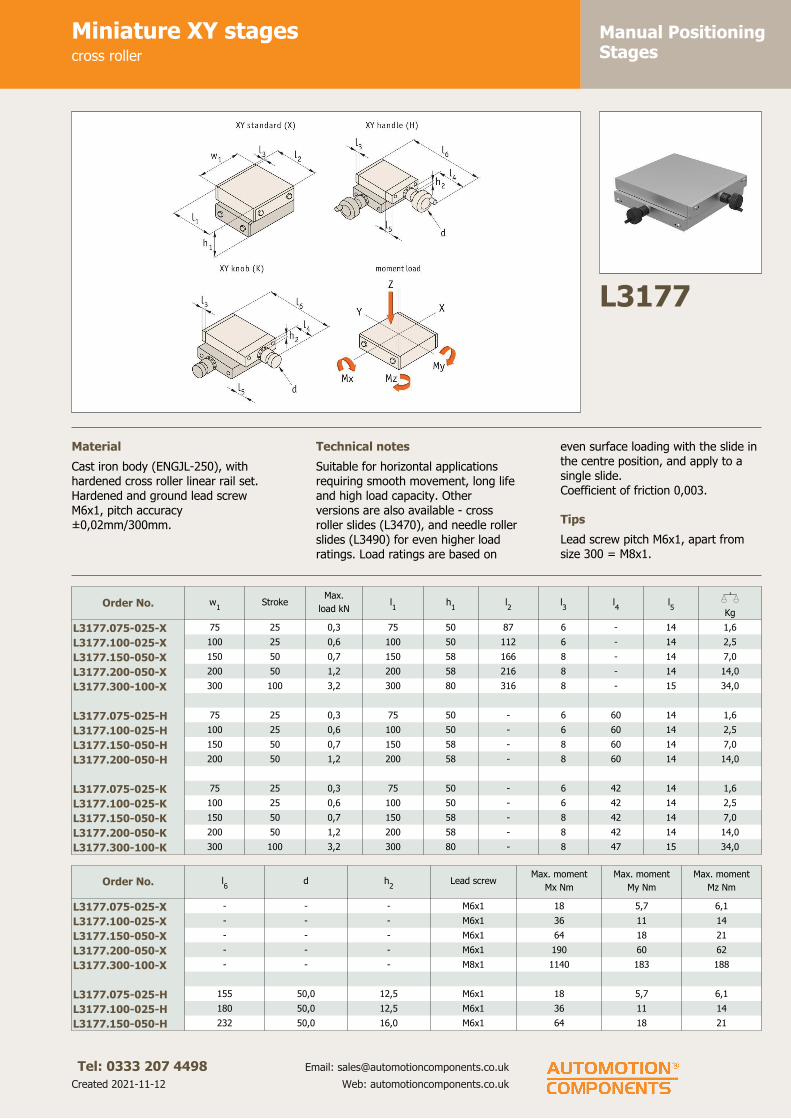
Manual PositioningStages
Miniature XY stagescross roller
Tel: 0333 207 4498
Created 2021-11-12
Email: [email protected]
Web: automotioncomponents.co.uk
L3177
Material
Cast iron body (ENGJL-250), with
hardened cross roller linear rail set.
Hardened and ground lead screw
M6x1, pitch accuracy
± 0,02mm/300mm.
Technical notes
Suitable for horizontal applications
requiring smooth movement, long life
and high load capacity. Other
versions are also available - cross
roller slides (L3470), and needle roller
slides (L3490) for even higher load
ratings. Load ratings are based on
even surface loading with the slide in
the centre position, and apply to a
single slide.
Coefficient of friction 0,003.
Tips
Lead screw pitch M6x1, apart from
size 300 = M8x1.
Order No. w1
StrokeMax.
load kNl1
h1
l2
l3
l4
l5
XKg
L3177.075-025-X 75 25 0,3 75 50 87 6 - 14 1,6
L3177.100-025-X 100 25 0,6 100 50 112 6 - 14 2,5
L3177.150-050-X 150 50 0,7 150 58 166 8 - 14 7,0
L3177.200-050-X 200 50 1,2 200 58 216 8 - 14 14,0
L3177.300-100-X 300 100 3,2 300 80 316 8 - 15 34,0
L3177.075-025-H 75 25 0,3 75 50 - 6 60 14 1,6
L3177.100-025-H 100 25 0,6 100 50 - 6 60 14 2,5
L3177.150-050-H 150 50 0,7 150 58 - 8 60 14 7,0
L3177.200-050-H 200 50 1,2 200 58 - 8 60 14 14,0
L3177.075-025-K 75 25 0,3 75 50 - 6 42 14 1,6
L3177.100-025-K 100 25 0,6 100 50 - 6 42 14 2,5
L3177.150-050-K 150 50 0,7 150 58 - 8 42 14 7,0
L3177.200-050-K 200 50 1,2 200 58 - 8 42 14 14,0
L3177.300-100-K 300 100 3,2 300 80 - 8 47 15 34,0
Order No. l6
d h2
Lead screwMax. moment
Mx Nm
Max. moment
My Nm
Max. moment
Mz Nm
L3177.075-025-X - - - M6x1 18 5,7 6,1
L3177.100-025-X - - - M6x1 36 11 14
L3177.150-050-X - - - M6x1 64 18 21
L3177.200-050-X - - - M6x1 190 60 62
L3177.300-100-X - - - M8x1 1140 183 188
L3177.075-025-H 155 50,0 12,5 M6x1 18 5,7 6,1
L3177.100-025-H 180 50,0 12,5 M6x1 36 11 14
L3177.150-050-H 232 50,0 16,0 M6x1 64 18 21

Manual PositioningStages
Miniature XY stagescross roller
Tel: 0333 207 4498
Created 2021-11-12
Email: [email protected]
Web: automotioncomponents.co.uk
Order No. l6
d h2
Lead screwMax. moment
Mx Nm
Max. moment
My Nm
Max. moment
Mz Nm
L3177.200-050-H 282 50,0 16,0 M6x1 190 60 62
L3177.075-025-K 137 23,9 12,5 M6x1 18 5,7 6,1
L3177.100-025-K 162 23,9 12,5 M6x1 36 11 14
L3177.150-050-K 214 23,9 16,0 M6x1 64 18 21
L3177.200-050-K 264 23,9 16,0 M6x1 190 60 62
L3177.300-100-K 370 31,0 23,0 M8x1 1140 183 188

Manual PositioningStages
XY stages with through holecross roller
Tel: 0333 207 4498
Created 2021-11-12
Email: [email protected]
Web: automotioncomponents.co.uk
L3179
Material
Cast iron body (ENGJL-250), with
hardened cross roller linear rail set.
Technical notes
Suitable for horizontal applications
requiring smooth movement, long life
and high load capacity. Low height
profile. The stage has a through hole.
No backlash due to pull back spring,
each micrometer has a locking
device.
Coefficient of friction 0,003.
Micrometer pitch =1,0 apart from
20mm stroke = 0,5.
Tips
Micrometer pitch 1,0mm except first
two sizes = 0,5mm.
For scientific and medical
applications.
Important notes
3D CAD models available.
Order No. l1
StrokeMax. load
kNl2
h1
d1
d2
h2
l3
l4
d3
Max.
moment
Mx Nm
Max.
moment
My Nm
Max.
moment
Mz Nm
XKg
L3179.075-020 75 20 0,37 186 40 20 55 3 14 6 20 26 7,1 7,5 1,3
L3179.100-020 100 20 0,64 211 40 50 80 3 14 6 20 44 13 15 2,0
L3179.150-045 150 45 0,74 303 50 50 105 3 16 8 20 64 18 22 6,3
L3179.200-045 200 45 1,23 355 50 75 130 3 16 8 20 190 62 63 13,0
L3179.300-095 300 95 3,22 543 70 100 205 3 20 10 24 1140 186 192 32,0
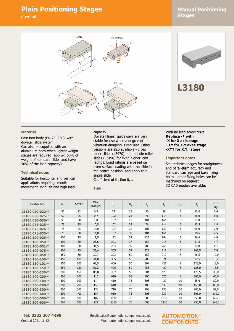
Manual PositioningStages
Plain Positioning Stagesdovetail
Tel: 0333 207 4498
Created 2021-11-12
Email: [email protected]
Web: automotioncomponents.co.uk
L3180
Material
Cast iron body (ENGJL-250), with
dovetail slide system.
Can also be supplied with an
aluminium body when lighter weight
stages are required (approx. 50% of
weight of standard slides and have
50% of the load capacity).
Technical notes
Suitable for horizontal and vertical
applications requiring smooth
movement, long life and high load
capacity.
Dovetail linear guideways are very
stable for use when a degree of
vibration damping is required. Other
versions are also available - cross
roller slides (L3470), and needle roller
slides (L3490) for even higher load
ratings. Load ratings are based on
even surface loading with the slide in
the centre position, and apply to a
single slide.
Coefficient of friction 0,1.
Tips
With no lead screw drive.
Replace -* with
-X for X axis stage
- XY for X,Y axes stage
-XYT for X,Y,. stage
Important notes
See technical pages for straightness
and parallelism accuracy and
standard carriage and base fixing
holes - other fixing holes can be
machined on request.
3D CAD models available.
Order No. w1
StrokeMax.
load kNl1
h1
l2
l3
l4
l5
XKg
L3180.050-022-* 50 22 0,5 76 25 50 88 6 13,0 0,6
L3180.050-025-* 50 25 0,7 102 25 76 114 6 26,0 0,8
L3180.050-050-* 50 50 1,0 152 25 101 164 6 51,0 1,1
L3180.075-025-* 75 25 10,5 102 32 76 114 6 13,5 1,8
L3180.075-026-* 75 25 14,0 127 32 101 139 6 26,0 2,0
L3180.075-050-* 75 50 14,0 152 32 101 164 6 38,5 2,5
L3180.100-025-* 100 25 19,5 152 37 126 164 6 26,0 4,0
L3180.100-050-* 100 50 23,6 203 37 152 215 6 51,5 4,7
L3180.100-051-* 100 50 31,5 254 37 203 266 6 77,0 6,1
L3180.100-075-* 100 75 35,4 305 37 228 317 6 102,5 7,0
L3180.150-050-* 150 50 30,7 203 50 152 219 8 26,5 10,0
L3180.150-100-* 150 100 41,0 305 50 203 321 8 77,5 13,2
L3180.150-101-* 150 100 61,5 406 50 304 422 8 128,0 18,0
L3180.150-150-* 150 150 51,2 406 50 253 422 8 128,0 16,5
L3180.200-150-* 200 150 86,8 457 58 304 473 8 128,5 30,0
L3180.200-200-* 200 200 116 610 58 406 626 8 205,0 40,0
L3180.300-100-* 300 100 114 410 75 308 430 10 55,0 59,0
L3180.300-200-* 300 200 150 610 75 408 630 10 155,0 80,0
L3180.300-300-* 300 300 150 710 75 408 730 10 205,0 92,0
L3180.300-400-* 300 400 187 910 75 508 930 10 305,0 110,0
L3180.300-500-* 300 500 187 1010 75 508 1030 10 355,0 125,0
L3180.300-600-* 300 600 224 1210 75 608 1230 10 455,0 145,0

Manual PositioningStages
Plain Positioning Stagesdovetail
Tel: 0333 207 4498
Created 2021-11-12
Email: [email protected]
Web: automotioncomponents.co.uk
Order No. w1
StrokeMax.
load kNl1
h1
l2
l3
l4
l5
XKg
L3180.400-200-* 400 200 233 610 102 408 650 20 105,0 169,0
L3180.400-300-* 400 300 233 710 102 408 750 20 155,0 182,0
L3180.400-400-* 400 400 233 810 102 408 850 20 205,0 195,0
L3180.400-401-* 400 400 290 910 102 508 950 20 255,0 225,0
L3180.400-500-* 400 500 290 1010 102 508 1050 20 305,0 238,0
L3180.400-600-* 400 600 290 1110 102 508 1150 20 355,0 251,0
L3180.400-601-* 400 600 347 1210 102 608 1250 20 405,0 270,0
Order No. w2
h2
h3
h4
Max. moment
Mx Nm
Max. moment
My Nm
Max. moment
Mz Nm
L3180.050-022-* 0,0 50 - - 3,4 1,8 2,1
L3180.050-025-* 13,0 50 - - 5,2 4,1 4,9
L3180.050-050-* 25,5 50 - - 6,9 7,2 8,6
L3180.075-025-* 0,5 64 82 18 10,0 5,1 6,1
L3180.075-026-* 13,0 64 82 18 14,0 9,1 10,0
L3180.075-050-* 13,0 64 82 18 14,0 9,1 10,0
L3180.100-025-* 13,0 74 92 18 33,0 20,0 24,0
L3180.100-050-* 26,0 74 92 18 40,0 29,0 35,0
L3180.100-051-* 51,5 74 92 18 54,0 52,0 63,0
L3180.100-075-* 64,0 74 92 18 61,0 66,0 79,0
L3180.150-050-* 1,0 100 120 20 77,0 30,0 36,0
L3180.150-100-* 26,5 100 120 20 103 54,0 65,0
L3180.150-101-* 77,0 100 120 20 155 123 146
L3180.150-150-* 51,5 100 120 20 129 85,0 101
L3180.200-150-* 52,0 116 136 20 275 164 195
L3180.200-200-* 103,0 116 136 20 365 290 245
L3180.300-100-* 4,0 150 180 30 605 235 280
L3180.300-200-* 54,0 150 180 30 800 410 490
L3180.300-300-* 54,0 150 180 30 800 410 490
L3180.300-400-* 104,0 150 180 30 1000 640 760
L3180.300-500-* 104,0 150 180 30 1000 640 760
L3180.300-600-* 154,0 150 180 30 1195 915 1095
L3180.400-200-* 4,0 204 244 40 1360 470 560
L3180.400-300-* 4,0 204 244 40 1360 470 560
L3180.400-400-* 4,0 204 244 40 1360 470 560
L3180.400-401-* 54,0 204 244 40 1695 730 870
L3180.400-500-* 54,0 204 244 40 1685 730 870
L3180.400-600-* 54,0 204 244 40 1695 730 870
L3180.400-601-* 104,0 204 244 40 2025 1050 1250

Manual PositioningStages
Plain Compact Stagesdovetail
Tel: 0333 207 4498
Created 2021-11-12
Email: [email protected]
Web: automotioncomponents.co.uk
L3181
Material
Cast iron body (ENGJL-250), with
dovetail slide system.
Can also be supplied with an
aluminium body when lighter weight
stages are required (approx. 50% of
weight of standard slides and have
50% of the load capacity).
Technical notes
Suitable for horizontal and vertical
applications requiring smooth
movement, long life and high load
capacity.
Dovetail linear guideways are very
stable for use when a degree of
vibration damping is required. Other
versions are also available - cross
roller slides (L3470), and needle roller
slides (L3490) for even higher load
ratings. Load ratings are based on
even surface loading with the slide in
the centre position, and apply to a
single slide.
Coefficient of friction 0,1.
Important notes
See technical pages for straightness
and parallelism accuracy and
standard carriage and base fixing
holes - other fixing holes can be
machined on request.
3D CAD models available.
Order No. w1
StrokeMax.
load kNl1
h1
l2
l3
Max.
moment
Mx Nm
Max.
moment
My Nm
Max.
moment
Mz Nm
XKg
L3181.050-025 50 25 0,5 50 25 12,5 1 x25 3,4 1,8 2,1 0,5
L3181.050-050 50 50 1,0 101 25 13,0 3 x25 6,9 7,2 8,6 0,7
L3181.050-075 50 75 1,4 152 25 13,5 5 x25 10 16 19 1,4
L3181.050-100 50 100 1,9 202 25 13,5 7 x25 13 29 34 1,8
L3181.075-050 75 50 1,4 102 32 13,0 3 x25 14 9,2 11 1,8
L3181.075-075 75 75 2,1 152 32 13,5 5 x25 21 20 24 2,9
L3181.075-100 75 100 2,8 202 32 13,5 7 x25 28 36 43 3,9
L3181.075-125 75 125 3,5 252 32 13,5 9 x25 35 56 67 4,8
L3181.075-150 75 150 4,2 302 32 13,5 11x25 42 81 96 6,0
L3181.100-050 100 50 1,6 102 37 13,5 3 x25 27 13 15 8,4
L3181.100-075 100 75 2,3 152 37 13,5 5 x25 40 29 35 4,2
L3181.100-100 100 100 3,2 203 37 14,5 7 x25 54 52 63 5,9
L3181.100-125 100 125 3,9 254 37 14,5 9 x25 67 82 98 6,8
L3181.100-150 100 150 4,7 305 37 15,0 11x25 81 119 142 8,8
L3181.100-175 100 175 5,5 355 37 15,0 13x25 94 161 192 10,5
L3181.100-200 100 200 6,3 405 37 15,0 15x25 108 210 250 11,8
L3181.100-225 100 225 7,1 445 37 15,0 17x25 121 265 315 12,9
L3181.100-250 100 250 7,8 505 37 15,0 19x25 135 325 385 14,0
L3181.150-050 150 50 3,1 152 50 26,0 2 x50 77 30 36 11,0
L3181.150-075 150 75 3,1 152 50 26,0 2 x50 77 30 36 11,0
L3181.150-100 150 100 4,1 203 50 26,5 3 x50 103 54 65 13,8
L3181.150-125 150 125 5,1 253 50 26,5 4 x50 129 85 101 15,0
L3181.150-150 150 150 6,2 305 50 27,5 5 x50 155 123 147 16,0
L3181.150-200 150 200 8,2 406 50 28,0 7 x50 205 219 260 22,0

Manual PositioningStages
Plain Compact Stagesdovetail
Tel: 0333 207 4498
Created 2021-11-12
Email: [email protected]
Web: automotioncomponents.co.uk
Order No. w1
StrokeMax.
load kNl1
h1
l2
l3
Max.
moment
Mx Nm
Max.
moment
My Nm
Max.
moment
Mz Nm
XKg
L3181.150-250 150 250 10,2 506 50 28,0 9 x50 255 340 405 27,5
L3181.150-300 150 300 12,3 606 50 28,0 11x50 305 485 580 32,5
L3181.200-050 200 50 5,8 203 58 26,5 3 x50 184 73 87 23,0
L3181.200-100 200 100 5,8 203 58 26,5 3 x50 184 73 87 23,0
L3181.200-150 200 150 8,7 304 58 27,0 5 x50 275 164 195 26,1
L3181.200-200 200 200 11,6 406 58 28,0 7 x50 365 290 345 34,4
L3181.200-250 200 250 14,6 510 58 30,0 9 x50 460 460 550 43,0
L3181.200-300 200 300 17,4 610 58 30,0 11x50 550 660 785 51,5
L3181.200-350 200 350 20,3 710 58 30,0 13x50 645 895 1065 60,0
L3181.200-400 200 400 23,1 810 58 30,0 15x50 735 1165 1385 67,0
L3181.200-500 200 500 23,1 810 58 30,0 15x50 735 1165 1385 67,0
L3181.200-600 200 600 23,1 810 58 30, 15x50 735 1165 1385 67,0

Manual PositioningStages
Manual Lead Screw Stagesdovetail
Tel: 0333 207 4498
Created 2021-11-12
Email: [email protected]
Web: automotioncomponents.co.uk
L3182
Material
Cast iron body (ENGJL-250), with
dovetail slide system. Hardened and
ground lead screw, pitch accuracy
± 0.02mm/300mm.
Can also be supplied with an
aluminium body when lighter weight
stages are required (approx. 50% of
weight of standard slides and have
50% of the load capacity).
Technical notes
Suitable for horizontal and vertical
applications requiring smooth
movement, long life and high load
capacity.
Dovetail linear guideways are very
stable for use when a degree of
vibration damping is required. Other
versions are also available - cross
roller slides (L3470), and needle roller
slides (L3490) for even higher load
ratings. Load ratings are based on
even surface loading with the slide in
the centre position, and apply to a
single slide.
Coefficient of friction 0,1.
Tips
Replace -* with
-XH for X axis stage with handle
-XK for X axis stage with knob
-XYH for X,Y axes stage with
handle
-XYK for X,Y axes stage with
knob
-XYTH for X,Y,. stage with handle
-XYTK for X,Y,. stage with knob
Important notes
See technical pages for straightness
and parallelism accuracy and
standard carriage and base fixing
holes - other fixing holes can be
machined on request.
3D CAD models available.
Order No. w1
StrokeMax.
load kNl1
h1
l2
l3
l4
l5
l6
l7
l8
XKg
L3182.050-022-* 50 22 0,5 76 25 50 156 60,0 14 14 138 42,0 0,8
L3182.050-025-* 50 25 0,7 102 25 76 182 60,0 14 14 164 42,0 0,8
L3182.050-050-* 50 50 1,0 152 20 101 232 60,0 14 14 214 42,0 1,1
L3182.075-025-* 75 25 1,1 102 32 76 193 70,0 15 15 170 47,0 1,8
L3182.075-026-* 75 25 1,4 127 32 101 218 70,0 15 15 195 47,0 2,0
L3182.075-050-* 75 50 1,4 152 32 101 243 70,0 15 15 220 47,0 2,5
L3182.100-025-* 100 25 2,0 152 37 126 243 70,0 15 15 222 49,0 4,0
L3182.100-050-* 100 50 2,4 203 37 152 294 70,0 15 15 273 49,0 4,7
L3182.100-051-* 100 50 3,2 254 37 203 345 70,0 15 15 324 49,0 6,1
L3182.100-075-* 100 75 3,5 305 37 228 396 70,0 15 15 375 49,0 7,0
L3182.150-050-* 150 50 3,1 203 50 152 334 107,0 16 16 297 70,0 10,0
L3182.150-100-* 150 100 4,1 305 50 203 436 107,0 16 16 399 70,0 13,2
L3182.150-101-* 150 100 6,2 406 50 304 357 107,0 16 16 500 70,0 18,0
L3182.150-150-* 150 150 5,1 406 50 253 537 107,0 16 16 500 70,0 16,5
L3182.200-150-* 200 150 8,7 457 58 304 588 107,0 16 16 551 70,0 30,0
L3182.200-200-* 200 200 11,6 610 58 406 741 107,0 16 16 704 70,0 40,0
L3182.300-100-* 300 100 11,4 410 75 308 607 166,5 20 20 538 97,5 59,0
L3182.300-200-* 300 200 15,0 610 75 408 87 166,5 20 20 738 97,5 80,0
L3182.300-300-* 300 300 15,0 710 75 408 907 166,5 20 20 838 97,5 92,0
L3182.300-400-* 300 400 18,7 910 75 508 1107 166,5 20 20 1038 97,5 110,0
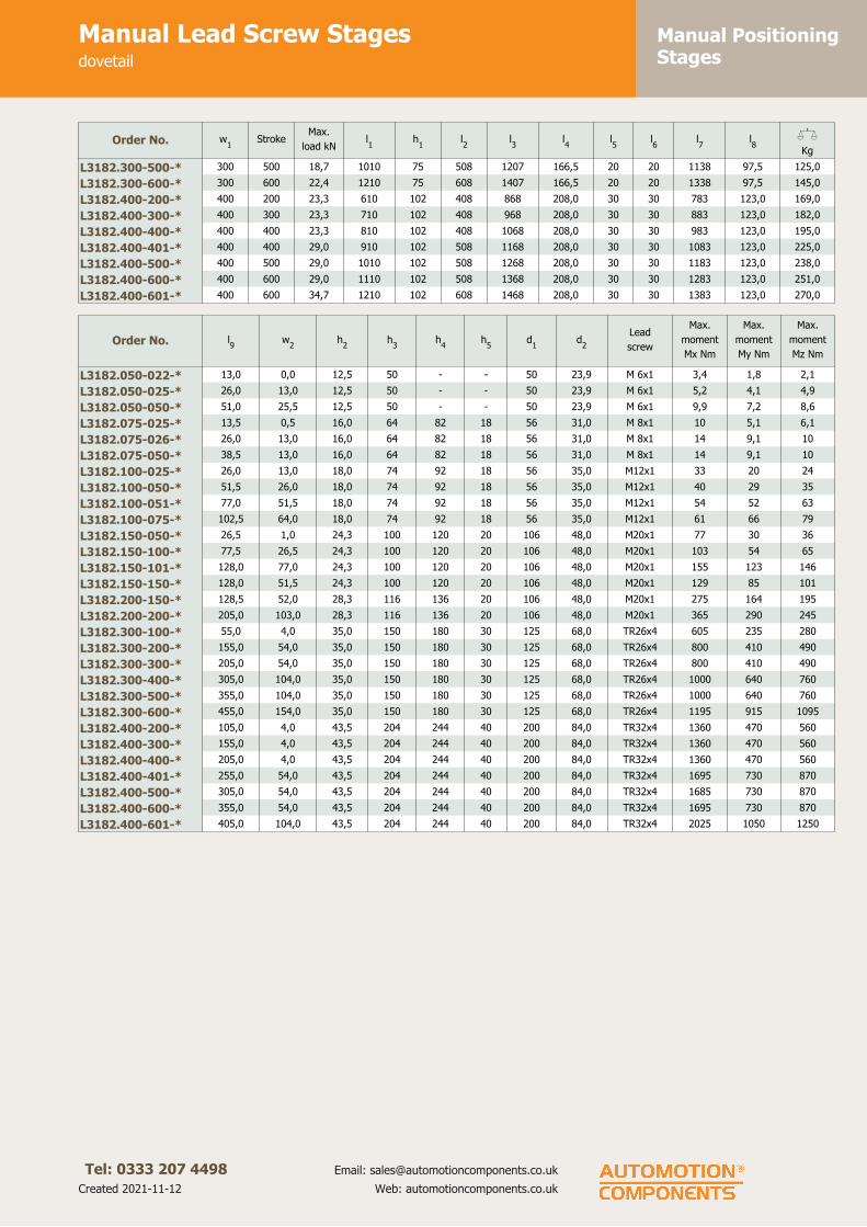
Manual PositioningStages
Manual Lead Screw Stagesdovetail
Tel: 0333 207 4498
Created 2021-11-12
Email: [email protected]
Web: automotioncomponents.co.uk
Order No. w1
StrokeMax.
load kNl1
h1
l2
l3
l4
l5
l6
l7
l8
XKg
L3182.300-500-* 300 500 18,7 1010 75 508 1207 166,5 20 20 1138 97,5 125,0
L3182.300-600-* 300 600 22,4 1210 75 608 1407 166,5 20 20 1338 97,5 145,0
L3182.400-200-* 400 200 23,3 610 102 408 868 208,0 30 30 783 123,0 169,0
L3182.400-300-* 400 300 23,3 710 102 408 968 208,0 30 30 883 123,0 182,0
L3182.400-400-* 400 400 23,3 810 102 408 1068 208,0 30 30 983 123,0 195,0
L3182.400-401-* 400 400 29,0 910 102 508 1168 208,0 30 30 1083 123,0 225,0
L3182.400-500-* 400 500 29,0 1010 102 508 1268 208,0 30 30 1183 123,0 238,0
L3182.400-600-* 400 600 29,0 1110 102 508 1368 208,0 30 30 1283 123,0 251,0
L3182.400-601-* 400 600 34,7 1210 102 608 1468 208,0 30 30 1383 123,0 270,0
Order No. l9
w2
h2
h3
h4
h5
d1
d2
Lead
screw
Max.
moment
Mx Nm
Max.
moment
My Nm
Max.
moment
Mz Nm
L3182.050-022-* 13,0 0,0 12,5 50 - - 50 23,9 M 6x1 3,4 1,8 2,1
L3182.050-025-* 26,0 13,0 12,5 50 - - 50 23,9 M 6x1 5,2 4,1 4,9
L3182.050-050-* 51,0 25,5 12,5 50 - - 50 23,9 M 6x1 9,9 7,2 8,6
L3182.075-025-* 13,5 0,5 16,0 64 82 18 56 31,0 M 8x1 10 5,1 6,1
L3182.075-026-* 26,0 13,0 16,0 64 82 18 56 31,0 M 8x1 14 9,1 10
L3182.075-050-* 38,5 13,0 16,0 64 82 18 56 31,0 M 8x1 14 9,1 10
L3182.100-025-* 26,0 13,0 18,0 74 92 18 56 35,0 M12x1 33 20 24
L3182.100-050-* 51,5 26,0 18,0 74 92 18 56 35,0 M12x1 40 29 35
L3182.100-051-* 77,0 51,5 18,0 74 92 18 56 35,0 M12x1 54 52 63
L3182.100-075-* 102,5 64,0 18,0 74 92 18 56 35,0 M12x1 61 66 79
L3182.150-050-* 26,5 1,0 24,3 100 120 20 106 48,0 M20x1 77 30 36
L3182.150-100-* 77,5 26,5 24,3 100 120 20 106 48,0 M20x1 103 54 65
L3182.150-101-* 128,0 77,0 24,3 100 120 20 106 48,0 M20x1 155 123 146
L3182.150-150-* 128,0 51,5 24,3 100 120 20 106 48,0 M20x1 129 85 101
L3182.200-150-* 128,5 52,0 28,3 116 136 20 106 48,0 M20x1 275 164 195
L3182.200-200-* 205,0 103,0 28,3 116 136 20 106 48,0 M20x1 365 290 245
L3182.300-100-* 55,0 4,0 35,0 150 180 30 125 68,0 TR26x4 605 235 280
L3182.300-200-* 155,0 54,0 35,0 150 180 30 125 68,0 TR26x4 800 410 490
L3182.300-300-* 205,0 54,0 35,0 150 180 30 125 68,0 TR26x4 800 410 490
L3182.300-400-* 305,0 104,0 35,0 150 180 30 125 68,0 TR26x4 1000 640 760
L3182.300-500-* 355,0 104,0 35,0 150 180 30 125 68,0 TR26x4 1000 640 760
L3182.300-600-* 455,0 154,0 35,0 150 180 30 125 68,0 TR26x4 1195 915 1095
L3182.400-200-* 105,0 4,0 43,5 204 244 40 200 84,0 TR32x4 1360 470 560
L3182.400-300-* 155,0 4,0 43,5 204 244 40 200 84,0 TR32x4 1360 470 560
L3182.400-400-* 205,0 4,0 43,5 204 244 40 200 84,0 TR32x4 1360 470 560
L3182.400-401-* 255,0 54,0 43,5 204 244 40 200 84,0 TR32x4 1695 730 870
L3182.400-500-* 305,0 54,0 43,5 204 244 40 200 84,0 TR32x4 1685 730 870
L3182.400-600-* 355,0 54,0 43,5 204 244 40 200 84,0 TR32x4 1695 730 870
L3182.400-601-* 405,0 104,0 43,5 204 244 40 200 84,0 TR32x4 2025 1050 1250

Manual PositioningStages
Motor Lead Screw X Stagesdovetail
Tel: 0333 207 4498
Created 2021-11-12
Email: [email protected]
Web: automotioncomponents.co.uk
L3184
Material
Cast iron body (ENGJL-250), with
dovetail slide system. Hardened and
ground lead screw, pitch accuracy
± 0.015mm/300mm.
Can also be supplied with an
aluminium body when lighter weight
stages are required (approx. 50% of
weight of standard slides and have
50% of the load capacity).
Technical notes
Suitable for horizontal and vertical
applications requiring smooth
movement, long life and high load
capacity.
Dovetail linear guideways are very
stable for use when a degree of
vibration damping is required. Other
versions are also available - cross
roller slides (L3470), and needle roller
slides (L3490) for even higher load
ratings. Load ratings are based on
even surface loading with the slide in
the centre position, and apply to a
single slide.
Coefficient of friction 0,1.
Speeds up to 3000 rpm, max. 20
m/min.
Positioning accuracy max. 0.001mm.
Tips
Replace -* with
-X for X axis stage
-XB for X axis stage with bellows
-XI for inverse X axis stage with
bellows
When limit switches are installed the
stroke is reduced by approx. 20mm.
Important notes
See technical pages for straightness
and parallelism accuracy and
standard carriage and base fixing
holes - other fixing holes can be
machined on request.
3D CAD models available.
Order No. w1
StrokeMax.
load kNl1
h1
l2
l3
l4
XKg
L3184.075-025-* 75 25 1,0 102 32 76 15 50 1,8
L3184.075-026-* 75 25 1,4 127 32 101 15 65 2,0
L3184.075-050-* 75 50 1,4 152 32 101 15 55 2,5
L3184.100-025-* 100 25 2,0 152 37 126 15 100 4,0
L3184.100-050-* 100 50 2,4 203 37 152 15 115 4,7
L3184.100-051-* 100 50 3,2 254 37 203 15 160 6,1
L3184.100-075-* 100 75 3,5 305 37 228 15 180 7,0
L3184.150-050-* 150 50 3,1 203 50 152 16 120 10,0
L3184.150-100-* 150 100 4.1 305 50 203 16 150 13,2
L3184.150-101-* 150 100 6,2 406 50 304 16 250 18,0
L3184.150-150-* 150 150 5,1 406 50 253 16 190 16,5
L3184.200-150-* 200 150 8,7 457 58 304 16 250 30,0
L3184.200-200-* 200 200 11,6 610 58 406 16 340 40,0
L3184.300-100-* 300 100 11,4 410 75 308 20 280 59,0
L3184.300-200-* 300 200 15,0 610 75 408 20 380 80,0
L3184.300-300-* 300 300 15,0 710 75 408 20 380 92,0
L3184.300-400-* 300 400 18,7 910 75 508 20 480 110,0
L3184.300-500-* 300 500 18,7 1010 75 508 20 480 125,0
L3184.300-600-* 300 600 22,4 1210 75 608 20 580 145,0
L3184.400-200-* 400 200 23,3 610 102 408 70 380 169,0

Manual PositioningStages
Motor Lead Screw X Stagesdovetail
Tel: 0333 207 4498
Created 2021-11-12
Email: [email protected]
Web: automotioncomponents.co.uk
Order No. w1
StrokeMax.
load kNl1
h1
l2
l3
l4
XKg
L3184.400-300-* 400 300 23,3 710 102 408 70 380 182,0
L3184.400-400-* 400 400 23,3 810 102 408 90 380 195,0
L3184.400-401-* 400 400 29,0 910 102 508 90 480 225,0
L3184.400-500-* 400 500 29,0 1010 102 508 100 480 238,0
L3184.400-600-* 400 600 29,0 1110 102 508 100 480 251,0
L3184.400-601-* 400 600 34,7 1210 102 508 100 580 270,0
Order No. h2
h3
w2
Lead
screw
Max. moment
Mx Nm
Max. moment
My Nm
Max. moment
Mz Nm
L3184.075-025-* 11,5 14 110 8 x1 10 5,1 6,1
L3184.075-026-* 11,5 14 110 8 x1 14 9,1 10
L3184.075-050-* 11,5 14 110 8 x1 14 9,1 10
L3184.100-025-* 13,5 14 135 8 x1 33 20 24
L3184.100-050-* 13,5 14 135 8 x1 40 29 35
L3184.100-051-* 13,5 14 135 8 x1 54 52 63
L3184.100-075-* 13,5 14 135 8 x1 61 66 79
L3184.150-050-* 19,0 24 205 15x2 77 30 36
L3184.150-100-* 19,0 24 205 15x2 103 54 65
L3184.150-101-* 19,0 24 205 15x2 155 123 146
L3184.150-150-* 19,0 24 205 15x2 129 85 101
L3184.200-150-* 21,5 24 255 15x2 275 164 195
L3184.200-200-* 21,5 24 255 15x2 365 290 345
L3184.300-100-* 26,0 32 375 23x4 605 235 280
L3184.300-200-* 26,0 32 375 23x4 800 410 490
L3184.300-300-* 26,0 32 375 23x4 800 410 490
L3184.300-400-* 26,0 32 375 23x4 1000 640 760
L3184.300-500-* 26,0 32 375 23x4 1000 640 760
L3184.300-600-* 26,0 32 375 23x4 1195 915 1095
L3184.400-200-* 34,0 37 480 23x4 1360 470 560
L3184.400-300-* 34,0 37 480 23x4 1360 470 560
L3184.400-400-* 34,0 37 480 23x4 1360 470 560
L3184.400-401-* 34,0 37 480 23x4 1695 730 870
L3184.400-500-* 34,0 37 480 23x4 1685 730 870
L3184.400-600-* 34,0 37 480 23x4 1695 730 870
L3184.400-601-* 34,0 37 480 23x4 2025 1050 1250

Manual PositioningStages
Motor Lead Screw XY Stagesdovetail
Tel: 0333 207 4498
Created 2021-11-12
Email: [email protected]
Web: automotioncomponents.co.uk
L3185
Material
Cast iron body (ENGJL-250), with
dovetail slide system. Hardened and
ground lead screw, pitch accuracy
± 0.015mm/300mm.
Can also be supplied with an
aluminium body when lighter weight
stages are required (approx. 50% of
weight of standard slides and have
50% of the load capacity).
Technical notes
Suitable for horizontal and vertical
applications requiring smooth
movement, long life and high load
capacity.
Dovetail linear guideways are very
stable for use when a degree of
vibration damping is required. Other
versions are also available - cross
roller slides (L3470), and needle roller
slides (L3490) for even higher load
ratings. Load ratings are based on
even surface loading with the slide in
the centre position, and apply to a
single slide.
Coefficient of friction 0,1.
Speeds up to 3000 rpm, max. 20
m/min.
Positioning accuracy max. 0.001mm.
Tips
Replace -* with
-XY for XY axis stage
-XYB for XY axis stage with
bellows
-XYI for inverse X axis stage
with bellows
When limit switches are installed the
stroke is reduced by approx. 20mm.
Important notes
See technical pages for straightness
and parallelism accuracy and
standard carriage and base fixing
holes - other fixing holes can be
machined on request.
3D CAD models available.
Order No. w1
StrokeMax.
load kNl1
h1
l2
l3
h2
h3
h4
XKg
L3185.075-025-* 75 25 1,0 102 32 76 15 11,5 64 79 1,8
L3185.075-026-* 75 25 1,4 127 32 101 15 11,5 64 79 2,0
L3185.075-050-* 75 50 1,4 152 32 101 15 11,5 64 79 2,5
L3185.100-025-* 100 25 2,0 152 37 126 15 13,5 74 89 4,0
L3185.100-050-* 100 50 2,4 203 37 152 15 13,5 74 89 4,7
L3185.100-051-* 100 50 3,2 254 37 203 15 13,5 74 89 6,1
L3185.100-075-* 100 75 3,5 305 37 228 15 13,5 74 89 7,0
L3185.150-050-* 150 50 3,1 203 50 152 16 19,0 100 125 10,0
L3185.150-100-* 150 100 4.1 305 50 203 16 19,0 100 125 13,2
L3185.150-101-* 150 100 6,2 406 50 304 16 19,0 100 125 18,0
L3185.150-150-* 150 150 5,1 406 50 253 16 19,0 100 125 16,5
L3185.200-150-* 200 150 8,7 457 58 304 16 21,5 116 141 30,0
L3185.200-200-* 200 200 11,6 610 58 406 16 21,5 116 141 40,0
L3185.300-100-* 300 100 11,4 410 75 308 20 26,0 150 185 59,0
L3185.300-200-* 300 200 15,0 610 75 408 20 26,0 150 185 80,0
L3185.300-300-* 300 300 15,0 710 75 408 20 26,0 150 185 92,0
L3185.300-400-* 300 400 18,7 910 75 508 20 26,0 150 185 110,0
L3185.300-500-* 300 500 18,7 1010 75 508 20 26,0 150 185 125,0
L3185.300-600-* 300 600 22,4 1210 75 608 20 26,0 150 185 145,0
L3185.400-200-* 400 200 23,3 610 102 408 70 34,0 204 229 169,0

Manual PositioningStages
Motor Lead Screw XY Stagesdovetail
Tel: 0333 207 4498
Created 2021-11-12
Email: [email protected]
Web: automotioncomponents.co.uk
Order No. w1
StrokeMax.
load kNl1
h1
l2
l3
h2
h3
h4
XKg
L3185.400-300-* 400 300 23,3 710 102 408 0 34,0 204 229 182,0
L3185.400-400-* 400 400 23,3 810 102 408 90 34,0 204 229 195,0
L3185.400-401-* 400 400 29,0 910 102 508 90 34,0 204 229 225,0
L3185.400-500-* 400 500 29,0 1010 102 508 100 34,0 204 204 238,0
L3185.400-600-* 400 600 29,0 1110 102 508 100 34,0 204 204 251,0
L3185.400-601-* 400 600 34,7 1210 102 508 100 34,0 204 204 270,0
Order No. h5
h6
h7
w2
Lead screwMax. moment
Mx Nm
Max. moment
My Nm
Max. moment
Mz Nm
L3185.075-025-* 15 79 15 110 8 x1 10 5,1 6,1
L3185.075-026-* 15 79 15 110 8 x1 14 9,1 10
L3185.075-050-* 15 79 15 110 8 x1 14 9,1 10
L3185.100-025-* 15 89 15 135 8 x1 33 20 24
L3185.100-050-* 15 89 15 135 8 x1 40 29 35
L3185.100-051-* 15 89 15 135 8 x1 54 52 63
L3185.100-075-* 15 89 15 135 8 x1 61 66 79
L3185.150-050-* 25 125 25 205 15x2 77 30 36
L3185.150-100-* 25 125 25 205 15x2 103 54 65
L3185.150-101-* 25 125 25 205 15x2 155 123 146
L3185.150-150-* 25 125 25 205 15x2 129 85 101
L3185.200-150-* 25 141 25 255 15x2 275 164 195
L3185.200-200-* 25 141 25 255 15x2 365 290 345
L3185.300-100-* 35 185 35 375 23x4 605 235 280
L3185.300-200-* - 185 - 375 23x4 800 410 490
L3185.300-300-* - 185 - 375 23x4 800 410 490
L3185.300-400-* - 185 - 375 23x4 1000 640 760
L3185.300-500-* - 185 - 375 23x4 1000 640 760
L3185.300-600-* - 185 - 375 23x4 1195 915 1095
L3185.400-200-* 25 229 25 480 30x4 1360 470 560
L3185.400-300-* 25 229 25 480 30x4 1360 470 560
L3185.400-400-* 25 229 25 480 30x4 1360 470 560
L3185.400-401-* 25 229 25 480 30x4 1695 730 870
L3185.400-500-* - 204 - 480 30x4 1685 730 870
L3185.400-600-* - 204 - 480 30x4 1695 730 870
L3185.400-601-* - 204 - 480 30x4 2025 1050 1250

Manual PositioningStages
Miniature XY Stagesdovetail
Tel: 0333 207 4498
Created 2021-11-12
Email: [email protected]
Web: automotioncomponents.co.uk
L3188
Material
Cast iron body (ENGJL-250), with
dovetail slide system. Hardened and
ground lead screw, pitch accuracy
± 0.02mm/300mm.
Technical notes
Suitable for horizontal and vertical
applications requiring smooth
movement, long life and high load
capacity.
Dovetail linear guideways are very
stable for use when a degree of
vibration damping is required. Other
versions are also available - cross
roller slides (L3470), and needle roller
slides (L3490) for even higher load
ratings. Load ratings are based on
even surface loading with the slide in
the centre position, and apply to a
single slide.
Coefficient of friction 0,1.
Tips
Lead screw pitch M6 x 0,5.
Centre mounting of compound slides
is standard. Please advise dimensions
w2
and l7
when off-centre mounting
is required.
Important notes
See technical pages for straightness
and parallelism accuracy and
standard carriage and base fixing
holes - other fixing holes can be
machined on request.
3D CAD models available.
Order No. w StrokeMax. load
kNl1
l2
l3
l4
l5
h1
h2
Lead
screw
Max.
moment
Mx Nm
Max.
moment
My Nm
Max.
moment
Mz Nm
XKg
L3188.030-010 30 10 0,15 35 25 41 - 3 17 8,5 M6x0,5 0,5 0,2 0,3 0,2
L3188.030-020 30 20 0,22 55 35 61 - 3 17 8,5 M6x0,5 0,7 0,4 0,5 0,3
L3188.030-030 30 30 0,22 65 35 71 - 3 17 8,5 M6x0,5 0,7 0,4 0,5 0,4
L3188.030-040 30 40 0,28 85 45 91 - 3 17 8,5 M6x0,5 1,0 0,7 0,8 0,5
L3188.030-050 30 50 0,34 105 55 111 - 3 17 8,5 M6x0,5 1,2 1,0 1,2 0,6
L3188.030-010-K 30 10 0,15 35 25 41 65 3 17 8,5 M6x0,5 0,5 0,2 0,3 0,2
L3188.030-020-K 30 20 0,22 55 35 61 85 3 17 8,5 M6x0,5 0,7 0,4 0,5 0,3
L3188.030-030-K 30 30 0,22 65 35 71 95 3 17 8,5 M6x0,5 0,7 0,4 0,5 0,4
L3188.030-040-K 30 40 0,28 85 45 91 115 3 17 8,5 M6x0,5 1,0 0,7 0,8 0,5
L3188.030-050-K 30 50 0,34 105 55 111 135 3 17 8,5 M6x0,5 1,2 1,0 1,2 0,6
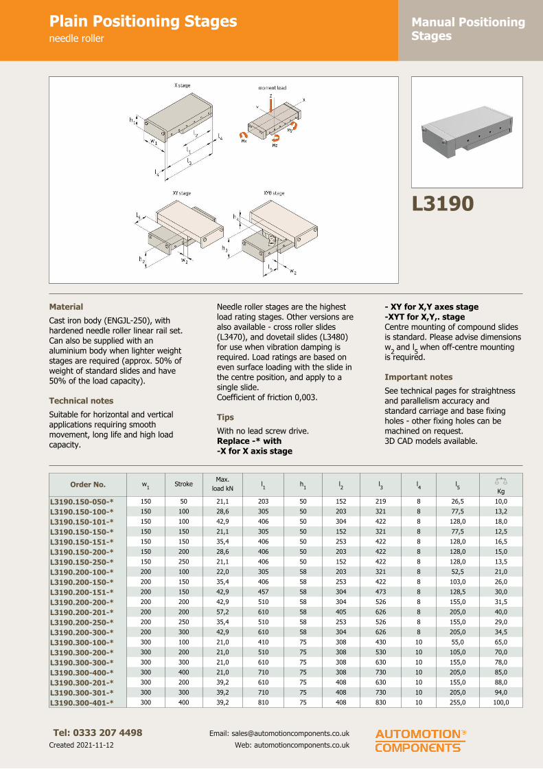
Manual PositioningStages
Plain Positioning Stagesneedle roller
Tel: 0333 207 4498
Created 2021-11-12
Email: [email protected]
Web: automotioncomponents.co.uk
L3190
Material
Cast iron body (ENGJL-250), with
hardened needle roller linear rail set.
Can also be supplied with an
aluminium body when lighter weight
stages are required (approx. 50% of
weight of standard slides and have
50% of the load capacity).
Technical notes
Suitable for horizontal and vertical
applications requiring smooth
movement, long life and high load
capacity.
Needle roller stages are the highest
load rating stages. Other versions are
also available - cross roller slides
(L3470), and dovetail slides (L3480)
for use when vibration damping is
required. Load ratings are based on
even surface loading with the slide in
the centre position, and apply to a
single slide.
Coefficient of friction 0,003.
Tips
With no lead screw drive.
Replace -* with
-X for X axis stage
- XY for X,Y axes stage
-XYT for X,Y,. stage
Centre mounting of compound slides
is standard. Please advise dimensions
w2
and l5
when off-centre mounting
is required.
Important notes
See technical pages for straightness
and parallelism accuracy and
standard carriage and base fixing
holes - other fixing holes can be
machined on request.
3D CAD models available.
Order No. w1
StrokeMax.
load kNl1
h1
l2
l3
l4
l5
XKg
L3190.150-050-* 150 50 21,1 203 50 152 219 8 26,5 10,0
L3190.150-100-* 150 100 28,6 305 50 203 321 8 77,5 13,2
L3190.150-101-* 150 100 42,9 406 50 304 422 8 128,0 18,0
L3190.150-150-* 150 150 21,1 305 50 152 321 8 77,5 12,5
L3190.150-151-* 150 150 35,4 406 50 253 422 8 128,0 16,5
L3190.150-200-* 150 200 28,6 406 50 203 422 8 128,0 15,0
L3190.150-250-* 150 250 21,1 406 50 152 422 8 128,0 13,5
L3190.200-100-* 200 100 22,0 305 58 203 321 8 52,5 21,0
L3190.200-150-* 200 150 35,4 406 58 253 422 8 103,0 26,0
L3190.200-151-* 200 150 42,9 457 58 304 473 8 128,5 30,0
L3190.200-200-* 200 200 42,9 510 58 304 526 8 155,0 31,5
L3190.200-201-* 200 200 57,2 610 58 405 626 8 205,0 40,0
L3190.200-250-* 200 250 35,4 510 58 253 526 8 155,0 29,0
L3190.200-300-* 200 300 42,9 610 58 304 626 8 205,0 34,5
L3190.300-100-* 300 100 21,0 410 75 308 430 10 55,0 65,0
L3190.300-200-* 300 200 21,0 510 75 308 530 10 105,0 70,0
L3190.300-300-* 300 300 21,0 610 75 308 630 10 155,0 78,0
L3190.300-400-* 300 400 21,0 710 75 308 730 10 205,0 85,0
L3190.300-201-* 300 200 39,2 610 75 408 630 10 155,0 88,0
L3190.300-301-* 300 300 39,2 710 75 408 730 10 205,0 94,0
L3190.300-401-* 300 400 39,2 810 75 408 830 10 255,0 100,0

Manual PositioningStages
Plain Positioning Stagesneedle roller
Tel: 0333 207 4498
Created 2021-11-12
Email: [email protected]
Web: automotioncomponents.co.uk
Order No. w1
StrokeMax.
load kNl1
h1
l2
l3
l4
l5
XKg
L3190.300-500-* 300 500 39,2 910 75 408 930 10 305,0 108,0
L3190.300-600-* 300 600 39,2 1010 75 408 1030 10 355,0 115,0
L3190.300-700-* 300 700 39,2 1110 75 408 1130 10 405,0 122,0
L3190.300-800-* 300 800 39,2 1210 75 408 1230 10 455,0 128,0
L3190.300-302-* 300 300 39,2 810 75 508 830 10 255,0 111,0
L3190.300-402-* 300 400 39,2 910 75 508 930 10 305,0 118,0
L3190.300-501-* 300 500 39,2 1010 75 508 1030 10 355,0 125,0
L3190.300-601-* 300 600 39,2 1110 75 508 1130 10 405,0 132,0
L3190.300-701-* 300 700 39,2 1210 75 508 1230 10 455,0 137,0
L3190.400-200-* 400 200 44,3 610 102 408 650 10 105,0 169,0
L3190.400-300-* 400 300 44,3 710 102 408 750 20 155,0 182,0
L3190.400-400-* 400 400 44,3 810 102 408 850 20 205,0 195,0
L3190.400-500-* 400 500 44,3 910 102 408 950 20 255,0 208,0
L3190.400-600-* 400 600 44,3 1010 102 408 1050 20 305,0 222,0
L3190.400-700-* 400 700 44,3 1110 102 408 1150 20 355,0 235,0
L3190.400-800-* 400 800 44,3 1210 102 408 1250 20 405,0 249,0
L3190.400-301-* 400 300 58,5 810 102 508 850 20 205,0 210,0
L3190.400-401-* 400 400 58,5 910 102 508 950 20 255,0 225,0
L3190.400-501-* 400 500 58,5 1010 102 508 1050 20 305,0 238,0
L3190.400-601-* 400 600 58,5 1110 102 508 1150 20 355,0 251,0
L3190.400-701-* 400 700 58,5 1210 102 508 1250 20 405,0 265,0
Order No. w2
h2
h3
h4
Max. moment
Mx Nm
Max. moment
My Nm
Max. moment
Mz Nm
L3190.150-050-* 1,0 100 120 20 940 435 435
L3190.150-100-* 26,5 100 120 20 1270 800 800
L3190.150-101-* 77,0 100 120 20 1910 1830 1830
L3190.150-150-* 1,0 100 120 20 940 435 435
L3190.150-151-* 51,5 100 120 20 1570 1250 1250
L3190.150-200-* 26,5 100 120 20 1270 800 800
L3190.150-250-* 1,0 100 120 20 940 435 435
L3190.200-100-* 1,5 116 136 20 1150 720 720
L3190.200-150-* 26,5 116 136 20 2215 1250 1250
L3190.200-151-* 52,0 116 136 20 2680 1830 1830
L3190.200-200-* 52,0 116 136 20 2680 1830 1830
L3190.200-201-* 102,5 116 136 20 3575 3275 3275
L3190.200-250-* 26,5 116 136 20 2215 1250 1250
L3190.200-300-* 52,0 116 136 20 2680 1830 1830
L3190.300-100-* 4,0 150 190 30 5520 2100 2100
L3190.300-200-* 4,0 150 190 30 5520 2100 2100
L3190.300-300-* 4,0 150 190 30 5520 2100 2100
L3190.300-400-* 4,0 150 190 30 5520 2100 2100
L3190.300-201-* 54,0 150 190 30 7440 4060 4060
L3190.300-301-* 54,0 150 190 30 7440 4060 4060
L3190.300-401-* 54,0 150 190 30 7440 4060 4060
L3190.300-500-* 54,0 150 190 30 7440 4060 4060
L3190.300-600-* 54,0 150 190 30 7440 4060 4060
L3190.300-700-* 54,0 150 190 30 7440 4060 4060
L3190.300-800-* 54,0 150 190 30 7440 4060 4060
L3190.300-302-* 104,0 150 190 30 9290 6600 6600
L3190.300-402-* 104,0 150 190 30 9290 6600 6600
L3190.300-501-* 104,0 150 190 30 9290 6600 6600
L3190.300-601-* 104,0 150 190 30 9290 6600 6600
L3190.300-701-* 104,0 150 190 30 9290 6600 6600
L3190.400-200-* 4,0 204 244 40 13000 5920 5920
L3190.400-300-* 4,0 204 244 40 13000 5920 5920
L3190.400-400-* 4,0 204 244 40 13000 5920 5920
L3190.400-500-* 4,0 204 244 40 13000 5920 5920
L3190.400-600-* 4,0 204 244 40 13000 5920 5920
L3190.400-700-* 4,0 204 244 40 13000 5920 5920
L3190.400-800-* 4,0 204 244 40 13000 5920 5920

Manual PositioningStages
Plain Positioning Stagesneedle roller
Tel: 0333 207 4498
Created 2021-11-12
Email: [email protected]
Web: automotioncomponents.co.uk
Order No. w2
h2
h3
h4
Max. moment
Mx Nm
Max. moment
My Nm
Max. moment
Mz Nm
L3190.400-301-* 54,0 204 244 40 16430 9750 9750
L3190.400-401-* 54,0 204 244 40 16430 9750 9750
L3190.400-501-* 54,0 204 244 40 16430 9750 9750
L3190.400-601-* 54,0 204 244 40 16430 9750 9750
L3190.400-701-* 54,0 204 244 40 16430 9750 9750

Manual PositioningStages
Plain Compact Positioning Stagesneedle roller
Tel: 0333 207 4498
Created 2021-11-12
Email: [email protected]
Web: automotioncomponents.co.uk
L3191
Material
Cast iron body (ENGJL-250), with
hardened needle roller linear rail set.
Can also be supplied with an
aluminium body when lighter weight
stages are required (approx. 50% of
weight of standard slides and have
50% of the load capacity).
Technical notes
Suitable for horizontal and vertical
applications requiring smooth
movement, long life and high load
capacity.
Needle roller stages are the highest
load rating stages. Other versions are
also available - cross roller slides
(L3470), and dovetail slides (L3480)
for use when vibration damping is
required. Load ratings are based on
even surface loading with the slide in
the centre position, and apply to a
single slide.
Coefficient of friction 0,003.
Important notes
See technical pages for straightness
and parallelism accuracy and
standard carriage and base fixing
holes - other fixing holes can be
machined on request.
3D CAD models available.
Order No. w1
StrokeMax.
load kNl1
h1
w2
d1
h2
l2
l3
l4
XKg
L3191.100-060 100 60 9,70 110 45 64 11 23,5 1xl3
50 30 3,1
L3191.100-095 100 95 14,3 160 45 64 11 23,5 2xl3
50 30 4,5
L3191.100-130 100 130 18,8 210 45 64 11 23,5 3xl3
50 30 5,9
L3191.100-165 100 165 23,4 260 45 64 11 23,5 4xl3
50 30 7,2
L3191.100-200 100 200 28,6 310 45 64 11 23,5 5xl3
50 30 8,6
L3191.100-235 100 235 33,1 360 45 64 11 23,5 6xl3
50 30 10,0
L3191.100-265 100 265 37,7 410 45 64 11 23,5 7xl3
50 30 11,4
L3191.145-130 145 130 18,8 210 60 98 15 32,0 1xl3
100 55 11,8
L3191.145-180 145 180 29,7 310 60 98 15 32,0 2xl3
100 55 17,3
L3191.145-350 145 350 32,0 410 60 98 15 32,0 3xl3
100 55 22,8
L3191.145-450 145 450 38,8 510 60 98 15 32,0 4xl3
100 55 28,3
L3191.145-550 145 550 46,3 610 60 98 15 32,0 5xl3
100 55 22,8
L3191.145-650 145 650 53,1 710 60 98 15 32,0 6xl3
100 55 39,3
L3191.145-750 145 750 60,6 810 60 98 15 32,0 7xl3
100 55 44,8
L3191.145-850 145 850 67,4 910 60 98 15 32,0 8xl3
100 55 50,3
L3191.145-950 145 950 74,9 1010 60 98 15 32,0 9xl3
100 55 55,8
Order No.
Max.
moment
Mx Nm
Max.
moment
My Nm
Max.
moment
Mz Nm
Hole
patternla
lb
wa
da
db
dc
L3191.100-060 215 104 104 1 10 1x90 60 6,5 6,6 11
L3191.100-095 320 230 230 1 10 1x140 60 6,5 6,6 11
L3191.100-130 420 410 410 2 10 1x50 / 1x90 / 1x50 60 6,5 6,6 11
L3191.100-165 525 645 645 2 10 1x50 / 1x140 / 1x50 60 6,5 6,6 11

Manual PositioningStages
Plain Compact Positioning Stagesneedle roller
Tel: 0333 207 4498
Created 2021-11-12
Email: [email protected]
Web: automotioncomponents.co.uk
Order No.
Max.
moment
Mx Nm
Max.
moment
My Nm
Max.
moment
Mz Nm
Hole
patternla
lb
wa
da
db
dc
L3191.100-200 640 950 950 2 10 1x50 / 1x190 / 1x50 60 6,5 6,6 11
L3191.100-235 745 1285 1285 3 10 2x50 / 1x140 / 2x50 60 6,5 6,6 11
L3191.100-265 845 1695 1695 3 10 2x50 / 1x190 / 2x50 60 6,5 6,6 11
L3191.145-130 675 410 410 1 55 1x100 90 8,5 9,0 15
L3191.145-180 1070 1035 1035 1 55 1x200 90 8,5 9,0 15
L3191.145-350 1150 1200 1200 2 55 3x100 90 8,5 9,0 15
L3191.145-450 1400 1795 1795 2 55 1x100 /1x200 /1x100 90 8,5 9,0 15
L3191.145-550 1665 2540 2540 2 55 5x100 90 8,5 9,0 15
L3191.145-650 1915 3375 3375 3 55 2x100 /1x200 /2x100 90 8,5 9,0 15
L3191.145-750 2180 4375 4375 2 55 7x100 90 8,5 9,0 15
L3191.145-850 2425 5455 5455 3 55 3x100 /1x200 /3x100 90 8,5 9,0 15
L3191.145-950 2695 6705 6705 2 55 9x100 90 8,5 9,0 15

Manual PositioningStages
Manual Lead Screw Positioning Stagesneedle roller
Tel: 0333 207 4498
Created 2021-11-12
Email: [email protected]
Web: automotioncomponents.co.uk
L3192
Material
Cast iron body (ENGJL-250), with
hardened needle roller linear rail set.
Hardened and ground lead screw,
pitch accuracy ± 0.02mm/300mm.
Can also be supplied with an
aluminium body when lighter weight
stages are required (approx. 50% of
weight of standard slides and have
50% of the load capacity).
Technical notes
Suitable for horizontal and vertical
applications requiring smooth
movement, long life and high load
capacity.
Needle roller stages are the highest
load rating stages. Other versions are
also available - cross roller slides
(L3470), and dovetail slides (L3480)
for use when vibration damping is
required. Load ratings are based on
even surface loading with the slide in
the centre position, and apply to a
single slide.
Coefficient of friction 0,003.
Tips
Replace -* with
-XH for X axis stage with handle
-XK for X axis stage with knob
-XYH for X,Y axes stage with
handle
-XYK for X,Y axes stage with
knob
-XYTH for X,Y,. stage with handle
-XYTK for X,Y,. stage with knob
Centre mounting of compound slides
is standard. Please advise dimensions
w2
and l9
when off-centre mounting
is required.
Important notes
See technical pages for straightness
and parallelism accuracy and
standard carriage and base fixing
holes - other fixing holes can be
machined on request.
3D CAD models available.
Order No. w1
StrokeMax.
load kNl1
h1
l2
l3
l4
l5
l6
l7
l8
XKg
L3192.150-050-* 150 50 21,1 203 50 152 334 107 8 16 297 70,0 10,0
L3192.150-100-* 150 100 28,6 305 50 203 436 107 8 16 399 70,0 13,2
L3192.150-101-* 150 100 42,9 406 50 304 537 107 8 16 500 70,0 18,0
L3192.150-150-* 150 150 21,1 305 50 152 436 107 8 16 399 70,0 12,5
L3192.150-151-* 150 150 35,4 406 50 253 537 107 8 16 500 70,0 16,5
L3192.150-200-* 150 200 28,6 406 50 203 537 107 8 16 500 70,0 15,0
L3192.150-250-* 150 250 21,1 406 50 152 537 107 8 16 600 70,0 13,5
L3192.200-100-* 200 100 22,0 305 58 203 436 107 8 16 399 70,0 21,0
L3192.200-150-* 200 150 35,4 406 58 253 537 107 8 16 500 70,0 26,0
L3192.200-151-* 200 150 42,9 457 58 304 588 107 8 16 551 70,0 30,0
L3192.200-200-* 200 200 42,9 510 58 304 641 107 8 16 604 70,0 31,5
L3192.200-201-* 200 200 57,2 610 58 406 741 107 8 16 704 70,0 40,0
L3192.200-250-* 200 250 35,4 510 58 253 841 107 8 16 604 70,0 29,0
L3192.200-300-* 200 300 42,9 610 58 304 741 107 8 16 704 70,0 34,5
L3192.300-100-* 300 100 21,0 410 75 308 607 166,5 10 20 538 97,5 65
L3192.300-200-* 300 200 21,0 510 75 308 707 166,5 10 20 638 97,5 70
L3192.300-300-* 300 300 21,0 610 75 308 807 166,5 10 20 738 97,5 78
L3192.300-400-* 300 400 21,0 710 75 308 907 166,5 10 20 838 97,5 85

Manual PositioningStages
Manual Lead Screw Positioning Stagesneedle roller
Tel: 0333 207 4498
Created 2021-11-12
Email: [email protected]
Web: automotioncomponents.co.uk
Order No. w1
StrokeMax.
load kNl1
h1
l2
l3
l4
l5
l6
l7
l8
XKg
L3192.300-201-* 300 200 30,2 610 75 408 807 166,5 10 20 738 97,5 88
L3192.300-301-* 300 300 30,2 710 75 408 907 166,5 10 20 838 97,5 94
L3192.300-401-* 300 400 30,2 810 75 408 1007 166,5 10 20 938 97,5 100
L3192.300-500-* 300 500 30,2 910 75 408 1107 166,5 10 20 1038 97,5 108
L3192.300-600-* 300 600 30,2 1010 75 408 1207 166,5 10 20 1138 97,5 115
L3192.300-700-* 300 700 30,2 1110 75 408 1307 166,5 10 20 1238 97,5 122
L3192.300-800-* 300 800 39,2 1210 75 408 1407 166,5 10 20 1338 97,5 128
L3192.300-302-* 300 300 39,2 810 75 508 1007 166,5 10 20 938 97,5 111
L3192.300-402-* 300 400 39,2 910 75 508 1107 166,5 10 20 1038 97,5 118
L3192.300-502-* 300 500 39,2 1010 75 508 1207 166,5 10 20 1138 97,5 125
L3192.300-602-* 300 600 39,2 1110 75 508 1307 166,5 10 20 1238 97,5 132
L3192.300-702-* 300 700 39,2 1210 75 508 1407 166,5 10 20 1338 97,5 137
L3192.400-203-* 400 200 44,3 610 102 408 868 208,0 20 30 783 123,0 169
L3192.400-303-* 400 300 44,3 710 102 408 968 208,0 20 30 883 123,0 182
L3192.400-403-* 400 400 44,3 810 102 408 1068 208,0 20 30 983 123,0 195
L3192.400-503-* 400 500 44,3 910 102 408 1168 208,0 20 30 1083 123,0 208
L3192.400-603-* 400 600 44,3 1010 102 408 1268 208,0 20 30 1183 123,0 222
L3192.400-703-* 400 700 44,3 1110 102 408 1368 208,0 20 30 1283 123,0 235
L3192.400-803-* 400 800 44,3 1210 102 408 1468 208,0 20 30 1383 123,0 249
L3192.400-304-* 400 300 58,2 810 102 508 1068 208,0 20 30 983 123,0 210
L3192.400-404-* 400 400 58,2 910 102 508 1168 208,0 20 30 1083 123,0 225
L3192.400-504-* 400 500 58,2 1010 102 508 1268 208,0 20 30 1183 123,0 238
L3192.400-604-* 400 600 58,2 1110 102 508 1368 208,0 20 30 1283 123,0 251
L3192.400-704-* 400 700 58,2 1210 102 508 1468 208,0 20 30 1383 123,0 265
Order No. l9
w2
h2
h3
h4
h5
d1
d2
Lead
screw
Max.
moment
Mx Nm
Max.
moment
My Nm
Max.
moment
Mz Nm
L3192.150-050-* 26,5 1,0 24,3 100 120 20 106 48 M20x1 940 435 435
L3192.150-100-* 77,5 26,5 24,3 100 120 20 106 48 M20x1 1270 800 800
L3192.150-101-* 128,0 77,0 24,3 100 120 20 106 48 M20x1 1910 1830 1830
L3192.150-150-* 77,5 1,0 24,3 100 120 20 106 48 M20x1 940 435 435
L3192.150-151-* 128,0 51,5 24,3 100 120 20 106 48 M20x1 1570 1250 1250
L3192.150-200-* 128,0 26,5 24,3 100 120 20 106 48 M20x1 1270 800 800
L3192.150-250-* 128,0 1,0 24,3 100 120 20 106 48 M20x1 940 435 435
L3192.200-100-* 52,5 1,5 28,3 116 136 20 106 48 M20x1 1150 720 720
L3192.200-150-* 103,0 26,5 28,3 116 136 20 106 48 M20x1 2215 1250 1250
L3192.200-151-* 128,5 52,0 28,3 116 136 20 106 48 M20x1 2680 1830 1830
L3192.200-200-* 155,0 52,0 28,3 116 136 20 106 48 M20x1 2680 1830 1830
L3192.200-201-* 205,0 103,0 28,3 116 136 20 106 48 M20x1 3575 3275 3275
L3192.200-250-* 155,0 26,5 28,3 116 136 20 106 48 M20x1 2215 1250 1250
L3192.200-300-* 205,0 52,0 28,3 116 136 20 106 48 M20x1 2680 1830 1830
L3192.300-100-* 55,0 4,0 35,0 150 190 30 125 68 TR26x4 5520 2100 2100
L3192.300-200-* 105,0 4,0 35,0 150 190 30 125 68 TR26x4 5520 2100 2100
L3192.300-300-* 155,0 4,0 35,0 150 190 30 125 68 TR26x4 5520 2100 2100
L3192.300-400-* 205,0 4,0 35,0 150 190 30 125 68 TR26x4 5520 2100 2100
L3192.300-201-* 155,0 54,0 35,0 150 190 30 125 68 TR26x4 7440 4060 4060
L3192.300-301-* 205,0 54,0 35,0 150 190 30 125 68 TR26x4 7440 4060 4060
L3192.300-401-* 255,0 54,0 35,0 150 190 30 125 68 TR26x4 7440 4060 4060
L3192.300-500-* 305,0 54,0 35,0 150 190 30 125 68 TR26x4 7440 4060 4060
L3192.300-600-* 355,0 54,0 35,0 150 190 30 125 68 TR26x4 7440 4060 4060
L3192.300-700-* 405,0 54,0 35,0 150 190 30 125 68 TR26x4 7440 4060 4060
L3192.300-800-* 455,0 54,0 35,0 150 190 30 125 68 TR26x4 7440 4060 4060
L3192.300-302-* 255,0 104,0 35,0 150 190 30 125 68 TR26x4 9290 6600 6600
L3192.300-402-* 305,0 104,0 35,0 150 190 30 125 68 TR26x4 9290 6600 6600
L3192.300-502-* 355,0 104,0 35,0 150 190 30 125 68 TR26x4 9290 6600 6600
L3192.300-602-* 405,0 104,0 35,0 150 190 30 125 68 TR26x4 9290 6600 6600
L3192.300-702-* 455,0 104,0 35,0 150 190 30 125 68 TR26x4 9290 6600 6600
L3192.400-203-* 105,0 4,0 43,5 204 244 40 200 84 TR32x4 13000 5920 5920
L3192.400-303-* 155,0 4,0 43,5 204 244 40 200 84 TR32x4 13000 5920 5920

Manual PositioningStages
Manual Lead Screw Positioning Stagesneedle roller
Tel: 0333 207 4498
Created 2021-11-12
Email: [email protected]
Web: automotioncomponents.co.uk
Order No. l9
w2
h2
h3
h4
h5
d1
d2
Lead
screw
Max.
moment
Mx Nm
Max.
moment
My Nm
Max.
moment
Mz Nm
L3192.400-403-* 205,0 4,0 43,5 204 244 40 200 84 TR32x4 13000 5920 5920
L3192.400-503-* 255,0 4,0 43,5 204 244 40 200 84 TR32x4 13000 5920 5920
L3192.400-603-* 305,0 4,0 43,5 204 244 40 200 84 TR32x4 13000 5920 5920
L3192.400-703-* 355,0 4,0 43,5 204 244 40 200 84 TR32x4 13000 5920 5920
L3192.400-803-* 405,0 4,0 43,5 204 244 40 200 84 TR32x4 13000 5920 5920
L3192.400-304-* 205,0 54,0 43,5 204 244 40 200 84 TR32x4 16430 9750 9750
L3192.400-404-* 255,0 54,0 43,5 204 244 40 200 84 TR32x4 16430 9750 9750
L3192.400-504-* 305,0 54,0 43,5 204 244 40 200 84 TR32x4 16430 9750 9750
L3192.400-604-* 355,0 54,0 43,5 204 244 40 200 84 TR32x4 16430 9750 9750
L3192.400-704-* 405,0 54,0 43,5 204 244 40 200 84 TR32x4 16430 9750 9750

Manual PositioningStages
Motor Lead Screw X Stagesneedle roller
Tel: 0333 207 4498
Created 2021-11-12
Email: [email protected]
Web: automotioncomponents.co.uk
L3194
Material
Cast iron body (ENGJL-250), with
hardened needle roller linear rail set.
Hardened and ground lead screw,
pitch accuracy ± 0.015mm/300mm.
Can also be supplied with an
aluminium body when lighter weight
stages are required (approx. 50% of
weight of standard slides and have
50% of the load capacity).
Technical notes
Suitable for horizontal and vertical
applications requiring smooth
movement, long life and high load
capacity.
Needle roller stages are the highest
load rating stages. Other versions are
also available - cross roller slides
(L3470), and dovetail slides (L3480)
for use when vibration damping is
required. Load ratings are based on
even surface loading with the slide in
the centre position, and apply to a
single slide.
Coefficient of friction 0,003.
Speeds up to 2000 rpm, max. 20
m/min.
Positioning accuracy max. 0.001mm.
Tips
Replace -* with
-X for X axis stage
-XB for X axis stage with bellows
-XI for inverse X axis stage with
bellows
When limit switches are installed the
stroke is reduced by approx. 20mm.
Important notes
See technical pages for straightness
and parallelism accuracy and
standard carriage and base fixing
holes - other fixing holes can be
machined on request.
3D CAD models available.
Order No. w1
StrokeMax.
load kNl1
h1
l2
l3
l4
XKg
L3194.150-050-* 150 50 21,1 203 50 152 16 120 10,0
L3194.150-100-* 150 100 21,1 285 50 152 16 120 12,0
L3194.150-101-* 150 100 28,6 305 50 203 16 150 13,2
L3194.150-102-* 150 100 42,9 406 50 304 16 250 18,0
L3194.150-150-* 150 150 21,1 305 50 152 30 130 12,5
L3194.150-151-* 150 150 35,4 406 50 253 16 190 16,5
L3194.150-200-* 150 200 28,6 406 50 203 16 150 15,0
L3194.150-250-* 150 250 21,1 406 50 152 35 130 13,5
L3194.150-300-* 150 300 28,6 530 50 203 16 150 19,0
L3194.150-400-* 150 400 28,6 650 50 203 16 150 19,5
L3194.150-500-* 150 500 28,6 770 50 203 16 150 21,0
L3194.150-600-* 150 600 28,6 880 50 203 16 150 22,5
L3194.200-100-* 200 100 28,6 335 58 220 16 200 22,5
L3194.200-150-* 200 150 35,4 406 58 253 16 200 26,0
L3194.200-151-* 200 150 42,9 457 58 304 16 200 30,0
L3194.200-200-* 200 200 28,6 460 58 220 16 200 25,5
L3194.200-201-* 200 200 42,9 510 58 304 16 200 31,5
L3194.200-202-* 200 200 57,2 610 58 406 16 200 40,0
L3194.200-250-* 200 250 35,4 520 58 253 16 200 29,0
L3194.200-300-* 200 300 28,6 580 58 220 16 200 29,0

Manual PositioningStages
Motor Lead Screw X Stagesneedle roller
Tel: 0333 207 4498
Created 2021-11-12
Email: [email protected]
Web: automotioncomponents.co.uk
Order No. w1
StrokeMax.
load kNl1
h1
l2
l3
l4
XKg
L3194.200-301-* 200 300 42,9 610 58 304 16 200 34,5
L3194.200-400-* 200 400 28,6 700 58 220 16 200 32,0
L3194.200-500-* 200 500 28,6 820 58 220 16 200 35,5
L3194.200-600-* 200 600 28,6 940 58 220 16 200 38,5
L3194.200-700-* 200 700 28,6 1070 58 220 16 200 42,0
L3194.200-800-* 200 800 28,6 1185 58 220 16 200 45,0
0
L3194.300-100-* 300 100 21,0 410 75 280 70 280 70,0
L3194.300-200-* 300 200 21,0 510 75 280 70 280 75,0
L3194.300-300-* 300 300 21,0 610 75 280 70 280 83,0
L3194.300-400-* 300 400 21,0 710 75 280 70 280 90,0
L3194.300-201-* 300 200 30,2 610 75 380 70 380 93,0
L3194.300-301-* 300 300 30,2 710 75 380 70 380 98,0
L3194.300-401-* 300 400 30,2 810 75 380 70 380 105,0
L3194.300-500-* 300 500 30,2 910 75 380 90 380 113,0
L3194.300-600-* 300 600 30,2 1010 75 380 100 380 120,0
L3194.300-700-* 300 700 30,2 1110 75 380 100 380 127,0
L3194.300-800-* 300 800 30,2 1210 75 380 110 380 133,0
L3194.300-302-* 300 300 39,2 810 75 480 70 480 115,0
L3194.300-402-* 300 400 39,2 910 75 480 70 480 123,0
L3194.300-502-* 300 500 39,2 1010 75 480 90 480 130,0
L3194.300-602-* 300 600 39,2 1110 75 480 100 480 137,0
L3194.300-702-* 300 700 39,2 1210 75 480 100 480 142,0
L3194.400-200-* 400 200 44,3 610 102 380 70 380 174,0
L3194.400-300-* 400 300 44,3 710 102 380 70 380 186,0
L3194.400-400-* 400 400 44,3 810 102 380 90 380 200,0
L3194.400-500-* 400 500 44,3 910 102 380 90 380 213,0
L3194.400-600-* 400 600 44,3 1010 102 380 100 380 227,0
L3194.400-700-* 400 700 44,3 1110 102 380 100 380 240,0
L3194.400-800-* 400 800 44,3 1210 102 380 110 380 254,0
L3194.400-301-* 400 300 58,2 810 102 480 90 480 215,0
L3194.400-401-* 400 400 58,2 910 102 480 90 480 230,0
L3194.400-501-* 400 500 58,2 1010 102 480 100 480 243,0
L3194.400-601-* 400 600 58,2 1110 102 480 100 480 256,0
L3194.400-701-* 400 700 58,2 1210 102 480 110 480 270,0
Order No. h2
h3
w2
Lead
screw
Max. moment
Mx Nm
Max. moment
My Nm
Max. moment
Mz Nm
L3194.150-050-* 19,0 24 200 15x2 940 435 435
L3194.150-100-* 19,0 24 200 15x2 940 435 435
L3194.150-101-* 19,0 24 200 15x2 1270 800 800
L3194.150-102-* 19,0 24 200 15x2 1910 1830 1830
L3194.150-150-* 19,0 24 200 15x2 940 435 435
L3194.150-151-* 19,0 24 200 15x2 1570 1250 1250
L3194.150-200-* 19,0 24 200 15x2 1270 800 800
L3194.150-250-* 19,0 24 200 15x2 940 435 435
L3194.150-300-* 19,0 24 200 15x2 1270 800 800
L3194.150-400-* 19,0 24 200 15x2 1270 800 800
L3194.150-500-* 19,0 24 200 15x2 1270 800 800
L3194.150-600-* 19,0 24 200 15x2 1270 800 800
L3194.200-100-* 21,5 24 250 15x2 1270 800 800
L3194.200-150-* 21,5 24 250 15x2 2215 1250 1250
L3194.200-151-* 21,5 24 250 15x2 2680 1830 1830
L3194.200-200-* 21,5 24 250 15x2 1785 800 800
L3194.200-201-* 21,5 24 250 15x2 2680 1830 1830
L3194.200-202-* 21,5 24 250 15x2 3575 3275 3275
L3194.200-250-* 21,5 24 250 15x2 2215 1250 1250
L3194.200-300-* 21,5 24 250 15x2 1785 800 800
L3194.200-301-* 21,5 24 250 15x2 2680 1830 1830
L3194.200-400-* 21,5 24 250 15x2 1785 800 800
L3194.200-500-* 21,5 24 250 15x2 1785 800 800

Manual PositioningStages
Motor Lead Screw X Stagesneedle roller
Tel: 0333 207 4498
Created 2021-11-12
Email: [email protected]
Web: automotioncomponents.co.uk
Order No. h2
h3
w2
Lead
screw
Max. moment
Mx Nm
Max. moment
My Nm
Max. moment
Mz Nm
L3194.200-600-* 21,5 24 250 15x2 1785 800 800
L3194.200-700-* 21,5 24 250 15x2 1785 800 800
L3194.200-800-* 21,5 24 250 15x2 1785 800 800
L3194.300-100-* 26 32 375 23x4 5520 2100 2100
L3194.300-200-* 26 32 375 23x4 5520 2100 2100
L3194.300-300-* 26 32 375 23x4 5520 2100 2100
L3194.300-400-* 26 32 375 23x4 5520 2100 2100
L3194.300-201-* 26 32 375 23x4 7440 4060 4060
L3194.300-301-* 26 32 375 23x4 7440 4060 4060
L3194.300-401-* 26 32 375 23x4 7440 4060 4060
L3194.300-500-* 26 32 375 23x4 7440 4060 4060
L3194.300-600-* 26 32 375 23x4 7440 4060 4060
L3194.300-700-* 26 32 375 23x4 7440 4060 4060
L3194.300-800-* 26 32 375 23x4 7440 4060 4060
L3194.300-302-* 26 32 375 23x4 9290 6600 6600
L3194.300-402-* 26 32 375 23x4 9290 6600 6600
L3194.300-502-* 26 32 375 23x4 9290 6600 6600
L3194.300-602-* 26 32 375 23x4 9290 6600 6600
L3194.300-702-* 26 32 375 23x4 9290 6600 6600
L3194.400-200-* 34 37 480 30x4 13000 5920 5920
L3194.400-300-* 34 37 480 30x4 13000 5920 5920
L3194.400-400-* 34 37 480 30x4 13000 5920 5920
L3194.400-500-* 34 37 480 30x4 13000 5920 5920
L3194.400-600-* 34 37 480 30x4 13000 5920 5920
L3194.400-700-* 34 37 480 30x4 13000 5920 5920
L3194.400-800-* 34 37 480 30x4 13000 5920 5920
L3194.400-301-* 34 37 480 30x4 16430 9750 9750
L3194.400-401-* 34 37 480 30x4 16430 9750 9750
L3194.400-501-* 34 37 480 30x4 16430 9750 9750
L3194.400-601-* 34 37 480 30x4 16430 9750 9750
L3194.400-701-* 34 37 480 30x4 16430 9750 9750

Manual PositioningStages
Motor Lead Screw XY Stagesneedle roller
Tel: 0333 207 4498
Created 2021-11-12
Email: [email protected]
Web: automotioncomponents.co.uk
L3195
Material
Cast iron body (ENGJL-250), with
hardened needle roller linear rail set.
Hardened and ground lead screw,
pitch accuracy ± 0.015mm/300mm.
Can also be supplied with an
aluminium body when lighter weight
stages are required (approx. 50% of
weight of standard slides and have
50% of the load capacity).
Technical notes
Suitable for horizontal and vertical
applications requiring smooth
movement, long life and high load
capacity.
Needle roller stages are the highest
load rating stages. Other versions are
also available - cross roller slides
(L3470), and dovetail slides (L3480)
for use when vibration damping is
required. Load ratings are based on
even surface loading with the slide in
the centre position, and apply to a
single slide.
Coefficient of friction 0,003.
Speeds up to 2000 rpm, max. 20
m/min.
Positioning accuracy max. 0.001mm.
Tips
Replace -* with
-XY for XY axis stage
-XYB for XY axis stage with
bellows
-XYI for inverse X axis stage
with bellows
Centre mounting of compound slides
is standard. Please advise dimensions
w2
and l9
when off-centre mounting
is required.
When limit switches are installed the
stroke is reduced by approx. 20mm.
Important notes
See technical pages for straightness
and parallelism accuracy and
standard carriage and base fixing
holes - other fixing holes can be
machined on request.
3D CAD models available.
Order No. w1
StrokeMax.
load kNl1
h1
l2
l3
h2
h3
h4
XKg
L3195.300-100-* 300 100 21,0 410 75 308 20 26 220 185 70
L3195.300-200-* 300 200 21,0 510 75 308 20 26 220 185 75
L3195.300-300-* 300 300 21,0 610 75 308 20 26 220 185 83
L3195.300-400-* 300 400 21,0 710 75 308 20 26 220 185 90
L3195.300-201-* 300 200 30,2 610 75 408 20 26 185 150 93
L3195.300-301-* 300 300 30,2 710 75 408 20 26 185 150 98
L3195.300-401-* 300 400 30,2 810 75 408 20 26 185 150 105
L3195.300-500-* 300 500 30,2 910 75 408 20 26 185 150 113
L3195.300-600-* 300 600 30,2 1010 75 408 20 26 185 150 120
L3195.300-700-* 300 700 30,2 1110 75 408 20 26 185 150 127
L3195.300-800-* 300 800 30,2 1210 75 408 20 26 185 150 133
L3195.300-302-* 300 300 39,2 810 75 508 20 26 150 150 115
L3195.300-402-* 300 400 39,2 910 75 508 20 26 150 150 123
L3195.300-502-* 300 500 39,2 1010 75 508 20 26 150 150 130
L3195.300-602-* 300 600 39,2 1110 75 508 20 26 150 150 137
L3195.300-702-* 300 700 39,2 1210 75 508 20 26 150 150 142
L3195.300-202-* 400 200 44,3 610 102 408 30 34 284 244 174
L3195.300-303-* 400 300 44,3 710 102 408 30 34 284 244 186
L3195.300-403-* 400 400 44,3 810 102 408 30 34 284 244 200

Manual PositioningStages
Motor Lead Screw XY Stagesneedle roller
Tel: 0333 207 4498
Created 2021-11-12
Email: [email protected]
Web: automotioncomponents.co.uk
Order No. w1
StrokeMax.
load kNl1
h1
l2
l3
h2
h3
h4
XKg
L3195.300-503-* 400 500 44,3 910 102 408 30 34 284 244 213
L3195.300-603-* 400 600 44,3 1010 102 408 30 34 284 244 227
L3195.300-703-* 400 700 44,3 1110 102 408 30 34 284 244 240
L3195.300-803-* 400 800 44,3 1210 102 408 30 34 284 244 254
L3195.300-304-* 400 300 58,2 810 102 508 30 34 244 204 215
L3195.300-404-* 400 400 58,2 910 102 508 30 34 244 204 230
L3195.300-504-* 400 500 58,2 1010 102 508 30 34 244 204 243
L3195.300-604-* 400 600 58,2 1110 102 508 30 34 244 204 256
L3195.300-704-* 400 700 58,2 1210 102 508 30 34 244 204 270
Order No. h5
h6
h7
w2
Lead screwMax. moment
Mx Nm
Max. moment
My Nm
Max. moment
Mz Nm
L3195.300-100-* 35 185 35 375 23x4 5520 2100 2100
L3195.300-200-* 35 185 35 375 23x4 5520 2100 2100
L3195.300-300-* 35 185 35 375 23x4 5520 2100 2100
L3195.300-400-* 35 185 35 375 23x4 5520 2100 2100
L3195.300-201-* - 150 - 375 23x4 7440 4060 4060
L3195.300-301-* - 150 - 375 23x4 7440 4060 4060
L3195.300-401-* - 150 - 375 23x4 7440 4060 4060
L3195.300-500-* - 150 - 375 23x4 7440 4060 4060
L3195.300-600-* - 150 - 375 23x4 7440 4060 4060
L3195.300-700-* - 150 - 375 23x4 7440 4060 4060
L3195.300-800-* - 150 - 375 23x4 7440 4060 4060
L3195.300-302-* - 150 - 375 23x4 9290 6600 6600
L3195.300-402-* - 150 - 375 23x4 9290 6600 6600
L3195.300-502-* - 150 - 375 23x4 9290 6600 6600
L3195.300-602-* - 150 - 375 23x4 9290 6600 6600
L3195.300-702-* - 150 - 375 23x4 9290 6600 6600
L3195.300-202-* 40 229 25 480 30x4 13000 5920 5920
L3195.300-303-* 40 229 25 480 30x4 13000 5920 5920
L3195.300-403-* 40 229 25 480 30x4 13000 5920 5920
L3195.300-503-* 40 229 25 480 30x4 13000 5920 5920
L3195.300-603-* 40 229 25 480 30x4 13000 5920 5920
L3195.300-703-* 40 229 25 480 30x4 13000 5920 5920
L3195.300-803-* 40 229 25 480 30x4 13000 5920 5920
L3195.300-304-* - 204 - 480 30x4 16430 9750 9750
L3195.300-404-* - 204 - 480 30x4 16430 9750 9750
L3195.300-504-* - 204 - 480 30x4 16430 9750 9750
L3195.300-604-* - 204 - 480 30x4 16430 9750 9750
L3195.300-704-* - 204 - 480 30x4 16430 9750 9750
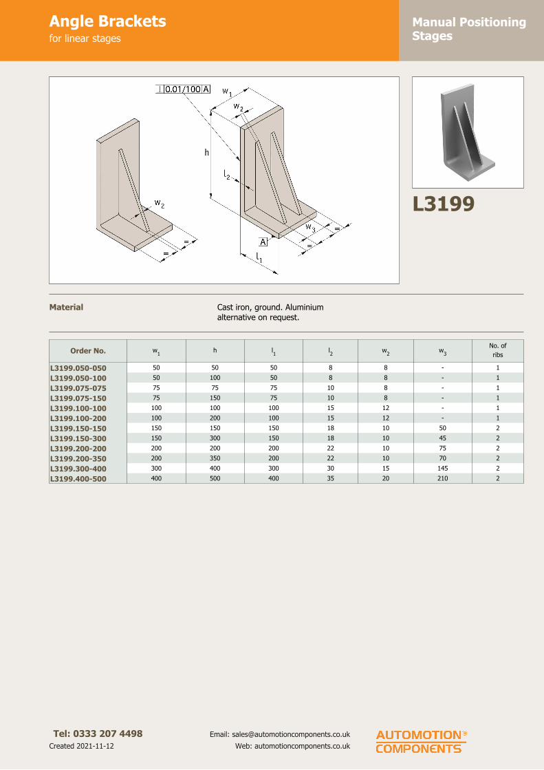
Manual PositioningStages
Angle Bracketsfor linear stages
Tel: 0333 207 4498
Created 2021-11-12
Email: [email protected]
Web: automotioncomponents.co.uk
L3199
Material Cast iron, ground. Aluminium
alternative on request.
Order No. w1
h l1
l2
w2
w3
No. of
ribs
L3199.050-050 50 50 50 8 8 - 1
L3199.050-100 50 100 50 8 8 - 1
L3199.075-075 75 75 75 10 8 - 1
L3199.075-150 75 150 75 10 8 - 1
L3199.100-100 100 100 100 15 12 - 1
L3199.100-200 100 200 100 15 12 - 1
L3199.150-150 150 150 150 18 10 50 2
L3199.150-300 150 300 150 18 10 45 2
L3199.200-200 200 200 200 22 10 75 2
L3199.200-350 200 350 200 22 10 70 2
L3199.300-400 300 400 300 30 15 145 2
L3199.400-500 400 500 400 35 20 210 2

175
Miniature Stages
ov-m
iniatu
re-stages-d
ivider - U
pd
ated - 1
8-0
9-2
017

Manual PositioningStages
Miniature Dovetail StagesX axis
Tel: 0333 207 4498
Created 2021-11-12
Email: [email protected]
Web: automotioncomponents.co.uk
L3300.X
Material
Brass, blackened body, aluminium
knob.
Technical notes
Travel 0,5mm for one revolution.
Minimum vernier reading 0,1mm.
Straightness accuracy 30µ.
Order No. w1
h1
Travel Max. load Kg w2
w3
w4
w5
L3300.025-X 25 15 ± 3 3,0 10 - 15 20
L3300.040-X 40 15 ± 7 3,0 20 20 28 20
L3300.060-X 60 17 ± 9 4,0 25 32 40 20
Order No. w6
w7
d1
d2
d3
d4
d5
h2
h3
l1
l2
L3300.025-X 8 20 M2 - 6 12 2,5 11,5 7,0 6,7 23
L3300.040-X 8 32 M3 M2 6 12 3,5 11,5 7,0 6,7 23
L3300.060-X 8 50 M4 M3 10 12 4,5 10,5 6,5 11,5 20

Manual PositioningStages
Miniature Dovetail StagesXY axis
Tel: 0333 207 4498
Created 2021-11-12
Email: [email protected]
Web: automotioncomponents.co.uk
L3300.XY
Material
Brass, blackened body, aluminium
knob.
Technical notes
Travel 0,5mm for one revolution.
Minimum vernier reading 0,1mm.
Straightness accuracy 30µ.
Order No. w1
h1
Travel Max. load Kg w2
w3
w4
w5
L3300.025-XY 25 30 ± 3 2,9 10 - 20 8,0
L3300.040-XY 40 30 ± 7 2,8 20 20 20 8,0
L3300.060-XY 60 34 ± 9 3,4 25 32 20 11,5
Order No. w6
d1
d2
d3
d4
d5
h2
h3
h4
h5
h6
l1
l2
l3
L3300.025-XY 20 M2 - 6 12 2,5 26,5 7,0 22,0 11,5 4,5 15 20 8
L3300.040-XY 32 M3 M2 6 12 3,5 26,5 7,0 22,0 11,5 3,5 28 20 8
L3300.060-XY 50 M4 M3 10 12 4,5 27,5 6,5 23,5 10,5 2,5 40 20 8

Manual PositioningStages
Dovetail Stages - Rack & PinionX axis
Tel: 0333 207 4498
Created 2021-11-12
Email: [email protected]
Web: automotioncomponents.co.uk
L3303.X
Material
Aluminium body blackened, steel
knob.
Technical notes
Travel 18mm for one revolution.
Minimum vernier reading 0,1mm.
Straightness accuracy 30µ.
Order No. l1
h1
w1
TravelMax.
load Kgw
2w
3w
4w
5l2
l3
l4
h2
d1
d2
d3
L3303.042-X 42 34 24,8 ± 12 3,0 50 40 15 17,8 50 40 20 8 4,5 M4 15
L3303.060-X 60 34 40,0 ± 21 4,0 60 50 25 17,8 60 50 20 8 4,5 M4 15
L3303.090-X 90 34 40,0 ± 35 4,0 60 50 25 17,8 60 50 20 8 4,5 M4 15
L3303.140-X 140 34 40,0 ± 60 4,0 60 50 25 17,8 60 50 20 8 4,5 M4 15

Manual PositioningStages
Dovetail Stages - Rack & PinionXY axis
Tel: 0333 207 4498
Created 2021-11-12
Email: [email protected]
Web: automotioncomponents.co.uk
L3303.XY
Material
Aluminium body blackened, steel
knob.
Technical notes
Travel 18mm for one revolution.
Minimum vernier reading 0,1mm.
Straightness accuracy 30µ.
Order No. l1
h1
w1
TravelMax.
load Kgw
2w
3d
3w
4l2
l3
h2
h2
d1
d2
L3303.042-XY 42 60 24,8 ± 12 2,5 28 12 15 12,5 50 40 34 8 M4 4,5
L3303.060-XY 60 60 40,0 ± 21 3,5 28 12 15 20 60 50 34 8 M4 4,5
L3303.090-XY 90 60 40,0 ± 35 3,5 43 13 15 20 60 50 34 8 M4 4,5

Manual PositioningStages
Dovetail Stages - Rack & Pinionlong stroke, X axis
Tel: 0333 207 4498
Created 2021-11-12
Email: [email protected]
Web: automotioncomponents.co.uk
L3305
Material
Aluminium body blackened, steel
knob.
Technical notes
Travel 18mm for one revolution.
Minimum vernier reading 0,1mm.
Straightness accuracy 30µ.
Use screwdriver to adjust knob to
allow coarse or fine adjustment.
Order No. l1
h1
w1
Travel Max. load Kg Accuracy l2
l3
L3305.100 100 25 25 ± 40 3,0 30µ 42 30
L3305.150 150 25 25 ± 60 3,0 40µ 42 30
L3305.200 200 25 25 ± 95 3,0 50µ 42 30
Order No. l4
l5
w2
w3
w4
h2
h3
h4
d1
d2
d3
for d4
d5
L3305.100 25 15 15 40,2 24,5 17,1 14,8 6 M2 M2 M3 15 8
L3305.150 25 15 15 40,2 24,5 17,1 14,8 6 M4 M2 M3 15 8
L3305.200 25 15 15 40,2 24,5 17,1 14,8 6 M4 M2 M3 15 8

Manual PositioningStages
Manual Laboratory JacksZ axis
Tel: 0333 207 4498
Created 2021-11-12
Email: [email protected]
Web: automotioncomponents.co.uk
L3320
Material Aluminium body blackened, steel
knob.
Order No. w1
l1
h1
Holding force
KgfParallelism l
2l3
l4
L3320.080 80 120 60-100 7 0,2 70 - 25
L3320.120 120 180 90-160 10 0,2 90 70 25
Order No. l5
w2
w3
w3
w4
h2
h3
d1
d2
d3
d4
L3320.080 42 70 - 70 - 8 3,5 M4 35 4,5 7,0
L3320.120 62 90 70 100 90 12 5,5 M4 50 4,5 8,0

Rotary StagesManual Rotary Stageseconomy type
Tel: 0333 207 4498
Created 2021-11-12
Email: [email protected]
Web: automotioncomponents.co.uk
L3330
Material
Aluminium body blackened, steel
knob.
Technical notes
360° adjustment.
Runout 50µ.
Order No. d1
Max. load
Kgf
Min. vernier
readingh
1h
2d
2d
3d
4XKg
L3330.040 40 5,0 2° 20 4 M2 25 5,5 0,14
L3330.060 60 7,0 1° 25 4 M4 50 5,5 0,20
Order No. d5
d6
d7
w1
w2
w3
w4
l1
l2
L3330.040 M6x 8 7,5 6 25 - 15 - 10,3 10
L3330.060 M6x14 7,5 8 40 32 25 15 15,5 13

Rotary StagesManual Rotary Stagesprecision type
Tel: 0333 207 4498
Created 2021-11-12
Email: [email protected]
Web: automotioncomponents.co.uk
L3331
Material
Aluminium body blackened, steel
knob. Transmission mechanism -
brass bush rotary system.
Technical notes
Coarse 360° adjustment., fine
adjustment ± 5°.
Order No. d1
Max. load
Kgf
Min. vernier
readingh
1h
2h
3h
4d
2XKg
L3331.038 38 1,0 1' 26" 17,5 11 10,5 4,5 16 0,09
L3331.060 60 3,0 0' 55" 22,5 13 12,5 11,5 15 0,28
L3331.085 85 4,0 0' 43" 25 22 13,0 11,5 20 0,48
L3331.110 110 5,0 0' 34" 25 22 13,0 11,5 25 0,75
Order No. d3
d4
d5
d6
d7
d8
for d9
w1
w2
w3
w4
l1
l2
L3331.038 32 6 4 M 6x1 M2 M2 - - 32 14 24,0 37,4 38,5
L3331.060 50 12 4 M16x1 M3 M4 - - 50 32 37,5 47,8 45,0
L3331.085 50 12 4 M16x1 M3 M4 8 - 50 32 48,0 53,3 62,0
L3331.110 50 12 4 M16x1 M3 M4 8 70 50 32 61,5 53,3 62,0

Rotary StagesManual Rotary Stagesstainless
Tel: 0333 207 4498
Created 2021-11-12
Email: [email protected]
Web: automotioncomponents.co.uk
L3339
Material
Stainless steel AISI 303 rotary disc,
black anodized aluminium control
knob. All other part steel or brass.
Technical notes
The rotary table can be clamped
using a grub screw. it also has a fast
adjustment when a grub screw on
the side of the disc is released.
Rotating range 0° to infinity.
Order No.d
1
h7
d2
d3
d4
H7
d5
h1
h2
l w1
w2
w3
± 0,02
L3339.055 55 M5x8 4,3 4x10 17 38 17,5 44 32 42 20
L3339.080 80 M5x8 5,4 4x10 23 45 24,0 59 40 60 30
Order No. Concentricity tolerance Circular runout toleranceMax. knob
torque Md
Nm
Max. torque
unclamped Nm
Max. torque
clamped Nm
Max. load
Fmax.
N
L3339.055 ± 0,02 ± 0,02 1,5 5 10 50
L3339.080 ± 0,03 ± 0,03 2,5 5 10 100

177
Motorised Linear Stages
ov-m
oto
rised-lin
ear-stages-d
ivider - U
pd
ated - 1
8-0
9-2
017

Positioning Stages
Tel: 01483 26 67 74 Web: automotioncomponents.co.uk Fax: 01483 26 67 75 a website from Automotion Components
Motorised Linear & Rotary StagesOverview
L3500Medium duty
motorised stage
L3508Motorised linear
stage
L3524Multi-axes stepper
controller
L3554Motorised rotary
stage Ø75
L3562Motorised rotary
stage Ø200
L3504Heavy-duty
motorised stage
L3510Motorised linear
stage
L3525Single axis servo
controller
L3556Motorised rotary
stage Ø125
L3569High speed rotary
table
L3505Motorised linear
stage
L3521Single axis stepper
controller
L3550Motorised rotary
stage Ø50
L3558Motorised rotary
stage Ø125
L3591Vertical lift stage
motorised
L3506Miniature
motorised stage
L3522Two axes stepper
controller
L3552Motorised rotary
stage Ø75
L3559Manual rotary stage
Ø125
L3592Vertical lift stage
motorised
ov-m
oto
rised-stag
es-overview
-1 - U
pd
ated - 1
8-0
9-2
017

Positioning Stages
Tel: 01483 26 67 74 Web: automotioncomponents.co.uk Fax: 01483 26 67 75 a website from Automotion Components
software
host PC
power supply
further motors
driver
controller
intelligent
motor
motor
linear
stage
rotary
stage
second
intelligent
motor
software
host PC
1/2/ multi axismotion
controller
stepper
or servo
motor
linear
stage
rotary
stage
Motorised StagesOverview
XY Assembly
Using intelligent motors Using motion controllers
XY Assembly XY Assembly
Our motorised linear stages are precise, heavy duty and available from 25mm stroke to 800mm.They can be easily controlled either with an Intelligent motor (this is a motor with an inbuilt driver and controller) or with a motor and one of our motion controller stages.Programming for both the intelligent motor (less expensive) and the motion controllers is very simple and we provide free software and sample source code for Labview, VB, C++, OSX etc. It is also possible to download a stand-alone programmed to the device so it can run independently of a host.We also off er a Joystick controller.
The stages can be readily supplied in X, XY, XZ and XYZ confi gurations and can also be used with our range of rotary tables (L3550 to L3562).
• RS-485 - USB connection.• Can run independently from host.• Joystick control option
• RS-485 - USB connection.• Can run independently from host.• Joystick control option
ov-m
oto
rised-stag
es-overview
-2 - U
pd
ated - 1
8-0
9-2
017

Positioning Stages
Positioning Stages from Autom
otion Components
Tel: 01483 26 67 74 Web: automotioncomponents.co.uk Fax: 01483 26 67 75 a website from Automotion Components
Motorised StagesStepper + servo motors
Stepper limitations
For all of their advantages, stepper motors have a number of limitations which can cause signifi cant implementation and operational issues depending on your application. Stepper motors do not have any reserve power. In fact, stepper motors lose a signifi cant amount of their torque as they approach their maximum driver speed. A loss of 80% of the rated torque at 90% of the maximum speed is typical.
Stepper motors are also not as good as servo motors in accelerating a load. Attempting to accelerate a load too fast where the stepper cannot generate enough torque to move to the next step before the next drive pulse will result in a skipped step and a loss in position. If positional accuracy is essential, either the load on the motor must never exceed its torque or the stepper must be combined with a position encoder to ensure positional accuracy.
Stepper motors may also suff er from vibration and resonance problems. At certain speeds, partially depending on the load dynamics, they may resonate and be unable to drive the load. This may result in skipped steps, stalled motors, excessive vibration and noise.
Servo limitations
Servo motors are capable of delivering more power than stepper motors, but do require much more complex drive circuitry and positional feedback for accurate positioning. Servo motors are also much considerably expensive than stepper motors and are often harder to fi nd. Servo motors often require gear boxes, especially for lower speed operation.
The requirement for a gearbox and a position encoder makes servo motor designs more mechanically complex and increases the maintenance requirements for the system. To top it all off , servo motors are more expensive than stepper motors before adding on the cost of a position encoder.
Summary
Selecting the best motor for your application depends on a few key design criteria for your system including cost, positional accuracy requirements, torque requirements, drive power availability, and acceleration requirements. Overall, servo motors are best for high speed, high torque applications while stepper motors are better suited for lower acceleration, high holding torque applications as well as generally being less expensive and easier to control.
Stepper motor• Standard • With rotary encoder (1000 line)
Intelligent stepper motor• Standard• With rotary encoder (512 line)
Servo motor• Standard• With rotary encoder (1000 line)
Motor options
ov-step
per&
servo-m
oto
rs - Up
dated
- 18
-09
-20
17

Motorised LinearStages
Medium-Duty Motorised Stageshigh precision
Tel: 0333 207 4498
Created 2021-11-12
Email: [email protected]
Web: automotioncomponents.co.uk
L3500
Material
Black anodised aluminium body
(6061). Hardened linear guideways,
stainless steel Acme lead screw (with
internally lubricated anti-backlash
nut).
Technical notes
These are smooth running, precise
and stiff linear stages. For ease of
use they have separate connections
for motor power and limit/encoder
signals. Integrated limit switches are
provided as standard.
Easy plug and play system.
Controllable from PC or PLC when
used in conjunction with a motion
controller. Controllers come with their
own software but many pre-existing
software packages (such as Labview)
can be used.
Can be readily supplied in XY, XZ and
XYZ configurations.
Applications - research,
semi-conductors, fibre optics,
automation etc.
Replace -XXX in part number
with the code for your preferred
motor type - see second data
table for codes and
specifications.
Tips
Motor options:
Stepper - Nema 17, high torque,
brushless. 0.95 Amp/phase, 5.0
Ohm/phase, 3.1 mH/phase,
1.8°/step. Optional Stepper & 1000
line linear encoder.
Servo - Nema 17, brushless DC
motor. Continuous stall torque
0.25Nm, peak torque 0.7 Nm, with
1000 line rotary encoder.
Intelligent stepper - Nema 17 with
a fully programmable motion
controller inbuilt (ie no need for an
external motion controller). Two +5
to +24VDC I/O lines. One 10 bit
analogue input selectable 0 to
+10VDC, 0 to +5VDC. RS422/485
communications. Input voltage
+24VDC.
Limit switches are wired normally
open.
Option with 512 line encoder.
Drawings show stepper motor
configuration. See special pages for
further motor options.
Important notes
Max. moment loads:
Mx = 20 Nm
My = 20 Nm
Mz = 19 Nm
For 50mm travel stage Ma and Mb =
12 Nm.
For combined stages, add suffixes:
XY - for XY stage
XZ - for XZ stage
XYZ - for XYZ stage
Order No. TravelAccuracy
µ/mm
Bi-directional
repeatability
Max.
horizontal
load Kg.
Max. vertical
load Kg.
Max. side
load Kg.l1
l2
XKg.
L3500.050-STA 50 0,6µ 10µ 23 6,5 18 176 44,5 1,36
L3500.050-STB 50 0,6µ 10µ 23 6,5 18 176 44,5 1,36
L3500.050-STC 50 0,6µ 10µ 23 6,5 18 176 44,5 1,36
L3500.050-STD 50 0,6µ 10µ 23 6,5 18 176 44,5 1,36
L3500.050-IMA 50 0,6µ 10µ 23 6,5 18 176 44,5 1,36
L3500.050-IMB 50 0,6µ 10µ 23 6,5 18 176 44,5 1,36
L3500.050-IMC 50 0,6µ 10µ 23 6,5 18 176 44,5 1,36
L3500.050-IMD 50 0,6µ 10µ 23 6,5 18 176 44,5 1,36
L3500.050-SVA 50 0,6µ 10µ 23 6,5 18 176 44,5 1,36
L3500.050-SVB 50 0,6µ 10µ 23 6,5 18 176 44,5 1,36
L3500.150-STA 150 0,6µ 10µ 23 6,5 18 277 94,3 2,41
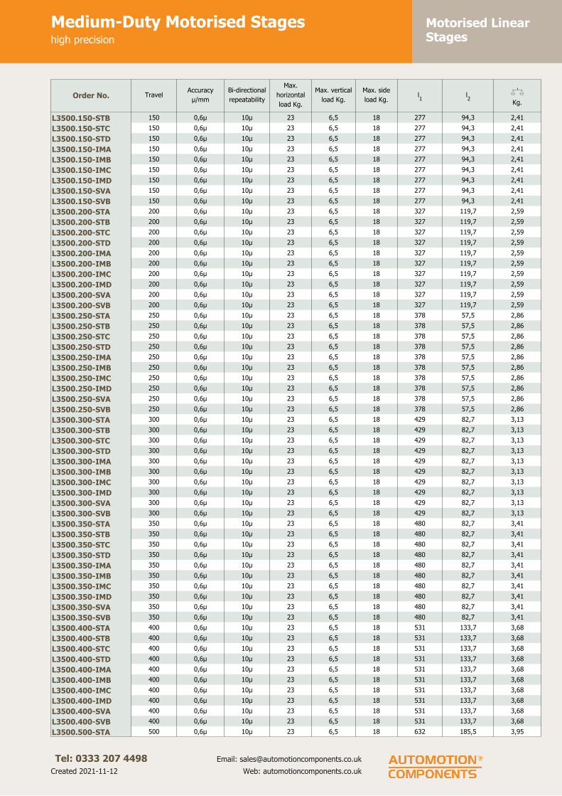
Motorised LinearStages
Medium-Duty Motorised Stageshigh precision
Tel: 0333 207 4498
Created 2021-11-12
Email: [email protected]
Web: automotioncomponents.co.uk
Order No. TravelAccuracy
µ/mm
Bi-directional
repeatability
Max.
horizontal
load Kg.
Max. vertical
load Kg.
Max. side
load Kg.l1
l2
XKg.
L3500.150-STB 150 0,6µ 10µ 23 6,5 18 277 94,3 2,41
L3500.150-STC 150 0,6µ 10µ 23 6,5 18 277 94,3 2,41
L3500.150-STD 150 0,6µ 10µ 23 6,5 18 277 94,3 2,41
L3500.150-IMA 150 0,6µ 10µ 23 6,5 18 277 94,3 2,41
L3500.150-IMB 150 0,6µ 10µ 23 6,5 18 277 94,3 2,41
L3500.150-IMC 150 0,6µ 10µ 23 6,5 18 277 94,3 2,41
L3500.150-IMD 150 0,6µ 10µ 23 6,5 18 277 94,3 2,41
L3500.150-SVA 150 0,6µ 10µ 23 6,5 18 277 94,3 2,41
L3500.150-SVB 150 0,6µ 10µ 23 6,5 18 277 94,3 2,41
L3500.200-STA 200 0,6µ 10µ 23 6,5 18 327 119,7 2,59
L3500.200-STB 200 0,6µ 10µ 23 6,5 18 327 119,7 2,59
L3500.200-STC 200 0,6µ 10µ 23 6,5 18 327 119,7 2,59
L3500.200-STD 200 0,6µ 10µ 23 6,5 18 327 119,7 2,59
L3500.200-IMA 200 0,6µ 10µ 23 6,5 18 327 119,7 2,59
L3500.200-IMB 200 0,6µ 10µ 23 6,5 18 327 119,7 2,59
L3500.200-IMC 200 0,6µ 10µ 23 6,5 18 327 119,7 2,59
L3500.200-IMD 200 0,6µ 10µ 23 6,5 18 327 119,7 2,59
L3500.200-SVA 200 0,6µ 10µ 23 6,5 18 327 119,7 2,59
L3500.200-SVB 200 0,6µ 10µ 23 6,5 18 327 119,7 2,59
L3500.250-STA 250 0,6µ 10µ 23 6,5 18 378 57,5 2,86
L3500.250-STB 250 0,6µ 10µ 23 6,5 18 378 57,5 2,86
L3500.250-STC 250 0,6µ 10µ 23 6,5 18 378 57,5 2,86
L3500.250-STD 250 0,6µ 10µ 23 6,5 18 378 57,5 2,86
L3500.250-IMA 250 0,6µ 10µ 23 6,5 18 378 57,5 2,86
L3500.250-IMB 250 0,6µ 10µ 23 6,5 18 378 57,5 2,86
L3500.250-IMC 250 0,6µ 10µ 23 6,5 18 378 57,5 2,86
L3500.250-IMD 250 0,6µ 10µ 23 6,5 18 378 57,5 2,86
L3500.250-SVA 250 0,6µ 10µ 23 6,5 18 378 57,5 2,86
L3500.250-SVB 250 0,6µ 10µ 23 6,5 18 378 57,5 2,86
L3500.300-STA 300 0,6µ 10µ 23 6,5 18 429 82,7 3,13
L3500.300-STB 300 0,6µ 10µ 23 6,5 18 429 82,7 3,13
L3500.300-STC 300 0,6µ 10µ 23 6,5 18 429 82,7 3,13
L3500.300-STD 300 0,6µ 10µ 23 6,5 18 429 82,7 3,13
L3500.300-IMA 300 0,6µ 10µ 23 6,5 18 429 82,7 3,13
L3500.300-IMB 300 0,6µ 10µ 23 6,5 18 429 82,7 3,13
L3500.300-IMC 300 0,6µ 10µ 23 6,5 18 429 82,7 3,13
L3500.300-IMD 300 0,6µ 10µ 23 6,5 18 429 82,7 3,13
L3500.300-SVA 300 0,6µ 10µ 23 6,5 18 429 82,7 3,13
L3500.300-SVB 300 0,6µ 10µ 23 6,5 18 429 82,7 3,13
L3500.350-STA 350 0,6µ 10µ 23 6,5 18 480 82,7 3,41
L3500.350-STB 350 0,6µ 10µ 23 6,5 18 480 82,7 3,41
L3500.350-STC 350 0,6µ 10µ 23 6,5 18 480 82,7 3,41
L3500.350-STD 350 0,6µ 10µ 23 6,5 18 480 82,7 3,41
L3500.350-IMA 350 0,6µ 10µ 23 6,5 18 480 82,7 3,41
L3500.350-IMB 350 0,6µ 10µ 23 6,5 18 480 82,7 3,41
L3500.350-IMC 350 0,6µ 10µ 23 6,5 18 480 82,7 3,41
L3500.350-IMD 350 0,6µ 10µ 23 6,5 18 480 82,7 3,41
L3500.350-SVA 350 0,6µ 10µ 23 6,5 18 480 82,7 3,41
L3500.350-SVB 350 0,6µ 10µ 23 6,5 18 480 82,7 3,41
L3500.400-STA 400 0,6µ 10µ 23 6,5 18 531 133,7 3,68
L3500.400-STB 400 0,6µ 10µ 23 6,5 18 531 133,7 3,68
L3500.400-STC 400 0,6µ 10µ 23 6,5 18 531 133,7 3,68
L3500.400-STD 400 0,6µ 10µ 23 6,5 18 531 133,7 3,68
L3500.400-IMA 400 0,6µ 10µ 23 6,5 18 531 133,7 3,68
L3500.400-IMB 400 0,6µ 10µ 23 6,5 18 531 133,7 3,68
L3500.400-IMC 400 0,6µ 10µ 23 6,5 18 531 133,7 3,68
L3500.400-IMD 400 0,6µ 10µ 23 6,5 18 531 133,7 3,68
L3500.400-SVA 400 0,6µ 10µ 23 6,5 18 531 133,7 3,68
L3500.400-SVB 400 0,6µ 10µ 23 6,5 18 531 133,7 3,68
L3500.500-STA 500 0,6µ 10µ 23 6,5 18 632 185,5 3,95
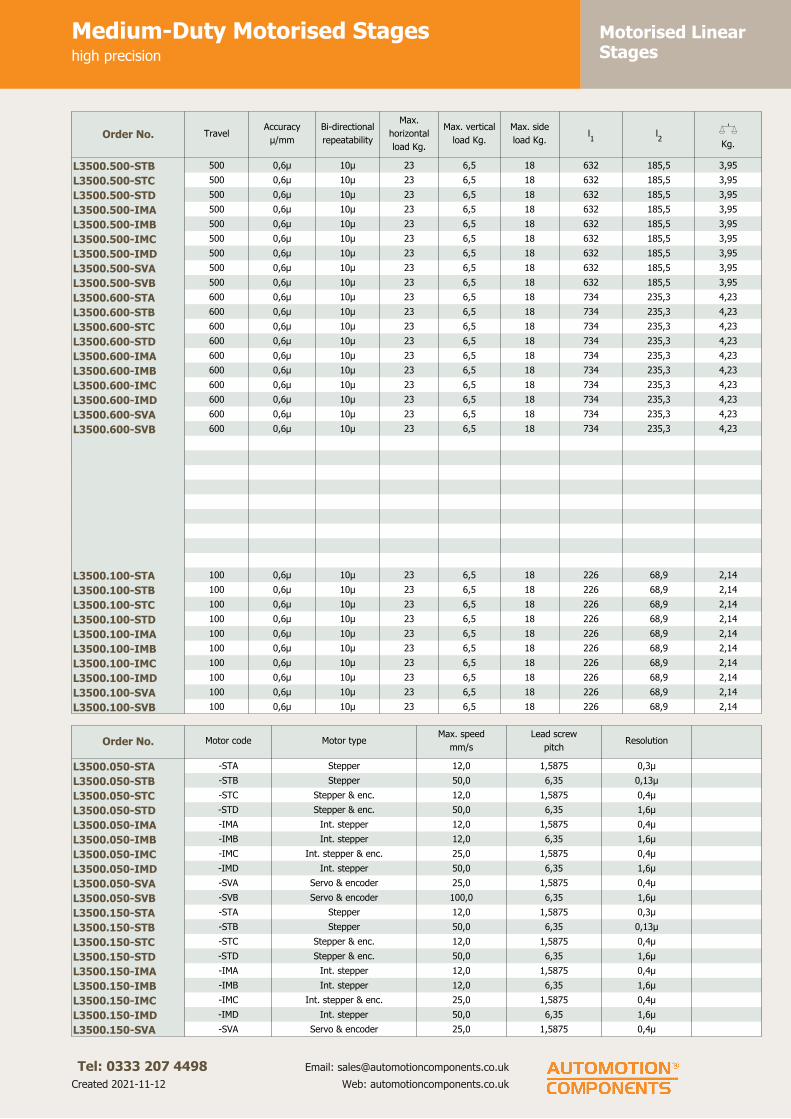
Motorised LinearStages
Medium-Duty Motorised Stageshigh precision
Tel: 0333 207 4498
Created 2021-11-12
Email: [email protected]
Web: automotioncomponents.co.uk
Order No. TravelAccuracy
µ/mm
Bi-directional
repeatability
Max.
horizontal
load Kg.
Max. vertical
load Kg.
Max. side
load Kg.l1
l2
XKg.
L3500.500-STB 500 0,6µ 10µ 23 6,5 18 632 185,5 3,95
L3500.500-STC 500 0,6µ 10µ 23 6,5 18 632 185,5 3,95
L3500.500-STD 500 0,6µ 10µ 23 6,5 18 632 185,5 3,95
L3500.500-IMA 500 0,6µ 10µ 23 6,5 18 632 185,5 3,95
L3500.500-IMB 500 0,6µ 10µ 23 6,5 18 632 185,5 3,95
L3500.500-IMC 500 0,6µ 10µ 23 6,5 18 632 185,5 3,95
L3500.500-IMD 500 0,6µ 10µ 23 6,5 18 632 185,5 3,95
L3500.500-SVA 500 0,6µ 10µ 23 6,5 18 632 185,5 3,95
L3500.500-SVB 500 0,6µ 10µ 23 6,5 18 632 185,5 3,95
L3500.600-STA 600 0,6µ 10µ 23 6,5 18 734 235,3 4,23
L3500.600-STB 600 0,6µ 10µ 23 6,5 18 734 235,3 4,23
L3500.600-STC 600 0,6µ 10µ 23 6,5 18 734 235,3 4,23
L3500.600-STD 600 0,6µ 10µ 23 6,5 18 734 235,3 4,23
L3500.600-IMA 600 0,6µ 10µ 23 6,5 18 734 235,3 4,23
L3500.600-IMB 600 0,6µ 10µ 23 6,5 18 734 235,3 4,23
L3500.600-IMC 600 0,6µ 10µ 23 6,5 18 734 235,3 4,23
L3500.600-IMD 600 0,6µ 10µ 23 6,5 18 734 235,3 4,23
L3500.600-SVA 600 0,6µ 10µ 23 6,5 18 734 235,3 4,23
L3500.600-SVB 600 0,6µ 10µ 23 6,5 18 734 235,3 4,23
L3500.100-STA 100 0,6µ 10µ 23 6,5 18 226 68,9 2,14
L3500.100-STB 100 0,6µ 10µ 23 6,5 18 226 68,9 2,14
L3500.100-STC 100 0,6µ 10µ 23 6,5 18 226 68,9 2,14
L3500.100-STD 100 0,6µ 10µ 23 6,5 18 226 68,9 2,14
L3500.100-IMA 100 0,6µ 10µ 23 6,5 18 226 68,9 2,14
L3500.100-IMB 100 0,6µ 10µ 23 6,5 18 226 68,9 2,14
L3500.100-IMC 100 0,6µ 10µ 23 6,5 18 226 68,9 2,14
L3500.100-IMD 100 0,6µ 10µ 23 6,5 18 226 68,9 2,14
L3500.100-SVA 100 0,6µ 10µ 23 6,5 18 226 68,9 2,14
L3500.100-SVB 100 0,6µ 10µ 23 6,5 18 226 68,9 2,14
Order No. Motor code Motor typeMax. speed
mm/s
Lead screw
pitchResolution
L3500.050-STA -STA Stepper 12,0 1,5875 0,3µ
L3500.050-STB -STB Stepper 50,0 6,35 0,13µ
L3500.050-STC -STC Stepper & enc. 12,0 1,5875 0,4µ
L3500.050-STD -STD Stepper & enc. 50,0 6,35 1,6µ
L3500.050-IMA -IMA Int. stepper 12,0 1,5875 0,4µ
L3500.050-IMB -IMB Int. stepper 12,0 6,35 1,6µ
L3500.050-IMC -IMC Int. stepper & enc. 25,0 1,5875 0,4µ
L3500.050-IMD -IMD Int. stepper 50,0 6,35 1,6µ
L3500.050-SVA -SVA Servo & encoder 25,0 1,5875 0,4µ
L3500.050-SVB -SVB Servo & encoder 100,0 6,35 1,6µ
L3500.150-STA -STA Stepper 12,0 1,5875 0,3µ
L3500.150-STB -STB Stepper 50,0 6,35 0,13µ
L3500.150-STC -STC Stepper & enc. 12,0 1,5875 0,4µ
L3500.150-STD -STD Stepper & enc. 50,0 6,35 1,6µ
L3500.150-IMA -IMA Int. stepper 12,0 1,5875 0,4µ
L3500.150-IMB -IMB Int. stepper 12,0 6,35 1,6µ
L3500.150-IMC -IMC Int. stepper & enc. 25,0 1,5875 0,4µ
L3500.150-IMD -IMD Int. stepper 50,0 6,35 1,6µ
L3500.150-SVA -SVA Servo & encoder 25,0 1,5875 0,4µ

Motorised LinearStages
Medium-Duty Motorised Stageshigh precision
Tel: 0333 207 4498
Created 2021-11-12
Email: [email protected]
Web: automotioncomponents.co.uk
Order No. Motor code Motor typeMax. speed
mm/s
Lead screw
pitchResolution
L3500.150-SVB -SVB Servo & encoder 100,0 6,35 1,6µ
L3500.200-STA -STA Stepper 12,0 1,5875 0,3µ
L3500.200-STB -STB Stepper 50,0 6,35 0,13µ
L3500.200-STC -STC Stepper & enc. 12,0 1,5875 0,4µ
L3500.200-STD -STD Stepper & enc. 50,0 6,35 1,6µ
L3500.200-IMA -IMA Int. stepper 12,0 1,5875 0,4µ
L3500.200-IMB -IMB Int. stepper 12,0 6,35 1,6µ
L3500.200-IMC -IMC Int. stepper & enc. 25,0 1,5875 0,4µ
L3500.200-IMD -IMD Int. stepper 50,0 6,35 1,6µ
L3500.200-SVA -SVA Servo & encoder 25,0 1,5875 0,4µ
L3500.200-SVB -SVB Servo & encoder 100,0 6,35 1,6µ
L3500.250-STA -STA Stepper 12,0 1,5875 0,3µ
L3500.250-STB -STB Stepper 50,0 6,35 0,13µ
L3500.250-STC -STC Stepper & enc. 12,0 1,5875 0,4µ
L3500.250-STD -STD Stepper & enc. 50,0 6,35 1,6µ
L3500.250-IMA -IMA Int. stepper 12,0 1,5875 0,4µ
L3500.250-IMB -IMB Int. stepper 12,0 6,35 1,6µ
L3500.250-IMC -IMC Int. stepper & enc. 25,0 1,5875 0,4µ
L3500.250-IMD -IMD Int. stepper 50,0 6,35 1,6µ
L3500.250-SVA -SVA Servo & encoder 25,0 1,5875 0,4µ
L3500.250-SVB -SVB Servo & encoder 100,0 6,35 1,6µ
L3500.300-STA -STA Stepper 12,0 1,5875 0,3µ
L3500.300-STB -STB Stepper 50,0 6,35 0,13µ
L3500.300-STC -STC Stepper & enc. 12,0 1,5875 0,4µ
L3500.300-STD -STD Stepper & enc. 50,0 6,35 1,6µ
L3500.300-IMA -IMA Int. stepper 12,0 1,5875 0,4µ
L3500.300-IMB -IMB Int. stepper 12,0 6,35 1,6µ
L3500.300-IMC -IMC Int. stepper & enc. 25,0 1,5875 0,4µ
L3500.300-IMD -IMD Int. stepper 50,0 6,35 1,6µ
L3500.300-SVA -SVA Servo & encoder 25,0 1,5875 0,4µ
L3500.300-SVB -SVB Servo & encoder 100,0 6,35 1,6µ
L3500.350-STA -STA Stepper 12,0 1,5875 0,3µ
L3500.350-STB -STB Stepper 50,0 6,35 0,13µ
L3500.350-STC -STC Stepper & enc. 12,0 1,5875 0,4µ
L3500.350-STD -STD Stepper & enc. 50,0 6,35 1,6µ
L3500.350-IMA -IMA Int. stepper 12,0 1,5875 0,4µ
L3500.350-IMB -IMB Int. stepper 12,0 6,35 1,6µ
L3500.350-IMC -IMC Int. stepper & enc. 25,0 1,5875 0,4µ
L3500.350-IMD -IMD Int. stepper 50,0 6,35 1,6µ
L3500.350-SVA -SVA Servo & encoder 25,0 1,5875 0,4µ
L3500.350-SVB -SVB Servo & encoder 100,0 6,35 1,6µ
L3500.400-STA -STA Stepper 12,0 1,5875 0,3µ
L3500.400-STB -STB Stepper 50,0 6,35 0,13µ
L3500.400-STC -STC Stepper & enc. 12,0 1,5875 0,4µ
L3500.400-STD -STD Stepper & enc. 50,0 6,35 1,6µ
L3500.400-IMA -IMA Int. stepper 12,0 1,5875 0,4µ
L3500.400-IMB -IMB Int. stepper 12,0 6,35 1,6µ
L3500.400-IMC -IMC Int. stepper & enc. 25,0 1,5875 0,4µ
L3500.400-IMD -IMD Int. stepper 50,0 6,35 1,6µ
L3500.400-SVA -SVA Servo & encoder 25,0 1,5875 0,4µ
L3500.400-SVB -SVB Servo & encoder 100,0 6,35 1,6µ
L3500.500-STA -STA Stepper 12,0 1,5875 0,3µ
L3500.500-STB -STB Stepper 50,0 6,35 0,13µ
L3500.500-STC -STC Stepper & enc. 12,0 1,5875 0,4µ
L3500.500-STD -STD Stepper & enc. 50,0 6,35 1,6µ
L3500.500-IMA -IMA Int. stepper 12,0 1,5875 0,4µ
L3500.500-IMB -IMB Int. stepper 12,0 6,35 1,6µ
L3500.500-IMC -IMC Int. stepper & enc. 25,0 1,5875 0,4µ
L3500.500-IMD -IMD Int. stepper 50,0 6,35 1,6µ
L3500.500-SVA -SVA Servo & encoder 25,0 1,5875 0,4µ
L3500.500-SVB -SVB Servo & encoder 100,0 6,35 1,6µ

Motorised LinearStages
Medium-Duty Motorised Stageshigh precision
Tel: 0333 207 4498
Created 2021-11-12
Email: [email protected]
Web: automotioncomponents.co.uk
Order No. Motor code Motor typeMax. speed
mm/s
Lead screw
pitchResolution
L3500.600-STA -STA Stepper 12,0 1,5875 0,3µ
L3500.600-STB -STB Stepper 50,0 6,35 0,13µ
L3500.600-STC -STC Stepper & enc. 12,0 1,5875 0,4µ
L3500.600-STD -STD Stepper & enc. 50,0 6,35 1,6µ
L3500.600-IMA -IMA Int. stepper 12,0 1,5875 0,4µ
L3500.600-IMB -IMB Int. stepper 12,0 6,35 1,6µ
L3500.600-IMC -IMC Int. stepper & enc. 25,0 1,5875 0,4µ
L3500.600-IMD -IMD Int. stepper 50,0 6,35 1,6µ
L3500.600-SVA -SVA Servo & encoder 25,0 1,5875 0,4µ
L3500.600-SVB -SVB Servo & encoder 100,0 6,35 1,6µ
L3500.100-STA -STA Stepper 12,0 1,5875 0,3µ
L3500.100-STB -STB Stepper 50,0 6,35 0,13µ
L3500.100-STC -STC Stepper & enc. 12,0 1,5875 0,4µ
L3500.100-STD -STD Stepper & enc. 50,0 6,35 1,6µ
L3500.100-IMA -IMA Int. stepper 12,0 1,5875 0,4µ
L3500.100-IMB -IMB Int. stepper 12,0 6,35 1,6µ
L3500.100-IMC -IMC Int. stepper & enc. 25,0 1,5875 0,4µ
L3500.100-IMD -IMD Int. stepper 50,0 6,35 1,6µ
L3500.100-SVA -SVA Servo & encoder 25,0 1,5875 0,4µ
L3500.100-SVB -SVB Servo & encoder 100,0 6,35 1,6µ

Motorised LinearStages
Medium-Duty Motorised Stageshigh precision
Tel: 0333 207 4498
Created 2021-11-12
Email: [email protected]
Web: automotioncomponents.co.uk
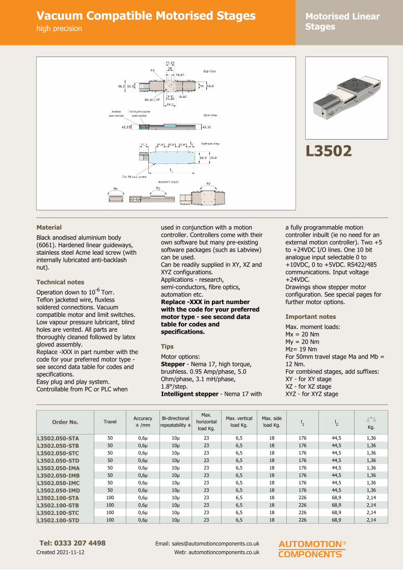
Motorised LinearStages
Vacuum Compatible Motorised Stageshigh precision
Tel: 0333 207 4498
Created 2021-11-12
Email: [email protected]
Web: automotioncomponents.co.uk
L3502
Material
Black anodised aluminium body
(6061). Hardened linear guideways,
stainless steel Acme lead screw (with
internally lubricated anti-backlash
nut).
Technical notes
Operation down to 10-6
Torr.
Teflon jacketed wire, fluxless
soldered connections. Vacuum
compatible motor and limit switches.
Low vapour pressure lubricant, blind
holes are vented. All parts are
thoroughly cleaned followed by latex
gloved assembly.
Replace -XXX in part number with the
code for your preferred motor type -
see second data table for codes and
specifications.
Easy plug and play system.
Controllable from PC or PLC when
used in conjunction with a motion
controller. Controllers come with their
own software but many pre-existing
software packages (such as Labview)
can be used.
Can be readily supplied in XY, XZ and
XYZ configurations.
Applications - research,
semi-conductors, fibre optics,
automation etc.
Replace -XXX in part number
with the code for your preferred
motor type - see second data
table for codes and
specifications.
Tips
Motor options:
Stepper - Nema 17, high torque,
brushless. 0.95 Amp/phase, 5.0
Ohm/phase, 3.1 mH/phase,
1.8°/step.
Intelligent stepper - Nema 17 with
a fully programmable motion
controller inbuilt (ie no need for an
external motion controller). Two +5
to +24VDC I/O lines. One 10 bit
analogue input selectable 0 to
+10VDC, 0 to +5VDC. RS422/485
communications. Input voltage
+24VDC.
Drawings show stepper motor
configuration. See special pages for
further motor options.
Important notes
Max. moment loads:
Mx = 20 Nm
My = 20 Nm
Mz= 19 Nm
For 50mm travel stage Ma and Mb =
12 Nm.
For combined stages, add suffixes:
XY - for XY stage
XZ - for XZ stage
XYZ - for XYZ stage
Order No. TravelAccuracy
± /mm
Bi-directional
repeatability ±
Max.
horizontal
load Kg.
Max. vertical
load Kg.
Max. side
load Kg.l1
l2
XKg.
L3502.050-STA 50 0,6µ 10µ 23 6,5 18 176 44,5 1,36
L3502.050-STB 50 0,6µ 10µ 23 6,5 18 176 44,5 1,36
L3502.050-STC 50 0,6µ 10µ 23 6,5 18 176 44,5 1,36
L3502.050-STD 50 0,6µ 10µ 23 6,5 18 176 44,5 1,36
L3502.050-IMA 50 0,6µ 10µ 23 6,5 18 176 44,5 1,36
L3502.050-IMB 50 0,6µ 10µ 23 6,5 18 176 44,5 1,36
L3502.050-IMC 50 0,6µ 10µ 23 6,5 18 176 44,5 1,36
L3502.050-IMD 50 0,6µ 10µ 23 6,5 18 176 44,5 1,36
L3502.100-STA 100 0,6µ 10µ 23 6,5 18 226 68,9 2,14
L3502.100-STB 100 0,6µ 10µ 23 6,5 18 226 68,9 2,14
L3502.100-STC 100 0,6µ 10µ 23 6,5 18 226 68,9 2,14
L3502.100-STD 100 0,6µ 10µ 23 6,5 18 226 68,9 2,14
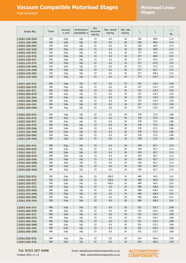
Motorised LinearStages
Vacuum Compatible Motorised Stageshigh precision
Tel: 0333 207 4498
Created 2021-11-12
Email: [email protected]
Web: automotioncomponents.co.uk
Order No. TravelAccuracy
± /mm
Bi-directional
repeatability ±
Max.
horizontal
load Kg.
Max. vertical
load Kg.
Max. side
load Kg.l1
l2
XKg.
L3502.100-IMA 100 0,6µ 10µ 23 6,5 18 226 68,9 2,14
L3502.100-IMB 100 0,6µ 10µ 23 6,5 18 226 68,9 2,14
L3502.100-IMC 100 0,6µ 10µ 23 6,5 18 226 68,9 2,14
L3502.100-IMD 100 0,6µ 10µ 23 6,5 18 226 68,9 2,14
L3502.150-STA 150 0,6µ 10µ 23 6,5 18 277 44,5 2,41
L3502.150-STB 150 0,6µ 10µ 23 6,5 18 277 68,9 2,41
L3502.150-STC 150 0,6µ 10µ 23 6,5 18 277 94,3 2,41
L3502.150-STD 150 0,6µ 10µ 23 6,5 18 277 119,7 2,41
L3502.150-IMA 150 0,6µ 10µ 23 6,5 18 277 57,5 2,41
L3502.150-IMB 150 0,6µ 10µ 23 6,5 18 277 82,7 2,41
L3502.150-IMC 150 0,6µ 10µ 23 6,5 18 277 108,3 2,41
L3502.150-IMD 150 0,6µ 10µ 23 6,5 18 277 133,7 2,41
L3502.200-STA 200 0,6µ 10µ 23 6,5 18 327 119,7 2,59
L3502.200-STB 200 0,6µ 10µ 23 6,5 18 327 119,7 2,59
L3502.200-STC 200 0,6µ 10µ 23 6,5 18 327 119,7 2,59
L3502.200-STD 200 0,6µ 10µ 23 6,5 18 327 119,7 2,59
L3502.200-IMA 200 0,6µ 10µ 23 6,5 18 327 119,7 2,59
L3502.200-IMB 200 0,6µ 10µ 23 6,5 18 327 119,7 2,59
L3502.200-IMC 200 0,6µ 10µ 23 6,5 18 327 119,7 2,59
L3502.200-IMD 200 0,6µ 10µ 23 6,5 18 327 119,7 2,59
L3502.250-STA 250 0,6µ 10µ 23 6,5 18 378 57,5 2,86
L3502.250-STB 250 0,6µ 10µ 23 6,5 18 378 57,5 2,86
L3502.250-STC 250 0,6µ 10µ 23 6,5 18 378 57,5 2,86
L3502.250-STD 250 0,6µ 10µ 23 6,5 18 378 57,5 2,86
L3502.250-IMA 250 0,6µ 10µ 23 6,5 18 378 57,5 2,86
L3502.250-IMB 250 0,6µ 10µ 23 6,5 18 378 57,5 2,86
L3502.250-IMC 250 0,6µ 10µ 23 6,5 18 378 57,5 2,86
L3502.250-IMD 250 0,6µ 10µ 23 6,5 18 378 57,5 2,86
L3502.300-STA 300 0,6µ 10µ 23 6,5 18 429 82,7 3,13
L3502.300-STB 300 0,6µ 10µ 23 6,5 18 429 82,7 3,13
L3502.300-STC 300 0,6µ 10µ 23 6,5 18 429 82,7 3,13
L3502.300-STD 200 0,6µ 10µ 23 6,5 18 429 82,7 3,13
L3502.300-IMA 250 0,6µ 10µ 23 6,5 18 429 82,7 3,13
L3502.300-IMB 300 0,6µ 10µ 23 6,5 18 429 82,7 3,13
L3502.300-IMC 350 0,6µ 10µ 23 6,5 18 429 82,7 3,13
L3502.300-IMD 400 0,6µ 10µ 23 6,5 18 429 82,7 3,13
L3502.350-STA 350 0,6µ 10µ 23 108,3 18 480 44,5 3,41
L3502.350-STB 350 0,6µ 10µ 23 108,3 18 480 68,9 3,41
L3502.350-STC 350 0,6µ 10µ 23 108,3 18 480 94,3 3,41
L3502.350-STD 350 0,6µ 10µ 23 6,5 18 480 108,3 3,41
L3502.350-IMA 350 0,6µ 10µ 23 6,5 18 480 108,3 3,41
L3502.350-IMB 350 0,6µ 10µ 23 6,5 18 480 108,3 3,41
L3502.350-IMC 350 0,6µ 10µ 23 6,5 18 480 108,3 3,41
L3502.350-IMD 350 0,6µ 10µ 23 6,5 18 480 108,3 3,41
L3502.400-STA 400 0,6µ 10µ 23 6,5 18 531 133,7 3,68
L3502.400-STB 400 0,6µ 10µ 23 6,5 18 531 133,7 3,68
L3502.400-STC 400 0,6µ 10µ 23 6,5 18 531 133,7 3,68
L3502.400-STD 400 0,6µ 10µ 23 6,5 18 531 133,7 3,68
L3502.400-IMA 400 0,6µ 10µ 23 6,5 18 531 133,7 3,68
L3502.400-IMB 400 0,6µ 10µ 23 6,5 18 531 133,7 3,68
L3502.400-IMC 400 0,6µ 10µ 23 6,5 18 531 133,7 3,68
L3502.400-IMD 400 0,6µ 10µ 23 6,5 18 531 133,7 3,68
L3502.500-STA 500 0,6µ 10µ 23 6,5 18 632 185,5 3,95
L3502.500-STB 500 0,6µ 10µ 23 6,5 18 632 185,5 3,95

Motorised LinearStages
Vacuum Compatible Motorised Stageshigh precision
Tel: 0333 207 4498
Created 2021-11-12
Email: [email protected]
Web: automotioncomponents.co.uk
Order No. TravelAccuracy
± /mm
Bi-directional
repeatability ±
Max.
horizontal
load Kg.
Max. vertical
load Kg.
Max. side
load Kg.l1
l2
XKg.
L3502.500-STC 500 0,6µ 10µ 23 6,5 18 632 185,5 3,95
L3502.500-STD 500 0,6µ 10µ 23 6,5 18 632 185,5 3,95
L3502.500-IMA 500 0,6µ 10µ 23 6,5 18 632 185,5 3,95
L3502.500-IMB 500 0,6µ 10µ 23 6,5 18 632 185,5 3,95
L3502.500-IMC 500 0,6µ 10µ 23 6,5 18 632 185,5 3,95
L3502.500-IMD 500 0,6µ 10µ 23 6,5 18 632 185,5 3,95
L3502.600-STA 600 0,6µ 10µ 23 6,5 18 734 235,3 4,23
L3502.600-STB 600 0,6µ 10µ 23 6,5 18 734 235,3 4,23
L3502.600-STC 600 0,6µ 10µ 23 6,5 18 734 235,3 4,23
L3502.600-STD 600 0,6µ 10µ 23 6,5 18 734 235,3 4,23
L3502.600-IMA 600 0,6µ 10µ 23 6,5 18 734 235,3 4,23
L3502.600-IMB 600 0,6µ 10µ 23 6,5 18 734 235,3 4,23
L3502.600-IMC 600 0,6µ 10µ 23 6,5 18 734 235,3 4,23
L3502.600-IMD 600 0,6µ 10µ 23 6,5 18 734 235,3 4,23
Order No. l2
Motor code Motor typeMax. speed
mm/s
Lead screw
pitch
Resolution
±
L3502.050-STA 44,5 -STA Stepper 12,0 1,5875 0,03µ
L3502.050-STB 44,5 -STB Stepper 50,0 6,35 0,13µ
L3502.050-STC 44,5 -STC Stepper & enc. 12,0 1,5875 0,4µ
L3502.050-STD 44,5 -STD Stepper & enc. 50,0 6,35 1,6µ
L3502.050-IMA 44,5 -IMA Int. stepper 12,0 1,5875 0,4µ
L3502.050-IMB 44,5 -IMB Int. stepper 12,0 6,35 1,6µ
L3502.050-IMC 44,5 -IMC Int. stepper & enc. 25,0 1,5875 0,4µ
L3502.050-IMD 44,5 -IMD Int. stepper 50,0 6,35 1,6µ
L3502.100-STA 68,9 -STA Stepper 12,0 1,5875 0,03µ
L3502.100-STB 68,9 -STB Stepper 50,0 6,35 0,13µ
L3502.100-STC 68,9 -STC Stepper & enc. 12,0 1,5875 0,4µ
L3502.100-STD 68,9 -STD Stepper & enc. 50,0 6,35 1,6µ
L3502.100-IMA 68,9 -IMA Int. stepper 12,0 1,5875 0,4µ
L3502.100-IMB 68,9 -IMB Int. stepper 12,0 6,35 1,6µ
L3502.100-IMC 68,9 -IMC Int. stepper & enc. 25,0 1,5875 0,4µ
L3502.100-IMD 68,9 -IMD Int. stepper 50,0 6,35 1,6µ
L3502.150-STA 44,5 -STA Stepper 12,0 1,5875 0,03µ
L3502.150-STB 68,9 -STB Stepper 50,0 6,35 0,13µ
L3502.150-STC 94,3 -STC Stepper & enc. 12,0 1,5875 0,4µ
L3502.150-STD 119,7 -STD Stepper & enc. 50,0 6,35 1,6µ
L3502.150-IMA 57,5 -IMA Int. stepper 12,0 1,5875 0,4µ
L3502.150-IMB 82,7 -IMB Int. stepper 12,0 6,35 1,6µ
L3502.150-IMC 108,3 -IMC Int. stepper & enc. 25,0 1,5875 0,4µ
L3502.150-IMD 133,7 -IMD Int. stepper 50,0 6,35 1,6µ
L3502.200-STA 119,7 -STA Stepper 12,0 1,5875 0,03µ
L3502.200-STB 119,7 -STB Stepper 50,0 6,35 0,13µ
L3502.200-STC 119,7 -STC Stepper & enc. 12,0 1,5875 0,4µ
L3502.200-STD 119,7 -STD Stepper & enc. 50,0 6,35 1,6µ
L3502.200-IMA 119,7 -IMA Int. stepper 12,0 1,5875 0,4µ
L3502.200-IMB 119,7 -IMB Int. stepper 12,0 6,35 1,6µ
L3502.200-IMC 119,7 -IMC Int. stepper & enc. 25,0 1,5875 0,4µ
L3502.200-IMD 119,7 -IMD Int. stepper 50,0 6,35 1,6µ
L3502.250-STA 57,5 -STA Stepper 12,0 1,5875 0,03µ
L3502.250-STB 57,5 -STB Stepper 50,0 6,35 0,13µ
L3502.250-STC 57,5 -STC Stepper & enc. 12,0 1,5875 0,4µ
L3502.250-STD 57,5 -STD Stepper & enc. 50,0 6,35 1,6µ
L3502.250-IMA 57,5 -IMA Int. stepper 12,0 1,5875 0,4µ
L3502.250-IMB 57,5 -IMB Int. stepper 12,0 6,35 1,6µ

Motorised LinearStages
Vacuum Compatible Motorised Stageshigh precision
Tel: 0333 207 4498
Created 2021-11-12
Email: [email protected]
Web: automotioncomponents.co.uk
Order No. l2
Motor code Motor typeMax. speed
mm/s
Lead screw
pitch
Resolution
±
L3502.250-IMC 57,5 -IMC Int. stepper & enc. 25,0 1,5875 0,4µ
L3502.250-IMD 57,5 -IMD Int. stepper 50,0 6,35 1,6µ
L3502.300-STA 82,7 -STA Stepper 12,0 1,5875 0,03µ
L3502.300-STB 82,7 -STB Stepper 50,0 6,35 0,13µ
L3502.300-STC 82,7 -STC Stepper & enc. 12,0 1,5875 0,4µ
L3502.300-STD 82,7 -STD Stepper & enc. 50,0 6,35 1,6µ
L3502.300-IMA 82,7 -IMA Int. stepper 12,0 1,5875 0,4µ
L3502.300-IMB 82,7 -IMB Int. stepper 12,0 6,35 1,6µ
L3502.300-IMC 82,7 -IMC Int. stepper & enc. 25,0 1,5875 0,4µ
L3502.300-IMD 82,7 -IMD Int. stepper 50,0 6,35 1,6µ
L3502.350-STA 44,5 -STA Stepper 12,0 1,5875 0,03µ
L3502.350-STB 68,9 -STB Stepper 50,0 6,35 0,13µ
L3502.350-STC 94,3 -STC Stepper & enc. 12,0 1,5875 0,4µ
L3502.350-STD 108,3 -STD Stepper & enc. 50,0 6,35 1,6µ
L3502.350-IMA 108,3 -IMA Int. stepper 12,0 1,5875 0,4µ
L3502.350-IMB 108,3 -IMB Int. stepper 12,0 6,35 1,6µ
L3502.350-IMC 108,3 -IMC Int. stepper & enc. 25,0 1,5875 0,4µ
L3502.350-IMD 108,3 -IMD Int. stepper 50,0 6,35 1,6µ
L3502.400-STA 133,7 -STA Stepper 12,0 1,5875 0,03µ
L3502.400-STB 133,7 -STB Stepper 50,0 6,35 0,13µ
L3502.400-STC 133,7 -STC Stepper & enc. 12,0 1,5875 0,4µ
L3502.400-STD 133,7 -STD Stepper & enc. 50,0 6,35 1,6µ
L3502.400-IMA 133,7 -IMA Int. stepper 12,0 1,5875 0,4µ
L3502.400-IMB 133,7 -IMB Int. stepper 12,0 6,35 1,6µ
L3502.400-IMC 133,7 -IMC Int. stepper & enc. 25,0 1,5875 0,4µ
L3502.400-IMD 133,7 -IMD Int. stepper 50,0 6,35 1,6µ
L3502.500-STA 185,5 -STA Stepper 12,0 1,5875 0,03µ
L3502.500-STB 185,5 -STB Stepper 50,0 6,35 0,13µ
L3502.500-STC 185,5 -STC Stepper & enc. 12,0 1,5875 0,4µ
L3502.500-STD 185,5 -STD Stepper & enc. 50,0 6,35 1,6µ
L3502.500-IMA 185,5 -IMA Int. stepper 12,0 1,5875 0,4µ
L3502.500-IMB 185,5 -IMB Int. stepper 12,0 6,35 1,6µ
L3502.500-IMC 185,5 -IMC Int. stepper & enc. 25,0 1,5875 0,4µ
L3502.500-IMD 185,5 -IMD Int. stepper 50,0 6,35 1,6µ
L3502.600-STA 235,3 -STA Stepper 12,0 1,5875 0,03µ
L3502.600-STB 235,3 -STB Stepper 50,0 6,35 0,13µ
L3502.600-STC 235,3 -STC Stepper & enc. 12,0 1,5875 0,4µ
L3502.600-STD 235,3 -STD Stepper & enc. 50,0 6,35 1,6µ
L3502.600-IMA 235,3 -IMA Int. stepper 12,0 1,5875 0,4µ
L3502.600-IMB 235,3 -IMB Int. stepper 12,0 6,35 1,6µ
L3502.600-IMC 235,3 -IMC Int. stepper & enc. 25,0 1,5875 0,4µ
L3502.600-IMD 235,3 -IMD Int. stepper 50,0 6,35 1,6µ

Motorised LinearStages
Heavy-Duty Motorised Stageshigh precision
Tel: 0333 207 4498
Created 2021-11-12
Email: [email protected]
Web: automotioncomponents.co.uk
L3504
Material
Black anodised aluminium body
(6061).
Hardened linear guideways, stainless
steel Acme lead screw with internally
lubricated anti-backlash nut.
Technical notes
These are smooth running, precise
and stiff linear stages. For ease of
use they have separate connections
for motor power and limit/encoder
signals. Integrated limit switches are
provided as standard.
Easy plug and play system.
Controllable from PC or PLC when
used in conjunction with a motion
controller. Controllers come with their
own software but you can also use
your own pre-existing software with
them such as Labview etc.
Replace -XXX in part number
with the code for your preferred
motor type. See the second data
table for these codes and the
specifications of these motors.
Tips
Motor options:
Stepper - Nema 23, high torque. 2.8
Amp/phase, 0.9 Ohm/phase, 2.5
mH/phase, 1.8°/step. Optionally with
optical linear encoder or 1000 line
rotary encoder.
Servo - Nema 23 brushless DC
motor. Continuous stall torque
0.51Nm, peak torque 1.34 Nm.
Option with 4000 count/rev optical
rotary encoder with index mark.
Intelligent stepper - Nema 23 with
a fully programmable motion
controller inbuilt (ie no need for an
external motion controller). Two +5
to +24VDC I/O lines. One 10 bit
analogue input selectable 0 to
+10VDC, 0 to +5VDC. RS422/485
communications. Input voltage
+24VDC.
Limit switches are wired normally
closed. Drawings show stepper motor
configuration. See special pages for
further motor options.
Important notes
Max. moment loads:
Mx = 200 Nm
My = 280 Nm
For combined stages, add suffixes:
XY - for XY stage
XZ - for XZ stage
XYZ - for XYZ stage
Order No. TravelMax. horiz.
load Kg.
Max.
vertical
load Kg.
Max. side
load Kg.
Lead
screw
pitch
l1
l2
l3
l4
l5
XKg.
L3504.200-STA 200 113 36 36 4 389 150 - - 70 9
L3504.200-STB 200 113 36 36 4 389 150 - - 70 9
L3504.200-STC 200 113 36 36 4 389 150 - - 70 9
L3504.200-IMA 200 113 36 36 4 389 150 - 100 70 9
L3504.300-STA 300 113 36 36 4 490 150 100 - 156 10
L3504.300-STB 300 113 36 36 4 490 150 100 - 156 10
L3504.300-STC 400 113 36 36 4 490 150 100 - 156 10
L3504.300-IMA 500 113 36 36 4 490 150 100 - 156 10
L3504.400-STA 400 113 36 36 4 592 150 100 - 112 12
L3504.400-STB 400 113 36 36 4 592 150 100 - 112 12
L3504.400-STC 400 113 36 36 4 592 150 100 - 112 12
L3504.400-IMA 400 113 36 36 4 592 150 100 100 112 12
L3504.500-STA 500 113 36 36 4 694 150 100 100 70 14
L3504.500-STB 500 113 36 36 4 694 150 100 100 70 14

Motorised LinearStages
Heavy-Duty Motorised Stageshigh precision
Tel: 0333 207 4498
Created 2021-11-12
Email: [email protected]
Web: automotioncomponents.co.uk
Order No. TravelMax. horiz.
load Kg.
Max.
vertical
load Kg.
Max. side
load Kg.
Lead
screw
pitch
l1
l2
l3
l4
l5
XKg.
L3504.500-STC 500 113 36 36 4 694 150 100 100 70 14
L3504.500-IMA 500 113 36 36 4 694 150 100 100 70 14
Order No. Motor code Motor typeMax. speed
mm/s
Accuracy
± /200mRepeatability Resolution
L3504.200-STA -STA Stepper 25 30µ/200mm 1,0µ 0,08µ
L3504.200-STB -STB Stepper & rot. enc. 25 30µ/200mm 1,0µ 1,0µ
L3504.200-STC -STC Stepper & lin. enc. 25 5µ 1,0µ 1,0µ
L3504.200-IMA -IMA Int. stepper 25 30µ/200mm 1,0µ 1,0µ
L3504.300-STA -STA Stepper 25 30µ/200mm 1,0µ 0,08µ
L3504.300-STB -STB Stepper & rot. enc. 25 30µ/200mm 1,0µ 1,0µ
L3504.300-STC -STC Stepper & lin. enc. 25 5µ 1,0µ 1,0µ
L3504.300-IMA -IMA Int. stepper 25 30µ/200mm 1,0µ 1,0µ
L3504.400-STA -STA Stepper 25 30µ/200mm 1,0µ 0,08µ
L3504.400-STB -STB Stepper & rot. enc. 25 30µ/200mm 1,0µ 1,0µ
L3504.400-STC -STC Stepper & lin. enc. 25 5µ 1,0µ 1,0µ
L3504.400-IMA -IMA Int. stepper 25 30µ/200mm 1,0µ 1,0µ
L3504.500-STA -STA Stepper 25 30µ/200mm 1,0µ 0,08µ
L3504.500-STB -STB Stepper & rot. enc. 25 30µ/200mm 1,0µ 1,0µ
L3504.500-STC -STC Stepper & lin. enc. 25 5µ 1,0µ 1,0µ
L3504.500-IMA -IMA Int. stepper 25 30µ/200mm 1,0µ 1,0µ

Motorised LinearStages
Heavy-Duty Motorised Stageshigh precision
Tel: 0333 207 4498
Created 2021-11-12
Email: [email protected]
Web: automotioncomponents.co.uk

Motorised LinearStages
Motorised Linear Stageshigh precision
Tel: 0333 207 4498
Created 2021-11-12
Email: [email protected]
Web: automotioncomponents.co.uk
L3505
Material
Black anodised aluminium body
(6061). Hardened linear guideways,
stainless steel Acme lead screw (with
internally lubricated anti-backlash
nut).
Technical notes
These are smooth running, precise
and stiff linear stages. For ease of
use they have separate connections
for motor power and limit/encoder
signals. Integrated limit switches are
provided as standard. Supplied with
optical linear encoder.
Easy plug and play system.
Controllable from PC or PLC when
used in conjunction with a motion
controller. Controllers come with their
own software but many pre-existing
software packages (such as Labview)
can be used.
Can be readily supplied in XY, XZ and
XYZ configurations for 100 and
150mm stroke models.
Applications - research,
semi-conductors, fibre optics,
automation etc.
Tips
Stepper motor - Nema 17, high
torque, brushless. 0.95 Amp/phase,
5.0 Ohm/phase, 3.1 mH/phase,
1.8°/step.
Limit switches wired normally closed.
Supplied with in-built linear encoder
to increase positional accuracy.
Drawings show stepper motor
configuration. See special pages for
further motor options.
Important notes
Max. moment loads:
My = 20 Nm
Mz = 20 Nm.
For combined stages, add suffixes:
XY - for XY stage
XZ - for XZ stage
XYZ - for XYZ stage
Order No. Motor type TravelAccuracy
±
Repeat-
ability
±
Max.
horizontal
load Kg.
Max. sidel
load Kg.
Max.
speed
mm/s
Lead
screw
pitch
Reso-
lution
±
l1
XKg.
L3505.100 Stepper & enc. 100 3µ 0,5µ 22,6 4,5 50 5 0,1µ 225,4 2,9
L3505.150 Stepper & enc. 150 3µ 0,5µ 22,6 4,5 50 5 0,1µ 275,4 3,2
L3505.200 Stepper & enc. 200 3µ 0,5µ 22,6 4,5 50 5 0,1µ 325,4 3,6
L3505.250 Stepper & enc. 250 3µ 0,5µ 22,6 4,5 50 5 0,1µ 375,4 3,9
L3505.300 Stepper & enc. 300 3µ 0,5µ 22,6 4,5 50 5 0,1µ 425,4 4,2
L3505.050 Stepper & enc. 50 3µ 0,5µ 22,6 4,5 50 5 0,1µ 174,6 2,7

Motorised LinearStages
Motorised Linear Stageshigh precision
Tel: 0333 207 4498
Created 2021-11-12
Email: [email protected]
Web: automotioncomponents.co.uk

Motorised LinearStages
Miniature Motorised Stageshigh precision
Tel: 0333 207 4498
Created 2021-11-12
Email: [email protected]
Web: automotioncomponents.co.uk
L3506
Material
Black anodised aluminium body
(6061). Hardened linear guideways,
stainless steel Acme lead screw (with
internally lubricated anti-backlash
nut).
Technical notes
Compact, high precision slide.
Easy plug and play system.
Controllable from PC or PLC when
used in conjunction with a motion
controller. Controllers come with their
own software but many pre-existing
software packages (such as Labview)
can be used.
Can be readily supplied in XY, XZ and
XYZ configurations.
Applications - research,
semi-conductors, fibre optics,
automation etc.
Max. speed 8 mm/sec.
Accuracy ±50µ. Uni-directional
repeatability ±5µ, resolution ±0,7µ.
Tips
Motor options:
Stepper - Nema 17, high torque,
brushless. 0.95 Amp/phase, 5.0
Ohm/phase, 3.1 mH/phase,
1.8°/step. Option with 1000 line
rotary encoder.
Intelligent stepper - Nema 17 high
torque 1.8° stepper motor with a fully
programmable motion controller
inbuilt (ie no need for an external
motion controller). Two +5 to
+24VDC I/O lines. One 10 bit
analogue input selectable 0 to
+10VDC, 0 to +5VDC. RS-422/485
communications. Input voltage
24VDC.
Limit switches are wired normally
open. Drawings show stepper motor
configuration. See special pages for
further motor options.
Important notes
Max. moment loads:
Mx = 4,0 Nm
My = 6,5 Nm
For combined stages, add suffixes:
XY - for XY stage
XZ - for XZ stage
XYZ - for XYZ stage
Order No. Travel
Max.
horizontal
load Kg.
Max. axial
load Kg.
Max. side
load Kg.
Lead screw
pitchl1
l2
l3
XKg.
L3506.025-STA 25 2,2 2,2 0,9 1,058 109,2 83,9 41,9 0,46
L3506.050-STA 50 2,2 2,2 0,9 1,058 143,3 117,9 54,6 0,59
L3506.025-STB 25 2,2 2,2 0,9 1,058 109,2 83,9 41,9 0,46
L3506.050-STB 50 2,2 2,2 0,9 1,058 143,3 117,9 54,6 0,59
L3506.025-IMA 25 2,2 2,2 0,9 1,058 109,2 83,9 41,9 0,46
L3506.050-IMA 50 2,2 2,2 0,9 1,058 143,3 117,9 54,6 0,59
Order No. Motor Code Motor type Max. speed mm/sAccuracy
±
Uni- directional
repeatability
±
Resolution
±
L3506.025-STA -STA Stepper 8 50µ 5µ 0,7µ
L3506.050-STA -STA Stepper 8 50µ 5µ 0,7µ
L3506.025-STB -STB Stepper & enc. 8 50µ 5µ 0,7µ
L3506.050-STB -STB Stepper & enc. 8 50µ 5µ 0,7µ
L3506.025-IMA -IMA Int. stepper 8 50µ 5µ 0,7µ
L3506.050-IMA -IMA Int. stepper 8 50µ 5µ 0,7µ

Motorised LinearStages
Miniature Motorised Stageshigh precision
Tel: 0333 207 4498
Created 2021-11-12
Email: [email protected]
Web: automotioncomponents.co.uk

Motorised LinearStages
Motorised Linear Stageshigh precision
Tel: 0333 207 4498
Created 2021-11-12
Email: [email protected]
Web: automotioncomponents.co.uk
L3508
Material
Black anodised aluminium body
(6061). Hardened linear guideways,
stainless steel Acme lead screw (with
internally lubricated anti-backlash
nut).
Technical notes
Easy plug and play system.
Controllable from PC or PLC when
used in conjunction with a motion
controller. Controllers come with their
own software but many pre-existing
software packages (such as Labview)
can be used. Integrated limit
switches are provided as standard.
Can be readily supplied in XY, XZ and
XYZ configurations.
Applications - research,
semi-conductors, fibre optics,
automation etc.
Replace -XXX in part number
with the code for your preferred
motor type - see second data
table for codes and
specifications.
Tips
Motor options:
Stepper Nema 17, high torque,
brushless. 0.95 Amp/phase, 5.0
Ohm/phase, 3.1 mH/phase,
1.8°/step. Option with 1000 line
encoder.
Intelligent stepper - Nema 17 with
a fully programmable motion
controller inbuilt (ie no need for an
external motion controller). Two +5
to +24VDC I/O lines. One 10 bit
analogue input selectable 0 to
+10VDC, 0 to +5VDC. RS 422/485
communications. Input voltage
24VDC.
Option with 512 line encoder.
Limit switches are wired normally
closed. Drawings show stepper motor
configuration. See special pages for
further motor points.
Important notes
Max. moment loads:
Mx = 12 Nm
My = 8 Nm
For combined stages, add suffixes:
XY - for XY stage
XZ - for XZ stage
XYZ - for XYZ stage
Order No. TravelAccuracy
± /mm
Repeatability
±
Max.
horizontal
load Kg.
Max. axial
load Kg.
(for 2mm lead
screw)
Max. axial
load Kg.
(for 10mm lead
screw)
l1
l2
XKg.
L3508.025-STA 25 0,6µ 5µ 4,5 2,5 0,5 109,0 54,5 0,73
L3508.025-STB 25 0,6µ 5µ 4,5 2,5 0,5 109,0 54,5 0,73
L3508.025-STC 25 0,6µ 5µ 4,5 2,5 0,5 109,0 54,5 0,73
L3508.025-STD 25 0,6µ 5µ 4,5 2,5 0,5 109,0 54,5 0,73
L3508.025-IMA 25 0,6µ 5µ 4,5 2,5 0,5 109,0 54,5 0,73
L3508.050-STA 50 0,6µ 5µ 4,5 2,5 0,5 134,4 67,2 0,77
L3508.050-STB 50 0,6µ 5µ 4,5 2,5 0,5 134,4 67,2 0,77
L3508.050-STC 50 0,6µ 5µ 4,5 2,5 0,5 134,4 67,2 0,77
L3508.050-STD 50 0,6µ 5µ 4,5 2,5 0,5 134,4 67,2 0,77
L3508.050-IMA 50 0,6µ 5µ 4,5 2,5 0,5 134,4 67,2 0,77
L3508.100-STA 100 0,6µ 5µ 4,5 2,5 0,5 185,2 62,6 0,89
L3508.100-STB 100 0,6µ 5µ 4,5 2,5 0,5 185,2 62,6 0,89
L3508.100-STC 100 0,6µ 5µ 4,5 2,5 0,5 185,2 62,6 0,89
L3508.100-STD 100 0,6µ 5µ 4,5 2,5 0,5 185,2 62,6 0,89
L3508.100-IMA 100 0,6µ 5µ 4,5 2,5 0,5 185,2 62,6 0,89

Motorised LinearStages
Motorised Linear Stageshigh precision
Tel: 0333 207 4498
Created 2021-11-12
Email: [email protected]
Web: automotioncomponents.co.uk
Order No. TravelAccuracy
± /mm
Repeatability
±
Max.
horizontal
load Kg.
Max. axial
load Kg.
(for 2mm lead
screw)
Max. axial
load Kg.
(for 10mm lead
screw)
l1
l2
XKg.
L3508.150-STA 150 0,6µ 5µ 4,5 2,5 0,5 236,0 67,2 1,01
L3508.150-STB 150 0,6µ 5µ 4,5 2,5 0,5 236,0 67,2 1,01
L3508.150-STC 150 0,6µ 5µ 4,5 2,5 0,5 236,0 67,2 1,01
L3508.150-STD 150 0,6µ 5µ 4,5 2,5 0,5 236,0 67,2 1,01
L3508.150-IMA 150 0,6µ 5µ 4,5 2,5 0,5 236,0 67,2 1,01
L3508.200-STA 200 0,6µ 5µ 4,5 2,5 0,5 286,8 92,6 1,13
L3508.200-STB 200 0,6µ 5µ 4,5 2,5 0,5 286,8 92,6 1,13
L3508.200-STC 200 0,6µ 5µ 4,5 2,5 0,5 286,8 92,6 1,13
L3508.200-STD 200 0,6µ 5µ 4,5 2,5 0,5 286,8 92,6 1,13
L3508.200-IMA 200 0,6µ 5µ 4,5 2,5 0,5 286,8 92,6 1,13
Order No. Motor code Motor type Max. speed mm/s Lead screw pitch mm Resolution ±
L3508.025-STA -STA Stepper 25 2 0,04µ
L3508.025-STB -STB Stepper 100 10 0,2µ
L3508.025-STC -STC Stepper & enc. 25 2 0,04µ
L3508.025-STD -STD Stepper & enc. 100 10 0,2µ
L3508.025-IMA -IMA Int. stepper 25 2 0,04µ
L3508.050-STA -STA Stepper 25 2 0,04µ
L3508.050-STB -STB Stepper 100 10 0,2µ
L3508.050-STC -STC Stepper & enc. 25 2 0,04µ
L3508.050-STD -STD Stepper & enc. 100 10 0,2µ
L3508.050-IMA -IMA Int. stepper 25 2 0,04µ
L3508.100-STA -STA Stepper 25 2 0,04µ
L3508.100-STB -STB Stepper 100 10 0,2µ
L3508.100-STC -STC Stepper & enc. 25 2 0,04µ
L3508.100-STD -STD Stepper & enc. 100 10 0,2µ
L3508.100-IMA -IMA Int. stepper 25 2 0,04µ
L3508.150-STA -STA Stepper 25 2 0,04µ
L3508.150-STB -STB Stepper 100 10 0,2µ
L3508.150-STC -STC Stepper & enc. 25 2 0,04µ
L3508.150-STD -STD Stepper & enc. 100 10 0,2µ
L3508.150-IMA -IMA Int. stepper 25 2 0,04µ
L3508.200-STA -STA Stepper 25 2 0,04µ
L3508.200-STB -STB Stepper 100 10 0,2µ
L3508.200-STC -STC Stepper & enc. 25 2 0,04µ
L3508.200-STD -STD Stepper & enc. 100 10 0,2µ
L3508.200-IMA -IMA Int. stepper 25 2 0,04µ
-IMB Int. stepper 200 10 0,2µ
-IMC Int. stepper & enc. 40 2 0,04µ
-IMD Int. stepper & enc. 200 10 0,2µ

Motorised LinearStages
Motorised Linear Stageseconomy
Tel: 0333 207 4498
Created 2021-11-12
Email: [email protected]
Web: automotioncomponents.co.uk
L3510
Material
Black anodised aluminium body
(6061). Hardened linear guideways,
stainless steel Acme lead screw (with
internally lubricated anti-backlash
nut).
Technical notes
Easy plug and play system.
Controllable from PC or PLC when
used in conjunction with a motion
controller. Controllers come with their
own software but you can also use
your own pre-existing software with
them such as Labview etc. Integrated
limit switches are provided as
standard.
Can be readily supplied in XY, XZ and
XYZ configurations (for travel lengths
Replace -XXX in part number with the
code for your preferred motor type -
see second data table for codes and
specifications.
Tips
Motor options:
Stepper - Nema 17, high torque,
brushless. 0.95 Amp/phase, 5.0
Ohm/phase, 3.1 mH/phase,
1.8°/step. Option with 1000 line
encoder.
Intelligent stepper - Nema 17 with
a fully programmable motion
controller inbuilt (ie no need for an
external motion controller). Two +5
to +24VDC I/O lines. One 10 bit
analogue input selectable 0 to
+10VDC, 0 to +5VDC. RS422/485
communications. Input voltage
+24VDC. Option with 512 line
encoder.
Limit switches are wired normally
closed. Drawings show stepper motor
configuration. See special pages for
further motor points.
Important notes
For combined stages, add suffixes:
XY - for XY stage
XZ - for XZ stage
XYZ - for XYZ stage
Order No. TravelAccuracy
± /mm
Repeatability
±
Max. horizontal
load Kg.l1
XKg.
L3510.050-STB 50 1,2µ 30µ 4,5 100 1,1
L3510.050-STC 50 1,2µ 30µ 4,5 100 1,1
L3510.050-STD 50 1,2µ 30µ 4,5 100 1,1
L3510.050-IMA 50 1,2µ 30µ 4,5 100 1,1
L3510.050-IMB 50 1,2µ 30µ 4,5 100 1,1
L3510.100-STB 100 1,2µ 30µ 4,5 150 1,2
L3510.100-STC 100 1,2µ 30µ 4,5 150 1,3
L3510.100-STD 100 1,2µ 30µ 4,5 150 1,4
L3510.100-IMA 100 1,2µ 30µ 4,5 150 1,5
L3510.100-IMB 100 1,2µ 30µ 4,5 150 1,6
L3510.100-STA 100 1,2µ 30µ 4,5 150 1,1
L3510.050-STA 50 1,2µ 30µ 4,5 100 1,1
L3510.250-STB 250 1,2µ 30µ 4,5 300 1,2
L3510.250-STC 250 1,2µ 30µ 4,5 300 1,3
L3510.250-STD 250 1,2µ 30µ 4,5 300 1,4
L3510.250-IMA 250 1,2µ 30µ 4,5 300 1,5
L3510.250-IMB 250 1,2µ 30µ 4,5 300 1,6
L3510.300-STB 350 1,2µ 30µ 4,5 350 1,2
L3510.300-STC 350 1,2µ 30µ 4,5 350 1,3

Motorised LinearStages
Motorised Linear Stageseconomy
Tel: 0333 207 4498
Created 2021-11-12
Email: [email protected]
Web: automotioncomponents.co.uk
Order No. TravelAccuracy
± /mm
Repeatability
±
Max. horizontal
load Kg.l1
XKg.
L3510.300-STD 350 1,2µ 30µ 4,5 350 1,4
L3510.300-IMA 350 1,2µ 30µ 4,5 350 1,5
L3510.300-IMB 350 1,2µ 30µ 4,5 350 1,6
L3510.300-STA 350 1,2µ 30µ 4,5 350 1,1
L3510.200-STB 200 1,2µ 30µ 4,5 250 1,2
L3510.200-STC 200 1,2µ 30µ 4,5 250 1,3
L3510.200-STD 200 1,2µ 30µ 4,5 250 1,4
L3510.200-IMA 200 1,2µ 30µ 4,5 250 1,5
L3510.200-IMB 200 1,2µ 30µ 4,5 250 1,6
L3510.200-STA 200 1,2µ 30µ 4,5 250 1,1
L3510.150-STB 150 1,2µ 30µ 4,5 200 1,2
L3510.150-STC 150 1,2µ 30µ 4,5 200 1,3
L3510.150-STD 150 1,2µ 30µ 4,5 200 1,4
L3510.150-IMA 150 1,2µ 30µ 4,5 200 1,5
L3510.150-IMB 150 1,2µ 30µ 4,5 200 1,6
L3510.150-STA 150 1,2µ 30µ 4,5 200 1,1
L3510.250-STA 250 1,2µ 30µ 4,5 300 1,1
Order No. Motor code Motor type Max. speed mm/sLead screw pitch
mmResolution ± l
2
L3510.050-STB -STB Stepper 150 12 7,5µ
L3510.050-STC -STC Stepper & enc. 20 2 1,3µ
L3510.050-STD -STD Stepper & enc. 150 12 7,5µ
L3510.050-IMA -IMA Int. stepper 20 2 1,3µ
L3510.050-IMB -IMB Int. stepper 150 12 7,5µ
L3510.100-STB -STB Stepper 150 12 7,5µ
L3510.100-STC -STC Stepper & enc. 20 2 1,3µ
L3510.100-STD -STD Stepper & enc. 150 12 7,5µ
L3510.100-IMA -IMA Int. stepper 20 2 1,3µ
L3510.100-IMB -IMB Int. stepper 150 12 7,5µ
L3510.100-STA -STA Stepper 20 2 1,3µ
L3510.050-STA -STA Stepper 20 2 1,3µ
L3510.250-STB -STB Stepper 150 12 7,5µ
L3510.250-STC -STC Stepper & enc. 20 2 1,3µ
L3510.250-STD -STD Stepper & enc. 150 12 7,5µ
L3510.250-IMA -IMA Int. stepper 20 2 1,3µ
L3510.250-IMB -IMB Int. stepper 150 12 7,5µ
L3510.300-STB -STB Stepper 150 12 7,5µ
L3510.300-STC -STC Stepper & enc. 20 2 1,3µ
L3510.300-STD -STD Stepper & enc. 150 12 7,5µ
L3510.300-IMA -IMA Int. stepper 20 2 1,3µ
L3510.300-IMB -IMB Int. stepper 150 12 7,5µ
L3510.300-STA -STA Stepper 20 2 1,3µ
L3510.200-STB -STB Stepper 150 12 7,5µ
L3510.200-STC -STC Stepper & enc. 20 2 1,3µ
L3510.200-STD -STD Stepper & enc. 150 12 7,5µ
L3510.200-IMA -IMA Int. stepper 20 2 1,3µ
L3510.200-IMB -IMB Int. stepper 150 12 7,5µ
L3510.200-STA -STA Stepper 20 2 1,3µ
L3510.150-STB -STB Stepper 150 12 7,5µ

Motorised LinearStages
Motorised Linear Stageseconomy
Tel: 0333 207 4498
Created 2021-11-12
Email: [email protected]
Web: automotioncomponents.co.uk
Order No. Motor code Motor type Max. speed mm/sLead screw pitch
mmResolution ± l
2
L3510.150-STC -STC Stepper & enc. 20 2 1,3µ
L3510.150-STD -STD Stepper & enc. 150 12 7,5µ
L3510.150-IMA -IMA Int. stepper 20 2 1,3µ
L3510.150-IMB -IMB Int. stepper 150 12 7,5µ
L3510.150-STA -STA Stepper 20 2 1,3µ
L3510.250-STA -STA Stepper 20 2 1,3µ
-IMC Int. stepper & enc. 20 2 1,3µ 121,4
-IMD Int. stepper & enc. 150 12 7,5µ 121,4

Positioning Stages
Positioning Stages from Autom
otion Components
Tel: 01483 26 67 74 Web: automotioncomponents.co.uk Fax: 01483 26 67 75 a website from Automotion Components
Rotary StagesMotors & controllers
Intelligent stepper motor• No need for separate motion controller.• Inbuit motor, driver and controller.
Options• Standard• With rotary encoder (512 line)
• Standard• With rotary encoder (512 line)
• Standard• With rotary encoder (1000 line)
• Standard• With rotary encoder (1000 line)
Separate motor controllers (single axis)
Single axis stepper controller Single axis servo controller
Intelligent stepper motor Stepper motor
Servo motoro
v-mo
tors-an
d-co
ntro
llers - Up
dated
- 18
-09
-20
17

857
Positioning Stages
Po
sitio
nin
g S
tag
es fro
m A
uto
mo
tion
Co
mp
on
en
ts
Tel: 01483 26 67 74 Web: automotioncomponents.co.uk
Fax: 01483 26 67 75 a website from Automotion Components
Motorised StagesControllers & accessories
L3295 Two axis stepper motor controller
� Communicate via RS-232 or Ethernet interface
� Programming via Labupu, VB, C++ and OSX etc.� Stand alone programs can be downloaded� Max output of 1.5A
L3297 Single axis servo motor controller
� Communicate via RS-232 or Ethernet interface
� Uses virtually any programming language
Connector RS232-USB
Connector RS422-USB
L3294 Single axis stepper motor controller
� Communicate via RS-232 or Ethernet interface
� Uses virtually any programming language
L3296 Multi axis stepper motor controller
� Communicate via RS-232 or Ethernet interface
� Can control 4 axis and perform coordinated or independent motion of each or all the axis simultaneously� Uses virtually and programming language
Controllers
Accessories
Joysticks Digital readout
ov-co
ntro
llers-and
-accessories - U
pd
ated - 11
-01
-20
17

Motorised LinearStages
Single Axis Stepper Controllers
Tel: 0333 207 4498
Created 2021-11-12
Email: [email protected]
Web: automotioncomponents.co.uk
L3521
Material
Includes universal AC power adapter,
user interface software and USB
cable.
Technical notes
Communication: USB 2,0 or RS-485
ASCII (9600 - 115200 bps)
Digital IO Communication: 4 bit
motion profile select inputs
(DI3-DI6). One start motion input
(DI1). One abort/clear motion input
(DI2). One in position output (DO1).
One error output (DO2).
A/B/Z differential encoder inputs:
StepNLoop closed loop control
(position verification)
2 x 10-bit analog inputs (joystick
control).
Opto-isolated I/O: 6 x inputs, 2 x
outputs, 1 x high speed position
capture latch input,
+limit/-limit/home inputs.
Tips
Can only be plugged into, and control
a single axis. Comes with cables and
software. Simple plug and play
system via USB port of your laptop or
PC. Also has analogue inputs for
connection of a joystick control.
This motion controller can only be
used with stages that have a stepper
motor attached. If you have a servo
motor, see part number L3297.
Micro-stepping is the number of steps
per step of the motor output shaft.
e.g the stepper motors have 200
steps per revolution of the shaft. The
motion controllers are defaulted to
250 microsteps. This means that the
motor shaft has 50,000 steps per
revolution (250 x 200).
Compatible with LabView, Matlab, VB,
C++, Python, and OS X.
Important notes
When using with Matlab a RS-485 to
USB adapter will be required.
Order No. No. of axes EncoderInput voltage
V DC
Output current
max. amps
Micro-step
resolutionXKg
L3521.ST1X One No +12 to +24 3,0 2 to 500 0,34
L3521.ST1X-E One Yes +12 to +24 3,0 2 to 500 0,34
L3521.RS485 USB cable

Motorised LinearStages
Two Axes Stepper Controllers
Tel: 0333 207 4498
Created 2021-11-12
Email: [email protected]
Web: automotioncomponents.co.uk
L3522
Material
Includes universal AC power adapter,
user interface software and USB
cable.
Technical notes
Communication: USB 2,0 or RS-485
ASCII (9600 - 115200 bps)
Digital IO Communication: 4 bit
motion profile select inputs
(DI3-DI6). One start motion input
(DI1). One abort/clear motion input
(DI2). One in position output (DO1).
One error output (DO2).
A/B/Z differential encoder inputs
(Max frequency of 5 MHz):
StepNLoop closed loop control
(position verification)
2 x 10-bit analog inputs.
Opto-isolated I/O: 8 x inputs, 8 x
outputs, +Limit/-Limit/Home inputs
per axis
Stand alone programmable.
Max. pulse input rate of 400K.
Tips
Can be plugged into, and control two
axis simultaneously. Comes with
cables and software. Simple plug and
play system via USB port of your
laptop or PC.
This motion controller can only be
used with stages that have a stepper
motor attached. If you have a Servo
motor, see part number L3297.
Micro-stepping is the number of steps
per step of the motor output shaft.
e.g the stepper motors have 200
steps per revolution of the shaft. If
the motion controllers are set to 8
microsteps, this means that the
motor shaft has 1600 steps per
revolution (8 x 200).
Compatible with LabView, Matlab, VB,
C++, Python, and OS X.
Important notes
When using with Matlab a RS-485 to
USB adapter will be required.
Order No. No. of axes EncoderInput voltage
V DC
Output current
max. amps
Micro-step
resolutionXKg
L3522.ST2X Two No +12 to +24 1,5 1 to 8 0,45
L3522.ST2X-E Two Yes +12 to +24 1,5 1 to 8 0,45
L3522.RS485 USB cable

Motorised LinearStages
Multi-Axes Stepper Controllers
Tel: 0333 207 4498
Created 2021-11-12
Email: [email protected]
Web: automotioncomponents.co.uk
L3524
Material
Incorporates a Motorola 32 bit
microcomputer. Configurable to run
up to four stepper or servo motors.
For 2/4 phase bipolar stepper motors.
Power input 100-240V AC, 47-63 Hz.
Technical notes
Communication: RS-485 (up to 19,2
kbps) 10 Base-T Ethernet.
Encoder feedback: High speed
differential inputs up to 12Mhz.
Number of I/O: 4 x inputs, 4 x
outputs.
Program and data storage: 1000 lines
x 80 characters. 510 variables. 8000
array elements in up to 30 arrays.
Easy programming with simple
command language. Communication
drivers are available for Windows,
.NET, Mac OSX and Linux.
Operating temperature 0°C to 50°C,
humidity 20-95%.
Tips
Can be plugged into, and control up
to four axes simultaneously. Comes
with cables and software. Simple plug
and play system via USB port of your
laptop or PC.
Micro-stepping is the number of steps
per revolution of the motor output
shaft.
Order No. No. of axes EncoderVoltage for
stepper driver
Output current
continuous amps
Output current
peak amps
L3524.ST2X Two stepper No 24V DC - 3
L3524.ST2X-E Two stepper Yes 24V DC - 3
L3524.ST3X Three stepper No 24V DC - 3
L3524.ST3X-E Three stepper Yes 24V DC - 3
L3524.ST4X Four stepper No 24V DC - 3
L3524.ST4X-E Four stepper Yes 24V DC - 3
L3524.SV2X Two servo No 48V DC 7 10
L3524.SV2X-E Two servo Yes 48V DC 7 10
L3524.SV3X Three servo No 48V DC 7 10
L3524.SV3X-E Three servo Yes 48V DC 7 10
L3524.STV4X Four servo No 48V DC 7 10
L3524.SV4X-E Four servo Yes 48V DC 7 10

Motorised LinearStages
Single Axis Servo Controllers
Tel: 0333 207 4498
Created 2021-11-12
Email: [email protected]
Web: automotioncomponents.co.uk
L3525
Technical notes
The L3297 servo motion controller is
a single-axis controller and amplifier
designed for use with all servo motor
stages. The controller can
communicate with the host computer
through an RS-232 or 10/100 Base-T
Ethernet interface. With built-in high
level functionality such as position
tracking, contouring and
teach/playback, programming the
controller is greatly simplified.
The motion controller can operate as
a stand-alone system through the
digital I/O for synchronizing motion
with external events. It utilises a
32-bit microprocessor to control the
trajectory profile, acceleration,
velocity, deceleration and program
memory with multi-tasking for
simultaneously running up to eight
programs.
Tips
Features:
Single-axis motion controller with
on-board PWM drive for brush or
brushless servo motor and integrated
power supply.
Ethernet 10/100 Base-T and (1)
19.2kb RS232 port.
Accepts encoder feedback up to 12
MHz.
Advanced PID compensation with
velocity and acceleration feedforward,
integration limits, notch filter and
low-pass filter.
Modes of motion include jogging,
point-to-point positioning, contouring,
electronic gearing and ECAM.
Multi-tasking for concurrent execution
of up to eight application programs.
Non-volatile memory for application
programs, variables and arrays.
Over 200 English-like commands
executable by controller. Includes
conditional statements and event
triggers.
Home input and forward and reverse
limits.
Four TTL uncommitted inputs and 4
outputs.
TWO uncommitted analog inputs
(0-5V).
Order No. No. of axes Input powerDrive current
continuous amps
Drive current
peak amps
L3525.SV1X One 120-240V AC 7 10

Positioning Stages
Positioning Stages from Autom
otion Components
Tel: 01483 26 67 74 Web: automotioncomponents.co.uk Fax: 01483 26 67 75 a website from Automotion Components
Integrated Motor ControllersOverview
These have major benefi ts as they combine the motor (from size NEMA17 up) with an inbuilt driver and controller.• Stepper or servo motor versions.• Simple to install
• CE certifi ed• Free software programming
• Low cost solution.• The I/O points can be set by users to input, output or analogue input.• NEMA17, 23, 34, 43 and larger sizes available.• 12-48VDC.
• High torque stepper motors (1.2 to 10.5 Nm).• Simple Windows software program provided free).• Also Labview VB etc. programs.• IP67, Motor brake.• Optional Joysticks.
Plug and play
• Download free software • Connect motor to computer (USB port)• Connect power supply to the motor• Start controlling/programming
PC Power supply Inputs
Robust M12 connectorstype IP67 for use inharsh enviroment
Optional semi absolute multiturnmagnetic encoder for precisepositioning and stall detection
Wide supply range pulsedirection driver and controllerversons: 12 to 48VDC
RS485 and CANopeninterface for setupand monitoring
5-28V I/O that can beconfigured as inputs, outputsor analogue inputs
High-efficiency powerMos-Fets in motor driver
Robust aluminium housingwhich protects and shieldsthe internal components
2 phase high torquestepper motor
Standard NEMAflange and shaft
Ball bearings for maintenancefree opperation.Brushless motor = long lifetimeand no mainance
ov-in
tegrated
-mo
tor-co
ntro
llers-overview
- Up
dated
- 18
-09
-20
17
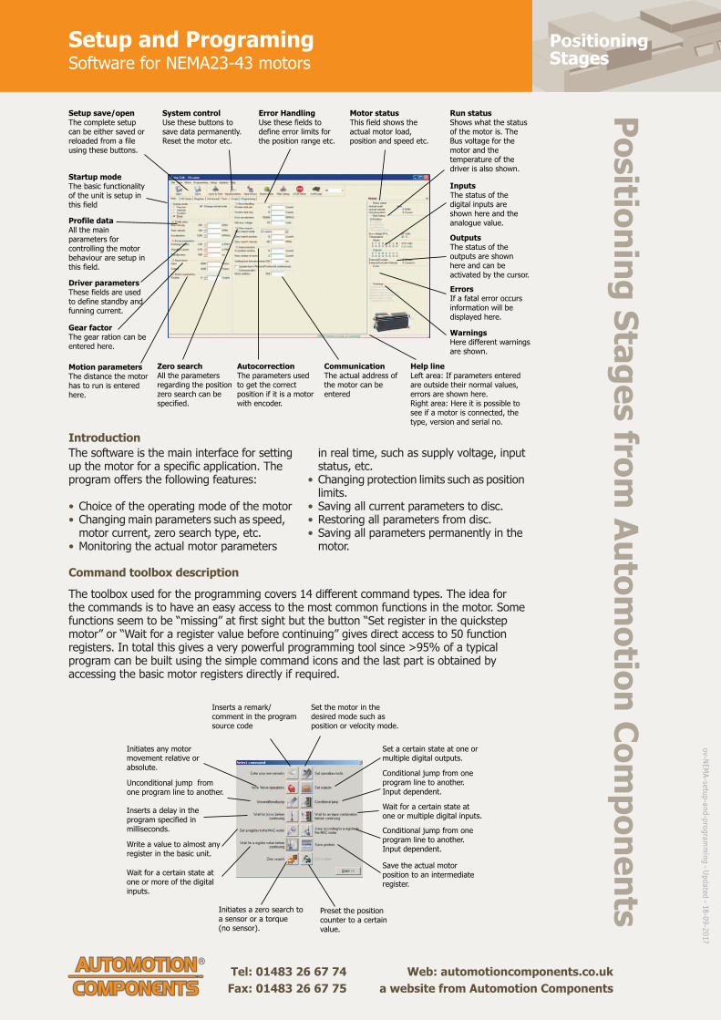
Positioning Stages
Positioning Stages from Autom
otion Components
Tel: 01483 26 67 74 Web: automotioncomponents.co.uk Fax: 01483 26 67 75 a website from Automotion Components
Setup and ProgramingSoftware for NEMA23-43 motors
The software is the main interface for setting up the motor for a specifi c application. The program off ers the following features:
• Choice of the operating mode of the motor• Changing main parameters such as speed, motor current, zero search type, etc.• Monitoring the actual motor parameters
in real time, such as supply voltage, input status, etc. • Changing protection limits such as position limits.• Saving all current parameters to disc.• Restoring all parameters from disc.• Saving all parameters permanently in the motor.
The toolbox used for the programming covers 14 diff erent command types. The idea for the commands is to have an easy access to the most common functions in the motor. Some functions seem to be “missing” at fi rst sight but the button “Set register in the quickstep motor” or “Wait for a register value before continuing” gives direct access to 50 function registers. In total this gives a very powerful programming tool since >95% of a typical program can be built using the simple command icons and the last part is obtained by accessing the basic motor registers directly if required.
Introduction
Command toolbox description
Setup save/openThe complete setup can be either saved or reloaded from a file using these buttons.
System controlUse these buttons to save data permanently. Reset the motor etc.
Error HandlingUse these fields to define error limits for the position range etc.
Motor statusThis field shows the actual motor load, position and speed etc.
InputsThe status of the digital inputs are shown here and the analogue value.
OutputsThe status of the outputs are shown here and can be activated by the cursor.
ErrorsIf a fatal error occurs information will be displayed here.
WarningsHere different warnings are shown.
Run statusShows what the status of the motor is. The Bus voltage for the motor and the temperature of the driver is also shown.
Zero searchAll the parameters regarding the position zero search can be specified.
AutocorrectionThe parameters used to get the correct position if it is a motor with encoder.
CommunicationThe actual address of the motor can be entered
Help lineLeft area: If parameters entered are outside their normal values, errors are shown here. Right area: Here it is possible to see if a motor is connected, the type, version and serial no.
Startup modeThe basic functionality of the unit is setup in this field
Profile dataAll the main parameters for controlling the motor behaviour are setup in this field.
Driver parametersThese fields are used to define standby and funning current.
Gear factorThe gear ration can be entered here.
Motion parametersThe distance the motor has to run is entered here.
Initiates any motor movement relative or absolute.
Unconditional jump from one program line to another.
Inserts a delay in the program specified in milliseconds.
Write a value to almost any register in the basic unit.
Wait for a certain state at one or more of the digital inputs.
Set a certain state at one or multiple digital outputs.
Conditional jump from one program line to another. Input dependent.
Conditional jump from one program line to another. Input dependent.
Save the actual motor position to an intermediate register.
Wait for a certain state at one or multiple digital inputs.
Initiates a zero search to a sensor or a torque(no sensor).
Preset the position counter to a certain value.
Inserts a remark/ comment in the program source code
Set the motor in the desired mode such as position or velocity mode.
ov-N
EMA
-setup
-and
-pro
gram
min
g - U
pd
ated - 1
8-0
9-2
017

Motorised LinearStages
Intelligent NEMA 14 Stepper Motorswith mcode software
Tel: 0333 207 4498
Created 2021-11-12
Email: [email protected]
Web: automotioncomponents.co.uk
L3530
Material
Combined 2 phase, high torque
stepper motors with in-built power
driver and controller.
IP20 rated (IP 67 optional).
Technical notes
Allows easy control from a PC or PLC
for single or multiple motors. Low
cost alternative to motors, drivers
and controllers.
Easy to use free software, little
cabling.
Voltage 12 to 48V DC.
20 microstepping resolutions up to
51,200 steps per rev.
Up to 8 I/O lines, one 10 bit
selectable analogue input.
Tips
Can readily be programmed in
Labview, VB etc. The motor can be
run independently from PC if required
(programmed can be downloaded to
motor). Easy connection via
RS422/485.
Optional encoders, gearing, motor
brake etc.
Important notes
We have a free motor selection help
service - including a free motor
configuration software programme
and technical help to ensure the
motor is to your requirement - please
consult our technical department for
full motor specifications.
Order No.Holding
torque Nm
l1
max.
l2
max.
Flange
dimensions
Shaft
+0, -0,013
Rotor
inertia kg-cm2
XKg
L3530.14-1 0,13 49 67 35x35 5,00 0,014 0,15
L3530.14-3 0,25 77 95 35x35 5,00 0,057 0,38

Motorised LinearStages
Intelligent NEMA 17 Stepper Motorswith mcode software
Tel: 0333 207 4498
Created 2021-11-12
Email: [email protected]
Web: automotioncomponents.co.uk
L3532
Material
Combined 2 phase, high torque
stepper motors with in-built power
driver and controller.
IP20 rated (IP 67 optional).
Technical notes
Allows easy control from a PC or PLC
for single or multiple motors. Low
cost alternative to motors, drivers
and controllers.
Easy to use free software, little
cabling.
Voltage 12 to 48V DC.
20 microstepping resolutions up to
51,200 steps per rev.
Up to 8 I/O lines, one 10 bit
selectable analogue input.
Tips
Can readily be programmed in
Labview, VB etc. The motor can be
run independently from PC if required
(programmed can be downloaded to
motor). Easy connection via
RS422/485.
Optional encoders, gearing, motor
brake etc.
Important notes
We have a free motor selection help
service - including a free motor
configuration software programme
and technical help to ensure the
motor is to your requirement - please
consult our technical department for
full motor specifications.
Order No.Holding
torque Nm
l
max.
Flange
dimensions
Shaft
+0, -0,013
Rotor
inertia kg-cm2
XKg
L3532.17-1 0,23 56 43x43 5,00 0,038 0,30
L3532.17-2 0,42 62 43x43 5,00 0,057 0,34
L3532.17-3 0,53 71 43x43 5,00 0,082 0,43

Motorised LinearStages
Intelligent NEMA 23 Stepper Motorswith mactalk software
Tel: 0333 207 4498
Created 2021-11-12
Email: [email protected]
Web: automotioncomponents.co.uk
L3534
Material
Combined 2 phase, high torque
stepper motors with in-built power
driver and controller.
IP42/55 rated (IP 67 optional).
Technical notes
Allows easy control from a PC or PLC
for single or multiple motors. Low
cost alternative to motors, drivers
and controllers.
Easy to use free software, little
cabling.
The I/O points can be set up by users
as Input or Output or as analogue
input.
Resolution: 1600 counts/rev.
Mainly supply voltage: 12-48V DC.
Control and main I/O supply voltage:
12-28V DC.
Typical main supply current @ 24V:
2.2 ADC RMS
Typical main supply current @ 48V:
2.1 ADC RMS
Nominal speed range 0-1023 rpm.
Tips
8 I/O's that can be configured to
Inputs, Outputs or analogue Inputs.
Can readily be programmed in
Labview, VB etc. The motor can be
run independently from PC if required
(programmed can be downloaded to
motor). Easy connection via USB
port, RS 485, optional wireless and
ethernet control.
Optional encoders, gearing, motor
brake etc.
Important notes
We have a free motor selection help
service - including a free motor
configuration software programme
and technical help to ensure the
motor is to your requirement - please
consult our technical department for
full motor specifications.
Order No.Holding
torque NmLength
Flange
dimensions
Shaft
+0, -0,013
Max. power
W
Rotor
inertia kg-cm2
Typical
supply
current @24V
DCADC RMS
Typical
supply
current @48V
DCADC RMS
Typical
supply
current
@80V DCADC RMS
XKg
L3534.23-1 1,2 96 57x57 6,35 74 0,30 2,2 2,1 - 0,9
L3534.23-2 1,9 119 57x57 6,35 85 0,48 2,2 2,2 - 1,2
L3534.23-4 3,0 154 57x57 10,0 77 0,96 2,5 2,0 - 1,8

Motorised LinearStages
Intelligent NEMA 23 Stepper Motorswith mactalk software
Tel: 0333 207 4498
Created 2021-11-12
Email: [email protected]
Web: automotioncomponents.co.uk

Motorised LinearStages
Intelligent NEMA 34 Stepper Motorswith mactalk software
Tel: 0333 207 4498
Created 2021-11-12
Email: [email protected]
Web: automotioncomponents.co.uk
L3536
Material
Combined 2 phase, high torque
stepper motors with in-built power
driver and controller.
IP42/55 rated (IP 67 optional).
Technical notes
Allows easy control from a PC or PLC
for single or multiple motors. Low
cost alternative to motors, drivers
and controllers.
Easy to use free software, little
cabling.
The I/O points can be set up by users
as Input or Output or as analogue
input.
Resolution: 409600 counts/rev.
Mainly supply voltage: 12-80V DC.
Control and main I/O supply voltage:
12-28V DC.
Nominal speed range 0.01-3000 rpm.
Tips
8 I/O's that can be configured to
Inputs, Outputs or analogue Inputs.
Can readily be programmed in
Labview, VB etc. The motor can be
run independently from PC if required
(programmed can be downloaded to
motor). Easy connection via USB
port, RS 485, optional wireless and
ethernet control.
Optional encoders, gearing, motor
brake etc.
Important notes
We have a free motor selection help
service - including a free motor
configuration software programme
and technical help to ensure the
motor is to your requirement - please
consult our technical department for
full motor specifications.
Order No.Holding
torque NmLength
Flange
dimensions
Shaft
+0, -0,013
Max. power
W
Rotor
inertia
kg-cm2
Typical
supply
current @24V
DCADC RMS
Typical
supply
current @48V
DCADC RMS
Typical
supply
current @80V
DCADC RMS
XKg
L3536.34-0 3,0 95 87x87 9,53 260 1,4 5,1 5,1 5,1 2,0
L3536.34-1 6,1 126 87x87 9,53 288 2,7 5,6 5,3 5,6 3,1
L3536.34-2 9,0 156 87x87 14,0 315 4,0 6,0 5,4 6,1 4,2
L3536.34-3 10,5 220 87x87 14,0 >320 5,3 6,3 5,7 6,6 5,3
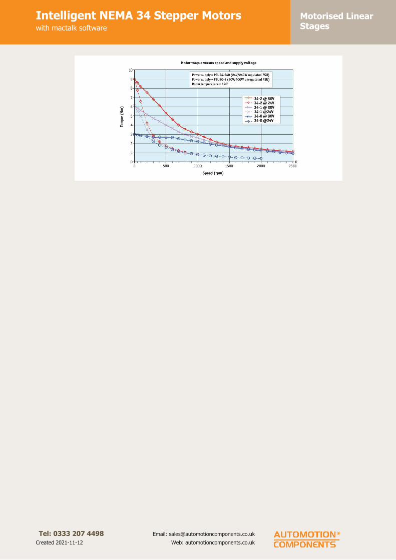
Motorised LinearStages
Intelligent NEMA 34 Stepper Motorswith mactalk software
Tel: 0333 207 4498
Created 2021-11-12
Email: [email protected]
Web: automotioncomponents.co.uk

Motorised LinearStages
Intelligent NEMA 43 Stepper Motorswith mactalk software
Tel: 0333 207 4498
Created 2021-11-12
Email: [email protected]
Web: automotioncomponents.co.uk
L3538
Material
Combined 2 phase, high torque
stepper motors with in-built power
driver and controller.
IP42/55 rated (IP 67 optional).
Technical notes
Allows easy control from a PC or PLC
for single or multiple motors. Low
cost alternative to motors, drivers
and controllers.
Easy to use free software, little
cabling.
The I/O points can be set up by users
as Input or Output or as analogue
input.
Resolution: 409600 counts/rev.
Mainly supply voltage: 12-48V DC.
Control and main I/O supply voltage:
12-28V DC.
Nominal speed range 0.01-3000 rpm.
Tips
8 I/O's that can be configured to
Inputs, Outputs or analogue Inputs.
Can readily be programmed in
Labview, VB etc. The motor can be
run independently from PC if required
(programmed can be downloaded to
motor). Easy connection via USB
port, RS 485, optional wireless and
ethernet control.
Optional encoders, gearing, motor
brake etc.
Important notes
We have a free motor selection help
service - including a free motor
configuration software programme
and technical help to ensure the
motor is to your requirement - please
consult our technical department for
full motor specifications.
Order No.Holding
torque NmLength
Flange
dimensions
Shaft
+0, -0,013
Max. power
W
Rotor
inertia kg-cm2
Typical
supply
current
@24V DCADC RMS
Typical
supply
current
@48V DCADC RMS
Typical
supply
current
@80V DCADC RMS
XKg
L3538.43-0 10 145 110x110 19,0 >300 5,5 - - - 5,5
L3538.43-2 25 247 110x110 19,0 >500 16,2 - - - 12,2

Motorised LinearStages
Intelligent NEMA 43 Stepper Motorswith mactalk software
Tel: 0333 207 4498
Created 2021-11-12
Email: [email protected]
Web: automotioncomponents.co.uk

Motorised LinearStages
Motorised Vertical Lift Stageshigh precision
Tel: 0333 207 4498
Created 2021-11-12
Email: [email protected]
Web: automotioncomponents.co.uk
L3591
Material
Black anodised aluminium body
(6061). Hardened linear guideways,
stainless steel Acme lead screw (with
internally lubricated anti-backlash
nut).
Technical notes
Easy plug and play system.
Integrated limit switches are provided
as standard. Controllable from PC or
PLC when used in conjunction with a
motion controller. Controllers come
with their own software but many
pre-existing software packages (such
as Labview) can be used.
Applications - research,
semi-conductors, fibre optics,
automation etc.
Tips
Stepper - Nema 17, high torque,
brushless. 0.95 Amp/phase, 5.0
Ohm/phase, 3.1 mH/phase,
1.8°/step. Option with 1000 line
rotary encoder.
Limit switches are wired normally
closed.
Important notes
Motor resolution 0,03µ, encoder
resolution 0,4µ. Minimum step size
0,5µ.
Order No. TravelAccuracy
±
Uni-directional
repeatability
±
Max. load
Kg.
Max. speed
mm/sLead screw pitch
Motor
typeXKg.
L3591.025-STA 25 10µ 1µ 7,0 10 1,5875 Stepper 2,5
L3591.025-STB 25 10µ 1µ 7,0 10 1,5875 Stepper & enc. 2,5

Motorised LinearStages
Motorised Vertical Lift Stageshigh precision
Tel: 0333 207 4498
Created 2021-11-12
Email: [email protected]
Web: automotioncomponents.co.uk
L3592
Material
Black anodised aluminium body
(6061). Hardened linear guideways,
stainless steel Acme lead screw (with
internally lubricated anti-backlash
nut).
Technical notes
Easy plug and play system.
Integrated limit switches are provided
as standard. Controllable from PC or
PLC when used in conjunction with a
motion controller. Controllers come
with their own software but many
pre-existing software packages (such
as Labview) can be used.
Applications - research,
semi-conductors, fibre optics,
automation etc.
Tips
Motor options:
Stepper - Nema 17, high torque,
brushless. 0.95 Amp/phase, 5.0
Ohm/phase, 3.1 mH/phase,
1.8°/step. Option with 1000 line
encoder.
Intelligent stepper - Nema 17 with
a fully programmable motion
controller inbuilt (ie no need for an
external motion controller). Two +5
to +24VDC I/O lines. One 10 bit
analogue input selectable 0 to
+10VDC, 0 to +5VDC. RS422/485
communications. Input voltage
+24VDC.
Option with 512 line encoder.
Limit switches are wired normally
closed. Drawings show stepper motor
configuration. See special pages for
further motor options.
Important notes
Motor resolution 0.03µ, encoder
resolution 0.4µ.
Order No. TravelAccuracy
±
Uni-directiona
l
repeatability
±
Max. load
Kg.
Max. speed
mm/s
Lead screw
pitch
Motor
typeXKg.
L3592.015-STB 15 10µ 1µ 7,0 5 1,5875 Stepper & enc. 1,1
L3592.015-IMA 15 10µ 1µ 7,0 5 1,5875 Int. stepper & enc. 1,1
L3592.015-IMB 15 10µ 1µ 7,0 5 1,5875 Int. stepper 1,1
L3592.015-STA 15 10µ 1µ 7,0 5 1,5875 Stepper 1,1