Neural Adaptive Robust Motion-Tracking Control for Robotic ...
22
Citation: Galvan-Perez, D.; Yañez-Badillo, H.; Beltran-Carbajal, F.; Rivas-Cambero, I.; Favela-Contreras, A.; Tapia-Olvera, R. Neural Adaptive Robust Motion-Tracking Control for Robotic Manipulator Systems. Actuators 2022, 11, 255. https:// doi.org/10.3390/act11090255 Academic Editor: Haim Abramovich Received: 19 August 2022 Accepted: 5 September 2022 Published: 7 September 2022 Publisher’s Note: MDPI stays neutral with regard to jurisdictional claims in published maps and institutional affil- iations. Copyright: © 2022 by the authors. Licensee MDPI, Basel, Switzerland. This article is an open access article distributed under the terms and conditions of the Creative Commons Attribution (CC BY) license (https:// creativecommons.org/licenses/by/ 4.0/). actuators Article Neural Adaptive Robust Motion-Tracking Control for Robotic Manipulator Systems Daniel Galvan-Perez 1 , Hugo Yañez-Badillo 2 , Francisco Beltran-Carbajal 3, * , Ivan Rivas-Cambero 1 , Antonio Favela-Contreras 4 and Ruben Tapia-Olvera 5 1 Departamento de Posgrado, Universidad Politécnica de Tulancingo, Tulancingo de Bravo 43629, Hidalgo, Mexico 2 Departamento de Investigación, Tecnológico de Estudios Superiores de Tianguistenco, Santiago Tianguistenco 52650, Estado de México, Mexico 3 Departamento de Energía, Unidad Azcapotzalco, Universidad Autónoma Metropolitana, Av. San Pablo No. 180, Col. Reynosa Tamaulipas, Mexico City 02200, Mexico 4 Tecnologico de Monterrey, School of Engineering and Sciences, Ave. Eugenio Garza Sada 2501, Monterrey 64849, Nuevo León, Mexico 5 Departamento de Energía Eléctrica, Universidad Nacional Autónoma de México, Mexico City 04510, Mexico * Correspondence: [email protected] Abstract: This paper deals with the motion trajectory tracking control problem based on output feedback and artificial neural networks for anthropomorphic manipulator robots under disturbed operating scenarios. This class of manipulator robots constitutes nonlinear dynamic systems subjected to disturbance torques induced mainly by work payload. Parametric uncertainty and possible dynamic modeling errors stand for other kind of disturbances that can deteriorate the efficiency and robustness of the tracking of controlled nonlinear robotic system trajectories. In fact, the presence of unknown dynamic disturbances is unavoidable in industrial robotic engineering systems. Therefore, for high-precision applications, such as laser cutting, marking, or welding, effective control schemes should be designed to guarantee adequate motion profile tracking planned on this class of disturbed nonlinear robotic system. In this context, a new adaptive robust motion trajectory tracking control scheme based on output feedback and artificial neural networks of anthropomorphic manipulator robots is presented. Three-layer B-spline artificial neural networks and time-series modeling are properly exploited in the design of novel adaptive robust motion tracking controllers for robotic applications of laser manufacturing. In this way, dependency on detailed nonlinear mathematical modeling of robotic systems is considerably reduced, and real-time estimation of uncertain dynamic disturbances is not required. Furthermore, several cases studies to demonstrate the motion planning tracking control robustness for a class of MIMO nonlinear robotic systems are described. blue Insights for the extension of the introduced output-feedback adaptive neural control design approach for other architecture of nonlinear robotic systems are depicted. Keywords: active disturbance rejection; artificial neural networks; laser manufacturing; manipulator robot; trajectory tracking control 1. Introduction The study and application of intelligent control techniques, such as fuzzy logic and neural networks, have gained widespread recognition in recent years. The basis of these techniques consists of learning in a prescribed manner the input–output behavior of a system to subsequently be controlled [1]. The importance of these types of techniques is found in nonlinear systems, variants in time, and those that are subjected to different types of disturbances [2]. Manipulator robots have complex nonlinear dynamics that can make accurate and robust control difficult. In today’s manufacturing environments, Actuators 2022, 11, 255. https://doi.org/10.3390/act11090255 https://www.mdpi.com/journal/actuators
-
Upload
khangminh22 -
Category
Documents
-
view
4 -
download
0
Transcript of Neural Adaptive Robust Motion-Tracking Control for Robotic ...

Citation: Galvan-Perez, D.;
Yañez-Badillo, H.; Beltran-Carbajal, F.;
Rivas-Cambero, I.; Favela-Contreras,
A.; Tapia-Olvera, R. Neural Adaptive
Robust Motion-Tracking Control for
Robotic Manipulator Systems.
Actuators 2022, 11, 255. https://
doi.org/10.3390/act11090255
Academic Editor: Haim Abramovich
Received: 19 August 2022
Accepted: 5 September 2022
Published: 7 September 2022
Publisher’s Note: MDPI stays neutral
with regard to jurisdictional claims in
published maps and institutional affil-
iations.
Copyright: © 2022 by the authors.
Licensee MDPI, Basel, Switzerland.
This article is an open access article
distributed under the terms and
conditions of the Creative Commons
Attribution (CC BY) license (https://
creativecommons.org/licenses/by/
4.0/).
actuators
Article
Neural Adaptive Robust Motion-Tracking Control for RoboticManipulator SystemsDaniel Galvan-Perez 1 , Hugo Yañez-Badillo 2 , Francisco Beltran-Carbajal 3,* , Ivan Rivas-Cambero 1 ,Antonio Favela-Contreras 4 and Ruben Tapia-Olvera 5
1 Departamento de Posgrado, Universidad Politécnica de Tulancingo,Tulancingo de Bravo 43629, Hidalgo, Mexico
2 Departamento de Investigación, Tecnológico de Estudios Superiores de Tianguistenco,Santiago Tianguistenco 52650, Estado de México, Mexico
3 Departamento de Energía, Unidad Azcapotzalco, Universidad Autónoma Metropolitana, Av. San Pablo No.180, Col. Reynosa Tamaulipas, Mexico City 02200, Mexico
4 Tecnologico de Monterrey, School of Engineering and Sciences, Ave. Eugenio Garza Sada 2501,Monterrey 64849, Nuevo León, Mexico
5 Departamento de Energía Eléctrica, Universidad Nacional Autónoma de México,Mexico City 04510, Mexico
* Correspondence: [email protected]
Abstract: This paper deals with the motion trajectory tracking control problem based on outputfeedback and artificial neural networks for anthropomorphic manipulator robots under disturbedoperating scenarios. This class of manipulator robots constitutes nonlinear dynamic systems subjectedto disturbance torques induced mainly by work payload. Parametric uncertainty and possibledynamic modeling errors stand for other kind of disturbances that can deteriorate the efficiency androbustness of the tracking of controlled nonlinear robotic system trajectories. In fact, the presence ofunknown dynamic disturbances is unavoidable in industrial robotic engineering systems. Therefore,for high-precision applications, such as laser cutting, marking, or welding, effective control schemesshould be designed to guarantee adequate motion profile tracking planned on this class of disturbednonlinear robotic system. In this context, a new adaptive robust motion trajectory tracking controlscheme based on output feedback and artificial neural networks of anthropomorphic manipulatorrobots is presented. Three-layer B-spline artificial neural networks and time-series modeling areproperly exploited in the design of novel adaptive robust motion tracking controllers for roboticapplications of laser manufacturing. In this way, dependency on detailed nonlinear mathematicalmodeling of robotic systems is considerably reduced, and real-time estimation of uncertain dynamicdisturbances is not required. Furthermore, several cases studies to demonstrate the motion planningtracking control robustness for a class of MIMO nonlinear robotic systems are described. blue Insightsfor the extension of the introduced output-feedback adaptive neural control design approach forother architecture of nonlinear robotic systems are depicted.
Keywords: active disturbance rejection; artificial neural networks; laser manufacturing; manipulatorrobot; trajectory tracking control
1. Introduction
The study and application of intelligent control techniques, such as fuzzy logic andneural networks, have gained widespread recognition in recent years. The basis of thesetechniques consists of learning in a prescribed manner the input–output behavior of asystem to subsequently be controlled [1]. The importance of these types of techniquesis found in nonlinear systems, variants in time, and those that are subjected to differenttypes of disturbances [2]. Manipulator robots have complex nonlinear dynamics thatcan make accurate and robust control difficult. In today’s manufacturing environments,
Actuators 2022, 11, 255. https://doi.org/10.3390/act11090255 https://www.mdpi.com/journal/actuators

Actuators 2022, 11, 255 2 of 22
velocity and accuracy requirements increase when compared to earlier generations ofrobots. However, the efficiency of fixed-gain PID controllers often is limited for providingadequate performance in real-time operations of robot motion [3].
Since there are no adaptive or learning capabilities, control accuracy is significantlyaffected when a variation due to unknown frictions and disturbing torques is presentedduring motion control in laser manufacturing applications, such as cutting, welding, mark-ing, and additive 3D printing [4]. The main purpose of controlling a manipulator robot isto accomplish a specific task, such as payload transport [5], and motion profile tracking formaterial processing [6], among others. To perform the required tasks, the manipulator iscommanded for reaching the desired position, velocity, acceleration, or force at a specifictime [7]. The nonlinear nature of manipulator robots makes it difficult to obtain an adequatecontrol law to perform different programmed tasks. There are computational methodsthat improve the control laws efficiency, such as the artificial neural networks [8] thatare used to online update the control parameters value to improve the robotic system’sclosed-loop response. The exhibited adaptive behavior learns from the nonlinear natureof the robot intelligently. So using neural networks for the tuning of the parameters of acontroller applied to a nonlinear and strongly coupled system represents a great advantage.The recent renewed interest in neural networks can be attributed to different factors, one ofthem is that different learning techniques have been developed for sophisticated artificialneural network architectures, which are capable of eliminating the limitations of the pastassociated with simple neural networks [9]. Neural networks are parallel computer modelsthat mimic a human’s learning process. The networks process information by adaptingtheir connections and nodes, based on the information they are given [10]. One importantfeature is the intrinsic parallel architecture that allows fast computation of the solution.This is achieved when the networks are implemented on digital computers or in specializedhardware [11].
Artificial neural networks (ANN) have been used for the control of manipulatorrobots for different applications in recent years. In [12], a trajectory planning methodologyof a manipulator robot is proposed through the design of an adaptive robust controllerthat uses a neural network activated with radial basis functions; this is done to solvenonlinearity and uncertainty problems and improve the performance during trajectorytracking. In [13], a fixed-time control algorithm for the trajectory tracking of manipulatorrobots with uncertainty and input saturation is designed, which combines the non-singularterminal sliding mode control with the reinforcement learning method. To compensatefor the saturation of the actuators due to the effect of joint torque overflow, a nonlinearanti-windup compensator is designed. Authors in [14] introduce a multi-layer neuralnetwork with iterative learning for controller design to compensate for the dynamics of anarticulated industrial manipulator robot for trajectory tracking tasks. The iterative learningcontrol commands the robot motion, which corresponds to a set of desired joint trajectories.Additionally, the torques of the input/output trajectories are used for training the innercontrol loop through inverse dynamics. In this scheme, the trajectory is used as the inputdesired joint of the robot, and the output is related to the commanded robot motion. In [15],a modified artificial neural network algorithm is suggested to be applied as an adaptiveadjustment algorithm. A mathematical modulation is introduced to promote the scanningform, and no initial parameters are set. The suggested algorithm is tested to select the gains,and an appropriate configuration is selected. This algorithm is applied for improving aPID-like joint motion controller for a manipulator robot. In [16], the output error constraintsand input saturation of robot manipulators are considered and presented with a trajectorytracking controller to attend to these requirements simultaneously through an artificialneural network structure with radial basis functions that can approximate the pooleduncertainties. In [17], a deep convolutional neural network is designed to implement afractional order sliding mode control strategy for trajectory tracking control in manipulatorrobots. The neural network compensates for system uncertainty without the need toknow the upper bounds, thus the controller switching gain is greatly reduced. The main

Actuators 2022, 11, 255 3 of 22
advantage of the controller used lies in the elimination of chattering, so continuous controlsignals can be obtained and applied in practical applications. In [18], a control scheme isproposed to handle the unknown dynamics and the external disturbances in a manipulatorrobot by combining a self-tuning PID structure with an artificial neural network using radialbasis activation functions to handle the different uncertainties. In [19], to track the trajectoryof a robot and supply constant force during contact working conditions, a PID fuzzy neuralnetwork controller is developed. For manufacturing applications, changing the contactforce during machining operations will affect the quality, so it is crucial to maintain themconstantly throughout the process. For the parameters of the PID controller to be adjustedquickly and effectively, a fuzzy algorithm is proposed that includes neural networks insuch a way that the controller has two functions: path following and bounded shiftingonline whilst maintaining the contact force constant. In [20], an adaptive neural controlscheme for manipulator robots that includes actuator dynamics under model uncertainty isproposed based on prescribed performance without measuring input current, acceleration,or velocity. A neural adaptive second-order PID controller is combined with an accelerationvelocity observer. The proposed method demonstrates that semi-global bounds are foundfor tracking and state observation errors, and they eventually converge in a small circleabout the origin.
With the B-spline artificial neural networks (Bs-ANN), adaptive control and modelingof systems are possible both online and with nonlinearities taken into account [21]. In theliterature, the estimation of harmonics and DC offset component of multi-frequency oscil-lating electric signals [22], control of electric power systems [23], different types of electricmotors, such as DC shunt [24], induction [25] and permanent magnet synchronous [9] aswell as unmanned aerial vehicles [26] are some examples of the successful implementationof B-spline neural networks. Nevertheless, there is no evidence of the previous implemen-tation in anthropomorphic manipulator robots. The main advantage of the B-spline neuralnetwork is that it can limit the input to a set of values defined in the base function. Thisreduces computational effort and time because there are only a limited number of basisfunctions involved in the output; not all weights need to be calculated every time iterationsare performed [26]. The proposal allows calculating and updating the values of the param-eters of the proposed controller through the neural network for each operating conditionof the robot. A proper design requires prior information: the maximum and minimumvalues for the input signal and defining the shape of the basis functions. This informationallows for limiting the input space of the B-spline neural networks, which improves theirconvergence and stability in adaptation. Additionally, this information is used to determinethe optimal weights for the neural network [27]. The B-spline neural networks used inthis work are created by third-order uni-variable basis functions considering that the inputsignal is bounded.
The main contribution of this work is a new neural adaptive robust motion trajectorytracking control technique based on output feedback for a very important class of nonlinearrobotic manipulator systems used in applications of laser manufacturing. In this context,advantages and differences with respect to other relevant contributions reported in theliterature are as follows. Position measurements are only required. Time derivatives of mea-sured output signals are not requested. Accurate real-time estimation of different types ofdisturbances is unnecessary. B-spline artificial neural networks are used correctly to preventhigh-gain control actions to suppress unknown time-varying disturbances. The number ofcontrol parameters that need to be adaptively adjusted is lessened. Dependency on detailednonlinear mathematical modeling of the manipulator robot system is reduced. Robustnessagainst external disturbances, such as external vibrating torques, is also obtained. Moreover,the introduced output feedback adaptive neural control design approach can be extendedfor other architectures of complex nonlinear robotic systems.
A summary of the contents of the manuscript is as follows. The robotic system modelis described in Section 2. The robot motion control approach is presented in Section 3.In Section 4, the artificial neural networks-based robot motion control is described. Subse-

Actuators 2022, 11, 255 4 of 22
quently, some numeric simulation experiments are presented in Section 5 to highlight theperformance of the introduced methodology. Finally, some conclusions and remarks arementioned in the conclusions section.
2. 3-DOF Robot Mathematical Modeling2.1. System Description
The geometry of interest in this work is anthropomorphic as shown in Figure 1.The robotic system configuration is composed of three rotational joints. This configurationrepresents the most dexterous structure, which can be adapted to almost any type of task.
Figure 1. Architecture of the anthropomorphic robotic system.
Figure 2 depicts projections of the anthropomorphic manipulator robot on XY andXZ planes for the derivation of a nonlinear dynamic model. Generalized coordinates ofthe configuration space are denoted by qi, i = 1, . . . , 3. Here, q1 is the rotation angle oflink 1 about the Z axis. q2 and q3 are the rotation angles of links 2 and 3 about the Y axis.d1 is the distance between point O of the fixed inertial coordinate reference frame XYZ and

Actuators 2022, 11, 255 5 of 22
the rotation axis of q2. l2 corresponds to the distance between the rotation axis of q2 and therotation axis of q3. lc2 is the distance from the rotation axis of q2 to the center of mass oflink 2. l3 is the distance between the rotation axis of q3 and the center of the end effector. lc3
is the distance from the rotation axis of q3 to the center of mass of link 3. m1 is the mass oflink 1. m2 corresponds to the mass of link 2. m3 is the mass of link 3, which also includesthe mass of the end effector.
Figure 2. Projections on XY and XZ planes for mathematical modeling purposes.

Actuators 2022, 11, 255 6 of 22
2.2. Kinematic Modeling
The direct kinematic model of a 3-DOF anthropomorphic manipulator robot [28,29] isexpressed as
x = cos(q1)[l2 cos(q2) + l3 cos(q2 + q3)]
y = sin(q1)[l2 cos(q2) + l3 cos(q2 + q3)] (1)
z = d1 + l2 sin(q2) + l3 sin(q2 + q3)
The inverse kinematic model of the 3-DOF anthropomorphic manipulator robot [28,29]is then described as
q1 = tan−1( y
x
)
q2 = tan−1
(z− d1√x2 + y2
)− tan−1
l3
√√√√1−(
x2 + y2 + (z− d1)2 − l2
2− l2
3
2l2 l3
)2
l2 + l3
(x2 + y2 + (z− d1)
2 − l22− l2
3
2l2 l3
) (2)
q3 = tan−1
±
√√√√1−(
x2 + y2 + (z− d1)2 − l2
2− l2
3
2l2 l3
)2
(x2 + y2 + (z− d1)
2 − l22− l2
3
2l2 l3
)
2.3. Dynamic Modeling
The analysis of a manipulator robot requires the use of differential equations to under-stand the relationship between the elements that compose it. By modeling the dynamicbehavior of a manipulator robot, all physical phenomena found in its mechanical structureare explained, including inertial effects, centripetal and Coriolis forces, gravitational torque,and friction, which are physical phenomena resulting from the robot’s dynamic nature [30].The development of the dynamic model of an anthropomorphic manipulator robot throughthe Euler–Lagrange methodology was widely studied in [28–30].
The nonlinear behavior of a manipulator robot can be thus modeled by the Euler–Lagrange equations
ddt
(∂L∂qi
)− ∂L
∂qi= Qi i = 1, . . . , n (3)
with
L = K−V (4)
where L is the Lagrangian, K and V are the kinetic and potential energy. n denotes thenumber of degrees of freedom, q = (q1, q2, . . . , qn) represents the generalized coordinatesof the robotic system, and Qi stands for components of the generalized force.
The kinetic energy of the robotic system depicted in Figures 1 and 2 is given by
K = K1 + K2 + K3 (5)

Actuators 2022, 11, 255 7 of 22
with
K1 =12
Iz1 q21
K2 =12
m2l2c2[(1− sin(q2)
2)q21 + q2
2] +12
Iz2 q21 +
12
Iy2 q22
K3 =12
m3[(l22 + l2
2 cos(2q2) + 2l2lc3 cos(2q2 + q3) + 2l2lc3 cos(q3) + l2c3
cos(2q2 + 2q3)
+ l2c3)
q21
2+ (l2
2 + 2l2lc3 cos(q3) + l2c3)q2
2 + (2l2lc3 cos(q3) + 2l2c3)q2q3 + l2
c3q2
3] +12
Iz3 q21
+12
Iy3(q2 + q3)2
The potential energy is obtained as
V = V1 + V2 + V3 (6)
with
V1 = m1gd1
V2 = m2g[d1 + lc2 sin(q2)]
V3 = m3g[d1 + l2 sin(q2) + lc3 sin(q2 + q3)]
From Equations (3) and (4), nonlinear dynamics of the robotic system can be thendescribed by the vector differentialequation
D(q)q + C(q, q)q + G(q) = τ − τd (7)
where D(q) ∈ Rn×n stands for the inertia matrix, C(q, q) ∈ Rn×n represents the Coriolisand centripetal matrix and G(q) ∈ Rn denotes the torque vector due to gravity [28]. More-over, τ and τd ∈ Rn are the joint driving torque and the external load torque, respectively.
From Equation (7) and without loss of generality, the dynamic model for a 3-DOFanthropomorphic manipulator robot is given byd11 d12 d13
d21 d22 d23d31 d32 d33
q1q2q3
+
c11 c12 c13c21 c22 c23c31 c32 c33
q1q2q3
+
g11g21g31
g =
τ1
τ2
τ3
−τd1
τd2τd3
(8)
Grouping terms according to the joint accelerations of the robot (q1, q2, q3), the inertiamatrix is expressed as
D(q) =
d11 0 00 d22 d23
031 d32 d33
q1q2q3
(9)
with
d11 = Iz1 + Iz2 + Iz3 +(m2
2
)[l2
c2(1 + cos(2q2))]
+(m3
2
)[2l2lc3(cos(2q2 + q3) + cos(q3)) + l2
2(1 + cos(2q2)) + l2c3(1 + cos(2q2 + 2q3))]
d22 = Iy2 + Iy3 + m2l2c2+ 2m3l2lc3 cos(q3) + m3
(l22 + l2
c3
)d23 = Iy3 + m3l2lc3 cos(q3) + m3l2
c3
d32 = Iy3 + m3l2lc3 cos(q3) + m3l2c3
d33 = Iy3 + m3l2c3
Actuators 2022, 11, 255 8 of 22
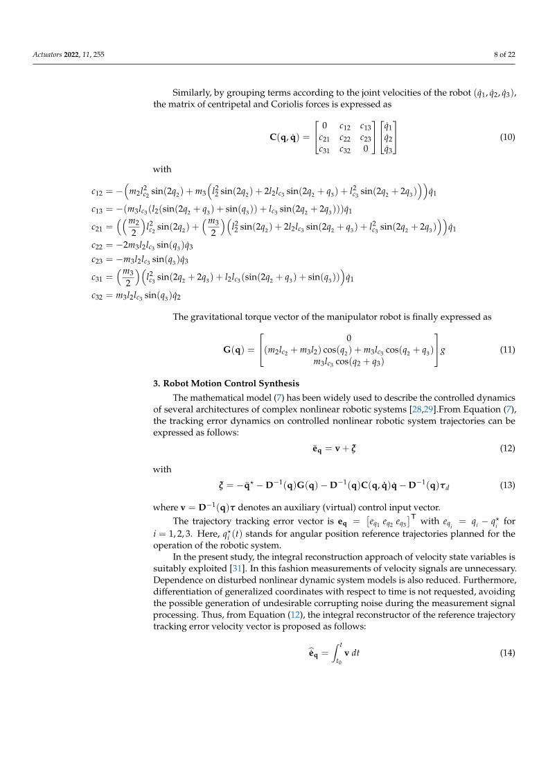
Similarly, by grouping terms according to the joint velocities of the robot (q1, q2, q3),the matrix of centripetal and Coriolis forces is expressed as
C(q, q) =
0 c12 c13c21 c22 c23c31 c32 0
q1q2q3
(10)
with
c12 = −(
m2l2c2
sin(2q2) + m3
(l22 sin(2q2) + 2l2lc3 sin(2q2 + q3) + l2
c3sin(2q2 + 2q3)
))q1
c13 = −(m3lc3(l2(sin(2q2 + q3) + sin(q3)) + lc3 sin(2q2 + 2q3)))q1
c21 =((m2
2
)l2c2
sin(2q2) +(m3
2
)(l22 sin(2q2) + 2l2lc3 sin(2q2 + q3) + l2
c3sin(2q2 + 2q3)
))q1
c22 = −2m3l2lc3 sin(q3)q3
c23 = −m3l2lc3 sin(q3)q3
c31 =(m3
2
)(l2c3
sin(2q2 + 2q3) + l2lc3(sin(2q2 + q3) + sin(q3)))
q1
c32 = m3l2lc3 sin(q3)q2
The gravitational torque vector of the manipulator robot is finally expressed as
G(q) =
0(m2lc2 + m3l2) cos(q2) + m3lc3 cos(q2 + q3)
m3lc3 cos(q2 + q3)
g (11)
3. Robot Motion Control Synthesis
The mathematical model (7) has been widely used to describe the controlled dynamicsof several architectures of complex nonlinear robotic systems [28,29].From Equation (7),the tracking error dynamics on controlled nonlinear robotic system trajectories can beexpressed as follows:
eq = v + ξ (12)
with
ξ = −q? −D−1(q)G(q)−D−1(q)C(q, q)q−D−1(q)τd (13)
where v = D−1(q)τ denotes an auxiliary (virtual) control input vector.The trajectory tracking error vector is eq =
[eq1 eq2 eq3
]T with eqi= qi − q?
ifor
i = 1, 2, 3. Here, q?i (t) stands for angular position reference trajectories planned for theoperation of the robotic system.
In the present study, the integral reconstruction approach of velocity state variables issuitably exploited [31]. In this fashion measurements of velocity signals are unnecessary.Dependence on disturbed nonlinear dynamic system models is also reduced. Furthermore,differentiation of generalized coordinates with respect to time is not requested, avoidingthe possible generation of undesirable corrupting noise during the measurement signalprocessing. Thus, from Equation (12), the integral reconstructor of the reference trajectorytracking error velocity vector is proposed as follows:
eq =∫ t
t0
v dt (14)

Actuators 2022, 11, 255 9 of 22
For robust control design purposes, ξ = [ξ1 ξ2 ξ3]T is considered a completely un-
known time-varying disturbance vector to be actively rejected, which can be approximatedinto a self-adjusting, very small window of time by the Taylor series polynomial expansion
ξ = p0 + p1t (15)
Moreover, parameter vectors of the disturbance signal model (15), p0 =[p01 p02 p03
]Tand p1 =
[p11 p12 p13
]T, are assumed to be unknown as well. Small uncertainties incomponents of the matrix D(q) and dynamic modeling errors could be also considered intothe disturbance vector ξ. In contrast to other active disturbance rejection control approaches,the real-time estimation of disturbances and time derivatives of position output signals isnot required in the present contribution.
Then, the real and reconstructed tracking error velocity vectors holds the followingrelationship:
eq = eq + a0t + a1t2 (16)
where vector parameters a0 =[a01 a02 a03
]T and a1 =[a11 a12 a13
]T are also assumed to beunknown, which depend on initial conditions of the nonlinear robotic system and parame-ters of the polynomial signal model (15). The interested reader on integral reconstructors asan alternative to bypass time derivatives of measurement signals and design of asymptoticstate observers is referred to the contribution [31].
The auxiliary control vector v is proposed as follows
v = −B4eq − B3eq − B2
∫eq − B1
∫ (2)eq − B0
∫ (3)eq (17)
where
Bi =
βi1 0 00 βi2 00 0 βi3
(18)
for i = 0, 1, . . . , 3, and∫ (n)
stands for the nth integral respect to time. Here, integral error
action is properly embedded into auxiliary control to actively compensate disturbancesξ as well as differences between real and reconstructed velocity vectors as described byEquation (16).
By considering the torque controllers defined by
τ = D(q)v (19)
the closed-loop tracking error dynamics results in
e(5)q + B4e(4)q + B3e(3)q + B2eq + B1eq + B0eq = 0 (20)
Then, the gain matrices are suitably selected as matching the following Hurwitz stablecharacteristic polynomials:
PH(s) = s5I3×3 + BH4 s4 + BH3 s3 + BH2 s2 + BH1 s + BH0 (21)
4. Artificial Neural Networks-Based Robot Motion Control
In the robust control approach introduced above, the control gains vector can beselected as a constant. However, this vector can be dynamically updated to improve thedynamic response of the system. Artificial neural networks are intelligent agents capableof learning from experiences. These artificial entities employ a massive interconnection

Actuators 2022, 11, 255 10 of 22
of neurons, referred to in the literature as simple computing or processing cell units [1].In this research, the role of the B-spline artificial neural networks is to provide adaptationcapabilities to the introduced robot motion control strategy by updating online the controllergains, as shown in scheme of Figure 3. With the online training of the Bs-ANN, the controllaw is constantly updated based on the tracking error information. In contrast with otherconventional multilayer networks, used in identification and control applications, B-splinenetworks are based on a defined three-layer structure which decreases its complexity,consequently making them a powerful alternative in real-time implementations.
Neuron
OutputWeight
vector
Basis
functions
Input
vector
Input layer Hidden layer Output layer
Figure 3. Proposed architecture for the B-spline artificial neural network (Bs-ANN).
Adaptive Outline for Control Purposes
Without high-gain feedback or high-frequency switching, adaptive control schemeshave successfully handled parametric uncertainties and achieved asymptotic stability [32].Using a linear combination of mono-variable and multi-variable basis functions, a B-splinefunction is a polynomial function defined by its extremes. In this work, an adaptive robustcontrol scheme was dynamically tuned using B-spline artificial neural networks. EachBs-ANN updates its synaptic weights based on different learning indexes and inputs. Bycontinually learning the variables associated with the physical system, this type of networkcan cope with the system’s nonlinearities and uncertainties [27].
In Figure 3, an implementation of Bs-ANN is shown as a set of associative networkswith synaptic weights that can be adjusted to reproduce a specific function. The authorin [33] proposes the following output
yn = aw, w =[w1 w2 . . . wj
]T , a =[a1 a2 . . . aj
](22)
where wj and aj are the j-th weight and the j-th basis function input, respectively, and jis the number of synaptic weights. Here, the B-spline functions are used to calculate thegains of the controllers, with the input of each neural network defined as the tracking errorand the error derivatives, and with the output yn(t) defined as the control parameters.To determine the initial weight values and input thresholds, it is common to performoffline training of the network by studying the system in different and relevant operationalconditions, which can be easily done by using bio-inspired optimization algorithms [26].The minimization error, i.e., the difference between the actual output vector and its desiredvalue, is a key element of the learning process. For this development, the following instantlearning rule was adopted [34]:
wn(t) = wn(t− 1) +`en(t)‖ a(t) ‖2
2a(t) (23)

Actuators 2022, 11, 255 11 of 22
here, ‖ · ‖2 is the vector 2-norm or Euclidean norm; ` is the learning rate, and en(t) isthe instantaneous output error. Through this method, training is performed online andcontinuously, with weight values updated in response to tracking error and derivativeerror feedback. With the boundaries properly set by choosing the correct knot vectorand basis function form, this single-inner-layer structure becomes an extremely powerfulmechanism. For the proposed adaptive control scheme, four third-order base functions areused: two related to the tracking error and two for the error derivative.
5. Numeric Simulation Results
The proposed motion control scheme was evaluated through several numeric sim-ulations. During the first scenario, the proposal is implemented for motion control injoint-space mode. Secondly, the approach is used in motion control in the operative space,where the independence of a precise robot dynamical model is exhibited, and controlgains are suitably updated online. Finally, the proposed control scheme is compared witha PID-like control scheme when the system is subjected to external disturbance torques.It is important to note that in the different laser manufacturing applications, the precisemotion of the robot is required, even in the presence of disturbances, as addressed in thenumeric experiments.
During the simulations, the anthropomorphic manipulator robot with three degrees offreedom previously described is considered, which is characterized by the set of parameterspresented in Table 1.
Table 1. System parameters used during simulation scenarios.
Parameter Quantity Units Description
m1 0.73 Kg Link 1 massm2 0.85 Kg Link 2 massm3 0.51 Kg Link 3 massd1 0.14 m Link 1 lengthlc2 0.10 m Link 2 length to the center of massl2 0.20 m Link 2 lengthlc3 0.20 m Link 3 length to the center of massl3 0.30 m Link 3 lengthIz1 0.0015 Kg m2 Inertia of link 1 in the Z axisIy2 0.0054 Kg m2 Inertia of link 2 in the Y axisIz2 0.0013 Kg m2 Inertia of link 2 in the Z axisIy3 0.0031 Kg m2 Inertia of link 3 in the Y axisIz3 0.0032 Kg m2 Inertia of link 3 in the Z axisg 9.81 m/s 2 Gravitational acceleration constant
5.1. Scenario 1: Joint Space Control
In Figure 4, it is presented the proposed control scheme for the first scenario. It isevident from this figure that only measurements of the angular positions are required forthe adaptive robust controller.
Controller
Figure 4. Motion robot control in the joint space.

Actuators 2022, 11, 255 12 of 22
On the other hand, it is relevant to mention that in order to tune a reduced number ofcontrol parameters, the following Hurwitz stable polynomial is considered for each degreeof freedom:
Pd(s) = (s2 + 2ζcωcs + ω2c )
2(s + Pc) (24)
here ωc, ζc, Pc > 0, are the tuning parameters.Therefore, to ensure closed-loop stability and proper tracking of the planned trajectory,
control gains can be selected as follows:
β4i = 4ζcωc + Pc
β3i = 2ω2c + 4ζ2
c ω2c + 4Pcζcωc
β2i = 4ω3c ζc + 2Pω2
c + 4Pcζ2c ω2
c
β1i = 4Pcω3ζc + ω4c
β0i = Pcω4c (25)
As a result, only three tuning parameters are required instead of six.During the first simulation scenario, the robot performs motion regulation in the
articular space. For smooth transitions between initial and final angular positions, let usintroduce the position reference profile in (26), which is implemented in order to avoidabrupt motion:
Π? =
Π0 0 ≤ t < T1 [s]
Π0 +(
Π f −Π0
)Bz(t, T1, T2) T1 ≤ t ≤ T2 [s]
Π f t > T2 [s](26)
where Π0 and Π f stand for desired initial and final values of angular motion trajectoriesplanned for the manipulator robot. Meantime, Bz is a Bézier polynomial defined as
Bz(t, T1, T2) =n
∑k=0
δk
(t− T1
T2 − T1
)k(27)
with n = 6, and δ1 = 252, δ2 = 1050, δ3 = 1800, δ4 = 1575, δ5 = 700, δ6 = 126 [35].In Figure 5, it is portrayed the results for the first scenario, where several changes
in the trajectory references are commanded for each joint by using the expression in (27).From the figure, it is evident a suitable tracking of the Bézier motion profiles. The computeddriving torques for each joint are soft and reachable. A very common problem in the designof controllers is the saturation of the actuators due to the high magnitude of the requiredtorque signals, something that in this case is solved satisfactorily.
0 10 20 30 40 50 60
0
0.2
0.4
0.6
0.8
1
0 20 40 60
-0.02
-0.01
0
0.01
0.02
(a) (b)
Figure 5. Cont.

Actuators 2022, 11, 255 13 of 22
0 20 40 60
-0.2
0
0.2
0.4
0.6
0.8
0 10 20 30 40 50 60
0
0.5
1
1.5
2
2.5
3
(c) (d)
0 10 20 30 40 50 60
0
0.1
0.2
0.3
0.4
0.5
0.6
0 10 20 30 40 50 60
0
0.2
0.4
0.6
0.8
(e) (f)
Figure 5. Controlled robot motion in the joint-space for the first scenario. (a) Controlled angularposition q1. (b) Computed driving torque τ1. (c) Controlled angular position q2. (d) Computeddriving torque τ2. (e) Controlled angular position q3. (f) Computed driving torque τ3.
Notwithstanding, the gain values are based on the computation of the ωc, ζc, Pc pa-rameters, as shown in Figures 6 and 7. In this case of joint movement control, the evolutionof the control parameters in the first joint is presented. This is because it is the joint thatbears the full weight of the robot, so it would be expected to require a greater magnitude oftorque to perform the required movements. However, due to the proposed control scheme,it should be noted that the demanded torque has a very small magnitude, and an excellentfollow-up of the programmed joint trajectory is obtained.
0 10 20 30 40 50 60
0
2
4
6
8
0 10 20 30 40 50 60
0
0.2
0.4
0.6
0.8
(a) (b)
0 20 40 60
0
0.02
0.04
0.06
0.08
0.1
(c)
Figure 6. Computed dynamic control parameters for the first joint motion (a) Adaptive ωn1 controlparameter. (b) Adaptive ζn1 control parameter. (c) Adaptive Pn1 control parameter.

Actuators 2022, 11, 255 14 of 22
0 20 40 60
0
50
100
150
200
0 20 40 60
0
500
1000
1500
2000
(a) (b)
0 20 40 60
0
200
400
600
800
0 20 40 60
0
50
100
150
200
(c) (d)
0 10 20 30 40 50 60
0
5
10
15
20
(e)
Figure 7. Computed control gains for the first joint motion. (a) β01 . (b) β11 . (c) β21 . (d) β31 . (e) β41 .
Notice from figures that the control gains are dynamic, updated online by the adaptivescheme based on the information of the tracking error dynamics, as shown in Figure 3.
5.2. Scenario 2: Cartesian Space Control
In the second scenario, the Cartesian space control is considered. Here, the inversekinematics of the robot is used for computing the joint tracking references. In this experi-ment, a Cartesian reference trajectory is selected that is typically used in laser applications.The Cartesian position references Λ? are as follows:
x? = 0.08 + 0.15(tk/4) [m]
y? = −0.15 + 0.05 cos(π + tk) sin(π + tk) [m] (28)
z? = 0.4− 0.1 cos(π + tk) cos(π + tk) [m]
where tk = (tk + ∆tk)/10 s, with initial values of tk and ∆tk are zero and updated eachiteration as ∆tk = ∆tk + 0.1× 10⁻³.

Actuators 2022, 11, 255 15 of 22
In the same way as in the previous case, it is only necessary to know the desiredangular positions of the robot in order to carry out the trajectory tracking satisfactorily.Figure 8 presents the block diagram of the proposed control scheme in the Cartesian space.
ControllerInverse
kinematics
Direct
kinematics
Figure 8. Motion robot control in the Cartesian space.
Figure 9 presents the results of the robot motion control scheme in Cartesian space.It is highlighted that the proposed scheme presents excellent tracking results without theneed to provide the speeds and accelerations of the reference to be followed.
0 2 4 6 8 100.05
0.1
0.15
0.2
0.25
0.3
0.35
0 2 4 6 8 10-0.18
-0.17
-0.16
-0.15
-0.14
-0.13
-0.12
(a) (b)
0 2 4 6 8 100.25
0.3
0.35
0.4
0.45
0.25
0.3
-0.1
0.35
0.4
0.4
0.45
-0.15 0.20-0.2
(c) (d)
Figure 9. Motion robot control in the Cartesian space. (a) Trajectory tracking on the x axis. (b) Trajec-tory tracking on the y axis. (c) Trajectory tracking on the z axis. (d) 3D trajectory tracking.
Finally, Figure 10 presents the tracking of the system in the joint space. It can be notedthat the system demands very small torque magnitudes to execute the movement of thesystem. This is a very important aspect to prevent the actuators from saturation due to veryhigh magnitudes of torque.
In scenarios where non-modeled dynamics and/or disturbances occur, the proposedcontrol scheme can present excellent results, so it would be an excellent alternative to beimplemented in high-precision manufacturing systems, such as laser cutting and weldingrobots. This aspect can be better appreciated in the following scenario.

Actuators 2022, 11, 255 16 of 22
0 2 4 6 8 10
0.4
0.6
0.8
1
1.2
0 2 4 6 8 10
-0.02
0
0.02
0.04
0.06
0.08
0.1
(a) (b)
0 2 4 6 8 10
1.2
1.4
1.6
1.8
2
2.2
2.4
0 2 4 6 8 10
-1.5
-1
-0.5
0
0.5
1
1.5
(c) (d)
0 2 4 6 8 10
-2.4
-2.2
-2
-1.8
-1.6
-1.4
-1.2
0 2 4 6 8 10
-0.5
0
0.5
1
(e) (f)
Figure 10. Properly controlled motion even in presence of unmodeled dynamics. (a) Controlled q1
joint motion. (b) Computed driving torque τ1. (c) Controlled q2 joint motion. (d) Computed drivingtorque τ2. (e) Controlled q3 joint motion. (f) Computed driving torque τ3.
5.3. Scenario 3: Joint Space Robot Motion Subjected to External Vibrating Torques
To demonstrate the effectiveness of the proposed control strategy, the joint spacemotion control of the manipulator robot subjected to disturbance torques τd =
[τd1 τd2 τd3
]Tis presented. Here, the robotic system is intentionally suddenly perturbed with unknownand undesired vibrating torques, portrayed in Figure 11, which are given as follows:
τd1 =
{0 [Nm] 0 ≤ t < 10 [s]
0.7 cos(0.1t) [Nm] t ≥ 10 [s](29)
τd2 =
{0 [Nm] 0 ≤ t < 15 [s]
0.3 cos(0.1t) + 0.2 sin(0.5t) [Nm] t ≥ 15 [s](30)
τd3 =
{0 [Nm] 0 ≤ t < 20 [s]
0.2 sin(0.1t) + 0.1 sin(0.5t) [Nm] t ≥ 20 [s](31)

Actuators 2022, 11, 255 17 of 22
0 10 20 30 40 50
-0.5
0
0.5
Figure 11. Induced external vibrating torques.
On the other hand, the model-based PID-like plus a dynamic inversion controllerintroduced in Equation (32) is presented for contrasting the capabilities of the introducedmotion controller.
τ = D(q)[q? − u] + C(q, q)q + G(q) (32)
where u is a PID-like controller vector given by
u = Kpeq + Ki
∫ t
t0
eq dt + Kdeq (33)
and eq = q − q?. Notice from the equations that there exists a high dependence ofthe mathematical model, which is not desirable in manufacturing applications due to theparameter uncertainty of both the robot and the objects it must manipulate and the presenceof the non-modeled dynamics and unknown perturbations, which is the case of frictionsand vibrations that can occur during the operation of the system.
In Figure 12, the unperturbed responses are portrayed for both controllers. It isevident that an acceptable performance is achieved. Notwithstanding, in the presence ofundesired and unknown vibration torques, the PID-like controller is unable to stabilizethe system or to track the reference, as observed in Figure 13. Here, it is observed that themotion controller performance is significantly deteriorated when external disturbancesare present. Notice that in the proposed motion control scheme, the suitable integration ofthe Bézier polynomials as the reference motion profiles allows to achieve a superior robotmotion performance.
Figure 12 shows the comparison in the robot motion control between a PID-likecontroller dependent on the mathematical model of the system and the proposed robustadaptive controller without considering external disturbances. In the trajectory trackingwith the PID-like controller, it is clearly observed that the system does not reach the desiredreference with the requirements that are being demanded, but instead presents a delay,which is not desirable in high-precision manufacturing applications. In contrast, the pro-posed control strategy reaches the references with smooth and controlled movements,which allows to avoid collisions and damages in cases of application in real environmentsboth for the robot and also for what it is going to manipulate. A system with a PID-likecontroller in most cases can only work under pre-established conditions.
It is also true that the tuning of the PID controller gains could be improved, but thisdoes not make it less dependent on the model and due to the non-modeled dynamicsexisting in the robot environment, it would still not work properly if subjected to externaldisturbances. In addition, a greater number of control parameters than those calculatedwith the proposed controller would have to be considered.

Actuators 2022, 11, 255 18 of 22
0 10 20 30 40 500
0.2
0.4
0.6
0.8
1
0 10 20 30 40 500
0.2
0.4
0.6
0.8
1
(a) (b)
0 10 20 30 40 500
0.1
0.2
0.3
0.4
0.5
0.6
0 10 20 30 40 500
0.1
0.2
0.3
0.4
0.5
0.6
(c) (d)
0 10 20 30 40 500
0.05
0.1
0.15
0.2
0.25
0.3
0 10 20 30 40 500
0.05
0.1
0.15
0.2
0.25
0.3
(e) (f)
Figure 12. Controlled motion without external disturbance inputs. (a) Controlled q1 joint motion withPID controller. (b) Controlled q1 joint motion with proposed robust adaptive controller. (c) Controlledq2 joint motion with PID controller. (d) Controlled q2 joint motion with proposed robust adaptivecontroller. (e) Controlled q3 joint motion with PID controller. (f) Controlled q3 joint motion withproposed robust adaptive controller.
Figure 13 shows that when the system with the PID controller is subjected to externaldisturbances, it has a very low performance, so the robot does not have the ability toperform the required trajectory tracking, unlike the proposed control scheme in which itcan be seen that no deviation is generated from the paths that the robot is required to followdespite the disturbances that are being input.
Finally, it is considered a last experiment, where parametric uncertainty in matrix D(q)is presented, which might affect considerably the system performance since the controllersintroduced in Equations (19) and (32) depend on the matrix values. In this fashion, let usconsider additional variations of ±20% in the matrix value used for control purposes underthe previous scenario conditions. A quantitative comparison of the controllers performanceis carried out by using the integral time absolute error (ITAE) and the integral squaredcontrol input (ISCI) indexes, which are associated with the tracking error and control inputefforts for each joint as follows:
ITAE =∫ t
0t|e|dt (34)

Actuators 2022, 11, 255 19 of 22
ISCI =∫ t
0u2dt (35)
where e and u stand for the tracking errors and control inputs for each degree of freedom.From Table 2, it is corroborated a better performance of the proposed control schemefor the robotic manipulator systems, even when less information is required from thephysical system in contrast with the PID-like controller. Moreover, in Tables 3 and 4, itis summarized the performance indexes when there exist variations in the matrix valuesused by the control schemes, which are ±20 of the nominal real matrix value. Furthermore,from Equations (19) and (32), it is evident that when uncertainty is also considered in theCoriolis and centripetal forces matrix C(q, q), the performance of the PID-like controller isfurther deteriorated. On the other hand, the low system model information dependence ofthe proposed adaptive robust motion tracking controller allows the system to portray abetter performance when the system is subjected to parametric uncertainty, non-modeleddynamics and unknown disturbing vibrating load torques. Overall, the presented resultsdemonstrate that the proposal is a feasible and robust alternative to achieve an acceptableperformance in motion tracking control for robotic manipulator systems.
0 10 20 30 40 500
0.2
0.4
0.6
0.8
1
0 10 20 30 40 500
0.2
0.4
0.6
0.8
1
(a) (b)
0 10 20 30 40 500
0.1
0.2
0.3
0.4
0.5
0.6
0 10 20 30 40 500
0.1
0.2
0.3
0.4
0.5
0.6
(c) (d)
0 10 20 30 40 50
0
0.05
0.1
0.15
0.2
0.25
0.3
0 10 20 30 40 500
0.05
0.1
0.15
0.2
0.25
0.3
(e) (f)
Figure 13. Controlled motion subjected to external disturbance inputs. (a) Controlled q1 jointmotion with PID controller. (b) Controlled q1 joint motion with proposed robust adaptive controller.(c) Controlled q2 joint motion with PID controller. (d) Controlled q2 joint motion with proposedrobust adaptive controller. (e) Controlled q3 joint motion with PID controller. (f) Controlled q3 jointmotion with proposed robust adaptive controller.

Actuators 2022, 11, 255 20 of 22
Table 2. 0% variation from the real D(q) matrix in the controller implementation.
PID-Like Proposal
Joint ITAE ISCI ITAE ISCI
q1 37.08 8.75 0.05 8.02q2 13.50 323.68 2.60× 10⁻³ 322.76q3 36.54 41.11 3.80× 10⁻⁴ 39.51
Table 3. 20% variation from the real D(q) matrix in the controller implementation.
PID-Like Proposal
Joint ITAE ISCI ITAE ISCI
q1 45.85 8.64 0.04 8.02q2 16.10 324.08 2.21× 10⁻³ 322.67q3 45.06 41.33 2.81× 10⁻⁴ 39.77
Table 4. −20% variation from the real D(q) matrix in the controller implementation.
PID-Like Proposal
Joint ITAE ISCI ITAE ISCI
q1 31.22 8.84 3.01 35.53q2 11.78 324.10 0.08 324.4972q3 30.91 41.06 0.0014 39.77
6. Conclusions
In this paper, the anthropomorphic robot manipulation problem was addressed withan adaptive robust motion control scheme, where B-spline artificial neural networks anddynamic compensators are successfully integrated in motion controllers for regulation andoutput tracking tasks, where just the angular position information is demanded. In thiscontribution, it is neither required the use of a disturbance observer, angular velocity mea-surements nor the feed-forward of the tracking references information. The performance ofthe proposed controller is demonstrated in exhaustive simulation experiments where thesystem is subjected to both external undesired forced torques and non-modeled dynamics.Acceptable levels of the tracking error are corroborated when the proposed motion controlscheme is implemented in a three degree of freedom virtual robot system in the articularand Cartesian space perspectives. It is worth mentioning that this novel proposal can be eas-ily further extended to n-degrees of freedom robotic manipulator systems. Future researchwork will deal with the synthesis of high-efficiency adaptive output-feedback plannedmotion profile tracking control strategies based on artificial neural networks for MIMOnonlinear robotic systems under operational scenarios where uncertainty on dimensionalspecifications of mechanical design could be expected.
Author Contributions: Conceptualization, D.G.-P., H.Y.-B., F.B.-C., A.F.-C. and R.T.-O.; Data curation,D.G.-P. and H.Y.-B.; Formal analysis, F.B.-C., A.F.-C. and R.T.-O.; Investigation, D.G.-P., H.Y.-B.,F.B.-C., I.R.-C., A.F.-C. and R.T.-O.; Methodology, D.G.-P., H.Y.-B., F.B.-C., A.F.-C. and R.T.-O.; Projectadministration, F.B.-C.; Resources, I.R.-C.; Software, D.G.-P. and H.Y.-B.; Supervision, F.B.-C. andR.T.-O.; Validation, D.G.-P. and H.Y.-B.; Writing—original draft, D.G.-P. and H.Y.-B.; Writing—reviewand editing, H.Y.-B. and F.B.-C. All authors have read and agreed to the published version ofthe manuscript.
Funding: This research received no external funding.
Acknowledgments: The authors would like to thank Consejo Nacional de Ciencia y Tecnología(CONACyT) and Universidad Politécnica de Tulancingo for their support given to developingthis work.

Actuators 2022, 11, 255 21 of 22
Conflicts of Interest: The authors declare no conflict of interest.
AbbreviationsThe following abbreviations are used in this manuscript:
ANN Artificial Neural NetworksBs-ANN B-spline Artificial Neural NetworksDOF Degrees of FreedomPID Proportional Integral Derivative
References1. Haykin, S. Neural Networks and Learning Machines, 3/E; Pearson Education, Inc.: Upper Saddle River, NJ, USA, 2009.2. Lewis, F.; Jagannathan, S.; Yesildirak, A. Neural Network Control of Robot Manipulators and Non-Linear Systems; CRC Press: Boca
Raton, FL, USA, 2020.3. Ibrahim, K.; Sharkawy, A.B. A hybrid PID control scheme for flexible joint manipulators and a comparison with sliding mode
control. Ain Shams Eng. J. 2018, 9, 3451–3457. [CrossRef]4. Beschi, M.; Mutti, S.; Nicola, G.; Faroni, M.; Magnoni, P.; Villagrossi, E.; Pedrocchi, N. Optimal robot motion planning of
redundant robots in machining and additive manufacturing applications. Electronics 2019, 8, 1437. [CrossRef]5. Jin, L.; Li, S.; Luo, X.; Li, Y.; Qin, B. Neural dynamics for cooperative control of redundant robot manipulators. IEEE Trans.
Ind. Inform. 2018, 14, 3812–3821. [CrossRef]6. Zhu, Y.; He, X.; Liu, Q.; Guo, W. Semiclosed-loop motion control with robust weld bead tracking for a spiral seam weld beads
grinding robot. Robot. Comput.-Integr. Manuf. 2022, 73, 102254. [CrossRef]7. Wang, F.; Chao, Z.q.; Huang, L.b.; Li, H.y.; Zhang, C.q. Trajectory tracking control of robot manipulator based on RBF neural
network and fuzzy sliding mode. Clust. Comput. 2019, 22, 5799–5809. [CrossRef]8. Yañez Badillo, H.; Tapia Olvera, R.; Aguilar Mejía, O.; Beltrán Carbajal, F. Control neuronal en línea para regulación y seguimiento
de trayectorias de posición para un quadrotor. Rev. Iberoam. Automática E Inform. Ind. 2017, 14, 141–151. [CrossRef]9. Aguilar-Mejía, O.; Tapia-Olvera, R.; Valderrabano-González, A.; Rivas Cambero, I. Adaptive neural network control of chaos in
permanent magnet synchronous motor. Intell. Autom. Soft Comput. 2016, 22, 499–507. [CrossRef]10. Dongare, A.D.; Kharde, R.R.; Kachare, A.D. Introduction to artificial neural network. Int. J. Eng. Innov. Technol. (IJEIT) 2012,
2, 189–194.11. Bohra, P.; Campos, J.; Gupta, H.; Aziznejad, S.; Unser, M. Learning activation functions in deep (spline) neural networks.
IEEE Open J. Signal Process. 2020, 1, 295–309. [CrossRef]12. Song, Q.; Li, S.; Bai, Q.; Yang, J.; Zhang, A.; Zhang, X.; Zhe, L. Trajectory Planning of Robot Manipulator Based on RBF Neural
Network. Entropy 2021, 23, 1207. [CrossRef]13. Cao, S.; Sun, L.; Jiang, J.; Zuo, Z. Reinforcement Learning-Based Fixed-Time Trajectory Tracking Control for Uncertain Robotic
Manipulators with Input Saturation. IEEE Trans. Neural Netw. Learn. Syst. 2021, 1–12. [CrossRef] [PubMed]14. Chen, S.; Wen, J.T. Industrial Robot Trajectory Tracking Control Using Multi-Layer Neural Networks Trained by Iterative Learning
Control. Robotics 2021, 10, 50. [CrossRef]15. Elsisi, M.; Mahmoud, K.; Lehtonen, M.; Darwish, M.M. An improved neural network algorithm to efficiently track various
trajectories of robot manipulator arms. IEEE Access 2021, 9, 11911–11920. [CrossRef]16. Yang, C.; Huang, D.; He, W.; Cheng, L. Neural control of robot manipulators with trajectory tracking constraints and input
saturation. IEEE Trans. Neural Netw. Learn. Syst. 2020, 32, 4231–4242. [CrossRef] [PubMed]17. Zhou, M.; Feng, Y.; Xue, C.; Han, F. Deep convolutional neural network based fractional-order terminal sliding-mode control for
robotic manipulators. Neurocomputing 2020, 416, 143–151. [CrossRef]18. Nohooji, H.R. Constrained neural adaptive PID control for robot manipulators. J. Frankl. Inst. 2020, 357, 3907–3923. [CrossRef]19. Dachang, Z.; Baolin, D.; Puchen, Z.; Shouyan, C. Constant force PID control for robotic manipulator based on fuzzy neural
network algorithm. Complexity 2020, 2020, 3491845. [CrossRef]20. Shojaei, K.; Kazemy, A.; Chatraei, A. An Observer-Based Neural Adaptive PID Controller for Robot Manipulators Including
Motor Dynamics With a Prescribed Performance. IEEE/ASME Trans. Mechatron. 2020, 26, 1689–1699. [CrossRef]21. Yañez-Badillo, H.; Beltran-Carbajal, F.; Tapia-Olvera, R.; Valderrabano-Gonzalez, A.; Favela-Contreras, A.; Rosas-Caro, J.C.
A Dynamic Motion Tracking Control Approach for a Quadrotor Aerial Mechanical System. Shock Vib. 2020, 2020, 6635011.[CrossRef]
22. Beltran-Carbajal, F.; Tapia-Olvera, R. An adaptive neural online estimation approach of harmonic components. Electr. PowerSyst. Res. 2020, 186, 106406. [CrossRef]
23. Tapia, O.; Ramirez, J.M. Power Systems Neural Voltage Control by a Statcom. In Proceedings of the 2006 IEEE International JointConference on Neural Network Proceedings, Vancouver, BC, Canada, 16–21 July 2006; pp. 2249–2254.
24. Beltran-Carbajal, F.; Tapia-Olvera, R.; Lopez-Garcia, I.; Guillen, D. Adaptive dynamical tracking control under uncertainty ofshunt DC motors. Electr. Power Syst. Res. 2018, 164, 70–78. [CrossRef]

Actuators 2022, 11, 255 22 of 22
25. Beltran-Carbajal, F.; Tapia-Olvera, R.; Valderrabano-Gonzalez, A.; Lopez-Garcia, I. Adaptive neuronal induction motor controlwith an 84-pulse voltage source converter. Asian J. Control 2021, 23, 1603–1616. [CrossRef]
26. Yañez-Badillo, H.; Beltran-Carbajal, F.; Tapia-Olvera, R.; Favela-Contreras, A.; Sotelo, C.; Sotelo, D. Adaptive Robust MotionControl of Quadrotor Systems Using Artificial Neural Networks and Particle Swarm Optimization. Mathematics 2021, 9, 2367.[CrossRef]
27. Yañez-Badillo, H.; Tapia-Olvera, R.; Beltran-Carbajal, F. Adaptive Neural Motion Control of a Quadrotor UAV. Vehicles 2020,2, 468–490. [CrossRef]
28. Spong, M.W.; Hutchinson, S.; Vidyasagar, M. Robot Modeling and Control; John Wiley & Sons: Hoboken, NJ, USA, 2020.29. Siciliano, B.; Sciavicco, L.; Villani, L.; Oriolo, G. Kinematics. Robotics: Modelling, Planning and Control; Springer: New York, NY,
USA, 2009; pp. 39–103.30. Cortés, F.R. Robótica: Control de Robots Manipuladores; Marcombo: Barcelona, Spain, 2020.31. Fliess, M.; Marquez, R.; Delaleau, E.; Sira-Ramirez, H. Correcteurs proportionnels-intégraux généralisés. ESAIM Control Optim.
Calc. Var. 2002, 7, 23–41. [CrossRef]32. Yao, J.; Deng, W. Active disturbance rejection adaptive control of uncertain nonlinear systems: Theory and application.
Nonlinear Dyn. 2017, 89, 1611–1624. [CrossRef]33. Bossley, K.; Brown, M.; Harris, C. Neurofuzzy adaptive modelling and construction of nonlinear dynamical processes. In Neural
Network Applications in Control; The Institution of Electrical Engineers: London, UK, 1995; pp. 253–292.34. Saad, D. On-Line Learning in Neural Networks; Cambridge University Press: Cambridge, UK, 1999.35. Beltran-Carbajal, F.; Silva-Navarro, G. Output feedback dynamic control for trajectory tracking and vibration suppression.
Appl. Math. Model. 2020, 79, 793–808. [CrossRef]