Changes in Storage Properties of Hydrides Induced by Ion Irradiation

MRS Proceedingshttp://journals.cambridge.org/OPL
Additional services for MRS Proceedings:
Email alerts: Click hereSubscriptions: Click hereCommercial reprints: Click hereTerms of use : Click here
Nanostructured Metal Hydrides for Hydrogen Storage Studied by In Situ Synchrotron and Neutron Diffraction
Volodymyr Yartys, Roman Denys, Jan Petter Maehlen, Colin J Webb, Evan MacA Gray, Tomas Blach, Andrey A. Poletaev, Jan Ketil Solberg and Olivier Isnard
MRS Proceedings / Volume 1262 / 2010DOI: 10.1557/PROC1262W0401
Link to this article: http://journals.cambridge.org/abstract_S1946427400004590
How to cite this article:Volodymyr Yartys, Roman Denys, Jan Petter Maehlen, Colin J Webb, Evan MacA Gray, Tomas Blach, Andrey A. Poletaev, Jan Ketil Solberg and Olivier Isnard (2010). Nanostructured Metal Hydrides for Hydrogen Storage Studied by In Situ Synchrotron and Neutron Diffraction. MRS Proceedings,1262, 1262W0401 doi:10.1557/PROC1262W0401
Request Permissions : Click here
Downloaded from http://journals.cambridge.org/OPL, IP address: 128.42.202.150 on 06 Sep 2012
Nanostructured Metal Hydrides for Hydrogen Storage Studied by In Situ Synchrotron and
Neutron Diffraction
V. A. Yartys1,2, R.V. Denys1, J.P. Maehlen1, C.J. Webb3, E. MacA. Gray3, T. Blach3, A.A. Poletaev1,2, J.K. Solberg2, and O. Isnard4
1Institute for Energy Technology, P.O.Box 40, Kjeller, NO-2027, NORWAY
2Norwegian University of Science and Technology, Trondheim, NO-7491, NORWAY 3Queensland Micro- and Nanotechnology Centre, Griffith University, Nathan 4111,
AUSTRALIA 4Institute Néel, CNRS/UJF, 38042 Grenoble, FRANCE
ABSTRACT
This work was focused on studies of the metal hydride materials having a potential in building hydrogen storage systems with high gravimetric and volumetric efficiencies of H storage and formed / decomposed with high rates of hydrogen exchange. In situ diffraction studies of the metal-hydrogen systems were explored as a valuable tool in probing both the mechanism of the phase-structural transformations and their kinetics. Two complementary techniques, namely Neutron Powder Diffraction (NPD) and Synchrotron X-ray diffraction (SR XRD) were utilised. High pressure in situ NPD studies were performed at D2 pressures reaching 1000 bar at the D1B diffractometer accommodated at Institute Laue Langevin, Grenoble. The data of the time resolved in situ SR XRD were collected at the Swiss Norwegian Beam Lines, ESRF, Grenoble in the pressure range up to 50 bar H2 at temperatures 20-400°C.
The systems studied by NPD at high pressures included deuterated Al-modified Laves-type C15 ZrFe2-xAlx intermetallics with x = 0.02; 0.04 and 0.20 and the CeNi5-D2 system. D content, hysteresis of H uptake and release, unit cell expansion and stability of the hydrides systematically change with Al content. Deuteration exhibited a very fast kinetics; it resulted in increase of the unit cells volumes reaching 23.5 % for ZrFe1.98Al0.02D2.9(1) and associated with exclusive occupancy of the Zr2(Fe,Al)2 tetrahedra.
For CeNi5 deuteration yielded a hexahydride CeNi5D6.2 (20°C, 776 bar D2) and was accompanied by a nearly isotropic volume expansion reaching 30.1% (∆a/a=10.0%; ∆c/c=7.5%). Deuterium atoms fill three different interstitial sites including Ce2Ni2, Ce2Ni3 and Ni4. Significant hysteresis was observed on the first absorption-desorption cycle. This hysteresis decreased on the absorption-desorption cycling.
A different approach to the development of H storage systems is based on the hydrides of light elements, first of all the Mg-based ones. These systems were studied by SR XRD. Reactive ball milling in hydrogen (HRBM) allowed synthesis of the nanostructured Mg-based hydrides. The experimental parameters (PH2, T, energy of milling, ball / sample ratio and balls size), significantly influence rate of hydrogenation. The studies confirmed (a) a completeness of hydrogenation of Mg into MgH2; (b) indicated a partial transformation of the originally formed α-MgH2 into a metastable γ-MgH2 (a ratio α/γ was 3/1); (c) yielded the crystallite size for the main hydrogenation product, α-MgH2, as close to 10 nm. Influence of the additives to Mg on the structure and hydrogen absorption/desorption properties and cycle behaviour of the composites was established and will be discussed in the paper.
Mater. Res. Soc. Symp. Proc. Vol. 1262 © 2010 Materials Research Society 1262-W04-01
INTRODUCTION
Recent R&D on hydrogen storage have resulted in a new method, “hybrid” H storage,
yielding improved by up to 50 % overall H storage system efficiency [1]. In present work we have focused on metal hydrogen systems where one can significantly increase hydrogen storage capacity of the MH on application of high H2 pressures. H storage capacities of the MH suitable for such systems are highly pressure-dependent, when pressures increase to a few hundred bar.
Characterisation of such systems can be efficiently performed by performing in situ diffraction studies of the metal-hydrogen interactions in the pressure cells loaded by hydrogen gas. Using deuterated samples and neutron scattering allows to “see” hydrogen environment and to probe metal-H/D and H-H/D-D interactions via establishing a pressure-dependant changes of the phase-structural composition of the materials. Such works, despite providing a very interesting and important scientific insight, meet obvious technical challenges. Thus, the list of particular metal hydride systems studied by in situ NPD at high D2 pressures is rather limited. The system mostly focused during the earlier research is the LaNi5-D2 system where systematic studies at different applied high pressure experimental conditions were performed (see [2] as example). However, broadening of the materials field would be much desirable allowing overseeing a broader picture of the behaviours of the high pressure hydrides. Such a task was aimed in present work where a structural analogue of La-containing intermetallic, CeNi5–D2
system was studied by in situ NPD at pressures up to 1000 bar. Zr-based Laves phase compounds ZrFe2 and ZrCo2 can be hydrogenated only using high
applied hydrogen pressures, up to 3000 bar, giving ZrFe(Co)2D~3 [3]. These deuterides were studied ex situ by NPD and their crystal structures were solved. Al substitution for Fe in ZrFe2 significantly modifies the hydrogenation behaviours decreasing equilibrium pressures of hydrogen and increasing stability of the hydrides [4]. The range of the studied ZrFe2-xAlx materials was limited to the alloys with a rather large content of Al; thus, the equilibrium pressures of hydrogen desorption were well below 100 bar [4]. In present work we were focused on the experimental study of the systems in which Al content was very low, below 0.1 at.Al/f.u. Zr(Fe,Al)2, thus aiming to synthesize the hydrides where the stability was expected to be only slightly increased as compared to ZrFe2-H2 system.
The other focus of the in situ studies of the metal-hydrogen systems is in studies of the nanoscale materials, as they exhibit extremely high specific surface and form nanocomposites consisting of small crystallites of a metal hydride and nanoscale dopants, facilitating hydrogen exchange rates and lowering kinetic barriers for the phase-structural transformations. Synthesis of the nanomaterials with controlled content of doping catalysers was proved to be especially successful for the Mg based alloys where complementing high H storage capacity of Mg, 7.6 wt.% H, by increased rates of H charge and discharge will help in building practical systems for H storage based on this light metal. In situ synchrotron XRD of the phase-structural transformations in the systems of Mg alloys and hydrogen gives valuable input in establishing the mechanism of the transformations, their kinetics as related to the nanostructuring. Reactive Ball Milling in hydrogen is a valuable tool in synthesis of the nanostructured Mg-based hydrides. These hydrides were studied by in situ SR XRD in our previous works [5,6]. In present paper we would like to report some new experimental data in the area. The focus will be on the V-catalysed processes of hydrogenation of Mg and its alloys.
EXPERIMENTAL DETAILS
Materials used: The CeNi5 and Zr(Fe,Al)2 alloys were prepared by arc melting using
starting materials with a purity of at least 99.9%. X-ray diffraction pattern (Siemens D 5000 diffractometer, Cu Kα1 radiation) showed that the samples prepared were single phases with correspondingly CaCu5-type and MgCu2 types of structures. The magnesium metal used was a grit of 50–150 mesh (0.1–0.3 mm) from Fluka (purity 99+%).
RBM in hydrogen: Hydrides were synthesized and processed by application of high-energy RBM in a Fritsch Pulverisette P6 planetary mill. The samples were placed into a custom-built Duplex SS 2377 (austenitic–ferritic steel) vial. The sample-to-balls weight ratio was ~ 1:80. The vial was initially evacuated and filled with 30 bar H2. The milling was performed at 500 rpm. To monitor the hydrogenation process, the milling was paused (typically in 15-20 min intervals) and the vial, after cooling to room temperature, was connected to a Sieverts-type apparatus to monitor the amount of hydrogen absorbed; the vial was then refilled with hydrogen, and milling was continued. A complete hydrogenation of the Mg powder was reached in 6 hours, and in less than 2 h for its composite with 10-35 wt.% of the BCC-type V75Ti10Zr7.5Cr7.5 alloy.
In situ SR XRD experiments: In situ SR-XRD studies of the Mg-based hydride nanocomposites were performed at the Swiss Norwegian Beam Lines (SNBL), at the European Synchrotron Radiation Facility (ESRF), Grenoble, France. The measurements were performed using a set-up designed for in situ studies of the chemical processes occurring in hydrogen gas or in vacuum (see Ref. [7] and references therein). A small amount of the sample was put into a 0.5 mm quartz glass capillary (0.01 mm wall thickness), filling approximately 3-5 mm of the capillary. The capillary was seal-proof connected to the gaseous system using either a carbon ferrule, or a 1/8” Swagelok VCR fitting via a T-piece; the latter was attached to the goniometer head. Vacuum was created using a turbomolecular vacuum pump. Experimental data at BM01A were collected using a MAR2300 image plate detector. The wavelength and sample-to-detector distance were calibrated using LaB6 as a reference material. The collection of one diffraction data set took 10 s. Powder diffraction data were analysed by the Rietveld whole-profile refinement method using the General Structure Analysis System (GSAS) [8] and Fullprof [9] softwares.
Crystallite size and strains: The sizes of the crystallites and strains in the materials were evaluated from the refinements of the Rietveld powder profile parameters using the following equations [10]: DV = λ/(βs - cosθ); e = βD/(4 - tan θ), where DV is a volume-weighted crystallite size, λ is the wavelength, β is the integral width of the reflection, θ is the Bragg angle and e is the microstrain. To obtain the integral width of the size-broadened and strain-broadened profiles, the size-broadening and micro-strain broadening profile coefficients were converted according to the procedure described in Ref. [10]. The instrumental contribution to the line broadening was evaluated by refining the profile parameters for LaB6. During the refinements, only Lorentzian size-broadening and strain broadening profile parameters were refined.
In situ NPD measurements: Powder neutron diffraction data were collected with the D1B diffractometer at ILL, Grenoble (λ = 2.52 Å). More information about the in situ neutron powder diffraction can be found in the following review [11]. The scheme of the experimental setup is presented in Figure 1 and consists of a high-pressure Sievert's hydrogenator connected to a high-pressure sample cell made of a zero coherent scattering alloy (Zr-Ti) with a stainless steel inner liner. High pressures were achieved by the use of multistage, heat-based deuterium intensifier (maximum H2 pressure 2 kbar). The in situ apparatus allowed simultaneous
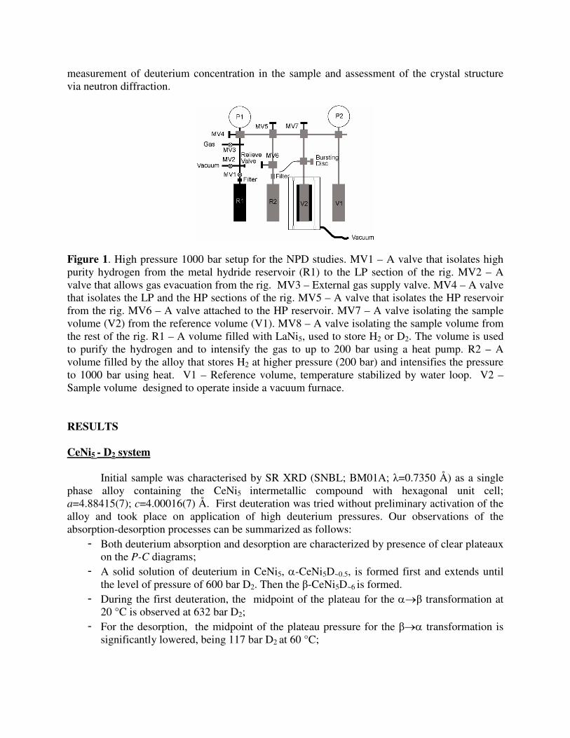
measurement of deuterium concentration in the sample and assessment of the crystal structure via neutron diffraction.
Figure 1. High pressure 1000 bar setup for the NPD studies. MV1 – A valve that isolates high purity hydrogen from the metal hydride reservoir (R1) to the LP section of the rig. MV2 – A valve that allows gas evacuation from the rig. MV3 – External gas supply valve. MV4 – A valve that isolates the LP and the HP sections of the rig. MV5 – A valve that isolates the HP reservoir from the rig. MV6 – A valve attached to the HP reservoir. MV7 – A valve isolating the sample volume (V2) from the reference volume (V1). MV8 – A valve isolating the sample volume from the rest of the rig. R1 – A volume filled with LaNi5, used to store H2 or D2. The volume is used to purify the hydrogen and to intensify the gas to up to 200 bar using a heat pump. R2 – A volume filled by the alloy that stores H2 at higher pressure (200 bar) and intensifies the pressure to 1000 bar using heat. V1 – Reference volume, temperature stabilized by water loop. V2 – Sample volume designed to operate inside a vacuum furnace.
RESULTS
CeNi5 - D2 system
Initial sample was characterised by SR XRD (SNBL; BM01A; λ=0.7350 Å) as a single phase alloy containing the CeNi5 intermetallic compound with hexagonal unit cell; a=4.88415(7); c=4.00016(7) Å. First deuteration was tried without preliminary activation of the alloy and took place on application of high deuterium pressures. Our observations of the absorption-desorption processes can be summarized as follows:
- Both deuterium absorption and desorption are characterized by presence of clear plateaux on the P-C diagrams;
- A solid solution of deuterium in CeNi5, α-CeNi5D~0.5, is formed first and extends until the level of pressure of 600 bar D2. Then the β-CeNi5D~6 is formed.
- During the first deuteration, the midpoint of the plateau for the α→β transformation at 20 °C is observed at 632 bar D2;
- For the desorption, the midpoint of the plateau pressure for the β→α transformation is significantly lowered, being 117 bar D2 at 60 °C;
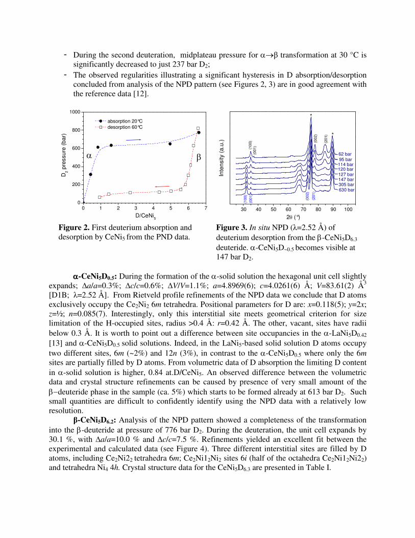
- During the second deuteration, midplateau pressure for α→β transformation at 30 °C is significantly decreased to just 237 bar D2;
- The observed regularities illustrating a significant hysteresis in D absorption/desorption concluded from analysis of the NPD pattern (see Figures 2, 3) are in good agreement with the reference data [12].
0 1 2 3 4 5 6 70
200
400
600
800
1000
βα
D2
pres
sure
(ba
r)
D/CeNi5
absorption 20°C desorption 60°C
30 40 50 60 70 80 90 100
(201
)
(201
)(0
02)
(001
)(100
)
(002
)
(100
)
(001
)
*
62 bar 95 bar114 bar120 bar127 bar147 bar305 bar
Inte
nsity
(a.
u.)
2θ (°)
630 bar
*
Figure 2. First deuterium absorption and desorption by CeNi5 from the PND data.
Figure 3. In situ NPD (λ=2.52 Å) of deuterium desorption from the β-CeNi5D6.3 deuteride. α-CeNi5D~0.5 becomes visible at 147 bar D2.
αααα-CeNi5D0.5: During the formation of the α-solid solution the hexagonal unit cell slightly
expands; ∆a/a=0.3%; ∆c/c=0.6%; ∆V/V=1.1%; a=4.8969(6); c=4.0261(6) Å; V=83.61(2) Å3 [D1B; λ=2.52 Å]. From Rietveld profile refinements of the NPD data we conclude that D atoms exclusively occupy the Ce2Ni2 6m tetrahedra. Positional parameters for D are: x=0.118(5); y=2x; z=½; n=0.085(7). Interestingly, only this interstitial site meets geometrical criterion for size limitation of the H-occupied sites, radius >0.4 Å: r=0.42 Å. The other, vacant, sites have radii below 0.3 Å. It is worth to point out a difference between site occupancies in the α-LaNi5D0.42 [13] and α-CeNi5D0.5 solid solutions. Indeed, in the LaNi5-based solid solution D atoms occupy two different sites, 6m (~2%) and 12n (3%), in contrast to the α-CeNi5D0.5 where only the 6m sites are partially filled by D atoms. From volumetric data of D absorption the limiting D content in α-solid solution is higher, 0.84 at.D/CeNi5. An observed difference between the volumetric data and crystal structure refinements can be caused by presence of very small amount of the β−deuteride phase in the sample (ca. 5%) which starts to be formed already at 613 bar D2. Such small quantities are difficult to confidently identify using the NPD data with a relatively low resolution.
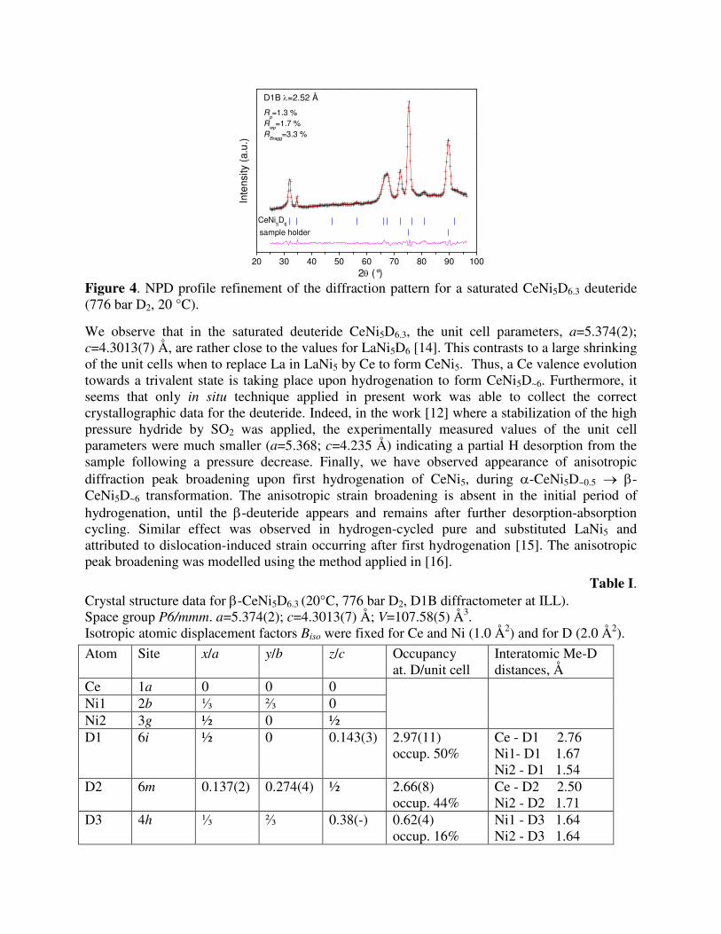
β-CeNi5D6.2: Analysis of the NPD pattern showed a completeness of the transformation into the β-deuteride at pressure of 776 bar D2. During the deuteration, the unit cell expands by 30.1 %, with ∆a/a=10.0 % and ∆c/c=7.5 %. Refinements yielded an excellent fit between the experimental and calculated data (see Figure 4). Three different interstitial sites are filled by D atoms, including Ce2Ni22 tetrahedra 6m; Ce2Ni12Ni2 sites 6i (half of the octahedra Ce2Ni12Ni22) and tetrahedra Ni4 4h. Crystal structure data for the CeNi5D6.3 are presented in Table I.
20 30 40 50 60 70 80 90 100
Rp=1.3 %
Rwp
=1.7 %R
Bragg=3.3 %
D1B λ=2.52 Å
sample holder
CeNi5D
6
Inte
nsity
(a.
u.)
2θ (°) Figure 4. NPD profile refinement of the diffraction pattern for a saturated CeNi5D6.3 deuteride (776 bar D2, 20 °C).
We observe that in the saturated deuteride CeNi5D6.3, the unit cell parameters, a=5.374(2); c=4.3013(7) Å, are rather close to the values for LaNi5D6 [14]. This contrasts to a large shrinking of the unit cells when to replace La in LaNi5 by Ce to form CeNi5. Thus, a Ce valence evolution towards a trivalent state is taking place upon hydrogenation to form CeNi5D~6. Furthermore, it seems that only in situ technique applied in present work was able to collect the correct crystallographic data for the deuteride. Indeed, in the work [12] where a stabilization of the high pressure hydride by SO2 was applied, the experimentally measured values of the unit cell parameters were much smaller (a=5.368; c=4.235 Å) indicating a partial H desorption from the sample following a pressure decrease. Finally, we have observed appearance of anisotropic diffraction peak broadening upon first hydrogenation of CeNi5, during α-CeNi5D~0.5 → β-CeNi5D~6 transformation. The anisotropic strain broadening is absent in the initial period of hydrogenation, until the β-deuteride appears and remains after further desorption-absorption cycling. Similar effect was observed in hydrogen-cycled pure and substituted LaNi5 and attributed to dislocation-induced strain occurring after first hydrogenation [15]. The anisotropic peak broadening was modelled using the method applied in [16].
Table I. Crystal structure data for β-CeNi5D6.3 (20°C, 776 bar D2, D1B diffractometer at ILL). Space group P6/mmm. a=5.374(2); c=4.3013(7) Å; V=107.58(5) Å3. Isotropic atomic displacement factors Biso were fixed for Ce and Ni (1.0 Å2) and for D (2.0 Å2).
Atom Site x/a y/b z/c Occupancy at. D/unit cell
Interatomic Me-D distances, Å
Ce 1a 0 0 0 Ni1 2b ⅓ ⅔ 0 Ni2 3g ½ 0 ½
D1 6i ½ 0 0.143(3) 2.97(11) occup. 50%
Ce - D1 2.76 Ni1- D1 1.67 Ni2 - D1 1.54
D2 6m 0.137(2) 0.274(4) ½ 2.66(8) occup. 44%
Ce - D2 2.50 Ni2 - D2 1.71
D3 4h ⅓ ⅔ 0.38(-) 0.62(4) occup. 16%
Ni1 - D3 1.64 Ni2 - D3 1.64
ZrFe2-xAlx – D2 system
ZrFe2 intermetallic compound crystallizes with MgCu2-type C15 FCC structure. Three different alloys containing 0.02; 0.04 and 0.20 at.Al/f.u. ZrFe2-xAlx were synthesized by arc melting. SR XRD studies showed that Fe substitution by Al in Zr(Fe,Al)2 alloys increases the unit cell parameter without change of the Laves-type of the crystal structure, from a=7.072 Å for ZrFe2[4] to a=7.08492(8) Å for ZrFe1.98Al0.02, a=7.08658(7) Å for ZrFe1.96Al0.04 and a=7.0978(1) Å for ZrFe1.80Al0.20.
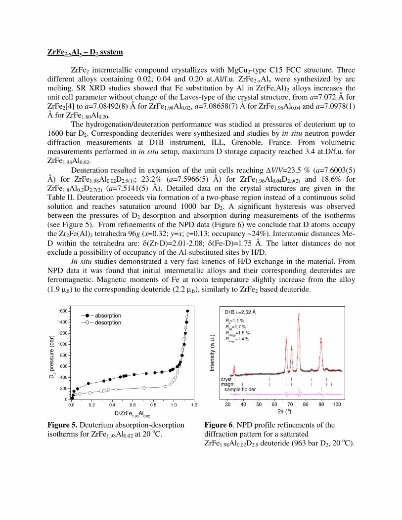
The hydrogenation/deuteration performance was studied at pressures of deuterium up to 1600 bar D2. Corresponding deuterides were synthesized and studies by in situ neutron powder diffraction measurements at D1B instrument, ILL, Grenoble, France. From volumetric measurements performed in in situ setup, maximum D storage capacity reached 3.4 at.D/f.u. for ZrFe1.98Al0.02.
Deuteration resulted in expansion of the unit cells reaching ∆V/V=23.5 % (a=7.6003(5) Å) for ZrFe1.98Al0.02D2.9(1); 23.2% (a=7.5966(5) Å) for ZrFe1.96Al0.04D2.9(2) and 18.6% for ZrFe1.8Al0.2D2.7(2) (a=7.5141(5) Å). Detailed data on the crystal structures are given in the Table II. Deuteration proceeds via formation of a two-phase region instead of a continuous solid solution and reaches saturation around 1000 bar D2. A significant hysteresis was observed between the pressures of D2 desorption and absorption during measurements of the isotherms (see Figure 5). From refinements of the NPD data (Figure 6) we conclude that D atoms occupy the Zr2Fe(Al)2 tetrahedra 96g (x=0.32; y=x; z=0.13; occupancy ~24%). Interatomic distances Me-D within the tetrahedra are: δ(Zr-D)=2.01-2.08; δ(Fe-D)=1.75 Å. The latter distances do not exclude a possibility of occupancy of the Al-substituted sites by H/D.
In situ studies demonstrated a very fast kinetics of H/D exchange in the material. From NPD data it was found that initial intermetallic alloys and their corresponding deuterides are ferromagnetic. Magnetic moments of Fe at room temperature slightly increase from the alloy (1.9 µB) to the corresponding deuteride (2.2 µB), similarly to ZrFe2 based deuteride.
0.0 0.2 0.4 0.6 0.8 1.0 1.20
200
400
600
800
1000
1200
1400
1600 absorption desorption
D2 p
ress
ure
(bar
)
D/ZrFe1.98
Al0.02
30 40 50 60 70 80 90 100
magn
Rp=1.1 %
Rwp
=1.7 %R
Bragg=1.5 %
Rmagn
=1.4 %
D1B λ=2.52 Å
sample holder
cryst
Inte
nsity
(a.
u.)
2θ (°) Figure 5. Deuterium absorption-desorption isotherms for ZrFe1.98Al0.02 at 20 oC.
Figure 6. NPD profile refinements of the diffraction pattern for a saturated ZrFe1.98Al0.02D2.9 deuteride (963 bar D2, 20 oC).
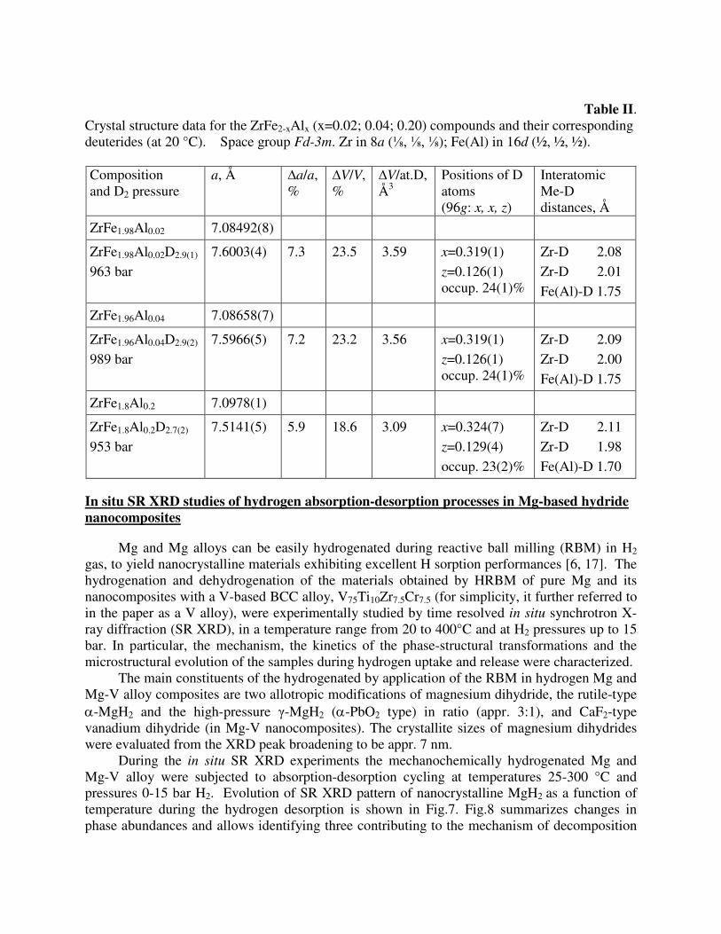
Table II. Crystal structure data for the ZrFe2-xAlx (x=0.02; 0.04; 0.20) compounds and their corresponding deuterides (at 20 °C). Space group Fd-3m. Zr in 8a (⅛, ⅛, ⅛); Fe(Al) in 16d (½, ½, ½). Composition and D2 pressure
a, Å ∆a/a, %
∆V/V, %
∆V/at.D, Å3
Positions of D atoms (96g: x, x, z)
Interatomic Me-D distances, Å
ZrFe1.98Al0.02 7.08492(8)
ZrFe1.98Al0.02D2.9(1) 963 bar
7.6003(4) 7.3 23.5 3.59 x=0.319(1) z=0.126(1) occup. 24(1)%
Zr-D 2.08 Zr-D 2.01 Fe(Al)-D 1.75
ZrFe1.96Al0.04 7.08658(7)
ZrFe1.96Al0.04D2.9(2)
989 bar 7.5966(5)
7.2 23.2 3.56 x=0.319(1) z=0.126(1) occup. 24(1)%
Zr-D 2.09 Zr-D 2.00 Fe(Al)-D 1.75
ZrFe1.8Al0.2 7.0978(1)
ZrFe1.8Al0.2D2.7(2) 953 bar
7.5141(5) 5.9 18.6
3.09 x=0.324(7) z=0.129(4) occup. 23(2)%
Zr-D 2.11 Zr-D 1.98 Fe(Al)-D 1.70
In situ SR XRD studies of hydrogen absorption-desorption processes in Mg-based hydride
nanocomposites
Mg and Mg alloys can be easily hydrogenated during reactive ball milling (RBM) in H2 gas, to yield nanocrystalline materials exhibiting excellent H sorption performances [6, 17]. The hydrogenation and dehydrogenation of the materials obtained by HRBM of pure Mg and its nanocomposites with a V-based BCC alloy, V75Ti10Zr7.5Cr7.5 (for simplicity, it further referred to in the paper as a V alloy), were experimentally studied by time resolved in situ synchrotron X-ray diffraction (SR XRD), in a temperature range from 20 to 400°C and at H2 pressures up to 15 bar. In particular, the mechanism, the kinetics of the phase-structural transformations and the microstructural evolution of the samples during hydrogen uptake and release were characterized.
The main constituents of the hydrogenated by application of the RBM in hydrogen Mg and Mg-V alloy composites are two allotropic modifications of magnesium dihydride, the rutile-type α-MgH2 and the high-pressure γ-MgH2 (α-PbO2 type) in ratio (appr. 3:1), and CaF2-type vanadium dihydride (in Mg-V nanocomposites). The crystallite sizes of magnesium dihydrides were evaluated from the XRD peak broadening to be appr. 7 nm.
During the in situ SR XRD experiments the mechanochemically hydrogenated Mg and Mg-V alloy were subjected to absorption-desorption cycling at temperatures 25-300 °C and pressures 0-15 bar H2. Evolution of SR XRD pattern of nanocrystalline MgH2 as a function of temperature during the hydrogen desorption is shown in Fig.7. Fig.8 summarizes changes in phase abundances and allows identifying three contributing to the mechanism of decomposition
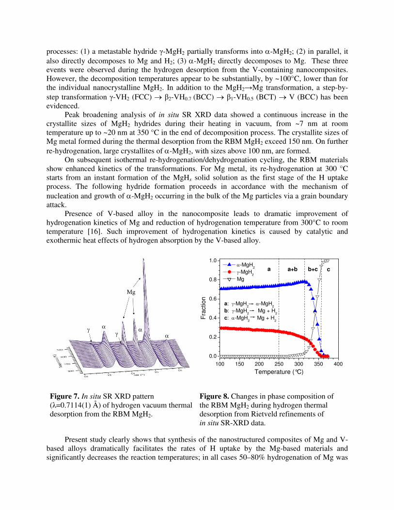
processes: (1) a metastable hydride γ-MgH2 partially transforms into α-MgH2; (2) in parallel, it also directly decomposes to Mg and H2; (3) α-MgH2 directly decomposes to Mg. These three events were observed during the hydrogen desorption from the V-containing nanocomposites. However, the decomposition temperatures appear to be substantially, by ~100°C, lower than for the individual nanocrystalline MgH2. In addition to the MgH2→Mg transformation, a step-by-step transformation γ-VH2 (FCC) → β2-VH0.7 (BCC) → β1-VH0.5 (BCT) → V (BCC) has been evidenced.
Peak broadening analysis of in situ SR XRD data showed a continuous increase in the crystallite sizes of MgH2 hydrides during their heating in vacuum, from ~7 nm at room temperature up to ~20 nm at 350 °C in the end of decomposition process. The crystallite sizes of Mg metal formed during the thermal desorption from the RBM MgH2 exceed 150 nm. On further re-hydrogenation, large crystallites of α-MgH2, with sizes above 100 nm, are formed.
On subsequent isothermal re-hydrogenation/dehydrogenation cycling, the RBM materials show enhanced kinetics of the transformations. For Mg metal, its re-hydrogenation at 300 °C starts from an instant formation of the MgHx solid solution as the first stage of the H uptake process. The following hydride formation proceeds in accordance with the mechanism of nucleation and growth of α-MgH2 occurring in the bulk of the Mg particles via a grain boundary attack.
Presence of V-based alloy in the nanocomposite leads to dramatic improvement of hydrogenation kinetics of Mg and reduction of hydrogenation temperature from 300°C to room temperature [16]. Such improvement of hydrogenation kinetics is caused by catalytic and exothermic heat effects of hydrogen absorption by the V-based alloy.
100 150 200 250 300 350 400
0.0
0.2
0.4
0.6
0.8
1.0
a: γ-MgH2 α-MgH
2
b: γ-MgH2 Mg + H
2
c: α-MgH2 Mg + H
2
cb+ca+ba
Fra
ctio
n
Temperature (°C)
α-MgH2
γ-MgH2
Mg
Figure 7. In situ SR XRD pattern (λ=0.7114(1) Å) of hydrogen vacuum thermal desorption from the RBM MgH2.
Figure 8. Changes in phase composition of the RBM MgH2 during hydrogen thermal desorption from Rietveld refinements of in situ SR-XRD data.
Present study clearly shows that synthesis of the nanostructured composites of Mg and V-based alloys dramatically facilitates the rates of H uptake by the Mg-based materials and significantly decreases the reaction temperatures; in all cases 50–80% hydrogenation of Mg was
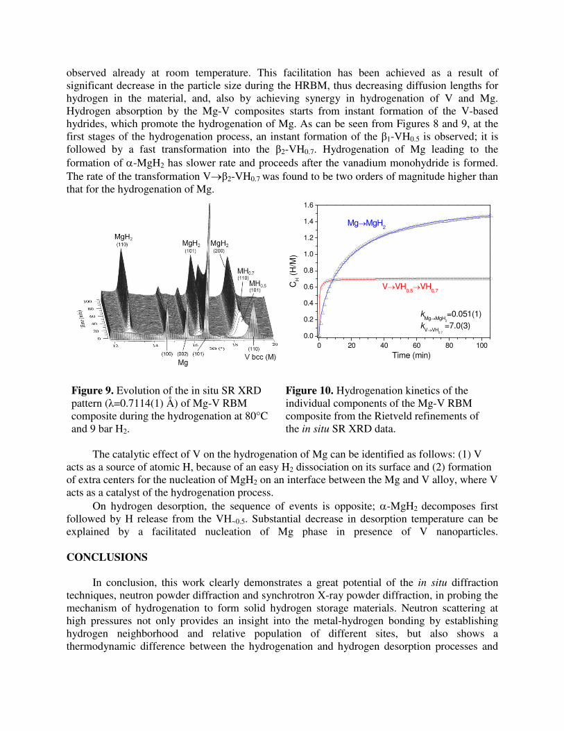
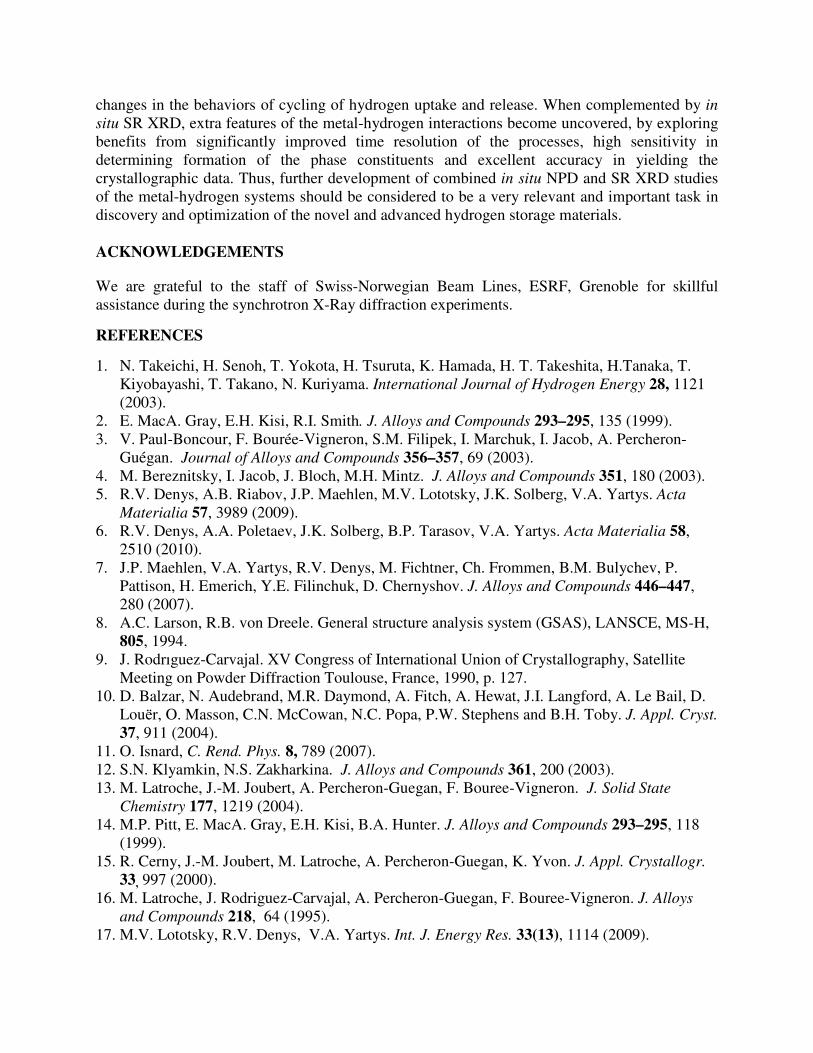
observed already at room temperature. This facilitation has been achieved as a result of significant decrease in the particle size during the HRBM, thus decreasing diffusion lengths for hydrogen in the material, and, also by achieving synergy in hydrogenation of V and Mg. Hydrogen absorption by the Mg-V composites starts from instant formation of the V-based hydrides, which promote the hydrogenation of Mg. As can be seen from Figures 8 and 9, at the first stages of the hydrogenation process, an instant formation of the β1-VH0.5 is observed; it is followed by a fast transformation into the β2-VH0.7. Hydrogenation of Mg leading to the formation of α-MgH2 has slower rate and proceeds after the vanadium monohydride is formed. The rate of the transformation V→β2-VH0.7 was found to be two orders of magnitude higher than that for the hydrogenation of Mg.
0 20 40 60 80 1000.0
0.2
0.4
0.6
0.8
1.0
1.2
1.4
1.6
kMg→MgH
2
=0.051(1)k
V→VH0.7
=7.0(3)
V→VH0.5
→VH0.7
Mg→MgH2
CH (
H/M
)
Time (min)
Figure 9. Evolution of the in situ SR XRD pattern (λ=0.7114(1) Å) of Mg-V RBM composite during the hydrogenation at 80°C and 9 bar H2.
Figure 10. Hydrogenation kinetics of the individual components of the Mg-V RBM composite from the Rietveld refinements of the in situ SR XRD data.
The catalytic effect of V on the hydrogenation of Mg can be identified as follows: (1) V
acts as a source of atomic H, because of an easy H2 dissociation on its surface and (2) formation of extra centers for the nucleation of MgH2 on an interface between the Mg and V alloy, where V acts as a catalyst of the hydrogenation process.
On hydrogen desorption, the sequence of events is opposite; α-MgH2 decomposes first followed by H release from the VH~0.5. Substantial decrease in desorption temperature can be explained by a facilitated nucleation of Mg phase in presence of V nanoparticles. CONCLUSIONS
In conclusion, this work clearly demonstrates a great potential of the in situ diffraction
techniques, neutron powder diffraction and synchrotron X-ray powder diffraction, in probing the mechanism of hydrogenation to form solid hydrogen storage materials. Neutron scattering at high pressures not only provides an insight into the metal-hydrogen bonding by establishing hydrogen neighborhood and relative population of different sites, but also shows a thermodynamic difference between the hydrogenation and hydrogen desorption processes and
changes in the behaviors of cycling of hydrogen uptake and release. When complemented by in
situ SR XRD, extra features of the metal-hydrogen interactions become uncovered, by exploring benefits from significantly improved time resolution of the processes, high sensitivity in determining formation of the phase constituents and excellent accuracy in yielding the crystallographic data. Thus, further development of combined in situ NPD and SR XRD studies of the metal-hydrogen systems should be considered to be a very relevant and important task in discovery and optimization of the novel and advanced hydrogen storage materials.
ACKNOWLEDGEMENTS
We are grateful to the staff of Swiss-Norwegian Beam Lines, ESRF, Grenoble for skillful assistance during the synchrotron X-Ray diffraction experiments.
REFERENCES
1. N. Takeichi, H. Senoh, T. Yokota, H. Tsuruta, K. Hamada, H. T. Takeshita, H.Tanaka, T. Kiyobayashi, T. Takano, N. Kuriyama. International Journal of Hydrogen Energy 28, 1121 (2003).
2. E. MacA. Gray, E.H. Kisi, R.I. Smith. J. Alloys and Compounds 293–295, 135 (1999). 3. V. Paul-Boncour, F. Bourée-Vigneron, S.M. Filipek, I. Marchuk, I. Jacob, A. Percheron-
Guégan. Journal of Alloys and Compounds 356–357, 69 (2003). 4. M. Bereznitsky, I. Jacob, J. Bloch, M.H. Mintz. J. Alloys and Compounds 351, 180 (2003). 5. R.V. Denys, A.B. Riabov, J.P. Maehlen, M.V. Lototsky, J.K. Solberg, V.A. Yartys. Acta
Materialia 57, 3989 (2009). 6. R.V. Denys, A.A. Poletaev, J.K. Solberg, B.P. Tarasov, V.A. Yartys. Acta Materialia 58,
2510 (2010). 7. J.P. Maehlen, V.A. Yartys, R.V. Denys, M. Fichtner, Ch. Frommen, B.M. Bulychev, P.
Pattison, H. Emerich, Y.E. Filinchuk, D. Chernyshov. J. Alloys and Compounds 446–447, 280 (2007).
8. A.C. Larson, R.B. von Dreele. General structure analysis system (GSAS), LANSCE, MS-H, 805, 1994.
9. J. Rodrıguez-Carvajal. XV Congress of International Union of Crystallography, Satellite Meeting on Powder Diffraction Toulouse, France, 1990, p. 127.
10. D. Balzar, N. Audebrand, M.R. Daymond, A. Fitch, A. Hewat, J.I. Langford, A. Le Bail, D. Louёr, O. Masson, C.N. McCowan, N.C. Popa, P.W. Stephens and B.H. Toby. J. Appl. Cryst. 37, 911 (2004).
11. O. Isnard, C. Rend. Phys. 8, 789 (2007). 12. S.N. Klyamkin, N.S. Zakharkina. J. Alloys and Compounds 361, 200 (2003). 13. M. Latroche, J.-M. Joubert, A. Percheron-Guegan, F. Bouree-Vigneron. J. Solid State
Chemistry 177, 1219 (2004). 14. M.P. Pitt, E. MacA. Gray, E.H. Kisi, B.A. Hunter. J. Alloys and Compounds 293–295, 118
(1999). 15. R. Cerny, J.-M. Joubert, M. Latroche, A. Percheron-Guegan, K. Yvon. J. Appl. Crystallogr.
33, 997 (2000). 16. M. Latroche, J. Rodriguez-Carvajal, A. Percheron-Guegan, F. Bouree-Vigneron. J. Alloys
and Compounds 218, 64 (1995). 17. M.V. Lototsky, R.V. Denys, V.A. Yartys. Int. J. Energy Res. 33(13), 1114 (2009).
Copyright © 2022 FDOKUMEN