
PETRA III: A Low Emittance Synchrotron Radiation Source ...
558
PETRA III: A Low Emittance Synchrotron Radiation Source Technical Design Report Editors: K. Balewski, W. Brefeld, W. Decking, H. Franz, R. R¨ ohlsberger, E. Weckert DESY, Hamburg, Germany February 29, 2004 EDMS Nr.: D00000000822371 Rev: A Ver: 1 Status: Released - Dat.: 8. Apr 2008
-
Upload
khangminh22 -
Category
Documents
-
view
1 -
download
0
Transcript of PETRA III: A Low Emittance Synchrotron Radiation Source ...
PETRA III:A Low Emittance Synchrotron Radiation Source
Technical Design Report
Editors:K. Balewski, W. Brefeld, W. Decking, H. Franz, R. Rohlsberger, E. Weckert
DESY, Hamburg, Germany
February 29, 2004
ED
MS
Nr.:
D00
0000
0082
2371
Rev
: A V
er: 1
Sta
tus:
Rel
ease
d -
Dat
.: 8.
Apr
200
8

ii
ED
MS
Nr.:
D00
0000
0082
2371
Rev
: A V
er: 1
Sta
tus:
Rel
ease
d -
Dat
.: 8.
Apr
200
8

iii
Authors and Contributors
I. Ascone20, R. Bacher6, K. Balewski6, J. Bansmann52, H.D. Bartunik21, U. Becker10,F. Beckmann14, S. Bessedine15, Ch. Betzel46, P. Boesecke8, R. Bospflug6, J. Boster6,G. Bourenkov21, W. Brefeld6, T. Bruckel11, Ch. Buhr6, O. Bunk27, S. Celik6, J. Chwiej63,R. Claessen38, H. Dau10, Z. Dauter4, W. Decking6, M. Denecke12, R. Denecke43,R. Dorner44, W. Drube6, P. Duval6, M. Ebert6, H.-J. Eckholdt6, H. Ehrenberg34, S. Eisebitt3,M. Faesing6, G. Falkenberg6, J. Falta40, R. Feidenhans’l27, P. Fischer23, R. Frahm54,H. Franz6, M. Froba45, T. Fujisawa25, R. Gehrke6, W. Gießke6, G. Goerigk11, H. Grabe-Celik6, W. Graeff6, J. Grenzer51, G. Grossmann32, G. Grubel6, J.-D. Grunwaldt9, P. Gurtler6,L. Hanisch6, U. Hahn6, G. Henkel50, S. Herb6, Ch. Hermes7, R. Hilgenfeld49, K. Hodgson33,U. Hoppe52, T. Irving17, D. Jagnow6, K. Janssens57, J.-P. Jensen6, R.L. Johnson46,L. Kipp47, U. Klemradt28, J. Klute6, L. Kover2, W. Kook6, J. Kouptsidis6, T. Kracht6,B. Krause6, W. Krechlok6, M. Krisch8, G. Kube6, Ch. Kumpf55, V. Kuzminykh5,V. Lamzin7, M. Lankosz63, U. Laustroer6, L. LeFevre20, A. Leslie18, A. Leuschner6,E. Levichev5, T. Lippmann14, K.D. Liss35, D. Lott14, D. Lutzenkirchen-Hecht54,A. Madsen8, O. Magnussen47, J. Maidment6, E. Mandelkow21, S. Mangani64, M. Martins46,R.V. Martins14, P. McNally26, S. McSweeney8, W. Merz6, J. Metge14, W. Meyer-Klaucke7,A. Meyer46, M. Minty6, T. Moller6, W. Moritz19, P. Muller-Buschbaum36, A. Muller45,K. Muller6, M. Muller47, U. Muller3, B. Murphy47, M. Nielsen27, D.V. Novikov6, F. Obier6,R. Onken6, H. Over45, S. Panjikar7, O. Paris22, J. Penner-Hahn61, J. Perez31, M.V. Petoukov7,A. Petrov6, J. Pfluger6, U. Pietsch51, E. Pohl7, A. Popov7, J. Prenting6, A. Pyzalla37,B. Racky6, D. Ramert6, H. Reichert23, R. Reininger29, H. Requardt8, K. Rickers6,13,I. Robinson60, J. Rohler56, R. Rohlsberger6, G. Rosenbaum1, J.E. Rubensson65,R. Ruffer8, G.K. Sahoo6, T. Salditt41, M. Schmidbauer16, H. Schmidt-Bocking44,A. Schmidt7, C. Schmidt13, Th. Schmidt40, R. Schmitz6, J.R. Schneider6, A. Schreyer14,C. Schussler-Langheine48, W. Schutte6, U. Schuetz6, G. Schutz23, H. Schulte-Schrepping6,M. Schwartz6, R. Scott58, O.H. Seeck11, M. Seidel6, B. Sepiol53, R. Serimaa59, S.D. Shastri1,Y.V. Shvyd’ko46, H. Sinn1, K. Sinram6, M. Sladecek53, S.v. Smaalen39, J. Strempfer23,N. Stribeck46, V.N. Strocov30, D.I. Svergun7, M. Szczerbowska-Boruchowska63, N. Tesch6,A. Thompson31, K. Tiedke6, J. Tiessen6, M. Tischer6, L.H. Tjeng48, M. Tolan42, D. Trines6,H. Tsuruta33, P. Tucker7, J. Ullrich44, M.A. Vanoni62, L. Vincze57, P. Vobly5, G. Vogl53,A. Wanning6, R. Wanzenberg6, E. Weckert6, G. Weichert6, H. Weise6, M. Weiss7, E. Welter6,M. Wendt6, M. Wilke51, S. Wilke6, R. Willumeit14, M. Wilmanns7, K. Wittenburg6,P. Wochner23, J.C. Woicik24, G. Wortmann50, T. Wroblewski6, W. Wurth46, Li Yougjun6,J. Zegenhagen8, M.v. Zimmermann6, K. Zolotarev5
1APS, Argonne, USA2ATOMKI, Debrecen, Hungary3BESSY, Berlin, Germany4BNL, Upton, USA5Budker Institute of Nuclear Physics, Novosibirsk, Russia6DESY, Hamburg, Germany7EMBL Outstation, Hamburg, Germany
ED
MS
Nr.:
D00
0000
0082
2371
Rev
: A V
er: 1
Sta
tus:
Rel
ease
d -
Dat
.: 8.
Apr
200
8

iv
8ESRF, Grenoble, France9ETH Zurich, Switzerland10FU Berlin, Berlin, Germany11FZ Julich GmbH, Julich, Germany12FZ Karlsruhe, Karlsruhe, Germany13GeoForschungsZentrum, Potsdam, Germany14GKSS Research Center, Geesthacht, Germany15Humboldt-Universitat Berlin, Germany16Humbold-Universitat, Berlin, Germany17Illinois Institute of Technology, Chicago, USA18LMB Cambridge, UK19LMU Munchen, Germany20LURE, Orsay, France21MPG-ASMB, Hamburg, Germany22MPI Golm, Germany23MPI Stuttgart, Germany24NIST/APS, Argonne, USA25RIKEN, SPring-8, Himeji, Japan26RINCE, Dublin City University, Ireland27RISØ Nat. Lab., Denmark28RWTH Aachen, Germany29Scientific Answers and Solutions, Madison, USA30SLS, Villingen, Switzerland31SOLEIL, Gif-sur-Yvette, France32SRS, Daresbury Laboratory, Daresbury, UK33SSRL, Stanford, USA34TH Darmstadt, Germany35TU Hamburg-Harburg, Germany36TU Munchen, Germany37TU Wien, Austria38Universitat Augsburg, Germany39Universitat Bayreuth, Germany40Universitat Bremen, Germany41Universitat Darmstadt, Germany42Universitat Dortmund, Germany43Universitat Erlangen-Nurnberg, Germany44Universitat Frankfurt, Germany45Universitat Gießen, Germany46Universitat Hamburg, Germany47Universitat Kiel, Germany48Universitat Koln, Germany49Universitat Lubeck, Germany50Universitat Paderborn, Germany51Universitat Potsdam, Germany
ED
MS
Nr.:
D00
0000
0082
2371
Rev
: A V
er: 1
Sta
tus:
Rel
ease
d -
Dat
.: 8.
Apr
200
8

v
52Universitat Rostock, Germany53Universitat Wien, Austria54Universitat Wuppertal, Germany55Universitat Wurzburg, Germany56Universitat zu Koln, Germany57University of Antwerp, Belgium58University of Georgia, Athens, USA59University of Helsinki, Finland60University of Illinois, Urbana, USA61University of Michigan, Ann Arbor, USA62University of Milan, Italy63University of Mining and Metallurgy, Krakow, Poland64University of Siena, Siena, Italy65University of Uppsala, Sweden
ED
MS
Nr.:
D00
0000
0082
2371
Rev
: A V
er: 1
Sta
tus:
Rel
ease
d -
Dat
.: 8.
Apr
200
8

vi
ED
MS
Nr.:
D00
0000
0082
2371
Rev
: A V
er: 1
Sta
tus:
Rel
ease
d -
Dat
.: 8.
Apr
200
8
Contents
1 Introduction 1
2 Executive Summary 72.1 Science at Low Emittance SR Sources . . . . . . . . . . . . . . . . . . . . 72.2 PETRA III Conversion Overview . . . . . . . . . . . . . . . . . . . . . . . 10
2.2.1 Storage ring . . . . . . . . . . . . . . . . . . . . . . . . . . . . . . 102.2.2 Experimental hall . . . . . . . . . . . . . . . . . . . . . . . . . . . 132.2.3 Expected photon beam performance . . . . . . . . . . . . . . . . . 14
2.3 Proposed Experimental Stations . . . . . . . . . . . . . . . . . . . . . . . 162.3.1 X-ray diffraction and imaging . . . . . . . . . . . . . . . . . . . . 182.3.2 High-energy resolution spectroscopy . . . . . . . . . . . . . . . . . 202.3.3 Materials science . . . . . . . . . . . . . . . . . . . . . . . . . . . 222.3.4 X-ray absorption and resonant scattering . . . . . . . . . . . . . . 242.3.5 Structural biology . . . . . . . . . . . . . . . . . . . . . . . . . . 27
2.4 Future Upgrade Prospects . . . . . . . . . . . . . . . . . . . . . . . . . . . 292.5 Summary of Project Costs and Timetable . . . . . . . . . . . . . . . . . . 31
2.5.1 Project costs . . . . . . . . . . . . . . . . . . . . . . . . . . . . . 312.5.2 Time table . . . . . . . . . . . . . . . . . . . . . . . . . . . . . . 31
3 The Storage Ring 333.1 Introduction . . . . . . . . . . . . . . . . . . . . . . . . . . . . . . . . . . 333.2 Accelerator Physics Issues . . . . . . . . . . . . . . . . . . . . . . . . . . 38
3.2.1 Geometry and optics . . . . . . . . . . . . . . . . . . . . . . . . . 383.2.2 Nonlinear dynamics . . . . . . . . . . . . . . . . . . . . . . . . . 463.2.3 Current limitations . . . . . . . . . . . . . . . . . . . . . . . . . . 513.2.4 Closed orbit correction and stability . . . . . . . . . . . . . . . . . 56
3.3 Magnets for the New Octant of PETRA III . . . . . . . . . . . . . . . . . . 663.3.1 Quadrupole magnets . . . . . . . . . . . . . . . . . . . . . . . . . 673.3.2 Specification of the quadrupole magnets . . . . . . . . . . . . . . . 673.3.3 Results of the 2-D calculation for the quadrupole magnets . . . . . 683.3.4 Dipole magnets . . . . . . . . . . . . . . . . . . . . . . . . . . . . 713.3.5 Results of the 2-D calculation for the PDA dipole . . . . . . . . . . 713.3.6 Corrector magnets . . . . . . . . . . . . . . . . . . . . . . . . . . 733.3.7 Magnets for the 7/8 of PETRA III . . . . . . . . . . . . . . . . . . 74
ED
MS
Nr.:
D00
0000
0082
2371
Rev
: A V
er: 1
Sta
tus:
Rel
ease
d -
Dat
.: 8.
Apr
200
8

viii CONTENTS
3.4 Damping Wigglers . . . . . . . . . . . . . . . . . . . . . . . . . . . . . . 783.4.1 Introduction . . . . . . . . . . . . . . . . . . . . . . . . . . . . . . 783.4.2 Wiggler design . . . . . . . . . . . . . . . . . . . . . . . . . . . . 783.4.3 Wiggler radiation power . . . . . . . . . . . . . . . . . . . . . . . 833.4.4 Radiation dose . . . . . . . . . . . . . . . . . . . . . . . . . . . . 883.4.5 Absorbers and vacuum chamber design . . . . . . . . . . . . . . . 893.4.6 SR monitoring system . . . . . . . . . . . . . . . . . . . . . . . . 943.4.7 Steering magnets . . . . . . . . . . . . . . . . . . . . . . . . . . . 95
3.5 The Vacuum System of PETRA III . . . . . . . . . . . . . . . . . . . . . . 973.5.1 Beam parameters and philosophy . . . . . . . . . . . . . . . . . . 973.5.2 Mechanical considerations . . . . . . . . . . . . . . . . . . . . . . 1043.5.3 New octant . . . . . . . . . . . . . . . . . . . . . . . . . . . . . . 1063.5.4 Further modifications of the vacuum system . . . . . . . . . . . . . 1073.5.5 Conditioning and expected performance . . . . . . . . . . . . . . . 107
3.6 The RF System . . . . . . . . . . . . . . . . . . . . . . . . . . . . . . . . 1103.6.1 Introduction . . . . . . . . . . . . . . . . . . . . . . . . . . . . . . 1103.6.2 RF system design for PETRA III . . . . . . . . . . . . . . . . . . . 1123.6.3 Reliability of RF systems . . . . . . . . . . . . . . . . . . . . . . . 1163.6.4 Upgrade to 200 mA beam current . . . . . . . . . . . . . . . . . . 1173.6.5 Conclusion . . . . . . . . . . . . . . . . . . . . . . . . . . . . . . 119
3.7 Mechanical Structure of the New PETRA III Octant . . . . . . . . . . . . . 1203.7.1 General girder design . . . . . . . . . . . . . . . . . . . . . . . . . 1213.7.2 Girder . . . . . . . . . . . . . . . . . . . . . . . . . . . . . . . . . 122
3.8 Injection System . . . . . . . . . . . . . . . . . . . . . . . . . . . . . . . 1243.8.1 Introduction . . . . . . . . . . . . . . . . . . . . . . . . . . . . . . 1243.8.2 Concept of the kicker magnet . . . . . . . . . . . . . . . . . . . . 1243.8.3 Pulser . . . . . . . . . . . . . . . . . . . . . . . . . . . . . . . . . 1253.8.4 Septum . . . . . . . . . . . . . . . . . . . . . . . . . . . . . . . . 126
3.9 Diagnostics . . . . . . . . . . . . . . . . . . . . . . . . . . . . . . . . . . 1273.9.1 Electron beam position monitors . . . . . . . . . . . . . . . . . . . 1273.9.2 Position monitors for the transverse multibunch feedback system . . 1353.9.3 Intensity monitors (DCCT, FCT) . . . . . . . . . . . . . . . . . . . 1373.9.4 Emittance monitoring by synchrotron radiation . . . . . . . . . . . 1373.9.5 Emittance monitoring by conventional wire scanners . . . . . . . . 1393.9.6 Emittance monitoring by laser wire scanners . . . . . . . . . . . . 1403.9.7 Parasitic bunch measurements . . . . . . . . . . . . . . . . . . . . 1403.9.8 Screens . . . . . . . . . . . . . . . . . . . . . . . . . . . . . . . . 1413.9.9 Scrapers . . . . . . . . . . . . . . . . . . . . . . . . . . . . . . . . 1423.9.10 Beam stoppers . . . . . . . . . . . . . . . . . . . . . . . . . . . . 1423.9.11 Photon beam position monitors . . . . . . . . . . . . . . . . . . . 143
3.10 Multi Bunch Feedback Systems . . . . . . . . . . . . . . . . . . . . . . . 1463.10.1 Introduction . . . . . . . . . . . . . . . . . . . . . . . . . . . . . . 1463.10.2 System design . . . . . . . . . . . . . . . . . . . . . . . . . . . . 146
3.11 General Control System . . . . . . . . . . . . . . . . . . . . . . . . . . . . 149
ED
MS
Nr.:
D00
0000
0082
2371
Rev
: A V
er: 1
Sta
tus:
Rel
ease
d -
Dat
.: 8.
Apr
200
8

CONTENTS ix
3.11.1 Introduction . . . . . . . . . . . . . . . . . . . . . . . . . . . . . . 1493.11.2 General properties of the PETRA III control system . . . . . . . . . 1493.11.3 Technical subsystems and beam control . . . . . . . . . . . . . . . 155
3.12 Power Supplies and Cables . . . . . . . . . . . . . . . . . . . . . . . . . . 1593.12.1 Magnet power supplies and cables . . . . . . . . . . . . . . . . . . 1593.12.2 HVDC transmitter power supply and klystron protection . . . . . . 166
3.13 Cooling Systems . . . . . . . . . . . . . . . . . . . . . . . . . . . . . . . 1693.13.1 RF cooling systems . . . . . . . . . . . . . . . . . . . . . . . . . . 1693.13.2 Magnet cooling systems . . . . . . . . . . . . . . . . . . . . . . . 1713.13.3 Vacuum chamber cooling system . . . . . . . . . . . . . . . . . . . 1733.13.4 Air conditioning . . . . . . . . . . . . . . . . . . . . . . . . . . . 173
3.14 Radiation Safety System . . . . . . . . . . . . . . . . . . . . . . . . . . . 1753.14.1 Safety considerations . . . . . . . . . . . . . . . . . . . . . . . . . 1753.14.2 Basic machine parameters . . . . . . . . . . . . . . . . . . . . . . 1763.14.3 Beam loss scenarios . . . . . . . . . . . . . . . . . . . . . . . . . 1763.14.4 Shielding calculations . . . . . . . . . . . . . . . . . . . . . . . . 177
3.15 The Personal Protection Interlock System . . . . . . . . . . . . . . . . . . 1803.15.1 Basic technology . . . . . . . . . . . . . . . . . . . . . . . . . . . 1803.15.2 Supervision of relays . . . . . . . . . . . . . . . . . . . . . . . . . 1803.15.3 Modules with CAN bus interface . . . . . . . . . . . . . . . . . . . 1803.15.4 The door interlock . . . . . . . . . . . . . . . . . . . . . . . . . . 1813.15.5 Logic for the beam permission . . . . . . . . . . . . . . . . . . . . 1813.15.6 Integration of computer tasks . . . . . . . . . . . . . . . . . . . . . 182
3.16 Injector . . . . . . . . . . . . . . . . . . . . . . . . . . . . . . . . . . . . 1853.16.1 Linac 2/PIA upgrade and modifications for PETRA III . . . . . . . 1853.16.2 DESY II . . . . . . . . . . . . . . . . . . . . . . . . . . . . . . . . 187
4 Radiation Sources 1894.1 Insertion Devices . . . . . . . . . . . . . . . . . . . . . . . . . . . . . . . 189
4.1.1 Introduction . . . . . . . . . . . . . . . . . . . . . . . . . . . . . . 1894.1.2 Design and manufacturing issues . . . . . . . . . . . . . . . . . . . 1914.1.3 Standard undulator . . . . . . . . . . . . . . . . . . . . . . . . . . 1934.1.4 Spectroscopy undulator . . . . . . . . . . . . . . . . . . . . . . . . 1944.1.5 Hard X-ray source . . . . . . . . . . . . . . . . . . . . . . . . . . 1974.1.6 Variable polarization soft X-ray undulator . . . . . . . . . . . . . . 1994.1.7 Quasi-periodic undulator . . . . . . . . . . . . . . . . . . . . . . . 2034.1.8 20m undulator . . . . . . . . . . . . . . . . . . . . . . . . . . . . 2044.1.9 Future upgrade ideas . . . . . . . . . . . . . . . . . . . . . . . . . 206
4.2 Damping Wigglers . . . . . . . . . . . . . . . . . . . . . . . . . . . . . . 2074.3 Bending Magnets . . . . . . . . . . . . . . . . . . . . . . . . . . . . . . . 208
ED
MS
Nr.:
D00
0000
0082
2371
Rev
: A V
er: 1
Sta
tus:
Rel
ease
d -
Dat
.: 8.
Apr
200
8
x CONTENTS
5 Beamline Front Ends and Optics 2115.1 Introduction . . . . . . . . . . . . . . . . . . . . . . . . . . . . . . . . . . 2115.2 Ring Tunnel – Beamline Front End Installations . . . . . . . . . . . . . . . 212
5.2.1 Radiation safety . . . . . . . . . . . . . . . . . . . . . . . . . . . 2135.2.2 Beam position monitors . . . . . . . . . . . . . . . . . . . . . . . 2135.2.3 Beam shaping and photon shutter . . . . . . . . . . . . . . . . . . 214
5.3 Optics Hutch Installations . . . . . . . . . . . . . . . . . . . . . . . . . . . 2155.3.1 Crystal monochromator . . . . . . . . . . . . . . . . . . . . . . . 2165.3.2 Mirrors . . . . . . . . . . . . . . . . . . . . . . . . . . . . . . . . 2165.3.3 Filters and windows . . . . . . . . . . . . . . . . . . . . . . . . . 217
5.4 Vacuum System . . . . . . . . . . . . . . . . . . . . . . . . . . . . . . . . 217
6 Beamlines and Experimental Stations 2196.0.1 Introduction . . . . . . . . . . . . . . . . . . . . . . . . . . . . . . 2196.0.2 General experiment support infrastructure . . . . . . . . . . . . . . 221
6.1 High-Energy X-ray Diffraction . . . . . . . . . . . . . . . . . . . . . . . . 2226.1.1 Current state of the scientific field . . . . . . . . . . . . . . . . . . 2226.1.2 Science at the high-energy X-ray diffraction beamline . . . . . . . 2236.1.3 Beamline description . . . . . . . . . . . . . . . . . . . . . . . . . 2286.1.4 Capital investment and personnel . . . . . . . . . . . . . . . . . . 231
6.2 Coherent X-ray Beamline . . . . . . . . . . . . . . . . . . . . . . . . . . . 2326.2.1 Current state of the scientific field . . . . . . . . . . . . . . . . . . 2326.2.2 Science at the Coherent X-ray Beamline (CXB) . . . . . . . . . . 2346.2.3 Beamline description . . . . . . . . . . . . . . . . . . . . . . . . . 2386.2.4 Capital investment and personnel . . . . . . . . . . . . . . . . . . 240
6.3 High Resolution X-Ray Diffraction Beamline . . . . . . . . . . . . . . . . 2416.3.1 Research with high-resolution X-ray diffraction methods . . . . . . 2416.3.2 High resolution beamlines at existing synchrotron facilities . . . . . 2426.3.3 High resolution diffraction at PETRA III . . . . . . . . . . . . . . 2426.3.4 Beamline optics and apparatus . . . . . . . . . . . . . . . . . . . . 2496.3.5 Research and development challenges . . . . . . . . . . . . . . . . 2536.3.6 Capital investment and personnel . . . . . . . . . . . . . . . . . . 253
6.4 Micro- and Nanotomography . . . . . . . . . . . . . . . . . . . . . . . . . 2546.4.1 Introduction . . . . . . . . . . . . . . . . . . . . . . . . . . . . . . 2546.4.2 Current state of the scientific field . . . . . . . . . . . . . . . . . . 2546.4.3 Science at PETRA III . . . . . . . . . . . . . . . . . . . . . . . . . 2596.4.4 Beamline description . . . . . . . . . . . . . . . . . . . . . . . . . 2606.4.5 Capital investment and personnel . . . . . . . . . . . . . . . . . . 261
6.5 Inelastic Scattering . . . . . . . . . . . . . . . . . . . . . . . . . . . . . . 2626.5.1 Current state of the scientific field . . . . . . . . . . . . . . . . . . 2626.5.2 Science at the inelastic scattering beamline at PETRA III . . . . . . 2636.5.3 Beamline description . . . . . . . . . . . . . . . . . . . . . . . . . 2676.5.4 Capital investment and personnel . . . . . . . . . . . . . . . . . . 273
6.6 Nuclear Resonant Scattering . . . . . . . . . . . . . . . . . . . . . . . . . 274
ED
MS
Nr.:
D00
0000
0082
2371
Rev
: A V
er: 1
Sta
tus:
Rel
ease
d -
Dat
.: 8.
Apr
200
8
CONTENTS xi
6.6.1 Current state of the scientific field . . . . . . . . . . . . . . . . . . 2746.6.2 Science at the NRS beamline at PETRA III . . . . . . . . . . . . . 2756.6.3 Beamline layout . . . . . . . . . . . . . . . . . . . . . . . . . . . 2816.6.4 Capital investment and personnel . . . . . . . . . . . . . . . . . . 286
6.7 High Energy Materials Science . . . . . . . . . . . . . . . . . . . . . . . . 2876.7.1 Current state of the scientific field . . . . . . . . . . . . . . . . . . 2876.7.2 Science at PETRA III . . . . . . . . . . . . . . . . . . . . . . . . . 2916.7.3 Description of the beamline . . . . . . . . . . . . . . . . . . . . . 2966.7.4 Capital investment and personnel . . . . . . . . . . . . . . . . . . 301
6.8 Powder Diffraction . . . . . . . . . . . . . . . . . . . . . . . . . . . . . . 3036.8.1 Current state of the scientific field . . . . . . . . . . . . . . . . . . 3036.8.2 Science at the high-energy powder diffraction side station . . . . . 3046.8.3 Beamline description . . . . . . . . . . . . . . . . . . . . . . . . . 3076.8.4 Capital investment and personnel . . . . . . . . . . . . . . . . . . 308
6.9 Unfocused ASAXS Beamline . . . . . . . . . . . . . . . . . . . . . . . . . 3106.9.1 Abstract . . . . . . . . . . . . . . . . . . . . . . . . . . . . . . . . 3106.9.2 Current state of the field . . . . . . . . . . . . . . . . . . . . . . . 3106.9.3 Design of the beamline . . . . . . . . . . . . . . . . . . . . . . . . 3136.9.4 Conclusion . . . . . . . . . . . . . . . . . . . . . . . . . . . . . . 3176.9.5 Capital investment and personnel . . . . . . . . . . . . . . . . . . 317
6.10 A Microfocus Beamline for Soft Matter Science . . . . . . . . . . . . . . . 3186.10.1 Introduction . . . . . . . . . . . . . . . . . . . . . . . . . . . . . . 3186.10.2 Current state of the scientific field . . . . . . . . . . . . . . . . . . 3206.10.3 Scientific case for the proposed instrument . . . . . . . . . . . . . 3246.10.4 Beamline layout . . . . . . . . . . . . . . . . . . . . . . . . . . . 3256.10.5 Capital investment and personnel . . . . . . . . . . . . . . . . . . 329
6.11 Absorption Spectroscopy . . . . . . . . . . . . . . . . . . . . . . . . . . . 3306.11.1 Current state of the scientific field . . . . . . . . . . . . . . . . . . 3306.11.2 Science at PETRA III . . . . . . . . . . . . . . . . . . . . . . . . . 3326.11.3 Beamline description . . . . . . . . . . . . . . . . . . . . . . . . . 3376.11.4 Capital investment and personnel . . . . . . . . . . . . . . . . . . 341
6.12 High-Energy Photoelectron Spectroscopy . . . . . . . . . . . . . . . . . . 3426.12.1 Current state of the scientific field . . . . . . . . . . . . . . . . . . 3426.12.2 Science at PETRA III . . . . . . . . . . . . . . . . . . . . . . . . . 3446.12.3 Beamline description . . . . . . . . . . . . . . . . . . . . . . . . . 3506.12.4 Capital investment and personnel . . . . . . . . . . . . . . . . . . 355
6.13 Hard X-ray Microprobe . . . . . . . . . . . . . . . . . . . . . . . . . . . . 3566.13.1 Current state of the scientific field . . . . . . . . . . . . . . . . . . 3566.13.2 Science at PETRA III . . . . . . . . . . . . . . . . . . . . . . . . . 3586.13.3 Beamline description . . . . . . . . . . . . . . . . . . . . . . . . . 3656.13.4 Capital investment and personnel . . . . . . . . . . . . . . . . . . 369
6.14 Variable Polarization XUV Beamline . . . . . . . . . . . . . . . . . . . . . 3706.14.1 Introduction . . . . . . . . . . . . . . . . . . . . . . . . . . . . . . 3706.14.2 Scientific applications of soft X-ray radiation . . . . . . . . . . . . 371
ED
MS
Nr.:
D00
0000
0082
2371
Rev
: A V
er: 1
Sta
tus:
Rel
ease
d -
Dat
.: 8.
Apr
200
8

xii CONTENTS
6.14.3 Gas phase studies on atoms, molecules, clusters and ions . . . . . . 3726.14.4 Surface chemistry . . . . . . . . . . . . . . . . . . . . . . . . . . . 3756.14.5 Surface studies with soft X-ray spectromicroscopy . . . . . . . . . 3776.14.6 High-resolution photoelectron spectroscopy in a wide energy range 3806.14.7 Magnetic spectroscopy . . . . . . . . . . . . . . . . . . . . . . . . 3826.14.8 Resonant soft X-ray scattering . . . . . . . . . . . . . . . . . . . . 3846.14.9 Anomalous soft X-ray diffraction .. . . . . . . . . . . . . . . . . . 3866.14.10 Beamline description . . . . . . . . . . . . . . . . . . . . . . . . . 3886.14.11 Capital investment and personnel . . . . . . . . . . . . . . . . . . 391
6.15 Resonant Scattering Beamline in the Hard X-Ray Regime . . . . . . . . . . 3926.15.1 Introduction: correlated electrons . . . . . . . . . . . . . . . . . . 3926.15.2 Resonant magnetic scattering . . . . . . . . . . . . . . . . . . . . 3936.15.3 Magnetic circular dichroism (XMCD) experiments . . . . . . . . . 3956.15.4 Templeton scattering . . . . . . . . . . . . . . . . . . . . . . . . . 3976.15.5 Beamline design . . . . . . . . . . . . . . . . . . . . . . . . . . . 3996.15.6 Capital investment and personnel . . . . . . . . . . . . . . . . . . 403
6.16 EMBL Proposals for Structural Biology Beamlines . . . . . . . . . . . . . 4046.16.1 Introduction . . . . . . . . . . . . . . . . . . . . . . . . . . . . . . 4046.16.2 Biological macromolecular X-ray crystallography beamlines . . . . 4096.16.3 Biological small-angle X-ray scattering . . . . . . . . . . . . . . . 4276.16.4 Biological X-ray absorption spectroscopy (BioXAS) . . . . . . . . 439
6.17 Protein Crystallography at PETRA III . . . . . . . . . . . . . . . . . . . . 4496.17.1 Scientific aims . . . . . . . . . . . . . . . . . . . . . . . . . . . . 4496.17.2 Basic concept of the beamlines . . . . . . . . . . . . . . . . . . . . 4516.17.3 Auxiliary installations . . . . . . . . . . . . . . . . . . . . . . . . 4546.17.4 Capital investment and personnel . . . . . . . . . . . . . . . . . . 455
6.18 Experimental Techniques . . . . . . . . . . . . . . . . . . . . . . . . . . . 4566.18.1 High pressure diamond anvil cell laboratory . . . . . . . . . . . . . 4566.18.2 X-ray topography . . . . . . . . . . . . . . . . . . . . . . . . . . . 458
7 Civil Engineering 4617.1 Site Characterization . . . . . . . . . . . . . . . . . . . . . . . . . . . . . 461
7.1.1 Description of the DESY site, geological overview . . . . . . . . . 4617.1.2 Ground motion . . . . . . . . . . . . . . . . . . . . . . . . . . . . 461
7.2 Experimental Hall . . . . . . . . . . . . . . . . . . . . . . . . . . . . . . . 4637.2.1 Overview of the arrangement of the rooms, staircases, elevator, etc. 4647.2.2 Construction method . . . . . . . . . . . . . . . . . . . . . . . . . 4667.2.3 General power supplies . . . . . . . . . . . . . . . . . . . . . . . . 4677.2.4 Air conditioning . . . . . . . . . . . . . . . . . . . . . . . . . . . 471
7.3 Computing Infrastructure, Experiment Control . . . . . . . . . . . . . . . . 4767.3.1 Computing at the experimental stations . . . . . . . . . . . . . . . 4767.3.2 The beamline PC . . . . . . . . . . . . . . . . . . . . . . . . . . . 4787.3.3 Data storage . . . . . . . . . . . . . . . . . . . . . . . . . . . . . 4787.3.4 Compute servers . . . . . . . . . . . . . . . . . . . . . . . . . . . 478
ED
MS
Nr.:
D00
0000
0082
2371
Rev
: A V
er: 1
Sta
tus:
Rel
ease
d -
Dat
.: 8.
Apr
200
8

CONTENTS xiii
7.3.5 Data transfer . . . . . . . . . . . . . . . . . . . . . . . . . . . . . 4797.3.6 Summary . . . . . . . . . . . . . . . . . . . . . . . . . . . . . . . 479
8 Project Costs, Personnel, and Management 4818.1 Project Cost Estimate . . . . . . . . . . . . . . . . . . . . . . . . . . . . . 4818.2 Personnel Requirement . . . . . . . . . . . . . . . . . . . . . . . . . . . . 4838.3 Operating Costs . . . . . . . . . . . . . . . . . . . . . . . . . . . . . . . . 4838.4 Management . . . . . . . . . . . . . . . . . . . . . . . . . . . . . . . . . 484
8.4.1 Definition of the work packages . . . . . . . . . . . . . . . . . . . 484
9 Timetable, Milestones 4879.1 Storage Ring . . . . . . . . . . . . . . . . . . . . . . . . . . . . . . . . . 4879.2 Experimental Hall . . . . . . . . . . . . . . . . . . . . . . . . . . . . . . . 4879.3 Experiments and Radiation Sources . . . . . . . . . . . . . . . . . . . . . 487
10 Further Upgrade Possibilities 49510.1 Beamlines at Damping Wigglers . . . . . . . . . . . . . . . . . . . . . . . 49510.2 Additional 20 m IDs . . . . . . . . . . . . . . . . . . . . . . . . . . . . . . 49610.3 Bending Magnet Beamlines . . . . . . . . . . . . . . . . . . . . . . . . . . 49610.4 Exact Backscattering Beamline . . . . . . . . . . . . . . . . . . . . . . . . 498
A Supplementary Material 499A.1 Additional Material: EMBL Structural Biology Proposal . . . . . . . . . . 499
A.1.1 Beamline parameters for the structural biology stations . . . . . . . 499A.1.2 Ray-tracing parameters for the BioSAXS beamlines . . . . . . . . 500
Bibliography 544
ED
MS
Nr.:
D00
0000
0082
2371
Rev
: A V
er: 1
Sta
tus:
Rel
ease
d -
Dat
.: 8.
Apr
200
8

xiv CONTENTS
ED
MS
Nr.:
D00
0000
0082
2371
Rev
: A V
er: 1
Sta
tus:
Rel
ease
d -
Dat
.: 8.
Apr
200
8

Chapter 1
Introduction
During the past 30 years, research carried out at synchrotron radiation facilities has made sig-nificant contributions to basic as well as applied sciences. The development of experimentaltechniques answering a wide variety of scientific questions is progressing at an unprece-dented pace. These improvements have always been strongly correlated to the advances insource brilliance. In the very beginning, scientists, mainly physicists, investigated the basicproperties of synchrotron radiation. However, soon its unique properties were recognized:tunability over a large range of the electromagnetic spectrum, extreme collimation, very highintensity, polarization properties and a pulsed time structure. Synchrotron radiation experi-ments at the synchrotron of the Deutsches Elektronen-Synchrotron (DESY) were among thefirst and played a key role for the following developments. First experiments in 1967 con-centrated on spectroscopic investigations of atoms in the VUV energy range for which nolaboratory sources were available. Already in 1970 first small angle scattering experimentsusing X-rays were carried out on biological samples exploiting the small divergence of thebeam. Today, the spectral range used for experiments extends from the infrared to the veryhard X-ray range at several 100 keV. Since these early days when only few experts took onthe effort to carry out pioneering experiments, the situation has changed dramatically andmany synchrotron radiation techniques have reached a considerable state of maturity and ahigh degree of automation, thus, making these techniques available for a wide user commu-nity. The developments in many fields such as surface and interface physics, magnetism,absorption and fluorescence spectroscopy, or diffraction and scattering experiments at highphoton energies would be unthinkable without synchrotron radiation. Another very suc-cessful field is structural biology, where meanwhile the fraction of protein crystal structuresnewly deposited in the Protein Data Base (PDB), and measured using synchrotron radiation,is approaching 90%.
Worldwide about 40000 scientists are using synchrotron radiation very often in an interdis-ciplinary approach. The operational German sources serve about 3000 users per year, 2000of them using DESY facilities. The applications stretch over such different fields as atomicand cluster physics, condensed matter physics, chemistry, materials science, structural biol-ogy, crystallography, geo- and environmental science and medical science. In the beginning,scientists used in a ‘parasitic’ mode the radiation emitted from the bending magnets of syn-
ED
MS
Nr.:
D00
0000
0082
2371
Rev
: A V
er: 1
Sta
tus:
Rel
ease
d -
Dat
.: 8.
Apr
200
8
2 1. Introduction
chrotrons and later of storage rings, built for particle physics research. These so-called firstgeneration sources were soon followed by the 2nd generation providing radiation from lin-ear, periodic magnetic arrays of small dipoles, so-called wigglers, in addition to the radiationemitted by bending magnets. Such wigglers provide a 30–100 fold flux of a bending mag-net. All these machines have in common relatively large particle beam cross sections of theorder of one millimeter. They provide rather large photon beams, which are very well suitedfor studies of samples of milli- to centimeter sizes such as whole work pieces common inmaterials science.
For the 3rd generation of synchrotron radiation sources a further, rather dramatic improve-ment of the photon beam quality has been achieved by exploiting the constructive interfer-ence of the radiation emitted from the individual poles of periodic magnetic structures calledundulators. For these devices to function efficiently rather small and parallel particle beamsare needed. These very demanding requirements and the fast growth of the user communityled to the construction of dedicated synchrotron radiation sources specialized for servingundulators with particle energies matching the photon energy range needed for the main ap-plications, e.g. BESSY II in Berlin for the VUV and soft X-ray regime and the EuropeanSynchrotron Radiation Facility (ESRF) in Grenoble for hard X-rays.The main domain of undulator beams is the investigation of small samples or sample re-gions in the sub-millimeter to sub-micrometer range. The most suitable parameter to com-pare 3rd generation sources is brilliance, that means the flux per second in a given energyrange normalized to the size of the source and to the solid angle under which the radiationis emitted. In Fig. 1.0.1 the brilliance as a function of photon energy is compared for anumber of synchrotron radiation sources. The dramatic increase in brilliance from 2nd to3rd generation facilities has triggered a large number of new techniques and experiments un-thinkable before. Meanwhile, focussing of hard X-rays down to a spot size of < 100 nm hasbeen demonstrated at ESRF providing the possibility to analyze samples at very high spa-tial resolution. A high brilliance beam contains a considerable fraction of coherent photonsenabling techniques like phase contrast imaging and X-ray photon correlation spectroscopy(XPCS) to become practical tools for the investigation of the static and dynamic propertiesof matter. The same holds for a number of other techniques where the basic feasibility wasdemonstrated at 2nd generation sources but applications to scientifically interesting samplesneed the high brilliance of 3rd generation sources.
At present, DESY is operating the storage ring DORIS III, a 2nd generation synchrotron ra-diation source, at a positron energy of 4.45 GeV. The relatively high particle energy providesa considerable flux also at photon energies in the hard X-ray regime beneficial to a number ofapplications that require penetration into or through larger bulk specimen. The large positronbeam at DORIS III provides relatively large photon beams which are ideally suited for theinvestigation of milli- to centimenter size samples. The corresponding beamlines are robustand easy to operate by users. However, small samples, extremely small foci, experimentsat extremely high resolution in reciprocal space or in energy, or coherence experiments arebeyond the capability of the radiation provided by this storage ring. For that reason DESYdecided to rebuild its 2.304 km long storage ring PETRA II into a 3rd generation synchrotron
ED
MS
Nr.:
D00
0000
0082
2371
Rev
: A V
er: 1
Sta
tus:
Rel
ease
d -
Dat
.: 8.
Apr
200
8

3
108
1010
1012
1014
1016
1018
1020
1022
1024
1026
Ave
rage
Bril
lianc
e [P
hoto
ns/(
s m
rad2 m
m2 0
.1%
BW
)]
101
102
103
104
105
106
Energy [eV]
10.0
2.04
.MT
Cu Kα
X-ray tube
Bending Magnet
XFEL
VUV FEL
VUV-Undulator
Wiggler
3. Generation
X-ray Undulator
PETRA III
PETRA II
DORIS III
SASE FELs
VUV FEL(seeded)
2. Generation
1. Generation
LCLS, SLAC
a
b
c1
2
3
4 5
Figure 1.0.1: Average brilliance of synchrotron radiation and free-electron laser (FEL) photonsources available or planned at DESY compared with the actual performance of other 3rd generationstorage rings and the FEL for hard X-rays under construction at SLAC, Stanford. The tuning curvesof the DORIS III sources are colored in dark green including the BW2 and BW3 wiggler. The otherlabels apply as follows: 1. BESSY II U125, 2. ALS U5, 3. DIAMOND U46, 4. ESRF ID16, 5.SPring-8 BL46; PETRA III: a. soft-X-ray undulator (4 m, high-β), b. standard Kmax ≈ 2.2 undulator(5 m, high-β), c. hard X-ray wiggler (Kmax ≈ 7, 5 m, high-β).
ED
MS
Nr.:
D00
0000
0082
2371
Rev
: A V
er: 1
Sta
tus:
Rel
ease
d -
Dat
.: 8.
Apr
200
8
4 1. Introduction
radiation source called PETRA III. The conversion of PETRA will start in 2007. The par-ticle energy of this new source will be 6 GeV at an initial current of 100 mA. Present plansfeature 13 independent undulator beamlines for experiments. The emittance of PETRA IIIwill be 1 nmrad which is a so far unrivaled value for storage rings operated at a comparablehigh particle energy for the production of hard X-rays. PETRA III will provide a maximumbrilliance of the order of 1021 ph/s/mm2/mrad2/0.1% BW with a considerable fraction of co-herent photons also in the hard X-ray range. With a coupling ratio of 1% PETRA III will bediffraction limited in the vertical direction up to a photon energy of about 10 keV.The choice of a particle energy of 6 GeV was motivated by an optimization for a small beamemittance, which scales with the square of the energy, and a sufficiently high particle energywhich is needed to provide tunable high-energy photon beams with sufficient flux and bril-liance.
After the conversion of PETRA, a number of unique sources will be available for the re-search with synchrotron radiation at DESY: (i) the high energy storage ring PETRA III forthe investigation of matter with sub-millimeter to sub-micrometer spatial resolution, (ii) thestorage ring DORIS III for applications that need high flux and that can use beams of mil-limeter size dimensions, (iii) the VUV-Free Electron Laser (VUV-FEL) for research withextremely intense and coherent photon beams in the VUV and soft X-ray regime down to6 nm wavelength and pulses of ≈ 50 fs duration. In 2012, the planned European X-ray FreeElectron Laser Laboratory (XFEL) should provide very short, extremely intense, coherenthard X-ray pulses up to about 12–14 keV photon energy with a peak brilliance about nineorders of magnitude higher than available today. This unique ensemble of X-ray sources willoffer most attractive opportunities for photon science.
Today, the ESRF is serving the European synchrotron radiation community with brilliantphotons mainly in the hard X-ray regime. However, the ESRF is heavily overbooked and cannot fulfil all user requests for beamtime. In the somewhat softer energy range a number ofmedium particle-energy storage rings like SOLEIL close to Paris, DIAMOND near Oxfordand the Spanish light source in the vicinity of Barcelona are planned or under construction inEurope in addition to the existing facilities ELETTRA, MAXLab, BESSY II and the SwissLight Source (SLS). These facilities attract communities using the photons in the VUV aswell as in the soft X-rays regime from undulators and X-ray photons up to about 10–20 keVfrom wigglers, wavelength shifters, and small gap in-vacuum undulators. With its particleenergy of 6 GeV and the future upgrade possibilities for beamlines providing even extremelyhard X-ray radiation, PETRA III fits very well into the whole scenario of European sourcesin order to serve the community with very brilliant X-ray beams at photon energies also wellbeyond 20 keV photon energy.
Furthermore, with its design parameters (see Sec. 2.2) and future upgrade possibilities thePETRA III storage ring represents a development about half way in between presently oper-ating 3rd generation X-ray sources and what is, according to a theoretical study by the ESRFmachine group, considered to be the ultimate storage ring. Especially the very small horizon-tal emittance is expected to provide significantly better conditions than presently available
ED
MS
Nr.:
D00
0000
0082
2371
Rev
: A V
er: 1
Sta
tus:
Rel
ease
d -
Dat
.: 8.
Apr
200
8
5
for the realization of very small focal spot sizes and for experiments exploiting the coherenceproperties of the beam. Therefore, the PETRA III upgrade represents a unique possibility tostrengthen the research infrastructure in the harder X-ray regime and, probably more im-portant, to provide a significant improvement for all techniques that require a low emittancesource.
The design study presented in this report has been developed since year 2000 in close col-laboration with the synchrotron radiation community and a large number of internationalexperts in the field of beamline instrumentation and synchrotron radiation storage rings. Tenworkshops were organized to exchange and discuss ideas.The technical design concerning the conversion of the storage ring has already been prelim-inary reviewed by a panel consisting of the DESY machine advisory committee (MAC) andexternal machine experts from 3rd generation synchrotron radiation sources. According totheir first judgement the conversion of PETRA is ‘. . . considered to be a cost effective solu-tion . . . and . . . a very clever design . . . ’. This panel is expected to accompany the storagering part of this project.
Experiments requiring the high brilliance of PETRA III were discussed in a series of userworkshops which led to a larger number of proposed experiments for PETRA III than thenumber of available undulator ports. After publication of this report, an external, inter-national advisory board will be established to assist DESY in prioritizing these beamlineproposals.
The next chapter in this technical design report will give a comprehensive overview of thePETRA III project including a short description of the proposed experimental stations. Thefollowing chapters describe in detail the conversion of the storage ring and the refurbish-ment of its infrastructure, the proposed insertion devices, the beamline vacuum system, theX-ray optics, and a detailed description of the science case as well as technical issues of theproposed experimental stations. The last chapters of this TDR deal with civil engineering,project costs and personnel requirements, schedule, and future upgrade possibilities.
ED
MS
Nr.:
D00
0000
0082
2371
Rev
: A V
er: 1
Sta
tus:
Rel
ease
d -
Dat
.: 8.
Apr
200
8

6 1. Introduction
ED
MS
Nr.:
D00
0000
0082
2371
Rev
: A V
er: 1
Sta
tus:
Rel
ease
d -
Dat
.: 8.
Apr
200
8
Chapter 2
Executive Summary
2.1 Science at Low Emittance High-Energy SynchrotronRadiation Sources
Synchrotron radiation science experienced a tremendous boost during the past 10–15 yearsafter the advent of 3rd generation low emittance synchrotron radiation sources like ESRF(Grenoble), APS (Argonne) and SPring-8 (Harima) in the hard X-ray regime and ELETTRA(Trieste), BESSY II (Berlin), SLS (Villingen) and MAXLab (Lund) in the somewhat softerenergy range. While the sources of first and 2nd generation operating in parasitic or dedi-cated mode deliver intense X-ray beams from bending magnets and wigglers, 3rd generationfacilities use undulators as their main radiation sources. The total flux of a wiggler at a2nd generation source like DORIS III at DESY is not significantly smaller than the flux ofan undulator beamline at a 3rd generation source but it is distributed over a considerablylarger solid angle, thus providing ideal conditions for the investigation of samples of aboutmillimeter to centimeter size. In comparison, the source size of an undulator beam of a3rd generation source is about two orders of magnitude smaller providing ideal conditionsfor the investigation of much smaller samples or for micro- to nano-focussed beam. Thecommonly used quantity to characterize synchrotron radiation sources is the well knownbrilliance B1
B =F
4π2σTxσTyσTx′σTy′(2.1.1)
where F is the spectral photon flux in photons/(s·0.1% BW); σTx and σTy are the total (index:T) photon source sizes in horizontal and vertical direction, respectively; σTx′ and σTy′ are thetotal beam divergence in horizontal and vertical direction2. Usually, all flux and brilliancevalues are given for a 0.1% energy bandwidth (BW) which is about seven times larger thanthe average intrinsic energy bandwidth behind a Si (1 1 1) monochromator. The total photonsource size and divergence are given by the convolution of the sizes (σx,y) and divergences
1Brilliance is often called brightness in American literature. The definition of all quantities in this TDR areaccording to (Kim, 1995).
2All source sizes and divergences will be characterized by their RMS values assuming Gaussian shapeddistribution functions.
ED
MS
Nr.:
D00
0000
0082
2371
Rev
: A V
er: 1
Sta
tus:
Rel
ease
d -
Dat
.: 8.
Apr
200
8

8 2. Executive Summary
(σx′,y′) of the electron beam with the intrinsic radiation characteristics (σr, σr′) of a singleelectron. For that reason the horizontal emittance
εx = σx · σx′ (2.1.2)
of a storage ring is of crucial importance for the photon beam parameters. The vertical emit-tance is given by εy = κ · εx with the so-called coupling factor κ that depends mainly on theprecision of the alignment of the storage ring. Typical values for κ at present synchrotronradiation storage rings are in the range of 1 %. The brilliance is usually given in units of pho-tons/(s mm2 mrad2 0.1%BW) and characterizes the number of photons per unit phase spacevolume. Undulator sources at modern 3rd generation storage rings are very well suited toproduce high brilliance due to the small source size and the low divergence of the emittedradiation.To a certain extent it is also possible to focus the relatively large beam of a wiggler of a2nd generation source onto a small sample area at the expense of an increased divergence inthe focus. However, due to limitations in the achievable demagnification ratio and the smallaperture of X-ray optical elements the large source size of 2nd generation storage rings im-poses a lower limit for the smallest achievable focal spot size. If an experiment requiresboth, high flux on a very small sample area and a beam as parallel as possible, then only3rd generation sources are able to fulfill these demands.
High brilliance is mandatory for a number of experimental techniques:
• Protein crystallography: For many proteins it is extremely difficult to grow large crys-tals. At the same time interesting structures get more complex, leading to weaklydiffracting crystals with large unit cells and a very densely populated reciprocal spacewhich requires a parallel and intense beam to resolve different diffraction orders.
• High resolution diffraction from small sample areas, especially from surfaces and in-terfaces: These techniques require a very parallel beam conditioned by slits to an ap-propriate size. Providing a high intensity beam under these conditions is not possibleat a 2nd generation source.
• Spectroscopy with sub-µm spatial resolution: These experiments require the small-est possible source size due to the achievable demagnification ratio and the limitedaperture of the available X-ray optical elements.
• Small angle scattering with µm spatial resolution or very small samples: This tech-nique requires a micro-focus beam but a divergence small enough to obtain sufficientresolution in the scattering pattern.
A low emittance storage ring operated in the 6–8 GeV range allows to generate well col-limated undulator radiation up to quite high X-ray photon energies which have significantadvantages in materials science applications where
• very small but intense photon beams can be generated for hard X-rays that are neededto penetrate large samples and components for 3D microscopy with sub-µm spatialresolution.
ED
MS
Nr.:
D00
0000
0082
2371
Rev
: A V
er: 1
Sta
tus:
Rel
ease
d -
Dat
.: 8.
Apr
200
8

2.1. Science at Low Emittance SR Sources 9
• Extremely small foci of hard X-rays will also allow for cone beam tomographic tech-niques for 3D imaging in the 100 nm resolution range.
The spectral flux F of such an undulator is significantly higher than that of a wiggler. Yet,since an undulator emits discrete energy bands the total heat load on the optical elementscompared to the flux density available for the experiment is significantly lower than for awiggler. For this reason an extremely high flux at the sample position can be generatedwith sufficient stability. This is a prerequisite for experiments that use only a very smallwavelength bandpass of the incident radiation such as:
• Inelastic scattering: This technique only became a standard technique due to the avail-ability of 3rd generation synchrotron radiation sources. Experiments on µm-size sam-ples like those used for high pressure studies are still a challenge and need very longdata acquisition times.
• Nuclear resonant scattering: Since only a very small part of the energy spectrum of theincident photons can be used, experiments are flux limited at present 3rd generationsources.
Every incoherent source like an undulator at a storage ring provides a certain fraction ofcoherent photons. The transversely coherent flux Fc is given by
Fc = B
(λ
2
)2
=Fλ2
16π2σTxσTyσTx′σTy′, (2.1.3)
with λ being the photon wavelength. At a PETRA III undulator with a brilliance above1020 ph/(s mm2 mrad2 0.1% BW) Fc will be about 4 · 1010 ph/s in a monochromatic beam3 at12 keV photon energy. The transverse coherence length ξt(x,y) of a beam from an incoherentsource of size σT (x,y) at distance L for a particular wavelength is given by
ξt(x,y) =λ · L
2 ·√
2 ln 2 · σT (x,y)
. (2.1.4)
The longitudinal coherence length ξl is determined by the monochromaticity of the beam:
ξl =λ2
∆λ. (2.1.5)
For the intrinsic line of an undulator the relative bandwidth is given by
∆λ/λ = 1/nN, (2.1.6)
with N being the number of poles and n the harmonic number4. Thus the longitudinalcoherence length of an undulator line is given by ξl = nNλ. These coherence propertiespromoted the development of new experimental techniques during the last years:
3Behind a Si (1 1 1) monochromator.4In principle 1/nN has to be convoluted with the particle energy spread of the storage ring in order to obtain
the true ∆λ/λ. The energy spread contribution, however, is only significant for higher harmonics of very longundulators.
ED
MS
Nr.:
D00
0000
0082
2371
Rev
: A V
er: 1
Sta
tus:
Rel
ease
d -
Dat
.: 8.
Apr
200
8

10 2. Executive Summary
• X-ray photon correlation spectroscopy (XPCS): This technique allows to gain insightinto the dynamics of materials on time and length scales that are not accessible withother methods like inelastic neutron scattering or laser correlation spectroscopy usingenergies in the visible spectral range.
• Phase contrast imaging: In samples where differences in absorption contrast are verysmall, the interference contrast of neighboring rays that experience slightly differentphase shifts due to inhomogeneities of the index of refraction can clearly be detected.This experimental technique provides a totally new, non destructive imaging methodmainly for low-Z materials.
The advantages mentioned above hold more or less for all 3rd generation high-energy syn-chrotron radiation sources such as ESRF, APS and SPring-8. The emittance of PETRA IIIwill be 1 nmrad. This is by a factor of three to four smaller than that of present sources.The smaller emittance translates directly to a smaller source size which results in a higherbrilliance and a higher coherent fraction. The experiments that benefit most from the smalleremittance are:
• Micro- or nano-focus experiments; the smaller source size allows the realization ofvery small focal spots. Since at the same time the divergence of the radiation is alsosmaller, a significantly larger part of the total beam can be collected by optical elementsleading to a higher focal flux density.
• High resolution diffraction experiments for the investigation of fine details in momen-tum space that derive from long range correlations in real space, because they needextremely high resolution in energy (∆λ/λ) and Q-space.
• Coherence applications like XPCS as mentioned before.
In addition to ‘standard’ size insertion devices that are available at most other synchrotron ra-diation sources, the geometry of PETRA III allows to install a number of very long (> 20 m)insertion devices. One of them will be implemented already in the first stage. Therefore,very high photon flux can be provided for some of the flux ‘hungry’ experiments mentionedabove.
2.2 PETRA III Conversion Overview
2.2.1 Storage ringThe conversion of the PETRA storage ring will include the total rebuilding of one eighth ofthe storage ring to provide the electron beam optics for nine straight sections (see Sec. 3.1).Eight of them will provide space for one 5 m or two 2 m long insertion devices (ID). The two2 m IDs will be inclined towards each other by 5 mrad. This scheme allows to operate twoindependently tunable undulators in a single straight section with beam paths sufficientlyseparated for individual beamline optics. The ninth straight section will be suitable for theinstallation of an insertion device up to a length of 25 m. From the present point of view and
ED
MS
Nr.:
D00
0000
0082
2371
Rev
: A V
er: 1
Sta
tus:
Rel
ease
d -
Dat
.: 8.
Apr
200
8
2.2. PETRA III Conversion Overview 11
εx [nmrad] E [GeV] εx/E2 εx [nmrad] E [GeV] εx/E2
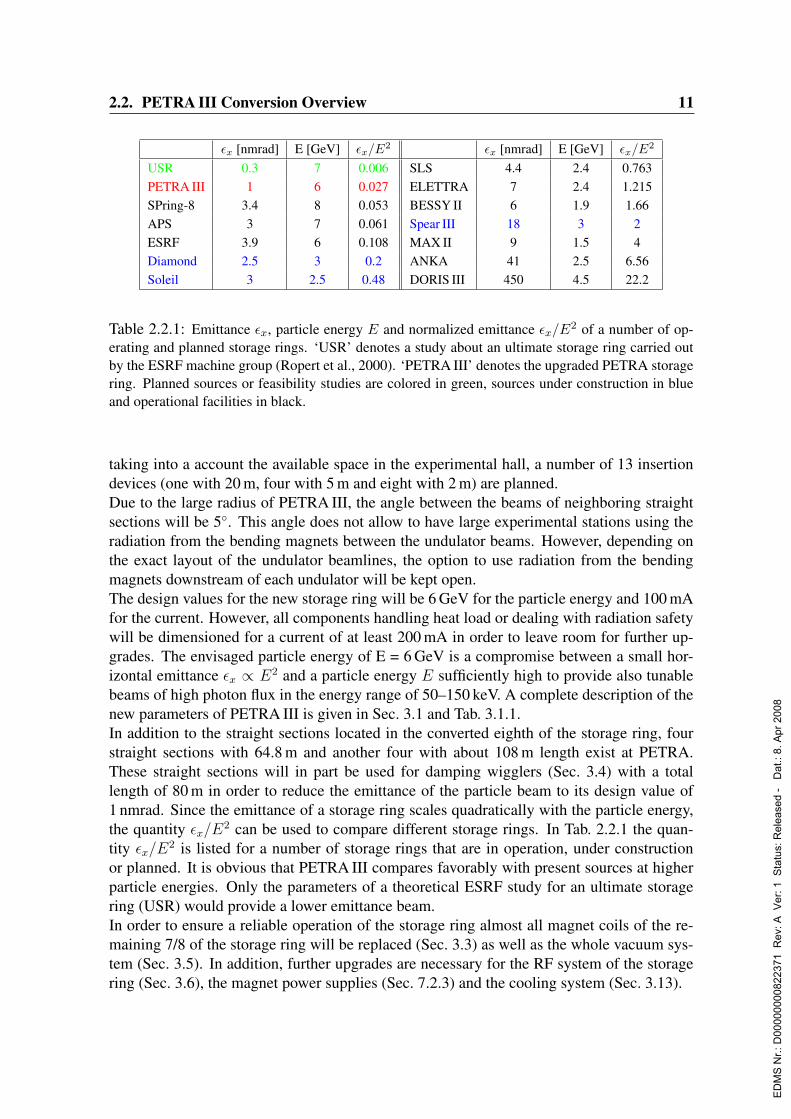
USR 0.3 7 0.006 SLS 4.4 2.4 0.763PETRA III 1 6 0.027 ELETTRA 7 2.4 1.215SPring-8 3.4 8 0.053 BESSY II 6 1.9 1.66APS 3 7 0.061 Spear III 18 3 2ESRF 3.9 6 0.108 MAX II 9 1.5 4Diamond 2.5 3 0.2 ANKA 41 2.5 6.56Soleil 3 2.5 0.48 DORIS III 450 4.5 22.2
Table 2.2.1: Emittance εx, particle energy E and normalized emittance εx/E2 of a number of op-erating and planned storage rings. ‘USR’ denotes a study about an ultimate storage ring carried outby the ESRF machine group (Ropert et al., 2000). ‘PETRA III’ denotes the upgraded PETRA storagering. Planned sources or feasibility studies are colored in green, sources under construction in blueand operational facilities in black.
taking into a account the available space in the experimental hall, a number of 13 insertiondevices (one with 20 m, four with 5 m and eight with 2 m) are planned.Due to the large radius of PETRA III, the angle between the beams of neighboring straightsections will be 5. This angle does not allow to have large experimental stations using theradiation from the bending magnets between the undulator beams. However, depending onthe exact layout of the undulator beamlines, the option to use radiation from the bendingmagnets downstream of each undulator will be kept open.The design values for the new storage ring will be 6 GeV for the particle energy and 100 mAfor the current. However, all components handling heat load or dealing with radiation safetywill be dimensioned for a current of at least 200 mA in order to leave room for further up-grades. The envisaged particle energy of E = 6 GeV is a compromise between a small hor-izontal emittance εx ∝ E2 and a particle energy E sufficiently high to provide also tunablebeams of high photon flux in the energy range of 50–150 keV. A complete description of thenew parameters of PETRA III is given in Sec. 3.1 and Tab. 3.1.1.In addition to the straight sections located in the converted eighth of the storage ring, fourstraight sections with 64.8 m and another four with about 108 m length exist at PETRA.These straight sections will in part be used for damping wigglers (Sec. 3.4) with a totallength of 80 m in order to reduce the emittance of the particle beam to its design value of1 nmrad. Since the emittance of a storage ring scales quadratically with the particle energy,the quantity εx/E2 can be used to compare different storage rings. In Tab. 2.2.1 the quan-tity εx/E2 is listed for a number of storage rings that are in operation, under constructionor planned. It is obvious that PETRA III compares favorably with present sources at higherparticle energies. Only the parameters of a theoretical ESRF study for an ultimate storagering (USR) would provide a lower emittance beam.In order to ensure a reliable operation of the storage ring almost all magnet coils of the re-maining 7/8 of the storage ring will be replaced (Sec. 3.3) as well as the whole vacuum sys-tem (Sec. 3.5). In addition, further upgrades are necessary for the RF system of the storagering (Sec. 3.6), the magnet power supplies (Sec. 7.2.3) and the cooling system (Sec. 3.13).
ED
MS
Nr.:
D00
0000
0082
2371
Rev
: A V
er: 1
Sta
tus:
Rel
ease
d -
Dat
.: 8.
Apr
200
8
12 2. Executive Summary
βx βy σTx σTy σTx′ σTy′ ID-length[m] [m] [µm] [µm] [µrad] [µrad] [m]
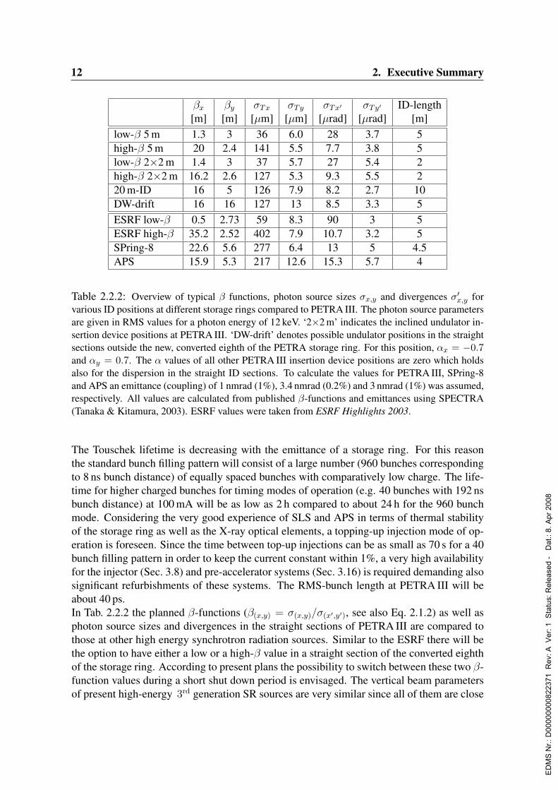
low-β 5 m 1.3 3 36 6.0 28 3.7 5high-β 5 m 20 2.4 141 5.5 7.7 3.8 5low-β 2×2 m 1.4 3 37 5.7 27 5.4 2high-β 2×2 m 16.2 2.6 127 5.3 9.3 5.5 220 m-ID 16 5 126 7.9 8.2 2.7 10DW-drift 16 16 127 13 8.5 3.3 5ESRF low-β 0.5 2.73 59 8.3 90 3 5ESRF high-β 35.2 2.52 402 7.9 10.7 3.2 5SPring-8 22.6 5.6 277 6.4 13 5 4.5APS 15.9 5.3 217 12.6 15.3 5.7 4
Table 2.2.2: Overview of typical β functions, photon source sizes σx,y and divergences σ′x,y forvarious ID positions at different storage rings compared to PETRA III. The photon source parametersare given in RMS values for a photon energy of 12 keV. ‘2×2 m’ indicates the inclined undulator in-sertion device positions at PETRA III. ‘DW-drift’ denotes possible undulator positions in the straightsections outside the new, converted eighth of the PETRA storage ring. For this position, αx = −0.7and αy = 0.7. The α values of all other PETRA III insertion device positions are zero which holdsalso for the dispersion in the straight ID sections. To calculate the values for PETRA III, SPring-8and APS an emittance (coupling) of 1 nmrad (1%), 3.4 nmrad (0.2%) and 3 nmrad (1%) was assumed,respectively. All values are calculated from published β-functions and emittances using SPECTRA(Tanaka & Kitamura, 2003). ESRF values were taken from ESRF Highlights 2003.
The Touschek lifetime is decreasing with the emittance of a storage ring. For this reasonthe standard bunch filling pattern will consist of a large number (960 bunches correspondingto 8 ns bunch distance) of equally spaced bunches with comparatively low charge. The life-time for higher charged bunches for timing modes of operation (e.g. 40 bunches with 192 nsbunch distance) at 100 mA will be as low as 2 h compared to about 24 h for the 960 bunchmode. Considering the very good experience of SLS and APS in terms of thermal stabilityof the storage ring as well as the X-ray optical elements, a topping-up injection mode of op-eration is foreseen. Since the time between top-up injections can be as small as 70 s for a 40bunch filling pattern in order to keep the current constant within 1%, a very high availabilityfor the injector (Sec. 3.8) and pre-accelerator systems (Sec. 3.16) is required demanding alsosignificant refurbishments of these systems. The RMS-bunch length at PETRA III will beabout 40 ps.In Tab. 2.2.2 the planned β-functions (β(x,y) = σ(x,y)/σ(x′,y′), see also Eq. 2.1.2) as well asphoton source sizes and divergences in the straight sections of PETRA III are compared tothose at other high energy synchrotron radiation sources. Similar to the ESRF there will bethe option to have either a low or a high-β value in a straight section of the converted eighthof the storage ring. According to present plans the possibility to switch between these two β-function values during a short shut down period is envisaged. The vertical beam parametersof present high-energy 3rd generation SR sources are very similar since all of them are close
ED
MS
Nr.:
D00
0000
0082
2371
Rev
: A V
er: 1
Sta
tus:
Rel
ease
d -
Dat
.: 8.
Apr
200
8
2.2. PETRA III Conversion Overview 13
to the diffraction limit in this direction. Therefore, the improvement provided by PETRA IIIis mainly for the beam parameters in the horizontal direction.The experiments can only benefit from the small source sizes if the beam stability is veryhigh. For this reason a suitable diagnostics (Sec. 3.9) and beam position control system willbe established.
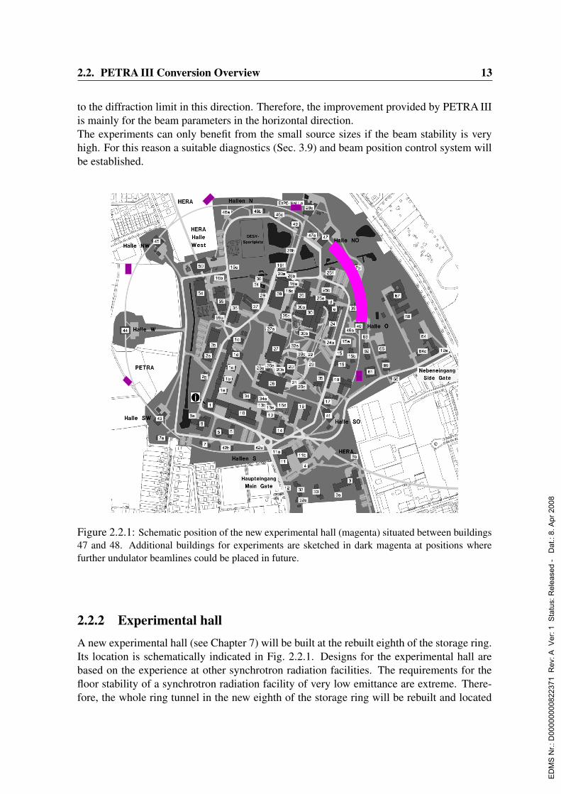
Figure 2.2.1: Schematic position of the new experimental hall (magenta) situated between buildings47 and 48. Additional buildings for experiments are sketched in dark magenta at positions wherefurther undulator beamlines could be placed in future.
2.2.2 Experimental hallA new experimental hall (see Chapter 7) will be built at the rebuilt eighth of the storage ring.Its location is schematically indicated in Fig. 2.2.1. Designs for the experimental hall arebased on the experience at other synchrotron radiation facilities. The requirements for thefloor stability of a synchrotron radiation facility of very low emittance are extreme. There-fore, the whole ring tunnel in the new eighth of the storage ring will be rebuilt and located
ED
MS
Nr.:
D00
0000
0082
2371
Rev
: A V
er: 1
Sta
tus:
Rel
ease
d -
Dat
.: 8.
Apr
200
8
14 2. Executive Summary
inside the experimental hall. Both shielding walls will be of 1 m thickness and cast out ofheavy concrete. The tunnel roof will consist out of 0.5 m thick removable concrete blocks.The experimental hall will be equipped with a crane able to lift up to 20 tons. The presentplanning foresees to cast the floor in the experimental hall as one concrete slab about 1 min thickness which will carry the ring tunnel and the experiments. This slab will be vibra-tionally decoupled from the experimental hall super structure and the auxiliary buildings.Other possibilities for the design of the experimental hall floor are still under investigation.The dimensions of the hall are such that beamlines can be up to 103 m long inside the exper-imental hall. For experimental hutches outside the main hall the following options exist:
• The first undulator (20 m ID, counting starts at hall 47) has space for a 210 m longbeamline.
• The beamlines of the second and third ID can be extended up to 150 m length.
The air conditioning of the hall will be designed for a temperature stability of ±1 K. Alongthe outer perimeter of the experimental hall there will be laboratory and workshop space inthe ground floor and office space in the first floor among other necessary infrastructure andfacilities. The total space for laboratories and offices amounts to about 1800 m2. The hallwill be accessible from both ends by doors large enough for trucks. In addition there will befour entrances along the outside of the hall large enough for smaller fork lifters.
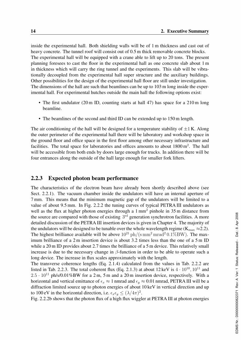
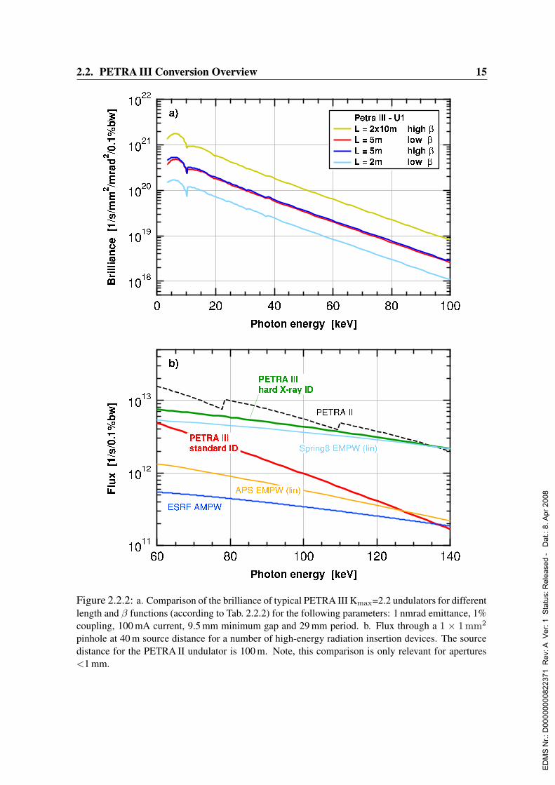
2.2.3 Expected photon beam performanceThe characteristics of the electron beam have already been shortly described above (seeSect. 2.2.1). The vacuum chamber inside the undulators will have an internal aperture of7 mm. This means that the minimum magnetic gap of the undulators will be limited to avalue of about 9.5 mm. In Fig. 2.2.2 the tuning curves of typical PETRA III undulators aswell as the flux at higher photon energies through a 1 mm2 pinhole in 35 m distance fromthe source are compared with those of existing 3rd generation synchrotron facilities. A moredetailed discussion of the PETRA III insertion devices is given in Chapter 4. The majority ofthe undulators will be designed to be tunable over the whole wavelength regime (Kmax ≈2.2).The highest brilliance available will be above 1021 ph/(s mm2 mrad2 0.1%BW). The max-imum brilliance of a 2 m insertion device is about 3.2 times less than the one of a 5 m IDwhile a 20 m ID provides about 2.7 times the brilliance of a 5 m device. This relatively smallincrease is due to the necessary change in β-function in order to be able to operate such along device. The increase in flux scales approximately with the length.The transverse coherence lengths (Eq. 2.1.4) calculated from the values in Tab. 2.2.2 arelisted in Tab. 2.2.3. The total coherent flux (Eq. 2.1.3) at about 12 keV is 4 · 1010, 1011 and2.5 · 1011 ph/s/0.01%BW for a 2 m, 5 m and a 20 m insertion device, respectively. With ahorizontal and vertical emittance of εx ≈ 1 nmrad and εy ≈ 0.01 nmrad, PETRA III will be adiffraction limited source up to photon energies of about 10 keV in vertical direction and upto 100 eV in the horizontal direction, i.e. εxεy ≤ (λ/4π)2.Fig. 2.2.2b shows that the photon flux of a high flux wiggler at PETRA III at photon energies
ED
MS
Nr.:
D00
0000
0082
2371
Rev
: A V
er: 1
Sta
tus:
Rel
ease
d -
Dat
.: 8.
Apr
200
8
2.2. PETRA III Conversion Overview 15
Figure 2.2.2: a. Comparison of the brilliance of typical PETRA III Kmax=2.2 undulators for differentlength and β functions (according to Tab. 2.2.2) for the following parameters: 1 nmrad emittance, 1%coupling, 100 mA current, 9.5 mm minimum gap and 29 mm period. b. Flux through a 1 × 1 mm2
pinhole at 40 m source distance for a number of high-energy radiation insertion devices. The sourcedistance for the PETRA II undulator is 100 m. Note, this comparison is only relevant for apertures<1 mm.
ED
MS
Nr.:
D00
0000
0082
2371
Rev
: A V
er: 1
Sta
tus:
Rel
ease
d -
Dat
.: 8.
Apr
200
8

16 2. Executive Summary
ξt,x ξt,y
high-β 18µm 500µm
low-β 72µm 460µm
Table 2.2.3: Horizontal and vertical coherence lengths at PETRA III in FWHM calculated for1 nmrad emittance and 1% coupling at 12 keV photon energy and at 60 m distance from the source.
around 100 keV through a 1 mm2 pinhole is higher than that of a standard Kmax. ≈ 2.2 un-dulator. Very likely both devices will be outperformed by superconducting undulators if thedevelopment advances so far that these devices can be manufactured with a phase error smallenough for the effective use of the higher harmonics of the spectrum. Another interestingand new development that should be kept in mind are variable period undulators (Shenoyet al., 2003a; Shenoy et al., 2003b).It should be emphasized that the brilliance calculations above are based on the assumptionof a 1% horizontal/vertical coupling. A smaller coupling value would further increase thebrilliance especially at higher photon energies due to a smaller vertical source size. However,it will also further reduce the Touschek lifetime. The main difference between PETRA IIIand current high-energy, 3rd generation synchrotron radiation sources will therefore be inhorizontal emittance which results in a smaller horizontal source size and therefore a largertotal fraction of coherent photons or a higher number of photons in a given microfocus.For photons in the VUV and XUV range, a high-energy storage ring has significant advan-tages for experiments needing circular polarized photons in the 200–2300 eV range with ahigh degree of polarization, which can only be obtained in the first undulator harmonic of ahelical undulator. The performance of such devices is discussed in Sec. 4.1.1.
2.3 Proposed Experimental StationsA detailed description of all proposed experimental stations including a description of thescientific applications is given in Chapter 6. In order to define the experimental stations tobe proposed for PETRA III a number of user workshops were organized in the years 2002and 2003 at DESY and the following criteria have been applied for beamline proposals:
1. Exploitation of the unique properties of the X-ray beams provided by PETRA III.
2. Implementation of innovative developments and techniques.
3. Consideration of the requirements of the specific HASYLAB user community.
4. Complementarity to other existing opportunities at large scale synchrotron radiationfacilities in Europe and at upcoming X-ray free-electron lasers.
In the following a list of the titles of beamlines or experimental stations proposed for PE-TRA III is given:
ED
MS
Nr.:
D00
0000
0082
2371
Rev
: A V
er: 1
Sta
tus:
Rel
ease
d -
Dat
.: 8.
Apr
200
8

2.3. Proposed Experimental Stations 17
• X-ray diffraction and imaging
– High energy X-ray diffraction
– Coherence applications
– High resolution diffraction
– Micro- and nano-tomography
• High energy resolution spectroscopy
– Inelastic scattering
– Nuclear resonant scattering
• Materials science
– High energy X-rays for materials science
– Powder diffraction
– Small angle scattering
– Microfocus applications
• X-ray absorption and resonant scattering
– Absorption spectroscopy
– High-energy photoelectron spectroscopy
– Hard X-ray microprobe
– Resonant scattering
– Variable polarization XUV beamline
• Structural biology
– Macromolecular crystallography (EMBL proposal for three stations, MPG pro-posal for two stations)
– Biological absorption spectroscopy
– Biological small angle scattering
In the following sections each proposed station will be described briefly. A full descriptionof each proposal can be found in Sec. 6. For the final layout of the experimental hall itis assumed that in many cases more than one experimental station can be operated in timesharing mode on a single undulator beamline if the requirements for the beamline optics aresimilar.
ED
MS
Nr.:
D00
0000
0082
2371
Rev
: A V
er: 1
Sta
tus:
Rel
ease
d -
Dat
.: 8.
Apr
200
8
18 2. Executive Summary
2.3.1 X-ray diffraction and imaging
2.3.1.1 High energy X-ray diffraction
With the development of high-energy 3rd generation synchrotron radiation sources, high-energy X-ray diffraction became a powerful tool for the analysis of bulk materials and buriedinterfaces by the use of extremely collimated and small beams. Since the absorption lengthsabove 100 keV for most materials lie in the range of 0.1 mm to several cm, studies on thicksamples become feasible. For the same reason, thick window materials for sample envi-ronments as cryostats or furnaces become less critical or even negligible. Moreover, dif-ficult corrections for absorption, extinction and multiple scattering effects can be avoidedin many cases. Another important feature of high-energy X-rays is that reciprocal spacecan be mapped up to large momentum transfers such as 30–50 A−1, which is crucial forprecise structure determination of liquids and amorphous materials. Up to now most ap-plications of hard X-rays have addressed bulk properties of thick samples. However, theapplication of high-energy diffraction methods becomes particularly attractive if combinedwith microfocusing techniques. The high penetration depth allows one to directly accessordering phenomena and phase transitions at buried interfaces that are not accessible withany other technique. It is expected that such studies can be extended into new areas by usinghigh-brilliance X-ray beams delivered at PETRA III.
Using a particle energy of 6 GeV the flux density at 100 keV photon energy delivered by aPETRA III undulator or wiggler is one or two orders of magnitude and the brilliance is morethan four orders of magnitude larger than the most powerful hard X-ray insertion deviceat DORIS III. Upcoming new insertion device techniques, like superconducting in-vacuumundulators, and the very small emittance of PETRA III will provide an even more brilliantbeam at higher photon energies. The beam will be further concentrated by refractive lensesand/or bent monochromator crystals. The beamline will be optimized for an energy rangeof 50–100 keV. A minimum focal spot size in the micrometer range is envisaged for theinvestigation of buried layers or small volume elements inside larger bulk samples. Thebeamline will be equipped with a flexible high precision diffractometer. However, there willalso be enough space for special setups developed by users.
2.3.1.2 Coherence applications
A recent development at modern synchrotron radiation sources is the use of coherent undu-lator radiation for both, scattering and imaging applications. If coherent light is scatteredfrom a disordered system it gives rise to a random diffraction or “speckle” pattern. Such a“speckle” pattern is an interference pattern and related to the exact spatial arrangement ofthe disorder although phase information is lost. Major progress has however been made inrecent years (e.g. by the oversampling technique) to retrieve this phase information, thusallowing to reconstruct the pattern and to unravel real space information.The improved coherence parameters at PETRA III (almost 100µm spatial coherence lengthin the low-β configuration, see Tab. 2.2.3) will facilitate the reconstruction of complicatedpatterns and allow access to shorter (eventually atomic) length scales. One might anticipate
ED
MS
Nr.:
D00
0000
0082
2371
Rev
: A V
er: 1
Sta
tus:
Rel
ease
d -
Dat
.: 8.
Apr
200
8

2.3. Proposed Experimental Stations 19
that even disorder in magnetic systems will become accessible. This will only be possibledue to the high brilliance B and the correspondingly increased coherent flux Fc=(λ/2)2·Bprovided by the PETRA III undulators.The unprecedented coherence properties of the PETRA III source will also impact imagingtechniques in the near field or Fresnel limit. Phase contrast imaging will benefit from anincreased degree of coherence and the increased flux will allow not only to improve the res-olution but might enable time series of phase contrast images limited only by the detectorframe rate.
Of outmost importance is the possibility to study the dynamics of disordered systems withcoherent light: If the spatial arrangement of a system changes as a function of time thecorresponding speckle pattern will also change and fluctuate. Characterization of temporalintensity fluctuations is usually performed by correlation spectroscopy techniques and X-rayphoton correlation spectroscopy (XPCS) gives access to the slow (>ns) dynamics on lengthscales (Q>10−3 A−1) not accessible to visible coherent light. Many applications lie in the softcondensed matter domain (dynamics of complex fluids, glass forming systems, or capillarywave dynamics) or in the area of critical fluctuations. Here it is in particular the increasedcoherent flux of the PETRA III facility that will allow to address questions of slow dynamicson even shorter length scales (<100 nm) than presently feasible. Furthermore, the improvedbeam parameters will permit the operation in heterodyne mixing mode (known from Dy-namic Light Scattering) and to finally also address questions of non-equilibrium dynamics.The energy tunability, the polarization properties of the beam and the surface sensitivity ofX-rays will allow XPCS to be applied to a multitude of surface/interface phenomena and tothe dynamics of magnetic systems being barely possible or unachieved today.
2.3.1.3 High resolution diffraction
High resolution X-ray diffraction (HRXRD) using extremely collimated beams is widelyused as a standard technique for structural investigations at a wide variety of length scales,from the atomic level to bulk behavior and to surfaces and interfaces. The technique is usedfor precise lattice parameter measurements to access very small changes in lattice spacingdue to thermal expansion, strain, chemical composition, or due to the exposure to externalfields, etc. At solid and liquid surfaces and buried interfaces HRXRD allows to determineparameters, such as layer thickness, chemical composition and interface roughness. By vari-ation of the penetration depth in grazing incidence diffraction also depth-resolved studies arepossible. Two-dimensional reciprocal space mapping methods are now standard for theseapplications. Lattice distortions and crystal quality can be examined by reflection profileanalysis. Structural parameters of periodic and non-periodic nano- or mesoscopic structurescan be investigated by high resolution reciprocal space maps.
The low emittance and high brilliance of PETRA III provides ideal beam conditions to gen-erate a photon beam of ultra-high collimation and high monochromatization over a wideenergy range. The high coherence length of the beam will provide access to length scalesranging up to tens of micrometers. The brilliance available also at higher photon energies(25–45 keV) will enable experiments at internal solid/solid and liquid/solid interfaces. This
ED
MS
Nr.:
D00
0000
0082
2371
Rev
: A V
er: 1
Sta
tus:
Rel
ease
d -
Dat
.: 8.
Apr
200
8

20 2. Executive Summary
is of special importance, as interface processes are so far mostly studied in model surfaceexperiments. The high brilliance will also allow in situ studies of process dynamics whichdetermine diffusion, growth and phase transitions. Research on very small sample volumesand highly diluted materials will become feasible. The beamline will be equipped with anUHV chamber connected via a transfer tunnel to a UHV preparation chamber for surfaceresearch.
2.3.1.4 Micro- and nano-tomography
In recent years micro-tomography using synchrotron radiation became a valuable tool forthe non-destructive three-dimensional investigation of specimens in fields such as medicine,biology and materials science. At DORIS III absorption- and phase-contrast techniques weredeveloped and applied at photon energies in the range of 8 to 150 keV. At the wiggler-beamlines BW2, W2, and BW5, a public user instrument for microtomography makes use ofthe large, intense, and incoherent X-ray source. Experiments at DORIS III are optimized forperforming absorption-contrast microtomography on large samples. Due to the divergenceof the source the spatial resolution of a tomogram is limited to about 2µm.
PETRA III will allow for new absorption- and phase-contrast techniques which make useof the coherence of the X-ray beam. Different features of the specimens can be mappedsimultaneously. By using a standard setup the spatial resolution can easily be increased toresolve about 0.7µm structures. For resolving smaller structures in the 100 nm regime newtechniques have to be developed. Recently first results were obtained performing cone-beamtomography by creating a nanometer divergent X-ray source using a KB multilayer arrange-ment and magnifying the sample onto a two dimensional X-ray detector.The standard user experiments for microtomography at PETRA III will require a large mono-chromatic, parallel and intense beam. The photon energies will range from 8 to 150 keV andthe required beam size is about 5×1 mm2. To achieve a smooth beam profile the beam-line will have as few optical elements as possible. The experimental hutch will allow fora variable sample detector distance from almost 0 to 10 m. For cone-beam geometry, opti-cal elements will be added to the beamline to achieve a divergent X-ray source in the nmregime. The high brilliance of PETRA III and the development of faster detectors will alsoenable time resolved tomographic studies.
2.3.2 High-energy resolution spectroscopy2.3.2.1 Inelastic scattering
Inelastic X-ray scattering (IXS) with meV energy resolution allows one to study elementaryexcitations in condensed matter, providing detailed insight into the mechanisms of phasetransitions and dynamic processes. These properties play a crucial role in nanoscale mate-rials because the modification of the dynamic properties due to the reduced dimensionalityvery often forms the basis for a new functionality. In this field, inelastic X-ray scattering atPETRA III will open new research areas that are hardly accessible at existing facilities. Par-ticularly exciting are the study of low-energy excitations in disordered metallic alloys and
ED
MS
Nr.:
D00
0000
0082
2371
Rev
: A V
er: 1
Sta
tus:
Rel
ease
d -
Dat
.: 8.
Apr
200
8

2.3. Proposed Experimental Stations 21
the study of lattice dynamics in high-Tc superconductors and correlated electron systems,for example. A unique feature of IXS at PETRA III will be the combination of inelasticscattering with microfocusing techniques. Experiments on smallest amounts of material likethin films, single crystallites within a polycrystalline material and tiny grains of materialin diamond-anvil cells under extreme conditions of pressure and temperature will be possi-ble. Metastable and non-equilibrium phases become accessible that can only be produced insmall quantities like tiny crystals or thin films.
The small beam sizes available at PETRA III allow for a very efficient implementation ofspectrometers with sub-meV resolution. This will help to clearly identify low-energy collec-tive excitations that are often observed in disordered materials and in the vicinity of phasetransformations. KB mirror optics will be used for the generation of sub-µm focal spotsfor the investigation of extremely small amounts of material. The instrument proposed hereconsists of a vertical spectrometer for the investigation of excitations in single crystals with2–3 meV energy resolution and a horizontal spectrometer for the study of dynamical proper-ties of disordered materials with sub-meV energy resolution. In general, the properties of theradiation delivered at PETRA III will stimulate the development of innovative experimentaltechniques in this field that are hardly possible at existing sources. The utmost performanceof these techniques is achieved if the experimental stations are installed at the 20 m longundulator, because many of these experiments are strongly flux-limited. This will put thisbeamline significantly ahead of those that are currently in operation.
2.3.2.2 Nuclear resonant scattering
Nuclear resonant scattering (NRS) using synchrotron radiation has a long standing historyin Hamburg since the first experiments almost 20 years ago at the DORIS storage ring. Theadvent of high-energy 3rd generation synchrotron sources has turned this method into a rou-tine experimental technique. With increasing brilliance of the radiation, this method becamesensitive to smallest amounts of material like single monolayers, nanoparticles and samplesin high-pressure cells. This trend will continue at PETRA III, so that magnetic ordering andvibrational dynamics in reduced dimensions can be revealed. The narrow energy bandpassmakes NRS an ideal tool to study dynamical properties on very short time scales. Examplesare diffusive and relaxational processes that can be studied on time scales ranging from ps toµs. The much faster dynamics of phonons becomes accessible in an energy resolved modewith resolutions in the sub-meV range. Moreover, the high brilliance at PETRA III will allowfor the application of ultrathin isotopic probe layers to study magnetic and dynamic proper-ties with atomic resolution.
Due to the narrow linewidth of the nuclear resonances involved (typically some neV to µeV)NRS experiments are extremely flux hungry. For this reason such experiments have to beperformed at the 20 m insertion device at PETRA III. An experimental station at this inser-tion device will provide 1.6 · 107 ph/s in an energy bandpass of 0.1µeV. This is four timeshigher than on other NRS beamlines at present 3rd generation synchrotron radiation sources.Besides the established and widely used techniques where a resonant isotope is needed as
ED
MS
Nr.:
D00
0000
0082
2371
Rev
: A V
er: 1
Sta
tus:
Rel
ease
d -
Dat
.: 8.
Apr
200
8

22 2. Executive Summary
part of the sample, the increased spectral flux available at PETRA III could make time-domain interferometry a more widespread technique. This offers the option to study dy-namical properties of samples that do not contain resonant isotopes.
2.3.3 Materials science2.3.3.1 High energy X-rays for materials science
The activities on the new high energy materials science beamline will be concentrating onthree intersecting topics: Industrial research, applied research, and fundamental research.The industrial user community will be provided with fast, robust, and standardized exper-imental techniques and online data analysis routines. Applied research will focus on thein-situ investigation of real manufacturing processes, the optimization of systems of highinterest (e.g. fuel cells, battery electrodes), ”classic” as well as cutting edge materials (e.g.Mg-base alloys, TiAl, trip-steel, bulk metallic glasses, composites, ceramics, ”smart materi-als”), and materials processing. Fundamental research will yield new insight in the field ofmetallurgy (e.g. micro structure, grain boundary engineering or the understanding of com-plex phenomena such as plastic deformation), rapidly emerging fields like biomimetics (e.g.biomineralization) and nanoscience. The length scales at which the different experiments areaiming at will range from the macroscopic over the mesoscopic scale down to the investiga-tion of nano structures, atoms, and their displacements down to the range of 10−15 m. Allapplied techniques will be non-destructive, allowing bulk investigations of several centime-ters thick samples.
The beamline will have an insertion device with a main energy of 120 keV, tunable in therange from 50–300 keV and optimized for sub-micron focusing. Positioning units for sam-ples up to 1 t will be available. A 150 m long flight tube will be installed for small anglescattering experiments at high energies. The beamline will stand out by the combination ofthree unique main features: Firstly, the high flux, ultra fast data acquisition systems, andthe beamline infrastructure will be the basis for complex in-situ experiments for the obser-vation of highly dynamic processes. Secondly, an exceptional flexibility in beam shapingand focusing down to spot sizes below 1µm will be available for the high energy X-rays.Thirdly, the beamline will provide the possibilities to merge different analytical techniquessuch as diffraction, tomography, small angle scattering, and spectroscopy. By exploitingthese techniques simultaneously it will be the first beamline, where the boundaries betweenthe different analytical techniques are gradually disappearing, being one of the prerequisitesfor a leap in materials science and engineering research.
2.3.3.2 Powder diffraction
Powder diffraction is the method of choice for crystal structure determinations if no singlecrystals can be obtained or if samples have to be investigated under conditions where singlecrystals are not stable, for example during a phase transition. New experimental techniquesas well as new data evaluation methods developed recently provide means to solve crystalstructures from powder diffraction data with increasing complexity.
ED
MS
Nr.:
D00
0000
0082
2371
Rev
: A V
er: 1
Sta
tus:
Rel
ease
d -
Dat
.: 8.
Apr
200
8
2.3. Proposed Experimental Stations 23
Other important applications of powder diffraction are in-situ studies such as formation ofnew phases in chemical reactions. Further examples are reactions of solids with gases or liq-uids as they are common in catalysis research like the adsorption of molecules into zeolitesor ion exchange reactions between solids and liquids.
Undulator photon beams from a low emittance high energy storage ring like PETRA III haveseveral advantages for powder diffraction experiments: (i) the high brilliance provides intrin-sically very parallel photon beams that are needed to resolve neighboring diffraction profiles,(ii) even at energies as high as the foreseen 50–60 keV a very high photon flux is available,(iii) very small focal spot sizes can easily be achieved by suitable optics for experiments onsmall sample volumes as they are needed for example in high pressure investigations. Thehigh photon energy of the proposed station has the advantage of a reduced radiation damagemainly for organic materials that contain mostly light atoms, less absorption and thereforethe possibility to collect more accurate data for heavily absorbing samples, and the option topenetrate through sample or reaction containers in case of in-situ studies.
2.3.3.3 Unfocused small angle scattering
Classical Small-Angle X-ray Scattering (SAXS) experiments average over a large samplevolume and give structural and quantitative information of high statistical significance on amesoscopic length scale between 1 and several 100 nm, which can be correlated with macro-scopic physical and chemical parameters of the analyzed materials (alloys, semiconductors,glasses, macromolecules in solution, metal nano particles, composites). In addition to thenormal SAXS signal, the anomalous signal close to absorption edges of suitable atoms canbe exploited for contrast variation. This so-called ASAXS method has gained quite someimportance in materials science, catalysis and polyelectrolytes.
Due to the low emittance of PETRA III, the beam parameters at a high-β section are bestsuited for the design of an unfocused SAXS beamline with high Q-resolution. Additionallythe energy spectrum covered by a PETRA III standard undulator will allow to make useof the element-selective ASAXS technique and to extend the classical energy range of thistechnique (5–35 keV) up to energies of about 90 keV. The extension to higher energies willgive access to the K-absorption edges of the heavier elements (Z > 53). The energy range incombination with the high flux of a 3rd generation source offers the opportunity to addressnumerous challenging scientific objectives in solid state physics, catalyst research, chemistryand biology, which are not accessible by the existing state of the art (A)SAXS-experiments.
2.3.3.4 Microfocus applications
A scattering beamline with micro- or nano-focus capabilities will enable static and time re-solved measurements in the WAXS5 to the USAXS6 regime for the investigation of phaseformations and transformations in a vast variety of isotropic and anisotropic materials like
5Wide Angle X-ray Scattering6Ultra Small Angle X-ray Scattering
ED
MS
Nr.:
D00
0000
0082
2371
Rev
: A V
er: 1
Sta
tus:
Rel
ease
d -
Dat
.: 8.
Apr
200
8
24 2. Executive Summary
polymer systems, colloids or nanostructured samples. Using an extremely small focus allowsthe spatially resolved investigation of hierarchically organized samples in the field of life sci-ence like bones or wood and synthetic systems like polymer composites. WAXS, SAXS andUSAXS under grazing incidence conditions allow one to study short and long range orderedsystems on substrate surfaces like dewetting polymer films on metals, adhesives during de-taching from a surface or self organization of quantum dots on semiconductor surfaces. To acertain extent all these techniques can be combined with a micro focus in order to investigatea sample by 2D-scanning techniques.
Due to the extremely low divergence of the undulator located at a high-β section of PE-TRA III, a focus of 7µm vertical and 40µm horizontal width (FWHM) with 13 µrad verticaland 120µrad horizontal divergence (FWHM) can be achieved. A Kirkpatrick-Baez (KB)mirror arrangement with a first mirror at 57 m behind the source and a second one at 75 mwill reach such a focus which is then at 85 m distance from the source and has a total flux of3·1013 photons/s using a Si(1 1 1) double crystal monochromator at 10 keV. The low diver-gence still maintained in this focus allows to resolve correlation distances of up to 1000 nm inthe vertical direction and about 200 nm horizontally, the latter can be increased by acceptinga corresponding flux reduction. This high brilliance beam will surpass all others available forcomparable scattering applications at existing 3rd generation synchrotron radiation facilitiesworldwide.
2.3.4 X-ray absorption and resonant scattering
2.3.4.1 Absorption spectroscopy
In general, X-ray absorption fine structure (XAFS) and X-ray absorption near edge struc-ture (XANES) are no typical high-brilliance applications. However, if very small sampleregions have to be investigated as it is the case in high pressure experiments, for example,a highly brilliant source is mandatory. This applies as well for XAFS tomography or forµ-XAFS if a very high spatial resolution is desired. Furthermore, the considerable brillianceof a PETRA III undulator at higher photon energies allows to measure XAFS at the K-edgesof heavy elements with reasonable flux. Despite the life time broadening these spectra yieldmore precise spectral information than measurements at the L3-edges, because the scan rangecan be larger and the matrix effects are negligible. Higher energies offer the possibility tostudy these elements, for example during in situ experiments in catalysts.
The design of the beamline has a monochromatic beam (∆E/E ∼ 10−4) tunable over an en-ergy range of up to 2000 eV while covering an energy range between 2.4 and 80 keV usingdifferent crystals. It will be followed by an optional pair of mirrors for the suppression ofhigher harmonics radiation. The final focusing device for spot sizes < 1µm will be close tothe sample. Depending on the photon energy, KB-mirrors and different kinds of lenses willbe used. A low-β section will be of advantage to achieve a very small focus. The experi-mental hutch will be equipped with all necessary installations to perform in-situ experimentswith toxic and/or flammable gases and liquids.
ED
MS
Nr.:
D00
0000
0082
2371
Rev
: A V
er: 1
Sta
tus:
Rel
ease
d -
Dat
.: 8.
Apr
200
8
2.3. Proposed Experimental Stations 25
2.3.4.2 High-energy photoelectron spectroscopy
Photoelectron spectroscopy is a key method to study electronic properties of matter in solidstate physics and materials science, providing unique information on chemical bonding andcomposition, on electronic correlations and other atomic many-body effects. In conven-tional applications using UV and soft X-ray excitation, the information is obtained from thetopmost atomic layers due to the short electron mean free path. This is a serious limita-tion since electronic properties near the surface often differ from those of the bulk material.Buried interfaces and structures cannot be reached at all. The high surface sensitivity can beovercome with hard X-rays emitting energetic photoelectrons with a correspondingly largerescape depth up to about 10 nm around 10 keV kinetic energy. At the same time, the shortphoton wavelength can be utilized to excite X-ray standing waves in crystalline materialsthus allowing to correlate structural and electronic information on an atomic scale.
Hard X-ray photoelectron spectroscopy with high-energy resolution down ≈ 10 meV is ex-tremely challenging and requires an intense and brilliant source as well as highly sophis-ticated and efficient electron detection. At present, strong attempts are being made to im-plement this promising new technique at 3rd generation X-ray sources. The experimentalstation proposed for PETRA III specifically utilizes the low emittance properties. The lowdivergence beam from a high-β undulator is ideally suited for high-resolution monochrom-atization (≈ 10 meV at 10 keV) preserving the high monochromatic flux (≈ 1011 photons/s)needed to cope with low photoelectric cross sections and electron analyzer transmission.Furthermore, the achievable resolving power of the analyzer is directly linked to the focussize on the sample which can be easily brought down to 10µm with suitable optics such asKB-mirrors. If sub-micron focussing of the beam is accomplished, lateral spatial resolutionfor studies of inhomogeneous materials is achieved in a scanning mode of operation. Incombination with the high bulk-sensitivity, this will make the instrument a unique tool forstudies of the electronic and chemical properties directly of bulk material and, in particular,buried nano-structures.
2.3.4.3 Hard X-ray microprobe
Hard X-ray microprobe beamlines combine the non-destructive elemental micro-analysis ca-pability of µ-XRF (microscopic X-ray fluorescence analysis) with the ability of performingcomplementary µ-XAS (X-ray absorption spectroscopy) and/or µ-XRD (X-ray diffraction)measurements. These instruments provide simultaneously correlated information on the lo-cal elemental composition, chemical state, the local structural environment of specific el-ements and/or the local crystallographic structure of the examined materials. Hard X-raymicroprobe techniques are mostly applied in materials, geological, biological, biomedical,and environmental sciences, as well as archeology and arts.
The hard X-ray microprobe beamline will enable different complementary X-ray micro-beam methods to be performed simultaneously or sequentially during one experiment. Scan-ning X-ray fluorescence microscopy measurements in combination with broad beam radio-graphy imaging will be the most straightforward technique to characterize heterogeneous
ED
MS
Nr.:
D00
0000
0082
2371
Rev
: A V
er: 1
Sta
tus:
Rel
ease
d -
Dat
.: 8.
Apr
200
8
26 2. Executive Summary
samples in terms of local elemental composition and density. Microscopic X-ray absorptionspectroscopy (µ-XANES, also µ-EXAFS) and microscopic X-ray diffraction will provideinformation on the local speciation and structure. Tomographic methods (fluorescence mi-crotomography, XANES microtomography) and confocal arrangements of X-ray optics forthe primary beam and fluorescence photons give access to quantitative three-dimensionalmeasurements.The beamline will provide beam sizes down to the 100 nm range utilizing the outstandingsmall source size and high brilliance of PETRA III, but also larger beam sizes of 1–10µmand an unfocused beam for flat field imaging will be available. The accessible energy rangecovers the K-edge energies from sulfur to uranium (E = 2.4–116 keV) and the flux is maxi-mized by the use of KB mirrors. For broad band excitations a pink beam option is foreseen.
2.3.4.4 Resonant scattering
Correlated electron materials provide one of the biggest challenges of condensed matterresearch today. Complex magnetic ordering phenomena occurring in nano structured multi-component materials are an example of the consequences of electronic correlations. Ofparticular interest are materials with exceptionally strong electronic correlations. The com-plex interplay of spin, charge, orbital and lattice degrees of freedom gives rise to a variety ofdifferent phases having insulating, metallic or superconducting properties, being anti-ferro,ferro- or paramagnetic and possessing different structures. The most prominent examples aretransition metal oxides, which exhibit high-Tc superconductivity or the colossal magneto-resistance effect. The competition between the different phases can result in an electronic orstructural phase separation from the A to the µm scale.Resonant X-ray scattering is an ideal tool to characterize the ground state of these new ma-terials. It probes correlations of spin, charge, orbital and lattice degrees of freedom. Theresonance technique provides element sensitivity and even band selectivity, giving detailedinformation on the electronic structure.
The resonant scattering experiments will take advantage of the excellent beam properties ofthe PETRA III source in the following aspects: (i) The high brilliance of more than 1021
photons/(s mm2 mrad2 0.1% BW) at 12 keV allows the design of X-ray optics that enable ahigh Q-resolution of about 10−5 A−1 with considerable flux. (ii) A highly polarized beam,essential for the resonant scattering technique, can only be obtained on a small emittancesource. At PETRA III a very high degree of linear polarization (close to 99.99 %) shouldbe achievable. The high degree of linear polarization combined with small divergence pro-vides the possibility also for a highly circular polarized beam using a phase retarder. (iii)Spatial resolutions ranging from micro- to nanometers can be acquired using a microfocusdevice which is important when studying nano-devices or phase separated materials. (iv)The high degree of coherence enables speckle experiments to resolve domain shapes andprobe dynamic properties utilizing the time correlation function.
ED
MS
Nr.:
D00
0000
0082
2371
Rev
: A V
er: 1
Sta
tus:
Rel
ease
d -
Dat
.: 8.
Apr
200
8

2.3. Proposed Experimental Stations 27
2.3.4.5 Variable polarization XUV beamline
Soft X-rays are ideal for spectroscopic investigations ranging from magnetism in nano struc-tures to biological systems. Many absorption edges of practically all important elementslie in the soft X-ray range (100 eV to 3 keV) which opens up the possibility to uniquelydetermine the element-specific local electronic structure in complex materials by exploit-ing atomic resonances. Until recently really high brilliance light sources were not availablefor such investigations. Experiments at the latest 3rd generation synchrotron light sourcesare now beginning to demonstrate the enormous scientific potential of this spectral region.Currently, investigations are still limited by the light source and improved sources will imme-diately produce new science. In the future, polarization-dependent studies with soft X-rayswill play a key role in enhancing our knowledge of the structure of matter.
Suitable insertion devices at high-energy storage rings can provide very high brilliance ofcircularly polarized light in the energy range of 500–2000 eV as has been demonstrated atboth the ESRF and SPring-8. Helical undulators operating in the first harmonic provide thehighest flux and complete polarization, but require machine energies greater than 3 GeV. In-sertion devices on lower energy machines like BESSY II, ELETTRA, and ALS only producecircularly polarized light up to about 500 eV in the first harmonic and newer machines likeSLS and SOLEIL will extend this limit to 700–900 eV. The variable-polarization soft X-raybeamline at PETRA III will be unique and will open up completely new scientific opportuni-ties by providing the highest brilliance and flux in the important spectral region from 500 eVto 2.5 keV . With current technology it is possible to achieve a spectral resolution of 10000 at1 keV with an extremely high flux (more than 1012 ph/s) focused on the sample. Comparedto the best present day sources the PETRA III soft X-ray beamline will provide up to twoorders of magnitude higher flux at photon energies above 1 keV. This beamline will promotesignificant progress in fields ranging from surface science to molecular and cluster physics,magnetic studies, condensed matter physics and nanotechnology.
2.3.5 Structural biology2.3.5.1 Macromolecular crystallography
Over the last fifty years biological X-ray crystallography has evolved into an advanced fieldof life sciences and has provided unprecedented three dimensional structural information onthe molecular level of a large number of complicated biological processes. Knowledge ofspatial structures has allowed to delineate the molecular origins for diseases such as cancer,autoimmune diseases and microbial infections. The performance and contribution of bio-logical X-ray crystallography can be readily assessed by the huge number of new structuresbeing deposited in the Protein Data Base (PDB), which is increasing at a nearly exponentialrate. As a result, the growth in demand for synchrotron radiation beamlines for macro-molecular crystallographic experiments has risen substantially both in absolute numbers andin overall proportion. New challenges for the future are the understanding of the functionof large macromolecular assemblies. At present, the largest structures determined, thoughbearing internal symmetry, are from viral assemblies. Some of these structures have imposed
ED
MS
Nr.:
D00
0000
0082
2371
Rev
: A V
er: 1
Sta
tus:
Rel
ease
d -
Dat
.: 8.
Apr
200
8

28 2. Executive Summary
unprecedented challenges in terms of the size of available crystals, which may be as low asa few microns, and unit cell dimensions, in a few cases even exceeding 1000 A. Many ofthese projects have only become feasible with the recent availability of the highest brilliancebeamlines at 3rd generation synchrotron sources providing both a small focal spot size and abeam divergence small enough to resolve individual reflections even for the largest unit cells.
A number of beamlines for structural biology at PETRA III are proposed by the EMBL andMPG outstations at DESY (Sects. 6.16, 6.17). Due to the high brilliance of PETRA IIIabout 1013 ph/s will be available in the monochromatic beam. Minimal focal spot sizes inthe 10µm range are envisaged. At the same time, the maximal divergence will not exceed0.5 mrad even for the smallest focus. The different stations will be optimized for differentapplications such as wide range energy tunability, high-throughput structure determination,microfocus and special applications like investigation of large macromolecular complexes.All of them will be highly automated for optimum use of the beamtime.
2.3.5.2 Biological absorption spectroscopy
X-ray absorption spectroscopy determines the electronic structure of probe atoms and theirstructural vicinity. In biology typical probe atoms are metals or other elements of limitedoccurrence. In proteins metals fulfill a variety of essential functions: They stabilize the sec-ondary protein structure, they serve as a binding partner in transport processes, they definethe pathway for electron transfer, and they act as the key element in catalytic reactions. In atleast 30% of the gene products, metals are believed to play a key role; these are classified asmetallo-proteins. Cutting edge applications are (i) Time-resolved BioXAS experiments to fa-cilitate insights in reaction dynamics/kinetics and structural characterization of intermediatestates, (ii) spatially resolved XANES (tomography) facilitating spatially resolved speciationwith respect to oxidation state and ligand environment and (iii) high-resolution fluorescencefor site-specific measurements, these experiments have the added advantage that they pro-vide greatly improved spectral resolution for XANES studies.
A BioXAS station at PETRA III with an energy range from 5 keV to 35 keV will cover K-and L- edges of most important probe elements in biological materials. A 2 m long standardKmax = 2.2 undulator will provide sufficient flux for this station. The main advantage ofPETRA III for BioXAS will be the small focal spot sizes. For tomography experimentsat a low-β section a demagnification below 100 nm is possible with parabolic refractive Be-lenses. With KB mirrors similar spot sizes can be achieved. The high brilliance of PETRA IIIwill also provide sufficient intensity for resonant inelastic X-ray scattering (RIXS) which islooking at the decay of excited states and is a powerful tool in determining site sensitiveinformation on probe atoms as well as in understanding electronic structure of probe atomsand their ligands.
ED
MS
Nr.:
D00
0000
0082
2371
Rev
: A V
er: 1
Sta
tus:
Rel
ease
d -
Dat
.: 8.
Apr
200
8
2.4. Future Upgrade Prospects 29
2.3.5.3 Biological small angle scattering
During the last decade, small-angle X-ray scattering (SAXS) has become an increasinglyimportant tool for the study of biological macromolecules. The method enables studies ofnative particles in solution, from individual proteins to large macromolecular complexes,under nearly physiological conditions. SAXS not only provides low resolution models ofparticle shapes but in many cases answers important functional questions. In particular, ki-netic SAXS experiments allow one to analyze structural changes in response to variations inexternal conditions. Fundamental biological processes such as cell-cycle control, signalling,DNA duplication, gene expression and regulation, some metabolic pathways, depend onsupra-molecular assemblies, and their configurational changes over time can be studies bySAXS techniques. There are well recognized basic problems for studying such complexsystems, especially their dynamic changes by other structural techniques like spectroscopy,NMR and macromolecular X-ray crystallography.The recent resurgence of biological SAXS is due to the synergy of software and hardware de-velopment. New powerful data analysis methods have become available, which have tremen-dously improved resolution and reliability of models deduced from SAXS data leading to anenlargement of the user community.
A SAXS station for biological applications is proposed by the EMBL outstation. As theSAXS pattern is collected in the vicinity of the primary beam, the data quality depends criti-cally on the beam size and divergence. SAXS is therefore among the techniques, which profitmost from the low emittance undulator radiation on a 3rd generation sources. Furthermore,the high flux of these sources is extremely important for the analysis of weakly scatteringbiological samples. Currently, high quality scattering patterns can be collected in less thana second using sub-mm beam sizes on the undulator SAXS beamlines at 3rd generationsources. The biological SAXS beamline at PETRA III will provide a resolution range fromabout 2000 nm to 0.1 nm and will be tunable in an energy range of 4 to 20 keV in order toenable ASAXS studies using all relevant biological ions from Ca to Mo.
2.4 Future Upgrade ProspectsAfter the conversion of PETRA described in this report there will still be several futureupgrade options for more beamlines. They all have the advantage that they do not need anysignificant change of the magnetic lattice of the storage ring.
• In the beginning one experimental station per undulator will be built. The efficiency ofeach beamline can be increased by constructing additional experimental stations withreproducibly positionable roll-in/roll-out equipment.
• In case of sufficient user demands, bending magnet stations can be build where theavailable space permits.
• The damping wigglers are designed to be cost effective and adapted to their mainfunction to reduce the emittance. They generate a wide fan of extremely hard radiation.
ED
MS
Nr.:
D00
0000
0082
2371
Rev
: A V
er: 1
Sta
tus:
Rel
ease
d -
Dat
.: 8.
Apr
200
8
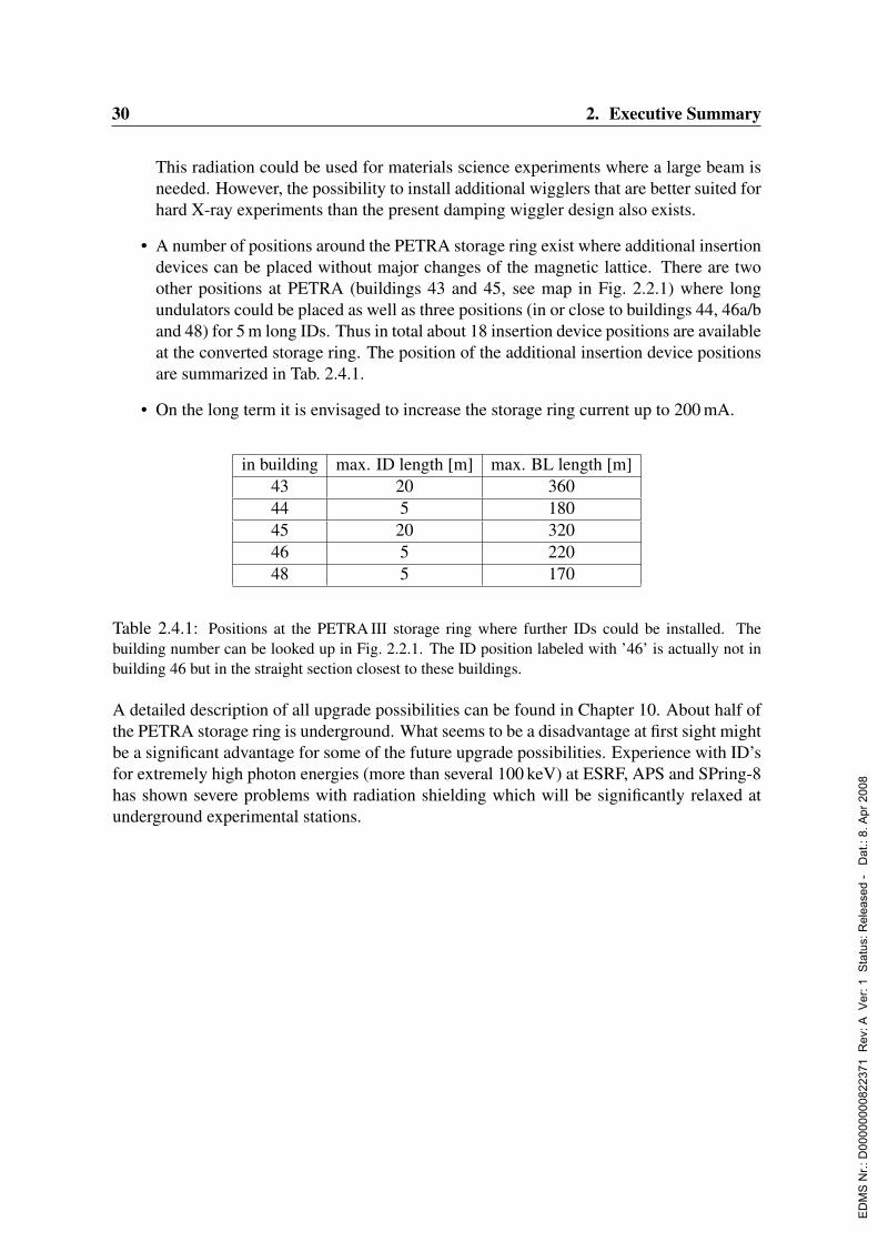
30 2. Executive Summary
This radiation could be used for materials science experiments where a large beam isneeded. However, the possibility to install additional wigglers that are better suited forhard X-ray experiments than the present damping wiggler design also exists.
• A number of positions around the PETRA storage ring exist where additional insertiondevices can be placed without major changes of the magnetic lattice. There are twoother positions at PETRA (buildings 43 and 45, see map in Fig. 2.2.1) where longundulators could be placed as well as three positions (in or close to buildings 44, 46a/band 48) for 5 m long IDs. Thus in total about 18 insertion device positions are availableat the converted storage ring. The position of the additional insertion device positionsare summarized in Tab. 2.4.1.
• On the long term it is envisaged to increase the storage ring current up to 200 mA.
in building max. ID length [m] max. BL length [m]43 20 36044 5 18045 20 32046 5 22048 5 170
Table 2.4.1: Positions at the PETRA III storage ring where further IDs could be installed. Thebuilding number can be looked up in Fig. 2.2.1. The ID position labeled with ’46’ is actually not inbuilding 46 but in the straight section closest to these buildings.
A detailed description of all upgrade possibilities can be found in Chapter 10. About half ofthe PETRA storage ring is underground. What seems to be a disadvantage at first sight mightbe a significant advantage for some of the future upgrade possibilities. Experience with ID’sfor extremely high photon energies (more than several 100 keV) at ESRF, APS and SPring-8has shown severe problems with radiation shielding which will be significantly relaxed atunderground experimental stations.
ED
MS
Nr.:
D00
0000
0082
2371
Rev
: A V
er: 1
Sta
tus:
Rel
ease
d -
Dat
.: 8.
Apr
200
8
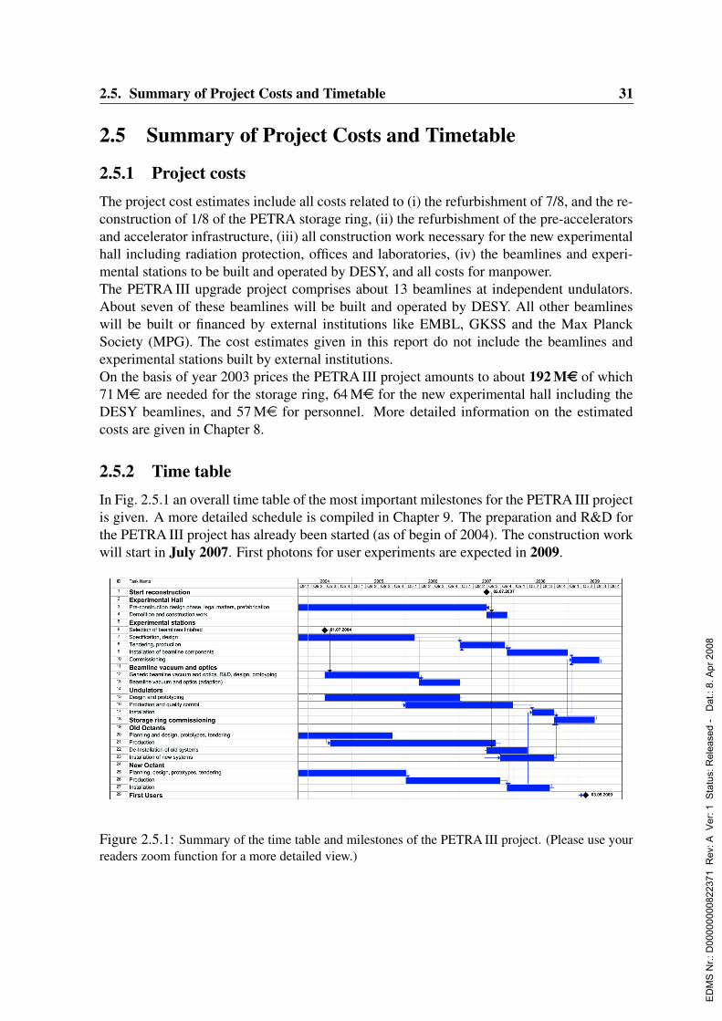
2.5. Summary of Project Costs and Timetable 31
2.5 Summary of Project Costs and Timetable
2.5.1 Project costsThe project cost estimates include all costs related to (i) the refurbishment of 7/8, and the re-construction of 1/8 of the PETRA storage ring, (ii) the refurbishment of the pre-acceleratorsand accelerator infrastructure, (iii) all construction work necessary for the new experimentalhall including radiation protection, offices and laboratories, (iv) the beamlines and experi-mental stations to be built and operated by DESY, and all costs for manpower.The PETRA III upgrade project comprises about 13 beamlines at independent undulators.About seven of these beamlines will be built and operated by DESY. All other beamlineswill be built or financed by external institutions like EMBL, GKSS and the Max PlanckSociety (MPG). The cost estimates given in this report do not include the beamlines andexperimental stations built by external institutions.On the basis of year 2003 prices the PETRA III project amounts to about 192 Me of which71 Me are needed for the storage ring, 64 Me for the new experimental hall including theDESY beamlines, and 57 Me for personnel. More detailed information on the estimatedcosts are given in Chapter 8.
2.5.2 Time tableIn Fig. 2.5.1 an overall time table of the most important milestones for the PETRA III projectis given. A more detailed schedule is compiled in Chapter 9. The preparation and R&D forthe PETRA III project has already been started (as of begin of 2004). The construction workwill start in July 2007. First photons for user experiments are expected in 2009.
Figure 2.5.1: Summary of the time table and milestones of the PETRA III project. (Please use yourreaders zoom function for a more detailed view.)
ED
MS
Nr.:
D00
0000
0082
2371
Rev
: A V
er: 1
Sta
tus:
Rel
ease
d -
Dat
.: 8.
Apr
200
8

32 2. Executive Summary
ED
MS
Nr.:
D00
0000
0082
2371
Rev
: A V
er: 1
Sta
tus:
Rel
ease
d -
Dat
.: 8.
Apr
200
8
Chapter 3
The Storage Ring
3.1 IntroductionThe following part of the design report covers aspects of accelerator physics and technicalissues of the PETRA III project. As was already pointed out PETRA III will be designed tobe a high brilliant light source in the hard X-ray regime. Although this machine has featuresof existing light sources it also differs considerably from the design of any present radiationsource.In the introduction we will present the general design philosophy and give reasons why wedecide to build PETRA III in this particular form. This part can be viewed as a guide lineand a summary for the accelerator and technical part of the project.The schematic layout of PETRA II is given in Fig. 3.1.1. PETRA II has a large circumferenceof 2304 m which is considerably larger than any existing light source. The machine consistsof arcs and several straight sections. The so-called long straights which have a length of108 m are located in the North, East, South and West. In between two long straights areshort straight sections with a length of 64.8 m. These straights are connected by arcs. Themagnetic structure is a simple FODO lattice. The part that extends from the middle of onelong straight to the middle of the adjacent short straight is the basic building block of themachine. Since this section is just one eighths of the machine it is called an octant. Inprinciple the magnetic arrangement of one octant is mirror reflected at the middle of theshort straight. The machine has therefore a four fold symmetry. Positrons or electrons areinjected in the South-East (SE) and travel clockwise around the machine.The basic design parameters of the new machine PETRA III are given in Tab. 3.1.1. Thedesign is driven by two major criterions. First of all PETRA III should be competitive withthe existing high energy synchrotron radiation sources like APS, ESRF and SPring-8 but onthe other hand the reconstruction should be cost effective. That last criterion is the reasonwhy the number of insertion devices is relatively small for a machine with a circumferenceas large as 2304 m. The energy is fixed by a compromise of the different user requirements.The maximum current and the emittances are chosen to achieve a high brilliance. The currentis limited by coupled bunch instabilities driven by the parasitic modes of the existing RFcavities. Replacing the exiting cavities would be to costly and does not fit into our presentbudget. All components of the machine and in particular those which are affected by heat
ED
MS
Nr.:
D00
0000
0082
2371
Rev
: A V
er: 1
Sta
tus:
Rel
ease
d -
Dat
.: 8.
Apr
200
8

34 3. The Storage Ring
Figure 3.1.1: Overview of PETRA storage ring.
Parameternumber of insertion devices 13
energy (GeV) 6current (mA) 100εx (nmrad) 1εy (nmrad) 0.01
Table 3.1.1: Basic design parameters of PETRA III.
load or radiation should be designed and dimensioned for a current of up to 200 mA in ordernot to prevent future upgrades. The emittances are rather small compared to achievements ofother light sources. To meet the design goal for the emittances is certainly one of the majorchallenges of this project.In the following we will show how the design parameters can be accomplished.We investigated several possibilities to house the insertion devices in the machine. Finallywe decided to accommodate the insertion devices in one octant of the machine since this isan effective solution in terms of costs and constructional changes. The octant extending fromNorth-East to East was chosen for reconstruction (see Fig. 2.2.1) because here the machineis above ground and easily accessible which eases the rebuilding. The magnetic lattice of
ED
MS
Nr.:
D00
0000
0082
2371
Rev
: A V
er: 1
Sta
tus:
Rel
ease
d -
Dat
.: 8.
Apr
200
8
3.1. Introduction 35
this new octant consists of nine double bend achromat cells (DBA). Details of the optics andthe way how to make room for thirteen insertion devices is described in Sec. 3.2.1.If the optics of the new octant is combined with an established optics of the remainingseven eighths of the machine, the so-called old octants, the minimum achievable emittance is4.5 nmrad. So obviously changes to the rest of the machine are necessary to get the emittancedown to 1 nmrad. There are basically three different ways to reduce the emittance:
• Using the above mentioned optics for the remaining seven eights of the machine whichresults in an emittance of 4.5 nmrad and enhancing the radiation damping with damp-ing wigglers to reduce the emittance. These damping wigglers can be installed in twoof the four long straights sections where there is plenty of space available. This optionis referred to as Optic A.
• A completely new design of the optics of the remaining seven eights of the machinebut using the existing hardware. The appropriate candidate for such a lattice wouldbe a so-called theoretical minimum emittance lattice abbreviated TME. This option isreferred to as Optic B.
• A completely new design of the optics of the remaining seven eights of the machinewith new magnets in particular shorter dipoles so that the bending angle can be sig-nificantly reduced which then results in a smaller emittance. The shorter dipoles areintegrated into a FODO lattice with a phase advance of 90. This option is referred toas Optic C.
Figures 3.1.2 and 3.2.2 show the beta and dispersion functions for the three different choicesfor an old octant.We investigated the dynamic aperture of the three different options for an ideal machinei.e. without field and alignment errors. Furthermore all lattices were optimized with respectto first order sextupole effects. Fig. 3.1.3 shows the dynamic aperture for the three differentoptions. This graph clearly indicates that the option with damping wigglers offers the biggestdynamic aperture. The graph indicates that option B and C provide a much too small dynamicaperture especially at injection. This result is not completely unexpected since the sextupolestrengths for option B and C are significantly larger than the sextupole strengths for optionA. The sextupoles are the main source of non-linear effects in case B and C and the non-linear effects coming from the wigglers for option A mainly affect the vertical plane. Thiscomparison in terms of dynamic aperture and the fact that option B and C tend to be moresensitive to errors because of the higher field strengths of their quadrupole and sextupolemagnets clearly favors the option with the damping wigglers. This option is investigated ingreat detail in Sec. 3.2.2.The small emittance in combination with the optical function at the source points of syn-chrotron radiation give beam sizes in particular in the vertical plane in the micron range.That means that orbit stability in the micron or even sub-micron range is required. Our ownexperience and the experience gained at other laboratories indicate that an active stabiliza-tion system will be necessary in order to achieve the specified orbit stability. Our presentexpectations concerning orbit stability and a schematic layout of an orbit stability system is
ED
MS
Nr.:
D00
0000
0082
2371
Rev
: A V
er: 1
Sta
tus:
Rel
ease
d -
Dat
.: 8.
Apr
200
8
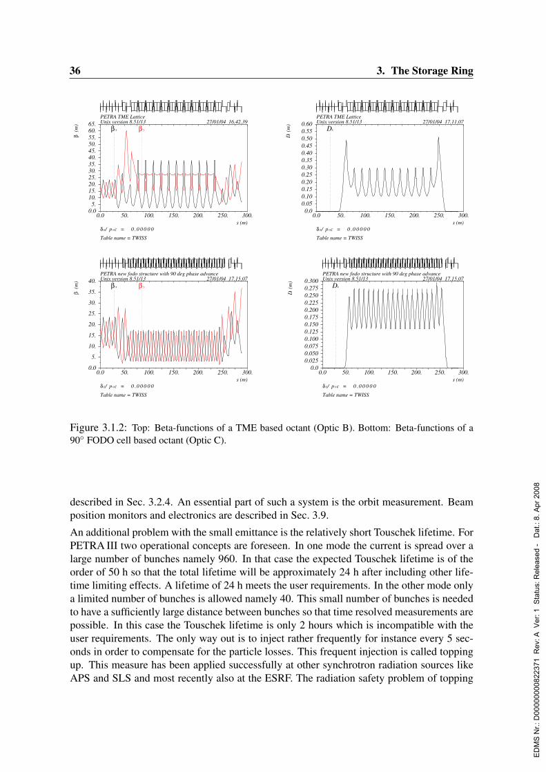
36 3. The Storage Ring
0.0 50. 100. 150. 200. 250. 300.s (m)
δ E/ p 0c = 0 .0 0 0 0 0
Table name = TWISS
PETRA TME LatticeUnix version 8.51/13 27/01/04 16.42.39
0.05.
10.15.20.25.30.35.40.45.50.55.60.65.
β(m
)
β x β y
0.0 50. 100. 150. 200. 250. 300.s (m)
δ E/ p 0c = 0 .0 0 0 0 0
Table name = TWISS
PETRA TME LatticeUnix version 8.51/13 27/01/04 17.11.07
0.00.050.100.150.200.250.300.350.400.450.500.550.60
Dx(m
)
Dx
0.0 50. 100. 150. 200. 250. 300.s (m)
δ E/ p 0c = 0 .0 0 0 0 0
Table name = TWISS
PETRA new fodo structure with 90 deg phase advanceUnix version 8.51/13 27/01/04 17.15.07
0.0
5.
10.
15.
20.
25.
30.
35.
40.
β(m
)
β x β y
0.0 50. 100. 150. 200. 250. 300.s (m)
δ E/ p 0c = 0 .0 0 0 0 0
Table name = TWISS
PETRA new fodo structure with 90 deg phase advanceUnix version 8.51/13 27/01/04 17.15.07
0.00.0250.0500.0750.1000.1250.1500.1750.2000.2250.2500.2750.300
Dx(m
)Dx
Figure 3.1.2: Top: Beta-functions of a TME based octant (Optic B). Bottom: Beta-functions of a90 FODO cell based octant (Optic C).
described in Sec. 3.2.4. An essential part of such a system is the orbit measurement. Beamposition monitors and electronics are described in Sec. 3.9.
An additional problem with the small emittance is the relatively short Touschek lifetime. ForPETRA III two operational concepts are foreseen. In one mode the current is spread over alarge number of bunches namely 960. In that case the expected Touschek lifetime is of theorder of 50 h so that the total lifetime will be approximately 24 h after including other life-time limiting effects. A lifetime of 24 h meets the user requirements. In the other mode onlya limited number of bunches is allowed namely 40. This small number of bunches is neededto have a sufficiently large distance between bunches so that time resolved measurements arepossible. In this case the Touschek lifetime is only 2 hours which is incompatible with theuser requirements. The only way out is to inject rather frequently for instance every 5 sec-onds in order to compensate for the particle losses. This frequent injection is called toppingup. This measure has been applied successfully at other synchrotron radiation sources likeAPS and SLS and most recently also at the ESRF. The radiation safety problem of topping
ED
MS
Nr.:
D00
0000
0082
2371
Rev
: A V
er: 1
Sta
tus:
Rel
ease
d -
Dat
.: 8.
Apr
200
8
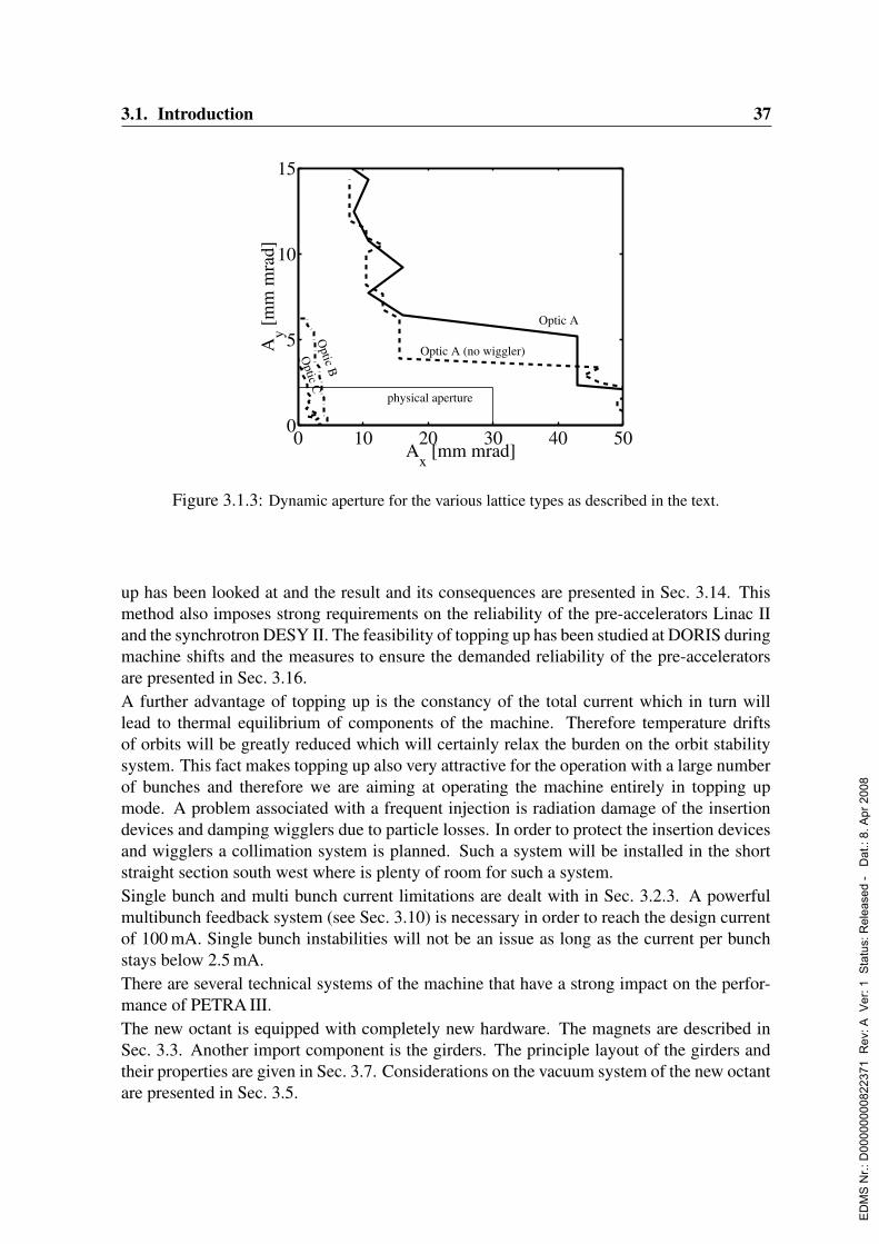
3.1. Introduction 37
0 10 20 30 40 500
5
10
15
Optic C
Optic B
Optic A (no wiggler)
Optic A
Ax [mm mrad]
Ay [
mm
mra
d]
physical aperture
Figure 3.1.3: Dynamic aperture for the various lattice types as described in the text.
up has been looked at and the result and its consequences are presented in Sec. 3.14. Thismethod also imposes strong requirements on the reliability of the pre-accelerators Linac IIand the synchrotron DESY II. The feasibility of topping up has been studied at DORIS duringmachine shifts and the measures to ensure the demanded reliability of the pre-acceleratorsare presented in Sec. 3.16.A further advantage of topping up is the constancy of the total current which in turn willlead to thermal equilibrium of components of the machine. Therefore temperature driftsof orbits will be greatly reduced which will certainly relax the burden on the orbit stabilitysystem. This fact makes topping up also very attractive for the operation with a large numberof bunches and therefore we are aiming at operating the machine entirely in topping upmode. A problem associated with a frequent injection is radiation damage of the insertiondevices and damping wigglers due to particle losses. In order to protect the insertion devicesand wigglers a collimation system is planned. Such a system will be installed in the shortstraight section south west where is plenty of room for such a system.Single bunch and multi bunch current limitations are dealt with in Sec. 3.2.3. A powerfulmultibunch feedback system (see Sec. 3.10) is necessary in order to reach the design currentof 100 mA. Single bunch instabilities will not be an issue as long as the current per bunchstays below 2.5 mA.There are several technical systems of the machine that have a strong impact on the perfor-mance of PETRA III.The new octant is equipped with completely new hardware. The magnets are described inSec. 3.3. Another import component is the girders. The principle layout of the girders andtheir properties are given in Sec. 3.7. Considerations on the vacuum system of the new octantare presented in Sec. 3.5.
ED
MS
Nr.:
D00
0000
0082
2371
Rev
: A V
er: 1
Sta
tus:
Rel
ease
d -
Dat
.: 8.
Apr
200
8

38 3. The Storage Ring
The damping wiggler section is certainly a technically challenging part of the machine. Thevacuum system and the absorbers have to be designed very carefully. A conceptual designof this section is presented in Sec. 3.4.Concerning the old octants we want to make use of existing infrastructure and hardwarewhenever possible in order to be cost effective. Nevertheless there will be also substantialchanges to the hardware. For example the present vacuum system will be completely re-placed (see Sec. 3.5). In addition we also want to replace the coils of all main magnetsbecause they have been damaged by radiation over the last 25 years. Fig. 3.1.4 shows aradiation damaged coil and magnet with a new coil.
Figure 3.1.4: Damaged and new magnet coil.
The power supplies for both the magnets and the RF system will be replaced (Sec. 3.12). Thecooling water system will be renewed in order to fulfill the higher demands on temperaturestability. Parts of the RF system will be modernized but the present cavities will be used alsofor PETRA III (see Sec. 3.6).
3.2 Accelerator Physics Issues
3.2.1 Geometry and opticsConcerning the geometry and optics the basic idea is to keep the lattice structure on seveneighths of the PETRA II machine whereas one eighth will be completely reconstructed.PETRA II consists of eight arcs (Fig. 3.2.1) connected alternately by four long (108 m) andfour short (65 m) straight sections. One octant starts at the center of one straight section andends at the center of the next one. The optical functions of such a FODO lattice based octantare shown in Fig. 3.2.2. All straight sections are designed for zero dispersion by using themissing magnet principle.For the octant from North-East to East a new design has been made fitting to the geometricaland optical boundary conditions of the rest of the storage ring. It consists of 9 double-bendachromat (DBA) cells with zero dispersion straight sections for the installation of eight 5 mundulators and one 20 m undulator (Fig. 3.2.3). Following the demand of the users two types
ED
MS
Nr.:
D00
0000
0082
2371
Rev
: A V
er: 1
Sta
tus:
Rel
ease
d -
Dat
.: 8.
Apr
200
8
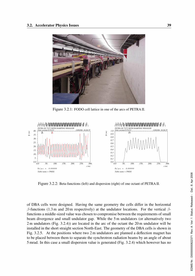
3.2. Accelerator Physics Issues 39
Figure 3.2.1: FODO cell lattice in one of the arcs of PETRA II.
0.0 50. 100. 150. 200. 250. 300.s (m)
δ E/ p 0c = 0 .0 0 0 0 0
Table name = TWISS
PETRA III 72/72 WITH DAMPING WIGGLERUnix version 8.51/13 13/01/04 10.26.55
0.0
5.
10.
15.
20.
25.
30.
35.
40.
β(m
)
β x β y
0.0 50. 100. 150. 200. 250. 300.s (m)
δ E/ p 0c = 0 .0 0 0 0 0
Table name = TWISS
PETRA III 72/72 WITH DAMPING WIGGLERUnix version 8.51/13 13/01/04 10.26.55
0.0
0.1
0.2
0.3
0.4
0.5
0.6
0.7
0.8
0.9
1.0
Dx(m
)
Dx
Figure 3.2.2: Beta-functions (left) and dispersion (right) of one octant of PETRA II.
of DBA cells were designed. Having the same geometry the cells differ in the horizontalβ-functions (1.3 m and 20 m respectively) at the undulator locations. For the vertical β-functions a middle-sized value was chosen to compromise between the requirements of smallbeam divergence and small undulator gap. While the 5 m undulators (or alternatively two2 m undulators (Fig. 3.2.4)) are located in the arc of the octant the 20 m undulator will beinstalled in the short straight section North-East. The geometry of the DBA cells is shown inFig. 3.2.5. At the positions where two 2 m undulators are planned a deflection magnet hasto be placed between them to separate the synchrotron radiation beams by an angle of about5 mrad. In this case a small dispersion value is generated (Fig. 3.2.4) which however has no
ED
MS
Nr.:
D00
0000
0082
2371
Rev
: A V
er: 1
Sta
tus:
Rel
ease
d -
Dat
.: 8.
Apr
200
8
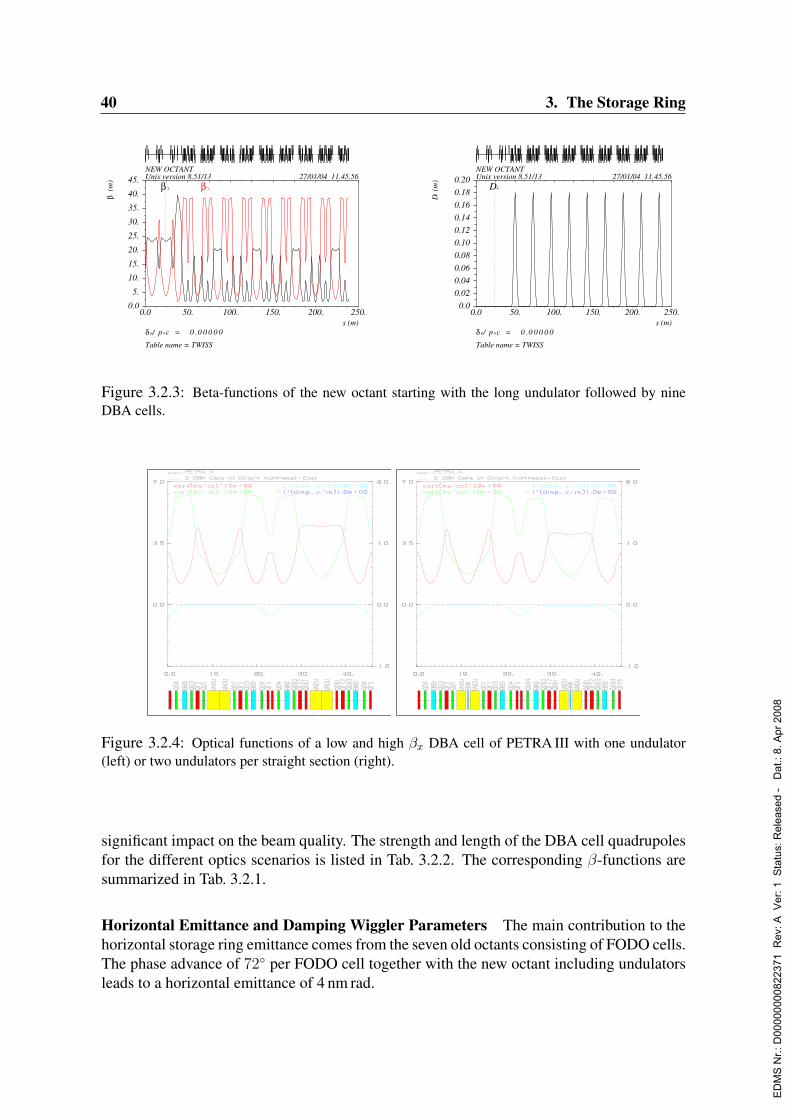
40 3. The Storage Ring
0.0 50. 100. 150. 200. 250.s (m)
δ E/ p 0c = 0 .0 0 0 0 0
Table name = TWISS
NEW OCTANTUnix version 8.51/13 27/01/04 11.45.56
0.0
5.
10.
15.
20.
25.
30.
35.
40.
45.
β(m
)
β x β y
0.0 50. 100. 150. 200. 250.s (m)
δ E/ p 0c = 0 .0 0 0 0 0
Table name = TWISS
NEW OCTANTUnix version 8.51/13 27/01/04 11.45.56
0.0
0.02
0.04
0.06
0.08
0.10
0.12
0.14
0.16
0.18
0.20
Dx(m
)
Dx
Figure 3.2.3: Beta-functions of the new octant starting with the long undulator followed by nineDBA cells.
Figure 3.2.4: Optical functions of a low and high βx DBA cell of PETRA III with one undulator(left) or two undulators per straight section (right).
significant impact on the beam quality. The strength and length of the DBA cell quadrupolesfor the different optics scenarios is listed in Tab. 3.2.2. The corresponding β-functions aresummarized in Tab. 3.2.1.
Horizontal Emittance and Damping Wiggler Parameters The main contribution to thehorizontal storage ring emittance comes from the seven old octants consisting of FODO cells.The phase advance of 72 per FODO cell together with the new octant including undulatorsleads to a horizontal emittance of 4 nm rad.
ED
MS
Nr.:
D00
0000
0082
2371
Rev
: A V
er: 1
Sta
tus:
Rel
ease
d -
Dat
.: 8.
Apr
200
8

3.2. Accelerator Physics Issues 41
PETRA IIImagnetic unit cell
HF, Version 08.09.2003
1
2
3
4
5
6
7
8
9
10
11
12
13
14
15
16
17
18
19
20
21
22
23
24
25
26
27
28
29
30
31
32
33
34353637383940
41
0
55000
3226240000
4600055000
0
-1500
1350
3000
0
-1000
2750
1400
5000
0 5500032262 40000 50000 58000 72000 78000
0
-1500
1350
3000
4410
0
-1000
2750
1400
5000
640 480
Figure 3.2.5: Structure and geometry of a DBA cell in the new octant of PETRA III.
5 m undulator two 2 m undulatorslow βx high βx low βx high βx
βx [m] 1.34 20.00 1.40 16.15βy [m] 3.00 2.39 3.00 2.61
Table 3.2.1: Beta-functions in the new octant at the center of the undulator sections.
For a further reduction of the emittance down to 1 nm rad it is planned to install dampingwigglers between the quadrupoles of the dispersion free long straight sections West andNorth (Fig. 3.2.6). A total length of about 80 m is available for damping wiggler magnets tocool the transverse momentum of the stored positrons by synchrotron radiation sufficiently.The equilibrium emittance in a storage ring is given through the effects of radiation damping,described by the synchrotron integral I2 ∼
∫B2dl and betatron oscillation excitation, de-
scribed by I5. Damping wigglers increase I2 while keeping I5 small. The different emittancecontributions of the ring can be combined through the following sum:
εx =1
I2;arc + I2;oct + I2;und + I2;wig
(I2;arcεx;arc + I2;octεx;oct + I2;undεx;und + I2;wigεx;wig)
(3.2.1)where εx ∼ I5 is the equilibrium emittance of the various contributions.The lattice of the FODO arcs and the new octant have been described in Sec. 3.2.1, the valuesfor I2 and εx which are necessary to reach a 1 nm emittance are given in Tab. 3.2.4:The wiggler itself creates an emittance of:
εx;wig = 2 – 13× 10−2λ2B30 < βx > (3.2.2)
with λ the wiggler period length and B0 the peak magnetic field. The average beta-function< βx > is around 16 m in the case of PETRA III given by the chosen lattice. This requires
ED
MS
Nr.:
D00
0000
0082
2371
Rev
: A V
er: 1
Sta
tus:
Rel
ease
d -
Dat
.: 8.
Apr
200
8
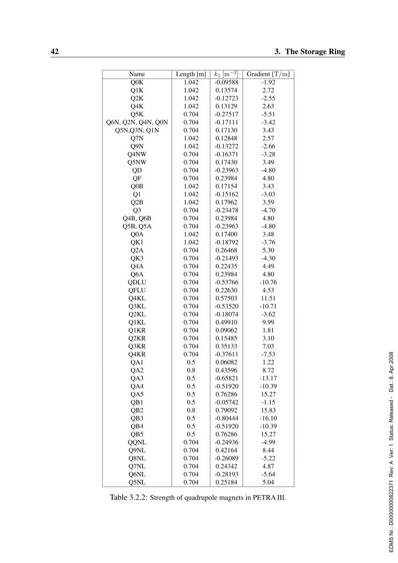
42 3. The Storage Ring
Name Length [m] k1 [m−2] Gradient [T/m]Q0K 1.042 -0.09588 -1.92Q1K 1.042 0.13574 2.72Q2K 1.042 -0.12723 -2.55Q4K 1.042 0.13129 2.63Q5K 0.704 -0.27517 -5.51
Q6N, Q2N, Q4N, Q0N 0.704 -0.17111 -3.42Q5N,Q3N, Q1N 0.704 0.17130 3.43
Q7N 1.042 0.12848 2.57Q9N 1.042 -0.13272 -2.66
Q4NW 0.704 -0.16371 -3.28Q5NW 0.704 0.17430 3.49
QD 0.704 -0.23963 -4.80QF 0.704 0.23984 4.80
Q0B 1.042 0.17154 3.43Q1 1.042 -0.15162 -3.03
Q2B 1.042 0.17962 3.59Q3 0.704 -0.23478 -4.70
Q4B, Q6B 0.704 0.23984 4.80Q5B, Q5A 0.704 -0.23963 -4.80
Q0A 1.042 0.17400 3.48QK1 1.042 -0.18792 -3.76Q2A 0.704 0.26468 5.30QK3 0.704 -0.21493 -4.30Q4A 0.704 0.22435 4.49Q6A 0.704 0.23984 4.80
QDLU 0.704 -0.53766 -10.76QFLU 0.704 0.22630 4.53Q4KL 0.704 0.57503 11.51Q3KL 0.704 -0.53520 -10.71Q2KL 0.704 -0.18074 -3.62Q1KL 0.704 0.49910 9.99Q1KR 0.704 0.09062 1.81Q2KR 0.704 0.15485 3.10Q3KR 0.704 0.35133 7.03Q4KR 0.704 -0.37611 -7.53QA1 0.5 0.06082 1.22QA2 0.8 0.43596 8.72QA3 0.5 -0.65821 -13.17QA4 0.5 -0.51920 -10.39QA5 0.5 0.76286 15.27QB1 0.5 -0.05742 -1.15QB2 0.8 0.79092 15.83QB3 0.5 -0.80444 -16.10QB4 0.5 -0.51920 -10.39QB5 0.5 0.76286 15.27
QQNL 0.704 -0.24936 -4.99Q9NL 0.704 0.42164 8.44Q8NL 0.704 -0.26089 -5.22Q7NL 0.704 0.24342 4.87Q6NL 0.704 -0.28193 -5.64Q5NL 0.704 0.25184 5.04
Table 3.2.2: Strength of quadrupole magnets in PETRA III.
ED
MS
Nr.:
D00
0000
0082
2371
Rev
: A V
er: 1
Sta
tus:
Rel
ease
d -
Dat
.: 8.
Apr
200
8
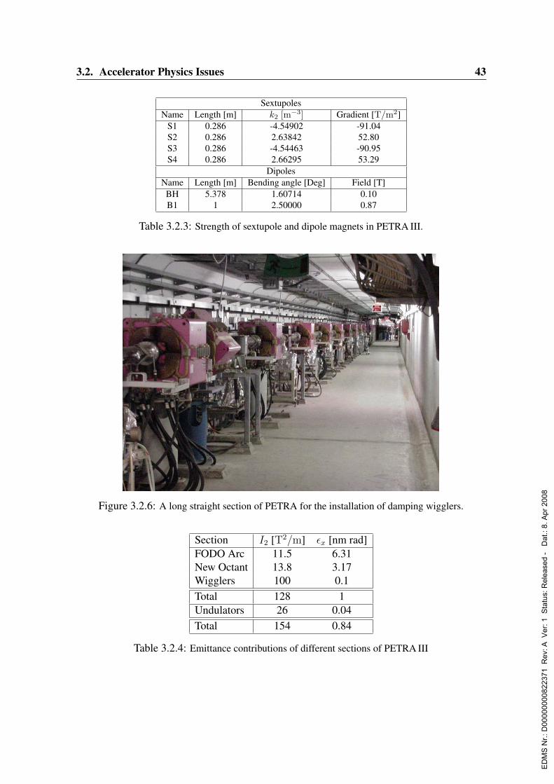
3.2. Accelerator Physics Issues 43
SextupolesName Length [m] k2 [m−3] Gradient [T/m2]
S1 0.286 -4.54902 -91.04S2 0.286 2.63842 52.80S3 0.286 -4.54463 -90.95S4 0.286 2.66295 53.29
DipolesName Length [m] Bending angle [Deg] Field [T]BH 5.378 1.60714 0.10B1 1 2.50000 0.87
Table 3.2.3: Strength of sextupole and dipole magnets in PETRA III.
Figure 3.2.6: A long straight section of PETRA for the installation of damping wigglers.
Section I2 [T2/m] εx [nm rad]FODO Arc 11.5 6.31New Octant 13.8 3.17Wigglers 100 0.1Total 128 1Undulators 26 0.04Total 154 0.84
Table 3.2.4: Emittance contributions of different sections of PETRA III
ED
MS
Nr.:
D00
0000
0082
2371
Rev
: A V
er: 1
Sta
tus:
Rel
ease
d -
Dat
.: 8.
Apr
200
8
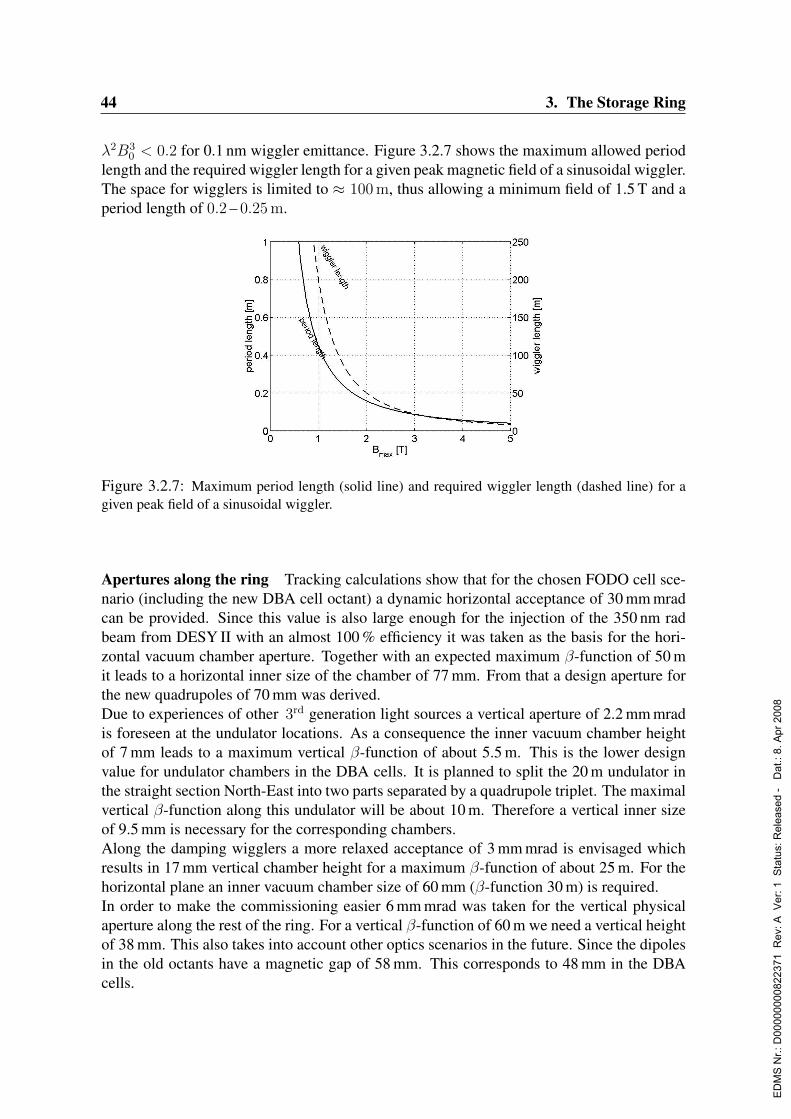
44 3. The Storage Ring
λ2B30 < 0.2 for 0.1 nm wiggler emittance. Figure 3.2.7 shows the maximum allowed period
length and the required wiggler length for a given peak magnetic field of a sinusoidal wiggler.The space for wigglers is limited to ≈ 100 m, thus allowing a minimum field of 1.5 T and aperiod length of 0.2 – 0.25 m.
Figure 3.2.7: Maximum period length (solid line) and required wiggler length (dashed line) for agiven peak field of a sinusoidal wiggler.
Apertures along the ring Tracking calculations show that for the chosen FODO cell sce-nario (including the new DBA cell octant) a dynamic horizontal acceptance of 30 mm mradcan be provided. Since this value is also large enough for the injection of the 350 nm radbeam from DESY II with an almost 100 % efficiency it was taken as the basis for the hori-zontal vacuum chamber aperture. Together with an expected maximum β-function of 50 mit leads to a horizontal inner size of the chamber of 77 mm. From that a design aperture forthe new quadrupoles of 70 mm was derived.Due to experiences of other 3rd generation light sources a vertical aperture of 2.2 mm mradis foreseen at the undulator locations. As a consequence the inner vacuum chamber heightof 7 mm leads to a maximum vertical β-function of about 5.5 m. This is the lower designvalue for undulator chambers in the DBA cells. It is planned to split the 20 m undulator inthe straight section North-East into two parts separated by a quadrupole triplet. The maximalvertical β-function along this undulator will be about 10 m. Therefore a vertical inner sizeof 9.5 mm is necessary for the corresponding chambers.Along the damping wigglers a more relaxed acceptance of 3 mm mrad is envisaged whichresults in 17 mm vertical chamber height for a maximum β-function of about 25 m. For thehorizontal plane an inner vacuum chamber size of 60 mm (β-function 30 m) is required.In order to make the commissioning easier 6 mm mrad was taken for the vertical physicalaperture along the rest of the ring. For a vertical β-function of 60 m we need a vertical heightof 38 mm. This also takes into account other optics scenarios in the future. Since the dipolesin the old octants have a magnetic gap of 58 mm. This corresponds to 48 mm in the DBAcells.
ED
MS
Nr.:
D00
0000
0082
2371
Rev
: A V
er: 1
Sta
tus:
Rel
ease
d -
Dat
.: 8.
Apr
200
8

3.2. Accelerator Physics Issues 45
Injection Section The injection into PETRA III takes place in the short straight sectionSouth-East. The position of the septum magnet is unchanged to maintain the present injec-tion line as much as possible. Three kickers are distributed to provide a closed bump withthe maximum amplitude at the septum (see Tab. 3.2.5). With a horizontal β-function of 25 mat the position of the septum, a free half-aperture of 30 mm and the width of the septum-barbeing 5 mm, approximately 7σ of the beam can be injected into the 30 mm mrad aperture ofPETRA III. Fig. 3.2.8 shows the β-function and the amplitude of the kicker injection bump.The required kick strength is of the order of 1.3 mrad, this corresponds to approximately200σ of the stored beam. Requirements for the bump closure lead to an amplitude accuracyof 5× 10⁻³ for a 1σ horizontal beam jitter during injection.
Element Position Required kick strength(South-East right) for 25 mm bump amplitude
KICKER 1 12.7 m 1.25 mradKICKER 2 31.8 m 1.13 mradSEPTUM 37.4 m
KICKER 3 52.8 m 0.51 mrad
Table 3.2.5: Position and Parameters of PETRA III injection elements.
Although a high injection efficiency is foreseen, the permanent magnets of the wigglers andundulators have to be protected against particles which are injected outside the aperture ofPETRA III. For this purpose, a simple collimation section with a pair of movable collima-tors is foreseen in the South-West straight section of the ring. Particles are either directlyintercepted by the collimators or will lose enough energy to get lost in the octant after thecollimators, before they reach the first wiggler section.
0.0 5. 10. 15. 20. 25. 30. 35. 40. 45. 50. 55. 60.s (m)
δ E/ p 0c = 0 .0 0 0 0 0
Table name = TWISS
PETRA III INJECTION SHORT STRAIGTH SEUnix version 8.51/13 31/10/03 10.30.42
0.0
5.
10.
15.
20.
25.
30.
35.
40.
β(m
)
β x β y
0.0 10. 20. 30. 40. 50. 60.s (m)
δ E/ p 0c = 0 .0 0 0 0 0
Table name = TWISS
PETRA III INJECTION SHORT STRAIGTH SEUnix version 8.51/13 31/10/03 10.30.42
-0.00250.0
0.00250.00500.00750.01000.01250.01500.01750.02000.02250.02500.0275
x (m
) x
Kic
ker3
Sept
um
Kic
ker2
Kic
ker1
Figure 3.2.8: β− functions and injection bump in the injection section.
ED
MS
Nr.:
D00
0000
0082
2371
Rev
: A V
er: 1
Sta
tus:
Rel
ease
d -
Dat
.: 8.
Apr
200
8

46 3. The Storage Ring
Linear Optics Error Random errors for the main field components of the magnets ariseeither from fabrication errors, affecting each single magnet, and from power-supply errorsor excitation curve calibration errors, affecting magnets of one family together. Gradienterrors of the quadrupoles as well as closed orbit offsets in the sextupoles will perturb thelinear optics of the machine and in turn the performance of orbit correction algorithms andthe non-linear dynamics. Tab. 3.2.6 summarizes the effects of various errors.
Error RMS Amplitude ∆βx/βx ∆βy/βy
Quadrupole fabrication error 5× 10⁻⁴ ∆k/k 0.01 0.01Power supply jitter 5× 10⁻⁴ ∆k/k 0.01 0.01
Closed orbit jitter in sextupole 20µm 0.014 0.01Closed orbit offset in sextupole 200µm 0.1 0.1
Calibration error 5× 10⁻⁴ ∆k/k 0.08 0.22
Table 3.2.6: Linear optics errors due to various machine error sources.
The time dependent jitter sources like the quadrupole power supply jitter and the closedorbit variation in the sextupoles will account for a tolerable β-function variation of only1 %. Larger optic disturbances come from the closed orbit offset in the sextupoles. Thiscontribution can be kept small by beam based alignment and the combined orbit/dispersioncorrection. Calibration errors will also be corrected through beam based techniques, namelyorbit response matrix analysis. With global optics corrections (using only the 5 most effectivequadrupole families) the β-beat at HERA could be reduced to within 5 %. At PETRA II themeasured β-beat is of the order of 10 %, in accordance with our assumptions above.
3.2.2 Nonlinear dynamicsChromaticity Correction The chromaticity correction in PETRA is done with sextupoleswhich are located adjacent to the FODO cell quadrupoles. Compensation of the chromaticitycontribution of the 9 DBA cells within these cells would require large sextupole strengths.The reason is a DBA bending magnet deflection of only 2.5 together with the dispersionsection length of 7.6 m which leads to small dispersion values for all possible sextupolelocations. Therefore the chromaticity of the complete ring is corrected only in the sevenFODO octants. This requires an over-compensation of roughly 2 per FODO cell, a valuewhich is also reached in colliders with strong focusing in the interaction regions. The dy-namic aperture of the lattice without wigglers has been calculated with the tracking codeSIXTRACK (Schmidt, 1991), which allows for full 6-dimensional particle tracking withoutradiation damping.Fig. 3.2.9 gives an example of the results. On the left graph particles which are stable over2048 turns (≈ 1/4 damping time) are plotted as thick dots versus their initial start ampli-tudes. Lost particles are plotted as thin dots. In addition, each particle carries a color codeaccording to the difference in tunes between the second and first half of survived turns. Thisdifference gives an indication of chaotic behavior of the corresponding trajectory (Laskar,1994). On the right graph the same particles are plotted in tune space, with the betatron tune
ED
MS
Nr.:
D00
0000
0082
2371
Rev
: A V
er: 1
Sta
tus:
Rel
ease
d -
Dat
.: 8.
Apr
200
8
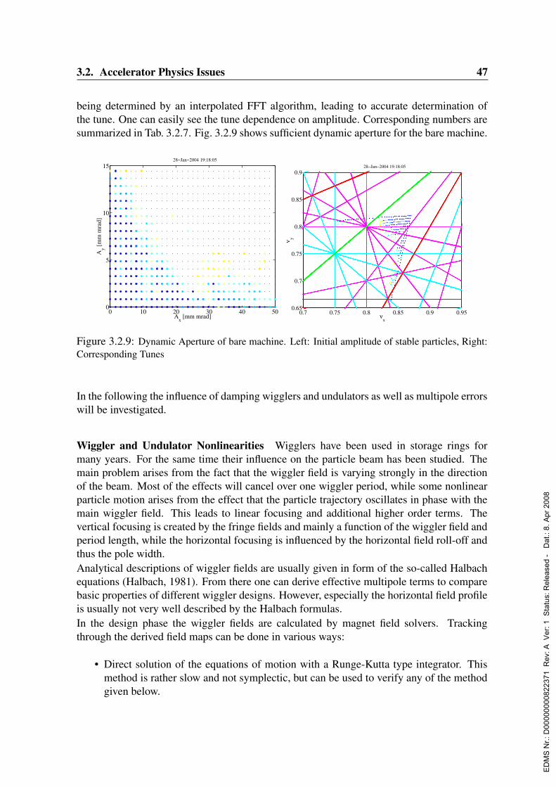
3.2. Accelerator Physics Issues 47
being determined by an interpolated FFT algorithm, leading to accurate determination ofthe tune. One can easily see the tune dependence on amplitude. Corresponding numbers aresummarized in Tab. 3.2.7. Fig. 3.2.9 shows sufficient dynamic aperture for the bare machine.
0 10 20 30 40 500
5
10
15
Ax [mm mrad]
Ay [
mm
mra
d]
28−Jan−2004 19:18:05
0.7 0.75 0.8 0.85 0.9 0.950.65
0.7
0.75
0.8
0.85
0.9
νx
ν y
28−Jan−2004 19:18:05
Figure 3.2.9: Dynamic Aperture of bare machine. Left: Initial amplitude of stable particles, Right:Corresponding Tunes
In the following the influence of damping wigglers and undulators as well as multipole errorswill be investigated.
Wiggler and Undulator Nonlinearities Wigglers have been used in storage rings formany years. For the same time their influence on the particle beam has been studied. Themain problem arises from the fact that the wiggler field is varying strongly in the directionof the beam. Most of the effects will cancel over one wiggler period, while some nonlinearparticle motion arises from the effect that the particle trajectory oscillates in phase with themain wiggler field. This leads to linear focusing and additional higher order terms. Thevertical focusing is created by the fringe fields and mainly a function of the wiggler field andperiod length, while the horizontal focusing is influenced by the horizontal field roll-off andthus the pole width.Analytical descriptions of wiggler fields are usually given in form of the so-called Halbachequations (Halbach, 1981). From there one can derive effective multipole terms to comparebasic properties of different wiggler designs. However, especially the horizontal field profileis usually not very well described by the Halbach formulas.In the design phase the wiggler fields are calculated by magnet field solvers. Trackingthrough the derived field maps can be done in various ways:
• Direct solution of the equations of motion with a Runge-Kutta type integrator. Thismethod is rather slow and not symplectic, but can be used to verify any of the methodgiven below.
ED
MS
Nr.:
D00
0000
0082
2371
Rev
: A V
er: 1
Sta
tus:
Rel
ease
d -
Dat
.: 8.
Apr
200
8

48 3. The Storage Ring
• Fitting the field map to a set of Halbach equations which in turn allow symplecticintegration (Litvinenko et al., 2001) or integration by another method.
• Obtain a Taylor map from either form of integration, which in turn can be simplectifiedwith the appropriate generating function (Bahrdt & Wustefeld, 1990).
The wiggler design has been optimized especially in terms of period length and pole width.As a design criterion a relative field error of ∆By/By|10mm < 1 × 10⁻³ has been specified.Each wiggler design has been checked with the above mentioned methods. Results of wig-gler tracking with a realistic wiggler model are shown in Fig. 3.2.11 in comparison with themachine without wigglers. The wiggler model is based on field calculations.Additional nonlinearities arise from manufacturing errors and non-complete cancellation ofthe end-poles of the device. The latter can be largely corrected by choosing an antisymmetricwiggler design, although for a fixed gap device like the damping wigglers this precautionmay not be necessary. Contrary to the nonlinear effects arising from the wiggling trajectory,these error fields are well described by usual multipole fields and can be measured along astraight line in the wiggler.
δνx/δJx δνy/δJy δνx/δJy
FODO without wiggler −5.5× 10⁻⁴ −8.8× 10⁻⁴ −3.0× 10⁻³
FODO with wiggler −1.3× 10⁻⁴ 3.7× 10⁻⁴ −3.4× 10⁻³
FODO with wiggler and undulator +6.5× 10⁻⁵ 3.4× 10⁻³ −4.1× 10⁻³
Table 3.2.7: Detuning with amplitude
Wiggler UndulatorPeak field T 1.56 0.86Period length m 0.25 0.028Horizontal field parameter m−1 0.6 0.1
Table 3.2.8: Wiggler and undulator parameters used for tracking
The insertion devices in the new octant are simulated with the parameters given in Tab. 3.2.8.Notable is the smaller field and roll-off parameter kx, which is achieved due to the smallerpossible gap. The main effect of the insertion devices is thus in the vertical plane. In the DBAcells the vertical β-functions at insertion devices are only 4 m, suppressing the influence ofthe insertion devices on the beam. Only the long undulator has a considerable influence ifthe vertical β-function is above 10 m.One of the major effects of the insertion device nonlinearities is the change in the detuningwith amplitude as shown in Fig. 3.2.10. This change may require a different optimization ofthe working point.
ED
MS
Nr.:
D00
0000
0082
2371
Rev
: A V
er: 1
Sta
tus:
Rel
ease
d -
Dat
.: 8.
Apr
200
8

3.2. Accelerator Physics Issues 49
0.7 0.75 0.8 0.85 0.9 0.950.65
0.7
0.75
0.8
0.85
0.9
νx
ν y 28−Jan−2004 19:29:32
0.7 0.75 0.8 0.85 0.9 0.950.65
0.7
0.75
0.8
0.85
0.9
νx
ν y
29−Jan−2004 12:06:42
Figure 3.2.10: Stable particles in tune space for PETRA III including damping wigglers (left) anddamping wigglers and a full set of insertion devices (right).
Multipole Errors The influence of multipole errors on the dynamic aperture has beencalculated. For the existing magnets of the old octants measured field values have been used(Wolff, 1978b; Wolff, 1978a; Rossbach, 1987), while for the magnets of the new octantwe have assumed field imperfections based on calculations (Petrov, 2003). The multipolecoefficients are summarized in Tab. 3.2.9. A summary of tracking calculations is shown inFig. 3.2.11. It turns out that the on-momentum dynamic aperture is not affected by multipole
order dipole old quadrupoles new quadrupoles sextupole1× 10−3
1 1.02 0.030 1.0 1.03 0.295 0.565 0.0 1.04 0.138 0.174 0.0 1.095 0.366 0.217 0.0 2.766 0.239 0.435 0.08 0.537 0.145 0.107 0.0 0.348 0.683 0.415 0.013 0.289 0.315 0.217 0.0 3.10
10 0.300 0.674 4.9 0.34standard deviation
of main pole 2.5× 10⁻⁴ 5× 10⁻⁴ 1× 10⁻⁴ 2× 10⁻³
within series
Table 3.2.9: Relative multipole coefficients of PETRA III magnets at r = 50mm and standarddeviation of main pole amplitude within magnet series.
ED
MS
Nr.:
D00
0000
0082
2371
Rev
: A V
er: 1
Sta
tus:
Rel
ease
d -
Dat
.: 8.
Apr
200
8
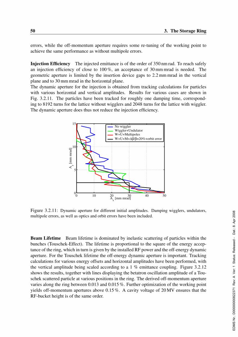
50 3. The Storage Ring
errors, while the off-momentum aperture requires some re-tuning of the working point toachieve the same performance as without multipole errors.
Injection Efficiency The injected emittance is of the order of 350 nm rad. To reach safelyan injection efficiency of close to 100 %, an acceptance of 30 mm mrad is needed. Thegeometric aperture is limited by the insertion device gaps to 2.2 mm mrad in the verticalplane and to 30 mm mrad in the horizontal plane.The dynamic aperture for the injection is obtained from tracking calculations for particleswith various horizontal and vertical amplitudes. Results for various cases are shown inFig. 3.2.11. The particles have been tracked for roughly one damping time, correspond-ing to 8192 turns for the lattice without wigglers and 2048 turns for the lattice with wiggler.The dynamic aperture does thus not reduce the injection efficiency.
0 10 20 30 40 500
5
10
15
Ax [mm mrad]
Ay [
mm
mra
d]
No wiggler Wiggler+Undulator W+U+Multipoles W+U+M+∆β/β=20%+orbit error
Figure 3.2.11: Dynamic aperture for different initial amplitudes. Damping wigglers, undulators,multipole errors, as well as optics and orbit errors have been included.
Beam Lifetime Beam lifetime is dominated by inelastic scattering of particles within thebunches (Touschek-Effect). The lifetime is proportional to the square of the energy accep-tance of the ring, which in turn is given by the installed RF power and the off-energy dynamicaperture. For the Touschek lifetime the off-energy dynamic aperture is important. Trackingcalculations for various energy offsets and horizontal amplitudes have been performed, withthe vertical amplitude being scaled according to a 1 % emittance coupling. Figure 3.2.12shows the results, together with lines displaying the betatron oscillation amplitude of a Tou-schek scattered particle at various positions in the ring. The derived off-momentum aperturevaries along the ring between 0.013 and 0.015 %. Further optimization of the working pointyields off-momentum apertures above 0.15 %. A cavity voltage of 20 MV ensures that theRF-bucket height is of the same order.
ED
MS
Nr.:
D00
0000
0082
2371
Rev
: A V
er: 1
Sta
tus:
Rel
ease
d -
Dat
.: 8.
Apr
200
8
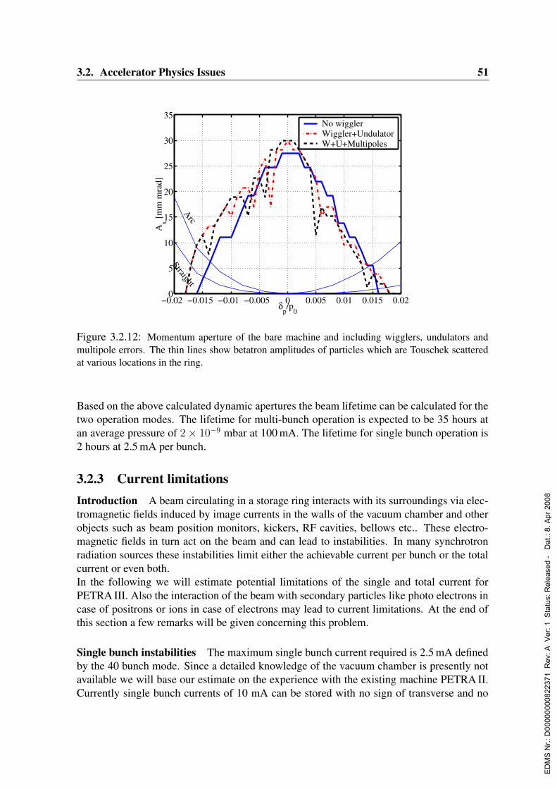
3.2. Accelerator Physics Issues 51
−0.02 −0.015 −0.01 −0.005 0 0.005 0.01 0.015 0.020
5
10
15
20
25
30
35
δp/p
0
Ax [
mm
mra
d]
Arc
Straight
No wiggler Wiggler+UndulatorW+U+Multipoles
Figure 3.2.12: Momentum aperture of the bare machine and including wigglers, undulators andmultipole errors. The thin lines show betatron amplitudes of particles which are Touschek scatteredat various locations in the ring.
Based on the above calculated dynamic apertures the beam lifetime can be calculated for thetwo operation modes. The lifetime for multi-bunch operation is expected to be 35 hours atan average pressure of 2× 10⁻⁹ mbar at 100 mA. The lifetime for single bunch operation is2 hours at 2.5 mA per bunch.
3.2.3 Current limitationsIntroduction A beam circulating in a storage ring interacts with its surroundings via elec-tromagnetic fields induced by image currents in the walls of the vacuum chamber and otherobjects such as beam position monitors, kickers, RF cavities, bellows etc.. These electro-magnetic fields in turn act on the beam and can lead to instabilities. In many synchrotronradiation sources these instabilities limit either the achievable current per bunch or the totalcurrent or even both.In the following we will estimate potential limitations of the single and total current forPETRA III. Also the interaction of the beam with secondary particles like photo electrons incase of positrons or ions in case of electrons may lead to current limitations. At the end ofthis section a few remarks will be given concerning this problem.
Single bunch instabilities The maximum single bunch current required is 2.5 mA definedby the 40 bunch mode. Since a detailed knowledge of the vacuum chamber is presently notavailable we will base our estimate on the experience with the existing machine PETRA II.Currently single bunch currents of 10 mA can be stored with no sign of transverse and no
ED
MS
Nr.:
D00
0000
0082
2371
Rev
: A V
er: 1
Sta
tus:
Rel
ease
d -
Dat
.: 8.
Apr
200
8

52 3. The Storage Ring
evidence of longitudinal instabilities. We can form an impedance model of the machineusing old (Weiland, 1981a; Weiland, 1981b; Klatt, Kohaupt & Weiland, 1985) and morerecent measurements. We will express the impedance in terms of so-called kick parameters.
k‖ =
∫ ∞
−∞dsW0(s)λ(s)
k‖(1) =
∫ ∞
−∞dsW0(s)
dλ(s)
ds
k⊥ =
∫ ∞
−∞ds W⊥(s)λ(s)∫ ∞
−∞ds λ(s) = 1
Here W (s) denotes the wake potentials and λ(s) the line particle density.
In Tab. 3.2.10 the kick parameters of the complete vacuum chamber and the 16 seven cellcavities are given.
In Tab. 3.2.11 the basic machine parameters are listed which are necessary to estimate singlebunch limitations.
We will apply the following two formulas to calculate the coherent tune shift of the lowest
Parameter Vacuum chamber Cavities total
k‖ (V/pC) 47 81 128
k‖(1) (V/pCm) -6400 3500 -2900
k⊥ (V/pCm) 1000 500 1500
Table 3.2.10: Kick parameters for PETRA III.
ParameterIB (mA) 2.5< β > (m) 20T0 (µs) 7.69R (m) 366.7E (GeV) 6Qs 0.049h 3840
Urf (MV) 20α 1.22× 10⁻³
σs (cm) 1.1energy spread σE 0.0011
Table 3.2.11: Machine parameters to estimate current limitations.
ED
MS
Nr.:
D00
0000
0082
2371
Rev
: A V
er: 1
Sta
tus:
Rel
ease
d -
Dat
.: 8.
Apr
200
8

3.2. Accelerator Physics Issues 53
order modes in the longitudinal and transverse plane.
δνs = νsIBRT0
2hUrf
k0(1)
δνβ =IB < β > T0
4πE/ek⊥
As long as these tune shifts are considerably smaller than the synchrotron tune no fast headtail instability and no turbulent bunch lengthening will occur. In units of the synchrotrontune the calculated tune shifts are:
|δνs/νs| = 0.13
|δνβ/νs| = 0.15
These two relative shifts are small enough that no instabilities should occur which is con-firmed by the fact that PETRA II does not suffer from single bunch instabilities up to singlebunch currents of 10 mA.There will be clearly differences between the vacuum chamber of PETRA III and PETRA II.In the old octants the existing vacuum chamber will be replaced by a new one. Although thevacuum chamber has not been designed in detail yet the basic parameters have been fixed(see Sec. 3.5). For example a cross section of the dipole chamber is shown in Fig. 3.2.13.
Figure 3.2.13: Cross section of the dipole vacuum chamber in the old octants.
The basic differences of the new chamber compared with the old one are the smaller dimen-sions and the fact that the chamber has a continuous pumping slit of 6 mm height and 5 mmdepth. In order to check that this chamber does not contribute significantly to the impedanceof the machine we calculated the kick parameters and higher order modes.Strictly speaking the higher modes do not limit the single bunch current but may have othernegative effects. The frequencies of the higher order modes are within a band extending from
ED
MS
Nr.:
D00
0000
0082
2371
Rev
: A V
er: 1
Sta
tus:
Rel
ease
d -
Dat
.: 8.
Apr
200
8

54 3. The Storage Ring
4 up to 10 GHz. These will not trouble for example the monitor electronics which will havea low pass characteristic so that it is not sensitive to signals with a frequency above 2 GHz.Furthermore the higher order modes will not lead to a significant heating of the NEG strip.The results for the kick parameters of 196 dipole chambers are summarized in Tab. 3.2.12.
Parameterk‖ (V/pC) −5.5× 10⁻³
k‖(1) (V/pCm) 6.3× 10⁻³
k⊥ (V/pCm) −4.7× 10⁻²
Table 3.2.12: Kick parameters of new dipole vacuum chambers.
Compared with the numbers given in Tab. 3.2.10 the new dipole chamber contributes onlyvery little to the impedance of the machine. The necessary vacuum chamber joints and bel-lows will be carefully designed similar to those existing in the HERA electron ring. In termsof impedance the vacuum chamber of HERA has an even lower impedance than the existingPETRA II vacuum chamber (Klatt & Weiland, 1988). Therefore we assume that concerningthe old octants the impedance of the chamber for PETRA III will at least not be larger thanthe impedance of the PETRA II chamber.Unfortunately this will not be true for the new octant. The complicated vacuum chamberwill significantly contribute to the impedance. To estimate the impedance of the new oc-tant we consider the impedances of the large synchrotron radiation sources APS and ESRF(Harkay, 2002). Based on their experience the new octant will almost double the impedanceof the machine. This effect is more pronounced in the transverse plane. However since therelative tune shifts given above are quite small there is some safety margin left that even ifthe impedance of the machine doubles a single bunch current of 2.5 mA will still be stable.Nevertheless a careful design of the vacuum chamber of the old and new octants will benecessary taking into account the experience gained by the existing synchrotron radiationsources.
Coupled bunch instabilities Presently the total current in PETRA II is limited to rathersmall values of about 5 mA by coupled bunch instabilities. These instabilities are mainlydriven by the parasitic modes of the RF cavities. In order to achieve the required currents forHERA and the parasitic synchrotron radiation operation two powerful transverse feedbacksystems are necessary. Although the beam is also longitudinally unstable this imposes onlya limitation for total beam currents above 55 mA.For PETRA III the situation will be similar since it is foreseen to keep the existing RF cavitiesin the machine. In order to find out what kind of countermeasures are necessary to achievethe design current for PETRA III we tried to determine the narrow band impedance of themachine. To this end we measured the threshold currents of coupled instabilities for uniformfillings and the natural damping rate of the beam for all directions. By applying the following
ED
MS
Nr.:
D00
0000
0082
2371
Rev
: A V
er: 1
Sta
tus:
Rel
ease
d -
Dat
.: 8.
Apr
200
8
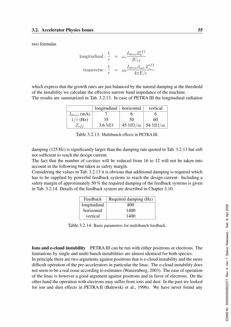
3.2. Accelerator Physics Issues 55
two formulas
longitudinal :1
τ= ωs
IthresZeff0
2Urf
transverse :1
τ= ω0
Ithresβcav.Zeff⊥
4πE/e
which express that the growth rates are just balanced by the natural damping at the thresholdof the instability we calculate the effective narrow band impedance of the machine.The results are summarized in Tab. 3.2.13. In case of PETRA III the longitudinal radiation
longitudinal horizontal verticalIthres (mA) 7 6 61/τ (Hz) 35 50 60Zeff 3.6 MΩ 45 MΩ/m 54 MΩ/m
Table 3.2.13: Multibunch effects in PETRA III.
damping (125 Hz) is significantly larger than the damping rate quoted in Tab. 3.2.13 but stillnot sufficient to reach the design current.The fact that the number of cavities will be reduced from 16 to 12 will not be taken intoaccount in the following but taken as safety margin.Considering the values in Tab. 3.2.13 it is obvious that additional damping is required whichhas to be supplied by powerful feedback systems to reach the design current. Including asafety margin of approximately 50 % the required damping of the feedback systems is givenin Tab. 3.2.14. Details of the feedback system are described in Chapter 3.10.
Feedback Required damping (Hz)longitudinal 800horizontal 1400
vertical 1400
Table 3.2.14: Basic parameters for multibunch feedback.
Ions and e-cloud instability PETRA III can be run with either positrons or electrons. Thelimitations by single and multi bunch instabilities are almost identical for both species.In principle there are two arguments against positrons that is e-cloud instability and the moredifficult operation of the pre-accelerators in particular the linac. The e-cloud instability doesnot seem to be a real issue according to estimates (Wanzenberg, 2003). The ease of operationof the linac is however a good argument against positrons and in favor of electrons. On theother hand the operation with electrons may suffer from ions and dust. In the past we lookedfor ion and dust effects in PETRA II (Balewski et al., 1996). We have never found any
ED
MS
Nr.:
D00
0000
0082
2371
Rev
: A V
er: 1
Sta
tus:
Rel
ease
d -
Dat
.: 8.
Apr
200
8
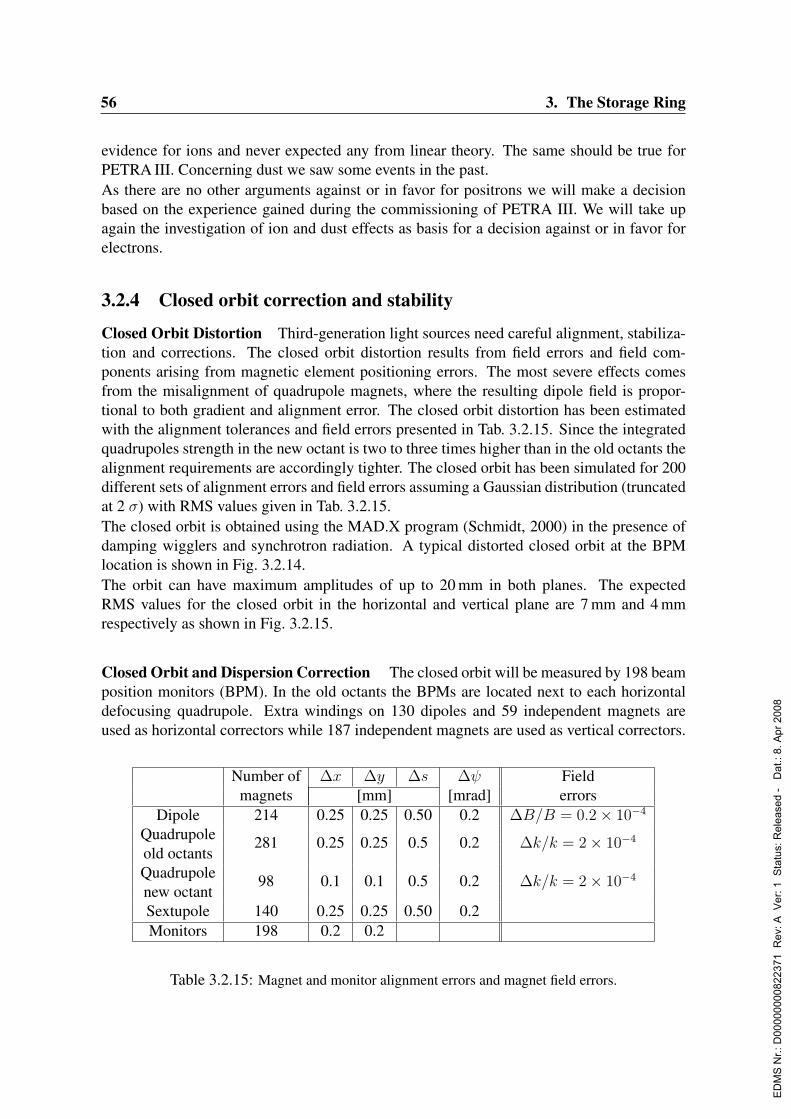
56 3. The Storage Ring
evidence for ions and never expected any from linear theory. The same should be true forPETRA III. Concerning dust we saw some events in the past.As there are no other arguments against or in favor for positrons we will make a decisionbased on the experience gained during the commissioning of PETRA III. We will take upagain the investigation of ion and dust effects as basis for a decision against or in favor forelectrons.
3.2.4 Closed orbit correction and stability
Closed Orbit Distortion Third-generation light sources need careful alignment, stabiliza-tion and corrections. The closed orbit distortion results from field errors and field com-ponents arising from magnetic element positioning errors. The most severe effects comesfrom the misalignment of quadrupole magnets, where the resulting dipole field is propor-tional to both gradient and alignment error. The closed orbit distortion has been estimatedwith the alignment tolerances and field errors presented in Tab. 3.2.15. Since the integratedquadrupoles strength in the new octant is two to three times higher than in the old octants thealignment requirements are accordingly tighter. The closed orbit has been simulated for 200different sets of alignment errors and field errors assuming a Gaussian distribution (truncatedat 2 σ) with RMS values given in Tab. 3.2.15.The closed orbit is obtained using the MAD.X program (Schmidt, 2000) in the presence ofdamping wigglers and synchrotron radiation. A typical distorted closed orbit at the BPMlocation is shown in Fig. 3.2.14.The orbit can have maximum amplitudes of up to 20 mm in both planes. The expectedRMS values for the closed orbit in the horizontal and vertical plane are 7 mm and 4 mmrespectively as shown in Fig. 3.2.15.
Closed Orbit and Dispersion Correction The closed orbit will be measured by 198 beamposition monitors (BPM). In the old octants the BPMs are located next to each horizontaldefocusing quadrupole. Extra windings on 130 dipoles and 59 independent magnets areused as horizontal correctors while 187 independent magnets are used as vertical correctors.
Number of ∆x ∆y ∆s ∆ψ Fieldmagnets [mm] [mrad] errors
Dipole 214 0.25 0.25 0.50 0.2 ∆B/B = 0.2× 10⁻⁴
Quadrupoleold octants
281 0.25 0.25 0.5 0.2 ∆k/k = 2× 10⁻⁴
Quadrupolenew octant
98 0.1 0.1 0.5 0.2 ∆k/k = 2× 10⁻⁴
Sextupole 140 0.25 0.25 0.50 0.2Monitors 198 0.2 0.2
Table 3.2.15: Magnet and monitor alignment errors and magnet field errors.
ED
MS
Nr.:
D00
0000
0082
2371
Rev
: A V
er: 1
Sta
tus:
Rel
ease
d -
Dat
.: 8.
Apr
200
8
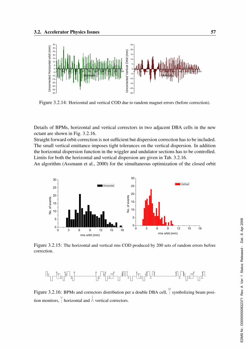
3.2. Accelerator Physics Issues 57
Figure 3.2.14: Horizontal and vertical COD due to random magnet errors (before correction).
Details of BPMs, horizontal and vertical correctors in two adjacent DBA cells in the newoctant are shown in Fig. 3.2.16.Straight forward orbit correction is not sufficient but dispersion correction has to be included.The small vertical emittance imposes tight tolerances on the vertical dispersion. In additionthe horizontal dispersion function in the wiggler and undulator sections has to be controlled.Limits for both the horizontal and vertical dispersion are given in Tab. 3.2.16.An algorithm (Assmann et al., 2000) for the simultaneous optimization of the closed orbit
Figure 3.2.15: The horizontal and vertical rms COD produced by 200 sets of random errors beforecorrection.
Figure 3.2.16: BPMs and correctors distribution per a double DBA cell,2| symbolizing beam posi-
tion monitors,∨| horizontal and
|∧ vertical correctors.
ED
MS
Nr.:
D00
0000
0082
2371
Rev
: A V
er: 1
Sta
tus:
Rel
ease
d -
Dat
.: 8.
Apr
200
8
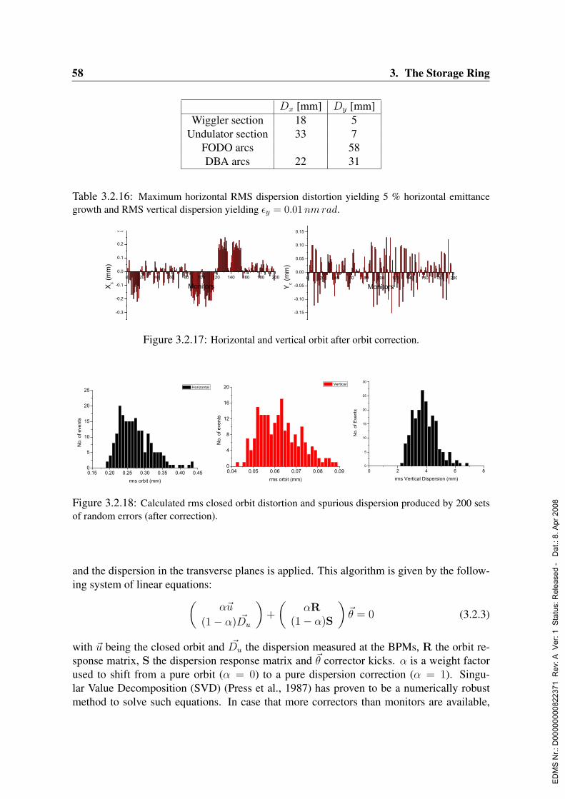
58 3. The Storage Ring
Dx [mm] Dy [mm]Wiggler section 18 5
Undulator section 33 7FODO arcs 58DBA arcs 22 31
Table 3.2.16: Maximum horizontal RMS dispersion distortion yielding 5 % horizontal emittancegrowth and RMS vertical dispersion yielding εy = 0.01 nm rad.
Figure 3.2.17: Horizontal and vertical orbit after orbit correction.
Figure 3.2.18: Calculated rms closed orbit distortion and spurious dispersion produced by 200 setsof random errors (after correction).
and the dispersion in the transverse planes is applied. This algorithm is given by the follow-ing system of linear equations:(
α~u
(1− α) ~Du
)+
(αR
(1− α)S
)~θ = 0 (3.2.3)
with ~u being the closed orbit and ~Du the dispersion measured at the BPMs, R the orbit re-sponse matrix, S the dispersion response matrix and ~θ corrector kicks. α is a weight factorused to shift from a pure orbit (α = 0) to a pure dispersion correction (α = 1). Singu-lar Value Decomposition (SVD) (Press et al., 1987) has proven to be a numerically robustmethod to solve such equations. In case that more correctors than monitors are available,
ED
MS
Nr.:
D00
0000
0082
2371
Rev
: A V
er: 1
Sta
tus:
Rel
ease
d -
Dat
.: 8.
Apr
200
8
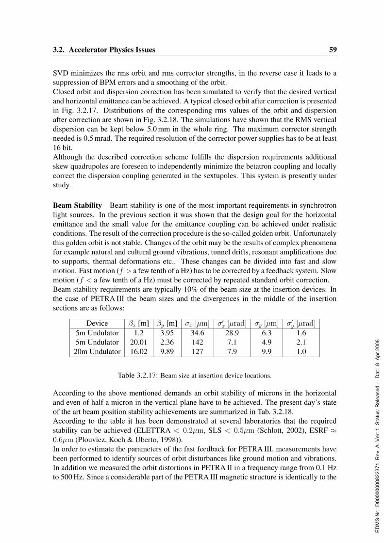
3.2. Accelerator Physics Issues 59
SVD minimizes the rms orbit and rms corrector strengths, in the reverse case it leads to asuppression of BPM errors and a smoothing of the orbit.Closed orbit and dispersion correction has been simulated to verify that the desired verticaland horizontal emittance can be achieved. A typical closed orbit after correction is presentedin Fig. 3.2.17. Distributions of the corresponding rms values of the orbit and dispersionafter correction are shown in Fig. 3.2.18. The simulations have shown that the RMS verticaldispersion can be kept below 5.0 mm in the whole ring. The maximum corrector strengthneeded is 0.5 mrad. The required resolution of the corrector power supplies has to be at least16 bit.Although the described correction scheme fulfills the dispersion requirements additionalskew quadrupoles are foreseen to independently minimize the betatron coupling and locallycorrect the dispersion coupling generated in the sextupoles. This system is presently understudy.
Beam Stability Beam stability is one of the most important requirements in synchrotronlight sources. In the previous section it was shown that the design goal for the horizontalemittance and the small value for the emittance coupling can be achieved under realisticconditions. The result of the correction procedure is the so-called golden orbit. Unfortunatelythis golden orbit is not stable. Changes of the orbit may be the results of complex phenomenafor example natural and cultural ground vibrations, tunnel drifts, resonant amplifications dueto supports, thermal deformations etc.. These changes can be divided into fast and slowmotion. Fast motion (f > a few tenth of a Hz) has to be corrected by a feedback system. Slowmotion (f < a few tenth of a Hz) must be corrected by repeated standard orbit correction.Beam stability requirements are typically 10% of the beam size at the insertion devices. Inthe case of PETRA III the beam sizes and the divergences in the middle of the insertionsections are as follows:
Device βx [m] βy [m] σx [µm] σ′x [µrad] σy [µm] σ′y [µrad]
5m Undulator 1.2 3.95 34.6 28.9 6.3 1.65m Undulator 20.01 2.36 142 7.1 4.9 2.1
20m Undulator 16.02 9.89 127 7.9 9.9 1.0
Table 3.2.17: Beam size at insertion device locations.
According to the above mentioned demands an orbit stability of microns in the horizontaland even of half a micron in the vertical plane have to be achieved. The present day’s stateof the art beam position stability achievements are summarized in Tab. 3.2.18.According to the table it has been demonstrated at several laboratories that the requiredstability can be achieved (ELETTRA < 0.2µm, SLS < 0.5µm (Schlott, 2002), ESRF ≈0.6µm (Plouviez, Koch & Uberto, 1998)).In order to estimate the parameters of the fast feedback for PETRA III, measurements havebeen performed to identify sources of orbit disturbances like ground motion and vibrations.In addition we measured the orbit distortions in PETRA II in a frequency range from 0.1 Hzto 500 Hz. Since a considerable part of the PETRA III magnetic structure is identically to the
ED
MS
Nr.:
D00
0000
0082
2371
Rev
: A V
er: 1
Sta
tus:
Rel
ease
d -
Dat
.: 8.
Apr
200
8

60 3. The Storage Ring
Table 1: Position feedbacks in SR sources worldwide
SR facility FB type Monitors max. BW Stability
ALS* G rf-BPMs < 100 Hz < 1
m
APS G and L rf & p-BPMs < 30 Hz
< 50 Hz *< 2
m
< 1
m *
NSLS G rf-BPMs < 200 Hz 0.5
m
SPEAR 3* G rf-BPMs < 200 Hz < 1
m
BESSY * L rf and p-BPMs < 100 Hz < 1
m
DELTA G rf-BPMs < 1 Hz < 5
m
ELETTRA * L rf-BPMs < 20 Hz < 0.2
m
ESRF G rf-BPMs 100 Hz 0.6
m
MAX-lab G rf-BPMs 1 Hz < 3
m
SLS * G rf & p-BPMs 100 Hz < 0.5
m
SRS L p-BPMs 0.03 Hz 1
m
SUPER-ACO G Rf-BPMs < 150 Hz < 5
m
DIAMOND * G rf-BPMs 100 Hz < 1
m
SOLEIL * G rf and p-BPMs 100 Hz 0.2
m
KEK-PF G rf-BPMs 3 Hz < 5
m
SPRING-8 G rf-BPMs < 0.01 Hz
200 Hz *< 3
m
< 1
m *
* feedbacks in commissioning, respectively proposed systems(table comprehends only data, which could be collected until EPAC
paper submission deadline and thus might not be complete)
Table 3.2.18: Achieved orbit stability at selected synchrotron radiation sources. (from Schlott, 2002)
structure of PETRA II these measurements are useful and relevant in order to estimate orbitdistortions for PETRA III. Measurements of ground motion have been performed at severallocations on the DESY site in the past (Decking, Flottmann & Rossbach, 1990; Brinkmann &Rossbach, 1994; Shiltsev, 1996). Recently some of the measurements have been repeated(Ehrlichmann & Bialowons, 2003) and compared with the situation at other laboratories. Theresult of the most recent measurements are shown in Fig. 3.2.19. The power spectrum showsthe typical form. From 0.1 Hz to a few Hertz the power density is a strongly decreasingfunction. The ground motion is mainly given by ground waves. The increase around afew Hertz is due to cultural noise. From this figure one can conclude that the situationat DESY and the ESRF are comparable. Fig. 3.2.19 also shows the integrated spectrumwhich indicates that the most significant contributions to ground displacement come fromfrequencies below 10 Hz. The rms value of the ground motion is below 140 nm.This noise spectrum is translated by the magnet supports and the beam optics into orbitdistortions. These orbit distortions have been measured at PETRA II and results are shownin Fig. 3.2.20. Comparing the two power spectra (ground motion and orbit) indicates that theorbit is basically determined by the amplification factors of the optics between 0.1 and 10 Hzand that the noise power spectrum is amplified around 20 Hz. This is due to the resonantbehavior of the magnet supports in particular the quadrupole stands. The lowest resonancefrequency of the quadrupole supports is around 20 Hz.
ED
MS
Nr.:
D00
0000
0082
2371
Rev
: A V
er: 1
Sta
tus:
Rel
ease
d -
Dat
.: 8.
Apr
200
8
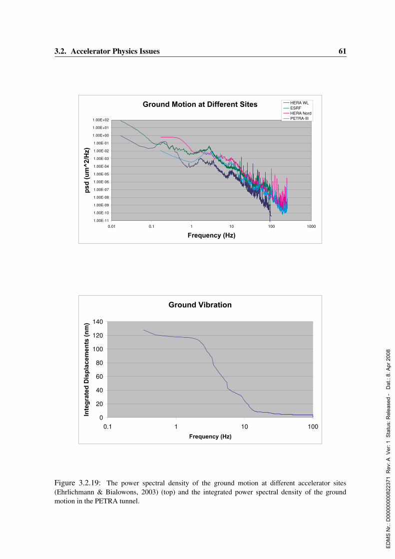
3.2. Accelerator Physics Issues 61
*URXQG0RWLRQDW'LIIHUHQW6LWHV
1.00E-11
1.00E-10
1.00E-09
1.00E-08
1.00E-07
1.00E-06
1.00E-05
1.00E-04
1.00E-03
1.00E-02
1.00E-01
1.00E+00
1.00E+01
1.00E+02
0.01 0.1 1 10 100 1000
)UHTXHQF\+]
HERA WLESRFHERA NordPETRA-III
*URXQG9LEUDWLRQ
0
20
40
60
80
100
120
140
0.1 1 10 100
)UHTXHQF\+]
Figure 3.2.19: The power spectral density of the ground motion at different accelerator sites(Ehrlichmann & Bialowons, 2003) (top) and the integrated power spectral density of the groundmotion in the PETRA tunnel.
ED
MS
Nr.:
D00
0000
0082
2371
Rev
: A V
er: 1
Sta
tus:
Rel
ease
d -
Dat
.: 8.
Apr
200
8

62 3. The Storage Ring
Figure 3.2.20: Power spectral density of horizontal and vertical orbit distortions and integratedpower spectral density.
Figure 3.2.21: The power spectral density of orbit motion due to measured ground motion.
ED
MS
Nr.:
D00
0000
0082
2371
Rev
: A V
er: 1
Sta
tus:
Rel
ease
d -
Dat
.: 8.
Apr
200
8
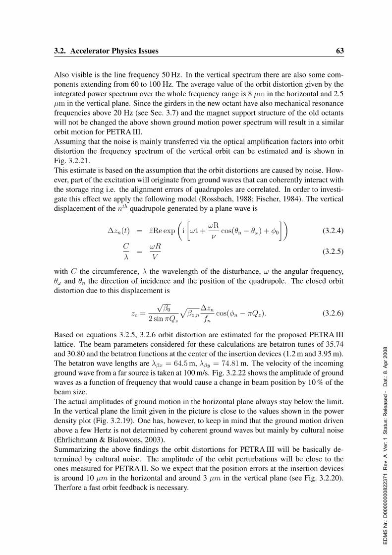
3.2. Accelerator Physics Issues 63
Also visible is the line frequency 50 Hz. In the vertical spectrum there are also some com-ponents extending from 60 to 100 Hz. The average value of the orbit distortion given by theintegrated power spectrum over the whole frequency range is 8 µm in the horizontal and 2.5µm in the vertical plane. Since the girders in the new octant have also mechanical resonancefrequencies above 20 Hz (see Sec. 3.7) and the magnet support structure of the old octantswill not be changed the above shown ground motion power spectrum will result in a similarorbit motion for PETRA III.Assuming that the noise is mainly transferred via the optical amplification factors into orbitdistortion the frequency spectrum of the vertical orbit can be estimated and is shown inFig. 3.2.21.This estimate is based on the assumption that the orbit distortions are caused by noise. How-ever, part of the excitation will originate from ground waves that can coherently interact withthe storage ring i.e. the alignment errors of quadrupoles are correlated. In order to investi-gate this effect we apply the following model (Rossbach, 1988; Fischer, 1984). The verticaldisplacement of the nth quadrupole generated by a plane wave is
∆zn(t) = zRe exp
(i
[ωt +
ωR
νcos(θn − θω) + φ0
])(3.2.4)
C
λ=
ωR
V(3.2.5)
with C the circumference, λ the wavelength of the disturbance, ω the angular frequency,θω and θn the direction of incidence and the position of the quadrupole. The closed orbitdistortion due to this displacement is
zc =
√β0
2 sin πQz
√βz,n
∆zn
fn
cos(φn − πQz). (3.2.6)
Based on equations 3.2.5, 3.2.6 orbit distortion are estimated for the proposed PETRA IIIlattice. The beam parameters considered for these calculations are betatron tunes of 35.74and 30.80 and the betatron functions at the center of the insertion devices (1.2 m and 3.95 m).The betatron wave lengths are λβx = 64.5 m, λβy = 74.81 m. The velocity of the incomingground wave from a far source is taken at 100 m/s. Fig. 3.2.22 shows the amplitude of groundwaves as a function of frequency that would cause a change in beam position by 10 % of thebeam size.The actual amplitudes of ground motion in the horizontal plane always stay below the limit.In the vertical plane the limit given in the picture is close to the values shown in the powerdensity plot (Fig. 3.2.19). One has, however, to keep in mind that the ground motion drivenabove a few Hertz is not determined by coherent ground waves but mainly by cultural noise(Ehrlichmann & Bialowons, 2003).Summarizing the above findings the orbit distortions for PETRA III will be basically de-termined by cultural noise. The amplitude of the orbit perturbations will be close to theones measured for PETRA II. So we expect that the position errors at the insertion devicesis around 10 µm in the horizontal and around 3 µm in the vertical plane (see Fig. 3.2.20).Therfore a fast orbit feedback is necessary.
ED
MS
Nr.:
D00
0000
0082
2371
Rev
: A V
er: 1
Sta
tus:
Rel
ease
d -
Dat
.: 8.
Apr
200
8
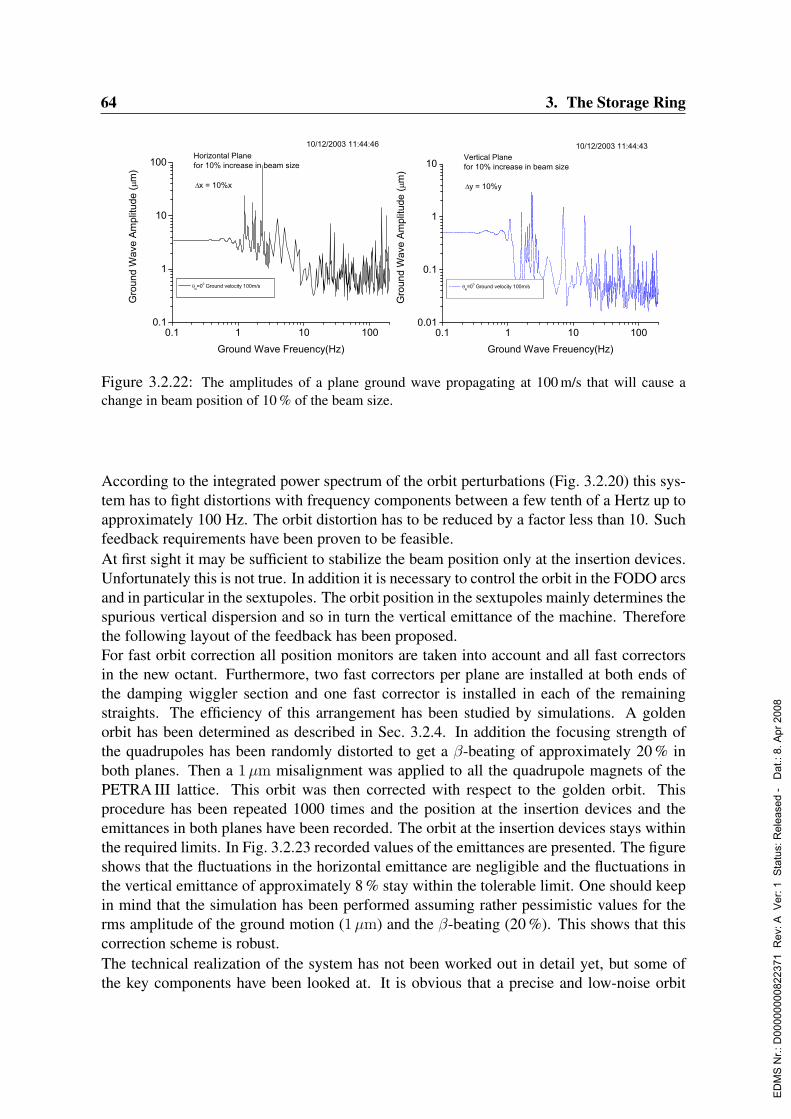
64 3. The Storage Ring
Figure 3.2.22: The amplitudes of a plane ground wave propagating at 100 m/s that will cause achange in beam position of 10 % of the beam size.
According to the integrated power spectrum of the orbit perturbations (Fig. 3.2.20) this sys-tem has to fight distortions with frequency components between a few tenth of a Hertz up toapproximately 100 Hz. The orbit distortion has to be reduced by a factor less than 10. Suchfeedback requirements have been proven to be feasible.At first sight it may be sufficient to stabilize the beam position only at the insertion devices.Unfortunately this is not true. In addition it is necessary to control the orbit in the FODO arcsand in particular in the sextupoles. The orbit position in the sextupoles mainly determines thespurious vertical dispersion and so in turn the vertical emittance of the machine. Thereforethe following layout of the feedback has been proposed.For fast orbit correction all position monitors are taken into account and all fast correctorsin the new octant. Furthermore, two fast correctors per plane are installed at both ends ofthe damping wiggler section and one fast corrector is installed in each of the remainingstraights. The efficiency of this arrangement has been studied by simulations. A goldenorbit has been determined as described in Sec. 3.2.4. In addition the focusing strength ofthe quadrupoles has been randomly distorted to get a β-beating of approximately 20 % inboth planes. Then a 1µm misalignment was applied to all the quadrupole magnets of thePETRA III lattice. This orbit was then corrected with respect to the golden orbit. Thisprocedure has been repeated 1000 times and the position at the insertion devices and theemittances in both planes have been recorded. The orbit at the insertion devices stays withinthe required limits. In Fig. 3.2.23 recorded values of the emittances are presented. The figureshows that the fluctuations in the horizontal emittance are negligible and the fluctuations inthe vertical emittance of approximately 8 % stay within the tolerable limit. One should keepin mind that the simulation has been performed assuming rather pessimistic values for therms amplitude of the ground motion (1µm) and the β-beating (20 %). This shows that thiscorrection scheme is robust.The technical realization of the system has not been worked out in detail yet, but some ofthe key components have been looked at. It is obvious that a precise and low-noise orbit
ED
MS
Nr.:
D00
0000
0082
2371
Rev
: A V
er: 1
Sta
tus:
Rel
ease
d -
Dat
.: 8.
Apr
200
8
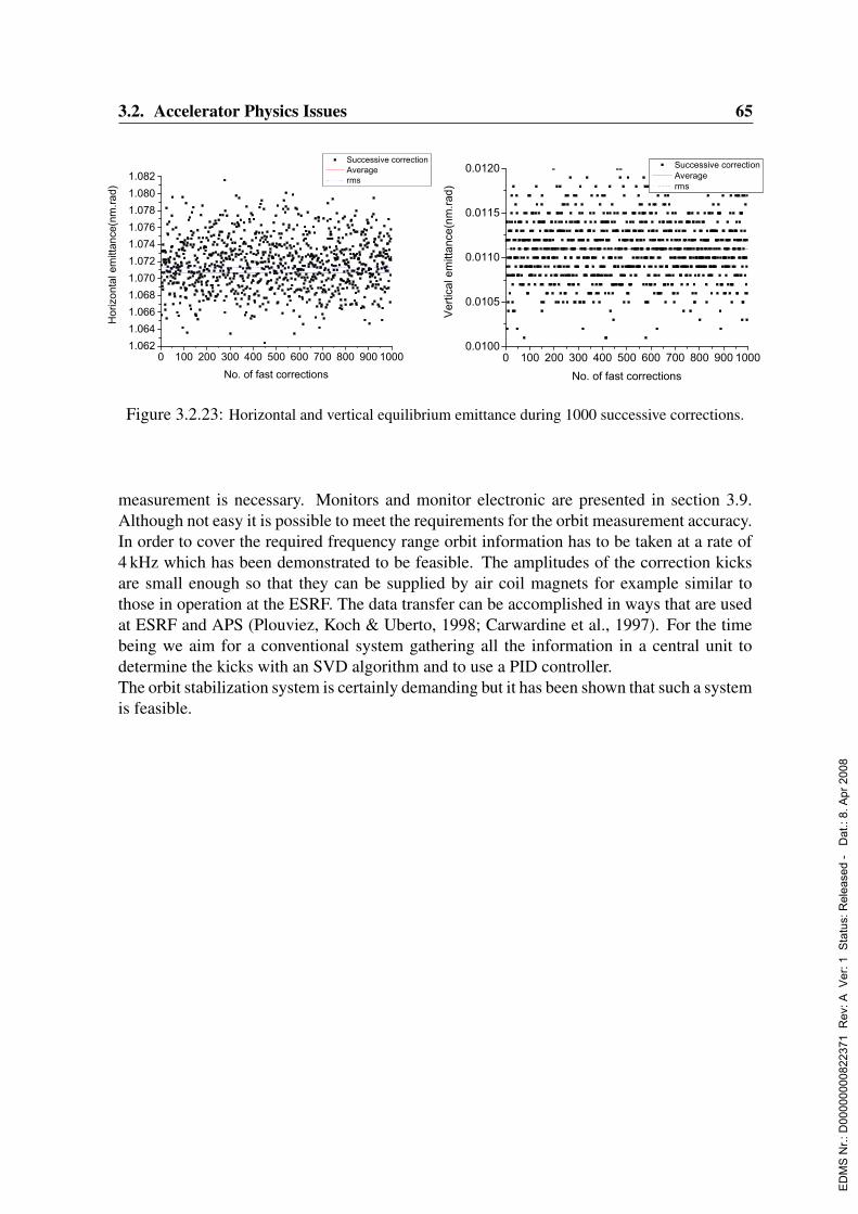
3.2. Accelerator Physics Issues 65
Figure 3.2.23: Horizontal and vertical equilibrium emittance during 1000 successive corrections.
measurement is necessary. Monitors and monitor electronic are presented in section 3.9.Although not easy it is possible to meet the requirements for the orbit measurement accuracy.In order to cover the required frequency range orbit information has to be taken at a rate of4 kHz which has been demonstrated to be feasible. The amplitudes of the correction kicksare small enough so that they can be supplied by air coil magnets for example similar tothose in operation at the ESRF. The data transfer can be accomplished in ways that are usedat ESRF and APS (Plouviez, Koch & Uberto, 1998; Carwardine et al., 1997). For the timebeing we aim for a conventional system gathering all the information in a central unit todetermine the kicks with an SVD algorithm and to use a PID controller.The orbit stabilization system is certainly demanding but it has been shown that such a systemis feasible.
ED
MS
Nr.:
D00
0000
0082
2371
Rev
: A V
er: 1
Sta
tus:
Rel
ease
d -
Dat
.: 8.
Apr
200
8
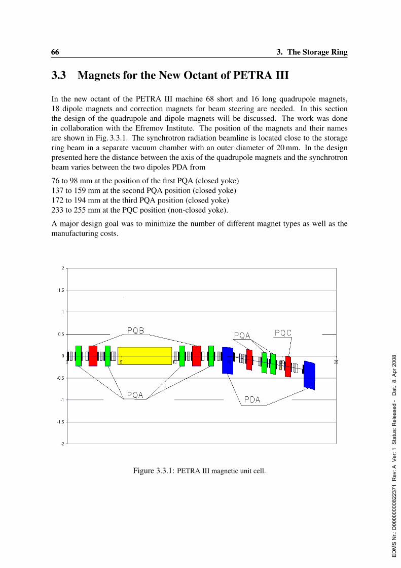
66 3. The Storage Ring
3.3 Magnets for the New Octant of PETRA III
In the new octant of the PETRA III machine 68 short and 16 long quadrupole magnets,18 dipole magnets and correction magnets for beam steering are needed. In this sectionthe design of the quadrupole and dipole magnets will be discussed. The work was donein collaboration with the Efremov Institute. The position of the magnets and their namesare shown in Fig. 3.3.1. The synchrotron radiation beamline is located close to the storagering beam in a separate vacuum chamber with an outer diameter of 20 mm. In the designpresented here the distance between the axis of the quadrupole magnets and the synchrotronbeam varies between the two dipoles PDA from
76 to 98 mm at the position of the first PQA (closed yoke)137 to 159 mm at the second PQA position (closed yoke)172 to 194 mm at the third PQA position (closed yoke)233 to 255 mm at the PQC position (non-closed yoke).
A major design goal was to minimize the number of different magnet types as well as themanufacturing costs.
Magnets for the New Octant of PETRA III
In the new octant of the PETRA III machine 68 short and 16 long quadrupole magnets, 18
dipole magnets and correction magnets for beam steering are needed.
In this chapter the design of the quadrupole and dipole magnets will be discussed. The work was
done in collaboration with the Efremov Institute.
The position of the magnets and their names are shown in Fig. I.1. The synchrotron radiation
beamline is located close to the storage ring electron beam in a separate vacuum chamber with
an outer diameter of 20 mm. In the design presented here the distance between the axis of the
quadrupole magnets and the synchrotron beam varies between the two dipoles PDA from
76 to 98 mm at the position of the first PQA (closed yoke)
137 to 159 mm at the second PQA position (closed yoke)
172 to 194 mm at the third PQA position (closed yoke)
233 to 255 mm at the PQC position (non closed yoke).
Fig. I.1: PETRA III magnetic unit cell.
Figure 3.3.1: PETRA III magnetic unit cell.
ED
MS
Nr.:
D00
0000
0082
2371
Rev
: A V
er: 1
Sta
tus:
Rel
ease
d -
Dat
.: 8.
Apr
200
8
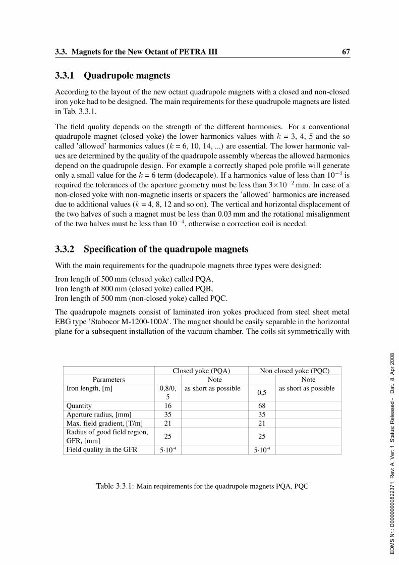
3.3. Magnets for the New Octant of PETRA III 67
3.3.1 Quadrupole magnets
According to the layout of the new octant quadrupole magnets with a closed and non-closediron yoke had to be designed. The main requirements for these quadrupole magnets are listedin Tab. 3.3.1.
The field quality depends on the strength of the different harmonics. For a conventionalquadrupole magnet (closed yoke) the lower harmonics values with k = 3, 4, 5 and the socalled ’allowed’ harmonics values (k = 6, 10, 14, ...) are essential. The lower harmonic val-ues are determined by the quality of the quadrupole assembly whereas the allowed harmonicsdepend on the quadrupole design. For example a correctly shaped pole profile will generateonly a small value for the k = 6 term (dodecapole). If a harmonics value of less than 10−4 isrequired the tolerances of the aperture geometry must be less than 3×10⁻² mm. In case of anon-closed yoke with non-magnetic inserts or spacers the ’allowed’ harmonics are increaseddue to additional values (k = 4, 8, 12 and so on). The vertical and horizontal displacement ofthe two halves of such a magnet must be less than 0.03 mm and the rotational misalignmentof the two halves must be less than 10−4, otherwise a correction coil is needed.
3.3.2 Specification of the quadrupole magnets
With the main requirements for the quadrupole magnets three types were designed:
Iron length of 500 mm (closed yoke) called PQA,Iron length of 800 mm (closed yoke) called PQB,Iron length of 500 mm (non-closed yoke) called PQC.
The quadrupole magnets consist of laminated iron yokes produced from steel sheet metalEBG type ’Stabocor M-1200-100A’. The magnet should be easily separable in the horizontalplane for a subsequent installation of the vacuum chamber. The coils sit symmetrically with
A major design goal was to minimize the number of different magnet types as well as the
manufacturing costs.
Quadrupole Magnets
According to the layout of the new octant quadrupole magnets with a close and non-closed iron
yoke had to be designed. The main requirements for these quadrupole magnets are listed in
Table I.1.
Closed yoke (PQA) Non closed yoke (PQC)
Parameters Note Note
Iron length, [m] 0,8/0,
5
as short as possible0,5
as short as possible
Quantity 16 68
Aperture radius, [mm] 35 35
Max. field gradient, [T/m] 21 21
Radius of good field region,
GFR, [mm]25 25
Field quality in the GFR 5⋅10-4 5⋅10-4
Table I.1: Main requirements for the quadrupole magnets PQA, PQC
In the good field region the field quality depends on superposition of the different harmonics.
For a conventional quadrupole magnet (closed yoke) the lower harmonics values with k=3,4,5
and the so called “allowed” harmonics values (k=6,10,14, and so on) are essential. The lower
harmonic values are determined by the quality of the quadrupole assembly whereas the allowed
harmonics depend on the quadrupole design. For example a correctly shaped pole profile will
generate only a small value for k=6 term (dodecapole). If a harmonics value of less than 10-4 is
required the tolerances of the aperture geometry must be less than 3×10⁻² mm.
In case of a non closed yoke with non magnetic inserts or spacers the “allowed” harmonics are
increased due to additional values (k=4,8,12 and so on). The vertical and horizontal
displacement of the two halves of such a magnet must be less than 0.03 mm and the rotational
misalignment of the two halves must be less than 10-4, otherwise a correction coil is needed.
Table 3.3.1: Main requirements for the quadrupole magnets PQA, PQC
ED
MS
Nr.:
D00
0000
0082
2371
Rev
: A V
er: 1
Sta
tus:
Rel
ease
d -
Dat
.: 8.
Apr
200
8

68 3. The Storage Ring
respect to the axis on the quadrant iron and all four coils are electrically connected in series.The main parameters of these magnets are listed in Tab. 3.3.3 (closed yoke) and Tab. 3.3.4(non-closed yoke) at the end of this section. The nominal current is 190 A. Four watercircuits are needed for the coil cooling made from a 9×9 mm2 copper conductor with ahole of 4.5 mm diameter. The copper conductor is wrapped by three layers of fiber glassband. The thickness of the turn insulation is 0.5 mm per side. The coil has six layers and atotal of 57 windings. The correction coil has a copper conductor of 1.25×3.55 mm2 crosssection and consists of two layers of 56 windings. The insulation of the coil is vacuumimpregnated. A water temperature rise of 15 C is expected. The gap between the coilsfor the accommodation of the vacuum chamber is 28 mm. To minimize the tooling costs(stamping tool) the PQB is stacked of the same lamination as the PQA. The length of PQBis increased to 800 mm.
3.3.3 Results of the 2-D calculation for the quadrupole magnets
For the 2-d calculation the OPERA-2D code was used. The material for the yoke is ’StabocorM-1200-100A’ steel with a filling factor of 0.98. In Fig. 3.3.2 the cross section of a quarterof the quadrupole magnet (PQA) with a closed yoke is shown. The horizontal gap of 28mm height between the coils allows to use this magnet at several positions for the outgoingsynchrotron radiation beam. Because of the symmetry one eighth of the cross-section wasused for the 2d calculation (red line). The result is shown in Fig. 3.3.3 (a quarter of the yokeis shown). A quarter of the cross-section of the quadrupole magnet with a non-closed yoke(PQC) is shown in Fig. 3.3.4 and the result is shown in Fig. 3.3.5. With the input parametersfrom Tables 3.3.3 and 3.3.4 at the end of this section, the general results of the calculated fieldquality, the maximum inductions at the pole (Bmax
p ) and yoke (BmaxY ) are listed in Tab. 3.3.2
for the closed and non-closed yokes.
Results of 2-d calculation
For the 2-d calculation the OPERA-2D code was used. The material for the yoke is “Stabocor
M-1200-100A” steel with a filling factor of 0.98. In Fig I.2 the cross section of a quarter of the
quadrupole magnet (PQA) with a closed yoke is shown. The horizontal gap of 28 mm height
between the coils allows to use this magnet at several positions for the outgoing synchrotron
radiation beam. Because of the symmetry one eighth of the cross-section was used for the 2d
calculation (red line). The result is shown in Fig. I.3 (a quarter of the yoke is shown).
A quarter of the cross-section of the quadrupole magnet with a non closed yoke (PQC) is shown
in Fig. I.4 and the result is shown in Fig. I.5. With the input parameters from Table I.3 and I.4
the general results of the calculated field quality, the maximum inductions at the pole (Bpmax) and
yoke (BYmax) are listed in Table I.5 for the closed and non closed yokes.
Var.Ampere
turns
Current Gradient Bpmax BY
max
kA A T/m T T
Closed
yoke10.7 187.7 21.6 1.45 1.45
Non
closed
yoke
10.7 187.7 21.6 1.43 1.4
Var.
Rref = 25 mm
A4/a2 a6/a2 a8/a2 a10/a2 a14/a2 a18/a2 Σai /a2
10-5
Closed yoke 0.5 -1.9 -3.2 -3.1 9
Non closed
yoke-0.03 0.5 0.02 -1.9 -3.2 -3.1 9
Table I.5: Results of the calculation for the quadrupole magnetsTable 3.3.2: Results of the calculation for the quadrupole magnets
ED
MS
Nr.:
D00
0000
0082
2371
Rev
: A V
er: 1
Sta
tus:
Rel
ease
d -
Dat
.: 8.
Apr
200
8

3.3. Magnets for the New Octant of PETRA III 69
Fig. I.2: One quarter cross-section of the quadrupole magnet with a closed yokeFigure 3.3.2: One quarter cross-section of the quadrupole magnet with a closed yoke.
Fig I.3: Results of the calculation for the closed yoke. The induction (BMOD) in Tesla is shown. In the
top figure the induction in air and in the bottom figure the induction in the iron is shown. The coil
geometry is shown in red.Figure 3.3.3: Results of the calculation for the closed yoke. The induction (BMOD) in Tesla isshown. In the left figure the induction in air and in the right figure the induction in the iron is shown.The coil geometry is shown in red.
ED
MS
Nr.:
D00
0000
0082
2371
Rev
: A V
er: 1
Sta
tus:
Rel
ease
d -
Dat
.: 8.
Apr
200
8
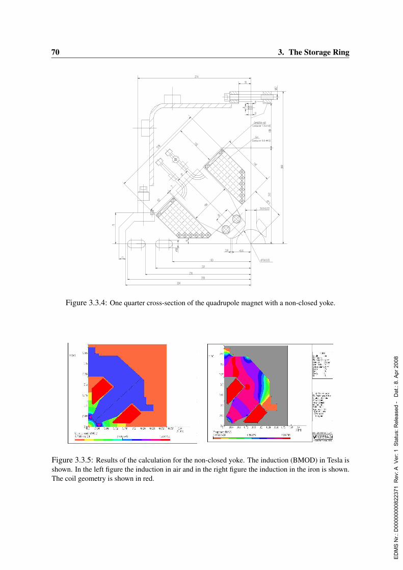
70 3. The Storage Ring
Fig I.4: Cross-section of the quadrupole magnet (one quarter) with a non closed yokeFigure 3.3.4: One quarter cross-section of the quadrupole magnet with a non-closed yoke.
Fig I.5: Results of the calculation for the non-closed yoke. The induction (BMOD) in Tesla is shown. In
the top figure the induction in air and in the bottom figure the induction in the iron is shown. The coil
geometry is shown in red.
Dipole Magnet
The dipole magnet will be an H-type magnet of 1 m length with a maximum induction of 1 Tesla. The
vertical gap height is 48 mm. The good field region has to be 60 mm in horizontal and 36 mm in vertical
direction. The field quality must be better than 5x10⁻⁴. The main parameters are listed in Table I.5. To
facilitate the installation and deinstallation of the vacuum chamber in the beam position from the top a
H-type magnet design with separation in the horizontal plane was chosen (Fig. I.6)
Figure 3.3.5: Results of the calculation for the non-closed yoke. The induction (BMOD) in Tesla isshown. In the left figure the induction in air and in the right figure the induction in the iron is shown.The coil geometry is shown in red.
ED
MS
Nr.:
D00
0000
0082
2371
Rev
: A V
er: 1
Sta
tus:
Rel
ease
d -
Dat
.: 8.
Apr
200
8

3.3. Magnets for the New Octant of PETRA III 71
Fig. I.6: Cross-section of the PDA dipole magnet.
The iron yoke can be produced from a solid soft magnetic iron with a coercitive force between 75 A/m
and 100 A/m with a maximum permeability around 4500 or can be made of steel laminations. The gap
between the poles is 48 mm. To ensure the field quality the surfaces must be parallel to better than 0.02
mm. The weight of the yoke is 1080 kg. Each coil has three main pancakes and two correction ones.
Each main pancake has 12 windings whereas the correction pancake has 38 windings. The main coil is
made of a copper conductor with dimensions 9 x 9 mm2 and a hole of 5 mm Ø. The turn insulation
for the main coil is made of a fiber glass band with a thickness of 0.5 mm.
The copper conductor for the correction pancake has a cross section of 2.5 x 5 mm2 and the turn
insulation is made of fiber glass band with a thickness of 0.3 mm. The coil is vacuum
impregnated. Each coil of the dipole has three water cooling circuits.
Figure 3.3.6: Cross-section of the PDA dipole magnet
3.3.4 Dipole magnets
The dipole magnet will be a H-type magnet of 1 m length with a maximum induction of 1Tesla. The vertical gap height is 48 mm. The good field region has to be 60 mm in horizontaland 36 mm in vertical direction. The field quality must be better than 5×10⁻⁴. The mainparameters are listed in Tab. 3.3.5 at the end of this section. To facilitate the installation anddeinstallation of the vacuum chamber into the H-type magnet in the accelerator from the top,a design with separation in the horizontal plane was chosen (Fig. 3.3.6). The iron yoke canbe produced either from a solid soft magnetic iron with a coercive force between 75 A/m and100 A/m with a maximum permeability around 4500 or steel laminations. The gap betweenthe poles is 48 mm. To ensure the field quality the surfaces must be parallel to better than0.02 mm. The weight of the yoke is 1080 kg. Each coil has three main pancakes and twocorrection ones. Each main pancake has 12 windings whereas the correction pancake has38 windings. The main coil is made of a copper conductor with dimensions 9×9 mm2 anda hole of 5 mm diameter. The turn insulation for the main coil is made of a fiber glass bandwith a thickness of 0.5 mm. The copper conductor for the correction pancake has a crosssection of 2.5×5 mm2 and the turn insulation is made of fiber glass band with a thicknessof 0.3 mm. The coil is vacuum impregnated. Each coil of the dipole has three water coolingcircuits.
3.3.5 Results of the 2-D calculation for the PDA dipole
For the 2d calculation the OPERA-2D code was used. The material used is soft magneticiron with a coercive force of 75 A/m and a maximum permeability of 4500. The results areshown in Figs. 3.3.7, 3.3.8. The maximum field nonlinearity in the good field region (30mm) is less then ∆B/B = ±3× 10⁻⁴.For the 3d calculation the MAFIA code was used. Special shims and chamfers provide the
ED
MS
Nr.:
D00
0000
0082
2371
Rev
: A V
er: 1
Sta
tus:
Rel
ease
d -
Dat
.: 8.
Apr
200
8
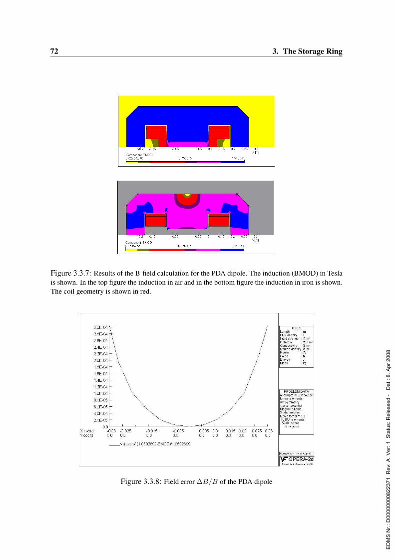
72 3. The Storage Ring
Results of the two dimensional (2d) calculation for the PDA dipole
For the 2d calculation the OPERA-2D code was used. The material used is soft magnetic iron with a
coercitive force of 75 A/m and a maximum permeability of 4500. The results are shown in Fig. I.7, I.8.
The maximum field nonlinearity in the required good field region (x ≤ 30 mm) is less then ∆B/B =
±3 x 10⁻⁴.
Fig. I.7: Results of the B-field calculation. The induction (BMOD) in Tesla is shown. In the top
figure the induction in air and in the bottom figure (next page) the induction in iron is shown.
The coil geometry is shown in red.
Fig. I.8: Field error ∆B/B of the PDA dipole
Figure 3.3.7: Results of the B-field calculation for the PDA dipole. The induction (BMOD) in Teslais shown. In the top figure the induction in air and in the bottom figure the induction in iron is shown.The coil geometry is shown in red.
Results of the three dimensional (3d) calculation
For the 3d calculation the MAFIA code was used. Special shims and chamfers provide the
required field quality (see Fig. I.9). The result of the optimization of the iron yoke are shown in
the Fig. I.10. The field errors in the good field region are within the limits of –1 x 10⁻⁴ to + 4 x
10-4. Shown in Fig. I.10 is the variation of the field integral (I- Io )/ Io
where: I=z= 0
z= 0 . 7
By
x , y , z dz
I0=z= 0
z= 0 . 7
By
0,0, z dz
for one quarter of the good field region in the gap of the dipole.
Figure 3.3.8: Field error ∆B/B of the PDA dipole
ED
MS
Nr.:
D00
0000
0082
2371
Rev
: A V
er: 1
Sta
tus:
Rel
ease
d -
Dat
.: 8.
Apr
200
8
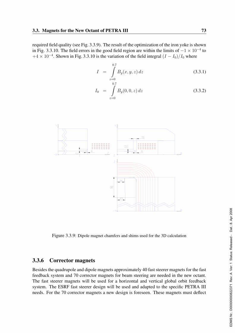
3.3. Magnets for the New Octant of PETRA III 73
required field quality (see Fig. 3.3.9). The result of the optimization of the iron yoke is shownin Fig. 3.3.10. The field errors in the good field region are within the limits of −1× 10⁻⁴ to+4× 10⁻⁴. Shown in Fig. 3.3.10 is the variation of the field integral (I − I0)/I0 where
I =
0.7∫z=0
By(x, y, z) dz (3.3.1)
I0 =
0.7∫z=0
By(0, 0, z) dz (3.3.2)
Fig. I.9: Dipole magnet chamfers and shims used for the 3d calculation
Figure 3.3.9: Dipole magnet chamfers and shims used for the 3D calculation
3.3.6 Corrector magnetsBesides the quadrupole and dipole magnets approximately 40 fast steerer magnets for the fastfeedback system and 70 corrector magnets for beam steering are needed in the new octant.The fast steerer magnets will be used for a horizontal and vertical global orbit feedbacksystem. The ESRF fast steerer design will be used and adapted to the specific PETRA IIIneeds. For the 70 corrector magnets a new design is foreseen. These magnets must deflect
ED
MS
Nr.:
D00
0000
0082
2371
Rev
: A V
er: 1
Sta
tus:
Rel
ease
d -
Dat
.: 8.
Apr
200
8
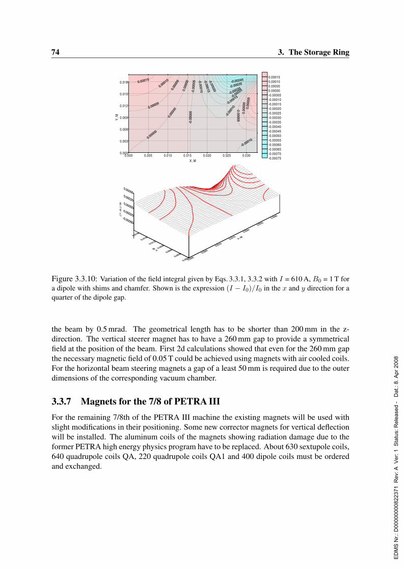
74 3. The Storage Ring
Fig. I.10: I = 610 A, Bo = 1 T , dipole with shims and chamfer, shown is the expression (I- Io )/ Io
in the x and y direction for a quarter of the dipole gap.
0.000 0.005 0.010 0.015 0.020 0.025 0.030
X, M
0.000
0.003
0.006
0.009
0.012
0.015
0.018
Y,
M
-0.00075
-0.00070
-0.00065
-0.00060
-0.00055
-0.00050
-0.00045
-0.00040
-0.00035
-0.00030
-0.00025
-0.00020
-0.00015
-0.00010
-0.00005
0.00000
0.00005
0.00010
0.00015
Figure 3.3.10: Variation of the field integral given by Eqs. 3.3.1, 3.3.2 with I = 610 A, B0 = 1 T fora dipole with shims and chamfer. Shown is the expression (I − I0)/I0 in the x and y direction for aquarter of the dipole gap.
the beam by 0.5 mrad. The geometrical length has to be shorter than 200 mm in the z-direction. The vertical steerer magnet has to have a 260 mm gap to provide a symmetricalfield at the position of the beam. First 2d calculations showed that even for the 260 mm gapthe necessary magnetic field of 0.05 T could be achieved using magnets with air cooled coils.For the horizontal beam steering magnets a gap of a least 50 mm is required due to the outerdimensions of the corresponding vacuum chamber.
3.3.7 Magnets for the 7/8 of PETRA IIIFor the remaining 7/8th of the PETRA III machine the existing magnets will be used withslight modifications in their positioning. Some new corrector magnets for vertical deflectionwill be installed. The aluminum coils of the magnets showing radiation damage due to theformer PETRA high energy physics program have to be replaced. About 630 sextupole coils,640 quadrupole coils QA, 220 quadrupole coils QA1 and 400 dipole coils must be orderedand exchanged.
ED
MS
Nr.:
D00
0000
0082
2371
Rev
: A V
er: 1
Sta
tus:
Rel
ease
d -
Dat
.: 8.
Apr
200
8

3.3. Magnets for the New Octant of PETRA III 75
Table I.3: Main parameters of the quadrupole magnet with a closed yoke (PQA). The PQB
magnet parameters differ in the higher power consumption (4.9 kW) and a slightly lower water
flow rate so that the temperature rise is around 24 degree Celsius.
Table 3.3.3: Main parameters of the quadrupole magnet with a closed yoke (PQA). The PQB magnetparameters differ in the higher power consumption (4.9 kW) and a slightly lower water flow rate sothat the temperature rise is around 24 C
ED
MS
Nr.:
D00
0000
0082
2371
Rev
: A V
er: 1
Sta
tus:
Rel
ease
d -
Dat
.: 8.
Apr
200
8

76 3. The Storage Ring
Table I.4: Main parameters of the quadrupole magnet with a non closed yoke (PQC).Table 3.3.4: Main parameters of the quadrupole magnet with a non-closed yoke (PQC).
ED
MS
Nr.:
D00
0000
0082
2371
Rev
: A V
er: 1
Sta
tus:
Rel
ease
d -
Dat
.: 8.
Apr
200
8
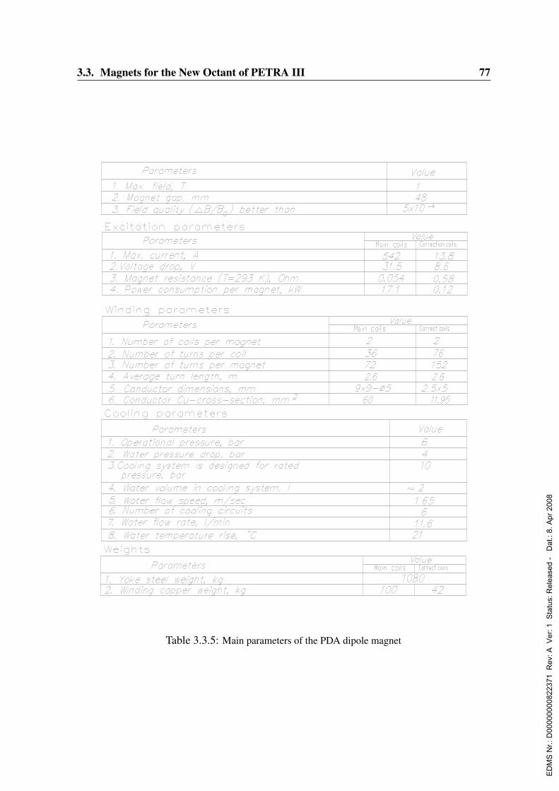
3.3. Magnets for the New Octant of PETRA III 77
Table I.5: Main parameters of the PDA dipole magnet.Table 3.3.5: Main parameters of the PDA dipole magnet
ED
MS
Nr.:
D00
0000
0082
2371
Rev
: A V
er: 1
Sta
tus:
Rel
ease
d -
Dat
.: 8.
Apr
200
8
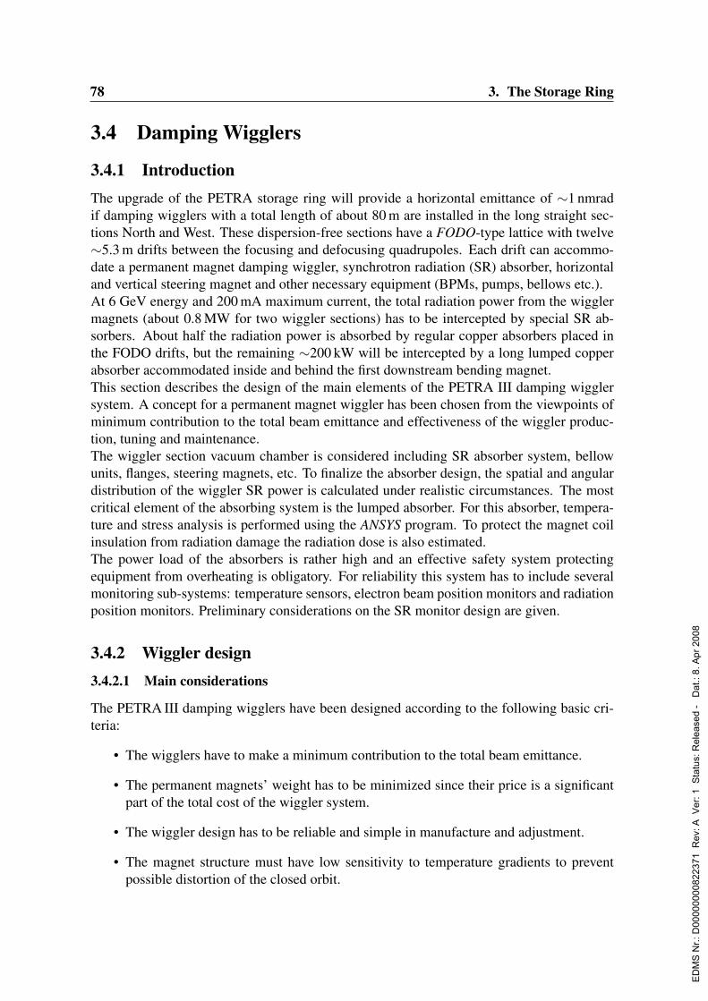
78 3. The Storage Ring
3.4 Damping Wigglers
3.4.1 IntroductionThe upgrade of the PETRA storage ring will provide a horizontal emittance of ∼1 nmradif damping wigglers with a total length of about 80 m are installed in the long straight sec-tions North and West. These dispersion-free sections have a FODO-type lattice with twelve∼5.3 m drifts between the focusing and defocusing quadrupoles. Each drift can accommo-date a permanent magnet damping wiggler, synchrotron radiation (SR) absorber, horizontaland vertical steering magnet and other necessary equipment (BPMs, pumps, bellows etc.).At 6 GeV energy and 200 mA maximum current, the total radiation power from the wigglermagnets (about 0.8 MW for two wiggler sections) has to be intercepted by special SR ab-sorbers. About half the radiation power is absorbed by regular copper absorbers placed inthe FODO drifts, but the remaining ∼200 kW will be intercepted by a long lumped copperabsorber accommodated inside and behind the first downstream bending magnet.This section describes the design of the main elements of the PETRA III damping wigglersystem. A concept for a permanent magnet wiggler has been chosen from the viewpoints ofminimum contribution to the total beam emittance and effectiveness of the wiggler produc-tion, tuning and maintenance.The wiggler section vacuum chamber is considered including SR absorber system, bellowunits, flanges, steering magnets, etc. To finalize the absorber design, the spatial and angulardistribution of the wiggler SR power is calculated under realistic circumstances. The mostcritical element of the absorbing system is the lumped absorber. For this absorber, tempera-ture and stress analysis is performed using the ANSYS program. To protect the magnet coilinsulation from radiation damage the radiation dose is also estimated.The power load of the absorbers is rather high and an effective safety system protectingequipment from overheating is obligatory. For reliability this system has to include severalmonitoring sub-systems: temperature sensors, electron beam position monitors and radiationposition monitors. Preliminary considerations on the SR monitor design are given.
3.4.2 Wiggler design3.4.2.1 Main considerations
The PETRA III damping wigglers have been designed according to the following basic cri-teria:
• The wigglers have to make a minimum contribution to the total beam emittance.
• The permanent magnets’ weight has to be minimized since their price is a significantpart of the total cost of the wiggler system.
• The wiggler design has to be reliable and simple in manufacture and adjustment.
• The magnet structure must have low sensitivity to temperature gradients to preventpossible distortion of the closed orbit.
ED
MS
Nr.:
D00
0000
0082
2371
Rev
: A V
er: 1
Sta
tus:
Rel
ease
d -
Dat
.: 8.
Apr
200
8

3.4. Damping Wigglers 79
For a periodic planar wiggler, an additional contribution to the total emittance of the ring canbe expressed by the so-called I5 radiation integral (Wiedemann, 1993):
I5 ≈8
15Nwβx
θ3w
ρ2w
(3.4.1)
where Nw, θw and ρw are the wiggler period number, maximum deviation angle and cur-vature radius respectively, while βx is the horizontal betatron function averaged over thewiggler length. To reduce the I5 radiation integral for fixed βx and ρw, one has to keep thedeviation angle as small as possible. A conventional periodic wiggler design with a sin-likemagnetic field and half-field poles at both ends complies most with this primarily importantcondition.Special attention was paid to the optimization of the wiggler design with respect to costreduction, which mainly depends on the volume of the magnetic material used for the wig-gler production. Another important point is ease of assembly and adjustment of more than750 wiggler poles: To save the time span required for this procedure as well as to providereliability of the system, the wiggler tuning process has to be as simple as possible.
3.4.2.2 Detailed layout
At the selected field amplitude ofBw = 1.52 T and vertical gap h = 24 mm the wiggler periodlength was optimized as λw = 20 cm. For a shorter period with the same field amplitude onehas to increase the volume of the NeFeB permanent magnets significantly. The thickness dm
of the permanent magnets placed between the poles is determined by the following equation
Bw · h = Bm · dm (3.4.2)
It can be shown that the optimum operation point of a permanent magnet is Bm = 0.6 T. Thatyields a magnet thickness of dm =60 mm. Fig. 3.4.1 shows a schematic design of the wigglerpole magnet structure and the magnetic induction distribution inside.It is proposed to design wedge-shaped ferromagnetic poles (Fig. 3.4.1). Such a design al-
lows splitting one 60 mm thick magnet into two magnets of half thickness and placing thewedge-like ARMCO plate between them. Magnetic symmetry provides that the magneticpotential of this wedge-like plate is zero, therefore the electromagnetic coupling between thepoles practically vanishes. This makes it possible to adjust the field amplitude for each poleseparately without changing it in the adjacent poles. By that means, the wiggler field tuningprocedure becomes simple and is reduced to tuning each individual pole.The side view of the wiggler and its transverse cross-section are shown in Fig. 3.4.2 andFig. 3.4.3. Special magnets are placed at the wiggler sides (Fig. 3.4.3) to reduce the leakageflux from the central iron poles. The reduction of the leakage flux minimizes the size of thecentral iron pole and main magnets. The iron enclosure around the wiggler provides zeromagnetic potential of the iron wedge inserted between the magnets.In order to settle the pole field amplitude within a few percent, special adjustment iron screw-correctors (Fig. 3.4.3) are planned for every pole block. By them moving in and out, theleakage flux changes and the magnetic potential of the pole reduces or increases.
ED
MS
Nr.:
D00
0000
0082
2371
Rev
: A V
er: 1
Sta
tus:
Rel
ease
d -
Dat
.: 8.
Apr
200
8
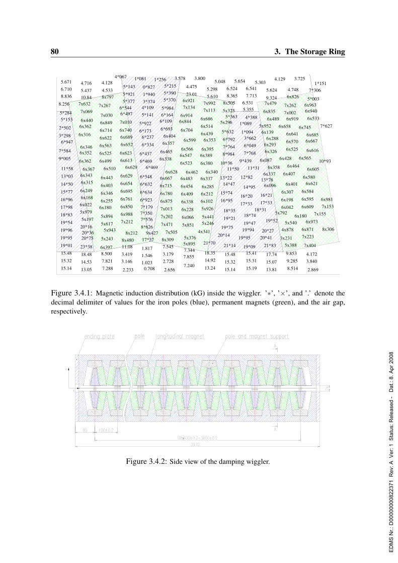
80 3. The Storage Ring
9*005
7*584
3*298
2*502
8.256
15.14
15.32
15.48
19*01
19*95
19*96
19*54
18*83
17*98
16*96
15*77
14*50
13*03
11*58
6*947
5*1535*284
8.8366.710
5.671
13.05
14.53
18.48
23*38
20*16
5x979
6x022
7x63210.845.437
4.716
20*7520*36
5x197
6x1686x249
6x3156x343
6x362
6x3526x346
6x316
6x3626x440
7x069
6x367
7x267
7.288
7.821
8.5006x397
5x243
5x617
5x894
6x1806x255
6x346
6x403
6x443
6x499
6x525
6x563
6x622
6x714
6x849
7x030
8x7974.533
4.128
5x943
6x510
4*067
2.233
3.1463.419
11.088x480
7x212
6x988
6x850
6x761
6x695
6x654
6x629
6x613
6x623
6x652
6x6896x740
7x010
6*4976*544
8x212
6x629
5*3775*921
5*143
1*081
1.0231.5461.817
17*37
8*626
7*5767*3507*1796*923
6*634
6*632
6*548
6*469
6*437
6*173
5*922
0.708
6*334
6*237
5*1414*1093*3741*940
0*827
9x427
6*469
1*256
2.656
2.7283.179
7.5458x309
7x471
7x202
7x013
6x875
6x780
6x715
6x667
6x338
6x465
6*693
6*1096*1645*984
7x505
6x628
6x3576x404
5*3705*3905*215
3.578
7.240
7.8557.3445x8955x376
5x851
6x066
6x228
6x338
6x409
6x454
6x483
6x523
6x5476x566
6x704
6x8446x914
6x462
6x599
7x1346x921
23.01
4.475
4x341
3.800
21*70
5x2465x441
5x926
6x10²
6x2126x285
6x337
6x380
6x3896x395
6x439
6x514
6x686
13.24
14.92
18.35
6x340
6x353
7x1137x992
5.610
5.298
20*14
5.048
19*75
16*95
15*74
13*22
10*36
5x296
15.14
15.32
15.48
21*14
19*21
18*35
14*47
8*984
7*764
6*792
5*632
5x325
8x505
11*50
5*363
8.365
6.524
5.654
19*95
17*33
16*20
12*82
9*439
1*094
1*089
19*09
19*9419*47
18*74
14*95
7*768
6*049
3*662
4*388
5.3556.531
15.19
15.31
15.41
11*31
7.713
6.541
18*31
5.303
17*33
16*21
13*78
6x087
5x952
20*4120*27
6x096
6x337
6x139
13.81
15.07
17.74
21*83
19*52
6x3266x293
6x835
7x4799.324
5.624
6x358
6x288
6x489
4.129
5x792
6x428
6x658
3x231
4x878
6x042
6x198
6x307
6x407
7x002
7x262
8.514
9.285
9.853
5x388
5x540
6x401
6x464
6x525
6x570
6x641
6x919
6x8264.748
3.725
6x180
6x565
6x745
7x404
7x223
6x871
6x609
6x595
6x584
6x580
2.869
3.8404.172
6x973
6x621
6x605
6x616
6x6676x685
6x533
6x9406x963
5*003
7*306
7x155
1*151
10*93
8x306
7x1536x981
7*627
Figure 3.4.1: Magnetic induction distribution (kG) inside the wiggler. ’∗’, ’×’, and ’.’ denote thedecimal delimiter of values for the iron poles (blue), permanent magnets (green), and the air gap,respectively.
Figure 3.4.2: Side view of the damping wiggler.
ED
MS
Nr.:
D00
0000
0082
2371
Rev
: A V
er: 1
Sta
tus:
Rel
ease
d -
Dat
.: 8.
Apr
200
8
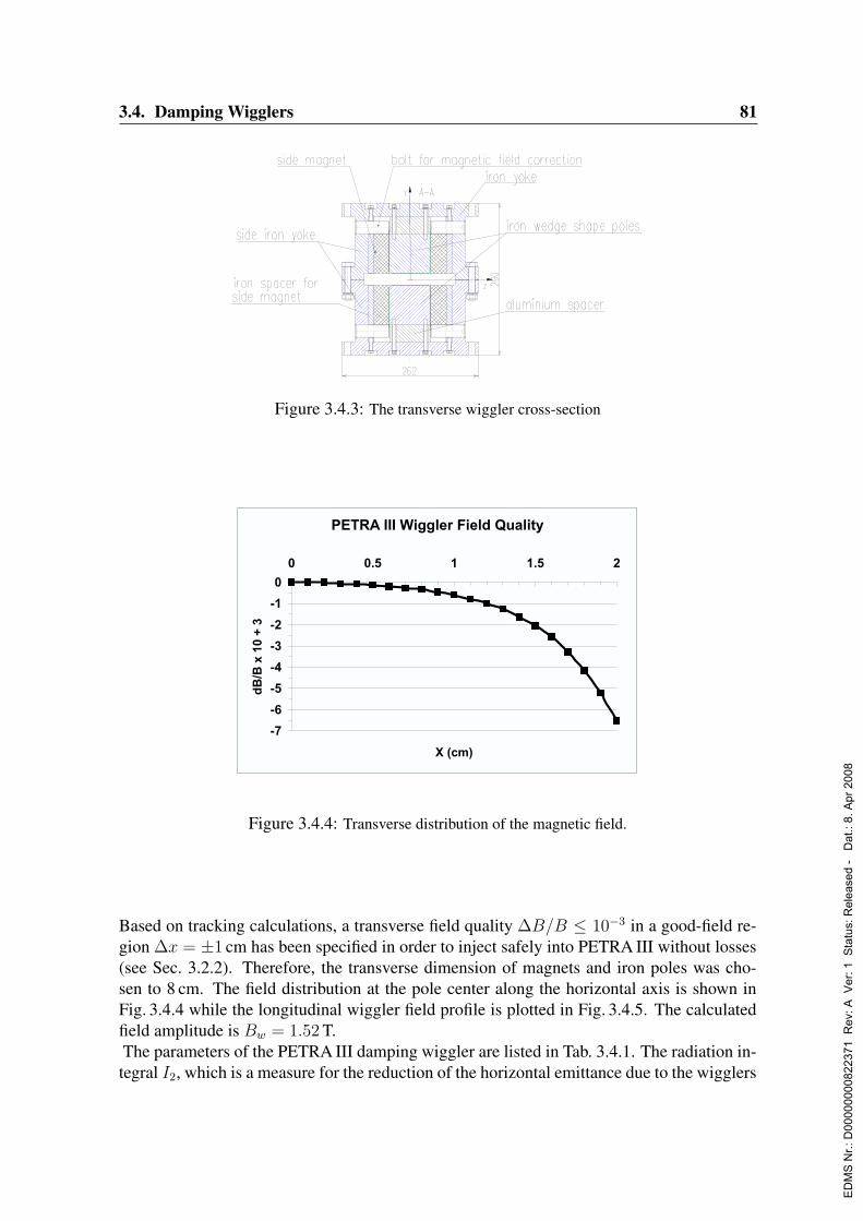
3.4. Damping Wigglers 81
Figure 3.4.3: The transverse wiggler cross-section
PETRA III Wiggler Field Quality
-7
-6
-5
-4
-3
-2
-1
0
0 0.5 1 1.5
X (cm)
dB
/B x
10
+ 3
2
Fig.2.5 Transverse distribution of the wiggler magnetic field.
To provide the transverse field quality in a good field region
cm, the transverse dimension of the magnets and iron poles was chosen to
equal 8 cm. The field distribution at the pole center along the horizontal axis is shown
in Fig.2.4 while the longitudinal wiggler field profile is plotted in Fig.2.5. The
calculated field amplitude is T.
310/ BB
1x
52.1wB
PETRA III Damping Wiggler Field
-20
-15
-10
-5
0
5
10
15
20
0 50 100 150 200 250 300 350 400
Z (cm)
B (
kG
)
Fig.2.5 Longitudinal distribution of the wiggler magnetic field.
Figure 3.4.4: Transverse distribution of the magnetic field.
Based on tracking calculations, a transverse field quality ∆B/B ≤ 10−3 in a good-field re-gion ∆x = ±1 cm has been specified in order to inject safely into PETRA III without losses(see Sec. 3.2.2). Therefore, the transverse dimension of magnets and iron poles was cho-sen to 8 cm. The field distribution at the pole center along the horizontal axis is shown inFig. 3.4.4 while the longitudinal wiggler field profile is plotted in Fig. 3.4.5. The calculatedfield amplitude is Bw = 1.52 T.The parameters of the PETRA III damping wiggler are listed in Tab. 3.4.1. The radiation in-tegral I2, which is a measure for the reduction of the horizontal emittance due to the wigglers
ED
MS
Nr.:
D00
0000
0082
2371
Rev
: A V
er: 1
Sta
tus:
Rel
ease
d -
Dat
.: 8.
Apr
200
8

82 3. The Storage Ring
PETRA III Wiggler Field Quality
-7
-6
-5
-4
-3
-2
-1
0
0 0.5 1 1.5
X (cm)
dB
/B x
10
+ 3
2
Fig.2.5 Transverse distribution of the wiggler magnetic field.
To provide the transverse field quality in a good field region
cm, the transverse dimension of the magnets and iron poles was chosen to
equal 8 cm. The field distribution at the pole center along the horizontal axis is shown
in Fig.2.4 while the longitudinal wiggler field profile is plotted in Fig.2.5. The
calculated field amplitude is T.
310/ BB
1x
52.1wB
PETRA III Damping Wiggler Field
-20
-15
-10
-5
0
5
10
15
20
0 50 100 150 200 250 300 350 400
Z (cm)
B (
kG
)
Fig.2.5 Longitudinal distribution of the wiggler magnetic field.
Figure 3.4.5: Longitudinal distribution of the magnetic field.
Peak field Bw 1.52 TMagnetic gap 24 mmPeriod length 0.2 mNumber of periods 20Number of poles 37 + 2 half polesMagnet volume per period 2200 cm3
Field quality at x0 = 10 mm < 10−3
Damping integral per segment 3.859 T2mOverall length of wiggler segment 3.97 mNumber of wiggler segments 20
Table 3.4.1: Damping wiggler parameters
is defined as :I2 =
∫Wig
ds
ρ2(s)=
1
(Bρ)2
∫Wig
B2w(s)ds (3.4.3)
The damping integral∫B2
w(s)ds = 3.859 T2m was obtained from the longitudinal wigglerfield distribution.The top and bottom halves of the wiggler are made from a single piece of iron with a millingaccuracy of±0.1 mm. After the wedge-like poles have been installed, the pole surface facingthe gap and the joint plane of top and bottom halves are ground. Our previous experiencewith this technology shows that the gap accuracy can reach ±30µm which is sufficient forour purpose. This manufacturing technique will allow significant simplification and accel-eration of the wiggler assembly as well as a reduction of the number of parts in the wigglerdesign.The wiggler adjustment includes two stages:
• The magnetic field is measured by a Hall probe array to be inserted in the aperture,
ED
MS
Nr.:
D00
0000
0082
2371
Rev
: A V
er: 1
Sta
tus:
Rel
ease
d -
Dat
.: 8.
Apr
200
8

3.4. Damping Wigglers 83
and the field amplitude is adjusted by means of the screw-correctors within 1 G overthe whole wiggler length.
• A moving wire measures the wiggler field integrals. Measurement accuracy for thefirst and second field integrals using such a technique is ± 5 G cm and 2000 G cm2,respectively. The integrals will be set to zero with the same accuracy.
The use of two wedge-like iron inserts between the magnets and manufacture of each wig-gler half from a solid iron lump minimize temperature gradients in the wiggler. In orderto exclude temperature effects on the magnetic field due to beam heating it is possible toapply a water cooling to the vacuum chamber of the wiggler. Although the absolute valueof the wiggler magnet temperature can vary and lead to a small change of the field ampli-tude (∆B/B ≈ 10−3/K for the NeFeB magnets), the first and second field integrals, whichdepend on the temperature gradient, remain constant.
3.4.3 Wiggler radiation power
3.4.3.1 Introduction
The main tasks of the wiggler radiation power calculation are
1. Developing the procedure for calculation of SR power density distribution at differentazimuths of the wiggler section.
2. Finding the optimal aperture of the regular absorber to provide uniform absorptionalong the straight section length.
3. Estimating tolerances for the absorber alignment in the transverse plane as well as forthe closed orbit deviation in the wiggler section.
An estimate of the power density is derived for an electron energy of 6 GeV and a maximumbeam current of 200 mA. The general characteristics of the damping wiggler radiation aregiven in Tab. 3.4.2.
SR critical energy 35.84 keVK - Parameter 28.39Wiggler length 4 mWiggler SR power 42.12 kWRelativistic factor 1.17×10⁴
Vertical SR spread 85.2µradHorizontal SR spread 4.84 mrad
Table 3.4.2: General SR characteristics of the damping wiggler
ED
MS
Nr.:
D00
0000
0082
2371
Rev
: A V
er: 1
Sta
tus:
Rel
ease
d -
Dat
.: 8.
Apr
200
8
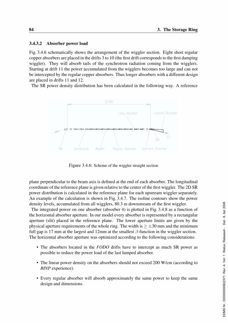
84 3. The Storage Ring
3.4.3.2 Absorber power load
Fig. 3.4.6 schematically shows the arrangement of the wiggler section. Eight short regularcopper absorbers are placed in the drifts 3 to 10 (the first drift corresponds to the first dampingwiggler). They will absorb tails of the synchrotron radiation coming from the wigglers.Starting at drift 11 the power accumulated from the wigglers becomes too large and can notbe intercepted by the regular copper absorbers. Thus longer absorbers with a different designare placed in drifts 11 and 12.The SR power density distribution has been calculated in the following way. A reference
0 0.5 1 1.50
0.2
0.4
0.6
0.8
1
K
G(K
)
0 0.2 0.4 0.6 0.8 10
0.2
0.4
0.6
0.8
1
/ K
0.1
0. 1
0.1
0.2
0.2
0.2
0.3
0.3
0.3
0.30.3
0.4
0.4
0.4
0.4
0.5
0.5
0.50.5
0.6
0.6
0.6
0.7
0.70.7
0.8
0.8
0.8
0.9
0.9
Fig.3.1 G plot. Fig.3.2 )(K ),(Kf plot.
Functions and )(KG ),(Kf are plotted in Fig.3.1 and Fig.3.2,
respectively. For our K = 28.39 the value of G is practically equal to 1. )(K
3.3 Absorbers power load
Fig.3.3 schematically shows an arrangement of the wiggler section equipment
including the 10 wigglers, magnets and absorbers. Eight short regular copper
absorbers placed in the drifts numbered from 3 to 10 (the first drift corresponds to the
first damping wiggler) will absorb tails of the SR distribution coming from the several
first wigglers.
Fig.3.3 Wiggler straight section schematically.
Then the power accumulated from the wigglers became too large and we can
not intercept it by the regular copper absorbers. A solution is to accommodate in the
Figure 3.4.6: Scheme of the wiggler straight section
plane perpendicular to the beam axis is defined at the end of each absorber. The longitudinalcoordinate of the reference plane is given relative to the center of the first wiggler. The 2D SRpower distribution is calculated in the reference plane for each upstream wiggler separately.An example of the calculation is shown in Fig. 3.4.7. The isoline contours show the powerdensity levels, accumulated from all wigglers, 80.3 m downstream of the first wiggler.The integrated power on one absorber (absorber 4) is plotted in Fig. 3.4.8 as a function of
the horizontal absorber aperture. In our model every absorber is represented by a rectangularaperture (slit) placed in the reference plane. The lower aperture limits are given by thephysical aperture requirements of the whole ring. The width is≥±30 mm and the minimumfull gap is 17 mm at the largest and 12mm at the smallest β-function in the wiggler section.The horizontal absorber aperture was optimized according to the following considerations:
• The absorbers located in the FODO drifts have to intercept as much SR power aspossible to reduce the power load of the last lumped absorber.
• The linear power density on the absorbers should not exceed 200 W/cm (according toBINP experience).
• Every regular absorber will absorb approximately the same power to keep the samedesign and dimensions.
ED
MS
Nr.:
D00
0000
0082
2371
Rev
: A V
er: 1
Sta
tus:
Rel
ease
d -
Dat
.: 8.
Apr
200
8

3.4. Damping Wigglers 85
0 10 20 30 40 50 600
1
2
3
4
5
6
X, mm
Y,
mm
dP/ds [W/mm2], P = 189.23 kW, Ptot = 441.99 (443.66) kW
50
50
100
150
200
250
300
350
400
450
Figure 3.4.7: Power density (W) at 80.3 m from the center of the first wiggler (1/4 of the distribu-tion).
0 10 20 30 40 50 60 70 80 900
50
100
150
200
250
X, mm
C(x
), k
W
30 31 32 33 34 35 36 37 38 39 400
5
10
15
20
25
30
X, mm
Figure 3.4.8: Accumulated power at the azimuth of the forth regular absorber.
The vertical absorber aperture has to provide reliable shading of the wiggler vacuum cham-ber. Therefore the aperture will be reduced to 13 mm for all absorbers which are placed closeto the horizontal focusing quadrupoles. This yields a maximum allowed incident angle of∆′
R = 163µrad, as shown in Fig. 3.4.9.
ED
MS
Nr.:
D00
0000
0082
2371
Rev
: A V
er: 1
Sta
tus:
Rel
ease
d -
Dat
.: 8.
Apr
200
8

86 3. The Storage Ring
The total opening angle of the 1σ RMS radiation fan is equal to
σ′R =√σ′2SR + σ′2ye, (3.4.4)
where σ′SR = 1/γ = 85µrad is the vertical angular spread of the radiation at 6 GeV, σ′ye =√εy/βy is the natural divergence of the electron beam, being ≈ 8 µrad for a mean vertical
betatron function in the wiggler of βy ≈ 15 m and an emittance of εy = 0.5 nm rad (fullycoupled beam). With these values the maximum RMS closed orbit is estimated to be:
σy,cod =
√(∆′
R − σ′R)2
〈γ〉〈β〉 = 0.84 mm. (3.4.5)
The apertures of all regular absorbers are summarized in Tab. 3.4.3. The power that can beabsorbed by each of the absorbers was chosen to be ≈ 15 kW for the regular short absorbers(S1-S8) and ≈ 70 kW for the long ones (S9 and S10).The part of the SR power from the 10 damping wigglers which is not intercepted by theregular absorbers amounts to 182.2 kW with a maximal power density of 352.7 W/mm2. Itwill be absorbed in the lumped absorber at the end of the straight section.
3.4.3.3 COD and absorbers misalignment tolerance
If the closed orbit has deviations or tilts in the wiggler or the position of the absorbers differsfrom the projected one, the thermal load on the absorbers can increase. To estimate thiseffect we have assumed an RMS closed orbit of 1.0 mm in the horizontal plane and 0.5 mmin the vertical plane. This leads to a RMS slope of the closed orbit of 60 µrad horizontallyand 33 µrad vertically at the wiggler SR source points. SR power calculations with theseclosed orbit values yield the maximum increase of SR power on a single absorber as givenin Tab. 3.4.4.
Fig.3.6 Vertical collimating of the wiggler vacuum chamber (schematically).
The total deviation of the 1-sigma (rms) radiation beam is equal to
222 yy yeSR ,
where 85/1SR rad is the vertical angular spread of the radiation at 6 GeV,
yy /
01.
ye
0y
is the natural divergence of the electron beam (for vertical emittance
nm-rad and mean wiggler betatron function 15y m this value is
negligibly small) and y is the rms value of the vertical orbit slope in the wiggler.
Supposing the rms COD 5.0y mm, one can obtain 33/ yyy rad,
which yields the total vertical inclination rad.91y
The collimating scheme proposed in Fig.3.6 provides reliable (with a safety
margin factor ~2) shading of the wiggler vacuum chamber and does not reduce the
total vertical acceptance defined by the height 2 mm and the maximum value
of the vertical betatron function in the wiggler
17ya
20maxy m
6
max
2
106.3y
y
y
aA m-rad.
Table 3.3 lists the resulting absorber apertures.
Figure 3.4.9: Scheme of the vertically collimating vacuum chamber of the damping wiggler.
ED
MS
Nr.:
D00
0000
0082
2371
Rev
: A V
er: 1
Sta
tus:
Rel
ease
d -
Dat
.: 8.
Apr
200
8
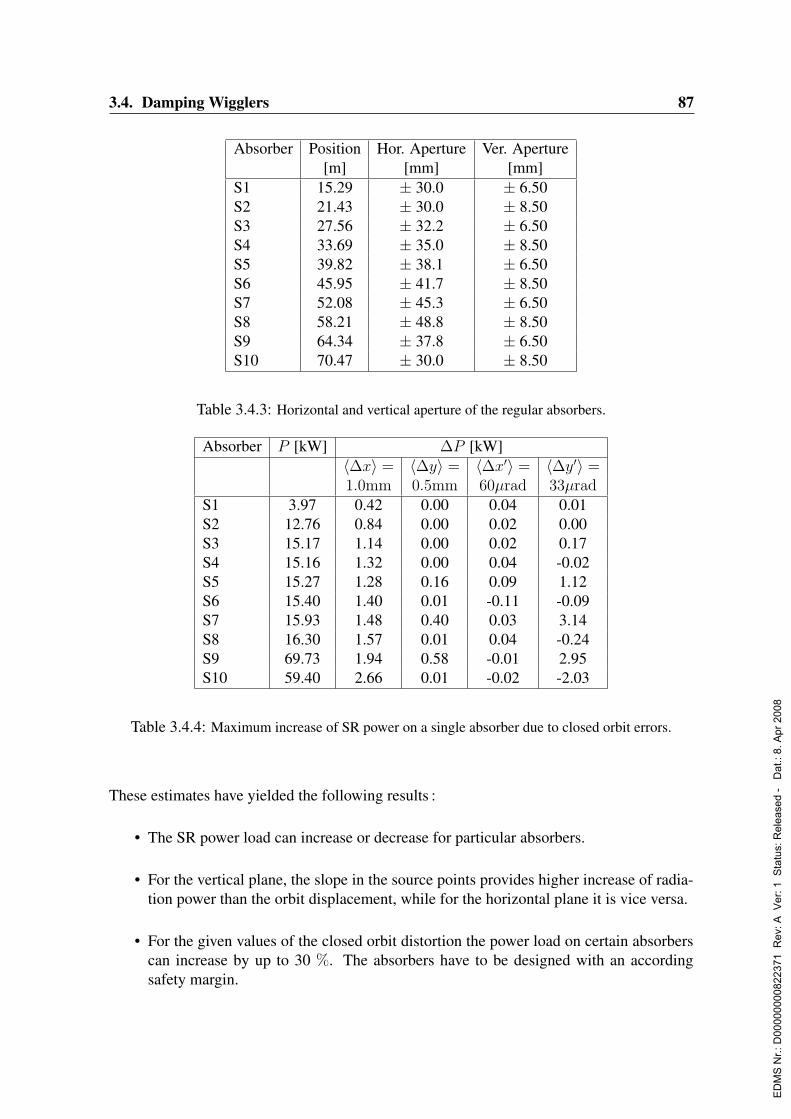
3.4. Damping Wigglers 87
Absorber Position Hor. Aperture Ver. Aperture[m] [mm] [mm]
S1 15.29 ± 30.0 ± 6.50S2 21.43 ± 30.0 ± 8.50S3 27.56 ± 32.2 ± 6.50S4 33.69 ± 35.0 ± 8.50S5 39.82 ± 38.1 ± 6.50S6 45.95 ± 41.7 ± 8.50S7 52.08 ± 45.3 ± 6.50S8 58.21 ± 48.8 ± 8.50S9 64.34 ± 37.8 ± 6.50S10 70.47 ± 30.0 ± 8.50
Table 3.4.3: Horizontal and vertical aperture of the regular absorbers.
Absorber P [kW] ∆P [kW]〈∆x〉 = 〈∆y〉 = 〈∆x′〉 = 〈∆y′〉 =1.0mm 0.5mm 60µrad 33µrad
S1 3.97 0.42 0.00 0.04 0.01S2 12.76 0.84 0.00 0.02 0.00S3 15.17 1.14 0.00 0.02 0.17S4 15.16 1.32 0.00 0.04 -0.02S5 15.27 1.28 0.16 0.09 1.12S6 15.40 1.40 0.01 -0.11 -0.09S7 15.93 1.48 0.40 0.03 3.14S8 16.30 1.57 0.01 0.04 -0.24S9 69.73 1.94 0.58 -0.01 2.95S10 59.40 2.66 0.01 -0.02 -2.03
Table 3.4.4: Maximum increase of SR power on a single absorber due to closed orbit errors.
These estimates have yielded the following results :
• The SR power load can increase or decrease for particular absorbers.
• For the vertical plane, the slope in the source points provides higher increase of radia-tion power than the orbit displacement, while for the horizontal plane it is vice versa.
• For the given values of the closed orbit distortion the power load on certain absorberscan increase by up to 30 %. The absorbers have to be designed with an accordingsafety margin.
ED
MS
Nr.:
D00
0000
0082
2371
Rev
: A V
er: 1
Sta
tus:
Rel
ease
d -
Dat
.: 8.
Apr
200
8
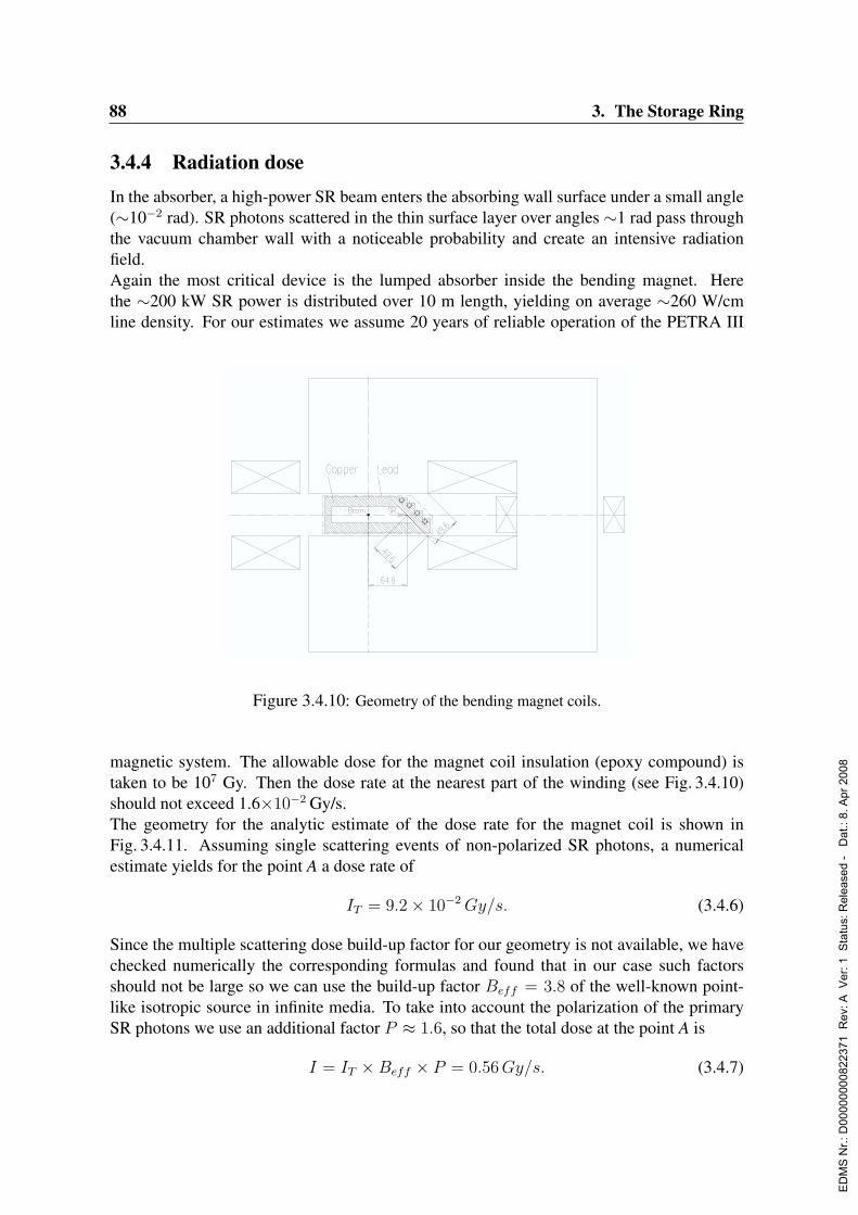
88 3. The Storage Ring
3.4.4 Radiation doseIn the absorber, a high-power SR beam enters the absorbing wall surface under a small angle(∼10−2 rad). SR photons scattered in the thin surface layer over angles ∼1 rad pass throughthe vacuum chamber wall with a noticeable probability and create an intensive radiationfield.Again the most critical device is the lumped absorber inside the bending magnet. Herethe ∼200 kW SR power is distributed over 10 m length, yielding on average ∼260 W/cmline density. For our estimates we assume 20 years of reliable operation of the PETRA III
4. RADIATION SAFETY
In the absorber, a high-power SR beam enters the absorbing wall under a small
angle (~10-2
rad) to the surface. SR photons scattered in the thin surface layer over
angles ~1 rad with a noticeable probability pass through the vacuum chamber wall
and create around it an intensive radiation field.
From this point of view, the most dangerous is the lumped absorber inside the
bending magnet. Over 10 meters here the received power of SR from the wigglers is
about ~200 kW (~260 W/cm of average running power). The same order of
magnitude radiation power however over a larger length dissipates right in the
straightforward section.
Fig.4.1 Bending magnet coils geometry.
For our estimation we assume 20 years of allowable period for reliable
operation of the PETRA III magnetic system. The allowable dose for the magnet coil
insulation (epoxy compound) is taken to be 107 Gy. Then the dose rate at the nearest
part of the winding (see Fig.4.1) should not exceed Gy/s.2106.1D
Geometry for the analytic estimation of the dose rate for the magnet coil is
shown in Fig.4.2.
Figure 3.4.10: Geometry of the bending magnet coils.
magnetic system. The allowable dose for the magnet coil insulation (epoxy compound) istaken to be 107 Gy. Then the dose rate at the nearest part of the winding (see Fig. 3.4.10)should not exceed 1.6×10⁻² Gy/s.The geometry for the analytic estimate of the dose rate for the magnet coil is shown inFig. 3.4.11. Assuming single scattering events of non-polarized SR photons, a numericalestimate yields for the point A a dose rate of
IT = 9.2× 10⁻²Gy/s. (3.4.6)
Since the multiple scattering dose build-up factor for our geometry is not available, we havechecked numerically the corresponding formulas and found that in our case such factorsshould not be large so we can use the build-up factor Beff = 3.8 of the well-known point-like isotropic source in infinite media. To take into account the polarization of the primarySR photons we use an additional factor P ≈ 1.6, so that the total dose at the point A is
I = IT ×Beff × P = 0.56Gy/s. (3.4.7)
ED
MS
Nr.:
D00
0000
0082
2371
Rev
: A V
er: 1
Sta
tus:
Rel
ease
d -
Dat
.: 8.
Apr
200
8

3.4. Damping Wigglers 89
Fig.4.2 Radiation dose rate estimation geometry.
The radiation dose rate at the distance from the SR trace at the inner surface
of absorber can be found according to the following expression
Figure 3.4.11: Geometry for an estimate of the radiation dose rate.
A preliminary Monte-Carlo simulation, carried out with the EMSH computer code, hasshown that the total energy of photons passed through the copper wall is around 0.01%of the incident SR power. However to convert this data to dose rate is rather difficult withoutdetailed knowledge of the photon spatial-angular distribution. Thus the dose rate estimatedby the computer simulation is 2 times less than that obtained by the analytic calculation.Both calculated values are significantly above the tolerable dose rate. An additional attenua-tion with the factor K = 35 is necessary to provide a reliable operation of the magnets coils.A ∼3 mm thick lead layer will provide this attenuation factor.
3.4.5 Absorbers and vacuum chamber design
The wiggler section vacuum chamber consists of 14 drift vacuum chambers. The typical driftchamber, which is shown in Fig. 3.4.12a, includes the quadrupole magnet vacuum chamber,BPM unit, bellows unit, wiggler vacuum tube and the regular absorber. All the vacuum ves-sels are made of stainless steel except for the copper beam stop part.
The drift vacuum sections are joined by CF-flanges with RF shields inside. The bellows unit,which is necessary to mount all components of the vacuum system and to compensate ther-mal expansion, incorporates a BPM and CF-flanges with movable RF shield contacts inside(Fig. 3.4.12c).Twelve water-cooled copper absorbers intercept the SR power (412.2 kW in total) producedby the 10 damping wigglers installed in the PETRA III long straight section. Ten absorbersare placed in front of the quadrupole magnets and one in front of the bending magnet to pro-tect its vacuum chamber from the radiation fan. One long lumped absorber is accommodatedinside and after the dipole magnet.The thermal design of the absorbers is based on a SR power load of 250 W per 1-cm-length
ED
MS
Nr.:
D00
0000
0082
2371
Rev
: A V
er: 1
Sta
tus:
Rel
ease
d -
Dat
.: 8.
Apr
200
8

90 3. The Storage Ring
Fig.5.1 Drift vacuum chamber arrangement.
The drift vacuum sections are joined by the CF-flanges with the RF shields
inside (Fig.5.2).
Fig.5.2 CF-flange unit.
The bellows unit, which is necessary to mount all components of the vacuum
system and to compensate possible variation (including the thermal ones) of their
length, incorporates a BPM and CF-flanges with the movable RF shield contacts
inside (Fig.5.3).
Fig.5.3 Bellows unit with BPM and CF-flanges.
Twelve water-cooled copper absorbers intercept SR power (totally 412.2 kW)
produced by the 10 damping wigglers installed in the PETRA III long straight section.
Ten absorbers are placed directly before the quadrupole magnets, one before the
bending magnet to protect its vacuum chamber from radiation fan and one long
lumped absorber is accommodated inside and after the dipole magnet.
The thermal design of the absorbers supposes an SR power load of 250 W per
1-cm-length of the absorber for a 4 bar cooling water pressure drop and a water
temperature rise 30 C. Ten first absorbers trim the tails of SR power distribution to
prevent heating of the quadrupoles and wigglers vacuum vessels. Eight short regular
absorbers have a design that provides absorbing of 16 kW power each (Fig.5.4).
Fig.5.4 Short absorbers arrangement (length in mm).
Fig.5.1 Drift vacuum chamber arrangement.
The drift vacuum sections are joined by the CF-flanges with the RF shields
inside (Fig.5.2).
Fig.5.2 CF-flange unit.
The bellows unit, which is necessary to mount all components of the vacuum
system and to compensate possible variation (including the thermal ones) of their
length, incorporates a BPM and CF-flanges with the movable RF shield contacts
inside (Fig.5.3).
(a)
(b) (c)
Figure 3.4.12: a) Drift vacuum chamber arrangement, b) CF-flange unit, c) Bellows unit with BPMand CF-flanges
of the absorber, a cooling water pressure drop of 4 bar and a water temperature rise of 30 K.The ten first absorbers trim the tails of the SR power distribution to prevent heating of the
Fig.5.3 Bellows unit with BPM and CF-flanges.
Twelve water-cooled copper absorbers intercept SR power (totally 412.2 kW)
produced by the 10 damping wigglers installed in the PETRA III long straight section.
Ten absorbers are placed directly before the quadrupole magnets, one before the
bending magnet to protect its vacuum chamber from radiation fan and one long
lumped absorber is accommodated inside and after the dipole magnet.
The thermal design of the absorbers supposes an SR power load of 250 W per
1-cm-length of the absorber for a 4 bar cooling water pressure drop and a water
temperature rise 30 C. Ten first absorbers trim the tails of SR power distribution to
prevent heating of the quadrupoles and wigglers vacuum vessels. Eight short regular
absorbers have a design that provides absorbing of 16 kW power each (Fig.5.4).
Fig.5.4 Short absorbers arrangement (length in mm).Figure 3.4.13: Short absorbers arrangement (length in mm)
vacuum vessels in quadrupoles and wigglers. The eight short regular absorbers allow theabsorption of 16 kW power each (Fig. 3.4.13). The maximum possible power load for thelast two long regular absorbers is 80 kW (Fig. 3.4.14). The eleventh absorber is placed just
ED
MS
Nr.:
D00
0000
0082
2371
Rev
: A V
er: 1
Sta
tus:
Rel
ease
d -
Dat
.: 8.
Apr
200
8
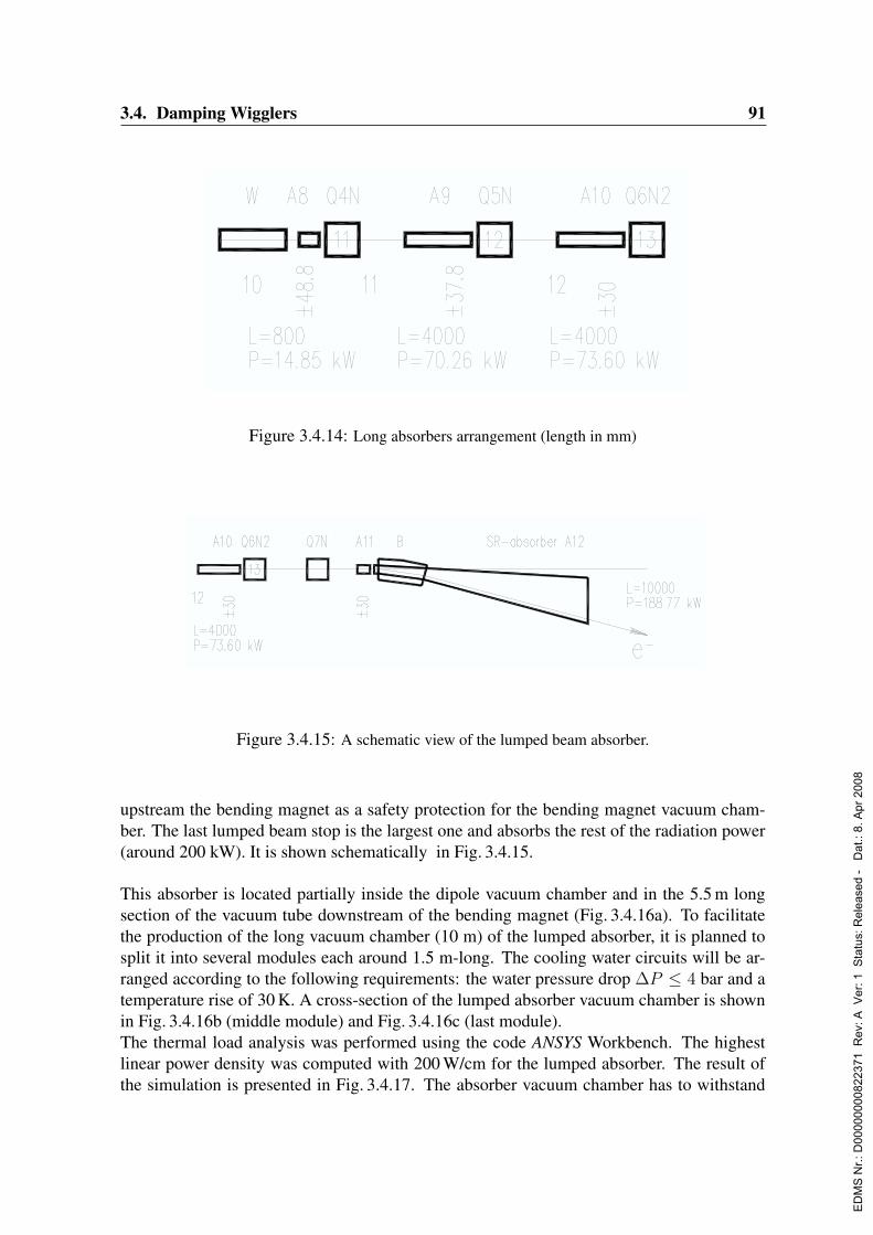
3.4. Damping Wigglers 91The maximum possible power load for the last two long regular absorbers is
80 kW (Fig.5.5).
Fig.5.5 Long absorbers arrangement (length in mm).
The eleventh absorber is placed just before the bending magnet as a safety
protection for the bending magnet vacuum chamber.
The last lumped beam stop is the largest one, which absorbs the rest of the
radiation power (around 200 kW). It is shown schematically in Fig.5.6.
Fig.5.6 A schematic view of the lumped beam absorber.
From the design viewpoint, this absorber is placed inside the dipole vacuum
chamber and in the 5.5-m-long section of the vacuum tube downstream the bending
magnet (Fig.5.7).
Fig.5.7 Lumped absorber vacuum chamber.
Figure 3.4.14: Long absorbers arrangement (length in mm)
The maximum possible power load for the last two long regular absorbers is
80 kW (Fig.5.5).
Fig.5.5 Long absorbers arrangement (length in mm).
The eleventh absorber is placed just before the bending magnet as a safety
protection for the bending magnet vacuum chamber.
The last lumped beam stop is the largest one, which absorbs the rest of the
radiation power (around 200 kW). It is shown schematically in Fig.5.6.
Fig.5.6 A schematic view of the lumped beam absorber.
From the design viewpoint, this absorber is placed inside the dipole vacuum
chamber and in the 5.5-m-long section of the vacuum tube downstream the bending
magnet (Fig.5.7).
Fig.5.7 Lumped absorber vacuum chamber.
Figure 3.4.15: A schematic view of the lumped beam absorber.
upstream the bending magnet as a safety protection for the bending magnet vacuum cham-ber. The last lumped beam stop is the largest one and absorbs the rest of the radiation power(around 200 kW). It is shown schematically in Fig. 3.4.15.
This absorber is located partially inside the dipole vacuum chamber and in the 5.5 m longsection of the vacuum tube downstream of the bending magnet (Fig. 3.4.16a). To facilitatethe production of the long vacuum chamber (10 m) of the lumped absorber, it is planned tosplit it into several modules each around 1.5 m-long. The cooling water circuits will be ar-ranged according to the following requirements: the water pressure drop ∆P ≤ 4 bar and atemperature rise of 30 K. A cross-section of the lumped absorber vacuum chamber is shownin Fig. 3.4.16b (middle module) and Fig. 3.4.16c (last module).The thermal load analysis was performed using the code ANSYS Workbench. The highestlinear power density was computed with 200 W/cm for the lumped absorber. The result ofthe simulation is presented in Fig. 3.4.17. The absorber vacuum chamber has to withstand
ED
MS
Nr.:
D00
0000
0082
2371
Rev
: A V
er: 1
Sta
tus:
Rel
ease
d -
Dat
.: 8.
Apr
200
8
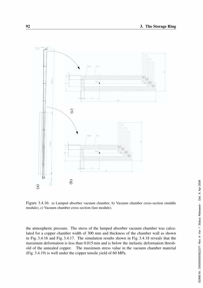
92 3. The Storage Ring
Th
e m
axim
um
po
ssib
le p
ow
er l
oad
fo
r th
e la
st t
wo
lo
ng
reg
ula
r ab
sorb
ers
is
80 k
W (
Fig
.5.5
). F
ig.5
.5 L
on
g a
bso
rber
s ar
ran
gem
ent
(len
gth
in
mm
).
Th
e el
even
th a
bso
rber
is
pla
ced
ju
st b
efo
re t
he
ben
din
g m
agn
et a
s a
safe
ty
pro
tect
ion
fo
r th
e b
end
ing
mag
net
vac
uu
m c
ham
ber
.
Th
e la
st l
um
ped
bea
m s
top
is
the
larg
est
on
e, w
hic
h a
bso
rbs
the
rest
of
the
radia
tion p
ow
er (
around 2
00 k
W).
It
is s
how
n s
chem
atic
ally
in F
ig.5
.6.
Fig
.5.6
A s
chem
atic
vie
w o
f th
e lu
mped
bea
m a
bso
rber
.
Fro
m t
he
des
ign
vie
wp
oin
t, t
his
ab
sorb
er i
s p
lace
d i
nsi
de
the
dip
ole
vac
uu
m
cham
ber
an
d i
n t
he
5.5
-m-l
on
g s
ecti
on
of
the
vac
uu
m t
ub
e d
ow
nst
ream
th
e b
end
ing
mag
net
(F
ig.5
.7).
Fig
.5.7
Lum
ped
abso
rber
vac
uum
cham
ber
.
Fig.5.8 Lumped absorber vacuum chamber cross-section (middle module).
To facilitate the production of the long vacuum chamber (10 m) of the lumped
absorber, it is planned to split it into several modules each around 1.5 m-long. The
cooling water circuits will be arranged according to the following requirements: the
water pressure drop 4P bar and a temperature rise of 30 C. A cross-section of the
lumped absorber vacuum chamber is shown in Fig.5.8 (middle module) and Fig.5.9
(last module).
Fig.5.9 Lumped absorber vacuum chamber cross-section (last module).
(a) (b
)(c
)
Figure 3.4.16: a) Lumped absorber vacuum chamber, b) Vacuum chamber cross-section (middlemodule), c) Vacuum chamber cross-section (last module).
the atmospheric pressure. The stress of the lumped absorber vacuum chamber was calcu-lated for a copper chamber width of 300 mm and thickness of the chamber wall as shownin Fig. 3.4.16 and Fig. 3.4.17. The simulation results shown in Fig. 3.4.18 reveals that themaximum deformation is less than 0.015 mm and is below the inelastic deformation thresh-old of the annealed copper. The maximum stress value in the vacuum chamber material(Fig. 3.4.19) is well under the copper tensile yield of 60 MPa.
ED
MS
Nr.:
D00
0000
0082
2371
Rev
: A V
er: 1
Sta
tus:
Rel
ease
d -
Dat
.: 8.
Apr
200
8

3.4. Damping Wigglers 93
Figure 3.4.17: Thermal analysis of the lumped absorber vacuum chamber.
Figure 3.4.18: Stress deformation of the 300-mm-wide module.
It is foreseen to join the units of the lumped absorber vacuum chambers modules by electron-beam welding and high-temperature brazing in a vacuum oven. It is planned to connect themodules with each other with the help of a technology developed at BINP. High-temperaturesilver solder is used to braze two copper-stainless steel flanges to both the ends of the mod-
ED
MS
Nr.:
D00
0000
0082
2371
Rev
: A V
er: 1
Sta
tus:
Rel
ease
d -
Dat
.: 8.
Apr
200
8

94 3. The Storage Ring
Figure 3.4.19: Stress values for the 300-mm-wide module.
ules. The vacuum chamber is assembled by welding of the stainless steel flanges. Theelectrical conductivity inside the chamber is provided by gold-coated copper brasses joinedby diffusion bonding.
3.4.6 SR monitoring systemThe power load to the absorbers is very high, and thus a reliable operation requires differentmeasurements to be incorporated into the interlock safety system, including:
• Absorber temperature measurement with thermo-switches.
• Electron beam position measurement with regular BPMs installed in the wiggler straightsection.
• SR beam position detection with special SR monitors. A proposal for these monitorswill be described below.
A schematic view of the SR monitor that measures radiation displacement in the verticalplane is shown in Fig. 3.4.20. The monitor is combined with every absorber installed in thefocusing quadrupole drift (1). Inside the vertical narrowing of the absorber a special gap ismachined and an anode-electrode is placed inside it (3). The gap is closed with a copper foil(2) that screens the electrodes from the primary electron beam and provides electromagneticsmoothness of the vacuum chamber. The electrodes are fixed in the vacuum chamber with aceramic insulator (4). The gap is connected with the main volume of the vacuum chamber
ED
MS
Nr.:
D00
0000
0082
2371
Rev
: A V
er: 1
Sta
tus:
Rel
ease
d -
Dat
.: 8.
Apr
200
8

3.4. Damping Wigglers 95
Power load to the absorbers is rather high, and to provide their reliable
operation different measurements have to be incorporated to the interlock safety
system, including
Absorbers temperature measurement with thermoswitches.
Position of the electron beam measurement with regular BPMs installed in the
wiggler straight section.
Detection of position of the SR beam with special SR monitors described below.
A schematic view of the SR monitor that measures radiation displacement in
the vertical plane is shown in Fig.6.1. The monitor is combined with every absorber
installed in the F-quadrupole drift (1). Inside the vertical narrowing of the absorber a
special gap is machined and an anode-electrode is placed inside it (3). The gap is
closed with the copper foil (2) that screens the electrodes from the primary electron
beam and provides electromagnetic smoothness of the vacuum chamber. The
electrodes are fixed in the vacuum chamber with the ceramic insulator (4). The gap is
connected with the main volume of the vacuum chamber by hole(s), which are
arranged so as to prevent HOM generated by the electron beam.
Fig.6.1 SR monitor schematically.
Figure 3.4.20: Scheme of the SR monitor.
by hole(s), which are arranged as to prevent HOM’s generated by the electron beam. Thefoil thickness will be chosen to provide:
• Good RF screening of the electrodes.
• Effective penetration of the SR quanta.
• Effective heat conductivity and low temperature of the foil.
• High photo-current signal.
The operating principle of the system is as follows. Radiation photons absorbed in the foilproduce photoelectrons, which are registered by the electrical circuit schematically shown inFig. 3.4.20 for the lower electrode. A similar circuit is assumed for the upper electrode. Ameasure for the SR fan deviation is:
k =Uu − Ul
Uu + Ul
(3.4.8)
where Uu and Ul are the upper and lower electrode voltage signal. From our experience, thevoltage signal will be sufficient to reliably monitor the SR beam deviation.
3.4.7 Steering magnetsTo save space in the damping wiggler drifts a steering magnet that produces both verticaland horizontal magnetic field components is proposed. A schematic cross-section of themagnet is shown in Fig. 3.4.21 together with the magnetic field flux lines. Two differentcoils are excited to generate either the horizontal field (coil 2) or the vertical one (coil 1).
ED
MS
Nr.:
D00
0000
0082
2371
Rev
: A V
er: 1
Sta
tus:
Rel
ease
d -
Dat
.: 8.
Apr
200
8
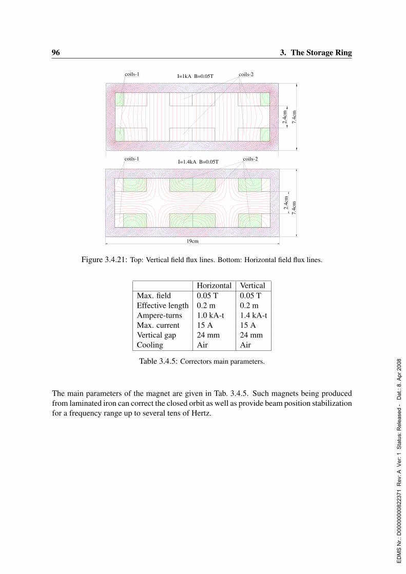
96 3. The Storage Ring
19cm
2.4c
m
7.4c
m
I=1kA B=0.05Tcoils-1 coils-2
19cm
7.4c
m2.
4cm
I=1.4kA B=0.05Tcoils-1 coils-2
Figure 3.4.21: Top: Vertical field flux lines. Bottom: Horizontal field flux lines.
Horizontal VerticalMax. field 0.05 T 0.05 TEffective length 0.2 m 0.2 mAmpere-turns 1.0 kA-t 1.4 kA-tMax. current 15 A 15 AVertical gap 24 mm 24 mmCooling Air Air
Table 3.4.5: Correctors main parameters.
The main parameters of the magnet are given in Tab. 3.4.5. Such magnets being producedfrom laminated iron can correct the closed orbit as well as provide beam position stabilizationfor a frequency range up to several tens of Hertz.
ED
MS
Nr.:
D00
0000
0082
2371
Rev
: A V
er: 1
Sta
tus:
Rel
ease
d -
Dat
.: 8.
Apr
200
8

3.5. The Vacuum System of PETRA III 97
3.5 The Vacuum System of PETRA IIIPresently the 25 year old PETRA accelerator is equipped with aluminum chambers and inte-grated ion getter pumps that use the magnetic field of the dipole magnets. The machine wasinitially laid out for an electron current of a few mA and an energy of 23 GeV. Today it isused to deliver electrons of 12 GeV and protons of 40 GeV to HERA. The proton RF systemas well as injection and ejection elements will be superfluous after the rebuild and will beremoved. We distinguish here two sections of the accelerator - the old 7 octants that keepthe magnet arrangement but will be equipped with a new vacuum system, and the new octantwith short new dipoles and the undulators. It is planned to build major parts of the system,such as the dipole chambers, from aluminum.There is a third new section with about 100 m active length of damping wiggler magnets.The layout of this section is presently investigated by colleagues from Novosibirsk and istherefore not discussed here (see Sec. 3.4).
3.5.1 Beam parameters and philosophy
3.5.1.1 Vacuum requirements
The goal is to achieve a vacuum lifetime not shorter than the one imposed by the Touschekeffect, which is about 50 hours. Of course the overall lifetime issue becomes less critical ifthe machine is operated in top-up mode but this option should not be used to relax the vacuumrequirements. For estimating the maximally acceptable residual gas pressure in PETRA IIIwe consider the two lifetime limiting effects - elastic coulomb scattering and losses frominelastic bremsstrahlung interactions. We assume a gas composition of 25 % CO and 75 %H2 which is common for electron storage rings. For inelastic scattering the beam lifetime isgiven by
τinel [h] =−0.695
ln(δE)∑
iPi [pbar]X0,i [m]
(3.5.1)
Here δE = 1.5 % is the energy acceptance, X0,i the radiation length of gas i under standardconditions (CO: 321 m, H2: 7500 m), and Pi the corresponding partial pressure. With a totalpressure of 2 · 10−9 mbar one obtains a lifetime of 94 hours which is larger than the expectedTouschek lifetime.The lifetime-formula for the coulomb scattering reads:
τel [h] = 2839E2 [GeV2] A2
y [mm2]
β2y [m2]
∑i Pi [pbar]
∑j kijZ2
j
(3.5.2)
Pi is the partial pressure of the i-th molecular species and kij the number of atoms withnuclear charge Zj contained in the i-th molecule. Ay is the limiting aperture and βy thevertical β-function. With the above mentioned gas composition and pressure, Ay = 3.5 mm,βy = 6 m we obtain a theoretical lifetime of 660 h from elastic scattering. The effective Z ofthe assumed gas composition amounts to 3.6.
ED
MS
Nr.:
D00
0000
0082
2371
Rev
: A V
er: 1
Sta
tus:
Rel
ease
d -
Dat
.: 8.
Apr
200
8
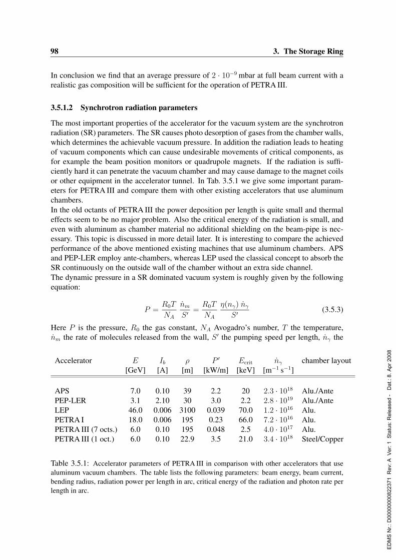
98 3. The Storage Ring
In conclusion we find that an average pressure of 2 · 10−9 mbar at full beam current with arealistic gas composition will be sufficient for the operation of PETRA III.
3.5.1.2 Synchrotron radiation parameters
The most important properties of the accelerator for the vacuum system are the synchrotronradiation (SR) parameters. The SR causes photo desorption of gases from the chamber walls,which determines the achievable vacuum pressure. In addition the radiation leads to heatingof vacuum components which can cause undesirable movements of critical components, asfor example the beam position monitors or quadrupole magnets. If the radiation is suffi-ciently hard it can penetrate the vacuum chamber and may cause damage to the magnet coilsor other equipment in the accelerator tunnel. In Tab. 3.5.1 we give some important param-eters for PETRA III and compare them with other existing accelerators that use aluminumchambers.In the old octants of PETRA III the power deposition per length is quite small and thermaleffects seem to be no major problem. Also the critical energy of the radiation is small, andeven with aluminum as chamber material no additional shielding on the beam-pipe is nec-essary. This topic is discussed in more detail later. It is interesting to compare the achievedperformance of the above mentioned existing machines that use aluminum chambers. APSand PEP-LER employ ante-chambers, whereas LEP used the classical concept to absorb theSR continuously on the outside wall of the chamber without an extra side channel.The dynamic pressure in a SR dominated vacuum system is roughly given by the followingequation:
P =R0T
NA
nm
S ′=R0T
NA
η(nγ) nγ
S ′(3.5.3)
Here P is the pressure, R0 the gas constant, NA Avogadro’s number, T the temperature,nm the rate of molecules released from the wall, S ′ the pumping speed per length, nγ the
Accelerator E Ib ρ P ′ Ecrit nγ chamber layout[GeV] [A] [m] [kW/m] [keV] [m−1 s−1]
APS 7.0 0.10 39 2.2 20 2.3 · 1018 Alu./AntePEP-LER 3.1 2.10 30 3.0 2.2 2.8 · 1019 Alu./AnteLEP 46.0 0.006 3100 0.039 70.0 1.2 · 1016 Alu.PETRA I 18.0 0.006 195 0.23 66.0 7.2 · 1016 Alu.PETRA III (7 octs.) 6.0 0.10 195 0.048 2.5 4.0 · 1017 Alu.PETRA III (1 oct.) 6.0 0.10 22.9 3.5 21.0 3.4 · 1018 Steel/Copper
Table 3.5.1: Accelerator parameters of PETRA III in comparison with other accelerators that usealuminum vacuum chambers. The table lists the following parameters: beam energy, beam current,bending radius, radiation power per length in arc, critical energy of the radiation and photon rate perlength in arc.
ED
MS
Nr.:
D00
0000
0082
2371
Rev
: A V
er: 1
Sta
tus:
Rel
ease
d -
Dat
.: 8.
Apr
200
8
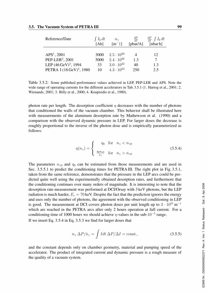
3.5. The Vacuum System of PETRA III 99
Reference/Date∫Ib dt nγ
dPdI
dPdI
∫Ib dt
[Ah] [m−1] [pbar/A] [nbar h]
APS1, 2001 3000 2.5 · 1026 4 12PEP-LER2, 2001 5000 2.4 · 1026 1.3 7LEP (46 GeV)3, 1994 33 3.0 · 1022 40 1.3PETRA I (18 GeV)4, 1980 10 4.3 · 1023 250 2.5
Table 3.5.2: Some published performance values achieved in LEP, PEP-LER and APS. Note thewide range of operating currents for the different accelerators in Tab. 3.5.1 (1. Hartog et al., 2001; 2.Wienands, 2001; 3. Billy et al., 2000; 4. Kouptsidis et al., 1980).
photon rate per length. The desorption coefficient η decreases with the number of photonsthat conditioned the walls of the vacuum chamber. This behavior shall be illustrated herewith measurements of the aluminum desorption rate by Mathewson et al. (1990) and acomparison with the observed dynamic pressure in LEP. For larger doses the decrease isroughly proportional to the inverse of the photon dose and is empirically parameterized asfollows:
η(nγ) =
η0 for nγ < nγ0
η0nγ0
nγfor nγ > nγ0
(3.5.4)
The parameters nγ0 and η0 can be estimated from those measurements and are used inSec. 3.5.5.1 to predict the conditioning times for PETRA III. The right plot in Fig. 3.5.1,taken from the same reference, demonstrates that the pressure in the LEP arcs could be pre-dicted quite well using the experimentally obtained desorption rates, and furthermore thatthe conditioning continues over many orders of magnitude. It is interesting to note that thedesorption rate measurement was performed at DCI/Orsay with 3 keV photons, but the LEPradiation is much harder, Ec = 70 keV. Despite the fact that the prediction ignores the energyand uses only the number of photons, the agreement with the observed conditioning in LEPis good. The measurement at DCI covers photon doses per unit length up to 3 · 1021 m−1
which are reached in the PETRA arcs after only 2 hours operation at full current. For aconditioning time of 1000 hours we should achieve η-values in the sub-10−5 range.If we insert Eq. 3.5.4 in Eq. 3.5.3 we find for larger doses that
nγ ∆P/nγ =
∫Idt ∆P/∆I = const., (3.5.5)
and the constant depends only on chamber geometry, material and pumping speed of theaccelerator. The product of integrated current and dynamic pressure is a rough measure ofthe quality of a vacuum system.
ED
MS
Nr.:
D00
0000
0082
2371
Rev
: A V
er: 1
Sta
tus:
Rel
ease
d -
Dat
.: 8.
Apr
200
8
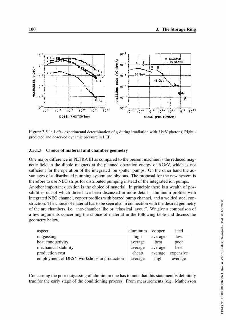
100 3. The Storage Ring
Figure 3.5.1: Left - experimental determination of η during irradiation with 3 keV photons, Right -predicted and observed dynamic pressure in LEP.
3.5.1.3 Choice of material and chamber geometry
One major difference in PETRA III as compared to the present machine is the reduced mag-netic field in the dipole magnets at the planned operation energy of 6 GeV, which is notsufficient for the operation of the integrated ion sputter pumps. On the other hand the ad-vantages of a distributed pumping system are obvious. The proposal for the new system istherefore to use NEG strips for distributed pumping instead of the integrated ion pumps.Another important question is the choice of material. In principle there is a wealth of pos-sibilities out of which three have been discussed in more detail - aluminum profiles withintegrated NEG channel, copper profiles with brazed pump channel, and a welded steel con-struction. The choice of material has to be seen also in connection with the desired geometryof the arc chambers, i.e. ante-chamber like or “classical layout”. We give a comparison ofa few arguments concerning the choice of material in the following table and discuss thegeometry below.
aspect aluminum copper steeloutgassing high average lowheat conductivity average best poormechanical stability average average bestproduction cost cheap average expensiveemployment of DESY workshops in production average high average
Concerning the poor outgassing of aluminum one has to note that this statement is definitelytrue for the early stage of the conditioning process. From measurements (e.g. Mathewson
ED
MS
Nr.:
D00
0000
0082
2371
Rev
: A V
er: 1
Sta
tus:
Rel
ease
d -
Dat
.: 8.
Apr
200
8
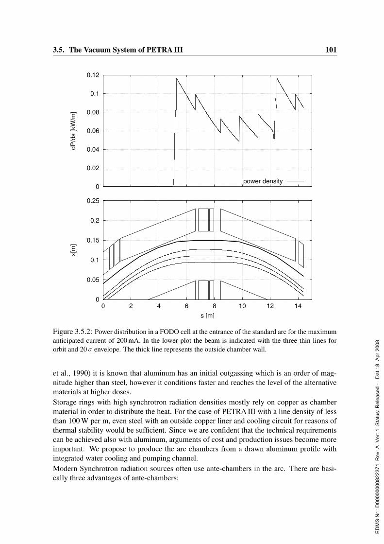
3.5. The Vacuum System of PETRA III 101
0
0.02
0.04
0.06
0.08
0.1
0.12dP
/ds
[kW
/m]
power density
0
0.05
0.1
0.15
0.2
0.25
0 2 4 6 8 10 12 14
x[m
]
s [m]
Figure 3.5.2: Power distribution in a FODO cell at the entrance of the standard arc for the maximumanticipated current of 200 mA. In the lower plot the beam is indicated with the three thin lines fororbit and 20 σ envelope. The thick line represents the outside chamber wall.
et al., 1990) it is known that aluminum has an initial outgassing which is an order of mag-nitude higher than steel, however it conditions faster and reaches the level of the alternativematerials at higher doses.Storage rings with high synchrotron radiation densities mostly rely on copper as chambermaterial in order to distribute the heat. For the case of PETRA III with a line density of lessthan 100 W per m, even steel with an outside copper liner and cooling circuit for reasons ofthermal stability would be sufficient. Since we are confident that the technical requirementscan be achieved also with aluminum, arguments of cost and production issues become moreimportant. We propose to produce the arc chambers from a drawn aluminum profile withintegrated water cooling and pumping channel.Modern Synchrotron radiation sources often use ante-chambers in the arc. There are basi-cally three advantages of ante-chambers:
ED
MS
Nr.:
D00
0000
0082
2371
Rev
: A V
er: 1
Sta
tus:
Rel
ease
d -
Dat
.: 8.
Apr
200
8
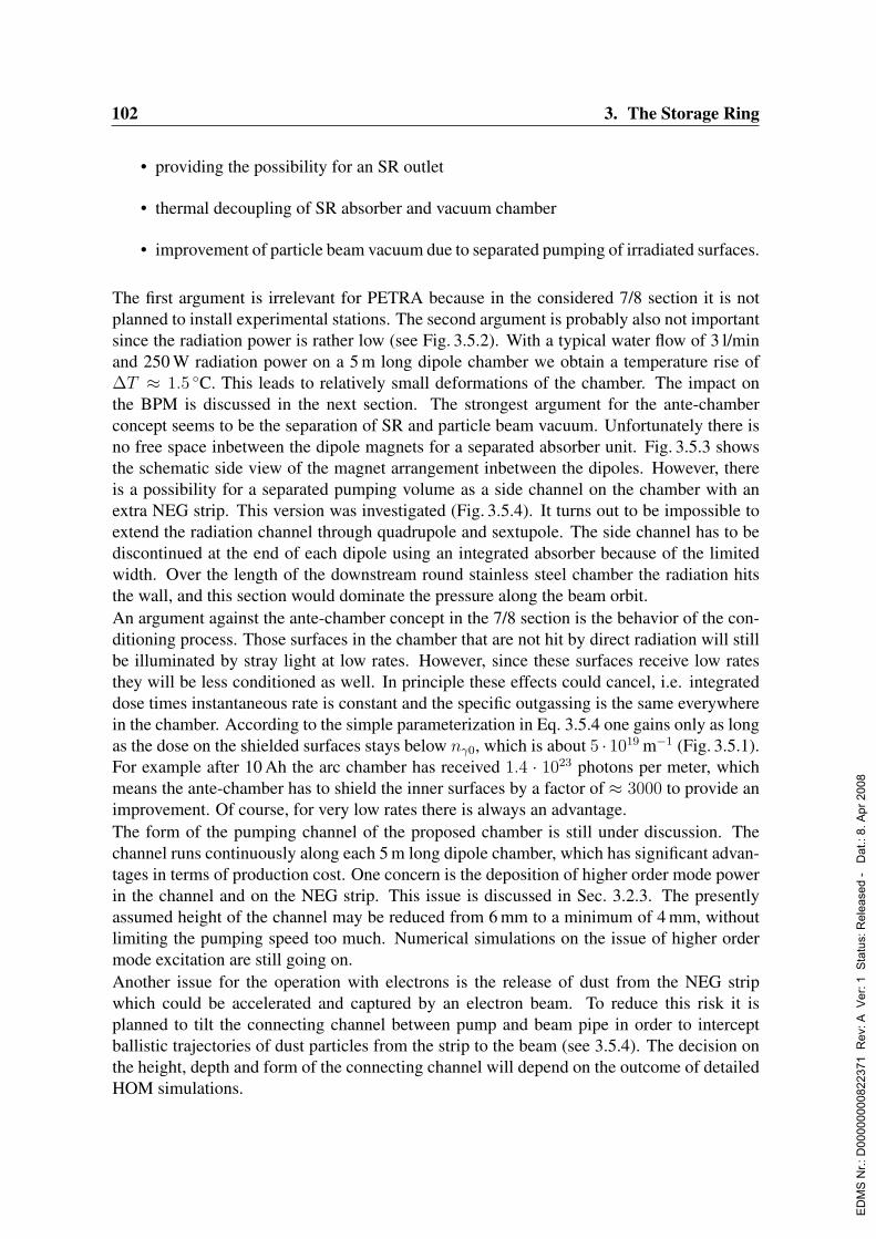
102 3. The Storage Ring
• providing the possibility for an SR outlet
• thermal decoupling of SR absorber and vacuum chamber
• improvement of particle beam vacuum due to separated pumping of irradiated surfaces.
The first argument is irrelevant for PETRA because in the considered 7/8 section it is notplanned to install experimental stations. The second argument is probably also not importantsince the radiation power is rather low (see Fig. 3.5.2). With a typical water flow of 3 l/minand 250 W radiation power on a 5 m long dipole chamber we obtain a temperature rise of∆T ≈ 1.5 C. This leads to relatively small deformations of the chamber. The impact onthe BPM is discussed in the next section. The strongest argument for the ante-chamberconcept seems to be the separation of SR and particle beam vacuum. Unfortunately there isno free space inbetween the dipole magnets for a separated absorber unit. Fig. 3.5.3 showsthe schematic side view of the magnet arrangement inbetween the dipoles. However, thereis a possibility for a separated pumping volume as a side channel on the chamber with anextra NEG strip. This version was investigated (Fig. 3.5.4). It turns out to be impossible toextend the radiation channel through quadrupole and sextupole. The side channel has to bediscontinued at the end of each dipole using an integrated absorber because of the limitedwidth. Over the length of the downstream round stainless steel chamber the radiation hitsthe wall, and this section would dominate the pressure along the beam orbit.An argument against the ante-chamber concept in the 7/8 section is the behavior of the con-ditioning process. Those surfaces in the chamber that are not hit by direct radiation will stillbe illuminated by stray light at low rates. However, since these surfaces receive low ratesthey will be less conditioned as well. In principle these effects could cancel, i.e. integrateddose times instantaneous rate is constant and the specific outgassing is the same everywherein the chamber. According to the simple parameterization in Eq. 3.5.4 one gains only as longas the dose on the shielded surfaces stays below nγ0, which is about 5 · 1019 m−1 (Fig. 3.5.1).For example after 10 Ah the arc chamber has received 1.4 · 1023 photons per meter, whichmeans the ante-chamber has to shield the inner surfaces by a factor of ≈ 3000 to provide animprovement. Of course, for very low rates there is always an advantage.The form of the pumping channel of the proposed chamber is still under discussion. Thechannel runs continuously along each 5 m long dipole chamber, which has significant advan-tages in terms of production cost. One concern is the deposition of higher order mode powerin the channel and on the NEG strip. This issue is discussed in Sec. 3.2.3. The presentlyassumed height of the channel may be reduced from 6 mm to a minimum of 4 mm, withoutlimiting the pumping speed too much. Numerical simulations on the issue of higher ordermode excitation are still going on.Another issue for the operation with electrons is the release of dust from the NEG stripwhich could be accelerated and captured by an electron beam. To reduce this risk it isplanned to tilt the connecting channel between pump and beam pipe in order to interceptballistic trajectories of dust particles from the strip to the beam (see 3.5.4). The decision onthe height, depth and form of the connecting channel will depend on the outcome of detailedHOM simulations.
ED
MS
Nr.:
D00
0000
0082
2371
Rev
: A V
er: 1
Sta
tus:
Rel
ease
d -
Dat
.: 8.
Apr
200
8

3.5. The Vacuum System of PETRA III 103
Figure 3.5.3: Side view of the proposed magnet arrangement inbetween dipoles. The element in thecenter is a vertical correction coil. At this position the beam pipe is supported and contains the beamposition monitor.
Also the option to realize pumping with a NEG coating on the walls of the chamber hasbeen discussed. We see two major uncertainties in this concept. There is some experience atDESY with the coating of UHV components using a sputter process. Steel coated ceramicschambers and copper coated steel components were produced for the TESLA Test Facilityand had to undergo very stringent tests on the release of dust particles. From these experi-ences we know that it is very difficult to achieve good adhesion of sputtered layers. Onlyafter electro-polishing before and a high temperature baking cycle after the sputter process itwas possible to achieve the TESLA standards. In this context we see potential problems forthe PETRA III operation with electrons, if we use the sputtered chambers. In addition thereis not much room for thermal isolation of the chambers inside the magnets and the systemfor thermal activation of the NEG layer will be expensive and difficult to install.
Another potentially important point for the design of vacuum chambers is the shielding ofSR. The absorption length of X-rays in material is a strong function of the radiation energy.For high energies the chamber walls become transparent and equipment in the acceleratortunnel like magnet coils or electronics will suffer from radiation damage. It turns out that inthe 7/8 section there is no problem as the critical energy (cf Tab. 3.5.1) is low. The attenuationlengths of aluminum and iron are displayed in Fig. 3.5.5. Although the short dipoles inthe new octant generate much harder radiation with a critical energy of 21 keV, the steelchambers still provide more than 10 attenuation lengths. Consequently we do not need leadshielding on the surface of the vacuum chambers.
ED
MS
Nr.:
D00
0000
0082
2371
Rev
: A V
er: 1
Sta
tus:
Rel
ease
d -
Dat
.: 8.
Apr
200
8
104 3. The Storage Ring
Figure 3.5.4: Left - present proposal (not finalized) of the PETRA III dipole chamber in the oldoctants. Right - investigated variant with separated pumping channel for SR absorption.
3.5.2 Mechanical considerations
The points of major importance are thermal deformation of the vacuum chambers due toheating by SR and also NEG pump activation, and on the other hand a support concept forthe vacuum chambers that guarantees maximum stability for BPM and quadrupole positions.Up to now a few analytical estimates have been carried out. A more detailed finite elementsimulation of these problems is planned.A hollow steel support tube with length l, inner and outer diameters di, do will be bentthrough the action of a force F at the upper end by an amount:
∆x =64l3
3πE(d4o − d4
i )F (3.5.6)
E ≈ 2 · 107 N/cm2 is the elastic modulus of steel. Obviously the length of the supporttubes should be as short as possible. A length of 0.5 m will be sufficient if concrete socketsof roughly the same height will be installed underneath. For a tube with 10 cm outer and8 cm inner diameter the deformation amounts to ∆x = 70 nm/N. The highest force that canoccur is the force of the air pressure on a blind flange at the end of the chamber during aninstallation period. It amounts to about 1000 N, so we expect 70µm deformation in this case.The bending of the aluminum chamber due to asymmetric heating by SR can be estimatedas follows. The bending is caused by a length difference of the inner and outer side of thechamber. Temperature difference ∆T , length change ∆l, bending radius ρ and sector angleθ are related via
∆l = ∆T α ρθ = θ(ρ+ h/2)− θ(ρ− h/2) (3.5.7)
Here α = 2 · 10−5 C−1 is the expansion coefficient for aluminum and h the width of thechamber. We obtain a bending radius of ρ = h/(∆T α), and for fixed ends a displacementof the chamber center by ∆x ≈ ρθ2/8 = α l2 ∆T/(8h). For a chamber width of 100 mm, alength l = 5 m and a temperature difference of 1.5 C (full current vs. no current) we obtaina displacement of 1 mm.
ED
MS
Nr.:
D00
0000
0082
2371
Rev
: A V
er: 1
Sta
tus:
Rel
ease
d -
Dat
.: 8.
Apr
200
8

3.5. The Vacuum System of PETRA III 105
1e-04
0.001
0.01
0.1
1
10
1 10 100 1000
att.
leng
th. [
cm]
Eγ [keV]
old octs. new octs.
AluminumIron
Figure 3.5.5: Attenuation lengths of aluminum and iron as a function of photon energy. The criticalenergies in the old and new octants are indicated.
The forces due to thermal deformation are difficult to estimate analytically because frictionand spring constants of bellows play a role. However, for a force of 100 N the displacementwill be less than 10µm and it can be reduced further by choosing stronger dimensions ofthe support tube. A specific topic is the reproducibility of the chamber position after NEGregeneration at 200 C strip temperature. This will be investigated by heating experimentswith aluminum chamber samples.
In the present machine the interconnections of the vacuum chambers are done by welding.This has caused problems over the years of operation. For the new machine we are planningto use a flange system. The flanges can be realized using stainless steel with the difficultieslying in the interconnection between steel and aluminum, which can be solved, however,by friction bonding or explosion bonding. Another possibility is the employment of sur-face hardened aluminum flanges. This principle was tested successfully at local positions inPETRA II.
Regardless of the material choice we are planning to use flat seals, for example a systemdeveloped by the company VAT using silver coated copper seals. This system has beensuccessfully used at specific locations of HERA. The advantages over the conflat system isthe provision of RF shielding for the flange gap and, according to our experience, betterthermal/mechanical robustness.
ED
MS
Nr.:
D00
0000
0082
2371
Rev
: A V
er: 1
Sta
tus:
Rel
ease
d -
Dat
.: 8.
Apr
200
8
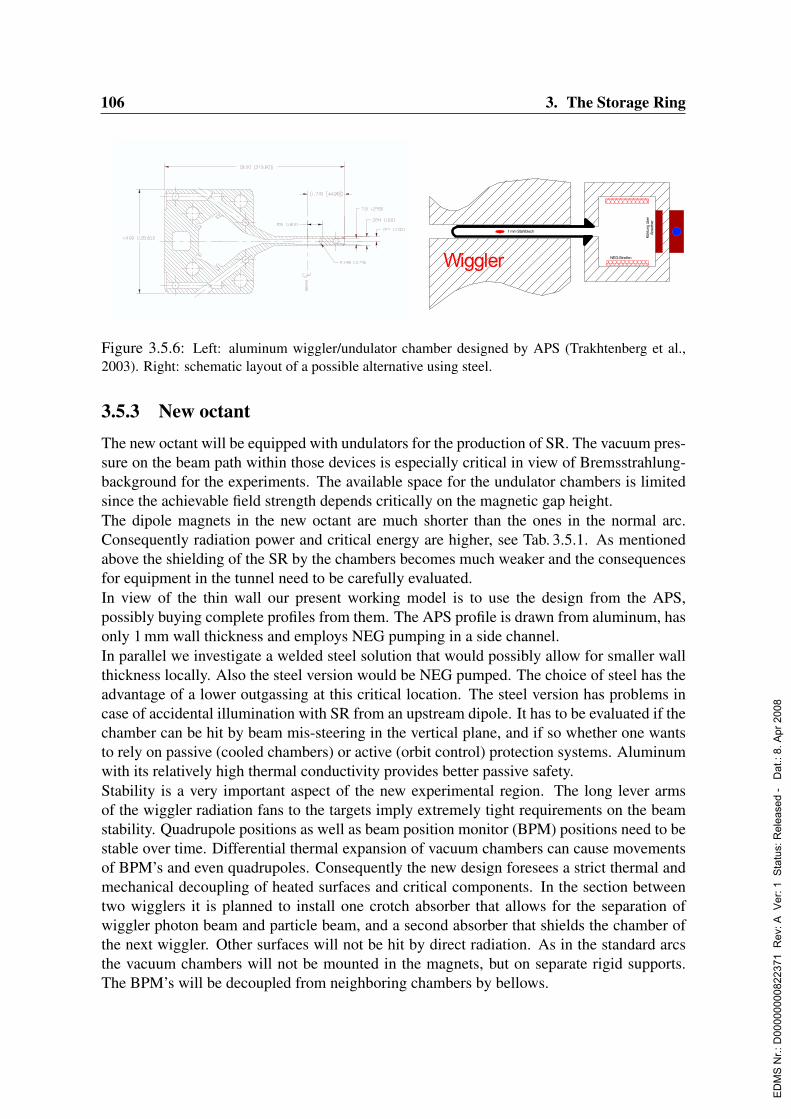
106 3. The Storage Ring
NEW INSERTION DEVICE VACUUM CHAMBERS AT THE ADVANCED
PHOTON SOURCE *Emil Trakhtenberg, Greg Wiemerslage, Patric DenHartog and Branislav Brajuskovic,
Advanced Photon Source, Argonne National laboratory, Argonne, Il 60439
Abstract
Six new types of insertion device vacuum chambers
have been designed at the Advanced Photon Source
(APS). One chamber has been designed for the APS
canted undulator beamlines, two for the Canadian Light
Source (CLS), and three for BESSY II. For the double
canted undulators and CLS, a new extrusion shape with
an oval aperture (not elliptical as usual) was developed
and extruded. That required a thorough stress analysis and
some compromise, which included a small increase of the
vacuum chamber wall thickness. The details of the stress
analyses and design of the chambers, along with lessons
learned, are presented.
INTRODUCTION
The APS at Argonne National Laboratory developed a
number of special vacuum chambers for the insertion
devices (ID) [1]. Similar vacuum chambers designed and
fabricated at Argonne National Laboratory are in use also
at the Berlin Synchrotron Radiation Source (BESSY-II),
Swiss Light Source (SLS), and European Synchrotron
Radiation Facility (ESRF). This report is about a new type
of ID VC designed and manufactured recently for the
APS, Canadian Light Source (CLS) and BESSY-II.
NEW EXTRUSION SHAPE
All previous ID VC had an elliptical aperture. The
deflection under atmospheric pressure for such a shape,
even with 1 mm wall thickness, is below 100 m per wall.
Nevertheless, from the accelerator physics point of view,
such a shape is not ideal. Each injected particle traces a
rectangular area in x-y space because x and y motions are
independent. The elliptical chamber reduces the aperture
required for injection because some particles are lost at
the corners of the ellipse. A rectangular aperture with
small radiuses at the corners makes a better fit to the
particle trajectories.
Of course, the deflection of the wall for a VC with a
rectangular aperture is more than for an elliptical one. To
keep the deflection reasonably small, we have found a
compromise after a number of iterations: the horizontal
aperture of the chamber was slightly decreased from 20
mm to 18 mm and the wall thickness was increased from
the standard 1 mm to 1.25 mm while maintaining the
same outside dimension of the ID VC as before: 10 mm.
The new shape of the vacuum chamber is shown in Fig. 1.
* Work supported by the U.S. Department of Energy
under contract # W-31-109-Eng-38
Fig. 1: 7.5 mm vacuum chamber cross section.
Fig 1: 7.5 mm vacuum chamber cross section.
Final results of the deflection calculation and stress
analyses are shown in Fig. 2. The deflection at the
location of the beam center is about 120 microns per side,
and stresses are far away from the yield data.
Figure 2: Stresses and deflection for 7.5 mm ID VC.
Wiggler NEG-Streifen
Kühlu
ng ü
ber
Abso
rber
1 mm Stahlblech
Figure 3.5.6: Left: aluminum wiggler/undulator chamber designed by APS (Trakhtenberg et al.,2003). Right: schematic layout of a possible alternative using steel.
3.5.3 New octantThe new octant will be equipped with undulators for the production of SR. The vacuum pres-sure on the beam path within those devices is especially critical in view of Bremsstrahlung-background for the experiments. The available space for the undulator chambers is limitedsince the achievable field strength depends critically on the magnetic gap height.The dipole magnets in the new octant are much shorter than the ones in the normal arc.Consequently radiation power and critical energy are higher, see Tab. 3.5.1. As mentionedabove the shielding of the SR by the chambers becomes much weaker and the consequencesfor equipment in the tunnel need to be carefully evaluated.In view of the thin wall our present working model is to use the design from the APS,possibly buying complete profiles from them. The APS profile is drawn from aluminum, hasonly 1 mm wall thickness and employs NEG pumping in a side channel.In parallel we investigate a welded steel solution that would possibly allow for smaller wallthickness locally. Also the steel version would be NEG pumped. The choice of steel has theadvantage of a lower outgassing at this critical location. The steel version has problems incase of accidental illumination with SR from an upstream dipole. It has to be evaluated if thechamber can be hit by beam mis-steering in the vertical plane, and if so whether one wantsto rely on passive (cooled chambers) or active (orbit control) protection systems. Aluminumwith its relatively high thermal conductivity provides better passive safety.Stability is a very important aspect of the new experimental region. The long lever armsof the wiggler radiation fans to the targets imply extremely tight requirements on the beamstability. Quadrupole positions as well as beam position monitor (BPM) positions need to bestable over time. Differential thermal expansion of vacuum chambers can cause movementsof BPM’s and even quadrupoles. Consequently the new design foresees a strict thermal andmechanical decoupling of heated surfaces and critical components. In the section betweentwo wigglers it is planned to install one crotch absorber that allows for the separation ofwiggler photon beam and particle beam, and a second absorber that shields the chamber ofthe next wiggler. Other surfaces will not be hit by direct radiation. As in the standard arcsthe vacuum chambers will not be mounted in the magnets, but on separate rigid supports.The BPM’s will be decoupled from neighboring chambers by bellows.
ED
MS
Nr.:
D00
0000
0082
2371
Rev
: A V
er: 1
Sta
tus:
Rel
ease
d -
Dat
.: 8.
Apr
200
8
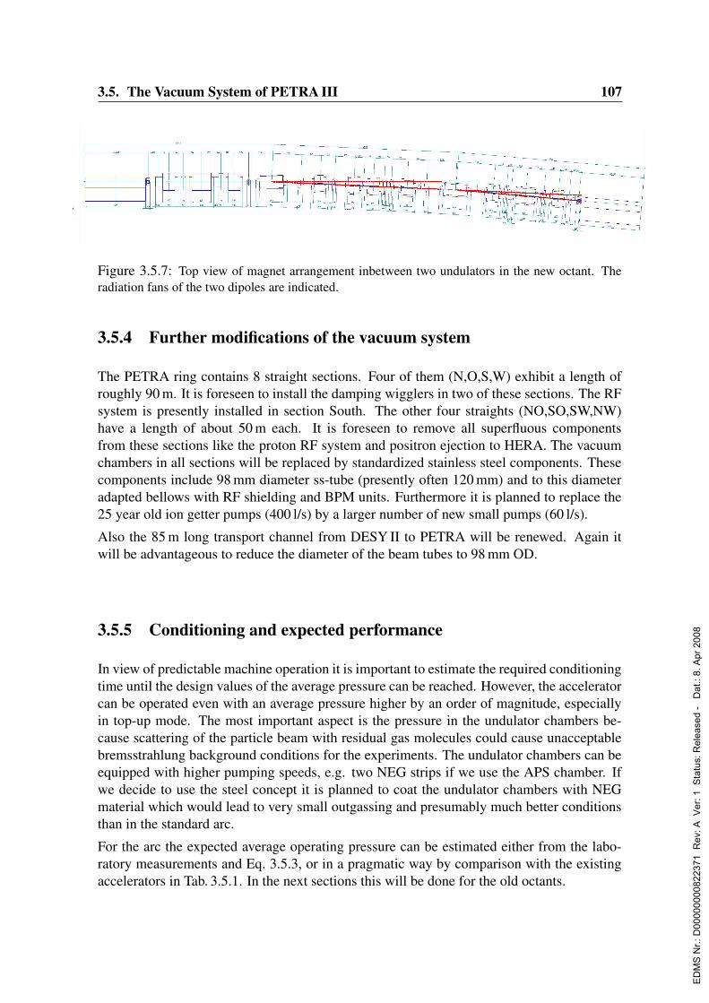
3.5. The Vacuum System of PETRA III 107
Figure 3.5.7: Top view of magnet arrangement inbetween two undulators in the new octant. Theradiation fans of the two dipoles are indicated.
3.5.4 Further modifications of the vacuum system
The PETRA ring contains 8 straight sections. Four of them (N,O,S,W) exhibit a length ofroughly 90 m. It is foreseen to install the damping wigglers in two of these sections. The RFsystem is presently installed in section South. The other four straights (NO,SO,SW,NW)have a length of about 50 m each. It is foreseen to remove all superfluous componentsfrom these sections like the proton RF system and positron ejection to HERA. The vacuumchambers in all sections will be replaced by standardized stainless steel components. Thesecomponents include 98 mm diameter ss-tube (presently often 120 mm) and to this diameteradapted bellows with RF shielding and BPM units. Furthermore it is planned to replace the25 year old ion getter pumps (400 l/s) by a larger number of new small pumps (60 l/s).
Also the 85 m long transport channel from DESY II to PETRA will be renewed. Again itwill be advantageous to reduce the diameter of the beam tubes to 98 mm OD.
3.5.5 Conditioning and expected performance
In view of predictable machine operation it is important to estimate the required conditioningtime until the design values of the average pressure can be reached. However, the acceleratorcan be operated even with an average pressure higher by an order of magnitude, especiallyin top-up mode. The most important aspect is the pressure in the undulator chambers be-cause scattering of the particle beam with residual gas molecules could cause unacceptablebremsstrahlung background conditions for the experiments. The undulator chambers can beequipped with higher pumping speeds, e.g. two NEG strips if we use the APS chamber. Ifwe decide to use the steel concept it is planned to coat the undulator chambers with NEGmaterial which would lead to very small outgassing and presumably much better conditionsthan in the standard arc.
For the arc the expected average operating pressure can be estimated either from the labo-ratory measurements and Eq. 3.5.3, or in a pragmatic way by comparison with the existingaccelerators in Tab. 3.5.1. In the next sections this will be done for the old octants.
ED
MS
Nr.:
D00
0000
0082
2371
Rev
: A V
er: 1
Sta
tus:
Rel
ease
d -
Dat
.: 8.
Apr
200
8
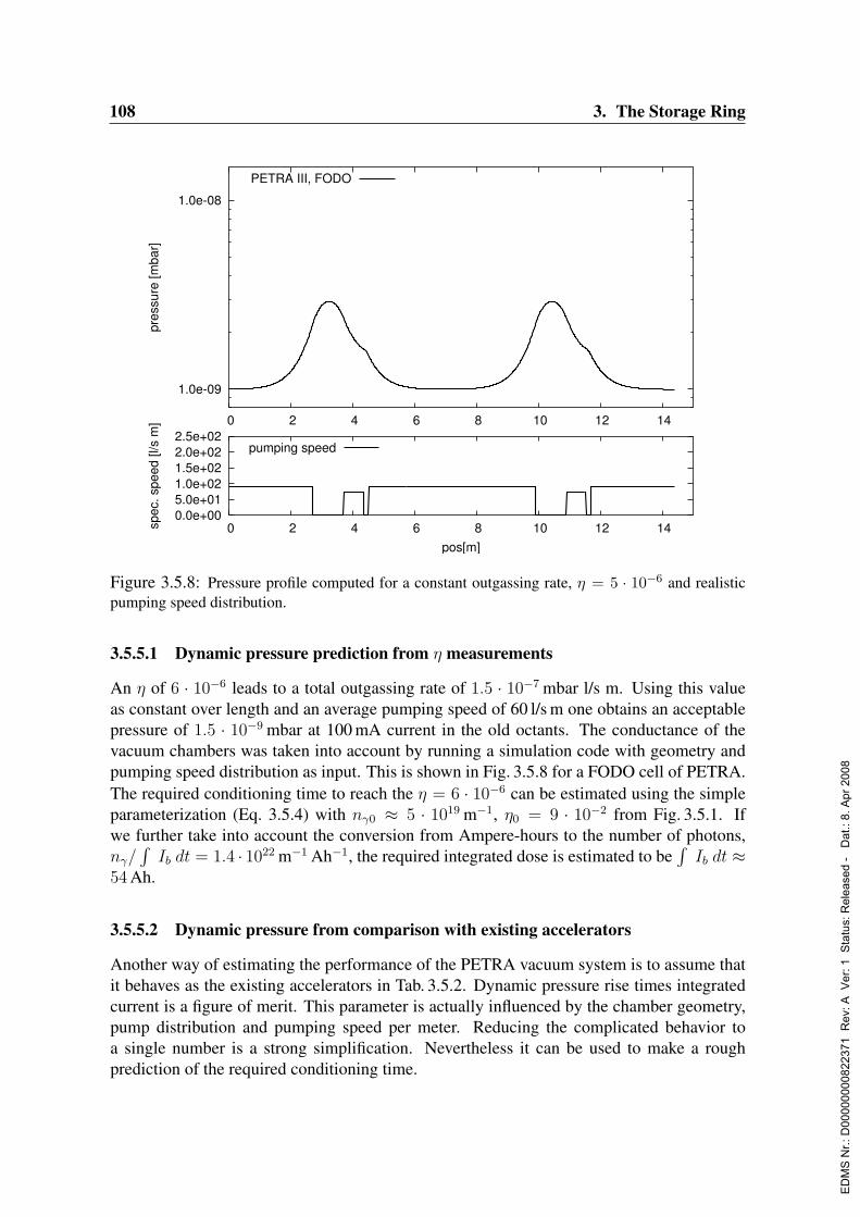
108 3. The Storage Ring
1.0e-09
1.0e-08
0 2 4 6 8 10 12 14
pres
sure
[mba
r]
PETRA III, FODO
0.0e+005.0e+011.0e+021.5e+022.0e+022.5e+02
0 2 4 6 8 10 12 14spec
. spe
ed [l
/s m
]
pos[m]
pumping speed
Figure 3.5.8: Pressure profile computed for a constant outgassing rate, η = 5 · 10−6 and realisticpumping speed distribution.
3.5.5.1 Dynamic pressure prediction from η measurements
An η of 6 · 10−6 leads to a total outgassing rate of 1.5 · 10−7 mbar l/s m. Using this valueas constant over length and an average pumping speed of 60 l/s m one obtains an acceptablepressure of 1.5 · 10−9 mbar at 100 mA current in the old octants. The conductance of thevacuum chambers was taken into account by running a simulation code with geometry andpumping speed distribution as input. This is shown in Fig. 3.5.8 for a FODO cell of PETRA.The required conditioning time to reach the η = 6 · 10−6 can be estimated using the simpleparameterization (Eq. 3.5.4) with nγ0 ≈ 5 · 1019 m−1, η0 = 9 · 10−2 from Fig. 3.5.1. Ifwe further take into account the conversion from Ampere-hours to the number of photons,nγ/
∫Ib dt = 1.4 · 1022 m−1 Ah−1, the required integrated dose is estimated to be
∫Ib dt ≈
54 Ah.
3.5.5.2 Dynamic pressure from comparison with existing accelerators
Another way of estimating the performance of the PETRA vacuum system is to assume thatit behaves as the existing accelerators in Tab. 3.5.2. Dynamic pressure rise times integratedcurrent is a figure of merit. This parameter is actually influenced by the chamber geometry,pump distribution and pumping speed per meter. Reducing the complicated behavior toa single number is a strong simplification. Nevertheless it can be used to make a roughprediction of the required conditioning time.
ED
MS
Nr.:
D00
0000
0082
2371
Rev
: A V
er: 1
Sta
tus:
Rel
ease
d -
Dat
.: 8.
Apr
200
8

3.5. The Vacuum System of PETRA III 109
If we assume a value of dP/dI ·∫I dt = 2.5 nbar h as observed in PETRA I, PETRA III will
achieve a dynamic pressure of 2 pbar at 100 mA current after 125 Ah. Note, however, thatPETRA I had significantly less pumping speed delivered by the integrated ion sputter pumpsas compared to the NEG pumps in the new machine.
If we assume 75 mA average current (linear rise from 50 mA to 100 mA) one can concludethat the required conditioning time lies in the range of 700 to 1700 operating hours to reachthe design pressure with full operating current of 100 mA. Acceptable machine operationwill be already possible after a tenth of this time with a beam lifetime beyond 5 h.
ED
MS
Nr.:
D00
0000
0082
2371
Rev
: A V
er: 1
Sta
tus:
Rel
ease
d -
Dat
.: 8.
Apr
200
8
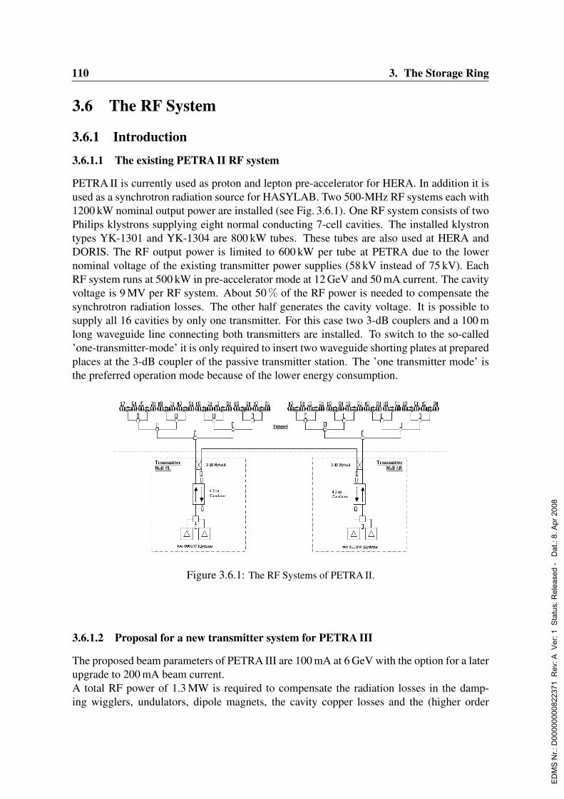
110 3. The Storage Ring
3.6 The RF System
3.6.1 Introduction
3.6.1.1 The existing PETRA II RF system
PETRA II is currently used as proton and lepton pre-accelerator for HERA. In addition it isused as a synchrotron radiation source for HASYLAB. Two 500-MHz RF systems each with1200 kW nominal output power are installed (see Fig. 3.6.1). One RF system consists of twoPhilips klystrons supplying eight normal conducting 7-cell cavities. The installed klystrontypes YK-1301 and YK-1304 are 800 kW tubes. These tubes are also used at HERA andDORIS. The RF output power is limited to 600 kW per tube at PETRA due to the lowernominal voltage of the existing transmitter power supplies (58 kV instead of 75 kV). EachRF system runs at 500 kW in pre-accelerator mode at 12 GeV and 50 mA current. The cavityvoltage is 9 MV per RF system. About 50 % of the RF power is needed to compensate thesynchrotron radiation losses. The other half generates the cavity voltage. It is possible tosupply all 16 cavities by only one transmitter. For this case two 3-dB couplers and a 100 mlong waveguide line connecting both transmitters are installed. To switch to the so-called’one-transmitter-mode’ it is only required to insert two waveguide shorting plates at preparedplaces at the 3-dB coupler of the passive transmitter station. The ’one transmitter mode’ isthe preferred operation mode because of the lower energy consumption.
Version engl. 1.4 11.12.03
PETRA-III- Technical Design Report -
a. The RF System
i.Introduction
1. The existing PETRA-II RF System
PETRA-II is currently used as proton and lepton pre-accelerator for HERA. In addition it is
used as a synchrotron radiation source for HASYLAB. Two 500-MHz rf systems with
1200 kW nominal output power each are installed. One rf system consists of two Philips
klystrons for supplying eight normal conducting 7-cell cavities. The installed klystron types
YK-1301 and YK-1304 are 800-kW tubes. This tube types are also in service at HERA and
DORIS. The rf output power is limited to 600 kW per tube at PETRA due to the lower
nominal voltage of the existing transmitter power supplies (58 kV instead of 75 kV). Both rf
systems are running at 500 kW each in pre-accelerator mode at 12 GeV and 50 mA beam
current. The cavity voltage is 9 MV per rf system. About 50% of the rf power is needed to
compensate the synchrotron radiation losses. The other half generates the cavity voltage. It is
possible to supply all 16 cavities by only one transmitter. For this case two 3-dB couplers and
a 100 m waveguide line connecting both transmitters are installed. For switching to the so
called “one-transmitter-mode” it is only required to insert two waveguide shorting plates at
prepared places at the 3-dB coupler of the passive transmitter station. The “one transmitter-
mode” is the preferred operation mode because of the lower energy consumption.
Fig. 1: The RF Systems of PETRA-II
2. Proposal for a New Transmitter System for PETRA-
III
The proposed beam parameters of PETRA-III are 100 mA at 6 GeV with the option for a later
upgrade to 200 mA beam current.
Figure 3.6.1: The RF Systems of PETRA II.
3.6.1.2 Proposal for a new transmitter system for PETRA III
The proposed beam parameters of PETRA III are 100 mA at 6 GeV with the option for a laterupgrade to 200 mA beam current.A total RF power of 1.3 MW is required to compensate the radiation losses in the damp-ing wigglers, undulators, dipole magnets, the cavity copper losses and the (higher order
ED
MS
Nr.:
D00
0000
0082
2371
Rev
: A V
er: 1
Sta
tus:
Rel
ease
d -
Dat
.: 8.
Apr
200
8
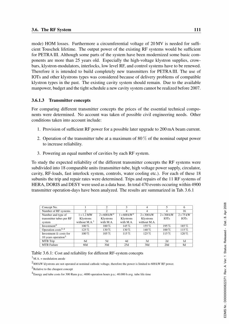
3.6. The RF System 111
mode) HOM losses. Furthermore a circumferential voltage of 20 MV is needed for suffi-cient Touschek lifetime. The output power of the existing RF systems would be sufficientfor PETRA III. Although some parts of the system have been modernized some basic com-ponents are more than 25 years old. Especially the high-voltage klystron supplies, crow-bars, klystron-modulators, interlocks, low level RF, and control systems have to be renewed.Therefore it is intended to build completely new transmitters for PETRA III. The use ofIOTs and other klystrons types was considered because of delivery problems of compatibleklystron types in the past. The existing cavity system should remain. Due to the availablemanpower, budget and the tight schedule a new cavity system cannot be realized before 2007.
3.6.1.3 Transmitter concepts
For comparing different transmitter concepts the prices of the essential technical compo-nents were determined. No account was taken of possible civil engineering needs. Otherconditions taken into account include:
1. Provision of sufficient RF power for a possible later upgrade to 200 mA beam current.
2. Operation of the transmitter tube at a maximum of 80 % of the nominal output powerto increase reliability.
3. Powering an equal number of cavities by each RF system.
To study the expected reliability of the different transmitter concepts the RF systems weresubdivided into 18 comparable units (transmitter-tube, high voltage power supply, circulator,cavity, RF-loads, fast interlock system, controls, water cooling etc.). For each of these 18subunits the trip and repair rates were determined. Trips and repairs of the 11 RF systems ofHERA, DORIS and DESY were used as a data base. In total 470 events occuring within 4900transmitter operation-days have been analyzed. The results are summarized in Tab. 3.6.1
Concept No. 1 2 3 4 5 6Number of RF systems 2 2 4 4 4 16Number and type of 1×1.2 MW 2×600 kW2 1×600 kW2 2×300 kW 2×300 kW 2×75 kWtransmitter tubes per RF Klystrons Klystrons Klystrons Klystrons IOTs IOTssystem without M.A.1 with M.A. with M.A. without M.A.Investment3 100 % 100 % 145 % 155 % 195 % 185 %Operation costs3,4 125 % 130 % 130 % 140 % 100 % 115 %Investment & costs for 100 % 105 % 115 % 125 % 115 % 120 %10 years operation3
MTB Trip 6d 5d 4d 3d 2d 1dMTB Failure 60d 30d 25d 30d 20d 8d
Table 3.6.1: Cost and reliability for different RF-system concepts1M.A. = modulation anode2800 kW klystrons are not operated at nominal cathode voltage, therefore the power is limited to 600 kW RF power.3Relative to the cheapest concept4Energy and tube costs for 300 Runs p.a.; 4000 operation hours p.a.; 40.000 h avg. tube life time
ED
MS
Nr.:
D00
0000
0082
2371
Rev
: A V
er: 1
Sta
tus:
Rel
ease
d -
Dat
.: 8.
Apr
200
8

112 3. The Storage Ring
3.6.1.4 Comparison of costs
Because concepts 1 and 2 have the smallest number of components they are cheaper than theother concepts shown in Tab. 3.6.1. Additionally the two existing 4-MW circulators couldbe reused.The concepts using IOTs are the most expensive although IOTs are about 30 % cheaper thancomparable klystrons. Since they are only available for less than 90 kW RF power at presentthey can not compete in costs with klystrons in the MW power range, nevertheless 300-kWIOTs are considered in concept 5. The cost per kW RF power of such tubes would be quiteattractive, unfortunately they are not state of the art at present. The additional costs for de-velopment, prototype tubes and for generating some kW of drive power makes this conceptmore expensive than the 300 kW klystron concept which was only considered for compari-son.One significant advantage of IOTs is the 10 % higher efficiency compared to klystrons. Fur-thermore the efficiency is quite constant over a wide output power range. Due to the oper-ation costs the 300-kW IOT concept would be the most favorable in this respect. Howeverthis is offset by the higher initial investment. Regarding investment and operational costsover a period of 10 years concepts 1 and 2 remain the most economic.
3.6.1.5 Comparison of reliability
Reliability of a facility decreases with the number of installed power components. In firstapproximation one can assume that four 300 kW tubes cause four times more trips than one1.2-MW tube. This applies also to high power supplies and all essential subsystems. There-fore concept 6 has the lowest expected reliability. On the other hand machine operationwould only be affected if more than 3 of the 16 RF systems were off line at the same time.However, beam loss is probably unavoidable when just one RF system trips.Due to the smaller number of installed power components the highest reliability can be ex-pected for concepts 1 and 2. However, in the case of a serious failure of one of the RFsystems operation would only be possible at lower total beam current.
3.6.1.6 Conclusion
Concepts 1 and 2 are the cheapest and the most reliable. Concept 2 has the additional ad-vantage that it is very similar to the existing PETRA II installation and therefore requires theleast effort to renew the system.In the following only concept 2 is considered in more detail.
3.6.2 RF system design for PETRA III
3.6.2.1 Design criteria
The preferred RF system for PETRA III can be very similar to that of PETRA II, as shownin Fig. 3.6.2. To increase the current threshold for beam instabilities it is planned to reduce
ED
MS
Nr.:
D00
0000
0082
2371
Rev
: A V
er: 1
Sta
tus:
Rel
ease
d -
Dat
.: 8.
Apr
200
8
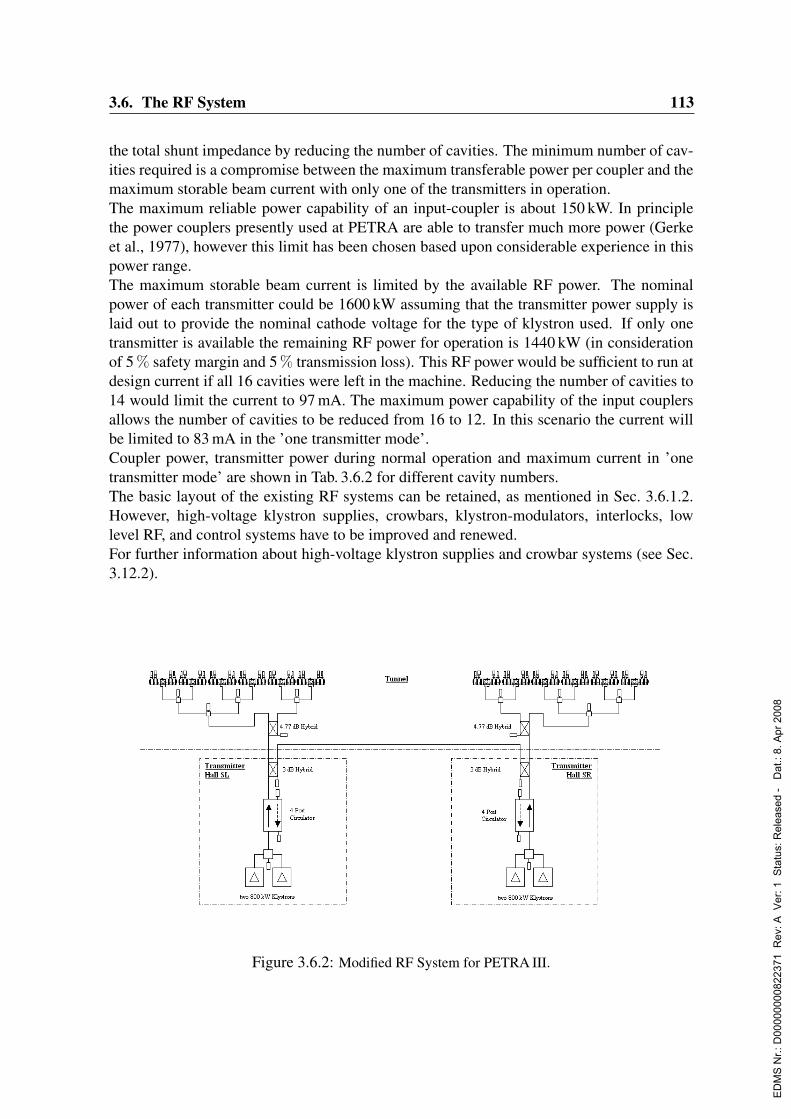
3.6. The RF System 113
the total shunt impedance by reducing the number of cavities. The minimum number of cav-ities required is a compromise between the maximum transferable power per coupler and themaximum storable beam current with only one of the transmitters in operation.The maximum reliable power capability of an input-coupler is about 150 kW. In principlethe power couplers presently used at PETRA are able to transfer much more power (Gerkeet al., 1977), however this limit has been chosen based upon considerable experience in thispower range.The maximum storable beam current is limited by the available RF power. The nominalpower of each transmitter could be 1600 kW assuming that the transmitter power supply islaid out to provide the nominal cathode voltage for the type of klystron used. If only onetransmitter is available the remaining RF power for operation is 1440 kW (in considerationof 5 % safety margin and 5 % transmission loss). This RF power would be sufficient to run atdesign current if all 16 cavities were left in the machine. Reducing the number of cavities to14 would limit the current to 97 mA. The maximum power capability of the input couplersallows the number of cavities to be reduced from 16 to 12. In this scenario the current willbe limited to 83 mA in the ’one transmitter mode’.Coupler power, transmitter power during normal operation and maximum current in ’onetransmitter mode’ are shown in Tab. 3.6.2 for different cavity numbers.The basic layout of the existing RF systems can be retained, as mentioned in Sec. 3.6.1.2.However, high-voltage klystron supplies, crowbars, klystron-modulators, interlocks, lowlevel RF, and control systems have to be improved and renewed.For further information about high-voltage klystron supplies and crowbar systems (see Sec.3.12.2).
Version engl. 1.4 11.12.03
The existing rf systems can remain in their basic structure, as mentioned in 3.5.1.2. However,
high-voltage klystron supplies, crowbars, klystron-modulators, interlocks, low level rf, and
control systems have to be improved and renewed.
For further information about high-voltage klystron supplies and crowbar systems see chapter
3.14.3 Transmitter Power Supplies.
Figure 3.6.2: Modified RF System for PETRA III.
ED
MS
Nr.:
D00
0000
0082
2371
Rev
: A V
er: 1
Sta
tus:
Rel
ease
d -
Dat
.: 8.
Apr
200
8

114 3. The Storage Ring
Version engl. 1.4 11.12.03
2. High Voltage Supply of the Klystrons
The 500-MHz klystrons of the 13 transmitters at DESY are equipped with modulation anodes.
Therefore it is reasonable to use this klystron type for PETRA-III as well. However this
requires additional modulation anode supplies. Having the possibility to operate different
klystron types of different suppliers an independent modulation anode power supply for each
klystron is necessary. For driving the modulation anodes fibre link controlled 65-kV power
supplies are foreseen. DESY has long time positive experience with this kind of driving
klystron modulation anodes.
Fig. 3: High Voltage Supply of the Klystrons
3. RF Controlling
Cavity Voltage Control Loop
The cavity voltage loop controls phase and amplitude of summed cavity voltages of one
cavity system. The loop acts on the klystron drive. Instead of common used phase and
amplitude control loops the higher performance of IQ control loops will be used [2]. It is
foreseen to keep the klystron efficiency at maximum by controlling cathode voltage and
current as a function of klystron output power and klystron drive. A klystron controller
algorithm is under development.
Figure 3.6.3: High Voltage Supply of the Klystrons
3.6.2.2 Klystron high voltage supply
The 500 MHz klystrons of the 13 transmitters at DESY are equipped with modulation an-odes. To preserve uniformity with the remaining systems it is prudent to also use this klystrontype for PETRA III. However this requires additional modulation anode supplies. To havethe possibility to operate klystron types from different suppliers, an independent modula-tion anode power supply for each klystron is necessary. Fiber link controlled 65 kV powersupplies are foreseen to drive the modulation anodes, as shown in Fig. 3.6.3. DESY hasextensive positive experience with such units.
3.6.2.3 RF controls
A sketch of the RF controlling system is shown in Fig. 3.6.4
Number of 7-cell Coupling factor Power Transmission Required Transmitter Max. Beam Currentcavities installed for Matching per Coupler (kW) Power @ 20 MV, 100 mA with one Transmitter
@ 100 mA (kW) @ 1440 kW (mA)2 × 8 2.4 81 2 × 690 1072 × 7 2.2 99 2 × 731 972 × 6 2.0 124 2 × 786 832 × 5 1.9 163 2 × 863 632 × 4 1.7 230 2 × 978 31
Table 3.6.2: Required RF power and maximum beam current versus number of cavities installed
ED
MS
Nr.:
D00
0000
0082
2371
Rev
: A V
er: 1
Sta
tus:
Rel
ease
d -
Dat
.: 8.
Apr
200
8
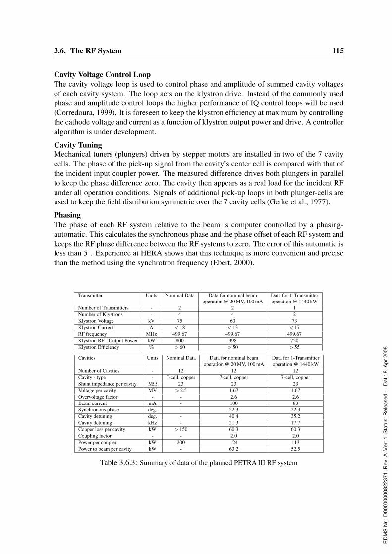
3.6. The RF System 115
Cavity Voltage Control LoopThe cavity voltage loop is used to control phase and amplitude of summed cavity voltagesof each cavity system. The loop acts on the klystron drive. Instead of the commonly usedphase and amplitude control loops the higher performance of IQ control loops will be used(Corredoura, 1999). It is foreseen to keep the klystron efficiency at maximum by controllingthe cathode voltage and current as a function of klystron output power and drive. A controlleralgorithm is under development.
Cavity TuningMechanical tuners (plungers) driven by stepper motors are installed in two of the 7 cavitycells. The phase of the pick-up signal from the cavity’s center cell is compared with that ofthe incident input coupler power. The measured difference drives both plungers in parallelto keep the phase difference zero. The cavity then appears as a real load for the incident RFunder all operation conditions. Signals of additional pick-up loops in both plunger-cells areused to keep the field distribution symmetric over the 7 cavity cells (Gerke et al., 1977).
PhasingThe phase of each RF system relative to the beam is computer controlled by a phasing-automatic. This calculates the synchronous phase and the phase offset of each RF system andkeeps the RF phase difference between the RF systems to zero. The error of this automatic isless than 5. Experience at HERA shows that this technique is more convenient and precisethan the method using the synchrotron frequency (Ebert, 2000).
Transmitter Units Nominal Data Data for nominal beam Data for 1-Transmitteroperation @ 20 MV, 100 mA operation @ 1440 kW
Number of Transmitters - 2 2 1Number of Klystrons - 4 4 2Klystron Voltage kV 75 60 73Klystron Current A < 18 < 13 < 17RF frequency MHz 499.67 499.67 499.67Klystron RF - Output Power kW 800 398 720Klystron Efficiency % > 60 > 50 > 55
Cavities Units Nominal Data Data for nominal beam Data for 1-Transmitteroperation @ 20 MV, 100 mA operation @ 1440 kW
Number of Cavities - 12 12 12Cavity - type - 7-cell, copper 7-cell, copper 7-cell, copperShunt impedance per cavity MΩ 23 23 23Voltage per cavity MV > 2.5 1.67 1.67Overvoltage factor - - 2.6 2.6Beam current mA - 100 83Synchronous phase deg. - 22.3 22.3Cavity detuning deg. - 40.4 35.2Cavity detuning kHz - 21.3 17.7Copper loss per cavity kW > 150 60.3 60.3Coupling factor - - 2.0 2.0Power per coupler kW 200 124 113Power to beam per cavity kW - 63.2 52.5
Table 3.6.3: Summary of data of the planned PETRA III RF system
ED
MS
Nr.:
D00
0000
0082
2371
Rev
: A V
er: 1
Sta
tus:
Rel
ease
d -
Dat
.: 8.
Apr
200
8
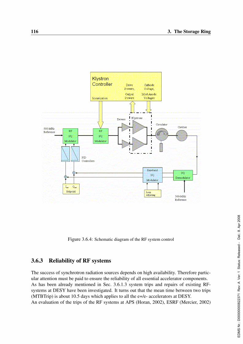
116 3. The Storage Ring
Version engl. 1.4 11.12.03
Fig. 4: Controlling the RF Systems
Cavity-Tuning
Stepper motor driven plunges are installed in two of the 7 cavity cells for tuning. The pick-up
signal phase of the cavity’s centre cell is compared with the phase of the incident input
coupler power. The measured phase difference drives both plungers in parallel in order to
keep the phase difference at 0. Thereby the cavity appears as a real load for the incident rf
under all operation conditions. Signals of additional pick-up loops in both plunger-cells are
used to keep the field distribution symmetric over the 7 cavity cells [1].
Phasing
The rf phases of each rf system related to the beam are controlled by a phasing-automatic. The
phasing-automatic calculates the synchronous phase and the phase offset of each rf system
and keeps the rf phase difference between the rf systems at 0. The inaccuracy of the phasing-
automatic is less than 5°. The experience at HERA shows that phasing rf systems in this way
is more convenient and precise than the common method using the synchrotron frequency [3].
Figure 3.6.4: Schematic diagram of the RF system control
3.6.3 Reliability of RF systems
The success of synchrotron radiation sources depends on high availability. Therefore partic-ular attention must be paid to ensure the reliability of all essential accelerator components.As has been already mentioned in Sec. 3.6.1.3 system trips and repairs of existing RF-systems at DESY have been investigated. It turns out that the mean time between two trips(MTBTrip) is about 10.5 days which applies to all the e+/e- accelerators at DESY.An evaluation of the trips of the RF systems at APS (Horan, 2002), ESRF (Mercier, 2002)
ED
MS
Nr.:
D00
0000
0082
2371
Rev
: A V
er: 1
Sta
tus:
Rel
ease
d -
Dat
.: 8.
Apr
200
8
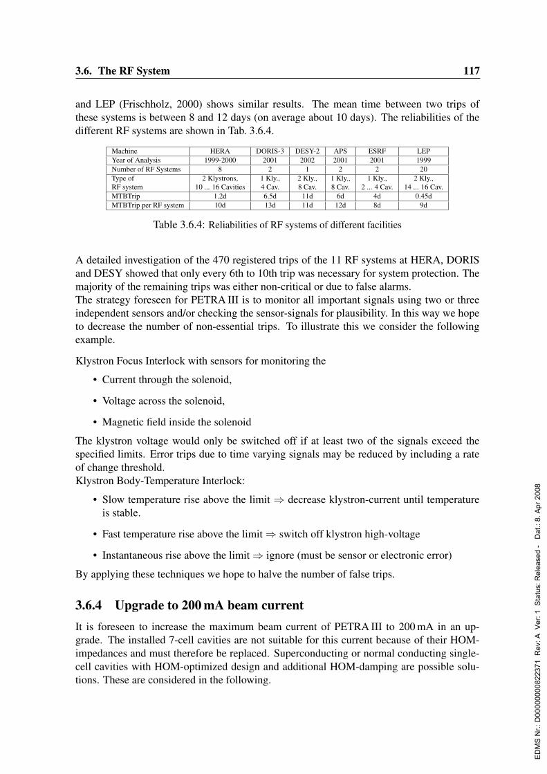
3.6. The RF System 117
and LEP (Frischholz, 2000) shows similar results. The mean time between two trips ofthese systems is between 8 and 12 days (on average about 10 days). The reliabilities of thedifferent RF systems are shown in Tab. 3.6.4.
Machine HERA DORIS-3 DESY-2 APS ESRF LEPYear of Analysis 1999-2000 2001 2002 2001 2001 1999Number of RF Systems 8 2 1 2 2 20Type of 2 Klystrons, 1 Kly., 2 Kly., 1 Kly., 1 Kly., 2 Kly.,RF system 10 ... 16 Cavities 4 Cav. 8 Cav. 8 Cav. 2 ... 4 Cav. 14 ... 16 Cav.MTBTrip 1.2d 6.5d 11d 6d 4d 0.45dMTBTrip per RF system 10d 13d 11d 12d 8d 9d
Table 3.6.4: Reliabilities of RF systems of different facilities
A detailed investigation of the 470 registered trips of the 11 RF systems at HERA, DORISand DESY showed that only every 6th to 10th trip was necessary for system protection. Themajority of the remaining trips was either non-critical or due to false alarms.The strategy foreseen for PETRA III is to monitor all important signals using two or threeindependent sensors and/or checking the sensor-signals for plausibility. In this way we hopeto decrease the number of non-essential trips. To illustrate this we consider the followingexample.
Klystron Focus Interlock with sensors for monitoring the
• Current through the solenoid,
• Voltage across the solenoid,
• Magnetic field inside the solenoid
The klystron voltage would only be switched off if at least two of the signals exceed thespecified limits. Error trips due to time varying signals may be reduced by including a rateof change threshold.Klystron Body-Temperature Interlock:
• Slow temperature rise above the limit ⇒ decrease klystron-current until temperatureis stable.
• Fast temperature rise above the limit ⇒ switch off klystron high-voltage
• Instantaneous rise above the limit ⇒ ignore (must be sensor or electronic error)
By applying these techniques we hope to halve the number of false trips.
3.6.4 Upgrade to 200 mA beam currentIt is foreseen to increase the maximum beam current of PETRA III to 200 mA in an up-grade. The installed 7-cell cavities are not suitable for this current because of their HOM-impedances and must therefore be replaced. Superconducting or normal conducting single-cell cavities with HOM-optimized design and additional HOM-damping are possible solu-tions. These are considered in the following.
ED
MS
Nr.:
D00
0000
0082
2371
Rev
: A V
er: 1
Sta
tus:
Rel
ease
d -
Dat
.: 8.
Apr
200
8
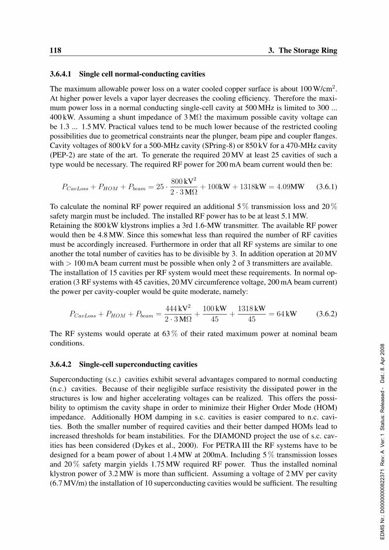
118 3. The Storage Ring
3.6.4.1 Single cell normal-conducting cavities
The maximum allowable power loss on a water cooled copper surface is about 100 W/cm2.At higher power levels a vapor layer decreases the cooling efficiency. Therefore the maxi-mum power loss in a normal conducting single-cell cavity at 500 MHz is limited to 300 ...400 kW. Assuming a shunt impedance of 3 MΩ the maximum possible cavity voltage canbe 1.3 ... 1.5 MV. Practical values tend to be much lower because of the restricted coolingpossibilities due to geometrical constraints near the plunger, beam pipe and coupler flanges.Cavity voltages of 800 kV for a 500-MHz cavity (SPring-8) or 850 kV for a 470-MHz cavity(PEP-2) are state of the art. To generate the required 20 MV at least 25 cavities of such atype would be necessary. The required RF power for 200 mA beam current would then be:
PCavLoss + PHOM + Pbeam = 25 · 800 kV2
2 · 3 MΩ+ 100kW + 1318kW = 4.09MW (3.6.1)
To calculate the nominal RF power required an additional 5 % transmission loss and 20 %safety margin must be included. The installed RF power has to be at least 5.1 MW.Retaining the 800 kW klystrons implies a 3rd 1.6-MW transmitter. The available RF powerwould then be 4.8 MW. Since this somewhat less than required the number of RF cavitiesmust be accordingly increased. Furthermore in order that all RF systems are similar to oneanother the total number of cavities has to be divisible by 3. In addition operation at 20 MVwith > 100 mA beam current must be possible when only 2 of 3 transmitters are available.The installation of 15 cavities per RF system would meet these requirements. In normal op-eration (3 RF systems with 45 cavities, 20 MV circumference voltage, 200 mA beam current)the power per cavity-coupler would be quite moderate, namely:
PCavLoss + PHOM + Pbeam =444 kV2
2 · 3 MΩ+
100 kW45
+1318 kW
45= 64 kW (3.6.2)
The RF systems would operate at 63 % of their rated maximum power at nominal beamconditions.
3.6.4.2 Single-cell superconducting cavities
Superconducting (s.c.) cavities exhibit several advantages compared to normal conducting(n.c.) cavities. Because of their negligible surface resistivity the dissipated power in thestructures is low and higher accelerating voltages can be realized. This offers the possi-bility to optimism the cavity shape in order to minimize their Higher Order Mode (HOM)impedance. Additionally HOM damping in s.c. cavities is easier compared to n.c. cavi-ties. Both the smaller number of required cavities and their better damped HOMs lead toincreased thresholds for beam instabilities. For the DIAMOND project the use of s.c. cav-ities has been considered (Dykes et al., 2000). For PETRA III the RF systems have to bedesigned for a beam power of about 1.4 MW at 200mA. Including 5 % transmission lossesand 20 % safety margin yields 1.75 MW required RF power. Thus the installed nominalklystron power of 3.2 MW is more than sufficient. Assuming a voltage of 2 MV per cavity(6.7 MV/m) the installation of 10 superconducting cavities would be sufficient. The resulting
ED
MS
Nr.:
D00
0000
0082
2371
Rev
: A V
er: 1
Sta
tus:
Rel
ease
d -
Dat
.: 8.
Apr
200
8

3.6. The RF System 119
Units n.c. cavities s.c. cavitiesNumber of transmitters - 3 2nominal RF power per transmitter MW 1.6 1.6RF power per transmitter @ 200 mA MW 1.02 0.75total RF power @ 200 mA MW 3.07 1.49number of cavities per RF system - 15 5total number of cavities - 45 10voltage per cavity MV 0.444 2.0gradient MV/m 1.5 6.7power per coupler @ 200 mA KW 64 142power to beam per cavity @ 200 mA kW 32 142
Table 3.6.5: Superconducting (s.c.) versus normal conducting (n.c.) cavities
coupler power of 142 kW per cavity would be moderate. Use of s.c. cavities for the upgradeof PETRA III would be quite attractive, especially considering the energy consumption. TheAC input power for two s.c. RF systems is about 3 MW lower compared to that for threen.c. RF systems. The investment costs are estimated to be at least 10 Me for either option.Superconducting cavities require more complex interlock systems compared to n.c. cavities.Therefore one can assume that they trip more frequently. The experience at HERA show atrip rate of about 70 days for a s.c. cavity (compared to 300 days for a n.c. cavity). At LEPthe trip rate was about 23 days for a single s.c. cavity. At CESR and KEK-B the experienceis similar. The higher trip rate of s.c. cavities is partially compensated by the smaller numberrequired. From the above it is reasonable to expect 1 to 3 trips per week for the PETRA IIIsuperconducting RF system. Experience from accelerators which use or intend to use singlecell superconducting cavities may help to make a choice between the two alternatives.
3.6.5 ConclusionReusing essential parts of the present PETRA II RF system is planned based on cost, sched-ule and manpower considerations. Renewing the klystron high-voltage supplies, crowbarsystems, klystron modulators, interlock electronics and control system is foreseen to ensurereliable operation and efficient diagnostics. To be able to store 100 mA with an 8 ns bunch-spacing, the shunt-impedance of the 500 MHz cavities will be decreased by removing 4 ofthe 16 installed 7-cell-cavities. Additionally installing a broadband longitudinal multibunchfeedback system is foreseen (see Sec. 3.10).
For a future upgrade of PETRA III to 200 mA it is planned to replace the existing 7-cell-cavities by HOM-optimized single-cell cavities. The decision whether superconducting ornormal conducting cavities will be more suitable for PETRA III has yet to be made.
ED
MS
Nr.:
D00
0000
0082
2371
Rev
: A V
er: 1
Sta
tus:
Rel
ease
d -
Dat
.: 8.
Apr
200
8
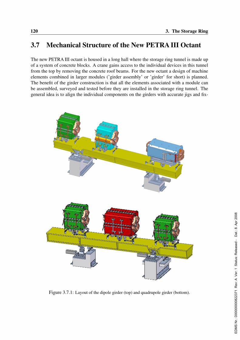
120 3. The Storage Ring
3.7 Mechanical Structure of the New PETRA III Octant
The new PETRA III octant is housed in a long hall where the storage ring tunnel is made upof a system of concrete blocks. A crane gains access to the individual devices in this tunnelfrom the top by removing the concrete roof beams. For the new octant a design of machineelements combined in larger modules (’girder assembly’ or ’girder’ for short) is planned.The benefit of the girder construction is that all the elements associated with a module canbe assembled, surveyed and tested before they are installed in the storage ring tunnel. Thegeneral idea is to align the individual components on the girders with accurate jigs and fix-
Figure 3.7.1: Layout of the dipole girder (top) and quadrupole girder (bottom).
ED
MS
Nr.:
D00
0000
0082
2371
Rev
: A V
er: 1
Sta
tus:
Rel
ease
d -
Dat
.: 8.
Apr
200
8

3.7. Mechanical Structure of the New PETRA III Octant 121
Figure 3.7.2: Result of the bending load calculation of the quadrupole girder
tures outside the machine, and then survey the girder assembly into position in the tunnelrather than the individual elements.
3.7.1 General girder design
The mechanical frame for the new octant of the PETRA machine is build up of eight repeti-tive units (cell) of four girders each as shown in Fig. 3.7.3. Two of the four girders are calledquadrupole girders (QG) carrying three quadrupoles as the main components. The other twoare called dipole girders (DG). They support the dipoles plus two quadrupoles, see Fig. 3.7.1.In addition to magnets, other devices like monitors, vacuum pumps, valves and correctionmagnets will be installed on the girder. The accuracy of the quadrupole magnet axis withrespect to the beam on the girder must be within 100µm (± 50µm on average). The fourgirders in one cell have to be aligned vertically and horizontally to the beam axis with anaccuracy of 0.2 mm (0.1 mm on average) to each other. In the z direction the positioningaccuracy must be within 0.5 mm. The girders can be moved vertically by ± 5 mm remotelycontrolled with an accuracy of 50µm during beam operation for beam based alignment.
ED
MS
Nr.:
D00
0000
0082
2371
Rev
: A V
er: 1
Sta
tus:
Rel
ease
d -
Dat
.: 8.
Apr
200
8
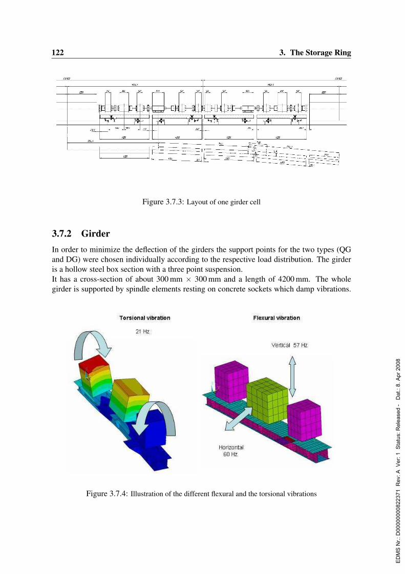
122 3. The Storage Ring
Figure 3.7.3: Layout of one girder cell
3.7.2 GirderIn order to minimize the deflection of the girders the support points for the two types (QGand DG) were chosen individually according to the respective load distribution. The girderis a hollow steel box section with a three point suspension.It has a cross-section of about 300 mm × 300 mm and a length of 4200 mm. The wholegirder is supported by spindle elements resting on concrete sockets which damp vibrations.
Fig. II.4: Illustration of the different flexural and the torsional vibration.
The calculated flexural resonance frequency of the girder structure is 57 Hz in vertical and 60 Hz in
horizontal direction (Fig. II.4). The torsional resonance has a calculated value of 21 Hz. The magnet
must be rigidly mounted to the girder. The individual magnet is supported by commercial supports
with a high adjustment accuracy of 40 µm (10 degree rotation) and a setting range of ±4.5 mm. After
aligning the magnets by means of a laser tracker system they are fixed firmly in their exact position on
the girder. A test setup showed that after rough handling of the girder with a crane and transport on a
flat bed trailer the magnets stayed in their correct position with respect to the beam axis.
Figure 3.7.4: Illustration of the different flexural and the torsional vibrations
ED
MS
Nr.:
D00
0000
0082
2371
Rev
: A V
er: 1
Sta
tus:
Rel
ease
d -
Dat
.: 8.
Apr
200
8

3.7. Mechanical Structure of the New PETRA III Octant 123
With wall thicknesses between 15 mm (sides) and 25 mm (top, bottom) and the load distribu-tion indicated in Fig. 3.7.1 the quadrupole girder will be deflected by not more than 11µm,see Fig.3.7.2. In case of the dipole girder the deflection does not exceed 9µm. The calcu-lated flexural resonance frequency of the girder structure is 57 Hz in vertical and 60 Hz inhorizontal direction. The corresponding vibrational modes are sketched in Fig. 3.7.4. Thetorsional resonance has a calculated value of 21 Hz. Further calculations will be done tocheck whether torsional vibrations would lead to unacceptable beam oscillations. In thiscase the girder alignment by three spindle elements will be followed by a fixation of the fourcorners of the girder. This would increase the torsional resonance frequency by about 50%to more than 30 Hz. The individual magnets are supported by commercial supports with anadjustment accuracy of 40µm (10 degree rotation) and a setting range of ± 4.5 mm. Afteraligning the magnets by means of a laser tracker system they are fixed firmly to their positionon the girder. A test setup showed that after transporting of the girder with a crane and on aflat bed trailer the magnets stayed in their correct position with respect to the girder.
ED
MS
Nr.:
D00
0000
0082
2371
Rev
: A V
er: 1
Sta
tus:
Rel
ease
d -
Dat
.: 8.
Apr
200
8

124 3. The Storage Ring
3.8 Injection System
3.8.1 Introduction
In order to convert PETRA into a dedicated synchrotron light source, kicker magnets aswell as the driving pulsers were studied with respect to their reliability and availability. ThePETRA III injection requires high pulse repetition stability for operating the machine in top-up mode.
PETRA I PETRA III
Energy 7GeV 6GeV
Number of bunches 4 1920
Beam current 100 mA 200 mA
Deflection 2.88 mrad 2.88 mrad
Kicker length 590 mm 590 mm
Three identical kicker magnets and one septum magnet are included in the PETRA III storagering magnet system to produce closed bumps during injection of the beam from the DESY IItransfer line.The kickers are designed to run with identical currents and waveforms with an amplitudeand pulse length stability of 0.1%.
3.8.2 Concept of the kicker magnet
The kicker magnets can be realized in two different ways. First, one can adopt the presentPETRA injection kicker design (Figs. 3.8.1, 3.8.2). A window-frame like ferrite surroundsa sputtered ceramic vacuum chamber. The kicker is outside the beam vacuum system. Themetal coated ceramic chamber of the kicker will be renewed. The impedance of the ceramicchambers has to be determined for the new PETRA machine parameters to check that theheat load generated by the beam current is tolerable. The insulation of the conductors mustbe replaced since it is 20 years old.
An alternative design is a C-yoke ferrite kicker (Fig. 3.8.3) with two conductors around asputtered ceramic chamber. The advantage of this design is to have sufficient space aroundthe ceramic chamber for air cooling if necessary.If it turns out that air cooling is necessary then we will realize a C-yoke kicker otherwise wewill retain the present kicker design.
ED
MS
Nr.:
D00
0000
0082
2371
Rev
: A V
er: 1
Sta
tus:
Rel
ease
d -
Dat
.: 8.
Apr
200
8
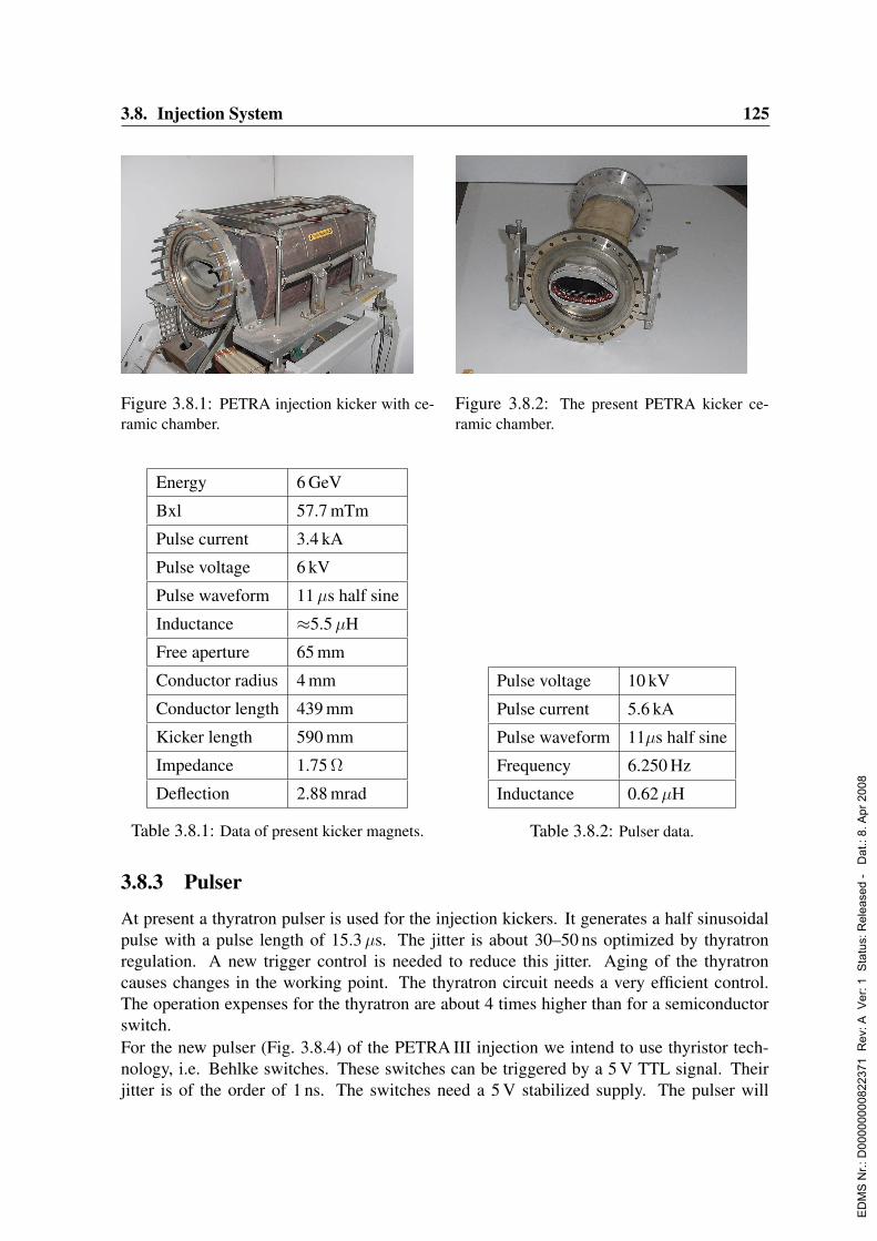
3.8. Injection System 125
Figure 3.8.1: PETRA injection kicker with ce-ramic chamber.
Figure 3.8.2: The present PETRA kicker ce-ramic chamber.
Energy 6 GeV
Bxl 57.7 mTm
Pulse current 3.4 kA
Pulse voltage 6 kV
Pulse waveform 11µs half sine
Inductance ≈5.5µH
Free aperture 65 mm
Conductor radius 4 mm
Conductor length 439 mm
Kicker length 590 mm
Impedance 1.75 Ω
Deflection 2.88 mrad
Table 3.8.1: Data of present kicker magnets.
Pulse voltage 10 kV
Pulse current 5.6 kA
Pulse waveform 11µs half sine
Frequency 6.250 Hz
Inductance 0.62µH
Table 3.8.2: Pulser data.
3.8.3 Pulser
At present a thyratron pulser is used for the injection kickers. It generates a half sinusoidalpulse with a pulse length of 15.3µs. The jitter is about 30–50 ns optimized by thyratronregulation. A new trigger control is needed to reduce this jitter. Aging of the thyratroncauses changes in the working point. The thyratron circuit needs a very efficient control.The operation expenses for the thyratron are about 4 times higher than for a semiconductorswitch.For the new pulser (Fig. 3.8.4) of the PETRA III injection we intend to use thyristor tech-nology, i.e. Behlke switches. These switches can be triggered by a 5 V TTL signal. Theirjitter is of the order of 1 ns. The switches need a 5 V stabilized supply. The pulser will
ED
MS
Nr.:
D00
0000
0082
2371
Rev
: A V
er: 1
Sta
tus:
Rel
ease
d -
Dat
.: 8.
Apr
200
8

126 3. The Storage Ring
be built as a resonant circuit with a positive output pulse. The design should achieve lowinductance. Protection against over voltage will be implemented by using an RF-protectiveelement together with a recovery diode. The pulser capacity is about 2µF.Similar pulsers with identical switches are in operation at DESY (HERA-e injection andDESY II injection). No failures occured during the last 2 years. The required kicker pulselength can be obtained with a calibration inductance. Amplitude and time stability have tobe studied in detail and the target stability of 0.1% is feasible.
Figure 3.8.3: Cross section of the second kicker.Figure 3.8.4: The kicker magnet power supplyprinciple.
3.8.4 SeptumThe existing injection septum is housed in a vacuum vessel with the PETRA vacuum cham-ber being directly attached. This system, of 6.25 m overall length will be redesigned in orderto split it into two smaller devices which are easier to handle.Thus it will consist of the PETRA beamline vacuum chamber with ports for vacuum pumps(approx. length 4.5 m) and the septum tank with an integrated foil monitor (approx. length1.8 m). The new design uses a stainless steel pipe as a tank whereas the old one had a morecomplicated rectangular cross section. The large rectangular flange presently used becomesobsolete. Standard round Conflat (®) flanges can be used. In addition a higher stability withrespect to twisting is achieved.The support structure will be built from two steel pipes and a plate which acts as the basis forthe steering gears needed for the final adjustment in all three dimensions. This well provenconcept is used at DESY for all dipole and quadrupole magnets.Whether the septum magnet is designed as an active (current loop inside the gap) or as aneddy current shielded septum still has to be investigated. The eddy current version wouldresult in a much simpler mechanical design but the length of the half-sine current pulse wouldhave to be reduced from 480µs to approx. 150µs, i.e a higher charging voltage would berequired for the same current amplitude. In principle the conductor could be water cooled.However alternative methods of cooling are under investigation.
ED
MS
Nr.:
D00
0000
0082
2371
Rev
: A V
er: 1
Sta
tus:
Rel
ease
d -
Dat
.: 8.
Apr
200
8
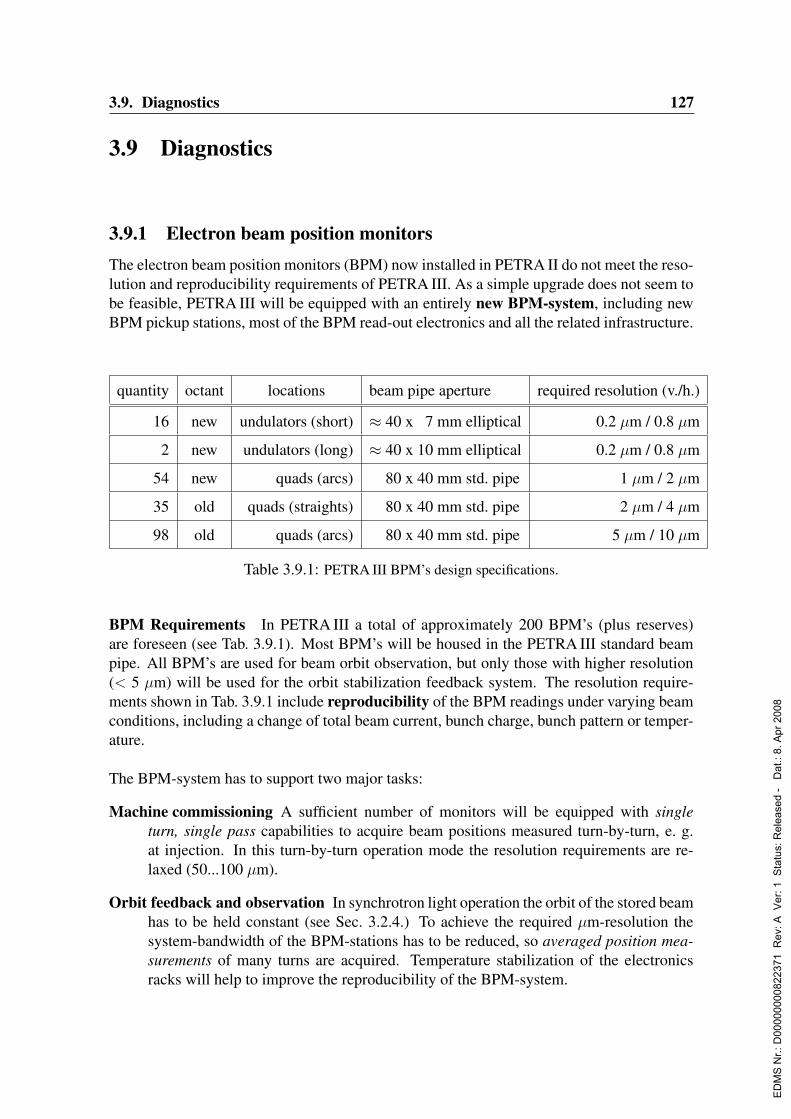
3.9. Diagnostics 127
3.9 Diagnostics
3.9.1 Electron beam position monitorsThe electron beam position monitors (BPM) now installed in PETRA II do not meet the reso-lution and reproducibility requirements of PETRA III. As a simple upgrade does not seem tobe feasible, PETRA III will be equipped with an entirely new BPM-system, including newBPM pickup stations, most of the BPM read-out electronics and all the related infrastructure.
quantity octant locations beam pipe aperture required resolution (v./h.)
16 new undulators (short) ≈ 40 x 7 mm elliptical 0.2 µm / 0.8 µm
2 new undulators (long) ≈ 40 x 10 mm elliptical 0.2 µm / 0.8 µm
54 new quads (arcs) 80 x 40 mm std. pipe 1 µm / 2 µm
35 old quads (straights) 80 x 40 mm std. pipe 2 µm / 4 µm
98 old quads (arcs) 80 x 40 mm std. pipe 5 µm / 10 µm
Table 3.9.1: PETRA III BPM’s design specifications.
BPM Requirements In PETRA III a total of approximately 200 BPM’s (plus reserves)are foreseen (see Tab. 3.9.1). Most BPM’s will be housed in the PETRA III standard beampipe. All BPM’s are used for beam orbit observation, but only those with higher resolution(< 5 µm) will be used for the orbit stabilization feedback system. The resolution require-ments shown in Tab. 3.9.1 include reproducibility of the BPM readings under varying beamconditions, including a change of total beam current, bunch charge, bunch pattern or temper-ature.
The BPM-system has to support two major tasks:
Machine commissioning A sufficient number of monitors will be equipped with singleturn, single pass capabilities to acquire beam positions measured turn-by-turn, e. g.at injection. In this turn-by-turn operation mode the resolution requirements are re-laxed (50...100 µm).
Orbit feedback and observation In synchrotron light operation the orbit of the stored beamhas to be held constant (see Sec. 3.2.4.) To achieve the required µm-resolution thesystem-bandwidth of the BPM-stations has to be reduced, so averaged position mea-surements of many turns are acquired. Temperature stabilization of the electronicsracks will help to improve the reproducibility of the BPM-system.
ED
MS
Nr.:
D00
0000
0082
2371
Rev
: A V
er: 1
Sta
tus:
Rel
ease
d -
Dat
.: 8.
Apr
200
8
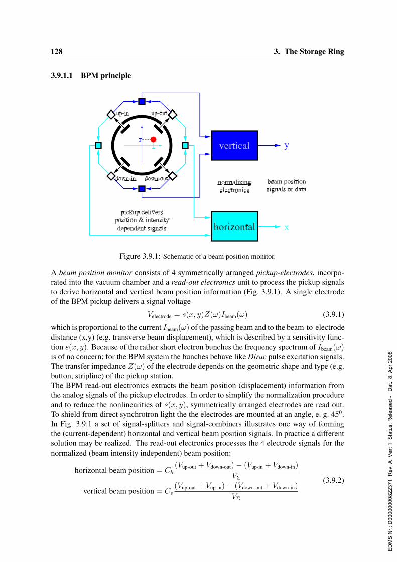
128 3. The Storage Ring
3.9.1.1 BPM principle
Figure 3.9.1: Schematic of a beam position monitor.
A beam position monitor consists of 4 symmetrically arranged pickup-electrodes, incorpo-rated into the vacuum chamber and a read-out electronics unit to process the pickup signalsto derive horizontal and vertical beam position information (Fig. 3.9.1). A single electrodeof the BPM pickup delivers a signal voltage
Velectrode = s(x, y)Z(ω)Ibeam(ω) (3.9.1)
which is proportional to the current Ibeam(ω) of the passing beam and to the beam-to-electrodedistance (x,y) (e.g. transverse beam displacement), which is described by a sensitivity func-tion s(x, y). Because of the rather short electron bunches the frequency spectrum of Ibeam(ω)is of no concern; for the BPM system the bunches behave like Dirac pulse excitation signals.The transfer impedance Z(ω) of the electrode depends on the geometric shape and type (e.g.button, stripline) of the pickup station.The BPM read-out electronics extracts the beam position (displacement) information fromthe analog signals of the pickup electrodes. In order to simplify the normalization procedureand to reduce the nonlinearities of s(x, y), symmetrically arranged electrodes are read out.To shield from direct synchrotron light the the electrodes are mounted at an angle, e. g. 450.In Fig. 3.9.1 a set of signal-splitters and signal-combiners illustrates one way of formingthe (current-dependent) horizontal and vertical beam position signals. In practice a differentsolution may be realized. The read-out electronics processes the 4 electrode signals for thenormalized (beam intensity independent) beam position:
horizontal beam position = Ch
(Vup-out + Vdown-out)− (Vup-in + Vdown-in)
VΣ
vertical beam position = Cv
(Vup-out + Vup-in)− (Vdown-out + Vdown-in)
VΣ
(3.9.2)
ED
MS
Nr.:
D00
0000
0082
2371
Rev
: A V
er: 1
Sta
tus:
Rel
ease
d -
Dat
.: 8.
Apr
200
8

3.9. Diagnostics 129
VΣ is the sum of all 4 electrode signals and Ch, Cv are the horizontal and vertical calibrationconstants of the electronics.
3.9.1.2 BPM pickup stations
All 3rd generation synchrotron light sources – today in operation, as well as those underconstruction – use electrostatic button pickup stations in their BPM-system. Although otherpickup types, like stripline- or resonant cavity BPM’s have a potential for higher sensitivityand resolution, their practical implementation in a large scale BPM-system with more than100 units is too complicated and cost-intensive. For these reasons, and because of a long-term practical experience with button pickup’s at DESY, also PETRA III will be equippedwith button pickup stations for beam orbit observation and feedback systems.
Figure 3.9.2: Cross-section of the PETRA III standard BPM button pickup (draft, measures are inmm).
Fig. 3.9.2 shows a draft of 4 button electrodes integrated into the PETRA III standard vac-uum chamber by welding. RF button feedthroughs are commercially available with SMA orN-type connectors from several companies in standard or custom versions. In PETRA IIIthe BPM pickup stations will be located very close to the quadrupoles. Encoders are fore-seen, to track all movements between pickup and nearby quadrupole due to thermal expan-sion processes, as done successfully at the SLS, Villingen, Switzerland (Dehler et al., 1999).Only the 18 pickup stations with ultimate resolution requirements, located at the undulators,will be realized as separate, rigid BPM blocks between bellows, fixed with Invar-supportson resonance-free girders.
ED
MS
Nr.:
D00
0000
0082
2371
Rev
: A V
er: 1
Sta
tus:
Rel
ease
d -
Dat
.: 8.
Apr
200
8
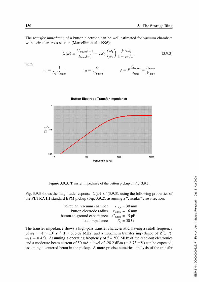
130 3. The Storage Ring
The transfer impedance of a button electrode can be well estimated for vacuum chamberswith a circular cross-section (Marcellini et al., 1996):
Z(ω) ≡ V button(ω)
Ibeam(ω)= ϕZ0
(ω1
ω2
)jω/ω1
1 + jω/ω1
(3.9.3)
withω1 =
1
Z0Cbuttonω2 =
c02rbutton
ϕ = FSbutton
Stotal=rbutton
4rpipe
Button Electrode Transfer Impedance
0.01
0.1
1
10 100 1000 10000
frequency [MHz]
Z [
]
Figure 3.9.3: Transfer impedance of the button pickup of Fig. 3.9.2.
Fig. 3.9.3 shows the magnitude response |Z(ω)| of (3.9.3), using the following properties ofthe PETRA III standard BPM pickup (Fig. 3.9.2), assuming a “circular” cross-section:
“circular” vacuum chamber rpipe = 30 mmbutton electrode radius rbutton = 6 mm
button-to-ground capacitance Cbutton = 5 pFload impedance Z0 = 50 Ω
The transfer impedance shows a high-pass transfer characteristic, having a cutoff frequencyof ω1 = 4 × 10⁹ s−1 (f = 636.62 MHz) and a maximum transfer impedance of Z(ω ω1) = 0.4 Ω. Assuming a operating frequency of f = 500 MHz of the read-out electronicsand a moderate beam current of 50 mA a level of -28.2 dBm (≡ 8.73 mV) can be expected,assuming a centered beam in the pickup. A more precise numerical analysis of the transfer
ED
MS
Nr.:
D00
0000
0082
2371
Rev
: A V
er: 1
Sta
tus:
Rel
ease
d -
Dat
.: 8.
Apr
200
8

3.9. Diagnostics 131
characteristics has to be done for the final geometries of all different button pickup stationsof PETRA III.As a total of 800 button electrodes will be installed in PETRA III, they will give a notice-able contribution to the machine impedance. For a single button electrode the longitudinalcoupling impedance scales with the transfer impedance Z(ω) and can be roughly estimated:
Z‖(ω) ≈ ϕω1
ω2
Z(ω) (3.9.4)
It is known that (Eq. 3.9.4) underestimates the coupling impedance, as electromagnetic ef-fects in the annular gap wgap between button and beam pipe wall, e.g. resonant modes, arenot taken into account. However, the first resonant mode is of TE11 type and has a frequencyof
fTE11gap =
c0π(2rbutton + wgap)
which, with dimensions of Fig. 3.9.2 (rbutton = 6 mm, wgap = 1.65 mm), results in a frequencyfTE11
gap = 12.5 GHz, well above the 5 GHz of the bunch spectrum with a 30 mm FWHMbunch length. At lower frequencies the contribution of the annular gap can be estimatedanalytically:
Z‖gap(ω) = j337Ωω(rbutton + wgap)
3
8c0r2pipeln[32(rbutton + wgap)/wgap]− 2
(3.9.5)
which gives a total normalized coupling impedance of 800 × (Z‖gap/nrev) = j 1.5×10⁻² Ω.The actual vacuum chamber is not circular and an accurate estimate of the coupling impedancerequires a numerical analysis using electromagnetic solvers.
CST EM Studio 10/30/2003 - 22:58
File: D:\Documents and Settings\wendt\My Documents\CST\EMS\PetraBPM\TDR_PUStdChamber2d.ems
Figure 3.9.4: Normalized horizontal position characteristic of the button pickup of Fig. 3.9.2.
ED
MS
Nr.:
D00
0000
0082
2371
Rev
: A V
er: 1
Sta
tus:
Rel
ease
d -
Dat
.: 8.
Apr
200
8
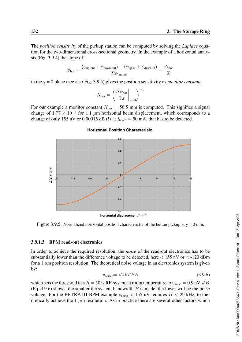
132 3. The Storage Ring
The position sensitivity of the pickup station can be computed by solving the Laplace equa-tion for the two-dimensional cross-sectional geometry. In the example of a horizontal analy-sis (Fig. 3.9.4) the slope of
φhor =(φup-out + φdown-out)− (φup-in + φdown-in)
Σφbuttons=
∆hor
Σ
in the y = 0 plane (see also Fig. 3.9.5) gives the position sensitivity as monitor constant.
Khor =
(∂ φhor
∂ x
∣∣∣∣x=0
)−1
For our example a monitor constant Khor = 56.5 mm is computed. This signifies a signalchange of 1.77 × 10⁻⁵ for a 1 µm horizontal beam displacement, which corresponds to achange of only 155 nV or 0.00015 dB (!) at Ibeam = 50 mA, that has to be detected.
Horizontal Position Characterisic
-0.3
-0.2
-0.1
0
0.1
0.2
0.3
-20 -15 -10 -5 0 5 10 15 20
horizontal displacement [mm]
D
/S
sig
nal
Figure 3.9.5: Normalized horizontal position characteristic of the button pickup at y = 0 mm.
3.9.1.3 BPM read-out electronics
In order to achieve the required resolution, the noise of the read-out electronics has to besubstantially lower than the difference voltage to be detected, here < 155 nV or < -123 dBmfor a 1 µm position resolution. The theoretical noise voltage in an electronics system is givenby:
vnoise =√
4kTBR (3.9.6)
which sets the threshold in aR = 50 Ω RF-system at room temperature to vnoise = 0.9 nV√B.
(Eq. 3.9.6) shows, the smaller the system bandwidth B is made, the lower will be the noisevoltage. For the PETRA III BPM example vnoise < 155 nV requires B < 29 kHz, to the-oretically achieve the 1 µm resolution. As in practice there are several other factors which
ED
MS
Nr.:
D00
0000
0082
2371
Rev
: A V
er: 1
Sta
tus:
Rel
ease
d -
Dat
.: 8.
Apr
200
8
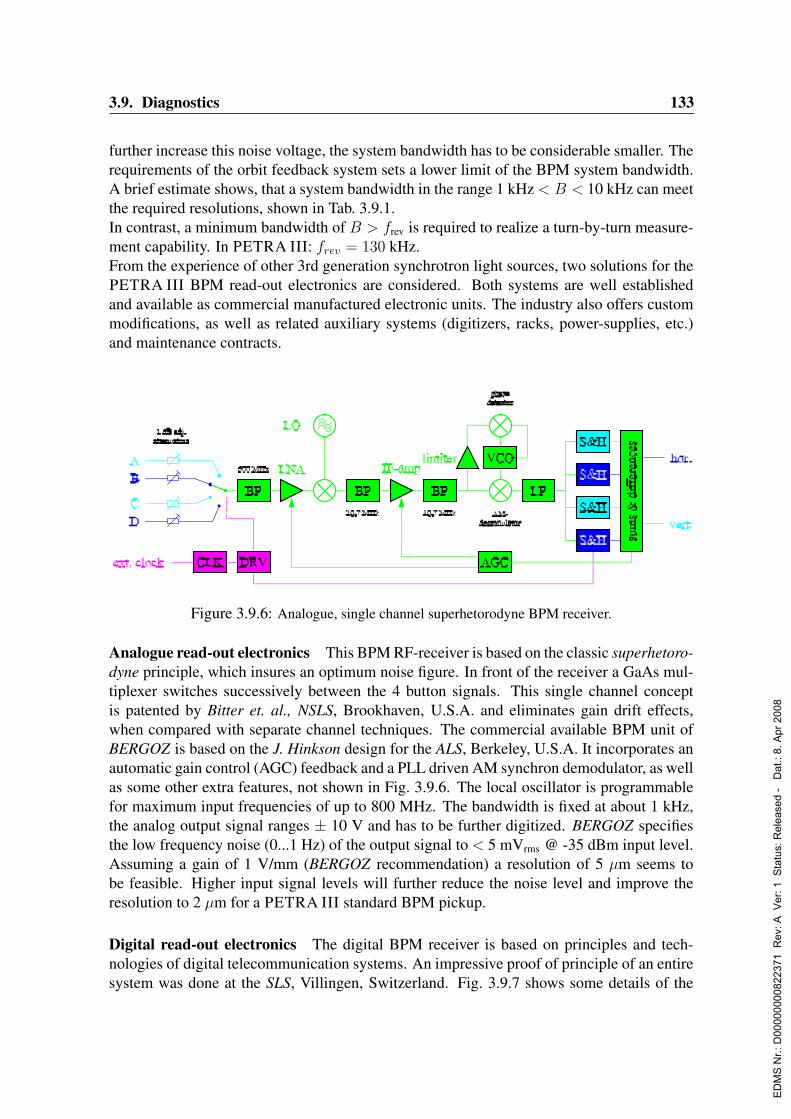
3.9. Diagnostics 133
further increase this noise voltage, the system bandwidth has to be considerable smaller. Therequirements of the orbit feedback system sets a lower limit of the BPM system bandwidth.A brief estimate shows, that a system bandwidth in the range 1 kHz < B < 10 kHz can meetthe required resolutions, shown in Tab. 3.9.1.In contrast, a minimum bandwidth of B > frev is required to realize a turn-by-turn measure-ment capability. In PETRA III: frev = 130 kHz.From the experience of other 3rd generation synchrotron light sources, two solutions for thePETRA III BPM read-out electronics are considered. Both systems are well establishedand available as commercial manufactured electronic units. The industry also offers custommodifications, as well as related auxiliary systems (digitizers, racks, power-supplies, etc.)and maintenance contracts.
Figure 3.9.6: Analogue, single channel superhetorodyne BPM receiver.
Analogue read-out electronics This BPM RF-receiver is based on the classic superhetoro-dyne principle, which insures an optimum noise figure. In front of the receiver a GaAs mul-tiplexer switches successively between the 4 button signals. This single channel conceptis patented by Bitter et. al., NSLS, Brookhaven, U.S.A. and eliminates gain drift effects,when compared with separate channel techniques. The commercial available BPM unit ofBERGOZ is based on the J. Hinkson design for the ALS, Berkeley, U.S.A. It incorporates anautomatic gain control (AGC) feedback and a PLL driven AM synchron demodulator, as wellas some other extra features, not shown in Fig. 3.9.6. The local oscillator is programmablefor maximum input frequencies of up to 800 MHz. The bandwidth is fixed at about 1 kHz,the analog output signal ranges ± 10 V and has to be further digitized. BERGOZ specifiesthe low frequency noise (0...1 Hz) of the output signal to < 5 mVrms @ -35 dBm input level.Assuming a gain of 1 V/mm (BERGOZ recommendation) a resolution of 5 µm seems tobe feasible. Higher input signal levels will further reduce the noise level and improve theresolution to 2 µm for a PETRA III standard BPM pickup.
Digital read-out electronics The digital BPM receiver is based on principles and tech-nologies of digital telecommunication systems. An impressive proof of principle of an entiresystem was done at the SLS, Villingen, Switzerland. Fig. 3.9.7 shows some details of the
ED
MS
Nr.:
D00
0000
0082
2371
Rev
: A V
er: 1
Sta
tus:
Rel
ease
d -
Dat
.: 8.
Apr
200
8

134 3. The Storage Ring
AnalogueSignal
Processing
DigitalSignal
ProcessingApplications
Housekeeping
Sampling
Timing
ABCD
Ext ReferenceSync
TriggerPost Mortem
Com
mun
icat
ion
and
Dat
a Fo
rmat
ting
Ethernet
SFP Slots
RS485Wideband
ButtonData
NarrowbandButton
Data
A
B
C
D
A
B
C
D
Gain and Gain Equalization Control
Timing
RF
Cro
ssba
r Sw
itch
RF A
RF B
RF C
RF D
ADC A
ADC B
ADC C
ADC D
Dig
ital C
ross
bar S
witc
h
DDC A
DDC B
DDC C
DDC D
LPF1A
LPF1B
LPF1C
LPF1D
LPF2A
LPF2B
LPF2C
LPF2D
M1
M2
M3
M4
NCO
CICI
FIR1I
C2P
CICQ
FIR1Q
Fromanalogue to
digitalconverters
Output topostprocessing
Clock
sin
cos
FIR2A
DDCA
BUF2A
BUF1A
FIR2A
DDCA
BUF2A
BUF1A
FIR2A
DDCA
BUF2A
BUF1A
FIR2A
DDCA
BUF2A
BUF1A
From analogue todigital converters
To wideband postprocessing(turn-by-turn, first turn,transfer path pulsed)
To narrowband postprocessing(standard operation)
AB
CD
AB
CD
AB
CD
AB
CD
To fast feedbackprocessing
Figure 3.9.7: Details of the digital read-out electronics (courtesy of R. Ursic, i-Tech).
now commercial available digital BPM read-out electronics manufactured at i-Tech. Herethe if- and demodulator sections of the superhetorodyne receiver are realized digitally, in aFPGA circuit. To eliminate the gain drifts of the analog part of the 4 channels, a set of 2crossover switches successively exchanges the read-out channels. This complex system sup-ports turn-by-turn acquisition with a bandwidth of 1 MHz and high resolution beam positionmeasurements with 1 kHz bandwidth simultaneously. The FPGA can be re-programmed,which makes the read-out system even more flexible and offers sufficient resources to storeSVD algorithm and data of the orbit feedback. i-Tech specifies the resolution limit to 1 µmassuming the PETRA III standard button pickup.Both read-out electronics, analog or digital, have strong and weak points. The analog systemis rather simple, cost-effective and well understood, as most 3rd generation light sources areequipped with this electronics. In order to measure the beam position on a turn-by-turn basisfor machine commissioning and maintenance a sufficient number of BPM’s (16...32) have tobe equipped with additional wideband read-out electronics.Experience at the SLS has shown, that a digital read-out system works well in routine opera-tion. To reach the required performance and to offer high flexibility, a quite complex systemof hard- and software has been developed. The differences between digital and analog signalprocessing cannot be worked out here, but obviously digital systems have advantages in thenumerics, which allow a better performance/resolution optimization.Both read-out electronics are potential candidates for the PETRA III BPM instrumentation,a detailed comparison in a test series on the PETRA II beam has to be done.
3.9.1.4 Environment and infrastructure
Achieving the required BPM resolution and stability must take into account the BPM relatedenvironment and infrastructure. Important points to be considered are
ED
MS
Nr.:
D00
0000
0082
2371
Rev
: A V
er: 1
Sta
tus:
Rel
ease
d -
Dat
.: 8.
Apr
200
8

3.9. Diagnostics 135
• cables and connectors
• pickup support structures
• low noise power supplies
• temperature control of tunnel and electronic racks
High performance semi-rigid cables will be used for all the BPM-signal cabling. SMA-typemicrowave connectors of highest quality will be used for all BPM-signal connections in thefront-end signal path.The broadband (DC...300 MHz) noise of the power supplies of the read-out electronics mustbe < 5 mVpp, the industry standard of high-end VME- and VXI-crates.The racks of the BPM-electronics have to be temperature stabilized to < ±10. The tem-perature variation in the temperature stabilized tunnel leads to a vertical BPM movement of< 0.1µm due to the thermal expansion of the Invar pickup supports.
3.9.1.5 Conclusion
Resolution and reproducibility requirements for the beam position monitor system of PE-TRA III are tight (Tab. 3.9.1). However, a BPM system of button-type electrostatic pickupstations and commercially available read-out electronics of latest state-of-the-art technologysatisfy these requirements.
3.9.2 Position monitors for the transverse multibunch feedback system
Figure 3.9.8: Stripline electrode.
Two position monitors, a horizontal and a vertical, are required for the transverse multi-bunch feedback system. A bandwidth of> 250 MHz is required in order acquire single bunchmeasurements within 2...8 ns (minimum bunch-to-bunch distance in PETRA III). Among thedifferent types of broadband pickups, position monitors based on stripline electrodes seemto be best suited.
ED
MS
Nr.:
D00
0000
0082
2371
Rev
: A V
er: 1
Sta
tus:
Rel
ease
d -
Dat
.: 8.
Apr
200
8

136 3. The Storage Ring
Fig. 3.9.8 shows a stripline electrode of length l and widthw, passed by a charge q of velocityv ≈ c0. At both ends the stripline is terminated in it’s characteristic impedance Z0. Theimpulse response of a stripline electrode is:
z(t) =Z0
2
[δ(t) − δ(t− 2l
c0)
](3.9.7)
The Fourier transform of (3.9.7) gives the transfer impedance:
Z(ω) = j Z0 e−j ωl
c0 sin
(ω l
c0
)(3.9.8)
The magnitude of (3.9.8) has a maximum at frequencies where the length is an odd multipleof the quarter-wavelength:
fcenter =c04 l
(2n− 1) (3.9.9)
Usually the stripline pickup operates at the first “lobe” (n=1). Its 3dB-bandwidth exceeds anoctave:
flo =1
2fcenter fhi = 3 flo
The electrode arrangement and transverse characteristic is the same as for button type pickupstations. Advantages of the stripline BPM are to operate at maximum transfer impedance(fcenter) and a defined, resistive source impedance Z0. The second argument is importantwhen operating in broadband systems, as it helps to minimize reflection effects.In order to operate at fcenter = 500 MHz, a physical length l = 150 mm of the PETRA IIIstripline electrodes is foreseen. For the minimum possible bunch-to-bunch spacing of 2 nsthis frequency is equal to the lowest bunch harmonic, but also gives highest flexibility forany other bunch spacing. Stripline BPM’s of various dimensions have been designed, buildand successfully operated in several accelerators on the DESY site. Fig. 3.9.9 shows anexample of a “warm” HERA stripline pickup with longitudinal slotted, semi-coaxial striplineelectrodes.The stripline BPM has two major advantages over an equivalent electrostatic “button” BPM:
• The characteristic impedance of the stripline-electrode can be designed for Z0 = 50 Ω,which results in a resistive 50 Ω source impedance. The button-electrode has a purecapacitive source reactance.
• By adapting the length l of the stripline-electrode the frequency of maximum beam-to-electrode coupling fcenter can be optimized to the feedback system requirements. Themagnitude response of the button pickup has a high-pass characteristic, which requiresa rather high operating frequency.
Minimizing signal reflections in broadband multi-bunch feedback systems is essential. Theresistive source impedance of the stripline-electrode – it is the signal source – reduces theseeffects and simplifies the design of the detector electronics.Furthermore the stripline-electrode gives higher signal power at moderate frequencies, com-pared to the button-electrode. The signal-to-noise ratio at f = 500 MHz of a stripline-electrode is typically 3..4 times higher compared to an equivalent button-electrode.
ED
MS
Nr.:
D00
0000
0082
2371
Rev
: A V
er: 1
Sta
tus:
Rel
ease
d -
Dat
.: 8.
Apr
200
8
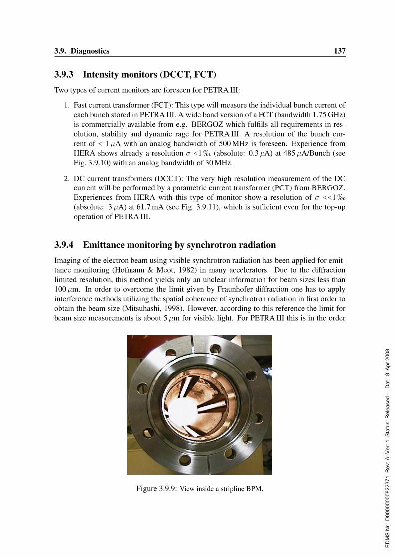
3.9. Diagnostics 137
3.9.3 Intensity monitors (DCCT, FCT)Two types of current monitors are foreseen for PETRA III:
1. Fast current transformer (FCT): This type will measure the individual bunch current ofeach bunch stored in PETRA III. A wide band version of a FCT (bandwidth 1.75 GHz)is commercially available from e.g. BERGOZ which fulfills all requirements in res-olution, stability and dynamic rage for PETRA III. A resolution of the bunch cur-rent of < 1µA with an analog bandwidth of 500 MHz is foreseen. Experience fromHERA shows already a resolution σ <1 ‰ (absolute: 0.3µA) at 485µA/Bunch (seeFig. 3.9.10) with an analog bandwidth of 30 MHz.
2. DC current transformers (DCCT): The very high resolution measurement of the DCcurrent will be performed by a parametric current transformer (PCT) from BERGOZ.Experiences from HERA with this type of monitor show a resolution of σ <<1 ‰(absolute: 3µA) at 61.7 mA (see Fig. 3.9.11), which is sufficient even for the top-upoperation of PETRA III.
3.9.4 Emittance monitoring by synchrotron radiationImaging of the electron beam using visible synchrotron radiation has been applied for emit-tance monitoring (Hofmann & Meot, 1982) in many accelerators. Due to the diffractionlimited resolution, this method yields only an unclear information for beam sizes less than100µm. In order to overcome the limit given by Fraunhofer diffraction one has to applyinterference methods utilizing the spatial coherence of synchrotron radiation in first order toobtain the beam size (Mitsuhashi, 1998). However, according to this reference the limit forbeam size measurements is about 5µm for visible light. For PETRA III this is in the order
Figure 3.9.9: View inside a stripline BPM.
ED
MS
Nr.:
D00
0000
0082
2371
Rev
: A V
er: 1
Sta
tus:
Rel
ease
d -
Dat
.: 8.
Apr
200
8
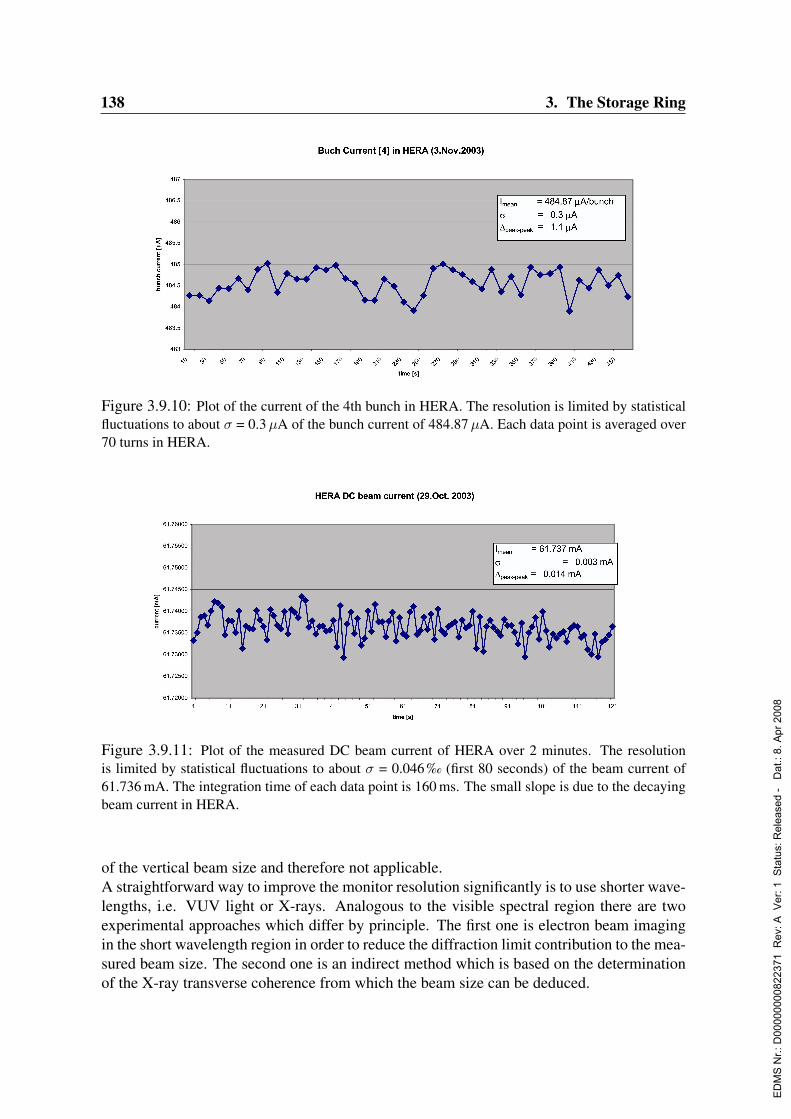
138 3. The Storage Ring
Figure 3.9.10: Plot of the current of the 4th bunch in HERA. The resolution is limited by statisticalfluctuations to about σ = 0.3 µA of the bunch current of 484.87 µA. Each data point is averaged over70 turns in HERA.
Figure 3.9.11: Plot of the measured DC beam current of HERA over 2 minutes. The resolutionis limited by statistical fluctuations to about σ = 0.046 ‰ (first 80 seconds) of the beam current of61.736 mA. The integration time of each data point is 160 ms. The small slope is due to the decayingbeam current in HERA.
of the vertical beam size and therefore not applicable.A straightforward way to improve the monitor resolution significantly is to use shorter wave-lengths, i.e. VUV light or X-rays. Analogous to the visible spectral region there are twoexperimental approaches which differ by principle. The first one is electron beam imagingin the short wavelength region in order to reduce the diffraction limit contribution to the mea-sured beam size. The second one is an indirect method which is based on the determinationof the X-ray transverse coherence from which the beam size can be deduced.
ED
MS
Nr.:
D00
0000
0082
2371
Rev
: A V
er: 1
Sta
tus:
Rel
ease
d -
Dat
.: 8.
Apr
200
8
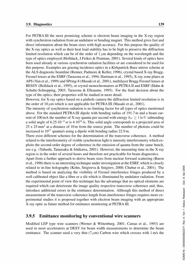
3.9. Diagnostics 139
For PETRA III the most promising scheme is electron beam imaging in the X-ray regionwith synchrotron radiation from an undulator or bending magnet. This method gives fast anddirect information about the beam sizes with high accuracy. For this purpose the quality ofthe X-ray optics as well as their heat load stability has to be high to preserve the diffractionlimited resolution which can be of the order of 1µm depending on the wavelength and thetype of optics employed (Holldack, J.Feikes & Peatman, 2001). Several kinds of optics havebeen used already at various synchrotron radiation facilities or are considered to be used forthis purpose. Examples are grazing incidence optics in a Kirkpatrick-Baez mirror scheme atthe ALS diagnostic beamline (Renner, Padmore & Keller, 1996), crystal based X-ray Bragg-Fresnel lenses at the ESRF (Tarazona et al., 1994; Hartman et al., 1995), X-ray zone plates atAPS (Yun et al., 1999) and SPring-8 (Masaki et al., 2001), multilayer Bragg-Fresnel lenses atBESSY (Holldack et al., 1995), or crystal monochromators at PETRA II and ESRF (Hahn &Schulte-Schrepping, 2003; Tarazona & Elleaume, 1995). For the final decision about thetype of the optics, their properties will be studied in more detail.However, for X-ray optics based on a pinhole camera the diffraction limited resolution is inthe order of 10µm which is not applicable for PETRA III (Masaki et al., 2001).The intensity of synchrotron radiation is no limiting factor for all types of optics mentionedabove. For the standard PETRA III dipole with bending radius of 191.7 m and a beam cur-rent of 100 mA the number of X-ray quanta per second with energy ~ω ≥ 1 keV subtendinga solid angle of 6.25·10−6 sr is 4·1016 /s. This solid angle corresponds to a projected area of25 x 25 mm2 at a distance of 10 m from the source point. The number of photons could beincreased to 1017 quanta/s using a dipole with bending radius 22.9 m.There exist different schemes for the determination of the transverse coherence. A methodrelated to the interferometry of visible synchrotron light is intensity interferometry which ex-ploits the second-order degree of coherence in the emission of quanta from the same bunch,see e.g. (Yabashi, Tamasaku & Ishikawa, 2001). However, the measuring time in the X-rayregion is in the order of several hours and therefore not practicable for beam diagnostics.Apart from a further approach to derive beam sizes from nuclear forward scattering (Baronet al., 1996) there is an interesting technique under investigation at the ESRF, which is closelyrelated to in-line holography (Kohn, Snigireva & Snigirev, 2000; Chubar et al., 2001). Themethod is based on analyzing the visibility of Fresnel interference fringes produced by awell calibrated object like a fiber or a slit which is illuminated by undulator radiation. Fromthe experimental point of view this technique has the advantage that no optical elements arerequired which can deteriorate the image quality respective transverse coherence and, thus,introduce additional errors in the emittance determination. Although this method of directmeasurement of the transverse coherence length from interference fringes requires more ex-perimental studies it is proposed together with electron beam imaging with an appropriateX-ray optic as future method for emittance monitoring at PETRA III.
3.9.5 Emittance monitoring by conventional wire scanners
Modified LEP type wire scanners (Werner & Wittenburg, 2001; Camas et al., 1993) areused in most accelerators at DESY for beam width measurements to determine the beamemittance. The scanner used a very thin (7µm) Carbon wire which crosses with 1 m/s the
ED
MS
Nr.:
D00
0000
0082
2371
Rev
: A V
er: 1
Sta
tus:
Rel
ease
d -
Dat
.: 8.
Apr
200
8
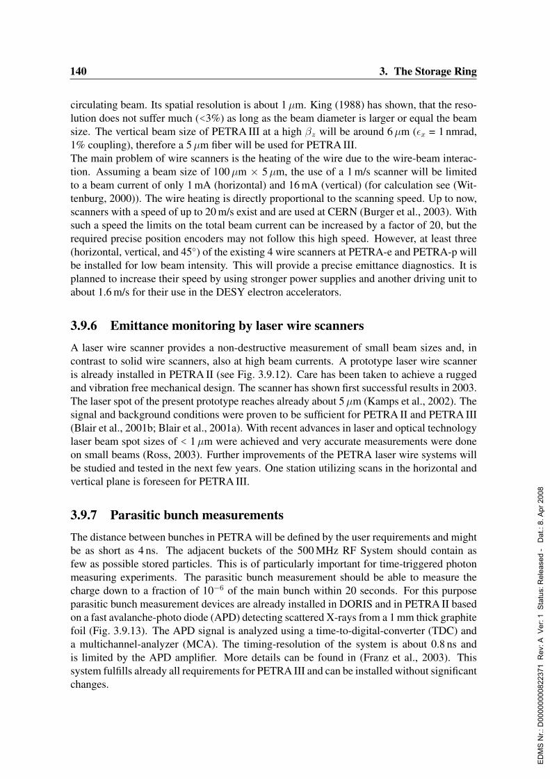
140 3. The Storage Ring
circulating beam. Its spatial resolution is about 1µm. King (1988) has shown, that the reso-lution does not suffer much (<3%) as long as the beam diameter is larger or equal the beamsize. The vertical beam size of PETRA III at a high βz will be around 6µm (εx = 1 nmrad,1% coupling), therefore a 5µm fiber will be used for PETRA III.The main problem of wire scanners is the heating of the wire due to the wire-beam interac-tion. Assuming a beam size of 100µm × 5µm, the use of a 1 m/s scanner will be limitedto a beam current of only 1 mA (horizontal) and 16 mA (vertical) (for calculation see (Wit-tenburg, 2000)). The wire heating is directly proportional to the scanning speed. Up to now,scanners with a speed of up to 20 m/s exist and are used at CERN (Burger et al., 2003). Withsuch a speed the limits on the total beam current can be increased by a factor of 20, but therequired precise position encoders may not follow this high speed. However, at least three(horizontal, vertical, and 45) of the existing 4 wire scanners at PETRA-e and PETRA-p willbe installed for low beam intensity. This will provide a precise emittance diagnostics. It isplanned to increase their speed by using stronger power supplies and another driving unit toabout 1.6 m/s for their use in the DESY electron accelerators.
3.9.6 Emittance monitoring by laser wire scannersA laser wire scanner provides a non-destructive measurement of small beam sizes and, incontrast to solid wire scanners, also at high beam currents. A prototype laser wire scanneris already installed in PETRA II (see Fig. 3.9.12). Care has been taken to achieve a ruggedand vibration free mechanical design. The scanner has shown first successful results in 2003.The laser spot of the present prototype reaches already about 5µm (Kamps et al., 2002). Thesignal and background conditions were proven to be sufficient for PETRA II and PETRA III(Blair et al., 2001b; Blair et al., 2001a). With recent advances in laser and optical technologylaser beam spot sizes of < 1µm were achieved and very accurate measurements were doneon small beams (Ross, 2003). Further improvements of the PETRA laser wire systems willbe studied and tested in the next few years. One station utilizing scans in the horizontal andvertical plane is foreseen for PETRA III.
3.9.7 Parasitic bunch measurementsThe distance between bunches in PETRA will be defined by the user requirements and mightbe as short as 4 ns. The adjacent buckets of the 500 MHz RF System should contain asfew as possible stored particles. This is of particularly important for time-triggered photonmeasuring experiments. The parasitic bunch measurement should be able to measure thecharge down to a fraction of 10−6 of the main bunch within 20 seconds. For this purposeparasitic bunch measurement devices are already installed in DORIS and in PETRA II basedon a fast avalanche-photo diode (APD) detecting scattered X-rays from a 1 mm thick graphitefoil (Fig. 3.9.13). The APD signal is analyzed using a time-to-digital-converter (TDC) anda multichannel-analyzer (MCA). The timing-resolution of the system is about 0.8 ns andis limited by the APD amplifier. More details can be found in (Franz et al., 2003). Thissystem fulfills already all requirements for PETRA III and can be installed without significantchanges.
ED
MS
Nr.:
D00
0000
0082
2371
Rev
: A V
er: 1
Sta
tus:
Rel
ease
d -
Dat
.: 8.
Apr
200
8
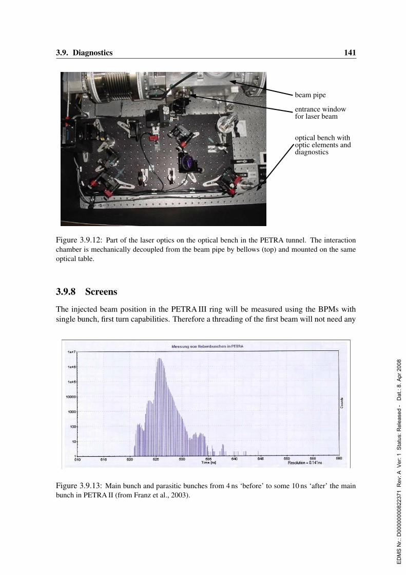
3.9. Diagnostics 141
beam pipe
entrance windowfor laser beam
optical bench withoptic elements anddiagnostics
Figure 3.9.12: Part of the laser optics on the optical bench in the PETRA tunnel. The interactionchamber is mechanically decoupled from the beam pipe by bellows (top) and mounted on the sameoptical table.
3.9.8 Screens
The injected beam position in the PETRA III ring will be measured using the BPMs withsingle bunch, first turn capabilities. Therefore a threading of the first beam will not need any
Figure 3.9.13: Main bunch and parasitic bunches from 4 ns ‘before’ to some 10 ns ‘after’ the mainbunch in PETRA II (from Franz et al., 2003).
ED
MS
Nr.:
D00
0000
0082
2371
Rev
: A V
er: 1
Sta
tus:
Rel
ease
d -
Dat
.: 8.
Apr
200
8
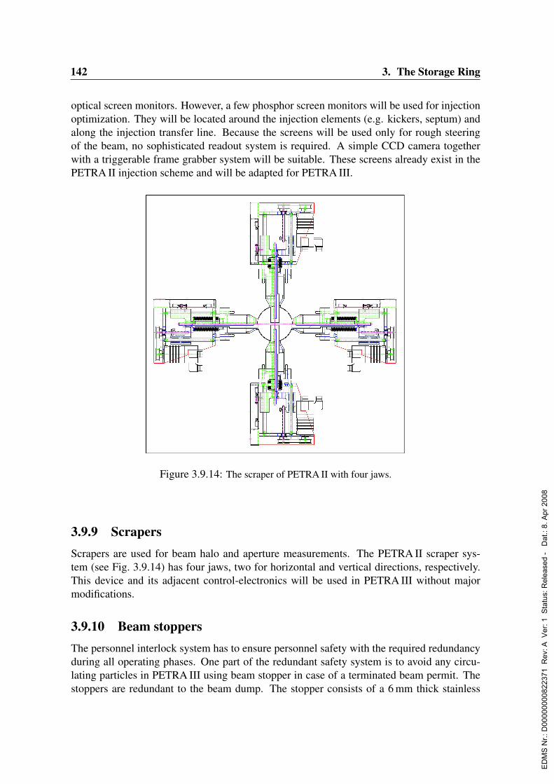
142 3. The Storage Ring
optical screen monitors. However, a few phosphor screen monitors will be used for injectionoptimization. They will be located around the injection elements (e.g. kickers, septum) andalong the injection transfer line. Because the screens will be used only for rough steeringof the beam, no sophisticated readout system is required. A simple CCD camera togetherwith a triggerable frame grabber system will be suitable. These screens already exist in thePETRA II injection scheme and will be adapted for PETRA III.
Figure 3.9.14: The scraper of PETRA II with four jaws.
3.9.9 ScrapersScrapers are used for beam halo and aperture measurements. The PETRA II scraper sys-tem (see Fig. 3.9.14) has four jaws, two for horizontal and vertical directions, respectively.This device and its adjacent control-electronics will be used in PETRA III without majormodifications.
3.9.10 Beam stoppersThe personnel interlock system has to ensure personnel safety with the required redundancyduring all operating phases. One part of the redundant safety system is to avoid any circu-lating particles in PETRA III using beam stopper in case of a terminated beam permit. Thestoppers are redundant to the beam dump. The stopper consists of a 6 mm thick stainless
ED
MS
Nr.:
D00
0000
0082
2371
Rev
: A V
er: 1
Sta
tus:
Rel
ease
d -
Dat
.: 8.
Apr
200
8
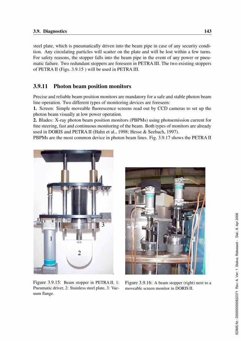
3.9. Diagnostics 143
steel plate, which is pneumatically driven into the beam pipe in case of any security condi-tion. Any circulating particles will scatter on the plate and will be lost within a few turns.For safety reasons, the stopper falls into the beam pipe in the event of any power or pneu-matic failure. Two redundant stoppers are foreseen in PETRA III. The two existing stoppersof PETRA II (Figs. 3.9.15 ) will be used in PETRA III.
3.9.11 Photon beam position monitors
Precise and reliable beam position monitors are mandatory for a safe and stable photon beamline operation. Two different types of monitoring devices are foreseen:1. Screen: Simple moveable fluorescence screens read out by CCD cameras to set up thephoton beam visually at low power operation.2. Blades: X-ray photon beam position monitors (PBPMs) using photoemission current forfine steering, fast and continuous monitoring of the beam. Both types of monitors are alreadyused in DORIS and PETRA II (Hahn et al., 1998; Hesse & Seebach, 1997).PBPMs are the most common device in photon beam lines. Fig. 3.9.17 shows the PETRA II
Figure 3.9.15: Beam stopper in PETRA II. 1:Pneumatic driver, 2: Stainless steel plate, 3: Vac-uum flange.
Figure 3.9.16: A beam stopper (right) next to amoveable screen monitor in DORIS II.
ED
MS
Nr.:
D00
0000
0082
2371
Rev
: A V
er: 1
Sta
tus:
Rel
ease
d -
Dat
.: 8.
Apr
200
8

144 3. The Storage Ring
PBPM. It has an additional tungsten dump electrode (2), mounted in front of the blades (1).These electrodes protect the copper block against melting by a misaligned photon beam. Thenormalized difference of the photoemission current on the electrodes will indicate the beamposition. The PETRA II PBPMs and the adjacent readout electronics provide an internalresolution of about 1µm (see Fig. 3.9.18). In the figure beam position changes of a few µmare clearly detectable. The steps in the traces are related to the last significant bit (LSB)of the readout electronics, which corresponds to 1µm. The resolution of such a PBPM canbe improved down to few tenth of a micron by more sophisticated designs and a properinstallation (avoiding vibrations (Johnson & Oversluizen, 1989)), and by a more sensitivereadout electronics. For the high brilliant photon beams of PETRA III additional cooling ofthe blades has to taken into account. CVD diamond blades have excellent thermal propertiesand a low absorption coefficient and might be preferred. However, it is well known that thevarying characteristics of the undulator radiation with the K-value, the presence of dipoleand quadrupole background radiation and the spectral efficiency of the blade material willprevent a universal calibration of the PBPM (Holldack, Ponwitz & Peatman, 2001). Eachsetting of the undulator will have a unique set of calibration parameters of the PBPM. Onlywith such a proper calibration, the PBPMs are sufficient for a precise position feedback loopto provide very stable beam conditions at PETRA III.
Figure 3.9.17: The PETRA PBPM with (1) tungsten electrode, (2) dump electrode, (3) copper block,(4) cooling channel, (5) monitor module, (6) electrical feed-through (from Hahn et al., 1998).
ED
MS
Nr.:
D00
0000
0082
2371
Rev
: A V
er: 1
Sta
tus:
Rel
ease
d -
Dat
.: 8.
Apr
200
8

3.9. Diagnostics 145
Figure 3.9.18: Signal from two PBPMs in the DORIS photon beam line (horizontal and vertical).Scale: vert. = mm, hor. = minutes.
ED
MS
Nr.:
D00
0000
0082
2371
Rev
: A V
er: 1
Sta
tus:
Rel
ease
d -
Dat
.: 8.
Apr
200
8
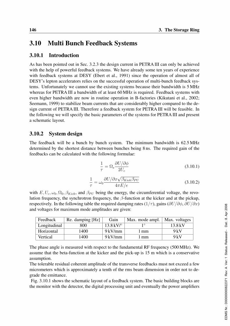
146 3. The Storage Ring
3.10 Multi Bunch Feedback Systems
3.10.1 IntroductionAs has been pointed out in Sec. 3.2.3 the design current in PETRA III can only be achievedwith the help of powerful feedback systems. We have already some ten years of experiencewith feedback systems at DESY (Ebert et al., 1991) since the operation of almost all ofDESY’s lepton accelerators relies on the successful operation of multi-bunch feedback sys-tems. Unfortunately we cannot use the existing systems because their bandwidth is 5 MHzwhereas for PETRA III a bandwidth of at least 60 MHz is required. Feedback systems witheven higher bandwidth are now in routine operation in B-factories (Kikutani et al., 2002;Seemann, 1999) to stabilize beam currents that are considerably higher compared to the de-sign current of PETRA III. Therefore a feedback system for PETRA III will be feasible. Inthe following we will specify the basic parameters of the systems for PETRA III and presenta schematic layout.
3.10.2 System designThe feedback will be a bunch by bunch system. The minimum bandwidth is 62.5 MHzdetermined by the shortest distance between bunches being 8 ns. The required gain of thefeedbacks can be calculated with the following formulae:
1
τ= Ωs
∂U/∂φ
2Uc
(3.10.1)
1
τ= ω0
∂U/∂x√βKickβPU
4πE/e(3.10.2)
with E,Uc, ω0,Ω0, βKick, and βPU being the energy, the circumferential voltage, the revo-lution frequency, the synchrotron frequency, the β-function at the kicker and at the pickup,respectively. In the following table the required damping rates (1/τ ), gains (∂U/∂φ, ∂U/∂x)and voltages for maximum mode amplitudes are given:
Feedback Re. damping [Hz] Gain Max. mode ampl. Max. voltagesLongitudinal 800 13.8 kV/ 1 13.8 kVHorizontal 1400 9 kV/mm 1 mm 9 kVVertical 1400 9 kV/mm 1 mm 9 kV
The phase angle is measured with respect to the fundamental RF frequency (500 MHz). Weassume that the beta-function at the kicker and the pick-up is 15 m which is a conservativeassumption.The tolerable residual coherent amplitude of the transverse feedbacks must not exceed a fewmicrometers which is approximately a tenth of the rms beam dimension in order not to de-grade the emittance.Fig. 3.10.1 shows the schematic layout of a feedback system. The basic building blocks are
the monitor with the detector, the digital processing unit and eventually the power amplifiers
ED
MS
Nr.:
D00
0000
0082
2371
Rev
: A V
er: 1
Sta
tus:
Rel
ease
d -
Dat
.: 8.
Apr
200
8
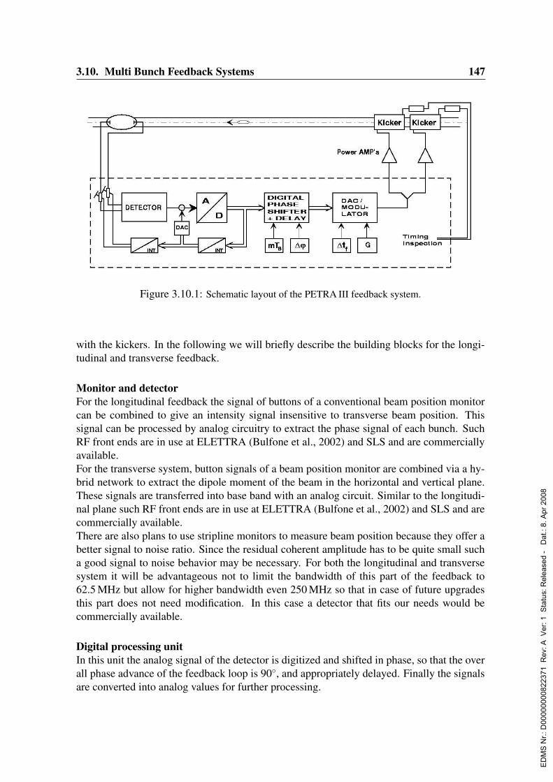
3.10. Multi Bunch Feedback Systems 147
Figure 3.10.1: Schematic layout of the PETRA III feedback system.
with the kickers. In the following we will briefly describe the building blocks for the longi-tudinal and transverse feedback.
Monitor and detectorFor the longitudinal feedback the signal of buttons of a conventional beam position monitorcan be combined to give an intensity signal insensitive to transverse beam position. Thissignal can be processed by analog circuitry to extract the phase signal of each bunch. SuchRF front ends are in use at ELETTRA (Bulfone et al., 2002) and SLS and are commerciallyavailable.For the transverse system, button signals of a beam position monitor are combined via a hy-brid network to extract the dipole moment of the beam in the horizontal and vertical plane.These signals are transferred into base band with an analog circuit. Similar to the longitudi-nal plane such RF front ends are in use at ELETTRA (Bulfone et al., 2002) and SLS and arecommercially available.There are also plans to use stripline monitors to measure beam position because they offer abetter signal to noise ratio. Since the residual coherent amplitude has to be quite small sucha good signal to noise behavior may be necessary. For both the longitudinal and transversesystem it will be advantageous not to limit the bandwidth of this part of the feedback to62.5 MHz but allow for higher bandwidth even 250 MHz so that in case of future upgradesthis part does not need modification. In this case a detector that fits our needs would becommercially available.
Digital processing unitIn this unit the analog signal of the detector is digitized and shifted in phase, so that the overall phase advance of the feedback loop is 90, and appropriately delayed. Finally the signalsare converted into analog values for further processing.
ED
MS
Nr.:
D00
0000
0082
2371
Rev
: A V
er: 1
Sta
tus:
Rel
ease
d -
Dat
.: 8.
Apr
200
8
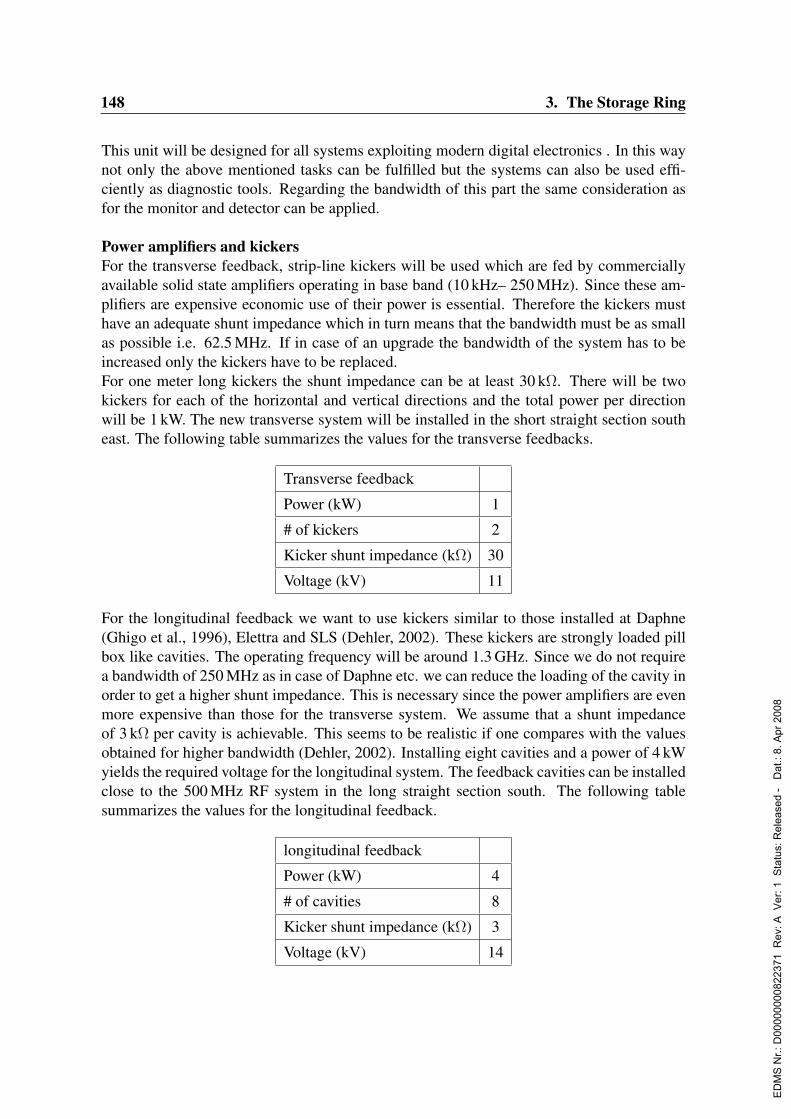
148 3. The Storage Ring
This unit will be designed for all systems exploiting modern digital electronics . In this waynot only the above mentioned tasks can be fulfilled but the systems can also be used effi-ciently as diagnostic tools. Regarding the bandwidth of this part the same consideration asfor the monitor and detector can be applied.
Power amplifiers and kickersFor the transverse feedback, strip-line kickers will be used which are fed by commerciallyavailable solid state amplifiers operating in base band (10 kHz– 250 MHz). Since these am-plifiers are expensive economic use of their power is essential. Therefore the kickers musthave an adequate shunt impedance which in turn means that the bandwidth must be as smallas possible i.e. 62.5 MHz. If in case of an upgrade the bandwidth of the system has to beincreased only the kickers have to be replaced.For one meter long kickers the shunt impedance can be at least 30 kΩ. There will be twokickers for each of the horizontal and vertical directions and the total power per directionwill be 1 kW. The new transverse system will be installed in the short straight section southeast. The following table summarizes the values for the transverse feedbacks.
Transverse feedback
Power (kW) 1
# of kickers 2
Kicker shunt impedance (kΩ) 30
Voltage (kV) 11
For the longitudinal feedback we want to use kickers similar to those installed at Daphne(Ghigo et al., 1996), Elettra and SLS (Dehler, 2002). These kickers are strongly loaded pillbox like cavities. The operating frequency will be around 1.3 GHz. Since we do not requirea bandwidth of 250 MHz as in case of Daphne etc. we can reduce the loading of the cavity inorder to get a higher shunt impedance. This is necessary since the power amplifiers are evenmore expensive than those for the transverse system. We assume that a shunt impedanceof 3 kΩ per cavity is achievable. This seems to be realistic if one compares with the valuesobtained for higher bandwidth (Dehler, 2002). Installing eight cavities and a power of 4 kWyields the required voltage for the longitudinal system. The feedback cavities can be installedclose to the 500 MHz RF system in the long straight section south. The following tablesummarizes the values for the longitudinal feedback.
longitudinal feedback
Power (kW) 4
# of cavities 8
Kicker shunt impedance (kΩ) 3
Voltage (kV) 14
ED
MS
Nr.:
D00
0000
0082
2371
Rev
: A V
er: 1
Sta
tus:
Rel
ease
d -
Dat
.: 8.
Apr
200
8

3.11. General Control System 149
3.11 General Control System
3.11.1 IntroductionFor over two decades, PETRA has been remotely operated by a modular, distributed andmulti-layered control system. At PETRA I, the control system consisted of a network ofindustrial mini-computers running programs written in an interpreted language. The controlsystem was connected through the DESY proprietary long-distance fieldbus system SEDAC(Serial Data Acquisition System and Control) with front-end electronics packed in crates.PETRA II started operation with this system; in 1996 the mini-computers were replaced byWindows PCs using VisualBasic and interconnected via Ethernet. VisualBasic has demon-strated its unique strength as an integrated development environment for powerful graphicsand rapid application design. In the meantime, industrial laboratory automation hardwareand software, industrial fieldbus systems, embedded CPUs and programmable logic arrayshave broken down the strict separation between front-end electronics and the control systemsoftware. The performance of modern software development tools and network technologiesas well as the available CPU power has grown dramatically during the past few years. Ef-ficient communication patterns such as publish-subscriber mechanisms are becoming stan-dard, component or object oriented software is more maintainable and reusable, and newWeb-based technologies provide simple access to all kinds of data and services.The proposed control system for PETRA III faces two major challenges. First, a reasonablebalance must be found between continued use of proven technologies and upgrades usingnew technologies and ideas. An important consideration here is support for the large numberof existing technical components and subsystems, which will be carried over into PETRA III.Second, the novel operation mode of PETRA III as a continuously running high-quality lightsource with low down time places strict requirements on the availability, stability and perfor-mance of the control system architecture, tools, hardware components and user applications.
3.11.2 General properties of the PETRA III control system3.11.2.1 Overview
The proposed system is based on our experiences with the present PETRA and HERA con-trol systems. It uses a multi-layer architecture consisting of a client tier, a server tier and anintegration tier, using TINE (Threefold Integrated Network Environment), a set of commu-nications protocols and services developed over the past 12 years as the core of the HERAcontrol system. Many of the existing components and subsystems which will be used in PE-TRA III already support TINE interfaces or gateways.We anticipate several significant changes in the general control system implementation. First,the present VisualBasic-based console applications run only on Microsoft Windows plat-forms. We intend to move to Java-based applications to remove this limitation. Second, theHERA control system, in particular, shows many signs of its gradual construction. TINEand its associated services are now in a mature state and for PETRA III we will be able toimplement features such as archiving, local history records, and naming conventions in auniform fashion across the control system.
ED
MS
Nr.:
D00
0000
0082
2371
Rev
: A V
er: 1
Sta
tus:
Rel
ease
d -
Dat
.: 8.
Apr
200
8
150 3. The Storage Ring
The control system must accommodate a range of users, with varying needs. At the clientlevel, TINE supports the scientific computing software tool MATLAB, which can be usedby accelerator physicists for specialized studies. For remote client access, we are developinga TINE-to-SOAP (Simple Object Access Protocol) interface, which could be a generic solu-tion for connection to standardized Web Services.The server level will include front-end device servers for which the control system group hasfull responsibility, servers for which the responsibility is shared, in varying degrees, betweenthe control system group and the engineers responsible for the hardware, and gateways toautonomous control systems maintained by other groups. Some of the gateways already ex-ist, for example a software interface between TINE and the EPICS (Experimental Physicsand Industrial Control System) control system used by most of the technical infrastructuresubsystems at DESY. The servers with shared responsibility raise several issues, for examplethe need to agree with other groups at DESY on the range of hardware (such as fieldbusses)and software, which will be supported by the control system group.More generally, the flexibility provided by a modern control system brings with it the dangerof excessive fragmentation of both hardware and software solutions, and associated increasesin the manpower required for support and maintenance. The old control system philosophyone size fits all is no longer practical or desirable; it is nonetheless important to limit therange of choice, and not unnecessarily throw away the enormous benefits of standardization.The balance must be somewhat different for the various classes of users.
3.11.2.2 Control system architecture and software bus
The architecture of the proposed control system for PETRA III follows the multi-layer ap-proach and consists of Ethernet connected client, integration and server tiers, see Fig. 3.11.1.It must allow for adiabatic updates as well as updates of complete components without majordisruption of the remaining system.The client tier contains the graphical client applications. The server tier houses the deviceserver applications and the adapters to control systems maintained by other groups. The in-tegration tier consists of a software bus and its associated services, as well as control systemserver applications with system-wide responsibilities (‘advanced server applications’). Thesoftware bus is a software library providing an interface to a certain object model for repre-sentation of data and devices and handling the communication between clients and servers.All clients or servers attached must feed the interface in conformance with the object model.Foreign systems are integrated through translation layers called gateways or software busadapters.The proposed software bus is TINE, originally developed at DESY for the HERA controlsystem. Features supported by TINE include:
• Runs on Windows, Unix, Linux and VxWorks platforms,
• Application Programmer Interfaces for C/C++, VisualBasic, Java, and MATLAB,
• Data exchange via client-server, publisher-subscriber, broadcast, and multicast com-munication,
ED
MS
Nr.:
D00
0000
0082
2371
Rev
: A V
er: 1
Sta
tus:
Rel
ease
d -
Dat
.: 8.
Apr
200
8
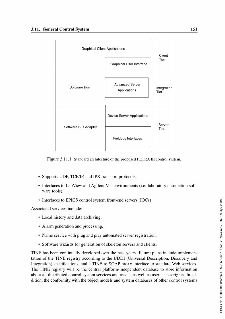
3.11. General Control System 151
Graphical User Interface
Software Bus
Software Bus Adapter
Advanced Server
Applications
ClientTier
TierServer
Device Server Applications
Fieldbus Interfaces
Graphical Client Applications
IntegrationTier
Figure 3.11.1: Standard architecture of the proposed PETRA III control system.
• Supports UDP, TCP/IP, and IPX transport protocols,
• Interfaces to LabView and Agilent Vee environments (i.e. laboratory automation soft-ware tools),
• Interfaces to EPICS control system front-end servers (IOCs)
Associated services include:
• Local history and data archiving,
• Alarm generation and processing,
• Name service with plug and play automated server registration,
• Software wizards for generation of skeleton servers and clients.
TINE has been continually developed over the past years. Future plans include implemen-tation of the TINE registry according to the UDDI (Universal Description, Discovery andIntegration) specifications, and a TINE-to-SOAP proxy interface to standard Web services.The TINE registry will be the central platform-independent database to store informationabout all distributed control system services and assets, as well as user access rights. In ad-dition, the conformity with the object models and system databases of other control systems
ED
MS
Nr.:
D00
0000
0082
2371
Rev
: A V
er: 1
Sta
tus:
Rel
ease
d -
Dat
.: 8.
Apr
200
8
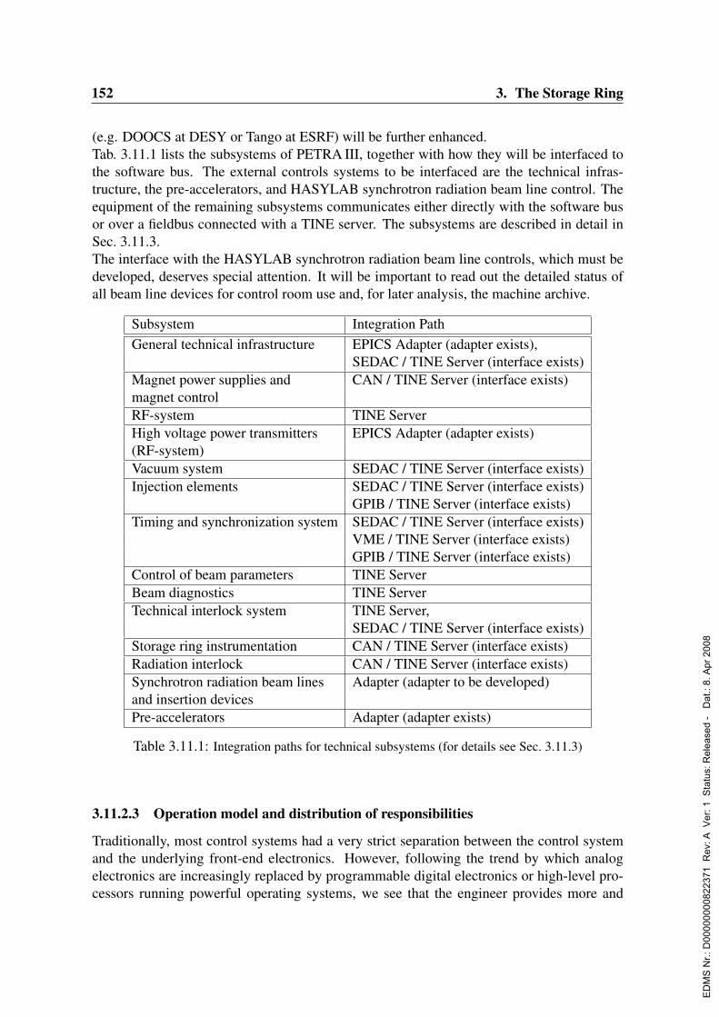
152 3. The Storage Ring
(e.g. DOOCS at DESY or Tango at ESRF) will be further enhanced.Tab. 3.11.1 lists the subsystems of PETRA III, together with how they will be interfaced tothe software bus. The external controls systems to be interfaced are the technical infras-tructure, the pre-accelerators, and HASYLAB synchrotron radiation beam line control. Theequipment of the remaining subsystems communicates either directly with the software busor over a fieldbus connected with a TINE server. The subsystems are described in detail inSec. 3.11.3.The interface with the HASYLAB synchrotron radiation beam line controls, which must bedeveloped, deserves special attention. It will be important to read out the detailed status ofall beam line devices for control room use and, for later analysis, the machine archive.
Subsystem Integration PathGeneral technical infrastructure EPICS Adapter (adapter exists),
SEDAC / TINE Server (interface exists)Magnet power supplies and CAN / TINE Server (interface exists)magnet controlRF-system TINE ServerHigh voltage power transmitters EPICS Adapter (adapter exists)(RF-system)Vacuum system SEDAC / TINE Server (interface exists)Injection elements SEDAC / TINE Server (interface exists)
GPIB / TINE Server (interface exists)Timing and synchronization system SEDAC / TINE Server (interface exists)
VME / TINE Server (interface exists)GPIB / TINE Server (interface exists)
Control of beam parameters TINE ServerBeam diagnostics TINE ServerTechnical interlock system TINE Server,
SEDAC / TINE Server (interface exists)Storage ring instrumentation CAN / TINE Server (interface exists)Radiation interlock CAN / TINE Server (interface exists)Synchrotron radiation beam lines Adapter (adapter to be developed)and insertion devicesPre-accelerators Adapter (adapter exists)
Table 3.11.1: Integration paths for technical subsystems (for details see Sec. 3.11.3)
3.11.2.3 Operation model and distribution of responsibilities
Traditionally, most control systems had a very strict separation between the control systemand the underlying front-end electronics. However, following the trend by which analogelectronics are increasingly replaced by programmable digital electronics or high-level pro-cessors running powerful operating systems, we see that the engineer provides more and
ED
MS
Nr.:
D00
0000
0082
2371
Rev
: A V
er: 1
Sta
tus:
Rel
ease
d -
Dat
.: 8.
Apr
200
8
3.11. General Control System 153
more often not only front-end electronics, but also front-end device server software andhardware. A similar situation exists when accelerator physicists provide either algorithmsfor the beam control or even application programs.To avoid an un-maintainable fragmentation of the control system between the various hard-ware and software platforms as well as programming languages and styles the control sys-tem group will define and maintain a restricted set of standards to be followed. The controlsystem group will help and guide the programmers and engineers with the goal of a cleanimplementation and consistent usage of the standards.The responsibilities of the control system group will include in any case the computer net-works, the core software such as the software bus, application programmer interfaces (API),generators, templates and adapters, the fieldbus interfaces and drivers, the overall systemintegration and administration, the code repository and other common services. Further, thecontrol system group offers to provide the client applications. For engineers, who implementonly the front-end electronics hardware the control system group will provide in addition thecorresponding front-end device server applications and the server hardware.
3.11.2.4 Conventions, supported platforms and programming languages
Uniform naming conventions will be enforced. The data attached to server specific proper-ties as well as the methods must be defined and named in an intuitive and human readableformat. Every server application must consistently maintain the complete set of stock ordefault properties of the control system such as engineering units or minimum / maximumlimits.It is important to maintain a clear separation between the tasks to be performed by the clientand the server applications. Console client applications should support visualization anduser initiated requests, while the data conversion and device-specific logic is encapsulated inthe front-end device servers. Automated procedures spanning devices on multiple front-enddevice servers should be implemented by the advanced server applications in the integrationtier. Examples are multi-step sequencing, parameter archiving, alarm handling etc. Excep-tion handling in reaction to software or system errors must be performed in a consistent way.Well-designed and user-friendly graphical client applications make extensive use of thegraphical features of the underlying run-time environment. These so-called rich clients arein contrast to the so-called thin clients usually implemented at present as dynamic Web pagesexecuted with greatly reduced performance by a Web browser. Rich client applications areproposed to be the standard human-machine interface. However, accessing the general con-trol system via the Web by viewing for example certain task specific maintenance pages willalso be supported.
The ability to visualize the PETRA III operation across all platforms while keeping a uniformlook-and-feel for the users is very important. The graphical user interface ACOP (Acceler-ator Component Oriented Programming) originally developed for the HERA control systemoffers an intuitive interface for accessing front-end devices as well as a graphics packagefor data presentation and online data analyses. Java is proposed as platform independentlanguage for graphical client applications. Desktop PCs running Windows or Linux are well
ED
MS
Nr.:
D00
0000
0082
2371
Rev
: A V
er: 1
Sta
tus:
Rel
ease
d -
Dat
.: 8.
Apr
200
8

154 3. The Storage Ring
suited to host the corresponding virtual machine.Advanced server applications (VisualBasic, Java, C, C++ or scientific computing softwaresuch as MATLAB) and device server applications (VisualBasic, Java, C, C++ or laboratoryautomation software such as LabView or Agilent Vee) must run with high availability. Thecorresponding computers (Windows, Linux) should be rack-mounted, remotely controllable,well cabled and efficiently air-cooled requiring more reliable computer hardware than mass-market desktop PCs. Crate-hosted computer hardware (cPCI with Windows, VME withLinux or VxWorks) can be chosen in combination with dedicated measurement or fieldbusboards. Boards packed in plug-in modules and housed in crates are superior compared toboards with PC card design, since, for example, hardware changes are facilitated.For embedded systems, dedicated versions of Windows or Linux with reduced features areavailable. The software development (VisualBasic, C) can be performed on desktop PCs ifthe hardware of the embedded system is carefully selected.
3.11.2.5 Tools and services
Integrated development environments enable creation of optimized graphical human-machineinterfaces and efficient online debugging. VisualStudio has demonstrated its strength forC++ and VisualBasic. For Java, a handful of tools (Eclipse, NetBeans etc) are availableand rapidly improving in their capabilities. The application programmers will decide on apreferred development environment. Reusable operation specific graphical software compo-nents must be written for general use.Software wizards will be provided for generation of server application skeletons fully inte-grated into the control system. Wizards will also be available for the configuration of simplegraphical application clients for data presentation, e.g. for urgent troubleshooting or dedi-cated measurement series. These skeletons are especially useful for engineers and physicistswho are not experts in the controls programming.
The DESY proprietary fieldbus technology SEDAC will continue to be used at PETRA IIIfor many existing systems. The control system group maintains the necessary interface anddriver software for Windows, Linux and VxWorks. The controls group will also support alimited number of industrial fieldbusses, definitely including CAN and GPIB.Experience shows that extensive, but intelligent error logging and parameter archiving is es-sential for fast fault detection and machine operation at high availability. A central alarm log-ging facility as well as an archive system for time series and snapshots will be implemented.The relevant parameters and event triggers will be supplied by the server applications byfeeding the corresponding interfaces of the software bus.
Automation of multi-step procedures is essential for high-efficiency machine operation. Asoftware tool to load and store parameter set-ups and to execute linear or repetitive automatedsequences will be installed. A supervisory server determines the actual machine state andissues information about allowed or forbidden actions according to predefined rules.
ED
MS
Nr.:
D00
0000
0082
2371
Rev
: A V
er: 1
Sta
tus:
Rel
ease
d -
Dat
.: 8.
Apr
200
8

3.11. General Control System 155
3.11.2.6 Network and security
A structured, broadband Ethernet network will connect the PETRA III control system com-puters allowing for high data throughput e.g. for video frames, efficient network adminis-tration and remote fault diagnosis. A well-configured firewall provides network security byseparating the control system network from the Internet and DESY intranet. Only authorizedhosts will have access to the control system.TINE communications require open TCP-ports. Therefore, direct remote access from out-side could be a risk. A VPN (Virtual Private Network) tunnel connection will allow outsideaccess without this risk.In addition, user login names are checked against the TINE registry, which keeps the secu-rity database maintaining the individual permissions. TINE can allow WRITE access onlyto specific users, and/or only from specific network, or network addresses.
3.11.2.7 Information services
Various Web-based information services will be provided: documentation pages and tem-plates, electronic logbook and e-mail based notification in case of errors, virtual white board,machine operation overview charts etc. In addition, the control system group will be avail-able for consultation regarding all aspects of the control system.
3.11.2.8 System administration
Many system administration tasks will be necessary for a smooth and reliable operation ofthe control system. Examples are user administration, creating computer configurations andimages, preparing new or spare computers prior to installation, operating the file server andmaintaining the code repository, executing updates, supervising running processes etc. Theuse of a platform-independent administration tool would ease the tasks. Highly automatedand fast procedures have to be provided to install security patches or for disaster recoveryafter major network troubles or mains power blackouts etc.
3.11.3 Technical subsystems and beam control3.11.3.1 General technical infrastructure
Most of the technical infrastructure (electrical power distribution, cooling water distribution,pressured-air distribution, ventilation) is supervised by a SCADA-like (Supervisory Controland Data Acquisition) control system based on EPICS. It is fully operated by the corre-sponding technical groups. They plan to integrate the operation of the PETRA III technicalinstallations according to the proven concept of common process visualization, alarm han-dling and data archiving originally introduced for the HERA operation.PLCs and other process control equipment communicate via fieldbus (Profibus) and Ether-net connections with the EPICS servers (IOCs). All equipment and process parameters arestored in a database (Oracle). From this repository, all local databases of the individual IOCsand the layout of the operator displays will be generated automatically. All alarm, archive
ED
MS
Nr.:
D00
0000
0082
2371
Rev
: A V
er: 1
Sta
tus:
Rel
ease
d -
Dat
.: 8.
Apr
200
8

156 3. The Storage Ring
and logging data will be stored in the database. To a growing extent Web-based tools tovisualize and analyze on- and offline data are used. It is not planned to duplicate this con-trol infrastructure within the general control system. The bi-directional interface betweenboth systems already in use at HERA will be used to allow access to EPICS IOCs. Namingconventions and object definitions have to be revised or redefined consistently.
3.11.3.2 Technical interlock system and storage ring instrumentation
The technical interlock system proposed by the instrumentation group will report its statusand messages to the central alarm logging facility using the dedicated software bus interfaceprovided by the control system group. The status of the temperature sensors and switchesfor example attached to the water-cooling tubes of the magnets or vacuum tubes with highsynchrotron radiation power absorption are traditionally read and analyzed by SEDAC basedelectronics. This infrastructure will remain unchanged at PETRA III. The fieldbus connec-tion between the front-end electronics of the movable collimators and slit masks and thecorresponding control system device server will be up-graded from SEDAC to CAN tech-nology by the instrumentation group.
3.11.3.3 Magnet power supplies and magnet current control
The power supply group operates many types of magnet power supplies, which are equippedwith various regulation and control electronics. The interface modules to the control sys-tem are the power supply controllers (PSC) designed and maintained by the control systemgroup. The PSCs are equipped with microprocessors and provide many features. Examplesare internal or synchronous current ramping, data recording using internal transient recorderchannels and passing status information from and commands to the power supply electron-ics. The PSCs communicate with the control system via the SEDAC fieldbus system. TheSEDAC equipment used for magnet control is the largest and most complicated fraction ofthe total installed SEDAC electronics. Due to the aging of the electronics involved, lack ofreplacement parts, the complexity of the PSC software written in assembler, and the com-plexity of the entire system, the components belonging to the general control system willbe completely redesigned. Based on a prototype development for the VUV-FEL Linac, acommon modular PSC type will be developed with individual interfaces for the differentmagnet power supply types. PSCs will be linked together in small groups interconnected bythe CAN bus and supervised and controlled by a local magnet server with a TINE interfaceto the network. These servers will contain local intelligence for alarm processing and ex-ecuting procedures such as demagnetization cycles. Experience with similar TINE devicesshows that the throughput for simple client commands is well over 100 Hz, so that use ofthis path for the slow orbit feedback should not be a problem.
3.11.3.4 RF-system and high voltage power transmitters
The technical control and data acquisition system as well as the technical interlock system ofthe RF equipment will be completely redone by the corresponding RF group also maintainingthe RF server. The server will be the interface to the general control system and will be fully
ED
MS
Nr.:
D00
0000
0082
2371
Rev
: A V
er: 1
Sta
tus:
Rel
ease
d -
Dat
.: 8.
Apr
200
8
3.11. General Control System 157
integrated. The slow-control and fast data acquisition of the high voltage power transmittersis realized by EPICS IOCs. Status information of the transmitters is vital for an efficientoperation of the storage ring and in particular the RF system. Therefore, the EPICs IOCs ofthe power transmitters will also be fully integrated into the general control systems and itsservices such as alarming or parameter archiving. The biggest challenge will be the handlingof the data generated by the extended RF data acquisition system. Transient recorders willpermanently digitize more than 200 data channels (12-bit resolution, 10 MHz sampling rateand 16 million samples storage depth per channel). Conceptual details such as central orlocal archiving, reasonable trigger and filter conditions as well as resulting network load andstorage capacity etc have to be worked out.
3.11.3.5 Vacuum system
The front-end electronics of the vacuum system is traditionally based on SEDAC modulesand maintained by the vacuum group. Getter pump and total pressure gauge readings or oper-ator requests to close or open valves etc are transmitted through the SEDAC fieldbus systemfrom the control system to the electronic modules and vice versa. Front-end microprocessorboards designed in SEDAC technology handle emergency situations requiring fast responsesuch as unexpected pressure rise. Auxiliary pump stations are operated in local mode andmodern mass spectrometers are interfaced with laptop computers. Both types of devices arepresently not remotely accessible via the control system. The client and server applicationsof the control system are maintained by the control system group and provide data visual-ization, midterm archiving and operator interventions tools, database handling and specialinterlock features.It is not planned to change the SEDAC based vacuum system electronics. However, thecapabilities to integrate and control remotely pump stations, mass spectrometers or othercommercial available equipment with standardized computer interfaces will be provided.
3.11.3.6 Injection elements
The electronics to remotely control and trigger the PETRA III injection elements is real-ized in SEDAC technology and maintained by the corresponding technical group. Variousmodules to define gates, to transmit high voltage set-values, to de-multiplex trigger signalsdelivered by fiber-optic cables etc are used. It is not planned to exchange this equipment.Slow-control of the injection elements is provided by a server application maintained by thecontrol system group.On the other hand, the group in charge of injection elements provides equipment based onoscilloscopes to digitize measured current pulses of the kicker and septa magnets. The os-cilloscopes are locally read out via GPIB. All measured traces are stored by a server runninga LabView application and visualized by a corresponding LabView client application. Thecorresponding technical group will no longer maintain these LabView applications. It is pro-posed to redo, integrate and maintain server and client applications by the control systemgroup.
ED
MS
Nr.:
D00
0000
0082
2371
Rev
: A V
er: 1
Sta
tus:
Rel
ease
d -
Dat
.: 8.
Apr
200
8

158 3. The Storage Ring
3.11.3.7 Timing and synchronization system
The central elements of the timing and synchronization system are the cycle generator andthe trigger generator. The cycle generator specifies and controls the transfer of electrons orpositrons from DESY II to its clients. The trigger generator controls the number of bunchestransported to the declared target RF buckets in DORIS and PETRA.The beam control group operates the cycle generator and the trigger generator. The controlsystem group is responsible for the server application and the interface to the timing andsynchronization system and for the client applications of the operators. Software changesare expected in particular with the proposed top-up filling mode. The measured traces of thedigital scopes used to verify the timing conditions and bunch fill patterns will be capturedand distributed via the general control system.
3.11.3.8 Control of beam parameters
Multi-bunch feedback and tune control for the electron machines at DESY is performed bycustom DSP (Digital Signal Processing) cards built by the beam control group and interfacedto the control system as bus cards in PCs using TINE for network communications. The sys-tem for PETRA III will continue this line of development.Orbit stabilization feedback will be shared between two systems. A fast feedback systemwill control oscillations about the mean orbit in the frequency range from several Hz to sev-eral hundred Hz. This is the responsibility of the beam control group and will use specialconnections to position monitors and fast correctors which bypass the Ethernet based com-munications, and, as for the multi-bunch feedback, use the control system only for a top levelinterface. The slow orbit feedback, in the range several Hz and below, will have access to thefull set of position monitors and correctors via the standard fieldbus or fast Ethernet paths.A single central computer will be responsible for orbit control calculations and for sendingthe corresponding commands to the correctors.For machine physics studies, experience at HERA has been that the many of the requiredsoftware tools require more flexibility than can be provided with hard-coded applications,and that it is preferable that the machine physicists construct their own programs using an in-teractive environment such as MATLAB. The controls group has been responsible for main-taining the TINE-MATLAB interface, and the physicists for the applications; we expect thisarrangement to continue. The controls group will also supply some simpler tools, such asgeneric programs for stepping set-values and displaying and recording the resulting beambehavior.
3.11.3.9 Beam diagnostics
The beam diagnostics group provides the measurement systems for transverse beam posi-tions, beam current as well as transverse and longitudinal beam sizes. In most cases, thediagnostics experts will also maintain the corresponding device servers.It is planned to avoid long-distance transmission of video sequences via cables to the endusers. Instead, it is proposed to distribute the video frames via the control system network asan integrated software bus service. TINE is able to handle in multi-cast mode captured videodata with a rate of 4.5 MBytes/s.
ED
MS
Nr.:
D00
0000
0082
2371
Rev
: A V
er: 1
Sta
tus:
Rel
ease
d -
Dat
.: 8.
Apr
200
8

3.12. Power Supplies and Cables 159
3.12 Power Supplies and Cables
3.12.1 Magnet power supplies and cables3.12.1.1 Magnet power supplies
Experimental Hall Section
• Dipole MagnetsThe power supply for the 18 dipole magnets in the new octant of PETRA will belocated in PETRA-hall Northeast. The magnets will be fed by a SCR power supplywith 750 V/650 A.
• Quadrupole MagnetsThe quadrupole magnets will be fed by power supplies that are located between thetunnel and the wall of the experimental hall. For the individual control of the quadru-pole magnets, a total of 90 power supplies will be installed. Each of them providesa current of 200 A and a maximum voltage of 40 V. These devices are fed by ninepre-rectifiers with 130 V/2300 A.
• Correction MagnetsFor operation of the 150 correction magnets the same number of power supplies isneeded with an individual power of 0.5 kW. They will be placed between the tunneland the wall of the experimental hall.
7/8 PETRA
• Dipole MagnetsThe 194 dipole magnets in the remaining 7/8 of PETRA will be fed by a single currentcircuit. For this purpose, a SCR power supply with 600 V/600 A is required that isinstalled in PETRA-hall Northeast. By that means, the transformers and oil pits of theformer dipole power supply of PETRA II can be further used.
• Quadrupole MagnetsFor the two serial quadrupole loops in the remaining 7/8 of PETRA III, two SCR powersupplies with 450 V/550 A will be installed. The quadrupole magnets, which are com-bined in 24 groups with 7 magnets each, 24 power supplies with 100 V/550 A areneeded. These power supplies are fed by six pre-rectifiers with 130 V/2300 A, to beinstalled in PETRA-hall NortheastFor the control of the individual quadrupole magnets near the experimental hall, eightpower supplies with 20 V/550 A will be installed in PETRA-hall Northeast and eightpower supplies with 20 V/550 A will be installed in PETRA-hall East. The power sup-plies in PETRA-hall East are fed by one pre-rectifier with 30 V/2300 A. The six powersupplies with 20 V/550 A for the six quadrupole magnets near PETRA-hall South willbe located in PETRA-hall South left. These power supplies are fed by one pre-rectifierwith 30 V/2300 A.
ED
MS
Nr.:
D00
0000
0082
2371
Rev
: A V
er: 1
Sta
tus:
Rel
ease
d -
Dat
.: 8.
Apr
200
8

160 3. The Storage Ring
• Sextupole MagnetsFor the power supply of the sextupole magnets, 4 SCR devices with 300 V/400 A aresufficient. These will be installed in hall Northeast as well.
• Correction MagnetsThe 200 power supplies (0.5 kW) for the correction magnets of the remaining 7/8 ofthe PETRA ring will be distributed amongst the PETRA halls, as for the operation ofPETRA II.
An overview about the various power supplies and their planned location is given in Tab. 3.12.1and 3.12.2.
3.12.1.2 Cabling
Experimental-Hall Section
• Dipole MagnetsFor the cabling of the dipole magnets in the experimental-hall section, cables with across section of 240 mm2 will be used. This cable will be guided directly from the hallNortheast to the series of dipole magnets and back again.
• Quadrupole MagnetsFor the supply of the quadrupole magnets, cables with a minimum cross section of70 mm2 are required. They will be guided through cable trenches with a cross sectionof 300 mm× 150 mm underneath the shielding wall to the magnets.
• Correction MagnetsThe correction magnets will be connected to their power supplies with cables of typeNYM-J or similar. They will be guided along the same way as the cables for thequadrupole magnets.
7/8 PETRA
For the supply of the remaining 7/8 of PETRA III, aluminum power rails will be used thatare already installed in the tunnel along the whole PETRA ring parallel to the accelerator.They have a cross section of 1000 mm2. Due to space limitations the lower layer will bedismounted and mounted beneath the tunnel ceiling. Along the experimental-hall section, thealuminum power rails are replaced by corresponding cables from hall East to hall Northeast.
• Dipole MagnetsThe dipole magnets will be connected with cables of 240 mm2 total cross section,running from the power supplies to the power rails.
• Quadrupole MagnetsIn a similar way the quadrupole magnets are connected with a cable cross section of120 mm2.
ED
MS
Nr.:
D00
0000
0082
2371
Rev
: A V
er: 1
Sta
tus:
Rel
ease
d -
Dat
.: 8.
Apr
200
8
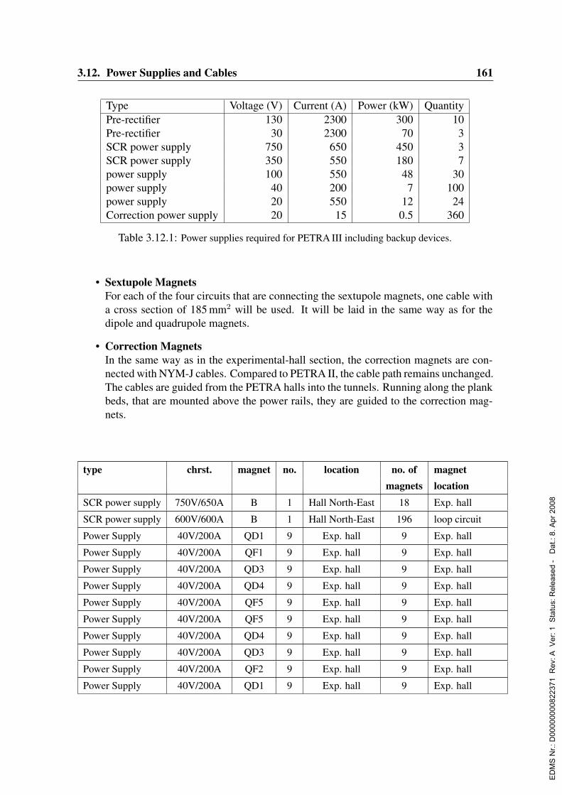
3.12. Power Supplies and Cables 161
Type Voltage (V) Current (A) Power (kW) QuantityPre-rectifier 130 2300 300 10Pre-rectifier 30 2300 70 3SCR power supply 750 650 450 3SCR power supply 350 550 180 7power supply 100 550 48 30power supply 40 200 7 100power supply 20 550 12 24Correction power supply 20 15 0.5 360
Table 3.12.1: Power supplies required for PETRA III including backup devices.
• Sextupole MagnetsFor each of the four circuits that are connecting the sextupole magnets, one cable witha cross section of 185 mm2 will be used. It will be laid in the same way as for thedipole and quadrupole magnets.
• Correction MagnetsIn the same way as in the experimental-hall section, the correction magnets are con-nected with NYM-J cables. Compared to PETRA II, the cable path remains unchanged.The cables are guided from the PETRA halls into the tunnels. Running along the plankbeds, that are mounted above the power rails, they are guided to the correction mag-nets.
type chrst. magnet no. location no. of magnetmagnets location
SCR power supply 750V/650A B 1 Hall North-East 18 Exp. hall
SCR power supply 600V/600A B 1 Hall North-East 196 loop circuit
Power Supply 40V/200A QD1 9 Exp. hall 9 Exp. hall
Power Supply 40V/200A QF1 9 Exp. hall 9 Exp. hall
Power Supply 40V/200A QD3 9 Exp. hall 9 Exp. hall
Power Supply 40V/200A QD4 9 Exp. hall 9 Exp. hall
Power Supply 40V/200A QF5 9 Exp. hall 9 Exp. hall
Power Supply 40V/200A QF5 9 Exp. hall 9 Exp. hall
Power Supply 40V/200A QD4 9 Exp. hall 9 Exp. hall
Power Supply 40V/200A QD3 9 Exp. hall 9 Exp. hall
Power Supply 40V/200A QF2 9 Exp. hall 9 Exp. hall
Power Supply 40V/200A QD1 9 Exp. hall 9 Exp. hall
ED
MS
Nr.:
D00
0000
0082
2371
Rev
: A V
er: 1
Sta
tus:
Rel
ease
d -
Dat
.: 8.
Apr
200
8

162 3. The Storage Ring
Pre-rectifier 130V/2300A - 4 Exp. hall - -
Power Supply 20V/550A Q1KL 1 Hall North-East 1 North-Northeast
Power Supply 20V/550A Q2KL 1 Hall North-East 1 North-Northeast
Power Supply 20V/550A Q3KL 1 Hall North-East 1 North-Northeast
Power Supply 20V/550A Q4KL 1 Hall North-East 1 North-Northeast
Power Supply 20V/550A Q1KR 1 Hall North-East 1 North-Northeast
Power Supply 20V/550A Q2KR 1 Hall North-East 1 North-Northeast
Power Supply 20V/550A Q3KR 1 Hall North-East 1 North-Northeast
Power Supply 20V/550A Q4KR 1 Hall North-East 1 North-Northeast
Power Supply 20V/550A Q5NL 1 Hall East 1 East-Southeast
Power Supply 20V/550A Q6NL 1 Hall East 1 East-Southeast
Power Supply 20V/550A Q7NL 1 Hall East 1 East-Southeast
Power Supply 20V/550A Q8NL 1 Hall East 1 East-Southeast
Power Supply 20V/550A Q9NL 1 Hall East 1 East-Southeast
Power Supply 20V/550A Q10NL 1 Hall East 1 East-Southeast
Pre-rectifier 30V/2300A - 1 Hall East - -
Power Supply 100V/550A Q0K 1 Hall North-East 4 loop circuit
Power Supply 60V/550A Q1K 1 Hall North-East 5 loop circuit
Power Supply 60V/550A Q2K 1 Hall North-East 5 loop circuit
Power Supply 60V/550A Q3K 1 Hall North-East 5 loop circuit
Power Supply 60V/550A Q4K 1 Hall North-East 5 loop circuit
Power Supply 60V/550A Q5K 1 Hall North-East 7 loop circuit
Power Supply 80V/550A Q0A 1 Hall North-East 7 loop circuit
Power Supply 80V/550A QK1 1 Hall North-East 7 loop circuit
Power Supply 60V/550A Q2A 1 Hall North-East 7 loop circuit
Power Supply 60V/550A QK3 1 Hall North-East 7 loop circuit
Power Supply 60V/550A Q4A 1 Hall North-East 7 loop circuit
SCR power supply 350V/550A QD 1 Hall North-East 63 loop circuit
SCR power supply 350V/550A QF 1 Hall North-East 63 loop circuit
Power Supply 60V/550A Q3 1 Hall North-East 7 loop circuit
Power Supply 80V/550A Q2B 1 Hall North-East 7 loop circuit
Power Supply 80V/550A Q1 1 Hall North-East 7 loop circuit
Power Supply 80V/550A Q0B 1 Hall North-East 7 loop circuit
Power Supply 80V/550A Q9N 1 Hall North-East 6 loop circuit
Power Supply 80V/550A Q8N 1 Hall North-East 6 loop circuit
ED
MS
Nr.:
D00
0000
0082
2371
Rev
: A V
er: 1
Sta
tus:
Rel
ease
d -
Dat
.: 8.
Apr
200
8

3.12. Power Supplies and Cables 163
Power Supply 80V/550A Q7N 1 Hall North-East 6 loop circuit
Power Supply 60V/550A Q6N 1 Hall North-East 6 loop circuit
Power Supply 60V/550A Q5N 1 Hall North-East 6 loop circuit
Power Supply 60V/550A Q4N 1 Hall North-East 8 loop circuit
Power Supply 60V/550A Q3N 1 Hall North-East 8 loop circuit
Power Supply 60V/550A Q2N 1 Hall North-East 8 loop circuit
Power Supply 60V/550A Q1N 1 Hall North-East 8 loop circuit
Power Supply 60V/550A Q0N 1 Hall North-East 3 loop circuit
Power Supply 60V/550A QG 1 Hall North-East 2 loop circuit
Pre-rectifier 130V/2300A - 5 Hall North-East - -
Power Supply 20V/550A - 6 Hall South 1 at Hall South
Pre-rectifier 30V/2300A - 1 Hall South - at Hall South
SCR power supply 300V/400A S1 1 Hall North-East 35 loop circuit
SCR power supply 300V/400A S2 1 Hall North-East 35 loop circuit
SCR power supply 300V/400A S3 1 Hall North-East 35 loop circuit
SCR power supply 300V/400A S4 1 Hall North-East 35 loop circuit
Corrector 20V/10A - 200 PETRA-Halls 200 7/8
Corrector 20V/10A - 60 Exp. hall 60 Exp. hall
Backleg 10V/15A - 18 Exp. hall 18 Exp. hall
Fast corrector 20V/10A - 70 Exp. hall 70 Exp. hall
Table 3.12.2: Overview of the power supplies for PETRA III in-cluding their location.
3.12.1.3 Redundance
For operation with high efficiency , sufficiently high reliability and fast failure handling arerequired. This will be achieved by having spare units in standby mode. For each group of tenactive chopper supplies one spare will be available. One extra SCR will serve as a spare forthe seven SCR power supplies. The interlock and permits for the ten units will be combinedand fed to the spare power supply. Hence no further cabling for these signals will be neces-sary. The magnet circuits are equipped with quick connectors. The faulty unit can then berepaired or replaced without disturbing operation. These measures will ensure that operationis interrupted for less than one hour.Due to their high reliability, the power supplies for the correction magnets are not includedin this redundancy concept.The accelerator availability could be further increased by equipping the power supplies withadditional switches. This enables power supply exchange to be automated from the controlroom. The down time could then be reduced to some 15 minutes in about 80 % of the trips.
ED
MS
Nr.:
D00
0000
0082
2371
Rev
: A V
er: 1
Sta
tus:
Rel
ease
d -
Dat
.: 8.
Apr
200
8
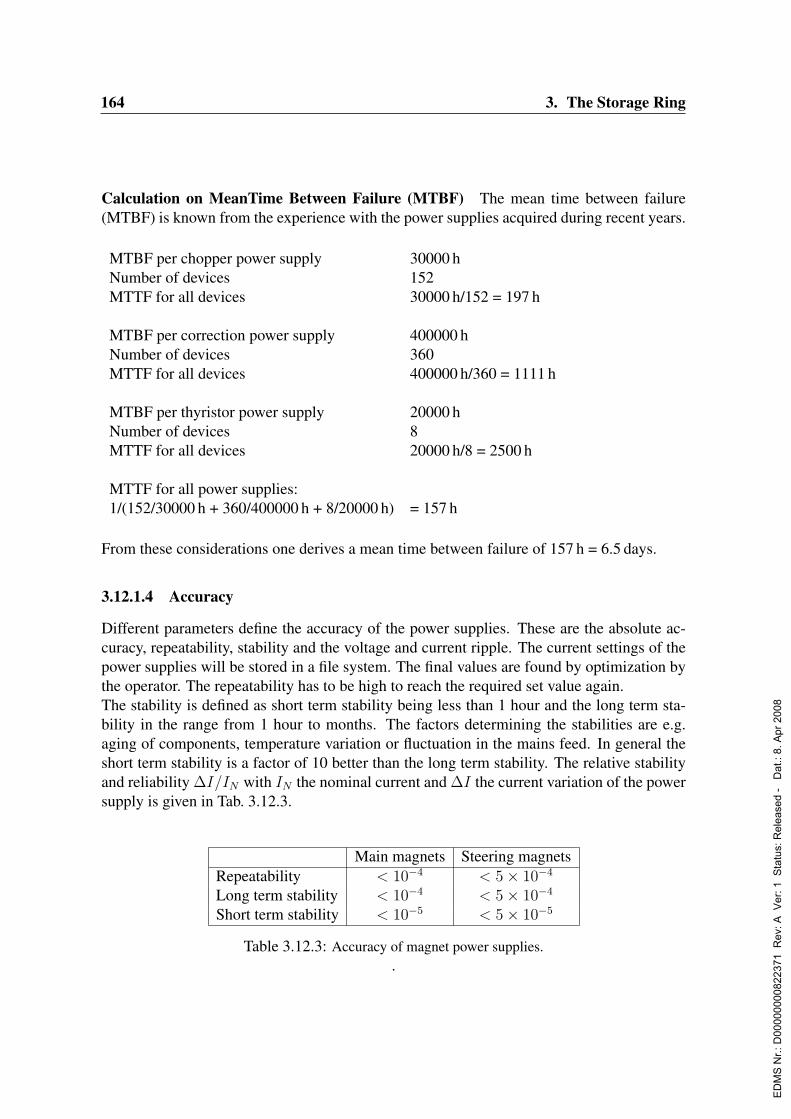
164 3. The Storage Ring
Calculation on MeanTime Between Failure (MTBF) The mean time between failure(MTBF) is known from the experience with the power supplies acquired during recent years.
MTBF per chopper power supply 30000 hNumber of devices 152MTTF for all devices 30000 h/152 = 197 h
MTBF per correction power supply 400000 hNumber of devices 360MTTF for all devices 400000 h/360 = 1111 h
MTBF per thyristor power supply 20000 hNumber of devices 8MTTF for all devices 20000 h/8 = 2500 h
MTTF for all power supplies:1/(152/30000 h + 360/400000 h + 8/20000 h) = 157 h
From these considerations one derives a mean time between failure of 157 h = 6.5 days.
3.12.1.4 Accuracy
Different parameters define the accuracy of the power supplies. These are the absolute ac-curacy, repeatability, stability and the voltage and current ripple. The current settings of thepower supplies will be stored in a file system. The final values are found by optimization bythe operator. The repeatability has to be high to reach the required set value again.The stability is defined as short term stability being less than 1 hour and the long term sta-bility in the range from 1 hour to months. The factors determining the stabilities are e.g.aging of components, temperature variation or fluctuation in the mains feed. In general theshort term stability is a factor of 10 better than the long term stability. The relative stabilityand reliability ∆I/IN with IN the nominal current and ∆I the current variation of the powersupply is given in Tab. 3.12.3.
Main magnets Steering magnetsRepeatability < 10−4 < 5× 10⁻⁴
Long term stability < 10−4 < 5× 10⁻⁴
Short term stability < 10−5 < 5× 10⁻⁵
Table 3.12.3: Accuracy of magnet power supplies..
ED
MS
Nr.:
D00
0000
0082
2371
Rev
: A V
er: 1
Sta
tus:
Rel
ease
d -
Dat
.: 8.
Apr
200
8

3.12. Power Supplies and Cables 165
The current ripple depends on the voltage ripple of the power supply, the inductance of themagnet and the frequency spectrum of the power supply. It is given by:
I = U × 1
jωL+R(3.12.1)
Iripple
Inominal
≈ Uripple
Unominal
× R
ωL(3.12.2)
with ω = 2πf , f being the frequency of the ripple and L the inductance of the magnet. Inthe following we assume pessimistically that the DC resistance R of the different magnetcircuits is 1 Ω.
SCR power supplies The current is controlled with a resolution of 16 bit. The typicalfrequency of the SCR power supplies is 600 Hz. The voltage ripple of the power supplies isspecified to be Uripple/Unominal < 0.01. The required relative ripple amplitude for the dipoleis < 1 × 10⁻⁵. With Ldipole = 0.8H the relative ripple amplitude becomes 3.3 × 10⁻⁶. Therequired relative ripple amplitude for the quadrupole is < 5× 10⁻⁵. With Lquad = 0.1H therelative ripple amplitude becomes 2.6× 10⁻⁵.
Chopper power supplies The resolution of the reference current is 16 bit. The typicalfrequency of the chopper power supplies is higher than 16 kHz. The voltage ripple of thepower supplies is specified to be less than 5 % of the output voltage. The required relativeripple amplitude for the quadrupole is < 5 × 10⁻⁵. With Lquad = 0.1H the relative rippleamplitude becomes 5× 10⁻⁶.
Correction power supplies The current is controlled with a resolution of 16 bit. Thetypical frequency of the steerer power supplies is higher than 16 kHz. The voltage rippleof the power supplies is specified to be less than 5 % of the output voltage. The requiredrelative ripple amplitude for the steerer is < 5× 10⁻⁵. With Lquad = 0.5H the relative rippleamplitude becomes 1× 10⁻⁶.
ED
MS
Nr.:
D00
0000
0082
2371
Rev
: A V
er: 1
Sta
tus:
Rel
ease
d -
Dat
.: 8.
Apr
200
8
166 3. The Storage Ring
3.12.2 HVDC transmitter power supply and klystron protection
3.12.2.1 PETRA II status
Two rectifying units exist to power the two double transmitter installations in PETRA II. Oneunit in hall south/left (building 42a) and the other in hall south/right (building 42b). The DCoutput power of each installation is 2.1 MW (58 kV DC / 36 A DC). Much of the equipmentis over 25 years old and no longer state of the art. An uncontrolled rectifier is driven bya tap changing transformer set. The output voltage is determined by the preselected tapwinding but cannot be regulated quickly in the case of load variations or system voltagedips. The tapping switch of the transformer is no longer commercially available and needsintensive maintenance. Control equipment and monitoring are obsolete and susceptible tomalfunction. Klystron protection is carried out by triggered spark gaps, which are out-datedand not reliable. The medium high voltage switchgear is state of the art. It has been renewedin 2002 and will stay in operation for PETRA III.
3.12.2.2 PETRA III design
It is necessary to build two new identical high voltage direct current (HVDC) power suppliesto feed the RF system for PETRA III. Their design is based upon the specification of thehigh power klystrons, in particular that they operate at 75 kV and 18 A DC. This results in2.7 MW of DC power to feed a double transmitter installation. Some flexibility is needed tocarry out e.g. klystron tests so we intend to provide an additional power margin of 10 percent. This results in the required DC output power of 3.0 MW for one HVDC power supply.Similar power supplies are in operation and have yielded good experience. Existing highreliable components will be reused. A schematic of the HVDC transmitter power supply andklystron protection is shown in Fig. 3.12.1 .
Medium High Voltage Switchgear The medium high voltage switchgear consists of onepassive incoming feeder panel and three outgoing feeder panels, which are equipped withvacuum circuit breakers. Two outgoing feeder panels are provided to supply each of theHVDC transmitter power supplies south/left and south/right. The third feeder panel is forback up purposes. The incoming supply is accomplished as a dead-end feeder from mainswitchgear station A. It is not planned to establish a redundant feed in. The switchgear isassembled inside a separate substation next to building 42b. Inside this substation addi-tional space is provided to extend the switchgear. Up to two additional feeder panels can bemounted.
HVDC Power Supplies One thyristor controlled HVDC power supply is provided to powereach of the double transmitters. The concept is based on the so-called “star point controller”in an intermediate voltage circuit. The thyristor controllers are fed by a medium high volt-age transformer set. Continuous regulation of the output voltage is realized by phase anglecontrol of the intermediate voltage ( < 1000 V AC ). The controlled voltage is transfered tothe high voltage transformer set and subsequently converted by diode rectifiers.Smoothing of the DC output voltage is accomplished by a passive RLC filter. The smoothing
ED
MS
Nr.:
D00
0000
0082
2371
Rev
: A V
er: 1
Sta
tus:
Rel
ease
d -
Dat
.: 8.
Apr
200
8

3.12. Power Supplies and Cables 167
inductance is connected to the DC current star point of the thyristor controller. The induc-tance is housed in a cabinet located next to the thyristor controller. The RC filter is at highvoltage DC level. Therefore it has to be installed inside the modulator room of the trans-mitter building. All components at voltages < 1000 V AC (thyristor controller, smoothinginductance, control electronics) will be mounted in cabinets for indoor installation. Thesecabinets will be arranged within an extended area of the transmitter building. All air insu-lated components at high voltage DC level will be installed inside the modulator room. Thisroom has to be erected inside the transmitter building. All components at voltages > 1000 VAC (main transformer, HV transformer, HV rectifier) will be located inside oil filled tanksfor outdoor installation. These tanks will be situated outside the transmitter building closeto the modulator room. The main parameters of a HVDC power supply are presented in thefollowing table:
Main parameters of one HVDC power supply:main input voltage UAC 10 kVmain input power SAC 4 MVAmax. DC output voltage UDCmax 80 kVmax. DC output current IDCmax 38 Amax. DC output power PDCmax 3,0 MWnom. DC output voltage UDCn 75 kVnom. DC output current IDCn 36 Anom. DC output power PDCn 2,7 MWcontrol range output voltage 0...80 kVoperating range at transmitter operation 50...80 kV
Klystron Protection High power klystrons are protected against arcing and other failures(e.g. focus current) by LTT-Crowbars (Light Triggered Thyristor Crowbar). In the caseof malfunction in one of the two klystrons a fast bypass is established by triggering thethyristors. Thus the energy is limited to an appropriate value.The technology of LTT-Crowbars has been developed at DESY. It has been in operation suc-cessfully at the DESY II since May 2003. For the operation at PETRA III the voltage levelof these crowbars has to be increased from the present 50 kV DC up to 80 kV DC. Suchdevelopment is under way. The LTT-Crowbar will be installed inside the modulator room.
Modulator room The new modulator room is part of the transmitter building. It servesas a closed electrical operating room to contain all components at high voltage DC level.Each of the two existing transmitter will be extended to serve a new modulator room. It isa significant part of this concept to arrange the outdoor components close to the modulatorroom. Thus special high voltage DC cables and appropriate cable sealings are no longerrequired. Losses regarding the intermediate voltage cabling (between thyristor controllerand transformer) are reduced. The areas necessary are available and earmarked for extensionof buildings, transformer foundations and oil pits.
ED
MS
Nr.:
D00
0000
0082
2371
Rev
: A V
er: 1
Sta
tus:
Rel
ease
d -
Dat
.: 8.
Apr
200
8
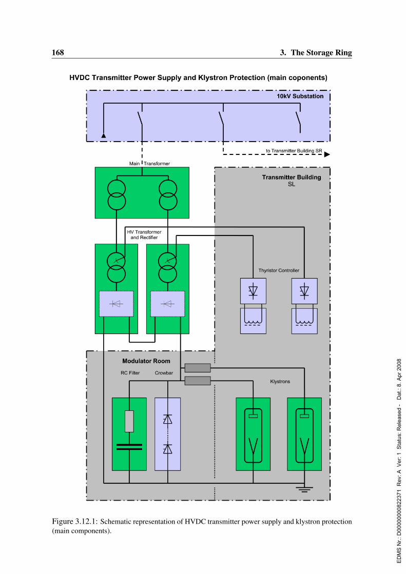
168 3. The Storage Ring
Figure 3.12.1: Schematic representation of HVDC transmitter power supply and klystron protection(main components).
ED
MS
Nr.:
D00
0000
0082
2371
Rev
: A V
er: 1
Sta
tus:
Rel
ease
d -
Dat
.: 8.
Apr
200
8

3.13. Cooling Systems 169
Figure 3.13.1: Overview of the cooling-water supply at PETRA
3.13 Cooling SystemsThe cooling-water of PETRA III is supplied from two locations as sketched in Fig. 3.13.1 :To cool the Al- and Cu magnet coils a circumferential cooling pipe of cross section dimen-sion DN 100 is foreseen. Input of the cooling water proceeds from a separate hall near toPETRA-hall Northeast. The magnets are connected with hoses. A separate distribution pipeis installed in each octant to cool the dipole-magnet coils. The magnets in the new octantwill be connected to the Cu cooling circuit. The draining of individual components can beperformed with help of a circumferential bilge suction line.Chilled water for the experimental hall will also be produced in PETRA-hall Northeast.Cooling generators are hybrid dry-cell coolers with a closed cooling cycle. All cooling cy-cles are operated with fully demineralized water (conductivity < 1µS/cm).
3.13.1 RF cooling systemsPETRA III contain two RF-systems that are fed by a common cooling water supply. Eachsystem consists of two klystrons with the corresponding absorbers, circulators and cavitiesas sketched in Fig. 3.13.2. The following components of the RF-systems are supplied withcooling water :
• 4 klystrons (2 in each system), consisting ofcollector with ∆p = 2.0 bar, inlet temperature, qe = 38.3C, and4× body with ∆p = 3.0 bar, qe = 28C.Cooling power for each system max. 2700 kW
ED
MS
Nr.:
D00
0000
0082
2371
Rev
: A V
er: 1
Sta
tus:
Rel
ease
d -
Dat
.: 8.
Apr
200
8

170 3. The Storage Ring
• RF-absorber (hall) with ∆p = 4.5 bar, qe = 28C.Cooling power for each system max. 750 kW
• RF-absorber (tunnel) with ∆p = 4.5 bar, qe = 28C.Cooling power for each system max. 700 kW
• Cavities with ∆p = 1.0 bar, qe = 28C.Cooling power for each system max. 1260 kW
• Circulator with ∆p = 3.0 bar, qe = 28C.Cooling power for each system max. 40 kW
1. The cooling of the magnets and the experimental hall is provided from PETRA-hallNortheast.
2. The cooling of the RF-system is supplied via PETRA-hall South.
The the temperature of the cooling water will be reduced in the cooling towers to 28C andthen fed into the cavities and the corresponding absorbers. The return water will be used assupply water for the klystrons. In this way the amount of water to be delivered is significantlyreduced.
Figure 3.13.2: Scheme of the cooling circuits for the RF-system South
ED
MS
Nr.:
D00
0000
0082
2371
Rev
: A V
er: 1
Sta
tus:
Rel
ease
d -
Dat
.: 8.
Apr
200
8
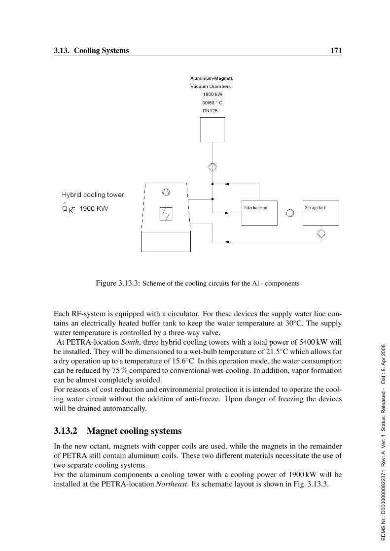
3.13. Cooling Systems 171
Figure 3.13.3: Scheme of the cooling circuits for the Al - components
Each RF-system is equipped with a circulator. For these devices the supply water line con-tains an electrically heated buffer tank to keep the water temperature at 30C. The supplywater temperature is controlled by a three-way valve.At PETRA-location South, three hybrid cooling towers with a total power of 5400 kW will
be installed. They will be dimensioned to a wet-bulb temperature of 21.5C which allows fora dry operation up to a temperature of 15.6C. In this operation mode, the water consumptioncan be reduced by 75 % compared to conventional wet-cooling. In addition, vapor formationcan be almost completely avoided.For reasons of cost reduction and environmental protection it is intended to operate the cool-ing water circuit without the addition of anti-freeze. Upon danger of freezing the deviceswill be drained automatically.
3.13.2 Magnet cooling systemsIn the new octant, magnets with copper coils are used, while the magnets in the remainderof PETRA still contain aluminum coils. These two different materials necessitate the use oftwo separate cooling systems.For the aluminum components a cooling tower with a cooling power of 1900 kW will beinstalled at the PETRA-location Northeast. Its schematic layout is shown in Fig. 3.13.3.
ED
MS
Nr.:
D00
0000
0082
2371
Rev
: A V
er: 1
Sta
tus:
Rel
ease
d -
Dat
.: 8.
Apr
200
8
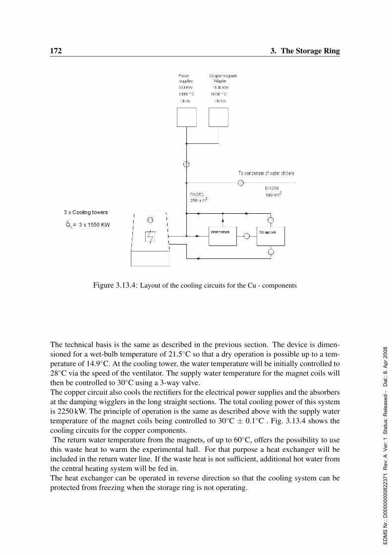
172 3. The Storage Ring
Figure 3.13.4: Layout of the cooling circuits for the Cu - components
The technical basis is the same as described in the previous section. The device is dimen-sioned for a wet-bulb temperature of 21.5C so that a dry operation is possible up to a tem-perature of 14.9C. At the cooling tower, the water temperature will be initially controlled to28C via the speed of the ventilator. The supply water temperature for the magnet coils willthen be controlled to 30C using a 3-way valve.The copper circuit also cools the rectifiers for the electrical power supplies and the absorbersat the damping wigglers in the long straight sections. The total cooling power of this systemis 2250 kW. The principle of operation is the same as described above with the supply watertemperature of the magnet coils being controlled to 30C ± 0.1C . Fig. 3.13.4 shows thecooling circuits for the copper components.The return water temperature from the magnets, of up to 60C, offers the possibility to use
this waste heat to warm the experimental hall. For that purpose a heat exchanger will beincluded in the return water line. If the waste heat is not sufficient, additional hot water fromthe central heating system will be fed in.The heat exchanger can be operated in reverse direction so that the cooling system can beprotected from freezing when the storage ring is not operating.
ED
MS
Nr.:
D00
0000
0082
2371
Rev
: A V
er: 1
Sta
tus:
Rel
ease
d -
Dat
.: 8.
Apr
200
8

3.13. Cooling Systems 173
Figure 3.13.5: Scheme of the cooling of the vacuum chamber.
3.13.3 Vacuum chamber cooling system
The vacuum chambers are made of aluminum and will be supplied from the same coolingcircuit as the aluminum coils. For this purpose a separate distribution pipe is provided ineach octant.To cool the vacuum chamber a significantly lower pressure is needed compared to that forthe magnets. Therefore pressure reducing valves will be installed at each distribution pipe.The synchrotron radiation power density in the old seven octants is about 100 W per m. Toavoid deformation the temperature and its gradient across the chamber should vary as littleas possible.The new vacuum chambers for PETRA III are equipped with cooling tubes on both sides.This setup maintains thermal stability by the use of a suitable flow rate on the inside andoutside of the chamber with a low amount of cooling water. A similar system is already usedsuccessfully at DORIS. The layout proposed for PETRA III is shown in Fig. 3.13.5.
3.13.4 Air conditioning
3.13.4.1 Air conditioning of the tunnel
For the air conditioning of the tunnel four independent climate-control devices working intransverse mode are installed. Fresh air is drawn in through a weather protection barrier inthe mixing chamber of the device. Recirculating air can be mixed in upon demand. After
ED
MS
Nr.:
D00
0000
0082
2371
Rev
: A V
er: 1
Sta
tus:
Rel
ease
d -
Dat
.: 8.
Apr
200
8

174 3. The Storage Ring
filtering and temperature adjustment, this air is blown by a ventilating fan through galvanizedsteel ducts into the tunnel.The climate control devices are mounted outside the experimental hall on the southwest side.Water at a temperatures of 12(16) C (supply / return temperature) and of 50(30) C is usedfor cooling and heating respectively. The climate control devices are equipped with fireshutters to fulfil fire protection requirements. The air conditioning system for the tunnel isshown schematically in Fig 3.13.6.
Figure 3.13.6: Air conditioning layout for the tunnel
• Temperature control:To control the air conditioning process each system is equipped with individual di-rect digital control (DDC) regulation. Temperature regulation is realized as a cascadecontrol of the intake/interior air. The cascade consists of a guiding regulator and subse-quent regulators. The guiding regulator adjust the air supply flow in proportion to thedeviation of the temperature in the tunnel. This temperature is defined as the averagevalue acquired from four sensors. No humidification or drying of the air is foreseenfor the tunnel.
• Technical dataIncoming air flow rate : 4 × 9.000 m3/h = 36.000 m3/hUsed air flow rate : 4 × 9.000 m3/h = 36.000 m3/hRatio intake/exhaust air : 0 – 100 % variableTemperature in the tunnel : 28 C ± 0.1 C
ED
MS
Nr.:
D00
0000
0082
2371
Rev
: A V
er: 1
Sta
tus:
Rel
ease
d -
Dat
.: 8.
Apr
200
8

3.14. Radiation Safety System 175
3.14 Radiation Safety System
3.14.1 Safety considerations
The shielding of the synchrotron light source is built to ensure total containment of the pri-mary electrons1 in the storage ring tunnel. The storage ring shielding is designed to ab-sorb both primary electrons and their secondary radiation. The optical hutch shielding inturn will block bremsstrahlung and its secondary radiation only. Thus primary electronlosses in optical hutches must be prevented. Therefore the separation of the synchrotronlight/bremsstrahlung from the primary electrons is a key issue of radiation safety. The rele-vant technical component is the dipole magnet called separation dipole immediately down-stream of the insertion device. A malfunction e.g. a short of this element has to be consideredfor two different operation modes of the storage ring:
a) Stored beam operation:
A field change of approximately 3 % leads to a total loss of the primary beam whereas areduction of more than 90 % is necessary to direct primary electrons into the synchrotronlight beam line. So the separation dipole prevents losses of primary electrons into the opticalhutches under stored beam operation.
b) Injection into the storage ring:
If the separation dipole had no magnetic field during injection the primary electron would gostraight into the optical hutch. A system called Safe Injection System is needed to avoid thisproblem.The existing synchrotron light source DORIS III uses a Save Injection System employingbeam shutters: one injection shutter in the transfer line to the storage ring and shutters ineach of the synchrotron light beam lines. During transfer the injection shutter is open and allsynchrotron light shutters are closed. The synchrotron light shutters can only be opened ifthe injection shutter is closed.PETRA III is expected to be operated in top-up mode that means that the synchrotron lightshutters stay open during injection. So a shutter based Safe Injection System cannot be used.A different system has to be implemented. There are at least two methods to achieve this:one passive and one active.
The passive solution is a permanent dipole magnet located in the synchrotron light beamline deflecting all primary particles. Advantages are no maintenance effort and no specialpersonnel interlock system. Disadvantages are the need for additional space in the syn-chrotron light beam line and possible degradation of the magnetic field due to radiation.
1In this section the notation “electron” is used for both “electron” and “positron”.
ED
MS
Nr.:
D00
0000
0082
2371
Rev
: A V
er: 1
Sta
tus:
Rel
ease
d -
Dat
.: 8.
Apr
200
8

176 3. The Storage Ring
The active solution is based on the fact that the injected beam cannot travel along a syn-chrotron beam line while there is stored beam in the machine. It consists of a redundantbeam current monitor system which triggers a dump, if the current drops below a thresholde.g. 20 % of the nominal value. Although no extra element is required in the beam line dis-advantages arise from reliability issues, high maintenance effort and the need for a specialpersonnel interlock system. This solution seems to be the only one for upgrading existingSynchrotron Light Sources to the top-up mode (Emery & Borland, 1999b; Borland & Emery,1999; Emery & Borland, 1999a; Luedeke & Munoz, 2002; Sanosian, 2002; Berkvens et al.,2002; Job, 2002; Casarin et al., 2002).For PETRA III the passive solution will be chosen. Each synchrotron beam line will beequipped with a permanent dipole magnet as the Save Injection System. The permanentmagnet fields will be measured once a year to ensure their integrity. Note, that this passivesolution is also sufficient for start-up injection. So the PETRA III personnel interlock systemwill be simpler than that of DORIS III.
3.14.2 Basic machine parametersThe main parameters relevant for radiation protection are the electron energy 6 GeV and themaximum current of 200 mA corresponding to 1013 circulating electrons. An operation timeof 6000 hours per year is assumed. The injector DESY II can deliver 1010 electrons at a rateof 6 Hz.
3.14.3 Beam loss scenariosAs we have seen above the primary electron beam is contained and therefore lost only insidethe main storage ring tunnel and cannot exit the shielding. In the following, different beamloss scenarios are discussed.
3.14.3.1 Normal continuous beam loss
The total number of electrons injected per year has to be estimated. Two different modes areforeseen, the few bunch mode (high bunch charge) with a lifetime of 1 h and the multi bunchmode (low bunch charge) with a lifetime of 24 h. A simplified assumption of equal operationtime in each mode yields 1013 * 3000h/1h + 1013 * 3000h/24h = 3*1016 lost electrons peryear. If the transfer efficiency is 50 % one finally gets 6*1016 lost electrons per year.In the worst case scenario, all electrons are considered to be lost within the new octant oflength 300 m (as opposed to being equally distributed around the ring). In order to applya simple model, this line source is translated into equivalent point sources. This modelallows a simple calculation of the dose at a given perpendicular distance from the line sourcebehind the shielding. As a rule of thumb the number of lost electrons over a length oftwice the perpendicular distance to the line source is taken as the strength of the equivalentpoint source. This point source is located in the middle of this segment. To calculate thedose behind the shielding at 2.5 m from the line source a segment length of 5m defines theequivalent point source with a strength of 1015 electrons per year.
ED
MS
Nr.:
D00
0000
0082
2371
Rev
: A V
er: 1
Sta
tus:
Rel
ease
d -
Dat
.: 8.
Apr
200
8
3.14. Radiation Safety System 177
3.14.3.2 Accidental beam loss
Beam loss events can occur for different reasons namely malfunction of machine compo-nents or human error. Here two worst case scenarios are described:
a) Start-up injection:
Either there is an obstacle in the electron beam pipe, for instance a closed vacuum valve or aseparation dipole trips and the beam is lost immediately downstream the permanent magnetinside the tunnel. In both cases no beam can be stored. One may use additional transfers todiagnose the fault. Suppose this takes an hour then 1010 * 6 Hz * 3600 s = 2*1014 electronsare lost. So the point source strength is 2*1014 electrons per event.
a) Stored beam:
A separation dipole fails due to a short. The magnetic field decays slowly compared to the8µs resolution time so the beam gets lost over many turns. Assuming that all the losses occurin one insertion device the point source strength is 1013 electrons per event.
3.14.4 Shielding calculations
3.14.4.1 Design goal
The experimental hall should be accessible without any restrictions. So the acquired personaldose of 1 mSv/a may not be exceeded according to the German Regulations for RadiationProtection. The shielding will designed such that the personal dose will be at least a factorof two, 0.5 mSv/a, below this limit. The machine is assumed to be operated for 6000 h/ahowever as an individual works at most 2000 h/a, the local dose could be 1.5 mSv/a withoutexceeding the goal. A beam loss event as described above is expected to occur less than fivetimes per year. Hence the shielding should restrict the dose to 0.1 mSv per event.
3.14.4.2 Lateral shielding of the Storage Ring
Photons, low energy neutrons and high energy neutrons are the most penetrating secondaryparticles produced by the primary electrons. Behind thick shielding high energy neutronsmainly contribute to the dose. To minimize the space required in the experimental hall thelateral shielding is made from heavy concrete having an attenuation length of 30 cm for highenergy neutrons. The following doses are calculated at a distance of 3 m from the loss pointbehind a 1 m thick heavy concrete wall:For the beam loss events a target efficiency of 0.1 is applied. This is an empirical valuederived from the comparison of measurements with the simple point model predictions. Ittakes into account that a real loss is not point-like but is distributed over a longer section ofthe beam pipe.
ED
MS
Nr.:
D00
0000
0082
2371
Rev
: A V
er: 1
Sta
tus:
Rel
ease
d -
Dat
.: 8.
Apr
200
8

178 3. The Storage Ring
Scenario Personal dose Design goalPers. dose Local dose
Normal continuous loss 0.3 mSv/a 0.5 mSv/a 1.5 mSv/aStart-up (Dipole fault) 0.02 mSv/event 0.1 mSv/eventTop-up (Dipole fault) 0.0009 mSv/event 0.1 mSv/event
Table 3.14.1: Comparison of dose estimates with design goals.
The rest of the PETRA III ring is shielded by 4 m of soil equivalent to more than 2 m ofheavy concrete, so it needs not to be considered here.
3.14.4.3 Shielding of an optical hutch
Interaction of the primary electrons with any atom generates bremsstrahlung. Only brems-strahlung produced in the straight section containing an insertion device can travel along thebeam line. This radiation will interact with any material in its path e.g. mirrors. In thefollowing estimates are given for electron beam interactions with the residual gas inside thebeam pipe and with its wall.
a) Gas bremsstrahlung:
A 20 m undulator is considered installed in a 61.5 m long drift section at an N2 equivalentpressure of 5 * 10−10 mbar. The bremsstrahlung from this section as well as the synchrotronlight from the undulator reaches the optics hutch. When the bremsstrahlung interacts witha mirror neutrons are generated. At a distance of 1 m the dose is estimated to 6 mSv/a. Toremain below the design goal an attenuation by a factor of 4 will be required.
b) Wall bremsstrahlung:
Here a scaling to the TTF-II case (Leuschner, 2002) is given. Scaling based upon beampower leads to reliable results at least for the neutron yields. A loss of 1016 electrons at1.6 GeV corresponds to 2.7*1015 electrons in our case. It leads to a neutron dose of 1 Sv at1 m distance from the mirror. For the scenario of normal continuous loss of 1015 electronsper year the neutron dose is about 400 mSv/a, therefore, an attenuation by a factor of 250 isneeded.
c) Shielding Requirements for the White Beam:
There are different means to reduce the neutron dose around components located in thewhite beam, for instance collimation (Takahashi et al., 2001) and shielding. Using shieldingto attenuate the neutron doses by a factor of 4 to 250 then 20 cm to 70 cm of heavy con-crete is needed. Here, heavy concrete is an economic compromise between a low-Z materialagainst neutrons and a high-Z material against scattered electro-magnetic radiation such as
ED
MS
Nr.:
D00
0000
0082
2371
Rev
: A V
er: 1
Sta
tus:
Rel
ease
d -
Dat
.: 8.
Apr
200
8

3.14. Radiation Safety System 179
bremsstrahlung and γ’s. The dose level due to the latter radiation components is not acces-sible by a simple formula but could be much higher than that of the neutrons. In order toefficiently use the available space the losses in each beam line will be individual modelledand a consistent shielding concept will be developed. The optimization will be done usingMonte Carlo codes also giving the dose fields due to the electro-magnetic radiation.
ED
MS
Nr.:
D00
0000
0082
2371
Rev
: A V
er: 1
Sta
tus:
Rel
ease
d -
Dat
.: 8.
Apr
200
8
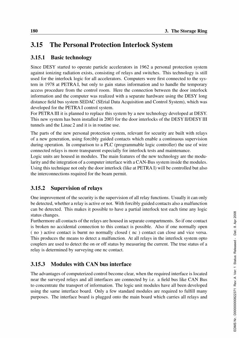
180 3. The Storage Ring
3.15 The Personal Protection Interlock System
3.15.1 Basic technologySince DESY started to operate particle accelerators in 1962 a personal protection systemagainst ionizing radiation exists, consisting of relays and switches. This technology is stillused for the interlock logic for all accelerators. Computers were first connected to the sys-tem in 1978 at PETRA I, but only to gain status information and to handle the temporaryaccess procedure from the control room. Here the connection between the door interlockinformation and the computer was realized with a separate hardware using the DESY longdistance field bus system SEDAC (SErial Data Acquisition and Control System), which wasdeveloped for the PETRA I control system.For PETRA III it is planned to replace this system by a new technology developed at DESY.This new system has been installed in 2003 for the door interlocks of the DESY II/DESY IIItunnels and the Linac 2 and it is in routine use.
The parts of the new personal protection system, relevant for security are built with relaysof a new generation, using forcibly guided contacts which enable a continuous supervisionduring operation. In comparison to a PLC (programmable logic controller) the use of wireconnected relays is more transparent especially for interlock tests and maintenance.Logic units are housed in modules. The main features of the new technology are the modu-larity and the integration of a computer interface with a CAN-Bus system inside the modules.Using this technique not only the door interlock (like at PETRA I) will be controlled but alsothe interconnections required for the beam permit.
3.15.2 Supervision of relaysOne improvement of the security is the supervision of all relay functions. Usually it can onlybe detected, whether a relay is active or not. With forcibly guided contacts also a malfunctioncan be detected. This makes it possible to have a partial interlock test each time any logicstatus changes.Furthermore all contacts of the relays are housed in separate compartments. So if one contactis broken no accidental connection to this contact is possible. Also if one normally open( no ) active contact is burnt no normally closed ( nc ) contact can close and vice versa.This produces the means to detect a malfunction. At all relays in the interlock system optocouplers are used to detect the on or off status by measuring the current. The true status of arelay is determined by surveying one nc contact.
3.15.3 Modules with CAN bus interfaceThe advantages of computerized control become clear, when the required interface is locatednear the surveyed relays and all interfaces are connected by i.e. a field bus like CAN Busto concentrate the transport of information. The logic unit modules have all been developedusing the same interface board. Only a few standard modules are required to fulfill manypurposes. The interface board is plugged onto the main board which carries all relays and
ED
MS
Nr.:
D00
0000
0082
2371
Rev
: A V
er: 1
Sta
tus:
Rel
ease
d -
Dat
.: 8.
Apr
200
8

3.15. The Personal Protection Interlock System 181
60V connections. The interface board (see Fig. 3.15.1) consists of two parts: the generalinterface with the interlock proprietary electronics, and an industrial CAN Bus controller. Ifthis industrial controller would become obsolete, only the interface board would have to bechanged to use some other commercial type of controller. Each module has its own CANaddress. Each crate containing the modules has its own CAN Bus repeater. This ensures easeof maintenance.
Figure 3.15.1: Interface board with plugged CAN Bus controller
3.15.4 The door interlockLike all other components of the interlock system also the door interlock has two identicalindependent logic systems in this case two separate contacts at each door. In addition, thestandard modules for the door interlock (see Fig. 3.15.2) have a third system which registersthe status of a searched area and the locked door. Only this system has to be jumpered to openthe door for a controlled access to a searched area without breaking the interlock. Duringthis procedure the two door contacts remain active.
3.15.5 Logic for the beam permissionAnother standard module was created to serve as a logic unit to process all input signalsrequired for the beam permit. It consists of eight inputs with supervised relays and an outputmatrix with four trees to create logical operands as required for the door interlocks, emer-gency offs, key boxes, contacts of beamshutters or dumps etc. Additional modules couldbe easily accommodated to combine more inputs or have more combinations. Operatingmodes and combinations thereof will be handled with similarly constructed modules (seeFig. 3.15.3)
ED
MS
Nr.:
D00
0000
0082
2371
Rev
: A V
er: 1
Sta
tus:
Rel
ease
d -
Dat
.: 8.
Apr
200
8
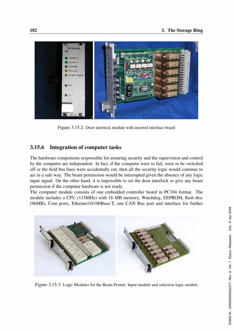
182 3. The Storage Ring
Figure 3.15.2: Door interlock module with inserted interface board
3.15.6 Integration of computer tasks
The hardware components responsible for ensuring security and the supervision and controlby the computer are independent. In fact, if the computer were to fail, were to be switchedoff or the field bus lines were accidentally cut, then all the security logic would continue toact in a safe way. The beam permission would be interrupted given the absence of any logicinput signal. On the other hand, it is impossible to set the door interlock or give any beampermission if the computer hardware is not ready.The computer module consists of one embedded controller board in PC104 format. Themodule includes a CPU (133MHz) with 16 MB memory, Watchdog, EEPROM, flash disc(96MB), Com ports, Ethernet10/100Base-T, one CAN Bus port and interface for further
Figure 3.15.3: Logic Modules for the Beam Permit: Input module and selection logic module
ED
MS
Nr.:
D00
0000
0082
2371
Rev
: A V
er: 1
Sta
tus:
Rel
ease
d -
Dat
.: 8.
Apr
200
8

3.15. The Personal Protection Interlock System 183
plugged interface boards. Here two isolated double CAN Bus boards and one module withfour isolated RS232 / RS422 (switchable) ports are used. All these boards are combined intoone module with the width of 21 units. (see Fig. 3.15.4)
The operating system is ELinOS , a special Linux OS for embedded systems configurablee.g. to be booted from flash disc, which is used also for event logging. There are runningseveral tasks for communication with the control system of the accelerators, the door inter-lock, permission logic, video controller, p.a. system etc. Not only the door interlock itselfbut some components near each door, including displays mounted on the door (e.g. DoorInterlock set , Radiation, Prohibited area), the magnet holding the door shut, warning lampsetc. will be controlled by the computer. So near each door a box, the CAN Terminal Box(see Fig. 3.15.5), is installed, which is connected to the computer by the CAN Bus. This busmay be as long as one km or more.Using this technique a new beam permission interlock has been developed realizing improv-ing security by a combination of relays and computer. It is planned to use the new technology
Figure 3.15.4: Computer module with interface boards
Figure 3.15.5: CAN Terminal Box and some internal components
ED
MS
Nr.:
D00
0000
0082
2371
Rev
: A V
er: 1
Sta
tus:
Rel
ease
d -
Dat
.: 8.
Apr
200
8

184 3. The Storage Ring
for the complete interlock system of PETRA III. This includes components of the acceleratortunnel as well as of the photon beamline experiments and the interconnection to the injectingaccelerator, the synchrotron DESY II. Further development work for the application of thesystem at the user controlled experimental areas has to be done.
ED
MS
Nr.:
D00
0000
0082
2371
Rev
: A V
er: 1
Sta
tus:
Rel
ease
d -
Dat
.: 8.
Apr
200
8
3.16. Injector 185
3.16 Injector
3.16.1 Linac 2/PIA upgrade and modifications for PETRA III3.16.1.1 Description of the components
The Linac 2 is the first accelerator in DESY’s e−/e+ accelerator chain. It delivers either450 MeV electrons or positrons of about the same energy for the injection into the PositronIntensity Accumulator (PIA), which is a small storage ring of 28.8 m circumference. Theaccelerator is operated with 50 Hz repetition rate and delivers 50 ns, 10 mA, ∆E/E ≈ 1 %bunch trains with a bunch to bunch distance reflecting the linac’s RF operating frequencyof 2.998 GHz. The electron beam’s time/current structure differs slightly: 20 ns, 50 mA,∆E/E ≈ 0.27 %
The accelerator consists of a 150 keV electron source and two groups of 5.2 m long acceler-ator sections separated by the conversion target for positron production. The total length isapproximately 75 m. Many of the components have been renewed during the last years. Partof the infrastructure is still from the linacs commissioned in the late 1960s.
The injector is based on a thermionic gun with a specially prepared cathode of 28 cm2.The cathode is heated by electron bombardment (3 kV, 400 mA). The 150 kV gun voltageis shaped in a pulse forming network. The produced electron beam structure is: 150 keV,6 A, 30µs long pulses with 50 Hz repetition rate. The gun is then followed by a chopper/ pre-buncher combination which delivers either 2–3 A (positron mode) or 50 mA (electronmode) in pulses of a few 10 ns. In 1999 the complete vacuum system has been rebuilt inorder to allow for a quick cathode exchange. All gold wire sealing gaskets were replaced bystandard Conflat type gaskets. Chopper and pre-buncher were renewed. New beam opticsallows for higher electron current transmission from the gun into the first accelerator section.
The accelerator sections are 5.2 m long traveling wave units operated in the 2π/3 mode at2.998 GHz. The filling time is 0.74µs, the group velocity varies from 3.5 % down to 1.3% ofthe speed of light. The typical accelerating gradient is 17 MV/m, corresponding to 100 MWafter SLED pulse compression. The first group of accelerator sections consists of 5 units anddelivers up to 450 MeV for positron production. The second group of sections has 5 plus 2units. The additional two are used to optimize the beam energy by opposed phase detuning.Between 1999 and 2003 all 12 sections were replaced using a new design in which the water-cooling tubes have no soldered connections inside the vacuum anymore. The structures weredesigned, built and commissioned at DESY. The production was successful so that the tech-nology could be transferred to industry. Identical accelerator sections are now used at otheraccelerators.
Each accelerator section is driven by its own klystron (type Thales TV 2002 DoD) and modu-lator. The typical klystron lifetime of 25,000 hours together with the operation time per yearleads to a replacement of approximately 4 klystrons per year. The driving RF modulatorswere all renewed between 2001 and 2003. They got a complete new wiring, new chargingpower supplies, and new controls. Beside the housing the pulse forming network was kept.
The positron conversion between accelerator sections 5 and 6 is based on a 7 mm thick Tung-
ED
MS
Nr.:
D00
0000
0082
2371
Rev
: A V
er: 1
Sta
tus:
Rel
ease
d -
Dat
.: 8.
Apr
200
8
186 3. The Storage Ring
sten target which is followed by a 1.8 T solenoid (3 kA, 10µs, 50 Hz, water cooled). Twotargets are available without replacing the converter unit.Each of the two targets is 17 mm in diameter and has a 5 mm orifice for e− operation, i.e. theelectrons are passing the conversion target without hitting it, using steering coils. Althoughno problem occurred during the last 8 years, the target unit was replaced together with theneighboring accelerator sections in 2003.
The Positron Intensity Accumulator PIA is operated at 450 MeV energy and accumulatestypically 1010 positrons for the injection into the DESY II storage ring. At present theejection takes place with either 6.25 Hz (DORIS mode) or half that frequency, i.e. 3.125 Hz(PETRA mode). The Linac 2 delivers 20 ns long bunch trains.In PIA a 10.4 MHz as well as a 125 MHz is used to produce the bunch time structure neededfor the injection into DESY II. The 10.4 MHz RF system was replaced beginning of 2001and the old transmitter was reconstructed accordingly. The 125 MHz cavity still needs to bereplaced by the new one which was commissioned independent of the PIA operation in fall2003. Installation is expected for the next shutdown.
3.16.1.2 Required modifications
Until today the Linac 2 as well as PIA are used to produce beam for either DORIS, PETRA,or HERA. The required operation time per day is of the order of hours. The consequence isthat simple repair or needed maintenance can often be done between two subsequent runs.Water leaks or aged cables can be replaced whenever needed. For the planned top-up opera-tion of PETRA III a careful check of all components is required. In the following a completelist of action items is given.
The electron gun needs either a renewal of the modulator or a complete new design. Themodifications of the modulator will be similar to the reconstruction of the modulators driv-ing the accelerator section.
The alternative is a completely new design. A motivation to consider this is the fact that theceramic used for the 150 kV isolation separates the beam line vacuum from the oil surround-ing all the back parts of the gun. At present a study is under preparation which compares theused gun with the much more common triode design. The effort for the modulator modifi-cations is well known. A new gun design requires additional resources in terms of FTE andmoney. Some spare accelerator sections are needed. They must be conditioned and storedunder vacuum in order to allow for a quick exchange. Four of these sections are underway.During the operation of the modulators the lifetime of the thyratrons as well as their reservoirvoltage needs attention. For PETRA III operation the thyratrons will be replaced by a newlong living type which presently is under test. The adjustment of the thyratron voltage willbe possible without switching off and opening the modulator.
As long as positrons are foreseen for the operation of PETRA III the quick exchange of thepositron converter in case of problems (vacuum or water leak) is a problem. After turningdown the linac, about 4 weeks decay time are needed before technicians can access the
ED
MS
Nr.:
D00
0000
0082
2371
Rev
: A V
er: 1
Sta
tus:
Rel
ease
d -
Dat
.: 8.
Apr
200
8
3.16. Injector 187
components. Therefore it is necessary to design a new conversion target which avoids allsoldering between vacuum and water cooling. The new design could have a non-movabletarget inside a ceramic cylinder and the focusing solenoid outside the vacuum system. Locallead shielding could be part of the converter unit. The risk of vacuum problems would beclearly reduced. Due to the local shielding the exchange should be possible in a much shortertime.Systems like water pump stations, magnet power supplies, magnets, controls must be stateof the art. Spares must be available wherever longer repair time is estimated. This clearlyimproves the reliability as well as availability of the Linac 2 and PIA.
3.16.1.3 Needed resources
The resources needed in terms of money and FTE were identified. With an uncertainty of30 % the Linac 2/PIA modifications need an additional amount of approximately twice theyearly operations budget. The funding profile is known. With respect to the needed FTE theassumption is that most of the modifications could be done together or instead of the anyhowrequired maintenance and preventions. The re-design of the positron converter and a newgun / injector design will require additional person power.
3.16.2 DESY IIAt present, the DESY II synchrotron accelerates single bunches of positrons or electronsfrom an injection energy of 450 MeV to either 4.5 GeV, for transfer to DORIS, or to 7 GeVfor injection into PETRA II and for three internal test beam experiments. The 5 families ofsynchrotron magnets are powered using resonant circuits, which cycle at 12.5 Hz and includeregulation hardware to ensure accurate tracking.
The injection frequency finj of DESY II is determined by the accumulation time in the up-stream intensity accumulator (PIA). Injection nominally takes place at 6.25 Hz in DORISmode or 3.125 Hz in PETRA mode, for which high single bunch intensities (Isb) of up to3 × 1010 particles per bunch (ppb) are accumulated with a 50 Hz injection rate in PIA. Theflexible timing system would allow the accumulation time in PIA to be shortened to matchthe 12.5 Hz repetition frequency of DESY II thus allowing maximally efficient injection intoPETRA III with single bunch intensities in the range of Isb = (1...5)× 109 ppb. Maintainingthe currently used intervals for accumulation in PIA, Isb = (0.1...1.5) × 1010 ppb, finj =6.25 Hz, and Isb = (0.1...3.5)×1010 ppb with finj = 3.125 Hz may be easily accommodated.
Within a measurement accuracy of a few percent, the injection and extraction efficienciesinto and from DESY II are ∼ 100 %. Transmission through DESY II typically exceeds 90 %.
The theoretical horizontal beam emittance at extraction from DESY II is presently 860 nmradat 7 GeV for PETRA II and is 325 nmrad at an extraction energy of 6 GeV for PETRA III.The reduction in emittance results from the lower energy and deactivation of the presentlyused frequency modulation, which is used at the expense of increased horizontal emittanceto detune the cavities to compensate for beam loading at high beam currents. While not
ED
MS
Nr.:
D00
0000
0082
2371
Rev
: A V
er: 1
Sta
tus:
Rel
ease
d -
Dat
.: 8.
Apr
200
8
188 3. The Storage Ring
considered in the design concept for PETRA III, further reductions in emittance might beachievable using a higher phase advance per cell in DESY II and/or by retuning the cavitiesand invoking a frequency shift during the acceleration cycle. The implications of these op-tions are under study.
The high level of performance in terms of delivered beam and reliability of the DESY IIsynchrotron is the result of continual refurbishment and modernization of the acceleratorsubsystems. TheDESY II and DESY III synchrotrons contribute only a few percent of the overall down timeof the existing accelerator facilities (including HERA). In the future, to assist in identify-ing potential weaknesses, software improvements will be made to detect out-of-tolerancehardware errors and to better automate logging of component failures. Also the RF cavitycontrol systems will be modernized and the 10 kV power transformer station will be renewed.Prior to commissioning of PETRA III, the sections of the vacuum chambers common to theDESY II and DESY III accelerators will be separated to decouple the two subsystems.
To ensure reliable and optimum performance of DESY II over the first decade of PETRA IIIoperation, three major upgrades have been identified (see Sec. 3.13 and 3.12): renewal of thewater cooling systems, replacement of the RF transmitter power feed systems, and replace-ment of the main synchrotron magnet power supplies. Smaller improvements foreseen forthe long-term include upgrading of the low voltage switching systems, replacement of thecorrection magnet power supplies. Minor improvements aimed at higher reliability of theRF systems, and the design and construction of a high dynamic range current monitor fordetection of unwanted satellite bunches are planned.
While PETRA III is being commissioned and/or in operation, it is foreseen that DESY IIcontinues to serve as an injector for DORIS. With PETRA III injecting in top-up mode, thepresently used option of independent setting of the DESY II extraction energy may not becompatible. In this case, ejection to DORIS will take place during the energy ramp of a6 GeV PETRA III cycle as has been demonstrated to be feasible in the past.
Preliminary tests of ’top-up’ mode injection, as foreseen for PETRA, have been performedin DORIS. Automated transfers at fixed bunch current have yielded so far a uniformity intotal current of 0.5 %.
ED
MS
Nr.:
D00
0000
0082
2371
Rev
: A V
er: 1
Sta
tus:
Rel
ease
d -
Dat
.: 8.
Apr
200
8
Chapter 4
Radiation Sources
4.1 Insertion Devices
4.1.1 IntroductionThe new octant of PETRA III houses 8 straight sections, each providing space for a 5 mlong insertion device. As discussed in Sec. 3.2.1 several of these straights will be split intotwo sections for 2 m long devices with a 5 mrad bent in-between. This scheme of cantedundulators, which feed different experimental beamlines and can be operated independentlyfrom each other, has successfully been installed also at other facilities (Elleaume, 2002;P. Den Hartog, 2003) in order to enlarge the number of independent undulators within onestraight section. At present, 4 straights are proposed to be equipped with altogether eight 2 minsertion devices (IDs). Furthermore, a long straight section upstream of the new PETRA IIIarc is available to place a 20 m long undulator. In total there will be 13 undulator beamlines inthe new arc. Three different planar hybrid undulators and three special devices are planned,namely a helical undulator of APPLE2 type, a quasi-periodic undulator and a long device forthe 20 m straight.The radiation characteristics of undulators and wigglers have been described in detail in nu-merous publications (e.g. Alferov, Bashmakov & Bessonov, 1974; Walker, 1993; Kim, 1995;Onuki & Elleaume, 2003). Here, only a few fundamental properties and approximations arebriefly summarized for easier assessment of the proposed insertion devices.The peak field B0 in a periodic magnet structure with period length λU strongly depends onthe magnetic gap g and can be approximated by (Elleaume, Chavanne & Faatz, 2000)
B0 = a · exp
[b
(g
λU
)+ c
(g
λU
)2]
(4.1.1)
with the parameters a, b, c depending on the applied magnet technology (e.g. a= 3.69, b =−5.07, c=1.52 for hybrid devices with vanadium-permandur pole pieces). The deflectionparameter K is a measure for the interaction strength of the electron beam with the magneticfield B0 of the insertion device and can be written in practical units as
K = 0.934 · λU [cm] ·B0 [T ]. (4.1.2)
ED
MS
Nr.:
D00
0000
0082
2371
Rev
: A V
er: 1
Sta
tus:
Rel
ease
d -
Dat
.: 8.
Apr
200
8

190 4. Radiation Sources
K/γ describes the maximum deflection angle of the electron, with γ = E/(me·c2). The max-imum transverse beam excursion for the PETRA III undulators is approximately x0∼2µm.The wavelength and spectral width of the undulator harmonics n is given by
λn =λU
2nγ2
(1 +
K2
2+ θ2γ2
)or En[keV ] =
0.95 · n · E [GeV ]2
(1 +K2/2 + θ2γ2)λU [cm](4.1.3)
∆λ
λ=
∆E
E≈ 1
nN(4.1.4)
where θ is the observation angle of the radiation and N is the number of undulator periods.On the other hand, the continuous spectrum of wiggler radiation (K1) is characterized bythe critical energy
Ec = 0.665 · E [GeV ]2 ·B0 [T ] (4.1.5)
The total radiation power generated by an insertion device with length L is
Ptot [kW ] = 0.633 · E [GeV ]2 ·B0 [T ]2 · L [m] · I [mA] (4.1.6)
The spectral characteristics of undulators is often described by the brilliance, i.e. the flux Fn
within the central cone of the n-th harmonic normalized to the 4-dimensional phase spacevolume
Bn =Fn
4π2σTxσTyσTx′σTy′(4.1.7)
The flux integrated over the central cone of the n-th harmonics can be written as
Fn [ph/s/0.1%BW ] = 1.43 · 1014 ·N · I [A] ·Qn(K) (4.1.8)
whereQn(K) ranging from 0 to 1 represents a sum over Bessel functions taking into accountthe angular characteristics of the emitted radiation.
The quantities σTx and σTx′ denote the total RMS source size and divergence, and are aconvolution of the finite electron beam size (σx, σx′) and the natural photon beam size (σr,σr′) caused by a single electron.
σTx =√σ2
x + σ2r ; σx =
√εxβx ; σr =
√2λL
4π
σTx′ =√σ2
x′ + σ2r′ ; σx′ =
√εxβx
; σr′ =
√λ
2L(4.1.9)
Different definitions of σr′ and σr as a Gaussian approximation of the line shape functionare used in the literature; the ones used here follow Kim (1995) and others. In low emittancestorage rings, two limiting cases of brilliance usually appear: In the VUV energy regime,the radiation is mostly diffraction-limited (B → ∼Fn/λ
2) while for higher X-ray energiesthe photon beam size is defined by the electron beam emittance (B → ∼Fn/εxεy). Also,the brilliance definition does not include the energy spread of the electron beam which is
ED
MS
Nr.:
D00
0000
0082
2371
Rev
: A V
er: 1
Sta
tus:
Rel
ease
d -
Dat
.: 8.
Apr
200
8

4.1. Insertion Devices 191
typically in the order of ∼10−3 in a storage ring and may lead to additional broadeningof harmonics, i.e. brilliance degradation, for very long undulators. Apart from the factthat experimentally only the integrated flux Fn or the angular flux density dFn/dΩ can bemeasured, the brilliance describes the figure of merit of a radiation source as it includesimportant properties like high flux, small source size and divergence, and small bandwidth.Depending on the sort of experimental station, the brilliance or the integrated flux through acertain aperture describe the radiation requirements more appropriate.All calculations have been done with the codes SPECTRA (Tanaka & Kitamura, 2001) orSRW (Chubar & Elleaume, 1998) using the nominal operation parameters for PETRA III(Tab. 3.1.1) and β functions according to Tab. 2.2.2.
Figure 4.1.1: Effect of undulator length and β-function on a) the brilliance of a standard undulatorand b) the partial flux through an aperture of 1×1 mm2 at 40 m source distance.
The electron optics is very flexible in the new arc of PETRA III. The lattice is of Double BentAchromat (DBA)-type with one dispersion-free section per cell for installation of undulators(Sec. 3.2.1). The twiss parameters of each DBA cell can be adjusted in two complementarysettings according to the requirements of the particular experimental station. Fig. 4.1.1 com-pares brilliance and flux through an aperture of short and long undulators for low and highβ optics at nominal operation parameters. Within 20%, the brilliance is the same for bothoptics as it is largely dominated by the electron phase space. The partial flux increase withundulator length is roughly linear for energies above 20 keV, only towards low energies theincrease is up to a factor ∼3.6, i.e. ∼N1.4, mostly due to the natural divergence σr′ ∼ 1/
√L
dominating the total vertical divergence. Typical source size values are given in Tab. 2.2.2.
4.1.2 Design and manufacturing issuesThe minimum magnetic gap has been deduced from the vertical acceptance of 2.2 mm mradintended for the undulator locations. This value corresponds to a minimum vertical innerhalf aperture of 3.5 mm equivalent to about 10·σy of the injected beam which has been con-firmed by tracking calculations (Sec. 3.2.1). Considering 1 mm wall thickness of the vacuumchamber and allowing for 0.5 mm tolerances, a minimum magnetic gap of 9.5 mm results forall IDs within the new arc. This value is considered for all the planar hybrid devices. For the
ED
MS
Nr.:
D00
0000
0082
2371
Rev
: A V
er: 1
Sta
tus:
Rel
ease
d -
Dat
.: 8.
Apr
200
8
192 4. Radiation Sources
soft X-ray APPLE2 undulator as a pure permanent magnet device, a minimum gap of 10 mmhas been chosen to provide space for the placement of shims.
Regarding the magnetic field quality, the requirements for the PETRA undulators are strongerto some extent than those of today’s 3rd generation sources as the expected gain in emittancehas to be preserved in the insertion devices in order to accomplish the expected brilliance.Tolerance limits for the residual field integrals and the integrated multipole errors of theundulators can be assumed to be the same as for the dipole magnets around the ring. A spec-ification for a transverse good-field region has been defined to kx=0.1 in a generalized case(Sec. 3.2.2) and will be reassessed by tracking calculations in the detailed design phase. Thephase error plays an important role for storage ring undulators as it critically determines thequality of the higher undulator harmonics. It has to be kept as small as possible to maintainthe spectral purity and intensity of the harmonics which become more and more sensitive tophase jitter. Today’s state of the art technology achieves values down to a few degrees.
The permanent magnet technology has been very well elaborated in the past. Pure perma-nent magnet and hybrid devices are equally established, the latter providing slightly higherfields but requiring more effort in magnetic design and field error correction. While NdFeBmagnets are used in conventional devices for the most part due to their large remanence field,SmCo material is usually applied where higher radiation exposure otherwise might possiblylead to a local demagnetization damage, e.g. in small gap in-vacuum undulators.
Sufficient radiation protection of the undulator structures is crucial for a long-term steadystate operation of a user facility as any demagnetization spoils the radiation characteristicsin an undefined way. This is especially important since top-up operation as a key featurerequires injection at closed gap. It is therefore planned to install a dedicated collimator inthe storage ring which adequately confines the injected beam (Sec. 3.2.1).
At present, three different types of planar hybrid devices are considered with two differentlengths together with a quasi-periodic undulator as a modified fourth type. Standardizationof the mechanical support frame, the magnet girders, the gap drive and motion control systemare a mandatory design issue. Design studies for a mechanical support structure and magnetgirders have already begun. Also here, requirements are somewhat more demanding in termsof stiffness and gap positioning accuracy than for today’s facilities in order to cope withthe expected emittance. Specifications can be reached with today’s technology. The sameholds for the motion control system. All these activities are strongly connected to paralleldevelopments for the XFEL project and will mutually benefit from each other.
For the construction and manufacturing of the proposed APPLE2 undulator (Sec. 4.1.6) andan in-vacuum undulator possibly desired for the long 20 m straight section (Sec. 4.1.8), nodetailed experience is available in the laboratory at present. Both technologies have beenwell established in recent years so that both insertion device types are available commerciallymeanwhile. It is planned to design these devices in close collaboration with well-experiencedother laboratories, to assemble them in industry for the most part, and to measure and shimthese undulators at DESY.
ED
MS
Nr.:
D00
0000
0082
2371
Rev
: A V
er: 1
Sta
tus:
Rel
ease
d -
Dat
.: 8.
Apr
200
8
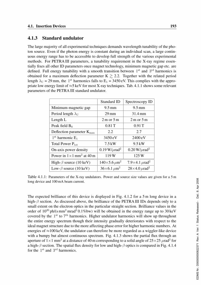
4.1. Insertion Devices 193
4.1.3 Standard undulator
The large majority of all experimental techniques demands wavelength tunability of the pho-ton source. Even if the photon energy is constant during an individual scan, a large contin-uous energy range has to be accessible to develop full strength of the various experimentalmethods. For PETRA III parameters, a tunability requirement in the X-ray regime essen-tially fixes all other ID parameters once magnet technology, minimum magnetic gap etc. aredefined. Full energy tunability with a smooth transition between 1st and 3rd harmonics isobtained for a maximum deflection parameter K & 2.2. Together with the related periodlength λU = 29 mm, the 1st harmonics falls to E1 = 3450 eV. This complies with the appro-priate low energy limit of≈5 keV for most X-ray techniques. Tab. 4.1.1 shows some relevantparameters of the PETRA III standard undulator.
Standard ID Spectroscopy IDMinimum magnetic gap 9.5 mm 9.5 mmPeriod length λU 29 mm 31.4 mmLength L 2 m or 5 m 2 m or 5 mPeak field B0 0.81 T 0.91 TDeflection parameter Kmax 2.2 2.71st harmonic E1 3450 eV 2400 eVTotal Power Ptot 7.5 kW 9.5 kWOn-axis power density 0.19 W/µrad2 0.20 W/µrad2
Power in 1×1 mm2 at 40 m 119 W 125 W
High-β source (10 keV) 140×5.6µm2 7.9×4.1µrad2
Low-β source (10 keV) 36×6.1µm2 28×4.0µrad2
Table 4.1.1: Parameters of the X-ray undulators. Power and source size values are given for a 5 mlong device and 100 mA beam current.
The expected brilliance of this device is displayed in Fig. 4.1.2 for a 5 m long device in ahigh-β section. As discussed above, the brilliance of the PETRA III IDs depends only to asmall extent on the electron optics in the particular straight section. Brilliance values in theorder of 1020 ph/(s mm2 mrad2 0.1%bw) will be obtained in the energy range up to 30 keVcovered by the 1st to 7th harmonics. Higher undulator harmonics will show up throughoutthe entire energy spectrum though their intensity gradually deteriorates with respect to theideal magnet structure due to the more affecting phase error for higher harmonic numbers. Atenergies of ≈100 keV, the undulator can therefore be more regarded as a wiggler-like devicewith a bumpy but almost continuous spectrum. Fig. 4.1.3 shows the partial flux through anaperture of 1×1 mm2 at a distance of 40 m corresponding to a solid angle of 25×25 µrad2 fora high-β section. The spatial flux density for low and high-β optics is compared in Fig. 4.1.4for the 1st and 3rd harmonics.
ED
MS
Nr.:
D00
0000
0082
2371
Rev
: A V
er: 1
Sta
tus:
Rel
ease
d -
Dat
.: 8.
Apr
200
8
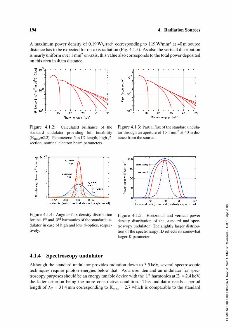
194 4. Radiation Sources
A maximum power density of 0.19 W/µrad2 corresponding to 119 W/mm2 at 40 m sourcedistance has to be expected for on-axis radiation (Fig. 4.1.5). As also the vertical distributionis nearly uniform over 1 mm2 on-axis, this value also corresponds to the total power depositedon this area in 40 m distance.
Figure 4.1.2: Calculated brilliance of thestandard undulator providing full tunability(Kmax=2.2). Parameters: 5 m ID length, high β-section, nominal electron beam parameters.
Figure 4.1.3: Partial flux of the standard undula-tor through an aperture of 1×1 mm2 at 40 m dis-tance from the source.
Figure 4.1.4: Angular flux density distributionfor the 1st and 3rd harmonics of the standard un-dulator in case of high and low β-optics, respec-tively.
Figure 4.1.5: Horizontal and vertical powerdensity distribution of the standard and spec-troscopy undulator. The slightly larger distribu-tion of the spectroscopy ID reflects its somewhatlarger K parameter.
4.1.4 Spectroscopy undulatorAlthough the standard undulator provides radiation down to 3.5 keV, several spectroscopictechniques require photon energies below that. As a user demand an undulator for spec-troscopy purposes should be an energy tunable device with the 1st harmonics at E1 = 2.4 keV,the latter criterion being the more constrictive condition. This undulator needs a periodlength of λU = 31.4 mm corresponding to Kmax = 2.7 which is comparable to the standard
ED
MS
Nr.:
D00
0000
0082
2371
Rev
: A V
er: 1
Sta
tus:
Rel
ease
d -
Dat
.: 8.
Apr
200
8
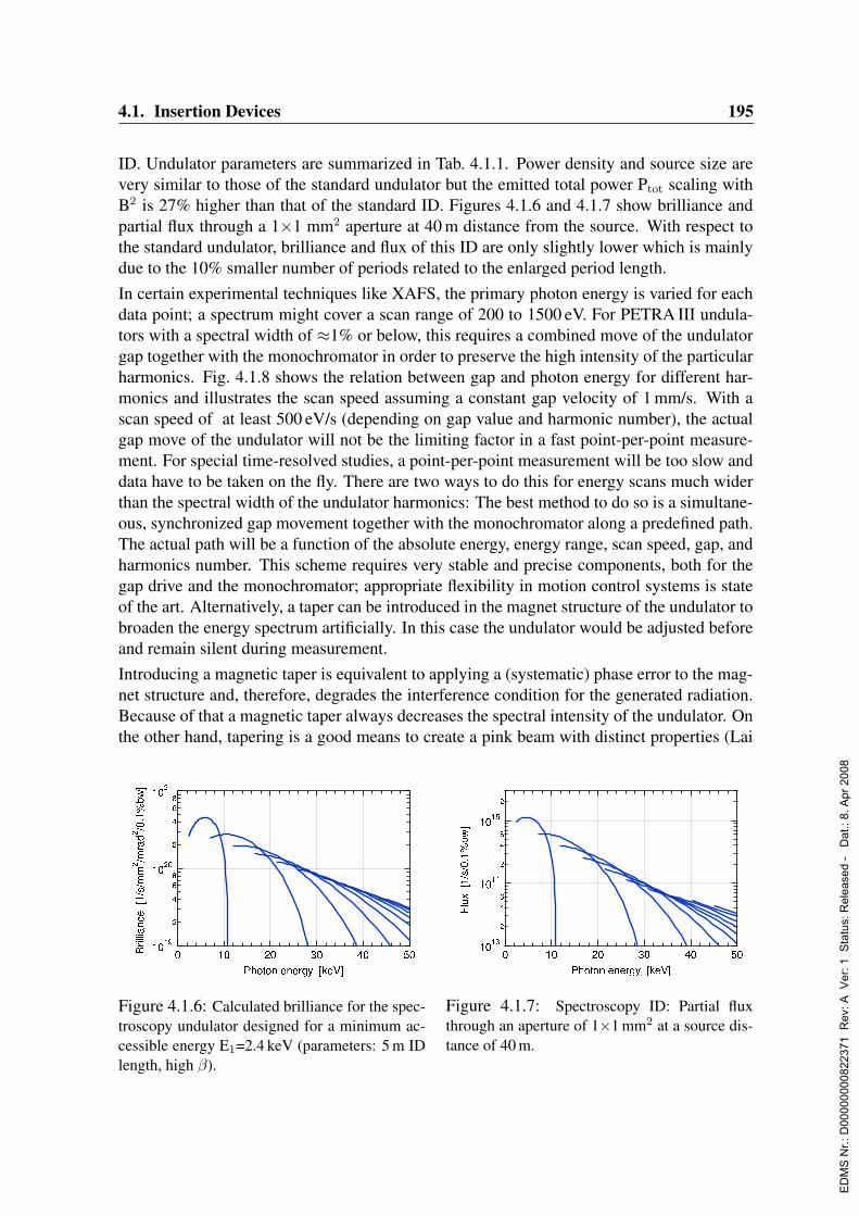
4.1. Insertion Devices 195
ID. Undulator parameters are summarized in Tab. 4.1.1. Power density and source size arevery similar to those of the standard undulator but the emitted total power Ptot scaling withB2 is 27% higher than that of the standard ID. Figures 4.1.6 and 4.1.7 show brilliance andpartial flux through a 1×1 mm2 aperture at 40 m distance from the source. With respect tothe standard undulator, brilliance and flux of this ID are only slightly lower which is mainlydue to the 10% smaller number of periods related to the enlarged period length.In certain experimental techniques like XAFS, the primary photon energy is varied for eachdata point; a spectrum might cover a scan range of 200 to 1500 eV. For PETRA III undula-tors with a spectral width of ≈1% or below, this requires a combined move of the undulatorgap together with the monochromator in order to preserve the high intensity of the particularharmonics. Fig. 4.1.8 shows the relation between gap and photon energy for different har-monics and illustrates the scan speed assuming a constant gap velocity of 1 mm/s. With ascan speed of at least 500 eV/s (depending on gap value and harmonic number), the actualgap move of the undulator will not be the limiting factor in a fast point-per-point measure-ment. For special time-resolved studies, a point-per-point measurement will be too slow anddata have to be taken on the fly. There are two ways to do this for energy scans much widerthan the spectral width of the undulator harmonics: The best method to do so is a simultane-ous, synchronized gap movement together with the monochromator along a predefined path.The actual path will be a function of the absolute energy, energy range, scan speed, gap, andharmonics number. This scheme requires very stable and precise components, both for thegap drive and the monochromator; appropriate flexibility in motion control systems is stateof the art. Alternatively, a taper can be introduced in the magnet structure of the undulator tobroaden the energy spectrum artificially. In this case the undulator would be adjusted beforeand remain silent during measurement.Introducing a magnetic taper is equivalent to applying a (systematic) phase error to the mag-net structure and, therefore, degrades the interference condition for the generated radiation.Because of that a magnetic taper always decreases the spectral intensity of the undulator. Onthe other hand, tapering is a good means to create a pink beam with distinct properties (Lai
Figure 4.1.6: Calculated brilliance for the spec-troscopy undulator designed for a minimum ac-cessible energy E1=2.4 keV (parameters: 5 m IDlength, high β).
Figure 4.1.7: Spectroscopy ID: Partial fluxthrough an aperture of 1×1 mm2 at a source dis-tance of 40 m.
ED
MS
Nr.:
D00
0000
0082
2371
Rev
: A V
er: 1
Sta
tus:
Rel
ease
d -
Dat
.: 8.
Apr
200
8
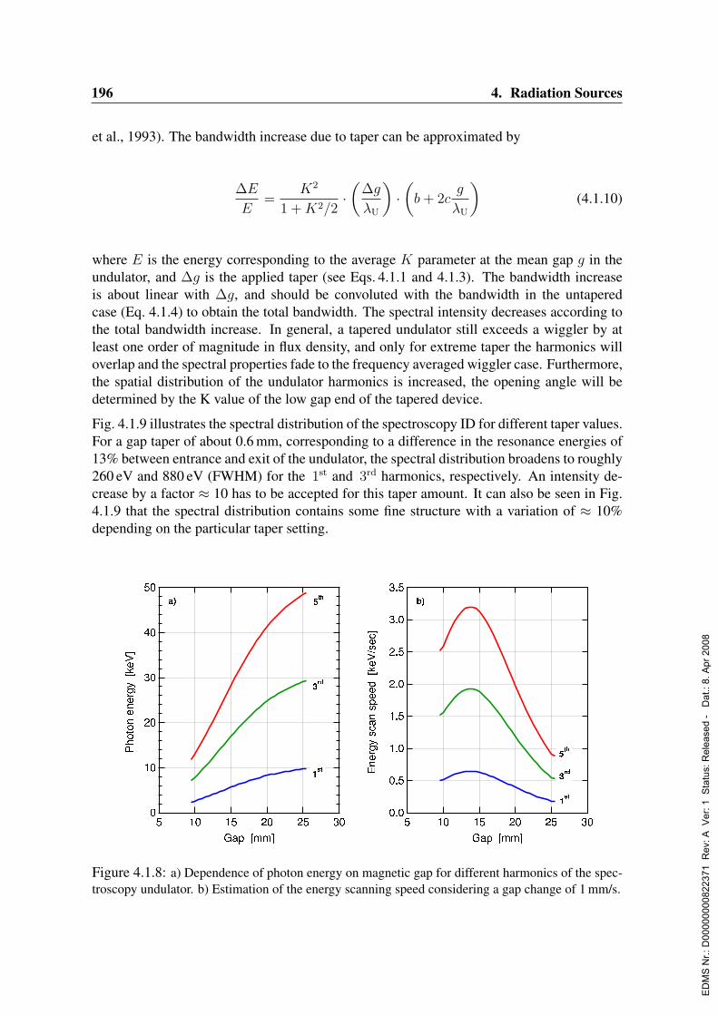
196 4. Radiation Sources
et al., 1993). The bandwidth increase due to taper can be approximated by
∆E
E=
K2
1 +K2/2·(
∆g
λU
)·(b+ 2c
g
λU
)(4.1.10)
where E is the energy corresponding to the average K parameter at the mean gap g in theundulator, and ∆g is the applied taper (see Eqs. 4.1.1 and 4.1.3). The bandwidth increaseis about linear with ∆g, and should be convoluted with the bandwidth in the untaperedcase (Eq. 4.1.4) to obtain the total bandwidth. The spectral intensity decreases according tothe total bandwidth increase. In general, a tapered undulator still exceeds a wiggler by atleast one order of magnitude in flux density, and only for extreme taper the harmonics willoverlap and the spectral properties fade to the frequency averaged wiggler case. Furthermore,the spatial distribution of the undulator harmonics is increased, the opening angle will bedetermined by the K value of the low gap end of the tapered device.
Fig. 4.1.9 illustrates the spectral distribution of the spectroscopy ID for different taper values.For a gap taper of about 0.6 mm, corresponding to a difference in the resonance energies of13% between entrance and exit of the undulator, the spectral distribution broadens to roughly260 eV and 880 eV (FWHM) for the 1st and 3rd harmonics, respectively. An intensity de-crease by a factor ≈ 10 has to be accepted for this taper amount. It can also be seen in Fig.4.1.9 that the spectral distribution contains some fine structure with a variation of ≈ 10%depending on the particular taper setting.
Figure 4.1.8: a) Dependence of photon energy on magnetic gap for different harmonics of the spec-troscopy undulator. b) Estimation of the energy scanning speed considering a gap change of 1 mm/s.
ED
MS
Nr.:
D00
0000
0082
2371
Rev
: A V
er: 1
Sta
tus:
Rel
ease
d -
Dat
.: 8.
Apr
200
8

4.1. Insertion Devices 197
Figure 4.1.9: Spectral flux distribution through 1×1 mm2 at 40 m source distance for the spec-troscopy undulator at different taper settings (0, 60, 150, 300, 600 µm). The line width of 1.1% (0.7%)at the 1st (5th) harmonic in the non-tapered case (red) broadens to about 11% (13%) FWHM for ataper of 0.6 mm (black) corresponding to 260 eV (1500 eV). At the same time, the intensity drops byroughly a factor of 10.
4.1.5 Hard X-ray source
Hard X-ray radiation will be required at PETRA III for various material science applications.The parameter choice for a device optimized for energies of 100 keV and above also dependson the desired beam spot size on the sample. Clearly, a strong wiggler provides the highesttotal flux, however, it radiates into a huge solid angle which is only of little use for thedownstream X-ray optics. Moreover, such a device is not really appropriate for a storagering trimmed towards lowest emittance. Instead, the insertion device with a given length hasto be optimized in terms of maximum flux density through a useful aperture. Fig. 4.1.10compares the angular flux density at an energy of 100 keV for permanent magnet deviceswith different period length. A maximum flux density of 7·1015 ph/(s mrad2 0.1% BW) canbe obtained for this particular photon energy with a moderate wiggler with 49 mm periodlength and K = 7.7 (Tab. 4.1.2).Fig. 4.1.11 shows the flux through an aperture of 1×1 mm2 at 40 m source distance as func-tion of energy for different insertion devices under consideration. This comparison is rep-resentative for this particular aperture, proportions do change especially for larger apertures(compare Fig. 4.1.10). Here, the standard undulator and the spectroscopy ID are treated aswigglers with their maximum K parameter as the high harmonics at energies above≈70 keVlargely overlap and even a small residual phase error will smear the spectral structure for the
ED
MS
Nr.:
D00
0000
0082
2371
Rev
: A V
er: 1
Sta
tus:
Rel
ease
d -
Dat
.: 8.
Apr
200
8

198 4. Radiation Sources
Hard X-ray IDMinimum magnetic gap 9.5 mmPeriod length λU 49 mmLength L 2 m or 5 mPeak field B0 1.68 TDeflection Parameter Kmax 7.7Critical energy Ec 40.2 keVTotal Power Ptot 32 kWOn-axis power density 0.24 W/µrad2
Power in 1×1 mm2 (L=40 m) 148 WBeam divergence at 100 keV 470×70µrad2
Table 4.1.2: Parameters of the hard X-ray source. Power values are given for a 5 m long device at100 mA beam current.
Figure 4.1.10: Angular distribution of the proposed hard X-ray device (λU=49 mm) at an energy of100 keV. For comparison, the flux density is also shown for the standard undulator, a dedicated shortperiod undulator, and a strong wiggler. For operation primarily at 100 keV, the two latter options areinadequate.
most part. On the other hand, a dedicated short period undulator with λU = 20 mm will haveits 9th harmonics at≈111 keV and will show clear undulator behavior. Such a device will betunable only at energies above 87.6 keV (7th harm.) but regarding an aperture of 1×1 mm2,
ED
MS
Nr.:
D00
0000
0082
2371
Rev
: A V
er: 1
Sta
tus:
Rel
ease
d -
Dat
.: 8.
Apr
200
8

4.1. Insertion Devices 199
Figure 4.1.11: Spectral flux through 1×1 mm2 at 40 m for the hard X-ray wiggler (λU=49 mm,K=7.7). Though a stronger wiggler would slightly excel the proposed device above 150 keV it wouldbe unfavorable due to power considerations. The performance of the standard and spectroscopy un-dulator in this energy range are shown for comparison (here, both devices are treated as wigglers).Finally, the spectral flux of the today’s PETRA II undulator is shown for a source distance of 100 m.
it will be superior to a wiggler only at energies below≈70 keV and cannot compete at higherenergies due to the rather low K parameter (0.87). The total emitted power is not more than≈2.5 kW.Considering a beam acceptance of 25×25µrad2, the optimum PETRA III device for energiesaround ≈100 keV and above is a wiggler with λU = 49 mm and Kmax = 7.7. It should benoticed that this hard X-ray device will even meet the performance of today’s PETRA IIundulator which largely benefits from the high electron energy (12 GeV) of this machine.
4.1.6 Variable polarization soft X-ray undulatorA soft X-ray beamline in the VUV regime providing circularly polarized radiation is a veryversatile instrument especially at storage rings operating at higher energies (Brookes et al.,1998; Saitoh, Nakatani & Matsushita, 1998). An undulator for this purpose covers the entireenergy range of experimental interest by the 1st harmonic which provides complete (100 %)circular polarization. At low energy storage rings devoted to the soft X-ray regime, energiesabove ≈800 eV can be accessed only by higher ( 3rd ) harmonics which do not exhibit fullcircular polarization. Instead, a trade-off has to be used between elliptical polarization andthe obtained flux. In the energy range above ∼5 keV, circularly polarized X-rays can beproduced very efficiently with maximum and constant polarization degree by means of aquarter wave plate (Lang, Srajer & Dejus, 1996) from a linearly polarized beam (Sec. 6.15).Because of strong absorption, however, this scheme does not work in the soft X-ray regime
ED
MS
Nr.:
D00
0000
0082
2371
Rev
: A V
er: 1
Sta
tus:
Rel
ease
d -
Dat
.: 8.
Apr
200
8

200 4. Radiation Sources
where the particular polarization has to be imprinted from the very first in the undulator.A momentous user demand for this soft X-ray undulator is the variability of polarization,i.e. both switching from left- to right-handed radiation and also tilting the linear polariza-tion vector from the horizontal to the vertical plane. Therefore, an APPLE2-type (AdvancedPlanar Polarized Light Emitter) undulator (Sasaki et al., 1993) is proposed which providesfull flexibility in this respect. In such a device the desired polarization is selected by a par-allel or antiparallel shift of the longitudinally separated magnet rows. For zero longitudinalshift, the APPLE2 provides horizontal linear polarization and resembles a usual planar purepermanent magnet undulator.A truly helical undulator has the peculiarity, that only the 1st harmonics radiation falls on-axis while all higher harmonics are emitted in rings. Because of that the on-axis powerdensity is drastically reduced which is very advantageous for the heat load-related propertiesof high performance optics. One possible option for this beamline could be to split theinsertion device into two 2 m undulator segments. Then, circularly polarized radiation withopposite helicity of the two IDs can be superimposed to generate linearly polarized radiationwith very little power on the optical elements. A phase shifter, which will be installed inbetween the segments to match the radiation of the two segments in the helical mode, canbe used in this linear superposition mode to adjust the declination angle of the polarizationvector from the horizontal to the vertical direction. This scheme has already been usedsuccessfully at other SR facilities (Bahrdt et al., 2001a). However, as a drawback of thismode the degree of linear polarization is reduced due to the electron energy spread, the beamemittance, and also the finite beamline acceptance.
Operation mode Shift Beff [T] Keff E1 [eV] Ptot [kW] dP/dΩ [kW/mrad2]Circular λU/4 1.10 6.5 246 11 0.14Horizontal linear 0 1.39 8.2 160 17 123Vertical linear λU/2 0.94 5.5 333 8.0 8245 linear λU/4 0.77 4.6 473 5.5 0.48
Table 4.1.3: Parameters of the soft X-ray APPLE2 undulator. ’Shift’ denotes the longitudinal dis-placement of the magnet rows. The device has a period length λU=63 mm and consists of two 2 mlong segments separated by an optical phase shifter.
The energy range of this APPLE undulator has been specified by the users to reach from thecarbon K-edge over the 3d L- to the rare earth M-edges, i.e. from ≈250 eV up to ≈2.3 keV.As known, the accessible energy range, in particular the 1st harmonics position, for a givenperiod length of the undulator depends on the longitudinal shift of the magnet rows and isdifferent in the various operation modes. The low energy limit should also be covered inthe helical mode to be able to apply the scheme of superimposed left and right polarizedradiation discussed above. The period length which results from these considerations isλU = 63 mm. This value is related to a minimum gap of 10 mm taking into account thatshims which have to be placed on the magnet structure need extra vertical space. Tab. 4.1.3summarizes the parameters for the different shift dependent operation modes. The lowest
ED
MS
Nr.:
D00
0000
0082
2371
Rev
: A V
er: 1
Sta
tus:
Rel
ease
d -
Dat
.: 8.
Apr
200
8
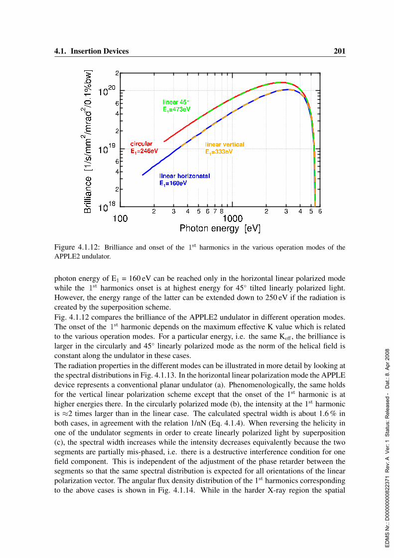
4.1. Insertion Devices 201
Figure 4.1.12: Brilliance and onset of the 1st harmonics in the various operation modes of theAPPLE2 undulator.
photon energy of E1 = 160 eV can be reached only in the horizontal linear polarized modewhile the 1st harmonics onset is at highest energy for 45 tilted linearly polarized light.However, the energy range of the latter can be extended down to 250 eV if the radiation iscreated by the superposition scheme.Fig. 4.1.12 compares the brilliance of the APPLE2 undulator in different operation modes.The onset of the 1st harmonic depends on the maximum effective K value which is relatedto the various operation modes. For a particular energy, i.e. the same Keff , the brilliance islarger in the circularly and 45 linearly polarized mode as the norm of the helical field isconstant along the undulator in these cases.The radiation properties in the different modes can be illustrated in more detail by looking atthe spectral distributions in Fig. 4.1.13. In the horizontal linear polarization mode the APPLEdevice represents a conventional planar undulator (a). Phenomenologically, the same holdsfor the vertical linear polarization scheme except that the onset of the 1st harmonic is athigher energies there. In the circularly polarized mode (b), the intensity at the 1st harmonicis ≈2 times larger than in the linear case. The calculated spectral width is about 1.6 % inboth cases, in agreement with the relation 1/nN (Eq. 4.1.4). When reversing the helicity inone of the undulator segments in order to create linearly polarized light by superposition(c), the spectral width increases while the intensity decreases equivalently because the twosegments are partially mis-phased, i.e. there is a destructive interference condition for onefield component. This is independent of the adjustment of the phase retarder between thesegments so that the same spectral distribution is expected for all orientations of the linearpolarization vector. The angular flux density distribution of the 1st harmonics correspondingto the above cases is shown in Fig. 4.1.14. While in the harder X-ray region the spatial
ED
MS
Nr.:
D00
0000
0082
2371
Rev
: A V
er: 1
Sta
tus:
Rel
ease
d -
Dat
.: 8.
Apr
200
8

202 4. Radiation Sources
Figure 4.1.13: APPLE2: Spectral brilliance distribution of the 1st harmonic at E1=246 eV for dif-ferent operation modes. In case (c) the horizontal linear polarized light is generated by superpositionof left and right circular polarized light from the two undulator segments.
Figure 4.1.14: Horizontal (solid) and vertical (dashed) flux density of the APPLE2 undulator atE1=246 eV for different operation modes (see Fig.4.1.13).
distribution of the central cone is elliptically, the beam footprint is almost circular in the VUVregion because it is limited in both directions by the natural divergence σr′ =
√λ/(2L). In
the planar linear (a) and in the circular mode (b) the central cone has an opening angle of≈70µrad (FWHM) which is very close to σr′ fully dominating the angular distribution. Inthe superimposed linear mode (c), however, the spatial distribution is considerably broadeneddue to the only partly phased magnetic condition in this mode. Furthermore, the degree oflinear polarization at the 1st harmonics is reduced to 0.91 (0.72) for E1 = 246 eV (2 keV)even for the on-axis radiation while it is 1 in case (a) across the entire central cone. Thesedistinct differences in the spectral and spatial distribution for different polarization modes atthe same energy might have to be kept in mind for special polarization dependent studies.Fig. 4.1.15 compares the angular (a) and spectral (b) power density distribution in the helicaland planar linear operation mode. In the low VUV region, i.e. for large K values, the power
ED
MS
Nr.:
D00
0000
0082
2371
Rev
: A V
er: 1
Sta
tus:
Rel
ease
d -
Dat
.: 8.
Apr
200
8
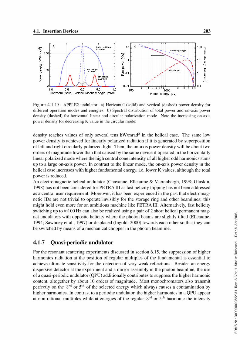
4.1. Insertion Devices 203
Figure 4.1.15: APPLE2 undulator: a) Horizontal (solid) and vertical (dashed) power density fordifferent operation modes and energies. b) Spectral distribution of total power and on-axis powerdensity (dashed) for horizontal linear and circular polarization mode. Note the increasing on-axispower density for decreasing K value in the circular mode.
density reaches values of only several tens kW/mrad2 in the helical case. The same lowpower density is achieved for linearly polarized radiation if it is generated by superpositionof left and right circularly polarized light. Then, the on-axis power density will be about twoorders of magnitude lower than that caused by the same device if operated in the horizontallylinear polarized mode where the high central cone intensity of all higher odd harmonics sumsup to a large on-axis power. In contrast to the linear mode, the on-axis power density in thehelical case increases with higher fundamental energy, i.e. lower K values, although the totalpower is reduced.An electromagnetic helical undulator (Chavanne, Elleaume & Vaerenbergh, 1998; Gluskin,1998) has not been considered for PETRA III as fast helicity flipping has not been addressedas a central user requirement. Moreover, it has been experienced in the past that electromag-netic IDs are not trivial to operate invisibly for the storage ring and other beamlines; thismight hold even more for an ambitious machine like PETRA III. Alternatively, fast helicityswitching up to ≈100 Hz can also be realized using a pair of 2 short helical permanent mag-net undulators with opposite helicity where the photon beams are slightly tilted (Elleaume,1994; Sawhney et al., 1997) or displaced (Ingold, 2000) towards each other so that they canbe switched by means of a mechanical chopper in the photon beamline.
4.1.7 Quasi-periodic undulatorFor the resonant scattering experiments discussed in section 6.15, the suppression of higherharmonics radiation at the position of regular multiples of the fundamental is essential toachieve ultimate sensitivity for the detection of very weak reflections. Besides an energydispersive detector at the experiment and a mirror assembly in the photon beamline, the useof a quasi-periodic undulator (QPU) additionally contributes to suppress the higher harmoniccontent, altogether by about 10 orders of magnitude. Most monochromators also transmitperfectly on the 3rd or 5th of the selected energy which always causes a contamination byhigher harmonics. In contrast to a periodic undulator, the higher harmonics in a QPU appearat non-rational multiples while at energies of the regular 3rd or 5th harmonic the intensity
ED
MS
Nr.:
D00
0000
0082
2371
Rev
: A V
er: 1
Sta
tus:
Rel
ease
d -
Dat
.: 8.
Apr
200
8
204 4. Radiation Sources
can be suppressed by more than one order of magnitude. Higher harmonics are likewisepresent and provide tunability over a large energy range.Based on the fundamental principles of a quasi-periodic undulator (Sasaki et al., 1995;Hashimoto & Sasaki, 1995), meanwhile QPUs have been built and operated in various modi-fications. The quasi-periodic magnet lattice has been applied successfully to pure permanentmagnet structures (Chavanne, Elleaume & van Vaerenbergh, 1998; Chavanne, Elleaume &van Vaerenbergh, 2000), to the APPLE2 design (Sasaki, Diviacco & Walker, 1998; Diviaccoet al., 2000), and to hybrid magnet structures (Bahrdt et al., 2001b). Usually, the quasi-periodicity in the magnet structure is introduced by a partial retraction of several distinctmagnets in the arrays.The perturbation pattern can be derived (Sasaki, 1998) from a projection of a 2-dimensionallattice (lattice constant ratio r) onto a line (inclination angle α). The parameters r and αare connected with the dislocation series affecting the position of the higher harmonics, andthe phase jump driving the relative intensities between harmonics. Using such a scheme,the quasi-periodic magnet structure can be designed according to experimental needs thoughthere is a mutual impact on brilliance and harmonics suppression which therefore cannot beoptimized separately. The suppression of the regular harmonics will usually be in a rangebetween 10 and 100 while the flux reduction of the QPU-harmonics regarding those of theperiodic structure is in the order of 0.3 to 0.8.Along with the user requirements for this beamline it is planned to modify a spectroscopyundulator (Sec. 4.1.4) for these purposes. With a period length of λU = 31.4 mm this ID hasits 1st harmonic at E1 = 2.4 keV which corresponds well with the specified low energy endof 2.8 keV.It will be advantageous if preferably the same mechanical design of the magnet structurecould be used for the QPU as it is developed for the standard undulator. A vertical adjustmentpossibility of the magnet keepers can be integrated by simple modifications. Furthermore,the keeper must allow sufficient space to enlarge the retracted magnets in height. It has beenpointed out (Bahrdt et al., 2001b) that this modification helps to localize the perturbation andto avoid an oscillation of the phase which leads to a cleaner optical spectrum.
4.1.8 20m undulatorAs a further option, the first straight section within the new arc of PETRA III provides spacefor an undulator of maximum 20 m length. No dedicated ID type for this straight is, how-ever, proposed at present as the individual experiments have not yet been assigned to certainbeamlines. Nevertheless as a general remark, it is very obvious that low count rate exper-iments, e.g. due to a very small band pass or spatial acceptance, will benefit most from avery long undulator. Also, an insertion device for the VUV energy range is unfavorable asa more wiggler-like device, necessary to access the low energies, in conjunction with thefull length of 20 m causes an enormous power load on all front end and primary optic com-ponents. A reasonable way around this difficulty is the placement of an Figure-8 undulatorwhich considerably reduces the on-axis power density while the brilliance is only moderatelydecreased as it has successfully been demonstrated at SPring-8 (Tanaka & Kitamura, 1995;Tanaka & Kitamura, 2000). Besides, in the VUV energy range the photon beam spot is still
ED
MS
Nr.:
D00
0000
0082
2371
Rev
: A V
er: 1
Sta
tus:
Rel
ease
d -
Dat
.: 8.
Apr
200
8

4.1. Insertion Devices 205
Figure 4.1.16: Brilliance map as function photon energy and period length for a set of 2 incoherentlysuperimposing 10 m long undulators with a minimum gap of 12 mm.
largely diffraction limited and the brilliance gain with ID length would be maximum therewhile in the X-ray region the increase is less beneficial as discussed in Sec. 4.1.1.There are two general ID concepts for this 20 m straight section that differ in their focusingscheme: The straight could be filled by several undulator segments separated by quadrupoles.This approach provides the possibility to keep the average vertical β-function rather smallwhich in turn is essential to allow for a small geometrical vertical aperture and magnetic gap.Because of the spatial separation of the undulator segments, also a phase shifter has to beinserted between two ID segments in order to adjust the interference condition according tothe particular gap. A phase shifter is a small magnetic chicane for the electron beam madefrom permanent or electromagnets (Pfluger & Tischer, 2000) and is also a key componentin the undulator system planned for the DESY X-ray FEL. In this respect there will be asubstantial mutual benefit for design, construction, and operation of such an undulator systemfor PETRA III and corresponding developments for the XFEL.Alternatively, the straight section could be filled by a single 20 m long undulator, the β-function spanning over the entire ID length. Due to the parabolic increase of β aside its
ED
MS
Nr.:
D00
0000
0082
2371
Rev
: A V
er: 1
Sta
tus:
Rel
ease
d -
Dat
.: 8.
Apr
200
8
206 4. Radiation Sources
minimum value within a cell, the vertical beam size at the ID ends will be considerablylarger for a long undulator. Even for an adapted β-function, the minimum vertical beamstay-clear will increase to ensure a similar geometrical beam acceptance as for a short device.Furthermore, it is evident that such an ID has to be built as an in-vacuum undulator sinceit would not be feasible technologically to build the vacuum chamber of a conventionalundulator in one single piece. Then, any interruption of the magnet structure due to a vacuumflange would imply a phase mis-match which has to be compensated by a phase shifting unit;the extra space required for that thwarts the original idea of this undulator and makes an in-vacuum undulator the only appropriate device similar as for the 27 m long undulator at theSPring-8 beamline BL19LXU (Kitamura et al., 2001).Finally, an intermediate scheme, like e.g. a set of two 10 m long undulators with a focusingtriplet in between, has been considered and will be reassessed once the beamline parametershave been specified. The expected performance of such a device can be seen in the brilliancemap (Fig. 4.1.16) as function of energy and period length. In this case, the radiation of two10 m long undulators would add up incoherently. A phase shifter in between the segmentswould improve brilliance only for the 1st harmonic radiation as e.g. for a fully tunable device(λU = 29 mm) the spectral line width ∆λ/λ of the 3rd harmonics approaches the electronenergy spread ∆γ/γ = 0.0011 at about 9 m undulator length.
4.1.9 Future upgrade ideas
The implementation of further beamlines in a future upgrade at the designated positions ofthe PETRA III storage ring as well as a potential upgrade of beamlines in the new arc willbenefit from the progress in the SR optics and especially from the ongoing developments inthe insertion device technology.As practiced at other 3rd generation facilities, vertical apertures and hence magnetic gapshad been lowered without constraint to safe operation once the machine has been runningroutinely and sufficient experience had been gained. Then, the minimum gap will be in arange where the use of in-vacuum undulators (Chavanne et al., 2002; Hara et al., 1998) willimprove the spectral intensity significantly as the gap is again reduced by the vacuum cham-ber wall thickness. Also, the vertical aperture can immediately be adapted to the needs ofa particular operation mode though possibly sacrificing the low energy end of the undulatorspectrum. The advantage of the in-vacuum technology is the decrease of period length for agiven K value, i.e. the attainment of a larger number of periods for a given undulator length.Therefore, the advantages of an in-vacuum undulator will appear especially for short perioddevices at high photon energies.In addition, the development of superconducting insertion devices has made continuousprogress in recent years (LeBlanc & Wallen, 2002; Berger et al., 2002; Batrakov et al.,2002). In particular, the recent completion of a short period undulator (Kubsky et al., 2003;Chouhan et al., 2003) with λU = 14 mm and a peak field of 1.3 T shows that superconductingundulators might be technologically feasible also for storage ring operation in several yearsonce the phase error will be in a range of today’s permanent magnet undulators. Paralleldevelopments on Nb3Sn superconductors (Prestemon et al., 2003) will push the performancelimit of superconducting devices even higher. Fig. 4.1.17 exemplarily shows the brilliance to
ED
MS
Nr.:
D00
0000
0082
2371
Rev
: A V
er: 1
Sta
tus:
Rel
ease
d -
Dat
.: 8.
Apr
200
8
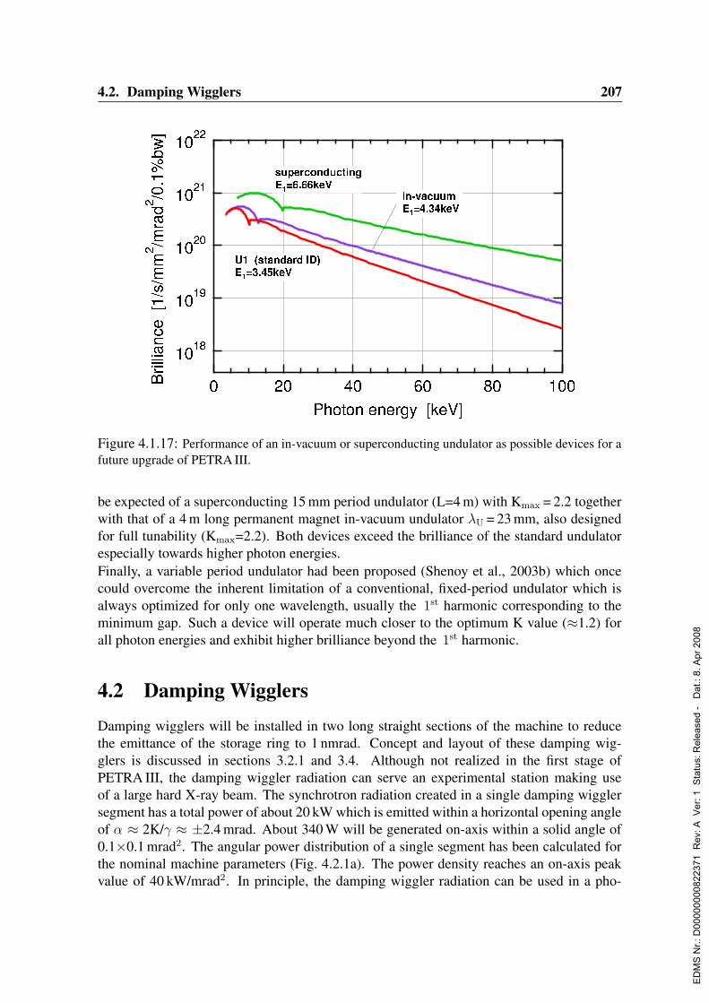
4.2. Damping Wigglers 207
Figure 4.1.17: Performance of an in-vacuum or superconducting undulator as possible devices for afuture upgrade of PETRA III.
be expected of a superconducting 15 mm period undulator (L=4 m) with Kmax = 2.2 togetherwith that of a 4 m long permanent magnet in-vacuum undulator λU = 23 mm, also designedfor full tunability (Kmax=2.2). Both devices exceed the brilliance of the standard undulatorespecially towards higher photon energies.Finally, a variable period undulator had been proposed (Shenoy et al., 2003b) which oncecould overcome the inherent limitation of a conventional, fixed-period undulator which isalways optimized for only one wavelength, usually the 1st harmonic corresponding to theminimum gap. Such a device will operate much closer to the optimum K value (≈1.2) forall photon energies and exhibit higher brilliance beyond the 1st harmonic.
4.2 Damping WigglersDamping wigglers will be installed in two long straight sections of the machine to reducethe emittance of the storage ring to 1 nmrad. Concept and layout of these damping wig-glers is discussed in sections 3.2.1 and 3.4. Although not realized in the first stage ofPETRA III, the damping wiggler radiation can serve an experimental station making useof a large hard X-ray beam. The synchrotron radiation created in a single damping wigglersegment has a total power of about 20 kW which is emitted within a horizontal opening angleof α ≈ 2K/γ ≈ ±2.4 mrad. About 340 W will be generated on-axis within a solid angle of0.1×0.1 mrad2. The angular power distribution of a single segment has been calculated forthe nominal machine parameters (Fig. 4.2.1a). The power density reaches an on-axis peakvalue of 40 kW/mrad2. In principle, the damping wiggler radiation can be used in a pho-
ED
MS
Nr.:
D00
0000
0082
2371
Rev
: A V
er: 1
Sta
tus:
Rel
ease
d -
Dat
.: 8.
Apr
200
8
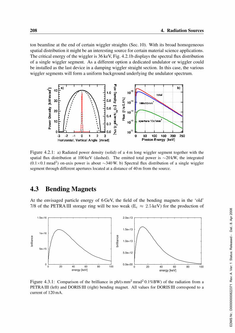
208 4. Radiation Sources
ton beamline at the end of certain wiggler straights (Sec. 10). With its broad homogeneousspatial distribution it might be an interesting source for certain material science applications.The critical energy of the wiggler is 36 keV, Fig. 4.2.1b displays the spectral flux distributionof a single wiggler segment. As a different option a dedicated undulator or wiggler couldbe installed as the last device in a damping wiggler straight section. In this case, the variouswiggler segments will form a uniform background underlying the undulator spectrum.
Figure 4.2.1: a) Radiated power density (solid) of a 4 m long wiggler segment together with thespatial flux distribution at 100 keV (dashed). The emitted total power is ∼20 kW, the integrated(0.1×0.1 mrad2) on-axis power is about ∼340 W. b) Spectral flux distribution of a single wigglersegment through different apertures located at a distance of 40 m from the source.
4.3 Bending MagnetsAt the envisaged particle energy of 6 GeV, the field of the bending magnets in the ‘old’7/8 of the PETRA III storage ring will be too weak (Ec ≈ 2.5 keV) for the production of
0 20 40 60 80 100energy [keV]
0.0e+00
5.0e+12
1.0e+13
1.5e+13
2.0e+13
brill
ianc
e
0 20 40 60 80 100energy [keV]
0
5e+15
1e+16
1.5e+16
brill
ianc
e
Figure 4.3.1: Comparison of the brilliance in ph/(s mm2 mrad2 0.1%BW) of the radiation from aPETRA III (left) and DORIS III (right) bending magnet. All values for DORIS III correspond to acurrent of 120 mA.
ED
MS
Nr.:
D00
0000
0082
2371
Rev
: A V
er: 1
Sta
tus:
Rel
ease
d -
Dat
.: 8.
Apr
200
8
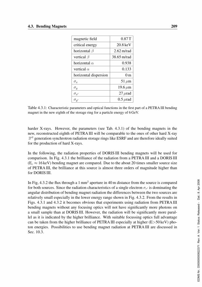
4.3. Bending Magnets 209
magnetic field 0.87 Tcritical energy 20.8 keVhorizontal β 2.62 m/radvertical β 38.65 m/radhorizontal α 0.938vertical α 0.133horizontal dispersion 0 mσx 51µmσy 19.6µmσx′ 27µradσy′ 0.5µrad
Table 4.3.1: Characteristic parameters and optical functions in the first part of a PETRA III bendingmagnet in the new eighth of the storage ring for a particle energy of 6 GeV.
harder X-rays. However, the parameters (see Tab. 4.3.1) of the bending magnets in thenew, reconstructed eighth of PETRA III will be comparable to the ones of other hard X-ray3rd generation synchrotron radiation storage rings like ESRF and are therefore ideally suitedfor the production of hard X-rays.
In the following, the radiation properties of DORIS III bending magnets will be used forcomparison. In Fig. 4.3.1 the brilliance of the radiation from a PETRA III and a DORIS III(Ec ≈ 16 keV) bending magnet are compared. Due to the about 20 times smaller source sizeof PETRA III, the brilliance at this source is almost three orders of magnitude higher thanfor DORIS III.
In Fig, 4.3.2 the flux through a 1 mm2 aperture in 40 m distance from the source is comparedfor both sources. Since the radiation characteristics of a single electron σr′ is dominating theangular distribution of bending magnet radiation the differences between the two sources arerelatively small especially in the lower energy range shown in Fig. 4.3.2. From the results inFigs. 4.3.1 and 4.3.2 it becomes obvious that experiments using radiation from PETRA IIIbending magnets without any focusing optics will not have significantly more photons ona small sample than at DORIS III. However, the radiation will be significantly more paral-lel as it is indicated by the higher brilliance. With suitable focussing optics full advantagecan be taken from the higher brilliance of PETRA III especially at higher (E>50 keV) pho-ton energies. Possibilities to use bending magnet radiation at PETRA III are discussed inSec. 10.3.
ED
MS
Nr.:
D00
0000
0082
2371
Rev
: A V
er: 1
Sta
tus:
Rel
ease
d -
Dat
.: 8.
Apr
200
8

210 4. Radiation Sources
0 20 40 60 80 100energy [keV]
0e+00
1e+10
2e+10
3e+10
4e+10
5e+10
part
ial f
lux
PETRA−III
DORIS−III
Figure 4.3.2: Comparison of the flux through a 1×1 mm2 aperture in 40 m distance from the sourcein ph/(s 0.1%BW) of the radiation from a PETRA III and a DORIS III bending magnet. All values forDORIS III correspond to a current of 120 mA.
ED
MS
Nr.:
D00
0000
0082
2371
Rev
: A V
er: 1
Sta
tus:
Rel
ease
d -
Dat
.: 8.
Apr
200
8
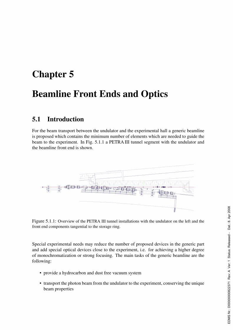
Chapter 5
Beamline Front Ends and Optics
5.1 IntroductionFor the beam transport between the undulator and the experimental hall a generic beamlineis proposed which contains the minimum number of elements which are needed to guide thebeam to the experiment. In Fig. 5.1.1 a PETRA III tunnel segment with the undulator andthe beamline front end is shown.
Figure 5.1.1: Overview of the PETRA III tunnel installations with the undulator on the left and thefront end components tangential to the storage ring.
Special experimental needs may reduce the number of proposed devices in the generic partand add special optical devices close to the experiment, i.e. for achieving a higher degreeof monochromatization or strong focusing. The main tasks of the generic beamline are thefollowing:
• provide a hydrocarbon and dust free vacuum system
• transport the photon beam from the undulator to the experiment, conserving the uniquebeam properties
ED
MS
Nr.:
D00
0000
0082
2371
Rev
: A V
er: 1
Sta
tus:
Rel
ease
d -
Dat
.: 8.
Apr
200
8

212 5. Beamline Front Ends and Optics
• ensure radiation safety by collimation and suitable beamshutters
• ensure equipment protection by an appropriate vacuum interlock system
• monitor the photon beam position
• shape the beam with fixed and movable masks to reduce the power load on opticalcomponents
• monochromatize the white beam
• collimate or focus white and monochromatic light by mirrors
• filter the white beam to reduce the power load and suppress harmonics
The layout is split into two parts separated by the storage ring tunnel wall. Inside the ringtunnel no optical components, as mirrors and monochromators, will be placed.
5.2 Ring Tunnel – Beamline Front End Installations
Inside the ring tunnel all components in the photon beamline dealing with radiation safety,beam position and beam collimation will be placed as shown in Fig. 5.2.1. There will be theoption for a collimating lens system placed inside the ring tunnel.Space is also needed for the vacuum protection system, i.e. the fast acting valve. The vacuumfailure sensing devices will be installed in the optics hutch. A windowless beam transportsystem will connect the storage ring and the experimental hutch.
Figure 5.2.1: Schematic layout of the generic beamline components located inside the ring tunnel.
ED
MS
Nr.:
D00
0000
0082
2371
Rev
: A V
er: 1
Sta
tus:
Rel
ease
d -
Dat
.: 8.
Apr
200
8

5.2. Ring Tunnel – Beamline Front End Installations 213
5.2.1 Radiation safetyThe radiation safety system allows a safe access to the optical elements and the experimentwithout interruption of the storage ring operation. PETRA III will run in a continuous fillingmode which requires a special arrangement of radiation safety components. For a fail safeparticle injection, each beam outlet has to be equipped with a permanent magnet whichextracts misguided particles out of the photon beamline.The beam shutter will be placed directly in front of the storage ring wall. A photon shutterprotects the beam shutter absorbing the full photon beam power.To limit the neutron dose caused by the Bremsstrahlung originating from electron beamlosses inside the undulator vacuum chamber, two vertical absorber slits are installed in thebeamline at 18 m and 28 m from the source. During normal operation of the storage ring anaperture size of≈1 mm prevents a direct line of sight towards the undulator vacuum chamber.These apertures will be opened for filling during alignment of the storage ring and the set-upof the apertures.
5.2.2 Beam position monitorsPhoton beam position monitors (BPM) will be installed in front of the vertical slit systems.At present, the basic BPM follows the 4 blade design (Hahn et al., 1998). In the case ofa high brilliance undulator beamline, the performance of these devices suffers from the ra-diation from adjacent bending magnets and quadrupoles. At PETRA II, the collimation ofthe bending magnet radiation proved to be feasible, and allowed the use of blade monitorsystems.For PETRA III, a BPM (Schulte-Schrepping et al., 2003) based on the detection and imagingof ionized residual gas is proposed. This device provides a non-intrusive, non-saturablemeans of detection of the center of mass of the beam position.
Repeller plate
hν
Mesh
MCP /phosphor
screen
Figure 5.2.2: First results from a photon beam position monitor imaging the photon trace throughan ionized gas.
In Fig.5.2.2 the set-up and a first measurement of a photon trace through the detector isshown. The set-up consists of a micro-channel plate (MCP) with fluorescent screen andfiber-optic, a mesh and a repeller plate. Residual gases in the detector will be ionized bythe photon beam and accelerated towards the MCP. A proper geometrical arrangement of theplates and the field distribution will image the ions/electrons onto the MCP. The amplifiedsignal is converted to visible light by the fluorescent screen and coupled into a fiber optic
ED
MS
Nr.:
D00
0000
0082
2371
Rev
: A V
er: 1
Sta
tus:
Rel
ease
d -
Dat
.: 8.
Apr
200
8

214 5. Beamline Front Ends and Optics
window. The image is recorded outside the vacuum chamber by a CCD camera. The speedof the monitor is determined by the gas pressure. A CCD and frame grabber setup workingat video frequencies would provide a 25Hz update rate of the position signal.The BPM in front of the first slit measures the vertical and horizontal position of the fullphoton beam. The BPM in front of the second slit will be used to center the first slit in thevertical direction and measures the photon beam position in the horizontal direction.
5.2.3 Beam shaping and photon shutter
The design of the two slit systems is shown in Fig.5.2.3. They will absorb off axis radiationof the undulator. The second slit additionally functions as a power absorber to shut off thephoton beam. While the first slit collimates only in the vertical direction, the second slit alsocollimates in the horizontal direction. The total power in the white beam will be as high as30 kW with a maximum power density of 800 W/mm2 in 30 m from the source in the caseof the 20 m long undulator at 100 mA. Future upgrades to a beam current of 200 mA will beconsidered and implemented in all designs.
Figure 5.2.3: High power slit system and beamshutter suitable for PETRA III undulator beam-lines. (U. Hahn, M. Ruter, Hochleistungsstrahlverschluss- und Spaltsystem fur Synchrotronstrahlung,Patent Nr. DE 101 35 307 C2).
The cross-section on the right in Fig.5.2.3 shows the principle of operation of the verticalslit system. The upper and lower jaw consist of an inclined (≈1 degree) water cooled copperabsorber (Wang & Hahn, 1996b) to accept the power, and a tungsten blade to stop highenergetic radiation. The slit height is controlled by one drive moving both jaws. The verticalslit position is adjusted by moving the whole set-up. The shutter function of the slit is drivenby the pneumatic cylinder.The horizontal slit function is achieved by integrating a horizontal movable absorber (Mar-ion & Zhang, 2003).
ED
MS
Nr.:
D00
0000
0082
2371
Rev
: A V
er: 1
Sta
tus:
Rel
ease
d -
Dat
.: 8.
Apr
200
8

5.3. Optics Hutch Installations 215
5.3 Optics Hutch InstallationsAll optical elements, except an optional collimating X-ray lens, will be located inside theoptics hutch outside the ring tunnel. This scheme allows access to all major beamline op-tics components without affecting the storage ring operation. The optics hutch will provideproper shielding and suppression of background radiation. A secondary beamshutter allowsaccess to the experiment while the main beamshutter is open. The thermal stability of theoptical components benefits from the continuous filling mode and the secondary beamshut-ter. The layouts of the optics hutches follow the experimental needs. The different beamlineoptions provide a fixed exit photon beam at the experiment, independent of the configurationof the optics:
• monochromatic photon beam, direct or mirrored
Figure 5.3.1: Top: Schematic layout of the optics hutch providing a monochromatic photon beam.The monochromatic and pink beam offset will be 25 mm relative to the white beam. The mirrors aremoveable in the vertical direction. Bottom: Layout of the optics hutch providing a monochromaticphoton beam or a mirrored pink beam.
ED
MS
Nr.:
D00
0000
0082
2371
Rev
: A V
er: 1
Sta
tus:
Rel
ease
d -
Dat
.: 8.
Apr
200
8
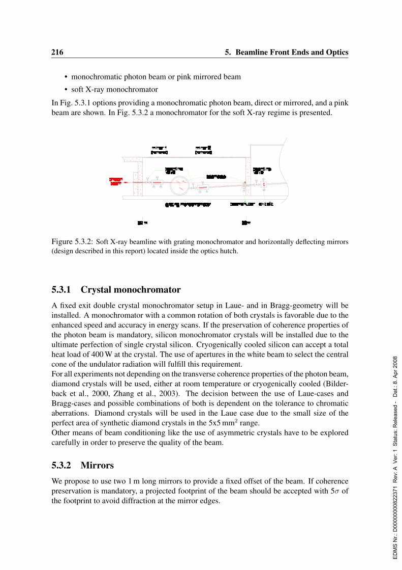
216 5. Beamline Front Ends and Optics
• monochromatic photon beam or pink mirrored beam
• soft X-ray monochromator
In Fig. 5.3.1 options providing a monochromatic photon beam, direct or mirrored, and a pinkbeam are shown. In Fig. 5.3.2 a monochromator for the soft X-ray regime is presented.
Figure 5.3.2: Soft X-ray beamline with grating monochromator and horizontally deflecting mirrors(design described in this report) located inside the optics hutch.
5.3.1 Crystal monochromatorA fixed exit double crystal monochromator setup in Laue- and in Bragg-geometry will beinstalled. A monochromator with a common rotation of both crystals is favorable due to theenhanced speed and accuracy in energy scans. If the preservation of coherence properties ofthe photon beam is mandatory, silicon monochromator crystals will be installed due to theultimate perfection of single crystal silicon. Cryogenically cooled silicon can accept a totalheat load of 400 W at the crystal. The use of apertures in the white beam to select the centralcone of the undulator radiation will fulfill this requirement.For all experiments not depending on the transverse coherence properties of the photon beam,diamond crystals will be used, either at room temperature or cryogenically cooled (Bilder-back et al., 2000, Zhang et al., 2003). The decision between the use of Laue-cases andBragg-cases and possible combinations of both is dependent on the tolerance to chromaticaberrations. Diamond crystals will be used in the Laue case due to the small size of theperfect area of synthetic diamond crystals in the 5x5 mm2 range.Other means of beam conditioning like the use of asymmetric crystals have to be exploredcarefully in order to preserve the quality of the beam.
5.3.2 MirrorsWe propose to use two 1 m long mirrors to provide a fixed offset of the beam. If coherencepreservation is mandatory, a projected footprint of the beam should be accepted with 5σ ofthe footprint to avoid diffraction at the mirror edges.
ED
MS
Nr.:
D00
0000
0082
2371
Rev
: A V
er: 1
Sta
tus:
Rel
ease
d -
Dat
.: 8.
Apr
200
8
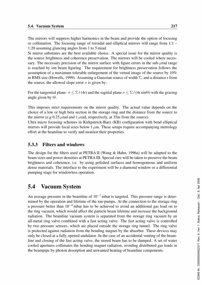
5.4. Vacuum System 217
The mirrors will suppress higher harmonics in the beam and provide the option of focusingor collimation. The focusing range of toroidal and elliptical mirrors will range from 1:1 –1:20 assuming glancing angles from 1 to 5 mrad.Si mirror substrates are the best available choice. A special issue for the mirror quality isthe source brightness and coherence preservation. The mirrors will be cooled where neces-sary. The necessary precision of the mirror surface with figure errors in the sub-µrad rangeis reached by ion beam figuring. The requirement for brightness preservation follows theassumption of a maximum tolerable enlargement of the virtual image of the source by 10%in RMS size (Howells, 1999). Assuming a Gaussian source of width Σ, and a distance r fromthe source, the allowed slope error σ is given by:
For the tangential plane: σ ≤Σ / (4r) and the sagittal plane σ ≤Σ / (4r sinΘ) with the grazingangle given by Θ.
This imposes strict requirements on the mirror quality. The actual value depends on thechoice of a low or high beta section in the storage ring and the distance from the source tothe mirror (e.g 0.25µrad and 1µrad, respectively, at 35m from the source).Ultra micro focusing schemes in Kirkpatrick-Baez (KB) configuration with bend ellipticalmirrors will provide focal sizes below 1µm. These setups require accompanying metrologyeffort at the beamline to verify and monitor their properties.
5.3.3 Filters and windows
The design for the filters used at PETRA II (Wang & Hahn, 1996a) will be adapted to thebeam sizes and power densities at PETRA III. Special care will be taken to preserve the beambrightness and coherence, i.e. by using polished surfaces and homogeneous and uniformdense materials. The interface to the experiment will be a diamond window or a differentialpumping stage for windowless operation.
5.4 Vacuum SystemAn average pressure in the beamline of 10−7 mbar is targeted. This pressure range is deter-mined by the operation and lifetime of the ion-pumps. At the connection to the storage ringa pressure better than 10−9 mbar has to be achieved to avoid an additional gas load on tothe ring vacuum, which would affect the particle beam lifetime and increase the backgroundradiation. The beamline vacuum system is separated from the storage ring vacuum by anall-metal ring valve combined with a fast acting valve. The fast acting valve is controlledby two pressure sensors, which are placed outside the storage ring tunnel. The ring valveis protected against radiation from the bending magnet by the absorber. These devices mayonly be closed at a fully opened undulator. In the case of an accidental venting of the beam-line and closing of the fast acting valve, the stored beam has to be dumped. A set of watercooled apertures collimates the bending magnet radiation, avoiding distributed gas loads inthe beampipe by photon desorption and unwanted heating of beamline components.
ED
MS
Nr.:
D00
0000
0082
2371
Rev
: A V
er: 1
Sta
tus:
Rel
ease
d -
Dat
.: 8.
Apr
200
8
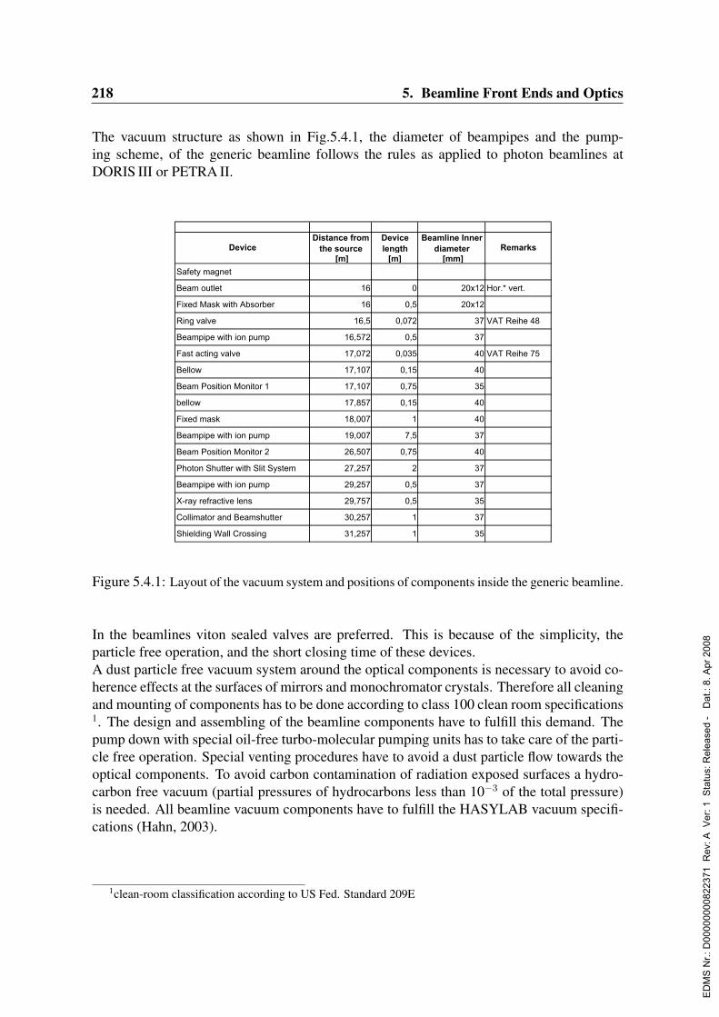
218 5. Beamline Front Ends and Optics
The vacuum structure as shown in Fig.5.4.1, the diameter of beampipes and the pump-ing scheme, of the generic beamline follows the rules as applied to photon beamlines atDORIS III or PETRA II.
[m] [m] [mm]
Safety magnet
Beam outlet 16 0 20x12 Hor.* vert.
Fixed Mask with Absorber 16 0,5 20x12
Ring valve 16,5 0,072 37 VAT Reihe 48
Beampipe with ion pump 16,572 0,5 37
Fast acting valve 17,072 0,035 40 VAT Reihe 75
Bellow 17,107 0,15 40
Beam Position Monitor 1 17,107 0,75 35
bellow 17,857 0,15 40
Fixed mask 18,007 1 40
Beampipe with ion pump 19,007 7,5 37
Beam Position Monitor 2 26,507 0,75 40
Photon Shutter with Slit System 27,257 2 37
Beampipe with ion pump 29,257 0,5 37
X-ray refractive lens 29,757 0,5 35
Collimator and Beamshutter 30,257 1 37
Shielding Wall Crossing 31,257 1 35
Device RemarksDistance from
the source
Device
length
Beamline Inner
diameter
Figure 5.4.1: Layout of the vacuum system and positions of components inside the generic beamline.
In the beamlines viton sealed valves are preferred. This is because of the simplicity, theparticle free operation, and the short closing time of these devices.A dust particle free vacuum system around the optical components is necessary to avoid co-herence effects at the surfaces of mirrors and monochromator crystals. Therefore all cleaningand mounting of components has to be done according to class 100 clean room specifications1. The design and assembling of the beamline components have to fulfill this demand. Thepump down with special oil-free turbo-molecular pumping units has to take care of the parti-cle free operation. Special venting procedures have to avoid a dust particle flow towards theoptical components. To avoid carbon contamination of radiation exposed surfaces a hydro-carbon free vacuum (partial pressures of hydrocarbons less than 10−3 of the total pressure)is needed. All beamline vacuum components have to fulfill the HASYLAB vacuum specifi-cations (Hahn, 2003).
1clean-room classification according to US Fed. Standard 209E
ED
MS
Nr.:
D00
0000
0082
2371
Rev
: A V
er: 1
Sta
tus:
Rel
ease
d -
Dat
.: 8.
Apr
200
8

Chapter 6
Beamlines and Experimental Stations
6.0.1 Introduction
The PETRA III upgrade will result in nine straight sections for insertion devices within thenew experimental hall. Depending on the applications each straight section can either beequipped with a single 5 m long insertion device or with two 2 m long devices which will beinclined towards each other by 5 mrad (see also Sec. 2.2.1). The distance from an insertiondevice to the end of the tunnel shielding wall will be about 33 m due to the large radius of thePETRA storage ring. According to the presently planned experimental hall dimensions themaximum source to sample distance will be about 100 m. The angle between neighboringstraight sections will be 5. Due to the very parallel photon beams expected at PETRA III(Sec. 2.2.3), especially in case of a high-β section, it should easily be possible to operatemore than one experimental station along the beampath of the same undulator either in atime sharing mode or even simultaneously. Such an arrangement is schematically sketchedin Fig. 6.0.1. The space for experiments will be more restricted in case of two insertiondevices located in the same straight section. As far as possible the layout will be optimizedfor minimal interaction of the two corresponding stations during the operation phase. InFig. 6.0.2 a possible layout of such canted undulator beamlines is shown. In this case, bothbeamlines will likely share at least the first optical hutch for some of their optical elements.Such an arrangement will leave one of the beams almost unrestricted in space except in the
Figure 6.0.1: Schematic drawing of several experimental hutches arranged at a single undulatorbeamline (top view).
ED
MS
Nr.:
D00
0000
0082
2371
Rev
: A V
er: 1
Sta
tus:
Rel
ease
d -
Dat
.: 8.
Apr
200
8
220 6. Beamlines and Experimental Stations
Figure 6.0.2: Schematic drawing of canted undulator beamlines. The exact layout of the hutcheswill depend on the equipment to be installed in the experimental endstations.
region close to the shielding wall. Depending on the exact layout of the experimental stationof the second beamline (“side station”) and the energy range that will be used, it has tobe discussed if a horizontally or vertically deflecting monochromator is advantageous. Thecanted undulator beamline with horizontal deflection is shown in Fig. 6.0.2. In either case,a wide energy tunability as well as a very long experimental station will be more difficult toachieve for side stations.In principle two insertion devices could be placed in every straight section. The differencein brilliance between a 5 m and a 2 m insertion device is a factor of 2.5–3.2 depending onthe photon energy (Fig. 4.1.1). According to present plans it is foreseen to split four straightsections. However, this number certainly needs to be evaluated again when the decision onthe first beamlines to be built has been made.Experimental issues that are relevant for almost all experimental stations are described inSec. 6.0.2. In Sec. 6.18 experimental techniques will be presented for which no dedicatedstation is proposed. These techniques will either be applied at many stations or can easily becarried out at several different experimental setups with limited additional effort.This report does not include any proposal for time resolved experiments exploiting a singlebunch mode operation of the storage ring for two reasons:
1. Due to the small emittance of PETRA III the lifetime for a single bunch with highcharge is rather low. If we assume an injection frequency of 0.1 Hz in top-up mode themaximum stored current per bunch will be about 5 mA. For that reason PETRA III isnot the ideal source for this kind of experiments.
2. More important: DESY expects the European XFEL laboratory in Hamburg to becomeoperational about 2–3 years after the first beam at PETRA III will be delivered. Thepulse intensity of the XFEL will about four orders of magnitude higher compared toPETRA III and the pulse duration will be almost three orders of magnitude shorter.
Keeping these arguments in mind and the fact that with the VUV-FEL, another source withextremely short pulses for time resolved experiments is available on site, specialized fast timeresolution experiments have not been considered for PETRA III. However, a bunch timingsignal will be provided to all beamlines. In the few bunch mode (≈ 40 bunches, equallydistributed, 2.5 mA bunch current) the time window will be 192 ns. This is well suited for
ED
MS
Nr.:
D00
0000
0082
2371
Rev
: A V
er: 1
Sta
tus:
Rel
ease
d -
Dat
.: 8.
Apr
200
8
221
pump-probe experiments with few ps time resolution. The number of photons per pulse in0.1% BW will be about 108, compared to about 1012 expected for the X-FEL in SASE mode.Presented as an individual beamline, 22 experimental stations are proposed in sections 6.1–6.17. The decision on
• the number of stations to be built in 2008,
• the experiments to be joined at one undulator beamline,
• the distribution of experiments on 2 m and 5 m insertion devices, and
• the assignment of experiments to straight or side station insertion devices
will be achieved with the assistance and expertise of a beamline advisory committee whichwill be established after publication of this report as already mentioned in Chapter 1.
The estimates for the investment costs given at the end of each beamline proposal are re-stricted only to endstation equipment. The capital investment and personnel needed forbeamline optics, vacuum system and shielding hutches have to be added for the total beam-line costs. The later ones amount to about 2 Me per beamline on average.
6.0.2 General experiment support infrastructureComputing and experiment control All PETRA III experiments will be controlled bythe same software and hardware modules, as far as possible. The experiments will also havedirect control of the undulator gap and access to relevant beamline information like beamposition, bunch current, bunch timing signals, etc.. A detailed description of the computinginfrastructure is given in Sec. 7.3.
Experiment support It is planned to set up an experiment support group for the experi-mental hall which will take care of specialized equipment that may be used on demand atdifferent beamlines. The instrumentation provided includes:
• high pressure cells and the related infrastructure (Sec. 6.18.1)
• cryo equipment like cryo streamers, closed cycle cryostats, bath- and flow-cryostats(He and N2)
• furnaces for different temperature ranges
• high field magnets
• detectors, 0–2 dimensional, . . .
• electronics such as NIM-modules
• mechanic components such as translation stages and turn tables
• lasers
The provision of a pool of specialized equipment has been very successful at other user facil-ities. The pool should be allowed to dynamically adopt to the experimentalists requirements.Sufficient staff will be allocated to ensure maintenance and development of the equipment.
ED
MS
Nr.:
D00
0000
0082
2371
Rev
: A V
er: 1
Sta
tus:
Rel
ease
d -
Dat
.: 8.
Apr
200
8
222 6. Beamlines and Experimental Stations
6.1 High-Energy X-ray Diffraction
Authors :
U. Hoppe Universitat Rostock, GermanyT. Lippmann GKSS Research Center, Geesthacht, GermanyH. Reichert MPI Stuttgart, GermanyR. Rohlsberger DESY, Hamburg, GermanyS. D. Shastri APS, Argonne, USAJ. Strempfer MPI Stuttgart, GermanyM. von Zimmermann DESY, Hamburg, Germany
6.1.1 Current state of the scientific field
With the development of modern synchrotron radiation sources, high energy X-ray diffrac-tion became a powerful tool for the analysis of bulk materials and buried interfaces. Sincethe absorption lengths above 100 keV for most materials lie in the range of 0.1 mm to severalcm, studies of the bulk behavior of thick samples as applied for materials research becomeevident. For the same reason, thick window materials for sample environments like cryostatsor furnaces are less critical or negligible. In many cases, the surface of a material exhibitscomplex defect structures. High energies can penetrate through millimeters of material sothat contributions from the near-surface region and the sample container become negligible.Moreover, corrections for absorption, extinction and multiple scattering effects can be ne-glected in many cases.Another important feature of high-energy X-rays is that reciprocal space can be mapped up tolarge momentum transfers such as 30–50 A−1 which is crucial for precise structure determi-nation of liquid and amorphous materials. As a result, slightly differing bond lengths in thestructure can be revealed, as demonstrated recently in the analysis of the network structure ina glass (Petkov et al., 2000). The analysis of the diffuse scattering provides high-resolutionstructural information also for crystalline materials. While conventional diffraction yields thespatially averaged crystalline structure, the diffuse scattering reveals local deviations fromthe average structure (Reichert et al., 2001).High-energy X-rays have been applied in a variety of areas for structure analysis : defect anddiffuse scattering, texture analysis (Bunge et al., 2003), structural phase transitions, chargeand orbital ordering (v. Zimmermann et al., 2003), and magnetic scattering (Strempfer et al.,2004).The application of high-energy diffraction methods becomes particularly attractive if com-bined with microfocusing techniques. This has been applied to investigate ordering phenom-ena at the solid-liquid interface which led to the discovery of a five-fold local symmetry inliquid Pb in contact with the Si(1 1 1) surface (Reichert et al., 2000). It is expected that suchstudies can be extended into new areas by using high-brilliance X-ray beams delivered atPETRA III.
ED
MS
Nr.:
D00
0000
0082
2371
Rev
: A V
er: 1
Sta
tus:
Rel
ease
d -
Dat
.: 8.
Apr
200
8

6.1. High-Energy X-ray Diffraction 223
6.1.2 Science at the high-energy X-ray diffraction beamlineThe very high brilliance of the undulator beams at PETRA III allows for a significant en-hancement of existing experimental techniques : Focusing to micron scale spot sizes willenable the selection of very small gauge volumes and a corresponding differential mappingof the sample properties. The implementation of high-resolution monochromators allows toprobe samples with elemental specifity via contrast variation around absorption edges. Thisis interesting for 5d and 5f elements with K - edges above 40 keV. Element specific investi-gations involving those elements often suffer from high absorption which leads to unreliablenear-surface effects.Moreover, the extremely high photon flux in these beams permits time-resolved investiga-tions to capture transient events on the sub-second time scale. Among the large number ofpossible applications, a few will be highlighted in the following sections. These are scien-tific fields that are not accessible to neutrons (unable to microfocus, low flux) or lower energyX-rays (low penetration capability).
6.1.2.1 Buried interfaces
Interfacial phenomena strongly determine the functionality and properties of complex sys-tems as they occur in nano technology and in nature. Very often one has to deal with deeplyburied solid-solid or solid-liquid interfaces which critically determine the function of elec-trolytes, fuel cells, or nano mechanical devices, see Fig. 6.1.1a-c. Particularly in nature and inbiological systems, fundamental phenomena and processes may occur at interfaces betweentwo macroscopic objects. A specific example is the phenomenon of interfacial melting ofice in contact with minerals as sketched in Fig. 6.1.1d. This phenomenon is expected tobe of crucial importance for many environmental processes. Access to buried interfaces isobtained in a transmission-reflection scheme using high-energy microbeams, as sketched inFig. 6.1.2a. Due to the high photon energy, a long path in the sample can be traveled whilekeeping the absorption losses low. The microbeam enters the sample sideways, thus select-ing just the boundary of interest and avoiding signal contamination by surrounding interfacesand surfaces as in the conventional scheme, see Fig. 6.1.2b. Such studies have an enormouspotential to investigate dynamical phenomena like melting and phase transitions at buriedinterfaces. While surface melting has been studied extensively (Frenken & van der Veen,1985), buried interfaces were hardly accessible due to the strong absorption of low-energyX-rays and the low brilliance of neutron sources. Here, the high-brilliance beams deliveredat PETRA III will open new experimental possibilities. High-resolution data are obtainedby recording specular reflectivities up to momentum transfers qz of 1.0 A−1 or beyond. Theuse of microbeams confines the specularly reflected signal to a very small region in phasespace, so that the background from diffuse scattering is strongly reduced. For that reason,the outstanding brilliance of the PETRA III undulator beams is essential for these studies.
6.1.2.2 High-energy diffuse scattering
Diffraction studies of the structure of condensed matter often suffer from a small scatteringcross section, especially when diffuse scattering experiments are required for the investi-
ED
MS
Nr.:
D00
0000
0082
2371
Rev
: A V
er: 1
Sta
tus:
Rel
ease
d -
Dat
.: 8.
Apr
200
8

224 6. Beamlines and Experimental Stations
µm
µm
nm
solid−liquidinterface
(d)
ice
Pel
functional interfaces
U+
−
(a)
nminterfacefunctional
(c)
(b)
functional interface
electrolyte
mineral, rock
+HH2
H2O
O2
Electrolyt
Figure 6.1.1: Examples of deeply buried functional interfaces as they occur in (a) electrolytes, (b)fuel cells, (c) lubrication in nanoscale mechanics, and (d) environmental problems such as interfacemelting of ice in contact with minerals. (Figure adopted from Reichert et al., 2003a)
gation of local deviations from the average structure. This problem can be overcome byusing new techniques based on high energy X-ray diffraction. With this technique a highenergy X-ray beam is directed at a well-oriented single crystal in transmission geometry.The scheme combines the advantages of two other scattering methods in diffraction physics.High energy photons penetrate a large sample volume giving a total number of scatterersin the X-ray beam comparable to the neutron case. As in electron diffraction (TEM) thediffraction pattern can then be imaged in a plane that is almost flat due to the large radiusof the Ewald sphere. This allows to record diffuse diffraction patterns with unprecedentedresolution and statistics on a time scale of seconds. An example is displayed in Fig. 6.1.3that shows scattering from the spin-glas Cu83Mn17 from which strain-induced nonanalyticshort-range order was derived (Reichert et al., 2001).Another example are ordering phenomena in complex oxide materials. The physics of thesematerials is determined by the competition between spin, charge and lattice degrees of free-dom. Particular effects are the formation of charge-ordered clusters in the manganite per-ovskites, giving rise to the phenomenon of colossal magneto resistance (CMR) (Vasiliu-Doloc et al., 1999) or the formation of stripe phases in high-Tc superconductors (Mook &Dogan, 1999). To obtain a complete picture of the physics of such systems, data from theentire volume of reciprocal space are essential. In contrast to neutron scattering, these datacan be collected very quickly if high-brilliance, high-energy X-rays are used in combinationwith large 2-dimensional detectors. This allows for extensive systematic investigations withunprecedented accuracy.Using modern focusing techniques (e.g. compound refractive lenses) it has become possibleto produce high energy microbeams to probe local deviations from the average structure in
ED
MS
Nr.:
D00
0000
0082
2371
Rev
: A V
er: 1
Sta
tus:
Rel
ease
d -
Dat
.: 8.
Apr
200
8
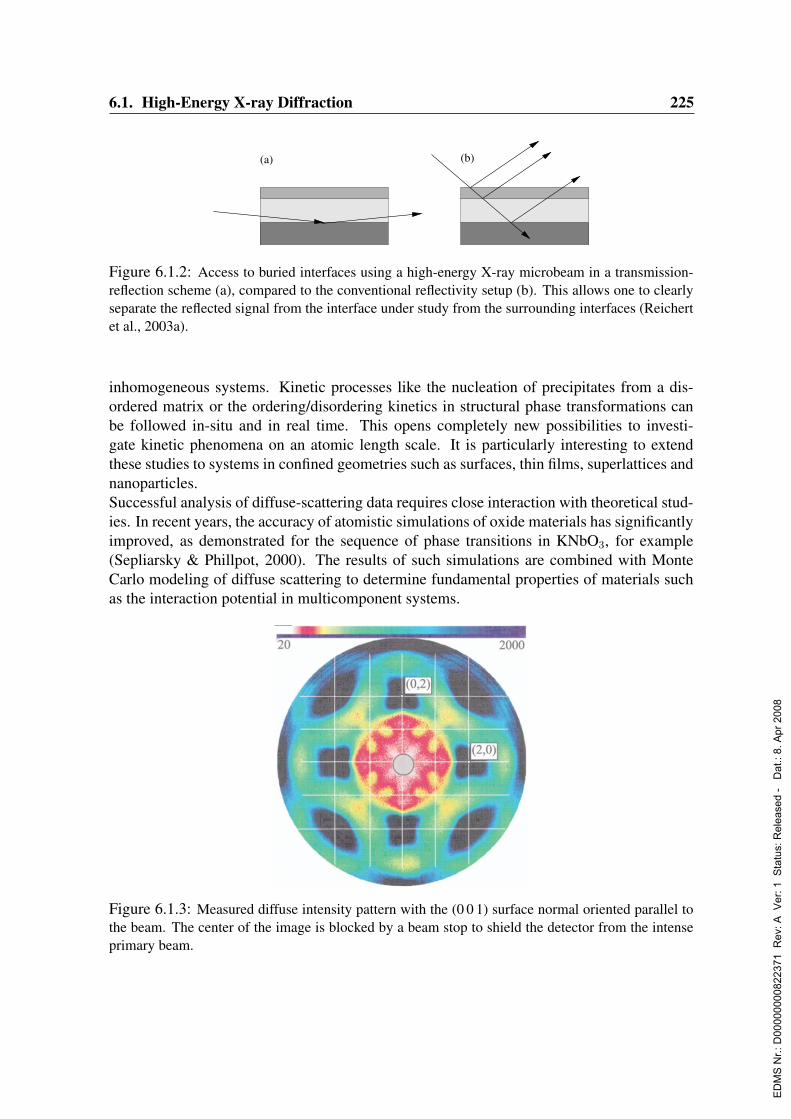
6.1. High-Energy X-ray Diffraction 225
(b)(a)
Figure 6.1.2: Access to buried interfaces using a high-energy X-ray microbeam in a transmission-reflection scheme (a), compared to the conventional reflectivity setup (b). This allows one to clearlyseparate the reflected signal from the interface under study from the surrounding interfaces (Reichertet al., 2003a).
inhomogeneous systems. Kinetic processes like the nucleation of precipitates from a dis-ordered matrix or the ordering/disordering kinetics in structural phase transformations canbe followed in-situ and in real time. This opens completely new possibilities to investi-gate kinetic phenomena on an atomic length scale. It is particularly interesting to extendthese studies to systems in confined geometries such as surfaces, thin films, superlattices andnanoparticles.Successful analysis of diffuse-scattering data requires close interaction with theoretical stud-ies. In recent years, the accuracy of atomistic simulations of oxide materials has significantlyimproved, as demonstrated for the sequence of phase transitions in KNbO3, for example(Sepliarsky & Phillpot, 2000). The results of such simulations are combined with MonteCarlo modeling of diffuse scattering to determine fundamental properties of materials suchas the interaction potential in multicomponent systems.
Figure 6.1.3: Measured diffuse intensity pattern with the (0 0 1) surface normal oriented parallel tothe beam. The center of the image is blocked by a beam stop to shield the detector from the intenseprimary beam.
ED
MS
Nr.:
D00
0000
0082
2371
Rev
: A V
er: 1
Sta
tus:
Rel
ease
d -
Dat
.: 8.
Apr
200
8
226 6. Beamlines and Experimental Stations
6.1.2.3 Charge - density analysis
In recent years it has been shown that high–energy synchrotron radiation is an excellent toolto perform charge density analysis, see, e.g. (Graafsma et al., 1998; Lippmann & Schneider,2000a; Lippmann & Schneider, 2000b; Kirfel et al., 2001; Lippmann et al., 2003). Expe-rimen tal charge distributions are often used in comparison with theoretical results in orderto test structural models, i.e. precise atomic coordinates, and to reveal details of the chem-ical bonding in crystals. Moreover, they can be used to derive further physical properties,e.g. electrostatic potentials, electrostatic moments, lattice energies, which can be comparedto results obtained by other methods, e.g. spectroscopy or thermodynamic measurements(Coppens, 1997).
Usually, charge densities are calculated after adjustments of an appropriate structure modelto a set of structure factors. These are obtained from integrated reflection Iint intensities viaapplication of various correction factors: Iint = L · P · T · A · E · |F |2, where the Lorentzcorrection L and the polarization correction P can simply be calculated after the experimentand the thermal diffuse scattering correction T can be minimized by measuring at low tem-peratures. In contrast, the absorption correction A often cause problems, if the shapes of thesamples are irregular. Moreover, the extinction correction E can not be carried out prior torefinement, because the crystal quality is usually a priori unknown. In order to minimize theerrors of the last two corrections the best solution is to minimize the corrections themselves,i.e. using high–energy radiation.
In addition to the improvement of the data quality, high–energy radiation opens the gate toa large number of new structures, which contain heavy elements, because the strong absorp-tion of low–energy radiation by these structures prohibited the experimental determinationof reliable structure factors in the past. High–Tc superconductors may be considered as anexample for these materials (Lippmann et al., 2003).
Most of the experiments have been performed at high–energy wiggler beamlines, e.g. BW5at DORIS III. Since the sample sizes are typically of the order of a few 100µm, only a smallfraction of the primary radiation is scattered by the sample. In contrast, the use of high–brilliant 3rd generation light sources with small beam sizes should yield an intensity gain ofthe scattered radiation by at least 1 to 2 magnitudes, which offers the possibility for variousnew experiments and studies in this field. In combination with fast detectors the performanceof time–resolved studies are possible, e.g. structure factor measurements after illuminatingthe samples with a laser in order to test excited states (Kim et al., 2002). Another benefitof the intensity gain is the enhancement of the data resolution by extending the size of thedata sets. Up to now this has simply failed due to a lack of beamtime. An enhancement ofthe data resolution would offer the possibility to study small structural features in detail andthus to answer open questions. As an example, 30 years ago theoretical considerations leadto the question, whether near–core electron orbitals are spherical, as usually believed, or alsoaffected with small aspherical distortions (Bentley & Stewart, 1974). A proof of this coredeformation will be possible, as soon as high–resolution experimental data are available.
ED
MS
Nr.:
D00
0000
0082
2371
Rev
: A V
er: 1
Sta
tus:
Rel
ease
d -
Dat
.: 8.
Apr
200
8
6.1. High-Energy X-ray Diffraction 227
6.1.2.4 High-resolution studies of liquids and amorphous materials
X-ray diffraction studies of structures of disordered materials (glasses, melts) are often ac-companied by correction problems arising from absorption, Compton scattering, fluores-cence, scattering from the sample environment, and finite momentum transfer range. Theidea using high-energy photons to overcome these problems goes back to Egelstaff (Egel-staff, 1983). A pioneering experiment using 95 keV photons was performed at wiggler beam-line BW5 of HASYLAB for studying the structure of vitreous silica (Poulsen et al., 1995).Since that time a progressing number of such experiments has been carried out. For example,structural studies of oxide glasses were performed, where data at momentum transfers Q upto 300 - 400 nm−1 were collected (Petkov et al., 2000; Ohno et al., 2001; Hoppe et al., 2000).The quality of the X-ray scattering data will be comparable with those obtained in neutronscattering experiments at the best sources. Effects of truncation of the measuring range be-come less significant with increasing Q. Data obtained from X-ray contrast variation andneutron scattering can be combined to reach highest resolving power and precision. Thisis also valid for samples which are known as highly absorbing for low-energy radiation inconventional experiments such as lead containing glasses (Ohno et al., 2001). Nevertheless,some problems are not properly solved and need optimization: The Compton scattering in-creases dramatically with momentum transfer and a separation of the elastic line with thestructural information from the Compton profile is only possible for large scattering anglesat energies significantly below 100 keV (Laaziri et al., 1999). This requires a vertical scat-tering plane to avoid problems with the beam polarization (Petkov et al., 2000). On the otherhand, the use of photon energies clearly beyond 100 keV is optimal to reduce absorptionproblems to a negligible degree and to obtain high-precision data. However, this means thatall structural information will be found at small scattering angles where Compton scatteringcannot be subtracted (Hoppe et al., 2000). Except for the use of energy-dispersive detectorsfor discrimination of fluorescence and other sources of background, also fast 2D-detectorsare desirable for series of measurements with short exposure times (Petkov, Qadir & Shastri,2004).
6.1.2.5 High - energy magnetic X-ray diffraction
Magnetic X-ray scattering results from the interaction of the electromagnetic wave not onlywith the charge of the electrons in the solid but also with the magnetic moment. The in-teraction with the magnetic moment is a relativistic effect and is described by first orderperturbation theory. Thus, the intensity of the magnetic signal is several orders of mag-nitudes weaker than the charge intensities. Whereas the magnetic X-ray scattering crosssection in the hard X-ray energy range (5–20 keV) involves both spin and orbital magneticmoment, non-resonant high-energy magnetic X-ray diffraction at energies above 80 keV isonly sensitive to the spin magnetic moment (Bruckel et al., 1993). At these energies, truebulk properties are investigated due to the high penetration depth of the radiation. High-energy magnetic X-ray diffraction is thus complementary to magnetic neutron diffraction,where also the whole sample is penetrated but where the sum of spin and orbital magneticmoment contributes to the magnetic cross section. With both techniques the same samplescan be investigated, even with the same sample environment. By combination of the results,
ED
MS
Nr.:
D00
0000
0082
2371
Rev
: A V
er: 1
Sta
tus:
Rel
ease
d -
Dat
.: 8.
Apr
200
8

228 6. Beamlines and Experimental Stations
absolute spin and orbital magnetic moments can be determined independently with high ac-curacy (Strempfer et al., 2004).The investigation of temperature dependencies of the magnetic order parameter with highenergy photons takes advantage of the high momentum space resolution of X-ray diffractionat the synchrotron compared to that in neutron scattering experiments. Because of the narrowrocking curves of the Bragg reflections, the Bragg intensity can be separated from the muchwider diffuse scattering background in the critical regime near the Neel temperature. Also,small magnetic satellite reflections can be separated easily from the much stronger chargeBragg reflections.Non-resonant magnetic scattering of high-energy X-rays provides highly precise and detailedinformation on the spin density which can serve as test data for density functional theories.So far, only rather simple compounds have been investigated. At PETRA III, this methodcan be extended to compounds of more complicated structure. Requirements here are highquality crystals, a large magnetic moment and a favorable ratio of the number of magneticelectrons to the total number of electrons. For such investigations, a high-brilliance beamcombined with high incident flux and low background is indispensable.
6.1.2.6 High-energy X-ray diffraction from correlated electron materials
Correlated electron materials are a highly interesting class of compounds both from a scien-tific point of view, but also for applications as functional materials. The strong interplay ofspin, orbital, charge and lattice degrees of freedom makes the comparison of model calcula-tions to experimental results highly desirable. A more detailed introduction into correlatedelectron materials can be found in Sec. 6.15. The hard X-ray diffraction technique is a verysensitive probe for lattice distortions and is thus capable to detect structural distortions asso-ciated with orbital ordering (Geck et al., 2002) and charge ordering (v. Zimmermann et al.,1998). Even the spin order can, in principle, be determined with hard X-ray diffraction(see Sec. 6.1.2.5). The technique offers possibilities that are important for the investigationof correlated electron materials, among these are the bulk sensitivity, which makes surfacecontaminations negligible. Furthermore, the signal from small structural features becomesenhanced by probing larger samples. The Laue scattering geometry allows to access largeamounts of reciprocal space. Another important aspect is the complex sample environmentthat can be used for hard X-ray diffraction experiments. Due to the high penetration depthof X-rays with energies around 100 keV, it is possible to use pressure cells and magneticfields without compromising the measured signal and the accessibility of reciprocal space.With these external fields it is possible to disturb the balance between the various degrees offreedom in these materials (Geck et al., 2002; Wakimoto et al., 2003). Since the structuraldistortions are often of diffuse nature, an option to relax the resolution and thus achieve thehighest possible photon flux on the sample, would be desirable.
6.1.3 Beamline description
The beamline consists of two optics hutches and two experimental hutches. Optics hutch1 (OH1) contains a cryogenically cooled double-Laue monochromator. Optionally, this
ED
MS
Nr.:
D00
0000
0082
2371
Rev
: A V
er: 1
Sta
tus:
Rel
ease
d -
Dat
.: 8.
Apr
200
8
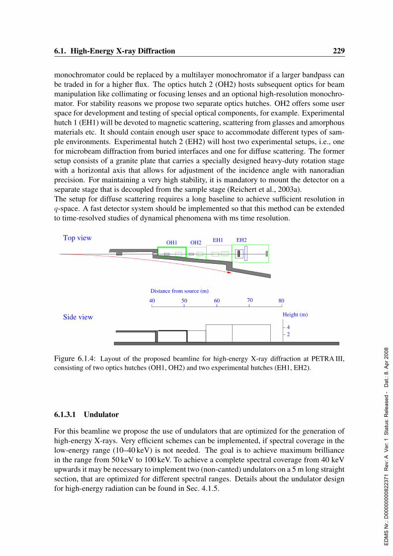
6.1. High-Energy X-ray Diffraction 229
monochromator could be replaced by a multilayer monochromator if a larger bandpass canbe traded in for a higher flux. The optics hutch 2 (OH2) hosts subsequent optics for beammanipulation like collimating or focusing lenses and an optional high-resolution monochro-mator. For stability reasons we propose two separate optics hutches. OH2 offers some userspace for development and testing of special optical components, for example. Experimentalhutch 1 (EH1) will be devoted to magnetic scattering, scattering from glasses and amorphousmaterials etc. It should contain enough user space to accommodate different types of sam-ple environments. Experimental hutch 2 (EH2) will host two experimental setups, i.e., onefor microbeam diffraction from buried interfaces and one for diffuse scattering. The formersetup consists of a granite plate that carries a specially designed heavy-duty rotation stagewith a horizontal axis that allows for adjustment of the incidence angle with nanoradianprecision. For maintaining a very high stability, it is mandatory to mount the detector on aseparate stage that is decoupled from the sample stage (Reichert et al., 2003a).The setup for diffuse scattering requires a long baseline to achieve sufficient resolution inq-space. A fast detector system should be implemented so that this method can be extendedto time-resolved studies of dynamical phenomena with ms time resolution.
24
Height (m)Side view
8070605040
Top view EH1 EH2
Distance from source (m)
OH2OH1
Figure 6.1.4: Layout of the proposed beamline for high-energy X-ray diffraction at PETRA III,consisting of two optics hutches (OH1, OH2) and two experimental hutches (EH1, EH2).
6.1.3.1 Undulator
For this beamline we propose the use of undulators that are optimized for the generation ofhigh-energy X-rays. Very efficient schemes can be implemented, if spectral coverage in thelow-energy range (10–40 keV) is not needed. The goal is to achieve maximum brilliancein the range from 50 keV to 100 keV. To achieve a complete spectral coverage from 40 keVupwards it may be necessary to implement two (non-canted) undulators on a 5 m long straightsection, that are optimized for different spectral ranges. Details about the undulator designfor high-energy radiation can be found in Sec. 4.1.5.
ED
MS
Nr.:
D00
0000
0082
2371
Rev
: A V
er: 1
Sta
tus:
Rel
ease
d -
Dat
.: 8.
Apr
200
8
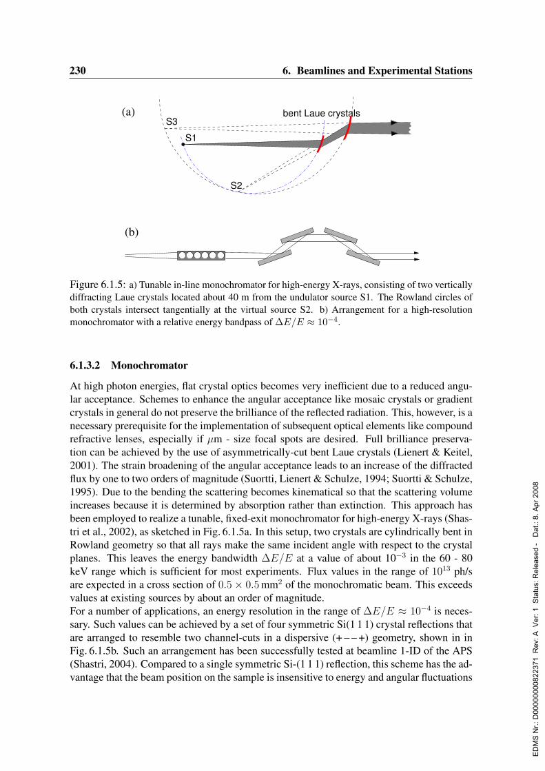
230 6. Beamlines and Experimental Stations
S1
S2
S3bent Laue crystals(a)
(b)
Figure 6.1.5: a) Tunable in-line monochromator for high-energy X-rays, consisting of two verticallydiffracting Laue crystals located about 40 m from the undulator source S1. The Rowland circles ofboth crystals intersect tangentially at the virtual source S2. b) Arrangement for a high-resolutionmonochromator with a relative energy bandpass of ∆E/E ≈ 10−4.
6.1.3.2 Monochromator
At high photon energies, flat crystal optics becomes very inefficient due to a reduced angu-lar acceptance. Schemes to enhance the angular acceptance like mosaic crystals or gradientcrystals in general do not preserve the brilliance of the reflected radiation. This, however, is anecessary prerequisite for the implementation of subsequent optical elements like compoundrefractive lenses, especially if µm - size focal spots are desired. Full brilliance preserva-tion can be achieved by the use of asymmetrically-cut bent Laue crystals (Lienert & Keitel,2001). The strain broadening of the angular acceptance leads to an increase of the diffractedflux by one to two orders of magnitude (Suortti, Lienert & Schulze, 1994; Suortti & Schulze,1995). Due to the bending the scattering becomes kinematical so that the scattering volumeincreases because it is determined by absorption rather than extinction. This approach hasbeen employed to realize a tunable, fixed-exit monochromator for high-energy X-rays (Shas-tri et al., 2002), as sketched in Fig. 6.1.5a. In this setup, two crystals are cylindrically bent inRowland geometry so that all rays make the same incident angle with respect to the crystalplanes. This leaves the energy bandwidth ∆E/E at a value of about 10−3 in the 60 - 80keV range which is sufficient for most experiments. Flux values in the range of 1013 ph/sare expected in a cross section of 0.5× 0.5 mm2 of the monochromatic beam. This exceedsvalues at existing sources by about an order of magnitude.For a number of applications, an energy resolution in the range of ∆E/E ≈ 10−4 is neces-sary. Such values can be achieved by a set of four symmetric Si(1 1 1) crystal reflections thatare arranged to resemble two channel-cuts in a dispersive (+ – – +) geometry, shown in inFig. 6.1.5b. Such an arrangement has been successfully tested at beamline 1-ID of the APS(Shastri, 2004). Compared to a single symmetric Si-(1 1 1) reflection, this scheme has the ad-vantage that the beam position on the sample is insensitive to energy and angular fluctuations
ED
MS
Nr.:
D00
0000
0082
2371
Rev
: A V
er: 1
Sta
tus:
Rel
ease
d -
Dat
.: 8.
Apr
200
8
6.1. High-Energy X-ray Diffraction 231
of the beam delivered from the first monochromator stage (only the transmitted intensity maydrift). As a result, such a monochromator scheme can be ideally combined with subsequentfocusing optics and experimental arrangements that demand for highest stability.
6.1.3.3 Focusing optics
For an efficient illumination of buried interfaces, the radiation has to be focused to µm sizedfocal spots. The use of microbeams significantly enhances the signal-to-noise ratio in evanes-cent X-ray diffraction and X-ray reflectivity studies. First, the entire beam cross section con-tributes to the scattered signal at very small grazing angles. Second, the very small phasespace volume covered by the detector drastically reduces the contribution from diffuse scat-tering. Thus, microfocusing is essential to access large momentum transfers where X-rayreflectivities have dropped to the range of 10−12.At high energies, several options are available to achieve micron-sized focal spots. Com-pound refractive lenses have been used to yield spot sizes in the range of 10µm at a photonenergy of 71 keV (Reichert et al., 2003a). Single zone plates cannot be manufactured thickenough to produce a π phase shift between zones. Nevertheless, a 10 micron-sized focal spothas been achieved at 50 keV by precise stacking of several zone plates (Shastri et al., 2001).Another option is the use of Laue crystals that are bent to set the source outside the Rowlandcircle. Using this method, 90 keV X-rays have been focused to 1.2µm (Lienert & Schulze,1998). Eventually, the most promising candidates for sub-micron focal spots seem to bebent multilayer mirrors, despite the demanding angular stability and slope-error require-ments. Point focusing in this case can be achieved by the combination of two multilayers inKirkpatrick-Baez geometry.
6.1.3.4 Sample stages
The stability of the sample stages plays a crucial role for X-ray scattering experiments involv-ing microbeams. For adjustment of the incidence angle in high-energy grazing-incidence re-flection, the accuracy of commercially available stages is not sufficient, in particular if heavyweights like UHV chambers have to be adjusted and kept stable within nanoradian precision.In this area, significant R&D activities have to be carried out to meet these requirements inroutine user operation.
6.1.4 Capital investment and personnelFor the development of the scientific program at the beamline, two researchers are requiredwho will run independent activities to accommodate a wide scientific community.The performance of the monochromators and high-resolution sample stages crucially de-pends on an engineer that is dedicated to such developments. In particular, experience innano-radian motion control is required. For installation of the beamline components andtheir maintenance, two technicians are needed, whereby one of them is specialized installa-tions, including motor control and data acquisition.The total capital investment for this experimental station amounts to 1990 ke.
ED
MS
Nr.:
D00
0000
0082
2371
Rev
: A V
er: 1
Sta
tus:
Rel
ease
d -
Dat
.: 8.
Apr
200
8
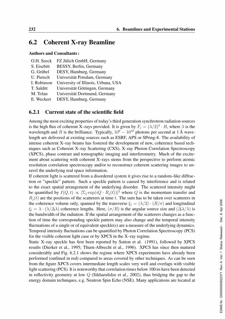
232 6. Beamlines and Experimental Stations
6.2 Coherent X-ray BeamlineAuthors and Consultants :
O.H. Seeck FZ Julich GmbH, GermanyS. Eisebitt BESSY, Berlin, GermanyG. Grubel DESY, Hamburg, GermanyU. Pietsch Universitat Potsdam, GermanyI. Robinson University of Illinois, Urbana, USAT. Salditt Universitat Gottingen, GermanyM. Tolan Universitat Dortmund, GermanyE. Weckert DESY, Hamburg, Germany
6.2.1 Current state of the scientific fieldAmong the most exciting properties of today’s third generation synchrotron radiation sourcesis the high flux of coherent X–rays provided. It is given by Fc = (λ/2)2 · B, where λ is thewavelength and B is the brilliance. Typically, 109 − 1010 photons per second at 1 A wave-length are delivered at existing sources such as ESRF, APS or SPring-8. The availability ofintense coherent X–ray beams has fostered the development of new, coherence based tech-niques such as Coherent X–ray Scattering (CXS), X–ray Photon Correlation Spectroscopy(XPCS), phase contrast and tomographic imaging and interferometry. Much of the excite-ment about scattering with coherent X–rays stems from the perspective to perform atomicresolution correlation spectroscopy and/or to reconstruct coherent scattering images to un-ravel the underlying real space information.If coherent light is scattered from a disordered system it gives rise to a random–like diffrac-tion or ”speckle” pattern. Such a speckle pattern is caused by interference and is relatedto the exact spatial arrangement of the underlying disorder. The scattered intensity mightbe quantified by I(Q, t) ∝ |Σj exp(iQ · Rj(t))|2 where Q is the momentum transfer andRj(t) are the positions of the scatterers at time t. The sum has to be taken over scatterers inthe coherence volume only, spanned by the transverse ξt = (λ/2) · (R/σ) and longitudinalξl = λ · (λ/∆λ) coherence lengths. Here, (σ/R) is the angular source size and (∆λ/λ) isthe bandwidth of the radiation. If the spatial arrangement of the scatterers changes as a func-tion of time the corresponding speckle pattern may also change and the temporal intensityfluctuations of a single or of equivalent speckle(s) are a measure of the underlying dynamics.Temporal intensity fluctuations can be quantified by Photon Correlation Spectroscopy (PCS)for the visible coherent light case or by XPCS in the X–ray regime.Static X–ray speckle has first been reported by Sutton et al. (1991), followed by XPCSresults (Dierker et al., 1995; Thurn-Albrecht et al., 1996). XPCS has since then maturedconsiderably and Fig. 6.2.1 shows the regime where XPCS experiments have already beenperformed (outlined in red) compared to areas covered by other techniques. As can be seenfrom the figure XPCS covers intermediate length scales very well and overlaps with visiblelight scattering (PCS). It is noteworthy that correlation times below 100 ns have been detectedin reflectivity geometry at low Q (Sikharulidze et al., 2002), thus bridging the gap to theenergy domain techniques, e.g. Neutron Spin Echo (NSE). Many applications are located at
ED
MS
Nr.:
D00
0000
0082
2371
Rev
: A V
er: 1
Sta
tus:
Rel
ease
d -
Dat
.: 8.
Apr
200
8

6.2. Coherent X-ray Beamline 233
low Q [surface/capillary wave type dynamics (Seydel et al., 2001; Madsen, Als-Nielsen &Grubel, 2003)] or moderate Q (< 5 · 10−2 A−1) addressing mostly questions in complexfluids (Mochrie et al., 1997; Grubel et al., 2000; Lurio et al., 2000). Access to shorter lengthscales (Q > 5 · 10−2 A−1) can be more difficult. The necessary higher temporal coherenceimplies a higher monochromaticity that can only be provided at the expense of coherent flux.This cannot always be compensated by 2–D detection since fast (ms - µs) 2–D single photoncounting detectors with appropriate spatial resolution and quantum efficiency do not existtoday. An accompanying R&D effort in 2-D detectors is thus mandatory and engaged e.g.for pixel detectors.
10-7 10-6 10-5 10-4 10-3 10-2 10-1 100 101
momentum transfer [Å-1]
10-2100102104106108
101010121014101610181020
frequ
ency
[Hz]
100101102103104105106107length scale [Å]
10-1610-1410-1210-1010-810-610-410-2100102104
ener
gy[e
V]
PCS XPCSNFS
Spin-EchoBrillouin
Raman
INS
IXS
Figure 6.2.1: Sketch of the ac-cessible frequency momentum trans-fer ranges for different experimentalmethods. The red outlined area canpresently be studied with XPCS.
The inversion of speckle images is complicated by the fact that the necessary phase informa-tion is lost during the measurement. There are, however, algorithms that allow to recover thisinformation when speckle images are sampled with fine enough resolution. This has beenshown for artificial model structures (Miao et al., 1999) and applied e.g. to nano-crystallinematerials (Williams et al., 2003; He et al., 2003). The latter work was successfully carriedout on single crystalline material with a typical dimension down to 100 nm. An increase inbrilliance would lead here to the possibility to study smaller objects and to eventually in-vestigate granular microstructure in polycrystalline films. Magnetic X–ray speckle has beenobserved and characterized in a variety of materials (Peters et al., 2000; Eisebitt et al., 2003)without however leading to any successful reconstruction (or dynamic measurement) yet.Novel sources such as PETRA III will enable to reconstruct magnetic speckle patterns and todeduce the exact 3–D spin arrangement in magnetic nanostructures, such as magnetic storagemedia. Diffraction on single molecules is beyond the scope of storage ring sources. Simula-tions indicate this possibility for a future FEL source (Miao, Hodgson & Sayre, 2001). It ishowever already evident today that at novel sources like PETRA III the borderlines betweennear–field (Fresnel) imaging and far–field (Fraunhofer) diffraction will become increasinglytransparent. Thus both, coherence preservation and/or tuning and reconstruction technolo-gies will become more and more important. Smaller sources will also permit the transitionfrom micro– to nano-focusing enabling new applications such as element specific micro– ornanofluorescence correlation spectroscopy (Wang et al., 1998a). It can furthermore be ex-
ED
MS
Nr.:
D00
0000
0082
2371
Rev
: A V
er: 1
Sta
tus:
Rel
ease
d -
Dat
.: 8.
Apr
200
8
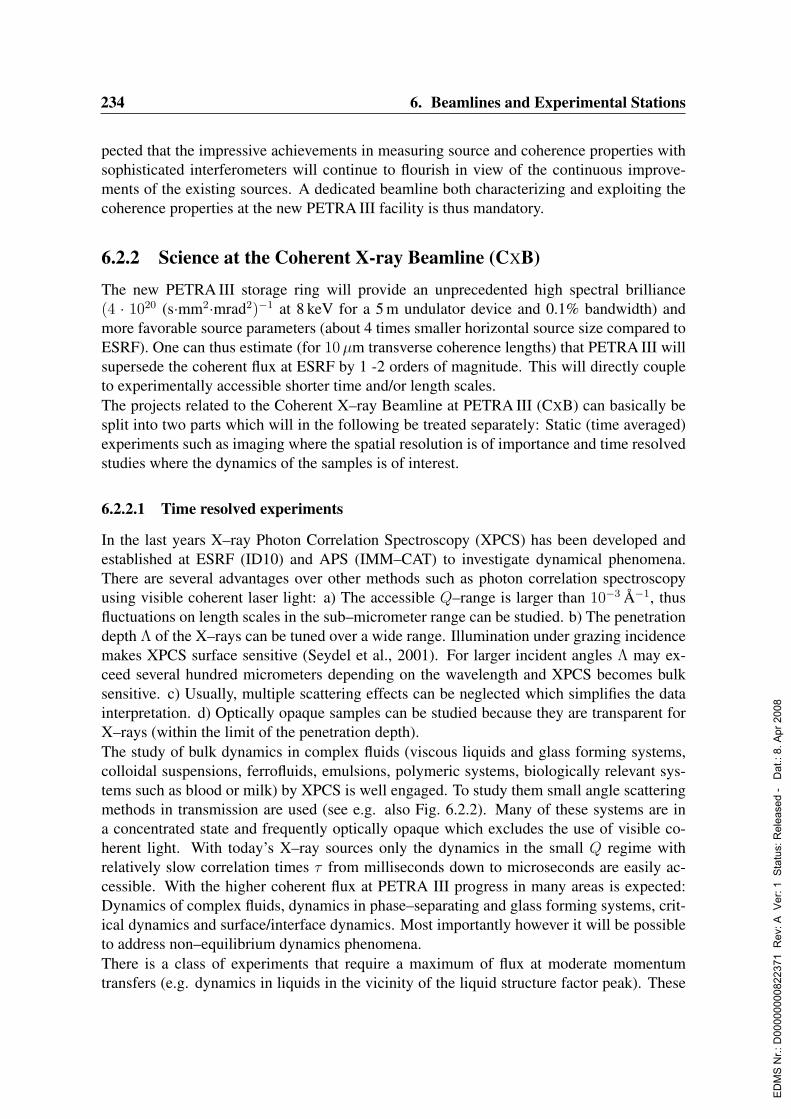
234 6. Beamlines and Experimental Stations
pected that the impressive achievements in measuring source and coherence properties withsophisticated interferometers will continue to flourish in view of the continuous improve-ments of the existing sources. A dedicated beamline both characterizing and exploiting thecoherence properties at the new PETRA III facility is thus mandatory.
6.2.2 Science at the Coherent X-ray Beamline (CXB)
The new PETRA III storage ring will provide an unprecedented high spectral brilliance(4 · 1020 (s·mm2·mrad2)−1 at 8 keV for a 5 m undulator device and 0.1% bandwidth) andmore favorable source parameters (about 4 times smaller horizontal source size compared toESRF). One can thus estimate (for 10µm transverse coherence lengths) that PETRA III willsupersede the coherent flux at ESRF by 1 -2 orders of magnitude. This will directly coupleto experimentally accessible shorter time and/or length scales.The projects related to the Coherent X–ray Beamline at PETRA III (CXB) can basically besplit into two parts which will in the following be treated separately: Static (time averaged)experiments such as imaging where the spatial resolution is of importance and time resolvedstudies where the dynamics of the samples is of interest.
6.2.2.1 Time resolved experiments
In the last years X–ray Photon Correlation Spectroscopy (XPCS) has been developed andestablished at ESRF (ID10) and APS (IMM–CAT) to investigate dynamical phenomena.There are several advantages over other methods such as photon correlation spectroscopyusing visible coherent laser light: a) The accessible Q–range is larger than 10−3 A−1, thusfluctuations on length scales in the sub–micrometer range can be studied. b) The penetrationdepth Λ of the X–rays can be tuned over a wide range. Illumination under grazing incidencemakes XPCS surface sensitive (Seydel et al., 2001). For larger incident angles Λ may ex-ceed several hundred micrometers depending on the wavelength and XPCS becomes bulksensitive. c) Usually, multiple scattering effects can be neglected which simplifies the datainterpretation. d) Optically opaque samples can be studied because they are transparent forX–rays (within the limit of the penetration depth).The study of bulk dynamics in complex fluids (viscous liquids and glass forming systems,colloidal suspensions, ferrofluids, emulsions, polymeric systems, biologically relevant sys-tems such as blood or milk) by XPCS is well engaged. To study them small angle scatteringmethods in transmission are used (see e.g. also Fig. 6.2.2). Many of these systems are ina concentrated state and frequently optically opaque which excludes the use of visible co-herent light. With today’s X–ray sources only the dynamics in the small Q regime withrelatively slow correlation times τ from milliseconds down to microseconds are easily ac-cessible. With the higher coherent flux at PETRA III progress in many areas is expected:Dynamics of complex fluids, dynamics in phase–separating and glass forming systems, crit-ical dynamics and surface/interface dynamics. Most importantly however it will be possibleto address non–equilibrium dynamics phenomena.There is a class of experiments that require a maximum of flux at moderate momentumtransfers (e.g. dynamics in liquids in the vicinity of the liquid structure factor peak). These
ED
MS
Nr.:
D00
0000
0082
2371
Rev
: A V
er: 1
Sta
tus:
Rel
ease
d -
Dat
.: 8.
Apr
200
8
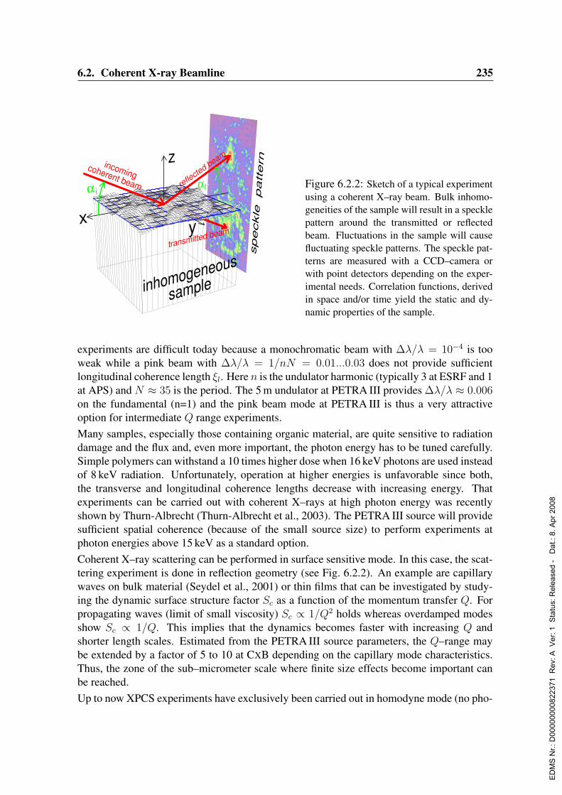
6.2. Coherent X-ray Beamline 235
speckle
pattern
transmitted beam
z
yx
inhomogeneous
sample
coherent beam
incomingrefle
cted beam
α iαf Figure 6.2.2: Sketch of a typical experiment
using a coherent X–ray beam. Bulk inhomo-geneities of the sample will result in a specklepattern around the transmitted or reflectedbeam. Fluctuations in the sample will causefluctuating speckle patterns. The speckle pat-terns are measured with a CCD–camera orwith point detectors depending on the exper-imental needs. Correlation functions, derivedin space and/or time yield the static and dy-namic properties of the sample.
experiments are difficult today because a monochromatic beam with ∆λ/λ = 10−4 is tooweak while a pink beam with ∆λ/λ = 1/nN = 0.01...0.03 does not provide sufficientlongitudinal coherence length ξl. Here n is the undulator harmonic (typically 3 at ESRF and 1at APS) and N ≈ 35 is the period. The 5 m undulator at PETRA III provides ∆λ/λ ≈ 0.006on the fundamental (n=1) and the pink beam mode at PETRA III is thus a very attractiveoption for intermediate Q range experiments.Many samples, especially those containing organic material, are quite sensitive to radiationdamage and the flux and, even more important, the photon energy has to be tuned carefully.Simple polymers can withstand a 10 times higher dose when 16 keV photons are used insteadof 8 keV radiation. Unfortunately, operation at higher energies is unfavorable since both,the transverse and longitudinal coherence lengths decrease with increasing energy. Thatexperiments can be carried out with coherent X–rays at high photon energy was recentlyshown by Thurn-Albrecht (Thurn-Albrecht et al., 2003). The PETRA III source will providesufficient spatial coherence (because of the small source size) to perform experiments atphoton energies above 15 keV as a standard option.Coherent X–ray scattering can be performed in surface sensitive mode. In this case, the scat-tering experiment is done in reflection geometry (see Fig. 6.2.2). An example are capillarywaves on bulk material (Seydel et al., 2001) or thin films that can be investigated by study-ing the dynamic surface structure factor Sc as a function of the momentum transfer Q. Forpropagating waves (limit of small viscosity) Sc ∝ 1/Q2 holds whereas overdamped modesshow Sc ∝ 1/Q. This implies that the dynamics becomes faster with increasing Q andshorter length scales. Estimated from the PETRA III source parameters, the Q–range maybe extended by a factor of 5 to 10 at CXB depending on the capillary mode characteristics.Thus, the zone of the sub–micrometer scale where finite size effects become important canbe reached.Up to now XPCS experiments have exclusively been carried out in homodyne mode (no pho-
ED
MS
Nr.:
D00
0000
0082
2371
Rev
: A V
er: 1
Sta
tus:
Rel
ease
d -
Dat
.: 8.
Apr
200
8
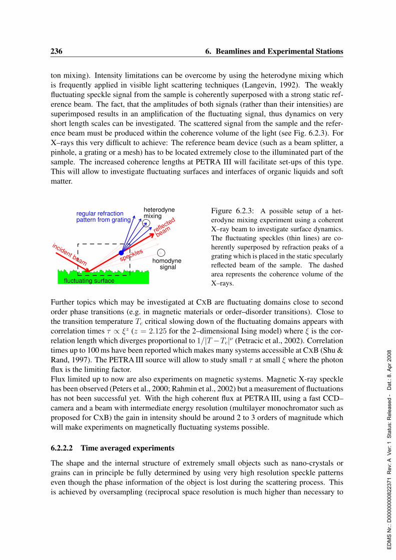
236 6. Beamlines and Experimental Stations
ton mixing). Intensity limitations can be overcome by using the heterodyne mixing whichis frequently applied in visible light scattering techniques (Langevin, 1992). The weaklyfluctuating speckle signal from the sample is coherently superposed with a strong static ref-erence beam. The fact, that the amplitudes of both signals (rather than their intensities) aresuperimposed results in an amplification of the fluctuating signal, thus dynamics on veryshort length scales can be investigated. The scattered signal from the sample and the refer-ence beam must be produced within the coherence volume of the light (see Fig. 6.2.3). ForX–rays this very difficult to achieve: The reference beam device (such as a beam splitter, apinhole, a grating or a mesh) has to be located extremely close to the illuminated part of thesample. The increased coherence lengths at PETRA III will facilitate set-ups of this type.This will allow to investigate fluctuating surfaces and interfaces of organic liquids and softmatter.
incident beam
fluctuating surface
regular refractionpattern from grating
reflected
beam
speckleshomodyne
signal
heterodynemixing
Figure 6.2.3: A possible setup of a het-erodyne mixing experiment using a coherentX–ray beam to investigate surface dynamics.The fluctuating speckles (thin lines) are co-herently superposed by refraction peaks of agrating which is placed in the static specularlyreflected beam of the sample. The dashedarea represents the coherence volume of theX–rays.
Further topics which may be investigated at CXB are fluctuating domains close to secondorder phase transitions (e.g. in magnetic materials or order–disorder transitions). Close tothe transition temperature Tc critical slowing down of the fluctuating domains appears withcorrelation times τ ∝ ξz (z = 2.125 for the 2–dimensional Ising model) where ξ is the cor-relation length which diverges proportional to 1/|T −Tc|ν (Petracic et al., 2002). Correlationtimes up to 100 ms have been reported which makes many systems accessible at CXB (Shu &Rand, 1997). The PETRA III source will allow to study small τ at small ξ where the photonflux is the limiting factor.Flux limited up to now are also experiments on magnetic systems. Magnetic X-ray specklehas been observed (Peters et al., 2000; Rahmin et al., 2002) but a measurement of fluctuationshas not been successful yet. With the high coherent flux at PETRA III, using a fast CCD–camera and a beam with intermediate energy resolution (multilayer monochromator such asproposed for CXB) the gain in intensity should be around 2 to 3 orders of magnitude whichwill make experiments on magnetically fluctuating systems possible.
6.2.2.2 Time averaged experiments
The shape and the internal structure of extremely small objects such as nano-crystals orgrains can in principle be fully determined by using very high resolution speckle patternseven though the phase information of the object is lost during the scattering process. Thisis achieved by oversampling (reciprocal space resolution is much higher than necessary to
ED
MS
Nr.:
D00
0000
0082
2371
Rev
: A V
er: 1
Sta
tus:
Rel
ease
d -
Dat
.: 8.
Apr
200
8
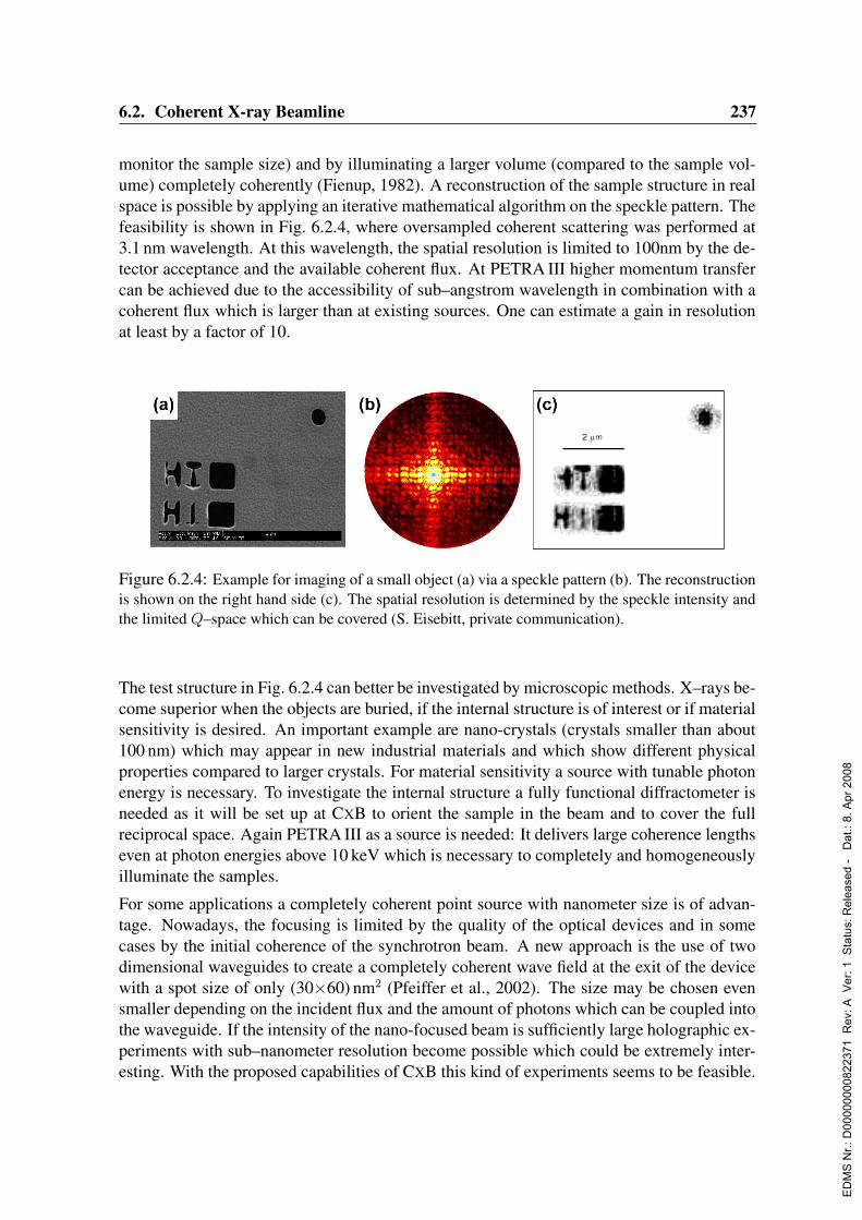
6.2. Coherent X-ray Beamline 237
monitor the sample size) and by illuminating a larger volume (compared to the sample vol-ume) completely coherently (Fienup, 1982). A reconstruction of the sample structure in realspace is possible by applying an iterative mathematical algorithm on the speckle pattern. Thefeasibility is shown in Fig. 6.2.4, where oversampled coherent scattering was performed at3.1 nm wavelength. At this wavelength, the spatial resolution is limited to 100nm by the de-tector acceptance and the available coherent flux. At PETRA III higher momentum transfercan be achieved due to the accessibility of sub–angstrom wavelength in combination with acoherent flux which is larger than at existing sources. One can estimate a gain in resolutionat least by a factor of 10.
Figure 6.2.4: Example for imaging of a small object (a) via a speckle pattern (b). The reconstructionis shown on the right hand side (c). The spatial resolution is determined by the speckle intensity andthe limited Q–space which can be covered (S. Eisebitt, private communication).
The test structure in Fig. 6.2.4 can better be investigated by microscopic methods. X–rays be-come superior when the objects are buried, if the internal structure is of interest or if materialsensitivity is desired. An important example are nano-crystals (crystals smaller than about100 nm) which may appear in new industrial materials and which show different physicalproperties compared to larger crystals. For material sensitivity a source with tunable photonenergy is necessary. To investigate the internal structure a fully functional diffractometer isneeded as it will be set up at CXB to orient the sample in the beam and to cover the fullreciprocal space. Again PETRA III as a source is needed: It delivers large coherence lengthseven at photon energies above 10 keV which is necessary to completely and homogeneouslyilluminate the samples.
For some applications a completely coherent point source with nanometer size is of advan-tage. Nowadays, the focusing is limited by the quality of the optical devices and in somecases by the initial coherence of the synchrotron beam. A new approach is the use of twodimensional waveguides to create a completely coherent wave field at the exit of the devicewith a spot size of only (30×60) nm2 (Pfeiffer et al., 2002). The size may be chosen evensmaller depending on the incident flux and the amount of photons which can be coupled intothe waveguide. If the intensity of the nano-focused beam is sufficiently large holographic ex-periments with sub–nanometer resolution become possible which could be extremely inter-esting. With the proposed capabilities of CXB this kind of experiments seems to be feasible.
ED
MS
Nr.:
D00
0000
0082
2371
Rev
: A V
er: 1
Sta
tus:
Rel
ease
d -
Dat
.: 8.
Apr
200
8
238 6. Beamlines and Experimental Stations
6.2.3 Beamline description
The crucial parameters for a coherence based beamline are the brilliance and the spatial andtemporal coherence lengths. In order to achieve extremely stable and vibration free beamconditions the beamline instrumentation and equipment has to be chosen carefully. Onlythe proper design of both (the source and the beamline) guarantees a successfully workinginstrument. This implies first of all maximum beam stability in both position and angle,long lifetime of the stored beam, thermal stability of optical elements and a filling patternas close as possible to DC conditions. External fluctuations are to be avoided. This refersto environmental noise, instrumentation related noise (pumps, cooling devices etc.,) andelectrical noise.Secondly, extremely important is the choice of a proper detector system. If a point detector ischosen to investigate single speckles an APD (avalanche photo diode) with its high dynamicrange is the detector of choice. This is especially important when correlation times becomevery short. In many cases 2D–detection (CCD–camera) is the only solution to gain scatteredintensity by averaging over iso–Q rings in small angle X–ray scattering (SAXS) geometry.In this way the illumination time on the sample can drastically be reduced (by a factor of 5to 100, depending on the experiment). Therefore, an ultra fast CCD–camera is mandatory tobe installed at CXB. This implies compatible set-ups for data transfer, the data storage, thecomputer hardware and software.For all experiments with high spatial resolution and for many time correlation experimentsa fully functional diffractometer with high accuracy is necessary (Q > 5 · 10−2 A). Thedetector arm should be able to carry a point detector or a CCD–camera. The option to tilt theincident beam (liquid diffractometer) is desirable. All optics and X–ray windows have to beoptimized in order to maintain a large degree of coherence.Key features and essential parameters for the beamline are listed in the following. A sketchof the beamline design is shown in Fig. 6.2.5.
• Type of undulator and stationCXB requires a straight station (no side station) with a 5 m undulator.
• Energy tunabilityThe full range of 5 keV – 25 keV. The energy will be quickly tunable during the exper-iment.
• High β– or low β–sectionA source with switchable β function is planned. If this is not possible a high β sectionis preferred.
• Beamsize and shape at the sampleThe beamsize and shape depends on the β-function. At a low–β section the FWHMbeamsize will be 3 mm horizontally and 0.45 mm vertically for 12 keV radiation andin 50 m distance from the source. For experiments at a high–β section a beam size of0.9×0.2 mm2 will be achieved for the same conditions.
ED
MS
Nr.:
D00
0000
0082
2371
Rev
: A V
er: 1
Sta
tus:
Rel
ease
d -
Dat
.: 8.
Apr
200
8

6.2. Coherent X-ray Beamline 239
• Divergence of the beamThe RMS divergence at a high-β section will be 30µrad horizontally and 4µrad ver-tically for 12 keV photons. At a high–β section the divergence will be (8×4)µrad2.Focusing will be possible.
• Stability of the beamThe beam will be extremely stable in terms of time and space. The fluctuations willbe smaller than 0.5% of the nominal values over 8 hours. External vibrations will beavoided. The beamline runs best with stable filling patterns of the electron/positron–bunches.
• Flux and bandwidth of the beam, tuning of the coherenceThe bandwidth of the first (fundamental) harmonic of a 5 m standard undulator atλ=1.5 A is ∆λ/λ = 6 · 10−3. The expected coherent flux at λ = 1.5 A for B = 4 · 1020
is Fc = (λ/2)2 · B is 1.4·1013. The nominal transverse coherence length at 50 m fromthe source is about 40µm (h) × 580µm (v) for a high-β section and 110µm (h) ×510µm (v) for a low-β section. The longitudinal coherence length for ∆λ/λ = 6·10−3
and λ=1.5 A is ξl = 0.025µm. Bandwidth tuning and increased longitudinal coher-ence lengths will be achieved via different monochromator configurations: A Si-(111)double monochromator and a multi layer monochromator will be installed. It will alsobe possible to guide the pink beam into the experimental hutch. A pair of mirrorswill suppress higher harmonics. Focusing is foreseen via mirrors and/or by compoundrefractive lenses.
• Coherence preservationAll optics will be carefully chosen and adapted under the aspect of coherence preser-vation and heat load resistance. The number of optical components will be minimized.All surfaces will be polished. Diamond based optics has to be considered.
• Distances from the sourceThe optical components will be located as close as possible to the source. The distancesource–sample will be about 50 m. The experimental hutch will be approximately 20 mlong (see Fig. 6.2.5). Some space will be reserved for an optional side station.
• Supplies at the beamlineCooling water (room temperature), He– and N2–gas supply, compressed air, supplyfor other gases. Two–phase and three–phase power outlets.
• Additional equipment at the experimental stationFast point detectors (avalanche photo diodes), a fast CCD-camera and a digital corre-lator for the point detectors will be set up. A 6–circle diffractometer for the sampleand an x–y stage for the CCD will be assembled with accuracies of 10−3 deg in angularspace and 0.1µm in translation. An optical bench in front of the diffractometer willbe installed. Pinholes, zone plates mounted on accurate x–y stages will be available.Additionally, temperature controllers, active vibration isolation stages, turbo pumps,ion getter pumps and power supplies will complete the setup.
ED
MS
Nr.:
D00
0000
0082
2371
Rev
: A V
er: 1
Sta
tus:
Rel
ease
d -
Dat
.: 8.
Apr
200
8

240 6. Beamlines and Experimental Stations
• ComputingA standard computer will control the beamline. A high performance computer withvery fast data transfer lines and very large disk space will be used with the CCD cam-era.
From the previous sections it is clear that CXB will be designed and equipped to makea multitude of different experiments possible. A straight station is mandatory: For someexperiments the pink beam passes to the experimental hutch, for others the energy has to betuned. A β–switchable source will be favorable: Imaging and CXS experiments can benefitfrom a low β–section, XPCS works better at a high β–section.
undu
lato
r sou
rce
optio
nal
focu
ssin
g
mirr
ors
doub
le c
ryst
alm
onoc
hrom
ator
optic
alba
nk 6-ci
rcle
diffr
acto
met
er
xy-s
tage
with
CC
D
optical hutch experimental hutch
0m 33m
34m
37m
41m
44m
45m
48m
52m
62m
64m
3.0m
0.0
m-1
.5m
Figure 6.2.5: Generic layout of the coherence application beamline CXB at PETRA III (not to scale).Only the most important devices are shown. The approximate height of the hutches will be 5 m. Thewhole ground should be as vibration free as possible.
To keep the degree of coherence the number of optical windows in the beamline will be min-imized. If the windows are made from Beryllium the surfaces have to be polished. Diamondwindows have to be considered, windowless operation has to be studied as an option.
6.2.4 Capital investment and personnelIn order to ensure 24 h operation the minimum staffing consists of 2 staff scientists (1 per-manent), 2 postdocs, 1 engineer and 1 technician. Estimated capital costs (excluding theinsertion device) comprising experimental instrumentation, detectors, beamline control, anddata acquisition are about 2000 ke. The layout of the beamline is highly modular and, basedon the experience at ESRF and APS, we have solutions for every component. This will en-able us to make the installation of the beamline and the start of commissioning compatiblewith day one operation of the machine.
ED
MS
Nr.:
D00
0000
0082
2371
Rev
: A V
er: 1
Sta
tus:
Rel
ease
d -
Dat
.: 8.
Apr
200
8

6.3. High Resolution X-Ray Diffraction Beamline 241
6.3 High Resolution X-Ray Diffraction Beamline
Authors and Consultants :
O. Bunk RISØ, DenmarkJ. Falta University of Bremen, GermanyR. Feidenhans’l RISØ, DenmarkJ. Grenzer University of Potsdam, GermanyU. Klemradt RWTH Aachen, GermanyCh. Kumpf University Wurzburg, GermanyO. Magnussen University of Kiel, GermanyW. Moritz LMU Munchen, GermanyB. Murphy University of Kiel, GermanyM. Nielsen RISØ, DenmarkD. V. Novikov DESY, GermanyH. Over University Giessen, GermanyU. Pietsch University of Potsdam, GermanyM. Schmidbauer Humboldt-Universitat zu Berlin, GermanyTh. Schmidt University of Bremen, GermanyO.H. Seeck FZ Julich GmbH, GermanyS. v. Smaalen Universitat Bayreuth, GermanyJ. Zegenhagen ESRF, France
6.3.1 Research with high-resolution X-ray diffraction methods
High resolution X-ray diffraction (HRXRD) is very widely used as a standard tool for struc-tural investigations over a wide variety of length scales (see, for instance, the “Advances inX-ray analysis” series, Gilfrich et al., 1993 and following issues):
• At atomic scale: The atomic structure and charge density in bulk, and layers as well asat surfaces and interfaces can be resolved. Diffraction methods are the most accurateprobe to determine the positions, occupation factors and displacement parameters ofatoms within the unit cell. Well ordered systems allow even charge density studies onthe level of binding electrons.
• At nanometer scale: For structures at solid and liquid surfaces and at buried inter-faces HRXRD allows to define such parameters as thickness, orientation, chemicalcomposition and interface roughness of layers. By variation of the incidence angle inreflectometry and grazing incidence diffraction/scattering also depth-resolved studiescan be carried out. Two-dimensional reciprocal space mapping methods are nowadaysstandard tools for these applications.
• At mesoscopic scale: Structural parameters of periodic and non-periodic nanostruc-tures and organic/inorganic material systems at mesoscopic scales can be investigated.Also for these techniques reciprocal space mapping is standard.
ED
MS
Nr.:
D00
0000
0082
2371
Rev
: A V
er: 1
Sta
tus:
Rel
ease
d -
Dat
.: 8.
Apr
200
8

242 6. Beamlines and Experimental Stations
• High resolution X-ray diffraction methods are traditionally used for precise measure-ments of lattice parameters. They allow to define important physical parameters ofperfect single crystals, for instance thermal expansion coefficients and phase transitionparameters. Also precise measurements of strain and stress distribution at the levelof relative lattice parameter variations of ∼ 10−4 − 10−6 in the bulk and at interfacesare possible. Lattice distortions induced by various defects can be studied from theirinfluence on the form and the width of reflection profiles.
6.3.2 High resolution beamlines at existing synchrotron facilitiesHigh resolution X-ray diffraction belongs to one of the most demanded basic techniques andinvolves a very wide variety of modern diffraction methods. Many undulator beamlines de-dicated for high resolution measurements are currently operated at ESRF, APS and SPring8.The common design includes a lq. N2-cooled double-crystal monochromator and a double-mirror harmonics suppression system. This optics provides good angular collimation in oneplane, usually in the vertical one. The beam has a relative bandwidth of ∆E/E ∼ 10−4.Many of the beamlines are equipped with focusing optics, which however degrades the beamcollimation. Such beam parameters suit well to a resolution level, which was demandedat the beginning of the 90’s. Since then, the complexity of objects and processes underinvestigation has immensely grown. To meet the new requirements, the beamlines mustprovide high flux X-rays with large transversal and longitudinal coherence.
6.3.3 High resolution diffraction at PETRA IIIThe proposed HRXRD beamline at PETRA III will deliver a beam, highly collimated inboth planes and with a controlled bandwidth variable in the range ∆E/E ∼ 10−5 − 10−4
in the whole wavelength range. The collimation and longitudinal coherence can be tailoredaccording to the demands of the experiment and allow investigations at variable length scalesand in a wide energy range. This is especially important for research of modern materialsand physical effects at mesoscopic lengths.The unique combination of very wide wavelength tunability in the range from 4 to 45 keV,ultra-high angular collimation and high monochromatization of the beam, delivered by theproposed HRXRD beamline, will open new possibilities for a wide spectrum of scientificfields:
• A variable longitudinal coherence and a large coherence volume of the beam will pro-vide access to length scales ranging from Angstrøms up to tens of micrometers.
• The high energies available (25–45 keV) will enable experiments at buried solid/solidand liquid/solid interfaces. This is of special importance, as interface processes are sofar mostly studied in model surface experiments.
• High brilliance and high photon flux will allow in situ investigations of process kineticsas in diffusion, growth and phase transitions. Research on very small, of the order ofnanometers, sample volumes and highly dissolved materials will become feasible.
ED
MS
Nr.:
D00
0000
0082
2371
Rev
: A V
er: 1
Sta
tus:
Rel
ease
d -
Dat
.: 8.
Apr
200
8
6.3. High Resolution X-Ray Diffraction Beamline 243
• Small beam sizes combined with high collimation will be used for combined real-and reciprocal space mapping of samples with complicated lateral structures, such assurface relief gratings or quantum dot arrangements. This is of a special interest forinvestigation on technologically relevant samples.
• The high brilliance at higher X-ray photon energies will also enable accurate crystal-lographic studies on extremely small single crystals of compounds that are so compli-cated in structure that powder crystallographic structure determination methods fail.The extremely parallel radiation is of advantage for the investigation of crystals withsatellite peaks very close to main reflections as they occur in some incommensuratestructures or in some long periodic super structures.
The list of experimental methods in the field of structural characterizations that will ben-efit from the high brilliance of PETRA III is large. It includes correlation spectroscopy,GIXRD (SXRD)1, GISAXS2, grazing incidence X-ray scattering, magnetic X-ray scatter-ing (MXRD), micro spot X-ray diffraction and scattering, X-ray reflectivity, X-ray standingwaves (XSW) employing X-ray fluorescence and X-ray photoelectron spectroscopy as sec-ondary signals. The sensitivity of the scattering methods can be enhanced by anomalousabsorption techniques for a wide range of materials.New prospects in surface and interface investigations, opened by high-resolution diffrac-tion at PETRA III, are of particular interest for the progress in the structural characterizationof new materials and will stimulate their development as exemplarily discussed for organicelectronics below. Here the main achievement will be the possibility to perform structuredeterminations for materials consisting of light elements (like carbon) which, due to theirvery small scattering amplitudes, have remained ‘invisible’ in conventional surface diffrac-tion and scattering experiments.The high brilliance combined with very large longitudinal coherence can also bring majoradvances in liquid surface research, especially in fluctuations at liquid surfaces, liquid met-als, surface freezing and layering and in-situ crystallization from solutions (Tolan, 1999).
6.3.3.1 In-vacuum surface research
The high brilliance storage ring PETRA III will enable a wide range of qualitatively newexperiments regarding the structure of surfaces and interfaces, like time-resolved measure-ments of surface and interface processes. Large benefit will be gained from the expected highbrilliance of PETRA III. It will allow to collect data at a drastically shorter time scale. Thebeamtime required to perform a structure determination by means of grazing incidence X-raydiffraction (GIXRD)3, for example, can be expected to be reduced from many hours to someminutes. This will not only permit to develop GIXRD into a standard tool of surface sci-ence, complementing LEED (low-energy electron diffraction) in its role as a work horse forthe characterization of surface structures, but also allows structure determination of highly
1GIXRD: grazing incidence X-ray diffraction; SXRD: surface X-ray diffraction.2GISAXS: grazing incidence small angle X-ray scattering.3This method is also referred to as SXRD (surface X-ray diffraction).
ED
MS
Nr.:
D00
0000
0082
2371
Rev
: A V
er: 1
Sta
tus:
Rel
ease
d -
Dat
.: 8.
Apr
200
8

244 6. Beamlines and Experimental Stations
diluted systems (like promoters in catalysis or dopants in semiconductors), and systems forwhich only very small sample volumes are available. The most important objects will bemineral and oxide surfaces, with applications in the fields of sensing and catalysis, materi-als for medical applications like implants, and quantum structures prepared on the basis onconventional and new semiconductors. Time-resolved diffraction experiments will allow tomonitor structural changes during surface, interface and ‘bulk’ processes like catalysis (per-formed in near ambiance conditions), adsorption and desorption (also intentional contami-nation), phenomena of epitaxial growth for a wide variety of growth methods such as MBE(molecular beam epitaxy), MOVPE (metal organic vapor pressure epitaxy), HPCVD (highpressure chemical vapor deposition, even up to atmospheric pressures), PECVD (plasma en-hanced chemical vapor deposition) and phase transitions of thin films. In combination with atunable polarization, analogous progress can be achieved in magnetic scattering experiments.
6.3.3.2 Mesoscopic semiconductor structures
Vertical carrier confinement is the basis for the most modern opto electronic devices. A lat-eral carrier confinement offers another degree of freedom for device design. In some cases,it allows to achieve better parameters, as i.e. a higher modal gain, a better thermal stability,and tunable emission wavelength of laser diodes (Klopf, Reithmayer & Forchel, 2000).Several concepts are being used to create a lateral confinement. One important approachis to exploit the self-organized growth of heavily strained 3D islands of the active material(Bimberg et al., 1999; Schmidbauer et al., 1998). In a different approach, semiconductorsurface wire and/or dot structures are created by a holographic exposure, a subsequent wetchemical etching and in a second epitaxial step the complete planarization of the corrugatedsurface. Another technology employs the low energy focused ion beam implantation for di-rect production of buried nanostructures. In case of implantation energies less than 100 keVthe penetration depth of ions lies below 1µm. At a depth up to 500 nm, the implantationinduces no significant structural damage, but a periodic strain profile.The challenge in structural characterization of lateral semiconductor nanostructures is thenon-destructive investigation of the shape and strain distribution (Schmidbauer et al., 1998;Roch et al., 2002; De Caro, Tapfer & Giuffrida, 1996; Shen et al., 1996; Grenzer et al.,2000; Grenzer et al., 2004; Zhong et al., 2003). Due to the lateral periodicity on the meso-scopic length scale each fundamental Bragg peak is accompanied by satellites, so-calledgrating peaks. For the typical lateral periodicity of 500 nm the period of these peaks equals∆qx= 0.013 nm−1, which requires a highly collimated beam and goniometers with an angu-lar resolution and angle reproducibility better than 0.001 for both sample ∆(ω) and detector∆(2Θ) rotation axis for peak separation. The large lateral correlation length of modern arti-ficial nanostructures results also in satellite peaks which are extremely narrow in width. Thismakes the requirement for the parallel beam optics and precise mechanics especially criticalin order to achieve that the width of the resolution function is smaller than the intrinsic widthof the satellite peaks. In structures obtained by ion implantation, damage and strain profilemust be defined. The entire strain lattice can be probed depth-resolved by GIXRD consider-ing the same instrumental demands (Grenzer et al., 2000).
ED
MS
Nr.:
D00
0000
0082
2371
Rev
: A V
er: 1
Sta
tus:
Rel
ease
d -
Dat
.: 8.
Apr
200
8
6.3. High Resolution X-Ray Diffraction Beamline 245
6.3.3.3 Phase transitions in surfaces and thin layers
Research of hase transitions at surfaces is a very important and fast developing field of mod-ern solid state physics. The existing theoretical descriptions of phase transitions at surfaces(Dietrich & Wagner, 1983; Binder, 1983; Diehl, 1986 and others) are yet to be fully verifiedexperimentally. Recent theoretical papers (Landau & Binder, 1990; Milchev et al., 2003)emphasize the importance of measuring critical behavior at the surface as close as possibleto the critical temperature.
Using surface X-ray scattering Burandt et al. (1993) obtained the first observations of near-surface critical phenomena of a phase transition in a molecular solid (NH4Br single crystal)showing both an order-disorder and a strong displacive component. In a very interestingexperiment Krimmel et al. (1997) performed an X-ray scattering study of the continuousB2-A2 order-disorder transition in semi- infinite FeCo(001). They observed that the surfacerelated order parameter persists above the bulk critical temperature for a mesoscopicallythick surface sheet. This temperature dependence displays a behavior similar to that of amagnet exposed to an external field. They conclude that the surface layer is not induced bysurface coupling but rather by surface segregation. This experiment provides evidence forthe presence of a surface field which couples to the surface susceptibility. In a grazing in-cidence study (Zhu et al., 1998) of the order-disorder transition in Cu3Au(111), a first orderphase transition in the bulk at 665 K was observed as well as enhanced surface ordering to aslightly higher temperature. The strong diffuse scattering from short range order fluctuationsin the bulk became much weaker in the surface region. Reichert et al.(2003) reported a newtype of short-range order correlations at the (001) surface of Cu3Au proposing that this newsurface effect was caused by a dramatic change in strain-induced interactions at the surface.
The physical properties of epitaxial ferroelectric films can be very different from those ofbulk crystals, mainly because of the distortion of the film by the substrate and the electrostric-tive coupling between polarization and strain, which is characteristic for perovskite ferro-electrics. Size effects in thin ferroelectric films result also from domain-wall contributionsand include (a) a minimum thickness for the existence of ferroelectricity, (b) a thickness-dependent increase of the transition temperature and (c) modifications of the spontaneouspolarization. In addition, also major qualitative changes of phase diagrams are predictedby theoretical calculations, leading to specific ferroelectric phases that do not exist in bulkcrystals. For example, the paraelectric to ferroelectric transition in certain perovskite filmsis predicted to be of second order instead of first-order as it is in the bulk; in a certain rangeof misfit strains and temperatures, a heterophase state may be stable, being composed ofdistorted ca and aa phases. However, since most calculations are based on relatively simpledomain models, high quality experimental data are necessary to test these critical issues forthe application of thin ferroelectric films and nanostructures. The observation of unusual,complex polarization states in ferroelectric films represents an experimental challenge.Synchrotron radiation offers the unique possibility to determine lattice parameters and unit-
ED
MS
Nr.:
D00
0000
0082
2371
Rev
: A V
er: 1
Sta
tus:
Rel
ease
d -
Dat
.: 8.
Apr
200
8
246 6. Beamlines and Experimental Stations
cell distortions in single-crystalline films, in and out of the plane of growth direction, withhigh precision. Furthermore, depth-resolved measurements allow access to the strain gradi-ent towards the surface as well.Such investigations would benefit strongly from a high-resolution beamline at PETRA IIIowing to the high brilliance of the beam and the high X-ray energies available (to penetratestrongly absorbing electrodes and other components of more complex multilayers). Experi-ments with small ferroelectric capacitor structures could be envisaged, with samples placedin additional contact to a dielectric spectroscopy setup.
The study of phase transitions in thin layers and especially at surfaces is a far clear casewhere both high resolution and high intensity are required simultaneously. Intrinsic widthsof the Bragg peaks are typically 0.005 or less and scattering becomes especially weak closeto the transition temperature. To investigate superstructures forming or melting, one willrequire the very low divergence provided by a high resolution beamline on a high flux highbrilliance source.
6.3.3.4 Soft matter systems: organic thin films - organic electronics
A central effort in organic electronics and related fields (notably organic photovoltaic andorganic light emitting diodes) is the development of a set of materials with a broad rangeof optical, optoelectronic, electronic, and sensing functionalities and adapted solution-basedadditive manufacturing processes (e.g. printing, display), applicable to a range of structuralsubstrates to form composite materials with designed multi-functionality. Structural controlof multi-functional materials is a key requirement for a solution-based manufacturing ap-proach. The ability to control the structures must extend over many different length scalesranging from the nanometer molecular length scale to the macroscopic length scale on whichcomponents and devices will be fabricated.In the last decade a number of publications have been devoted to inscription of surface re-lief gratings containing light sensitive moieties (Rochon, Batalla & Natansohn, 1995). Thewavelength of the laser should be near the absorption maximum associated with the trans-cis and cis-trans isomerisation of the azobenzene moieties. In case of polymers containingazobenzene units, a sinusoidal surface relief grating is created if the sample surface is illumi-nated by an interference pattern of two counter-rotating circular-polarized beams of an Ar+laser (l=488 nm). The absorption of this light induces material flow even at room tempera-ture which is at least 100 K below the glass transition temperature, of the polymers. Theseproperties make the investigated polymer materials very attractive for applications, in par-ticularly for high-density optical storage. Using a laser power of about 250 mW/cm2 and afilm thickness of 400 nm, a surface relief amplitude in the order of 100 nm is generated aftera time of about 30 s. The development of this surface relief grating is observed by in-situ X-ray diffuse scattering and reflectivity measurements. The correlation length of these gratingstructures exceeds several millimeter; therefore the grating peaks are again very narrow re-quiring an extreme high angular resolution (Kim et al., 1995; Barrett, Natansohn & Rochon,1996; Jiang et al., 1996; Geue et al., 2003).The typical length scale of self-organization is much smaller (typically < 10 nm) than the
ED
MS
Nr.:
D00
0000
0082
2371
Rev
: A V
er: 1
Sta
tus:
Rel
ease
d -
Dat
.: 8.
Apr
200
8

6.3. High Resolution X-Ray Diffraction Beamline 247
length scale on which devices and components are fabricated. Therefore, in many cases thepotential benefits of self-assembling properties do not translate into enhanced materials per-formance. If structural control is to be achieved, for example, with the help of a patterned,templating substrate, the length scale of patterns on such templates needs to match the lengthscale of self-organization (van de Craats et al., 2003; Bunk et al., 2003).Interfaces formed by solution processing of different materials, such as in inorganic/organichybrid materials are difficult to control, and are usually not atomically abrupt. Only a limitedset of metrology tools for quantitative characterization of interfaces exists, in particular forcharacterization of interfaces between functional polymers.Grazing Incidence X-ray Diffraction (GIXRD) is eminently suited for providing informa-tion about the molecular arrangements at buried interfaces and therefore also the method ofchoice for answering these questions. Using GIXRD one obtains detailed information onthe orientation and the apparent size of the self-organized domains in poly-3-hexylthiophene(P3HT) films spun on actual FET substrates (see Fig. 6.3.1). This result demonstrated thestrong dependence of the macroscopic charge carrier mobility on the orientation of the self-
Figure 6.3.1: The two-dimensional distribution of scattered grazing incidence X-ray intensities fromspin-coated 70–100 nm thick P3HT films with regioregularity of 96% (a) and 81% (b) on Si/SiO2 sub-strates: The vertical (horizontal) axis corresponds to scattering normal (parallel) to the plane of thefilm. Different orientations of the micro-crystallite grains with respect to the substrate are sketchedabove, together with the direction of motion probed when measuring the mobility of the charge car-riers. The measured charge carrier mobility increases by a factor of 100, from ∼ 0.001 cm2/V s to∼ 0.1 cm2/V s, going from the situation depicted in (b) to (a).
ED
MS
Nr.:
D00
0000
0082
2371
Rev
: A V
er: 1
Sta
tus:
Rel
ease
d -
Dat
.: 8.
Apr
200
8

248 6. Beamlines and Experimental Stations
organized domains (Sirringhaus et al., 1999), and lead to the conclusion that high mobilitiesreflect effective inter chain transport.Further, GIXRD investigations have revealed the structures formed at the interface betweenexternal alignment layers and a film of discotic molecules. Three epitactic growth modes ofthe discotic molecules were discovered, demonstrating a direct control of the orientation ofthe π-stack direction.A micro focus beamline with a well characterized, high collimated beam at the sample wouldallow to rapidly explore essential scattering data in one step, using a state-of-the-art CCDcamera. For many types of cast films (e.g. most spin-cast samples), the ordering is solely inthe direction parallel to the surface normal, hence a single image at grazing incidence wouldprovide the total scattering information obtainable in the diffraction regime.Combining diffraction analysis with X-ray reflectivity will add tremendously to the powerof characterization of buried interfaces. Here the main benefit can again be expected mostlyfrom a small, well defined and first and foremost a well collimated beam. Relating structuralcharacteristics to device properties requires the structure to be investigated under realisticconditions. The power of gaining insight into the structure of material is dramatically dimin-ished if we cannot correlate it to other material properties. For example, the characteristicsof FET devices are strongly dependent on the properties of the semiconductor in the channelregion between the source and drain electrodes. As typical channel widths are of the order ofa few microns, a true microprobe beam would allow us to monitor the structural developmentin the channel while a real transistor is operating.
6.3.3.5 Liquid surfaces and interfaces
The physics of liquid surfaces involves a wide variety of structural and dynamical properties,including among all capillary waves (Gutt et al., 2003), surface layering (Magnussen et al.,1995), surface freezing (Sloutskin et al., 2002), mixing/demixing, wetting, and the phasebehavior of Langmuir films (Magnussen et al., 1996; Kraack et al., 2002). They are inves-tigated at the surface of simple liquids, liquid metals, alloys, molten salts and inter metalliccompounds.Ideally, a dynamic range down to 10−10 should be accessible for these measurements, requir-ing high flux. Since liquid surfaces often exhibit significant curvature, small vertical beamsize and divergence, i.e. high brilliance, are required. Furthermore, the possibility of highflux / high energy measurements would allow to extend these studies to liquid-liquid inter-faces, e.g., to liquid metal/electrolyte interfaces or model biomembranes.Liquid surface research will require an additional tilting monochromator/mirror close to thesample and a liquid surface setup on the diffractometer the HRXD beamline.
6.3.3.6 High resolution structural investigation on bulk crystals
The high brilliance of a PETRA III undulator will provide unique possibilities for the inves-tigation of micro crystals, aperiodic compounds and for charge density studies.
ED
MS
Nr.:
D00
0000
0082
2371
Rev
: A V
er: 1
Sta
tus:
Rel
ease
d -
Dat
.: 8.
Apr
200
8
6.3. High Resolution X-Ray Diffraction Beamline 249
• Crystals of a large number of complex materials cannot be grown to large sizes sincethe corresponding synthesis paths deliver only micro crystalline powders. Crystalstructure determination from powders is still limited to relatively simple compoundsand also limited in accuracy due to the unavoidable overlap of reflection profiles. How-ever, most of the micro crystalline powders contain crystals from 1 to 10µm size whichis, depending on the exact composition and the radiation dose the crystals can sufferwithout damage, sufficient for single crystal diffraction studies at a high brillianceundulator beamline even for complex structures.
• Aperiodic crystals like incommensurately modulated crystals or quasi crystals show atleast in one dimension no translation symmetry despite the fact that they exhibit sharpBragg reflections. In general, the diffraction pattern consists of reasonably strongmain reflections and of satellite reflections with intensities 10−1 to 10−8 times weakerthan the main reflections. This large difference in intensity requires extremely intensebeams for a reliable determination of the satellite reflection intensities. Since thesesatellite peaks can occur very close to each other or to the main reflections a paral-lel beam is required in order to separate the different orders. Aperiodic crystals arefound in many material classes, e.g. many electronic materials exhibit at low temper-atures phase transitions giving rise to incommensurate spin- or charge-density waves.Only the accurate knowledge of the incommensurate structure will enable a thoroughunderstanding of the mechanism of the phase transition and of the physical properties.
• Accurate charge density studies allow to analyze the strength and kind of chemicalbonding and other interatomic interactions (Koritsanszky et al., 1998). The exper-imental determination requires reflection intensities of very high accuracy and highcompleteness up to a resolution of at least sin(θ)/λ = 1 A
−1or better up to sin(θ)/λ =
1.3 A−1
. Especially for more complex organic compounds like pharmaceuticals andsmall proteins it is extremely difficult to achieve a sufficiently high resolution due tothe weak scattering power in this range even at the low temperatures (20–100 K) usedin order to minimize the thermal motion of the atoms. Therefore, the high brilliance ofan undulator is required for the reliable determination of the intensity of the high orderreflections (Jelsch et al., 2000). In many cases X-ray photon energies above 20–30 keVare beneficial in order to reduce radiation damage and to minimize systematic errorslike absorption and extinction (see also Sec. 6.1.2.3).
6.3.4 Beamline optics and apparatus
The high resolution X-ray diffraction beamline can use a standard PETRA III undulator in ahigh-β section of the storage ring and will operate in the energy range from 4 to 45 keV. Dueto the wide energy range and the necessity to reach energies as high as 45 keV, the beamlinecan hardly be placed on a side station. No white or pink beam applications are planned.
ED
MS
Nr.:
D00
0000
0082
2371
Rev
: A V
er: 1
Sta
tus:
Rel
ease
d -
Dat
.: 8.
Apr
200
8

250 6. Beamlines and Experimental Stations
6.3.4.1 Beam conditioning optical elements
The first optical element of the beamline will be a fixed-exit double-crystal silicon monochro-mator cooled to 120 K. The monochromator includes two pairs of crystals, with symmetrical(1 1 1) and (3 1 1) reflections. The former pair can be used for preliminary monochromatiza-tion in the energy range from 4 to about 25 keV, while the latter one can be best operated inthe higher energy range.The double crystal primary monochromator is followed by a fixed-exit Bartels type doublechannel-cut high energy resolution monochromator. A set of interchangeable channel-cutSi crystals with (1 1 1), (1 1 0) and (3 1 1) surface orientations will allow a wide choice ofintense reflections. Depending on the combination of reflections employed, the divergenceof the beam can vary between 0.5µrad to the full 5µrad coming from the source. Thismonochromatization system ensures an energy resolution ∆E/E ∼ 2 ·10−4−5 ·10−5 in thewhole energy range. Simultaneously, the same double channel-cut monochromator providesa high angular collimation. Depending on the experimental requirements, the monochroma-tor can be installed in the vertical or in the horizontal plane. In experiments which requiresmall beam cross-sections, the secondary monochromator should preferably be placed nearto the sample position.The higher harmonics are suppressed by the same crystal arrangement (Fig. 6.3.2). As anoption for the lowest energy range, a set of two flat mirrors (two stripes, uncoated and Rhcoated, with the vertical deflection plane) can be used.
/2dλ
angle
3rd harmonicrad10
3rd harmonic
Si (220)
µ
Si (111)
Figure 6.3.2: Suppression of higher harmonics by Bartels type monochromator. The DuMond di-agram presents, as an example, a case of Si(1 1 1)/Si(2 2 0) reflection pair at 8 keV, with the thirdharmonic at 24 keV. The higher harmonics are visible only in a narrow angular interval, marked bythe red spot. Already a minor detuning of crystals allows to suppress the harmonics by a factor of10−4 or better. The dashed lines mark the angular interval, where the transmitted 8 keV beam willpass without a loss of intensity.
ED
MS
Nr.:
D00
0000
0082
2371
Rev
: A V
er: 1
Sta
tus:
Rel
ease
d -
Dat
.: 8.
Apr
200
8
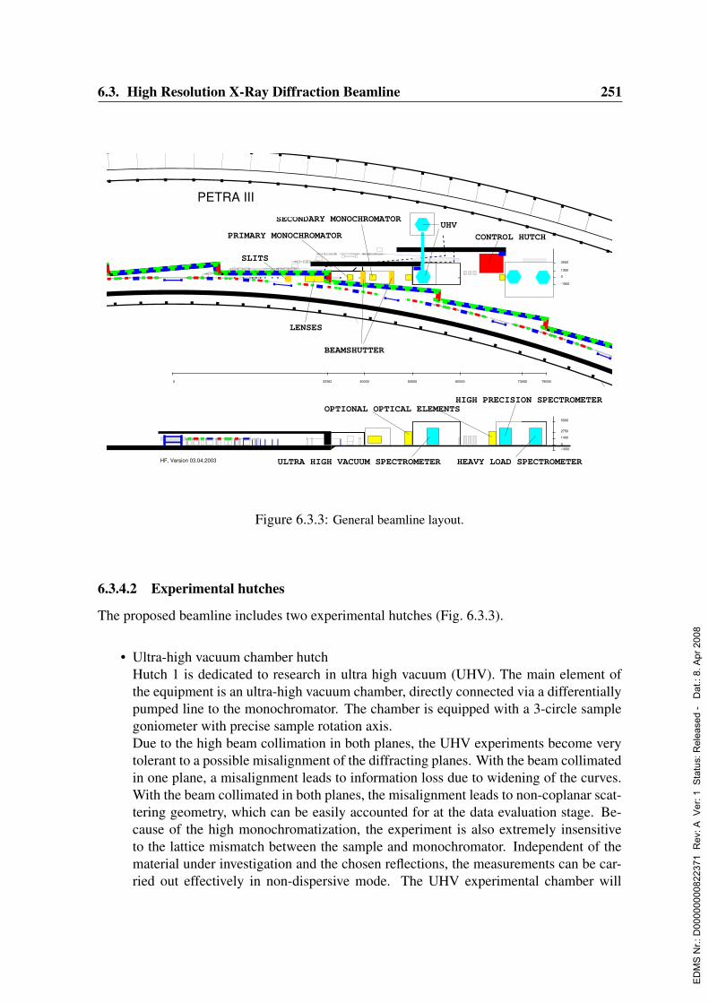
6.3. High Resolution X-Ray Diffraction Beamline 251
PETRA IIIBeamline PETRA4
HF, Version 03.04.2003
0 7800032262 40000 50000 60000 73000
0
-1500
1350
3000
0-1000
2750
1400
5000
BEAMSHUTTER
SLITS
UHV
LENSES
OPTIONAL OPTICAL ELEMENTSHIGH PRECISION SPECTROMETER
HEAVY LOAD SPECTROMETERULTRA HIGH VACUUM SPECTROMETER
PRIMARY MONOCHROMATOR
SECONDARY MONOCHROMATOR
CONTROL HUTCH
Figure 6.3.3: General beamline layout.
6.3.4.2 Experimental hutches
The proposed beamline includes two experimental hutches (Fig. 6.3.3).
• Ultra-high vacuum chamber hutchHutch 1 is dedicated to research in ultra high vacuum (UHV). The main element ofthe equipment is an ultra-high vacuum chamber, directly connected via a differentiallypumped line to the monochromator. The chamber is equipped with a 3-circle samplegoniometer with precise sample rotation axis.Due to the high beam collimation in both planes, the UHV experiments become verytolerant to a possible misalignment of the diffracting planes. With the beam collimatedin one plane, a misalignment leads to information loss due to widening of the curves.With the beam collimated in both planes, the misalignment leads to non-coplanar scat-tering geometry, which can be easily accounted for at the data evaluation stage. Be-cause of the high monochromatization, the experiment is also extremely insensitiveto the lattice mismatch between the sample and monochromator. Independent of thematerial under investigation and the chosen reflections, the measurements can be car-ried out effectively in non-dispersive mode. The UHV experimental chamber will
ED
MS
Nr.:
D00
0000
0082
2371
Rev
: A V
er: 1
Sta
tus:
Rel
ease
d -
Dat
.: 8.
Apr
200
8

252 6. Beamlines and Experimental Stations
be equipped with an energy-dispersive electron detector, mass spectrometer and sam-ple heating appliance. The X-ray experimental chamber is directly connected via anin-vacuum sample transfer line to an external UHV sample preparation and characteri-zation facility. The facility can be operated independently from the experiment. It willinclude a comprehensive set of equipment for different film growth (MBE, HPCVD,MOVPE) and surface analysis (LEED, RHEED, STM, etc) techniques. The samplesare delivered to the X-ray experimental chamber through an in-vacuum transfer line.This combination enables complex studies of interface processes. Focusing elementsas refraction lenses and Fresnel plates can be inserted between the UHV experimentalchamber and the monochromators for better localization of the experimental area.
• Diffractometry hutchThe high resolution diffractometry hutch is designed for two separate diffractometers:one precise 6-circle diffractometer and one heavy-load diffractometer. The exit win-dow of the high-vacuum part of the beamline will be made of polished Be or diamondto preserve the beam coherence. As an option, windowless layout could be realized infuture.At the first stage, only the precise spectrometer will be installed. The sample rota-tion stages of the spectrometer will provide four degrees of freedom, with a precisionon the main rotation axis better than 0.5µrad. The opened Eulerian cradle will allowinstallation of light sample chambers to control the sample environment during exper-iments. The possibility to use non-coplanar diffraction schemes will be provided bya detector arm with two degrees of freedom. The detector arm will rotate in a wideangular range and can be additionally equipped with an analyzer crystal setup or a 2Ddetector.For liquid surface experiments, the precise spectrometer will be used for installation ofan additional monochromator for beam inclination. The high precision and availabilityof multiple degrees of freedom will allow continuous incidence angle variation withfixed beam spot at the sample. A vibration-free user appliance for liquid samples willbe provided additionally.As in the UHV hutch, an optical bench for focusing optics and/or Bartels-type doublechannel-cut monochromator can be placed in the front part of the hutch.
The monochromator and experimental hutches will be built on a vibrationally isolated foun-dation. The temperature in this hutch will be kept stable within 0.5K.
6.3.4.3 Further experimental equipment
• Optical and mechanical elements, media supplies.The standard beamline equipment consists of Fresnel and refraction lenses, slits, andprecise translational stages. A set of pumps and power supplies will be available.Cooling water, helium and nitrogen gas supplies as well as a cabinet for gas flasks
ED
MS
Nr.:
D00
0000
0082
2371
Rev
: A V
er: 1
Sta
tus:
Rel
ease
d -
Dat
.: 8.
Apr
200
8

6.3. High Resolution X-Ray Diffraction Beamline 253
with possibly short connection lines to the sample will be integrated into the hutchlayout.
• DetectorsIonization chambers, scintillation counters and PIN- and avalanche photo-diodes willbe available for X-ray registration. For energy dispersive measurement, the beamlinewill be equipped with Si(Li) and/or multi-pixel silicon drift detectors. For 2D mappingand for crystallographic data collections an accurate, fast readout 2D CCD camera,diode or pixel array detector will be available.
• Electronics, computers and softwareThe beamline will be operated locally, including a possibility to vary the undulatorgap during the measurements. The electronics in modular NIM standard will allow themost fast and flexible way to optimize the data acquisition for any user experiment.
• Beamline control room and workshopThe beamline control room will be built adjacent to the diffractometry hutch. A generalpurpose workshop can be shared with several other beamlines. A separate vacuumworkshop is needed.
• CryogenicsA variety of cryostats will be available including lq.-N2 and He cryo-streamers for lowtemperature experiments.
6.3.5 Research and development challengesIn the optical and mechanical parts, all proposed components have already been tested innumerous applications and can be built and operated routinely.Some very limited R & D effort is necessary to construct an in-vacuum optical bench forinterchangeable double channel-cut monochromator, switchable between vertical and hori-zontal diffraction planes. Test experiments can be carried out to ensure the high harmonicsuppression in combination with angular stabilization operation.The bottleneck for high resolution diffraction experiments - just as for most modern SR tech-niques - will the problem of fast signal detection, especially the lack of fast high-resolution2D imaging detectors. Their development requires a coordinated effort of the whole syn-chrotron radiation community.
6.3.6 Capital investment and personnelThe beamline will be staffed with 2–3 scientists/postdocs and 2 technician/engineers.The estimated total capital investment of this experimental endstation amounts to about1900 ke.
ED
MS
Nr.:
D00
0000
0082
2371
Rev
: A V
er: 1
Sta
tus:
Rel
ease
d -
Dat
.: 8.
Apr
200
8
254 6. Beamlines and Experimental Stations
6.4 Micro- and Nanotomography
Author :
F. Beckmann GKSS - Research Center Geesthacht, Germany
6.4.1 Introduction
Microtomography (µCT) using synchrotron radiation became a valuable tool for the non-destructive three-dimensional investigation of specimens in fields of e.g. medicine, biologyand materials science. Employing highly brilliant and collimated X-rays of second and thirdgeneration synchrotron sources new contrast techniques including phase, fluorescence andenhancement by diffraction were developed. Existing schemes were optimized to yield moresensitivity to structural changes at less burden afflicted to the specimen.At DORIS III absorption- and phase-contrast µCT techniques were developed and appliedat photon energies in the range of 8 to 150 keV. At the wiggler-beamlines BW2, W2, andBW5 the present user experiment for microtomography makes use of the large, intense,and incoherent X-ray source. The present setup is optimized for performing absorption-contrast microtomography on large samples. Due to the divergence of the source the spatialresolution, which can be achieved in the tomogram, is limited to about 2µm. At PETRAIII the excellent X-ray source will allow for new absorption- and phase-contrast techniqueswhich make use of the coherence of the X-ray beam. Furthermore the spatial resolution willbe increased into the 50 nm regime.
6.4.2 Current state of the scientific field
The standard application of microtomography at current third generation synchrotron radi-ation facilities makes use of the low divergence and high intensity of the source to recordparallel 2-dim. projections of samples using monochromatic X-rays. By rotating the speci-men, typically in steps of 0.1 to 1 degree, and repeating the measurement over the range of0 to π the tomographical scan is performed. The tomographical reconstruction then yieldsthe 3-dim. spatial description of the projected property of the sample. Several differentabsorption- and phase-contrast techniques were developed in recent years (Bonse & Busch,1996).
6.4.2.1 Methods
The experimental setup consists of a 2-dim. X-ray detector and a high-precision samplemanipulator. The distance between detector and manipulator can be changed not only toallow to introduce sample environment or an X-ray interferometer, but also to exploit thecoherence effects of the X-ray beam of 3rd generation sources.
ED
MS
Nr.:
D00
0000
0082
2371
Rev
: A V
er: 1
Sta
tus:
Rel
ease
d -
Dat
.: 8.
Apr
200
8
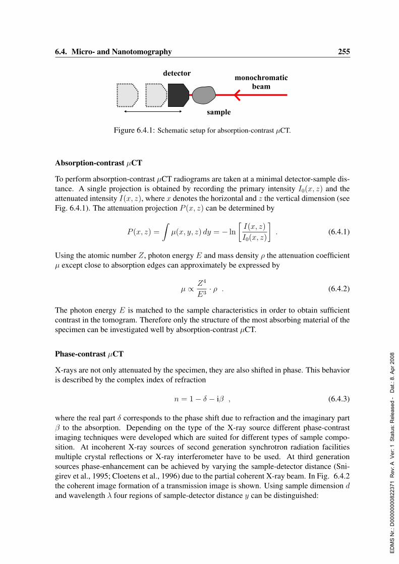
6.4. Micro- and Nanotomography 255
detectormonochromatic
beam
sample
Figure 6.4.1: Schematic setup for absorption-contrast µCT.
Absorption-contrast µCT
To perform absorption-contrast µCT radiograms are taken at a minimal detector-sample dis-tance. A single projection is obtained by recording the primary intensity I0(x, z) and theattenuated intensity I(x, z), where x denotes the horizontal and z the vertical dimension (seeFig. 6.4.1). The attenuation projection P (x, z) can be determined by
P (x, z) =
∫µ(x, y, z) dy = − ln
[I(x, z)
I0(x, z)
]. (6.4.1)
Using the atomic number Z, photon energy E and mass density ρ the attenuation coefficientµ except close to absorption edges can approximately be expressed by
µ ∝ Z4
E3· ρ . (6.4.2)
The photon energy E is matched to the sample characteristics in order to obtain sufficientcontrast in the tomogram. Therefore only the structure of the most absorbing material of thespecimen can be investigated well by absorption-contrast µCT.
Phase-contrast µCT
X-rays are not only attenuated by the specimen, they are also shifted in phase. This behavioris described by the complex index of refraction
n = 1− δ − iβ , (6.4.3)
where the real part δ corresponds to the phase shift due to refraction and the imaginary partβ to the absorption. Depending on the type of the X-ray source different phase-contrastimaging techniques were developed which are suited for different types of sample compo-sition. At incoherent X-ray sources of second generation synchrotron radiation facilitiesmultiple crystal reflections or X-ray interferometer have to be used. At third generationsources phase-enhancement can be achieved by varying the sample-detector distance (Sni-girev et al., 1995; Cloetens et al., 1996) due to the partial coherent X-ray beam. In Fig. 6.4.2the coherent image formation of a transmission image is shown. Using sample dimension dand wavelength λ four regions of sample-detector distance y can be distinguished:
ED
MS
Nr.:
D00
0000
0082
2371
Rev
: A V
er: 1
Sta
tus:
Rel
ease
d -
Dat
.: 8.
Apr
200
8
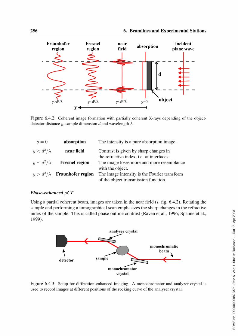
256 6. Beamlines and Experimental Stations
incidentplane wave
absorptionnearfield
Fresnelregion
Fraunhoferregion
y
y=0y<d²/ly~d²/ly>d²/l
d
object
Figure 6.4.2: Coherent image formation with partially coherent X-rays depending of the object-detector distance y, sample dimension d and wavelength λ.
y = 0 absorption The intensity is a pure absorption image.
y < d2/λ near field Contrast is given by sharp changes inthe refractive index, i.e. at interfaces.
y ∼ d2/λ Fresnel region The image loses more and more resemblancewith the object.
y > d2/λ Fraunhofer region The image intensity is the Fourier transformof the object transmission function.
Phase-enhanced µCT
Using a partial coherent beam, images are taken in the near field (s. fig. 6.4.2). Rotating thesample and performing a tomographical scan emphasizes the sharp changes in the refractiveindex of the sample. This is called phase outline contrast (Raven et al., 1996; Spanne et al.,1999).
detector
analyser crystal
monochromatorcrystal
monochromaticbeam
sample
Figure 6.4.3: Setup for diffraction-enhanced imaging. A monochromator and analyzer crystal isused to record images at different positions of the rocking curve of the analyser crystal.
ED
MS
Nr.:
D00
0000
0082
2371
Rev
: A V
er: 1
Sta
tus:
Rel
ease
d -
Dat
.: 8.
Apr
200
8

6.4. Micro- and Nanotomography 257
detector
analyser
splitter
monochromaticbeam
sample mirror
interferometer
phase rotor
Figure 6.4.4: Experimental setup for interferometric phase-contrast. A monolithic X-ray interferom-eter is used to divide the monochromatic beam into two coherent beams. The phase rotor introducesa defined phase shift and the direct phase projection can be obtained.
A more sensitive technique makes use of multiple crystal reflections. In Fig. 6.4.3 theschematic setup is shown. Images at different positions of the rocking curve of the twocrystals are recorded. From these images an absorption image and a phase enhanced imagecan be obtained (Bravin, 2003; Pagot et al., 2003). Using this as the contrast method intomography again results in mapping of borders of changes in the refractive index.
Interferometric phase-contrast µCT
To be able to obtain the refractive index in the tomogram, phase projections of the samplehave to be measured. A direct technique makes use of an X-ray interferometer which allowsfor the measurement of a phase projection modulo 2π. The principle setup is shown inFig. 6.4.4. For one phase projection interference patterns, with and without the sample, areobtained at different overall phase shifts introduced by the phase shifter (Momose, 1995;Beckmann et al., 1997; Momose, 2002). Using the electron density σ, the phase shift φ isgiven by
φ ∝ σ
E. (6.4.4)
Holotomography
An indirect method to measure the phase projection makes use of the partial coherence ofthird generation SR beams. By varying the sample-detector distance and recording imagesdifferent spatial frequencies in the projected phase images vanish (Talbot effect). The so-called holographic reconstruction procedure then determines the phase projection. (Cloetenset al., 1999)
X-ray imaging detector
The different microtomographic techniques described in the previous paragraphs make useof a 2-dim. X-ray detector. This device consists of a single crystal fluorescent screen and a
ED
MS
Nr.:
D00
0000
0082
2371
Rev
: A V
er: 1
Sta
tus:
Rel
ease
d -
Dat
.: 8.
Apr
200
8
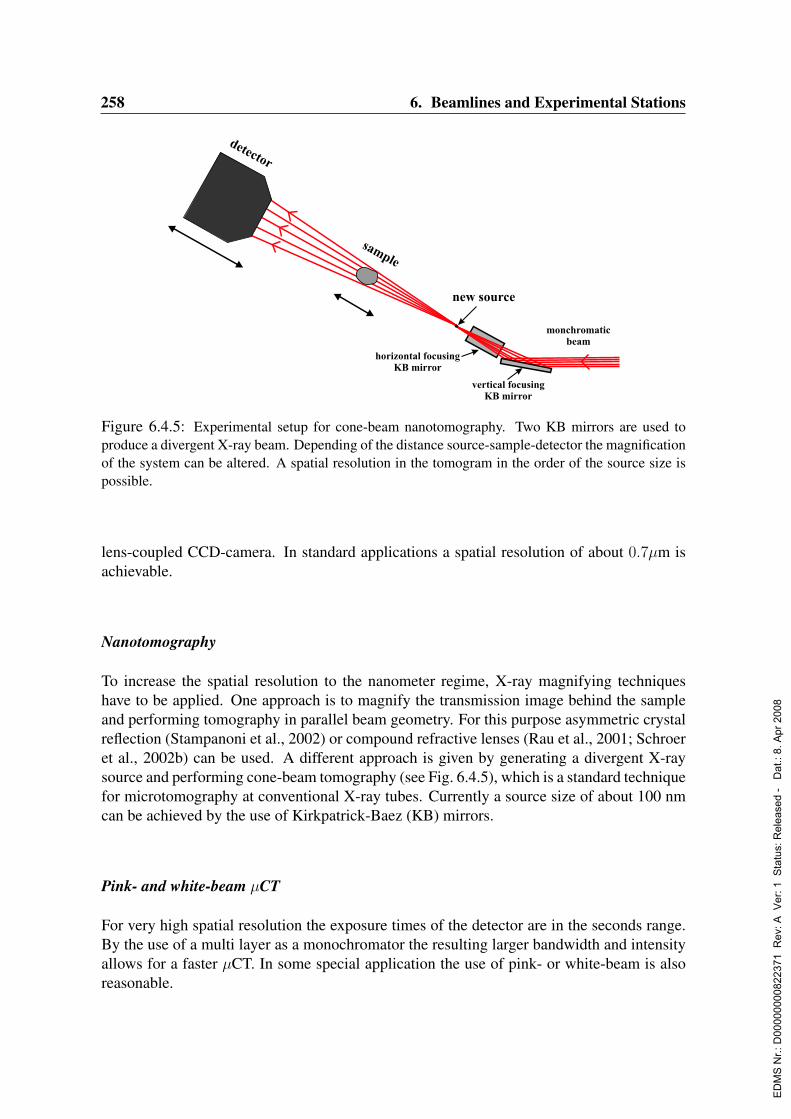
258 6. Beamlines and Experimental Stations
detector
sample
horizontal focusingKB mirror
vertical focusingKB mirror
monchromaticbeam
new source
Figure 6.4.5: Experimental setup for cone-beam nanotomography. Two KB mirrors are used toproduce a divergent X-ray beam. Depending of the distance source-sample-detector the magnificationof the system can be altered. A spatial resolution in the tomogram in the order of the source size ispossible.
lens-coupled CCD-camera. In standard applications a spatial resolution of about 0.7µm isachievable.
Nanotomography
To increase the spatial resolution to the nanometer regime, X-ray magnifying techniqueshave to be applied. One approach is to magnify the transmission image behind the sampleand performing tomography in parallel beam geometry. For this purpose asymmetric crystalreflection (Stampanoni et al., 2002) or compound refractive lenses (Rau et al., 2001; Schroeret al., 2002b) can be used. A different approach is given by generating a divergent X-raysource and performing cone-beam tomography (see Fig. 6.4.5), which is a standard techniquefor microtomography at conventional X-ray tubes. Currently a source size of about 100 nmcan be achieved by the use of Kirkpatrick-Baez (KB) mirrors.
Pink- and white-beam µCT
For very high spatial resolution the exposure times of the detector are in the seconds range.By the use of a multi layer as a monochromator the resulting larger bandwidth and intensityallows for a faster µCT. In some special application the use of pink- or white-beam is alsoreasonable.
ED
MS
Nr.:
D00
0000
0082
2371
Rev
: A V
er: 1
Sta
tus:
Rel
ease
d -
Dat
.: 8.
Apr
200
8

6.4. Micro- and Nanotomography 259
6.4.2.2 Applications
The described imaging techniques are not all available as a standard user application. Onlythe setup for absorption-contrast µCT and phase-outline µCT fulfill the requirements for be-coming a user experiment. One approach to setup a high-throughput x-ray µCT system wasdone by a group at the Advanced Photon Source (Wang et al., 2001). In the following sectiona few current examples of application of µCT at different synchrotron radiation facilities aregiven.
Medical science
First applications of µCT using synchrotron radiation in the field of medical science werethe investigation of bone. Here, mainly the structural parameters and the comparison toconventional methods were of interest (Bonse et al., 1994; Delling et al., 1995). Currentapplications put emphasize on the process of regrow and remodelling of bone.Many experiments were performed to characterize new biocompatible materials which canbe used as an implant for bone defects (Muller et al., 2002; Weiss et al., 2003; Schilleret al., 2004). Furthermore, phase contrast techniques were applied to soft tissues to find newtechniques for tumor detection (Takeda et al., 1998; Beckmann et al., 1999).
Materials research
In materials research the microstructure of a variety of different types of samples are studied.Starting from low absorbing carbon-carbon composites (Coindreau, Vignoles & Cloetens,2003) up to high absorbing metal foams and concrete samples (Maire et al., 2003).The behavior of materials under compression can be studied (Salvo et al., 2003). Further-more by tracking marker particles in Al alloys, the measurement of the plastic displacementgradient component in three dimensions becomes possible (Nielsen et al., 2003). Anotherapplication is the study of the interaction of short fatigue cracks with the grain boundaries incast Al alloys (Ludwig et al., 2003).
6.4.3 Science at PETRA III
The extraordinary source characteristics of PETRA III will allow for all the different tech-niques described in the previous section. Furthermore, these techniques will be combinedto simultaneously map different features of specimens. This will give new impact to theunderstanding of the 3-dim. composition and behavior of samples from a variety of differentresearch communities. Therefore it is necessary to provide for a user experiment allowingfor an automatic scanning and data evaluation.In combination with the tomography setup at DORIS III the following beamlines will beavailable for users at DESY:
ED
MS
Nr.:
D00
0000
0082
2371
Rev
: A V
er: 1
Sta
tus:
Rel
ease
d -
Dat
.: 8.
Apr
200
8

260 6. Beamlines and Experimental Stations
DORIS III Petra IIIBW2 HARWI II 100 m beamline 200 m beamline
energy range 6–24 keV 20–250 keV 6–150 keV 6–150 keVbeam width 10 mm 80 mm 5 mm 10 mmbeam height 4 mm 8 mm 1 mm 2 mm
coherent image no no yes yesspatial resolution 2 µm 3 µm 0.7 µm / 50 nm 0.7 µm / 50 nm
Exploiting the characteristics of the different beamlines for tomography the types of samplesinvestigated at PETRA III can be divided into:
• large samples: Ø >> 5 mm, typical 20-150 keVIn combination with the knowledge of a coarse tomography, region of interest tomog-raphy can be performed (sample larger than size of the beam).
• medium-size samples: Ø ≈ 3 mm, typical 8-60 keVThis type of sample will become the standard application of performing absorption-contrast and phase-enhanced µCT showing a spatial resolution of about 0.7 µm.
• small samples: Ø < 1 mm, typical 6-30 keVFor very small samples, a spatial resolution of ≈ 50 nm can be achieved by applyingcone-beam nanotomography.
Furthermore a variety of different sample environments and combination with other tech-niques e.g. diffraction experiments is foreseen.
6.4.4 Beamline descriptionThe standard user experiment for microtomography at PETRA III will require a large mo-noenergetic, parallel and intense beam. The photon energy range will be from 6 to 150 keVwith a beam size of about 5 x 1 mm2. The schematic beamline layout is shown in Fig. 6.4.6.
6.4.4.1 Insertion device and monochromator
As insertion device a tunable standard undulator at a low β section will be used. Inside theoptics hutch the standard monochromator will be installed. Mirrors can be added to suppresshigher harmonics especially for low photon energies. To be able to select photon energies in
experimental hutch I experimental hutch IIoptics hutch
32m 38m 50m 100m62m 88m
Figure 6.4.6: Schematic layout of the beamline for micro- and nanotomography.
ED
MS
Nr.:
D00
0000
0082
2371
Rev
: A V
er: 1
Sta
tus:
Rel
ease
d -
Dat
.: 8.
Apr
200
8

6.4. Micro- and Nanotomography 261
the total energy range of 6 to 150 keV different sets of crystals are foreseen. To achieve asmooth beam profile, the beamline will have as few optical elements as possible.
6.4.4.2 Experimental hutch I and II
The experimental hutches will allow for a variable sample detector distance up to 10 m.Experimental hutch II will house the user experiment for absorption-contrast and phase-enhanced microtomography. The experiments in hutch I will focus on nanotomographyapplications. There different optical elements, e.g. KB-mirrors, CRLs, asymmetric Bragg-magnifier, will be added to achieve a X-ray magnified image of the sample. Using KB-mirrors, a nanometer divergent X-ray source will allow for performing cone-beam nanoto-mography.
6.4.4.3 Environment
To provide for a user experiment for tomography, laboratory space for sample preparationis required. Furthermore an automatic sample changer will allow to effectively exploit theassigned beamtime. Gigabit ethernet infrastructure is needed to process and backup theexpected data.
6.4.5 Capital investment and personnelTwo different setups specialized for microtomography (hutch II) and nanotomography (hutchI) are needed.The total investment costs for these experimental stations account for 2130 ke.The costs for central data backup and computer power to provide for on-line reconstructionare not included in this estimate.
The beamline for micro- and nanotomography will be run as a user facility for short termand very fast experiments. New experimental and data evaluation techniques have to be de-veloped. Furthermore the user operation requires continuous improvement and maintenanceof the beamline hardware and software. Therefore two scientists, one software engineer, onemechanical engineer, and one technician should be employed on a permanent basis.
ED
MS
Nr.:
D00
0000
0082
2371
Rev
: A V
er: 1
Sta
tus:
Rel
ease
d -
Dat
.: 8.
Apr
200
8

262 6. Beamlines and Experimental Stations
6.5 Inelastic ScatteringAuthors:H. Franz DESY, Hamburg, GermanyM. Krisch ESRF, Grenoble, FranceM. Muller Universitat Kiel, GermanyH. Requardt ESRF, Grenoble, FranceR. Rohlsberger DESY, Hamburg, GermanyYu. V. Shvyd’ko Universitat Hamburg, GermanyH. Sinn Advanced Photon Source, Argonne, USA
Consultant:A. Q. R. Baron SPring-8, Harima, Japan
6.5.1 Current state of the scientific fieldOne of the most successful areas in science which has emerged from the advent of third-generation synchrotron radiation sources is inelastic X-ray scattering (IXS) with meV energyresolution. Starting from the pioneering work performed at HASYLAB in the 1980s (Dorner,Burkel & Peisl, 1986; Dorner et al., 1987), the technique is now established and has provento be a powerful spectroscopic tool in the study of lattice dynamics, complementing thepreviously unique inelastic neutron scattering (INS) technique. The impact and the maturityof the technique is documented by numerous high-level publications in fields of researchranging from materials science over geophysics to biology, see, e.g. (Sette et al., 1998;Burkel, 2000) and references therein. IXS constitutes the perfect complement to INS inareas where INS is difficult, and often impossible, to apply:
1) The study of collective excitations in disordered systems, where well defined exci-tations are typically only existing up to momentum transfers Q of a few nm−1. Inparticular for disordered systems with a high speed of sound (> 2000 m/s), the low-energy and low-momentum transfer regime, it is difficult, or even impossible, to accessby neutron scattering due to kinematic limitations (Sette et al., 1996; Burkel, 2000).
2) The small source size and beam divergence of modern synchrotron sources opens thepossibility to study materials available only in small quantities down to 10−5 mm3.This is of particular interest for the study of matter under high pressure, since it allowsone to employ diamond anvil cell techniques, and therefore access pressure regimesup to 100 GPa and beyond.
The extensive IXS studies on liquid water are probably the best example for the wealthof new insights which could be gained in its mesoscopic dynamics (Ruocco et al., 1996;Ruocco & Sette, 1999), but as well the large body of studies performed on other liquidsand glasses has allowed one to answer many open questions related to the nature of thehigh-frequency excitations, relaxation phenomena and the interplay between structural anddynamical properties (Sette et al., 1998). A more recent emerging field is high pressureresearch, where studies on single crystals are currently performed up to 400 kbar ( Occelli
ED
MS
Nr.:
D00
0000
0082
2371
Rev
: A V
er: 1
Sta
tus:
Rel
ease
d -
Dat
.: 8.
Apr
200
8
6.5. Inelastic Scattering 263
et al., 2001; Raymond et al., 2002; Loa et al., 2003), and the megabar regime has beenentered using polycrystalline samples (Fiquet et al., 2001). The determination of sound ve-locities and, in the case of single crystals, of the full elasticity tensor as a function of pressureis one of the key inputs for geo- and planetary science, but of course not restricted to thisspecific field of research. More generally, the possibility to map out the phonon dispersionallows one to evidence pressure-induced anomalies, thus gaining detailed insight into pre-cursor effects and the nature of phase transitions. As for the very high pressure studies, IXSis unique in the study of small sample quantities, and we cite as examples here the work onhighly correlated electron systems (Astuto et al., 2002; Shukla et al., 2003; Fukuda et al.,2003; Manley et al., 2003; Wong et al., 2003).At present there are four IXS beamlines operational: ID16 and ID28 at the ESRF (Verbeniet al., 1996; Masciovecchio et al., 1996; Sette et al., 1998), 3-ID at APS (Sinn et al., 2001;Sinn et al., 2002), and BL35XU at SPring-8 (Baron et al., 2001b), and at least two furtherprojects are in progress. All operating beamlines are heavily overbooked, and a large amountof excellent science proposals have to be rejected.
6.5.2 Science at the inelastic scattering beamline at PETRA IIIThe PETRA III project provides the opportunity to build a scientifically unique IXS beam-line, extending the existing possibilities worldwide and responding to the high demand ofthe international user community. The outstanding brilliance of undulator radiation will al-low for the combination of high-resolution inelastic X-ray spectroscopy with microfocusingtechniques. This has a major impact in the following areas:
a) The radiation can be focused to dimensions of a few µm, so that sample volumes in therange of 10−6 mm3 become accessible. As a result, the vibrational behavior of singlecrystallites in polycrystalline materials can be investigated. In this sense, the polycrys-tals of today will become the single crystals of tomorrow. Moreover, materials can bestudied where the growth of large single crystals is not possible like certain kinds ofquasicrystals or superconductors. The use of high photon energies allows one to studyhigh-Z materials. This is particularly interesting for the study of electron-phonon in-teractions in new materials like high-Tc superconductors or heavy-fermion systems.The application of microfocused beams allows one to study phonons in confined ge-ometries and at surfaces.
b) A small beam size at the monochromator position allows for a very effective im-plementation of sub-meV spectrometers. This applies in particular if multi-bouncemonochromators are used to achieve a very steep resolution function. Since the cor-responding optics relies on the utilization of highly asymmetric reflections, a smallvertical beam size allows one to keep the size of the monochromator crystals small.
The design goal for this beamline is an energy resolution of the inelastic spectrometer of0.5 meV. Together with the above mentioned features, this will open new experimental pos-sibilities in many areas of condensed matter research. A few of these exciting applicationswill be highlighted in the following sections.
ED
MS
Nr.:
D00
0000
0082
2371
Rev
: A V
er: 1
Sta
tus:
Rel
ease
d -
Dat
.: 8.
Apr
200
8

264 6. Beamlines and Experimental Stations
6.5.2.1 Disordered materials
In contrast to crystalline systems, disordered materials are characterized by the absence oftranslational order. The discrete inter particle distances are replaced by a correlation functionthat describes the topological disorder. It is obvious that dynamical properties are stronglyinfluenced by the type and degree of the disorder. Moreover, the disorder leads to additionaldegrees of freedom like diffusion and relaxation in liquids and melts as well as hoppingand tunneling processes in glasses. The interplay of these phenomena on different time andlength scales introduces a rich phenomenology of dynamical properties. Due to kinematicallimitations of neutron scattering, a comprehensive picture of the high-frequency collectivedynamics in disordered materials is still missing. In particular, the following questions onthe mesoscopic dynamics are still to be answered:
• How do the collective excitations observed in glasses relate to the anomalous thermalconductivity observed at low temperatures ?
• What is the relation between the structural properties and the spectrum of excitations ?How do the different atomic species of a multi-component melt contribute to theseexcitations ?
• What is the origin of the excess specific heat at low temperatures and the excess densityof vibrational density of states ?
• How are short wavelength excitations affected by relaxation processes compared tothose at long wavelengths and how is the high-frequency dynamics affected in thevicinity of the glass transition ?
Vibrational spectra of disordered materials are dominated by a very strong elastic line. Anunambiguous resolution of low-energy spectral features requires an energy resolution of thespectrometer that is in the range of 0.5 meV.
6.5.2.2 Collective excitations in low dimensions
Phonons are a good example for quasi particle excitations that can be significantly modifiedby interfaces and multilayered structures. Since the functionality of future micromechanicdevices will depend on phase transformations and their underlying dynamics, the tailoring ofphononic spectra to specific purposes will be of increasing importance in the future. In thisfield, basic research and applications are intimately related. Key roles are anticipated for thefollowing fields of materials physics:Functional materials like shape memory alloys are based on structural phase transitions,which allow the material to modify its domain structure. The underlying physics of thesephase transitions is intimately related to lattice instabilities with soft phonon modes (Shapiroet al., 1989). In the future, materials with new transformation behavior based on stronglymodified dispersion relations will emerge. Fig. 6.5.1 shows different types of such phononanomalies for a hypothetical material. Structural distortions associated with ferroelectricphase transitions can be used to generate actuator effects in conjunction with the permanent
ED
MS
Nr.:
D00
0000
0082
2371
Rev
: A V
er: 1
Sta
tus:
Rel
ease
d -
Dat
.: 8.
Apr
200
8
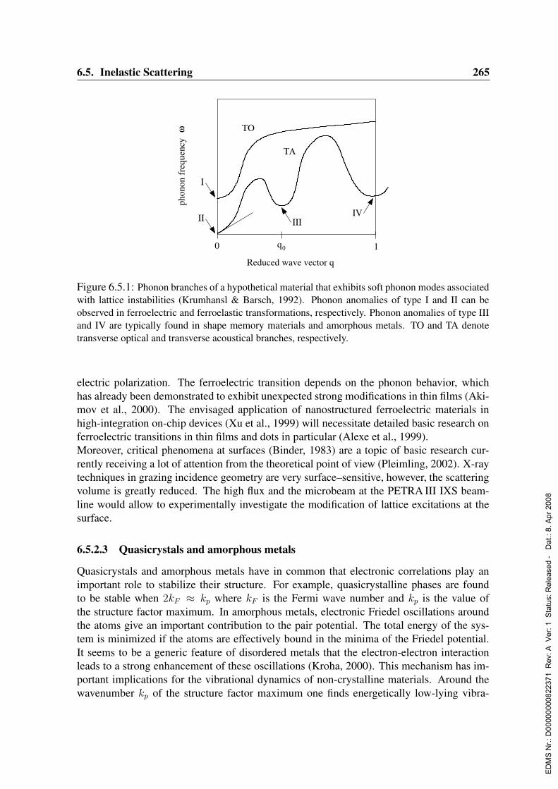
6.5. Inelastic Scattering 265
phon
on f
requ
ency
ω
q00 1
Reduced wave vector q
ΤΟ
ΤΑ
ΙΙΙ
Ι
ΙΙ IV
Figure 6.5.1: Phonon branches of a hypothetical material that exhibits soft phonon modes associatedwith lattice instabilities (Krumhansl & Barsch, 1992). Phonon anomalies of type I and II can beobserved in ferroelectric and ferroelastic transformations, respectively. Phonon anomalies of type IIIand IV are typically found in shape memory materials and amorphous metals. TO and TA denotetransverse optical and transverse acoustical branches, respectively.
electric polarization. The ferroelectric transition depends on the phonon behavior, whichhas already been demonstrated to exhibit unexpected strong modifications in thin films (Aki-mov et al., 2000). The envisaged application of nanostructured ferroelectric materials inhigh-integration on-chip devices (Xu et al., 1999) will necessitate detailed basic research onferroelectric transitions in thin films and dots in particular (Alexe et al., 1999).Moreover, critical phenomena at surfaces (Binder, 1983) are a topic of basic research cur-rently receiving a lot of attention from the theoretical point of view (Pleimling, 2002). X-raytechniques in grazing incidence geometry are very surface–sensitive, however, the scatteringvolume is greatly reduced. The high flux and the microbeam at the PETRA III IXS beam-line would allow to experimentally investigate the modification of lattice excitations at thesurface.
6.5.2.3 Quasicrystals and amorphous metals
Quasicrystals and amorphous metals have in common that electronic correlations play animportant role to stabilize their structure. For example, quasicrystalline phases are foundto be stable when 2kF ≈ kp where kF is the Fermi wave number and kp is the value ofthe structure factor maximum. In amorphous metals, electronic Friedel oscillations aroundthe atoms give an important contribution to the pair potential. The total energy of the sys-tem is minimized if the atoms are effectively bound in the minima of the Friedel potential.It seems to be a generic feature of disordered metals that the electron-electron interactionleads to a strong enhancement of these oscillations (Kroha, 2000). This mechanism has im-portant implications for the vibrational dynamics of non-crystalline materials. Around thewavenumber kp of the structure factor maximum one finds energetically low-lying vibra-
ED
MS
Nr.:
D00
0000
0082
2371
Rev
: A V
er: 1
Sta
tus:
Rel
ease
d -
Dat
.: 8.
Apr
200
8
266 6. Beamlines and Experimental Stations
tional excitations (Suck et al., 1983; Haussler, 1992). This is similar to the roton-like mod-ification of the phonon dispersion in quantum liquids, comparable to the type-III phononanomaly in Fig. 6.5.1. The energy ω0 of these excitations scales with the inverse of the struc-ture factor, i.e., ω0 ∼ 1/S(kp). Therefore, upon transition into the crystalline state, thesemodes approach zero energy. This transition is particularly interesting to be observed neara (quasi) crystalline-amorphous transition. To reveal the nature of these low-energy excita-tions, investigations with sub-meV energy resolution in the presence of a strong elastic peakare necessary.Also quasicrystalline order leads to new kinds of collective excitations like phasons and othernon acoustic localized modes at very low energies (Bak, 1985). Many quasicrystalline sys-tems cannot be studied by inelastic neutron scattering because single crystals are availableonly in very small sizes or they contain elements that are detrimental to neutron scattering.Amorphous metals very often can only be produced by vapor quenching in the form of thinfilms. Therefore, the proposed IXS beamline at PETRA III with 0.5 meV energy resolutionand the option for a microfocused beam will be ideally suited for the study of such systems.
6.5.2.4 High-pressure studies
As already mentioned before, the small source size and beam divergence of modern syn-chrotron sources opens the possibility to study materials available only in small quantitiesdown to 10−5 mm3. This is of particular interest for the study of matter under high pres-sure, since it allows to employ diamond anvil cell techniques, and therefore access pressureregimes up to 100 GPa and beyond. For disordered and polycrystalline materials orienta-tionally averaged information is obtained, whereas the use of single crystals allows to mapout the full dispersion scheme of the acoustic and optical branches. Recent examples are thephonon anomalies in Cesium metal (Loa et al., 2003) and SmS (Raymond et al., 2002). Fur-thermore, the complete set of elastic moduli can be straightforwardly determined from theinitial slope of the acoustic branches, therefore allowing to study elasticity under pressure(Antonangeli, 2004). Current challenges lie in the preparation of these tiny single crystals(with a typical diameter of 50 mm and a thickness of 20 mm or less), and the preservation of asufficient crystal quality to high pressures. The coupling of high pressure with low/high tem-peratures is a natural extension, and the corresponding instrumentation such as cryostats andheaters is well developed. The highest attainable pressure is intimately linked to the samplevolume, and therefore continuous efforts have to be made in order to match the lateral beamdimensions with the sample size. In this respect the expected performances of PETRA IIIpromises to further reduce the minimum sample volume needed, or to record IXS spectramore rapidly (in cases where extreme conditions of temperature and/or pressure can only bemaintained for a few hours).Another important field of research concerns the determination of sound velocities in ma-terials under geophysical conditions. This necessitates the use of anvil cells that allow forpressures in the Mbar range and temperatures up to 2000 K. For that purpose a laser heatingsystem has to be installed at the beamline. Such systems allow one to selectively heat thesamples in diamond anvil cells. Interesting systems are metallic melts under high pressureat high temperatures as they are extremely relevant to understand the properties of planetary
ED
MS
Nr.:
D00
0000
0082
2371
Rev
: A V
er: 1
Sta
tus:
Rel
ease
d -
Dat
.: 8.
Apr
200
8
6.5. Inelastic Scattering 267
cores, for example. In these studies, an important quantity to be derived from the data is thevelocity of sound. Under conditions of high temperature and high pressure, this is hardlypossible with any other method. However, an accurate determination of sound velocities isonly possible if the excitation spectrum can be measured at low momentum transfers and lowenergy transfers, i.e., very close to the elastic line.
6.5.3 Beamline description
The main components of the spectrometer for inelastic X-ray scattering are a monochro-mator selecting hard X-rays with a spectral width of ∆E < 1 meV and an analyzer perform-ing energy analysis of the inelastically scattered X-rays. The required momentum resolution∆Q < 0.5 nm−1 limits the solid angle (∆α)2 from which the scattered photons can be col-lected. Typical values are ∆α < 10 mrad. To obtain sufficiently high count rates in theseenergy/momentum intervals, a very high incident photon flux is mandatory. The design goalat this beamline is to exceed a flux of 1010 photons/s/meV at the sample position. Therefore,the beamline proposed here is located at the position of the 20-m undulator.The operating energy has to be above ∼ 22 keV where the Darwin width of Si-Bragg reflec-tions is below 1 meV. The use of high photon energies has significant advantages. First, oneobtains access to strongly absorbing samples or samples in strongly absorbing environments.Further important aspects are the fact that photo absorption along the beam path is low andradiation damage in the sample becomes much lower at higher energies.A very high energy resolution is mandatory to study collective excitations at low energy-and momentum transfers in disordered materials. For the study of lattice dynamics in singlecrystals, however, the requirement for high energy resolution can be relaxed. For that rea-son, the beamline should host two different instruments that are specially designed for theseapplications. The instrument for 0.5 meV energy resolution requires a long distance betweenthe sample and the analyzer (10 – 15 m). This instrument is operated in a horizontal scatter-ing plane covering a moderate range of momentum transfers up to 60 nm−1. Investigation ofsingle crystals requires the access to high momentum transfers (100 – 200 nm−1). Thus, theanalyzers should be mounted on a vertical spectrometer arm so that high scattering anglescan be reached without suffering from the polarization factor. In the following we describehow these design goals can be met in the beamline proposed here. The general layout of thebeamline is shown in Fig. 6.5.2. The individual components are described in the followingsections.
6.5.3.1 Undulator
In order to surpass the performance of present IXS instruments, the highest possible bril-liance has to be achieved. The optimum device in this respect is the 20 m undulator beinglocated in a high-β section of the storage ring. The choice of the undulator period is stronglydependent on the choice of working energies. The greatest flexibility in choosing the workingenergy is achieved by an PETRA III undulator with a fundamental in the range of 3–7 keV,as described in Sect. 4.1 of this report. Energies up to 35 keV are then reached in the 5th har-monics. This approach, however, imposes a significant heat load on the first optical elements
ED
MS
Nr.:
D00
0000
0082
2371
Rev
: A V
er: 1
Sta
tus:
Rel
ease
d -
Dat
.: 8.
Apr
200
8
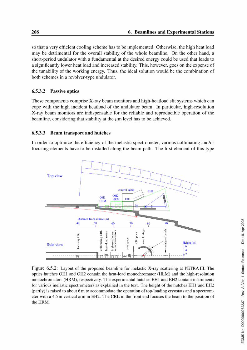
268 6. Beamlines and Experimental Stations
so that a very efficient cooling scheme has to be implemented. Otherwise, the high heat loadmay be detrimental for the overall stability of the whole beamline. On the other hand, ashort-period undulator with a fundamental at the desired energy could be used that leads toa significantly lower heat load and increased stability. This, however, goes on the expense ofthe tunability of the working energy. Thus, the ideal solution would be the combination ofboth schemes in a revolver-type undulator.
6.5.3.2 Passive optics
These components comprise X-ray beam monitors and high-heatload slit systems which cancope with the high incident heatload of the undulator beam. In particular, high-resolutionX-ray beam monitors are indispensable for the reliable and reproducible operation of thebeamline, considering that stability at the µm level has to be achieved.
6.5.3.3 Beam transport and hutches
In order to optimize the efficiency of the inelastic spectrometer, various collimating and/orfocusing elements have to be installed along the beam path. The first element of this type
HRM
Top view
HLM
OH2OH1
control cabin
40 50 60 70 80 90
Distance from source (m)
focu
sing
CR
L
KB
opt
ics
2
Side view Height (m)
46an
alyz
er b
ench
sam
ple
stag
e
EH1
EH2
user
spa
ce
colli
mat
ing
CR
L
heat
−loa
d m
ono
high
−res
olut
ion
mon
ochr
omat
ors
Figure 6.5.2: Layout of the proposed beamline for inelastic X-ray scattering at PETRA III. Theoptics hutches OH1 and OH2 contain the heat-load monochromator (HLM) and the high-resolutionmonochromators (HRM), respectively. The experimental hutches EH1 and EH2 contain instrumentsfor various inelastic spectrometers as explained in the text. The height of the hutches EH1 and EH2(partly) is raised to about 6 m to accommodate the operation of top-loading cryostats and a spectrom-eter with a 4.5 m vertical arm in EH2. The CRL in the front end focuses the beam to the position ofthe HRM.
ED
MS
Nr.:
D00
0000
0082
2371
Rev
: A V
er: 1
Sta
tus:
Rel
ease
d -
Dat
.: 8.
Apr
200
8
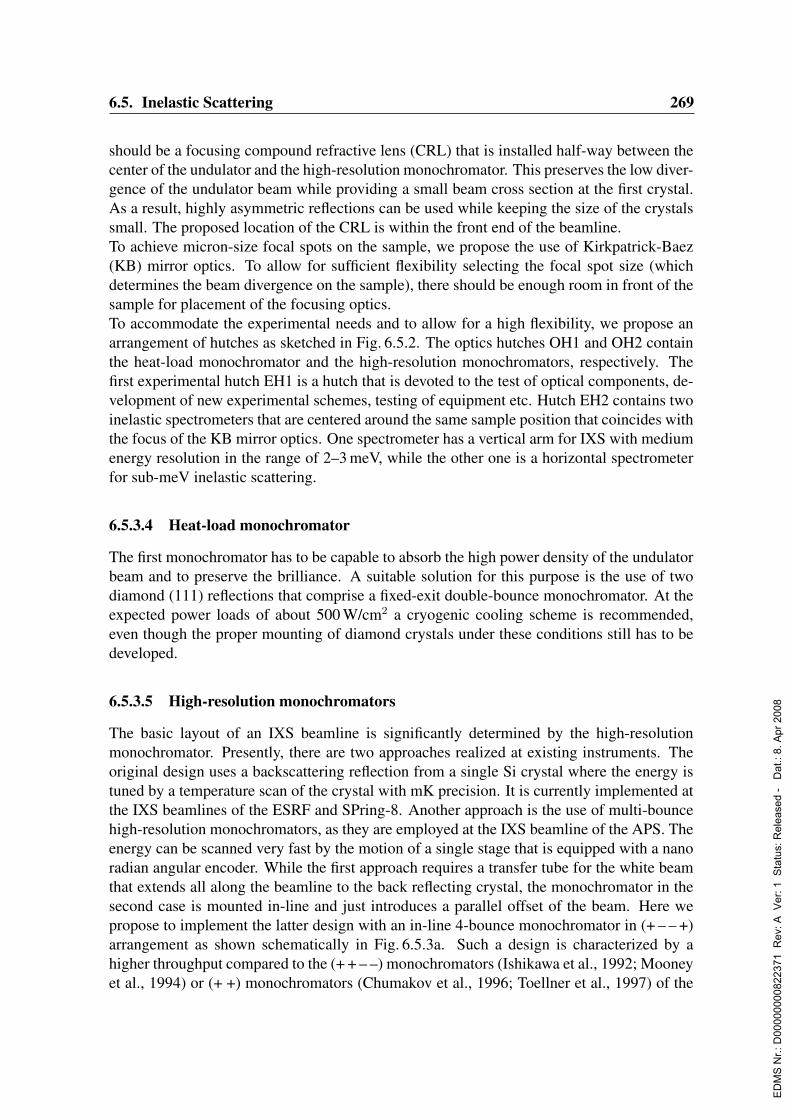
6.5. Inelastic Scattering 269
should be a focusing compound refractive lens (CRL) that is installed half-way between thecenter of the undulator and the high-resolution monochromator. This preserves the low diver-gence of the undulator beam while providing a small beam cross section at the first crystal.As a result, highly asymmetric reflections can be used while keeping the size of the crystalssmall. The proposed location of the CRL is within the front end of the beamline.To achieve micron-size focal spots on the sample, we propose the use of Kirkpatrick-Baez(KB) mirror optics. To allow for sufficient flexibility selecting the focal spot size (whichdetermines the beam divergence on the sample), there should be enough room in front of thesample for placement of the focusing optics.To accommodate the experimental needs and to allow for a high flexibility, we propose anarrangement of hutches as sketched in Fig. 6.5.2. The optics hutches OH1 and OH2 containthe heat-load monochromator and the high-resolution monochromators, respectively. Thefirst experimental hutch EH1 is a hutch that is devoted to the test of optical components, de-velopment of new experimental schemes, testing of equipment etc. Hutch EH2 contains twoinelastic spectrometers that are centered around the same sample position that coincides withthe focus of the KB mirror optics. One spectrometer has a vertical arm for IXS with mediumenergy resolution in the range of 2–3 meV, while the other one is a horizontal spectrometerfor sub-meV inelastic scattering.
6.5.3.4 Heat-load monochromator
The first monochromator has to be capable to absorb the high power density of the undulatorbeam and to preserve the brilliance. A suitable solution for this purpose is the use of twodiamond (111) reflections that comprise a fixed-exit double-bounce monochromator. At theexpected power loads of about 500 W/cm2 a cryogenic cooling scheme is recommended,even though the proper mounting of diamond crystals under these conditions still has to bedeveloped.
6.5.3.5 High-resolution monochromators
The basic layout of an IXS beamline is significantly determined by the high-resolutionmonochromator. Presently, there are two approaches realized at existing instruments. Theoriginal design uses a backscattering reflection from a single Si crystal where the energy istuned by a temperature scan of the crystal with mK precision. It is currently implemented atthe IXS beamlines of the ESRF and SPring-8. Another approach is the use of multi-bouncehigh-resolution monochromators, as they are employed at the IXS beamline of the APS. Theenergy can be scanned very fast by the motion of a single stage that is equipped with a nanoradian angular encoder. While the first approach requires a transfer tube for the white beamthat extends all along the beamline to the back reflecting crystal, the monochromator in thesecond case is mounted in-line and just introduces a parallel offset of the beam. Here wepropose to implement the latter design with an in-line 4-bounce monochromator in (+ – – +)arrangement as shown schematically in Fig. 6.5.3a. Such a design is characterized by ahigher throughput compared to the (+ + – –) monochromators (Ishikawa et al., 1992; Mooneyet al., 1994) or (+ +) monochromators (Chumakov et al., 1996; Toellner et al., 1997) of the
ED
MS
Nr.:
D00
0000
0082
2371
Rev
: A V
er: 1
Sta
tus:
Rel
ease
d -
Dat
.: 8.
Apr
200
8
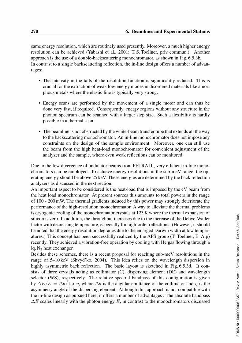
270 6. Beamlines and Experimental Stations
same energy resolution, which are routinely used presently. Moreover, a much higher energyresolution can be achieved (Yabashi et al., 2001; T. S. Toellner, priv. commun.). Anotherapproach is the use of a double-backscattering monochromator, as shown in Fig. 6.5.3b.In contrast to a single backscattering reflection, the in-line design offers a number of advan-tages:
• The intensity in the tails of the resolution function is significantly reduced. This iscrucial for the extraction of weak low-energy modes in disordered materials like amor-phous metals where the elastic line is typically very strong.
• Energy scans are performed by the movement of a single motor and can thus bedone very fast, if required. Consequently, energy regions without any structure in thephonon spectrum can be scanned with a larger step size. Such a flexibility is hardlypossible in a thermal scan.
• The beamline is not obstructed by the white-beam transfer tube that extends all the wayto the backscattering monochromator. An in-line monochromator does not impose anyconstraints on the design of the sample environment. Moreover, one can still usethe beam from the high heat-load monochromator for convenient adjustment of theanalyzer and the sample, where even weak reflections can be monitored.
Due to the low divergence of undulator beams from PETRA III, very efficient in-line mono-chromators can be employed. To achieve energy resolutions in the sub-meV range, the op-erating energy should be above 25 keV. These energies are determined by the back reflectionanalyzers as discussed in the next section.An important aspect to be considered is the heat-load that is imposed by the eV beam fromthe heat load monochromator. At present sources this amounts to total powers in the rangeof 100 - 200 mW. The thermal gradients induced by this power may strongly deteriorate theperformance of the high-resolution monochromator. A way to alleviate the thermal problemsis cryogenic cooling of the monochromator crystals at 123 K where the thermal expansion ofsilicon is zero. In addition, the throughput increases due to the increase of the Debye-Wallerfactor with decreasing temperature, especially for high-order reflections. (However, it shouldbe noted that the energy resolution degrades due to the enlarged Darwin width at low temper-atures.) This concept has been successfully realized by the APS group (T. Toellner, E. Alp)recently. They achieved a vibration-free operation by cooling with He gas flowing through alq. N2 heat exchanger.Besides these schemes, there is a recent proposal for reaching sub-meV resolutions in therange of 5–10 keV (Shvyd’ko, 2004). This idea relies on the wavelength dispersion inhighly asymmetric back reflection. The basic layout is sketched in Fig. 6.5.3d. It con-sists of three crystals acting as collimator (C), dispersing element (DE) and wavelengthselector (WS), respectively. The relative spectral bandpass of this configuration is givenby ∆E/E = ∆θ/ tan η, where ∆θ is the angular emittance of the collimator and η is theasymmetry angle of the dispersing element. Although this approach is not compatible withthe in-line design as pursued here, it offers a number of advantages : The absolute bandpass∆E scales linearly with the photon energy E, in contrast to the monochromators discussed
ED
MS
Nr.:
D00
0000
0082
2371
Rev
: A V
er: 1
Sta
tus:
Rel
ease
d -
Dat
.: 8.
Apr
200
8

6.5. Inelastic Scattering 271
before. Moreover, ∆E can be simply changed via the asymmetry angle η without affect-ing the angular acceptance and the throughput of the arrangement. Finally, the demands fortemperature stability and angular control are not as serious as at high photon energies. Toconvert this approach into an in-line monochromator, one could envisage an arrangement asin Fig. 6.5.3b with the back reflecting crystals being cut highly asymmetrically. The corre-sponding energy analyzer that relies on the same principle is shown in Fig. 6.5.4b.
6.5.3.6 Inelastic spectrometer
The analyzers for the scattered radiation will be spherically-bent silicon pixel analyzers madefrom dicing of Si wafers. The scattering geometry introduces an additional broadening ofthe resolution function of such a spectrometer. This contribution is given by ∆E/E =(a2 + p2)/L2, where a is the size of the illuminated area on the sample, p is the pixel sizeof the analyzer, and L is the distance between sample and analyzer. For the horizontalspectrometer one should aim at L ≈ 10 m to allow for sub-meV resolution around 25 keV.To enhance the efficiency of this spectrometer, multiple analyzers of this kind are foreseen.In case of the vertical spectrometer that is planned for the study of phonons in new materials,we aim at an energy resolution of 2–3 meV. To reach this goal, a long arm with L > 4.5 mhas to be implemented, hosting a single Si pixel analyzer. This arm can be constructed in a
2 mm
(a)
5 cm
(c)
1 m
(b)
(d)
C
DE
WS
η
Figure 6.5.3: Possible schemes for high-resolution in-line monochromators to achieve sub-meVenergy resolutions at photon energies above 20 keV. a) In this four-bounce arrangement, the two setsof crystals are mounted on a weak-link mechanism (shaded areas) for ultra precision motion control(Shu, Toellner & Alp, 2001), sometimes referred to as ’artificial channel-cut’. Similar schemes incombination with cryogenic cooling allow for a high-throughput monochromator at 25.7 keV with anenergy bandwidth of 0.7 meV (T. S. Toellner, priv. commun.). b) A very compact optical design forBragg reflections near backscattering (Baron et al., 2001a), using a very thin coupling crystal withina backscattering channel cut. c) Double - backscattering monochromator. This design combines ahigh throughput with narrow tails of the resolution function, as already successfully tested (H. Sinn,priv. commun.) d) The wavelength dispersion in highly asymmetric back reflection can be exploitedto design monochromators with sub-meV resolution in the 5–10 keV range (Shvyd’ko, 2004).
ED
MS
Nr.:
D00
0000
0082
2371
Rev
: A V
er: 1
Sta
tus:
Rel
ease
d -
Dat
.: 8.
Apr
200
8
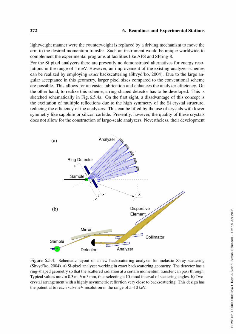
272 6. Beamlines and Experimental Stations
lightweight manner were the counterweight is replaced by a driving mechanism to move thearm to the desired momentum transfer. Such an instrument would be unique worldwide tocomplement the experimental programs at facilities like APS and SPring-8.For the Si pixel analyzers there are presently no demonstrated alternatives for energy reso-lutions in the range of 1 meV. However, an improvement of the existing analyzer schemescan be realized by employing exact backscattering (Shvyd’ko, 2004). Due to the large an-gular acceptance in this geometry, larger pixel sizes compared to the conventional schemeare possible. This allows for an easier fabrication and enhances the analyzer efficiency. Onthe other hand, to realize this scheme, a ring-shaped detector has to be developed. This issketched schematically in Fig. 6.5.4a. On the first sight, a disadvantage of this concept isthe excitation of multiple reflections due to the high symmetry of the Si crystal structure,reducing the efficiency of the analyzers. This can be lifted by the use of crystals with lowersymmetry like sapphire or silicon carbide. Presently, however, the quality of these crystalsdoes not allow for the construction of large-scale analyzers. Nevertheless, their development
DispersiveElement
Rl
h
Sample
Mirror
Detector
Collimator
Analyzer
Ring Detector
Analyzer
Sample
(a)
(b)
Figure 6.5.4: Schematic layout of a new backscattering analyzer for inelastic X-ray scattering(Shvyd’ko, 2004). a) Si-pixel analyzer working in exact backscattering geometry. The detector has aring-shaped geometry so that the scattered radiation at a certain momentum transfer can pass through.Typical values are l = 0.3 m, h = 3 mm, thus selecting a 10-mrad interval of scattering angles. b) Two-crystal arrangement with a highly asymmetric reflection very close to backscattering. This design hasthe potential to reach sub-meV resolution in the range of 5–10 keV.
ED
MS
Nr.:
D00
0000
0082
2371
Rev
: A V
er: 1
Sta
tus:
Rel
ease
d -
Dat
.: 8.
Apr
200
8

6.5. Inelastic Scattering 273
should be pursued during the R&D process for this beamline. Another way to enhance theefficiency of Si backscattering analyzers is the use of reflections that are less degenerate thanthe widely used ones. While the (13 13 13) back reflection at 25.7 keV is a 26-beam caseand the (15 15 15) back reflection is a 56-beam case, other cases like the Si (2 2 20) and theSi (10 12 18) back reflection are only 6-fold degenerate, respectively.Accordingly, a very small illuminated spot size on the sample allows for a larger pixel size ata given value for ∆E. This is another argument for using a microfocused beam. Moreover,in this case it will also be possible to illuminate thin films in grazing incidence geometrywhile maintaining a sufficiently small spot size on the sample.
6.5.3.7 Sample environment
For the investigation of single crystals or for adjusting samples in grazing incidence ge-ometry, a goniometer with four circles is required. The goniometer should as well supportheavy equipment such as cryostats. It is also desirable to have considerable free space at thesample position. For quick checks of sample orientation and/or quality, the mounting of atwo-dimensional CCD detector behind and close to the sample has to be foreseen.
6.5.4 Capital investment and personnelFor the development of the scientific program at the beamline, two researchers are requiredwho run independent activities to accommodate a wide scientific community.The special crystal optics for the high-resolution monochromators and the analyzers shouldbe made in-house. The performance of these devices crucially depends on an engineer thatis dedicated to such developments. In particular, experience in nano-radian motion controlis required. For installation of the beamline components and their maintenance, two tech-nicians are needed, whereby one of them is specialized in mechanical problems, includingoperation of the analyzer fabrication, and the other one is specialized on electrical installa-tions, including motor control and data acquisition.
The total capital investment for these experimental stations is 4060 ke.
ED
MS
Nr.:
D00
0000
0082
2371
Rev
: A V
er: 1
Sta
tus:
Rel
ease
d -
Dat
.: 8.
Apr
200
8

274 6. Beamlines and Experimental Stations
6.6 Nuclear Resonant ScatteringAuthors :
H. Franz DESY, Hamburg, GermanyR. Rohlsberger DESY Hamburg, GermanyR. Ruffer ESRF, Grenoble, FranceB. Sepiol Universitat Wien, AustriaYu.V. Shvyd’ko Universitat Hamburg, GermanyM. Sladecek Universitat Wien, AustriaG. Vogl Universitat Wien, AustriaG. Wortmann Universitat Paderborn, Germany
6.6.1 Current state of the scientific fieldNuclear resonant scattering (NRS) of synchrotron radiation was first demonstrated at HA-SYLAB in Hamburg almost 20 years ago now (Gerdau et al., 1985). First experiments weredone at a bending magnet beamline (F4 at DORIS III). But only the advent of high energythird generation synchrotron sources like ESRF and APS has allowed to turn this methodinto a routine technique. Due to the sharpness of the nuclear resonances (typically someneV to µeV) NRS experiments are extremely flux hungry. For the same reason they requiresophisticated monochromatization with a resolution in the meV or even sub-meV region.This is why NRS would profit most from the planned 20 m ID. Already now, ID18 at ERSFuses the equivalent of a 5 m long device, optimized for the 57Fe transition at 14.4 keV. Thisreflects the fact that 57Fe is the working horse for NRS due to it’s favorable transition energyand life-time. However several other isotopes (161Dy, 151Eu, 61Ni, 149Sm, 119Sn,....) are usedfor investigations mainly in the field of magnetism.Experiments using NRS can be divided into three classes:
• Hyperfine spectroscopy via elastic NRS. In this field NRS has been used to study mag-netism in thin films (Rohlsberger et al., 2003), high pressure (Lubbers, Wortmann &Grunsteudel, 1999) and biophysical applications (Trautwein & Winkler, 1999). Quasi-elastic forward scattering gives information about jump–diffusion (Vogl & Sepiol,1999), structural relaxation in disordered (bulk and confined) systems (Sergueev et al.,2002; Asthalter et al., 2001) and also spin relaxation (Shvyd’ko et al., 2001).
• Vibrational spectroscopy via nuclear inelastic scattering (NIS). In experiments on thinfilms (Ruckert et al., 2000), protein dynamics (Parak & Achterhold, 1999) NIS hasproven to be superior to inelastic neutron scattering, be it due to the small beam size,the element specifity or the larger scattering cross-section (0.13 Mbarn).
• Synchrotron radiation-based perturbed angular correlation SRPAC. This new tech-nique (Sergueev et al., 2003) can be used to gain information about rotational dynamicsin systems which display a vanishing Lamb–Mossbauer–factor.
NRS experiments take advantage of the large cross–section of nuclear resonances. Thus inspite of the narrow bandwidth the signal from the sample may be rather strong. In addition
ED
MS
Nr.:
D00
0000
0082
2371
Rev
: A V
er: 1
Sta
tus:
Rel
ease
d -
Dat
.: 8.
Apr
200
8

6.6. Nuclear Resonant Scattering 275
the isotope selectivity and the time discrimination help to reduce the background to a levelclose to zero. Sample environments like high pressure cell, cryostats, furnaces or matricesdo not contribute to the measured signal. That is why in NRS minute amounts of samplematerial is sufficient. Of course, also the small beam at third generation SR sources helpsto minimize the sample volume. This is often a big advantage compared both to neutronscattering and conventional Mossbauer spectroscopy.
6.6.2 Science at the NRS beamline at PETRA III
In the following we will sketch some scientific fields where we expect NRS at PETRA III todeliver a unique contribution.
6.6.2.1 Magnetism and dynamics of low-dimensional structures
The investigation of nanoscale structures by means of advanced X-ray scattering techniqueswill be an important contribution of PETRA III to the field of artificially structured materials.In particular, elastic and inelastic nuclear resonant scattering will offer unique opportunitiesfor the investigation of magnetic and dynamic properties that lie at the heart of novel func-tional materials. Due to the use of hard X-rays, buried interfaces will be accessible, for whichcurrently no alternative technique is available.
Lattice dynamics with nanoscale spatial resolutionPropagating excitations like phonons can be significantly modified by interfaces and artificialsuperlattices. The tailoring of phononic spectra to specific purposes will be of increasing im-portance in the future. Since only a fundamental understanding of vibrational properties un-der the influence of interfaces will ensure full tunability, basic research and applications willbe intimately related. Due to its isotopic specifity, NIS opens the possibility to selectivelyobtain the vibrational properties of nanoparticles and thin films that contain the resonant iso-tope. There is no need to discriminate against inelastic signals from surrounding materials.The sensitivity of the method to thin films has been proven already in a number of experi-ments (Rohlsberger, 2001). However, the statistical quality of the data that can be obtainedat present-day sources is not sufficient to allow for investigations of single monolayers. Onthe other hand, flux estimates for the 20 m undulator beamline at PETRA III indicate that avibrational spectrum from a single monolayer of 57Fe can be obtained in a few hours. Thisopens the possibility to selectively introduce isotopic probe layers in the sample and obtainvibrational properties with atomic resolution. It is a distinct advantage of this technique thatsuch probe layers do not disturb the chemical integrity of the system.A very interesting research area are low-energy excitations in nanoparticles and clusters(Fultz et al., 1997). The nature of these modes is far from being understood. NIS at PETRAIII will allow one to selectively probe, e.g. different parts of such structures to locate theirspatial origin (grain boundaries, surface or core). The application of focusing techniques willallow one to probe smallest amounts of material and thus facilitate, for the first time, exper-iments on thin films in high-pressure cells, for example. Such investigations are mandatory
ED
MS
Nr.:
D00
0000
0082
2371
Rev
: A V
er: 1
Sta
tus:
Rel
ease
d -
Dat
.: 8.
Apr
200
8
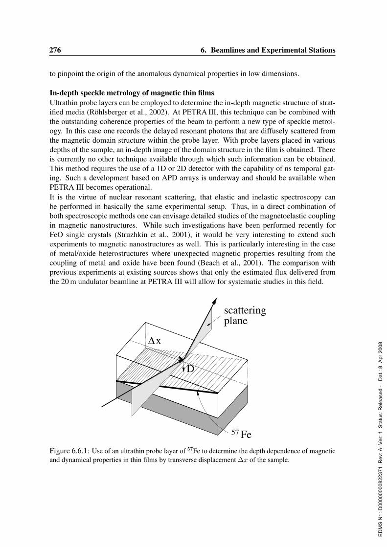
276 6. Beamlines and Experimental Stations
to pinpoint the origin of the anomalous dynamical properties in low dimensions.
In-depth speckle metrology of magnetic thin filmsUltrathin probe layers can be employed to determine the in-depth magnetic structure of strat-ified media (Rohlsberger et al., 2002). At PETRA III, this technique can be combined withthe outstanding coherence properties of the beam to perform a new type of speckle metrol-ogy. In this case one records the delayed resonant photons that are diffusely scattered fromthe magnetic domain structure within the probe layer. With probe layers placed in variousdepths of the sample, an in-depth image of the domain structure in the film is obtained. Thereis currently no other technique available through which such information can be obtained.This method requires the use of a 1D or 2D detector with the capability of ns temporal gat-ing. Such a development based on APD arrays is underway and should be available whenPETRA III becomes operational.It is the virtue of nuclear resonant scattering, that elastic and inelastic spectroscopy canbe performed in basically the same experimental setup. Thus, in a direct combination ofboth spectroscopic methods one can envisage detailed studies of the magnetoelastic couplingin magnetic nanostructures. While such investigations have been performed recently forFeO single crystals (Struzhkin et al., 2001), it would be very interesting to extend suchexperiments to magnetic nanostructures as well. This is particularly interesting in the caseof metal/oxide heterostructures where unexpected magnetic properties resulting from thecoupling of metal and oxide have been found (Beach et al., 2001). The comparison withprevious experiments at existing sources shows that only the estimated flux delivered fromthe 20 m undulator beamline at PETRA III will allow for systematic studies in this field.
∆x
Fe57
D
ϕ
scatteringplane
Figure 6.6.1: Use of an ultrathin probe layer of 57Fe to determine the depth dependence of magneticand dynamical properties in thin films by transverse displacement ∆x of the sample.
ED
MS
Nr.:
D00
0000
0082
2371
Rev
: A V
er: 1
Sta
tus:
Rel
ease
d -
Dat
.: 8.
Apr
200
8

6.6. Nuclear Resonant Scattering 277
6.6.2.2 Magnetism and lattice dynamics at extreme conditions: high pressure andhigh temperature
The knowledge about the properties of matter under extreme conditions, here high pressureand high temperature, is of utmost importance for solid state physics, material science andgeophysics. Using diamond anvil cells (DAC), ultra-high pressures up to 4 Mbar (400 GPa),which compares with 3.5 Mbar at the Earths inner core, can be reached. Since the size of thepressurized samples above 1 Mbar is in the 1 - 10µm range, such high pressure experimentsbenefit from the high brilliance of third-generation synchrotron sources as well as from therecent developments of focusing optics. Both NFS and NIS techniques have been alreadyused for studying magnetism and lattice dynamics in the Mbar range, for instance the sup-pression of Fe band magnetism in RFe2 Laves phases (Lubbers, Rupprecht & Wortmann,2000) and the lattice dynamics in the hexagonal high-pressure phase of iron (Lubbers et al.,2000; Mao et al., 2001). Future NFS and NIS experiments at higher pressures and smallersamples will profit from the increased brilliance and flux of the envisaged NRS beamlineat PETRA III enabling also experiments which combine two extreme conditions, e.g. highpressure and high temperature, possible for instance with Laser heating, or, as mentionedabove, high pressure/low temperature experiments on nano-scaled magnetic systems (e.g.layers).
Magnetism at extreme conditionsBeside iron magnetism which is already investigated routinely at high pressures and high/lowtemperatures (Lubbers, Rupprecht & Wortmann, 2000; Rupprecht et al., 2002), the rare-earth magnetism at extreme conditions is a wide field with new challenges, which can betackled with sensitive Mossbauer resonances like Sm149, Eu151 and Dy161, all of them al-ready employed successfully for various problems. Eu(II)-chalcogenides are presently stud-ied with an enormous variation of the magnetic ordering temperature, for instance in EuSfrom 16 K (0 GPa, NaCl-phase) to 280 K (77 GPa, CsCl-phase)(Lubbers, Rupprecht & Wort-mann, 2000; Rupprecht, Ponkratz & Wortmann, 2003). In Eu and Sm systems, magnetismand valence transitions are often closely related, as demonstrated recently by a study of SmS(Barla et al., 2004). Of current interest are strongly correlated 4f- and 5f-systems (HeavyFermion systems) exhibiting magnetism and superconductivity with pressure as an impor-tant parameter. Here probe atoms like Sn were used successfully (Barla et al., 2002). Futurework at PETRA III may approach new frontiers in 4f magnetism, for instance delocalizationof 4f-electrons in Sm and Dy metal at ultra-high pressures. A related topic is, as for Fe inmagnetic layers, the investigation of the phonon-magnon coupling in systems with strong 4fmagnetism, e.g. SmCo5 and DyFe2, by using NIS.
Phonon spectroscopy at extreme conditionsThe actual geophysical interest in the hexagonal high-pressure phase of iron as the mostrelevant phase of the Earths solid inner core has triggered the first high-pressure phononstudies of this phase (Lubbers et al., 2000), reaching 1.53 Mbar in a second attempt (Maoet al., 2001). At ESRF, recent progress in the focusing optics (compound refractive lensesand K-B mirrors) allow to concentrate the whole monochromatized beam to a spot of less
ED
MS
Nr.:
D00
0000
0082
2371
Rev
: A V
er: 1
Sta
tus:
Rel
ease
d -
Dat
.: 8.
Apr
200
8

278 6. Beamlines and Experimental Stations
than 10µm diameter and to record a NIS spectrum of iron at 130 GPa in 12 h with a muchbetter statistical accuracy and spectral resolution than in the first studies (Giefers et al., 2002).The texture in the pressurized sample, here ε-Fe, is used to extract from the NIS spectrathe phonon density-of-states (DOS) as seen in different crystallographic directions. Thisallows for a mode-specific analysis of the phonon spectra, for instance an identification ofthe two optical modes and provided the first experimental proof of an anisotropy in the soundvelocity parallel and perpendicular to the hexagonal c-axis (Giefers et al., 2002). It shouldbe remembered that the observed anisotropy of the sound velocities in the Earths core isattributed to highly textured ε-Fe in the core (Creager, 1997), the reason for this texture ispresently discussed with various models (Jephcoat & Refson, 2001; Steinle-Neumann et al.,2001; Buffet & Wenk, 2001).To approach the inner Earths conditions, one needs beside high pressure also high temper-ature. The thermodynamic properties of iron at ultrahigh pressures and temperatures aretherefore of utmost geophysical interest; the same holds for the minerals building up theupper and lower crust, all containing iron, e.g. the olivine (Mg, Fe)SiO3. Their dynamicproperties and phase transitions at high pressures and temperatures, also sound velocities,can be sensitively monitored by measuring the phonon DOS at the Fe sites. Temperaturesup to 1000 K can be easily reached with ”intelligent” diamonds (diamonds with integratedheaters) or with simple ovens (Rupprecht et al., 2002), temperatures up to 3000 K can bereached with resistance heatings of the gasket, even higher temperatures up to 4000 K withLaser heating. Such NIS studies at elevated temperatures can prove (or disprove) recent the-oretical predictions about the temperature dependence of the anisotropy of elastic parametersand sound velocity in ε-Fe (Jephcoat & Refson, 2001; Steinle-Neumann et al., 2001; Buf-fet & Wenk, 2001). The option to compare thermodynamic parameters derived at elevatedtemperatures with the ones at ambient temperature to improve estimates of important prop-erties such as melting temperatures beyond the Mie-Gruneisen approximation is one morereason for combined high-p,T NIS experiments.
6.6.2.3 Glass dynamics
The narrow bandpass makes NRS an ideal tool to study dynamics. In time resolved mode thenano- to µ-second region is accessible. This is the relevant time scale to study the glass tran-sition in the light of mode-coupling theory (Bengtzelius, Gotze & Sjolander, 1984; Sergueevet al., 2002). In particular the recent advances using single nucleus scattering (SRPAC) al-lows one to study the range from fast β-relaxation (several 10 ps) to the α-relaxation evenbelow Tc (Sergueev et al., 2003). Following the pioneer-experiment at ESRF a systematicstudy of glass-formers of different strength will help to unravel the mechanism underlyingthe glass transition. In particular the option to separate translational and rotational motion byNFS and SRPAC will shine light on the origin of discrepancies found when combining re-sults from different techniques like dielectric relaxation, light scattering or inelastic neutronscattering.In the energy resolved mode even faster dynamics in the ps-time scale are accessible. Thisis the domain of phonons. In this area the so called boson peak is still a puzzle waiting tobe solved. The boson peak is an excess density of states found in the vibrational spectra of
ED
MS
Nr.:
D00
0000
0082
2371
Rev
: A V
er: 1
Sta
tus:
Rel
ease
d -
Dat
.: 8.
Apr
200
8

6.6. Nuclear Resonant Scattering 279
all disordered systems around several meV . The following question may be addressed withinelastic scattering experiments:
• are the excess exitations propagating or localized
• if they are propagating, how does the dispersion look like, is it of acoustic or optic type
In combination with non-resonant inelastic scattering nuclear resonant experiments with verygood energy resolution (below 0.5meV ) can help to get answers to these points.
6.6.2.4 Diffusion
Diffusion plays a key role in the kinetics of structural changes that occur during the process-ing of metals, alloys, ceramics or semiconductors. The atomic migration in crystalline solidsconsists of jumps of individual atoms. The variety of atomic jump mechanisms is closelyconnected with defects.
Diffusion in solids is usually investigated on a macroscopic scale following the inter-penetra-tion of two atomic species across an interface (tracer technique). This method deducesatomic events from macroscopic effects as, for instance, the concentration gradient of dif-fusing isotopes. In contrast to this macroscopic, classical methods diffusion can be studiedat the microscopic level also. I.e. in a way which can reveal the jump vectors and the jumprates of the atoms. Nuclear resonant scattering of synchrotron radiation is one of the mostsuccessful methods for this kind of dynamics studies (Sepiol & Vogl, 2003; Vogl & Sepiol,1999).
Scattering of X-rays in grazing incidence geometry has become an established technique forstudying the structure of thin films and multilayers. The special goal of this method is thedepth profile analysis. Combining grazing-incidence reflection with nuclear resonant scat-tering results in the depth-selective investigation of diffusion and of the hyperfine parametersof resonant nuclei. Combination of diffusivity studies with ab-initio calculations will allowthe quantitative estimate of the diffusion rates and mechanisms at surfaces and in thin films.This is a challenging project, but should now be within the reach of the most performantsynchrotron sources and ab-initio simulation tools.
Recently we have indeed gained the first preliminary results on diffusion in iron layers closeto the surface (Sladecek et al., 2001) and in ultrathin iron films on a tungsten (110) surface(Sladecek et al., 2003), see Fig. 6.6.2. In the most challenging case a sub-monolayer isscanned for diffusion and relaxation. Until now these studies suffer from the limited bril-liance of presently available sources. Higher brilliance as expected from PETRA III willenable to perform such studies in decent measuring time and thus result in detailed under-standing of the kinetics of phase formation and transformation in thin films and multilayersby in-situ investigation.
ED
MS
Nr.:
D00
0000
0082
2371
Rev
: A V
er: 1
Sta
tus:
Rel
ease
d -
Dat
.: 8.
Apr
200
8
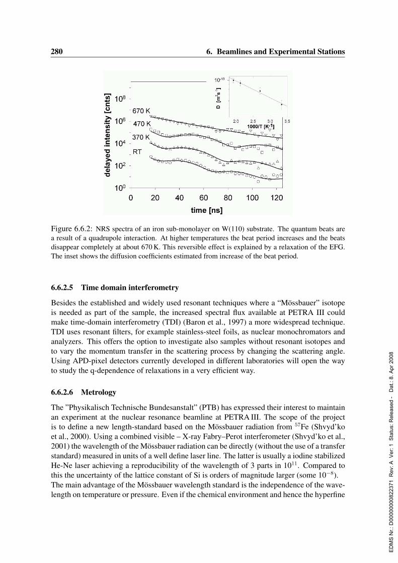
280 6. Beamlines and Experimental Stations
Figure 6.6.2: NRS spectra of an iron sub-monolayer on W(110) substrate. The quantum beats area result of a quadrupole interaction. At higher temperatures the beat period increases and the beatsdisappear completely at about 670 K. This reversible effect is explained by a relaxation of the EFG.The inset shows the diffusion coefficients estimated from increase of the beat period.
6.6.2.5 Time domain interferometry
Besides the established and widely used resonant techniques where a “Mossbauer” isotopeis needed as part of the sample, the increased spectral flux available at PETRA III couldmake time-domain interferometry (TDI) (Baron et al., 1997) a more widespread technique.TDI uses resonant filters, for example stainless-steel foils, as nuclear monochromators andanalyzers. This offers the option to investigate also samples without resonant isotopes andto vary the momentum transfer in the scattering process by changing the scattering angle.Using APD-pixel detectors currently developed in different laboratories will open the wayto study the q-dependence of relaxations in a very efficient way.
6.6.2.6 Metrology
The ”Physikalisch Technische Bundesanstalt” (PTB) has expressed their interest to maintainan experiment at the nuclear resonance beamline at PETRA III. The scope of the projectis to define a new length-standard based on the Mossbauer radiation from 57Fe (Shvyd’koet al., 2000). Using a combined visible – X-ray Fabry–Perot interferometer (Shvyd’ko et al.,2001) the wavelength of the Mossbauer radiation can be directly (without the use of a transferstandard) measured in units of a well define laser line. The latter is usually a iodine stabilizedHe-Ne laser achieving a reproducibility of the wavelength of 3 parts in 1011. Compared tothis the uncertainty of the lattice constant of Si is orders of magnitude larger (some 10−8).The main advantage of the Mossbauer wavelength standard is the independence of the wave-length on temperature or pressure. Even if the chemical environment and hence the hyperfine
ED
MS
Nr.:
D00
0000
0082
2371
Rev
: A V
er: 1
Sta
tus:
Rel
ease
d -
Dat
.: 8.
Apr
200
8
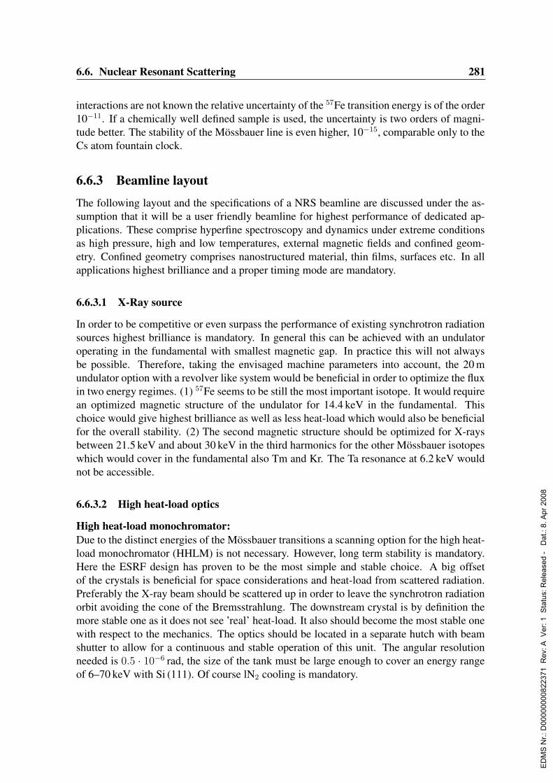
6.6. Nuclear Resonant Scattering 281
interactions are not known the relative uncertainty of the 57Fe transition energy is of the order10−11. If a chemically well defined sample is used, the uncertainty is two orders of magni-tude better. The stability of the Mossbauer line is even higher, 10−15, comparable only to theCs atom fountain clock.
6.6.3 Beamline layout
The following layout and the specifications of a NRS beamline are discussed under the as-sumption that it will be a user friendly beamline for highest performance of dedicated ap-plications. These comprise hyperfine spectroscopy and dynamics under extreme conditionsas high pressure, high and low temperatures, external magnetic fields and confined geom-etry. Confined geometry comprises nanostructured material, thin films, surfaces etc. In allapplications highest brilliance and a proper timing mode are mandatory.
6.6.3.1 X-Ray source
In order to be competitive or even surpass the performance of existing synchrotron radiationsources highest brilliance is mandatory. In general this can be achieved with an undulatoroperating in the fundamental with smallest magnetic gap. In practice this will not alwaysbe possible. Therefore, taking the envisaged machine parameters into account, the 20 mundulator option with a revolver like system would be beneficial in order to optimize the fluxin two energy regimes. (1) 57Fe seems to be still the most important isotope. It would requirean optimized magnetic structure of the undulator for 14.4 keV in the fundamental. Thischoice would give highest brilliance as well as less heat-load which would also be beneficialfor the overall stability. (2) The second magnetic structure should be optimized for X-raysbetween 21.5 keV and about 30 keV in the third harmonics for the other Mossbauer isotopeswhich would cover in the fundamental also Tm and Kr. The Ta resonance at 6.2 keV wouldnot be accessible.
6.6.3.2 High heat-load optics
High heat-load monochromator:Due to the distinct energies of the Mossbauer transitions a scanning option for the high heat-load monochromator (HHLM) is not necessary. However, long term stability is mandatory.Here the ESRF design has proven to be the most simple and stable choice. A big offsetof the crystals is beneficial for space considerations and heat-load from scattered radiation.Preferably the X-ray beam should be scattered up in order to leave the synchrotron radiationorbit avoiding the cone of the Bremsstrahlung. The downstream crystal is by definition themore stable one as it does not see ’real’ heat-load. It also should become the most stable onewith respect to the mechanics. The optics should be located in a separate hutch with beamshutter to allow for a continuous and stable operation of this unit. The angular resolutionneeded is 0.5 · 10−6 rad, the size of the tank must be large enough to cover an energy rangeof 6–70 keV with Si (111). Of course lN2 cooling is mandatory.
ED
MS
Nr.:
D00
0000
0082
2371
Rev
: A V
er: 1
Sta
tus:
Rel
ease
d -
Dat
.: 8.
Apr
200
8

282 6. Beamlines and Experimental Stations
Compound refractive lens:A compound refractive lens (CRL) is required upstream of the HHLM in order to collimatethe beam for best performance of the HHLM. Especially at higher energies a better matchingof the beam divergence and the crystal acceptance is achieved.
Beam position and intensity monitors:A beam position monitor as the first element, i.e. before any optical element will be benefi-cial. Furthermore, intensity monitors are required after each optical element.
Slit systems:The estimated high power of the synchrotron radiation will need a high power slit systemupstream of the HHLM. A beam defining slit system downstream of the HHLM should behighly precise and easily scanable.
6.6.3.3 Focusing
Focusing optics are mandatory for most of the applications in NRS. There are two options:(1) a moderate focus (e.g. 100µm × 100µm) utilizing CRLs for vertical and horizontal fo-cusing; (2) for e.g. a 10µm × 10µm or smaller focal spot utilizing a Kirkpatrick-Baez (KB)optics system based on graded multilayers. Option (1) has the advantage that the beam staysstraight and the focal length is big allowing for large sample environment and a permanentset-up somewhere in the beamline. Furthermore the alignment is very simple. Option (2)has a shorter focal length (approx. 500-700 mm) and deflects the beam out of the straight,i.e., the sample environment has to be chosen accordingly and the optics has to move to thecorresponding experimental station. The alignment is more challenging.
6.6.3.4 High energy resolution optics
The high resolution monochromator (HRM) is the ’main’ monochromator in NRS applica-tions. It needs most development and alignment efforts. So far HRMs for the energy regimeup to about 30 keV have been developed on the basis of multi-bounce arrangements. At leasttwo HRM mechanics should be foreseen, one hosting the crystals for the 57Fe resonanceenergy and one hosting alternative crystals for other isotopes. If one cannot afford moresystems right from the beginning, space should be provided for at least two to four other sys-tems. Collimating CRLs upstream of the HRM should be foreseen in order to ease the designand to improve the performance of the HRM. Options for HRMs which also cover higher en-ergies should be considered as ’true’ back-scattering arrangements. Permanent stations formonitoring the resonance up- and downstream of the HRM would ease the operation.Further space should be kept for polarization shifter and further upgrades or new ideas e.g.the nuclear lighthouse effect. The HRM optics will be located in a highly temperature andmechanical stabilized hutch with a separate beamshutter. This ensures low-vibrational noiseto maintain a good short- and long-term stability.
ED
MS
Nr.:
D00
0000
0082
2371
Rev
: A V
er: 1
Sta
tus:
Rel
ease
d -
Dat
.: 8.
Apr
200
8
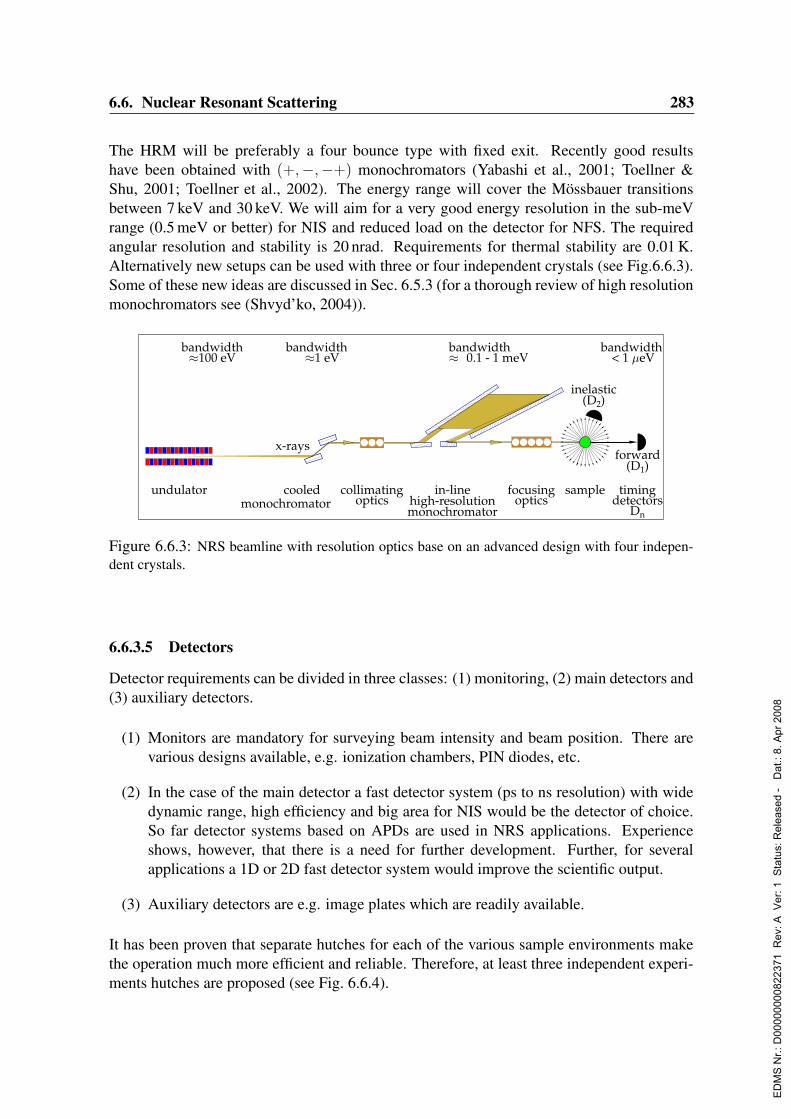
6.6. Nuclear Resonant Scattering 283
The HRM will be preferably a four bounce type with fixed exit. Recently good resultshave been obtained with (+,−,−+) monochromators (Yabashi et al., 2001; Toellner &Shu, 2001; Toellner et al., 2002). The energy range will cover the Mossbauer transitionsbetween 7 keV and 30 keV. We will aim for a very good energy resolution in the sub-meVrange (0.5 meV or better) for NIS and reduced load on the detector for NFS. The requiredangular resolution and stability is 20 nrad. Requirements for thermal stability are 0.01 K.Alternatively new setups can be used with three or four independent crystals (see Fig.6.6.3).Some of these new ideas are discussed in Sec. 6.5.3 (for a thorough review of high resolutionmonochromators see (Shvyd’ko, 2004)).
undulator
x-rays
bandwidth100 eV
cooledmonochromator
bandwidth1 eV
in-linehigh-resolutionmonochromator
bandwidth0.1 - 1 meV
inelastic(D2)
forward(D1)
timingdetectors
Dn
bandwidth< 1 eV
samplecollimatingoptics
focusingoptics
Figure 6.6.3: NRS beamline with resolution optics base on an advanced design with four indepen-dent crystals.
6.6.3.5 Detectors
Detector requirements can be divided in three classes: (1) monitoring, (2) main detectors and(3) auxiliary detectors.
(1) Monitors are mandatory for surveying beam intensity and beam position. There arevarious designs available, e.g. ionization chambers, PIN diodes, etc.
(2) In the case of the main detector a fast detector system (ps to ns resolution) with widedynamic range, high efficiency and big area for NIS would be the detector of choice.So far detector systems based on APDs are used in NRS applications. Experienceshows, however, that there is a need for further development. Further, for severalapplications a 1D or 2D fast detector system would improve the scientific output.
(3) Auxiliary detectors are e.g. image plates which are readily available.
It has been proven that separate hutches for each of the various sample environments makethe operation much more efficient and reliable. Therefore, at least three independent experi-ments hutches are proposed (see Fig. 6.6.4).
ED
MS
Nr.:
D00
0000
0082
2371
Rev
: A V
er: 1
Sta
tus:
Rel
ease
d -
Dat
.: 8.
Apr
200
8
284 6. Beamlines and Experimental Stations
Figure 6.6.4: Schematic layout of the proposed NRS beamline.
6.6.3.6 Sample environment
Four types of sample environments will be used in NRS experiments at PETRA III.
(1) A cryo-magnet system for nuclear forward scattering (NFS) and nuclear reflectometry(NR), hyperfine spectroscopy and small-angle scattering
(2) A UHV system for NR, hyperfine spectroscopy and dynamics
(3) Cryo-systems and furnaces for hyperfine spectroscopy and dynamics
(4) High pressure cells.
Cryo-magnet systemA cryo-magnet system (specifications see below) is used in NFS geometry mainly for high-pressure work (hyperfine spectroscopy and diffraction) and in NR geometry for surface in-vestigations (hyperfine spectroscopy and small-angle scattering). Other investigations whichneed low temperature and external magnetic fields are possible as well. An option for in-situX-ray diffraction would be an asset. This could be accomplished in the simplest case byan image plate detector or a separate 2Θ detector system. Of course much more efficientwould be an on-line 2D detector. The cryo-magnet system will be top-loading and sufficientvertical space is required (approx. 5 m).
Requirements for the cryo-magnet systemWe should head for a temperature range from 1.5 - 500 K with an additional option to achievemK temperatures. The horizontal magnetic field will have a maximum value of about 10 T.The sample volume will be at least (50 mm)3 delivering enough space for high pressure celland thin film samples. It turned out that the sample holder needs to be vertical motorized withposition feedback on the sample, a rotation around the vertical axis will also be provided.The entire set-up will be mounted on a two circle element for Bragg and tilt angle align-ment. For the translational (vertical and horizontal) alignment of the samples µm resolutionis mandatory. The system will allow in-situ pressure calibration and change of pressure.
ED
MS
Nr.:
D00
0000
0082
2371
Rev
: A V
er: 1
Sta
tus:
Rel
ease
d -
Dat
.: 8.
Apr
200
8
6.6. Nuclear Resonant Scattering 285
UHV environmentThere are two options for an UHV system: (1) UHV chamber with a load-lock system tocarry out NRS experiments and a characterization option (LEED, AES, ...) in order to mon-itor the sample quality, (2) UHV chamber for preparation, characterization and NRS experi-ments.In both cases a vertical Θ / 2Θ geometry for small angles (Θ < 5) is needed. The operationtemperature regime should cover at least lN2 temperature to highest temperature. This willallow for hyperfine and phonon spectroscopy as well as for diffusion studies. Specializedstaff is needed to operate the system and keep it functional at high performance level.
Cryo-systems and furnacesThese systems are employed for temperature dependent studies in NIS, SRPAC or NFS e.g.diffusion studies. Typically the systems are small in size and easily movable, i.e. they can beexchanged as needed. Furthermore, the same hutch might be used for ’unforeseen’ set-ups.There are different user friendly solutions to reach He-temperatures, i.e. closed-cycle cryo-stats, flow cryostats or bath cryostats with cold finger. Since some set-ups, e.g. for the deter-mination of isomer shifts and inelastic scattering with resonant energy analysis, are highlysensitive to vibrations, vibrational damping and mechanical stability will be guaranteed. Forthe high temperature range a mirror-furnace will be available.
6.6.3.7 Infrastructure
For an efficient operation of the instruments discussed above the following infrastructurewould be desirable.
High pressureProvided the users bring their own high pressure cells the necessary high pressure infras-tructure can be kept low. However, minimum equipment to load high pressure cells (e.g.DAC), to change and to determine pressure (e.g. Ruby fluorescence) is mandatory. De-pending on the choice for the position sensitive detector for diffraction work the necessaryinfrastructure should be provided. This equipment should be closely located to the beamline.
UHV environmentFrom the scientific point of view it is clear that a full UHV system with preparation option isthe proper choice. Preparation of samples is the most crucial part which needs experiencedpersonnel and sufficient test and preparation time. Therefore, the system should also be keptoperational in a separate laboratory outside the actual beamtime.
Control cabinIn order to ease the operation of the experimental stations and to make it efficient as pos-sible, control cabins attached to each experimental station are mandatory. They should beorganized such that independently to the other stations set-up and operation is possible. Oth-erwise the down time of the beamline will become unacceptable.
ED
MS
Nr.:
D00
0000
0082
2371
Rev
: A V
er: 1
Sta
tus:
Rel
ease
d -
Dat
.: 8.
Apr
200
8

286 6. Beamlines and Experimental Stations
6.6.4 Capital investment and personnelThe beamline will be staffed with 2–3 scientists and 1–2 engineers.The total costs for the nuclear scattering beamline amounts to about 2400 ke.
ED
MS
Nr.:
D00
0000
0082
2371
Rev
: A V
er: 1
Sta
tus:
Rel
ease
d -
Dat
.: 8.
Apr
200
8
6.7. High Energy Materials Science 287
6.7 High Energy Materials ScienceAuthors:
F. Beckmann GKSS - Research Center Geesthacht, GermanyT. Lippmann GKSS - Research Center Geesthacht, GermanyK.-D. Liß Technical University Hamburg - Harburg, GermanyR.V. Martins GKSS - Research Center Geesthacht, GermanyJ. Metge GKSS - Research Center Geesthacht, GermanyA. Pyzalla Vienna University of Technology, Vienna, AustriaA. Schreyer GKSS - Research Center Geesthacht, Germany
6.7.1 Current state of the scientific field6.7.1.1 Introduction
Diffraction methods are well established in Materials Science and Engineering. From the1930s on X-rays from laboratory sources have been used for non-destructive characteriza-tions of the phase composition of various materials (Hauk, 1997). One of the early andstill important applications regarding phase analysis in engineering materials is the deter-mination of the retained austenite content in steels, which has a strong influence on steelproperties (e.g. Wang et al., 2003a).Texture analysis by diffraction enables the determination of the orientation distribution ofthe crystallites. Important technical applications of texture analysis, for instance, are op-timizations of the directional properties of semi-finished material for forming processes,e.g. sheet materials, and optimizations of the directional properties of components (e.g.Juul Jensen & Kjems, 1983).The development of methods for the analysis of residual (internal) stress by neutron diffrac-tion started in several groups in parallel (e.g. Allen et al., 1981). The residual stress state ofmaterials and of components is of high importance, since their stress state under workingconditions is a superposition of the load and the residual stress state. Thus, for instance, incase of fatigue loading, in most cases compressive residual stresses in the component’s near-surface zone proved to be beneficial while tensile stresses were detrimental for the com-ponent’s lifetime. Reflection profile analysis reveals additional information about residualmicro-stresses and, in general, about inhomogeneities of the crystal lattice (e.g. twinning,stacking faults). Engineering applications of profile analysis include e.g. the determinationof solute nitrogen in high nitrogen steels and solute carbon in case-hardened steels as well asthe determination of the effective depth of surface treatments such as shot peening.
6.7.1.2 Neutron diffraction
Neutrons have been widely used for phase, texture and residual stress analysis, applying wellestablished techniques. Compared to laboratory X-rays the essential advantage of neutrons istheir higher penetration depth. This enables phase, texture and internal stress analyses in thebulk of materials and components. For instance the three-dimensional residual stress state ofthe matrix and the particles of composite materials can be determined non-destructively (e.g.
ED
MS
Nr.:
D00
0000
0082
2371
Rev
: A V
er: 1
Sta
tus:
Rel
ease
d -
Dat
.: 8.
Apr
200
8
288 6. Beamlines and Experimental Stations
Al - Si, Ti + SiC, Al + SiC) (e.g. Fiori et al., 2000). The application of neutron diffraction inmaterials science suffers from the comparatively low neutron flux and the high divergenceof neutron beams. Due to the low flux the gauge volume element has a minimum size ofapp. 1 mm3, which limits the achievable spatial resolution. Furthermore, the necessary dataacquisition times, which are usually in the range of minutes, restrain the application of neu-tron diffraction for in-situ experiments. In addition, the high divergence of the neutron beamoften leads to blurred volume element boundaries. This has also a strong influence on thereflection profiles and, thus, often rules out an accurate reflection profile analysis. Neverthe-less, well established and standardized techniques are commonly used for texture and strainanalyses and several dedicated instruments exist at various neutron sources. The comple-mentarity of these techniques to X-ray diffraction techniques is of particular interest for theproposed project due to the vicinity of the neutron source at GKSS, Geesthacht.
6.7.1.3 Synchrotron X-ray diffraction
The availability of synchrotron radiation has opened up a broad new field for the applicationof diffraction techniques in materials science (e.g. Liss et al., 2003). This is due to theextremely high photon flux, the high parallelism and the large range of photon energiesavailable.The high parallelism of the synchrotron radiation has opened up the possibilities to deter-mine phase composition, texture, lattice defects, and strains / stresses in new materials suchas nano-crystalline materials, nano-composites, and crystalline fractions of partially amor-phous materials. Due to the high photon flux strain and texture scanning as well as in-situexperiments are possible. Within the area of materials science and engineering a distinctionbetween experiments using monochromatic low and medium energy (<40 keV), monochro-matic high energy, and white high energy synchrotron radiation is useful.
Monochromatic low and medium energy synchrotron radiationAs a result of the low penetration depth bulk investigations with low and medium energyradiation are limited to materials with low absorption such as polymers (e.g. Swartjes et al.,2003; Terry et al., 2003) or thin samples. An example from the field of energy storage isthe in-situ investigation in transmission geometry of thin battery electrodes under operation(Morcrette et al., 2002a).In the case of highly absorbing bulk materials, characterizations of the very-near-surfacezone (penetration depths of a few hundred nanometers, e.g. in multi-layer-systems) and inthe near-surface zone (penetration depths of a few hundred µm, e.g. in surface treated com-ponents) are commonly performed. Various techniques addressing these questions were de-veloped in the past (e.g. Van Acker et al., 1993; Ruppersberg, Detemple & Krier, 1989;Genzel, 1994; Leverenz, Eigenmann & Macherauch, 1996).A technique for three-dimensional structural microscopy with sub-micrometer resolution hasbeen developed by Larson and co-workers (Ice & Larson, 2000; Larson et al., 2002). It isbased on the Laue technique, the use of polychromatic low energy radiation and a scanningapproach. It allows a micro structure and strain mapping in the near surface zone (Larsonet al., 2003). Another method is due to Wroblewski and co-workers (Wroblewski et al.,
ED
MS
Nr.:
D00
0000
0082
2371
Rev
: A V
er: 1
Sta
tus:
Rel
ease
d -
Dat
.: 8.
Apr
200
8
6.7. High Energy Materials Science 289
1999). It uses an 8 keV synchrotron beam and the setup consists of a 4 - circle diffractometerand a micro-channel plate in front of a CCD. The micro-channel plate serves as a 2D array ofcollimators. This so-called MAXIM setup provides extended maps with a reported resolutionof 12 µm, e.g. of the position of various fine-grained phases (Pyzalla et al., 2001b) or thestrain state (Wroblewski, 2002).A number of so-called micro-focus beamlines, working at low photon energies, exist today.The focusing to 0.1–1 micrometer is achieved by a variety of optical components, such asfocusing multi-layers (Ice et al., 2000), zone-plates (Tamura et al., 2000; MacMahon et al.,2003), refractive lenses (Snigirev et al., 1996; Lengeler et al., 1999b; Schroer et al., 2002a),and waveguides (Pfeiffer et al., 2002).
Monochromatic high energy synchrotron radiationDue to the high photon flux and the penetration power of hard X-rays bulk investigationsare commonly done in transmission geometry. The sample thickness ranges from severalcentimeters in case of Al samples to several millimeters in the case of samples containinglarge amounts of heavy elements like Ag, W or Pb. Three main fields where hard X-raysare used for the macroscopic characterization of materials can be identified. The first oneis a powder diffraction approach where an average, macroscopic information about the fullspecimen is obtained. The works reported comprise e.g. the structure solving from polycrys-talline specimens (Schmidt, Poulsen & Vaughan, 2003), high temperature powder diffraction(Kramer et al., 2002), and the processing of bulk metallic glasses (Yavari et al., 2002). A sec-ond field is the investigation of the local texture, initiated at HASYLAB (Garbe, Poulsen &Juul Jensen, 1996; Mishin et al., 2000) which later has led to a dedicated setup there (Wcis-lak et al., 2002). Thirdly, high energy X-rays have been applied by numerous groups forthe characterization of the local strain state, mostly in transmission geometry, hereby in-tegrating over the sample thickness or defining a fixed volume element for depth resolvedinvestigations (e.g. Withers et al., 2002; Webster et al., 2001; Hanan et al., 2002).The development and implementation of micro-focusing optics for hard X-rays (Lienertet al., 1998; Lienert et al., 1999) has opened the gate for the bulk characterization of themicro structure, texture, and strain on the mesoscopic length scale. Combined with opticalelements such as a conical slit cell (Nielsen et al., 2000) or a spiral slit small gauge voluminadown to 1.2 x 6 x 250 µm3 are realized. 2D CCD detector systems provide in combinationwith the high photon flux a fast data acquisition (about one image acquisition cycle persecond). Dynamic studies of the local texture and strain state in torsion samples during de-formation were reported (Martins et al., 2002), using a slit imaging technique (Lienert et al.,2000) with a microfocused beam in combination with a conical slit cell and a large area CCDwith fast readout. Non-destructive depth resolved phase and strain characterizations, e.g. offriction stir welds (Martins & Honkimaki, 2003), are possible with setups comprising a spi-ral slit and a large area detector. The development of the 3 Dimensional X-Ray Diffraction(3DXRD) microscope (Lienert, Poulsen & Kvick, 1999) has paved the way for investigationof mesoscopic phenomena such as e.g. the kinetics of individual bulk grains during recrys-tallization (Lauridsen et al., 2000), in-situ observation of the rotation of deeply embeddedindividual grains (Margulies, Winther & Poulsen, 2001) or the in-situ determination of thestrain tensor in individual bulk grains (Margulies et al., 2002). The 3DXRD method is based
ED
MS
Nr.:
D00
0000
0082
2371
Rev
: A V
er: 1
Sta
tus:
Rel
ease
d -
Dat
.: 8.
Apr
200
8
290 6. Beamlines and Experimental Stations
on a ”tomographic” (meaning here a data acquisition at a series of different angular samplepositions) approach in combination with a microfocused beam and area detectors. The use ofhigh resolution detectors and appropriate data reconstruction routines leads to a spatial res-olution down to 5 µm. The data acquisition in the ”tomographic” approach is considerablyfaster than in other 3D techniques, based on ”scanning” approaches. A fast data acquisitionis the basis for the in-situ observation of dynamic processes.A first experiment combining diffraction and a tomography data (acquired at two differentbeamlines), was reported by Preuss and co-workers (Preuss et al., 2002). In this combinedexperiment the progressive fragmentation process of a single SiC fibre embedded in a Ti-6Al-4V matrix was studied.
White high energy synchrotron radiationIn contrast to experiments with monochromatic X-rays, where the intensity of the diffractedphotons is measured as a function of the Bragg angle (i.e. angle dispersive), the experimentsusing white radiation are energy dispersive. Usually an energy dispersive point detectorwith a sufficient energy resolution is placed at a fixed Bragg angle and the intensities of theenergy spectrum are recorded. Residual stress analyses using white high energy synchrotronradiation were first reported by Reimers and co-workers (Reimers et al., 1999). Due tothe short data acquisition times, in the order of seconds, in-situ investigations of particlereinforced Al alloys under tensile load at elevated temperatures became feasible (Pyzallaet al., 2001a). Another common application is the residual strain analysis of ceramics, e.g.of thermal barrier coatings (e.g. Gnaupel-Herold et al., 2000).
Limiting factorsLimitations in the applications up to now depend on the length scale the experiments areaiming for.
In the case of investigations on the macro scale, which usually means a powder diffractionapproach, the limitations are given by the graininess of the material. To achieve a highspatial resolution parallel to the incident X-ray beam, slit systems are usually inserted inthe diffracted beam and the incident beam has to be confined or focused horizontally and/orvertically. In the case of a coarse grained sample micro structure, macroscopic information isnot ensured, because only a few grains are illuminated. (Due to the larger sampling volumesthis problem usually does not occur in neutron diffraction experiments.) To maintain the highspatial resolution along the beam the samples can be, in some cases, oscillated or rotatedperpendicularly to the beam to obtain a better grain sampling.In the case of investigations on the mesoscale, i.e. on a level, where the aim is to obtaininformation about individual grains, the problems are different. The aim here is to observesimultaneously as many individual (possibly nano sized) grains as possible, in certain cases(e.g. grain boundary mapping) with a high spatial resolution. This is until now hamperedby diffraction spot overlap, detection limit, and low detector resolution. Solutions to theseproblems are ,e.g. the development of detectors with higher spatial resolution (i.e. muchbetter than 5 µm), a smaller beam size (<1 µm), new experimental approaches, and modifiedor new reconstruction algorithms. In-situ observations are up to now mostly limited to model
ED
MS
Nr.:
D00
0000
0082
2371
Rev
: A V
er: 1
Sta
tus:
Rel
ease
d -
Dat
.: 8.
Apr
200
8
6.7. High Energy Materials Science 291
cases. Characterizations of complex and highly dynamic processes are still limited by factorssuch as data acquisition rate and photon flux.
6.7.2 Science at PETRA IIISynchrotron radiation has gained an increasing interest in the materials science commu-nity within recent years. It has been shown that substantial new insight into material andcomponent structures and relations between structures and properties can be obtained us-ing synchrotron radiation. In particular materials science with hard synchrotron X-rays hasbeen developing fast during the last 5 years and shown to be promising for investigations ofbulk materials and components. Most experiments so far have been carried out at the ESRF(beamlines ID11, ID15A, ID15B, ID30, and ID31), at HASYLAB (beamline BW5 and PE-TRA II), and at the APS (beamline 1IDB). In principle, both angle and energy-dispersivemeasurement setups with monochromatic and white radiation, respectively, are possible.The materials science beamline at PETRA III will initially focus on angle-dispersive setupsand take advantage of the small beamsize achievable there. The realization of an energy-dispersive setup will be highly emphasized at the HARWI-II beamline, projected by GKSSGeesthacht at the DORIS III storage ring (Beckmann et al., 2003). The HARWI-II beamlineavails of the large beam size provided by the wiggler source (e.g. tomography).The experiments performed up to now in materials science were, to a large majority, focusingon two fields: The investigation of engineering materials and components and fundamentalstudies in the field of metallurgy and crystallography. In both areas in-situ studies becamemore and more established. These studies were mostly comprising the (in-situ) investigationof thermally activated processes and / or the material behavior under different basic deforma-tion modes such as tension, compression, shear, and torsion.The experiments projected for the new beamline will focus on three main topics, which arepartly intersecting and for which the instruments will be optimized for (discussed in detail inthe following subsections):
• Experiments targeting the industrial user community which will be based on well es-tablished techniques with standardized evaluation routines.
• Applied research such as the investigation of power systems (e.g. fuel cells) or processoptimization (e.g. manufacturing processes).
• Fundamental research where engineering, metallurgy, physics, chemistry, biology etc.are merging.
Large scientific progress in these fields will be ensured by three particular and unique featuresof the new beamline:
• Emphasis on complex in-situ studies, e.g. of highly dynamic processes
• Submicron spatial resolution at high energies for high resolution bulk investigations
• Merging of different analytical techniques such as diffraction, tomography, and smallangle scattering
ED
MS
Nr.:
D00
0000
0082
2371
Rev
: A V
er: 1
Sta
tus:
Rel
ease
d -
Dat
.: 8.
Apr
200
8
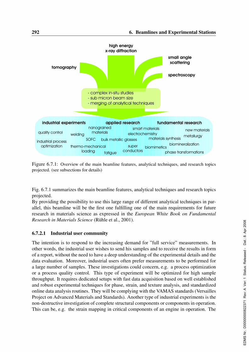
292 6. Beamlines and Experimental Stations
Figure 6.7.1: Overview of the main beamline features, analytical techniques, and research topicsprojected. (see subsections for details)
Fig. 6.7.1 summarizes the main beamline features, analytical techniques and research topicsprojected.By providing the possibility to use this large range of different analytical techniques in par-allel, this beamline will be the first one fulfilling one of the main requirements for futureresearch in materials science as expressed in the European White Book on FundamentalResearch in Materials Science (Ruhle et al., 2001).
6.7.2.1 Industrial user community
The intention is to respond to the increasing demand for ”full service” measurements. Inother words, the industrial user wishes to send his samples and to receive the results in formof a report, without the need to have a deep understanding of the experimental details and thedata evaluation. Moreover, industrial users often prefer measurements to be performed fora large number of samples. These investigations could concern, e.g. a process optimizationor a process quality control. This type of experiment will be optimized for high samplethroughput. It requires dedicated setups with fast data acquisition based on well establishedand robust experimental techniques for phase, strain, and texture analysis, and standardizedonline data analysis routines. They will be complying with the VAMAS standards (VersaillesProject on Advanced Materials and Standards). Another type of industrial experiments is thenon-destructive investigation of complete structural components or components in operation.This can be, e.g. the strain mapping in critical components of an engine in operation. The
ED
MS
Nr.:
D00
0000
0082
2371
Rev
: A V
er: 1
Sta
tus:
Rel
ease
d -
Dat
.: 8.
Apr
200
8
6.7. High Energy Materials Science 293
new beamline will provide the necessary infrastructure for heavy load sample and sampleenvironment positioning (up to 1 t) and the operation of ”specimens” (e.g. dedicated air outletfor an engine investigated in-situ; cooling).
6.7.2.2 Applied research
The experiments in this field will e.g. focus on the in-situ investigation of liquid / solid pro-cesses such as the melt spinning of bulk metallic glasses (e.g Yavari et al., 2002) or welding.These experiments will benefit from the high flux in combination with ultra-fast detectorsystems. In the field of power system development and optimization, which partly reachesinto the field of electrochemistry, experiments of high importance are the investigation of thestrain field and interface kinetics of operating Solid Oxide Fuel Cells (SOFC) or the in-situphase monitoring of battery electrodes (Morcrette et al., 2002a).
The rapidly advancing miniaturization of components and the development of nano-materialswill require powerful tools for the optimization of interface-engineering processes. Exam-ples are the non-destructive micro structural analysis of nano-grained metals and ceramics orhigh resolution strain maps in functionally graded materials. These applications will benefitfrom the sub-micrometer focusing and the nano-detection capabilities of the new beamline.Furthermore, ”classic materials” (e.g. steel, Al-alloys), ”advanced materials” (e.g. metal ma-trix composites, Mg base alloys, TiAl), and new materials such as ”smart materials” (e.g.materials with embedded strain monitoring devices or ”self healing” materials), can be in-vestigated. These investigations will excel in the new parallel design of the experiments. Itenables e.g. the monitoring of the crack propagation by tomography and the development ofthe strain field by diffraction within a self healing component or a fiber reinforced materialunder thermo-mechanical loading. In addition, the installation of the proposed flight tubepermits to characterize by small angle scattering for the first time at high energies and simul-taneously to diffraction e.g. polymers, precipitates, voids, and phase separation (e.g. Fratzl,2003; Kostorz, 1991) in bulk materials and complex components under thermo-mechanicalloading. The use of high energy radiation will permit to perform these investigations in bulksamples of several millimeters to centimeters thickness of technologically important mate-rials such as steel, Ni-base, and Al-base alloys. On a nanometer scale the technique willalso allow to gain information on the internal grain microstructure (Fratzl, 2003) which isthen directly related to the diffraction data from this specific volume element (cf. 6.7.2.3).Diffraction experiments employing different strain scanning techniques will allow to exam-ine the complete strain state of a sample, from the very-near-surface region down to thebulk. Sample environment for thermo-mechanical loading will cover uni-, bi-, and triaxialdeformation modes. The infrastructure will allow an easy accommodation of user providedequipment (e.g. for the in-situ monitoring of processes like friction stir welding). A uniquefeature of the projected beamline will be an external materials testing laboratory which willcontain mechanical testing devices, furnaces, cryostats etc. so that samples during long-termmechanical, thermal and thermo-mechanical testing can be frequently studied using highenergy synchrotron radiation.
ED
MS
Nr.:
D00
0000
0082
2371
Rev
: A V
er: 1
Sta
tus:
Rel
ease
d -
Dat
.: 8.
Apr
200
8

294 6. Beamlines and Experimental Stations
6.7.2.3 Fundamental research
A large number of experiments will be related to metallurgy and the investigation of poly-crystalline materials. The macroscopic properties of polycrystalline materials crucially de-pend on the behavior and interaction of the individual grains along the complex network ofinterfaces. The grain boundaries are the glue that hold polycrystalline materials together.Three-dimensional X-ray diffraction (3DXRD) microscopy provides a means for non de-structive characterization of the internal structure of polycrystalline materials (Poulsen et al.,2001, Schmidt, Poulsen & Vaughan, 2003). The method is illustrated in Fig. 6.7.2. Amonochromatic point-focused beam selects a local gauge volume that contains a sufficientlysmall number of grains for individual observation. Rotation about the ω axis is used to ex-cite multiple reflections from each individual grain, from which the orientations of all grainsin the gauge volume can be determined. Measuring the same reflection spot at differentdistances of the 2D detector, the position of the grains can be determined by backtrack-ing. Finally, a complete map of the grain boundaries within the volume can be reconstructed(Lauridsen et al., 2001, Poulsen & Fu, 2003). The types of grain boundaries in a material andthe way in which they are connected affect a wide range of material properties. The tailoringof these properties has triggered the emerging technology of ’grain boundary engineering’.Fundamental research in this field is essential to specify and produce the desired micro struc-tures. High-energy X-ray microbeams provide a unique opportunity for the determination ofinternal structures. A scientifically very active area is the study of grain growth. The finalmicro structure of a material, for example, depends on the grain growth during thermal pro-cessing. For a direct engineering it is essential to understand the driving forces behind thechange in grain size. The instrument proposed here offers a unique capability to access all
Figure 6.7.2: Grain mapping of a polycrystalline material by 3DXRD (courtesy H.F. Poulsen)
ED
MS
Nr.:
D00
0000
0082
2371
Rev
: A V
er: 1
Sta
tus:
Rel
ease
d -
Dat
.: 8.
Apr
200
8

6.7. High Energy Materials Science 295
quantities to study grain boundaries and their dynamics (Poulsen & Schmidt, 2003). Thedevelopment and numerous applications of 3DXRD have shown that a tremendous insightinto mesoscale phenomena is possible with high energy X-rays. Up to now most of these ex-periments were related to model materials such as pure Cu or Al. Moreover, each experimentwas focusing on one phenomenon at a time (deformation induced lattice rotation or plasticstrain or elastic strain etc.). The aim is to fully characterize samples non-destructively in oneexperiment, i.e. to analyze all the aspects of deformation induced phenomena in parallel ex-periments, hereby merging different techniques (plastic strain measurement by tomography;elastic strain and lattice rotation measurement by diffraction, using a large area detector;grain mapping by diffraction, using a high resolution area detector; precipitation and voidcharacterization by small angle scattering; spectroscopy (in the limits of the instrumentallygiven energy range) e.g. on single intermetallics or precipitations). The availability of a submicrometer focus combined with high resolution detectors and optical elements like spiraland conical slits (see Fig. 6.7.3) will push this kind of non-destructive in-situ investigationsto the subgrain and nano crystalline level.The beamline will provide the necessary infrastructure to perform experiments in the field ofphysics under extreme conditions (high pressures, high magnetic fields, low / high tempera-tures) to investigate e.g. phase transitions at high pressure or extreme temperatures. This isof particular interest in the field of high temperature superconductors.Furthermore, the beamline design permits an easy accommodation of sample environments
Figure 6.7.3: Schematic of setup with spiral slit system for non-destructive depth resolved phaseand strain investigations. The inset visualizes the principle of the beam path which leads to the spatialresolution.
ED
MS
Nr.:
D00
0000
0082
2371
Rev
: A V
er: 1
Sta
tus:
Rel
ease
d -
Dat
.: 8.
Apr
200
8
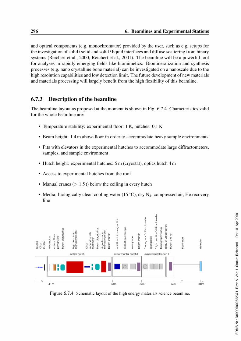
296 6. Beamlines and Experimental Stations
and optical components (e.g. monochromator) provided by the user, such as e.g. setups forthe investigation of solid / solid and solid / liquid interfaces and diffuse scattering from binarysystems (Reichert et al., 2000; Reichert et al., 2001). The beamline will be a powerful toolfor analyses in rapidly emerging fields like biomimetics. Biomineralization and synthesisprocesses (e.g. nano crystalline bone material) can be investigated on a nanoscale due to thehigh resolution capabilities and low detection limit. The future development of new materialsand materials processing will largely benefit from the high flexibility of this beamline.
6.7.3 Description of the beamlineThe beamline layout as proposed at the moment is shown in Fig. 6.7.4. Characteristics validfor the whole beamline are:
• Temperature stability: experimental floor: 1 K, hutches: 0.1 K
• Beam height: 1.4 m above floor in order to accommodate heavy sample environments
• Pits with elevators in the experimental hutches to accommodate large diffractometers,samples, and sample environment
• Hutch height: experimental hutches: 5 m (cryostat), optics hutch 4 m
• Access to experimental hutches from the roof
• Manual cranes (> 1.5 t) below the ceiling in every hutch
• Media: biologically clean cooling water (15 C), dry N2, compressed air, He recoveryline
vario
us fi
lters
sour
ce
CRL
sC
−filt
er
be
am
sh
utte
r
use
r sp
ac
e
be
am
sh
utte
r
"he
avy
loa
d" d
iffra
cto
me
ter
experimental hutch I experimental hutch II
62m54m40 m
use
r sp
ac
e
flig
ht
tub
e
de
tec
tor
200m
prim
ary
slit
s
be
am
dia
gn
ost
ics
hig
h h
ea
t lo
ad
sec
on
da
ry s
lits
be
am
dia
gn
ost
ics
CRL
s
mo
no
ch
rom
ato
rsin
gle
bo
un
ce
mo
no
ch
rom
ato
r
co
llima
tor
"hig
h p
rec
isio
n" d
iffra
cto
me
ter
tom
og
rap
hy
setu
p
be
am
sh
utte
r
arra
y o
f 2d
de
tec
tors
74m
3DX
RD m
icro
sco
pe
ad
diti
on
al f
oc
usin
g o
ptic
s
Al−
win
do
w
optics hutch
Figure 6.7.4: Schematic layout of the high energy materials science beamline.
ED
MS
Nr.:
D00
0000
0082
2371
Rev
: A V
er: 1
Sta
tus:
Rel
ease
d -
Dat
.: 8.
Apr
200
8

6.7. High Energy Materials Science 297
• Special air outlet for engines (cf. 6.7.2.1), for experimental hutches only
• Decoupling of all hutches from PETRA hall floor
• Large hutch doors without barriers on the floor
• Network and power connections in every hutch
Besides the beamline itself, 40 m2 for laboratory plus a storage area are needed. The lab hasto be located in the direct vicinity. Office space for 4 scientists, 1 technician, and severalstudents and postdocs is needed.
6.7.3.1 Insertion device
The insertion device has to meet the following three high priority requirements of the beam-line (discussed in detail below):
• Main energy of 120 keV
• Source suitable for sub-micron focusing at high energies
• Minimized heat load for optical elements
With an energy range between 50 and 300 keV the accessible energy range for hard X-rayswill be substantially larger than for most of the existing beamlines. The X-ray energy is acompromise between the penetration depth necessary for bulk studies in most engineeringmaterials (Al-, Fe-, Ni-, Co-base alloys) and the scattering angle respectively the angularresolution. Therefore, a main energy of 120 keV is proposed for the design of the insertiondevice.The sub-micron focusing requires mainly a small source size, a small source divergence.Therefore the insertion device should have a source size below 57 x 10 µm2 (H x V) FWHM(incl. source broadening) and a source divergence below 88 x 5 µrad2 (H x V) FWHM.A high flux is desirable for this device, but is of lower priority than the main energy, thesource size, and the low heat load.Typically a primary beam of about 1 mm2 will impinge on the focusing optics, but in partic-ular for fast grain mapping applications and tomography a primary beam with a substantiallylarger width (about 3mm) is favored.Studies will be undertaken to examine the feasibility of a superconducting device.Experiments using energies below 50 keV have to be performed at other beamlines.
6.7.3.2 Beamline optics
Filters are foreseen to strongly suppress the energies below 50 keV and thus reduce heat-loadproblems on the optics. They will allow to operate all monochromators in air ambiance.A unique specialty of the proposed beamline at PETRA III will be the high flexibility inshaping the high-energy X-ray beam, depending on the particular needs of the experiment.The beam type will range from a sub-micron focused pencil beam (e.g. for the investigation
ED
MS
Nr.:
D00
0000
0082
2371
Rev
: A V
er: 1
Sta
tus:
Rel
ease
d -
Dat
.: 8.
Apr
200
8

298 6. Beamlines and Experimental Stations
of individual nanosized grains), over a line focus (e.g. for fast grain tracking) to box shapedbeams with a homogeneous beam profile (e.g. macroscopic texture and strain analyses, to-mography), hereby benefitting from the high photon flux, the small source size, and the verysmall beam divergence.Beam focusing will be achieved with conventional bent monochromator and bent multilayersetup and with X-ray lens systems such as refractive X-ray lenses. The development oflens systems is currently progressing strongly and focusing spot sizes smaller than 1 µmare envisaged for hard X-rays. An important feature will be the availability of a fixed-exitfocusing monochromator, thus allowing e.g. phase analyses with high spatial resolution usinga conical slit cell. Compound Refractive Lenses (CRLs) that improve the parallelism of thebeam will be installed in the front end, close to the source. For large beam sizes the shapingof the beam will be performed using slit-systems.Optical elements that are part of the setups in the experimental hutches are conical and spiralslit cells, glas capillary arrays, and micro-channel-like plates made from tungsten. Theyensure a high spatial resolution, within the sample, parallel to the beam (better than 50 µm).Further developments in this area are expected. Furthermore, refractive lenses can be usedas analyzers in the diffracted beam.Such a comprehensive system of beam types, slits and lenses for the different applications inmaterials science is so far not available at a single high-energy beamline.
Summarizing, several optics have to be considered:
• Slit optics: This is the simplest either in a white beam or through a monochromatorsetup.
• Scanning fixed-exit monochromator: The second crystal defines the incident beamcondition by rotation to the appropriate Bragg angle only. The first crystal rotatesand moves on a long translation stage and is fed back to the maximum transmittedintensity, thus eliminating the influence of rotational errors of the first crystal. Thefixed-exit monochromator tunes through the whole energy range as defined above. Dueto the small scattering angles, reflection condition is in asymmetric Laue geometry. Asimple rotation of the inclination switches from the (111) to the (311) and eventuallymore reflections.
• Scanning fixed-exit focusing monochromator, maintaining focus size and position overa range of several keV, realized with bent Laue crystals.
• Several sets of crystals will be available such as perfect or oxygen precipitated andbent crystals. Different monochromators, placed besides each other, can be movedinto operation by lateral translation.
• Single-bounce monochromator: This monochromator type in horizontal geometry willbe foreseen for special purposes and the monochromatic beam will only go to the whitebeam hutch (experimental hutch I), allowing a high flexibility in the arrangement ofthe experimental setup in the hutch space as well as in focusing.
ED
MS
Nr.:
D00
0000
0082
2371
Rev
: A V
er: 1
Sta
tus:
Rel
ease
d -
Dat
.: 8.
Apr
200
8

6.7. High Energy Materials Science 299
• Space will be foreseen for compound refractive lenses in the front-end, improvingbeam parallelism.
• For focusing purposes compound refractive lenses will be foreseen after the monochro-mator.
6.7.3.3 Experimental hutch I
The first experimental hutch will be a white beam hutch with a space of 5×8 m2. It willpermit the installation of user provided monochromators, increasing the flexibility for beamfocusing and experimental setup design. All experiments using white beam can be carriedout here. The main components of this hutch are:
• 3DXRD microscope.
• Additional focusing optics close to the 3DXRD microscope.
• A cooled beam stop at the end of the hutch.
• Beam available from single-bounce monochromator (see optics hutch).
• Space e.g. for a “user monochromator” and for user provided setups.
The single-bounce monochromator (situated in the optics hutch) will be operated in horizon-tal geometry. Its distance to the beam shutter has to be small in order to reduce the size ofthe horizontal shutter opening. The experiment itself can be set up in the first experimentalhutch.Even if the white beam hutch is initially not built at once, it has to be foreseen in the designfor the static load for the whole beamline since from experience at the ESRF for safetyreasons a radiation shielding thickness of at least 50–200 mm Pb is necessary which resultsin a significant floor loading. Preferential to the Pb shielding would be a concrete shieldingof the white beam hutch, but the concrete shielding requires more space.
6.7.3.4 Experimental hutch II
The second experimental hutch will have space for four experiments:
• A heavy load diffractometer which can carry a load up to 1000 kg for big samples anddifferent sample environments (cryo magnet, press, tensile testing machine, furnace,etc).
• A smaller high precision diffractometer for micro beam applications.
• Space for user supplied experimental setups.
• A tomography setup which goes preferably to the end of the hutch using the largestpossible beam size. The possible implementation of the flight tube (see fig. 6.7.4 and6.7.3.5) will, therefore, also be of great advantage for these applications.
ED
MS
Nr.:
D00
0000
0082
2371
Rev
: A V
er: 1
Sta
tus:
Rel
ease
d -
Dat
.: 8.
Apr
200
8
300 6. Beamlines and Experimental Stations
The heavy load goniometer will be optimized for materials science investigations. For anal-ysis with a spatial resolution in the sub-µm range a high precision translation and rotationsystem will be installed. Until now (2003) there is no such instrument available at a syn-chrotron beamline. This device is supposed to enhance the precision in movement for largersamples and especially for large sample environments such as furnaces, devices for mechan-ical testing and thermo-mechanical testing. A further unique feature will be the combinationof the synchrotron radiation laboratory with the above mentioned external materials testinglaboratory (mechanical testing devices, furnaces, cryostats etc. ).The second hutch will be at least 12 m long in order to achieve high angular resolutionsand to accommodate all experiments. At the very end of the hutch 2-dim position sensitivedetectors will be mounted. A novel multi-detector concept will enable simultaneous datacollection for different diffraction angles.
6.7.3.5 Flight tube
A unique and particular feature of the projected beamline will be the possibility to performsmall angle scattering experiments at high energies on bulk samples, simultaneously withdiffraction experiments. The feature distances in the micro structures to be investigatedby small angle scattering typically range from 1 to 1000 A (e.g. porous media, polymers,precipitates). To achieve a minimum angular resolution at 120 keV the area detector needsto be placed at least 200 m away from the source, i.e. at a distance of about 150 m from thefirst possible sample position. The detector chamber will be connected to the experimentalhutch by a flight tube (see Fig. 6.7.4). Because of the resulting space constraints outside theexperimental hall the beamline should occupy the third or fourth position in the experimentalhall. Even if the flight tube is not part of the first construction phase the space requiredoutside the experimental hall should be taken into account when decisions are made on theposition inside the experimental hall.With the option to perform on the same sample and the same volume element, parallel todiffraction experiments, in particular cases analyses by small angle scattering, tomography,and spectroscopy, the proposed beamline will be the first, where the boundaries betweenthese analytical techniques are gradually disappearing.
6.7.3.6 Detectors
The wide variety of experiments for this beamline is reflected in the particular need of variousspecial detectors. In most cases the use of area detectors will be favored to realize the highdata acquisition rates required for dynamic in-situ studies and to fully benefit from the highphoton flux. Mainly three different types of area detectors for diffraction experiments can bedistinguished:
• Large area detectors, allowing the monitoring of complete Debye-Scherrer-rings atlarge sample-detector distances (at least 2000 mm) for ultra fast strain and lattice rota-tion analyses.
• Array of large area wire-detectors which can be translated over a long range along the
ED
MS
Nr.:
D00
0000
0082
2371
Rev
: A V
er: 1
Sta
tus:
Rel
ease
d -
Dat
.: 8.
Apr
200
8

6.7. High Energy Materials Science 301
beam for high angular resolution, comparable to the HARWI II setup. In contrast tothe other large area detector they can only monitor sections of Debye-Scherrer-rings.
• High resolution detectors (around 1 µm resolution) which, as a consequence, are placedclose to the sample, e.g. for subgrain mapping.
For the small angle scattering experiments area detectors with an efficiency optimized forhigh energies are required Standard point detectors are required in case of spectroscopyanalysis. Improvements in the field of detector development are expected within the nextyears.
6.7.3.7 Redundant-beamline concept
The beamline will be equipped based on a ”redundant-beamline concept”, meaning that criti-cal spare parts or a complete replacement exist for all crucial components of an experimentalsetup in case of failure. This concept relates to components such as critical sample translationand rotation units, detectors, fast beam shutters, sample environment, electronics etc. Thisspare pool does not necessarily need to be exclusively accessible to this one beamline. How-ever, many of the critical parts will certainly be beamline specific such as detectors for highenergy X-rays. The financial investment will be low in comparison to the loss of beamtime,considering the amount of lost manpower for several months of experiment preparation.
6.7.3.8 Beamline control and data collection
To attract user communities, especially from the engineering sector, who are not familiarwith synchrotron radiation, the concept for instrument control software and data evaluationwill strongly involve the aspect of user-friendliness. Measurement techniques and analysisroutines according to the VAMAS standards will be implemented, which will be of particu-lar interest for industrial users. For scientists familiar with the techniques interfaces betweenthe basic instrument control and data acquisition will be provided for the development ofnovel measurement and evaluation techniques. The use of SPEC as beamline control soft-ware is strongly favored. It ensures an easy compatibility of software and will facilitate thecollaboration on this sector with other synchrotrons, e.g. the ESRF.
6.7.4 Capital investment and personnel6.7.4.1 Capital investment
The total investment costs for this beamline sum up to 5350 ke.
6.7.4.2 Personnel
The projected beamline will be highly versatile in its application, merging different analyticaltechniques. This necessitates and justifies the employment of four scientists, one softwareengineer, one mechanical engineer, and one technician on a permanent basis.
ED
MS
Nr.:
D00
0000
0082
2371
Rev
: A V
er: 1
Sta
tus:
Rel
ease
d -
Dat
.: 8.
Apr
200
8
302 6. Beamlines and Experimental Stations
Ideally the scientists are complementary in each others competences. Particular skills andknowledge are required in the fields residual strain analysis, texture analysis, powder diffrac-tion, tomography, and high-energy X-ray optics.A software engineer is a prerequisite for the smooth and efficient operation of the beamline.Most experiments carried out will highly rely on complex software for high-speed data ac-quisition and on-line data analysis. Furthermore, the beamline control requires a continuousimprovement and maintenance.The continuous improvement of beamline hardware, development and realization of newcomponents and setups will be carried out by the mechanical engineer together with thetechnician, in close collaboration with the scientists.The technical staff might be part of a pool for beamline software and hardware support.However, particularly in the start up phase of all the beamlines it is clear that these poolshave to be sufficiently large (one engineer and technician per beamline) to avoid bottlenecks.It is emphasized here that dedicated PETRA groups of significant size will be highly appre-ciated for optics, metrology, detector support, computing, and beamline specific engineeringtasks.
ED
MS
Nr.:
D00
0000
0082
2371
Rev
: A V
er: 1
Sta
tus:
Rel
ease
d -
Dat
.: 8.
Apr
200
8
6.8. Powder Diffraction 303
6.8 Powder DiffractionAuthors and Consultants :
H. Ehrenberg Darmstadt University of Technology, GermanyTh. Wroblewski DESY, Hamburg, Germany
6.8.1 Current state of the scientific fieldThe low divergence of synchrotron radiation (SR) together with its high intensity permitspowder diffraction (PD) with much higher angular and time resolution than at conventionallaboratory X-ray sources. The resolution function of a powder diffractometer operated inparallel beam geometry is given by the sum of three angular dependent terms which areproportional to the acceptances of monochromator, receiving slit or analyzer crystal and thedivergence of the incident beam, respectively (Wroblewski, 1991). At a powder diffractome-ter situated at a bending magnet of a 2nd generation synchrotron source, for example the B2powder diffractometer (Knapp et al., 2003), the latter term is dominant due to the high diver-gence of the radiation from DORIS. To reduce this divergence a collimating mirror must beused, limiting the accessible energy range (Knapp et al., 2001). At a PETRA III undulatorall three terms will be in the same range of a few µrad yielding an instrumental resolutionfunction with two orders of magnitude smaller half widths without collimating elements.
In contrast to single crystal diffraction in PD the reciprocal space is projected from threedimensions to one dimension frequently leading to severe overlap of reflections. Additionalinformation can be obtained by measurements at different temperatures because of a partialpeak separation due to anisotropic thermal expansion. High resolution is, therefore, essentialfor the structural characterization of polycrystalline materials.The refinement of crystal structures by the Rietveld method is a very well established stan-dard technique in PD (Rietveld, 1969; Young, 1993; McCusker et al., 1999) and with the ad-vantages of synchrotron radiation now even applied in protein crystal structure analysis (vonDreele, 2003). However, the most significant progress in crystallographic applications of PDover the last decade was the improvement of structure determination strategies (David et al.,2002). Although structure solution from PD data is not yet a routine task, further progress inavailable software packages will allow their use for an expanding scientific community andpush the successful application to more complex structures (David, 2003). Present limita-tions are radiation damages, especially in beam-sensitive organic samples, and the availabil-ity of beam time at appropriate experimental stations to collect data with sufficient countingstatistics over a wide enough range of diffraction angles at several temperatures.
Crystal structure analysis on polycrystalline samples is a complementary tool to diffractionfrom microcrystals (Harding, 1996; Serda, Grochowski & Duddeck, 2004). The advantagesof microcrystal diffraction in general are a more straightforward unit-cell determination andstructure solution. In both cases the accuracy of the final structure model is limited by therestricted amount of diffraction data that is possible to record. It depends on the specific sit-uation whether PD or single-microcrystal diffraction is the method of choice. PD is the only
ED
MS
Nr.:
D00
0000
0082
2371
Rev
: A V
er: 1
Sta
tus:
Rel
ease
d -
Dat
.: 8.
Apr
200
8

304 6. Beamlines and Experimental Stations
applicable method whenever not even microcrystals are available or reconstructive phasetransitions or chemical reactions prevent single-crystal techniques. This is by far the mostfrequent case for applications in materials science, where structural analyses of inhomo-geneities and anisotropies of multi-phase and composite materials are requested over a widerange on length scale from nano-size domains, crystallites and grains up to micro devices.The properties of many materials result from the anisotropy of individual crystallites, theirlocations and orientations. High-resolution PD does not only provide bulk-representativeaverages; more and more sophisticated methods have been developed during the last years toseparate the effects of grain size and residual strain but also to analyze the effects of disloca-tion densities or inter-growth distributions (for example in ceramic superconductors) on theprofile shape (see for example the Size-Strain III conference, Trento, 2001 or (Mittemeijer& Scardi, 2004)). This progress in data evaluation entails a further increased demand forhigh-resolution PD data.
Especially the response of materials to external fields and the changes during aging and fa-tigue are in the center of interest of materials science. Such investigations require dedicatedsample environments, which allow conditions of real operation mode compatible with PD.At present, about 90% of all diffraction experiments at the high-resolution PD beamline B2at HASYLAB are performed in flexible sample environment with at least one variable pa-rameter. The recent development of a new position sensitive detector for highly efficient datacollection (Knapp et al., 2004) allows for sample environments with higher absorption andsmaller beam or sample size (Knapp et al., 2003).
The demand for powder diffraction using high-energy SR with low divergence will further in-crease in the next years because of qualitatively new opportunities offered by dedicated sam-ple environments for in-situ characterization of polycrystalline materials and the expandedcapabilities of established methods at enhanced radiation sources. The existing and alreadyplanned experimental stations cannot serve the expected beam time request.
6.8.2 Science at the high-energy powder diffraction side station
Dedicated high-resolution PD beamlines belong to the working horses at all synchrotronfacilities operating in the hard X-ray regime. The following applications are proposed for aside station with a fixed photon energy of about 56 keV.
6.8.2.1 Crystal structure determinations from PD data
In cases where no suitable single crystals are available, crystal structure solution and re-finement depends on high-resolution PD. The use of high-energy SR (> 50 keV) is of pri-mary importance: Radiation damage in beam-sensitive materials like organic, biological orpharmaceutical samples, is significantly reduced. Furthermore shorter exposure times willreduce the effects of secondary processes, following the primary radiation damages, thatlead to further degradation of the structure. The high intensity of the primary beam willallow for time-efficient data collection at different temperatures. Compounds with heavy el-
ED
MS
Nr.:
D00
0000
0082
2371
Rev
: A V
er: 1
Sta
tus:
Rel
ease
d -
Dat
.: 8.
Apr
200
8
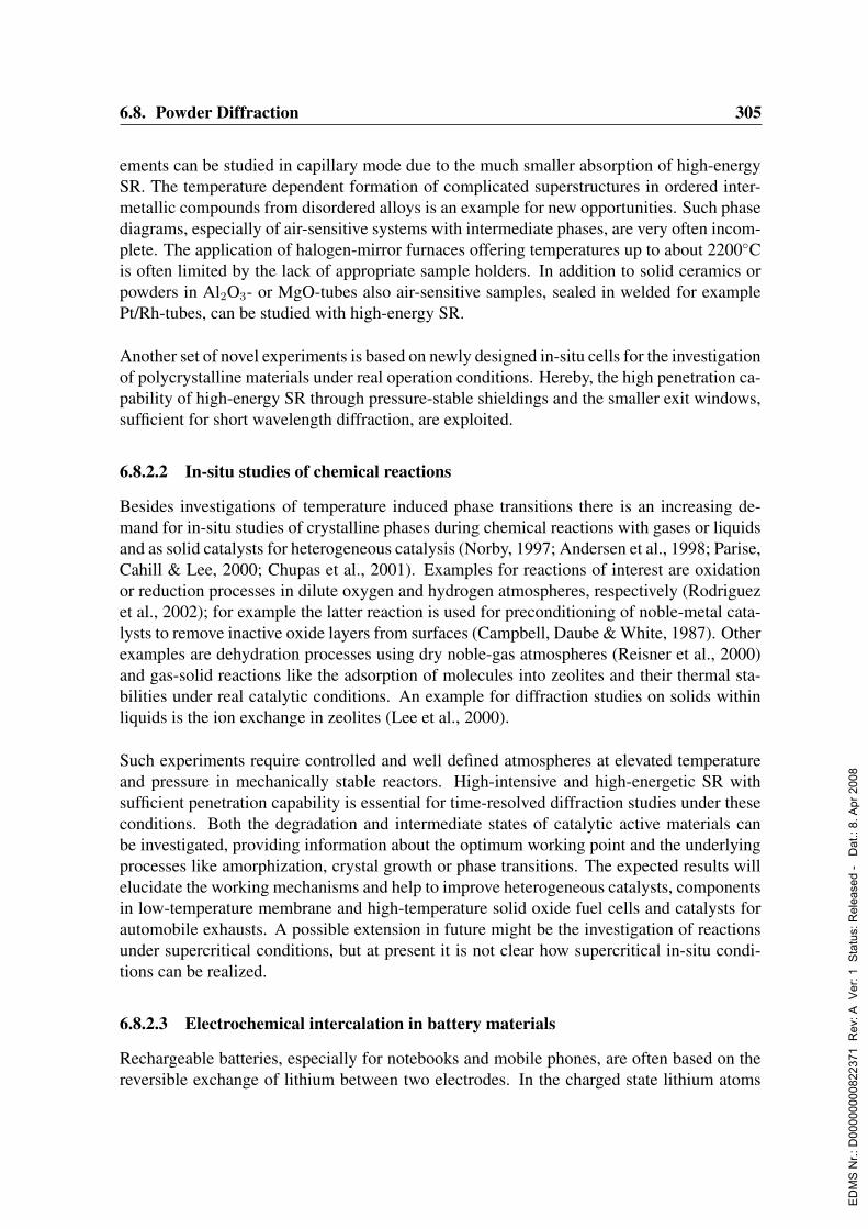
6.8. Powder Diffraction 305
ements can be studied in capillary mode due to the much smaller absorption of high-energySR. The temperature dependent formation of complicated superstructures in ordered inter-metallic compounds from disordered alloys is an example for new opportunities. Such phasediagrams, especially of air-sensitive systems with intermediate phases, are very often incom-plete. The application of halogen-mirror furnaces offering temperatures up to about 2200Cis often limited by the lack of appropriate sample holders. In addition to solid ceramics orpowders in Al2O3- or MgO-tubes also air-sensitive samples, sealed in welded for examplePt/Rh-tubes, can be studied with high-energy SR.
Another set of novel experiments is based on newly designed in-situ cells for the investigationof polycrystalline materials under real operation conditions. Hereby, the high penetration ca-pability of high-energy SR through pressure-stable shieldings and the smaller exit windows,sufficient for short wavelength diffraction, are exploited.
6.8.2.2 In-situ studies of chemical reactions
Besides investigations of temperature induced phase transitions there is an increasing de-mand for in-situ studies of crystalline phases during chemical reactions with gases or liquidsand as solid catalysts for heterogeneous catalysis (Norby, 1997; Andersen et al., 1998; Parise,Cahill & Lee, 2000; Chupas et al., 2001). Examples for reactions of interest are oxidationor reduction processes in dilute oxygen and hydrogen atmospheres, respectively (Rodriguezet al., 2002); for example the latter reaction is used for preconditioning of noble-metal cata-lysts to remove inactive oxide layers from surfaces (Campbell, Daube & White, 1987). Otherexamples are dehydration processes using dry noble-gas atmospheres (Reisner et al., 2000)and gas-solid reactions like the adsorption of molecules into zeolites and their thermal sta-bilities under real catalytic conditions. An example for diffraction studies on solids withinliquids is the ion exchange in zeolites (Lee et al., 2000).
Such experiments require controlled and well defined atmospheres at elevated temperatureand pressure in mechanically stable reactors. High-intensive and high-energetic SR withsufficient penetration capability is essential for time-resolved diffraction studies under theseconditions. Both the degradation and intermediate states of catalytic active materials canbe investigated, providing information about the optimum working point and the underlyingprocesses like amorphization, crystal growth or phase transitions. The expected results willelucidate the working mechanisms and help to improve heterogeneous catalysts, componentsin low-temperature membrane and high-temperature solid oxide fuel cells and catalysts forautomobile exhausts. A possible extension in future might be the investigation of reactionsunder supercritical conditions, but at present it is not clear how supercritical in-situ condi-tions can be realized.
6.8.2.3 Electrochemical intercalation in battery materials
Rechargeable batteries, especially for notebooks and mobile phones, are often based on thereversible exchange of lithium between two electrodes. In the charged state lithium atoms
ED
MS
Nr.:
D00
0000
0082
2371
Rev
: A V
er: 1
Sta
tus:
Rel
ease
d -
Dat
.: 8.
Apr
200
8
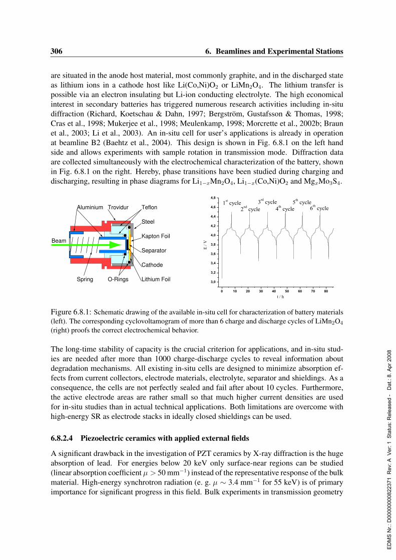
306 6. Beamlines and Experimental Stations
are situated in the anode host material, most commonly graphite, and in the discharged stateas lithium ions in a cathode host like Li(Co,Ni)O2 or LiMn2O4. The lithium transfer ispossible via an electron insulating but Li-ion conducting electrolyte. The high economicalinterest in secondary batteries has triggered numerous research activities including in-situdiffraction (Richard, Koetschau & Dahn, 1997; Bergstrom, Gustafsson & Thomas, 1998;Cras et al., 1998; Mukerjee et al., 1998; Meulenkamp, 1998; Morcrette et al., 2002b; Braunet al., 2003; Li et al., 2003). An in-situ cell for user’s applications is already in operationat beamline B2 (Baehtz et al., 2004). This design is shown in Fig. 6.8.1 on the left handside and allows experiments with sample rotation in transmission mode. Diffraction dataare collected simultaneously with the electrochemical characterization of the battery, shownin Fig. 6.8.1 on the right. Hereby, phase transitions have been studied during charging anddischarging, resulting in phase diagrams for Li1−xMn2O4, Li1−x(Co,Ni)O2 and MgxMo3S4.
Aluminium
Steel
TeflonTrovidur
Kapton Foil
Lithium Foil
Cathode
Spring
Beam
O-Rings
Separator
Figure 6.8.1: Schematic drawing of the available in-situ cell for characterization of battery materials(left). The corresponding cyclovoltamogram of more than 6 charge and discharge cycles of LiMn2O4
(right) proofs the correct electrochemical behavior.
The long-time stability of capacity is the crucial criterion for applications, and in-situ stud-ies are needed after more than 1000 charge-discharge cycles to reveal information aboutdegradation mechanisms. All existing in-situ cells are designed to minimize absorption ef-fects from current collectors, electrode materials, electrolyte, separator and shieldings. As aconsequence, the cells are not perfectly sealed and fail after about 10 cycles. Furthermore,the active electrode areas are rather small so that much higher current densities are usedfor in-situ studies than in actual technical applications. Both limitations are overcome withhigh-energy SR as electrode stacks in ideally closed shieldings can be used.
6.8.2.4 Piezoelectric ceramics with applied external fields
A significant drawback in the investigation of PZT ceramics by X-ray diffraction is the hugeabsorption of lead. For energies below 20 keV only surface-near regions can be studied(linear absorption coefficient µ > 50 mm−1) instead of the representative response of the bulkmaterial. High-energy synchrotron radiation (e. g. µ ∼ 3.4 mm−1 for 55 keV) is of primaryimportance for significant progress in this field. Bulk experiments in transmission geometry
ED
MS
Nr.:
D00
0000
0082
2371
Rev
: A V
er: 1
Sta
tus:
Rel
ease
d -
Dat
.: 8.
Apr
200
8

6.8. Powder Diffraction 307
with sputtered electrodes on both sides will become feasible with a sample oscillation forbetter statistics of crystallite orientation. In addition to DC fields in-situ studies with ACfields appear possible. The synchronization of a chopper or the detector electronics withthe applied alternating field will allow to sum up data from successive periods in the samepolarization state of the piezoceramic. For such stroboscopic studies the time structure of thePETRA ring (7.7 µs in single bunch mode) might be of interest. Temperature and frequencydependent studies can provide information about domain wall dynamics and the effects ofsintering conditions, doping, ageing and fatigue. High-resolution PD data are essential for asophisticated profile analysis, especially for samples near the morphotropic phase boundary,where different crystal structures can coexist.
6.8.2.5 Shape-memory alloys under external load
Behavior under mechanical stress is a common scientific problem for constructional materi-als and becomes particularly interesting in relation to smart materials, actuators and sensors,such as piezoelectrics or shape memory materials, and most importantly in relation to fatiguein any material. In the international scene, beamlines for materials research with mechani-cal loading frames have been constructed for neutrons and synchrotrons. In particular, theSMARTS neutron beamline at LANL has been constructed around a loading frame equippedwith a graphite heater to achieve 2000 K (Bourke, Dunand & Ustundag, 2002), similar, but sofar without heater is the new ENGIN-X beamline at RAL. At ESRF, ID11 is equipped with a5 kN loading frame, and the beamline has the capability of investigations of single grains inthe polycrystalline matrix and of 2D mapping of the microstructure (Margulies, Winther &Poulsen, 2001). The main advantage of the synchrotron, and in particular of high-energysynchrotron beam lines is the capability of true sub-mm space resolution (i. e. combine theadvantage of spatially resolved information (Schmahl et al., 2004) with bulk information(Sittner et al., 2002; Sitepu et al., 2003). Most important, a synchrotron experiment is ableto follow the stress state of selected single crystallites in a polycrystalline matrix (Gundlachet al., 2004), a capability with enormous potential for understanding the mechanical strengthof materials.
These are only selected examples for advanced characterization techniques of polycrystallinematerials under real operation conditions. The exploration of materials response with respectto a more dimensional parameter space, e. g. with respect to combinations of temperature,pressure, stress, frequency and amplitudes of external fields, etc., is the key issue for a newlyestablished high-resolution PD beamline.
6.8.3 Beamline description
From the above mentioned instrumental and experimental demands the following character-istics of beamline and instrumentation can be deduced :
The beam should be highly parallel in the vertical direction. In the horizontal direction, how-ever, a more divergent beam is required. This results from the demand of having sufficient
ED
MS
Nr.:
D00
0000
0082
2371
Rev
: A V
er: 1
Sta
tus:
Rel
ease
d -
Dat
.: 8.
Apr
200
8
308 6. Beamlines and Experimental Stations
orientational statistics of the grains in a powder. To achieve random orientation the sample isusually filled in a capillary and rotated. Nevertheless, the illuminated region of the capillaryshould be as long as possible to increase the number of diffracting grains. The photon en-ergy will be fixed to about 56 keV. In this case the powder diffractometer could be operatedat a ’side station’. For highest resolution analyzer crystals must be used. This should bedone with a multiple analyzer stage to reduce the measuring time. This circle should havea reproducible resolution of 0.0001 in 2Θ, matching the resolution function. For experi-ments not needing ultimate resolution a one-dimensional position sensitive detector (PSD) isneeded, which can be mounted in a fixed position, facing the analyzer arrangement. A two-dimensional PSD in the low-angle region with flexible sample-detector distance is neededfor texture analyses and orientation-resolved diffraction.
The operation with fixed photon energy imposes only minor restrictions, because most of theproposed experiments benefit from higher energies (limited by the monochromator specifi-cations for high-resolution PD). The overall demand for resonant diffraction studies is ratherlow and can be served elsewhere. On the other hand, a significant improvement in efficiencycan be obtained by optimizing the detector systems for a small energy range. The standarddetector systems for synchrotron powder diffraction, scintillation counters, image plates andCCDs, are working over a wide energy range with similar good performance. By restrictionto a narrow energy window the detector efficiency can be improved considerably by opti-mization for this specific energy.For the various in-situ studies appropriate sample environments (furnaces, cryostat, in-situcells, etc.) must be available, which can be easily changed. Operation at fixed energy willensure better compatibility between different set-ups.
A special environment is that for high pressure studies. It employs the anvil-type of highpressure apparatus. This option does not require bulky equipment, whereas it makes it possi-ble to generate the largest pressure range and provides large variety of experimental options.The high pressure environment includes diamond anvil cell, large-volume Paris-Edinburghcell, sapphire-anvil Kurchatov Institute cell. The cells can be combined with cryostats forlow temperature studies as well as with the laser heating system to achieve high pressure- high temperature conditions. The small sample volume due to the high pressure and/orlaser heating requires a micro beam. It is therefore recommended to have a kind of table topexperiment at a micro focus beamline instead of a high-resolution PD beamline.The powder diffractometer will be operated at a low beta (high divergence to obtain a broadbeam) section. No mirror will be used because of the required high energies. Dependingon whether the whole wavelength range will be used or only a fixed wavelength a double(cryogenic Si 111 or Si 311) or single crystal monochromator (Diamond 111) is needed.
6.8.4 Capital investment and personnel
An important component is a high precision diffractometer including encoder, multi analyzerstage and control system. The PSD should have a spatial resolution of 0.1 mm correspond-ing to the projection of a thin capillary. The readout time should be in the millisecond range.
ED
MS
Nr.:
D00
0000
0082
2371
Rev
: A V
er: 1
Sta
tus:
Rel
ease
d -
Dat
.: 8.
Apr
200
8

6.8. Powder Diffraction 309
Possible electronic detectors matching these specifications are diode arrays, strip detectorsor CCDs (spectroscopy mode), covering an angular range of ≈ 30. For certain applicationsmodified commercial detectors applied in non-destructive testing may be applied. (In thisfield even detectors covering a wide angular range are available. Presently, however, no de-tector covering this angular range is available from the shelf. Detector development is, there-fore, as for many other beamlines, of paramount importance. Open questions are whethera curved detector is needed or a linear one is sufficient and whether it must be monolithicor can be composed of several elements (blind areas between elements). It should also beinvestigated whether relatively cheap detectors as they are used in check-in applications atairports can be applied.Various sample environments like cryostat, furnace, in-situ cells are foreseen.
The total cost of the powder diffraction station will be about 1200 ke.
Two scientists and two engineers will be needed during construction and commissioning.After commissioning one engineer may be sufficient provided that there is support from cen-tral services (computing, electronics, workshops).
ED
MS
Nr.:
D00
0000
0082
2371
Rev
: A V
er: 1
Sta
tus:
Rel
ease
d -
Dat
.: 8.
Apr
200
8

310 6. Beamlines and Experimental Stations
6.9 Unfocused ASAXS BeamlineAuthor :
G. Goerigk IFF, FZ Julich GmbH, Julich, Germany
6.9.1 AbstractDue to the low emittance of PETRA III the beam parameters at a high-β section are in ahigh degree suitable for the design of an unfocused Small-Angle X-ray Scattering (SAXS)beamline with high q-resolution. Additionally the energy spectrum covered by a PETRA IIIstandard undulator will allow one to make use of the element-selective Anomalous Small-Angle X-ray Scattering (ASAXS) technique and to extend the classical energy range of thistechnique (5–35 keV) up to energies of about 90 keV. The extension to higher energies willgive access to the K-absorption edges of the heavier elements (Z > 53). The energy range incombination with the high flux of a 3rd generation source offers the opportunity to addressnumerous challenging scientific objectives in solid state physics, catalyst research, chemistryand biology, which are not accessible by the existing state of the art (A)SAXS-experiments.
6.9.2 Current state of the fieldSmall-Angle X-ray Scattering experiments average over a large sample volume and givestructural and quantitative information of high statistical significance on a mesoscopic lengthscale between one and hundreds of nanometers, which can be correlated with macroscopicphysical and chemical parameters of the analyzed materials (alloys, semiconductors, glasses,macromolecules in solution, metal nanoparticles, composites).In the past Synchrotron Radiation (SR) provided the SAXS-technique with four major im-provements:
1. The photon flux, which is many orders of magnitudes higher compared to classicalX-ray sources allows one to study samples, which show only weak small-angle X-rayscattering.
2. The continuous energy spectrum of SR allows for the energy tunability of the tech-nique. Beside the possibility to adapt the X-ray energy to the sample under investiga-tion (e.g. thinning of samples with internal stress is limited and SAXS analysis shouldbe done at higher energies to minimize absorption) the further advantage is the energytunability in the vicinity of the K- and LIII-absorption edges of most of the elements.This technique - known as Anomalous Small-Angle X-ray Scattering (ASAXS) – isbased on the anomalous variations of the atomic scattering factors near the absorptionedges and allows for the element-specific characterization of the samples under inves-tigation on the mesoscopic length scale. After the exploratory studies of the 1980s(Stuhrmann, 1985; Simon, Lyon & de Fontaine, 1985), ASAXS became a standardtechnique, which is nowadays used to address numerous challenging scientific objec-tives in solid state physics, materials science, catalyst research, chemistry and biology
ED
MS
Nr.:
D00
0000
0082
2371
Rev
: A V
er: 1
Sta
tus:
Rel
ease
d -
Dat
.: 8.
Apr
200
8

6.9. Unfocused ASAXS Beamline 311
(Goerigk et al., 2003), where classical SAXS experiments (with fixed energy) are notable to provide decisive information. As a consequence it appears desirable to designa SAXS beamline at a 3rd generation source with an unfocused, energy tunable beam,with the goal to fully exploit the scientific potential of this technique. For this reason,this proposal addresses the more general subject of an unfocused ASAXS beamline.
3. The very small beam divergence in both the horizontal and vertical directions. Thespatial resolution of a SAXS experiment depends strongly on the beam parametersand benefits crucially from low divergence and high collimation. This determines thesize scale of the topological or chemical inhomogeneities, which can be observed.
4. The extension of the X-ray spectrum to energies higher than 30 keV at the 3rd genera-tion sources with sufficient machine energy (ESRF, APS, SPring-8).
In Europe, three beamlines have been optimized for the ASAXS technique: JUSIFA at HA-SYLAB, D2AM at ESRF and D22 at LURE (the latter being upgraded and reinstalled atthe French synchrotron radiation source SOLEIL). Two of these beamlines (JUSIFA andD22) are using fixed exit double crystal monochromators, which turned out to allow far eas-ier operation compared to focusing optics (at D2AM). As a consequence, an “easy-to-use“ASAXS beamline should abandon focusing optics if possible (Goerigk et al., 2003).Scientific examples for key applications of the ASAXS technique are :
• Polyelectrolytes with counter ion distributions (Guilleaume et al., 2001; Guilleaumeet al., 2002; Goerigk et al., 2004; Das et al., 2003),
• amorphous semiconductor alloys (Goerigk & Williamson, 1998; Goerigk & Williamson,2001a),
• metal nanoparticles (for instance used as catalysts) (Polizzi et al., 2001; Rasmussenet al., 2000; Bota et al., 2002; Haubold et al., 2003),
• membranes from biology (Richardsen et al., 1996) and from technical applications(Prado et al., 2003).
Three examples are shown in Figs. 6.9.1–6.9.3. The examples have in common, that only theASAXS technique is able to provide the essential information.
Numerous materials were analyzed by ASAXS in the last decade and the concerned fieldsof research are solid state physics (amorphous alloys, glasses, semiconductors, bulk metal-lic glasses, ceramics), materials science (membranes in fuel cell techniques, nanostruc-ture caused by welding processes in alloys), catalyst research (metal nanoparticles on vari-ous support structures, zeolites), chemistry (polyelectrolytes) and biology (liposomes, pro-teins, DNA). The samples under investigation are solids, liquids, gels, aoregels, compound-materials, powders, crystals or thin layers studied under various process parameters (gasflow, gas mixture, temperature, external electric or magnetic field, electrolytes of differentmixture, pressure).
ED
MS
Nr.:
D00
0000
0082
2371
Rev
: A V
er: 1
Sta
tus:
Rel
ease
d -
Dat
.: 8.
Apr
200
8
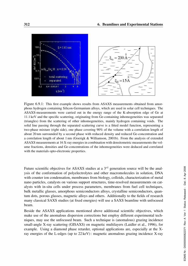
312 6. Beamlines and Experimental Stations
Figure 6.9.1: This first example shows results from ASAXS measurements obtained from amor-phous hydrogen containing Silicon-Germanium alloys, which are used in solar cell techniques. TheASAXS-measurements were carried out in the energy range of the K-absorption edge of Ge at11.1 keV and the specific scattering, originating from Ge-containing inhomogeneities was separated(triangles) from the scattering of other inhomogeneities, mainly hydrogen containing voids. Thesolid line passing through the separated scattering curve is a fitted model function, representing atwo-phase mixture (right side), one phase covering 90% of the volume with a correlation length ofabout 20 nm surrounded by a second phase with reduced density and reduced Ge-concentration anda correlation length of about 1 nm (Goerigk & Williamson, 2001b). From the analysis of extendedASAXS measurements at 16 X-ray energies in combination with densitometric measurements the vol-ume fractions, densities and Ge-concentrations of the inhomogeneities were deduced and correlatedwith the materials opto-electronic properties.
Future scientific objectives for ASAXS studies at a 3rd generation source will be the anal-ysis of the conformation of polyelectrolytes and other macromolecules in solution, DNAwith counter ion condensation, membranes from biology, colloids, characterization of metalnano particles, catalysts on various support structures, time-resolved measurements on cat-alysts with in-situ cells under process parameters, membranes from fuel cell techniques,bulk metallic glasses, amorphous semiconductors alloys, crystalline semiconductors, quan-tum dots, porous glasses, magnetic alloys and others. Additionally to the fields of researchmany classical SAXS studies (at fixed energies) will use a SAXS beamline with unfocusedbeam.
Beside the ASAXS applications mentioned above additional scientific objectives, whichmake use of the anomalous dispersion corrections but employ different experimental tech-niques, may use the unfocused beam. Such a technique is (anomalous) grazing incidencesmall-angle X-ray scattering (GISAXS) on magnetic multilayers (Laidler et al., 1996), forexample. Using a diamond phase retarder, optional applications are, especially at the X-ray energies of the L-edges (up to 22 keV) : magnetic anomalous grazing incidence X-ray
ED
MS
Nr.:
D00
0000
0082
2371
Rev
: A V
er: 1
Sta
tus:
Rel
ease
d -
Dat
.: 8.
Apr
200
8
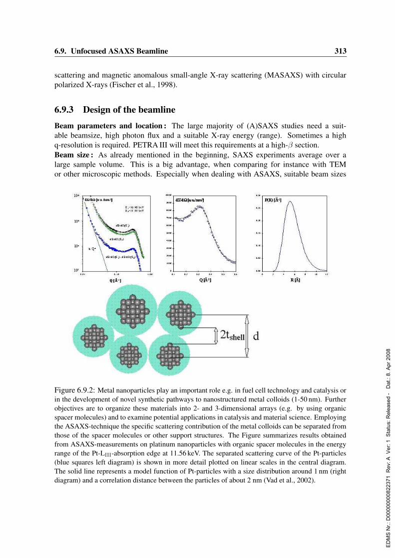
6.9. Unfocused ASAXS Beamline 313
scattering and magnetic anomalous small-angle X-ray scattering (MASAXS) with circularpolarized X-rays (Fischer et al., 1998).
6.9.3 Design of the beamline
Beam parameters and location : The large majority of (A)SAXS studies need a suit-able beamsize, high photon flux and a suitable X-ray energy (range). Sometimes a highq-resolution is required. PETRA III will meet this requirements at a high-β section.Beam size : As already mentioned in the beginning, SAXS experiments average over alarge sample volume. This is a big advantage, when comparing for instance with TEMor other microscopic methods. Especially when dealing with ASAXS, suitable beam sizes
Figure 6.9.2: Metal nanoparticles play an important role e.g. in fuel cell technology and catalysis orin the development of novel synthetic pathways to nanostructured metal colloids (1-50 nm). Furtherobjectives are to organize these materials into 2- and 3-dimensional arrays (e.g. by using organicspacer molecules) and to examine potential applications in catalysis and material science. Employingthe ASAXS-technique the specific scattering contribution of the metal colloids can be separated fromthose of the spacer molecules or other support structures. The Figure summarizes results obtainedfrom ASAXS-measurements on platinum nanoparticles with organic spacer molecules in the energyrange of the Pt-LIII-absorption edge at 11.56 keV. The separated scattering curve of the Pt-particles(blue squares left diagram) is shown in more detail plotted on linear scales in the central diagram.The solid line represents a model function of Pt-particles with a size distribution around 1 nm (rightdiagram) and a correlation distance between the particles of about 2 nm (Vad et al., 2002).
ED
MS
Nr.:
D00
0000
0082
2371
Rev
: A V
er: 1
Sta
tus:
Rel
ease
d -
Dat
.: 8.
Apr
200
8

314 6. Beamlines and Experimental Stations
Figure 6.9.3: Polyelectrolytes are highly charged macromolecules. The density of charges alongthe polymer chain may cause a wide variety of conformations. A large variety of polyelectrolytes isfound in nature, where the role of electric charges is essential for the proper functioning of nucleicacids, the numerous enzymes and proteins. The Figure summarizes the results obtained from ASAXSmeasurements on Na-polyacrylate (NaPA) surrounded by Sr-counter ions in aqueous solution. Dif-ferent ratios of the concentration of SrCl2 /[NaPa] reveal dramatic changes in the scattering curve. Atthe lower ratio (left) the scattering curves indicate a coil like behavior, while at the higher ratio (right)the scattering curves are contracted to smaller q-values, caused by the collapse of the NaPA coil topearl-like subdomains. The separation of the pure resonant scattering contribution (red circles) yieldsthe form factor of the distribution of the Sr-counter ions around the polymer chains, which shows alot of structural details like a maximum at 0.1/nm and a maximum at 0.3/nm. The solid line passingthrough the red circles is the model function of a pearl necklace model (Goerigk et al., 2004).
are necessary (not smaller than 100µm) because otherwise the transmission measurement,which represents one of the most crucial parameters in the ASAXS technique, is stronglyinfluenced by the local structure of the sample. For most applications a beam size between300 and 800µm appears desirable. At 10 keV a beam size of about 800µm (horiz.) times500µm (vert.) can be achieved with an unfocused beam at a distance of about 40 m at a high-β section. Tab. 6.9.1 summarizes the beam size for different energies at a high β-section at adistance of 40 m (without monochromator).
Energy [kev] 5 (Ti) 10 (Zn) 15 (Rb) 20 (Mo) 90 (Bi)x [mm] 0.5 0.46 0.45 0.44 0.43y [mm] 0.22 0.17 0.15 0.13 0.10
Table 6.9.1: RMS-beam size depending on the energy at a high-β-section at 40 m distance.
ED
MS
Nr.:
D00
0000
0082
2371
Rev
: A V
er: 1
Sta
tus:
Rel
ease
d -
Dat
.: 8.
Apr
200
8
6.9. Unfocused ASAXS Beamline 315
Photon flux : High flux is needed for SAXS studies on weak scatterers. The photon flux ofthe 3rd harmonic (K=1.5) through a pinhole of 0.8 x 0.4 mm2 amounts to about 1013 ph/secfor a bandwidth of 0.01% at 15.1 keV, which will reduce the measurement time for ASAXSsequences on highly diluted solutions or amorphous alloys from several days to several hours,with a clear improvement of the statistical significance of the data.q-resolution : The q-resolution due to the beam divergence at a high-β section amounts to∆q = 3 · 10−5 A−1 (again at 10 keV). In comparison to this, with a distance of 10 m betweensample and detector at the 40 m location, the q-resolution calculated from the beam size at10 keV is 1.9 · 10−4 A−1, which corresponds to a length scale of 3.3µm. The q-resolution islimited by the beam size and the smallest q-value is about a factor 6 larger compared to theminimum q-value limited by the beam divergence. Though this resolution is hard to achievewith a conventional SAXS equipment, in principle the vanishing beam divergence at thehigh-β section will allow to improve the q-resolution up to this theoretical value in the future(for instance at the expense of flux by reducing the beam size). Especially the SAXS studiesof highly correlated large particles (colloids > 100 nm ) will benefit from a high q-resolution.Energy range : The classical energy range of ASAXS between 5 and 35 keV can be accessedby harmonics up to the 7th order by tuning the K-parameter. In principle making use of the7th harmonic a future option may be to extend the energy range up to the energy of 91 keVgiving access to the K-edges of the heavier elements like Ba, Nd, Os, Ir, Pt, Ta ... Bi. Bariumis an important counter ion in polyelectrolyte research. Neodymium is of high interest in theresearch of amorphous alloys with magnetic properties. A lot of the heavier elements areused for the development of electrode materials in fuel cell techniques. The access to the K-edges of these heavy elements would offer to extend the ASAXS-technique to compact cellstructures of large thickness. This kind of in-situ experiments could be performed so far onlyby small-angle neutron scattering experiments (SANS). The photon flux at 90 keV is between2 and 3 orders of magnitude lower compared to 10 keV but is still considerably high. Atlower energies (< 5 keV) the fundamental and the 3rd harmonic provide considerable photonflux giving access to the K-edges of Ca at 4.04 keV.Beam stability : For the anomalous dispersion applications beam stability and precise en-ergy calibration are of great importance. A beam stability of 1% with respect to the beamsize is required.Monochromator and optics : The energy range between 5 and 35 keV can be assessed bya Silicon (3 1 1) fixed exit double monochromator with flat crystals. For the energies up to50 keV a Silicon (5 1 1) can be used. If the energy range is extended to energies beyond50 keV a Laue monochromator must be employed. Due to the high flux and the very smallbeam divergence at the high-β section no focusing optics are required. Higher harmonics(3rd) are rejected by detuning of the 2nd crystal (JUSIFA). To reduce the heatload a cooledpinhole with a variable size should be implemented before the 1st crystal. Only the centralcone is passing through the pinhole and the expected heatload of about 5 kW can be reducedby more than 90%.Vacuum : To avoid background scattering from air the secondary vacuum section of thebeamline is designed as a high vacuum beamline (p ∼ 10−4 mbar). The secondary vacuummust be separated from the ultra high vacuum of the monochromator section by a berylliumwindow.
ED
MS
Nr.:
D00
0000
0082
2371
Rev
: A V
er: 1
Sta
tus:
Rel
ease
d -
Dat
.: 8.
Apr
200
8
316 6. Beamlines and Experimental Stations
Slit system : A minimum of three slits are needed. The 1st slit is placed as an entranceslit to the monochromator reducing the fluorescence background originating from upstreamcomponents. The 2nd slit is located behind the 2nd crystal and the 3rd just before the sample,with the distance between the last two slits of several meters.Experimental setup : The experimental setup is expected to reproduce the JUSIFA standardof fast, precise and automated change of detector position with sample detector distancesbetween 0.5 and 10 m. Larger distances should be attainable.Sample environment : A sample chamber of sufficient size is needed, which can be eas-ily accessed and will allow the easy adaption and the implementation of complex samplemanipulators (sample orientation by tilting and rotating) and complex sample environments(heaters, cryogenics, electric and magnetic fields, electro-chemical cells, in-situ reactors ap-plying special gas mixtures plus temperature, capillary systems).Beam-detectors : Suitable beam monitors for beam alignment (before 1st monochromatorcrystal and downstream the 2nd crystal), and further monitors for the precise measurementof the primary flux coming to the sample (normalization) and transmitting the sample (trans-mission measurement) must be implemented.XAFS measurements : The reliable uncomplicated performance of XAFS measurements ismandatory for an ASAXS beamline (JUSIFA).SAXS-detectors : Probably a collection of different detector types will be needed for thedifferent applications. For applications requiring high position resolution CCDs or onlineimage plate scanners may come into operation for fast measurement sequences (membranes,layers). Long term measurements on highly diluted systems (polyelectrolytes) or highly ho-mogeneous alloys (bulk metallic glasses) will need devices with low noise. In the last yearspn-CCDs with energy resolution have been developed for X-ray astronomy. This detectortype would offer access to various materials, which so far are not accessible to the ASAXStechnique due to a strong fluorescence background from one of the elements in the mate-rial. Examples are bulk metallic glasses of the composition Cu60Zr20Ti20 at the Zr-K-edgeat 18 keV, where the SAXS is superimposed by the Cu fluorescence or pressure reactor ves-sel steel with Cu-carbides at the Cu-K-edge at 8.9 keV with a overwhelming fluorescencefrom Fe. Though the size and the maximum count rate up to now are not sufficient (positionand energy resolution are already fully sufficient), future developments will improve thesedevices and make it suitable for synchrotron radiation applications and open new horizonsespecially for the ASAXS technique (Goerigk et al., 2002).Measurement sequences : The measurement programs are expected to reproduce the JUSIFAstandards of highly automated, flexible and user-friendly (easy programming) algorithms,which are able to process complex measurement sequences (including SAXS-pattern of thesamples, background measurements, energy dependent detector sensitivity, dark current, cal-ibration and sample transmission at different energies, different samples, different sampleorientation). All measurements are calibrated into absolute units of macroscopic scatteringcross sections. Suitable reference standards for the different energy ranges must be calibratedand can be assessed by the measurement sequences on a different sample holder.Data processing : The data are subsequently processed by the fast JUSIFA data evaluationalgorithms (correction for background, dark current, detector sensitivity, transmission, cali-bration into absolute units, combination of the scattering curves obtained from different q-
ED
MS
Nr.:
D00
0000
0082
2371
Rev
: A V
er: 1
Sta
tus:
Rel
ease
d -
Dat
.: 8.
Apr
200
8

6.9. Unfocused ASAXS Beamline 317
ranges, calculation of scattering curves at pre-defined q-bins). Today the JUSIFA algorithmstypically process several 100 2d-patterns into scattering curves within a few minutes.
6.9.4 ConclusionAn unfocused (A)SAXS beamline at a high-β section at PETRA III will combine the highphoton flux of a 3rd generation source with an exceptional low beam divergence, which of-fers the possibility to improve the experiment to a very high q-resolution. Thus an expensivefocusing optic can be omitted with the result, that the beamline will be easy to use, especiallywhen dealing with the ASAXS technique, where a monochromator of sufficient energy res-olution is mandatory, which can be operated fast and reliable over a large energy range. Anadditional future option will be, to extend the classical ASAXS range to higher energies upto 91 keV giving access to the K-edges of the heavier elements.
6.9.5 Capital investment and personnelFor the operation of the beamline a minimum of manpower of two scientists and two engi-neers will be needed. Costs for infrastructure are not included.The total costs for investment amounts to 1570 ke.
ED
MS
Nr.:
D00
0000
0082
2371
Rev
: A V
er: 1
Sta
tus:
Rel
ease
d -
Dat
.: 8.
Apr
200
8
318 6. Beamlines and Experimental Stations
6.10 A Microfocus Beamline for Soft Matter ScienceAuthors:
R. Gehrke DESY, Hamburg, GermanyM. Muller Uni Kiel, GermanyP. Muller-Buschbaum TU Munchen, GermanyN. Stribeck Uni Hamburg, GermanyA. Meyer Uni Hamburg, GermanyO. Paris MPI Golm, Germany
6.10.1 IntroductionSmall-angle and wide-angle X-ray scattering (SAXS and WAXS) are extremely importanttools in soft condensed matter science. Phase separation, aggregation, or nanostructuringlead to ordered structures on various length scales ranging from a few up to several thousandnanometers. Often these structures are hierarchically organized, i.e. structures formed on agiven length scale compose superior domains ordered on a larger length scale. At surfacesand interfaces special structures can be formed which can be investigated by grazing inci-dence scattering techniques while the bulk structures are observed in transmission geometry.All SAXS techniques have common requirements concerning the incident X-ray beam at thesample position. These are :
• Low DivergenceThe divergence has to be as low as possible. The resolution in terms of the largestelectron density correlation distances which can be observed in a SAXS experimentdepends on this quantity.
• Small BeamsizeThe beam cross section has to be sufficiently small. If the sample is homogeneous onlength scales far beyond the investigated correlation distances then the beam size couldbe in the order of the sample size. In the case of hierarchically organized samples,however, the beam size must not be larger than the domains which are investigated.These domains can have dimensions down to the sub-micrometer range. Thus, a sub-micrometer focus is required to selectively scatter from single domains or to scanacross different domains. Systems of this kind have increasingly become subject ofSAXS investigations during the last years. Important representatives are compositematerials and biological materials like wood, bones, or even biological tissue.
• High IntensityThe flux in the incident beam has to be as high as possible. Most samples in softcondensed matter science are extremely weak scatterers. They contain mainly light el-ements like hydrogen, carbon, oxygen, and nitrogen with small numbers of scatteringelectrons, the phase contrast between the scattering phases is very often extremely low,and finally the number of scattering entities in the irradiated volume is small. The latteris especially true for experiments with very small focus size in relation to the size of
ED
MS
Nr.:
D00
0000
0082
2371
Rev
: A V
er: 1
Sta
tus:
Rel
ease
d -
Dat
.: 8.
Apr
200
8
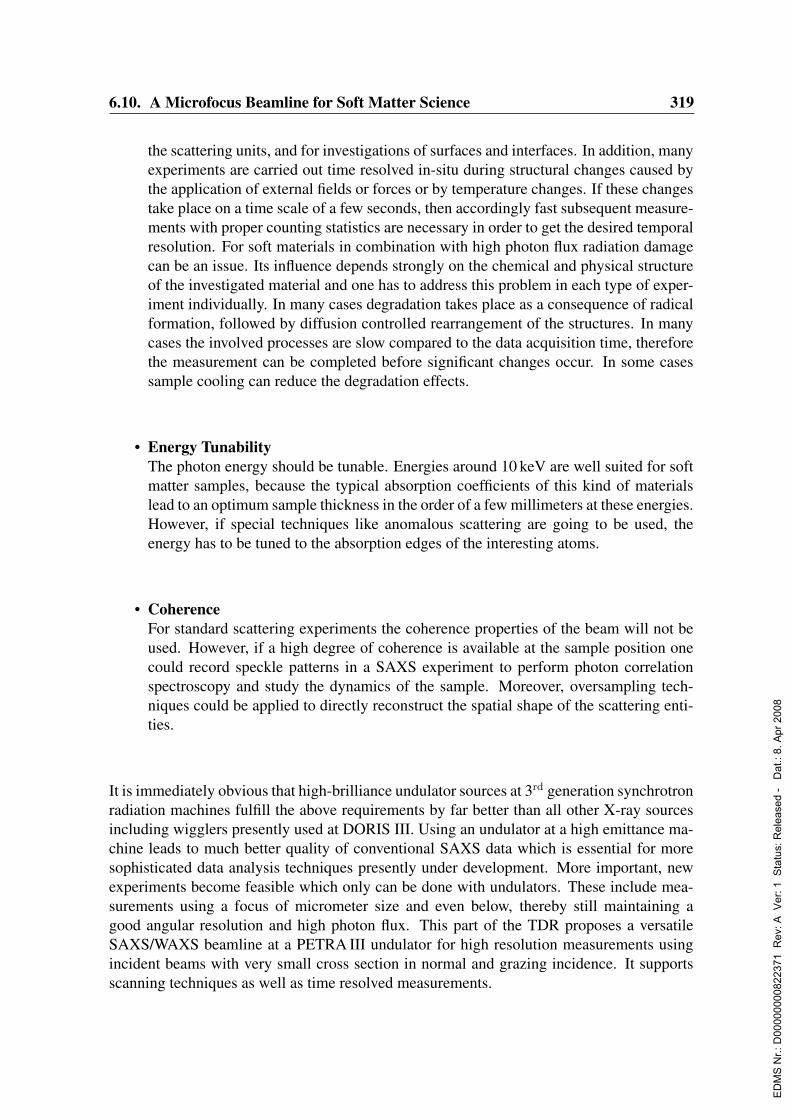
6.10. A Microfocus Beamline for Soft Matter Science 319
the scattering units, and for investigations of surfaces and interfaces. In addition, manyexperiments are carried out time resolved in-situ during structural changes caused bythe application of external fields or forces or by temperature changes. If these changestake place on a time scale of a few seconds, then accordingly fast subsequent measure-ments with proper counting statistics are necessary in order to get the desired temporalresolution. For soft materials in combination with high photon flux radiation damagecan be an issue. Its influence depends strongly on the chemical and physical structureof the investigated material and one has to address this problem in each type of exper-iment individually. In many cases degradation takes place as a consequence of radicalformation, followed by diffusion controlled rearrangement of the structures. In manycases the involved processes are slow compared to the data acquisition time, thereforethe measurement can be completed before significant changes occur. In some casessample cooling can reduce the degradation effects.
• Energy TunabilityThe photon energy should be tunable. Energies around 10 keV are well suited for softmatter samples, because the typical absorption coefficients of this kind of materialslead to an optimum sample thickness in the order of a few millimeters at these energies.However, if special techniques like anomalous scattering are going to be used, theenergy has to be tuned to the absorption edges of the interesting atoms.
• CoherenceFor standard scattering experiments the coherence properties of the beam will not beused. However, if a high degree of coherence is available at the sample position onecould record speckle patterns in a SAXS experiment to perform photon correlationspectroscopy and study the dynamics of the sample. Moreover, oversampling tech-niques could be applied to directly reconstruct the spatial shape of the scattering enti-ties.
It is immediately obvious that high-brilliance undulator sources at 3rd generation synchrotronradiation machines fulfill the above requirements by far better than all other X-ray sourcesincluding wigglers presently used at DORIS III. Using an undulator at a high emittance ma-chine leads to much better quality of conventional SAXS data which is essential for moresophisticated data analysis techniques presently under development. More important, newexperiments become feasible which only can be done with undulators. These include mea-surements using a focus of micrometer size and even below, thereby still maintaining agood angular resolution and high photon flux. This part of the TDR proposes a versatileSAXS/WAXS beamline at a PETRA III undulator for high resolution measurements usingincident beams with very small cross section in normal and grazing incidence. It supportsscanning techniques as well as time resolved measurements.
ED
MS
Nr.:
D00
0000
0082
2371
Rev
: A V
er: 1
Sta
tus:
Rel
ease
d -
Dat
.: 8.
Apr
200
8

320 6. Beamlines and Experimental Stations
6.10.2 Current state of the scientific field
6.10.2.1 Small- and wide-angle scattering (SAXS/WAXS)
SAXS experiments with moderate resolution below 100 nm, WAXS experiments and thesimultaneous combination of SAXS and WAXS have been performed at synchrotron radi-ation sources for many years. They cover the time-resolved observation of crystallizationand melting processes in polymer materials as well as orientation processes upon elongationof polymers (Stribeck et al., 2003; Barbi et al., 2003a; Barbi et al., 2003b) with tempo-ral resolution down to the range of a few seconds. Other examples are phase separationprocesses in block copolymers, phase transitions in liquid crystalline polymers and lipids(Funari, Barcelo & Escriba, 2003), and gel formation in polymer systems.
6.10.2.2 Ultra small angle scattering (USAXS)
Ultra small-angle scattering using pinhole collimation is currently performed at the ESRF un-dulator ID02 and at the HASYLAB wiggler BW4. Both instruments reach a maximum reso-lution of about 500 nm, with a total photon flux of 1013 photons/s at ID02 and of 1011 ph/s atBW4. Examples of present state-of-the-art experiments include the observation of the forma-tion and orientation of nanostructures in polymer systems during elongation or thermal treat-ment of the sample (Stribeck et al., 2002b; Stribeck et al., 2002a; Wang et al., 2003b). Highquality scattering data allow the application of new sophisticated data evaluation schemes.An example of a USAXS experiment with an extremely weak scattering nanostructured sam-ple is shown in Fig. 6.10.1. It addresses particle track etched polymer membranes whichserve as templates for the creation of nanotubes and nanowires. Thin polycarbonate filmswere irradiated with argon ions, the particle tracks were etched to produce nanometer sizedpores which then could be filled with other materials like metals or polymers. The figureshows scattering diagrams which reveal information about size and orientation distributionof the formed nanotubes and wires (Hermsdorf et al., 2003). Fig. 6.10.2 shows the develop-ment of USAXS during the formation of crazes upon elongation of a polycarbonate sample(Karl et al., 1999; Minko et al., 1999; Lorenz-Haas et al., 2003). Information about crazeformation is important as crazes are the precursors of cracks which finally cause the breakingof the sample upon elongation.
6.10.2.3 Grazing-incidence small-angle scattering (GISAXS/GIUSAXS)
Scattering experiments with grazing beam incidence and high resolution in reciprocal spaceare at present carried out at the HASYLAB beamline BW4 (Muller-Buschbaum, 2003;Muller-Buschbaum et al., 1998). A typical example is shown in Fig. 6.10.3 which illus-trates GIUSAXS measurements on dewetting of thin copolymer films on a Si/SiOx surface(Muller-Buschbaum et al., 2000). The out-of-plane intensity distribution parallel to the sur-face (qy-scan) reveals information about lateral correlations. In contrast to transmissionSAXS the maximum resolution is not limited by the size of the primary beam on the de-tector but mainly by the distance between sample and detector. Thus a maximum resolutionof more than 1000 nm can be achieved at BW4. With sufficiently high photon flux time
ED
MS
Nr.:
D00
0000
0082
2371
Rev
: A V
er: 1
Sta
tus:
Rel
ease
d -
Dat
.: 8.
Apr
200
8

6.10. A Microfocus Beamline for Soft Matter Science 321
resolved GISAXS measurements can be performed. This is illustrated in Fig. 6.10.4, where
Figure 6.10.1: Combined SAXS and USAXS measurements of particle track etched polycarbonatemembranes before and after filling of the pores with polypyrole (A2 and BW4 at HASYLAB).
Figure 6.10.2: Formation of crazes during elongation of polycarbonate. USAXS scattering patternsobtained at different draw ratios λ (BW4 at HASYLAB).
ED
MS
Nr.:
D00
0000
0082
2371
Rev
: A V
er: 1
Sta
tus:
Rel
ease
d -
Dat
.: 8.
Apr
200
8
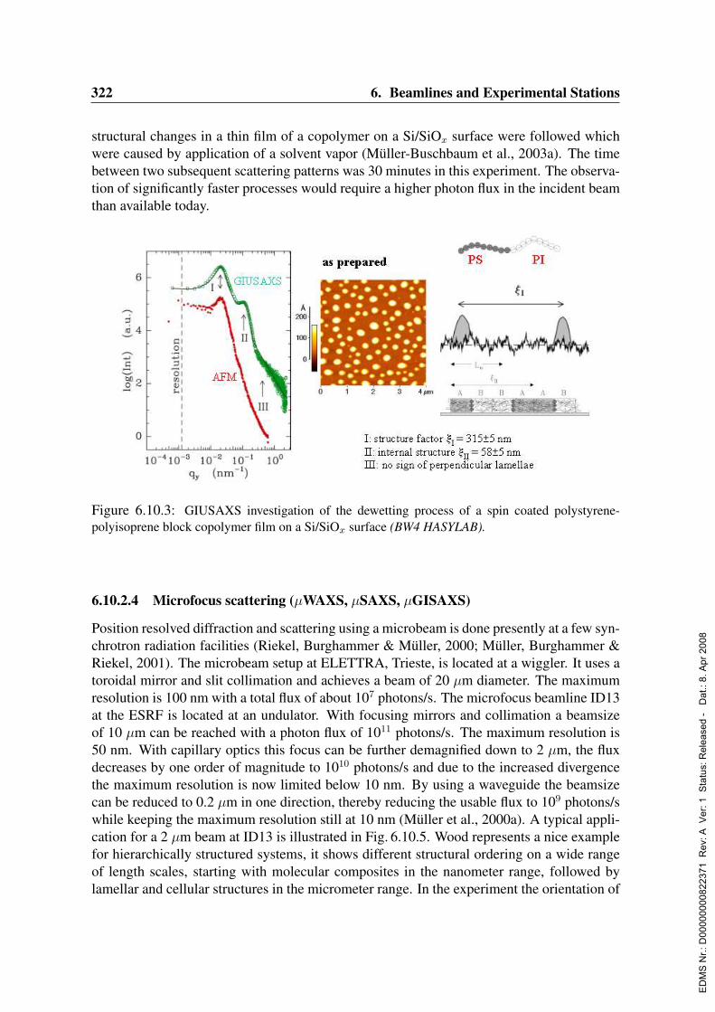
322 6. Beamlines and Experimental Stations
structural changes in a thin film of a copolymer on a Si/SiOx surface were followed whichwere caused by application of a solvent vapor (Muller-Buschbaum et al., 2003a). The timebetween two subsequent scattering patterns was 30 minutes in this experiment. The observa-tion of significantly faster processes would require a higher photon flux in the incident beamthan available today.
Figure 6.10.3: GIUSAXS investigation of the dewetting process of a spin coated polystyrene-polyisoprene block copolymer film on a Si/SiOx surface (BW4 HASYLAB).
6.10.2.4 Microfocus scattering (µWAXS, µSAXS, µGISAXS)
Position resolved diffraction and scattering using a microbeam is done presently at a few syn-chrotron radiation facilities (Riekel, Burghammer & Muller, 2000; Muller, Burghammer &Riekel, 2001). The microbeam setup at ELETTRA, Trieste, is located at a wiggler. It uses atoroidal mirror and slit collimation and achieves a beam of 20 µm diameter. The maximumresolution is 100 nm with a total flux of about 107 photons/s. The microfocus beamline ID13at the ESRF is located at an undulator. With focusing mirrors and collimation a beamsizeof 10 µm can be reached with a photon flux of 1011 photons/s. The maximum resolution is50 nm. With capillary optics this focus can be further demagnified down to 2 µm, the fluxdecreases by one order of magnitude to 1010 photons/s and due to the increased divergencethe maximum resolution is now limited below 10 nm. By using a waveguide the beamsizecan be reduced to 0.2 µm in one direction, thereby reducing the usable flux to 109 photons/swhile keeping the maximum resolution still at 10 nm (Muller et al., 2000a). A typical appli-cation for a 2 µm beam at ID13 is illustrated in Fig. 6.10.5. Wood represents a nice examplefor hierarchically structured systems, it shows different structural ordering on a wide rangeof length scales, starting with molecular composites in the nanometer range, followed bylamellar and cellular structures in the micrometer range. In the experiment the orientation of
ED
MS
Nr.:
D00
0000
0082
2371
Rev
: A V
er: 1
Sta
tus:
Rel
ease
d -
Dat
.: 8.
Apr
200
8
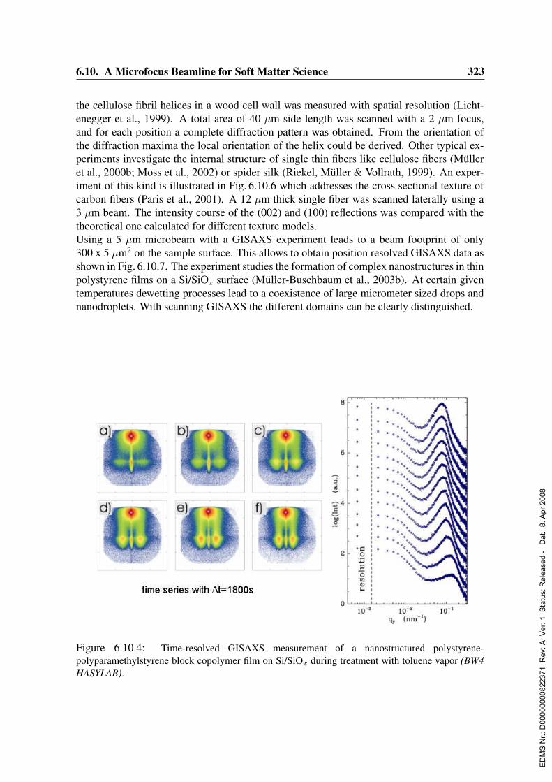
6.10. A Microfocus Beamline for Soft Matter Science 323
the cellulose fibril helices in a wood cell wall was measured with spatial resolution (Licht-enegger et al., 1999). A total area of 40 µm side length was scanned with a 2 µm focus,and for each position a complete diffraction pattern was obtained. From the orientation ofthe diffraction maxima the local orientation of the helix could be derived. Other typical ex-periments investigate the internal structure of single thin fibers like cellulose fibers (Mulleret al., 2000b; Moss et al., 2002) or spider silk (Riekel, Muller & Vollrath, 1999). An exper-iment of this kind is illustrated in Fig. 6.10.6 which addresses the cross sectional texture ofcarbon fibers (Paris et al., 2001). A 12 µm thick single fiber was scanned laterally using a3 µm beam. The intensity course of the (002) and (100) reflections was compared with thetheoretical one calculated for different texture models.Using a 5 µm microbeam with a GISAXS experiment leads to a beam footprint of only300 x 5 µm2 on the sample surface. This allows to obtain position resolved GISAXS data asshown in Fig. 6.10.7. The experiment studies the formation of complex nanostructures in thinpolystyrene films on a Si/SiOx surface (Muller-Buschbaum et al., 2003b). At certain giventemperatures dewetting processes lead to a coexistence of large micrometer sized drops andnanodroplets. With scanning GISAXS the different domains can be clearly distinguished.
Figure 6.10.4: Time-resolved GISAXS measurement of a nanostructured polystyrene-polyparamethylstyrene block copolymer film on Si/SiOx during treatment with toluene vapor (BW4HASYLAB).
ED
MS
Nr.:
D00
0000
0082
2371
Rev
: A V
er: 1
Sta
tus:
Rel
ease
d -
Dat
.: 8.
Apr
200
8

324 6. Beamlines and Experimental Stations
6.10.3 Scientific case for the proposed instrument
It should be noted that at PETRA III compared to the ESRF beamlines for each given focussize a markedly higher maximum resolution at higher photon flux can be reached. This ismainly caused by the smaller beam divergence at the PETRA III undulator. The state-of-the-art experiments illustrated with the above examples form the basis of the scientific case forthe proposed new instrument. Present experiments in the field are limited by the beamtimeavailable at existing instruments and, more important, by technical restrictions in terms ofsmallest achievable focus size and corresponding resolution and photon flux. Many scatter-ing investigations utilizing a beam of small cross section will clearly benefit from having asmaller focus and simultaneously higher resolution and flux than available today, and manynew experiments will only be possible with this. Generally, it will allow time resolved mea-surements on a shorter time scale and/or spatially resolved scattering experiments using amicrofocus especially in hierarchical systems where the observation of structural domainsdown to the 100 nm range is desired. Present attempts to reach this region suffer from fluxand/or resolution limitations and each step forward to improve this will be of great value.Also data quality in classical SAXS and USAXS experiments can be markedly improved byusing a high flux microbeam with a high degree of collimation, because the measurements
Figure 6.10.5: Determination of the helical arrangement of cellulose fibers in the cell wall of woodby means of scanning micro-diffraction using a 2 µm focus (ID13 ESRF).
ED
MS
Nr.:
D00
0000
0082
2371
Rev
: A V
er: 1
Sta
tus:
Rel
ease
d -
Dat
.: 8.
Apr
200
8
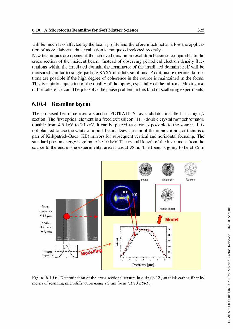
6.10. A Microfocus Beamline for Soft Matter Science 325
will be much less affected by the beam profile and therefore much better allow the applica-tion of more elaborate data evaluation techniques developed recently.New techniques are opened if the achieved maximum resolution becomes comparable to thecross section of the incident beam. Instead of observing periodical electron density fluc-tuations within the irradiated domain the formfactor of the irradiated domain itself will bemeasured similar to single particle SAXS in dilute solutions. Additional experimental op-tions are possible if the high degree of coherence in the source is maintained in the focus.This is mainly a question of the quality of the optics, especially of the mirrors. Making useof the coherence could help to solve the phase problem in this kind of scattering experiments.
6.10.4 Beamline layout
The proposed beamline uses a standard PETRA III X-ray undulator installed at a high-βsection. The first optical element is a fixed exit silicon (111) double crystal monochromator,tunable from 4.5 keV to 20 keV. It can be placed as close as possible to the source. It isnot planned to use the white or a pink beam. Downstream of the monochromator there is apair of Kirkpatrick-Baez (KB) mirrors for subsequent vertical and horizontal focusing. Thestandard photon energy is going to be 10 keV. The overall length of the instrument from thesource to the end of the experimental area is about 95 m. The focus is going to be at 85 m
Figure 6.10.6: Determination of the cross sectional texture in a single 12 µm thick carbon fiber bymeans of scanning microdiffraction using a 2 µm focus (ID13 ESRF).
ED
MS
Nr.:
D00
0000
0082
2371
Rev
: A V
er: 1
Sta
tus:
Rel
ease
d -
Dat
.: 8.
Apr
200
8
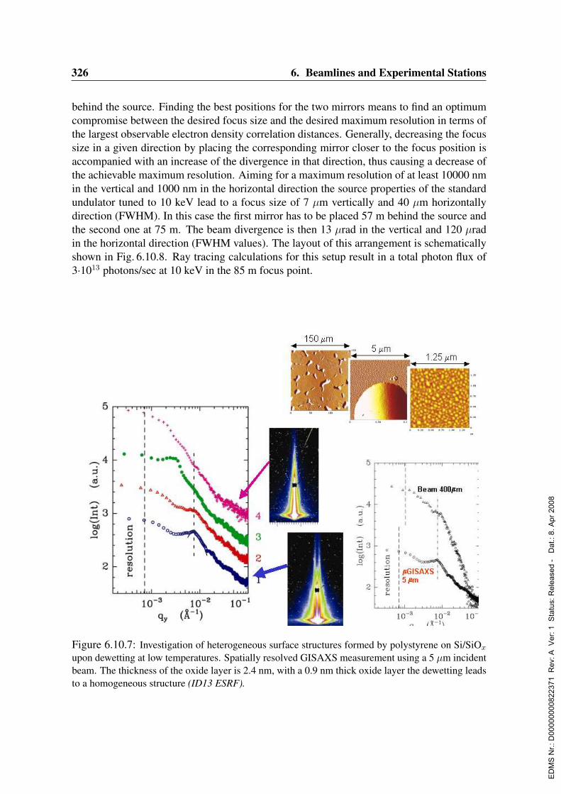
326 6. Beamlines and Experimental Stations
behind the source. Finding the best positions for the two mirrors means to find an optimumcompromise between the desired focus size and the desired maximum resolution in terms ofthe largest observable electron density correlation distances. Generally, decreasing the focussize in a given direction by placing the corresponding mirror closer to the focus position isaccompanied with an increase of the divergence in that direction, thus causing a decrease ofthe achievable maximum resolution. Aiming for a maximum resolution of at least 10000 nmin the vertical and 1000 nm in the horizontal direction the source properties of the standardundulator tuned to 10 keV lead to a focus size of 7 µm vertically and 40 µm horizontallydirection (FWHM). In this case the first mirror has to be placed 57 m behind the source andthe second one at 75 m. The beam divergence is then 13 µrad in the vertical and 120 µradin the horizontal direction (FWHM values). The layout of this arrangement is schematicallyshown in Fig. 6.10.8. Ray tracing calculations for this setup result in a total photon flux of3·1013 photons/sec at 10 keV in the 85 m focus point.
Figure 6.10.7: Investigation of heterogeneous surface structures formed by polystyrene on Si/SiOx
upon dewetting at low temperatures. Spatially resolved GISAXS measurement using a 5 µm incidentbeam. The thickness of the oxide layer is 2.4 nm, with a 0.9 nm thick oxide layer the dewetting leadsto a homogeneous structure (ID13 ESRF).
ED
MS
Nr.:
D00
0000
0082
2371
Rev
: A V
er: 1
Sta
tus:
Rel
ease
d -
Dat
.: 8.
Apr
200
8
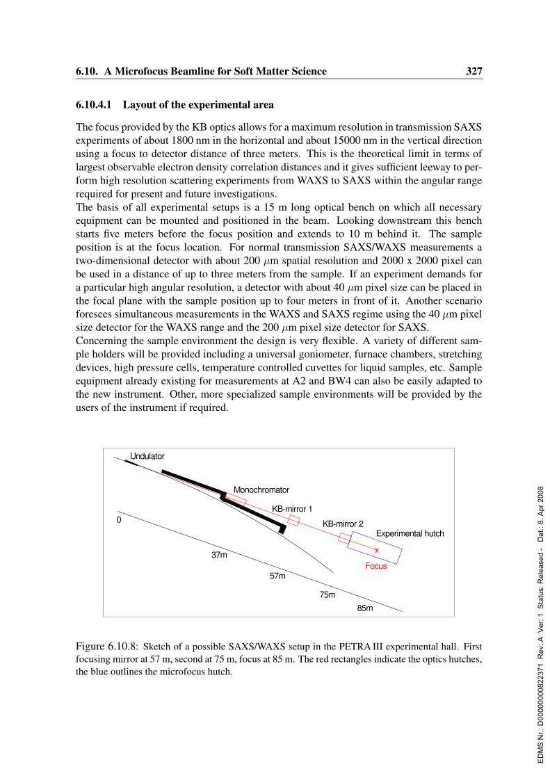
6.10. A Microfocus Beamline for Soft Matter Science 327
6.10.4.1 Layout of the experimental area
The focus provided by the KB optics allows for a maximum resolution in transmission SAXSexperiments of about 1800 nm in the horizontal and about 15000 nm in the vertical directionusing a focus to detector distance of three meters. This is the theoretical limit in terms oflargest observable electron density correlation distances and it gives sufficient leeway to per-form high resolution scattering experiments from WAXS to SAXS within the angular rangerequired for present and future investigations.The basis of all experimental setups is a 15 m long optical bench on which all necessaryequipment can be mounted and positioned in the beam. Looking downstream this benchstarts five meters before the focus position and extends to 10 m behind it. The sampleposition is at the focus location. For normal transmission SAXS/WAXS measurements atwo-dimensional detector with about 200 µm spatial resolution and 2000 x 2000 pixel canbe used in a distance of up to three meters from the sample. If an experiment demands fora particular high angular resolution, a detector with about 40 µm pixel size can be placed inthe focal plane with the sample position up to four meters in front of it. Another scenarioforesees simultaneous measurements in the WAXS and SAXS regime using the 40 µm pixelsize detector for the WAXS range and the 200 µm pixel size detector for SAXS.Concerning the sample environment the design is very flexible. A variety of different sam-ple holders will be provided including a universal goniometer, furnace chambers, stretchingdevices, high pressure cells, temperature controlled cuvettes for liquid samples, etc. Sampleequipment already existing for measurements at A2 and BW4 can also be easily adapted tothe new instrument. Other, more specialized sample environments will be provided by theusers of the instrument if required.
KB-mirror 1
KB-mirror 2
Monochromator
Experimental hutch
x
Undulator
0
37m
57m
75m
85m
Focus
Figure 6.10.8: Sketch of a possible SAXS/WAXS setup in the PETRA III experimental hall. Firstfocusing mirror at 57 m, second at 75 m, focus at 85 m. The red rectangles indicate the optics hutches,the blue outlines the microfocus hutch.
ED
MS
Nr.:
D00
0000
0082
2371
Rev
: A V
er: 1
Sta
tus:
Rel
ease
d -
Dat
.: 8.
Apr
200
8
328 6. Beamlines and Experimental Stations
For grazing incidence measurements a special goniometer will be installed which allows toadjust the sample orientation and the position of the focus on the sample with very highprecision. The design shall allow to do scanning experiments along the sample surface. Ifrequired, the distance between sample and detector can be increased up to 10 m to observelateral ordering on a very large length scale.The focus produced by the KB mirror system can be used as a prefocus for additional focus-ing elements to produce an extremely small focus down to the nanometer range. Dependingon the progress of various developments which are presently under way these elements couldbe capillary optics, Fresnel lenses, compound refractive lenses, or waveguides. Calculationsfor a glass capillary which uses the prefocus to produce a 100 nm size beam spot show thata 100 mm long capillary with 4 µm entrance diameter could produce such a focus with aefficiency of 4% . This implies a total flux of 9·1011 photons/s in a focus of 100 nm diameter.The beam divergence would be around 2 mrad which still allows to perform SAXS measure-ments with a resolution up to 50 nm. In general one can state that due to the properties ofthe prefocus, i.e. small beam cross section and low divergence, it will be well suited for eachkind of subsequent nanofocusing optics. To use the nanofocus for scanning microdiffractionapplications a positioning unit has to be provided which allows to align the sample preciselyrelative to the beam and to perform the scanning operation. The basic concept of alignmentis to define a position on the sample by means of an optical microscope and then to transferthis point to the position of the nanobeam.
6.10.4.2 Stability issues
In order to make proper use of the small focus, its position must be fixed at least within10% of its corresponding dimensions. Thus, special attention must be paid to thermal andmechanical stability of the beamline and decoupling of vibrations from grounding, coolingliquids and devices like pumping units etc. Stability considerations also serve as argumentsagainst the design of this instrument as a side station at a canted pair of undulators. Themonochromator has to be constructed as a compact unit to avoid independent motions of thefirst and second crystal relative to each other. Therefore, a large distance of both crystals asenvisaged in the side-station concept will surely have a negative impact on the stability ofthe focus. Finally, one should note that the planned top-up mode operation of the storagering will improve the overall stability of the experiment.
6.10.4.3 Infrastructure
Because the proposed instrument involves many different experimental options, sufficientspace must be available in the experimental hutch in order to keep the different experimentalmodules in place and to facilitate changing from one setup to another in an efficient and fastmanner. Also user specific sample equipment like stretching devices, cryostats, etc. mightrequire larger space. Therefore, the width and height of the experimental hutch shall not besignificantly below five meters. Envisaging the frequent setup changes, sufficient laboratoryspace in the vicinity of the experimental hutch is also required. An area of 16 m2 will be theminimum.
ED
MS
Nr.:
D00
0000
0082
2371
Rev
: A V
er: 1
Sta
tus:
Rel
ease
d -
Dat
.: 8.
Apr
200
8
6.10. A Microfocus Beamline for Soft Matter Science 329
6.10.4.4 Detectors and data handling
Two area detectors shall be available at the instrument. A large one with 2000 x 2000 pixel of200 µm2 size and a small one with 2000 x 2000 pixel with 40 µm2 or less. The pixels shallbe integrating with a signal to noise ratio of 104 or better and for time resolved measure-ments the readout time shall be in the order of seconds. As a first approach CCD detectorscan be used which are already commercially available, but it would be highly desirable tohave semiconductor pixel detectors with parallel pixel readout. However, such detectors arepresently not available and would have to be developed outside the scope of the proposedinstrument.The beamline shall be equipped with two PC workstations, one for the instrument controland data acquisition, the other for data evaluation. The beamline control shall be performedvia VME electronics. The amount of data obtained in an experiment depends strongly on theexperiments. For instance, a typical scanning experiment using the nanofocus would lead to30 x 30 scattering patterns each with up to 2000 x 2000 pixels and a depth of 24 bit per pixel.This amounts to about 10 Gigabyte of data which are typically acquired within two hours.Similar amounts of data could be generated in a typical time resolved experiment.
6.10.5 Capital investment and personnelThe many experimental options of the instrument require to construct and to operate it by ateam of two scientists who are full time in charge of this project. They shall be assisted bytwo full time engineers, one with major skills in electrical engineering and electronics, theother in mechanical engineering. The team should start working on the project about twoyears before the beginning of the construction of the instrument in order to design and pur-chase major components. Thereby, the construction of the experimental setup could start inparallel to the construction of the beamline and after one year of construction work the mainparts of the setup could be ready for test operation. Another year later the major componentsof all experimental setups can be finished. This amounts to a total main construction periodof four years. The work might be supported by postdocs and PHD students who take care ofthe construction of user specific sample environments. They could be delegated by externaluser groups, and they should start working on the project when it can be foreseen that theycan make practical use of their facilities within the time of their stay. As soon as the opticsand main parts of the experiments are going to be installed, an expert with skills in softwareengineering and programming shall join the project for three years. The task of this person isto design and implement software to control the instrument. This work shall be based on thelaboratory wide concept how to control various hardware components and shall implementsoftware which not only performs the task of moving motors and acquiring data but whichalso assists the workflows of changing setups and adjusting the instrument in a user friendlymanner. The aim is to help to make setup changes as efficient and fast as possible.
The total investment cost for this beamline amounts to 1020 ke.
ED
MS
Nr.:
D00
0000
0082
2371
Rev
: A V
er: 1
Sta
tus:
Rel
ease
d -
Dat
.: 8.
Apr
200
8

330 6. Beamlines and Experimental Stations
6.11 Absorption SpectroscopyAuthors and Consultants :
M. Denecke FZK, Karlsruhe, GermanyR. Frahm Bergische Universitat Wuppertal, Wuppertal, GermanyM. Froba Justus-Liebig Universitat, Giessen, GermanyJ.-D. Grunwaldt ETH Zurich, SwitzerlandD. Lutzenkirchen-Hecht Bergische Universitat Wuppertal, GermanyJ. Rohler Universitat zu Koln, GermanyE. Welter DESY, Hamburg, Germany
6.11.1 Current state of the scientific fieldX-ray Absorption Fine Structure Spectroscopy (XAFS) is a well established method forinvestigations of the local atomic and electronic structures of matter. Because absorptionedges are intrinsically element specific, XAFS yields unique insight into matter, especiallyin small atom aggregates (clusters, nano-particles), surfaces and dilute systems. Thus it ex-tends structural research beyond X-ray diffraction methods, and in combination with it in anovel method named DAFS (diffraction anomalous fine structure) both methods join theirstrengths. Synchrotron radiation based XAFS is nowadays routinely used in nearly all areasof fundamental and applied research. More intense or more brilliant sources can shift thelimits to currently inaccessible applications.While studies of the electronic structure using X-ray Absorption Near Edge Structure (XANES)spectroscopy require a high energy resolution, better than 10−4(∆E/E), in a relatively nar-row energy range of about 150 eV, studies of the local atomic structures by the ExtendedAbsorption Fine Structure (EXAFS) rely on a very high momentum transfer of the scatteredphotoelectrons, corresponding to typically 1–1.5 keV - in special cases up to 3 keV - photonenergy above the edge. Both types of measurements need very high monochromatic photonflux to achieve a high signal-to-noise ratio > 104, particularly in the case of dilute samples,surfaces, µm-sized samples, or data collection in reflectivity or fluorescence modes. To coveran appropriate energy range, a tapering of the undulator or gap scans of the untapered undu-lator are mandatory. For XANES-measurements just a small tapering is necessary (if at all),for EXAFS an energy range of typically 1.5 keV has to be covered for high quality data ofone absorption edge.The high flux and brilliance of 3rd generation sources do open new horizons for XANESand EXAFS experiments. Among the new possibilities are investigations of µm-sized sam-ples, tiny samples confined in strongly absorbing environments, fast measurements of highlydiluted species and spectroscopic investigations with spatial resolutions down to the µm oreven nm scale. As a consequence all 3rd generation facilities run XAFS beamlines at un-dulators. Tab. 6.11.1 lists the undulator XAFS beamlines at the three major high energy3rd generation sources in the world. Except ESRF ID 24, that uses a very specialized dis-persive set-up, none of the beamlines is exclusively dedicated to XAFS spectroscopy. Manybeamlines share an XAFS set-up with set-ups for X-ray fluorescence (beamlines dedicatedto geochemistry / environmental sciences) and/or X-ray diffraction (beamlines dedicated to
ED
MS
Nr.:
D00
0000
0082
2371
Rev
: A V
er: 1
Sta
tus:
Rel
ease
d -
Dat
.: 8.
Apr
200
8

6.11. Absorption Spectroscopy 331
Beamline Applications Energy range Spot Size Source(keV) (µm H x V)
ESRFID24 Dispersive XAFS 5 - 28 20 x 200 tapered undulatorID 21/22 µ-FluorescenceID26 High brilliance 3.2-30 200 x 80 scanable undulator
spectroscopy stepwise/continuousAPS1ID Materials Science 4.2-30 6 x 2 scanable/tapered
Physics (with CRL) undulator9ID Materials Science 3.1-22.5 scanable undulator10ID Materials Science 4.8-32 5 x 5
Environm. Science (with KB)11ID-D 4-50 (wiggler)13ID Geoscience 4-45
Env./soil Science16ID High pressure18ID Biology 3.5-35 40 x 20020ID Material Science 4 - 50 400 x 100 scanable undulator
Env. Science 1 x 1 with KB32ID Material ScienceSPring-8BL10XU Material Science 6-35 500 x 1000 scanable undulator
Table 6.11.1: XAFS beamlines at ESRF, APS and SPring-8
material science).
The working range of these beamlines starts at E > 3.5 keV. Mirrors are used up to E ≈30 keV for focusing and/or rejection of harmonics. This energy range comprises the mostimportant absorption edges for XAFS spectroscopy. The upper limit of the working range isgiven by the mirrors which have to be operated at reasonable glancing angles of a few mrad.A standard set-up with at least one focusing mirror achieves spots with diameters betweensome 10µm and ≈ 200µm. At some beamlines smaller spot sizes (1 - 25µm2) are reachedby additional Kirkpatrick-Baez (KB) mirror systems which are placed close to the sample.Alternatively, compound refractive lenses are used for µm-scale foci. The undulator beamis monochromatized by a cryogenically cooled Si double-crystal monochromator with fixedexit. In some cases (for instance 20 ID at APS) the monochromator is installed in front ofthe first mirror.
All of the listed beamlines use scanable undulators to perform EXAFS scans covering anenergy range of 1000–2000 eV. The design parameters of these undulators are close to thoseof the PETRA III spectroscopy undulator.
ED
MS
Nr.:
D00
0000
0082
2371
Rev
: A V
er: 1
Sta
tus:
Rel
ease
d -
Dat
.: 8.
Apr
200
8
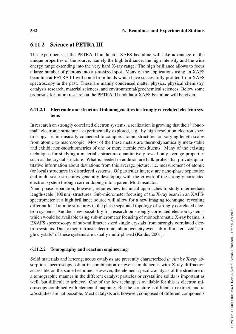
332 6. Beamlines and Experimental Stations
6.11.2 Science at PETRA III
The experiments at the PETRA III undulator XAFS beamline will take advantage of theunique properties of the source, namely the high brilliance, the high intensity and the wideenergy range extending into the very hard X-ray range. The high brilliance allows to focusa large number of photons into a µm-sized spot. Many of the applications using an XAFSbeamline at PETRA III will come from fields which have successfully profited from XAFSspectroscopy in the past. These are mainly condensed matter physics, physical chemistry,catalysis research, material sciences, and environmental/geochemical sciences. Below someproposals for future research at the PETRA III undulator XAFS beamline will be given.
6.11.2.1 Electronic and structural inhomogeneities in strongly correlated electron sys-tems
In research on strongly correlated electron systems, a realization is growing that their “abnor-mal” electronic structure - experimentally explored, e.g., by high resolution electron spec-troscopy - is intrinsically connected to complex atomic structures on varying length-scalesfrom atomic to macroscopic. Most of the these metals are thermodynamically meta-stableand exhibit non-stoichiometries of one or more atomic constituents. Many of the existingtechniques for studying a material’s structure quantitatively reveal only average propertiessuch as the crystal structure. What is needed in addition are bulk probes that provide quan-titative information about deviations from this average picture, i.e. measurement of atomic(or local) structures in disordered systems. Of particular interest are nano-phase separationand multi-scale structures generally developing with the growth of the strongly correlatedelectron system through carrier doping into a parent Mott insulator.Nano-phase separation, however, requires new technical approaches to study intermediatelength-scale (100 nm) structures. Sub-micrometer focusing of the X-ray beam in an XAFS-spectrometer at a high brilliance source will allow for a new imaging technique, revealingdifferent local atomic structures in the phase separated topology of strongly correlated elec-tron systems. Another new possibility for research on strongly correlated electron systems,which would be available using sub-micrometer focusing of monochromatic X-ray beams, isEXAFS spectroscopy of sub-millimeter sized single crystals from strongly correlated elec-tron systems. Due to their intrinsic electronic inhomogeneity even sub-millimeter sized “sin-gle crystals” of these systems are usually multi-phased (Kaldis, 2001).
6.11.2.2 Tomography and reaction engineering
Solid materials and heterogeneous catalysts are presently characterized in situ by X-ray ab-sorption spectroscopy, often in combination or even simultaneous with X-ray diffractionaccessible on the same beamline. However, the element-specific analysis of the structure ina tomographic manner in the different catalyst particles or crystalline solids is important aswell, but difficult to achieve. One of the few techniques available for this is electron mi-croscopy combined with elemental mapping. But the structure is difficult to extract, and insitu studies are not possible. Most catalysts are, however, composed of different components
ED
MS
Nr.:
D00
0000
0082
2371
Rev
: A V
er: 1
Sta
tus:
Rel
ease
d -
Dat
.: 8.
Apr
200
8
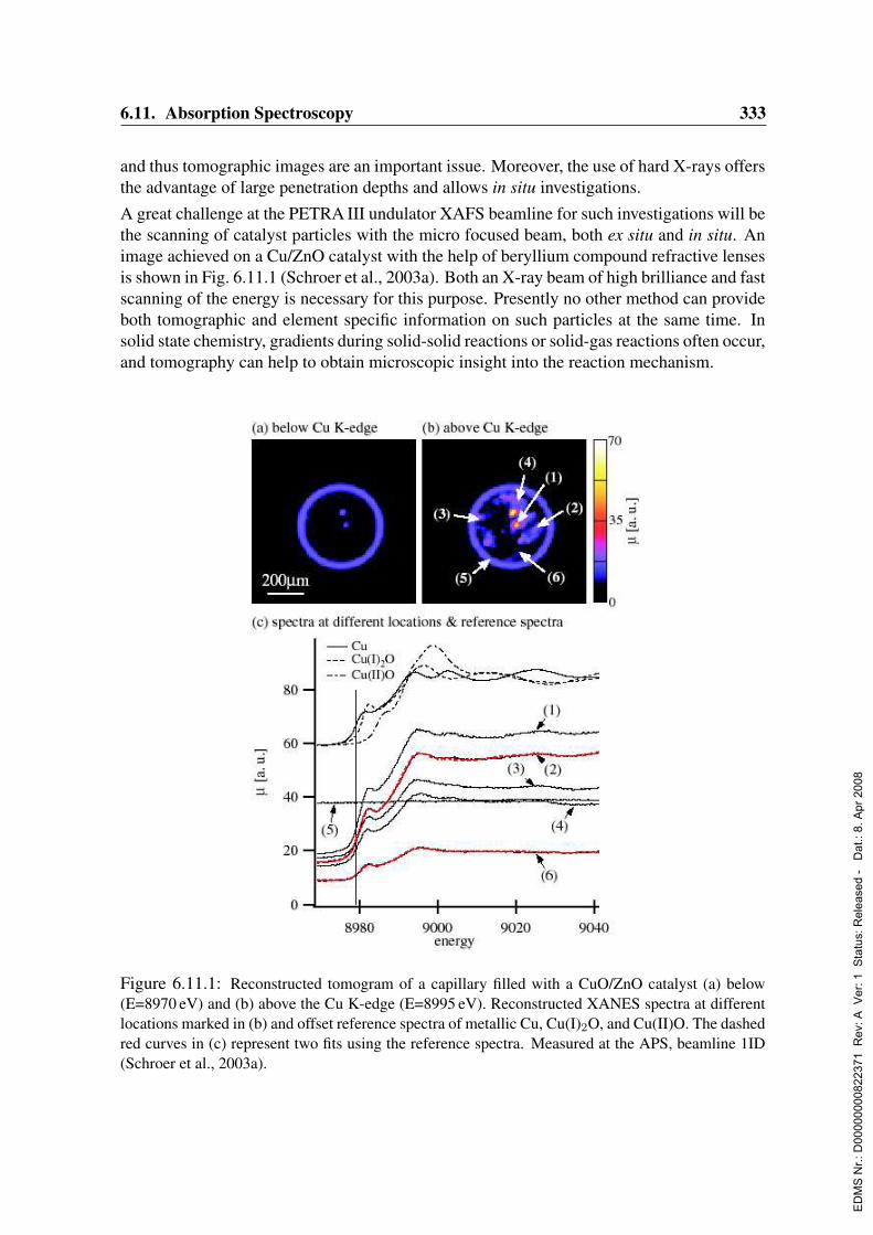
6.11. Absorption Spectroscopy 333
and thus tomographic images are an important issue. Moreover, the use of hard X-rays offersthe advantage of large penetration depths and allows in situ investigations.A great challenge at the PETRA III undulator XAFS beamline for such investigations will bethe scanning of catalyst particles with the micro focused beam, both ex situ and in situ. Animage achieved on a Cu/ZnO catalyst with the help of beryllium compound refractive lensesis shown in Fig. 6.11.1 (Schroer et al., 2003a). Both an X-ray beam of high brilliance and fastscanning of the energy is necessary for this purpose. Presently no other method can provideboth tomographic and element specific information on such particles at the same time. Insolid state chemistry, gradients during solid-solid reactions or solid-gas reactions often occur,and tomography can help to obtain microscopic insight into the reaction mechanism.
Figure 6.11.1: Reconstructed tomogram of a capillary filled with a CuO/ZnO catalyst (a) below(E=8970 eV) and (b) above the Cu K-edge (E=8995 eV). Reconstructed XANES spectra at differentlocations marked in (b) and offset reference spectra of metallic Cu, Cu(I)2O, and Cu(II)O. The dashedred curves in (c) represent two fits using the reference spectra. Measured at the APS, beamline 1ID(Schroer et al., 2003a).
ED
MS
Nr.:
D00
0000
0082
2371
Rev
: A V
er: 1
Sta
tus:
Rel
ease
d -
Dat
.: 8.
Apr
200
8
334 6. Beamlines and Experimental Stations
Another important topic in heterogeneous catalysis is the study of catalysts in their workingenvironment. Engineering of reactors (avoiding hot spots, etc.) is an important issue. Incontinuous fixed-bed reactors, large concentration gradients occur along the reactor bed.One of the great challenges is to unravel how such gradients affect the structure of the solidcatalyst, a question of tremendous industrial importance. Tomographic changes along theaxial and radial distribution in the catalyst bed can greatly support modeling studies. Suchinformation can be gained for both solid-catalyzed gas reactions as well as liquid phasereactions.
6.11.2.3 High pressure studies (in situ and ex situ)
Various technical processes such as methanol or ammonia synthesis are performed at highpressure. More recently, high pressure technology has gained renewed attention, mainlyspurred by the beneficial features reported for reactions performed in supercritical media.There is a strong need to gain information on the structure of catalysts under such reac-tion conditions (Grunwaldt, Wandeler & Baiker, 2003). X-ray absorption spectroscopy andattenuated total reflection infra-red spectroscopy are presently the most promising in situtechniques for heterogeneously catalyzed reactions giving information on the structure andthe surface of the catalysts.Recently, in situ EXAFS studies have been performed at the Pd K-edge during aerobic oxi-dation of alcohols in supercritical carbon dioxide (150 bar, oC), which show the potential ofhigh pressure studies (Grunwaldt et al., 2003). Small beam sizes will facilitate these studiesbecause the use of rather thin windows is especially important for absorption edges below10 keV. The potential of such high pressure studies has been recently outlined in differentpublications (Grunwaldt, Wandeler & Baiker, 2003; Topsøe, 2003).Not only in situ investigations will benefit from the small spot size. The small focal spot sizecombined with the high flux of a PETRA III undulator beamline will allow for studies of theelectronic and atomic structure under extreme conditions in high-pressure devices, such asdiamond anvil cells (Bassett et al., 2000). Applications are expected to be in the areas ofcondensed matter physics, physical chemistry, geochemistry and geophysics.
6.11.2.4 QEXAFS investigations of fast structural transformations
The high brilliance of the PETRA III undulator beam will also be advantageous for quickEXAFS (QEXAFS) studies (Frahm, 1989a), also in combination with lateral information onthe sample. In recent studies (Grunwaldt et al., 2001; Lutzenkirchen-Hecht et al., 2003),the data quality of QEXAFS in situ studies could be improved using undulator beamlinesat present 2nd and 3rd generation synchrotron sources. A further step forward is expectedwith the PETRA III upgrade. The higher photon flux on the sample directly corresponds to abetter time resolution, especially in the case of dilute samples (Lutzenkirchen-Hecht, Grund-mann & Frahm, 2001; Lutzenkirchen-Hecht & Frahm, 2001). A µm-sized focal spot allowse.g. to investigate individual grains in a catalyst sample during an in situ reaction, or to per-form EXAFS measurements in the reflective mode on small sample areas. Currently, in manycases the atomic reordering during fast chemical reactions like combustions and decomposi-
ED
MS
Nr.:
D00
0000
0082
2371
Rev
: A V
er: 1
Sta
tus:
Rel
ease
d -
Dat
.: 8.
Apr
200
8

6.11. Absorption Spectroscopy 335
tions is still unknown. For the understanding of such processes it is also important to look forintermediate, short lived structural phases. Additional applications for measurements withµm-size lateral resolution and high time resolution are manifold, e.g. the investigation of lo-calized corrosion phenomena such as pitting corrosion (Lutzenkirchen-Hecht & Strehblow,2003).
6.11.2.5 High energy XAFS
The energy range of the L-edge XAFS in most elements is strongly limited by the relativelysmall energy differences within the L-multiplet. K-edges do not have such a limitation. Theproblem is demonstrated in Fig. 6.11.2 (Borowski, Bowron & de Panfilis, 1999), comparingthe EXAFS and their corresponding Fourier transform (FT) spectra of Eu in Eu2O3 from theL3 and K-edges. The gain in resolution of bond distances through the extended momentumrange in the K-edges EXAFS is clearly visible.
Figure 6.11.2: Comparison of Eu K-edge and L3-edge XAFS spectra (top) and the correspondingFourier transformed spectra (bottom) measured on a Eu2O3 sample at the ESRF.
ED
MS
Nr.:
D00
0000
0082
2371
Rev
: A V
er: 1
Sta
tus:
Rel
ease
d -
Dat
.: 8.
Apr
200
8
336 6. Beamlines and Experimental Stations
A further advantage of high energy XAFS is the high penetration depth of the X-ray photons.It minimizes the ubiquitous problems arising from strongly absorbing matrices (Mavrogeneset al., 2002) and/or sample containers. The spectroscopy undulator (Sec. 4.1.4) of PETRA IIIemits a spectrum, intense enough for high quality XAFS measurements even at E 50 keV.The beamline design will take account of this property and enables measurements of K-edgeXAFS up to Z ≈ 83.It is important to develop an experimental system to improve the energy resolution of theXAFS-spectra beyond the lifetime broadening visible in simple absorption measurements,which is significant at high energy edges. Usage of a high resolution detector system (e.g. acrystal analyzer in Rowland geometry) enables to overcome the lifetime broadening causedby the very large broadening of the 1s core level that is observed in transmission measure-ments. This is done by choosing the wavelength of the detected photons so that only thoseelectrons that decay from the sharp 3p level into the 1s hole are detected (de Groot, 2001 andreferences therein). A further application for which high precision spectra are indispensableis the investigation and modeling of multiple shell excitations (Kodre et al., 2002) in the highenergy range.
6.11.2.6 Extremely small sample volumes
An advantage of the highly brilliant beam is that small sample volumes can be investigated.This is not only important for the aforementioned studies under extreme conditions (highpressure, temperature). Applications are in the fields of materials science, geochemistry,mineralogy and environmental chemistry. Due to safety and ecological aspects, it is impor-tant for toxic or radioactive samples to use small sample volumes. For example, experimentson plutonium, whose nuclides play the dominant role in long-term radio-toxicity of highlevel nuclear waste, can be down-scaled to a level of activity below the exemption limit.Fluorescence XAFS experiments on a solution containing 242Pu are typically performed on400 µL solutions with Pu concentrations of 1-2 mmol/L contained within 5 mm diameterpolyethylene tubes. A single sample in such an experiment contains an activity near 25 kBq.This value exceeds the exemption limit for 242Pu (10 kBq). If the beam is focused and theimpinging number of photons high, the same experiment can be performed in capillary cells,thereby reducing the sample volume to 0.5 µL and less. A sample with this volume, havingthe same expected signal, has an activity near 350 Bq. This is well below the exemptionlimit and allows leeway for volume errors and additional activity due to the presence of othernuclides in the 242Pu nuclide vector actually used.Geochemical understanding of the reactions between rocks and natural fluids in geologicalprocesses is important for many research areas (search for economically relevant deposits,performance assessment of waste repositories, etc.). The high chemical and physical het-erogeneity of natural systems requires investigation using techniques with high sensitivity,high spatial resolution and/or surface specificity. All these techniques will benefit from thehigh brilliance of the PETRA III undulator beamline. One specific example in this field isthe analysis of fluid- inclusions in minerals, where samples of small volume are of interest(Anderson, Mayanovic & Bajt, 1995).
ED
MS
Nr.:
D00
0000
0082
2371
Rev
: A V
er: 1
Sta
tus:
Rel
ease
d -
Dat
.: 8.
Apr
200
8
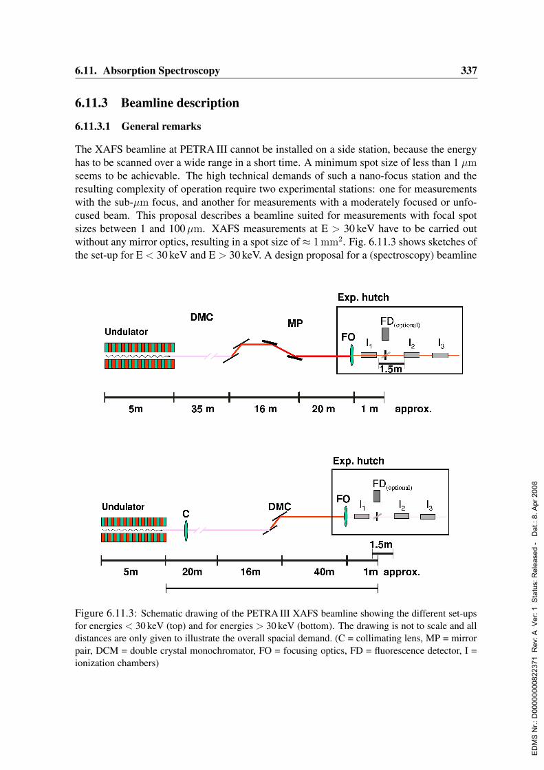
6.11. Absorption Spectroscopy 337
6.11.3 Beamline description
6.11.3.1 General remarks
The XAFS beamline at PETRA III cannot be installed on a side station, because the energyhas to be scanned over a wide range in a short time. A minimum spot size of less than 1 µmseems to be achievable. The high technical demands of such a nano-focus station and theresulting complexity of operation require two experimental stations: one for measurementswith the sub-µm focus, and another for measurements with a moderately focused or unfo-cused beam. This proposal describes a beamline suited for measurements with focal spotsizes between 1 and 100µm. XAFS measurements at E > 30 keV have to be carried outwithout any mirror optics, resulting in a spot size of≈ 1 mm2. Fig. 6.11.3 shows sketches ofthe set-up for E < 30 keV and E > 30 keV. A design proposal for a (spectroscopy) beamline
Figure 6.11.3: Schematic drawing of the PETRA III XAFS beamline showing the different set-upsfor energies < 30 keV (top) and for energies > 30 keV (bottom). The drawing is not to scale and alldistances are only given to illustrate the overall spacial demand. (C = collimating lens, MP = mirrorpair, DCM = double crystal monochromator, FO = focusing optics, FD = fluorescence detector, I =ionization chambers)
ED
MS
Nr.:
D00
0000
0082
2371
Rev
: A V
er: 1
Sta
tus:
Rel
ease
d -
Dat
.: 8.
Apr
200
8
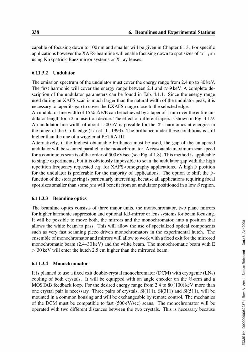
338 6. Beamlines and Experimental Stations
capable of focusing down to 100 nm and smaller will be given in Chapter 6.13. For specificapplications however the XAFS-beamline will enable focusing down to spot sizes of≈ 1µmusing Kirkpatrick-Baez mirror systems or X-ray lenses.
6.11.3.2 Undulator
The emission spectrum of the undulator must cover the energy range from 2.4 up to 80 keV.The first harmonic will cover the energy range between 2.4 and ≈ 9 keV. A complete de-scription of the undulator parameters can be found in Tab. 4.1.1. Since the energy rangeused during an XAFS scan is much larger than the natural width of the undulator peak, it isnecessary to taper its gap to cover the EXAFS range close to the selected edge.An undulator line width of 15 % ∆E/E can be achieved by a taper of 1 mm over the entire un-dulator length for a 2 m insertion device. The effect of different tapers is shown in Fig. 4.1.9.An undulator line width of about 1500 eV is possible for the 3rd harmonics at energies inthe range of the Cu K-edge (Lai et al., 1993). The brilliance under these conditions is stillhigher than the one of a wiggler at PETRA-III.Alternatively, if the highest obtainable brilliance must be used, the gap of the untaperedundulator will be scanned parallel to the monochromator. A reasonable maximum scan speedfor a continuous scan is of the order of 500 eV/sec (see Fig. 4.1.8). This method is applicableto single experiments, but it is obviously impossible to scan the undulator gap with the highrepetition frequency requested e.g. for XAFS-tomography applications. A high β positionfor the undulator is preferable for the majority of applications. The option to shift the β-function of the storage ring is particularly interesting, because all applications requiring focalspot sizes smaller than some µm will benefit from an undulator positioned in a low β region.
6.11.3.3 Beamline optics
The beamline optics consists of three major units, the monochromator, two plane mirrorsfor higher harmonic suppression and optional KB-mirror or lens systems for beam focusing.It will be possible to move both, the mirrors and the monochromator, into a position thatallows the white beam to pass. This will allow the use of specialized optical componentssuch as very fast scanning piezo driven monochromators in the experimental hutch. Theensemble of monochromator and mirrors will allow to work with a fixed exit for the mirroredmonochromatic beam (2.4–30 keV) and the white beam. The monochromatic beam with E> 30 keV will enter the hutch 2.5 cm higher than the mirrored beam.
6.11.3.4 Monochromator
It is planned to use a fixed exit double-crystal monochromator (DCM) with cryogenic (LN2)cooling of both crystals. It will be equipped with an angle encoder on the Θ-arm and aMOSTAB feedback loop. For the desired energy range from 2.4 to 80 (100) keV more thanone crystal pair is necessary. Three pairs of crystals, Si(111), Si(311) and Si(511), will bemounted in a common housing and will be exchangeable by remote control. The mechanicsof the DCM must be compatible to fast (500 eV/sec) scans. The monochromator will beoperated with two different distances between the two crystals. This is necessary because
ED
MS
Nr.:
D00
0000
0082
2371
Rev
: A V
er: 1
Sta
tus:
Rel
ease
d -
Dat
.: 8.
Apr
200
8
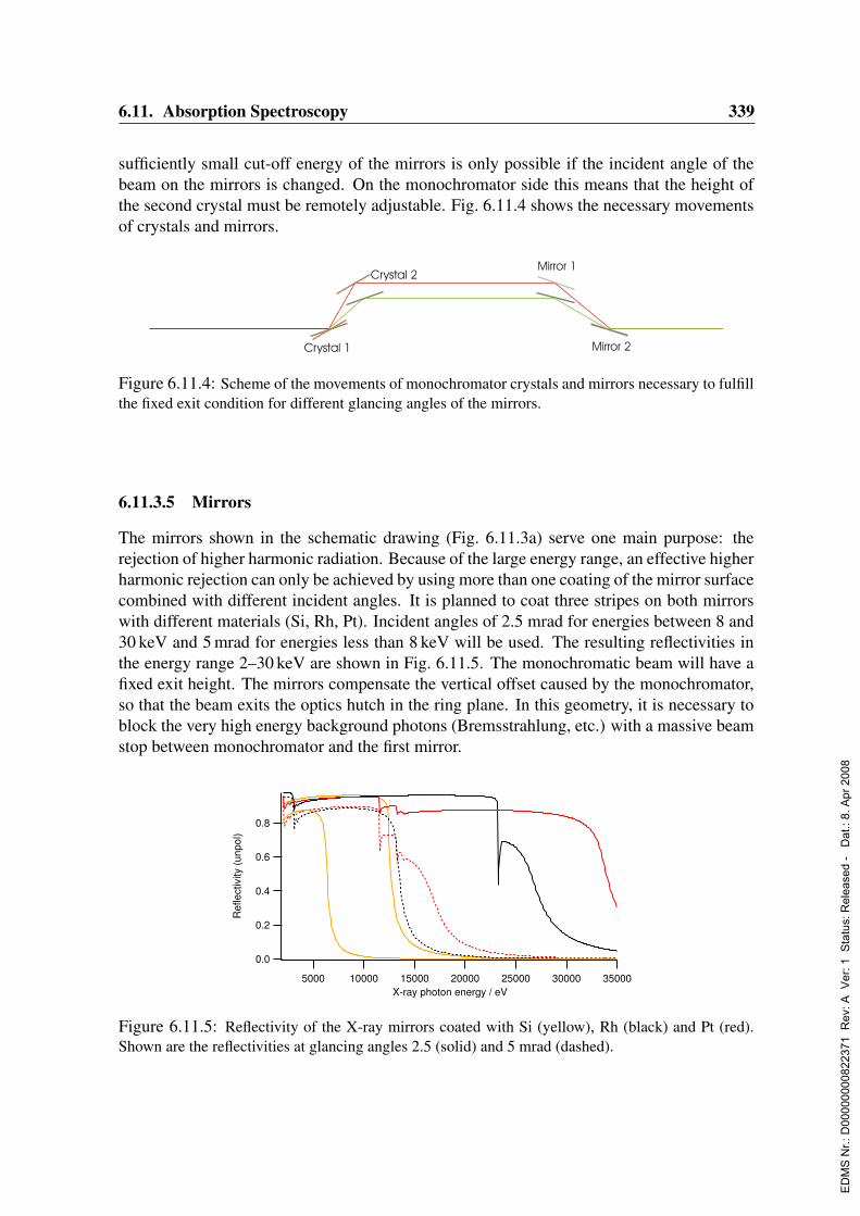
6.11. Absorption Spectroscopy 339
sufficiently small cut-off energy of the mirrors is only possible if the incident angle of thebeam on the mirrors is changed. On the monochromator side this means that the height ofthe second crystal must be remotely adjustable. Fig. 6.11.4 shows the necessary movementsof crystals and mirrors.
Mirror 1
Mirror 2Crystal 1
Crystal 2
Figure 6.11.4: Scheme of the movements of monochromator crystals and mirrors necessary to fulfillthe fixed exit condition for different glancing angles of the mirrors.
6.11.3.5 Mirrors
The mirrors shown in the schematic drawing (Fig. 6.11.3a) serve one main purpose: therejection of higher harmonic radiation. Because of the large energy range, an effective higherharmonic rejection can only be achieved by using more than one coating of the mirror surfacecombined with different incident angles. It is planned to coat three stripes on both mirrorswith different materials (Si, Rh, Pt). Incident angles of 2.5 mrad for energies between 8 and30 keV and 5 mrad for energies less than 8 keV will be used. The resulting reflectivities inthe energy range 2–30 keV are shown in Fig. 6.11.5. The monochromatic beam will have afixed exit height. The mirrors compensate the vertical offset caused by the monochromator,so that the beam exits the optics hutch in the ring plane. In this geometry, it is necessary toblock the very high energy background photons (Bremsstrahlung, etc.) with a massive beamstop between monochromator and the first mirror.
0.8
0.6
0.4
0.2
0.0
Ref
lect
ivity
(unp
ol)
3500030000250002000015000100005000X-ray photon energy / eV
Figure 6.11.5: Reflectivity of the X-ray mirrors coated with Si (yellow), Rh (black) and Pt (red).Shown are the reflectivities at glancing angles 2.5 (solid) and 5 mrad (dashed).
ED
MS
Nr.:
D00
0000
0082
2371
Rev
: A V
er: 1
Sta
tus:
Rel
ease
d -
Dat
.: 8.
Apr
200
8
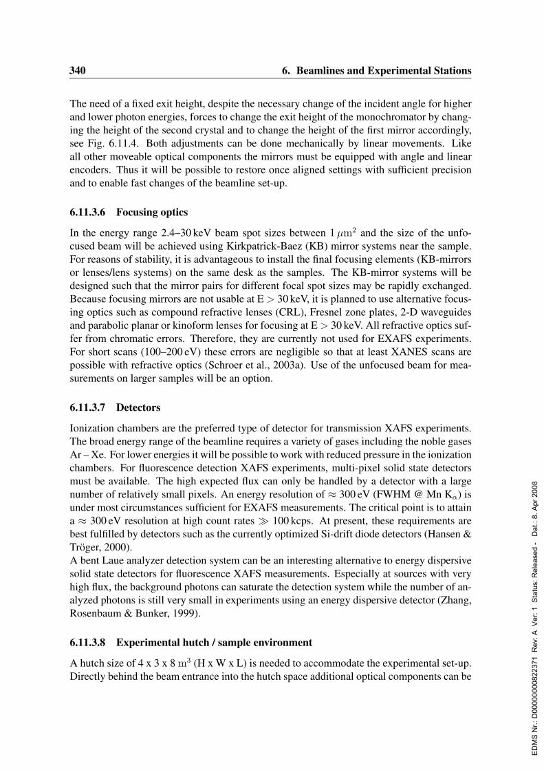
340 6. Beamlines and Experimental Stations
The need of a fixed exit height, despite the necessary change of the incident angle for higherand lower photon energies, forces to change the exit height of the monochromator by chang-ing the height of the second crystal and to change the height of the first mirror accordingly,see Fig. 6.11.4. Both adjustments can be done mechanically by linear movements. Likeall other moveable optical components the mirrors must be equipped with angle and linearencoders. Thus it will be possible to restore once aligned settings with sufficient precisionand to enable fast changes of the beamline set-up.
6.11.3.6 Focusing optics
In the energy range 2.4–30 keV beam spot sizes between 1µm2 and the size of the unfo-cused beam will be achieved using Kirkpatrick-Baez (KB) mirror systems near the sample.For reasons of stability, it is advantageous to install the final focusing elements (KB-mirrorsor lenses/lens systems) on the same desk as the samples. The KB-mirror systems will bedesigned such that the mirror pairs for different focal spot sizes may be rapidly exchanged.Because focusing mirrors are not usable at E > 30 keV, it is planned to use alternative focus-ing optics such as compound refractive lenses (CRL), Fresnel zone plates, 2-D waveguidesand parabolic planar or kinoform lenses for focusing at E > 30 keV. All refractive optics suf-fer from chromatic errors. Therefore, they are currently not used for EXAFS experiments.For short scans (100–200 eV) these errors are negligible so that at least XANES scans arepossible with refractive optics (Schroer et al., 2003a). Use of the unfocused beam for mea-surements on larger samples will be an option.
6.11.3.7 Detectors
Ionization chambers are the preferred type of detector for transmission XAFS experiments.The broad energy range of the beamline requires a variety of gases including the noble gasesAr – Xe. For lower energies it will be possible to work with reduced pressure in the ionizationchambers. For fluorescence detection XAFS experiments, multi-pixel solid state detectorsmust be available. The high expected flux can only be handled by a detector with a largenumber of relatively small pixels. An energy resolution of ≈ 300 eV (FWHM @ Mn Kα) isunder most circumstances sufficient for EXAFS measurements. The critical point is to attaina ≈ 300 eV resolution at high count rates 100 kcps. At present, these requirements arebest fulfilled by detectors such as the currently optimized Si-drift diode detectors (Hansen &Troger, 2000).A bent Laue analyzer detection system can be an interesting alternative to energy dispersivesolid state detectors for fluorescence XAFS measurements. Especially at sources with veryhigh flux, the background photons can saturate the detection system while the number of an-alyzed photons is still very small in experiments using an energy dispersive detector (Zhang,Rosenbaum & Bunker, 1999).
6.11.3.8 Experimental hutch / sample environment
A hutch size of 4 x 3 x 8 m3 (H x W x L) is needed to accommodate the experimental set-up.Directly behind the beam entrance into the hutch space additional optical components can be
ED
MS
Nr.:
D00
0000
0082
2371
Rev
: A V
er: 1
Sta
tus:
Rel
ease
d -
Dat
.: 8.
Apr
200
8

6.11. Absorption Spectroscopy 341
installed. This can be either KB- mirror systems for different focal spot sizes, or lens systems.Alternatively, it will be possible to install a very fast scanning monochromator at this position(Richwin et al., 2001). For larger in situ applications, the distance between the I0 and the I1detector must be adjustable. A maximum distance of 2 m is sufficient. For measurements atlower energies a vacuum chamber will be installed between the first and the second ionizationchamber. The large number of in situ experiments foreseen make it mandatory to have all thenecessary infrastructure for the use of toxic and/or corrosive gases in the experimental hutch,this includes an exhaust system for toxic and/or corrosive gases. Furthermore standard mediasuch as cooling water, pressurized air and gases like N2, He and Ar, which are needed forthe operation of ionization chambers and for some sample environments, will be available.A chemistry lab equipped with a glove box, a fume exhaust and all before mentioned mediasupplies will be available in the vicinity of the beamline. The sample will be mounted on ahigh precision sample manipulator. An optical microscope with CCD camera is necessaryfor the adjustment of the sample position relative to the beam. A sample holder with He-cryostat and heating coils will be available for measurements at temperatures between 4 and300 K. A closed cycle He-cryostat is desirable for measurements with an unfocused beam,when a certain amount of vibration can be tolerated. A diffractometer and a position sensitivedetector are useful for combined XAFS/XRD measurements, which are highly demanded formany investigations (Clausen, Topsøe & Frahm, 1998; Grunwaldt & Clausen, 2002; Clausenet al., 1993; Grunwaldt et al., 2000).
6.11.4 Capital investment and personnelThe investment costs for the XAFS beamline sums up to about 1830 ke.
Manpower requirement:1 Staff scientist (from beginning of 2004) 1 Engineer (6 month after the scientist) 1 Postdoc(not later than start of building/ordering phase) 1 Postdoc (Start of commissioning)
ED
MS
Nr.:
D00
0000
0082
2371
Rev
: A V
er: 1
Sta
tus:
Rel
ease
d -
Dat
.: 8.
Apr
200
8
342 6. Beamlines and Experimental Stations
6.12 High-Energy Photoelectron SpectroscopyAuthors and Consultants :
R. Claessen University of Augsburg, GermanyW. Drube DESY, Hamburg, GermanyL. Kover ATOMKI, Debrecen, HungaryP. LeFevre LURE, Orsay, FranceV. N. Strocov SLS, Villingen, SwitzerlandJ. C. Woicik NIST/APS, Argonne, USAJ. Zegenhagen ESRF, Grenoble, France
6.12.1 Current state of the scientific fieldPhotoelectron spectroscopy (PES) techniques are key methods in solid state physics andmaterial science, providing unique information about chemical composition and electronicstructure, both of the atomic core and the valence states (Kevan, 1992; Hufner, 1996). PES isalso an ideal experimental probe to study aspects of electronic correlations and other atomicmany-body effects, which are among the most fascinating topics of modern solid state re-search (Imada, Fujimori & Tokura, 1998). This includes very fundamental problems such ascorrelation-induced metal-insulator transitions in 3d-metal oxides or heavy-fermion behaviorin 4f-metal compounds, but also novel phenomena like high-temperature superconductivityin cuprates or colossal magnetoresistance in manganites, which hold high potential for pos-sible device applications. A thorough understanding of these materials requires a detaileddetermination of their microscopic electronic structure. Here PES has been established as afundamental experimental probe, because the signal can be directly compared to the single-particle excitation spectrum of the corresponding theoretical models used to describe theseinteracting electron systems (Hufner, 1996).In conventional PES, here defined as hν < 2 keV, the information is primarily obtained fromthe topmost atomic layers (≈ 1 nm) because of the strong Coulomb interaction of electronstraveling through a solid (Ley & Cardona, 1979). This is a great advantage for surfacestudies, but it seriously limits the capability to yield reliable information on the electronicstructure in the bulk, which often is different. Novel materials of interest today are ternary,quaternary or even more complex compounds, with large unit cells whose spatial dimensionsare comparable to or even exceed the probing depth of conventional PES (Fig. 6.12.1). Like-wise, technologically relevant buried interfaces and nano-structures cannot be accessed atall. As a consequence, the application of PES has at present little impact in material science.The extreme surface sensitivity can be overcome using hard X-ray excitation (hν 1 keV)which produces energetic electrons with a correspondingly larger escape depth. It is thenpossible to “look” much deeper into the sample, ≈ 10 nm, a range which is already interest-ing for modern nano-technology and future devices.To date, only few PES studies have been made at hard X-ray energies because the exper-iments are highly demanding. A high photon flux is required to compensate for low sig-nal rates: photoelectric cross-sections are decreasing rapidly above the excitation thresh-old σnl(E) ∝ E−3.5−l (Bethe & Salpeter, 1957) and the transmission of electron analyzers
ED
MS
Nr.:
D00
0000
0082
2371
Rev
: A V
er: 1
Sta
tus:
Rel
ease
d -
Dat
.: 8.
Apr
200
8

6.12. High-Energy Photoelectron Spectroscopy 343 1
YBa 2 Cu 3 O 7
CuO
BaO
CuO 2
Y
CuO
BaO
CuO
YBa 2 Cu 3 O 7
CuO
BaO
CuO
2
Y
CuO
BaO
CuO
1.2 nm
e-
30 eV
½ YBCO cell
3000 eV
3 YBCO cells
Mean-free-path
e-e-
30 eV
½ YBCO cell
30 eV
½ YBCO cell
3000 eV
3 YBCO cells
3000 eV
3 YBCO cells
Mean-free-path
Figure 6.12.1: The unit cell ofYBCO (left) and the mean freepath of electrons with differentkinetic energies relative to theYBCO unit cell (right).
strongly drops at high retardation ratios, which are required to measure fast electrons withhigh energy resolution. Also, suitable spectrometers are not readily available.To study atomic inner-shells, a moderate resolution is usually adequate to match the intrinsichole lifetime broadening. Experiments of this kind are now routinely performed at DORIScombining the high flux from the BW2 X-ray wiggler in the range 3–8 keV with a parallel de-tecting high-energy electron analyzer. Here, the achievable resolution (≈ 0.5 eV) is stronglylimited by the low source brilliance. Nevertheless, interesting novel results were obtainede.g. for resonant excitation of inner-shell Auger transitions in solid metals (Drube, Treusch &Materlik, 1995). Recently, it was demonstrated that high-energy resonant Auger spectra al-low to discriminate dipolar from quadrupolar transitions at the K-absorption threshold inTiO2 because excitations into localized final states differ in energy (Danger et al., 2002).Core level spectroscopy provides unique information on elemental composition, chemicalbonding and also electron correlation phenomena involving the atomic core. However, inorder to fully understand material properties, it is essential to study the valence states as well.Here, excellent energy resolution is a key ingredient to resolve the subtle features whichcarry the information needed to characterize the electronic structure and to put theoreticalpredictions obtained by state-of-the-art computational methods to a stringent test.State-of-the-art PES in the XUV-regime achieves meV energy resolution at energies< 100 eVwhere the surface sensitivity is extreme. At energies of ≈ 1 keV a resolution < 100 meV isalready challenging and grating monochromators become very inefficient at higher ener-gies. In the hard X-ray range, perfect Si crystals are used instead where the resolving powerand the achievable absolute resolution is improving with energy (using high-index reflec-tions). A bandwidth < 10 meV is obtained above 10 keV, well suited for high-resolutionspectroscopy as needed e.g. for correlated electronic systems. Clearly, this requires a bril-liant source which is capable of delivering the highest possible photon flux into this narrowspectral bandwidth to cope with low signal rates. Such demanding experiments have notbeen realized so far.Hard X-rays offer the additional possibility to excite X-ray standing waves (XSW) in crys-
ED
MS
Nr.:
D00
0000
0082
2371
Rev
: A V
er: 1
Sta
tus:
Rel
ease
d -
Dat
.: 8.
Apr
200
8
344 6. Beamlines and Experimental Stations
talline materials (Zegenhagen, 1993). If XSW is combined with PES, electronic and struc-tural information is obtained in parallel and can thus be directly correlated. This approachhas been recently used to identify local adsorption geometries exploiting the chemical shiftsensitivity of PES (Jackson et al., 2000). The combination of XSW with valence band spec-troscopy even enables unique site-specific investigations of hybridization and bonding as hasbeen demonstrated very recently (Woicik et al., 2002).In summary, photoelectron spectroscopy using hard X-rays is a novel technique with inter-esting prospects for electronic structure investigations of solid materials. However, the fullpotential of this method can only be explored at a high-flux and brilliant source. At present,strong attempts are being made to implement this promising technique at 3rd generationX-ray sources (ESRF, SPring-8).
6.12.2 Science at PETRA III6.12.2.1 Introductory Remarks
Hard X-ray PES with high energy resolution is extremely challenging and requires an in-tense and brilliant source as well as highly sophisticated electron detection. The instrumentproposed for PETRA III specifically utilizes the low source emittance. The low divergencebeam from a high-β undulator is ideally suited for high-resolution monochromatization pre-serving a high monochromatic flux (≈ 1011s−1 into ∆E ≈ 10 meV around 10 keV) which isneeded to compensate for small cross-sections. Furthermore, the achievable resolving powerof the electron analyzer is linked to the spot size on the sample which can be as small asabout 10µm with suitable X-ray optics. It is, however, not planned to aim at sub-µm X-rayfocusing for spatial resolution in a scanning mode. It seems that for spatial resolution, wherethe main focus is on elemental analysis, electron beam excitation is more powerful. It ispossible already today to perform e.g. scanning Auger measurements with 10 nm spatial res-olution which is unlikely possible with hard X-rays. However, there are currently interestingnovel developments in electron spectroscopy instrumentation. Lower energy PES spectromi-croscopy using a combination of a photoemission electron microscope and a hemisphericalenergy analyzer has already reached a level of about 20 nm resolution. This concept usedat somewhat higher energies is an option also for PETRA III since this approach clearlyrequires a sufficiently small X-ray focus and a high flux density.
6.12.2.2 Strongly correlated systems: states near the Fermi level
The proposed instrument is ideally suited to study strongly correlated systems which are mostinteresting, fascinating, and also promising for device applications. Novel magnetoresistancematerials are already frequently used for data storage and they are also candidates for otheradvanced applications, such as spin-valve transistors. High-temperature superconductors arestill of moderate industrial use, but they display puzzling properties, which are still lackingcomprehensive theoretical underpinning. Their theoretical understanding is mostly aided by(a) macroscopic transport measurements, (b) analysis of atomic and nano-scale structure and,most importantly here, (c) high resolution spectroscopic analysis of the electronic structureand excitation spectrum.
ED
MS
Nr.:
D00
0000
0082
2371
Rev
: A V
er: 1
Sta
tus:
Rel
ease
d -
Dat
.: 8.
Apr
200
8
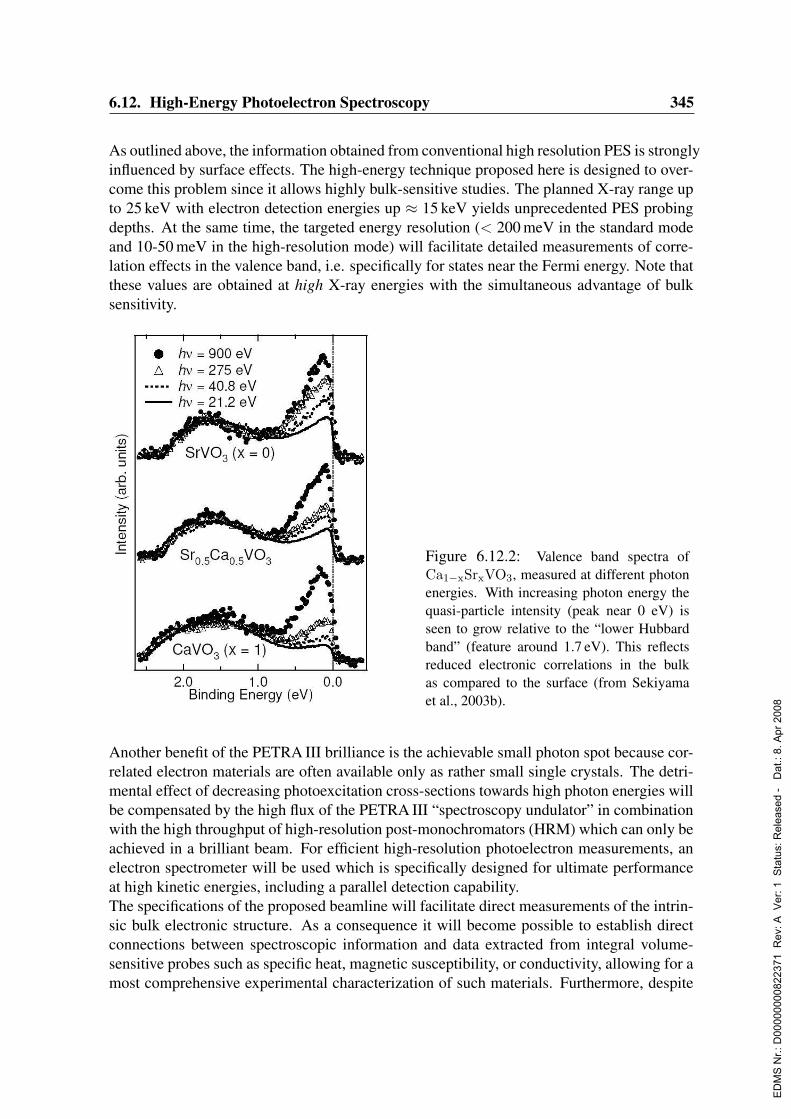
6.12. High-Energy Photoelectron Spectroscopy 345
As outlined above, the information obtained from conventional high resolution PES is stronglyinfluenced by surface effects. The high-energy technique proposed here is designed to over-come this problem since it allows highly bulk-sensitive studies. The planned X-ray range upto 25 keV with electron detection energies up ≈ 15 keV yields unprecedented PES probingdepths. At the same time, the targeted energy resolution (< 200 meV in the standard modeand 10-50 meV in the high-resolution mode) will facilitate detailed measurements of corre-lation effects in the valence band, i.e. specifically for states near the Fermi energy. Note thatthese values are obtained at high X-ray energies with the simultaneous advantage of bulksensitivity.
Figure 6.12.2: Valence band spectra ofCa1−xSrxVO3, measured at different photonenergies. With increasing photon energy thequasi-particle intensity (peak near 0 eV) isseen to grow relative to the “lower Hubbardband” (feature around 1.7 eV). This reflectsreduced electronic correlations in the bulkas compared to the surface (from Sekiyamaet al., 2003b).
Another benefit of the PETRA III brilliance is the achievable small photon spot because cor-related electron materials are often available only as rather small single crystals. The detri-mental effect of decreasing photoexcitation cross-sections towards high photon energies willbe compensated by the high flux of the PETRA III “spectroscopy undulator” in combinationwith the high throughput of high-resolution post-monochromators (HRM) which can only beachieved in a brilliant beam. For efficient high-resolution photoelectron measurements, anelectron spectrometer will be used which is specifically designed for ultimate performanceat high kinetic energies, including a parallel detection capability.The specifications of the proposed beamline will facilitate direct measurements of the intrin-sic bulk electronic structure. As a consequence it will become possible to establish directconnections between spectroscopic information and data extracted from integral volume-sensitive probes such as specific heat, magnetic susceptibility, or conductivity, allowing for amost comprehensive experimental characterization of such materials. Furthermore, despite
ED
MS
Nr.:
D00
0000
0082
2371
Rev
: A V
er: 1
Sta
tus:
Rel
ease
d -
Dat
.: 8.
Apr
200
8
346 6. Beamlines and Experimental Stations
the volume-sensitivity of high-energy PES it will still remain possible to vary the probingdepth and even detect surface effects by using a grazing electron emission geometry.Today, first steps are already being made to increase the information depth in high-resolutionvalence band spectroscopy in the soft X-ray regime up to ≈ 1000 eV using sophisticatedgrating monochromators and powerful undulators at 3rd generation facilities, such as beam-line BL25SU at SPring-8 (Saitoh et al., 2000). Recent experiments (Sekiyama et al., 2000;Mo et al., 2003) have already revealed dramatic surface effects in PES spectra of complexcorrelated electron materials. As an example, Fig. 6.12.2.2 shows valence band spectra ofCa1−xSrxVO3 at different photon energies (Sekiyama et al., 2003a). The crucial informationcontained in these data is the ratio of the quasi-particle peak and the “lower Hubbard band”intensity, which is directly linked to the quasi-particle mass renormalization. This ratio isseen to increase with photon energy and hence with probing depth, confirming that the effec-tive mass previously obtained from low energy PES is strongly distorted by surface effects.These observations helped to resolve a long-standing discrepancy between PES results andthermodynamic data and led to a comprehensive and even semi-quantitative understandingof the electronic structure of these vanadates (Sekiyama et al., 2003a).Finally, it is noted that valence band studies using energetic photoelectrons might retainangular information if the angular resolution of the spectrometer is high enough. At a kineticenergy of about 10 keV, the whole Brillouin zone collapses into a small angular cone of about2 for a 0.3 nm unit cell. Thus, using 2D detection, the 1D-angle versus energy distributioncan be obtained in parallel. The feasibility of performing angular resolved PES in this wayin the soft X-ray range has already been demonstrated (Brookes, 2003).
6.12.2.3 Material Science: buried interfaces and nano-structures
The achievable bulk sensitivity will also enable true material science applications wherethe relevant properties are mostly determined by interfacial regions well below the surface.Note that a modified surface region, generally not of interest, covers any material underambient conditions, incompatible with the need for surface “cleanliness” in low energy PESexperiments. Here, it will be possible to “look through” these dead layers. This opensmany possibilities which are crucial to material science studies: the bulk chemical state ofa compound can be determined, buried interfaces and/or nano-structures become accessible.Moreover, the information depth can still be tuned from bulk to surface to some extent, e.g.by varying the electron emission angle and/or the excitation energy (“depth profiling”).At a kinetic energy of ≈ 10 keV, the inelastic mean free path of photoelectrons is surpass-ing ≈ 7 nm (cf. Fig. 6.12.3) and chemical and electronic information can be retrieved fromregions buried deeper than 10 nm. It was recently demonstrated, that an AlAs layer in aGaAs/AlAs/GaAs quantum-well structure can be analyzed through 10 nm of covering ma-terial (Dallera et al., 2003) with kinetic energies of 6 keV. This is a length scale which isrelevant for the developing field of nano-electronics. High-resolution spectroscopy usingthis instrument at PETRA III will hence be a uniquely sensitive probe to study electronicmaterial properties in future nano-science and technology, provided the samples of interestare sufficiently conducting.The range of materials which comprise buried interfaces and/or nano-structures to tailor elec-
ED
MS
Nr.:
D00
0000
0082
2371
Rev
: A V
er: 1
Sta
tus:
Rel
ease
d -
Dat
.: 8.
Apr
200
8

6.12. High-Energy Photoelectron Spectroscopy 347
Figure 6.12.3: New measurements of theelectron escape depth in GaAs (dots) in com-parison with the “universal curve” (shadedcurve). Measurements were carried out atID32, ESRF.
tronic properties for specific device applications is enormous and will not be elaborated here.So far, high-energy PES has already been used to characterize interesting, but comparativelysimple interface systems such as SiO2/SiC (Virojanadara et al., 2001) and high-k insulatorson Si (Kobayashi et al., 2003). Another example of high current interest in microelectronicsis the incorporation of light-emitting devices into Si, which would allow the integration of op-toelectronics into the established Si device technology. Recently, intense room temperaturephotoluminescence originating from Ge quantum dots (QDs) embedded in Si was reported(Cirlin et al., 2002; Zakharov et al., 2003). The photoluminescence from the QDs occurs dueto quantum confinement effects. Structural aspects of the Ge/Si systems, including Ge/Siintermixing at the interface, have been extensively studied by electron microscopy and X-ray techniques. However, very little is known about their electronic structure. Of particularinterest are band offsets at the Ge/Si interface, which promote accumulation of electrons andholes in the QDs, and - of course - the local electronic structure near the interface.Since the QDs structures are usually buried a few nm, they are accessible to PES with thisinstrument. Furthermore, there is no need for in situ sample preparation which requiresadditional special instrumentation and is time consuming. Samples can be grown ex situ andprotected by cap layers which would still be “transparent” in the experiment.In general, the valence band region contains contributions from the entire elemental mani-fold within the probed sample volume. For a clear chemical contrast, it may therefore beadvantageous to measure shallow core electrons (e.g. Ge 2p in the example above) whichalso can be made highly energetic owing to the high excitation energy available at the PE-TRA III beamline. Measuring the exit-angle dependence of the peak intensities, it will bepossible to characterize the elemental intermixing near the interface and the diffusion of QDatoms into the matrix. If the selected levels are sharp enough, bulk and interfacial chemicalshifts can be separated. Indications for different electronic environments and/or disorder ofthe interface atoms can in principle be obtained from a detailed line shape analysis, providedthe data are of high statistical quality. Again, a high X-ray flux density is essential also forthis type of experiment. Finally, valence band offsets at the interface can be derived from therelative energies of core level lines in the bulk.
ED
MS
Nr.:
D00
0000
0082
2371
Rev
: A V
er: 1
Sta
tus:
Rel
ease
d -
Dat
.: 8.
Apr
200
8
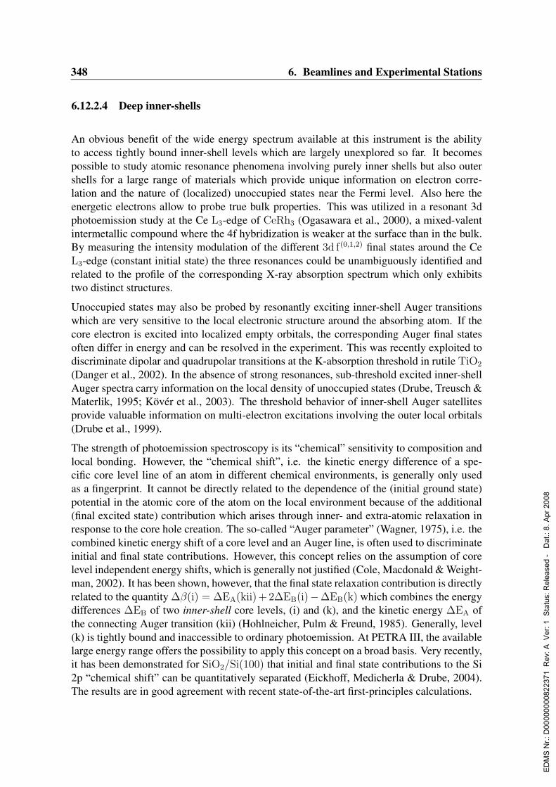
348 6. Beamlines and Experimental Stations
6.12.2.4 Deep inner-shells
An obvious benefit of the wide energy spectrum available at this instrument is the abilityto access tightly bound inner-shell levels which are largely unexplored so far. It becomespossible to study atomic resonance phenomena involving purely inner shells but also outershells for a large range of materials which provide unique information on electron corre-lation and the nature of (localized) unoccupied states near the Fermi level. Also here theenergetic electrons allow to probe true bulk properties. This was utilized in a resonant 3dphotoemission study at the Ce L3-edge of CeRh3 (Ogasawara et al., 2000), a mixed-valentintermetallic compound where the 4f hybridization is weaker at the surface than in the bulk.By measuring the intensity modulation of the different 3d f(0,1,2) final states around the CeL3-edge (constant initial state) the three resonances could be unambiguously identified andrelated to the profile of the corresponding X-ray absorption spectrum which only exhibitstwo distinct structures.
Unoccupied states may also be probed by resonantly exciting inner-shell Auger transitionswhich are very sensitive to the local electronic structure around the absorbing atom. If thecore electron is excited into localized empty orbitals, the corresponding Auger final statesoften differ in energy and can be resolved in the experiment. This was recently exploited todiscriminate dipolar and quadrupolar transitions at the K-absorption threshold in rutile TiO2
(Danger et al., 2002). In the absence of strong resonances, sub-threshold excited inner-shellAuger spectra carry information on the local density of unoccupied states (Drube, Treusch &Materlik, 1995; Kover et al., 2003). The threshold behavior of inner-shell Auger satellitesprovide valuable information on multi-electron excitations involving the outer local orbitals(Drube et al., 1999).
The strength of photoemission spectroscopy is its “chemical” sensitivity to composition andlocal bonding. However, the “chemical shift”, i.e. the kinetic energy difference of a spe-cific core level line of an atom in different chemical environments, is generally only usedas a fingerprint. It cannot be directly related to the dependence of the (initial ground state)potential in the atomic core of the atom on the local environment because of the additional(final excited state) contribution which arises through inner- and extra-atomic relaxation inresponse to the core hole creation. The so-called “Auger parameter” (Wagner, 1975), i.e. thecombined kinetic energy shift of a core level and an Auger line, is often used to discriminateinitial and final state contributions. However, this concept relies on the assumption of corelevel independent energy shifts, which is generally not justified (Cole, Macdonald & Weight-man, 2002). It has been shown, however, that the final state relaxation contribution is directlyrelated to the quantity ∆β(i) = ∆EA(kii)+ 2∆EB(i)−∆EB(k) which combines the energydifferences ∆EB of two inner-shell core levels, (i) and (k), and the kinetic energy ∆EA ofthe connecting Auger transition (kii) (Hohlneicher, Pulm & Freund, 1985). Generally, level(k) is tightly bound and inaccessible to ordinary photoemission. At PETRA III, the availablelarge energy range offers the possibility to apply this concept on a broad basis. Very recently,it has been demonstrated for SiO2/Si(100) that initial and final state contributions to the Si2p “chemical shift” can be quantitatively separated (Eickhoff, Medicherla & Drube, 2004).The results are in good agreement with recent state-of-the-art first-principles calculations.
ED
MS
Nr.:
D00
0000
0082
2371
Rev
: A V
er: 1
Sta
tus:
Rel
ease
d -
Dat
.: 8.
Apr
200
8
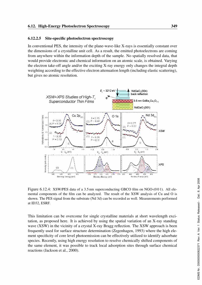
6.12. High-Energy Photoelectron Spectroscopy 349
6.12.2.5 Site-specific photoelectron spectroscopy
In conventional PES, the intensity of the plane-wave-like X-rays is essentially constant overthe dimensions of a crystalline unit cell. As a result, the emitted photoelectrons are comingfrom anywhere within the information depth of the sample. No spatially resolved data, thatwould provide electronic and chemical information on an atomic scale, is obtained. Varyingthe electron take-off angle and/or the exciting X-ray energy only changes the integral depthweighting according to the effective electron attenuation length (including elastic scattering),but gives no atomic resolution.
Figure 6.12.4: XSW/PES data of a 3.5 nm superconducting GBCO film on NGO-(0 0 1). All ele-mental components of the film can be analyzed. The result of the XSW analysis of Cu and O isshown. The PES signal from the substrate (Nd 3d) can be recorded as well. Measurements performedat ID32, ESRF.
This limitation can be overcome for single crystalline materials at short wavelength exci-tation, as proposed here. It is achieved by using the spatial variation of an X-ray standingwave (XSW) in the vicinity of a crystal X-ray Bragg reflection. The XSW approach is beenfrequently used for surface structure determination (Zegenhagen, 1993) where the high ele-ment specificity of core level photoemission can be effectively utilized to identify adsorbatespecies. Recently, using high energy resolution to resolve chemically shifted components ofthe same element, it was possible to track local adsorption sites through surface chemicalreactions (Jackson et al., 2000).
ED
MS
Nr.:
D00
0000
0082
2371
Rev
: A V
er: 1
Sta
tus:
Rel
ease
d -
Dat
.: 8.
Apr
200
8
350 6. Beamlines and Experimental Stations
Analyzing photoelectrons excited by an X-ray standing wave permits to directly correlatestructural with chemical and electronic properties, even in complex systems. As an example,Fig. 6.12.4 shows the XSW/XPS analysis of a superconducting GdBa2Cu3O(7−δ) (GBCO)film on the (001) surface of NdGaO3 (NGO), exposed to normal ambient. The PES lines ofCu and Oxygen can be decomposed in an intrinsic, clean part and a component, which can beassigned to the degraded portion of the film. The XSW analysis of the latter reveals a lowercoherent fraction and a different coherent position compared to the intrinsic part. The Nd3d signal from the substrate peak is split into several components, a shake-up satellite and ashifted component due to a charging effects. The analysis of the Cu XSW yield allowed todeduce the bonding geometry at the GBCO/NGO interface (Lee et al., 2003).Going one step further, the site-specificity of XSW combined with valence photoemissionallows to obtain quantitative “partial photoelectron spectra” which reflect the valence chargedistribution of the constituent atoms (Woicik et al., 2001). This was demonstrated by com-paring data obtained for the heteropolar GaAs and the homopolar Ge (Woicik, Nelson &Pianetta, 2000). It is emphasized that unlike in resonant photoemission, the sensitivity todifferent species is not obtained from (uncontrolled) sensitivity differences, but rather fromgeometrical structure of the material.In a recent combined experimental and theoretical study of rutile TiO2 it was possible toobserve experimentally, and confirm theoretically, the unequivocal trace of σ and π covalentbonds, and even non-bonding π orbitals associated with the O atoms alone (Woicik et al.,2002). Neither the positive identification of the physical origins for the spectral line-shapenor the observation of the detailed chemical hybridization can be obtained from conventionalPES.These studies show that site-specific PES is a powerful tool that affords a unique combinationof element-, space- and electron-initial-state sensitivity. In conjunction with first principlestheory, it provides insight into the spatial extent of electron states and into chemical bonding.It can be applied to a variety of materials that are of interest to the materials and physicscommunities from both a fundamental and an applied point of view. The key goal is toprovide the most direct evidence as to the nature and degree of chemical bonding and toprovide a definite, and as quantitative as possible, analysis of electronic structure in terms oforbital hybridization.
6.12.3 Beamline description
6.12.3.1 General Remarks
Hard X-ray photoelectron spectroscopy, in particular with high energy resolution (∆E/Edown to 10−6), requires a highly brilliant X-ray source to obtain a high flux density within anarrow spectral bandpass in order to cope with small photoelectric cross-sections.The total photon energy range is determined by two basic aspects: 1) The low energy regimeshould connect to the range still accessible by XUV-beamlines using grating monochroma-tors. Considering a reasonable Bragg angle limit for Si(1 1 1) crystal monochromatization,the energy range will extend down to 2.4 keV. This allows to access the Sulphur K-edge forresonant excitation. Also, energies around and below 3 keV are often necessary to excite
ED
MS
Nr.:
D00
0000
0082
2371
Rev
: A V
er: 1
Sta
tus:
Rel
ease
d -
Dat
.: 8.
Apr
200
8

6.12. High-Energy Photoelectron Spectroscopy 351
X-ray standing waves in back-reflection geometry. 2) A high energy limit, of course, is notstrictly defined but a practical limit around 20 keV may be assumed, given by the workingrange of electron spectrometers and photoelectric cross-section considerations. For inner-shell studies, kinetic electron energies are lower. Therefore it seems wise to aim at an upperphoton energy limit of about 25 keV to access the L-edges of all elements for resonant stud-ies. In any case, continuous tunability in the entire range is mandatory. This requirement isnot compatible with the operation at a side station.The beamline will provide maximum flux also at low energies which excludes the use ofBe-windows in the beam path. A windowless operation up to the sample, however, is notnecessary. The use of ultra-thin low-absorbing windows as vacuum separators, such as car-bon foils in the white beam or Mylar foils in the monochromatic beam, is advantageous tooperate the UHV system up to the experiment especially if the vacuum conditions and/orrequirements in the PES analysis chamber differ from those in the other parts of the beampath.
2 4 6 8 10 12 14 16 18 20 22 242.5
3.0
3.5
4.0
4.5
Photon Energy (keV)
1. harmonic
3. harmonic
Flu
x R
atio
Figure 6.12.5: Flux ratio of a 5 m vs.2 m undulator (“spectroscopy device”)for a high-β source. Shown is the ratioof the partial flux into a 18 (vert) × 25(hor) µrad2 angle which corresponds tothe FWHM of the full beam.
6.12.3.2 Undulator and Source
The photon energy ranges from 2.4 to 25 keV and the undulator will continuously cover theentire regime using the 1st and 3rd harmonic. The necessary undulator parameters are wellmatched by the “spectroscopy device” as described in Sec. 4.1.4. The 1st harmonic can betuned from 2.4 to 10 keV which is foreseen as the main working range for many applications.Except for energies below ≈ 10 keV, the photon flux scales linearly with the device length.The gain factor of a 5 m device compared to a 2 m device is 3–4 in the 1st harmonic (<10 keV) and ≈ 3 in the 3rd harmonic (> 10 keV) (Fig. 6.12.5). It must be recognized that,in general, high-energy PES experiments are photon flux limited. The reduced intensityat a short undulator scales the measurement time but is - in many cases - not critical forthe signal-to-noise ratio. If there is a necessity to operate a side station in parallel, a shortundulator may be used, although this is not a preferred mode of operation.A high β-source is best suited for an efficient monochromatization using high-resolutionpost-monochromators. Also, it is desired to minimize the horizontal beam size at larger
ED
MS
Nr.:
D00
0000
0082
2371
Rev
: A V
er: 1
Sta
tus:
Rel
ease
d -
Dat
.: 8.
Apr
200
8
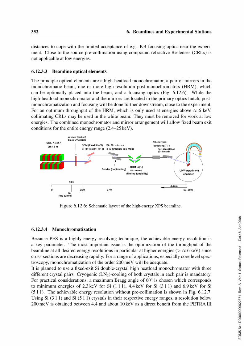
352 6. Beamlines and Experimental Stations
distances to cope with the limited acceptance of e.g. KB-focusing optics near the experi-ment. Close to the source pre-collimation using compound refractive Be-lenses (CRLs) isnot applicable at low energies.
6.12.3.3 Beamline optical elements
The principle optical elements are a high-heatload monochromator, a pair of mirrors in themonochromatic beam, one or more high-resolution post-monochromators (HRM), whichcan be optionally placed into the beam, and a focusing optics (Fig. 6.12.6). While thehigh-heatload monochromator and the mirrors are located in the primary optics hutch, post-monochromatization and focusing will be done further downstream, close to the experiment.For an optimum throughput of the HRM, which is only used at energies above ≈ 6 keV,collimating CRLs may be used in the white beam. They must be removed for work at lowenergies. The combined monochromator and mirror arrangement will allow fixed beam exitconditions for the entire energy range (2.4–25 keV).
window (carbon)block UV+visible
UHV experimentchamber
2m / 5 m
Und. K = 2.7
35m
33m
0 37m 50−60m
ring tunnel
4−6 m
Bender (collimating)
hor. acceptance(2−3 mrad)
focussing 7 : 1 KB−mirrors
HRM (opt.)50−10 meV
(limited tunability)
2−5 mrad (25 keV max)Si / Rh mirrors
Si (111) (311) (511)DCM (2.4−25 keV)
Figure 6.12.6: Schematic layout of the high-energy XPS beamline.
6.12.3.4 Monochromatization
Because PES is a highly energy resolving technique, the achievable energy resolution isa key parameter. The most important issue is the optimization of the throughput of thebeamline at all desired energy resolutions in particular at higher energies (> ≈ 6 keV) sincecross-sections are decreasing rapidly. For a range of applications, especially core level spec-troscopy, monochromatization of the order 200 meV will be adequate.It is planned to use a fixed-exit Si double-crystal high heatload monochromator with threedifferent crystal pairs. Cryogenic (LN2)-cooling of both crystals in each pair is mandatory.For practical considerations, a maximum Bragg angle of 60o is chosen which correspondsto minimum energies of 2.3 keV for Si (1 1 1), 4.4 keV for Si (3 1 1) and 6.9 keV for Si(5 1 1). The achievable energy resolution without pre-collimation is shown in Fig. 6.12.7.Using Si (3 1 1) and Si (5 1 1) crystals in their respective energy ranges, a resolution below200 meV is obtained between 4.4 and about 10 keV as a direct benefit from the PETRA III
ED
MS
Nr.:
D00
0000
0082
2371
Rev
: A V
er: 1
Sta
tus:
Rel
ease
d -
Dat
.: 8.
Apr
200
8
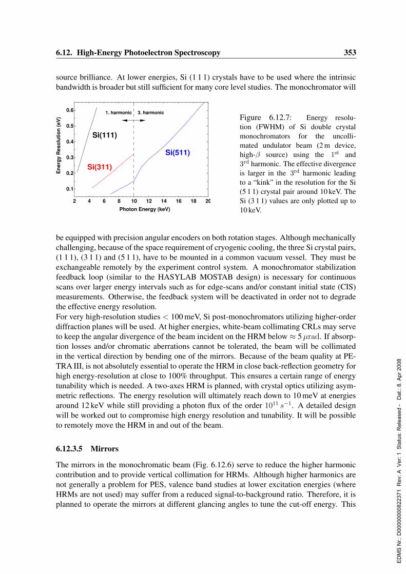
6.12. High-Energy Photoelectron Spectroscopy 353
source brilliance. At lower energies, Si (1 1 1) crystals have to be used where the intrinsicbandwidth is broader but still sufficient for many core level studies. The monochromator will
2 4 6 8 10 12 14 16 18 20
0.1
0.2
0.3
0.4
0.5
0.6
Photon Energy (keV)
En
erg
y R
eso
luti
on
(eV
)
Si(111)
3. harmonic1. harmonic
Si(311)
Si(511)
Figure 6.12.7: Energy resolu-tion (FWHM) of Si double crystalmonochromators for the uncolli-mated undulator beam (2 m device,high-β source) using the 1st and3rd harmonic. The effective divergenceis larger in the 3rd harmonic leadingto a “kink” in the resolution for the Si(5 1 1) crystal pair around 10 keV. TheSi (3 1 1) values are only plotted up to10 keV.
be equipped with precision angular encoders on both rotation stages. Although mechanicallychallenging, because of the space requirement of cryogenic cooling, the three Si crystal pairs,(1 1 1), (3 1 1) and (5 1 1), have to be mounted in a common vacuum vessel. They must beexchangeable remotely by the experiment control system. A monochromator stabilizationfeedback loop (similar to the HASYLAB MOSTAB design) is necessary for continuousscans over larger energy intervals such as for edge-scans and/or constant initial state (CIS)measurements. Otherwise, the feedback system will be deactivated in order not to degradethe effective energy resolution.For very high-resolution studies < 100 meV, Si post-monochromators utilizing higher-orderdiffraction planes will be used. At higher energies, white-beam collimating CRLs may serveto keep the angular divergence of the beam incident on the HRM below ≈ 5µrad. If absorp-tion losses and/or chromatic aberrations cannot be tolerated, the beam will be collimatedin the vertical direction by bending one of the mirrors. Because of the beam quality at PE-TRA III, is not absolutely essential to operate the HRM in close back-reflection geometry forhigh energy-resolution at close to 100% throughput. This ensures a certain range of energytunability which is needed. A two-axes HRM is planned, with crystal optics utilizing asym-metric reflections. The energy resolution will ultimately reach down to 10 meV at energiesaround 12 keV while still providing a photon flux of the order 1011 s−1. A detailed designwill be worked out to compromise high energy resolution and tunability. It will be possibleto remotely move the HRM in and out of the beam.
6.12.3.5 Mirrors
The mirrors in the monochromatic beam (Fig. 6.12.6) serve to reduce the higher harmoniccontribution and to provide vertical collimation for HRMs. Although higher harmonics arenot generally a problem for PES, valence band studies at lower excitation energies (whereHRMs are not used) may suffer from a reduced signal-to-background ratio. Therefore, it isplanned to operate the mirrors at different glancing angles to tune the cut-off energy. This
ED
MS
Nr.:
D00
0000
0082
2371
Rev
: A V
er: 1
Sta
tus:
Rel
ease
d -
Dat
.: 8.
Apr
200
8
354 6. Beamlines and Experimental Stations
implies that the vertical crystal offset in the high heatload monochromator must be adjustableto maintain fixed beam exit conditions.The lowest cut-off energy is about 8 keV and the highest energy to be reflected is about25 keV. The glancing angle will be> 2 mrad in any case to accept the full beam while keepingthe mirror length reasonable (< 1 m). Therefore, two pairs of mirrors with different coatings,e.g. Si and Rh, will be used. Si is necessary to obtain high and structure less reflectivity downto 2.4 keV (noble metals like Rh, Pt exhibit absorption edges around 3 keV). The glancingangle will be tunable in a range from 2–5 mrad. It is necessary to bend the second mirror forbeam collimation in cases where CRLs are not suitable.
6.12.3.6 Focusing optics
Focusing of the beam is necessary to match the acceptance of electron spectrometers. Itis, however, not planned to aim at sub-µm focusing for spatial resolution (see 6.12.2.1).Since the maximum photon energy is < 25 keV, beam focusing will be accomplished usingKirkpatrick-Baez (KB) mirror systems. This has the advantage of non-chromaticity as op-posed to CRLs, which also are not applicable at low energies. Assuming a practical demag-nification ratio of about 7:1, the beam can be focussed down to about 50µm horizontallyand a few µm vertically which directly translates into an increased electron spectrometerperformance at very high energy resolution, i.e. retardation ratio. A moderate demagni-fication ensures that the KB-mirror system does not intersect with the complex and largeUHV-equipment at the experiment (at 50–60 m from the source, see Fig. 6.12.6).
6.12.3.7 Experiment Hutch, Endstation and Instrumentation
The experiment needs a radiation shielded hutch for the endstation, post-monochromatorsand focusing optics (≈ 4 m(H)× 3.5 m(W)× 8 m(L)), and a control hutch (≈ 2.5 m(H)×3 m(W)× 4 m(L)) for the electronics, computing and work space for users.The endstation consists of a UHV-chamber arrangement with a µ-metal shielded main cham-ber housing the electron spectrometer, a sample manipulator with the necessary degrees offreedom for positioning and alignment (also for XSW), etc. Sample preparation and charac-terization facilities will be available in separate preparation chambers which can be accessedthrough a sample transfer mechanism.The high-transmission electron analyzer will be a specially designed instrument with high-stability, high-voltage power supplies. It will reach retardation ratios up to 1000 which arenecessary to measure electrons up to ≈ 15 keV with an energy resolution down to 10 meV.A parallel electron detection scheme will be implemented for an efficient operation of thespectrometer. Such novel types of analyzers are currently being developed by several com-panies and also in the framework of an EU-project (VOLPE). They will be put to first testsat X-ray beamlines at SPring-8 and ESRF in 2004. Temperature stabilization down to ±1Cat the endstation and the post-monochromators/focusing optics is necessary to achieve highenergy and spatial stability.The analyzer is a large and heavy device and it has to be aligned relative to the X-ray beamwith great precision in order to match the acceptance of the electron zoom lens and the focal
ED
MS
Nr.:
D00
0000
0082
2371
Rev
: A V
er: 1
Sta
tus:
Rel
ease
d -
Dat
.: 8.
Apr
200
8

6.12. High-Energy Photoelectron Spectroscopy 355
spot on the sample. Therefore, the entire UHV-system will be mounted on an adjustablesupport which can be positioned with high accuracy (< 10µm) under remote control fromthe experiment. The setup will also provide high mechanical stability and flexibility to allowprecision XSW experiments. All movements needed for positioning and alignment will bestepper-motor controlled.In order to pass to the monochromatic beam on to other experiments further downstream, itwill be possible to move the endstation out of the beam path without breaking the beamlineand the experiment vacuum. A rail system will allow to translate the complete setup perpen-dicular to the beam (after disconnecting the vacuum systems) by about 2 m into an “off-line”position. Additional transverse space must therefore be available implying the need for aposition of the experiment hutch not too close to the source (≈ 50-60 m). It will thus be pos-sible to maintain the instrument and prepare experiments while the beam is used for otherwork further downstream.The experiment control system (hardware plus software) will allow a fast and simultaneousoperation of the electron analyzer, the X-ray optics, in particular the monochromator, andthe motor controlled movements of the endstation. This is essential to achieve the highestdegree of flexibility for the experiments.
6.12.4 Capital investment and personnelThe total investment cost amounts to 1485 ke.
Manpower (construction phase):1 scientist (planning/construction/commissioning)1 engineer (planning/construction/commissioning)1 postdoc (ordering/construction/commissioning)1 postdoc (construction/commissioning)
Manpower (operation phase):1 scientist, 1 engineer, 2 postdocs
ED
MS
Nr.:
D00
0000
0082
2371
Rev
: A V
er: 1
Sta
tus:
Rel
ease
d -
Dat
.: 8.
Apr
200
8
356 6. Beamlines and Experimental Stations
6.13 Hard X-ray MicroprobeAuthors and Consultants :
G. Falkenberg DESY, Hamburg, GermanyK. Rickers DESY, GeoForschungsZentrum Potsdam, GermanyK. Janssens University of Antwerp, BelgiumL. Vincze University of Antwerp, BelgiumM. Wilke Universitat Potsdam, GermanyC. Schmidt GeoForschungsZentrum Potsdam, GermanyM. Lankosz University of Science and Technology, Krakow, PolandM. Szczerbowska-Boruchowska University of Science and Technology, Krakow, PolandJ. Chwiej University of Science and Technology, Krakow, Poland
6.13.1 Current state of the scientific fieldAt various beamlines at the ESRF, APS and SPring-8, hard X-ray microprobes are currentlyin operation (e.g., Somogyi et al., 2001; Susini et al., 2003; McNulty et al., 2003; Suzukiet al., 2003; Hansel et al., 2002) that combine the non-destructive elemental micro-analysiscapability of µ-XRF (microscopic X-ray fluorescence analysis) with the ability of performingcomplementary µ-XAS (X-ray absorption spectroscopy) and/or µ-XRD (X-ray diffraction)measurements. These instruments provide simultaneous, correlated information on the localelemental composition, chemical state, the local structural environment of specific elementsand/or the local crystallographic structure of the examined materials.The most advanced synchrotron microprobes use undulator sources at 3rd generation, high-energy storage rings, since the fundamental characteristics of these instruments in termsof achievable beam size and flux density are directly related to the outstanding proper-ties (small source size, high brilliance and degree of polarization) of these sources. De-pending on the type of focusing device and energy range used for the experiment, beamsizes in the low micron- and even sub-micron range are routinely achieved providing 109–1012 photon/s intensity with limited divergence (typically ≤ 1 mrad). The high flux resultsin low limits of detection (LLD) for trace element analysis in the parts-per-billion range (orattogram) for µ-XRF and parts-per-million (or femtogram) for µ-XAS measurements. Bothat ESRF ID22/ID18F and at APS 13-ID-C, beside local and two-dimensional micro-analysisby means of combined µ-XRF, µ-XAS and µ-XRD, also absorption/phase-contrast and flu-orescent tomography measurements can be realized, allowing the 3D-visualization of theinternal structure and/or composition of small samples. The high sensitivity of the spec-trometers allows investigations in multiple dimensions by fast scanning: full 3D imaging byfluorescence tomography, confocal µ-XRF, XANES 2D-imaging, XANES- tomography, 3Dmicro-diffraction and diverse in-situ experiments.Hard X-ray microprobe techniques are mostly applied in materials, geological, bio / biome-dical, and environmental sciences, as well as in archeology and arts. Studies on a variety ofscientific problems and materials performed at these beamlines have been published, includ-ing :
- the localization and speciation of As and Se in plant roots (Hansel et al., 2001)
ED
MS
Nr.:
D00
0000
0082
2371
Rev
: A V
er: 1
Sta
tus:
Rel
ease
d -
Dat
.: 8.
Apr
200
8

6.13. Hard X-ray Microprobe 357
- the speciation of Cd in fly-ash particles (Pinzani et al., 2002)- the characterization of the micro-heterogeneity of reference materials
(Kempenaers et al., 2002)- interplanetary dust particles (Flynn et al., 2003)- the chemical environment of the uranyl-ion in calcite (Kelly et al., 2003)- the distribution and microbial reduction of Cr in soil (Tokunaga et al., 2003)- the sorption and biomineralization of Pb(II) in biofilms (Templeton et al., 2003)- the three-dimensional analysis of individual fly-ash particles (Golosio et al., 2003)- the compression behavior of nano-crystalline anatase (Swamy et al., 2003)- the crystallographic phases present in ancient Egyptian make-up
(Martinetto et al., 2001)- changes in the structure of archaeological bone samples (Wess et al., 2002)- the dislocation density analysis in single grains of steel (Castelnau et al., 2001)- the three-dimensional elemental analysis of single cells (Bohic et al., 2001)
A recent review on the (combined) use of µ-XRF and micro-tomography can be found inSutton et al., 2002.Hard X-ray microprobe beamlines at third generation synchrotrons are found both at highand low-β sections and make use of undulator insertion devices. In addition, microprobesare installed at some bending magnet sources because of considerable overbooking of the un-dulator beamlines. Fixed-exit, cryogenically cooled monochromators, equipped with Si(111)(in addition Si(311)) crystals work in the energy range 4–45 keV (72 keV). At ID22 the Simonochromator can be moved out of the beam to enable pink beam operation with 1% bandpass by separation of a single undulator harmonic using filters and cut-off mirrors. Variousoptical systems have been in use at microprobe beamlines: Kirkpatrick-Baez (KB) mirrorsystems, compound refractive lenses (CRL), Fresnel zone plates (FZP) and capillary con-centrators have been used to generate monochromatic or pink micro-beams. Apart from theX-ray sources themselves, many of the capabilities of the above-mentioned beamlines are di-rectly related to the performance, stability, flexibility and robustness of the micro-focussingoptics that is employed.Tab. 6.13.1 summarizes some of the analytical characteristics recently recorded at ESRFbeamlines with CRL and a KB-mirror systems in “routine” monochromatic mode. Bothoptical systems provide a suitable micro-beam for combined µ-XRF, µ-XANES and µ-XRDmeasurements. The experience at ID22 showed that CRL are very convenient and robustoptical systems, requiring little or no (re)alignment and long focal distances (20 cm – 2 m).They can also be removed quickly and effortlessly from the beam, allowing to alternatebetween focused and unfocussed beam operations. However, their small solid angle does notallow to capture many photons prior to focusing. In addition, these optics are not achromatic,limiting their use for µ- EXAFS experiments. On the other hand, KB systems require amuch more elaborate alignment procedure, tend to gradually lose their alignment over timeand are not that easily removed from the optical axis of the beamline. The most prominentadvantage of KB mirrors is the ability to capture unfocussed photons in a large collectionangle and focus them with high transmission in an achromatic manner down to µm or sub-µm diameters.
ED
MS
Nr.:
D00
0000
0082
2371
Rev
: A V
er: 1
Sta
tus:
Rel
ease
d -
Dat
.: 8.
Apr
200
8
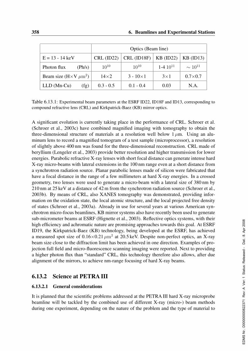
358 6. Beamlines and Experimental Stations
Optics (Beam line)
E = 13 - 14 keV CRL (ID22) CRL (ID18F) KB (ID22) KB (ID13)
Photon flux (Ph/s) 1010 1010 1-4 1011 ∼ 1011
Beam size (H×V µm2) 14×2 3 - 10×1 3×1 0.7×0.7
LLD (Mn-Cu) (fg) 0.3 - 0.5 0.1 - 0.4 0.03 N.A.
Table 6.13.1: Experimental beam parameters at the ESRF ID22, ID18F and ID13, corresponding tocompound refractive lens (CRL) and Kirkpatrick-Baez (KB) mirror optics.
A significant evolution is currently taking place in the performance of CRL. Schroer et al.(Schroer et al., 2003c) have combined magnified imaging with tomography to obtain thethree-dimensional structure of materials at a resolution well below 1µm. Using an alu-minum lens to record a magnified tomogram of a test sample (microprocessor), a resolutionof slightly above 400 nm was found for the three-dimensional reconstruction. CRL made ofberyllium (Lengeler et al., 2003) provide better resolution and higher transmission for lowerenergies. Parabolic refractive X-ray lenses with short focal distance can generate intense hardX-ray micro-beams with lateral extensions in the 100 nm range even at a short distance froma synchrotron radiation source. Planar parabolic lenses made of silicon were fabricated thathave a focal distance in the range of a few millimeters at hard X-ray energies. In a crossedgeometry, two lenses were used to generate a micro-beam with a lateral size of 380 nm by210 nm at 25 keV at a distance of 42 m from the synchrotron radiation source (Schroer et al.,2003b). By means of CRL, also XANES tomography was demonstrated, providing infor-mation on the oxidation state, the local atomic structure, and the local projected free densityof states (Schroer et al., 2003a). Already in use for several years at various American syn-chrotron micro-focus beamlines, KB mirror systems also have recently been used to generatesub-micrometer beams at ESRF (Hignette et al., 2003). Reflective optics systems, with theirhigh efficiency and achromatic nature are promising approaches towards this goal. At ESRFID19, the Kirkpatrick-Baez (KB) technology, being developed at the ESRF, has achieveda measured spot size of 0.16×0.21µm2 at 20.5 keV. Despite non-perfect optics, an X-raybeam size close to the diffraction limit has been achieved in one direction. Examples of pro-jection full field and micro-fluorescence scanning imaging were reported. Next to providinga higher photon flux than “standard” CRL, this technology therefore also allows, after duealignment of the mirrors, to achieve nm-range focusing of hard X-ray beams.
6.13.2 Science at PETRA III
6.13.2.1 General considerations
It is planned that the scientific problems addressed at the PETRA III hard X-ray microprobebeamline will be tackled by the combined use of different X-ray (micro-) beam methodsduring one experiment, depending on the nature of the problem and the type of material to
ED
MS
Nr.:
D00
0000
0082
2371
Rev
: A V
er: 1
Sta
tus:
Rel
ease
d -
Dat
.: 8.
Apr
200
8

6.13. Hard X-ray Microprobe 359
be investigated. It is expected that with most problems and materials, micro-beam X-rayfluorescence measurements (Janssens et al., 2000) in combination with broad beam radiog-raphy imaging, providing information on the (variation of the) local elemental compositionand density, will be the first and most straightforward experiments to perform in the ex-ploratory phase of an experiment. Based on these first observations, information of higherquality (with respect to quantitative character, spatial resolution, structural content) can thenbe obtained by the use of more elaborate sample manipulation and data acquisition modesand strategies.
6.13.2.2 Examples of applications
In order to provide an idea on the type of generic experiments that are envisaged at thePETRA III microprobe beamline, a selected list of representative problems is outlined below.These specific cases, based on the literature and results of recent feasibility studies, areeither being studied today by means of the currently operating X-ray microprobes at the3rd generation synchrotrons in Europe, the US and Japan or are border-line cases for the2nd generation X-ray microprobes.
A. Mapping of composition, chemical state and rheological properties in heterogeneousgeological samplesGeological processes are often ”conserved” in mineral reactions in rocks: the chemical com-position and the chemical state of a specific metal in two coexisting minerals render valuableinformation on the pressure-temperature-oxygen fugacity (P-T-fO2) conditions during therock-forming process and may be heterogeneous on the micrometer scale. Elements of in-terest range from S (Z = 16) to U (Z = 92) depending on the geological question. A spatialresolution in the (sub-) µm-range will allow the measurement of short diffusion profiles andthe separate analysis of small adjacent minerals. K-shell excitation of elements up to U withLLD in the sub-ppm range for all elements will be useful, together with variable excitationconditions in order to optimize measurement conditions for the element of interest.Similarly, X-ray micro-diffraction with a spatial resolution in the 0.1 to 1µm-range willpermit to study the deformation of polycrystalline materials, in which the stress distributionis very heterogeneous (Castelnau et al., 2001). Combined with diamond anvil cells (Swamyet al., 2003), a monochromatic micro-beam with high flux in the energy range between 25and 30 keV allows such studies even at the extreme P-T conditions of the deeper portions ofthe Earth’s interior, which would provide valuable information about fundamental geologicalprocesses such as mantle convection and deep earthquakes.
B. Analysis of fluid, melt and mineral inclusionsMineral, melt and fluid inclusions in minerals are formed during crystal growth and mayrecord the conditions present during formation. The quantitative analysis of single melt andfluid inclusions facilitates the study of the chemical evolution of a rock-forming system,which is extremely valuable for the study of rock and ore-forming processes and elementtransport in the Earth’s crust. A high spatial resolution in combination with a confocal setupand high excitation energies would be the set-up of choice. Detection limits in the sub-ppmrange for precious elements such as Au will be very important. A CCD camera with an
ED
MS
Nr.:
D00
0000
0082
2371
Rev
: A V
er: 1
Sta
tus:
Rel
ease
d -
Dat
.: 8.
Apr
200
8
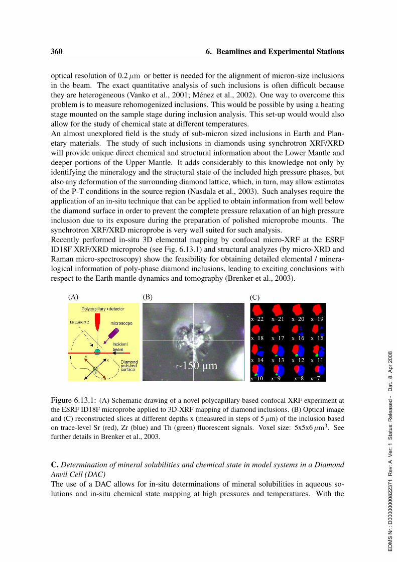
360 6. Beamlines and Experimental Stations
optical resolution of 0.2µm or better is needed for the alignment of micron-size inclusionsin the beam. The exact quantitative analysis of such inclusions is often difficult becausethey are heterogeneous (Vanko et al., 2001; Menez et al., 2002). One way to overcome thisproblem is to measure rehomogenized inclusions. This would be possible by using a heatingstage mounted on the sample stage during inclusion analysis. This set-up would would alsoallow for the study of chemical state at different temperatures.An almost unexplored field is the study of sub-micron sized inclusions in Earth and Plan-etary materials. The study of such inclusions in diamonds using synchrotron XRF/XRDwill provide unique direct chemical and structural information about the Lower Mantle anddeeper portions of the Upper Mantle. It adds considerably to this knowledge not only byidentifying the mineralogy and the structural state of the included high pressure phases, butalso any deformation of the surrounding diamond lattice, which, in turn, may allow estimatesof the P-T conditions in the source region (Nasdala et al., 2003). Such analyses require theapplication of an in-situ technique that can be applied to obtain information from well belowthe diamond surface in order to prevent the complete pressure relaxation of an high pressureinclusion due to its exposure during the preparation of polished microprobe mounts. Thesynchrotron XRF/XRD microprobe is very well suited for such analysis.Recently performed in-situ 3D elemental mapping by confocal micro-XRF at the ESRFID18F XRF/XRD microprobe (see Fig. 6.13.1) and structural analyzes (by micro-XRD andRaman micro-spectroscopy) show the feasibility for obtaining detailed elemental / minera-logical information of poly-phase diamond inclusions, leading to exciting conclusions withrespect to the Earth mantle dynamics and tomography (Brenker et al., 2003).
Figure 6.13.1: (A) Schematic drawing of a novel polycapillary based confocal XRF experiment atthe ESRF ID18F microprobe applied to 3D-XRF mapping of diamond inclusions. (B) Optical imageand (C) reconstructed slices at different depths x (measured in steps of 5 µm) of the inclusion basedon trace-level Sr (red), Zr (blue) and Th (green) fluorescent signals. Voxel size: 5x5x6 µm3. Seefurther details in Brenker et al., 2003.
C. Determination of mineral solubilities and chemical state in model systems in a DiamondAnvil Cell (DAC)The use of a DAC allows for in-situ determinations of mineral solubilities in aqueous so-lutions and in-situ chemical state mapping at high pressures and temperatures. With the
ED
MS
Nr.:
D00
0000
0082
2371
Rev
: A V
er: 1
Sta
tus:
Rel
ease
d -
Dat
.: 8.
Apr
200
8
6.13. Hard X-ray Microprobe 361
current set-up of the cell, XRF experiments at temperatures of up to 800C and pressuresof up to 1.5 GPa are possible (Schmidt & Rickers, 2003). A rearrangement of the geometryof the sample chamber with the mineral grain being located inside the sample volume en-ables studies at higher experimental pressures. However, this set-up is applicable only if aprimary beam in the micrometer range is available. Due to the absorption of the synchrotronbeam and the fluorescence in the diamond this application will take advantage of the highestachievable photon flux. The geometry of the cell requires a focal distance longer than 50 mmand focusing must be possible also at energies significantly above 30 keV in order to facilitatethe determination of rare earth elements (REE) at the ppm level via K-shell excitation.A valuable extension of the solubility studies is the structural characterization of a givenelement in the coexisting phases by the use of µ-XANES and µ-EXAFS measurements. Asnatural silicate melts usually contain considerable amounts of water that is only soluble atelevated pressures, XANES/EXAFS studies on the local structural environment of elementsusing a DAC will provide important insight into the nature of hydrous melts. XANES and,especially, EXAFS measurements rely on high photon flux and, at least of similar impor-tance, on a very stable, achromatic optical system, if focusing to a micron-sized beam spotis necessary.
D. In-situ localization and speciation of As, Se and other redox-sensitive trace metals inphyto-remediating plantsIn the industrialized parts of the world, and especially in Eastern Europe and Russia, an in-creasing number of areas are discovered that are polluted with heavy metals such as lead,cadmium, copper, chromium, mercury, arsenic and selenium (Foster et al., 1998). In the spe-cific case of Se, it replaces sulphur in thiol-group containing proteins, hereby significantlyaltering/reducing their functionality (see e.g. Lemly, 2002). An environmentally friendlyand cost-effective measure for soil cleanup is to employ phyto-remediation. Specific plantspecies can be grown in soils polluted with heavy metals so that the plants: (a) will con-centrate the heavy metals in their tissues (up to several hundreds to thousands of ppm inthe roots), (b) can change the chemical form of the metals, usually by reduction of inor-ganic (toxic) forms of the metals and (subsequent) incorporation into biomolecules. Also forclean-up of radioactively polluted soils (e.g. in the 30 km zone around Chernobyl), phyto-remediation is a technique that is being evaluated at present.A recent study (Wierzbicka et al., 2003) demonstrated that the take-up and effective toxicityof Se for Allium Cepa L. (common onion) strongly depends on the chemical form of Se towhich the plants are exposed. In order to understand these differences in response better,microscopic in vivo determinations of total Se and various Se species in various parts (e.g.,the roots, the bulb, the leaves) of this and other plants are very relevant. A recent feasibilitystudy performed at HASYLAB using a confocal µ-XRF and µ-XANES setup showed verypromising results (see Fig. 6.13.2).
E. Study of ion-channels and long range ion transport through plants: investigation ofstructure-function relations by combined XRF microtomography and scanning micro-XRDPlant physiologists and microbiologists are trying to link the macroscopic appearance to themolecular biology of a plant, especially with a view to understanding the influence of sin-gle genes on a plant’s large scale structure. This includes the study of ion channels and
ED
MS
Nr.:
D00
0000
0082
2371
Rev
: A V
er: 1
Sta
tus:
Rel
ease
d -
Dat
.: 8.
Apr
200
8
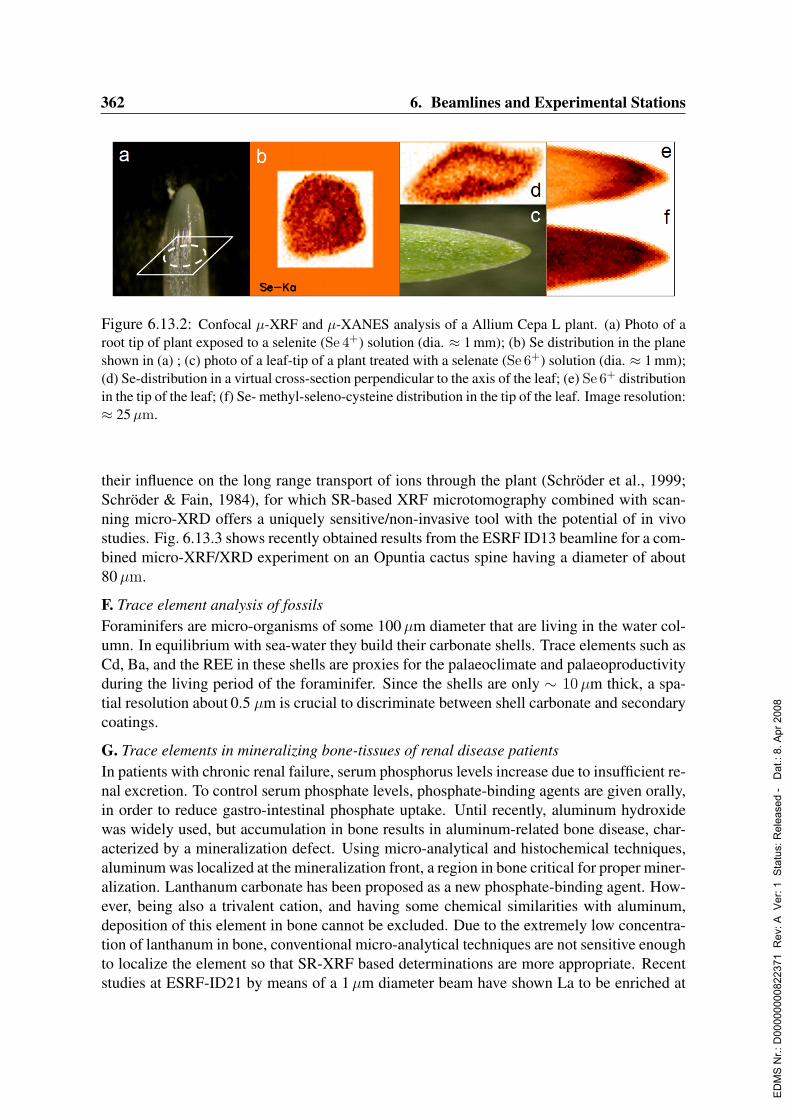
362 6. Beamlines and Experimental Stations
Figure 6.13.2: Confocal µ-XRF and µ-XANES analysis of a Allium Cepa L plant. (a) Photo of aroot tip of plant exposed to a selenite (Se 4+) solution (dia. ≈ 1 mm); (b) Se distribution in the planeshown in (a) ; (c) photo of a leaf-tip of a plant treated with a selenate (Se 6+) solution (dia. ≈ 1 mm);(d) Se-distribution in a virtual cross-section perpendicular to the axis of the leaf; (e) Se 6+ distributionin the tip of the leaf; (f) Se- methyl-seleno-cysteine distribution in the tip of the leaf. Image resolution:≈ 25 µm.
their influence on the long range transport of ions through the plant (Schroder et al., 1999;Schroder & Fain, 1984), for which SR-based XRF microtomography combined with scan-ning micro-XRD offers a uniquely sensitive/non-invasive tool with the potential of in vivostudies. Fig. 6.13.3 shows recently obtained results from the ESRF ID13 beamline for a com-bined micro-XRF/XRD experiment on an Opuntia cactus spine having a diameter of about80µm.
F. Trace element analysis of fossilsForaminifers are micro-organisms of some 100µm diameter that are living in the water col-umn. In equilibrium with sea-water they build their carbonate shells. Trace elements such asCd, Ba, and the REE in these shells are proxies for the palaeoclimate and palaeoproductivityduring the living period of the foraminifer. Since the shells are only ∼ 10µm thick, a spa-tial resolution about 0.5 µm is crucial to discriminate between shell carbonate and secondarycoatings.
G. Trace elements in mineralizing bone-tissues of renal disease patientsIn patients with chronic renal failure, serum phosphorus levels increase due to insufficient re-nal excretion. To control serum phosphate levels, phosphate-binding agents are given orally,in order to reduce gastro-intestinal phosphate uptake. Until recently, aluminum hydroxidewas widely used, but accumulation in bone results in aluminum-related bone disease, char-acterized by a mineralization defect. Using micro-analytical and histochemical techniques,aluminum was localized at the mineralization front, a region in bone critical for proper miner-alization. Lanthanum carbonate has been proposed as a new phosphate-binding agent. How-ever, being also a trivalent cation, and having some chemical similarities with aluminum,deposition of this element in bone cannot be excluded. Due to the extremely low concentra-tion of lanthanum in bone, conventional micro-analytical techniques are not sensitive enoughto localize the element so that SR-XRF based determinations are more appropriate. Recentstudies at ESRF-ID21 by means of a 1µm diameter beam have shown La to be enriched at
ED
MS
Nr.:
D00
0000
0082
2371
Rev
: A V
er: 1
Sta
tus:
Rel
ease
d -
Dat
.: 8.
Apr
200
8

6.13. Hard X-ray Microprobe 363
Figure 6.13.3: XRF microtomography and scanning micro-XRD analysis of a single spine collectedfrom an Opuntia ficus indica leaf at the sea promenade in Rapallo (Italy). (A) scanning electronmicroscopy (SEM) image of the spine, (B) reconstructed distributions of K, Mn, Fe, Zn across an80 µm diameter cross-section, (C) composite image from the individual XRD- patterns along the 2D-scan and (D) vector field display of the fitted 200 reflection parameters (intensity, azimuthal positionand width). Experiment performed by L. Vincze (UA), M. Burghammer and C. Riekel (ESRF ID13).
the edge of the calcified bone (D’Haese et al., 2001). This observation indicates the potentialfor using trace-level mapping for monitoring the effects of various metal-containing drugson the formation of dense biomaterials.
H. Effect of trace levels of Sr on mechanical strength of human bone
An element that plays an important role in the study of bone and bone diseases is Sr, whichis believed, when present in sufficient amounts in blood, to induce the distortion of the crys-tallographic structure of hydroxyapatite in bone, thereby reducing the mechanical strengthof the bone. This disease, known as osteomalacia (D’Haese et al., 2000), can also be in-duced by renal failure. In Sr-loaded chronic renal failure rats, Sr could be identified at theosteoid/calcification front, a critical site in bone mineralization. However, as in dialysis pa-tients, the bone Sr concentration are 10 to 30-fold lower so that conventional techniquesappear to be not sensitive enough to allow a spatial localization of the element in bone sec-tions. The mechanism by which Sr impairs mineralization is not yet clear. This might eitherbe due to a pure physicochemical process or an indirect interference by affecting osteoblastfunction. A combination of µ- XRF and µ-XRD was employed to (i) visualize the distribu-tions of Ca and Sr in bone-cross sections, indicating the enrichment of Sr in specific areasand (ii) to measure the increasing degree of lattice-distortion in cell cultures grown in so-lutions with increasing Sr levels (D’Haese et al., 2002). This study has shown that X-raymicro-beams of ≈ 1µm that allow to perform scanning µ-XRF and µ-XRD measurementson complex biomaterials consisting of several dense and diluted phases, allow to obtain rel-evant information on the effect of trace constituents on the structural properties of the dense
ED
MS
Nr.:
D00
0000
0082
2371
Rev
: A V
er: 1
Sta
tus:
Rel
ease
d -
Dat
.: 8.
Apr
200
8

364 6. Beamlines and Experimental Stations
phases in these materials.
I. Elemental analysis and oxidation-state mapping of single cells in neuro-degenerative re-searchThe localized elemental analysis of human central nervous system (CNS) tissues and indi-vidual cells is essential for the investigation of biochemical processes that lead to neuro-degenerative disorders. The main goal of the research is the investigation of the role ofelements, mainly metals, in processes leading to degeneration and atrophy of nerve cells incases of two neuro-degenerative disorders e.g. Parkinson’s disease (PD) and AmyotrophicLateral Sclerosis (ALS). A common pathological hallmark of these pathologies is the lossof neurons in selected parts of the brain or the spinal cord (Bains & Shaw, 1997). Thepathogenesis of PD and ALS is still not known but the most frequently cited theories ofthe degeneration and atrophy of neurons are oxidative stress, excitotoxicity, protein aggrega-tion, and mitochondrial dysfunction, all of which may be caused in part or enhanced by thepresence of metals such as Ca, Mn, Fe, Co, Cu or Zn in the nerve cells (Robberecht, 2000;Mattson et al., 2000; Bush, 2000; Cassarino & Bennett, 1999).In recent years, increasing experimental evidence was found for the generic relation be-tween the presence of metals and these disorders. For example, experiments performed atHASYLAB and ESRF revealed that neurons in substantia negra in patients suffering fromParkinsons’s disease show a significantly higher accumulation of S, Ca, Fe, Cu, Zn, Se andBr in comparison to control cases. Increased Cl, Ca, Zn and Br abundances were observed intissues from patients of Amyotrophic Lateral Sclerosis (Lankosz et al., 2002; Szczerbowska-Boruchowska et al., 2003). Because of the low content of Mn in CNS tissue (i.e., up to 10mg/kg), a micro-beam of high intensity and polarization is necessary for the analysis of thiselement. Moreover, to study the role of trace elements in neuro-degenerative processes theelemental micro-analysis of single neurons is required. The differences in the distributionof metallic elements within a neuron, for example between nucleus and cytoplasm (if vi-sualized) may lead to conclusions on the mechanism of potential action of these elements.Furthermore, in order to study the role of selected elements in pathogenesis of PD and ALSit is also necessary to know if a modification of oxidation states of these elements takes placein infected parts of the brain and spinal cord in comparison to the control tissue areas.
J. Mobility assessment of polluting and radio-active heavy metals in coarse and fine parti-cles.A number of sites in the world are polluted with particles containing high concentrations ofheavy metals such as As, Pb, Ni, Cd etc. Usually, the source of pollution are nearby industrialmetal-refining or fossil-fuel burning plants that have released pre-concentrated metal-richslags, dust or other reaction products into the environment. In a number of specific cases,the polluting metals (U, Pu) are radioactive as a result of intentional or accidental military orcivilian release of these materials.When the heavy metals are present in the coarse (> 10µm diameter) particulate fraction,a relatively insignificant fraction can be blown up by prevailing winds so that the majorinteraction takes place by contact with the ground water (leaching out of soluble ionic forms).Fine particles, on the other hand, may easily become air-borne and, e.g., become depositedin the nose, thorax and lungs where some metallic species may induce cancer (e.g., Ni in
ED
MS
Nr.:
D00
0000
0082
2371
Rev
: A V
er: 1
Sta
tus:
Rel
ease
d -
Dat
.: 8.
Apr
200
8
6.13. Hard X-ray Microprobe 365
metallic form, as produced in Ni-refineries).In order to assess the effective danger on the short, mid and long term associated with themobilization of these heavy and/or radio-active metals and their spread into the hydro- andbiosphere, apart from the composition, also knowledge on the chemical state and crystal-lographic phases in which the metals are present, is very important. These investigationsneed to be carried out on particles of various sizes and porosities. Various X-ray micro-beaminvestigations techniques (such as µ-XANES, µ-XRD and µ-computed tomography) can beused together to determine a number of different properties of such materials (Salbu et al.,2001; Lind et al., 2002; Salbu et al., 2003; Vincze et al., 2002a; Vincze et al., 2002b).The availability of X-ray micro-beams of variable diameter, ranging from 1 to 10µm willallow to characterize individual particles of various sizes by means of µ-XANES and µ-XRD in order to study the interrelation between particle size and the abundance of e.g., Nispecies and phases and the dependence of this on the release scenario of the particles.
6.13.3 Beamline description
A hard X-ray microprobe beamline at PETRA III will enable different complementary X-ray(micro-) beam methods to be performed simultaneously or sequentially during one exper-iment. Scanning X-ray fluorescence microscopy measurements in combination with broadbeam radiography imaging will be the most straightforward to characterize heterogeneoussamples in terms of (variation of the) local elemental composition and density. MicroscopicX-ray absorption spectroscopy (µ-XANES, also µ-EXAFS) and microscopic X-ray diffrac-tions will provide information on the local speciation and structure. Tomographic methods(fluorescence microtomography, XANES microtomography) and confocal arrangements ofX-ray optics give access to quantitative three-dimensional measurements.High demands are made on the accessible range of beam sizes and photon energies and onthe flux of the primary beam in order to realize the experiments introduced in the scientificcase. The hard X-ray microprobe beamline will provide beam sizes down to the 100 nmrange utilizing the outstanding small source size and high brilliance of PETRA III, but alsolarger beams of 1–10µm and an unfocused beam for flat field imaging will be available. Theaccessible energy range covers the K-edge energies from sulfur to uranium (E= 2.4–116 keV)and the flux is maximized by the use of KB mirrors and pink beam option.Stability, flexibility and robustness of the beamline will be of major importance for the prac-tical use of a microprobe beamline and will therefore guide its design. The key componentsof the setup are the undulator source, the monochromator system, plane mirrors for high-energy cutoff, the focusing optics and the experiment including scanning unit and detectorsystem. A schematic sketch of the setup indicating the positions of the components is shownin Fig. 6.13.4. The experimental hutch including the focusing elements is placed at 90 mclose to the end of the beamline in order to achieve a high demagnification of the X-raysource. The first optical element is located as close as possible to the focusing optics in orderto minimize the effect of vibrations. A beam shutter between optics hutch and experimentalhutch provides high beam stability by continuous irradiation of optics (e.g. during samplechange).
ED
MS
Nr.:
D00
0000
0082
2371
Rev
: A V
er: 1
Sta
tus:
Rel
ease
d -
Dat
.: 8.
Apr
200
8

366 6. Beamlines and Experimental Stations
6.13.3.1 Undulator
The hard X-ray microprobe beamline is equipped with the spectroscopy undulator describedin Sec. 4.1.4. The undulator is placed in a low-beta section in order to facilitate the smallestpossible horizontal beam size. Source size and divergence of the photon beam and otherbasic parameters of the spectroscopy undulator are listed in Tab. 4.1.1. A device of 2 mlength will be sufficient for the majority of the proposed experiments, although microscopicX-ray absorption measurements in ultra-dilute systems would benefit from the increasedbrilliance of a 5 m undulator device (see Fig. 4.1.1 for comparison). The spectrum of theundulator covers the energy range 2.4–120 keV and higher. In the high energy range, theundulator works like a wiggler, but the intensity in the hard X-ray region is still sufficient asshown in Fig. 4.1.11. A side station is not appropriate for the beamline because of the largeenergy range of the experiment and the pink beam option.
6.13.3.2 Monochromator system
The monochromator system is composed of a double crystal monochromator (DCM) asdescribed in Sec. 5.3.2 and, additionally, of a double multilayer monochromator (DMM).Both monochromators work in fixed exit-geometry and crystals are cryogenically cooled.The DCM covers the energy range 2.4–120 keV and the DMM the range 6–80 keV. Bothmonochromators will be operated with variable beam offset. For broad bandpass monochrom-atization of higher energies (> 60 keV) different approaches have been discussed includingthe mounting of gradient Si1−xGex crystal pairs or mosaic crystal pairs in Laue geometry,and the deposition of multilayer structures on the plane mirrors (see 6.13.3.3) or KB mirrors(see 6.13.3.4). The monochromator system is located as close as possible to the focusingoptics in order to minimize the effect of vibrations of the monochromator crystals on theposition of the focused beam.
UndulatorDCM + DMM
PM + DMM
0m 94 m
Optics hutch
82 m 90 m
Exp. hutch
Optical microscope
Sample stage
CCD detectorsFocusing elements
X-ray detectors
Monitors
Figure 6.13.4: Schematic illustration of the hard X-ray microprobe beamline proposed for PE-TRA III. The monochromator system is comprised of a double crystal monochromator (DCM) anda double multilayer monochromator (DMM). Plane mirrors (PM) are coated with different materialsand with a multilayer structure.
ED
MS
Nr.:
D00
0000
0082
2371
Rev
: A V
er: 1
Sta
tus:
Rel
ease
d -
Dat
.: 8.
Apr
200
8
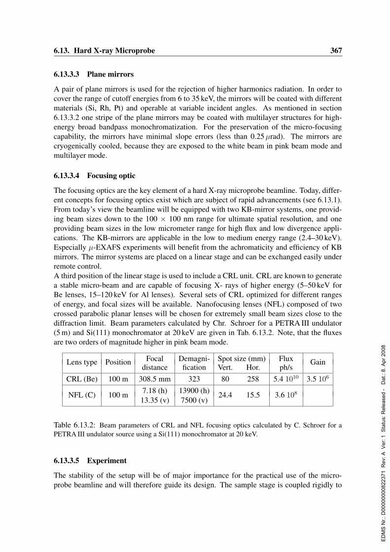
6.13. Hard X-ray Microprobe 367
6.13.3.3 Plane mirrors
A pair of plane mirrors is used for the rejection of higher harmonics radiation. In order tocover the range of cutoff energies from 6 to 35 keV, the mirrors will be coated with differentmaterials (Si, Rh, Pt) and operable at variable incident angles. As mentioned in section6.13.3.2 one stripe of the plane mirrors may be coated with multilayer structures for high-energy broad bandpass monochromatization. For the preservation of the micro-focusingcapability, the mirrors have minimal slope errors (less than 0.25µrad). The mirrors arecryogenically cooled, because they are exposed to the white beam in pink beam mode andmultilayer mode.
6.13.3.4 Focusing optic
The focusing optics are the key element of a hard X-ray microprobe beamline. Today, differ-ent concepts for focusing optics exist which are subject of rapid advancements (see 6.13.1).From today’s view the beamline will be equipped with two KB-mirror systems, one provid-ing beam sizes down to the 100 × 100 nm range for ultimate spatial resolution, and oneproviding beam sizes in the low micrometer range for high flux and low divergence appli-cations. The KB-mirrors are applicable in the low to medium energy range (2.4–30 keV).Especially µ-EXAFS experiments will benefit from the achromaticity and efficiency of KBmirrors. The mirror systems are placed on a linear stage and can be exchanged easily underremote control.A third position of the linear stage is used to include a CRL unit. CRL are known to generatea stable micro-beam and are capable of focusing X- rays of higher energy (5–50 keV forBe lenses, 15–120 keV for Al lenses). Several sets of CRL optimized for different rangesof energy, and focal sizes will be available. Nanofocusing lenses (NFL) composed of twocrossed parabolic planar lenses will be chosen for extremely small beam sizes close to thediffraction limit. Beam parameters calculated by Chr. Schroer for a PETRA III undulator(5 m) and Si(111) monochromator at 20 keV are given in Tab. 6.13.2. Note, that the fluxesare two orders of magnitude higher in pink beam mode.
Focal Demagni- Spot size (mm) FluxLens type Positiondistance fication Vert. Hor. ph/s
Gain
CRL (Be) 100 m 308.5 mm 323 80 258 5.4 1010 3.5 106
7.18 (h) 13900 (h)NFL (C) 100 m13.35 (v) 7500 (v)
24.4 15.5 3.6 108
Table 6.13.2: Beam parameters of CRL and NFL focusing optics calculated by C. Schroer for aPETRA III undulator source using a Si(111) monochromator at 20 keV.
6.13.3.5 Experiment
The stability of the setup will be of major importance for the practical use of the micro-probe beamline and will therefore guide its design. The sample stage is coupled rigidly to
ED
MS
Nr.:
D00
0000
0082
2371
Rev
: A V
er: 1
Sta
tus:
Rel
ease
d -
Dat
.: 8.
Apr
200
8
368 6. Beamlines and Experimental Stations
the focusing optics unit and includes three orthogonal translations and (at least) one rotation.The repeatability of the translations will fall significantly below the smallest achievable spotsizes, i.e. < 10 nm, at a travel range of 25 mm. In a standard experiment the sample will bemounted in air environment on a goniometer head, which is fixed onto the sample stage. Thesample stage can carry also small and light chambers that provide various environments, suchas vacuum and helium chambers, diamond anvils cells, heating and cooling stages, reactors,etc. A long distance optical microscope coupled to a CCD camera serves for the adjustmentof the sample in the X-ray beam and for documentation. A high-resolution CCD camera,which is placed behind the sample, is used for the same purpose and also for absorptiontomography. Optionally, the radiography CCD camera can be replaced under remote controlwith a large field CCD camera for X-ray diffraction. (Micro-) Ionization chambers are usedfor normalization and for transmission XAFS experiments. They can be loaded with variousmixtures of gases, also at reduced pressures. Several different detector types are provided forthe measurement of X-ray fluorescence and will be optionally installed. Multi element sili-con drift detectors (SDD) are applied for fluorescence XAFS and fast scanning fluorescencemicroscopy experiments which are characterized by count rates 10 kcps. A wavelengthdispersive detector is employed for samples providing very high count rates and measure-ments of fluorescence lines suffering from high background. High quality Si(Li) detectorsare well suited for quantitative multi-element analysis and germanium detectors are neededfor the measurement of K-lines of heavy elements. It is feasible to place a polycapillaryoptics in front of any energy-dispersive detector for spatially resolve detection and adjust itwith an accuracy of 5 µm (e.g. confocal setup).Data reduction for scanning micro-XRF/XRD techniques is becoming increasingly a lim-iting factor as the data rate is growing due to faster detectors and scanning systems anda further increase in source brilliance. In particular the possibility of ”data mining” mayhave an important influence on the outcome of an experimental period at a high-brillianceSR- source. Initial data treatment for scanning micro-XRF/XAS/XRD will be available on-line and provide an ”image” of the microscopic sample structure at the end of a raster-scan.Micro-XRF data will require in particular fast spectral deconvolution and standard-less quan-titative analysis techniques, which are applied recursively to individual spectra to determineand visualize the variation of elemental concentrations on-line (Vekemans et al., 2003).
6.13.3.6 Experimental hutch and infrastructure
A size of the hutch of 10 m in length, 4 m in width and 4 m in height is sufficient to ac-commodate the experimental setup and focussing elements. The sample stage is placed 4 mbehind the hutch wall proving space upstream for low divergence focusing optics with largefocal distances and downstream for CCD detectors. The levels of dust and other contami-nations inside the hutch are minimal and limited only by the free access of the user to theexperiment. Care is taken to avoid air flow and vibrations induced by the air condition ofthe hutch. Standard media such as cooling water, compressed air and gases (N2, He, Ar) areavailable. A calm control room providing space for 4 users and a microscopy room equippedwith various optical microscopes adjoin the hutch. A chemical lab with glove box and fumeexhaust is placed in the vicinity.
ED
MS
Nr.:
D00
0000
0082
2371
Rev
: A V
er: 1
Sta
tus:
Rel
ease
d -
Dat
.: 8.
Apr
200
8

6.13. Hard X-ray Microprobe 369
6.13.4 Capital investment and personnelThe investments for this beamline sum up to about 1850 ke.The required personnel is: 2 scientists, 1 engineer, 1 postdoc.
ED
MS
Nr.:
D00
0000
0082
2371
Rev
: A V
er: 1
Sta
tus:
Rel
ease
d -
Dat
.: 8.
Apr
200
8

370 6. Beamlines and Experimental Stations
6.14 Variable Polarization Soft X-Ray Beamline for Pho-ton Energies 50–2500 eV
Authors and Consultants :
J. Bansmann Universitat Rostock, GermanyU. Becker Freie Universitat Berlin, GermanyR. Denecke Universitat Erlangen-Nurnberg, GermanyR. Dorner Universitat Frankfurt, GermanyP. Fischer MPI Stuttgart, GermanyR. L. Johnson Universitat Hamburg, GermanyL. Kipp Universitat Kiel, GermanyM. Martins Universitat Hamburg, GermanyT. Moller DESY, Hamburg, GermanyA. Muller Universitat Gießen, GermanyR. Reininger SAS, Madison, Wisconsin, USAJ. E. Rubensson University of Uppsala, SwedenH. Schmidt-Bocking Universitat Frankfurt, GermanyC. Schußler-Langheine Universitat zu Koln, GermanyG. Schutz MPI Stuttgart, GermanyP. Steinruck Universitat Erlangen-Nurnberg, GermanyL. H. Tjeng Universitat zu Koln, GermanyJ. Ullrich MPI Heidelberg, GermanyW. Wurth Universitat Hamburg, Germany
6.14.1 Introduction
Soft X-rays are ideal for investigations ranging from magnetism in nanostructures to studieson biological systems. Key absorption edges of practically all important elements lie in thesoft X-ray range (100 eV to 2.5 keV) which opens up the possibility to uniquely determinethe element-specific local electronic structure in complex materials by exploiting atomicresonances. Experiments at the latest third generation synchrotron light sources are nowbeginning to demonstrate the enormous scientific potential of this spectral region. At present,investigations are still limited by the light source and improved sources will immediatelyproduce new science. In the future polarization-dependent studies with soft X-rays will playa key role in enhancing our knowledge of the structure of matter.High-energy storage rings are excellent soft X-ray sources and suitable insertion devicescan provide very high brilliance circularly polarized light in the energy range 500–2000 eVas has been demonstrated at both the ESRF and SPring-8 (Saitoh et al., 2000). Helicalundulators operating in the first harmonic provide the highest flux and complete polarization,but require machine energies greater than 3 GeV. Radiation from higher harmonics of helicalundulators is normally not used because it is emitted off axis in a broad cone. The soft X-ray beamlines presently providing circular polarization are heavily oversubscribed (ID 08at ESRF, BL17SU, BL25SU and BL27SU at SPring-8). Insertion devices on lower energy
ED
MS
Nr.:
D00
0000
0082
2371
Rev
: A V
er: 1
Sta
tus:
Rel
ease
d -
Dat
.: 8.
Apr
200
8

6.14. Variable Polarization XUV Beamline 371
machines like BESSY II, ELETTRA, and ALS only produce circularly polarized light upto about 500 eV in the first harmonic (see Fig. 6.14.1) and newer machines like SLS andSOLEIL will extend this limit to 700–900 eV. The variable polarization soft X-ray beamlineat PETRA III will be unique and by providing the highest brilliance and flux in the importantspectral region from 500 eV to 3 keV will open up completely new scientific opportunities.With current technology it is possible to achieve a spectral resolution of 10000 at 1 keVwith an extremely high flux (more than 1012 photons/sec) focused on the sample. Comparedto the best present day sources the PETRA III soft X-ray beamline will provide one to twoorders of magnitude higher flux at photon energies above 1 keV. This beamline will promotesignificant progress in fields ranging from surface science to molecular and cluster physics,magnetic studies, condensed matter physics and nanotechnology.
Figure 6.14.1: Brilliance of the first harmonic in the circular and linear mode at PETRA III andcircular for the (double) U64 at Diamond, BL25U at SPring-8, and U56 at BESSY. The higher bright-ness compared to the SPring-8 beamline results from the larger number of undulator periods at thePETRA beamline and from the smaller emittance of PETRA.
6.14.2 Scientific applications of soft X-ray radiation with variable po-larization
This section of the report contains contributions from the soft X-ray working groups withspecialists in the following fields:
1. Gas phase studies on atoms, molecules, clusters and ions
2. Surface chemistry
3. Surface studies with soft X-ray spectromicroscopy
ED
MS
Nr.:
D00
0000
0082
2371
Rev
: A V
er: 1
Sta
tus:
Rel
ease
d -
Dat
.: 8.
Apr
200
8
372 6. Beamlines and Experimental Stations
4. High resolution photoelectron spectroscopy in a wide energy range
5. Magnetic spectroscopy
6. Resonant soft X-ray scattering
7. Anomalous soft X-ray diffraction for spectroscopically-resolved structural studies
Despite the great diversity of the individual fields there is a unanimous consensus on thespecification of the soft X-ray beamline at PETRA III described in the final section.
6.14.3 Gas phase studies on atoms, molecules, clusters and ions
Spectroscopic studies on atoms and molecules using photoionization and photoelectron spec-troscopy have recently undergone dramatic changes. New synchrotron radiation light sourcestogether with new experimental techniques have greatly enhanced the range of questions thatcan be answered (Becker & Shirley, 1996; Snell et al., 1996; Bjorneholm et al., 2000). Onecurrent theme is the problem of electron correlation in its various forms. Specific electron-electron interactions play a dominant role in a variety of many-body problems and determinefundamental quantities such as binding energies and partial cross sections. A thorough un-derstanding of electron correlation in atomic and molecular systems provides a basis forunderstanding electron correlation in solids. While many aspects of the static electronicstructure of atoms are well described by current theory, the understanding of dynamical pro-cesses in atoms and molecules is still in its infancy. This is even more true for ions, radicalsand clusters, where experimental investigations have been seriously impeded by the low par-ticle density. A high resolution, high flux soft X-ray beamline with variable polarization atPETRA III will be an important step forward for many studies in this field.
6.14.3.1 Photoionization and Auger decay in atoms and molecules
Studies of double Auger processes in rare gases will be important at the XUV beamline onPETRA III since they complement the current work on double photoionization. The longtime-interval (192 ns bunch separation) between adjacent bunches will be a great advantagefor such experiments using time-of-flight electron spectroscopy. With the new beamline itwill be possible to study Auger decay from dissociating molecular systems. For these ex-periments both Doppler marking of the emitter atoms and resonance detuning as alternativemethods to achieve time resolution on the scale of molecular dissociation and core-hole re-laxation require a high photon energy resolution. Going to larger systems, e.g. the study offullerenes, the relation between core-level photoelectron emission and subsequent fragmen-tation in coincidence experiments is of great importance. In these systems the connectionbetween collective excitations, such as plasmons associated with core-level ionization, andmulti-electron relaxation, for example double Auger decay (Viefhaus et al., 2004), remainsto be investigated.
ED
MS
Nr.:
D00
0000
0082
2371
Rev
: A V
er: 1
Sta
tus:
Rel
ease
d -
Dat
.: 8.
Apr
200
8
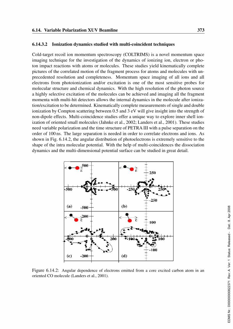
6.14. Variable Polarization XUV Beamline 373
6.14.3.2 Ionization dynamics studied with multi-coincident techniques
Cold-target recoil ion momentum spectroscopy (COLTRIMS) is a novel momentum spaceimaging technique for the investigation of the dynamics of ionizing ion, electron or pho-ton impact reactions with atoms or molecules. These studies yield kinematically completepictures of the correlated motion of the fragment process for atoms and molecules with un-precedented resolution and completeness. Momentum space imaging of all ions and allelectrons from photoionization and/or excitation is one of the most sensitive probes formolecular structure and chemical dynamics. With the high resolution of the photon sourcea highly selective excitation of the molecules can be achieved and imaging all the fragmentmomenta with multi-hit detectors allows the internal dynamics in the molecule after ioniza-tion/excitation to be determined. Kinematically complete measurements of single and doubleionization by Compton scattering between 0.5 and 3 eV will give insight into the strength ofnon-dipole effects. Multi-coincidence studies offer a unique way to explore inner shell ion-ization of oriented small molecules (Jahnke et al., 2002; Landers et al., 2001). These studiesneed variable polarization and the time structure of PETRA III with a pulse separation on theorder of 100 ns. The large separation is needed in order to correlate electrons and ions. Asshown in Fig. 6.14.2, the angular distribution of photoelectrons is extremely sensitive to theshape of the intra molecular potential. With the help of multi-coincidences the dissociationdynamics and the multi-dimensional potential surface can be studied in great detail.
Figure 6.14.2: Angular dependence of electrons emitted from a core excited carbon atom in anoriented CO molecule (Landers et al., 2001).
ED
MS
Nr.:
D00
0000
0082
2371
Rev
: A V
er: 1
Sta
tus:
Rel
ease
d -
Dat
.: 8.
Apr
200
8
374 6. Beamlines and Experimental Stations
6.14.3.3 Photoabsorption of free, mass-selected cluster ions
Research on clusters has become a very important and active field in recent years. Core-levelspectroscopic studies on mass selected clusters have been limited until recently to smallclusters deposited on surfaces. First measurements on free, mass-selected clusters with syn-chrotron radiation were performed by N. Berrah and coworkers on clusters with up to n=3atoms at the B 1s (' 200eV ) edge and the Si 2p edge (' 100eV ) (Bilodeau et al., 2003).Photoionization studies at inner shell edges will combine for the first time element-specificexcitation with cluster size selection. PETRA III will make it possible to perform experi-ments on free, mass-selected clusters of 3d, 4d and 4f transition metals in the whole XUVregion from 50 eV up to 2500 eV exploiting resonances at the L2,3 (3d), M2,3, M4,5 (4d), andM4,5 (4f) edges.
6.14.3.4 Photon-ion merged-beams experiment
Data on ionic species are required in many areas, such as technical plasmas, atmosphericscience and astrophysics. The study of matter in ionic form is a challenging experimentaltask. Intense third generation light sources have facilitated remarkable progress in the field ofphotoionization of ions (Schippers et al., 2003; Muller et al., 2003). Combining state-of-the-art particle sources with the brightest available photon beams will enhance the experimentalcapabilities. At present only total absorption cross sections can be measured on atomic ionsand experiments on molecular and cluster ions are at the detection limit. At PETRA III anexperimental set up is planned in which the intense X-ray photon beam interacts with anion beam of about 2 mm diameter over a length of 1 m. The ideal photon beam would beparallel with a diameter of 1 to 2 mm. The ion beam is prepared in a small electrostaticaccelerator with all the necessary mass analysis and beam transport systems so the photon-ion experiment should be an end station. The proposed experiment extends spectroscopicmeasurements to negatively or positively charged atoms, molecules and clusters. Suitableion sources (e.g. ECR sources for multiply charged atomic ions or electro-spray sources forhighly charged bio-molecules in the gas phase) will provide ions with high charge states anduseful beam intensities.
6.14.3.5 Requirements for gas phase studies
A common feature of all gas phase experiments is the need for a photon flux of greater than1012 photons/sec/0.1 %. For many experiments a bunch separation of at least 100 ns is neededsince time-of-flight techniques are essential for coincidence experiments. The planned XUVbeamline would cover the whole range of important inner-shell excitation and ionization ofatoms, ions, molecules and clusters. It would be of great help for these experiments if there isoverlap to lower photon energies. The carbon K-edge region is of scientific importance and itis necessary to calibrate the apparatus at well-known cross-sections and angular distributionsin order to measure these quantities at higher, unexplored energies. For energies from 200–2400 eV circularly polarized light with a high degree of polarization and the possibility toswitch easily between left-and right-handed radiation is required. This is particularly impor-tant because many experiments in the field of spin polarization and circular dichroism remain
ED
MS
Nr.:
D00
0000
0082
2371
Rev
: A V
er: 1
Sta
tus:
Rel
ease
d -
Dat
.: 8.
Apr
200
8

6.14. Variable Polarization XUV Beamline 375
to be performed in the soft X-ray regime. A resolving power of better than 104 would servemost experiments with high resolution requirements. But there are experiments in the fieldof multi-coincidence where a lower resolution would be acceptable. Concerning the spotsize the requirements are very different, they vary from 0.01- 0.1 mm in diameter depend-ing on the type of experiment. The space requirements are more or less the same for mostof the experiments, a square of 5m× 5m is sufficient for the majority of experiments. TheK-shell ionization studies on oriented molecules require variable linear polarization as wellas circular polarization. All COLTRIMS experiments would profit from a focus of 100µmtimes 100µm or smaller. For experiments on clusters a flux larger than 5 · 1012 photons/s atmoderate resolution (E/∆E > 2000) is best. Lower energy storage rings (BESSY II, ELET-TRA, ALS, MAX II) simply cannot compete with the photon flux that will be available atthe XUV beamline on PETRA III running at 6 GeV. The experiment on free clusters will bea part of the free ion experiments. Therefore, a 0.5-1 m section with a collimated beam willbe needed. The cluster sources will need approx. 1.5×3.0m2 floor space without electronicequipment. For the experiments on ions there are special requirements: The space, powerand cooling requirements can be characterized by typical numbers for existing laboratorysetups of similar nature: Area (including control racks, work place, space to access the hard-ware, etc.): 10m x 8m, Electrical Power: 250 kW, Cooling Water: 180 kW cooling power(high pressure circuit 10 bar for high-power electron-cyclotron-resonance heated -ECR- ionsource, low pressure circuit with e.g. 4 bar for pumps, power supplies etc.)
6.14.4 Surface chemistry
Surface chemistry deals mainly with the gas-surface interactions observed in processes rele-vant to heterogeneous catalysis. Given the complexity of real catalysts, studies are frequentlyperformed on model systems using well-defined single crystal surfaces. Due to the ratherlong acquisition time of most spectroscopic techniques in surface science, such studies areperformed on an ex-situ basis, i.e. after a certain reaction step has been finished. Dynamicalprocesses and parameters, such as adsorption or reaction rates, are not readily available fromthese experiments which only give integrated results. The use of high-intensity and high-resolution synchrotron radiation has enabled a new quality of research in surface chemistry.Both time-dependent X-ray photoelectron spectroscopy (XPS) (Baraldi et al., 2003; Deneckeet al., 2002; Kinne et al., 2002) and time-dependent X-ray absorption (quick extended X-rayabsorption fine structure, QEXAFS) (Frahm, 1988; Frahm, 1989b) became available on sec-ond and sub-second time scales, allowing in-situ studies on realistic macroscopic time scales(a few ms). The PETRA III upgrade and the planned XUV beamline would substantiallyenhance the possibilities of these approaches. A main shortcoming of present facilities likeBESSY II or MAX-lab is the limited flux and resolution at higher photon energies whichare necessary to study deeper core-levels and absorption edges, such as the 2p levels ofmetals (Cu, Ni) in more detail and also in a time-dependent fashion. This would open upnew options to study adsorption and reaction processes on surfaces by monitoring the sub-strate levels. High-resolution time-dependent studies on dynamic processes at surfaces willbecome possible with PETRA III. Together with an improved experimental system, whichincludes a pulsed molecular beam source for gas dosing and multichannel detection for the
ED
MS
Nr.:
D00
0000
0082
2371
Rev
: A V
er: 1
Sta
tus:
Rel
ease
d -
Dat
.: 8.
Apr
200
8
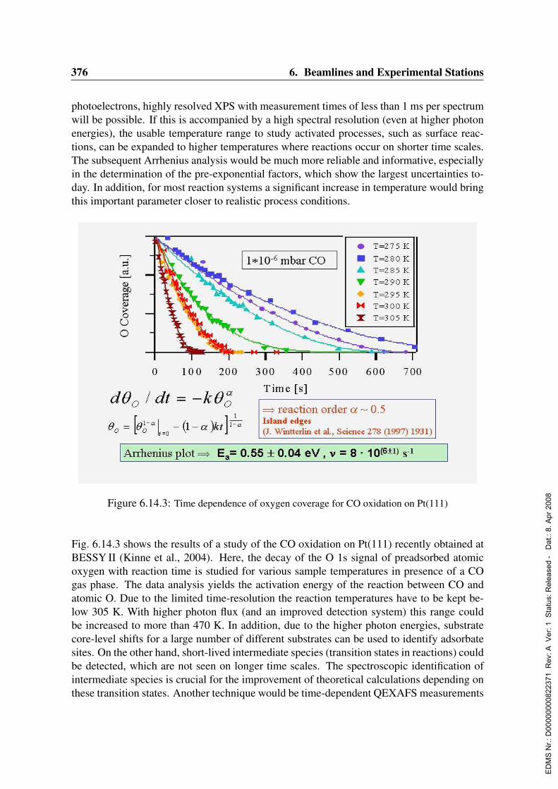
376 6. Beamlines and Experimental Stations
photoelectrons, highly resolved XPS with measurement times of less than 1 ms per spectrumwill be possible. If this is accompanied by a high spectral resolution (even at higher photonenergies), the usable temperature range to study activated processes, such as surface reac-tions, can be expanded to higher temperatures where reactions occur on shorter time scales.The subsequent Arrhenius analysis would be much more reliable and informative, especiallyin the determination of the pre-exponential factors, which show the largest uncertainties to-day. In addition, for most reaction systems a significant increase in temperature would bringthis important parameter closer to realistic process conditions.
Figure 6.14.3: Time dependence of oxygen coverage for CO oxidation on Pt(111)
Fig. 6.14.3 shows the results of a study of the CO oxidation on Pt(111) recently obtained atBESSY II (Kinne et al., 2004). Here, the decay of the O 1s signal of preadsorbed atomicoxygen with reaction time is studied for various sample temperatures in presence of a COgas phase. The data analysis yields the activation energy of the reaction between CO andatomic O. Due to the limited time-resolution the reaction temperatures have to be kept be-low 305 K. With higher photon flux (and an improved detection system) this range couldbe increased to more than 470 K. In addition, due to the higher photon energies, substratecore-level shifts for a large number of different substrates can be used to identify adsorbatesites. On the other hand, short-lived intermediate species (transition states in reactions) couldbe detected, which are not seen on longer time scales. The spectroscopic identification ofintermediate species is crucial for the improvement of theoretical calculations depending onthese transition states. Another technique would be time-dependent QEXAFS measurements
ED
MS
Nr.:
D00
0000
0082
2371
Rev
: A V
er: 1
Sta
tus:
Rel
ease
d -
Dat
.: 8.
Apr
200
8
6.14. Variable Polarization XUV Beamline 377
which can already be performed at sub-second time scales in the hard X-ray region (Frahm,1989b). Similar measurements are feasible in the XUV region and will open up new fieldsof research provided fast scanning of the monochromator and undulator are implemented.QEXAFS can give information about orientational changes of molecules on surfaces takingplace during reactions. Studying magnetic dichroism in adsorbate systems is a rather newfield (May et al., 1996; Yokoyama et al., 2000). Both the influence of magnetism on adsorp-tion and reaction as well as the influence of adsorption on the magnetic properties of varioussystems are of great interest, since a large number of metals used for catalysis are magnetic.Measuring magnetic circular dichroism in X-ray absorption (XMCD) or in photoemission(magnetic circular dichroism in angular distribution, MCDAD) gives information about themagnetic moments of the respective entities. Photo-induced surface reactions will be an-other interesting field which requires a high photon fluxes. By comparing the flux dependentproduct distributions excitation mechanisms could be resolved.
6.14.4.1 Experimental requirements for surface chemistry
The energy range needs to start at around 100 eV and extend up to about 2500 eV. Highresolution together with high flux, especially at higher energies, is more important thanthe highest photon energies. An ultimate resolution of better than 100 meV at 1000 eV(E/∆E > 10000) would be desirable, possibly extending to even higher energies (up to1500 eV). If no spatially resolved microscopy with scanned light spot is considered and ifusual sample sizes of diameters of some millimeters are used, the spot size need not be muchsmaller than 500µm. For some applications, like diffusion measurements a small light spotof some 50µm would be desirable. The best solution would be a variable spot size, achievedwith bendable refocusing mirrors. The photon flux needs to be high, but the situation has tobe adaptable to the systems studied. Some adsorbate systems are very sensitive to radiationdamage. A photon flux on the sample of about 1012 − 1013 photons per second in a mediumsize (100µm) is required. Variable polarization will permit symmetry selection rules and ma-trix element effects to be exploited in photoemission with linearly polarized light and permitdichroism experiments using circularly polarized light.
6.14.5 Surface studies with soft X-ray spectromicroscopy
Spectromicroscopy combines the power of spectroscopic analysis to determine chemicalcomposition and bonding configurations with imaging techniques to reveal the sample mor-phology and provide magnified pictures of the sample (Susini et al., 2002). The strengthof the method is that it provides information simultaneously in both the spatial and spectraldomains. Future technologies will rely on our ability to accurately measure, analyze, andcharacterize the complex multicomponent systems used in semiconductor devices, industrialcatalysts, polymeric systems, and even health care products. The currently planned activi-ties in the field of nanotechnology exemplify the demand for spectromicroscopy to satisfythe common needs of the diverse disciplines involved in this new endeavor. Over the pastdecade our knowledge of the chemical bonding, electronic structure and vibronic propertiesof a multitude of systems have been greatly enhanced using high resolution spectroscopies
ED
MS
Nr.:
D00
0000
0082
2371
Rev
: A V
er: 1
Sta
tus:
Rel
ease
d -
Dat
.: 8.
Apr
200
8
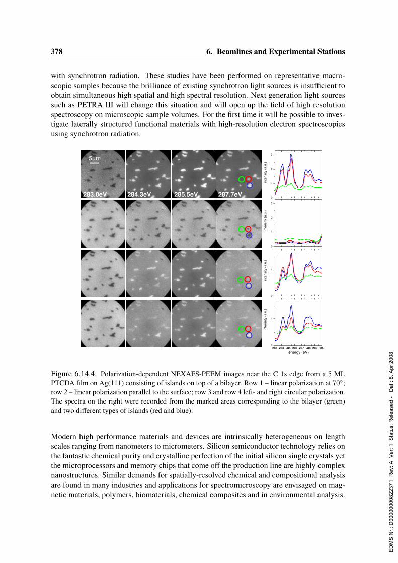
378 6. Beamlines and Experimental Stations
with synchrotron radiation. These studies have been performed on representative macro-scopic samples because the brilliance of existing synchrotron light sources is insufficient toobtain simultaneous high spatial and high spectral resolution. Next generation light sourcessuch as PETRA III will change this situation and will open up the field of high resolutionspectroscopy on microscopic sample volumes. For the first time it will be possible to inves-tigate laterally structured functional materials with high-resolution electron spectroscopiesusing synchrotron radiation.
5µm
283.0eV 284.3eV 285.5eV 287.7eV0
1
2
3
inte
nsity
(a.u
.)
0
1
2
3
inte
nsity
(a.u
.)
0
1
inte
nsity
(a.u
.)
283 284 285 286 287 288 289 2900
1
energy (eV)
inte
nsity
(a.u
.)
Figure 6.14.4: Polarization-dependent NEXAFS-PEEM images near the C 1s edge from a 5 MLPTCDA film on Ag(111) consisting of islands on top of a bilayer. Row 1 – linear polarization at 70;row 2 – linear polarization parallel to the surface; row 3 and row 4 left- and right circular polarization.The spectra on the right were recorded from the marked areas corresponding to the bilayer (green)and two different types of islands (red and blue).
Modern high performance materials and devices are intrinsically heterogeneous on lengthscales ranging from nanometers to micrometers. Silicon semiconductor technology relies onthe fantastic chemical purity and crystalline perfection of the initial silicon single crystals yetthe microprocessors and memory chips that come off the production line are highly complexnanostructures. Similar demands for spatially-resolved chemical and compositional analysisare found in many industries and applications for spectromicroscopy are envisaged on mag-netic materials, polymers, biomaterials, chemical composites and in environmental analysis.
ED
MS
Nr.:
D00
0000
0082
2371
Rev
: A V
er: 1
Sta
tus:
Rel
ease
d -
Dat
.: 8.
Apr
200
8
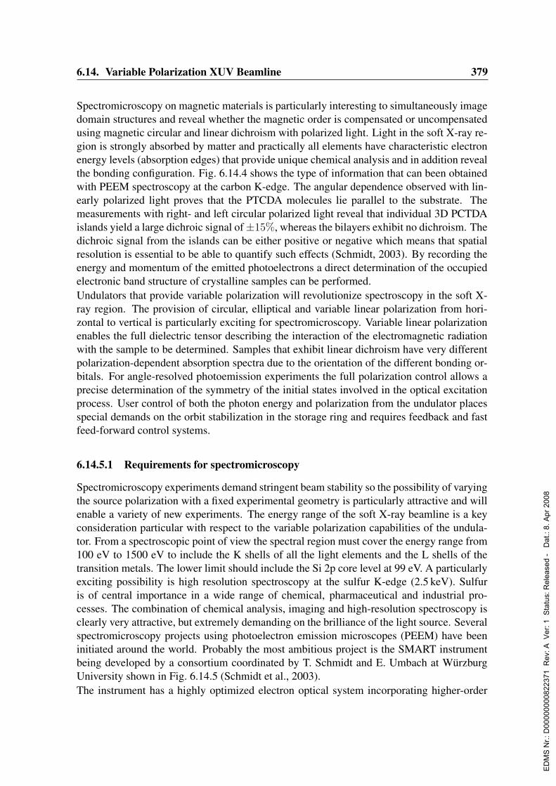
6.14. Variable Polarization XUV Beamline 379
Spectromicroscopy on magnetic materials is particularly interesting to simultaneously imagedomain structures and reveal whether the magnetic order is compensated or uncompensatedusing magnetic circular and linear dichroism with polarized light. Light in the soft X-ray re-gion is strongly absorbed by matter and practically all elements have characteristic electronenergy levels (absorption edges) that provide unique chemical analysis and in addition revealthe bonding configuration. Fig. 6.14.4 shows the type of information that can been obtainedwith PEEM spectroscopy at the carbon K-edge. The angular dependence observed with lin-early polarized light proves that the PTCDA molecules lie parallel to the substrate. Themeasurements with right- and left circular polarized light reveal that individual 3D PCTDAislands yield a large dichroic signal of±15%, whereas the bilayers exhibit no dichroism. Thedichroic signal from the islands can be either positive or negative which means that spatialresolution is essential to be able to quantify such effects (Schmidt, 2003). By recording theenergy and momentum of the emitted photoelectrons a direct determination of the occupiedelectronic band structure of crystalline samples can be performed.Undulators that provide variable polarization will revolutionize spectroscopy in the soft X-ray region. The provision of circular, elliptical and variable linear polarization from hori-zontal to vertical is particularly exciting for spectromicroscopy. Variable linear polarizationenables the full dielectric tensor describing the interaction of the electromagnetic radiationwith the sample to be determined. Samples that exhibit linear dichroism have very differentpolarization-dependent absorption spectra due to the orientation of the different bonding or-bitals. For angle-resolved photoemission experiments the full polarization control allows aprecise determination of the symmetry of the initial states involved in the optical excitationprocess. User control of both the photon energy and polarization from the undulator placesspecial demands on the orbit stabilization in the storage ring and requires feedback and fastfeed-forward control systems.
6.14.5.1 Requirements for spectromicroscopy
Spectromicroscopy experiments demand stringent beam stability so the possibility of varyingthe source polarization with a fixed experimental geometry is particularly attractive and willenable a variety of new experiments. The energy range of the soft X-ray beamline is a keyconsideration particular with respect to the variable polarization capabilities of the undula-tor. From a spectroscopic point of view the spectral region must cover the energy range from100 eV to 1500 eV to include the K shells of all the light elements and the L shells of thetransition metals. The lower limit should include the Si 2p core level at 99 eV. A particularlyexciting possibility is high resolution spectroscopy at the sulfur K-edge (2.5 keV). Sulfuris of central importance in a wide range of chemical, pharmaceutical and industrial pro-cesses. The combination of chemical analysis, imaging and high-resolution spectroscopy isclearly very attractive, but extremely demanding on the brilliance of the light source. Severalspectromicroscopy projects using photoelectron emission microscopes (PEEM) have beeninitiated around the world. Probably the most ambitious project is the SMART instrumentbeing developed by a consortium coordinated by T. Schmidt and E. Umbach at WurzburgUniversity shown in Fig. 6.14.5 (Schmidt et al., 2003).The instrument has a highly optimized electron optical system incorporating higher-order
ED
MS
Nr.:
D00
0000
0082
2371
Rev
: A V
er: 1
Sta
tus:
Rel
ease
d -
Dat
.: 8.
Apr
200
8

380 6. Beamlines and Experimental Stations
aberration corrections and a high performance OMEGA energy filter. It is currently in thetest phase and it will certainly set the standards for spatial resolution and transmission bywhich other systems will be measured. The spatial resolution will be less than 2 nm withan energy resolution of the imaged electrons below 100 meV. (The theoretical limits aresignificantly better with a spatial resolution of 0.5 nm). The optimization and aberrationcorrection enhance the transmission by a factor from 50 to 1000 compared to conventionalPEEM systems. The combination of the new PETRA III undulator with its variable polariza-tion capabilities with a SMART-type instrument will represent the state-of-the-art for highspatial resolution spectromicroscopy with polarization analysis.
6.14.5.2 Specification of the beamline
Photon flux at the sample; 1012 photons/s in an illuminated area of 10µm× 10µm to achievea spatial resolution better than 10 nm. Polarization variable linear and circular (both helic-ities); photon energy range from 100 to 1500 eV. Photon energy resolution below 100 meVsince the energy resolution of the OMEGA Filter is below 100 meV. The influence of thetime structure in ns-ps range has not yet been investigated, but it would be interesting toinvestigate reaction and diffusion processes on surfaces in real time.
6.14.6 High-resolution photoelectron spectroscopy in a wide energy rangeHigh resolution electron spectroscopies provide direct information about the chemical bond-ing and electronic structure of surfaces and interfaces of complex new materials. The ma-
0 100 200 300 400 500 600mm
EFil
SupExtAnode
C1
C2
C4
C3
EStigC /SED1x /yED2x /y
ED3x /y
ED4x /y
ED5x /yED6x /y
SepSepOSepCSepI
Mobj
UIm1UIm2
OS
tig
S/C
OD
1x
/yO
D2
x/y
DS
tig
S/C
OF
FilSTVUbUbombUth
MFel. Dodecapole1: MeD1x/y - MeStig1C/S - MeHex1C/S - MeOkt1C/S
el. Dodecapole2: MeD2x/y - MeStig2C/S - MeHex2C/S - MeOkt2C/S
magn. Oktupole1: MmD1x/y - MmStig1C/S - MmHex1C/S
magn. Oktupole2: MmD2x/y - MmStig2C/S - MmHex2C/S
Umir2Umir1Umir0
T1 T2 T3 T5T4
D1
X/Y
1D
1X
/Y2
D2
X/Y
1D
2X
/Y2
D3
X/Y
1D
3X
/Y2
H1 H7
Q1/2
H4QS/C
H2
H3
H6
H5
Dipol
P1
D4
X/Y
1D
4X
/Y2
P2 P3
ObjectiveSpecimen
Electron mirror
Transfer optics Omega filter Projection optics
Electron gun
Beam splitter
Illumination optics
Figure 6.14.5: Schematic of the SMART Instrument (Wichtendahl et al., 1998; Schmidt et al., 2003)
ED
MS
Nr.:
D00
0000
0082
2371
Rev
: A V
er: 1
Sta
tus:
Rel
ease
d -
Dat
.: 8.
Apr
200
8
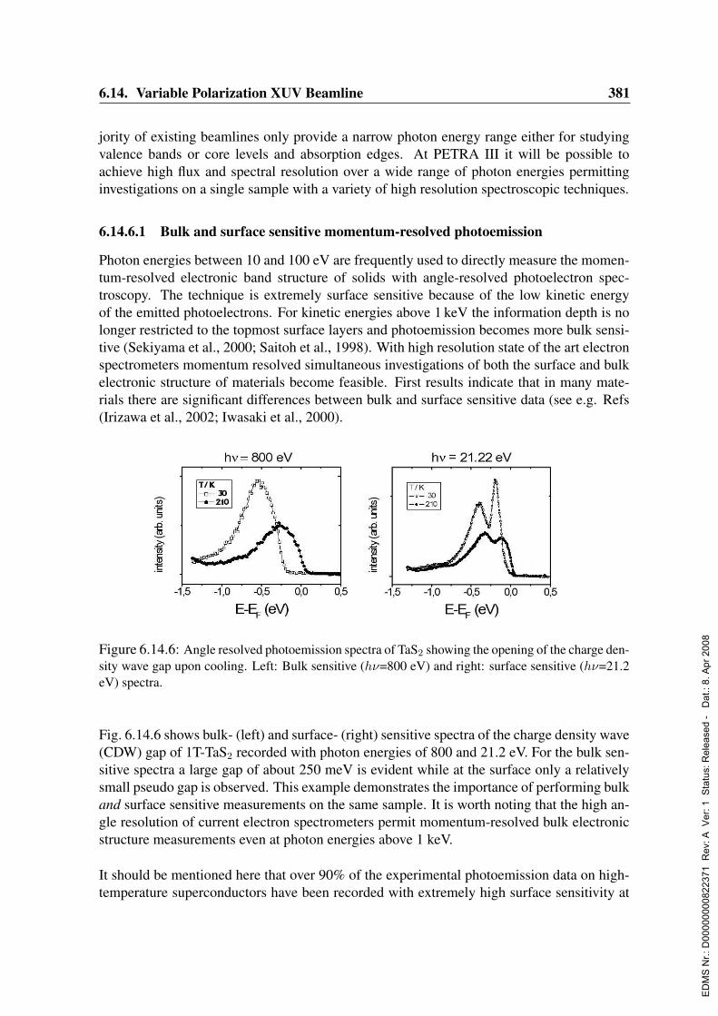
6.14. Variable Polarization XUV Beamline 381
jority of existing beamlines only provide a narrow photon energy range either for studyingvalence bands or core levels and absorption edges. At PETRA III it will be possible toachieve high flux and spectral resolution over a wide range of photon energies permittinginvestigations on a single sample with a variety of high resolution spectroscopic techniques.
6.14.6.1 Bulk and surface sensitive momentum-resolved photoemission
Photon energies between 10 and 100 eV are frequently used to directly measure the momen-tum-resolved electronic band structure of solids with angle-resolved photoelectron spec-troscopy. The technique is extremely surface sensitive because of the low kinetic energyof the emitted photoelectrons. For kinetic energies above 1 keV the information depth is nolonger restricted to the topmost surface layers and photoemission becomes more bulk sensi-tive (Sekiyama et al., 2000; Saitoh et al., 1998). With high resolution state of the art electronspectrometers momentum resolved simultaneous investigations of both the surface and bulkelectronic structure of materials become feasible. First results indicate that in many mate-rials there are significant differences between bulk and surface sensitive data (see e.g. Refs(Irizawa et al., 2002; Iwasaki et al., 2000).
Figure 6.14.6: Angle resolved photoemission spectra of TaS2 showing the opening of the charge den-sity wave gap upon cooling. Left: Bulk sensitive (hν=800 eV) and right: surface sensitive (hν=21.2eV) spectra.
Fig. 6.14.6 shows bulk- (left) and surface- (right) sensitive spectra of the charge density wave(CDW) gap of 1T-TaS2 recorded with photon energies of 800 and 21.2 eV. For the bulk sen-sitive spectra a large gap of about 250 meV is evident while at the surface only a relativelysmall pseudo gap is observed. This example demonstrates the importance of performing bulkand surface sensitive measurements on the same sample. It is worth noting that the high an-gle resolution of current electron spectrometers permit momentum-resolved bulk electronicstructure measurements even at photon energies above 1 keV.
It should be mentioned here that over 90% of the experimental photoemission data on high-temperature superconductors have been recorded with extremely high surface sensitivity at
ED
MS
Nr.:
D00
0000
0082
2371
Rev
: A V
er: 1
Sta
tus:
Rel
ease
d -
Dat
.: 8.
Apr
200
8

382 6. Beamlines and Experimental Stations
photon energies well below 100 eV. Due to large lattice constants in direction perpendicularto the cleavage planes of these materials not even one complete unit cell is accessed in astandard photoemission experiment. To investigate the changes in the electronic structurewith sampling depth a high performance soft X-ray beamline covering a photon energy rangefrom ∼ 100 eV up to 2 keV is required.The ongoing miniaturization of electronic devices means that their performance is increas-ingly determined by surface and interface effects. It is thus extremely important to be ableto tune the information depth of the spectroscopic technique on individual samples in situ.
6.14.6.2 Requirements
A high resolution electron spectrometer in conjunction with a wide energy range, high flux,high brilliance XUV beamline is required. Much progress has been achieved on the electronspectrometer side, but a high resolution XUV beamline covering a photon energy range from100 eV up to 2 keV in the first harmonic with linear and circular polarization capabilities isstill lacking. The circular polarization available over a wide photon energy range will beextremely interesting for studying magnetic interfaces. High flux and brilliance are requiredto obtain a high resolution focused monochromatic beam with spot sizes in the range ofseveral microns in order to measure small samples, individual domains and microstructures.The proposed beamline will extend the applicability of high-resolution photoemission tolaterally nanostructured samples by exploiting microfocusing and will also provide depthinformation via photon energy tunability.
6.14.7 Magnetic spectroscopy
Magnetic properties of nanoparticles and low-dimensional metallic systems are currently ofgreat interest for high density magnetic data storage, magnetic memories and sensors. Smallmetallic nanoclusters, i.e. agglomerates with a well-defined number of atoms, are especiallypromising. For isolated clusters it has been shown that they have magnetic properties thatdiffer both from those of the constituent atoms and from the corresponding bulk material.Since quantum size effects play an important role in small clusters particular properties canbe tailored by deliberately choosing a specific particle size. Soft X-ray spectroscopic tech-niques are ideal for investigating magnetism in small particles in a local element-specificway. The undulator beamlines at third generation synchrotron facilities have demonstratedthe strengths of polarization-dependent measurements to determine independently the localatom-specific spin and orbital moments. The variable polarization soft X-ray beamline at PE-TRA III will provide unique opportunities for X-ray magnetic circular dichroism (XMCD)measurements because the energy range covers all the important transition metal edges. Theunprecedented photon flux will permit studies on highly diluted magnetic systems. UsingXMCD the magnetic structure of thin layers can be studied layer by layer. Magnetizationstudies on the PETRA III XUV beamline will include the investigation of magnetic nanos-tructures, X-ray microscopy, and the study of magnetization dynamics.
ED
MS
Nr.:
D00
0000
0082
2371
Rev
: A V
er: 1
Sta
tus:
Rel
ease
d -
Dat
.: 8.
Apr
200
8
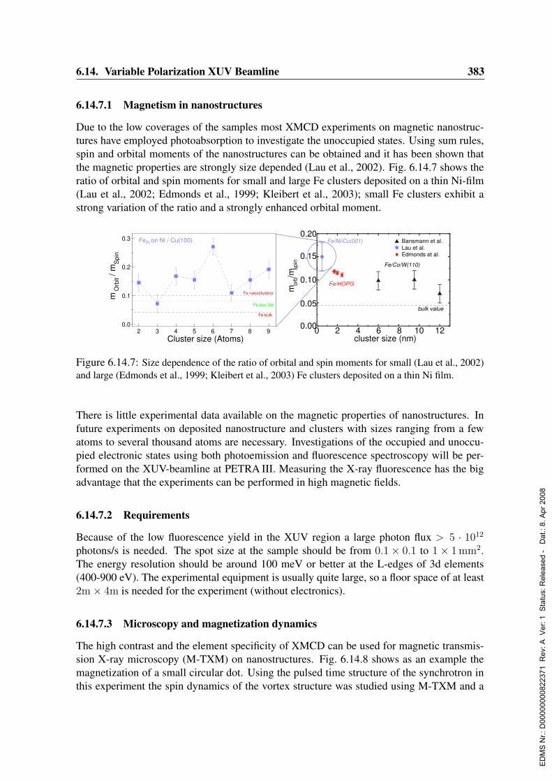
6.14. Variable Polarization XUV Beamline 383
6.14.7.1 Magnetism in nanostructures
Due to the low coverages of the samples most XMCD experiments on magnetic nanostruc-tures have employed photoabsorption to investigate the unoccupied states. Using sum rules,spin and orbital moments of the nanostructures can be obtained and it has been shown thatthe magnetic properties are strongly size depended (Lau et al., 2002). Fig. 6.14.7 shows theratio of orbital and spin moments for small and large Fe clusters deposited on a thin Ni-film(Lau et al., 2002; Edmonds et al., 1999; Kleibert et al., 2003); small Fe clusters exhibit astrong variation of the ratio and a strongly enhanced orbital moment.
2 3 4 5 6 7 8 9Cluster size (Atoms)
0.0
0.1
0.2
0.3
/ mm
Spi
nO
rbit
Fe nanoclusters
Fe thin film
Fe bulk
Fe on Ni / Cu(100)n Fe/Ni/Cu(001)
0 2 4 6 8 10 12cluster size (nm)
0.00
0.05
0.10
0.15
0.20Bansmann et al.
Edmonds et al.
bulk value
Lau et al.
/msp
inor
bm
Fe/HOPG
Fe/Co/W(110)
Figure 6.14.7: Size dependence of the ratio of orbital and spin moments for small (Lau et al., 2002)and large (Edmonds et al., 1999; Kleibert et al., 2003) Fe clusters deposited on a thin Ni film.
There is little experimental data available on the magnetic properties of nanostructures. Infuture experiments on deposited nanostructure and clusters with sizes ranging from a fewatoms to several thousand atoms are necessary. Investigations of the occupied and unoccu-pied electronic states using both photoemission and fluorescence spectroscopy will be per-formed on the XUV-beamline at PETRA III. Measuring the X-ray fluorescence has the bigadvantage that the experiments can be performed in high magnetic fields.
6.14.7.2 Requirements
Because of the low fluorescence yield in the XUV region a large photon flux > 5 · 1012
photons/s is needed. The spot size at the sample should be from 0.1× 0.1 to 1× 1 mm2.The energy resolution should be around 100 meV or better at the L-edges of 3d elements(400-900 eV). The experimental equipment is usually quite large, so a floor space of at least2m× 4m is needed for the experiment (without electronics).
6.14.7.3 Microscopy and magnetization dynamics
The high contrast and the element specificity of XMCD can be used for magnetic transmis-sion X-ray microscopy (M-TXM) on nanostructures. Fig. 6.14.8 shows as an example themagnetization of a small circular dot. Using the pulsed time structure of the synchrotron inthis experiment the spin dynamics of the vortex structure was studied using M-TXM and a
ED
MS
Nr.:
D00
0000
0082
2371
Rev
: A V
er: 1
Sta
tus:
Rel
ease
d -
Dat
.: 8.
Apr
200
8

384 6. Beamlines and Experimental Stations
pump-probe technique (Fischer et al., 2003). A major advantage of the photon based M-TXM technique is the potential to record domain structures in applied external magneticfields. Imaging can be performed in transmission or using the reflected intensity. Althoughthe signal in reflection is much smaller than the transmitted intensity the flipping ratio, whichdetermines the contrast, is just as high (Geissler et al., 2002) and in addition the lateral dis-tribution of the magnetic roughness at surfaces and interfaces can be investigated. The futurepotential to be exploited by M-TXM is magnetic microspectroscopy to address the lateraldistributions of spin and orbital moments on a sub-10nm length scale and achieve completeinformation on the spatio-temporal magnetization behavior in low-dimensional systems.
6.14.7.4 Requirements
For these experiments the time structure of the storage ring is important. The ring should runin a few bunch mode with t = 200− 300 ns between the electron bunches. The length of thelight pulse should be in the order of 10− 30 ps.
Figure 6.14.8: Microscopy and magnetization dynamic of nanostructures on a ps timescale.
6.14.8 Resonant soft X-ray scatteringSoft X-ray emission (SXE) spectroscopy has several advantages over competing techniquesfor studying the dynamics and electronic structure of matter. To exploit these advantagesvery high brilliance soft X-ray sources are required and SXE spectroscopy has recently un-dergone a renaissance at third generation synchrotron radiation sources. However, the flux atpresently available beamlines is the limiting factor, making both counting statistics and theenergy resolution inferior to what can be reached in electron spectroscopy. Increasing thespectral resolution is especially valuable, because the absorption-emission event constitutesa resonant inelastic scattering (RIXS) process, where the lifetime broadening of the core-hole state does not contribute to the spectral broadening; hence, the information inherent inthe spectra is only limited by the instrumental resolution. The resolution can be improvedsignificantly with the high brilliance of the soft X-ray beamline on PETRA III.The energy region 1-2.5 keV is comparatively unexplored and very few resonant X-ray scat-tering experiments have been performed to date. The K-edges of Na, Mg, Al, Si, P, S, the
ED
MS
Nr.:
D00
0000
0082
2371
Rev
: A V
er: 1
Sta
tus:
Rel
ease
d -
Dat
.: 8.
Apr
200
8
6.14. Variable Polarization XUV Beamline 385
L-edges of Zn, Ga, Ge, As, Se, Br and the L-edges of the early 4d elements all lie in thisenergy range. These elements are particularly important for semiconductor technology andare key constituents in many novel correlated materials with unusual superconducting andmagnetic properties. This energy range has been little exploited due to the lack of sourceswith appropriate brilliance, and to some extent also by the erroneous presumption that thecore hole lifetime width would smear out the spectral features. The soft X-ray beamlineon PETRA III will open the door to this ‘new’ energy range, where RIXS experiments haveenormous potential.Important features of RIXS include (Kotani & Shin, 2001):
• Large photon penetration lengths -True bulk properties are probed. This is espe-cially important in complex materials with large unit cells, and in non-conductingsamples where charging effects render electron spectroscopy difficult. Semiconductor(nano)structures, impurities, interfaces, magnetic (nano)structures and buried struc-tures can be probed in a non-destructive way. -Liquids can be studied (separated fromUHV by thin windows). Recent results reveal new important information about liquidwater (Guo et al., 2002), and hydrogen bonded solutions (Guo et al., 2003). This is anew field with applications in electrochemistry, environmental science, pharmacy andbiochemistry. - Gas-phase samples can also be studied using thin window cells andthis is of importance for exploring fundamental aspects of the scattering process.
• Independence of external fields Since the photons are not perturbed by external mag-netic and electric fields, any spectral field-dependence can be directly related to thephysical process under investigation.
• Local electronic properties Transitions to localized states reveal the density of elec-tronic states at specific local atomic sites. The data from various edges in complexmaterials are complementary and together can give a detailed picture of the electronicstructure.
• Dipole selection rules Dipole transitions are sensitive to angular momentum symmetryand orbital geometry. This can be further exploited if the incoming radiation has awell-defined and variable polarization state. Dichroic effects are particularly importantin studies of magnetic systems.
• k-resolution Momentum conservation in the scattering process makes band mappingfeasible. This will become increasingly important in the range above 1 keV, where themomentum transfer in the scattering process is far from zero: Scattering at variableand controlled momentum transfer can be studied.
• Femtosecond dynamics The intermediates core hole states have lifetimes on the orderof femtoseconds. Any rearrangement on the same time scale is reflected in the spectra.The lifetimes generally become shorter with increasing binding energy, making the1-2.5 keV energy range particularly interesting.
Resonant elastic scattering in the soft X-ray range has recently been used to identify thespectral features corresponding to various local electronic states in complex compounds and
ED
MS
Nr.:
D00
0000
0082
2371
Rev
: A V
er: 1
Sta
tus:
Rel
ease
d -
Dat
.: 8.
Apr
200
8
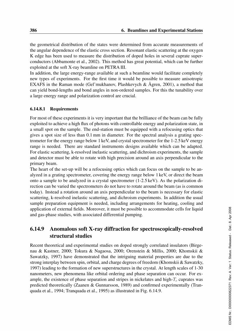
386 6. Beamlines and Experimental Stations
the geometrical distribution of the states were determined from accurate measurements ofthe angular dependence of the elastic cross section. Resonant elastic scattering at the oxygenK edge has been used to measure the distribution of doped holes in several cuprate super-conductors (Abbamonte et al., 2002). This method has great potential, which can be furtherexploited at the soft X-ray beamline on PETRA III.In addition, the large energy-range available at such a beamline would facilitate completelynew types of experiments. For the first time it would be possible to measure anisotropicEXAFS in the Raman mode (Gel’mukhanov, Plashkevych & Agren, 2001), a method thatcan yield bond-lengths and bond angles in non-ordered samples. For this the tunability overa large energy range and polarization control are crucial.
6.14.8.1 Requirements
For most of these experiments it is very important that the brilliance of the beam can be fullyexploited to achieve a high flux of photons with controllable energy and polarization state, ina small spot on the sample. The end-station must be equipped with a refocusing optics thatgives a spot size of less than 0.1 mm in diameter. For the spectral analysis a grating spec-trometer for the energy range below 1 keV, and crystal spectrometer for the 1-2.5 keV energyrange is needed. There are standard instruments designs available which can be adapted.For elastic scattering, k-resolved inelastic scattering, and dichroism experiments, the sampleand detector must be able to rotate with high precision around an axis perpendicular to theprimary beam.The heart of the set-up will be a refocusing optics which can focus on the sample to be an-alyzed in a grating spectrometer, covering the energy range below 1 keV, or direct the beamonto a sample to be analyzed in a crystal spectrometer (1-2.5 keV). As the polarization di-rection can be varied the spectrometers do not have to rotate around the beam (as is commontoday). Instead a rotation around an axis perpendicular to the beam is necessary for elasticscattering, k-resolved inelastic scattering, and dichroism experiments. In addition the usualsample preparation equipment is needed, including arrangements for heating, cooling andapplication of external fields. Moreover, it must be possible to accommodate cells for liquidand gas-phase studies, with associated differential pumping.
6.14.9 Anomalous soft X-ray diffraction for spectroscopically-resolvedstructural studies
Recent theoretical and experimental studies on doped strongly correlated insulators (Birge-nau & Kastner, 2000; Tokura & Nagaosa, 2000; Orenstein & Millis, 2000; Khomskii &Sawatzky, 1997) have demonstrated that the intriguing material properties are due to thestrong interplay between spin, orbital, and charge degrees of freedom (Khomskii & Sawatzky,1997) leading to the formation of new superstructures in the crystal. At length scales of 1-30nanometers, new phenomena like orbital ordering and phase separation can occur. For ex-ample, the existence of phase separation and stripes in nickelates and high-Tc cuprates waspredicted theoretically (Zaanen & Gunnarsson, 1989) and confirmed experimentally (Tran-quada et al., 1994; Tranquada et al., 1995) as illustrated in Fig. 6.14.9.
ED
MS
Nr.:
D00
0000
0082
2371
Rev
: A V
er: 1
Sta
tus:
Rel
ease
d -
Dat
.: 8.
Apr
200
8

6.14. Variable Polarization XUV Beamline 387
These examples strongly suggest that atomic and electronic ordering on a nanometer scaleare quite common in doped strongly correlated systems and that such phenomena may gov-ern the unusual low energy properties of the materials. Anomalous soft X-ray diffractionis a unique tool for studying such ordering phenomena since a dramatic enhancement ofBragg peaks is observed when scanning through the relevant inner-shell absorption edges.This technique can be used for the study of magnetic films (Durr et al., 1999). The excita-tion is highly sensitive to the oxidation state, orbital occupation and spin state of the ions(Castleton & Altarelli, 2000; Wilkins et al., 2003a; Wilkins et al., 2003b). The assignmentof multiplet components to particular electronic states is well established and provides thebasis for the interpretation of the experimental data. The period of the ordered phases isusually larger than the lattice constant and matches nicely the wavelength of soft X-ray pho-tons. The resonant enhancement of the scattering cross section for inner-shell excitation isextremely large: An enhancement of six orders of magnitude at the M5 resonance observedin Ho metal makes feasible investigations of ultra-thin films that are not possible at conven-tional X-ray energies (Schußler-Langeheine et al., 2001). Resonant soft X-ray diffractionwill greatly advance the understanding of order/disorder phenomena in correlated-electronsystems. The energy-dependence of the scattering cross section provides insight into theordering mechanism (Castleton & Altarelli, 2000).
6.14.9.1 Requirements
The energy range required for such experiments is 250 eV up to 2500 eV, covering the car-bon, nitrogen and oxygen K, the transition-metal L2,3 and the lanthanide M4,5 resonances.To make use of the strong polarization dependence of the scattering cross section, the undu-lator should provide variable circular and linear polarization. A well focussed beam with aspot size on the sample not larger than 0.05 x 0.05 mm2 is needed to study inhomogeneoussamples.
Figure 6.14.9: Stripe ordering in a CuO2 lattice. Charge is largely confined in the dark regions; thearrows indicate the orientation of the magnetic moment. The stripe is an antiphase boundary of theantiferromagnetic order. Oxygen ions are not shown (from Ref. (Orenstein & Millis, 2000).
ED
MS
Nr.:
D00
0000
0082
2371
Rev
: A V
er: 1
Sta
tus:
Rel
ease
d -
Dat
.: 8.
Apr
200
8

388 6. Beamlines and Experimental Stations
1019
2
3
4567
1020
Bri
ghtn
ess
(Ph/
s/m
m2 /m
rad2 /0
.1%
BW
)
2500200015001000500
Photon Energy (eV)
Circular Horizontal
a)
4
5
6
7
8
9
1015
Flux
(Ph/
s/0.
1% B
W)
2500200015001000500
Photon Energy (eV)
Circular Horizontal
b)
Figure 6.14.10: a) Brilliance and b) flux of the APPLE II insertion device for circular and horizontalpolarizations.
6.14.10 Beamline description
The 6 GeV energy of PETRA III and its very low emittance of 1 nm rad makes it an excellentsource for a very high resolution and high flux beamline optimized for the energy range 250–2500 eV.The source for the proposed beamline is a 5m APPLE II device (Sasaki, 1994) with a mag-netic period of 63 mm. This device generates 100% horizontally polarized and circular po-larized light in the first harmonic over the full energy range of the beamline. In the verticallypolarized mode, the lowest photon energy in the first harmonic is 470 eV. The brightness andflux emitted by the insertion device in the first harmonic for circular and linearly polarizedradiation are shown in Fig. 6.14.10a and Fig. 6.14.10b. The excellent performance can onlybe achieved with a full length undulator (5 m, 80 periods, or two 2 m undulator segments,see Sec. 4.1.6) because the brilliance at a side station is approximately five times lower.A schematic drawing of the beamline is shown in Fig. 6.14.11. The monochromator is ba-sically a collimated PGM developed at BESSY (Follath, Senf & Gudat, 1998) and in use atthe ALS (Warwick et al., 2003) and the SLS (Flechsig, Patthey & Quitmann, 2001). Thefirst optical element is a cylindrical mirror collimating the photon beam in the vertical (dis-persive) direction and deflecting it horizontally by 2. The use of a cylindrical mirror insteadof a toroid provides a larger demagnification in the horizontal direction. The next opticalelement is a plane mirror that diverts the central ray to the grating pole.To achieve a higher reflectivity in its tuning range, the angle of incidence on the mirror ischosen to be (α− β)/(2 + 0.5), where α is the angle of incidence on the grating and β(< 0)is the angle of diffraction. The angle between the central ray of the selected energy after thegrating and the beam incident on the plane mirror is 0.5. A toroidal mirror, diverting thebeam horizontally by 2, focuses in both the horizontal and vertical directions onto the exitslit. The final focusing at the sample position is achieved with two plane elliptical mirrorsarranged in a Kirkpatrick-Baez (KB) configuration. To achieve a larger demagnification inthe horizontal direction, the first mirror in the KB pair focuses in the vertical direction and
ED
MS
Nr.:
D00
0000
0082
2371
Rev
: A V
er: 1
Sta
tus:
Rel
ease
d -
Dat
.: 8.
Apr
200
8

6.14. Variable Polarization XUV Beamline 389
the second in the horizontal direction. The total demagnification in the horizontal directionis a factor 28.The monochromator “resolving power”, calculated with a 1200 l/mm grating, an exit slitwidth of 10 µm, and a c value of the monochromator (cos(β)/cos(α)) of 2.2, is given inFig. 6.14.12. Slope errors of 0.05” were assumed on the illuminated area of the plane mirrorand on the grating and 0.5” along the sagittal direction in the cylindrical mirror and the toroid.The limiting contribution to the resolving power at low photon energies is the astigmaticcoma of the toroid and at high photon energies, in decreasing importance, the contributionfrom the exit slit, figure errors on the grating, and figure errors on the plane mirror. Asseen in the figure, a resolving power greater than 10000 can be achieved up to 2320 eV. Ahigher resolving power could be obtained in the high-energy range if the monochromatorwere operated with higher c values, as shown in Fig. 6.14.12.Fig. 6.14.13 shows ray traces at the exit slit plane for 400 and 400.02 eV when the monochro-mator is tuned to 400 eV and c = 2.2. The optical elements were assumed to have the figure
Plane
PlaneGrating
ToroidPlane Elliptical
Source SampleExitSlit
Side View
Top View
Cylindrical
Plane Elliptical
Figure 6.14.11: Schematic drawing of the beamline
22x103
20
18
16
14
12
10
"Res
olvi
ng P
ower
"
2500200015001000500
Photon Energy (eV)
c=2.2c=4
Figure 6.14.12: ”Resolving power” obtained with an exit slit width of 10 µm and with c = 2.2 and4.0
ED
MS
Nr.:
D00
0000
0082
2371
Rev
: A V
er: 1
Sta
tus:
Rel
ease
d -
Dat
.: 8.
Apr
200
8
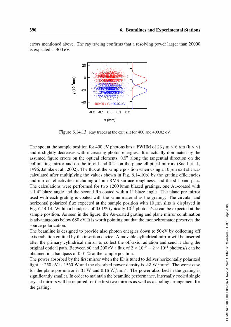
390 6. Beamlines and Experimental Stations
errors mentioned above. The ray tracing confirms that a resolving power larger than 20000is expected at 400 eV.
-40
-20
0
20
y (1
0-3
mm
)
-0.2 -0.1 0.0 0.1 0.2
x (mm)
400.00 eV, 400.02 eV
Figure 6.14.13: Ray traces at the exit slit for 400 and 400.02 eV.
The spot at the sample position for 400 eV photons has a FWHM of 23 µm× 6 µm (h× v)and it slightly decreases with increasing photon energies. It is actually dominated by theassumed figure errors on the optical elements, 0.5” along the tangential direction on thecollimating mirror and on the toroid and 0.2” on the plane elliptical mirrors (Snell et al.,1996; Jahnke et al., 2002). The flux at the sample position when using a 10 µm exit slit wascalculated after multiplying the values shown in Fig. 6.14.10b) by the grating efficienciesand mirror reflectivities including a 1 nm RMS surface roughness, and the slit band pass.The calculations were performed for two 1200 l/mm blazed gratings, one Au-coated witha 1.4 blaze angle and the second Rh-coated with a 1 blaze angle. The plane pre-mirrorused with each grating is coated with the same material as the grating. The circular andhorizontal polarized flux expected at the sample position with 10 µm slits is displayed inFig. 6.14.14. Within a bandpass of 0.01% typically 1012 photons/sec can be expected at thesample position. As seen in the figure, the Au-coated grating and plane mirror combinationis advantageous below 680 eV. It is worth pointing out that the monochromator preserves thesource polarization.The beamline is designed to provide also photon energies down to 50 eV by collecting offaxis radiation emitted by the insertion device. A movable cylindrical mirror will be insertedafter the primary cylindrical mirror to collect the off-axis radiation and send it along theoriginal optical path. Between 60 and 200 eV a flux of 2× 10¹⁰ − 2× 10¹¹ photons/s can beobtained in a bandpass of 0.01 % at the sample position.The power absorbed by the first mirror when the ID is tuned to deliver horizontally polarizedlight at 250 eV is 1560 W and the absorbed power density is 2.3 W/mm2. The worst casefor the plane pre-mirror is 31 W and 0.16 W/mm2. The power absorbed in the grating issignificantly smaller. In order to maintain the beamline performance, internally cooled singlecrystal mirrors will be required for the first two mirrors as well as a cooling arrangement forthe grating.
ED
MS
Nr.:
D00
0000
0082
2371
Rev
: A V
er: 1
Sta
tus:
Rel
ease
d -
Dat
.: 8.
Apr
200
8
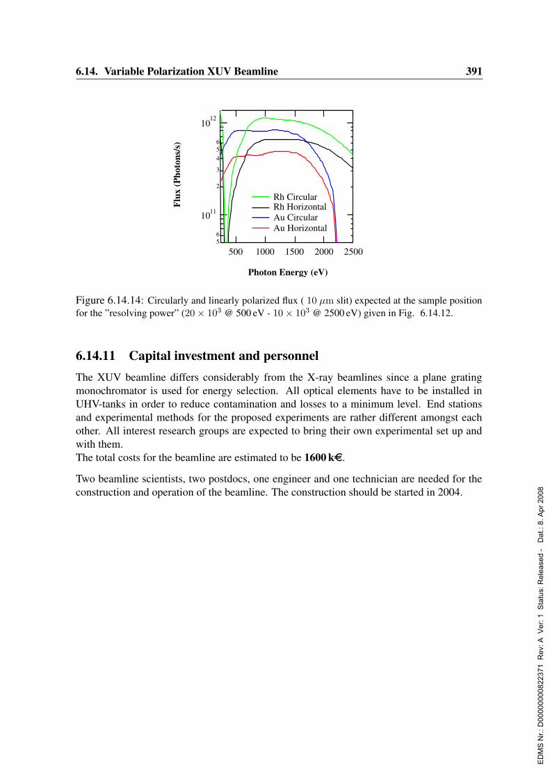
6.14. Variable Polarization XUV Beamline 391
56
1011
2
3
456
1012
Flux
(Pho
tons
/s)
2500200015001000500
Photon Energy (eV)
Rh CircularRh Horizontal
Au Circular Au Horizontal
Figure 6.14.14: Circularly and linearly polarized flux ( 10 µm slit) expected at the sample positionfor the ”resolving power” (20× 103 @ 500 eV - 10× 103 @ 2500 eV) given in Fig. 6.14.12.
6.14.11 Capital investment and personnelThe XUV beamline differs considerably from the X-ray beamlines since a plane gratingmonochromator is used for energy selection. All optical elements have to be installed inUHV-tanks in order to reduce contamination and losses to a minimum level. End stationsand experimental methods for the proposed experiments are rather different amongst eachother. All interest research groups are expected to bring their own experimental set up andwith them.The total costs for the beamline are estimated to be 1600 ke.
Two beamline scientists, two postdocs, one engineer and one technician are needed for theconstruction and operation of the beamline. The construction should be started in 2004.
ED
MS
Nr.:
D00
0000
0082
2371
Rev
: A V
er: 1
Sta
tus:
Rel
ease
d -
Dat
.: 8.
Apr
200
8
392 6. Beamlines and Experimental Stations
6.15 Resonant Scattering Beamline in the Hard X-Ray Regime
Authors and Consultants :
Th. Bruckel Institut fur Streumethoden, FZ Julich GmbH, JulichD. Lott GKSS Forschungszentrum, GeesthachtJ. Strempfer Max-Planck-Institut fur Festkorperforschung, StuttgartM. Tischer DESY, HamburgP. Wochner Max-Planck-Institut fur Metallforschung, StuttgartM. v. Zimmermann DESY, Hamburg
A resonant scattering beamline is proposed for experiments taking advantage of absorptionedges in the hard X-ray regime between 2.8 keV and 30 keV. These experiments includeresonant magnetic scattering of both ferro- and antiferromagnets, Templeton scattering andreflectivity measurements. While resonant magnetic scattering and Templeton scattering arewell established techniques, the combination with a microfocus in the nanometer regime andthe large coherence of the beam obtainable at the PETRA III source give access to new typesof experiments that are not possible today.Many resonant scattering experiments, in particular XMCD experiments, are nowadays car-ried out in the soft X-ray range, especially due to the large enhancements at the L-edges ofthe technologically and scientifically interesting 3d transition metals. Soft X-ray studies ofmagnetic nanostructures have huge scientific potential. However, by using soft X-rays forbulk studies the experiments suffer from high absorption and a limited Q-range due to thelong wavelength. Here, hard X-rays could be used to overcome these drawbacks with muchhigher penetration depths on the order of several micrometers and a wider accessible rangein reciprocal space. With X-ray energies from 2.8 keV to 30 keV the whole range of interest-ing magnetic elements from the K-absorption edges of the 3d transition metals, the K- andL- edges of the 4d elements, the L-edges of the 4f to the L- and M-edges of the 5d and 5felements is covered.
6.15.1 Introduction: correlated electrons
In condensed matter systems, electrons provide the ”glue” which holds the atoms together.Their Coulomb interaction together with the fermionic quantum character leads to correlationphenomena, which are largely not understood. Examples are provided by unconventionalmagnetism, non-Fermi liquid behavior, superconductivity, integer and fractional quantumHall effect etc. Research on electronic correlations is at the forefront of condensed matterphysics today. On the experimental side, probes are needed that provide detailed space andtime resolved information with additional distinction with respect to electronic band states,spin, charge, orbital and lattice degrees of freedom as well as to the atomic species. Suchinformation can be obtained from sophisticated scattering and spectroscopy experiments atundulator beamlines of third generation synchrotron radiation sources. Examples for majorchallenging issues concerned with electronic correlations, which can be tackled by modernsynchrotron radiation experiments, can be summarized as follows:
ED
MS
Nr.:
D00
0000
0082
2371
Rev
: A V
er: 1
Sta
tus:
Rel
ease
d -
Dat
.: 8.
Apr
200
8
6.15. Resonant Scattering Beamline in the Hard X-Ray Regime 393
1. Complex systems and nano-scale magnetism: While in the past mainly homoge-neous magnetic materials have been studied, the focus is now shifting to compositematerials consisting of structural and electronic and magnetic phases in close spatialproximity. The discovery of interlayer coupling and the giant magnetoresistance effectin layered magnetic systems has triggered the field of magneto-electronics or spin-tronics, where in addition to the electron charge, the electron spin is used to transport,store and process information. As a consequence, the field of magnetism enjoys an un-usually strong technological pull, second in condensed matter physics only to that ofsemiconductors. However, more complex systems not yet used for applications posemany unresolved fundamental puzzles. In a top-down approach, artificially patternedstructures consisting of different materials (metals, half-metals, semiconductors, insu-lators) in close proximity are produced by physical methods such as MBE or sputter-ing combined with lithography, while in the bottom-up approach self organization isexploited. Understanding the complex magnetic and electronic phases, the orderingphenomena and the proximity effects occurring in these materials is a major intellec-tual challenge. Experimental evidence can be provided with resonant magnetic X-rayscattering and dichroism experiments, spatially resolved on a sub-micrometer scale.
2. Highly correlated electron systems: Heavy-fermion systems, colossal magnetoresis-tance materials and high temperature superconductors are posing difficult problemsdespite intense research since more than two decades. The strong electron correla-tions lead to unusual quantum phenomena such as spin, orbital and charge ordering,metal-insulator transitions, non-Fermi-liquid behavior, or magnetism in close vicin-ity to superconductivity. Nanoscale phase separation can occur, leading to complexnanostructures by self-organization. Many of these systems have in common a com-petition of various degrees of freedom and interactions, leading to an extreme sensi-tivity to external parameters such as magnetic or electric fields, pressure, composition,etc. This nonlinear response to small disturbances renders these systems extremelyattractive for applications e.g. as sensors. To resolve the main intellectual problem ofunderstanding the strong electronic correlations one needs to disentangle the variousordering phenomena. Anomalous scattering of synchrotron radiation is ideally suitedto study charge order, spin order (resonance exchange scattering), orbital order andlattice distortions (anisotropic anomalous scattering or Templeton scattering). Sincemany of these scattering channels are rather weak compared to conventional chargescattering, a dedicated undulator beamline with full polarization handling is essential.
6.15.2 Resonant magnetic scattering
The worldwide investment in magnetic devices is 100 billion US-Dollars per year. One ofthe areas with the most rapid development is data storage media. Both the storage mediumand the data read out are based on magnetic phenomena. The rapid progress in this area isdemonstrated by the fact that the areal density of data storage grows exponentially in time.Clearly, materials properties on nano-scale dimensions become increasingly important forfunctional devices.
ED
MS
Nr.:
D00
0000
0082
2371
Rev
: A V
er: 1
Sta
tus:
Rel
ease
d -
Dat
.: 8.
Apr
200
8
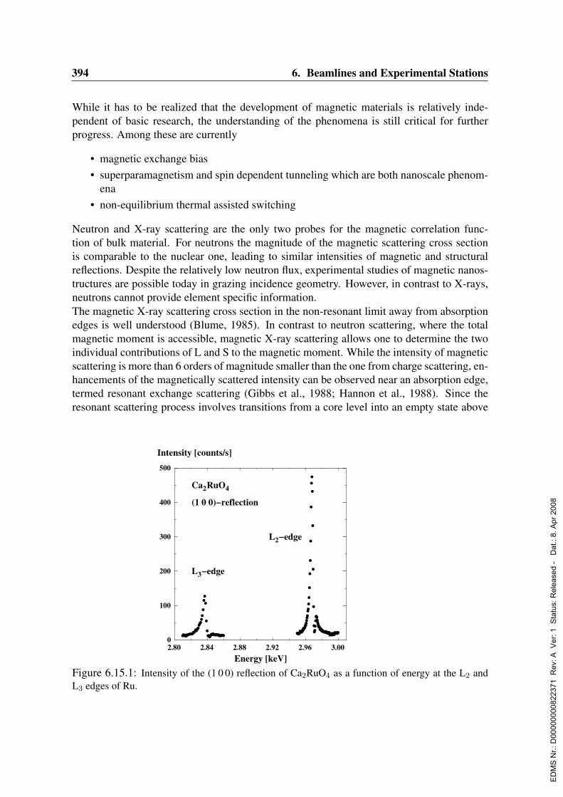
394 6. Beamlines and Experimental Stations
While it has to be realized that the development of magnetic materials is relatively inde-pendent of basic research, the understanding of the phenomena is still critical for furtherprogress. Among these are currently
• magnetic exchange bias• superparamagnetism and spin dependent tunneling which are both nanoscale phenom-
ena• non-equilibrium thermal assisted switching
Neutron and X-ray scattering are the only two probes for the magnetic correlation func-tion of bulk material. For neutrons the magnitude of the magnetic scattering cross sectionis comparable to the nuclear one, leading to similar intensities of magnetic and structuralreflections. Despite the relatively low neutron flux, experimental studies of magnetic nanos-tructures are possible today in grazing incidence geometry. However, in contrast to X-rays,neutrons cannot provide element specific information.The magnetic X-ray scattering cross section in the non-resonant limit away from absorptionedges is well understood (Blume, 1985). In contrast to neutron scattering, where the totalmagnetic moment is accessible, magnetic X-ray scattering allows one to determine the twoindividual contributions of L and S to the magnetic moment. While the intensity of magneticscattering is more than 6 orders of magnitude smaller than the one from charge scattering, en-hancements of the magnetically scattered intensity can be observed near an absorption edge,termed resonant exchange scattering (Gibbs et al., 1988; Hannon et al., 1988). Since theresonant scattering process involves transitions from a core level into an empty state above
2.80 2.84 2.88 2.92 2.96 3.000
100
200
300
400
500
Energy [keV]
Intensity [counts/s]
Ca2RuO4
(1 0 0)−reflection
L2−edge
L3−edge
Figure 6.15.1: Intensity of the (1 0 0) reflection of Ca2RuO4 as a function of energy at the L2 andL3 edges of Ru.
ED
MS
Nr.:
D00
0000
0082
2371
Rev
: A V
er: 1
Sta
tus:
Rel
ease
d -
Dat
.: 8.
Apr
200
8

6.15. Resonant Scattering Beamline in the Hard X-Ray Regime 395
the Fermi level, valuable information is obtained about the electronic structure. The scat-tering cross section depends on the polarization of the incident and scattered beam, makinga well defined polarization of the incident beam and a polarization analysis of the scatteredbeam necessary. The main strength of resonant magnetic X-ray scattering is the element-specificity. The combination of element and band sensitivity allows one to obtain detailedinformation on the mechanism of interlayer exchange and proximity effects (Voigt et al.,2004). Utilizing the resonant scattering technique it has been possible to investigate thesurface magnetism of UO2 and how it differs from the bulk magnetism (Watson et al., 2000).Compared to neutron scattering the X-ray scattering technique generally offers a high mo-mentum space resolution, provides element sensitivity and in combination with a micro fo-cused beam, structures on a nano-scale can be investigated. It is thus an excellent tool forstudies of functional materials as mentioned above. Beyond that, taking advantage of thelarge coherence length at PETRA III it will be possible to perform speckle studies to resolvedomain shapes or study the dynamic behavior of glassy systems on a µ-second time scaleemploying the time correlation spectroscopy technique.The L-edges of 4d transition metals as well as the M-edges of the actinides are located atenergies below 4 keV. They are of great interest for the investigation of magnetic propertiesof compounds containing these elements, since in both cases large resonance enhancementsare obtained at the respective absorption edges. At the L2/3-edges, the initial states are the2p1/2 and 2p3/2 states. Dipole transitions probe the d-states, where the electrons responsiblefor the magnetic ordering are located. Because of the large overlap integrals between the pand d levels the scattering amplitude is expected to be similar to the one of the M-edges ofthe actinides, where in addition the polarization of the f level is stronger.The M-edges of Uranium with energies above 3.6 keV can be accessed by several beamlinesat third generation synchrotrons around the world already. Resonance enhancements of upto 3 orders of magnitude are obtained for uranium and neptunium (Lidstrom et al., 2000).The 4d transition metal L-edges can only be accessed by one beamline at the APS, wherethe insertion device has been modified accordingly to reach this energy. There, first mea-surements have shown recently that indeed a resonance enhancement of more than a factorof 50 is obtained from Ru L-edges (Strempfer et al., 2003) (see Fig. 6.15.1). This opens anew perspective in investigating compounds containing 4d-transition metals.
6.15.3 Magnetic circular dichroism (XMCD) experiments
Research in the field of magnetic materials has largely benefited from the use of polarization-modulated X-ray diffraction and spectroscopy techniques. XMCD is an important effect thatis widely used to explore ferro- , ferri- and paramagnetic contributions in a large varietyof materials. XMCD describes the difference in the intensities measured with left and rightcircularly polarized light when the X-ray energy is tuned across an absorption edge of a mag-netic site (Schutz et al., 1987). It provides unique information not readily available via othermethods enabling a quantitative determination of element-specific spin and orbital magneticmoments. Using XMCD in X-ray scattering geometry, the element-specific sensitivity to themagnetic moments can be combined with the depth sensitivity of X-ray scattering giving in-formation about the magnetic spatial spin contributions from different magnetic sites (Chen
ED
MS
Nr.:
D00
0000
0082
2371
Rev
: A V
er: 1
Sta
tus:
Rel
ease
d -
Dat
.: 8.
Apr
200
8

396 6. Beamlines and Experimental Stations
Figure 6.15.2: Charge reflectivity (upper panel) and magnetic reflectivity (lower panel) on a[Gd(50A)/Fe(15A)]15 multilayer. The bottom inset shows the derived interfacial structure (Figuretaken from (Haskel et al., 2001)).
et al., 1990; Kao et al., 1990; Kao et al., 1994; Chakarian et al., 1996; Stohr, 1999).The feasibility of XMCD experiments is strongly dependent on the quality of the X-raybeam: high photon flux with high degree of circular polarization and high beam stability.Circularly polarized X-rays produced by application of phase plates show close to 100%circular polarization (Pizzini et al., 1998; Varga et al., 1999; Maruyama et al., 1999). Inaddition, the possibility of fast switching between left and right circularly polarized light byvariation of the reflection angle at the phase plate enables one to use lock-in amplifiers tofurther reduce the background noise. Effects with maximum XMCD ratios - the differencein the measured intensities for left and right circularly polarized light divided by its sum - ofsmaller than 10−4 will be easily detectable. Thus, measurements of very small magnetic sig-nals in short data collection times will be possible as e.g. at the K-edges of the 3d transitionmetals.The key scattering techniques taking advantage of the XMCD effect are magnetic X-rayreflectivity and diffuse magnetic scattering. Magnetic X-ray reflectivity uses the XMCDeffect in the setup of specular X-ray reflectivity and therefore allows to study the magnetiza-
ED
MS
Nr.:
D00
0000
0082
2371
Rev
: A V
er: 1
Sta
tus:
Rel
ease
d -
Dat
.: 8.
Apr
200
8

6.15. Resonant Scattering Beamline in the Hard X-Ray Regime 397
tion profile by distinguishing between different magnetic sites and their spin configurations(Seve et al., 1999; Jaouen et al., 2002). Fig. 6.15.2 shows an example of a magnetic reflectiv-ity curve near the Gd L3-edge (Haskel et al., 2001). From the magnetic reflectivity signal thespin configuration of the Gd atoms at the Gd/Fe interface can be determined. Due to the ex-cellent properties of the X-ray beam at PETRA III in combination with the proposed designof the beamline providing sensitivity to very small XMCD effects, a powerful tool for thecharacterization of magnetization profiles of magnetic thin films and multilayer structureswill be available. Another important feature is the ability to measure element specific hys-teresis loops to examine the switching behavior in magnetic materials, e.g. when consistingof two different magnetic sites as it is the case in exchange bias materials. By variation ofthe incident angle, different depths can be probed. This can be important if bulk and surfacemagnetic states should be separated (Haskel et al., 2003).One of the most intense discussed questions in the field of magnetic thin films and multi-layers is the spin ordering at interfaces, e.g. how the magnetic roughness and correlationlengths are related to the chemical counterparts (Nelson et al., 1999; Osgood III et al., 1999;Freeland et al., 1998; MacKay et al., 1996; Kelly IV et al., 2002). Here, diffuse magneticscattering is an ideal technique to tackle the task, combining the XMCD effect with standardrocking curves or other diffuse scattering techniques (Sinha et al., 1988; Salditt, Metzger &Peisl, 1994). Since the magnetic signal decreases rapidly with increasing parallel momentumtransfer, high photon flux and high sensitivity to the XMCD signal become very important.Another interesting aspect for using the XMCD effect in the hard X-ray regime is the acces-sible large Q-space. In principle XMCD measurements in high angle diffraction mode arepossible to access atomic Bragg reflections of magnetic sites and thus probe the ferromag-netic contributions even down to the atomic level. Finally, one of the outstanding propertiesof magnetic X-ray techniques is the possibility to distinguish between orbital and spin mo-ments by applying sum rules to the measured MCD spectra (Thole et al., 1992; Carra et al.,1993; Chen et al., 1995; Wu & Freeman, 1994).
6.15.4 Templeton scattering
Resonant X-ray scattering (RXS) at absorption edges not only provides access to the sub-tleties of microscopic magnetism. In recent years many experiments have shown, that RXSallows the investigation of charge, spin and orbital degrees of freedom even in a single exper-iment (Paolasini et al., 2002; Caciuffo et al., 2002). Especially for systems where the groundstate properties reflect a delicate balance between several different correlated processes, thistechnique can be of crucial importance.In a resonant scattering experiment the photon energy is tuned to an absorption edge soas to excite virtual electric multipole transitions between a core state and an intermediatebound state above the Fermi level. If the symmetry of the intermediate state is lowered andaligned by interactions (chemical bonding, Jahn-Teller effect, magnetic, multipolar etc.) thescattering becomes dependent on the polarization of the incident and scattered beam, andthe atomic scattering factor is no longer a scalar but becomes a tensor and the diffractionmay exhibit birefringence (Templeton scattering). In addition, when the resonating atomsexist in an anisotropic crystalline environment and they occur with more than one molecular
ED
MS
Nr.:
D00
0000
0082
2371
Rev
: A V
er: 1
Sta
tus:
Rel
ease
d -
Dat
.: 8.
Apr
200
8
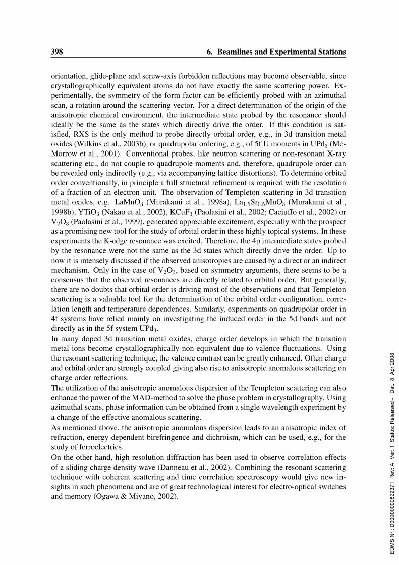
398 6. Beamlines and Experimental Stations
orientation, glide-plane and screw-axis forbidden reflections may become observable, sincecrystallographically equivalent atoms do not have exactly the same scattering power. Ex-perimentally, the symmetry of the form factor can be efficiently probed with an azimuthalscan, a rotation around the scattering vector. For a direct determination of the origin of theanisotropic chemical environment, the intermediate state probed by the resonance shouldideally be the same as the states which directly drive the order. If this condition is sat-isfied, RXS is the only method to probe directly orbital order, e.g., in 3d transition metaloxides (Wilkins et al., 2003b), or quadrupolar ordering, e.g., of 5f U moments in UPd3 (Mc-Morrow et al., 2001). Conventional probes, like neutron scattering or non-resonant X-rayscattering etc., do not couple to quadrupole moments and, therefore, quadrupole order canbe revealed only indirectly (e.g., via accompanying lattice distortions). To determine orbitalorder conventionally, in principle a full structural refinement is required with the resolutionof a fraction of an electron unit. The observation of Templeton scattering in 3d transitionmetal oxides, e.g. LaMnO3 (Murakami et al., 1998a), La1.5Sr0.5MnO3 (Murakami et al.,1998b), YTiO3 (Nakao et al., 2002), KCuF3 (Paolasini et al., 2002; Caciuffo et al., 2002) orV2O3 (Paolasini et al., 1999), generated appreciable excitement, especially with the prospectas a promising new tool for the study of orbital order in these highly topical systems. In theseexperiments the K-edge resonance was excited. Therefore, the 4p intermediate states probedby the resonance were not the same as the 3d states which directly drive the order. Up tonow it is intensely discussed if the observed anisotropies are caused by a direct or an indirectmechanism. Only in the case of V2O3, based on symmetry arguments, there seems to be aconsensus that the observed resonances are directly related to orbital order. But generally,there are no doubts that orbital order is driving most of the observations and that Templetonscattering is a valuable tool for the determination of the orbital order configuration, corre-lation length and temperature dependences. Similarly, experiments on quadrupolar order in4f systems have relied mainly on investigating the induced order in the 5d bands and notdirectly as in the 5f system UPd3.In many doped 3d transition metal oxides, charge order develops in which the transitionmetal ions become crystallographically non-equivalent due to valence fluctuations. Usingthe resonant scattering technique, the valence contrast can be greatly enhanced. Often chargeand orbital order are strongly coupled giving also rise to anisotropic anomalous scattering oncharge order reflections.The utilization of the anisotropic anomalous dispersion of the Templeton scattering can alsoenhance the power of the MAD-method to solve the phase problem in crystallography. Usingazimuthal scans, phase information can be obtained from a single wavelength experiment bya change of the effective anomalous scattering.As mentioned above, the anisotropic anomalous dispersion leads to an anisotropic index ofrefraction, energy-dependent birefringence and dichroism, which can be used, e.g., for thestudy of ferroelectrics.On the other hand, high resolution diffraction has been used to observe correlation effectsof a sliding charge density wave (Danneau et al., 2002). Combining the resonant scatteringtechnique with coherent scattering and time correlation spectroscopy would give new in-sights in such phenomena and are of great technological interest for electro-optical switchesand memory (Ogawa & Miyano, 2002).
ED
MS
Nr.:
D00
0000
0082
2371
Rev
: A V
er: 1
Sta
tus:
Rel
ease
d -
Dat
.: 8.
Apr
200
8
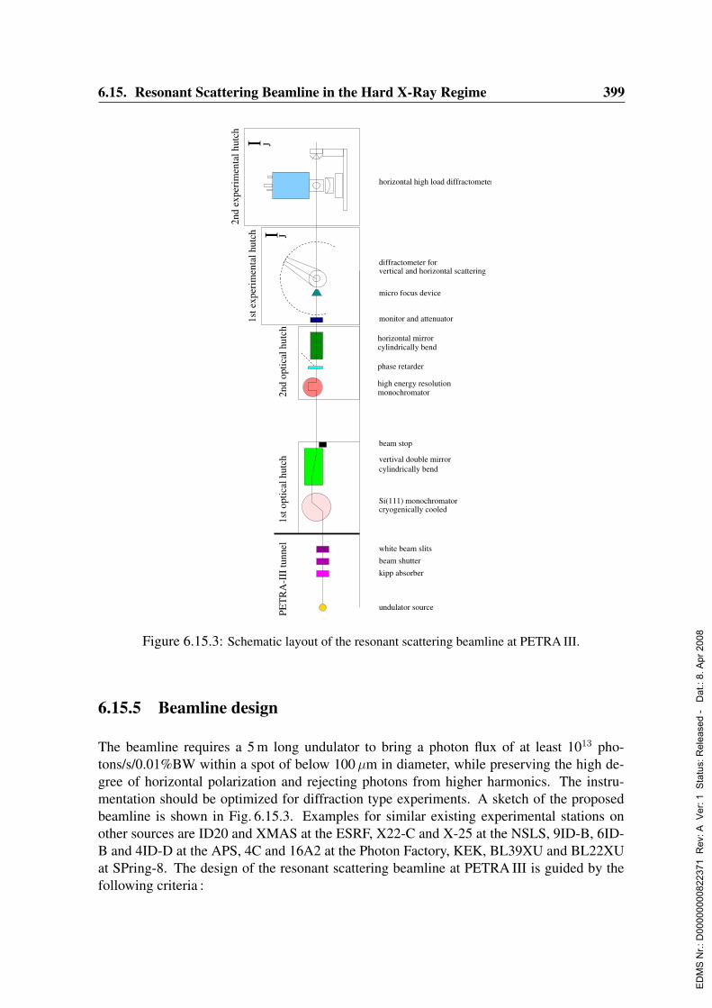
6.15. Resonant Scattering Beamline in the Hard X-Ray Regime 399
high energy resolution monochromator
horizontal mirrorcylindrically bend
I J
1st o
ptic
al h
utch
2nd
optic
al h
utch
1st e
xper
imen
tal h
utch
2nd
expe
rim
enta
l hut
ch
white beam slitsbeam shutterkipp absorber
Si(111) monochromatorcryogenically cooled
cylindrically bendvertival double mirror
beam stop
undulator source
phase retarder
horizontal high load diffractometer
monitor and attenuator
micro focus device
I JPE
TR
A-I
II tu
nnel
vertical and horizontal scatteringdiffractometer for
Figure 6.15.3: Schematic layout of the resonant scattering beamline at PETRA III.
6.15.5 Beamline design
The beamline requires a 5 m long undulator to bring a photon flux of at least 1013 pho-tons/s/0.01%BW within a spot of below 100µm in diameter, while preserving the high de-gree of horizontal polarization and rejecting photons from higher harmonics. The instru-mentation should be optimized for diffraction type experiments. A sketch of the proposedbeamline is shown in Fig. 6.15.3. Examples for similar existing experimental stations onother sources are ID20 and XMAS at the ESRF, X22-C and X-25 at the NSLS, 9ID-B, 6ID-B and 4ID-D at the APS, 4C and 16A2 at the Photon Factory, KEK, BL39XU and BL22XUat SPring-8. The design of the resonant scattering beamline at PETRA III is guided by thefollowing criteria :
ED
MS
Nr.:
D00
0000
0082
2371
Rev
: A V
er: 1
Sta
tus:
Rel
ease
d -
Dat
.: 8.
Apr
200
8

400 6. Beamlines and Experimental Stations
6.15.5.1 Energy tunability
The energy tunability should be from 2.8 keV - 30 keV, covering most of the absorption edgesin the hard X-ray regime. This includes the K-edges of transition metals, the L-edges of therare earth elements and the M-edges of the actinides. The beamline shall be optimized forthe range of 3.4 keV - 16 keV. The energy resolution of the incident beam should match atypical core hole life time, which is around ∆E = 1 eV. That will be achieved with a liquidnitrogen cooled Si(111) double crystal monochromator. The Darwin width of this reflection(26µrad at 10 keV) is significantly larger than the vertical divergence of the incident beamof 5.2µrad. For high resolution spectroscopic applications a high resolution monochromatorwith an energy resolution of around 0.2 eV can be added in the monochromatic beam ondemand. This will be a fixed exit four-bounce monochromator.To access the low energy range down to 2.8 keV the beamline should be designed window-less. To avoid absorption, the beam-paths to the sample and from the sample into the detectorhave to be evacuated.
6.15.5.2 Harmonic rejection
Crucial for the performance of the resonant scattering beamline will be the reduction ofhigher harmonics in the monochromatic beam. The intensity of the smallest measurablereflections can be 1010 times smaller than the main reflections, thus the number of photonsin the higher harmonics Ih should compare to the number of photons of the fundamentalwavelength I0 like Ih/I0 ∼ 10−10. This high harmonic suppression will be achieved by acombination of energy dispersive devices :First, the use of a quasi periodic undulator (Sasaki et al., 1995) would reduce the intensityat harmonic wavelengths by two orders of magnitude compared to a conventional undulatordevice (Sec. 4.1.7). In the ideal case the higher harmonics of a quasi-periodic undulatorappear at non rational multiples of the fundamental wavelength. However, in combinationwith a monochromator tuned to the fundamental wavelength, the wavelength at non rationalharmonics are not reflected and thus highly suppressed. Only the residual intensity at rationalmultiple wavelength will be reflected, which is, however, two orders of magnitude smallerthan the fundamental wavelength.Second, a mirror tuned to just below the critical angle reduces the harmonic contaminationby a factor between 10−2 and 10−3, while having a high reflectivity for the fundamental ofabout 95 %. A pair of vertical mirrors and a single horizontal mirror (which will be also usedto focus the beam on the sample, see below) would reduce the harmonic contamination to10−6 to 10−9.Third, an energy dispersive solid state detector is able to discriminate harmonic contamina-tion by a factor 10−1 to 10−2. Combining the quasi-periodic undulator with three mirrorsand an energy dispersive detector a harmonic suppression of a factors of 10−9 − 10−10 isobtained. Further possibilities for the reduction of higher harmonics would be the detuningof one of the monochromator crystals or the use of a multilayer mirror. Neither of thesemethods is taken into account since both of these result in a reduced intensity on the sample.
ED
MS
Nr.:
D00
0000
0082
2371
Rev
: A V
er: 1
Sta
tus:
Rel
ease
d -
Dat
.: 8.
Apr
200
8

6.15. Resonant Scattering Beamline in the Hard X-Ray Regime 401
6.15.5.3 Polarization
For polarization resolved measurements the degree of polarization of the incident beam onthe sample is of critical importance. This concerns both the linear polarization and the cir-cular polarization. An undulator source at PETRA III will provide a 99.99 % σ - polarizedbeam. To preserve the linear polarization all optical elements like mirrors and monochro-mators should scatter in the vertical direction, except for one horizontal focusing/harmonicrejection mirror.Circular polarization will be obtained by the use of a quarter wave plate (Golovchenko et al.,1986). In the hard X-ray range, the use of quarter wave plates has proven to be superior to avariable polarization insertion device (Lang, Srajer & Dejus, 1996). With quarter wave platesa degree of circular polarization of 99 % percent can be obtained at third generation sources.Generally, the smaller the incident beam divergence, the better the degree of polarization.To minimize the horizontal and vertical divergence (note that the scattering plane of thephase plate is tilted by 45, therefore both vertical and horizontal divergences need to beminimized) a high-β section will be required. Furthermore, switching rates of a few kHzbetween left and right circular polarization are possible with these devices (Pizzini et al.,1998). In contrast, typical switching rates for variable polarization insertion devices are inthe order of a few Hz, and the efficiency for circular polarization is rather small. Finally, thesource point for left- and right-circular polarization of a switching insertion device might bedifferent, which, combined with the high Q-space resolution, makes XMCD-measurementsin diffraction geometry impossible.The phase retarder can also be used as a half wave plate providing a linear π-polarizedbeam (Ishikawa et al., 1992). This is of importance when the sample environment (e.g., acryogenically cooled high field magnet) requires a horizontal scattering geometry.
6.15.5.4 Focus and divergence
Without compromising the intensity, the polarization properties and the harmonic rejection,a vertical and horizontal focus of about 10µm each should be achieved by mirrors. A verticaldouble mirror in a 1:1 focusing scheme provides a fixed exit and does not increase the verticaldivergence. This double mirror is also used for harmonic rejection. A single horizontalfocusing mirror with a mapping ratio of 20:1, about 3 m in front of the sample is used tolimit the horizontal offset to a few centimeters. Here a horizontal spot size of 10µm with adivergence of 0.3 mrad will be achieved. This horizontal mirror can be removed if a smallhorizontal divergence is required.
6.15.5.5 Diffractometer
Two experimental stations are envisioned, such that one experiment can be prepared in onehutch while another one is running in the other hutch. To accommodate the diffractometerswith 2 m arms in the hutches, the hutch length should be 7 m. A height of 5 m is required to beable to change samples in liquid He cooled cryostats. Each hutch contains one diffractome-ter. The first hutch hosts an 8-circle diffractometer for vertical and horizontal scattering.A horizontal scattering diffractometer will be placed in the second hutch. This horizontal
ED
MS
Nr.:
D00
0000
0082
2371
Rev
: A V
er: 1
Sta
tus:
Rel
ease
d -
Dat
.: 8.
Apr
200
8
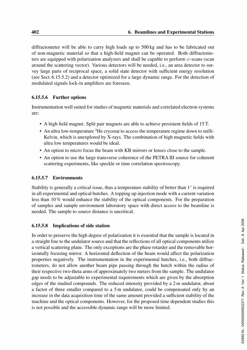
402 6. Beamlines and Experimental Stations
diffractometer will be able to carry high loads up to 500 kg and has to be fabricated outof non-magnetic material so that a high-field magnet can be operated. Both diffractome-ters are equipped with polarization analyzers and shall be capable to perform ψ-scans (scanaround the scattering vector). Various detectors will be needed, i.e., an area detector to sur-vey large parts of reciprocal space, a solid state detector with sufficient energy resolution(see Sect. 6.15.5.2) and a detector optimized for a large dynamic range. For the detection ofmodulated signals lock-in amplifiers are foreseen.
6.15.5.6 Further options
Instrumentation well suited for studies of magnetic materials and correlated electron systemsare:
• A high field magnet. Split pair magnets are able to achieve persistent fields of 15 T.• An ultra low-temperature 3He cryostat to access the temperature regime down to milli-
Kelvin, which is unexplored by X-rays. The combination of high magnetic fields withultra low temperatures would be ideal.
• An option to micro focus the beam with KB mirrors or lenses close to the sample.• An option to use the large transverse coherence of the PETRA III source for coherent
scattering experiments, like speckle or time correlation spectroscopy.
6.15.5.7 Environments
Stability is generally a critical issue, thus a temperature stability of better than 1 is requiredin all experimental and optical hutches. A topping up injection mode with a current variationless than 10 % would enhance the stability of the optical components. For the preparationof samples and sample environment laboratory space with direct access to the beamline isneeded. The sample to source distance is uncritical.
6.15.5.8 Implications of side station
In order to preserve the high degree of polarization it is essential that the sample is located ina straight line to the undulator source and that the reflections of all optical components utilizea vertical scattering plane. The only exceptions are the phase retarder and the removable hor-izontally focusing mirror. A horizontal deflection of the beam would affect the polarizationproperties negatively. The instrumentation in the experimental hutches, i.e., both diffrac-tometers, do not allow another beam pipe passing through the hutch within the radius oftheir respective two-theta arms of approximately two meters from the sample. The undulatorgap needs to be adjustable to experimental requirements which are given by the absorptionedges of the studied compounds. The reduced intensity provided by a 2 m undulator, abouta factor of three smaller compared to a 5 m undulator, could be compensated only by anincrease in the data acquisition time of the same amount provided a sufficient stability of themachine and the optical components. However, for the proposed time dependent studies thisis not possible and the accessible dynamic range will be more limited.
ED
MS
Nr.:
D00
0000
0082
2371
Rev
: A V
er: 1
Sta
tus:
Rel
ease
d -
Dat
.: 8.
Apr
200
8

6.15. Resonant Scattering Beamline in the Hard X-Ray Regime 403
6.15.5.9 Combination with other end stations
In order to extend capabilities and broaden the user community for the proposed beamline, acombination with resonant inelastic scattering experiments with an energy resolution in therange of 0.1 eV for both monochromator and analyzer is suggested. The additional instru-mentation for such experiments will be a high energy resolution analyzer.Studies of electronic excitations by means of inelastic X-ray scattering experienced tremen-dous progress in recent years. This technique probes the dynamic structure factor S(q, ω).Unlike Raman scattering, which is bound to zero momentum transfer, the whole Brillouinzone can be accessed. Thus it is complementary to electron energy loss spectroscopy. How-ever, the resonance process is not yet completely understood. The first experiment employingthis technique was performed on NiO and resonant enhancements of the charge-transfer ex-citation of two orders of magnitudes were found (Kao et al., 1996). The technique allowsone to study the dispersion of the charge transfer gap and the propagation of holes (Hasanet al., 2000). Orbital excitations, d-d transitions which are forbidden in the non-resonantcase, have been studied in manganite compounds (Inami et al., 2003).The resonant inelastic X-ray scattering requires the energy tunability foreseen for the pro-posed beamline and would gain from the high degree of polarization and the high rejection ofhigher harmonic contamination. Furthermore it would benefit from circular polarized light,an option that is not available on any other source presently.
6.15.6 Capital investment and personnelThe total capital investment for the experimental endstations amounts to 2110 ke not includ-ing 800 ke for a 15 T magnet.Personnel: 2 Scientists, 1 Engineer, 1 Technician
ED
MS
Nr.:
D00
0000
0082
2371
Rev
: A V
er: 1
Sta
tus:
Rel
ease
d -
Dat
.: 8.
Apr
200
8

404 6. Beamlines and Experimental Stations
6.16 Integrated Proposal by the European Molecular Bi-ology Laboratory for Beam Lines at the PETRA IIIStorage Ring
6.16.1 IntroductionAuthors: Matthias Wilmanns, Christoph Hermes, Victor Lamzin,
Wolfram Meyer-Klaucke, Dmitri Svergun & Paul TuckerAddress: EMBL c/o DESY, Notkestrasse 85, D-22603 Hamburg, Germany
6.16.1.1 Summary
The European Molecular Biology Laboratory (EMBL) presents a proposal to build and oper-ate synchrotron radiation beamlines and/or experimental stations in life sciences at the ded-icated PETRA III storage ring. The document comprises detailed proposals for beamlinesin Biological Macromolecular X-ray Crystallography (MX) in Biological X-ray Scattering(SAXS) and Biological X-ray Absorption Spectroscopy (XAS).
6.16.1.2 Past achievements in provision of synchrotron radiation beam line facilitiesat the DORIS storage ring
The EMBL-Hamburg Outstation has thirty years of experience in the provision of syn-chrotron radiation beamlines in life sciences at the DORIS storage ring and in research activ-ities that are associated with the experiments at these beamlines. The basis of these activitieshas been the provision of synchrotron radiation by the Deutsches Elektronen-Synchrotron(DESY) free of charge. The experimental end-stations including all beamline optics ‘behindthe beryllium window’ (i.e. proximal to the end-stations) have been designed, built and arebeing maintained by EMBL.While during the first two decades the amount of activities in MX, SAXS and XAS wascomparable, the reconfiguration of the DORIS ring into a dedicated source and the additionof the bypass with seven wiggler stations in 1992 permitted a massive increase of experi-ments, particularly in MX. During the last ten years three additional MX beamlines (BW7A,BW7B, X13) were completed bringing the total number of EMBL beamlines to seven, inaddition to the already existing ones (X11 and X31, MX; X33, SAXS; EXAFS; XAS). Aneighth, energy-tunable beamline (X12, MX) is currently being commissioned.The infrastructure of these beamlines is complemented by the EMBL building (25A) thathas been extended by an additional floor in 2002. It hosts a molecular and biochemistry lab-oratory with about 40 experimental benches, a scientific library, a computer department, anadministrative section and office space for about 80 staff and fellows, including some lim-ited facilities for external users. The locally available EMBL infrastructure is integrated intothe unique multiple-site structure of EMBL with its head quarters in Heidelberg (Germany)and further units in Hinxton Hall / Cambridge (UK), Grenoble (France) and Monterotondo/ Rome (Italy). Various research opportunities and services from these units are directlyavailable to the EMBL-Hamburg Outstation.
ED
MS
Nr.:
D00
0000
0082
2371
Rev
: A V
er: 1
Sta
tus:
Rel
ease
d -
Dat
.: 8.
Apr
200
8
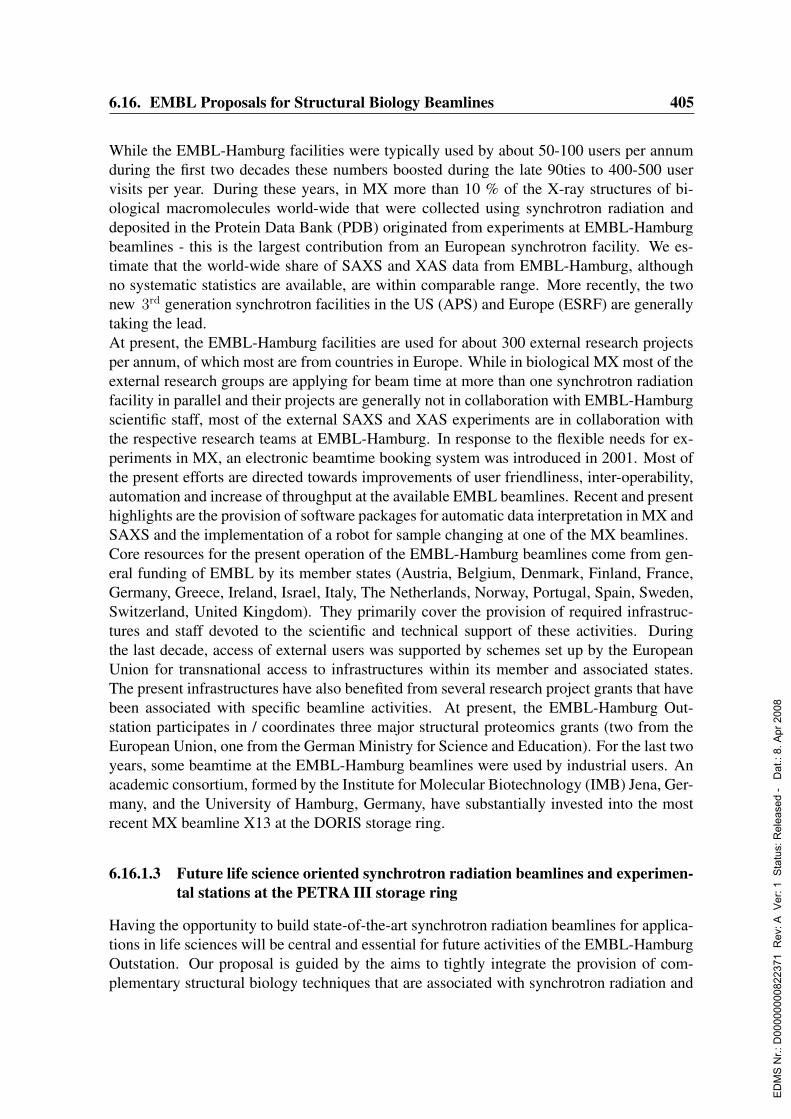
6.16. EMBL Proposals for Structural Biology Beamlines 405
While the EMBL-Hamburg facilities were typically used by about 50-100 users per annumduring the first two decades these numbers boosted during the late 90ties to 400-500 uservisits per year. During these years, in MX more than 10 % of the X-ray structures of bi-ological macromolecules world-wide that were collected using synchrotron radiation anddeposited in the Protein Data Bank (PDB) originated from experiments at EMBL-Hamburgbeamlines - this is the largest contribution from an European synchrotron facility. We es-timate that the world-wide share of SAXS and XAS data from EMBL-Hamburg, althoughno systematic statistics are available, are within comparable range. More recently, the twonew 3rd generation synchrotron facilities in the US (APS) and Europe (ESRF) are generallytaking the lead.At present, the EMBL-Hamburg facilities are used for about 300 external research projectsper annum, of which most are from countries in Europe. While in biological MX most of theexternal research groups are applying for beam time at more than one synchrotron radiationfacility in parallel and their projects are generally not in collaboration with EMBL-Hamburgscientific staff, most of the external SAXS and XAS experiments are in collaboration withthe respective research teams at EMBL-Hamburg. In response to the flexible needs for ex-periments in MX, an electronic beamtime booking system was introduced in 2001. Most ofthe present efforts are directed towards improvements of user friendliness, inter-operability,automation and increase of throughput at the available EMBL beamlines. Recent and presenthighlights are the provision of software packages for automatic data interpretation in MX andSAXS and the implementation of a robot for sample changing at one of the MX beamlines.Core resources for the present operation of the EMBL-Hamburg beamlines come from gen-eral funding of EMBL by its member states (Austria, Belgium, Denmark, Finland, France,Germany, Greece, Ireland, Israel, Italy, The Netherlands, Norway, Portugal, Spain, Sweden,Switzerland, United Kingdom). They primarily cover the provision of required infrastruc-tures and staff devoted to the scientific and technical support of these activities. Duringthe last decade, access of external users was supported by schemes set up by the EuropeanUnion for transnational access to infrastructures within its member and associated states.The present infrastructures have also benefited from several research project grants that havebeen associated with specific beamline activities. At present, the EMBL-Hamburg Out-station participates in / coordinates three major structural proteomics grants (two from theEuropean Union, one from the German Ministry for Science and Education). For the last twoyears, some beamtime at the EMBL-Hamburg beamlines were used by industrial users. Anacademic consortium, formed by the Institute for Molecular Biotechnology (IMB) Jena, Ger-many, and the University of Hamburg, Germany, have substantially invested into the mostrecent MX beamline X13 at the DORIS storage ring.
6.16.1.3 Future life science oriented synchrotron radiation beamlines and experimen-tal stations at the PETRA III storage ring
Having the opportunity to build state-of-the-art synchrotron radiation beamlines for applica-tions in life sciences will be central and essential for future activities of the EMBL-HamburgOutstation. Our proposal is guided by the aims to tightly integrate the provision of com-plementary structural biology techniques that are associated with synchrotron radiation and
ED
MS
Nr.:
D00
0000
0082
2371
Rev
: A V
er: 1
Sta
tus:
Rel
ease
d -
Dat
.: 8.
Apr
200
8

406 6. Beamlines and Experimental Stations
interdisciplinary research opportunities. The present proposal is limited to techniques thathave been established in Hamburg (MX, SAXS, XAS), however, keeping options open tomove into novel research methods and areas allowing the determination of structures, shapesand images of biological entities and their structural dynamics associated with biologicalprocesses. A key component of the future PETRA III beamline research activities in struc-tural biology will be the establishment of an experimental platform to accumulate expertiseand to develop novel experiments for the X-ray Free Electron Laser facility that DESY isplanning to set up, exploiting its expected unique specific properties such as coherence, timestructure and intensity.The EMBL-Hamburg Outstation proposes to make use of the last two straight sections at thededicated PETRA III storage ring (sections 8 and 9) and to build experimental stations in bio-logical SAXS and MX (Fig. 6.16.1). For biological XAS, we propose a flexible experimentalstation, which may be combined with related beamline activities by HASYLAB/DESY orother research institutes. We wish to have this station at section 7, thus allowing usage offacilities shared with biological SAXS and MX. In order to make effective and synergisticuse of these facilities and to promote their integration we are proposing a joint research areafor life sciences. In essence, such joint facility could provide an integrated format for bio-logical sample preparation, on-line data processing and interpretation, and common servicelogistics (see below). It may serve as a common platform to promote combined approachesusing different and complementary structural biology techniques associated with the avail-ability of synchrotron radiation.
Common area for biological sample preparation
There is wide consensus that today the rate limiting step in structural biology is in the prepa-ration of biological samples suitable for subsequent experiments using synchrotron radiation.In X-ray crystallography, in addition the availability of crystals with sufficient diffractionproperties is an essential requirement. Achieving these goals becomes even more demandingwhen moving to large multi-component assemblies and integral membrane proteins. Com-mon to all suggested experimental structural biology techniques, is the availability of biolog-ical samples that are homogeneously associated and can be obtained in concentrations in themM range. Therefore, it will be essential to interface the future EMBL beamline facilitieswith a common area for sample preparation, characterization and crystallization.Sample purification: The proposed infrastructure will provide facilities that will allow pu-rification steps that lead to pure samples with measurable feasibility for structural biologyexperiments. These steps will require equipment primarily suitable for affinity and size ex-clusion chromatography. Any preceding steps for initial sample preparation (cloning, het-erologous expression in prokaryotic and eukaryotic hosts as well as cell free expression sys-tems, initial purification steps) are expected to be carried out elsewhere, either in laboratoriesof external visitors or within the existing infrastructure of the EMBL-Hamburg Outstationbuilding 25A.Sample characterization: The proposed infrastructure will provide equipment to charac-terize the purity and the biophysical status of biological samples by electrophoretic methods(SDS-PAGE, native electrophoresis, isoelectric focusing), by scattering methods (dynamic
ED
MS
Nr.:
D00
0000
0082
2371
Rev
: A V
er: 1
Sta
tus:
Rel
ease
d -
Dat
.: 8.
Apr
200
8
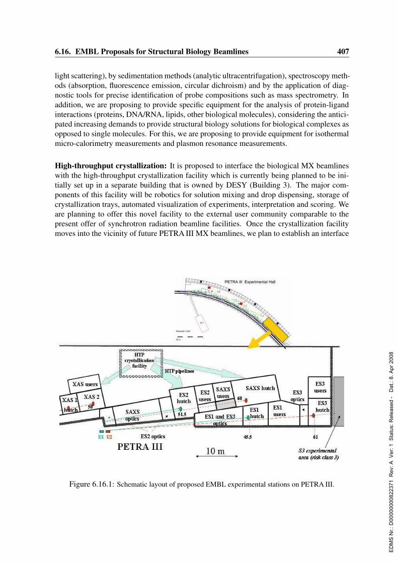
6.16. EMBL Proposals for Structural Biology Beamlines 407
light scattering), by sedimentation methods (analytic ultracentrifugation), spectroscopy meth-ods (absorption, fluorescence emission, circular dichroism) and by the application of diag-nostic tools for precise identification of probe compositions such as mass spectrometry. Inaddition, we are proposing to provide specific equipment for the analysis of protein-ligandinteractions (proteins, DNA/RNA, lipids, other biological molecules), considering the antici-pated increasing demands to provide structural biology solutions for biological complexes asopposed to single molecules. For this, we are proposing to provide equipment for isothermalmicro-calorimetry measurements and plasmon resonance measurements.
High-throughput crystallization: It is proposed to interface the biological MX beamlineswith the high-throughput crystallization facility which is currently being planned to be ini-tially set up in a separate building that is owned by DESY (Building 3). The major com-ponents of this facility will be robotics for solution mixing and drop dispensing, storage ofcrystallization trays, automated visualization of experiments, interpretation and scoring. Weare planning to offer this novel facility to the external user community comparable to thepresent offer of synchrotron radiation beamline facilities. Once the crystallization facilitymoves into the vicinity of future PETRA III MX beamlines, we plan to establish an interface
Figure 6.16.1: Schematic layout of proposed EMBL experimental stations on PETRA III.
ED
MS
Nr.:
D00
0000
0082
2371
Rev
: A V
er: 1
Sta
tus:
Rel
ease
d -
Dat
.: 8.
Apr
200
8

408 6. Beamlines and Experimental Stations
for automatic crystal transfer to those beamlines to perform test diffraction experiments asthe second step of crystal ‘visualization’ determining their feasibility for X-ray structure de-termination. Given that for the presently most complex experiments in X-ray crystallographysuch as the ribosome or multi-component signalling complexes often thousands of crystalsneeded to be tested, such automated pipeline for crystal feasibility assessment may becomea pivotal element in future experiments.There will be 50 m2 laboratory space available for each sample purification, sample charac-terization and for high-throughput crystallization.
On-line data acquisition, processing and interpretation
It is anticipated that packages for the automatic interpretation of experiment data acquiredat the PETRA III beamlines will be available, based on past and present developments suchas ARP/wARP (MX) and ATSAS (SAXS). We propose a joint infrastructure with sufficientwork space to carry out simultaneous work by ten scientists. The working area may alsobe used for training and teaching purposes. It will be equipped with computers suitable forgraphics based data processing and interpretations and document processing. About 80 m2
of office space is foreseen.
General services
Although we do expect to keep most of our current central services within the present build-ing (25A), there will be limited requirement for the provision of a computer infrastructure,safety instructions and administration. For this purpose about 50 m2 of office space will beallocated.
Facility for sample handling and X-ray measurements at the S3 security level (futureextension)
We propose to keep an option for one of the proposed MX beamlines to make it availablefor biological samples requiring S3 safety level. Although the actual construction of suchfacility is not a part of this proposal we wish already at this stage to make an allowance for anextension of a beam pipe into an S3 containment building where diffraction experiments onpathogenic organisms could be performed under the required safety regime. For this facilityabout 200 m2 of additional laboratory space outside of the experimental hall but close the theprotein crystallography beamlines is foreseen.
6.16.1.4 Support for present operation and proposal for future support
The EMBL-Hamburg proposal for PETRA III beamlines is based on the consideration that,after an intermediate phase of parallel operation of beamlines at DORIS and PETRA III,future operation of PETRA III beamlines will be possible with a funding scheme that iscomparable to the present one. However, the design and the construction of these beamlines
ED
MS
Nr.:
D00
0000
0082
2371
Rev
: A V
er: 1
Sta
tus:
Rel
ease
d -
Dat
.: 8.
Apr
200
8

6.16. EMBL Proposals for Structural Biology Beamlines 409
will require capital investments that are estimated to be in the order of 16.3 Me.In the context of a recent application to the European Union in spring 2003, the EMBL-Hamburg Outstation has received written support from a total of 83 research institutes thatare situated in Europe and Israel. These institutes constitute a large fraction of the EMBL-Hamburg user community. Given the superior parameters calculated for beamlines at thePETRA III storage ring, we anticipate that there will be even wider interest, including re-search groups that are not yet part of the EMBL-Hamburg user community.Building on previous models and experience from partnerships associated with the presentDORIS beamlines, the EMBL-Hamburg Outstation is also keen to establish new partnershipswith academic and industrial consortia for future beamlines at the PETRA III storage ring.At present, research centers from the Helmholtz Society and Aventis Pharma have expressedinterest to become putative partners. We anticipate, that once a formal proposal has beenmade, more opportunities for partnerships will emerge. EMBL-Hamburg will develop ownactivities for seeking such partnerships.
6.16.2 Biological macromolecular X-ray crystallography beamlinesAuthors: Victor Lamzin, Christoph Hermes, Santhosh Panjikar, Ehmke Pohl,
Alexander Popov, Andrea Schmidt, Paul Tucker, Manfred Weiss,Matthias Wilmanns
External advisors:Zigniew Dauter BNL, Upton, USAAndrew Leslie LMB Cambridge, UKSean McSweeney ESRF, Grenoble, FranceUwe Muller BESSY, Berlin, GermanyGerd Rosenbaum APS, Chicago, USAAndrew Thompson SOLEIL, Gif-sur-Yvette, France
6.16.2.1 Present and future challenges for biological crystallography
Over the last fifty years (Dennis & Campbell, 2003 further references within), biologicalX-ray crystallography has evolved into an advanced field of life sciences and has providedunprecedented structural insight into three-dimensional molecular information of compli-cated biological processes such as oxygen transport, muscle contraction, replication of genes,immune response, biological energy conversion, photosynthesis, viral assembly, protein syn-thesis and signal transduction. Knowledge of spatial structures has allowed to delineate themolecular origins for diseases such as cancer, autoimmune diseases and microbial infec-tions. The performance and contribution of biological X-ray crystallography can be readilyassessed by the number of new structures being deposited in the PDB, which is increasing ata nearly exponential rate. Coupled to this, the growth in a demand for synchrotron radiationbeamlines for macromolecular crystallographic experiments has risen substantially both inabsolute numbers and in overall proportion. More than 80 % of PDB depositions quote theuse of synchrotron beamlines thus reflecting the superiority of X-ray data from synchrotronsources (Minor, Tomchick & Otwinowski, 2000).
ED
MS
Nr.:
D00
0000
0082
2371
Rev
: A V
er: 1
Sta
tus:
Rel
ease
d -
Dat
.: 8.
Apr
200
8

410 6. Beamlines and Experimental Stations
Our aim is to provide synchrotron radiation beam time for macromolecular crystallography(MX) at the future PETRA III storage ring to the international user community, by offeringstate-of-the-art beamlines both for already established technologies (small crystals requiringmicrofocusing, phasing requiring energy tunability) and emerging or even novel applica-tions (time resolved studies, novel phasing methods, ultra-high resolution, remote and high-throughput operations). Clearly, the provision of such new beamline facilities at PETRA IIIwill require developments in X-ray structure analysis methods at a comparable scale. We in-tend to adapt the currently used successful model of independent assessment of the scientificquality of the applications and performed experiments. As a complement to this, we aimto maintain our tradition in training and teaching that are primarily targeted towards youngresearchers from the community. We also anticipate that the ongoing and future advances intechnology and increased throughput in structure determination will create an unprecedenteddemand of remote operation of the experiments (Smith, 2003). A number of important areasof biology, representing the most demanding challenges in X-ray crystallography and pro-viding a framework for future applications at PETRA III MX beamlines, are outlined below.Molecular machines and large assemblies: In recent years, crystal structures of large bio-logical complexes have unravelled some of the most fundamental processes in biology, suchas transcription (polymerase) and translation (ribosome), import and export across mem-branes, and the degradation machinery by the proteasome (further citations, see: Huber,1989; Johnson & Chiu, 2002; Yonath, 2002; Saenger, Jordan & Krauss, 2002; Harrison,2003). Some of these complexes are integrated into biological membranes, such as photo-systems I and II, the light harvesting complexes, the photo reaction center and some of thecomplexes of the respiratory chain. At present, the largest structures, though bearing internalsymmetry, are from - in part complete - viral assemblies. Some of these structures have im-posed unprecedented challenges in terms of the size of available crystals, which may be lowas a few microns only (Gluehmann et al., 2001; Abola et al., 2000) and unit cell dimensions,in a few cases even exceeding 1,000 A (Stuart et al., 2002). Many of these projects haveonly become feasible with the recent availability of the highest brilliance beamlines at 3rd
generation synchrotron sources.Structure based drug discovery: Rational drug design is a process that bases the develop-ment of a drug upon the structure of its protein target (Kuhn et al., 2002). Most pharmaceu-tical companies and some specialized biotech companies such as Astex, Syrrx and StructuralGenomiX are employing this approach for their drug discovery pipelines and have become asignificant part of the synchrotron user community. A prototype example has been the workon inhibitors of the HIV protease for finding new drugs against AIDS (Wlodawer, 2002). Al-though most of these approaches have been focused on small, soluble protein targets, recentadvances have extended them to targets of much higher complexity, such as the ribosome(Knowles et al., 2002).Structural Proteomics: The availability of a rapidly increasing number of genome se-quences from a wide range of organisms has revolutionized research in life sciences andhas ultimately allowed to study biological processes at complete genomic (or proteomic)scale. During the last five years a number of large-scale structural proteomics initiatives hasbeen formed. The common aim of these initiatives is to advance parallel, high-throughputtechnologies in experimental structural biology and to use them for a large number of struc-
ED
MS
Nr.:
D00
0000
0082
2371
Rev
: A V
er: 1
Sta
tus:
Rel
ease
d -
Dat
.: 8.
Apr
200
8

6.16. EMBL Proposals for Structural Biology Beamlines 411
ture determinations of a proteome. While some of the early structural proteomics initiativeshave have been aiming for a complete knowledge of the “fold space” (Heinemann et al.,2000), more recent projects attempt to make the structures useful for unravelling the molec-ular basis of biological processes (Burley & Bonanno, 2002; Sali et al., 2003) and to applythem for structure-based drug discovery screening approaches (Buchanan, 2002). A noveldirection in structural proteomics oriented research emerges from recent developments andapplications of experimental high-throughput methods to systematically identify and to char-acterize protein-ligand complexes within the proteomes of living organisms (Gavin et al.,2002). Some recent attempts to utilize this novel information, initially for a systematic lowresolution imaging of these protein-protein complexes (Aloy et al., 2002), have displayed itslarge potential for structural proteomics on protein-ligand (protein) complexes.Time-resolved X-ray studies and structural dynamics: In order to use the structures ofthe biological macromolecules as tools to understand their functions in biology, it is essen-tial to investigate the dynamic changes of their structures associated with these processes.Over the last two decades, an arsenal of crystallographic methods has been developed, rang-ing from monochromatic to polychromatic Laue applications (Hajdu et al., 2000; Moffat,2001). These methods require high intensity and energy tunable synchrotron radiation, per-mitting an experiment time regime that synchronizes with the reaction kinetics associatedwith, and the complementary application of spectroscopy and laser techniques, triggeringand terminating reactions with at precise time intervals. Proof-of-principle case studies havedemonstrated that experiments addressing specific biological questions are feasible in thensec and even psec regime (Schotte et al., 2003; Bourgeois et al., 2003; Adachi et al., 2003).The expected time structure and optical properties of the PETRA III beamlines will provideideal opportunities and an experimental set-up for future applications. As a spin-off, therecould be also the possibility to use a pink beam option, also known as the narrow band-passLaue data collection technique, for ultra-fast data collection. Such techniques may allowrapid exposure times in the range of 10−4 to 10−5 sec per frame, an improved signal-to-noiseratio, the absence of harmonic overlaps and reduced radiation damage effects. Ultimately,time resolved experiments at PETRA III could provide a basis to acquire sufficient exper-tise to plan and to design novel time-resolved experiments on single particles (Neutze et al.,2000) for the planned X-ray Free Electron Laser facility at DESY campus.
Biological structures at atomic and sub-atomic resolution: The number of X-ray crys-tal structures at atomic resolution (allowing visualization of atoms) and ultra-high resolution(visualization of electronic features), currently available from the PDB, is steadily increasing(Schmidt & Lamzin, 2002). A protein structure determined to such resolution offers a uniqueand extremely valuable tool by essentially closing the gap between biology and chemistryvia establishing structure-function relationships in unprecedented detail in terms of accuratelocation of atoms (including hydrogen atoms), accurate inter-atomic distances as well as pro-viding valuable information on the mobility and flexibility of the protein molecule even inthe crystal lattice (Dauter, Lamzin & Wilson, 1997; Harata & Kanai, 2002). At ultra-highresolution, as demonstrated for crambin as a proof-of-principle case (Jelsch et al., 2000),even atomic detail of bonding electrons and free electron pairs can be obtained. Some ofthe specific properties of the PETRA III ring, such as the delivery of X-rays at high energies
ED
MS
Nr.:
D00
0000
0082
2371
Rev
: A V
er: 1
Sta
tus:
Rel
ease
d -
Dat
.: 8.
Apr
200
8
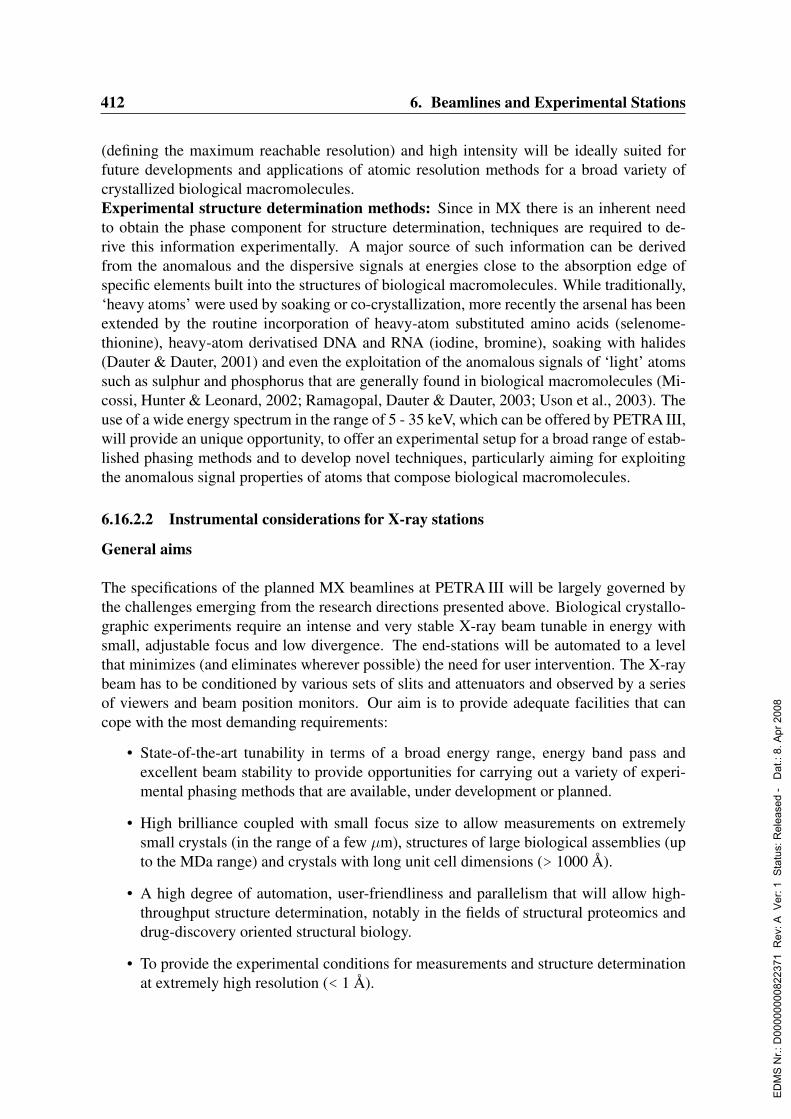
412 6. Beamlines and Experimental Stations
(defining the maximum reachable resolution) and high intensity will be ideally suited forfuture developments and applications of atomic resolution methods for a broad variety ofcrystallized biological macromolecules.Experimental structure determination methods: Since in MX there is an inherent needto obtain the phase component for structure determination, techniques are required to de-rive this information experimentally. A major source of such information can be derivedfrom the anomalous and the dispersive signals at energies close to the absorption edge ofspecific elements built into the structures of biological macromolecules. While traditionally,‘heavy atoms’ were used by soaking or co-crystallization, more recently the arsenal has beenextended by the routine incorporation of heavy-atom substituted amino acids (selenome-thionine), heavy-atom derivatised DNA and RNA (iodine, bromine), soaking with halides(Dauter & Dauter, 2001) and even the exploitation of the anomalous signals of ‘light’ atomssuch as sulphur and phosphorus that are generally found in biological macromolecules (Mi-cossi, Hunter & Leonard, 2002; Ramagopal, Dauter & Dauter, 2003; Uson et al., 2003). Theuse of a wide energy spectrum in the range of 5 - 35 keV, which can be offered by PETRA III,will provide an unique opportunity, to offer an experimental setup for a broad range of estab-lished phasing methods and to develop novel techniques, particularly aiming for exploitingthe anomalous signal properties of atoms that compose biological macromolecules.
6.16.2.2 Instrumental considerations for X-ray stations
General aims
The specifications of the planned MX beamlines at PETRA III will be largely governed bythe challenges emerging from the research directions presented above. Biological crystallo-graphic experiments require an intense and very stable X-ray beam tunable in energy withsmall, adjustable focus and low divergence. The end-stations will be automated to a levelthat minimizes (and eliminates wherever possible) the need for user intervention. The X-raybeam has to be conditioned by various sets of slits and attenuators and observed by a seriesof viewers and beam position monitors. Our aim is to provide adequate facilities that cancope with the most demanding requirements:
• State-of-the-art tunability in terms of a broad energy range, energy band pass andexcellent beam stability to provide opportunities for carrying out a variety of experi-mental phasing methods that are available, under development or planned.
• High brilliance coupled with small focus size to allow measurements on extremelysmall crystals (in the range of a few µm), structures of large biological assemblies (upto the MDa range) and crystals with long unit cell dimensions (> 1000 A).
• A high degree of automation, user-friendliness and parallelism that will allow high-throughput structure determination, notably in the fields of structural proteomics anddrug-discovery oriented structural biology.
• To provide the experimental conditions for measurements and structure determinationat extremely high resolution (< 1 A).
ED
MS
Nr.:
D00
0000
0082
2371
Rev
: A V
er: 1
Sta
tus:
Rel
ease
d -
Dat
.: 8.
Apr
200
8

6.16. EMBL Proposals for Structural Biology Beamlines 413
• An experimental environment to allow time-resolved measurements matched to thetime structure of the PETRA III ring with the intention of revealing the dynamics ofbiological processes.
• To allow adaptations in order to meet specific demands (lighting, data collection tem-perature, use of lasers, etc.).
Specific requirements
The instrumentation requirements are outlined as follows:
1. Beam divergence. The divergence of the beam has to be smaller than 0.5 mrad toresolve the diffraction spots of crystals with unit cell dimensions of up to 1,000 A.
2. Beam size. In order to provide the best signal-to-noise ratio in the diffraction pattern,the beam focal size has to be adjustable and made consistent with the specimen size(from 0.3 mm down to 0.02 mm).
3. Intensity. The X-ray intensity delivered to a sample will be about 1013 ph/sec. Suchintensity will allow collection of data from a typical protein crystal with an exposuretime of about 0.1 sec per frame (0.5 of oscillation). With sufficiently fast detectors(readout time of about 0.1 sec), appropriate goniometers (rotation speed of about 100-200 per second) and fast beam shutters the total data collection from a crystallinesample will take only minutes.
4. Energy range. Experiments utilizing anomalous dispersion properties require X-raystunable in energy range from 5 to 35 keV (2.5 to 0.36 A). The higher energy limit is setby the Xe K edge; the lower energy limit is defined by transition-metal K edges andwill also allow recording considerably improved anomalous signals from sulphur andphosphorus atoms.
5. Energy resolution. The incident spectral band pass ∆E/E will be less than 2x10⁻⁴ toresolve specific features in absorption spectra.
6. Beam stability. The relative position of sample and X-ray beam must be kept constantto within 5% of the beam size or sample size (whichever is smaller).
Instrumental design
Tab. 2.2.2 recalls the principal beam characteristics of PETRA III undulators. Very smallphoton source sizes, low divergence and extremely high brilliance (Fig. 2.2.2) will be ideallysuited for the tasks of biological crystallography.
ED
MS
Nr.:
D00
0000
0082
2371
Rev
: A V
er: 1
Sta
tus:
Rel
ease
d -
Dat
.: 8.
Apr
200
8

414 6. Beamlines and Experimental Stations
6.16.2.3 Proposed end-stations and optics
Overall scheme
In view of the increasing demand for structural information several important factors will betaken into consideration. Firstly, recent improvements in methodologies have provided non-specialists with the ability to carry out macromolecular structure determination. Secondly,the application of high-throughput technologies for protein production and crystallizationwill have a direct follow up in terms of the number of structures to be determined. Thirdly,industrial research in medicine, pharmacology, food and agriculture is poised to reap thebenefits of the high throughput technologies.To cope with the anticipated categories of experiments and with the diversity of the futureuser community we propose the construction of three MX beamlines. These beamlines willbe in conjunction with one biological SAXS beamline (see Chapter 6.16.3) and are proposedto be situated on the last two high-β straight sections (section 8 and section 94) using two 2 mlong undulator sources (U1 and U2) per section (Fig. 6.16.2). The SAXS station will utilizethe beam from undulator U2 of the second last straight section (section 8), while the threeMX stations will use U1 from the same section and both U1 and U2 undulators from the laststraight section. The initial 5 mrad horizontal separation of the U1 and U2 undulator beams(i.e. 170 mm in horizontal direction at 33 m distance from the undulator) will be increased to300 mm in the vertical direction using vertically deflecting double crystal monochromators.Thus the beam centers at the location of the downstream optics hutches and experimentalstations will be separated by more than 350 mm. This vertical separation will be sufficientto permit simultaneous operation of all four experimental stations and will allow the instal-lation of a large area detector and other bulky end-station equipment.
X-ray optics
The objective of the optical set-up is to deliver a monochromatic beam at a fixed positionof the sample with easily and quickly adjustable X-ray energy and maximized photon flux.Ideally, both focal spot size and beam divergence will be adjustable to meet the requirementsof each individual experiment.Tab. 6.16.1 summarizes the principal characteristics of the proposed beamlines. The opticsof all MX beamlines will be designed to be similar, thus allowing standardization of compo-nents design and know-how transfer, particularly during the commissioning stage. The mainoptical elements are liquid nitrogen cooled double-crystal monochromators and Kirkpatrick-Baez (KB) mirrors, which will be used as focusing elements and high-energy filters. The KBarrangement with two individual mirrors allows independent and tunable focusing in boththe vertical and the horizontal directions.In order to estimate the beam size, divergence, band pass and flux on the sample, ray-tracingcalculations were performed using the programs XOP and SHADOW with the input param-eters described in Appendix A.1.1. Some examples of these calculations are given below forthe station ES3.
4These are the two last sections close to building 48, see also Fig. 2.2.1.
ED
MS
Nr.:
D00
0000
0082
2371
Rev
: A V
er: 1
Sta
tus:
Rel
ease
d -
Dat
.: 8.
Apr
200
8

6.16. EMBL Proposals for Structural Biology Beamlines 415
Figure 6.16.2: A schematic floor plan of the PETRA III experimental hall showing the proposedlayout of the EMBL MX and SAXS beamlines.
Beamline ES1 ES2 ES3
Main purpose Wide range High-throughput Microfocus andtunability structure production special application
Energy range, keV 5.0 –35.0 6.0 – 16.5 6.0 –18.0
Bandpass (after Si(111): 1.4 –2.3·10−4 Si(111): < 1.6·10−4 Si(111): < 1.7·10−4
monochr.) ∆E/E Si(311): 4 – 9·10−5
Min. focus size, µm2 25 x 6 24 x 6 14 x 4(horizontal x vertical)
Divergence of thefocused beam, mrad2 0.3 x 0.2 0.3 x 0.2 0.5 x 0.25(horizontal x vertical)
Intensity, ph/sec 3·1013 – 1·1012 2·1013 2·1013
Pink beam option,(∆E/E = 1.5·10−2) Possible ∼1015 No No
Intensity, ph/sec
Table 6.16.1: Parameters of planned MX beamlines / end-stations on PETRA III.
Beamline control
The degree of automation controlling the alignment of optical components of a beamline hasto be as high as possible with the final aim of a fully self-aligning system. To achieve this goal
ED
MS
Nr.:
D00
0000
0082
2371
Rev
: A V
er: 1
Sta
tus:
Rel
ease
d -
Dat
.: 8.
Apr
200
8
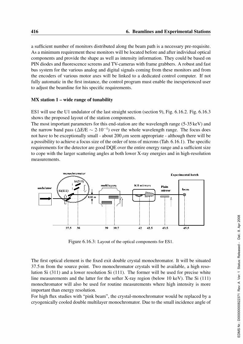
416 6. Beamlines and Experimental Stations
a sufficient number of monitors distributed along the beam path is a necessary pre-requisite.As a minimum requirement these monitors will be located before and after individual opticalcomponents and provide the shape as well as intensity information. They could be based onPIN diodes and fluorescence screens and TV-cameras with frame grabbers. A robust and fastbus system for the various analog and digital signals coming from these monitors and fromthe encoders of various motor axes will be linked to a dedicated control computer. If notfully automatic in the first instance, the control program must enable the inexperienced userto adjust the beamline for his specific requirements.
MX station 1 – wide range of tunability
ES1 will use the U1 undulator of the last straight section (section 9), Fig. 6.16.2. Fig. 6.16.3shows the proposed layout of the station components.The most important parameters for this end-station are the wavelength range (5-35 keV) andthe narrow band pass (∆E/E ∼ 2·10−4) over the whole wavelength range. The focus doesnot have to be exceptionally small - about 200µm seem appropriate - although there will bea possibility to achieve a focus size of the order of tens of microns (Tab. 6.16.1). The specificrequirements for the detector are good DQE over the entire energy range and a sufficient sizeto cope with the larger scattering angles at both lower X-ray energies and in high-resolutionmeasurements.
Figure 6.16.3: Layout of the optical components for ES1.
The first optical element is the fixed exit double crystal monochromator. It will be situated37.5 m from the source point. Two monochromator crystals will be available, a high reso-lution Si (311) and a lower resolution Si (111). The former will be used for precise whiteline measurements and the latter for the softer X-ray region (below 10 keV). The Si (111)monochromator will also be used for routine measurements where high intensity is moreimportant than energy resolution.For high flux studies with “pink beam”, the crystal-monochromator would be replaced by acryogenically cooled double multilayer monochromator. Due to the small incidence angle of
ED
MS
Nr.:
D00
0000
0082
2371
Rev
: A V
er: 1
Sta
tus:
Rel
ease
d -
Dat
.: 8.
Apr
200
8
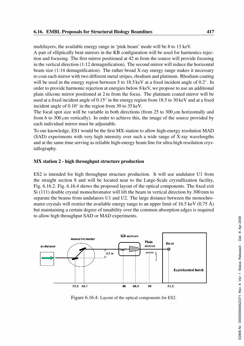
6.16. EMBL Proposals for Structural Biology Beamlines 417
multilayers, the available energy range in ‘pink beam’ mode will be 8 to 13 keV.A pair of elliptically bent mirrors in the KB configuration will be used for harmonics rejec-tion and focusing. The first mirror positioned at 42 m from the source will provide focusingin the vertical direction (1:12 demagnification). The second mirror will reduce the horizontalbeam size (1:14 demagnification). The rather broad X-ray energy range makes it necessaryto coat each mirror with two different metal stripes, rhodium and platinum. Rhodium coatingwill be used in the energy region between 5 to 18.5 keV at a fixed incident angle of 0.2. Inorder to provide harmonic rejection at energies below 8 keV, we propose to use an additionalplain silicone mirror positioned at 2 m from the focus. The platinum coated mirror will beused at a fixed incident angle of 0.15 in the energy region from 18.5 to 30 keV and at a fixedincident angle of 0.10 in the region from 30 to 35 keV.The focal spot size will be variable in both directions (from 25 to 300µm horizontally andfrom 6 to 300µm vertically). In order to achieve this, the image of the source provided byeach individual mirror must be adjustable.To our knowledge, ES1 would be the first MX-station to allow high-energy resolution MAD(SAD) experiments with very high intensity over such a wide range of X-ray wavelengthsand at the same time serving as reliable high-energy beam line for ultra-high resolution crys-tallography.
MX station 2 - high throughput structure production
ES2 is intended for high throughput structure production. It will use undulator U1 fromthe straight section 8 and will be located near to the Large-Scale crystallization facility,Fig. 6.16.2. Fig. 6.16.4 shows the proposed layout of the optical components. The fixed exitSi (111) double crystal monochromator will lift the beam in vertical direction by 300 mm toseparate the beams from undulators U1 and U2. The large distance between the monochro-mator crystals will restrict the available energy range to an upper limit of 16.5 keV (0.75 A)but maintaining a certain degree of tunability over the common absorption edges is requiredto allow high throughput SAD or MAD experiments.
Figure 6.16.4: Layout of the optical components for ES2.
ED
MS
Nr.:
D00
0000
0082
2371
Rev
: A V
er: 1
Sta
tus:
Rel
ease
d -
Dat
.: 8.
Apr
200
8
418 6. Beamlines and Experimental Stations
Over the last two years 80 % of the experiments at EMBL beamlines requiring tunabil-ity exploited the anomalous signals from selenium, mercury, bromine, platinum and iron.Therefore the station will be tunable over the range 6 to 16.5 keV (encompassing most ab-sorption edges of these elements) with a band pass of 2·10−4 and adjustable focus. Focalspot size will be variable from 24 to 300µm in the horizontal direction and from 6 to 300µmvertically.Both KB mirrors will have rhodium coating. In the energy range from 6 to 8.5 keV anadditional plain mirror either made from Si or SiO2 or coated with a low-Z material likealuminum will be used for harmonic rejection. The first KB mirror positioned at 48 m willprovide focusing in the vertical direction (1:14 demagnification), the second mirror will focusin the horizontal direction (1:16 demagnification). The mirrors will work at a fixed incidentangle (0.2).A large and fast area detector and state-of-the-art systems for sample mounting and center-ing as well as automatic data evaluation are indispensable features for the end station of thisbeam line.The end-station will be close to the high-throughput crystallization facility being establishedat the EMBL-Hamburg Outstation. In addition to the “standard” mounting-type experimentswe are planning to develop a protocol for direct X-ray scanning of the free interface diffusionplates or even standard vapor diffusion plates to characterize the diffraction properties of thecrystals in the trays directly. This option will be combined with the use of the microfocusedbeam described below.
MX station 3 - microfocus applications
This station will use undulator U2 from the last straight section (section 9), Fig. 6.16.2.The proposed layout for ES3 is shown in Fig. 6.16.5, some of the result of ray tracing inFig. 6.16.6. The end-station will cover the photon energy range from 6 to 18 keV with thefocus size smaller than 15µm and a divergence of 0.5 mrad in the horizontal direction at theposition of the protein crystal.A fixed exit Si (111) double crystal monochromator will lower the beam in vertical directionby 300 mm to separate the beams from undulators U1 and U2. A plain silicone mirror posi-tioned at 1 m distance from the focus will be used for the harmonic rejection in the energyrange of 6 to 8.5 keV. Both KB mirrors will have rhodium coating and will work at a fixedincident angle (0.2). The first KB mirror positioned at 58.5 m will provide focusing in thevertical direction (1:23.5 demagnification), the second mirror will focus in the horizontaldirection (1:30 demagnification). In special cases, focusing to 1x1µm2 or smaller will beachieved by the addition of refractive lenses after the KB mirrors.Given the downward trend in crystal size, reflecting the increasing sizes and complexitiesof the samples investigated, and the frequency with which initial crystallization conditionsyield very small crystals, means of characterization will become critical to determine if thecrystallization conditions warrant optimization. Large plate-like crystals susceptible to radi-ation damage can be exposed in different places to allow complete data sets to be collected,as demonstrated, for instance, for the nucleosome core particle (Luger et al., 1997). In addi-tion, diffraction properties often vary as a function of the way a particular part of the crystal
ED
MS
Nr.:
D00
0000
0082
2371
Rev
: A V
er: 1
Sta
tus:
Rel
ease
d -
Dat
.: 8.
Apr
200
8

6.16. EMBL Proposals for Structural Biology Beamlines 419
Figure 6.16.5: Layout of the optical components for ES3.
Figure 6.16.6: Ray tracing for the station ES3: (a) spatial distribution of the beam at the focal pointand (b) the energy resolution as simulated by SHADOW at an energy of 12 keV.
ED
MS
Nr.:
D00
0000
0082
2371
Rev
: A V
er: 1
Sta
tus:
Rel
ease
d -
Dat
.: 8.
Apr
200
8

420 6. Beamlines and Experimental Stations
Figure 6.16.7: Layout of the future S3 X-ray facility.
has grown. The beamline ES3 will allow to screen different parts of the crystal allowingfocused measurements of the “best” part that may be single or may diffract to the highestresolution.A key feature of this end-station will be a micro-goniometer with advanced optics and a verysmall sphere of confusion for the rotation axis. Many of the concepts being used for themicro-goniometer at the ESRF could be adapted. Given the small volumes of the diffractingmaterial the most important parameter for the choice of the detector will be the sensitivity.
MX station 3 - future expansion
Given the above listed specifications for ES3 it would be the obvious choice for measuring“difficult” crystals. A further option is then to expand into a field for which currently no facil-ity exists. Handling of certain viruses, prions and other hazardous compounds underlies strictsafety rules, ranging at the level of S3. This imposes certain restrictions on the end-stationconstruction, as it has to be ensured that the entire experimental hutch is well separated fromthe surroundings and can be chemically and biologically decontaminated. Also, it will bedirectly linked to an S3 lab for sample preparation and handling. A schematic layout of theS3 facility for applications in biological crystallography is shown in Fig. 6.16.7.Although actual construction of an S3 facility is not a part of this proposal, allowance willbe made already at this stage for the beamline ES3 to have a beam pipe, which could exitthe planned experimental hall and lead to an S3 containment building where diffraction ex-
ED
MS
Nr.:
D00
0000
0082
2371
Rev
: A V
er: 1
Sta
tus:
Rel
ease
d -
Dat
.: 8.
Apr
200
8
6.16. EMBL Proposals for Structural Biology Beamlines 421
periments on pathogenic organisms could be performed under the required safety regime. Itseems essential to offer the users an opportunity to access a facility that would allow handlingand measurements of samples at an S3 safety level. Topics and potential applications thatcurrently are of high scientific interest include the following: prions causing bovine spongi-form encephalopathy (BSE); human Creuzfeld-Jakob disease (CJD), kuru; retroviruses hu-man immunodeficiency virus (HIV), T-cell leukemia virus (HTLV) and hepatitis viruses Ato E.
6.16.2.4 End-station design: specifications for the basic end-station
EMBL will implement a novel design of the crystallographic end-stations where one basicmodel can be extended to the particular technical demands of each beamline. A number oftechnical specifications will be similar on all beamlines. Accessory equipment (e.g. a laserfor experiments in time resolved crystallography or a high-pressure cell for high-energy ap-plications) can be added when necessary. The end-stations will be designed to operate in afully automated manner with a possibility of remote control.
Fast Shutter
Due to the high photon flux of the synchrotron radiation extremely short exposure times perframe can be anticipated. Given the prospect of pixel detectors with read-out times in therange of milliseconds that are currently being developed at various laboratories it is consid-ered that diffraction data can be collected in a continuous rotation mode or with very fineslices (less than 0.1). This requires an extremely fast and accurate shutter-system that isable to close and open the X-ray beam within less than 1 msec.
Microfocusing and collimation
An accurate slit system is required to match the beam size optimally to the crystal size. TheES3 station will be specifically designed for applications with very small crystals down to5µm or even smaller. The accuracy of the slits system thus has to be better than 1µm. Com-mercially available systems can already provide the required accuracy.
Beam viewer
A beam viewing system is an integral part of modern end-stations, e.g. the micro-goniometerat the ESRF, as mentioned above. In order to ensure that the synchrotron beam actually hitsthe sample at a required position, a high-accuracy beam viewing system is required. Thiscan be accomplished by a single crystal scintillator or by a small CCD camera that is movedinto the beam in order to determine the center of the beam experimentally. Should the beambe misaligned, an automatic feedback system to the optical instrument (i.e. the final mirror)will move it into the desired position. Alternatively, the entire setup could be placed on anoptical bench that is positioned into the beam.
ED
MS
Nr.:
D00
0000
0082
2371
Rev
: A V
er: 1
Sta
tus:
Rel
ease
d -
Dat
.: 8.
Apr
200
8
422 6. Beamlines and Experimental Stations
Visible and fluorescence light coupled to a high-resolution video microscope
In order to identify single crystals of biological macromolecules frozen in a cryo-loop there isa need for image recognition in visual light and, possibly, in UV ranges. The idea of utilizingthe inherent UV fluorescence of biological macromolecules has been originally suggested byG. Rosenbaum (Rosenbaum, unpublished) and research exploring the feasibility is currentlyunderway at the EMBL-Hamburg Outstation and elsewhere. Whereas two images taken at0 at 90 degrees will be sufficient to center the crystal a series could be used for shape de-termination. The precise determination of the shape of the sample could then be used forvarious applications including an empirical absorption correction for long-wavelength datacollection.
Phi-goniostat and kappa goniometer
The end-stations will be equipped with a fast and accurate direct drive phi-goniostat thatwould also allow the collection of continuous rotation data. Due to the small beam apertureand crystal size the accuracy of the crystal position as well as the sphere of confusion has tobe within 5µm for the standard operation and within 1µm for the microfocus ES3 beamline.The rotation speed required is 360 per second or even faster.The end-station ES1 will be equipped with a kappa-axis goniostat, which will allow ex-act crystal alignment and re-orientation for completion of blind regions in high-resolutiondata collection. It will be particularly useful in a critical phasing experiment or for semi-empirical absorption correction using psi-scans. The specification for the accuracy will beslightly lower for a kappa goniometer with sphere of confusion of 5µm.
Motorized beamstop
Motorization of a beamstop is an integral component of the overall automation of the end-station. A versatile beamstop with an integrated X-ray sensor developed at SSRL has provedreliable for a variety of applications including the rapid alignment, exposure control, exami-nation of the direct beam profile, characterization of the shutter timing and energy calibration(Ellis, Cohen & Soltis, 2003).
Robotic sample mounting
A high degree of automation including robotic sample mounting is mandatory. Full soft-ware control is needed not merely to accelerate the mounting process as such, but to pro-vide robustness in sample handling and screening and to allow complete remote control ofthe experiment. The vast majority of the samples will be frozen in cryo-loops on standardmagnetic caps in plastic vials and supplied in standard sample containers. A sufficient-sizestorage container for several sample pucks will be installed at each end-station. We antici-pate that by the time of the construction of the PETRA III beamlines the sample containerand shipping systems will be standardized
ED
MS
Nr.:
D00
0000
0082
2371
Rev
: A V
er: 1
Sta
tus:
Rel
ease
d -
Dat
.: 8.
Apr
200
8

6.16. EMBL Proposals for Structural Biology Beamlines 423
Detector gantry
Given the fast rate of the development of X-ray detectors it is not clear which type of detectorwill be available by the time of construction of the beamlines at PETRA III (see Tab. A.1.2for the current anticipations). Therefore, we will stick to a framework that will be able toaccount for spatial demands and accommodate very large and heavy detectors (optionallyeven two different detectors). A sufficiently wide range of the sample-to-detector distancewill be made available. In order to decrease air scattering at longer wavelengths an option ofa helium cone covering the space between the crystal and the detector will be allowed.
6.16.2.5 End-station area
Beamline operators
Each MX beamline will contain sufficient space for the beamline operators and provides easyaccess to electrical connections, computers for motor controls, monitors for temperature ofoptical elements, vacuum and beam position. Ideally this area will be close to the beamlinesoptical hutch and will be enclosed (4 to 6 m2 is the minimum). Regular beamlines users willnot have access to this area.
User area
The user area for each beamline will be quiet (and therefore insulated from the main ex-perimental hall), will provide the necessary control, processing and graphics computers (thefuture is likely to see the majority of structures being processed and solved “on-site”) andwill be in close proximity to the experimental hutch. Local experience at DORIS and at othersynchrotron facilities will suggest an area of no less than 4x5 m2 for each of the three usercontrol areas. Given the likely shortage of space one could think of placing these user areason top of the respective end-stations.Indispensable components of the user area are: event-monitors for crystal, cryo-system,spindle axis, detector distance, slits, ring current, ion chamber readings, sample changer,fluorescence detector, table alignment and space for the overall set-up, desks for up to fourscientists, wardrobe, safe, computers for: monitoring beamline and end-station status, datacollection, data processing, computer graphics, PC for word processing and data backup fa-cilities.
Sample storage facility
In order to meet the demand which is likely to arise from the “crystal in the mail”-type datacollection, a facility will be installed in close proximity to the experimental hutches, in whichsamples received from users and ready to be mounted on the end-station, will be stored atliquid nitrogen temperature until they are scheduled for X-ray measurements. Such a storagefacility will be adapted to the to be agreed standards with respect to shipping containers,
ED
MS
Nr.:
D00
0000
0082
2371
Rev
: A V
er: 1
Sta
tus:
Rel
ease
d -
Dat
.: 8.
Apr
200
8

424 6. Beamlines and Experimental Stations
carousels and mounting robots.
The facility will include the following components:
• entry gate,
• barcode reader for sample tracking,
• robotic arm to receive and store the samples,
• storage space under liquid nitrogen temperature,
• automated nitrogen refill through a turbulence-free system,
• computer and data base for sample tracking,
• exit gate.
The facility will need to be accessible from both the outside (entry gate) and the inside ofthe hutch (exit gate). For practical and space reasons some elements of the manual transferbetween the facility and the end-station hutches will have to be accounted for. A room ofthe size of minimum 2 x 3 m2 will be sufficient. Efficient ventilation must be insured to copewith the use of large amounts of liquid nitrogen.
Sample preparation laboratory
A single laboratory area no less than 20 m2, equipped with benches, balance, fridge, deionisedwater, simple chemicals and basic tools for crystal handling, as well as room and tools forcrystal mounting (individually or into carousels), will be in the vicinity. An additional areaof 10 to 20 m2 or a separate enclosure for working with gases (for example for pressurederivatization of crystals with xenon or krypton), including a fume hood for derivatizationwith possibly toxic chemicals with a high vapor pressure and handling of heavy atom com-pounds (including waste containers) will also be close by. This enclosure must be ventilatedto the outside and must therefore be at the edge of the experimental hall. It will also be pos-sible to temporarily store crystallization plates in this room, which makes air conditioning /temperature stabilization necessary. Liquid nitrogen supply and equipment for cryo-freezingof crystals are absolute requirements and a dewar for storage of crystals at 100 K must beavailable.
Large-scale crystallization facility
The large-scale crystallization facility will be installed in the vicinity of the beamline ES2,Fig. 6.16.2. It will comprise a fully automated facility involving robotics preparation ofsolution cocktails for crystallization, drop dispensing, plate sealer, bar-code readers, trans-port system to and from storage cabinets, optical crystal visualization system and supportingcomputer environment for full sample tracking. The facility is planned to be installed byEMBL on a DESY side in 2004 and will be moved into the PETRA III hall in 2008. The
ED
MS
Nr.:
D00
0000
0082
2371
Rev
: A V
er: 1
Sta
tus:
Rel
ease
d -
Dat
.: 8.
Apr
200
8

6.16. EMBL Proposals for Structural Biology Beamlines 425
Figure 6.16.8: Schematic representation of the planned computing infrastructure for MX.
minimum space requirements are of an order of 7x8 m2.
Computer environment
For data collection and processing each beamline will be equipped with three computers,one for data collection, one for data processing and one graphics machine, Fig. 6.16.8. Thedata collection machine together with the central storage and data processing unit will forma storage area network (SAN) via fiber channel, where central storage device is connectedvia multiplexed FC uplinks. This will allow the fastest possible data transmission and willbe completely independent from the normal network traffic.The planned data storage unit can be an intelligent fiber channel RAID running RAID level 5plus hot spare disks and a snapshot functionality so that a normal tape backup will no longerbe needed. The needed capacity of the central storage device is related to the image size andthe read-out speed of the detectors. The capacity will be high enough to keep data files forat least 10 days, so that users can verify that the data were successfully archived. For dataarchiving a fiber channel compatible tape device (LTO, SuperDLT) can be connected to theSAN switch, which will then be available from all machines in the SAN. Another possibilityfor data archiving is the transfer to user laptops via normal network connection.Data processing machines are basically terminals connected to the central data processing
ED
MS
Nr.:
D00
0000
0082
2371
Rev
: A V
er: 1
Sta
tus:
Rel
ease
d -
Dat
.: 8.
Apr
200
8
426 6. Beamlines and Experimental Stations
unit via normal network connection. The central unit will consist of a cluster of machines,which can upscaled and extended when needed.In MX, data processing and archiving frequently still extends beyond the allocated exper-imental time. A major reason is within the large time-requirements, and with the smallcontrol stations advocated above, the parallel handling of two sets of experiments in thisarea becomes impossible. Therefore a second area containing the necessary computing andarchiving facilities will also be available and common for all crystallographic end-stations.This could be placed almost anywhere in the experimental hall and will have minimum di-mensions of 3x10 m2. This area will be equipped with at least three computers connected tothe SAN so that fast data transfer to those machines is ensured. They will also be connectedto archiving devices. For the type of those archiving device one may consider DVD burners,tape devices or transportable disks or whatever else that will be appropriate at the time ofinstallation.
6.16.2.6 Resource requirements
We have made estimates for the costs of the construction of three MX beamlines, see Tab. A.1.3for details. Expenses for construction of insulated hutches have not been accounted for. Theestimates for the optical and vacuum components, X-ray detector, end-station and computerenvironment are based on the currently available quotes. We estimate that 9 person-years ofa technical position and 3 person-years of a scientists position are required to construct eachof the MX beamlines.
ED
MS
Nr.:
D00
0000
0082
2371
Rev
: A V
er: 1
Sta
tus:
Rel
ease
d -
Dat
.: 8.
Apr
200
8

6.16. EMBL Proposals for Structural Biology Beamlines 427
6.16.3 Biological small-angle X-ray scatteringAuthors: M.V. Petoukhov and D.I. Svergun
External advisors:Peter Boesecke ESRF, Grenoble, FranceTetsuro Fujisawa RIKEN, SPring-8, Himeji, JapanGuenter Grossmann SRS, Daresbury Laboratory, Daresbury, UKTom Irving BioCAT, Illinois Institute of Technology, Chicago, USAJavier Perez Synchrotron Soleil, Gif-sur-Yvette, FranceRitva Serimaa University of Helsinki, FinlandHiro Tsuruta SSRL, Stanford University, USAMaria Antoinetta Vanoni University of Milan, ItalyRegine Willumeit GKSS Research Center, Geesthacht, Germany
6.16.3.1 Introduction
During the last decade, small-angle X-ray scattering (SAXS) has become an increasinglyimportant tool for the study of biological macromolecules. The method allows one to studynative particles, from individual proteins to large macromolecular complexes, in solutionunder nearly physiological conditions. SAXS not only provides low resolution models ofparticle shapes but in many cases answers important functional questions. In particular, ki-netic SAXS experiments allow one to analyze structural changes in response to variations inexternal conditions, protein-protein and protein-ligand interactions, and to effectively studyequilibrium and non-equilibrium processes like assembly/dissociation of (macro)molecularcomplexes or folding/unfolding. Fundamental biological processes such as cell-cycle con-trol, signalling, DNA duplication, gene expression and regulation, some metabolic pathways,depend on supra-molecular assemblies, and their changes over time. There are objective dif-ficulties to study such complex systems, especially their dynamic changes by other structuraltechniques like spectroscopy, NMR and macromolecular X-ray crystallography (MX). Fur-thermore, for macromolecules with molecular masses of a few hundred kDa - too large forNMR and too small for cryo-electron microscopy (EM) - SAXS remains effectively the onlymethod to obtain their shape in solution. Current trends in the life sciences point to a phaseof integrated systems biology, which aims to understand living systems across the differ-ent levels of biological organization. Here, SAXS together with cryo-EM will provide theframework for the analysis of complex structures in which the high resolution models fromMX and NMR can meaningfully be fitted.The recent resurgence in biological SAXS is attributed to the synergy of software and hard-ware development. New powerful data analysis methods have become available (Svergun &Koch, 2002), which tremendously improved resolution and reliability of models deducedfrom SAXS data, and the new possibilities have significantly enlarged the user community.Simultaneously, SAXS instruments have been built on high brilliance 3rd generation syn-chrotron sources (Irving, 1998; Fujisawa et al., 2000; Narayanan, Diat & Boesecke, 2001).As the SAXS pattern is collected in the vicinity of the primary beam, the data quality de-pends critically on the beam size and divergence. SAXS is therefore among the techniques
ED
MS
Nr.:
D00
0000
0082
2371
Rev
: A V
er: 1
Sta
tus:
Rel
ease
d -
Dat
.: 8.
Apr
200
8
428 6. Beamlines and Experimental Stations
which profit most from the low emittance undulator radiation on 3rd generation sources.Furthermore, the high flux of these sources is extremely important for the analysis of weaklyscattering biological samples. Currently, high quality scattering patterns can be collected inless than a second using sub-mm beam sizes on the undulator SAXS beamlines like ID02(ESRF, Grenoble, France), BL45A (SPring-8, Himeji, Japan), and BioCAT (APS, Argonne,USA).The high brilliance undulator beamlines are revolutionizing biological SAXS in severalways. Firstly, they permit studies using limited amounts of material (sample volumes downto a few µl and solute concentrations below 1 mg/ml) thus significantly widening the rangeof applications. This advantage of the high brilliance sources is comparable to the use ofsmall crystals in MX. Secondly, kinetic experiments to measure full solution scattering pat-terns in the millisecond range have recently become possible (e.g. Schmolzer et al., 2002;Akiyama et al., 2002; Russell et al., 2002). Moreover, the new sources will permit one torevive earlier and potentially powerful approaches like anomalous SAXS (ASAXS) for theanalysis not only of counter ion distributions (Guilleaume et al., 2002; Das et al., 2003) butalso of bound biologically relevant metals and ions.The parameters of the major present and planned SAXS beamlines partially used for lifesciences on third generation sources are summarized in Tab. 6.16.2. None of these beamlinesis dedicated to biological SAXS, except for BL45A at Spring-8, designed for high pressureand time-resolved experiments on solutions. The high flux beamline BL40XU (Spring8)utilizing pink beam is largely used for fluorescence and diffraction studies. The 8-ID IMMW-CAT beamline at the APS, which permits coherent scattering studies with pink beam andtime-resolved SAXS experiments, is largely devoted to material science. The 18-ID BioCATbeamline at the APS, designed for non-crystalline biological objects, is shared between threetechniques (fiber diffraction, EXAFS and SAXS). The ID02 beamline at the ESRF optimizedfor the use at 0.1 nm wavelength in wide range of scattering vectors is primarily dedicatedto soft condensed matter research. The ASAXS ID1 beamline yielding wide energy range ismostly used for materials research. The planned instruments at Soleil (France) and Diamond(UK) are multipurpose beamlines for research in the areas of condensed matter, materialsand the life sciences.
6.16.3.2 Main features of the biological SAXS (BioSAXS) beamline
The present proposal aims at the construction of an undulator beamline for biological small-angle scattering at PETRA III. The main idea is to utilize the low emittance of the PETRA IIIsource and the high brilliance of undulator radiation for providing the user community witha beamline, where the combination of the hardware and data analysis software opens thepossibilities for high throughput (HTP) experiments and for cutting-edge research. Thisbeamline will be built in the framework of the general EMBL concept for structural biologyat PETRA III, but will also provide options for non-biological studies. The main features ofthe BioSAXS beamline are:
• The beam quality provided by the PETRA III undulator will be fully exploited to obtaina stable beam of high flux, small size and divergence yielding scattering patterns in theresolution range from about 2000 to 0.1 nm.
ED
MS
Nr.:
D00
0000
0082
2371
Rev
: A V
er: 1
Sta
tus:
Rel
ease
d -
Dat
.: 8.
Apr
200
8

6.16. EMBL Proposals for Structural Biology Beamlines 429
• The beamline will be tunable over a broad energy range allowing for ASAXS exper-iments on biologically relevant atoms or ions, from Ca to Mo (K-edges 4.038 and19.99 keV, respectively). A high flux mode utilizing a multilayer monochromator isenvisaged for the analysis of fast kinetics.
• A pink beam option will be provided for sub-ms kinetic studies, coherent scatteringand pilot experiments for future XFEL applications.
• The beamline will share the infrastructure for biological sample preparation and hand-ling with other planned EMBL beamlines and endstations. A pipeline will be envis-aged to rapidly analyze proteins and protein complexes purified for the HTP crystal-lization facility.
• The sample environment will provide possibilities for performing HTP measurementswith minimum amounts of material and for kinetic studies. An option will be includedto collect crystallographic diffraction patterns from macromolecular assemblies withlarge unit cells.
• A data acquisition and analysis system will be installed at the beamline for automateddata processing and interpretation allowing in particular large scale studies of biologi-cal macromolecules and three-dimensional model building.
6.16.3.3 Expected user community and collaborations
The construction of the proposed BioSAXS beamline responds to the rapidly increasingnumber of biological systems being studied and amenable to SAXS. EMBL runs the SAXSbeamline X33 at DORIS III, and the number of biological projects at this beamline has grownannually by about 20% during the last four years. The BioSAXS beamline, combining ex-cellent beam properties provided by PETRA III with the expertise in methods and automateddata analysis developed at the EMBL, will make SAXS one of the major methods for theanalysis of biological macromolecules. The current user community of the X33 beamlineis expected to grow further, and the samples for the solution scattering analysis will comenot only from individual research projects but also from systematic HTP protein productionfacilities.A SAXS beamline with the proposed parameters (dynamic range, flux and beam size/di-vergence) will also be useful for soft condensed matter and material science applications(analysis of polymers, colloids and micro-emulsions, liquid crystalline phases, nanomate-rials, fiber diffraction studies). Although the main priority of the BioSAXS beamline willlie in biological applications, the short measurement times and automation of the data pro-cessing/analysis will leave about 25% beamtime also for non-biological experiments. Asa competent partner in this field, GKSS Research Center (Geesthacht, Germany) expressedinterest in participating in the construction and operation of this beamline in collaborationwith EMBL.
ED
MS
Nr.:
D00
0000
0082
2371
Rev
: A V
er: 1
Sta
tus:
Rel
ease
d -
Dat
.: 8.
Apr
200
8
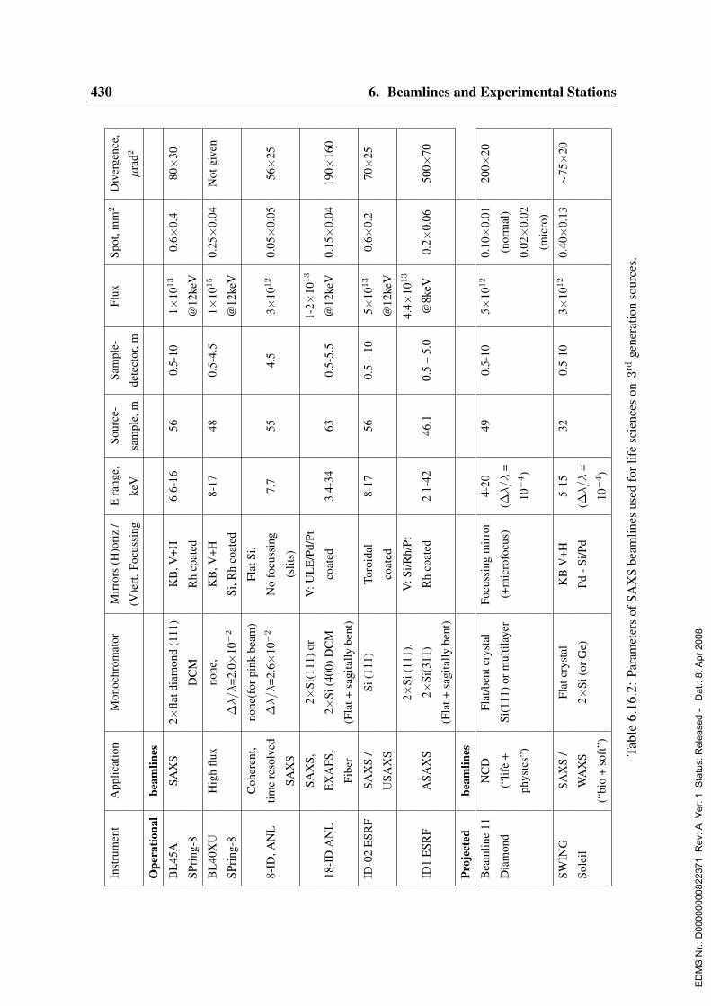
430 6. Beamlines and Experimental StationsIn
stru
men
tA
pplic
atio
nM
onoc
hrom
ator
Mir
rors
(H)o
riz
/E
rang
e,So
urce
-Sa
mpl
e-Fl
uxSp
ot,m
m2
Div
erge
nce,
(V)e
rt.F
ocus
sing
keV
sam
ple,
mde
tect
or,m
µra
d2
Ope
ratio
nal
beam
lines
BL
45A
SAX
S2×
flatd
iam
ond
(111
)K
B,V
+H6.
6-16
560.
5-10
1×10
13
0.6×
0.4
80×
30
SPri
ng-8
DC
MR
hco
ated
@12
keV
BL
40X
UH
igh
flux
none
,K
B,V
+H8-
1748
0.5-
4.5
1×10
15
0.25×
0.04
Not
give
n
SPri
ng-8
∆λ/λ
=2.0×
10−
2Si
,Rh
coat
ed@
12ke
V
Coh
eren
t,no
ne(f
orpi
nkbe
am)
Flat
Si,
8-ID
,AN
Ltim
ere
solv
ed∆
λ/λ
=2.6×
10−
2N
ofo
cuss
ing
7.7
554.
53×
1012
0.05×
0.05
56×
25
SAX
S(s
lits)
SAX
S,2×
Si(1
11)o
rV
:UL
E/P
d/Pt
1-2×
1013
18-I
DA
NL
EX
AFS
,2×
Si(4
00)D
CM
coat
ed3.
4-34
630.
5-5.
5@
12ke
V0.
15×
0.04
190×
160
Fibe
r(F
lat+
sagi
tally
bent
)
ID-0
2E
SRF
SAX
S/
Si(1
11)
Toro
idal
8-17
560.
5–
105×
1013
0.6×
0.2
70×
25
USA
XS
coat
ed@
12ke
V
2×Si
(111
),V
:Si/R
h/Pt
4.4×
1013
ID1
ESR
FA
SAX
S2×
Si(3
11)
Rh
coat
ed2.
1-42
46.1
0.5
–5.
0@
8keV
0.2×
0.06
500×
70
(Fla
t+sa
gita
llybe
nt)
Proj
ecte
dbe
amlin
es
Bea
mlin
e11
NC
DFl
at/b
entc
ryst
alFo
cuss
ing
mir
ror
4-20
490.
5-10
5×10
12
0.10×
0.01
200×
20
Dia
mon
d(“
life
+Si
(111
)orm
ultil
ayer
(+m
icro
focu
s)(∆
λ/λ
=(n
orm
al)
phys
ics”
)10−
4)
0.02×
0.02
(mic
ro)
SWIN
GSA
XS
/Fl
atcr
ysta
lK
BV
+H5-
1532
0.5-
103×
1012
0.40×
0.13
∼75×
20
Sole
ilW
AX
S2×
Si(o
rGe)
Pd-S
i/Pd
(∆λ/λ
=
(“bi
o+
soft
”)10−
4)
Tabl
e6.
16.2
:Par
amet
ers
ofSA
XS
beam
lines
used
forl
ife
scie
nces
on3r
dge
nera
tion
sour
ces.
ED
MS
Nr.:
D00
0000
0082
2371
Rev
: A V
er: 1
Sta
tus:
Rel
ease
d -
Dat
.: 8.
Apr
200
8
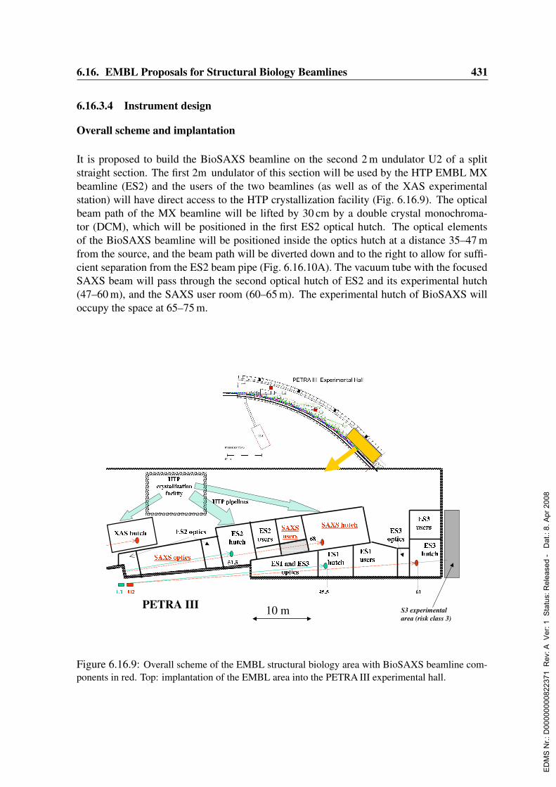
6.16. EMBL Proposals for Structural Biology Beamlines 431
6.16.3.4 Instrument design
Overall scheme and implantation
It is proposed to build the BioSAXS beamline on the second 2 m undulator U2 of a splitstraight section. The first 2m undulator of this section will be used by the HTP EMBL MXbeamline (ES2) and the users of the two beamlines (as well as of the XAS experimentalstation) will have direct access to the HTP crystallization facility (Fig. 6.16.9). The opticalbeam path of the MX beamline will be lifted by 30 cm by a double crystal monochroma-tor (DCM), which will be positioned in the first ES2 optical hutch. The optical elementsof the BioSAXS beamline will be positioned inside the optics hutch at a distance 35–47 mfrom the source, and the beam path will be diverted down and to the right to allow for suffi-cient separation from the ES2 beam pipe (Fig. 6.16.10A). The vacuum tube with the focusedSAXS beam will pass through the second optical hutch of ES2 and its experimental hutch(47–60 m), and the SAXS user room (60–65 m). The experimental hutch of BioSAXS willoccupy the space at 65–75 m.
Figure 6.16.9: Overall scheme of the EMBL structural biology area with BioSAXS beamline com-ponents in red. Top: implantation of the EMBL area into the PETRA III experimental hall.
ED
MS
Nr.:
D00
0000
0082
2371
Rev
: A V
er: 1
Sta
tus:
Rel
ease
d -
Dat
.: 8.
Apr
200
8

432 6. Beamlines and Experimental Stations
Optical elements
Several possible options have been considered for the BioSAXS optics setup to optimizethe beam size/divergence, stability and convenience of use. It was decided to use a flexi-ble setup separating monochromatizing and focussing elements and to employ a moderatelyfocussing configuration with small demagnification to minimize the beam divergence at thefocus. Given the extremely low emittance of the PETRA III undulator, such a setup permitsone to obtain a clean low divergence beam and to reach the scattering vectors correspondingto more than 2000 nm resolution.
The major elements of the beamline presented in Tab. A.1.5 and Fig. 6.16.10 are:
1. Beryllium window and pinhole. To reduce the absorption at low energies, a beryl-lium window of reduced thickness (250µm) is proposed (at 4 keV, this window yieldstransmission T=67% vs T=44% of a 500µm window). The position of the undulatorbeam will be detected by white beam monitors WBM (tungsten wire scan and/or slitscan, the latter detecting also the central cone). A cooled slit system (P) with variablesize will select the most intense portion of the white beam thus reducing the heat loadonto the subsequent optical elements.
2. Monochromators. A flat cryogenically cooled Si(111) fixed exit DCM is positionedat 37 m distance. We suggest the DCM to be the first optical element as it is relativelyeasy to adjust and monitor its position and orientation in the white beam by observingthe Bragg reflection from the first crystal. The DCM will provide ∆λ/λ=1-2×10−4 forpossible ASAXS applications in the relevant energy range (from 4 to 20 keV). For highflux studies, the DCM will be replaced by a cryogenically cooled Mo/C double multi-layer monochromator (MLM) at a distance of 38 m yielding two orders of magnitudegain in flux at the expenses of a broader bandpath (from ∆λ/λ=1.5×10−2 at 7 keVto ∆λ/λ=2.0×10−2 at 15 keV). Due to the smaller incidence angle of the MLM, thedistance between the two multilayers will be larger than that between the crystals inthe DCM (up to 0.7 m).
3. Slits and beam monitoring. Three pairs of cylindrical horizontal and vertical slitswill be used (Fig. 6.16.10). Slit S1 will select the central cone of the undulator anddefine the beam size. Slit S2, located at about 5 m before the sample, will reduce thebackground from the optical elements, and the guard slit S3 in front of the sample willreduce the parasitic scattering from S2. The position of the monochromatic beam willbe monitored by the removable fluorescent screens and pin diodes (beam monitors,BM). The intensity of the incoming beam will be measured by a removable pin diodeand/or by a non-removable device like ionization chamber or glassy carbon placedafter S3 in front of the sample and the transmitted intensity by the diode mounted ontothe beam stop.
4. Focussing mirrors. A pair of cylindrically bent mirrors in Kirkpatrick-Baez (KB)configuration will be used for harmonics rejection and focussing (Fig. 6.16.10). The
ED
MS
Nr.:
D00
0000
0082
2371
Rev
: A V
er: 1
Sta
tus:
Rel
ease
d -
Dat
.: 8.
Apr
200
8

6.16. EMBL Proposals for Structural Biology Beamlines 433
first vertically focussing mirror (VFM1), positioned at 40 m, slightly reduces the ver-tical beam size (1:1.2 demagnification). The horizontally focussing mirror (HFM) at45 m will reduce the horizontal beam size (1:1.6 demagnification). When used with theDCM and MLM, the water-cooled mirrors will work at a fixed incidence angle (0.18)and fixed curvatures (11.5 km for VFM1 and 11 km for HFM) to focus the beam at73 m. Each mirror will have two coatings (Si and Rh) to work in the energy ranges4-9 keV and 9-20 keV, respectively (Fig. 6.16.11A).
5. Pink beam mode. For extra high flux (three times more than for MLM) and coherentscattering applications, a pink beam option will be provided with ∆λ/λ=2×10−2. Thismode will be used for the energies around 8 keV, near the maximum brilliance of thefundamental undulator line. In this mode DCM and MLM will be removed from theoptical path, and the first optical element will be a vertically focussing nitrogen cooledmirror VFM2 at 43.2 m (1:1.4 demagnification). This Si coated mirror will have thesame focal point and grazing angle as VFM1 to keep the beam trajectory unchanged,so that there will be no need to adjust the focussing of the HFM.
The above configuration will ensure easy and rapid change of mode of operation between theDCM, MLM and pink beam options. The mirror inclinations will be fixed in normal modesof operation but could be changed if additional focussing elements like beryllium lenses willbe introduced. All the optical elements will be positioned in the SAXS optical hutch to workunder ultra-high vacuum conditions. Differential pumping will be employed to ensure thatthis portion of the beamline operates in ultra-high vacuum.
6.16.3.5 Beamline performance
To estimate the beam size, divergence and flux on the sample in the proposed configuration,ray tracing calculations were performed. The parameters of the 2 m long U2 PETRA IIIundulator were: period 2.9 cm, Kmax=2.2, yielding the source size 330×13µm2 and diver-gence 26×21µrad2 (both horizontal×vertical FWHM). The simulations were done usingthe programs XOP (ESRF) and SHADOW (University of Wisconsin) for the three modesof operation: (i) DCM in the range 4-20 keV; (ii) MLM @ 8 keV; (iii) pink beam @ 8 keV.The position of the focus was at 73 m from the source, and the offset of the beam cen-ter with respect to the initial beam direction at the focus point was 17.6 cm (horizontal)and -18.7 cm (vertical) (Fig. 6.16.10A). All the computations were made for the partial fluxthrough the aperture of 1.2×0.7 mm2 (horizontal×vertical) at 35 m distance (the pinhole sizecorresponding to the central cone). A 0.5µrad mean slope error of the mirrors was assumed;mirror surface roughness up to 1 nm did not change the size and divergence significantly.The beam size and divergence obtained by the ray tracing are presented in Fig. 6.16.10B,C.The materials, positions and orientations of optical elements are given in Tab. A.1.5 andthe computed properties of the beam in Tab. 6.16.4. Fig. 6.16.11B presents the energydistributions in the partial flux for the configurations with DCM, MLM and pink beam.From comparison with the existing and planned SAXS beamlines on 3rd generation sources(Tab. 6.16.2) it can be concluded that the BioSAXS beamline will provide the overall widest
ED
MS
Nr.:
D00
0000
0082
2371
Rev
: A V
er: 1
Sta
tus:
Rel
ease
d -
Dat
.: 8.
Apr
200
8

434 6. Beamlines and Experimental Stations
Figure 6.16.10: Schematic design of the BioSAXS beamline. The bottom scale displays distancefrom the source in meters; for explanations, see text. Insert A displays the cross section perpendicularto the beam direction at the focal point at 73 m from the source (distances are shown in cm). InsertsB and C present spatial and angular distribution of rays at the focal point simulated by SHADOW fora DCM setup at 8 keV.
experimental flexibility simultaneously yielding, thanks to the unique properties of the PE-TRA III beam, the best divergence for the given beam size.Allowing for a beamstop size five times larger than the beam size (FWHM), the first usefulexperimental point in the vertical direction could be measured at about 0.3 mm. For a sample-detector distance of 5 m and the wavelength λ=0.15 nm (E=8 keV), this yields the minimumscattering vector smin=2.5×10⁻³ nm where s = (4π/λ)sin(θ), 2θ being the scattering angle.This yields the resolution up to d=2π/smin= 2500 nm, comparable with that provided byUSAXS (Ultra Small Angle X-ray Scattering) in Bonse-Hart geometry. This resolution ofthe setup is also justified by the ultra-small beam divergence at the sample: over a 5 msample-detector distance, the effect of beam deterioration (smearing) due to the divergencedoes not exceed 0.1 mm.If required for future applications (e.g. for observation of a few particle scattering fromflash-frozen samples) the beam size could be further reduced (i.e. with beryllium lenses)at the expenses of divergence. The space for positioning the microfocussing lenses will be
ED
MS
Nr.:
D00
0000
0082
2371
Rev
: A V
er: 1
Sta
tus:
Rel
ease
d -
Dat
.: 8.
Apr
200
8

6.16. EMBL Proposals for Structural Biology Beamlines 435
Figure 6.16.11: Reflectivity of the Si and Rh mirrors at the grazing angle of 0.18 degrees as afunction of photon energy (A) and the partial flux (in 0.1%BW) of the U2 undulator at 8 KeV througha 2.0×1.5 mm2 slit at 73 m calculated by SPECTRA (broken line), together with appropriately scaledSHADOW histograms of energy distribution in the beam using different monochromatization options.
available in the small hutch adjacent to the SAXS user room (gray shaded in Fig. 6.16.9;60–65 m from the source).
6.16.3.6 Experimental hutch
The experimental hutch will have dimensions 10×5 m2. A motorized table (with a platformof 1×1 m2 size able to accommodate pre-mounted sample holders of different types) will bepositioned between the slits S3 and the entrance of the evacuated detector tube. A secondcopy of the table platform will be available for mounting another type of sample holderduring the current experiment. The sample environment will contain the following options:
• thermostated automated changer of vacuum-tight cells for HTP studies
• thermostated setup with sample circulation to diminish radiation damage
• thermostated stopped-flow apparatus for fast kinetic studies
• cryo-cell to measure flash-frozen samples
• high pressure cell
• a coherent scattering spectrometer
• a triple axis goniometer for measuring crystals with large unit cells.
ED
MS
Nr.:
D00
0000
0082
2371
Rev
: A V
er: 1
Sta
tus:
Rel
ease
d -
Dat
.: 8.
Apr
200
8
436 6. Beamlines and Experimental Stations
In most configurations, the sample will be kept in vacuum so that the detector tube will beconnected to the vacuum tube containing the optical elements. This will allow to avoid extrawindows and to minimize the background scattering and will also be useful for anaerobicexperiments. Configurations to measure liquid and solid samples in open sample containersin air will be foreseen as well. A mechanical shutter (MS) will be installed between slits S2and S3 for fast time resolved experiments.The beam alignment at the sample position will be monitored by a position sensitive ioniza-tion chamber. Two detectors will be used to register the scattering at small and wide angles,whenever possible, simultaneously (SAXS and WAXS detectors D1 and D2, respectively).The sample-detector distances will be variable (SAXS detector: from 1 to 6 m, WAXS detec-tor: 0.3 to 1 m). Off-center positions of the detectors will be foreseen to cover wider angularrange, which requires a large diameter (about 1.0 m) detector tank (displayed in dashed linein Fig. 6.16.10). The SAXS detector will provide high count rates at low noise and coverwide dynamic ranges without spatial distortions. It is expected that the further developmentof hybrid pixel detectors (Berar et al., 2002) will lead by 2007 to the detectors of sufficientsize to be effectively used for SAXS data registration. Another option would be e.g. a flatpanel solid state selenium detector (MAR Research), which could also be employed for datacollection at wide angles.The user room (3×5 m2) will be placed before the experimental hutch for monitoring theexperiment, on-site sample preparation and mounting. In addition to the acquisition systeminterface, the room will contain minimum sample storage and handling equipment like re-frigerator, balance, centrifuge, etc. For specialized biochemical work the users may use theEMBL on-site facilities. Two offices for four persons (personnel, users) will be required inthe office block of PETRA III.
6.16.3.7 Data analysis system
As the present beamline is designed for HTP studies, adequate real-time data processing andmodel-building techniques are indispensable. An integrated software system covering allthe analysis steps from data reduction to automated modelling methods will therefore be in-stalled at the beamline. It could be run either interactively via a menu-driven graphical userinterface launching the data analysis modules or automatically for which a decision-takingblock will be included to select proper analysis actions and to compare concurrent models.This system will be primarily oriented towards the analysis of biological macromolecules,but could also be used for non-biological isotropic and partially oriented objects (inorganic,colloidal solutions, polymers in solution and bulk).
The major components of the system will be:
• Primary data processing and reduction package based on the recently developedprogram package PRIMUS (Konarev et al., 2003) will employ standard data storageformats like Nexus (Maddison, Swofford & Maddison, 1997) and sasCIF (Malfois &Svergun, 2000). Major data processing steps will be performed automatically to com-pute characteristic functions and overall structural parameters.
ED
MS
Nr.:
D00
0000
0082
2371
Rev
: A V
er: 1
Sta
tus:
Rel
ease
d -
Dat
.: 8.
Apr
200
8
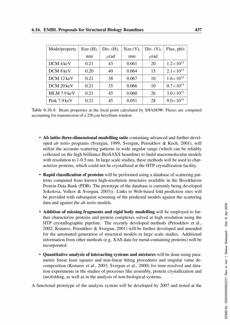
6.16. EMBL Proposals for Structural Biology Beamlines 437
Mode/property Size (H), Div. (H), Size (V), Div. (V), Flux, ph/s
mm µrad mm µrad
DCM 4 keV 0.21 43 0.061 20 1.2×10¹³
DCM 8 keV 0.20 40 0.064 15 2.1×10¹³
DCM 12 keV 0.21 38 0.067 10 1.6×10¹³
DCM 20 keV 0.21 35 0.066 10 0.7×10¹³
MLM 7.9 keV 0.21 45 0.060 26 3.0×10¹⁵
Pink 7.9 keV 0.21 45 0.051 28 9.0×10¹⁵
Table 6.16.4: Beam properties at the focal point calculated by SHADOW. Fluxes are computedaccounting for transmission of a 250 µm beryllium window.
• Ab initio three-dimensional modelling suite containing advanced and further devel-oped ab initio programs (Svergun, 1999; Svergun, Petoukhov & Koch, 2001), willutilize the accurate scattering patterns in wide angular range (which can be reliablycollected on the high brilliance BioSAXS beamline) to build macromolecular modelswith resolution to 1-0.5 nm. In large scale studies, these methods will be used to char-acterize proteins, which could not be crystallized at the HTP crystallization facility.
• Rapid classification of proteins will be performed using a database of scattering pat-terns computed from known high-resolution structures available in the BrookhavenProtein Data Bank (PDB). The prototype of the database is currently being developedSokolova, Volkov & Svergun, 2003)). Links to Web-based fold prediction sites willbe provided with subsequent screening of the predicted models against the scatteringdata and against the ab initio models.
• Addition of missing fragments and rigid body modelling will be employed to fur-ther characterize proteins and protein complexes solved at high resolution using theHTP crystallographic pipeline. The recently developed methods (Petoukhov et al.,2002; Konarev, Petoukhov & Svergun, 2001) will be further developed and amendedfor the automated generation of structural models in large scale studies. Additionalinformation from other methods (e.g. XAS data for metal-containing proteins) will beincorporated.
• Quantitative analysis of interacting systems and mixtures will be done using para-metric linear least squares and non-linear fitting procedures and singular value de-composition (Konarev et al., 2003; Svergun et al., 2000) for time-resolved and titra-tion experiments in the studies of processes like assembly, protein crystallization and(un)folding, as well as in the analysis of non-biological systems.
A functional prototype of the analysis system will be developed by 2007 and tested at the
ED
MS
Nr.:
D00
0000
0082
2371
Rev
: A V
er: 1
Sta
tus:
Rel
ease
d -
Dat
.: 8.
Apr
200
8

438 6. Beamlines and Experimental Stations
EMBL beamline X33 at DORIS. It is planned to incorporate a training block into the systememploying neural networks for advanced decision-taking and possible user-less operation.
6.16.3.8 Conclusions
The proposed BioSAXS beamline will adequately exploit the exceptionally high brillianceof the PETRA III source to provide an experimental SAXS station with excellent parame-ters (dynamic range, flux and beam size, divergence) and broad capabilities. The BioSAXSbeamline, linked to a HTP protein crystallization facility and equipped with a comprehensivedata analysis system will comprise a unique environment for large scale SAXS analysis ofbiological macromolecules, and, in particular, for simultaneous MX/SAXS/XAS analysis.The beamline will also be available for soft condensed matter and material science appli-cations. The construction of this beamline will further improve the efficiency of structuralanalysis using the small-angle scattering technique, and the expertise gained at BioSAXSwill be shared with other large scale facilities in Europe and worldwide.
6.16.3.9 Cost estimates
The total investment costs of the BioSAXS beamline is estimated to 2.7 Me.
Personnel (minimum requirement assuming efficient support structure): 4 staff×3 years,60 ke/person/year 0.7 Me
Total construction costs: 3.4 Me
Running costs: 4×staff + maintenance: about 0.5 Me/Year
ED
MS
Nr.:
D00
0000
0082
2371
Rev
: A V
er: 1
Sta
tus:
Rel
ease
d -
Dat
.: 8.
Apr
200
8

6.16. EMBL Proposals for Structural Biology Beamlines 439
6.16.4 Biological X-ray absorption spectroscopy (BioXAS)Author: Wolfram Meyer-Klaucke
External advisors:Isabella Ascone LURE, Orsay, FranceHolger Dau FU Berlin, Berlin, GermanyGerald Henkel Paderborn University, Paderborn, GermanyKeith Hodgson SSRL, Stanford, USAJames Penner-Hahn University of Michigan, Ann Arbor, USAStefano Mangani Siena University, Siena, ItalyRobert Scott University of Georgia, Athens, USA
6.16.4.1 Present and future challenges for biological X-ray absorption spectroscopy
X-ray absorption spectroscopy (XAS) determines the electronic structure of probe atoms andtheir structural vicinity. Experiments are independent of sample state, providing flexibilityfor the combination with a variety of experimental setups. Thus this spectroscopy is per-formed on small volumes as well as on bulk material, on frozen material or on a continuousflow of solution. The technique also structurally characterizes dynamic processes, such ascatalytic or light driven reactions.In biology typical probe atoms are metals (e.g. Fe, Zn, Mo) or other elements of limitedoccurrence (e.g. Br, Se, I). In proteins metals fulfill a variety of essential functions: Theystabilize the secondary protein structure, they serve as binding partners in transport pro-cesses, they define the pathway for electron transfer, and they act as key elements in catalyticreactions.Every year an increasing number of proteins is isolated. In at least 30% of these gene prod-ucts, metals are believed to play a key role; these are classified as metallo-proteins. Someof them, the metallo-enzymes, are catalytically active. The metal ions can serve as probeatoms in spectroscopy. X-ray absorption spectroscopy (XAS) is the only element specifictechnique that can utilize all metals as probe atoms and determine their metal binding motif.It can thereby identify the metals function in the protein (e.g. Dau, Liebisch & Haumann,2003; Pohl et al., 2003; Scott et al., 1982). In biocatalysis XAS characterizes the activesite depending on physico-chemical parameters, like temperature, pH, substrate or inhibitorconcentration, metal content etc. (e.g. Carrington et al., 2003).In addition to these well-established experiments more and more research activities focuson dynamic processes. In these experiments reaction intermediates are generated by rapidmixing devices (Kleifeld et al., 2003) or by light driven reactions (Dau & Haumann, 2003).The later experiments include pilot experiments for future XFEL applications. IncreasinglyBioXAS data are measured with high spatial resolution. Researchers obtain two or threedimensional maps of metal coordination and oxidation state. In the upcoming system biol-ogy projects research is no longer limited to isolated proteins. It is the interaction betweenproteins and the influence of external conditions that comes into play now. The so-calledMetallome, reflecting the role of metals on the cellular basis, will have an important role. Itis likely that again XAS will be the method of choice to provide element specific informa-
ED
MS
Nr.:
D00
0000
0082
2371
Rev
: A V
er: 1
Sta
tus:
Rel
ease
d -
Dat
.: 8.
Apr
200
8
440 6. Beamlines and Experimental Stations
tion on distribution, oxidation state and environment of metal ions in entire organisms andsubsets.
Current state of the scientific field
In the past decades X-ray absorption spectroscopy (XAS) has become a widely used tech-nique in biology and biochemistry. The element specific characterization of electronic statesand local environment has illuminated the role of metals in many catalytic reactions. More-over, it identifies functional metal binding sites. Such detailed information on metal oxi-dation state and metal coordination with subatomic resolution can be obtained by no othermethod on samples of any state, like solutions, crystals, cell extracts, or organism tissues.The independence of the sample state is a key feature of XAS. Entire organism tissues (e.g.bone, corals) are transparent for X-rays with more than 6 keV. The local environment ofprobe atoms in such organisms helps to understand general biological and geological pro-cesses (Greegor, Pingitore Jr. & Lytle, 1997). In order to illuminate the structure-functionrelation of the metal centers the effect of physico-chemical parameters on such samples isstudied (e.g. Pufahl et al., 1997; Wang et al., 1998b). The higher the number of differentsample states analyzed, the more detailed will the catalytic mechanism be understood.The role of BioXAS in molecular biology has changed in recent years. In the early days,the synergism with techniques like NMR (Banci et al., 2003) and protein crystallography(Scott et al., 1982; Hasnain & Strange, 2003) was not widely exploited. This has changeddramatically. Excellent scientific achievements could in many cases only be achieved due tojoint efforts of scientists from different fields (Arnesano et al., 2003; Pohl et al., 2003).At present for most BioXAS experiments, metal concentrations of about 1 mM are required,except at the most intense synchrotron sources. Although this value represents the lowerconcentration limit for data collection it is at the same time a very high concentration forproteins. Frequently, proteins precipitate at such concentrations. Increasing the maximumconcentration of protein in solution is time consuming and frequently fails. Thus BioXASexperiments require a tunable high-flux source of synchrotron radiation. At present the onlyspectrometer in Europe fully dedicated to BioXAS is the EMBL Hamburg bending magnetbeamline. All other spectrometers in Europe capable of performing BioXAS applicationsshare the experimental facilities with non-biological applications and are not embedded ina molecular biological research environment. Therefore, many of these facilities (Asone,Meyer-Klaucke & Murphy, 2003) are not optimized for BioXAS experiments or will nolonger be available in future (like DCI, France or SRS, UK). The EMBL Outstation Hamburgplays a central role in European BioXAS as a provider of experimental facilities dedicatedto biological experiments, a host for advanced training courses and a nucleus for methodsdevelopment. This key role has to be maintained in future.
6.16.4.2 Science at PETRA III – scientific case summary
High-throughput BioXAS
A BioXAS undulator station at PETRA III will provide a unique opportunity for molecular
ED
MS
Nr.:
D00
0000
0082
2371
Rev
: A V
er: 1
Sta
tus:
Rel
ease
d -
Dat
.: 8.
Apr
200
8

6.16. EMBL Proposals for Structural Biology Beamlines 441
biology in Europe. Experiments, like the ones summarized above, will be performed in ahigh-throughput mode. Compared to present data collection the amount of protein will bereduced by a factor 100 to 1000, down to about 5µg of protein. Under such conditionstypical BioXAS experiments can be performed in a high-throughput mode. This opens upnew fields for the characterization of metal binding sites in genomics and metallomics.The advantage of high-throughput XAS is realized by examination of individual compo-nents of an expressed proteome. The metal sites found in proteins expressed in vitro areexpected to retain biological relevance. Distribution of metals and relative expression levelsof metalloproteins as a function of environment (e.g. microbial growth conditions) couldbe determined readily. But the promise of metalloproteomics goes beyond the usual expres-sion profiling; this is accessible by standard proteomics techniques, in which the polypeptidechain of a given metalloprotein is quantified and related to environmental influences. For-mation of biologically relevant metal sites often requires a set of post-translational events,including metal transport, trafficking, metallocenter assembly, cluster exchange, etc., any ofwhich could be influenced by environmental changes. These metal-based, post-translationalevents are invisible to standard proteomics analysis and are therefore the sole purview ofmetalloproteomics (Scott, 2004).The set-up is also used for the characterization of steady states. By variation of the physico-chemical environment and by rapid freezing of reaction intermediates, a variety of proteinstates can be prepared and stabilized at cryogenic temperatures for the high-throughput XASanalysis. The much lower threshold for sample volume and concentration will allow to ex-pand the application of XAS in molecular biology to many metallo-proteins that can eithernot be produced in the quantities required at present or not be concentrated up to the mMmetal concentrations, because the protein precipitates. A third advantage of lower concen-trations is that these are more relevant to in vivo conditions; high protein concentration canlead to aggregate formation (Ralle, Lutsenko & Blackburn, 2003; Penner-Hahn, 2004) thatis not representative of the in vivo structure. Therefore, such a station is a breakthrough inthe characterization of metallo-proteins. Due to the unique environment to perform molec-ular biology experiments offered by the EMBL Outstation Hamburg, the characterizationof metal oxidation state and metal environment might even become a standard part of mostbiochemical work on metallo-proteins performed in Europe.Specific requirements and design criteria result from the irradiation sensitivity of the bio-logical sample. Exposure of metallo-proteins to high-intensity X-rays leads to changes inredox state (photoreduction) and structure that typically precede the damage to the aminoacid matrix. For very sensitive samples the onset of discernible photoreduction requires at20 K an integrated X-ray exposure of 1012-1014 photons/mm2. Irradiation by ∼1013 pho-tons is required for the collection of artefact-free data. This corresponds to scan durationsof ∼1 s and an irradiated sample area of 1 mm2 or greater. At the high-throughput stationthe potential photoreduction of protein and metal will be minimized by four means. First ofall the sample will be cooled down to 5 K in a closed cycle cryostat. Second the solid anglefor gathering of fluorescence radiation will be increased compared to present set-ups. Anoptimized ratio between incoming photons and collected fluorescence radiation lowers thenumber of photons on the sample required for a defined data quality. Third the experimentwill have full control over the undulator gap. The EXAFS signal decays with k3. In order
ED
MS
Nr.:
D00
0000
0082
2371
Rev
: A V
er: 1
Sta
tus:
Rel
ease
d -
Dat
.: 8.
Apr
200
8
442 6. Beamlines and Experimental Stations
to achieve a constant signal to noise ratio over the entire data range of about 1.5 keV theacquisition times at higher energies must rise in an appropriate way. By joint movement ofundulator gap and monochromator this optimizes the time for data acquisition, which effec-tively reduces the photoreduction. Fourth the photon flux can be spread over an area of 2 - 5mm2 by bending mirror 2 depending on the sensitivity of the metal center.
Cutting-edge experiments
By cutting-edge experiments new kind of information on the function of metals in biologywill be revealed that is mostly inaccessible to other experimental techniques.
(a) Time-resolved BioXAS experiments facilitate insights in reaction dynamics/kineticsand structural characterization of intermediate states (Dau, Liebisch & Haumann, 2003;Penner-Hahn, 2004). The proposed time-resolved experiments represent an exciting newapproach towards understanding of biological function (catalysis) at the atomic level.
The following types of time-resolved BioXAS experiments are planned:
Continuous flow-and-mixing. In combination with rapid mixing intermediate states can beidentified and characterized at a ms time scale (Kleifeld et al., 2003; Penner-Hahn, 2004).Even for experiments that do not require high time resolution, there is still a significant ad-vantage in making measurements under flow conditions. This setup allows one to make mea-surements in fluid solution without the danger of radiation damage. Room-temperature fluidsolution measurements are essential for studies of thermochromic materials (Whittaker &Whittaker, 1996); such measurements require the small beam and high flux density that willbe possible at PETRA III, but are not feasible using sources such as DORIS.
Voltametry and temperature cycling. The electrochemical potential (or temperature) is variedand a spectrum is taken, say, every 100 ms by piezo-QXAFS (Richwin et al., 2002).
Triggered reactions with ∆t > 10 ms–100 s. The reaction is initiated by a light pulse (pho-totrigger, release of caged substances), temperature pulse or jump, potential jump, or stopped-flow techniques. Then a time series of spectra is collected either by piezo-QXAFS (10ms>∆t< 1 s) or by rapid scanning of monochromator and undulator gap (∆t > 1 s).
Laser-triggered reactions with time resolutions of ∆t > 1µs. Employing either the photo-chemical reactions of the investigated metalloprotein itself or of suitable caged compounds,the investigated process is initiated by a ns laser pulse. For each flash-experiment a specificexcitation energy is chosen and the time course of the excited X-ray fluorescence is mon-itored. By carrying out this time scan experiment at 20-50 excitation energies, completeXANES and EXAFS spectra of high quality can be constructed (H. Dau, personal communi-cation). The practical limit of time resolution is estimated to fall in the range of 1-20µs. Forthe (unfortunately rare) processes that can be repetitively triggered on the same sample, alsons-experiments may become practicable. [microfocus of about 50µm x 50µm to minimize
ED
MS
Nr.:
D00
0000
0082
2371
Rev
: A V
er: 1
Sta
tus:
Rel
ease
d -
Dat
.: 8.
Apr
200
8

6.16. EMBL Proposals for Structural Biology Beamlines 443
sample consumption; plus ms beam shutter to prevent radiation damage]
(b) Spatially resolved XANES (tomography) facilitates spatially resolved speciation withrespect to oxidation state and ligand environment (Schroer et al., 2003a). Most experimentson tissue will require reference spectra collected under similar conditions. Rapid scans cov-ering several edges will be one of the new experimental strategies to counteract the radiationdamage problem. Thereby 3-dimensional maps on metal oxidation state and environmentwill visualize metal accumulation and distribution, providing new insights into detoxificationprocesses and metal utilization. Even in the absence of spatial resolution such experimentsreceive more and more attention (Harris, Pickering & George, 2003)). [microfocus with spotsize of 70 nm–1µm depending on scientific demands].
(c) Beyond the importance of high-resolution fluorescence for site-specific measurements,these experiments have the advantage that they provide greatly improved experimental reso-lution for XANES studies (de Groot, Krisch & Vogel, 2002; Kivimaki et al., 1998; Hamalainenet al., 1991). Improved energy resolution is critical for resolving small features on the edge,and thus for deducting details of the electronic structure of the absorbing site. Another ad-vantage of high-resolution experiments is that they offer, for the first time, the possibilityof distinguishing directly between different ligation types. In conventional EXAFS like inmost structural methods, it is impossible to tell the difference between, for example, N and Oligands. However, in high resolution fluorescence it is possible to resolve cross-over bands(core-electron charge transfer transitions) such as the Kβ′′ transition, that can be used todistinguish between N and O ligands (Bergmann et al., 1999). [expanded beam to preventphotoreduction or small spot if continuous flow cell is used].
(d) XAS on protein crystals merges protein crystallography (MX) and X-ray absorptionspectroscopy for the determination and differentiation of active site ligands as CN and COor sulfide and oxide (Hedman, in prep.). [focused beam to match crystal size].
Recent publications have illustrated the potential of the experiments mentioned above. Aflexible set-up is required to fulfill the demands of the complex instrumentation. Thereforein the second hutch user groups will find a modular experimental area consisting of fivemain parts: (a) rapid mixing device for time resolved experiments, (b) a laser system forpump and probe experiments, (c) a system of X-ray lenses for spatial resolved experimentswith a resolution of about 100 nm, (d) a goniometer with xy table for XAS tomography and(e) a fluorescence analyzer with meV energy resolution. A goniometer for mounting proteincrystals will be transferred from present DORIS stations. In order to minimize set-up periodsall equipment will be mounted on individual honeycomb tables so that components can beeasily exchanged depending on the scientific demands.
6.16.4.3 Experimental considerations for the BioXAS station
The K- and L- edges of most important probe elements in biological material are coveredby the energy range from 5 keV to 35 keV. Thus all elements from Vanadium up to Iodine
ED
MS
Nr.:
D00
0000
0082
2371
Rev
: A V
er: 1
Sta
tus:
Rel
ease
d -
Dat
.: 8.
Apr
200
8
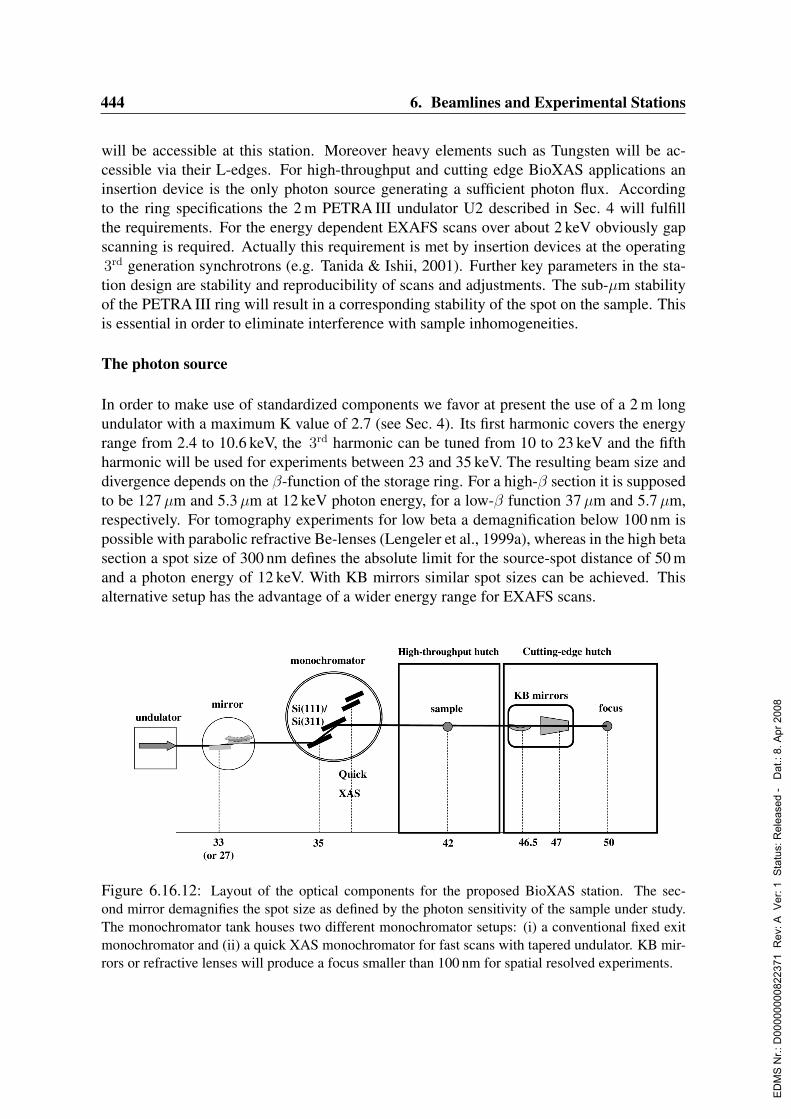
444 6. Beamlines and Experimental Stations
will be accessible at this station. Moreover heavy elements such as Tungsten will be ac-cessible via their L-edges. For high-throughput and cutting edge BioXAS applications aninsertion device is the only photon source generating a sufficient photon flux. Accordingto the ring specifications the 2 m PETRA III undulator U2 described in Sec. 4 will fulfillthe requirements. For the energy dependent EXAFS scans over about 2 keV obviously gapscanning is required. Actually this requirement is met by insertion devices at the operating3rd generation synchrotrons (e.g. Tanida & Ishii, 2001). Further key parameters in the sta-tion design are stability and reproducibility of scans and adjustments. The sub-µm stabilityof the PETRA III ring will result in a corresponding stability of the spot on the sample. Thisis essential in order to eliminate interference with sample inhomogeneities.
The photon source
In order to make use of standardized components we favor at present the use of a 2 m longundulator with a maximum K value of 2.7 (see Sec. 4). Its first harmonic covers the energyrange from 2.4 to 10.6 keV, the 3rd harmonic can be tuned from 10 to 23 keV and the fifthharmonic will be used for experiments between 23 and 35 keV. The resulting beam size anddivergence depends on the β-function of the storage ring. For a high-β section it is supposedto be 127µm and 5.3µm at 12 keV photon energy, for a low-β function 37µm and 5.7µm,respectively. For tomography experiments for low beta a demagnification below 100 nm ispossible with parabolic refractive Be-lenses (Lengeler et al., 1999a), whereas in the high betasection a spot size of 300 nm defines the absolute limit for the source-spot distance of 50 mand a photon energy of 12 keV. With KB mirrors similar spot sizes can be achieved. Thisalternative setup has the advantage of a wider energy range for EXAFS scans.
Figure 6.16.12: Layout of the optical components for the proposed BioXAS station. The sec-ond mirror demagnifies the spot size as defined by the photon sensitivity of the sample under study.The monochromator tank houses two different monochromator setups: (i) a conventional fixed exitmonochromator and (ii) a quick XAS monochromator for fast scans with tapered undulator. KB mir-rors or refractive lenses will produce a focus smaller than 100 nm for spatial resolved experiments.
ED
MS
Nr.:
D00
0000
0082
2371
Rev
: A V
er: 1
Sta
tus:
Rel
ease
d -
Dat
.: 8.
Apr
200
8
6.16. EMBL Proposals for Structural Biology Beamlines 445
It is important that the energy width of the undulator flux can be broadened. By taperinga gain of up to 200 eV in the harmonic width will be achieved at the expense of a reducedspectral flux. This will enable XANES scans to be easily obtained and ensures compatibilityof the source with the piezo-QEXAFS monochromator used for tomography.
Optics
The first optical element takes most of the heat load produced by the insertion device. Hereit will be a flat double mirror, which can vary the cut-off energy so that higher harmonicscontributions can be minimized. Two different coatings will be available covering the energyrange 5–13 keV and 12–35 keV, respectively. Details on the coatings will depend on ongoinginternational R&D. Variations of the double mirror angle will result in changes of the beamoffset between incident and outgoing beam by less than 5µm. The second mirror will behorizontal bendable in order to spread the photon flux over a larger area.A monochromator with two plane crystals is the dispersive element. The first crystal willbe cooled by liquid nitrogen. The energy range defined above will be covered by two dou-ble monochromators, Si(111) and Si(311). An additional Si(511) monochromator for high-resolved XANES at higher energies is under discussion. Beam stability is one of the mostimportant issues to be considered for the station. Thus a fixed exit height design is preferred.The design is aiming at very high stability over the spectral range and especially over thetypical scan ranges of about 2 keV. Avoidance of radiation-induced modifications to the bio-logical sample require (1) the capability of scanning simultaneously the monochromator andthe undulator gap over 500–1000 eV in∼2 s; and (2) an adjustable focus size (irradiated areaon the sample of 1–10 mm2).
The high-throughput BioXAS applications in the first hutch will be performed with thesestable and easily adjustable optical components. The cutting-edge experiments in the secondhutch require further optical elements. This includes focusing and a fast monochromator.The fast monochromator is essential for XANES tomography, because conventional systemscan not scan at the required high frequencies. Therefore a piezo-QEXAFS monochromatorwill be mounted as an alternative monochromator with repetition rates of 10 Hz (Richwinet al., 2002). Again the first crystal will be cooled by liquid nitrogen.A full assessment of microfocussing options will take place in the design phase. Refractivelenses achieve focal sizes of less than 100 nm combined with easy handling at the price oflimited flexibility in the energy range. In contrast Kirkpatrick-Baez mirror pairs come withthe greatest flexibility for EXAFS measurements, but are more complex in handling and lim-ited in focusing.
Detectors
Three main detector systems are used in BioXAS presently. The standard at low intensity sta-tions is a Ge-multi-element detector. Recent developments in fast digital electronics and de-tector design result in potential signal throughput of up to 800.000 cps per detector element.In order to cope with the expected fluorescence generated by the sample a multi-element Ge-
ED
MS
Nr.:
D00
0000
0082
2371
Rev
: A V
er: 1
Sta
tus:
Rel
ease
d -
Dat
.: 8.
Apr
200
8

446 6. Beamlines and Experimental Stations
detector with more than 100 elements would be required for this station. Present research onSi-drift diodes make it likely that such a device again would require a multi-element designwith a similar number of individual detector elements. An alternative are systems based onenergy separation by Laue diffraction (Zhong et al., 1999) or multilayers (Zhang, Rosen-baum & Bunker, 1998). In that case systems with several scintillator-photomultiplier unitsare used for photon counting. At present the later system seems superior, but future devel-opment has to be awaited. For example, 32-channel boards for digital signal procession areunder development and might be available at attractive prices in 2007.
Fluorescence analyzer (RIXS)
Resonant inelastic X-ray scattering (RIXS) looking at the decay of excited elements is apowerful tool in determining site sensitive information on probe atoms as well as in under-standing electronic structure of probe atoms and their ligands. Due to the limited sphericalangle that is covered by analyzer crystals this technique requires high flux. An arrangementof at least 6 analyzer crystals will be mounted on a honeycomb table for fast exchange ofcomponents in the second hutch. Arrangements on such tables have proven in other ex-periments that they can be removed and reinstalled without further adjustment. For RIXSmeasurements the sample will flow continuously through a small capillary in order to pre-vent any photo-reduction or the beam will be widened to lower the radiation dose. In thelatter case cryogenic sample temperatures will be obtained by means of a cryo-stream sys-tem.
Tomography
A focusing system, either KB or refractive lenses, will be used for tomography applications.Samples will be mounted on a xy table or a goniometer. In both cases the sample can be keptat cryogenic temperatures by the cryo-stream system. As a fluorescence detector the systemused in high-throughput BioXAS is installed.
Sample environment for high-throughput BioXAS
Present cryostat systems allow mounting of up to 25 samples. This could easily be extendedto 50 or 100 samples without much increase in sample temperature. Such a high-throughputsetup would allow automated data collection for long periods. Data collection on sampleswith low concentration still might require about ten hours of beamtime. On the other handa tray with up to 100 samples can be quickly screened and then only on the interesting hitsEXAFS data will be collected. Given that these processes will be performed in a highly au-tomated fashion, users will have sufficient time for sample preparation and preliminary dataanalysis.
Energy calibration
A BioXAS experiment typically requires several scans on an increasing number of samples.
ED
MS
Nr.:
D00
0000
0082
2371
Rev
: A V
er: 1
Sta
tus:
Rel
ease
d -
Dat
.: 8.
Apr
200
8
6.16. EMBL Proposals for Structural Biology Beamlines 447
Thus scan reproducibility and accurate energy calibration are essential. Therefore, all motorswill be equipped with encoders and the transmitted beam will be used for absolute energycalibration (Pettifer & Hermes, 1985).
6.16.4.4 Data acquisition and data reduction software
Data acquisition will be performed in two modes: fully and partially automated. Full au-tomation will allow unattended operation for the determination of metal content of about100 samples in high-throughput mode and measuring their EXAFS or XANES when appro-priate. Demanding applications will be performed in partially automated mode, consideringthe experimental requirements. For automated XAS data reduction statistical criteria havebeen defined (Lippold, submitted). Further development along these lines will ensure thatwhen PETRA III becomes available suitable program packages are available.
6.16.4.5 Offline laboratory provision
For the highly specialized BioXAS research an adequate laboratory must be available. Thiswill include a clean sample preparation area (filtered air). This area will be linked to amolecular biological laboratory (see above). Essential is equipment for enzyme activitydeterminations and a glove box for oxygen sensitive operations. For light sensitive proteinsspace in a dark room has to be available. Space will be dimensioned such that for routinesample preparation two or three user groups can work in parallel.For data analysis two working places will be available that do not interfere with the groupscollecting data. This will ensure that the user groups can refine their data on site, where suf-ficient BioXAS specific knowledge is available. This is an essential requirement to supportprojects from non-XAS experienced groups.
6.16.4.6 Resource requirements
Costs for the construction the BioXAS station have been estimated and given below. Ex-penses for construction of insulated hutches have not been accounted for. The estimates forthe optical and vacuum components, fluorescence detector, flexible end-stations and com-puter environment are based on the currently available quotes. We estimate that 9 person-years of a technical position and 3 person-years of a scientist position are required to con-struct an entire BioXAS beamline. If a beamline will be shared with other activities lessinvestment and man-years are required. Accounting for limited infrastructure of the EMBLHamburg initially only the hutch 1 for high-throughput BioXAS is supposed to be oper-ational from 2008 onwards. The second hutch for cutting-edge experiments will be con-structed at the same time. Different experimental setups will be implemented iteratively,starting with equipment for time and spatial resolved experiments.
6.16.4.7 Cost estimate
The total investment costs for a BioXAS station is estimated to 2.0 Me.
ED
MS
Nr.:
D00
0000
0082
2371
Rev
: A V
er: 1
Sta
tus:
Rel
ease
d -
Dat
.: 8.
Apr
200
8

448 6. Beamlines and Experimental Stations
Detector type Costs CommentsMonolithic Ge-multi element Very-high Reliable, but number of elements
goes beyond 100Si-drift diodes (multi element) high not yet proven under
such conditionsScintillator/photomultiplier with moderate not yet usedLaue X-ray energy separatorScintillator/photomultiplier with moderate Tested at APS, works for limitedMultilayer X-ray energy separator number of probe elements
Table 6.16.6: Overview of possible fluorescence detectors to be installed on the BioXAS station.
Personnel (minimum requirement assuming efficient support structure):4 staff×3 years, 60ke/person/year 0.7 Me
Total construction costs: 2.7 Me
Running costs: 4×staff + maintenance: about 0.5 Me/Year
In case that BioXAS will operate an undulator jointly with another application, runningcosts, personnel and hardware will reduce considerably. For a station being operational 50%of the beamtime the following numbers are estimated. Details strongly depend on overlapsin investment with the second application.
50% Scenario:Hardware: 1.2 Me - 1.6 MePersonnel: 0.4 MeTotal construction costs: 1.6 Me - 2.0 MeRunning costs: 2.5×staff + maintenance: about 0.35 Me/Year
ED
MS
Nr.:
D00
0000
0082
2371
Rev
: A V
er: 1
Sta
tus:
Rel
ease
d -
Dat
.: 8.
Apr
200
8
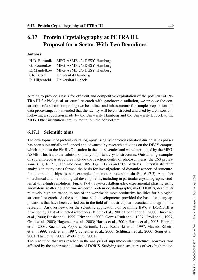
6.17. Protein Crystallography at PETRA III 449
6.17 Protein Crystallography at PETRA III,Proposal for a Sector With Two Beamlines
Authors:
H.D. Bartunik MPG-ASMB c/o DESY, HamburgG. Bourenkov MPG-ASMB c/o DESY, HamburgE. Mandelkow MPG-ASMB c/o DESY, HamburgCh. Betzel Universitat HamburgR. Hilgenfeld Universitat Lubeck
Aiming to provide a basis for efficient and competitive exploitation of the potential of PE-TRA III for biological structural research with synchrotron radiation, we propose the con-struction of a sector comprising two beamlines and infrastructure for sample preparation anddata processing. It is intended that the facility will be constructed and used by a consortium,following a suggestion made by the University Hamburg and the University Lubeck to theMPG. Other institutions are invited to join the consortium.
6.17.1 Scientific aimsThe development of protein crystallography using synchrotron radiation during all its phaseshas been substantially influenced and advanced by research activities on the DESY campus,which started at the EMBL Outstation in the late seventies and were later joined by the MPG-ASMB. This led to the solution of many important crystal structures. Outstanding examplesof supramolecular structures include the reaction center of photosynthesis, the 26S protea-some (Fig. 6.17.1), and ribosomal 30S (Fig. 6.17.2) and 50S particles. Crystal structureanalysis in many cases formed the basis for investigations of dynamic aspects of structure-function relationships, as in the example of the motor protein kinesin (Fig. 6.17.3). A numberof technical and methodological developments, including in particular crystallographic stud-ies at ultra-high resolution (Fig. 6.17.4), cryo-crystallography, experimental phasing usinganomalous scattering, and time-resolved protein crystallography, made DORIS, despite itsrelatively high emittance, to one of the worldwide most productive facilities for biologicalstructural research. At the same time, such developments provided the basis for many ap-plications that have been carried out in the field of industrial pharmaceutical and agronomicresearch. An overview over the scientific applications on beamline BW6 at DORIS III isprovided by a list of selected references (Blume et al., 2001; Bochtler et al., 2000; Burkhardet al., 2000; Einsle et al., 1999; Fritz et al., 2002; Gomis-Ruth et al., 1997; Groll et al., 1997;Groll et al., 2003; Hagemeier et al., 2003; Harms et al., 2001; Harms et al., 2003; Henrichet al., 2003; Kachalova, Popov & Bartunik, 1999; Kozielski et al., 1997; Macedo-Ribeiroet al., 1999; Sack et al., 1997; Scheufler et al., 2000; Schlunzen et al., 2000; Song et al.,2001; Than et al., 2002; Worbs et al., 2001).The resolution that was reached in the analysis of supramolecular structures, however, wasaffected by the experimental limits of DORIS. Studying such structures of very high molec-
ED
MS
Nr.:
D00
0000
0082
2371
Rev
: A V
er: 1
Sta
tus:
Rel
ease
d -
Dat
.: 8.
Apr
200
8
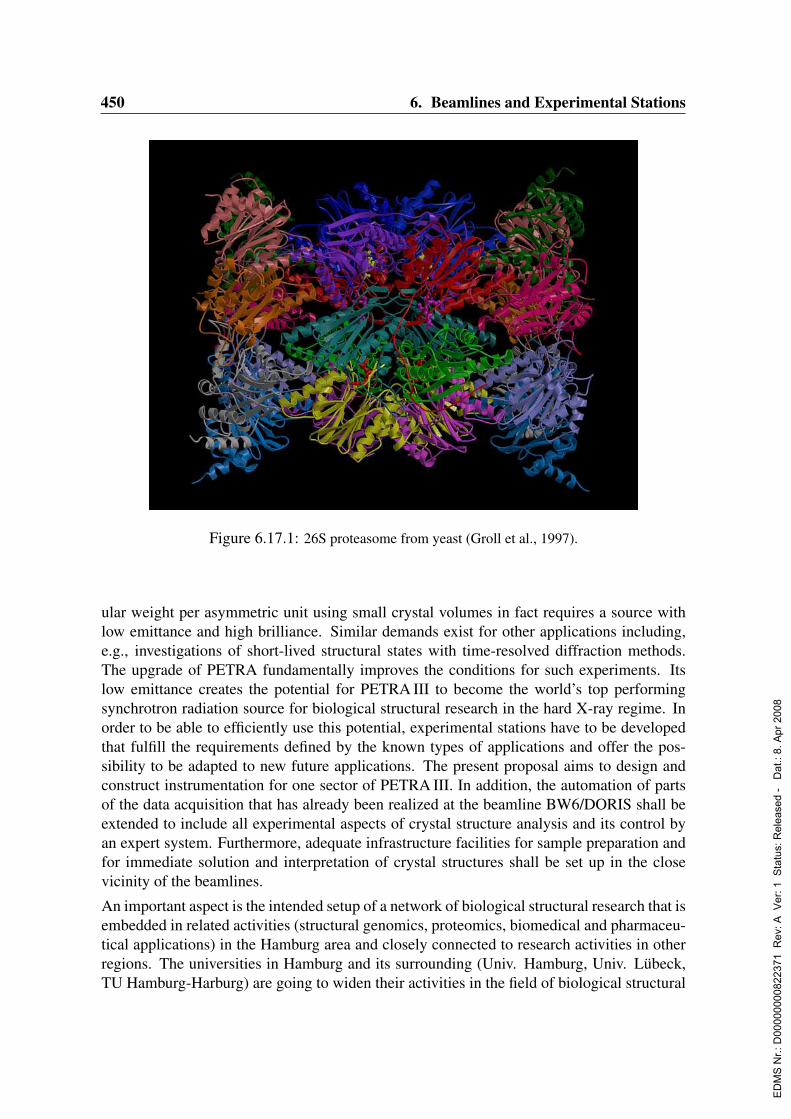
450 6. Beamlines and Experimental Stations
Figure 6.17.1: 26S proteasome from yeast (Groll et al., 1997).
ular weight per asymmetric unit using small crystal volumes in fact requires a source withlow emittance and high brilliance. Similar demands exist for other applications including,e.g., investigations of short-lived structural states with time-resolved diffraction methods.The upgrade of PETRA fundamentally improves the conditions for such experiments. Itslow emittance creates the potential for PETRA III to become the world’s top performingsynchrotron radiation source for biological structural research in the hard X-ray regime. Inorder to be able to efficiently use this potential, experimental stations have to be developedthat fulfill the requirements defined by the known types of applications and offer the pos-sibility to be adapted to new future applications. The present proposal aims to design andconstruct instrumentation for one sector of PETRA III. In addition, the automation of partsof the data acquisition that has already been realized at the beamline BW6/DORIS shall beextended to include all experimental aspects of crystal structure analysis and its control byan expert system. Furthermore, adequate infrastructure facilities for sample preparation andfor immediate solution and interpretation of crystal structures shall be set up in the closevicinity of the beamlines.
An important aspect is the intended setup of a network of biological structural research that isembedded in related activities (structural genomics, proteomics, biomedical and pharmaceu-tical applications) in the Hamburg area and closely connected to research activities in otherregions. The universities in Hamburg and its surrounding (Univ. Hamburg, Univ. Lubeck,TU Hamburg-Harburg) are going to widen their activities in the field of biological structural
ED
MS
Nr.:
D00
0000
0082
2371
Rev
: A V
er: 1
Sta
tus:
Rel
ease
d -
Dat
.: 8.
Apr
200
8
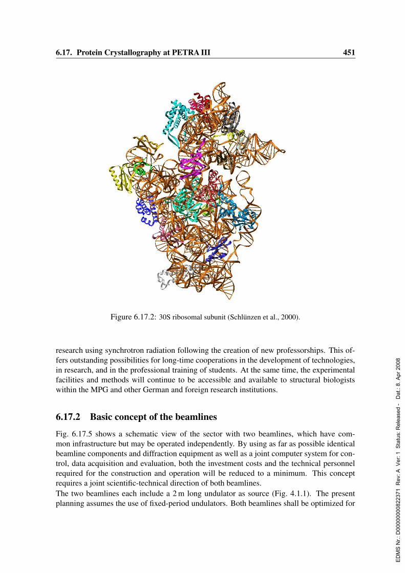
6.17. Protein Crystallography at PETRA III 451
Figure 6.17.2: 30S ribosomal subunit (Schlunzen et al., 2000).
research using synchrotron radiation following the creation of new professorships. This of-fers outstanding possibilities for long-time cooperations in the development of technologies,in research, and in the professional training of students. At the same time, the experimentalfacilities and methods will continue to be accessible and available to structural biologistswithin the MPG and other German and foreign research institutions.
6.17.2 Basic concept of the beamlines
Fig. 6.17.5 shows a schematic view of the sector with two beamlines, which have com-mon infrastructure but may be operated independently. By using as far as possible identicalbeamline components and diffraction equipment as well as a joint computer system for con-trol, data acquisition and evaluation, both the investment costs and the technical personnelrequired for the construction and operation will be reduced to a minimum. This conceptrequires a joint scientific-technical direction of both beamlines.The two beamlines each include a 2 m long undulator as source (Fig. 4.1.1). The presentplanning assumes the use of fixed-period undulators. Both beamlines shall be optimized for
ED
MS
Nr.:
D00
0000
0082
2371
Rev
: A V
er: 1
Sta
tus:
Rel
ease
d -
Dat
.: 8.
Apr
200
8

452 6. Beamlines and Experimental Stations
Figure 6.17.3: Kinesin dimer moving along the microtubule proto-filament (Song et al., 2001).
Figure 6.17.4: Fe-CO in myoglobin at ultra-high resolution (Kachalova, Popov & Bartunik, 1999).
MAD phasing applications in protein crystallography and at the same time offer small beamcross-sections (1–30µm) and high flux at the sample position. The relevant parameters arelisted in Tab. 6.17.1. The concept of the beamlines permits macromolecular crystal structureanalysis as well as other applications. For example, experimental setups involving grazing-incidence beam conditions for investigating structures at surfaces, diffraction measurementsfrom fibers with extremely narrow diameters, topographic techniques, and a combination ofX-ray diffraction with X-ray fluorescence spectroscopy may be possible.Beamline BL1 has priority in the planning. BL1 presently is designed for applications tosupramolecular structures and very small crystal volumina. It will be tunable through theentire energy range from 3.5–35 keV. Both Si (111) and Si (311) monochromators will beavailable, including rapid switching from one to the other as function of the energy rangeand the desired energy resolution. The focusing may be adapted to particular requirements.This includes the option for micro-focusing (1–3µm). PETRA III offers excellent conditions
ED
MS
Nr.:
D00
0000
0082
2371
Rev
: A V
er: 1
Sta
tus:
Rel
ease
d -
Dat
.: 8.
Apr
200
8
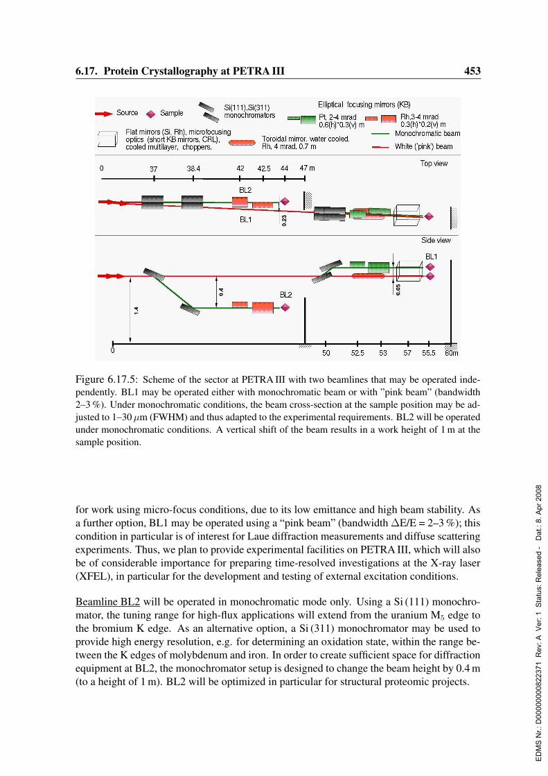
6.17. Protein Crystallography at PETRA III 453
Figure 6.17.5: Scheme of the sector at PETRA III with two beamlines that may be operated inde-pendently. BL1 may be operated either with monochromatic beam or with ”pink beam” (bandwidth2–3 %). Under monochromatic conditions, the beam cross-section at the sample position may be ad-justed to 1–30 µm (FWHM) and thus adapted to the experimental requirements. BL2 will be operatedunder monochromatic conditions. A vertical shift of the beam results in a work height of 1 m at thesample position.
for work using micro-focus conditions, due to its low emittance and high beam stability. Asa further option, BL1 may be operated using a “pink beam” (bandwidth ∆E/E = 2–3 %); thiscondition in particular is of interest for Laue diffraction measurements and diffuse scatteringexperiments. Thus, we plan to provide experimental facilities on PETRA III, which will alsobe of considerable importance for preparing time-resolved investigations at the X-ray laser(XFEL), in particular for the development and testing of external excitation conditions.
Beamline BL2 will be operated in monochromatic mode only. Using a Si (111) monochro-mator, the tuning range for high-flux applications will extend from the uranium M5 edge tothe bromium K edge. As an alternative option, a Si (311) monochromator may be used toprovide high energy resolution, e.g. for determining an oxidation state, within the range be-tween the K edges of molybdenum and iron. In order to create sufficient space for diffractionequipment at BL2, the monochromator setup is designed to change the beam height by 0.4 m(to a height of 1 m). BL2 will be optimized in particular for structural proteomic projects.
ED
MS
Nr.:
D00
0000
0082
2371
Rev
: A V
er: 1
Sta
tus:
Rel
ease
d -
Dat
.: 8.
Apr
200
8

454 6. Beamlines and Experimental Stations
6.17.3 Auxiliary installations
Automatic beamline control: High beam stability at the sample position is of importance formost applications, in particular for work under micro-focus conditions. The components ofthe X-ray optics and diffraction equipment therefore will be designed to permit automaticcontrol on the basis of automatic beam diagnostics and continuous re-alignment.Automation of measurements: All experimental steps of protein crystal structure analysis ex-tending from sample mounting to phasing will be automated as far as possible and controlledby an expert system. This includes the control of the sample environment (temperature, hu-midity, anaerobic conditions etc.), remote control of experiments, and compatibility with
A. Monochromatic conditions BL1 BL2Energy range, keV 3.5 – 35 3.5 – 14 Si (111)
7 – 20 Si (311)Energy resolution ∆E/E 10−4 0.4 - 2.5 0.4 - 2.5
Focused beam at the sample, FWHMMin. size, HxV µm 30 x 15 15 x 10
Max. divergence, HxV µrad 400 x 200 600 x 300Flux at the sample, ph/sec/100mA
@ 12 keV 3 ·1013 3 ·1013
@ 35 keV 1012
Microfocus optionFocus size, HxV µm 3 x 1
Divergence, mrad 2.2 x 1.2Flux @12 keV > 1012
B. Pink beam conditionsBandwidth < 9 keV ca. 3 %
> 9 keV 2 – 3 %Photon flux, photon/sec/100mA
9 keV, 10% 2 ·1016
12 keV, 3% (fixed-period undulator) 1 ·1015
12 keV, 10% (variable-period undulator, ∼ 2 ·1016
1st harmonic shifted to 12 keV)Photons per bunch @100mA, 40 bunches (192 ns)
9 keV, 10% 4 ·1010
12 keV, 3% (fixed-period undulator) 2 ·109
12 keV, 10% (variable-period undulator, ∼ 4 ·1010
1st harmonic shifted to 12 keV)Min. focus size, HxV µm 80 x 20
Chopper time window, ns / 1000rpm 25(rotating mirror chopper)
Table 6.17.1: Parameters of the protein crystallography beamlines.
ED
MS
Nr.:
D00
0000
0082
2371
Rev
: A V
er: 1
Sta
tus:
Rel
ease
d -
Dat
.: 8.
Apr
200
8

6.17. Protein Crystallography at PETRA III 455
high-throughput (HTP) applications.Sample preparation: Facilities for sample preparation and sample mounting will be availablein the immediate vicinity and jointly used for both beamlines. These include in particulardevices for ad-hoc derivatization (e.g. with xenon), possibilities for developing and testingcryo-solvents, and air-conditioned rooms or incubators for crystallization and preparation.Storage of samples at low temperatures and equipment for transferring samples to the beam-lines are required for HTP applications. The coding and identification of samples shall bestandardized within the framework of a European project (BIOXHIT).Data evaluation and structure solution: Complete evaluation of the experimental data, in-cluding an assessment of the quality and interpretability of electron density maps, in generalshall be feasible within short time immediately after completion of the data collection. Thisaim has already been reached in many cases on BW6. Furthermore, we aim to an interactivecontrol of the experiment on the basis of the currently evaluated data. This requires high datatransfer rates and computing performance. An Intel cluster shall be used for this purpose, andsoftware that is part of the expert system will be parallelized as far as possible. Both beam-lines will be equipped with the same front-end computers and bus systems and connectedto a joint computing facility, in order to facilitate the system management and software de-velopment. Measuring strategy, interactive data acquisition, and evaluation methods will bestandardized as far as possible within the framework of BIOXHIT.
6.17.4 Capital investment and personnelThe total investment costs for the proposed beamline endstations without optics, vacuumsystem and hutches is 4 Me.For the operation of both lines 4–6 scientists and 2–4 engineers/technicians will be needed.
ED
MS
Nr.:
D00
0000
0082
2371
Rev
: A V
er: 1
Sta
tus:
Rel
ease
d -
Dat
.: 8.
Apr
200
8

456 6. Beamlines and Experimental Stations
6.18 Experimental Techniques with no DedicatedBeamline Proposal
In this section two experimental techniques will be presented that certainly benefit from thebeam properties of a 3rd generation synchrotron radiation source, but for which no special-ized beamline proposal has been made. The first technique, high pressure experiments usingdiamond anvil cells, is meanwhile almost a standard at many synchrotron radiation beam-lines. The second one, which is topography, can easily be carried out at any beamline thatprovides a suitable beam such as high a resolution diffraction beamline.
6.18.1 High pressure diamond anvil cell laboratoryCurrent state of the scientific field Pressure is besides temperature one of the most im-portant thermodynamical parameters. Its variation over a large range is crucial for manyexperiments. Diamond anvil cells (DAC) are a high-pressure technique, which combinesseveral advantages. They are able to achieve the highest static pressures: several Mbars arecurrently possible (1 Mbar = 100 GPa). DACs are compact and can easily be transferredfrom one beamline to another. They are a versatile tool enabling to couple X-rays studieswith other physical characterization methods (e.g. Raman scattering, electrical resistance,magnetic susceptibility, and fluorescence measurements) as well as experiments at low andhigh temperature. At moderate pressures they are easy to handle and can be used by experi-mentalists not specialized in this field. Meanwhile, DACs have become a ‘standard’ sampleenvironment option at all major synchrotron facilities.Most X-ray experiments using DACs are powder or single-crystal diffraction studies for thedetermination of the crystal structure or the equation of state. Single-crystal diffraction pro-vides more precise data, however, measurements are only possible under (quasi-) hydrostaticconditions. In addition, this method requires DACs with large X-rays windows, thus limitingthe maximum achievable pressures to ∼ 50 GPa. Powder diffraction is less demanding tothe cell design and is used in the whole pressure range achievable with DACs. The methodincreasingly requires advanced methods for structure analysis, which in particular includesthe application of area detectors for data recording in order to provide the possibility fortexture analysis during data processing.New 3rd generation synchrotron sources open up new possibilities: (i) studying low-Z ma-terials (e.g. H2, Li), (ii) sampling data as function of the pressure gradients across the anvilworking flat with high spatial resolution, (iii) studying protein crystals by single-crystaldiffraction. They also enabled the application of new X-ray methods such as inelastic scatter-ing, fluorescence measurements, and X-ray absorption spectroscopy, which became a stan-dard method in high-pressure experiments.In many studies a combination of pressure with for example low/high temperature, externalmagnetic fields etc. is applied. Laser heating in a DAC has become a special area of researchoften called ‘Studies of matter under extreme conditions’. Currently, temperatures as highas ∼ 4000 K at pressures up to ∼200 GPa are achievable. However, the issues of absolutetemperature and pressure determination at high temperatures, as well as the characterizationof the sample exhibit an experimental challenge leading to a number of fundamental physical,
ED
MS
Nr.:
D00
0000
0082
2371
Rev
: A V
er: 1
Sta
tus:
Rel
ease
d -
Dat
.: 8.
Apr
200
8
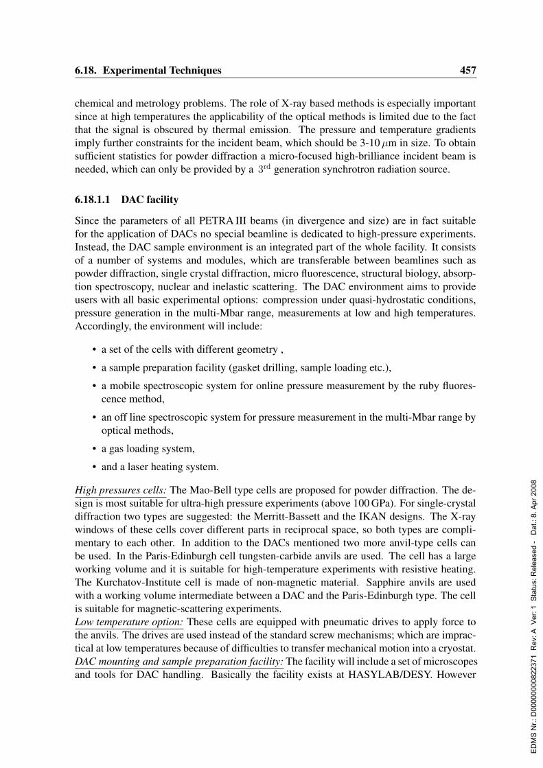
6.18. Experimental Techniques 457
chemical and metrology problems. The role of X-ray based methods is especially importantsince at high temperatures the applicability of the optical methods is limited due to the factthat the signal is obscured by thermal emission. The pressure and temperature gradientsimply further constraints for the incident beam, which should be 3-10µm in size. To obtainsufficient statistics for powder diffraction a micro-focused high-brilliance incident beam isneeded, which can only be provided by a 3rd generation synchrotron radiation source.
6.18.1.1 DAC facility
Since the parameters of all PETRA III beams (in divergence and size) are in fact suitablefor the application of DACs no special beamline is dedicated to high-pressure experiments.Instead, the DAC sample environment is an integrated part of the whole facility. It consistsof a number of systems and modules, which are transferable between beamlines such aspowder diffraction, single crystal diffraction, micro fluorescence, structural biology, absorp-tion spectroscopy, nuclear and inelastic scattering. The DAC environment aims to provideusers with all basic experimental options: compression under quasi-hydrostatic conditions,pressure generation in the multi-Mbar range, measurements at low and high temperatures.Accordingly, the environment will include:
• a set of the cells with different geometry ,
• a sample preparation facility (gasket drilling, sample loading etc.),
• a mobile spectroscopic system for online pressure measurement by the ruby fluores-cence method,
• an off line spectroscopic system for pressure measurement in the multi-Mbar range byoptical methods,
• a gas loading system,
• and a laser heating system.
High pressures cells: The Mao-Bell type cells are proposed for powder diffraction. The de-sign is most suitable for ultra-high pressure experiments (above 100 GPa). For single-crystaldiffraction two types are suggested: the Merritt-Bassett and the IKAN designs. The X-raywindows of these cells cover different parts in reciprocal space, so both types are compli-mentary to each other. In addition to the DACs mentioned two more anvil-type cells canbe used. In the Paris-Edinburgh cell tungsten-carbide anvils are used. The cell has a largeworking volume and it is suitable for high-temperature experiments with resistive heating.The Kurchatov-Institute cell is made of non-magnetic material. Sapphire anvils are usedwith a working volume intermediate between a DAC and the Paris-Edinburgh type. The cellis suitable for magnetic-scattering experiments.Low temperature option: These cells are equipped with pneumatic drives to apply force tothe anvils. The drives are used instead of the standard screw mechanisms; which are imprac-tical at low temperatures because of difficulties to transfer mechanical motion into a cryostat.DAC mounting and sample preparation facility: The facility will include a set of microscopesand tools for DAC handling. Basically the facility exists at HASYLAB/DESY. However
ED
MS
Nr.:
D00
0000
0082
2371
Rev
: A V
er: 1
Sta
tus:
Rel
ease
d -
Dat
.: 8.
Apr
200
8

458 6. Beamlines and Experimental Stations
some more developments are required to provide conditions for ultra-high pressures.A gas loading system: The system is necessary for both to provide possibility to study gaseoussamples and to provide studies under quasi hydrostatic conditions.A mobile spectrometer system for online pressure measurements: This system is the standardoption for the measurement of pressure in the range up to ∼120 GPa.An off line spectrometer system: This system is necessary to measure pressure in the multi-Mbar pressure range. It is based on a triple monochromator with subtractive dispersion. Twolasers Ar+ and Kr+ are included to excite the fluorescence and to initiate Raman scattering.High-quality optics elements are used to keep the background low and to provide effectivespatial filtering of the signal in the imaging system. A CCD detector will be used to collectthe signal.Laser heating system: Basic elements of these systems include: (i) one laser for heatingopaque samples (with a wavelength ∼1µm – Nd:YAG or Nd:YLF), (ii) another laser forheating transparent samples (CO2 laser with a wavelength of 10.64µm), (iii) an imagingspectroradiometric system for temperature measurements, and (iv) a feedback system fortemperature control. The exact configuration will be defined depending on the progressachieved in this field by the time when PETRA III becomes operational.Laboratory space: Two rooms in the experimental hall will be required. One room will beused for sample preparation. Another room is used as an optical laboratory for the off linefluorescence/Raman measurements as well as for the development of the laser heating sys-tem. A separate place about 4 m2 is needed for the gas loading system. For security reasonsthe compressor together with the high pressure vessel should be situated in a large hole (toallow gas expansion in case of an accident) and should be surrounded by a strong protectivefence.
6.18.1.2 Capital investment and personnel
The proposed high pressure equipment amounts to about 400 ke, the laser heating systemwill cost another 550 ke. One scientist will be needed to run the high pressure laboratorywith support of the engineer and technician allocated for the general sample environmentfacility.
6.18.2 X-ray topography
6.18.2.1 Introduction
X-Ray Topography (XRT) is a non-destructive technique, which can provide a map of thestrain or defect distributions in crystals. This technique is based on the difference in re-flecting power between perfect and distorted parts of a crystal. It is sensitive to strain fieldsextending over more than several micrometers and therefore XRT is mainly used for thestudy of strain, dislocations, planar defects, stacking faults, domain walls in ferroelectric andmagnetic materials, growth defects, and large precipitates.Localized imperfections may act as independent scattering centers e.g. small angle scatter-ing by small precipitates or thermal diffuse scattering, but it is the strains they induce which
ED
MS
Nr.:
D00
0000
0082
2371
Rev
: A V
er: 1
Sta
tus:
Rel
ease
d -
Dat
.: 8.
Apr
200
8

6.18. Experimental Techniques 459
modify the diffraction of X-rays by a good quality crystal. These strains due to the disloca-tion perturb the crystal for several microns from the defect, and it is these regions far fromthe dislocation core itself, which give rise to the defect image, through a deviation from theideal Bragg reflection observed in the more perfect crystalline regions. An example of theexperimental arrangement for a white beam transmission (i.e. Laue mode) X-ray topographicexperiment is shown in Fig. 6.18.1
Figure 6.18.1: Schematic setup of Laue topography.
When a single crystal is immersed in a white X-ray beam a number of lattice planes (h k l)select out of the continuous spectrum the proper wavelengths to be reflected according toBragg’s Law:
2 · dhkl sin ΘB = λ (6.18.1)
where dhkl is the inter-planar spacing of (hkl) lattice planes and ΘB is the Bragg angle. Abeam diffracted in a certain direction 2θB with respect to the incident beam has a spectrumof wavelengths λ, λ/2, λ/3, etc. corresponding to diffraction lattice planes (h k l), (2h 2k 2l),(3h 3k 3l) etc. The fundamental reflection h k l or its harmonics may, however, be structurefactor forbidden.Geometrical resolution is governed by the incident beam local divergence on the sample and,for typical experimental conditions, lies in the micron range at a 2nd generation synchrotronradiation source.
6.18.2.2 Technical issues
From the viewpoint of X-ray topography the ultimate achievable resolution on the recordingmedium (film, CCD array, etc.) is limited by the apparent source sizes in the horizontal andvertical dimensions. This is illustrated by the diagram in Fig. 6.18.2. The situation is littledifferent for back reflection (i.e. Bragg case) X-ray topography. From the above we find that
h =D
LH (6.18.2)
In Tab. 6.18.1 the achievable resolution for different topography setups at DORIS III, ESRFand PETRA III are compared.
ED
MS
Nr.:
D00
0000
0082
2371
Rev
: A V
er: 1
Sta
tus:
Rel
ease
d -
Dat
.: 8.
Apr
200
8
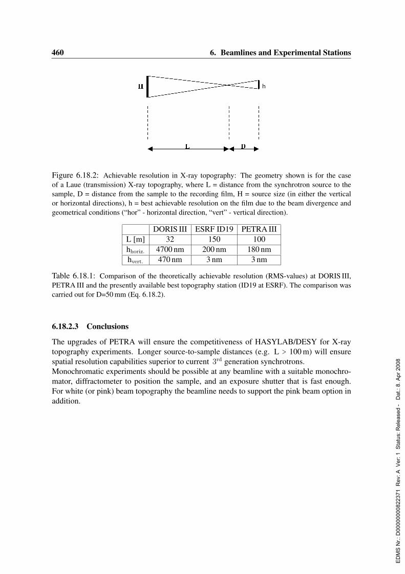
460 6. Beamlines and Experimental Stations
Figure 6.18.2: Achievable resolution in X-ray topography: The geometry shown is for the caseof a Laue (transmission) X-ray topography, where L = distance from the synchrotron source to thesample, D = distance from the sample to the recording film, H = source size (in either the verticalor horizontal directions), h = best achievable resolution on the film due to the beam divergence andgeometrical conditions (“hor” - horizontal direction, “vert” - vertical direction).
DORIS III ESRF ID19 PETRA IIIL [m] 32 150 100hhoriz. 4700 nm 200 nm 180 nmhvert. 470 nm 3 nm 3 nm
Table 6.18.1: Comparison of the theoretically achievable resolution (RMS-values) at DORIS III,PETRA III and the presently available best topography station (ID19 at ESRF). The comparison wascarried out for D=50 mm (Eq. 6.18.2).
6.18.2.3 Conclusions
The upgrades of PETRA will ensure the competitiveness of HASYLAB/DESY for X-raytopography experiments. Longer source-to-sample distances (e.g. L > 100 m) will ensurespatial resolution capabilities superior to current 3rd generation synchrotrons.Monochromatic experiments should be possible at any beamline with a suitable monochro-mator, diffractometer to position the sample, and an exposure shutter that is fast enough.For white (or pink) beam topography the beamline needs to support the pink beam option inaddition.
ED
MS
Nr.:
D00
0000
0082
2371
Rev
: A V
er: 1
Sta
tus:
Rel
ease
d -
Dat
.: 8.
Apr
200
8

Chapter 7
Civil Engineering
7.1 Site CharacterizationThe outstanding property of PETRA III is the extremely small beam which will be suppliedto the experiments. Using moderate focussing a beamsize of several µm2 can be achieved.To make efficient use of this beam the positioning of all optical elements and the samplemust be even more precise than that. In general a positional accuracy of 10 % of the beamsize is stipulated. This requires a high level of thermal stability (air conditioning) and groundstability. In the following section we describe the efforts to characterize the local situationand compare the expected stability to the situation at similar installations world wide.
7.1.1 Description of the DESY site, geological overviewThe ground at the DESY site was mainly formed during the last glacial period. The soilconsists mostly of permeable sands with a few impervious layers of marl or loam of theQuaternary period. Concerning the area of PETRA the site investigations from 1975 showsands and glacial loam. The loam in itself is sandy and contains smaller sandy layers within.The density of the sand is at least middle (see Fig. 7.1.1). The point resistance of the penetra-tions tests shows low values for the loam but this does not necessarily mean also low bearingcapacity. Of great advantage is the deep ground water table of more than 20 m below surfacelevel. This results in low effects on the surface by changing ground water table.
7.1.2 Ground motionOptimal use of the micrometer beam delivered by PETRA III requires a stability of the orderof 10 % of the beam size. Of importance is the relative stability of the experimental setupwith respect to the beam, i.e. the undulator source. Long wavelength motions or slow driftspose only a minor problem. Given the size of the facility and a speed of sound in sand of150 m/s, seismic waves with a frequency higher than roughly 0.5 Hz are potential sources ofinstabilities.DESY has taken a large effort to compare different accelerator sites around the world con-cerning ground motions. Fig. 7.1.2 shows power spectral densities of the ground motion
ED
MS
Nr.:
D00
0000
0082
2371
Rev
: A V
er: 1
Sta
tus:
Rel
ease
d -
Dat
.: 8.
Apr
200
8
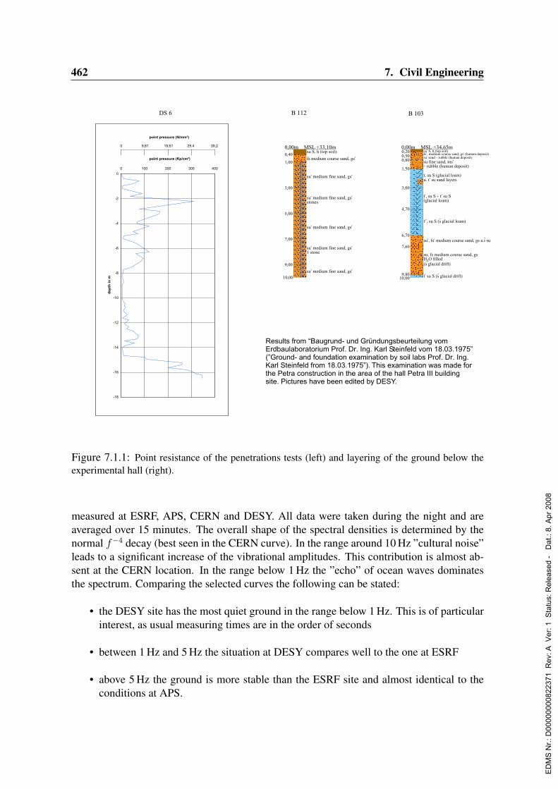
462 7. Civil Engineering
su, fs medium course sand, gsH O filled2
(s glacial drift)
0,00m MSL +34,65m
10,00t’ su S (s glacial drift)
su’, fs’ medium course sand, gs u.t su
t’’, su S (s glacial loam)
t’, su S + t’ su S(glacial loam)
t, su S (glacial loam)u. t’ su sand layers
su fine sand, ms’+ rubble (human deposit)
su’ sand + rubble (human deposit)fs’, medium course sand, gs’ (human deposit)su’ S, h (top soil)
7,60
9,80
6,70
4,70
3,00
1,50
0,80
0,200,50
su S, h (top soil)
fs medium course sand, gs’
su’ medium fine sand, gs’
su’ medium fine sand, gs’stones
su’ medium fine sand, gs’
su’ medium fine sand, gs’1 stone
su’ medium fine sand, gs’
0,00m MSL +33,10m
0,40
1,00
3,00
5,00
7,00
9,00
10,00
B 112 B 103
-10
-12
-14
-16
-18
-2
-4
-6
-8
0 100 200 300 400
0
point pressure (Kp/cm²)
de
pth
in
m
point pressure (N/mm²)
0 9,81 19,61 29,4 39,2
DS 6
Results from “Baugrund- und Gründungsbeurteilung vom Erdbaulaboratorium Prof. Dr. Ing. Karl Steinfeld vom 18.03.1975” (”Ground- and foundation examination by soil labs Prof. Dr. Ing. Karl Steinfeld from 18.03.1975”). This examination was made for the Petra construction in the area of the hall Petra III building site. Pictures have been edited by DESY.
Figure 7.1.1: Point resistance of the penetrations tests (left) and layering of the ground below theexperimental hall (right).
measured at ESRF, APS, CERN and DESY. All data were taken during the night and areaveraged over 15 minutes. The overall shape of the spectral densities is determined by thenormal f−4 decay (best seen in the CERN curve). In the range around 10 Hz ”cultural noise”leads to a significant increase of the vibrational amplitudes. This contribution is almost ab-sent at the CERN location. In the range below 1 Hz the ”echo” of ocean waves dominatesthe spectrum. Comparing the selected curves the following can be stated:
• the DESY site has the most quiet ground in the range below 1 Hz. This is of particularinterest, as usual measuring times are in the order of seconds
• between 1 Hz and 5 Hz the situation at DESY compares well to the one at ESRF
• above 5 Hz the ground is more stable than the ESRF site and almost identical to theconditions at APS.
ED
MS
Nr.:
D00
0000
0082
2371
Rev
: A V
er: 1
Sta
tus:
Rel
ease
d -
Dat
.: 8.
Apr
200
8

7.2. Experimental Hall 463
Figure 7.1.2: Power spectral densities of ground motions measured at different accelerator sites.Red: CERN; dark red: APS; blue: ESRF; dark green: DESY.
The spikes superimposed on the smooth decay are due to local resonances. Those mayoriginate from the geometry of the concrete structure at the location of the measurement orlocal activities. Also the vibrational damping characteristics of the ground influences thecurves in detail.
7.2 Experimental Hall
The design of the experimental hall was guided by several boundary conditions:
• The large radius of the machine and the optimal use of the low emittance requiresmostly rather long beamlines (up to 100 m or more).
• The building has to be kept compact in order to minimize costs and to fit on the areaavailable.
• Due to the radiation shielding concept offices and laboratory space have to be locatedon the outer perimeter of the hall.
• The design has to allow a building phase not exceeding eight month.
Thus a concept similar to the experimental hall of ESRF was chosen. However, as experienceshowed that offices and laboratory space should be located close to the beamlines, the outerperimeter of the hall will be used for offices and laboratories from the outset.
ED
MS
Nr.:
D00
0000
0082
2371
Rev
: A V
er: 1
Sta
tus:
Rel
ease
d -
Dat
.: 8.
Apr
200
8
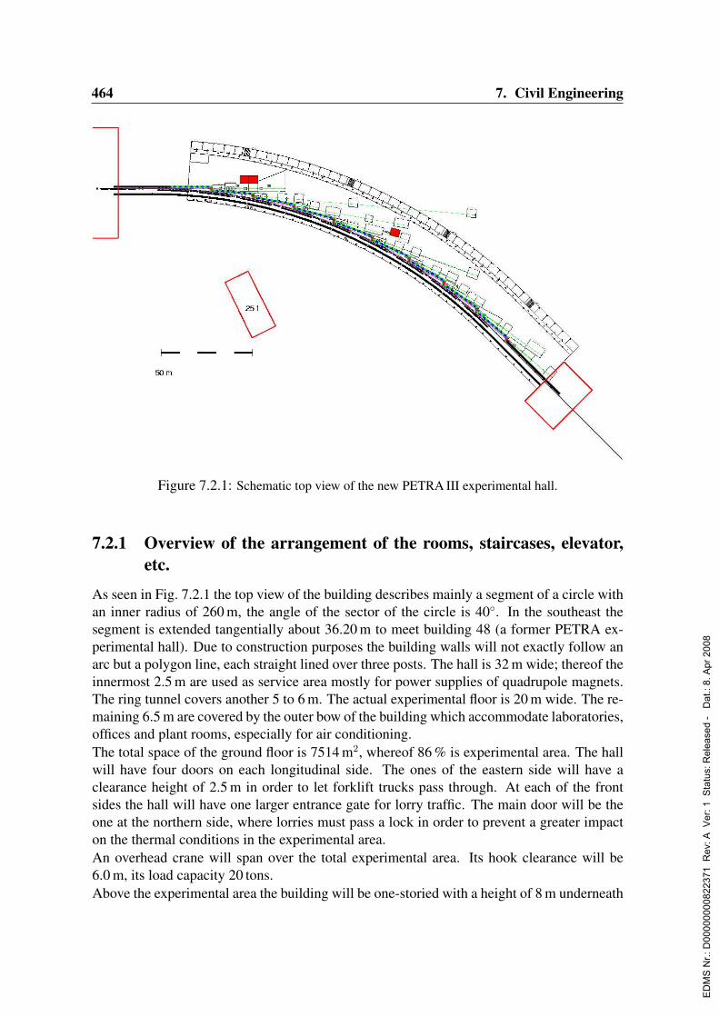
464 7. Civil Engineering
Figure 7.2.1: Schematic top view of the new PETRA III experimental hall.
7.2.1 Overview of the arrangement of the rooms, staircases, elevator,etc.
As seen in Fig. 7.2.1 the top view of the building describes mainly a segment of a circle withan inner radius of 260 m, the angle of the sector of the circle is 40. In the southeast thesegment is extended tangentially about 36.20 m to meet building 48 (a former PETRA ex-perimental hall). Due to construction purposes the building walls will not exactly follow anarc but a polygon line, each straight lined over three posts. The hall is 32 m wide; thereof theinnermost 2.5 m are used as service area mostly for power supplies of quadrupole magnets.The ring tunnel covers another 5 to 6 m. The actual experimental floor is 20 m wide. The re-maining 6.5 m are covered by the outer bow of the building which accommodate laboratories,offices and plant rooms, especially for air conditioning.The total space of the ground floor is 7514 m2, whereof 86 % is experimental area. The hallwill have four doors on each longitudinal side. The ones of the eastern side will have aclearance height of 2.5 m in order to let forklift trucks pass through. At each of the frontsides the hall will have one larger entrance gate for lorry traffic. The main door will be theone at the northern side, where lorries must pass a lock in order to prevent a greater impacton the thermal conditions in the experimental area.An overhead crane will span over the total experimental area. Its hook clearance will be6.0 m, its load capacity 20 tons.Above the experimental area the building will be one-storied with a height of 8 m underneath
ED
MS
Nr.:
D00
0000
0082
2371
Rev
: A V
er: 1
Sta
tus:
Rel
ease
d -
Dat
.: 8.
Apr
200
8
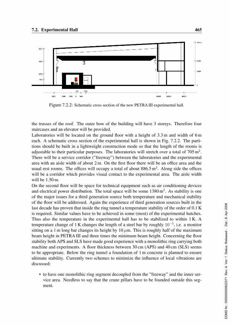
7.2. Experimental Hall 465
Figure 7.2.2: Schematic cross section of the new PETRA III experimental hall.
the trusses of the roof. The outer bow of the building will have 3 storeys. Therefore fourstaircases and an elevator will be provided.Laboratories will be located on the ground floor with a height of 3.3 m and width of 6 meach. A schematic cross section of the experimental hall is shown in Fig. 7.2.2. The parti-tions should be built in a lightweight construction mode so that the length of the rooms isadjustable to their particular purposes. The laboratories will stretch over a total of 705 m2.There will be a service corridor (”freeway”) between the laboratories and the experimentalarea with an aisle width of about 2 m. On the first floor there will be an office area and theusual rest rooms. The offices will occupy a total of about 886.5 m2. Along side the officeswill be a corridor which provides visual contact to the experimental area. The aisle widthwill be 1.50 m.On the second floor will be space for technical equipment such as air conditioning devicesand electrical power distribution. The total space will be some 1380 m2. As stability is oneof the major issues for a third generation source both temperature and mechanical stabilityof the floor will be addressed. Again the experience of third generation sources built in thelast decade has proven that inside the ring tunnel a temperature stability of the order of 0.1 Kis required. Similar values have to be achieved in some (most) of the experimental hutches.Thus also the temperature in the experimental hall has to be stabilized to within 1 K. Atemperature change of 1 K changes the length of a steel bar by roughly 10−5, i.e. a monitorsitting on a 1 m long bar changes its height by 10µm. This is roughly half of the maximumbeam height in PETRA III and three times the minimum beam height. Concerning the floorstability both APS and SLS have made good experience with a monolithic ring carrying bothmachine and experiments. A floor thickness between 30 cm (APS) and 40 cm (SLS) seemsto be appropriate. Below the ring tunnel a foundation of 1 m concrete is planned to ensureultimate stability. Currently two schemes to minimize the influence of local vibrations arediscussed:
• to have one monolithic ring segment decoupled from the ”freeway” and the inner ser-vice area. Needless to say that the crane pillars have to be founded outside this seg-ment.
ED
MS
Nr.:
D00
0000
0082
2371
Rev
: A V
er: 1
Sta
tus:
Rel
ease
d -
Dat
.: 8.
Apr
200
8

466 7. Civil Engineering
• to separate the above mentioned segment with tangential cuts between adjacent beam-lines to prevent vibrations to propagate from one experiment to the next.
In any case it seems to be important to have a rigid connection between beamline and ma-chine (undulator). As beam stability will be one of the main issues at PETRA III and vibra-tions of the experimental floor disturb experiments using a µ-beam as well as movements ofthe particle beam a vibrational monitoring system will be installed on the experimental floor.This will allow to identify possible sources of ”home-made” vibrations.
7.2.2 Construction method
The building will have to be made of prefabricated elements as far as possible, because ofthe requirement to build the entire hall within 8 months.The load-bearing structure will be made of pillars and trusses probably of pre-cast concrete.The distance between the posts on the outer perimeter of the hall will be 6 m. A steel orwooden framework is imaginable as well. This depends on demands coming from structuralfire protection or later adaptation issues.As there is a high requirement on temperature stability in the hall some special means haveto be considered in the layout of the structure and panelling (in order to reduce impact ofsolar radiation and the consequential daily changes of temperature):
1. there should be no windows except in the area of the offices and laboratories (whichare in north eastern direction).
2. the basic material of all structural and panelling elements should be of high volumedensity (to get a higher heat storage capacity). The panelling material will either be ofgas concrete with relatively high density or of lime malm brickwork.
3. the entire hall will be thermally insulated.
4. there will be a curtain wall in front of the load bearing inner wall on the southwesternside. The space between will be about 30 cm where a free airflow is guaranteed.
5. the advantages of a roof with natural cover are being investigated.
6. instead of the above mentioned roof there is also the possibility of a double deck roofin which a free airflow under the upper deck is guaranteed as well.
As outlined above a high ground stability is required. The definite solution is still underinvestigation. The slab for the experimental area will be separated from the foundations ofthe hall by using vibration-insulating material. It is also considerated whether to dig a deepditch around the building to reflect ground noise near the surface or to put the concrete slabon a pile foundation.The floor of the experimental area must be covered with anti-static material. The flatness isspecified to be 1 mm over a distance of 1 m.
ED
MS
Nr.:
D00
0000
0082
2371
Rev
: A V
er: 1
Sta
tus:
Rel
ease
d -
Dat
.: 8.
Apr
200
8
7.2. Experimental Hall 467
7.2.3 General power supplies
The general power supply contains the 10 kV medium voltage and the 400 V low voltageequipment. It includes the electrical installation of the building (power sockets, lighting,etc.) and the cables to the consumer loads. The interfaces to the consumers are the powersockets or, with hard-wired consumers, the terminal blocks.The requirement for electric power for the new experimental hall amounts to 2.500 kVA.This is divided into three fields of application:
• 1.100 kVA for the operation of the hall
• 600 kVA as a tranquilized net for the experimental hutches
• 800 kVA for the power supply units of the magnets
For each field its own 10/0.4 kV transformer is necessary. With some spare capacity one1.250 kVA and two 800 kVA transformers are needed. The 1.250 kVA transformer (Trafo 1)supplies the electrical load of the hall, such as power sockets, lighting, offices, laboratories,and air conditioning. The second transformer (Trafo 2) powers the experimental hutches. Aconstant voltage, without influences or peaks from other customers will be reached with thisown power-net for the experimental hutches.The second 800 kVA transformer (Trafo 3) feeds in the power supply units.Transformers 1 and 2 are set up in a laboratory-room on the ground floor. In order to achievecable lengths as short as possible, this room should be in the center of the hall (halfway down,Fig. 7.2.3). Special dampers are mounted between the transformer and the mounting rail toprevent vibrations emitted by the transformers. These dampers absorb approx. 90% of thetransformer-vibrations. Next to the transformer-room is the low-voltage room (Fig. 7.2.3).Here are the two 400 V main distribution boards (Niederspannungshauptverteilung NSHV).The first NSHV (NSHV 1) is supplied from Trafo1 and feeds six sub-distributions (Unter-verteilung UV). Three of them (UV1 - UV3) are on the ground floor and three are on thesecond floor (UV4 - UV6). The sub-distributions on the ground floor supply the power sock-ets and the laboratories. Each laboratory is separately fused and has its own fuse-box for thepower-sockets. The benefit is that, in a case of defects, the fuse in the fuse-box in the lab canbe disconnected.At each pillar in the hall one 400 V and one 230 V power-sockets, supplied from the sub-distributions on the ground-floor (UV1 - UV3), will be installed.The three sub-distributions on the top floor (UV4 - UV6) supply the offices on the first floor.Again we will take care of short cable lengths getting the additional benefit of low fire load.The ventilation, the crane, the elevator, the lighting and the rolling gates are supplied directlyfrom NSHV 1. The lighting control is also in the low-voltage room on the ground floor. Thebrightness in the hall is designed as a storage hall (100 lux) according to the workplaceguideline (Arbeitsstattenrichtlinie 7/3). Therefore it is mandatory to have additional lights atthe workplaces.The second main distribution board (NSHV 2) feeds three sub-distributions (UV7 - UV9)which are also on the ground floor. From these sub-distributions the experimental hutches
ED
MS
Nr.:
D00
0000
0082
2371
Rev
: A V
er: 1
Sta
tus:
Rel
ease
d -
Dat
.: 8.
Apr
200
8

468 7. Civil Engineering
03.09.03
H:\Petra III\Zeichnungen\Netzschema.e3s
PETRA IIINetzschema
MKK12
Faesing
1
Ers. f.Urspr.NameDatumÄnderungZustand Ers. d.
Norm
Gepr.
Bearb.
Datum
Bl.
Blatt
F
E
D
C
B
A
F
E
D
C
B
A
4321
4321
DESY
Trafo 1
M
M
lighting,ventilation,crane,lift
hall andlaboratories
M
power supply units
UV12UV10 UV11
M
experimental huts
UV9UV7 UV8
offices
UV6UV5UV4UV3UV2
NSHV3NSHV2NSHV1
low-voltageroom
Unterstation 2/A
compact-station
800 kVA
Trafo 3Trafo 2
Hauptstation B
UV1
800 kVA
M
transformer-room
1250 kVA
Figure 7.2.3: Schematic representation of the power supply in the PETRA III experimental hall.
ED
MS
Nr.:
D00
0000
0082
2371
Rev
: A V
er: 1
Sta
tus:
Rel
ease
d -
Dat
.: 8.
Apr
200
8
7.2. Experimental Hall 469
are supplied. The hutches contain ’Elektranten’ (Boxes with several 400 V and 230 V power-sockets) to supply the experimental equipment.The sub-distributions on the ground-floor (UV1 - UV3 and UV7 - UV9) are also located inlab-rooms (Fig. 7.2.3). In the top the sub-distributions UV4 - UV6 are in similar positionslike the UVs on the ground-floor.The third transformer (Trafo 3) is in a separate building on the west side halfway down thehall (Fig. 7.2.3). The medium voltage switchgear and the main distribution boards (NSHV 3)are also in this building.The medium voltage switchgear is a redundant system with two input cables. The main inputis from the Hauptstation B, the second from the Unterstation 2/A. In the case of a breakdownof one of these inputs switching over to the other input is possible. The advantage is an higherreliability. The input cables run on the west side of the hall (Fig. 7.2.3) to the switchgearbuilding. There will be another two cables from the switchgear to the transformers 1 and 2on the other side of the hall. These cables run from the switchgear building on a cable trayin the hall, from there up under the roof, onto the other side of the hall and then down to thetransformer room.The NSHV 3 is fed from Trafo 3. This main distribution board supplies three sub-distributions(UV10 - UV12) which are located on the west side of the hall. These sub-distributions feedthe power supply units. The cables between the sub-distributions (UV10 - UV12) and thepower supply units are lying on cable trays, which are mounted on the pillars at a height of5 m (Fig. 7.2.4). On the cable tray the cables are stranded with a twist length of 1 m. Withthis configuration it is possible to reduce the magnetic field, excited from the 400 V cables,lower than 0.1µT in the area of the beam line.
ED
MS
Nr.:
D00
0000
0082
2371
Rev
: A V
er: 1
Sta
tus:
Rel
ease
d -
Dat
.: 8.
Apr
200
8
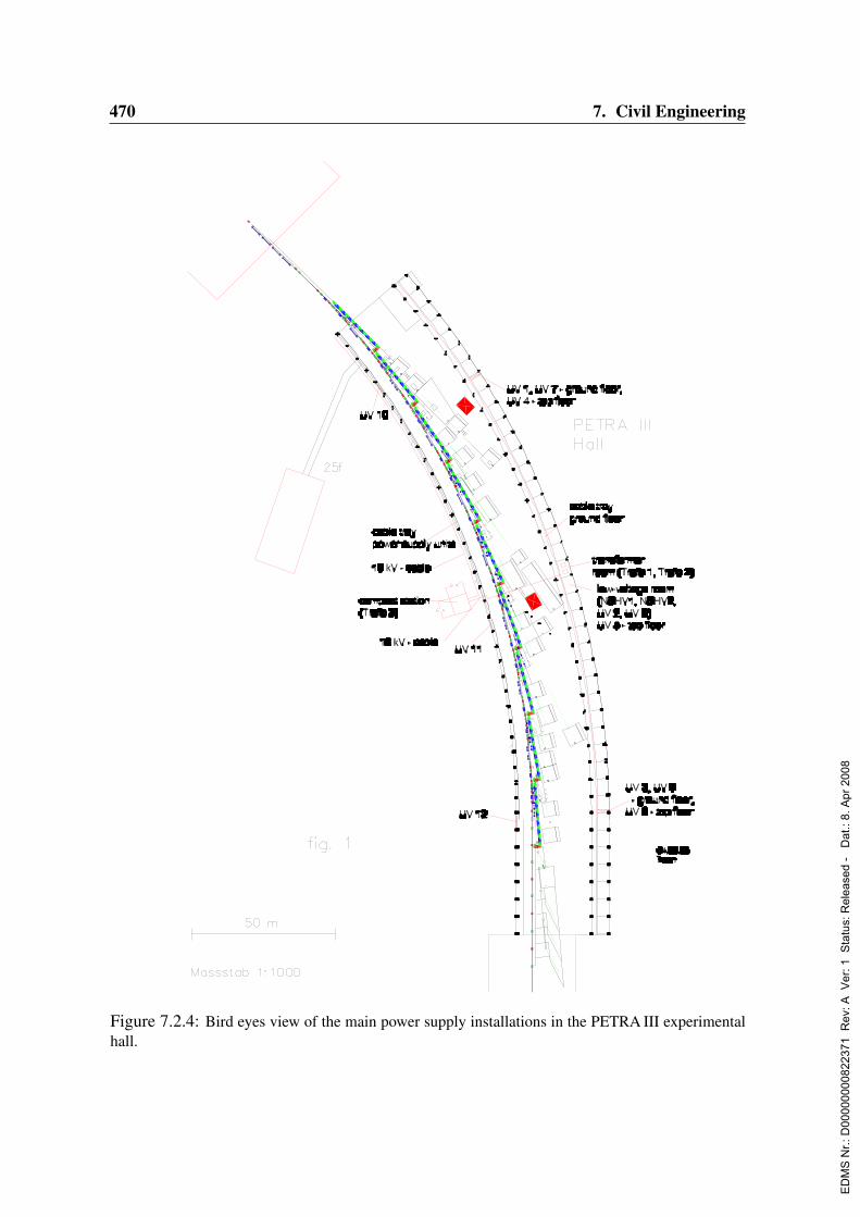
470 7. Civil Engineering
Figure 7.2.4: Bird eyes view of the main power supply installations in the PETRA III experimentalhall.
ED
MS
Nr.:
D00
0000
0082
2371
Rev
: A V
er: 1
Sta
tus:
Rel
ease
d -
Dat
.: 8.
Apr
200
8

7.2. Experimental Hall 471
7.2.4 Air conditioning7.2.4.1 Chilled-water systems
The layout of the chilled-water system is shown in Fig. 7.2.5. For the air-conditioning of theexperimental hall and the experimental hutches, chilled water with a temperature of 6C isneeded. This water is provided by three special coolers. They will be installed in a pumpingstation to be build near the PETRA-location Northeast.For the air-conditioning of the experimental hall, a total cooling power of 840 kW is neces-sary. The experimental hutches require a cooling power of 250 kW.The cooling circuit for the experiments and laboratories is connected to the chilled-watercircuit by an extra heat exchanger. Consequently, this circuit needs extra pumps and a pres-sure regulation. The water temperature of 20C is adjusted at the primary side of the heatexchanger. To avoid condensed water, all pipes for chilled water will be insulated with aclosed-cell material.
Figure 7.2.5: Scheme of chilled-water circuits
ED
MS
Nr.:
D00
0000
0082
2371
Rev
: A V
er: 1
Sta
tus:
Rel
ease
d -
Dat
.: 8.
Apr
200
8

472 7. Civil Engineering
7.2.4.2 Air conditioning of the experimental hall
For the air conditioning of the experimental hall six climate-control devices working inde-pendently of each other are conceived. These devices are mounted in the top floor on thenorth-east side of the experimental hall.Fresh air is drawn in from outside via a weather protection barrier at the mixing chamberof the device. In this device recirculated air can be mixed in upon demand. After filteringand temperature adjustment, this air is blown by a fan through galvanized steel canals andtwist diffusers into the experimental hall. The direction of the air flow from the twist dif-fusors is adjusted depending on the temperature: during heating operation the air stream isdirected vertically while in chilling mode the air stream is directed horizontally. The air thatis extracted from the hall is guided through galvanized steel canals to the exhaust fan. Theexhaust part of the air is blown out via a weather protection grid at the mixing chamber. Theair conditioning system for the experimental hall is shown schematically in Fig. 7.2.6.Continuous speed regulation of the ventilating fans is carried out with frequency converters.The climate-control devices are supplied with heating and cooling water through the watersupply network of DESY. For the cooling water of a temperature of 8(12)C and for theheating water of 50(30)C will be used. The heating of the experimental hall in winter willoccur through the air condition devices.
Figure 7.2.6: Scheme of the air conditioning for the experimental hall
• Temperature controlFor the feedback control of the air condition, each system will be equipped with anindividual DDC regulation. The regulation of the temperate is realized as a cascade
ED
MS
Nr.:
D00
0000
0082
2371
Rev
: A V
er: 1
Sta
tus:
Rel
ease
d -
Dat
.: 8.
Apr
200
8

7.2. Experimental Hall 473
control of the intake/interior air. The cascade consists of a guiding regulator and sub-sequent regulators. The guiding regulator shifts the set-point of the air supply propor-tional to the deviation of the temperature in the experimental hall. The measurement ofthe temperature proceeds via four sensors from which the average will be taken as theactual value. For the experimental hall no humidification or drying of the air is fore-seen. Within this concept, hot air exhaust of the experimental hall up to temperaturesof 70C is possible.
• Technical DataIncoming air volume stream : 6 × 60.000 m3/h = 360.000 m3/hUsed air volume stream : 6 × 60.000 m3/h = 360.000 m3/hRatio intake/exhaust air : 0 – 100 % variableTemperature in the experimental hall : 22 C ± 1 K
Figure 7.2.7: Scheme of the air conditioning for the experimental cabins
7.2.4.3 Air Conditioning of the experimental cabins
Every experimental cabin is equipped with an recirculating air condition device which issuitable for ceiling installation, stand installation and wall installation. The device is cooledwith water of 8(12) C. The air conditioning system for the experimental cabins is shownschematically in Fig. 7.2.7.
ED
MS
Nr.:
D00
0000
0082
2371
Rev
: A V
er: 1
Sta
tus:
Rel
ease
d -
Dat
.: 8.
Apr
200
8
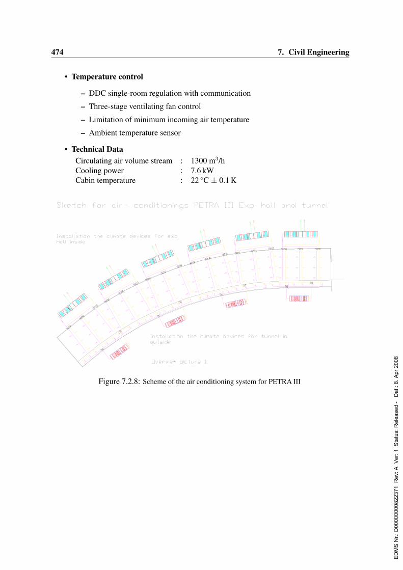
474 7. Civil Engineering
• Temperature control
– DDC single-room regulation with communication
– Three-stage ventilating fan control
– Limitation of minimum incoming air temperature
– Ambient temperature sensor
• Technical DataCirculating air volume stream : 1300 m3/hCooling power : 7.6 kWCabin temperature : 22 C ± 0.1 K
Figure 7.2.8: Scheme of the air conditioning system for PETRA III
ED
MS
Nr.:
D00
0000
0082
2371
Rev
: A V
er: 1
Sta
tus:
Rel
ease
d -
Dat
.: 8.
Apr
200
8

7.2. Experimental Hall 475
Figure 7.2.9: Cross section of the experimental hall with the main elements of the air conditioningsystems
ED
MS
Nr.:
D00
0000
0082
2371
Rev
: A V
er: 1
Sta
tus:
Rel
ease
d -
Dat
.: 8.
Apr
200
8
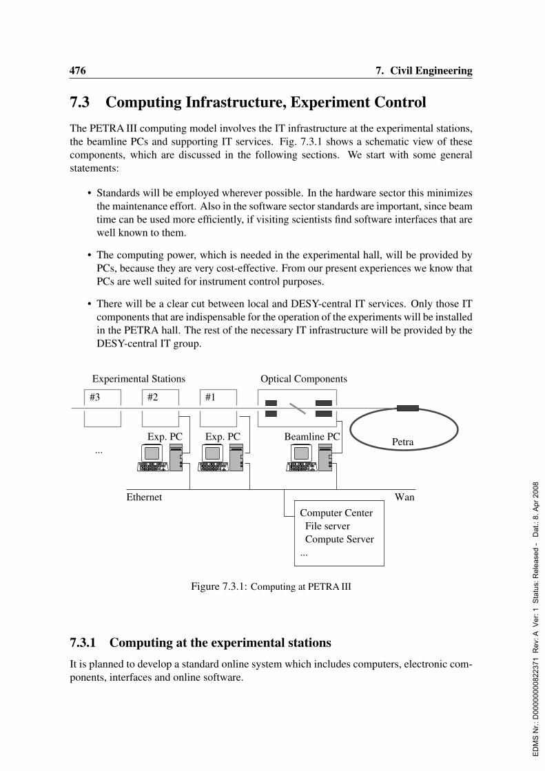
476 7. Civil Engineering
7.3 Computing Infrastructure, Experiment ControlThe PETRA III computing model involves the IT infrastructure at the experimental stations,the beamline PCs and supporting IT services. Fig. 7.3.1 shows a schematic view of thesecomponents, which are discussed in the following sections. We start with some generalstatements:
• Standards will be employed wherever possible. In the hardware sector this minimizesthe maintenance effort. Also in the software sector standards are important, since beamtime can be used more efficiently, if visiting scientists find software interfaces that arewell known to them.
• The computing power, which is needed in the experimental hall, will be provided byPCs, because they are very cost-effective. From our present experiences we know thatPCs are well suited for instrument control purposes.
• There will be a clear cut between local and DESY-central IT services. Only those ITcomponents that are indispensable for the operation of the experiments will be installedin the PETRA hall. The rest of the necessary IT infrastructure will be provided by theDESY-central IT group.
Exp. PC PetraExp. PC
File server Compute Server
Computer Center
...
#3
Beamline PC
WanEthernet
...
Experimental Stations
#2 #1
Optical Components
Figure 7.3.1: Computing at PETRA III
7.3.1 Computing at the experimental stationsIt is planned to develop a standard online system which includes computers, electronic com-ponents, interfaces and online software.
ED
MS
Nr.:
D00
0000
0082
2371
Rev
: A V
er: 1
Sta
tus:
Rel
ease
d -
Dat
.: 8.
Apr
200
8

7.3. Computing Infrastructure, Experiment Control 477
Instrument control, data acquisition and monitoring will be done by Linux PCs with VME,GPIB and CanBus interfaces. This way network overhead caused by I/O operations to thesebusses is avoided. In addition, socket interfaces are expected to be of great importance andserial lines (RS232), provided by terminal servers, will still be needed.The following table displays a list of those electronics which are going to be standardized.The interfaces are also given:
• VME: Stepping motor controller, ADC, MCA, timer, counter, I/O register, positionencoder.
• GPIB: Multimeter, amplifier, temperature controller, position encoder.
• CanBus: I/O register, stepping motor control.
• Socket: Communication with the beamline PC, CCD cameras.
• RS232: Monochromator stabilizer.
Ethernet
MonitoringDate collectionInstrument control
Experiment PC
...
VME
GPIB
CanBusWebAnalysis
RS232
TCP/IP
Windows PC
Linux1 0
Figure 7.3.2: Instrument control and data acquisition
It is intended to hold spare parts for all standard components in store and make them availablein case of hardware failures. This applies also for PCs. A backup-restore procedure will beimplemented which allows an almost automatic recovery from disk crashes or other severecomputer break-downs.Spectra serves as an online program, using Perl as the scripting language and PerlTk forthe graphical user interfaces. The program Spec (Certified Scientific Software, CSS), which
ED
MS
Nr.:
D00
0000
0082
2371
Rev
: A V
er: 1
Sta
tus:
Rel
ease
d -
Dat
.: 8.
Apr
200
8

478 7. Civil Engineering
is known to many of our guests, will be available at the PETRA III beamlines on request.Spectra and Spec have interfaces to the same hardware and it is ensured that the steppingmotor positions are maintained between two online sessions. Both programs have networkinterfaces which enable them to be used as servers or clients depending on the application.The beamlines will also be equipped with Windows PCs. They can be used to for dataanalysis and internet access.Some experimental stations will be operated by external groups. They are invited to adoptthe standard system. Only this way they can benefit from support by DESY staff.
7.3.2 The beamline PC
The status of the insertion devices, mirrors and absorbers will be made available by a ded-icated PC, the beamline PC. The data will be communicated using an ASCII protocol on aTCP/IP socket connection. In addition, the beamline PC is going to distribute informationabout the accelerator: the insertion device status, the beam current and the beam position.The beamline PC will not be associated with a specific experiment. Read-access will begranted to all experimental stations, write-access to one at a time.
7.3.3 Data storage
Depending on the amount of incoming data, the disk space of the experiment PC may besufficient to store the data before it is transfered to the home institutes. Other experimentsthat generate more data than can be hold on local disks need a network file system, thelarge file store (LFS). It is accessible from Linux and Windows, it has a short connectionto compute servers and it is backuped regularly. The LFS is installed and operated by theDESY IT group.
7.3.4 Compute servers
In general, data processing will be carried out at the home institutes. There are exceptions tothis rule:
• Data has to be analyzed at DESY, if the ongoing measurement critically depends onthese results.
• It can be useful to perform the necessary calculations at DESY, if the data analysis is apart of the experimental method, especially if the analysis requires an amount of CPUpower that is not available at all home institutes.
• Data reduction should be considered, if it leads to a considerably lower network loador disk usage.
Compute servers will be installed and operated by the central DESY IT group.
ED
MS
Nr.:
D00
0000
0082
2371
Rev
: A V
er: 1
Sta
tus:
Rel
ease
d -
Dat
.: 8.
Apr
200
8

7.3. Computing Infrastructure, Experiment Control 479
7.3.5 Data transferIn general, data will be copied via the network to the home institutes. DESY is a member ofthe DFN. It is expected that the bandwidth grows with the need of our user community.For those who do not have sufficient internet access, it will be possible to copy data to somemedium and carry it back.
7.3.6 SummaryDESY develops a standard system for instrument control and data acquisition and invitesexternal groups to use it. Beamline PCs will provide an interface to the optical componentsand accelerator data. File and compute servers will be supplied by DESY-central IT group.
ED
MS
Nr.:
D00
0000
0082
2371
Rev
: A V
er: 1
Sta
tus:
Rel
ease
d -
Dat
.: 8.
Apr
200
8

480 7. Civil Engineering
ED
MS
Nr.:
D00
0000
0082
2371
Rev
: A V
er: 1
Sta
tus:
Rel
ease
d -
Dat
.: 8.
Apr
200
8

Chapter 8
Project Costs, Personnel, andManagement
8.1 Project Cost EstimateThe estimate of the total PETRA III project costs includes all costs related to
• the refurbishment of 7/8, and the conversion of 1/8 of the PETRA storage ring,
• the refurbishment of the pre-accelerators and accelerator infrastructure,
• all construction work necessary for the new experimental hall including radiation pro-tection, offices and laboratories,
• the insertion devices, beamlines, and experimental stations to be built and operated byDESY,
• all R&D activities necessary for the storage ring, insertion devices, and beamline com-ponents from year 2005 on,
• and all costs for personnel.
Within the PETRA III upgrade about 13 beamlines at independent undulators will be pro-vided. According to the present plan seven of these undulator beamlines will be constructedand operated by DESY. It is expected that some of the remaining beamlines will be builtand/or financed by external institutions such as EMBL, GKSS, and the Max Planck Society(MPG). In these cases DESY will cover the costs for beamline front ends, vacuum systems,and radiation safety measures, which amounts to about 1 Me for each beamline and is al-ready included in the total capital investment presented here. The remaining costs of theexternally built experimental stations are not included.The PETRA III project amounts to about 192 Me in year 2003 prices, where
• 71 Me of capital investment are needed for the storage ring,
• 64 Me of capital investment are required for the new experimental hall including theinsertion devices and the DESY operated beamlines, and
• 57 Me cover the total personnel costs.
ED
MS
Nr.:
D00
0000
0082
2371
Rev
: A V
er: 1
Sta
tus:
Rel
ease
d -
Dat
.: 8.
Apr
200
8
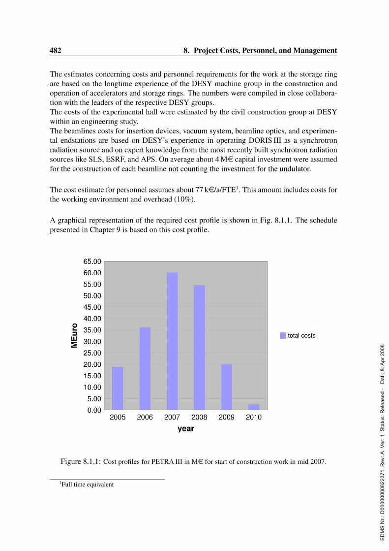
482 8. Project Costs, Personnel, and Management
The estimates concerning costs and personnel requirements for the work at the storage ringare based on the longtime experience of the DESY machine group in the construction andoperation of accelerators and storage rings. The numbers were compiled in close collabora-tion with the leaders of the respective DESY groups.The costs of the experimental hall were estimated by the civil construction group at DESYwithin an engineering study.The beamlines costs for insertion devices, vacuum system, beamline optics, and experimen-tal endstations are based on DESY’s experience in operating DORIS III as a synchrotronradiation source and on expert knowledge from the most recently built synchrotron radiationsources like SLS, ESRF, and APS. On average about 4 Me capital investment were assumedfor the construction of each beamline not counting the investment for the undulator.
The cost estimate for personnel assumes about 77 ke/a/FTE1. This amount includes costs forthe working environment and overhead (10%).
A graphical representation of the required cost profile is shown in Fig. 8.1.1. The schedulepresented in Chapter 9 is based on this cost profile.
Figure 8.1.1: Cost profiles for PETRA III in Me for start of construction work in mid 2007.
1Full time equivalent
ED
MS
Nr.:
D00
0000
0082
2371
Rev
: A V
er: 1
Sta
tus:
Rel
ease
d -
Dat
.: 8.
Apr
200
8
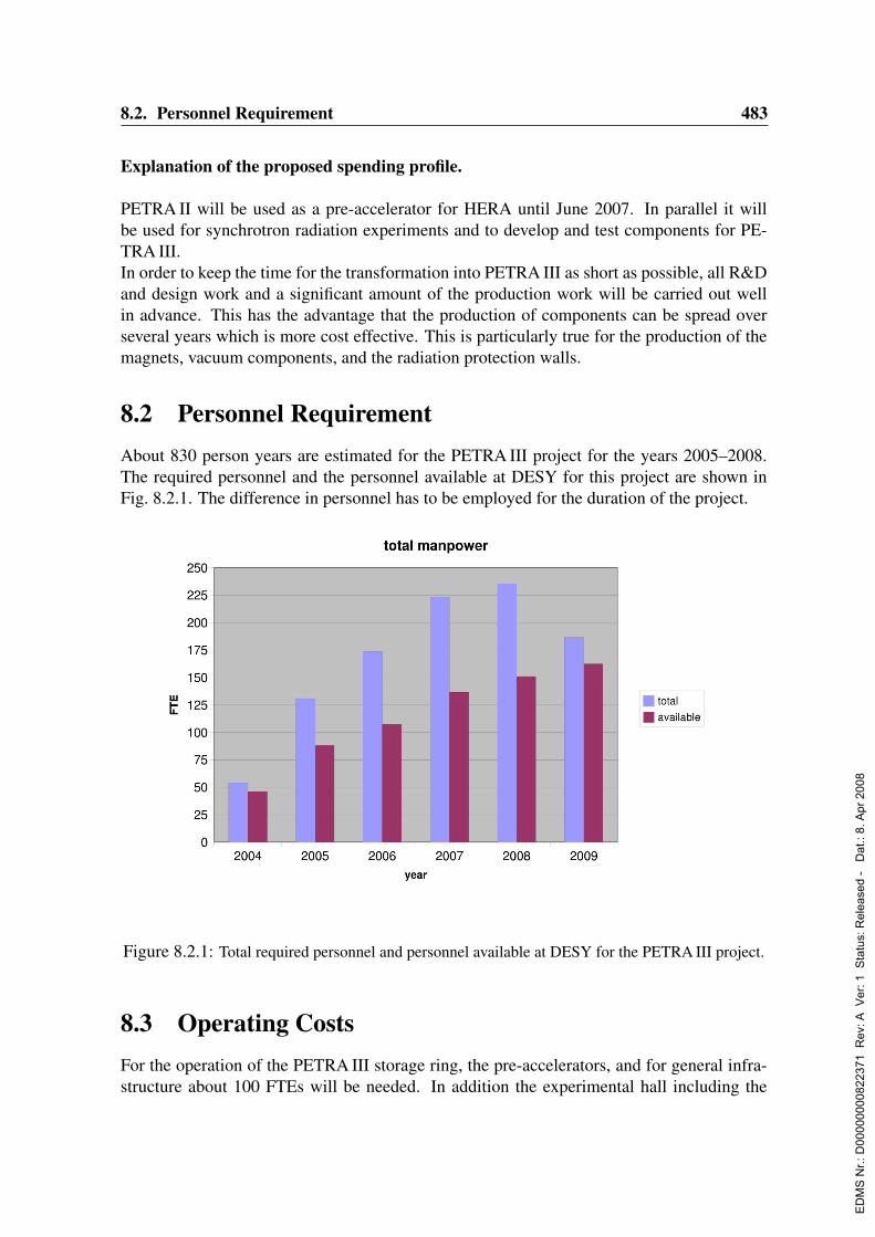
8.2. Personnel Requirement 483
Explanation of the proposed spending profile.
PETRA II will be used as a pre-accelerator for HERA until June 2007. In parallel it willbe used for synchrotron radiation experiments and to develop and test components for PE-TRA III.In order to keep the time for the transformation into PETRA III as short as possible, all R&Dand design work and a significant amount of the production work will be carried out wellin advance. This has the advantage that the production of components can be spread overseveral years which is more cost effective. This is particularly true for the production of themagnets, vacuum components, and the radiation protection walls.
8.2 Personnel RequirementAbout 830 person years are estimated for the PETRA III project for the years 2005–2008.The required personnel and the personnel available at DESY for this project are shown inFig. 8.2.1. The difference in personnel has to be employed for the duration of the project.
Figure 8.2.1: Total required personnel and personnel available at DESY for the PETRA III project.
8.3 Operating CostsFor the operation of the PETRA III storage ring, the pre-accelerators, and for general infra-structure about 100 FTEs will be needed. In addition the experimental hall including the
ED
MS
Nr.:
D00
0000
0082
2371
Rev
: A V
er: 1
Sta
tus:
Rel
ease
d -
Dat
.: 8.
Apr
200
8

484 8. Project Costs, Personnel, and Management
experiments will be staffed with about 50 FTEs. This means, that each DESY beamline willbe staffed with 4–5 FTEs and a number of FTEs will be available for technical infrastruc-ture, experiment support group, safety, hall services, etc.. Therefore, the total personnel costsamount to 8.25 Me/a.
For 5500 h/a operation of the storage ring and the pre-accelerators about 6.5 Me/a will beneeded for energy, spares, replacement, etc.. In addition, about 4.5 Me/a will be needed forthe operation, replacements, infrastructure costs and upgrades of the DESY operated beam-lines.
Therefore, in total an operational budget for the PETRA III facility including personnel of19.25 Me/a based on year 2003 prices is estimated.
8.4 Management
8.4.1 Definition of the work packagesThe entire PETRA III project is divided into a number of work packages (WP). A shortdescription of these work packages will be given in the next sections.
8.4.1.1 Reconstruction of the storage ring
All work packages related to the refurbishment and construction of the PETRA III storagering are listed in Tab. 8.4.1. For each work package a responsible person has been appointed.
name description name descriptionWPM1 Magnets WPM2 Magnet Supports and GirdersWPM3 Mains and Utilities WPM4 Magnet Power SuppliesWPM5 RF Power Supplies WPM6 Water Cooling SystemWPM7 Vacuum System WPM8 RF SystemWPM9 LINAC / PIA WPM10 Kicker and Septum MagnetsWPM11 DESY II WPM12 Topping up FeatureWPM13 Multi Bunch Feedback System WPM14 Damping WigglersWPM15 Control and Interlock System WPM16 DiagnosticsWPM17 Beam Protection System WPM18 AlignmentWPM19 Installation / Time Schedule WPM20 Beam Optics / Beam DynamicsWPM21 Beam Instabilities WPM22 Orbit Movement and Correction
Table 8.4.1: Definition of the work packages for the storage ring related activities.
ED
MS
Nr.:
D00
0000
0082
2371
Rev
: A V
er: 1
Sta
tus:
Rel
ease
d -
Dat
.: 8.
Apr
200
8
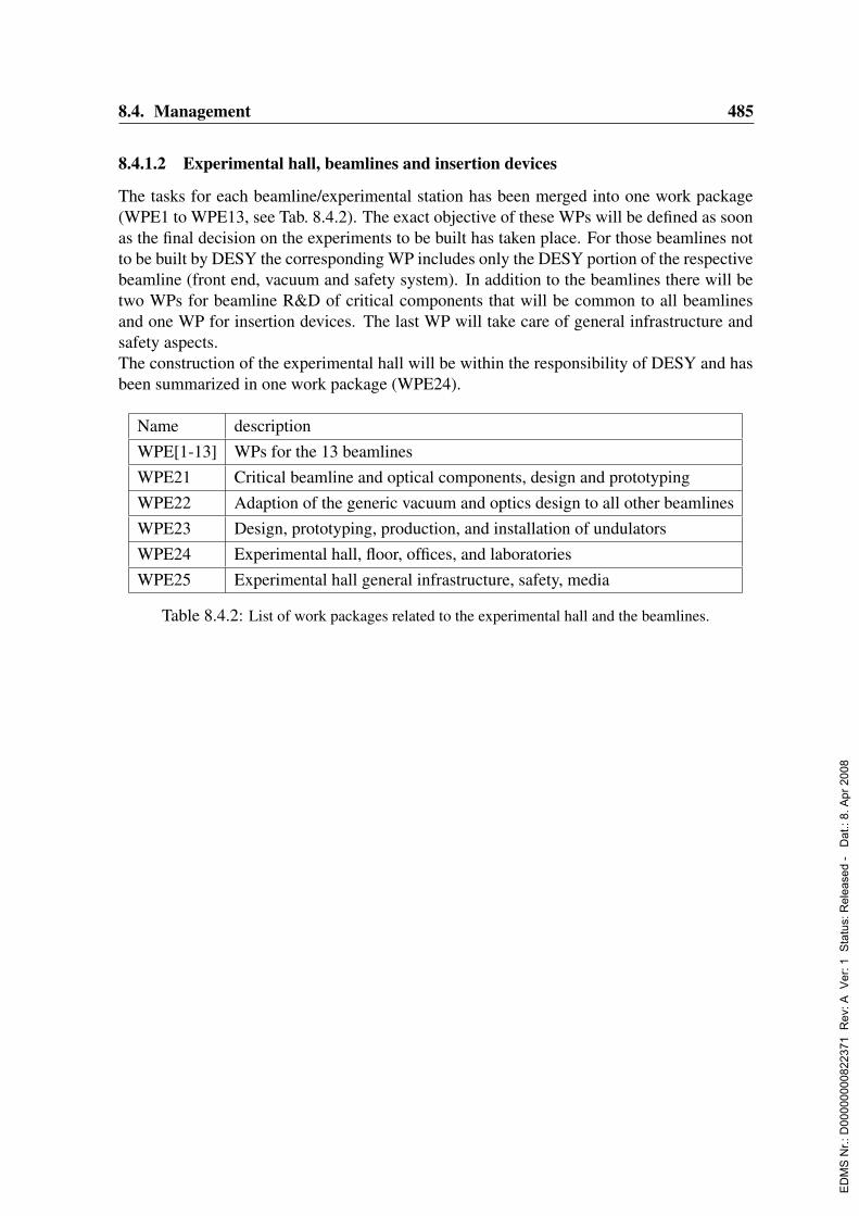
8.4. Management 485
8.4.1.2 Experimental hall, beamlines and insertion devices
The tasks for each beamline/experimental station has been merged into one work package(WPE1 to WPE13, see Tab. 8.4.2). The exact objective of these WPs will be defined as soonas the final decision on the experiments to be built has taken place. For those beamlines notto be built by DESY the corresponding WP includes only the DESY portion of the respectivebeamline (front end, vacuum and safety system). In addition to the beamlines there will betwo WPs for beamline R&D of critical components that will be common to all beamlinesand one WP for insertion devices. The last WP will take care of general infrastructure andsafety aspects.The construction of the experimental hall will be within the responsibility of DESY and hasbeen summarized in one work package (WPE24).
Name descriptionWPE[1-13] WPs for the 13 beamlinesWPE21 Critical beamline and optical components, design and prototypingWPE22 Adaption of the generic vacuum and optics design to all other beamlinesWPE23 Design, prototyping, production, and installation of undulatorsWPE24 Experimental hall, floor, offices, and laboratoriesWPE25 Experimental hall general infrastructure, safety, media
Table 8.4.2: List of work packages related to the experimental hall and the beamlines.
ED
MS
Nr.:
D00
0000
0082
2371
Rev
: A V
er: 1
Sta
tus:
Rel
ease
d -
Dat
.: 8.
Apr
200
8

486 8. Project Costs, Personnel, and Management
ED
MS
Nr.:
D00
0000
0082
2371
Rev
: A V
er: 1
Sta
tus:
Rel
ease
d -
Dat
.: 8.
Apr
200
8

Chapter 9
Timetable, Milestones
Tentative time tables for the PETRA III upgrade are given in the following sections. Mostimportant milestones from the present point of view are the start of reconstruction in July2007 and first light for user experiments in 2009. A simplified overview about the scheduleof the entire project in which summaries of the following schedules have been merged isshown in Fig. 2.5.1.
9.1 Storage RingA first tentative schedule for the refurbishment of the 7/8 of the PETRA II storage ring andfor the construction of the new 1/8 of the PETRA III is given in Figs. 9.1.1–9.1.4. Thisschedule includes also necessary work for R&D, tendering and the entire preparation phase.
9.2 Experimental HallThe schedule for the construction of the experimental hall including all preparation work isgiven in Fig. 9.2.1.
9.3 Experiments and Radiation SourcesA schedule for all beamline related activities including the preparation and R&D activities isgiven in Figs. 9.3.1 and 9.3.2.
ED
MS
Nr.:
D00
0000
0082
2371
Rev
: A V
er: 1
Sta
tus:
Rel
ease
d -
Dat
.: 8.
Apr
200
8

488 9. Timetable, Milestones
IDV
org
an
gsn
am
e
1re
co
ns
tru
cti
on
PE
TR
A III
2D
ism
an
tlin
g P
ET
RA
OR
to
NO
L (
1/8
)
3C
on
str
uctio
n o
f th
e n
ew
Ha
ll
4In
sta
llatio
n P
ET
RA
III in
th
e H
all
(1/8
)
5D
e-I
nsta
llatio
n P
ET
RA
NO
R to
OL
(7
/8)
6In
sta
llatio
n P
ET
RA
NO
R to
OL
(7
/8)
7C
om
mis
sio
nin
g P
ET
RA
III +
Te
st w
ith
Be
am
8B
ea
m O
pe
ratio
n
9R
F S
ys
tem
10
De
sig
n, C
on
str
uctio
n a
nd
Te
st o
f P
roto
typ
es
11
Ca
ll fo
r te
nd
ers
, O
rde
rs
12
So
ftw
are
De
ve
lop
me
nt, e
lectr
on
ica
l C
on
str
uctio
n
13
Pre
asse
mb
ling
an
d S
yste
m T
ests
14
RF
-Syste
m In
sta
llatio
n in
Tu
nn
el a
nd
Ha
lls
15
Co
mm
issio
nin
g
16
Ge
ne
ral P
ow
er
Su
pp
lie
s
17
De
sig
n u
nd
Co
nstr
uctio
n D
esig
n
18
Ca
ll fo
r te
nd
ers
19
Aw
ard
of co
ntr
act
20
Pro
du
ctio
n
21
Insta
llatio
n / R
eco
nstr
uctio
n
22
Ma
gn
et
Po
we
r S
up
plie
s
23
De
sig
n u
nd
Co
nstr
uctio
n D
esig
n
24
Ca
ll fo
r te
nd
ers
25
Aw
ard
of co
ntr
act
26
Pro
du
ctio
n
27
Insta
llatio
n / R
eco
nstr
uctio
n
28
Tra
ns
mit
ter
Po
we
r S
up
plie
s
29
De
sig
n u
nd
Co
nstr
uctio
n D
esig
n
30
Ca
ll fo
r te
nd
ers
31
Aw
ard
of co
ntr
act
32
Pro
du
ctio
n
33
Insta
llatio
n / r
eco
nstr
uctio
n
34
Wa
ter
Co
olin
g
35
De
sig
n u
nd
co
nstr
uctio
n d
esig
n
36
Ca
ll fo
r te
nd
ers
37
Aw
ard
of co
ntr
act
38
Pro
du
ctio
n
39
Insta
llatio
n / R
eco
nstr
uctio
n
40
Air
Co
nd
itio
nin
g
41
De
sig
n a
nd
Co
nstr
uctio
n D
esig
n
42
Ca
ll fo
r te
nd
ers
43
Aw
ard
of co
ntr
act
44
Pro
du
ctio
n
45
Insta
llatio
n / R
eco
nstr
uctio
n
46
Co
ntr
ol S
ys
tem
s
47
Su
pp
ly +
Tra
inin
g (
Pro
gra
mm
ing
En
vir
on
me
nt fo
r S
oftw
are
an
d H
ard
wa
re)
48
De
fin
itio
n W
ork
, C
on
ce
ptio
na
l D
esig
n
49
Pre
pa
ratio
n o
f sp
ecific
So
ftw
are
Co
mp
on
en
ts
50
Syste
m P
rog
ram
min
g
51
Ap
plic
atio
n P
rog
ram
mie
run
g
52
Su
pp
ly o
f g
en
era
l S
erv
ice
s
53
Su
pp
ly o
f H
ard
wa
re a
nd
Syste
m C
on
fig
ura
tio
n
54
Co
mm
issio
nin
g
55
Po
we
r S
up
ply
Co
ntr
olle
r
56
De
sig
n
57
Pro
toty
p a
nd
pilo
t S
eri
es
Q1
Q2
Q3
Q4
Q1
Q2
Q3
Q4
Q1
Q2
Q3
Q4
Q1
Q2
Q3
Q4
Q1
Q2
Q3
Q4
Q1
Q2
20
04
20
05
20
06
20
07
20
08
2
Da
tei: p
3-e
nglis
h_
Tim
e_S
che
du
le
Da
tum
:Th
u 1
9.0
2.0
4
PE
TR
A III
Overv
iew
fro
m J
an
uary
2004
Ve
rsio
n 1
Achtu
ng
! T
erm
ine s
ind
vorl
äufig
.
Auto
r: H
.Gra
be
-Çe
likG
rup
pe
: -M
R-
Tele
fon:
33
25
Seite 1
Figure 9.1.1: Time table (1/4) for the PETRA III storage ring reconstruction. (Please use yourreaders zoom function for details.)
ED
MS
Nr.:
D00
0000
0082
2371
Rev
: A V
er: 1
Sta
tus:
Rel
ease
d -
Dat
.: 8.
Apr
200
8

9.3. Experiments and Radiation Sources 489
IDV
org
an
gsn
am
e
58
Se
rie
s C
on
str
uctio
n
59
Insta
llatio
n a
nd
Co
mm
issio
nin
g
60
Va
cu
um
PE
TR
A o
ld O
cta
nts
61
Pla
nin
g a
nd
Co
nstr
uctio
n D
esig
n
62
Te
st o
f P
roto
typ
es
63
Pre
pa
ratio
n o
f D
raw
ing
s
64
Ord
er
65
Pro
du
ctio
n
66
De
-In
sta
llatio
n o
f o
ld V
acu
um
Ch
am
be
rs
67
Insta
llatio
n o
f n
ew
Va
ku
um
Ch
am
be
rs
68
Va
ku
um
PE
TR
A n
ew
s 1
/8:
69
Pla
nin
g a
nd
Co
nstr
uctio
n D
esig
n
70
Te
st o
f P
roto
typ
es
71
Pre
pa
ratio
n o
f D
raw
ing
s
72
Ord
er
73
Pro
du
ctio
n
74
Insta
llatio
n o
f n
ew
Va
cu
um
Ch
am
be
rs
75
PE
TR
A D
am
pin
g W
igg
lers
(N
ov
os
ibir
sk
)
76
Pla
nin
g a
nd
Co
nstr
uctio
n D
esig
n
77
Te
st o
f P
roto
typ
es
78
Pre
pa
ratio
n o
f D
raw
ing
s
79
Ord
er
80
Pro
du
ctio
n
81
Insta
llatio
n o
f th
e n
ew
Va
cu
um
Ch
am
be
rs
82
Ele
ktr
on
ic, E
lek
tro
tec
hn
ics
83
Pla
nin
g a
nd
Co
nstr
uctio
n D
esig
n
84
Te
st o
f P
roto
typ
es
85
Ord
er
86
Pro
du
ctio
n
87
De
-In
sta
llatio
n
88
Insta
llatio
n
89
Inje
cti
on
Kic
ke
r P
uls
er
90
Co
nstr
uctio
n D
esig
n
91
Co
nstr
uctio
n
92
Insta
llatio
n
93
Inje
cti
on
Kic
ke
r M
ag
ne
t
94
Co
nstr
uctio
n D
esig
n
95
Co
nstr
uctio
n
96
Asse
mb
ling
97
Insta
llatio
n
98
Fe
ed
ba
ck
Kic
ke
r
99
De
sig
n
10
0C
on
str
uctio
n D
esig
n
10
1C
all
for
ten
de
rs
10
2C
on
str
uctio
n
10
3A
sse
mb
ling
10
4In
sta
llatio
n
10
5In
jec
tio
n S
ep
tum
10
6D
esig
n
10
7C
on
str
uctio
n D
esig
n
10
8C
all
for
ten
de
rs
10
9C
on
str
uctio
n
11
0A
sse
mb
ling
11
1In
sta
llatio
n
11
2D
am
pin
g W
igg
lers
11
3D
esig
n u
nd
Co
nstr
uctio
n D
esig
n
11
4P
roto
typ
e F
ab
rica
tio
n a
nd
Te
st
Q1
Q2
Q3
Q4
Q1
Q2
Q3
Q4
Q1
Q2
Q3
Q4
Q1
Q2
Q3
Q4
Q1
Q2
Q3
Q4
Q1
Q2
20
04
20
05
20
06
20
07
20
08
2
Da
tei: p
3-e
nglis
h_
Tim
e_S
che
du
le
Da
tum
:Th
u 1
9.0
2.0
4
PE
TR
A III
Overv
iew
fro
m J
an
uary
2004
Ve
rsio
n 1
Achtu
ng
! T
erm
ine s
ind
vorl
äufig
.
Auto
r: H
.Gra
be
-Çe
likG
rup
pe
: -M
R-
Tele
fon:
33
25
Seite 2
Figure 9.1.2: Time table (2/4) for the PETRA III storage ring reconstruction. (Please use yourreaders zoom function for details.)
ED
MS
Nr.:
D00
0000
0082
2371
Rev
: A V
er: 1
Sta
tus:
Rel
ease
d -
Dat
.: 8.
Apr
200
8
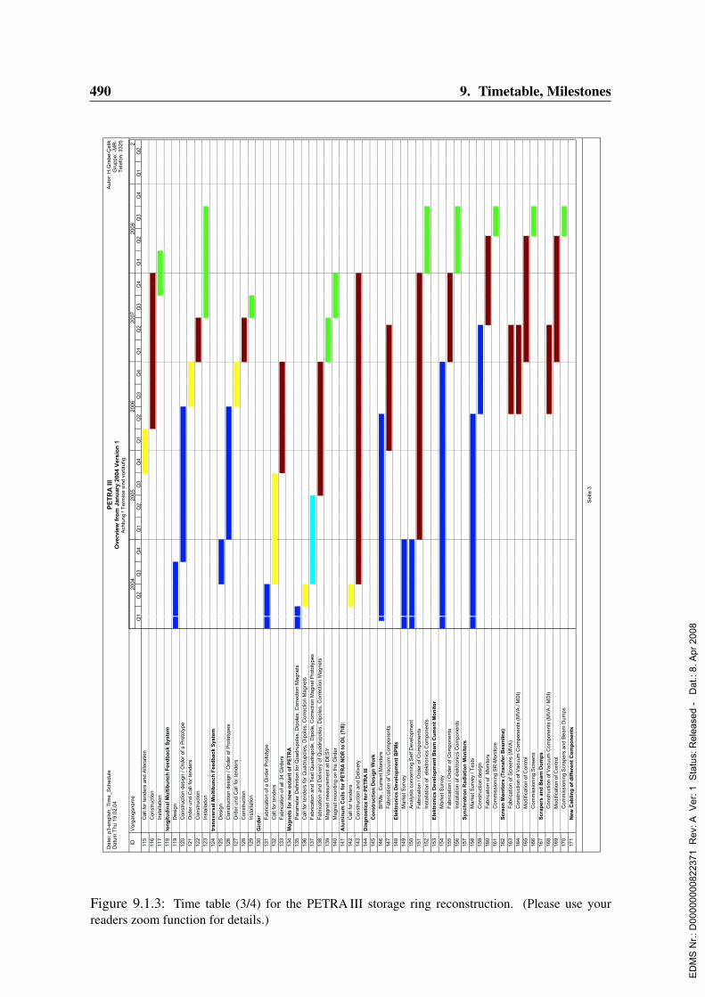
490 9. Timetable, Milestones
IDV
org
an
gsn
am
e
11
5C
all
for
ten
de
rs a
nd
Allo
ca
tio
n
11
6C
on
str
uctio
n
11
7In
sta
llatio
n
11
8lo
ng
itu
din
al M
ult
ibu
nc
h F
ee
db
ac
k S
ys
tem
11
9D
esig
n
12
0C
on
str
uctio
n d
esig
n / O
rde
r o
f a
Pro
toty
pe
12
1O
rde
r u
nd
Ca
ll fo
r te
nd
ers
12
2C
on
str
uctio
n
12
3In
sta
llatio
n
12
4tr
an
sv
ers
al M
ult
ibu
nc
h F
ee
db
ac
k S
ys
tem
12
5D
esig
n
12
6C
on
str
uctio
n d
esig
n / O
rde
r o
f P
roto
typ
es
12
7O
rde
r u
nd
Ca
ll fo
r te
nd
ers
12
8C
on
str
uctio
n
12
9In
sta
llatio
n
13
0G
ird
er
13
1F
ab
rica
tio
n o
f a
Gir
de
r P
roto
typ
e
13
2C
all
for
ten
de
rs
13
3F
ab
rica
tio
n o
f a
ll 3
4 G
ird
ers
13
4M
ag
ne
ts f
or
ne
w o
cta
nt
of
PE
TR
A
13
5P
ara
me
ter
De
fin
itio
n fo
r Q
ua
dru
po
les, D
ipo
les, C
orr
ectio
n M
ag
ne
ts
13
6C
all
for
ten
de
rs fo
r Q
ua
dru
po
les, D
ipo
les, C
orr
ectio
n M
ag
ne
ts
13
7F
ab
rica
tio
n a
nd
Te
st Q
ua
dru
po
le, D
ipo
le, C
orr
ectio
n M
ag
ne
t P
roto
typ
es
13
8F
ab
rica
tio
n a
nd
De
live
ry o
f Q
ua
dru
po
les, D
ipo
les, C
orr
ectio
n M
ag
ne
ts
13
9M
ag
ne
t m
ea
su
rem
en
t a
t D
ES
Y
14
0M
ag
ne
t m
ou
ntin
g o
n th
e G
ird
er
14
1A
lum
inu
m C
oils
fo
r P
ET
RA
NO
R t
o O
L (
7/8
):
14
2C
all
for
ten
de
rs
14
3C
on
str
uctio
n a
nd
De
live
ry
14
4D
iag
no
sti
cs
fo
r P
ET
RA
III
14
5C
on
str
uc
tio
n D
es
ign
Wo
rk
14
6B
PM
s , C
urr
en
t M
on
ito
rs
14
7F
ab
rica
tio
n o
f V
acu
um
Co
mp
on
en
ts
14
8E
lek
tro
nic
s D
ev
elo
pm
en
t B
PM
s
14
9M
ark
et S
urv
ey
15
0A
na
lysis
co
nce
rnin
g S
elf D
eve
lop
me
nt
15
1F
ab
rica
tio
n / O
rde
r o
f C
om
po
ne
nts
15
2In
sta
llatio
n o
f e
lektr
on
ics C
om
po
ne
nts
15
3E
lek
tro
nic
s D
ev
elo
pm
en
t B
ea
m C
urr
en
t M
on
ito
r
15
4M
ark
et S
urv
ey
15
5F
ab
rica
tio
n / O
rde
r o
f C
om
po
ne
nts
15
6In
sta
llatio
n o
f e
lektr
on
ics C
om
po
ne
nts
15
7S
yn
ch
rotr
on
Ra
dia
tio
n M
on
ito
rs
15
8M
ark
et S
urv
ey / T
ests
15
9C
on
str
uctio
n d
esig
n
16
0F
ab
rica
tio
n o
f M
on
ito
rs
16
1C
om
mis
sio
nin
g S
R-M
on
ito
re
16
2S
cre
en
Mo
nit
ors
(T
ran
sfe
r B
ea
mlin
e)
16
3F
ab
rica
tio
n o
f S
cre
en
s (
MV
A)
16
4C
on
str
uctio
n o
f V
acu
um
Co
mp
on
en
ts (
MV
A / M
DI)
16
5M
od
ific
atio
n o
f C
on
tro
l
16
6C
om
mis
sio
nin
g S
cre
en
s
16
7S
cra
pe
rs a
nd
Be
am
Du
mp
s
16
8C
on
str
uctio
n o
f V
acu
um
Co
mp
on
en
ts (
MV
A / M
DI)
16
9M
od
ific
atio
n o
f C
on
tro
l
17
0C
om
mis
sio
nin
g S
cra
pe
rs a
nd
Be
am
Du
mp
s
17
1N
ew
Ca
blin
g o
f d
iffe
ren
t C
om
po
ne
nts
Q1
Q2
Q3
Q4
Q1
Q2
Q3
Q4
Q1
Q2
Q3
Q4
Q1
Q2
Q3
Q4
Q1
Q2
Q3
Q4
Q1
Q2
20
04
20
05
20
06
20
07
20
08
2
Da
tei: p
3-e
nglis
h_
Tim
e_S
che
du
le
Da
tum
:Th
u 1
9.0
2.0
4
PE
TR
A III
Overv
iew
fro
m J
an
uary
2004
Ve
rsio
n 1
Achtu
ng
! T
erm
ine s
ind
vorl
äufig
.
Auto
r: H
.Gra
be
-Çe
likG
rup
pe
: -M
R-
Tele
fon:
33
25
Seite 3
Figure 9.1.3: Time table (3/4) for the PETRA III storage ring reconstruction. (Please use yourreaders zoom function for details.)
ED
MS
Nr.:
D00
0000
0082
2371
Rev
: A V
er: 1
Sta
tus:
Rel
ease
d -
Dat
.: 8.
Apr
200
8

9.3. Experiments and Radiation Sources 491
IDV
org
an
gsn
am
e
17
2O
rde
rs
17
3C
ab
ling
17
4In
sta
llatio
n a
nd
Ch
eck o
f P
iloth
erm
s
17
5L
as
er
Wir
e S
ca
nn
er
17
6S
tud
ies a
nd
Me
asu
rem
en
ts a
t P
ET
RA
II
17
7D
esig
n o
f th
e S
ca
nn
er
17
8O
rde
r a
nd
Fa
bri
ca
tio
n o
f C
om
po
ne
nts
17
9C
om
mis
sio
nin
g
18
0S
olid
Wir
e S
ca
nn
er
18
1S
tud
ies fo
r fa
st S
ca
nn
er
18
2F
ab
rica
tio
n / R
eco
nstr
uctio
n o
f S
ca
nn
ers
18
3C
om
mis
sio
nin
g
18
4M
ea
su
rem
en
t o
f a
dja
ce
nt
Bu
nc
he
s
18
5S
tud
ies
18
6F
ab
rica
tio
n / R
eco
nstr
uctio
n o
f th
e e
qu
ipm
en
t
18
7C
om
mis
sio
nin
g
18
8M
as
ch
ine
Pro
tec
tio
n S
ys
tem
18
9D
esig
n S
tud
ies
19
0D
esig
n c
on
str
uctio
n a
nd
Co
nstr
uctio
n
19
1C
om
mis
sio
nin
g
19
2
19
3
19
4L
INA
C II a
nd
PIA
:
19
5G
un
Mo
du
lato
r
19
6D
esig
n
19
7C
all
for
ten
de
rs
19
8C
on
str
uctio
n
19
9In
sta
llatio
n S
hu
tdo
wn
20
0R
ec
on
str
uc
tio
n o
f M
od
ula
tors
20
1In
sta
llatio
n
20
2C
on
ve
rte
r
20
3D
esig
n
20
4C
on
str
uctio
n D
esig
n
20
5C
all
for
ten
de
rs
20
6C
on
str
uctio
n
20
7A
sse
mb
ling
20
8In
sta
llatio
n
20
91
25
MH
z:
21
0D
esig
n
21
1C
on
str
uctio
n
21
2A
sse
mb
ling
21
3In
sta
llatio
n
21
4D
ES
Y II K
ick
er
Pu
lse
r
21
5C
on
str
uctio
n D
esig
n
21
6C
on
str
uctio
n
21
7In
sta
llatio
n
Q1
Q2
Q3
Q4
Q1
Q2
Q3
Q4
Q1
Q2
Q3
Q4
Q1
Q2
Q3
Q4
Q1
Q2
Q3
Q4
Q1
Q2
20
04
20
05
20
06
20
07
20
08
2
Da
tei: p
3-e
nglis
h_
Tim
e_S
che
du
le
Da
tum
:Th
u 1
9.0
2.0
4
PE
TR
A III
Overv
iew
fro
m J
an
uary
2004
Ve
rsio
n 1
Achtu
ng
! T
erm
ine s
ind
vorl
äufig
.
Auto
r: H
.Gra
be
-Çe
likG
rup
pe
: -M
R-
Tele
fon:
33
25
Seite 4
Figure 9.1.4: Time table (4/4) for the PETRA III storage ring reconstruction. (Please use yourreaders zoom function for details.)
ED
MS
Nr.:
D00
0000
0082
2371
Rev
: A V
er: 1
Sta
tus:
Rel
ease
d -
Dat
.: 8.
Apr
200
8
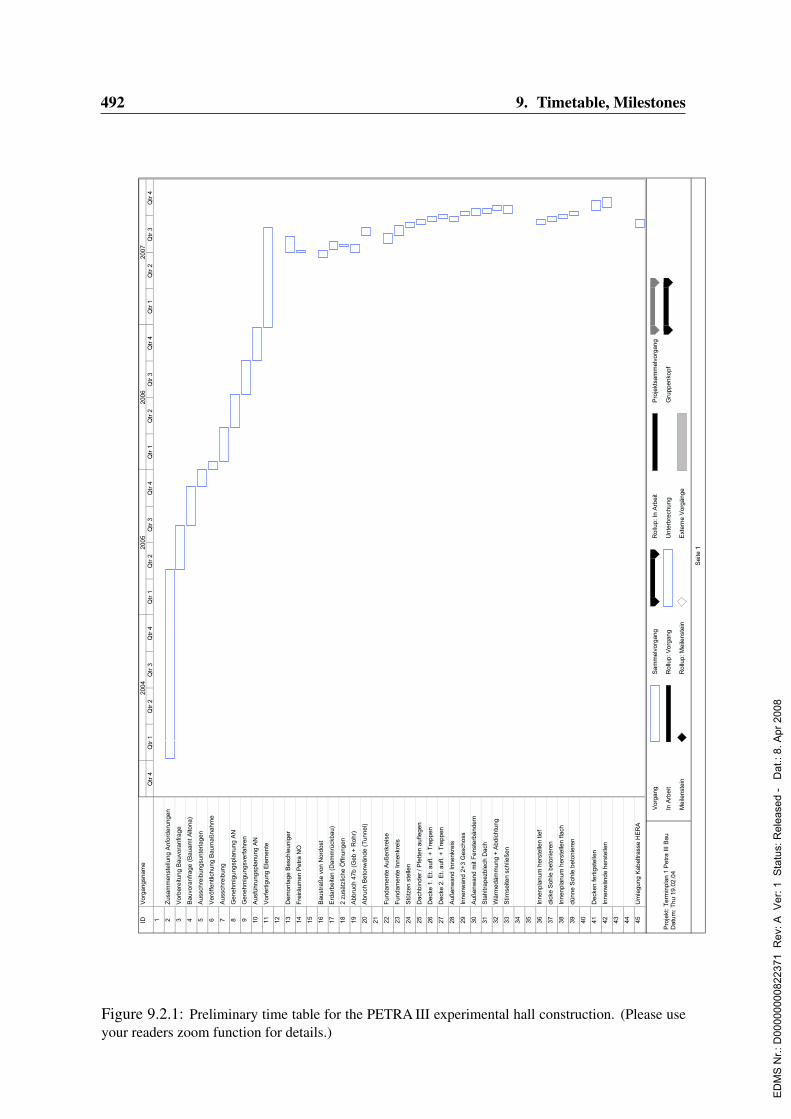
492 9. Timetable, Milestones
IDV
org
an
gsn
am
e
1 2Z
usa
mm
en
ste
llun
g A
nfo
rde
run
ge
n
3V
orb
ere
itun
g B
au
vora
nfr
ag
e
4B
au
vora
nfr
ag
e (
Ba
ua
mt A
lton
a)
5A
uss
chre
ibu
ng
sun
terl
ag
en
6V
erö
ffe
ntli
chu
ng
Ba
um
aß
na
hm
e
7A
uss
chre
ibu
ng
8G
en
eh
mig
un
gsp
lan
un
g A
N
9G
en
eh
mig
un
gsv
erf
ah
ren
10
Au
sfü
hru
ng
spla
nu
ng
AN
11
Vo
rfe
rtig
un
g E
lem
en
te
12
13
De
mo
nta
ge
Be
sch
leu
nig
er
14
Fre
irä
um
en
Pe
tra
NO
15
16
Ba
ust
raß
e v
on
No
rdo
st
17
Erd
arb
eite
n (
Da
mm
rück
ba
u)
18
2 z
usä
tzlic
he
Öffn
un
ge
n
19
Ab
bru
ch 4
7b
(G
eb
+ R
oh
r)
20
Ab
ruch
Be
ton
wä
nd
e (
Tu
nn
el)
21
22
Fu
nd
am
en
te A
uß
en
kre
ise
23
Fu
nd
am
en
te In
ne
nkr
eis
24
Stü
tze
n s
telle
n
25
Da
chb
ind
er
/ P
fette
n a
ufle
ge
n
26
De
cke
1. E
t. a
ufl.
+ T
rep
pe
n
27
De
cke
2. E
t. a
ufl.
+ T
rep
pe
n
28
Au
ße
nw
an
d In
ne
nkr
eis
29
Inn
en
wa
nd
2+
3 G
esc
ho
ss
30
Au
ße
nw
an
d m
it F
en
ste
rbä
nd
ern
31
Sta
hltr
ap
ezb
lech
Da
ch
32
Wä
rme
dä
mm
un
g +
Ab
dic
htu
ng
33
Stir
nse
iten
sch
ließ
en
34
35
36
Inn
en
pla
nu
m h
ers
telle
n tie
f
37
dic
ke S
oh
le b
eto
nie
ren
38
Inn
en
pla
nu
m h
ers
telle
n fla
ch
39
dü
nn
e S
oh
le b
eto
nie
ren
40
41
De
cke
n fe
rtig
ste
llen
42
Inn
en
wä
nd
e h
ers
telle
n
43
44
45
Um
leg
un
g K
ab
eltr
ass
e H
ER
A
Qtr
4Q
tr 1
Qtr
2Q
tr 3
Qtr
4Q
tr 1
Qtr
2Q
tr 3
Qtr
4Q
tr 1
Qtr
2Q
tr 3
Qtr
4Q
tr 1
Qtr
2Q
tr 3
Qtr
42
00
42
00
52
00
62
00
7
Vo
rga
ng
In A
rbe
it
Me
ilen
ste
in
Sa
mm
elv
org
an
g
Ro
llup
: V
org
an
g
Ro
llup
: M
eile
nst
ein
Ro
llup
: In
Arb
eit
Un
terb
rech
un
g
Ext
ern
e V
org
än
ge
Pro
jekt
sam
me
lvo
rga
ng
Gru
pp
en
kop
f
Se
ite 1
Pro
jekt
: T
erm
inp
lan 1
Petr
a III
Ba
uD
atu
m: T
hu 1
9.0
2.0
4
Figure 9.2.1: Preliminary time table for the PETRA III experimental hall construction. (Please useyour readers zoom function for details.)
ED
MS
Nr.:
D00
0000
0082
2371
Rev
: A V
er: 1
Sta
tus:
Rel
ease
d -
Dat
.: 8.
Apr
200
8
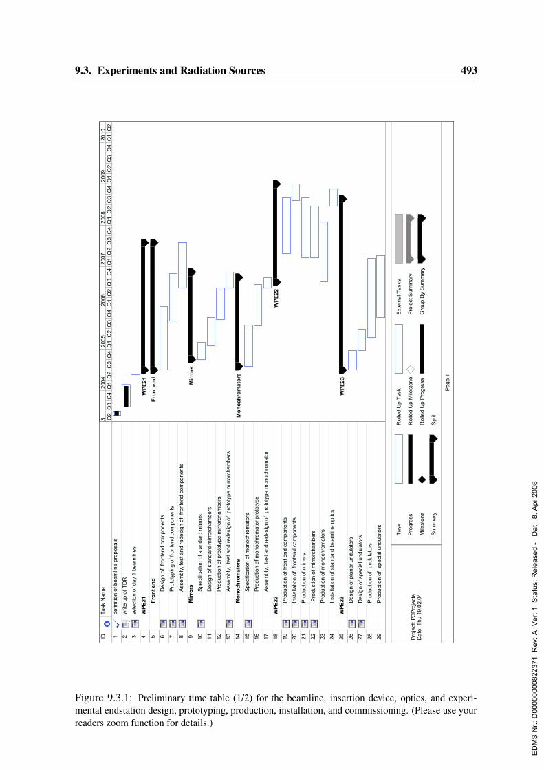
9.3. Experiments and Radiation Sources 493
IDT
ask N
am
e
1d
efin
itio
n o
f b
ea
mlin
e p
rop
osa
ls
2w
rite
up
of T
DR
3se
lectio
n o
f d
ay 1
be
am
line
s
4W
PE
21
5F
ro
nt
en
d
6D
esig
n o
f fro
nte
nd
co
mp
on
en
ts
7P
roto
typ
ing
of fr
on
ten
d c
om
po
ne
nts
8A
sse
mb
ly, te
st a
nd
re
de
sig
n o
f fro
nte
nd
co
mp
on
en
ts
9M
irro
rs
10
Sp
ecific
atio
n o
f sta
nd
ard
mir
rors
11
De
sig
n o
f sta
nd
ard
mir
rorc
ha
mb
ers
12
Pro
du
ctio
n o
f p
roto
typ
e m
irro
rch
am
be
rs
13
Asse
mb
ly, te
st a
nd
re
de
sig
n o
f p
roto
typ
e m
irro
rch
am
be
rs
14
Mo
no
ch
ro
ma
tors
15
Sp
ecific
atio
n o
f m
on
och
rom
ato
rs
16
Pro
du
ctio
n o
f m
on
och
rom
ato
r p
roto
typ
e
17
Asse
mb
ly, te
st a
nd
re
de
sig
n o
f p
roto
typ
e m
on
och
rom
ato
r
18
WP
E2
2
19
Pro
du
ctio
n o
f fr
on
t e
nd
co
mp
on
en
ts
20
Insta
llatio
n o
f fro
nte
nd
co
mp
on
en
ts
21
Pro
du
ctio
n o
f m
irro
rs
22
Pro
du
ctio
n o
f m
irro
rch
am
be
rs
23
Pro
du
ctio
n o
f m
on
och
rom
ato
rs
24
Insta
llatio
n o
f sta
nd
ard
be
am
line
op
tics
25
WP
E2
3
26
De
sig
n o
f p
lan
ar
un
du
lato
rs
27
De
sig
n o
f sp
ecia
l u
nd
ula
tors
28
Pro
du
ctio
n o
f u
nd
ula
tors
29
Pro
du
ctio
n o
f s
pe
cia
l u
nd
ula
tors
WP
E2
1
Fro
nt
en
d
Mir
ro
rs
Mo
no
ch
ro
ma
tors
WP
E2
2
WP
E2
3
Q2
Q3
Q4
Q1
Q2
Q3
Q4
Q1
Q2
Q3
Q4
Q1
Q2
Q3
Q4
Q1
Q2
Q3
Q4
Q1
Q2
Q3
Q4
Q1
Q2
Q3
Q4
Q1
Q2
32
00
42
00
52
00
62
00
72
00
82
00
92
01
0
Ta
sk
Pro
gre
ss
Mile
sto
ne
Su
mm
ary
Ro
lled
Up
Ta
sk
Ro
lled
Up
Mile
sto
ne
Ro
lled
Up
Pro
gre
ss
Sp
lit
Exte
rna
l T
asks
Pro
ject S
um
ma
ry
Gro
up
By S
um
ma
ry
Pa
ge
1
Pro
ject:
P3
Pro
jecta
Da
te:
Th
u 1
9.0
2.0
4
Figure 9.3.1: Preliminary time table (1/2) for the beamline, insertion device, optics, and experi-mental endstation design, prototyping, production, installation, and commissioning. (Please use yourreaders zoom function for details.)
ED
MS
Nr.:
D00
0000
0082
2371
Rev
: A V
er: 1
Sta
tus:
Rel
ease
d -
Dat
.: 8.
Apr
200
8

494 9. Timetable, Milestones
IDT
ask N
am
e
30
Insta
llatio
n o
f u
nd
ula
tors
31
WP
E2
4
32
de
taile
d d
escri
ptio
n o
f th
e h
all
33
ca
ll fo
r te
nd
ers
, a
pp
rova
l
34
Pre
fab
rica
tio
n o
f p
art
s fo
r e
xp
. H
all
35
De
mo
litio
n o
f 1
/8 o
f sto
rag
e r
ing
36
De
mo
litio
n o
f o
ld s
tora
ge
rin
g tu
nn
el
37
Co
nstr
uctio
n o
f e
xp
. h
all
(1)
38
Insta
llatio
n o
f h
all
cra
ne
39
WP
E2
5
40
de
sig
n o
f o
ptics h
utc
he
s
41
de
sig
n o
f in
terl
ock s
yste
m
42
de
sig
n o
f e
xp
eri
me
nta
l h
utc
he
s
43
Insta
llatio
n o
f o
ptics h
utc
he
s
44
Insta
llatio
n o
f e
xp
. H
utc
he
s
45
WP
E1
.. W
PE
13
46
De
sig
n o
f e
xp
eri
me
nta
l e
nd
sta
tio
ns
47
Pro
du
ctio
n o
f e
qu
ipm
en
t fo
r e
xp
. S
tatio
ns
48
Sta
rt o
f b
ea
mlin
e c
om
mis
ion
ing
49
Insta
llatio
n o
f e
xp
. E
qu
ipm
en
t
50
be
am
line
co
mm
isio
nin
g a
nd
fir
st e
xp
eri
me
nts
51
52
Insta
llatio
n o
f n
ew
sto
rag
e r
ing
53
Fir
st b
ea
m
54
Fir
st ye
ar
in u
se
r m
od
e
WP
E2
4
Ins
talla
tio
n o
f h
all c
ra
ne
16
.01
WP
E2
5
WP
E1
.. W
PE
13
Fir
st
be
am
22
.10
Q2
Q3
Q4
Q1
Q2
Q3
Q4
Q1
Q2
Q3
Q4
Q1
Q2
Q3
Q4
Q1
Q2
Q3
Q4
Q1
Q2
Q3
Q4
Q1
Q2
Q3
Q4
Q1
Q2
32
00
42
00
52
00
62
00
72
00
82
00
92
01
0
Ta
sk
Pro
gre
ss
Mile
sto
ne
Su
mm
ary
Ro
lled
Up
Ta
sk
Ro
lled
Up
Mile
sto
ne
Ro
lled
Up
Pro
gre
ss
Sp
lit
Exte
rna
l T
asks
Pro
ject S
um
ma
ry
Gro
up
By S
um
ma
ry
Pa
ge
2
Pro
ject:
P3
Pro
jecta
Da
te:
Th
u 1
9.0
2.0
4
Figure 9.3.2: Preliminary time table (2/2) for the beamline, insertion device, optics, and experi-mental endstation design, prototyping, production, installation, and commissioning. (Please use yourreaders zoom function for details.)
ED
MS
Nr.:
D00
0000
0082
2371
Rev
: A V
er: 1
Sta
tus:
Rel
ease
d -
Dat
.: 8.
Apr
200
8

Chapter 10
Further Upgrade Possibilities
10.1 Beamlines at Damping WigglersIn order to reach the emittance of 1.0 nmrad damping wigglers will be installed in the longstraight sections of PETRA (Sec. 3.4). In total a magnetic length of 80 m is required whichwill be distributed in the west and north. These wigglers produce a rather wide fan of hardX-rays. The power emitted amounts to 205 kW at a stored current of 100 mA in each straightsection. This is more power than any existing insertion device produces to date. The criticalenergy Ec is 35.9 keV. Fig. 4.2.1 shows the spectral distribution emitted by the present wig-gler design (3.4). The beam size at a distance of 70 m (the location of a potential experiment)amounts to 200 x 5mm2 FWHM.Given the fixed budget of the upgrade project the radiation produced by these wigglers willbe dumped in special absorbers inside the ring tunnel. A wide beam port will extract adecent fraction of the power emitted in forward direction and guide it to a dump, remote ofthe storage ring vacuum chamber. This dump can be replaced by a high power front end inan upgrade step. Furthermore, we will prepare the tunnel shielding to allow for a later use ofthese beams.These beam may be used for different purposes:
• The wide fan can be split by a comb–like slit system to feed several consecutive oreven parallel stations. Each beam would have a size of some mm2. The calculatedintensity is of the order of 1010 photons/(s mm2) behind a Si(111) monochromator. Sothese beams would compare to a typical bending magnet station at a third generationsource, however the spectrum extends to higher energies..
• The beam can be used in total to perform tomography experiments on large (scale of10 cm) samples. This application would profit most from the hard spectrum of thewiggler radiation.
• Experiments depending on a white X-ray spectrum which can not be delivered by theundulator beamlines in the new experimental hall would find an almost ideal source.This could e.g. be white beam Laue techniques or fast EXAFS measurements over awide energy range.
ED
MS
Nr.:
D00
0000
0082
2371
Rev
: A V
er: 1
Sta
tus:
Rel
ease
d -
Dat
.: 8.
Apr
200
8
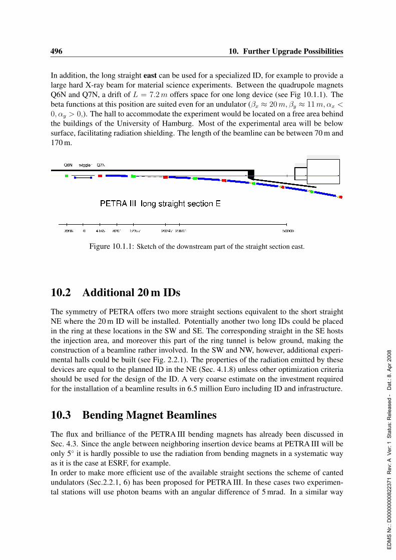
496 10. Further Upgrade Possibilities
In addition, the long straight east can be used for a specialized ID, for example to provide alarge hard X-ray beam for material science experiments. Between the quadrupole magnetsQ6N and Q7N, a drift of L = 7.2m offers space for one long device (see Fig 10.1.1). Thebeta functions at this position are suited even for an undulator (βx ≈ 20m,βy ≈ 11m,αx <0, αy > 0,). The hall to accommodate the experiment would be located on a free area behindthe buildings of the University of Hamburg. Most of the experimental area will be belowsurface, facilitating radiation shielding. The length of the beamline can be between 70 m and170 m.
Figure 10.1.1: Sketch of the downstream part of the straight section east.
10.2 Additional 20 m IDsThe symmetry of PETRA offers two more straight sections equivalent to the short straightNE where the 20 m ID will be installed. Potentially another two long IDs could be placedin the ring at these locations in the SW and SE. The corresponding straight in the SE hoststhe injection area, and moreover this part of the ring tunnel is below ground, making theconstruction of a beamline rather involved. In the SW and NW, however, additional experi-mental halls could be built (see Fig. 2.2.1). The properties of the radiation emitted by thesedevices are equal to the planned ID in the NE (Sec. 4.1.8) unless other optimization criteriashould be used for the design of the ID. A very coarse estimate on the investment requiredfor the installation of a beamline results in 6.5 million Euro including ID and infrastructure.
10.3 Bending Magnet BeamlinesThe flux and brilliance of the PETRA III bending magnets has already been discussed inSec. 4.3. Since the angle between neighboring insertion device beams at PETRA III will beonly 5 it is hardly possible to use the radiation from bending magnets in a systematic wayas it is the case at ESRF, for example.In order to make more efficient use of the available straight sections the scheme of cantedundulators (Sec.2.2.1, 6) has been proposed for PETRA III. In these cases two experimen-tal stations will use photon beams with an angular difference of 5 mrad. In a similar way
ED
MS
Nr.:
D00
0000
0082
2371
Rev
: A V
er: 1
Sta
tus:
Rel
ease
d -
Dat
.: 8.
Apr
200
8

10.3. Bending Magnet Beamlines 497
Figure 10.3.1: Scheme for the use of bending magnet radiation in horizontal direction. The center ofthe bending magnet beam is indicated in pink color below the undulator beam pipe. A monochromatorvessel is indicated in the optics hutch. A diffracted beam is shown for 20 keV photon energy using aSi (1 1 3) monochromator crystal.
one could consider for a future upgrade to use the radiation of the bending magnet down-stream of the undulator in those straight sections where only one insertion device is located.The angular separation of the two beams could be about 8 mrad which is sufficient to installseparate safety systems and optics which is mandatory for an independent operation of theundulator and the bending magnet beamline. However, such a scheme will impose somespace restrictions on each beamline which will be less severe if the undulator station needsa large source to sample distance and if it does not require bulky optics components in thevicinity of a possible bending magnet station.In Figs. 10.3.1 and 10.3.2, a horizontal and a vertical scheme, respectively, are shown for the
use of the bending magnet radiation. The vertical scheme has the advantage that the reflec-tivity of the monochromator is not affected by the polarization of the synchrotron radiation.The advantage of the horizontal scheme is that eventually larger separations from the beampipe of the undulator can be achieved, thus providing sufficient space for larger endstationequipment at the bending magnet station. An angle of 8 mrad between the undulator and thecenter of a possible bending magnet beam results in 32 cm separation between both beams in40 m distance (7 m behind the shielding wall) from the undulator source. If we assume, forexample, that the translation of a Si (1 1 1) double crystal monochromator with 30 cm beamoffset needs to be about 1 m long for an accessible energy range from 8–25 keV, then morethan 40 cm space is available to the beam pipe of the neighboring station. This is sufficient
Figure 10.3.2: Scheme for the use of bending magnet radiation in the vertical direction. The centerof the bending magnet beam is indicated in pink color below the undulator beam pipe.
ED
MS
Nr.:
D00
0000
0082
2371
Rev
: A V
er: 1
Sta
tus:
Rel
ease
d -
Dat
.: 8.
Apr
200
8
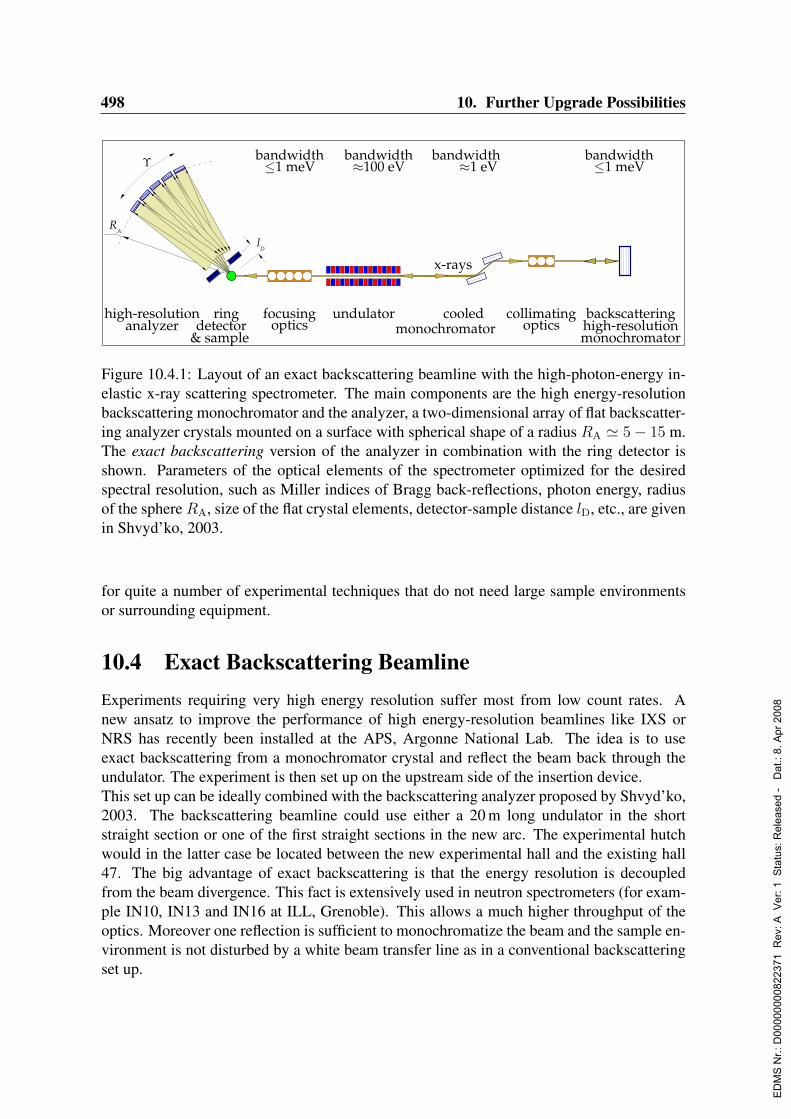
498 10. Further Upgrade Possibilities
undulator
x-rays
bandwidth100 eV
cooledmonochromator
bandwidth1 eV
collimatingoptics
backscatteringhigh-resolutionmonochromator
bandwidth1 meV
focusingoptics
bandwidth1 meV
ringdetector
& sample
RA
lD
high-resolutionanalyzer
Figure 10.4.1: Layout of an exact backscattering beamline with the high-photon-energy in-elastic x-ray scattering spectrometer. The main components are the high energy-resolutionbackscattering monochromator and the analyzer, a two-dimensional array of flat backscatter-ing analyzer crystals mounted on a surface with spherical shape of a radius RA ' 5− 15 m.The exact backscattering version of the analyzer in combination with the ring detector isshown. Parameters of the optical elements of the spectrometer optimized for the desiredspectral resolution, such as Miller indices of Bragg back-reflections, photon energy, radiusof the sphereRA, size of the flat crystal elements, detector-sample distance lD, etc., are givenin Shvyd’ko, 2003.
for quite a number of experimental techniques that do not need large sample environmentsor surrounding equipment.
10.4 Exact Backscattering BeamlineExperiments requiring very high energy resolution suffer most from low count rates. Anew ansatz to improve the performance of high energy-resolution beamlines like IXS orNRS has recently been installed at the APS, Argonne National Lab. The idea is to useexact backscattering from a monochromator crystal and reflect the beam back through theundulator. The experiment is then set up on the upstream side of the insertion device.This set up can be ideally combined with the backscattering analyzer proposed by Shvyd’ko,2003. The backscattering beamline could use either a 20 m long undulator in the shortstraight section or one of the first straight sections in the new arc. The experimental hutchwould in the latter case be located between the new experimental hall and the existing hall47. The big advantage of exact backscattering is that the energy resolution is decoupledfrom the beam divergence. This fact is extensively used in neutron spectrometers (for exam-ple IN10, IN13 and IN16 at ILL, Grenoble). This allows a much higher throughput of theoptics. Moreover one reflection is sufficient to monochromatize the beam and the sample en-vironment is not disturbed by a white beam transfer line as in a conventional backscatteringset up.
ED
MS
Nr.:
D00
0000
0082
2371
Rev
: A V
er: 1
Sta
tus:
Rel
ease
d -
Dat
.: 8.
Apr
200
8
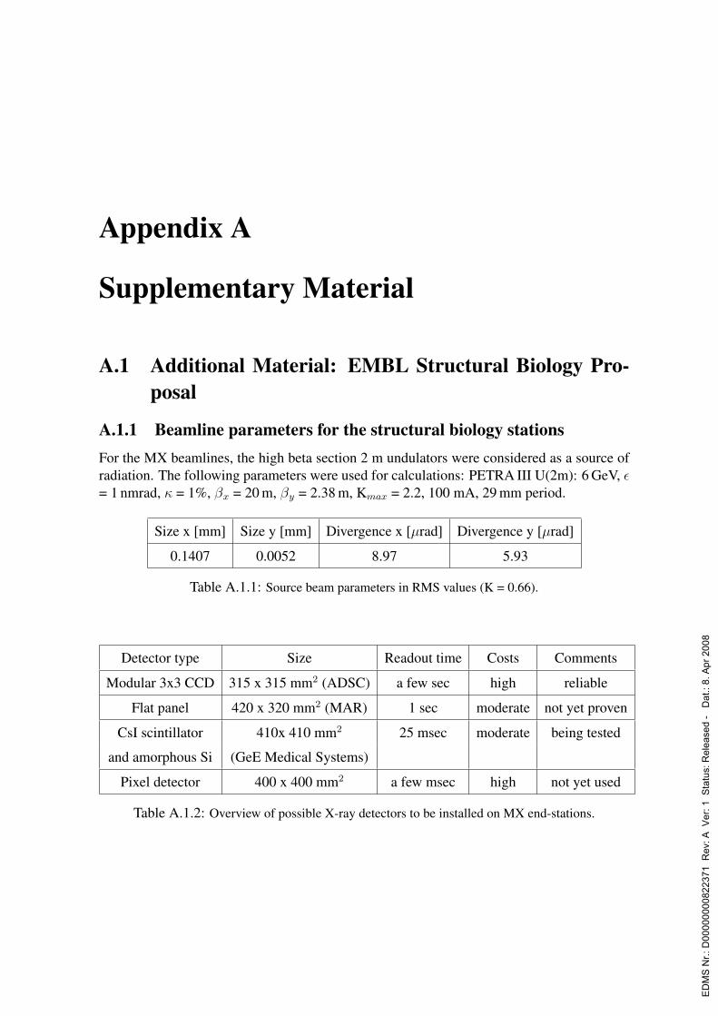
Appendix A
Supplementary Material
A.1 Additional Material: EMBL Structural Biology Pro-posal
A.1.1 Beamline parameters for the structural biology stationsFor the MX beamlines, the high beta section 2 m undulators were considered as a source ofradiation. The following parameters were used for calculations: PETRA III U(2m): 6 GeV, ε= 1 nmrad, κ = 1%, βx = 20 m, βy = 2.38 m, Kmax = 2.2, 100 mA, 29 mm period.
Size x [mm] Size y [mm] Divergence x [µrad] Divergence y [µrad]
0.1407 0.0052 8.97 5.93
Table A.1.1: Source beam parameters in RMS values (K = 0.66).
Detector type Size Readout time Costs Comments
Modular 3x3 CCD 315 x 315 mm2 (ADSC) a few sec high reliable
Flat panel 420 x 320 mm2 (MAR) 1 sec moderate not yet proven
CsI scintillator 410x 410 mm2 25 msec moderate being tested
and amorphous Si (GeE Medical Systems)
Pixel detector 400 x 400 mm2 a few msec high not yet used
Table A.1.2: Overview of possible X-ray detectors to be installed on MX end-stations.
ED
MS
Nr.:
D00
0000
0082
2371
Rev
: A V
er: 1
Sta
tus:
Rel
ease
d -
Dat
.: 8.
Apr
200
8

500 A. Supplementary Material
Optics, vacuum components and support equipment 2.2
X-ray detectors 1.9
End-stations and sample environment 1.0
Computer support and networking 0.6
Personnel 3.2
Infrastructure 0.6
Total 9.5
Table A.1.3: Estimated resource requirements (in Me) for the construction of three EMBL MXbeamlines at the PETRA ring.
A.1.2 Ray-tracing parameters for the BioSAXS beamlines
Position, cm / y 3700–3710, 3800–3837, 4000, 4320, 4500, 7300,mode of z 0–2.0 0–2.0 2 0, -1.1, -18.7,
operation x 0 0 0 0 0 17.6Double crystal- DCM VFM1 HFMmonochromator ∼5–29 0.18 0.18
∆λ/λ=10−4 Si 111 - Si/Rh - Si/Rh F2×2 cm2 4×35 cm2 4×50 cm2
r=11.5 km r=11.0 kmMultilayers MLM VFM1 HFM
∆λ/λ=1.5×10−2 1.55 0.18 0.18
- Mo/C Si(Si/Rh) - Si(Si/Rh) F4×6 cm2 4×35 cm2 4×50 cm2
d=2.97 nm r=11.5 km r=11.0 km100 pairs
Pink beam VFM2 HFM∆λ/λ=2.0×10−2 0.18 0.18
- - - Si Si(Si/Rh) F4×35 cm2 4×50 cm2
r=11.2 km r=11.0 km
Table A.1.5: Materials, positions and orientations of optical elements of the BioSAXS beamlineused for SHADOW simulations. Specifications for mirrors: type, grazing angle, material, size, radiusof curvature. Monochromators: type, grazing angle, material, size, period (for ML only) and numberof pairs (for ML only).
ED
MS
Nr.:
D00
0000
0082
2371
Rev
: A V
er: 1
Sta
tus:
Rel
ease
d -
Dat
.: 8.
Apr
200
8

Bibliography
Abbamonte, P., Venema, L., Rusydi, A., Sawatzky, G. A., Logvenov, G. & Bozovic, I.(2002). Science 297, 581.
Abola, E., Kuhn, P., Earnest, T. & Stevens, R. C. (2000). Nat. Struct. Biol 7, 973–977.
Adachi, S., Park, S. Y., Tame, J., Shiro, Y. & Shibayama, N. (2003). Proc. Natl. Acad. Sci.USA 100, 7039–7044.
Akimov, I. A., Sirenko, A. A., Clark, A. M., Hao, J.-H. & Xi, X. X. (2000). Phys. Rev. Lett.84, 4625.
Akiyama, S., Takahashi, S., Kimura, T., Ishimori, K., Morishima, I., Nishikawa, Y. & Fuji-sawa, T. (2002). Proc. Natl. Acad. Sci. USA 99, 1329–1334.
Alexe, M., Gruverman, A., Harnagea, C., Zakharov, N. D., Pignolet, A. & Hesse, D. (1999).Appl. Phys. Lett. 75, 1158.
Alferov, D. F., Bashmakov, Y. & Bessonov, E. G. (1974). Sov. Phys. Tech. Phys. 18, 1336.
Allen, A., Andreani, C., Hutchings, M. T. & Windsor, C. G. (1981). NDT Int. 14, 249–254.
Aloy, P., Ciccarelli, F., Leutwein, C., Gavin, A., Superti-Furga, G., Bork, P., Bottcher, B. &Russell, R. (2002). EMBO Rep. 3, 628–635.
Andersen, E. K., Andersen, I. G. K., Norby, P. & Hanson, J. C. (1998). J. Solid State Chem.141, 235–240.
Anderson, A. J., Mayanovic, R. A. & Bajt, S. (1995). Canad. Mineral. 33, 499–508.
Antonangeli, D. (2004). Dissertation, ESRF. in preparation.
Arnesano, F., Banci, L., Bertini, I., Mangani, S. & Thompsett, A. (2003). Proc. Natl. Acad.Sci. USA pages 3814 – 3819.
Asone, I., Meyer-Klaucke, W. & Murphy, L. (2003). J. Synchrotron Rad. 10, 16–22.
Assmann, R., Raimondi, P., Roy, G. & Wenninger, J. (2000). Proceedings of the 7th Euro-pean Particle Accelerator Conference (EPAC 2000), Vienna, Austria.
ED
MS
Nr.:
D00
0000
0082
2371
Rev
: A V
er: 1
Sta
tus:
Rel
ease
d -
Dat
.: 8.
Apr
200
8

502 BIBLIOGRAPHY
Asthalter, T., Sergueev, I., Franz, H., Ruffer, R., Petry, W., Messel, K., Harter, P. & Huwe,A. (2001). Eur. Phys. J. B 22, 301–306.
Astuto, M. D., Mang, P. K., Giura, P., Shukla, A., Ghigna, P., Mirone, A., Braden, M.,Greven, M., Krisch, M. & Sette, F. (2002). Phys. Rev. Lett. 88, 167002.
Baehtz, C., Buhrmester, T., Bramnik, N. N., Nikolowski, K., Ehrenberg, H. & Fuess, H.(2004). submitted.
Bahrdt, J., Frentrup, W., Gaupp, A., Scheer, M., Gudat, W., Ingold, G. & Sasaki, S. (2001a).Nucl. Instr. Methods Phys. Res. A 467-468, 21–29.
Bahrdt, J., Frentrup, W., Gaupp, A., Scheer, M., Gudat, W., Ingold, G. & Sasaki, S. (2001b).Nucl. Instr. Methods Phys. Res. A 467-468, 130–133.
Bahrdt, J. & Wustefeld, G. (1990). A new tracking routine for particles in undulator andwiggler fields. Technical report. BESSY Internal Report TB 90-158.
Bains, J. S. & Shaw, C. A. (1997). Brain Res. Rev. 25, 335–358.
Bak, P. (1985). Phys. Rev. B 32, 5764.
Balewski, K., Ehrlichmann, H., Kouptsidis, J. & Wittenburg, K. (1996). Proceedings of the5th European Particle Accelerator Conference (EPAC 1996), Barcelona, Spain, p. 2667-2669.
Banci, L., Bertini, I., Conte, R. D., Mangani, S. & Meyer-Klaucke, W. (2003). Biochemistry42, 2467–2474.
Baraldi, A., Comelli, G., Lizzit, S., Kiskinova, M. & Paolucci, G. (2003). Surf. Sci. Rep. 49,169.
Barbi, V., Funari, S., Gehrke, R., Scharnagl, N. & Stribeck, N. (2003a). Polymer 44, 4853.
Barbi, V., Funari, S., Gehrke, R., Scharnagl, N. & Stribeck, N. (2003b). Macromolecules 36,749.
Barla, A., Sanchez, J., Haga, Y., Lapertot, G., Doyle, B., Leupold, O., Ruffer, R., Abd-Elmeguid, M., Lengsdorf, R. & Flouquet, J. (2004). Phys. Rev. Lett. 92, 066401.
Barla, A., Sanchez, J., Ni, B., Boyle, B., Vulliet, P., Leupold, O., Ruffer, R., Kaczorowski,D., Plessel, J. & Abd-Elmeguid, M. (2002). Phys. Rev. B 66, 094425.
Baron, A. Q. R., Chumakov, A. I., Grunsteudel, H. F., Grunsteudel, H., Niesen, L. & Ruffer,R. (1996). Phys. Rev. Lett. 77, 4808.
Baron, A. Q. R., Franz, H., Meyer, A., Ruffer, R., Chumakov, A. I., Burkel, E. & Petry, W.(1997). Phys. Rev. Lett. 79, 2823.
ED
MS
Nr.:
D00
0000
0082
2371
Rev
: A V
er: 1
Sta
tus:
Rel
ease
d -
Dat
.: 8.
Apr
200
8

BIBLIOGRAPHY 503
Baron, A. Q. R., Tanaka, Y., Miwa, D., Ishikawa, D., Miwa, D., Yabashi, M. & Ishikawa, T.(2001a). J. Synchrotron Rad. 8, 1127.
Baron, A. Q. R., Tanaka, Y., Miwa, D., Ishikawa, D., Mochizuki, T., Takeshita, K., Goto, S.,Matsushita, T., Kimura, H., Yamamoto, F. & Ishikawa, T. (2001b). Nucl. Instrum. Meth-ods Phys. Res. A 467-468, 627.
Barrett, C. J., Natansohn, A. L. & Rochon, P. L. (1996). J. Phys. Chem. 100, 8836.
Bassett, W., Anderson, A.J., Mayanovic, R. & Chou, I.-M. (2000). Z. Kristall. 215, 711–717.
Batrakov, A., Jurba, V., Khrushchev, S., Kulipanov, G., Kuper, E., Kuzin, M., Medvedko,A., Mezentsev, N., Shkaruba, V., Zangrando, D., Diviacco, B. & Walker, R. P. (2002).Proceedings of the 8th European Particle Accelerator Conference (EPAC 2002), Paris,France page 2634.
Beach, G., Berkowitz, A., Parker, F. & Smith, D. (2001). Appl. Phys. Lett. 79, 224.
Becker, U. & Shirley, D. A. (1996). VUV and Soft X-ray Photoionization Plenum Press (NewYork).
Beckmann, F., Bonse, U., Busch, F. & Gunnewig, O. (1997). J. Comput. Assist. Tomogr. 21,539–553.
Beckmann, F., Heise, K., Kolsch, B., Bonse, U., Rajewsky, M. F., Bartscher, M. & Biermann,T. (1999). Biophys. J. 76, 98–102.
Beckmann, F., Lippmann, T., Metge, J., Dose, T., Donath, T., Tischer, M., Liss, K.-D. &Schreyer, A. (2003). HARWI-II, The New High-Energy Beamline for Materials Scienceat HASYLAB / DESY. Proceedings of the 8th International Conference on SynchrotronRadiation Instrumentation (SRI’03), San Francisco, USA.
Bengtzelius, U., Gotze, W. & Sjolander, A. (1984). J. Phys. C 17, 5915.
Bentley, J. & Stewart, R. F. (1974). Acta Cryst. A30, 60–67.
Berar, J., Blanquart, L., Boudet, N., Breugnon, P., Caillot, B., Clemens, J.-C., Delpierre, P.,Koudobine, I., Mouget, C., Potheau, R. & Valin, I. (2002). J. Appl. Cryst. 35, 471–476.
Berger, D., Weihreter, E., Mezentsev, N. & Shkaruba, V. (2002). Proceedings of the 8thEuropean Particle Accelerator Conference (EPAC 2002), Paris, France page 2595.
Bergmann, U., Horne, C. R., Collins, T. J. & Cramer, S. P. (1999). Chem. Phys. Lett. 302,119–124.
Bergstrom, O., Gustafsson, T. & Thomas, J. O. (1998). J. Appl. Cryst. 31, 103–105.
Berkvens, P. et al. (2002). Injection with front ends open at the ESRF. 2nd InternationalWorkshop on Radiation Safety at Synchrotron Radiation Sources, Grenoble.
ED
MS
Nr.:
D00
0000
0082
2371
Rev
: A V
er: 1
Sta
tus:
Rel
ease
d -
Dat
.: 8.
Apr
200
8
504 BIBLIOGRAPHY
Bernstein, F., Koetzle, T., Williams, G., Meyer Jr., E., Brice, M., Rodgers, J., Kennard, O.,Shimanouchi, T. & Tasumi, T. (1977). J. Mol. Biol. 112, 535–542.
Bethe, H. A. & Salpeter, E. E. (1957). Quantum Mechanics of One and Two Electron Atoms.Springer, Berlin.
Bilderback, D. H., Freund, A. K., Knapp, G. S. & Mills, D. M. (2000). J. Synchrotron Rad.7, 53–60.
Billy, J. C., Bojon, J. P., Grobner, O., Hilleret, N., Jimenez, M., Laugier, I. & Strubin, P.(2000). The lep vacuum system: A summary of 10 years of operation. Proceedings ofthe 7th European Particle Accelerator Conference (EPAC 2000), Vienna, Austria, pages2286–2288.
Bilodeau, R., Ackerman, G., Aguilar, A., Bozek, J., Turri, G. & Berrah, N. (2003). ICPEAC2003 Stockholm.
Bimberg, D., Grundmann, M. & Ledentsov, N. N. (1999). Quantum dot heterostructures.Chichester, New York: Wiley.
Binder, K. (1983). in : Domb, C., Lebowitz, J. L. (Eds.), Phase Transitions and CriticalPhenomena. London: Academic Press.
Birgenau, R. J. & Kastner, M. A. (2000). Science 288, 437.
Bjorneholm, O., Bassler, M., Ausmees, A., Hjelte, I., Feifel, R., Wang, H., Miron, C., Pi-ancastelli, M., Svensson, S., Sorensen, S., Gel’mukhanov, F. & Agren, H. (2000). Phys.Rev. Lett. 84, 2826.
Blair, G., Kamps, T., Poirier, F., Balewski, K., Honkavaara, K., Schlarb, H., Schmueser,P., Schreiber, S., Walker, N., Wendt, M., Wittenburg, K., Frisch, J., Ross, M., Ross,I. & Sertore, D. (2001a). Compton scattering techniques for the measurement of thetransverse beam size of particle beams at future linear colliders. Proc. of 21st ICFABeam Dynamics Workshop on Laser-Beam Interactions, Stony Brook USA.
Blair, G. A., Poirier, F., Kamps, T., Balewski, K., Sertore, D. & Wittenburg, K. (2001b).Simulation studies and background measurements for a laser based beam size monitorfor the future linear collider. Proc. of PAC2001.
Blume, H., Bosecke, P., Bourenkov, G. P., Kosciesza, D. & Bartunik, H. D. (2001). Nucl.Instr. Methods Phys. Res. A 467–468, 1358–1362.
Blume, M. (1985). J. Appl. Phys. 57, 3615.
Bochtler, M., Hartmann, C., Song, H., Bourenkov, G. P., Bartunik, H. D. & Huber, R. (2000).Nature (London) 403, 800–805.
Bohic, S., Simionovici, A., Ortega, R., Heymann, D., Schroer, C. & Snigirev, A. (2001).Nucl. Instr. Methods Phys. Res. A 181, 728–733.
ED
MS
Nr.:
D00
0000
0082
2371
Rev
: A V
er: 1
Sta
tus:
Rel
ease
d -
Dat
.: 8.
Apr
200
8

BIBLIOGRAPHY 505
Bonse, U. & Busch, F. (1996). Prog. Biophys. Molec. Biol. 65, 133–169.
Bonse, U., Busch, F., Gunnewig, O., Beckmann, F., Pahl, R., Delling, G., Hahn, M. & Graeff,W. (1994). Bone and Mineral 25, 25–38.
Borland, M. & Emery, L. (1999). Tracking studies of top-up safety for the Advanced PhotonSource. PAC 99, volume 4 of Particle Accelerator, pages 2319–2321, New York.
Borowski, M., Bowron, D. T. & Panfilis de, S. (1999). J. Synchrotron Rad. 6, 179.
Bota, A., Goerigk, G., Drucker, T., Haubold, H.-G. & Petro, J. (2002). J. Catalysis 205,354–357.
Bourgeois, D., Vallone, B., Schotte, F., Arcovito, A., Miele, A., Sciara, G., Wulff, M., An-finrud, P. & Brunori, M. (2003). Proc. Natl. Acad. Sci. USA . 100, 8704–8709.
Bourke, M. A. M., Dunand, D. C. & Ustundag, E. (2002). Appl. Phys. A 74, S1707–S1709.
Braun, A., Shrout, S., Fowlks, A. C., Osaisai, B. A., Seifert, S., Granlund, E. & Cairns, E. J.(2003). J. Synchrotron Rad. 10, 320–325.
Bravin, A. (2003). J. Phys. D: Appl. Phys 36, A24–A29.
Brenker, F. E., Vincze, L., Vekemans, B., Nasdala, L., Stachel, T., Kersten, M., Drakopou-los, M., Vollmer, C., Adams, F., Joswig, W. & Harris, J. W. (2003). Nature (London)submitted.
Brinkmann, R. & Rossbach, J. (1994). Nucl. Instrum. Methods Phys. Res. A 350, 8–12.
Brookes, N. B. (2003). private communication.
Brookes, N. B., Sinkovic, B., Tjeng, L., Goedkoop, J. B., Hesper, R., Pellegrin, E., Groot de,F. M. F., Altieri, S., Hulbert, S., Shekel, E. & Sawatzky, G. (1998). J. Elect. Spec. Rel.Phen. 92, 11–18.
Bruckel, T., Lippert, M., Bouchard, R., Schmidt, T., Schneider, J. R. & Jauch, W. (1993).Acta Cryst. A 49, 679.
Buchanan, S. (2002). Curr. Opin. Drug Discov. Devel. 5, 367–381.
Buffet, B. & Wenk, H. (2001). Nature (London) 413, 60.
Bulfone, D. et al. (2002). The ELETTRA digital multi-bunch feedback systems. Proceedingsof the 8th European Particle Accelerator Conference (EPAC 2002), volume 2, pages2061–2063, Paris.
Bunge, H. J., Wcislak, L., Klein, H., Garbe, U. & Schneider, J. R. (2003). J. Appl. Cryst. 36,1240.
ED
MS
Nr.:
D00
0000
0082
2371
Rev
: A V
er: 1
Sta
tus:
Rel
ease
d -
Dat
.: 8.
Apr
200
8
506 BIBLIOGRAPHY
Bunk, O., Nielsen, M. M., Solling, T. I., Craats van de, A. M. & Stutzmann, N. (2003). J.Am. Chem. Soc. 125, 2252–2258.
Burandt, B., Press, W. & Haussuhl, S. (1993). Phys. Rev. Lett. 71, 1188.
Burger, S., Carli, C., Priestnall, K. & Raich, U. (2003). The ps booster fast wire scanner.Technical report, CERN.
Burkel, E. (2000). Rep. Prog. Phys. 63, 171.
Burkhard, P., Kammerer, R. A., Steinmetz, M. O., Bourenkov, G. P. & Aebi, U. (2000).Structure 8, 223–230.
Burley, S. & Bonanno, J. (2002). Curr. Opin. Struct. Biol 12, 383–391.
Bush, A. I. (2000). Curr. Opin. Chem. Biol. 4, 184–191.
Caciuffo, R., Paolasini, L., Sollier, A., Ghigna, P., Pavarini, E., Brink van den, J. & Altarelli,M. (2002). Phys. Rev. B 65, 174425.
Camas, J., Crockford, G., Ferioli, G., Fischer, C., Gras, J. J., Jung, R., Koopman, J. & Mann,J. (1993). Resolution measurements of lepton beam transverse distributions with thelep wire scanners. Proceedings of the 1993 Particle Accelerator Conference (PAC 93),pages 2504–2506, Washington, DC. IEEE.
Campbell, C. T., Daube, K. A. & White, J. M. (1987). Surf. Sci. 182, 458–476.
Carra, P., Thole, B. T., Altarelli, M. & Wang, X. (1993). Phys. Rev. Lett. 70, 694.
Carrington, P., Chivers, P., Al-Mjeni, F., Sauer, R. & Maroney, M. (2003). Nature Struct.Biol. 10, 126–130.
Carwardine, L. et al. (1997). Presented at IEEE Particle Accelerator Conference (PAC1997),Vancouver, Canada, 12-16 May 1997.
Casarin, K. et al. (2002). Injection and FEL Lasing with Front End Open at ELETTRA. priv.communication.
Cassarino, D. S. & Bennett, J. P. (1999). Brain Res. Rev. 29, 1–25.
Castelnau, O., Drakopoulos, M., Schroer, C., Snigireva, I., Snigirev, A. & Ungar, T. (2001).Nucl. Instr. Methods Phys. Res. A 467, 1245–1248.
Castleton, C. & Altarelli, M. (2000). Phys. Rev. B 62, 1033.
Chakarian, V. et al. (1996). Synchrotron Radiation Techniques in Industrial, Chemical andMaterial Science. New York: Plenum Press.
Chavanne, J., Elleaume, P. & Vaerenbergh, P. V. (1998). A novel fast switching linear/helicalundulator. Proceedings of the 6th EPA, pages 317–319, Stockholm, Sweden.
ED
MS
Nr.:
D00
0000
0082
2371
Rev
: A V
er: 1
Sta
tus:
Rel
ease
d -
Dat
.: 8.
Apr
200
8
BIBLIOGRAPHY 507
Chavanne, J., Elleaume, P. & Vaerenbergh van, P. (1998). Proceedings of the 6th EuropeanParticle Accelerator Conference (EPAC 1998), Stockholm, Sweden page 2213.
Chavanne, J., Elleaume, P. & Vaerenbergh van, P. (2000). Proceedings of the 7th EuropeanParticle Accelerator Conference (EPAC 2000), Vienna, Austria page 2346.
Chavanne, J., Plan, B., Penel, C. & Vaerenbergh van, P. (2002). Proceedings of the 8thEuropean Particle Accelerator Conference (EPAC 2002), Paris, France page 2604.
Chen, C. T., Idzerda, Y. U., Lin, H.-J., Smith, N. V., Meigs, G., Chaban, E., Ho, G. H.,Pellegrin, E. & Sette, F. (1995). Phys. Rev. Lett. 75, 152.
Chen, C. T., Sette, F., Ma, Y. & Modesti, S. (1990). Phys. Rev. B 42, 7262.
Chouhan, S., Rossmanith, R., Strohmer, S., Doelling, D., Geisler, A., Hobl, A. & Kubsky, S.(2003). Proceedings of the PAC 2003, Portland, USA.
Chubar, O. & Elleaume, P. (1998). And efficient computation of synchrotron radiation inthe near field region. Proceedings of the 6th European Particle Accelerator Conference(EPAC 1998), pages 1177–1179.
Chubar, O., Snigirev, A., Kuznetsov, S., Weitkamp, T. & Kohn, V. (2001). X-ray interferencemethods of electron beam diagnostics. Proceedings of the 5th European Workshop onDiagnostics and Beam Instrumentation (DIPAC 2001), Grenoble. ESRF.
Chumakov, A. I., Metge, J., Baron, A. Q. R., Grunsteudel, H., Ruffer, R. & Ishikawa, T.(1996). Nucl. Instrum. Methods Phys. Res. A 383, 642.
Chupas, P. J., Ciralo, M. F., Hanson, J. C. & Grey, C. P. (2001). J. Am. Chem. Soc. 123,1694–1702.
Cirlin, G. E., Talalaev, V. G., Zakharov, N. D., Egorov, V. A. & Werner, P. (2002). phys. stat.sol (b) 232, R1–3.
Clausen, B., Grabaek, L., Steffensen, G., Hansen, P. & Topsøe, H. (1993). Catal. Lett. 20,23.
Clausen, B., Topsøe, H. & Frahm, R. (1998). Adv. in Catal. 42, 315.
Cloetens, P., Barrett, R., Baruchel, J., Guigay, J.-P. & Schlenker, M. (1996). J. Phys. D 29,133–146.
Cloetens, P., Ludwig, W., Baruchel, J., Dyck, D. V., Landuyt, J. V., Guigay, J. P. & Schlenker,M. (1999). Appl. Phys. Lett. 75, 2912–2914.
Coindreau, O., Vignoles, G. & Cloetens, P. (2003). Nucl. Instr. and Methods Phys. Res. B200, 308–314.
Cole, R. J., Macdonald, B. F. & Weightman, P. (2002). J. Electron Spec. Rel. Phenom. 125,147–152.
ED
MS
Nr.:
D00
0000
0082
2371
Rev
: A V
er: 1
Sta
tus:
Rel
ease
d -
Dat
.: 8.
Apr
200
8
508 BIBLIOGRAPHY
Coppens, P. (1997). X–ray charge densities and chemical bonding. Oxford Science Publica-tions.
Corredoura, P. (1999). Architecture and performance of the PEP-II low-level RF system.SLAC-PUB-8124, March 1999.
Craats van de, A., Stutzmann, N., Bunk, O., Nielsen, M., Watson, M., Mullen, K., Chanzy,H., Sirringhaus, H. & Friend, R. (2003). Adv. Mater. 15, 495–499.
Cras, F. L., Anne, M., Bloch, D. & Strobel, P. (1998). Solid State Ionics 106, 1–10.
Creager, K. C. (1997). Science 278, 1284.
Dallera, C. et al. (2003). Appl. Phys. Lett. submitted.
Danger, J., LeFevre, P., Magnan, H., Chandesris, D., Bourgeois, S., Jupille, J., Eickhoff, T. &Drube, W. (2002). Phys. Rev. Lett. 88, 243001.
Danneau, R., Ayari, A., Rideau, D., Requardt, H., Lorenzo, J. E., Ortega, L., Monceau, P.,Currat, R. & Grubel, G. (2002). Phys. Rev. Lett. 89, 106404.
Das, R., Mills, T. T., Kwok, L. W., Maskel, G. S., Millett, I. S., Doniach, S., Finkelstein,K. D., Herschlag, D. & Pollack, L. (2003). Phys Rev Lett. 90, 188103.
Dau, H. & Haumann, M. (2003). J. Synchrotron Rad 10, 76–85.
Dau, H., Liebisch, P. & Haumann, M. (2003). Anal. Bioanal. Chem. 376, 562–583.
Dauter, Z. & Dauter, M. (2001). Structure 7, R21–R26.
Dauter, Z., Lamzin, V. & Wilson, K. (1997). Curr. Opin. Struct. Biol 7, 681–688.
David, W. I. F. (2003). Structure determination from powders - crossing the 100-atom thresh-old. Proccedings of European Crystallographic Meeting, Durban, South Africa.
David, W. I. F., Shankland, K., McCusker, L. B. & Baerlocher, C. (2002). Structure determi-nation from powder diffraction data. Number 13 in IUCr Monographs on Crystallogra-phy. Oxford University Press.
De Caro, L., Tapfer, L. & Giuffrida, A. (1996). Phys. Rev. B 54, 10575.
Decking, W., Flottmann, K. & Rossbach, J. (1990). Proceedings of the 2nd European ParticleAccelerator Conference (EPAC 1990), Nice, France.
Dehler, M. (2002). Kicker design for the ELETTRA/SLS longitudinal multi-bunch feed-back. Proceedings of the 8th European Particle Accelerator Conference (EPAC 2002),volume 2, pages 2070–2072, Paris.
Dehler, M. et al. (1999). Proc. of the 1999 Particle Accelerator Conference, pages 2087–2089, New York, USA.
ED
MS
Nr.:
D00
0000
0082
2371
Rev
: A V
er: 1
Sta
tus:
Rel
ease
d -
Dat
.: 8.
Apr
200
8
BIBLIOGRAPHY 509
Delling, G., Hahn, M., Bonse, U., Busch, F., Gunnewig, O., Beckmann, F., Uebbing, H. &Graeff, W. (1995). Pathologe 16, 342–347.
Denecke, R., Kinne, M., Whelan, C. & Steinruck, H.-P. (2002). Surf. Rev. Lett. 9, 797.
Dennis, C. & Campbell, P. (2003). Nature (London) 421, 396.
D’Haese, P., Behets, G., Bervoets, A., Oste, L., Broe, M. D., Verberckmoes, S., Janssens,K., Somogyi, A. & Drakopoulos, M. (2002). ESRF Experimental Report LS 2137.
D’Haese, P., Behets, G., Verberckmoes, S., Bervoets, A., Debroe, M., Janssens, K. & Sa-lome, M. (2001). ESRF Experimental Report LS1709.
D’Haese, P. C., Schrooten, I., Goodman, W. G., Cabrera, W. E., Lamberts, L. V., Elseviers,M. M., Couttenye, M. M. & Broe, M. E. D. (2000). Kidney Int. 57, 1107–1114.
Diehl, H. W. (1986). Phase transitions and critical phenomena, Vol.10. London: AcademicPress.
Dierker, S. B., Pindak, R., Fleming, R. M., Robinson, I. K., & Berman, L. (1995).Phys. Rev. Lett. 75, 449.
Dietrich, S. & Wagner, H. (1983). Phys. Rev. Lett. 51, 1469.
Diviacco, B., Bracco, R., Millo, D., Walker, R. P., Zalateu, M. & Zangrando, D. (2000).Proceedings of the 7th European Particle Accelerator Conference (EPAC 2000), Vienna,Austria page 2322.
Dorner, B., Burkel, E., Illini, T. & Peisl, J. (1987). Z. Phys. B 69, 179.
Dorner, B., Burkel, E. & Peisl, J. (1986). Nucl. Instrum. Methods Phys. Res. A 246, 450.
Dreele von, R. B. (2003). volume 368, chapter Protein crystal structure analysis from high-resolution X-ray powder-diffraction data Macromolecular, pages 254–267. New York:Academic Press.
Drube, W., Grehk, T. M., Treusch, R., Materlik, G., Hansen, J. E. & Aberg, T. (1999).Phys. Rev. B 60, 15507–15510.
Drube, W., Treusch, R. & Materlik, G. (1995). Phys. Rev. Lett. 74, 42.
Durr, H., Dudzik, E., Dhesi, S. S., Goedkoop, J. B., Laan van der, G., Belakhovsky, M.,Mocuta, C., Marty, A. & Samson, Y. (1999). Science 284, 2166.
Dykes, D. M., McIntosh, P. A., Poole, M. W. & Suller, V. P. (2000). SuperconductingRF systems for light sources ? Proceedings of the 7th European Particle AcceleratorConference (EPAC 2000), Vienna, Austria.
Ebert, M. (2000). Automatic phasing of the HERA RF systems. Proceedings of the CW-RFUsers Group Meeting. Argonne National Laboratory, 1.-3. March 2000.
ED
MS
Nr.:
D00
0000
0082
2371
Rev
: A V
er: 1
Sta
tus:
Rel
ease
d -
Dat
.: 8.
Apr
200
8
510 BIBLIOGRAPHY
Ebert, M. et al. (1991). DESY Internal Report 91-036.
Edmonds, K. W., Binns, C., Baker, S. H., Thornton, S. C., Goedkoop, C. N. J. B., Finazzi,M. & Brookes, N. B. (1999). Phys. Rev. B 60, 472.
Egelstaff, P. A. (1983). Adv. Chem. Phys. 53, 1.
Ehrlichmann, H. & Bialowons, W. (2003). DESY Internal Report M-03-04.
Eickhoff, T., Medicherla, V. & Drube, W. (2004). J. Electron Spec. Rel. Phenom. in press.
Einsle, O., Messerschmidt, A., Stach, P., Bourenkov, G., Bartunik, H., Huber, R. & Kroneck,P. (1999). Nature (London) 400, 476–480.
Eisebitt, S., Lorgen, M., Eberhardt, W., Luning, J., Stohr, J., Rettner, C., Helwig, O., Fuller-ton, E. & Denbeaux, G. (2003). Phys. Rev. B 68, 104419.
Elleaume, P. (1994). J. Synchrotron Rad. 1, 19–26.
Elleaume, P. (2002). ESRF Highlights 2002.
Elleaume, P., Chavanne, J. & Faatz, B. (2000). Nucl. Instr. Methods Phys. Res. A 455, 503–523.
Ellis, P., Cohen, A. & Soltis, S. (2003). J. Synchrotron Rad., 10, 287–288.
Emery, L. & Borland, M. (1999a). Analytical Studies of Top-Up Safety for the AdvancedPhoton Source. PAC 99, volume 4 of Particle Accelerator, pages 2939–2941, NewYork.
Emery, L. & Borland, M. (1999b). Top-Up Operation Experience at the Advanced PhotonSource, booktitle = PAC 99. volume 1 of Particle Accelerator, pages 200–202, NewYork.
Fienup, J. (1982). Appl. Opt. 21, 2748.
Fiori, F., Girardin, E., Giuliani, A., Lorentzen, T., Pyzalla, A., Rustichelli, F. & Stanic, V.(2000). Physica B 276–278, 923–924.
Fiquet, G., Badro, J., Guyot, F., Requardt, H. & Krisch, M. (2001). Science 291, 468.
Fischer, G. E. (1984). Invited talk given at 1984 Summer School on High Energy ParticleAccelerators, Batavia, IL, Aug 13-24, 1984.
Fischer, P., Denbeaux, G., Stoll, H., Puzic, A., Raabe, J., Nolting, F., Eimuller, T. & Schutz,G. (2003). J. de Physique IV 104, 471.
Fischer, P., Zeller, R., Schutz, G., Goerigk, G., Haubold, H.-G., Pruegl, K. & Bayreuther, G.(1998). J. Appl. Phys. 83, 7088–7090.
ED
MS
Nr.:
D00
0000
0082
2371
Rev
: A V
er: 1
Sta
tus:
Rel
ease
d -
Dat
.: 8.
Apr
200
8

BIBLIOGRAPHY 511
Flechsig, U., Patthey, L. & Quitmann, C. (2001). Nucl. Instr. Methods Phys. Res. A 467,479–481.
Flynn, G. J., Keller, L. P., Wirick, S., Jacobsen, C. & Sutton, S. R. (2003). J. Physique 104,367–372.
Follath, R., Senf, F. & Gudat, W. (1998). J. Synchrotron Rad. 5, 769.
Foster, A., Brown, G. E., Tingle, T. N. & Parks, G. (1998). Am. Mineral. 83, 553–568.
Frahm, R. (1988). Nucl. Instrum. Methods Phys. Res. A 270, 578.
Frahm, R. (1989a). Rev. Sci. Instr. 60, 2315.
Frahm, R. (1989b). Rev. Sci. Instrum. 60, 2515.
Franz, H., Seebach, M., Ehnes, A. & Werner, M. (2003). Parasitic bunch measurement ine+/e storage rings. Proc. of DIPAC 2003, Mainz. GSI.
Fratzl, P. (2003). J. Appl. Cryst. 36, 397–404.
Freeland, J. W., Chakarian, V., Bussmann, K., Idzerda, Y. U., Wende, H. & Kao, C.-C.(1998). J. Appl. Phys. 83, 6290–6292.
Frenken, J. W. M. & Veen van der, J. F. (1985). Phys. Rev. Lett. 54, 134.
Frischholz, H. (2000). 10 years of operational experience with the LEP/RF high power sys-tem. Proceedings of the CW-RF Users Group Meeting. Argonne National Laboratory,1.-3. March 2000.
Fritz, G., Roth, A., Schiffer, A., Buchert, T., Bourenkov, G., Bartunik, H., Huber, H., Stetter,K., Kroneck, P. & Ermler, U. (2002). Proc. Natl. Acad. Sci. USA 99, 1836–1841.
Fujisawa, T., Inoue, K., Oka, T., Iwamoto, H., Uruga, T., Kumasaka, T., Inoko, Y., Yagi, N.,Yamamoto, M. & Ueki, T. (2000). J. Appl. Cryst. 33, 797–800.
Fukuda, T., Mizuki, J., Ikeuchi, K., Fujita, M., Yamada, K., Baron, A. Q. R., Tsutsui, S.,Tanaka, Y. & Endoh, Y. (2003). arXiv: cond-mat 0306190, v1.
Fultz, B., Ahn, C. C., Alp, E. E., Sturhahn, W. & Toellner, T. S. (1997). Phys. Rev. Lett. 79,937.
Funari, S., Barcelo, F. & Escriba, P. V. (2003). J. Lipid. Res. 44, 567.
Garbe, S., Poulsen, H. F. & Juul Jensen, D. (1996). Texture of materials. Proc. of the 11th int.conf. on textures of materials. ICOTOM-11, Xi’an (CN), 16-20 Sep 1996 1, 100–105.
ED
MS
Nr.:
D00
0000
0082
2371
Rev
: A V
er: 1
Sta
tus:
Rel
ease
d -
Dat
.: 8.
Apr
200
8

512 BIBLIOGRAPHY
Gavin, A., Bosche, M., Krause, R., Grandi, P., Marzioch, M., A., B., Schultz, J., Rick, J.,Michon, A., Cruciat, C., Remor, M., Hofert, C., Schelder, M., Brajenovic, M., Ruffner,H., Merino, A., Klein, K., Hudak, M., Dickson, D., Rudi, T., Gnau, V., Bauch, A., Bas-tuck, S., Huhse, B., Leutwein, C., Heurtier, M., Copley, R., Edelmann, A., Querfurth,E., Rybin, V., Drewes, G., Raida, M., Bouwmeester, T., Bork, P., Seraphin, B., Kuster,B., Neubauer, G. & Superti-Furga, G. (2002). Nature (London) 415, 141–147.
Geck, J., Bruns, D., Hess, C., Klingeler, R., Reutler, P., Zimmermann v., M., Cheong, S. W. &Buchner, B. (2002). Phys. Rev. B 66, 184407.
Geissler, J., Goering, E., Justen, M., Weigand, F., , Schutz, G., Langer, J., Schmitz, D.,Maletta, H. & Mattheis, R. (2002). Phys. Rev. B 65, 020405(R).
Gel’mukhanov, F., Plashkevych, O. & Agren, H. (2001). J. Phys. B 34, 869.
Genzel, C. (1994). Phys. Status Solidi A 146, 629–637.
Gerdau, E., Ruffer, R., Winkler, H., Tolksdorf, W., Klages, C. & Hannon, J. (1985). Phys.Rev. Lett. 54, 835.
Gerke, H., Scholz, H. P., Sommerfeld, M. & Zolfaghari, A. (1977). The PETRA cavity (inGerman). DESY Internal Report PET 77/08, August 1977.
Geue, T., Saphiannikova, M. G., Henneberg, O. & Pietsch, U. (2003). J. Appl. Phys. 93,3161.
Ghigo, A. et al. (1996). Kickers and power amplifiers for the dafne bunch-by- bunch longi-tudinal feedback system. Proceedings of the 6th European Particle Accelerator Con-ference (EPAC 1996).
Gibbs, D., Harshman, D., Isaacs, E., McWhan, D., Mills, D. & Vettier, C. (1988). Phys. Rev.Lett. 61, 1241.
Giefers, H., Lubbers, R., Rupprecht, K., Wortmann, G., Alf, D. & Chumakov, A. I. (2002).High Pressure Research 22, 501.
Gilfrich, J. V., Huang, T. C., Hubbard, C. R., James, H. R., Jenkins, R., Lachance, G. R. &Smith, D. K. (1993). Advances in X-ray Analysis. Dordrecht, The Netherlands: KluwerAcademic/Plenum Publishers.
Gluehmann, M., Zarivach, R., Bashan, A., Harms, J., Schluenzen, F., Bartels, H., Agmon,I., Rosenblum, G., Pioletti, M., Auerbach, T., Avila, H., Hansen, H., Franceschi, F. &Yonath, A. (2001). Methods 25, 292–302.
Gluskin, E. (1998). J. Synchrotron Rad. 5, 189–195.
Gnaupel-Herold, T., Haeffner, D., Prask, H. & Matejicek, J. (2000). Proc. ICRS6, IOMCommunications Ltd., London (UK) pages 751–758.
ED
MS
Nr.:
D00
0000
0082
2371
Rev
: A V
er: 1
Sta
tus:
Rel
ease
d -
Dat
.: 8.
Apr
200
8
BIBLIOGRAPHY 513
Goerigk, G., Gorke, H., Hartmann, R., Struder, L., Hamann, D. & Zwoll, K. (2002). HASY-LAB Annual report.
Goerigk, G., Haubold, H. G., Lyon, O. & Simon, J. P. (2003). J. Appl. Cryst. 36, 425–429.
Goerigk, G., Schweins, R., Huber, K. & Ballauff, M. (2004). Europhys. Lett. accepted.
Goerigk, G. & Williamson, D. L. (1998). Solid State Commun. 108, 419.
Goerigk, G. & Williamson, D. L. (2001a). J. Appl. Phys. 90, 5808–5811.
Goerigk, G. & Williamson, D. L. (2001b). J. Non-Cryst. Solids 281, 181.
Golosio, B., Simionovici, A., Somogyi, A., Camerani, C. & Steenari, B. M. (2003). J. dePhysique IV 104, 647–650.
Golovchenko, J. A., Kincaid, B. M., Levesque, R. A., Meixner, A. E. & Kaplan, D. R. (1986).Phys. Rev. Lett. 57, 202.
Gomis-Ruth, F., Maskos, K., Betz, M., Bergner, A., Huber, R., Suzuki, K., Yoshida, N.,K. Brew amd, H. N., Bourenkov, G., Bartunik, H. & Bode, W. (1997). Nature (London)389, 77–81.
Graafsma, H., Souhassou, M., Puig-Molina, A., Harkema, S., Lecomte, C. & Kvick, A.(1998). Acta Cryst. B 54, 193–195.
Greegor, R., Pingitore Jr., N. & Lytle, F. (1997). Science 275, 1452–1454.
Grenzer, J., Darowski, N., Pietsch, U., Daniel, A., Reithmaier, J. P., Rennon, S. & Forchel,A. (2000). Appl. Phys. Lett. 77, 4277.
Grenzer, J., Grigorian, S. A., Feranchuk, S., Pietsch, U., Zeimer, U., Fricke, J., Kissel, H.,Knauer, A. & Weyers, M. (2004). Phys. Rev. B submitted.
Groll, M., Brandstetter, M., Bartunik, H., Bourenkow, G. & Huber, R. (2003). J. Mol. Biol.327, 75–83.
Groll, M., Ditzel, L., Lowe, J., Stock, D., Bochtler, M., Bartunik, H. & Huber, R. (1997).Nature (London) 386, 463–471.
Groot de, F. (2001). Chem. Rev. 101, 1779–1808.
Groot de, F. M. F., Krisch, M. H. & Vogel, J. (2002). Phys. Rev. B 66, 195112.
Grubel, G., Abernathy, D., Riese, D., Vos, W. & Wegdam, G. (2000). J. Appl. Cryst. 33, 424.
Grunwaldt, J.-D.and Lutzenkirchen-Hecht, D., Richwin, M., Grundmann, S., Clausen,B. S. & Frahm, R. (2001). J. Phys. Chem. B 105, 5161.
Grunwaldt, J.-D., Caravati, M., Ramin, M. & Baiker, A. (2003). Catal. Lett. in press.
ED
MS
Nr.:
D00
0000
0082
2371
Rev
: A V
er: 1
Sta
tus:
Rel
ease
d -
Dat
.: 8.
Apr
200
8
514 BIBLIOGRAPHY
Grunwaldt, J.-D. & Clausen, B. (2002). Topics Catal. 18, 37.
Grunwaldt, J.-D., Molenbroek, A., Topsøe, N.-Y., Topsøe, H. & Clausen, B. (2000). J. Catal.194, 452.
Grunwaldt, J.-D., Wandeler, R. & Baiker, A. (2003). Catal. Rev. - Sci. Eng 45, 1.
Guilleaume, B., Ballauff, M., Goerigk, G., Wittemann, M. & Rehahn, M. (2001). ColloidPolym. Sci. 279, 829–835.
Guilleaume, B., Blaul, J., Ballauff, M., Wittemann, M., Rehahn, M. & Goerigk, G. (2002).Eur. Phys. J. E 8, 299–309.
Gundlach, C., Pantleon, W., Lauridsen, E. M., Margulies, L., Doherty, R. D. & Poulsen, H. F.(2004). Scripta Materialia 50, 477–481.
Guo, J. H., Luo, Y., Augustsson, A., Kashtanov, S., Rubensson, J. E., Shuh, D. K., Agren,H. & Nordgren, J. (2003). Phys. Rev. Lett. 91, 157401.
Guo, J. H., Luo, Y., Augustsson, A., Rubensson, J. E., Sathe, C., Agren, H., Siegbahn, H. &Nordgren, J. (2002). Phys. Rev. Lett. 89, 137402.
Gutt, C., Ghaderi, T., Chamard, V., Madsen, A., Seydel, T., Tolan, M., Sprung, M., Grubel,G. & Sinha, S. K. (2003). Phys. Rev. Lett. 91, 076104.
Hagemeier, C., Shima, S., Thauer, R., Bourenkov, G., Bartunik, H. & Ermler, U. (2003). J.Mol. Biol. 332, 1047–1057.
Hahn, U. (2003). HASYLAB vacuum guidelines for beamlines and experiments, www-hasylab.desy.de/services/vacuum/guides.htm. Technical report, HASYLAB at DESY.
Hahn, U., Brefeld, W., Hesse, M., Schneider, J. R., Schulte-Schrepping, H., Seebach, M. &Werner, M. (1998). J. Synchrotron Rad. 5, 627–629.
Hahn, U. & Schulte-Schrepping, H. (2003). Crystal monochromator based emittance mea-surements at the PETRA undulator beam line. Proceedings of the 8th InternationalConference on Synchrotron Radiation Instrumentation (SRI’03), San Francisco, USA.
Hajdu, J., Neutze, R., Sjogren, T., Edman, K., Szoke, A., Wilmouth, R. & Wilmot, C. (2000).Nat. Struct. Biol. 7, 1006–1012.
Halbach, K. (1981). Nucl. Instrum. Methods Phys. Res. A 187, 109–177.
Hamalainen, K., Siddons, D. P., Hastings, J. B. & Berman, L. E. (1991). Phys. Rev. Lett. 67,2850–2853.
Hanan, J. C., Swift, G. A., Ustundag, E., Beyerlein, I. J., Almer, J. D., Lienert, U. & Haeffner,D. R. (2002). Metall. Mater. Trans. A 33, 3839–3845.
Hannon, J. P., Trammell, G. T., Blume, M. & Gibbs, D. (1988). Phys. Rev. Lett. 61, 1245.
ED
MS
Nr.:
D00
0000
0082
2371
Rev
: A V
er: 1
Sta
tus:
Rel
ease
d -
Dat
.: 8.
Apr
200
8
BIBLIOGRAPHY 515
Hansel, C. M., Fendorf, S., Sutton, S. & Newville, M. (2001). Environ. Sci. Technol. 35,3863.
Hansel, C. M., Laforce, M. K., Fendorf, S. & Sutton, S. (2002). Environ. Sci. Technol. 36,1988–1994.
Hansen, K. & Troger, L. (2000). IEEE Transactions on Nucl. Science 47, 2748–2757.
Hara, T., Tanaka, T., Tanabe, T., Marchal, X.-M., Okada, S. & Kitamura, H. (1998). J.Synchrotron Rad. 5, 403–405.
Harata, K. & Kanai, R. (2002). Proteins 48, 53–62.
Harding, M. M. (1996). J. Synchrotron Rad. 3, 250–259.
Harkay, K. (2002). Proceedings of the 8th European Particle Accelerator Conference (EPAC2002), Paris 2002, p. 1505-1507.
Harms, J., Schlunzen, F., Zarivach, R., Bashan, A., Gat, S., Agmon, I., Bartels, H.,Franceschi, F. & Yonath, A. (2001). Cell 107, 679–688.
Harms, J. M., Bartels, H., Schlunzen, F. & Yonath, A. (2003). J. Cell Sci. 116, 1391–1393.
Harris, H., Pickering, I. & George, G. (2003). Science 301, 1203.
Harrison, S. (2003). Cell 112, 737–740.
Hartman, Y., Tarazona, E., Elleaume, P., Snigireva, I. & Snigirev, A. (1995). Rev. Sci. In-strum. 66, 1978.
Hartog, P. D., Gagliano, J., Goeppner, G., Noonan, J., Trakhtenberg, E. & Wiemerslage, G.(2001). Vacuum system of the APS: Operation experience and status report. Proceed-ings of the 2001 Particle Accelerator Conference, pages 607–609.
Hasan, M., Isaacs, E., Shen, Z.-X., Miller, L., Tsutsui, K., Tohoyama, T. & Meakawa, S.(2000). Science 288, 1811.
Hashimoto, S. & Sasaki, S. (1995). Nucl. Instr. Methods Phys. Res. A 361, 611–622.
Haskel, D., Srajer, G., Choi, Y., Lee, D. R., Lang, J. C., Meersschaut, J., Jiang, J. S. & Bader,S. D. (2003). Phys. Rev. B 67, 180406.
Haskel, D., Srajer, G., Lang, J. C., Pollmann, J., Nelson, C. S., Jiang, J. S. & D., B. S. (2001).Phys. Rev. Lett. 87, 207201.
Hasnain, S. S. & Strange, R. (2003). J. Synchrotron Rad. 10, 9–15.
Haubold, H.-G., Vad, T., Waldofner, N. & Bonnemann, H. (2003). J. Appl. Cryst. 36, 617–620.
ED
MS
Nr.:
D00
0000
0082
2371
Rev
: A V
er: 1
Sta
tus:
Rel
ease
d -
Dat
.: 8.
Apr
200
8
516 BIBLIOGRAPHY
Hauk, V. (1997). Structural and Residual Stress Analysis by Nondestructive Methods. Ams-terdam: Elsevier.
Haussler, P. (1992). Phys. Rep. 222, 65.
He, H., Marchesini, S., Howells, M., Weierstall, U., Chapman, H., Hau-Riege, S., Noy, A. &Spence, J. (2003). Phys. Rev. B 67, 174114.
Heinemann, U., Frevert, J., Hofmann, K., Illing, G., Maurer, C., Oschkinat, H. & Saenger,W. (2000). Prog. Biophys. Mol. Biol . 73, 347–362.
Henrich, S., Cameron, A., Bourenkov, G. P., Kiefersauer, R., Huber, R., Lindberg, I., Bode,W. & Than, M. E. (2003). Nat. Struct. Biol. 10, 520–526.
Hermsdorf, N., Sahre, K., Volodin, P., Stamm, M., Eichhorn, K. J., Gehrke, R., Panagiotou,P., Titz, T. & Muller-Buschbaum, P. (2003). in preparation.
Hesse, M. & Seebach, M. (1997). Photon beam position monitors at DORIS. Proc. of 3RD
European Workshop on Beam Diagostics and Instrumentation for Particle Accelerators,INFN Frascati, Italy.
Hignette, O., Cloetens, P., Lee, W. K., Ludwig, W. & Rostaing, G. (2003). J. de Physique IV104, 231–234.
Hofmann, A. & Meot, F. (1982). Nucl. Instr. Methods Phys. Res. 203, 483.
Hohlneicher, G., Pulm, H. & Freund, H.-J. (1985). J. Electron Spec. Rel. Phenom. 37, 209–224.
Holldack, K., Erko, A., Noll, T. & Peatman, W. B. (1995). Nucl. Instr. Methods Phys. Res. A365, 40.
Holldack, K., J.Feikes & Peatman, W. B. (2001). Review of emittance and stability mon-itoring using synchrotron radiation monitors. Proc. of the 5th European Workshop onDiagnostics and Beam Instrumentation (DIPAC 2001), Grenoble. ESRF.
Holldack, K., Ponwitz, D. & Peatman, W. B. (2001). Nucl. Instr. Methods Phys. Res. A467–468, 213–220.
Hoppe, U., Kranold, R., Barz, A., Stachel, D. & Neuefeind, J. (2000). Solid State Commun.115, 559.
Horan, D. (2002). Performance of the APS 350 MHz RF systems. Proceedings of the CW-RFUsers Group Meeting. Argonne National Laboratory, 13.-15. March 2002.
Howells, M. R. (1999). ALS report LSBL-538. Technical report, LBNL, USA.
Huber, R. (1989). EMBO J. 8, 2125–2147.
ED
MS
Nr.:
D00
0000
0082
2371
Rev
: A V
er: 1
Sta
tus:
Rel
ease
d -
Dat
.: 8.
Apr
200
8

BIBLIOGRAPHY 517
Hufner, S. (1996). Photoelectron Spectroscopy: Principles and Applications. Springer,Berlin.
Ice, G., Chung, J., J.Z., T., Lunt, A. & Assoufid, L. (2000). Rev. Sci. Instrum. 71, 2635–2639.
Ice, G. & Larson, B. (2000). Adv. Eng. Mater. 10, 643–646.
Imada, M., Fujimori, A. & Tokura, Y. (1998). Rev. Mod. Phys. 70, 1039.
Inami, T., Fukuda, T., , Mizuki, J., Ishihara, S., Kondo, H., Nakao, H., Matsumura, T., Hirota,K., Murakami, Y., Maekawa, S. & Endoh, Y. (2003). Phys. Rev. B 67, 045108.
Ingold, G. (2000). Insertion devices: New concepts and performance. Proceedings of the7th European Particle Accelerator Conference (EPAC 2000), pages 222–226, Vienna,Austria.
Irizawa, A., Yamasaki, A., Okazaki, M., Kasai, S., Sekiyama, A., Imada, S., Suga, S., Kula-tov, E., Ohta, H. & Nanba, T. (2002). Solid State Commun. 124, 1–5.
Irving, T. C. (1998). Nat. Struct. Biol. 5, Suppl. 648–650.
Ishikawa, T., Hirano, K., Kanzaki, K. & Kikuta, S. (1992). Rev. Sci. Instrum. 63, 1098–1103.
Iwasaki, T., Suga, S., Imada, S., Sekiyama, A., Matsuda, K., Kotsugi, M., An, K., Muro, T.,Ueda, S., Matsushita, T., Saitoh, Y., Nakatani, T., Ishii, H., Sakai, O., Takayama, R.,Suzuki, T., Oguchi, T., Katoh, K. & Ochiai, A. (2000). Phys. Rev. B 61, 4621–4628.
Jackson, G. J., Woodruff, D. P., Jones, R. G., Singh, N. K., Chan, A. S. Y., Cowie, B. C. C. &Vormoso, V. (2000). Phys. Rev. Lett. 84, 119–122.
Jahnke, T., Weber, T., Landers, A. L., Knapp, A., Schossler, S., Nickles, J., Kammer, S.,Jagutzki, O., Schmidt, L., Czasch, A., Osipov, T., Arenholz, E., Young, A. T., Muino,R. D., Rolles, D., Abajo de, F. J. G., Fadley, C. S., Hove, M. A. V., Semenov, S. K.,Cherepkov, N. A., Rosch, J., Prior, M. H., Schmidt-Bocking, H., Cocke, C. L. & Dorner,R. (2002). Phys. Rev. Lett. 88, 73002.
Janssens, K., Adams, F. & Rindby, A. (2000). Microscopic X-ray Fluorescence Analysis.Wiley, Chichester, UK.
Jaouen, N., Tonnerre, J. M., Raoux, D., Bontempi, E., Ortega, L., Muenzenberg, M., Felsch,W., Rogalev, A., Durr, H. A., Dudzik, E., Laan van der, G., Maruyama, H. & Suzuki,M. (2002). Phys. Rev. B 66, 134420.
Jelsch, C., Teeter, M., Lamzin, V., Pichon-Pesme, V., Blessing, R. & Lecomte, C. (2000).Proc. Nat. Acad. Sci. USA 97, 3171–3176.
Jephcoat, A. & Refson, K. (2001). Nature (London) 413, 27.
Jiang, X. L., Li, L., Kumar, J., Kim, D. Y., Shivshankar, V. & Tripathy, S. K. (1996). Appl.Phys. Lett. 68, 2618.
ED
MS
Nr.:
D00
0000
0082
2371
Rev
: A V
er: 1
Sta
tus:
Rel
ease
d -
Dat
.: 8.
Apr
200
8
518 BIBLIOGRAPHY
Job, P. K. (2002). Experiences in Radiation Safety during the Top-Up Operation at the Ad-vanced Photon Source. 2nd International Workshop on Radiation Safety at SynchrotronRadiation Sources, Grenoble.
Johnson, E. D. & Oversluizen, T. (1989). Rev. Sci. Instrum. 60, 1947.
Johnson, J. & Chiu, W. (2002). Curr. Opin. Struct. Biol. 10, 229–235.
Juul Jensen, D. & Kjems, J. (1983). Texture Microstruct. 5, 239–251.
Kachalova, G., Popov, A. & Bartunik, H. (1999). Science 284, 473–476.
Kaldis, E. (2001). Handbook of the Physics and Chemistry of the Rare Earths, volume 31,Amsterdam. North-Holland.
Kamps, T., Blair, G. A., Poirier, F., Lewin, H., Schreiber, S., Walker, N. & Wittenburg, K.(2002). R&D towards a laser based beam size monitor for the future linear collider.Proceedings of the 8th European Particle Accelerator Conference (EPAC 2002).
Kao, C.-C., Calibe, W. A. L., Hastings, J. B. & Gillet, J.-M. (1996). Phys. Rev. B 54, 16361.
Kao, C.-C., Chen, C. T., Johnson, E. D., Hastings, J. B., Lin, H. J., Ho, G. H., Meigs, G.,Brot, J.-M., Hulbert, S. L., Idzerda, Y. U. & Vettier, C. (1994). Phys. Rev. B 50, 9599.
Kao, C.-C., Hastings, J. B., Johnson, E. D., Siddons, D. P., Smith, G. C. & Prinz, G. A.(1990). Phys. Rev. Lett. 65, 373.
Karl, A., Cunis, S., Gehrke, R., Krosigk, G. v., Lode, U., Luzinov, I., Minko, S., Pomper, T.,Senkovsky, V., Voronov, A. & Wilke, W. (1999). J. Macromol. Sci., Phys. B 38, 901.
Kelly, S. D., Newville, M. G., Cheng, L. L., Kemner, K. M., Sutton, S. R., Fenter, P., Stur-chio, N. C. & Spotl, C. (2003). Env. Sci. Technol. 37, 1284–1287.
Kelly IV, J. J., Barnes, B. M., Flack, F., Lagally, D. P., Savage, D. E., Friesen, M. & Lagally,M. G. (2002). J. Appl. Phys. 91, 9978–9986.
Kempenaers, L., Janssens, K., Vincze, L., Vekemans, B., Somogyi, A., Drakopoulos, M.,Simionovici, A. & Adams, F. (2002). Anal. Chem. 74, 5017–5026.
Kevan, S. D. (1992). Angle-Resolved Photoemission: Theory and Current Applications.Elsevier, Amsterdam.
Khomskii, D. & Sawatzky, G. (1997). Solid State Commun. 102, 87.
Kikutani, E. et al. (2002). Present status of the KEKB bunch feedback systems. Proceedingsof the 8th European Particle Accelerator Conference (EPAC 2002), volume 2, pages2085–2087, Paris.
Kim, C. D., Pillet, S., Wu, G., Fullagar, W. K. & Coppens, P. (2002). Acta Cryst. A58,133–137.
ED
MS
Nr.:
D00
0000
0082
2371
Rev
: A V
er: 1
Sta
tus:
Rel
ease
d -
Dat
.: 8.
Apr
200
8

BIBLIOGRAPHY 519
Kim, D. Y., Tripathy, S. K., Li, L. & Kumar, J. (1995). Appl. Phys. Lett. 66, 1166.
Kim, K.-J. (1995). Optical Engineering 34, 342–352.
King, Q. (1988). Analysis of the influence of fibre diameter on wirescanner beam profilemeasurements. Technical report, DESY.
Kinne, M., Fuhrmann, T., Whelan, C., Zhu, J., Pantforder, J., Probst, M., Held, G., Denecke,R. & Steinruck, H.-P. (2002). J. Chem. Phys. 117, 10852.
Kinne, M., Fuhrmann, T., Zhu, J., Whelan, C. M., Denecke, R. & Steinruck, H.-P. (2004). J.Chem. Phys. in print.
Kirfel, A., Krane, H. G., Blaha, P., Schwarz, K. H. & Lippmann, T. (2001). Acta Cryst. A57, 663–677.
Kitamura, H., Bizen, T., Hara, T., Marchal, X., Seike, T. & Tanaka, T. (2001). Nucl. Instr.Methods Phys. Res. A 467-468, 110–113.
Kivimaki, A., Maier, K., Hergenhahn, U., Piancastelli, M. N., Kempgens, B., Rudel, A. &Bradshaw, A. M. (1998). Phys. Rev. Lett 81, 301–304.
Klatt, R., Kohaupt, R. D. & Weiland, T. (1985). IEEE Trans. Nucl. Sci. 32, 2356–2358.
Klatt, R. & Weiland, T. (1988). DESY Internal Report M-88-04, p53-55.
Kleibert, A. et al. (2003). BESSY Jahresbericht 2002 page 89.
Kleifeld, O., Frenkel, A., Martin, J. & Sagi, I. (2003). Nature Struct. Biol. 10, 98–103.
Klopf, F., Reithmayer, J. P. & Forchel, A. (2000). Appl. Phys. Lett. 77, 1419.
Knapp, M., Baehtz, C., Ehrenberg, H. & Fuess, H. (2003). J. Appl. Cryst. submitted.
Knapp, M., Ehrenberg, H., Fuess, H., Hahn, U., Hesse, M., Schulte-Schrepping, H. & Wrob-lewski, T. (2001). Nucl. Instr. Methods Phys. Res. A 467-468, 291–293.
Knapp, M., Joco, V., Baehtz, C., Brecht, H. H., Berghauser, A., Ehrenberg, H., Seggern von,H. & Fuess, H. (2004). Nucl. Instrum. Methods Phys. Res. A in print.
Knowles, D., Foloppe, N., Matassova, N. & Murchie, A. (2002). Curr. Opin. Pharmacol. 2,501–506.
Kobayashi, K., Yabashi, M., Takata, Y., Tokushima, T., Shin, S., Tamasaku, K., Miwa, D.,Ishikawa, T., Nohira, H., Hattori, T., Sugita, Y., Nakatsuka, O., Sakai, A. & Zaima, S.(2003). Appl. Phys. Lett. 83, 1005–1007.
Kodre, A., Arcon, I., Padeznik Gomilsek, I., Preseren, J. & Frahm, R. (2002). J. Phys. B 35,3497.
ED
MS
Nr.:
D00
0000
0082
2371
Rev
: A V
er: 1
Sta
tus:
Rel
ease
d -
Dat
.: 8.
Apr
200
8
520 BIBLIOGRAPHY
Kohn, V., Snigireva, I. & Snigirev, A. (2000). Phys. Rev. Lett. 85, 2745.
Konarev, P., Volkov, V. V., Sokolova, A. V., Koch, M. H. J. & Svergun, D. I. (2003). J. Appl.Cryst. 36, 1277–1282.
Konarev, P. V., Petoukhov, M. V. & Svergun, D. I. (2001). J. Appl. Cryst. 34, 527–532.
Koritsanszky, T., Flaig, R., Zobel, D., Krane, H.-G., Morgenroth, W. & Luger, P. (1998).Science 279, 356–358.
Kostorz, G. (1991). J. Appl. Cryst. 24, 444–456.
Kotani, A. & Shin, S. (2001). Rev. Mod. Phys. 73, 203.
Kouptsidis, J. et al. (1980). Technical report, DESY Jahresbericht.
Kover, L., Drube, W., Berenyi, Z., Cserny, I., Medicherla, V. R. R., Ishii, T., Ikeno, H. &Adachi, H. (2003). Phys. Rev. B. submitted.
Kozielski, F., Sack, S., Marx, A., Thormahlen, M., Schonbrunn, E., Biou, V., Thompson, A.,Mandelkow, E.-M. & Mandelkow, E. (1997). Cell 91, 985–994.
Kraack, H., Deutsch, M., Ocko, B. M. & Pershan, P. S. (2002). Science 298, 1404.
Kramer, M., Margulies, L., Goldmann, A. & Lee, P. (2002). J. Alloys Comp. 338, 235–241.
Krimmel, S., Donner, W., Nickel, B., Dosch, H., Sutter, C. & Grubel, G. (1997). Phys. Rev.Lett. 78, 3880.
Kroha, H. (2000). Mat. Sci. Eng. A 294-296, 500.
Krumhansl, J. A. & Barsch, G. R. (1992). Proc. Int. Conf. on Martensitic Transformations,Monterey Inst. of Advanced Studies page 25.
Kubsky, S., Dolling, D., Geisler, A., Hobl, A., Klein, U., Krischel, D., Moser, H., Ross-manith, R. & Couhan, S. (2003). Proceedings of the 8th conference on synchrotronradiation instrumentation (SRI’03), San Francisco, USA in press.
Kuhn, P., Wilson, K., Patch, M. & Stevens, R. (2002). Curr. Opin. Chem. Biol. 6, 704–710.
Laaziri, K., Robertson, J. L., Roorda, S., Chicoine, M., Kycia, S., Wang, J. & Moss, S. C.(1999). J. Appl. Cryst. 32, 322.
Lai, B., Khounsary, A., Savoy, R., Moog, L. & Gluskin, E. (1993). Undulator A characteris-tics and specifications. Technical report, ANL/APS.
Laidler, H., Pape, I., Gregory, C. I., Hickey, B. J. & Tanner, B. K. (1996). J. Magn. Magn.Mater. 154, 165–174.
Landau, D. P. & Binder, K. (1990). Phys. Rev. B 41, 4786.
ED
MS
Nr.:
D00
0000
0082
2371
Rev
: A V
er: 1
Sta
tus:
Rel
ease
d -
Dat
.: 8.
Apr
200
8

BIBLIOGRAPHY 521
Landers, A., Weber, T., Ali, I., Cassimi, A., Hattass, M., Jagutzi, O., Nauert, A., Osipov, T.,Staudte, A., Prior, M. H., Schmidt-Bocking, H. & R. Dorner und, C. L. C. (2001). Phys.Rev. Lett. 87, 13002.
Lang, J. C., Srajer, G. & Dejus, R. J. (1996). Rev. Sci. Instrum. 67, 62–67.
Langevin, D. (1992). Light scattering by liquid surfaces and complementary techniques.New York: Marcel Dekker.
Lankosz, M., Szczerbowska-Boruchowska, M., Ostachowicz, J., Adamek, D., Krygowska-Wajs, A., Tomik, B., Bohic, S. & Simionovici, A. (2002). ESRF Highlights 2002 pages87–88.
Larson, B., Yang, W., Ice, G., Budai, J. & Tischler, J. (2002). Nature (London) 415, 887–890.
Larson, B., Yang, W., Tischler, J., Ice, G., Budai, J., Liu, W. & Weiland, H. (2003). Int. J.Plasticity in press.
Laskar, J. (1994). Workshop on Nonlinear Dynamics in Particle Accelerators: Theory andExperiments, Arcidosso, Italy, 4-9 Sep 1994.
Lau, J. T., Fohlisch, A., Nietubyc, R., Reif, M. & Wurth, W. (2002). Phys. Rev. Lett 89,057201.
Lauridsen, E., Juul Jensen, D., Poulsen, H. & Lienert, U. (2000). Scripta Mater. 43, 561–566.
Lauridsen, E. M., Schmidt, S., Suter, R. M. & Poulsen, H. F. (2001). J. Appl. Cryst. 34, 744.
LeBlanc, G. & Wallen, E. (2002). Proceedings of the 8th European Particle AcceleratorConference (EPAC 2002), Paris, France page 2622.
Lee, T. L. et al. (2003). Sol. State Commun. submitted.
Lee, Y., Kim, S. J., Schoonen, M. A. A. & Parise, J. B. (2000). Chem. Mater. 12, 1597–1603.
Lemly, A. D. (2002). Aquatic Toxicology 57, 39–49.
Lengeler, B., Schroer, C., Tummler, J., Benner, B., Richwin, M., Snigirev, A., Snigireva,I. & Drakopoulos, M. (1999a). J. Synchrotron Rad. 6, 1999.
Lengeler, B., Schroer, C. G., Kuhlmann, M., Benner, B., Gunzler, T. F., Kurapova, O., Rau,C., Weitkamp, T., Simionovici, A., Snigirev, A. & Snigireva, I. (2003). J. de PhysiqueIV 104, 221.
Lengeler, B., Schroer, C. G., Richwin, M., Tummler, J., Drakopoulos, M., Snigirev, A. A. &Snigireva, I. I. (1999b). Appl. Phys. Lett. 74, 3924–3926.
Leuschner, A. (2002). Sicherheit gegenuber ionisierender Strahlung an der TESLA TestFacility, Phase 2 (TTF-II). Laborbericht DESY D3-118, DESY.
ED
MS
Nr.:
D00
0000
0082
2371
Rev
: A V
er: 1
Sta
tus:
Rel
ease
d -
Dat
.: 8.
Apr
200
8

522 BIBLIOGRAPHY
Leverenz, T., Eigenmann, B. & Macherauch, E. (1996). Z. Metallkd. 87, 616–625.
Ley, L. & Cardona, M. (1979). Photoemission in Solids II: Case Studies. Springer, Heidel-berg.
Li, Z. G., Harlow, R. L., Gao, F., Lin, P., Miao, R. & Liang, L. (2003). J. Electrochem. Soc.150, A1171–A1175.
Lichtenegger, H. C., Muller, M., Paris, O., Riekel, C. & Fratzl, P. (1999). J. Appl. Cryst. 32,1127.
Lidstrom, E., Mannix, D., Hiess, A., Rebizant, J., Wastin, F., Lander, G. H., Marri, I., Carra,P., Vettier, C. & Longfield, M. J. (2000). Phys. Rev. B 61, 1375.
Lienert, U. & Keitel, S. (2001). Nucl. Instrum. Methods Phys. Res. A 467, 659.
Lienert, U., Martins, R., Grigull, S., Pinkerton, M., Poulsen, H. F. & Kvick, A. (2000). Mat.Res. Soc. Symp. Proc. 590, 241–246.
Lienert, U., Poulsen, H. F., Honkimaki, V., Schulze, C. & Hignette, O. (1999). J. SynchrotronRadiat. 6, 979–984.
Lienert, U., Poulsen, H. F. & Kvick, A. (1999). Proc. 40th Conf. of AIAA: Structures, struc-tural dynamics and materials, St. Louis, USA pages 206–214.
Lienert, U. & Schulze, C. (1998). J. Synchrotron Rad. 5, 226.
Lienert, U., Schulze, C., Honkimaki, V., Tschentscher, T., Garbe, S., Hignette, O., Horsewell,A., Lingham, M., Poulsen, H. F., Thomsen, N. B. & Ziegler, E. (1998). J. SynchrotronRad. 5, 226–231.
Lind, O. C., Salbu, B., Janssens, K. & Simionovici, A. (2002). Radioactive particle charac-terization by means of synchrotron radiation-based x-ray micro beam techniques. Pro-ceedings of the 5th Int. Conference on Environmental Radioactivity in the Arctic &Antarctic, edited by P. Strand, pages 260–263.
Lippmann, T., Blaha, P., Andersen, N. H., Poulsen, H. F., Wolf, T., Schneider, J. R. &Schwarz, K. H. (2003). Acta Cryst. A 59, 437–451.
Lippmann, T. & Schneider, J. R. (2000a). J. Appl. Cryst. 33, 156–167.
Lippmann, T. & Schneider, J. R. (2000b). Acta Cryst. A 56, 575–584.
Liss, K.-D., Bartels, A., Schreyer, A. & Clemens, H. (2003). Texture Microstruct. in press.
Litvinenko, V. et al. (2001). IEEE Particle Accelerator Conference (PAC2001), Chicago,Illinois, 18-22 Jun.
Loa, I., Kunc, K., Syassen, K., Krisch, M., Mermet, A. & Hanfland, M. (2003). HighPressure Research 23, 1.
ED
MS
Nr.:
D00
0000
0082
2371
Rev
: A V
er: 1
Sta
tus:
Rel
ease
d -
Dat
.: 8.
Apr
200
8

BIBLIOGRAPHY 523
Lorenz-Haas, C., Muller-Buschbaum, P., Ittner, T., Kraus, J., Mahltig, B., Cunis, S., Krosigk,G. v., Gehrke, R., Creton, C. & Stamm, M. (2003). Phys. Chem. Chem. Phys 5, 1235.
Lubbers, R., Grunsteudel, H. F., Chumakov, A. I. & Wortmann, G. (2000). Science 287,1250.
Lubbers, R., Rupprecht, K. & Wortmann, G. (2000). Hyperfine Interact. 128, 115.
Lubbers, R., Wortmann, G. & Grunsteudel, H. F. (1999). Hyperfine Interact. 123/124, 529.
Ludwig, W., Buffiere, J.-Y., Savelli, S. & Cloetens, P. (2003). Acta Materialia 51, 585–598.
Luedeke, A. & Munoz, M. (2002). Top-Up Operation Experience at the Swiss Light Source.Proceedings of the 8th European Particle Accelerator Conference (EPAC 2002), pages721–723, Paris.
Lurio, L. B., Lumma, D., Sandy, A. R., Borthwick, M. A., Falus, P., Mochrie, S. G. J.,Pelletier, J. F., Sutton, M., Regan, L., Malik, A. & Stephenson, G. B. (2000).Phys. Rev. Lett. 84, 785.
Lutzenkirchen-Hecht, D. & Frahm, R. (2001). Phys. Chem. B 105, 9988.
Lutzenkirchen-Hecht, D., Grundmann, S. & Frahm, R. (2001). J. Synchrotron Rad. 8, 6.
Lutzenkirchen-Hecht, D., Grunwaldt, J.-D., Richwin, M., Griesebock, B., Baiker, A. &Frahm, R. (2003). Phys. Scripta in press.
Lutzenkirchen-Hecht, D. & Strehblow, H.-H. (2003). Synchrotron Methods in CorrosionResearch. Marcel-Dekker.
Macedo-Ribeiro, S., Bode, W., Huber, R., Quin-Allen, M. A., Kim, S. W., Ortel, T. L.,Bourenkov, G. P., Bartunik, H. D., Stubbs, M. T., Kane, W. H. & Fuentes-Prior, P.(1999). Nature (London) 402, 434–439.
MacKay, J. F., Teichert, C., Savage, D. E. & Lagally, M. G. (1996). Phys. Rev. Lett. 77,3925.
MacMahon, P. J., Peele, A. G., Paterson, D., Lin, J. J. A., Irving, T. H. K. & McNulty, I.(2003). Opt. Commun. 217, 53–58.
Maddison, D., Swofford, D. & Maddison, W. (1997). Syst. Biol. 46, 590–621.
Madsen, A., Als-Nielsen, J. & Grubel, G. (2003). Phys. Rev. Lett. 90, 85701.
Magnussen, O. M., Ocko, B. M., Deutsch, M., Regan, M. J., Pershan, P. S., Berman, L. E.,Abernathy, D., Legrand, J. F. & Grubel, G. (1996). Nature (London) 384, 250.
Magnussen, O. M., Ocko, B. M., Regan, M. J., Penanen, K., Pershan, P. S. & Deutsch, M.(1995). Phys. Rev. Lett. 74, 4444.
ED
MS
Nr.:
D00
0000
0082
2371
Rev
: A V
er: 1
Sta
tus:
Rel
ease
d -
Dat
.: 8.
Apr
200
8
524 BIBLIOGRAPHY
Maire, E., Fazekas, A., Salvo, L., Dendievel, R., Youssef, S., Cloetens, P. & Letang, J. M.(2003). Composites Science and Technology 63, 2431–2443.
Malfois, M. & Svergun, D. I. (2000). J. Appl. Cryst. 34, 812–816.
Manley, M. E., Lander, G. H., Sinn, H., Alatas, A., Hults, W. L., McQueeney, R. J., Smith,J. L. & Willit, J. (2003). Phys. Rev. B 67, 052302.
Mao, H. K., Xu, J., Struzhkin, V. V., Shu, J., Hemley, R. J., Sturhahn, W., Hu, M. Y.,Alp, E. E., Vocadlo, L., Alf, D., Price, G. D., Gilan, M. J., Schwoerer-Bohning, M.,Hausermann, D., Eng, P., Shen, G., Giefers, H., Lubbers, R. & Wortmann, G. (2001).Science 292, 914.
Marcellini, F. et al. (1996). Technical report, INFN-LNF, Frascati, Italy. DAΦNE TechnicalNote, Note: CD-6.
Margulies, L., Lorentzen, T., Poulsen, H. F. & Leffers, T. (2002). Acta Mater. 50, 1771–1779.
Margulies, L., Winther, G. & Poulsen, H. F. (2001). Science 291, 2392–2394.
Marion, P. & Zhang, L. (2003). New high power primary slit for the ESRF beamlines.Proceedings of the International Conference on Synchrotron Radiation Instrumentation(SRI 2003), San Francisco, USA.
Martinetto, P., Anne, M., Dooryhee, E., Drakopoulos, M., Dubus, M., Salomon, J.,Simionovici, A. & Walter, P. (2001). Nucl. Instr. Methods Phys. Res. B 181, 744–748.
Martins, R. V. & Honkimaki, V. (2003). Texture Microstruct. 35, 145–152.
Martins, R. V., Lienert, U., Margulies, L. & Pyzalla, A. (2002). Mater. Science Forum 404–407, 115–120.
Maruyama, H., Suzuki, M., Kawamura, N., Ito, M., Arakawa, E., Kokubun, J., Hirano,K., Horie, K., Uemura, S., Hagiwara, K., Mizumaki, M., Goto, S., Kitamura, H.,Namikawa, K. & Ishikawa, T. (1999). J. Synchrotron Rad. 6, 1133–1137.
Masaki, M., Ohkuma, H., Sasaki, S., Shoji, M., Takano, S. & Tamura, K. (2001). Planned X-ray imaging of the electron beam at the spring-8 diagnostics beamline bl38b2. Proc. ofthe 5th European Workshop on Diagnostics and Beam Instrumentation (DIPAC 2001),Grenoble. ESRF.
Masciovecchio, C., Bergmann, U., Krisch, M., Ruocco, G., Sette, F. & Verbeni, R. (1996).Nucl. Instrum. Methods Phys. Res. B 111, 181.
Mathewson, A. G., Grobner, O., Strubin, P., Martin, P. & Souchet, R. (1990). Comparison ofsynchrotron radiation induced gas desorption from Al, stainless steel and Cu chambers.Technical report, CERN.
ED
MS
Nr.:
D00
0000
0082
2371
Rev
: A V
er: 1
Sta
tus:
Rel
ease
d -
Dat
.: 8.
Apr
200
8

BIBLIOGRAPHY 525
Mattson, M. P., LaFerla, F. M., Chan, S. L., Leissring, M. A., Shepel, P. N. & Geiger, J. D.(2000). Trends Neurosci. 23, 222–229.
Mavrogenes, J. A., Berry, A. J., Newville, M. & Sutton, S. R. (2002). Am. Mineral. 87,1360–1364.
May, F., Tischer, M., Arvanitis, D., Russo, M., Dunn, J. H., Henneken, H., Wende, H.,Chauvistre, R., Martensson, N. & Baberschke, K. (1996). Phys. Rev. B 53, 1076.
McCusker, L. B., Dreele von, R. B., Cox, D. E., Louer, D. & Scardi, P. (1999). J. Appl.Cryst. 32, 36–50.
McMorrow, D. F., McEwen, K. A., Steigenberger, U., Rønnow, H. M. & Yakhou, F. (2001).Phys. Rev. Lett. 87, 057201.
McNulty, I., Lai, B., Maser, J., Paterson, D. J., Evans, P., Heald, S. M., Ice, G. E., Isaacs,E. D., Rivers, M. L. & Sutton, S. R. (2003). Synchrotron Radiation News 16, 34–42.
Menez, B., Philippot, P., Bonnin-Mosbah, M., Simionovici, A. & Gibert, F. (2002).Geochimica Cosmochimica Acta 66, 561–576.
Mercier, J. M. (2002). Operation of the RF at the ESRF. Proceedings of the CW-RF UsersGroup Meeting. Argonne National Laboratory, 13.-15. March 2002.
Meulenkamp, E. A. (1998). J. Electrochem. Soc. 145, 2759–2762.
Miao, J., Charalambous, P., Kirz, J. & Sayre, D. (1999). Nature (London) 400, 342.
Miao, J., Hodgson, K. & Sayre, D. (2001). Proc. Nat. Acad. Sci. USA 98, 6641.
Micossi, E., Hunter, W. & Leonard, G. (2002). Acta Cryst. D 58, 21–28.
Milchev, A., Muller, M., Binder, K. & Landau, D. P. (2003). Phys. Rev. Lett. 90, 136101.
Minko, S., Karl, A., Senkovsky, V., Pomper, T., Cunis, S., Gehrke, R., Krosigk, G. v., Lode,U., Luzinov, I., Voronov, A. & Wilke, W. (1999). J. Macromol. Sci., Phys. B 38, 913.
Minor, W., Tomchick, D. & Otwinowski, Z. (2000). Structure 8, R105–R110.
Mishin, O. V., Lauridsen, E. M., Krieger-Lassen, N. C., Bruckner, G., Tschentscher, T., Bay,B., Juul Jensen, D. & Poulsen, H. F. (2000). J. Appl. Cryst. 33, 364–371.
Mitsuhashi, T. (1998). Beam profile and size measurements by SR interferometers.Proc. Joint US-CERN-Japan-Russian School on Particle Accelerators, edited by S.Kurokawa, S. Y. Lee, E. Perevedentsev & S. Turner, page 399. World Scientific, Lon-don.
Mittemeijer, E. J. & Scardi, P. (2004). Diffraction analysis of the microstructure of materials.Berlin, Heidelberg: Springer Verlag.
ED
MS
Nr.:
D00
0000
0082
2371
Rev
: A V
er: 1
Sta
tus:
Rel
ease
d -
Dat
.: 8.
Apr
200
8
526 BIBLIOGRAPHY
Mo, S. K., Denlinger, J. D., Kim, H. D., Park, J. H., Allen, J. W., Sekiyama, A., Yamasaki,A., Kadono, K., Suga, S., Saitoh, Y., Muro, T., Metcalf, P., Keller, G., Held, K., Eyert,V., Anisimov, V. I. & Vollhardt, D. (2003). Phys. Rev. Lett. 90, 186403.
Mochrie, S., Mayes, M., Sandy, A., Sutton, M., Brauer, S., Stephenson, G., Abernathy, D. &Als-Nielsen, J. (1997). Phys. Rev. Lett. 78, 1275.
Moffat, K. (2001). Chem. Rev. 101, 1569–1581.
Momose, A. (1995). Nucl. Instrum. Methods Phys. Res. A 352, 622–628.
Momose, A. (2002). J. Synchrotron Rad. 9, 136–142.
Mook, H. A. & Dogan, F. (1999). Nature (London) 401, 145.
Mooney, T. M., Toellner, T. S., Sturhahn, W., Alp, E. E. & Shastri, S. D. (1994). Nucl.Instrum. Methods Phys. Res. A 347, 348.
Morcrette, M., Chabre, Y., Vaughan, G., Amatucci, G., Leriche, J.-B., Patoux, S., Masque-lier, C. & Tarascon, J.-M. (2002a). Electrochim. Acta 47, 3137–3149.
Morcrette, M., Chabre, Y., Vaughan, G., Amatucci, G., Leriche, J.-B., Patoux, S., Masque-lier, C. & Tarascon, J.-M. (2002b). Electrochimica Acta 47, 3137–3149.
Moss, C. E., Butler, M. F., Muller, M. & Cameron, R. E. (2002). J. Appl. Polym. Sci. 83,2799.
Mukerjee, S., Thurston, T. R., Jisrawi, N. M., Yang, X. Q., McBreen, J., Daroux, M. L. &Xing, X. K. (1998). J. Electrochem. Soc. 145, 466–472.
Muller, A., Phaneuf, R. A., Aguilar, A., Gharaibeh, M. F., Schlachter, A. S., Alvarez, I.,Cisneros, C., Hinojosa, G. & McLaughlin, B. M. (2003). Nucl. Instrum. Methods Phys.Res. B 205, 301.
Muller, B., Beckmann, F., Huser, M., Maspero, F., Szekely, G., Ruffieux, K., Thurner, P. &Wintermantel, E. (2002). Biomolecuar Engineering 19, 73–78.
Muller, M., Burghammer, M., Flot, D., Riekel, C., Morawe, C., Murphy, B. & Cedola, A.(2000a). J. Appl. Cryst. 33, 1231.
Muller, M., Burghammer, M. & Riekel, C. (2001). Nucl. Instrum. Methods Phys. Res. A 467,958.
Muller, M., Czihak, C., Burghammer, M. & Riekel, C. (2000b). J. Appl. Cryst. 33, 817.
Muller-Buschbaum, P. (2003). Anal. Bioanal. Chem. 376, 3.
Muller-Buschbaum, P., Casagrande, M., Gutmann, J. S., Kuhlmann, T., Stamm, M., Krosigk,G. v., Lode, U. & Gehrke, R. (1998). Europhys. Lett. 42, 517.
ED
MS
Nr.:
D00
0000
0082
2371
Rev
: A V
er: 1
Sta
tus:
Rel
ease
d -
Dat
.: 8.
Apr
200
8

BIBLIOGRAPHY 527
Muller-Buschbaum, P., Gutmann, J. S., Stamm, M., Cubitt, R., Krosigk, G. v., Gehrke, R. &Petry, W. (2000). Physica B 283, 53.
Muller-Buschbaum, P., Hermsdorf, N., Roth, S. V., Wiedersich, J., Cunis, S. & Gehrke, R.(2003a). submitted to Elsevier Science.
Muller-Buschbaum, P., Roth, S. V., Burghammer, M., Diethert, A., Panagiotou, P. & Riekel,C. (2003b). Europhys. Lett. 61, 639.
Murakami, Y., Hill, J. P., Gibbs, D., Blume, M., Koyama, I., Tanaka, M., Kawata, H., Arima,T., Tokura, Y., Hirota, K. & Endoh, Y. (1998a). Phys. Rev. Lett. 81, 582–585.
Murakami, Y., Kawada, H., Kawata, H., Tanaka, M., Arima, T., Moritomo, Y. & Tokura, Y.(1998b). Phys. Rev. Lett. 80, 1932–1935.
Nakao, H., Wakabayashi, Y., Kiyama, T., Murakami, Y., Zimmermann v., M., Hill, J. P.,Gibbs, D., Ishihara, S., Taguchi, Y. & Tokura, Y. (2002). Phys. Rev. B 66, 184419.
Narayanan, T., Diat, O. & Boesecke, P. (2001). Nucl. Instr. Methods Phys. Res. A 346,1005–1009.
Nasdala, L., Brenker, F. E., Glinnemann, J., Hofmeister, W., , Gasparik, T., Harris, J. W.,Stachel, T. & Reese, I. (2003). Eur. J. Mineral. accepted.
Nelson, C. S., Srajer, G., Lang, J. C., Venkataraman, C. T., Sinha, S. K., Hashizume, H.,Ishimatsu, N. & Hosoito, N. (1999). Phys. Rev. B 60, 12234.
Neutze, R., Wouts, R., Spoel van der, D., Weckert, E. & Hajdu, J. (2000). Nature (London)408, 752–757.
Nielsen, S., Poulsen, H., Beckmann, F., Thorning, C. & Wert, J. (2003). Acta Mater. 51,2407–2415.
Nielsen, S. F., Wolf, A., Poulsen, H. F., Ohler, M., Lienert, U. & Owen, R. A. (2000). J.Synchrotron Radiat. 7, 103–109.
Norby, P. (1997). J. Am. Chem. Soc. 119, 5215–5221.
Occelli, F., Krisch, M., Loubeyre, P., Sette, F., Toullec, R. L., Masciovecchio, C. & Rueff,J.-P. (2001). Phys. Rev. B 63, 224306.
Ogasawara, H., Kotani, A., LeFevre, P., Chandesris, D. & Magnan, H. (2000). Phys. Rev. B62, 7970.
Ogawa, N. & Miyano, K. (2002). Appl. Phys. Lett. 80, 3225–3227.
Ohno, H., Kohara, S., Umesaki, N. & Suzuya, K. (2001). J. Non-Cryst. Solids 293-295, 125.
Onuki, H. & Elleaume, P. (2003). Undulators, wigglers and their applications. New York:Taylor & Francis.
ED
MS
Nr.:
D00
0000
0082
2371
Rev
: A V
er: 1
Sta
tus:
Rel
ease
d -
Dat
.: 8.
Apr
200
8
528 BIBLIOGRAPHY
Orenstein, J. & Millis, A. (2000). Science 288, 468.
Osgood III, R. M., Sinha, S. K., Freeland, J. W., Idzerda, Y. U. & Bader, S. D. (1999). J.Appl. Phys. 85, 4619–4621.
P. Den Hartog, G. A. Decker, L. J. E. (2003). Dual canted undulators at the Advanced PhotonSource. Proceedings of the PAC03 Conference, pages 833–835, Portland, Oregon, USA.
Pagot, E., Cloetens, P., Fiedler, S., Bravin, A., Coan, P., Baruchel, J. & Hartwig, J. (2003).Appl. Phys. Lett. 82, 3421–3423.
Paolasini, L., Caciuffo, R., Sollier, A., Ghigna, P. & Altarelli, M. (2002). Phys. Rev. Lett. 88,106403.
Paolasini, L., Vettier, C., Bergevin de, F., Yakhou, F., Mannix, D., Stunault, A., Neubeck,W., Altarelli, M., Fabrizio, M., Metcalf, P. A. & Honig, J. M. (1999). Phys. Rev. Lett.82, 4719–4722.
Parak, F. & Achterhold, K. (1999). Hyperfine Interact. 123/124, 825.
Paris, O., Loidl, D., Muller, M., Lichtenegger, H. C. & Peterlik, H. (2001). J. Appl. Cryst34, 473.
Parise, J. B., Cahill, C. L. & Lee, Y. (2000). Can. Mineral. 38, 777–800.
Penner-Hahn, J. (2004). in preparation.
Peters, J., deVries, M., Miguel, J., Toulemonde, O. & Goedkoop, J. (2000). ESRF Newsletter34, 15.
Petkov, V., Billinge, S. J. L., Shastri, S. D. & Himmel, B. (2000). Phys. Rev. Lett. 85, 3436.
Petkov, V., Qadir, D. & Shastri, S. D. (2004). Solid State Commun. 129, 239.
Petoukhov, M., Eady, N. A., Brown, K. A. & Svergun, D. I. (2002). Biophys J. 83, 3113–3125.
Petracic, O., Kleemann, W., Binek, C., Kakazei, G., Pogorelov, Y., Sousa, J., Cardoso, S. &Freitas, P. (2002). Phase Transitions 75, 73.
Petrov, A. (2003). private communication.
Pettifer, R. & Hermes, C. (1985). J. Appl. Cryst. 18, 404–412.
Pfeiffer, F., David, C., Burghammer, M., Riekel, C. & Salditt, T. (2002). Science 297, 230–234.
Pfluger, J. & Tischer, M. (2000). A prototype phase shifter for the undulator systems at theTESLA X-ray FEL. Technical report, DESY.
ED
MS
Nr.:
D00
0000
0082
2371
Rev
: A V
er: 1
Sta
tus:
Rel
ease
d -
Dat
.: 8.
Apr
200
8

BIBLIOGRAPHY 529
Pinzani, M. C. C., Somogyi, A., Simionovici, A. S., Ansell, S., Steenari, B. M. & Lindqvist,O. (2002). Env. Sci. Technol. 36, 3165–3169.
Pizzini, S., Bonfim, M., Baudelet, F., Tolentino, H., San Miguel, A., Mackay, K., Malgrange,C., Hagelstein, M. & Fontaine, A. (1998). J. Synchrotron Rad. 5, 1298–1303.
Pleimling, M. (2002). Phys. Rev. B. 65, 184406.
Plouviez, E., Koch, J. M. & Uberto, F. (1998). Proceedings of the 6th European ParticleAccelerator Conference (EPAC 1998), Stockholm, Sweden.
Pohl, E., Haller, J. C., Mijovilovich, A., Meyer-Klaucke, W., Garman, E. & Vasil, M. L.(2003). Molec. Microbiol. 47, 903–915.
Polizzi, S., Riello, P., Balerna, A. & Benedetti, A. (2001). Phys. Chem. Chem. Phys. 3,4614–4619.
Poulsen, H. F. & Fu, X. (2003). J. Appl. Cryst. 36, 1062.
Poulsen, H. F., Neuefeind, J., Neumann, H. B., Schneider, J. R. & Zeidler, M. D. (1995). J.Non-Cryst. Solids 188, 63.
Poulsen, H. F., Nielsen, S. F., Lauridsen, E. M., Schmidt, S., Suter, R. M., Lienert, U.,Margulies, L., Lorentzen, T. & Juul Jensen, D. (2001). J. Appl. Cryst. 34, 751.
Poulsen, H. F. & Schmidt, S. (2003). J. Appl. Cryst. 36, 319.
Prado, L. A. S. A., Wittich, H., Schulte, K., Goerigk, G., Haramus, V., Willumeit, R., Ruff-mann, B. & Nunes, S. P. (2003). J. Polym. Sci. Polym. Phys. 42, 567–575.
Press, W., Flannery, B., Teukosky, S. & Vetterling, W. (1987). Numerical Recipes. Cam-bridge University Press.
Prestemon, S., Dietderich, D., Marks, S. & Schlueter, R. (2003). Proceedings of the 8thconference on synchrotron radiation instrumentation (SRI’03), San Francisco, USA inpress.
Preuss, M., Withers, P. J., Maire, E. & Buffiere, J.-Y. (2002). Acta Mater. 50, 3175–3190.
Pufahl, R. A., Singer, C., Peariso, K. L., Lin, S. J., Schmidt, P. J., Fahmi, C. J., Cizewski Cu-lotta, V., Penner-Hahn, J. E. & O’Halloran, T. V. (1997). Science 278, 853–856.
Pyzalla, A., Jacques, A., Feiereisen, J. P., Buslaps, T., D’Almeida, T. & Liss, K. D. (2001a).J. Neutron Research 9, 435–442.
Pyzalla, A., Wang, L., Wild, E. & Wroblewski, T. (2001b). Wear 251, 901–907.
Rahmin, A., Tixier, S., Tiedje, T., Eisebitt, S., Lorgen, M., Scherer, R., Eberhardt, W.,Luning, J. & Scholl, A. (2002). Phys. Rev. B 65, 235241.
ED
MS
Nr.:
D00
0000
0082
2371
Rev
: A V
er: 1
Sta
tus:
Rel
ease
d -
Dat
.: 8.
Apr
200
8

530 BIBLIOGRAPHY
Ralle, M., Lutsenko, S. & Blackburn, N. (2003). J. Biol. Chem. 278, 2316–2317.
Ramagopal, U. A., Dauter, M. & Dauter, Z. (2003). Acta Cryst. D 59, 1020–1027.
Rasmussen, F. B., Molenbroek, A. M., Clausen, B. S. & Feidenhansl’l, R. (2000). J. Catal-ysis 190, 205–208.
Rau, C., Weitkamp, T., Snigirev, A., Schroer, C., Tummler, J. & Lengeler, B. (2001). Nucl.Instr. Methods Phys. Res. A 467–468, 929–931.
Raven, C., Snigirev, A., Snigireva, I., Spanne, P., Souvorov, A. & Kohn, V. (1996). Appl.Phys. Lett. 69, 1826–1828.
Raymond, S., Rueff, J. P., Astuto, M. D., Braithwaite, D., Krisch, M. & Flouquet, J. (2002).Phys. Rev. B 66, 220301.
Reichert, H., Bugaev, V. N., Shchyglo, O., Schops, A., Sikula, Y. & Dosch, H. (2001). Phys.Rev. Lett. 87, 236105.
Reichert, H., Honkimaki, V., Snigirev, A., Engemann, S. & Dosch, H. (2003a). Physica B336, 46.
Reichert, H., Klein, O., Bugaev, V., Shchyglo, O., Udyanskyy, A., Dosch, H. & Peters, K. F.(2003b). Phys. Rev. Lett. 90, 185504.
Reichert, H., Klein, O., Dosch, H., Denk, M., Honkimaki, V., Lippmann, T. & Reiter, G.(2000). Nature (London) 408, 839–841.
Reimers, W., Pyzalla, A., Broda, M., Brusch, G., Dantz, D., Liss, K.-D., Schmackers, T. &Tschentscher, T. (1999). J. Mater. Sci. Lett. 18, 581–583.
Reisner, B. A., Lee, Y., Hanson, J. C., Jones, G. A., Parise, J. B., Corbin, D. R., Toby, B. H.,Freitag, A., Larese, J. Z. & Kahlenberg, V. (2000). Chem. Commun. 22, 2221–2222.
Renner, T. R., Padmore, H. A. & Keller, R. (1996). Rev. Sci. Instrum. 67, 1.
Richard, M. N., Koetschau, I. & Dahn, J. R. (1997). J. Electrochem. Soc. 144, 554–557.
Richardsen, H., Vierl, U., Cevc, G. & Fenzl, W. (1996). Europhys. Lett. 34, 543–548.
Richwin, M., Zaeper, R., Lutzenkirchen-Hecht, D. & Frahm, R. (2001). J. Synchrotron Rad.8, 354–356.
Richwin, M., Zaeper, R., Lutzenkirchen-Hecht, D. & Frahm, R. (2002). Rev. Sci. Instrum.73, 1668–1670.
Riekel, C., Burghammer, M. & Muller, M. (2000). J. Appl. Cryst. 33, 421.
Riekel, C., Muller, M. & Vollrath, F. (1999). Macromolecules 32, 4464.
ED
MS
Nr.:
D00
0000
0082
2371
Rev
: A V
er: 1
Sta
tus:
Rel
ease
d -
Dat
.: 8.
Apr
200
8
BIBLIOGRAPHY 531
Rietveld, H. M. (1969). J. Appl. Cryst. 2, 65–71.
Robberecht, W. J. (2000). Neurol. 247, I/1 – I/6.
Roch, T., Holy, V., Hesse, A., Stangl, J., Fromherz, T., Bauerand, G., Metzger, T. H. &Ferrer, S. (2002). Phys. Rev. B 65, 245324.
Rochon, P., Batalla, E. & Natansohn, A. (1995). Appl. Phys. Lett. 66, 136.
Rodriguez, J. A., Hanson, J. C., Frenkel, A. I., Kim, J. Y. & Perez, M. (2002). J. Am. Chem.Soc. 124, 346–354.
Rohlsberger, R. (2001). J. Phys.: Condens. Matter 13, 7659–7677.
Rohlsberger, R., Bansmann, J., Senz, V., Jonas, K. L., Bettac, A., , Meiwes-Broer, K. H. &Leupold, O. (2003). Phys. Rev. B 67, 245412.
Rohlsberger, R., Thomas, H., Schlage, K., Burkel, E., Leupold, O. & Ruffer, R. (2002).Phys. Rev. Lett. 89, 237201.
Ropert, A., Filhol, J., Elleaume, P., Farvacque, L., Hardy, L., Jacob, J. & Weinrich, U. (2000).Towards the ultimate storage ring-based light source. Proceedings of the 7th EuropeanParticle Accelerator Conference (EPAC 2000), pages 83–87.
Ross, M. (2003). Laser-based profile monitor for electron beams. Proc. of Particle Acceler-ator Conference (PAC03), Portland, Oregon. SLAC.
Rossbach, J. (1987). DESY Internal Report HERA-87-06.
Rossbach, J. (1988). Part. Accel. 23, 121.
Ruckert, T., Keune, W., Sturhahn, W., Hu, M. Y., Sutter, J. P., Toellner, T. S. & Alp, E. E.(2000). Hyperfine Interact. 126, 363.
Ruhle, M., Dosch, H., Mittemeijer, E. J. & Voorde van de, M. H. (2001). European WhiteBook on Fundamental Research in Materials Science. Stuttgart: Max Planck Institutefor Metals Science.
Ruocco, G. & Sette, F. (1999). J. Phys.: Cond. Matt. 11, R259.
Ruocco, G., Sette, F., Bergmann, U., Krisch, M., Masciovecchio, C., Mazzacurati, V., Sig-norelli, G. & Verbeni, R. (1996). Nature (London) 379, 521.
Ruppersberg, H., Detemple, I. & Krier, J. (1989). Phys. Status Solidi A 116, 681–687.
Rupprecht, K., Friedmann, T., Giefers, H., Wortmann, G., Doyle, B. & Zukrowski, J. (2002).High Pressure Research 22, 189.
Rupprecht, K., Ponkratz, U. & Wortmann, G. (2003). ESRF Exp. Report HE-1490 submitted.
ED
MS
Nr.:
D00
0000
0082
2371
Rev
: A V
er: 1
Sta
tus:
Rel
ease
d -
Dat
.: 8.
Apr
200
8

532 BIBLIOGRAPHY
Russell, R., Millett, I. S., Tate, M. W., Kwok, L. W., Nakatani, B., Gruner, S. M., Mochrie,S. G., Pande, V., Doniach, S., Herschlag, D. & Pollack, L. (2002). Proc. Natl. Acad.Sci. USA 99, 4266–4271.
Sack, S., Muller, J., Marx, A., Thormahlen, M., Mandelkow, E.-M., Brady, S. & Mandelkow,E. (1997). Biochemistry 36, 16155–16165.
Saenger, W., Jordan, P. & Krauss, N. (2002). Curr. Opin. Struct. Biol. 12, 244–254.
Saitoh, Y., Kimura, H., Suzuki, Y., Nakatani, T., Matsushita, T., Muro, T., Miyahara, T.,Fujisawa, M., Soda, K., Ueda, S., Harada, H., Kotsugi, M., Sekiyama, A. & Suga, S.(2000). Rev. Sci. Instr. 71, 3254–3259.
Saitoh, Y., Nakatani, T. & Matsushita, T. (1998). J. Synchrotron Rad. 5, 542–544.
Saitoh, Y., Nakatani, T., Matsushita, T., Miyahara, T., Fujisawa, M., Soda, K., Muro, T. .,Ueda, S., Harada, H., Sekiyama, A., Imada, S., Daimon, H. & Suga, S. (1998). J.Synchrotron Rad. 5, 542–544.
Salbu, B., Janssens, K., Lind, O. C., Proost, K. & Danesi, P. R. (2003). J. Env. Radioactivity64, 167–173.
Salbu, B., Krekling, T., Lind, O. C., Oughton, D. H., Drakopoulos, M., Simionovici, A.,Snigireva, I., Snigirev, A., Weitkamp, T., Adams, F., Janssens, K. & Kashparov, V. A.(2001). Nucl. Instr. Methods Phys. Res. A 467, 1249–1252.
Salditt, T., Metzger, T. H. & Peisl, J. (1994). Phys. Rev. Lett. 73, 2228.
Sali, A., Glaeser, R., Earnest, T. & Baumeister, W. (2003). Nature (London) 422, 216–225.
Salvo, L., Cloetens, P., Maire, E., Zabler, S., Blandin, J. J., Buffiere, J. Y., Ludwig, W.,Boller, E., Bellet, D. & Josserond, C. (2003). Nucl. Instr. Methods Phys. Res. B 200,273–286.
Sanosian, K. N. (2002). Radiation safety considerations for candle light source. Proceedingsof the 8th European Particle Accelerator Conference (EPAC 2002), volume 2, pages2667–2669, Paris.
Sasaki, S. (1994). Nucl. Instr. Methods Phys. Res. A 347, 83–86.
Sasaki, S. (1998). Technical report, Sincrotrone Trieste.
Sasaki, S., Diviacco, B. & Walker, R. P. (1998). Proceedings of the 6th European ParticleAccelerator Conference (EPAC 1998), Stockholm, Sweden page 2237.
Sasaki, S., Kakuno, K., Takada, T., Shimada, T., Yanegida, K. & Miyahara, Y. (1993). Nucl.Instr. Methods Phys. Res. A 331, 763–767.
Sasaki, S., Kobayashi, H., Takao, M., Miyahara, Y. & Hashimoto, S. (1995). Rev. Sci.Instrum. 66, 1953.
ED
MS
Nr.:
D00
0000
0082
2371
Rev
: A V
er: 1
Sta
tus:
Rel
ease
d -
Dat
.: 8.
Apr
200
8
BIBLIOGRAPHY 533
Sawhney, K. J. S., Senf, F., Scheer, M., Schafers, F., Bahrdt, J., Gaupp, A. & Gudat, W.(1997). Nucl. Instr. Methods Phys. Res. A 390, 395–402.
Scheufler, C., Brinker, A., Bourenkov, G., Pegoraro, S., Moroder, L., Bartunik, H., Hartl,F. & Moarefi, I. (2000). Cell 101, 199–210.
Schiller, C., Rasche, C., Wehmoller, M., Beckmann, F., Eufinger, H., Epple, M. & Weihe, S.(2004). Biomaterials 25, 1239–1247.
Schippers, S., Muller, A., Ricz, S., Bannister, M. E., Dunn, G. H., Schlachter, A. S., Hi-nojosa, G., Cisneros, C., Aguilar, A., Covington, A. M., Gharaibeh, M. F. & Phaneuf,R. A. (2003). Phys. Rev. A 67, 032702.
Schlott, V. (2002). Proceedings of the 8th European Particle Accelerator Conference (EPAC2002), Paris, France.
Schlunzen, F., Tocilj, A., Zarivach, R., Harms, J., Gluhmann, M., Janell, D., Bashan, A.,Bartels, H., Agmon, I., Franceschi, F. & Yonath, A. (2000). Cell 102, 615–623.
Schmahl, W. W., Khalil-Allafi, J., Hasse, B., Wagner, M., Heckmann, A. & Somsen, C.(2004). Materials Science & Engineering A, in print.
Schmidbauer, M., Wiebach, T., Raidt, H., Hanke, M., Wawra, H. & Kohler, R. (1998). Phys.Rev. B 58, 10523.
Schmidt, A. & Lamzin, V. (2002). Curr. Opin. Struct. Biol. 12, 698–703.
Schmidt, C. & Rickers, K. (2003). Am. Mineral. 88, 288 – 292.
Schmidt, F. (1991). CERN-SL-91-52-AP.
Schmidt, F. (2000). Geneva, CERN, 2002.
Schmidt, S., Poulsen, H. F. & Vaughan, G. B. M. (2003). Journal of Applied Crystallography362, 326–332.
Schmidt, T. (2003). private communication.
Schmidt, T., Groh, U., Fink, R., Umbach, E., Schaff, O., Engel, W., Richter, B., Kuhlenbeck,H., Schlogl, R., Freund, H.-J., Bradshaw, A. M., Preikszas, D., Hartel, P., Spehr, R.,Rose, H., Lilienkamp, G., Bauer, E. & Benner, G. (2003). Surf. Rev. Lett. 9, 223.
Schmolzer, S., Grabner, D., Gradzielski, M. & Narayanan, T. (2002). Phys. Rev. Lett. 88,258301.
Schotte, F., Lim, M., Jackson, T., Smirnov, A., Soman, J., Olson, J., Phillips, G. J., Wulff,M. & Anfinrud, P. (2003). Science 300, 1944–1947.
Schroder, W., Schroer, C., Lengeler, B., Tummler, J., Gunzler, F., Simionovici, A. & Sni-girev, A. (1999). ESRF Highlights 1999.
ED
MS
Nr.:
D00
0000
0082
2371
Rev
: A V
er: 1
Sta
tus:
Rel
ease
d -
Dat
.: 8.
Apr
200
8
534 BIBLIOGRAPHY
Schroder, W. H. & Fain, G. L. (1984). Nature (London) 309, 268–270.
Schroer, C. G., Kuhlmann, M., Gunzler, T. F., Lengeler, B., Richwin, M., Griesebock, B.,Lutzenkirchen-Hecht, D., Frahm, R., Ziegler, E., Mashayekhi, A., Haeffner, D. R.,Grunwaldt, J.-D. & Baiker, A. (2003a). Appl. Phys. Lett. 82, 3360–3362.
Schroer, C. G., Kuhlmann, M., Hunger, U. T., Gunzler, T. F., Kurapova, O., Feste, S., Frehse,F., Lengeler, B., Drakopoulos, M., Somogyi, A., Simionovici, A., Snigirev, A., Sni-gireva, I., Schug, C. & Schroder, W. H. (2003b). Appl. Phys. Lett. 82, 1485–1487.
Schroer, C. G., Meyer, J., Kuhlmann, M., Benner, B., Gunzler, T. F., Lengeler, B., Rau, C.,Weitkamp, T., Snigirev, A. & I, I. S. (2003c). J. de Physique IV 104, 271.
Schroer, C. G., Meyer, J., Kuhlmann, M., Benner, B., Gunzler, T. F., Lengeler, B., Rau, C.,Weitkamp, T., Snigirev, A. & Snigireva, I. (2002a). Appl. Phys. Lett. 81, 1527–1529.
Schroer, C. G., Meyer, J., Kuhlmann, M., Brenner, B., Gunzler, T. & Lengeler, B. (2002b).Appl. Phys. Lett. 81, 1527–1529.
Schulte-Schrepping, H., Hahn, U., Tiedke, K., Bruggmann, U. & Jastrow, U. (2003). Beamposition detection using ionized gases. Technical report, HASYLAB at DESY.
Schußler-Langeheine, C., Weschke, E., Grigoriev, A. Y., Ott, H., Meier, R., Vyalikh, D. V.,Mazumdar, C., Sutter, C., Abernathy, D., Grubel, G. & Kaindl, G. (2001). Journ.Electron. Spectrosc. Relat. Phenom. 114-116, 953.
Schutz, G., Wagner, W., Wilhelm, W., Kienle, P., Zeller, R., Frahm, R. & Materlik, G. (1987).Phys. Rev. Lett. 58, 737.
Scott, R. (2004). submitted.
Scott, R. A., Hahn, J. F., Doniach, S., Freeman, H. C. & Hodgson, K. O. (1982). J. Am.Chem. Soc. 104, 5364–5369.
Seemann, J. T. (1999). Commissioning results of the KEKB and PEP-II B-factories. PAC1999, New York.
Sekiyama, A., Fujiwara, H., Imada, S., Eisaki, H., Uchida, S. I., Takegahara, K., Harima, H.,Saitoh, Y. & Suga, S. (2003a). Phys. Rev. Lett. submitted,cond-mat/0206471.
Sekiyama, A., Fujiwara, H., Imada, S., Suga, S., Eisaki, H., Uchida, S. I., Takegahara, K.,Harima, H., Saitoh, Y., Nekrasov, I. A., Keller, G., Kondakov, D. E., Kozhevnikov,A. V., Pruschke, T., Held, K., Vollhardt, D. & Anisimov, V. I. (2003b). Phys. Rev. Lett.submitted,cond-mat/0312429.
Sekiyama, A., Iwasaki, T., Matsuda, K., Saitoh, Y., Onuki, Y. & Suga, S. (2000). Nature(London) 403, 396 – 398.
ED
MS
Nr.:
D00
0000
0082
2371
Rev
: A V
er: 1
Sta
tus:
Rel
ease
d -
Dat
.: 8.
Apr
200
8
BIBLIOGRAPHY 535
Sepiol, B. & Vogl, G. (2003). Diffusion in Condensed Matter - From the Elementary Step toTransport in Complex Systems. Heidelberg: Springer.
Sepliarsky, M. & Phillpot, S. R. (2000). Appl. Phys. Lett. 76, 3986.
Serda, P., Grochowski, J. & Duddeck, H. (2004). J. Alloys Comp. 362, 224–230.
Sergueev, I., Burck van, U., Chumakov, A. I., Asthalter, T., Smirnov, G. V., Franz, H., Ruffer,R. & Petry, W. (2003). Phys. Rev. Lett. submitted.
Sergueev, I., Franz, H., Asthalter, T., Petry, W., Burck van, U. & Smirnov, G. (2002).Phys. Rev. B 66, 184210.
Sette, F., Krisch, M. H., Masciovecchio, C., Ruocco, G. & Monaco, G. (1998). Science 280,1550.
Sette, F., Ruocco, G., Krisch, M., Masciovecchio, C. & Verbeni, R. (1996). Physica ScriptaT66, 48.
Seve, L., Jaouen, N., Tonnerre, J. M., Raoux, D. & Bartolome, F. (1999). Phys. Rev. B 60,9662.
Seydel, T., Madsen, A., Tolan, M., Grubel, G. & Press, W. (2001). Phys. Rev. B 63, 73409.
Shapiro, S. M., Yang, B. X., Shirane, G., Noda, Y. & Tanner, L. E. (1989). Phys. Rev. Lett.62, 1298.
Shastri, S. D. (2004). J. Synchrotron Rad. 11, 150–156.
Shastri, S. D., Fezzaa, K., Mashayekhi, A., Lee, W.-K., Fernandez, P. B. & Lee, P. L. (2002).J. Synchrotron Rad. 9, 317–322.
Shastri, S. D., Maser, J. M., Lai, B. & Tys, J. (2001). Opt. Commun. 197, 9.
Shen, Q., Kycia, S. W., Tentarelli, E. S., Schaff, W. J. & Eastman, L. F. (1996). Phys. Rev. B54, 16381.
Shenoy, G., Lewellen, J., Shu, D. & Vinokurov, N. (2003a). Variable-Period Undulators-A Potential Source for Storage Ring, ERL and FEL Applications. Proceedings of the8th International Conference on Synchrotron Radiation Instrumentation (SRI’03), SanFrancisco, USA.
Shenoy, G. K., Lewellen, J. W., Shu, D. & Vinokurov, N. A. (2003b). J. Synchrotron Rad.10, 205–213.
Shiltsev, V. D. (1996). Talk given at 5th European Particle Accelerator Conference (EPAC96), Sitges, Spain, 10-14 Jun 1996.
Shu, D., Toellner, T. S. & Alp, E. E. (2001). Nucl. Instrum. Methods Phys. Res. A 467-468,771.
ED
MS
Nr.:
D00
0000
0082
2371
Rev
: A V
er: 1
Sta
tus:
Rel
ease
d -
Dat
.: 8.
Apr
200
8
536 BIBLIOGRAPHY
Shu, Q. & Rand, S. (1997). Phys. Rev. B 55, 8776.
Shukla, A., Calandra, M., Astuto, M. D., Lazzeri, M., Mauri, F., Bellin, C., Krisch,M., Karpinski, J., Kazakov, S. M., Jun, J., Daghero, D. & Parlinski, K. (2003).Phys. Rev. Lett. 90, 095506.
Shvyd’ko, Y. V. (2003). X-ray optics. High Energy-Resolution Applications. Optical Sci-ences. Berlin: Springer.
Shvyd’ko, Y. V. (2004). X-ray Optics. High Energy-Resolution Applications. Berlin:Springer Verlag.
Shvyd’ko, Y. V., Gerken, M., Franz, H., Lucht, M. & Gerdau, E. (2001). Europhys. Lett. 56,39.
Shvyd’ko, Y. V., Lerche, M., Jaschke, J., Lucht, M., Gerdau, E., Gerken, M., Ruter, H. D.,Wille, H. C., Becker, P., Alp, E. E., Sturhahn, W., Sutter, J. & Toellner, T. S. (2000).Phys. Rev. Lett. 85, 495.
Sikharulidze, I., Dolbnya, I., Fera, A., Madsen, A., Ostrovskii, B. & Jeu de, W. (2002).Phys. Rev. Lett. 88, 115503.
Simon, J. P., Lyon, O. & Fontaine de, D. (1985). J. Appl. Cryst. 18, 230–236.
Sinha, S. K., Sirota, E. B., Garoff, S. & Stanley, H. B. (1988). Phys. Rev. B 38, 2297.
Sinn, H., Alp, E. E., Alatas, A., Barraza, J., Bortel, G., Burkel, E., Shu, D., Sturhahn, W.,Sutter, J. P., Toellner, T. S. & Zhao, J. (2001). Nucl. Instrum. Methods Phys. Res. A467-468, 1545.
Sinn, H., Moldovan, N., Said, A. H. & Alp, E. E. (2002). Proc. SPIE - Int. Soc. Opt. Eng.4783, 123.
Sirringhaus, H., Brown, P., Friend, R., Nielsen, M., Bechgaard, K., Langeveld-Voss, B.,Spiering, A., Janssen, R., Meijer, E., Herwig, P. & Leeuw de, D. (1999). Nature (Lon-don) 401, 685.
Sitepu, H., Klonne, M., Schmahl, W. W., Predki, W. & Pirling, T. (2003). J. de Physique IV112, 811–814.
Sittner, P., Novak, V., Lukas, P., Lugovyy, D., Neov, D. & Tovar, M. (2002). Mater. Sci.Forum 404, 829–834.
Sladecek, M., Sepiol, B., Kaisermayr, M., Korecki, J., Handke, B., Thiess, H., Leupold, O.,Ruffer, R. & Vogl, G. (2001). Surf. Sci. 507–510C, 124.
Sladecek, M., Sepiol, B., Korecki, J., Handke, B., Ruffer, R. & Vogl, G. (2003). Surf. Sci. tobe published.
ED
MS
Nr.:
D00
0000
0082
2371
Rev
: A V
er: 1
Sta
tus:
Rel
ease
d -
Dat
.: 8.
Apr
200
8
BIBLIOGRAPHY 537
Sloutskin, E., Gang, O., Kraack, H., Ocko, B. M., Sirota, E. B. & Deutsch, M. (2002).Phys. Rev. Lett. 89, 065501.
Smith, T. (2003). Nature (London) 423, 799–800.
Snell, G., Drescher, M., Muller, N., Heinzmann, U., Hergenhahn, U., Viefhaus, J., Heiser,F., Becker, U. & Brookes, N. (1996). Phys. Rev. Lett. 76, 3923.
Snigirev, A., Kohn, V., Snigireva, I. & Lengeler, B. (1996). Nature (London) 384, 49–51.
Snigirev, A., Snigireva, I., Kohn, V., Kuznetsov, S. & Schelokov, I. (1995). Rev. Sci. Instrum.66, 5486–5492.
Sokolova, A. V., Volkov, V. V. & Svergun, D. I. (2003). J. Appl. Cryst. 36, 865–868.
Somogyi, A., Drakopoulos, M., Vincze, L., Vekemans, B., Camerani, C., Janssens, K., Sni-girev, A. & Adams, F. (2001). X-ray Spectrometry 30, 242–252.
Song, Y.-H., Marx, A., Muller, J., Woehlke, G., Schliwa, M., Krebs, A., Hoenger, A. &Mandelkow, E. (2001). EMBO J. 20, 6213–6225.
Spanne, P., Raven, C., Snigireva, I. & Snigirev, A. (1999). Phys. Med. Biol. 44, 741–749.
Stampanoni, M., Borchert, G., Abela, R. & Ruegsegger, P. (2002). J. Appl. Phys. 92, 7630–7635.
Steinle-Neumann, G., Stixrude, L., Cohen, R. E. & Gulseren, O. (2001). Nature (London)413, 57.
Stohr, J. (1999). J. Magn. Magn. Mater. 200, 470.
Strempfer, J., Rutt, U., Bayrakci, S. P., Bruckel, T. & Jauch, W. (2004). Phys. Rev. B 69,014417.
Strempfer, J., Zegkinoglou, I., Nelson, C., Hill, J., Lang, J., Srajer, G. & Keimer, B. (2003).to be published.
Stribeck, N., Bayer, R., Krosigk, G. & Gehrke, R. (2002a). Polymer 43, 3779.
Stribeck, N., Buzdugan, E., Ghioca, P., Serban, S. & Gehrke, R. (2002b). Macromol. Chem.Phys. 203, 636.
Stribeck, N., Fakirov, S., Apostolov, A. A., Denchev, Z. & Gehrke, R. (2003). Macromol.Chem. Phys. 204, 1000.
Struzhkin, V. V., Mao, H. K., Hu, J., Schwoerer-Bohning, M., Shu, J., Hemley, R. J.,Sturhahn, W., Hu, M. Y., Alp, E. E., Eng, P. & Shen, G. (2001). Phys. Rev. Lett.87, 255501.
ED
MS
Nr.:
D00
0000
0082
2371
Rev
: A V
er: 1
Sta
tus:
Rel
ease
d -
Dat
.: 8.
Apr
200
8
538 BIBLIOGRAPHY
Stuart, A. D., McKee, T. A., Williams, P. A., Harley, C., Shen, S., Stuart, D. I., Brown,T. D. & Lea, S. M. (2002). J. Virol 76, 7694–7704.
Stuhrmann, H. B. (1985). Advances in Polymer Science 67, 123–163.
Suck, J. B., Rudin, H., Guntherodt, H. J. & Beck, H. (1983). Phys. Rev. Lett. 50, 1983.
Suortti, P., Lienert, U. & Schulze, C. (1994). Nucl. Instrum. Methods Phys. Res. A 338, 27.
Suortti, P. & Schulze, C. (1995). J. Synchrotron Rad. 2, 6.
Susini, J., Salome, M., Fayard, B., Ortega, R. & Kaulich, B. (2002). Surf. Rev. Lett. 9,223–232.
Susini, J., Salome, M., Neuhaeusler, U., Dhez, O., Fayard, B., Somogyi, A., Bohic,S., Bleuet, P., Martinex-Criado, G., Tucoulou, R., Simionovici, A., Barrett, R., &Drakopoulos, M. (2003). Synchrotron Radiation News 16, 35–43.
Sutton, M., Nagler, S., Mochrie, S., Greytak, T., Bermann, L., Held, G. & Stephenson, G.(1991). Nature (London) 352, 608.
Sutton, S. R., Bertsch, P. M., Newville, M., Rivers, M., Lanzirotti, A. & Eng, P. (2002). Rev.Mineral Geochem. 49, 429–483.
Suzuki, Y., Watanabe, N., Aoki, S. & Kagoshima, Y. (2003). Synchrotron Radiation News16, 44–48.
Svergun, D. I. (1999). Biophys J. 76, 2879–2886.
Svergun, D. I. & Koch, M. H. J. (2002). Curr. Opin. Struct. Biol. 12, 654–660.
Svergun, D. I., Konarev, P. V., Volkov, V. V., Koch, M. H. J., Sager, W. F. C., Smeets, J. &Blokhuis, E. M. (2000). J. Chem. Phys. 113, 1651–1665.
Svergun, D. I., Petoukhov, M. V. & Koch, M. H. J. (2001). Biophys J. 80, 2946–2953.
Swamy, V., Dubrovinsky, L. S., Dubrovinskaia, N. A., Simionovici, A. S., Drakopoulos, M.,Dmitriev, V. & Weber, H. P. (2003). Sol. State Comm. 125, 111–115.
Swartjes, F. H. M., Peters, G. W. M., Rastogi, S. & Meijer, H. E. H. (2003). Int. Polym. Proc.18, 53–66.
Szczerbowska-Boruchowska, M., Lankosz, M., Ostachowicz, J., Adamek, D., Krygowska-Wajs, A., Tomik, B., Szczudlik, A., Simionovici, A. & Bohic, S. (2003). J. de PhysiqueIV 104, 325–328.
Takahashi, S., Aoyagi, H., Mochizuki, T., Oura, M., Sakurai, Y., Watanabe, A. & Kitamura,H. (2001). Nucl. Instrum. Methods Phys. Res. A 467-468, 758–761.
Takeda, T., Momose, A., Ueno, E. & Itai, Y. (1998). J. Synchrotron Rad. 5, 1133–1135.
ED
MS
Nr.:
D00
0000
0082
2371
Rev
: A V
er: 1
Sta
tus:
Rel
ease
d -
Dat
.: 8.
Apr
200
8
BIBLIOGRAPHY 539
Tamura, S., Murai, K., Kamijo, N., Yoshida, K., Kihara, H. & Suzuki, Y. (2000). Vacuum59, 553–558.
Tanaka, T. & Kitamura, H. (1995). Nucl. Instr. Methods Phys. Res. A 364, 368–373.
Tanaka, T. & Kitamura, H. (2000). Nucl. Instr. Methods Phys. Res. A 449, 629–637.
Tanaka, T. & Kitamura, H. (2001). J. Synchrotron Rad. 8, 1221.
Tanaka, T. & Kitamura, H. (2003). Program: SPECTRA. RIKEN, Institute of Physical andChemical Research.
Tanida, H. & Ishii, M. (2001). Nucl. Instrum. Methods Phys. Res. A 467–468, 1564–1567.
Tarazona, E. & Elleaume, P. (1995). Rev. Sci. Instrum. 66, 1974.
Tarazona, E., Elleaume, P., Chavanne, J., Hartman, Y., Snigirev, A. & Snigireva, I. (1994).Rev. Sci. Instrum. 65, 1959.
Templeton, A. S., Trainor, T. P., Spormann, A. M., Newville, M., Sutton, S. R., Dohnalkova,A., Gorby, Y. & Brown, G. E. (2003). Env. Sci & Techn. 37, 300–307.
Terry, A. E., Hobbs, J. K., Organ, S. J. & J., B. P. (2003). Polymer 44, 3001–3008.
Than, M., Henrich, S., Huber, R., Ries, A., Mann, K., Kuhn, K., Timpl, R., Bourenkov, G.,Bartunik, H. & Bode, W. (2002). Proc. Natl. Acad. Sci. USA 99, 6607–6612.
Thole, B. T., Carra, P., Sette, F. & Laan van der, G. (1992). Phys. Rev. Lett. 68, 1943.
Thurn-Albrecht, T., Steffen, W., Patkowski, A., Meier, G., Fischer, E., Grubel, G. & Aber-nathy, D. (1996). Phys. Rev. Lett. 77, 5437.
Thurn-Albrecht, T., Zontone, F., Grubel, G., Steffen, W., Muller-Buschbaum, P. &Patkowski, A. (2003). Phys. Rev. E 68, 31407.
Toellner, T. S., Hu, M. Y., Sturhahn, W., Quast, K. & Alp, E. E. (1997). Appl. Phys. Lett. 71,2112.
Toellner, T. S. & Shu, D. (2001). private communication.
Toellner, T. S., Shu, D., Sturhahn, W., Alp, E. E. & Zhao, J. (2002). private communication.
Tokunaga, T. K., Wan, J. M., Hazen, T. C., Schwartz, E., Firestone, M. K., Sutton, S. R., M,M. N., Olson, K. R., Lanzirotti, A. & Rao, W. (2003). J. Env. Qual. 32, 541–549.
Tokura, Y. & Nagaosa, N. (2000). Science 288, 462.
Tolan, M. (1999). X-Ray Scattering from Soft-Matter Thin Films: Materials Science andBasic Research. Berlin: Springer Verlag.
Topsøe, H. J. (2003). Catal. 216, 155.
ED
MS
Nr.:
D00
0000
0082
2371
Rev
: A V
er: 1
Sta
tus:
Rel
ease
d -
Dat
.: 8.
Apr
200
8
540 BIBLIOGRAPHY
Trakhtenberg, E. et al. (2003). New insertion device vacuum chambers at the AdvancedPhoton Source. Proceedings of the 2003 Particle Accelerator Conference.
Tranquada, J. M., Buttrey, D. J., Sachan, V. & Lorenzo, J. E. (1994). Phys. Rev. Lett. 73,1003.
Tranquada, J. M., Sternlieb, B. J., Axe, J. D., Nakamura, Y. & Uchida, S. (1995). Nature(London) 375, 561.
Trautwein, A. X. & Winkler, H. (1999). Hyperfine Interact. 123/124, 561.
Uson, I., Schmidt, B., Bulow von, R., Grimme, S., Figura von, K., Dauter, M., Rajashankar,K., Dauter, Z. & Sheldrick, G. (2003). Acta Cryst. D 59, 57–66.
Vad, T., Haubold, H.-G., Waldofner, N. & Bonnemann, H. (2002). J. Appl. Cryst. 35, 459–470.
Van Acker, K., De Buyser, L., Celis, J. P., Van Houtte, P. & Aernoudt, E. (1993). Proc. FirstForum Young Researchers, July 18-23, 1993 pages 61–66.
Vanko, D. A., Bonnin-Mosbah, M., Philippot, P., Roedder, E. & Sutton, S. (2001). ChemicalGeology 173, 227–238.
Varga, L., Giles, C., Zheng, Y. L., Pizzini, S., Bergevin de, F., Fontaine, A. & Malgrange, C.(1999). J. Synchrotron Rad. 6, 1125–1132.
Vasiliu-Doloc, L., Rosenkranz, S., Osborn, R., Sinha, S. K., Lynn, J. W., Mesot, J., Seeck,O. H., Preosti, G., Fedro, A. J. & Mitchell, J. F. (1999). Phys. Rev. Lett. 83, 4393.
Vekemans, B., Vincze, L., Somogyi, A., Drakopoulos, M., Kempenaers, L., Simionovici,A. & Adams, F. (2003). Nucl. Instr. Methods Phys. Res. B 199, 396–401.
Verbeni, R., Sette, F., Krisch, M. H., Bergmann, U., Gorges, B., Halcoussis, C., Martel, K.,Masciovecchio, C., Ribois, J. F., Ruocco, G. & Sinn, H. (1996). J. Synchrotron Rad. 3,62.
Viefhaus, J., Cvejanovic, S., Langer, B., Lischke, T., Prumper, G., Rolles, D., Golovin, A. V.,Grum-Grzhimailo, A. N., Kabachnik, N. M. & Becker, U. (2004). Phys. Rev. Lett. 92,083001.
Vincze, L., Somogyi, A., Osan, J., Vekemans, B., Torok, S., Janssens, K. & Adams, F.(2002a). Analytical Chemistry 74, 1128–1135.
Vincze, L., Vekemans, B., Szalki, I., Janssens, K., VanGrieken, R., Feng, H., Jones, K. W. &Adams, F. (2002b). High-resolution x-ray fluorescence micro-tomography on singlesediment particles. Proceedings SPIE conference on ”Developments in X-ray tomogra-phy”, edited by U. Bonse, pages 240–245.
ED
MS
Nr.:
D00
0000
0082
2371
Rev
: A V
er: 1
Sta
tus:
Rel
ease
d -
Dat
.: 8.
Apr
200
8
BIBLIOGRAPHY 541
Virojanadara, C., Johansson, L. I., Glanz, P. A., Eickhoff, T. & Drube, W. (2001). Appl. Surf.Sci. 172, 253–259.
Vogl, G. & Sepiol, B. (1999). Hyperfine Interact. 123/124, 595–609.
Voigt, J., Kentzinger, E., Rucker, U., Wermeille, D., Hupfeld, D., Schweika, W., Schmidt,W. & Bruckel, T. (2004). Europhys. Lett. 65, 560–566.
Wagner, C. D. (1975). Farad. Discuss. Chem. Soc. 60, 291.
Wakimoto, S., Birgeneau, R. J., Fujimaki, Y., Ichikawa, N., Kasuga, T., Kim, Y. J., Kojima,K. M., Lee, S.-H., Niko, H., Tranquada, J. M., Uchida, S. & Zimmermann v., M. (2003).Phys. Rev. B 67, 184419.
Walker, R. P. (1993). Nucl. Instr. Methods Phys. Res. A 335, 328–337.
Wang, J., Sood, A., Satyam, P., Feng, Y., Wu, X., Cai, Z., Yun, W. & Sinha, S. (1998a).Phys. Rev. Lett. 80, 1110.
Wang, L., Pyzalla, A., Stadlbauer, W. & Werner, E. A. (2003a). Mat. Sci. Eng. A 359, 31–43.
Wang, Y., Carlo, F. D., Mancini, D. C., McNulty, I., Tieman, B., Bresnahan, J., Foster,I., Insley, J., Lane, P., Laszewski von, G., Kesselman, C., Su, M.-H. & Thiebaux, M.(2001). Rev. Sci. Instrum. 72, 2062–2068.
Wang, Y., DuBois, J. L., Hedman, B., Hodgson, K. O. & Stack, T. D. P. (1998b). Science 35,537–540.
Wang, Z. & Hahn, U. (1996a). Design analysis with XRAP for PETRA/HASYLAB beam-line filters/windows. Optics for High brightness synchrotron radiation beamlines, vol-ume 2856, pages 268–278.
Wang, Z. & Hahn, U. (1996b). Geometry and parameter optimization of PETRA undulatorbeamline slits. Optics for High brightness synchrotron radiation beamlines, volume2855, pages 242–249.
Wang, Z., Hsiao, B. S., Stribeck, N. & Gehrke, R. (2003b). Macromolecules 35, 2200.
Wanzenberg, R. (2003). DESY Internal Report M-03-02.
Warwick, T., Andresen, N., Comins, J., Franck, A., Gilles, M., Tonnessen, T. & Tyliszczak,Y. (2003). AIP Conf. Proc. to be published.
Watson, G. M., Gibbs, D., Lander, G. H., Gaulin, B. D., Berman, L. E., Matzke, H. & Ellis,W. (2000). Phys. Rev. B 61, 8966.
Wcislak, L., Klein, H., Bunge, H. J., Garbe, U., Tschentscher, T. & Schneider, J. R. (2002).J. Appl. Cryst. 35, 82–95.
ED
MS
Nr.:
D00
0000
0082
2371
Rev
: A V
er: 1
Sta
tus:
Rel
ease
d -
Dat
.: 8.
Apr
200
8
542 BIBLIOGRAPHY
Webster, P. J., Oosterkamp, L. D., Browne, P. A., Hugues, D. J., Kang, W. P., Withers, P. J. &Vaughan, G. B. M. (2001). J. Strain Anal. 36, 61–70.
Weiland, T. (1981a). DESY Internal Report M-81/04.
Weiland, T. (1981b). DESY Internal Report M-81/23.
Weiss, P., Obadia, L., Magne, D., Bourges, X., Rau, C., Weitkamp, T., Khairoun, I., Bouler,J., Chappard, D., Gauthier, O. & Daculsi, G. (2003). Biomaterials 24, 4591–4601.
Werner, M. & Wittenburg, K. (2001). A new wirescanner control unit. Proc. of 5th EuropeanWorkshop on Diagnostics and Beam Instrumentation, Grenoble. ESRF.
Wess, T., Alberts, I., Hiller, J., Drakopoulos, M., Chamberlain, A. T. & Collins, M. (2002).Calcif. Tissue Int. 70, 103–110.
Whittaker & Whittaker (1996). Biochemistry 35, 6762–6770.
Wichtendahl, R., Fink, R., Kuhlenbeck, H., Preikszas, D., Rose, H., Spehr, R., Hartel, P.,Engel, W., Schlogl, R., Freund, H.-J., Bradshaw, A. M., Lilienkamp, G., Schmidt, T.,Bauer, E., Benner, G. & Umbach, E. (1998). Surf. Rev. Lett. 5, 1249.
Wiedemann, H. (1993). PARTICLE ACCELERATOR PHYSICS: Basic principles and linearbeam dynamics. Springer.
Wienands, U. (2001). Vacuum performance and beam lifetime in the PEP II storage rings.Proceedings of the 2001 Particle Accelerator Conference, pages 597–601.
Wierzbicka, M., Wysocka, I. A., Bulska, E. & Caruso, J. (2003). Analyst in press.
Wilkins, S. B., Hatton, P. D., Roper, M. D., Prabhakaran, D. & Boothroyd, A. T. (2003a).Phys. Rev. Lett. 90, 187201.
Wilkins, S. B., Spencer, P. D., Hatton, P. D., Collins, S. P., Roper, M. D., Prabhakaran, D. &Boothroyd, A. T. (2003b). Phys. Rev. Lett. 91, 167205.
Williams, G., Pfeifer, M., Vartanyants, I. & Robinson, I. (2003). Phys. Rev. Lett. 90, 175501.
Withers, P. J., Preuss, M., Webster, P. J., Hughes, D. J. & Korsunsky, A. M. (2002). MaterialsScience Forum 404–407, 1–12.
Wittenburg, K. (2000). Conventional wire scanners at tesla. Technical report, DESY.
Wlodawer, A. (2002). Annu. Rev. Med. 53, 595–614.
Woicik, J. C., Nelson, E. J., Heskett, D., Warner, J., Berman, L. E., Karlin, B. A., Var-tanyants, I. A., Hasan, M. Z., Kendelewicz, T., Shen, Z. X. & Pianetta, P. (2001).Phys. Rev. B 64, 125115.
ED
MS
Nr.:
D00
0000
0082
2371
Rev
: A V
er: 1
Sta
tus:
Rel
ease
d -
Dat
.: 8.
Apr
200
8

BIBLIOGRAPHY 543
Woicik, J. C., Nelson, E. J., Kronik, L., Jain, M., Chelikowski, J. R., Heskett, D., Berman,L. E. & Herman, G. S. (2002). Phys. Rev. Lett. 89, 077401.
Woicik, J. C., Nelson, E. J. & Pianetta, P. (2000). Phys. Rev. Lett. 84, 773–776.
Wolff, S. (1978a). DESY - Internal Report PET-78-06, p. 23 and Internal Report B1-78-01,p. 23.
Wolff, S. (1978b). DESY - Internal Report B1-78-02, p. 51.
Wong, J., Krisch, M., Farber, D. L., Occelli, F., Schwartz, A. J., Chiang, T.-C., Wall, M.,Boro, C. & Xu, R. (2003). Science 301, 1078.
Worbs, M., Bourenkov, G. P., Bartunik, H. D., Huber, R. & Wahl, M. V. (2001). Mol. Cell 7,1177–1189.
Wroblewski, T. (1991). Acta Cryst. A 47, 571–577.
Wroblewski, T. (2002). Mater. Science Forum 404–407, 121–126.
Wroblewski, T., Clauss, O., Crostack, H.-A., Ertel, A., Fandrich, F., Genzel, C., Hradil, K. &Woldt, E. (1999). Nucl. Instrum. Methods Phys. Res. A 428, 570–582.
Wu, R. & Freeman, A. J. (1994). Phys. Rev. Lett. 73, 1994.
Xu, B., Ye, Y., Cross, L. E., Bernstein, J. J. & Miller, R. (1999). Appl. Phys. Lett. 74, 3549.
Yabashi, M., Tamasaku, K. & Ishikawa, T. (2001). Phys. Rev. Lett. 87, 140801.
Yabashi, M., Tamasaku, K., Kikuta, S. & Ishikawa, T. (2001). Rev. Sci. Instrum. 72, 4080.
Yavari, A., Le Moulec, A., Inoue, A., Vaughan, G. & Kvick, A. (2002). Annales de ChimieScience des Matriaux 27, 107–112.
Yokoyama, T., Amemiya, K., Miyachi, M., Yonamoto, Y., Matsumura, D. & Ohta, T. (2000).Phys. Rev. B 62, 14191.
Yonath, A. (2002). Annu. Rev. Biophys. Biomol. Struct. 31, 257–73.
edited by R. A. Young (1993). The Rietveld method. Oxford University Press.
Yun, W., Lai, B., Krasnoperova, A. A., Fabrizio, E. D., Cai, Z., Cerrina, F., Chen, Z., Gentili,M. & Gluskin, E. (1999). Rev. Sci. Instrum. 70, 3537.
Zaanen, J. & Gunnarsson, O. (1989). Phys. Rev. B 40, 7391.
Zakharov, N. D., Talalaev, V. G., Werner, P., Tonkikh, A. A. & Cirlin, G. E. (2003).Appl. Phys. Lett. 83, 3084–6.
Zegenhagen, J. (1993). Surf. Sci. Rep. 18, 202–271.
ED
MS
Nr.:
D00
0000
0082
2371
Rev
: A V
er: 1
Sta
tus:
Rel
ease
d -
Dat
.: 8.
Apr
200
8
544 BIBLIOGRAPHY
Zhang, K., Rosenbaum, G. & Bunker, G. (1998). J. Synchroton Rad. 5, 1227–1234.
Zhang, K., Rosenbaum, G. & Bunker, G. (1999). J. Synchrotron Rad. 6, 220–221.
Zhang, L., Freund, A. K., Tschentscher, T. & Schulte-Schrepping, H. (2003). Proceedings ofthe 8th International Conference on Synchrotron Radiation Instrumentation (SRI’03),San Francisco, USA.
Zhong, Z., Chapman, L. D., Bunker, B. A., Bunker, G., Fischetti, R. & Segre, C. U. (1999).J. Synchroton. Rad. 6, 212–214.
Zhong, Z., Halilovich, A., Fromherz, T., Schaffler, F. & Bauer, G. (2003). Appl. Phys. Lett.82, 4779–4781.
Zhu, X. M., Feidenhans’l, R., Zabel, H., Als-Nielsen, J., Du, R., Flynn, C. P. & Grey, F.(1998). Phys. Rev. B 37, 7157.
Zimmermann v., M., Schneider, J. R., Frello, T., Andersen, N. H., Madsen, J., Kall, M.,Poulsen, H. F., Liang, R., Dosanjh, P. & Hardy, W. N. (2003). Phys. Rev. B 68, 104515.
Zimmermann v., M., Vigliante, A., Niemoller, T., Ichikava, N., Frello, T., Madsen, J.,Uchida, S., Andersen, N. H., Wochner, P., Tranquada, J. M., Gibbs, D. & Schneider,J. R. (1998). Europhys. Lett. 41, 629–634.
ED
MS
Nr.:
D00
0000
0082
2371
Rev
: A V
er: 1
Sta
tus:
Rel
ease
d -
Dat
.: 8.
Apr
200
8