M. E. Couprie Synchrotron SOLEIL - CERN Indico
77
www.lunex5 .com M. E. Couprie, CAS School Free Electron Lasers and Energy Recovery Linacs (FELs and ERLs), Hamburg, Germany, 31 May –10 June, 2016 Historical survey of Free Electron Lasers M. E. Couprie Synchrotron SOLEIL jeudi 2 juin 2016
-
Upload
khangminh22 -
Category
Documents
-
view
0 -
download
0
Transcript of M. E. Couprie Synchrotron SOLEIL - CERN Indico

www.lunex5.com
M. E. Couprie, CAS School Free Electron!Lasers!and!Energy!Recovery!Linacs !(FELs and !ERLs), Hamburg, Germany, 31 !May –10 !June, 2016
Historical survey of Free Electron Lasers
M. E. Couprie
Synchrotron SOLEIL
jeudi 2 juin 2016
www.lunex5.com
M. E. Couprie, CAS School Free Electron!Lasers!and!Energy!Recovery!Linacs !(FELs and !ERLs), Hamburg, Germany, 31 !May –10 !June, 2016
Introduction
Free Electron LaserFree Electron Laser:«simple and elegant gain medium» : an electron beam in a magnetic field- broad wavelength tunability (vibration frequency can be adjusted by changing the magnetic field or the speed of the electrons)- excellent optical beam quality- high power
free electrons bound electrons in atoms and molecules : vibrate at specific frequencies
Synchrotron radiation Vacuum tubes Lasers
Free Electron Laser
jeudi 2 juin 2016
www.lunex5.com
M. E. Couprie, CAS School Free Electron!Lasers!and!Energy!Recovery!Linacs !(FELs and !ERLs), Hamburg, Germany, 31 !May –10 !June, 2016
1.1 : The photon-matter interaction processes
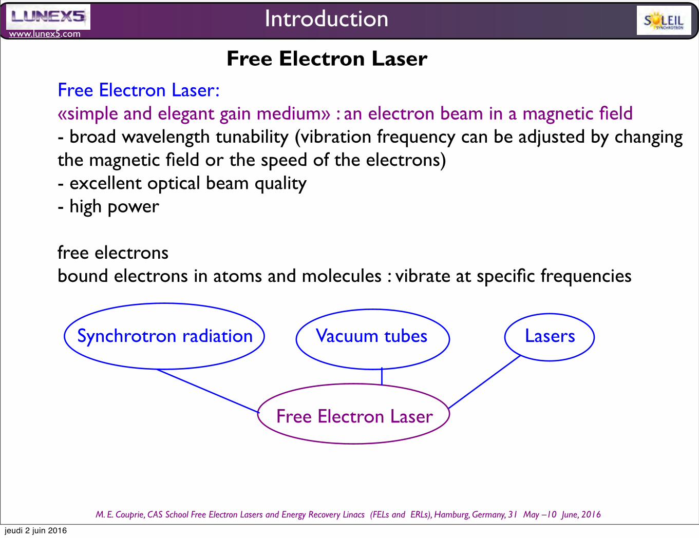
1917: black-body analysisprediction of the stimulated emission
Absorption
E
E
E
E
E
E
E
E
Non excited atom + photon
Excited atom
Spontaneous Emission
Stimulated Emission
E
E
E
EExcited atom
E
E
E
E
The excited atom being unstable, it emits a spontaneous photon after a duration depending on the lifetime of the excited level.
E
E
E
E
même longueur d’ondemême directionmême phase
même polarisation
Excited atom+Photon
E
E
E
E
même longueur d’ondemême directionmême phase
même polarisation
Non excited atom+2 identical photons (wavelength, direction, phase, polarisation)
I. The origins of the Free Electron Laser
a photon is absorbed and drives an atom to an excited state
A photon is absorbed by an excited atom, which results in the emission of two photons with identical wavelength, direction, phase, polarisation, while the atom returns to its fundamental state.
Stimulated emission was seen as addition of photons to already existing photons, and not as the amplification of a monochromatic wave with conservation of its phase. The notion of light coherence, related to its undulatory properties, was not considered at that time.
jeudi 2 juin 2016
www.lunex5.com
M. E. Couprie, CAS School Free Electron!Lasers!and!Energy!Recovery!Linacs !(FELs and !ERLs), Hamburg, Germany, 31 !May –10 !June, 2016
1.3 The early times of synchrotron radiationI. The origins of the Free Electron Laser
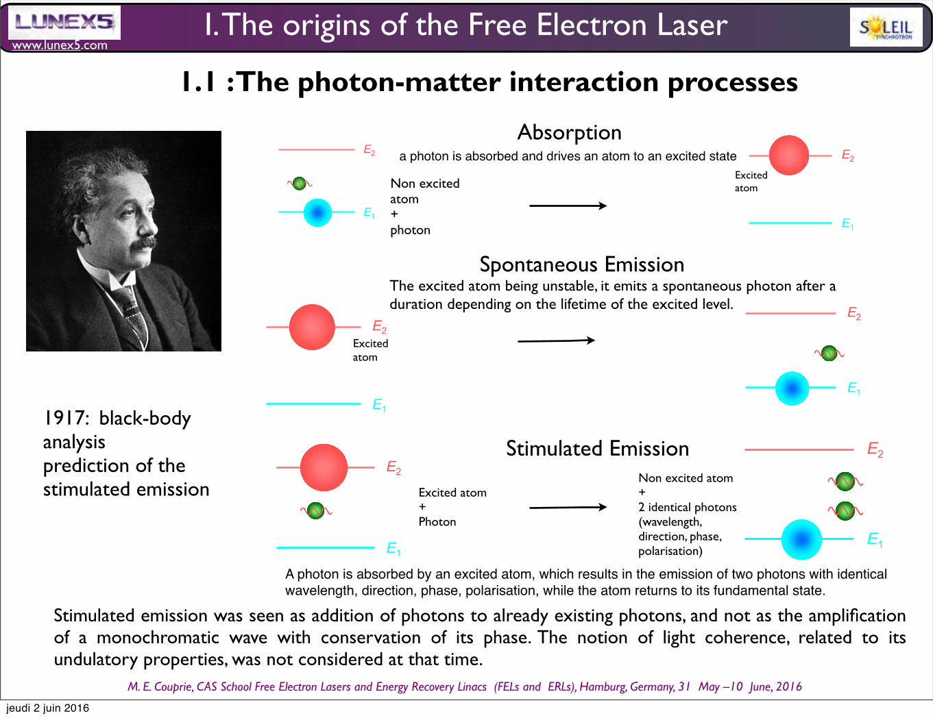
Josepf Larmor (1857-1942)
Alfred-Marie Liénard (1869-1958)
George Adolphus Schott(1868-1937)
First correct calculation of the emitted power by an accelerated charged particule (E/mc2)4/R2
first specific prediction of time dilation : "... individual electrons describe corresponding parts of their orbits in times shorter for the [rest] system in the ratio (1 – v2/c2)1/2".
J. Larmor, On the Theory o f t h e M a g n e t i c Influence on Spectra ; And On the Radiation from Moving Ions, Phil. Mag . 44 , 503 -512 (1897)
angular and spectral distribution and polarization properties
G. A. Schott, Ann. Phys. 24, 635 (1907), G . A . S c h o t t , E l e c t r o m a g n e t i c Radiation, : And the mechanical reactions arising from it, Cambridge University Press (1912)
Dmitri Ivanenko (!"#$%&#' !"#$%&#()#* +),-($-./) (1904-1994)
D. Ivanenko and I. Pomeranchuk, Phys. Rev. 65, 343 (1944)
energy losses due to radiating electrons would set a limit on the energy obtainable in a betatron (around 0.5 GeV).
Isaak Yakovlevich Pomeranchuk (+0,,$. 1$./)2()#* 3/"(&,-*4$. (1913-1966)
Julian Seymour Schwinger (1918 –1994)
peaked spectrum
Physics, 1965
J . Schwinger, Phys. Rev. 70, 798 (1946)
peaked spectrum
Synchronism and phase stability
Edwin Mattison McMillan (1907-1991)
Chemistry, 1951E. M. McMillan, PRL 68, 1434 (1945)
Vladimir Iossifovitch Veksler (52,6#"#& +/0#7/)#* 5(.02(&)(1907-1966)
V. Veksler J. Phys. USSR 9, 153 (1946)
A. Liénard, L ‘ Eclairage électrique, 16, 5 (1898)
jeudi 2 juin 2016
www.lunex5.com
M. E. Couprie, CAS School Free Electron!Lasers!and!Energy!Recovery!Linacs !(FELs and !ERLs), Hamburg, Germany, 31 !May –10 !June, 2016
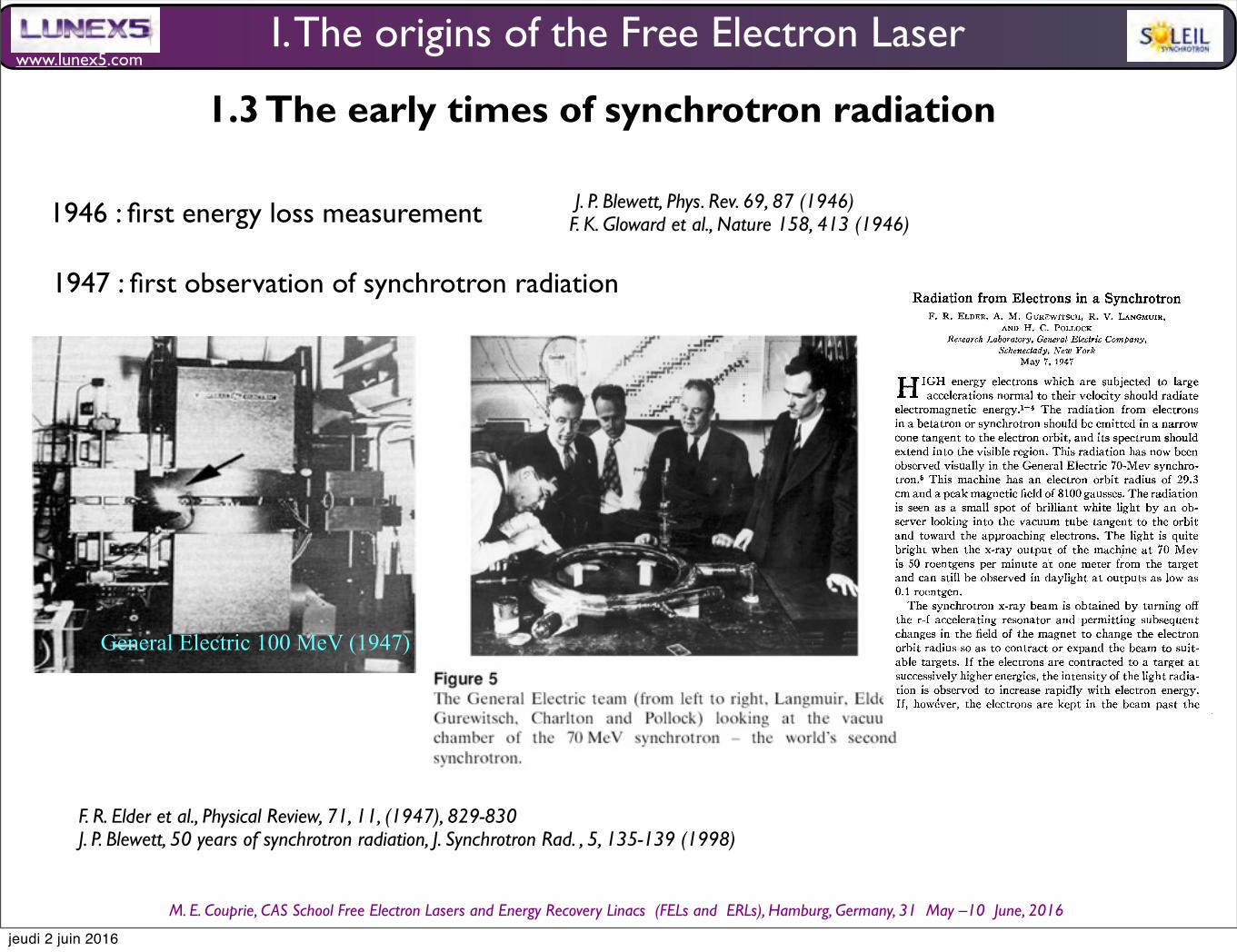
F. R. Elder et al., Physical Review, 71, 11, (1947), 829-830J. P. Blewett, 50 years of synchrotron radiation, J. Synchrotron Rad. , 5, 135-139 (1998)
General Electric 100 MeV (1947)
1947 : first observation of synchrotron radiation
J. P. Blewett, Phys. Rev. 69, 87 (1946)F. K. Gloward et al., Nature 158, 413 (1946)1946 : first energy loss measurement
LETTERS TO THE E D I TO R
Errata: The Collision of Neutrons withDeuterons and the Reality of
Exchange Forces[Phys. Rev. 71, 558 (1947)]
S. W. MASSEY AND R. A. BUCKINGHAMUniversity College, London, England
AND
Conductivity of Sodium-Ammonia Solutions[Phys. Rev. 'Fl, 563 (1947))
D. K. C. MACDONALD AND K. MENDELSSOHNClarendon Laboratory, Oxford, L'ngland
ANDA. J. BIRCH
Dyson Perrins Laboratory, Oxford, England
&HE Editor regrets that Fig. 2 of the first of the abovepapers has been interchanged with Fig. 1 of the sec-
ond paper. The captions, however, are right, as they stand.
Erratum: The Quadrupole Moments andSpins of Br, Cl, and N Nuclei
[Phys. Rev. Vl, 644 (1947)]C. H. TOWNES, A. N. HOLDEN, J. BARDEEN, AND F. R. MERRITT
Bell Telephone Laboratories, Murray Hill, !mJersey
~HE Editor regrets that Figs. 1 and 2 of the abovepaper have been interchanged. The captions for the
figures, however, are correct as they stand.
Isotopic Changes in Cadmiumby Neutron Absorption
A. J. DEMPSTERArgonne Nationa/ Laboratory, Chicago, Ilbnois
May 1, 1947
N a recent letter B. J. Moyer, B. Peters, and F. H.~ - Schmidt' report that the absorption of thermal neu-trons in cadmium that had been enriched in the isotope atmass 113 was six times normal, and conclude that thisisotope is mainly responsible for the large absorption inthis element.The mass spectra reproduced in Fig. 1 illustrate another
phenomenon that also indicates the absorbing isotope,namely, the gradual alteration of the isotopic constitutionof an element by long exposure to neutrons. The uppermass spectrum shows the normal isotopes at masses 110,111, 112, 11.3, and 114, with Cd"3=12.3, and Cd"4=28percent. The faint isotopes at 106 and 108 do not show onthe prints. The lower spectrum shows the changed iso-topic abundance in a sample scraped from the surface ofa piece of metal that had been used to absorb intenseneutrons from a pile over a long period of time. Theseneutrons include a considerable number with energiesabove the thermal range.Photometric measurements, made by using Nier's
measurements of the normal cadmium abundances asstandards, showed that the isotope at mass 113was reduced
FIG. 1. Normal cadmium (above) and isotopes alteredby neutron absorption (below).
to 1.6+0.2 percent, about one-eighth of its normal abun-dance, and that the isotope at mass 114 was increased to39.5+1.5 percent. Within the limits of the accuracy at-tained, the increase in 114 is equal to the decrease in 113.Any changes in the abundances of the isotopes at masses110, 111, 112, and 116 were less than five percent. It wasnoticed, however, that in both samples the isotopes at 110and 111 had a greater difference in abundance than isindicated by Nier's measurements (12.8 and 13.0 percent).We may conclude that the other main isotopes have ab-sorbing cross sections less than one-fortieth. of that ofCd", and that if any (n, 2n) or other reactions occur,they are comparatively rare.I B. J. Moyer, B. Peters, and F. H. Schmidt, Phys. Rev. 69, 666
(1946).
Radiation from Electrons in a SynchrotronF. R. ELDER, A. M. GUREWITSCH, R. V. LANGMUIR,
AND H. C. POLLOCKResearch Laboratory, General Blectric Company,
Schenectady, %no ForkMay 7, 1947
'" 'IGH energy electrons which are subjected to large~ - ~ ~ accelerations normal to their velocity should radiateelectromagnetic energy. ' 4 The radiation from electronsin a betatron or synchrotron should be emitted in a narrowcone tangent to the electron orbit, and its spectrum shouldextend into the visible region. This radiation has now beenobserved visually in the General Electric 70-Mev synchro-tron. ' This machine has an electron orbit radius of 29.3cm and a peak magnetic field of 8100gausses. The radiationis seen as a sma11 spot of brilliant white light by an ob-server looking into the vacuum tube tangent to the orbitand toward the approaching electrons. The light is quitebright when the x-ray output of the machine at 70 Mevis 50 roentgens per minute at one meter from the targetand can still be observed in daylight at outputs as low as0.1 roentgen.The synchrotron x-ray beam is obtained by turning off
the r-f accelerating resonator and permitting subsequentchanges in the field of the magnet to change the electronorbit radius so as to contract or expand the beam to suit-able targets. If the electrons are contracted to a target atsuccessively higher energies, the intensity of the light radia-tion is observed to increase rapidly with electron energy.If, however, the electrons are kept in the beam past the
I. The origins of the Free Electron Laser
1.3 The early times of synchrotron radiation
jeudi 2 juin 2016

www.lunex5.com
M. E. Couprie, CAS School Free Electron!Lasers!and!Energy!Recovery!Linacs !(FELs and !ERLs), Hamburg, Germany, 31 !May –10 !June, 2016
• Emission of the radiation spectrum (6 mm) produced from an undulator installed on a 2.3 MeV accelerator Combes R., Frelot T. , présenté par L. de Broglie, Production d'ondes millimétriques par un ondulateur magnétique. Comptes-Rendus Hebd. Scéance Acad. Sci. Paris, 241, 1559 (1955)
The undulator
Journal of
Applied Physics Volume 22, Number 5 May, 1951
Applications of the Radiation from Fast Electron Beams H. MoTZ
Microwave Laboratory, Stanford University, California (Received July 3, 1950)
The radiation from fast electron beams passing through a succession of electric or magnetic fields of alternating polarity is examined. The radiation of maximum frequency is emitted in the forward direction. If the deflecting fields are not too large, a semiqualitative argument shows that the maximum frequency is the lowest possible harmonic. The frequencies emitted are determined by studying the Doppler eifect, and the angular distribution of radiated energy as well as the total radiation are calculated in a simple straight-forward manner with reference to well-known formulas of special relativity. The question of the coherence of the radiation is discussed. The spectral distribution of radiated energy is then calculated more exactly. It is concluded that several applications of the radiation appear possible. A scheme for obtaining millimeter-waves of considerable power is outlined. The upper limit of the power in a band extending down to a wave-length of 1 millimeter is calculated to be of the order of several kilowatts for a beam of one ampere and an energy of 1.5 megavolt. The use of the radiation for speed monitoring of beams with energies up to lOOO megavolt is discussed.
I. INTRODUCTION
AN electron, traveling through a stationary electric or magnetic field distribution, radiates. The fre-
quency spectrum of the emitted radiation depends on the speed of the electron. We shall see that the entire spectrum of electromagnetic radiation starting from microwaves and extending to hard x-rays may be easily obtained from electrons with speeds ranging from a megavolt, say, to 1000 Mev.
from the output end and travels back to the starting section.
Several applications suggest themselves. We shall discuss them under the following headings:
(1) production of energy in rather inaccessible spec-tral bands, viz., millimeter to infrared radiation j*
(2) speed monitoring for electron beams produced by linear or other accelerating devices;
(3) speed measurement for fast individual electrons or other particles (mesons, protons).
We shall also briefly consider the radiation emitted by an electron moving through an electromagnetic wave traveling in the opposite direction. This occurs, e.g., in a linear accelerator in which a wave is reflected
* Notes added in proof: According to reports of the Electronics Research Laboratory at M.I.T., P. D. Coleman is working on such a scheme. Prior reference to the problem treated in this paper has also been paper by V. L. Ginsburg, Radiation of microwaves and their absorption in air, Bull. Acad. Sci. U.R.S.S. Ser. Phys. 9 (1947), No.2, 165 (in Russian).
The stationary field distribution we have in mind is a succession of electric or magnetic fields of alternating polarity, regularly spaced, as in Fig. 1. The radiation in transverse fields turns out to be much larger than that emitted by electrons crossing an array of longitudinal fields. Hence, we shall be mainly interested in the case of transverse fields, as shown in Fig. 1. The spatial field distribution may be fourier analyzed. Let the fundamental wavelength be 10• It will be shown that the frequency of the emitted radiation varies with the angle of observation. The fundamental component of the radiation emitted under the angle (j (see Fig. 1) has a frequency
w=\l,e=21T/3c/lo(1-f3 cos8). (1)
Beam
FIG. 1. Schematic arrangement of undulator magnets. 527
[This article is copyrighted as indicated in the article. Reuse of AIP content is subject to the terms at: http://scitation.aip.org/termsconditions. Downloadedto ] IP: 195.221.0.34 On: Sat, 01 Aug 2015 20:55:40
830 1\1 0 T Z, THO 1'\, ,\ 1'\ /) '" HIT E H \' R S T
IRON PLATE
13< 0,5 COUPLER
R.F. LOAD
DEfLECTED BEAM
FIG, 6. Equipment outline for buncher tests.
corresponding to light passing through the two polaroid windows was 2: 1 in favor of perpendicular polarization. Subtracting the background makes the evidence for polarization even stronger. A quantitative determina-tion was not attempted.
3. Color
A qualitative experiment was also carried out concerning the color distribution of the light. An interference filter passing a band 100A wide centered on 4400A was used. Theoretically, the color of the light should range from green (5500A) to blue (3400A) in the energy range from 95 Mev to 120 Mev. The light fell on a photomultiplier 1P21, which has a sensitivity curve starting at 3000A, rising sharply to a peak at 4OOOA, and falling to almost zero at 7500A. We got maximum transmission at 90-95 Mev and almost no transmission at 120 Mev. We consider this as a very rough indication of agreement with theoretical pre-dictions.
V. MILLIMETER WAVE GENERATION
1. The Electron Buncher It has been shown that the power output of the
undulator in the millimeter band can be greatly enhanced by suitable bunching of the electrons. A 3-5-Mev electron beam was used in the millimeter wave generation experiment. It was produced by a special linear accelerator, which also achieved a high degree of bunching. The design of this buncher was carried out by Mr. R. Neal and was based on some calculations by Dr. E. L. Chu. It is now used as an injection system for the Mark III Stanford linear accelerator and will be the subject of a separate publica-tion. For our purpose suffice it to say that it is a travel-ing wave type of accelerator consisting of a disk-loaded structure in which the phase velocity changes from 0.5 c to approximately c over a length of 32
inches. The filling time is 0.2 microseconds. An input power up to 8 M w is required and was obtained from a Stanford high power klystron operating at 2856 Me/sec. Electron pulses drawn at 80 kv are obtained from a tungsten filament gun and injected into the accelerator. The gun pulse lasts 1 microsecond and is applied 0.2 microseconds after the klystron pulse.
Tests of this buncher revealed an energy spectrum of 0.2-Mev half-width at 5 Mev. The accelerator collects electrons during the full period of the traveling in the accelerator and bunches them to within 30°; and it may have been better than indicated by the foregoing numbers. Figure 6 shows a block diagram of the set-up used for testing the buncher. The buncher is followed by a standard (2-ft) accelerator section, i.e., by a uniformly disk-loaded section which obtains power coupled out of the end of the buncher through a phase shifter which allows variation of the relative phases of buncher and standard section ranging over 360°. For energy measurement purposes the beam can be magnetically deflected into a channel leading to a radiation monitor. It was necessary to insert colli-mators with IIG-inch clearing holes in order to obtain good energy resolution.
SEAL
FIG. 7. Crystal detector for millimeter waves.
[This article is copyrighted as indicated in the article. Reuse of AIP content is subject to the terms at: http://scitation.aip.org/termsconditions. Downloaded to ] IP:195.221.0.34 On: Sat, 01 Aug 2015 20:58:36
• Calculation of the field created by a relativistic particle in the magnetic sinusoidal field (i.e. such as produced by undulators) Motz H. : Applications of the radiation from fast electron beams, Journ. Appl. Phys. 22, 527--535 (1951)
• Influence of the bunching of the electrons on the coherence of the produced radiation • observation of the polarized visible radiation from an undulator installed on the 100 MeV Stanford accelerator. A buncher set-up after a 3.5 MeV accelerator enables to achieve 1 W peak power at 1,9 mm thanks the the bunching of the electrons. Motz H., Thon W. , Whitehurst R. N. : Experiments on Radiation by Fast Electron Beams , Journ. Appl. Phys. 24, 826--833 (1953)
I. The origins of the Free Electron Laser
1.3 The early times of synchrotron radiation
ÉLECTRONIQUE. – Production d'ondes millimétriques par un ondulateurmagnétique. Note de M. RENÉ COMBE et Mme Thérèse FRELOT,présentée par M. Louis de Broglie.
Après avoir décrit un dispositif destiné à produire,par application de l'effet Dopplerrelativiste, un rayonnement de courte longueur d'onde, on donne les résultats concer-nant la puissance et le spectre de fréquences.
Nous avons construit un ondulateur (*), composé d'un aimant, d'un guided'ondes spécial, d'un banc de mesures, et d'un correcteur de champ, et quifait suite à un accélérateur linéaire d'électrons fonctionnant en régime pulsé(5o impulsions de i fxs/s). Le spectre des électrons s'étend de i,5 à 3,oMeV,avec un maximum à 2,3 MeV.L'aimant, permanent, produit un champ sinusoïdal, avec B = 960 gauss, et/= 16 cm. Le guide d'ondes, rectangulaire(dimensionsintérieures4o X 25mm),
ONDULATEUR
est étanche et permet le passage du faisceau, compte tenu de la vibration dansle plan vertical(la trajectoireest sensiblement une sinusoïded'amplitudemm).Ce guide doit aussi satisfaire à certaines conditions relatives à l'existence desrégimes d'ondes guidés.Grâce à l'électroaimantcorrecteur, la vitesse des électrons de 2,3 MeV en M
est parallèle à l'axe, et leur trajectoiremoyenne coïncide avec cet axe (i). Cedispositifjoue le rôle d'un spectromètre, car les électrons d'énergie différentese perdent dans le métal. Il en est de même des électrons de 2,3 MeV, à la sortiede l'aimant permanent.Une transition progressive assure la jonction avec le banc de mesures, formé
d'éléments de guides rectangulaires millimétriques (dimensions intérieures7,10 X 3,55 mm). Situé à l'intérieur d'une chambre étanche, ce banc comporteune section courbe arrêtant les électrons qui pourraient subsister (des tests aucompteur de bétas n'ont révélé aucun courant décelable dans cette partie del'appareil), une fenêtre métallique, une monture de cristal, et une terminaison.
(*) R. Combe et M.Feix, Comptes rendus, 237, 1953, p. i3i8 et 237, 1953, p. 1660. Nousconservons ici les mêmes notations.
jeudi 2 juin 2016

www.lunex5.com
M. E. Couprie, CAS School Free Electron!Lasers!and!Energy!Recovery!Linacs !(FELs and !ERLs), Hamburg, Germany, 31 !May –10 !June, 2016
I. The origins of the Free Electron Laser1.3 The early times of synchrotron radiation
electron movement in the undulator
20 Marie-Emmanuelle COUPRIE and Mathieu VALLEAU
4.2 The electron movement in the undulator
Let’s introduce in the area of the laboratory free of current an undulator creating a periodic permanent magneticfield of peak amplitude Buz, period λu, length Lu Lu = Nuλu with Nu the number of periods λu. Let’s first considerthe movement of a relativistic electron of velocity v introduced at the origin of the undulator coordinate along thelongitudinal coordinate s ( s ∈ [0,Lu]) in the two cases of the planar and helical undulator. The field can be created byalternated poles.
4.2.1 Planar undulator case
Vertical undulator field created by a planar undulator
Let’s consider first the case of a planar undulator, creating a field along the vertical direction expressed in the [0,Lu]interval as:
−→Buz = Buz cos
2πλu
s−→z = Buz cos(kus)−→z (48)
with the undulator wavenumber ku given by:
ku =2πλu
(49)
The undulator scheme is shown in Fig. 18.
Fig. 18 Planar undulator scheme, creating a periodic magnetic field created by two arrays of permanent magnets arranged in the Halbachconfiguration [55] Vertical field in green, electron trajectory in blue.
Electron velocity in the planar undulator case
Let’s apply the fundamental equation of the dynamics to the case of this planar undualtor :
d−→pdt
=−→f = e(
−→E +−→v x
−→B )
with the electron momentum −→p , being −→p = γmoc−→β .
In absence of electric field and in substituting the momentum expression, it becomes:
Case of a planar undulator of Nu periods
Synchrotron radiation and Free Electron Laser 21
d−→β
dt=
emoγ
−→β x
−→B (50)
With−→β
βxβzβs
and−→B
0
Bu cos(kus)0
, one gets :
−→β
βx =− emoγ Buβs cos(kus)
βz = 0
βs =e
moγ Buβx cos(kus)
Let’s consider the longitudinal velocity :
βs =e
moγBuβx cos(kus) =− e
moγ2B2
u
βs cos(kus)dt
At first order, s ≈ cβst, so βs ∝ 1
γ2whereas βx ∝ 1
γ . In consequence, the longitudinal component of the electron
velocity is practically not modified by the undulator and βs remains very close to 1. One gets βs ≈ 1 and s ≈ ct.Then,
βx =− eBu
moγβs cos(kus)≈− eBu
moγcos(kus)
so :
βx =− eBu
moγ
cos(kus)dt =− eBu
moγc
cos(kus)ds =− eBu
moγcλu
2πsin(kus)
Let’s define the undulator associated deflection parameter Ku as :
Ku =eBuλu
2πmoc(51)
It is given in practical units as :
Ku = 0.934Bu(T )λu(cm) (52)
With an electron entering the undulator without transverse velocity βx = 0, one can take the integration constant
equal to zero, one gets :
βx =Ku
γsin(kus) (53)
With an electron entering the undulator without transverse velocity βz = 0 and using βz = 0 one can take the
integration constant equal to zero, one gets :
βz = 0 (54)
The expression of the longitudinal electron velocity is then given by :
βs =
1− 1
γ2−β 2
x =
1− 1
γ2− K2
uγ2
sin2(kus)
so :
20 Marie-Emmanuelle COUPRIE and Mathieu VALLEAU
4.2 The electron movement in the undulator
Let’s introduce in the area of the laboratory free of current an undulator creating a periodic permanent magneticfield of peak amplitude Buz, period λu, length Lu Lu = Nuλu with Nu the number of periods λu. Let’s first considerthe movement of a relativistic electron of velocity v introduced at the origin of the undulator coordinate along thelongitudinal coordinate s ( s ∈ [0,Lu]) in the two cases of the planar and helical undulator. The field can be created byalternated poles.
4.2.1 Planar undulator case
Vertical undulator field created by a planar undulator
Let’s consider first the case of a planar undulator, creating a field along the vertical direction expressed in the [0,Lu]interval as:
−→Buz = Buz cos
2πλu
s−→z = Buz cos(kus)−→z (48)
with the undulator wavenumber ku given by:
ku =2πλu
(49)
The undulator scheme is shown in Fig. 18.
Fig. 18 Planar undulator scheme, creating a periodic magnetic field created by two arrays of permanent magnets arranged in the Halbachconfiguration [55] Vertical field in green, electron trajectory in blue.
Electron velocity in the planar undulator case
Let’s apply the fundamental equation of the dynamics to the case of this planar undualtor :
d−→pdt
=−→f = e(
−→E +−→v x
−→B )
with the electron momentum −→p , being −→p = γmoc−→β .
In absence of electric field and in substituting the momentum expression, it becomes:
22 Marie-Emmanuelle COUPRIE and Mathieu VALLEAU
βs ≈ 1− 1
2γ2− K2
u2γ2
sin2(kus) (55)
In average, one has:
< βs >≈ 1− 1
2γ2− K2
u4γ2
=< v >
c(56)
The maximum difference between the average longitudinal velocity < v > and the electron longitudinal velocity is
given by :
|v−< v > |max = |K2u c
4γ2(2sin
2(kus)−1)|max = |K2u c
4γ2(sin(2kus)|max =
K2u c
4γ2(57)
The relative maximum difference of the longitudinal velovity isK2
u c4γ2
. In the LUNEX5 case ( 400 MeV, γ = 783),
with a cryogenic planar undulator of peak field Bu = 1.65T and period λu = 1.5cm, i.e. of Ku = 2.3, this difference is
of 2.15 10−6
. It is indeed very small.
In transverse, the maximum value of the transverse velocity is given byKuγ . Numerically, it gives 2.934 10
−3.
In recapitulation, one has:
−→β
Kuγ sin(kus)
0
1− 1
2γ2− K2
u2γ2
sin2(kus)
(58)
and in average over one undulator period
−−−−→< β >
0
0
1− 1
2γ2(1+ K2
u2)
(59)
Electron trajectory in the planar undulator case
Since the velocity in the vertical direction is zero, the movement takes place in the horizontal plane (x, s).
With kus = ωut with ωu = kuc, a further integration leads to :
s = c[1− 1
2γ2− K2
u4γ2
(1− cos(2ωut))]
Considering that the electron enter at the origin position, one takes integration constants equal to zero, and one gets
:
x = Kucγ
sin(ωut)dt = Kuc
γωucos(ωut)
y = 0
s = c(1− 1
2γ2− K2
u4γ2
)t + K2u λu
16πγ2sin(2ωut) =< v > ct + K2
u λu16πγ2
sin(2ωut)(60)
The maximum amplitude of the transverse motion isKuγ
λu2π , which gives, for the numerical example of LUNEX5, a
value of 7.016µm. In the longitudinal direction occurs oscillations at twice the frequency, with a maximum amplitude
ofK2
u λu16πγ2
, i.e. 2.56 nm, so 2720 times smaller than the maximum transverse amplitude.
20 Marie-Emmanuelle COUPRIE and Mathieu VALLEAU
4.2 The electron movement in the undulator
Let’s introduce in the area of the laboratory free of current an undulator creating a periodic permanent magneticfield of peak amplitude Buz, period λu, length Lu Lu = Nuλu with Nu the number of periods λu. Let’s first considerthe movement of a relativistic electron of velocity v introduced at the origin of the undulator coordinate along thelongitudinal coordinate s ( s ∈ [0,Lu]) in the two cases of the planar and helical undulator. The field can be created byalternated poles.
4.2.1 Planar undulator case
Vertical undulator field created by a planar undulator
Let’s consider first the case of a planar undulator, creating a field along the vertical direction expressed in the [0,Lu]interval as:
−→Buz = Buz cos
2πλu
s−→z = Buz cos(kus)−→z (48)
with the undulator wavenumber ku given by:
ku =2πλu
(49)
The undulator scheme is shown in Fig. 18.
Fig. 18 Planar undulator scheme, creating a periodic magnetic field created by two arrays of permanent magnets arranged in the Halbachconfiguration [55] Vertical field in green, electron trajectory in blue.
Electron velocity in the planar undulator case
Let’s apply the fundamental equation of the dynamics to the case of this planar undualtor :
d−→pdt
=−→f = e(
−→E +−→v x
−→B )
with the electron momentum −→p , being −→p = γmoc−→β .
In absence of electric field and in substituting the momentum expression, it becomes:
Case of a helical undulator of Nu periods
Synchrotron radiation and Free Electron Laser 23
4.2.2 Helical undulator case
Helical undulator field
Let’s consider a helical undulator creating a magnetic field in both horizontal and vertical directions given by :
−→Bux = Bux sin( 2π
λus)−→x = Bu sin(kus)−→x
−→Buz = Bu cos
2πλu
s
−→z = Bu cos(kus)−→z
−→Bus = 0
(61)
Electron velocity in the helical undulator case
Considering an electron arriving on axis without angle at the entrance of the undulator, one applies the Lorentz equation:
d−→β
dt=
e
moγ−→β x
−→B
Using−→β
βx
βz
βs
and−→B
Bu sin
2πλu
s
= Bu sin(kus)
Bu cos
2πλu
s
= Bu cos(kus)
0
one gets :
−→β
βx =− eBu
moγ βs cos(kus)
βz =eBu
moγ βs sin(kus)
βs =eBu
moγ [βx cos(kus)−βz sin(kus)].
For an electron arriving at x = z = 0 without transverse velocity, one has βs ≈ 1, and the longitudinal velocity :
βx =2πeBu
moγλu
sin(kus) =Ku
γsin(kus) (62)
βz =−2πeBu
moγλu
cos(kus) =−Ku
γcos(kus) (63)
βs =
1− 1γ2 −β 2
x−β 2
z=
1− 1γ2 − K2
u
γ2 sin2(kus)− K2u
γ2 cos2(kus) =
1− 1γ2 − K2
u
γ2 (sin2(kus)+ cos2(kus))
.It comes :
βs =
1− 1γ2 − K2
u
γ2 (64)
βs ≈ 1− 12γ2 − K
2u
2γ2 (65)
In this case :
βs =< βs > (66)
In recapitulation, one has:
24 Marie-Emmanuelle COUPRIE and Mathieu VALLEAU
−→β
Kuγ sin(kus)
−Kuγ cos(kus)
1− 1
2γ2− K2
u2γ2
(67)
Since the velocity in the vertical direction is zero, the movement takes place in the horizontal plane (x, s).
With kus = ωut with ωu = kuc, a further integration leads to :
Considering that the electron enter at the origin position, one takes integration constants equal to zero, and one gets
:
x = Kucγ
sin(ωut)dt =− Kuc
γωucos(ωut)
y = Kucγ
cos(ωut)dt = Kuc
γωusin(ωut)
s = c(1− 1
2γ2− K2
u4γ2
)t =< v > ct(68)
The electron trajectory is helical. There is no oscillatory movement in the longitudinal direction at twice the fre-
quency.
4.3 Origins of Free Electron Lasers
The discovery of the Free Electron Laser (FEL) takes place in the context of the development of vacuum tubes in the
twentieth century, together with the invention of the laser in 1960. The development of optical lasers has changed our
current life. Presently, the advent of tuneable X FELs with unpriceeded intensities enable new investigation of matter
with ultra-high intensities, ultra-short pulses...
4.3.1 The understanding of interaction between light and matter at the beginning of the twentiest century
The laser concept relies on the prediction of energy enhancement by atom des-excitation by Albert Einstein in 1917 in
the analysis of the back-body radiation, while absorption and spontaneous emission were the known light matter inter-
actions at that time. The process was called later stimulated emission by J. Van Vleck in 1924. In the absorption case,
a photon is absorbed and drives an atom to an excited state. The excited atom being unstable, it emits a spontaneous
photon after a duration depending on the lifetime of the excited level. In the stimulated emission case, a photon is
absorbed by an excited atom, which results in the emission of two photons with identical wavelength, direction, phase,
polarisation, while the atom returns to its fundamental state. Einstein was mainly interested by thermal radiation and
exchanges of momentum in different process, but not specifically to the production of light by matter. Stimulated
emission was seen as addition of photons to already existing photons, and not as the amplification of a monochro-
matic wave with conservation of its phase. The notion of light coherence, related to its undulatory properties, was not
considered at that time.
4.3.2 The development of the vacuum tubes
The electron beam in vacuum tubes knew a rapid and spectacular development in the beginning of the twentieth
century for the current amplifier applications such as radiodiffusion, radar detection for iceberg or military use, where
high frequency oscillations are needed. Electron beam in vacuum tubes rely on the interaction of a free electron of
relativistic factor γ given by γ = Emoc2
(with E its energy, mo the particle mass, e the particle charge and c the speed of
light) and an electromagnetic wave of electric field−→E with
−→E =
−→E sin(ks−ω.t) with the k wave number and ω the
pulsation according to :
e. beam
1 Synchrotron radiation, polarization, devices and new sources 9
In accelerators, synchrotron is produced when the particle trajectory is sub-jected to a magnetic field, which is for example generated in bending magnetsin circular accelerators. The coordinate system given in Fig. 1.1 with s thelongitudinal coordinate, x (resp. z) the horizontal (resp. vertical) position isadopted.
Fig. 1.1 Adopted coordinatesystem a s the longitudinalcoordinate of the electron,transverse coordinates x inhorizontal and z in vertical,b position of the observerwith respect to the emittingparticle.
When a relativistic particle of normalized energy γ given by γ = Emoc2 (with
E its energy, mo the particle mass, e the particle charge and c the speed oflight) is submitted to the magnetic field Bd of a dipole, its movement is givenby the Lorentz equation, as γmo
dvdτ = ev ×Bd , with the particle time τ , its
velocity v(τ) = β (τ)c , and its position R(τ) . In case of an uniform magneticfield, the particle follows an arc of circle, whose radius ρ is given by
ρ =moγβc
eBd(1.1)
The observer receives the emitted radiation in a cone of solid angle 1γ be-
cause of the relativistic transformation of the angles from the particle frame tothe laboratory frame (see Fig. 1.2). Synchrotron radiation is very collimated,and the higher the electron beam energy, the smaller the collimation angle.
Fig. 1.2 Relativistic projec-tion of the radiation angles,dipole emission in the labo-ratory frame of the particleand projected emission in theobservation frame, within acone of 1
γ .
18 Marie-Emmanuelle COUPRIE and Mathieu VALLEAU
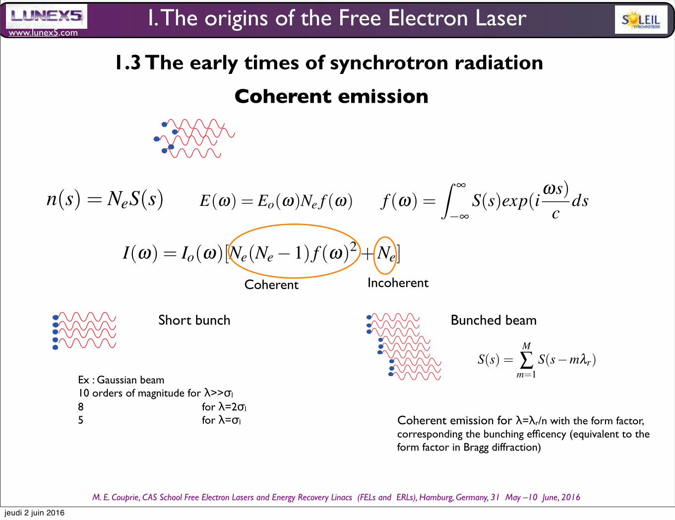
n(s) = NeS(s) (30)
E(ω) = Eo(ω)Ne f (ω) (31)
f (ω) = ∞
−∞S(s)exp(i
ωs)c
ds (32)
I(ω) = Io(ω)[Ne(Ne −1) f (ω)2 +Ne] (33)
case of short electron bunch Gaussian expression order of magnitude
case of bunched beam
S(s) =M
∑m=1
S(s−mλr) (34)
4 The emergence of the Free Electron Laser concept
4.1 Considerations on relativistic electrons
Let’s consider a laboratory region, without current, with a laboratory referential (0,x,z,s) with the frame R = (x,z,s).A relativistic electron of energy E and velocity v with respect to R are introduced along the s direction. Its relativistic
factor γ is given by :
γ =1
1−β 2(35)
with β the normalised velocity of the electron:
β =vc
(36)
One has :
1
γ2= 1−β 2
(37)
so :
β 2 = 1− 1
γ2(38)
If γ >> 1, then1
γ << 1 and the reduced velocity can be approximated as :
β ≈ 1− 1
2γ2(39)
The total energy of the electrons is given by :
E = γmoc2(40)
with γ the relativistic factor, mo the rest particle mass (mo= 9 10−31kg), c the speed of light (c= 3 10
8m/s). The
particle energy is the sum of the rest energy Eo and the kinetic energy Ek as follows :
18 Marie-Emmanuelle COUPRIE and Mathieu VALLEAU
n(s) = NeS(s) (30)
E(ω) = Eo(ω)Ne f (ω) (31)
f (ω) = ∞
−∞S(s)exp(i
ωs)c
ds (32)
I(ω) = Io(ω)[Ne(Ne −1) f (ω)2 +Ne] (33)
case of short electron bunch Gaussian expression order of magnitude
case of bunched beam
S(s) =M
∑m=1
S(s−mλr) (34)
4 The emergence of the Free Electron Laser concept
4.1 Considerations on relativistic electrons
Let’s consider a laboratory region, without current, with a laboratory referential (0,x,z,s) with the frame R = (x,z,s).A relativistic electron of energy E and velocity v with respect to R are introduced along the s direction. Its relativistic
factor γ is given by :
γ =1
1−β 2(35)
with β the normalised velocity of the electron:
β =vc
(36)
One has :
1
γ2= 1−β 2
(37)
so :
β 2 = 1− 1
γ2(38)
If γ >> 1, then1
γ << 1 and the reduced velocity can be approximated as :
β ≈ 1− 1
2γ2(39)
The total energy of the electrons is given by :
E = γmoc2(40)
with γ the relativistic factor, mo the rest particle mass (mo= 9 10−31kg), c the speed of light (c= 3 10
8m/s). The
particle energy is the sum of the rest energy Eo and the kinetic energy Ek as follows :
Approximation of ultra-relativistic beams
Synchrotron radiation, polarization, devices and new sources 9
The approximation of ultra-relativistic beams (1γ 1) can also be considered, itcomes :
β
βxβz
1 1
γ2 β 2x β 2
z
βxβz1 12γ2
β 2x β 2
z2
.
In the small angle (or paraxial) approximation with small values of the an-gle of observation θ , the direction of observation n is then given by : n
θxθz
1θ 2x θ 2
z
θxθz1θ 2
x θ 2z
2
.
3.4 Brilliance and mutual coherence
The common approach is to define the brilliance as the number of photons per sec-ond and per unit of phase space (or the density distribution in phase space), whichcorresponds to the geometrical optics frame. It enables to describe somehow thepropagation properties of the rays through optical elements. The general expressionof the brilliance B (or spectral brightness in a narrow bandwidth) is given by meansof the Wigner distribution [136, 46] as defined in quantum mechanics as a quasi-probability density of a quantum system in phase space. The Wigner distribution[47], first developed in the statistical quantum mechanics, has also been adopted forthe treatment of optical waves [48].
Bxzxzsωu ε0ω2I2π2hce
∞
∞
∞
∞
E
χ
i
ξ
2sωu
E
χ
i ξ
2sωuexpi
ωcχi
ξ d2ξ
(11)
with u the polarization state,E the electric field in its angular representation,
for its complex conjugate, χi and χi representing transverse position (x,z) and an-
gles θxθz. This concept inherently incorporates the complete information on theelectric field, from different position. It thus properly provides information on thetransverse coherence (ability to interfere [49]). Indeed, the one of mutual intensity,
defined as M xzxzξ
i sωu∑i
Ei
χi
ξ
2 sω
u
E
i
χ
i ξ
2 sωu
simply relates to the generalized brilliance definition, as : M xzxzbxsωu h
2πε0ceI ∞∞
∞∞ Bxzxzsωuexp
i ω
cχ
iξ
d2χ i . The generalized Wigner
brilliance enables to recover the usual quantities. The density of photons per unitsurface and solid angle results from the integration of the brilliance over spatial co-ordinates. This general spectral brightness, by relating directly to the electric field,contains the information on the phase and enables a proper treatment of the wave-front propagation within Fresnel diffraction, and transformation through optical el-ements. Such a brightness is real, but not necessarily positive. This could appear asa paradox for a quantity describing a photon density, but it could result from thequantum nature of photon for which position and momentum can not be measuredat the same time, forbidding strictly speaking to define a photon density [136]. Moreprecisely, its projections are positive [46]. A part from the specific case of bunching
1 Synchrotron radiation, polarization, devices and new sources 9
In accelerators, synchrotron is produced when the particle trajectory is sub-jected to a magnetic field, which is for example generated in bending magnetsin circular accelerators. The coordinate system given in Fig. 1.1 with s thelongitudinal coordinate, x (resp. z) the horizontal (resp. vertical) position isadopted.
Fig. 1.1 Adopted coordinatesystem a s the longitudinalcoordinate of the electron,transverse coordinates x inhorizontal and z in vertical,b position of the observerwith respect to the emittingparticle.
When a relativistic particle of normalized energy γ given by γ = Emoc2 (with
E its energy, mo the particle mass, e the particle charge and c the speed oflight) is submitted to the magnetic field Bd of a dipole, its movement is givenby the Lorentz equation, as γmo
dvdτ = ev ×Bd , with the particle time τ , its
velocity v(τ) = β (τ)c , and its position R(τ) . In case of an uniform magneticfield, the particle follows an arc of circle, whose radius ρ is given by
ρ =moγβc
eBd(1.1)
The observer receives the emitted radiation in a cone of solid angle 1γ be-
cause of the relativistic transformation of the angles from the particle frame tothe laboratory frame (see Fig. 1.2). Synchrotron radiation is very collimated,and the higher the electron beam energy, the smaller the collimation angle.
Fig. 1.2 Relativistic projec-tion of the radiation angles,dipole emission in the labo-ratory frame of the particleand projected emission in theobservation frame, within acone of 1
γ .
s : longitudinal coordinate x : horizontal directionz : vertical direction
jeudi 2 juin 2016
www.lunex5.com
M. E. Couprie, CAS School Free Electron!Lasers!and!Energy!Recovery!Linacs !(FELs and !ERLs), Hamburg, Germany, 31 !May –10 !June, 2016
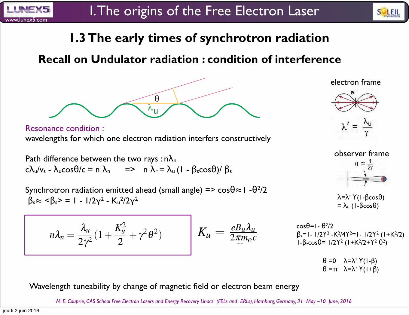
Recall on Undulator radiation : condition of interference
u!"
Resonance condition : wavelengths for which one electron radiation interfers constructively
Path difference between the two rays : nλn
cλu/vs - λucosθ/c = n λn => n λr = λu (1 - βscosθ)/ βs
Synchrotron radiation emitted ahead (small angle) => cosθ≈1 -θ2/2 βs≈ <βs> = 1 - 1/2γ2 - Ku2/2γ2
4 Marie-Emmanuelle COUPRIE and Mathieu VALLEAU
Table 1 Velocity and trajectory of a single electron in the magnetic fields for the planar or ellip-
soidal undulator cases.
Planar undulator Elliptical Polarized Undulator
Field Field
−→Buz = Buz cos
2πλu
s−→z
−→Bux = 0−→Bus = 0
−→Buz =−Buzsin( 2π
λus)−→z
−→Bux = Buxsin( 2π
λus+ϕ)−→x
−→Bus = 0
Velocity Velocity
βz = 0
βx =Kuγ sin( 2π
λus)
βs =
1− 1
γ2− K2
uγ2
sin2( 2π
λus))
βz =−Kuxγ cos( 2π
λus+ϕ)
βx =Kuzγ cos( 2π
λus)
βs = 1− 1
γ2− K2
ux4γ2
− K2uz
4γ2+ K2
ux4γ2
cos( 4πλu
s)+ K2uz
4γ2cos( 4π
λus+2ϕ)
Trajectory Trajectory
z = 0
x = Kuλu2πγ cos( 2π
λuτ)
s = (1− 1
2γ2− K2
uγ2)cτ + cK2
u λu16πγ2
sin( 4πλuc τ)
z =−Kuxλu2πγ sin( 2π
λus+ϕ)
x = Kuzλu2πγ sin( 2π
λus)
s = (1− 1
2γ2− K2
uzγ2
− K2ux
γ2)cτ + cK2
uzλu16πγ2
sin( 4πλuc τ +2ϕ)+ cK2
uxλu16πγ2
sin( 4πλuc τ)
in Table 1, considering that1
γ =
1−β 2x −β 2
z −β 2s with the deflection parame-
ter Ku, Kux, Kuz given by Ku = eBuλu2πmoc (Kux =
eBuxλu2πmoc , Kuz =
eBuzλu2πmoc ). In the wiggler
regime, the angle of the velocityKuγ is large with respect to
1
γ . For Kux = Kuz = Ku
and ϕ = π2
, one has βs = 1− 1
γ2− K2
u2γ2
. A second integration gives the trajectory.
In the planar case, the electrons execute smooth sinusoıdal oscillations in the hori-
zontal plane, so that the radiation is kept in the same emitted cone. In addition, the
beam oscillates at twice the pulsation in the longitudinal direction. The interference
takes place for the wavelengths λn for which nλn = c(1−βs)t, with n an integer, βsthe longitudinal reduced velocity of the electrons. The fundamental resonant wave-
length is obtained for n = 1, i.e. for λ1 = λu(1−βs). Using the expression of βs, it
comes for the resonant wavelength and its harmonics in the planar case :
nλn =λu
2γ2(1+
K2u
2) (2)
nλn =λu
2γ2(1+
K2u
2+ γ2θ 2) (3)
The wavelength λn of the emitted radiation can be varied by a modification of the
undulator magnetic field (by changing the gap for permanent magnet insertion de-
vices or the power supply current for electromagnetic insertion devices). In the time
domain, the observer receives a train of Nu magnetic periods which can be consid-
ered as quasi-continuous emission of radiation with respect to the bending magnet
radiation. The radiation spectrum, square of the Fourier transform of this train, is
4 Marie-Emmanuelle COUPRIE and Mathieu VALLEAU
Table 1 Velocity and trajectory of a single electron in the magnetic fields for the planar or ellip-
soidal undulator cases.
Planar undulator Elliptical Polarized Undulator
Field Field
Buz Buz cos
2πλu
sz
Bux 0Bus 0
Buz Buzsin 2π
λusz
Bux Buxsin 2π
λusϕx
Bus 0
Velocity Velocity
βz 0
βx Kuγ sin 2π
λus
βs
1 1
γ2 K2
uγ2
sin2 2π
λus
βz Kuxγ cos 2π
λusϕ
βx Kuzγ cos 2π
λus
βs 1 1
γ2 K2
ux4γ2
K2uz
4γ2 K2
ux4γ2
cos 4πλu
s K2uz
4γ2cos 4π
λus2ϕ
Trajectory Trajectory
z 0
x Kuλu2πγ cos 2π
λuτ
s 1 1
2γ2 K2
uγ2cτ cK2
u λu16πγ2
sin 4πλuc τ
z Kuxλu2πγ sin 2π
λusϕ
x Kuzλu2πγ sin 2π
λus
s 1 1
2γ2 K2
uzγ2
K2ux
γ2cτ cK2
uzλu16πγ2
sin 4πλuc τ 2ϕ cK2
uxλu16πγ2
sin 4πλuc τ
in Table 1, considering that1
γ
1β 2x β 2
z β 2s with the deflection parame-
ter Ku, Kux, Kuz given by Ku eBuλu2πmoc (Kux
eBuxλu2πmoc , Kuz
eBuzλu2πmoc ). In the wiggler
regime, the angle of the velocityKuγ is large with respect to
1
γ . For Kux Kuz Ku
and ϕ π2
, one has βs 1 1
γ2 K2
u2γ2
. A second integration gives the trajectory.
In the planar case, the electrons execute smooth sinusoıdal oscillations in the hori-
zontal plane, so that the radiation is kept in the same emitted cone. In addition, the
beam oscillates at twice the pulsation in the longitudinal direction. The interference
takes place for the wavelengths λn for which nλn c1βst, with n an integer, βsthe longitudinal reduced velocity of the electrons. The fundamental resonant wave-
length is obtained for n 1, i.e. for λ1 λu1βs. Using the expression of βs, it
comes for the resonant wavelength and its harmonics in the planar case :
nλn λu
2γ21
K2u
2 (2)
The wavelength λn of the emitted radiation can be varied by a modification of the
undulator magnetic field (by changing the gap for permanent magnet insertion de-
vices or the power supply current for electromagnetic insertion devices). In the time
domain, the observer receives a train of Nu magnetic periods which can be consid-
ered as quasi-continuous emission of radiation with respect to the bending magnet
radiation. The radiation spectrum, square of the Fourier transform of this train, is
then composed of a series of square sinus cardinal, centered on odd harmonics. The
”homogeneous” relative linewidth of the harmonics is thus given by :
Wavelength tuneability by change of magnetic field or electron beam energy
I. The origins of the Free Electron Laser
1.3 The early times of synchrotron radiation
electron frame
!"#$%&'()*+&,--.##+&/&0(123&456&7#8$2"2892&,:;:1-&<=><?@&<ABC& 7#D2"2892E0(123E<F,:;<ABC%GG-&
!"#$%&'()*)&#+&'+("*
BH&
!"#$%&'()*+&,--.##+&/&0(123&456&7#8$2"2892&,:;:1-&<=><?@&<ABC& 7#D2"2892E0(123E<F,:;<ABC%GG-&
!"#$%&'()*)&#+&'+("*
BH&
observer frame
θ =0 λ=λ’ ϒ(1-β)θ =π λ=λ’ ϒ(1+β)
λ=λ’ ϒ(1-βcosθ)= λu (1-βcosθ)
cosθ=1- θ2/2βz=1- 1/2ϒ2 -K2/4ϒ2=1- 1/2ϒ2 (1+K2/2)1-βzcosθ= 1/2ϒ2 (1+K2/2+ϒ2 θ2)
!"#$%&'()*+&,--.##+&/&0(123&456&7#8$2"2892&,:;:1-&<=><?@&<ABC& 7#D2"2892E0(123E<F,:;<ABC%GG-&
!"#$%&'()*)&#+&'+("*
BH&jeudi 2 juin 2016

www.lunex5.com
M. E. Couprie, CAS School Free Electron!Lasers!and!Energy!Recovery!Linacs !(FELs and !ERLs), Hamburg, Germany, 31 !May –10 !June, 2016
• Homogeneous linewidthinterference from trains Nu periods :
6 Marie-Emmanuelle Couprie
The electrons execute smooth sinusoidal oscillations in the horizontal plane, sothat the radiation is kept in the same emitted cone. In addition, there is a oscillationat twice the pulsation in the longitudinal direction. The interference takes place forthe wavelengths when the λn for which :
nλn = c(1−βs)t (14)
with n an integer, βs the longitudinal reduced velocity of the electrons. The fun-damental resonant wavelength is obtained bor n = 1, i.e. for λ1 = λu(1−βs).
Using the expression of βs, one gets the expression of the resonant wavelengthand its harmonics, according to :
nλn =λu
2γ2 (1+K2
u2) (15)
The wavelength λn of the emitted radiation can be varied by a modification of theundulator magnetic field (by changing the gap for permanent magnet insertion de-vices or the power supply current for electromagnetic insertion devices). In the timedomain, the observer receives a train of Nu magnetic periods which can be consid-ered as quasi-continuous emission of radiation with respect to the bending magnetradiation. The radiation spectrum, square of the Fourier transform of this train, isthen composed of a series of square sinus cardinal, centered on odd harmonics. The”homogenous” relative linewidth of the harmonics is then given by :
∆λλn
=1
nNu(16)
The so-called ”homogenous linewidth” refers to the case of a single electron.The emission is then a narrow-band in the frequency domain. In other words, theemitted field interfere between different points of the trajectory, leading to sharppeak emission.
xxxxxxxxxxxxxxx RESTE donner la longueur d’onde critique et la puissancetotale rayonnee xxxxxxxxxxxxxxxxxx
2 Electron beam characteristics
3 General characteristics of synchrotron radiation
3.1 Retarded Lienard-Wiechert potentials
Let’s consider an electron traveling on a curved trajectory and emitting radiationat time τ (the electron time or retarded time) at the position
−−→R(τ) with a velocity
−−→v(τ) = −−→β (τ)c. The stationary observer receives the emission at time t at the fixed
Intensity α Nu2
• Inhomogeneous linewidth
- energy spread :
- divergence and size(emittance)
-observation angle
- beam size
Synchrotron radiation, polarization, devices and new sources 5
then composed of a series of square sinus cardinal, centered on odd harmonics. The”homogeneous” relative linewidth of the harmonics is thus given by :
∆λh
λn=
1nNu
(4)
∆λi
λn=
γ2θ 2
1+ K2u
2
(5)
The so-called ”homogeneous linewidth” refers to the case of a single electron.The emission is then a narrow-band in the frequency domain. In other words, theemitted field interferes between different points of the trajectory, leading to sharpspectral peak emission. The ”inhomogeneous” broadening of the undulator line re-sults from the electron beam energy spread, size and divergence.
2 Electron beam characteristics
Fig. 4 Accelerator schemes: a) storage ring b) linearaccelerator.
Storage rings [26] (see Fig. 4) are composed of a succession of magnetic el-ements for keeping the particle in a close trajectory. Bending magnets insure thecurvature of the trajectory, quadrupoles the focusing, sextupoles and possibly oc-tupoles the compensation of the non linear terms. The transverse dynamics is ruledby the so-called betatron motion defined by the electron beam lattice with evolutionof the betatron function βi (i being either x or z) and the dispersion function ηi.Electron beam size and divergence are given by :
σi =
εiβi +η2i σ2
γ σ i =
εi(1+β 2
i /4)/βi +η 2i σ2
γ (6)
with σγ the energy spread. The emittance ε (horizontal εx and vertical εz), theproduct of the beam size by its divergence, is a figure of merit. εx strongly dependson the electron energy, the number of bending magnets as well as the magnetic fo-calization strengths (optical lattice). For a given ring size, the beam emittance rises
Synchrotron radiation, polarization, devices and new sources 5
then composed of a series of square sinus cardinal, centered on odd harmonics. The”homogeneous” relative linewidth of the harmonics is thus given by :
∆λλn
=1
nNu(4)
∆λλn
=γ2θ 2
1+ K2u
2
(5)
∆λλn
=2σγ
γ(6)
The so-called ”homogeneous linewidth” refers to the case of a single electron.The emission is then a narrow-band in the frequency domain. In other words, theemitted field interferes between different points of the trajectory, leading to sharpspectral peak emission. The ”inhomogeneous” broadening of the undulator line re-sults from the electron beam energy spread, size and divergence.
2 Electron beam characteristics
Fig. 4 Accelerator schemes: a) storage ring b) linearaccelerator.
Storage rings [?] (see Fig. ??) are composed of a succession of magnetic el-ements for keeping the particle in a close trajectory. Bending magnets insure thecurvature of the trajectory, quadrupoles the focusing, sextupoles and possibly oc-tupoles the compensation of the non linear terms. The transverse dynamics is ruledby the so-called betatron motion defined by the electron beam lattice with evolutionof the betatron function βi (i being either x or z) and the dispersion function ηi.Electron beam size and divergence are given by :
σi =
εiβi +η2i σ2
γ σ i =
εi(1+β 2
i /4)/βi +η 2i σ2
γ (7)
Nu= 300 => 0.3 % on H1, 0.07 % on H5Nu = 100 => 1 % on H1, 0.2 % on H5, 0.07 % on H15
Storage ring : SOLEIL = 0.1%Conventional linac : 0.01 %
=> When inhomogenous bandwidth becomes dominant, then Intensity α Nu
100 µrad SOLEIL U20: 10%100 µrad LUNEX5, U15, 0.01%
Synchrotron radiation, polarization, devices and new sources 5
then composed of a series of square sinus cardinal, centered on odd harmonics. The”homogeneous” relative linewidth of the harmonics is thus given by :
∆λλn
=1
nNu(4)
∆λλn
=γ2θ 2
1+ K2u
2
(5)
∆λλn
=2σγ
γ(6)
∆λλn
=2π2K2
u1+K2
u
σ2γλ 2
u(7)
The so-called ”homogeneous linewidth” refers to the case of a single electron.The emission is then a narrow-band in the frequency domain. In other words, theemitted field interferes between different points of the trajectory, leading to sharpspectral peak emission. The ”inhomogeneous” broadening of the undulator line re-sults from the electron beam energy spread, size and divergence.
2 Electron beam characteristics
Fig. 4 Accelerator schemes: a) storage ring b) linearaccelerator.
Storage rings [26] (see Fig. 4) are composed of a succession of magnetic el-ements for keeping the particle in a close trajectory. Bending magnets insure thecurvature of the trajectory, quadrupoles the focusing, sextupoles and possibly oc-tupoles the compensation of the non linear terms. The transverse dynamics is ruledby the so-called betatron motion defined by the electron beam lattice with evolutionof the betatron function βi (i being either x or z) and the dispersion function ηi.Electron beam size and divergence are given by :
filament electron beam
3.9 nm.mrad et 39 pm.mrad
0.1% energy spread
0.1% energy spread
U20 case, 0.97 T, 2.75 GeV
3.9 nm.mrad et 39 pm.mrad
Recall of undulator radiation : linewidth
I. The origins of the Free Electron Laser
1.3 The early times of synchrotron radiation
jeudi 2 juin 2016
www.lunex5.com
M. E. Couprie, CAS School Free Electron!Lasers!and!Energy!Recovery!Linacs !(FELs and !ERLs), Hamburg, Germany, 31 !May –10 !June, 2016
Coherent emission
Synchrotron radiation, polarization, devices and new sources 25
n(s) = NeS(s) (30)
Φ(ω n,−→u ) =
απNenγ2 (1+
K2ux2
+K2
uz2
)|−→hn(0,0)−→u |2 (31)
Fig. 17 FEL configurations : a) oscillator case with an optical cavity enabling to store the spon-taneous emission (insert with the energy exchange between the electron and the radiation leadingto density modulation), b) Self Amplified Spontaneous Emission (SASE) where the spontaneousemission emitted in the beginning of the undulator is amplified in one single pass, c) seeding wherea coherent source tuned on the resonant wavelength of the undulator enables to perform efficientlythe energy echange leading further to the density modulation d) High Gain Harmonic Generatione) Echo Enable Harmonic Generation (EEHG).
With a FEL, the generated radiation is not only based on the spontaneous syn-chrotron radiation emitted in the undulator: a wavelength λ light wave interacts withthe electron bunch in the undulator, inducing an energy modulation of the electrons;which is gradually transformed into density modulation at λ and leads to a coherentradiation emission at λ and λ/n, n being an integer (fundamental and harmonics)[52]. The laser tunability, one of the major advantages of FEL sources, is obtainedby merely modifying the magnetic field of the undulator in a given spectral rangeset by the electron beam energy. The polarization depends on the undulator config-uration. The small signal gain is proportional to the electronic density and varies as1/γ3, depending on the undulator length. Operation at short wavelengths requireshigh beam energies for reaching the resonant wavelength, and thus long undulators(0.1−1 km for 0.1 nm) and high electron beam density (small emittance and shortbunches) for ensuring a sufficient gain. On single pass FEL, transverse coherenceresults from the electron beam emittance (which should be of the order of the emit-ted wavelength) and from possible gain guiding. FELs can be declined in differentconfigurations. In the oscillator mode [125, 126], the laser field, starting from syn-chrotron radiation, is stored in an optical cavity (see Fig. 17a), enabling interactionwith the optical wave on many passes. FEL oscillators cover a spectral range fromthe THz to the VUV, where mirrors are available. After the theoretical prediction ofthe FEL concept in 1971, the first IR FEL was achieved in 1977 on the MARK-III
Synchrotron radiation, polarization, devices and new sources 25
n(s) = NeS(s) (30)
E(ω) = Eo(ω)Ne f (ω) (31)
f (ω) = ∞
−∞S(s)exp(i
ωs)c
ds (32)
Fig. 17 FEL configurations : a) oscillator case with an optical cavity enabling to store the spon-taneous emission (insert with the energy exchange between the electron and the radiation leadingto density modulation), b) Self Amplified Spontaneous Emission (SASE) where the spontaneousemission emitted in the beginning of the undulator is amplified in one single pass, c) seeding wherea coherent source tuned on the resonant wavelength of the undulator enables to perform efficientlythe energy echange leading further to the density modulation d) High Gain Harmonic Generatione) Echo Enable Harmonic Generation (EEHG).
With a FEL, the generated radiation is not only based on the spontaneous syn-chrotron radiation emitted in the undulator: a wavelength λ light wave interacts withthe electron bunch in the undulator, inducing an energy modulation of the electrons;which is gradually transformed into density modulation at λ and leads to a coherentradiation emission at λ and λ/n, n being an integer (fundamental and harmonics)[52]. The laser tunability, one of the major advantages of FEL sources, is obtainedby merely modifying the magnetic field of the undulator in a given spectral rangeset by the electron beam energy. The polarization depends on the undulator config-uration. The small signal gain is proportional to the electronic density and varies as1/γ3, depending on the undulator length. Operation at short wavelengths requireshigh beam energies for reaching the resonant wavelength, and thus long undulators(0.1−1 km for 0.1 nm) and high electron beam density (small emittance and shortbunches) for ensuring a sufficient gain. On single pass FEL, transverse coherenceresults from the electron beam emittance (which should be of the order of the emit-ted wavelength) and from possible gain guiding. FELs can be declined in differentconfigurations. In the oscillator mode [125, 126], the laser field, starting from syn-chrotron radiation, is stored in an optical cavity (see Fig. 17a), enabling interactionwith the optical wave on many passes. FEL oscillators cover a spectral range from
Synchrotron radiation, polarization, devices and new sources 25
n(s) = NeS(s) (30)
E(ω) = Eo(ω)Ne f (ω) (31)
f (ω) = ∞
−∞S(s)exp(i
ωs)c
ds (32)
I(ω) = Io(ω)[Ne(Ne −1) f (ω)2 +Ne] (33)
Fig. 17 FEL configurations : a) oscillator case with an optical cavity enabling to store the spon-taneous emission (insert with the energy exchange between the electron and the radiation leadingto density modulation), b) Self Amplified Spontaneous Emission (SASE) where the spontaneousemission emitted in the beginning of the undulator is amplified in one single pass, c) seeding wherea coherent source tuned on the resonant wavelength of the undulator enables to perform efficientlythe energy echange leading further to the density modulation d) High Gain Harmonic Generatione) Echo Enable Harmonic Generation (EEHG).
With a FEL, the generated radiation is not only based on the spontaneous syn-chrotron radiation emitted in the undulator: a wavelength λ light wave interacts withthe electron bunch in the undulator, inducing an energy modulation of the electrons;which is gradually transformed into density modulation at λ and leads to a coherentradiation emission at λ and λ/n, n being an integer (fundamental and harmonics)[52]. The laser tunability, one of the major advantages of FEL sources, is obtainedby merely modifying the magnetic field of the undulator in a given spectral rangeset by the electron beam energy. The polarization depends on the undulator config-uration. The small signal gain is proportional to the electronic density and varies as1/γ3, depending on the undulator length. Operation at short wavelengths requireshigh beam energies for reaching the resonant wavelength, and thus long undulators(0.1−1 km for 0.1 nm) and high electron beam density (small emittance and shortbunches) for ensuring a sufficient gain. On single pass FEL, transverse coherenceresults from the electron beam emittance (which should be of the order of the emit-ted wavelength) and from possible gain guiding. FELs can be declined in different
Short bunch Bunched beam
Ex : Gaussian beam10 orders of magnitude for λ>>σl
8 for λ=2σl
5 for λ=σl
Coherent Incoherent
Synchrotron radiation, polarization, devices and new sources 25
n(s) = NeS(s) (30)
E(ω) = Eo(ω)Ne f (ω) (31)
f (ω) = ∞
−∞S(s)exp(i
ωs)c
ds (32)
I(ω) = Io(ω)[Ne(Ne −1) f (ω)2 +Ne] (33)
case of short electron bunch Gaussian expression order of magnitudecase of bunched beam
S(s) =M
∑m=1
S(s−mλr) (34)
Fig. 17 FEL configurations : a) oscillator case with an optical cavity enabling to store the spon-taneous emission (insert with the energy exchange between the electron and the radiation leadingto density modulation), b) Self Amplified Spontaneous Emission (SASE) where the spontaneousemission emitted in the beginning of the undulator is amplified in one single pass, c) seeding wherea coherent source tuned on the resonant wavelength of the undulator enables to perform efficientlythe energy echange leading further to the density modulation d) High Gain Harmonic Generatione) Echo Enable Harmonic Generation (EEHG).
With a FEL, the generated radiation is not only based on the spontaneous syn-chrotron radiation emitted in the undulator: a wavelength λ light wave interacts withthe electron bunch in the undulator, inducing an energy modulation of the electrons;which is gradually transformed into density modulation at λ and leads to a coherentradiation emission at λ and λ/n, n being an integer (fundamental and harmonics)[52]. The laser tunability, one of the major advantages of FEL sources, is obtainedby merely modifying the magnetic field of the undulator in a given spectral rangeset by the electron beam energy. The polarization depends on the undulator config-uration. The small signal gain is proportional to the electronic density and varies as1/γ3, depending on the undulator length. Operation at short wavelengths requires
Coherent emission for λ=λr/n with the form factor, corresponding the bunching efficency (equivalent to the form factor in Bragg diffraction)
I. The origins of the Free Electron Laser
1.3 The early times of synchrotron radiation
jeudi 2 juin 2016
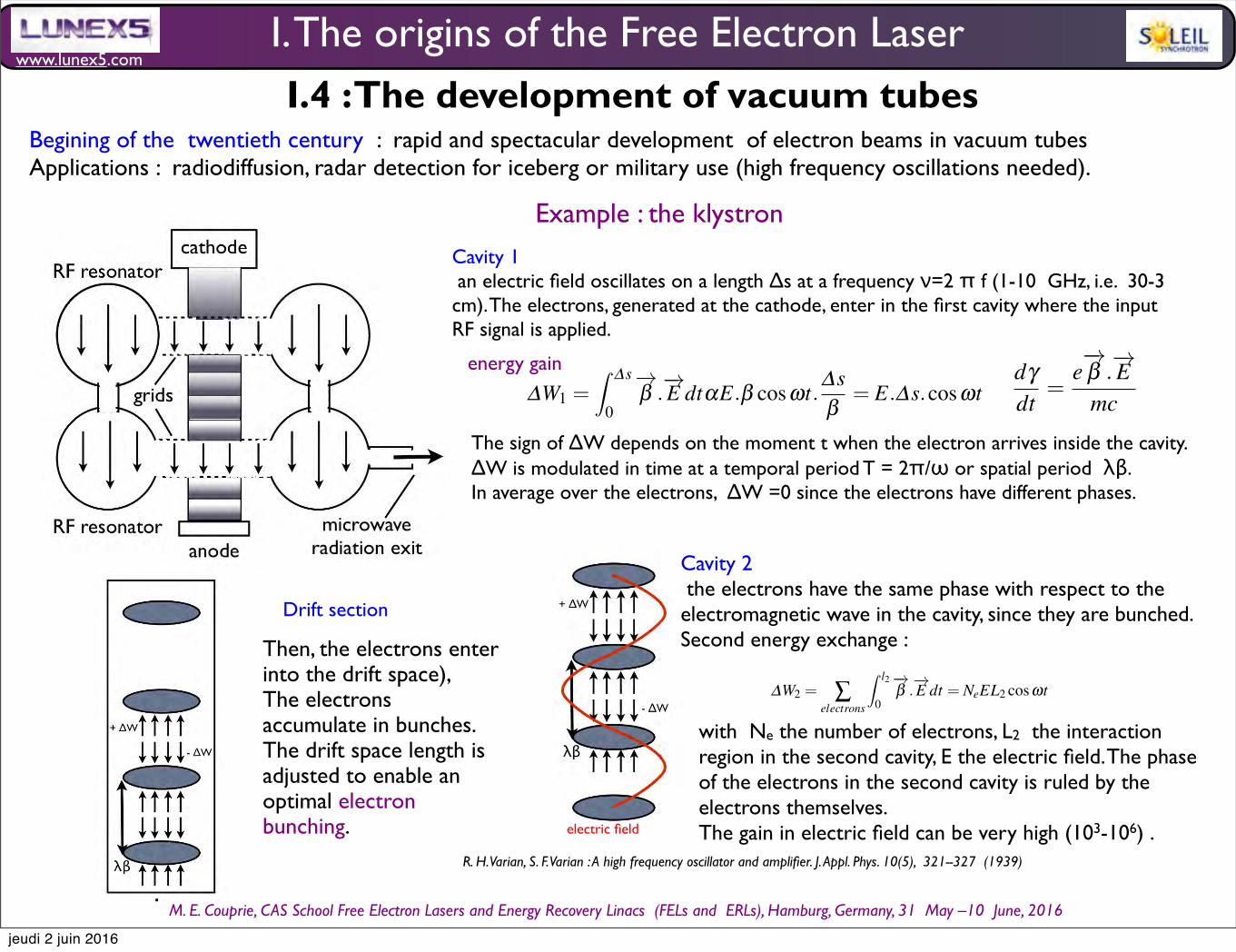
www.lunex5.com
M. E. Couprie, CAS School Free Electron!Lasers!and!Energy!Recovery!Linacs !(FELs and !ERLs), Hamburg, Germany, 31 !May –10 !June, 2016
Synchrotron radiation and Free Electron Laser 25
dγdt
=e−→β .
−→E
mc(69)
with−→β the normalised velocity of the electrons, with γ = 1√
1−β 2
The magnetron is a high power vacuum tube where electron bunches passing through open cavities excite RF wavesoscillations by interaction with the magnetic field, the frequency being determined by the geometry of the cavity. Itcan act only as an oscillator for the generation of microwave signal from the direct current supplied to the tube. Thisdevice can not amplify the RF signal. It is now used for microwave ovens.
The klystron, invented by the Russel and Sigurd Varian brothers [207] consists of two cavities (metal boxes alongthe tube), as shown in Fig. 19a. . In the first one, an electric field oscillates on a length ∆s at a frequency ν = 2π f
ranging between 1 and 10 GHz (i.e. with corresponding wavelengths of 30-3 cm). The electrons, generated at thecathode, enter in the first cavity where the input RF signal is applied. They can gain energy according to :
∆W1 = ∆s
0
−→β .
−→E dtαE.β cosωt.
∆s
β= E.∆s.cosωt (70)
The XXX revoir equation XXXThe sign of ∆W1 depends on the moment t when the electron arrives inside the cavity. ∆W1 is modulated in time
at a temporal period T = 12πω or spatial period λβ . In average over the electrons, ∆W1 = 0 since the electrons have
different phases. Then, the electrons enter into the drift space (see in Fig. 19b), enabling the electrons to accumulatein bunches. The drift space length is adjusted to enable an optimal electron bunching.
Fig. 19 klystron principle : a) klystron scheme, b) electron bunching by energy modulation in the klystron drift space, electrons accumulatein bunches, c) Phased electron in the second klystron cavity, electric field in red
In the second cavity, the electrons have the same phase with respect to the electromagnetic wave in the cavity, sincethey have been bunched (see in Fig. 19c). The second energy exchange is given by :
∆W2 = ∑electrons
l2
0
−→β .
−→E dt = NeEL2 cosωt (71)
with Ne the number of electrons, L2 the interaction region in the second cavity, E the electric field. The phase ofthe electrons in the second cavity is ruled by the electrons themselves. The gain in electric field can be very high(practically, 103 −106) .
R. H. Varian, S. F. Varian : A high frequency oscillator and amplifier. J. Appl. Phys. 10(5), 321--327 (1939)
Cavity 1 an electric field oscillates on a length ∆s at a frequency ν=2 π f (1-10 GHz, i.e. 30-3 cm). The electrons, generated at the cathode, enter in the first cavity where the input RF signal is applied.
The sign of ∆W depends on the moment t when the electron arrives inside the cavity. ∆W is modulated in time at a temporal period T = 2π/ω or spatial period λβ. In average over the electrons, ∆W =0 since the electrons have different phases.
Then, the electrons enter into the drift space), The electrons accumulate in bunches. The drift space length is adjusted to enable an optimal electron bunching.
Cavity 2 the electrons have the same phase with respect to the electromagnetic wave in the cavity, since they are bunched. Second energy exchange :
Synchrotron radiation and Free Electron Laser 25
dγdt
=e−→β .
−→E
mc(69)
with−→β the normalised velocity of the electrons, with γ = 1√
1−β 2
The magnetron is a high power vacuum tube where electron bunches passing through open cavities excite RF wavesoscillations by interaction with the magnetic field, the frequency being determined by the geometry of the cavity. Itcan act only as an oscillator for the generation of microwave signal from the direct current supplied to the tube. Thisdevice can not amplify the RF signal. It is now used for microwave ovens.
The klystron, invented by the Russel and Sigurd Varian brothers [207] consists of two cavities (metal boxes alongthe tube), as shown in Fig. 19a. . In the first one, an electric field oscillates on a length ∆s at a frequency ν = 2π f
ranging between 1 and 10 GHz (i.e. with corresponding wavelengths of 30-3 cm). The electrons, generated at thecathode, enter in the first cavity where the input RF signal is applied. They can gain energy according to :
∆W1 = ∆s
0
−→β .
−→E dtαE.β cosωt.
∆s
β= E.∆s.cosωt (70)
The XXX revoir equation XXXThe sign of ∆W1 depends on the moment t when the electron arrives inside the cavity. ∆W1 is modulated in time
at a temporal period T = 12πω or spatial period λβ . In average over the electrons, ∆W1 = 0 since the electrons have
different phases. Then, the electrons enter into the drift space (see in Fig. 19b), enabling the electrons to accumulatein bunches. The drift space length is adjusted to enable an optimal electron bunching.
Fig. 19 klystron principle : a) klystron scheme, b) electron bunching by energy modulation in the klystron drift space, electrons accumulatein bunches, c) Phased electron in the second klystron cavity, electric field in red
In the second cavity, the electrons have the same phase with respect to the electromagnetic wave in the cavity, sincethey have been bunched (see in Fig. 19c). The second energy exchange is given by :
∆W2 = ∑electrons
l2
0
−→β .
−→E dt = NeEL2 cosωt (71)
with Ne the number of electrons, L2 the interaction region in the second cavity, E the electric field. The phase ofthe electrons in the second cavity is ruled by the electrons themselves. The gain in electric field can be very high(practically, 103 −106) .
with Ne the number of electrons, L2 the interaction region in the second cavity, E the electric field. The phase of the electrons in the second cavity is ruled by the electrons themselves. The gain in electric field can be very high (103-106) .
Drift section
electric field
I. The origins of the Free Electron LaserI.4 : The development of vacuum tubes
energy gain
Begining of the twentieth century : rapid and spectacular development of electron beams in vacuum tubes Applications : radiodiffusion, radar detection for iceberg or military use (high frequency oscillations needed).
Example : the klystron
jeudi 2 juin 2016
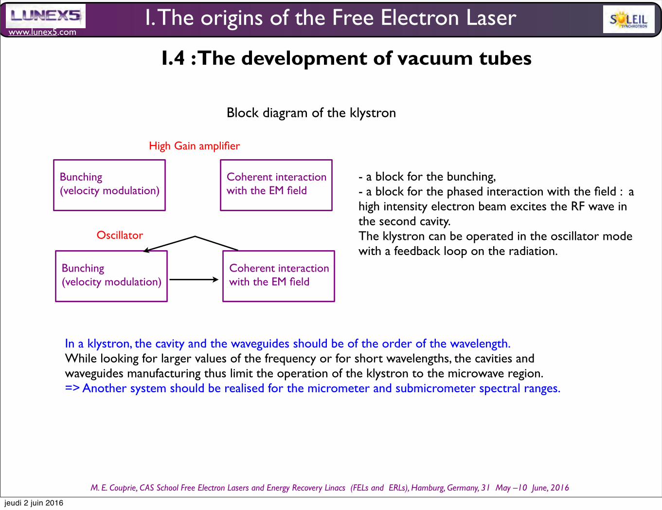
www.lunex5.com
M. E. Couprie, CAS School Free Electron!Lasers!and!Energy!Recovery!Linacs !(FELs and !ERLs), Hamburg, Germany, 31 !May –10 !June, 2016
Bunching(velocity modulation)
Coherent interaction with the EM field
Oscillator
High Gain amplifier
Bunching(velocity modulation)
Coherent interaction with the EM field
Block diagram of the klystron
- a block for the bunching, - a block for the phased interaction with the field : a high intensity electron beam excites the RF wave in the second cavity. The klystron can be operated in the oscillator mode with a feedback loop on the radiation.
In a klystron, the cavity and the waveguides should be of the order of the wavelength. While looking for larger values of the frequency or for short wavelengths, the cavities and waveguides manufacturing thus limit the operation of the klystron to the microwave region. => Another system should be realised for the micrometer and submicrometer spectral ranges.
I. The origins of the Free Electron Laser
I.4 : The development of vacuum tubes
jeudi 2 juin 2016
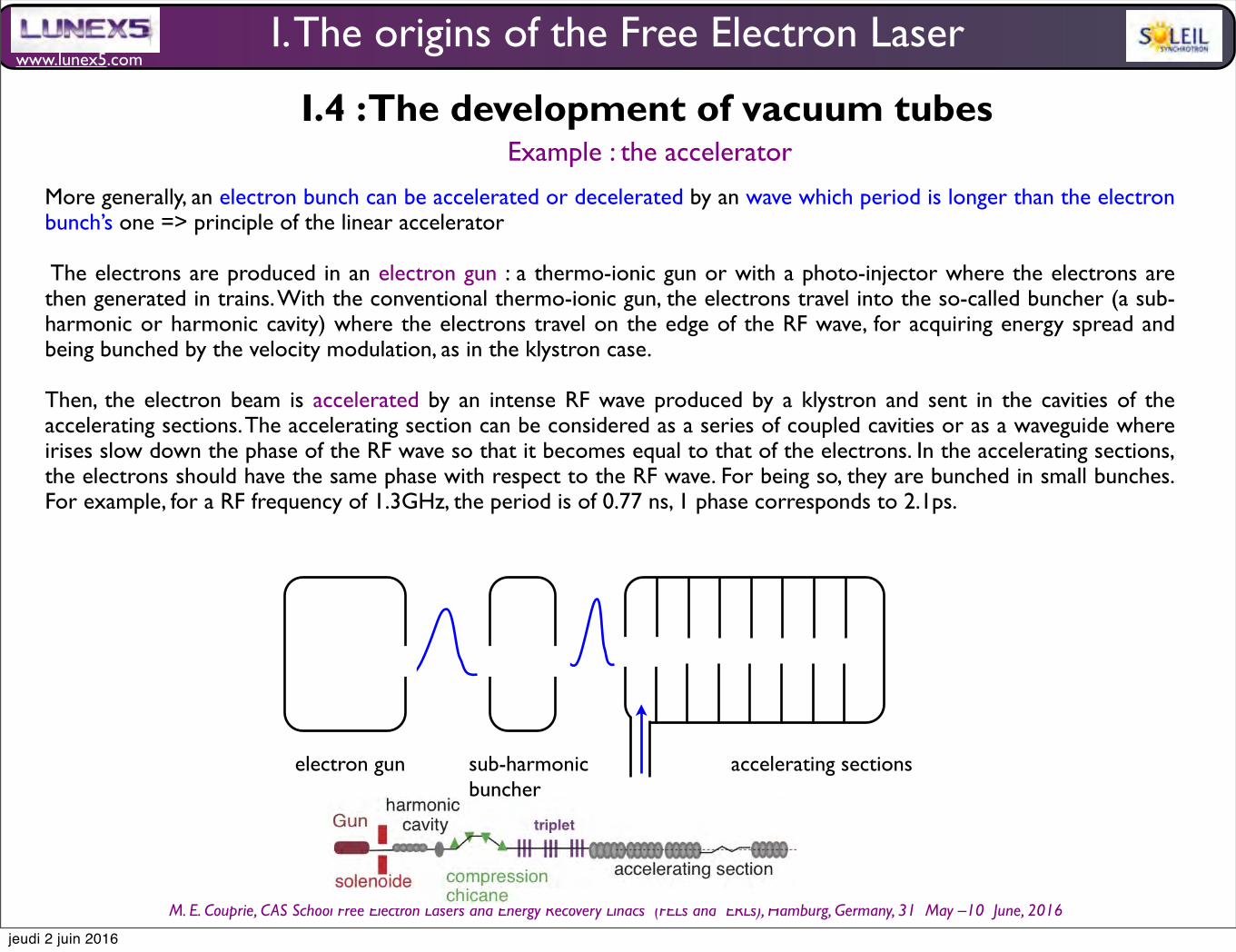
www.lunex5.com
M. E. Couprie, CAS School Free Electron!Lasers!and!Energy!Recovery!Linacs !(FELs and !ERLs), Hamburg, Germany, 31 !May –10 !June, 2016
electron gun sub-harmonicbuncher
accelerating sections
RF wave
More generally, an electron bunch can be accelerated or decelerated by an wave which period is longer than the electron bunch’s one => principle of the linear accelerator
The electrons are produced in an electron gun : a thermo-ionic gun or with a photo-injector where the electrons are then generated in trains. With the conventional thermo-ionic gun, the electrons travel into the so-called buncher (a sub-harmonic or harmonic cavity) where the electrons travel on the edge of the RF wave, for acquiring energy spread and being bunched by the velocity modulation, as in the klystron case.
Then, the electron beam is accelerated by an intense RF wave produced by a klystron and sent in the cavities of the accelerating sections. The accelerating section can be considered as a series of coupled cavities or as a waveguide where irises slow down the phase of the RF wave so that it becomes equal to that of the electrons. In the accelerating sections, the electrons should have the same phase with respect to the RF wave. For being so, they are bunched in small bunches. For example, for a RF frequency of 1.3GHz, the period is of 0.77 ns, 1 phase corresponds to 2.1ps.
I. The origins of the Free Electron Laser
I.4 : The development of vacuum tubesExample : the accelerator
jeudi 2 juin 2016
www.lunex5.com
M. E. Couprie, CAS School Free Electron!Lasers!and!Energy!Recovery!Linacs !(FELs and !ERLs), Hamburg, Germany, 31 !May –10 !June, 2016
Vacuum tubes such as klystrons and magnetrons and more generally electronics, discovered at the end of the thirties, knew a wide development during the second world war with applications such as radiodiffusion, radar detection, where oscillators with high frequencies are needed.
The sources generally use electron beams submitted to electric or magnetic fields, where the ”bunching” is the key concept for the wave amplification.
The use of resonant cavities at the frequency of the emitted wavelength can efficiently insure the retroaction needed for the production of a coherent wavelength.
=> This field of electronics enables to understand that in setting a loop on a wide band amplifier (in connecting one part of its output to its entry), on can transform it into a very monochromatic oscillator.
=> This concept will be used later for the maser and laser inventions.
I. The origins of the Free Electron Laser
I.4 : The development of vacuum tubes
K. Landecker, Possibility of frequency multiplication and wave amplification by means of some relaticistic effects, Phys. Rev. 36 (6) (1952) 852-855J. Schneider, Stimulated emission of radiation by relativistic electrons in a magnetic field, Phys. Rev. Lett. 2(12) (1959) 504-505R. H. Pantell, G. Soncini, H. E. Puthoff, Stimulated Photon-Electron Scattering, IEEE Jounral of Quantum Electronics 4 (11) 906-908 (1968)R. B. Palmer, Interaction of relativistic particles and Free Electromagnetic waves in the presence of a static helical magnet, J. Appl. Phys. 43(7) (1972)3014-3023K. W. Robinson , Nucl. Instr. Meth. A239 (1985)Csonka (1976)
jeudi 2 juin 2016

www.lunex5.com
M. E. Couprie, CAS School Free Electron!Lasers!and!Energy!Recovery!Linacs !(FELs and !ERLs), Hamburg, Germany, 31 !May –10 !June, 2016
I. The origins of the Free Electron Laser
1.5 The ubitron : Undulating Beam Interaction
The Ubitron : high-power traveling-wave tube which makes use of the interaction between a magnetically undulated periodic electron beam and the TE01mode in unloaded waveguide.
R. M. Phillips, The Ubitron, a high-power traveling-wave tube based on a periodic beam interaction in unloaded waveguide, IRE Transactions on Electron Devices !(Volume:7 ,! Issue: 4 ), 231 - 241 (1960)R. M. Phillips, History of the ubitron, Nuclear Instruments and Methods in Physics Research A272 (1988) 1-9
GE Microwave Lab
ELECTRONGUN
I NPUTW I NDOW
45° MATCH I NGRAMP
The second pa r t o f t he i n i t i a l i nves t i ga t i on cons i s t edo f bu i l d i ng an X-band t ube t o obse r ve beam / wavebehav i or . The i n t e r ac t i on r eg i on o f t h i s and t hr ee subse -quen t S-band t ubes , i l l us t r a t ed schema t i ca l l y i n f i g . 3 ,had t he appea r ance o f t he c l ass i ca l FEL. The expe r i -men t a l t ube p i c t ur ed i n f i g. 4 used a 0 . 3 i nch d i ame t e rbeam w i t h a m i c rope r veance o f 0 . 7 . I ndox pe rmanen tmagne t s , ass i s t ed by t r i m co i l s , we r e used t o w i gg l e andf ocus t he beam . Focus i ng pe rpend i cu l a r t o t he p l ane o ft he w i gg l e occur s au t oma t i ca l l y as desc r i bed i n a pape r
by S t ur rock o f S t an f ord [1] , t he con f i n i ng f or ce be i ng t heproduc t o f w i gg l e ve l oc i t y and ax i a l magne t i c f i e l d .Howeve r , i f no ba l anc i ng f or ce we r e prov i ded , t he beamwou l d spr ead un i mpeded i n t he p l ane o f t he w i gg l e .Th i s prob l em was so l ved by t ape r i ng t he magne t i c f i e l dso t ha t e l ec t rons a t t he ou t s i de o f t he w i gg l e r ece i ved agr ea t e r r e t urn k i ck t han t hose a t t he i ns i de . I pro -gr ammed t he equa t i ons o f mo t i on f or t he beam on t heana l og compu t e r and f ound t ha t a pa r abo l i c va r i a t i oni n t he magne t i c f i e l d cou l d be made t o dus t ba l ance t hespace cha rge f or ces so t ha t t he beam wou l d r ema i nf ocused .
The X-band t ube was des i gned t o ope r a t e a t am i n i mum synchronous vo l t age o f 115 kV . Tr ansm i ss i on
R M . Ph i l l i ps / H i s t or y o f t he ub i t ron
I NPUTWAVEGU I DE
BEAM
I NTERACT I ONREG I ON
OUTPUTWAVEGU I DE
OUTPUTW I NDOW
45° MATCH I NGRAMP
COLLECTOR
F i g. 3 Schema t i c o f f i r s t f our expe r i men t a l ub i t rons . These used FEL- l i ke w i gg l ed penc i l beam con f i gur a t i on .
F i g. 4 . Pho t ogr aph o f X-band w i gg l e beam ub i t ron . Magne t i c c i r cu i t used mdox pe rmanen t magne t s w i t h co i l s f or f i e l d t r i mm i ng .
3
be l ow 50 kV was as h i gh as 50% bu t dropped w i t hi nc r eas i ng vo l t age , r each i ng a l ow o f 5% . The l ow t r ans -m i ss i on was unexpec t ed bu t was a t t r i bu t ed t o i nade -qua t e magne t i c f i e l d amp l i t ude and i nsu f f i c i en t ad j us t a -b i l i t y . I n t e r ac t i on was obse r ved i n t he f orm o f r f ab -sorp t i on be l ow synchronous vo l t age and ga i n abovesynchron i sm . The omega -be t a d i agr am de r i ved f romt hese da t a was a good ma t ch t o t he t heor e t i ca l hype r -bo l a f or t he wavegu i de . The 2 dB max i mum ga i n wast he same f or an r f dr i ve o f 1 W and 1 kW , i nd i ca t i ngt ha t t he e f f ec t was mor e t han j us t sma l l s i gna l .
I pr esen t ed t hese concep t s and i n i t i a l r esu l t s a t t he17 t h E l ec t ron Tube Resea r ch Con f e r ence i n Mex i coC i t y i n 1959 [2] . The r esu l t s caused qu i t e a s t i r amongt hose who appr ec i a t ed t he i r s i gn i f i cance . One o f t hosewas sess i on organ i ze r Pro f essor Pau l Co l eman o f t heUn i ve r s i t y o f I l l i no i s , who was t he numbe r one propo -nen t o f t he use o f megavo l t e l ec t ron beams f or m i l l i me -t e r and subm i l l i me t e r wave gene r a t i on . Ano t he r wasPro f essor Ma r v i n Chodorow o f S t an f ord who was t hesess i on cha i rman . A t h i rd was M . B . Go l an t o f t heSov i e t Un i on , who approached me a f t e r t he sess i on t osay t ha t he and h i s co l l eagues we r e " do i ng s i m i l a r f as twave wor k a t t he i ns t i t u t e i n Moscow " , a l so us i ng t he
1 . I NTRODUCT I ON
1960 : Combining Travelling Wave Tubes and undulators
Nuc l ea r I ns t rumen t s and Me t hods i n Phys i cs Resea r ch A272 (1988) 1 -9Nor t h -Ho l l and , Ams t e rdam
Sec t i on 1 . I n t roduc t i on
H I STORY OF THE UB I TRON
Robe r t M. PH I LL I PSResea r ch and Deve l opmen t , STAR M i c rowave , 546 D i v i s i on S t r ee t , Campbe l l , CA 95008 , USA
The h i s t or y o f t he ub i t ron , t he or i g i na l FEL , i s t r aced f rom i t s i nven t i on and ea r l y X-band expe r i men t s i n 1957 , t hrough t hegene r a t i on i n 1964 o f m i l l i me t e r wave powe r a t a l eve l wh i ch r ema i ns t oday a r ecord f or amp l i f i e r s .
1 . I n t roduc t i on
The ub i t ron ( ac ronym f or undu l a t i ng beam i n t e r ac -t i on ) i s an FEL wh i ch was se t t i ng r ecords f or r f powe rgene r a t i on 15 yea r s be f or e t he t e rm " f r ee e l ec t ron l ase r "was co i ned . As i s so o f t en t he case , t he i nven t i on o f t heub i t ron was acc i den t a l . The yea r was 1957 and I wassea r ch i ng , a t t he GE M i c rowave Lab , f or an i n t e r ac t i onwh i ch wou l d exp l a i n why an X-band pe r i od i ca l l yf ocussed coup l ed cav i t y TWT osc i l l a t ed when a so l eno i df ocused ve r s i on d i d no t . The mos t appa r en t d i f f e r encebe t ween t he t wo was t he behav i or o f t he e l ec t ron beam ;one w i gg l ed wh i l e t he o t he r s i mp l y sp i r a l ed . Ou t o f apape r s t udy o f ways o f coup l i ng an r f wave t o anundu l a t i ng ax i a l l y symme t r i c e l ec t ron beam came t hei dea o f coup l i ng t o t he TE O, mode by a l l ow i ng t he wavet o s l i p t hrough t he beam such t ha t t he e l ec t r i c f i e l d
wou l d r eve r se d i r ec t i on a t t he same i ns t an t t he e l ec t ronve l oc i t y r eve r sed .
The coup l ed cav i t y osc i l l a t i on t urned ou t t o be a s l o tmode , wh i ch depends , no t on t he beam w i gg l e , bu t onave r age beam d i ame t e r . By t he t i me t h i s was r ecogn i zed ,I was o f f exp l or i ng my new f ound f as t wave i n t e r ac t i on ,an eng i nee r i ng adven t ur e wh i ch was t o l as t f or sevenyea r s , span t he f r equency r ange f rom 3 t o 60 GHz andse t new powe r gene r a t i on r ecords wh i ch wou l d s t andf or t wo decades .
The po t en t i a l f or gene r a t i ng supe r powe r w i t h t henew f as t wave amp l i f i ca t i on was i mmed i a t e l y obv i ous .He r e was a beam-wave i n t e r ac t i on wh i ch r equ i r ed nos l ow wave c i r cu i t , and t he coup l i ng r eg i on cou l d be ve r yl a rge. Any o f t he wavegu i de and beam con f i gur a t i onsi l l us t r a t ed i n f i g . 1 wou l d prov i de 100 t i mes t he c rosssec t i ona l a r ea o f a conven t i ona l s l ow wave TWT. Fur -t he rmor e , t he pr e f e r r ed r f mode , TE o t , was un i que i nhav i ng no ax i a l wa l l cur r en t s , so mode se l ec t i on shou l dbe s t r a i gh t f orwa rd , even i n an ove rmoded wavegu i de .Because propaga t i on was f as t wave , max i mum r f f i e l dwas we l l r emoved f rom t he gu i de wa l l s .
The po t en t i a l f or h i gh e f f i c i ency was a l so t he r e . As i mp l e no t e pad and penc i l ana l ys i s showed t ha t bunch -
0168 -9002 / 88 / $03 . 50 © E l sev i e r Sc i ence Pub l i she r s B . V .(Nor t h -Ho l l and Phys i cs Pub l i sh i ng D i v i s i on )
i ng and ene rgy ex t r ac t i on wou l d be ax i a l even t hought he i n t e r ac t i ng ve l oc i t y and f i e l d componen t s we r et r ansve r se . To ve r i f y t h i s conc l us i on , I progr ammed t he
ba l l i s t i c equa t i ons o f mo t i on (no space cha rge ) f or amagne t i ca l l y undu l a t ed e l ec t ron beam i n t e r ac t i ng w i t h aTE o t mode on an ana l og compu t e r (d i g i t a l compu t e r sand codes we r e no t ava i l ab l e a t t ha t t i me ) . The r esu l t s ,p i c t ur ed i n f i g. 2 , showed t ha t t he i n t e r ac t i on d i d i ndeedproduce f i r s t orde r ax i a l bunch i ng o f t he e l ec t ron beam ,compa r ab l e i n e f f i c i ency w i t h t ha t o f a s l ow wavet r ave l i ng wave t ube , and t ha t t he r f ene rgy came u l t i -ma t e l y f rom t he ax i a l ve l oc i t y , no t t he much sma l l e rw i gg l e ve l oc i t y . I t i s i n t e r es t i ng t o no t e t ha t t he r esu l t sp i c t ur ed i n f i g . 2 a r e qua l i t a t i ve l y s i m i l a r t o t hoseob t a i ned expe r i men t a l l y a t Los A l amos abou t s i x yea r sago w i t h an FEL.
E
( a ) PLANAR
(b ) COAX I AL
N S N S
(C) C I RCULAR
F i g. 1 . Examp l es o f beam-gu i de ub i t ron con f i gur a t i ons wh i chprov i de 100 t i mes t he i n t e r ac t i on a r ea o f a TWT .
I . I NTRODUCT I ON
jeudi 2 juin 2016
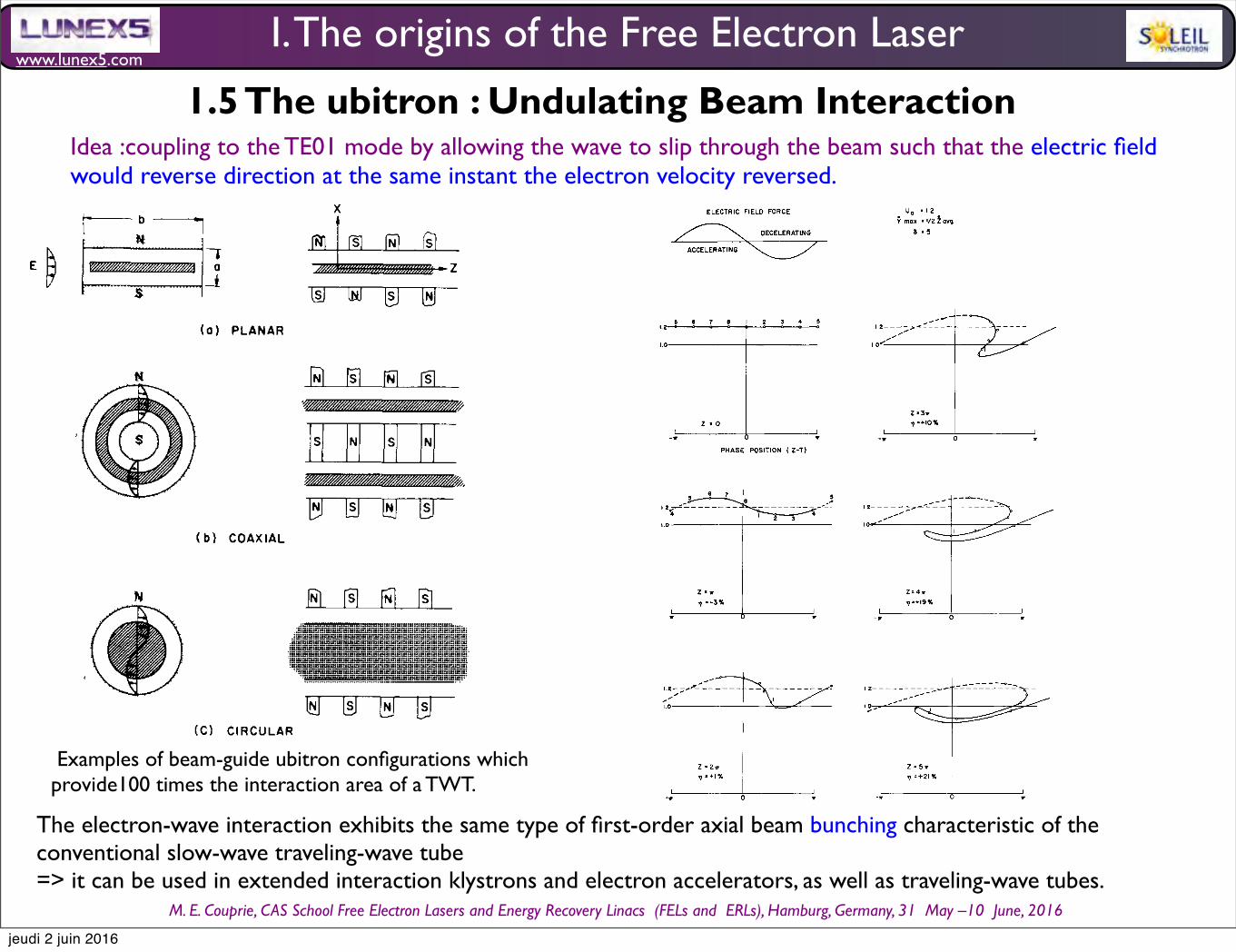
www.lunex5.com
M. E. Couprie, CAS School Free Electron!Lasers!and!Energy!Recovery!Linacs !(FELs and !ERLs), Hamburg, Germany, 31 !May –10 !June, 2016
Nuc l ea r I ns t rumen t s and Me t hods i n Phys i cs Resea r ch A272 (1988) 1 -9Nor t h -Ho l l and , Ams t e rdam
Sec t i on 1 . I n t roduc t i on
H I STORY OF THE UB I TRON
Robe r t M. PH I LL I PSResea r ch and Deve l opmen t , STAR M i c rowave , 546 D i v i s i on S t r ee t , Campbe l l , CA 95008 , USA
The h i s t or y o f t he ub i t ron , t he or i g i na l FEL , i s t r aced f rom i t s i nven t i on and ea r l y X-band expe r i men t s i n 1957 , t hrough t hegene r a t i on i n 1964 o f m i l l i me t e r wave powe r a t a l eve l wh i ch r ema i ns t oday a r ecord f or amp l i f i e r s .
1 . I n t roduc t i on
The ub i t ron ( ac ronym f or undu l a t i ng beam i n t e r ac -t i on ) i s an FEL wh i ch was se t t i ng r ecords f or r f powe rgene r a t i on 15 yea r s be f or e t he t e rm " f r ee e l ec t ron l ase r "was co i ned . As i s so o f t en t he case , t he i nven t i on o f t heub i t ron was acc i den t a l . The yea r was 1957 and I wassea r ch i ng , a t t he GE M i c rowave Lab , f or an i n t e r ac t i onwh i ch wou l d exp l a i n why an X-band pe r i od i ca l l yf ocussed coup l ed cav i t y TWT osc i l l a t ed when a so l eno i df ocused ve r s i on d i d no t . The mos t appa r en t d i f f e r encebe t ween t he t wo was t he behav i or o f t he e l ec t ron beam ;one w i gg l ed wh i l e t he o t he r s i mp l y sp i r a l ed . Ou t o f apape r s t udy o f ways o f coup l i ng an r f wave t o anundu l a t i ng ax i a l l y symme t r i c e l ec t ron beam came t hei dea o f coup l i ng t o t he TE O, mode by a l l ow i ng t he wavet o s l i p t hrough t he beam such t ha t t he e l ec t r i c f i e l d
wou l d r eve r se d i r ec t i on a t t he same i ns t an t t he e l ec t ronve l oc i t y r eve r sed .
The coup l ed cav i t y osc i l l a t i on t urned ou t t o be a s l o tmode , wh i ch depends , no t on t he beam w i gg l e , bu t onave r age beam d i ame t e r . By t he t i me t h i s was r ecogn i zed ,I was o f f exp l or i ng my new f ound f as t wave i n t e r ac t i on ,an eng i nee r i ng adven t ur e wh i ch was t o l as t f or sevenyea r s , span t he f r equency r ange f rom 3 t o 60 GHz andse t new powe r gene r a t i on r ecords wh i ch wou l d s t andf or t wo decades .
The po t en t i a l f or gene r a t i ng supe r powe r w i t h t henew f as t wave amp l i f i ca t i on was i mmed i a t e l y obv i ous .He r e was a beam- wave i n t e r ac t i on wh i ch r equ i r ed nos l ow wave c i r cu i t , and t he coup l i ng r eg i on cou l d be ve r yl a rge. Any o f t he wavegu i de and beam con f i gur a t i onsi l l us t r a t ed i n f i g . 1 wou l d prov i de 100 t i mes t he c rosssec t i ona l a r ea o f a conven t i ona l s l ow wave TWT. Fur -t he rmor e , t he pr e f e r r ed r f mode , TE o t , was un i que i nhav i ng no ax i a l wa l l cur r en t s , so mode se l ec t i on shou l dbe s t r a i gh t f orwa rd , even i n an ove rmoded wavegu i de .Because propaga t i on was f as t wave , max i mum r f f i e l dwas we l l r emoved f rom t he gu i de wa l l s .
The po t en t i a l f or h i gh e f f i c i ency was a l so t he r e . As i mp l e no t e pad and penc i l ana l ys i s showed t ha t bunch -
0168 -9002 / 88 / $03 . 50 © E l sev i e r Sc i ence Pub l i she r s B . V .(Nor t h -Ho l l and Phys i cs Pub l i sh i ng D i v i s i on )
i ng and ene rgy ex t r ac t i on wou l d be ax i a l even t hought he i n t e r ac t i ng ve l oc i t y and f i e l d componen t s we r et r ansve r se . To ve r i f y t h i s conc l us i on , I progr ammed t he
ba l l i s t i c equa t i ons o f mo t i on (no space cha rge ) f or amagne t i ca l l y undu l a t ed e l ec t ron beam i n t e r ac t i ng w i t h aTE o t mode on an ana l og compu t e r (d i g i t a l compu t e r sand codes we r e no t ava i l ab l e a t t ha t t i me ) . The r esu l t s ,p i c t ur ed i n f i g. 2 , showed t ha t t he i n t e r ac t i on d i d i ndeedproduce f i r s t orde r ax i a l bunch i ng o f t he e l ec t ron beam ,compa r ab l e i n e f f i c i ency w i t h t ha t o f a s l ow wavet r ave l i ng wave t ube , and t ha t t he r f ene rgy came u l t i -ma t e l y f rom t he ax i a l ve l oc i t y , no t t he much sma l l e rw i gg l e ve l oc i t y . I t i s i n t e r es t i ng t o no t e t ha t t he r esu l t sp i c t ur ed i n f i g . 2 a r e qua l i t a t i ve l y s i m i l a r t o t hoseob t a i ned expe r i men t a l l y a t Los A l amos abou t s i x yea r sago w i t h an FEL.
E
( a ) PLANAR
(b ) COAX I AL
N S N S
(C) C I RCULAR
F i g. 1 . Examp l es o f beam-gu i de ub i t ron con f i gur a t i ons wh i chprov i de 100 t i mes t he i n t e r ac t i on a r ea o f a TWT .
I . I NTRODUCT I ON
Examples of beam-guide ubitron configurations which provide100 times the interaction area of a TWT.
I. The origins of the Free Electron Laser
1.5 The ubitron : Undulating Beam Interaction
2
R . M Ph i l l i ps / H i s tory o f the ub i t ron
ELECTR IC F IELD FORCE
U a =12Y max = 1 / 2 Z avq
DECELERAT ING
D - S
ACCELERAT ING
s s
e 1 2 a + s1 . 2
Z =O
- ; r
( )
s
-
0
rPHASE POS IT ION ( Z-T)
F i g. 2 . Ana l og compu t er ana l ys i s o f ax i a l beam bunch i ng ver i f i ed TWT- l i ke per formance.
Idea :coupling to the TE01 mode by allowing the wave to slip through the beam such that the electric field would reverse direction at the same instant the electron velocity reversed.
The electron-wave interaction exhibits the same type of first-order axial beam bunching characteristic of the conventional slow-wave traveling-wave tube => it can be used in extended interaction klystrons and electron accelerators, as well as traveling-wave tubes.
jeudi 2 juin 2016

www.lunex5.com
M. E. Couprie, CAS School Free Electron!Lasers!and!Energy!Recovery!Linacs !(FELs and !ERLs), Hamburg, Germany, 31 !May –10 !June, 2016
I. The origins of the Free Electron Laser
1.5 The ubitron : Undulating Beam Interaction
R. M. Phillips, The Ubitron, a high-power traveling-wave tube based on a periodic beam interaction in unloaded waveguide, IRE Transactions on Electron Devices !(Volume:7 ,! Issue: 4 ), 231 - 241 (1960)R. M. Phillips, History of the ubitron, Nuclear Instruments and Methods in Physics Research A272 (1988) 1-9
Experiments : an undulated pencil beam in a rectangular waveguide. unique features :- very broad interaction bandwidth which results from the absence of a dispersive slow-wave circuit, - variable interaction phase velocity--hence, variable saturation power level. Among the physical embodiments of the Ubitron are a number of higher-order mode waveguide and beam configurations. =>interesting prospect for high-power millimeter wave amplification.
4
TE o I mode , and we r e mos t i n t e r es t ed i n my wor k . Heproposed t ha t we se t up an exchange o f i n f orma t i on .The s i m i l a r wor k t o wh i ch he r e f e r r ed was probab l y t heea r l y Russ i an expe r i men t s w i t h t he gy ro t ron . Need l esst o say , t he S t a t e Depa r t men t n i xed any exchange o fi n f orma t i on .
2 . US Army suppor t
A t t he conc l us i on o f t he X-band t es t s i n 1958 , t heArmy ( For t Monmou t h ) f unded a progr am t o eva l ua t et he ub i t ron as a supe r powe r nr i c rowave r ad i a t i onweapon . The ob j ec t i ve was t o produce 1 MW o f cwpowe r a t X- band . To mee t t h i s goa l , I f i r s t sca l ed t heX-band t ube ( r ec t angu l a r gu i de and penc i l beam) downt o S-band , whe r e co i l s cou l d be used t o produce a mor ef l ex i b l e w i gg l e r f i e l d . As was t he case w i t h t he X-bandt ube , t he b d i mens i on o f t he gu i de was i nc r eased t oabou t 12 t i mes t ha t o f s t anda rd wavegu i de i n orde r t oprov i de amp l e room f or t he penc i l beam t o w i gg l e . Th i sgu i de mod i f i ca t i on , i t wou l d t urn ou t , was r espons i b l ef or t he poor beam t r ansm i ss i on .
The pho t ogr aph o f f i g . 5 i s t he t h i rd o f t hr ee S-bandt ubes wh i ch we r e f abr i ca t ed and t es t ed . The peak beamt r ansm i ss i on o f t he f i r s t t ube was abou t 60% a t vo l t agesbe l ow 50 kV , bu t aga i n dropped w i t h i nc r eas i ng vo l t age ,
F i g . 5 . Pho t ogr aph o f S-band ub i t ron wh i ch produced 1 . 2 MWo f powe r . Cod cur r en t s we r e rheos t a t con t ro l l ed . Ca t hode i s
h i dden i n t he o i l t ank .
R . M Ph i l l i ps / H i s t or y o f t he ub i t ron
t h i s t i me t o a va l ue o f on l y 2% a t t he 115 kV i n t e r ac t i onvo l t age . A f t e r conc l ud i ng t ha t t he magne t i c f i e l d wasno t a t f au l t , I began a sea r ch f or t he ex i s t ence o f acompe t i ng pe r i od i c beam i n t e r ac t i on wh i ch cou l daccoun t f or such ex t r eme de f ocus i ng . No r f powe r hadbeen obse r ved , so t he o f f end i ng mode had t o be t r appedi n t he ove r s i zed i n t e r ac t i on r eg i on o f t he gu i de.
A pe r i od i c beam d i sp l acemen t i n t e r ac t i on w i t h t heTM , 1 mode was soon d i scove r ed , one hav i ng a synchro -nous vo l t age wh i ch ma t ched t he beam br eakup vo l t age .The ax i a l componen t o f t he e l ec t r i c f i e l d o f t he TM11mode has a max i mum va l ue on t he ax i s and goes t o ze roa t t he wa l l s . A t synchron i sm , t he mos t f avor ab l y phasee l ec t ron " sees " t he peak va l ue o f t he ax i a l dece l e r a t i ngf i e l d each t i me i t c rosses t he ax i s and a much sma l l e rcomponen t o f t he acce l e r a t i ng f i e l d as i s passes nea re i t he r wa l l , r esu l t i ng i n a ne t ax i a l dece l e r a t i ng f or ce .The f undamen t a l pe r i od f or t h i s pe r i od i c d i sp l acemen ti n t e r ac t i on i s one ha l f t ha t o f t he TE o i pe r i od i c i n t e r ac -t i on , so i t occur s a t a l owe r vo l t age , even t hough i t i s a
h i ghe r orde r mode . W i t h t he d i scove r y o f t hus compe t -i ng f as t wave i n t e r ac t i on , mode i n t e r f e r ence prob l emsand mode suppr ess i on t echn i ques we r e t o become apr i ma r y conce rn f or t he dur a t i on o f t he seven yea rub i t ron deve l opmen t e f f or t .
The second S-band t ube d i f f e r ed f rom t he f i r s t on l yi n t he add i t i on o f a mode suppr essor wh i ch made use o ft he f ac t t ha t t he TM modes have s t rong l ong i t ud i na lcur r en t s i n t he s i de wa l l s wh i l e t he TE o i mode has on l yt r ansve r se cur r en t s . A mode suppr essor cons i s t i ng o f
ve r t i ca l s l o t s m t he wa l l s backed by t h i n s l abs o f l ossyce r am i c was added t o t he nex t t ube . The measur ed l osst o t he TM , , mode r anged f rom 30 dB nea r cu t o f f t o 10
dB a t t he h i ghes t t r apped f r equency , wh i l e t he l oss t ot he TE o I mode was l ess t han 0 . 5 dB a t a l l measur edf r equenc i es .
The mode suppr essor so l ved t he prob l em . Beamt r ansm i ss i on was a t l eas t 80% a t a l l vo l t ages t hrough150 kV . The max i mum ne t gam o f t h i s t ube was ad i sappo i n t i ng 7 dB bu t t he bandw i d t h was an encour ag -i ng 30% . Us i ng f eedback t o ob t a i n sa t ur a t i on , we mea -sur ed a bes t e f f i c i ency o f 10% .
The t h i rd t ube , t ha t shown i n f i g. 5 , was mod i f i ed t oob t a i n h i ghe r ga i n . I t d i f f e r ed f rom t he second i n t hr eer espec t s :(1) Gun m i c rope r veance was i nc r eased f rom 1 . 0 t o 1 . 45 .(2) The c i r cu i t l eng t h was i nc r eased by 50% .(3) I n t en t i ona l TEo I mode l oss was i n t roduced t o i n -
sur e aga i ns t r e f l ec t i on t ype i ns t ab i l i t i es . Th i s wasdone by ang l i ng t he mode suppr essor s l o t s by 30 °t o t he Y ax i s . I nse r t i on l oss t o t he TE o I moder anged f rom 19 dB a t 2 . 55 GHz t o 3 dB a t 4 GHz.
Beam t r ansm i ss i on o f a t l eas t 80% was aga i n obt a i ned a t a l l vo l t ages . Sma l l s i gna l ga i n a t t wo va l ues o fbeam vo l t age i s shown i n f i g . 6 . The 3B bandw i d t h wasabou t 30% a t 125 kV . The peak sma l l s i gna l ga i n ,
2 . 5
2 . 6
2 . 7
2 . 8
2 9
F i g . 6 . Measured sma l l s i gna l ga i n o f the ub i t ron o f f i g . 5 , a t two va l ues o f beam vo l t age .
ob t a i ned a t 135 kV , was 13 dB . Max i mum sa tura t i onpower was 1 . 2 MW and the ne t e f f i c i ency (a f t er sub-t rac t i ng dr i ve power ) was 10% .
These ear l y resu l t s were a l l repor t ed i n a paperpub l i shed i n Oc tober 1960 [3] . In tha t paper , I s t a t edtha t an e f f i c i ency enhanc i ng t apered w i gg l er exper i men twas p l anned . The exper i men t requ i red the w i nd i ng o fspec i a l th i nner co i l s to a l l ow the magne t per i od to bedecreased . At the t i me o f pub l i ca t i on , the exper i men thad been comp l e t ed bu t i t was too l a t e for i nc l us i on i nthe paper . A 10% t aper i n the w i gg l er per i od i n the f i na l1 / 3 o f the tube i ncreased the max i mum e f f i c i ency f rom10% to 13% . Th i s i mprovemen t was i n par t due to theconserva t i ve me thod o f compu t i ng e f f i c i ency . Sa tura -t i on ga i n as we l l as ou tpu t power i ncreased , l eav i ng l essdr i ve power to be sub t rac t ed f rom the ou tpu t power i ncompu t i ng e f f i c i ency .
3 . US A i r Force t akes over
Abou t the t i me the t es t i ng o f the th i rd tube wascomp l e t ed , the Army dec i ded to ge t ou t o f the rad i a t i onweapons bus i ness , bu t the A i r Force had expressed ani n t eres t i n suppor t i ng a program a i med a t a t t a i n i ngmax i mum poss i b l e power a t 1 mm wave l eng th . Amu l t i -year program was i n i t i a t ed , cons i s t i ng o f a ser i eso f ub i t ron t es ts , f i rs t a t 16 GHz , then a t 60 , 120 , and
R . M . Ph i l l i ps / H i s tory o f the ub i t ron
3 0
3 . 1
3 . 2DR IVE FREQUENCY (kmc )
3 . 3
3 . 4
3 . 5
3 . 6 3 . 7
5
300 GHz . One o f the 16 GHz tubes i s shown i n thepho tograph o f f i g . 7 . The r f c i rcu i t cons i s t ed bas i ca l l y o fa 1 i nch d i ame t er p i pe made o f i ron and copper r i ngs ,w i th the i ron r i ngs serv i ng as po l e p i eces for rad i a lA l n i co V permanen t magne t s . These prov i ded bo th theundu l a t i on for the i n t erac t i on and the beam focus i ng .To guard aga i ns t mod i ng prob l ems , each o f the spacers ,wh i ch separa t ed the s l i gh t l y re -en t ran t magne t po l ep i eces , had embedded to them two l ossy ceram i c r i ngs .The mode suppressor produced no measurab l e l oss tothe TE o t c i rcu l ar wavegu i de mode bu t prov i ded 10 ' s o fdB o f l oss to TM modes o f concern . The convergen tso l i d beam gun used on th i s tube was f rom a GE 20MW S-band k l ys t ron .
Two o f these tubes were bu i l t . The f i rs t , des i gned for170 kV opera t i on , prov i ded l ow ga i n and re l a t i ve l y poorbeam t ransm i ss i on due to i nsu f f i c i en t magne t i c f i e l d .The second tube was des i gned to opera t e nearer the 250kV upper l i m i t o f the modu l a tor where the magne tper i od was l onger and the f i e l d h i gher . Beam cur ren twas approx i ma t e l y 125 A .
Th i s ub i t ron per formed we l l . We were ab l e to sa tura t ethe tube by t erm i na t i ng three o f the four ou tpu t wave -gu i des w i th h i gh power l oads , wh i l e f eed i ng the powerf rom the four th gu i de back through the power d i v i der tothe four i npu t gu i des wh i ch produced the TE O , mode . Amax i mum power o f 1 . 65 MW was measured a t 15 . 7GHz , a t an e f f i c i ency o f approx i ma t e l y 6% . Th i s was an
I . INTRODUCT ION
jeudi 2 juin 2016
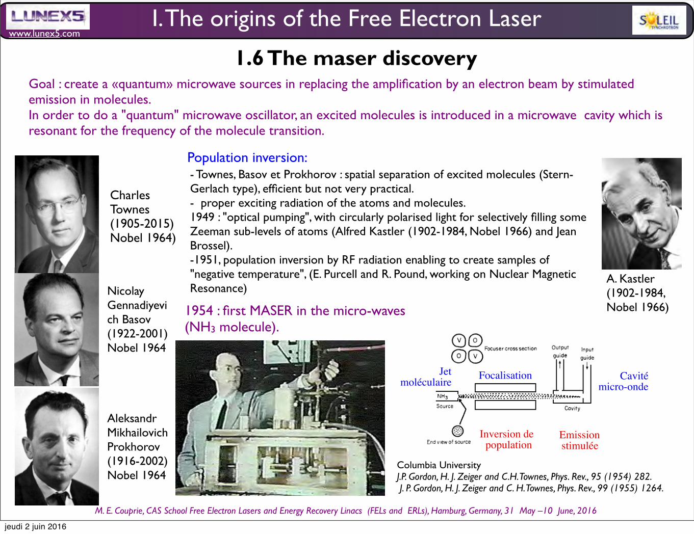
www.lunex5.com
M. E. Couprie, CAS School Free Electron!Lasers!and!Energy!Recovery!Linacs !(FELs and !ERLs), Hamburg, Germany, 31 !May –10 !June, 2016
Goal : create a «quantum» microwave sources in replacing the amplification by an electron beam by stimulated emission in molecules. In order to do a "quantum" microwave oscillator, an excited molecules is introduced in a microwave cavity which is resonant for the frequency of the molecule transition.
1.6 The maser discovery
Nicolay Gennadiyevich Basov (1922-2001)Nobel 1964
Aleksandr Mikhailovich Prokhorov (1916-2002)Nobel 1964
Charles Townes (1905-2015) Nobel 1964)
I. The origins of the Free Electron Laser
Columbia UniversityJ.P. Gordon, H. J. Zeiger and C.H. Townes, Phys. Rev., 95 (1954) 282. J. P. Gordon, H. J. Zeiger and C. H. Townes, Phys. Rev., 99 (1955) 1264.
LE MASER A AMMONIAC
Jetmoléculaire Focalisation Cavité
micro-onde
1954 : 1014 molécules/sec, P = 10-9 W, f = 24 GHz
Inversion depopulation
Emissionstimulée
-> Oscillation auto-entretenue !
LE MASER A AMMONIAC
MASER : Microwave Amplification by Stimulated Emission of Radiation. (Means of Acquiring Support for Expensive Research !)
CharlesTownes,
1954
(+Basov,Prokhorov :
Nobel 1964)
Population inversion:- Townes, Basov et Prokhorov : spatial separation of excited molecules (Stern-Gerlach type), efficient but not very practical. - proper exciting radiation of the atoms and molecules. 1949 : "optical pumping", with circularly polarised light for selectively filling some Zeeman sub-levels of atoms (Alfred Kastler (1902-1984, Nobel 1966) and Jean Brossel). -1951, population inversion by RF radiation enabling to create samples of "negative temperature", (E. Purcell and R. Pound, working on Nuclear Magnetic Resonance)
1954 : first MASER in the micro-waves (NH3 molecule).
A. Kastler (1902-1984, Nobel 1966)
jeudi 2 juin 2016

www.lunex5.com
M. E. Couprie, CAS School Free Electron!Lasers!and!Energy!Recovery!Linacs !(FELs and !ERLs), Hamburg, Germany, 31 !May –10 !June, 2016
1.7 The laser discovery
«The extension of maser techniques to the infrared and optical region is considered. It is shown that by using a resonant cavity of centimeter dimensions, having many resonant modes, maser oscillation at these wavelengths can be achieved by pumping with reasonable amounts of incoherent light. For wavelengths much shorter than those of the ultraviolet region, maser-type amplification appears to be quite impractical. Although use of a multimode cavity is suggested, a single mode may be selected by making only the end walls highly reflecting, and defining a suitably small angular aperture. Then extremely monochromatic and coherent light is produced. The design principles are illustrated by reference to a system using potassium vapor.»
Bell Tel. I.aboratories,
A. L. Schawlow C. H. Townes, Infra-red and optical masers, Phys. Rev. Lett. 1940-1948 (1958)
Patent, Optical Masers and Communication, by Bell Labs.
1958 : principle of realisation of the laser by Charles Townes and Arthur Schawlow (1921-1999, Nobel 1981)
Charles Townes (1905-2015 Nobel 1964)
Arthur Leonard Schawlow (1905-1999 Nobel 1981)
I. The origins of the Free Electron Laser
jeudi 2 juin 2016
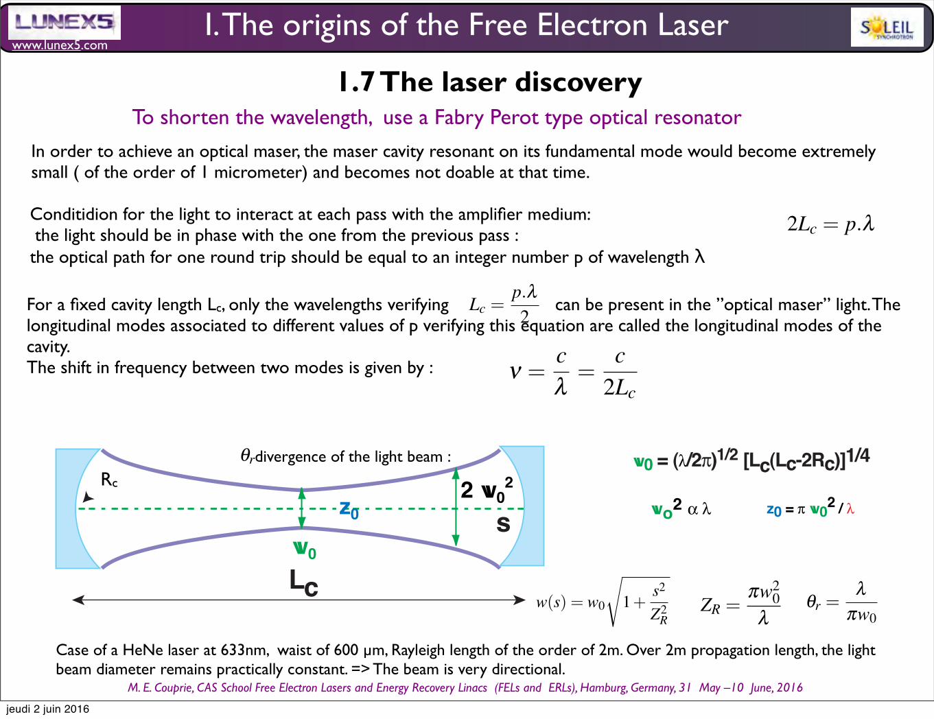
www.lunex5.com
M. E. Couprie, CAS School Free Electron!Lasers!and!Energy!Recovery!Linacs !(FELs and !ERLs), Hamburg, Germany, 31 !May –10 !June, 2016
To shorten the wavelength, use a Fabry Perot type optical resonator
In order to achieve an optical maser, the maser cavity resonant on its fundamental mode would become extremely small ( of the order of 1 micrometer) and becomes not doable at that time.
34 Marie-Emmanuelle COUPRIE and Mathieu VALLEAU
Nobel 1966)) and Jean Brossel propose and develop the ”optical pumping”, based on
the use of circularly polarised light for selectively filling some Zeeman sub-levels of
atoms. In 1951, E. Purcell and R. Pound, working on Nuclear Magnetic Resonance,
show that RF radiation enables to create samples of ”negative temperature”, i.e. a
population inversion. inspired by the resonators of vacuum tubes, the light feedback
is insured by a avity resonant on its fundamental mode.
In 1954, the first MASER (Microwave Amplification by Stimulated Emission of
Radiation) in operated in the micro-waves by Charles Townes (1905- Nobel prize
in1964) [?] at Columbia Univ with NH3 molecule. In 1954, N. Bloembergen, Basov
and Prokhorov propose the 3-level MASER concept : with a proper illumination
of a solid such as a Ruby crystal, population inversion takes place. This ”solid-
state” maser is first experimentally demonstrated in 1957 in Bell Labs. It is easier to
operate than the equivalent gas based maser. It has been used in particular as a very
low noise amplifier.
Natural masers also exist in stars.
From the interplay between electronic vacuum tubes and quantum properties of
matter domains has emerged a new domain, quantum electronics, which has seen
an extraordinary spread and rise a lot of interests. The question was then of the
extension of the maser to the optical wavelengths.
7.1.4 The laser advent
In order to achieve an optical maser, the maser cavity resonant on its fundamental
mode would become extremely small ( of the order of 1 micrometer) and becomes
not doable at that time. Nowadays, these cavities are manufactured using nanotech-
nologies (for VCSEL (Vertical Cavity Surface Emitting Laser) semi-conductors
lasers). C. Townes and A. Schawlow at Bell Labs, G. Gould at Columbia and A.
Prokhorov at Lebedev institute propose to feedback with an open resonant cavity
(Fabry-Perot type used in spectroscopy). In a Fabry-Perot cavity of length Lc, the
light makes round trips between the two mirrors on which it is reflected. For the
light to interact at each pass with the amplifier medium, and to get larger, it should
be in phase with the one from the previous pass. In other terms, the optical path for
one round trip should be equal to an integer number p of wavelength λ , i.e.:
2Lc = p.λ (38)
Lc =p.λ2
(39)
For a fixed cavity length Lc, only the wavelengths verifying this equation can be
present in the ”optical maser” light. The longitudinal modes associated to different
values of p verifying this equation are called the longitudinal modes of the cavlty.
The shift in frequency between two modes is given by :
For a fixed cavity length Lc, only the wavelengths verifying can be present in the ”optical maser” light. The longitudinal modes associated to different values of p verifying this equation are called the longitudinal modes of the cavity. The shift in frequency between two modes is given by :
34 Marie-Emmanuelle COUPRIE and Mathieu VALLEAU
Nobel 1966)) and Jean Brossel propose and develop the ”optical pumping”, based on
the use of circularly polarised light for selectively filling some Zeeman sub-levels of
atoms. In 1951, E. Purcell and R. Pound, working on Nuclear Magnetic Resonance,
show that RF radiation enables to create samples of ”negative temperature”, i.e. a
population inversion. inspired by the resonators of vacuum tubes, the light feedback
is insured by a avity resonant on its fundamental mode.
In 1954, the first MASER (Microwave Amplification by Stimulated Emission of
Radiation) in operated in the micro-waves by Charles Townes (1905- Nobel prize
in1964) [?] at Columbia Univ with NH3 molecule. In 1954, N. Bloembergen, Basov
and Prokhorov propose the 3-level MASER concept : with a proper illumination
of a solid such as a Ruby crystal, population inversion takes place. This ”solid-
state” maser is first experimentally demonstrated in 1957 in Bell Labs. It is easier to
operate than the equivalent gas based maser. It has been used in particular as a very
low noise amplifier.
Natural masers also exist in stars.
From the interplay between electronic vacuum tubes and quantum properties of
matter domains has emerged a new domain, quantum electronics, which has seen
an extraordinary spread and rise a lot of interests. The question was then of the
extension of the maser to the optical wavelengths.
7.1.4 The laser advent
In order to achieve an optical maser, the maser cavity resonant on its fundamental
mode would become extremely small ( of the order of 1 micrometer) and becomes
not doable at that time. Nowadays, these cavities are manufactured using nanotech-
nologies (for VCSEL (Vertical Cavity Surface Emitting Laser) semi-conductors
lasers). C. Townes and A. Schawlow at Bell Labs, G. Gould at Columbia and A.
Prokhorov at Lebedev institute propose to feedback with an open resonant cavity
(Fabry-Perot type used in spectroscopy). In a Fabry-Perot cavity of length Lc, the
light makes round trips between the two mirrors on which it is reflected. For the
light to interact at each pass with the amplifier medium, and to get larger, it should
be in phase with the one from the previous pass. In other terms, the optical path for
one round trip should be equal to an integer number p of wavelength λ , i.e.:
2Lc = p.λ (38)
Lc =p.λ2
(39)
For a fixed cavity length Lc, only the wavelengths verifying this equation can be
present in the ”optical maser” light. The longitudinal modes associated to different
values of p verifying this equation are called the longitudinal modes of the cavlty.
The shift in frequency between two modes is given by :
Synchrotron radiation, polarization, devices and new sources 35
ν =cλ
=c
2Lc(40)
In practice, in order to focus the light transversally and to avoid diffraction losses,one of the mirrors should be concave.The light circulating in the optical resonator isnot a plane wave, and the radius of the light changes along its propagation. In case ofa cavity with two concentric mirrors, the light radius is minimum at the waist w0 anddiverges according to XXXXXXXXREF Khogelnik, YarivXXXXXXXXXXXXX :
w(s) = w0
1+s2
Z2R
(41)
with ZR the Rayleigh length, i.e. the distance from the waist for which the radiusof the light beam is increased by a factor of
√2. It is given by :
ZR =πw2
0λ
(42)
it corresponds to the diffraction of light by an aperture of diameter 2w0. Theradiation at the entry and at the exit of the cavity have the same characteristics. itcan be adapted to the user need with the help of mirrors and lenses. The divergenceof the light beam θr can be expressed as :
θr =λ
πw0(43)
In the case of a HeNe laser at 633nm with a waist of 600 m, the Rayleigh lengthis of the order of 2m. Over 2m propagation length, the light beam diameter remainspractically constant. The beam is very directional.
XXX je n’arrive pas faire micronXXXXXXXXX cas de la longueur de Rayleigh et du waist, LEL SACOXXXXXXXXXXXXXXXXXXXXXXXXXXXXXXXAccording to the user need, it can be focused or expandedMETTRE fig cavite optique,Toutefois, on ne peut pas obtenir simultanment un faisceau trs directif et de trs pe-
tit rayon. En effet, plus on focalise (en utilisant des miroirs concaves de faible rayonde courbure), plus w0 est petit, mais plus le faisceau diverge ensuite (la longueur deRayleigh est galement petite).
Following the publication of the theoretical paper by A. L. Schawlow and C.Townes, on ”Infra-red and Optical masers” , different laboratories enter the race todemonstrate experimentally the ”optical maser”. It is won by an outsider in 1960,Theodore Maiman, who has the idea to realize a pulse and not a CW source, forwhich the oscillation conditions take place transiently. In 1960, Maiman achievedthe first working laser by generating pulses of coherent light from a fingertip-sizedlump of ruby illuminated by a flash lamp [?] in Malibu (USA). The device is ex-tremely simple. Several ”optical masers” followed : the one by Mirek Stevensonand Peter Sorokin at General Electric, the He-Ne laser by Ali Javan, Bill Bennettand Don Herriott at Bell Labs. These ”optical lasers” were then named obviouslyLASER for Light Amplification by Stimulated Emission of Radiation.
Conditidion for the light to interact at each pass with the amplifier medium: the light should be in phase with the one from the previous pass : the optical path for one round trip should be equal to an integer number p of wavelength λ
I. The origins of the Free Electron Laser
1.7 The laser discoverySynchrotron radiation, polarization, devices and new sources 35
ν =cλ
=c
2Lc(40)
In practice, in order to focus the light transversally and to avoid diffraction losses,one of the mirrors should be concave.The light circulating in the optical resonator isnot a plane wave, and the radius of the light changes along its propagation. In case ofa cavity with two concentric mirrors, the light radius is minimum at the waist w0 anddiverges according to XXXXXXXXREF Khogelnik, YarivXXXXXXXXXXXXX :
w(s) = w0
1+s2
Z2R
(41)
with ZR the Rayleigh length, i.e. the distance from the waist for which the radiusof the light beam is increased by a factor of
√2. It is given by :
ZR =πw2
0λ
(42)
it corresponds to the diffraction of light by an aperture of diameter 2w0. Theradiation at the entry and at the exit of the cavity have the same characteristics. itcan be adapted to the user need with the help of mirrors and lenses. The divergenceof the light beam θr can be expressed as :
θr =λ
πw0(43)
In the case of a HeNe laser at 633nm with a waist of 600 m, the Rayleigh lengthis of the order of 2m. Over 2m propagation length, the light beam diameter remainspractically constant. The beam is very directional.
XXX je n’arrive pas faire micronXXXXXXXXX cas de la longueur de Rayleigh et du waist, LEL SACOXXXXXXXXXXXXXXXXXXXXXXXXXXXXXXXAccording to the user need, it can be focused or expandedMETTRE fig cavite optique,Toutefois, on ne peut pas obtenir simultanment un faisceau trs directif et de trs pe-
tit rayon. En effet, plus on focalise (en utilisant des miroirs concaves de faible rayonde courbure), plus w0 est petit, mais plus le faisceau diverge ensuite (la longueur deRayleigh est galement petite).
Following the publication of the theoretical paper by A. L. Schawlow and C.Townes, on ”Infra-red and Optical masers” , different laboratories enter the race todemonstrate experimentally the ”optical maser”. It is won by an outsider in 1960,Theodore Maiman, who has the idea to realize a pulse and not a CW source, forwhich the oscillation conditions take place transiently. In 1960, Maiman achievedthe first working laser by generating pulses of coherent light from a fingertip-sizedlump of ruby illuminated by a flash lamp [?] in Malibu (USA). The device is ex-tremely simple. Several ”optical masers” followed : the one by Mirek Stevensonand Peter Sorokin at General Electric, the He-Ne laser by Ali Javan, Bill Bennettand Don Herriott at Bell Labs. These ”optical lasers” were then named obviouslyLASER for Light Amplification by Stimulated Emission of Radiation.
Synchrotron radiation, polarization, devices and new sources 35
ν =cλ
=c
2Lc(40)
In practice, in order to focus the light transversally and to avoid diffraction losses,one of the mirrors should be concave.The light circulating in the optical resonator isnot a plane wave, and the radius of the light changes along its propagation. In case ofa cavity with two concentric mirrors, the light radius is minimum at the waist w0 anddiverges according to XXXXXXXXREF Khogelnik, YarivXXXXXXXXXXXXX :
w(s) = w0
1+s2
Z2R
(41)
with ZR the Rayleigh length, i.e. the distance from the waist for which the radiusof the light beam is increased by a factor of
√2. It is given by :
ZR =πw2
0λ
(42)
it corresponds to the diffraction of light by an aperture of diameter 2w0. Theradiation at the entry and at the exit of the cavity have the same characteristics. itcan be adapted to the user need with the help of mirrors and lenses. The divergenceof the light beam θr can be expressed as :
θr =λ
πw0(43)
In the case of a HeNe laser at 633nm with a waist of 600 m, the Rayleigh lengthis of the order of 2m. Over 2m propagation length, the light beam diameter remainspractically constant. The beam is very directional.
XXX je n’arrive pas faire micronXXXXXXXXX cas de la longueur de Rayleigh et du waist, LEL SACOXXXXXXXXXXXXXXXXXXXXXXXXXXXXXXXAccording to the user need, it can be focused or expandedMETTRE fig cavite optique,Toutefois, on ne peut pas obtenir simultanment un faisceau trs directif et de trs pe-
tit rayon. En effet, plus on focalise (en utilisant des miroirs concaves de faible rayonde courbure), plus w0 est petit, mais plus le faisceau diverge ensuite (la longueur deRayleigh est galement petite).
Following the publication of the theoretical paper by A. L. Schawlow and C.Townes, on ”Infra-red and Optical masers” , different laboratories enter the race todemonstrate experimentally the ”optical maser”. It is won by an outsider in 1960,Theodore Maiman, who has the idea to realize a pulse and not a CW source, forwhich the oscillation conditions take place transiently. In 1960, Maiman achievedthe first working laser by generating pulses of coherent light from a fingertip-sizedlump of ruby illuminated by a flash lamp [?] in Malibu (USA). The device is ex-tremely simple. Several ”optical masers” followed : the one by Mirek Stevensonand Peter Sorokin at General Electric, the He-Ne laser by Ali Javan, Bill Bennettand Don Herriott at Bell Labs. These ”optical lasers” were then named obviouslyLASER for Light Amplification by Stimulated Emission of Radiation.
divergence of the light beam :
Case of a HeNe laser at 633nm, waist of 600 µm, Rayleigh length of the order of 2m. Over 2m propagation length, the light beam diameter remains practically constant. => The beam is very directional.
z02 w0
2
w0
s
Lc
Rcw0 = (!/2")1/2 [Lc(Lc-2Rc)]1/4
wo2 ! " z0 = ! w02 / "
Rc
Synchrotron radiation, polarization, devices and new sources 35
ν =cλ
=c
2Lc(40)
In practice, in order to focus the light transversally and to avoid diffraction losses,one of the mirrors should be concave.The light circulating in the optical resonator isnot a plane wave, and the radius of the light changes along its propagation. In case ofa cavity with two concentric mirrors, the light radius is minimum at the waist w0 anddiverges according to XXXXXXXXREF Khogelnik, YarivXXXXXXXXXXXXX :
w(s) = w0
1+s2
Z2R
(41)
with ZR the Rayleigh length, i.e. the distance from the waist for which the radiusof the light beam is increased by a factor of
√2. It is given by :
ZR =πw2
0λ
(42)
it corresponds to the diffraction of light by an aperture of diameter 2w0. Theradiation at the entry and at the exit of the cavity have the same characteristics. itcan be adapted to the user need with the help of mirrors and lenses. The divergenceof the light beam θr can be expressed as :
θr =λ
πw0(43)
In the case of a HeNe laser at 633nm with a waist of 600 m, the Rayleigh lengthis of the order of 2m. Over 2m propagation length, the light beam diameter remainspractically constant. The beam is very directional.
XXX je n’arrive pas faire micronXXXXXXXXX cas de la longueur de Rayleigh et du waist, LEL SACOXXXXXXXXXXXXXXXXXXXXXXXXXXXXXXXAccording to the user need, it can be focused or expandedMETTRE fig cavite optique,Toutefois, on ne peut pas obtenir simultanment un faisceau trs directif et de trs pe-
tit rayon. En effet, plus on focalise (en utilisant des miroirs concaves de faible rayonde courbure), plus w0 est petit, mais plus le faisceau diverge ensuite (la longueur deRayleigh est galement petite).
Following the publication of the theoretical paper by A. L. Schawlow and C.Townes, on ”Infra-red and Optical masers” , different laboratories enter the race todemonstrate experimentally the ”optical maser”. It is won by an outsider in 1960,Theodore Maiman, who has the idea to realize a pulse and not a CW source, forwhich the oscillation conditions take place transiently. In 1960, Maiman achievedthe first working laser by generating pulses of coherent light from a fingertip-sizedlump of ruby illuminated by a flash lamp [?] in Malibu (USA). The device is ex-tremely simple. Several ”optical masers” followed : the one by Mirek Stevensonand Peter Sorokin at General Electric, the He-Ne laser by Ali Javan, Bill Bennettand Don Herriott at Bell Labs. These ”optical lasers” were then named obviouslyLASER for Light Amplification by Stimulated Emission of Radiation.
jeudi 2 juin 2016
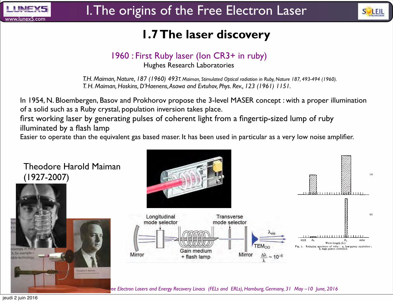
www.lunex5.com
M. E. Couprie, CAS School Free Electron!Lasers!and!Energy!Recovery!Linacs !(FELs and !ERLs), Hamburg, Germany, 31 !May –10 !June, 2016
!"#$%&'()*+&,--.##+&/&0(123&456&7#8$2"2892&,:;:1-&<=><?@&<ABC& 7#D2"2892E0(123E<F,:;<ABC%GG-&
!"#$%$&'$(
<&
T.H. Maiman, Nature, 187 (1960) 493T. Maiman, Stimulated Optical radiation in Ruby, Nature 187, 493-494 (1960).T. H. Maiman, Hoskins, D’Haenens, Asawa and Evtuhov, Phys. Rev., 123 (1961) 1151.
1960 : First Ruby laser (Ion CR3+ in ruby)Hughes Research Laboratories
In 1954, N. Bloembergen, Basov and Prokhorov propose the 3-level MASER concept : with a proper illumination of a solid such as a Ruby crystal, population inversion takes place. first working laser by generating pulses of coherent light from a fingertip-sized lump of ruby illuminated by a flash lampEasier to operate than the equivalent gas based maser. It has been used in particular as a very low noise amplifier.
Theodore Harold Maiman(1927-2007)
I. The origins of the Free Electron Laser
1.7 The laser discovery
© 1960 Nature Publishing Group
jeudi 2 juin 2016

www.lunex5.com
M. E. Couprie, CAS School Free Electron!Lasers!and!Energy!Recovery!Linacs !(FELs and !ERLs), Hamburg, Germany, 31 !May –10 !June, 2016
1962 : R. Hallfirst semi-conductor AsGa laser (diode laser)
1960: Ali Javanfirst gas laser (He-Ne)
....
NATURE PHOTONICS | VOL 6 | DECEMBER 2012 | www.nature.com/naturephotonics 795
editorial
In 2010, the 50th anniversary of Ted Maiman’s experimental demonstration of the !rst ruby laser quite rightly gave rise to substantial publicity, including celebratory events such as the LaserFest series (www.laserfest.org) and much coverage in a wide variety of newspapers and magazines. However, in many ways it was actually the successful development of the GaAs semiconductor laser diode in 1962 that really ignited the laser revolution. "e fabrication of a semiconductor laser kick-started the important !eld of optoelectronics and showed that lasers could, in principle, be fabricated in a miniature, cost-e#ective format that showed great promise for mass-production in a form similar to electronic devices. Shortly a$erwards, the demonstration of electrically pumped devices capable of operating at room-temperature with high output powers further added to the practicality and appeal of semiconductor lasers.
In contrast, if lasers had remained limited to getting their gain from doped glass crystals such as ruby or Ti:sapphire, or gas mixtures such as HeNe or CO2, their technological impact would have been considerably less and the world of photonics would look very di#erent. Although the use of high-power lasers for materials processing applications such as cutting and welding might still have come to fruition, many other tasks that we take for granted today would probably not have been feasible. Take, for example, optical data storage and communication networks, which today represent two of largest and most important markets for laser technology. It is unlikely that !bre-based data networks, CDs, DVDs and BluRay players would have been seriously pursued or even considered practical without the realization of an e%cient and low-cost laser diode.
Given this context, it is pleasing to see that the 50th birthday of the laser diode has not been overlooked. "e Institute of Physics in the UK organized a two-day celebratory seminar entitled “50th Anniversary of the Laser Diode” at the University of Warwick on 20–21 September 2012, during which several of the founding fathers of the technology reminisced about the early days of its development and the race to make the !rst laser diode. Speakers included Marshall Nathan, formerly of IBM Labs in
the USA, Yuri Popov from Russia, Maurice Bernard from France, Jim Coleman from the USA and Cyril Hilsum, Robin "ompson and John Orton from the UK.
"e competition between various scientists (such as Gordon Gould, Charles Townes, Art Schawlow and Ted Maiman, among others) to achieve the !rst experimental demonstration of a laser in 1960 is well documented (see the excellent account in Je# Hecht’s book “Beam: "e Race to Make the Laser”). However, the quest to develop a semiconductor laser two years later was arguably just as exciting, fast-paced and competitive, with a handful of research groups all reported working lasers based on GaAs p–n junctions within a short period in the autumn of 1962.
Ultimately, Robert Hall (pictured) and his group at General Electric’s research labs in Schenectady is credited as getting there !rst. "eir report of coherent infrared (850&nm) emission from a GaAs laser appeared in the 1 November 1962 issue of Physical Review Letters1. "is was simultaneously accompanied by reports of lasing from GaAs devices appearing in the journal
Applied Physics Letters by Marshall Nathan’s group at IBM’s Watson Research Labs2 and Ted Quist’s group from the Massachusetts Institute of Technology Lincoln Labs3. A 'urry of results then followed from around the world, including the !rst visible semiconductor laser by Nick Holonyak’s group at General Electric’s lab in Syracuse (who became famous for inventing the light-emitting diode that same year) as well as demonstrations by Cyril Hilsum and colleagues at the UK’s Services Electronics Research Laboratory and a Russian group of scientists led by Nikolay Basov.
Speaking at the event, Marshall Nathan says that in early 1962 he was at IBM studying the photoluminescence from GaAs when the department director Rolf Landauer announced that he wanted IBM to be the !rst group to make a GaAs laser and threw a team of people onto the project. In February, Nathan and his co-workers tried using a 'ash lamp to pump a sample of GaAs but were unsuccessful in achieving lasing. "en, following further research in September 1962, they observed “spectacular line narrowing”, which suggested that lasing was taking place.
“We sent the results to Applied Physics Letters, hand-delivered,” said Nathan. “We then started to get lots of results very quickly, such as continuous-wave lasing at 4.2&K, room-temperature lasing and measurement of far-!eld emission patterns,” said Nathan. “"e !rst real semiconductor laser at IBM was made in October 1962, and we got the patent out in just !ve days.”
Astonishingly, Nathan says at the time that the researchers at IBM didn’t know that they had serious competition from General Electric and were shocked to learn Hall’s APL paper had been submitted 11 days before their own, e#ectively scooping them. “We had no idea that General Electric was working on this,” commented Nathan. "is story is not only an interesting history lesson, but also a valuable reminder of just how exciting and fast-paced research can be. !
References1. Hall, R N, Fenner, G. E, Kingsley, J. D, Soltys, T. J and Carlson R. O.
Phys. Rev. Lett. 9, 366–369 (1962).2. Nathan M,I, Dumke W.P, Burns G, Dill F, H, Jr and Lasher G
Appl. Phys. Lett. 1, 62 (1962).3. Quist T.M et al Appl. Phys. Lett. 1, 91 (1962).
Fifty years ago, researchers at a handful of laboratories around the world were reporting lasing from the first semiconductor lasers. Our IT infrastructure today relies on their diligence and success.
Remembering the laser diode
GEN
ERA
L EL
ECTR
IC R
ESEA
RCH
AN
D D
EVEL
OPM
ENT
CEN
TER,
CO
URT
ESY
AIP
EM
ILIO
SEG
RE V
ISUA
L A
RCH
IVES
1971: Concept of the Free Electron Laser1977 : First FEL in the IR (Stanford, USA)1983 : First FEL in the visible (Orsay, France)
1966: Mirek Stevenson and Peter Sorokin at General Electricfirst dye lasertuneable yellow to red
74 1964 C H A R L E S H . T O W N E S
FLASH TUBE
Fig. 3. Schematic diagram of a ruby (optically excited solid-state) laser. When the gasflash tube is activated, electromagnetic oscillations occur within the ruby rod, and someof these light waves are emitted in a beam through one partially reflecting end of the rod.
Not very long after the ruby laser was developed, Javan, Bennett and Her-riott35 obtained maser oscillations from neon atoms excited by collisions ofthe second kind with metastable helium, in accordance with an idea previous-ly put forward by Javan
36. This system, illustrated in Fig. 4, requires only agaseous discharge through a tube containing a mixture of helium and neonat low pressure, and two reflectors at the ends of the tube. It oscillates at the
Fig.4. Schematic diagram of a helium-neon (gas discharge) laser. Electrical excitationcan initiate a steady maser oscillation, resulting in an emitted light beam from either end
of the gas discharge, where there are reflecting mirrors.
Javan, Bennett and Herriott, Phys. Rev. Letters, 6 (1961) 106.
Gaseous dischargeCW source of infra red, 1 mW p-n junction of the semiconductor gallium arsenide through
which a current is passed can emit near-infrared light from recombination processes with very high efficiency.
R. J. Keyes and T.M. Quist, Proc. IEEE (Inst. Electron. Elec. Engrs.), 50 (1962) 1822. Hall, Fenner, Kingsley, Soltys and Carlson, Phys. Rev. Letters, 9 (1962) 366.
76 1964 CHARLES H. TOWNES
SILVER RIBBON
SILVER-GOLDEVAPORATED STRIPE(MICROALLOYED)
Fig. 5. Schematic diagram of a gallium arsenide (injection, or semiconductor) laser. Asmall voltage applied between the silver ribbon and the molybdenum disc can produce
maser oscillations with resulting emission of coherent infrared radiation.
One might consider the population of the virtual level in a Raman maser(see Fig. 6) to be greater than that of the first excited state, so that there is nopopulation inversion. On the other hand the initial state, which is the groundstate, needs to be more populated than the first excited state. One can quiteproperly consider the amplification process as a parametric one with themolecular frequency as idler, or as due to a mixture of ground and excitedstates in which there is phase coherence between the various molecules. Thisis the second type of loophole through the black-body radiation law men-tioned earlier. The ammonia-beam maser itself illustrates the case of amplifi-cation without the necessity of population inversion. As the ammonia mole-cules progress through the cavity and become predominantly in the groundstate rather than the excited state, they continue to amplify because their oscil-lations are correlated in phase with each other, and have the appropriate phasewith respect to the electromagnetic wave.
Raman masers were first demonstrated by Woodbury and Ng43 as the re-sult of excitation of various liquid molecules with a very intense beam from apulsed laser. They too have now many versions, giving frequencies which
I. The origins of the Free Electron Laser
1.7 The laser discovery
jeudi 2 juin 2016

www.lunex5.com
M. E. Couprie, CAS School Free Electron!Lasers!and!Energy!Recovery!Linacs !(FELs and !ERLs), Hamburg, Germany, 31 !May –10 !June, 2016
«As one attempts to extend maser operation towards very short wavelengths, a number of new aspects and problems arise, which require a quantitative reorientation of theoretical discussions and considerable modification of the experimental techniques used.»
...
«These figures show that maser systems can be expected to operate successfully in the infrared, optical, and perhaps in the ultraviolet regions, but that, unless some radically new approach is found, they cannot be pushed to wavelengths much shorter than those in the ultraviolet region.»
A. L. Schawlow and C. Townes, Infra-red and Optical masers», Phys. Rev. 112 1940 (1958)
The limitations of the «optical maser»
I. The origins of the Free Electron Laser
1.7 The laser discovery
jeudi 2 juin 2016
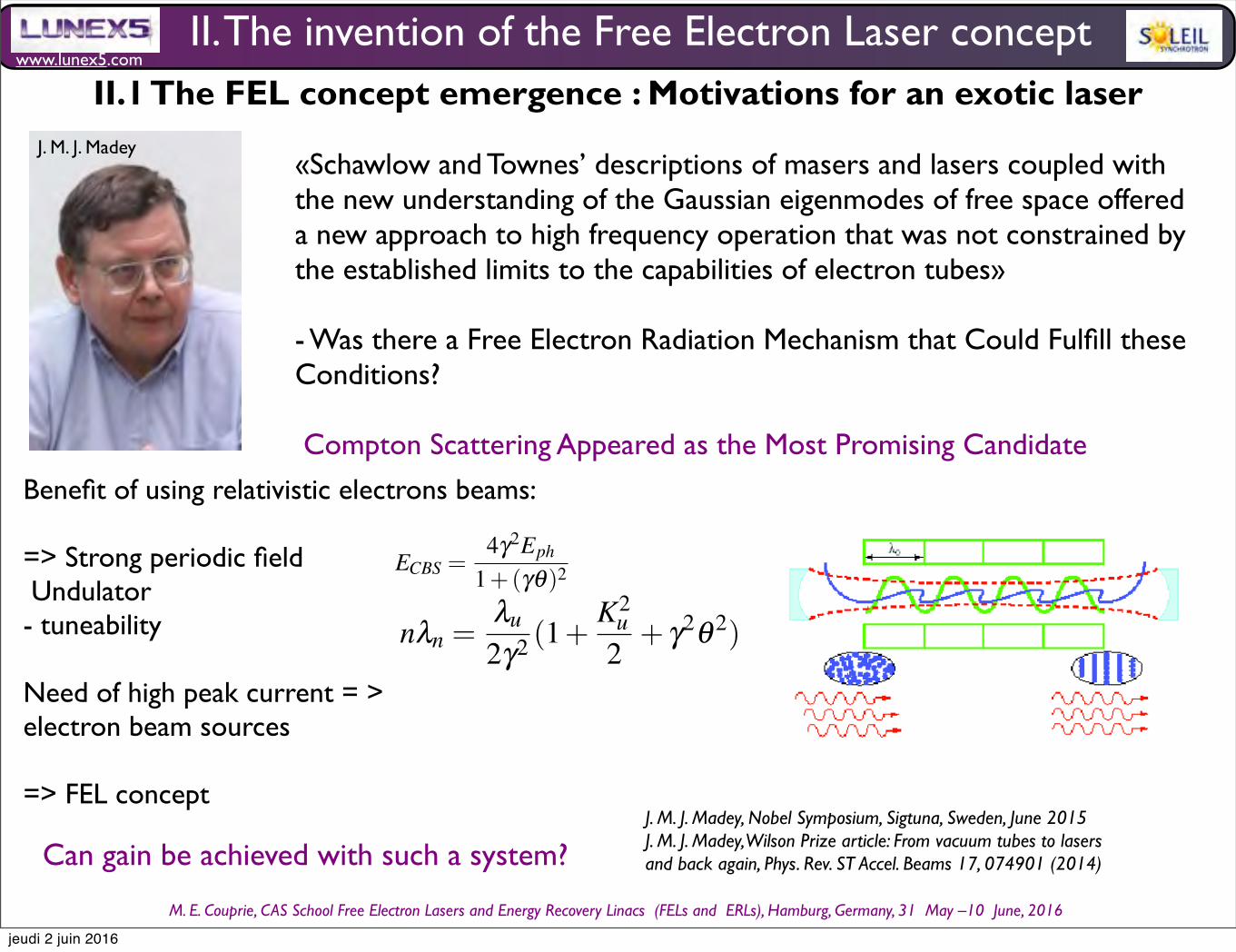
www.lunex5.com
M. E. Couprie, CAS School Free Electron!Lasers!and!Energy!Recovery!Linacs !(FELs and !ERLs), Hamburg, Germany, 31 !May –10 !June, 2016
J. M. J. Madey«Schawlow and Townes’ descriptions of masers and lasers coupled with the new understanding of the Gaussian eigenmodes of free space offered a new approach to high frequency operation that was not constrained by the established limits to the capabilities of electron tubes»
- Was there a Free Electron Radiation Mechanism that Could Fulfill these Conditions?
Compton Scattering Appeared as the Most Promising Candidate
J. M. J. Madey, Nobel Symposium, Sigtuna, Sweden, June 2015J. M. J. Madey, Wilson Prize article: From vacuum tubes to lasers and back again, Phys. Rev. ST Accel. Beams 17, 074901 (2014)
II. The invention of the Free Electron Laser concept II.1 The FEL concept emergence : Motivations for an exotic laser
Benefit of using relativistic electrons beams:
=> Strong periodic field Undulator- tuneability
Need of high peak current = > electron beam sources
=> FEL concept
Can gain be achieved with such a system?
4 Marie-Emmanuelle COUPRIE and Mathieu VALLEAU
Table 1 Velocity and trajectory of a single electron in the magnetic fields for the planar or ellip-
soidal undulator cases.
Planar undulator Elliptical Polarized Undulator
Field Field
−→Buz = Buz cos
2πλu
s−→z
−→Bux = 0−→Bus = 0
−→Buz =−Buzsin( 2π
λus)−→z
−→Bux = Buxsin( 2π
λus+ϕ)−→x
−→Bus = 0
Velocity Velocity
βz = 0
βx =Kuγ sin( 2π
λus)
βs =
1− 1
γ2− K2
uγ2
sin2( 2π
λus))
βz =−Kuxγ cos( 2π
λus+ϕ)
βx =Kuzγ cos( 2π
λus)
βs = 1− 1
γ2− K2
ux4γ2
− K2uz
4γ2+ K2
ux4γ2
cos( 4πλu
s)+ K2uz
4γ2cos( 4π
λus+2ϕ)
Trajectory Trajectory
z = 0
x = Kuλu2πγ cos( 2π
λuτ)
s = (1− 1
2γ2− K2
uγ2)cτ + cK2
u λu16πγ2
sin( 4πλuc τ)
z =−Kuxλu2πγ sin( 2π
λus+ϕ)
x = Kuzλu2πγ sin( 2π
λus)
s = (1− 1
2γ2− K2
uzγ2
− K2ux
γ2)cτ + cK2
uzλu16πγ2
sin( 4πλuc τ +2ϕ)+ cK2
uxλu16πγ2
sin( 4πλuc τ)
in Table 1, considering that1
γ =
1−β 2x −β 2
z −β 2s with the deflection parame-
ter Ku, Kux, Kuz given by Ku = eBuλu2πmoc (Kux =
eBuxλu2πmoc , Kuz =
eBuzλu2πmoc ). In the wiggler
regime, the angle of the velocityKuγ is large with respect to
1
γ . For Kux = Kuz = Ku
and ϕ = π2
, one has βs = 1− 1
γ2− K2
u2γ2
. A second integration gives the trajectory.
In the planar case, the electrons execute smooth sinusoıdal oscillations in the hori-
zontal plane, so that the radiation is kept in the same emitted cone. In addition, the
beam oscillates at twice the pulsation in the longitudinal direction. The interference
takes place for the wavelengths λn for which nλn = c(1−βs)t, with n an integer, βsthe longitudinal reduced velocity of the electrons. The fundamental resonant wave-
length is obtained for n = 1, i.e. for λ1 = λu(1−βs). Using the expression of βs, it
comes for the resonant wavelength and its harmonics in the planar case :
nλn =λu
2γ2(1+
K2u
2) (2)
nλn =λu
2γ2(1+
K2u
2+ γ2θ 2) (3)
The wavelength λn of the emitted radiation can be varied by a modification of the
undulator magnetic field (by changing the gap for permanent magnet insertion de-
vices or the power supply current for electromagnetic insertion devices). In the time
domain, the observer receives a train of Nu magnetic periods which can be consid-
ered as quasi-continuous emission of radiation with respect to the bending magnet
radiation. The radiation spectrum, square of the Fourier transform of this train, is
Synchrotron radiation and Free Electron Laser 29
4.4 The free electron laser invention and concept
4.4.1 A fertile basis for the FEL concept emergence
Following the laser discovery, much less interest was devoted to the electron tubes based systems. The produced
radiation is independent of phase. In addition, the Gaussian eigenmodes of free space provided an alternative to the
coupled slow wave structures of the prior electron devices. In the case of the vacuum tubes, the XXX pas introduits
encore XXXX
In the original paper from A. Schawlow and C. Townes [207], it was written that :”As one attempts to extend maser
operation towards very short wavelengths, a number of new aspects and problems arise, which require a quantitative
reorientation of theoretical discussions and considerable modification of the experimental techniques used. ” and
”These figures show that maser systems can be expected to operate successfully in the infrared, optical, and perhaps
in the ultraviolet regions, but that, unless some radically new approach is found, they cannot be pushed to wavelengths
much shorter than those in the ultraviolet region.”
J. M. J. Madey, from Stanford, Univ., thought that ”Schawlow and Townes descriptions of masers and lasers cou-
pled with the new understanding of the Gaussian eigenmodes of free space offered a new approach to high frequency
operation that was not constrained by the established limits to the capabilities of electron tubes [144] and he wondered
whether there was ”a Free Electron Radiation Mechanism that Could Fulfill these Conditions” and considered the
different possible radiation processes. He first examined, Compton Scattering which appeared as the most promis-
ing candidate. Indeed, Stimulated Compton Backscattering has been analysed by Dreicer in the cosmic blackbody
radiation. XXXX chercher la REFXXXXX.
The Compton Back Scattering (CBS) process between a laser pulse and a bunch of relativistic particles (electrons,
positrons, etc.) leads to the production of high-energy radiation coming from the head-on collision between the photons
and the particles. In order to reduce the divergence of the scattered radiation, it is better to use a relativistic electron
beam, which radiation cone is reduced to 1/γ . For relativistic particles (i.e. γ >> 1), he energy of the produced photons
ECBS is given by :
ECBS =4γ2Eph
1+(γθ)2(78)
with Eph the energy of the initial photon beam, θ the angle between the CBS photons and the electron beam
trajectory. The energy of the relativistic electrons can easily be changed, so the CBS radiation could be tuneable.
First analysis of the stimulated Compton Backcattering ware carried out [126]. J. M. J. Madey had the idea to make
the phenomenon more efficient by using the magnetic field of an undulator [123]. He considered that ”Relativistic
electrons can also not tell the difference between real and virtual incident photons, permitting the substitution of a
strong, periodic transverse magnetic field for the usual counter-propagating real photon beam”[144] . He was aware of
the theoretical [23] and experimental [24] work of Motz, where radiation from bunch beams has been observed. The
fields can be the one generated by an undulator.
4.4.2 The FEL quantum approach
According to the Weisacher-Williams approximation, the undulator field of period λu can be assumed to be a planar
wave of virtual photons. By Lorentz transformation, the wavelength λ of planar wave in the moving frame of the
electrons in the undulator, is given by :
λ =λu
γs(79)
Photon emission and absorption are forbidden by conservation of energy and momentum. For free electrons, one
can then consider a two photon process, such as Compton scattering, as shown in Fig. 22. The emission is then again
given by the Doppler effect, according to :
jeudi 2 juin 2016
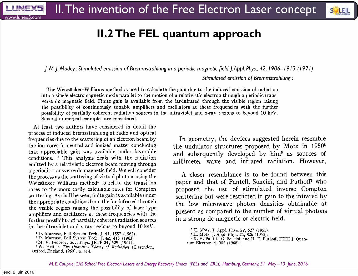
www.lunex5.com
M. E. Couprie, CAS School Free Electron!Lasers!and!Energy!Recovery!Linacs !(FELs and !ERLs), Hamburg, Germany, 31 !May –10 !June, 2016
JOURNAL OF APPLIED PHYSICS VOLUME 42, NUMBER 5 APRIL 1971
Stimulated Emission of Bremsstrahlung in a Periodic Magnetic Field JOHN M. J. MADEY
Physics Department, Stanford University, Stanford, California 94305 (Received 20 February 1970; in final form 21 August 1970)
The Weizsacker-Williams method is used to calculate the gain due to the induced emission of radiation into a single electromagnetic mode parallel to the motion of a relativistic electron through a periodic trans-verse dc magnetic field. Finite gain is available from the far-infrared through the visible region raising the possibility of continuously tunable amplifiers and oscillators at these frequencies with the further possibility of partially coherent radiation sources in the ultraviolet and x-ray regions to beyond 10 keY. Several numerical examples are considered.
At least two authors have considered in detail the process of induced bremsstrahlung at radio and optical frequencies due to the scattering of an electron beam by the ion cores in neutral and ionized matter concluding that appreciable gain was available under favorable conditions.1-3 This analysis deals with the radiation emitted by a relativistic electron beam moving through a periodic transverse dc magnetic field. We will consider the process as the scattering of virtual photons using the Weizsacker-Williams method' to relate the transition rates to the more easily calculable rates for Compton scattering. As shall be seen, finite gain is available under the appropriate conditions from the far-infrared through the visible region raising the possibility of laser-type amplifiers and oscillators at these frequencies with the further possibility of partially coherent radiation sources in the ultraviolet and x-ray regions to beyond 10 keV.
In geometry, the devices suggested herein resemble the undulator structures proposed by Motz in 19505
and subsequently developed by him6 as sources of millimeter wave and infrared radiation. However, Motz' proposal was entirely classical requiring a bunched beam harmonically related to the magnet period. These restrictions do not apply to the process of stimulated emission.
A closer resemblance is to be found between this paper and that of Pantell, Soncini, and PuthofF who proposed the use of stimulated inverse Compton scattering but were restricted in gain to the infrared by the low microwave photon densities obtainable at present as compared to the number of virtual photons in a strong dc magnetic or electric field.
I. TRANSITION RATES A vector potential
A(z) = Re[(Bo/q)eiqz]y
in the lab frame yields a magnetic field B= V xA= Re[( -i) Boeiqz]i.
In the rest frame of a relativistic electron moving in the direction Z the potential appears as a traveling wave A'= ReI (Bo/q) exp[iq'Y(z'+jet')]lyyieldingthefields:
where j=vz/e
and '1'= 1/ (1- j2)1/2.
In the limit these fields approach in detail those associated with a wave packet of real photons moving in the direction - z'. Assuming that the matrix element for scattering is a continuous and slowly changing function of the initial photon mass, in the limit that the photon energy in the electron rest frame is large in comparison with the photon mass excess, the mass zero expressions (for Compton scattering) can be used to obtain the desired transition rates.
The virtual photon mass excess can be computed in the laboratory frame since it is a scalar invariant:
m v2c4=ELp2e2= (hw)L (qh)2e2. (2)
Since w = 0 in the lab frame:
i mve2 i =qhe. (3)
The Weizsacker-Williams method would then be expected to be applicable in the limit:
hv= 'Yhqe» i mve2i = qhe, (4)
which reduces to '1'»1. In this limit the same scattering transition rates would be obtained in passage of the electron beam through a pulse of radiation with lab frame wavelength AO= (1+j)Aq and peak magnetic field E = Eo/ (1 + (3) as with an alternating dc field of period Aq and peak field Eo. This approximation, with j set equal to one, will be used throughout the remainder of this analysis.
With a magnet period of 1 mm and a 20-GeV electron beam the wavelength of the equivalent radiation pulse in the electron rest frame is
(5)
Since these are the highest beam energy and shortest magnet period likely to be used, scattering in the electron rest frame can be regarded to be governed by the Thompson formula:
(6) B'= ReI (-ihBo exp[iq'Y (z'+jet') Jli,
8' = Re I ( - ihjBo exp[ iq'Y (z' + (jet') ] I y, where '0 is the classical electron radius. Furthermore, the
(1) backscattered photon can be regarded as having the 1906
[This article is copyrighted as indicated in the article. Reuse of AIP content is subject to the terms at: http://scitation.aip.org/termsconditions. Downloaded to ] IP:195.221.0.35 On: Fri, 31 Jul 2015 14:44:35
J. M. J. Madey.: Stimulated emission of Bremmstrahlung in a periodic magnetic field; J. Appl. Phys., 42, 1906--1913 (1971)
Stimulated emission of Bremmstrahlung :
JOURNAL OF APPLIED PHYSICS VOLUME 42, NUMBER 5 APRIL 1971
Stimulated Emission of Bremsstrahlung in a Periodic Magnetic Field JOHN M. J. MADEY
Physics Department, Stanford University, Stanford, California 94305 (Received 20 February 1970; in final form 21 August 1970)
The Weizsacker-Williams method is used to calculate the gain due to the induced emission of radiation into a single electromagnetic mode parallel to the motion of a relativistic electron through a periodic trans-verse dc magnetic field. Finite gain is available from the far-infrared through the visible region raising the possibility of continuously tunable amplifiers and oscillators at these frequencies with the further possibility of partially coherent radiation sources in the ultraviolet and x-ray regions to beyond 10 keY. Several numerical examples are considered.
At least two authors have considered in detail the process of induced bremsstrahlung at radio and optical frequencies due to the scattering of an electron beam by the ion cores in neutral and ionized matter concluding that appreciable gain was available under favorable conditions.1-3 This analysis deals with the radiation emitted by a relativistic electron beam moving through a periodic transverse dc magnetic field. We will consider the process as the scattering of virtual photons using the Weizsacker-Williams method' to relate the transition rates to the more easily calculable rates for Compton scattering. As shall be seen, finite gain is available under the appropriate conditions from the far-infrared through the visible region raising the possibility of laser-type amplifiers and oscillators at these frequencies with the further possibility of partially coherent radiation sources in the ultraviolet and x-ray regions to beyond 10 keV.
In geometry, the devices suggested herein resemble the undulator structures proposed by Motz in 19505
and subsequently developed by him6 as sources of millimeter wave and infrared radiation. However, Motz' proposal was entirely classical requiring a bunched beam harmonically related to the magnet period. These restrictions do not apply to the process of stimulated emission.
A closer resemblance is to be found between this paper and that of Pantell, Soncini, and PuthofF who proposed the use of stimulated inverse Compton scattering but were restricted in gain to the infrared by the low microwave photon densities obtainable at present as compared to the number of virtual photons in a strong dc magnetic or electric field.
I. TRANSITION RATES A vector potential
A(z) = Re[(Bo/q)eiqz]y
in the lab frame yields a magnetic field B= V xA= Re[( -i) Boeiqz]i.
In the rest frame of a relativistic electron moving in the direction Z the potential appears as a traveling wave A'= ReI (Bo/q) exp[iq'Y(z'+jet')]lyyieldingthefields:
where j=vz/e
and '1'= 1/ (1- j2)1/2.
In the limit these fields approach in detail those associated with a wave packet of real photons moving in the direction - z'. Assuming that the matrix element for scattering is a continuous and slowly changing function of the initial photon mass, in the limit that the photon energy in the electron rest frame is large in comparison with the photon mass excess, the mass zero expressions (for Compton scattering) can be used to obtain the desired transition rates.
The virtual photon mass excess can be computed in the laboratory frame since it is a scalar invariant:
m v2c4=ELp2e2= (hw)L (qh)2e2. (2)
Since w = 0 in the lab frame:
i mve2 i =qhe. (3)
The Weizsacker-Williams method would then be expected to be applicable in the limit:
hv= 'Yhqe» i mve2i = qhe, (4)
which reduces to '1'»1. In this limit the same scattering transition rates would be obtained in passage of the electron beam through a pulse of radiation with lab frame wavelength AO= (1+j)Aq and peak magnetic field E = Eo/ (1 + (3) as with an alternating dc field of period Aq and peak field Eo. This approximation, with j set equal to one, will be used throughout the remainder of this analysis.
With a magnet period of 1 mm and a 20-GeV electron beam the wavelength of the equivalent radiation pulse in the electron rest frame is
(5)
Since these are the highest beam energy and shortest magnet period likely to be used, scattering in the electron rest frame can be regarded to be governed by the Thompson formula:
(6) B'= ReI (-ihBo exp[iq'Y (z'+jet') Jli,
8' = Re I ( - ihjBo exp[ iq'Y (z' + (jet') ] I y, where '0 is the classical electron radius. Furthermore, the
(1) backscattered photon can be regarded as having the 1906
[This article is copyrighted as indicated in the article. Reuse of AIP content is subject to the terms at: http://scitation.aip.org/termsconditions. Downloaded to ] IP:195.221.0.35 On: Fri, 31 Jul 2015 14:44:35
S TIM U L ATE D EM ISS ION 0 F MAG NET I C B REM SST R A H L U N G 1913
We have omitted from this analysis the consequences of the absorption occurring in the nuclei lying just inside the surface of the absorbers. The effect of this process is to reduce the reflection coefficient within the Mossbauer line from R= 1 to for an angle of incidence of 0.47° while leaving the reflection coefficient outside the line essentially unchanged. While this would substantially reduce the number of reflected photons, the estimated flux still appears to be large enough to be of experimental interest provided that the angular spread in the reflected beam due to imperfections in the mirrors could be kept at a minimum.
Note Added in Proof. The classical result for the radiated energy calculated using the synchrotron radia-tion formula [Eq. (38)] is also proportional to the square of the magnetic field strength provided that an account is taken of the shift in wavelength of the emitted radiation. If WlO in Eq. (38) is understood to be the frequency of the backscattered photons at a beam energy of 'Yomc2 in the weak field limit and if the actual beam energy is selected to compensate for the wave-length shift due to the magnetic field [Eqs. (43) and (44)], then in the region of validity of Eq. (38) the radiated energy per magnet semi-period is given by
d2E ('Yo4e2)(XqCB)2.
dwdfJ c 4mc2
This result remains valid for arbitrarily large magnetic fields. Evidently the increase in the scattering transition rate with 'Y compensates for the effects of multiple scattering above the Landau limit.
With respect to the available gain this result indicates that a significant improvement could be obtained through the use of very large magnetic fields. Extrapola-tion of the weak field results in Table I to 100 kG
that useful gain would be available to beyond 100 A.
ACKNOWLEDGMENTS
I wish to thank Professor W. M. Fairbank for his encouragement of this analysis and to acknowledge my discussions with Professor H. A. Schwettman who has had a concurrent and independent interest in the
of a free-electron laser. In this application partlcularly, he recognized the potentially unique properties for the construction of such a device of the electron beam in the superconducting linear accelerator being built at Stanford. It is also my pleasure to acknowledge the contributions of R. H. Pantell, S. A. Johnson, M. Levinson, W. A. Little, and L. V. Knight of Stanford University, and of A. Yariv of the California Institute of Technology.
'D. Marcuse, Bell System Tech. J. 41,1557 (1962). 2 D. Marcuse, Bell System Tech. J. 42, 415 (963). 3 M. V. Fedorov, Sov. Phys. JETP 24, 529 (1967). 4 W. Heitler, The Quantum Theory of Radiation (Clarendon
Oxford, England, 1960), p. 414. ' 5 H. Motz, J. App!. Phys. 22, 527 (1951). 'H. Motz, J. App!. Phys. 24, 826 (1953). 7 R. H. Pantell, G. Soncini, and H. E. Puthoff, IEEE]. Quan-
tum Electron. 4, 905 (1968). 8 R. P. Feynman, Quantum Electrodynamics (Benjamin New
York,1962),p.94. ' 9 J. D. Jackson, Classical Electrodynamics (Wiley, New York,
1962), p. 481. 10 L. Landau and I. Pomeranchuk, Dokl. Akad. Nauk. SSSR
92, 535 (1953). 11 For an account of the experimental features of this
phenomenon see S. Bernstein and E. C. Campbell Phys. Rev. 132,1625 (1963). '
12 R. S. Preston, S. S. Hanna, and J. Heberle Phys. Rev. 128 2207 (1963). "
13 G. K. Wertheim, Mossbauer Effect (Academic, New York, 1964), p. 12.
14 A. H. Compton and S. K. Allison, X-Rays in Theory and Experiment (Van Nostrand, Princeton, N.]., 1935), p. 279.
[This article is copyrighted as indicated in the article. Reuse of AIP content is subject to the terms at: http://scitation.aip.org/termsconditions. Downloaded to ] IP:195.221.0.35 On: Fri, 31 Jul 2015 14:44:35
II. The invention of the Free Electron Laser concept
II.2 The FEL quantum approach
jeudi 2 juin 2016

www.lunex5.com
M. E. Couprie, CAS School Free Electron!Lasers!and!Energy!Recovery!Linacs !(FELs and !ERLs), Hamburg, Germany, 31 !May –10 !June, 2016
J. M. J. Madey.: Stimulated emission of Bremmstrahlung in a periodic magnetic field; J. Appl. Phys., 42, 1906--1913 (1971)J. M. J. Madey, H. A. Schwettman, W. M. Fairbank, IEE Trans. Nucl. Sci. NS-20 (1973) 980
Virtual photons : associated to the magnetic field Weisäcker-Williams approximation:Undulator : similar to the field of a planar wave of wavelength ; λu
Fields in the moving frame of the electrons in the undulatorUndulator wavelength in the electron ‘s frame : λu/Υs = λ’the electrons see the magnetic field as a planar wave
Photon emission / absorption forbidden due to the conservation of energy and momentum=> for free electrons : two photon process: Compton scattering
emission : Doppler effect λ = λ’ / (1 + βs) Υs= λu/ 2 Υs2 = λu/ 2 Υ2
Stimulated Compton scattering gain : transition rate(diffusion) - transition rate (absorption)
E. Schrödinger, Annalen der Physik IV, Folge 82, 257 (1927)P. L. Kapitza, P. A. M.ab Dirac, Proc. Cambridge Phys. Soc. 29, 297 (1933)H. Dreicer, Phys. Fluids 7 (1964) 735R. H. Pantell, G. Soncini, H. E. Puthoff, Stimulated Photon-Electron Scattering, IEEE Jounral of Quantum Electronics 4 (11) 906-908 (1968)
does not depend on Planck constant.
Synchrotron radiation and Free Electron Laser 29
4.4 The free electron laser invention and concept
4.4.1 A fertile basis for the FEL concept emergence
Following the laser discovery, much less interest was devoted to the electron tubes based systems. The produced
radiation is independent of phase. In addition, the Gaussian eigenmodes of free space provided an alternative to the
coupled slow wave structures of the prior electron devices. In the case of the vacuum tubes, the XXX pas introduits
encore XXXX
In the original paper from A. Schawlow and C. Townes [207], it was written that :”As one attempts to extend maser
operation towards very short wavelengths, a number of new aspects and problems arise, which require a quantitative
reorientation of theoretical discussions and considerable modification of the experimental techniques used. ” and
”These figures show that maser systems can be expected to operate successfully in the infrared, optical, and perhaps
in the ultraviolet regions, but that, unless some radically new approach is found, they cannot be pushed to wavelengths
much shorter than those in the ultraviolet region.”
J. M. J. Madey, from Stanford, Univ., thought that ”Schawlow and Townes descriptions of masers and lasers cou-
pled with the new understanding of the Gaussian eigenmodes of free space offered a new approach to high frequency
operation that was not constrained by the established limits to the capabilities of electron tubes [144] and he wondered
whether there was ”a Free Electron Radiation Mechanism that Could Fulfill these Conditions” and considered the
different possible radiation processes. He first examined, Compton Scattering which appeared as the most promis-
ing candidate. Indeed, Stimulated Compton Backscattering has been analysed by Dreicer in the cosmic blackbody
radiation. XXXX chercher la REFXXXXX.
The Compton Back Scattering (CBS) process between a laser pulse and a bunch of relativistic particles (electrons,
positrons, etc.) leads to the production of high-energy radiation coming from the head-on collision between the photons
and the particles. In order to reduce the divergence of the scattered radiation, it is better to use a relativistic electron
beam, which radiation cone is reduced to 1/γ . For relativistic particles (i.e. γ >> 1), he energy of the produced photons
ECBS is given by :
ECBS =4γ2Eph
1+(γθ)2(78)
with Eph the energy of the initial photon beam, θ the angle between the CBS photons and the electron beam
trajectory. The energy of the relativistic electrons can easily be changed, so the CBS radiation could be tuneable.
First analysis of the stimulated Compton Backcattering ware carried out [126]. J. M. J. Madey had the idea to make
the phenomenon more efficient by using the magnetic field of an undulator [123]. He considered that ”Relativistic
electrons can also not tell the difference between real and virtual incident photons, permitting the substitution of a
strong, periodic transverse magnetic field for the usual counter-propagating real photon beam”[144] . He was aware of
the theoretical [23] and experimental [24] work of Motz, where radiation from bunch beams has been observed. The
fields can be the one generated by an undulator.
4.4.2 The FEL quantum approach
According to the Weisacher-Williams approximation, the undulator field of period λu can be assumed to be a planar
wave of virtual photons. By Lorentz transformation, the wavelength λ of planar wave in the moving frame of the
electrons in the undulator, is given by :
λ =λu
γs(79)
Photon emission and absorption are forbidden by conservation of energy and momentum. For free electrons, one
can then consider a two photon process, such as Compton scattering, as shown in Fig. 22. The emission is then again
given by the Doppler effect, according to :
II. The invention of the Free Electron Laser concept
II.2 The FEL quantum approach
jeudi 2 juin 2016
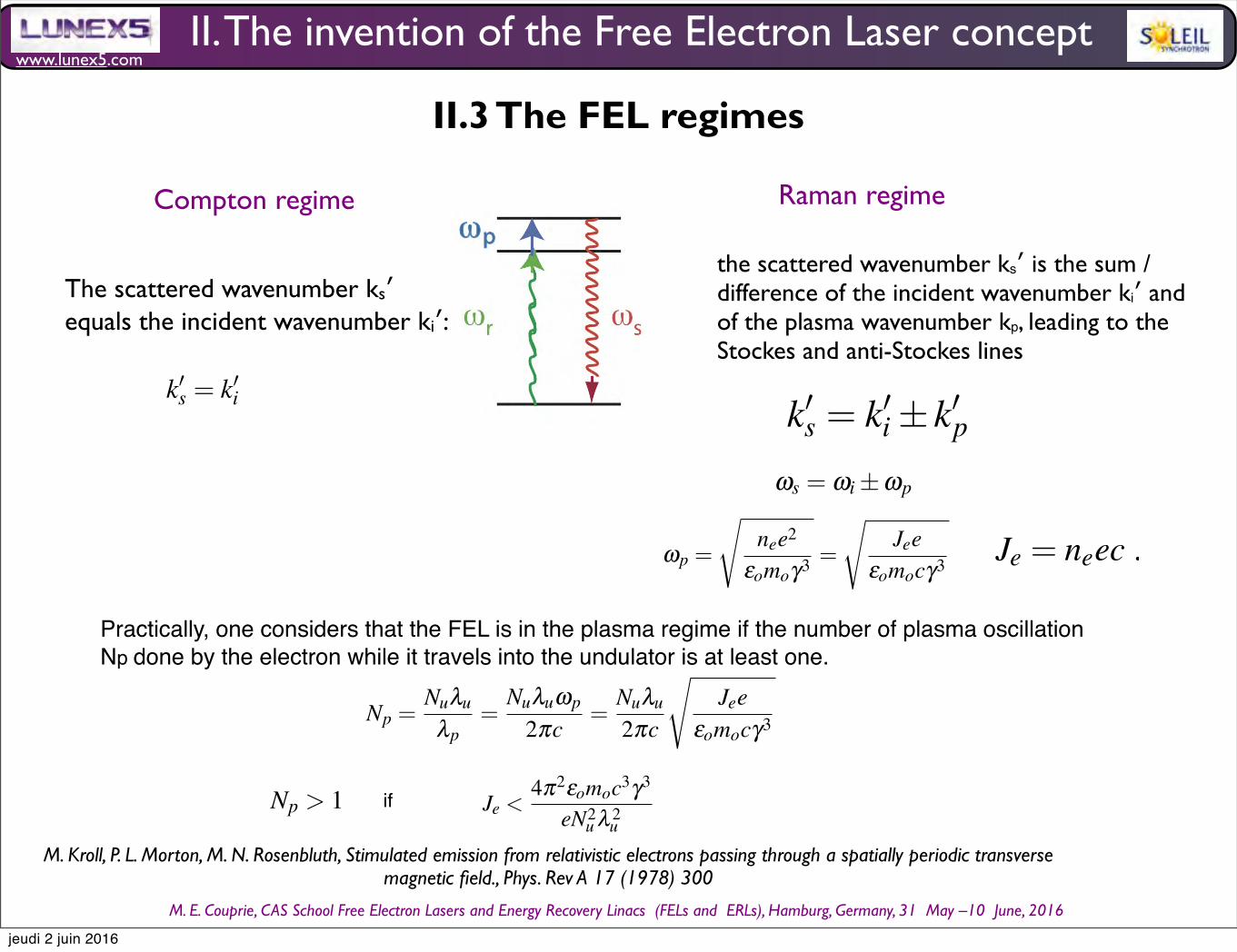
www.lunex5.com
M. E. Couprie, CAS School Free Electron!Lasers!and!Energy!Recovery!Linacs !(FELs and !ERLs), Hamburg, Germany, 31 !May –10 !June, 2016
30 Marie-Emmanuelle COUPRIE and Mathieu VALLEAU
Fig. 22 Feymann diagrams of Compton Scattering
λ =λ
(1+βs)γs=
λu
2γs
2
≈ λu
2γ
2
(80)
For Stimulated Compton scattering, the diffusion transition rate τd should be larger than the absorption one τa. One
can define the gain g as :
g = τd − τa (81)
The original calculation, performed in [123], is not reproduced here. One prefers nowadays to use a classical
approach, which is simpler and which can explain the FEL in the majority of cases.
4.4.3 The FEL regimes
The FEL can thus be described as a Stimulated Compton Scattering, as shown in Fig. 23. If the electronic density is
large enough, a plasma wave can develop.
Fig. 23 Stimulated Compton Scattering scheme in the electron frame, with ωp the plasma pulsation, ωr the resonant pulsation, and ωs the
scattered pulsation
The Compton FEL regime
In the Compton regime, the scattered wavenumber ks equals the incident wavenumber ki:
ks = ki (82)
the scattered wavenumber ks′ is the sum / difference of the incident wavenumber ki′ and of the plasma wavenumber kp, leading to the Stockes and anti-Stockes lines
30 Marie-Emmanuelle COUPRIE and Mathieu VALLEAU
Fig. 22 Feymann diagrams of Compton Scattering
λ =λ
(1+βs)γs=
λu
2γs
2
≈ λu
2γ
2
(80)
For Stimulated Compton scattering, the diffusion transition rate τd should be larger than the absorption one τa. One
can define the gain g as :
g = τd − τa (81)
The original calculation, performed in [123], is not reproduced here. One prefers nowadays to use a classical
approach, which is simpler and which can explain the FEL in the majority of cases.
4.4.3 The FEL regimes
The FEL can thus be described as a Stimulated Compton Scattering, as shown in Fig. 23. If the electronic density is
large enough, a plasma wave can develop.
Fig. 23 Stimulated Compton Scattering scheme in the electron frame, with ωp the plasma pulsation, ωr the resonant pulsation, and ωs the
scattered pulsation
The Compton FEL regime
In the Compton regime, the scattered wavenumber ks equals the incident wavenumber ki:
ks = ki (82)
Compton regime Raman regime
Synchrotron radiation and Free Electron Laser 31
The Raman FEL regime
In the Raman regime, the scattered wavenumber ks is the sum / difference of the incident wavenumber ki and of the
plasma wavenumber kp, leading to the Stockes and anti-Stockes lines :
ks = ki ± kp (83)
In the laboratory frame, it comes:
ωs = ωi ±ωp (84)
where the plasma pulsation ωp is given by :
ωp =
nee2
εomoγ3=
Jee
εomocγ3(85)
with ne the electronic density and Je the current density Je = neec .
Practically, one considers that the FEL is in the plasma regime if the number of plasma oscillation Np done by the
electron while it travels into the undulator is at least one.
Np =Nuλu
λp=
Nuλuωp
2πc=
Nuλu
2πc
Jee
εomocγ3
Thus No > 1 if
Je <4π2εomoc3γ3
eN2u λ 2
u(86)
manque AN CLIO XXXXXXXXXXXXXXXXXXXXXXXXXXXXXXXXXXXXX
4.4.4 The FEL classical approach
The FEL spontaneous emission
Fig. 24 Radiation train emitted from the undulator of period Nu periods λu. The electron moves along the undulator length with a speed v(vt = Nuλu) and emits a wave packet whose length is (c−v)t = Nuλ . The wavepacket contains the same number of periods as the undulator,
i. e. Nu.
The FEL spontaneous emission is given by the synchrotron radiation emitted by the Nu periods of the undulator, ,
as shown in Fig. 24. Since the wave packet emitted by each electron contains only a finite number Nu of oscillations,
The scattered wavenumber ks′ equals the incident wavenumber ki′:
Practically, one considers that the FEL is in the plasma regime if the number of plasma oscillation Np done by the electron while it travels into the undulator is at least one.
Synchrotron radiation and Free Electron Laser 31
The Raman FEL regime
In the Raman regime, the scattered wavenumber ks is the sum / difference of the incident wavenumber ki and of the
plasma wavenumber kp, leading to the Stockes and anti-Stockes lines :
ks = ki ± kp (83)
In the laboratory frame, it comes:
ωs = ωi ±ωp (84)
where the plasma pulsation ωp is given by :
ωp =
nee2
εomoγ3=
Jee
εomocγ3(85)
with ne the electronic density and Je the current density Je = neec .
Practically, one considers that the FEL is in the plasma regime if the number of plasma oscillation Np done by the
electron while it travels into the undulator is at least one.
Np =Nuλu
λp=
Nuλuωp
2πc=
Nuλu
2πc
Jee
εomocγ3
Thus Np > 1 if
Je <4π2εomoc3γ3
eN2u λ 2
u(86)
manque AN CLIO XXXXXXXXXXXXXXXXXXXXXXXXXXXXXXXXXXXXX
4.4.4 The FEL classical approach
The FEL spontaneous emission
Fig. 24 Radiation train emitted from the undulator of period Nu periods λu. The electron moves along the undulator length with a speed v(vt = Nuλu) and emits a wave packet whose length is (c−v)t = Nuλ . The wavepacket contains the same number of periods as the undulator,
i. e. Nu.
The FEL spontaneous emission is given by the synchrotron radiation emitted by the Nu periods of the undulator, ,
as shown in Fig. 24. Since the wave packet emitted by each electron contains only a finite number Nu of oscillations,
if
Synchrotron radiation and Free Electron Laser 31
The Raman FEL regime
In the Raman regime, the scattered wavenumber ks is the sum / difference of the incident wavenumber ki and of the
plasma wavenumber kp, leading to the Stockes and anti-Stockes lines :
ks = ki ± kp (83)
In the laboratory frame, it comes:
ωs = ωi ±ωp (84)
where the plasma pulsation ωp is given by :
ωp =
nee2
εomoγ3=
Jee
εomocγ3(85)
with ne the electronic density and Je the current density Je = neec .
Practically, one considers that the FEL is in the plasma regime if the number of plasma oscillation Np done by the
electron while it travels into the undulator is at least one.
Np =Nuλu
λp=
Nuλuωp
2πc=
Nuλu
2πc
Jee
εomocγ3
Thus Np > 1 if
Je <4π2εomoc3γ3
eN2u λ 2
u(86)
manque AN CLIO XXXXXXXXXXXXXXXXXXXXXXXXXXXXXXXXXXXXX
4.4.4 The FEL classical approach
The FEL spontaneous emission
Fig. 24 Radiation train emitted from the undulator of period Nu periods λu. The electron moves along the undulator length with a speed v(vt = Nuλu) and emits a wave packet whose length is (c−v)t = Nuλ . The wavepacket contains the same number of periods as the undulator,
i. e. Nu.
The FEL spontaneous emission is given by the synchrotron radiation emitted by the Nu periods of the undulator, ,
as shown in Fig. 24. Since the wave packet emitted by each electron contains only a finite number Nu of oscillations,
II. The invention of the Free Electron Laser concept
II.3 The FEL regimes
M. Kroll, P. L. Morton, M. N. Rosenbluth, Stimulated emission from relativistic electrons passing through a spatially periodic transverse magnetic field., Phys. Rev A 17 (1978) 300
jeudi 2 juin 2016

www.lunex5.com
M. E. Couprie, CAS School Free Electron!Lasers!and!Energy!Recovery!Linacs !(FELs and !ERLs), Hamburg, Germany, 31 !May –10 !June, 2016
II. The invention of the Free Electron Laser concept
II.3 The FEL classical approach
electron motion : collisionless relativistic Boltzmann equation, with P the canonical momentum, x the position
Maxwell equations
transverse current Jt
VurtiME 37, NUM»r. .R 1&4 P H Y S I (.A I R F. V I K O' L K T T K R S 1 Nov EMs FR 1976
mon, New York, 1970).I,. M~n~hagen, Ark. Fys. 25, 203 (1963).5B.%. Farmery, A. Marwick, and M. W. Thompson,
Ato~nie Collision Phenomena in SoEids (North-Holland,Amsterdam, 1970).P. Sigmund, Phys. Rev. 184, 383 (1969).VE. S. Mashkova and V. A. Molchanov, Radiat. Eff.
23, 215 (1974).R. Behrisch et al. , Atomic. Collisions in Solids
(Plenum, New York, 1975), p. 315,'The rank & characterizes isotropic (k'=0), oriented
(k = 1), aligned (4 = 2) excitation. See H. J.Andra,Phys. Scr. 9, 257 (1974).' Andra, Ref. 9.D. G. Ellis, J. Opt. Soc. Am. 63, 1232 (1973).' C. Rau and R. Sizmann, in Atomic Collision. s in SoE-ids, edited by S. Datz, B, R. Appleton, and C. D. Mo-ack (Plenum, New York, 1975), p. 295.
Classical Theory of a Free-Electron Laser*
F. A. Hopf, f P. Meystre, and M. O. ScullyDePa'vftpzeplt of PAgs'Ecs and. OPtical Scxeplces CentF. "v, UniveJ'sit(~ of A'YszoNa, TRcson, A'nzo'Na 8572l
W. H. LouisellDepartnvent of I'hysies, V»iversity of Soufhen~ CaEifonlia, I.os Angeles, Califon~ia 90007
(Received 13 August 1976)%e present a completely classical analysis of the small-signal regime of a free-elec-
tron laser. It is explicitly shown that the amplification is due to stimulated scatteringproduced by a bunching of the electron distribution.
Stimulated emission of bremsstrahlung in atransverse periodic magnetic field' has been re-cently observed by Elias et a/. ' In this experi-ment, a relativistic electron beam (E = @me'= 24-1VIeV) was passed through a tube centered withina supereonducting double helix supplying a period-ic static field. Amplification was achieved forthe stimulated radiation in the direction of theelectron beam. The stimulated emission of radia-tion in a transverse magnetic field ha, s been ana-lyzed by Dreicer, ' Pantell, Soncini, and Puthoff, ~Madey and co-workers, ' ' and Sukhatme andWolff. ' All of these theories are quantum me-chanical in nature. They give the impression thatthey have to be so, since it is argued that it isthe electron recoil Ajl =8/X, where X ls theCompton wavelength, which is the source of a. fi-nite gain. Furthermore, quantum approaches,while agreeing on the structure of the gain for-mula, differ from one another by orders of mag-nitude in numerical coefficients.In this Letter, we show that this problem is
completely classical, and that the gain is pro-duced by a bunching of the electron density in thepresence of a field.In order to avoid difficulties in numerical coef-
ficients, we choose to work directly in the labora-tory frame, and stay in a space-time descriptionof the problem. We use the Weizsacker-Williamsapproximation, ' which allows us in the extremerelativistic limit to replace the static magnetic
field of period ~, by a pure electromagnetic fieldof wavelength
~, =(1+P)Z,= 2~„
We describe the motion of the electron distribu-tion f(x, P, t) by the collisionless relativisticBoltzma, nn equation'
«f af sf af—=—+x] +P] =0, (3)dt Bt ' Bx, ' BP&
where P is the canonical momentum, x the posi-tion, and a dot expresses the total derivative withrespect to time. The total number of electronsN(t) is
N(t) = J«3xf«'Pf(x, P, t). (4)
The Boltzmann equation is coupled via the trans-verse current J~ to the Maxwell equations
+V A —e 8 A/st = —poJr,where A is the vector potential, and
Jr(x, t) = ef«'P vr f(x, P-, t). (6
(5)
Here, e is the electron charge, and v~ the trans-verse component of the electron velocity.In order to simplify the set of Eqs. (3) and (5),
we now consider a model in which the electro-magnetic field is transverse and depends on ~ and
Weizsäcker-Williams approximation : for extreme relativistic limit : the static undulator field of period λu replaced by a pure electromagnetic field of wavelength
λi = (1 + βs) λu ≈ 2λu
Case of a pure transverse electromagnetic field=> Usual classical scattering problem, complicated by the relativistic nature of the particles
Development of the reduced distribution in perturbations small-signal theory : incident and scattered modes are kept
New hyp : - slowly varying amplitude and phase
- depletion of the incident field neglected
=> electron density fluctuations (bunching) responsible for the scattering
reduced distribution in Maxwell eq.=>small signal gain
Vuat)MF. h7, Nt MovR 1Y PHYSICAL REVIEW' LETTERS 1 NuvEMaER 1~&76
and (d, =ch, ((o, =ch,) is the frequency of the incident (scattered) field. We also make the slowly vary-ing amplitude and phase approximation, and neglect the depletion of the incident field, since it is as-sumed to be very intense.Taking the electrons to be injected at a constant rate inside the cavity, we find
h'"=n, F(t),),where n, is the electron density, and F(t),) is the initial electron momentum distribution. The first-or-der correction to h is
h")(z,p„f) = ' ' ' expl-ia(d(t —z/U. )j+c.c.,diaz
(22
(23)
(24)
(25)
We observe that h(') describes the electron density fluctuations (bunching) which are responsible for thescattering.Introducing h into the Maxwell equation, and integrating over the length I of the cavity, we obtain the
small-signal gain n, defined by
—4)('ro'Fn, mKL d 1 sin&L/2
I; (Ig is the incident (scattered) flux
I((s) = 2c ~oh((s) I +((s)l
and )'o is the classical radius of the electron. The term sin(pL/2)/(pL/2) appearing in the gain formu-la is a, consequence of the finite length of the cavity. As pointed out by Sukhatme and Wolff, this finite-ness implies that the momentum conservation law is relaxed, so that electrons with a momentum with-in this cavity bandwidth can scatter light from &; to w, . Et is therefore natural to consider two cases,namely the large-cavity and small-cavity limits. In the large-cavity limit, the electron momentumdistribution is very broad compared to the cavity bandwidth, which can therefore be approximated by a6 function. The small-cavity limit corresponds to the opposite case, where the initial electron momen-tum distribution function F(P,) can be taken as a () function,
F(t.) =IP.-Po) (29)
This corresponds to the limit of a homogeneously broadened medium. We shall consider only this lat-ter case, since it corresponds to the condition of the Stanford experiment.With (29), the gain formula, becomes
n = ' '„', , ' I; —(sing/)))'+ ' (sinn/))'yo'[I +(Uo/c)'j (30mh, h; o'Uo' d'g cL h, -h;
(sin))/r)) )(;/2)(L && 1. (32)
Therefore, except for g = 0, we can neglect this
where vo H~/OPO an
n = p.L/2.The second term inside the bracket is of the or-der of
! term and obtain, with Eq. (18) and noting that n,»k& for y» 1,
n A'" d
The point g =0 corresponds to the condition forexact conservation of momentum, and, at this
η=0 : no net gainη<0 : v>vo, gain, eq. of Stockes line in Raman scatteringη>0 : v>vo, absorption, eq. of anti- Stockes line
F. A. Hopf, P. Meystre, M. O. Scully, W. H. Louisell, Classical theory of a Free Electron Laser, Opt. Comm. 18 (4) (1976) 413-416F. A. Hopf et al., Classical theory of a free-electron laser, Phys. Rev. Lett 57 (18) 1215-1218 (1976);
The Gain is produced by a bunching of the electronic density in presence of a field
Relevant radiation : back scattered, with a Doppler shift of the wavelength
jeudi 2 juin 2016
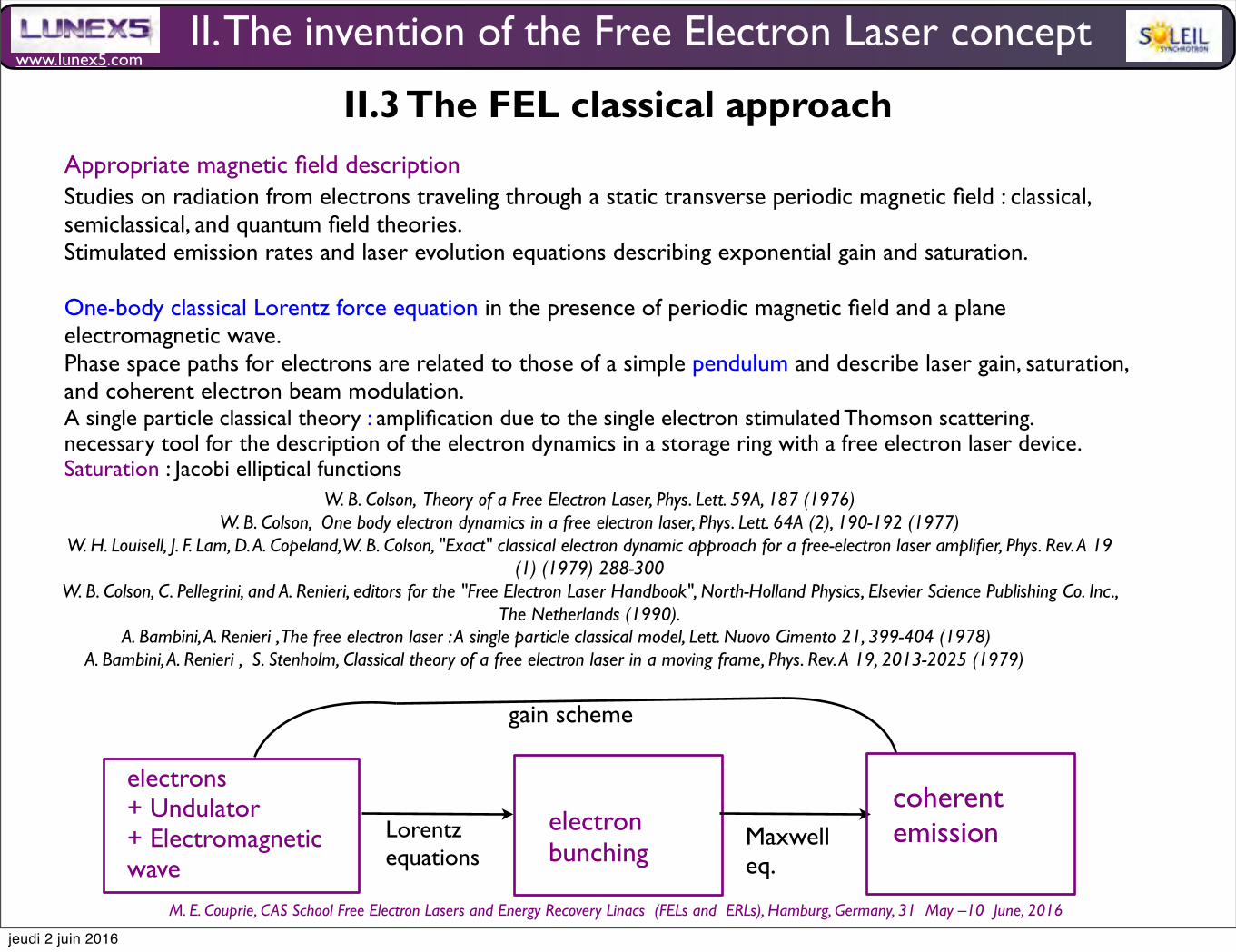
www.lunex5.com
M. E. Couprie, CAS School Free Electron!Lasers!and!Energy!Recovery!Linacs !(FELs and !ERLs), Hamburg, Germany, 31 !May –10 !June, 2016
II. The invention of the Free Electron Laser concept
II.3 The FEL classical approach
W. B. Colson, Theory of a Free Electron Laser, Phys. Lett. 59A, 187 (1976)
W. B. Colson, One body electron dynamics in a free electron laser, Phys. Lett. 64A (2), 190-192 (1977)W. H. Louisell, J. F. Lam, D. A. Copeland, W. B. Colson, "Exact" classical electron dynamic approach for a free-electron laser amplifier, Phys. Rev. A 19
(1) (1979) 288-300W. B. Colson, C. Pellegrini, and A. Renieri, editors for the "Free Electron Laser Handbook", North-Holland Physics, Elsevier Science Publishing Co. Inc.,
The Netherlands (1990).
Studies on radiation from electrons traveling through a static transverse periodic magnetic field : classical, semiclassical, and quantum field theories. Stimulated emission rates and laser evolution equations describing exponential gain and saturation.
One-body classical Lorentz force equation in the presence of periodic magnetic field and a plane electromagnetic wave. Phase space paths for electrons are related to those of a simple pendulum and describe laser gain, saturation, and coherent electron beam modulation.A single particle classical theory : amplification due to the single electron stimulated Thomson scattering. necessary tool for the description of the electron dynamics in a storage ring with a free electron laser device. Saturation : Jacobi elliptical functions
Appropriate magnetic field description
A. Bambini, A. Renieri , The free electron laser : A single particle classical model, Lett. Nuovo Cimento 21, 399-404 (1978)A. Bambini, A. Renieri , S. Stenholm, Classical theory of a free electron laser in a moving frame, Phys. Rev. A 19, 2013-2025 (1979)
electrons+ Undulator+ Electromagnetic wave
electron bunching
Lorentz equations
Maxwell eq.
coherent emission
gain scheme
jeudi 2 juin 2016
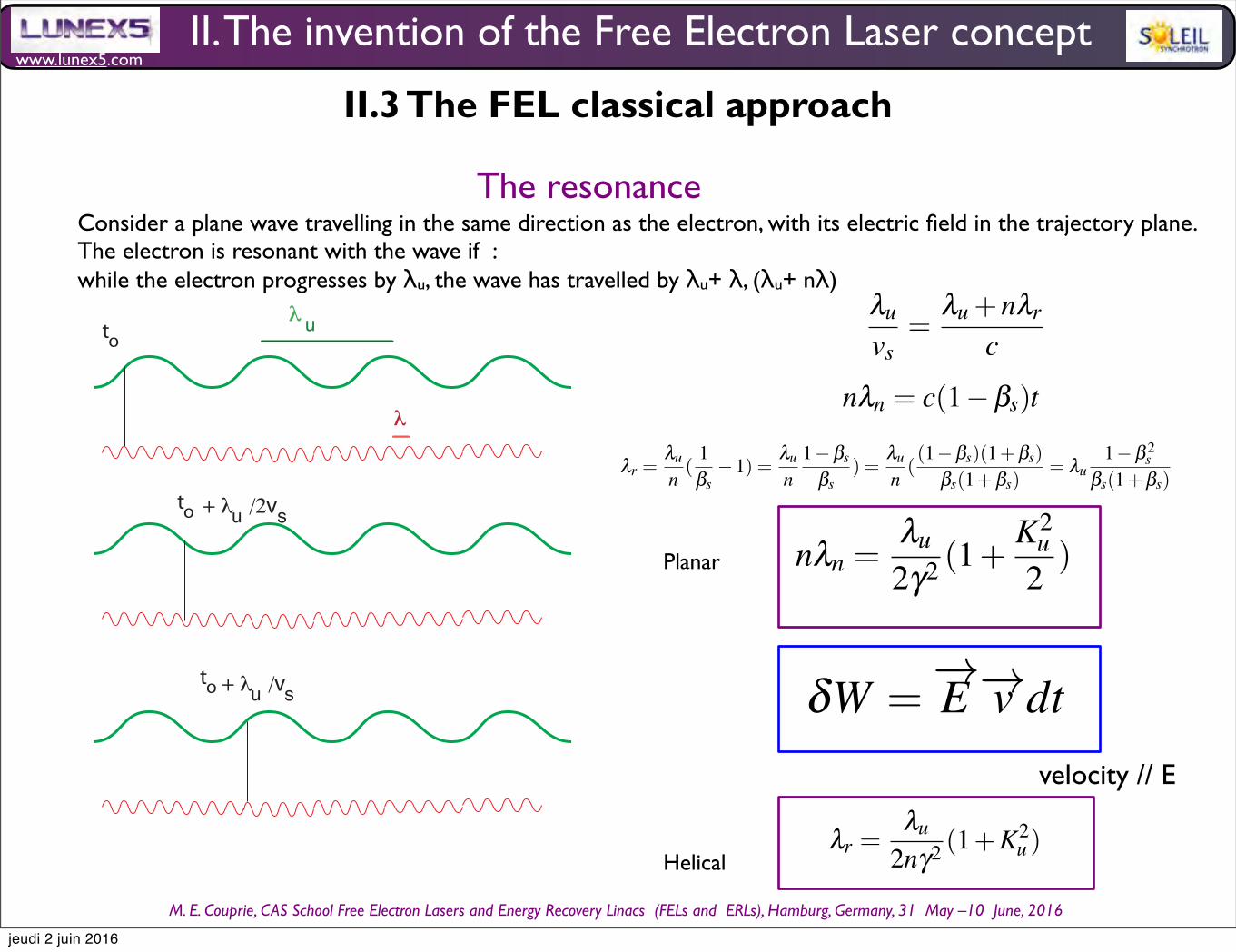
www.lunex5.com
M. E. Couprie, CAS School Free Electron!Lasers!and!Energy!Recovery!Linacs !(FELs and !ERLs), Hamburg, Germany, 31 !May –10 !June, 2016
The resonance
to
to + ! /2vu s
+ ! /vu sto
!
u!
Consider a plane wave travelling in the same direction as the electron, with its electric field in the trajectory plane. The electron is resonant with the wave if :while the electron progresses by λu, the wave has travelled by λu+ λ, (λu+ nλ)
6 Marie-Emmanuelle Couprie
The electrons execute smooth sinusoidal oscillations in the horizontal plane, sothat the radiation is kept in the same emitted cone. In addition, there is a oscillationat twice the pulsation in the longitudinal direction. The interference takes place forthe wavelengths when the λn for which :
nλn = c(1−βs)t (14)
with n an integer, βs the longitudinal reduced velocity of the electrons. The fun-damental resonant wavelength is obtained bor n = 1, i.e. for λ1 = λu(1−βs).
Using the expression of βs, one gets the expression of the resonant wavelengthand its harmonics, according to :
nλn =λu
2γ2 (1+K2
u2) (15)
The wavelength λn of the emitted radiation can be varied by a modification of theundulator magnetic field (by changing the gap for permanent magnet insertion de-vices or the power supply current for electromagnetic insertion devices). In the timedomain, the observer receives a train of Nu magnetic periods which can be consid-ered as quasi-continuous emission of radiation with respect to the bending magnetradiation. The radiation spectrum, square of the Fourier transform of this train, isthen composed of a series of square sinus cardinal, centered on odd harmonics. The”homogenous” relative linewidth of the harmonics is then given by :
∆λλn
=1
nNu(16)
The so-called ”homogenous linewidth” refers to the case of a single electron.The emission is then a narrow-band in the frequency domain. In other words, theemitted field interfere between different points of the trajectory, leading to sharppeak emission.
xxxxxxxxxxxxxxx RESTE donner la longueur d’onde critique et la puissancetotale rayonnee xxxxxxxxxxxxxxxxxx
2 Electron beam characteristics
3 General characteristics of synchrotron radiation
3.1 Retarded Lienard-Wiechert potentials
Let’s consider an electron traveling on a curved trajectory and emitting radiationat time τ (the electron time or retarded time) at the position
−−→R(τ) with a velocity
−−→v(τ) = −−→β (τ)c. The stationary observer receives the emission at time t at the fixed
Synchrotron radiation, polarization, devices and new sources 25
Fig. 17 FEL configurations : a) oscillator case with an optical cavity enabling to store the spon-taneous emission (insert with the energy exchange between the electron and the radiation leadingto density modulation), b) Self Amplified Spontaneous Emission (SASE) where the spontaneousemission emitted in the beginning of the undulator is amplified in one single pass, c) seeding wherea coherent source tuned on the resonant wavelength of the undulator enables to perform efficientlythe energy echange leading further to the density modulation d) High Gain Harmonic Generatione) Echo Enable Harmonic Generation (EEHG).
radiation, is stored in an optical cavity (see Fig. ??a), enabling interaction with theoptical wave on many passes. FEL oscillators cover a spectral range from the THzto the VUV, where mirrors are available. After the theoretical prediction of the FELconcept in 1971, the first IR FEL was achieved in 1977 on the MARK-III linac(Stanford, USA) in the oscillator configuration. ACO (Orsay, France) [?] providedthe second worldwide FEL (first visible radiation) in 1983 and first FEL based har-monic generation [?] in the UV and VUV [?], followed by results on the SuperACOFEL (Orsay, France) [?]. First FEL applications started in the infrared and in theUV-FELs in biology [?, ?] and surface science [?] in 1993.Various FEL oscillatorswere then built down to 190 nm [?].
δW =−→E −→v dt (29)
nλn =λu
2γ2 (1+K2
u2
+ γ2θ 2) (30)
Because of the limited performance of mirrors, short wavelength FEL are usu-ally operated in the so-called Self Amplified Spontaneous Emission (SASE) (seeFig. ??b) setup [?, ?, ?], where the spontaneous emission at the input of the FELamplifier is amplified, typically up to saturation in a single pass after a regime ofexponential growth. Once the saturation is reached, the amplification process is re-placed by a cyclic energy exchange between the electrons and the radiated field.The uncorrelated trains of radiation, which result from the interaction of electronsprogressing jointly with the previously emitted spontaneous radiation, lead to spikylongitudinal and temporal distributions, apart from single spike operation for lowcharge short bunch regime [?, ?]. The emission usually presents poor longitudi-nal coherence properties. Thanks to recent accelerator advances (high peak cur-
velocity // E
32 Marie-Emmanuelle COUPRIE and Mathieu VALLEAU
the frequency is imperfectly defined. The radiation spectrum corresponds to the Fourier transform of the wavepacket
emitted by the electron. The electron radiates uniformly from the undulator entrance to its end, so the wavepacket has
a square envelop. For the optical wave central wavelength λl =2πcωl
, the intensity is given by :
I(ω) ∝ |
0
Nuλu/cexp [−ı(ω −ωl)t]dt|2 ∝
sinc2πNu(ω −ωl)
2ωl
2
(87)
The spectral distribution is plotted in Fig. 25. With n the harmonic number, the linewidth of the radiation is of the
order of :
∆λλn
=1
nNu(88)
Per analogy to conventional lasers, it is called the ”homogeneous linewidth”.
Fig. 25 Intensity spectral distribution for different values of Nu, in red (resp. green), the undulator number of periods is doubled (resp.
multiplied by 5) with respect to the blue case.
The FEL resonance
In the classical approach [124], let’s consider a plane wave traveling in the same direction as the electron, with its
electric field in the trajectory plane. This wave can be the spontaneous emission (one pass or stored in an optical
resonator), or an external optical wave properly tuned.
As shown in Fig. 26, the electron is resonant with the light wave of wavelength λr if, when the electron progresses
by λu, the wave has travelled by λu +λr or more generally, with n being an integer λu +nλr.
The travel times spent by the electrons and the photon writes :
λu
vs=
λu +nλr
c(89)
so :
λr =λu
n(
1
βs−1) =
λu
n1−βs
βs) =
λu
n((1−βs)(1+βs)
βs(1+βs)= λu
1−β 2s
βs(1+βs)(90)
II. The invention of the Free Electron Laser concept
II.3 The FEL classical approach
Synchrotron radiation and Free Electron Laser 33
Fig. 26 Undulator resonance condition : when the electron progresses by λu, the wave has travelled by λu + λ , to : time origin, vs :longitudinal velocity of the electrons
Let’s consider first the case of a planar undulator. With βs ≈ 1, the denominator of the resonant wavelength becomes2 and developing the expression of 1−β 2
s = 1γ2 +
K2u
γ2 in the numerator, the resonant wavelength becomes in the planarcase :
λr =λu
2nγ2 (1+K2
u2) (91)
In the case of a helical undulator, the resonant wavelength comes :
λr =λu
2nγ2 (1+K2u ) (92)
XXXX Application numeriquexxxxxxxxx prendre les parametres de la manip de Stanford cas LUNEX5, casFERMI, E XFELXXXXXXXXXXXXXX
The infra-red spectral range can be reached with reasonable beam energies.The resonance can also be scanned either by changing the electron beam energy or by modifying the magnetic field
of the undulator.Cas du hors axe XXXXXXXXXXXXXXXXX
The electron bunching process
As for the klystron, the electron tend to gather around preferred positions separated by the resonant wavelength λr
Planar
Helical
jeudi 2 juin 2016
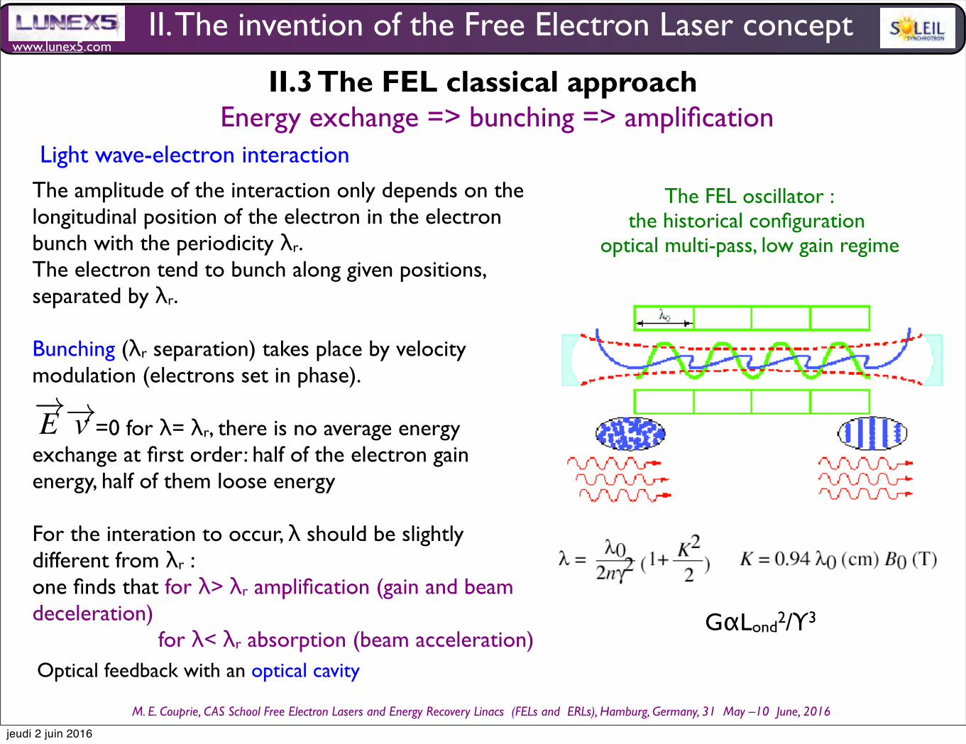
www.lunex5.com
M. E. Couprie, CAS School Free Electron!Lasers!and!Energy!Recovery!Linacs !(FELs and !ERLs), Hamburg, Germany, 31 !May –10 !June, 2016
Light wave-electron interactionThe amplitude of the interaction only depends on the longitudinal position of the electron in the electron bunch with the periodicity λr. The electron tend to bunch along given positions, separated by λr.
Bunching (λr separation) takes place by velocity modulation (electrons set in phase).
=0 for λ= λr, there is no average energy exchange at first order: half of the electron gain energy, half of them loose energy
For the interation to occur, λ should be slightly different from λr :one finds that for λ> λr amplification (gain and beam deceleration) for λ< λr absorption (beam acceleration)
Synchrotron radiation, polarization, devices and new sources 25
Fig. 17 FEL configurations : a) oscillator case with an optical cavity enabling to store the spon-taneous emission (insert with the energy exchange between the electron and the radiation leadingto density modulation), b) Self Amplified Spontaneous Emission (SASE) where the spontaneousemission emitted in the beginning of the undulator is amplified in one single pass, c) seeding wherea coherent source tuned on the resonant wavelength of the undulator enables to perform efficientlythe energy echange leading further to the density modulation d) High Gain Harmonic Generatione) Echo Enable Harmonic Generation (EEHG).
radiation, is stored in an optical cavity (see Fig. ??a), enabling interaction with theoptical wave on many passes. FEL oscillators cover a spectral range from the THzto the VUV, where mirrors are available. After the theoretical prediction of the FELconcept in 1971, the first IR FEL was achieved in 1977 on the MARK-III linac(Stanford, USA) in the oscillator configuration. ACO (Orsay, France) [?] providedthe second worldwide FEL (first visible radiation) in 1983 and first FEL based har-monic generation [?] in the UV and VUV [?], followed by results on the SuperACOFEL (Orsay, France) [?]. First FEL applications started in the infrared and in theUV-FELs in biology [?, ?] and surface science [?] in 1993.Various FEL oscillatorswere then built down to 190 nm [?].
δW =−→E −→v dt (29)
nλn =λu
2γ2 (1+K2
u2
+ γ2θ 2) (30)
Because of the limited performance of mirrors, short wavelength FEL are usu-ally operated in the so-called Self Amplified Spontaneous Emission (SASE) (seeFig. ??b) setup [?, ?, ?], where the spontaneous emission at the input of the FELamplifier is amplified, typically up to saturation in a single pass after a regime ofexponential growth. Once the saturation is reached, the amplification process is re-placed by a cyclic energy exchange between the electrons and the radiated field.The uncorrelated trains of radiation, which result from the interaction of electronsprogressing jointly with the previously emitted spontaneous radiation, lead to spikylongitudinal and temporal distributions, apart from single spike operation for lowcharge short bunch regime [?, ?]. The emission usually presents poor longitudi-nal coherence properties. Thanks to recent accelerator advances (high peak cur-
•
Energy exchange => bunching => amplificationII.3 The FEL classical approach
II. The invention of the Free Electron Laser concept
Optical feedback with an optical cavity
GαLond2/Υ3
The FEL oscillator : the historical configuration
optical multi-pass, low gain regime
jeudi 2 juin 2016
www.lunex5.com
M. E. Couprie, CAS School Free Electron!Lasers!and!Energy!Recovery!Linacs !(FELs and !ERLs), Hamburg, Germany, 31 !May –10 !June, 2016
Gain expression
Synchrotron radiation and Free Electron Laser 45
< ∆γ2 >=1
2
∂< ∆γ2 >
∂γ(161)
with α the fine structure constant, I the beam current,dΦdΩ (θ = 0) the angular spectral flux on-axis of the undulator
spontaneous emission.
The first theorem relates the the energy spread < E2
l > introduced by the optical wave to the spontaneous emission
of the undulator.
According to the second theorem, the second order energy exchange < ∆γ2 > is proportional to the derivative of
the spontaneous emission of the undulator.
Due to the resonance relationship linking the particles’ energy to the emission wavelength, the spectral ”gain”
distribution is close to the wavelength derivative of the spontaneous emission spectrum versus λ .
The first experimental demonstration of the Free Electron Laser amplification was performed on the MARK II FEL
in Stanford in 1976 [124], as shown in Fig. 32.
Fig. 32 (a) Spontaneous undulator emission and (b) measured gain which corresponds to the derive of the sptonaneous emission, from
[124]
5.3.4 Gain expression
The small signal gain is given by :
G = n2πe2
εomoc2ρe
K2u
λu(
Lu
γ)3
Jn−1
2
(ξ )− Jn+1
2
(ξ )2 ∂
∂γsinc
2 (πNuη) (162)
One finds here the main characteristics of the gain.
The gain varies as the inverse of the cube of the energy. The higher the energy, the lower the gain. But, according to
the resonance condition, short wavelength operation requires the use of high electron beam energies. In consequence,
for a same undulator length, the gain is smaller at short wavelengths than at longer ones.
Small signal gain :
Depending on the sign of (λ − λr), the optical wave is either absorbed to the benefit of a gain of kinetic energy of the electrons, or is amplified to the detriment of the kinetic energy of the electrons.
G varies as the inverse of the cube of the energy. The higher the energy, the lower the gain. But, according to the resonance condition, short wavelength operation requires the use of high electron beam energies. In consequence, for a same undulator length, the gain is smaller at short wavelengths than at longer ones.
The gain is proportional to the electronic density. The more electrons interact, the larger the gain. For short wavelength FELs where the gain is naturally small, one should employ beams with high electronic densities.
The gain is proportional to the beam current.
The gain is proportional to the third power of the undulator length, it seems that the longer the undulator, the higher the gain. As the undulator length, the gain width also decreases by 1/nNu, because of the interference nature of the interaction. Temporally, the light pulse should remain in the longitudinal bunch distribution, for the interaction to occur. Similarly, both the optical light and electron bunch should overlap properly all long the undulator propagation.
To account for these effects, letʼs introduce some correction factors in the gain.
II. The invention of the Free Electron Laser concept
II.3 The FEL classical approach
jeudi 2 juin 2016
www.lunex5.com
M. E. Couprie, CAS School Free Electron!Lasers!and!Energy!Recovery!Linacs !(FELs and !ERLs), Hamburg, Germany, 31 !May –10 !June, 2016
Gain correction terms• Transverse filling factor : Non perfect transverse overlap between the laser transverse modes (TEM00 mode of waist wo) and the transverse dimensions of the electron beam σx and σz.
46 Marie-Emmanuelle COUPRIE and Mathieu VALLEAU
The gain varies as the inverse of the cube of the energy. The higher the energy, the lower the gain. But, according to
the resonance condition, short wavelength operation requires the use of high electron beam energies. In consequence,
for a same undulator length, the gain is smaller at short wavelengths than at longer ones.
The gain is proportional to the electronic density. The more electrons interact, the larger the gain. For short wave-
length FELs where the gain is naturally small, one should employ beams with high electronic densities.
The gain is proportional to the beam current.
The gain appears to also proportional to the third power of the undulator length, it seems that the longer the undu-
lator, the higher the gain. As the undulator length, the gain width also decreases by 1/nNu, because of the interference
nature of the interaction.
Temporally, the light pulse should remain in the longitudinal bunch distribution, for the interaction to occur. Simi-
larly, both the optical light and electron bunch should overlap properly all long the undulator propagation. To account
for these effects, let’s introduce some correction factors in the gain.
5.3.5 Gain correction terms
A first reduction factor can occur from a non perfect transverse overlap between the laser transverse modes and the
transverse dimensions of the electron beam σxand σz. Considering a laser of TEM00 mode of waist wo, the transverse
filling factor is given by :
Ff =1
1+( wo2σx
)2
1+( wo
2σz)2
(163)
Besides, according the the Madey’s theorem, spontaneous emission broadening due to energy spread and emittance
affect directly the gain. The homogeneous linewidth is given by :
(∆λλn
)hom =1
nNu(164)
whereas the inhomogeneous contributions are given by :
(∆λλn
)div =γ2θ 2
1+ K2u
2
(165)
(∆λλn
)σγ =2σγ
γ(166)
(∆λλn
)σ =2π2K2
u1+K2
u
σ2
λ 2u
(167)
It results into an inhomogeneous reduction factor Finh expressed as :
Finh =1+
(∆λλn
)2σγ
(∆λλn
)2
hom
−1
.1+
(∆λλn
)2
div
(∆λλn
)2
hom
−1
.1+
(∆λλn
)2σ
(∆λλn
)2
hom
−1
(168)
The longitudinal overlap between the electron bunch of RMS length σl and the optical wave should be be main-
tained. The light wave in in advance by Nuλu with respect to the electrons, and for short electron bunch distributions,
it could escape. A new correction factor Fg is introduced as :
Fg =1+
(Nuλu
σl)
−1
(169)
The small signal gain can be expressed as :
• «Inhomogeneous reduction» : According the the Madeyʼs theorem, spontaneous emission broadening due to energy spread and emittance affect directly the gain.
Homogeneous linewidth
46 Marie-Emmanuelle COUPRIE and Mathieu VALLEAU
The gain varies as the inverse of the cube of the energy. The higher the energy, the lower the gain. But, according to
the resonance condition, short wavelength operation requires the use of high electron beam energies. In consequence,
for a same undulator length, the gain is smaller at short wavelengths than at longer ones.
The gain is proportional to the electronic density. The more electrons interact, the larger the gain. For short wave-
length FELs where the gain is naturally small, one should employ beams with high electronic densities.
The gain is proportional to the beam current.
The gain appears to also proportional to the third power of the undulator length, it seems that the longer the undu-
lator, the higher the gain. As the undulator length, the gain width also decreases by 1/nNu, because of the interference
nature of the interaction.
Temporally, the light pulse should remain in the longitudinal bunch distribution, for the interaction to occur. Simi-
larly, both the optical light and electron bunch should overlap properly all long the undulator propagation. To account
for these effects, let’s introduce some correction factors in the gain.
5.3.5 Gain correction terms
A first reduction factor can occur from a non perfect transverse overlap between the laser transverse modes and the
transverse dimensions of the electron beam σxand σz. Considering a laser of TEM00 mode of waist wo, the transverse
filling factor is given by :
Ff =1
1+( wo2σx
)2
1+( wo
2σz)2
(163)
Besides, according the the Madey’s theorem, spontaneous emission broadening due to energy spread and emittance
affect directly the gain. The homogeneous linewidth is given by :
(∆λλn
)hom =1
nNu(164)
whereas the inhomogeneous contributions are given by :
(∆λλn
)div =γ2θ 2
1+ K2u
2
(165)
(∆λλn
)σγ =2σγ
γ(166)
(∆λλn
)σ =2π2K2
u1+K2
u
σ2
λ 2u
(167)
It results into an inhomogeneous reduction factor Finh expressed as :
Finh =1+
(∆λλn
)2σγ
(∆λλn
)2
hom
−1
.1+
(∆λλn
)2
div
(∆λλn
)2
hom
−1
.1+
(∆λλn
)2σ
(∆λλn
)2
hom
−1
(168)
The longitudinal overlap between the electron bunch of RMS length σl and the optical wave should be be main-
tained. The light wave in in advance by Nuλu with respect to the electrons, and for short electron bunch distributions,
it could escape. A new correction factor Fg is introduced as :
Fg =1+
(Nuλu
σl)
−1
(169)
The small signal gain can be expressed as :
Inhomogeneous contributions• Electron beam emittance
46 Marie-Emmanuelle COUPRIE and Mathieu VALLEAU
The gain varies as the inverse of the cube of the energy. The higher the energy, the lower the gain. But, according to
the resonance condition, short wavelength operation requires the use of high electron beam energies. In consequence,
for a same undulator length, the gain is smaller at short wavelengths than at longer ones.
The gain is proportional to the electronic density. The more electrons interact, the larger the gain. For short wave-
length FELs where the gain is naturally small, one should employ beams with high electronic densities.
The gain is proportional to the beam current.
The gain appears to also proportional to the third power of the undulator length, it seems that the longer the undu-
lator, the higher the gain. As the undulator length, the gain width also decreases by 1/nNu, because of the interference
nature of the interaction.
Temporally, the light pulse should remain in the longitudinal bunch distribution, for the interaction to occur. Simi-
larly, both the optical light and electron bunch should overlap properly all long the undulator propagation. To account
for these effects, let’s introduce some correction factors in the gain.
5.3.5 Gain correction terms
A first reduction factor can occur from a non perfect transverse overlap between the laser transverse modes and the
transverse dimensions of the electron beam σxand σz. Considering a laser of TEM00 mode of waist wo, the transverse
filling factor is given by :
Ff =1
1+( wo2σx
)2
1+( wo
2σz)2
(163)
Besides, according the the Madey’s theorem, spontaneous emission broadening due to energy spread and emittance
affect directly the gain. The homogeneous linewidth is given by :
(∆λλn
)hom =1
nNu(164)
whereas the inhomogeneous broadening result from different contributions. The two first terms are related to the
electron beam emittance.
(∆λλn
)div =γ2θ 2
1+ K2u
2
(165)
(∆λλn
)σγ =2σγ
γ(166)
Another contribution comes from the electron beam energy spread.
(∆λλn
)σ =2π2K2
u1+K2
u
σ2
λ 2u
(167)
It results into an inhomogeneous reduction factor Finh expressed as :
Finh =1+
(∆λλn
)2σγ
(∆λλn
)2
hom
−1
.1+
(∆λλn
)2
div
(∆λλn
)2
hom
−1
.1+
(∆λλn
)2σ
(∆λλn
)2
hom
−1
(168)
The longitudinal overlap between the electron bunch of RMS length σl and the optical wave should be be main-
tained. The light wave in in advance by Nuλu with respect to the electrons, and for short electron bunch distributions,
it could escape. A new correction factor Fg is introduced as :
• Electron energy spread
46 Marie-Emmanuelle COUPRIE and Mathieu VALLEAU
The gain varies as the inverse of the cube of the energy. The higher the energy, the lower the gain. But, according to
the resonance condition, short wavelength operation requires the use of high electron beam energies. In consequence,
for a same undulator length, the gain is smaller at short wavelengths than at longer ones.
The gain is proportional to the electronic density. The more electrons interact, the larger the gain. For short wave-
length FELs where the gain is naturally small, one should employ beams with high electronic densities.
The gain is proportional to the beam current.
The gain appears to also proportional to the third power of the undulator length, it seems that the longer the undu-
lator, the higher the gain. As the undulator length, the gain width also decreases by 1/nNu, because of the interference
nature of the interaction.
Temporally, the light pulse should remain in the longitudinal bunch distribution, for the interaction to occur. Simi-
larly, both the optical light and electron bunch should overlap properly all long the undulator propagation. To account
for these effects, let’s introduce some correction factors in the gain.
5.3.5 Gain correction terms
A first reduction factor can occur from a non perfect transverse overlap between the laser transverse modes and the
transverse dimensions of the electron beam σxand σz. Considering a laser of TEM00 mode of waist wo, the transverse
filling factor is given by :
Ff =1
1+( wo2σx
)2
1+( wo
2σz)2
(163)
Besides, according the the Madey’s theorem, spontaneous emission broadening due to energy spread and emittance
affect directly the gain. The homogeneous linewidth is given by :
(∆λλn
)hom =1
nNu(164)
whereas the inhomogeneous broadening result from different contributions. The two first terms are related to the
electron beam emittance.
(∆λλn
)div =γ2θ 2
1+ K2u
2
(165)
(∆λλn
)σγ =2σγ
γ(166)
Another contribution comes from the electron beam energy spread.
(∆λλn
)σ =2π2K2
u1+K2
u
σ2
λ 2u
(167)
It results into an inhomogeneous reduction factor Finh expressed as :
Finh =1+
(∆λλn
)2σγ
(∆λλn
)2
hom
−1
.1+
(∆λλn
)2
div
(∆λλn
)2
hom
−1
.1+
(∆λλn
)2σ
(∆λλn
)2
hom
−1
(168)
The longitudinal overlap between the electron bunch of RMS length σl and the optical wave should be be main-
tained. The light wave in in advance by Nuλu with respect to the electrons, and for short electron bunch distributions,
it could escape. A new correction factor Fg is introduced as :
46 Marie-Emmanuelle COUPRIE and Mathieu VALLEAU
The gain varies as the inverse of the cube of the energy. The higher the energy, the lower the gain. But, according to
the resonance condition, short wavelength operation requires the use of high electron beam energies. In consequence,
for a same undulator length, the gain is smaller at short wavelengths than at longer ones.
The gain is proportional to the electronic density. The more electrons interact, the larger the gain. For short wave-
length FELs where the gain is naturally small, one should employ beams with high electronic densities.
The gain is proportional to the beam current.
The gain appears to also proportional to the third power of the undulator length, it seems that the longer the undu-
lator, the higher the gain. As the undulator length, the gain width also decreases by 1/nNu, because of the interference
nature of the interaction.
Temporally, the light pulse should remain in the longitudinal bunch distribution, for the interaction to occur. Simi-
larly, both the optical light and electron bunch should overlap properly all long the undulator propagation. To account
for these effects, let’s introduce some correction factors in the gain.
5.3.5 Gain correction terms
A first reduction factor can occur from a non perfect transverse overlap between the laser transverse modes and the
transverse dimensions of the electron beam σxand σz. Considering a laser of TEM00 mode of waist wo, the transverse
filling factor is given by :
Ff =1
1+( wo2σx
)2
1+( wo
2σz)2
(163)
Besides, according the the Madey’s theorem, spontaneous emission broadening due to energy spread and emittance
affect directly the gain. The homogeneous linewidth is given by :
(∆λλn
)hom =1
nNu(164)
whereas the inhomogeneous broadening result from different contributions. The two first terms are related to the
electron beam emittance.
(∆λλn
)div =γ2θ 2
1+ K2u
2
(165)
(∆λλn
)σ =2π2K2
u1+K2
u
σ2
λ 2u
(166)
Another contribution comes from the electron beam energy spread.
(∆λλn
)σγ =2σγ
γ(167)
It results into an inhomogeneous reduction factor Finh expressed as :
Finh =1+
(∆λλn
)2σγ
(∆λλn
)2
hom
−1
.1+
(∆λλn
)2
div
(∆λλn
)2
hom
−1
.1+
(∆λλn
)2σ
(∆λλn
)2
hom
−1
(168)
The longitudinal overlap between the electron bunch of RMS length σl and the optical wave should be be main-
tained. The light wave in in advance by Nuλu with respect to the electrons, and for short electron bunch distributions,
it could escape. A new correction factor Fg is introduced as :
• Longitudinal overlap : between the electron bunch of RMS length σl and the optical wave should be be maintained. The light wave in in advance by Nuλu with respect to the electrons, and for short electron bunch distributions, it could escape.
Synchrotron radiation and Free Electron Laser 47
Fg =1+
Nuλu
σl
−1(169)
The small signal gain can be expressed as :
G = n2πe2
εomoc2 ρeFf FinhFgK2
uλu
(Lu
γ)3Jn−1
2(ξ )− Jn+1
2(ξ )
2 ∂∂γ
sinc2 (πNuη) (170)
or :
G = nπ2roλ 2
u N3u K2
uγ3 Ff FinhFgρe
Jn−1
2(ξ )− Jn+1
2(ξ )
2 ∂∂γ
sinc2 (πNuη) (171)
with ρe the electronic density, ro the classical radius of the electron. The filling factor Ff represents the
5.4 Phase evolution and pendulum equation
5.4.1 Pendulum equation
Let’s consider now the phase evolution.
Using 1+ K2u
2 = γ2r 2n ku
krand dζ
dt = nkuc− k 1+K2u2
2γ2 c It comes :
dζdt
= nkuc−nkucγ2
rγ2 = nkuc(1− γ2
rγ2 ) = nkuc
(γ − γr)(γ + γr)
γ2 = 2nkuc(γ − γr)
γ(172)
It then comes :
dζdt
= 2nkucη (173)
Besides, applying the second Lorentz equation, as :
dγdt
=−→E .−→vmoc2 (174)
It comes :
dηdt
=− eElKu
2γ2moc
Jn−1
2(ξ )− Jn+1
2(ξ )
sin(ζ +φ) (175)
Combining the two equations, it comes :
d2ζdt2 = 2nkuc
dηdt
=−2nkuceElKu
2γ2moc
Jn−1
2(ξ )− Jn+1
2(ξ )
sin(ζ +φ)
Replacing Ku =eBuλu2πmoc and ku, one gets :
d2ζdt2 =
ne2ElKu
γ2m2oc
Jn−1
2(ξ )− Jn+1
2(ξ )
sin(ζ +φ) (176)
Noting:
II. The invention of the Free Electron Laser concept II.3 The FEL classical approach
jeudi 2 juin 2016

www.lunex5.com
M. E. Couprie, CAS School Free Electron!Lasers!and!Energy!Recovery!Linacs !(FELs and !ERLs), Hamburg, Germany, 31 !May –10 !June, 2016
Saturation• Electron beam energy loss (unsatisfied resonant condition)- energy exchange- (spontaneous emission)
• Increase of energy spreadintuitively, the gain bandwidth gets larger because of the inhomogeneous contribution and the gain distribution flattens
• Slippage- The slippage can stop the interaction : the electrons travel slightly slower than the photons, and one at the exit of the undulator, the time difference becomes typically Nuλ/c. For not the radiation to escape from an electron bunch of duration σl , one can consider that the radiation advance should remain in the peak of the distribution :
34 Marie-Emmanuelle COUPRIE and Mathieu VALLEAU
i.e. γmod−→β
dτ = e−→β ×−→
Bu. A first integration leads to the normalized velocity β , given in Table 1, considering that
1
γ =
1−β 2x −β 2
z −β 2s with the deflection parameter Ku, Kux, Kuz given by Ku =
eBuλu2πmoc (Kux =
eBuxλu2πmoc , Kuz =
eBuzλu2πmoc ).
In the wiggler regime, the angle of the velocityKuγ is large with respect to
1
γ . For Kux = Kuz = Ku and ϕ = π2
, one has
βs = 1− 1
γ2− K2
u2γ2
.
If one considers that the undulator deflection parameter is very small with respect to 1 (Ks << 1), then βs ≈< β >and :
1−βs =−= λr = λu(1
βs−1) (93)
partie revoir xxxxxxxxxxxxxxxxxxxxxxxxxxxxxxxxxxxxxxxxx
Saturation
Electron beam energy loss
Different electron beam energy loss can occur. The electron energy is decreased due to the kinetic energy loss enabling
FEL amplification. It can also be reduced by the accumulated effects of emission spontaneous emission along the
undulator.
∆γSR
γo=−1
3reγoK2
u k2
uLu (94)
with re the classical electron radius re =e2
4πεomoc2is 2,8210
−15. In the example of LCLS, the tuneable X-ray FEL
in Stanford, one has : Ku = 3.5, λu = 0.15nm, Lu = 110m, E = 14GeV , it comes∆γSR
γo= 0.17%.
In consequence, it can happen that the resonance condition is no more fulfilled. A solution is to adapt the magnetic
field to the electron beam energy, with the so-called ”tapered undulator” for keeping the resonance condition. One can
apply a linear change of the magnetic field along the longitudinal coordinate.
Increase of energy spread
Besides, the electron bunching and interaction via an energy exchange with the optical wave leads to an increase of
the energy spread of the beam, reducing in consequence the gain (intuitively, the gain bandwidth gets larger because
of the inhomogeneous contribution and the gain distribution flattens).
Slippage
The slippage can stop the interaction : the electrons travel slightly slower than the photons, and one at the exit of
the undulator, the time difference becomes typicallyNuλ
c . For not the radiation to escape from an electron bunch of
duration σl , one can consider that the radiation advance should remain in the peak of the distribution :
Nuλc
<σl
10
or
Nu <σlc10λ
(95)
which gives 300 periods for 1 nm radiation, 10 fs electron bunch, 300 periods, or for 1 µm, 10 ps electron bunch.
II.3 The FEL classical approach
II. The invention of the Free Electron Laser concept
Z. Huang, K. J. Kim, Review of the free-electron laser theory, Physical Review Special Topics-Accelerators and Beams, 10(3), 034801.
jeudi 2 juin 2016
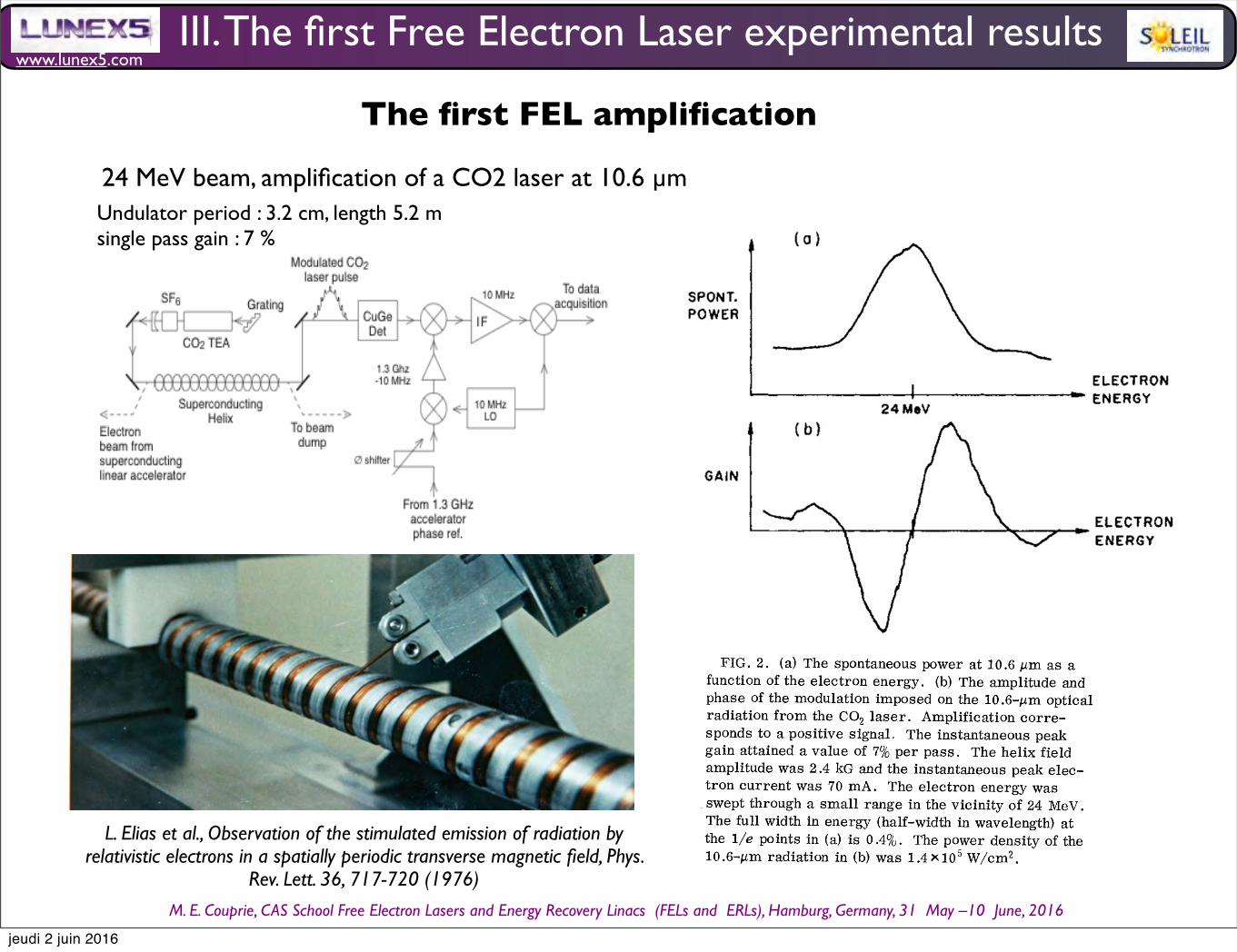
www.lunex5.com
M. E. Couprie, CAS School Free Electron!Lasers!and!Energy!Recovery!Linacs !(FELs and !ERLs), Hamburg, Germany, 31 !May –10 !June, 2016
The first FEL amplification
Amplifier Experiment Setup
Winding the Superconducting Helix
L. Elias et al., Observation of the stimulated emission of radiation by relativistic electrons in a spatially periodic transverse magnetic field, Phys.
Rev. Lett. 36, 717-720 (1976)
VOLUME 36, NUMBER 13 PHYSICAL REVIEW LETTERS 29 MwRcH 1976
tor output with a signal derived from the accele-rator master oscillator. The local oscillatorphase was set to maximize the signal due to spon-taneous radiation by the electron beam. The rel-ative response of the detector to 1300-MHz mod-ulation was determined by observing the quantumQuctuations in the radiation from a 600 black-body.A 1-m Czerny-Turner monochromator was used
to analyze the spectral distribution of the sponta-neous radiation propagating at angles of up to 1.3mrad relative to the magnet axis. A helium-cooled germanium bolometer was used with themonochromator to detect the spontaneous radia-tion.Observation of the spontaneous radiation and the
gain included measurement of (1) the spectral dis-tribution and polarization of the spontaneous radi-ation, (2) the magnitude of the gain, and (3) thedependence of the gain on the electron energy, thepolarization of the stimulating radiation fields,the electron current, the magnetic field, and theoptical power density.According to theory, the wavelengths for emis-
sion and absorption are given by
SPON T.POWER
I
24 MeVELECTRONENERGY
GAlN
ELECTRONENERGY
FIG. 2. (a) The spontaneous power at 10.6 p,m as afunction of the electron energy. (b) The amplitude andphase of the modulation imposed on the 10.6-pm opticalradiation from the CO& laser. Amplification corre-sponds to a positive. signal, The instantaneous peakgain attained a value of 7~/o per pass. The helix fieldamplitude was 2.4 kG and the instantaneous peak elec-tron current was 70 mA. The electron energy wasswept through a small range in the vicinity of 24 MeV.The full width in energy (half-width in wavelength) atthe 1/e points in (a) is 0.4~/0. The power density of the10.6-pm radiation in (b) was 1.4mlo' W/cm'.
where r, is the classical electron radius (cm),ymc' is the electron energy (ergs), X, is the mag-net period (cm), and J3 is the transverse magnet-ic field (Q). Equation (1) is for a helical magnet-ic field and for radiation parallel to the electronbeam axis. The equation is correct to lowest or-der in 1/y and hv/ymc . No harmonics are pre-sent in the spectrum for radiation along the axis.Polarization is determined by the helix symme-try.The minimum theoretical linewidth for sponta-
neous emission is established by the length of themagnet. For the magnet in the experiment theminimum 1/e half -linewidth (d v/v) is 0.3%. Thebroadening due to the finite length is homogene-ous. There are also inhomogeneous effects, in-cluding the spread in energy and angular diver-gence of the electron beam and the variation inmagnetic field over the cross section of the beam.Figure 2(a) indicates the observed dependence
on the electron energy of the spontaneous powerat 10.6 pm. The monochromator was set at 10.6pm while the electron energy from the supercon-ducting accelerator was swept through a range ofapproximately 2% in the vicinity of 24 MeV. Theresolution of the monochromator was 0.2%. The
1/e half-width of the spectrum (hv/v) is 0.4%.The linewidth is close to the theoretical mini-mum. No harmonics were observed. The mag-netic field was 2.4 kQ. The instantaneous spon-taneous power radiated into the 5 &10 '-sr accep-tance of the detection system was 4&&10 ' W at aninstantaneous peak current of 70 mA. The radia-tion was right-circularly polarized.Figure 2(b) indicates the dependence of the gain
on electron energy. The energy scale is the sameas for Figure 2(a). The trace shows the phase andamplitude of the 1300-MHz modulation imposed onthe 10.6-pm optical radiation from the Co, laser.This signal is proportional to the time-averagedgain (or absorption) per pass. The instantaneouspeak gain is equal to the time-averaged gain di-vided by the electron-beam duty cycle, i.e., theratio of the electron bunch length to the bunchperiod (0.56%). The instantaneous peak gain perpass in Fig. 2(b) reaches 7%. The instantaneouspeak current was 70 mA.Figures 2(a) and 2(b) illustrate the correlation
between the gain and the line shape for spontane-ous emission. Note that (1) the gain falls to zeroat the peak of the spontaneous spectrum, (2) thereis a net gain on the high-energy side and net ab-sorption on the low-energy side of the line-shapefor spontaneous emission, and (3) the maximum
Gain Measured in Amplifier Experiment Exactly Matches Theory
III. The first Free Electron Laser experimental results
24 MeV beam, amplification of a CO2 laser at 10.6 µmUndulator period : 3.2 cm, length 5.2 msingle pass gain : 7 %
jeudi 2 juin 2016

www.lunex5.com
M. E. Couprie, CAS School Free Electron!Lasers!and!Energy!Recovery!Linacs !(FELs and !ERLs), Hamburg, Germany, 31 !May –10 !June, 2016
Synchrotron radiation and Free Electron Laser 45
< ∆γ2 >=1
2
∂< ∆γ2 >
∂γ(161)
with α the fine structure constant, I the beam current,dΦdΩ (θ = 0) the angular spectral flux on-axis of the undulator
spontaneous emission.
The first theorem relates the the energy spread < E2
l > introduced by the optical wave to the spontaneous emission
of the undulator.
According to the second theorem, the second order energy exchange < ∆γ2 > is proportional to the derivative of
the spontaneous emission of the undulator.
Due to the resonance relationship linking the particles’ energy to the emission wavelength, the spectral ”gain”
distribution is close to the wavelength derivative of the spontaneous emission spectrum versus λ .
CONFIRMATION th Madey experimentale
5.3.4 Gain expression
The small signal gain is given by :
G = n2πe2
εomoc2ρe
K2u
λu(
Lu
γ)3
Jn−1
2
(ξ )− Jn+1
2
(ξ )2 ∂
∂γsinc
2 (πNuη) (162)
One finds here the main characteristics of the gain.
The gain varies as the inverse of the cube of the energy. The higher the energy, the lower the gain. But, according to
the resonance condition, short wavelength operation requires the use of high electron beam energies. In consequence,
for a same undulator length, the gain is smaller at short wavelengths than at longer ones.
The gain is proportional to the electronic density. The more electrons interact, the larger the gain. For short wave-
length FELs where the gain is naturally small, one should employ beams with high electronic densities. The gain is
proportional to the beam current.
Depending on the sign of (λ −λr), the optical wave is either absorbed to the benefit of a gain of kinetic energy of
the electrons, or is amplified to the detriment of the kinetic energy of the electrons.
The gain appears to also proportional to the third power of the undulator length, it seems that the longer the
undulator, the higher the gain. As the undulator length, the gain width also decreases by 1/nN − u, because of the
interference nature of the interaction. Temporally, the light pulse should remain in the longitudinal bunch distribution,
for the interaction to occur. Similarly, both the optical light and electron bunch should overlap properly all long the
undulator propagation. To account for these effects, let’s introduce some correction factors in the gain.
5.3.5 Gain correction terms
A first reduction factor can occur from a non perfect transverse overlap between the laser transverse modes and the
transverse dimensions of the electron beam σxand σz. Considering a laser of TEM00 mode of waist wo, the transverse
filling factor is given by :
Ff =1
1+( wo2σx
)2
1+( wo
2σz)2
(163)
Besides, according the the Madey’s theorem, spontaneous emission broadening due to energy spread and emittance
affect directly the gain. The homogeneous linewidth is given by :
(∆λλn
)hom =1
nNu(164)
44 Marie-Emmanuelle COUPRIE and Mathieu VALLEAU
For small variation of the optical field, The gain G per pass can be expresses as the second order energy exchange
divided by the incident field energy, according to :
G =mocI < ∆γ2 >
eεo
E2
l dS=
moc2ρe < ∆γ2 >1
2εoE2
l(156)
where εo is the vacuum permeability, the radiation field is integrated over the transverse coordinates, ρe the elec-
tronic density in the volume.
5.3.3 Madey’s theorems
One notices that x given by :
x = 2πNu(1−ω/ωr) (157)
is in fact the argument which appears in the spontaneous emission expression.
On can notice also that :
1− cosx− x2
sinxx3
=− ddx
(sincx2)2
(158)
So :
g(x) =2(1−1cosx− x
2sinx)
x3=−2
ddx
(sincx2)2
(159)
The gain can be expressed as the derivative of the undulator spontaneous emission expression as shown in Fig. 31 .
It is a remarkable result which corresponds to the Madey’s theorem [131, 132].
Fig. 31 Spontaneous emission and small signal free electron laser gain illustrating the Madey ’s theorem : the gain being the derivative of
the spontaneous emission
The Madey’s theorems are given by :
dΦdΩ
(θ = 0) =2αm2
oc4I < ∆γ2 >
e2λ 2 < E2
l >(160)
Synchrotron radiation and Free Electron Laser 45
< ∆γ2 >=1
2
∂< ∆γ2 >
∂γ(161)
with α the fine structure constant, I the beam current,dΦdΩ (θ = 0) the angular spectral flux on-axis of the undulator
spontaneous emission. The first theorem relates the the energy spread < E2
l > introduced by the optical wave to the
spontaneous emission of the undulator. According to the second theorem, the second order energy exchange < ∆γ2 >is proportional to the derivative of the spontaneous emission of the undulator. Due to the resonance relationship linking
the particles’ energy to the emission wavelength, the spectral ”gain” distribution is close to the wavelength derivative
of the spontaneous emission spectrum versus λ .
CONFIRMATION th Madey experimentale
5.3.4 Gain expression
The small signal gain is given by :
G = n2πe2
εomoc2ρe
K2u
λu(
Lu
γ)3
Jn−1
2
(ξ )− Jn+1
2
(ξ )2 ∂
∂γsinc
2 (πNuη) (162)
One finds here the main characteristics of the gain.
The gain varies as the inverse of the cube of the energy. The higher the energy, the lower the gain. But, according to
the resonance condition, short wavelength operation requires the use of high electron beam energies. In consequence,
for a same undulator length, the gain is smaller at short wavelengths than at longer ones.
The gain is proportional to the electronic density. The more electrons interact, the larger the gain. For short wave-
length FELs where the gain is naturally small, one should employ beams with high electronic densities. The gain is
proportional to the beam current.
Depending on the sign of (λ −λr), the optical wave is either absorbed to the benefit of a gain of kinetic energy of
the electrons, or is amplified to the detriment of the kinetic energy of the electrons.
The gain appears to also proportional to the third power of the undulator length, it seems that the longer the
undulator, the higher the gain. As the undulator length, the gain width also decreases by 1/nN − u, because of the
interference nature of the interaction. Temporally, the light pulse should remain in the longitudinal bunch distribution,
for the interaction to occur. Similarly, both the optical light and electron bunch should overlap properly all long the
undulator propagation. To account for these effects, let’s introduce some correction factors in the gain.
5.3.5 Gain correction terms
A first reduction factor can occur from a non perfect transverse overlap between the laser transverse modes and the
transverse dimensions of the electron beam σxand σz. Considering a laser of TEM00 mode of waist wo, the transverse
filling factor is given by :
Ff =1
1+( wo2σx
)2
1+( wo
2σz)2
(163)
Besides, according the the Madey’s theorem, spontaneous emission broadening due to energy spread and emittance
affect directly the gain. The homogeneous linewidth is given by :
(∆λλn
)hom =1
nNu(164)
whereas the inhomogeneous contributions are given by :
Madey’s theorems
J.M.J.Madey,H.A.Schwettman,W.F.Fairbank:,IEEETrans.Nucl.Sci.:20,980–980(1973) J. M. J. Madey: Relationship between mean radiated energy, mean squared radiated energy and spontaneous power spectrum in apower series expansion of the equations of motion in a free-electron laser, Nuovo Cimento 50B, 64 (1979)
Validity : Gain <0.2
The gain can be expressed as the derivative of the undulator spontaneous emission expression.It is a remarkable result which corresponds to the Madeyʼs theorem.
III. The first Free Electron Laser experimental results
44 Marie-Emmanuelle COUPRIE and Mathieu VALLEAU
For small variation of the optical field, The gain G per pass can be expresses as the second order energy exchange
divided by the incident field energy, according to :
G =mocI < ∆γ2 >
eεo
E2
l dS=
moc2ρe < ∆γ2 >1
2εoE2
l(156)
where εo is the vacuum permeability, the radiation field is integrated over the transverse coordinates, ρe the elec-
tronic density in the volume.
5.3.3 Madey’s theorems
One notices that x given by :
x = 2πNu(1−ω/ωr) (157)
is in fact the argument which appears in the spontaneous emission expression.
On can notice also that :
1− cosx− x2
sinxx3
=− ddx
(sincx2)2
(158)
So :
g(x) =2(1−1cosx− x
2sinx)
x3=−2
ddx
(sincx2)2
(159)
The gain can be expressed as the derivative of the undulator spontaneous emission expression as shown in Fig. 31 .
It is a remarkable result which corresponds to the Madey’s theorem [131, 132].
Fig. 31 Spontaneous emission and small signal free electron laser gain illustrating the Madey ’s theorem : the gain being the derivative of
the spontaneous emission
The Madey’s theorems are given by :
dΦdΩ
(θ = 0) =2αm2
oc4I < ∆γ2 >
e2λ 2 < E2
l >(160)
jeudi 2 juin 2016

www.lunex5.com
M. E. Couprie, CAS School Free Electron!Lasers!and!Energy!Recovery!Linacs !(FELs and !ERLs), Hamburg, Germany, 31 !May –10 !June, 2016
The first FEL in 19771977 : First Free Electron Laser by J. M. J. Madey in Stanford
VOLUME $8, NUMBER 16 PHYSICAL REVIEW LETTERS 18 APRIL 1977
frequency changes during the electronic transi-tion) as well as medium anharmonicity, increasethe mean effective phonon frequency (due to theappearance of higher harmonics) and, therefore,are expected to moderate the calculated energy-gap dependence of the rate. '(d) In principle slow processes can be masked
by the occurrence of competing processes likeinfrared emission, pure vibrational relaxation,and energy transfer to other impurities. In thepresent case pure intrastate (infrared radiationor vibrational relaxation) relaxation was shown tobe too slow to compete with the observed rates.The lack of concentration dependence of the ratesalso excludes energy transfer between differentCN molecules.In summary, we have established the impor-
tance of a process characterized by interstatecascading for the relaxation of diatomic guestmolecules. The observed rates in CN qualitative-ly satisfy the energy-gap law but further studies
are needed to establish quantitative agreement.One of us (A.N. ) is grateful to ProfessorJ. Jortner for many helpful discussions.
*Permanent address: Department of Chemistry, Tel-Aviv University, Tel-Aviv, Israel.'For a recent review see K. F. Freed, in "Topics in
Applied Physics, " edited by E. Lim (to be published),A. Nitzan and J. Jortner, Theor. Chim. Acta. 29, 97
(1973).H, Dubost and R, Charneau, Chem. Phys. 12, 407
(1976); K. Dressier, 0. Oheler, and D. A. Smith, Phys.Rev. Lett. 34, 1364 (1975).V. E. Bondyvey, to be published.'See, e.g. , R. Kubo and Y. Toyozawa, Prog. Theor,
Phys. 13, 160 (1955).We are grateful to J. Jortner for suggesting this mo-
del.~A. Nitzan and J. Jortner, J. Chem. Phys. 56, 3360
(1972).I. Weissman, J. Jortner, and A. Nitzan, "Quadratic
Effects in Multiphonon Transition Rates in Solids" (tobe published).
First Operation of a Free-Electron Laser*
D. A. G. Deacon, f L. R. Elias, J. M. J.Madey, G. J. Ramian, H. A. Schwettman, and T. I. SmithHigh Energy Physics Laboratory, Stanford University, Stanford, California 94305
(Received 17 February 1977)
A free-electron laser oscillator has been operated above threshold at a wavelength of3.4 p,m.
Ever since the first maser experiment in 1954,physicists have sought to develop a broadly tun-able source of coherent radiation. Several ingen-ious techniques have been developed, of which thebest example is the dye laser. Most of these de-vices have relied upon an atomic or a molecularactive medium, and the wavelength and tuningrange has therefore been limited by the detailsof atomic structure.Several authors have realized that the constraints
associated with atomic structure would not applyto a laser based on stimulated radiation by free
electrons. ' ' Our research has focused on the in-teraction between radiation and an electron beamin a spatially periodic transverse magnetic field.Of the schemes which have been proposed, thisapproach appears the best suited to the generationof coherent radiation in the infrared, the visible,and the ultraviolet, and also has the potential foryielding very high average power. We have pre-viously described the results of a measurementof the gain at 10.6 pm. ' In this Letter we reportthe first operation of a free-electron laser oscil-lator.
HELICAL MAGNET(3.2 cm PERIOD) 43 MeV BUNCHED
BEAM
RESONATOR ~RESONATORMIRROR
I 2.7mMIRROR
FIG. 1. Schematic diagram of the free-electron laser oscillator. (For more details see Ref. 6.)
VOLUME 38, NUMBER 16 PHYSICAL REVIEW LETTERS 18 APRIL 1977
TABLE I. Laser characteristics.
Laser characteristics Above threshold Below threshold
Wavelength (p m)W'idth (full width of half-maximum)Average Power (W)Peak power (Ref. 7)Mirror transmission
3.4170.0080.367x 10
1.5%
3.4070.03110 8
10 '
Our apparatus is shown schematically in Fig. 1.A superconducting helix generates a periodictransverse magnetic field of 2.4 kG. A 43-MeVelectron beam from the superconducting accelera-tor is fired along the axis of the helix. Radiationpassing through the helix with the electron beamis amplified and a pair of mirrors at the ends ofthe interaction region provide feedback.The characteristics of the oscillator are listed
in Tables I and II. The wavelength was 3.417 p mand the average power output was 0.36 W. Fac-toring out the duty cycle of the machine, ' thistranslates to a peak power of the order of V kW.With a mirror transmission of 1.5% the intracav-ity power was 500 kW. The total energy collectedon the detector was 0.01% of the electron beamenergy.The laser spectrum is shown in the upper half
of Fig. 2 and the spontaneous spectrum in the low-er half. Note the difference in the radiated power:Above threshold, the oscillator power increasesby a factor of 10' over the spontaneous radiation.The oscillator linewidth was 8 nm (200 6Hz).The electron energy in the experiment was cho-
sen to satisfy the wavelength equation'
A. 1 A. q raB2 4g2 C2
width observed in the experiment is by no meansthe limiting linewidth. As established by the ear-lier experiments, ' a homogeneously broadenedgain profile is attainable and the laser linewidthcan be improved by means of intracavity disper-sive elements. The efficiency of the present las-er is limited by the fraction of the electrons' en-ergy which can be converted to radiation in a sin-gle pass through the interaction region. This lim-itation would not apply to devices in which theelectron beam was reaccelerated and recirculatedthrough the interaction region as in an electronstorage ring, where efficiency above 20% shouldbe possible. ' The nanosecond electron bunch
ABOVETHRESHOLD
0.7m p.
INSTRUMENTWl DT H
where X, is the magnet period, y~c2 the electronenergy, r, the classical electron radius, and Bthe magnetic field strength. The wavelength var-ies inversely as the square of the electron energy.The experiment demonstrates the capability of
a free-electron laser to operate at high power atan arbitrary wavelength. We note that the line- TH
3.4l 7p,
TABLE II. Electron beam characteristics.
Energy (Ref. 8)Width (full width at half-maximum):Average currentPeak current (Ref. 7)Emittance (at 43.5 MeV):
43.5 MeV0.05%130 pA2.6 A0.06 mm mrad
I
3.4lOpFIG. 2. Emission spectrum of the laser oscillator
above threshold (top) and of the spontaneous radiationemitted by the electron beam bottom).
893
D. A. G. Deacon et al, First Operation of a FEL. PRL 38, 16, 1977, 892
First demo : on linear accelerator, MARK III, Stanford, infra-red
J. M. J. Madey
FEL oscillator at 3.4 µm, 43 MeV, 12.7 m long optical cavity
III. The first Free Electron Laser experimental results
jeudi 2 juin 2016

www.lunex5.com
M. E. Couprie, CAS School Free Electron!Lasers!and!Energy!Recovery!Linacs !(FELs and !ERLs), Hamburg, Germany, 31 !May –10 !June, 2016
OLUME 36, NUMBER 13 PHYSICAL REVIEW LETTERS 2g MwacH 1/76
values of gain and absorption occur at the pointsof inflection of the spontaneous spectrum.Figure 2(b) was made using right-circular po-
larization. The measured gain was zero for left-circular polarization. The observed gain for lin-ear polarization was half the gain for right-circu-lar polarization. The magnitude of the gain wasobserved to be a linear function of the electroncurrent over a range of 5 to 70 mA.Finally, the gain was measured at optical pow-
er densities ranging from 100 to 1.4 x10' W/cm'.
The magnitude of the gain and the dependence ofthe gain on the electron energy were observed tobe independent of the optical power density overthis range. The stimulated power radiated by theelectrons reached 4 &10' W in these measure-ments. This power was 10' times larger than thespontaneous power measured with the same elec-tron current and corresponds to an energy loss of60 keV per electron in passage through the helix.According to Madey, Schwettman, and Fair-
bank' the gain due to stimulated bremsstrahlungis given by
10 (log„e) r„', » (b, v ' (5 v/v)' [(5v/v) —(2h v/ymc')]2
where p, is the density of electrons in the electron beam (cm ); x and v are the operating wavelengthand frequency (cm and Hz, respectively); 6v is the 1/e half-linewidth for spontaneous emission (Hz);5v is the difference between the operating frequency and the emission line center (Hz); and JI, thefilling factor, is the ratio of the squares of the radii of the electron beam and the radiation field. Thefilling factor is unity if the electron beam radius exceeds the radius of the radiation field.The gain equation is for a helical magnetic field and for circularly polarized radiation propagating
parallel to the electron beam. Stimulated emission is possible only for that component of the stimulat-ing radiation field which matches the polarization of the spontaneous radiation. The derivation as-sumes a small signal and a weak magnetic field.The first exponential within the braces is due to stimulated emission and the second to absorption.
The line shape for stimulated emission and absorption have the same form as the line shape for spon-taneous emission (a Gaussian line shape was assumed). For optical photons 2@v/ymc'«hv/v and thedifference between the two exponentials is small. The gain is then proportional to the derivative of theline shape for spontaneous emission and becomes independent of k. The derivative relationship is nice-ly illustrated by the traces in Fig. 2. The maximum available theoretical gain is
The functional form of the gain is constrained bysymmetry and dimensionality. This is importantbecause the constraints establish scaling laws in-dependent of the approximations used in computa-tion. Given that the gain arises from a second-order process and is independent of h, the small-signal weak-field gain must be linear in the elec-tron current, quadratic in the magnetic field, andvary as z" for unity filling factor as in Eq. (3).The dependence on wavelength is modified whenthe filling factor is less than 1: For a fixed inter-action length and optimal Guassian optics the fill-ing factor scales as X ' and the gain scales as~1/2
For the experimental conditions and with the as-sumption of an effective area of 0.33 cm' for theEHy y mode, the calculated gain attains a maxi-mum value of 5g for the 5.2-m interaction lengthas opposed to l%%uo, the observed value. The sig-nificance of the difference is not yet estab]. jshed;
however, random errors in the measurementwere negligible and the difference is believed toexceed the systematic error.These measurements have important device im-
plications. Lasers based on the stimulated emis-sion of bremsstrahlung have a potential for con-tinuously tunable operation at high power. Thecurrent available from existing electron machinesindicates the possibility of laser operation fromthe infrared to the ultraviolet. The instantaneouspeak current from the superconducting accelera-tor can be raised to the ampere level by reducingthe duty cycle, and circulating peak currents inexcess of 10 A have been obtained in electronstorage rings. "Use of a storage ring would be particularly at-
tractive because the rf accelerating field for thering would have to supply only the energy actuallytransformed to radiation in the periodic field. The
719
VOLUME 36, NUMBER 13 PHYSICAL RKVIKW LETTERS 29 MARcH 1976
overall efficiency of such a system thus would notbe limited to the fraction of the electrons' energyconvertible to radiation in a single pass throughthe interaction region. The feasibility of the ideahinges on the form of the electrons' phase-spacedistribution after passage through the periodicfield, a subject currently under study.An electron current of the order of 1 A at 240
MeV would be sufficient for laser operation at1000 A for a 1-mm' electron-beam cross section.The measurements indicate that 0.@of the elec-trons' energy can be converted to radiation in theperiodic field without evidence of saturation; thecorresponding power output for a ].-A, ].0'-eyelectron beam would exceed 10' W.We gratefully acknowledge the contributions of
the Hansen Laboratory personnel and others whohave assisted in this effort.
*Work supported in part by the U. S. Air Force Officeof Scientific Research.iJ. M. J. Madey, J. Appl. Phys. 42, 1906 (1971).
~J. M. J. Madey, H. A. Sehwettman, and W. M. Fair-bank, IEEE Trans. Nucl. Sei. 20, 980 (1978).While the published Compton-scattering gain formu-
las can be reduced to a common functional form, thenumerical factors are such that the predicted gains dif-fer by up to two orders of magnitude.4H. Dreieer, Phys. Fluids 7, 785 (1964).~B. H. Pantell, G. Soncini, and H. E. Puthoff, IEEEJ. Quantum Electron. 4, 905 (1968).V. P. Sukhatme and P. A. Wolff, J. Appl. Phys. 44,
23S1 (197').N. Kroll, in Stanford Research Institute Technical
Report No. JSR-74-1, 1975 (unpublished), p. 74.8J. L. Hirshfield, I. B.Bernstein, and J. M. Wachtel,
IEEE J. Quantum Electron. 1, 287 (1965).~V. L. Granatstein, M. Herndon, R. K. Parker, andS. P. Schlesinger, IEEE Trans. Microwave TheoryTech. 22, 1000 (1974).P. Sprangle, V. L. Granatstein, and L. Baker, Phys.
Bev. A 12, 1697 (1975).i~R. L. Abrams, IEEE J. Quantum Electron. 8, 888(1972).The Stanford-Princeton ring stored a peak current
of 15 A at 800 MeV tW. C. Barber, High Energy Phys-ics Laboratory Report No. 850 (unpublished)]. TheSPEAR ring at SLAC has stored a peak current in ex-cess of 100 A tH. Winick, SLAC Report No. 1849 (un-published)].
Detection of Brillouin Backscattering in Underdense Plasmas*
John J. Turechek and Francis F. ChenElect&cat Sciences and Engineering Department, University of CalifonHa, Los Angeles, California 90024
(Received 16 September 1975)
Two new results are reported: (1) verification of the finite-interaction-length thresholdfor stimulated Brillouin scattering in a plasma with no critical layers, and (2) use of thetime-dependent Stark effect to detect ion-frequency electric fields in a plasma.
Numerous theorists' ' have predicted that in-tense laser radiation (&uo, k, ) used to heat a plas-ma or implode a pellet may undergo parametricdecay into an acoustic wave (~;,k, ) and a back-scattered light wave (&u„k,), resulting in reflec-tion of the incident energy in the underdense, out-er regions of the plasma, and thus diminishingabsorption at the critical layer, where no= e~=(4nne'/m)~' or n=n, =m&u02/4&e2 This proc. ess ofstimulated Brillouin scattering (SBS) has a. lowerthreshold' and higher nonlinear saturation' thanthe competing decay into a backscattered waveand an electron plasma wave (stimulated Ramanscattering). The practical threshold depends onthe finite interaction length' and the plasma. in-homogeneity, Recent high-power measurements'
on solid targets indicate an increase in backscat-tered power with incident power I, up to 10"W/cm', but a decrease thereafter; the latter hasbeen attributed to a decrease in plasma scalelength with intensity. ' Because solid-target ex-periments are complicated by plasma formationand expansion and by reflection and absorptiveparametric processes occurring at the critical(&uo=&u~) and quarter-critical (no= 2m~) layers,we have designed an experiment to test the basicfinite-length linear SBS theory under conditions inwhich the plasma is independently created and iseverywhere underdense (n&n, /4 or a, )2~ ).Our previously reported observations' have beenconfirmed by direct detection of the low-frequen-cy field by means of the time-dependent Stark ef-
720
bending magnets
synchrotron radiation
undulator source
• Magnetic elements (dipoles, quadrupoles, sectupoles...)• Emission of synchrotron radiation (dipoles, undulators)• Compensation of the energy loss per turn with a radio-
frequency cavity • Bunching
42 Marie-Emmanuelle COUPRIE and Mathieu VALLEAU
Fig. 28 Electron bunching due to the electron / optical wave interaction
Considering this electron bunching will enable to evaluate the second order energy exchange.
5.3 Gain
Let’s consider now the optical wave. The FEL spontaneous emission is given by the synchrotron radiation emitted by
the Nu periods of the undulator. In the historical configuration, the oscillator, the spontaneous emission is stored in an
optical cavity, as shown in Fig. 29. It is the considered optical wave.
Fig. 29 Free electron laser oscillator configuration
The first order energy exchange average over the electrons is zero. One should then calculate the second order
energy exchange < ∆γ2 > averaged over phases with the bunched electron distribution.
The change in electromagnetic power ∆P is given by :
∆P =− Ie
moc2 < ∆γ2 > (148)
For small variation of the optical field, The gain G per pass can be expresses as the second order energy exchange
divided by the incident field energy, according to :
G =mocI < ∆γ2 >
eεo
E2
l dS=
moc2ρe < ∆γ2 >1
2εoE2
l(149)
where εo is the vacuum permeability, the radiation field is integrated over the transverse coordinates, ρe the elec-
tronic density in the volume.
One first calculate the second order energy exchange.
+ =
L. Elias et al., Observation of the stimulated emission of radiation by relativistic electrons in a spatially periodic transverse magnetic field, Phys. Rev. Lett. 36, 717-720 (1976)
!"
#$%&'() *)%
(+, -+ * -)%
*
FEL
Saturation- Hope in storage ring FELs
Renieri, A. (1979). Storage ring operation of the free-electron laser: The amplifier. Il Nuovo Cimento B Series 11, 53(1), 160-178.Dattoli, G., & Renieri, A. (1980). Storage ring operation of the free-electron laser: the oscillator. Il Nuovo Cimento B Series 11, 59
(1), 1-39.
III. The first Free Electron Laser experimental results
jeudi 2 juin 2016

www.lunex5.com
M. E. Couprie, CAS School Free Electron!Lasers!and!Energy!Recovery!Linacs !(FELs and !ERLs), Hamburg, Germany, 31 !May –10 !June, 2016
After the first FEL ....
III. The first Free Electron Laser experimental results
Unfortunately, none of the electron-beam sources available at that time had enough electron-beam current and satisfactory electron-beam quality to make lasing easy. Although gain was measured in several experiments, it was not until six years later, in 1983, that the second free-electron laser was operated in the optical part of the spectrum. The first was at Laboratoire pour l’Utilisation du Rayonnement Electromagnétique (LURE), in Orsay, France, where the electron beam in the storage ring ACO was used to acheive lasing in the visible. The second was at Stanford, a team from TRW used the superconducting accelerator previously used by Madey to acheive laseing in the near infra-red.The third was Los Alamos, where a newly constructed electron accelerator was used to acheive lasing in the mid-infrared.
During the same period, development of ubitron-type devices began at several laboratories. Because the threshold electron-beam current at which space-charge wave can be excited increses as the third power of the electron energy, these devices were limited to low electron energy (no more than a few MeV), and long wavelength. Neverthess, Marshall and his co-workers acheived lasing at 400 µm with electron beam having an energy og 1.2 MeV and a peak current of 25 kA. sub-mmcollective instabilities involved (space charge waves)
C. Brau, Free Electron Lasers, Advanced in electronics and electron physics, edited by P. W. Hawkes, B. Kazan, supplement 22, Academic press (1990)
M. Billardon et al., First operation of a storage ring free electron laser» Phys. Rev. Lett. 51, 1652,(1983)
J. A. Edighoffer et al., Variable-Wiggler Free-Electron-Laser Oscillation, Phys. Rev. Lett 52, 344 (1984)
R. W. Warren et al, First operation of the Los Alamos Free Electron Laser», DOE_Report (1984)
D. B. McDermott et al., High-Power Free-Electron Laser Based on Stimulated Raman Backscattering, Phys. Rev. Lett. 41, 1368 (1978)
jeudi 2 juin 2016
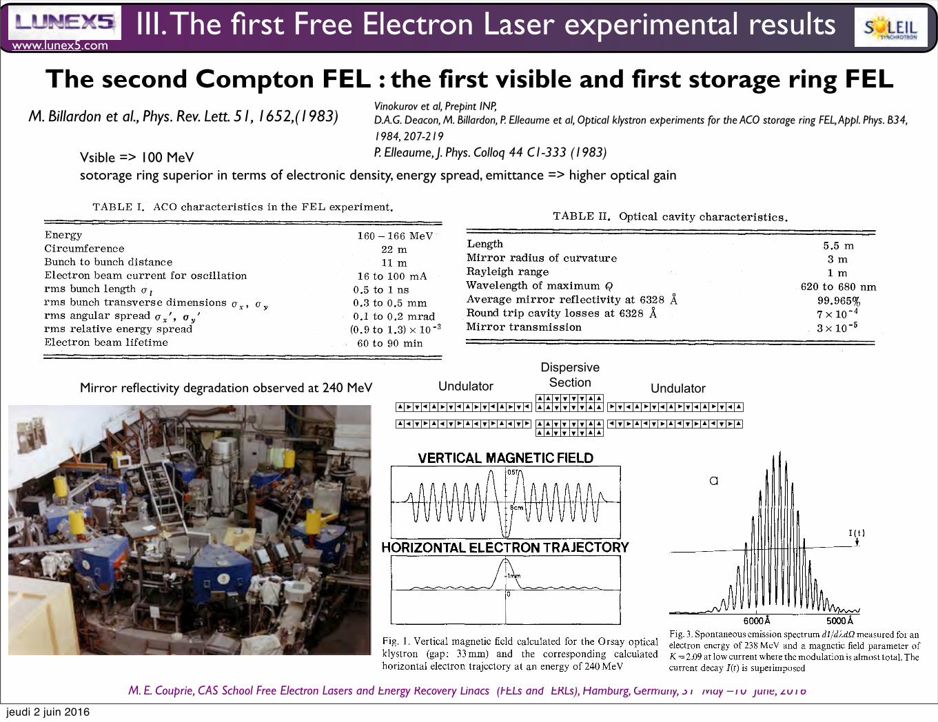
www.lunex5.com
M. E. Couprie, CAS School Free Electron!Lasers!and!Energy!Recovery!Linacs !(FELs and !ERLs), Hamburg, Germany, 31 !May –10 !June, 2016
The second Compton FEL : the first visible and first storage ring FEL
III. The first Free Electron Laser experimental results
M. Billardon et al., Phys. Rev. Lett. 51, 1652,(1983)
Vsible => 100 MeVsotorage ring superior in terms of electronic density, energy spread, emittance => higher optical gain
Mirror reflectivity degradation observed at 240 MeV
Undulators for Storage Ring based FEL Oscillator
– gain /pass is low ( 0.1% to 10 %) because :
• Relatively long bunch length ( several10 ps)
• Straight section length is limited to a few meters
– All storage ring FELs use a modified version of the Undulator
called “Optical Klystron”
– Magnetic Field Quality : Same requirement as other storage ring
IDs in terms of multipole correction and shimming
Undulator Undulator
Dispersive
Section
V, 5/22 , P. Elleaume, CAS, Brunnen July 2-9, 2003.
Optical Klystron Experiments 209
away from the axis of the electron beam (Fig. 2). The
calculated trajectory is shown in Fig. 1 which shows a
large wiggle of about 2 mm amplitude for an electron
energy of 240 MeV and a gap of 33 mm.
2. Spontaneous Emission
2.1. General Features of the Fundamental
As was done for the undulator, the electron beam is
initially aligned by optical means into the axis of the
vacuum chamber within + 1 mm [-3].
The spontaneous emission pattern of the optical
klystron looks the same to the eye as that of an
undulator [7, 6, 3], namely a series of concentric
coloured rings with a similar pattern produced by each
harmonic at progressively larger opening angles. The
big difference appears in the spectrum.
The experimental set up used to measure the
spontaneous emission spectrum has already been
described [6]. It consists of a 1750mm focal length
spherical mirror placed at about 6.5 m from the center
of the optical klystron.
The light transmitted by a 75 ~tm pinhole placed at the
focal distance from the mirror is sent through a lens
into an M20 uv Jobin Yvon monochromator (4~
resolution with 0.1ram slits). The output of the
monochromator is then sent into a Hamamatsu R 928
photomultiplier. Fig. 3 shows a spontaneous emission
spectrum of the fundamental at an energy of 240 MeV
for a gap of 34.4 mm at low current in the ring.
We have compared the envelope of the oscillations
with that of the emission spectrum of a perfect
undulator having exactly N sinusoidal periods, the
fields outside these periods being exactly zero. The
emission spectrum dI/d2 of such an undulator is:
d ~ - - (31
with 6 = n~N (1 - 2a/2),
where 2R is the resonant wavelength and n is the
harmonic number. Fitting the envelope to curves given
by (3) gives N = 8.1 + 0.1 instead of 7. This discrepancy
is probably due to the dispersive section field which
could be partly resonant with the other 7 periods. It is
certainly not due to the fringe field of the half periods
which slightly decreases the effective number of
periods. The envelope of oscillations also presents a
long, short wavelength tail with the secondary
maximum amplitude lower than expected. This effect
was also seen in the 17 period undulator emission
curves and is due to the parasitic tail of the ACO
bending magnets fringe field [2]. Similar curves of
emission were obtained as function of energy or field in
the dispersive section (by changing the gap).
VERTICAL MAGNETIC FIELD
AAAAAA/1 ~ vvvvvvv lic vvvvvvv '
HORIZONTAL ELECTRON TRAJECTORY
Fig. 1. Vertical magnetic field calculated for the Orsay optical klystron (gap: 33mm) and the corresponding calculated horizontal electron trajectory at an energy of 240 MeV
Fig. 2. Dispersive section permanent magnet configuration optimizing the low field gain
G
I(t)
6oooA sooo~
Fig. 3. Spontaneous emission spectrum dI/d2dQ measured for an electron energy of 238 MeV and a magnetic field parameter of K = 2.09 at low current where the modulation is almost total. The current decay I(t) is superimposed
Plotting the Nd of each maximum as a function of 1/2,
we verified a high linearity (0.9999 correlation
coefficient in the range 0.3 < 2 < 0.7 [gm]). From the
slope, we can calculate the experimental value of Ne
which is Nd =65.3+0.2 at 7mc2=240MeV and
2= 6238 A for a dispersive section gap of 35 ram. This
value is close to the value Nd----68 predicted from the
Vinokurov et al, Prepint INP, D.A.G. Deacon, M. Billardon, P. Elleaume et al, Optical klystron experiments for the ACO storage ring FEL, Appl. Phys. B34, 1984, 207-219 P. Elleaume, J. Phys. Colloq 44 C1-333 (1983)
jeudi 2 juin 2016
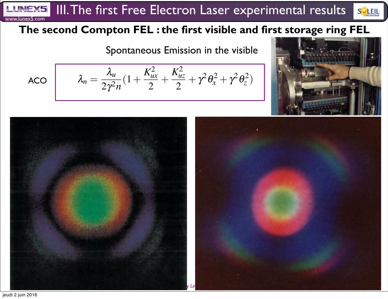
www.lunex5.com
M. E. Couprie, CAS School Free Electron!Lasers!and!Energy!Recovery!Linacs !(FELs and !ERLs), Hamburg, Germany, 31 !May –10 !June, 2016
ACO
Synchrotron radiation, polarization, devices and new sources 11
soft-X-ray undulator source, Nature Physics, 5, 826 (2009) 11. Fawley W. M. et al.,A Design for an XUV FEL Driven by the Laser-Plasma Accelerator at the LBNLLOASIS Facility, Proceed. FEL06, Berlin, Germany, 455-458; Anania M.P. et al.,The ALPHA-X Beam Line: towards a Compact FEL, Proceedings IPAC10, Kyoto,Japan, 2263; http://www.mpq.mpg.de/APS/gruener.php 12. Xiang D. and StupakovG., Triple modulatorchicane scheme for seeding sub-nanometer x-ray free-electronlasers, New J. Phys. 13 (2011) 093028. xxxxxxxxxxxxxxxxxxxxxxxxx
4 Radiation from a bending magnet and from wigglers
4.1 Radiation from a bending magnet
4.2 Wiggler technology
4.3 Wiggler emission from a filament monoenergetic electron beam
4.4 Wiggler emission from a thick electron beam
5 Undulator radiation
The rather general case of a periodic field is considered (period λux and λuz) andthen analyzed in the case of the planar and elliptical undulator. The general expres-sion of the resonant wavelength is given by :
λn =λu
2γ2n(1+
K2ux2
+K2
uz2
+ γ2θ 2x + γ2θ 2
z ) (30)
Kux =eBuxλu
2πmocKux =
eBuxλu
2πmoc(31)
COMMENT METTRE DE L’ESPACE ENTRE LES DEUX FORMULES? RA-JOUTER FORMULE GNRALE K
5.1 Angular spectral flux
The angular spectral flux dφdΩ (θx,θz,ω,−→u ) at the pulsation ω close the the one of
the undulator harmonics can be expressed for a filament mono-energetic beam inthe direction (θx, θz) :
III. The first Free Electron Laser experimental results The second Compton FEL : the first visible and first storage ring FEL
Spontaneous Emission in the visible
jeudi 2 juin 2016
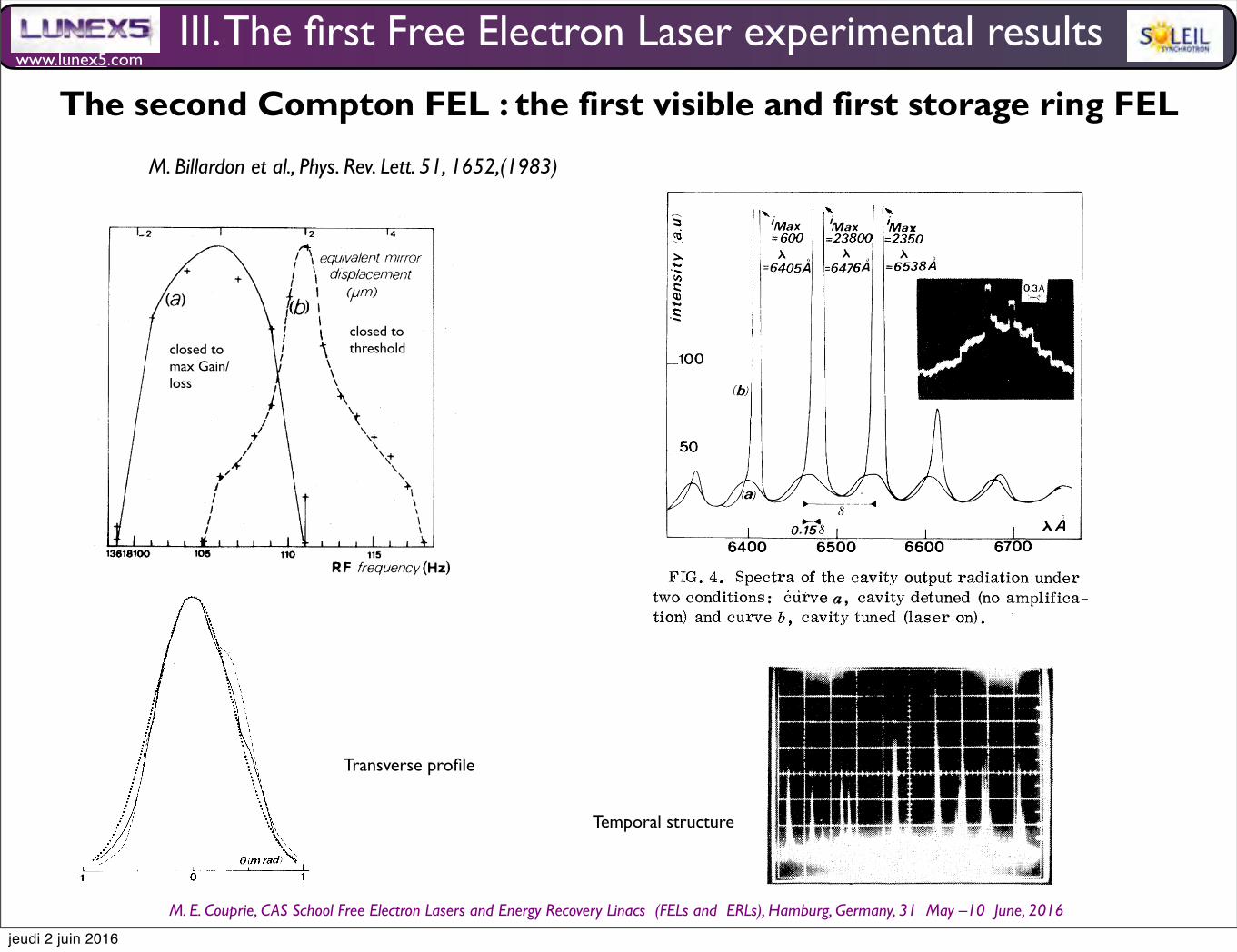
www.lunex5.com
M. E. Couprie, CAS School Free Electron!Lasers!and!Energy!Recovery!Linacs !(FELs and !ERLs), Hamburg, Germany, 31 !May –10 !June, 2016
III. The first Free Electron Laser experimental results
M. Billardon et al., Phys. Rev. Lett. 51, 1652,(1983)
closed to max Gain/ loss
closed to threshold
Transverse profile
Temporal structure
VOLUME 51, NUMBER 18 PHYSICAL RKVIKW LKTTKRS 31 OcToBER 1983
(a)
20m'
(b)
FIG. 2. Experimental laser horizontal (solid curve),vertical (dashed curve) transverse profiles, and thecalculated (dotted curve) cavity TEMpo profile.
pends on how far the laser is from threshold.Quasiperiodic peaks have sometimes been seennear a 40-Hz frequency. And the laser variationalso reproduces the pulsed 27.2-MHz structux eof the electron beam.Figure 4 presents two spectra: (a) is recorded
without amplif ication (optical cavity completelydetuned) and (b) is recorded at laser operation(cavity tuned). For case (b), the laser oscillatesat three wavelengths, with the strongly dominantone being at A. =6476 A; each wavelength is locat-ed at a maximum of the gain versus wavelengthcurve. ' Smaller gain/loss ratios would restrictthe number of laser wavelengths to two or one.Typical laser lines are Gaussian if averaged overa long time scale of ~ 1 sec, with 2 to 4 A full widthat half maximum. Figure 4 also shows an enlarge-ment of the main laser-line spectrum recordedby using a one-dimensional charge-coupled-de-vice (CCD) detector instead of the usual mono-chromator exit slit. The aperture time is 3 ms.Each narrow square peak in this curve is record-ed on only one CCD element and corresponds toa 0.3 A spectral width which is of the same orderas the monochromator resolution. We concludethat there is a residual inhomogeneous contribu-tion to the laser linewidth probably connectedwith the long-time-scale laser-pulse structure(see Fig. 4). The central wavelength of any lineis always equal to the wavelength of maximumemission of spontaneous emission with the cavitycompletely detuned (no amplification) plus 0.15
FIG. 3. Laser time structure over a 200-ms interval.Curve b is recorded in the same condition as g, butwith a higher detector sensitivity.
'Max=600
[=o4ogA
IMax=23800
A=6476A
Max=2350
=6538A
100
I
64000.15&6500
l
6600AA
6700FIG. 4. Spectra of the cavity output radiation under
two conditions: cuive g, cavity detuned (no amp1ifica-tion) and curve b, cavity tuned (laser on).
of the wavelength interfringe distance (see Fig. 4)instead of 0.25 as predicted from Madey's theo-rem. ' This discrepancy is probably due to thetransverse multimode content of the spontaneousemission stored in the cavity; laser operation isonly achieved on the TEM«mode. Laser tunabil-ity was obtained between 640 and 655 nm bychanging the magnetic gap [equivalent to a changeof K in Eq. (1)]. The range of tunability is in factlimited for the moment by the mirror ref lectivity.A typical 75-&% average output power has been
recorded at 50-mA current of 166-MeV electrons.This corresponds to a typical 60-mW output peak
1654
The second Compton FEL : the first visible and first storage ring FEL
jeudi 2 juin 2016

www.lunex5.com
M. E. Couprie, CAS School Free Electron!Lasers!and!Energy!Recovery!Linacs !(FELs and !ERLs), Hamburg, Germany, 31 !May –10 !June, 2016
Second FEL : on storage ring, ACO, Orsay, visible, 1983
M. Billardon et al., Phys. Rev. Lett. 51, 1652,(1983)
The second Compton FEL : the first visible and first storage ring FEL
III. The first Free Electron Laser experimental results
jeudi 2 juin 2016
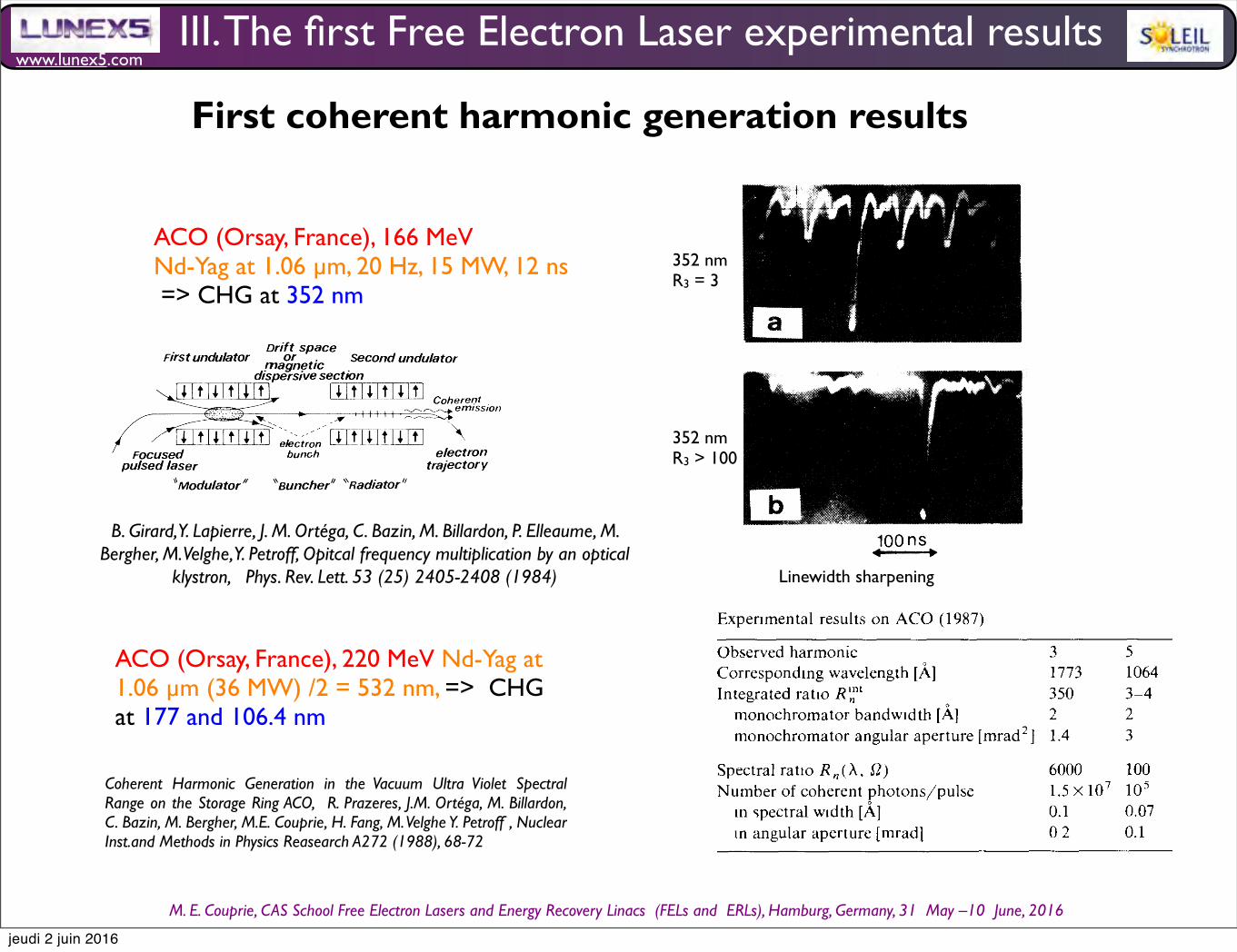
www.lunex5.com
M. E. Couprie, CAS School Free Electron!Lasers!and!Energy!Recovery!Linacs !(FELs and !ERLs), Hamburg, Germany, 31 !May –10 !June, 2016
ACO (Orsay, France), 166 MeVNd-Yag at 1.06 µm, 20 Hz, 15 MW, 12 ns => CHG at 352 nm
VOLUME 53, NUMBER 25 PHYSICAL REVIEW LETTERS 17 DECEMBER 1984
Optical Frequency Multiplication by an Optical Klystron
B. Girard, ' Y. Lapierre, J. M. Ortega, ' C. Bazin, M. Billardon, ' P. Elleaume,M. Bergher, M. Velghe, d and Y. Petroff
Laboratoire pour l'Utilisation du Rayonnement Electromagnetique, Universite de Paris-Sud, F-91405 Orsay, France(Received 25 June 1984)
We report the first observation of the emission of coherent light by an electron beambunched at 1.06 p, m by a Nd-doped yttrium aluminum garnet laser focused into an opticalklystron. An enhancement of 10' to 10 over its spontaneous emission level at 355 nm hasbeen observed in these experiments performed at the ACO storage ring at Orsay.
PACS numbers: 42.65.Cq, 07.60.—j, 41.70.+ t, 42.60.—v
In the past few years much attention has beenpaid to the possibility of producing coherent light inthe vacuum-ultraviolet (h. ( 2000 A) spectral rangeby use of free-electron sources. ' One way is to real-ize a storage-ring free-electron laser operating inthis spectral range. However, this will take sometime to come about even with todays existingstorage rings. Another possibility is to realize anup-frequency conversion of a high-power externallaser focused into an optical klystron or an undula-tor. The external laser "bunches" the electronbeam, i.e., makes a spatial partition of the electronsinto microbunches separated by the laserwavelength, XL (Fig. 1). Therefore, in the Fourieranalysis of the bunch density there appears a seriesof lines at the laser frequency and its harmonics. Inthe optical klystron (OK) configuration the externallaser is focused into a first undulator (modulator)where it produces an energy modulation. Thismodulation is converted into a spatial modulation inthe dispersive section (buncher) which is either adrift space or a long period of magnetic field. Thenat wavelengths XL jn, where n is the harmonicnumber, light emission of the electrons passingthrough the second undulator (radiator) isenhanced by this coherent bunching and becomesproportional to the square of the number of elec-trons. This technique avoids the use of mirrors, asin the free-electron-laser case, to produce uv light.It should be efficient on most of the existingstorage rings to produce light of wavelengthbetween about 100 and 2000 A by starting with avisible or uv, commercially available, laser.Although this process is often called "multiplica-tion" or "up-conversion" it is different from theusual harmonic production since the coherent out-put power is taken from the electron energy and notfrom the pumping laser. Coherent emission bybunched beams (emission proportional to thesquare number of electrons) is a common fact inthe centimeter and millimeter range of the elec-tromagnetic spectrum. Recently, it has been ob-
served with an undulator in the infrared. Howev-er, no quantitative studies had been made yet. Inthis Letter we report the first observation ofcoherent light in the uv region produced by an OKwith a high enhancement of the spontaneous emis-sion.The theory of the OK has been discussed by
many authors, as has the theory of harmonic pro-duction. Let us only recall that, in the case of theOK, the ratio, R„,of the coherent over the in-coherent (spontaneous) emission, for the nth har-monic of the laser frequency and for a given laserpower and within the bandwidth of the coherentemission, is proportional to
R„~NIf„,where N is the number of periods of the radiatorand I the ring current. f„is the spontaneous-emission modulation rate, resulting from the in-terference of the two undulators constituting theOK, at wavelength XL /n This . interference isdriven by the strength of the dispersive section andthe energy spread of the electrons and
f„~exp —242m. (N+ Nd) " ny
where Nd is the number of wavelength of the yttri-um aluminum garnet (YAG) laser passing over anelectron in the dispersive section and characterizes
Drift spaceFirst undulator or . Second undulatormagnetic
dispersive sectionI L I tILL114 I t1
emission
I I I t J i I t I l It I;„;;;.„[J&.t lk1tll It
I
Focused electronpulsed laser traj ector y
'Modulator" "launcher" "Radiator"
FIG. 1. Schematic principle of the experiment (seetext).
1984 The American Physical Society 2405
VOLUME 53, NUMBER 25 PHYSICAL REVIEW LETTERS 17 DECEMBER 1984
sk R3
«'stls'tssu%'Q'F '-~
. '«sI
+———0.3
100ns
k0.2
~--e iFIG. 2. Time structure of the optical klystron emission
measured on the third harmonic of the fundamental lineat 3550 A. The pulse corresponding to a passage of theelectron through the OK in coincidence with the laser isshown (a) for a weak amplification ratio (R3=3); (b)for a strong amplification ratio (R 3 ) 100).value is about 5 to 6 times more. We explained thiseffect by considering the pulse-to-pulse fluctuationsof the coherent emission when recorded on a fastscope. These fluctuations are of the order ofseveral units and do not appear on Fig. 3 where thesignal is averaged over about 50 laser pulses. Theymight correspond to a time jitter between the elec-tron and laser pulses of the order of a fewnanoseconds considering the fact that the laserlongitudinal pulse shape exhibits 2 to 3 peaks for atotal duration of 12 nsec. We have also consideredthe effect of the lack of coherence of the laser(li /b, A. = 15 mm although the bunch length is—300 mm). It seems to have no effect on the in-tensity of the coherent emission, but only on itsspectral width. Let us point out that since the realspectral width of the coherent emission is less than
00.1 A, as discussed above, the maximum measuredvalue of R3, within the coherent emission line, is atleast 3&&10 .The maximum number of coherent photons
emitted per pulse is about 4x 10 theoretically and6x 10 experimentally. This rather small number isdue to various losses: (i) Because of the large ener-gy dispersion of the ring at low energy, the max-imum is reached at 1 mA of ring current where f32is only 10 2. (ii) We worked at a lower laser power
—O.i
0)s s s I s ~ s s I
„
i(mA)s ss I ssssl
FIG. 3. Amplification ratio between the coherent andincoherent emission measured for AX = 0.7 A and a solidangle of 0.2 mrad' (full line, theory; points with errorbars, experiment) and modulation rate of the spontane-ous emission measured with (curve b) and without(curve c) the laser, with respect to the ring current.Since the real spectral width of the coherent emission isless than 0.1 A, the ordinate has to be multiplied at leastby 7 to obtain the real value of this amplification ratio.
(PL = 15 MW); this accounts for a loss of a factor—102 (PL =100 MW and optimized dispersivesection). (iii) We have a limited number of periodsin the "radiator" section (N =7). Thus a factor10 —10 is lost when we compare with an optimizedklystron placed on a storage ring exhibiting noanomalous bunch lengthening. In our case the OKhad been optimized for free-electron-laser stud-ies ' and the parameter Nz is too strong for thisexperiment. Moreover the energy of 166 MeV isvery far from the nominal working energy of theACO storage ring (540 MeV).In summary, this work demonstrates for the first
time the feasibility of the free-electron harmonic-generation experiment. This technique will be ableto deliver 10' -10' photons/pulse when installedon modern storage rings working at their nominalenergy. The spectral region covered should extendtoward a few hundred angstroms. Experiments inthe vuv region are planned in the near future.
2407
B. Girard, Y. Lapierre, J. M. Ortéga, C. Bazin, M. Billardon, P. Elleaume, M. Bergher, M. Velghe, Y. Petroff, Opitcal frequency multiplication by an optical
klystron, Phys. Rev. Lett. 53 (25) 2405-2408 (1984)
352 nmR3 = 3
352 nmR3 > 100
ACO (Orsay, France), 220 MeV Nd-Yag at 1.06 µm (36 MW) /2 = 532 nm, => CHG at 177 and 106.4 nm
Coherent Harmonic Generation in the Vacuum Ultra Violet Spectral Range on the Storage Ring ACO, R. Prazeres, J.M. Ortéga, M. Billardon, C. Bazin, M. Bergher, M.E. Couprie, H. Fang, M. Velghe Y. Petroff , Nuclear Inst.and Methods in Physics Reasearch A272 (1988), 68-72
70
4 . Expe r i men t s
I n 1984 , we had obse r ved t he t h i rd ha rmon i c a t 3547Â o f an ex t e rna l Nd -YAG l ase r [9] . A d i e l ec t r i c m i r rorwas used t o sepa r a t e t he ha rmon i c f rom t he f undamen -t a l wave . The ha rmon i c s i gna l was ana l ysed by a norma li nc i dence gr a t i ng monochroma t or . I n orde r t o ana l yset he cohe r en t i n t ens i t y i n t he prope r " t i me w i ndow "cor r espond i ng t o t he i nc i den t l ase r pu l se , we used a" Box -Ca r " ave r age r . The beam ene rgy (166 MeV) wast oo l ow t o ensur e good s t ab i l i t y o f t he r i ng , and t hel i f e t i me was on l y one hour . The i nc i den t l ase r powe rwas 15 MW a t 1 . 06 , um . Howeve r , t he max i mum i n -t egr a t ed r a t i o has been measur ed t o be R3 t = 300 ,cor r espond i ng t o a spec t r a l r a t i o o f R 1 (A , 0) = 3000 ,f or a cur r en t t o t he s t or age r i ng o f 1 mA . Th i s cor r e -sponds t o 3 X 10 5 cohe r en t pho t ons by pu l se , a t t heou t pu t o f t he op t i ca l k l ys t ron .
Th i s expe r i men t has shown t he ex i s t ence o f t hecohe r en t gene r a t i on process , bu t t he i n t e r es t o f t h i s k i ndo f expe r i men t s i s t he produc t i on o f pho t ons i n VUVspec t r a l r ange. Thus , t he nex t s t ep was t o ope r a t e i n t h i sspec t r a l r ange , wh i ch i mp l i es d i f f e r en t expe r i men t a lt echn i ques .
I n r ecen t expe r i men t s , we gene r a t ed t he 3rd and 5 t hha rmon i c , a t 1773 and 1064 Â , f rom a doub l edNd -YAG l ase r (5320 Â) . The 220 MeV beam was mor es t ab l e t h i s t i me , and t he l i f e t i me was a f ew hour s. Thel ase r powe r was i nc r eased t o 36 MW . F i g . 2 shows t heexpe r i men t a l sys t em . The VUV spec t r a l r ange has t o behand l ed w i t h a d i f f e r en t t echno l ogy t han be f or e , and i npa r t i cu l a r l eads t o wor k i n u l t r ah i gh vacuum (becauseu l t r ah i gh vacuum i s needed f or s t or age r i ngs ) . Theem i ss i on f rom t he op t i ca l k l ys t ron was f i l t e r ed by agr az i ng i nc i dence monochroma t or . The l i gh t wasana l ysed by one o f t wo d i f f e r en t k i nds o f pho t omu l t i -
N
R Pr aae r es e t a l / Cohe r en t ha rmon i c gene r a t i on i n t he VUV r ange
O t ma l
F i g. 2 Expe r i men t a l se t up .
p l i e r s . The bo t t om de t ec t or (CsTe ca t hode ) was devo t edt o t he 3rd ha rmon i c , and t he t op (CuBe ca t hode ) t osma l l e r wave l eng t hs . I n pr ac t i ce , t he pho t omu l t i p l t e r sa r e chosen t o be b l i nd i n t he v i s i b l e r ange , bu t t he h i gha t t enua t i on r equ i r ed (10 16 ) l ed us t o use a l so a d i chrd i cm i r ror p l aced a f t e r t he monochroma t or . The synchro -n i sa t i on o f t he da t a r ecord i ng sys t em i s prov i ded by af as t pho t od i ode , wh i ch r ece i ves t he l ase r l i gh t sca t t e r edt hrough t he w i ndows o f t he vacuum chambe r . No t e t ha tt he h i gh powe r dens i t y o f t he l ase r f or ces us t o open t heen t r ance s l i t o f t he monochroma t or , i n orde r t o avo i dt he i r des t ruc t i on ( t he powe r dens i t y a t t h i s po i n t be i ng
approx i ma t e l y 10 GW / cm2 ) . Th i s dec r eases i t s spec t r a lr eso l u t i on t o approx i ma t e l y AN = 2 Â , and a l so t hemeasur ed i n t egr a t ed r a t i o R ; , n t .
Look i ng a t t he 3rd ha rmon i c , w i t h an ene rgy spr eado f 4 X 10 - ° f or a cur r en t o f 2 mA and f or a g i venape r t ur e o f t he monochroma t or , we have measur ed ani n t egr a t ed r a t i o o f R 3 t = 350 . Th i s cor r esponds t o aspec t r a l r a t i o o f R 3 (A , 0) = 6000 . The cur ves g i ven t of i g . 3 show , as a f unc t i on o f cur r en t , t he i n t egr a t ed r a t i o(R i t ) , and t he numbe r o f cohe r en t pho t ons pr esen t a t
Cu Be
PM
LASER TR I GGER
KBP
CsTe
PMBOX CARave r age r
SPONT . EM I SS I ONMEASUREMENT
®band -pass f i l t e r
Tr i gge r I r r e
K l ys i ron R I NG
Ad j us t ab l ede l ay
Tab l e 1Expe r i men t a l r esu l t s on ACO (1987)
Obse r ved ha rmon i c 3 5Cor r espond i ng wave l eng t h [Â] 1773 1064I n t egr a t ed r a t i o Rn t 350 3 -4
monochroma t or bandw i d t h [?+] 2 2monochroma t or angu l a r ape r t ur e [mr ad 2 1 1 . 4 3
Spec t r a l r a t i o R , (X , Sd ) 6000 100Numbe r o f cohe r en t pho t ons / pu l se 1 . 5 X 10 7 10 5
m spec t r a l w i d t h [A] 0 . 1 0 . 07i n angu l a r ape r t ur e [mr ad ] 0 2 0 . 1
Linewidth sharpening
First coherent harmonic generation results
III. The first Free Electron Laser experimental results
jeudi 2 juin 2016
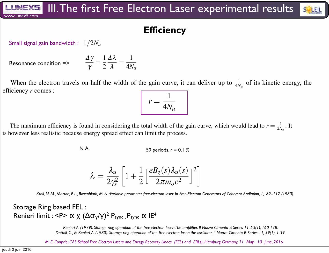
www.lunex5.com
M. E. Couprie, CAS School Free Electron!Lasers!and!Energy!Recovery!Linacs !(FELs and !ERLs), Hamburg, Germany, 31 !May –10 !June, 2016
Efficiency50 Marie-Emmanuelle COUPRIE and Mathieu VALLEAU
∆γγ
=12
∆λλ
=1
4Nu(181)
When the electron travels on half the width of the gain curve, it can deliver up to 14Nu
of its kinetic energy, theefficiency r comes :
r =1
4Nu(182)
The maximum efficiency is found in considering the total width of the gain curve, which would lead to r = 12Nu
. Itis however less realistic because energy spread effect can limit the process.
In the example of the CLIO infra-red free electron laser at Lab. Chimie Physique (Orsay) with 48 undulator periods,the efficiency is of the order of 0.5 %.
The limit can be overcome in using tapered undulator, as already introduced. The tapered undulator provides avarying magnetic field along the longitudinal direction Bz(s) but just changing the angle of the array on which arelocated the undulator magnets. There is also the possibility to vary the period, but it is slight less convenient.
The resonance condition becomes :
λ =λu
2γ2s
1+
12
eBz(s)λu(s)2πmoc2
2
(183)
enables to maintain the resonance. Efficiency of 1-2 % XXXXXX was reported [130]XXXXRajouter ref, Los Alamos, tapered und,schma diagramme LELCas du LEL sur anneau de stockaga
6 High gain regime of Free Electron Lasers
6.1 Introduction
High density electron beam and long undulator : a strong bunching takes place (space charge) the change in electricfield can no more be neglected
thus- coupled pendulum equation, describing the phase space evolution of the particules under the combined undulator
magnetic field and electric field of the optical wave - evolution of the optical field - evolution of the bunching coupledto the longitudinal sapce charge forces
=¿ evaluation of the electronic density and current evaluation of the light wave evolution
6.2 Radiation field evolution
The radiated field evolution is ruled by the Maxwell equation :
∂ 2
∂ s2 − 1c2
∂ 2
∂ t2
Ex(s, t) = µ0
∂ jx∂ t
+1εo
∂ρ∂x
(184)
with jx is the average over the electron beam cross section of the transverse electron peak current.
jx = ∑j=1
Nvxδ (x− x j(t)) (185)
50 Marie-Emmanuelle COUPRIE and Mathieu VALLEAU
∆γγ
=12
∆λλ
=1
4Nu(181)
When the electron travels on half the width of the gain curve, it can deliver up to 14Nu
of its kinetic energy, theefficiency r comes :
r =1
4Nu(182)
The maximum efficiency is found in considering the total width of the gain curve, which would lead to r = 12Nu
. Itis however less realistic because energy spread effect can limit the process.
In the example of the CLIO infra-red free electron laser at Lab. Chimie Physique (Orsay) with 48 undulator periods,the efficiency is of the order of 0.5 %.
The limit can be overcome in using tapered undulator, as already introduced. The tapered undulator provides avarying magnetic field along the longitudinal direction Bz(s) but just changing the angle of the array on which arelocated the undulator magnets. There is also the possibility to vary the period, but it is slight less convenient.
The resonance condition becomes :
λ =λu
2γ2s
1+
12
eBz(s)λu(s)2πmoc2
2
(183)
enables to maintain the resonance. Efficiency of 1-2 % XXXXXX was reported [130]XXXXRajouter ref, Los Alamos, tapered und,schma diagramme LELCas du LEL sur anneau de stockaga
6 High gain regime of Free Electron Lasers
6.1 Introduction
High density electron beam and long undulator : a strong bunching takes place (space charge) the change in electricfield can no more be neglected
thus- coupled pendulum equation, describing the phase space evolution of the particules under the combined undulator
magnetic field and electric field of the optical wave - evolution of the optical field - evolution of the bunching coupledto the longitudinal sapce charge forces
=¿ evaluation of the electronic density and current evaluation of the light wave evolution
6.2 Radiation field evolution
The radiated field evolution is ruled by the Maxwell equation :
∂ 2
∂ s2 − 1c2
∂ 2
∂ t2
Ex(s, t) = µ0
∂ jx∂ t
+1εo
∂ρ∂x
(184)
with jx is the average over the electron beam cross section of the transverse electron peak current.
jx = ∑j=1
Nvxδ (x− x j(t)) (185)
N. A. 50 periods, r = 0.1 %
Storage Ring based FEL : Renieri limit : <P> α χ (∆σγ/γ)2 Psync , Psync α IE4
Renieri, A. (1979). Storage ring operation of the free-electron laser: The amplifier. Il Nuovo Cimento B Series 11, 53(1), 160-178.Dattoli, G., & Renieri, A. (1980). Storage ring operation of the free-electron laser: the oscillator. Il Nuovo Cimento B Series 11, 59(1), 1-39.
Synchrotron radiation and Free Electron Laser 33
In the example of the CLIO infra-red free electron laser at Lab. Chimie Physique (Orsay) with 48 undulator
periods, the efficiency is of the order of 0.5 %.
The limit can be overcome in using tapered undulator, as already introduced. The tapered undulator provides a
varying magnetic field along the longitudinal direction Bz(s) but just changing the angle of the array on which are
located the undulator magnets. There is also the possibility to vary the period, but it is slight less convenient.
The resonance condition becomes :
λ =λu
2γ2s
1+
1
2
eBz(s)λu(s)2πmoc2
2
(141)
enables to maintain the resonance. Efficiency of 1-2 % XXXXXX was reported [134]
XXXXRajouter ref, Los Alamos, tapered und,
schema diagramme LEL
Cas du LEL sur anneau de stockage
4 High gain regime of Free Electron Lasers
4.1 The coupled system of equations
With high density electron beams and long undulators, a strong bunching takes place (space charge) and the change
in electric field can no more be neglected
Thus, the FEL is treated via a set of coupled equations:
- coupled pendulum equation, describing the phase space evolution of the particles under the combined undula-
tor magnetic field and electric field of the optical wave
- evolution of the optical field in presence of an electronic density and current
- evolution of the bunching coupled to the longitudinal space charge forces, enabling to evaluate the electronic
density and current
4.1.1 Radiation field evolution
The radiated field now depends on the longitudinal coordinate as:
Ex(s, t) = Ex(s)exp [−ık(s− ct)] (142)
Its evolution is ruled by the Maxwell equation :
∂ 2
∂ s2− 1
c2
∂ 2
∂ t2
Ex(s, t) = µ0
∂ jx∂ t
+1
εo
∂ρ∂x
(143)
with jx is the average over the electron beam cross section of the transverse electron peak current.
In the 1 dimensional FEL theory, one assumes that the electronic density is independent of x, so∂ρ∂x = 0. The
transverse current is mainly due to the electrons in the wiggler, and a little bit to the radiation field.
Under the hypothesis of slowly varying envelop (SVEA) : the electric field does not change much over a few
undulator periods even although its increase over the whole undulator length is large.
∂Ex
∂ s
<< |kEx| and∂Ex
∂ t
<< |ωEx| (144)
The second order derivative can be neglected.
∂ 2
∂ s2− 1
c2
∂ 2
∂ t2
Ex exp(ıks−ωt)∼= 2ık
∂∂ s
+1
c∂∂ t
Ex exp(ıks−ωt) (145)
So :
Kroll, N. M., Morton, P. L., Rosenbluth, M. N : Variable parameter free-electron laser. In Free-Electron Generators of Coherent Radiation, 1, 89--112 (1980)
III. The first Free Electron Laser experimental results
Small signal gain bandwidth :
Resonance condition =>
Synchrotron radiation and Free Electron Laser 49
Fig. 34 Electron trajectories in energy-phase space representation. The vertical axis represents the deviation with respect to resonace, the
horizontal axis the electron phase with respect to the optical wave. Open trajectories (green) with energy oscillation. Close trajectories of
particles trapped by the ponderomotive potential : maximum kinetic energy is given / taken to/from the optical wave for half a rotation, i.e.
for highest and lowest positions
The pendulum equation is a non linear differential equation, with an analytic solution using time dependent elliptical
Jacobi functions. One usually represents the energy evolution in the energy-phase space, as illustrated in Fig. 34.
The electrons enter the undulator with a specific phase.
They can follow open trajectories (green) from one potential well to another : the present oscillations in energy and
an evolving phase.
They can also be trapped in the ponderomotive field −Ω 2cosφ , and rotate in phase space. The close trajectories in
phase space correspond to those of an oscillating pendulum around its equilibrium position.
5.5 Saturation
When the optical wave power grows, a increasing number of electrons are trapped in the ponderomotive potential.
When going down in phase space, the electron looses kinetic energy to the advantage of the light wave. When it
reaches the bottom of accessible space, it can not give anymore energy, the laser saturates. Indeed, the the electrons
can even undergo several rotations in phase space before escaping the undulator, while alternately providing or taking
energy from and to the optical wave, These oscillations are called ”synchrotron oscillations”. They induce sidebands
in the radiation spectrum.
While the laser intensity saturates, the gain is reduced. There are mainly two phenomena. Firstly, the energy spread
is increased because of the various interactions and the contribution of Finh becomes more important. Second, if too
much energy is taken by the light wave, the resonant condition is no more fulfilled since the electron energy is reduced.
One can avoid such a saturation and let the intensity grow further by adjusting the undulator magnetic field so that the
resonance condition remains fulfilled. Such a configuration of undulator is called ”tapered undulator”. One introduces
a magnetic field dependent on the longitudinal position, as Bu(s).Besides, the undulator length is limited by two phenomena : the gain bandwidth (related to the spontaneous emission
bandwidth proportional to the inverse of the number of undulator periods) and the electron bunch duration that should
be larger than Nuλu.
5.6 Efficiency
Besides undertaking detailed numerical simulations of the FEL evolution at saturation, physical considerations enable
to give an order of magnitude. The small signal gain half width is of 1/2Nu. Using the resonance condition, it comes
that :
jeudi 2 juin 2016
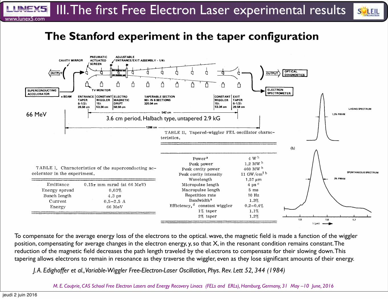
VOLUME 52, NUMBER 5 PHYSICAL REVIEW LETTERS )0 JANLJARY 1984
TABLE II. Tapered-wiggler FEL oscillator charac-teristics.
(a)1.3% FWHM
LASING SPECTRUM
Power'Peak power
Peak cavity powerPeak cavity intensity
WavelengthMicropuls e lengthMacropulse lengthRepetition rateBandwidth ~
Efficiency, constant wiggler1% taper2P taper
4Wb1.2 MWb460 MWbll GW/cm "1.57 pm4 psc5 ms10 Hz1.3%
0.2-0.4%%u()1.1%1.2 $ SPONTANEOUS SPECTRUM
These quantities were measured by averaging overmany shots.1% taper.Inferred under the assumption that the optical pulse
shape is the same as the measured electron pulse shape.Based on electron deceleration.
is controlled by four sets of quadrupole coils ex-terior to the wiggler. Cavity mirror alignmentwas accomplished by use of the reflection of theHeNe alignment beam onto one of three insertion-al. ayertures and by peaking the Q of the cavity asseen by the green line (514 nm) of an argon laser(mirror ref lectivity = 99.9'%%uo at the third harmonicof the fundamental).The characteristics of the oscillator are listed
in Table II. The wavelength was 1.57 p,m and theaverage power output during the linac macro-yulse was 4 W with 1%%uo tayer. With the duty cycleof the machine factored out this translates to apeak power of 1.2 MW. With a mirror transmis-sion of 0.13% on each side, the intracavity powerwas 460 1VIW.The laser spectrum for a 1% taper is shown in
the upper half of Fig. 3 and the spontaneous spec-trum in the lower half. Above threshold the powerincreases by a factor of 10"over the spontaneousradiation. The oscill. ator time-average linewidthis 18.8 nm. The time of the laser pulse to 10%%uo
saturation was 25 p.s, corresponding to 305 pass-es for a gain of V%%uo yer pass. The power level.produced was then constant for the 5 ms of theele ctron macropulse. Simultaneously with the1.6-p, m output of the laser, output at 0.8 p.m and0.53 p, m was observed. The characteristics ofthis radiation wil. l. be discussed in a future article.The wiggler was operated with three different
tapers, 0'%%uo, 1%%uo, and 2%, iny. Without taper,
I
1.4 . 1.5 1.7
FIG. 3. a) Lasing spectrum and (4) spontaneous out-put of the FEL as measured through the outcoupler.The time-averaged peak lasing power is 95 kW whilethe peak spontaneous power is only 0.95 mW.
one expects an efficiency of 1/(2N), where N isthe effective number of wiggler periods (131periods with the dispersion section turned off)which amounts to 0.38% efficiency. This com-pares favorably with the measured efficiency of0.4/o. Benson etal. demonstrated about 0.2%efficiency with a 160-period wiggler. " For the1%%uo-taper case the electron spectra show a cleardivision into a trapped group (50% to 65%) whichare decelerated 1% to 1.8% in energy and an un-trayped remainder which is spread + 0.4% aroundthe initial energy. The net deceleration efficiencyin this case is 1.1%%uo (Fig. 4). The buckets for the2%-taper case were less clearly defined; how-ever, efficiencies up to 1.2% were obtained. Thequoted efficiency in each case is based on meas-urements of electron deceleration.Comparing the power extracted from the elec-
tron beam with the output power of the laser isdifficult, because electron spectra are single-pulse spectra while the optical. power is time av-eraged, and there was large macropul. se-to-macropul. se power variations, probably due to aninadvertent vibrational coupling to one of the mir-
346
www.lunex5.com
M. E. Couprie, CAS School Free Electron!Lasers!and!Energy!Recovery!Linacs !(FELs and !ERLs), Hamburg, Germany, 31 !May –10 !June, 2016
III. The first Free Electron Laser experimental results
J. A. Edighoffer et al., Variable-Wiggler Free-Electron-Laser Oscillation, Phys. Rev. Lett 52, 344 (1984)
The Stanford experiment in the taper configurationVOLUME 52, NUMBER 5 pHy SICALAL REVIEW LETTERS go JAN vAR»&84
SUPE RCONDUCT INGACCELERATOR
TAPERASLE SECTION90K IN 6 SECTIONS320.04 cm
542 cm
PNEUMATIC ADJUSTABLEENTRANCE/EXIT ASSEMBLY - 1/-1 4XCAVITY MIRROR ACTUATED
/ SCREENf g&, I
TV MONITOR
AM ENTRANCE CONSTANT ELECTROe BEAM ETAPER W IGGL ER MAGNETIC6-1/2X 15K DR I FT28.58 cm 53.34cm 58.59 cm
CONSTANT EXITWIGGLER TAPER15K 6-1/2X53 34 cm 28 58 cm
!OPTICALDIAGNOSTICSI
ELECTRONSPECTROMETER
1268 cm
FIG. 1. Schema xc ot f the multicomponent wiggi ler FEL system.
eral. gro p .rou s.4 ' An op icat' l. kl.ystron variant of a ciency.When untapere, ed th magnets of the main wig-
ce a maximum field of 2.9 kGstant wiggl. er oscillated a
gl.er sections produ7
i . 1. on axis. e front an rei 1. on axis. e d ar of these sec ions1. t h h t l th
ppA 66-MeV electron beam from e
tween the sides of each wigg ersteered down the axism nets is increased the fie on
conducting accel.erator is sel.ectron beam c ar- gap between the magn ' ' fie onof the tapered wiggler. The e
axis falls, creating a ag ' ' ta m netic field taper.bown in Table I. The cavitythe deviations of the electrons from e
acteristics are s own ina taper~ e e-'.-ll.:-:"., "-b..".-'-.
thi th. Th r fo, th i t oHal.bach design, ' con- tron path lengTh iggler is based on the Ha acewira s of SmCO, per- decelerate through the wigg er,
e. This al. l,ows the e ec-SlS lllgt' of a pair of linear arrays o
t in f equency need not change.ro tical ie l.d
manent magne s.t The arrays are constantvar trons o s ay 't t in resonance with the p
'el.en th (X = . cm var—3 6 ) but can be made to varythe full l.eng ot th f the wiggl. er. An advantage
er is that the configuration andcontrol ing e1 th spacing between the magnet p anes.h con- amoun o apt f t er may be adjusted for study. en
ler oneThe wiggler consis
i uration used incorporate in ofifteen periods. The conf igurt ns large smal, l-signal gain comp
tainingp
f I. in the operationi ler sections give arge s
s di nostics are help u inAt h h optical Var jous jagain as in an optical. klystron. ig erc er r ' odu- of th' FEL. A total of fourteen inser
gcher rovides momentum m
s nine inside the wiggler, g'fields the prebunc er pr
t' d er- rescent screens, nine '
f the elec-lation of the el.ectron beam; ag p
nt information on the positiotal
b rovi ing a m'd' a momentum-dependen i orFor eac scrh reen a set of horizonta
sion section ( y pat o tical. wave- tron beam.
s for the align-) o ppath eng
lengths at the entrance o ped ment of the electron e
ls. Focusd t a ing within the tapered m
laser beam w ich' h defines the optical axis. ocussection and, therefore, higher extraction e
TABLE I. Characteristics of the psu erconducting ac-celerator in the experiment.
I I I
I IOio(Sic
EmittanceEnergy spreadBunch lengthCurrentEnergy
0.15~ mm mrad I,'at 66 MeV)
0.03$()4.3 ps0.5-2.5 A66 MeV
PREBUNCHER DISPERSIONMAGNETS
TAPEREDSECTION
CONSTANTSECTION
FIG. 2. Key elemen s ot f the multicomponent wigglersystem.
66 MeV
VOLUME 52, NUMBER 5 pHy SICALAL REVIEW LETTERS go JAN vAR»&84
SUPE RCONDUCT INGACCELERATOR
TAPERASLE SECTION90K IN 6 SECTIONS320.04 cm
542 cm
PNEUMATIC ADJUSTABLEENTRANCE/EXIT ASSEMBLY - 1/-1 4XCAVITY MIRROR ACTUATED
/ SCREENf g&, I
TV MONITOR
AM ENTRANCE CONSTANT ELECTROe BEAM ETAPER W IGGL ER MAGNETIC6-1/2X 15K DR I FT28.58 cm 53.34cm 58.59 cm
CONSTANT EXITWIGGLER TAPER15K 6-1/2X53 34 cm 28 58 cm
!OPTICALDIAGNOSTICSI
ELECTRONSPECTROMETER
1268 cm
FIG. 1. Schema xc ot f the multicomponent wiggi ler FEL system.
eral. gro p .rou s.4 ' An op icat' l. kl.ystron variant of a ciency.When untapere, ed th magnets of the main wig-
ce a maximum field of 2.9 kGstant wiggl. er oscillated a
gl.er sections produ7
i . 1. on axis. e front an rei 1. on axis. e d ar of these sec ions1. t h h t l th
ppA 66-MeV electron beam from e
tween the sides of each wigg ersteered down the axism nets is increased the fie on
conducting accel.erator is sel.ectron beam c ar- gap between the magn ' ' fie onof the tapered wiggler. The e
axis falls, creating a ag ' ' ta m netic field taper.bown in Table I. The cavitythe deviations of the electrons from e
acteristics are s own ina taper~ e e-'.-ll.:-:"., "-b..".-'-.
thi th. Th r fo, th i t oHal.bach design, ' con- tron path lengTh iggler is based on the Ha acewira s of SmCO, per- decelerate through the wigg er,
e. This al. l,ows the e ec-SlS lllgt' of a pair of linear arrays o
t in f equency need not change.ro tical ie l.d
manent magne s.t The arrays are constantvar trons o s ay 't t in resonance with the p
'el.en th (X = . cm var—3 6 ) but can be made to varythe full l.eng ot th f the wiggl. er. An advantage
er is that the configuration andcontrol ing e1 th spacing between the magnet p anes.h con- amoun o apt f t er may be adjusted for study. en
ler oneThe wiggler consis
i uration used incorporate in ofifteen periods. The conf igurt ns large smal, l-signal gain comp
tainingp
f I. in the operationi ler sections give arge s
s di nostics are help u inAt h h optical Var jous jagain as in an optical. klystron. ig erc er r ' odu- of th' FEL. A total of fourteen inser
gcher rovides momentum m
s nine inside the wiggler, g'fields the prebunc er pr
t' d er- rescent screens, nine '
f the elec-lation of the el.ectron beam; ag p
nt information on the positiotal
b rovi ing a m'd' a momentum-dependen i orFor eac scrh reen a set of horizonta
sion section ( y pat o tical. wave- tron beam.
s for the align-) o ppath eng
lengths at the entrance o ped ment of the electron e
ls. Focusd t a ing within the tapered m
laser beam w ich' h defines the optical axis. ocussection and, therefore, higher extraction e
TABLE I. Characteristics of the psu erconducting ac-celerator in the experiment.
I I I
I IOio(Sic
EmittanceEnergy spreadBunch lengthCurrentEnergy
0.15~ mm mrad I,'at 66 MeV)
0.03$()4.3 ps0.5-2.5 A66 MeV
PREBUNCHER DISPERSIONMAGNETS
TAPEREDSECTION
CONSTANTSECTION
FIG. 2. Key elemen s ot f the multicomponent wigglersystem.
3.6 cm period, Halbach type, untapered 2.9 kG
To compensate for the average energy loss of the electrons to the optical. wave, the magnetic field is made a function of the wiggler position, compensating for average changes in the electron energy, y, so that X, in the resonant condition remains constant. The reduction of the magnetic field decreases the path length traveled by the el.ectrons to compensate for their slowing down. This tapering allows electrons to remain in resonance as they traverse the wiggler, even as they lose significant amounts of their energy.
VOLUME 52, NUMBER 5 PHYSICAL REVIEW LETTERS )0 JANLJARY 1984
TABLE II. Tapered-wiggler FEL oscillator charac-teristics.
(a)1.3% FWHM
LASING SPECTRUM
Power'Peak power
Peak cavity powerPeak cavity intensity
WavelengthMicropuls e lengthMacropulse lengthRepetition rateBandwidth ~
Efficiency, constant wiggler1% taper2P taper
4Wb1.2 MWb460 MWbll GW/cm "1.57 pm4 psc5 ms10 Hz1.3%
0.2-0.4%%u()1.1%1.2 $ SPONTANEOUS SPECTRUM
These quantities were measured by averaging overmany shots.1% taper.Inferred under the assumption that the optical pulse
shape is the same as the measured electron pulse shape.Based on electron deceleration.
is controlled by four sets of quadrupole coils ex-terior to the wiggler. Cavity mirror alignmentwas accomplished by use of the reflection of theHeNe alignment beam onto one of three insertion-al. ayertures and by peaking the Q of the cavity asseen by the green line (514 nm) of an argon laser(mirror ref lectivity = 99.9'%%uo at the third harmonicof the fundamental).The characteristics of the oscillator are listed
in Table II. The wavelength was 1.57 p,m and theaverage power output during the linac macro-yulse was 4 W with 1%%uo tayer. With the duty cycleof the machine factored out this translates to apeak power of 1.2 MW. With a mirror transmis-sion of 0.13% on each side, the intracavity powerwas 460 1VIW.The laser spectrum for a 1% taper is shown in
the upper half of Fig. 3 and the spontaneous spec-trum in the lower half. Above threshold the powerincreases by a factor of 10"over the spontaneousradiation. The oscill. ator time-average linewidthis 18.8 nm. The time of the laser pulse to 10%%uo
saturation was 25 p.s, corresponding to 305 pass-es for a gain of V%%uo yer pass. The power level.produced was then constant for the 5 ms of theele ctron macropulse. Simultaneously with the1.6-p, m output of the laser, output at 0.8 p.m and0.53 p, m was observed. The characteristics ofthis radiation wil. l. be discussed in a future article.The wiggler was operated with three different
tapers, 0'%%uo, 1%%uo, and 2%, iny. Without taper,
I
1.4 . 1.5 1.7
FIG. 3. a) Lasing spectrum and (4) spontaneous out-put of the FEL as measured through the outcoupler.The time-averaged peak lasing power is 95 kW whilethe peak spontaneous power is only 0.95 mW.
one expects an efficiency of 1/(2N), where N isthe effective number of wiggler periods (131periods with the dispersion section turned off)which amounts to 0.38% efficiency. This com-pares favorably with the measured efficiency of0.4/o. Benson etal. demonstrated about 0.2%efficiency with a 160-period wiggler. " For the1%%uo-taper case the electron spectra show a cleardivision into a trapped group (50% to 65%) whichare decelerated 1% to 1.8% in energy and an un-trayped remainder which is spread + 0.4% aroundthe initial energy. The net deceleration efficiencyin this case is 1.1%%uo (Fig. 4). The buckets for the2%-taper case were less clearly defined; how-ever, efficiencies up to 1.2% were obtained. Thequoted efficiency in each case is based on meas-urements of electron deceleration.Comparing the power extracted from the elec-
tron beam with the output power of the laser isdifficult, because electron spectra are single-pulse spectra while the optical. power is time av-eraged, and there was large macropul. se-to-macropul. se power variations, probably due to aninadvertent vibrational coupling to one of the mir-
346
jeudi 2 juin 2016
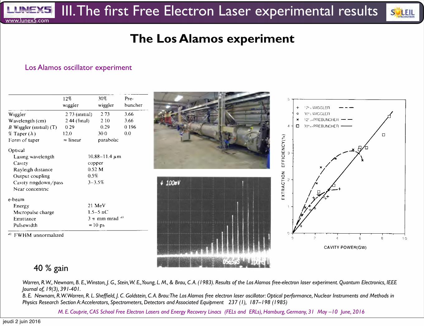
www.lunex5.com
M. E. Couprie, CAS School Free Electron!Lasers!and!Energy!Recovery!Linacs !(FELs and !ERLs), Hamburg, Germany, 31 !May –10 !June, 2016
The Los Alamos experiment
Los Alamos oscillator experiment
12
Tab l e 1
Charac t er i s t i cs o f the w i gg l ers and sys t em parame t ers used m
the exper i men t s . The w i gg l er w i th 12% wave l eng th t aper was
used m our prev i ous amp l i f i er exper i men t s. The w i gg l er w i th
30% wave l eng th t aper i s based on the des i gn d i scussed i n re f .
[4] .
Op t i ca lLas i ng wave l eng th
10 . 88-11 . 4 l m
Cav i ty
copperRay l e i gh d i s t ance
0 . 52 MOu tpu t coup l i ng
0 . 5%
Cav i ty r i ngdown / pass
3-3 . 5%
Near concen t r i c
e -beamEnergy
21 MeV
M i cropu l se charge
1 . 5-5 nCEm i t t ance
3 r r mm mrad
Pu l sew i d th
=10 ps
°) FWHM unnorma l i zed
the e l ec t ron-beam energy [7] . When bo th t echn i ques
were used toge ther , the i r agreemen t was w i th i n abou t
15% .
2 . 5 . Prebuncher
The use o f a prebuncher to i mprove ext rac t i on e f -
f i c i enc i es a t h i gh op t i ca l power was descr i bed i n re f . [4] .
The prebuncher i s a shor t (2 . 5 per i od) w i gg l er p l aced i n
f ron t o f the pr i mary w i gg l er. As the e l ec t rons pass
through the prebuncher , the i r ve l oc i t y i s modu l a t ed so
as to produce a bunch i ng ac t i on around the resonan t
par t i c l e . I f the buncher and w i gg l er are cor rec t l y spaced ,
s l i ppage be tween the e l ec t rons and l i gh t i s an i n t egra l
number o f wave l eng ths i n the dr i f t space be tween pre -
buncher and w i gg l er . The bunched e l ec t rons are i n-
j ec t ed i n to the w i gg l er a t the op t i mum phase for cap ture
and dece l era t i on , produc i ng an i mprovemen t i n ga i n
and e f f i c i ency o f the l aser by a l mos t a f ac tor o f 2 .
3 . Exper i men t a l resu l t s
3 . 1 . Ext rac t i on e f f i c i ency versus op t i ca l power
F i g . 1 shows the va l ues ob t a i ned for ext rac t i on e f -
f i c i enc i es versus es t i ma t ed i n t racav i ty power where bo th
t apered w i gg l ers are opera t ed w i th and w i thou t the
D . W Fe l dman e t a l . / H i gh ext rac t i on e f f i c i ency exper i men t s
prebuncher . The cav i ty powers are es t i ma t ed for pu l se
w i d ths o f 10 ps . The ext rac t i on e f f i c i enc i es represen t
averages t aken over a number o f macropu l ses and are
= 20% be l ow the h i ghes t s i ng l e pu l se ext rac t i on ob-
served . The da t a for the 30% w i gg l er i s sparse .
A l l o f the sys t ems show the same genera l t rend w i th
cav i ty power . The 12% w i gg l er , w i th and w i thou t pre -
buncher , shows sa tura t i on . Th i s may be caused by
grow th m the e -beam ' s em i t t ance when the m i cropu l se
charge approaches 3 nC . The curves i n f i g . 1 are i n-
t ended to i l l us t ra t e t rends and do no t represen t any
theory .
The 30% w i gg l er does no t exh i b i t any s i gn o f sa tura -
t i on up to a cav i ty power o f approx i ma t e l y 8 . 4 GW and
may be capab l e o f s t i l l h i gher e f f i c i enc i es . The i ncreased
ga i n w i th the prebuncher a l l ows the a t t a i nmen t o f h i gher
cav i ty powers for the same beam cur ren t and e f f i c i en-
c i es 1 . 5-2 t i mes h i gher . Th i s enhancemen t i s expec t ed
f rom theory for bo th w i gg l ers , bu t there i s no t enough
da t a for the 30% w i gg l er w i thou t prebuncher to ver i f y
the enhancemen t for th i s w i gg l er.
3 . 2 . Compar i son w i th ca l cu l a t i ons
The h i ghes t e f f i c i enc i es ob t a i ned f rom each w i gg l er
comb i na t i on were compared w i th cor respond i ng ca l cu-
l a t i ons made us i ng the e -beam code PARMELA to
mode l the acce l era tor and beam l i ne and to genera t e an
Uzw_U
' t
I l
wz0
UQ
xw
4
3 ,
2-
t
' 2`o VJ IGGLER
- - -0
30 ' , V , ' IGGLERz
i 2 " -PREBUNCHER - -
O 30 ° -PREBUNCHER -
CAV ITY POWER(GW)
F i g 1 Ext rac t i on e f f i c i enc i es versus cav i ty power for severa lw i gg l er -prebuncher comb i na t i ons .
12%w i gg l er
30%
w i gg l er
Pre -
buncher
W i gg l er 2 73 ( i n i t i a l ) 273 3 . 66
Wave l eng th (cm) 2 44 ( f i na l ) 210 3 . 66
B W i gg l er ( i n i t i a l ) (T) 029 0 . 29 0 196
Taper (X) 12 . 0 300 0 . 0
Form o f t aper = l i near parabo l i c
Warren, R. W., Newnam, B. E., Winston, J. G., Stein, W. E., Young, L. M., & Brau, C. A. (1983). Results of the Los Alamos free-electron laser experiment. Quantum Electronics, IEEE Journal of, 19(3), 391-401.B. E. Newnam, R. W. Warren, R. L. Sheffield, J. C. Goldstein, C. A. Brau: The Los Alamos free electron laser oscillator: Optical performance, Nuclear Instruments and Methods in Physics Research Section A: Accelerators, Spectrometers, Detectors and Associated Equipment 237 (1), 187--198 (1985)
40 % gain
192
whe r e t he sa t ur a t ed op t i ca l powe r was i nsens i t i ve t ocav i t y l eng t h , t ha t i s , h i gh beam cur r en t , op t i mum cav -i t y l eng t h , and l ow ou t pu t coup l i ng , t he no i se had l i t t l ee f f ec t , and t he ou t pu t powe r gr ew smoo t h l y dur i ng t hemac ropu l se . Unde r mor e c r i t i ca l cond i t i ons t he mac ro -pu l se was ex t r eme l y r agged . F i gs . 6 and 7 show exam-p l es o f t hese ex t r emes . (Recen t ca l cu l a t i ons o f powe rve r sus t i me i nd i ca t e t ha t , even w i t h ze ro no i se i n t hee l ec t ron beam ene rgy , h i gh - f r equency powe r f l uc t ua -t i ons o f sma l l (5 t o 10% ) amp l i t ude , s i m i l a r t o t ha t seeni n f i g . 6 , w i l l s t i l l be pr esen t . )
Op t i ca l ou t pu t powe r was no t t he on l y pa r ame t e ra f f ec t ed by t he no i se i n t he e l ec t ron beam . Spec t r a lmeasur emen t s , i n pa r t i cu l a r , d i f f e r ed f rom sho t t o sho t .The qua l i t a t i ve f ea t ur es o f t he spec t r a , t ha t i s , wave -l eng t h r ange , amoun t o f de t a i l , e t c . , we r e r e l a t i ve l ycons t an t f rom mac ropu l se t o mac ropu l se , bu t t he de t a i l sva r i ed . I n t he spec t r a pr esen t ed i n sec t . 5 . 4 , we se l ec t edcha r ac t e r i s t i c examp l es f rom a l a rge numbe r o f mea -sur emen t s f or d i scuss i on o f t he i r qua l i t a t i ve , no tde t a i l ed , f ea t ur es , Some prope r t i es o f t he op t i ca l beamwe r e qu i t e i nsens i t i ve t o t he no i se . Spa t i a l beam qua l i t ywas a pr i me examp l e , show i ng no ev i dence o f de t e r i or a -t i on f rom no i se ,
4 . 2 Fas t i n i t i a l t r ans i en t o f e l ec t ron ene rgy
A second prob l em pr esen t ed by t he e l ec t ron beamoccur r ed a t t he s t a r t up o f osc i l l a t i on . When t he acce l e r -a t or was t urned on a t t he beg i nn i ng o f each mac ropu l se ,i t s e l ec t r i c f i e l d i nc r eased i n a rough l y exponen t i a lf ash i on . Once t he f i e l d was w i t h i n a f ew pe r cen t o f i t sf i na l va l ue and s t i l l i nc r eas i ng , t hr ee t h i ngs happened :(1) t he cur r en t t hrough t he undu l a t or i nc r eased f ormze ro t o i t s f i na l va l ue , (2) t he max i mum o f t he SSGf unc t i on , m r esponse t o t he ene rgy change , sh i f t ed f roml onge r wave l eng t hs t o i t s f i na l va l ue , and (3) because o ft he nomsochronous 60° bends , t he m i c ropu l se sep -
a r a t i on i n t e r va l measur ed a t t he undu l a t or sh i f t ed f roma s i gn i f i can t l y shor t t i me t o i t s norma l 46 ns . A l l t hr eeo f t hese processes occur r ed w i t h i n t he f i r s t 10 I t s o fl as i ng when we obse r ved r ap i d grow t h o f t he op t i ca ls i gna l . Norma l l y , a l l t hr ee t ended t o r educe grow t h andcon t r i bu t ed t o a measur ed SSG t ha t was no t cons i s t en tw i t h t he measur ed sa t ur a t ed powe r or ex t r ac t i on e f -f i c i ency and , add i t i ona l l y , va r i ed e r r a t i ca l l y f rom day t o
day r e f l ec t i ng m i nor changes i n t he t i me dependence o ft he acce l a r a t or f i e l d .
5 . Op t i ca l r esu l t s
A d i scuss i on o f t he op t i ca l r esu l t s i s d i v i ded i n t oseven t op i cs t ha t i nc l ude t he f o l l ow i ng :- The grow t h o f op t i ca l powe r w i t h t i me f rom spon t a -
neous em i ss i on t o sa t ur a t i on , i nc l ud i ng measur e -men t s o f op t i ca l ga i n ,
B E . Ne i vnan i e t a l / I , ov A l amos FEL op t i ca l pe r f ormance
- Ene rgy and powe r ou t pu t and t he i r dependence ont he ou t pu t coup l e r s ,
- The e f f ec t o f cav i t y l eng t h de t un i ng on sa t ur a t edpowe r ,
- Spec t r a l ou t pu t ,- Op t i ca l ha rmon i cs .- Wave l eng t h t un i ng ,- Spa t i a l beam qua l i t y .
5 . 1 Sma l l - s i gna l ga i n
The SSG was rou t i ne l y measur ed a t t he beg i nn i ng o feach l as i ng expe r i men t by use o f a l i qu i d -He coo l ded ,Hg : Ge pho t ode t ec t or (San t a Ba rba r a Resea r ch Mode l9145 - 2HS) . The SSG depended s t rong l y on t he peake l ec t ron cur r en t , and ne t va l ues r ang i ng f rom 15 t o 60%we r e r ecorded f or r espec t i ve peak cur r en t s f rom 30 t o50 A The cur r en t r equ i r ed t o r each t he l as i ng t hr esho l dwas 5 A . A s l i gh t l y h i ghe r va l ue o f 7 A was necessa r y t oproduce s i gn i f i can t ou t pu t powe r measur ab l e w i t h ourl i nea r py roe l ec t r i c de t ec t or . F i g . 8 shows an examp l e o ft he exponen t i a l r i se , s t a r t i ng f rom i ncohe r en t spon t a -neous em i ss i on . Th i s osc i l l ogr am i s ac t ua l l y a measur eo f t he SSG o f t he pu l se ene rgy , r a t he r t han powe r ,because o f t he l i m i t ed bandw i d t h o f t he de t ec t i on sys -t em ( - I GHz ) r e l a t i ve t o t he - 30 -ps op t i ca l pu l ses .F rom nume r i ca l ana l ys i s o f t he t empor a l pro f i l e o f t hecur r en t pu l se , we de t e rm i ned t ha t t he SSG a t t he pu l sepeak shou l d be 10% gr ea t e r t han measur ed because t hepowe r ga i n depends on t he i ns t an t aneous va l ue o f t hem i c ropu l se cur r en t . A l so , t he measur ed va l ues shou l d bei nc r eased by an add i t i ona l 20% t o accoun t f or t heknown non l i nea r i t y o f t he pho t ode t ec t or . By app l i ca -
F i g. 8 , Exponen t i a l r i se o f t he l as i ng m i c ropu l se ene rgy f romspon t aneous em i ss i on en rou t e t o sa t ur a t i on a t t he s t a r t o f t hee l ec t ron -beam mac ropu l se . A ne t sma l l - s i gna l ene rgy ga i n o f34% pe r cav i t y round t r i p i s r epr esen t ed . The cor r espond i nggross powe r ga i n i s 52% .
III. The first Free Electron Laser experimental results
jeudi 2 juin 2016
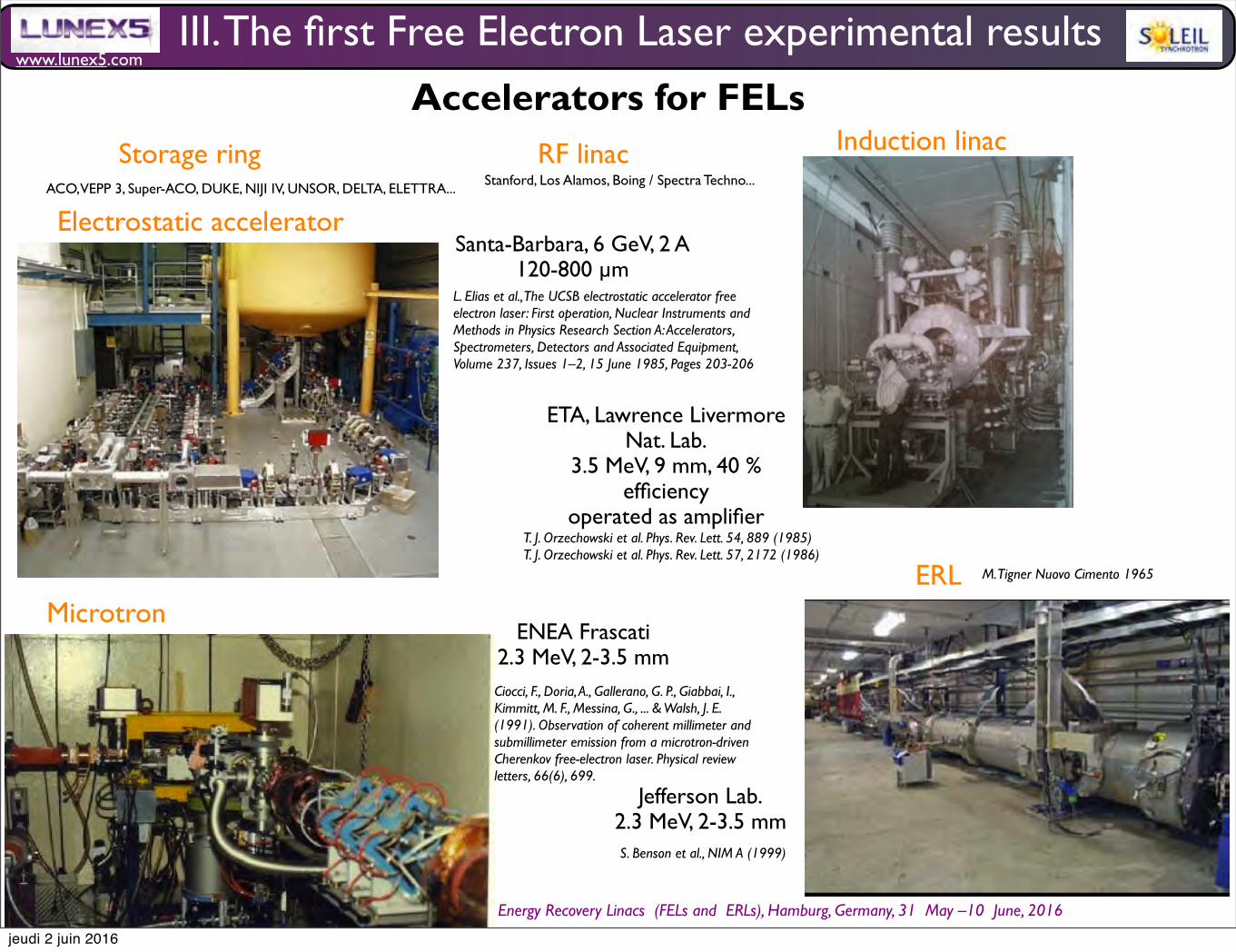
www.lunex5.com
M. E. Couprie, CAS School Free Electron!Lasers!and!Energy!Recovery!Linacs !(FELs and !ERLs), Hamburg, Germany, 31 !May –10 !June, 2016
III. The first Free Electron Laser experimental results
Electrostatic acceleratorSanta-Barbara, 6 GeV, 2 A
120-800 µm L. Elias et al., The UCSB electrostatic accelerator free electron laser: First operation, Nuclear Instruments and Methods in Physics Research Section A: Accelerators, Spectrometers, Detectors and Associated Equipment, Volume 237, Issues 1–2, 15 June 1985, Pages 203-206
Induction linac
ETA, Lawrence Livermore Nat. Lab.
3.5 MeV, 9 mm, 40 % efficiency
operated as amplifierT. J. Orzechowski et al. Phys. Rev. Lett. 54, 889 (1985)T. J. Orzechowski et al. Phys. Rev. Lett. 57, 2172 (1986)
Storage ring RF linac
Accelerators for FELs
ACO, VEPP 3, Super-ACO, DUKE, NIJI IV, UNSOR, DELTA, ELETTRA...Stanford, Los Alamos, Boing / Spectra Techno...
MicrotronENEA Frascati
2.3 MeV, 2-3.5 mm Ciocci, F., Doria, A., Gallerano, G. P., Giabbai, I., Kimmitt, M. F., Messina, G., ... & Walsh, J. E. (1991). Observation of coherent millimeter and submillimeter emission from a microtron-driven Cherenkov free-electron laser. Physical review letters, 66(6), 699.
ERL
Jefferson Lab.2.3 MeV, 2-3.5 mm S. Benson et al., NIM A (1999)
M. Tigner Nuovo Cimento 1965
jeudi 2 juin 2016

www.lunex5.com
M. E. Couprie, CAS School Free Electron!Lasers!and!Energy!Recovery!Linacs !(FELs and !ERLs), Hamburg, Germany, 31 !May –10 !June, 2016
FEL oscillator propertiesG
ain
redu
ctio
n (u
. a.)
Desalignement (u. a.)
Optical cavities for storage ring FELs in the UV, M.E. Couprie, D. Garzella, M. Billardon, 1995, Nucl. Inst. Meth. A 358, 382-386 (1995)
III. The first Free Electron Laser experimental results
Transverse modes Temporal properties
M. E. Couprie et al., NIMA 304 (1991) 47-52
λ/∆λ = 10-5
VEPP3 (Russia)
jeudi 2 juin 2016

www.lunex5.com
M. E. Couprie, CAS School Free Electron!Lasers!and!Energy!Recovery!Linacs !(FELs and !ERLs), Hamburg, Germany, 31 !May –10 !June, 2016
DNA or proteins, enzymatic reactions, mechanisms of trans-port, and photochemotherapy.
A. Time-resolved fluorescence experiments
The experimental layout of the time-resolved fluores-cence experiments is shown in Fig. 36. The sample understudy is irradiated by a short FEL pulse, and its fluorescencedecay F(t) is recorded by measuring the arrival time ofsingle photons of fluorescence versus a synchronization sig-nal !Fig. 37". The photons must be selected randomly, notmore than one per excitation pulse, to avoid pile-up effects.For each fluorescence decay curve, about 10 million totalcounts were stored, giving approximately 105 counts at thepeak !Fig. 37". The counting rate should be maintained atapproximately 10 kHz for optimum time response. Thus ameasurement is completed in approximately half an hour.The excitation wavelength was 350 nm (#$exc!1 Å beingthe linewidth of the FEL emission" and the emission wave-length was 460 nm (#$em!8 nm), selected by a H10 Jobin-Yvon monochromator.
NADH !%-nicotinamide adenine dinucleotide, reducedform" from Sigma Chemical Co. was studied in a 10 mMtris-!hydroxymethyl"-aminomethane buffer at pH 8, and con-tained 0.02% sodium azide as an antibacterial agent. Thefinal concentration of NADH in fluorescence measurementswas 18 &mol/l, giving an optical density of about 0.1 at 350nm in the 1 cm path of a quartz cuvette. NADH can bind toa large variety of enzymes, and provide the H" ions or elec-trons for chemical reactions, which are catalyzed by the de-hydrogenase. It constitutes an in vitro natural probe of theactive sites of these enzymes. In addition, it is used as anindicator of the metabolic state of organisms and tissues inimaging techniques. In its reduced form, NADH shows anabsorption band at 340 nm and an emission band in the vis-ible, centered around 460 nm, with a quantum efficiency of
2%. The oxided form (NAD") neither absorbs nor emits inthis spectral range.
The temperature dependence of the measured lifetimedistributions of NADH fluorescence decay is shown in TableII. The decay is described well in all cases by three to fourclearly separated relaxation processes, only two of whichmake a significant contribution to the kinetics !0.28 and 0.62ns". The temperature dependence of the nonradiative rate isdescribed by an Arrhenius law, the frequency factor A andthe activation energy Ea characterizing the dynamic quench-ing process. A linear fit, ln(1/' f#kR)!lnA#Ea /RTassuming79 kR!5$107 s#1 leads to an activation energy of2.6%0.3 kcal/mol and a frequency factor of 2%1$1011 s#1. We observe a shift of the lifetime amplitudesfrom the long to the short component when the temperatureis increased, and Arrhenius dependence of both componentswith similar activation energies of about 1.5 kcal/mol. Theamplitudes ci of the different components in Table II can, tofirst approximation, be identified as the relative populationsof chromophores that have the corresponding fluorescencelifetime, with the equilibrium constant being K!c2 /c1 . Thethermodynamic parameters !Table II" governing this equilib-rium are obtained by the linear fit
lnK!##HR ! 1T ""
#SR , !9"
assuming that these parameters are approximately constant inthe temperature range studied. These data are in good agree-ment with data obtained by other techniques.80
Polarization of the fluorescence depends on the distribu-tion of moments of the electronic transitions responsible for
FIG. 36. Schematic diagram of the photon counting fluorescence experi-ment. A Hamamatsu R1564U-06 microchannel plate photomultiplier wasused for fluorescence detection, and a fast Hamamatsu S4753 silicon pho-todiode with homemade amplification was used for synchronization. Thepolarization of the incident light is rotated to the vertical direction by aFresnel rhomb for detection at 90° in the horizontal plane of independentcomponents I # and I! of the fluorescence. The polarized components Ivv(t)and Ivh(t) are obtained by orienting the emission polarizer to vertical andhorizontal positions, respectively. The apparatus function g(t) was recordedat the excitation wavelength with a scattering solution of Ludox® !DuPontCo." in place of the sample.
FIG. 37. Single photon counting data obtained with the Super-ACO SRFEL: !A" Total fluorescence decay F(t) of NADH at pH 8, 10 °C, $exc 350nm, $em 460 nm, and corresponding instrumental function g(t); !B" residu-als obtained from maximum entropy method analysis of the decay in !A";!C" autocorrelation of the residuals.
3233Rev. Sci. Instrum., Vol. 74, No. 7, July 2003 FEL-based biophysical instrumentation
First use of the UV Super-ACO Free Electron Laser : fluorescence decays and rotational dynamics of the NADH coenzyme , M. E. Couprie, P. Tauc, F. Merola, A. Delboulbé, D. Garzella, T. Hara, M. Billardon , Rev. of Scient. Inst., 65(5) May 1994, 1485-1495
Fig. 2. SPV intensity as a function of the FEL/SR delay for3 Si(1 1 1) surfaces: (a) Si(1 1 1)2!1 freshly cleaved surface; (b)partially contaminated surface; (c) surface with a high defectdensity.
semiconductors surfaces and interfaces such asSi(1 1 1) 2!1 and Ag/GaAs [11,15]. The SPV is dueto the motion of FEL-created electron/hole pairs,leading to modi"cations of the band bending. Onethen directly measures the SPV by shifts of the corephotoelectron peaks generated by the SR from theSU3 undulator beamline. Owing to the naturalsynchronization between the FEL and SR pulses,e!ects due to the nanosecond and sub-nanosecondtimescale dynamics of the process have been ob-served by scanning the FEL-to-SR delay with anoptical delay line on the FEL beam path.
Fig. 2 shows the SPV intensity #uctuations asa function of the delay between the two pulses forthree di!erent surface qualities of cleavedSi(1 1 1)2!1. The long-time behavior is due to thesteady-state regime of photocarrier relaxation asobserved in the bulk. In contrast, the strongly oscil-lating transient regime, observed during the "rsthalf-nanosecond, is attributed to the ! (bonding)and !H (anti-bonding) electronic surface states [11].One can then understand the very di!erent behav-ior observed on a surface showing many defectsknown to accelerate the electronic relaxation (curvec in the "gure). These results, as well as recent dataobtained on other silicon interfaces [16], are veryimportant for the understanding of surface recom-bination phenomena and their role in the dynamicsof photon-induced electron/hole pairs.
Such studies allow one to track the sub-nanosecond electrostatic charge density evolutionof o!-equilibrium systems, with an application insemi-conductor physics related to the transient be-havior of Schottky diodes. Besides, there are alsointeresting high `photon densitya e!ects as ob-served in spectro-microscopy experiments onsemiconductor surfaces (photoelectron analysis ona micron size volume) performed with a very bril-liant SR beam as available on third generation SRsources. Inducing with the FEL such high-#ux den-sity e!ects, which could be linked to a SPV e!ect,permits their precise and quantitative evaluation.
2.2. What can we learn from the SPV experimenton the experimental procedure
During the performance of the SPV experiment,several points appeared to be critical for obtainingreliable data, which are of general importance:
FEL operation lifetime: A complex photoemissionexperiment, like many other endstations encoun-tered around SR sources, requires some time tobecome operational (warming up of the mirrorscarrying the SR, checking procedure for the elec-tron analyzer...), even though the sample has beenprepared previously to the FEL operation. Thetypical acquisition time for a given temporal delayis in the range of 10 min. Therefore, the investiga-tion of several temporal delay values for a givensample, with the possible intermediate "ne tuningof the FEL pointing, requires a minimum of severalhours of satisfactory operation of both the SR andthe FEL. This was the case at Super-ACO, where,depending on the operation of the FEL (with orwithout the use of the 500 MHz harmonic RFcavity [17]) the lifetime of the FEL in useful experi-mental conditions (power, stability) is usually in therange of 36 h. This is de"nitely one of the greatestadvantages of operating the FEL at the rather highenergy of 800 MeV, the nominal energy of Super-ACO, as compared to other SRFELs.
Flux: Because of the thermal load deposited ofthe FEL cavity front mirror, exposed to the intensephoton #ux of the undulator, and because of thehigh-order coherent synchrotron oscillations whichcan be triggered at high current, the FEL operationrequires a moderate stored current, typically below
492 L. Nahon et al. / Nuclear Instruments and Methods in Physics Research A 429 (1999) 489496
Surface States and Space Charge Layer Dynamics on Si(111)2x1 : a Free Electron Laser-Synchrotron radiation study , M. Marsi, M. E. Couprie, L. Nahon, D. Garzella, A. Delboulbé, T. Hara, R. Bakker, G. Indlekofer, M. Billardon, A. Taleb-Ibrahimi, , Appl. Phys. Lett. 70(7) (1997) 895-897
the emissions process, which is related to rotational Brown-ian motion of the molecules in solution. The decay of anisot-ropy of a chromophore rigidly attached to a sphere can bedescribed by r(t)!r0 exp("t/!) where r0 is the static anisot-ropy related to the angles between the moments associated toabsorption and to emission and ! is the relaxation coefficient,which is inversely proportional to the rotational diffusioncoefficient of a sphere. The measurements of fluorescenceanisotropy decay lead to very fast depolarization of the nico-tinamide ring, independent of the rest of the NADH mol-ecule. We find an average hydrodynamic volume of 1000#100 Å3 for NADH, which would correspond to a spherewith radius of 6.2 Å. This is in good agreement with thevolume of a folded configuration (836 Å3) given by a vander Waals model. The spatial conformations deduced areshown in Fig. 38 in folded and open conformations. Theseresults are in agreement with those obtained from previousnuclear magnetic resonance "NMR# studies of aqueousNAD.81
B. Transient absorption experiments
Figure 39 shows the transient absorption experimentalsetup employed at Super-ACO. Control of the spatial overlapbetween the pulses is critical. To monitor this, we mounted aquartz lens, which was used to focus the pump beam onto the
sample, on an X–Y –Z manipulator. The pump beam canthen be moved and focused precisely in the region where theprobe beam intersects the sample. This region where the twophoton beams intersect is optimized with the signal obtainedby a charge coupled device "CCD# camera in steady-stateoperation. The time-resolved experiment was performed at alower repetition rate, i.e., 83.2 kHz, than the normal one"8.32 MHz# using a Pockel’s cell.
Acridine from Prolabo, used without further purification,was studied. Absorption spectra were recorded using a Cary210 "Varian Inc.# spectrophotometer. Typically, a 0.1 cm or a1 cm quartz optical cell was used. Its final concentration was116 $M and 1.6 mM, giving an absorbance of about 0.5 at350 nm and absorbance of about 1 at 363 nm, respectively, inthe 0.1 cm path of a quartz cuvette.
The absolute intensity of a differential transient absorp-tion spectrum %A(& ,t) is directly proportional to the popu-lation of the molecule in an excited state. Assuming that thepump beam interacts only via the transition S0!S1 , thesaturation fluence is FS!1/'(0(&) where 'a0(&) is the ab-sorption cross section of the ground state "in units of cm2) atwavelength &. The pulse fluence of the pump should be ofthe same order as the saturation fluence in order to excite alarge fraction of the molecules. The FEL power on thesample is limited to a maximum of 100 mW, which corre-sponds to energy of 12 nJ per pulse "i.e., 2$1010 photons/pulse#. The pump beam is focused onto the sample to withina diameter of )20 $m, leading to the possibility of fluenceapproximately equal to the saturation fluence. In the simplestsituation, the pump/probe signal observed is proportional tothe population that is not in the ground state. Thus, if theground state is the only absorbing state, then the pump/probeobservable is given by S(t)!A*Pex(t)+ where A is a con-stant determined by experimental parameters such as the la-ser intensity and the probability that the system is found inthe excited state *Pex+. If the probe wavelength is in thespectral region of existing absorption of the ground state orof the stimulated emission, bleaching of the solution may beobserved. This was the case in our investigation of acridine.The change in transient absorption shown in Fig. 40 displaysdecay of the transient at 430 nm. The lifetime of the first
TABLE II. Fluorescence measurements of NADH performed with the super-ACO FEL.
Temperature(°C)
c1#1%
!1 , ns#0.01
c2#1%
!2 , ns#0.02 c3
!3 , ns#0.2
! , ns#0.01 ,2
10 61% 0.30 38% 0.70 1% 1.7 0.47 1.3020 68% 0.28 32% 0.62 %0.1% 1.8 0.39 1.2040 78% 0.24 22% 0.55 %0.01% 2.1 0.31 1.24
Arrhenius fits for different fluorescence decays.
!1 !2 !Ea 1.4#0.3 kcal/mole 1.5#0.1 kcal/mole 2.6#0.3 kcal/moleA 4#3$1010 s"1 2#1$1010 s"1 2#1$1011 s"1
Thermodynamical parameter K!c2 /c1!exp("%G/RT) with others techniques.
Technique %H "kcal/mole# %S "cal/K mole# G0 °C "kcal/mole#Fluorescence "5.0#0.2 "18.5#0.7 &0.1#0.4NMR ("5.6#0.2) ("17.5#1) ("0.8#0.2) (&0.4#0.1)
FIG. 38. Possible conformations of aqueous NADH. "A# Folded form con-structed from minimized fragments of the NADH chemical structure understereochemical rules borrowed from the DNA structure. "B# Structureadopted by NADH within the active site of lactate dehydrogenase in itsternary complex with oxamate, according to the x-ray crystallographic dataof C. Abad-Zapatero, J. P. Griffith, J. L. Sussman, and M. G. Rossmann"1987# J. Mol. Biol. 198 445, entry 1LDM of the Protein Data Bank.
3234 Rev. Sci. Instrum., Vol. 74, No. 7, July 2003 Edwards et al.III. The first Free Electron Laser experimental results
User applications started
A. Human neurosurgery
The first patient had a suspected meningioma of at least3 cm in size, as shown in Fig. 7, and was neurologicallystable prior to the procedure. The patient was operated on byan experienced neurosurgical team in Vanderbilt’s Keck FELCenter. While this was the first human operation in this fa-cility utilizing the Mark-III FEL, the facility had been per-forming both conventional laser and nonlaser human surgery!primarily orthopedic procedures" on a daily basis for severalmonths prior to this operation. There are extraordinary needsfor a neurosurgical operation of this complexity. It becameclear early on in the design of these operating rooms thatgreat care was required to minimize the likelihood of forget-ting a seemingly insignificant device, medicine, supply, orpart. Thus a track record was established of successful, rou-tine cases using these operating rooms prior to the first FELcase.
The patient was brought to a holding area from the mainhospital, where anesthesiologists prepared the patient forgeneral anesthesia. The patient was prepped and brought intoone of the two operating rooms fitted for use of the FEL.Once under anesthesia, the patient was positioned in a supineposition with a shoulder roll under her right shoulder, thusallowing her head to be easily positioned nearly horizontally!Fig. 8".
A standard neurosurgical approach was used in the righttemporal area, guided by a Pickar® neuronavigational sys-tem which utilized a computer topography !CT" scan thatshowed contrast obtained the day prior to the procedure. Thissystem enables a computer in the operating room to show thelocation and position of our instruments with respect to thepatient’s anatomic features by viewing a computer monitorloaded with the preoperative CT images. This is accom-plished using a system of infrared emitters on the patient andour instruments, and a series of infrared cameras within theroom all of which feed back to the computer. Using a neu-ronavigational system thus allowed the creation of a com-paratively small 6 cm curvilinear incision over the right
temple to expose the skull over the tumor, rather than thetypically large skin flap one uses just to ensure that the tumoris within the exposed area. A 5 cm bone flap was raised,exposing the underlying dura, which lines the inside of theskull. The tumor, attached to the deep, or brain side, of thedura, was easily located using the wand of the neuronaviga-tional system. A 1 cm cuff of dura was cut around the borderof the tumor and then folded back to expose the tumor. Thesurrounding normal brain was protected from any possiblestray laser energy by moistened cottonoids !Fig. 9".
Once surgically exposed, about 1500 macropulses of6.45 #m radiation averaging 32 mJ/macropulse were deliv-ered through an articulated arm to the outer surface of thetumor. The articulated arm terminates in a hand piece, wherea calcium fluoride lens with a focal length of 12.5 cm fo-cused the FEL beam to a spot size of 310!20 #m. Ahelium–neon pilot beam was used to guide the excision. Bypracticing one final time with some sterile paper on a sidetable, the surgeon was able to then position the hand piecewith the visible pilot beam to keep the focus on the tumorsurface, controlling FEL-beam delivery with a foot-pedal-actuated beam block. In the first operation, total FEL expo-sure administered in multiple passes took about 50 s, ablat-ing approximately a cubic centimeter ‘‘divot’’ from the outersurface of the tumor. The remainder of the tumor was re-sected en bloc !Fig. 10".
Once removed, the tumor was divided and a portion ofthe tumor that did not include the defect was sent for neuro-
FIG. 7. Preoperative MRI scan !axial T1 weighting with gadolinium con-trast". The arrow points to the tumor and its compression of the right tem-poral lobe.
FIG. 8. Position of the patient prior to incision. The arrow shows location ofthe tumor !circled ‘‘T’’" based on data from the neuronavigational system.
FIG. 9. !Color" Exposed tumor just prior to lasing.
3216 Rev. Sci. Instrum., Vol. 74, No. 7, July 2003 Edwards et al.
Reuse of AIP Publishing content is subject to the terms at: https://publishing.aip.org/authors/rights-and-permissions. Download to IP: 195.221.0.35 On: Mon, 30 May 201614:22:35
Human surgery
Edwards, G. S., Austin, R. H., Carroll, F. E., Copeland, M. L., Couprie, M. E., Gabella, W. E., ... & Joos, K. M. (2003). Free-electron-laser-based biophysical and biomedical instrumentation. Review of scientific instruments, 74(7), 3207-3245.
0.8
0.6
0.4
0.2
0
-10 0 10 20 30 40 50 60 70 Time (ps)
Figure 10. Vibrational photon echo decay data taken of W(CO)6 in 2- MTHF at 16 K. The inset is a semilogarithmic plot showing the data decay exponentially. Reprinted with pemission from reference 28.
Metal carbonyl solutes in glassy and liquid solvents
Vibrational photon echo, pump-probe and transient-grating experi- ments of the asymmetric CO-stretch mode of tungsten hexacar- bony1 (w[co]6) in various solvents have provided a foundation for understanding the dynamics of molecular vibrations in condensed- matter systems. The seminal experiment investigated the asym- metric CO-stretch mode of W(CO)6 in 2-methyltetrahydrofuran (2- MTHF) (28). The FEL was tuned to 5.10 pm and the micropulse duration was 2.7 ps at a repetition rate of 1 kHz. Because the coupling of vibrations to the heat bath, i.e. mechanical degrees of freedom external to the molecule, is substantially weaker than that of electronic states, the dephasing times are relatively long for the vibrational photon echo, and there are little or no solvation dynamics. Consequently, picosecond pulses are appropriate for this investigation. The temperature was varied from 300 to 16 K, taking the sample from a liquid to a supercooled liquid and then to a glass. Photon echoes were observed from 16 to 140 K, where T, is 90 K, and the photon-echo decay curve at 16 K is shown in Fig. 10. The time constant for the decay is 15 ps, the homogeneous dephasing time is 60 ps and the homogeneous linewidth is 5.2 GHz, which should be compared with the inhomogeneous linewidth of 540 GHz. The pure dephasing time contribution to the homogeneous linewidth, a measure of the influence of conformational fluctua- tions on the vibrational energy level spacing, is 1.6 GHz.
Subsequent measurements investigated W(CO)6 in 2-methyl- pentane (2-MP) from room temperature to 10 K (36). The FEL was tuned to 5.04 pm, and the pulse duration was -1.5 ps. These results suggest that the asymmetric CO-stretch mode can be inhomogeneously broadened in liquid solutions and that in- homogeneous broadening occurs at room temperature. The apparent decay time was 1.6 ps, the homogeneous linewidth was 49 GHz and the inhomogeneous linewidth was -300 GHz. The room temperature observation of the photon echo is attributable to the relatively sharp homogeneous linewidth of asymmetric CO- stretch mode for W(CO)6 in 2-MP.
Infrared photon-echo beats have been observed with -700 fs FEL micropulses to investigate the asymmetric CO-stretching mode of w ( C 0 ) ~ in dibutyl pthalate (DBP) (37). The FEL can populate higher vibrational levels when the bandwidth or Rabi frequency of the micropulse exceeds the vibrational anharmonicity.
Photochemistry and Photobiology, 2005, 81 71 7
-5 0 5 10 15 20 25 2 Time (ps)
Figure 11. Beating evident in photon echo decays and fits for the asymmetric CO-stretching mode for W(CO)6 in DBP as a function of temperature. Reprinted with permission from reference 37.
The beats are interpreted as multilevel coherence of the anharmonic oscillator. Figure 11 exhibits beats in the photon-echo decay curve, which are accounted for by a three-level model with a modulation frequency of 2.3 ps and a vibrational anharmonic splitting of 14.7 ? 0.3 cm-'.
Vibrational spectral diffusion has been investigated with pump- probe and transient-grating techniques using 1.3 ps pulses from the FEL and 10 ps pulses from an optical parametric amplifier (38). An ensemble of solute molecules will sample all possible solvent environments and thus a distribution of transition energies on some timescale. Consequently, the homogeneous line spectrally diffuses throughout the full inhomogeneous line on a timescale that is long with respect to the homogeneous dephasing time. Measurements of a transient spectral hole demonstrate spectral diffusion and orientational motion of the asymmetric CO-stretching mode for W(CO)6 in 2-MP. Intriguingly, the lifetime increases with temperature.
Native and mutant myogiobins
Investigation of the dynamics of the CO-stretching mode in myoglobin has provided insight into protein dynamics (39). Myoglobin stores and transports O2 in muscle tissue. CO or O2 binds to the iron atom located in a symmetric protoheme, i.e. iron(II) protoporphyrin-lX, located in the myoglobin interior. Myoglobin has a number of conformational substates and conformational dynamics of proteins occur over a wide variety of timescales. The FEL was used for pump-probe measurements of
Edwards, G. S., Allen, S. J., Haglund, R. F., Nemanich, R. J., Redlich, B., Simon, J. D., & Yang, W. C. (2005). Applications of Free‐Electron Lasers in the Biological and Material Sciences. Photochemistry and photobiology, 81(4), 711-735.
Photon echo
jeudi 2 juin 2016
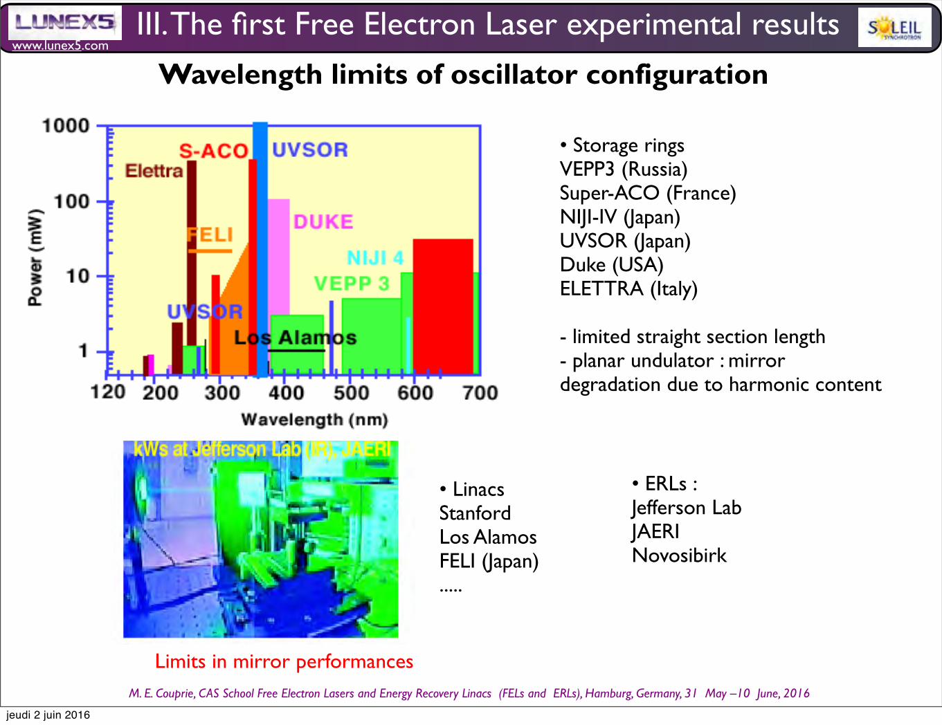
www.lunex5.com
M. E. Couprie, CAS School Free Electron!Lasers!and!Energy!Recovery!Linacs !(FELs and !ERLs), Hamburg, Germany, 31 !May –10 !June, 2016
• Storage ringsVEPP3 (Russia)Super-ACO (France)NIJI-IV (Japan)UVSOR (Japan)Duke (USA)ELETTRA (Italy)
- limited straight section length- planar undulator : mirror degradation due to harmonic content
• LinacsStanfordLos AlamosFELI (Japan).....
• ERLs :Jefferson LabJAERINovosibirk
III. The first Free Electron Laser experimental results
Wavelength limits of oscillator configuration
Limits in mirror performances
jeudi 2 juin 2016

www.lunex5.com
M. E. Couprie, CAS School Free Electron!Lasers!and!Energy!Recovery!Linacs !(FELs and !ERLs), Hamburg, Germany, 31 !May –10 !June, 2016
Strong signal case : Case of «long» undulator, «high» current : The change of electric field in one pass can not be neglectedtreatment with a set of generalised Bloch equationsF. A. Hopf, P. Meystre, M. O. Scully, W. H. Louisell, Strong-signal theory of a Free Electron laser, Phys. Rev. Lett 17 (30) (1976) 1342-1345
Hamiltonian despcriptionG. Dattoli, A. Marino, A. Renieri, F. Romanelli, Progress in the Hamiltonian Pictoure of the Free-Electron l Laser, IEEE journal of Quantum Electronics QE17 (8) 1371-1387 (1981)
IV. The high gain Free Electron Laser
N. M. Kroll, P. L. Morton, M. N. Rosenbluth, in Free Electron generators of coherent radiation, edited by S. F. Jacobs et al. Physics of Quantum Electronics 7 (Addison_Wesley), 147 (1980) A. Gover, P. Srangle, IEEE J. Quantum Electron. 17, 1196 (1981)
Collective instabilitythe electron communicate with each other through the radiation and the space charge field. => electron «self bunching» on the scale of the radiation wavelength periods. The electrons have nearly the same phase and emit collectively coherent synchrotron radiation. Exponential growth of the radiation. Ex of cooperative effect in radiation-matter interaction
R. Bonifacio et al., Cooperative and chaotic transition of a free electron laser Hamiltonian model, Optics Communications 40(3), 1(1982), 219-223R. Bonifacio, Pellegrini C. and L.M. Narucci, Collective instabilities and high-gain regime in a free electron laser, Opt. Comm. 50, 376 (1984)Sprangle, P., Tang, C. M., & Roberson, C. W. (1985). Collective effects in the free electron laser. Nuclear Instruments and Methods in Physics Research Section A: Accelerators, Spectrometers, Detectors and Associated Equipment, 239(1), 1-18.Bonifacio, R., Casagrande, F., Cerchioni, G., de Salvo Souza, L., Pierini, P., & Piovella, N. (1990). Physics of the high-gain FEL and superradiance. La Rivista del Nuovo Cimento (1978-1999), 13(9), 1-69.
High gain studies
Start-up from spontaneous emissionFirst considered by Saldin and Kondratenko in order to amplify the emission in the high gain regime until saturation. Considered cases : infra-red FEL @ 10 MeV, shorter wavelengths (20 GeV, 0.25 keV).
A.M. Kondratenko et al, Sou Phys. Dokl. 24 (12), 1979, 989 Kondratenko A.M., Saldin E.L.: Generation ofCoherent Radiation by a Relativistic Electron Beam in a Undulator. Part. Accelerators 10, 207–216 (1986)Y.S. Derbenev, A.M. Kondratenko, E.L. Saldin: On the possibility of using a free electron laser for polarisation control in a storage ring, Nucl. Instr. Meth. A 193, 415–421 (1982)K. J. Kim et al, PRL57, 1986, 1871C. Pelligrini et al, NIMA475, 2001, 1
jeudi 2 juin 2016
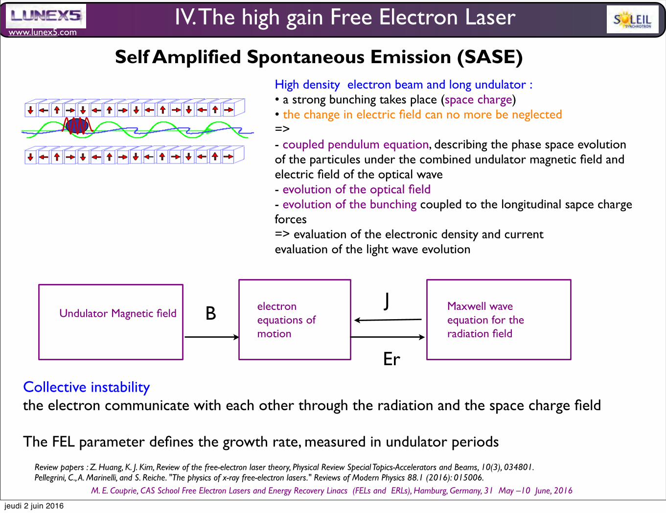
www.lunex5.com
M. E. Couprie, CAS School Free Electron!Lasers!and!Energy!Recovery!Linacs !(FELs and !ERLs), Hamburg, Germany, 31 !May –10 !June, 2016
Self Amplified Spontaneous Emission (SASE)
Undulator Magnetic fieldelectron equations of motion
Maxwell wave equation for the radiation field
B
Er
J
IV. The high gain Free Electron Laser
High density electron beam and long undulator : • a strong bunching takes place (space charge)• the change in electric field can no more be neglected => - coupled pendulum equation, describing the phase space evolution of the particules under the combined undulator magnetic field and electric field of the optical wave- evolution of the optical field- evolution of the bunching coupled to the longitudinal sapce charge forces=> evaluation of the electronic density and currentevaluation of the light wave evolution
Collective instabilitythe electron communicate with each other through the radiation and the space charge field
The FEL parameter defines the growth rate, measured in undulator periods
Review papers : Z. Huang, K. J. Kim, Review of the free-electron laser theory, Physical Review Special Topics-Accelerators and Beams, 10(3), 034801.Pellegrini, C., A. Marinelli, and S. Reiche. "The physics of x-ray free-electron lasers." Reviews of Modern Physics 88.1 (2016): 015006.
jeudi 2 juin 2016

www.lunex5.com
M. E. Couprie, CAS School Free Electron!Lasers!and!Energy!Recovery!Linacs !(FELs and !ERLs), Hamburg, Germany, 31 !May –10 !June, 2016
1
3
2
4
E
nerg
y
Light
e-
E
nerg
y
Phase
1) energy modulation 2) density modulation
3) Coherent emission
Start-up
Exponential gain regime
Saturation
Evolution of the light wave in the High gain regimeSASE : Self Amplified Spontaneous Emissionstart-up from spontaneous emission noiseexponential growth due to a collective instability (self-organisation of the electrons from a ramdon initial state)At saturation, the amplification process is replaced by a cyclic energy exchange between the electrons and the radiated field.
IV. The high gain Free Electron Laser
Optical guiding• gain guiding (quadratic gain medium, Kogelnick 1965)• refractive index=> undulator longer than a few Rayleigh lengths is possibleScharlemann, E.T., A.M. Sessler and J.S. Wurtele, 1985, Physical Review Letters 54, 1925.Scharlemann, E. T., Sessler, A. M., & Wurtele, J. S. (1985). Optical guiding in a free electron laser. Nuclear Instruments and Methods in Physics Research Section A: Accelerators, Spectrometers, Detectors and Associated Equipment, 239(1), 29-35.Z. Huang, K. J. Kim, A Review of X-ray Free-Electron Laser theory, Phys. Rev. Spe. Topics AB, 10, 034801 (2007)
jeudi 2 juin 2016
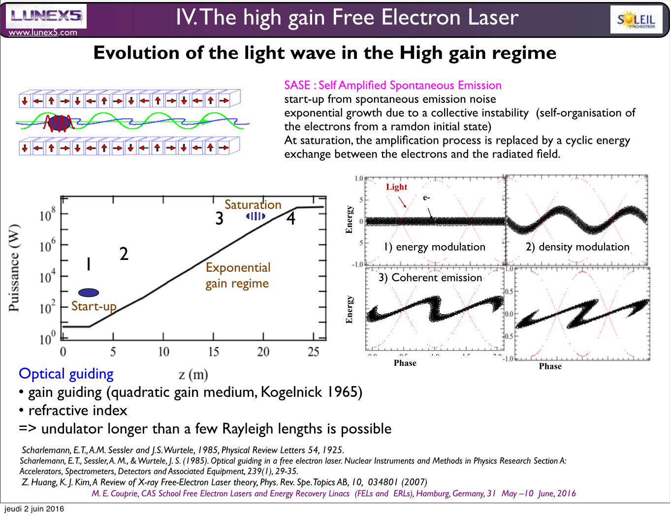
www.lunex5.com
M. E. Couprie, CAS School Free Electron!Lasers!and!Energy!Recovery!Linacs !(FELs and !ERLs), Hamburg, Germany, 31 !May –10 !June, 2016
1
3
2
4
E
nerg
y
Light
e-
Phase
Ene
rgy
Phase
1) energy modulation 2) density modulation
3) Coherent emission
Start-up
Exponential gain regime
Saturation
Evolution of the light wave in the High gain regimeSASE : Self Amplified Spontaneous Emissionstart-up from spontaneous emission noiseexponential growth due to a collective instability (self-organisation of the electrons from a ramdon initial state)At saturation, the amplification process is replaced by a cyclic energy exchange between the electrons and the radiated field.
IV. The high gain Free Electron Laser
Optical guiding• gain guiding (quadratic gain medium, Kogelnick 1965)• refractive index=> undulator longer than a few Rayleigh lengths is possibleScharlemann, E.T., A.M. Sessler and J.S. Wurtele, 1985, Physical Review Letters 54, 1925.Scharlemann, E. T., Sessler, A. M., & Wurtele, J. S. (1985). Optical guiding in a free electron laser. Nuclear Instruments and Methods in Physics Research Section A: Accelerators, Spectrometers, Detectors and Associated Equipment, 239(1), 29-35.Z. Huang, K. J. Kim, A Review of X-ray Free-Electron Laser theory, Phys. Rev. Spe. Topics AB, 10, 034801 (2007)
jeudi 2 juin 2016
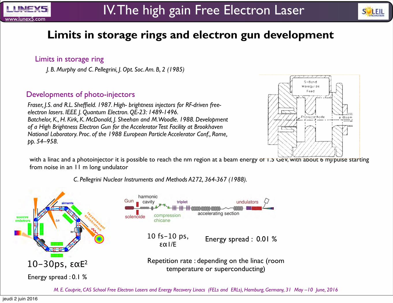
www.lunex5.com
M. E. Couprie, CAS School Free Electron!Lasers!and!Energy!Recovery!Linacs !(FELs and !ERLs), Hamburg, Germany, 31 !May –10 !June, 2016
Limits in storage rings and electron gun development
IV. The high gain Free Electron Laser
Fraser, J.S. and R.L. Sheffield. 1987. High- brightness injectors for RF-driven free-electron lasers. IEEE J. Quantum Electron. QE-23: 1489-1496.Batchelor, K., H. Kirk, K. McDonald, J. Sheehan and M. Woodle. 1988. Development of a High Brightness Electron Gun for the Accelerator Test Facility at Brookhaven National Laboratory. Proc. of the 1988 European Particle Accelerator Conf., Rome, pp. 54–958.
Limits in storage ring
with a linac and a photoinjector it is possible to reach the nm region at a beam energy of 1.5 GeV, with about 6 mJ/pulse starting from noise in an 11 m long undulator
J. B. Murphy and C. Pellegrini, J. Opt. Soc. Am. B, 2 (1985)
Developments of photo-injectors
C. Pellegrini Nuclear Instruments and Methods A272, 364-367 (1988).
Photo-injector development The Los Alamos photo-injector was developed in L-band for high average power FELs as part of the Star Wars program, and promised a much higher electron beam brightness. Robert Palmer and I, at the Center for Accelerator Physics at Brookhaven National Laboratory, decided in 1986-87 to develop this new technology for application in laser acceleration and FELs. An S-band version of the Los Alamos gun, optimized for high peak power and small emittance, was designed at Brookhaven.
Sigtuna, June 14-18, 2015 C. Pellegrini 25
Batchelor, K., H. Kirk, K. McDonald, J. Sheehan and M. Woodle. 1988. Development of a High Brightness Electron Gun for the Accelerator Test Facility at Brookhaven National Laboratory. Proc. of the 1988 European Particle Accelerator Conf., Rome, pp. 54–958.
Later work on photo-injector development was done at UCLA and a program was started later at SLAC by Herman Winick, and continued with a BNL-SLAC-UCLA collaboration.
10 fs-10 ps,εα1/E
Repetition rate : depending on the linac (room temperature or superconducting) 10-30ps, εαE2
Energy spread : 0.1 %
Energy spread : 0.01 %
jeudi 2 juin 2016
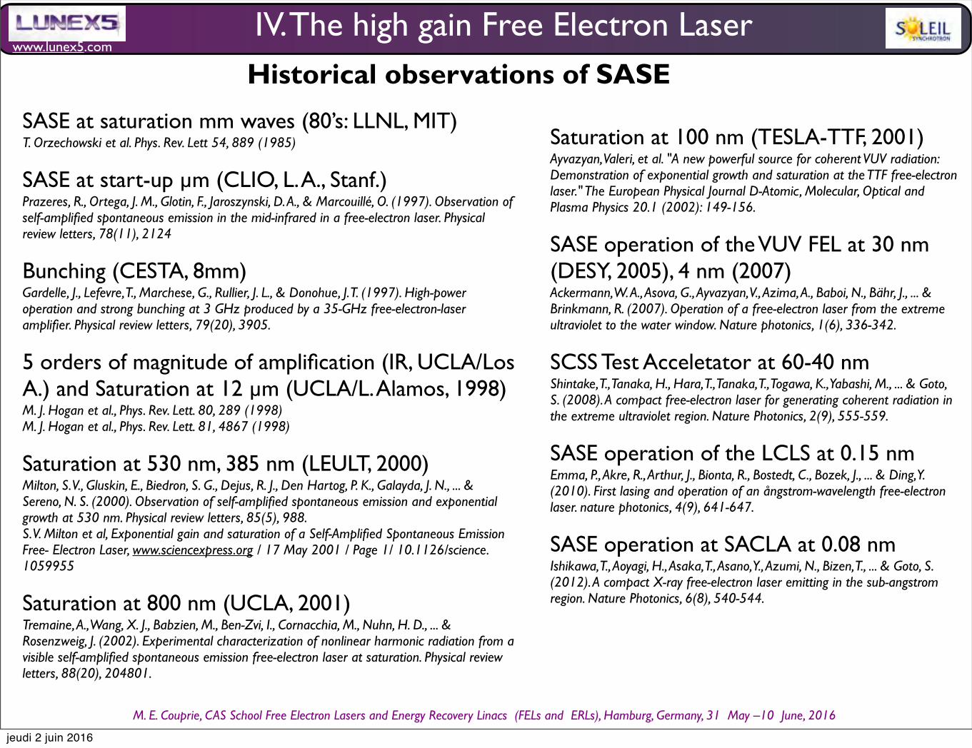
www.lunex5.com
M. E. Couprie, CAS School Free Electron!Lasers!and!Energy!Recovery!Linacs !(FELs and !ERLs), Hamburg, Germany, 31 !May –10 !June, 2016
Saturation at 100 nm (TESLA-TTF, 2001)Ayvazyan, Valeri, et al. "A new powerful source for coherent VUV radiation: Demonstration of exponential growth and saturation at the TTF free-electron laser." The European Physical Journal D-Atomic, Molecular, Optical and Plasma Physics 20.1 (2002): 149-156.
SASE operation of the VUV FEL at 30 nm (DESY, 2005), 4 nm (2007)Ackermann, W. A., Asova, G., Ayvazyan, V., Azima, A., Baboi, N., Bähr, J., ... & Brinkmann, R. (2007). Operation of a free-electron laser from the extreme ultraviolet to the water window. Nature photonics, 1(6), 336-342.
SCSS Test Acceletator at 60-40 nmShintake, T., Tanaka, H., Hara, T., Tanaka, T., Togawa, K., Yabashi, M., ... & Goto, S. (2008). A compact free-electron laser for generating coherent radiation in the extreme ultraviolet region. Nature Photonics, 2(9), 555-559.
SASE operation of the LCLS at 0.15 nm Emma, P., Akre, R., Arthur, J., Bionta, R., Bostedt, C., Bozek, J., ... & Ding, Y. (2010). First lasing and operation of an ångstrom-wavelength free-electron laser. nature photonics, 4(9), 641-647.
SASE operation at SACLA at 0.08 nmIshikawa, T., Aoyagi, H., Asaka, T., Asano, Y., Azumi, N., Bizen, T., ... & Goto, S. (2012). A compact X-ray free-electron laser emitting in the sub-angstrom region. Nature Photonics, 6(8), 540-544.
Historical observations of SASE
IV. The high gain Free Electron Laser
SASE at saturation mm waves (80’s: LLNL, MIT)T. Orzechowski et al. Phys. Rev. Lett 54, 889 (1985)
SASE at start-up µm (CLIO, L. A., Stanf.)Prazeres, R., Ortega, J. M., Glotin, F., Jaroszynski, D. A., & Marcouillé, O. (1997). Observation of self-amplified spontaneous emission in the mid-infrared in a free-electron laser. Physical review letters, 78(11), 2124
Bunching (CESTA, 8mm)Gardelle, J., Lefevre, T., Marchese, G., Rullier, J. L., & Donohue, J. T. (1997). High-power operation and strong bunching at 3 GHz produced by a 35-GHz free-electron-laser amplifier. Physical review letters, 79(20), 3905.
5 orders of magnitude of amplification (IR, UCLA/Los A.) and Saturation at 12 µm (UCLA/L. Alamos, 1998)M. J. Hogan et al., Phys. Rev. Lett. 80, 289 (1998)M. J. Hogan et al., Phys. Rev. Lett. 81, 4867 (1998)
Saturation at 530 nm, 385 nm (LEULT, 2000)Milton, S. V., Gluskin, E., Biedron, S. G., Dejus, R. J., Den Hartog, P. K., Galayda, J. N., ... & Sereno, N. S. (2000). Observation of self-amplified spontaneous emission and exponential growth at 530 nm. Physical review letters, 85(5), 988.S. V. Milton et al, Exponential gain and saturation of a Self-Amplified Spontaneous Emission Free- Electron Laser, www.sciencexpress.org / 17 May 2001 / Page 1/ 10.1126/science.1059955
Saturation at 800 nm (UCLA, 2001)Tremaine, A., Wang, X. J., Babzien, M., Ben-Zvi, I., Cornacchia, M., Nuhn, H. D., ... & Rosenzweig, J. (2002). Experimental characterization of nonlinear harmonic radiation from a visible self-amplified spontaneous emission free-electron laser at saturation. Physical review letters, 88(20), 204801.
jeudi 2 juin 2016
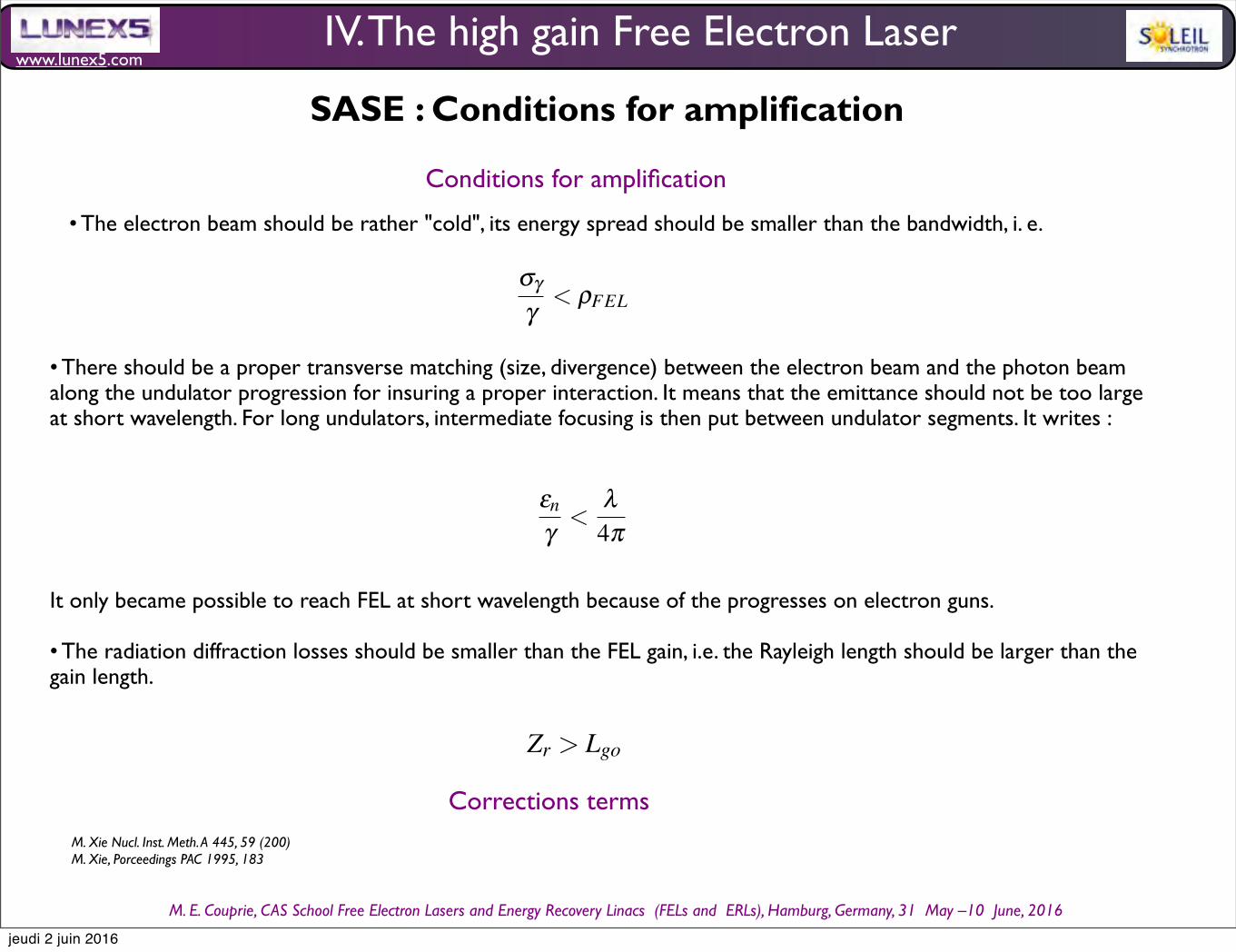
www.lunex5.com
M. E. Couprie, CAS School Free Electron!Lasers!and!Energy!Recovery!Linacs !(FELs and !ERLs), Hamburg, Germany, 31 !May –10 !June, 2016
• The electron beam should be rather "cold", its energy spread should be smaller than the bandwidth, i. e.
Conditions for amplification
• There should be a proper transverse matching (size, divergence) between the electron beam and the photon beam along the undulator progression for insuring a proper interaction. It means that the emittance should not be too large at short wavelength. For long undulators, intermediate focusing is then put between undulator segments. It writes :
It only became possible to reach FEL at short wavelength because of the progresses on electron guns.
• The radiation diffraction losses should be smaller than the FEL gain, i.e. the Rayleigh length should be larger than the gain length.
40
Fig. 25 Bunching factor. Parameters : 25 GeV, peak current 5 kA undulator period 50 mm, resonant radiation wavelength ∼ 0.1nm
For photons of 10 keV with a beam of 15 GeV , a Pierce parameter of 0.001, at 10 keV , Ncoh.ph ∼ 1500 !
The uncorrelated trains of radiation, which result from the interaction of electrons progressing jointly with the
previously emitted spontaneous radiation, lead to spiky longitudinal and temporal distributions, apart from single
spike operation for low charge short bunch regime [135, 136]. The emission usually presents poor longitudinal
coherence properties. On single pass FEL, transverse coherence results from the electron beam emittance (which
should be of the order of the emitted wavelength) and from possible gain guiding.
Because of the limited performance of mirrors, short wavelength FEL are usually operated in the so-called Self
Amplified Spontaneous Emission (SASE) (see Fig. 26b) setup [118, 120, 119], where the spontaneous emission at
the input of the FEL amplifier is amplified, typically up to saturation in a single pass after a regime of exponential
growth.
3.4 Conditions for amplification
Let’s discuss now the conditions for SASE amplification.
The electron beam should be rather "cold", its energy spread should be smaller than the bandwidth, i. e.
σγγ
< ρFEL (172)
There should be a proper transverse matching (size, divergence) between the electron beam and the photon
beam along the undulator progression for insuring a proper interaction. It means that the emittance should not be
too large at short wavelength. For long undulators, intermediate focusing is then put between undulator segments.
It writes :
εn
γ<
λ4π
(173)
It only became possible to reach FEL at short wavelenght because of the progresses on electron guns.
The radiation diffraction losses should be smaller than the FEL gain, i.e. the Rayleigh length should be larger
than the gain length.
Zr > Lgo (174)
Corrections terms (from the 3D theory) can be introduced XXX REF M. XieXXXX
40
Fig. 25 Bunching factor. Parameters : 25 GeV, peak current 5 kA undulator period 50 mm, resonant radiation wavelength ∼ 0.1nm
For photons of 10 keV with a beam of 15 GeV , a Pierce parameter of 0.001, at 10 keV , Ncoh.ph ∼ 1500 !
The uncorrelated trains of radiation, which result from the interaction of electrons progressing jointly with the
previously emitted spontaneous radiation, lead to spiky longitudinal and temporal distributions, apart from single
spike operation for low charge short bunch regime [135, 136]. The emission usually presents poor longitudinal
coherence properties. On single pass FEL, transverse coherence results from the electron beam emittance (which
should be of the order of the emitted wavelength) and from possible gain guiding.
Because of the limited performance of mirrors, short wavelength FEL are usually operated in the so-called Self
Amplified Spontaneous Emission (SASE) (see Fig. 26b) setup [118, 120, 119], where the spontaneous emission at
the input of the FEL amplifier is amplified, typically up to saturation in a single pass after a regime of exponential
growth.
3.4 Conditions for amplification
Let’s discuss now the conditions for SASE amplification.
The electron beam should be rather "cold", its energy spread should be smaller than the bandwidth, i. e.
σγγ
< ρFEL (172)
There should be a proper transverse matching (size, divergence) between the electron beam and the photon
beam along the undulator progression for insuring a proper interaction. It means that the emittance should not be
too large at short wavelength. For long undulators, intermediate focusing is then put between undulator segments.
It writes :
εn
γ<
λ4π
(173)
It only became possible to reach FEL at short wavelenght because of the progresses on electron guns.
The radiation diffraction losses should be smaller than the FEL gain, i.e. the Rayleigh length should be larger
than the gain length.
Zr > Lgo (174)
Corrections terms (from the 3D theory) can be introduced XXX REF M. XieXXXXCorrections termsM. Xie Nucl. Inst. Meth. A 445, 59 (200)M. Xie, Porceedings PAC 1995, 183
SASE : Conditions for amplification
IV. The high gain Free Electron Laser
jeudi 2 juin 2016
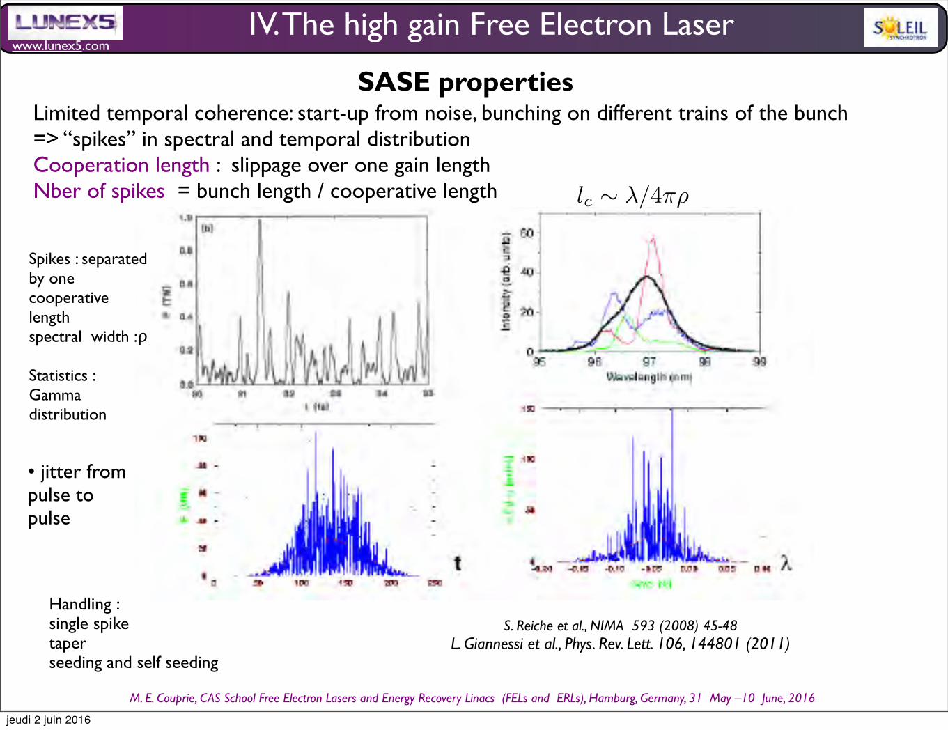
www.lunex5.com
M. E. Couprie, CAS School Free Electron!Lasers!and!Energy!Recovery!Linacs !(FELs and !ERLs), Hamburg, Germany, 31 !May –10 !June, 2016
Limited temporal coherence: start-up from noise, bunching on different trains of the bunch => “spikes” in spectral and temporal distributionCooperation length : slippage over one gain lengthNber of spikes = bunch length / cooperative length
Spikes : separated by one cooperative lengthspectral width :ρ
Statistics : Gamma distribution
1 Seeding FELS with HHG 13
while an FEL amplifier has a relative amplification bandwidth of the orderof ∼ 2ρfel [31] and only the noise in the FEL amplification spectral rangewill be amplified. We need then to calculate the fluctuations in a frequencyrange ∆ω ∼ 2ωρfel and the portion of beam that we have to consider for theaverage, has to be of the order of the cooperation length, lc ∼ λ/4πρfel . Thenumber of electrons in a cooperation length is
nec = Ipeak lc/e0c = Ipeak λ/ (4πe0cρfel) (1.15)
We may therefore estimate the shot noise intensity combining equations1.12, 1.14 and 1.15
Isn ∼ 18e−√3ω
ρ2felΣb
γm0c2 ∼ 3ωρ2felγm0c
2 (1.16)
This function is proportional to the square of the ρfel parameter, growslinearly with the frequency and with the electron beam energy. Assumingtypical values for the main parameters (ρfel ∼ 10−3, λu = 3 cm and K = 2)we have plotted in Fig. 1.5 the power corresponding to the intensity 1.16 overa transverse mode area equivalent to the electron beam transverse size.
Fig. 1.5. Calculated shot noise associated power as a function of the operating
wavelength. Parameters : ρfel ∼ 10−3, λu = 3 cm and K = 2.
The shot noise power scales as ∝ λ−3/2 and while it is simple to acheivethe necessary intensity threshold in the visible range, it becomes more andmore difficult in the VUV and in the Soft X-rays. In addition it is reasonableto assume a contrast ratio of 10− 102 between the seed and the backgroundnoise. Especially at short wavelengths the seed pulse length is shorter than theelectron bunch, and an additional factor has to be considered to preserve the
• jitter from pulse to pulse
Handling :single spiketaperseeding and self seeding
S. Reiche et al., NIMA 593 (2008) 45-48 L. Giannessi et al., Phys. Rev. Lett. 106, 144801 (2011)
IV. The high gain Free Electron Laser
SASE properties
jeudi 2 juin 2016

www.lunex5.com
M. E. Couprie, CAS School Free Electron!Lasers!and!Energy!Recovery!Linacs !(FELs and !ERLs), Hamburg, Germany, 31 !May –10 !June, 2016
Wavefront quality : ability to properly focus
M. Kuhlmann et al, FEL06P. Mercère et al, , Optics Letters, 28 (17), 1534-1536 (2003)
A. Singer et al. PRL 101, 254801 (2008)
SCSS Test Accelerator : 60-40 nmFLASH
Single-shot wavefront analysis of SASE harmonics in different FEL regimes, R. Bachelard, P. Mercere, M. Idir, M. E. Couprie, M. Labat, O. Chubar, G. Lambert, P. Zeitoun, H. Kimura, H. Ohashi, A. Higashiya, M. Yabashi, N. Nagasono, T. Hara, T. Ishikawa, accpeted in Phys. Rev. Lett. 2011
SASE properties
IV. The high gain Free Electron Laser
jeudi 2 juin 2016

www.lunex5.com
M. E. Couprie, CAS School Free Electron!Lasers!and!Energy!Recovery!Linacs !(FELs and !ERLs), Hamburg, Germany, 31 !May –10 !June, 2016
• short wavelength operation (1 Å) • good transverse coherence => low emittance required=> gun, energy• spike• single spike (low charge, chrip/taper), self-seeding
SASE (Self Amplified Spontaneous Emission) : no laser - electron interaction
Seeding : one laser-electron interaction • temporal coherence given by the external seed laser• improved stability (intensity, spectral fluctuations and jitter) => pump-probe experiments • quicker saturation => cost and size reduction • good transverse coherence• Seed : laser and HHG ( 60 nm)
Echo : Echo Enable Harmonic Generation : two laser - electron interactions
!
1"echo
=1"1
+1"2! high order harmonics
reached in a compact manner
R. Bonifacio et al, Opt. Comm. 50, 1984, 376, K. J. Kim et al, PRL57, 1986, 1871, C. Pelligrini et al, NIMA475, 2001, 1, A.M. Kondratenko et al, Sou
Phys. Dokl. 24 (12), 1979, 989
S. Reiche et al., NIMA 593 (2008) 45-48
L. Giannessi et al., Phys. Rev. Lett. 106, 144801 (2011)
G. Stupakov., PRL 102, 074801 (2009)D. Xiang et al., PRL 105, 114801 (2010)
Zhao et al., Proceed FEL conf, Mamö (2010)
IV. The high gain Free Electron Laser
SASE Versus seeding and echo
L. H. Yu et al, Science 289, 2000, 932L. H. Yu et al, PRL912003, 074801
T. Saftan APAC 2004, Gyeongu
jeudi 2 juin 2016

www.lunex5.com
M. E. Couprie, CAS School Free Electron!Lasers!and!Energy!Recovery!Linacs !(FELs and !ERLs), Hamburg, Germany, 31 !May –10 !June, 2016
SACLALCLS
FLASH
FERMI
2 mJ, 1.4 Å 1.5 Å saturation at 65 m (of 112 m)now 6 mJ, 96.7 % availability
!"#$%$
#$&'($ "#)$&'($ "*#)$&'($
+,-./$01%23'44134$
5#)$&'($
6..'7'389:-;$<93,.9,3'4$=>$<989:1-4$
?84'34$=>$@,-$
<1A9$BC38D$E-F,789134$4>?6<G$
>H?$HI2'3:%'-94$
J/191-$K:8;-149:.4$
+'8%$K,%2$
LGM$!"#$%&'
!"
!"#$%&'()*(+*,-./0*1'&2*/2($&*/./34,3-*5%6'%&'()*789:#:*
Katja Honkavaara | FEL Conference 2014 | August-27, 2014
FLASH. Free-Electron Laser
in Hamburg FLASH2 Operation Started
> Official permission for FLASH2 beam operation February-7, 2014
> Electron beam operation started in March 2014 first electron beam in extraction March-4, 2014
first beam to dump May-23, 2014
only few days available for FLASH2 beam operation before simultaneous operation established
> Simultaneous operation of FLASH1 (SASE) and FLASH2 (electron beam) starting end of May 2014
FLASH2 runs now in parallel to FLASH1 whenever possible, mainly during FLASH1 photon user experiments
dedicated FLASH2 beam time reserved as well
> First lasing: August-20, 2014
Electron beam on 4FL2EXTR March-4, 2014
Electron beam on 3FL2DUMP May-23, 2014
Photon beam on FL2_CE_YAG August-20, 2014
IV. The high gain Free Electron Laser
X-ray FELs
to come : E XFEL, PAL FEL, Swiss FEL ....
jeudi 2 juin 2016
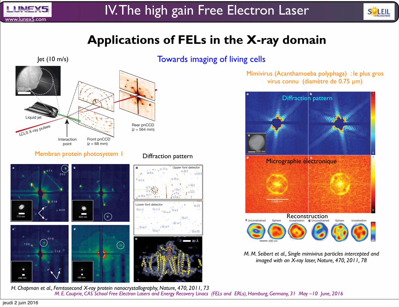
www.lunex5.com
M. E. Couprie, CAS School Free Electron!Lasers!and!Energy!Recovery!Linacs !(FELs and !ERLs), Hamburg, Germany, 31 !May –10 !June, 2016
IV. The high gain Free Electron Laser
Towards imaging of living cells
photon energy of the X-ray pulses was 1.8 keV (6.9-Awavelength), withmore than 1012 photons per pulse at the sample and pulse durations of10, 70, and 200 fs (ref. 13). AnX-ray fluence of 900 J cm22 was achievedby focusing the FEL beam to a full-width at half-maximum of 7mm,corresponding to a sample dose of up to 700MGy per pulse (calculated
using the program RADDOSE14) and a peak power density in excess of1016Wcm22 at 70-fs duration. In contrast, the typical tolerable dose inconventional X-ray experiments is only about 30MGy (ref. 1). A singleLCLS X-ray pulse destroys any solid material placed in this focus, butthe stream replenishes the vaporized sample before the next pulse.The front detector module, located close to the interaction region,
recorded high-angle diffraction to a resolution of 8.5 A, whereas therear module intersected diffraction at resolutions in the range of 4,000to 100 A. We observed diffraction from crystals smaller than ten unitcells on a side, as determined by examining the data recorded on therear pnCCDs (Fig. 2). A crystal with a side length of N unit cells givesrise to diffraction features that are finer by a factor of 1/N than theBragg spacing (that is, withN2 2 fringes between neighbouring Braggpeaks), providing a simple way to determine the projected size of thenanocrystal. Images of crystal shapes obtained using an iterative phaseretrieval method15,16 are shown in Fig. 2. The 3D Fourier transform ofthe crystal shape is repeated on every reciprocal lattice point. However,the diffraction condition for lattice points is usually not exactly satisfied,so each recorded Bragg spot represents a particular ‘slice’ of the Ewaldsphere through the shape transform, giving a variety of Bragg spotprofiles in a pattern; these are apparent in Fig. 2. The sum of countsin each Bragg spot underestimates the underlying structure factorsquare modulus, representing a partial reflection.Figure 3a shows strong single-crystal diffraction to the highest
angles of the front detector. The nanocrystal shape transform is alsoapparent in many patterns at the high angles detected by the frontdetector, giving significant measured intensities between Bragg peaksas is noticeable in Supplementary Fig. 3a. These mid-Bragg intensities
715 nm 620 nm
290 nm 160 nm
c*
b*
a* b*
a b
c d
0 1 1¯
1 1 0
0 0 2
0 1 0
0 1 0
1 0 0
0 2 0
¯
Figure 2 | Coherent crystal diffraction. Low-angle diffraction patternsrecorded on the rear pnCCDs, revealing coherent diffraction from the structureof the photosystem I nanocrystals, shown using a logarithmic, false-colourscale. The Miller indices of the peaks in a were identified from the
corresponding high-angle pattern. In c we count seven fringes in the b*direction, corresponding to nine unit cells, or 250 nm. Insets, real-space imagesof the nanocrystal, determined by phase retrieval (using the Shrinkwrapalgorithm15) of the circled coherent Bragg shape transform.
LCLS X-ray pulses
Liquid jet
Interaction point
Rear pnCCD(z = 564 mm)
Front pnCCD(z = 68 mm)
200 !m
Figure 1 | Femtosecond nanocrystallography. Nanocrystals flow in theirbuffer solution in a gas-focused, 4-mm-diameter jet at a velocity of 10m s21
perpendicular to the pulsed X-ray FEL beam that is focused on the jet. Inset,environmental scanning electron micrograph of the nozzle, flowing jet andfocusing gas30. Two pairs of high-frame-rate pnCCD detectors12 record low-and high-angle diffraction from single X-ray FEL pulses, at the FEL repetitionrate of 30Hz. Crystals arrive at random times and orientations in the beam, andthe probability of hitting one is proportional to the crystal concentration.
RESEARCH LETTER
7 4 | N A T U R E | V O L 4 7 0 | 3 F E B R U A R Y 2 0 1 1
Macmillan Publishers Limited. All rights reserved©2011
Jet (10 m/s)
Diffraction pattern
photon energy of the X-ray pulses was 1.8 keV (6.9-Awavelength), withmore than 1012 photons per pulse at the sample and pulse durations of10, 70, and 200 fs (ref. 13). AnX-ray fluence of 900 J cm22 was achievedby focusing the FEL beam to a full-width at half-maximum of 7mm,corresponding to a sample dose of up to 700MGy per pulse (calculated
using the program RADDOSE14) and a peak power density in excess of1016Wcm22 at 70-fs duration. In contrast, the typical tolerable dose inconventional X-ray experiments is only about 30MGy (ref. 1). A singleLCLS X-ray pulse destroys any solid material placed in this focus, butthe stream replenishes the vaporized sample before the next pulse.The front detector module, located close to the interaction region,
recorded high-angle diffraction to a resolution of 8.5 A, whereas therear module intersected diffraction at resolutions in the range of 4,000to 100 A. We observed diffraction from crystals smaller than ten unitcells on a side, as determined by examining the data recorded on therear pnCCDs (Fig. 2). A crystal with a side length of N unit cells givesrise to diffraction features that are finer by a factor of 1/N than theBragg spacing (that is, withN2 2 fringes between neighbouring Braggpeaks), providing a simple way to determine the projected size of thenanocrystal. Images of crystal shapes obtained using an iterative phaseretrieval method15,16 are shown in Fig. 2. The 3D Fourier transform ofthe crystal shape is repeated on every reciprocal lattice point. However,the diffraction condition for lattice points is usually not exactly satisfied,so each recorded Bragg spot represents a particular ‘slice’ of the Ewaldsphere through the shape transform, giving a variety of Bragg spotprofiles in a pattern; these are apparent in Fig. 2. The sum of countsin each Bragg spot underestimates the underlying structure factorsquare modulus, representing a partial reflection.Figure 3a shows strong single-crystal diffraction to the highest
angles of the front detector. The nanocrystal shape transform is alsoapparent in many patterns at the high angles detected by the frontdetector, giving significant measured intensities between Bragg peaksas is noticeable in Supplementary Fig. 3a. These mid-Bragg intensities
715 nm 620 nm
290 nm 160 nm
c*
b*
a* b*
a b
c d
0 1 1¯
1 1 0
0 0 2
0 1 0
0 1 0
1 0 0
0 2 0
¯
Figure 2 | Coherent crystal diffraction. Low-angle diffraction patternsrecorded on the rear pnCCDs, revealing coherent diffraction from the structureof the photosystem I nanocrystals, shown using a logarithmic, false-colourscale. The Miller indices of the peaks in a were identified from the
corresponding high-angle pattern. In c we count seven fringes in the b*direction, corresponding to nine unit cells, or 250 nm. Insets, real-space imagesof the nanocrystal, determined by phase retrieval (using the Shrinkwrapalgorithm15) of the circled coherent Bragg shape transform.
LCLS X-ray pulses
Liquid jet
Interaction point
Rear pnCCD(z = 564 mm)
Front pnCCD(z = 68 mm)
200 !m
Figure 1 | Femtosecond nanocrystallography. Nanocrystals flow in theirbuffer solution in a gas-focused, 4-mm-diameter jet at a velocity of 10m s21
perpendicular to the pulsed X-ray FEL beam that is focused on the jet. Inset,environmental scanning electron micrograph of the nozzle, flowing jet andfocusing gas30. Two pairs of high-frame-rate pnCCD detectors12 record low-and high-angle diffraction from single X-ray FEL pulses, at the FEL repetitionrate of 30Hz. Crystals arrive at random times and orientations in the beam, andthe probability of hitting one is proportional to the crystal concentration.
RESEARCH LETTER
7 4 | N A T U R E | V O L 4 7 0 | 3 F E B R U A R Y 2 0 1 1
Macmillan Publishers Limited. All rights reserved©2011
oversample the molecular transform, providing a potential route tophasing of the pattern17,18.In conventional crystallography, the ‘full’ Bragg reflection is deter-
mined to high precision, for example by integrating counts as thecrystal is rotated such that these reflections pass through the diffrac-tion condition. By indexing individual patterns and then summingcounts in all partial reflections for each index, we performed aMonte Carlo integration over the reciprocal-space volume of theBragg reflection and the distribution of crystal shapes and orientationsand variations in the X-ray pulse fluence. The result of this procedureconverges to the square of the structure factormoduli18.We found thatover 13% of diffraction patterns with ten or more spots could beconsistently indexed using the programs MOSFLM19 and DirAx20
(Methods). Merged intensities at 70-fs pulse duration are presentedas a precession-style image of the [001]-zone axis in Fig. 3b (see alsoSupplementary Figs 3 and 4).We tested the reliability of this approachby comparing the LCLS merged data with data collected at 100K with12.4-keV synchrotron radiation from a single crystal of photosystem Icryopreserved in 2M sucrose. These data sets show good agreement,with a difference metric, Riso, of 22.1% computed over the entire reso-lution range and of less than 13% in the middle resolution shells; seeSupplementary Table 1 for detailed statistics.To complete our proof of principle, we conducted a rigid-body
refinement of the published photosystem I structure (Protein DataBank ID, 1JB0) against the nanocrystal structure factors, yieldingR/Rfree5 0.25/0.23. A representative region of the 2mFo2DFc elec-tron density map at 8.5 A (Methods) from the LCLS data set is shownin Fig. 3c. This map shows the details expected at this resolution,including transmembrane helices, membrane extrinsic features andsome loop structures. For comparison, the electron density refinedfrom the 12.4-keV, single-crystal data set truncated to a resolution of8.5 A is given in Fig. 3d.The dose of 700MGy corresponds to a K-shell photoabsorption of
3% of all carbon atoms in the protein. This energy is subsequently
released by photoionization and Auger decay, followed by a cascadeof lower-energy electrons caused by secondary ionizations, takingplace on the 10–100-fs timescale21. Using a model of the plasmadynamics22,23, we calculated that by the end of a 100-fs pulse each atomof the crystal was ionized once, on average, and that motion of nucleihad begun. This is expected to give rise to a decrease in Bragg ampli-tudes, similar to an increase in a Debye–Waller temperature factor24.We studied the effects of the initial ionization damage on the diffrac-tion of photosystem I nanocrystals by collecting a series of data sets atpulse durations of 10, 70 and 200 fs. The 10-fs pulses were producedwith lower pulse energy:,10% of the total number of photons of thelonger pulses13, or a 70-MGy dose. Plots of the scattering strength ofthe crystals versus resolution, generated by selecting and summingBragg spots frommore than 66,000 patterns for each of the three pulsedurations measured, are shown in Fig. 4. The 10- and 70-fs traces arevery similar, indicating that these pulses are short enough to overcomeradiation damage at the observed resolution, 8.5 A. For 200-fs pulses,there is a decrease in scattering strength at resolutions beyond 25 A,indicating disordering on this longer timescale. The highest-resolutionBragg peaks for the 200-fs pulseswere not broadened or shifted relativeto the short-duration data sets, which indicates there was no strain orexpansion of the lattice, respectively.Our next step is to improve resolution by using shorter-wavelength
X-rays. Resolution may ultimately be limited by X-ray pulse fluence,the ultrafast radiation damage and the intrinsic disorder within thenanocrystals themselves. Recent experiments21 at LCLS indicate a briefsaturation of the X-ray photoabsorption of atoms in a tightly focusedpulse, resulting in a decrease in photoionization damage on a 20-fstimescale without a reduction in the scattering cross-sections that giverise to the diffraction pattern22. Planned beamlines at LCLS aim toachieve up to a 105-fold increase in pulse irradiance by tighter focusing,allowing data collectionwith low-fluence, 10-fs pulses or pulses of evenshorter duration25. This provides a route to further reducing radiationdamage and may allow measurements on even smaller nanocrystals,
0 1 0
100
a b
0
1
11 0 1
9 2 18 1 1
¯¯15 20 2¯¯14 24 4
¯13 12 019 2 0
¯19 10 0
¯21 11 0
12 1 1¯
22 6 0¯
¯7 16 2
¯4 14 27 9 0¯5 7 0¯
3 5 0¯
¯ ¯10 21 4
¯ ¯15 26 7 ¯ ¯19 19 7
¯ ¯18 22 7
¯ ¯19 9 7
¯ ¯¯14 2 6
¯23 9 10
14 9 414 14 4
13 17 4
20 14 7
20 Åc d
Upper font detector
Lower font detector
010
Figure 3 | Diffraction intensities and electron density of photosystem I.a, Diffraction pattern recorded on the front pnCCDs with a single 70-fs pulseafter background subtraction and correction of saturated pixels. Some peaks arelabelled with their Miller indices. The resolution in the lower detector corner is8.5 A. b, Precession-style pattern of the [001] zone for photosystem I, obtainedfrom merging femtosecond nanocrystal data from over 15,000 nanocrystal
patterns, displayed on the linear colour scale shown on the right. c, d, Region ofthe 2mFo2DFc electron density map at 1.0s (purple mesh), calculated fromthe 70-fs data (c) and from conventional synchrotron data truncated at aresolution of 8.5 A and collected at a temperature of 100K (d) (Methods). Therefined model is depicted in yellow.
LETTER RESEARCH
3 F E B R U A R Y 2 0 1 1 | V O L 4 7 0 | N A T U R E | 7 5
Macmillan Publishers Limited. All rights reserved©2011
H. Chapman et al., Femtosecond X-ray protein nanocrystallography, Nature, 470, 2011, 73
Membran protein photosystem 1
Mimivirus (Acanthamoeba polyphaga) : le plus gros virus connu (diamètre de 0.75 µm)
necessary improvement is to increase the dynamic range of the detec-tors. In our experiments, there were shots extending to significantlyhigher resolutions than those reported here but they contained toomany saturated pixels at low angles (more missing modes), prevent-ing image reconstruction.With reproducible samples, where the experi-ment can be repeated on a new object, a three-dimensional data set canbe collected, and the resolution extended (even from weak individual
exposures) by merging redundant data25–29. Studies of virus particleswith higher-intensity photon pulses and improved detectors couldanswer the question of whether the core is reproducible to subnano-metre resolution or whether the viral genome has the ‘molecular indi-vidualism’ that genomic DNA structures explore in vitro30.Note added in proof: In a previous study31, synchrotron radiation wasused to obtain X-ray diffraction data on a herpes virus.
1
1
0
0
a b
f g
1
0
ed
200 nm
PRTF = 0.5
32 nm
PRTF = 0. 1
PR
TF
PRTF = 0.5
32 nm
PRTF = 0.1
Resolution shell (nm–1) Resolution shell (nm–1)
0.00.010.00 0.02 0.03 0.04 0.05 0.06 0.07 0.08 0.010.00 0.02 0.03 0.04 0.05 0.06 0.07 0.08
0.2
0.4
0.6
0.8
1.0
0.0
0.2
0.4
0.6
0.8
1.0P
RTF
h i
1,000 nm
c
200 nm
Icosahedron IcosahedronSphere SphereUnconstrained Unconstrained
32 nm
PRTF = 0.5 PRTF = 0.1
Figure 2 | Single-shot diffraction patterns on single virus particles giveinterpretable results. a, b, Experimentally recorded far-field diffractionpatterns (in false-colour representation) from individual virus particlescaptured in two different orientations. c, Transmission electron micrograph ofan unstained Mimivirus particle, showing pseudo-icosahedral appearance7.d, e, Autocorrelation functions for a (d) and b (e). The shape and size of eachautocorrelation correspond to those of a single virus particle after high-passfiltering due to missing low-resolution data. f, g, Reconstructed images afteriterative phase retrieval with the Hawk software package16. The size of a pixelcorresponds to 9 nm in the images. Three different reconstructions are shownfor each virus particle: an averaged reconstruction with unconstrained Fourier
modes19 and two averaged images after fitting unconstrained low-resolutionmodes to a spherical or an icosahedral profile, respectively. The orientation ofthe icosahedron was determined from the diffraction data. The results showsmall differences between the spherical and icosahedral fits. h, i, The PRTF forreconstructions where the unconstrained low-resolution modes were fitted toan icosahedron. All reconstructions gave similar resolutions. We characterizeresolution by the point where the PRTF drops to 1/e (ref. 20). This correspondsto 32-nm full-period resolution in both exposures. Arrowsmark the resolutionrange with other cut-off criteria found in the literature (Methods). Resolutioncan be substantially extended for samples available in multiple identicalcopies1,25–28.
RESEARCH LETTER
8 0 | N A T U R E | V O L 4 7 0 | 3 F E B R U A R Y 2 0 1 1
Macmillan Publishers Limited. All rights reserved©2011
Micrographie électronique
Diffraction pattern
Reconstruction
M. M. Seibert et al., Single mimivirus particles intercepted and imaged with an X-ray laser, Nature, 470, 2011, 78
Applications of FELs in the X-ray domain
jeudi 2 juin 2016
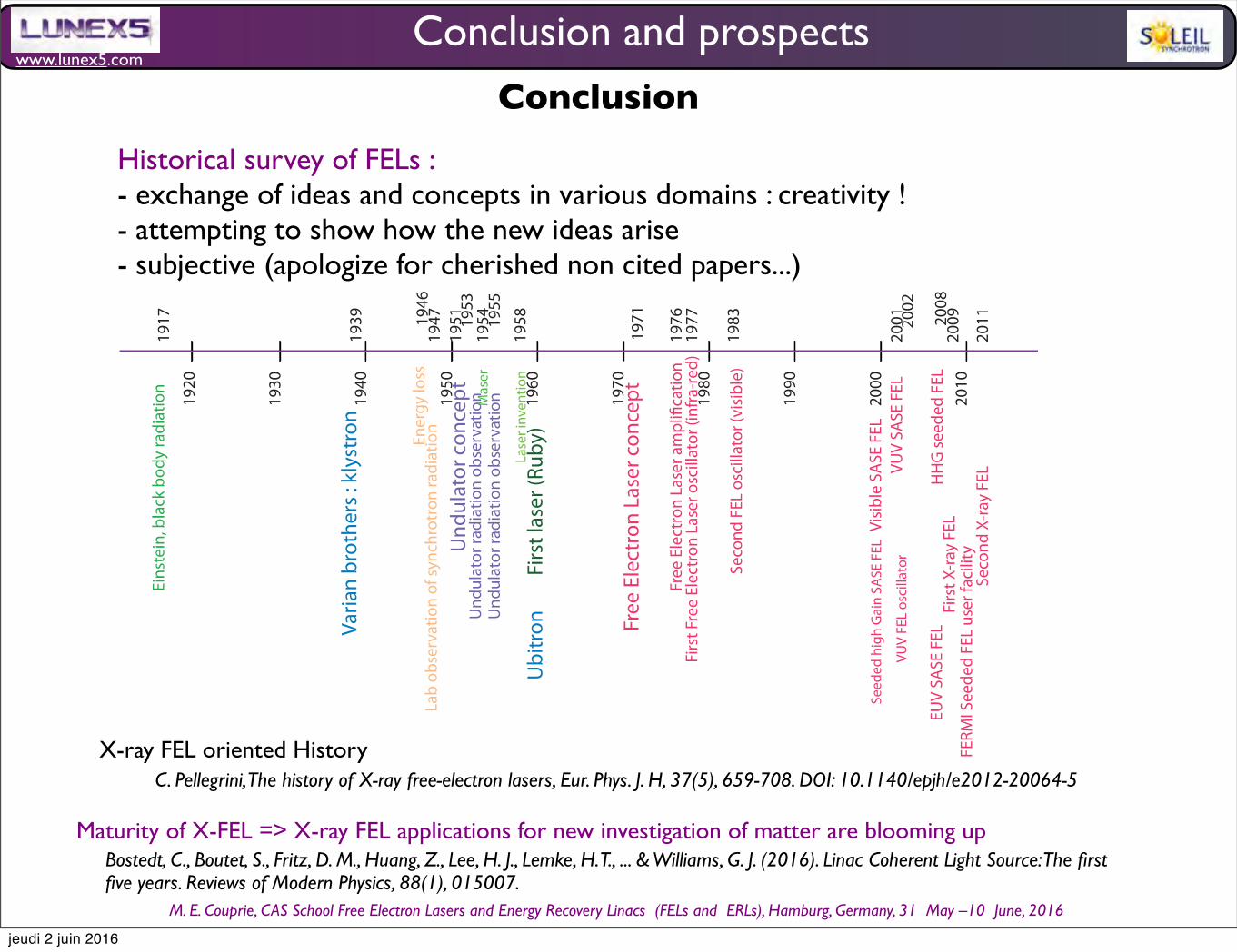
www.lunex5.com
M. E. Couprie, CAS School Free Electron!Lasers!and!Energy!Recovery!Linacs !(FELs and !ERLs), Hamburg, Germany, 31 !May –10 !June, 2016
Conclusion and prospects
Conclusion
Historical survey of FELs :- exchange of ideas and concepts in various domains : creativity ! - attempting to show how the new ideas arise- subjective (apologize for cherished non cited papers...)
Bostedt, C., Boutet, S., Fritz, D. M., Huang, Z., Lee, H. J., Lemke, H. T., ... & Williams, G. J. (2016). Linac Coherent Light Source: The first five years. Reviews of Modern Physics, 88(1), 015007.
C. Pellegrini, The history of X-ray free-electron lasers, Eur. Phys. J. H, 37(5), 659-708. DOI: 10.1140/epjh/e2012-20064-5X-ray FEL oriented History
Maturity of X-FEL => X-ray FEL applications for new investigation of matter are blooming up
1920
1930
1940
1950
1960
1970
1980
1990
2000
2010
1917
1939
1947
Eins
tein
, bla
ck b
ody
radi
atio
n
Lab
obse
rvat
ion
of sy
nchr
otro
n ra
diat
ion
Ener
gy lo
ss
Und
ulat
or c
once
pt
Und
ulat
or ra
diat
ion
obse
rvat
ion
Und
ulat
or ra
diat
ion
obse
rvat
ion M
aser
Lase
r inv
entio
nFi
rst l
aser
(Rub
y)
Free
Ele
ctro
n La
ser c
once
pt
Free
Ele
ctro
n La
ser a
mpl
i!ca
tion
Firs
t Fre
e El
ectr
on L
aser
osc
illat
or (i
nfra
-red)
Seco
nd F
EL o
scill
ator
(visi
ble)
Visib
le S
ASE
FEL
Seed
ed h
igh
Gai
n SA
SE F
EL
VUV
FEL
osci
llato
r
FERM
I See
ded
FEL
user
faci
lity
VUV
SASE
FEL
EUV
SASE
FEL
Fi
rst X
-ray
FEL
HH
G se
eded
FEL
Seco
nd X
-ray
FEL
Varia
n br
othe
rs : k
lyst
ron
Ubi
tron
1954
1951 19
53
1955
1971
1977
197619
46
1958
200920
08
2001 20
02
2011
1983
jeudi 2 juin 2016

www.lunex5.com
M. E. Couprie, CAS School Free Electron!Lasers!and!Energy!Recovery!Linacs !(FELs and !ERLs), Hamburg, Germany, 31 !May –10 !June, 2016
Approach diffraction and Fourier limits in a wide spectral range, with flexibility for users
Make «more compact» FELs
single spike, modified SASE, XFELO
Compact accelerator : Laser wakefield
acceleration, dielectric acceleration, inverse FEL
Compact undulator
FEL property manipulations
seeding, echo, up frequency conversion
Short FEL interaction
multiple users
High rep. rate : superconducting linacs, rings
Combinaison with lasers and THz (e.g.
pump-probe...)
as pulses / high energy
resolution (BW : 10-6)
high stability
higher photon energies
Physics and applications of High Brightness Beams : towards a fifth generation light source, Puerto-Rico, March 25-28, 2013
Conclusion and prospects
jeudi 2 juin 2016

www.lunex5.com
M. E. Couprie, CAS School Free Electron!Lasers!and!Energy!Recovery!Linacs !(FELs and !ERLs), Hamburg, Germany, 31 !May –10 !June, 2016
Various regimes and studies• MOPA
• Chaos and control
• Regerative FEL
• Vortives
E. Hemsing et al. , Nature Physics 9, 549–553 (2013)
the attractors via successive values of I!t" with asimple processing of the data. Typically, t which isclearly a multiple of the sampling time Dt; ischosen to be 12Dt; or one-fifth of the modulationperiod. The attractors I!t"cos(2pft), I!t"sin!2pft),I!t# t"; in cylindrical coordinates for the intensityrecords of Fig. 2a are shown in Fig. 6a. Thestratification seen in the chaotic regime is aproperty of strange attractors. CorrespondingPoincar!e sections are illustrated in Fig. 6b, forwhich the number of intercepts n of the attractorwith the plane of the Poincar!e section is asignature of the ‘‘nT’’ regime, and where a foldedshape which does not fill the whole spacecorresponds to the chaos. From the observationof the attractors, the origin of the irregularpatterns of the FEL can be attributed to thedeterministic chaos rather than to noise.
The evolution of the system when a givencontrol parameter is varied can be followed bythe observation of the bifurcation diagram, inwhich the intensity sampled at a definite time of
the modulation period is plotted versus the controlparameter. As the stroboscopy is synchronizedwith the modulation, a nT regime delivers a n-valued output and random answers reflect thestatistics of the chaos. Fig. 7 illustrates a 1T–2Tbifurcation for a change of the frequency of themodulation in (a), and a 1T, 2T, chaos, 2T, 3Tsequence for a modification of the amplitude ofmodulation. Bifurcation diagrams are powerfultools for the observation of the transitions betweenthe different regimes.
5. Conclusion
Clear bifurcation and chaos sequences havebeen observed in the response of the FEL to adetuning modulation. In a further work, thesequences (period doubling, inverse cascade, logis-tic map, etc.) corresponding to various parametersset-ups should be studied, for the determination ofthe basins of attraction. Clear analysis of the data
Fig. 6. (a) I!t"cos!2pft), I!t"sin!2pft), I!t# t" attractors recon-structed from intensity evolution of Fig. 3. 2T regime fora $ 12Hz, chaos for a $ 20Hz, 3T regime for a=46Hz. (b)Corresponding Poincar!e sections.
Fig. 7. Bifurcation diagrams (a) for a change of f between 200and 400Hz, a $ 14:3Hz and (b) for a change of a between 0and 60Hz, f=600Hz.
M.E. Couprie / Nuclear Instruments and Methods in Physics Research A 507 (2003) 1–76
M. Billardon, PRL 65 (6) , 713 (1990)M. E. Couprie, NIM A 507 (2003) 1-7
• Mode locking
• Q-switching
• Super-radiance
• CPA
• limit cycles
• 2 color operation....
Conclusion
jeudi 2 juin 2016
www.lunex5.com
M. E. Couprie, CAS School Free Electron!Lasers!and!Energy!Recovery!Linacs !(FELs and !ERLs), Hamburg, Germany, 31 !May –10 !June, 2016
Question for the end
Is FEL a real laser?
jeudi 2 juin 2016

www.lunex5.com
M. E. Couprie, CAS School Free Electron!Lasers!and!Energy!Recovery!Linacs !(FELs and !ERLs), Hamburg, Germany, 31 !May –10 !June, 2016
Quantum description ? yesvery heavy....needed for some particular effects (electromgantic undulator...)
Macroscopical quantum system? no
Light Amplification by Stimulated Emission ? theoretically : yes if stimulated diffusion considered as stimulated emission
experimentally : light amplifier (with optical resonator, SASE...)
Spatial and longitudinal coherence properties yes
M. Orzag, R. Ramirez, Quantum features of a fre electron laser, J. Opt. Soc. Am. B , 3 (6) , 895-900 (1986)C. B. Schroeder, C. Pelligrini, P. Chen, Quantum effects in high gain FELs, Phys. Rev. E (64), 056502
Is FEL a real laser?
Question for the end
jeudi 2 juin 2016
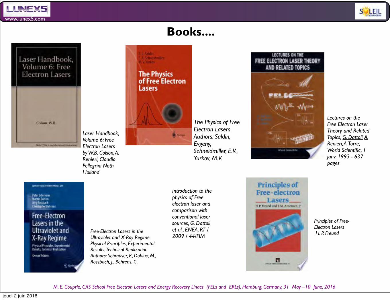
www.lunex5.com
M. E. Couprie, CAS School Free Electron!Lasers!and!Energy!Recovery!Linacs !(FELs and !ERLs), Hamburg, Germany, 31 !May –10 !June, 2016
The Physics of Free Electron LasersAuthors: Saldin, Evgeny, Schneidmiller, E.V., Yurkov, M.V.
Lectures on the Free Electron Laser Theory and Related Topics, G. Dattoli, A. Renieri, A. Torre, World Scientific, 1 janv. 1993 - 637 pages
Free-Electron Lasers in the Ultraviolet and X-Ray RegimePhysical Principles, Experimental Results, Technical RealizationAuthors: Schmüser, P., Dohlus, M., Rossbach, J., Behrens, C.
Laser Handbook, Volume 6: Free Electron Lasersby W.B. Colson, A. Renieri, Claudio Pellegrini Noth Holland
Principles of Free-Electron Lasers!H. P. Freund
Books....
Introduction to the physics of Free electron laser and comparison with conventional laser sources, G. Dattoli et al., ENEA, RT / 2009 / 44/FIM
jeudi 2 juin 2016
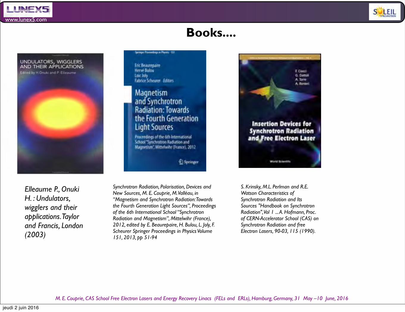
www.lunex5.com
M. E. Couprie, CAS School Free Electron!Lasers!and!Energy!Recovery!Linacs !(FELs and !ERLs), Hamburg, Germany, 31 !May –10 !June, 2016
Synchrotron Radiation, Polarisation, Devices and New Sources, M. E. Couprie, M. Valléau, in “Magnetism and Synchrotron Radiation: Towards the Fourth Generation Light Sources”, Proceedings of the 6th International School “Synchrotron Radiation and Magnetism”, Mittelwihr (France), 2012, edited by E. Beaurepaire, H. Bulou, L. Joly, F. Scheurer Springer Proceedings in Physics Volume 151, 2013, pp 51-94
Books....
Elleaume P., Onuki H. : Undulators, wigglers and their applications. Taylor and Francis, London (2003)
S. Krinsky, M.L. Perlman and R.E. Watson Characteristics of Synchrotron Radiation and Its Sources "Handbook on Synchrotron Radiation", Vol 1 ... A. Hofmann, Proc. of CERN-Accelerator School (CAS) on Synchrotron Radiation and free Electron Lasers, 90-03, 115 (1990).
jeudi 2 juin 2016
www.lunex5.com
M. E. Couprie, CAS School Free Electron!Lasers!and!Energy!Recovery!Linacs !(FELs and !ERLs), Hamburg, Germany, 31 !May –10 !June, 2016
jeudi 2 juin 2016
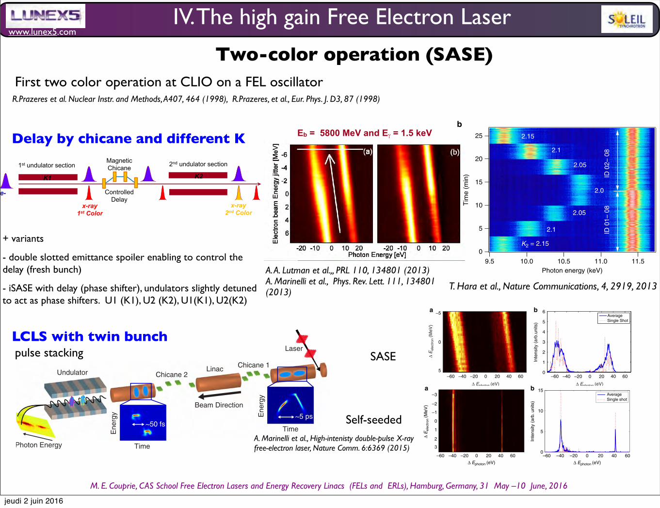
www.lunex5.com
M. E. Couprie, CAS School Free Electron!Lasers!and!Energy!Recovery!Linacs !(FELs and !ERLs), Hamburg, Germany, 31 !May –10 !June, 2016
Two-color operation (SASE)
R.Prazeres et al. Nuclear Instr. and Methods, A407, 464 (1998), R.Prazeres, et al., Eur. Phys. J. D3, 87 (1998)
Magnetic Chicane 1st undulator section
K1
e-
x-ray 1st Color
2nd undulator section
x-ray 2nd Color
Controlled Delay
K2
Eb = 5800 MeV and E! = 1.5 keV
+ variants
- double slotted emittance spoiler enabling to control the delay (fresh bunch)
- iSASE with delay (phase shifter), undulators slightly detuned to act as phase shifters. U1 (K1), U2 (K2), U1(K1), U2(K2)
Delay by chicane and different K
A. A. Lutman et al.,, PRL 110, 134801 (2013)A. Marinelli et al., Phys. Rev. Lett. 111, 134801 (2013)
second colour increases. In the TCDP operation, the electronbeam energy spread resulting from the first-colour lasing affectsthe gain of the second colour22.
This relation is more clearly shown in Figure 3, in which theshot-to-shot intensity correlation between the first and secondcolour pulses is plotted. K1 and K2 were set at 2.14 (9.75 keV) and1.95 (11 keV), and the pulse energies were estimated from theintegrated spectral area measured by the in-line spectrometerusing a Gaussian fit (see methods). To vary the electron beamenergy spread generated by the first-colour lasing, the number ofthe undulators of the first section was changed between eight(ID01-08) and four (ID05-08) by opening the undulator gaps.When all eight undulators were closed (brown diamonds inFig. 3), the first-colour lasing was close to saturation. Under thiscondition, the pulse energy of the first colour (9.75 keV) was140mJ with a 23% fluctuation (s.d.), whereas that of the secondcolour (11 keV) was a few mJ. The second-colour emissionincreases as decreasing the first-colour intensity by reducing the
number of the undulators in the first section. The pulse energiesof two colours can be balanced or relatively adjusted by changingthe number of undulators.
Angular separation of two-colour pulses. Since the amplificationprocess of the second-colour pulse independently starts up fromnoise after the chicane, the electron density modulation at thefirst-colour wavelength or its smearing does not affect the lasingof the second-colour pulse. Thus, the second-colour pulse can beemitted on a completely different axis without losing the laserintensity. In Figure 4, K1 and K2 were set at 1.8 (12.2 keV) and2.15 (9.7 keV), and the electron beam was deflected at the chicaneby 10 mrad horizontally (Fig. 4a) and vertically (Fig. 4b). Tworadiation profiles, each corresponding to the different photonenergy, were observed on a diamond screen located 130mdownstream of the chicane. The pulse energies of 50mJ and 31 mJwere obtained for 12.2 keV and 9.7 keV, respectively. To maintaina straight orbit of the electron beam, the undulator heightsand the quadrupole magnet positions were accordingly alignedwith respect to the deflected electron orbit downstream of thechicane. Note that the increase of the effective emittance due to adispersion function23 is negligibly small.
DiscussionThe TCDP operation of XFEL realizes a jitter-free stable X-raylight source equipped with wide wavelength tunability of bothcolours and variable delay at attosecond resolution. In SACLA,the two colours are completely out of the SASE gain bandwidth toeach other and the maximum wavelength separation of morethan 30% has been achieved. The two-colour pulses can beseparated not only spectrally but also spatially. The spatialseparation enables the irradiation of the two-colour pulses fromdifferent angles to a sample. For example, simultaneous two-colour diffraction imaging from different angles becomes possiblewithout losing photon intensity caused by a spectrometer.
0
5
10
15
20
25
Tim
e (m
in)
9.5 10.0 10.5 11.0 11.5Photon energy (keV)
2.0x10⁻²
1.8
1.6
1.4
1.2
1.0
0.8
0.6
0.4
0.2
0.0
Inte
nsity
(a.
u.)
13121110Photon energy (keV)
Second colour First colour
2.15
2.1
2.05
2.0
2.05
ID 0
1– 0
8ID
02–
08
2.1
K2 = 2.15
a
b
Figure 2 | Measured spectra of the two-colour XFEL. (a) Spectrummeasured by scanning a monochromator with K1! 1.7 and K2! 2.15.(b) Consecutive single-shot spectra measured by an in-line spectrometer.The line at 11.4 keV is emitted from the first undulator section and thenumber of undulators is reduced from eight to seven at around 13min onthe ordinate. K2 is varied stepwisely from 2.15 to 2.0 in the lower part andfrom 2.0 to 2.15 in the upper part of the figure. The accelerator wasoperated at 10Hz and the sampling frequency of the in-line spectrometerwas 1Hz.
104
2
3456
105
2
3456
106
2
3456
107
Inte
nsity
of t
he s
econ
d co
lour
(11
keV
) (a
.u.)
104 2 3 4 5 6105 2 3 4 5 6
106 2 3 4 5 6107
Intensity of the first colour (9.75 keV) (a.u.)
ID01-08ID02-08ID03-08ID04-08ID05-08
Figure 3 | Single-shot intensity correlation between the first andsecond colour pulses. The first colour is 9.75 keV (K1! 2.14) and thesecond colour is 11 keV (K2! 1.95). The symbol colours correspond to thedifferent number of the first section undulators, eight undulators forbrown diamonds, seven for blue open circles, six for red squares, five forgreen triangles and four for black solid circles.
NATURE COMMUNICATIONS | DOI: 10.1038/ncomms3919 ARTICLE
NATURE COMMUNICATIONS | 4:2919 | DOI: 10.1038/ncomms3919 |www.nature.com/naturecommunications 3
& 2013 Macmillan Publishers Limited. All rights reserved.
First two color operation at CLIO on a FEL oscillator
T. Hara et al., Nature Communications, 4, 2919, 2013
LCLS with twin bunch
The X-ray free-electron laser (XFEL) is the brightest sourceof X-rays for scientific applications1–4. The uniqueproperties of XFELs have attracted the interest of a wide
community of scientists (for example, see refs 5–7). Despite theenormous success of XFELs, the effort to improve and extendtheir capabilities is growing steadily, fueled by user demands fornew modes of operation4,8–12 and more precise photon andelectron diagnostics13–15.
Two-colour pulses are an example of custom-made X-raysfrom a free-electron laser (FEL), where two pulses of differentphoton energy and with a variable time delay are generated.Two-colour X-rays have received considerable attention at manyFEL facilities worldwide16–21. This mode of operation allowsusers to probe the dynamics of ultra-fast processes triggered by ahigh-intensity X-ray pump, with a time resolution on the order ofa few femtoseconds. For example, in the field of time-resolvedresonant X-ray spectroscopy, two colour pulses allow the selectiveexcitation of molecular and atomic processes, such as chemicalbond breakage and rearrangement. High-intensity two-colourFELs also allow the study of warm dense matter with time-resolved X-ray pump/X-ray probe experiments22,23 as well as theexperimental investigation of X-ray-induced Coulomb explosionin atom clusters and nanocrystals at the femtosecond scale.Finally, in the field of coherent X-ray imaging, there is awidespread interest in extending multiple wavelength anomalousdispersion (MAD) imaging24 to fourth-generation light sourcesusing serial femtosecond crystallography5.In an XFEL, an intense electron bunch travels in a magnetic
undulator, generating a high-power X-ray pulse (ranging form afew GW to several tens of GW) with narrow bandwidth (between0.005 and 0.1%) and duration between a few femtoseconds and afew hundred femtoseconds1. The central wavelength lr is givenby the resonance formula25
lr ! lw1" K2
2
2g2; #1$
where lw is the undulator period, g is the beam’s Lorentz factorand K the scaled amplitude of the magnetic field. At X-rayenergies, the methods developed so far rely on generating twoX-ray colours by using two distinct values of K with a quasimono-energetic electron beam16,20,21. Although this approachcan achieve full control of the time and energy separation, theintensity of both pulses is lower than the saturation level becausethe same electron bunch is used for lasing twice, yielding a totalpower typically between 5 and 15% of the full saturation power.
Here we show how two independent electron bunches ofdifferent energies can be used to generate two X-ray pulses in oneundulator (we will refer to this technique as the twin-bunchmethod). Our method builds on the recent application of pulse-stacking techniques to high-brightness electron injectors19,26,27.In this case, each X-ray pulse is generated by one electron bunchand can reach the full saturation power, improving the two-colour intensity by one order of magnitude at hard X-rayenergies. In addition to improving the peak power of two-colourFELs, twin-bunches allow the use of MAD imaging techniques atXFEL facilities by combining two-colour FELs with the existinghard X-ray self-seeding capability8. This new capability has beensuccessfully tested in user experiments at Linac Coherent LightSource (LCLS) in a wide variety of fields.
ResultsTwin-bunch experiment at hard X-rays. The twin-bunchmethod is schematically illustrated in Fig. 1. The electrons aregenerated by a photocathode illuminated by a train of two laserpulses (generated with a pulse stacker, see the Methods section)with a variable delay on the order of a few picoseconds,generating two separate electron bunches. The two bunches areaccelerated up to 15GeV in the LCLS linear accelerator andcompressed from a peak current of 20A to roughly 4 kA bymeans of two magnetic chicanes. As a result of the bunch com-pression, the final arrival time difference of the electron bunchesis on the order of a few tens of femtoseconds. As the acceleration/compression system generates a time–energy correlation in theelectron beam, the two bunches also have different energies at theend of the accelerator. Finally, the two compressed bunches aresent into the undulator where they emit two X-ray pulses ofdifferent energies. Although we will present experimental data ata photon energy of 8.3 keV, the scheme described can work at anyphoton energy in the available LCLS range (nominally from 300to 10 keV).The recently developed X-band transverse deflector13 provides
an effective diagnostic tool for this two-bunch technique.Figures 2a and 2c show the measured longitudinal phase-spaceof the two bunches at the end of the undulator beamline for theunspoiled beam (that is, suppressing the lasing process with a largetransverse perturbation in the electron orbit) and for the beamafter the lasing process. The peak current is roughly 5 kA for a totalcharge of 150 pC, with an energy separation of 70MeV. Figure 2dshows the temporal profile of the X-ray pulses reconstructed from
Beam Direction
Laser
Undulator
Time
Linac Chicane 1Chicane 2
Photon Energy
Ene
rgy
Time
Ene
rgy
~5 ps~50 fs
Figure 1 | Schematic representation of the experiment. Illustration not to scale. From right to left: a laser pulse train generates two electron bunches at aphotocathode (the right inset shows the measured longitudinal phase-space at the photo-injector exit). The two bunches are accelerated in the LCLSlinac and compressed by means of two magnetic chicanes (the left inset shows the measured phase-space at the end of the beam line). Finally,the two bunches are sent to an undulator for the emission of two X-ray FEL pulses. The two X-ray pulses have a tunable energy difference in the rangeof a few percent and a variable time delay of tens of fs.
ARTICLE NATURE COMMUNICATIONS | DOI: 10.1038/ncomms7369
2 NATURE COMMUNICATIONS | 6:6369 |DOI: 10.1038/ncomms7369 | www.nature.com/naturecommunications
& 2015 Macmillan Publishers Limited. All rights reserved.
pulse stacking
the longitudinal phase-space measurement (see the Methodssection and ref. 13). The two bunches emit two X-ray pulseswith a peak power of 76GW for the head pulse and 62GW for thetail, and a full-width at half-maximum (FWHM) pulse duration ofapproximately 8 and 10 fs, respectively. The two pulses are notFourier transform limited as the FEL process is initiated by noise inthe electron distribution, a mode of operation commonly referredto as self-amplified spontaneous emission or SASE28. The finespiky temporal structure of the two SASE pulses is not resolved bythis diagnostic, which at this energy has a time resolution of 4 fsroot mean square (RMS). For this data set, the pulse energyaveraged over 100 shots is 1.207mJ with a shot-to-shot fluctuationlevel of 12%. These data illustrate the main advantage of this two-colour scheme, which is that of generating peak power levels andpulse energies comparable to the standard SASE operation ofLCLS, improving the performance by over an order of magnitudecompared with other two-colour methods at LCLS and other userfacilities16,20,21 (we note that although the results published onsingle-bunch two-colour techniques at LCLS report measurementsperformed at soft X-ray energies, unpublished measurements athard X-rays yield a pulse energy on the order of 100mJ for doublethe pulse duration reported here).
Spectral properties. To illustrate the double-colour structure ofthe X-rays, Fig. 3 shows X-ray spectra taken under the same beamconditions as Fig. 2. Figure 3a shows the spectral intensity as afunction of electron-beam energy and photon energy. The dataare binned in beam energy using a single-shot measurement ofthe average electron energy in order to deconvolve the effect ofshot-to-shot energy fluctuations. The peak-to-peak energyseparation of the two colours is 90 eV centred around 8.3 keV.The photon energy of the two pulses is correlated to the beamenergy and the colour separation is independent of the averagebeam energy variations (note that this implies that the fluctua-tions of the energies of the two bunches are correlated). Thebandwidth of the two pulses differs slightly. This is because ofdifferent features in the longitudinal phase-space of the twobunches. Although this effect could, in principle, be controlled byvarying the strength of the LCLS linearizing RF cavity, the typicaltuning procedure is focused on balancing the peak powerand time duration of the two X-ray pulses. Figure 3b shows asingle-shot spectrum and an average spectrum for a fixed beamenergy.
The energy separation of the two colours can be tunedindependently of the other main beam parameters (such as peak
Phase-space at undulator exit (lasing off) Phase-space at undulator exit (lasing on)13.5
13.4
13.3
13.5
13.4
13.3–40 –20 0 20 40 –40 –20 0 20 40
–40 –20 0 20 40–40 –20 0 20 40
Ene
rgy
(GeV
)
Ene
rgy
(GeV
)HEAD HEADTAIL
TAIL
Time (fs) Time (fs)
Time (fs)Time (fs)
0
2
4
6
8Current distribution at undulator exit X-ray temporal profile
100
50
0
I (kA
)
Pow
er (
GW
)
a
b
c
d
Figure 2 | Time-resolved measurements. (a) Measured longitudinal phase-space of the two unspoiled electron bunches at the end of the beam-line(the FEL process being suppressed). (b) Associated current profile of the two bunches. (c) Measured longitudinal phase-space of the two bunchesafter lasing. (d) Temporal profile of the two X-ray pulses reconstructed from the two phase-space measurements. The error bars are derived from theaveraging of 100 unspoiled phase-space measurements, as discussed in ref. 13. The horizontal axis represents the arrival time with respect to a fixedobserver (the beam head is on the left).
–5
0
5 0
1
2
3
4
5
6
–60 –60–40 –40–20 –200 020 2040 4060 60
! Ephoton (eV) ! Ephoton (eV)
! E
elec
tron
(MeV
)
Inte
nsity
(ar
b.un
its)
AverageSingle Shot
a b
Figure 3 | Spectral measurements: SASE. (a) Spectral intensity as a function of beam energy and photon energy in the SASE regime. (b) Averageand single-shot spectrum for a fixed beam energy (the data are binned over electron beam energy fluctuations).
NATURE COMMUNICATIONS | DOI: 10.1038/ncomms7369 ARTICLE
NATURE COMMUNICATIONS | 6:6369 | DOI: 10.1038/ncomms7369 | www.nature.com/naturecommunications 3
& 2015 Macmillan Publishers Limited. All rights reserved.
current and time arrival separation) by varying the amount ofcompression in the first magnetic chicane (see the Methodssection for further details). Separations as high as 120 eV havebeen generated during delivery to user experiments at this averagephoton energy. Although the spectral separation in this experi-ment is limited by the photon diagnostic, we estimate that themaximum separation achievable is limited to a few percent bychromatic effects in the electron beam transport system. Specificchromaticity correction methods could be adopted to increase theenergy acceptance of the transport system, and hence theachievable colour separation.It has been recently demonstrated that the LCLS self-seeding
system can be tuned to select two narrow spectral lines29.This is accomplished by means of two independent rotations ofthe self-seeding diamond crystal. The two degrees of freedom areused to select two nearby crystal reflections, causing two distinctphoton energies to be present in the forward transmitted seedingX-ray pulse. The double bunch mode presented here has beencombined with the two-colour self-seeding scheme to obtaintwo widely spaced narrow X-ray spectra. Figure 4 shows thespectral intensity as a function of beam and photon energy (a)and single-energy spectra for both averaged and single-shot (b).As the crystal selects two photon energies regardless of thebeam energy, the two colours appear as two vertical lines in thebinned data (as opposed to Fig. 3a). In the self-seeded mode,the average pulse energy is 130 mJ with 50% shot-to-shotintensity fluctuations. The spectral intensity of the two coloursis improved by a factor 2 compared with the SASE mode andthe bandwidth decreases to 1.6 and 0.8 eV for the low- andhigh-energy colours, respectively. The difference in bandwidthbetween the two colours is likely due to a difference in the
second-order time–energy correlation of the two electronbunches30.
Time delay tunability. The ability to vary the time delay betweentwo pulses without affecting their energy separation or theirindividual pulse duration is a crucial feature for X-ray pump/X-ray probe experiments. This goal is achieved in the two-bunchmode thanks to the two-stage bunch compression system.Figure 5 shows the measured phase space, as well as the
projected current profile and the energy profile of the twobunches for two configurations yielding an arrival time delay of30 and 125 fs. The energy difference is unchanged in the twocases, as well as the peak current (except for a variation in thehead bunch, which is within the typical fluctuation level). The twosets of data were measured using two different initial time delaysat the cathode (8 and 12 ps, respectively) and by keeping theenergy separation and final peak current constant with the use offeedback systems acting on the two compression chicanes. Thetime delay jitter depends on the specific tune of the machine,however, it generally varies between 3 and 7 fs and it is inducedby the phase-fluctuations of the accelerating field before thesecond bunch compressor.We note that the range of tunability is dependent on the
chosen peak current, which in turn is constrained by the energyof operation. For peak currents in ranging between 3 and 5 kA,which are normally used at hard X-rays, the high-energy pulsetypically arrives first, with a delay ranging from 0 to roughly100 fs. For lower peak currents (that is, at soft X-rays), the arrivaltime can be inverted. The arrival time of the two pulses at hardX-rays could be inverted with the construction of a dedicated
–3a b 15
10
5
0–60 –40 –20 0 20
! Ephoton (eV) ! Ephoton (eV)
AverageSingle shot
40 60 –60 –40 –20 0 20 40 60
–2
–1
0
1
2
3
! E
elec
tron
(MeV
)
Inte
nsity
(ar
b. u
nits
)
Figure 4 | Spectral measurements: self-seeding. (a) Spectral intensity as a function of beam energy and photon energy in the self-seeded regime.(b) Average and single-shot spectrum for a fixed beam energy (the data are binned over electron beam energy fluctuations).
E-Profile (arb.) E-Profile (arb.)100
5,000 5,000
50 100 150 200 250
50
0
0 0
–50
–100
! E
(M
eV)
100
50
0
–50
–100
! E
(M
eV)
I (A
)
I (A
)
t (fs)50 100 150 200 250
t (fs)
a b
Figure 5 | Final time delay variation. Phase-space, current profile and energy profile of the two bunches for an initial delay of 8 ps (a) and 12 ps (b).The final time delays are 30 and 125 fs. Both the energy separation and the peak current are unchanged.
ARTICLE NATURE COMMUNICATIONS | DOI: 10.1038/ncomms7369
4 NATURE COMMUNICATIONS | 6:6369 |DOI: 10.1038/ncomms7369 | www.nature.com/naturecommunications
& 2015 Macmillan Publishers Limited. All rights reserved.
SASE
Self-seededA. Marinelli et al., High-intenisty double-pulse X-ray free-electron laser, Nature Comm. 6:6369 (2015)
IV. The high gain Free Electron Laser
jeudi 2 juin 2016
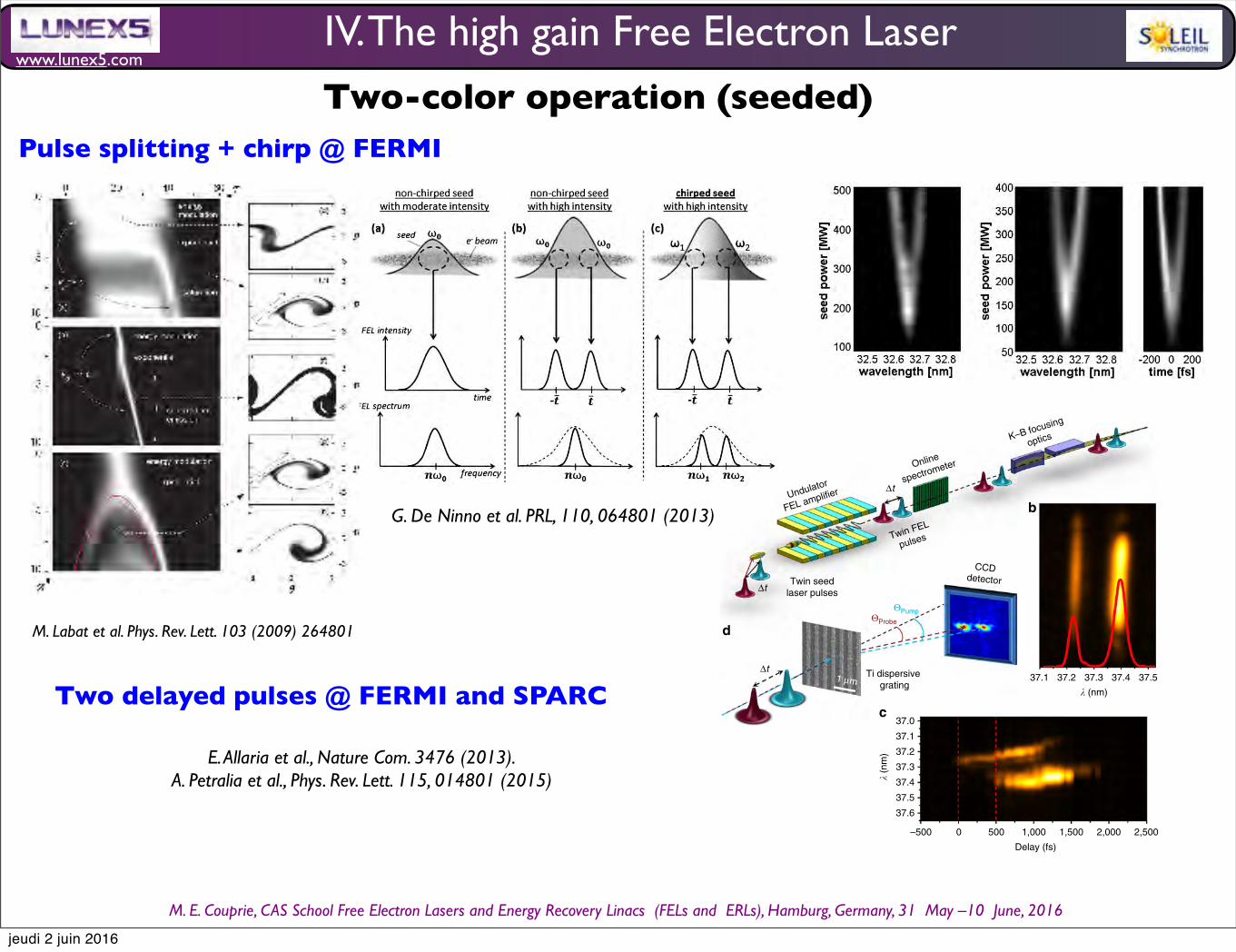
www.lunex5.com
M. E. Couprie, CAS School Free Electron!Lasers!and!Energy!Recovery!Linacs !(FELs and !ERLs), Hamburg, Germany, 31 !May –10 !June, 2016
modulation. Figure 1b shows a typical spectrometer image ofthe twin FEL pulses generated with a time delay of 500 fs. As canbe seen from the figure (and from the Supplementary Movie 1),the spectrum in this twin-pulse seeded regime is extremely cleanand stable.
The performance of the twin-pulse-seeding scheme in terms ofspectral purity and intensity stability compared with single-seedFEL emission is displayed in Fig. 2. The results are obtainedrecording 1,150 consecutive spectra on both the ‘online’ spectro-meter (Fig. 2a) and the total FEL intensity on the I0 gas monitordetector26 (Fig. 2b). The switching between the single and doubleFEL emissions is obtained by blocking one of the seed laser arms,without changing the electron-beam characteristics nor theundulator strength parameter K. Fitting the two-colour FELspectra as a sum of two independent Gaussians, we estimate anegligible difference between the single and double FELemissions, confirming the robustness of the pulse generationscheme. Statistical analysis of the spectra in Fig. 2a shows that theroot mean square bandwidth is about 25! 10" 3 nm, that is,B0.05% of the central wavelength, together with a shot-to-shotpeak position root mean square jitter of about 3! 10" 3 nm(about 0.005% of the central wavelength, Fig. 2c). Figure 2b shows
that the absolute single-wavelength intensities of double FELemission, obtained from the corresponding peak area of thespectrum (see Supplementary Fig. S3 and Supplementary Note 3),is comparable to those of single FEL emission, with a root meansquare shot-to-shot stability of about 15% (Fig. 2d). In theadopted scheme, the intensity ratio between the pump and probepulses can be tuned easily by changing the relative intensity ofeither seed laser pulse. This can also be accomplished by changingthe normalized strength K of the FEL undulators to favour thegrowth of one of the pulses over the other.
Proof-of-principle pump and probe experiment. As the wave-lengths of the twin pulses are rather close, we used a Ti grating(Fig. 1d) that acts as a spectral analyser, separating angularly thediffraction peaks of the pump and probe pulses. The wavelengthand intensity of each pulse were measured by the I0 gas monitorand the ‘online’ spectrometer (Fig. 1a). The maximum pulseintensity for the pump pulse was 30 mJ, corresponding to a fluence(F) of about 18.5 J cm" 2 on the sample, and was attenuated usinga gas cell and/or Al solid-state filters. The diffraction measure-ments were carried out at the DiProI end station27, where the FEL
37.1
! (nm)
!t
!t
!t
Undulator
FEL amplifier
Twin seedlaser pulses
Twin FEL
pulses
Online
spectrometer
K–B focusing
optics
Ti dispersive grating
CCDdetector
"Probe
"Pump
1 µm 37.537.437.337.2
–500 0 500 1,000 1,500 2,000 2,500
37.0
37.1
37.2
37.3
37.4
37.5
37.6
! (n
m)
Delay (fs)
Figure 1 | Generation and characterization of the twin-seeded FEL pulses and experimental set-up. (a) Energetically distinct two ultraviolet laserpulses with an adjustable delay interact with a single electron bunch. Inside the FEL amplifier, the two seeded regions emit XUV radiation. The wavelengthand temporal separation of generated twin FEL pulses are determined by the parameters of the seed laser pulses and the spectral purity, pulse intensitiesand widths of the pulses is monitored by an ‘online’ spectrometer. (b) Typical spectrum of the twin-FEL pulses. (c) Sequence of FEL spectra obtainedduring a temporal scan of the seed laser pulse pair with respect to the electron bunch. The zero time is defined as the instant when the first laser pulseinteracts with the electron bunch. Increasing the arrival time delay of the laser pulses with respect to the electron bunch, the emission of the secondFEL pulse is evident after B500 fs. The relative time separation, marked by the dashed red line, between the two FEL spectral lines ensures that thetemporal structure of the twin FEL emission is determined by the delay between the seed laser pair. (d) Experimental layout: the twin FEL pulses withdifferent wavelength, focused by K–B optics (shown in (a)), impinge on the Ti grating (80-nm thick and 165-nm wide Ti strips with 400-nm pitch fabricatedon a 20-nm thick Si3N4 window) and are diffracted along the horizontal plane. The seventh order diffraction pattern is detectedby a CCD camera placed off-axis with respect to the direct beam.
NATURE COMMUNICATIONS | DOI: 10.1038/ncomms3476 ARTICLE
NATURE COMMUNICATIONS | 4:2476 |DOI: 10.1038/ncomms3476 |www.nature.com/naturecommunications 3
& 2013 Macmillan Publishers Limited. All rights reserved.
!inst!t" #!0 $d!!t"dt
$ 2!It: (2)
In order to illustrate our findings, we consider the para-digmatic example of the FERMI@Elettra FEL [17], whoserelevant parameters are listed in the caption of Fig. 3. Theleft panel of Fig. 3 shows the measured spectral evolutionof the FERMI@Elettra FEL pulse, as a function of theseed power.
As expected, above a given power threshold the FELpulse splits, both in time and in spectrum [18]. Larger seedpowers correspond to larger extensions of the overbunchedzone around the pulse center and, therefore, to largertemporal and spectral separations.
The central panel of Fig. 3 reports the spectral evolutionof the FEL pulse, simulated using the numerical codePERSEO [19]. As can be seen, the agreement with experi-ments (left panel) is very satisfactory. This confirms thecorrectness of our interpretation of the pulse splittingmechanism. The left panel of Fig. 3 shows the correspond-ent (simulated) temporal pulse splitting. We remark thatthe maximum obtainable temporal split is limited by theelectron-beam duration and by the possibility of generatinglong-enough (chirped) seed pulses characterized bysignificant local power at their tails.
In the following, we concentrate on the analysis of theso-called low-gain regime. In this low-gain regime, therelative FEL gain bandwidth B (approximately equal tothe relative maximum spectral separation) is proportional
to the inverse of the number of radiator periods (Nu):B ’ 1=Nu.Exploiting a chirped seeded FEL for carrying out pump-
probe experiments relies on the possibility of controllingindependently the spectral and temporal distance betweensubpulses. Let us show how this can be achieved.Suppose we want to generate, at the radiator exit, two
subpulses having constant spectral distance and variabletemporal separation. First, let’s see how, for a given chirp,one can decide the subpulses’ spectral distance. We indi-
cate the latter with "! $ !1 # !2, where !1 $ n!1 and!2 $ n!2 are the central frequencies of the two subpulses,!1 and !2 being the corresponding instantaneous frequen-cies carried by the seed [determined according to Eq. (2)],and n the selected harmonic number; see Fig. 2. In general,
"! will be given by "B!rad, where " is a factor (smalleror slightly larger than one) fixed by the user and!rad $ n!0 is the central frequency at which the radiatoris tuned.According to Eq. (2),
j"!j $ nj!2 #!1j $ 4n!I #t ’ "nB!0; (3)
where #t is the temporal position of !1 and !2 (symmetricwith respect to !0; see Fig. 2), determining the (identical)seed powers experienced by the portions of the electronbeam emitting in the radiator at the two frequencies !1 and!2. Such a power is given by
P $ P0 exp
##t2
2#2l
!; (4)
P0 being the maximum seed power. Knowing P, one canfind the electron-beam energy modulation, "$, induced bythe laser-electron interaction inside the modulator [20]:
"$!r" $!!!!P#P
sKLu
$0#rJ0;1
"K2
4% 2K2
#exp
# r2
4#2r
!: (5)
Here #P ’ 8:7 GW, K is the modulator parameter, Lu themodulator length, $0 the nominal (normalized) beamenergy, J0;1 is the difference between the J0 and J1 Besselfunctions, r is the radial position inside the electron beam,and #r is the seed-laser spot size in the modulator. Theenergy modulation is related to the bunching, b, created inthe dispersive section by the following relation [9]:
b $ exp"# 1
2n2#2
$d#Jn!n"$d"; (6)
where #$ is the (normalized) electron-beam incoherentenergy spread, d is the strength of the dispersive sectionand Jn the Bessel function. The parameter d is usuallyexpressed in terms of the parameter R56, as d $2%R56=!&0$0". Our aim is to find the optimum value ofthe dispersive section which, for a fixed seed power, allowsmaximizing the FEL emission at the two wavelengths we
FIG. 3. Projected spectral and temporal FEL intensities fordifferent seed powers. Left panel: experimental spectral splitting,measured at FERMI@Elettra [7]; central and right panels:simulated spectral and temporal splitting (using the codePERSEO). The set of parameters, valid both for the experimentand for the simulation, is the following: normalized energy!$0" $ 2:544& 103, energy spread !#$" $ 2:544& 10#1, peakcurrent !Ipeak" $ 200 A, bunch duration $ 1 ps (rms); modula-
tor period $ 0:1 m, modulator length !Lu" $ 3 m, modulatorparameter !K" $ 5:7144, radiator period !&w" $ 55& 10#3 m,number of radiator periods !Nu" $ 264, central modulator wave-length !’ 2%c=!0" $ 261 nm, central radiator wavelength!&rad" $ 32:6 nm, harmonic number !n" $ 8; seed-laser power!P0" $ 50–500 MW, strength of the dispersive section !R56" $20 'm, laser spot size in the modulator !#r" ’ 300 'm,!!R;!I"3 $ !5& 10#5 fs#2; 3:2& 10#5 fs#2".
PRL 110, 064801 (2013) P HY S I CA L R EV I EW LE T T E R Sweek ending
8 FEBRUARY 2013
064801-3
Two-color operation (seeded)
M. Labat et al. Phys. Rev. Lett. 103 (2009) 264801
The method we propose overcomes all the issues related tothe previously mentioned schemes.
Seeded FELs can rely on different configurations[9–14]. In this work, we focus on the so-called harmonicgeneration scheme, in which a relativistic electron beampropagating through the static and periodic magnetic fieldgenerated by an undulator (called a modulator) interactswith a collinear externally injected optical pulse (seed)having wavelength !0; see Fig. 1. The interaction modu-lates the electron-beam energy. Energy modulation istransformed into spatial bunching, when the electronbeam propagates through a magnetic chicane (dispersivesection). The bunching (as the energy modulation) has aperiodicity equal to the seed wavelength. However, it alsopresents significant components at the harmonics of thelatter, i.e., at n!0 (where !0 ! 2"c=!0, c being the speedof light and n an integer number). Finally, the bunchedelectron beam is injected into a long undulator chain(called a radiator), where it emits coherently at one ofthe seed harmonics. In the radiator, the electromagneticintensity generated from bunched electrons is amplified,until, due to bunching deterioration, electrons are no longerable to supply energy to the wave and the process reachessaturation.
Consider now an FEL, in which a homogeneous electronbeam is seeded by a Gaussian monochromatic laser pulse,e.g., the one generated by a Ti:Sa laser. In standard opera-tion mode, the seed peak intensity, the strength of thedispersive section, and, as a consequence, the bunchingat the radiator entrance are tuned, so as to maximize theemission from the part of the electron beam seeded by thecenter of the Gaussian pulse [see Fig. 2(a)]. The parts ofthe beam seeded by the tail of the Gaussian pulse willinstead arrive at the radiator entrance with a local bunchingsmaller than optimum. As a result, the output FEL pulsewill approximately reproduce the Gaussian shape of theseed, both in time and in spectrum. Suppose now wemaintain constant the strength of the dispersive sectionand steadily increase the seed intensity [(see Fig. 2(b)].For high enough intensities, the part of the electron beamthat, in the modulator, interacted with the center of the
Gaussian seed will have, at the radiator entrance, a bunch-ing larger than optimum (overbunching). Because of thelarge laser-induced energy spread, the FEL emission fromthis part of the bunch will be significantly attenuated. Thelarger the seed peak intensity, the larger the overbunchedzone will be. The beam portions having optimum bunching(seeded by the lateral parts of the Gaussian seed) will belocated both at the right and at the left of that zone. As aconsequence, in these conditions the FEL pulse will becharacterized, in the time domain, by two lateral peaks[(see Fig. 2(b)] or, if the seed is sufficiently intense tosuppress the emission from the central part, by twoseparated subpulses [8]. Because the seed is assumed tobe monochromatic, the two subpulses have the samewavelength.The situation changes if the seed carries a significant
frequency chirp. Indeed, in this case, the two subpulseswill be also characterized by different wavelengths; seeFig. 2(c). This opens up the possibility of using the FEL asa self-standing source to carry out two-color pump-probeexperiments.Let’s consider a seed pulse carrying a controllable
linear chirp [15]. The pulse electric field reads [16]:
E"t# $ exp"%!Rt2 % i!It
2#; (1)
where !R and !I are constant parameters controlling,respectively, the pulse duration and bandwidth. Accordingto the previous equation, one can define the time-dependentphase of the pulse as #"t# ! !It
2. Switching to intensity(’ jE"t#j2), one finds that the rms pulse temporal duration,
$l, is given by $l ! 1="2!!!!!!!R
p#.
The instantaneous frequency within the seed pulse,!inst"t#, is defined by the following relation:
FIG. 1. Schematic layout of a seeded single-pass FEL(harmonic generation scheme).
FIG. 2. Seed-electron interaction and resulting FEL (temporaland spectral) outputs for different seed configurations: no chirpand moderate seed intensity (left panel), no chirp and highseed intensity (central panel), chirped seed with high intensity(right panel). The meaning of the symbols is explained in thetext.
PRL 110, 064801 (2013) P HY S I CA L R EV I EW LE T T E R Sweek ending
8 FEBRUARY 2013
064801-2
Pulse splitting + chirp @ FERMI
G. De Ninno et al. PRL, 110, 064801 (2013)
Two delayed pulses @ FERMI and SPARC
E. Allaria et al., Nature Com. 3476 (2013).A. Petralia et al., Phys. Rev. Lett. 115, 014801 (2015)
IV. The high gain Free Electron Laser
jeudi 2 juin 2016
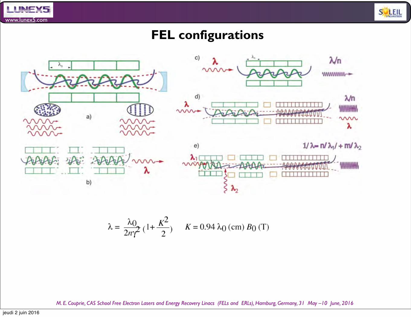
www.lunex5.com
M. E. Couprie, CAS School Free Electron!Lasers!and!Energy!Recovery!Linacs !(FELs and !ERLs), Hamburg, Germany, 31 !May –10 !June, 2016
FEL configurations
jeudi 2 juin 2016

www.lunex5.com
M. E. Couprie, CAS School Free Electron!Lasers!and!Energy!Recovery!Linacs !(FELs and !ERLs), Hamburg, Germany, 31 !May –10 !June, 2016
Low gain regime of Free Electron Lasers
First FELs : Linac based detuning curve
jeudi 2 juin 2016
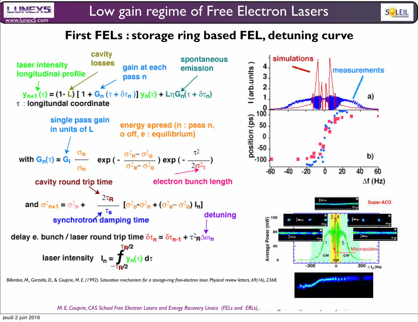
www.lunex5.com
M. E. Couprie, CAS School Free Electron!Lasers!and!Energy!Recovery!Linacs !(FELs and !ERLs), Hamburg, Germany, 31 !May –10 !June, 2016
Low gain regime of Free Electron Lasers
First FELs : storage ring based FEL, detuning curve
Billardon, M., Garzella, D., & Couprie, M. E. (1992). Saturation mechanism for a storage-ring free-electron laser. Physical review letters, 69(16), 2368.
jeudi 2 juin 2016
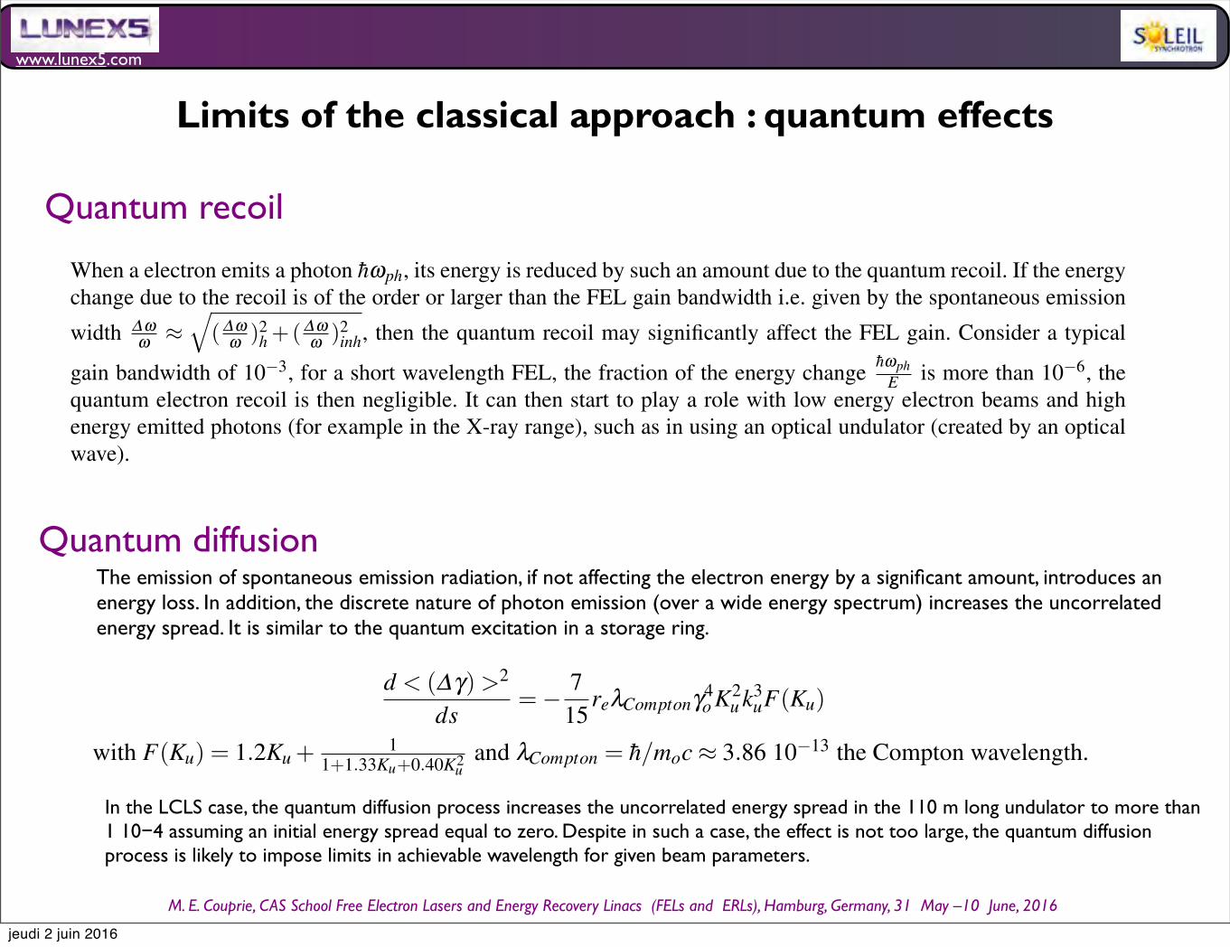
www.lunex5.com
M. E. Couprie, CAS School Free Electron!Lasers!and!Energy!Recovery!Linacs !(FELs and !ERLs), Hamburg, Germany, 31 !May –10 !June, 2016
Limits of the classical approach : quantum effects
Quantum recoil
Quantum diffusion
Synchrotron radiation and Free Electron Laser 35
4.4.5 Limits of the classical approach : quantum effects
Even though the first FEL theory has been approached with quantum mechanics, subsequent classical theory approachcan be applied for the majority of the experimental set-ups. Let’s consider how quantum effects can influence the FELprocess.
Quantum recoil
When a electron emits a photon hωph, its energy is reduced by such an amount due to the quantum recoil. If the energychange due to the recoil is of the order or larger than the FEL gain bandwidth i.e. given by the spontaneous emissionwidth ∆ω
ω ≈
(∆ωω )2
h +(∆ωω )2
inh, then the quantum recoil may significantly affect the FEL gain. Consider a typical
gain bandwidth of 10−3, for a short wavelength FEL, the fraction of the energy change hωphE is more than 10−6, the
quantum electron recoil is then negligible. It can then start to play a role with low energy electron beams and highenergy emitted photons (for example in the X-ray range), such as in using an optical undulator (created by an opticalwave).
Quantum diffusion
The emission of spontaneous emission radiation, if not affecting the electron energy by a significant amount, intro-duces an energy lass as described just above. In addition, the discrete nature of photon emission (over a wide energyspectrum) increases the uncorrelated energy spread. It is similar to the quantum excitation in a storage ring. Thediffusion rate of the energy spread is given by [?] :
d < (∆γ)>2
ds=− 7
15reλComptonγ4
o K2u k3
uF(Ku) (96)
with F(Ku) = 1.2Ku +1
1+1.33Ku+0.40K2u
and λCompton = h/moc ≈ 3.86 10−13 the Compton wavelength. In the LCLScase, the quantum diffusion process increases the uncorrelated energy spread in the 110 m long undulator to more than1 10−4 assuming an initial energy spread equal to zero. Despite in such a case, the effect is not too large, the quantumdiffusion process is likely to impose limits in achievable wavelength for given beam parameters [?].
Il faut avoir fait la discussion sur les valeurs de la dispersion en nergie, de l’mittance.....XXXXXXXXXXXXXXXXXXcf Dattoli
5 Low gain regime of Free Electron Lasers
5.1 First order energy exchange
5.1.1 Expression of the energy exchange
Let’s calculate the work of the electrons in the undulator field submitted to the electric field−→E propagating along the
direction s. The electric field being expressed as :
−→E = El cos(ks−ωt +φ)−→es (97)
with φ the phase of the monochromatic plane wave with respect to each single electron. In the small signal case,the work ∆W between the times t1 and t2 is given by :
∆W = e t2
t1c−→β .
−→E dt (98)
The emission of spontaneous emission radiation, if not affecting the electron energy by a significant amount, introduces an energy loss. In addition, the discrete nature of photon emission (over a wide energy spectrum) increases the uncorrelated energy spread. It is similar to the quantum excitation in a storage ring.
Synchrotron radiation and Free Electron Laser 35
4.4.5 Limits of the classical approach : quantum effects
Even though the first FEL theory has been approached with quantum mechanics, subsequent classical theory approachcan be applied for the majority of the experimental set-ups. Let’s consider how quantum effects can influence the FELprocess.
Quantum recoil
When a electron emits a photon hωph, its energy is reduced by such an amount due to the quantum recoil. If the energychange due to the recoil is of the order or larger than the FEL gain bandwidth i.e. given by the spontaneous emissionwidth ∆ω
ω ≈
(∆ωω )2
h +(∆ωω )2
inh, then the quantum recoil may significantly affect the FEL gain. Consider a typical
gain bandwidth of 10−3, for a short wavelength FEL, the fraction of the energy change hωphE is more than 10−6, the
quantum electron recoil is then negligible. It can then start to play a role with low energy electron beams and highenergy emitted photons (for example in the X-ray range), such as in using an optical undulator (created by an opticalwave).
Quantum diffusion
The emission of spontaneous emission radiation, if not affecting the electron energy by a significant amount, intro-duces an energy lass as described just above. In addition, the discrete nature of photon emission (over a wide energyspectrum) increases the uncorrelated energy spread. It is similar to the quantum excitation in a storage ring. Thediffusion rate of the energy spread is given by [?] :
d < (∆γ)>2
ds=− 7
15reλComptonγ4
o K2u k3
uF(Ku) (96)
with F(Ku) = 1.2Ku +1
1+1.33Ku+0.40K2u
and λCompton = h/moc ≈ 3.86 10−13 the Compton wavelength. In the LCLScase, the quantum diffusion process increases the uncorrelated energy spread in the 110 m long undulator to more than1 10−4 assuming an initial energy spread equal to zero. Despite in such a case, the effect is not too large, the quantumdiffusion process is likely to impose limits in achievable wavelength for given beam parameters [?].
Il faut avoir fait la discussion sur les valeurs de la dispersion en nergie, de l’mittance.....XXXXXXXXXXXXXXXXXXcf Dattoli
5 Low gain regime of Free Electron Lasers
5.1 First order energy exchange
5.1.1 Expression of the energy exchange
Let’s calculate the work of the electrons in the undulator field submitted to the electric field−→E propagating along the
direction s. The electric field being expressed as :
−→E = El cos(ks−ωt +φ)−→es (97)
with φ the phase of the monochromatic plane wave with respect to each single electron. In the small signal case,the work ∆W between the times t1 and t2 is given by :
∆W = e t2
t1c−→β .
−→E dt (98)
In the LCLS case, the quantum diffusion process increases the uncorrelated energy spread in the 110 m long undulator to more than 1 1084 assuming an initial energy spread equal to zero. Despite in such a case, the effect is not too large, the quantum diffusion process is likely to impose limits in achievable wavelength for given beam parameters.
jeudi 2 juin 2016