Nano-opto-mechanical characterization of neuron membrane mechanics under cellular growth and...
12
Nano-opto-mechanical characterization of neuron membrane mechanics under cellular growth and differentiation Ashwini Gopal & Zhiquan Luo & Jae Young Lee & Karthik Kumar & Bin Li & Kazunori Hoshino & Christine Schmidt & Paul S. Ho & Xiaojing Zhang # Springer Science + Business Media, LLC 2008 Abstract We designed and fabricated silicon probe with nanophotonic force sensor to directly stimulate neurons (PC12) and measured its effect on neurite initiation and elongation. A single-layer pitch-variable diffractive nano- gratings was fabricated on silicon nitride probe using e- beam lithography, reactive ion etching and wet-etching techniques. The nanogratings consist of flexure folding beams suspended between two parallel cantilevers of known stiffness. The probe displacement, therefore the force, can be measured through grating transmission spectrum. We measured the mechanical membrane charac- teristics of PC12 cells using the force sensors with displacement range of 10 μm and force sensitivity 8 μN/μm. Young’s moduli of 425±30 Pa are measured with membrane deflection of 1% for PC12 cells cultured on polydimethylsiloxane (PDMS) substrate coated with col- lagen or laminin in Ham’ s F-12K medium. In a series of measurements, we have also observed stimulation of directed neurite contraction up to 6 μm on extended probing for a time period of 30 min. This method is applicable to measure central neurons mechanics under subtle tensions for studies on development and morpho- genesis. The close synergy between the nano-photonic measurements and neurological verification can improve our understanding of the effect of external conditions on the mechanical properties of cells during growth and differentiation. Keywords Mechanotransduction . Cytomechanics . PC12 . Cell membrane . Growth . Differentiation . Nanogratings . Micro-electro-mechanical systems (MEMS) . Force sensor 1 Introduction Neuronal studies are among the most fundamental building blocks of modern biology and medicine. Neurons establish axons and dendrites, the morphology of which determines the number and type of inputs they receive (Moore and Jan et al. 2002). It has been proposed that environment- and activity-dependent struc- tural remodeling are critical cellular basis of learning and memory (Matsuzaki and Honkura et al. 2004). Neuronal shape and the complex pattern of connections in the nervous system depend on both progressive and regressive processes such as axonal elongation and axonal elimina- tion (Purves and Lichtman 1980; Cowan, and Fawcett et al. 1984). The growth cone behavior that are involved in the generation of these neuronal cytoarchitecuture are apparently regulated in quite specific ways of extrinsic factors such as chemical gradient (in particular calcium; Kater and Mattson et al. 1988), and neurotrophic factor (Mitchison and Kirschner 1988). In particular, sensory neurons and PC12 cells also show clear evidence of solid, elastic behaviors below the tension threshold required for Biomed Microdevices DOI 10.1007/s10544-008-9172-9 A. Gopal : K. Kumar : K. Hoshino : X. Zhang (*) Department of Biomedical Engineering, The University of Texas at Austin, 1 University Station, ENS 12, Austin, TX 78712-0238, USA e-mail: [email protected] Z. Luo : B. Li : P. S. Ho Department of Mechanical Engineering, University of Texas at Austin, Austin, TX 78758, USA J. Y. Lee : C. Schmidt Department of Chemical Engineering, University of Texas at Austin, Austin, TX 78712, USA
-
Upload
independent -
Category
Documents
-
view
2 -
download
0
Transcript of Nano-opto-mechanical characterization of neuron membrane mechanics under cellular growth and...

Nano-opto-mechanical characterization of neuron membranemechanics under cellular growth and differentiation
Ashwini Gopal & Zhiquan Luo & Jae Young Lee &
Karthik Kumar & Bin Li & Kazunori Hoshino &
Christine Schmidt & Paul S. Ho & Xiaojing Zhang
# Springer Science + Business Media, LLC 2008
Abstract We designed and fabricated silicon probe withnanophotonic force sensor to directly stimulate neurons(PC12) and measured its effect on neurite initiation andelongation. A single-layer pitch-variable diffractive nano-gratings was fabricated on silicon nitride probe using e-beam lithography, reactive ion etching and wet-etchingtechniques. The nanogratings consist of flexure foldingbeams suspended between two parallel cantilevers ofknown stiffness. The probe displacement, therefore theforce, can be measured through grating transmissionspectrum. We measured the mechanical membrane charac-teristics of PC12 cells using the force sensors withdisplacement range of 10 μm and force sensitivity 8 μN/μm.Young’s moduli of 425±30 Pa are measured withmembrane deflection of 1% for PC12 cells cultured onpolydimethylsiloxane (PDMS) substrate coated with col-lagen or laminin in Ham’s F-12K medium. In a series ofmeasurements, we have also observed stimulation ofdirected neurite contraction up to 6 μm on extendedprobing for a time period of 30 min. This method is
applicable to measure central neurons mechanics undersubtle tensions for studies on development and morpho-genesis. The close synergy between the nano-photonicmeasurements and neurological verification can improveour understanding of the effect of external conditions onthe mechanical properties of cells during growth anddifferentiation.
Keywords Mechanotransduction . Cytomechanics . PC12 .
Cell membrane . Growth . Differentiation . Nanogratings .
Micro-electro-mechanical systems (MEMS) . Force sensor
1 Introduction
Neuronal studies are among the most fundamentalbuilding blocks of modern biology and medicine.Neurons establish axons and dendrites, the morphologyof which determines the number and type of inputs theyreceive (Moore and Jan et al. 2002). It has beenproposed that environment- and activity-dependent struc-tural remodeling are critical cellular basis of learning andmemory (Matsuzaki and Honkura et al. 2004). Neuronalshape and the complex pattern of connections in thenervous system depend on both progressive and regressiveprocesses such as axonal elongation and axonal elimina-tion (Purves and Lichtman 1980; Cowan, and Fawcett etal. 1984). The growth cone behavior that are involved inthe generation of these neuronal cytoarchitecuture areapparently regulated in quite specific ways of extrinsicfactors such as chemical gradient (in particular calcium;Kater and Mattson et al. 1988), and neurotrophic factor(Mitchison and Kirschner 1988). In particular, sensoryneurons and PC12 cells also show clear evidence of solid,elastic behaviors below the tension threshold required for
Biomed MicrodevicesDOI 10.1007/s10544-008-9172-9
A. Gopal :K. Kumar :K. Hoshino :X. Zhang (*)Department of Biomedical Engineering,The University of Texas at Austin,1 University Station, ENS 12,Austin, TX 78712-0238, USAe-mail: [email protected]
Z. Luo :B. Li : P. S. HoDepartment of Mechanical Engineering,University of Texas at Austin,Austin, TX 78758, USA
J. Y. Lee :C. SchmidtDepartment of Chemical Engineering,University of Texas at Austin,Austin, TX 78712, USA

growth, like springs at low tension levels (Dennerll 1988;Lamoureux and Zheng et al. 1992).
Axonal development of neurons is intimately dependenton applied mechanical tension (Bray 1984; Zheng andLamoureux et al. 1991). Local 3-D cell growth microenvi-ronment and size-dependant mechanical stimulations canhave profound impacts on the reliability of regeneratednerves. Various techniques have been employed to under-stand cell membrane interaction with its external environ-ment. Micropipette aspiration is a technique that employs amicroneedle with a diameter of 1–10 μm for manipulatingcells. The aspiration length varies with the applied pressurethat in turn helps to determine the rigidity of the cellularmembrane (Hochmuth 2000). Optical tweezers is aninstrument used to optically attach particles to the cellularmembrane and manipulate the complex over preciselydefined distance to estimate the stiffness of the cell (Berns1998; Guck and Ananthakrishnan et al. 2001). Magnetictwisting cytometry is a method that uses 4–5 um diametermagnetic bead which is bound to the cell coated with anextracellular matrix protein sensitive to target receptors.The cell displacement under external magnetic fieldtwisting can be used to characterize cellular mechanics(Bausch and Ziemann et al. 1998). In addition, mechanicaland fluidic membrane stretching are other techniques usedto observe cells cultured on flexible substrates. Thesubstrate is cyclically deformed where by the cells boundto the substrate are stretched (DePaola and Davies et al.1999; You and Cowin et al. 2001; Basso and Heersche2002). It has been observed that cell stiffness is sensitive tothe substrate to which it is adhered to. Cells attached to thesurface of a substrate via extracellular matrix can result infunctional changes of the receptors present in the cell. Cellsattempt to match the stiffness with that of the underlyingsubstrate by altering the organization of the cytoskeleton(Discher and Janmey et al. 2005).
Many methods employed thus far are still limited bymeasurement range, resolution, and device-cell coupling forminimal invasive measurements (Bao and Suresh 2003).For neurons typically of small size (diameter less than 15μm),irregular shape and fragile membranes (10–1,000 Pa), newtools are needed to quantify the membrane properties,especially the elastic modulus, and to reveal the cellularresponses to mechanical stimulations. Further consider-ations are also needed on the compatibility of probes withmaterials and media in which biologically relevant studiesare performed. Development of the probes would be suchthat they do not damage the cell and can be functional in acell culture media such that cells are not removed from theirgrowth environment. Atomic force microscope (AFM)cantilever, a well established technique to deform a singlecell, is used to measure and map the stiffness of the cell thatis generated across the cell surface (Mathur and Truskey etal. 2000). These probes have been designed to work onproteins and the size of the tip being really small for thatparticular application. Recent advancements in microfabri-cated multi-layer grating photonics (Hane and Endo et al.2002; Kim and Barbastathis 2006; Zhang and Scott et al.2006) enable non-destructive sensing and microscopy ofsingle cells with high resolution.
In this paper, we demonstrate the integration of nano-scale one dimensional (1D) photonic grating, on MEMScantilever to probe neurons during growth to investigateneuronal cell mechanics and impact on cellular differenti-ation and growth due to probing of cells. The advancementin micro-optical–biological interface design (Zhang andChen et al. 2005) opens the window to observe andmanipulate cells (typically on the order of 10–15 μm) withhigh resolution in liquid media. Here, we present single-layer pitch-variable diffractive nanogratings on siliconnitride probe to investigate membrane mechanics and stressof PC12 cells.
Fig. 1 Geometry for Fraunhoferdiffraction of a phase grating
Biomed Microdevices

2 Principles of operation
2.1 Nanograting design and analysis
We implemented a binary phase transmissive grating designfor its superior diffraction efficiency. For an electromag-netic wave passing through an aperture and imaged on ascreen, the Fresnel number is defined as: F ¼ a2
zol, where λ
is wavelength of the wave, a is the characteristic size of theaperture, and zo is the distance of the screen from theaperture. As shown in Fig. 1, the diffraction characteristicsof this grating are analyzed using Fraunhofer diffractionprinciple (Goodman 2005) where the Fraunhofer diffractionequation is given by:
U x0; y
0� �
¼ e jkzoe j k2zo
x 02þy 02ð Þ 1
jλzo= TA x; yð Þð Þ
fx¼ x 0λzo
; fy¼ y 0λzo
ð1Þ
The transfer function of the structure is:
TA x; yð Þ ¼ eiforectx
w
� �rect
y
a
� �DXN�1
j¼0
δ y� jdð Þ ð2Þ
Where TA(x′,y′) is the transfer function of the gratingstructure, eiφo is the phase term that is present in the trans-mission phase grating, Θ represents convolution of thesystem, w is the aperture in the x-direction and a is theaperture in the y-direction (a=d−dg), N is the number ofgrating periods under illumination and d is the pitch of thegrating structure. In our studies,w is on the order of 150 μm,λ is the wavelength of illumination that is on the order of635 nm and viewing distance zo is around 15–20 cm;hence Fraunhofer diffraction (F<<1) is applicable for thissystem.
Fig. 2 Force sensor. (a) Schematic of nanograting force sensor. (b)Principle of operation of nanogratings force sensor under no loadcondition. (c) When a force is applied to the grating a change in pitch
of the grating is observed; diffraction angle changes by force loading.Table 3: Device parameters for the nanograting structure
Biomed Microdevices

The phase-delay over the thickness t of the structure is φo:
φ0 ¼2π$ntλ
ð3Þ
Where,
$n ¼ nGrating � nCulture ð4ÞWhere n is the refractive index of the medium, Δn is the
change in refractive index from culture media (nCulture forPBS solution=1.35) to grating material (nGrating for siliconnitride=2.02) is calculated using equation.
Hence the far field amplitude U(x, y) is given by:
U x; yð Þ ¼ e jkzoe j k2zo
x 02þy 02ð Þe�nπdyλzo
1
jλzow sin c w
x0
λzo
� �Nð Þ
sin c Nð Þ*d y 0λzo
� �
sin c d y 0λzo
� �
d sin c dy0
λzo
� �þ d � dgð Þ eiφo � 1
� �sin c d � dgð Þ y0
λzo
�� �ð5Þ
Intensity of Fraunhofer diffraction pattern for the forcesensor:
I ¼ U x; yð Þj j2¼ � A2
λ2z2o
sin c2 wx0
λzo
� � sin c2 Nð Þ*d y 0λzo
� �
sin c2 d y 0λzo
� �
ðd sin c d y 0λzo
� �þ d � dgð Þ sin c d � dgð Þ y 0
λzocosφo � 1ð Þ2
þ ðd � dgð Þ sin c d � dgð Þ y 0λzo
* sinφoÞÞ2
24
35
ð6Þ
Where I is the intensity of the Fraunhofer diffractionpattern, U(x, y) is the far field amplitude, k ¼ 2p
l is thewavenumber, λ is the wavelength of illumination, N is thenumber of grating periods under illumination, φ0 is the phase-delay over the thickness of one grating finger, dg is the widthof each grating rule in the period of the grating, d is the pitchof the grating structure.
Flexure beams
Variable Pitch Grating
Probe Tip
Suspension Beam
Ls
Lf/2
(a)
(b)
Fig. 3 Stress analysis of nanograting layer. (a) Sensor displacement(in microns) distribution using FEM analysis. (b) Stress (in megaPascal) present only on the flexure folding junctions supporting the
gratings. This shows that significant probe tip translation can bepresent while maintaining the flatness of the grating readout
Fig. 4 Force versus displacement for different suspension beamlengths
Biomed Microdevices

The pitch variable phase gratings are operated intransmission. The diffraction equation under paraxialapproximation is given by:
ml ¼ d sin a þ sin qð Þ ð7ÞWhere m is diffraction order, d is grating pitch, α isillumination angle, and θ is diffraction angle. Using Taylorseries to expanding Eq. 7, the equation for normalillumination we get:
$θ$d
¼ � mλ
d2ffiffiffiffiffiffiffiffiffiffiffiffiffiffiffiffiffiffiffiffi1� mλ
d
� �2q ð8Þ
Where the change in diffraction angle (Δθ) per unit pitch(Δp) variation under normal illumination (α=0) is defined
as the sensitivity of the sensor. Therefore, the sensitivity ofthe device can be greatly improved by reducing the criticalfeature size, d, of the grating. Improving sensitivity of thedevice implies that small changes in probe displacementwill lead to large changes in diffraction pattern thereforeeven small displacements can be detected.
2.2 Sensor design
The force-sensing element presented here is a transmissivephase grating that is connected through nano-scale flexurebeams, which is shown in Fig. 2. The grating is suspendedby supporting beams and can be expanded by application ofa load along the principal axis of the grating. Thisexpansion changes the pitch of the grating, leading to achange in position of the diffraction orders (Fig. 2(b–c)).The nanograting is further integrated with a probe, both ofwhich are suspended on cantilevers of known stiffness. Theprobe displacement, therefore the force, can be measuredthrough tracking the position of the diffraction order (Table 3).
2.3 Mechanical stress, spring constant and eigen modes
Multilayer thin film microdevices are often fabricatedthrough repetitive micro- or nanoscale processing includingpatterning, deposition and assembly. Intrinsic stresses areusually present which can distort the final micromachined
Table 1 Variation of spring constant with respect to supporting beamlength of the force sensor
Support beam length (μm) Spring constant of the devicea (N/m)
250 8.32275 6.28300 4.89325 3.83350 3.61
aK was calculated based on structure consisting of supporting beamsand flexure beams together
Fig. 5 Four eigen modes ofoperation of nanograting forcesensor. (a) Up and down motionof the gratings. (b) Rotationabout the X axis causing thebuckling of the gratings. (c)Motion of the probe tip in the Zdirection. (d) Y direction vibra-tion which gives the requiredmode for this operation
Biomed Microdevices

surfaces upon release. Two symmetric nanogratings aredesigned along each side of the probe (Fig. 3(a)) to providemechanical balance and maximal optical surface area. Withforce (37.5 pN) applied to the probe tip, the amount ofstress and the displacement across the grating layer wassimulated using finite element method (FEM) Coventor-ware™. As shown in Fig. 3(a), the displacement of thesensor on application of force was on the order of 10 μmand in Fig. 3(b) the stress is present only on the foldingjunctions that hold the grating beams where in the stress iswell under the yield stress level.
The spring constant k for various suspension beamlengths were simulated using finite element method (FEM)Coventorware™ (Fig. 4). To determine the effective springconstant (Senturia 2001, Nesterov and Brand 2004, 2005,2006)) of the entire system contributed, there are twoelements that contribute to the compliance of the device:the supporting beams which connect the suspended struc-ture to the anchors, and the flexures which connect adjacentgrating beams. The stiffness of the supporting beams isgiven by:
ks ¼ 2Ew3s t
L3sð9Þ
Where ks is the effective spring constant of thesupporting beam, E is the Young’s modulus of the material(for silicon nitride: 225 GPa), t is the thickness of thestructure (750 nm), ws is the width of the beam (4 μm), andLs is the length of the supporting beam. The stiffness of thesupporting beams on one side is estimated by consideringtwo beams in parallel.
The stiffness of the flexure between two adjacent beams(one grating period) is estimated to be:
kf ¼ 8Ew3f t
L3fð10Þ
Where kf and Lf are the effective spring constant and thelength of the flexure (10 μm) structure, respectively. wf isthe width of the flexure beam suspension (500 nm). Theoverall force constant of the nanograting sensor is acombination of ks and kf depending on the sensordimension and geometry (Table 1).
The total spring constant of the device is given by:
kt ¼ 2ks þ number of flexure beams� kf=2 ð11ÞFor linear operation within small probe displacement, theforce can be determined by F=kx. Where F is the force thatFig. 6 Fabrication process of single layer nanograting force sensor.
(a) Thermal oxidation of bare <100> silicon wafer. (b) NitrideLPCVD and chromium e-beam evaporation. (c) E-beam lithographyand RIE of chromium (hard mask) layer. (d) Pattern transfer to nitridelayer by RIE. (e) Dicing and TMAH etching of underlying siliconsubstrate. TMAH etch of the underlying substrate silicon. (f) Bufferedoxide etch release
Fig. 7 Scanning electron micrographs (SEM) of the nanograting forcesensor used in neuron membrane characterization. (a) Sensoroverview, (b) released probe, (c) variable pitch gratings, (d) flexurefolding beams and (e) optical micrograph of the nanograting forcesensor indicating absence of deformation in the grating structure
Biomed Microdevices

is applied, k is the spring constant of the device and x is thedisplacement of the device. The force sensor can be treatedas a linear spring–mass–dashpot system. Therefore thedynamic properties can be studied through eigen functionanalysis. Eigen modes under mechanical vibration weresimulated using CoventorWare™ (Fig. 5). Eight fundamen-tal modes were observed. Lower order modes had vibrationpresent along the Z-axis that is greatly reduced byincreasing the thickness. Only the Y-vibration modes areused for stress/strain measurements.
3 Device fabrication
As shown in Fig. 6, the fabrication of nanograting forceprobe described previously in (Gopal and Luo et al. 2007)begins with the deposition of 750 nm of silicon nitridedevice layer over 1000 nm of thermally oxidized <100>silicon wafer. Silicon nitride is transparent in the ultra violetwavelength region and hence can be used as a phase
grating. Chromium (Cr) layer of 30 nm thickness isdeposited over silicon nitride and is patterned usingelectron-beam lithography (EBL). A positive e-beam resistZEP520-A is used for EBL. In EBL writing, the structure isaligned parallel to the <110> crystallographic direction ofthe silicon substrate. The sensor structure pattern istransferred from the e-beam resist to the Cr layer byreactive ion etching (RIE) process. Chrome acts as a hardmask during RIE to transfer the structure pattern into nitridelayer. Nitride layer is partially etched and the device isplaced in 25% TMAH solution held at 90°C to undercut thesubstrate until the device is completely released. Oxidelayer is removed by buffered oxide etchant leaving thereleased nitride layer behind. During the tetra-methyl-ammonium-hydroxide (TMAH) etching process, the chro-mium layer is etched completely leaving behind siliconnitride as a device layer. Scanning electron micrographs(SEM) of the fabricated nanograting force sensor are shownin Fig. 7. The appearing deformation of the grating in theSEM was caused by the electron beam incident on siliconnitride surface. Curling of the silicon nitride suspended filmwas observed on scanning the electron beam across thesurface of the device. An optical micrograph of thestructure shows no such deformation present in the device(Fig. 7(e)) prior to SEM.
We also fabricated poly-di-methyl-siloxane (PDMS) cellholder to culture and immobilize the neurons for measure-ments. Prior to photolithography the master wafer is
Fig. 8 PDMS cell holder. (a) Fabrication of PDMS cell holder. A Spinlayer of SU9-2100 photoresist. B pattern and develop the master moldwith UV through a dark field mask. C After baking PR, pour PDMSpre-polymer mixture over mold. D Place in oven and cure thepolymer, and peel PDMS off the mold. (b) micro-fabricated PDMSneuron cell holder with coupler to force probe
Fig. 9 Experimental setup for characterization of single neuronmembrane mechanics
Biomed Microdevices
cleaned using piranha cleaning method for a time span of8 min. This wafer is then dipped into hydrofluoric acid(HF) for 20 s. The wafers are cleaned using deionized (DI)water and then dried using nitrogen. Clean wafers are thenplaced into an HMDS oven. Once the priming of thesurface of the wafer is done using HMDS, the photoresistSU8 (Microchem Corp.) is spun for a time span of 50 s at500 rpm (Fig. 8(a)).The wafer is then prebaked at 95°C for20 min. Pattern is exposed onto the wafer for 95 s followedby post bake at 95°C for 45 min. The wafer was thendeveloped using an SU8 developer and hard baked for 2 h.The channels are fabricated using polydimethylsiloxane(PDMS). A mixture of curing agent and PDMS in the ratio1:10 are mixed and bubbles trapped in the PDMS areremoved using a vacuum dessicator. This mixture of PDMSis then poured onto the master wafer containing the channelsand then placed in the oven at 70°C for a time period of4 h for curing. The channels are cut out of the mold using ascalpel, and pulled out using tweezers (Fig. 8(b)).
4 Experimental procedure and results
4.1 Materials and methods
PC12 an immortalized cell line derived from rat pheochro-mocytoma, can be induced to extend neurites with addition
of nerve growth factor (NGF). Although there is nosynaptic activity along the neurites of these cells, theyserve as good models for neuron cells (Tischler and Greene1976).
PC12 cells (American Type Tissue Collection) areroutinely cultured in Ham’s F-12K culture media (15% heatinactivated horse serum, 2.5% fetal bovine serum, 1%penicillin-streptomycin), in a humidified atmosphere main-tained at 37°C, 5% CO2 and passaged with a 0.05% trypsinand 0.01% EDTA solution every week. Priming of PC12cells is done by culturing cells in medium containing 50 ng/ml of NGF.
Fig. 10 Variation of diffractionspot with displacement of theforce sensor. (a) Diffractionspots when no load is applied tothe probe tip. (b) Variation ofdiffraction spots observed onapplication of force
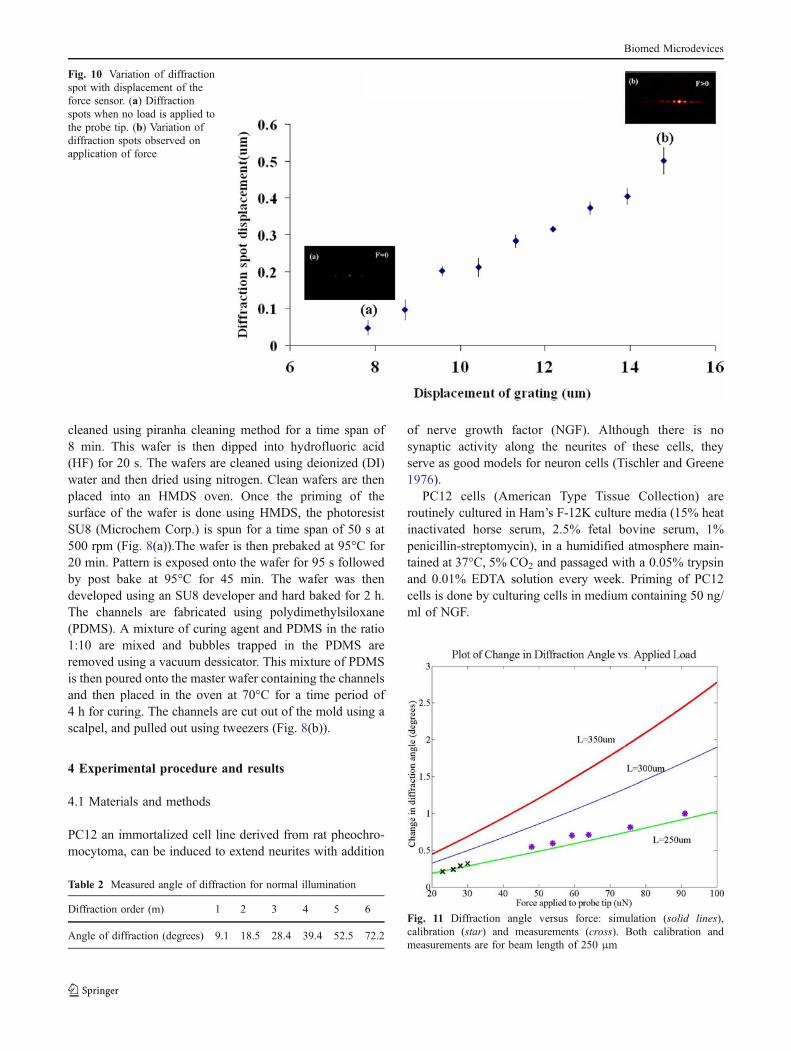
Fig. 11 Diffraction angle versus force: simulation (solid lines),calibration (star) and measurements (cross). Both calibration andmeasurements are for beam length of 250 μm
Table 2 Measured angle of diffraction for normal illumination
Diffraction order (m) 1 2 3 4 5 6
Angle of diffraction (degrees) 9.1 18.5 28.4 39.4 52.5 72.2
Biomed Microdevices

PC12 cells are detached using Trypsin-EDTA solution(Life Technologies/Gibco BRL, Rockville, MD, USA), andwashed with PBS buffer and media. The 2×10⁴ cells permilliliter were seeded onto PDMS substrates that wereplaced in an F-12K culture media. Upon addition of Nervegrowth factor (NGF) a well known morphogen for PC12cells, branching neuron like process gradually attaining thephenotypic properties of sympathetic neurons was observed(S.D. Senturia Microsystem Design). We used murine 2.5SNGF (Promega) to study its effect on membrane stiffness ofPC12 cells. In addition, its combinational effects with extracellular matrix (ECM) components, such as collagen, werestudied. Collagen: Rat tail collagen type I (Sigma), treating1 mg/ml solution for 2 hours was used in the experiment.
4.2 Experimental setup and calibration
The experimental setup shown in Fig. 9 has a seamlessintegration of PDMS cell holders (1 cm×1 cm) with silicon
nanograting probe that allowed biological measurements tobe carried out in a liquid medium. The nanograting forcesensor with the 50 μm long and 30 μm (Fig. 2) wide probewas attached to a piezoelectric actuator (Thorlabs), andsubsequently placed in a liquid media (serum containingHam’s F-12K media) to probe the neurons. The sensor wasilluminated with a 635 nm diode laser (Blue Sky Research),with the spot size (∼100 μm diameter) covering the gratingarea of 120 μm×120 μm.
The probe displacement is measured by tracking thechange of the diffraction order positions (Fig. 10).Diffraction spots were captured on a charged couple device(CCD) placed at 10° from normal placed at a distance of15 cm from the force sensor. On illumination, the shift ofdiffraction angle indicated the amount of force applied tothe cells. The first order diffraction spot (size on the orderof 45 μm) was captured using a CCD (Basler VisionTechnologies 659×480 pixels). In our experiments weimplemented the use of the first order diffraction spot
(a) (b)
20µm
Neurite gro wth of PC12 cells
20µm
Probe with Force Sensor
Fig. 12 Image of neurite growthcharacteristics of PC12 cells on(a) collagen coated substrate,with no neurite growth wasobserved, (b) collagen coatedsubstrate treated with nervegrowth factor, significant neuritegrowth was observed
Fig. 13 Membrane deflectioncharacterization of PC12 cells.Embedded images showingcoupling of MEMS probe withthe PC12 cells. (a) Ready toprobe, with no membrane de-flection, (b) membrane deflec-tion by 5% after probing thePC12 cells
Biomed Microdevices

since intensity of the laser beam is concentrated in thelower order diffraction spots as seen from simulationspreviously. In the experiments the force sensor wasaligned to the cell and was mounted on a piezoactuator.The sensor is in plane with the cell to ensure that there isperfect contact to the cell. The cell deformation onprobing is simultaneously measured using an opticalmicroscope. The cell deformation is given by thedisplacement of the cell membrane radially outwards onapplication of force to the surface of the cell. In thisexperiment the force response and the cell deformationswere measured.
It was observed that the diffraction spots were measuredwith an error of ±10% (Table 2). Force sensor wascalibrated by probing against a flat wall. The displacementof the sensor was predetermined by a calibrated piezo-transducer (Fig. 11). The variation of the diffraction spotsfits very well with calculations using Snell’s law andFourier analysis.
4.3 Results and discussion
The method shown above was developed to study the cellmechanotransduction of PC12 cells due to external me-chanical stimulation. The sensor was brought in contactwith the cells laterally. The amount of force applied to thecell was read out using the diffraction spots captured usinga CCD. Figure 11 shows that the measurement results fitwell with theoretical simulations for 250 μm length beam.The change of the cell shape was recorded for a time periodof 30 min with the sensor fixed at a particular position.
Figure 12(a) shows the probing of cells on collagen coatedsubstrate with no NGF added to it. Figure 12(b) shows theprobing of PC12 cells treated with NGF on collagen coatedPDMS substrate. We deformed the membrane up toapproximately 5% of its original shape to derive the elasticmodulus of the cell (Fig. 13). As seen in Fig. 13 it wasobserved that when force was applied in the range of 20–27 μN the cell would return to the original shape. Onapplications of larger force it was observed that thedeformation was irreversible. During the experiment itwas observed that the cells deflected radially outwards onapplication of force. The elastic modulus of the cell washence calculated using the following equation (Lur’e1964) similar to deformable sphere:
E ¼ rsm
2ur
s� 2
sþ 1� 8� 14s
5þ 7s
� �ð12Þ
Where E is the Young’s Modulus, ur is the radialdeformation, s is the inverse of Possion’s ratio, ρ is the
Fig. 14 Measured elastic modulus of PC12 cells under differentsubstrate conditions. (The reference Young’s modulus is adapted from(Radmacher and Fritz et al. 1996) for adhered platelets measured byAFM)
Fig. 15 Variation of dendrite length with application of forceobserved on multiple PC12 cells for a period of 30 min. Linearincrease in dendrite length with application of force was observed
Table 3 Nanogratings device parameters
Device parameters Values
Number of grating rules on each grating (N) 30Grating area 120 μm×120 μmPitch of the grating (d) 4 μmSuspension beam length (Ls) 250 μmSuspension beam width (ws) 4 μmThickness of the device (t) 750 nmFlexure beam length (Lf) 10 μmFlexure beam width (wf) 500 nmElastic modulus of nitride layer 225 Gpa
Biomed Microdevices

radius, σm is the stress across the membrane and thePossion’s ratio is 0.5 for biological membranes. In our caseur, was determined by the change in radius of the cellobserved on the screen.
It was estimated that the Young’s modulus of the cellscultured on collagen substrate had an average modulus of425±30 Pa, and those treated with NGF had a modulus of675±25 Pa (Fig. 14). The experiment was conducted on10–15 PC12 cells and the results were consistent. The PC12 cells have a number of mechanical elements whichcomprise the cellular cytoskeleton and define its shape andlocomotive abilities. This cytoskeleton is a filamentousnetwork of several molecular components, including actinfilaments, microtubules, and intermediate filaments. Actinfilaments localize just beneath the cell membrane and instress fibers that span the cell. Similarly, intermediatefilaments and microtubules crisscross the cell, contributingto the cytoskeletal network that mechanically couples thecell membrane to the nucleus and points in between. Themechanisms as to how these components are able toprovide mechanical stability to cells can be investigatedusing the method presented here. The results show that thepresence of extensive cytoskeleton of the cells when treatedwith NGF as well as the extracellular matrix may have animpact on the elasticity of the cell. The presence of NGFincreases the crosslinking inside the cell when compared tocells without NGF. We also found that an average force of22±8 μN caused the neurite length to contract up to 6 μm(Fig. 15). The variation of neurite length on application offorce show clear evidence of solid, elastic behaviors belowthe tension limit damaging the cell required for growth(Dennerll 1988; Lamoureux and Zheng et al. 1992), withhigh spatial–temporal force sensing resolution. Theseresults suggest that mechanical tension is a critical factorin the development of neurites of a cell.
5 Conclusion
We designed and fabricated nanophotonic sensors integrat-ed on a silicon probe to directly stimulate peripheralneurons, and measured its effect on neurite initiation andelongation.
The force sensor is comprised of a suspended diffractiongrating structure whose pitch can be varied by applicationof a force (20 μN) on the tip of the probe. The diffractiongrating is suspended on of nanometer-scale flexural beam.When a force (50 μN) is applied to the probe tip, the pitchof the diffraction grating is varied (by 0.5°). This variationcan be sensed by illuminating the grating with a laser andviewing the change in position of the diffracted beam spotfrom the ‘no-load’ condition using a charged coupled
device (CCD) camera. The sensitivity of the displacementsensor was determined to be 8 μm/μN by the stiffness ofthe beam structure by which the grating is suspended.
We numerically and experimentally calibrated the opto-mechanical response of single-layer pitch-variable diffrac-tive nanogratings under various load conditions during thePC12 cells-probe interactions. Young’s moduli of 425±30Pa are measured with membrane deflection of 1% for PC12cells cultured on PDMS substrate coated with collagen orlaminin in Ham’s F-12K medium. We have also observedstimulation of directed neurite contraction up to 6 μm onextended probing for a time period of 30 min. The closesynergy between the nano-photonic measurement tools andcellular scale neurological verification can improve ourunderstanding of the effect of the external conditions on themechanical properties of cells during growth and differen-tiation. These findings will likely have a broad impact onunderstanding the role of neuron cytoskeleton in thepathology of nervous system disorders towards providingeffective diagnosis and therapy.
Acknowledgments We would like to thank Microelectronics Re-search Center (MRC) and the Center for Nano and Molecular Scienceand Technology (CNM) at UT Austin for providing the micro-fabrication facilities. This study was supported in part by the Na-tional Science Foundation Nanoscale Exploratory Research Program(ECS-0609413).
References
G. Bao, S. Suresh, Nat. Mater. 2, 715–725 (2003)N. Basso, J.N.M. Heersche, Bone. 30, 347–351 (2002)A.R. Bausch, F. Ziemann et al., Biophys. J. 75, 2038–2049 (1998)M.W. Berns, Sci. Am. 278, 52–7 (1998)D. Bray, Dev. Biol. 102, 379–389 (1984)W.M. Cowan, J.W. Fawcett et al., Science. 225, 1258–1265 (1984)T.J. Dennerll, J. Cell. Biol. 107, 665–674 (1988)N. DePaola, P.F. Davies et al., Proc. Natl. Acad. Sci. U. S. A. 96, 3154
(1999)D.E. Discher, P. Janmey, et al., 310, 1139–1143 (2005)J.W. Goodman, Introduction to Fourier optics (Roberts & Co 2005)A. Gopal, Z. Luo, et al., Solid-state sensors, actuators and micro-
systems conference, 2007. TRANSDUCERS 2007. International,1239–1242 (2007)
J. Guck, R. Ananthakrishnan et al., Biophys. J. 81, 767–784 (2001)K. Hane, T. Endo et al., Sens Actuators: A. Physical. 97, 139–146
(2002)R.M. Hochmuth, J. Biomech. 33, 15–22 (2000)S.B. Kater, M.P. Mattson et al., Trends. Neurosci. 11, 315–21 (1988)WCSSG. Kim, G. Barbastathis, J. Microelectromechanical Syst. 15,
763–769 (2006)P. Lamoureux, J. Zheng et al., J. Cell. Biol. 118, 655–661 (1992)A.I. Lur’e Three-dimensional problems of the theory of elasticity
(Interscience Publishers 1964)A.B. Mathur, G.A. Truskey et al., Biophys. J. 78, 1725–1735 (2000)M. Matsuzaki, N. Honkura et al., Nature. 429, 761–766 (2004)T. Mitchison, M. Kirschner, Neuron. 1, 761–72 (1988)
Biomed Microdevices

A.W. Moore, L.Y. Jan et al., Hamlet, a binary genetic switch betweensingle- and multiple-dendrite neuron morphology Science 297,1355–1358 (2002)
V. Nesterov, U. Brand. The nonlinear mechanical and elastricalproperties of silicon 3D micro probes, euspen. (2004)
V. Nesterov, U. Brand, J. Micromechanics Microengineering. 15, 514–520 (2005)
V. Nesterov, U. Brand, J. Micromechanics Microengineering. 16,1116–1127 (2006)
D. Purves, J.W. Lichtman, Science. 210, 153–157 (1980)
M. Radmacher, M. Fritz et al., Biophys. J. 70, 556–567 (1996)S.D. Senturia Microsystem Design (Kluwer Academic Publishers
2001)A.S. Tischler, L. Greene, Proc. Natl. Acad. Sci. USA. 73, 2424–2428
(1976)L. You, S.C. Cowin et al., J. Biomech. 34, 1375–1386 (2001)X. Zhang, C.C. Chen et al., J. Microelectromechanical Syst. 14, 1187–
1197 (2005)X. Zhang, M.P. Scott, et al., J. Microelectro. Mech. Syst. 15 (2006)J. Zheng, P. Lamoureux et al., J. Neurosci. 11, 1117–1125 (1991)
Biomed Microdevices