N14 TYPE USER'S MANUAL
32
METER OF NETWORK N14 TYPE USER’S MANUAL
-
Upload
khangminh22 -
Category
Documents
-
view
0 -
download
0
Transcript of N14 TYPE USER'S MANUAL

�
METER OF NETWORK
N14 TYPE
USER’S MANUAL

�

�
CONTENTS
METER OF NETWORK N14 TYPE
USER’S MANUAL
1. APPLICATION..............................................................................5 2. METERSET.................................................................................5 3. BASICREQUIREMENTS,OPERATIONALSAFETY..................6 4. MOUNTING..................................................................................6 5. METERDESCRIPTION................................................................7 6. N14PROGRAMMING................................................................12 7. RS-485INTERFACE..................................................................20 8. ERRORCODES.........................................................................25 9. TECHGNICALDATA..................................................................2510. ORDERCODES.........................................................................2811. MAINTENANCEANDGUARANTEE.........................................29
Page
September 2007

�
�
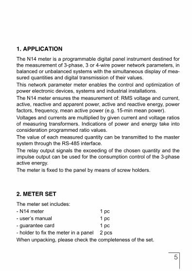
1. APPLICATION
The N14 meter is a programmable digital panel instrument destined for the measurement of 3-phase, 3 or 4-wire power network parameters, in balanced or unbalanced systems with the simultaneous display of mea-sured quantities and digital transmission of their values.This network parameter meter enables the control and optimization of power electronic devices, systems and industrial installations.The N14 meter ensures the measurement of: RMS voltage and current, active, reactive and apparent power, active and reactive energy, power factors, frequency, mean active power (e.g. 15-min mean power).Voltages and currents are multiplied by given current and voltage ratios of measuring transformers. Indications of power and energy take into consideration programmed ratio values.The value of each measured quantity can be transmitted to the master system through the RS-485 interface.The relay output signals the exceeding of the chosen quantity and the impulse output can be used for the consumption control of the 3-phase active energy.The meter is fixed to the panel by means of screw holders.
2. METER SET
The meter set includes:- N14 meter 1 pc- user’s manual 1 pc- guarantee card 1 pc- holder to fix the meter in a panel 2 pcsWhen unpacking, please check the completeness of the set.
�
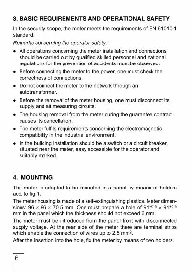
3. BASIC REQUIREMENTS AND OPERATIONAL SAFETY
In the security scope, the meter meets the requirements of EN 61010-1 standard.Remarks concerning the operator safety:lAll operations concerning the meter installation and connections should be carried out by qualified skilled personnel and national regulations for the prevention of accidents must be observed.lBefore connecting the meter to the power, one must check the correctness of connections.lDo not connect the meter to the network through an autotransformer.lBefore the removal of the meter housing, one must disconnect its supply and all measuring circuits.lThe housing removal from the meter during the guarantee contract causes its cancellation.lThe meter fulfils requirements concerning the electromagnetic compatibility in the industrial environment.lIn the building installation should be a switch or a circuit breaker, situated near the meter, easy accessible for the operator and suitably marked.
4. MOUNTING
The meter is adapted to be mounted in a panel by means of holders acc. to fig.1.The meter housing is made of a self-extinguishing plastics. Meter dimen-sions: 96 ´ 96 ´ 70.5 mm. One must prepare a hole of 91+0.5 ´ 91+0.5
mm in the panel which the thickness should not exceed 6 mm.The meter must be introduced from the panel front with disconnected supply voltage. At the rear side of the meter there are terminal strips which enable the connection of wires up to 2.5 mm2.After the insertion into the hole, fix the meter by means of two holders.

�
Fig. 1. Overall meter dimensions
5. METER DESCRIPTION
5.1. Current inputsAll current inputs are galvanically isolated (internal current transformers).The meter is adapted to co-operate with external current transformers.Displayed current values and derived quantities are automatically re-counted by the quantity of the introduced external transformer ratio. Current inputs are defined in the order as 1 A or 5 A.
5.2. Voltage inputsQuantities on voltage inputs are automatically recounted by the quantitiy of the introduced external voltage transformer ratio.Voltage inputs are defined in the order as 3 x 57.7/100 V, 3 x 230/400 V or 3 x 400/690 V.
�
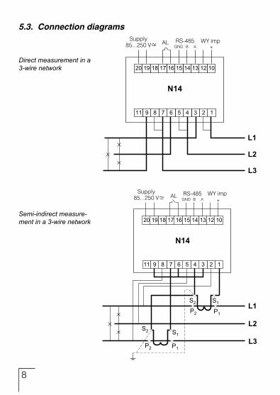
5.3. Connection diagrams
Direct measurement in a 3-wire network
Semi-indirect measure-ment in a 3-wire network

�
Indi
rect
mea
sure
men
t with
th
e us
e of
2 c
urre
nt tr
ans-
form
ers
and
2 or
3 v
olta
ge
trans
form
e3rs
in a
3-w
ire
netw
ork.
Fig.
2 M
eter
con
nect
ion
diag
ram
s in
a 3
-wire
net
wor
k
�0
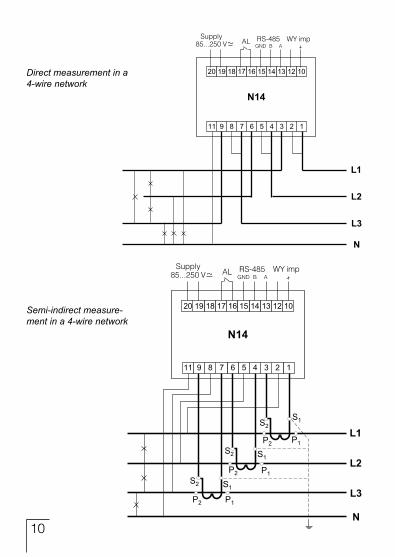
Semi-indirect measure-ment in a 4-wire network
Direct measurement in a 4-wire network
��
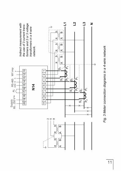
Indi
rect
mea
sure
men
t with
th
e us
e of
3 c
urre
nt tr
ans-
form
ers
and
2 or
3 v
olta
ge
trans
form
ers
in a
4-w
ire
netw
ork.
Fig.
3 M
eter
con
nect
ion
diag
ram
s in
a 4
-wire
net
wor
k
��
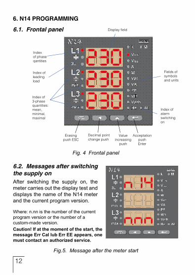
Fig. 4 Frontal panel
6.2. Messages after switching the supply onAfter switching the supply on, the meter carries out the display test and displays the name of the N14 meter and the current program version.
Where: n.nn is the number of the current program version or the number of a custom-made version.Caution!Ifatthemomentofthestart,themessageErrCallubErrEEappears,onemustcontactanauthorizedservice.
Fig.5. Message after the meter start
6. N14 PROGRAMMING
6.1. Frontal panel
��
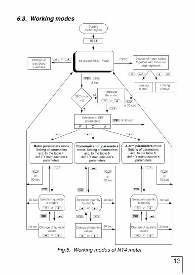
6.3. Working modes
Fig.6. Working modes of N14 meter
��
Table 2
Mean, minimal, maximal quantities (indexes 3L, min, max are background lighted).
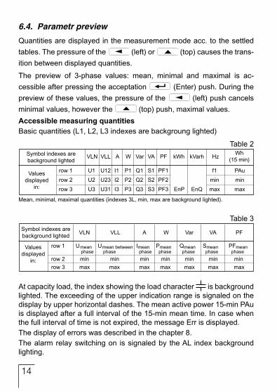
6.4. Parametr preview
Quantities are displayed in the measurement mode acc. to the settled tables. The pressure of the (left) or (top) causes the trans-ition between displayed quantities.
The preview of 3-phase values: mean, minimal and maximal is ac-cessible after pressing the acceptation (Enter) push. During the preview of these values, the pressure of the (left) push cancels minimal values, however the (top) push, maximal values.AccessiblemeasuringquantitiesBasic quantities (L1, L2, L3 indexes are backgroung lighted)
At capacity load, the index showing the load character is background lighted. The exceeding of the upper indication range is signaled on the display by upper horizontal dashes. The mean active power 15-min PAu is displayed after a full interval of the 15-min mean time. In case when the full interval of time is not expired, the message Err is displayed.The display of errors was described in the chapter 8.The alarm relay switching on is signaled by the AL index background lighting.
Symbol indexes are background lighted
Values displayed
in:
row 1 U1 U12 I1 P1 Q1 S1 PF1 f1 PAu
row 2 U2 U23 I2 P2 Q2 S2 PF2 min min
row 3 U3 U31 I3 P3 Q3 S3 PF3 EnP EnQ max max
VLN VLL A W Var VA PF kWh kVarh HzWh
(15 min)
Table 3Symbol indexes are background lighted
Values displayed
in:
VLN VLL A W Var VA PF
Umean phase
row 1
row 2row 3
minmax
Umean between phase
Imean phase
Pmean phase
Qmean phase
Smean phase
PFmean phase
min min min min min minmax max max max max max

��
Table 4
Displayed information
Default value
Range of changes
Parameter name A
cces
s
code
Cur
rent
ra
tio
Volta
ge
ratio
Ene
rgy
er
asin
g
Era
sing
of
15-m
inut
ac
tive
pow
er
Res
tora
tion
of
man
ufac
ture
r va
lues
SEC t_I t_U En0 PA0 dEF
0 1 1 no no no
0...999 1...10000 1...4000 YES/no YES/no YES/no
Fig. 7. Menu setup
6.5. Setting of parameters
The entry in the programming mode is carried out by pressing and hol-ding during ca 3 sec. and pushes.The entry in the programming mode is protected by the access code. In case when there is no code, the program transits into the programming option. The in-scription SET (in the first column) and symbols of respective levels P, C, A are displayed.
6.5.1. Setting of meter parameters
Select the mode P in options (by or pushes) and confirm the choice by the push.

��
Following values are set by means of and pushes: Posi-tion of the decimal digit is selected by the push, the digit value is increased by the push. The active position is signalled by the cursor. The value is accepted by the push or abandoned by pres-sing the push. During the acceptation, one can check if the value is contained in the range.In case of the value setting beyond the range, the meter remains in the parameter edition mode, however the value is set on the maximal value (if the value is too high) or on the minimal value (if the value is too small).Caution: to display and set 4 and 5-digit parameters (t_U, t_I) two lower display rows are used.
6.5.2. Setting of communication parameters
In options, select the mode C and confirm the choice by the push.
Table 5
Displayed information
Default value
Range of changes
Parameter name M
eter
ad
dres
s
Inte
rface
m
ode
Inte
rface
ra
te
Res
tora
tion
of
man
ufac
ture
r va
lues
Adr trY bAU dEF
1 8n2 9.6 k no
1...247 8n2, 8e1, 8o1, 8n1
4.8, 9.6, 19.2, 38.4 k YES/no

��
6.5.3. Setting of alarm parameters
In options, select the mode A and confirm the choice by the push.
Table 6
Displayed information
Default value
Range of changes
Parameter name
Mon
itore
d
quan
tity
Kin
d of
al
arm
op
erat
ion
Upp
er s
wit-
chhi
ng v
alue
(in
%)
Tim
e de
lay
of
the
reac
tion
(in
sec
.)
Res
tora
tion
of
man
ufac
ture
r va
lues
A_n A_t Aon Aof Adt dEF
oFF nor 101 99 0 no
see table 7
nor, on, oFF, hon, hoF 0...120 0...120 0...300 YES/no
Low
er s
wit
chin
g va
lue
(in %
)
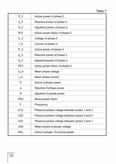
Table 7
Selection of monitored quantity:
Quantity monitored by the alarm
off Alarm disabled
U_1 Voltage of phase 1
I_1 Current of phase 1
P_1 Active power of phase 1
q_1 Reactive power of phase 1
S_1 Apparent power of phase 1
PF1 Active power factor of phase 1
U_2 Voltage of phase 2
I_2 Current of phase 2
Displayed parameter
��
Table 7
P_2 Active power of phase 2
q_2 Reactive power of phase 2
S_2 Apparent power of phase 2
PF2 Active power factor of phase 2
U_3 Voltage of phase 3
I_3 Current of phase 3
P_3 Active power of phase 3
q_3 Reactive power of phase 3
S_3 Apparent power of phase 3
PF3 Active power factor of phase 3
U_A Mean phase voltage
I_A Mean phase current
P Active 3-phase power
q Reactive 3-phase power
S Apparent 3-phase power
PFA Mean power factor
F Frequency
U12 Phase-to-phase voltage between phase 1 and 2
U23 Phase-to-phase voltage between phase 2 and 3
U31 Phase-to-phase voltage between phase 3 and 1
U4A Mean phase-to-phase voltage
PAu Active 3-phase 15-minute power
��
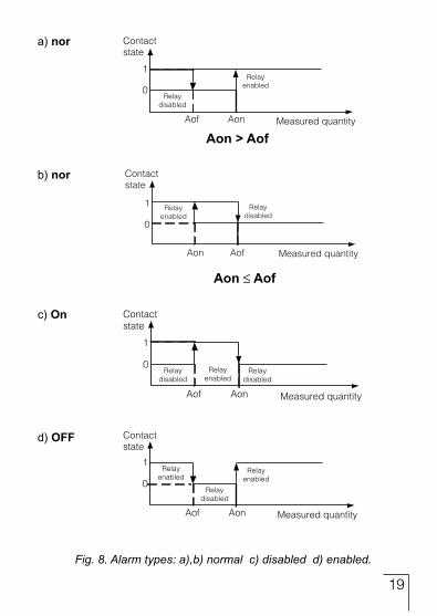
Aon>Aof
a) nor
b) nor
c) On
d) OFF
AonAof
Fig. 8. Alarm types: a),b) normal c) disabled d) enabled.

�0
Remained types of alarms: hon – always enabled; hof – always disab-led.Example of alarm setting:Set the alarm of nor for Aon>Aof, for the monitored 3-phase active Power PVersion: 5 A; 3 x 230/400 V. Alarm enabled after exceeding 3800 W, alarm disabled after decreasing 3100 W.
Calculation:rated 3-phase active Power: P = 3 x 230 V x 5 A = 3450 W3450 W – 100% 3450 W – 100%3800 W – Aon% 3100 W – AoF%Therefore: Aon = 110 % AoF = 90%Set: Monitored quantity: P; Kind of alarm: nor, Aon 110, AoF 90.
7. INTERFEJS RS-485
Set of the N14 meter serial link parameters:l identifier 0xACl meter address 1...247l baud rate 4.8, 9.6, 19.2, 38.4 kbit/s,l working mode Modbus RTU,l information unit 8N2, 8E1, 8O1, 8N1,l maximal response time 1000 ms.l Implemented functions: 03, 16, 17 -03 - register readout, -16 - register write, -17 - device identification.Manufacturer’s settings: address 1, baud rate 9600 bit/s, RTU 8N2 mode.
RegistermapoftheN14meter.In the N14 meter, data are placed in 16 and 32-bit registers.Process variables and meter parameters are placed in the address area of registers in the way dependent on the variable value type.

��
Bits in the 16-bit registers are numbered from the youngest to the oldest (b0-b15). 32-bit registers include numbers of float type in the IEEE-745 standard.
Table 8Addressrange Typeofvalue Description
4000 – 4019 Integer (16 bits)
Value placed in one 16-bit register. De-scription of registers are included in the table 9. Registers for write and readout.
Value placed in one 32-bit register. De-scription of registers are included in the table 10. Registers for readout.
7500 – 7555 Float (32 bits)
Table of 16 – bit register for N14 meter Table 9
DefaultRegister address Operations Range Description
4000 RW 0…999 Access code to parameters 0
4001 RW 1...10000 Ratio of the current transformer 1
4002 RW 1..4000 Ratio of the voltage transformer 1
4003 RW 0,1 Erasing of watt-hour meters 0
4004 RW 0,1 Erasing of 15-minute active Power PAV 0
4005 RW 0,1 Erasing of min. and max. 0
4006 RW 0,1...30 Quantity on the relay output 0
4007 RW 0...4 Output type: 0 – nor, 1- on, 2 - oFF,3 - hon, 4 - hoFF 0
4008 RW 0...120% Upper value of alarm switching (relay) 101
4009 RW 0...120% Lower value of alarm switching (relay) 99
4010 RW 0...300s Delay of alarm switching 0
4011 RW 0...247 Address in MODBUS network 1
4012 RW 0...3 Transmission mode: 0->8n2, 1->8e1, 2->8o1, 3->8n1 0

��
4013 RW 0...3 Baud rate: 0->4800, 1->9600 2->19200,3->38400 1
4014 RW 0...1 Acceptation of above transmission parameters 0
4015 R 0...15258 Active energy, two older bytes 0
4016 R 0...65535 Active energy, two younger bytes 0
4017 R 0...15258 Reactive energy, two older bytes 0
4018 R 0...65535 Reactive energy, two younger bytes 0
4019 R 0...65535 Status register – description below 0
Table 9
Status register:Bit 15 – relay output state „1” – On, „0” - offBit 14 – „1” – FRAM damagedBit 13 – „1” – lack of calibration or erroneous calibrationBit 12 – „1” – active calibrationBit 11 – reservedBit 10 – „1” – the interval of power averaging does not elapseBit 09 – „1” –error of parameter values in FRAMBit 08 – „1” – error of energy value in FRAMBit 7 – reservedBit 6 – „1” – too small voltage for frequency measurementBit 5 – „1” – too small voltage in phase CBit 4 – „1” – too small voltage in phase BBit 3 – „1” – too small voltage in phase CBit 2 – current range „0” – 1 A~; 1” – 5 A~Bit 1 Bit 0 voltage range 0 0 57,8 V~ 0 1 230 V~ 1 1 400 V~

��
Table of 32 bit registers for N14 meter Table 10
Register address Operation Description
7500 R Voltage of phase L1
7501 R Current of phase L1
7502 R Active power of phase L1
7503 R Reactive power of phase L1
7504 R Apparent power of phase L1
7505 R Active power factor of phase L1
7506 R Ratio of reactive power/active power of phase L1
7507 R Voltage of phase L2
7508 R Current of phase L2
7509 R Active power of phase L2
7510 R Reactive power of phase L2
7511 R Apparent power of phase L2
7512 R Active power factor of phase L2
7513 R Ratio of reactive power/active power of phase L2
7514 R Voltage of phase L3
7515 R Current of phase L3
7516 R Active power of phase L3
7517 R Reactive power of phase L3
7518 R Apparent power of phase L3
7519 R Active power factor of phase L3
7520 R Ratio of reactive power/active power of phase L3
7521 R Mean 3-phase voltage
7522 R Mean 3-phase current
7523 R 3-phase active power
7524 R 3-phase reactive power
7525 R 3-phase apparent power
7526 R Mean active power factor
7527 R Ratio of mean reactive Power/mean active power

��
Table of 32 bit registers for N14 meter Table 10
7528 R Frequency
7529 R Phase-to-phase voltage L1-L2
7530 R Phase-to-phase voltage L2-L3
7531 R Phase-to phase voltage L3-L1
7532 R Mean phase-to-phase voltage
7533 R Mean 15-minute active power
7534 R Reserved
7535 R Reserved
7536 R Mean minimal 3-phase voltage
7537 R Mean maximal 3-phase voltage
7538 R Mean minimal 3-phase current
7539 R Mean maximal 3-phase current
7540 R Minimal 3-phase active power
7541 R Maximal 3-phase active power
7542 R Minimal 3-phase reactive power
7543 R Maximal 3-phase reactive power
7544 R Minimal 3-phase apparent power
7545 R Maximal 3-phase apparent power
7546 R Minimal active power factor
7547 R Maximal active power factor
7548 R Minimal mean 3-phase reactive power factor/active power factor ratio 7549 R Maximal mean 3-phase reactive power factor/active power factor ratio 7550 R Minimal frequency 7551 R Maximal frequency 7552 R Minimal mean phase-to-phase voltage 7553 R Maximal mean phase-to phase voltage 7554 R Minimal mean 15-minute active power 7555 R Maximal mean 15-minute active power

��
8. ERROR CODES
Messages about errors can appear during the meter operation.Reasons of these errors are presented below. Err - when the voltage or current is too low during the meter work: - Pfi, tj i below 10% Un, In - f below 10% Un -ThefulltimeintervałofpoweraveragingPAudoesnotelapse.
9. TECHNICAL DATA
Measuring ranges and admissible basic errors are presented in the table 11.
Table 11
Measured value Indication range Measuring range L1
Basic errorL2 L3 S
Current 1/5 A L1...L3
0.00...9.99 kA 0.02...6 A~ ± 0.5%
Voltage L-N
Voltage L-L
0.0...289 kV 2.9...440 V~ ± 0.5%
0.0...500 kV 10...760 V~ ± 1%
l l l
± 0.2%Frequency 45.0...70.0 Hz 45.0...65.0 Hz
Active power
Reactive power
Apparent power
Power factor PF
Active energy 0...99 999 999.9 kWh
Reactive energy 0...99 999 999.9 kvarh
0.00 cap...1.00...0.00 ind
-999 MW...0.00 W ...999 MW
-999 Mvar...0.00 var ...999 Mvar
0.00 VA...999 MVA
0.2 cap...1,00 ...0.2 ind
1.4 VA...2.64 kVA
-2.64 kvar...1.4 var ...2.64 kvar
-2.64 kW...1.4 W ...2.64 kW
± 1%
± 1%
± 1%
± 2%
± 1%
± 1%
l l l
l l l
l
l l l l
l l l l
l l l l
l l l l
l
l
Ku - ratio of voltage transformer: 1... 4000Ki - ratio of current transformer: 1... 10000
l l
��
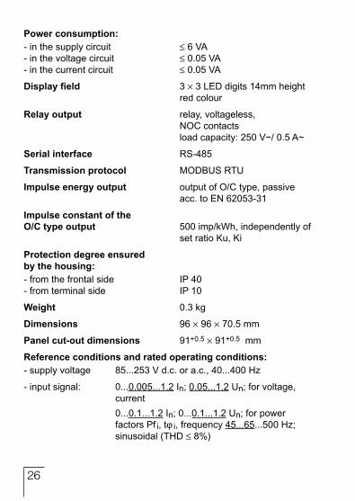
Powerconsumption:- in the supply circuit 6 VA- in the voltage circuit 0.05 VA- in the current circuit 0.05 VA
Displayfield 3 ´ 3 LED digits 14mm height red colour
Relayoutput relay, voltageless, NOC contacts load capacity: 250 V~/ 0.5 A~
Serialinterface RS-485
Transmissionprotocol MODBUS RTU
Impulseenergyoutput output of O/C type, passive acc. to EN 62053-31
ImpulseconstantoftheO/Ctypeoutput 500 imp/kWh, independently of set ratio Ku, Ki
Protectiondegreeensuredbythehousing:- from the frontal side IP 40- from terminal side IP 10
Weight 0.3 kg
Dimensions 96 ´ 96 ´ 70.5 mm
Panelcut-outdimensions 91+0.5 ´ 91+0.5 mm
Referenceconditionsandratedoperatingconditions:- supply voltage 85...253 V d.c. or a.c., 40...400 Hz
- input signal: 0...0.005...1.2 In; 0.05...1.2 Un; for voltage, current 0...0.1...1.2 In; 0...0.1...1.2 Un; for power factors Pf i, tj i, frequency 45...65...500 Hz; sinusoidal (THD 8%)
��
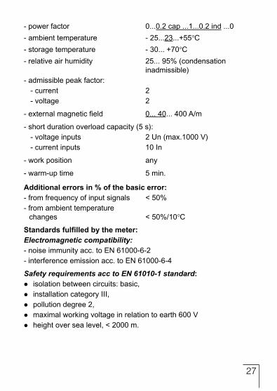
- power factor 0...0.2 cap ...1...0.2 ind ...0- ambient temperature - 25...23...+55C- storage temperature - 30... +70C- relative air humidity 25... 95% (condensation inadmissible)- admissible peak factor:
- current 2- voltage 2
- external magnetic field 0... 40... 400 A/m
- short duration overload capacity (5 s):- voltage inputs 2 Un (max.1000 V)- current inputs 10 In
- work position any
- warm-up time 5 min.
Additionalerrorsin%ofthebasicerror:- from frequency of input signals < 50%- from ambient temperature
changes < 50%/10C
Standardsfulfilledbythemeter:Electromagnetic compatibility:- noise immunity acc. to EN 61000-6-2- interference emission acc. to EN 61000-6-4
Safety requirements acc to EN 61010-1 standard:lisolation between circuits: basic,linstallation category III,lpollution degree 2,lmaximal working voltage in relation to earth 600 Vlheight over sea level, < 2000 m.
��
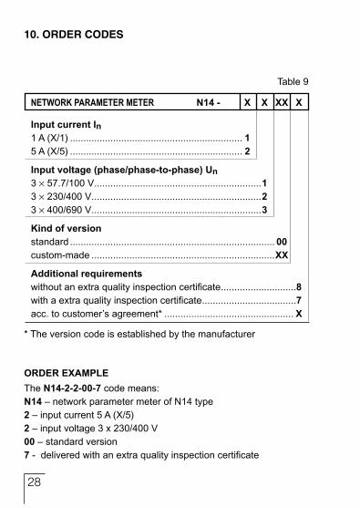
NETWORK PARAMETER METER N14- X X XX X
InputcurrentIn1 A (X/1) ................................................................ 15 A (X/5) ................................................................ 2
Inputvoltage(phase/phase-to-phase)Un3 ´ 57.7/100 V ..............................................................13 ´ 230/400 V ...............................................................23 ´ 400/690 V ...............................................................3
Kindofversionstandard ............................................................................ 00custom-made ....................................................................XX
Additionalrequirementswithout an extra quality inspection certificate ............................8with a extra quality inspection certificate ...................................7acc. to customer’s agreement* ................................................ X
* The version code is established by the manufacturer
Table 9
10. ORDER CODES
ORDEREXAMPLEThe N14-2-2-00-7 code means:N14 – network parameter meter of N14 type2 – input current 5 A (X/5)2 – input voltage 3 x 230/400 V00 – standard version7 - delivered with an extra quality inspection certificate

��
11. MAINTENANCE AND WARRANTY
The N14 network parameter meter does not require any periodical ma-intenance.In case of some incorrect operations:1.Intheperiodof12monthsfromthedateofpurchase:
One should take the transducer down from the installation and return it to the Manufacturer’s Quality Control Dept.If the unit has been used in compliance with the instructions, the Ma-nufacturer warrants to repair it free of charge.
2.Afterthewarrantyperiod:One should turn over the transducer to repair it in a certified service workshop. The disassembling of the housing causes the cancellation of the granted warranty.Spare parts are available for the period of five years from the date of purchase.
Our policy is one of continuous improvement and we reserve the right to make changes in design and specifications of any pro-ducts as engineering advances or necessity requires and revise the above specifications without notice.

�0

��

��
MEASUREMENTCONTROLRECORDING
LubuskieZak³adyAparatówElektrycznychLUMELS.A.ul. Sulechowska 1, 65-022 ZielonaGóra,PolandTel.: (48-68) 3295 100 (exchange)Fax: (48-68) 3295 101e-mail:[email protected]://www.lumel.com.pl
ExportDepartment:Tel.: (48-68) 329 53 02 or 53 04Fax: (48-68) 325 40 91e-mail: [email protected]
SALESPROGRAMn DIGITAL and BARGRAPH PANEL METERSn MEASURING TRANSDUCERSn ANALOG PANEL METERS (DIN INSTRUMENTS)n ANALOG and DIGITAL CLAMP-ON METERSn INDUSTRIAL and HOUSEHOLD CONTROLLERSn CHART AND PAPERLESS RECORDERSn POWER CONTROL UNITS and INVERTERSn WATT-HOUR METERSn AUTOMOTIVE DASHBOARD INDICATORSn ACCESSORIES FOR MEASURING INSTRUMENTS (SHUNTS)n MEASURING SYSTEMS (ENERGY, HEAT, CONTROL)n CUSTOM-MADE MEASURING ELECTRONIC DEVICES.
WE ALSO OFFER OUR SERVICES IN THE PRODUCTION OF:n ALUMINIUM ALLOY PRESSURE CASTINGSn PRECISION ENGINEERING AND THERMOPLASTICS PARTSn PRESSURE CASTING DIES AND OTHER TOOLSn VARIOUS ELECTRONIC SUB-ASSEMBLIES (MSD TECHNOLOGY)
QUALITYPROCEDURES:According to ISO 9001 and ISO 14001 international requirements.All our instruments have CE mark.For more information, please write to or phone our Export