Multiple Disc Brakes - Environmental Expert
51
1 1 1 1 1 1 1 1 1 Innovative Braking and Controls Worldwide Multiple Disc Brakes posi-torque winch brakes, pressure override brakes, wheel mount brakes, and driveline brakes Spring Apply Hydraulic Release Multiple Disc Brakes
-
Upload
khangminh22 -
Category
Documents
-
view
0 -
download
0
Transcript of Multiple Disc Brakes - Environmental Expert

MICO, Inc. Form No. 84-500-001 Online Revision 2012-10-23 111111111
Innovative Braking and Controls Worldwide
Multiple Disc Brakes
posi-torque winch brakes, pressure override brakes,wheel mount brakes, and driveline brakes
Spring Apply HydraulicRelease Multiple
Disc Brakes

2 MICO, Inc. Form No. 84-500-001 Online Revision 2012-10-23
Why choose MICO?MICO, Inc. designs, manufactures and markets hydraulic components, controls, and brake systems primarily for off-road markets. We have manufacturing facilities in:
North Mankato, Minnesota U.S.A. Ontario, California U.S.A. Empalme, Sonora, Mexico
Many of the world’s largest off-highway OEMs value the knowledgeable staff at MICO and work with us to make their products better. Our custom-engineered products are designed with the customer requirements as the primary driver. It is our intent to help custom-ers build their systems with our expertise in hydraulic components, braking systems and controls.
Our goal is to meet or exceed our customers’ expectations in every aspect of our business.
Product lines we specialize in include:
Actuators Brake Locks Brakes Controls Cylinders Electrohydraulics Master Cylinders Valves
MICO is proud to be ISO 9001 and ISO 14001 certifi ed and continuously strive for improvement while remaining a quality leader in our fi eld. We have been a successful business for over 60 years. Privately owned, customer driven. We look forward to working with you!
Spring Apply, Hydraulic Release, Multiple Disc BrakesSafe, sure controlled braking . . . precise control of swing drives or other vehicles and equipment with swivel joints . . . positive load positioning and “run-away” protection for winches . . . virtual elimination of slippage in hydraulic motors . . . These and many other brake related problems have been solved by using a superior, quality built MICO Multiple Disc Brake in the applica-tion.
These precisely engineered brakes are totally enclosed units applied by built-in springs and "held-off" by hydraulic pressure. Maximum torque is produced when hydraulic pressure is absent, either intentionally or due to system failure.
Many MICO brake designs have features developed specifi cally to solve problems encountered with other brake designs . . . Such as piston breakage, piston cocking, spring, spline or bearing failure and low torque and high torque pressure drag.
The catalog coding in this catalog describes mounting, shaft, torque and available options. The catalog code system offers considerable versatility and fl exibility, enabling you to select the product for your specifi c application. Complete the proper online Application Data Sheet (80-500-008, 80-500-009, 80-500-010, 80-500-013) at www.mico.com. The MICO Applications Department will analyze your specifi cations and recommend a multiple disc brake most suitable to the requirements.
Minimum quantity orders apply to some brake combina-tions. Not all possible brake combinations are currently in production.

MICO, Inc. Form No. 84-500-001 Online Revision 2012-10-23 3
Applications
Forestry Equipment
Agricultural Equipment
Heavy ConstructionEquipment
Mining Equipment
In-Plant & WarehouseEquipment
Airport SupportVehicles
Catalog IndexWhy choose MICO ............................................................................................... 2MICO Advantages ................................................................................................. 4Multiple Disc Brake Applications............................................................................ 5Catalog Code Explanation ..................................................................................... 6General Brake Information .................................................................................... 7Multiple Disc Brakes (modular) Introduction .......................................................8-9 SAE A - Mount ........................................................................................ 10-11 SAE C - Mount ........................................................................................12-13 SAE D - Mount ........................................................................................14-15Multiple Disc Brakes (narrow) Introduction .....................................................16-17 ** SAE B - Mount ....................................................................................18-19Multiple Disc Brakes (compact) Introduction ..................................................20-21 SAE B - Mount ........................................................................................22-23Closed Output Motor Brakes ............................................................................... 24Posi-Torque Winch Brakes Introduction .............................................................. 25 SAE C - Mount ........................................................................................26-27* Pressure Override Brakes SAE B - Mount ........................................................................................28-29 SAE C - Mount ........................................................................................30-31Large Wheel Mount Brakes Motor Input ..............................................................................................32-33 Closed Input ............................................................................................34-35Compact Wheel Mount Brakes ** Motor Input ..........................................................................................36-37 Closed Input ............................................................................................38-39Driveline Multiple Disc Brakes ........................................................................40-41Driveline Multiple Disc Brakes, Through Mount ..............................................42-43Driveline Multiple Disc Brakes, Through Mount Compact ..............................44-45Input Face Dimensional Information ..............................................................46-48
MICO Pressure Override Brakes provide secondary actuation when used for service braking. May be ordered with optional pressure override feature.
Swing Drive Equipment

4 MICO, Inc. Form No. 84-500-001 Online Revision 2012-10-23
Representation and ServiceIn addition to the numerous design improvements over competitive models, you also get MICO rep-resentation and service which is second to none.
Direct Access to MICO EngineersInvolving the customer directly in product design and testing en-sures that customer requirements are met. Our engineering staff has a very strong background in spring apply, hydraulically released brakes. As new technology be-comes available, it is integrated into MICO products and when technology is not available, MICO Engineers develop it.
Simplifi ed Disassemblyand AssemblyFeatures such as inboard oil seal, one piece piston separators, longer torque pins and modular design concepts on many models help to simplify disassembly and assembly procedures.
Large Diameter DiscsLarger disc diameters on many models give MICO Brakes higher torque, better heat dissipation and fewer operating parts.
Extensive TestingTesting on MICO Multiple Disc Brakes include high pressure cycle, temperature, horizontal and vertical mount heat generation, spring life and performance, static torque, dynamic torque and leak testing.
Compact Modular DesignsCompact modular designs reduce problems encountered in many installations. Most models can be installed into restricted space with little or no additional adjustment, alignment or special brackets.
AdvantagesInterchangeable with Other Fail-safe Type BrakesMICO Multiple Disc Brakes are interchangeable with other fail-safe type brakes using SAE and indus-try standards as a guide. In most cases engineering changes are not required, therefore, these brakes are economical to use.
Unique Balanced Piston DesignSome models feature a piston design that virtually eliminates areas of localized stress by more uniformly distributing the pressure generated load.
Quality &Reliabilityequal fewerfi eldproblems.

MICO, Inc. Form No. 84-500-001 Online Revision 2012-10-23 5
Multiple Disc Brakes(spring apply, hydraulic release)
MICO engineers are innovators in the design of spring apply, hydraulic release multiple disc brakes, wheel brakes, closed-output motor brakes, posi-torque winch brakes and more. The engineers are committed to improving the product while reducing cost. Simple, straight forward designs result in rugged brake products. These products require less maintenance because they are designed with fewer moving parts. They are truly superior in reliability and performance.MICO Multiple Disc Brakes are designed for use with heavy-duty machinery and off-highway vehicles in the
construction, material handling, agriculture, mining, sanitation, utilities and timber industries. They are also used in a multitude of winching applications. Brakes of this type reduce maintenance and downtime by prevent-ing contaminants, which cause brake lining wear, from entering the brake. They will provide consistent braking torque, positive hold, and long life in rugged environ-ments.
TypicalMultipleDisc BrakeApplications

6 MICO, Inc. Form No. 84-500-001 Online Revision 2012-10-23
CatalogCodeExplanation
The catalog code numbering system allows you to construct the brake by combining the variables that meet your needs. Catalog code number example: 3A-060618-M.A production number will be assigned by our Engineering Department upon receipt of your order. Production order number example: 13-538-004.
NOTEFor brake combinations that are not currently established, but possible, quotation and assignment of part number must be predicated by receipt, review, and acceptance of applicable multiple disc brake data sheet.
Options ExplanationZ = OIL COOLED OPTION, designated as code Z, allows fl ow-through or sump oil cooling for brakes which may be required to handle limited dynamic inputs. Wet brakes are also used in applications where the package is exposed to severe duty or to adverse environmental conditions such as marine winches or mining vehicles. Products that are to be used strictly wet are noted as such. Oils containing slippery or antiwear additives, such as graphite or molybdenum disulfi de or extreme pres-sure (EP) type lubricants, may allow the brake to slip at torque levels below the rated values and should be avoided. Specifi cations (Modular Design)
Flow through - 3.8 L/min (1.0 GPM) to a maximum of 26.5 L/min (7.0 GPM)
Case pressure should not exceed 1.03 bar (15 PSI) Inlet ports - SAE No. 6, 9/16-18 o-ring boss Outlet ports - SAE No. 6, 9/16-18 o-ring boss Brakes are shipped dry and the customer is respon-
sible for adding proper type and volume of cooling oil
Contact MICO for specifi c model information such as inlet/outlet port locations and sump oil fl uid volume.
S = SPEED SENSOR OPTION, noted as suffi x S, allows a customer supplied magnetic pickup to simply screw into the brake housing. The magnetic pickup generates an output frequency that is proportional to the rotational speed of the brake shaft.
Specifi cations Direct mounting of Flow-Tech or Motorola Tach
Drive Pickup Speed sensing range 0 - 4000 RPM Speed sensor ports are 3/8-18 straight thread or
3/4-16UNF (other sizes available upon request, consult MICO)
Available number of notched teeth on speed sensor pickup rotor: C-Mount Modular: 11, 15, 18, 40, 55 and 70 teeth B-Mount Narrow: 40 and 70 teeth
Contact MICO for specifi c model information such as speed sensor port locations
D = DOUBLE BEARING OPTION, is recommended only for special applications. In applications involving overhung loads, such as a sprocket or drum, a double bearing brake usually lacks the load capacity required. In these instances the use of a load adaptor is recom-mended.V = VITON® (or equivalent fl uorocarbon) SEALS,designated as code V, can be used in applications where standard (nitrile) o-rings and seals are incompatible.

MICO, Inc. Form No. 84-500-001 Online Revision 2012-10-23 7
General Brake Information 1. Brake torque values listed are dry static torque ratings except for the C-Mount Posi-Torque Brakes (page 26), Compact Wheel Mount Brakes (page 36), and Driveline Multiple Disc Brakes (pages 40-45). a. For brakes with Z option (oil-cooled) actual torque is 67% of the dry torque listed. b. Static torque may vary ± 10% from specifi ed values. 2. Initial release pressure is the point where the amount of hydraulic pressure to relieve the spring force on the rotor stack has zero brake torque with no running clearance. 3. Full release pressure is the amount of hydraulic pressure required to achieve full running clearance of the rotor stack. 4. Maximum continuous hydraulic input pressure is 206.8 bar (3000 PSI) unless otherwise specifi ed. 5. All splined shafts are 30° involute, fl at root, side fi t per ANSI B92.1-1970 specifi cations unless otherwise specifi ed. 6. All mounting fl ange dimensions conform to SAE Standard J744 unless otherwise specifi ed. 7. Standard (nitrile) o-rings and seals are compatible with mineral based hydraulic fl uids. For applications with non- mineral based fl uids or extreme temperatures, other o-ring materials are available. 8. Brakes include mounting face gaskets and/or o-rings. Some motors and gear-boxes allow for the use of o-rings to seal the mounting faces on either side of the brake. Do not use the o-ring and face gasket together to seal a mounting face. 9. When mounting a brake use a minimum of SAE grade 5 bolts. Tighten to appropriate torque specifi cations for grade used. Make sure the compression load in the joint does not cause the material under the bolt to yield. Hardened fl at washers may be needed.
A. If hydrostatic bench testing is performed on a brake assembly, release pressure must not exceed 68.9 bar (1000 PSI) unless additional mounting bolts are used for supplemental clamping.B. Pressures above 206.8 bar (3000 PSI) caused by spikes in the hydraulic system can shorten brake life and must be avoided.C. Most brakes are designed for limited side load capability at output end. Use of an overhung load adaptor is recommended for most applications. Contact MICO for further information.

8 MICO, Inc. Form No. 84-500-001 Online Revision 2012-10-23
MultipleDisc BrakesModular Design
Features Large diameter spline shafts virtually
eliminate spline battering Versatile modular design Spring loaded, hydraulically released Sealed environment - isolation from
contaminants Nitrile case seals High strength ductile iron construction Standard SAE mounting fl anges
Benefi ts Eliminates problems found in com-
petitive brake designs, such as piston breakage, piston cocking, spring failure, bearing failure and low and high torque pressure drag Designed primarily for use on
hydraulic drive systems, can replace most fail-safe type brakes in use today, and do it economically Engineering changes to replace
fail-safe designs are not required in most cases
OperationMICO Modular Multiple Disc Brakes are spring apply, hydraulic release brakes. Powerful chrome-silicon die springs automati-cally apply the brake’s disc pack when hydraulic pressure drops, giving safe, sure braking.
Cover, Spring Plate and Pressure Plateconstructed of heavy duty ductile iron.
Powerful Chrome Silicon Die Springsautomatically apply the brake's disc packswhen hydraulic pressure drops.
Balanced Piston Design virtually eliminates areas of localized stress by uniformly distributing the pressure generated load.

MICO, Inc. Form No. 84-500-001 Online Revision 2012-10-23 9
Increased Bearing Support improvesshaft alignment between motor, brake and driven load.
Spline Shafts are constructed of high quality, heat treated 8620 steel for high strength and long life. Larger pitch diameter splines for shaft to disc interface give, in many cases, a seven to one advantage in strength. Improved lower tooth loading helps to eliminate spline battering.
Inboard Oil Seal allows for gear box lubrication of the bearing.
Friction Discs use sintered metallic linings and 1035-1050 steel core mate-rial for long life. Large disc diameters are possible because the balanced piston design has the actuating spring and piston all on one side. Location of the torque and tension pins also permits use of the larger discs. With a greater mean radius, the Modular Brake develops more retarding torque, better heat dissipation and requires fewer parts than comparably sized units. Thinner rotor material is possible with larger spline shafts.

10 MICO, Inc. Form No. 84-500-001 Online Revision 2012-10-23
A-Mount Brakes,Modular Design
FEATURES Low release pressures - ideal for use with
closed-loop hydrostatic systems Rugged heavy-duty construction with
torques to 1017 N·m (9000 lb·in)
Heat treated 8620 steel shafts for high strength and long life Unique balanced piston design
13-538-008(3A-060640-M)
millimetersinches
INPUT END
OUTPUT FACE"3M" OUTPUT FACE
SPECIFICATIONSTorque range at 0 bar (0 PSI) back pressure . . . . . . . . . . . . . . . . . . . . . . . . . . . . . 203 - 1017 N·m (1800 - 9000 lb·in)Release pressure range . . . . . . . . . . . . 8.3 - 26.9 bar (120 - 390 PSI)Maximum operating pressure . . . . . . . . . . . . . . . 206.8 bar (3000 PSI)Maximum energy input . . . . . . . . . . . . . . 216,960 joule (160,000 ft·lb) (one stop, no damage)Volume of oil to release brake . . . . . . . . . . . . . . . . . . . 8.2 cm3 (0.5 in3)Maximum operating temperature. . . . . . . . . . . . . . . . . 132 °C (270 °F)
Maximum speed . . . . . . . . . . . . . . . . . . . . . . . . . . . . . . . . . 4000 RPMApproximate weight . . . . . . . . . . . . . . . . . . . . . . . . . . . . . . 11 kg (24 lb)Fluid type . . . . . . . . . . . . . . . . . . . . . . . . . . . Mineral base hydraulic oil
For detailed information on other model numbers go to www.mico.com/service-literature/installation-drawing-search. If the drawing is not available, contact MICO for more information.

MICO, Inc. Form No. 84-500-001 Online Revision 2012-10-23 11
CATALOG CODE (See NOTE on the top of page 6)Not all of the brake combinations are possible due to certain design limitations.NOTE: Dry design only, not for wet applications.
3 M– –
OUTPUT FACE3A - SAE A-Mount 2-Bolt3M - 4-Bolt A-Mount
OUTPUT SPLINE / INPUT SPLINE06/0610/1014/1425/25
SAE Designation06 = 25.4 mm (1.00 in) Diameter 6B10 = 25.4 mm (1.00 In) Diameter Keyed14 = 14T 12/2425 = 31.8 mm (1.25 in) Diameter Keyed
For other confi gurations, consult a MICO Applications Specialist.
Mounting InstructionsInstall cover/shaft assembly on gearbox using eithertwo or four 1/2-13UNC x 1.00 inch long socket headcap screws (not included), depending on brake modelbeing used. See Mounting Instructions (Form No. 81-538-002) included with each brake.
OPTIONS(Available separately orin combination)D - Double BearingS - Speed Sensor
INPUT FACEM - 4-Bolt and SAE A-Mount 2-Bolt
TORQUE Initial Full Torque Code Release Release Rating Pressure Pressure N·m (lb·in) bar (PSI) bar (PSI) 90 * 1017 (9000) 22.8 (330) 26.9 (390) 70 * 791 (7000) 17.2 (250) 20.7 (300) 56 * 633 (5600) 14.5 (210) 17.2 (250) 48 * 542 (4800) 11.7 (170) 13.8 (200) 40 452 (4000) † 14.5 (210) 17.2 (250) 39 441 (3900) 10.3 (150) 12.4 (180) 35 396 (3500) † 11.7 (170) 13.8 (200) 34 384 (3400) 9.0 (130) 10.3 (150) 29 328 (2900) † 10.3 (150) 12.4 (180) 25 283 (2500) † 9.0 (130) 10.3 (150) 24 271 (2400) 6.9 (100) 8.3 (120) 18 203 (1800) † 6.9 (100) 8.3 (120) 11 1243 (11,000) 26.9 (390) 32.4 (470)* For use with input and output spline codes 14 and 25 only. † Models available with speed sensor port. Other torques and/or release pressures are available upon request.
Input Face
M - 4-Bolt and SAE A-Mount 2-Bolt
CATALOG MODEL CODE NUMBER
3A-060618-M 13-538-004 3A-060624-M 13-538-052 3A-060625-M 13-538-230 3A-060629-M 13-538-054 3A-060639-M 13-538-058 3A-060635-M 13-538-006 3A-060640-M 13-538-008 3A-060656-M 13-538-232 3A-100625-M 13-538-294 3A-100640-M 13-538-044 3A-101018-M 13-538-010 3A-101025-M 13-538-196 3A-101029-M 13-538-024 3A-101035-M 13-538-026 3A-101040-M 13-538-012 3A-141418-M 13-538-016 3A-141424-M 13-538-036 3A-141435-M 13-538-384
ASSIGNED NUMBERS CATALOG MODEL CODE NUMBER
3A-141439-M 13-538-050 3A-141448-M 13-538-300 3A-141456-M 13-538-056 3A-141470-M 13-538-290 3A-141490-M 13-538-320 3A-141490-MD 13-538-034 3A-252518-M 13-538-178 3A-252524-M 13-538-376 3A-252525-M 13-538-022 3A-252529-M 13-538-274 3A-252535-M 13-538-370 3A-252540-M 13-538-242 3A-252548-M 13-538-272 3A-252556-M 13-538-028 3A-252590-M 13-538-060 3M-060625-M 13-538-244 3M-060640-M 13-538-064 3M-101040-M 13-538-040
CATALOG MODEL CODE NUMBER
3M-141411-M 13-538-390 3M-141440-M 13-538-020 3M-141440-MD 13-538-032 3M-141448-M 13-538-046 3M-141456-M 13-538-234 3M-141470-M 13-538-236 3M-141470-MD 13-538-202 3M-141490-M 13-538-038 3M-252529-M 13-538-318
CATALOG MODEL CODE NUMBER
3M-252535-M 13-538-182 3M-252540-M 13-538-042 3M-252556-M 13-538-382 3M-252590-M 13-538-048

12 MICO, Inc. Form No. 84-500-001 Online Revision 2012-10-23
C-Mount Brakes,Modular Design
FEATURES More retarding torque than competitive
models Numerous mounting confi gurations
available Low release pressures, ideal for use with
closed-loop hydrostatic systems Rugged heavy-duty construction
Heat treated 8620 steel shafts for high strength and long life Compact modular package simplifi es
mounting Unique balanced piston design
13-547-078(3C-141455-CZ)
millimetersinches
INPUT END
OUTPUT FACE
SPECIFICATIONSTorque range at 0 bar (0 PSI) back pressure . . . . . . . . . . . . . . . . . . . . . . . . . . . . . 509 - 1356 N·m (2200 - 12,000 lb·in)Release pressure range . . . . . . . . . . . 10.3 - 21.4 bar (150 - 310 PSI)Maximum operating pressure . . . . . . . . . . . . . . . 206.8 bar (3000 PSI)Maximum speed . . . . . . . . . . . . . . . . . . . . . . . . . . . . . . . . . 4000 RPMVolume of oil to release brake . . . . . . . . . . . . . . . . . . 16.4 cm3 (1.0 in3)Maximum operating temperature. . . . . . . . . . . . . . . . . 132 C (270 F)
Maximum energy input . . . . . . . . . . . . . . 542,400 joule (400,000 ft·lb) (one stop, no damage)Approximate weight . . . . . . . . . . . . . . . . . . . . . . . . . . . . . . 18 kg (40 lb)Fluid type . . . . . . . . . . . . . . . . . . . . . . . . . . . Mineral base hydraulic oil
For detailed information on other model numbers go to www.mico.com/service-literature/installation-drawing-search. If the drawing is not available, contact MICO for more information.

MICO, Inc. Form No. 84-500-001 Online Revision 2012-10-23 13
CATALOG CODE (See NOTE on the top of page 6)Not all of the brake combinations are possible due to certain design limitations.NOTE: On oil cooled models (Z option) actual torque is 67% of value shown on torque code chart. Recom- mended sump oil fl uid volume when mounted: Horizontal - 118.3 mL (4 oz), Vertical - Contact MICO.
OUTPUT FACE3C - SAE C-Mount 4-Bolt
OUTPUT SPLINE / INPUT SPLINE04/0004/1413/0014/0014/0614/1314/1414/1717/1417/1721/0021/2125/14
SAE Designation00 = Used with "R" input face only04 = 14T 12/24 (internal)06 = 25.4 mm (1.00 in) Diameter 6B13 = 13T 8/1613 = 13T 16/3214 = 14T 12/2417 = 17T 12/2421 = 21T 16/3225 = 31.6 mm (1.25 in) Diameter Keyed
For other confi gurations, consult a MICO Applications Specialist.
OPTIONS(Available separately or in combination)D - Double BearingS - Speed SensorV - Fluorocarbon sealsZ - Oil Cooled - see note above
INPUT FACEB - SAE B-Mount 2-BoltC - SAE C-Mount 4-BoltC2 - SAE C-Mount 2-Bolt ThroughC24 - 2-Bolt and 4-Bolt C-Mount
TORQUE Initial Full Torque Code Release Release Rating Pressure Pressure N·m (lb·in) bar (PSI) bar (PSI) 98 1107 (9800) 14.5 (210) 20.0 (290) 85 960 (8500) 11.0 (160) 15.2 (220) 80 904 (8000) 12.4 (180) 17.2 (250) 70 791 (7000) 11.0 (160) 14.5 (210) 66 746 (6600) 9.0 (130) 12.4 (180) 55 622 (5500) 9.0 (130) 11.7 (170) 54 610 (5400) 7.6 (110) 11.0 (160) 45 508 (4500) 7.6 (110) 10.3 (150) 30 339 (3000) 4.1 (60) 6.2 (90) 28 316 (2800) 4.1 (60) 6.2 (90) 25 283 (2500) 6.9 (100) 9.0 (130) 24 271 (2400) 5.5 (80) 7.6 (110) 22 249 (2200) 2.8 (40) 4.1 (60) 16 1808 (16,000) 19.3 (280) 28.3 (410) 12 1356 (12,000) 14.5 (210) 21.4 (310) 10 1130 (10,000) 12.4 (180) 17.2 (250)
Other torques and/or release pressures are available upon request.
ASSIGNED NUMBERS CATALOG MODEL CODE NUMBER
3C-141412-C24Z 13-547-022 3C-141412-K4 13-547-296 3C-141412-K4Z 13-547-036 3C-141412-M 13-547-038 3C-141422-C 13-547-046 3C-141424-CZ 13-547-486 3C-141425-C 13-547-054 3C-141428-C 13-547-058 3C-141430-C 13-547-064 3C-141430-C24Z 13-547-544 3C-141445-C 13-547-072 3C-141445-CZ 13-547-362 3C-141445-C2 13-547-208 3C-141445-C2Z 13-547-522 3C-141445-C24 13-547-424 3C-141445-K4 13-547-384 3C-141445-M 13-547-352 3C-141454-C 13-547-074 3C-141455-B 13-547-354 3C-141455-BZ 13-547-298 3C-141455-C 13-547-076 3C-141455-CD 13-547-344 3C-141455-CS 13-547-452 3C-141455-CZ 13-547-078 3C-141455-C24 13-547-492 3C-141455-M 13-547-364 3C-141466-C 13-547-082 3C-141466-CZ 13-547-474 3C-141466-C24 13-547-358 3C-141466-C 13-547-082 3C-141466-M 13-547-204 3C-141466-MZ 13-547-226 3C-141470-C 13-547-084
CATALOG MODEL CODE NUMBER
3C-141470-CZ 13-547-086 3C-141480-B 13-547-342 3C-141480-BZ 13-547-472 3C-141480-C 13-547-090 3C-141480-K4 13-547-094 3C-141480-K4Z 13-547-254 3C-141480-M 13-547-096 3C-141485-C 13-547-098 3C-141498-C 13-547-102 3C-141498-C2 13-547-104 3C-141498-CS 13-547-106 3C-141498-CV 13-547-450 3C-141498-CZ 13-547-108 3C-141498-C24 13-547-396 3C-141498-C24Z 13-547-048 3C-141498-K4 13-547-110 3C-141498-M 13-547-116 3C-141498-MD 13-547-378 3C-141712-C 13-547-118
3 C – –
D - SAE D-MountK4 - Eaton Standard 4000M - 4-Bolt and SAE A-Mount 2-BoltR - Closed
See page 46 for Input Face Dimensions.
CATALOG MODEL CODE NUMBER
3C-040080-RZ 13-547-532 3C-041412-C 13-547-282 3C-040080-RZ 13-547-532 3C-041445-C2D 13-547-502 3C-041498-C 13-547-324 3C-130016-RZ 13-547-530 3C-140012-R 13-547-272 3C-140012-RZ 13-547-420 3C-140016-RZ 13-547-510 3C-140098-R 13-547-268 3C-140612-MZ 13-547-370 3C-140628-M 13-547-002 3C-140645-M 13-547-264 3C-140655-M 13-547-232 3C-140655-MZ 13-547-006 3C-140685-M 13-547-246 3C-140698-M 13-547-190 3C-141316-B 13-547-540 3C-141324-B 13-547-252 3C-141328-B 13-547-306 3C-141345-D 13-547-422 3C-141355-B 13-547-290 3C-141380-D 13-547-410 3C-141398-D 13-547-016 3C-141398-DZ 13-547-434 3C-141410-C 13-547-482 3C-141410-CZ 13-547-024 3C-141410-K4 13-547-164 3C-141410-M 13-547-026 3C-141412-C 13-547-030 3C-141412-CD 13-547-316 3C-141412-CDZ 13-547-288 3C-141412-CZ 13-547-034
CATALOG MODEL CODE NUMBER
3C-141724-CZ 13-547-464 3C-141754-C 13-547-214 3C-141755-C 13-547-120 3C-141785-C 13-547-182 3C-141798-C 13-547-294 3C-171485-C 13-547-122 3C-171712-C 13-547-462 3C-171780-C 13-547-124 3C-171785-C 13-547-278 3C-171785-CZ 13-547-126 3C-171798-C 13-547-212 3C-212145-C 13-547-332 3C-212145-CZ 13-547-526 3C-212166-C 13-547-130 3C-212180-C 13-547-132 3C-212185-C 13-547-220 3C-212198-C 13-547-134 3C-251498-K4 13-547-334

14 MICO, Inc. Form No. 84-500-001 Online Revision 2012-10-23
D-Mount Brakes,Modular Design
FEATURES Oil cooled or dry design applications Simple four-bolt mounting confi guration Low-release pressures, ideal for use with
closed-loop hydrostatic systems Rugged heavy-duty construction
Heat treated 8620 steel shafts for high strength and long life Unique balanced piston design
13-552-006(3D-131312-DZ)
millimetersinches
INPUT END
OUTPUT FACE
SPECIFICATIONSTorque range at 0 bar (0 PSI) back pressure . . . . . . . . . . . . . 621 - 2712 N·m (5500 - 24,000 lb·in)Release pressure range . . . . . . . . . . . . 7.6 - 26.9 bar (110 - 470 PSI)Maximum operating pressure . . . . . . . . . . . . . . . 206.8 bar (3000 PSI)Maximum speed . . . . . . . . . . . . . . . . . . . . . . . . . . . . . . . . . 4000 RPMVolume of oil to release brake . . . . . . . . . . . . . . . . . . 16.4 cm3 (1.0 in3)
Maximum energy input . . . . . . . . . . . . . . 610,200 joule (450,000 ft·lb) (one stop, no damage)Fluid type . . . . . . . . . . . . . . . . . . . . . . . . . . . Mineral base hydraulic oilMaximum operating temperature. . . . . . . . . . . . . . . . . 132 °C (270 °F)Approximate weight . . . . . . . . . . . . . . . . . . . . . . . . . . . . . . 24 kg (52 lb)
For detailed information on other model numbers go to www.mico.com/service-literature/installation-drawing-search. If the drawing is not available, contact MICO for more information.

MICO, Inc. Form No. 84-500-001 Online Revision 2012-10-23 15
CATALOG CODE (See NOTE on the top of page 6)Not all of the brake combinations are possible due to certain design limitations.NOTE: On oil cooled models (Z option) actual torque is 67% of value shown on torque code chart. Recom- mended sump oil fl uid volume when mounted: Horizontal - 147.9 mL (5 oz), Vertical - Contact MICO.
OUTPUT FACE3D - SAE D-Mount 4-Bolt
OUTPUT SPLINE / INPUT SPLINE13/0013/1313/1413/1513/1613/2175/75
SAE and DIN 5480 Designation00 = Used with "R" input face only13 = 13T 8/1614 = 14T 12/2415 = 15T 8/1616 = 16T 8/1621 = N45 x 2 x 21 x 9H75 = 44.5 mm (1.75 in) Diameter Keyed
For other confi gurations, consult a MICO Applications Specialist.
OPTIONSZ - Oil Cooled - see note above
INPUT FACEC - SAE C-MountD - SAE D-MountE - SAE E-MountR - Closed Face
TORQUE Initial Full Torque Code Release Release Rating Pressure Pressure N·m (lb·in) bar (PSI) bar (PSI) 80 904 (8000) 9.0 (130) 11.7 (170) 55 621 (5500) 5.5 (80) 7.6 (110) 24 2712 (24,000) 22.8 (330) 32.4 (470) 20 2260 (20,000) 18.6 (270) 26.2 (380) 16 1808 (16,000) 14.5 (210) 20.7 (300) 12 1356 (12,000) 11.0 (160) 15.9 (230) 10 1130 (10,000) 10.3 (150 13.8 (200)
Other torques and/or release pressures are available upon request.
ASSIGNED NUMBERS CATALOG MODEL CODE NUMBER
3D-131380-DZ 13-552-036 3D-131380-E 13-552-044 3D-131416-C 13-552-094 3D-131424-CZ 13-552-102 3D-131480-C 13-552-038 3D-131512-E 13-552-078 3D-131512-EZ 13-552-104 3D-131516-E 13-552-090 3D-131524-EZ 13-552-106 3D-131580-E 13-552-100 3D-131624-C 13-552-080 3D-132112-D 13-552-054 3D-757512-DZ 13-552-028
3 D – –
CATALOG MODEL CODE NUMBER
3D-130020-RZ 13-552-068 3D-130024-R 13-552-076 3D-131310-D 13-552-040 3D-131310-E 13-552-042 3D-131312-D 13-552-002 3D-131312-DZ 13-552-006 3D-131316-C 13-552-016 3D-131316-D 13-552-008 3D-131320-D 13-552-060 3D-131324-D 13-552-070 3D-131324-DZ 13-552-086 3D-131355-D 13-552-012 3D-131380-D 13-552-033
Input Faces
C - SAE C-Mount E - SAE E-MountD - SAE D-Mount

16 MICO, Inc. Form No. 84-500-001 Online Revision 2012-10-23
MultipleDisc BrakesNarrow Design
Features Complete self-contained package Standard SAE mounting fl anges Spring loaded, hydraulically released High-strength ductile iron construction Sealed environment - isolation from
contaminants
Benefi ts Thick discs eliminate tooth wear-out
and brake "freewheeling," resulting in longer life between parts replacement Large inlet port helps avoid sluggish
response if air is entrapped in the oil One piece separator design helps
eliminate breaking and bending moments on piston, resulting in minimal loss because of good contact on plates Longer dowel pins simplify assembly
and keep rotor in place, reducing risk of shearing teeth from rotor
OperationBraking using this version is provided by a pack of rotating friction discs splined to the shaft and stationary separator plates restrained by pins in the housing. Force is transmitted to the disc pack through the return plate by a series of preloaded springs. The brakes are released by hydraulic pressure applied to the piston to compress the springs. They are self-applying since any func-tion which reduces the hydraulic pressure below the release pressure will start to initiate a brake application. Zero pressure produces maximum brake torque.
Cover Bolts are high-strength SAE grade 8 fl anged type, which allow for higher brake release pressure shocks without subsequent cover bolt damage.
O-ring and Back-up ring combinationon all models.

MICO, Inc. Form No. 84-500-001 Online Revision 2012-10-23 17
Chrome Silicon Die Springs provide higher torque capabilities where space is limited, resulting in longer service life.
Spline Shafts are constructed of high quality, heat treated 8620 steel for high strength and long life. The preci-sion ground one-piece spline shafts reduce vibration.
Rotary Shaft Seal at output end to prevent oil and other contaminants from entering brake.
Friction Discs use sintered metalliclinings and high strength 1035-1050 steel core material for long life.
Piston Separator design allows for easier disassembly and assem-bly. This one piece powdered metal design as opposed to a split piston design, helps eliminate breaking and bending moments on piston.
Housings are constructed of high quality ductile iron castings for strength and durability.

18 MICO, Inc. Form No. 84-500-001 Online Revision 2012-10-23
B-Mount Brakes,Narrow Design
FEATURES Complete self-contained dry design
package Standard SAE mounting fl anges High-strength ductile iron castings for
strength and durability
Sintered bronze or non-metallic friction plates for high strength and long lining life Sealed environment - isolated from
contaminants Optional pressure override models available
for limited service braking
02-556-326(LMB-131321-B)
millimetersinches
OUTPUT FACE
INPUT END
SPECIFICATIONSTorque range at 0 bar (0 PSI) back pressure . . . . . . . . . . . . . . . . 113 - 542 N·m (700 - 6000 lb·in)Release pressure range . . . . . . . . . . . . 8.3 - 23.8 bar (120 - 345 PSI)Maximum operating pressure . . . . . . . . . . . . . . . 206.8 bar (3000 PSI)Maximum speed . . . . . . . . . . . . . . . . . . . . . . . . . . . . . . . . . 4000 RPMVolume of oil to release brake . . . . . . . . 8.2 cm3 (0.5 in3) (new linings) 14.8 cm3 (0.9 in3) (maximum)Maximum energy input . . . . . . . . . . . . . . 339,000 joule (250,000 ft·lb) (one stop, no damage)
Fluid type . . . . . . . . . . . . . . . . . . . . . . . . . . . Mineral base hydraulic oilMaximum operating temperature. . . . . . . . . . . . . . . . . 132 °C (270 °F)Approximate weight . . . . . . . . . . . . . . . . . . . . . . . . . . . . 10.9 kg (24 lb)
Optional pressure override section Service torque rating . . . . . . . . . . . . . . . . . . . . 305 N·m @ 69.0 bar (2700 lb·in @ 1000 PSI) Maximum input pressure . . . . . . . . . . . . . . . . . . 69.0 bar (1000 PSI)
For detailed information on other model numbers go to www.mico.com/service-literature/installation-drawing-search. If the drawing is not available, contact MICO for more information.

MICO, Inc. Form No. 84-500-001 Online Revision 2012-10-23 19
CATALOG CODE (See NOTE on the top of page 6)Not all of the brake combinations are possible due to certain design limitations.NOTE: On oil cooled models (Z option) actual torque is 67% of value shown on torque code chart. Recom- mended sump oil fl uid volume when mounted: Horizontal - 88.7 mL (3 oz), Vertical - Contact MICO.
SERIESLM - MICO
OUTPUT SPLINE / INPUT SPLINE06/0613/0613/1213/1314/1315/1215/15
SAE Designation06 = 25.4 mm (1.00 in) Diameter 6B12 = 12T 12/24 used with L2 input face only13 = 13T 16/3214 = 14T 12/2415 = 15T 16/32
For other confi gurations, consult a MICO Applications Specialist.
OPTIONS(Available separately or in combination)P - Pressure OverrideS - Speed SensorZ - Oil Cooled - see note above
INPUT FACEB - SAE B-Mount 4-BoltL2 - Eaton Bearingless 2000M - Modifi ed SAE A-Mount 2 or 4-BoltN - NEMA
TORQUE Initial Full Torque Code Release Release Rating Pressure Pressure N·m (lb·in) bar (PSI) bar (PSI) 60 678 (6000) 23.1 (335) 27.6 (400) 51 576 (5100) 20.0 (290) 23.4 (340) 50 565 (5000) 22.1 (320) 27.6 (400) 48 542 (4800) 17.9 (260) 21.4 (310) 40 452 (4000) 15.2 (220) 17.9 (260) 35 396 (3500) 20.0 (290) 23.8 (345) 30 339 (3000) 16.5 (240) 20.0 (290) 29 328 (2900) 11.0 (160) 15.9 (230) 28 316 (2800) 15.9 (230) 19.3 (280) 24 271 (2400) 12.4 (180) 15.2 (220) 21 237 (2100) 12.4 (180) 14.5 (210) 19 215 (1900) 11.7 (170) 13.8 (200) 17 192 (1700) 9.7 (140) 11.7 (170) 16 181 (1600) 7.9 (115) 9.3 (135) 15 170 (1500) 7.2 (105) 7.9 (115) 14 158 (1400) 8.3 (120) 10.0 (145) 12 136 (1200) 13.8 (200) 16.2 (235) 11 124 (1100) 9.3 (135) 11.0 (160) 10 113 (1000) 11.7 (170) 13.8 (200) 08 90 (800) 7.2 (105) 7.9 (115) 07 79 (700) 3.4 (50) 4.1 (60)
Other torques and/or release pressures are available upon request.
ASSIGNED NUMBERS CATALOG MODEL CODE NUMBER
LMB-131317-B 02-556-332 LMB-131321-B 02-556-326 LMB-131324-B 02-556-360 LMB-131328-B 02-556-324 LMB-131329-BS 02-556-418 LMB-131330-B 02-556-320 LMB-131335-B 02-556-334 LMB-131340-B 02-556-376 LMB-141360-M 02-556-422 LMB-151240-L2 02-556-428 LMB-151250-L2 02-556-454 LMB-151507-B 02-556-432 LMB-151528-B 02-556-404 LMB-151535-B 02-556-340 LMB-151540-B 02-556-392
L M B – –
CATALOG MODEL CODE NUMBER
LMB-060651-B 02-556-420 LMB-130614-M 02-556-304 LMB-130616-MP 02-556-434 LMB-130621-M 02-556-328 LMB-130628-M 02-556-378 LMB-130635-M 02-556-336 LMB-130640-M 02-556-358 LMB-131219-L2 02-556-348 LMB-131228-L2 02-556-350 LMB-131240-L2 02-556-352 LMB-131308-N 02-556-406 LMB-131310-B 02-556-322 LMB-131311-NS 02-556-390 LMB-131312-B 02-556-330 LMB-131314-B 02-556-318 LMB-131315-BP 02-556-398
OUTPUT FACEB - SAE B-Mount 2-Bolt
NOTE: MICO recommends that all applications for pressure override brakes have a completed Data Sheet submitted to the MICO Application Department. Complete the online Application Data Sheet (80-500-010) at www.mico.com/products/ brakes/multiple-disc-brakes.
See page 47 for Input Face Dimensions

20 MICO, Inc. Form No. 84-500-001 Online Revision 2012-10-23
Multiple Disc BrakesCompact Design
Features Non-metallic lining material Extreme compact design Low release pressures Full system pressure capacity Low actuation volume
Benefi ts Design allows for pressure spikes of
up to 275.8 bar (4000 PSI) without affecting cycle life One repair kit for all serviceable parts Non-metallic lining material contributes
to high torque and low release pressure
OperationBraking is provided by stationary friction plates and a rotating disc splined to the shaft. Force is transmitted to the disc pack through the return plate by a series of preloaded springs. The brake is released by hydraulic pressure applied to the piston to compress the springs. The brake is self-applying since any function which reduces the hydraulic system pressure of the brake will start to initiate a brake application. Zero pressure produces maximum brake torque.
Integrated return plate/separators help prevent piston cocking.

MICO, Inc. Form No. 84-500-001 Online Revision 2012-10-23 21
Gasket design and high-strength bolts provide high pressure capability and long life.
8620 alloy steel shafts are heat treated for strength and shock resistance.
High performance non-metallic lining materials contribute to high torque, low release pressure.
Chrome silicon die springs for long life and high torque.
High quality ductile iron casting material for strength and durability.

22 MICO, Inc. Form No. 84-500-001 Online Revision 2012-10-23
B-Mount Multiple Disc Brakes,Compact Design
FEATURES Non-metallic lining material Extremely compact package length Low release pressures - ideal for use with
closed-loop hydraulic systems
Full system pressure capacity Low actuation volume needed
13-100-002(GB-131312-B)
For detailed information on other model numbers go to www.mico.com/service-literature/installation-drawing-search. If the drawing is not available, contact MICO for more information.
millimetersinches
INPUT ENDOUTPUT FACE
SPECIFICATIONSTorque range at 0 bar (0 PSI) back pressure . . . . . . . . . . . . . . . 136 - 452 N·m (1200 - 6000 lb·in)Release pressure range . . . . . . . . 6.9 - 20.0 bar (100 - 290 PSI) initial 7.9 - 23.4 bar (115 - 340 PSI) fullMaximum operating pressure . . . . . . 206.8 bar (3000 PSI) continuousMaximum speed . . . . . . . . 4000 RPM shaft speed capability specifi ed is for brake in released condition. Energy absorption during apply cycle must be carefully examined for each application.
Volume of oil to release brake . . . . . . . . . . . 8.2 cm3 (0.5 in3) minimum 14.8 cm3 (0.9 in3) maximumMaximum energy input . . . . . . . . . . . . . . 231,000 joule (170,385 ft·lb)Spline shaft . . . . . . . . . . . . . . . . . . . . . . . 30° involute, fl at root side fi t per ANSI B92.1 - 1970Fluid type . . . . . . . . . . . . . . . . . . . . . . . . . . . Mineral base hydraulic oilMaximum operating temperature. . . . . . . . . . . . . . . . . 132 °C / 270 °FApproximate weight . . . . . . . . . . . . . . . . . . . . . . . . . . . . 10.3 kg (19 lb)

MICO, Inc. Form No. 84-500-001 Online Revision 2012-10-23 23
CATALOG CODE (See NOTE on the top of page 6)Not all of the brake combinations are possible due to certain design limitations.
B-MOUNT COMPACT
OUTPUT SPLINE / INPUT SPLINE06/0613/0613/1314/1214/1415/12
SAE Designation06 = 25.4 mm (1.00 in) diameter 6B12 = 12T 12/24 used with L2 input face only13 = 13T 16/3214 = 14T 12/2415 = 15T 16/32
For other confi gurations, consult a MICO Applications Specialist.
INPUT FACEB - SAE B-Mount 2-BoltL2 - Eaton Bearingless 2000M - Modifi ed SAE A-Mount 2 or 4 Bolt
TORQUE Initial Full Torque Code Release Release Rating Pressure Pressure N·m (lb·in) bar (PSI) bar (PSI) 60* 678 (6000) 26.2 (380) 30.3 (440) 51 576 (5100) 22.1 (320) 25.2 (365) 50 565 (5000) 21.4 (310) 26.2 (380) 48 542 (4800) 20.7 (300) 23.8 (345) 40 452 (4000) 20.0 (290) 23.4 (340) 35 396 (3500) 16.5 (240) 19.3 (280) 28 316 (2800) 13.8 (200 16.2 (235) 24 271 (2400) 13.1 (190) 14.8 (215) 21 237 (2100) 11.8 (165) 13.1 (190) 16 181 (1600) 8.6 (125) 10.0 (145) 14 158 (1400) 7.6 (110) 8.6 (125) 12 136 (1200) 6.9 (100) 7.9 (115)
* For use with input and output spline code 14 only.
Other torques and/or release pressures are available upon request.
ASSIGNED NUMBERS CATALOG MODEL CODE NUMBER
GB-131335-B 13-100-012 GB-131340-B 13-100-014 GB-131351-M 13-100-018 GB-141260-L2 13-100-044 GB-141460-M 13-100-020 GB-151250-L2 13-100-048
G – –B
CATALOG MODEL CODE NUMBER
GB-060628-B 13-100-046 GB-060635-B 13-100-054 GB-130648-M 13-100-040 GB-131312-B 13-100-002 GB-131314-B 13-100-004 GB-131316-B 13-100-006 GB-131321-B 13-100-024 GB-131324-B 13-100-022 GB-131328-B 13-100-010
Input Faces
B - SAE B-Mount 2-Bolt M - Modifi ed SAE A-Mount 2-Boltor 4-Bolt
L2 - Eaton Bearingless 2000
OUTPUT FACESAE B-Mount 2-Bolt

24 MICO, Inc. Form No. 84-500-001 Online Revision 2012-10-23
Closed OutputMotor Brakes
FEATURES Mates with Parker Nichols
& Sauer Danfoss through-shaft motors Low cost with high
torque capacity
02-550-116(MN-1356)
For detailed information on other model numbers go to www.mico.com/service-literature/installation-drawing-search. If the drawing is not available, contact MICO for more information.
millimetersinches
SPECIFICATIONSTorque rating at 0 bar (0 PSI) back pressure . . . . . . . . . . . . . . 283 - 633 Nm (2500 - 5600 lbin)Release pressure range . . . . . . . . . . . 10.3 - 25.5 bar (150 - 370 PSI)Maximum operating pressure . . . . . . . . . . . . . . . 206.8 bar (3000 PSI)Maximum speed . . . . . . . . . . . . . . . . . . . . . . . . . . . . . 1000 RPM (MN) 4000 RPM (MS)Volume of oil to release brake . . . . . . . . . . . . . . . . . . 7.4 cm3 (0.45 in3)Maximum operating temperature. . . . . . . . . . . . . . . . . 132 °C (270 °F)Approximate Weight . . . . . . . . . . . . . . . . . . . . . . . . . . . . 8.2 kg (18 lb)Fluid type . . . . . . . . . . . . . . . . . . . . . . . . . . . Mineral base hydraulic oilMaximum energy input . . . . . . . . . . . . . . 135,600 joule (100,000 ftlb)
CATALOG CODE (See NOTE on the top of page 6)Not all of the brake combinations are possible due to certain design limitations.NOTE: Dry design only, not for wet applications.
THROUGH-SHAFT BRAKEPRODUCT CODE
For other confi gurations, consult a MICO Applications Specialist.
INPUT FACEM35 - Sauer Danfoss 5.75 inch B.C.M46 - Sauer Danfoss 6.125 inch B.C.
TORQUE Initial Full Torque Code Release Release Rating Pressure Pressure N·m (lb·in) bar (PSI) bar (PSI) 56 633 (5600) 20.0 (290) 25.5 (370) 42 475 (4200) 15.9 (230) 20.7 (300) 35 396 (3500) 12.4 (180) 16.5 (240) 25 282 (2500) 8.3 (120) 10.3 (150) 15 170 (1500) 4.8 (70) 6.6 (95)
Other torques and/or release pressures are available upon request.
ASSIGNED NUMBERS
– –
CATALOG MODEL CODE NUMBER
MN-1315 02-550-214 MN-1325 02-550-120 MN-1335 02-550-122 MN-1342 02-550-114 MN-1356 02-550-116 MS-1325-M35 02-550-124 MS-1325-M46 02-550-118
INPUT SPLINE13 - 13T 16/32
MN - Parker Nichols Series 110A (also former Nichols Series 100, 110, 120, 130)MS - Sauer Danfoss

MICO, Inc. Form No. 84-500-001 Online Revision 2012-10-23 25
Posi-TorqueWinch BrakesThe compact size of these MICO® Posi-Torque Winch Brakes permit easy installation into restricted space without requiring special adjustment, alignment, shims or brackets. Large diameter friction discs are possible because of the location of the tension pins. With these large discs the posi-torque brake develops more retard-ing torque than comparable sized units. The balanced piston design keeps critical components in tension when the brake is engaged. This helps eliminate bending or fracturing due to stress.If winching is the application, a MICO® Spring Apply, Hydraulic Release, Multiple Disc Brake with posi-torque option is the ideal choice. This brake is designed primarily for use on a hydraulically driven winch system. It combines the benefi ts of allowing one-way winching, positive load positioning and “runaway” protection all in a single, compact package.
Quality pays in performance and reliability
LUBRICATIONOils containing slippery or antiwear additives, such as graphite or molybdenum disulfi de or extreme pres-sure (EP) type lubricants, may allow the brake to slip at torque levels below the rated values and should be avoided.MICO recommends a good grade of ATF, SAE 10 or SAE 20 oil, or Mobil DTE and oils meeting MIL.7808 or MIL.23699.
Benefi tsTHE BRAKE "FREEWHEELS" INTHE LIFT DIRECTIONThe MICO® Posi-Torque Brake is engaged while the load is being raised. The brakes internal over-riding clutch "freewheels" allowing travel in only one direction.
A ONE-WAY POSITIVE POSITIONING WINCH BRAKEOnce the winch stops lifting, the Posi-Torque Brake automatically holds the load in the desired position. Positive load positioning is immediately available because the brake is always engaged. There is no lag time or drift.
SAFE, RUNAWAY PROTECTION WHEN LOWERING THE LOADWhen lowering a load, hydraulic pressure disen-gages the Posi-Torque Brake. The load can be “powered” down using the winch’s hydraulic motor for safe, slow descent. If hydraulic pressure drops and the load begins to runaway from the motor, the MICO® Posi-Torque Brake automatically engages to bring the load to a safe controlled stop.

26 MICO, Inc. Form No. 84-500-001 Online Revision 2012-10-23
C-Mount Posi-Torque Brakes,Modular Design
FEATURES Wet design brake Nitrile case seals Positions the load at the instant the
winch stops Compact size for easy installation Large-diameter discs
Metallic linings for long life Hardened high-strength steel shafts Balanced piston design
13-602-006(3CWC-141480-CCC)
millimetersinches
OUTPUT FACE
INPUT END
SPECIFICATIONSTorque range at 0 bar (0 PSI) back pressure . . . . . . . . . . . . . . . . . . . . . . . . . . Oil cooled operation 452 - 904 N·m (4000 - 8000 lb·in)Release pressure range . . . . . . . . . . . 13.1 - 25.5 bar (190 - 370 PSI)Maximum operating pressure . . . . . . . . . . . . . . . 206.8 bar (3000 PSI)Maximum speed (Non-freewheeling direction) . . . . . . . . . . (Flow through) 4000 RPM (Sump) 3000 RPM (Freewheeling direction) . . . . . . . . . . . . . (Flow through) 4000 RPM (Sump) 4000 RPMOptimal fl ow through cooling . . . . . . . . . 3.8 - 26.5 L/min (1 - 7 GPM)
Maximum case pressure . . . . . . . . . . . . . . . . . . . . . . . 2.1 bar (30 PSI)Sump cooling fl uid volume . . . . . . . . . . . . . . . . . . . . . 177.4 mL (6 oz)Volume of oil to release brake . . . . . . . . . . . . . . . . . . 16.4 cm3 (1.0 in3)Maximum energy input . . . . . . . . . . . . . . 542,400 joule (400,000 ftlb) (one stop, no damage)Fluid type . . . . . . . . . . . . . . . . . . . . . . . . . . . Mineral base hydraulic oilMaximum operating temperature. . . . . . . . . . . . . . . . . 132 °C (270 °F)Approximate weight . . . . . . . . . . . . . . . . . . . . . . . . . . . . . . 19 kg (42 lb)
For detailed information on other model numbers go to www.mico.com/service-literature/installation-drawing-search. If the drawing is not available, contact MICO for more information.

MICO, Inc. Form No. 84-500-001 Online Revision 2012-10-23 27
CATALOG CODE (See NOTE on the top of page 6)Not all of the brake combinations are possible due to certain design limitations.NOTE: Wet design only, not intended for dry applications. To be installed in horizontal position only.
3CW - C-MOUNT POSI-TORQUE WINCH BRAKE
OUTPUT SPLINE / INPUT SPLINE04/1414/14
SAE Designation04 = 14T 12/24 (internal)14 = 14T 12/24
For other confi gurations, consult a MICO Applications Specialist.
FREEWHEELINGDIRECTION CODE
(As you face the outputend of brake)CC - Counter ClockwiseCW - Clockwise
INPUT FACEC - SAE C-Mount 4-BoltC24 - 2 Bolt and 4-Bolt C-MountK4 - Eaton Standard 4000M - 4-Bolt and SAE A-Mount 2-Bolt
TORQUE Initial Full Torque Code Release Release Rating Pressure Pressure N·m (lb·in) bar (PSI) bar (PSI) 80 904 (8000) 18.6 (270) 25.5 (370) 75 848 (7500) 17.2 (250) 22.7 (330) 70 791 (7000) 15.8 (230) 21.4 (310) 65 734 (6500) 15.2 (220) 20.7 (300) 40 452 (4000) 9.6 (140) 13.1 (190)
NOTE: Torque is coded as wet use.Other torques and/or release pressures are avail-able upon request.
ASSIGNED NUMBERS
3 C W C – –
CATALOG MODEL CODE NUMBER
3CWC-041440-CCW 13-602-0463CWC-041475-CCW 13-602-002 3CWC-141440-CCC 13-602-0223CWC-141440-C24CC 13-602-0303CWC-141440-C24CW 13-602-0323CWC-141465-CCC 13-602-0103CWC-141465-CCW 13-602-012 3CWC-141465-MCC 13-602-024 3CWC-141465-MCW 13-602-0203CWC-141475-CCW 13-602-0343CWC-141480-CCC 13-602-006 3CWC-141480-CCW 13-602-0083CWC-141480-MCC 13-602-018
OUTPUT FACEC - SAE C-Mount 4-Bolt
See page 47 for Input Face Dimensions
28 MICO, Inc. Form No. 84-500-001 Online Revision 2012-10-23
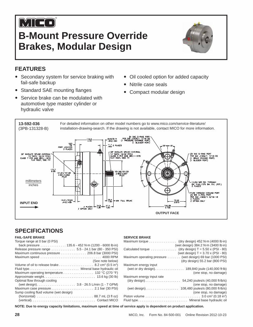
B-Mount Pressure OverrideBrakes, Modular Design
FEATURES Secondary system for service braking with
fail-safe backup Standard SAE mounting fl anges Service brake can be modulated with
automotive type master cylinder or hydraulic valve
Oil cooled option for added capacity Nitrile case seals Compact modular design
13-592-036(3PB-131328-B)
For detailed information on other model numbers go to www.mico.com/service-literature/installation-drawing-search. If the drawing is not available, contact MICO for more information.
millimetersinches
INPUT END
OUTPUT FACE
SPECIFICATIONSFAIL-SAFE BRAKETorque range at 0 bar (0 PSI) back pressure . . . . . . . . . . . . . . 135.6 - 452 N·m (1200 - 6000 lb·in)Release pressure range . . . . . . . . . . . . . 5.5 - 24.1 bar (80 - 350 PSI)Maximum continuous pressure . . . . . . . . . . . . . . 206.8 bar (3000 PSI)Maximum speed . . . . . . . . . . . . . . . . . . . . . . . . . . . . . . . . . 4000 RPM (See note below)Volume of oil to release brake . . . . . . . . . . . . . . . . . . . 8.2 cm3 (0.5 in3)Fluid type . . . . . . . . . . . . . . . . . . . . . . . . . . . Mineral base hydraulic oilMaximum operating temperature. . . . . . . . . . . . . . . . . 132 °C (270 °F)Approximate weight . . . . . . . . . . . . . . . . . . . . . . . . . . . . 13.6 kg (30 lb)Optimal fl ow through cooling (wet design) . . . . . . . . . . . . . . . . . . . . . 3.8 - 26.5 L/min (1 - 7 GPM)Maximum case pressure . . . . . . . . . . . . . . . . . . . . . . . 2.1 bar (30 PSI)Sump cooling fl uid volume (wet design) (horizontal) . . . . . . . . . . . . . . . . . . . . . . . . . . . . . . . 88.7 mL (3 fl oz) (vertical). . . . . . . . . . . . . . . . . . . . . . . . . . . . . . . . . . . Contact MICO
SERVICE BRAKEMaximum torque . . . . . . . . . . . . . . . (dry design) 452 N·m (4000 lb·in) (wet design) 384.2 N·m (3400 lb·in)Calculated torque . . . . . . . . . . . . . . (dry design) T = 5.50 x (PSI - 80) (wet design) T = 3.70 x (PSI - 80)Maximum operating pressure . . . . . . . (wet design) 69 bar (1000 PSI) (dry design) 55.2 bar (800 PSI)Maximum energy input (wet or dry design). . . . . . . . . . . . . . . . 189,840 joule (140,000 ft·lb) (one stop, no damage)Maximum energy input rate (dry design) . . . . . . . . . . . . . . . . . . . 54,240 joules/s (40,000 ft·lb/s) (one stop, no damage) (wet design) . . . . . . . . . . . . . . . . . . 108,480 joules/s (80,000 ft·lb/s) (one stop, no damage)Piston volume . . . . . . . . . . . . . . . . . . . . . . . . . . . . . . 3.0 cm3 (0.18 in3)Fluid type . . . . . . . . . . . . . . . . . . . . . . . . . . . Mineral base hydraulic oil
NOTE: Due to energy capacity limitations, maximum speed at time of service apply is dependent on product application.

MICO, Inc. Form No. 84-500-001 Online Revision 2012-10-23 29
CATALOG CODE (See NOTE on the top of page 6)Not all of the brake combinations are possible due to certain design limitations.NOTE: On oil-cooled models (Z option) actual torque is 67% of value shown on torque code chart.
3P - PRESSURE OVERRIDE
OUTPUT SPLINE / INPUT SPLINE13/0613/1315/15
SAE Designation06 = 25.4 mm (1.00 in) diameter 6B13 = 13T 16/3215 = 15T 16/32
For other confi gurations, consult a MICO Applications Specialist.
OPTIONZ - Oil Cooled - see note above
TORQUE Initial Full Torque Code Release Release Rating Pressure Pressure N·m (lb·in) bar (PSI) bar (PSI) 60* 678 (6000) 20.0 (290) 24.1 (350) 52* 588 (5200) 17.2 (250) 20.7 (300) 40 452 (4000) 13.8 (200) 16.5 (240) 35 396 (3500) 12.4 (180) 14.5 (210) 28 316 (2800) 9.6 (140 11.7 (170) 24 271 (2400) 8.3 (120) 10.3 (150) 19 215 (1900) 7.6 (110) 9.0 (130) 16 181 (1600) 6.2 (90) 7.6 (110) 12 136 (1200) 4.8 (70) 5.5 (80)
* Maximum dry service brake torque is 4000 lbin. The 5200 lbin, and 6000 lbin torque is used only for coding of 3500 lbin and 4000 lbin oil-cooled brakes.
Other torques and/or release pressures are available upon request.
ASSIGNED NUMBERS CATALOG MODEL CODE NUMBER
3PB-131335-B 13-592-010 3PB-131340-B 13-592-042 3PB-131340-MZ 13-592-022 3PB-131352-BZ 13-592-048 3PB-151552-BZ 13-592-050
CATALOG MODEL CODE NUMBER
3PB-130612-M 13-592-044 3PB-130619-MZ 13-592-046 3PB-130635-M 13-592-002 3PB-130640-M 13-592-004 3PB-130640-MZ 13-592-024 3PB-131328-B 13-592-036
Input Faces
B - SAE B-Mount M - 4-Bolt and SAE A-Mount 2-Bolt
OUTPUT FACEB - SAE B-Mount 2-Bolt
3 P – –B
NOTE: MICO recommends that all applications for pressure override brakes have a completed Data Sheet submitted to the MICO Application Department. Complete the online Application Data Sheet (80-500-010) at www.mico.com/products/ brakes/multiple-disc-brakes.
INPUT FACEB - SAE B-MountM - 4-Bolt and SAE A-Mount 2-Bolt

30 MICO, Inc. Form No. 84-500-001 Online Revision 2012-10-23
C-Mount Pressure OverrideBrakes, Modular Design
FEATURES Secondary system for service braking with
fail-safe backup Standard SAE mounting fl anges Service brake can be modulated with
automotive type master cylinder or hydraulic valve
Oil cooled option for added capacity Nitrile case seals Compact modular design
13-597-008(3PC-141470-CZ)
For detailed information on other model numbers go to www.mico.com/service-literature/installation-drawing-search. If the drawing is not available, contact MICO for more information.
millimetersinches
INPUT END OUTPUT FACE
SPECIFICATIONSFAIL-SAFE BRAKETorque range at 0 bar (0 PSI) back pressure . . . . . . . . . . . . . 407 - 1469 N·m (3600 - 13,000 lb·in)Release pressure range . . . . . . . . . . . . 9.7 - 25.5 bar (140 - 370 PSI)Maximum continuous pressure . . . . . . . . . . . . . . 206.8 bar (3000 PSI)Maximum speed . . . . . . . . . . . . . . . . . . . . . . . . . . . . . . . . . 4000 RPM (See note below)Volume of oil to release brake . . . . . . . . . . . . . . . . . . 16.4 cm3 (1.0 in3)Fluid type . . . . . . . . . . . . . . . . . . . . . . . . . . . Mineral base hydraulic oilMaximum operating temperature. . . . . . . . . . . . . . . . . 132 °C (270 °F)Approximate weight . . . . . . . . . . . . . . . . . . . . . . . . . . . . . . 20 kg (44 lb)Optimal fl ow through cooling (wet design) . . . . . . . . . . . . . . . . . . . . . 3.8 - 26.5 L/min (1 - 7 GPM)Maximum case pressure . . . . . . . . . . . . . . . . . . . . . . . 2.1 bar (30 PSI)Sump cooling fl uid volume (wet design) (horizontal) . . . . . . . . . . . . . . . . . . . . . . . . . . . . . . 118.3 mL (4 fl oz) (vertical). . . . . . . . . . . . . . . . . . . . . . . . . . . . . . . . . . . Contact MICO
SERVICE BRAKEMaximum torque . . . . . . . . . . . . . . (dry design) 1062 N·m (9400 lb·in) (wet design) 700.6 N·m (6200 lb·in)Calculated torque . . . . . . . . . . . . . (dry design) T = 10.10 x (PSI - 70) (wet design) T = 6.66 x (PSI - 70)Maximum operating pressure . . . . . . . . . . . . . . . . 69.0 bar (1000 PSI)Maximum energy input (wet or dry design). . . . . . . . . . . . . . . . 406,800 joule (300,000 ft·lb) (one stop, no damage)Maximum energy input rate (dry design) . . . . . . . . . . . . . . . . . . . 101,700 joule/s (75,000 ft·lb/s) (one stop, no damage) (wet design) . . . . . . . . . . . . . . . . . . 203,400 joule/s (150,000 ft·lb/s) (one stop, no damage)Piston volume . . . . . . . . . . . . . . . . . . . . . . . . . . . . . . 5.2 cm3 (0.32 in3)Fluid type . . . . . . . . . . . . . . . . . . . . . . . . . . . Mineral base hydraulic oil
NOTE: Due to energy capacity limitations, maximum speed at time of service apply is dependent on product application.

MICO, Inc. Form No. 84-500-001 Online Revision 2012-10-23 31
CATALOG CODE (See NOTE on the top of page 6)Not all of the brake combinations are possible due to certain design limitations.NOTE: On oil-cooled models (Z option) actual torque is 67% of value shown on torque code chart.
3P - PRESSURE OVERRIDE
OUTPUT SPLINE / INPUT SPLINE14/0014/0614/1314/1423/23
SAE Designation00 = used with "R" only06 = 25.4 mm (1.00 in) diameter 6B13 = 13T 8/1614 = 14T 12/2423 = 23T 16/32
For other confi gurations, consult a MICO Applications Specialist.
OPTION(Available separately or in combination)S - Speed SensorZ - Oil Cooled - see note above
TORQUE Initial Full Torque Code Release Release Rating Pressure Pressure N·m (lb·in) bar (PSI) bar (PSI) 98 1107 (9800) 18.6 (270) 25.5 (370) 80 904 (8000) 15.2 (220) 20.7 (300) 70 791 (7000) 13.8 (200) 19.3 (280) 57 644 (5700) 12.4 (180) 19.3 (280) 55 622 (5500) 11.0 (160 15.2 (220) 45 508 (4500) 8.3 (120) 11.7 (170) 36 407 (3600) 6.9 (100) 9.6 (140) 13 1469 (13,000) 24.1 (350) 32.8 (475)
Other torques and/or release pressures are available upon request.
ASSIGNED NUMBERS CATALOG MODEL CODE NUMBER
3PC-140080-R 13-597-0323PC-140645-M 13-597-0343PC-140670-MZ 13-597-0443PC-140680-M 13-597-0263PC-141313-DZ 13-597-0523PC-141398-DZ 13-597-0463PC-141436-C 13-597-0143PC-141436-C24 13-597-0423PC-141436-M 13-597-0403PC-141445-C24Z 13-597-0303PC-141445-K4 13-597-0723PC-141455-C 13-597-0023PC-141455-CZ 13-597-0163PC-141457-CZ 13-597-0503PC-141470-C 13-597-0043PC-141470-CZ 13-597-0083PC-141470-C24Z 13-597-0543PC-141480-C 13-597-0183PC-141480-CZ 13-597-0243PC-141498-C 13-597-0103PC-141498-CZ 13-597-0223PC-141498-C24Z 13-597-0563PC-232380-CZ 13-597-070
OUTPUT FACEC - SAE C-Mount 4-Bolt
3 P – –C
NOTE: MICO recommends that all applications for pressure override brakes have a completed Data Sheet submitted to the MICO Application Department. Complete the online Application Data Sheet (80-500-010) at www.mico.com/products/ brakes/multiple-disc-brakes.
INPUT FACEC - SAE C-Mount StandardC2 - SAE C-Mount 2-BoltC24 - 2 Bolt and 4-Bolt C-MountD - SAE D-MountK4 - Eaton Standard 4000M - 4-Bolt and SAE A-Mount 2-BoltR - Closed Face
See page 48 for Input Face Dimensions

32 MICO, Inc. Form No. 84-500-001 Online Revision 2012-10-23
Large Wheel Mount Brakes,Motor Input
FEATURES Provision for direct mounting of brake to
wheels Heat-treated 8620 shafts
Complete self-contained, dry-design package Full system pressure capability
13-587-002(WH-501415-M)
For detailed information on other model numbers go to www.mico.com/service-literature/installation-drawing-search. If the drawing is not available, contact MICO for more information.
millimetersinches
OUTPUT END
INPUT FACE
SPECIFICATIONSTorque range at 0 bar (0 PSI) back pressure . . . . . . . . . . . . . 904 - 1695 N·m (8000 - 15,000 lb·in)Release pressure range . . . . . . . . . . . 21.4 - 34.5 bar (310 - 500 PSI)Maximum operating pressure . . . . . . . . . . . . . . . 206.8 bar (3000 PSI)Maximum speed . . . . . . . . . . . . . . . . . . . . . . . . . . . . . . . . . 1000 RPMVolume of oil to release brake . . . . . . . . . . . . . . . . . . . 9.8 cm3 (0.6 in3)
Maximum energy input . . . . . . . . . . . . . . 339,000 joule (250,000 ft·lb) (one stop, no damage)Fluid type . . . . . . . . . . . . . . . . . . . . . . . . . . . Mineral base hydraulic oilMaximum operating temperature. . . . . . . . . . . . . . . . . 132 °C (270 °F)Approximate weight . . . . . . . . . . . . . . . . . . . . . . . . . . . . 17.2 kg (38 lb)

MICO, Inc. Form No. 84-500-001 Online Revision 2012-10-23 33
CATALOG CODE (See NOTE on the top of page 6)Not all of the brake combinations are possible due to certain design limitations.NOTE: Dry design only, not for oil-cooled applications.
WH - WHEEL MOUNT BRAKE
OUTPUT SHAFT / INPUT SHAFT50/0650/1250/14
SAE Designation06 = 25.4 mm (1.00 in) Diameter 6B12 = 12T 22/24 modifi ed (as required for Eaton 2000 Bearingless)14 = 14T 12/2450 = 38.1 mm (1.50 in) Keyed, Taper
For other confi gurations, consult a MICO Applications Specialist.
TORQUE Initial Full Torque Code Release Release Rating Pressure Pressure N·m (lb·in) bar (PSI) bar (PSI) 80 904 (8000) 14.5 (210) 21.4 (310) 15 1695 (15,000) 26.9 (390) 40.0 (580) 12 1356 (12,000) 24.8 (360) 31.0 (450) 10 1130 (10,000) 17.9 (260 26.2 (380)
Other torques and/or release pressures are available upon request.
ASSIGNED NUMBERS CATALOG MODEL CODE NUMBER
WH-500680-M 13-587-014WH-501215-L2 13-587-004WH-501280-L2 13-587-006WH-501412-M 13-587-030WH-501415-M 13-587-002WH-501415-K4 13-587-008WH-501480-M 13-587-012
W H – –
INPUT FACEM - 4-Bolt and SAE A-Mount 2-BoltL2 - Eaton Bearingless 2000K4 - Eaton Standard 4000
See page 48 for Input Face Dimensions
MAX. LOAD
LOAD CAPACITY @ 100 RPM AND B10 = 6500 HRS 325 RPM AND B10 = 2000 HRS
6000
5000
4000
3000
2000
1000
0+2 +1 ¤ -1 -2 -3 -4+3
DISTANCE FROM CENTERLINE OF KEY (¤)(INCHES)
(Refer to drawing on previous page)
THRUST LOAD CAPACITY: 1100 lb max. @ 100 RPM & 2000 hrs B10 life. (Based on constant 3700 lb side-load at center- line of key)
ALLOWABLERADIAL
LOAD (LB)

34 MICO, Inc. Form No. 84-500-001 Online Revision 2012-10-23
Large Wheel Mount Brakes,Closed Input
FEATURES Automotive type linings Provides direct mounting of brake to wheel Heat-treated 8620 steel shafts
Low release pressures - ideal for use with closed-loop hydrostatic systems Full system pressure capability
13-587-020(SWH-50096-R)
For detailed information on other model numbers go to www.mico.com/service-literature/installation-drawing-search. If the drawing is not available, contact MICO for more information.
millimetersinches
OUTPUT END
INPUT FACE
SPECIFICATIONSTorque range at 0 bar (0 PSI) back pressure . . . . . . . . . . . . 904 - 1356 Nm (5400 - 14,000 lbin)Release pressure range . . . . . . . . . . .21.37 - 34.5 bar (310 - 500 PSI)Maximum operating pressure . . . . . . . . . . . . . . . 206.8 bar (3000 PSI) 241.3 bar (3500 PSI) intermittentMaximum speed . . . . . . . . . . . . . . . . . . . . . . . . . . . . . . . . . 1000 RPM
Maximum energy input . . . . . . . . . . . . . . 335,000 joule (247,096 ftlb) Volume of oil to release brake . . . . . . . . . . . . . . . . . . . 9.8 cm3 (0.6 in3)Fluid type . . . . . . . . . . . . . . . . . . . . . . . . . . . Mineral base hydraulic oilMaximum operating temperature. . . . . . . . . . . . . . . . . 132 °C (270 °F)Approximate weight . . . . . . . . . . . . . . . . . . . . . . . . . . . . 17.2 kg (38 lb)

MICO, Inc. Form No. 84-500-001 Online Revision 2012-10-23 35
CATALOG CODE (See NOTE on the top of page 6)Not all of the brake combinations are possible due to certain design limitations.
SWH - WHEEL MOUNT BRAKE
OUTPUT SHAFT50 SAE Designation
50 = 38.1 mm (1.50 in) Keyed, Taper
For other confi gurations, consult a MICO Applications Specialist.
TORQUE Initial Full Torque Code Release Release Rating Pressure Pressure N·m (lb·in) bar (PSI) bar (PSI) 96 1085 (9600) 26.2 (380) 31.7 (460) 54 6102 (5400) 24.1 (350) 27.6 (400) 14 1582 (14,000) 40.0 (580) 45.5 (660)
Other torques and/or release pressures are available upon request.
ASSIGNED NUMBERS CATALOG MODEL CODE NUMBER
SWH-500014-R 13-587-016SWH-500054-R 13-587-024SWH-500096-R 13-587-020
INPUT FACER - Closed Face
MAX. LOAD
LOAD CAPACITY @ 100 RPM AND B10 = 6500 HRS 325 RPM AND B10 = 2000 HRS
6000
5000
4000
3000
2000
1000
0+2 +1 ¤ -1 -2 -3 -4+3
DISTANCE FROM CENTERLINE OF KEY (¤)(INCHES)
(Refer to drawing on previous page)
THRUST LOAD CAPACITY: 1100 lb max. @ 100 RPM & 2000 hrs B10 life. (Based on constant 3700 lb side-load at center- line of key)
0 0S W H – –
CLOSED INPUT
ALLOWABLERADIAL
LOAD (LB)

36 MICO, Inc. Form No. 84-500-001 Online Revision 2012-10-23
Compact Wheel Mount Brakes,Motor Input
FEATURES Provides direct mounting of brake to wheel Wet design with patented pressure override
option
Metallic linings Designed for standard SAE hydraulic motor
inputs
13-587-086(MW-250642-AP)
For detailed information on other model numbers go to www.mico.com/service-literature/installation-drawing-search. If the drawing is not available, contact MICO for more information.
millimetersinches
INPUT ENDOUTPUT FACE
SPECIFICATIONSType . . . . . . . . . . . . . . . . . . . . . . . . . . . . . . . . Wet multiple disc brake, spring apply, hydraulic release with hydraulic apply service brake optionRelease pressure . . . . . . . . . . . . . . . . . . . . . 26.9 bar (390 PSI) initial, 31.7 bar (460 PSI) full 206.8 bar (3000 PSI) maximum (continuous)Torque rating parking/emergency . . . . . . . . . . . . . . . . . 475 N·m (4200 lb·in) static @ 0 bar (0 PSI) service brake . . . . . . . . . . . . . . . . . . . 396 N·m (3500 lb·in) dynamic @ 103.4 bar (1500 PSI) maximum input pressure
Maximum speed . . . . . . . . . . . . . . . . . . . . . . . . . . . . . . . . . . 300 RPMMaximum energy input . . . . . . . . . . . . . . 418,000 joule (308,300 ft·lb)Lining material . . . . . . . . . . . . . . . . . . . . . . . . . . . . . . Metallic graphiticApproximate weight . . . . . . . . . . . . . . . . . . . . . . . . . . . . . 12 kg (27 lbs)Sump cooling fl uid volume. . . . . . . . . . . . . . . . . . . . 118.3 mL (4 fl . oz.)Fluid type . . . . . . . . . . . . . . . . . . . . . . . . . . . Mineral base hydraulic oil

MICO, Inc. Form No. 84-500-001 Online Revision 2012-10-23 37
CATALOG CODE (See NOTE on the top of page 6)Not all of the brake combinations are possible due to certain design limitations.NOTE: Wet design only, not intended for dry applications. To be installed in horizontal position only.
MW - MINI WHEEL BRAKE
OUTPUT SHAFT / INPUT SHAFT50/0625/06
SAE Designation50 = 38.1 mm (1.50 in) Keyed, Taper25 = 31.8 mm (1.25 in) Keyed, Taper06 = 25.4 mm (1.00 in) Diameter 6B
For other confi gurations, consult a MICO Applications Specialist.
TORQUE Initial Full Torque Code Release Release Rating Pressure Pressure N·m (lb·in) bar (PSI) bar (PSI) 42 475 (4200) 26.9 (390) 31.7 (460)
NOTE: Torque is coded as wet use.Other torques and/or release pressures are available upon request.
ASSIGNED NUMBERS CATALOG MODEL CODE NUMBER
MW-250642-AP 13-587-086
OPTIONSP - Pressure Override
MAX. LOAD
LOAD CAPACITY @ 240 RPM AND B10 = 3000 HRS
5000
4000
3000
2000
1000
0+2 +1 ¤ -1 -2 -3 -4+3
DISTANCE FROM CENTERLINE OF KEY (¤)(INCHES)
(Refer to drawing on previous page)
M W – –
NOTE: MICO recommends that all applications for pressure override brakes have a completed Data Sheet submitted to the MICO Application Department. Complete the online Application Data Sheet (80-500-010) at www.mico.com/products/ brakes/multiple-disc-brakes.
INPUT FACEA - SAE A-Mount 2-Bolt
ALLOWABLERADIAL
LOAD (LB)

38 MICO, Inc. Form No. 84-500-001 Online Revision 2012-10-23
Compact Wheel Mount Brakes,Closed Input
FEATURES Non-metallic type linings Provides direct mounting of brake to wheel Low release pressures - ideal for use with
closed-loop hydrostatic systems
Full system pressure capability Integral hub eliminates the need for an
adaptor Superior radial wheel load capacities
13-587-072(MW-054560-R)
For detailed information on other model numbers go to www.mico.com/service-literature/installation-drawing-search. If the drawing is not available, contact MICO for more information.
millimetersinches
SPECIFICATIONSTorque range at 0 bar (0 PSI) back pressure . . . . . . . . . . . . 170 - 1130 N·m (1500 to 10,000 lb·in)Release pressure range . . . . . . . . . . . . 6.9 - 27.6 bar (100 - 400 PSI)Maximum sustained operating pressure . . . . . . . 206.8 bar (3000 PSI) 275.8 bar (4000 PSI) intermittentMaximum speed . . . . . . . .100 RPM or 200 RPM depending on modelMaximum operating temperature. . . . . . . . . . . . . . . . . . 93 °C (200 °F)Maximum energy input . . . . . . . . . . . . . . 231,000 joule (170,500 ft·lb)
Approximate weight . . . . . . . . . . . . . . . . . . . . . . . . . . . . 10.4 kg (23 lb)Volume of oil to release brakes . . . . . . . . . . 8.2 cm3 (0.5 in3) minimum 14.8 cm3 (0.9 in3) maximumFluid type . . . . . . . . . . . . . . . . . . . . . . . . . . . Mineral base hydraulic oil

MICO, Inc. Form No. 84-500-001 Online Revision 2012-10-23 39
CATALOG CODE (See NOTE on the top of page 6)Not all of the brake combinations are possible due to certain design limitations.NOTE: On oil-cooled models (Z option) actual torque is 67% of value shown on torque code chart.
MW - MINI WHEEL BRAKE
WHEEL MOUNT CONFIGURATION0440 = 4-Bolt on 4.00 inch B.C.0445 = 4-Bolt on 4.50 inch B.C.0545 = 5-Bolt on 4.50 inch B.C.2500 = 31.8 mm (1.25 in) Keyed, Taper5000 = 38.1 mm (1.50 in) Keyed, Taper
For other confi gurations, consult a MICO Applications Specialist.
TORQUE Initial Full Torque Code Release Release Rating Pressure Pressure N·m (lb·in) bar (PSI) bar (PSI) 90 1017 (9000) 24.1 (385) 29.0 (460) 60 678 (6000) 33.8 (490) 40.0 (580) 51 576 (5100) 25.2 (385) 29.6 (460) 40 452 (4000) 21.0 (335) 24.0 (385) 35 396 (3500) 18.6 (300) 21.0 (340) 25 283 (2500) 16.6 (240) 19.3 (280) 10 1130 (10,000) 25.2 (400) 29.6 (470)
Other torques and/or release pressures are available upon request.
ASSIGNED NUMBERS CATALOG MODEL CODE NUMBER
MW-054525-RZ 13-587-068MW-054535-R 13-587-074MW-054560-R 13-587-072MW-054590-R 13-587-082MW-500051-R 13-587-080
OPTIONSz - Oil Cooled - see note above
M W – –
INPUT FACER - Closed Face
MAX. LOAD
LOAD CAPACITY @ 100 RPM AND B10 = 6500 HRS 325 RPM AND B10 = 2000 HRS
3000
2500
2000
1500
1000
500
0+2 +1 ¤ -1 -2 -3 -4+3
DISTANCE FROM EDGE OF WHEEL FLANGE (¤)(INCHES)
(Refer to drawing on previous page)
THRUST LOAD CAPACITY: 300 lb max. @ 100 RPM & 2000 hrs B10 life. (Based on constant 290 lb side-load at edge of wheel fl ange)
ALLOWABLERADIAL
LOAD (LB)

40 MICO, Inc. Form No. 84-500-001 Online Revision 2012-10-23
DrivelineMultiple Disc Brakes
FEATURES Enclosed/sealed wet design Tapered roller bearings for high radial and
thrust loads Metallic linings provide high energy and
long life
Isolation from environmental contaminants Developed to retrofi t competitive drum/
caliper driveline parking brakes Lining wear indicator port
02-560-104(DB-757518)
For detailed information on other model numbers go to www.mico.com/service-literature/installation-drawing-search. If the drawing is not available, contact MICO for more information.
millimetersinches
SPECIFICATIONSType . . . . . . . . . . . . . . . . . . . . . . . . . . . . . . . . Wet multiple disc brake, spring apply, hydraulic releaseRelease pressure for 2034 N·m (18,000 lb·in) version . . . . . . . . . . . . . . . . . . . 18.6 bar (270 PSI) initial 22.4 bar (325 PSI) full 137.9 bar (2000 PSI) maximum (continuous)Release pressure for 2825 N·m(25,000 lb·in) version . . . . . . . . . . . . . . . . . . . 24.1 bar (350 PSI) initial 29.0 bar (420 PSI) full 137.9 bar (2000 PSI) maximum (continuous)
Torque Rating . . . . . . . . . . 2034 N·m (18,000 lb·in) static (breakaway) 2825 N·m (25,000 lb·in) static (breakaway)Volume of oil required to release brake . . . . . . . . . . . . 32.8 cm3 (2 in3)Sump cooling fl uid volume. . . . . . . . . . . . . . . . . . . . 236.6 mL (8 fl . oz.)Maximum speed . . . . . . . . . . . . . . . . . . . . . . . . . . . . . . . . . 3200 RPMMaximum energy input . . . . . . . . . . . 1,654,000 joule (1,220,000 ft·lb)Approximate weight . . . . . . . . . . . . . . . . . . . . . . . . . . . . . . 42 kg (92 lb)Fluid type . . . . . . . . . . . . . . . . . . . . . . . . . . . Mineral base hydraulic oil

MICO, Inc. Form No. 84-500-001 Online Revision 2012-10-23 41
CATALOG CODE (See NOTE on the top of page 6)Not all of the brake combinations are possible due to certain design limitations.
DB - DRIVELINE BRAKE
OUTPUT SHAFT / INPUT SHAFT75/75 = 1.75 inch Diameter 10B Parallel Spline-External50/50 = 1.50 inch Diameter 10B Parallel Spline-Internal (through-shaft)
For other confi gurations, consult a MICO Applications Specialist.
TORQUE Initial Full Torque Code Release Release Rating Pressure Pressure N·m (lb·in) bar (PSI) bar (PSI) 25 2825 (25,000) 24.1 (350) 29.0 (420) 18 2034 (18,000) 18.6 (270) 22.4 (325)
NOTE: Torque is coded as wet use.
Other torques and/or release pressures are available upon request.
ASSIGNED NUMBERS CATALOG MODEL CODE NUMBER
DB-505018 02-560-108DB-505025 02-560-110DB-757518 02-560-104DB-757525 02-560-106
D B –

42 MICO, Inc. Form No. 84-500-001 Online Revision 2012-10-23
Driveline Multiple Disc Brakes,Through Mount
FEATURES Enclosed/sealed wet design Tapered roller bearings for high radial and
thrust loads Metallic linings provide high energy and
long life
Isolation from environmental contaminants Developed to retrofi t competitive drum/
caliper driveline parking brakes Lining wear indicator port
02-560-118(DBT-757525)
For detailed information on other model numbers go to www.mico.com/service-literature/installation-drawing-search. If the drawing is not available, contact MICO for more information.
millimetersinches
SPECIFICATIONSType . . . . . . . . . . . . . . . . . . . . . . . . . . . . . . . . Wet multiple disc brake, spring apply, hydraulic releaseRelease pressure . . . . . . . . . . . . . . . . . . . . . 24.1 bar (350 PSI) initial 29.0 bar (420 PSI) full 137.9 bar (2000 PSI) maximum (continuous)Torque Rating . . . . . . . . . . 2825 N·m (25,000 lb·in) static (breakaway)Volume of oil required to release brake . . . . . . . . . . . . 32.8 cm3 (2 in3)Sump cooling fl uid volume. . . . . . . . . . . . . . . . . . . . 236.6 mL (8 fl . oz.)Maximum speed . . . . . . . . . . . . . . . . . . . . . . . . . . . . . . . . . 3200 RPM
Approximate weight . . . . . . . . . . . . . . . . . . . . . . . . . . . . . . 42 kg (92 lb)Fluid type . . . . . . . . . . . . . . . . . . . . . . . . . . . Mineral base hydraulic oil

MICO, Inc. Form No. 84-500-001 Online Revision 2012-10-23 43
CATALOG CODE (See NOTE on the top of page 6)Not all of the brake combinations are possible due to certain design limitations.
DBT - DRIVELINE BRAKE THROUGH MOUNT
OUTPUT SHAFT / INPUT SHAFT75/75 = 1.75 inch Diameter 10B Parallel Spline-External
For other confi gurations, consult a MICO Applications Specialist.
TORQUE Initial Full Torque Code Release Release Rating Pressure Pressure N·m (lb·in) bar (PSI) bar (PSI) 25 2825 (25,000) 24.1 (350) 29.0 (420)
NOTE: Torque is coded as wet use.
Other torques and/or release pressures are available upon request.
ASSIGNEDNUMBERS CATALOG MODEL CODE NUMBER
DBT-757525 02-560-118
D B T –

44 MICO, Inc. Form No. 84-500-001 Online Revision 2012-10-23
Driveline Multiple Disc Brakes,Through Mount Compact
FEATURES Enclosed/sealed wet design Tapered roller bearings for high radial and
thrust loads Metallic linings provide high energy and
long life
Isolation from environmental contaminants Developed to retrofi t competitive drum/
caliper driveline parking brakes Lining wear indicator port
02-560-116(DB-141412)
For detailed information on other model numbers go to www.mico.com/service-literature/installation-drawing-search. If the drawing is not available, contact MICO for more information.
millimetersinches
SPECIFICATIONSType . . . . . . . . . . . . . . . . . . . . . . . . . . . . . . . . . Wet multiple disc brake, spring apply, hydraulic releaseRelease pressure . . . . . . . . . . . . . . . . . . . . . .17.9 bar (260 PSI) initial 24.1 bar (350 PSI) full 137.9 bar (2000 PSI) maximum (continuous)Torque Rating . . . . . . . . . . 1356 N·m (12,000 lb·in) static (breakaway)Volume of oil required to release brake . . . . . . . . . . . . . 32.8 cm3 (2 in3)Sump cooling fl uid volume. . . . . . . . . . . . . . . . . . . . 236.6 mL (8 fl . oz.)
Maximum speed . . . . . . . . . . . . . . . . . . . . . . . . . . . . . . . . . .3200 RPMApproximate weight . . . . . . . . . . . . . . . . . . . . . . . . . . . . . . 24 kg (53 lb)Fluid type . . . . . . . . . . . . . . . . . . . . . . . . . . . .Mineral base hydraulic oil

MICO, Inc. Form No. 84-500-001 Online Revision 2012-10-23 45
CATALOG CODE (See NOTE on the top of page 6)Not all of the brake combinations are possible due to certain design limitations.
DBTC - DRIVELINE BRAKETHROUGH MOUNT COMPACT
OUTPUT SHAFT / INPUT SHAFT14/14
75/75 = 1.75 inch Diameter 10B Parallel Spline-External
For other confi gurations, consult a MICO Applications Specialist.
TORQUE Initial Full Torque Code Release Release Rating Pressure Pressure N·m (lb·in) bar (PSI) bar (PSI) 12 1356 (12,000) 17.9 (260) 24.1 (350)
NOTE: Torque is coded as wet use.
Other torques and/or release pressures are available upon request.
ASSIGNEDNUMBERS CATALOG MODEL CODE NUMBER
DBT-141412 02-560-116
D B T C –
SAE Designation14 = 14t 12/24 (interval)

46 MICO, Inc. Form No. 84-500-001 Online Revision 2012-10-23
Input Face Dimensional InformationReference for Page 13
millimetersinches
B - SAE B-Mount 2-Bolt C - SAE C-Mount 4-Bolt C2 - SAE C-Mount 2-Bolt Through
C24 - 2-Bolt and 4-Bolt C-Mount D - SAE D-Mount K4 - Eaton Standard 4000
M - 4-Bolt and SAE A-Mount 2-Bolt

MICO, Inc. Form No. 84-500-001 Online Revision 2012-10-23 47
Reference for Page 19 millimetersinches
B - SAE B-Mount 2-Bolt L2 - Eaton Bearingless 2000 M - Modifi ed SAE A-Mount 2-Bolt
NEMA Mount
Reference for Page 27 millimetersinches
C - SAE C-Mount Standard C24 - 2-Bolt and 4-Bolt C-Mount K4 - Eat Standard 4000
M - 4-Bolt and SAE A-Mount 2-Bolt

48 MICO, Inc. Form No. 84-500-001 Online Revision 2012-10-23
Input Face Dimensional InformationReference for Page 31
millimetersinches
C - SAE C-Mount Standard C24 - 2-Bolt and 4-Bolt C-Mount D - SAE D-Mount
K4 - Eaton Standard 4000 M - 4-Bolt and SAE A-Mount 2-Bolt
Reference for Page 33 millimetersinches
K4 - Eaton Standard 4000 L2 - Eaton Bearingless 2000 M - 4-Bolt and SAE A-Mount 2-Bolt

MICO, Inc. Form No. 84-500-001 Online Revision 2012-10-23 49
BRAKES ELECTROHYDRAULICVALVES
ELECTRONIC PEDALS REMOTE ACTUATORS
Learn more about all MICO Products at:www.mico.com
Innovative Braking and Controls Worldwide
HYDRAULIC OVER AIR RELAY VALVES
ACCUMULATORCHARGING VALVES
MODULATING BRAKEVALVES
QUADRIGAGE™
FLUID RESERVOIRS

50 MICO, Inc. Form No. 84-500-001 Online Revision 2012-10-23
BRAKES ELECTROHYDRAULICVALVES
ELECTRONIC PEDALS REMOTE ACTUATORS
Learn more about all MICO Products at:www.mico.com
Innovative Braking and Controls Worldwide
HYDRAULIC OVER AIR RELAY VALVES
ACCUMULATORCHARGING VALVES
MODULATING BRAKEVALVES
QUADRIGAGE™
FLUID RESERVOIRS

52 MICO, Inc. Form No. 84-500-001 Online Revision 2012-10-23525252252525252 MICMICO,O Inc. Form Nm No. ooo 84-84-84-84-8 500500500500000-0-00-00-0 1 OnlO ine Revisi ion 202012-10-23
MICO has made every attempt to present accurate information in catalogs, brochures, and other printed material. MICO can accept no responsibility for errors from unintentional oversights that may exist. Due to a continuous program of product improvement, both materials and specifi cations are subject to change without notice or obligation. Refer to www.mico.com for the most recent versions of our literature. If you have any further questions, please call MICO.
MICO, Incorporated1911 Lee BoulevardNorth Mankato, MN U.S.A. 56003-2507Tel: +1 507 625 6426 Fax: +1 507 625 3212
Web Site: www.mico.com
MICO is a registered trademark of MICO, Inc. MICO is registered in the U.S. Patent and Trademark Offi ce as well as in Australia, Canada, Indonesia, Japan, Peoples Republic of China, South Korea, and the European Community.
PRODUCT LINE:BrakesCaliper Disc BrakesMultiple Disc Brakes
Brake LocksElectricMechanical
ControlsElectronic ControlsHydraulic Throttle ControlsPedal ControlsSwitchesTransducers/Sensors
CylindersDrive Axle Brake ActuatorsSlave CylindersWheel Cylinders
Master CylindersBoosted CylindersHydraulically and Air ActuatedStraight Bore CylindersTwo-Stage Cylinders
ValvesAccumulator ChargingElectrohydraulic BrakePark BrakePressure Modulating
Miscellaneous ComponentsIn-line Residual Check ValvesPump with Integrated ValvesReservoirs
Form No. 84-500-001 Online Revision 2012-10-23 Printed in U.S.A.