Basic Design Clutches/Brakes
288
A L T R A I N D U S T R I A L M O T I O N Basic Design Clutches/Brakes
-
Upload
khangminh22 -
Category
Documents
-
view
0 -
download
0
Transcript of Basic Design Clutches/Brakes

A L T R A I N D U S T R I A L M O T I O N
Basic DesignClutches/Brakes

Clutches
Stationary Field Designn Flange or bearing mounted stylesn The SF design eliminates collector
rings and brush-holder. Ideal for adverse environmental conditions. Mounting tolerances are generally more critical than the PC design.
Brakes
Primary Clutch/Brake Couplingn The PCBC clutch/brake coupling
series combines a PCC clutch coupling with a PB brake.
Primary style clutch/braken The PCB Series clutch-brakes
combine a PC clutch and a PB brake into one compact design.
Stationary Field Clutch/Brake Couplingn The SFPBC clutch/brake coupling
series combines a SFC clutch coupling with a PB brake.
Primary Designn Current is carried through brushes
and the collector ring to the rotating magnet. The PC design is less expensive than the SF design.
Primary Design Coupling Unitsn The PCC Series clutch couplings
employ the same basic components as the PC design except for a splined hub and adapter which serves as a coupling for in-line shaft applications.
Motor Braken MB motor brakes are composed
of a PB Series brake mounted on a NEMA C-face adapter and cover assembly.
Stationary Field Designn The SFC Series clutch couplings
employ the same basic components as the SF design except for a splined hub and adapter which serves as a coupling for in-line shaft applications.
Braken The PB Series brakes consist of a
magnet, armature and mounting hub in a very simple and extremely compact design.
Clutch Couplings
Clutch/Brake Combinations
SF series
Page 14
SFC series
Page 90
PB series
Page 146
PC series
Page 72
PCC series
Page 134
MB series
Page 176
PCBC series
Page 214
SFPBC series
Page 208
PCB series
Page 188
Custom Design Clutches and BrakesOptimum Performance with Off-the-shelf Components

1P-1264-WE 10/18 www.warnerelectric.com
Applying Clutches & Brakes .................................................................................. 2-3Design Features ..................................................................................................... 4-5Selection ................................................................................................................ 6-11Mounting Examples & Options ......................................................................... 12-13
Custom Design Product Line
Size 120 Clutches ............................................................................ 14-17 Clutch Couplings ............................................................... 90-93 Brakes ........................................................................... 146-147
Size 170 Clutches ............................................................................ 18-21 Clutch Couplings ............................................................... 94-97 Brakes ........................................................................... 148-149
Size 250 Clutches ............................................................................ 22-25 Clutch Couplings ............................................................. 98-101 Brakes ........................................................................... 150-151
Size 400 Clutches ............................................................................ 26-29 Clutch Couplings ........................................................... 102-105 Brakes ........................................................................... 152-153
Size 500 Clutches .................................................................30-31, 72-73 Clutch Couplings ............................................106-109, 134-137 Brakes ........................................................................... 154-157 Clutch Brake Couplings ..................................208-211, 214-217
Size 650 Clutches ............................................................................ 32-35 Clutch Couplings ........................................................... 110-113 Brakes ........................................................................... 158-159 Clutch Brake Couplings ................................................. 212-213
Size 825 & 1000 Clutches .................................................................36-51, 74-81 Clutch Couplings ............................................114-121, 138-141 Brakes ........................................................................... 160-167 Clutch Brakes ................................................................ 188-195 Clutch Brake Couplings ................................................. 218-221 Motor Brakes ................................................................ 176-183
Size 1225 Clutches .................................................................52-59, 82-85 Clutch Couplings ............................................122-125, 142-143 Brakes ........................................................................... 168-171 Clutch Brakes ................................................................ 200-203 Clutch Brake Couplings ................................................. 224-225 Motor Brakes ................................................................ 184-187
Size 1225/1000 Clutch Brakes ................................................................ 196-199 Clutch Brake Couplings ................................................. 222-223
Size 1525 Clutches .................................................................60-71, 86-89 Clutch Couplings ............................................126-133, 144-145 Brakes ........................................................................... 172-175
Size 1525/1225 Clutch Brakes ................................................................ 204-207 Clutch Brake Couplings ................................................. 226-227
Application Engineering ........................................................................................ 229
Ordering Information ............................................................................................ 257
Model Number / Drawing Number Index ............................................................ 257
Drawing Number / Model Number Index ............................................................ 260
Clutch and Brake Controls ................................................................................... 261
Wide Range of SizesAssembled around the basic components of an electric clutch-brake, magnet and armature, custom design products come in a tremendous range of sizes, torque ratings and configurations.
Custom design with off-the-shelf componentsFor maximum mounting versatility and design flexibility Custom Design prod ucts may be designed into the most de mand ing and space restrictive appli ca tions. They require additional en gi neer ing and assembly capability, but their lower initial cost and wider range of sizes makes them an ideal con sid er ation for many ap pli ca tions. Like all Warner Electric packaged clutches and brakes, they never need adjustment, and they are built to the same standards of quality and performance.
Custom Design Clutches and Brakes

2 www.warnerelectric.com P-1264-WE 10/18
Clutches
SF series Page 14
Stationary Field Designn Flange or bearing mounted
stylesn The SF design eliminates
collector rings and brush-holder. Ideal for adverse environmental conditions. Mounting tolerances are generally more critical than the PC design.
Clutch Couplings
SFC series Page 90
Stationary Field Designn The SFC Series clutch couplings
employ the same basic components as the SF design except for a splined hub and adapter which serves as a coupling for in-line shaft applications.
PC series Page 72
Primary Designn Current is carried through
brushes and the collector ring to the rotating magnet. The PC design is less expensive than the SF design.
PCC series Page 134
Primary Design Coupling Untsn The PCC Series clutch
couplings employ the same basic components as the PC design except for a splined hub and adapter which serves as a coupling for in-line shaft applications.
ApplicationA clutch coupling is used to couple two inline shafts.
ApplicationA clutch is used when the load is driven to a parallel shaft through sheaves, belts, sprockets or gears.
Custom Design Clutches and BrakesProduct Line

3P-1264-WE 10/18 www.warnerelectric.com
Brakes
PB series Page 146
Braken The PB Series brakes consist of a
magnet, armature and mounting hub in a very simple and extremely compact design.
Clutch/Brake Combinations
PCB series Page 188
Primary Style Clutch/Braken The PCB Series clutch-brakes
combine a PC clutch and a PB brake into one compact design.
ApplicationA clutch-brake is used to combine the func tions of a clutch and a brake in a compact assembly.
MB series Page 176
Motor Braken MB motor brakes are
composed of a PB Series brake mounted on a NEMA C-face adapter and cover assembly.
SFPBC series Page 208
Stationary Field Clutch/Brake Couplingn The SFPBC clutch/brake coupling
series combines and SFC clutch coupling with a PB brake.
PCBC series Page 214n The PCBC clutch/brake coupling
series combines a PCC clutch coupling with a PB brake.
ApplicationA motor brake mounts directly on the end bell of a double shafted motor.
ApplicationA clutch-brake coupling is used to combine the functions of a clutch coupling and a brake.
ApplicationA brake is used when a rotating load is to be stopped.
Custom Design Clutches and BrakesProduct Line

4 www.warnerelectric.com P-1264-WE 10/18
Versatility and Flexibility
Wide range of sizesAssembled around the basic com po nents of an electric clutch-brake, magnet and armature. Custom design products come in a tre men dous range of sizes, torque ratings and con fig u ra tions.
Custom design brakes and clutches are user assembled from standard com po-nents for op ti mum per for mance in the smallest possible package size.n Easily adaptable to any mounting
requirementn Low initial costn Wide range of models and optionsn 10 sizes from 1-1/4” to 15-1/4”
diametern 45 models of clutches, brakes and
motor brakesn Torque range: 5 lb.in. to 1350 lb.ft.n Horsepower capability to 100 HP
LK friction materialWarner Electric offers a special low coefficient (LK) friction material for many standard clutches and brakes. Since two friction materials are available, a com par i-son of LK to standard is in order.
Since LK has a lower coefficient of friction, lower torque ca pa bil i ty results. With LK facing, static torque capacity is only about 60% of catalog rating for any given size. So if a specific size clutch or brake is chosen for its rated torque capacity and LK facings are substituted for standard, a larger size unit will be needed to provide the same torque.
If lower torque ratings can be con sid ered a dis ad van tage, what are the ad van tag es of LK material? The first is longer life. An ideal situation for LK use is a constant slip ap pli ca tion which requires a large unit for high heat dis si pa tion. Another feature of LK is “softer” pickup. Since more slippage will occur, en gage ment time is increased and shock is reduced. LK material will
also reduce en gage ment noise, so it can be suc cess ful ly em ployed where high noise levels are a problem. It is the standard facing in all tension brakes and motor brake magnets.
For more information on LK facing, see page 232.
ArmatureFluted and segmented. Designed as a cooling device to dissipate max i mum heat and increase life.
CoilAvailable in various voltages for each model.
Warner Electric controls (see controls section) provide optimum performance
and controllability. All Warner Electric units are either UL listed or recognized.
All are CSA certified.
Magnet or FieldBrake magnet mounts to any
machine member. Warner Electric clutches are available in flange mount or bearing mount
designs.
Friction MaterialStandard friction material rep re sents the
optimum in high torque per for mance and long life. Long wearing LK facing is available
in the larger models to meet applica tion re quire ments where exceedingly long life is a
critical design factor.
Armature DrivesHeavy duty spline drive absorbs
shock. Rugged, long life materials used in outer and
inner spline members. Pin drive design available for normal,
lighter duty applications. Anti-backlash armatures available for
sizes 170, 250, and 400.
BushingsStandard industry bushings are used in all the larger sizes to meet your shaft size re quire ment. Several bore sizes are avail able as standard in each of the smaller models.
Custom Design Clutches and BrakesDesign Features

5P-1264-WE 10/18 www.warnerelectric.com
SF design Stationary Field ClutchesThe SF design eliminates collector rings and brush holder. Ideal for adverse environmental conditions. Mounting tolerances are generally more critical than the PC design.
Antibacklash Armature
Antibacklash Armature
Autogap™ SystemThe Autogap is a system de signed to sep a rate the armature from the friction face. This spacing is automatic and occurs prior to total mag net ic decay, effectively eliminating noise by pre vent ing drag.
In Normal Duty units the autogap is incorporated as part of the drive pin assembly. In Heavy Duty units the autogap is incorporated as part of the armature/splined hub assembly.
The key advantage that the Warner Electric autogap system provides is automatic adjustment for wear, ensuring that the air gap between friction faces is the same throughout the life of the clutch or brake. This in turn provides:
• Consistent torque throughout the life of the unit
• Consistent engagement time throughout the life of the unit
• Freedom from maintenance adjustment.
For more detail on autogaps, see page 231.
Normal duty vs. Heavy duty armature drives
Torque is transmitted through a rugged splined hub to a mating splined adapter bolted to the armature. Designed for heavy cycle duty and shock loading ap pli ca tions. Standard on clutch cou plings, clutch-brake couplings and Electro-Packs. Optional on brakes and clutches size 500 to 1525.
Torque is transmitted through three or four drive pins. Proven standard of the industry for all normal duty applications. Standard on clutches, brakes, motor brakes and clutch-brakes, size 500 to 1525.
Normal Duty
Warner Electric’s spring-mounted antibacklash armature design, initially introduced for use in high-cycle-rate ap pli ca tions, is now available for sizes 120, 170, 250, and 400 for general performance applications.
Here are some of their performance features:
• Zero Backlash All backlash, or play, inherent in other
armature designs is eliminated. Torque is trans mit ted through leaf springs which are riveted solidly to armature and hub.
• Positive Disengagement The leaf springs which attach armature
to hub pull the armature back sharply when the coil is deenergized, pro vid-ing positive disen gage ment. Wear, heat, and noise caused by dragging armatures are eliminated.
• Bi-Directional Operation Will operate equally well in both clock-
wise and coun ter clock wise directions.
• Low Engagement Noise Leaf spring design isolates armature
engagement vibration, effectively dampening engagement noise.
• High Cycle Rate Capabilities Makes these armatures suitable for
computer and business machine applications and other uses which require high cycle rates for extended periods.
• Slotted Armatures for Greater Torque Stability
Friction faces can withstand heat inputs without distortion.
Dimensions, part numbers, and spec i fi-ca tions are listed in product descriptions for sizes 120, 170, 250 and 400 clutches and brakes.
Two clutch designs
Heavy Duty Drive
PC design Primary style clutchesCurrent is carried through brushes and the collector ring to the rotating magnet. The PC design is less expensive than the SF design.
Custom Design Clutches and BrakesDesign Features

6 www.warnerelectric.com P-1264-WE 10/18
SFC (Stationary Field Clutch Coupling)
Clutch Couplings
Clutches
Outside Overall Model Max. Rated Diameter Length Number Torque (inches) (inches) Page No.
SFC-120 5 lb.in. 1-1/4 1 90, 92
SFC-170 15 lb.in. 1-3/4 1-3/8 94, 96
SFC-250 70 lb.in. 2-5/8 2-1/4 98, 100
SFC-400 270 lb.in. 4-1/4 2-3/4 102, 104
SFC-500* 50 lb. ft. 5-1/4 3-7/8 106, 108
SFC-650 95 lb. ft. 6-3/4 3-5/8 110, 112
SFC-825FM 125 lb. ft. 8-5/8 4-3/8 114
SFC-825BM 150 lb. ft. 8-5/8 4-5/8 116
SFC-1000FM 240 lb. ft. 10-3/8 5-7/8 118
SFC-1000BM 240 lb. ft. 10-3/8 5-7/8 120
SFC-1225FM 465 lb. ft. 12-3/4 6-3/8 122
SFC-1225BM 465 lb. ft. 12-3/4 6-3/8 124
SFC-1525FM 700 lb. ft. 15-3/4 6-1/2 126
SFC-1525BM 700 lb. ft. 15-3/4 6-1/2 128
SFC-1525HTFM 1,350 lb. ft. 15-3/4 6-1/2 130
SFC-1525HTBM 1,350 lb. ft. 15-3/4 6-1/2 132
SF (Stationary Field Clutch)
Outside Overall Model Max. Rated Diameter Length Number Torque (inches) (inches) Page No.
SF-120 5 lb.in. 1-1/4 1-3/8 14, 16
SF-170 15 lb.in. 1-3/4 1-7/8 18, 20
SF-250 70 lb.in. 2-5/8 3-1/2 22, 24
SF-400 270 lb.in. 4-1/4 3-3/4 26, 28
SF-500 50 lb. ft. 5-1/4 4 30
SF-650 95 lb. ft. 6-3/4 3-3/8 32, 34
SF-825FM* 125 lb. ft. 8-5/8 3 36, 40
SF-825BM* 150 lb. ft. 8-5/8 2-3/4 38, 42
SF-1000FM* 240 lb. ft. 10-3/8 3-1/8 44, 48
SF-1000BM* 240 lb. ft. 10-3/8 3-1/8 46, 50
SF-1225FM* 465 lb. ft. 12-3/4 3-3/4 52, 54
SF-1225BM* 465 lb. ft. 12-3/4 3-3/4 56, 58
SF-1525FM* 700 lb. ft. 15-3/4 4-1/4 60, 62
SF-1525BM* 700 lb. ft. 15-3/4 4-1/4 64, 66
SF-1525HTFM 1,350 lb. ft. 15-3/4 5 68
SF-1525HTBM 1,350 lb. ft. 15-3/4 5 70
Outside Overall Model Max. Rated Diameter Length Number Torque (inches) (inches) Page No.
PCC-500* 40 lb. ft. 6 4-1/4 134, 136
PCC-825 125 lb. ft. 9-1/4 4-3/8 138
PCC-1000 240 lb. ft. 10-7/8 5-7/8 140
PCC-1225 465 lb. ft. 12-7/8 6-1/2 142
PCC-1525 700 lb. ft. 16-1/8 6-3/4 144
PCC (Primary Clutch Coupling)
Outside Overall Model Max. Rated Diameter Length Number Torque (inches) (inches) Page No.
PC-500 40 lb. ft. 6 3-1/4 72
PC-825* 125 lb. ft. 9-1/4 3-1/2 74, 76
PC-1000* 240 lb. ft. 10-7/8 3-7/8 78, 80
PC-1225* 465 lb. ft. 12-7/8 4-1/2 82, 84
PC-1525* 700 lb. ft. 16-1/8 4-3/4 86, 88
PC (Primary Clutch)
Custom Design Clutches and BrakesSelection
All model numbers are Normal Duty unless otherwise designated. See Nomenclature Table on next page for more detailed information on offerings.
*Available in Normal Duty (ND) or Heavy Duty (HD)

7P-1264-WE 10/18 www.warnerelectric.com
Brakes Clutch/Brake Combinations
Outside Overall Model Max. Rated Diameter Length Number Torque (inches) (inches) Page No.
PB-120 5 lb.in. 1-1/4 1 146
PB-170 15 lb.in. 1-3/4 1-3/16 148
PB-250 70 lb.in. 2-5/8 2 150
PB-400 270 lb.in. 4-1/4 2-1/4 152
PB-500* 40 lb. ft. 5-1/8 3 154, 156
PB-650 95 lb. ft. 6-1/2 2-7/8 158
PB-825* 125 lb. ft. 8-5/8 3-1/2 160, 162
PB-1000* 240 lb. ft. 10-1/4 4-1/8 164, 166
PB-1225* 465 lb. ft. 12-5/8 5-3/8 168, 170
PB-1525* 700 lb. ft. 15-1/2 4-1/2 172, 174
PB (Primary Brakes) Outside Overall Model Max. Rated Diameter Length Number Torque (inches) (inches) Page No.
PCB-825* 125 lb. ft. 9-1/4 5-1/2 188, 190
PCB-1000* 240 lb. ft. 10-7/8 6 192, 194
PCB-1225/1000* 465/240 lb. ft. 12-7/8 6-1/4 196, 198
PCB-1225* 465 lb. ft. 12-7/8 6-7/8 200, 202
PCB-1525/1225* 700/465 lb. ft. 12-7/8 7-1/6 204, 206
PCB Clutch/Brake (Primary Clutch Brake)
Outside Overall Model Max. Rated Diameter Length Number Torque (inches) (inches) Page No.
SFPBC-500* 50/40 lb. ft. 5-1/4 5-3/8 208, 210
SFPBC-650 95 lb. ft. 6-3/4 5-1/4 212
SFPBC Clutch/Brake Coupling (Stationary Clutch Brake Coupling)
Outside Overall Model Max. Rated Diameter Length Number Torque (inches) (inches) Page No.
PCBC-500* 40 lb. ft 6 6 214, 216
PCBC-825 125 lb. ft. 9-1/4 6-1/4 218
PCBC-1000 240 lb. ft. 10-7/8 7-7/8 220
PCBC-1225 465 lb. ft. 12-7/8 8-3/4 224
PCBC-1225/1000 465/240 lb. ft. 16-1/8 8 220
PCBC-1525/1225 700/465 lb. ft. 16-1/8 9 226
PCBC Clutch/Brake Coupling (Primary Clutch Brake Coupling)
Outside Overall Model Max. Rated Diameter Length Number Torque (inches) (inches) Page No.
MB-825* 80 lb. ft. 11-1/2 4-1/4 176, 178
MB-1000* 160 lb. ft. 13-1/4 4-3/4 180, 182
MB-1225* 260 lb. ft. 15-3/4 5 184, 186
MB Motor Brakes
Nomenclature:BM Bearing Mount
FM Flange Mount
HT High Torque
MB Motor Break
PB Brake—Primary
PC Clutch—Primary. Current is carried through the brushes and collector ring.
PCC Clutch Coupling—Primary
PCB Clutch Brake— Primary
PCBC Clutch Brake Coupling—Primary
SF Clutch—Stationary Field Style. Does not have brushes or collector ring.
SFC Clutch Coupling—Stationary Field
SFPBC Clutch Brake Coupling—Stationary Field
Custom Design Clutches and BrakesSelection
*Available in Normal Duty (ND) or Heavy Duty (HD)

8 www.warnerelectric.com P-1264-WE 10/18
Determine the shaft speed at the clutch location. The number listed at the intersection of the horse pow-er and speed lines is the size unit you require.
EXAMPLE: START AP PLI CA TIONFunction: To couple the output shaft of a motor in line with the input shaft of a reducer.
Type: A clutch coupling will couple two in line shafts.
Size: The motor horsepower is 1/2 and the speed is 1800 rpm. On the clutch chart opposite follow across the 1/2 HP line to the 1800 rpm column. A size 250 clutch coupling will handle this application.
SELECTION CHARTSThe clutch selection charts are based on the following common power trans-mis sion formula:
CLUTCH TORQUE
T = K x 5250 x HP RPM
Where: T = Torque (lb. ft.)
HP = Horsepower
RPM = Speed at clutch location
K = Motor overload factor
IF THERE IS A CHOICE OF LOCATIONS FOR THE CLUTCH OR BRAKE SELECT THE HIGHEST SPEED SHAFT. THE HIGHER THE SPEED – THE SMALLER THE CLUTCH OR BRAKE REQUIRED.
Unit installation at speeds below 100 rpm is not recommended, see page 244.
HP
1/50
1/20
1/12
1/8
1/6
1/4
1/3
1/2
3/4
1
1-1/2
2
3
5
7-1/2
10
15
20
25
30
40
100 200 300 400 500 600 700 800 900 1000 1100 1200 1500 1800 2000 2400 3000 3600 4000 4600 5000
SHAFT SPEED AT CLUTCH (IN RPM)
170
250
400
500
650
825
1000
1225
1525
1525 HT
Clutch – Horsepower vs. Shaft Speed
MOTOR OVERLOAD FACTORThe motor overload factor K is the maximum or “pull-out” torque capacity of an electric motor. K is expressed as a percentage of the full load running torque. NEMA Design B motor are the standard general purpose design. The max i mum torque of Design B motors has been used in the formulation of our selection charts.
Example: The maximum torque of a 2 HP, 1800 rpm, Design B motor is 275% of the full load running torque. In the clutch torque formula a motor overload factor of 2.75 would be used for K.
Clutches selected will therefore handle the maximum capacity of the motor. The motor would actually stall before the clutch would slip.
For determining the torque capacity required when the prime mover is not an electric motor the peak torques that could be encountered must be con sid-ered. Gasoline or diesel engines and compressors may require a K factor of 5.
NOTES ON SELECTIONIn some instances a clutch selection can be made from the brake chart, page 9, if the maximum capacity of the clutch is not required until AFTER the load is accelerated to normal running speed. An example would be a lathe where the tool starts to cut AFTER the work piece is brought up to speed.
See page 6 for Index of available sizes.
See page 234 for Torque Curves.
See page 237 for Heat Dissipation Curves.
Clutch Selection
Custom Design Clutches and BrakesSelection

9P-1264-WE 10/18 www.warnerelectric.com
100 200 300 400 500 600 700 800 900 1000 1100 1200 1500 1800 2000 2400 3000 3600 4000 4600 5000
SHAFT SPEED AT BRAKE (IN RPM)HP
1/50
1/20
1/12
1/8
1/6
1/4
1/3
1/2
3/4
1
1-1/2
2
3
5
7-1/2
10
15
20
25
30
40
50
60
75
100
170
250
400
500
650
825
1000
1225
1525
Brake SelectionDetermine the shaft speed at the brake location. The number listed at the intersection of the horsepower and speed lines is the size unit you require. MOTOR BRAKE Frame Sizes are listed on product spec i fi ca tion sheets.
EXAMPLES:STOP APPLICATIONFunction: To stop a lathe spindle.
Type: A brake will provide either a rapid or cushioned stop.
Size: The motor horsepower is 2 and the speed at the brake location is 1100 rpm. On the brake chart opposite follow across the 2 HP line to the 1100 rpm column. A size 500 brake will handle this application.
START-STOP APPLICATIONFunction: To index a conveyor along a packing line.
Type: A clutch-brake will provide the start-stop index motion re quired. For this example the clutch-brake will be mounted on a jackshaft.
Size: The motor horsepower is 15 and the speed of the jackshaft is 900 rpm. From the clutch chart on page 8 a size 1225 clutch is required. From brake chart a size 1000 brake is required. Therefore, a size 1225/1000 clutch-brake combination would handle this application.
SELECTION CHARTSThe clutch selection charts are based on the following common power trans mis-sion formula:
BRAKE TORQUE T = 5250 x HP
RPM
Where: T = Torque (lb. ft.)
HP = Horsepower
RPM = Speed at brake location
NOTE: Motor overload factor K does not apply for brakes.
A brake selected will stop the load at least as fast as the time it takes the motor to bring the load up to speed.
IF THERE IS A CHOICE OF LO CA TIONS FOR THE CLUTCH OR BRAKE SELECT THE HIGHEST SPEED SHAFT. THE HIGHER THE SPEED – THE SMALLER THE CLUTCH OR BRAKE REQUIRED.
NOTES ON SELECTION:See page 234 for Torque Curves.
See page 237 for Heat Dissipation Curves.
Brake – Horsepower vs. Shaft Speed
Custom Design Clutches and BrakesSelection

10 www.warnerelectric.com P-1264-WE 10/18
Based on Motor HP of DriveThe formula to use when calculating clutch torque requirement based on motor HP is: 5,250 x HP x 2.75* T = ––––––––––––––––– N
Where: HP = name plate HP of the motor
*K = motor overload factor = 2.75
N = RPM at the shaft where the clutch is located
All electric motors can exceed their rated torque for short periods of time during overload conditions. For a clutch to work properly in a system, therefore, the clutch must be designed to handle this overload torque without slipping. A ‘K’ factor of 2.75 is based on an average motor overload capability of common electric motors. Failure to include motor overload in clutch designs can lead to premature clutch failures as the clutch will have too little torque capacity to handle the overload output torque of the motor. The K factor is only used when calculating clutch torque. When selecting a brake, the K factor can be ignored since the brake is not stopping a driving motor. Therefore, the brake calculation for torque will be: 5,250 x HP T = –––––––––– N
Where: HP = name plate HP of the motor
N = RPM must indicate the speed at the shaft where the brake will be mounted. This will account for torque changes as the result of speed reductions or increases.
Based on Load Inertia and Time
WR2N Tav = 308t
Where:
WR2 = inertial load in terms of lb.ft.2 referred to at the unit location.
N = RPM
t = time allowed for the en gage ment
Tav = Average Torque (lb.ft.)
This formula gives us the torque (T) and is the average amount of torque required to accelerate a part from rest to a rotation of N revolutions per minute, about its axis, in t seconds, or de cel er ate a part from a rotation of N revolutions per minute about its axis to rest in t seconds.
Example Based on Inertia and Time
What is the average torque required to decelerate a total load of 1.0 lb.ft.2 from 1750 rpm in .2 seconds?
WR2 total =
= WR2 load + WR2 clutch + components
WR2 = 1 lb.ft.2
WR2N 1(1750) Tav = –––––– = ––––––– = 28.4 lb.ft. 308t 308(.2)
Based on average torque,A size 500 brake should be used. (Tav = 32 lb.ft.)
Torque Calculations
1750 RPM
Brake
Motor
Custom Design Clutches and BrakesSelection

11P-1264-WE 10/18 www.warnerelectric.com
Motor1800 RPM10 HP
K = 2.75
TM
Reducer 20:1
Ratio 2:1
Load
Clutch Location(proposed)
TC
Torque and Horsepower RelationshipWhen selecting clutches and brakesWarner Electric disregards efficiency orfrictional losses in pulley, sprocket orgearing drive trains. Torque on a clutchor brake will be greater or lesser than thetorque at the motor shaft based on thespeed differences between the motorshaft and the shaft where the clutch orbrake is located. This is an inverse 1:1relationship. A clutch at the slow speedside of a 10:1 ratio speed reduction willneed to accelerate 10 times the torqueas a clutch at the motor shaft.Conversely, a clutch at the high speedside of a 2:1 speed increase willaccelerate half of the torque of a clutchat the motor shaft. Therefore, inselecting the best location to install aclutch and/or brake, the highest speedshaft that is available will allow for thesmallest clutch or brake selection.
Example:Find Tc:Speed at load
Motor Speed = 1,800 = 45 RPM Reduction 20(2)
T = 5,250 x HP x K = N
T = 5,250 x 10 x 2.75 = 3,208 lb.ft.
20(2)
However, if clutch is located betweenmotor and reducer:
T = 5,250 x 10 x 2.75 = 80.2 lb.ft. 1,800The selected clutch position should bemade at the motor rather than the load.A size 1000 unit would do the job.(T = 90 lb.ft. at 1,800 RPM.)
For most installations, Warner Electrichas devised simple selection charts onpages 8 and 9. The supporting data oneach specific size clutch is on pages234 and 235.
Other considerations
InertiaComplete information begins on page239.
Heat DissipationComplete information begins on page236.
Dynamic TorqueComplete information begins on page234.
Custom Design Clutches and BrakesSelection

12 www.warnerelectric.com P-1264-WE 10/18
Warner Electric custom design brakes and clutches are eco nom i cal to purchase and simple to install. They consist of com po nents which must be as sem bled on the shaft and properly at tached to the machine frame.
Various customer furnished drive components must be assembled with the brake or clutch. Pulleys, sprock ets and bearings/pillow blocks for shafting may be essential elements of a complete drive system. Squareness and con cen tric i ty tolerances are specified where critical to proper clutch/brake functioning.
The illustrations show SF, PC and PCB units mounted with customer supplied bearing mounted pulley. In each illustration the drive pin for a normal duty clutch is shown. In this manner the pulley will support the armature.
SF ClutchTypical Installation
SFC Clutch CouplingTypical Installation
SF ClutchTypical Installation
SFC Clutch CouplingTypical Installation
SF Clutches and SFC Clutch Couplings
Flange MountingConcentricity tolernaces, held by customer, are critical. Pilot surfaces required on machine member. Eliminates bearings. Good design for high speed applications.
Custom Design Clutches and BrakesMounting Examples and Options
Bearing MountingBearing supports field and holds close tolerances required between rotor and field. Easy to install and priced about the same as the flange mounted design.

13P-1264-WE 10/18 www.warnerelectric.com
PC Clutches and PCC Clutch Couplings
PC ClutchTypical Installation
(Left hand hub shown)
PCC Clutch CouplingTypical Installation
PB BrakeTypical Installation
PB Brakes
Clutch/Brake Combinations
PCB Clutch/BrakeTypical Installation
SFPBC Clutch/Brake CouplingTypical Installation
PCBC Clutch/Brake CouplingTypical Installation
Inside or Outside Mounting Option
Inside MountMounting screws for the magnet are accessible from inside the magnet only.
Outside MountMounting screws for the magnet are accessible on the outside of the magnet. Outside mounted units cost slightly more.
Taperlock bushing enters from magnet side. Mounting screws accessible from magnet size only.
Taperlock bushing enters from opposite side.
Left handed or right handed Taperlock bushing installation
L.H. R.H.
Left Hand vs. Right Hand Hubs
Custom Design Clutches and BrakesMounting Examples and Options

14 www.warnerelectric.com P-1264-WE 10/18
Customer Shall Maintain:1. Squareness of field mounting face with shaft with .003 T.I.R.
measured at pilot dia.
2. Concentricity of field mounting pilot diameter with rotor mounting shaft within .003 T.I.R.
Static Torque 5 lb.in.
Maximum Speed 3,600 rpm
Standard Voltage D.C. 6, 24, 90
Bore Di men sions
Rotor Armature Bore Dia. Bore Dia.
.188/.187 .195/.190 .251/.250 .257/.252 .313/.312 —
ARMATURE VIEW
For Bore sizes see chart below.
For Bore sizes see chart below.
FIELD VIEW
45°
.130/.123 dia.4 holes equally
spaced on 1.312 dia. B.C.*
1.499/1.497Pilot Dia.
1.140 Max. Sq.
* Mounting holes are within .006 of true position relative to pilot diam e ter.
.502
.500
.515
.511
Std. Arm
.072 (Std.).072 (Anti.)
.035/.004 (Std.).020/.008 (Anti.)
When New
12
.156
.062
.109
.019
.000
.065/.062 dia.2 holes equal ly
spaced
#4-40UNC-3A
.187 Max.
*.020.000
.546
1.171 Max.
.375(Std.).375(Anti.)
.528
.375(Std.).375(Anti.)
.625
Antibacklash Arm
.072 (Std.).072 (Anti.)
.031
1.234Max. Dia.
Std. Arm.
Antibacklash Arm.
All dimensions are nominal unless otherwise noted.
Information on inertia and weights begins on page 239. Coil data is on pages 250 and 251.
SF Series ClutchSF-120 Flange Mounted

15P-1264-WE 10/18 www.warnerelectric.com
1B
1A-1
1A-2
1A
2
4
3
Drawing I-25508
Item Description Part Number Qty.
1A Armature and Hub
1A-1 Armature Hub 1
3/16” Bore 5602-541-009
1/4” Bore 5602-541-008
1A-2 Armature 110-0110 1
1B Antibacklash Armature 1
3/16” Bore 5602-111-002
1/4” Bore 5602-111-003
5/16” Bore 5602-111-007
2 Rotor 1
3/16” Bore 5602-751-004
1/4” Bore 5602-751-002
5/16” Bore 5602-751-003
3 Mounting Accessory 5101-101-001 1
4 Field 1
6 Volt 5602-451-003
24 Volt 5602-451-005
90 Volt 5602-451-007
How to Order:1. Specify Type of Armature Desired.2. Specify Bore Size for Item 1A-1 or 1B
and Item 2.3. Specify Voltage for Item 4.4. See Controls Section.Example:SF-120 Clutch per I-25508 - 90 Volt Standard Armature 1/4” Armature Hub Bore 1/4” Rotor Bore
These units meet standards set forth in UL508 and are listed under guide card #NMTR2, file #59164.
These units are CSA certified under file #LR11543.
Refer to Service Manual P-0200-WE
SF Series ClutchSF-120 Flange Mounted

16 www.warnerelectric.com P-1264-WE 10/18
Bore Di men sions
Rotor Armature Bore Dia. Bore Dia.
.188/.187 .195/.190 .251/.250 .257/.252 .313/.312 —
Static Torque 5 lb.in.
Maximum Speed 3,600 rpm
Standard Voltage D.C. 6, 24, 90
*Customer shall maintain dimension as noted.
ARMATURE VIEW
FIELD VIEW
For Bore sizes see chart below.
For Bore sizessee chart below.
45°
.578
.125
.562
.562
.703
Std. Arm.
AntibacklashArm.
Std. Arm
Antibacklash Arm
.502
.500
.515
.511
.687
.072 (Std.).072 (Anti.)
When New
.035/.004 (Std.).020/.008 (Anti.)
12.072 (Std.).072 (Anti.)
.156
.062
.218
.031 .375 (Std.).375 (Anti.)
*
.020
.000
.375 (Std.).375 (Anti.)
.035/.004 (Std.).020/.008 (Anti.)
.781
.859
1.406 Max.
.093
.528Max.
1.234Max. Dia.
All dimensions are nominal unless otherwise noted.
Information on inertia and weights begins on page 239. Coil data is on pages 250 and 251.
SF Series ClutchSF-120 Bearing Mounted

17P-1264-WE 10/18 www.warnerelectric.com
1B
1A-1
1A-2
2
3
4
1A
Drawing I-25509
Item Description Part Number Qty.
1A Armature and Hub
1A-1 Armature Hub 1
3/16” Bore 5602-541-009
1/4” Bore 5602-541-008
1A-2 Armature 110-0110 1
1B Antibacklash Armature 1
3/16” Bore 5602-111-002
1/4” Bore 5602-111-003
5/16” Bore 5602-111-007
2 Rotor 1
3/16” Bore 5602-751-008
1/4” Bore 5602-751-006
5/16” Bore 5602-751-007
3 Field 1
6 Volt 5602-451-021
24 Volt 5602-451-023
90 Volt 5602-451-025
4 Set Collar 5602-266-001 1
How to Order:1. Specify Type of Armature Desired. 2. Specify Bore Size for Item 1A-1 or 1B
and Item 2.3. Specify Voltage for Item 3. 4. See Controls Section.
Example:SF-120 Clutch per I-25509 - 90 Volt Standard Armature 1/4” Armature Hub Bore
These units meet standards set forth in UL508 and are listed under guide card #NMTR2, file #59164.
These units are CSA certified under file #LR11543.
Refer to Service Manual P-0200-WE
SF Series ClutchSF-120 Bearing Mounted

18 www.warnerelectric.com P-1264-WE 10/18
ARMATURE VIEW
For Bore sizes see chart below.
Customer Shall Maintain:1. Squareness of field mounting face with shaft with .003 T.I.R.
measured at pilot diameter.
2. Concentricity of field mounting pilot diameter with rotor mounting shaft within .003 T.I.R.
Static Torque 15 lb.in.
Maximum Speed 5,000 rpm
Standard Voltage D.C. 6, 24, 90
Rotor Bore Di men sions
Rotor Keyway Ar ma ture Bore Dia. Bore Dia.
.251/.250 .062/.031 .2522/.2507 .313/.312 .062/.031 .3145/.3130 .376/.375 .093/.047 .3773/.3755
FIELD VIEW
Std. Arm.
Antibacklash Arm.
For Bore sizes & Keyway sizes see chart below.
.204/.187 dia. 4 holes equally spaced on 2.125 diameter. Mounting holes are within .010 of true position relative to pilot diameter.
Pilot Dia.
45°
2.4372.435
1.812
1.718Max. Dia.
Std. Arm
Anti. Arm
.751
.750
.633
.629
.751/.750 pilot dia. backing plate only
.086 (Std.).094 (Anti.)
When New.035/.004 (Std.).021/.009 (Anti.)
12
.375
.062
.160
.150
.437Max.
#8-32 UNC-3A
.040
.000
1.703 Max.1
.750
.035/.004
.021/.009
.484 (Std.).390 (Anti.)
.632
.031
.484 (Std.).390 (Anti.)
.086 (Std.).094 (Anti.)
*
All dimensions are nominal unless otherwise noted.
Information on inertia and weights begins on page 239. Coil data is on pages 250 and 251.
*Diameter over knurl.
.187
SF Series ClutchSF-170 Flange Mounted

19P-1264-WE 10/18 www.warnerelectric.com
1A
1A-1
1A-2
1A-3
2
4
3
1B
Drawing I-25754
Item Description Part Number Qty.
1A Armature and Hub
1A-1 Armature Hub 1
1/4” Bore 5123-541-002
5/16” Bore 5123-541-003
3/8” Bore 5123-541-004
1A-2 Armature 110-0111 1
1A-3 Release Spring 808-0019 1
1B Antibacklash Armature 1
1/4” Bore 5603-111-033
5/16” Bore 5603-111-034
3/8” Bore 5603-111-035
2 Rotor 1
1/4” Bore 5603-751-028
5/16” Bore 5603-751-029
3/8” Bore 5603-751-030
3 Mounting Accessory 5102-101-001 1
4 Field 1
6 Volt 5603-451-047
24 Volt 5603-451-049
90 Volt 5603-451-051
How to Order:1. Specify Type of Armature Desired. 2. Specify Bore Size for Item 1A-1 or 1B and
Item 2.3. Specify Voltage for Item 4. 4. See Controls Section.Example:SF-170 Clutch per I-25754 - 90 Volt Antibacklash Armature 1/4” Armature Hub Bore 1/4” Rotor Bore
These units meet standards set forth in UL508 and are listed under guide card #NMTR2, file #59164.
These units are CSA certified under file #LR11543.
Refer to Service Manual P-0200-WE
SF Series ClutchSF-170 Flange Mounted

20 www.warnerelectric.com P-1264-WE 10/18
ARMATURE VIEW
For Bore sizes see chart below.
FIELD VIEW
Bore Di men sions
Rotor Armature Bore Dia. Bore Dia.
.251/.250 .2522/.2507 .313/.312 .3145/.3130 .376/.375 .3773/.3755
Static Torque 15 lb.in.
Maximum Speed 5,000 rpm
Standard Voltage D.C. 6, 24, 90
Customer Shall Maintain:*Customer shall maintain dimension as noted.† over knurl
Std. Arm.
AntibacklashArm.
.500
1.375
.187
1.062
1.750 Max. Dia.
.751
.750
.031
.035/.004 (Std.).021/.009 (Anti.)
When New
.086 (Std.).094 (Anti.)
12
.625Anti. Arm.
.062
.093
.250
.040/.000*
.632 Max.
.633†
.629
.086 (Std.).094 (Anti.)
Std. Arm.1.718Max. Dia.
.484 (Std.)
.390 (Anti.)
.484 (Std.).390 (Anti.)
1.906 Max.
1.093
1.203.375
All dimensions are nominal unless otherwise noted.
Information on inertia and weights begins on page 239. Coil data is on pages 250 and 251.
SF Series ClutchSF-170 Bearing Mounted
For Bore sizes see chart below.

21P-1264-WE 10/18 www.warnerelectric.com
1A
1A-1
1A-2
1A-3
2
3
4
1B
Drawing I-25755
Item Description Part Number Qty.
1A Armature and Hub
1A-1 Armature Hub 1
1/4” Bore 5123-541-002
5/16” Bore 5123-541-003
3/8” Bore 5123-541-004
1A-2 Armature 110-0111 1
1A-3 Release Spring `808-0019 1
1B Antibacklash Armature 1
1/4” Bore 5603-111-033
5/16” Bore 5603-111-034
3/8” Bore 5603-111-035
2 Rotor 1
1/4” Bore 5603-751-019
5/16” Bore 5603-751-021
3/8” Bore 5603-751-020
3 Field 1
6 Volt 5603-451-039
24 Volt 5603-451-041
90 Volt 5603-451-043
4 Retainer Ring 748-0024 1
How to Order:1. Specify Type of Armature Desired. 2. Specify Bore Size for Item 1A-1 or 1B
and Item 2.3. Specify Voltage for Item 3. 4. See Controls Section.
Example:SF-170 Clutch per I-25755 - 90 Volt Antibacklash Armature 1/4” Armature Hub Bore
These units meet standards set forth in UL508 and are listed under guide card #NMTR2, file #59164.
These units are CSA certified under file #LR11543.
Refer to Service Manual P-0200-WE
SF Series ClutchSF-170 Bearing Mounted

22 www.warnerelectric.com P-1264-WE 10/18
.135*
.095
8-32 UNC-3A
.015 When New
.343 Max.
1.125.468
.380/.370
.062
.062
2 .437 Max.
.171 1.0631.061 Pilot Dia.
1.453 Min.
3.281 Max.
.750
2.625Max. Dia.
1.3761.375Dia.
.750Dia.
1.250
Bore and Keyway Di men sions
Armature Keyway Rotor Key way Bore Dia. Bore Dia.
.3750/.3745 .376/.375 .093 x .046 .5000/.4995 .312 x .156 .438/.437 .125 x .031 *.5625/.5620 x 1.250 .501/.500 .125 x .031 .6250/.6245
*Available on special order only.
Customer Shall Maintain:1. Squareness of field mounting face with shaft within .003 T.I.R.
measured at pilot diameter.
2. Concentricity of field mounting pilot diameter with rotor mounting shaft within .003 T.I.R.
* Mounting holes are within .010 of true position relative to pilot diameter.
Static Torque 70 lb.in.
Maximum Speed 7,500 rpm
Standard Voltage D.C. 6, 24, 90
ARMATURE VIEW
For Bore & Keyway sizes see chart below.
FIELD VIEW
For Bore & Keyway sizes see chart below.
45°
3.5003.498
Pilot Dia.
.204/.187 dia. (4) holes equally
spaced on 3.125 dia.*
2.625 Sq.
24°
12°
.437.437
*Customer shall maintain dimension as noted.
All dimensions are nominal unless otherwise noted.
Information on inertia and weights begins on page 239. Coil data is on pages 250 and 251.
SF Series ClutchSF-250 Flange Mounted

23P-1264-WE 10/18 www.warnerelectric.com
Item Description Part Number Qty.
1 Armature Hub 1
3/8” Bore 5124-541-002
1/2” Bore 5124-541-003
5/8” Bore 5124-541-005
2 Armature 5124-111-001 1
3 Release Spring 5103-101-003 1
4 Rotor 1
3/8” Bore 5103-751-008
1/2” Bore 5103-751-010
5 Field 1
6 Volt 5103-451-002
24 Volt 5103-451-004
90 Volt 5103-451-007
5-1 Terminal Accessory 5103-101-002 1
6 Mounting Accessory 5102-101-001 1
1
3
2
4
5
5-1
6
How to Order:1. Specify Bore Size for Item 1 and Item 4. 2. Specify Voltage for Item 5. 3. See Controls Section.
Example:SF-250 Clutch per I-25520 - 90 Volt 3/8” Armature Hub Bore 3/8” Rotor Bore
These units meet standards set forth in UL508 and are listed under guide card #NMTR2, file #59164.
These units are CSA certified under file #LR11543.
Drawing I-25520
Refer to Service Manual P-0200-WE
SF Series ClutchSF-250 Flange Mounted

24 www.warnerelectric.com P-1264-WE 10/18
Static Torque 70 lb.in.
Maximum Speed 7,500 rpm
Standard Voltage D.C. 6, 24, 90
Bore and Keyway Di men sions
Armature Keyway Rotor Key way Bore Dia. Bore Dia.
.3750/.3745 .376/.375 .093 x .046 .5000/.4995 .312 x .156 .438/.437* .125 x .062 .5625/.5620* x 1.25 .501/.500 .125 x .062 .6250/.6245
* Available on special order only.
ARMATURE VIEW
FIELD VIEW
For Bore & Keyway sizes see chart below.
For Bore & Keyway sizes see to the right.
.125*
.085
.015 When New
.343 Max.
.468
.171 + .062 - 0
.062
.062
2
.171
.609Dia.
1.453 Min.
3.468 Max.
1.312
2.625Max. Dia.
1.3761.375Dia.
.750Dia.
1.437
1.125
45°
.937
24°
12°
.437
.500
.187 1.562Rad.
.187
1.750Max.
*Customer shall maintain dimension as noted.
All dimensions are nominal unless otherwise noted.
Information on inertia and weights begins on page 239. Coil data is on pages 250 and 251.
SF Series ClutchSF-250 Bearing Mounted

25P-1264-WE 10/18 www.warnerelectric.com
1
2
3
4(Shipped Assembled)
4-14-2
4-3
4-2
4-4
4-4-1
4-5
Drawing I-25521
Item Description Part Number Qty.
1 Armature Hub 1
3/8” Bore 5124-541-002
1/2” Bore 5124-541-003
5/8” Bore 5124-541-005
2 Release Spring Optional 5103-101-003 1
3 Armature 5124-111-001 1
4 Field and Rotor Assembly 1
6 Volt – 3/8” Bore 5103-452-002
24 Volt – 3/8” Bore 5103-452-004
90 Volt – 3/8” Bore 5103-452-007
6 Volt – 1/2” Bore 5103-452-016
24 Volt – 1/2” Bore 5103-452-018
90 Volt – 1/2” Bore 5103-452-021
4-1 Rotor 1
3/8” Bore 5103-751-014
1/2” Bore 5103-751-016
4-2 Retainer Ring 748-0371 2
4-3 Ball Bearing 166-0108 1
4-4 Field 1
6 Volt 5103-451-018
24 Volt 5103-451-020
90 Volt 5103-451-023
4-4-1 Terminal Accessory 5103-101-002 1
4-5* Set Collar 266-0005 1
*Used with 1/2” Bore only.
How to Order:1. Specify Bore Size for Item 1 and Item 4.2. Specify Voltage for Item 4.3. See Controls Section.Example:SF-250 Clutch per I-25521 - 90 Volt 1/2” Armature Hub Bore 1/2” Rotor Bore
These units meet standards set forth in UL508 and are listed under guide card #NMTR2, file #59164.
These units are CSA certified under file #LR11543.
Refer to Service Manual P-0200-WE
SF Series ClutchSF-250 Bearing Mounted

26 www.warnerelectric.com P-1264-WE 10/18
Customer Shall Maintain:1. Squareness of field mounting face with shaft within .003 T.I.R.
measured at pilot diameter.
2. Concentricity of field mounting pilot diameter with rotor mounting shaft within .003 T.I.R.
Bore and Keyway Di men sions
Armature Keyway Rotor Key way Bore Dia. Bore Dia.
.5000/.4995 .312 x .156 .501/.500 .125 x.062 .6250/.6245 x 1.25 .626/.625 .7500/.7495 .751/.750 .187 x .093
Static Torque 270 lb.in.
Maximum Speed 4,500 rpm
Standard Voltage D.C. 6, 24, 90
ARMATURE VIEW
FIELD VIEW
For Bore & Keyway sizes see chart below.
Removable plug in ends for 1/2” conduit.
.296/.280 dia. (4) holes equally spaced on 5.000 dia. Mount ing holes are within .010 of true po si tion relative to pilot diameter.
45°5.6255.623
Pilot Dia.
4.250 Sq.
3.750
4.687 Max.
1.8751.873
Pilot Dia.
4.234Max. Dia.
1.3761.375Dia.
.875Dia.
.328 Max.
1.500
1.312
.015 When New
.192/.182
.093
.250
.062 1.468Min.
2.125
3.546 Max.
1.125
.609 Max.
1/4-20 UNC-3A
.082
.042
1.546
.937
3.562
For Bore & Keyway sizes see chart below.
*
All dimensions are nominal unless otherwise noted.
Information on inertia and weights begins on page 239. Coil data is on pages 250 and 251.
SF Series ClutchSF-400 Flange Mounted
*Customer shall maintain dimension as noted.

27P-1264-WE 10/18 www.warnerelectric.com
1
3
2
4
5
5-1
6
7
Drawing I-25695
Item Description Part Number Qty.
1 Armature Hub 1
1/2” Bore 5125-541-002
5/8” Bore 5125-541-003
3/4” Bore 5125-541-004
2 Armature 5125-111-001 1
3 Release Spring 5104-101-003 1
4 Rotor 1
1/2” Bore 5104-751-033
5/8” Bore 5104-751-034
3/4” Bore 5104-751-035
7/8” Bore 5104-751-036
1” Bore 5104-751-037
5 Field 1
6 Volt 5104-451-032
24 Volt 5104-451-033
90 Volt 5104-451-034
5-1 Terminal Accessory 5103-101-002 1
6 Conduit Box 5200-101-010 1
7 Mounting Accessory 5104-101-002 1
How to Order:1. Specify Bore Size for Items 1 and 4. 2. Specify Voltage for Item 5. 3. See Controls Section.
Example:SF-400 Clutch per I-25695 - 90 Volt 3/4” Armature Hub Bore 3/4” Rotor Bore
These units, when used in conjunction with the correct Warner Electric conduit box, meet the standards set of UL508 and are listed under guide card #NMTR2, file #59164.
These units are CSA certified under file #LR11543
Refer to Service Manual P-0200-WE
SF Series ClutchSF-400 Flange Mounted

28 www.warnerelectric.com P-1264-WE 10/18
SF Series ClutchSF-400 Bearing Mounted
Removable plug in ends for 1/2” conduit.
45°
3.750
.500
.859
.187
2.312 Rad.
.187Dia.
4.687 Max.
Bore and Keyway Di men sions
Armature Keyway Rotor Key way Bore Dia. Bore Dia.
.501/.500 .125 x.062 .5000/.4995 .312 x .156 .626/.625 .6250/.6245 x 1.25 .751/.750 .187 x .093 .7500/.7495 .876/.875 1.001/1.000
Static Torque 270 lb.in.
Maximum Speed 4,500 rpm
Standard Voltage D.C. 6, 24, 90
ARMATURE VIEW
For Bore & Keyway sizes see chart below.
FIELD VIEW
*Customer shall maintain dimension as noted.
1.218
.062
1.546
3.562
.015 When New
1.375Dia.
.203
.328.062
3.859 Max.
1.6252.125
1.468Min.
.328 Max. 1.812
1.281
.090
.050
4.234Max. Dia. 1.376
1.375Dia.
.875 Dia.
For Bore & Keyway sizes see
chart below.
*
All dimensions are nominal unless otherwise noted.
Information on inertia and weights begins on page 239. Coil data is on pages 250 and 251.

29P-1264-WE 10/18 www.warnerelectric.com
SF Series Clutch
1
2
3
4-1
4-3
4-4
4-4-14-2
5
4(Shipped Assembled)
Drawing I-25696
Item Description Part Number Qty.
1 Armature Hub 1
1/2” Bore 5125-541-002
5/8” Bore 5125-541-003
3/4” Bore 5125-541-004
2 Release Spring Optional 5104-101-003 1
3 Armature 5125-111-001 1
4 Field and Rotor Assembly 1
6 Volt – 1/2” Bore 5104-452-052
24 Volt – 1/2” Bore 5104-452-053
90 Volt – 1/2” Bore 5104-452-054
6 Volt – 5/8” Bore 5104-452-055
24 Volt – 5/8” Bore 5104-452-056
90 Volt – 5/8” Bore 5104-452-057
6 Volt – 3/4” Bore 5104-452-058
24 Volt – 3/4” Bore 5104-452-059
90 Volt – 3/4” Bore 5104-452-060
6 Volt – 7/8” Bore 5104-452-061
24 Volt – 7/8” Bore 5104-452-062
90 Volt – 7/8” Bore 5104-452-063
6 Volt – 1” Bore 5104-452-064
24 Volt – 1” Bore 5104-452-065
90 Volt – 1” Bore 5104-452-066
4-1 Rotor 1
1/2” Bore 5104-751-043
How to Order:1. Specify Bore Size for Items 1 and 4. 2. Specify Voltage for Item 4. 3. See Controls Section.
Example:SF-400 Clutch per I-25696 - 90 Volt 3/4” Armature Hub Bore 3/4” Rotor Bore
These units, when used in conjunction with the correct Warner Electric conduit box, meet standards set forth in UL508 and are listed under guide card #NMTR2, file #59164.
These units are CSA certified under file #LR11543
Item Description Part Number Qty.
5/8” Bore 5104-751-044
3/4” Bore 5104-751-045
7/8” Bore 5104-741-046
1” Bore 5104-741-047
4-2 Retainer Ring 748-0018 1
4-3 Ball Bearing 166-0150 1
4-4 Field 1
6 Volt 5104-451-038
24 Volt 5104-451-039
90 Volt 5104-451-040
4-4-1 Terminal Accessory 5103-101-002 1
5 Conduit Box 5200-101-010 1
Service Manual P-0200-WE
SF-400 Bearing Mounted

30 www.warnerelectric.com P-1264-WE 10/18
Bore and Keyway Di men sions
Rotor Bore Dia. Keyway
.751/.750 .187 x .093 .876/.875
.9385/.9375 1.001/1.000 .250 x .125 1.126/1.125 1.251/1.250
Static Torque 50 lb.ft.
Maximum Speed 4,000 rpm
Standard Voltage D.C. 6, 24, 90Customer Shall Maintain:1. Armature shafts to be concentric with
rotor mounting shaft within .006 T.I.R.
See page 230 for details on Drive Pin mountings.
ARMATURE VIEW
FIELD VIEW
.062 When New
2.062 Dia.
4.093
1.234
.625
.453
.968 Min.
.281
.125
.187
3.781
1.546
5.328 Max. Dia.
5.062 Dia.
2.093
1.5931.343
1.750 Dia.
For Bore & Keyway sizes see chart below.
Re mov able plug in ends for 1/2”
conduit.
45°
5.218.750
.218
2.7813.156
3.750
All dimensions are nominal unless otherwise noted.
Information on inertia and weights begins on page 239. Coil data is on pages 250 and 251.
SF Series ClutchSF-500 Bearing Mounted

31P-1264-WE 10/18 www.warnerelectric.com
1
2
3-1
3-4
3-2
3-2-2
3-3
3(Shipped Assembled)
3-2-1
4
Drawing I-25715
Item Description Part Number Qty.
1 Autogap Accessory 5200-101-009 3
2 Armature 5300-111-002 1
3 Field and Rotor Assembly 1
90 Volt – 5/8” Bore 5200-452-115
6 Volt – 3/4” Bore 5200-452-002
24 Volt – 3/4” Bore 5200-452-004
90 Volt – 3/4” Bore 5200-452-005
6 Volt – 7/8” Bore 5200-452-008
24 Volt – 7/8” Bore 5200-452-010
90 Volt – 7/8” Bore 5200-452-011
24 Volt – 15/16” Bore 5200-452-016
90 Volt – 15/16” Bore 5200-452-017
6 Volt – 1” Bore 5200-452-020
24 Volt – 1” Bore 5200-452-022
90 Volt – 1” Bore 5200-452-023
6 Volt – 1-1/8” Bore 5200-452-026
24 Volt – 1-1/8” Bore 5200-452-028
90 Volt – 1-1/8” Bore 5200-452-029
6 Volt – 1-1/4” Bore 5200-452-032
24 Volt – 1-1/4” Bore 5200-452-034
90 Volt – 1-1/4” Bore 5200-452-035
3-1 Rotor 1
5/8” Bore 5200-751-048
3/4” Bore 5200-751-002
7/8” Bore 5200-751-003
15/16” Bore 5200-741-004
Item Description Part Number Qty.
1” Bore 5200-751-005
1-1/8” Bore 5200-751-006
1-1/4” Bore 5200-751-007
3-2 Field & Bearing Assembly 1
6 Volt 5200-451-024
24 Volt 5200-451-026
90 Volt 5200-451-027
3-2-1 Terminal Accessory 5311-101-001 1
3-2-2 Ball Bearing 166-0110 1
3-3 Retainer Ring 748-0002 1
3-4 Setscrew 797-0069 2
4 Conduit Box 5200-101-010 1
How to Order:1. Specify Bore Size for Item 3. 2. Specify Voltage for Item 3. 3. See Controls Section.
Example:SF-500 Clutch per I-25715 - 90 Volt, 3/4” Bore
These units meet standards set forth in UL508 and are listed under guide card #NMTR2, file #59164.
These units are CSA certified under file #LR11543.
Refer to Service Manual P-0202-WE
SF Series ClutchSF-500 Bearing Mounted
32 www.warnerelectric.com P-1264-WE 10/18
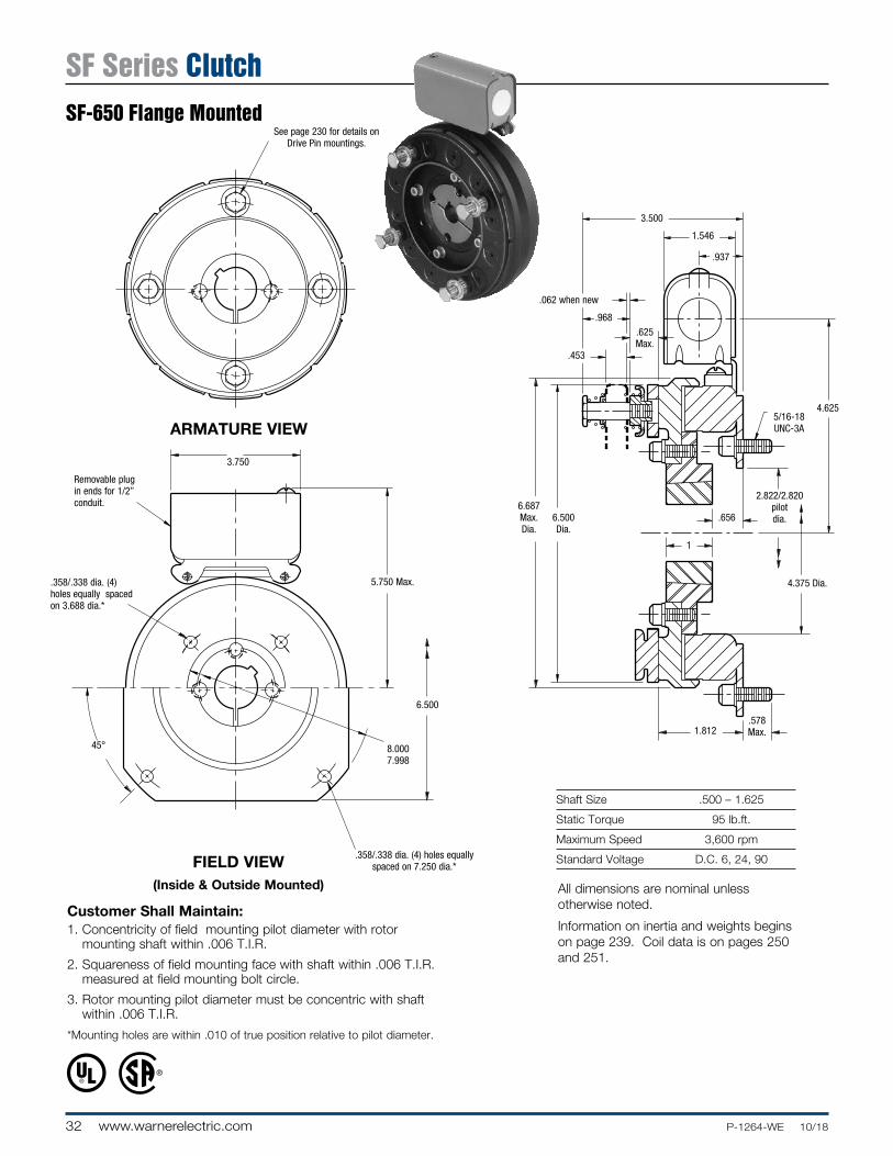
Customer Shall Maintain:1. Concentricity of field mounting pilot diameter with rotor
mounting shaft within .006 T.I.R.
2. Squareness of field mounting face with shaft within .006 T.I.R. measured at field mounting bolt circle.
3. Rotor mounting pilot diameter must be concentric with shaft within .006 T.I.R.
*Mounting holes are within .010 of true position relative to pilot diameter.
Shaft Size .500 – 1.625
Static Torque 95 lb.ft.
Maximum Speed 3,600 rpm
Standard Voltage D.C. 6, 24, 90
See page 230 for details on Drive Pin mountings.
4.375 Dia.
2.822/2.820 pilot dia.
4.625
.625 Max.
.578 Max.
.062 when new
.656
1
5/16-18 UNC-3A
.453
.968
3.500
1.546
.937
6.687 Max. Dia.
6.500 Dia.
1.812
ARMATURE VIEW
FIELD VIEW(Inside & Outside Mounted)
Removable plug in ends for 1/2” conduit.
.358/.338 dia. (4) holes equally spaced on 7.250 dia.*
45°
3.750
5.750 Max..358/.338 dia. (4) holes equally spaced on 3.688 dia.*
6.500
8.0007.998
All dimensions are nominal unless otherwise noted.
Information on inertia and weights begins on page 239. Coil data is on pages 250 and 251.
SF Series ClutchSF-650 Flange Mounted

33P-1264-WE 10/18 www.warnerelectric.com
Drawing I-25749
1
2
3
5
4
7
6A6A-1
8
8
6B-1
6B
7
Item Description Part Number Qty.
1 Armature Accessory 5181-101-010 4
2 Armature 5281-111-002 1
3 Rotor Hub & Mounting Acc. 5207-101-005 1
4 Rotor 5281-751-001 1
5 Bushing* 1
1/2” to 1-5/8” Bore 180-0326 to 180-0344
6A Field - Inside Mounted 1
6 Volt 5207-451-009
24 Volt 5207-451-012
90 Volt 5207-451-011
6A-1 Terminal Accessory 5311-101-001 1
6B Field - Outside Mounted 1
6 Volt 5207-451-003
24 Volt 5207-451-006
90 Volt 5207-451-005
6B-1 Terminal Accessory 5311-101-001 1
7 Mounting Accessory 5321-101-002 1
8 Conduit Box 5200-101-010 1
How to Order:1. Specify Bore Size for Item 5. 2. Specify Voltage for Item 6. 3. Specify Inside or Outside Mounted for Item 6. 4. See Controls Section.
Example:SF-650 Clutch per I-25749 - 90 Volt, 1” Bore
These units, when used in conjunction with the correct Warner Electric conduit box, meet the stan dards of UL508 and are listed under guide card #NMTR, file #59164.
These units are CSA certified under file #LR11543
* See page 252 for specific part numbers.
Refer to Service Manual P-0202-WE
SF Series ClutchSF-650 Flange Mounted

34 www.warnerelectric.com P-1264-WE 10/18
Shaft Size .500 – 1.500
Static Torque 95 lb.ft.
Maximum Speed 3,600 rpm
Standard Voltage D.C. 6, 24, 90
FIELD VIEW
ARMATURE VIEW
Re mov able plug in ends for 1/2” conduit.
See page 252 for details on Bushings.
45°
5.750
.562
3.750
.312
3.750
See page 230 for details on Drive Pin mountings.
Reverse Mounting
.062 when new
4.625
.625
.421 Max.
.765 Max.
1/4-20 UNC-2A
.156
.453
.968
3.500 Max.
1.546
.937
6.359 Dia.
3.625 Max.
1.781
1.250
1.7506.687 Max. Dia.
6.500 Dia.
All dimensions are nominal unless otherwise noted.
Information on inertia and weights begins on page 239. Coil data is on pages 250 and 251.
SF Series ClutchSF-650 Bearing Mounted

35P-1264-WE 10/18 www.warnerelectric.com
1
3-1
3-2
3-3 4
3-4
3-5
3-6-1
6
3-6
3-7
3-8
3-9
5
3(Shipped Assembled)
2
Drawing I-25750
Item Description Part Number Qty.
1 Autogap Accessory 5181-101-010 4
2 Armature 5281-111-002 1
3 Field and Rotor Assembly 1
6 Volt 5207-452-002
24 Volt 5207-452-005
90 Volt 5207-452-004
3-1 Capscrew 797-0083 4
3-2 Lockwasher 950-0355 4
3-3 Rotor Assembly 5281-751-001 1
3-4 Rotor Hub 540-0614 1
3-5 Reverse Mounting Accessory 5201-101-005 1
3-6 Field 1
6 Volt 5281-451-002
24 Volt 5281-451-004
90 Volt 5281-451-005
3-6-1 Terminal Accessory 5311-101-001 1
3-7 Ball Bearing 166-0104 1
3-8 Retainer Ring - External 748-0004 1
3-9 Retainer Ring -Internal 748-0104 1
Item Description Part Number Qty.
4 Bushing* 1
1/2” to 1-1/2” Bore 180-0002 to 180-0018
†5 Torque Arm Accessory 5207-101-003 1
6 Conduit Box 5200-101-010 1
How to Order:1. Specify Voltage for Item 3. 2. Specify Bore Size for Item 4. 3. See Controls Section.
Example:SF-650 Clutch, bearing mounted per I-25750 - 90 Volt, 1” Bore
These units, when used in conjunction with the correct Warner Electric conduit box, meet the stan dards of UL508 and are listed under guide card #NMTR, file #59164.
These units are CSA certified under file #LR11543
* See page 252 for specific part numbers.
Refer to Service Manual P-0202-WE
SF Series ClutchSF-650 Bearing Mounted

36 www.warnerelectric.com P-1264-WE 10/18
1.546
.921
5.656
5/16-18 UNC-3A
.562 Max.
.68712.562Dia.
3.562Dia.
8.656Max. Dia.
2.2532.251
Pilot Dia.
.602
.586
.2812.593Max.
.093When New
.5621.312
Shaft Size .500 – 1.250
Static Torque 125 lb.ft.
Maximum Speed 4,000 rpm
Standard Voltage D.C. 6, 24, 90
ARMATURE VIEW
FIELD VIEW(Inside & Outside Mounted)
Customer Shall Maintain:1. Concentricity of field mounting pilot diameter with
rotor mounting shaft within .006 T.I.R.
2. Squareness of field mounting face with shaft within .006 T.I.R. measured at field mounting bolt circle.
* Mounting holes are within .010 of true position relative to pilot diameter.
** Mounting holes are within .008 of true position relative to pilot diameter.
See page 230 for Drive Pin mountings.
Removable plug in ends for 1/2” conduit.
3.503/3.501Pilot Dia.
6.812 Max.
3.750
.358/.338 dia. (6) holes equally spaced on
4.250 dia.*
9.749/9.747 Pilot Dia.
.358/.338 dia. (4) holes equally spaced
on 8.875 dia.*
.350/.341 dia. (6) holes equally spaced on 2.875 dia.**
All dimensions are nominal unless otherwise noted.
Information on inertia and weights begins on page 239. Coil data is on pages 250 and 251.
Series SF ClutchSF-825 Flange Mounted Normal Duty

37P-1264-WE 10/18 www.warnerelectric.com
Drawing I-25560
How to Order:1. Specify Bore Size for Item 3. 2. Specify Voltage for Items 7A or 7B. 3. Specify Inside Mounted for Items 7A and 8A or Outside
Mounted for Items 7B and 8B.4. See Con trols Section.
Example:SF-825 Clutch per I-25560 -90 Volt, 1” Bore, Inside Mount ed
These units, when used in conjunction with the correct Warner Electric conduit box, meet the standards of UL508 and are listed under guide card #NMTR, file #59164.
These units are CSA certified under file #LR11543.
Item Description Part Number Qty.
1 Armature 5301-111-018 1
2 Autogap Accessory 5201-101-008 3
3 Bushing* 1
1/2” to 1-1/4” Bore 180-0101 to 180-0113
4 Mounting Accessory 5201-101-007 1
5 Rotor 1
Standard Friction Material 5201-751-003
†Optional LK Facing 5201-751-007
6 Rotor Hub 540-0013 1
7A Field - Inside Mounted 1
6 Volt 5201-451-006
24 Volt 5201-451-008
90 Volt 5201-451-010
7B Field - Outside Mounted 1
6 Volt 5201-451-014
24 Volt 5201-451-016
90 Volt 5201-451-018
8A Mounting Accessory - I.M. 5321-101-001 1
8B Mounting Accessory - O.M. 5321-101-002 1
9 Conduit Box 5200-101-012 1
* See page 252 for specific part numbers.
Refer to Service Manual P-0222-WE
† Optional LK facing available. For more information, see page 232.
5
3
6
8A
7A9
9
7B
8B
1
2
4
Series SF ClutchSF-825 Flange Mounted
Normal Duty

38 www.warnerelectric.com P-1264-WE 10/18
Shaft Size .500 – 1.500
Static Torque 150 lb.ft.
Maximum Speed 3,600 rpm
Standard Voltage D.C. 6, 24, 90
ARMATURE VIEW
FIELD VIEW
See page 230 for details on Drive Pin Mountings.
Re verse Mounting
1.296
.156
5.656
.984
1.546
1.2501.656
.093 When New
.562
.187
8.656Max. Dia.
3.5625 Dia.
2.562 Dia.
2.687 Max.
2.765 Max.
Re mov able plug in ends for 1/2” conduit.
See page 252 for details on Bushings.
45°
.343
.875
6.812 Max.
5.00
3.750
.350/.342
All dimensions are nominal unless otherwise noted.
Information on inertia and weights begins on page 239. Coil data is on pages 250 and 251.
Series SF ClutchSF-825 Bearing MountedNormal Duty

39P-1264-WE 10/18 www.warnerelectric.com
1
1
2
3
3
4-1
4-2
4-3
54-4
4-3-2
4-3-1
4-7
4-14-8
4-9
4-3
5
4-44-5
4-6
4-104-11
4(Shipped Assembled)
4(Shipped Assembled)
2
Drawing I-25575
How to Order:1. Specify Bore Size for Item 3. 2. Specify Voltage for Item 4. 3. See Controls Section.
Example:SF-825 Clutch per I-25575 - 90 Volt, 1” Bore
These units, when used in conjunction with the correct Warner Electric conduit box, meet the stan dards of UL508 and are listed under guide card #NMTR, file #59164. These units are CSA certified under file #LR11543.
Item De scrip tion Part Number Qty.
1 Armature 5301-111-018 1
2 Autogap Accessory 5201-101-008 3
3 Bushing* 1
1/2” to 1-1/2” Bore 180-0002 to 180-0018
4 Field & Rotor Assembly 1
6 Volt 5201-452-002
24 Volt 5201-452-004
90 Volt 5201-452-006
4-1 Rotor 1
Standard Friction Material 5201-751-008
†Optional LK Facing 5201-751-014
4-2 Mounting Accessory 5201-101-005 1
4-3 Field & Bearing Assembly 1
6 Volt 5201-451-054
24 Volt 5201-451-056
90 Volt 5201-451-057
4-3-1 Retainer Ring 748-0111 1
4-3-2 Ball Bearing 166-0142 1
4-4 Retainer Ring 748-0016 1
5 Conduit Box 5200-101-012 1
* See page 252 for specific part numbers.
Refer to Service Manual P-0215-WE
† Optional LK facing available. For more information, see page 232.
Series SF ClutchSF-825 Bearing Mounted
Normal Duty

40 www.warnerelectric.com P-1264-WE 10/18
Shaft Size .500 – 1.250
Static Torque 125 lb.ft.
Maximum Speed 4,000 rpm
Standard Voltage D.C. 6, 24, 90
Customer Shall Maintain:1. Concentricity of field mounting pilot diameter with rotor
mounting shaft within .006 T.I.R.
2. Squareness of field mounting face with shaft within .006 T.I.R. measured at field mounting bolt circle.
3. Rotor mounting shaft concentric with ar ma ture hub pilot diameter within .010 T.I.R.
When Hub is Furnished by Customer:Rotor mounting pilot diameter must be concentric with rotor mounting shaft within .006 T.I.R.
ARMATURE VIEW
FIELD VIEW(Inside & Outside Mounted)
.271/.263 dia. 5 holes (hub) equally spaced on 2.015 dia. Mounting holes are within .003 of true position relative to pilot dia.
1.640 dia.
1.546
.921
5/16-18 UNC-3A.093 Max. Length of Customer Pilot.
.687
.531
.468 Max.
1.312
.281
.602/.586
1/4-28 UNF-3A
5.656
.562 Max.
2.2532.251 Pilot
1.001.3432.313
2.311 Pilot
4.250 Dia.
8.656 Max. Dia.
.125
.062
3.765 Max.
Removable plug in ends for 1/2” conduit.
3.503/3.501Pilot Dia.
6.812 Max.
3.750
.358/.338 dia. (6) holes equally spaced on
4.250 dia. Mounting holes are within .010 of true position relative to
pilot dia.
9.749/9.747 Pilot Dia.
.358/.338 dia. (4) holes equally spaced on 8.875
dia. are within .010 of true position relative to pilot dia.
.350/.341 dia. (6) holes equally spaced on 2.875 dia. Mounting holes are within .008 of true position
relative to pilot dia.
See page 252 for details on bushings.
All dimensions are nominal unless otherwise noted.
Information on inertia and weights begins on page 239. Coil data is on pages 250 and 251.
Series SF ClutchSF-825 Flange MountedHeavy Duty

41P-1264-WE 10/18 www.warnerelectric.com
3-1
13-4
3-2
3-3
3-6
3-5
2
3(Shipped
Assembled)
4
5 6
7
8A
9A10
10
9B
8B
Drawing I-25561
How to Order:1. Specify Bore Size for Item 6.2. Specify Voltage for Item 9A or 9B.3. Specify Inside Mounted for Items 8A and 9A or Outside
Mounted for Items 8B and 9B.4. See Con trols Section.
Example:SF-825 Clutch Coupling, Heavy Duty, per I-25561 - 90 Volt, Inside Mounted, 1” Bore (Item 6)
These units, when used in conjunction with the correct Warner Electric conduit box, meet the standards of UL508 and are listed under guide card #NMTR, file #59164. These units are CSA certified under file #LR11543
Item Description Part # Qty.
9B Field, Outside Mounted 1
6 Volt 5201-451-014
24 Volt 5201-451-016
90 Volt 5201-451-018
10 Conduit Box 5200-101-012 1
Item Description Part # Qty.
1 Splined Hub 540-0146 1
2 Mounting Accessory 5201-101-001 1
3 Armature & Splined Adapter 5201-111-001 1
3-1 Armature 5321-111-022 1
3-2 Splined Adapter 104-0008 1
3-3 Autogap Accessory 5321-101-006 1
3-4 Screw 797-0341 3
3-5 Locknut 661-0004 3
3-6 Spacer 748-0333 3
4 Mounting Accessory 5201-101-007 1
5 Rotor 1
Standard Friction Material 5201-751-003
†Optional LK Facing 5201-751-007
6 Bushing, Taperlock* 180-0101 to 180-0113 1
7 Rotor Hub 540-0013 1
8A Mounting Accessory, I.M. 5321-101-001 1
8B Mounting Accessory, O.M. 5321-101-002 1
9A Field, Inside Mounted 1
6 Volt 5201-451-006
24 Volt 5201-451-008
90 Volt 5201-451-010
* See page 252 for specific part numbers.
Refer to Service Manual P-0215-WE
† Optional LK facing available. For more information, see page 232.
Series SF ClutchSF-825 Flange Mounted
Heavy Duty

42 www.warnerelectric.com P-1264-WE 10/18
Shaft Size .500 – 1.500
Static Torque 150 lb.ft.
Maximum Speed 3,600 rpm
Standard Voltage D.C. 6, 24, 90
Customer Shall Maintain:1. Armature hub pilot diameter to be concentric with
field and rotor mounting shaft within .010 T.I.R.
ARMATURE VIEW
FIELD VIEW
1.3431.250
.468 Dia.
.125
1.296
.187
3.844
5.656
1.546
1/4-28 UNF-3A
.984
.093 Max. Length of Customer Pilot.
3.953 Max.
.531
.062
1.6568.656 Max. Dia.
4.250 Dia.
2.3132.311 Dia.
.271/.263 dia. 5 holes (hub) equally spaced on 2.015 dia. and within .003 of true position
relation to 2.313/2.311 pilot dia.
1.640
45°
.350
Removable plug in ends for 1/2” conduit.
See page 252 for details on Bushings.
6.812
.875
.343
3.750
5
All dimensions are nominal unless otherwise noted.
Information on inertia and weights begins on page 239. Coil data is on pages 250 and 251.
Series SF ClutchSF-825 Bearing MountedHeavy Duty
45º

43P-1264-WE 10/18 www.warnerelectric.com
1 2
3-4
3-2
3-3
3-6
3-53(Shipped Assembled)
5
4-1 4-2
4-3
4(Shipped Assembled)
6
4-3-2
4-3-14-4
12
3(Shipped Assembled)
3-4
3-2
3-3
3-6
3-5
5
4-6
4-1
4-7
4-8
4-2
4(Shipped Assembled)
4-9
4-10
6
4-3
4-4
4-5
3-1
3-1
Drawing I-25573
How to Order:1. Specify Bore Size for Item 5.2. Specify Voltage for Item 4.3. See Controls Section.Example:SF-825 Clutch per I-25573 - 90 Volt, 1” Bore
These units, when used in conjunction with the correct Warner Electric conduit box, meet the standards of UL508 and are listed under guide card #NMTR, file #59164. These units are CSA certified under file #LR11543.
Item Description Part Number Qty.
1 Splined Hub 540-0146 1
2 Accessory, Mounting 5201-101-001 1
3 Armature & Adapter Assembly 5201-111-001 1
3-1 Armature 5321-111-022 1
3-2 Splined Adapter 104-0008 1
3-3 Autogap Accessory 5321-101-006 1
3-4 Screw 797-0341 3
3-5 Locknut 661-0004 3
3-6 Spacer 748-0333 3
4 Field & Rotor Assembly 1
6 Volt 5201-452-002
24 Volt 5201-452-004
90 Volt 5201-452-006
4-1 Rotor
Standard Friction Material 5201-751-008 1
†Optional LK Facing 5201-751-014
4-2 Mounting Accessory 5201-101-005 1
4-3 Field & Bearing Assembly 1
6 Volt 5201-451-054
24 Volt 5201-451-056
90 Volt 5201-451-057
Item Description Part Number Qty.
4-3-1 Ball Bearing 166-0142 1
4-3-2 Retainer Ring 748-0111 1
4-4 Retainer Ring 748-0016 1
5 Bushing* 180-0002 to 180-0018 1
6 Conduit Box 5200-101-012 1
* See page 252 for specific part numbers.
Refer to Service Manual P-0215-WE
† Optional LK facing available. For more information, see page 232.
Series SF ClutchSF-825 Bearing Mounted
Heavy Duty

44 www.warnerelectric.com P-1264-WE 10/18
1.546
.921
6.531
5/16-18 UNC-3A
.562Max.
.2501.2504.125
Dia.
5.252Dia.
10.328Max. Dia.
4.1284.126
Pilot Dia.
.570
.554
.0932.593Max.
.093When New .562
1.375
Shaft Size .500 – 2.000
Static Torque 240 lb.ft.
Maximum Speed 3,600 rpm
Standard Voltage D.C. 6, 24, 90
See page 230for Drive Pin mountings.
ARMATURE VIEW
Customer Shall Maintain:1. Concentricity of field mounting pilot diameter with
rotor mounting shaft within .006 T.I.R.
2. Squareness of field mounting face with shaft within .006 T.I.R. measured at field mounting bolt circle.
* Mounting holes are within .010 of true position relative to pilot diameter.
** Mounting holes are within .008 of true position relative to pilot diameter.
FIELD VIEW(Inside & Outside Mounted)
5.378/5.376Pilot Dia.
7.687 Max.
3.750
.358/.338 dia. (6) holes equally spaced on
6.125 dia.*
11.500/11.498 Pilot Dia.
.358/.338 dia. (8) holes equally spaced on
10.625 dia.*
.350/.341 dia. (6) holes equally spaced on 4.875 dia.**
Removable plug in ends for 1/2” conduit.
All dimensions are nominal unless otherwise noted.
Information on inertia and weights begins on page 239. Coil data is on pages 250 and 251.
Series SF ClutchSF-1000 Flange MountedNormal Duty

45P-1264-WE 10/18 www.warnerelectric.com
5
3
6
8A
7A9
9
7B
8B
1
2
4
Drawing I-25580
How to Order:1. Specify Bore Size for Item 3.2. Specify Voltage for Items 8A or 8B.3. Specify Inside Mounted for Items 7A and 8A or Outside
Mounted for Items 7B and 8B.4. See Con trols Section.
Example:SF-1000 Clutch per I-25580 - 90 Volt, 1” Bore, Inside Mount ed
These units, when used in conjunction with the correct Warner Electric conduit box, meet the standards of UL508 and are listed under guide card #NMTR, file #59164.
These units are CSA certified under file #LR11543.
Item Description Part Number Qty.
1 Armature 5302-111-013 1
2 Autogap Accessory 5201-101-008 3
3 Bushing* 1
1/2” to 2” Bore 180-0155 to 180-0179
4 Mounting Accessory 5201-101-007 1
5 Rotor 1
Standard Friction Material 5202-751-003
†Optional LK Facing 5202-751-007
6 Rotor Hub 540-0315 1
7A Field - Inside Mounted 1
6 Volt 5202-451-004
24 Volt 5202-451-006
90 Volt 5202-451-007
7B Field - Outside Mounted 1
6 Volt 5202-451-011
24 Volt 5202-451-013
90 Volt 5202-451-014
8A Mounting Accessory - I.M. 5321-101-001 1
8B Mounting Accessory - O.M. 5321-101-002 2
9 Conduit Box 5200-101-012 1
* See page 252 for specific part numbers.
Refer to Service Manual P-0222-WE
† Optional LK facing available. For more information, see page 232.
Series SF ClutchSF-1000 Flange Mounted
Normal Duty

46 www.warnerelectric.com P-1264-WE 10/18
Shaft Size .500 – 2.000
Static Torque 240 lb.ft.
Maximum Speed 2,500 rpm
Standard Voltage D.C. 6, 24, 90
ARMATURE VIEW
FIELD VIEW
See page 252 for details on Bushings.
Re mov able plug in ends for 1/2” conduit.
See page 252 for details on Bushings.
45°
.343
.875
7.687 Max.
6.125
3.750
.350/.342
1.375
.437
6.531
1.250
.093 When New
.562
.187
2.562 Dia.5.252 Dia.
4.125 Dia.
2.718 Max.
1.421
1.546
10.328 Dia.
2.062
3.156 Max.
All dimensions are nominal unless otherwise noted.
Information on inertia and weights begins on page 239. Coil data is on pages 250 and 251.
Series SF ClutchSF-1000 Bearing MountedNormal Duty

47P-1264-WE 10/18 www.warnerelectric.com
1
1
2
3
3
4-1
4-2
4-3
54-4
4-3-2
4-3-1
4-7
4-14-8
4-9
4-3
5
4-44-5
4-6
4-104-11
4(Shipped Assembled)
4(Shipped Assembled)
2
Drawing I-25596
Item De scrip tion Part Number Qty.
1 Armature 5302-111-013 1
2 Autogap Accessory 5201-101-008 3
3 Bushing* 1
1/2” to 2” Bore 180-0155 to 180-0179
4 Field & Rotor Assembly 1
6 Volt 5202-452-012
24 Volt 5202-452-014
90 Volt 5202-452-015
4-1 Rotor 1
Standard Friction Material 5202-751-003
†Optional LK Facing 5202-751-007
4-3 Field & Bearing Assembly 1
6 Volt 5202-451-040
24 Volt 5202-451-042
90 Volt 5202-451-043
4-4 Retainer Ring 748-0116 1
4-5 Ball Bearing 166-1046 1
4-6 Retainer Ring 748-0582 1
4-7 Rotor Hub 540-1300 1
Item De scrip tion Part Number Qty.
4-8 Buttonhead Capscrew 797-1261 6
4-9 Ring Adapter 748-1047 1
4-10 Lockwasher 950-0359 6
4-11 Socket Head Capscrew 797-0424 6
5 Conduit Box 5200-101-012 1
How to Order:1. Specify Bore Size for Item 3.2. Specify Voltage for Item 4.3. See Controls Section.Example:SF-1000 Clutch per I-25596 - 90 Volt, 1” Bore
These units, when used in con junc tion with the correct Warner Electric conduit box, meet the stan dards of UL508 and are listed under guide card #NMTR, file #59164. These units are CSA certified under file #LR11543.
* See page 252 for specific part numbers.
Refer to Service Manual P-0215-WE
† Optional LK facing available. For more information, see page 232.
Series SF ClutchSF-1000 Bearing Mounted
Normal Duty
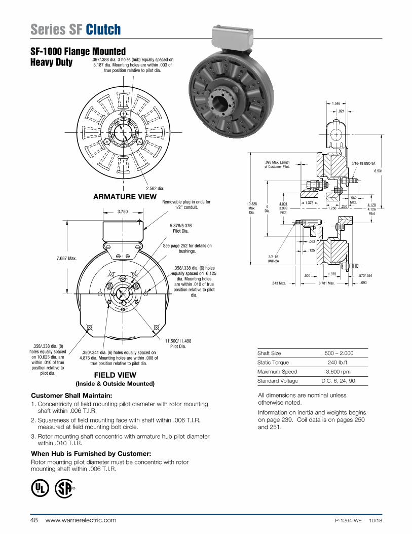
48 www.warnerelectric.com P-1264-WE 10/18
Shaft Size .500 – 2.000
Static Torque 240 lb.ft.
Maximum Speed 3,600 rpm
Standard Voltage D.C. 6, 24, 90
Customer Shall Maintain:1. Concentricity of field mounting pilot diameter with rotor mounting
shaft within .006 T.I.R.
2. Squareness of field mounting face with shaft within .006 T.I.R. measured at field mounting bolt circle.
3. Rotor mounting shaft concentric with ar ma ture hub pilot diameter within .010 T.I.R.
When Hub is Furnished by Customer:Rotor mounting pilot diameter must be concentric with rotor mounting shaft within .006 T.I.R.
ARMATURE VIEW
FIELD VIEW(Inside & Outside Mounted)
.397/.388 dia. 3 holes (hub) equally spaced on 3.187 dia. Mounting holes are within .003 of
true position relative to pilot dia.
2.562 dia.
.921
5/16-18 UNC-3A.093 Max. Length of Customer Pilot.
.250
.500
.843 Max.
1.375
..093
.570/.554
3/8-16 UNC-2A
6.531
.562 Max.
1.546
4.1284.126 Pilot
1.2501.375
6Dia.
10.328 Max. Dia.
.125
.062
3.781 Max.
4.0013.999 Pilot
Removable plug in ends for 1/2” conduit.
5.378/5.376Pilot Dia.
7.687 Max.
3.750
.358/.338 dia. (6) holes equally spaced on 6.125
dia. Mounting holes are within .010 of true position relative to pilot
dia.
11.500/11.498 Pilot Dia..358/.338 dia. (8)
holes equally spaced on 10.625 dia. are within .010 of true position relative to
pilot dia.
.350/.341 dia. (6) holes equally spaced on 4.875 dia. Mounting holes are within .008 of
true position relative to pilot dia.
See page 252 for de tails on bush ings.
All dimensions are nominal unless otherwise noted.
Information on inertia and weights begins on page 239. Coil data is on pages 250 and 251.
Series SF ClutchSF-1000 Flange MountedHeavy Duty

49P-1264-WE 10/18 www.warnerelectric.com
3-1
13-4
3-2
3-3
3-6
3-5
2
3(Shipped
Assembled)
4
5 6
7
8A
9A10
10
9B
8B
Drawing I-25581
Item Description Part Number Qty.
9B Field, Outside Mounted 1
6 Volt 5202-451-011
24 Volt 5202-451-013
90 Volt 5202-451-014
10 Conduit Box 5200-101-012 1
How to Order:1. Specify Bore Size for Item 6.2. Specify Voltage for Item 9A or 9B.3. Specify Inside Mounted for Items 8A and 9A or Outside
Mounted for Items 8B and 9B.4. See Con trols Section.
Example:SF-1000 Clutch Coupling, Heavy Duty per I-25581 - 90 Volt, Inside Mounted, 1-1/4” Bore (Item 6)
These units, when used in conjunction with the correct Warner Electric conduit box, meet the standards of UL508 and are listed under guide card #NMTR, file #59164. These units are CSA certified under file #LR11543
Item Description Part Number Qty.
1 Splined Hub 540-0147 1
2 Mounting Accessory 5202-101-001 1
3 Armature & Splined Adapter 5202-111-001 1
3-1 Armature 5322-111-036 1
3-2 Splined Adapter 104-0009 1
3-3 Autogap Accessory 5322-101-004 1
3-4 Screw 797-0341 3
3-5 Locknut 661-0004 3
3-6 Spacer 748-0333 3
4 Mounting Accessory 5201-101-007 1
5 Rotor 1
Standard Friction Material 5202-751-003
†Optional LK Facing 5202-751-007
6 Bushing, Taperlock* 180-0155 to 180-0179 1
7 Rotor Hub 540-0315 1
8A Mounting Accessory, I.M. 5321-101-001 1
8B Mounting Accessory, O.M. 5321-101-002 2
9A Field, Inside Mounted 1
6 Volt 5202-451-004
24 Volt 5202-451-006
90 Volt 5202-451-007
* See page 252 for specific part numbers.
Refer to Service Manual P-0215-WE
† Optional LK facing available. For more information, see page 232.
Series SF ClutchSF-1000 Flange Mounted
Heavy Duty

50 www.warnerelectric.com P-1264-WE 10/18
Shaft Size .500 – 2.000
Static Torque 240 lb.ft.
Maximum Speed 2,500 rpm
Standard Voltage D.C. 6, 24, 90
Customer Shall Maintain:1. Armature hub pilot diameter to be concentric with field and
rotor mounting shaft within .010 T.I.R.
ARMATURE VIEW
FIELD VIEW
.397/.388 dia. 3 holes (hub) equally spaced on 3.187 dia. and within .003 of true position
relation to 4.001/3.999 pilot dia.
2.562
.397/.388 dia. 3 holes (hub) equally spaced on
3.187 dia. and within .003 of true position relation to
4.001/3.999 pilot dia.
Removable plug in ends for 1/2” conduit.
See page 252 for details on Bushings.
7.687
.875
.343
3.750
45°
6.125
1.3751.250
.843 Dia.
.125
1.375
.187
.437
6.531
3/8-16 UNF-2A
1.421
.093 Max. Length of Customer Pilot.
4.281 Max.
.500
.062
2.062
10.328 Max. Dia.
6.000 Dia.
4.0013.999 Dia.
2.562 Dia.
1.546
All dimensions are nominal unless otherwise noted.
Information on inertia and weights begins on page 239. Coil data is on pages 250 and 251.
Series SF ClutchSF-1000 Bearing MountedHeavy Duty

51P-1264-WE 10/18 www.warnerelectric.com
How to Order:1. Specify Bore Size for Item 5.2. Specify Voltage for Item 4.3. See Controls Section.Example:SF-1000 Clutch per I-25597 - 90 Volt, 1” Bore
These units, when used in conjunction with the correct Warner Electric conduit box, meet the standards of UL508 and are listed under guide card #NMTR, file #59164. These units are CSA certified under file #LR11543.
* See page 252 for specific part numbers.
Refer to Service Manual P-0215-WE
† Optional LK facing available. For more information, see page 232.
Item Description Part Number Qty.
1 Splined Hub 540-0147 1
2 Accessory, Mounting 5202-101-001 1
3 Armature & Adapter Assembly 5202-111-001 1
3-1 Armature 5322-111-036 1
3-2 Splined Adapter 104-0009 1
3-3 Autogap Accessory 5322-101-004 1
3-4 Screw 797-0341 3
3-5 Locknut 661-0004 3
3-6 Spacer 748-0333 3
4 Field & Rotor Assembly 1
6 Volt 5202-452-012
24 Volt 5202-452-014
90 Volt 5202-452-015
4-1 Rotor 1
Standard Friction Material 5202-751-003
†Optional LK Facing 5202-751-007
4-2 Field & Bearing Assembly 1
6 Volt 5202-451-040
24 Volt 5202-451-042
90 Volt 5202-451-043
4-3 Retainer Ring 748-0116 1
Item Description Part Number Qty.
4-4 Ball Bearing 166-1046 1
4-5 Retainer Ring 748-0582 1
4-6 Rotor Hub 540-1300 1
4-7 Buttonhead Capscrew 797-1261 6
4-8 Ring Adapter 748-1047 1
4-9 Lockwasher 950-0359 6
4-10 Socket Head Capscrew 797-0422 6
5 Bushing* 180-0155 to 180-0179 1
6 Conduit Box 5200-101-012 1
1 2
3-4
3-2
3-3
3-6
3-53(Shipped Assembled)
5
4-1 4-2
4-3
4(Shipped Assembled)
6
4-3-2
4-3-14-4
12
3(Shipped Assembled)
3-4
3-2
3-3
3-6
3-5
5
4-6
4-1
4-7
4-8
4-2
4(Shipped Assembled)
4-9
4-10
6
4-3
4-4
4-5
3-1
3-1
Drawing I-25597
Series SF ClutchSF-1000 Bearing Mounted
Heavy Duty

52 www.warnerelectric.com P-1264-WE 10/18
Shaft Size .500 – 2.500
Static Torque 465 lb.ft.
Maximum Speed 3,000 rpm
Standard Voltage D.C. 6, 24, 90
Customer Shall Maintain:1. Concentricity of field mounting pilot diameter with rotor
mounting shaft within .006 T.I.R.
2. Squareness of field mounting face with rotor mounting shaft within .006 T.I.R. measured at field mounting bolt circle.
3. Rotor mounting shaft concentric with armature center of rotation within .006 T.I.R.
4. Armature hub pilot diameter to be concentric with armature center of rotation within .010 T.I.R.
When Hub is Furnished by customer:Rotor mounting pilot diameter must be concentric with rotor mounting shaft within .006 T.I.R.
ARMATURE VIEW
FIELD VIEW(Inside & Outside Mounted)
* Mounting holes are within. 010 of true po si tion relative to pilot diameter.
** Mounting holes are within .008 of true position relative to pilot diameter.
See page 230 for details on Drive Pin mountings.
.358/.338 dia. (8) holes equally spaced on 13.000 dia.*
.358/.338 dia. (6) holes equally spaced on 7.250 dia.*
See page 252 for details on Bushings.
Removable plug in ends for 1/2” conduit.
.350/.341 dia. (8) holes equally spaced on 6.062 dia. **
6.378/6.376 Pilot Dia.
13.875/13.871 Pilot Dia.
3.750 Max.
8.687
.5931.562
.758/.742
.562 Max.
.3121.750
7.531
1.546
.921
5/16-18 UNC-3A
.281
.093 When New
12.703 Max.
12.625 Dia.
5.877 Dia.
4.625 Dia.
5.438 5.436 Pilot Dia.
3.031 Max.
All dimensions are nominal unless otherwise noted.
Information on inertia and weights begins on page 239. Coil data is on pages 250 and 251.
SF Series ClutchSF-1225 Flange MountedNormal Duty

53P-1264-WE 10/18 www.warnerelectric.com
1
2
3
4
5
8A
7A
9
7B
9
8B6
Drawing I-25600
Item Description Part Number Qty.
1 Armature 5303-111-009 1
2 Autgap Accessory 5201-101-008 4
3 Mounting Accessory 5321-101-002 2
4 Rotor 1
Standard Friction Material 5203-751-001
†Optional LK Facing 5203-751-004
5 Bushing* 1
1/2” to 2-1/2” Bore 180-0185 to 180-0217
6 Rotor Hub 540-0318 1
7A Field - Inside Mounted 1
6 Volt 5203-451-002
24 Volt 5203-451-006
90 Volt 5203-451-005
7B Field - Outside Mounted 1
6 Volt 5203-451-010
24 Volt 5203-451-013
90 Volt 5203-451-011
Item Description Part Number Qty.
8A Mounting Accessory - I.M. 5321-101-001 1
8B Mounting Accessory - O.M. 5321-101-002 2
9 Conduit Box 5200-101-012 1
How to Order:1. Specify Bore Size for Item 5.2. Specify Voltage for Item 7A or 7B.3. Specify Inside Mounted for Items 7A and 8A or Outside
Mounted for Items 7B and 8B.4. See Con trols Section.Example:SF-1225 Clutch per I-25600 - 90 Volt, 1-1/2” Bore, Inside Mount ed.
These units, when used in conjunction with the correct Warner Electric conduit box, meet the standards of UL508 and are listed under guide card #NMTR, file #59164. These units are CSA certified under file #LR11543.
* See page 252 for specific part numbers.
Refer to Service Manual P-0215-WE
† Optional LK facing available. For more information, see page 232.
SF Series ClutchSF-1225 Flange Mounted
Normal Duty

54 www.warnerelectric.com P-1264-WE 10/18
1.546
.921
7.531
5.4385.436Pilot Dia.
.3125
.562Max.
1.751.5
7.062Dia.12.703
Max. Dia.
3/8-16 UNC-2A
.718Max
.125
.062
.562 1.562
.2814.390Max.
.093Max.
.758.742
Customer Shall Maintain:1. Concentricity of field mounting pilot diameter with rotor
mounting shaft within .006 T.I.R.
2. Squareness of field mounting face with shaft within .006 T.I.R. measured at field mounting bolt circle.
3. Armature hub pilot diameter to be concentric with rotor mounting shaft within .010 T.I.R.
When Hub is Furnished by customer:Rotor mounting pilot diameter must be concentric with rotor mounting shaft within .006 T.I.R.
ARMATURE VIEW
FIELD VIEW(Inside & Outside Mounted)
* Mounting holes are within.010 of true po si tion relative to pilot diameter.
** Mounting holes are within .008 of true position relative to pilot diameter.
† Mounting holes are within .003 of true position relative to pilot diameter.
Shaft Size .500 – 2.500
Static Torque 465 lb.ft.
Maximum Speed 3,000 rpm
Standard Voltage D.C. 6, 24, 90
All dimensions are nominal unless otherwise noted.
Information on inertia and weights begins on page 239. Coil data is on pages 250 and 251.
3.062 dia.
.397/.388 dia. 8 holes (hub) equally spaced on 3.625 dia. †
3.58/3.38 dia. 6 holes equally spaced on 7.250 dia.*
See Page 252 for details on Bushings
Removeable plug in ends for 1/2” conduit.
3.750
13.87513.871pilot dia.
8.687 Max.
.350/.341 dia. 8 holes equally spaced on 6.062 dia.**
3.58/3.58 dia. 8 holes equally spaced on 13.875/13.871dia.*
5/16-18 UNC-3A
4.313 4.311Pilot
6.3786.376
Pilot Dia.
SF Series ClutchSF-1225 Flange MountedHeavy Duty
12.625Dia.

55P-1264-WE 10/18 www.warnerelectric.com
Item Description Part Number Qty.
1 Splined Hub 540-0148 1
2 Mounting Accessory 5202-101-001 3
3 Armature and Splined Adapter 5203-111-001 1
3-1 Armature 5323-111-034 1
3-2 Splined Adapter 104-0010 1
3-3 Autogap Accessory 5323-101-002 1
3-4 Screw 797-0356 4
3-5 Locknut 661-0005 4
3-7 Spacer 266-0004 4
4 Mounting Accessory 5321-101-002 2
5 Rotor 1
Standard Friction Material 5203-751-001
†Optional LK Facing 5203-751-004
6 Bushing, Taperlock* 180-0185 to 180-0217 1
7 Rotor Hub 540-0318 1
8A Mounting Accessory, I.M. 5321-101-001 1
8B Mounting Accessory, O.M. 5321-101-002 2
9A Field, Inside Mtd. 1
6 Volt 5203-451-002
24 Volt 5203-451-006
90 Volt 5203-451-005
Item Description Part Number Qty.
9B Field, Outside Mtd. 1
6 Volts 5203-451-010
24 Volts 5203-451-013
90 Volts 5203-451-011
10 Conduit Box 5200-101-012 1
How to Order:1. Specify Bore Size for Item 6.2. Specify Voltage for Item 9A or 9B.3. Specify Inside Mounted for Items 8A and 9A or Outside
Mounted for Items 8B and 9B.4. See Con trols Section.Example:SF-1225 Clutch per I-25601 - 90 Volt, 1-1/2” Bore, Inside Mount ed.
These units, when used in conjunction with the correct Warner Electric conduit box, meet the standards of UL508 and are listed under guide card #NMTR, file #59164. These units are CSA certified under file #LR11543.
* See page 252 for specific part numbers.
Refer to Service Manual P-0215-WE
† Optional LK facing available. For more information, see page 232.
Drawing I-25601
1
2
3-5
3-2
3-3
3(Shipped Assembled)
3-7
3-43-1
4
5 6
7
8A
9A10
10
9B
8B
SF Series ClutchSF-1225 Flange Mounted
Heavy Duty

56 www.warnerelectric.com P-1264-WE 10/18
ARMATURE VIEW
FIELD VIEW
Shaft Size .500 – 2.500
Static Torque 465 lb.ft.
Maximum Speed 2,200 rpm
Standard Voltage D.C. 6, 24, 90
All dimensions are nominal unless otherwise noted.
Information on inertia and weights begins on page 239. Coil data is on pages 250 and 251.
See page 230 for details on Drive Pin mountings.
3.75
.875 45°
.343
.350/.342
8.687Max.
Removable plug in ends for 1/2” conduit.
See page252 for
details onBushings.
7
1.546
1.500
7.531
3.125Dia.
1.75
2.625
5.877Dia.
12.625Dia.
12.703Max. Dia.
.187
.515
1.562
3.562Max.
.593
.093 When New
4.625Dia.
SF Series ClutchSF-1225 Bearing MountedNormal Duty

57P-1264-WE 10/18 www.warnerelectric.com
Item Description Part Number Qty.
1 Armature 5303-111-009 1
2 Autogap Accessory 5201-101-008 4
3 Bushing* 1
1/2” to 2-1/2” Bore 180-0185 to 180-0217
4 Field and Rotor Assembly 1
6 Volt 5203-452-009
24 Volt 5203-452-011
90 Volt 5203-452-012
4-1 Rotor 1
Standard Friction Material 5203-751-001
†Optional LK Facing 5203-751-004
4-2 Field 1
6 Volt 5203-451-034
24 Volt 5203-451-036
90 Volt 5203-451-037
4-3 Retainer Ring 748-0119 1
4-4 Ball Bearing 166-1047 1
4-5 Retainer Ring 748-0011 1
4-6 Rotor Hub 540-1304 1
Item Description Part Number Qty.
4-7 Buttonhead Capscrew 797-1261 8
4-8 Ring Adapter 748-0591 1
4-9 Lockwasher 950-0359 6
4-10 Sockethead Capscrew 797-0424 6
5 Conduit Box 5200-101-012 1
How to Order:1. Specify Bore Size for Item 3.2. Specify Voltage for Item 4.3. See Con trols Section.
Example:SF-1225 Clutch per I-25621 - 90 Volt, 1” Bore.
These units, when used in conjunction with the correct Warner Electric conduit box, meet the standards of UL508 and are listed under guide card #NMTR, file #59164. These units are CSA certified under file #LR11543.
* See page 252 for specific part numbers.
Refer to Service Manual P-0215-WE
† Optional LK facing available. For more information, see page 232.
Drawing I-25621
1
3
4-6
4-14-7
4-8
4-2
5
4-34-4
4-5
4-94-10
4
2
SF Series ClutchSF-1225 Bearing Mounted
Normal Duty

58 www.warnerelectric.com P-1264-WE 10/18
Shaft Size .500 – 2.500
Static Torque 465 lb.ft.
Maximum Speed 2,200 rpm
Standard Voltage D.C. 6, 24, 90
Customer Shall Maintain:1. Armature hub pilot diameter to be concentric with
field and rotor mounting shaft within .010 T.I.R.
ARMATURE VIEW
FIELD VIEW
FIELD VIEW
45°
.343
3.750
.875
8.687 Max.
Removable plug in ends for 1/2” conduit.
See page 252 for details on Bushings.
.350/.342 7.000
3.062 Dia.
.397/.388 dia. (8) holes (hub) equally spaced on
3.625 dia. and within .003 of true position in relation to
4.313/4.311 pilot dia.
.359
1.7501.500
.5621.562
.187
.718 Max.
7.531
1.546
.093 Max.
Length of Customer
Pilot
1.500
12.625 Dia.
12.703 Max. Dia.
7.062 Dia.
4.313/4.311 Pilot Dia. 2.625
3.125 Dia.
.125
.0623/8-16
UNC-2A
4.921 Max.
All dimensions are nominal unless otherwise noted.
Information on inertia and weights begins on page 239. Coil data is on pages 250 and 251.
SF Series ClutchSF-1225 Bearing MountedHeavy Duty

59P-1264-WE 10/18 www.warnerelectric.com
Drawing I-25622
Item Description Part Number Qty.
4-5 Retainer Ring 748-0011 1
4-6 Rotor Hub 540-1304 1
4-7 Buttonhead Screw 797-1261 8
4-8 Ring Adapter 748-0591 1
4-9 Lockwasher 950-0359 6
4-10 Sockethead Screw 797-0424 6
5 Bushing* 180-0185 to 180-0217 1
6 Conduit Box 5200-101-012 1
How to Order:1. Specify Bore Size for Item 5.2. Specify Voltage for Item 4.3. See Controls Section.Example:SF-1225 Clutch per I-25622 - 90 Volt, 1” Bore
These units, when used in conjunction with the correct Warner Electric conduit box, meet the standards of UL508 and are listed under guide card #NMTR, file #59164. These units are CSA certified under file #LR11543.
Item Description Part Number Qty.
1 Splined Hub 540-0148 1
2 Accessory Mounting 5202-101-001 3
3 Armature & Adapter Assembly 5203-111-001 1
3-1 Armature 5323-111-034 1
3-2 Splined Adapter 104-0010 1
3-3 Autogap Accessory 5323-101-002 1
3-4 Screw 797-0356 4
3-5 Locknut 661-0005 4
3-6 Spacer 266-0004 4
4 Field & Rotor Assembly 1
6 Volt 5203-452-009
24 Volt 5203-452-011
90 Volt 5203-452-012 1
4-1 Rotor 1
Standard Friction Material 5203-751-001
†Optional LK Facing 5203-751-004
4-2 Field 1
6 Volt 5203-451-034
24 Volt 5203-451-036
90 Volt 5203-451-037
4-3 Retainer Ring 748-0119 1
4-4 Ball Bearing 166-1047 1
* See page 252 for specific part numbers.
Refer to Service Manual P-0215-WE
† Optional LK facing available. For more information, see page 232.
1
2
3-5
3-2
3-3
3(Shipped Assembled)
3-6
3-4
5
3-1
4-6
4-1 4-7
4-8
4-2
4(Shipped Assembled)
6
4-9
4-10
4-3
4-4
4-5
SF Series ClutchSF-1225 Bearing Mounted
Heavy Duty

60 www.warnerelectric.com P-1264-WE 10/18
Shaft Size .937 – 3.000
Static Torque 700 lb.ft.
Maximum Speed 2,000 rpm
Standard Voltage D.C. 6, 24, 90
Customer Shall Maintain:1. Concentricity of field mounting pilot diameter with rotor mounting shaft
within .006 T.I.R.
2. Squareness of field mounting face with rotor mounting shaft within .006 T.I.R. measured at field mounting bolt circle.
3. Rotor mounting shaft concentric with armature center of rotation within .006 T.I.R.
4. Armature hub pilot diameter to be concentric with armature center of rotation within .010 T.I.R.
When Hub is Furnished by customer:Rotor mounting pilot diameter must be concentric with rotor mounting shaft within .006 T.I.R.
ARMATURE VIEW
* Mounting holes are within.010 of true po si tion relative to pilot diameter.
** Mounting holes are within .008 of true position relative to pilot diameter.
FIELD VIEW(Inside & Outside Mounted)
See page 230 for details on Drive Pin mountings.
.358/.338 dia. (12) holes equally spaced on 16.000 dia.*
.358/.338 dia. (12) holes equally spaced on 9.750 dia.*
See page 252 for details on Bushings.
Removable plug in ends for 1/2” conduit.
.350/.341 dia. (8) holes equally spaced
on 8.500 dia. **
9.002/9.000 Pilot Dia.
16.875/16.871Pilot Dia.
5/16-18 UNC-2B (2) holes equally spaced for removal of rotor from hub.
3.750 Max.
10.343
.5931.562
.758/.742
.562 Max.
.2182.000
9.187
1.546
.921
5/16-18 UNC-3A
.437
.093 When New
15.671 Max.
15.578 Dia.
8.500 Dia.
7.093 Dia.
7.878 7.876 Pilot Dia.
3.031 Max.
All dimensions are nominal unless otherwise noted.
Information on inertia and weights begins on page 239. Coil data is on pages 250 and 251.
SF Series ClutchSF-1525 Flange MountedNormal Duty

61P-1264-WE 10/18 www.warnerelectric.com
1
2
3
4
5
8A
7A
9
7B
9
8B6
Drawing I-25625
How to Order:1. Specify Bore Size for Item 5.
2. Specify Voltage for Item 7A or 7B.
3. Specify Inside Mounted for Items 7A and 8A or Outside Mounted for Items 7B and 8B.
4. See Con trols Section.
Example:SF-1525 Clutch per I-25625 - 90 Volt, 2” Bore, Inside Mounted.
These units, when used in conjunction with the correct Warner Electric conduit box, meet the standards of UL508 and are listed under guide card #NMTR, file #59164. These units are CSA certified under file #LR11543.
Item Description Part Number Qty.
1 Armature 5304-111-004 1
2 Autogap Accessory 5201-101-008 4
3 Mounting Accessory 5321-101-002 2
4 Rotor 1
Standard Friction Material 5204-751-002
†Optional LK Facing 5204-751-004
5 Bushing* 1
15/16” to 3” Bore 180-0223 to 180-0256
6 Rotor Hub 540-0004 1
7A Field - Inside Mounted 1
6 Volt 5204-451-013
24 Volt 5204-451-015
90 Volt 5204-451-016
7B Field - Outside Mounted 1
6 Volt 5204-451-055
24 Volt 5204-451-056
90 Volt 5204-451-057
8A Mounting Accessory - I.M. 5321-101-001 2
Item Description Part Number Qty.
8B Mounting Accessory - O.M. 5321-101-001 2
9 Conduit Box 5200-101-012 1
* See page 252 for specific part numbers.
Refer to Service Manual P-0215-WE
† Optional LK facing available. For more information, see page 232.
SF Series ClutchSF-1525 Flange Mounted
Normal Duty

62 www.warnerelectric.com P-1264-WE 10/18
1.546
.921
9.187
7.8787.876 Pilot Dia.
.218
.562Max.
2.001.5
8.750Dia.15.671
Max. Dia.
3/8-16 UNC-2A
.718Max
.125
.062
.562
1.562
.4374.531Max.
.093Max.
.758.742
5/16-18 UNC-3A
Customer Shall Maintain:1. Concentricity of field mounting pilot diameter with rotor
mounting shaft within .006 T.I.R.
2. Squareness of field mounting face with rotor mounting shaft within .006 T.I.R. measured at field mounting bolt circle.
3. Armature hub pilot diameter to be concentric with armature center of rotation within .010 T.I.R.
When Hub is Furnished by customer:Rotor mounting pilot diameter must be concentric with rotor mounting shaft within .006 T.I.R.
ARMATURE VIEW
FIELD VIEW(Inside & Outside Mounted)
* Mounting holes are within. 010 of true po si tion relative to pilot diameter.
** Mounting holes are within .008 of true position relative to pilot diameter.
† Mounting holes are within .003 of true position relative to pilot diameter.
Shaft Size .937 – 3.000
Static Torque 700 lb.ft.
Maximum Speed 2,000 rpm
Standard Voltage D.C. 6, 24, 90
All dimensions are nominal unless otherwise noted.
Information on inertia and weights begins on page 239. Coil data is on pages 250 and 251.
3.062 dia.
.397/.388 dia. 8 holes (hub) equally spaced on 3.625 dia. †
3.58/3.38 dia. 12 holes equally spaced on 9.750 dia.*
See Page 252 for details on Bushings
Removeable plug in ends for 1/2” conduit.
3.750
16.87516.871pilot dia.
10.343 Max. 9.002
9.000 Pilot Dia.
.350/.341 dia. 8 holes equally spaced on 8.500 dia.**
3.58/3.58 dia. 12 holes equally spaced on 16.875/16.871 dia.*
4.313 4.311Pilot Dia.
15.578Dia.
SF Series ClutchSF-1525 Flange MountedHeavy Duty

63P-1264-WE 10/18 www.warnerelectric.com
Item Description Part Number Qty.
1 Splined Hub 540-0148 1
2 Mounting Accessory 5202-101-001 3
3 Armature and Splined Adapter 5204-111-004 1
3-1 Armature 5324-111-034 1
3-2 Splined Adapter 104-0011 1
3-3 Autogap Accessory 5323-101-002 1
3-4 Screw 797-0342 8
3-5 Locknut 661-0004 8
3-6 Retainer Plate 686-0003 1
3-7 Spacer 748-0333 8
4 Mounting Accessory 5321-101-002 2
5 Rotor 1
Standard Friction Material 5204-751-002
†Optional LK Facing 5204-751-004
6 Bushing, Taperlock* 180-0223 to 180-0256 1
7 Rotor Hub 540-0004 1
8A Mounting Accessory, I.M. 5321-101-001 2
8B Mounting Accessory, O.M. 5321-101-002 2
9A Field, Inside Mtd. 1
6 Volt 5204-451-013
24 Volt 5204-451-015
90 Volt 5204-451-016
Item Description Part Number Qty.
9B Field, Outside Mtd. 1
6 Volt 5204-451-055
24 Volt 5204-451-056
90 Volt 5204-451-057
10 Conduit Box 5200-101-012 1
How to Order:1. Specify Bore Size for Item 6.2. Specify Voltage for Item 9A or 9B.3. Specify Inside Mounted for Items 8A and 9A or Outside
Mounted for Items 8B and 9B.4. See Con trols Section.Example:SF-1525 Clutch per I-25626 - 90 Volt, 2” Bore,
Inside Mount ed.
These units, when used in conjunction with the correct Warner Electric conduit box, meet the standards of UL508 and are listed under guide card #NMTR, file #59164. These units are CSA certified under file #LR11543.* See page 252 for specific part numbers.
Refer to Service Manual P-0215-WE
† Optional LK facing available. For more information, see page 232.
Drawing I-25626
1
2
3-5
3-2
3-3
3(Shipped Assembled)
3-7
3-6
3-43-1
4
5 6
7
8A
9A10
10
9B
8B
SF Series ClutchSF-1525 Flange Mounted
Heavy Duty

64 www.warnerelectric.com P-1264-WE 10/18
ARMATURE VIEW
FIELD VIEW
Shaft Size .937 – 3.000
Static Torque 700 lb.ft.
Maximum Speed 1,800 rpm
Standard Voltage D.C. 6, 24, 90
All dimensions are nominal unless otherwise noted.
Information on inertia and weights begins on page 239. Coil data is on pages 250 and 251.
See page 230 for details on Drive Pin mountings.
3.75
.87545°
.343
.350/.342
10.343Max.
Removable plug in ends for 1/2” conduit.
See page 252 fordetails on Bushings.
8.531
1.546
2.093
9.187
3.968Pilot Dia.
2.000
2.937
8.500Dia.
15.578Dia.
15.671Max. Dia.
.187
1.1251.562
4.250Max.
.593
.093 When New
7.093Pilot Dia.
SF Series ClutchSF-1525 Bearing MountedNormal Duty

65P-1264-WE 10/18 www.warnerelectric.com
Item Description Part Number Qty.
1 Armature 5304-111-004 1
2 Autogap Accessory 5201-101-008 4
3 Bushing* 1
15/16” to 3” Bore 180-0223 to 180-0256
4 Field and Rotor Assembly 1
6 Volt 5204-452-009
24 Volt 5204-452-011
90 Volt 5204-452-012
4-1 Rotor 1
Standard Friction Material 5204-751-002
†Optional LK Facing 5204-751-004
4-2 Field 1
6 Volt 5204-451-084
24 Volt 5204-451-086
90 Volt 5204-451-087
4-3 Retainer Ring 748-0114 1
4-4 Ball Bearing 166-0163 1
4-5 Retainer Ring 748-0583 1
4-6 Rotor Hub 540-1306 1
Item Description Part Number Qty.
4-7 Buttonhead Capscrew 797-1261 8
4-8 Ring Adapter 748-1048 1
4-9 Lockwasher 950-0359 6
4-10 Sockethead Capscrew 797-0424 6
5 Conduit Box 5200-101-012 1
How to Order:1. Specify Bore Size for Item 3.2. Specify Voltage for Item 4.3. See Con trols Section.
Example:SF-1525 Clutch per I-25639 - 90 Volt, 1” Bore.
These units, when used in conjunction with the correct Warner Electric conduit box, meet the standards of UL508 and are listed under guide card #NMTR, file #59164. These units are CSA certified under file #LR11543.
* See page 252 for specific part numbers.
Refer to Service Manual P-0215-WE
† Optional LK facing available. For more information, see page 232.
Drawing I-25639
1
3
4-6
4-14-7
4-8
4-2
5
4-34-4
4-5
4-94-10
4
2
SF Series ClutchSF-1525 Bearing Mounted
Normal Duty

66 www.warnerelectric.com P-1264-WE 10/18
Shaft Size .937 – 3.000
Static Torque 700 lb.ft.
Maximum Speed 1,800 rpm
Standard Voltage D.C. 6, 24, 90
Customer Shall Maintain:1. Armature hub pilot diameter to be concentric with field and
rotor mounting shaft within .010 T.I.R.
ARMATURE VIEW
FIELD VIEW
1.125
2.0001.500
.5621.562
.187
.718 Max.
9.187
1.546
.093 Max.
Length of Customer
Pilot
2.093
15.578 Dia.
15.671 Max. Dia.
8.750 Dia.
4.313/4.311 Pilot Dia. 2.937
3.968 Dia.
.125
.0623/8-16
UNC-2A
5.593 Max.
.397/.388 dia. (8) holes (hub) equally spaced on 3.625 dia. and within .003 of true position in relation to 4.313/4.311 pilot dia.
45°
.343
3.750
.875
10.343 Max.
Removable plug in ends for 1/2” conduit.
See page 252 for details on Bushings.
.350/.3428.531
3.062 Dia.
All dimensions are nominal unless otherwise noted.
Information on inertia and weights begins on page 239. Coil data is on pages 250 and 251.
SF Series ClutchSF-1525 Bearing MountedHeavy Duty

67P-1264-WE 10/18 www.warnerelectric.com
1
2
3-5
3-2
3-3
3(Shipped Assembled)
3-6
3-7
3-4
5
3-1
4-6
4-1 4-7
4-8
4-2
4(Shipped Assembled)
6
4-9
4-10
4-3
4-4
4-5
Drawing I-25640
How to Order:1. Specify Bore Size for Item 5.2. Specify Voltage for Item 4.3. See Controls Section.Example:SF-1525 Clutch per I-25640 - 90 Volt,1” Bore
These units, when used in conjunction with the correct Warner Electric conduit box, meet the standards of UL508 and are listed under guide card #NMTR, file #59164. These units are CSA certified under file #LR11543.
Item Description Part Number Qty.
1 Splined Hub 540-0148 1
2 Accessory Mounting 5202-101-001 3
3 Armature & Adapter Assembly 5204-111-004 1
3-1 Armature 5324-111-034 1
3-2 Splined Adapter 104-0011 1
3-3 Autogap Accessory 5323-101-002 1
3-4 Screw 797-0342 8
3-5 Locknut 661-0004 8
3-6 Retainer Plate 686-0003 1
3-7 Spacer 748-0333 8
4 Field & Rotor Assembly 1
6 Volt 5204-452-009
24 Volt 5204-452-011
90 Volt 5204-452-012
4-1 Rotor 1
Standard Friction Material 5204-751-002
†Optional LK Facing 5204-751-004
4-2 Field 1
6 Volt 5204-451-084
24 Volt 5204-451-086
90 Volt 5204-451-087
4-3 Retainer Ring 748-0114 1
Item Description Part Number Qty.
4-4 Ball Bearing 166-0163 1
4-5 Retainer Ring 748-0583 1
4-6 Rotor Hub 540-1306 1
4-7 Buttonhead Screw 797-1261 8
4-8 Ring Adapter 748-1048 1
4-9 Lockwasher 950-0359 6
4-10 Sockethead Screw 797-0424 6
5 Bushing* 180-0223 to 180-0256 1
6 Conduit Box 5200-101-012 1
* See page 252 for specific part numbers.
Refer to Service Manual P-0215-WE
† Optional LK facing available. For more information, see page 232.
SF Series ClutchSF-1525 Bearing Mounted
Heavy Duty

68 www.warnerelectric.com P-1264-WE 10/18
Shaft Size .937– 3.000
Static Torque 1,350 lb.ft.
Maximum Speed 2,000 rpm
Standard Voltage D.C. 6, 90
When Hub is Furnished by Customer:Rotor mounting pilot diameter must be concentric with rotor mounting shaft within .006 T.I.R.
Customer Shall Maintain:1. Concentricity of field mounting pilot diameter with rotor
mounting shaft within .006 T.I.R.
2. Squareness of field mounting face with rotor mounting shaft within .006 T.I.R. measured at field mounting bolt circle.
3. Rotor mounting shaft concentric with armature center of rotation within .006 T.I.R.
4. Armature hub pilot diameter to be concentric with ar ma ture center of rotation within .010 T.I.R.
* Mounting holes are within .010 of true position relative to pilot diameter.
** Mounting holes are within .008 of true position relative to pilot diameter.
FIELD VIEW
ARMATURE VIEW
Removable plug in ends for 1/2” conduit.
.350/.341 dia. (8) holes equally spaced on 8.500 dia.**
5/16-18 UNC-2B (2) holes equally spaced for removal
of rotor from hub.
3.750
10.343 Max. 9.002/9.000 Pilot Dia.
See page 252 for details on
Bushings.
.358/.338 dia. (12) holes equal ly spaced on 9.750 dia.*
.562 1.562.758/.742
.562 Max.
1.546
.921
.437
.218
9.187
1.500
.093
2
.718 Max.
5/16-18 UNC-3A
3/8-16 UNC-
2A
.187
4.531 Max.
7.878 7.876 Pilot Dia.
4.3134.311 Pilot Dia.
8.750 Dia.
15.578 Dia.
15.781 Max.
3.062 Dia. .397/.388 dia. (8) holes equally spaced on
3.625 dia.
All dimensions are nominal unless otherwise noted.
Information on inertia and weights begins on page 239. Coil data is on pages 250 and 251.
SF Series ClutchSF-1525 HT Flange MountedHigh Torque

69P-1264-WE 10/18 www.warnerelectric.com
8
9
1-7
1-2
1-3
1-4
1-5
1-6
1-11
2
3
4
5
7
6
10
Drawing I-25627
How to Order:1. Specify Bore Size of Item 4.2. See Controls Section.Ex am ple:SF-1525 Clutch, Hi-Torque, per I-25627 - 90 Volt, 2” Bore
These units, when used in conjunction with the correct Warner Electric conduit box, meet the stan dards of UL508 and are listed under guide card #NMTR, file #59164. These units are CSA certified under file #LR11543.
Item Description Part Number Qty.
1 Armature Assembly 5204-111-004 1
1-1 Locknut 661-0004 8
1-2 Splined Adapter 104-0011 1
1-3 Autogap Accessory 5323-101-002 1
1-4 Retainer Plate 686-0003 1
1-5 Spacer 748-0333 8
1-6 Armature 5324-111-034 1
1-7 Screw 797-0342 8
2 Mounting Accessory 5321-101-002 2
3 Rotor 5204-751-001 1
4 Bushing*
15/16” to 3” Bore 180-0223 to 180-0256 1
5 Rotor Hub 540-0004 1
6 Field - Inside Mounted 1
6 Volt 5204-451-005
24 Volt 5204-451-066
90 Volt 5204-451-006
Item Description Part Number Qty.
7 Mounting Accessory - I.M. 5321-101-001 2
8 Splined Hub 540-0148 1
9 Mounting Accessory 5202-101-001 3
10 Conduit Box 5200-101-012 1
* See page 252 for specific part numbers.
Refer to Service Manual P-0215-WE
SF Series ClutchSF-1525 HT Flange Mounted
High Torque

70 www.warnerelectric.com P-1264-WE 10/18
Customer Shall Maintain:1. Armature hub pilot diameter to be concentric with field
and rotor mounting shaft within .010 T.I.R.
Shaft Size .937– 3.000
Static Torque 1,350 lb.ft.
Maximum Speed 1,800 rpm
Standard Voltage D.C. 90
FIELD VIEW
ARMATURE VIEW
See page 252 for details on Bushings.
Removable plug in ends for 1/2” conduit.
10.343 Max.
3.750
.350/.342 Dia.
.343
.875
8.531
45°
.397/.388 dia. (8) holes (hub) equally spaced on 3.625 dia. and within .003 of true position relative to 4.313/4.311
pilot diameter.3.062 Dia.
2.0001.500
.718
.125
.062
.562 1.562
.187
1.125
9.187
1.546
2.093
.093 Max.
length of customer
pilot
3/8-16 UNC-2A
15.671 Max. Dia. 15.578
Dia.8.750 Dia. 4.313
4.311 Pilot Dia.
3.968 Dia.
2.937
5.593 Max.
All dimensions are nominal unless otherwise noted.
Information on inertia and weights begins on page 239. Coil data is on pages 250 and 251.
SF Series ClutchSF-1525 HT Bearing MountedHigh Torque

71P-1264-WE 10/18 www.warnerelectric.com
How to Order:1. Specify Bore Size for Item 5.2. Specify Voltage for Item 4.3. See Controls Section.Example:SF-1525 Clutch Hi-Torque per I-25643 - 90 Volt, 1” Bore
These units, when used in conjunction with the correct Warner Electric conduit box, meet the standards of UL508 and are listed under guide card #NMTR, file #59164. These units are CSA certified under file #LR11543.
1
3-5
3-2
2
3-3
3-6
5
3-7
3-43
(Shipped Assembled)
3-1
4-6
4-1
4-7
4-8
4-2
6
4-3 4-4
4-5
4-104-9
4(Shipped Assembled)
Drawing I-25643
Item Description Part Number Qty.
1 Splined Hub 540-0148 1
2 Accessory, Mounting 5202-101-001 3
3 Armature & Adapter Assembly 5204-111-004 1
3-1 Armature 5324-111-034 1
3-2 Splined Adapter 104-0011 1
3-3 Autogap Accessory 5323-101-002 1
3-4 Screw 797-0342 8
3-5 Locknut 661-0004 8
3-6 Retainer Plate 686-0003 1
3-7 Spacer 748-0333 8
4 Field & Rotor Assembly 1
90 Volt 5204-452-015
4-1 Rotor 5204-751-001 1
4-2 Field 1
90 Volt 5204-451-090
4-3 Retainer Ring 748-0114 1
4-4 Ball Bearing 166-0163 1
4-5 Retainer Ring 748-0583 1
4-6 Rotor Hub 540-1306 1
Item Description Part Number Qty.
4-7 Buttonhead Screw 797-1261 8
4-8 Ring Adapter 748-1048 1
4-9 Lockwasher 950-0359 6
4-10 Sockethead Screw 797-0424 6
5 Bushing* 180-0223 to 180-0256 1
6 Conduit Box 5200-101-012 1
* See page 252 for specific part numbers.
Refer to Service Manual P-0215-WE
SF Series ClutchSF-1525 HT Bearing Mounted
High Torque

72 www.warnerelectric.com P-1264-WE 10/18
Shaft Size .500 – 1.250
Static Torque 40 lb.ft.
Maximum Speed 5,400 rpm
Standard Voltage D.C. 6, 24, 90
Customer Shall Maintain:1. Armature mounting to be concentric with
magnet hub assembly within .006 T.I.R.
ARMATURE VIEW
MAGNET VIEW
.171 Max.
4
1.50 Max.
.625.968
.062 When New
5.937 Max. Dia.
5.062 Dia.
3.468
.453
1.187 1.375
3.187
See page 230 for details on Drive Pin mountings.
See page 252 for
details on Bushings.
1/2-14 NPSM Am. std. straight pipe tap.
All dimensions are nominal unless otherwise noted.
Information on inertia and weights begins on page 239. Coil data is on pages 250 and 251.
PC Series ClutchPC-500

73P-1264-WE 10/18 www.warnerelectric.com
4
4-1
7
3
1-2
1-1
2-1
2
1(Shipped Assembled)
5
6
How to Order:1. Specify Bore Size for Item 3.2. Specify Voltage for Item 4.3. See Controls Section.
Example:PC-500 Clutch per I-25716 - 90 Volt, 3/4” Bore
These units, when used in conjunction with the correct Warner Electric conduit box, meet the standards set of UL508 and are listed under guide card #NMTR2, file #59164.
These units are CSA certified under file #LR11543.
Item Description Part Number Qty.
1 Magnet Hub 5300-541-001 1
1-1 Collector Ring 5300-749-001 1
1-2 Collector Ring Mounting Acc. 5300-101-002 1
2 Brushholder 5300-178-001 1
2-1 Brush 176-0001 4
3 Bushing* 1
1/2” to 1-1/4” Bore 180-0116 to 180-0128
4 Magnet 1
6 Volt. 5300-631-002
24 Volt 5300-631-003
90 Volt 5300-631-005
4-1 Terminal Accessory 5311-101-001 1
5 Armature 5300-111-002 1
6 Autogap Accessory 5200-101-009 3
7 Mounting Accessory 5102-101-001 2
* See page 252 for specific part numbers.
Refer to Service Manual P-0203-WE
Drawing I-25716
PC Series ClutchPC-500

74 www.warnerelectric.com P-1264-WE 10/18
Shaft Size .500 – 1.625
Static Torque 125 lb.ft.
Maximum Speed 4,000 rpm
Standard Voltage D.C. 6, 24, 90
ARMATURE VIEW
COLLECTOR RING VIEW
.062
.171 Max.
5.750
1.312
.093 when new
.562
Min. Running Clearance
2.562
9.437 Max. Dia.
8.625 Dia. 3.5625
Dia.
2.562 Dia.
1.5007.781 Dia.
1.593
1.437
3.468 Max.
See page 230 for details on Drive Pin mountings.
See page 252 for details on Bushings.
1/2-14 NPSM Am. std. straight pipe tap.
All dimensions are nominal unless otherwise noted.
Information on inertia and weights begins on page 239. Coil data is on pages 250 and 251.
PC Series ClutchPC-825 Normal Duty

75P-1264-WE 10/18 www.warnerelectric.com
Drawing I-25562
How to Order:1. Specify Voltage for Item 4.2. Specify Bore Size for Item 5.3. Specify left hand or right hand hub for Item 6. (Bushing
enters from magnet side for L.H. hub and from hub side for R.H.)
4. See Con trols Section.
Example:PC-825 Clutch per I-25562 - 90 Volt, L.H. hub, 1” Bore
These units meet the standards of UL508 and are listed under guide card #NMTR2, file #59164.
These units are CSA certified under file #LR11543.
1
3
4
4-1
2
6(Shipped
Assembled)
7-1
7
5
6-1
6-2
Item Description Part Number Qty.
1 Armature 5301-111-018 1
2 Autogap Accessory 5201-101-008 3
3 Mounting Accessory 5321-101-001 1
4 Magnet 1
6 Volt 5301-631-002
24 Volt 5301-631-004
90 Volt 5301-631-005
†90 Volt LK Facing 5301-631-011
4-1 Terminal Accessory 5311-101-001 1
5 Bushing* 1
1/2” to 1-5/8” Bore 180-0131 to 180-0149
6 Magnet Hub 1
Left Hand (shown) 5301-541-001
Right Hand 5301-541-002
6-1 Collector Ring 5301-749-001 1
6-2 Collector Ring Accessory 5301-101-002 1
7 Brushholder 5300-178-001 1
7-1 Brush 176-0001 4
* See page 252 for specific part numbers.
Refer to Service Manual P-0206-WE
† Optional LK facing available. For more information, see page 232.
PC Series ClutchPC-825 Normal Duty

76 www.warnerelectric.com P-1264-WE 10/18
Shaft Size .500 – 1.625
Static Torque 125 lb.ft.
Maximum Speed 4,000 rpm
Standard Voltage D.C. 6, 24, 90
COLLECTOR RING VIEW
ARMATURE VIEW
Customer Shall Maintain:1. Splined hub pilot diameter to be concentric with splined
armature center of rotation within .010 T.I.R.
2. Magnet hub shaft to be concentric with splined armature center of rotation within .006 T.I.R.
1.3431.593
5.750.093
.062
.171 Max.
.125
.468 Max.
.531
1.312 1.437
.062
1/4-28 UNF-3A
Max. Length of Customer Pilot
(Left Hand Magnet Hub
Shown)
Min. Running Clearance
9.437 Max. Dia.
8.625 Dia.
2.313 2.311 Pilot Dia. 1.500
7.781 Dia.
2.531
3.656 Max.
See page 252 for details on Bushings.
1/2-14 NPSM Am. std. straight pipe tap.
.271/.263 Dia. (5) holes equally spaced on 2.015 dia. Mounting holes are
within .003 of true po si tion relative to pilot diameter.
1.640 dia.
All dimensions are nominal unless otherwise noted.
Information on inertia and weights begins on page 239. Coil data is on pages 250 and 251.
PC Series ClutchPC-825 Heavy Duty

77P-1264-WE 10/18 www.warnerelectric.com
Drawing I-25563
How to Order:1. Specify Voltage for Item 5.2. Specify Bore Size for Item 7.3. Specify left hand or right hand hub for Item 6.4. See Controls Section.
Example:PC-825 Clutch per I-25563 - 90 Volt, L.H. hub, 1” Bore
These units meet the standards of UL508 and are listed under guide card #NMTR2, file #59164. These units are CSA certified under file #LR11543
* See page 252 for specific part numbers.
Refer to Service Manual P-0206-WE
† Optional LK facing available. For more information, see
page 232.
1(Shipped
Assembled)
1-5
1-1
1-2
1-4
3
2
1-3
4
5
5-1
7
8-1
6-1
6-28
6(Shipped
Assembled)
Item Description Part Number Qty.
1 Armature & Splined
Adapter Assembly 5321-111-001 1
1-1 Armature 5321-111-022 1
1-2 Splined Armature Adapter 104-0008 1
1-3 Autogap Accessory 5321-101-006 1
Autogap Spring 808-0054 1
Retainer Ring 748-0373 1
1-4 Button Head Screw 797-0272 3
1-5 Locknut 661-0004 3
2 Mounting Accessory 5201-101-001 1
3 Splined Hub 540-0146 1
4 Mounting Accessory 5321-101-001 1
5 Magnet 1
6 Volt 5301-631-002
24 Volt 5301-631-004
90 Volt 5301-631-005
†90 Volt LK Facing 5301-631-011
5-1 Terminal Accessory 5311-101-001 1
6 Magnet Hub Assembly 1
Right Hand 5301-541-002
Left Hand (shown) 5301-541-001
Item Description Part Number Qty.
6-1 Collector Ring 5301-749-001 1
6-2 Collector Ring Accessory 5301-101-002 1
7 Bushing, Taperlock* 180-0131 to 180-0149 1
8 Brushholder 5300-178-001 1
8-1 Brush 176-0001 4
PC Series ClutchPC-825 Heavy Duty

78 www.warnerelectric.com P-1264-WE 10/18
Shaft Size .500 – 2.500
Static Torque 240 lb.ft.
Maximum Speed 3,600 rpm
Standard Voltage D.C. 6, 24, 90
ARMATURE VIEW
COLLECTOR RING VIEW
See page 230 for details on Drive Pin mountings.
See page 252 for details on Bushings.
1/2-14 NPSM Am. std. straight pipe tap.
.062
.171 Max.
5.750
1.453
.093 When New
.562
Min. Running Clearance
2.937
11.093 Max. Dia. 10.296
Dia. 5.252 Dia.
4.125 Dia.
1.7507.781 Dia.
1.906
1.750
3.906 Max.
All dimensions are nominal unless otherwise noted.
Information on inertia and weights begins on page 239. Coil data is on pages 250 and 251.
PC Series ClutchPC-1000 Normal Duty

79P-1264-WE 10/18 www.warnerelectric.com
Drawing I-25582
How to Order:1. Specify Voltage for Item 4.2. Specify Bore Size for Item 5.3. Specify left hand or right hand hub for Item 6. (Bush ing
enters from magnet side for L.H. hub and from hub side for R.H.)
4. See Controls Section.
Example:PC-1000 Clutch per I-25582 - 90 Volt, L.H. hub, 1” Bore
These units meet the standards of UL508 and are listed under guide card #NMTR2, file #59164.
These units are CSA certified under file #LR11543.
1
3
4
4-1
2
6(Shipped
Assembled)
7-1
7
5
6-1
6-2
Item Description Part Number Qty.
1 Armature 5302-111-013 1
2 Autogap Accessory 5201-101-008 3
3 Mounting Accessory 5321-101-001 1
4 Magnet 1
6 Volt 5302-631-003
24 Volt 5302-631-014
90 Volt 5302-631-005
†90 Volt LK Facing 5302-631-001
4-1 Terminal Accessory 5311-101-001 1
5 Bushing* 1
1/2” to 2-1/2” Bore 180-0185 to 180-0217
6 Magnet Hub 1
Left Hand (shown) 5302-541-001
Right Hand 5302-541-002
6-1 Collector Ring 5301-749-001 1
6-2 Collector Ring Accessory 5302-101-002 1
7 Brushholder 5300-178-001 1
7-1 Brush 176-0001 4
* See page 252 for specific part numbers.
Refer to Service Manual P-0206-WE
† Optional LK facing available. For more information, see page 232.
PC Series ClutchPC-1000 Normal Duty

80 www.warnerelectric.com P-1264-WE 10/18
Shaft Size .500 – 2.500
Static Torque 240 lb.ft.
Maximum Speed 3,600 rpm
Standard Voltage D.C. 6, 24, 90COLLECTOR RING VIEW
ARMATURE VIEW
Customer Shall Maintain:1. Splined hub pilot diameter to be concentric with splined
armature center of rotation within .010 T.I.R.
2. Magnet hub shaft to be concentric with splined armature center of rotation within .006 T.I.R.
See page 252 for details on Bushings.
1/2-14 NPSM Am. std. straight pipe tap.
.397/.388 Dia. (3) holes equally spaced on 3.187 dia. Mounting holes are within .003 of true po si tion
relative to pilot diameter.
2.562 dia.
1.3751.906
5.750.093
.062
.171 Max.
.125
.843 Max.
.500
1.453 1.750
.062
3/8-16 UNF-2A
Max. Length of Customer Pilot
(Left Hand Magnet Hub
Shown)
Min. Running Clearance
11.093 Max. Dia.
10.296 Dia.
4.001 3.999 Pilot Dia. 1.750
7.781 Dia.
2.875
4.093 Max.
All dimensions are nominal unless otherwise noted.
Information on inertia and weights begins on page 239. Coil data is on pages 250 and 251.
PC Series ClutchPC-1000 Heavy Duty

81P-1264-WE 10/18 www.warnerelectric.com
Drawing I-25583
How to Order:1. Specify Voltage for Item 5.2. Specify Bore Size for Item 7.3. Specify left hand or right hand hub for Item 6.4. See Controls Section.
Example:PC-1000 Clutch per I-25583 - 90 Volt, L.H. hub, 1” Bore
These units meet the standards of UL508 and are listed under guide card #NMTR2, file #59164.
These units are CSA certified under file #LR11543
1(Shipped
Assembled)
1-5
1-1
1-2
1-4
3
2
1-3
4
5
5-1
7
8-1
6-1
6-28
6(Shipped
Assembled)
Item Description Part Number Qty.
1 Armature & Splined
Adapter Assembly 5322-111-002 1
1-1 Armature 5322-111-036 1
1-2 Splined Armature Adapter 104-0009 1
1-3 Autogap Accessory 5322-101-004 1
Autogap Spring 808-0061 1
Retainer Ring 748-0374 1
1-4 Button Head Screw 797-0272 3
1-5 Locknut 661-0004 3
2 Mounting Accessory 5202-101-001 1
3 Splined Hub 540-0147 1
4 Mounting Accessory 5321-101-001 1
5 Magnet 1
6 Volt 5302-631-003
24 Volt 5302-631-014
90 Volt 5302-631-005
†90 Volt LK Facing 5302-631-001
5-1 Terminal Accessory 5311-101-001 1
6 Magnet Hub Assembly 1
Right Hand 5302-541-002
Left Hand (shown) 5302-541-001
Item Description Part Number Qty.
6-1 Collector Ring 5301-749-001 1
6-2 Collector Ring Accessory 5302-101-002 1
7 Bushing, Taperlock* 180-0185 to 180-0217 1
8 Brushholder 5300-178-001 1
8-1 Brush 176-0001 4
* See page 252 for specific part numbers.
Refer to Service Manual P-0206-WE
† Optional LK facing available. For more information, see page 232.
PC Series ClutchPC-1000 Heavy Duty
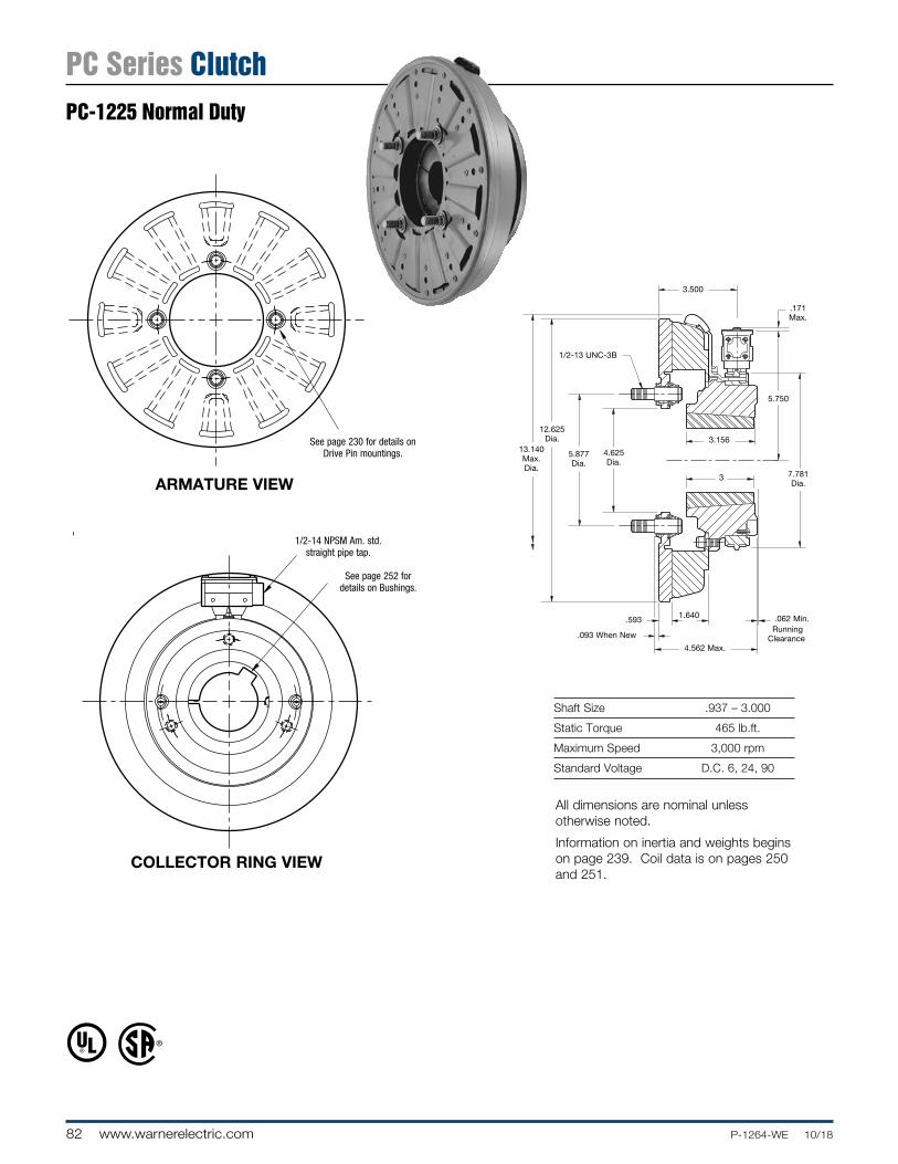
82 www.warnerelectric.com P-1264-WE 10/18
Shaft Size .937 – 3.000
Static Torque 465 lb.ft.
Maximum Speed 3,000 rpm
Standard Voltage D.C. 6, 24, 90
COLLECTOR RING VIEW
ARMATURE VIEW 3
5.750
.171 Max.
.093 When New
.062 Min.1.640.593
1/2-13 UNC-3B
Running Clear ance
4.562 Max.
13.140 Max. Dia.
12.625 Dia.
5.877 Dia.
4.625 Dia.
3.500
7.781 Dia.
3.156
See page 252 for details on Bushings.
1/2-14 NPSM Am. std. straight pipe tap.
See page 230 for de tails on Drive Pin mountings.
All dimensions are nominal unless otherwise noted.
Information on inertia and weights begins on page 239. Coil data is on pages 250 and 251.
PC Series ClutchPC-1225 Normal Duty

83P-1264-WE 10/18 www.warnerelectric.com
Drawing I-25602
How to Order:1. Specify Voltage for Item 4.2. Specify Bore Size for Item 5.3. Specify left hand or right hand hub for Item 6. (Bushing
enters from magnet side for L.H. hub and from hub side for R.H.)
4. See Con trols Section.
Example:PC-1225 Clutch per I-25602 - 90 Volt, L.H. hub, 1” Bore
These units meet standards set forth in UL508 and are listed under guide card #NMTR2, file #59164.
These units are CSA certified under file #LR11543
* See page 252 for specific part numbers.
Refer to Service Manual P-0207-WE
† Optional LK facing available. For more information, see page 232.
1
2
3
4
4-1
5
7-1
6-1
6-2
6(Shipped Assembled)
7
Item De scrip tion Part Number Qty.
1 Armature 5303-111-009 1
2 Autogap Accessory 5201-101-008 4
3 Mounting Accessory 5321-101-001 1
4 Magnet 1
6 Volt 5303-631-005
24 Volt 5303-631-007
90 Volt 5303-631-008
†90 Volt LK Facing 5303-631-001
4-1 Terminal Accessory 5311-101-001 1
5 Bushing* 1
15/16” to 3” Bore 180-0262 to 180-0295
6 Magnet Hub 1
Left Hand (shown) 5303-541-001
Right Hand 5303-541-002
6-1 Collector Ring 5301-749-001 1
6-2 Collector Ring Accessory 5303-101-004 1
Item De scrip tion Part Number Qty.
7 Brushholder 5300-178-001 1
7-1 Brush 176-0001 4
PC Series ClutchPC-1225 Normal Duty

84 www.warnerelectric.com P-1264-WE 10/18
Shaft Size .937 – 3.000
Static Torque 465 lb.ft.
Maximum Speed 3,000 rpm
Standard Voltage D.C. 6, 24, 90
Customer Shall Maintain:1. Splined hub pilot diameter to be concentric
with splined armature center of rotation within .010 T.I.R.
ARMATURE VIEW
COLLECTOR RING VIEW
1.500
4.3134.311
Pilot Dia.
5.750
.093
12.625
Running Dia. Max.
Max. Length of Customer Pilot
13.140
.171 Max.
.062
.125
.718 Max.
.062 Min. Running
Clearance
3/8-16 UNC-2A
(Left Hand Magnet Hub
Shown)
1.640 2.187
4.875 Max.
.562
3.156
7.781 Dia.
3.00
3.468
See page 252 for details on Bush ings.
1/2-14 NPSM Am. std. straight pipe tap.
All dimensions are nominal unless otherwise noted.
Information on inertia and weights begins on page 239. Coil data is on pages 250 and 251.
.397/.388 Dia. (8) holes equally spaced on 3.625 dia. Mounting holes are within .003 of
true po si tion relative to pilot diameter.
3.062 dia.
PC Series ClutchPC-1225 Heavy Duty

85P-1264-WE 10/18 www.warnerelectric.com
Drawing I-25603
How to Order:1. Specify Voltage for Item 5.2. Specify Bore Size for Item 7.3. Specify left hand or right hand hub for Item 6.4. See Con trols Section.
Example:PC-1225 Clutch per I-25603 - 90 Volt, L.H. hub, 1” Bore
These units meet the standards of UL508 and are listed under guide card #NMTR2, file #59164.
These units are CSA certified under file #LR11543.
* See page 252 for specific part numbers.
Refer to Service Manual P-0206-WE
† Optional LK facing available. For more information, see page 232.
1(Shipped
Assembled)
1-5
3
2
1-1
1-2
1-3 5-1
4
57
8-1
8
6-1
6(Shipped
Assembled)
6-2
1-4
Item De scrip tion Part Number Qty.
1 Armature & Splined
Adapter Assembly 5323-111-001 1
1-1 Armature 5323-111-034 1
1-2 Splined Armature Adapter 104-0010 1
1-3 Autogap Accessory 5323-101-002 1
Autogap Spring 808-0044 1
Retainer Ring 748-0370 1
1-4 Button Head Screw 797-0281 4
1-5 Locknut 661-0005 4
2 Mounting Accessory 5202-101-001 3
3 Splined Hub 540-0148 1
4 Mounting Accessory 5321-101-001 1
5 Magnet 1
6 Volt 5303-631-005
24 Volt 5303-631-007
90 Volt 5303-631-008
†90 Volt LK Facing 5303-631-001
5-1 Terminal Accessory 5311-101-001
6 Magnet Hub Assembly 1
Right Hand 5303-541-002
Left Hand (shown) 5303-541-001
Item De scrip tion Part Number Qty.
6-1 Collector Ring 5301-749-001 1
6-2 Collector Ring Accessory 5303-101-004 1
7 Bushing, Taperlock* 180-0262 to 180-0295 1
8 Brushholder 5300-178-001 1
8-1 Brush 176-0001 4
PC Series ClutchPC-1225 Heavy Duty

86 www.warnerelectric.com P-1264-WE 10/18
Shaft Size .937 – 3.000
Static Torque 700 lb.ft.
Maximum Speed 2,000 rpm
Standard Voltage D.C. 6, 24, 90
ARMATURE VIEW
COLLECTOR RING VIEW
See page 230 for de tails on Drive Pin mountings.
3
5.750
.171 Max.
.093 When New
.062 Min.1.750.593
1/2-13 UNC-3B
Running Clear ance
4.796 Max.
16.250 Max. Dia.
15.578 Dia.
8.500 Dia.
7.093 Dia.
3.812
7.781 Dia.
3.187
See page 252 for details on Bushings.
1/2-14 NPSM Am. std. straight pipe tap.
All dimensions are nominal unless otherwise noted.
Information on inertia and weights begins on page 239. Coil data is on pages 250 and 251.
PC Series ClutchPC-1525 Normal Duty

87P-1264-WE 10/18 www.warnerelectric.com
Drawing I-25628
How to Order:1. Specify Voltage for Item 4.2. Specify Bore Size for Item 5.3. Specify left hand or right hand hub for Item 6. (Bushing
enters from magnet side for L.H. hub and from hub side for R.H.)
4. See Con trols Section.Example:PC-1525 Clutch per I-25628 - 90 Volt, L.H. hub, 1” Bore
These units meet standards set forth in UL508 and are listed under guide card #NMTR2, file #59164.
These units are CSA certified under file #LR11543
* See page 252 for specific part numbers.
Refer to Service Manual P-0206-WE
† Optional LK facing available. For more information, see page 232.
1
2
3
4
4-1
5
7-1
6-1
6-2
6(Shipped Assembled)
7
Item De scrip tion Part Number Qty.
1 Armature 5304-111-004 1
2 Autogap Accessory 5201-101-008 4
3 Mounting Accessory 5321-101-001 2
4 Magnet 1
6 Volt 5304-631-009
24 Volt 5304-631-011
90 Volt 5304-631-010
†90 Volt LK Facing 5304-631-002
4-1 Terminal Accessory 5311-101-001 1
5 Bushing* 1
15/16” to 3” Bore 180-0262 to 180-0295
6 Magnet Hub 1
Left Hand (shown) 5304-541-001
Right Hand 5304-541-002
6-1 Collector Ring 5301-749-001 1
6-2 Collector Ring Accessory 5304-101-004 1
Item De scrip tion Part Number Qty.
7 Brushholder 5300-178-001 1
7-1 Brush 176-0001 4
PC Series ClutchPC-1525 Normal Duty

88 www.warnerelectric.com P-1264-WE 10/18
Shaft Size .937 – 3.000
Static Torque 700 lb.ft.
Maximum Speed 2,000 rpm
Standard Voltage D.C. 6, 24, 90
Customer Shall Maintain:1. Splined hub pilot diameter to be concentric
with splined armature center of rotation within .010 T.I.R.
ARMATURE VIEW
COLLECTOR RING VIEW
1.500
4.3134.311
Pilot Dia.
5.750
.093
15.578
Running Dia. Max.
Max. Length of Customer Pilot
16.250
.171 Max.
.062
.125
.718 Max.
.062 Min. Running
Clearance
3/8-16 UNC-2A
(Left Hand Magnet Hub
Shown)
1.750 2.312
5.109 Max.
.562
3.187
7.781 Dia.
3.00
3.781
.397/.388 Dia. (8) holes (hub) equally spaced on 3.625 dia.
Mounting holes are within .003 of true po si tion relative to pilot
diameter.
3.062 dia.
See page 252 for details on Bush ings.
1/2-14 NPSM Am. std. straight pipe tap.
All dimensions are nominal unless otherwise noted.
Information on inertia and weights begins on page 239. Coil data is on pages 250 and 251.
PC Series ClutchPC-1525 Heavy Duty

89P-1264-WE 10/18 www.warnerelectric.com
Drawing I-256291
(ShippedAssembled)
1-5
3
2
1-11-6
1-2
1-3 5-1
4
57
8-1
8
6-1
6(Shipped
Assembled)
6-2
1-4
How to Order:1. Specify Voltage for Item 5.2. Specify Bore Size for Item 7.3. Specify left hand or right hand hub for Item 6.4. See Con trols Section.
Example:PC-1525 Clutch per I-25629 - 90 Volt, L.H. hub, 1” Bore
These units meet the standards of UL508 and are listed under guide card #NMTR2, file #59164. These units are CSA certified under file #LR11543.
* See page 252 for specific part numbers.
Refer to Service Manual P-0206-WE
† Optional LK facing available. For more information, see page 232.
Item De scrip tion Part Number Qty.
1 Armature & Splined
Adapter Assembly 5324-111-001 1
1-1 Armature 5324-111-034 1
1-2 Splined Armature Adapter 104-0011 1
1-3 Autogap Accessory 5323-101-002 1
Autogap Spring 808-0044 1
Retainer Ring 748-0370 1
1-4 Button Head Screw 797-0272 8
1-5 Locknut 661-0004 8
1-6 Retainer Plate 686-0003 1
2 Mounting Accessory 5202-101-001 3
3 Splined Hub 540-0148 1
4 Mounting Accessory 5321-101-001 2
5 Magnet 1
6 Volt 5304-631-009
24 Volt 5304-631-011
90 Volt 5304-631-010
†90 Volt LK Facing 5304-631-002
5-1 Terminal Accessory 5311-101-001 1
6 Magnet Hub Assembly 1
Right Hand 5304-541-002
Left Hand (shown) 5304-541-001
Item De scrip tion Part Number Qty.
6-1 Collector Ring 5301-749-001 1
6-2 Collector Ring Accessory 5304-101-004 1
7 Bushing, Taperlock* 180-0262 to 180-0295 1
8 Brushholder 5300-178-001 1
8-1 Brush 176-0001 4
PC Series ClutchPC-1525 Heavy Duty

90 www.warnerelectric.com P-1264-WE 10/18
Static Torque 5 lb.in.
Maximum Speed 3,600 rpm
Standard Voltage D.C. 6, 24, 90Customer Shall Maintain:1. Squareness of field mounting face with rotor
shaft within .003 T.I.R. measured at pilot diameter
2. Concentricity of field mounting pilot diameter with rotor mounting shaft within .003 T.I.R.
3. Rotor and armature shafts in line within .003 T.I.R.
Bore Di men sions
Rotor Armature Bore Dia. Bore Dia.
.188/.187 .188/.187 .251/.250 .251/.250 .313/.312 (.313/.312)*
*(Antibacklash Armatures)
ARMATURE VIEW
FIELD VIEW
Std. Arm.
Antibacklash Arm.
For Bore sizes see chart below.
.130/.123 dia. (4) holes equally spaced on 1.312 dia. Mounting holes are within .006 of true position relative to pilot diameter.
For Bore sizes see chart below.
45°
1.499/1.497 Pi lot Dia.
1.140 Max. Sq.
12 Min..062
.063/.062 dia. (2) holes
equally spaced.
.109
.156
.019
.000
.187 Max.
.500
.109 (Std.) .140 (Anti.)
.072 (Std.).072 (Anti.)
.015
.015 When New
Std. Arm
.562
.968 (Std.).968 (Anti.)
.625
.546.343
.072 (Std.).072
(Anti.)
Antibacklash Arm.
1.234 Max. Dia.
#4-40 UNC-3A
All dimensions are nominal unless otherwise noted.
Information on inertia and weights begins on page 239. Coil data is on pages 250 and 251.
SFC Series Clutch CouplingSFC-120 Flange Mounted

91P-1264-WE 10/18 www.warnerelectric.com
Drawing I-25503
1B
1A-1
1A-2
2
4
1A
3
How to Order:1. Specify Type of Armature Desired.2. Specify Bore Size for Item 1A-1 or 1B and
Item 2.3. Specify Voltage for Item 4.4. See Controls Section.
Example:SFC-120 Clutch per I-25503 - 90 Volt, Standard Armature, 1/4” Armature Hub Bore, 1/4” Rotor Bore
These units meet standards set forth in UL508 and are listed under guide card #NMTR2, file #59164.
These units are CSA certified under file #LR11543.
Refer to Service Manual P-0200-WE
Item Description Part Number Qty.
1A Armature and Hub
1A-1 Armature Hub 1
3/16” Bore 5622-541-009 1/4” Bore 5622-541-008
1A-2 Armature 110-0110 1
1B Antibacklash Armature 1
3/16” Bore 5622-111-004 1/4” Bore 5622-111-002 5/16” Bore 5622-111-003
2 Rotor 1
3/16” Bore 5602-751-004 1/4” Bore 5602-751-002 5/16” Bore 5602-751-003
3 Mounting Accessory 5101-101-001 1
4 Field 1
6 Volt 5602-451-003 24 Volt 5602-451-005 90 Volt 5602-451-007
SFC Series Clutch CouplingSFC-120 Flange Mounted

92 www.warnerelectric.com P-1264-WE 10/18
Static Torque 5 lb.in.
Maximum Speed 3,600 rpm
Standard Voltage D.C. 6, 24, 90
Bore Di men sions
Rotor Armature Bore Dia. Bore Dia.
.188/.187 .188/.187 .251/.250 .251/.250 .313/.312 (.313/.312)*
*(Antibacklash Armatures)
Customer Shall Maintain:1. Alignment between rotor and armature shafts to be .003 T.I.R.
FIELD VIEW
ARMATURE VIEW
.156
.015 When New
.072 (Std.).072 (Anti.)
.062
12
.109 (Std.).140 (Anti.)
.218
.500 (Std.)
.093
.562 (Anti.)
.072 (Std.).072 (Anti.)
.015
.687 Dia.
.781
.8591.203 Max.
1.234 Max. Dia.
For Bore sizes see chart below.
.125
.578
.703
45°
.562
For Bore sizes see chart below.
Std. Arm.
Antibacklash Arm.
All dimensions are nominal unless otherwise noted.
Information on inertia and weights begins on page 239. Coil data is on pages 250 and 251.
SFC Series Clutch CouplingSFC-120 Bearing Mounted

93P-1264-WE 10/18 www.warnerelectric.com
Drawing I-25504
1B
1A-1
2
1A-2
1A
3
4
How to Order:1. Specify Type of Armature Desired.2. Specify Bore Size for Item 1A-1 or 1B and Item 2.3. Specify Voltage for Item 3.4. See Controls Section.
Example:SFC-120 Clutch per I-25504 - 90 Volt, Standard Armature, 1/4” Armature Hub Bore
These units meet standards set forth in UL508 and are listed under guide card #NMTR2, file #59164.
These units are CSA certified under file #LR11543.
Refer to Service Manual P-0200-WE
Item Description Part Number Qty.
1A Armature and Hub
1A-1 Armature Hub 1
3/16” Bore 5622-541-009 1/4” Bore 5622-541-008
1A-2 Armature 110-0110 1
1B Antibacklash Armature 1
3/16” Bore 5622-111-004 1/4” Bore 5622-111-002 5/16” Bore 5622-111-003
2 Rotor 1
3/16” Bore 5602-751-008 1/4” Bore 5602-751-006 5/16” Bore 5602-751-007
3 Field 1
6 Volt 5602-451-021 24 Volt 5602-451-023 90 Volt 5602-451-025
4 Set Collar 5602-266-001 1
SFC Series Clutch CouplingSFC-120 Bearing Mounted

94 www.warnerelectric.com P-1264-WE 10/18
Static Torque 15 lb.in.
Maximum Speed 5,000 rpm
Standard Voltage D.C. 6, 24, 90
Bore Di men sions
Rotor Armature Bore Dia. Keyway Bore Dia.
.251/.250 .062 x .031 .251/.250 .313/.312 .062 x .031 .313/.312 .376/.375 .093 x .046 .376/.375
Customer Shall Maintain:1. Squareness of field mounting face with
rotor shaft within .003 T.I.R. measured at pilot diameter
2. Concentricity of field mounting pilot diameter with rotor mounting shaft within .003 T.I.R.
3. Rotor and armature shafts in line within .003 T.I.R.
ARMATURE VIEW
FIELD VIEW
.625 (Std.)
.125 (Std.)
.109 (Anti.)
.015 When New
.086 (Std.).094 (Anti.)
.015.515 Max.
.160/.150
.437 Max..187
#8-32 UNC-3A
.375
.06212
.752
.750Pi lot Dia.
Backing Plate Only.843
(Anti.)
.086 (Std.).094 (Anti.)
1.375 (Std.)1.359 (Anti.)
.750
1.718 Max. Dia.
Antibacklash Arm.
Std. Arm.
For Bore sizes see chart below.
45°
.204/.187 dia. (4) holes equally spaced on 2.125 dia.
Mounting holes are within .010 of true position
relative to pilot diameter.
For Bore & Keyway sizes see chart below. 2.437
2.435 Dia.
1.812 Max. Sq.
All dimensions are nominal unless otherwise noted.
Information on inertia and weights begins on page 239. Coil data is on pages 250 and 251.
SFC Series Clutch CouplingSFC-170 Flange Mounted

95P-1264-WE 10/18 www.warnerelectric.com
1A-1
1A
1A-2
1A-3
1B
3
2
4
Drawing I-25756
How to Order:1. Specify Type of Armature Desired.2. Specify Bore Size for Item 1A-1 or 1B and Item 2.3. Specify Voltage for Item 4.4. See Controls Section.
Example:SFC-170 Clutch per I-25756 - 90 Volt, Antibacklash Armature, 1/4” Armature Hub Bore, 1/4” Rotor Bore
These units meet standards set forth in UL508 and are listed under guide card #NMTR2, file #59164.
These units are CSA certified under file #LR11543.
Refer to Service Manual P-0200-WE
Item Description Part Number Qty.
1A Armature and Hub
1A-1 Armature Hub 1
1/4” Bore 5102-541-002 5/16” Bore 5102-541-003 3/8” Bore 5102-541-004
1A-2 Armature 110-0111 1
1A-3 Release Spring 808-0019 1
1B Antibacklash Armature 1
1/4” Bore 5623-111-008 5/16” Bore 5623-111-009 3/8” Bore 5623-111-010
2 Rotor 1
1/4” Bore 5603-751-028 5/16” Bore 5603-751-029 3/8” Bore 5603-751-030
3 Mounting Accessory 5102-101-001 1
4 Field 1
6 Volt 5603-451-047 24 Volt 5603-451-049 90 Volt 5603-451-051
SFC Series Clutch CouplingSFC-170 Flange Mounted

96 www.warnerelectric.com P-1264-WE 10/18
Static Torque 15 lb.in.
Maximum Speed 5,000 rpm
Standard Voltage D.C. 6, 24, 90
Customer Shall Maintain:1. Alignment between rotor and armature shafts to be .003 T.I.R.
Bore Di men sions
Rotor Armature Bore Dia. Bore Dia.
.251/.250 .251/.250 .313/.312 .313/.312 .376/.375 .376/.375
ARMATURE VIEW
FIELD VIEW
.375
.015 When New
.06212
.125 (Std.).109 (Anti.)
.093
.625 (Std.)
.250
.843 (Anti.)
.015
.625 Dia.
1.718 Max. Dia.
.086 (Std.).094 (Anti.)
.086 (Std.).094 (Anti.)
1.562 Max.
1.2031.093
For Bore sizes see chart below.
Antibacklash Arm.
Std. Arm.
For Bore sizes see chart below.
1.87 .500
1.062
1.375
1.750 Max. Dia.
All dimensions are nominal unless otherwise noted.
Information on inertia and weights begins on page 239. Coil data is on pages 250 and 251.
SFC Series Clutch CouplingSFC-170 Bearing Mounted

97P-1264-WE 10/18 www.warnerelectric.com
Drawing I-25757
Item Description Part Number Qty.
1A Armature and Hub
1A-1 Armature Hub 1
1/4” Bore 5102-541-002 5/16” Bore 5102-541-003 3/8” Bore 5102-541-004
1A-2 Armature 110-0111 1
1A-3 Release Spring 808-0019 1
1B Antibacklash Armature 1
1/4” Bore 5623-111-008 5/16” Bore 5623-111-009 3/8” Bore 5623-111-010
2 Rotor 1
1/4” Bore 5603-751-019 5/16” Bore 5603-751-021 3/8” Bore 5603-751-020
3 Field 1
6 Volt 5603-451-039 12 Volt 5603-451-040 24 Volt 5603-451-041 90 Volt 5603-451-043
How to Order:1. Specify Type of Armature Desired.2. Specify Bore Size for Item 1A-1 or 1B and Item 2.3. Specify Voltage for Item 3.4. See Controls Section.
Example:SFC-170 Clutch per I-25757 - 90 Volt, Antibacklash Armature, 1/4” Armature Hub Bore
These units meet standards set forth in UL508 and are listed under guide card #NMTR2, file #59164.
These units are CSA certified under file #LR11543.
Refer to Service Manual P-0200-WE
Item Description Part Number Qty.
4 Retainer Ring 748-0024 1
1A
1A-1
1A-2
1B
1A-3
2
3
4
SFC Series Clutch CouplingSFC-170 Bearing Mounted

98 www.warnerelectric.com P-1264-WE 10/18
Static Torque 70 lb. in.
Maximum Speed 7,500 rpm
Standard Voltage D.C. 6, 24, 90
Customer Shall Maintain:1. Squareness of field mounting face with rotor shaft within .003
T.I.R. measured at pilot di am e ter.
2. Concentricity of field mounting pilot diameter with rotor mounting shaft within .003 T.I.R.
3. Rotor and armature shafts in line within .003 T.I.R.
Bore and Keyway Di men sions
Armature Keyway Rotor Key way Bore Dia. Bore Dia.
.376/.375 .093 x .046
*.438/.437 .376/.375 .093 x .046 .501/.500 .125 x .062 *.438/.437 .125x .062 *.563/.562 .501/.500
.626/.625 *.688/.687 .187 x .093 .751/.750
* Available on special order only.
ARMATURE VIEW
FIELD VIEW
1.187 (Std.)
.171
.171 (Std.).562 (Anti.)
.437 Max.
8-32 UNC-3A
.546 Max.
.171
.062
.343 Max.
1.0631.061
Pilot Dia.
.015
.380/.370
Backing Plate Only
1.390 (Anti.)
.015 When New
2.625 Max. Dia.
.687
1.125.468
1.968 (Std.)1.984 (Anti.)
.750
1.250
Std. Arm.
Antibacklash Arm.
For Bore & Keyway sizes see chart below.
3.500/3.498 Pilot Dia.
.437 Max.
.437 Max.
12°
24°
45°
For Bore & Key way sizes see chart
be low.
.204/.187 dia. (4) holes equally spaced on 3.125 dia. Mounting holes are within .010 of true po si tion relative
to pilot diameter.
2.625 Sq.
All dimensions are nominal unless otherwise noted.
Information on inertia and weights begins on page 239. Coil data is on pages 250 and 251.
SFC Series Clutch CouplingSFC-250 Flange Mounted

99P-1264-WE 10/18 www.warnerelectric.com
Drawing I-25522
How to Order:1. Specify Type of Armature Desired.2. Specify Bore Size for Item 1A-1 or 1-B and Item 2.3. Specify Voltage for Item 3.4. See Controls Section.
Example:SFC-250 Clutch Coupling per I-25522 - 90 Volt, Standard Armature, 1/2” Armature Hub Bore, 1/2” Rotor Bore
These units meet standards set forth in UL508 and are listed under guide card #NMTR2, file #59164.
These units are CSA certified under file #LR11543.
Refer to Service Manual P-0200-WE
1A-1
1A-3
1A1A-2
2
4
3
3-1
1B
Item Description Part Number Qty.
1A Armature and Hub
1A-1 Armature Hub 1
3/8” Bore 5103-541-002
1/2” Bore 5103-541-004
5/8” Bore 5103-541-006
3/4” Bore 5103-541-008
1A-2 Armature 5124-111-001 1
1A-3 Release Spring 5103-101-003 1
1B Antibacklash Armature 1
3/8” Bore 5365-111-003
1/2” Bore 5365-111-005
5/8” Bore 5365-111-007
3/4” Bore 5365-111-009
2 Rotor 1
3/8” Bore 5103-751-008
1/2” Bore 5103-751-010
3 Field 1
6 Volt 5103-451-002
24 Volt 5103-451-004
90 Volt 5103-451-007
Item Description Part Number Qty.
3-1 Terminal Accessory 5103-101-002 1
4 Mounting Accessory 5102-101-001 1
SFC Series Clutch CouplingSFC-250 Flange Mounted

100 www.warnerelectric.com P-1264-WE 10/18
Static Torque 70 lb. in.
Maximum Speed 7,500 rpm
Standard Voltage D.C. 6, 24, 90
Bore and Keyway Di men sions
Armature Keyway Rotor Key way Bore Dia. Bore Dia.
.375/.376 .093 x .046 .376/.375 .093 x .046
*.438/.437 .501/.500 .125 x .062 *.438/.437 .125 x .062 *.563/.562 .501/.500
.626/.625 *.688/.687 .187 x .093 .751/.750
* Available on special order only.
Customer Shall Maintain:1. Armature shaft to be concentric with rotor shaft
within .003 T.I.R.
ARMATURE VIEW
FIELD VIEW
1.187 (Std.)
.687 (Std.)
.687 (Std.).718
(Anti.)
.171
.062
.171 (Std.).187 (Anti.) .015 (Std.)
.015 (Anti.)
.343 Max.
.015 (Std.).015 (Anti.)when new .468
.171 + .062 -0
1.390 (Anti.)
.718 (Anti.)
2.625 Max. Dia.
1.437
1.125
.609 Dia.
1.312
2.156 (Std.)2.171 (Anti.)
Antibacklash Arm.
Std. Arm.
For Bore & Keyway sizes see chart below.
1.750 Max.
.187 Dia.
.437Max.
.500 12°
24°45°
For Bore & Key way sizes see chart be low.
.937
.187 1.562 Rad.
All dimensions are nominal unless otherwise noted.
Information on inertia and weights begins on page 239. Coil data is on pages 250 and 251.
SFC Series Clutch CouplingSFC-250 Bearing Mounted

101P-1264-WE 10/18 www.warnerelectric.com
1B
1A-1
1A
1A-3
1A-2
2-1 2-2
2-3
2(Shipped Assembled)
2-2
2-4
2-5
2-4-1
Drawing I-25523
How to Order:1. Specify Type of Armature Desired.2. Specify Bore Size for Item 1A-1 or 1B and Item 2.3. Specify Voltage for Item 2.4. See Controls Section.
Example:SFC-250 Clutch Coupling per I-25523 - 90 Volt, Standard Armature, 1/2” Armature Hub Bore, 1/2” Rotor Bore
These units meet standards set forth in UL508 and are listed under guide card #NMTR2, file #59164. These units are CSA certified under file #LR11543.
*Used with 1/2” Bore only.
Refer to Service Manual P-0200-WE
Item Description Part Number Qty.
1A Armature and Hub
1A-1 Armature Hub 1
3/8” Bore 5103-541-002
1/2” Bore 5103-541-004
5/8” Bore 5103-541-006
3/4” Bore 5103-541-008
1A-2 Armature 5124-111-001 1
1A-3 Release Spring 5103-101-003 1
1B Antibacklash Armature 1
3/8” Bore 5365-111-003
1/2” Bore 5365-111-005
5/8” Bore 5365-111-007
3/4” Bore 5365-111-009
2 Field and Rotor Assembly 1
6 Volt – 3/8” Bore 5103-452-002
24 Volt – 3/8” Bore 5103-452-004
90 Volt – 3/8” Bore 5103-452-007
6 Volt – 1/2” Bore 5103-452-016
24 Volt – 1/2” Bore 5103-452-018
90 Volt – 1/2” Bore 5103-452-021
2-1 Rotor 1
3/8” Bore 5103-751-014
1/2” Bore 5103-751-016
Item Description Part Num ber Qty.
2-2 Retainer Ring 748-0371 2
2-3 Ball Bearing 166-0108 1
2-4 Field 1
6 Volt 5103-451-018
24 Volt 5103-451-020
90 Volt 5103-451-023
2-4-1 Terminal Accessory 5103-101-002 1
2-5 Set Collar* 266-0005 1
SFC Series Clutch CouplingSFC-250 Bearing Mounted

102 www.warnerelectric.com P-1264-WE 10/18
Static Torque 270 lb. in.
Maximum Speed 4,500 rpm
Standard Voltage D.C. 6, 24, 90
Bore and Keyway Di men sions
Armature Keyway Rotor Key way Bore Dia. Bore Dia.
.501/.500 .125 x .062 .501/.500 .125 x.062 *.563/.562 .626/.625 .626/.625 *.688/.687 .187 x .093 .751/.750 .187 x .093 .751/.750 .876/.875 .876/.875 1.001/1.000
*Available on special order only
ARMATURE VIEW
* Mounting holes are within .010 of true position relative to pilot diameter.
FIELD VIEW
1.8751.873 Pilot Dia.
1/4-20 UNC-3A
1.250 (Std.)
.328
.015
.671
3.562
.609 Max.
.328 Max.
.015 When New
.187 (Std.).218 (Anti.)
.250
.093
1.640 (Anti.)
1.546
.937
.8754.234 Max. Dia.
.187 (Std.).218 (Anti.)
.828 1.312
1.500
1.502.328/2.359
.192/.182
1.125
Antibacklash Arm.
Std. Arm.
For Bore & Keyway sizes see chart below.
For Bore & Key way sizes see chart below.
Removable plug in ends for 1/2” conduit.
45°
.296/.280 dia. (4) holes equally spaced on 5.000 dia.*
4.250 Sq.
4.687
3.750
5.6265.623
Pilot Dia.
Customer Shall Maintain:1. Squareness of field mounting face with rotor shaft within .003
T.I.R. measured at pilot di am e ter.
2. Concentricity of field mounting pilot diameter with rotor mounting shaft within .003 T.I.R.
3. Rotor and armature shafts in line within .003 T.I.R.All dimensions are nominal unless otherwise noted.
Information on inertia and weights begins on page 239. Coil data is on pages 250 and 251.
SFC Series Clutch CouplingSFC-400 Flange Mounted

103P-1264-WE 10/18 www.warnerelectric.com
1A-1
1A-3
1A1A-2
2
3
5
3-1
4
1B
Drawing I-25697
How to Order:1. Specify Type of Armature Desired.2. Specify Bore Size for Item 1A-1 or 1B and Item 2.3. Specify Voltage for Item 3.4. See Controls Section.
Example:SFC-400 Clutch Coupling per I-25697 - 90 Volt, 3/4” Armature Hub Bore, 3/4” Rotor Bore
These units, when used in conjunction with the correct Warner Electric conduit box, meet standards set forth in UL508 and are listed under guide card #NMTR2, file #59164.
These units are CSA certified under file #LR11543.
Refer to Service Manual P-0200-WE
Item Description Part Number Qty.
1A Armature and Hub
1A-1 Armature Hub 1
1/2” Bore 5104-541-002
5/8” Bore 5104-541-004
3/4” Bore 5104-541-006
7/8” Bore 5104-541-007
1A-2 Armature 5125-111-001 1
1A-3 Release Spring 5104-101-003 1
1B Antibacklash Armature 1
1/2” Bore 5367-111-003
5/8” Bore 5367-111-005
3/4” Bore 5367-111-007
7/8” Bore 5367-111-008
2 Rotor 1
1/2” Bore 5104-751-033
5/8” Bore 5104-751-034
3/4” Bore 5104-751-035
7/8” Bore 5104-751-036
1” Bore 5104-751-037
3 Field 1
6 Volt 5104-451-032
24 Volt 5104-451-033
90 Volt 5104-451-034
Item Description Part Number Qty.
3-1 Terminal Accessory 5103-101-002 1
4 Conduit Box 5200-101-010 1
5 Mounting Accessory 5104-101-002 1
SFC Series Clutch CouplingSFC-400 Flange Mounted

104 www.warnerelectric.com P-1264-WE 10/18
Static Torque 270 lb. in.
Maximum Speed 4,500 rpm
Standard Voltage D.C. 6, 24, 90
ARMATURE VIEW
Bore and Keyway Di men sions
Armature Keyway Rotor Key way Bore Dia. Bore Dia.
.501/.500 .125 x .062 .501/.500 .125 x.062 *.563/.562
.626/.625 .626/.625 *.688/.687 .187 x .093 .751/.750 .187 x .093 .751/.750 .876/.875 .876/.875 1.001/1.000
* Available on special order only.
Customer Shall Maintain:1. Armature shaft to be concentric with rotor
shaft within .003 T.I.R.
FIELD VIEW
Antibacklash Arm.
Std. Arm.
For Bore & Keyway sizes see chart below.
For Bore & Keyway sizes see chart below.
Re mov able plug in ends for 1/2” conduit.
4.687
45°
.500
.859
2.312
.187
.187
3.750
1.250 (Std.)
.187 (Std.).218 (Anti.)
.015 (Std.).015 (Anti.) when
new
.015
.328 Max.
.328 (Anti.)
.203 (Anti.)
.062 (Std.)
.875 (Std.).843 (Anti.)
.875 (Std.).843 (Anti.)
3.562
1.640 (Anti.)
4.234 Max. Dia.
1.546
1.218
1.375 Dia.
1.281 (Std.)
1.812
1.625
2.640 (Std.)2.734 (Anti.)
All dimensions are nominal unless otherwise noted.
Information on inertia and weights begins on page 239. Coil data is on pages 250 and 251.
SFC Series Clutch CouplingSFC-400 Bearing Mounted

105P-1264-WE 10/18 www.warnerelectric.com
1B
1A-1
1A-3
1A-2
2-1
1-A
2(Shipped Assembled)
2-3
2-4
2-4-12-2
3
Drawing I-25698
How to Order:1. Specify Type of Armature Desired.2. Specify Bore Size for Item 1A-1 or 1-B and Item 2.3. Specify Voltage for Item 2.4. See Controls Section.
Example:SFC-400 Clutch Coupling per I-25698 - 90 Volt, Antibacklash Armature, 3/4” Armature Hub Bore, 3/4” Rotor Bore
These units meet standards set forth in UL508 and are listed under guide card #NMTR2, file #59164. These units are CSA certified under file #LR11543.
Refer to Service Manual P-0200-WE
Item Description Part Number Qty.
1A Armature and Hub1A-1 Armature Hub 1 1/2” Bore 5104-541-002 5/8” Bore 5104-541-004 3/4” Bore 5104-541-006 7/8” Bore 5104-541-0071A-2 Armature 5125-111-001 11A-3 Release Spring 5104-101-003 11B Antibacklash Armature 1 1/2” Bore 5367-111-003 5/8” Bore 5367-111-005 3/4” Bore 5367-111-007 7/8” Bore 5367-111-0082 Field and Rotor Assembly 1 6 Volt – 1/2” Bore 5104-452-052 24 Volt – 1/2” Bore 5104-452-053 90 Volt – 1/2” Bore 5104-452-054 6 Volt – 5/8” Bore 5104-452-055 24 Volt – 5/8” Bore 5104-452-056 90 Volt – 5/8” Bore 5104-452-057 6 Volt – 3/4” Bore 5104-452-058 24 Volt – 3/4” Bore 5104-452-059 90 Volt – 3/4” Bore 5104-452-060 6 Volt – 7/8” Bore 5104-452-061 24 Volt – 7/8” Bore 5104-452-062 90 Volt – 7/8” Bore 5104-452-063 6 Volt – 1” Bore 5104-452-064 24 Volt – 1” Bore 5104-452-065 90 Volt – 1” Bore 5104-452-066
Item Description Part Number Qty.
2-1 Rotor 1 1/2” Bore 5104-751-043 5/8” Bore 5104-751-044 3/4” Bore 5104-751-045 7/8” Bore 5104-751-046 1” Bore 5104-751-0472-2 Retainer Ring 748-0018 12-3 Ball Bearing 166-0150 12-4 Field 1 6 Volt 5104-451-038 24 Volt 5104-451-039 90 Volt 5104-451-0402-4-1 Terminal Accessory 5103-101-002 13 Conduit Box 5200-101-010 1
SFC Series Clutch CouplingSFC-400 Bearing Mounted

106 www.warnerelectric.com P-1264-WE 10/18
Armature Shaft .500 – 1.250
Rotor Shaft .750 – 1.250
Static Torque 50 lb.ft.
Maximum Speed 4,000 rpm
Standard Voltage D.C. 6, 24, 90
Bore & Keyway Dimensions
Rotor Bore Dia. Keyway
.751/.750 .187 x .093 .876/.875
.9385/.9375 1.001/1.000 .250 x .125 1.126/1.125 1.251/1.250
HUB VIEW
See page 252 for details on Bushings & keyways.
FIELD VIEW
2.062 Min. Flat
4.093
5 Dia.
.062 When New
.125 Max.
.187
.281
5.328 Max Dia. 1.500
1.750 Dia.
1.546
1.234
3.937
2.093
1.593
1.343
Removable plug in ends for 1/2”
conduit.
3.156 Max. 2.781
.750
.218
5.218
45°
3.750
For Bore & Keyway sizes see chart below.
Customer Shall Maintain:1. Armature mounting shaft to be concentric with rotor mounting
shaft within .006 T.I.R.
All dimensions are nominal unless otherwise noted.
Information on inertia and weights begins on page 239. Coil data is on pages 250 and 251.
SFC Series Clutch CouplingSFC-500 Bearing MountedNormal Duty

107P-1264-WE 10/18 www.warnerelectric.com
3
1
25-2-1
5-3
6
5-2-2
5-2
5 (Shipped Assembled)
5-1
5-4
4
Drawing I-25540
Item Description Part Number Qty.
1 Armature Hub 1 Standard Hub 5300-541-004 Optional Bronze Bushings 5300-541-0142 Bushing* 1 1/2” to 1 1/4” Bore 180-0116 to 180-0128 3 Autogap Accessory 5200-101-009 34 Armature 1 Segmented-Standard 5300-111-002 Solid 110-02415 Field and Rotor Assembly 1 90 Volt – 5/8” Bore 5200-452-115 6 Volt – 3/4” Bore 5200-452-002 24 Volt – 3/4” Bore 5200-452-004 90 Volt – 3/4” Bore 5200-452-005 6 Volt – 7/8” Bore 5200-452-008 24 Volt – 7/8” Bore 5200-452-010 90 Volt – 7/8” Bore 5200-452-011 24 Volt – 15/16” Bore 5200-452-016 90 Volt – 15/16” Bore 5200-452-017 6 Volt – 1” Bore 5200-452-020 24 Volt – 1” Bore 5200-452-022 90 Volt – 1” Bore 5200-452-023 6 Volt – 1-1/8” Bore 5200-452-026 24 Volt – 1-1/8” Bore 5200-452-028 90 Volt – 1-1/8” Bore 5200-452-029 6 Volt – 1-1/4” Bore 5200-452-032 24 Volt – 1-1/4” Bore 5200-452-034 90 Volt – 1-1/4” Bore 5200-452-0355-1 Rotor 1 5/8” Bore 5200-751-048 3/4” Bore 5200-751-002
How to Order:1. Specify Bore Size for Item 2 and Item 5.2. Specify Voltage for Item 5.3. See Controls Section.
Example:SFC-500 Clutch Coupling per I-25540 - 90 Volt, 3/4” Bores
These units, when used in conjunction with the correct Warner Electric conduit box, meet the standards set of UL508 and are listed under guide card #NMTR2, file #59164.
These units are CSA certified under file #LR11543
* See page 252 for specific part numbers.
Refer to Service Manual P-0202-WE
Item Description Part Number Qty.
15/16” Bore 5200-751-004 1” Bore 5200-751-005 7/8” Bore 5200-751-003 1-1/8” Bore 5200-751-006 1-1/4” Bore 5200-751-0075-2 Field & Bearing Assembly 1 6 Volt 5200-451-024 24 Volt 5200-451-026 90 Volt 5200-451-0275-2-1 Terminal Accessory 5311-101-001 15-2-2 Ball Bearing 166-0110 15-3 Retainer Ring 748-0002 15-4 Setscrew 797-0069 26 Conduit Box 5200-101-010 1
SFC Series Clutch CouplingSFC-500 Bearing Mounted
Normal Duty

108 www.warnerelectric.com P-1264-WE 10/18
Customer Shall Maintain:1. Angular alignment of shafts within 1/2 degree.
2. Armature mounting shaft to be concentric with rotor mount ing shaft within .006 T.I.R.
Armature Shaft .750 – 1.250
Rotor Shaft .750 – 1.250
Static Torque 50 lb.ft.
Maximum Speed 4,000 rpm
Standard Voltage D.C. 6, 24, 90
Bore & Keyway Di men sions
Bore Dia. Keyway
.751/.750 .187 x .093 .876/.875
.9385/.9375 1.001/1.000 .250 x .125 1.126/1.125 1.251/1.250
For Bore & Keyway sizes see chart
below.
ARMATURE VIEW
FIELD VIEW
2.062 Min. Flat
4.093
.062 When New
.125
.187
.281
5.328 Max. Dia.
5.125 Dia.
1.203
1.546
1.234
1.75 Dia.
.171 Max.
.375
3.2182.093
1.593
1.343
3.156 Max. 2.781
Removable plug in ends for 1/2” conduit.
.750
.218
5.218
45°
3.750
For Bore & Keyway sizes see chart below.
All dimensions are nominal unless otherwise noted.
Information on inertia and weights begins on page 239. Coil data is on pages 250 and 251.
SFC Series Clutch CouplingSFC-500 Bearing MountedHeavy Duty

109P-1264-WE 10/18 www.warnerelectric.com
1
2B-2
2B-5
2B-4
2B(Shipped Assembled)
2B-3
2B-1
3-2-14
3-3
3-2-2
3-2
3(Shipped Assembled) 3-1
3-4
Drawing I-25541
How to Order:1. Specify Bore Size for Item 1 and Item 3.2. Specify Voltage for Item 3.3. See Controls Section.
Example:SFC-500 Clutch Coupling per I-25541- 90 Volt, 3/4” Armature Hub Bore, 7/8” Rotor Bore
These units, when used in conjunction with the correct Warner Electric conduit box, meet standards set forth in UL508 and are listed under guide card #NMTR2, file #59164.
These units are CSA certified under file #LR11543
Refer to Service Manual P-0202-WE
Item Description Part Number Qty.
1 Armature Hub Assembly 1
5/8” Bore 5200-541-015
3/4” Bore 5200-541-002
7/8” Bore 5200-541-003
15/16” Bore 5200-541-004
1” Bore 5200-541-005
1-1/8” Bore 5200-541-006
1-1/4” Bore 5200-541-007
2B Armature Assembly w/Autogap 5230-111-002 1
2B-1 Armature 5230-111-001 1
2B-2 Retainer Ring 748-0355 1
2B-3 Autogap Spring 808-0412 1
2B-4 Retainer Plate 748-0364 1
2B-5 Screw 797-0028 3
3 Field and Rotor Assembly 1
90 Volt – 5/8” Bore 5200-452-115
6 Volt – 3/4” Bore 5200-452-002
24 Volt – 3/4” Bore 5200-452-004
90 Volt – 3/4” Bore 5200-452-005
6 Volt – 7/8” Bore 5200-452-008
24 Volt – 7/8” Bore 5200-452-010
90 Volt – 7/8” Bore 5200-452-011
24 Volt – 15/16” Bore 5200-452-016
90 Volt – 15/16” Bore 5200-452-017
6 Volt – 1” Bore 5200-452-020
24 Volt – 1” Bore 5200-452-022
90 Volt – 1” Bore 5200-452-023
6 Volt – 1-1/8” Bore 5200-452-026
24 Volt – 1-1/8” Bore 5200-452-028
90 Volt – 1-1/8” Bore 5200-452-029
6 Volt – 1-1/4” Bore 5200-452-032
24 Volt – 1-1/4” Bore 5200-452-034
90 Volt – 1-1/4” Bore 5200-452-035
Item Description Part Number Qty.
3-1 Rotor 1
5/8” Bore 5200-541-048
3/4” Bore 5200-751-002
7/8” Bore 5200-751-003
15/16” Bore 5200-751-004
1” Bore 5200-751-005
1-1/8” Bore 5200-751-006
1-1/4” Bore 5200-751-007
3-2 Field & Bearing Assembly 1
6 Volt 5200-451-024
24 Volt 5200-451-026
90 Volt 5200-451-027
3-2-1 Terminal Accessory 5311-101-001 1
3-2-2 Ball Bearing 166-0110 1
3-3 Retainer Ring 748-0002 1
3-4 Setscrew 797-0069 2
4 Conduit Box 5200-101-010 1
SFC Series Clutch CouplingSFC-500 Bearing Mounted
Heavy Duty

110 www.warnerelectric.com P-1264-WE 10/18
Customer Shall Maintain:1. Concentricity of field mounting pilot diameter with rotor
mounting shaft within .006 T.I.R.
2. Squareness of field mounting face with shaft within .006 T.I.R. measured at field mounting bolt circle.
3. Rotor mounting pilot diameter must be concentric with shaft within .006 T.I.R.
4. Armature mounting shaft to be concentric with rotor mount ing shaft within .006 T.I.R.
Armature Shaft .500 – 1.625
Rotor Shaft .500 – 1.625
Static Torque 95 lb.ft.
Maximum Speed 3,600 rpm
Standard Voltage D.C. 6, 24, 90
HUB VIEW
See page 252 for details on Bushings.
* Mounting holes are within .010 of true position relative to pilot diameter.
.656
1
.062 Max.
2.822/2.820 Dia.
4.625
.062 When New
1.812 Max. .578
1
5/16-18 UNC-3A
Reversible Hub
Min. Running Clearance
4.375 Dia.
6.687 Max. Dia.
6.500 Dia.
3.500
.937
1.546
3.58/.338 dia. (4) holes equally spaced on 7.250 dia.*
45°
5.750
Removable plug in ends for 1/2” conduit.
6.500
8.0007.998
3.58/.338 dia. (4) holes equally spaced
on 3.688 dia.*
3.750
FIELD VIEW(Inside & Outside Mounted)
All dimensions are nominal unless otherwise noted.
Information on inertia and weights begins on page 239. Coil data is on pages 250 and 251.
SFC Series Clutch CouplingSFC-650 Flange Mounted

111P-1264-WE 10/18 www.warnerelectric.com
Item Description Part Number Qty.
1 Autogap Accessory 5181-101-010 4
2 Bushing* 2
1/2” to 1-5/8” Bore 180-0326 to 180-0344 1
3 Armature Hub 5207-541-002 1
4 Armature 5281-111-002 1
5 Rotor 5281-751-001 1
6 Rotor Hub &
Mounting Accessory 5207-101-005 1
7A Field - Inside Mounted 1
6 Volt 5207-451-009
24 Volt 5207-451-012
90 Volt 5207-451-011
7A-1 Terminal Accessory 5311-101-001 1
7B Field - Outside Mounted 1
6 Volt 5207-451-003
24 Volt 5207-451-006
90 Volt 5207-451-005
7B-1 Terminal Accessory 5311-101-001 1
How to Order:1. Specify Bore Size for Item 2 (both shafts).2. Specify Voltage for Item 7.3. Specify Inside or Outside Mounted for Item 7.4. See Controls Section.
Example:SFC-650 Clutch Coupling, Flange Mounted per I-25728 - 90 Volt, 1” Bore
These units, when used in conjunction with the correct Warner Electric conduit box, meet the standards of UL508 and are listed under guide card #NMTR, file #59164.
These units are CSA certified under file #LR11543.
* See page 252 for specific part numbers.
Refer to Service Manual P-0202-WE
Item Description Part Number Qty.
8 Mounting Accessory 5321-101-002 1
9 Conduit Box 5200-101-010 1
1
4
2
3
5
6
9
9
7A
7A-1
8
2
7B-1
7B
8
Drawing I-25728
SFC Series Clutch CouplingSFC-650 Flange Mounted

112 www.warnerelectric.com P-1264-WE 10/18
Armature Shaft .500 – 1.625
Rotor Shaft .500 – 1.500
Static Torque 95 lb.ft.
Maximum Speed 3,600 rpm
Standard Voltage D.C. 6, 24, 90Customer Shall Maintain:1. Armature mounting shaft to be concentric with rotor mounting
shaft within .006 T.I.R.
HUB VIEW
See page 252 for details on Bushings.
FIELD VIEW
45°
5.750
Removable plug in ends for 1/2” conduit.
.312
3.750
3.750
See page 252 for details on Bushings.
.156
.421
.765
.062
4.625
6.359 Dia.
.937
.062
1/4-20 UNC-2A
Reversible Hub
When New
Min. Running Clearance
3.625
3.500
1.781
1.2501.00
1.7506.687 Max. Dia.
6.500 Dia.
1.546
Reverse Mounting
All dimensions are nominal unless otherwise noted.
Information on inertia and weights begins on page 239. Coil data is on pages 250 and 251.
SFC Series Clutch CouplingSFC-650 Bearing Mounted

113P-1264-WE 10/18 www.warnerelectric.com
1
4
2
3
5-7
8
5-5
5-6
5-4-1
5-4
5-35-2
65-1
7
5
Drawing I-25729
How to Order:1. Specify Bore Size of Item 2 and Item 6.2. Specify Voltage for Item 5.3. See Controls Section.Example:SFC-650 Clutch Coupling, Bearing Mounted per I-25729 - 90 Volt, 1” Bore
These units, when used in conjunction with the correct Warner Electric conduit box, meet the standards of UL508 and are listed under guide card #NMTR, file #59164.
These units are CSA certified under file #LR11543
* See page 252 for specific part numbers.
Refer to Service Manual P-0202-WE
† Optional – not included in price.
Item Description Part Number Qty.
1 Autogap Accessory 5181-101-010 4
2 Bushing* 1
1/2” to 1-5/8” Bore 180-0326 to 180-0344
3 Armature Hub 5207-541-002 1
4 Armature 5281-111-002 1
5 Field and Rotor Assembly 1
6 Volt 5207-452-002
24 Volt 5207-452-005
90 Volt 5207-452-004
5-1 Rotor Assembly 5281-751-001 1
5-2 Ro tor Hub 540-0614 1
5-3 Reverse Mounting Accessory 5201-101-005 1
5-4 Field Assembly 1
6 Volt 5281-451-002
24 Volt 5281-451-004
90 Volt 5281-451-005
5-4-1 Terminal Accessory 5311-101-001 1
5-5 Ball Bearing 166-0104 1
5-6 Retainer Ring - Exterior 748-0004 1
Item Description Part Num ber Qty.
5-7 Retainer Ring - Interior 748-0104 1
6 Bushing* 1
1/2” to 1-1/2” Bore 180-0002 to180-0018
†7 Torque Arm Accessory 5207-101-003 1
8 Conduit Box 5200-101-010 1
SFC Series Clutch CouplingSFC-650 Bearing Mounted

114 www.warnerelectric.com P-1264-WE 10/18
Customer Shall Maintain:1. Concentricity of field mounting pilot diameter with rotor
mounting shaft within .006 T.I.R.
2. Squareness of field mounting face with rotor shaft within .006 T.I.R. mea sured at field mounting bolt circle.
3. Rotor mounting shaft concentric with ar ma ture mounting shaft within .006 T.I.R.
4. Angular alignment of shafts wtihin 1/2 degree.
Armature Shaft .500 – 1.500
Rotor Shaft .500 – 1.250
Static Torque 125 lb.ft.
Maximum Speed 4,000 rpm
Standard Voltage D.C. 6, 24, 90
* Mounting holes are within .010 of true po si tion relative to pilot diameter.
** Mounting holes are within .008 of true po si tion relative to pilot diameter.
See page 252 for details on Bushings.
ARMATURE VIEW
FIELD VIEW(Inside & Outside Mounted)
Removable plug in ends for 1/2” conduit.
3.503/3.501 Pilot Dia.
3.750 Max.
6.812
.358/.338 dia. (6) holes equally spaced
on 4.250 dia. *
.358/.338 dia. (4) holes equally
spaced on 8.875 dia. * 9.749/9.747
Pilot Dia..350/.341 dia.
(6) holes equally spaced on 2.875
dia. **
.281
1.250
.602/.586
.562 Max.
5.656
.687
.156
.062
.5311.312
.921
1.546
5/16-18 UNC-3A
8.656 Max. Dia. 4.250
Dia.2.500 Dia. 1.00
2.2532.251 Pilot Dia.
4.406 Max.
1.765
All dimensions are nominal unless otherwise noted.
Information on inertia and weights begins on page 239. Coil data is on pages 250 and 251.
Note: The two mating shafts on which the clutch is mounted must be mounted rigidly to prevent flexing during engagement. Any flexing will cause vibration and rapid clutchwear. The drive motor should not be mounted on the reducer “scoop” mount or other flexible mounts.
SFC Series Clutch CouplingSFC-825 Flange Mounted

115P-1264-WE 10/18 www.warnerelectric.com
1
2
3
4-1
4-24-3
4(Shipped Assembled)
4-4
4-6
4-5
9A
10A
11
9B
8
76
5
10B
11
Drawing I-25564
Item Description Part Number Qty.
1 Bushing* 1
1/2” to 1-1/2” Bore 180-0002 to 180-0018
2 Retainer Ring 748-0006 1
3 Splined Hub 540-0057 1
4 Armature & Splined Adapter 5201-111-001 1
4-1 Capscrew 797-0341 3
4-2 Splined Adapter 104-0008 1
4-3 Autogap Accessory 5321-101-006 1
4-4 Spacer 748-0333 3
4-5 Armature 5321-111-022 1
4-6 Locknut 661-0004 3
5 Mounting Accessory 5201-101-007 1
6 Rotor 1
Standard Friction Material 5201-751-003
†Optional LK Facing 5201-751-007
7 Bushing* 1
1/2” to 1-1/4” Bore 180-0101 to 180-0013
8 Rotor Hub 540-0013 1
9A Field - Inside Mounted 1
6 Volt 5201-451-006
24 Volt 5201-451-008
90 Volt 5201-451-010
Item Description Part Number Qty.
9B Field - Outside Mounted 1
6 Volt 5201-451-014
24 Volt 5201-451-016
90 Volt 5201-451-018
10A Mounting Accessory - I.M. 5321-101-001 1
10B Mounting Accessory - O.M. 5321-101-002 1
11 Conduit Box 5200-101-012 1
How to Order:1. Specify Bore Size for Item 1.2. Specify Bore Size for Item 7.3. Specify Voltage for Item 9A or 9B.4. Specify Inside Mounted for Items 9A and 10A or Outside
Mounted for Items 9B and 10B.5. See Con trols Section.
Example:SFC-825 Clutch Coupling per I-25564 - 90 Volt, Inside Mounted, 1” Bore (Item 1), 1” Bore (Item 7)
These units, when used in conjunction with the correct Warner Electric conduit box, meet standards of UL508 and are listed under guide card #NMTR, file #59164. These units are CSA certified under file #LR11543.
* See page 252 for specific part numbers.
Refer to Service Manual P-0207-WE
† Optional LK facing available. For more information, see page 232.
SFC Series Clutch CouplingSFC-825 Flange Mounted

116 www.warnerelectric.com P-1264-WE 10/18
Customer Shall Maintain:1. Armature mounting shaft concentric with field and rotor
mounting shaft within .006 T.I.R.
2. Angular alignment of shafts within 1/2 degree.
ARMATURE VIEW
See page 252 for details on Bushings.
FIELD VIEW
Armature Shaft .500 – 1.500
Rotor Shaft .500 – 1.500
Static Torque 150 lb.ft.
Maximum Speed 3,600 rpm
Standard Voltage D.C. 6, 24, 90
5.656
.984
1.546
.156
.562 1.296
1.6561.250
Reverse Mounting
.187
4.250 Dia.
2.500 Dia.
1.250
1.765
8.656 Max. Dia.
.062
4.468 Max.
4.562 Max.
Removable plug in ends for 1/2” conduit.
45°
6.812.343
.350/.342
See page 252 for details on Bushings.
3.750
.875
5.000
All dimensions are nominal unless otherwise noted.
Information on inertia and weights begins on page 239. Coil data is on pages 250 and 251.
SFC Series Clutch CouplingSFC-825 Bearing Mounted

117P-1264-WE 10/18 www.warnerelectric.com
1 3
2
4-1
4-2
4-3
4(Shipped Assembled)
4-44-6
4-5
1
5-1 5-2
5-3
6
5-3-1
5-4
5(Shipped Assembled)
5-3-2
Drawing I-25574
How to Order:1. Specify Bore Size for Item 1 (both shafts).2. Specify Voltage for Item 5.3. See Controls Section.
Example:SFC-825 Clutch Coupling per I-25574 - 90 Volt, 1” Bore
These units, when used in conjunction with the correct Warner Electric conduit box, meet the standards of UL508 and are listed under guide card #NMTR, file #59164. These units are CSA certified under file #LR11543.
* See page 252 for specific part numbers.
Refer to Service Manual P-0207-WE
† Optional LK facing available. For more information, see page 232.
Item Description Part Number Qty.
1 Bushing* 2
1/2” to 1-1/2” Bore 180-0002 to 180-0018
2 Retainer Ring 748-0006 1
3 Splined Hub 540-0057 1
4 Armature & Splined Adapter 5201-111-001 1
4-1 Capscrew 797-0341 3
4-2 Splined Adapter 104-0008 1
4-3 Autogap Accessory 5321-101-006 1
4-4 Spacer 748-0333 3
4-5 Armature 5321-111-022 1
4-6 Locknut 661-0004 3
5 Field & Rotor Assembly 1
6 Volt 5201-452-002
24 Volt 5201-452-004
90 Volt 5201-452-006
5-1 Rotor 1
Standard Friction Material 5201-751-008
†Optional LK Facing 5201-751-014
5-2 Mounting Accessory 5201-101-005 1
5-3 Field & Bearing Assembly 1
6 Volt 5201-451-054
24 Volt 5201-451-056
90 Volt 5201-451-057
Item Description Part Number Qty.
5-3-1 Retainer Ring 748-0111 1
5-3-2 Bearing 166-0142
5-4 Retainer Ring 748-0016 1
6 Conduit Box 5200-101-012 1
SFC Series Clutch CouplingSFC-825 Bearing Mounted

118 www.warnerelectric.com P-1264-WE 10/18
Customer Shall Maintain:1. Concentricity of field mounting pilot diameter with rotor
mounting shaft within .006 T.I.R.
2. Squareness of field mounting face with rotor shaft within .006 T.I.R. mea sured at field mounting bolt circle.
3. Rotor mounting shaft concentric with ar ma ture mounting shaft within .006 T.I.R.
4. Angular alignment of shafts wtihin 1/2 degree.
Armature Shaft .750 – 2.687
Rotor Shaft .500 – 2.000
Static Torque 240 lb.ft.
Maximum Speed 3,600 rpm
Standard Voltage D.C. 6, 24, 90
* Mounting holes are within .010 of true po si tion relative to pilot diameter.
** Mounting holes are within .008 of true po si tion relative to pilot diameter.
See page 252 for details on Bushings.
ARMATURE VIEW
FIELD VIEW(Inside & Outside Mounted)
Removable plug in ends for 1/2” conduit.
5.378/5.376 Pilot Dia.
3.750 Max.
7.687
.358/.338 dia. (6) holes equally spaced on 6.125
dia. *
.358/.338 dia. (8) holes equally spaced
on 10.625 dia. *
11.500/11.498 Pilot Dia..350/.341 dia. (6) holes equally
spaced on 4.875 dia. **
.093
2.500
.570/.554
.562 Max.
6.531
.250
.234
.062
.5001.375
.921
1.546
5/16-18 UNC-3A
10.328 Max. Dia. 6.000
Dia.4.093 Dia. 1.250
4.1284.126 Pilot Dia.
5.359 Max.
2.687
All dimensions are nominal unless otherwise noted.
Information on inertia and weights begins on page 239. Coil data is on pages 250 and 251.
Note: The two mating shafts on which the clutch is mounted must be mounted rigidly to prevent flexing during engagement. Any flexing will cause vibration and rapid clutchwear. The drive motor should not be mounted on the reducer “scoop” mount or other flexible mounts.
SFC Series Clutch CouplingSFC-1000 Flange Mounted

119P-1264-WE 10/18 www.warnerelectric.com
1
2
3
4-1
4-24-3
4(Shipped Assembled)
4-4
4-6
4-5
9A
10A
11
9B
8
76
5
10B
11
Drawing I-25584
Item Description Part Number Qty.
1 Bushing* 1
3/4” to 2-11/16” Bore 180-0026 to 180-0057
2 Retainer Ring 748-0007 1
3 Splined Hub 540-0062 1
4 Armature & Splined Adapter 5202-111-001 1
4-1 Capscrew 797-0341 3
4-2 Splined Adapter 104-0009 1
4-3 Autogap Accessory 5322-101-004 1
4-4 Spacer 748-0333 3
4-5 Armature 5322-111-036 1
4-6 Locknut 661-0004 3
5 Mounting Accessory 5201-101-007 1
6 Rotor 1
Standard Friction Material 5202-751-003
†Optional LK Facing 5202-751-007
7 Bushing* 1
1/2” to 2” Bore 180-0155 to 180-0179
8 Rotor Hub 540-0315 1
9A Field - Inside Mounted 1
6 Volt 5202-451-004
24 Volt 5202-451-006
90 Volt 5202-451-007
Item Description Part Number Qty.
9B Field - Outside Mounted 1
6 Volt 5202-451-011
24 Volt 5202-451-013
90 Volt 5202-451-014
10A Mounting Accessory - I.M. 5321-101-001 1
10B Mounting Accessory - O.M. 5321-101-002 2
11 Conduit Box 5200-101-012 1
How to Order:1. Specify Bore Size for Item 1.2. Specify Bore Size for Item 7.3. Specify Voltage for Item 9A or 9B.4. Specify Inside Mounted for Items 9A and 10A
or Outside Mounted for Items 9B and 10B.5. See Con trols Section.
Example:SFC-1000 Clutch Coupling per I-25584 - 90 Volt, Inside Mount ed, 1-1/4” Bore (Item 1), 1-1/2” Bore (Item 7)
These units, when used in conjunction with the correct Warner Electric conduit box, meet standards of UL508 and are listed under guide card #NMTR, file #59164. These units are CSA certified under file #LR11543.
* See page 252 for specific part numbers.
Refer to Service Manual P-0207-WE
† Optional LK facing available. For more information, see page 232.
SFC Series Clutch CouplingSFC-1000 Flange Mounted

120 www.warnerelectric.com P-1264-WE 10/18
Customer Shall Maintain:1. Armature mounting shaft concentric with field and rotor
mounting shaft within .006 T.I.R.
2. Angular alignment of shafts within 1/2 degree.
ARMATURE VIEW
See page 252 for details on Bushings.
FIELD VIEW
Armature Shaft .750 – 2.687
Rotor Shaft .500 – 2.000
Static Torque 240 lb.ft.
Maximum Speed 2,500 rpm
Standard Voltage D.C. 6, 24, 90
Removable plug in ends for 1/2” conduit.
45°
7.687.343
.350/.342
See page 252 for details on Bushings.
3.750
.875
6.125
6.531
1.4211.546
.234
.062
.5621.375
.187.437
1.250
2.562 Dia.
2.0622.687
2.500
10.328 Max. Dia.
6.000 Dia.
4.093 Dia.
5.890 Max.
All dimensions are nominal unless otherwise noted.
Information on inertia and weights begins on page 239. Coil data is on pages 250 and 251.
SFC Series Clutch CouplingSFC-1000 Bearing Mounted

121P-1264-WE 10/18 www.warnerelectric.com
1
2
3 4-1
4-24-3
4-4
4-5
4(Shipped Assembled)
4-6
6
7 5-5
5-4
5-3
5-10
5-9
5-2
5(Shipped Assembled)
5-7
5-8
5-1
5-6
Drawing I-25598
Item Description Part Number Qty.
1 Bushing* 1
3/4” to 2-11/16” Bore 180-0026 to 180-0057
2 Retainer Ring 748-0007 1
3 Splined Hub 540-0062 1
4 Armature & Splined Adapter 5202-111-001 1
4-1 Capscrew 797-0341 3
4-2 Splined Adapter 104-0009 1
4-3 Autogap Accessory 5322-101-004 1
4-4 Spacer 748-0333 3
4-5 Armature 5322-111-036 1
4-6 Locknut 661-0004 3
5 Field & Rotor Assembly 1
6 Volt 5202-452-012
24 Volt 5202-452-014
90 Volt 5202-452-015
5-1 Rotor 1
Standard Friction Material 5202-751-003
†Optional LK Facing 5202-751-007
5-2 Field & Bearing Assembly 1
6 Volt 5202-451-040
24 Volt 5202-451-042
90 Volt 5202-451-043
5-3 Retainer Ring 748-0116 1
5-4 Ball Bearing 166-1046 1
Item Description Part Number Qty.
5-5 Retainer Ring 748-0582 1
5-6 Rotor Hub 540-1300 1
5-7 Buttonhead Capscrew 797-1261 6
5-8 Ring Adapter 748-1047 1
5-9 Lockwasher 950-0359 6
5-10 Socket Head Capscrew 797-0422 6
6 Bushing* 1
1/2” to 2” Bore 180-0155 to 180-0179
7 Conduit Box 5200-101-012 1
How to Order:1. Specify Bore Size for Items 1 and 6.2. Specify Voltage for Item 5.3. See Controls Section.
Example:SFC-1000 Clutch Coupling per I-25598 - 90 Volt, 1” Bore
These units, when used in conjunction with the correct Warner Electric conduit box, meet the standards of UL508 and are listed under guide card #NMTR, file #59164.
These units are CSA certified under file #LR11543.
* See page 252 for specific part numbers.
Refer to Service Manual P-0207-WE
† Optional LK facing available. For more information, see page 232.
SFC Series Clutch CouplingSFC-1000 Bearing Mounted

122 www.warnerelectric.com P-1264-WE 10/18
ARMATURE VIEW
When Hub is Furnished by Customer:Rotor mounting pilot diameter must be concentric with rotor mounting shaft within .006 T.I.R.
Customer Shall Maintain:1. Concentricity of field mounting pilot diameter with rotor
mounting shaft within .006 T.I.R.2. Squareness of field mounting face with rotor mounting shaft
within .006 T.I.R. measured at field mounting bolt circle.3. Rotor mounting shaft concentric with armature mounting
shaft within .006 T.I.R.4. Angular alignment of shafts within 1/2 degree.
Armature Shaft .750 – 2.687
Rotor Shaft .500 – 2.500
Static Torque 465 lb.ft.
Maximum Speed 3,000 rpm
Standard Voltage D.C. 6, 24, 90
See page 252 for de tails on
bush ings.
* Mounting holes are within .010 of true position relative to pilot diameter.
** Mounting holes are within .008 of true position relative to pilot diameter.
FIELD VIEW(Inside & Outside Mounted)
.234
.562
.281
.758
.7421.562
.062
.562
1.750.312
5/16-18 UNC-3A
7.531
.921
1.546
12.703 Max. Dia. 12.625
Dia.7.062 Dia.
4.093 Dia.
2.500
2.6875.4385.436 Pilot Dia.
5.890 Max.
Removable plug in ends for 1/2” conduit.
.350/.341 dia. (8) holes equally spaced on 6.062
dia.**
.358/.338 dia. (8) holes equally spaced on 13.000 dia.*
6.378/6.376 Pilot Dia.
13.875/13.871 Pilot Dia.
3.750
8.687 Max.
.358/.338 dia. (6) holes equally spaced on 7.250 dia.*
All dimensions are nominal unless otherwise noted.
Information on inertia and weights begins on page 239. Coil data is on pages 250 and 251.
SFC Series Clutch CouplingSFC-1225 Flange Mounted

123P-1264-WE 10/18 www.warnerelectric.com
1
2
3
4-2
4-3
4(Shipped Assembled)
4-4
4-1
4-5
4-6
9A
10A
76
5
810B
9B
11
11
Drawing I-25604
Item Description Part Number Qty.
1 Bushing* 1
3/4” to 2-11/16” Bore 180-0026 to 180-0057
2 Retainer Ring 748-0005 1
3 Splined Hub 540-0064 1
4 Armature & Splined Adapter 5203-111-001 1
4-1 Locknut 661-0004 4
4-2 Splined Adapter 104-0010 1
4-3 Autogap Accessory 5323-101-002 1
4-4 Spacer 266-0004 4
4-5 Armature 5323-111-034 1
4-6 Screw 797-0356 4
5 Mounting Accessory 5321-101-002 2
6 Rotor 1
Standard Friction Material 5203-751-001
†Optional LK Facing 5203-751-004
7 Bushing* 1
1/2” to 2-1/2” Bore 180-0185 to 180-0217
8 Rotor Hub 540-0318 1
9A Field - Inside Mounted 1
6 Volt 5203-451-002
24 Volt 5203-451-006
90 Volt 5203-451-005
9B Field - Outside Mounted 1
6 Volt 5203-451-010
24 Volt 5203-451-013
90 Volt 5203-451-011
Item Description Part Number Qty.
10A Mounting Accessory - I.M. 5321-101-001 1
10B Mounting Accessory - O.M. 5321-101-002 2
11 Conduit Box 5200-101-012 1
How to Order:1. Specify Bore Size for Item 1.2. Specify Bore Size for Item 7.3. Specify Voltage for Item 9A or 9B.4. Specify Inside or Outside Mounted for Item 5.5. Specify Inside Mounted for Items 9A and 10A or Outside
Mounted for Items 9B and 10B.6. See Con trols Section.
Example:SFC-1225 Clutch Coupling perI-25604 - 90 Volt, Inside Mounted, 1-1/2” Bore (Item 1), 1-3/4” Bore (Item 7).
These units, when used in conjunction with the correct Warner Electric conduit box, meet the standards of UL508 and are listed under guide card #NMTR, file #59164.
These units are CSA certified under file #LR11543.
* See page 252 for specific part numbers.
Refer to Service Manual P-0207-WE
† Optional LK facing available. For more information, see page 232.
SFC Series Clutch CouplingSFC-1225 Flange Mounted
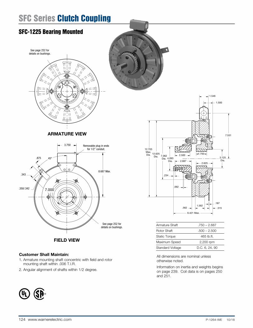
124 www.warnerelectric.com P-1264-WE 10/18
Armature Shaft .750 – 2.687
Rotor Shaft .500 – 2.500
Static Torque 465 lb.ft.
Maximum Speed 2,200 rpm
Standard Voltage D.C. 6, 24, 90
Customer Shall Maintain:1. Armature mounting shaft concentric with field and rotor
mounting shaft within .006 T.I.R.
2. Angular alignment of shafts within 1/2 degree.
ARMATURE VIEW
FIELD VIEW
7.531
1.500
1.546
.234
.062
.5621.562
.515
.187
12.625 Dia.
12.703 Max. Dia. 7.062
Dia. 4.093 Dia.
2.500 1.750
3.125 Dia.
2.6252.687
6.421 Max.
Removable plug in ends for 1/2” con duit.
8.687 Max..343
.875
.350/.342
45°
7.000
3.750
See page 252 for de tails on bush ings.
See page 252 for de tails on bush ings.
All dimensions are nominal unless otherwise noted.
Information on inertia and weights begins on page 239. Coil data is on pages 250 and 251.
SFC Series Clutch CouplingSFC-1225 Bearing Mounted

125P-1264-WE 10/18 www.warnerelectric.com
1
2
3
4-6
4-2
4-3
4-4
4(Shipped Assembled)
4-1
7
4-5
5-2
5-35-4
5-5
5-10
5-9
5-7
5-8
5-1
5-6
6
5(Shipped Assembled)
Drawing I-25623
How to Order:1. Specify Bore Size for Item 1.2. Specify Bore Size for Item 6.3. Specify Voltage for Item 5.4. See Controls Section.
Example:SFC-1225 Clutch Coupling per I-25623 - 90 Volt, 1” Bore
These units, when used in conjunction with the correct Warner Electric conduit box, meet the standards of UL508 and are listed under guide card #NMTR, file #59164.
These units are CSA certified under file #LR11543.
* See page 252 for specific part numbers.
Refer to Service Manual P-0207-WE
† Optional LK facing available. For more information, see page 232.
Item Description Part Number Qty.
1 Bushing* 1
3/4” to 2-11/16” Bore 180-0026 to 180-0057
2 Retainer Ring 748-0005 1
3 Splined Hub 540-0064 1
4 Armature & Splined Adapter 5203-111-001 1
4-1 Capscrew 797-0356 4
4-2 Splined Adapter 104-0010 1
4-3 Autogap Accessory 5323-101-002 1
4-4 Spacer 266-0004 4
4-5 Armature 5323-111-034 1
4-6 Locknut 661-0005 4
5 Field & Rotor Assembly 1
6 Volt 5203-452-009
24 Volt 5203-452-011
90 Volt 5203-452-012
5-1 Rotor 1
Standard Friction Material 5203-751-001
†Optional LK Facing 5203-751-004
5-2 Field 1
6 Volt 5203-451-034
24 Volt 5203-451-036
90 Volt 5203-451-037
5-3 Retainer Ring 748-0119 1
5-4 Ball Bearing 166-1047 1
Item Description Part Number Qty.
5-5 Retainer Ring 748-0011 1
5-6 Rotor Hub 540-1304 1
5-7 Ring Adapter 748-0591 1
5-8 Buttonhead Capscrew 797-1261 6
5-9 Lockwasher 950-0359 6
5-10 Sockethead Capscrew 797-0424 6
6 Bushing* 1
1/2” to 2-1/2” Bore 180-0185 to 180-0217
7 Conduit Box 5200-101-012 1
SFC Series Clutch CouplingSFC-1225 Bearing Mounted

126 www.warnerelectric.com P-1264-WE 10/18
ARMATURE VIEW
When Hub is Furnished by Customer:Rotor mounting pilot diameter must be concentric with rotor mounting shaft within .006 T.I.R.
Customer Shall Maintain:1. Concentricity of field mounting pilot diameter with rotor
mounting shaft within .006 T.I.R.2. Squareness of field mounting face with rotor mounting shaft
within .006 T.I.R. measured at field mounting bolt circle.3. Rotor mounting shaft concentric with armature mounting
shaft within .006 T.I.R.4. Angular alignment of shafts within 1/2 degree.
Armature Shaft .750 – 2.687
Rotor Shaft .937 – 3.000
Static Torque 700 lb.ft.
Maximum Speed 2,000 rpm
Standard Voltage D.C. 6, 24, 90
See page 252 for de tails on bush ings.
* Mounting holes are within .010 of true position relative to pilot diameter.
** Mounting holes are within .008 of true position relative to pilot diameter.FIELD VIEW
(Inside & Outside Mounted)
.234
.562
.437
.758
.7421.562
.062
.562
2 .218
5/16-18 UNC-3A
9.187
.921
1.546
15.671 Max. Dia. 15.578
Dia.8.750 Dia.
4.093 Dia.
2.500
2.6877.8787.876 Pilot Dia.
6.031 Max.
Removable plug in ends for 1/2” conduit.
.350/.341 dia. (8) holes equally spaced on 8.500 dia.**
.358/.338 dia. (12) holes equally spaced on 16.000 dia.*
9.002/9.000 Pilot Dia.
16.875/16.871 Pilot Dia.
3.750
10.343 Max.
.358/.338 dia. (12) holes equally spaced on 9.750 dia.*
All dimensions are nominal unless otherwise noted.
Information on inertia and weights begins on page 239. Coil data is on pages 250 and 251.
SFC Series Clutch CouplingSFC-1525 Flange Mounted

127P-1264-WE 10/18 www.warnerelectric.com
1
2
34-1
4-2
4-3
4-4
4-5
4(Shipped Assembled) 4-6
4-7
9A 11
11
9B
10B8
10A
76
5
Item Description Part Number Qty.
1 Bushing* 1
3/4” to 2-11/16” Bore 180-0026 to180-0057
2 Retainer Ring 748-0005 1
3 Splined Hub 540-0064 1
4 Armature & Splined Adapter 5204-111-004 1
4-1 Locknut 661-0004 8
4-2 Splined Adapter 104-0011 1
4-3 Autogap Accessory 5323-101-002 1
4-4 Retainer Plate 686-0003 1
4-5 Spacer 748-0333 8
4-6 Armature 5324-111-034 1
4-7 Screw 797-0342 8
5 Mounting Accessory 5321-101-002 2
6 Rotor 1
Standard Friction Material 5204-751-002
†Optional LK Facing 5204-751-004
7 Bushing* 1
15/16” to 3” Bore 180-0223 to 180-0256
8 Rotor Hub 540-0004 1
9A Field - Inside Mounted 1
6 Volt 5204-451-013
24 Volt 5204-451-015
90 Volt 5204-451-016
How to Order:1. Specify Bore Size for Item 1.2. Specify Bore Size for Item 7.3. Specify Voltage for Item 9A or 9B.4. Specify Inside Mounted for Items 9A and 10A or Outside
Mounted for Items 9B and 10B.5. See Con trols Section.
Example:SFC-1525 Clutch Coupling per I-25630 - 90 Volt, Inside Mounted, 1-1/2” Bore (Item 1), 1-3/4” Bore (Item 7).
These units, when used in conjunction with the correct Warner Electric conduit box, meet the standards of UL508 and are listed under guide card #NMTR, file #59164.
These units are CSA certified under file #LR11543.
* See page 252 for specific part numbers.
Refer to Service Manual P-0207-WE
† Optional LK facing available. For more information, see page 232.
Item Description Part Number Qty.
9B Field - Outside Mounted 1
6 Volt 5204-451-055
24 Volt 5204-451-056
90 Volt 5204-451-057
10A Mounting Accessory - I.M. 5321-101-001 2
10B Mounting Accessory - O.M. 5321-101-001 2
11 Conduit Box 5200-101-012 1
Drawing I-25630
SFC Series Clutch CouplingSFC-1525 Flange Mounted

128 www.warnerelectric.com P-1264-WE 10/18
Armature Shaft .750 – 2.687
Rotor Shaft .937 – 3.000
Static Torque 700 lb.ft.
Maximum Speed 1,800 rpm
Standard Voltage D.C. 6, 24, 90
Customer Shall Maintain:1. Armature mounting shaft concentric with field and rotor
mounting shaft within .006 T.I.R.
2. Angular alignment of shafts within 1/2 degree.
ARMATURE VIEW
FIELD VIEW
9.187
2.093
1.546
.234
.062
.5621.562
1.125
.187
15.578 Dia.
15.671 Max. Dia. 8.750
Dia. 4.093 Dia.
2.500 2.0003.968 Dia.
2.9372.687
7.187 Max.
Removable plug in ends for 1/2” con duit.
10.343 Max..343
.875
.350/.342
45°
8.531
3.750
See page 252 for de tails on bush ings.
See page 252 for de tails on bush ings.
All dimensions are nominal unless otherwise noted.
Information on inertia and weights begins on page 239. Coil data is on pages 250 and 251.
SFC Series Clutch CouplingSFC-1525 Bearing Mounted

129P-1264-WE 10/18 www.warnerelectric.com
Drawing I-25641
Item Description Part Number Qty.
1 Bushing* 1
3/4” to 2-11/16” Bore 180-0026 to 180-0057
2 Retainer Ring 748-0005 1
3 Splined Hub 540-0064 1
4 Armature & Splined Adapter 5204-111-004 1
4-1 Capscrew 797-0342 8
4-2 Splined Adapter 104-0011 1
4-3 Autogap Accessory 5323-101-002 1
4-4 Spacer 748-0333 8
4-5 Armature 5324-111-034 1
4-6 Locknut 661-0004 8
4-7 Retainer Plate 686-0003 1
5 Field & Rotor Assembly 1
6 Volt 5204-452-009
24 Volt 5204-452-011
90 Volt 5204-452-012
5-1 Rotor 1
Standard Friction Material 5204-751-002
†Optional LK Facing 5204-751-004
5-2 Field 1
6 Volt 5204-451-084
24 Volt 5204-451-086
90 Volt 5204-451-087
5-3 Retainer Ring 748-0114 1
5-4 Ball Bearing 166-0163 1
Item Description Part Number Qty.
5-5 Retainer Ring 748-0583 1
5-6 Rotor Hub 540-1306 1
5-7 Ring Adapter 748-1048 1
5-8 Buttonhead Capscrew 797-1261 8
5-9 Lockwasher 950-0359 6
5-10 Sockethead Capscrew 797-0424 6
6 Bushing* 1
15/16” to 3” Bore 180-0223 to 180-0256
7 Conduit Box 5200-101-012 1
How to Order:1. Specify Bore Size for Item 1.2. Specify Bore Size for Item 6.3. Specify Voltage for Item 5.4. See Controls Section.
Example:SFC-1525 Clutch Coupling per I-25641 - 90 Volt, 1” Bore
These units, when used in conjunction with the correct Warner Electric conduit box, meet the standards of UL508 and are listed under guide card #NMTR, file #59164. These units are CSA certified under file #LR11543.
* See page 252 for specific part numbers.
Refer to Service Manual P-0207-WE
† Optional LK facing available. For more information, see page 232.
SFC Series Clutch CouplingSFC-1525 Bearing Mounted

130 www.warnerelectric.com P-1264-WE 10/18
Armature Shaft .750 – 2.687
Rotor Shaft .937 – 3.000
Static Torque 1,350 lb.ft.
Maximum Speed 2,000 rpm
Standard Voltage D.C. 6, 90
Customer Shall Maintain:1. Concentricity of field mounting pilot diameter with rotor
mounting shaft within .006 T.I.R.
2. Squareness of field mounting face with rotor mounting shaft within .006 T.I.R. measured at field mounting bolt circle.
3. Rotor mounting shaft concentric with armature mounting shaft within .006 T.I.R.
4. Angular alignment of shafts within 1/2 degree.
When Hub is Furnished by Customer:Rotor mounting pilot diameter must be concentric with rotor mounting shaft within .006 T.I.R.
ARMATURE VIEW
See page 252 for de tails on bush ings.
* Mounting holes are within .010 of true position relative to pilot diameter.
** Mounting holes are within .008 of true position relative to pilot diameter.
FIELD VIEW
2 .218
.062
.5621.562
.437
.758/.742
.562 Max.
5/16-18 UNC-3A
9.187
.921
1.546
2.500
15.781 Max. Dia.
15.578 Dia.
8.750 Dia. 4.093
Dia. 2.687
7.8787.876 Pilot Dia.
.234
6.031 Max.
.350/.341 dia. (8) holesequally spaced on 8.500 dia.**
Removable plug in ends for 1/2” conduit.
9.002/9.000 Pilot Dia.10.343
3.750
.358/.338 dia. (12) holes equally spaced on
9.750 dia.
5/16-18 UNC-2B (2) holes equally spaced for removal of rotor from hub.
See page 252 for details on Bushings.
All dimensions are nominal unless otherwise noted.
Information on inertia and weights begins on page 239. Coil data is on pages 250 and 251.
SFC Series Clutch CouplingSFC-1525 HT Flange MountedHigh Torque

131P-1264-WE 10/18 www.warnerelectric.com
Drawing I-25631
1
2
3 4-1
4-2
4-3
4(Shipped Assembled)
4-4
4-5
4-64-7
119
10
8
76
5
Item Description Part Number Qty.
1 Bushing* 1
3/4” to 2-11/16” Bore 180-0026 to 180-0057
2 Retainer Ring 748-0005 1
3 Splined Hub 540-0064 1
4 Armature & Splined Adapter 5204-111-004 1
4-1 Locknut 661-0004 8
4-2 Splined Adapter 104-0011 1
4-3 Autogap Accessory 5323-101-002 1
4-4 Retainer Plate 686-0003 1
4-5 Spacer 748-0333 8
4-6 Armature 5324-111-034 1
4-7 Screw 797-0342 8
5 Mounting Accessory 5321-101-002 2
6 Rotor 5204-751-001 1
7 Bushing* 1
15/16” to 3” Bore 180-0223 to 180-0256
8 Rotor Hub 540-0004 1
Item Description Part Number Qty.
9 Field - Inside Mounted 1
6 Volt 5204-451-005
24 Volt 5204-451-066
90 Volt 5204-451-006
10 Mounting Accessory - I.M. 5321-101-001 2
11 Conduit Box 5200-101-012 1
How to Order:1. Specify Bore Size for Item 1.2. Specify Bore Size for Item 7.3. See Controls Section.
Example:SFC-1525 Clutch Coupling, Hi-Torque, per I-25631 - 90 Volt, 2” Bore (Item 1), 2-1/2” Bore (Item 7)
These units, when used in conjunction with the correct Warner Electric conduit box, meet the standards of UL508 and are listed under guide card #NMTR, file #59164. These units are CSA certified under file #LR11543.
* See page 252 for specific part numbers.
Refer to Service Manual P-0207-WE
SFC Series Clutch CouplingSFC-1525 HT Flange Mounted
High Torque

132 www.warnerelectric.com P-1264-WE 10/18
Armature Shaft .750 – 2.687
Rotor Shaft .937 – 3.000
Static Torque 1,350 lb.ft.
Maximum Speed 1,800 rpm
Standard Voltage D.C. 90
ARMATURE VIEW
Customer Shall Maintain:1. Armature mounting shaft concentric with field
and rotor mount ing shaft within .006 T.I.R.
2. Angular alignment of shafts within 1/2 degree.
FIELD VIEW
9.187
2.093
1.546
.062
.5621.562
.187
2.000
.234
1.125
7.187 Max.
15.671 Max. Dia.
15.578 Dia. 8.750
Dia. 4.093 Dia.
2.500
2.6872.937
3.968 Dia.
See page 252 for details on Bushings.
Removable plug in ends for 1/2” conduit.
45°
3.750
10.343 Max..343
.875
.350/.342
See page 252 for details on Bushings.
8.531
All dimensions are nominal unless otherwise noted.
Information on inertia and weights begins on page 239. Coil data is on pages 250 and 251.
SFC Series Clutch CouplingSFC-1525 HT Bearing MountedHigh Torque

133P-1264-WE 10/18 www.warnerelectric.com
Drawing I-25644
How to Order:1. Specify Bore Size for Item 1.2. Specify Bore Size for Item 6.3. Specify Voltage for Item 5.4. See Controls Section.
Example:SFC-1525 Clutch Coupling Hi-Torque per I-25644 - 90 Volt, 1” Bore
These units, when used in conjunction with the correct Warner Electric conduit box, meet the standards of UL508 and are listed under guide card #NMTR, file #59164. These units are CSA certified under file #LR11543.
* See page 252 for specific part numbers.
Refer to Service Manual P-0207-WE
1
2
3
4-1
4-2
4-3
4(Shipped Assembled)
4-4
4-6
4-5
5-5
5-4
5-37
5-105-9
5-2
5-7
5(Shipped Assembled)
5-85-1
5-6
6
Item Description Part Number Qty.
1 Bushing* 1
3/4” to 2-11/16” Bore 180-0026 to 180-0057
2 Retainer Ring 748-0005 1
3 Splined Hub 540-0064 1
4 Armature & Splined Adapter 5204-111-004 1
4-1 Capscrew 797-0342 8
4-2 Splined Adapter 104-0011 1
4-3 Autogap Accessory 5323-101-002 1
4-4 Spacer 748-0333 8
4-5 Armature 5324-111-034 1
4-6 Locknut 661-0004 8
4-7 Retainer Plate 686-0003 1
5 Field & Rotor Assembly 1
90 Volt 5204-452-015
5-1 Rotor 5204-751-001 1
5-2 Field 1
90 Volt 5204-451-090
5-3 Retainer Ring 748-0114 1
5-4 Ball Bearing 166-0163 1
5-5 Retainer Ring 748-0583 1
5-6 Rotor Hub 540-1306 1
5-7 Ring Adapter 748-1048 1
Item Description Part Number Qty.
5-8 Buttonhead Capscrew 797-1261 8
5-9 Lockwasher 950-0359 6
5-10 Sockethead Capscrew 797-0424 6
6 Bushing* 1
15/16” to 3” Bore 180-0223 to 180-0256
7 Conduit Box 5200-101-012 1
SFC Series Clutch CouplingSFC-1525 HT Bearing Mounted
High Torque

134 www.warnerelectric.com P-1264-WE 10/18
Customer Shall Maintain:1. Armature mounting shaft concentric with magnet mounting
shaft within .006 T.I.R.
Armature Shaft .500 – 1.250
Magnet Shaft .500 – 1.250
Static Torque 40 lb.ft.
Maximum Speed 5,400 rpm
Standard Voltage D.C. 6, 24, 90
COLLECTOR RING VIEW
HUB VIEW
.171
4
.062 when new
.062Min. running
clearance
3.578
5.937 Max.
5 Dia. 1.50 Max. 1.343 1.50
4.406
1.187 1.375
.453
1/2-14 NPSM Am. std. straight pipe tap.
See page 252 for details on Bush ings.
See page 252 for details on Bush ings.
All dimensions are nominal unless otherwise noted.
Information on inertia and weights begins on page 239. Coil data is on pages 250 and 251.
PCC Series Clutch CouplingPCC-500 Normal Duty

135P-1264-WE 10/18 www.warnerelectric.com
Drawing I-25542
How to Order:1. Specify Bore Size for Item 5 (two shafts).2. Specify Voltage for Item 7.3. See Controls Section.
Example: PCC-500 Clutch Coupling per I-25542 - 90 Volt, 3/4” Bore
These units meet standards set forth in UL508 and are listed under guide card #NMTR2, file #59164.
These units are CSA certified under file #LR11543
* See page 252 for specific part numbers.
Refer to Service Manual P-0203-WE
4
4-1
3-1
3-2
3 (Shipped
Assembled)
5
6-1
6
8
7
2
5
1
Item Description Part Number Qty.
1 Armature Hub 5300-541-004 1
2 Armature 5300-111-002 1
3 Magnet Hub 5300-541-001 1
3-1 Collector Ring 5300-749-001 1
3-2 Collector Ring Mounting Accessory 5300-101-002 1
4 Brushholder 5300-178-001 1
4-1 Brush 176-0001 4
5 Bushing* 2
1/2” to 1-1/4” Bore 180-0116 to 180-0128
6 Magnet
6 Volt 5300-631-002
24 Volt 5300-631-003
90 Volt 5300-631-005
6-1 Terminal Accessory 5311-101-001 1
7 Autogap Accessory 5200-101-009 3
Item Description Part Number Qty.
8 Mounting Accessory 5102-101-001 2
PCC Series Clutch CouplingPCC-500 Normal Duty

136 www.warnerelectric.com P-1264-WE 10/18
Bore & Keyway Dimensions
Armature Bore Dia. Keyway
.751/.750 .187 x .093 .876/.875
.9385/.9375 1.001/1.000 .250 x .125 1.126/1.125 1.251/1.250
Customer Shall Maintain:1. Armature mounting shaft concentric with magnet mounting
shaft within .006 T.I.R.
COLLECTOR RING VIEW
ARMATURE VIEW1.203 Max.
4
.171
.062 when new
.171
3.703
1.187 1.375.375
1.500
5.125 Dia.
5.937 Max.
2.953
1/2-14 NPSM Am. std. straight pipe tap.
See page 252 for details on Bushings.
For Bore & Keyway sizes see chart below.
Armature Shaft .750 – 1.250
Magnet Shaft .500 – 1.250
Static Torque 40 lb.ft.
Maximum Speed 5,400 rpm
Standard Voltage D.C. 6, 24, 90
All dimensions are nominal unless otherwise noted.
Information on inertia and weights begins on page 239. Coil data is on pages 250 and 251.
PCC Series Clutch CouplingPCC-500 Heavy Duty

137P-1264-WE 10/18 www.warnerelectric.com
Drawing I-25543
How to Order:1. Specify Bore Size for Item 1 and Item 5.2. Specify Voltage for Item 6.3. See Controls Section.
Example:PCC-500 Clutch Coupling per I-25543 - 90 Volt, 3/4” Armature Hub Bore, 1” Bushing Bore
These units meet standards set forth in UL508 and are listed under guide card #NMTR2, file #59164.
These units are CSA certified under file #LR11543.
* See page 252 for specific part numbers.
Refer to Service Manual P-0203-WE
2(Shipped Assembled) 2-1
2-3
2-4
2-5
2-2
1
4
4-1
3-13-2
5
3(Shipped Assembled)
6
6-1
7
Item Description Part Number Qty.
1 Armature Hub 1
3/4” Bore 5200-541-002
7/8” Bore 5200-541-003
15/16” Bore 5200-541-004
1” Bore 5200-541-005
1-1/8” Bore 5200-541-006
1-1/4” Bore 5200-541-007
2 Armature Assembly 5230-111-002 1
2-1 Armature 5230-111-001 1
2-2 Retainer Ring 748-0355 1
2-3 Autogap Spring 808-0412 1
2-4 Retainer Plate 748-0364 1
2-5 Screw 797-0028 3
3 Magnet Hub 5300-541-001 1
3-1 Collector Ring 5300-749-001 1
3-2 Collector Ring Mounting Acc. 5300-101-002 1
4 Brushholder 5300-178-001 1
4-1 Brush 176-0001 4
5 Bushing* 2
1/2” to 1-1/4” Bore 180-0116 to 180-0128
Item Description Part Number Qty.
6 Magnet 1
6 Volt 5300-631-002
24 Volt 5300-631-003
90 Volt 5300-631-005
6-1 Terminal Accessory 5311-101-001 1
7 Mounting Accessory 5102-101-001 2
PCC Series Clutch CouplingPCC-500 Heavy Duty

138 www.warnerelectric.com P-1264-WE 10/18
Armature Shaft .500 – 1.500
Magnet Shaft .500 – 1.625
Static Torque 125 lb.ft.
Maximum Speed 4,000 rpm
Standard Voltage D.C. 6, 24, 90
ARMATURE VIEW
Customer Shall Maintain:1. Armature mounting shaft concentric with magnet
mounting shaft within .006 T.I.R.
2. Angular alignment of shafts within 1/2 degree.
COLLECTOR RING VIEW
8.625 Dia.
2.500 Dia.
7.781 Dia.
.156
1.250
5.750
.171 Max.2.531
.062
4.250 Max.
.062Min. Running
Clear ance
1.312 1.437.531
9.437 Max. Dia.
1.765
1.593
1.500
See page 252 for details on Bushings.
See page 252 for details on Bushings.
1/2-14 NPSM Am. std. straight pipe tap.
All dimensions are nominal unless otherwise noted.
Information on inertia and weights begins on page 239. Coil data is on pages 250 and 251.
PCC Series Clutch CouplingPCC-825

139P-1264-WE 10/18 www.warnerelectric.com
Drawing I-25565
How to Order:1. Specify Bore Size for Item 1.2. Specify Voltage for Item 6.3. Specify left hand or right hand hub for Item 7. (Bushing
enters from magnet side for L.H. hub and from hub side for R.H.)
4. Specify Bore Size for Item 8.5. See Con trols Section.
Example: PCC-825 Clutch Coupling per I-25565 - 90 Volt, L.H. hub, 1” Bore (Item 1), 1-1/2” Bore (Item 8)
These units meet the standards of UL508 and are listed under guide card #NMTR2, file #59164.
These units are CSA certified under file #LR11543
* See page 252 for specific part numbers.
Refer to Service Manual P-0206-WE
† Optional LK facing available. For more information, see page 232.
4(Shipped Assembled)
4-5
4-3
4-2
4-1
4-4
3
2
1
6-1
9
9-1
7-2
7-1
7(Shipped Assembled)
86
8
5
Item Description Part Number Qty.
1 Bushing* 1
1/2” to 1-1/2” Bore 180-0002 to 180-0018
2 Retainer Ring 748-0006 1
3 Splined Hub 540-0057 1
4 Armature & Splined Adapter 5321-111-001 1
4-1 Locknut 661-0004 3
4-2 Armature 5321-111-022 1
4-3 Splined Adapter 104-0008 1
4-4 Autogap Accessory 5321-101-006 1
4-5 Screw 797-0272 3
5 Mounting Accessory 5321-101-001 1
6 Magnet 1
6 Volt 5301-631-002
24 Volt 5301-631-004
90 Volt 5301-631-005
†90 Volt Optional LK Facing 5301-631-011
6-1 Terminal Accessory 5311-101-001 1
7 Magnet Hub 1
Left Hand (shown) 5301-541-001
Right Hand 5301-541-002
7-1 Collector Ring 5301-749-001 1
7-2 Collector Ring Accessory 5301-101-002 1
8 Bushing* 1
1/2” to 1-5/8” Bore 180-0131 to 180-0149
Item Description Part Number Qty.
9 Brushholder 5300-178-001 1
9-1 Brush 176-0001 4
PCC Series Clutch CouplingPCC-825

140 www.warnerelectric.com P-1264-WE 10/18
Armature Shaft .750 – 2.687
Magnet Shaft .500 – 2.500
Static Torque 240 lb.ft.
Maximum Speed 3,600 rpm
Standard Voltage D.C. 6, 24, 90
ARMATURE VIEW
Customer Shall Maintain:1. Armature mounting shaft concentric with magnet
mounting shaft within .006 T.I.R.
2. Angular alignment of shafts within 1/2 degree.
COLLECTOR RING VIEW
See page 252 for details on Bushings.
See page 252 for details on Bushings.
1/2-14 NPSM Am. std. straight pipe tap.
7.781 Dia.
.234
5.750
.062
.500
.062
.171 Max.
Min. Running Clearance
5.718 Max.
1.453 1.750
11.093 Max. Dia.
10.296 Dia.
4.093 Dia.
2.500 1.750
2.687 1.906
2.875
All dimensions are nominal unless otherwise noted.
Information on inertia and weights begins on page 239. Coil data is on pages 250 and 251.
PCC Series Clutch CouplingPCC-1000

141P-1264-WE 10/18 www.warnerelectric.com
Drawing I-25585
How to Order:1. Specify Bore Size for Item 1.2. Specify Voltage for Item 6.3. Specify left hand or right hand hub for Item 7. (Bushing
enters from magnet side for L.H. hub and from hub side for R.H.)
4. Specify Bore Size for Item 8.5. See Con trols Section.
Example: PCC-1000 Clutch Coupling per I-25585 - 90 Volt, L.H. hub, 1-1/2” Bore (Item 1), 2” Bore (Item 8)
These units meet the standards of UL508 and are listed under guide card #NMTR2, file #59164.
These units are CSA certified under file #LR11543
* See page 252 for specific part numbers.
Refer to Service Manual P-0206-WE
† Optional LK facing available. For more information, see page 232.
Item Description Part Number Qty.
1 Bushing* 1
3/4” to 2-11/16” Bore 180-0026 to 180-0057
2 Retainer Ring 748-0007 1
3 Splined Hub 540-0062 1
4 Armature & Splined Adapter 5322-111-002 1
4-1 Locknut 661-0004 3
4-2 Armature 5322-111-036 1
4-3 Splined Adapter 104-0009 1
4-4 Autogap Accessory 5322-101-004 1
4-5 Screw 797-0272 3
5 Mounting Accessory 5321-101-001 1
6 Magnet 1
6 Volt 5302-631-003
24 Volt 5302-631-014
90 Volt 5302-631-005
†90 Volt Optional LK Facing 5302-631-001
6-1 Terminal Accessory 5311-101-001 1
7 Magnet Hub 1
Left Hand (shown) 5302-541-001
Right Hand 5302-541-002
7-1 Collector Ring 5301-749-001 1
7-2 Collector Ring Accessory 5302-101-002 1
Item Description Part Number Qty.
8 Bushing* 1
1/2” to 2-1/2” Bore 180-0185 to 180-0217
9 Brushholder 5300-178-001 1
9-1 Brush 176-0001 4
4(Shipped Assembled)
4-5
4-3
4-2
4-1
4-4
3
2
1
6-1
9
9-1
7-2
7-1
7(Shipped Assembled)
86
8
5
PCC Series Clutch CouplingPCC-1000
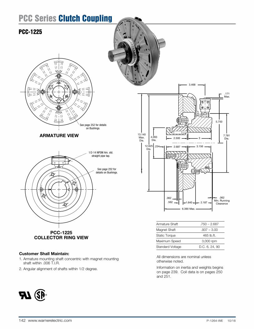
142 www.warnerelectric.com P-1264-WE 10/18
Armature Shaft .750 – 2.687
Magnet Shaft .937 – 3.00
Static Torque 465 lb.ft.
Maximum Speed 3,000 rpm
Standard Voltage D.C. 6, 24, 90
Customer Shall Maintain:1. Armature mounting shaft concentric with magnet mounting
shaft within .006 T.I.R.
2. Angular alignment of shafts within 1/2 degree.
PCC-1225 COLLECTOR RING VIEW
ARMATURE VIEW
.234
3
5.750
.171 Max.
.562
.062 .062 Min. Running
Clearance
6.390 Max.
2.1871.640
2.687
2.500
3.156
7.781 Dia.
3.468
13.140 Max. Dia.
4.093 Dia.
12.625 Dia.
See page 252 for details on Bushings.
1/2-14 NPSM Am. std. straight pipe tap.
See page 252 for details on Bushings.
All dimensions are nominal unless otherwise noted.
Information on inertia and weights begins on page 239. Coil data is on pages 250 and 251.
PCC Series Clutch CouplingPCC-1225

143P-1264-WE 10/18 www.warnerelectric.com
Drawing I-25605
4(Shipped
Assembled) 4-5
4-6
4-4
4-3
4-2
4-1
1
2
3
9
9-1
7-2
7-1
8
7(Shipped
Assembled)
6-1
6
5
4(Shipped
Assembled)
4-5
4-3
4-2
4-1
1
2
3
4-4
9
9-1
7-2
7-1
7(Shipped
Assembled)
86-1
6
5
How to Order:1. Specify Bore Size for Item 1.2. Specify Voltage for Item 6.3. Specify left hand or right hand hub for Item 7. (Bushing
enters from magnet side for L.H. hub and from hub side for R.H.)
4. Specify Bore Size for Item 8.5. See Controls Section.
Example:PCC-1225 Clutch Coupling per I-25605 - 90 Volt, L.H. hub, 1-1/2” Bore (Item 1), 2” Bore (Item 8)
These units meet the standards of UL508 and are listed under guide card #NMTR2, file #59164.
These units are CSA certified under file #LR11543.
* See page 252 for specific part numbers.
Refer to Service Manual P-0206-WE
† Optional LK facing available. For more information, see page 232.
Item Description Part Number Qty.
1 Bushing* 1
3/4” to 2-11/16” Bore 180-0026 to 180-0057
2 Retainer Ring 748-0005 1
3 Splined Hub 540-0064 1
4 Armature & Splined Adapter 5323-111-001 1
4-1 Locknut 661-0005 4
4-2 Armature 5323-111-034 1
4-3 Splined Adapter 104-0010 1
4-4 Autogap Accessory 5323-101-002 1
4-5 Screw 797-0281 4
5 Mounting Accessory 5321-101-001 1
6 Magnet 1
6 Volt 5303-631-005
24 Volt 5303-631-007
90 Volt 5303-631-008
†90 Volt Optional LK Facing 5303-631-001
6-1 Terminal Accessory 5311-101-001 1
7 Magnet Hub 1
Left Hand (shown) 5303-541-001
Right Hand 5303-541-002
7-1 Collector Ring 5301-749-001 1
7-2 Collector Ring Accessory 5303-101-004 1
Item Description Part Number Qty.
8 Bushing* 1
15/16” to 3” Bore 180-0262 to 180-0295
9 Brushholder 5300-178-001 1
9-1 Brush 176-0001 4
PCC Series Clutch CouplingPCC-1225

144 www.warnerelectric.com P-1264-WE 10/18
Armature Shaft .750 – 2.687
Magnet Shaft .937 – 3.00
Static Torque 700 lb.ft.
Maximum Speed 2,000 rpm
Standard Voltage D.C. 6, 24, 90
Customer Shall Maintain:1. Armature mounting shaft concentric with magnet mounting
shaft within .006 T.I.R.
2. Angular alignment of shafts within 1/2 degree.
ARMATURE VIEW
PCC-1525 COLLECTOR RING VIEW
.234
3
5.750
.171 Max.
.562
.062 .062 Min. Running
Clearance
6.609 Max.
2.3121.750
2.687
2.500
3.187
7.781 Dia.
3.781
16.250 Max. Dia.
4.093 Dia.
15.578 Dia.
See page 252 for details on Bushings.
See page 252 for details on Bushings.
1/2-14 NPSM Am. std. straight pipe tap.
All dimensions are nominal unless otherwise noted.
Information on inertia and weights begins on page 239. Coil data is on pages 250 and 251.
PCC Series Clutch CouplingPCC-1525

145P-1264-WE 10/18 www.warnerelectric.com
Drawing I-25632
How to Order:1. Specify Bore Size for Item 1.2. Specify Voltage for Item 6.3. Specify left hand or right hand hub for Item 7. (Bushing
enters from magnet side for L.H. hub and from hub side for R.H.)
4. Specify Bore Size for Item 8.5. See Con trols Section.
Example: PCC-1525 Clutch Coupling per I-25632 - 90 Volt, L.H. hub, 1-1/2” Bore (Item 1), 2” Bore (Item 8)
These units meet the standardsof UL508 and are listed under guide card #NMTR2, file #59164.
These units are CSA certified under file #LR11543.
* See page 252 for specific part numbers.
Refer to Service Manual P-0206-WE
† Optional LK facing available. For more information, see page 232.
4(Shipped
Assembled) 4-5
4-6
4-4
4-3
4-2
4-1
1
2
3
9
9-1
7-2
7-1
8
7(Shipped
Assembled)
6-1
6
5
4(Shipped
Assembled)
4-5
4-3
4-2
4-1
1
2
3
4-4
9
9-1
7-2
7-1
7(Shipped
Assembled)
86-1
6
5
Item Description Part Number Qty.
8 Bushing* 1
15/16” to 3” Bore 180-0262 to 180-0295
9 Brushholder 5300-178-001 1
9-1 Brush 176-0001 4
Item Description Part Number Qty.
1 Bushing* 1
3/4” to 2-11/16” Bore 180-0026 to 180-0057
2 Retainer Ring 748-0005 1
3 Splined Hub 540-0064 1
4 Armature & Splined Adapter 5324-111-001 1
4-1 Locknut 661-0004 8
4-2 Armature 5324-111-034 1
4-3 Splined Adapter 104-0011 1
4-4 Autogap Accessory 5323-101-002 1
4-5 Retainer Plate 686-0003 1
4-6 Screw 797-0272 8
5 Mounting Accessory 5321-101-001 2
6 Magnet 1
6 Volt 5304-631-009
24 Volt 5304-631-011
90 Volt 5304-631-010
†90 Volt Optional LK Facing 5304-631-002
6-1 Terminal Accessory 5311-101-001 1
7 Magnet Hub 1
Left Hand (shown) 5304-541-001
Right Hand 5304-541-002
7-1 Collector Ring 5301-749-001 1
7-2 Collector Ring Accessory 5304-101-004 1
PCC Series Clutch CouplingPCC-1525

146 www.warnerelectric.com P-1264-WE 10/18
Static Torque 5 lb.in.
Maximum Speed 10,000 rpm
Standard Voltage D.C. 6, 24, 90
ARMATURE VIEW
MAGNET VIEW
Customer Shall Maintain:1. Concentricity of brake mounting pilot diameter with
armature shaft within .003 T.I.R.
2. Squareness of brake mounting face with armature shaft within .003 T.I.R.
Bore Di men sions
Armature Bore Dia.
.188/.187 .251/.250 (.313/.312)*
*(Antibacklash Armatures)
Antibacklash Arm.
Std. Arm.
For Bore sizes see chart below.
45°
1.499/1.497 Pilot Dia.
.130/.123 dia. (4) holes equally spaced
on 1.312 dia. Mounting holes are within .006 of true position relative to
pilot diameter.
1.125 Max. Sq.
.109 (Std.).140 (Anti.)
.015 When New
.072 (Std.).072 (Anti.) 12
.375 Dia.
#4-40 UNC-3A
.187 Max.
.062
.500
Anti Arm.
.015 Nom.
.072 (Std.).072 (Anti.)
Std. Arm.
.562
1.234 Max. Dia.
.312
.968 Max.
.343
.625
All dimensions are nominal unless otherwise noted.
Information on inertia and weights begins on page 239. Coil data is on pages 250 and 251.
PB Series BrakePB-120

147P-1264-WE 10/18 www.warnerelectric.com
1B
3
2
1A
1A-1
1A-2
Drawing I-25507
Item Description Part Number Qty.
1A Armature and Hub
1A-1 Armature Hub 1
3/16” Bore 5622-541-009
1/4” Bore 5622-541-008
1A-2 Armature 110-0110 1
1B Antibacklash Armature 1
3/16” Bore 5622-111-004
1/4” Bore 5622-111-002
5/16” Bore 5622-111-003
2 Mounting Accessory 5101-101-001 1
3 Magnet 1
6 Volt 5373-631-003
24 Volt 5373-631-005
90 Volt 5373-631-007
How to Order:1. Specify Type of Armature Desired.2. Specify Bore Size for Item 1A-1 or 1B.3. Specify Voltage for Item 3.4. See Controls Section.
Example:PB-120 Brake per I-25507 - 90 Volt, Standard Armature 3/16” Hub Bore
These units meet the standards of UL508 and are listed under guide card #NMTR, file #59164.
These units are CSA certified under file #LR11543.
Refer to Service Manual P-0201-WE
PB Series BrakePB-120

148 www.warnerelectric.com P-1264-WE 10/18
Static Torque 15 lb.in.
Maximum Speed 10,000 rpm
Standard Voltage D.C. 6, 24, 90
Bore Di men sions Armature Bore Dia.
.251/.250 .313/.312 .376/.375
Customer Shall Maintain:1. Squareness of brake mounting face with armature shaft within
.006 T.I.R.
2. Concentricity of brake mounting pilot diameter with armature shaft within .010 T.I.R.
ARMATURE VIEW
MAGNET VIEW
.062
.437 Max.
#8-32 UNC-3A
.752/.750 Pilot Dia.
.015 When New
.125 (Std.)
.109 (Anti)
.625
.086 (Std.).094 (Anti.)
.015
Std. Arm.
Anti. Arm..843
.086 (Std.).094 (Anti.)
1.375 Max.
.812
.515
1.718 Max. Dia.
12 Min.
.390Antibacklash Arm.
Std. Arm.
For Bore sizes see chart below.
45°
.204/.187 dia. (4) holes equally spaced on 2.125 dia.
Mount ing holes are within .010 of true position relative to pilot diameter.
2.437/2.435 Pilot Dia.
1.812 Max. Sq.
All dimensions are nominal unless otherwise noted.
Information on inertia and weights begins on page 239. Coil data is on pages 250 and 251.
PB Series BrakePB-170

149P-1264-WE 10/18 www.warnerelectric.com
Drawing I-25753
3
1A-3
2
1B
1A-1
1A-21A
How to Order:1. Specify Type of Armature Desired.2. Specify Bore Size for Item 1A-1 or 1B.3. Specify Voltage for Item 3.4. See Controls Section.
Example: PB-170 Brake per I-25753 - 90 Volt, Antibacklash Armature, 1/4” Armature Hub Bore
These units meet the standards of UL508 and are listed under guide card #NMTR2, file #59164.
These units are CSA certified under file #LR11543.
Refer to Service Manual P-0201-WE
Item Description Part Number Qty.
1A Armature and Hub
1A-1 Armature Hub 1
1/4” Bore 5102-541-002
5/16” Bore 5102-541-003
3/8” Bore 5102-541-004
1A-2 Armature 110-0111 1
1A-3 Release Spring 808-0019 1
1B Antibacklash Armature 1
1/4” Bore 5623-111-008
5/16” Bore 5623-111-009
3/8” Bore 5623-111-010
2 Mounting Accessory 5102-101-001 1
3 Magnet 1
6 Volt 5375-631-003
24 Volt 5375-631-005
90 Volt 5375-631-007
PB Series BrakePB-170

150 www.warnerelectric.com P-1264-WE 10/18
Static Torque 70 lb.in.
Maximum Speed 7,500 rpm
Standard Voltage D.C. 6, 24, 90
Customer Shall Maintain:1. Squareness of brake mounting face with armature hub shaft
within .006 T.I.R.
2. Concentricity of brake mounting pilot diameter with armature shaft within .010 T.I.R.
Bore and Keyway Dimensions
Armature Keyway Bore Dia.
.376/.375 .093 x .046
.438/.437* .501/.500 .125 x .062 .563/.562*
.626/.625 .688/.687* .187 x .093 .751/.750
* Available on special order only.
ARMATURE VIEW
FIELD VIEW
1.0631.061
Pilot Dia.
Anti. Arm.
.062
.171 (Std.).187 (Anti.)
.687 (Std.).718 (Anti.) .437
Max.
#8-32 UNC-3A
.203 Min.
1.187
.015 When New
.343 Max.
K
Std. Arm.
1.390
2.625 Max. Dia.
1.250
1.078
.718
1.968 (Std.)1.984 (Anti.)
Antibacklash Arm.
Std. Arm.
For Bore & Keyway sizes see chart below.
45°
24°
.437 Max.
12°
.437 Max.
3.500/3.498 Pi lot Dia.
2.625 Sq.
.204/1.87 dia. (4) holes equally spaced on 3.125 dia.Mounting holes are within .010 of true po si tion relative
to pilot diameter.
All dimensions are nominal unless otherwise noted.
Information on inertia and weights begins on page 239. Coil data is on pages 250 and 251.
PB Series BrakePB-250 Flange Mounted

151P-1264-WE 10/18 www.warnerelectric.com
Drawing I-25519
How to Order:1. Specify Type of Armature Desired.2. Specify Bore Size for Item 1A-1 and 1-B.3. Specify Voltage for Item 2.4. See Controls Section.
Example:PB-250 Brake per I-25519 - 90 Volt, Standard Armature, 1/2” Armature Hub Bore
These units meet the standards of UL508 and are listed under guide card #NMTR2, file #59164.
These units are CSA certified under file #LR11543.
Refer to Service Manual P-0201-WE
1A 1A-3
1A-2
1A-1
2
3
1B
2-1
Item Description Part Number Qty.
1A Armature and Hub
1A-1 Armature Hub 1
3/8” Bore 5103-541-002
7/16” Bore 5103-541-003
1/2” Bore 5103-541-004
5/8” Bore 5103-541-006
11/16” Bore 5103-541-007
3/4” Bore 5103-541-008
1A-2 Release Spring 5103-101-003 1
1A-3 Armature 5124-111-001 1
1B Antibacklash Armature 1
3/8” Bore 5365-111-003
1/2” Bore 5365-111-005
5/8” Bore 5365-111-007
3/4” Bore 5365-111-009
2 Magnet 1
6 Volt 5319-631-002
24 Volt 5319-631-003
90 Volt 5319-631-005
Item Description Part Number Qty.
2-1 Terminal Accessory 5103-101-002 1
3 Mounting Accessory 5102-101-001 1
PB Series BrakePB-250 Flange Mounted

152 www.warnerelectric.com P-1264-WE 10/18
Static Torque 270 lb.in.
Maximum Speed 4,500 rpm
Standard Voltage D.C. 6, 24, 90
ARMATURE VIEW
Customer Shall Maintain:1. Squareness of brake mounting face with armature hub
shaft within .006 T.I.R.
2. Concentricity of brake mounting pilot diameter with armature shaft within .010 T.I.R.
Bore and Keyway Dimensions Armature Keyway Bore Dia.
.501/.500 .125 x .062 .563/.562*
.626/.625 .688/.687* .751/.750 .187 x .093 .876/.875
* Available on special order only.
Antibacklash Arm.
Std. Arm.
Removable plug in ends for 1/2” conduit.
4.687 Max.
45°
5.625/5.623 Pilot Dia.
.296/.280 dia. (4) holes equally spaced on 5.000 dia.Mounting holes are within .010 of true position relative to
pilot diameter.
4.250 Sq.
3.750
.015 When New
1/4-20 UNC-3A
1.250
1.8751.873
Pilot Dia.
.093
.328 Max.
.187 (Std.).218 (Anti.)
K
.343
.609 Max.
3.562
Anti. Arm.
.875 (Std.).843 (Anti.)
Std. Arm.
1.640
1.546
.953
4.234 Max. Dia.
2.328 (Std.)2.359 (Anti.)
1.500
1.312
FIELD VIEW
All dimensions are nominal unless otherwise noted.
Information on inertia and weights begins on page 239. Coil data is on pages 250 and 251.
PB Series BrakePB-400 Flange Mounted
For Bore & Keyway sizes see chart below.

153P-1264-WE 10/18 www.warnerelectric.com
Drawing I-25694
How to Order:1. Specify Type of Armature Desired.2. Specify Bore Size for Item 1A-1 or 1B.3. Specify Voltage for Item 2.4. See Controls Section.Example:PB-400 Brake per I-25694 - 90 Volt, Antibacklash Armature 3/4” Armature Hub Bore
These units meet standards set forth in UL508 and are listed under guide card #NMTR, file #59164. These units are CSA certified under file #LR11543.
3
2
4
2-1
1A-2
1A-3
1A
1B
1A-1
Item Description Part Number Qty.
1A Armature and Hub
1A-1 Armature Hub 1
1/2” Bore 5104-541-002
5/8” Bore 5104-541-004
3/4” Bore 5104-541-006
7/8” Bore 5104-541-007
1A-2 Armature 5125-111-001 1
1A-3 Release Spring 5104-101-003 1
1B Antibacklash Armature 1
1/2” Bore 5367-111-003
5/8” Bore 5367-111-005
3/4” Bore 5367-111-007
7/8” Bore 5367-111-008
2 Magnet 1
6 Volt 5115-631-002
24 Volt 5115-631-003
90 Volt 5115-631-004
Item Description Part Number Qty.
2-1 Terminal Accessory 5103-101-002 1
3 Conduit Box 5200-101-010 1
4 Mounting Accessory 5104-101-002 1
Refer to Service Manual P-0201-WE
PB Series BrakePB-400 Flange Mounted

154 www.warnerelectric.com P-1264-WE 10/18
Static Torque 40 lb.ft.
Maximum Speed 5,400 rpm
Standard Voltage D.C. 6, 24, 90
HUB VIEW
Customer Shall Maintain:1. Squareness of brake mounting face with
armature hub shaft within .006 T.I.R.
2. Concentricity of brake mounting pilot di am e ter with armature hub shaft within .010 T.I.R
* Mounting holes are within .010 of true position relative to pilot diameter.
** Mounting holes are within .008 of true position relative to pilot diameter.
MAGNET VIEW(Inside & Outside Mounted)
Outside Mounted Offset Backing Plate
Outside Mounted Flush Backing Plate
See page 252 for details on Bushings.
5 Sq.
6.5006.498
Removable plug in ends for 1/2” conduit.
.208/.201 dia. (8) holes equally spaced on
2.375 dia.*
.399/.389 dia. (4) holes equally spaced on 5.875 dia.**
5.062 Max.
45°
3.750
3.953
.062 When New
5.078 Dia. 2.0652.063
Pilot Dia.
.390 Max.
8-32 UNC-3A
1.062 Min. Running
Clearance .515 Max.
3/8-16 UNC-2A
1.500 1.546
1.468 2.687 Dia.
3.015 Max.
1.546
1.093
1.031
1.187
3.109 Max.1.281
.468 Max.
1.390
1.125
.953
2.937 Max.
All dimensions are nominal unless otherwise noted.
Information on inertia and weights begins on page 239. Coil data is on pages 250 and 251.
PB Series BrakePB-500 Normal Duty

155P-1264-WE 10/18 www.warnerelectric.com
3
2
1
7
6
5A
4A
5A-1
6
5B-15C-1
5B5C
4B
Drawing I-25544
How to Order:1. Specify Bore Size for Item 7.2. Specify Voltage for Item 5A, 5B, or 5C.3. Specify Inside Mounted for Item 5A and Outside
Mounted (Offset) for Item 5B or Outside Mounted (Flush) for Item 5C.
4. See Controls Section.
Example:PB-500 Brake per I-25544 - 90 Volt, Inside Mounted, 3/4” Bore
These units, when used in conjunction with the correct Warner Electric conduit box, meet the standards of UL508 and are listed under guide card #NMTR, file #59164. These units are CSA certified under file #LR11543.
* See page 252 for specific part numbers.
Refer to Service Manual P-0204-WE
† Optional LK facing available. For more information, see page 232.
Item Description Part Number Qty.
1 Armature Hub 1
Standard Hub 5300-541-004
Optional Bronze Bushings 5300-541-014
2 Armature 1
Segmented-Standard 5300-111-002
Solid 110-0241
3 Autogap Accessory 5200-101-009 3
4A Mounting Accessory - I.M. 5102-101-001 2
4B Mounting Accessory - O.M. 5300-101-008 1
5A Magnet - I.M. 1
6 Volt 5300-631-002
24 Volt 5300-631-003
90 Volt 5300-631-005
†90 Volt LK Facing 5300-631-020
5A-1 Terminal Accessory 5311-101-001 1
5B Magnet - O.M. - Offset 1
90 Volt 5300-631-014
5B-1 Terminal Accessory 5311-101-001 1
5C Magnet - O.M. - Flush 1
6 Volt 5300-631-009
24 Volt 5300-631-010
90 Volt 5300-631-011
†90 Volt LK Facing 5300-631-025
Item Description Part Number Qty.
5C-1 Terminal Accessory 5311-101-001 1
6 Conduit Box 5200-101-010 1
7 Bushing* 1
1/2” to 1-1/4” Bore 180-0116 to 180-0128
PB Series BrakePB-500 Normal Duty

156 www.warnerelectric.com P-1264-WE 10/18
Static Torque 40 lb.ft.
Maximum Speed 5,400 rpm
Standard Voltage D.C. 6, 24, 90
Outside Mounted Offset Backing Plate
Customer Shall Maintain:1. Squareness of brake mounting face with armature hub shaft
within .006 T.I.R.
2. Concentricity of brake mounting pilot diameter with ar ma ture hub shaft within .010 T.I.R.
Bore and Keyway Dimensions
Armature Keyway Bore Dia.
.751/.750 .187 x .093 .876/.875
.9385/.9375 1.001/1.000 1.126/1.125 .250 x .125 1.251/1.250
* Mounting holes are within .010 of true position relative to pilot diameter.
** Mounting holes are within .008 of true position relative to pilot diameter.
MAGNET VIEW(Inside & Outside Mounted)
ARMATURE VIEW
Outside Mounted Flush Backing Plate
5.140 Dia.
3.953
.515 Max.
8-32 UNC-3A
.390 Max.
3/8-16 UNC-2A
.062 When New
2.312 Max.
1.546
1.031
1.187
1.093
1.1711.203
.171 Max.
2.687 Dia.
2.0652.063
Pilot Dia.
1.281
2.390 Max.
.375
1.093
3.750
.208/.201 dia. (8) holes equally spaced on 2.375 dia.*
5.062
Removable plug in ends for 1/2”
conduit.
45°5 Sq.
6.5006.498
.399/.389 dia. (4) holes equally spaced on 5.875 dia.**
For Bore & Keyway sizes see chart below.
.468 Max.
2.234 Max.
1.125
.953
1.015
All dimensions are nominal unless otherwise noted.
Information on inertia and weights begins on page 239. Coil data is on pages 250 and 251.
PB Series BrakePB-500 Heavy Duty

157P-1264-WE 10/18 www.warnerelectric.com
2(Shipped
Assembled) 2-1
2-3
2-4
2-5
2-21
5
4A4A-1
3A
3B
4B4C
5
4B-14C-1
Drawing I-25550
How to Order:1. Specify Bore Size for Item 1.2. Specify Voltage for Item 4A, 4B, or 4C.3. Specify Inside Mounted for Item 4A and Outside
Mounted (Offset) for Item 4B or Outside Mounted (Flush) for Item 4C.
4. See Controls Section.
Example:PB-500 Brake per I-25550 - 90 Volt, Inside Mounted, 1” Bore
These units, when used in conjunction with the correct Warner Electric conduit box, meet the standards of UL508 and are listed under guide card #NMTR, file #59164. These units are CSA certified under file #LR11543.
Refer to Service Manual P-0204-WE
† Optional LK facing available. For more information, see page 232.
Item Description Part Number Qty.
1 Armature Hub 1
3/4” Bore 5200-541-002
7/8” Bore 5200-541-003
15/16” Bore 5200-541-004
1” Bore 5200-541-005
1-1/8” Bore 5200-541-006
1-1/4” Bore 5200-541-007
2 Armature Assembly 5230-111-002 1
2-1 Armature 1
Segmented 5230-111-001
Solid 110-0076
2-2 Retainer Ring 748-0355 1
2-3 Autogap Spring 808-0412 1
2-4 Retainer Plate 748-0364 1
2-5 Screw 797-0028 3
3A Mounting Accessory - I.M. 5102-101-001 2
3B Mounting Accessory - O.M. 5300-101-008 1
4A Magnet - I.M. 1
6 Volt 5300-631-002
24 Volt 5300-631-003
90 Volt 5300-631-005
†90 Volt LK Facing 5300-631-020
4A-1 Terminal Accessory 5311-101-001 1
Item Description Part Number Qty.
4B Magnet - O.M. - Offset 1
90 Volt 5300-631-014
4B-1 Terminal Accessory 5311-101-001 1
4C Magnet - O.M. - Flush 1
6 Volt 5300-631-009
24 Volt 5300-631-010
90 Volt 5300-631-011
†90 Volt LK Facing 5300-631-025
4C-1 Terminal Accessory 5311-101-001 1
5 Conduit Box 5200-101-010 1
PB Series BrakePB-500 Heavy Duty

158 www.warnerelectric.com P-1264-WE 10/18
Shaft Sizes .500 – 1.625
Static Torque 95 lb.ft.
Maximum Speed 3,600 rpm
Standard Voltage D.C. 6, 24, 90
HUB VIEW
Customer Shall Maintain:1. Squareness of brake mounting face with armature
hub shaft within .006 T.I.R.
2. Concentricity of brake mounting pilot diameter with armature hub shaft within .010 T.I.R.
* Mounting holes are within .010 of true position relative to pilot diameter.
MAGNET VIEW(Inside & Outside Mount ed)
See page 252 for details on Bushings.
8.0007.998
Pilot Dia.
5.765 Max.
45°
6.500 Sq.
.358/.338 dia. (4) holes equally spaced on 3.688 dia.*
.358/.338 dia. (4) holes equally spaced on 7.250 dia.*
Removable plug in ends for 1/2” conduit.
3.750
2.822/2.820 Pilot Dia.
Reversible Hub
5/16-18 UNC-3A
.062 Min.
Running Clearance
.546 Max.
.062 When New
.937
4.640
1
6.50 Dia.
4.375 Dia.
2.953 Max.
1.265
1.796
1.546
All dimensions are nominal unless otherwise noted.
Information on inertia and weights begins on page 239. Coil data is on pages 250 and 251.
PB Series BrakePB-650

159P-1264-WE 10/18 www.warnerelectric.com
7
7
5A-1
5A
5B-1
6
5B
32
1
4
Drawing I-25730
How to Order:1. Specify Bore Size for Item 2.2. Specify Voltage for Item 5.3. Specify Inside or Outside Mounted for Item 5.4. See Controls Section.
Example:PB-650 Brake per I-25730 - 90 Volt, 1” Bore
These units, when used in conjunction with the correct Warner Electric conduit box, meet the standards of UL508 and are listed under guide card #NMTR, file #59164. These units are CSA certified under file #LR11543.
* See page 252 for specific part numbers.
Refer to Service Manual P-0204-WE
Item Description Part Number Qty.
1 Autogap Accessory 5181-101-010 4
2 Bushing* 1
1/2” to 1-5/8” Bore 180-0326 to 180-0344
3 Armature Hub 5207-541-002 1
4 Armature 5281-111-002 1
5A Magnet - Inside Mounted 1
6 Volt 5369-631-003
24 Volt 5369-631-006
90 Volt 5369-631-005
5A-1 Terminal Accessory 5311-101-001 1
5B Magnet - Outside Mounted 1
6 Volt 5369-631-009
24 Volt 5369-631-012
90 Volt 5369-631-011
5B-1 Terminal Accessory 5311-101-001 1
6 Mounting Accessory 5321-101-002 1
7 Conduit Box 5200-101-010 1
PB Series BrakePB-650

160 www.warnerelectric.com P-1264-WE 10/18
PB Series BrakePB-825 Normal Duty
Shaft Size .500 – 1.625
Static Torque 125 lb.ft.
Maximum Speed 4,000 rpm
Standard Voltage D.C. 6, 24, 90
ARMATURE VIEW
Customer Shall Maintain:1. Squareness of magnet mounting face with armature shaft
within .006 T.I.R.
2. Concentricity of magnet mounting pilot diameter with armature shaft within .010 T.I.R.
MAGNET VIEW(Inside & Outside Mounted)
.062 Min.
Running Clearance
1.312
.562 Max.
5.656
.921
1.546
.562
.093 When New
5/16-18 UNC-3A
1.593
1.500
4.625 Dia.
8.656 Max. Dia.
3.609 Max.
2.562 Dia.
See page 252 for details on Bushings.
.358/.338 dia. (4) holes equally spaced on 8.875 dia.
3.503/3.501 Pilot Dia.
3.750
9.749/9.747 Pilot Dia.
.358/.338 dia. (6) holes equally spaced on 4.250 dia.
Removable plug in ends for 1/2” conduit.
6.812 Max.
All dimensions are nominal unless otherwise noted.
Information on inertia and weights begins on page 239. Coil data is on pages 250 and 251.
* Mounting holes are within .010 of true positioning relative to pilot diameter.

161P-1264-WE 10/18 www.warnerelectric.com
Drawing I-25566
PB Series BrakePB-825 Normal Duty
2
1
3
4
7
6B-1
6B
7
6A-16A
5A5B
How to Order:1. Specify Bore Size for Item 1.2. Specify Inside Mounted for Items 5A and 6A or
Outside Mounted for Items 5B and 6B.3. Specify Voltage for Item 6A or 6B.4. See Controls Section.
Example:PB-825 Brake per I-25566 - 90 Volt, Inside Mounted, 1” Bore
These units, when used in conjunction with the correct Warner Electric conduit box, meet the standards of UL508 and are listed under guide card #NMTR, file #59164. These units are CSA certified under file #LR11543.
* See page 252 for specific part numbers.
Refer to Service Manual P-0208-WE
† Optional LK facing available. For more information, see page 232.
Item De scrip tion Part Number Qty.
1 Bushing* 1
1/2” to 1-5/8” Bore 180-0131 to 180-0149
2 Armature Hub 540-0394 1
3 Armature 5301-111-018 1
4 Autogap Accessory 5201-101-008 3
5A Mounting Accessory - I.M. 5321-101-001 1
5B Mounting Accessory - O.M. 5321-101-002 1
6A Magnet - Inside Mounted 1
6 Volt 5311-631-002
24 Volt 5311-631-003
90 Volt 5311-631-004
†90 Volt LK Facing 5311-631-011
6A-1 Terminal Accessory 5311-101-001 1
6B Magnet, Outside Mounted 1
6 Volt 5311-631-007
24 Volt 5311-631-009
90 Volt 5311-631-008
†90 Volt LK Facing 5311-631-012
Item De scrip tion Part Number Qty.
6B-1 Terminal Accessory 5311-101-001 1
7 Conduit Box 5200-101-011 1

162 www.warnerelectric.com P-1264-WE 10/18
Shaft Size .500 – 1.500
Static Torque 125 lb.ft.
Maximum Speed 4,000 rpm
Standard Voltage D.C. 6, 24, 90
ARMATURE VIEW
Customer Shall Maintain:1. Squareness of magnet mounting face with
armature shaft within .006 T.I.R.
2. Concentricity of magnet mounting pilot di am e ter with armature shaft within .010 T.I.R.
* Mounting holes are within .010 of true position relative to pilot diameter.
MAGNET VIEW(Inside & Outside Mounted)
2.500
.531 1.312
.562 Max.
5.656
.921
1.546
5/16-18 UNC-3A
.062
.156
8.656 Max. Dia.
1.250
1.765
2.718 Max..358/.338 dia. (4) holes equally
spaced on 8.875 dia.*
3.503/3.501 Pilot Dia.
3.750
9.749/9.747 Pilot Dia.
.358/.338 dia. (6) holes equally spaced on 4.250 dia.*
Removable plug in ends for 1/2” conduit.
6.812 Max.
All dimensions are nominal unless otherwise noted.
Information on inertia and weights begins on page 239. Coil data is on pages 250 and 251.
PB Series BrakePB-825 Heavy Duty
See page 252 for details on Bushings.

163P-1264-WE 10/18 www.warnerelectric.com
1(Shipped
Assembled)
1-5
1-1
1-2
1-4
1-3
3
4
2
6A 6A-1
6B-1
7
7
6B
5B
5A
Drawing I-25567
How to Order:1. Specify Bore Size for Item 2.2. Specify Inside Mounted for Items 5A and 6A or
Outside Mounted for Items 5B and 6B.3. Specify Voltage for Item 6A or 6B.4. See Controls Section.
Example:PB-825 Brake per I-25567 - 90 Volt, 1” Bore, Inside Mounted
These units, when used in conjunction with the correct Warner Electric conduit box, meet the standards of UL508 and are listed under guide card #NMTR, file #59164. These units are CSA certified under file #LR11543.
* See page 252 for specific part numbers.
Refer to Service Manual P-0209-WE
† Optional LK facing available. For more information, see page 232.
Item De scrip tion Part Number Qty.
1 Armature Assembly 5321-111-001 1
1-1 Armature 5321-111-022 1
1-2 Splined Adapter 104-0008 1
1-3 Autogap Accessory 5321-101-006 1
1-4 Screw 797-0272 3
1-5 Locknut 661-0004 3
2 Bushing* 1
1/2” to 1-1/2” Bore 180-0002 to 180-0018
3 Splined Hub 540-0057 1
4 Retainer Ring 748-0006 1
5A Mounting Accessory - I.M. 5321-101-001 1
5B Mounting Accessory - O.M. 5321-101-002 1
6A Magnet - Inside Mounted 1
6 Volt 5311-631-002
24 Volt 5311-631-003
90 Volt 5311-631-004
†90 Volt LK Facing 5311-631-011
6A-1 Terminal Accessory 5311-101-001 1
6B Magnet - Outside Mounted 1
6 Volt 5311-631-007
24 Volt 5311-631-009
90 Volt 5311-631-008
†90 Volt LK Facing 5311-631-012
Item De scrip tion Part Number Qty.
6B-1 Terminal Accessory 5311-101-001 1
7 Conduit Box 5200-101-011 1
PB Series BrakePB-825 Heavy Duty

164 www.warnerelectric.com P-1264-WE 10/18
Shaft Size .500 – 2.500
Static Torque 240 lb.ft.
Maximum Speed 3,600 rpm
Standard Voltage D.C. 6, 24, 90
ARMATURE VIEW
Customer Shall Maintain:1. Squareness of magnet mounting face with armature shaft
within .006 T.I.R.
2. Concentricity of magnet mounting pilot diameter with armature shaft within .010 T.I.R.
MAGNET VIEW(Inside & Outside Mounted)
See page 252 for details on Bushings.
.358/.338 dia. (8) holes equally spaced on 10.625 dia.*
5.378/5.376 Pilot Dia.
3.750
11.500/11.498 Pilot Dia.
.358/.338 dia. (6) holes equally spaced on 6.125 dia.*
Removable plug in ends for 1/2” conduit.
7.687 Max.
.062 Min.
Running Clearance
1.453
.562 Max.
6.531
.921
1.546
.562
.093 When New
5/16-18 UNC-3A
1.906
1.750
6.250 Dia.
10.328 Max. Dia.
4.046 Max.
4.125 Dia.
All dimensions are nominal unless otherwise noted.
Information on inertia and weights begins on page 239. Coil data is on pages 250 and 251.
* Mounting holes are within .010 of true position relative to pilot diameter.
PB Series BrakePB-1000 Normal Duty

165P-1264-WE 10/18 www.warnerelectric.com
2
1
3
4
7
6B-1
6B
7
6A-16A
5A5B
Drawing I-25586
How to Order:1. Specify Bore Size for Item 1.2. Specify Inside Mounted for Items 5A and 6A or Outside
Mounted for Items 5B and 6B.3. Specify Voltage for Item 6A or 6B.4. See Controls Section.
Example:PB-1000 Brake per I-25586 - 90 Volt, Inside Mounted, 1” Bore
These units, when used in conjunction with the correct Warner Electric conduit box, meet the standards of UL508 and are listed under guide card #NMTR, file #59164. These units are CSA certified under file #LR11543.
* See page 252 for specific part numbers.
Refer to Service Manual P-0208-WE
† Optional LK facing available. For more information, see page 232.
Item De scrip tion Part Number Qty.
1 Bushing* 1
1/2” to 2-1/2” Bore 180-0185 to 180-0217
2 Armature Hub 540-0313 1
3 Armature 5302-111-013 1
4 Autogap Accessory 5201-101-008 3
5A Mounting Accessory - I.M. 5321-101-001 1
5B Mounting Accessory - O.M. 5321-101-002 2
6A Magnet - Inside Mounted 1
6 Volt 5312-631-004
24 Volt 5312-631-005
90 Volt 5312-631-006
†90 Volt LK Facing 5312-631-001
6A-1 Terminal Accessory 5311-101-001 1
6B Magnet, Outside Mounted 1
6 Volt 5312-631-011
24 Volt 5312-631-013
90 Volt 5312-631-012
†90 Volt LK Facing 5312-631-002
Item De scrip tion Part Number Qty.
6B-1 Terminal Accessory 5311-101-001 1
7 Conduit Box 5200-101-011 1
PB Series BrakePB-1000 Normal Duty

166 www.warnerelectric.com P-1264-WE 10/18
Shaft Size .750 – 2.687
Static Torque 240 lb.ft.
Maximum Speed 3,600 rpm
Standard Voltage D.C. 6, 24, 90
ARMATURE VIEW
Customer Shall Maintain:1. Squareness of magnet mounting face with
armature shaft within .006 T.I.R.
2. Concentricity of magnet mounting pilot di am e ter with armature shaft within .010 T.I.R.
* Mounting holes are within .010 of true position relative to pilot diameter.
MAGNET VIEW(Inside & Outside Mounted)
4.093
.500 1.453
.562 Max.
6.531
.921
1.546
5/16-18 UNC-3A
.062
.234
10.328 Max. Dia.
2.500
2.687
3.921 Max.
See page 252 for details on Bushings.
.358/.338 dia. (8) holes equally spaced on
10.625 dia.
5.378/5.376 Pilot Dia.
3.750
11.500/11.498 Pilot Dia.
.358/.338 dia. (6) holes equally spaced on 6.125 dia.*
Removable plug in ends for 1/2” conduit.
7.687Max.
All dimensions are nominal unless otherwise noted.
Information on inertia and weights begins on page 239. Coil data is on pages 250 and 251.
PB Series BrakePB-1000 Heavy Duty

167P-1264-WE 10/18 www.warnerelectric.com
1(Shipped
Assembled)
1-5
1-1
1-2
1-4
1-3
3
4
2
6A 6A-1
6B-1
7
7
6B
5B
5A
Drawing I-25587
How to Order:1. Specify Bore Size for Item 2.2. Specify Inside Mounted for Items 5A and 6A or Outside
Mounted for Items 5B and 6B.3. Specify Voltage for Item 6A or 6B.4. See Controls Section.
Example:PB-1000 Brake per I-25587 - 90 Volt, 1-1/2” Bore, Inside Mounted
These units, when used in conjunction with the correct Warner Electric conduit box, meet the standards of UL508 and are listed under guide card #NMTR, file #59164. These units are CSA certified under file #LR11543.
* See page 252 for specific part numbers.
Refer to Service Manual P-0209-WE
† Optional LK facing available. For more information, see page 232.
Item De scrip tion Part Number Qty.
1 Armature Assembly 5322-111-002 1
1-1 Armature 5322-111-036 1
1-2 Splined Adapter 104-0009 1
1-3 Autogap Accessory 5322-101-004 1
1-4 Screw 797-0272 3
1-5 Locknut 661-0004 3
2 Bushing* 1
3/4” to 2-11/16” Bore 180-0026 to 180-0057
3 Splined Hub 540-0062 1
4 Retainer Ring 748-0007 1
5A Mounting Accessory - I.M. 5321-101-001 1
5B Mounting Accessory - O.M. 5321-101-002 2
6A Magnet - Inside Mounted 1
6 Volt 5312-631-004
24 Volt 5312-631-005
90 Volt 5312-631-006
†90 Volt LK Facing 5312-631-001
6A-1 Terminal Accessory 5311-101-001 1
6B Magnet - Outside Mounted 1
6 Volt 5312-631-011
24 Volt 5312-631-013
90 Volt 5312-631-012
†90 Volt LK Facing 5312-631-002
Item De scrip tion Part Number Qty.
6B-1 Terminal Accessory 5311-101-001 1
7 Conduit Box 5200-101-011 1
PB Series BrakePB-1000 Heavy Duty

168 www.warnerelectric.com P-1264-WE 10/18
Shaft Size .937 – 3.000
Static Torque 465 lb. ft.
Maximum Speed 3,000 rpm
Standard Voltage D.C. 6, 24, 90
Customer Shall Maintain:1. Squareness of magnet mounting face with armature shaft
within .006 T.I.R.
2. Concentricity of magnet mounting pilot diameter with armature shaft within .010 T.I.R.
ARMATURE VIEW
MAGNET VIEW(Inside & Outside Mounted)
* Mounting holes are within .010 of true position relative to pilot diameter.
3
.593
.562 Max.
1.546
.921
.093 When New1.640
4.625 Dia.
.062 Min.
Running Clearance
7.5315/16-18 UNC-3A
12.671 Max. Dia.
6.875 Dia.
5.359 Max.
See page 252 for details on Bushings.
13.875/13.871 pilot dia.
Removable plug in ends for 1/2” conduit.
.358/.338 dia. (6) holes equally spaced on 7.250 dia.*
6.378/6.376 Pilot Dia.
3.750
.358/.338 dia. (8) holes equally spaced on 13.000 dia.*
8.687
All dimensions are nominal unless otherwise noted.
Information on inertia and weights begins on page 239. Coil data is on pages 250 and 251.
PB Series BrakePB-1225 Normal Duty

169P-1264-WE 10/18 www.warnerelectric.com
1
2
3
4
7
6B
6B-1 7
5B
6A6A-1
5A
3
6
5
6-1
7
1
2
4
Drawing I-25606
How to Order:1. Specify Bore Size for Item 1.2. Specify Inside Mounted for Items 5A and 6A or Outside
Mounted for Items 5B and 6B.3. Specify Voltage for Item 6A or 6B.4. See Controls Section.
Example:PB-1225 Brake per I-25606 - 90 Volt, 1” Bore, Inside Mounted
These units, when used in conjunction with the correct Warner Electric conduit box, meet the standards of UL508 and are listed under guide card #NMTR, file #59164. These units are CSA certified under file #LR11543.
* See page 252 for specific part numbers.
Refer to Service Manual P-0208-WE
† Optional LK facing available. For more information, see page 232.
Item De scrip tion Part Number Qty.
1 Bushing* 1
15/16” to 3” Bore 180-0262 to 180-0295
2 Armature Hub 540-0015 1
3 Armature 5303-111-009 1
4 Autogap Accessory 5201-101-008 4
5A Mounting Accessory - I.M. 5321-101-001 1
5B Mounting Accessory - O.M. 5321-101-002 2
6A Magnet - Inside Mounted 1
6 Volt 5313-631-005
24 Volt 5313-631-006
90 Volt 5313-631-007
†90 Volt 5313-631-001
6A-1 Terminal Accessory 5311-101-001 1
6B Magnet - Outside Mounted 1
6 Volt 5313-631-010
24 Volt 5313-631-012
90 Volt 5313-631-011
†90 Volt 5313-631-002
Item De scrip tion Part Number Qty.
6B-1 Terminal Accessory 5311-101-001 1
7 Conduit Box 5200-101-011 1
PB Series BrakePB-1225 Normal Duty

170 www.warnerelectric.com P-1264-WE 10/18
Shaft Size .750 – 2.687
Static Torque 465 lb. ft.
Maximum Speed 3,000 rpm
Standard Voltage D.C. 6, 24, 90
Customer Shall Maintain:1. Squareness of magnet mounting face with
armature shaft within .006 T.I.R.
2. Concentricity of magnet mounting pilot diameter with armature shaft within .010 T.I.R.
ARMATURE VIEW
* Mounting holes are within .010 of true position relative to pilot diameter.
MAGNET VIEW
5/16-18 UNC-3A
.562 1.640
.562
7.531
.921
1.546
.062
.234
4.093 Dia.12.671
Max. Dia.
2.500
2.687
4.156 Max.
See page 252 for details on Bushings.
.358/.338 dia. (8) holes equally spaced
on 13.000 dia.*
6.378/6.376 Pilot Dia.
3.750
13.875/12.871 Pilot Dia.
.358/.338 dia. (6) holes equally spaced on 7.250 dia.*
Removable plug in ends for 1/2” conduit.
8.687 Max.
All dimensions are nominal unless otherwise noted.
Information on inertia and weights begins on page 239. Coil data is on pages 250 and 251.
PB Series BrakePB-1225 Heavy Duty

171P-1264-WE 10/18 www.warnerelectric.com
1(Shipped
Assembled)
1-5
1-11-2
1-4
1-3
3
4
2
6A
5A
7
7
6B
6A-1
5B
6B-1
How to Order:1. Specify Bore Size for Item 2.2. Specify Inside Mounted for Items 5A and 6A or Outside
Mounted for Items 5B and 6B.3. Specify Voltage for Item 6A or 6B.4. See Controls Section.
Example:PB-1225 Clutch per I-25607 - 90 Volt, 1-1/2” Bore, Inside Mounted
These units, when used in conjunction with the correct Warner Electric conduit box, meet the standards of UL508 and are listed under guide card #NMTR, file #59164. These units are CSA certified under file #LR11543.
* See page 252 for specific part numbers.
Refer to Service Manual P-0209-WE
† Optional LK facing available. For more information, see page 232.
Drawing I-25607
Item Description Part Number Qty.
1 Armature & Splined Adapter 5323-111-001 1
1-1 Armature 5323-111-034 1
1-2 Splined Adapter 104-0010 1
1-3 Autogap Accessory 5323-101-002 1
1-4 Screw 797-0281 4
1-5 Locknut 661-0005 4
2 Bushing* 1
3/4” to 2-11/16” Bore 180-0026 to 180-0057
3 Splined Hub 540-0064 1
4 Retainer Ring 748-0005 1
5A Mounting Accessory - I.M. 5321-101-001 1
5B Mounting Accessory - O.M. 5321-101-002 2
6A Magnet - Inside Mounted 1
6 Volt 5313-631-005
24 Volt 5313-631-006
90 Volt 5313-631-007
†90 Volt 5313-631-001
6A-1 Terminal Accessory 5311-101-001 1
6B Magnet - Outside Mounted 1
6 Volt 5313-631-010
24 Volt 5313-631-012
90 Volt 5313-631-011
†90 Volt 5313-631-002
Item Description Part Number Qty.
6B-1 Terminal Accessory 5311-101-001 1
7 Conduit Box 5200-101-011 1
PB Series BrakePB-1225 Heavy Duty

172 www.warnerelectric.com P-1264-WE 10/18
Shaft Size .937 – 3.000
Static Torque 700 lb. ft.
Maximum Speed 2,000 rpm
Standard Voltage D.C. 6, 24, 90
Customer Shall Maintain:1. Squareness of magnet mounting face with armature shaft
within .006 T.I.R.
2. Concentricity of magnet mounting pilot diameter with armature shaft within .010 T.I.R.
ARMATURE VIEW
MAGNET VIEW(Inside Mounted)
* Mounting holes are within .010 of true position relative to pilot diameter.
See page 252 for details on Bushings.
Removable plug in ends for 1/2” conduit.
.358/.338 dia. (12) holes equally spaced
on 9.750 dia.*
9.004/9.000 Pilot Dia.
3.750
3
.593
.562 Max.
1.546
.921
.093 When New
1.750
7.093 Dia.
.062 Min.
Running Clearance
5/16-18 UNC-3A
6 Dia.
4.500 Max.
9.500
9.187
15.609 Max. Dia.
All dimensions are nominal unless otherwise noted.
Information on inertia and weights begins on page 239. Coil data is on pages 250 and 251.
PB Series BrakePB-1525 Normal Duty

173P-1264-WE 10/18 www.warnerelectric.com
1
2
3
4
7
6B
6B-1 7
5B
6A6A-1
5A
3
6
5
6-1
7
1
2
4
Drawing I-25633
How to Order:1. Specify Bore Size for Item 1.2. Specify Inside Mounted for Items 5 and 6.3. Specify Voltage for Item 6.4. See Controls Section.
Example:PB-1525 Brake per I-25633 - 90 Volt, 1-1/2” Bore, Inside Mounted
These units, when used in conjunction with the correct Warner Electric conduit box, meet the standards of UL508 and are listed under guide card #NMTR, file #59164. These units are CSA certified under file #LR11543.
* See page 252 for specific part numbers.
Refer to Service Manual P-0208-WE
† Optional LK facing available. For more information, see page 232.
Item De scrip tion Part Number Qty.
1 Bushing* 1
15/16” to 3” Bore 180-0262 to 180-0295
2 Armature Hub 540-0314 1
3 Armature 5304-111-004 1
4 Autogap Accessory 5201-101-008 4
5 Mounting Accessory - I.M. 5321-101-001 2
6 Magnet - Inside Mounted 1
6 Volt 5314-631-004
24 Volt 5314-631-006
90 Volt 5314-631-005
†90 Volt LK Facing 5314-631-001
6-1 Terminal Accessory 5311-101-001 1
7 Conduit Box 5200-101-011 1
PB Series BrakePB-1525 Normal Duty

174 www.warnerelectric.com P-1264-WE 10/18
Shaft Size .750 – 2.687
Static Torque 700 lb. ft.
Maximum Speed 2,000 rpm
Standard Voltage D.C. 6, 24, 90
Customer Shall Maintain:1. Squareness of magnet mounting face with
armature shaft within .006 T.I.R.
2. Concentricity of magnet mounting pilot diameter with armature shaft within .010 T.I.R.
ARMATURE VIEW
* Mounting holes are within .010 of true position relative to pilot diameter.
MAGNET VIEW
See page 252 for details on Bushings.
9.004/9.000 Pilot Dia.
3.750
.358/.338 dia. (12) holes equally spaced on 9.750 dia.*
Removable plug in ends for 1/2” conduit.
10.343 Max.
All dimensions are nominal unless otherwise noted.
Information on inertia and weights begins on page 239. Coil data is on pages 250 and 251.
4.281 Max.
.562
.062
2.687
2.500
.234
4.093Dia.15.609
Max.Dia.
.562
9.187
5/16-18UNC-3A
.921
1.546
1.750
PB Series BrakePB-1525 Heavy Duty

175P-1264-WE 10/18 www.warnerelectric.com
1(Shipped
Assembled)
1-6
1-11-2
1-3
1-4
1-5
2
3
4
6
5
6-1
7Drawing I-25634
How to Order:1. Specify Bore Size for Item 2.2. Specify Inside Mounted for Items 5 and 6.3. Specify Voltage for Item 6.4. See Controls Section.
Example:PB-1525 Clutch per I-25634 - 90 Volt, 1-3/4” Bore
These units, when used in conjunction with the correct Warner Electric conduit box, meet the standards of UL508 and are listed under guide card #NMTR, file #59164. These units are CSA certified under file #LR11543.
* See page 252 for specific part numbers.
Refer to Service Manual P-0209-WE
† Optional LK facing available. For more information, see page 232.
Item Description Part Number Qty.
1 Armature & Splined Adapter 5324-111-001 1
1-1 Armature 5324-111-034 1
1-2 Splined Adapter 104-0011 1
1-3 Autogap Accessory 5323-101-002 1
1-4 Retainer Plate 686-0003 1
1-5 Screw 797-0272 8
1-6 Locknut 661-0004 8
2 Bushing* 1
3/4” to 2-11/16” Bore 180-0026 to 180-0057
3 Splined Hub 540-0064 1
4 Retainer Ring 748-0005 1
5 Mounting Accessory - I.M. 5321-101-001 2
6 Magnet - Inside Mounted 1
6 Volt 5314-631-004
24 Volt 5314-631-006
90 Volt 5314-631-005
†90 Volt LK Facing 5314-631-001
6-1 Terminal Accessory 5311-101-001 1
7 Conduit Box 5200-101-011 1
PB Series BrakePB-1525 Heavy Duty

176 www.warnerelectric.com P-1264-WE 10/18
NEMA Frame Sizes Dim. D
213C & 215C or TC 5.250
254C & 256C or TC 6.250
.875 dia. (2) holes 180° apart.
4.812
2.250 Min.3.500 Max.
5.750
4.187
D
45° .437
1/4-20 UNC-3B (4) holes equally spaced on 10.750 dia.
10.750 10.750
Installation
All dimensions are nominal unless otherwise noted.
Information on inertia and weights begins on page 239. Coil data is on pages 250 and 251.
Shaft Size .500 – 1.625
Static Torque 80 lb. ft.
Maximum Speed 4,000 rpm
Standard Voltage D.C. 90
4.359 Max.
2.687
10.000Dia.
2.250Min.
3.375Max.
.156
8.5098.501Dia.
11.515Max. Dia.
1/2-13 UNC-2A (4) holes equally spaced on 7.250 dia.*
5/16-18 UNC-3B (8) holes equally spaced on 8.875 dia.*
.062
* Mounting holes are within .006 of true position.
MB Series Motor BrakeMB-825 Flange MountedNormal Duty

177P-1264-WE 10/18 www.warnerelectric.com
1
4
3
2
10
8
7
5
9
5-1
7
6
Drawing I-25572
How to Order:1. MB-825 Adapts to NEMA C Face, Double Shaft Motors,
Frame Sizes 213 C, 215 C, 254 UC and 256 UC.2. Specify Bore Size for Item 2. (Frame size de ter mines
bore).3. See Controls Section.
Example:MB-825 Motor Brake per I-25572 - 90 Volt, 7/8” Bore
These units meet the standards of UL508 and are listed under guide card #NMTR2, file #59164. These units are CSA certified under file #LR11543.
* See page 252 for specific part numbers.
Refer to Service Manual P-0208-WE
Item Description Part Number Qty.
1 Cover 5351-288-001 N/A
2 Bushing* 1
1/2” to 1-5/8” Bore 180-0131 to 180-0149
3 Armature Hub 540-0394 1
4 Armature 5301-111-018 1
5 Magnet - 90 Volt 5351-631-001 1
5-1 Terminal Accessory 5311-101-001 1
6 Adapter 5351-105-001 1
7 Mount ing Accessory 5351-101-003 1
8 Drive Pin and Retainer 5301-101-001 3
9 Mounting Accessory 5321-101-002 1
10 Spring Accessory 5301-101-014 1
MB Series Motor BrakeMB-825 Flange Mounted
Normal Duty

178 www.warnerelectric.com P-1264-WE 10/18
10.750 10.750
1/2-14 NPSM Am. Std. straight pipe tap (2) holes 180° apart.
45°.437
1/4-20 UNC-3B (4) holes equally spaced on 10.750
dia. and within .004 of true position.
4.812
5.750
Installation
2.250 Min.3.500 Max.
4.187
D
All dimensions are nominal unless otherwise noted.
Information on inertia and weights begins on page 239. Coil data is on pages 250 and 251.
NEMA Frame Sizes Dim. D
213C & 215C or TC 5.250
254C & 256C or TC 6.250
MB Series Motor BrakeMB-825 Flange MountedHeavy Duty
Shaft Size .500 – 1.500
Static Torque 80 lb. ft.
Maximum Speed 4,000 rpm
Standard Voltage D.C. 90
14.125Dia.
3.250Min.
4.062Max.
.093
15.703Max. Dia.
1/2-13 UNC-2A (4) holes equally spaced on 9.000 dia.*
5/16-18 UNC-3B (8) holes equally spaced on 13.000 dia.*
10.50910.501
Pilot Dia.
Position hub to this dimension 4.000±0.062

179P-1264-WE 10/18 www.warnerelectric.com
Drawing I-25576
How to Order:1. MB-825 Adapts to NEMA C Face, Double Shaft Motors,
Frame Sizes 213 C, 215 C, 254 UC and 256 UC.2. Specify Bore Size for Item 4. (Frame size determines
bore).3. See Controls Section.
Example:MB-825 Motor Brake per I-25576 - 90 Volt, 7/8” Bore
These units meet the standards of UL508 and are listed under guide card #NMTR2, file #59164. These units are CSA certified under file #LR11543.
* See page 252 for specific part numbers.
Refer to Service Manual P-0208-WE
Item Description Part Number Qty.
1 Cover 5351-288-001 N/A
2 Bushing* 1
1/2” to 1-1/2” Bore 180-0002 to 180-0018
3 Armature Hub 540-0057 1
4 Armature Assembly 5321-111-001 1
4-1 Ar ma ture 5321-111-022 1
4-2 Splined Adapter 104-0008 1
4-3 Autogap Accessory 5321-101-006 1
4-4 Screw 797-0272 3
4-5 Locknut 661-0004 3
5 Magnet 5351-631-001 1
5-1 Terminal Accessory 5311-101-001 1
6 Adapter 5351-105-001 1
7 Mounting Accessory 5351-101-003 1
8 Mounting Accessory 5321-101-002 1
MB Series Motor BrakeMB-825 Flange Mounted
Heavy Duty4
(ShippedAssembled)
1
4-5
4-14-2
4-4
4-3
2
3 6
7
5-1
8
7
5

180 www.warnerelectric.com P-1264-WE 10/18
Shaft Size .500 – 2.500
Static Torque 160 lb. ft.
Maximum Speed 3,600 rpm
Standard Voltage D.C. 90
Installation
5.437
2.750 Min.4 Max.
6.625
4.750
7
7/8 dia. (2) holes 180° apart.
45°.593
1/4-20 UNC-3B (4) holes equally spaced on 12.500 dia.
12.500 12.500
All dimensions are nominal unless otherwise noted.
Information on inertia and weights begins on page 239. Coil data is on pages 250 and 251.
4.796 Max.
2.687
11.750Dia.
2.75Min.
3.750Max.
.187
10.50910.501
Dia.
13.265Max. Dia.
1/2-13 UNC-2A (4) holes equally spaced on 9.000 dia.*
5/16-18 UNC-3B (8) holes equally spaced on 10.625 dia.*
* Mounting holes are within .006 of true position.
MB Series Motor BrakeMB-1000 Flange MountedNormal Duty
NEMA Frame Size Dim. D
284C & 286C or TC 7

181P-1264-WE 10/18 www.warnerelectric.com
1
4
3
2
10
8
7
5
9
5-1
7
6
Drawing I-25591
How to Order:1. MB-1000 Adapts to NEMA C Face, Double Shaft
Motors, Frame Sizes 284 UC and 286 UC.2. Specify Bore Size for Item 2. (Frame size determines
bore).3. See Controls Section.
Example:MB-1000 Motor Brake per I-25591 - 90 Volt, 1-3/8” Bore
These units meet the standards of UL508 and are listed under guide card #NMTR2, file #59164. These units are CSA certified under file #LR11543.
* See page 252 for specific part numbers.
Refer to Service Manual P-0208-WE
Item Description Part Number Qty.
1 Cover 5352-288-001 N/A
2 Bushing* 1
1/2” to 2-1/2” Bore 180-0185 to 180-0217
3 Armature Hub 540-0313 1
4 Armature 5302-111-013 1
5 Mag net - 90 Volt 5352-631-001 1
5-1 Terminal Accessory 5311-101-001 1
6 Adapter 5352-105-001 1
7 Mount ing Accessory 5351-101-003 1
8 Drive Pin and Retainer 5301-101-001 3
9 Mounting Accessory 5321-101-002 2
10 Spring Accessory 5301-101-014 1
MB Series Motor BrakeMB-1000 Flange Mounted
Normal Duty

182 www.warnerelectric.com P-1264-WE 10/18
Shaft Size .750 – 2.687
Static Torque 160 lb. ft.
Maximum Speed 3,600 rpm
Standard Voltage D.C. 90
12.500 12.500
1/2-14 NPSM Am. Std. straight pipe tap (2) holes 180° apart.
45°.593
1/4-20 UNC-3B (4) holes equally spaced on 12.500
dia. and within .004 of true position.
5.437
2.750 Min.4 Max.
6.625
4.750
7
* Mounting holes are within .006 of true position.
11.750
5/16-18 UNC-3B (8) holes equal ly spaced on 10.625
dia.*
Position hub to this dimension
13.265 Max.
1/2-13 UNC-2A (4) holes equal ly spaced on 9.000 dia.*
3.625 Min.
3.750 Max.
3.750/3.625
10.50910.501
Pilot Dia.
4.796 Max.
Installation
All dimensions are nominal unless otherwise noted.
Information on inertia and weights begins on page 239. Coil data is on pages 250 and 251.
MB Series Motor BrakeMB-1000 Flange MountedHeavy Duty
NEMA Frame Size Dim. D
284C & 286C or TC 7

183P-1264-WE 10/18 www.warnerelectric.com
Drawing I-25595
How to Order:1. MB-1000 Adapts to NEMA C Face, Double Shaft Motors,
Frame Sizes 284 UC and 286 UC.2. Specify Bore Size for Item 2. (Frame size determines
bore).3. See Controls Section.
Example:MB-1000 Motor Brake per I-25595 - 90 Volt, 1-3/8” Bore
These units meet the standards of UL508 and are listed under guide card #NMTR2, file #59164. These units are CSA certified under file #LR11543.
* See page 252 for specific part numbers.
Refer to Service Manual P-0208-WE
Item Description Part Number Qty.
1 Cover 5352-288-001 N/A
2 Bushing* 1
3/4” to 2-11/16” Bore 180-0026 to 180-0057
3 Armature Hub 540-0062 1
4 Armature Assembly 5322-111-002 1
4-1 Ar ma ture 5322-111-036 1
4-2 Splined Adapter 104-0009 1
4-3 Autogap Accessory 5322-101-004 1
4-4 Screw 797-0272 3
4-5 Locknut 661-0004 3
5 Magnet 5352-631-001 1
5-1 Terminal Accessory 5311-101-001 1
6 Adapter 5352-105-001 1
7 Mounting Accessory 5351-101-003 2
8 Mounting Accessory 5321-101-002 1
MB Series Motor BrakeMB-1000 Flange Mounted
Heavy Duty4
(ShippedAssembled)
1
4-5
4-14-2
4-4
4-3
2
3 6
7
5-1
8
7
5

184 www.warnerelectric.com P-1264-WE 10/18
NEMA Frame Sizes Dim. D
284C & 286C or TC 7
324C & 326C or TC 8
364C & 365C or TC 9
6.875
3.250 Min.4.125 Max.
7.843
4.937
D
45°.718
1/4-20 UNC-3B (4) holes equally spaced on 15.000 dia.
15.000 15.000
45°.718
* Mounting holes are within .006 of true position.Installation
7/8 dia. (2) holes 180° apart.
Shaft Size .500 – 2.500
Static Torque 260 lb. ft.
Maximum Speed 3,000 rpm
Standard Voltage D.C. 90
All dimensions are nominal unless otherwise noted.
Information on inertia and weights begins on page 239. Coil data is on pages 250 and 251.
5.296 Max.
2.812
14.125Dia.
3.250Min.
4.062Max.
.093 .093
15.703Max. Dia.
1/2-13 UNC-2A (4) holes equally spaced on 9.000 dia.*
5/16-18 UNC-3B (4) holes equally spaced on 11.000 dia.*
5/16-18 UNC-3B (8) holesequally spaced on 13.000 dia.*
.062
10.50910.501
Dia.
12.50912.501
Pilot Dia.
MB Series Motor BrakeMB-1225 Flange MountedNormal Duty

185P-1264-WE 10/18 www.warnerelectric.com
Drawing I-25614
How to Order:1. MB-1225 Adapts to NEMA C Face, Double Shaft Motors,
Frame Sizes 284, 284 UC, 324 UC, 326 UC, 364 UC and 365 UC.
2. Specify Bore Size for Item 2. (Frame size determines bore).
3. See Controls Section.
Example:MB-1225 Motor Brake per I-25614 - 90 Volt, 1-5/8” Bore
These units meet the standards of UL508 and are listed under guide card #NMTR2, file #59164. These units are CSA certified under file #LR11543.
* See page 252 for specific part numbers.
Refer to Service Manual P-0208-WE
Item Description Part Number Qty.
1 Cover 5353-288-001 N/A
2 Bushing* 1
1/2” to 2-1/2” Bore 180-0185 to 180-0217
3 Armature Hub 540-0014 1
4 Armature 5303-111-009 1
5 Mag net - 90 Volt 5353-631-001 1
5-1 Terminal Accessory 5311-101-001 1
6 Adapter 5353-105-002 1
7 Mount ing Accessory 5351-101-003 1
8 Drive Pin and Retainer 5301-101-001 4
9 Mounting Accessory 5321-101-002 2
10 Spring Accessory 5303-101-006 1
MB Series Motor BrakeMB-1225 Flange Mounted
Normal Duty
1
4
3
2
10
8
7
5
9
5-1
7
6

186 www.warnerelectric.com P-1264-WE 10/18
Shaft Size .750 – 2.687
Static Torque 260 lb. ft.
Maximum Speed 3,000 rpm
Standard Voltage D.C. 90
NEMA Frame Sizes Dim. D
284C & 286C or TC 7
324C & 326C or TC 8
364C & 365C or TC 9
15.000 15.000
1/2-14 NPSM Am. Std. straight pipe tap (2) holes 180° apart.
45°.718
1/4-20 UNC-3B (4) holes equally spaced on 15.000 dia. and within .004 of true
position.
6.875
3.250 Min.4.125 Max.
7.843
4.937
D
Installation
All dimensions are nominal unless otherwise noted.
Information on inertia and weights begins on page 239. Coil data is on pages 250 and 251.
5.296 Max.
14.125Dia.
3.250Min.
4.062Max.
4.000±0.062
.093
.093
15.703Max. Dia.
1/2-13 UNC-2A (4) holes equally spaced on 9.000 dia.*
5/8-16 UNC-2A (4) holes equally spaced on 11.000 dia.*
5/16-18 UNC-3B (8) holes equally spaced on 13.000 dia.*
10.50910.501
Pilot Dia.
12.50912.501
Pilot Dia.
MB Series Motor BrakeMB-1225 Flange MountedHeavy Duty
Position hub to this dimension

187P-1264-WE 10/18 www.warnerelectric.com
4(Shipped
Assembled)
1
4-5
4-14-2
4-4
4-3
2
3 6
7
5-1
8
7
5
Drawing I-25618
How to Order:1. MB-1225 Adapts to NEMA C Face, Double Shaft
Motors, Frame Sizes 284, 284 UC, 324 UC, 326 UC, 364 UC and 365 UC.
2. Specify Bore Size for Item 2. (Frame size determines bore).
3. See Controls Section.
Example:MB-1225 Motor Brake per I-25618 - 90 Volt, 1-5/8” Bore
These units meet the standards of UL508 and are listed under guide card #NMTR2, file #59164. These units are CSA certified under file #LR11543.
* See page 252 for specific part numbers.
Refer to Service Manual P-0208-WE
Item Description Part Number Qty.
1 Cover 5353-288-001 N/A
2 Bushing* 1
3/4” to 2-11/16” Bore 180-0026 to180-0057
3 Armature Hub 540-0064 1
4 Armature Assembly 5323-111-001 1
4-1 Ar ma ture 5323-111-034 1
4-2 Splined Adapter 104-0010 1
4-3 Autogap Accessory 5323-101-002 1
4-4 Screw 797-0281 4
4-5 Locknut 661-0005 4
5 Magnet 5353-631-001 1
5-1 Terminal Accessory 5311-101-001 1
6 Adapter 5353-105-002 1
7 Mounting Accessory 5351-101-003 2
8 Mounting Accessory 5321-101-002 1
MB Series Motor BrakeMB-1225 Flange Mounted
Heavy Duty
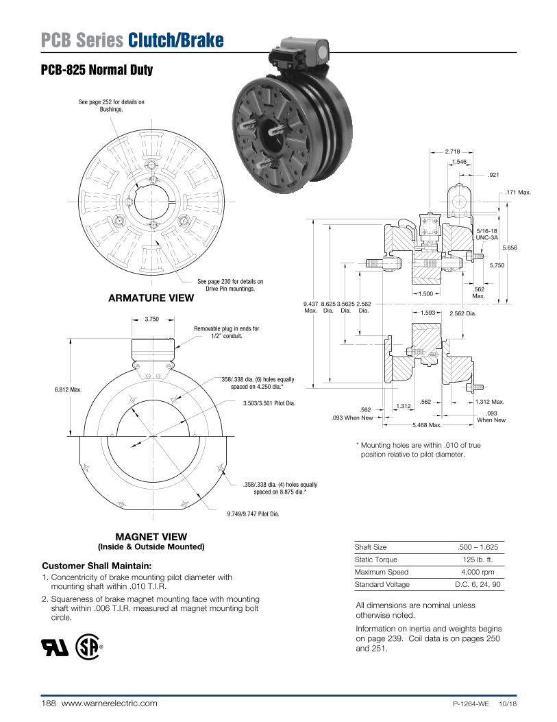
188 www.warnerelectric.com P-1264-WE 10/18
Shaft Size .500 – 1.625
Static Torque 125 lb. ft.
Maximum Speed 4,000 rpm
Standard Voltage D.C. 6, 24, 90
Customer Shall Maintain:1. Concentricity of brake mounting pilot diameter with
mount ing shaft within .010 T.I.R.
2. Squareness of brake magnet mounting face with mounting shaft within .006 T.I.R. measured at magnet mounting bolt circle.
.562 1.312 Max.
.562 Max.
5.656
5.750
.171 Max.
1.546
.921
5/16-18 UNC-3A
.5621.312
2.562 Dia.
.093 When New.093
When New
2.718
1.500
1.593
9.437 Max.
8.625 Dia.
3.5625 Dia.
2.562 Dia.
5.468 Max.
* Mounting holes are within .010 of true position relative to pilot diameter.
MAGNET VIEW(Inside & Outside Mounted)
Removable plug in ends for 1/2” conduit.
6.812 Max.
9.749/9.747 Pilot Dia.
.358/.338 dia. (4) holes equally spaced on 8.875 dia.*
.358/.338 dia. (6) holes equally spaced on 4.250 dia.*
3.503/3.501 Pilot Dia.
3.750
See page 252 for details on Bushings.
See page 230 for details on Drive Pin mountings.
ARMATURE VIEW
All dimensions are nominal unless otherwise noted.
Information on inertia and weights begins on page 239. Coil data is on pages 250 and 251.
PCB Series Clutch/BrakePCB-825 Normal Duty

189P-1264-WE 10/18 www.warnerelectric.com
74-14
3
2
1
6-1
6
5-2
8
5-1
5 (Shipped Assembled)
9
10A
11A
11A-1
12
12
11B
11B-1
10B
Drawing I-25568
How to Order:1. Specify Voltage for Item 4 and Item 11A or 11B.2. Specify left hand or right hand hub for Item 5. Bushing enters
from magnet side for L.H. hub and from hub side for R.H.3. Specify Bore Size for Item 7.4. Specify Inside Mounted for Items 10A and 11A or Outside
Mounted for Items 10B and 11B.5. See Controls Section.
Example:PCB-825 Clutch Brake per I-25568 - 90 Volt, Left Hand hub, 1” Bore, Inside Mounted
These units meet standards set forth in UL508 and are listed under guide card #NMTR2, file #59164. These units are CSA certified under file #LR11543
* See page 252 for specific part numbers.
Refer to Service Manual P-0205-WE
† Optional LK facing available. For more information, see page 232.
Item De scrip tion Part Number Qty.
1 Armature 5301-111-018 1
2 Autogap Accessory 5201-101-008 3
3 Mounting Accessory 5321-101-001 1
4 Magnet 1
6 Volt 5301-631-002
24 Volt 5301-631-004
90 Volt 5301-631-005
†90 Volt LK Facing 5301-631-011
4-1 Terminal Accessory 5311-101-001 1
5 Magnet Hub 1
Left Hand (shown) 5301-541-001
Right Hand 5301-541-002
5-1 Collector Ring 5301-749-001 1
5-2 Collector Ring Assembly 5301-101-002 1
6 Brushholder 5300-178-001 1
6-1 Brush 176-0001 4
7 Bushing* 1
1/2” to 1-5/8” Bore 180-0131 to 180-0149
8 Armature 5301-111-018 1
9 Autogap Accessory 5201-101-008 3
10A Mounting Accessory - I.M. 5321-101-001 1
10B Mounting Accessory - O.M. 5321-101-002 1
11A Magnet - Inside Mounted 1
6 Volt 5311-631-002
24 Volt 5311-631-003
Item De scrip tion Part Number Qty.
90 Volt 5311-631-004
†90 Volt LK Facing 5311-631-011
11A-1 Terminal Accessory 5311-101-001 1
11B Magnet - Outside Mounted 1
6 Volt 5311-631-007
24 Volt 5311-631-009
90 Volt 5311-631-008
†90 Volt LK Facing 5311-631-012
11B-1 Terminal Accessory 5311-101-001 1
12 Conduit Box 5200-101-011 1
PCB Series Clutch/BrakePCB-825 Normal Duty

190 www.warnerelectric.com P-1264-WE 10/18
Shaft Size .500 – 1.625
Static Torque 125 lb. ft.
Maximum Speed 4,000 rpm
Standard Voltage D.C. 6, 24, 90
* Mounting holes are within .010 of true position relative to pilot diameter.
ARMATURE VIEW
1.343
.468 Max.
.125.062
1.312
9.437 Running
Dia. 2.562 Dia.
.093 When New
.5621.312
Max. Length of Customer Pilot
1.546
.921
5.656
.562 Max.
.093
.171 Max.
1/4-28 UNF-3A
5.750
5/16-18 UNC-3A
1.500
1.593
2.3132.311 Pilot Dia.
8.625 Dia.
1.437.531
5.640 Max.
2.718
Customer Shall Maintain:1. Concentricity of brake magnet mounting pilot diameter with
mounting shaft within .010 T.I.R.
2. Squareness of brake magnet mounting face with magnet mounting shaft within .006 T.I.R.
3. Splined hub pilot diameter to be concentric with splined armature center of rotation within .010 T.I.R.
1.640 Dia.
.271/.263 dia. (5) holes (hub) equally spaced on 2.015 dia. and within .003 of true position in relation
to 2.313/2.311 pilot dia.
MAGNET VIEW(Inside & Outside Mounted)
.358/.338 dia. (4) holes equally spaced on 8.875 dia.
See page 252 for details on
Bushings.
Removable plug in ends for 1/2” conduit.
.358/.338 dia. (6) holes equally spaced on 4.250 dia.*
6.812 Max.
3.503/3.501 Pilot Dia.
3.750
9.749/9.747 Pilot Dia.
All dimensions are nominal unless otherwise noted.
Information on inertia and weights begins on page 239. Coil data is on pages 250 and 251.
PCB Series Clutch/BrakePCB-825 Heavy Duty

191P-1264-WE 10/18 www.warnerelectric.com
3(Shipped
Assembled)
5
5-1
8
4
3-5
3-23-1
3-6
1
2
3-3
3-4
13A
9
9-1
10
6-2
6-1
6
11
12A
12B
13B-1
14
13B
13A-1
14Drawing I-25569
How to Order:1. Specify Voltage for Item 5 and Item 13A or 13B.2. Specify left hand or right hand hub for Item 6. Bushing enters
from magnet side for L.H. hub and from hub side for R.H. hub.3. Specify Bore Size for Item 8.4. Specify Inside Mounted for Items 12A and 13A or Outside
Mounted for Items 12B and 13B.5. See Controls Section.
Example:PCB-825 Clutch Brake per I-25569 - 90 Volt, Left Hand hub, 1” Bore, Inside Mounted
These units meet the standards of UL508 and are listed under guide card #NMTR2, file #59164. These units are CSA certified under file #LR11543
* See page 252 for specific part numbers.
Refer to Service Manual P-0205-WE
† Optional LK facing available. For more information, see page 232.
Item Description Part Number Qty.
1 Splined Hub 540-0146 1
2 Mounting Accessory 5201-101-001 1
3 Armature Accessory 5321-111-001 1
3-1 Armature 5321-111-022 1
3-2 Armature Adapter 104-0008 1
3-3 Autogap Spring 808-0054 1
3-4 Retainer Ring 748-0373 1
3-5 Buttonhead Screw 797-0272 3
3-6 Locknut 661-0004 3
4 Mounting Accessory 5321-101-001 1
5 Magnet 1
6 Volt 5301-631-002
24 Volt 5301-631-004
90 Volt 5301-631-005
†90 Volt LK Facing 5301-631-011
5-1 Terminal Accessory 5311-101-001 1
6 Magnet Hub 1
Right Hand 5301-541-002
Left Hand (shown) 5301-541-001
6-1 Collector Ring 5301-749-001 1
6-2 Collector Ring Accessory 5301-101-002 1
8 Bushing* 180-0131 to 180-0149 1
9 Brushholder 5300-178-001 1
9-1 Brush 176-0001 4
10 Armature 5301-111-018 1
11 Autogap Accessory 5201-101-008 3
12A Mounting Accessory - I.M. 5321-101-001 1
12B Mounting Accessory - O.M. 5321-101-002 1
Item Description Part Number Qty.
13A Magnet - Inside Mounted 1
6 Volt 5311-631-002
24 Volt 5311-631-003
90 Volt 5311-631-004
†90 Volt LK Facing 5311-631-011
13A-1 Terminal Accessory 5311-101-001 1
13B Magnet Hub - Outside Mounted 1
6 Volt 5311-631-007
24 Volt 5311-631-009
90 Volt 5311-631-008
†90 Volt LK Facing 5311-631-012
13B-1 Terminal Accessory 5311-101-001 1
14 Conduit Box 5200-101-011 1
PCB Series Clutch/BrakePCB-825 Heavy Duty

192 www.warnerelectric.com P-1264-WE 10/18
Shaft Size .500 – 2.500
Static Torque 240 lb. ft.
Maximum Speed 3,600 rpm
Standard Voltage D.C. 6, 24, 90Customer Shall Maintain:1. Concentricity of brake mounting pilot diameter with mount ing
shaft within .010 T.I.R.
2. Squareness of brake magnet mounting face with mounting shaft within .006 T.I.R. measured at magnet mounting bolt circle.
.562 1.453 Max.
.562Max.
6.531
5.750
.171
1.546 Max.
.921
5/16-18 UNC-3A
.5621.453
4.125 Dia.
.093 When New.093
When New
2.906
1.750
1.906
11.093 Max.
10.296 Dia.
5.252 Dia.
4.125 Dia.
6.031 Max.
MAGNET VIEW(Inside & Outside Mounted)
Removable plug in ends for 1/2” conduit.
7.687 Max.
11.500/11.498 Pilot Dia.
.358/.338 dia. (8) holes equally spaced on 10.625 dia.*
.358/.338 dia. (6) holes equally spaced on 6.125 dia.*
5.378/5.376 Pilot Dia.
3.750
ARMATURE VIEW
See page 252 for details on Bushings.
See page 230 for deatils on Drive Pin mountings.
* Mounting holes are within .010 of true position relative to pilot diameter.
All dimensions are nominal unless otherwise noted.
Information on inertia and weights begins on page 239. Coil data is on pages 250 and 251.
PCB Series Clutch/BrakePCB-1000 Normal Duty

193P-1264-WE 10/18 www.warnerelectric.com
74-14
3
2
1
6-1
6
5-2
8
5-1
5 (Shipped Assembled)
9
10A
11A
11A-1
12
12
11B
11B-1
10B
Drawing I-25588
How to Order:1. Specify Voltage for Item 4 and Item 11A or 11B.2. Specify left hand or right hand hub for Item 5. Bushing enters
from magnet side for L.H. hub and from hub side for R.H.3. Specify Bore Size for Item 7.4. Specify Inside Mounted for Items 10A and 11A or Outside
Mounted for Items 10B and 11B.5. See Controls Section.
Example:PCB-1000 Clutch Brake per I-25588 - 90 Volt, Left Hand hub, 1-1/2” Bore, Inside Mounted
These units meet standards set forth in UL508 and are listed under guide card #NMTR2, file #59164. These units are CSA certified under file #LR11543
* See page 252 for specific part numbers.
Refer to Service Manual P-0205-WE
† Optional LK facing available. For more information, see page 232.
Item De scrip tion Part Number Qty.
1 Armature 5302-111-013 1
2 Autogap Accessory 5201-101-008 3
3 Mounting Accessory 5321-101-001 1
4 Magnet 1
6 Volt 5302-631-003
24 Volt 5302-631-014
90 Volt 5302-631-005
†90 Volt LK Facing 5302-631-001
4-1 Terminal Accessory 5311-101-001 1
5 Magnet Hub 1
Left Hand (shown) 5302-541-001
Right Hand 5302-541-002
5-1 Collector Ring 5301-749-001 1
5-2 Collector Ring Assembly 5302-101-002 1
6 Brushholder 5300-178-001 1
6-1 Brush 176-0001 4
7 Bushing* 1
1/2” to 2-1/2” Bore 180-0185 to 180-0217
8 Armature 5302-111-013 1
9 Autogap Accessory 5201-101-008 3
10A Mounting Accessory - I.M. 5321-101-001 1
10B Mounting Accessory - O.M. 5321-101-002 2
11A Magnet - Inside Mounted 1
6 Volt 5312-631-004
24 Volt 5312-631-005
Item De scrip tion Part Number Qty.
90 Volt 5312-631-006
†90 Volt LK Facing 5312-631-001
11A-1 Terminal Accessory 5311-101-001 1
11B Magnet - Outside Mounted 1
6 Volt 5312-631-011
24 Volt 5312-631-013
90 Volt 5312-631-012
†90 Volt LK Facing 5312-631-002
11B-1 Terminal Accessory 5311-101-001 1
12 Conduit Box 5200-101-011 1
PCB Series Clutch/BrakePCB-1000 Normal Duty

194 www.warnerelectric.com P-1264-WE 10/18
Shaft Size .500 – 2.500
Static Torque 240 lb. ft.
Maximum Speed 3,600 rpm
Standard Voltage D.C. 6, 24, 90
* Mounting holes are within .010 of true position relative to pilot diameter.
ARMATURE VIEW
1.375
.843 Max.
.125.062
1.453
11.093 Running
Dia. 4.125 Dia.
.093 When New
.5621.453
Max. Length of Customer Pilot
1.546
.921
6.531
.562 Max.
.093
.171 Max.
3/8-16 UNF-2A
5.750
5/16-18 UNC-3A
1.750
1.906
4.0013.999 Pilot Dia.
10.296Dia.
1.750.500
6.218 Max.
2.906
Customer Shall Maintain:1. Concentricity of brake magnet mounting pilot diameter with
mounting shaft within .010 T.I.R.
2. Squareness of brake magnet mounting face with magnet mounting shaft within .006 T.I.R.
3. Splined hub pilot diameter to be concentric with splined armature center of rotation within .010 T.I.R.
2.562 Dia.
.397/.388 dia. (3) holes (hub) equally spaced on 3.187 dia. and within .003 of true position in relation to
4.001/3.999 pilot dia.
MAGNET VIEW(Inside & Outside Mounted)
.358/.338 dia. (8) holes equally spaced
on 10.625 dia.See page 252 for details on
Bushings.
Removable plug in ends for 1/2” conduit.
.358/.338 dia. (6) holes equally spaced on 6.125 dia.*
7.687 Max.
5.378/5.376 Pilot Dia.
3.750
11.500/11.498 Pilot Dia.
All dimensions are nominal unless otherwise noted.
Information on inertia and weights begins on page 239. Coil data is on pages 250 and 251.
PCB Series Clutch/BrakePCB-1000 Heavy Duty

195P-1264-WE 10/18 www.warnerelectric.com
3(Shipped
Assembled)
5
5-1
8
4
3-5
3-23-1
3-6
1
2
3-3
3-4
13A
9
9-1
10
6-2
6-1
6
11
12A
12B
13B-1
14
13B
13A-1
14Drawing I-25589
How to Order:1. Specify Voltage for Item 5 and Item 13A or 13B.2. Specify left hand or right hand hub for Item 6. Bushing enters
from magnet side for L.H. hub and from hub side for R.H. hub.3. Specify Bore Size for Item 7.4. Specify Inside Mounted for Items 12A and 13A or Outside
Mounted for Item 12B and 13B.5. See Controls Section.
Example:PCB-1000 Clutch Brake per I-25589 - 90 Volt, Left Hand hub, 1-1/2” Bore, Inside Mount ed
These units meet the standards of UL508 and are listed under guide card #NMTR2, file #59164. These units are CSA certified under file #LR11543.
* See page 252 for specific part numbers.
Refer to Service Manual P-0205-WE
† Optional LK facing available. For more information, see page 232.
Item Description Part Number Qty.
1 Splined Hub 540-0147 1
2 Mounting Accessory 5202-101-001 1
3 Armature Accessory 5322-111-002 1
3-1 Armature 5322-111-036 1
3-2 Armature Adapter 104-0009 1
3-3 Autogap Spring 808-0061 1
3-4 Retainer Ring 748-0374 1
3-5 Buttonhead Screw 797-0272 3
3-6 Locknut 661-0004 3
4 Mounting Accessory 5321-101-001 1
5 Magnet 1
6 Volt 5302-631-003
24 Volt 5302-631-014
90 Volt 5302-631-005
†90 Volt LK Facing 5302-631-001
5-1 Terminal Accessory 5311-101-001 1
6 Magnet Hub 1
Right Hand 5302-541-002
Left Hand (shown) 5302-541-001
6-1 Collector Ring 5301-749-001 1
6-2 Collector Ring Accessory 5301-101-002 1
8 Bushing* 180-0185 to 180-0217 1
9 Brushholder 5300-178-001 1
9-1 Brush 176-0001 4
10 Armature 5302-111-013 1
11 Autogap Accessory 5201-101-008 3
12A Mounting Accessory - I.M. 5321-101-001 1
12B Mounting Accessory - O.M. 5321-101-002 2
Item Description Part Number Qty.
13A Magnet - Inside Mounted 1
6 Volt 5312-631-004
24 Volt 5312-631-005
90 Volt 5312-631-006
†90 Volt LK Facing 5312-631-001
13A-1 Terminal Accessory 5311-101-001 1
13B Magnet Hub - Outside Mounted 1
6 Volt 5312-631-011
24 Volt 5312-631-013
90 Volt 5312-631-012
†90 Volt LK Facing 5312-631-002
13B-1 Terminal Accessory 5311-101-001 1
14 Conduit Box 5200-101-011 1
PCB Series Clutch/BrakePCB-1000 Heavy Duty

196 www.warnerelectric.com P-1264-WE 10/18
Shaft Size .500 – 2.500
Static Torque Clutch 465 lb. ft.
Static Torque Brake 240 lb. ft.
Maximum Speed 3,000 rpm
Standard Voltage D.C. 6, 24, 90
* Mounting holes are within .010 of true position relative to pilot diameter.
Customer Shall Maintain:1. Concentricity of brake mounting pilot diameter
with mounting shaft within .010 T.I.R.
2. Squareness of brake magnet mounting face with mounting shaft within .006 T.I.R. mea sured at magnet mounting bolt circle.
MAGNET VIEW(Inside & Outside Mounted)
ARMATURE VIEW
See page 252 for details on Bushings.
See page 230 for details on Drive Pin mountings.
11.500/11.498 Pilot Dia.
.358/.338 dia. (8) holes equally spaced on 10.625 dia.*
Removable plug in ends for 1/2” conduit.
.358/.338 dia. (6) holes equally spaced on 6.125 dia.*
5.378/5.376 Pilot Dia.
3.750
7.687
All dimensions are nominal unless otherwise noted.
Information on inertia and weights begins on page 239. Coil data is on pages 250 and 251.
4.125 Dia.
.593
.562 1.453
.562 Max.
6.531
5.750
.171 Max.
1.546
.921
.093 When New
2.906
5/16-18
UNC-3A
1.750
1.906
13.140 Max. 12.625
Dia.
5.877 Dia. 4.625
Dia.
6.250Max.
.093 When New1.640
PCB Series Clutch/BrakePCB-1225/1000 Normal Duty

197P-1264-WE 10/18 www.warnerelectric.com
4-1
74
3
2
1
6
6-1
5-2
8 10A
11A
11A-1
12
11B
11B-1
12
10B
9
5 (Shipped Assembled)
5-1
Drawing I-25610
How to Order:1. Specify Voltage for Item 4 and Item 11A or 11B.2. Specify left hand or right hand hub for Item 5. Bushing enters
from magnet side for L.H. hub and from hub side for R.H. 3. Specify Bore Size for Item 7.4. Specify Inside Mount ed for Items 10A and 11A or Outside
Mount ed for Items 10B and 11B.5. See Controls Section.
Example:PCB-1225/1000 Clutch Brake per I-25610 - 90 Volt, Left Hand hub, 1-1/2” Bore, Inside Mounted
These units meet the standards of UL508 and are listed under guide card #NMTR2, file #59164. These units are CSA certified under file #LR11543.
* See page 252 for specific part numbers.
Refer to Service Manual P-0214-WE
† Optional LK facing available. For more information, see page 232.
**24 Volt is available as a special.
Item Description Part Number Qty.
1 Armature 5303-111-009 1
2 Autogap Ac ces so ry 5201-101-008 4
3 Mounting Accessory 5321-101-001 1
4 Magnet** 1
6 Volt 5333-631-008
90 Volt 5333-631-009
†90 Volt LK Facing 5333-631-013
4-1 Terminal Accessory 5311-101-001 1
5 Magnet Hub 1
Left Hand (shown) 5302-541-004
Right Hand 5302-541-005
5-1 Collector Ring 5301-749-001 1
5-2 Collector Ring Accessory 5303-101-004 1
6 Brushholder 5300-178-001 1
6-1 Brush 176-0001 4
7 Bushing* 1
1/2” to 2-1/2” Bore 180-0185 to 180-0217
8 Armature 5302-111-013 1
9 Autogap Accessory 5201-101-008 3
10A Mounting Accessory - I.M. 5321-101-001 1
10B Mounting Accessory - O.M. 5321-101-002 2
11A Magnet - Inside Mounted 1
6 Volt 5312-631-004
24 Volt 5312-631-005
90 Volt 5312-631-006
†90 Volt LK Facing 5312-631-001
Item Description Part Number Qty.
11A-1 Terminal Accessory 5311-101-001 1
11B Magnet - Outside Mounted 1
6 Volt 5312-631-011
24 Volt 5312-631-013
90 Volt 5312-631-012
†90 Volt LK Facing 5312-631-002
11B-1 Terminal Accessory 5311-101-001 1
12 Conduit Box 5200-101-011 1
PCB Series Clutch/BrakePCB-1225/1000 Normal Duty

198 www.warnerelectric.com P-1264-WE 10/18
Shaft Size .500 – 2.500
Static Torque Clutch 465 lb. ft.
Static Torque Brake 240 lb. ft.
Maximum Speed 3,000 rpm
Standard Voltage D.C. 6, 24, 90
* Mounting holes are within .010 of true position relative to pilot diameter.
ARMATURE VIEW
1.546
.921
.718 Max.
.125.062
4.3134.311 Pilot 4.125 Dia.
1.500
.093 When New
.562 1.453
.562 Max.
6.531
3/8-16 UNC-2A
.093 Max.
Length of Customer
Pilot
5/16-18 UNC-3A
.171 Max.
5.750
6.562 Max.
1.7501.640.562
13.140 Max. Dia. 12.625
Dia.
1.750
2.906
1.906
Customer Shall Maintain:1. Concentricity of brake magnet mounting pilot
diameter to mounting shaft within .010 T.I.R.
2. Squareness of brake magnet mounting face to magnet mount ing shaft within .006 T.I.R.
3. Splined hub pilot diameter to be concentric with splined armature center of rotation within .010 T.I.R.
3.062
.397/.388 dia. (8) holes (hub) equally spaced on (3.625) dia. and within .003 of true position in relation to
4.313/4.311pilot dia.
MAGNET VIEW
11.500/11.498 Pilot Dia.
.358/.338 dia. (8) holes equally spaced on 10.625 dia.*
Removable plug in ends for 1/2” conduit.
.358/.338 dia. (6) holes equally spaced on 6.125 dia.*
7.687 Max.5.378/5.376 Pilot Dia.
See page 252 for details on Bush ings.
3.750
All dimensions are nominal unless otherwise noted.
Information on inertia and weights begins on page 239. Coil data is on pages 250 and 251.
PCB Series Clutch/BrakePCB-1225/1000 Heavy Duty

199P-1264-WE 10/18 www.warnerelectric.com
3(Shipped
Assembled)
3-7
3-1
3-2
3-6
4
5
5-1
7
3-4
3-3
2
1
8
8-1
9
10
6 (Shipped Assembled)
12B
11B
11B-1
13
11A-111A
13
12A
Drawing I-25611
How to Order:1. Specify Voltage for Item 5 and Item 11A or 11B.2. Specify left hand or right hand hub for Item 6. Bushing enters
from magnet side for L.H. hub and from hub side for R.H.3. Specify Bore Size for Item 7.4. Specify Inside Mount ed for Items 11A and 12A or Outside
Mounted for Items 11B and 12B.5. See Controls Section.
Example:PCB-1225/1000 Clutch Brake per I-25611- 90 Volt, Left Hand hub, 1-1/2” Bore, Inside Mounted
These units meet the standards of UL508 and are listed under guide card #NMTRs, file #59164. These units are CSA certified under file #LR11543.
* See page 252 for specific part numbers.
Refer to Service Manual P-0214-WE
† Optional LK facing available. For more information, see page 232.
**24 Volt is available as a special.
Item Description Part Number Qty.
1 Splined Hub 540-0148 12 Mounting Accessory 5202-101-001 13 Armature Assembly 5323-111-001 13-1 Armature 5323-111-034 13-2 Splined Armature Adapter 104-0010 13-3 Autogap Spring 808-0044 13-4 Retainer Ring 748-0370 13-6 Buttonhead Screw 797-0281 43-7 Locknut 661-0005 44 Mounting Accessory 5321-101-001 15 Magnet Assembly** 1 6 Volt 5333-631-008 90 Volt 5333-631-009 †90 Volt LK Facing 5333-631-0135-1 Terminal Accessory 5311-101-001 16 Hub Assembly Left Hand (shown) 5302-541-004 1 Right Hand 5302-541-005 17 Bushing* 180-0185 to 180-0217 18 Brushholder 5300-178-001 18-1 Brush 176-0001 49 Armature Assembly 5302-111-013 110 Autogap Accessory 5201-101-008 311A Magnet I.M. 1 6 Volt 5312-631-004 24 Volt 5312-631-005 90 Volt 5312-631-006 †90 Volt LK Facing 5312-631-00111A-1 Terminal Accessory 5311-101-001 1
Item Description Part Number Qty.
11B Magnet - Outside Mounted 1 6 Volt 5312-631-011 24 Volt 5312-631-013 90 Volt 5312-631-012 †90 Volt LK Facing 5312-631-00211B-1 Terminal Accessory 5311-101-001 112A Mounting Accessory I.M. 5321-101-001 112B Mounting Accessory O.M. 5321-101-002 213 Conduit Box 5200-101-011 1
PCB Series Clutch/BrakePCB-1225/1000 Heavy Duty

200 www.warnerelectric.com P-1264-WE 10/18
Shaft Size .937 – 3.000
Static Torque 465 lb. ft.
Maximum Speed 3,000 rpm
Standard Voltage D.C. 6, 24, 90
Customer Shall Maintain:1. Concentricity of brake mounting pilot di am e ter with mount-
ing shaft within .010 T.I.R.
2. Squareness of brake magnet mounting face with mounting shaft within .006 T.I.R measured at magnet mounting bolt circle.
.171 Max.
.5931.640
.593 1.640
.562 Max.
7.5315.750
1.546
.921
4.625 Dia.
.093 When New
.093 When New
3.250
5/16-18 UNC-3A
3.000
3.156
13.140 Max.
12.625 Dia.
5.877 Dia.
4.625 Dia.
6.906 Max.
ARMATURE VIEW
See page 252 for details on Bushings.
See page 230 for details on Drive Pin mountings.
MAGNET VIEW(Inside & Outside Mounted)
.358/.338 dia. (8) holes equally spaced on 13.000 dia.
Removable plug in ends for 1/2” conduit.
.358/.338 dia. (6) holes equally spaced on 7.250 dia.*
8.687 Max.
6.378/6.376 Pilot Dia.
3.750
13.875/13.871 Pilot Dia.
All dimensions are nominal unless otherwise noted.
Information on inertia and weights begins on page 239. Coil data is on pages 250 and 251.
* Mounting holes are within .010 of true position relative to pilot diameter.
PCB Series Clutch/BrakePCB-1225 Normal Duty

201P-1264-WE 10/18 www.warnerelectric.com
6-1
68
5-1
5-2
9
11A
11A-111B
12
13
11B-1
10B
2
1
3
4
4-17
10A
5(Shipped
Assembled)
Drawing I-25608
How to Order:1. Specify Voltage for Item 4 and Item 11A or 11B.2. Specify left hand or right hand hub for Item 5. Bushing
enters from magnet side for L.H. hub and from hub side for R.H.
3. Specify Bore Size for Item 7.4. Specify Inside Mounted for Items 10A and 11A or Outside
Mounted for Items 10B and 11B.5. See Controls Section.
Example:PCB-1225 Clutch Brake per I-25608 - 90 Volt, Left hand hub, 2” Bore, Inside Mounted.
These units meet the standards of UL508 and are listed under guide card #NMTR2, file #59164. These units are CSA certified under file #LR11543.
* See page 252 for specific part numbers.
Refer to Service Manual P-0205-WE
† Optional LK facing available. For more information, see page 232.
Item Description Part Number Qty.
1 Armature 5303-111-009 1
2 Autogap Accessory 5201-101-008 4
3 Mounting Accessory 5321-101-001 1
4 Magnet 1
6 Volt 5303-631-005
24 Volt 5303-631-007
90 Volt 5303-631-008
†90 Volt LK Facing 5303-631-001
4-1 Terminal Accessory 5311-101-001 1
5 Magnet Hub 1
Left Hand (shown) 5303-541-001
Right Hand 5303-541-002
5-1 Collector Ring 5301-749-001 1
5-2 Collector Ring Assembly 5303-101-004 1
6 Brushholder 5300-178-001 1
6-1 Brush 176-0001 4
7 Bushing* 1
15/16” to 3” Bore 180-0262 to180-0295
8 Armature 5303-111-009 1
9 Autogap Accessory 5201-101-008 4
10A Mounting Accessory - I.M. 5321-101-001 1
10B Mounting Accessory - O.M. 5321-101-002 2
11A Magnet - Inside Mounted 1
6 Volt 5313-631-005
24 Volt 5313-631-006
90 Volt 5313-631-007
†90 Volt LK Facing 5313-631-001
Item Description Part Number Qty.
11A-1 Terminal Accessory 5311-101-001 1
11B Magnet - Outside Mounted 1
6 Volt 5313-631-010
24 Volt 5313-631-012
90 Volt 5313-631-011
†90 Volt LK Facing 5313-631-002
11B-1 Terminal Accessory 5311-101-001 1
12 Conduit Box 5200-101-011 2
PCB Series Clutch/BrakePCB-1225 Normal Duty

202 www.warnerelectric.com P-1264-WE 10/18
Shaft Size .937 – 3.000
Static Torque 465 lb. ft.
Maximum Speed 3,000 rpm
Standard Voltage D.C. 6, 24, 90
* Mounting holes are within .010 of true position relative to pilot diameter.
Customer Shall Maintain:1. Concentricity of brake magnet mounting pilot diameter with
mounting shaft within .010 T.I.R.
2. Squareness of brake magnet mounting face with magnet mounting shaft within .006 T.I.R.
3. Splined hub pilot diameter to be concentric with splined armature center of rotation within .010 T.I.R.
31.500
.718 Max.
4.3134.311
Pilot Dia.
4.625 Dia.
1.546.921
5/16-18 UNC-3A
13.140 Running
Dia.
.125
.062
1.640.593
1.640
7.531
.562 Max.
5.750
.171
3/8-16 UNC-2A
.093 Max.
Length of Customer
Pilot
.093
3.250
12.625 Dia.
3.156
2.187
When New
7.218 Max.
.562
ARMATURE VIEW
(.397/.388) dia. (8) holes (hub) equally spaced on (3.625) dia. and within .003 of true position in relation to
(4.313/4.311) pilot dia.
3.062 Dia.
MAGNET VIEW(Inside & Outside Mounted)
.358/.338 dia. (8) holes equally spaced on 13.000 dia.
Removable plug in ends for 1/2” conduit.
.358/.338 dia. (6) holes equally spaced on 7.250 dia.*8.687
6.378/6.376 Pilot Dia.
3.750
13.875/13.871 Pilot Dia.
See page 252 for details on Bushings.
All dimensions are nominal unless otherwise noted.
Information on inertia and weights begins on page 239. Coil data is on pages 250 and 251.
PCB Series Clutch/BrakePCB-1225 Heavy Duty

203P-1264-WE 10/18 www.warnerelectric.com
3(Shipped
Assembled)
12
3-6
3-1
3-2
3-5
3-3
3-4
4
5
5-1 7 12A
11A
13
12A-1
12B
13
12B-1
11B
4
10
9
8
8-1
6
6-1
6-2
Drawing I-25609
How to Order:1. Specify Voltage for Item 5 and Item 12A or 12B.2. Specify left hand or right hand hub for Item 6. Bushing
enters from magnet side for L.H. hub and from hub side for R.H.
3. Specify Bore Size for Item 7.4. Specify Inside Mounted for Items 11A and 12A or Outside
Mounted for Items 11B and 12B.5. See Controls Section.
Example:PCB-1225 Clutch Brake per I-25609 - 90 Volt, Left Hand hub, 2” Bore, Inside Mounted
These units meet the standards of UL508 and are listed under guide card #NMTR2, file #59164. These units are CSA certified under file #LR11543.
* See page 252 for specific part numbers.
Refer to Service Manual P-0205-WE
† Optional LK facing available. For more information, see page 232.
Item Description Part Number Qty.
1 Splined Hub 540-0148 1
2 Mounting Accessory 5202-101-001 1
3 Armature Assembly 5323-111-001 1
3-1 Armature 5323-111-034 1
3-2 Armature Adapter 104-0010 1
3-3 Autogap Spring 808-0044 1
3-4 Retainer Ring 748-0370 1
3-5 Buttonhead Screw 797-0281 3
3-6 Locknut 661-0005 3
4 Mounting Accessory 5321-101-001 1
5 Magnet 1
6 Volt 5303-631-005
24 Volt 5303-631-007
90 Volt 5303-631-008
†90 Volt LK Facing 5303-631-001
5-1 Terminal Accessory 5311-101-001 1
6 Magnet Hub 1
Right Hand 5303-541-002
Left Hand (shown) 5303-541-001
6-1 Collector Ring 5301-749-001 1
6-2 Collector Ring Accessory 5303-101-004 1
7 Bushing* 180-0262 to 180-0295 1
8 Brushholder 5300-178-001 1
8-1 Brush 176-0001 4
9 Armature 5303-111-009 1
10 Autogap Accessory 5201-101-008 4
11A Mounting Accessory
Inside Mounted 5321-101-001 1
11B Mounting Accessory
Outside Mounted 5321-101-002 2
Item Description Part Number Qty.
12A Magnet - Inside Mounted 1
6 Volt 5313-631-005
24 Volt 5313-631-006
90 Volt 5313-631-007
†90 Volt LK Facing 5313-631-001
12A-1 Terminal Accessory 5311-101-001 1
12B Magnet - Outside Mounted 1
6 Volt 5313-631-010
24 Volt 5313-631-012
90 Volt 5313-631-011
†90 Volt LK Facing 5313-631-002
12B-1 Terminal Accessory 5311-101-001 1
13 Conduit Box 5200-101-010 1
PCB Series Clutch/BrakePCB-1225 Heavy Duty

204 www.warnerelectric.com P-1264-WE 10/18
Shaft Size .937 – 3.000
Static Torque Clutch 700 lb. ft.
Static Torque Brake 465 lb. ft.
Maximum Speed 2,000 rpm
Standard Voltage D.C. 6, 24, 90
* Mounting holes are within .010 of true position relative to pilot diameter.
Customer Shall Maintain:1. Concentricity of brake mounting pilot diameter with
mount ing shaft within .010 T.I.R.
2. Squareness of brake magnet mounting face with mounting shaft within .006 T.I.R. measured at magnet mounting bolt circle.
4.625 Dia.
.5931.750
.593.562 Max.
.171 Max.
7.5315.750
1.546
.921
5/16-18 UNC-3A
.093 When New
1.640
16.250 Max.
15.578 Dia.
8.500 Dia.
7.093 Dia.
3.250
3.187
3.000
7.140 Max.
.093 When New
ARMATURE VIEW
See page 252 for details on Bushings.
See page 230 for details on Drive Pin mountings.
MAGNET VIEW(Inside & Outside Mounted)
.358/.338 dia. (8) holes equally spaced on 13.000 dia.
Removable plug in ends for 1/2” conduit.
.358/.338 dia. (6) holes equally spaced on 7.250 dia.*
8.6876.378/6.376 Pilot
Dia.
3.750
13.875/13.871 Pilot Dia.
All dimensions are nominal unless otherwise noted.
Information on inertia and weights begins on page 239. Coil data is on pages 250 and 251.
PCB Series Clutch/BrakePCB-1525/1225 Normal Duty

205P-1264-WE 10/18 www.warnerelectric.com
1
23
6-1
6 8
5-1
5-29
10B
11B-1
12
12
11A-1
11A
10A11B
4
4-1 7
5 (Shipped Assembled)
Drawing I-25635
How to Order:1. Specify Voltage for Item 4 and Item 11A or 11B.2. Specify left hand or right hand hub for Item 5. Bushing
enters from magnet side for L.H. hub and from hub side for R.H.
3. Specify Bore Size for Item 7.4. Specify Inside Mount ed for Items 10A and 11A or Outside
Mount ed for Items 10B and 11B.5. See Controls Section.
Example:PCB-1525/1225 Clutch Brake per I-25635 - 90 Volt, Left Hand hub, 2” Bore, Inside Mounted
These units meet the standards of UL508 and are listed under guide card #NMTR2, file #59164. These units are CSA certified under file #LR11543.
* See page 252 for specific part numbers.
Refer to Service Manual P-0214-WE
† Optional LK facing available. For more information, see page 232.
Item Description Part Number Qty.
1 Armature 5304-111-004 1
2 Autogap Accessory 5201-101-008 4
3 Mounting Accessory 5321-101-001 1
4 Magnet 1
6 Volt 5304-631-009
24 Volt 5304-631-011
90 Volt 5304-631-010
†90 Volt LK Facing 5304-631-002
4-1 Terminal Accessory 5311-101-001 1
5 Magnet Hub 1
Left Hand (shown) 5304-541-001
Right Hand 5304-541-002
5-1 Collector Ring 5301-749-001 1
5-2 Collector Ring Accessory 5304-101-004 1
6 Brushholder 5300-178-001 1
6-1 Brush 176-0001 4
7 Bushing* 1
15/16” to 3” Bore 180-0262 to 180-0295
8 Armature 5303-111-009 1
9 Autogap Accessory 5201-101-008 4
10A Mounting Assembly - I.M. 5321-101-001 1
10B Mounting Accessory - O.M. 5321-101-002 2
11A Magnet - Inside Mounted 1
6 Volt 5313-631-005
24 Volt 5313-631-006
90 Volt 5313-631-007
†90 Volt LK Facing 5313-631-001
Item Description Part Number Qty.
11A-1 Terminal Accessory 5311-101-001 1
11B Magnet - Outside Mounted 1
6 Volt 5313-631-010
24 Volt 5313-631-012
90 Volt 5313-631-011
†90 Volt LK Facing 5313-631-002
11B-1 Terminal Accessory 5311-101-001 1
12 Conduit Box 5200-101-010 1
PCB Series Clutch/BrakePCB-1525/1225 Normal Duty

206 www.warnerelectric.com P-1264-WE 10/18
Shaft Size .937 – 3.000
Static Torque Clutch 700 lb. ft.
Static Torque Brake 465 lb. ft.
Maximum Speed 2,000 rpm
Standard Voltage D.C. 6, 24, 90
* Mounting holes are within .010 of true position relative to pilot diameter.
Customer Shall Maintain:1. Concentricity of brake magnet mounting pilot diameter to
mounting shaft within .010 T.I.R.
2. Squareness of brake magnet mounting face to magnet mounting shaft within .006 T.I.R.
3. Splined hub pilot diameter to be concentric with splined armature center of rotation within .010 T.I.R.
4.3134.311 Pilot Dia.
.718
.125
.062
1.750
1.546
.921
.093 When New
.593 1.640
.562 Max.
.171 Max.
31.500 4.625
7.5315.750
.093 Max. Length of Customer
Pilot
3/8-16 UNC-2A
5/16-18 UNC-3A
7.437 Max.
.562
2.312
16.250 Max. Dia.
15.578 Dia.
3.187
3.250
(.397/.388) dia. (8) holes (hub) equally spaced on (3.625) dia. and within .003 of true position
relative to (4.313/4.311) pilot di am e ter.
3.062 Dia.
.358/.338 dia. (8) holes equally spaced on 13.000 dia.*
Removable plug in ends for 1/2” conduit.
.358/.338 dia. (6) holes equally spaced on 7.250 dia.*
8.687
6.378/6.376 Pilot Dia.
3.750
13.875/13.871 Pilot Dia.See page 252 for details on Bushings.
ARMATURE VIEW
MAGNET VIEW
All dimensions are nominal unless otherwise noted.
Information on inertia and weights begins on page 239. Coil data is on pages 250 and 251.
PCB Series Clutch/BrakePCB-1525/1225 Heavy Duty

207P-1264-WE 10/18 www.warnerelectric.com
Drawing I-25636
How to Order:1. Specify Voltage for Item 5 and Item 11A or 11B.2. Specify left hand or right hand hub for Item 6. Bushing
enters from magnet side for L.H. hub and from hub side for R.H.
3. Specify Bore Size for Item 7.4. Specify Inside Mounted for Items 11A and 12A or Outside
Mounted for Items 11B and 12B.5. See Controls Section.
Example:PCB-1525/1225 Clutch Brake per I-25636 - 90 Volt, Left Hand hub, 2” Bore, Inside Mounted
These units meet standards set forth in UL508 and are listed under guide card #NMTR2, file #59164.
These units are CSA certified under file #LR11543.
3(Shipped
Assembled)
1 2
3-7
3-1
3-2
3-3
3-4
3-5
3-64
5
5-1
7
6 (Shipped
Assembled)
8-1
8
9
12A
10
12B
11B-1
13
11B
11A-1
1311A
Item Description Part Number Qty.
1 Splined Hub 540-0148 1
2 Mounting Accessory 5202-101-001 1
3 Armature Assembly 5324-111-001 1
3-1 Ar ma ture 5324-111-034 1
3-2 Splined Armature Adapter 104-0011 1
3-3 Autogap Spring 808-0044 1
3-4 Retainer Ring 748-0370 1
3-5 Retainer Plate 686-0003 1
3-6 Buttonhead Screw 797-0272 8
3-7 Locknut 661-0004 8
4 Mounting Accessory 5321-101-001 1
5 Magnet Assembly
6 Volt 5304-631-009
24 Volt 5304-631-011
90 Volt 5304-631-010
†90 Volt LK Facing 5304-631-002
5-1 Terminal Accessory 5311-101-001 1
6 Hub Assembly
Left Hand (shown) 5304-541-001
Right Hand 5304-541-002
7 Bushing* 180-0262 to 180-0295 1
8 Brushholder 5300-178-001 1
8-1 Brush 176-0001 4
9 Armature Assembly 5303-111-009 1
10 Autogap Accessory 5201-101-008 4
11A Magnet - Inside Mounted 1
6 Volt 5313-631-005
24 Volt 5313-631-006
90 Volt 5313-631-007
†90 Volt LK Facing 5313-631-001
Item Description Part Number Qty.
11A-1 Terminal Accessory 5311-101-001 1
11B Magnet - Outside Mounted 1
6 Volt 5313-631-010
24 Volt 5313-631-012
90 Volt 5313-631-011
†90 Volt LK Facing 5313-631-002
11B-1 Terminal Accessory 5311-101-001 1
12A Mounting Accessory I.M. 5321-101-001 1
12B Mounting Accessory O.M. 5321-101-002 2
13 Conduit Box 5200-101-011 1
*See page 252 for specific part numbers.
Refer to Service Manual P-0214-WE
† Optional LK facing available. For more information, see page 232.
PCB Series Clutch/BrakePCB-1525/1225 Heavy Duty

208 www.warnerelectric.com P-1264-WE 10/18
Shaft Size .750 – 1.250
Static Torque Clutch 50 lb. ft.
Static Torque Brake 40 lb. ft.
Maximum Speed 4,000 rpm
Standard Voltage D.C. 6, 24, 90
Customer Shall Maintain:1. Squareness of brake mounting face with armature hub
shaft within .006 T.I.R.
2. Concentricity of brake mounting pilot di am e ter with arma ture hub shaft within .010 T.I.R.
3. Concentricity of clutch magnet hub assembly shaft with armature hub shaft within .006 T.I.R.
.953.4681.125
5.296
1.390
Outside Mounted Offset Backing Plate
1.750 Min. Flat
.187
4.093
2.0652.063 Pilot Dia.
5.062
3.953.390
1.187
1.031
1.093
.062
.125
.281
3/8-16 UNC-2A
1.5935.453
.515
.062When New
1.3431.281
1.546
1.468
2.687
8-32 UNC-3A
1.500
2.062Dia.
5.328 Dia.
2.093
1.234
5.375
2.031
1.546
* Mounting holes are within .010 of true position relative to pilot diameter.
** Mounting holes are within .008 of true position relative to pilot diameter.
MAGNET VIEW
3.750
.399/.389 dia. (4) holes equally spaced on 5.875 dia.**
See page 252 for details on Bush ings.
Removable plug in ends for 1/2” conduit.
5.062
.208/.201 dia. (8) holes equally spaced on 2.375 dia.*
5
6.500/6.498 Pilot Dia.
45°
FIELD VIEW
See page 252 for details on
Bushings.
45°
5.218
3.156 2.781
.218
.750
3.750
Outside Mounted Flush Backing Plate
All dimensions are nominal unless otherwise noted.
Information on inertia and weights begins on page 239. Coil data is on pages 250 and 251.
SFPBC Series Clutch/Brake CouplingSFPBC-500 Normal Duty

209P-1264-WE 10/18 www.warnerelectric.com
Drawing I-25546
1(Shipped
Assembled)
8
1-2-1
1-2
1-2-2
1-3
1-1
1-4
2
3
45
2
7B7C
6B
7B-17C-1
8
8
7A-17A
6A
Item Description Part Number Qty.
1 Field and Rotor Assembly 1 6 Volt – 3/4” Bore 5200-452-002 24 Volt – 3/4” Bore 5200-452-004 90 Volt – 3/4” Bore 5200-452-005 6 Volt – 7/8” Bore 5200-452-008 24 Volt – 7/8” Bore 5200-452-010 90 Volt – 7/8” Bore 5200-452-011 90 Volt – 15/16” Bore 5200-452-017 6 Volt – 1” Bore 5200-452-020 24 Volt – 1” Bore 5200-452-022 90 Volt – 1” Bore 5200-452-023 6 Volt – 1-1/8” Bore 5200-452-026 24 Volt – 1-1/8” Bore 5200-452-028 90 Volt – 1-1/8” Bore 5200-452-029 6 Volt – 1-1/4” Bore 5200-452-032 90 Volt – 1-1/4” Bore 5200-452-0351-1 Rotor 1 3/4” Bore 5200-751-002 7/8” Bore 5200-751-003 15/16” Bore 5200-751-004 1” Bore 5200-751-005 1-1/8” Bore 5200-751-006 1-1/4” Bore 5200-751-0071-2 Field 1 6 Volt 5200-451-024 24 Volt 5200-451-026 90 Volt 5200-451-0271-2-1 Terminal Accessory 5311-101-001 11-2-2 Ball Bearing 166-0110 11-3 Retainer Ring 748-0002 11-4 Setscrew 797-0069 22 Armature 5300-111-002 23 Autogap Accessory 5200-101-009 64 Bushing*- 1/2” to 1-1/4” Bore 180-0116 to 180-0128 15 Armature Hub 5300-541-004 1
Item Description Part Number Qty.
6A Mounting Accessory - I.M. 5102-101-001 26B Mounting Accessory - O.M. 5300-101-008 17A Magnet - I.M. 1 6 Volt 5300-631-002 24 Volt 5300-631-003 90 Volt 5300-631-0057A-1 Terminal Accessory 5311-101-001 17B Magnet - O.M. - Offset 1 90 Volt 5300-631-0147B-1 Terminal Accessory 5311-101-001 17C Magnet - O.M. - Flush 1 6 Volt 5300-631-009 24 Volt 5300-631-010 90 Volt 5300-631-0117C-1 Terminal Accessory 5311-101-001 18 Conduit Box 5200-101-010 2
How to Order:1. Specify Bore Size for Item 1 and Item 4.2. Specify Voltage for Item 1 and Item 7A, 7B or 7C.3. Specify Inside Mounted for Item 7A and Outside Mounted
(Offset) for Item 7B or Outside Mount ed (Flush) for Item 7C.
4. See Controls Section.
Example:SFPBC-500 Clutch Brake Cou pling per I-25546 - 90 Volt, Inside Mounted, 1” Bore
These units, when used in con junc tion with the correct Warner Electric conduit box, meet the standards of UL508 and are listed under guide card #NMTR, file #59164.
These units are CSA certified under file #LR11543.
* See page 252 for specific part numbers.
Refer to Service Manual P-0202-WE
SFPBC Series Clutch/Brake CouplingSFPBC-500 Normal Duty

210 www.warnerelectric.com P-1264-WE 10/18
Shaft Size .750 – 1.250
Static Torque Clutch 50 lb. ft.
Static Torque Brake 40 lb. ft.
Maximum Speed 4,000 rpm
Standard Voltage D.C. 6, 24, 90
Customer Shall Maintain:1. Squareness of brake mounting face with armature hub
shaft within .006 T.I.R.
2 . Concentricity of brake mounting pilot diameter with arma-ture hub shaft within .010 T.I.R.
3. Concentricity of clutch magnet hub assembly shaft with armature hub shaft within .006 T.I.R.
.953
.468
1.125
5.234
.906
Outside Mounted Offset Backing Plate
.187
4.093
2.0652.063 Pilot Dia.
5.125
3.953.390
1.187
1.031
1.093
.062
.125
.281
3/8-16 UNC-2A
1.5935.390
1.281
.515
1.062
.984
2.687
8-32 UNC-3A
2.375
5.328 Dia.
2.093
1.234
5.312
1.937
1.546
1.750 Min. Flat
2.062Dia.
1.343
* Mounting holes are within .010 of true position relative to pilot diameter.
** Mounting holes are within .008 of true position relative to pilot diameter.
MAGNET VIEW
3.750
.399/.389 dia. (4) holes equally spaced on 5.875 dia.**
Removable plug in ends for 1/2” conduit.
5.062
.208/.201 dia. (8) holes equally spaced on 2.375 dia.*
5
6.500/6.498 Pilot Dia.
45°
FIELD VIEW
45°
5.218
3.156
2.781
.218
.750
3.750
Outside Mounted Flush Backing Plate
All dimensions are nominal unless otherwise noted.
Information on inertia and weights begins on page 239. Coil data is on pages 250 and 251.
SFPBC Series Clutch/Brake CouplingSFPBC-500 Heavy Duty

211P-1264-WE 10/18 www.warnerelectric.com
Drawing I-25554
1(Shipped
Assembled)
1-3
1-2-2
1-2
1-2-1
1-1
6
5A-1
5A
4A6
5B5C
5B-15C-1
4B
2
3
2
1-4
6
Item Description Part Number Qty.
1 Field and Rotor Assembly 1 6 Volt – 3/4” Bore 5200-452-002 24 Volt – 3/4” Bore 5200-452-004 90 Volt – 3/4” Bore 5200-452-005 6 Volt – 7/8” Bore 5200-452-008 24 Volt – 7/8” Bore 5200-452-010 90 Volt – 7/8” Bore 5200-452-011 90 Volt – 15/16” Bore 5200-452-017 6 Volt – 1” Bore 5200-452-020 24 Volt – 1” Bore 5200-452-022 90 Volt – 1” Bore 5200-452-023 6 Volt – 1-1/8” Bore 5200-452-026 24 Volt – 1-1/8” Bore 5200-452-028 90 Volt – 1-1/8” Bore 5200-452-029 6 Volt – 1-1/4” Bore 5200-452-032 90 Volt – 1-1/4” Bore 5200-452-0351-1 Rotor 1 3/4” Bore 5200-751-002 7/8” Bore 5200-751-003 15/16” Bore 5200-751-004 1” Bore 5200-751-005 1-1/8” Bore 5200-751-006 1-1/4” Bore 5200-751-0071-2 Field 1 6 Volt 5200-451-024 24 Volt 5200-451-026 90 Volt 5200-451-0271-2-1 Terminal Accessory 5311-101-001 11-2-2 Ball Bearing 166-0110 11-3 Retainer Ring 748-0002 11-4 Setscrew 797-0069 22 Armature 5230-111-002 23 Armature Hub 1 3/4” Bore 5300-541-006 7/8” Bore 5300-541-007 15/16” Bore 5300-541-008 1” Bore 5300-541-009 1-1/8” Bore 5300-541-010 1-1/4” Bore 5300-541-011
Item Description Part Number Qty.
4A Mounting Accessory - I.M. 5102-101-001 24B Mounting Accessory - O.M. 5300-101-008 15A Magnet - I.M. 1 6 Volt 5300-631-002 24 Volt 5300-631-003 90 Volt 5300-631-0055A-1 Terminal Accessory 5311-101-001 15B Magnet - O.M. - Offset 1 90 Volt 5300-631-0145B-1 Terminal Accessory 5311-101-001 15C Magnet - O.M. - Flush 1 6 Volt 5300-631-009 24 Volt 5300-631-010 90 Volt 5300-631-0115C-1 Terminal Accessory 5311-101-001 16 Conduit Box 5200-101-010 2
How to Order:1. Specify Bore Size for Item 1 and Item 3.2. Specify Voltage for Item 1 and Item 5A, 5B or 5C.3. Specify Inside Mounted for Item 5A and Outside Mounted
(Offset) for Item 5B or Outside Mount ed (Flush) for Item 5C.
4. See Controls Section.
Example:SFPBC-500 Clutch Brake Cou pling per I-25554 - 90 Volt, Inside Mounted, 1” Bore
These units, when used in con junc tion with the correct Warner Electric conduit box, meet the standards of UL508 and are listed under guide card #NMTR, file #59164.
These units are CSA certified under file #LR11543.
Refer to Service Manual P-0202-WE
SFPBC Series Clutch/Brake CouplingSFPBC-500 Heavy Duty

212 www.warnerelectric.com P-1264-WE 10/18
Shaft Size .500 – 1.500
Static Torque Clutch 95 lb. ft.
Static Torque Brake 95 lb. ft.
Maximum Speed 3,600 rpm
Standard Voltage D.C. 6, 24, 90Customer Shall Maintain:1. Squareness of brake mounting face with armature hub
shaft within .006 T.I.R.
2. Concentricity of brake mounting pilot diameter with ar ma ture hub shaft within .010 T.I.R.
3. Concentricity of clutch magnet hub assembly shaft with armature hub shaft within .006 T.I.R.
.734
.156
4.375 Dia.
5/16-18 UNC-3A
.937
.421
.765 Max.
1/4-20 UNC-2A .546
Max
Reversible Hub
.062
1.7815.203 Max.
2.093
6.687 Max. Dia.
6.359 Dia.
1.750
1.250 1.000
1.796 2.8222.820 Pilot Dia.
4.640 Dia.
1.546
.062 When New
FIELD VIEW
See page 252 for details on Bushings.
45°
5.765
3.750
.312
3.750
Removable plug-in ends for 1/2” conduit.
* Mounting holes are within .010 of true position relative to pilot diameter.
MAGNET VIEW(Inside & Outside Mounted)
3.750
.358/.338 dia. (4) holes equally spaced on 7.250 dia.
Removable plug in ends for 1/2” conduit.
5.765
.358/.338 dia. (4) holes equally spaced on 3.688 dia.*
6.500 Sq.
8.000/7.998 Pilot Dia.45°
See page 252 for details on Bushings.
All dimensions are nominal unless otherwise noted.
Information on inertia and weights begins on page 239. Coil data is on pages 250 and 251.
SFPBC Series Clutch/Brake CouplingSFPBC-650

213P-1264-WE 10/18 www.warnerelectric.com
How to Order:1. Specify Voltage for Item 1 and Item 8.2. Specify Bore Size for Item 2 and Item 5.3. Specify Inside Mount ed for Item 8A and Outside Mounted
for Item 8B.4. See Controls Section.
Example:SFPBC-650 per I-25751 - 90 Volt, 1” Bore
These units, when used in conjunction with the correct Warner Electric conduit box, meet the standards of UL508 and are listed under guide card #NMTR, file #59164. These units are CSA certified under file #LR11543
Drawing I-257511( Shipped Assembled)
10 11
1-1
1-2
1-3
1-4
1-4-1
1-5
1-9
2
1-61-7
1-8
3
11
118A8A-1
8B-1
9
8B
9
7
4
6
6
5
Item Description Part Number Qty.
1 Field & Rotor Assembly 1
6 Volt 5207-452-002
24 Volt 5207-452-005
90 Volt 5207-452-004
1-1 Retainer Ring External 748-0004 1
1-2 Retainer Ring Internal 748-0104 1
1-3 Ball Bearing 166-0104 1
1-4 Field Assembly 1
6 Volt 5281-451-002
24 Volt 5281-451-004
90 Volt 5281-451-005
1-4-1 Terminal Accessory 5311-101-001 3
1-5 Rotor Hub 540-0614 1
1-6 Rotor Assembly 5281-751-001 1
1-7 Lockwasher 950-0355 4
1-8 Capscrew 797-0083 4
1-9 Reverse Mounting Accessory 5201-101-005 1
2 Bushing* 1
1/2” to 1-1/2” Bore 180-0002 to 180-0018
3 Armature Clutch 5281-111-002 1
4 Armature Hub 5207-541-002 1
5 Bushing*
1/2” to 1-5/8” Bore 180-0326 to 180-0344 1
6 Autogap Accessory 5181-101-010 8
7 Armature - Brake 5281-111-002 1
8A Magnet - Inside Mounted 1
6 Volt 5369-631-003
24 Volt 5369-631-006
90 Volt 5369-631-005
Item Description Part Number Qty.
8A-1 Terminal Accessory 5311-101-001 2
8B Magnet - Outside Mounted 1
6 Volt 5369-631-009
24 Volt 5369-631-012
90 Volt 5369-631-011
8B-1 Terminal Accessory 5311-101-001 2
9 Mounting Accessory 5321-101-002 1
†10 Torque Arm Accessory 5207-101-003 1
11 Conduit Box 5200-101-010 3
* See page 252 for specific part numbers.
Refer to Service Manual P-0202-WE
† Optional – not included in price.
SFPBC Series Clutch/Brake CouplingSFPBC-650

214 www.warnerelectric.com P-1264-WE 10/18
Armature Shaft .500 – 1.250
Magnet Shaft .500 – 1.250
Static Torque 40 lb. ft.
Maximum Speed 5,400 rpm
Standard Voltage D.C. 6, 24, 90
Customer Shall Maintain:1. Squareness of brake mounting face with armature hub
shaft within .006 T.I.R.
2. Concentricity of brake mounting pilot di am e ter with ar ma ture hub shaft within .010 T.I.R.
3. Concentricity of clutch magnet hub assembly shaft with armature hub shaft within .006 T.I.R.
Outside Mounted Offset Backing Plate
5.062
3.9534
2.687
.390
.062WhenNew
1.187
1.031
1.093
.171
.062 When New
5.937
.515
3/8-16 UNC-2A
5.937 Running
Dia. Max.
1.375 1.281
1.546
1.4681.5001.3431.500
2.0652.063 Pilot Dia.
8-32 UNC-3A
1.546
2.031
5.031
5.125
5.859Max.
Outside Mounted Flush Backing Plate
.953
.468 Max.
1.1254.968
5.781 Max.
1.390
MAGNET VIEW(Inside & Outside Mounted)
Removable plug in ends for 1/2” conduit.
5.062 Max.
45° 5
6.500/6.498 Pilot Dia.
.208/.201 dia. (8) holes equally spaced on 2.375 dia.*
.399/.389 dia. (4) holes equally spaced
on 5.875 dia.**
* Mounting holes are within .010 of true position relative to pilot diameter.
** Mounting holes are within .008 of true position relative to pilot diameter.
3.750
COLLECTOR RING VIEW
1/2-14 NPSM Am. std. straight pipe tap.
See page 252 for details on Bushings.
See page 252 for details on Bushings.
All dimensions are nominal unless otherwise noted.
Information on inertia and weights begins on page 239. Coil data is on pages 250 and 251.
PCBC Series Clutch/Brake CouplingPCBC-500 Normal Duty
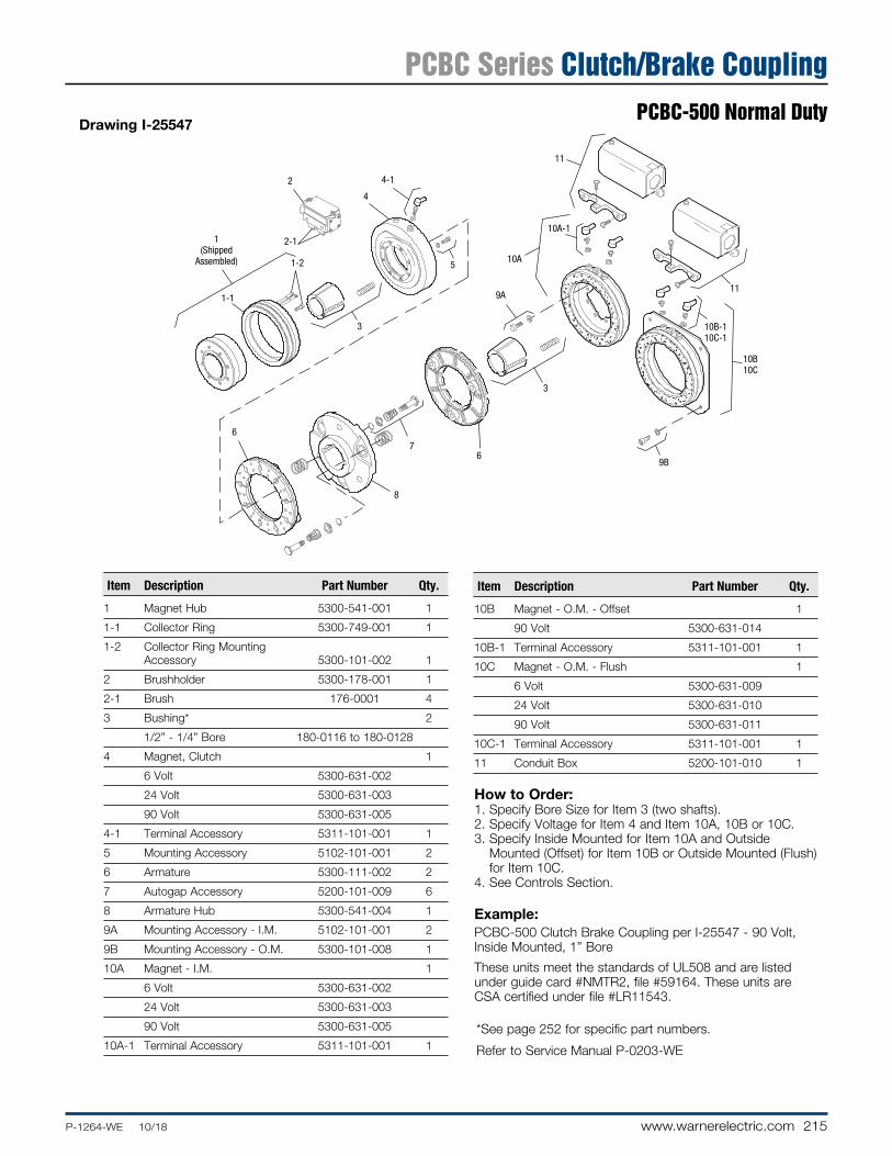
215P-1264-WE 10/18 www.warnerelectric.com
Drawing I-25547
How to Order:1. Specify Bore Size for Item 3 (two shafts).2. Specify Voltage for Item 4 and Item 10A, 10B or 10C.3. Specify Inside Mount ed for Item 10A and Outside
Mounted (Offset) for Item 10B or Outside Mounted (Flush) for Item 10C.
4. See Controls Section.
Example:PCBC-500 Clutch Brake Coupling per I-25547 - 90 Volt, Inside Mount ed, 1” Bore
These units meet the standards of UL508 and are listed under guide card #NMTR2, file #59164. These units are CSA certified under file #LR11543.
1(Shipped
Assembled)
2
2-1
1-1
1-2
3
4
4-1
5
6
8
76
3
9A
10A
10A-1
11
9B
11
10B-110C-1
10B10C
Item Description Part Number Qty.
1 Magnet Hub 5300-541-001 1
1-1 Collector Ring 5300-749-001 1
1-2 Collector Ring Mounting Accessory 5300-101-002 1
2 Brushholder 5300-178-001 1
2-1 Brush 176-0001 4
3 Bushing* 2
1/2” - 1/4” Bore 180-0116 to 180-0128
4 Magnet, Clutch 1
6 Volt 5300-631-002
24 Volt 5300-631-003
90 Volt 5300-631-005
4-1 Terminal Accessory 5311-101-001 1
5 Mounting Accessory 5102-101-001 2
6 Armature 5300-111-002 2
7 Autogap Accessory 5200-101-009 6
8 Armature Hub 5300-541-004 1
9A Mounting Accessory - I.M. 5102-101-001 2
9B Mounting Accessory - O.M. 5300-101-008 1
10A Magnet - I.M. 1
6 Volt 5300-631-002
24 Volt 5300-631-003
90 Volt 5300-631-005
10A-1 Terminal Accessory 5311-101-001 1
Item Description Part Number Qty.
10B Magnet - O.M. - Offset 1
90 Volt 5300-631-014
10B-1 Terminal Accessory 5311-101-001 1
10C Magnet - O.M. - Flush 1
6 Volt 5300-631-009
24 Volt 5300-631-010
90 Volt 5300-631-011
10C-1 Terminal Accessory 5311-101-001 1
11 Conduit Box 5200-101-010 1
* See page 252 for specific part numbers.
Refer to Service Manual P-0203-WE
PCBC Series Clutch/Brake CouplingPCBC-500 Normal Duty

216 www.warnerelectric.com P-1264-WE 10/18
Armature Shaft .500 – 1.250
Magnet Shaft .750 – 1.250
Static Torque 40 lb. ft.
Maximum Speed 5,400 rpm
Standard Voltage D.C. 6, 24, 90
Outside Mounted Flush Backing Plate
Customer Shall Maintain:1. Squareness of brake mounting face with armature hub
shaft within .006 T.I.R.
2. Concentricity of brake mounting pilot diameter with ar ma ture hub shaft within .010 T.I.R.
3. Concentricity of clutch magnet hub assembly shaft with armature hub shaft within .006 T.I.R.
.953
.468 Max.
1.1254.875
5.734 Max.
.906
Outside Mounted Offset Backing Plate
2.687
3.953Pilot Dia.
4 .390
.062WhenNew
1.187
1.031
1.093
.171
.062 When New
5.890 .515
3/8-16 UNC-2A
5.937 Running
Dia. Max.
1.375 1.281
1.062
.9842.3751.500
8-32 UNC-3A
1.546
1.937
4.953
5.031
5.812
5.125
2.0652.063
Bore and Keyway Dimensions Armature Keyway Bore Dia.
.751/.750 .187 x .093 .876/.875
.9385/.9375 1.001/1.000 1.126/1.125 .250 x .125 1.251/1.250
MAGNET VIEW
* Mounting holes are within .010 of true position relative to pilot di am e ter.
** Mounting holes are within .008 of true position relative to pilot di am e ter.
Removable plug in ends for 1/2” conduit.
6.500/6.498 Pilot Dia.
45°
For Bore & Keyway sizes see
chart below. .208/.201 dia. (8) holes equally spaced on 2.375 dia.*
.399/.389 dia. (4) holes equally spaced on 5.875 dia.**
3.750
5.062
5
COLLECTOR RING VIEW
1/2-14 NPSM Am. std. straight pipe tap.
See page 252 for details on Bushings.
All dimensions are nominal unless otherwise noted.
Information on inertia and weights begins on page 239. Coil data is on pages 250 and 251.
PCBC Series Clutch/Brake CouplingPCBC-500 Heavy Duty

217P-1264-WE 10/18 www.warnerelectric.com
Drawing I-25553
How to Order:1. Specify Bore Size for Items 3 and 7.2. Specify Voltage for Item 4 and Item 9A, 9B or 9C.3. Specify Inside Mounted for Item 9A and Outside Mounted
(Offset) for Item 9B or Outside Mounted (Flush) for Item 9C.
4. Specify Inside Mount for Item 8A or Outside Mount for Item 8B.
5. See Controls Section.
Example:PCBC-500 Clutch Brake Coupling per I-25553 - 90 Volt, Outside Mounted Flush, 1” Bore
These units meet the standards of UL508 and are listed under guide card #NMTR2, file #59164. These units are CSA certified under file #LR11543.
2
2-11
(ShippedAssembled) 1-2
1-1
3
4
4-1
5
9A
8A
6
7
6
10
9A-1
10
9B-19C-1
9B9C
8B
Item Description Part Number Qty.
1 Magnet Hub 5300-541-001 1
1-1 Collector Ring 5300-749-001 1
1-2 Collector Ring Mounting Accessory 5300-101-002 1
2 Brushholder 5300-178-001 1
2-1 Brush 176-0001 4
3 Bushing* 1
1/2” - 1-1/4” Bore 180-0116 to 180-0128
4 Magnet, Clutch 1
6 Volt 5300-631-002
24 Volt 5300-631-003
90 Volt 5300-631-005
4-1 Terminal Accessory 5311-101-001 1
5 Mounting Accessory 5102-101-001 2
6 Armature 5230-111-002 2
7 Armature Hub 1
Bore Keyway
3/4” 3/16 x 3/32 5300-541-006
7/8” 3/16 x 3/32 5300-541-007
15/16” 1/4 x 1/8 5300-541-008
1” 1/4 x 1/8 5300-541-009
1-1/8” 1/4 x 1/8 5300-541-010
1-1/4” 1/4 x 1/8 5300-541-011
8A Mounting Accessory - I.M. 5102-101-001 2
8B Mounting Accessory - O.M. 5300-101-008 1
9A Magnet - I.M. 1
6 Volt 5300-631-002
24 Volt 5300-631-003
90 Volt 5300-631-005
Item Description Part Number Qty.
9A-1 Terminal Accessory 5311-101-001 1
9B Magnet - O.M. - Offset 1
90 Volt 5300-631-014
9B-1 Terminal Accessory 5311-101-001 1
9C Magnet - O.M. - Flush 1
6 Volt 5300-631-009
24 Volt 5300-631-010
90 Volt 5300-631-011
9C-1 Terminal Accessory 5311-101-001 1
10 Conduit Box 5200-101-010 1
* See page 252 for specific part numbers.
Refer to Service Manual P-0203-WE
PCBC Series Clutch/Brake CouplingPCBC-500 Heavy Duty

218 www.warnerelectric.com P-1264-WE 10/18
Armature Shaft .500 – 1.500
Magnet Shaft .500 – 1.625
Static Torque 125 lb.ft.
Maximum Speed 4,000 rpm
Standard Voltage D.C. 6, 24, 90
* Mounting holes are within .010 of true position relative to pilot diameter.
Customer Shall Maintain:1. Armature mounting shaft concentric with magnet mounting
shaft within .006 T.I.R.
2. Squareness of brake magnet mounting face with magnet mounting shaft within .006 T.I.R.
3. Concentricity of brake magnet mounting pilot di am e ter with magnet mounting shaft within .010 T.I.R.
4. Angular alignment of shafts within 1/2 degree.
.062
.5311.312
.562
9.437 8.625 2.500
1.312.562
2.562 Dia.
5.656
1.546
.171 Max.
.921
5.750
5/16-18 UNC-3A
.093 When New
2.718
1.250 1.500
1.765 1.593.156
6.250 Max.
1.437
ARMATURE VIEW
See page 252 for details on Bushings.
MAGNET VIEW(Inside & Outside Mounted)
Removable plug in ends for 1/2” conduit.
.358/.338 dia. (6) holes equally spaced on 4.250 dia.*
3.503/3.501 Pilot Dia.
9.749/9.747 Pilot Dia.
.358/.338 dia. (4) holes equally spaced on 8.875 dia.*
6.812
See page 252 for details on Bushings.
3.750
All dimensions are nominal unless otherwise noted.
Information on inertia and weights begins on page 239. Coil data is on pages 250 and 251.
PCBC Series Clutch/Brake CouplingPCBC-825

219P-1264-WE 10/18 www.warnerelectric.com
Drawing I-25570
How to Order:1. Specify Bore Size for Items 1 and 9.2. Specify Voltage for Items 6 and 13.3. Specify left hand or right hand hub for Item 7. Bushing
enters from magnet side for L.H. hub and from hub side for R.H.
4. Specify Inside Mounted for Items 12A and 13A or Outside Mounted for Items 12B and 13B.
5. See Controls Section.
Example:PCBC-825 Clutch Brake Coupling per I-25570 - 90 Volt, Inside Mounted, Left Hand hub, 1” Bore, ( Items 1 and 9)
These units meet the standards of UL508 and are listed under guide card #NMTR2, file #59164. These units are CSA certified under file #LR11543.
1
2
3
4-1
4-2
4-3
4-5
4 5
66-1
9
4-4
7-1
7-2
7(Shipped Assembled)
11
8-1
8
10 12A
13A
13A-1
14
14
13B
13B-1
12B
Item De scrip tion Part Number Qty.
1 Bushing* - 1/2” to 1-1/2” Bore 180-0002 to 180-0018 1
2 Retainer Ring 748-0006 1
3 Splined Hub 540-0057 1
4 Armature & Splined Adapter 5321-111-001 1
4-1 Locknut 661-0004 3
4-2 Armature 5321-111-022 1
4-3 Splined Adapter 104-0008 1
4-4 Autogap Accessory 5321-101-006 1
4-5 Screw 797-0272 3
5 Mounting Accessory 5321-101-001 1
6 Magnet 1
6 Volt 5301-631-002
24 Volt 5301-631-004
90 Volt 5301-631-005
†90 Volt LK Facing 5301-631-011
6-1 Terminal Accessory 5311-101-001 1
7 Magnet Hub 1
Left Hand (shown) 5301-541-001
Right Hand 5301-541-002
7-1 Collector Ring 5301-749-001 1
7-2 Collector Ring Accessory 5301-101-002 1
8 Brushholder 5300-178-001 1
8-1 Brush 176-0001 4
9 Bushing* - 1/2” to 1-5/8” Bore 180-0131 to 180-0149 1
10 Armature 5301-111-018 1
11 Autogap Accessory 5201-101-008 3
12A Mounting Accessory - I.M. 5321-101-001 1
12B Mounting Accessory - O.M. 5321-101-002 1
13A Magnet - Inside Mounted 1
6 Volt 5311-631-002
Item De scrip tion Part Number Qty.
24 Volt 5311-631-003
90 Volt 5311-631-004
†90 Volt LK Facing 5311-631-011
13A-1 Terminal Accessory 5311-101-001 1
13B Magnet - Outside Mounted 1
6 Volt 5311-631-007
24 Volt 5311-631-009
90 Volt 5311-631-008
†90 Volt LK Facing 5311-631-012
13B-1 Terminal Accessory 5311-101-001 1
14 Conduit Box 5200-101-011 1
* See page 252 for specific part numbers.
Refer to Service Manual P-0205-WE
† Optional LK facing available. For more information, see page 232.
PCBC Series Clutch/Brake CouplingPCBC-825

220 www.warnerelectric.com P-1264-WE 10/18
Armature Shaft .750 – 2.687
Magnetic Shaft .500 – 2.500
Static Torque 240 lb.ft.
Maximum Speed 3,600 rpm
Standard Voltage D.C. 6, 24, 90
* Mounting holes are within .010 of true position relative to pilot diameter.
Customer Shall Maintain:1. Armature mounting shaft concentric with magnet mounting
shaft within .006 T.I.R.
2. Squareness of brake magnet mounting face with magnet mounting shaft within .006 T.I.R.
3. Concentricity of brake magnet mounting pilot di am e ter with magnet mounting shaft within .010 T.I.R.
4. Angular alignment of shafts within 1/2 degree.
.062
.5001.453
.562
11.09310.296
4.093
1.453.562
4.125 Dia.
6.531
1.546
.171 Max.
.921
5.750
5/16-18 UNC-3A
.093 When New
2.906
2.500 1.750
2.687 1.906.234
7.843 Max.
1.750
ARMATURE VIEW
See page 252 for details on Bushings.
MAGNET VIEW(Inside & Outside Mounted)
Removable plug in ends for 1/2” conduit.
.358/.338 dia. (6) holes equally spaced on 6.125 dia.*
5.378/5.376 Pilot Dia.
11.500/11.498 Pilot Dia.
.358/.338 dia. (8) holes equally spaced on 10.625 dia.*
7.687
See page 252 for details on Bushings.
3.750
All dimensions are nominal unless otherwise noted.
Information on inertia and weights begins on page 239. Coil data is on pages 250 and 251.
PCBC Series Clutch/Brake CouplingPCBC-1000

221P-1264-WE 10/18 www.warnerelectric.com
Drawing I-25590
How to Order:1. Specify Bore Size for Items 1 and 9.2. Specify Voltage for Items 6 and 13.3. Specify left hand or right hand hub for Item 7. Bushing
enters from magnet side for L.H. hub and from hub side for R.H.
4. Specify Inside Mounted for Items 12A and 13A or Outside Mounted for Items 12B and 13B.
5. See Controls Section.
Example:PCBC-1000 Clutch Brake Coupling per I-25590 - 90 Volt, Inside Mounted, Left Hand hub, 1-1/2” Bore, (Items 1 and 9)
These units meet the standards of UL508 and are listed under guide card #NMTR2, file #59164. These units are CSA certified under file #LR11543.
1
2
3
4-1
4-2
4-3
4-5
4(Shipped
Assembled)5
66-1
9
4-4
7-1
7-2
7(Shipped Assembled)
11
8-1
8
10 12A
13A
13A-1
14
14
13B
13B-1
12B
Item De scrip tion Part Number Qty.
1 Bushing* 1
3/4” to 2-11/16” Bore 180-0026 to 180-0057
2 Retainer Ring 748-0007 1
3 Splined Hub 540-0062 1
4 Armature & Splined Adapter 5322-111-002 1
4-1 Locknut 661-0004 3
4-2 Armature 5322-111-036 1
4-3 Splined Adapter 104-0009 1
4-4 Autogap Accessory 5322-101-004 1
4-5 Screw 797-0272 3
5 Mounting Accessory 5321-101-001 1
6 Magnet 1
6 Volt 5302-631-003
24 Volt 5302-631-014
90 Volt 5302-631-005
†90 Volt LK Facing 5302-631-001
6-1 Terminal Accessory 5311-101-001 1
7 Magnet Hub 1
Left Hand (shown) 5302-541-001
Right Hand 5302-541-002
7-1 Collector Ring 5301-749-001 1
7-2 Collector Ring Accessory 5302-101-002 1
8 Brushholder 5300-178-001 1
8-1 Brush 176-0001 4
9 Bushing* 1
1/2” to 2-1/2” Bore 180-0185 to 180-0217
10 Armature 5302-111-013 1
11 Autogap Accessory 5201-101-008 3
12A Mounting Accessory - I.M. 5321-101-001 1
12B Mounting Accessory - O.M. 5321-101-002 2
Item De scrip tion Part Number Qty.
13A Magnet - Inside Mounted 1
6 Volt 5312-631-004
24 Volt 5312-631-005
90 Volt 5312-631-006
†90 Volt LK Facing 5312-631-001
13A-1 Terminal Accessory 5311-101-001 1
13B Magnet - Outside Mounted 1
6 Volt 5312-631-011
24 Volt 5312-631-013
90 Volt 5312-631-012
†90 Volt LK Facing 5312-631-002
13B-1 Terminal Accessory 5311-101-001 1
14 Conduit Box 5200-101-011 1
* See page 252 for specific part numbers.
Refer to Service Manual P-0205-WE
† Optional LK facing available. For more information, see page 232.
PCBC Series Clutch/Brake CouplingPCBC-1000

222 www.warnerelectric.com P-1264-WE 10/18
Armature Shaft .750 – 2.687
Magnet Shaft .500 – 2.500
Static Torque Clutch 465 lb.ft.
Static Torque Brake 240 lb.ft.
Maximum Speed 3,000 rpm
Standard Voltage D.C. 6, 90
* Mounting holes are within .010 of true position relative to pilot diameter.
4.09313.140 12.625
1.640
1.750 .453
.062
.562
4.125
6.531
1.546
.171
.921
2.906
2.500
2.687
1.750
1.906
.562 Max.
5/16-18 UNC-3A
5.750
.234
8.062 Max.
.562
.093 When New
Customer Shall Maintain:1. Armature mounting shaft concentric with magnet mounting
shaft within .006 T.I.R.
2. Squareness of brake magnet mounting face with magnet mount ing shaft within .006 T.I.R.
3. Concentricity of brake magnet mounting pilot diameter with magnet mounting shaft within .010 T.I.R.
ARMATURE VIEW
See page 252 for details on Bushings.
MAGNET VIEW(Inside & Outside Mounted)
See page 252 for details on
Bushings.
Removable plug in ends for 1/2” conduit.
7.687
11.500/11.498 Pilot Dia.
.358/.338 dia. (8) holes equally spaced on 10.625 dia.*
.358/.338 dia. (6) holes equally spaced on 6.125 dia.*
5.378/5.376 Pilot Dia.
3.750
All dimensions are nominal unless otherwise noted.
Information on inertia and weights begins on page 239. Coil data is on pages 250 and 251.
PCBC Series Clutch/Brake CouplingPCBC-1225/1000

223P-1264-WE 10/18 www.warnerelectric.com
Drawing I-25613
How to Order:1. Specify Bore Size for Item 1 and 9.2. Specify Voltage for Item 6 and Item 13A or 13B.3. Specify left hand or right hand hub for Item 7. Bushing enters
from magnet side for L.H. hub and from hub side for R.H.4. Specify Inside Mounted for Items 12A and 13A or Outside
Mount ed for Items 12B and 13B.5. See Controls Section.
Example:PCBC-1225/1000 Clutch Brake Coupling per I-25613 - 90 Volt, Inside Mounted, Left Hand hub, 1-3/4” Bore (Items 1 and 9).
These units meet standards set forth in UL508 and are listed under guide card #NMTR2, file #59164. These units are CSA certified under file #LR11543.
* See page 252 for specific part numbers.
Refer to Service Manual P-0214-WE
† Optional LK facing available. For more information, see page 232.
**24 Volt is available as a special.
1
2
3
4-1
4-2
4-3
4-6
4-4
4(Shipped
Assembled)
5
6
6-1
9
8
8-1
7-1
7-2
7 (Shipped Assembled)
11
10 12A
13A 13A-1
14
14
13B
13B-1
12B
Item Description Part Number Qty.
1 Bushing* 1
3/4” to 2-11/16” Bore 180-0026 to 180-0057
2 Retainer Ring 748-0005 1
3 Splined Hub 540-0064 1
4 Armature & Splined Adapter 5323-111-001 1
4-1 Locknut 661-0005 4
4-2 Armature 5323-111-034 1
4-3 Splined Adapter 104-0010 1
4-4 Autogap Accessory 5323-101-002 1
4-6 Screw 797-0281 4
5 Mounting Accessory 5321-101-001 1
6 Magnet** 1
6 Volt 5333-631-008
90 Volt 5333-631-009
†90 Volt LK Facing 5333-631-013
6-1 Terminal Accessory 5311-101-001 1
7 Magnet Hub 1
Left Hand (shown) 5302-541-004
Right Hand 5302-541-005
7-1 Collector Ring 5301-749-001 1
7-2 Collector Ring Accessory 5303-101-004 1
8 Brushholder 5300-178-001 1
8-1 Brush 176-0001 4
9 Bushing* 1
1/2” to 2-1/2” Bore 180-0185 to 180-0217
10 Armature 5302-111-013 1
11 Autogap Accessory 5201-101-008 3
12A Mounting Accessory - I.M. 5321-101-001 1
12B Mounting Accessory - O.M. 5321-101-002 2
13A Magnet - Inside Mounted 1
6 Volt 5312-631-004
Item Description Part Number Qty.
24 Volt 5312-631-005
90 Volt 5312-631-006
†90 Volt LK Facing 5312-631-001
13A-1 Terminal Accessory 5311-101-001 1
13B Magnet - Outside Mounted 1
6 Volt 5312-631-011
24 Volt 5312-631-013
90 Volt 5312-631-012
†90 Volt LK Facing 5312-631-002
13B-1 Terminal Accessory 5311-101-001 1
14 Conduit Box 5200-101-011 1
PCBC Series Clutch/Brake CouplingPCBC-1225/1000

224 www.warnerelectric.com P-1264-WE 10/18
Armature Shaft .750 – 2.687
Magnet Shaft .937 – 3.000
Static Torque 465 lb.ft.
Maximum Speed 3,000 rpm
Standard Voltage D.C. 6, 24, 90
* Mounting holes are within .010 of true position relative to pilot diameter.
Customer Shall Maintain:1. Armature mounting shaft concentric with magnet mount ing
shaft within .006 T.I.R.
2. Squareness of brake magnet mounting face with magnet mounting shaft within .006 T.I.R.
3. Concentricity of brake magnet mounting pilot diameter with magnet mounting shaft within .010 T.I.R.
4. Angular alignment of shafts within 1/2 degree.
13.140
4.093.234
12.625
.562 1.640
2.187
.593
1.640
.093When New
4.625
7.5315.750
1.546
.171
.921
3.250
5/16-18 UNC-3A
.562
3.000
3.156
2.500
2.687
.062
8.718 Max.
MAGNET VIEW(Inside & Outside Mounted)
Removable plug in ends for 1/2” conduit.
.358/.338 dia. (6) holes equally spaced on 7.250 dia.*
6.378/6.376 Pilot Dia.
13.875/13.871 Pilot Dia.
.358/.338 dia. (8) holes equally spaced on 13.000 dia.*
8.687
See page 252 for details on Bushings.
3.750
ARMATURE VIEW
See page 252 for details on Bushings.
All dimensions are nominal unless otherwise noted.
Information on inertia and weights begins on page 239. Coil data is on pages 250 and 251.
PCBC Series Clutch/Brake CouplingPCBC-1225

225P-1264-WE 10/18 www.warnerelectric.com
12
3
4-1
4-2
4-3
4-5
5
66-1
9
7(Shipped
Assembled)
4(Shipped
Assembled)
8-1
8
7-1
7-2
11
10
12A
13A
13A-1
14
14
13B-1
13B
12B
4-4
Item Description Part Number Qty.
1 Bushing* 1
3/4” to 2-11/16” Bore 180-0026 to 180-0057
2 Retainer Ring 748-0005 1
3 Splined hub 540-0064 1
4 Armature & Splined Adapter 5323-111-001 1
4-1 Locknut 661-0005 4
4-2 Armature 5323-111-034 1
4-3 Splined Adapter 104-0010 1
4-4 Autogap Accessory 5323-101-002 1
4-5 Screw 797-0281 4
5 Mounting Accessory 5321-101-001 1
6 Magnet 1
6 Volt 5303-631-005
24 Volt 5303-631-007
90 Volt 5303-631-008
†90 Volt LK Facing 5303-631-001
6-1 Terminal Accessory 5311-101-001 1
7 Magnet Hub 1
Left Hand (shown) 5303-541-001
Right Hand 5303-541-002
7-1 Collector Ring 5301-749-001 1
7-2 Collector Ring Assembly 5303-101-004 1
8 Brushholder 5300-178-001 1
8-1 Brush 176-0001 4
9 Bushing* 1
15/16” to 3” Bore 180-0262 to 180-0295
10 Armature 5303-111-009 1
11 Autogap Accessory 5201-101-008 4
12A Mounting Accessory - I.M. 5321-101-001 1
12B Mounting Accessory - O.M. 5321-101-002 2
Item Description Part Number Qty.
13A Magnet - Inside Mounted 1
6 Volt 5313-631-005
24 Volt 5313-631-006
90 Volt 5313-631-007
†90 Volt LK Facing 5313-631-001
13A-1 Terminal Accessory 5311-101-001 1
13B Magnet - Outside Mounted 1
6 Volt 5313-631-010
24 Volt 5313-631-012
90 Volt 5313-631-011
†90 Volt LK Facing 5313-631-002
13B-1 Terminal Accessory 5311-101-001 1
14 Conduit Box 5200-101-011 1
How to Order:1. Specify Bore Size for Items 1 and 9.2. Specify Voltage for Items 6 and 13.3. Specify left hand or right hand hub for Item 7. Bushing
enters from magnet side for L.H. hub and from hub side for R.H.
4. Specify Inside Mounted for Items 12A and 13A or Outside Mounted for Items 12B and 13B.
5. See Controls Section.
Example:PCBC-1225 Clutch Brake Coupling per I-25612 - 90 Volt, Inside Mounted Left Hand hub, 1-3/4” Bore (Items 1 and 9)
These units meet the standards of UL508 and are listed under guide card #NMTR2, file #59164. These units are CSA certified under file #LR11543.
* See page 252 for specific part numbers.
Refer to Service Manual P-0205-WE
† Optional LK facing available. For more information, see page 232.
Drawing I-25612
PCBC Series Clutch/Brake CouplingPCBC-1225

226 www.warnerelectric.com P-1264-WE 10/18
Armature Shaft .750 – 2.687
Magnet Shaft .937 – 3.000
Static Torque Clutch 700 lb.ft.
Static Torque Brake 465 lb.ft.
Maximum Speed 2,000 rpm
Standard Voltage D.C. 6, 24, 90
* Mounting holes are within .010 of true position relative to pilot diameter.
.234
.562
4.625
7.5315.750
1.546
16.250
15.578
4.093
.5621.750
.5931.640
.171
.921
5/16-18 UNC-3A
3.250
3.000
3.1872.687
2.500
2.312
8.937 Max.
.062 .093 New
Customer Shall Maintain:1. Armature mounting shaft concentric with magnet mounting
shaft within .006 T.I.R.
2. Squareness of brake magnet mounting face with magnet mounting shaft within .006 T.I.R.
3. Concentricity of brake magnet mounting pilot diameter with magnet mounting shaft within .010 T.I.R.
ARMATURE VIEW
See page 252 for details on Bushings.
MAGNET VIEW(Inside & Outside Mounted)
Removable plug in ends for 1/2” conduit.
.358/.338 dia. (6) holes equally spaced on 7.250 dia.*
6.378/6.376 Pilot Dia.
13.875/13.871 Pilot Dia.
.358/.338 dia. (8) holes equally spaced on 13.000 dia.*
8.687
See page 252 for details on Bushings.
3.750
All dimensions are nominal unless otherwise noted.
Information on inertia and weights begins on page 239. Coil data is on pages 250 and 251.
PCBC Series Clutch/Brake CouplingPCBC-1525/1225

227P-1264-WE 10/18 www.warnerelectric.com
12
3
4-1
4-2
4-3
4-4
4-5
4-64(Shipped Assembled)
5
8-1
9
7-27-111
12B
13B-1
13B
13A
13A-1
12A
8 10
14
14
7 (Shipped Assembled)
6 6-1Drawing I-25637
Item Description Part Number Qty.
1 Bushing* 1
3/4” to 2-11/16” Bore 180-0026 to 180-0057
2 Retainer Ring 748-0005 1
3 Splined Hub 540-0064 1
4 Armature & Splined Adapter 5324-111-001 1
4-1 Locknut 661-0004 8
4-2 Armature 5324-111-034 1
4-3 Splined Adapter 104-0011 1
4-4 Autogap Accessory 5323-101-002 1
4-5 Retainer Plate 686-0003 1
4-6 Screw 797-0272 8
5 Mounting Accessory 5321-101-001 2
6 Magnet 1
6 Volt 5304-631-009
24 Volt 5304-631-011
90 Volt 5304-631-010
†90 Volt LK Facing 5304-631-002
6-1 Terminal Accessory 5311-101-001 1
7 Magnet Hub 1
Left Hand (shown) 5304-541-001
Right Hand 5304-541-002
7-1 Collector Ring 5301-749-001 1
7-2 Collector Ring Accessory 5304-101-004 1
8 Brushholder 5300-178-001 1
8-1 Brush 176-0001 4
9 Bushing* 1
15/16” to 3” Bore 180-0262 to 180-0295
10 Armature 5303-111-009 1
11 Autogap Accessory 5201-101-008 4
12A Mounting Accessory - I.M. 5321-101-001 1
Item Description Part Number Qty.
12B Mounting Accessory - O.M. 5321-101-002 2
13A Magnet - Inside Mounted 1
6 Volt 5313-631-005
24 Volt 5313-631-006
90 Volt 5313-631-007
†90 Volt LK Facing 5313-631-001
13A-1 Terminal Accessory 5311-101-001 1
13B Magnet - Outside Mounted 1
6 Volt 5313-631-010
24 Volt 5313-631-012
90 Volt 5313-631-011
†90 Volt LK Facing 5313-631-002
13B-1 Terminal Accessory 5311-101-001 1
14 Conduit Box 5200-101-010 1
How to Order:1. Specify Bore Size for Items 1 and 9.2. Specify Voltage for Item 6 and 13A or 13B.3. Specify left hand or right hand hub for Item 7. Bushing
enters from magnet side for L.H. hub and from hub side for R.H.
4. Specify Inside Mounted for Items 12A and 13A or Outside Mounted for Items 12B and 13B.
5. See Controls Section.
Example:PCBC-1525/1225 Clutch Brake Coupling per I-25637 - 90 Volt, Inside Mount ed, Left Hand hub, 2” Bore (Items 1 and 9)
These units meet the standards of UL508 and are listed under guide card #NMTR2, file #59164. These units are CSA certified under file #LR11543.
* See page 252 for specific part numbers.
Refer to Service Manual P-0214-WE
† Optional LK facing available. For more information, see page 232.
PCBC Series Clutch/Brake CouplingPCBC-1525/1225

228 www.warnerelectric.com P-1264-WE 10/18
Notes

229P-1264-WE 10/18 www.warnerelectric.com
Drive Pin Mounting ................................................................................................ 230
Autogap Applications ............................................................................................ 231
LK Friction Material ............................................................................................... 232
Theory of Operation .............................................................................................. 233
Dynamic Torque Curves ...................................................................................... 234
Heat Dissipation Formulae ................................................................................... 236
Heat Dissipation Curves ....................................................................................... 237
Inertia Values ......................................................................................................... 238
Weights and Inertias ............................................................................................. 239
Rotational Speed/Burnishing ............................................................................... 244
Clutch Field Restraining Devices/Torque Arms ................................................. 245
UL/UR/CSA ............................................................................................................ 246
Cycle Rate Curves ................................................................................................. 247
Electrical Coil Ratings .......................................................................................... 248
Electrical Installation Recommendations ........................................................... 249
Coil Suppression and Overlap ............................................................................. 250
Overexcitation ........................................................................................................ 251
Bushing Part Numbers .......................................................................................... 252
Conversion Factors ............................................................................................... 254
Glossary of Terms ................................................................................................. 255
Ordering Information ............................................................................................ 257
Clutch and Brake Controls ................................................................................... 261
Application Engineering - Mechanical Data

230 www.warnerelectric.com P-1264-WE 10/18
Machining instructions for gear, sprocket or pulley
D
CAB
Unit Size A B C D 500 3.356 ± .001 3.875 ± .001
650 3.624 ± .001 5.125 ± .001
825 3.085 ± .001 3.563 ± .001
1000 4.548 ± .002 5.252 ± .002
1225 4.155 ± .002 5.877 ± .002
1525 6.010 ± .002 8.500 ± .002
1. Chordal dimensions must be held for all chords between pin holes.
Size 825-15252. Drill 27/64 inch diameter holes to a sufficient
depth and tap for 1/2-13 UNC-3B, one inch minimum full threads. Pin holes must be concentric with mounting shaft within .010 T.I.R. and parallel with mounting shaft within .002 T.I.R., surface that pins seat against to be square with mounting shaft within .004 T.I.R.
3. Ream .500/.501 to a 3/8 inch depth and to be concentric with tapped holes.
Size 500 and 6504. Sleeve bearings (oilite bronze) must be provided
in the holes of pulley or hub with an I.D. of .376 ± .001 at the chordal and bolt circle dimensions shown above.
5. The drive pin holes must be concentric with mounting shaft within .006 T.I.R. and parallel with mounting shaft within .002 T.I.R.
1-3/8"
7/8" 1/16"
5/16"–24 UNF–3AThreads
.3665" .0005" Dia.
Size 500-650 Drive Pin
1-9/32" 5/16"
2-1/4"
1/2"–13 UNC–3AThreads
Size 825-1525 Drive Pin+.0005"
.6185" Dia.–.0010"
Drive Pin Mounting

231P-1264-WE 10/18 www.warnerelectric.com
Autogaps – When Not To UseThe Autogap is a system de signed to sep a rate the armature from the friction face. This spacing is automatic and occurs prior to total mag net ic decay, effectively eliminating noise by pre vent ing drag. Although Autogaps are desirable and nec es sary in the vast majority of applications, they should be removed when using over-excitation controls for fast response and high accuracy or when very soft starts and stops with low voltage to the clutch or brake are required. Removing the Autogap assembly closes the gap between the armature and magnet or field, resulting in reduced engagement time, improved repeatability, and the ability to engage the armature at very low voltage settings required for very soft starts and stops.
Pin Drive ApplicationsOn pin drive armatures, the Autogap can be re moved by taking out the entire assembly except the ar ma ture backup spring, which should remain in place to slightly preload the armature against the friction face. On Electro-Modules, the Autogap device is con tained within the retaining cup screwed onto each armature.
To disable the assembly, only the Au to-gap spring should be removed and the balance of the cup contents should be reinstalled. With spline drives, the Autogap system must first be removed and then the detent spring should be placed directly behind the armature to prevent spinback from vibration.
Heavy Duty Spline Drive AutogapsWarner Electric’s patented Autogap system is the reason Warner Electric clutches and brakes require no ad just-ment and offer consistent performance throughout the life of the unit. Without a wear take-up system, armature and magnet or rotor wear will eventually prevent the magnet coil from “pulling in” the armature and the clutch or brake will fail to respond when energized. A wear compensating system which maintains a constant, optimal space between the armature and the magnet or rotor is nec-es sary to achieve consistent per for mance without manual adjustment.
Spline drive hubs which utilize the Autogap system pictured are found on all Warner Electric heavy duty Custom Design clutches and brakes, as well as Electro Modules, Electro Packs and Advanced Technology (AT) clutches and brakes.
How They WorkAs material wears off the magnet or rotor and armature during operation, gap “X” increases. When the clutch or brake is energized, the armature is mag net i cal-ly pulled to the magnet or rotor. If gap “X” is larger than gap “Y”, the lip on the retainer plate will push on the detent ring overcoming the grip force between the detent ring and outside diameter of the splined hub, moving the detent ring. This adjusts gap “X” to be the same as gap “Y”, and will maintain that gap over the life of the unit. When the unit is de-energized, the spring pushes against the detent ring and the retainer plate, which is secured to the armature. The ar ma ture assembly au to mat i cal ly moves away from the magnet or rotor by gap “X” each time the clutch or brake is cycled.
How to SetIf the armature does not engage when the unit is en er gized, gap “X” has increased to a point where the magnetic pull cannot overcome the excess gap.
Armature
Detent Ring
Retainer Plate
Spring
Gap “Y”
SplinedHub
Magnet orRotor Face
Gap “X”
This can happen with excess vibration or mis han dling. To reset the autogap, move the armature assembly toward the magnet or rotor. This can be done by 1) or 2) below:
1) Preferable – If an adjustable power supply is available, voltage can be increased for a short time to over come the excess gap and pull the armature in to reset the gap.
2) If increased voltage is not available or is in ad e quate, the armature must be manually pushed toward the magnet or rotor until available voltage will pull it in. Slots are provided in electromodule fans for access to the armatures. When pushing the armature, the force must be applied against the retainer plate outer ring and not against the detent ring itself.
If the detent ring has been moved too close to the magnet or rotor, reducing gap “X” and causing drag, the armature must be manually moved away from the unit and then be readjusted as described above.
Design Features Application EngineeringAutogap® Application

232 www.warnerelectric.com P-1264-WE 10/18
Warner Electric offers a special low coefficient (LK) friction material for many standard clutches and brakes. Since two friction materials are available, a comparison of LK to standard is in order.
Since LK has a lower coefficient of friction, lower torque capability results. With LK facing, static torque capacity is only about 60% of catalog rating for any given size. So if a specific size clutch or brake is chosen for its rated torque capacity and LK facings are substituted for standard, a larger size unit will be needed to provide the same torque.
If lower torque ratings can be considered a dis ad van tage, what are the ad van tag-es of LK material? The first is longer life. An ideal situation for LK use is a constant slip ap pli ca tion which requires a large unit for high heat dis si pa tion. Another feature of LK is “softer” pickup. Since more slippage will occur, en gage ment time is increased and shock is reduced. LK material will also reduce en gage ment
noise, so it can be suc cess ful ly employed where high noise levels are a problem. It is the standard facing in all tension brakes and motor brake magnets. LK has been a popular special feature for many years, enabling us to offer it in the following sizes with no special handling charge. Delivery can usually be made in 30 days, and quite often im me di ate ly from our stock. No hard and fast rules can be written to cover LK application, but this option can be used to solve application problems. For price, delivery, and further in for ma tion, contact your Warner Electric Dis trib u tor.
LK can be added to any magnet or rotor. For those not shown below added lead time and cost will be required. Consult factory for additional details.
Stationary Field Clutches
DescriptionPage No.
Rotor Part No.- LK
Re plac es Stan dard Rotor
SF-825, F.M., N.D. 36 5201-751-007 5201-751-003SF-825, F.M., H.D. 40 5201-751-007 5201-751-003SFC-825, F.M. 114 5201-751-007 5201-751-003SF-825, B.M., N.D. 38 5201-751-014 5201-751-008SF-825, B.M., H.D. 42 5201-751-014 5201-751-008SFC-825, B.M. 116 5201-751-014 5201-751-008SF-1000, F.M., N.D. 44 5202-751-007 5202-751-003SF-1000, F.M., H.D. 48 5202-751-007 5202-751-003SFC-1000, F.M. 118 5202-751-007 5202-751-003SF-1000, B.M., N.D. 46 5202-751-007 5202-751-003SF-1000, B.M., H.D. 50 5202-751-007 5202-751-003SFC-1000, B.M. 120 5202-751-007 5202-751-003SF-1225, F.M., N.D. 52 5203-751-004 5203-751-001SF-1225, F.M., H.D. 54 5203-751-004 5203-751-001SFC-1225, F.M. 122 5203-751-004 5203-751-001SF-1225, B.M., N.D. 56 5203-751-004 5203-751-001SF-1225, B.M., H.D. 58 5203-751-004 5203-751-001SFC-1225, B.M. 124 5203-751-004 5203-751-001SF-1525, F.M., N.D. 60 5204-751-004 5204-751-002SF-1525, F.M., H.D. 62 5204-751-004 5204-751-002SFC-1525, F.M. 126 5204-751-004 5204-751-002SF-1525, B.M., N.D. 64 5204-751-004 5204-751-002SF-1525, B.M., H.D. 66 5204-751-004 5204-751-002SFC-1525, B.M. 128 5204-751-004 5204-751-002
Primary Clutches
DescriptionPage No.
Magnet Part No.- LK
Replaces Stan dard
Mag net No.PC-825, N.D., 90V 74 5301-631-011 5301-631-005PC-825, H.D., 90V 76 5301-631-011 5301-631-005PCC-825, 90V 138 5301-631-011 5301-631-005PC-1000, N.D., 90V 78 5302-631-001 5302-631-005PC-1000, H.D., 90V 80 5302-631-001 5302-631-005PCC-1000, 90V 140 5302-631-001 5302-631-005PC-1225, N.D., 90V 82 5303-631-001 5303-631-008PC-1225, H.D., 90V 84 5303-631-001 5303-631-008PCC-1225, 90V 142 5303-631-001 5303-631-008PC-1525, N.D., 90V 86 5304-631-002 5304-631-010PC-1525, H.D., 90V 88 5304-631-002 5304-631-010PCC-1525, 90V 144 5304-631-002 5304-631-010
Primary Brakes
DescriptionPage No.
Magnet Part No.- LK
Replaces Stan dard
Mag net No.PB-500, N.D., I.M., 90V 154 5300-631-020 5300-631-005PB-500, N.D., O.M., 90V 154 5300-631-025 5300-631-011PB-500, H.D., I.M., 90V 156 5300-631-020 5300-631-005PB-500, H.D., O.M., 90V 156 5300-631-025 5300-631-011PB-825, N.D., I.M., 90V 160 5311-631-011 5311-631-004PB-825, N.D., O.M., 90V 160 5311-631-012 5311-631-008PB-825, H.D., I.M., 90V 162 5311-631-011 5311-631-004PB-825, H.D., O.M., 90V 162 5311-631-012 5311-631-008PB-1000, N.D., I.M., 90V 164 5312-631-001 5312-631-006PB-1000, N.D., O.M., 90V 164 5312-631-002 5312-631-012PB-1000, H.D., I.M., 90V 166 5312-631-001 5312-631-006PB-1000, H.D., O.M., 90V 166 5312-631-002 5312-631-012PB-1225, N.D., I.M., 90V 168 5313-631-001 5313-631-007PB-1225, N.D., O.M., 90V 168 5313-631-002 5313-631-011PB-1225, H.D., I.M., 90V 170 5313-631-001 5313-631-007PB-1225, H.D., O.M., 90V 170 5313-631-002 5313-631-011PB-1525, N.D., I.M., 90V 172 5314-631-001 5314-631-005PB-1525, H.D., I.M., 90V 174 5314-631-001 5314-631-005
Clutch/Brake CombinationsFor all clutch/brake combinations, for magnets other than those listed below, use the corresponding LK magnets from the PC and PB sections at left and above.
DescriptionPage No.
Replaces Magnet
Part No.- LK
Replaces Stan dard
Mag net No.PCB-1225/1000, N.D., 90V 196 5333-631-013 5333-631-009PCB-1225/1000, H.D., 90V 198 5333-631-013 5333-631-009
How to Order:Specify “LK facing” and substitute LK part number for standard part number.
Design Features Application EngineeringLK Friction Material

233P-1264-WE 10/18 www.warnerelectric.com
Warner Electric designed product uses electromagnetism to engage the clutches and brakes. When electric current is passed through a wire, lines of magnetic flux are created. Warner Electric uses coils of wire embedded into a C-shaped iron “shell”. When the electrical current is passed through the coil the shell is magnetized with the magnetism concentrating at the ends of the shell. These are also called “poles”. When a steel or iron plate is close to the poles it is attracted to them, and the two pieces clamp together. To accomplish stable operation, DC power is required for electric clutches and brakes.
In a PC type clutch or a brake, a cross section will appear like Figure 1. When DC power is applied a magnetic field causes the armature to clamp against the magnet. Since magnetism is the engaging force, it is appropriate in Warner Electric designs for the metal poles of the magnet to engage directly against the metal plate of the armature. Friction material is included in industrial clutches and brakes to provide longer life, greater heat dissipation and to reduce noise during engagement.
SF style clutches (Figure 2) have a stationary field and rotor in place of the magnet. They function in a similar manner. When current is applied to the field coil, magnetism is created. The magnetism travels to the rotor face where it engages the armature.
Figure 1
Figure 2
Mechanical Data Application EngineeringTheory of Operation

234 www.warnerelectric.com P-1264-WE 10/18
NOTES:Speed difference means the difference in speed between one friction face and the other at the moment of en gage ment. The intersection of the top curve and the speed difference is the maximum torque produced by the unit. When both friction faces are engaged and rotating at the same speed, the unit is said to be locked-in and produces the maximum static torque (zero speed difference).
The % lines indicate the percentage of full voltage being used. Example: If 90 volt unit runs at 45 volts, use the 50% line.Average Torque = Dynamic Torque at 1/2 operating speed. Example: If operating speed is 1800, use dynamic torque at 900.
100%
50%
8
6
4
2
00 20 40 60 80 100
Speed Difference in Hundreds of R.P.M.
Dyn
amic
Tor
que
– lb
./in.
Size 120 Maximum Speed 10,000 rpmStatic Torque 5 lb./in.
100%
50%
16
14
12
10
8
6
4
200 20 40 60 80 100
Speed Difference in Hundreds of R.P.M.
Dyn
amic
Tor
que
– lb
./in.
Size 170 Maximum Speed 10,000 rpmStatic Torque 15 lb./in.
100%
50%
0 16 32 48 64 80Speed Difference in Hundreds of R.P.M.
Dyn
amic
Tor
que
– lb
./in.
Size 250 Maximum Speed 7,500 rpmStatic Torque 70 lb./in.
80
70
60
50
40
30
20
100
100%
50%
0 10 20 30 40 50Speed Difference in Hundreds of R.P.M.
Dyn
amic
Tor
que
– lb
./in.
Size 400 Maximum Speed 4,500 rpmStatic Torque 270 lb./in.
320
280
240
200
160
120
80
400
100%50%35%
64
56
48
40
32
24
16
8
00 4 8 12 16 20 24 28 32 36 40
Speed Difference in Hundreds of R.P.M.
Dyn
amic
Tor
que
– lb
./ft.
Size 500-SF Maximum Speed 4,000 rpmStatic Torque 50 lb./ft.
100%
50%
25%
0 6 12 18 24 30 36 42 48 54 60
48
42
36
30
24
18
12
6
0
Speed Difference in Hundreds of R.P.M.
Dyn
amic
Tor
que
– lb
./ft.
Size 500-PC/PB
Maximum Speed 5,400 rpmStatic Torque 40 lb./ft.
100%
60%25%
0 4 8 12 16 20 24 28 32 36 40Speed Difference in Hundreds of R.P.M.
Dyn
amic
Tor
que
– lb
./ft.
Size 650 Maximum Speed 3,600 rpmStatic Torque 95 lb./ft.
96
84
72
60
48
36
24
12
0
NOTE: Torque values are in inch lbs. for size 400 and smaller, and in ft.lbs. for size 500 and larger.
Mechanical Data Application EngineeringDynamic Torque
100%
50%25%
160
140
120
100
80
60
40
20
00 4 8 12 16 20 24 28 32 36 40
Speed Difference in Hundreds of R.P.M.
Dyn
amic
Tor
que
– lb
./ft.
Size 825-SFBrg. Mtd.
Maximum Speed 3,600 rpmStatic Torque 150 lb./ft.

235P-1264-WE 10/18 www.warnerelectric.com
100%
25%50%
0 4 8 12 16 20 24 28 32 36 40Speed Difference in Hundreds of R.P.M.
Dyn
amic
Tor
que
– lb
./ft.
Size 825 Maximum Speed 4,000 rpmElectro-Pack 3,600 rpmStatic Torque 125 lb./ft.160
140
120
100
80
60
40
20
0
100%
0 4 8 12 16 20 24 28 32 36 40Speed Difference in Hundreds of R.P.M.
Dyn
amic
Tor
que
– lb
./ft.
Size 825-MB Maximum Speed 4,000 rpmStatic Torque 80 lb./ft.
80
70
60
50
40
30
20
10
0
100%
50%
25%
240
210
180
150
120
90
60
30
00 4 8 12 16 20 24 28 32 36 40
Speed Difference in Hundreds of R.P.M.
Dyn
amic
Tor
que
– lb
./ft.
Size 1000 Maximum Speed 3,600 rpmElectro-Pack 3,000 rpmStatic Torque 240 lb./ft.
100%
0 4 8 12 16 20 24 28 32 36 40
160
140
120
100
80
60
40
20
0
Speed Difference in Hundreds of R.P.M.
Dyn
amic
Tor
que
– lb
./ft.
Size 1000-MB Maximum Speed 3,600 rpmStatic Torque 160 lb./ft.
100%
60%
30%
0 3 6 9 12 15 18 21 24 27 30Speed Difference in Hundreds of R.P.M.
Dyn
amic
Tor
que
– lb
./ft.
Size 1225 Maximum Speed 3,000 rpmStatic Torque 465 lb./ft.
480
420
360
300
240
180
120
60
0
100%
320
280
240
200
160
120
80
40
00 4 8 12 16 20 24 28 32 36 40
Speed Difference in Hundreds of R.P.M.D
ynam
ic T
orqu
e –
lb./f
t.
Size 1225-MB Maximum Speed 3,000 rpmStatic Torque 260 lb./ft.
100%
30%
60%
0 2 4 6 8 10 12 14 16 18 20Speed Difference in Hundreds of R.P.M.
Dyn
amic
Tor
que
– lb
./ft.
Size 1525 Maximum Speed 2,000 rpmElectro-Pack 1,800 rpmStatic Torque 700 lb./ft.800
700
600
500
400
300
200
100
0
100%
0 5 10 15 20 25Speed Difference in Hundreds of R.P.M.
Dyn
amic
Tor
que
– lb
./ft.
Size 1525-Hi Torque
Maximum Speed 2,000 rpmStatic Torque 1,350 lb./ft.
2000
1750
1500
1250
1000
750
500
250
0
Mechanical Data Application EngineeringDynamic Torque

236 www.warnerelectric.com P-1264-WE 10/18
300°F
200°F
High
Medium
Low
Special
250°F
0 3 6 9 12 15 18 21 24 27 30Speed Difference in Hundreds of R.P.M.
Size 1225 Maximum Speed 3,000 rpm
Hea
t Inp
ut –
Tho
usan
ds o
f ft.l
bs./m
in. 160
140
120
100
80
60
40
20
0
To accelerate any part of a machine from rest to a given velocity or decelerate from a given velocity to rest, energy must be given to or taken from the part. This energy, neglecting friction and windage losses, is equal to the energy possessed by the part when moving at the given velocity.
Kinetic energy in parts that rotate about an axis such as gears, pulleys, and rotors is:
N 2 E = 1.7 x WR2 x –––– 100
Where:
N = RPM
E = Energy, ft.lb.
WR2 = Inertia, lb.ft.2
On repetitive cycles, the energy per minute may be determined by mul ti ply ing the energy calculation by the cycle fre-quen cy F:
N 2 a. E/min. = 1.7 x WR2 x ––– x F 100
Where:
E/min. = Energy, ft.lb./min.
This becomes important when de ter-min ing whether a given size clutch or brake is capable of dissipating the heat (energy) required to cycle a given load. To determine this, the heat dissipating capability of the clutch-brake must be calculated using the formula:
b. E/min. = avg.
t1 E/min. t2 E/min.
––––– + ––––– t1 + t2 @RPM1 t1 + t2 @RPM2
Where:
t1 = time (seconds) @ RPM1
t2 = time (seconds) @ RPM2
RPM1 = starting speed
RPM2 = maximum speed
E/min. = energy rate from heat dis si pa tion curves
The heat (energy) to be dissipated (per formula a. above) is then compared with the heat (energy) dissipating capacity (per formula b. above) of the clutch-brake to determine whether unit sizing is correct.
Example: A load of 5.353 lb.ft.2 (includes couplings, bearings, etc.) is driven by a 15 HP, 700 RPM motor. Using an SF-1225 (bearing mounted, normal duty with armature in input side) and PB-1225 (normal duty, pin drive), determine whether this clutch-brake can be cycled 40 times per minute with an “on” time of one second without overheating.
1. Determine amount of heat which is dis si-pat ed at this cycle rate.
N 2 E = 1.7 x WR2 x –––– x F 100
Total WR2: 5.353 lb.ft.2 (load inertia) 2.751 lb.ft.2 (clutch inertia, ref. p. 239) 2.147 lb.ft.2 (brake inertia, ref. p. 239)Total = 10.251 lb.ft.2
700 2 E = 1.7 x 10.251 x –––– x 40 100
E = 34,156 ft.lbs./min.
2. Determine the heat dissipating ca pac i ty of this clutch-brake combination.
E/min. = avg. t1 E/min. t2 E/min. ––––– + ––––––– t1 + t2 @RPM1 t1 + t2 @RPM2
Where:
t1 = .5 second
t2 = 1 second
RPM1 = 0
RPM2 = 700
E/min. @ RPM1 = 20,000 ft.lbs./min.
E/min @ RPM2 = 47,000 ft.lbs./min.
E/min. = .5 1 ––– x 20,000 + ––– x 47,000 avg. 1.5 1.5
E/min. = 38,000 ft.lbs. avg.
Since the capacity (38,000 ft. lbs./min.) is greater than the heat to be dissipated (34,156 ft. lbs./min.), this clutch-brake can be operated con tin u ous ly at 40 cycles/ min. under the stated load without overheating.
( )( )
( )
( ) ( )
( )
( ) ( )
Examples
Heat at RPM1 = 20,000
300°F
200°F
High
Medium
Low
Special
250°F
0 3 6 9 12 15 18 21 24 27 30Speed Difference in Hundreds of R.P.M.
Size 1225 Maximum Speed 3,000 rpm
Hea
t Inp
ut –
Tho
usan
ds o
f ft.l
bs./m
in. 160
140
120
100
80
60
40
20
0
Heat at RPM2 = 47,000
Note:Select a clutch or brake with heat dissipation requirements below the 250° line. For heat greater than 250° but less than 300°, special coils are required.
Mechanical Data Application EngineeringHeat Dissipation

237P-1264-WE 10/18 www.warnerelectric.com
300°F
Special
High
Medium
Low200°F
250°F
16
14
12
10
8
6
4
2
00 10 20 30 40 50
Speed Difference in Hundreds of R.P.M.
Hea
t Inp
ut –
Tho
usan
ds o
f ft.l
bs./m
in.
Size 400 Maximum Speed 4,500 rpm
300°F250°F200°F
High
Medium
Low
Special
0 4 8 12 16 20 24 28 32 36 40Speed Difference in Hundreds of R.P.M.
Size 500-SF Maximum Speed 4,000 rpm
Hea
t Inp
ut –
Tho
usan
ds o
f ft.l
bs./m
in. 40
35
30
25
20
15
10
5
0
300°F
250°F
200°F
High
Medium
Low
Special
0 6 12 18 24 30 36 42 48 54 60Speed Difference in Hundreds of R.P.M.
Hea
t Inp
ut –
ft.lb
s./m
in.
Size 500PC & PB
Maximum Speed 5,400 rpm
40
35
30
25
20
15
10
5
0
200°F
300°F
Special
High
Medium
Low
250°F
0 4 8 12 16 20 24 28 32 36 40
48
42
36
30
24
18
12
6
0
Speed Difference in Hundreds of R.P.M.
Hea
t Inp
ut –
Tho
usan
ds o
f ft.l
bs./m
in.
Size 650 Maximum Speed 3,600 rpm
300°F
Special
High
Medium
Low200°F
250°F
0 4 8 12 16 20 24 28 32 36 40Speed Difference in Hundreds of R.P.M.
Hea
t Inp
ut –
Tho
usan
ds o
f ft.l
bs./m
in.
Size 825-Brg. Mtd.
Maximum Speed 3,600 rpm
160
140
120
100
80
60
40
20
0
Special
300°F
High
Medium
Low200°F
250°F
0 4 8 12 16 20 24 28 32 36 40Speed Difference in Hundreds of R.P.M.
Hea
t Inp
ut –
Tho
usan
ds o
f ft.l
bs./m
in.
Size 825 Maximum Speed 4,000 rpmElectro-Pack 3,600 rpm
80
70
60
50
40
30
20
10
0
300°F
Special
High
Medium
Low
200°F
250°F
0 4 8 12 16 20 24 28 32 36 40Speed Difference in Hundreds of R.P.M.
Hea
t Inp
ut –
Tho
usan
ds o
f ft.l
bs./m
in.
Size 1000 Maximum Speed 3,600 rpmElectro-Pack 3,000 rpm
160
140
120
100
80
60
40
20
0
300°F
200°F
High
Medium
Low
Special
250°F
0 3 6 9 12 15 18 21 24 27 30Speed Difference in Hundreds of R.P.M.
Size 1225 Maximum Speed 3,000 rpm
Hea
t Inp
ut –
Tho
usan
ds o
f ft.l
bs./m
in. 160
140
120
100
80
60
40
20
0
250°F
300°F
Special
High
Medium
Low200°F
0 2 4 6 8 10 12 14 16 18 20Speed Difference in Hundreds of R.P.M.
Hea
t Inp
ut –
Tho
usan
ds o
f ft.l
bs./m
in.
Size 1525 Maximum Speed 2,000 rpmElectro-Pack 1,800 rpm
320
280
240
200
160
120
80
40
0
300°F
250°F
200°F
600
500
400
300
200
100
00 20 40 60 80 100
Speed Difference in Hundreds of R.P.M.
Hea
t Inp
ut –
ft.lb
s./m
in.
Size 120 Maximum Speed 10,000 rpm
300°F
250°F
200°F
1800
1600
1400
1200
1000
800
600
400
20000 20 40 60 80 100
Speed Difference in Hundreds of R.P.M.H
eat I
nput
– ft
.lbs.
/min
.
Size 170 Maximum Speed 10,000 rpm
300°F
Special High
Medium
Low200°F
250°F
8
7
6
5
4
3
2
1
00 15 30 45 60 75
Speed Difference in Hundreds of R.P.M.
Hea
t Inp
ut –
Tho
usan
ds o
f ft.l
bs./m
in.
Size 250 Maximum Speed 7,500 rpm
Mechanical Data Application EngineeringHeat Dissipation

238 www.warnerelectric.com P-1264-WE 10/18
To simplify the calculation of the WR2 of more complex parts, these drawings show shapes most commonly en coun-tered and the formula for calculating radius of gyration squared (R2). This multiplied by the weight of the part will give WR2.
When calculating radius of gypration (R2) using the formula, be sure that all dimensions are converted to feet in order to get radius of gyration expressed in terms of pounds feet squared.
Radii of Gyration for Rotating Bodies
r1
r2
r
HOLLOWR2 = 1/2 (r12 + r22)
SOLID
R2 = 1/2r2
Inertia of Steel ShaftingPer Inch of Length or ThicknessTo determine WR2 of a given shaft or disc, multiply the WR2 given above by the length of shaft, or thickness of disc, in inches.
NOTE: For hollow shafts, subtract WR2 of the I.D. from the WR2 of the O.D. and multiply by length.
Per Inch of Length or Thickness Dia. WR2 Dia. WR2 Dia. WR2 (In.) (lb.ft.2) (In.) (lb.ft.2) (In.) (lb.ft.2)
3/4 .00006 10-1/2 2.35 32 201.8
1 .0002 10-3/4 2.58 33 228.2
1-1/4 .0005 11 2.83 34 257.2
1-1/2 .001 11-1/4 3.09 35 288.8
1-3/4 .002 11-1/2 3.38 36 323.2
2 .003 11-3/4 3.68 37 360.7
2-1/4 .005 12 4.00 38 401.3
2-1/2 .008 12-1/4 4.35 39 445.3
2-3/4 .011 12-1/2 4.72 40 492.8
3 .016 12-3/4 5.11 41 543.9
3-1/2 0.029 13 5.58 42 598.8
3-3/4 0.038 13-1/4 5.96 43 658.1
4 0.049 13-1/2 6.42 44 721.4
4-1/4 0.063 13-3/4 6.91 45 789.3
4-1/2 0.079 14 7.42 46 861.8
5 0.120 14-1/4 7.97 47 939.3
5-1/2 0.177 14-1/2 8.54 48 1021.8
6 0.250 14-3/4 9.15 49 1109.6
6-1/4 0.296 15 9.75 50 1203.1
6-1/2 0.345 16 12.61 51 1302.2
6-3/4 0.402 17 16.07 52 1407.4
7 0.464 18 20.21 53 1518.8
7-1/4 0.535 19 25.08 54 1636.7
7-1/2 0.611 20 30.79 55 1761.4
7-3/4 0.699 21 37.43 56 1893.1
8 0.791 22 45.09 57 2031.9
8-1/4 0.895 23 53.87 58 2178.3
8-1/2 1.00 24 63.86 59 2332.5
8-3/4 1.13 25 75.19 60 2494.7
9 1.27 26 87.96 66 3652.5
9-1/4 1.41 27 102.30 72 5172
9-1/2 1.55 28 118.31 78 7125
9-3/4 1.75 29 136.14 84 9584
10 1.93 30 155.92 90 12629
10-1/4 2.13 31 177.77 96 16349
102 20836
Mechanical Data Application EngineeringMoment of Inertia

239P-1264-WE 10/18 www.warnerelectric.com
NOTE: The “Weight” column gives the “average” weight per item The “Inertia” column gives the inertia of “rotating” components.
Unit Size SF-120, B.M. SF-170, B.M. SF-250, B.M. SF-400, B.M. Wt. Inertia Wt. Inertia Wt. Inertia Wt. Inertia (lbs.) (lbs.in.2) (lbs.) (lbs.in.2) (lbs.) (lbs.in.2) (lbs.) (lbs.in.2)
Fi eld & Rotor Assembly ....................... .113 .00831 .356 .036 1.00 .253 3.59 2.157 Field .................................................. .053 ...... .218 ...... .651 ...... 2.13 ...... Rotor ................................................ .049 .00717 .138 .036 .348 .253 1.459 2.157 Set Collar .......................................... .011 .00114 ...... ...... .029 .004 ...... ......
Armature ............................................. .018 .00378 .031 .014 .234 .255 .670 1.56 Armature Hub...................................... .020 .00413 .071 .00518 .557 .202 .540 .213 Antibacklash Armature ........................ ...... .00467 ...... .025 ...... .293 ...... 1.751
Unit Size SF-120, F.M. SF-170, F.M. SF-250, F.M. SF-400, F.M. Wt. Inertia Wt. Inertia Wt. Inertia Wt. Inertia (lbs.) (lbs.in.2) (lbs.) (lbs.in.2) (lbs.) (lbs.in.2) (lbs.) (lbs.in.2)
Field .................................................... .060 ...... .250 ...... .678 ...... 2.433 ...... Rotor ................................................... .049 .00717 .127 .033 .367 .267 1.386 2.152 Armature ............................................. .018 .00378 .031 .014 .234 .255 .670 1.56 Armature Hub...................................... .020 .00413 .071 .00518 .111 .030 .540 .213 Antibacklash Armature ........................ ...... .00467 ...... .025 ...... .293 ...... 1.751
Unit Size SF-500, B.M. SF-650, B.M. SF-650, F.M. Wt. Inertia Wt. Inertia Wt. Inertia (lbs.) (lbs.ft.2) (lbs.) (lbs.ft.2) (lbs.) (lbs.ft.2)
Fi eld & Rotor Assembly ....................... 5.947 .036 9.8 .21 ...... ...... Field .................................................. 3.618 ...... 4.4 ...... 4.4 ...... Rotor ................................................ 2.329 .036 2.3 .20 2.3 .20
Rotor Hub ........................................... ...... ...... 1.8 .01 1.8 .01 Armature & Pins .................................. 1.20 .033 1.8 .08 1.8 .08
Unit Size SF-825, F.M. SF-1000, F.M. Wt. Inertia Wt. Inertia (lbs.) (lbs.ft.2) (lbs.) (lbs.ft.2)
Fi eld & Rotor Assembly ....................... Field .................................................. 8.750 ...... 11.125 ...... Rotor ................................................ 5.148 .381 7.880 .894
Rotor Hub ........................................... .311 .003 1.089 .027 Armature & Pins .................................. 4.783 .323 6.0 .624 Bushing: Max. Bore to ....................... .315 .0015 .810 .088
Min. Bore............................. .583 .0018 1.685 .011
Unit Size SF-825, B.M. SF-1000, B.M. SF-1225, B.M. SF-1525, B.M. Wt. Inertia Wt. Inertia Wt. Inertia Wt. Inertia (lbs.) (lbs.ft.2) (lbs.) (lbs.ft.2) (lbs.) (lbs.ft.2) (lbs.) (lbs.ft.2)
Fi eld & Rotor Assembly ....................... 15.552 .756 26.905 1.004 49.455 2.75 73.316 5.989 Field .................................................. 8.994 ...... 11.125 ...... 21.250 ...... 30.750 ...... Field Hub & Brg. ............................... ...... ...... 3.400 ...... 5.800 ...... 12.200 ...... Rotor ................................................ 6.558 .756 7.880 .894 14.005 2.421 18.266 5.139 Rotor Hub ......................................... ...... ...... 4.500 .110 8.400 .330 12.100 .850
Armature & Pins .................................. 4.738 .373 6.0 .624 10.84 1.7 15.362 3.962 Bushing: Max. Bore to ....................... .301 .002 .810 .008 1.553 .022 3.234 .071
Min. Bore............................. .762 .003 1.685 .011 3.575 0.31 6.345 .099
Unit Size SF-1225, F.M. SF-1525, F.M. SF-1525, H.T. Wt. Inertia Wt. Inertia Wt. Inertia (lbs.) (lbs.ft.2) (lbs.) (lbs.ft.2) (lbs.) (lbs.ft.2)
Field .................................................... 21.250 ...... 30.750 ...... 29.500 ...... Rotor ................................................... 14.005 2.421 18.266 5.139 20.493 5.866 Rotor Hub ........................................... 2.181 .081 4.963 .323 4.963 .323 Bushing: Max. Bore to ....................... 1.553 .022 3.234 .071 3.234 .071
Unit Size.......................... 3.575 .031 6.345 .099 6.345 .099 Armature & Splined Adapter ................ ...... ...... ...... ...... 22.528 4.498 Armature & Pins .................................. 10.84 1.7 15.362 3.962 ...... ...... Splined Hub ........................................ ...... ...... ...... ...... 2.792 .069
Mechanical Data Application EngineeringWeights and Inertia
SF Series (Stationary Field Clutches)

240 www.warnerelectric.com P-1264-WE 10/18
Unit Size SFC-120, B.M. SFC-170, B.M. SFC-250, B.M. SFC-400, B.M. Wt. Inertia Wt. Inertia Wt. Inertia Wt. Inertia (lbs.) (lbs.in.2) (lbs.) (lbs.in.2) (lbs.) (lbs.in.2) (lbs.) (lbs.in.2)
Fi eld & Rotor Assembly ....................... .113 .00831 .356 .036 1.00 .253 3.59 2.157 Field .................................................. .053 ...... .218 ...... .651 ...... 2.13 ...... Rotor ................................................ .049 .00717 .138 .036 .348 .253 1.459 2.157 Set Collar .......................................... .011 .00114 ...... ...... .029 .004 ...... ......
Armature ............................................. .018 .00378 .031 .014 .234 .255 .670 1.56 Armature Hub...................................... .019 .000407 .032 .00223 .111 .030 .249 .091 Antibacklash Armature ........................ ...... .00456 ...... .024 ...... .293 ...... 1.751
Unit Size SFC-120, F.M. SFC-170, F.M. SFC-250, F.M. SFC-400, F.M. Wt. Inertia Wt. Inertia Wt. Inertia Wt. Inertia (lbs.) (lbs.in.2) (lbs.) (lbs.in.2) (lbs.) (lbs.in.2) (lbs.) (lbs.in.2)
Field .................................................... .060 ...... .250 ...... .678 ...... 2.433 ...... Rotor ................................................... .049 .00717 .127 .033 .367 .267 1.386 2.152 Armature ............................................. .018 .00378 .031 .014 .234 .255 .670 1.56 Armature Hub...................................... .019 .000407 .032 .00223 .111 .030 .249 .091 Antibacklash Armature ........................ ...... .00456 ...... .024 ...... .293 ...... 1.751
Unit Size SFC-500, N.D. SFC-500, H.D. Wt. Inertia Wt. Inertia (lbs.) (lbs.ft.2) (lbs.) (lbs.ft.2)
Fi eld & Rotor Assembly ....................... 5.947 .036 5.947 .036 Field .................................................. 3.618 ...... 3.618 ...... Rotor ................................................ 2.329 .036 2.329 .036
Armature & Pins .................................. 1.20 .033 ...... ...... Armature ............................................. ...... ...... 1.192 .029 Armature Hub...................................... .941 .018 .161 .0007 Bushing: Max. Bore to ....................... .436 .002 ...... ......
Min. Bore............................. .842 .003 ...... ...... Unit Size SFC-650, B.M. SFC-650, F.M. Wt. Inertia Wt. Inertia (lbs.) (lbs.ft.2) (lbs.) (lbs.ft.2)
Fi eld & Rotor Assembly ....................... 9.8 .21 ...... ...... Field .................................................. 4.4 ...... 4.4 ...... Rotor ................................................ 2.3 .20 2.3 .20
Rotor Hub ........................................... 1.8 .01 1.8 .01 Armature & Pins .................................. 1.8 .08 1.8 .08 Armature Hub...................................... 1.3 .02 1.3 .02 Unit Size SFC-825, B.M. SFC-1000, B.M. SFC-1225, B.M. SFC-1525, B.M. Wt. Inertia Wt. Inertia Wt. Inertia Wt. Inertia (lbs.) (lbs.ft.2) (lbs.) (lbs.ft.2) (lbs.) (lbs.ft.2) (lbs.) (lbs.ft.2)
Fi eld & Rotor Assembly ....................... 15.552 .756 26.905 1.004 49.455 2.75 73.316 5.989 Field .................................................. 8.994 ...... 11.125 ...... 21.250 ...... 30.750 ...... Field Hub & Brg. ............................... ...... ...... 3.400 ...... 5.800 ...... 12.200 ...... Rotor ................................................ 6.558 .756 7.880 .894 14.005 2.421 18.266 5.139 Rotor Hub ......................................... ...... ...... 4.500 .110 8.400 .330 12.100 .850
Bushing - Rotor Hub: Max. Bore to ..... .600 .004 .810 .008 1.533 .022 3.234 .071 Min. Bore .......... 1.276 .005 1.685 .010 3.575 0.31 6.345 .099
Armature & Splined Adapter ................ 5.263 .326 6.84 .667 13.408 1.817 22.528 4.498 Splined Hub ........................................ .834 .006 3.547 .077 3.582 .077 3.582 .077Bushing - Splined Hub: Max. Bore to ..... .301 .0026 2.064 .033 2.064 .033 2.064 .033
Min. Bore .......... .762 .0039 4.171 .048 4.171 .048 4.171 .048 Unit Size SFC-825, F.M. SFC-1000, F.M. SFC-1225, F.M. SFC-1525, F.M. SFC-1525, H.T. Wt. Inertia Wt. Inertia Wt. Inertia Wt. Inertia Wt. Inertia (lbs.) (lbs.ft.2) (lbs.) (lbs.ft.2) (lbs.) (lbs.ft.2) (lbs.) (lbs.ft.2) (lbs.) (lbs.ft.2)
Field ................................................... 8.750 ...... 11.125 ...... 21.250 ...... 30.750 ...... 29.500 ...... Rotor .................................................. 5.148 .381 7.880 .894 14.005 2.421 18.266 5.139 20.493 5.866 Rotor Hub .......................................... .311 .003 1.089 .027 2.181 .081 4.963 .323 4.963 .323 Bushing-Rotor Hub : Max. Bore to ...... .315 .0015 .810 .008 1.553 .022 3.234 .071 3.234 .071
Min. Bore ........... .583 .0018 1.685 .011 3.575 .031 6.345 .099 6.345 .099 Splined Hub .................................... .834 .006 3.547 .077 3.582 .077 3.582 .077 3.582 .077 Bushing-Splined Hub : Max. Bore to ... .301 .0026 2.064 .033 2.064 .033 2.064 .033 2.064 .033
Min. Bore ........ .762 .0039 4.171 .048 4.171 .048 4.171 .048 4.171 .048
NOTE: The “Weight” column gives the “average” weight per item. The “Inertia” column gives the inertia of “rotating” components.
Mechanical Data Application EngineeringWeights and Inertia
SFC Series (Stationary Field Clutch Couplings)

241P-1264-WE 10/18 www.warnerelectric.com
PC Series (Primary Clutches)NOTE: The “Weight” column gives the “average” weight per item.
The “Inertia” column gives the inertia of “rotating” components.
Unit Size PC-500 Wt. Inertia (lbs.) (lbs.ft.2)
Magnet ................................................ 2.800 .074 Magnet Hub Assembly ........................ 1.224 .031 Armature & Pins .................................. 1.20 .033 Armature ............................................. ...... ...... Armature Hub...................................... ...... ...... Bushing: Max. Bore to ........................ ...... ......
Min. Bore .............................. ...... ......
Unit Size PC-825 PC-1000 PC-1225 PC-1525 Wt. Inertia Wt. Inertia Wt. Inertia Wt. Inertia (lbs.) (lbs.ft.2) (lbs.) (lbs.ft.2) (lbs.) (lbs.ft.2) (lbs.) (lbs.ft.2)
Magnet ................................................ 7.178 .571 10.549 1.297 18.557 3.245 27.817 7.416 Magnet Hub Assembly ........................ 4.362 .257 5.702 .332 7.252 .461 9.350 .680 Armature & Pins .................................. 4.783 .323 6.0 .629 10.84 1.7 15.362 3.925 Bushing: Max. Bore to ........................ .600 .004 1.553 .022 4.055 .085 4.055 .085
Min. Bore .............................. 1.276 .005 3.575 .031 9.141 .133 9.141 .133
PCC Series (Primary Clutch Couplings)
Unit Size PCC-500, N.D. PCC-500, H.D. Wt. Inertia Wt. Inertia (lbs.) (lbs.ft.2) (lbs.) (lbs.ft.2)
Magnet ................................................ 2.800 .074 2.800 .074 Magnet Hub Assembly ........................ 1.224 .031 1.224 .031 Armature & Pins .................................. 1.20 .033 ...... ...... Armature ............................................. ...... ...... 1.192 .029 Armature Hub...................................... .941 .018 .161 .0007 Bushing: Max. Bore to ........................ .436 .002 ...... ......
Min. Bore .............................. .842 .003 ...... ......
Unit Size PCC-825 PCC-1000 PCC-1225 PCC-1525 Wt. Inertia Wt. Inertia Wt. Inertia Wt. Inertia (lbs.) (lbs.ft.2) (lbs.) (lbs.ft.2) (lbs.) (lbs.ft.2) (lbs.) (lbs.ft.2)
Magnet ................................................ 7.780 .571 10.549 1.297 18.557 3.245 27.817 7.416 Magnet Hub Assembly ........................ 4.362 .257 5.702 .332 7.252 .461 9.350 .680 Armature & Splined Adapter ................ 5.263 .326 6.84 .667 13.408 1.817 22.528 4.498 Splined Hub ........................................ .834 .006 3.547 .077 3.582 .077 3.582 .077 Bu shing - Magnet Hub
Max. Bore to ................................... .600 .004 1.533 .022 4.055 .085 4.055 .085 Min. Bore ........................................ 1.276 .005 3.575 .031 9.141 .133 9.141 .133
Bu shing - Splined Hub Max. Bore to ................................... .301 .002 2.064 .033 2.064 .033 2.064 .033 Min. Bore ........................................ .762 .003 4.171 .048 4.171 .048 4.171 .048
Mechanical Data Application EngineeringWeights and Inertia

242 www.warnerelectric.com P-1264-WE 10/18
PCB Series (Primary Clutch/Brake Comination)
NOTE: The “Weight” column gives the “average” weight per item. The “Inertia” column gives the inertia of “rotating” components.PB Series (Primary Brakes)
Unit Size PB-120 PB-170 PB-250 PB-400 Wt. Inertia Wt. Inertia Wt. Inertia Wt. Inertia (lbs.) (lbs.in.2) (lbs.) (lbs.in.2) (lbs.) (lbs.in.2) (lbs.) (lbs.in.2)
Magnet ................................................ .090 ...... .263 ...... .846 ...... 3.034 ...... Armature ............................................. .018 .00378 .031 .014 .234 .255 .670 1.56 Armature Hub...................................... .019 .000407 .032 .00223 .111 .030 .249 .091 Antibacklash Armature ........................ ...... .00456 ...... .024 ...... .293 ...... 1.751
Unit Size PB-500, N.D. PB-500, H.D. PB-650 Wt. Inertia Wt. Inertia Wt. Inertia (lbs.) (lbs.ft.2) (lbs.) (lbs.ft.2) (lbs.) (lbs.ft.2)
Magnet ................................................ 2.800 ...... 2.800 ...... 4.5 ...... Armature & Pins .................................. 1.20 .033 Armature ............................................. ...... ...... 1.192 .029 1.8 .08 Armature Hub...................................... .941 .018 .161 .0007 1.3 .02 Bushing: Max. Bore to ........................ .436 .002 ...... ...... ...... ......
Min. Bore .............................. .842 .003 ...... ...... ...... ......
Unit Size PB-825, N.D. PB-1000, N.D. PB-1225, N.D. PB-1525, N.D. Wt. Inertia Wt. Inertia Wt. Inertia Wt. Inertia (lbs.) (lbs.ft.2) (lbs.) (lbs.ft.2) (lbs.) (lbs.ft.2) (lbs.) (lbs.ft.2)
Magnet ................................................ 7.780 ...... 10.549 ...... 18.557 ...... 27.817 ...... Armature ............................................. 4.783 .323 6.0 .629 10.227 1.667 15.362 3.925 Armature Hub...................................... 1.857 .043 3.860 .164 6.716 .380 8.127 .602 Bushing: Max. Bore to ........................ .600 .004 1.553 .022 4.055 .085 4.055 .085
Min. Bore .............................. 1.276 .005 3.575 .031 9.141 .133 9.141 .133
Unit Size PB-825, H.D. PB-1000, H.D. PB-1225, H.D. PB-1525, H.D. Wt. Inertia Wt. Inertia Wt. Inertia Wt. Inertia (lbs.) (lbs.ft.2) (lbs.) (lbs.ft.2) (lbs.) (lbs.ft.2) (lbs.) (lbs.ft.2)
Magnet ................................................ 7.780 ...... 10.549 ...... 18.557 ...... 27.817 ...... Armature & Splined Adapter ................ 5.263 .326 6.84 .667 13.317 1.737 22.528 4.498 Splined Hub ........................................ .834 .006 3.547 .077 3.582 .077 3.582 .077 Bu shing - Spline Hub
Max. Bore to ................................... .301 .002 2.064 .033 2.064 .033 2.064 .033 Min. Bore ........................................ .762 .003 4.171 .048 4.171 .048 4.171 .048
Unit Size MB-825 MB-1000 MB-1225 Wt. Inertia Wt. Inertia Wt. Inertia (lbs.) (lbs.ft.2) (lbs.) (lbs.ft.2) (lbs.) (lbs.ft.2)
Magnet ................................................ 7.780 ...... 10.549 ...... 18.557 ...... Armature & Pins .................................. 4.783 .323 6.0 .629 10.84 1.7 Armature Hub...................................... 1.857 .043 3.860 .164 6.716 .380 Bushing: Max. Bore to ........................ .600 .004 1.533 .022 1.553 .022
Min. Bore .............................. 1.276 .005 3.575 .031 3.575 .031 Cover .................................................. 3.687 ...... 4.875 ...... 6.0 ...... Adapter ............................................... 3.5 ...... 5.5 ...... 7.0 ......
MB Series (Motor Brakes)
Unit Size PCB-825 PCB-1000 PCB-1225 Wt. Inertia Wt. Inertia Wt. Inertia (lbs.) (lbs.ft.2) (lbs.) (lbs.ft.2) (lbs.) (lbs.ft.2)
Magnet - Brake ................................... 7.780 ...... 10.549 ...... 18.557 ...... Magnet - Clutch .................................. 7.780 .571 10.549 1.297 18.557 3.245 Magnet Hub Assembly ........................ 4.362 .257 5.702 .332 7.252 .461 Bushing: Max. Bore to ........................ .600 .004 1.553 .022 4.055 .085
Min. Bore .............................. 1.276 .005 3.575 .031 9.141 .133 Armature & Pins .................................. 4.783 .323 6.0 .629 10.84 1.7 Unit Size PCB-1225/1000 PCB-1525/1225 Wt. Inertia Wt. Inertia (lbs.) (lbs.ft.2) (lbs.) (lbs.ft.2)
Magnet - Brake ................................... 10.549 ...... 18.557 ...... Magnet - Clutch .................................. 18.557 3.245 27.817 7.416 Magnet Hub Assembly ........................ 5.702 .332 9.350 .680 Bushing - Magnet Hub: Max. Bore to .. 1.553 .022 4.055 .085
Min. Bore ....... 3.575 .031 9.141 .133 Armature & Pins - Brake ...................... 6.0 .629 10.227 1.667 Armature & Pins - Clutch ..................... 10.227 1.667 15.362 3.925
Mechanical Data Application EngineeringWeights and Inertia

243P-1264-WE 10/18 www.warnerelectric.com
SFPBC Series (Stationary Field Clutch/Brake Couplings)
NOTE: The “Weight” column gives the “average” weight per item The “Inertia” column gives the inertia of “rotating” components.
Unit Size SFPBC-500, N.D. SFPBC-650, N.D.
Wt. Inertia Wt. Inertia (lbs.) (lbs.ft.2) (lbs.) (lbs.ft.2)
Fi eld & Rotor Assembly ....................... 5.947 .036 9.8 .21 Field .................................................. 3.618 ...... 4.4 ...... Rotor ................................................ 2.329 .036 2.3 .20
Rotor Hub ........................................... ...... ...... 1.8 .01 Magnet ................................................ 2.800 ...... 4.5 ...... Magnet Hub Assembly ........................ ...... ...... ...... ...... Armature ............................................. ...... ...... ...... ...... Armature & Pins .................................. 1.20 .033 1.8 .08 Armature Hub...................................... .941 .018 1.3 .02 Bushing: Max. Bore to ........................ .436 .002 ...... ......
Min. Bore .............................. .842 .003 ...... ......
PCBC Series (Primary Clutch/Brake Couplings)
Unit Size PCBC-500, N.D. PCBC-500, H.D. Wt. Inertia Wt. Inertia (lbs.) (lbs.ft.2) (lbs.) (lbs.ft.2)
Fi eld & Rotor Assembly ....................... ...... ...... ...... ...... Field .................................................. ...... ...... ...... ...... Rotor ................................................ ...... ...... ...... ......
Rotor Hub ........................................... ...... ...... ...... ...... Magnet ................................................ 2.800 .074 2.800 .074 Magnet Hub Assembly ........................ 1.224 .031 1.224 .031 Armature ............................................. ...... ...... 1.192 .029 Armature & Pins .................................. 1.20 .033 ...... ...... Armature Hub...................................... .941 .018 ...... ...... Bushing: Max. Bore to ........................ .941 .002 .436 .002
Min. Bore .............................. .842 .003 .842 .003 Splined Hub: 5300-541-006 ............... ...... ...... 1.914 .0073
5300-541-007 ............... ...... ...... 1.800 .0071 5300-541-008 ............... ...... ...... 1.735 .0071 5300-541-009 ............... ...... ...... 1.667 .0069 5300-541-010 ............... ...... ...... 1.518 .0067 5300-541-011 ............... ...... ...... 1.351 .0063
Unit Size PCBC-825 PCBC-1000 PCBC-1225 Wt. Inertia Wt. Inertia Wt. Inertia (lbs.) (lbs.ft.2) (lbs.) (lbs.ft.2) (lbs.) (lbs.ft.2)
Magnet - Brake ................................... 7.780 ...... 10.549 ...... 18.557 ...... Magnet - Clutch .................................. 7.780 .571 10.549 1.297 18.557 3.495 Magnet Hub Assembly ........................ 4.362 .257 5.702 .332 7.252 .461 Bushing - Magnet Hub: Max. Bore to .. .600 .004 1.553 .022 4.055 .085
Min. Bore ....... 1.276 .005 3.575 .031 9.141 .133 Armature & Splined Adapter - Clutch .. 4.49 .281 6.942 .625 13.317 1.671 Armature & Pins - Brake ...................... 5.263 .326 6.84 .667 13.408 1.817 Splined Hub ........................................ 4.783 .323 6.0 .629 10.84 1.7 Bushing - Splined Hub: Max. Bore to .. .301 .002 2.064 .033 2.064 .033
Min. Bore ....... .762 .003 4.171 .048 4.171 .048 Unit Size PCBC-1225/1000 PCBC-1525/1225 Wt. Inertia Wt. Inertia (lbs.) (lbs.ft.2) (lbs.) (lbs.ft.2)
Magnet - Brake ................................... 10.549 ...... 18.557 ...... Magnet - Clutch .................................. 18.557 3.495 27.817 7.416 Magnet Hub Assembly ........................ 5.702 .332 9.350 .680 Bushing - Magnet Hub: Max. Bore to .. 1.553 .022 4.055 .085
Min. Bore ....... 3.575 .031 9.141 .133 Armature & Splined Adapter - Clutch .. 13.523 1.737 22.528 4.498 Armature - Brake................................. 6.0 .629 15.362 3.925 Splined Hub ........................................ 3.582 .077 3.582 .077 Bushing - Splined Hub: Max. Bore to .. 2.064 .033 2.064 .033
Min. Bore ....... 4.171 .048 4.171 .048
Mechanical Data Application EngineeringWeights and Inertia

244 www.warnerelectric.com P-1264-WE 10/18
Rotational SpeedRotational speed of a clutch or brake is an im por tant con sid er ation when selecting a unit for a particular ap pli ca-tion. Nu mer ous factors must be con sid-ered, such as the maximum rated speed of the clutch/brake unit, the dynamic torque required, the heat dissipation needed, the effect of speed on wear rate, and torque stability at very low speeds. Each of these issues are separate, and sometimes interrelated, but always important in selecting the right product for an application.
Maximum RPM RatingThe most important rotational speed consideration is the maximum rated RPM capability of a unit. DO NOT exceed this rating. Exceeding the maximum RPM of a unit may cause personal injury and/or machine damage. Maximum rated speeds are based on the structural integrity of the rotating components and associated shaft and bearing capabilities. If the RPM rating is exceeded, struc tur al failure may occur, or the unit may experience premature bearing failure and/or pre ma ture friction material wear out.
Dynamic TorqueWhen determining the correct size clutch/brake for an ap pli ca tion, dynamic torque at the highest slip speed is often the determining factor. As you can see by reviewing the dynamic torque curves for different units as shown starting on page 234, dynamic clutch/brake torque usually decreases with higher speeds. As slip RPM increases, the co ef fi cient of friction of a unit de creas es, causing a decrease in dynamic torque avail abil i ty. Be careful to consider this when selecting the appropriate unit size needed.
Warner Electric has devised a simple to use selection chart based on motor HP and unit RPM. See pages 8 and 9.
Heat DissipationHeat dissipation is inversely related to dynamic torque. As RPM increases, the heat dissipation ability of a unit
Wear RateThe wear rate of friction surfaces is dependent on the clamping pressure of the mating surfaces as well as the surface velocity between the wearing surfaces. Many variables are involved in predicting wear life, of which RPM is probably the most influential. Typically, the wear rate will increase directly with the rubbing velocity distance. Another way of stating this is the higher the relative engagement speeds of two rotating parts, the longer they are allowed to slip against each other and the faster the wear rate.
Special
High
Medium
Low
Speed
Figure 1
Typical Heat Dissipation Characteristics
300°F
250°F
200°F
Hea
t Inp
ut
in creas es. When an armature is rotating, the heat dis si pa tion rate is proportional to the aero dy nam ic fan effect of the rotating armature. The faster the armature rotates, the greater the heat dissipation. This is illustrated with a typical catalog curve as shown in Figure 1. It’s interesting to note that, at zero RPM, the unit still has some heat dissipation capability. This is due to convection and radiation, but is usually not an important consideration.
Low Speed OperationThe effect of low speed useage should also be considered in applications. Performance of clutch/brake units at less than 100 RPM may be very different than at higher RPM. This is due to “bur nish” characteristics of friction sur fac es.
Figure 2 Unburnished Contact Areas
Wear In“Burnish” is the wear in, or mating of two surfaces. When new, these surfaces have manufacturing features which include roughness and waviness. When these surfaces come into initial contact, only the high spots actually meet. See Figure 2. This results in only a small surface area in contact, while the non-contact surface area is “air.” The result is low torque. As the mating surfaces continue to engage and slip against each other, the high spots are worn down and more surface area is in contact, thus increasing torque ca pa bil i ty. This wear in period, or burnish, typically occurs in the first few hundred cycles of a clutch/brake’s life. Faster slip speeds and higher loads mean fewer cycles needed to complete the burnish process. For applications where the speed is less than 100 RPM, the required application torque should be doubled to compensate for the low speed “burnish” that the unit experiences. A low speed burnish will require many cycles before
full torque and stability are achieved. For example, if an application is determined to need 20 ft.lbs. of static torque, an SF-400 clutch could be selected. But, if the application is only 100 RPM or less, then an SF-500 unit should be the choice to com pen sate for the low RPM useage, as indicated on the selection chart found on page 234.
Careful consideration of rotating speeds will help the selection process of an application. Follow these guide lines and the proper clutch/brake selected will provide troublefree operation.
ab
ActualContactArea
GeometricArea = a x b
ab
ActualContactArea
GeometricArea = a x b
Mechanical Data Application EngineeringRotational Speed

245P-1264-WE 10/18 www.warnerelectric.com
Many Warner Electric clutch as sem-blies have a bearing mounted stationery field. By design the bearing maintains its proper position between the field and rotor making it easy for the cutomer to mount the field-rotor assembly. How ev er, the bearing has a slight drag which tends to make the field rotate if not restrained. And, since the field has lead wires at tached, it must be restrained to prevent rotation and pulling of these wires. To counteract this rotational force, the field has a “torque tab” to which the customer must attach an appropriate anti-rotational restraint.
A few hints regarding proper torque tab restraints are in order. First and fore most, it is important to recognize that the force to be overcome is very small and the tab should not be restrained in any manner which will preload the bearing. For example, if the clutch is mounted with the back of the field adjacent to a rigid machine member the customer should not attach a capscrew tightly between the tab and the machine member. This may pull the tab back against the rigid member as shown in Figure 1 and preload the bearing. The rec om mend ed methods are illustrated in Figures 2, 3, and 4. The method selected is primarily a matter of cus tom er pref er ence or convenience.
Figure 3Pin in Hole Loosely (Preferred)
Figure 1Rigid member
Top View
Figure 4Flexible Strap (Preferred)
Side View
Top View
Side View
Top
Side
Figure 2Rigid Member with Slot Straddling Tab (Preferred)
Mechanical Data Application EngineeringClutch Field Restraining Devices

246 www.warnerelectric.com P-1264-WE 10/18
Before beginning any discussion of Warner Elec tric’s program related to UL, it is important to clearly un der stand what lies behind the UL listing mark.
Underwriters’ Laboratories Inc., (UL) is an in de pen dent testing organization. UL cooperates in the development of the (NEC) National Electrical Code published by the National Fire Pro tec tion As so ci-a tion, and with or ga ni za tions such as (NEMA) National Electrical Manufacturers’ Association and the (JIC) Joint Industry Conference in establishing standards. UL, however, is entirely in de pen dent. Contrary to what many people think, UL does not “approve” or “disapprove” electrical products. So, al though the term “UL approved” is commonly used, it is incorrect. Instead, UL tests and eval u ates a product according to applicable UL standards and then reports the results to the manufacturer. Be cause UL tests products for all foreseeable electrical hazards to life and property, safety conscious end-product users equate the UL symbol with product safety.
ServicesUL provides four testing services: certification, clas si fi ca tion, listing, and recognition. Electrical products fit into one of these categories according to their intended use.
1. The “certification” service evaluates only field installed systems at specific locations, or specific quan ti ties of certain products where it is im prac ti cal to apply the Listing Mark or Clas si fi ca tion Marking.
2. The “classification” service evaluates prod ucts only for specific hazards or under specific conditions.
3. The “listing” service tests end-products for all reasonably fore see able hazards to life and property. UL defines end-products as equip ment for stand-alone use, or field installed.
4. The “recognition” service tests OEM com po nents. UL defines components as devices that are factory installed in UL Listed, certified or classified end-product equipment.
The two services that apply to Warner Electric clutch/brake products are the last two: “Listing” and “Rec og ni tion.” A product that is UL Listed has been suc-cess ful ly tested as an end-product for stand-alone use. A product that is UL Recognized has been successfully tested as a component.
The use of UL Recognized components simplifies the ad di tion al procedures required to achieve a higher UL category for end-use equipment. In general, all Warner Electric products with a conduit box and all pack aged products are UL Listed. Other products, without a conduit box, are UL Recognized.
Products that are UL Listed are labeled with this symbol:
Products that are UL Recognized are labeled with this symbol:
CSAThe authority for electrical stan dards in Canada is the Canadian Standards As so ci a tion (CSA). CSA’s tests and the procedure for submitting a product are similar to UL’s; however, there is no reciprocal ac cep-tance of products. Therefore, products must be sent to each or ga ni za tion for independent eval u a tion. Unlike UL in America, CSA is the only or ga ni za tion in Canada that can test electrical products. Also unlike UL, the same CSA mark may be used on both components and stand-alone equipment. However, components are certified only for use as part of an end-product. All Warner Electric in dus tri-al clutch/brake products are certified by CSA as components.
UL and City CodesManufacturers of electrically powered equipment are not compelled legally to have their equipment UL tested. How ev-er, many municipalities and states refer to UL in their local codes. Los Angeles and Chicago, for example, maintain two of the strictest building codes in the country. Both make direct references to UL as the standard for electrical testing.
Warner Electric and ULWhen a product meets UL standards, it is entitled to carry a UL symbol. This symbol brings several benefits, perhaps the most important of which is improved product mar ket abil i ty. Because UL tests products for all rea son ably forseeable electrical hazards to life and property, safety conscious and users directly relate the UL symbol with product safety and reliability. Equally important, end product designers who use UL tested com po nents save time and money in getting their end product listed.
Electrical Data Application EngineeringUL Testing

247P-1264-WE 10/18 www.warnerelectric.com
Packaged and Basic Products, Sizes 120-1525
Load Inertia - lb./ft.2
Minimum Cycle Time
Cyc
le/s
ec.
.0001 .001 .01 .10
.10
1.0
10.
100.
Size 250Load Inertia - lb./ft.2
Minimum Cycle Time
Cyc
le/s
ec.
.01 .10 1.0 10.
.01
.10
1.0
10.
Size 400 (EM 50)
Load Inertia - lb./ft.2
Minimum Cycle Time
Cyc
le/s
ec.
.000001 .00001 .0001 .001
1.0
10.
100.
10
00.
Size 120
Load Inertia - lb./ft.2
Minimum Cycle Time
Cyc
le/s
ec.
.10 1.0 10. 100.
.01
.10
1.0
10.
Size 1000
Load Inertia - lb./ft.2
Minimum Cycle Time
Cyc
le/s
ec.
.000001 .00001 .0001 .001
.10
1.0
10.
100.
Size 170
600 RPM
1800 RPM
3600 RPM
4500 RPM
Load Inertia - lb./ft.2
Minimum Cycle Time
Cyc
le/s
ec.
.01 .10 1.0 10.
.01
.10
1.0
10.
Size 650 (EM 210 & 215)
600 RPM
1800 RPM
2600 RPM
3600 RPM
Load Inertia - lb./ft.2
Minimum Cycle Time
Cyc
le/s
ec.
.01 .10 1.0 10.
.01
.10
1.0
10.
Size 500 (EM180)
600 RPM
1800 RPM
4000 RPM
2600 RPM
Load Inertia - lb./ft.2
Minimum Cycle Time
Cyc
le/s
ec.
.01 .10 1.0 10.
.01
.10
1.0
10.
Size 825
600 RPM
1800 RPM
3000 RPM
3600 RPM
600 RPM
1800 RPM
2600 RPM
3600 RPM
600 RPM
1800 RPM
4000 RPM
600 RPM
1800 RPM
3600 RPM
600 RPM
1200 RPM
1800 RPM
2800 RPM
3000 RPM
2600 RPM
To de ter mine max i mum al low able cycle rate, select the chart which covers your size clutch or brake, refer to the hor i zon tal “Load Inertia” axis and project vertically until intersecting the applicable RPM line. Then project hor i zon tal ly to the left to intersect the vertical cycle/second axis. This is the maximum cycle rate al low able for class A operation, or 105°C maximum coil temperature.
Electrical Data Application EngineeringAllowable Cycle Rates

248 www.warnerelectric.com P-1264-WE 10/18
Size 1225Load Inertia - lb./ft.2
Minimum Cycle Time
Cyc
le/s
ec.
.10 1.0 10. 100.
.01
.10
1.0
10.
Size 1525Load Inertia - lb./ft.2
Minimum Cycle Time
Cyc
le/s
ec.
.10 1.0 10. 100.
.01
.10
1.0
10.
600 RPM
1500 RPM
2700 RPM
2100 RPM
600 RPM
900 RPM
1800 RPM
1100 RPM
Coil Ratings
Unit Size SF/PB 120 SF/PB 170 SF/PB 250
Voltage – DC 6 24 90 6 24 90 6 24 90 Resistance @ 20°C – Ohms 6.32 104 1386 6.96 111.2 1506 5 76.4 1079 Current – Amperes .949 .230 .065 .861 .215 .060 1.2 .314 .084 Watts 5.69 5.52 5.85 5.85 5.16 5.37 7.2 7.5 7.51 Coil Build-up – milliseconds 12 12 11 17 17 16 48 48 44 Coil Decay – milliseconds 8 8 7 8 7 6 15 15 13
Unit Size SF/PB 400 SF-500 PB & PC 500 SF-650
Voltage – DC 6 24 90 6 24 90 6 24 90 6 24 90 Resistance @ 20°C – Ohms 4.88 73 1087 1.076 14.9 206.1 1.36 23.8 251.1 1.16 17.7 225 Current – Amperes 1.23 .322 .083 5.58 1.61 .44 4.4 1.01 .36 5.19 1.36 .4 Watts 7.39 7.96 7.45 34 39 39 26 24 32 31 33 36 Coil Build-up – milliseconds 154 154 154 82 85 90 84 87 93 110 115 120 Coil Decay – milliseconds 62 60 55 40 40 40 38 35 30 50 50 50
Unit Size PB-650 SF-825 SF-825 Brg PB & PC 825 SF-1000 PB & PC 1000
Voltage – DC 6 24 90 6 24 90 6 24 90 6 24 90 6 24 90 6 24 90 Resistance @ 20°C – Ohms 1.24 18.3 257.2 1.23 20.9 267.0 1.098 14.6 221 1.27 20.4 223.3 1.07 14.4 214.4 1.23 19.7 248.7 Current – Amperes 4.84 1.31 .35 4.9 1.15 .34 5.464 1.65 .407 4.74 1.18 .4 5.61 1.67 .42 4.87 1.22 .36 Watts 29 31 32 29 28 30 33 40 37 28 28 36 34 40 38 29 29 33 Coil Build-up – milliseconds 100 105 110 222 200 245 180 200 225 170 170 170 256 275 283 205 220 235 Coil Decay – milliseconds 50 50 50 105 120 100 115 120 130 70 75 80 123 105 90 70 75 80
Unit Size SF-1225 PB & PC 1225 SF-1525 PB & PC 1525 SF-1525 H.T.
Voltage – DC 6 24 90 6 24 90 6 24 90 6 24 90 6 90 Resistance @ 20°C – Ohms 1.21 19.5 268.3 1.33 22.3 261.7 1.11 15.5 239.1 1.45 19.8 258.4 55 113.4 Current – Amperes 4.97 1.23 .34 4.5 1.08 .34 5.41 1.55 .38 4.13 1.21 .35 10.83 .794 Watts 30 30 30 27 26 31 32 37 34 25 29 31 65 72 Coil Build-up – milliseconds 475 490 510 300 320 350 505 535 575 470 490 512 480 560 Coil Decay – milliseconds 240 230 220 190 190 190 230 237 215 200 170 140 210 160
NOTES: Build-up time equals current to approximately 90% of steady state value and flux to 90%. Decay time equals current to approximately 10% of steady state value and flux to 10%. Approximately because current leads or lags flux by a small amount.
Electrical Data Application EngineeringAllowable Cycle Rates

249P-1264-WE 10/18 www.warnerelectric.com
1/2" Flexible Conduit12" Min, -6' Max.
4" x 4" Junction Box
Power Supply
115 VACIncomingLine Power
4" x 4" Junction
10' Max.
3' Max.
12" Max.
4"- 6" Max.
12"
12"
3/4" Rigid
Conduit
Recommended Electrical In stal-la tion Procedure for Warner Electric Clutches and BrakesWarner Electric clutches and brakes conform to UL (Un der writ ers Lab o ra-to ries) and CSA (Canadian Stan dards Association) requirements. All packaged products come with conduit boxes or are enclosed in housings with provision for electrical conduit connection. All sizes 400 and larger SF clutch fields and brake magnets accept UL and CSA conforming conduit boxes avaliable from Warner Electric.
The National Electrical Code (NEC) requires that con duc tors subject to physical damage be adequately pro tect-ed. When electrical conduit is used, a minimum of 12” of 1/2” flexible conduit is to be used between each brake and/or clutch and its box. This construction will prevent improper bearing loading in bearing mounted units and ease field and magnet assembly and disassembly. Refer to the information below for proper
installation practices and wire sizes.
Notwithstanding the above rec om men-da tions, all electrical installations should conform to NEC and/or other gov ern ing electrical codes.
Recommended wire size versus maximum distance Fractional Horsepower Integral Horsepower Siz es 170-400 Sizes 500-1525
Wire Size Dis tance (feet) Dis tance (feet) AWG 6 Volt 24 Volt 90 Volt 6 Volt 24 Volt 90 Volt
18 20 280 1000 4 65 700 16 30 430 6 95 14 50 720 10 160 12 75 720 10 160 10 125 25 400 8 200 40
General construction wire type MTW or THW recommended. #6 terminal screws (size 400 and smaller) are to be torqued to 15 in.lb. #8 terminal screws (size 500 and larger) are to be torqued to 20 in.lb.
Electrical Data Application EngineeringElectrical Installation Procedures

250 www.warnerelectric.com P-1264-WE 10/18
Users of electric clutch and brake systems are sometimes concerned that a clutch and brake will oppose each other or “overlap”during switching, i.e., when the clutch is switched off and the brake is switched on, or vice versa. This concern relates primarily to dual armature type clutch/brakes similar to the Warner Electric Electro Module product line, as compared to shuttle armature clutch/brakes.
In use, Warner Electric clutches and brakes are not subject to overlap when Zener diode coil suppression tech niques are applied to the clutch/brake control. All Warner Electric clutch/brake controls use Zener diode suppression to eliminate any overlap situations.
The charts below graphically display current decay of the clutch and current rise of the brake with Zener diode and with straight diode suppression. In Chart 1, which shows brake and clutch operation with Zener diode sup pres-sion, the “Overlap Area” below the intersection of the brake and clutch current lines shows potential for the devices to fight one another. But this intersection occurs at an ex treme ly low current level and the armature Autogap® springs keep the friction sur fac es of the
Brake Engagement with Zener Diode SuppressionClutch current decay and brake current rise overlap, but the brake armature is not engaged until well past the overlap point. Note that the “blip” in the brake current trace coincides with the sharp decline in the “speed” trace, indicating brake armature engagement at that point.
Brake Engagement with Straight Diode Sup pres sionClutch current decay is much slower than with Zener diode suppression as shown in Chart 1, greatly increasing the overlap area. The currrent level in the clutch coil is much higher at the point of brake engagement than with Zener diode suppression.
Chart 1Speed
Brake Engagement
Clutch Current
BrakeCurrent
Overlap Area
Chart 2Speed
Brake Engagement
Clutch Current
BrakeCurrent
Overlap Area
Chart 1Speed
Brake Engagement
Clutch Current
BrakeCurrent
Overlap Area
Chart 2Speed
Brake Engagement
Clutch Current
BrakeCurrent
Overlap Area
CNTL+
-
CNTL CL
SW
VAC +
-
CNTLVAC +
-CL
SW
SW
CLVAC
Simple control orrectifier with add-onstraight diodesuppression.
Warner controlwith built-in Zenner diodesuppression.
Simple control orrectifier with no suppression.
VAC = AC power source SW = Clutch selector switch CL = Clutch CNTL = Control module
brake armature and magnet separate at such low currents. Even though there is the ap pear anc e of a minor clutch/brake overlap in this in stance, the brake armature has not yet contacted the brake magnet. Chart 2 shows a much larger overlap area since straight diode sup pres-sion is used in this circuit. Clutch current has not decayed fully as the brake is engaged and the load is brought to zero speed.
Clutch and brake coils are inductors. Inductance is the elec tri cal equivalent to mechanical inertia and an en er gized coil dissipates its energy when turned “off.” Upon removal of power, voltage across an inductor reverses and current continues to flow in the same direction until the energy is fully dissipated. Without sup pres sion in the control circuit, an arc can result from this potentially very large reverse voltage which can damage the electrical switching contacts.
Consequently, Zener diode suppression circuitry, by limiting the reverse voltage to a sufficiently high but safe level, has two major benefits:
• Hastens coil decay
• Protects the switching contacts
The schematics below show circuits with no sup pres sion and both straight diode and Zener diode suppression.
The rapid coil decay of Zener diode suppression lets users enjoy the major advantages which dual armatures have over single, “shuttle” armatures. These include:
• Better heat dissipation – greater area to give off heat and more “off” time.
• Longer life – two armatures absorb wear.
• Armature Autogap® self adjusting for the life of the unit
• Enhanced repeatability and controllability with the use of a light preload spring to keep the armatures in light contact with their mating surfaces, elim i nat ing armature movement time and reducing noise and spline wear. Warner Electric utilizes this preload spring in some packaged clutch/brake models including ceramic EPs and Unimodules and Smooth Start Unimodules.
Electrical Data Application EngineeringCoil Suppression and Clutch/Brake Overlap

251P-1264-WE 10/18 www.warnerelectric.com
Overexcitation is a technique which makes a clutch or brake engage faster and have greatly improved starting and stopping accuracy. It involves applying over voltage to the clutch or brake coil to reduce current build up time, thereby reducing the magnetizing time.
The graphs below show current rise and shaft speed for an identical system using a Warner Electric EP-400 clutch/brake both with and without overexcitaton. The effect of overexcitation is to reduce the time needed to achieve full current and thereby reduce the time required to achieve full speed with a clutch or zero speed with a brake. In the example below, “time to start” is ap prox i mate-ly 70 ms without overexcitation. This is
Chart 1Without OverexcitationCurrent/speed trace of EP400 clutch/brake being run through a single stop/start cycle. Note that 110 mil li sec onds is required to stop from the time the clutch coil is de-energized and the brake coil is energized. At the 200 milliseconds point on the graph the clutch coil is energized and the load is at speed 70 milliseconds later. Note that the coil current is still increasing after the load is at full speed.
Chart 2With OverexcitationCurrent/speed trace of EP400 clutch/brake being run through a single stop/start cycle. With overexcitation, both brake and clutch coil currents build much faster with concurrent reductions in both stop and start times, when compared with Chart 1.
reduced to 30 ms when overexcitation is applied. This time is com pa ra ble to the coil buildup times stated on page 248. The “time to stop” has been similarly reduced; the nominally excited system requires about 110 ms to stop the load, while this is accomplished in only 50 ms with overexcitation.
Overexcitation does not increase torque. Rather, the reduction in start-stop times comes from reduced coil current build up times (or “time to current”). For many common industrial applications, the reduction in “time to speed” and “time to stop” is one half when using overexcitation.
Speed
BrakeCoilCurrent
ClutchCoilCurrent
50 100 150 200 250 300Time to
StopTime in
MillisecondsTime to
Start
Speed
BrakeCoilCurrent
ClutchCoilCurrent
50 100 150 200 250 300Time to
StopTime in
MillisecondsTime toSpeed
The use of overexcitation on a clutch/brake system does not increase system wear. In fact, the clutch/brake wear rate may be reduced because slippage and energy dissipation is marginally reduced in the clutch/brake. Compliance in the drivetrain may absorb some of the start/stop inertia or wear may be observed in other drivetrain components. Whenever overexcitation is used, adequate coil suppression must be employed. Please refer to “Coil Suppression and Clutch/Brake Overlap” on page 250.
Electrical Data Application EngineeringOverexcitation

252 www.warnerelectric.com P-1264-WE 10/18
1⁄2 1⁄8 x 1⁄16 180-0002 9⁄16 1⁄8 x 1⁄16 180-0003 5⁄8 3⁄16 x 3⁄32 180-0004 11⁄16 3⁄16 x 3⁄32 180-0005 3⁄4 3⁄16 x 3⁄32 180-0006 13⁄16 3⁄16 x 3⁄32 180-0007 7⁄8 3⁄16 x 3⁄32 180-0008 15⁄16 1⁄4 x 1⁄8 180-0009 1 1⁄4 x 1⁄8 180-0010 11⁄16 1⁄4 x 1⁄8 180-0011 11⁄8 1⁄4 x 1⁄8 180-0012 13⁄16 1⁄4 x 1⁄8 180-0013 11⁄4 1⁄4 x 1⁄8 180-0014 15⁄16 5⁄16 x 5⁄32 180-0015 13⁄8 5⁄16 x 5⁄32 180-0016 17⁄16 3⁄8 x 3⁄16 180-0017 11⁄2 3⁄8 x 3⁄16 180-0018 3⁄4 3⁄16 x 3⁄32 180-0026 13⁄16 3⁄16 x 3⁄32 180-0027 7⁄8 3⁄16 x 3⁄32 180-0028 15⁄16 1⁄4 x 1⁄8 180-0029 1 1⁄4 x 1⁄8 180-0030 11⁄16 1⁄4 x 1⁄8 180-0031 11⁄8 1⁄4 x 1⁄8 180-0032 13⁄16 1⁄4 x 1⁄8 180-0033 11⁄4 1⁄4 x 1⁄8 180-0034 15⁄16 5⁄16 x 5⁄32 180-0035 13⁄8 5⁄16 x 5⁄32 180-0036 17⁄16 3⁄8 x 3⁄16 180-0037 11⁄2 3⁄8 x 3⁄16 180-0038 19⁄16 3⁄8 x 3⁄16 180-0039 15⁄8 3⁄8 x 3⁄16 180-0040 111⁄16 3⁄8 x 3⁄16 180-0041 13⁄4 3⁄8 x 3⁄16 180-0042 113⁄16 1⁄2 x 1⁄4 180-0043 17⁄8 1⁄2 x 1⁄4 180-0044 115⁄16 1⁄2 x 1⁄4 180-0045 2 1⁄2 x 1⁄4 180-0046 21⁄16 1⁄2 x 1⁄4 180-0047 21⁄8 1⁄2 x 1⁄4 180-0048 23⁄16 1⁄2 x 1⁄4 180-0049 21⁄4 1⁄2 x 1⁄4 180-0050 25⁄16 5⁄8 x 5⁄16 180-0051 23⁄8 5⁄8 x 5⁄16 180-0052 27⁄16 5⁄8 x 5⁄16 180-0053 21⁄2 5⁄8 x 5⁄16 180-0054 29⁄16 5⁄8 x 5⁄16 180-0055 25⁄8 5⁄8 x 5⁄16 180-0056 211⁄16 5⁄8 x 5⁄16 180-0057
Shaft Size
KeywaySize
Bushing NumberWarnerElectric
Browning
H Type-1
H Type-2
Q1Type-1
Q1 Type-2
(Browning® is registered to Emerson Electric Co.)
Browning® Bushing
1⁄2 1⁄8 x 1⁄16 180-0101 9⁄16 1⁄8 x 1⁄16 180-0102 5⁄8 3⁄16 x 3⁄32 180-0103 11⁄16 3⁄16 x 3⁄32 180-0104 3⁄4 3⁄16 x 3⁄32 180-0105 13⁄16 3⁄16 x 3⁄32 180-0106 7⁄8 3⁄16 x 3⁄32 180-0107 15⁄16 1⁄4 x 1⁄8 180-0108 1 1⁄4 x 1⁄8 180-0109 11⁄16 1⁄4 x 1⁄8 180-0110 11⁄8 1⁄4 x 1⁄8 180-0111 13⁄16 1⁄4 x 1⁄8 180-0112 11⁄4 1⁄4 x 1⁄8 180-0113 1⁄2 1⁄8 x 1⁄16 180-0116 9⁄16 1⁄8 x 1⁄16 180-0117 5⁄8 3⁄16 x 3⁄32 180-0118 11⁄16 3⁄16 x 3⁄32 180-0119 3⁄4 3⁄16 x 3⁄32 180-0120 13⁄16 3⁄16 x 3⁄32 180-0121 7⁄8 3⁄16 x 3⁄32 180-0122 15⁄16 1⁄4 x 1⁄8 180-0123 1 1⁄4 x 1⁄8 180-0124 11⁄16 1⁄4 x 1⁄8 180-0125 11⁄8 1⁄4 x 1⁄8 180-0126 13⁄16 1⁄4 x 1⁄8 180-0127 11⁄4 1⁄4 x 1⁄8 180-0128 1⁄2 1⁄8 x 1⁄16 180-0131 9⁄16 1⁄8 x 1⁄16 180-0132 5⁄8 3⁄16 x 3⁄32 180-0133 11⁄16 3⁄16 x 3⁄32 180-0134 3⁄4 3⁄16 x 3⁄32 180-0135 13⁄16 3⁄16 x 3⁄32 180-0136 7⁄8 3⁄16 x 3⁄32 180-0137 15⁄16 1⁄4 x 1⁄8 180-0138 1 1⁄4 x 1⁄8 180-0139 11⁄16 1⁄4 x 1⁄8 180-0140 11⁄8 1⁄4 x 1⁄8 180-0141 13⁄16 1⁄4 x 1⁄8 180-0142 11⁄4 1⁄4 x 1⁄8 180-0143 15⁄16 5⁄16 x 5⁄32 180-0144 13⁄8 5⁄16 x 5⁄32 180-0145 17⁄16 3⁄8 x 3⁄16 180-0146 11⁄2 3⁄8 x 3⁄16 180-0147 19⁄16 3⁄8 x 3⁄16 180-0148 15⁄8 3⁄8 x 3⁄16 180-0149 1⁄2 1⁄8 x 1⁄16 180-0155 9⁄16 1⁄8 x 1⁄16 180-0156 5⁄8 3⁄16 x 3⁄32 180-0157 11⁄16 3⁄16 x 3⁄32 180-0158 3⁄4 3⁄16 x 3⁄32 180-0159 13⁄16 3⁄16 x 3⁄32 180-0160 7⁄8 3⁄16 x 3⁄32 180-0161 15⁄16 1⁄4 x 1⁄8 180-0162 1 1⁄4 x 1⁄8 180-0163 11⁄16 1⁄4 x 1⁄8 180-0164 11⁄8 1⁄4 x 1⁄8 180-0165 13⁄16 1⁄4 x 1⁄8 180-0166 11⁄4 1⁄4 x 1⁄8 180-0167
Shaft Size
KeywaySize
Bushing NumberWarnerElectric
Dodge
1210
1215
1615
2012
Dodge Bushing
Application EngineeringBushing Part Numbers

253P-1264-WE 10/18 www.warnerelectric.com
15⁄16 5⁄16 x 5⁄32 180-0168 13⁄8 5⁄16 x 5⁄32 180-0169 17⁄16 3⁄8 x 3⁄16 180-0170 11⁄2 3⁄8 x 3⁄16 180-0171 19⁄16 3⁄8 x 3⁄16 180-0172 15⁄8 3⁄8 x 3⁄16 180-0173 111⁄16 3⁄8 x 3⁄16 180-0174 13⁄4 3⁄8 x 3⁄16 180-0175 113⁄16 1⁄2 x 1⁄4 180-0176 17⁄8 1⁄2 x 1⁄4 180-0177 115⁄16 1⁄2 x 1⁄4 180-0178 2 1⁄2 x 1⁄4 180-0179 1⁄2 1⁄8 x 1⁄16 180-0185 9⁄16 1⁄8 x 1⁄16 180-0186 5⁄8 3⁄16 x 3⁄32 180-0187 11⁄16 3⁄16 x 3⁄32 180-0188 3⁄4 3⁄16 x 3⁄32 180-0189 13⁄16 3⁄16 x 3⁄32 180-0190 7⁄8 3⁄16 x 3⁄32 180-0191 15⁄16 1⁄4 x 1⁄8 180-0192 1 1⁄4 x 1⁄8 180-0193 11⁄16 1⁄4 x 1⁄8 180-0194 11⁄8 1⁄4 x 1⁄8 180-0195 13⁄16 1⁄4 x 1⁄8 180-0196 11⁄4 1⁄4 x 1⁄8 180-0197 15⁄16 5⁄16 x 5⁄32 180-0198 13⁄8 5⁄16 x 5⁄32 180-0199 17⁄16 3⁄8 x 3⁄16 180-0200 11⁄2 3⁄8 x 3⁄16 180-0201 19⁄16 3⁄8 x 3⁄16 180-0202 15⁄8 3⁄8 x 3⁄16 180-0203 111⁄16 3⁄8 x 3⁄16 180-0204 13⁄4 3⁄8 x 3⁄16 180-0205 113⁄16 1⁄2 x 1⁄4 180-0206 17⁄8 1⁄2 x 1⁄4 180-0207 115⁄16 1⁄2 x 1⁄4 180-0208 2 1⁄2 x 1⁄4 180-0209 21⁄16 1⁄2 x 1⁄4 180-0210 21⁄8 1⁄2 x 1⁄4 180-0211 23⁄16 1⁄2 x 1⁄4 180-0212 21⁄4 1⁄2 x 1⁄4 180-0213 25⁄16 5⁄8 x 5⁄16 180-0214 23⁄8 5⁄8 x 5⁄16 180-0215 27⁄16 5⁄8 x 5⁄16 180-0216 21⁄2 5⁄8 x 5⁄16 180-0217 15⁄16 1⁄4 x 1⁄8 180-0223 1 1⁄4 x 1⁄8 180-0224 11⁄16 1⁄4 x 1⁄8 180-0225 11⁄8 1⁄4 x 1⁄8 180-0226 13⁄16 1⁄4 x 1⁄8 180-0227 11⁄4 1⁄4 x 1⁄8 180-0228 15⁄16 5⁄16 x 5⁄32 180-0229 13⁄8 5⁄16 x 5⁄32 180-0230 17⁄16 3⁄8 x 3⁄16 180-0231 11⁄2 3⁄8 x 3⁄16 180-0232 19⁄16 3⁄8 x 3⁄16 180-0233 15⁄8 3⁄8 x 3⁄16 180-0234
Shaft Size
KeywaySize
Bushing NumberWarnerElectric
Dodge
2012
2517
3020
111⁄16 3⁄8 x 3⁄16 180-0235 13⁄4 3⁄8 x 3⁄16 180-0236 113⁄16 1⁄2 x 1⁄4 180-0237 17⁄8 1⁄2 x 1⁄4 180-0238 115⁄16 1⁄2 x 1⁄4 180-0239 2 1⁄2 x 1⁄4 180-0240 21⁄16 1⁄2 x 1⁄4 180-0241 21⁄8 1⁄2 x 1⁄4 180-0242 23⁄16 1⁄2 x 1⁄4 180-0243 21⁄4 1⁄2 x 1⁄4 180-0244 25⁄16 5⁄8 x 5⁄16 180-0245 23⁄8 5⁄8 x 5⁄16 180-0246 27⁄16 5⁄8 x 5⁄16 180-0247 21⁄2 5⁄8 x 5⁄16 180-0248 29⁄16 5⁄8 x 5⁄16 180-0249 25⁄8 5⁄8 x 5⁄16 180-0250 211⁄16 5⁄8 x 5⁄16 180-0251 23⁄4 5⁄8 x 5⁄16 180-0252 213⁄16 3⁄4 x 3⁄8 180-0253 27⁄8 3⁄4 x 3⁄8 180-0254 215⁄16 3⁄4 x 3⁄8 180-0255 3 3⁄4 x 3⁄8 180-0256 15⁄16 1⁄4 x 1⁄8 180-0262 1 1⁄4 x 1⁄8 180-0263 11⁄16 1⁄4 x 1⁄8 180-0264 11⁄8 1⁄4 x 1⁄8 180-0265 13⁄16 1⁄4 x 1⁄8 180-0266 11⁄4 1⁄4 x 1⁄8 180-0267 15⁄16 5⁄16 x 5⁄32 180-0268 13⁄8 5⁄16 x 5⁄32 180-0269 17⁄16 3⁄8 x 3⁄16 180-0270 11⁄2 3⁄8 x 3⁄16 180-0271 19⁄16 3⁄8 x 3⁄16 180-0272 15⁄8 3⁄8 x 3⁄16 180-0273 111⁄16 3⁄8 x 3⁄16 180-0274 13⁄4 3⁄8 x 3⁄16 180-0275 113⁄16 1⁄2 x 1⁄4 180-0276 17⁄8 1⁄2 x 1⁄4 180-0277 115⁄16 1⁄2 x 1⁄4 180-0278 2 1⁄2 x 1⁄4 180-0279 21⁄16 1⁄2 x 1⁄4 180-0280 21⁄8 1⁄2 x 1⁄4 180-0281 23⁄16 1⁄2 x 1⁄4 180-0282 21⁄4 1⁄2 x 1⁄4 180-0283 25⁄16 5⁄8 x 5⁄16 180-0284 23⁄8 5⁄8 x 5⁄16 180-0285 27⁄16 5⁄8 x 5⁄16 180-0286 21⁄2 5⁄8 x 5⁄16 180-0287 29⁄16 5⁄8 x 5⁄16 180-0288 25⁄8 5⁄8 x 5⁄16 180-0289 211⁄16 5⁄8 x 5⁄16 180-0290 23⁄4 5⁄8 x 5⁄16 180-0291 213⁄16 3⁄4 x 3⁄8 180-0292 27⁄8 3⁄4 x 3⁄8 180-0293 215⁄16 3⁄4 x 3⁄8 180-0294 3 3⁄4 x 3⁄8 180-0295
Shaft Size
KeywaySize
Bushing NumberWarnerElectric
Dodge
3020
3030
1⁄2 1⁄8 x 1⁄16 180-0326 9⁄16 1⁄8 x 1⁄16 180-0327 5⁄8 3⁄16 x 3⁄32 180-0328 11⁄16 3⁄16 x 3⁄32 180-0329 3⁄4 3⁄16 x 3⁄32 180-0330 13⁄16 3⁄16 x 3⁄32 180-0331 7⁄8 3⁄16 x 3⁄32 180-0332 15⁄16 1⁄4 x 1⁄8 180-0333 1 1⁄4 x 1⁄8 180-0334 11⁄16 1⁄4 x 1⁄8 180-0335 11⁄8 1⁄4 x 1⁄8 180-0336 13⁄16 1⁄4 x 1⁄8 180-0337 11⁄4 1⁄4 x 1⁄8 180-0338 15⁄16 5⁄16 x 5⁄32 180-0339 13⁄8 5⁄16 x 5⁄32 180-0340 17⁄16 3⁄8 x 3⁄16 180-0341 11⁄2 3⁄8 x 3⁄16 180-0342 19⁄16 3⁄8 x 3⁄16 180-0343 15⁄8 3⁄8 x 3⁄16 180-0344 1⁄2 1⁄8 x 1⁄16 180-0410 9⁄16 1⁄8 x 1⁄16 180-0411 5⁄8 3⁄16 x 3⁄32 180-0412 11⁄16 3⁄16 x 3⁄32 180-0413 3⁄4 3⁄16 x 3⁄32 180-0414 3⁄16 3⁄16 x 3⁄32 180-0415 7⁄8 3⁄16 x 3⁄32 180-0416 15⁄16 1⁄4 x 1⁄8 180-0417 1 1⁄4 x 1⁄8 180-0418 1⁄2 1⁄8 x 1⁄16 180-0421 9⁄16 1⁄8 x 1⁄16 180-0422 5⁄8 3⁄16 x 3⁄32 180-0423 11⁄16 3⁄16 x 3⁄32 180-0424 3⁄4 3⁄16 x 3⁄32 180-0425 13⁄16 3⁄16 x 3⁄32 180-0426 7⁄8 3⁄16 x 3⁄32 180-0427 15⁄16 1⁄4 x 1⁄16 180-0428 1 1⁄4 x 1⁄8 180-0429 11⁄16 1⁄4 x 1⁄8 180-0430 11⁄8 1⁄4 x 1⁄8 180-0431 13⁄16 1⁄4 x 1⁄8 180-0432 11⁄4 1⁄4 x 1⁄8 180-0433 15⁄16 5⁄16 x 5⁄32 180-0434 13⁄8 5⁄16 x 5⁄32 180-0435
Shaft Size
KeywaySize
Bushing NumberWarnerElectric
Dodge
1610
1008
1310
Application EngineeringBushing Part Numbers

254 www.warnerelectric.com P-1264-WE 10/18
To Obtain Length: Multiply Number of: By:cm inches 2.540cm feet 30.48inches cm .3937inches feet 12.0feet cm 3.281 x 10⁻²
feet inches 8.333 x 10⁻²
Torquedyne cm gm cm 980.7dyne cm oz in 7.062 x 10⁴
dyne cm lb ft 1.356 x 10⁷
gm cm dyne cm 1.020 x 10⁻³
gm cm oz in 72.01gm cm lb ft 1.383 x 10⁴
oz in dyne cm 1.416 x 10⁻⁵
oz in gm cm 1.389 x 10⁻²
oz in lb ft 192.0lb ft dyne cm 7.376 x 10⁻⁸
lb ft gm cm 7.233 x 10⁻⁵
lb ft oz in 5.208 x 10⁻³
lb ft kg m 7.233lb ft Nm .738
Rotationdegrees/sec RPM 6.0degrees/sec rad/sec 57.30RPM degrees/sec .1667RPM rad/sec 9.549rad/sec degrees/sec 1.745 x 10⁻²
rad/sec RPM .1047
Moment of Inertiagm cm2 oz in2 182.9gm cm2 lb ft2 4.214 x 10⁵
gm cm2 slug ft2 1.356 x 10⁷
oz in2 gm cm2 5.467 x 10⁻³
oz in2 lb ft2 2.304 x 10³
oz in2 slug ft2 7.412 x 10⁴
lb in2 lb ft2 144.0lb in sec2 lb ft2 .37272lb ft2 gm cm2 2.373 x 10⁻⁶
lb ft2 oz in2 4.340 x 10⁻⁴
lb ft2 slug ft2 32.17lb ft2 Kgm2 23.73slug ft2 gm cm2 7.376 x 10⁻⁸
slug ft2 oz in2 1.349 x 10⁻⁵
slug ft2 lb ft2 3.108 x 10⁻²
PowerHP (oz in) (RPM) 9.917 x 10⁻⁷
HP (#ft) (RPM) 1`.904 x 10-4
HP watts 1.341 x 10⁻³
Watts (oz in) (RPM) 7.395 x 10⁻⁴
Watts (#ft) (RPM) .1420Watts HP 745.7
Application EngineeringConversion Factors

255P-1264-WE 10/18 www.warnerelectric.com
Acceleration Time, Engagement TimeThe time required to change the speed of a system from the mo ment the clutch receives the appropriate electrical signal until the clutch is statically engaged and the system is moving at its max i mum speed.
AnnealingThe “softening” of metal by heating and slow cooling. This is done on clutch and brake mag nets, armatures, and rotors to ensure rapid and complete magnetizing and demagnetizing.
Anti-Backlash ArmatureA spring-mounted armature designed to eliminate backlash and noises caused by the ar ma ture dragging.
Autogap®
A Warner Electric patented spring loaded device in clutches and brakes that automatically sep a rates the ar ma ture from the friction face and adjusts for wear. Avail able in Warner Electric units 2.5” diameter and above.
Backing PlateThe circular formed steel plate on which armature segments are welded.
Bearing MountA means of mounting SF and SFC clutch fields. The other method of field mount ing is called “flange-mounted.”
British Thermal Unit (BTU)The heat required to raise the tem per-a ture of 1 lb. of water 1° F at a stated temperature.
BrushesElectrical conductors made of carbon which transfer electricity to a rotating collector ring. Brushes are used on Warner Electric PC and PCC clutches which employ rotating magnets.
Build Up TimeThe time in seconds required to build up to 90% of rated flux which cor re sponds to 80% rated torque.
BurnishingThe process of rubbing mating friction surfaces together for maximum torque, sometimes referred to as “wearing in.”
Collector RingA circular electrical conductor (ring) which, while moving, is able to transfer current from stationary brushes. The collector ring is used on Warner Electric PC and PCC clutches.
CSACanadian Standards Association–an organization which tests electrical equipment for product safety–similar to Underwriters Laboratory in U.S.
Decay TimeThe time in seconds required to decay to 10% of rated flux, which cor re sponds to 1% of rated torque, on de-energization of the unit.
Deceleration Time, Engagement TimeThe time required to stop a system from the moment the brake receives the appropriate electrical signal until the brake is statically engaged and the system is at rest.
Energy (ft. lb.)A measure of heat x 0.00128593 = B.T.U. e (Base of nature log a rithms) = 2.7182818285.
FieldA component part of Warner Electric SF clutches consisting of a steel shell and a coil.
Field and RotorPart of SF and SFC clutches which incorporates the non-rotating mag net ic field and the rotating friction surface.
FlangeMounting plate located on the back of brake magnets and clutch fields.
ForceThat which changes or tends to change the state of rest or motion of a body.
GapThe distance between armature and magnetic poles in clutches and brakes when the unit is in an inactive state (i.e., disengaged).
GlazeA polished, slick and shiny con di tion that occurs on the face of friction material. Glaze is not a desired condition.
Heat Dissipation RateThe capability of a clutch or brake to dissipate energy in the form of heat that is generated in a given time interval.
Horsepower33,000 ft. lbs. per minute.
InertiaThat property of a body to con tin ue in the state of motion or rest in which it may be placed until acted upon by some force.
I.M. or Inside MountedRefers to the location of the mounting holes on the flange of magnets or fields.
K FactorMaximum torque which a motor can produce momentarily.
Kinetic EnergyEnergy of a body possessed by virtue of its velocity.
Application EngineeringGlossary of Terms

256 www.warnerelectric.com P-1264-WE 10/18
LKA low coefficient friction material for certain clutches and brakes. Reduces torque and increases life. Very useful for slipping application and “soft” starts and stops.
Moment of Inertia (WR2)Weight of an object times (the object’s radius of gyration)2.
O.M. or Outside MountedRefers to the location of the mounting holes on the flange of magnets or fields.
Overexcitation (O.E.)A condition of applying momentary (short duration) high voltage to clutches and brakes for ultra-fast engagement. Warner Electric man u fac tures several special O.E. power supplies.
Pin DriveA type of armature drive which uses pins to hold the armature to the hub, pulley, gear, or other rotating part. Two other types of Warner Electric armature drives are “spline drive” and “antibacklash.”
Poles1. Refers to magnet poles:
North/South poles
2. The edge of a Warner Electric magnet shell, through which magnetic flux flows.
Potential EnergyEnergy of a body possessed by virtue of its configuration.
Potting CompoundThe material in some magnets which is a filler between the coil and shell. Used to secure and insulate the coil and elim i nate damage from vibration.
Residual MagnetismThe condition in magnets where low level magnetism remains after the electric current is removed.
RotorThe rotating member of a stationary field clutch–carries the friction material facing.
SegmentsPie-shaped steel pieces that com-prise the friction surface of an armature. The segmented con struc tion permits more effective heat dissipation without distortion or surface warping.
ShellThe steel outer casing of a magnet or field in which the coil, potting material, and friction material is placed.
Shock LoadThe load seen by a clutch or brake in a system which transmits high peak loads such as from an internal combustion engine, par tic u lar ly a diesel engine, a re cip ro cat ing type compressor, an un bal-anced load condition, etc.
SlugThe mass which will acquire an ac cel er a-tion of one ft. per sec2 when acted upon by a force of one lb. Wt.
Slug – Ft2
Moment of inertia equal to: lb.ft.2 = 32.1739 x slug ft.2.
Spline DrivesA gear drive which provides axial freedom and a positive radial con nec tion (i.e., Torque, Rotation). Typically used in Warner Electric spline drive armatures.
Static FrictionThat friction which opposes motion when there is no slipping.
TorqueThe product of the force and the perpendicular distance from its line of action to the instantaneous center of rotation. Its physical unit is the poundal ft. and its technical unit is the lb.ft. Two types of torque define clutch and brake per for mance:
Static: The torque which is de vel oped when there is no relative motion or slippage be tween the mating friction surfaces. A clutch locked in and driving or a brake holding a load both exhibit static torque. All standard units are rated on the basis of static torque, after burnishing.
Dynamic: The torque developed when there is relative motion between the mating friction sur fac es. The torque varies inversely with the amount of slip, so specific values must be taken from en gi-neer ing data.
UndercutA process of cutting back one surface as compared to another such as the friction material from the magnet poles to allow bur nish ing of the pole edges.
Application EngineeringGlossary of Terms

257P-1264-WE 10/18 www.warnerelectric.com
SF (Stationary Field) PC (Primary)
Master Catalog Model Function Mounting Pg. Draw ing
SF-120 Clutch Flange 14 I-25508
SF-120 Clutch Bearing 16 I-25509
SF-170 Clutch Flange 18 I-25754
SF-170 Clutch Bearing 20 I-25755
SF-250 Clutch Flange 22 I-25520
SF-250 Clutch Bearing 24 I-25521
SF-400 Clutch Flange 26 I-25695
SF-400 Clutch Bearing 28 I-25696
SF-500 Clutch Bearing 30 I-25715
SF-650 Clutch Flange 32 I-25749 Inside Outside
SF-650 Clutch Bearing IM 34 I-25750
SF-825 Clutch Normal Duty–Flange 36 I-25560 Inside Outside Heavy Duty–Flange 40 I-25561 Inside Outside
SF-825 Clutch Normal Duty–Bearing 38 I-25575 Heavy Duty–Bearing 42 I-25573
SF-1000 Clutch Normal Duty–Flange 44 I-25580 Inside Outside Heavy Duty–Flange 48 I-25581 Inside Outside
SF-1000 Clutch Normal Duty–Bearing 46 I-25596 Heavy Duty–Bearing 50 I-25597
SF-1225 Clutch Normal Duty–Flange 52 I-25600 Inside Outside Heavy Duty–Flange 54 I-25601 Inside Outside
SF-1225 Clutch Normal Duty–Bearing 56 I-25621 Heavy Duty–Bearing 58 I-25622
SF-1525 Clutch Normal Duty–Flange 60 I-25625 Inside Outside Heavy Duty–Flange 62 I-25626 Inside Outside
SF-1525 Clutch Normal Duty–Bearing 64 I-25639
SF-1525 Clutch Heavy Duty–Bearing 66 I-25640
SF-1525 H.T. Clutch Inside–Flange 68 I-25627
SF-1525 H.T. Clutch Bearing 70 I-25643
Master Catalog Model Function Mounting Pg. Draw ing
PC-500 Clutch 72 I-25716
PC-825 Clutch Normal Duty 74 I-25562 Heavy Duty 76 I-25563
PC-1000 Clutch Normal Duty 78 I-25582 Heavy Duty 80 I-25583
PC-1225 Clutch Normal Duty 82 I-25602 Heavy Duty 84 I-25603
PC-1525 Clutch Normal Duty 86 I-25628 Heavy Duty 88 I-25629
Ordering InformationClutches

258 www.warnerelectric.com P-1264-WE 10/18
PCC (Primary)
SFC (Stationary Field) PB (Primary)
MB (Motor Brake)
Master Catalog Model Function Mounting Pg. Drawing
SFC-120 Clutch Coupling Flange 90 I-25503
SFC-120 Clutch Coupling Bearing 92 I-25504
SFC-170 Clutch Coupling Flange 94 I-25756
SFC-170 Clutch Coupling Bearing 96 I-25757
SFC-250 Clutch Coupling Flange 98 I-25522
SFC-250 Clutch Coupling Bearing 100 I-25523
SFC-400 Clutch Coupling Flange 102 I-25697
SFC-400 Clutch Coupling Bearing 104 I-25698
SFC-500 Clutch Coupling Normal Duty 106 I-25540 Heavy Duty 108 I-25541
SFC-650 Clutch Coupling Flange 110 I-25728 Inside Outside
SFC-650 Clutch Coupling Bearing IM 112 I-25729
SFC-825 Clutch Coupling Flange 114 I-25564 Inside Outside
SFC-825 Clutch Coupling Bearing 116 I-25574
SFC-1000 Clutch Coupling Flange 118 I-25584 Inside Outside
SFC-1000 Clutch Coupling Bearing 120 I-25598
SFC-1225 Clutch Coupling Flange 122 I-25604 Inside Outside
SCF-1225 Clutch Coupling Bearing 124 I-25623
SFC-1525 Clutch Coupling Flange 126 I-25630 Inside Outisde
SFC-1525 Clutch Coupling Bearing 128 I-25641
SFC-1525 H.T. Clutch Coupling Inside–Flange 130 I-25631
SFC-1525 H.T. Clutch Coupling Bearing 132 I-25644
Master Catalog Model Function Mounting Pg. Drawing
PCC-500 Clutch Coupling Normal Duty 134 I-25542 Heavy Duty 136 I-25543
PCC-825 Clutch Coupling 138 I-25565
PCC-1000 Clutch Coupling 140 I-25585
PCC-1225 Clutch Coupling 142 I-25605
PCC-1525 Clutch Coupling 144 I-25632
Master Catalog Model Function Mounting Pg. Drawing
PB-120 Brake 147 I-25507
PB-170 Brake 148 I-25753
PB-250 Brake Flange 150 I-25519
PB-400 Brake Flange 152 I-25694
PB-500 Brake Normal Duty 154 I-25544 Inside Outside Heavy Duty 156 I-25550 Inside Outside
PB-650 Brake 158 I-25730 Inside Outside
PB-825 Brake Normal Duty 160 I-25566 Inside Outside Heavy Duty 162 I-25567 Inside Outside
PB-1000 Brake Normal Duty 164 I-25586 Inside Outside Heavy Duty 166 I-25587 Inside Outside
PB-1225 Brake Normal Duty 168 I-25606 Inside Outside Heavy Duty 170 I-25607 Inside Outside
PB-1525 Brake Normal Duty 172 I-25633 Heavy Duty 174 I-25634
Master Catalog Model Function Mounting Pg. Drawing
MB-825 Motor Brake Normal Duty 176 I-25572 Heavy Duty 178 I-25576
MB-1000 Motor Brake Normal Duty 180 I-25591 Heavy Duty 182 I-25595
MB-1225 Motor Brake Normal Duty 184 I-25614 Heavy Duty 186 I-25618
Ordering InformationClutch Couplings Brakes

259P-1264-WE 10/18 www.warnerelectric.com
PCB (Primary) SFPBC (Stationary Field)
PCBC (Primary)
Master Catalog Model Function Mounting Pg. Drawing
PCB-825 Clutch Brake Normal Duty 188 I-25568 Inside Outside Heavy Duty 190 I-25569 Inside Outside
PCB-1000 Clutch Brake Normal Duty 192 I-25588 Inside Outside Heavy Duty 194 I-25589 Inside Outside
PCB-1225 Clutch Brake Normal Duty 200 I-25608 Inside Outside Heavy Duty 202 I-25609 Inside Outside
PCB-1225/ Clutch Brake Normal Duty 196 I-25610 1000 Inside Outside Heavy Duty 198 I-25611 Inside Outside
PCB-1525/ Clutch Brake Normal Duty 204 I-25635 1225 Inside Outside Heavy Duty 206 I-25636 Inside Outside
Master Catalog Model Function Mounting Pg. Drawing
SFPBC-500 Clutch Brake Normal Duty 208 I-25546 Coupling Inside Outside Heavy Duty 210 I-25554 Inside Outside
SFPBC-650 Clutch Brake Inside 212 I-25751 Coupling Outside
Master Catalog Model Function Mounting Pg. Drawing
PCBC-500 Clutch Brake Normal Duty 214 I-25547 Coupling Inside Outside Heavy Duty 216 I-25553 Inside Outside
PCBC-825 Clutch Brake Inside 218 I-25570 Coupling Outside
PCBC-1000 Clutch Brake Inside 220 I-25590 Coupling Outside
PCBC-1225 Clutch Brake Inside 224 I-25612 Coupling Outside
PCBC-1225/ Clutch Brake Inside 222 I-25613 1000 Coupling Outside
PCBC-1525/ Clutch Brake Inside 226 I-25637 1225 Coupling Outside
Ordering InformationClutch/Brakes Clutch/Brake Couplings

260 www.warnerelectric.com P-1264-WE 10/18
Model number Function Mounting Page I-drawingSFC-120 Clutch Coupling Flange 90 I-25503
SFC-120 Clutch Coupling Bearing 92 I-25504
PB-120 Brake Flange 147 I-25507
SF-120 Clutch Flange 14 I-25508
SF-120 Clutch Bearing 16 I-25509
PB-250 Brake Flange 150 I-25519
SF-250 Clutch Flange 22 I-25520
SF-250 Clutch Bearing 24 I-25521
SFC-250 Clutch/Coupling Flange 98 I-25522
SFC-250 Clutch Coupling Bearing 100 I-25523
SFC-500 Clutch Coupling Bearing ND 106 I-25540
SFC -500 Clutch Coupling Bearing HD 108 I-25541
PCC-500 Clutch Coupling Shaft ND 134 I-25542
PCC-500 Clutch Coupling Shaft HD 136 I-25543
PB-500 Brake Flange ND 154 I-25544
SFPBC-500 Clutch/Brake Flange ND 208 I-25546
PCBC-500 Clutch/Brake Flange ND 214 I-25547
PB-500 Brake Flange HD 156 I-25550
PCBC-500 Clutch/Brake Flange HD 216 I-25553
SFPBC-500 Clutch/Brake Flange HD 210 I-25554
SF-650 Clutch Flange ND 36 I-25560
SF-825 Clutch Flange HD 40 I-25561
PC-825 Clutch Shaft ND 74 I-25562
PC-825 Clutch Shaft HD 76 I-25563
SFC-825 Clutch Coupling Flange 114 I-25564
PCC-825 Clutch Coupling Shaft 138 I-25565
PB-825 Brake Flange ND 160 I-25566
PB-825 Brake Flange HD 162 I-25567
PCB-825 Clutch/Brake Flange ND 164 I-25568
PCB-825 Clutch/Brake Flange HD 190 I-25569
PCBC-825 Clutch/Brake Flange 218 I-25570
MB-825 Motor Brake Flange ND 176 I-25572
SF-825 Clutch Bearing HD 42 I-25573
SFC-825 Clutch Coupling Bearing 116 I-25574
SF-825 Clutch Beairng ND 38 I-25575
MB-825 Motor Brake Flange HD 178 I-25576
SF-1000 Clutch Flange ND 44 I-25580
SF-1000 Clutch Flange HD 48 I-25581
PC-1000 Clutch Shaft ND 78 I-25582
PC-1000 Clutch Shaft HD 80 I-25583
SFC-1000 Clutch Coupling Flange 118 I-25584
PCC-1000 Clutch Coupling Shaft 140 I-25585
PB-1000 Brake Flange ND 164 I-25586
PB-1000 Brake Flange HD 166 I-25587
PCB-1000 Clutch/Brake Flange ND 192 I-25588
PCB-1000 Clutch/Brake Flange HD 194 I-25589
PCBC-1000 Clutch/Brake Flange 220 I-25590
MB-1000 Motor Brake Flange ND 180 I-25591
MB-1000 Motor Brake Flange HD 182 I-25595
SF1000 Clutch Bearing ND 46 I-25596
SF-1000 Clutch Bearing HD 50 I-25597
SFC-1000 Clutch Coupling Bearing 120 I-25598
SF-1225 Clutch Flange ND 52 I-25600
SF-1225 Clutch Flange HD 54 I-25601
Model number Function Mounting Page I-drawingPC-1225 Clutch Shaft ND 82 I-25602
PC-1225 Clutch Shaft HD 84 I-25603
SFC-1225 Clutch Coupling Flange 122 I-25604
PCC-1225 Clutch Coupling Shaft 142 I-25605
PB-1225 Brake Flange ND 168 I-25606
PB-1225 Brake Flange HD 170 I-25607
PCB-1225 Clutch/Brake Flange ND 200 I-25608
PCB-1225 Clutch/Brake Flange HD 202 I-25609
PCB-1225/1000 Clutch/Brake Flange ND 196 I-25610
PCB-1225/1000 Clutch/Brake Flange HD 198 I-25611
PCBC-1225 Clutch/Brake Flange 224 I-25612
PCBC-1225/1000 Clutch/Brake Flange 222 I-25613
MB-1225 Motor Brake Flange HD 184 I-25614
MB-1225 Motor Brake Flange HD 186 I-25618
SF-1225 Clutch Bearing ND 56 I-25621
SF-1225 Clutch Bearing HD 58 I-25622
SFC-1225 Clutch Coupling Bearing 124 I-25623
SF-1525 Clutch Flange ND 60 I-25625
SF-1525 Clutch Flange HD 62 I-25626
SF-1525 HT Clutch Flange 68 I-25627
PC-1525 Clutch Shaft ND 86 I-25628
PC-1525 Clutch Shaft HD 88 I-25629
SFC-1525 Clutch Coupling Flange 126 I-25630
SFC-1525 HT Clutch Coupling Flange 130 I-25631
PCC-1525 Clutch Coupling Shaft 144 I-25632
PB-1525 Brake Flange ND 172 I-25633
PB-1525 Brake Flange HD 174 I-25634
PCB-1525/1225 Clutch/Brake Flange ND 204 I-25635
PCB-1525/1225 Clutch/Brake Flange HD 206 I-25636
PCBC-1525/1225 Clutch/Brake Flange 226 I-25637
SF-1525 Clutch Bearing ND 39 I-25627
SF-1525 Clutch Bearing HD 66 I-25640
SFC-1525 Clutch Coupling Bearing 128 I-25641
SF-1525 HT Clutch Bearing 70 I-25643
SFC-1525 HT Clutch Coupling Bearing 132 I-25644
PB-400 Brake Flange 152 I-25694
SF-400 Clutch Flange 26 I-25695
SF-400 Clutch Bearing 28 I-25696
SFC-400 Clutch Coupling Flange 102 I-25697
SFC-400 Clutch Coupling Bearing 104 I-25698
SF-500 Clutch Bearing 30 I-25715
PC-500 Clutch Shaft 72 I-25716
SFC-650 Clutch Coupling Flange 110 I-25728
SFC-650 Clutch Coupling Bearing 112 I-25729
PB-650 Brake Flange 158 I-25730
SF-650 Clutch Flange 32 I-25749
SF-650 Clutch Bearing 34 I-25750
SFPBC-650 Clutch/Brake Flange 212 I-25751
PB-170 Brake Flange 148 I-25753
SF-170 Clutch Flange 18 I-25754
SF-170 Clutch Bearing 20 I-25755
SFC-170 Clutch Coupling Flange 94 I-25756
SFC-170 Clutch Coupling Bearing 96 I-25757
Ordering InformationDrawing Numbers

261P-1264-WE 10/18 www.warnerelectric.com
Clutch and Brake Controls. . . . . . . . . . . . . . . . . . . . . . . . . . . . . . . 262
On-Off Controls
CBC-100 . . . . . . . . . . . . . . . . . . . . . . . . . . . . . . . . . . . . . . . . . 264
CBC-150 . . . . . . . . . . . . . . . . . . . . . . . . . . . . . . . . . . . . . . . . . 264
CBC-160 . . . . . . . . . . . . . . . . . . . . . . . . . . . . . . . . . . . . . . . . . 265
CBC-801 . . . . . . . . . . . . . . . . . . . . . . . . . . . . . . . . . . . . . . . . . 266
CBC-802 . . . . . . . . . . . . . . . . . . . . . . . . . . . . . . . . . . . . . . . . . 267
CBC-400 . . . . . . . . . . . . . . . . . . . . . . . . . . . . . . . . . . . . . . . . . 268
CBC-450 . . . . . . . . . . . . . . . . . . . . . . . . . . . . . . . . . . . . . . . . . 269
Adjustable Torque Controls
MCS-103-1 . . . . . . . . . . . . . . . . . . . . . . . . . . . . . . . . . . . . . . . 270
MCS-153 . . . . . . . . . . . . . . . . . . . . . . . . . . . . . . . . . . . . . . . . . 271
CBC-200 (Obsolete, replaced by CBC-300) . . . . . . . . . . . . . . . . . 272
CBC-300 . . . . . . . . . . . . . . . . . . . . . . . . . . . . . . . . . . . . . . . . . 272
CBC-500 . . . . . . . . . . . . . . . . . . . . . . . . . . . . . . . . . . . . . . . . . 273
CBC-550 . . . . . . . . . . . . . . . . . . . . . . . . . . . . . . . . . . . . . . . . . 274
CBC-1825R . . . . . . . . . . . . . . . . . . . . . . . . . . . . . . . . . . . . . . . 276
Overexcitation Controls
CBC-700 . . . . . . . . . . . . . . . . . . . . . . . . . . . . . . . . . . . . . . . . . 277
CBC-750 . . . . . . . . . . . . . . . . . . . . . . . . . . . . . . . . . . . . . . . . . 278
Closed Loop Position Control
CBC-1000 . . . . . . . . . . . . . . . . . . . . . . . . . . . . . . . . . . . . . . . . 280
Appendix . . . . . . . . . . . . . . . . . . . . . . . . . . . . . . . . . . . . . . . . . . . 282
Questions & Answers . . . . . . . . . . . . . . . . . . . . . . . . . . . . . . . . . . 283
Warner Electric’s electronic controls are designed to provide simple setup and maximum performance when used with electric clutches and brakes. Our controls offer a range of functions from on-off to torque control to over-excitation.
SelectionMany parameters beyond function can impact control selection. Warner Electric produces a variety of control options to suit numerous application requirements. Control selection parameters include:
• Mounting Location – Panel or conduit box mounting
• Switching – Relay switching of A.C. or D.C. lines or solid state switching
• Output Voltage – Controls are avail able for 6, 24 and 90 VDC clutch/brake coils
• Input Voltage – Controls with input power transformers are available for connection to high voltage mains.
If your application requires something special, please call us. We will be happy to provide solutions.
Clutch and Brake ControlsContents

262 www.warnerelectric.com P-1264-WE 10/18
Torque A.C. D.C. Customer Supplied Control Model No. of Control Input Output Over- Switching Page Type Number Channels Channels Voltages Voltages Excitation Options Description Number
On-Off CBC-100-1 1 No 120 90 No Relay A.C. Single channel control to Conduit Box CBC-100-2 1 No 220/240 mount inside standard 264 Mount conduit box
CBC-150-1 2 No 120 90 No Relay A.C. Dual channel control CBC-150-2 2 No 220/240 for clutch/brake to 264 mount inside module conduit box
CBC-160-1 120 Single channel control with CBC-160-2 1 1 220/240 90 No Relay A.C. torque adjust for module 265 electrically released brakes
On-Off CBC-801-1 2 No 120 90 No Relay D.C. Dual channel control for Octal Socket CBC-801-2 2 220/240 2 clutches and/or brakes 266 Mount
CBC-802 2 No 120 90 No Transistor or Dual channel control with Relay D.C. transistor switching 267
On-Off CBC-400-90 2 No 120 90 No Dual channel control for Panel Mount CBC-400-24 2 No 24-30 24 No Transistor or use with 2 clutches 268 CBC-450-90 2 No 120/220/240/380/480 90 No Relay D.C. and/or brakes; CBC-450-24 2 No 120/220/240/380/480 24 No Emergency stop input and AUX power supply
Adjustable MCS-103-1 2 1 120 90 No Relay D.C. Dual channel control Torque with torque adjust 270 for one channel
MCS-805-1 1 1 120/240 35-75 No Relay D.C. Single adjustable channel MCS-805-2 control for use with 271 ER 1225 brake
CBC-200 2 1 120 90 No Transistor or Dual channel control with Relay D.C. one adjustable current 272 and one fixed voltage
CBC-300 2 2 120 90 No Transistor or Dual channel adjustable 272 Relay D.C. current control
CBC-500-90 2 2 120 90 No Dual channel control for two CBC-500-24 2 2 24-30 24 No Transistor or clutches and/or brakes with 273 CBC-550-90 2 2 120/220/240/380/480 90 No Relay D.C. two torque adjust channels; CBC-550-24 2 2 120/220/240/380/480 24 No Emergency stop input
Adjustable Accel-Decel CBC-1825-R 2 2 120 90 No Transistor or Dual channel adjustable Relay D.C. time ramp with short 276 circuit protection
Overexcitation CBC-700-90 2 No 120 90 Yes Transistor or Dual channel compact CBC-700-24 2 24–28 24 Relay D.C. overexcitation control for 277 24 or 90 volt clutches and brakes
CBC-750-6-24-90 2 2 120/220/240 6,24,90 Yes Transistor, Dual channel full function Relay D.C. or overexcitation control; 278 Triac A.C. provides input/output logic, torque adjustable current and remote inputs
Position Loop CBC-1000 2 N.A. 120/230 N.A. N.A. N.A. Error correction control to be used with one of 280 the above
Functions
On-Off (Basic start-stop)Many applications are controlled by energizing the clutches and brakes with their rated D.C. voltages. Warner Electric controls are available with various mounting, input voltage and switching options.
Adjustable Torque
(Soft start-stop)The torque transmitted by a clutch or brake is proportional to the coil current. Warner Electric offers several products that provide torque control for smooth and repeatable starts and stops.
Adjustable Accel-Decel
(Soft start-stop with full torque)Warner Electric offers a control that allows for adjustment of the acceleration and deceleration time ramps to achieve a repeatable soft start or stop while still allowing for full torque.
Overexcitation
(Rapid cycling)The clutch/brake speed of response can be increased for im proved accuracy and per for mance through overexcitation, which is the application of a short high voltage pulse to provide nearly in stan ta-neous torque.
Position Loop
(Programmable cycling)Warner Electric’s CBC-1000 position loop control system offers servo system per for mance with electric clutch/brake economy in high accuracy indexing applications. The unique error correction capability of the CBC-1000 to achieve re peat abil i ty and ac cu ra cy makes this an ideal control for many ap pli ca tions.
Clutch and Brake Controls

263P-1264-WE 10/18 www.warnerelectric.com
Torque A.C. D.C. Customer Supplied Control Model No. of Control Input Output Over- Switching Page Type Number Channels Channels Voltages Voltages Excitation Options Description Number
On-Off CBC-100-1 1 No 120 90 No Relay A.C. Single channel control to Conduit Box CBC-100-2 1 No 220/240 mount inside standard 264 Mount conduit box
CBC-150-1 2 No 120 90 No Relay A.C. Dual channel control CBC-150-2 2 No 220/240 for clutch/brake to 264 mount inside module conduit box
CBC-160-1 120 Single channel control with CBC-160-2 1 1 220/240 90 No Relay A.C. torque adjust for module 265 electrically released brakes
On-Off CBC-801-1 2 No 120 90 No Relay D.C. Dual channel control for Octal Socket CBC-801-2 2 220/240 2 clutches and/or brakes 266 Mount
CBC-802 2 No 120 90 No Transistor or Dual channel control with Relay D.C. transistor switching 267
On-Off CBC-400-90 2 No 120 90 No Dual channel control for Panel Mount CBC-400-24 2 No 24-30 24 No Transistor or use with 2 clutches 268 CBC-450-90 2 No 120/220/240/380/480 90 No Relay D.C. and/or brakes; CBC-450-24 2 No 120/220/240/380/480 24 No Emergency stop input and AUX power supply
Adjustable MCS-103-1 2 1 120 90 No Relay D.C. Dual channel control Torque with torque adjust 270 for one channel
MCS-805-1 1 1 120/240 35-75 No Relay D.C. Single adjustable channel MCS-805-2 control for use with 271 ER 1225 brake
CBC-200 2 1 120 90 No Transistor or Dual channel control with Relay D.C. one adjustable current 272 and one fixed voltage
CBC-300 2 2 120 90 No Transistor or Dual channel adjustable 272 Relay D.C. current control
CBC-500-90 2 2 120 90 No Dual channel control for two CBC-500-24 2 2 24-30 24 No Transistor or clutches and/or brakes with 273 CBC-550-90 2 2 120/220/240/380/480 90 No Relay D.C. two torque adjust channels; CBC-550-24 2 2 120/220/240/380/480 24 No Emergency stop input
Adjustable Accel-Decel CBC-1825-R 2 2 120 90 No Transistor or Dual channel adjustable Relay D.C. time ramp with short 276 circuit protection
Overexcitation CBC-700-90 2 No 120 90 Yes Transistor or Dual channel compact CBC-700-24 2 24–28 24 Relay D.C. overexcitation control for 277 24 or 90 volt clutches and brakes
CBC-750-6-24-90 2 2 120/220/240 6,24,90 Yes Transistor, Dual channel full function Relay D.C. or overexcitation control; 278 Triac A.C. provides input/output logic, torque adjustable current and remote inputs
Position Loop CBC-1000 2 N.A. 120/230 N.A. N.A. N.A. Error correction control to be used with one of 280 the above
Clutch and Brake Controls
Obsolete, replaced by CBC-300

264 www.warnerelectric.com P-1264-WE 10/18
Specifications
CBC-100-1 CBC-100-2 CBC-150-1 CBC-150-2
Part No. 6003-448-101 6003-448-103 6004-448-001 6004-448-002
Input 120 VAC 220/240 VAC 120 VAC 220/240 VAC 50/60 Hz 50/60 Hz 50/60 Hz 50/60 Hz
Output 90 VDC full wave 90 VDC half wave 90 VDC full wave 90 VDC half wave rectified rectified .8 Amp max. .8 Amp Dual .8 Amp Dual .8 Amp
Ambient Temperatures -20° to 113°F (-29° to 45°C)
Switching External to control, accomplished on A.C. line using relay or triac.
SPST SPST SPDT SPDT
Solid State (maximum 140 VAC, 280 VAC, 140 VAC, 280 VAC, leakage 1 Amp min. 1 Amp min. 2 Amp min. 2 Amp min. current <2 mA)
Electro- 120 VAC, 240 VAC, 120 VAC, 240 VAC, mechanical 1 Amp min. 1 Amp min. 1 Amp min. 1 Amp min.
Connection diagrams
CBC-100-1, -2
CBC-150-1, -2
Dimensions
CBC-100-1, -2
CBC-150-1, -2
All dimensions nominal unless otherwise specified.
The CBC-100 and CBC-150 series are UL listed, conduit box mounted controls for 90 volt clutches and brakes. Models are available for either 120 VAC or 220/240 VAC input.
FUSE SWITCHBLACK/
REDHOTCBC-100-1
120 VAC
CBC-100-2220/240 VAC
NEUTRAL
USER FURNISHEDWHITE
CBC-100
RED
RED/WHITE
90VOLT
2.18" MAX. 1.34"MAX.
0.625"
0.166" DIA.MOUNTING HOLEFOR #6 SCREW
0.625"
CBC-150-1120 V AC
CBC-150-2220/240 V AC
HOT
FUSE SWITC H BLACK/RED
CBC-150-1,-2RED
NEUTRALUSER FURNISHED
WHIT E RED/WHIT E
BLACK/BLU E
CHANNEL 1
(BLUE)
BLUE/WHIT E
BLUE
CHANNEL 2
(RED )
90 VO LTCLUTCH
OR BRAKE
+-
-+
2.88"3.3" MAX.
1.80"2.20"
0.22" MIN.4 HOLES
0.56" MAX.
.15"
CBC-150 series Dual channel capacityThe CBC-150 replaces the cover on the standard module conduit box (part no. 5370-101-042). Provides rec ti fi ca tion and sup pres-sion for two devices. Green LED indicates power to clutch. Red LED indicates power to brake.
• and
• Dual channel
• Replaces the cover on the module conduit box
CBC-100 series Single unit capacityThe CBC-100 mounts inside a standard Warner Electric conduit box and includes rectification and sup pres sion circuits.
• and
On-Off Controls CBC-100, CBC-150Integral/Conduit Box Mounted Controls
•
• Compact
• Single channel
• Mounts inside conduit box

265P-1264-WE 10/18 www.warnerelectric.com
0.56".15"
2.2"
1.8"
0.22" , 4 HOLES
2.88"3.30"
Connection Diagram
Dimensions
All dimensions nominal unless otherwise specified.
•
•
CBC-160-190 VDCBRAKE
+
-0 100
50RED
RED/WHITE
460 VAC
•
•
CBC-160-2
230 VAC 90 VDCBRAKE
+
-0 100
50
230 VAC
•
•
CBC-160-2
230 VAC 90 VDCBRAKE
+
-0 100
50
460 VAC
•
•
CBC-160-2
230 VAC 90 VDCBRAKE
+
-0 100
50
230 VAC
RED
RED/WHITE
BLACK/RED
WHITE
(MOTOR TERMINALS)
RED
RED/WHITE
•
•
CBC-160-2BLACK/RED
WHITE
230 VAC 90 VDCBRAKE
(MOTOR TERMINALS)
+
-0 100
50T7 T8 T9
T1 T2 T3
T4 T5 T6
T7 T8 T9
T1 T2 T3
T4 T5 T6
T7 T8 T9
T1 T2 T3
T4 T5 T6
T7 T8 T9
T1 T2 T3
T4 T5 T6
RED
RED/WHITE
BLACK/RED
WHITE
(MOTOR TERMINALS)
RED
RED/WHITE
BLACK/RED
WHITE
(MOTOR TERMINALS)
FUSE SWITCHBLACK/
REDHOT120 VAC
NEUTRAL
USER FURNISHEDWHITE
WYE Connected Motor
DELTA Connected Motor
Specifications
CBC-160-1 CBC-160-2
Part No. 6013-448-001 6013-448-002
Input 120 VAC, 50/60 Hz 220/240 VAC, 60 Hz, 1 Phase, 100 VA max.
Status Indicator Red LED indicates — power to the brake
Output Single Channel, 30-100 VDC half-wave rectified nominal, 0.8 Amps maximum
Ambient Temperatures 0° to 122°F (-18° to 50°C)
Switching Accomplished through motor starter or on A.C. line using relay or triac
CBC-160
The CBC-160 series clutch/brake controls provide a single 90 VDC adjustable output for use with any clutch/brake unit. The adjustable output will provide con sis tent and re peat able release for Warner Elec tric’s 90 VDC per ma nent magnet elec tri cal ly released brakes. The CBC-160 mounts as the cover on the standard module conduit box (part no. 5370-101-042).
The 160-1 accommodates 120 volts A.C. motors.
•
The power to the 160-2 control can come from either a 230 volt or 460 volt A.C. motor. Cus tom er-provided switching is ac com plished through the motor starter on the A.C. input. This allows convenient retrofit of spring-set style motor brakes and inexpensive in stal la tion of new ap plica tions.
•
On-Off Controls CBC-160Integral/Electrically Released Motor Brake Controls
• Adjustable 30-100 VDC
• LED indicator
• 120 volt A.C. input
• Adjustable 30-100 VDC
• Power from motor
• Easy retrofit
• 230/460 motors

266 www.warnerelectric.com P-1264-WE 10/18
6 5 4 3
7 8 1 2
NEUTRAL
90 V CLUTCH
OCTAL SOCKET120 VAC50/60 Hz
HOT
STOP
START
90 V BRAKE
SWITCH
USER FURNISHED
6 5 4 3
7 8 1 2
NEUTRAL
90 V CLUTCH
OCTAL SOCKET120 VAC50/60 Hz
HOT
90 V BRAKE
SWITCHUSER FURNISHED
1.718" ± .031"
1.968" ± .031" SQ.
2.437" ± .062"
STD. OCTAL KEYED PLUG
1.57"(39.9)
2.39"(60.7)
.70"(17.8)
2.40"(61)
.71"(18)
1.57"(39.9)
OCTAL SOCKET
DIN RAIL MOUNT SOCKET
The CBC-801 is a basic on-off power supply that provides full voltage to a 90 volt clutch or brake and is activated by an external switch. This type of power supply is sufficient for many clutch/brake applications.
CBC-801 series Multi-unit capacityThe CBC-801 is a plug-in power supply which is used with an octal socket. The wiring connections are made at the socket. The CBC-801 will operate two units separately—or si mul ta neous ly. Octal socket is purchased separately. Specifications
CBC-801-1 CBC-801-2
Part No. 6001-448-004 6001-448-006
Input Voltage 120 VAC, 50/60 Hz 220/240 VAC, 50/60 Hz
Output 90 VDC, 1.25 A max.
Circuit Protection Fused 1.6 Amp, 250 V fast-blo
Ambient Temperature -23° to 116°F (-31° to 47°C)
Max. Cycle Rate Limited by the clutch or brake, variable with application
Switching Single pole, double throw Minimum contact rating: 10 Amp, 28 VDC resistive or 10 Amp, 120 VAC
inductive
Status Indicator Red LED indicates brake is energized, Green LED indicates clutch is energized
Mounting Two versions of octal socket are available: 6001-101-001 foot mount 6001-101-002 DIN rail mount
•
•
• For basic on-off operation
• Wiring connections made at octal socket
• Arc suppression circuitry extends switch life
• Fused for overload protection
• LED output indicators
• DIN rail mountable
Dimensions
Connection Diagram
All dimensions nominal unless otherwise specified.
Connection diagram for operating clutch/brake separately.
Connection diagram for operating clutch/brake si mul ta neous ly.
On-Off Controls CBC-801Plug-in Octal Socket Power Supplies

267P-1264-WE 10/18 www.warnerelectric.com
CBC-802 PLC compatibleThe CBC-802 is a power supply with solid state circuits for load switching. A brake and clutch may be operated separately—or, two brakes or two clutches, one unit on at a time. The CBC-802 mounts on an octal socket (pur chased sep a rate ly), and the wiring connections are made at the socket terminals. Octal socket sold separately, refer to mounting specifications for part number.
• Plug-in power supply with solid state switching circuits—increases switch service life
• Adjustable time delay for controlling clutch/brake overlap
• Internally fused for overload protection
• DIN rail mountable
• LED output indicators
Specifications
CBC-802
Part No. 6002-448-001
Input 120 VAC, 50/60 Hz
Output 90 VDC, 0.5 A max.
Status Indicator Red LED indicates brake energized. Green LED indicates clutch energized.
Circuit Protection Fused 0.5 Amps, 250 V
Ambient Temperature -20° to 113°F (-29° to 45°C)
Leakage Current 500 uA max. for solid state switches
Max. Cycle Rate Limited by the clutch or brake, variable with application
Switching Momentary contact, maintained contact, or solid state open collector logic Minimum contact rating 20 VDC resistive, 0.01 Amps Minimum input pulse—1 millisecond
Adjustments Externally adjusted potentiometer sets overlap between clutch and brake from 0 to 130 MS.
Mounting: Two versions of octal socket are available: 6001-101-001 foot mount 6001-101-002 DIN rail mount
Dimensions
Connection Diagram
3.562"
3.75"
.062"
STD. OCTAL KEYED PLUG
1.437"
1.57"(39.9)
2.39"(60.7)
.70"(17.8)
2.40"(61)
.71"(18)
1.57"(39.9)
OCTAL SOCKET
DIN RAIL MOUNT SOCKET
NEUTRAL
OCTAL SOCKET120 VAC50/60 Hz
HOT
SWITCHUSER FURNISHED
STOP
5 3
7 8 1 2
90 V BRAKE
90 V BRAKE
46
All dimensions nominal unless otherwise specified.
On-Off Controls CBC-802Plug-in Octal Socket Power Supplies
•

268 www.warnerelectric.com P-1264-WE 10/18
CBC-400 series Dual channel controlsThe CBC-400 series is a basic on-off control which supplies 24 or 90 VDC for electric clutch/brake operation. They offer optically isolated switching inputs for start, stop, and emergency stop (E-stop). These controls can be set up to operate the two outputs alternately (single) or simultaneously (dual). Refer to the Appendix page 282 for additional setup and switching information.
• 24 or 90 Volt DC output
• Auxiliary 12V supply
• Fast coil suppression
• Single or dual channel operation
• Optically isolated input switching
Specifications
CBC-400-90 CBC-400-24
Part No. 6006-448-003 6006-448-002
Input Voltage 120 VAC 24-30 VAC
Output Voltage 90 VDC 24 VDC
Output Current 1 Amp/Channel 5 Amps/Channel 2 Amps Total 5 Amps Total
Auxiliary Supply 12 VDC 250 mA
Circuit Protection Fused 2.5 Amp, 250 V fast-blo Fused 6.3 Amp, 250 V fast-blo
Ambient Temperature +32° to 122°F (0° to 50°C)
Status Indicators Red LED indicates channel is energized.
Adjustments Jumper for single or dual operation. See appendix on page 282 for explanation.
Inputs 3 Optically isolated, 10-30 VDC, 3-9 mA for Channel 1, Channel 2 and Channel 2 override (applies full voltage to channel 1 output).
Enclosure (Optional)
Dimensions
Connection Diagram
CBC-400WARNER ELECTRIC
POWER/OUTPUT
N/C (DO NOT USE)• • •Single
1
2
3
4
5
6
7
8
NEUTRAL CBC-400-90120 VAC
HOT CBC-400-2424-30 VAC
8
7
6
5
4
3
2
1
Dual
(CHANNEL 2 LED) (CHANNEL 1 LED)
CHANNEL 2(CLUTCH OR BRAKE)
CHANNEL 1(CLUTCH OR BRAKE)
J1
+-+-
CHANNEL 1INPUT
(10-30 VDC)
CHANNEL 2INPUT
(10-30 VDC)
AUXILIARYSUPPLY+12 VDC,250 mA
CHANNEL 2OVERRIDE(10-30 VDC)
+
–
+
–
+
–
+
–
SWITCHING
1.75"
0.90"
6.00".20"
3.90"
1.15"
1.25"
1.40"
6.40"
.10" R
All dimensions nominal unless otherwise specified.
• Lift off hinge
• Quick-release latches
• Conforms to NEMA Type 13
• European Standard IEC 529, IP65
Part No. 6042-101-004
Size 8”H x 6”W x 4”D (203.2 x 152.4 x 101.6 mm)
On-Off Controls CBC-400Panel Mounted Control

269P-1264-WE 10/18 www.warnerelectric.com
Specifications
CBC-450-90 CBC-450-24
Part No. 6006-448-006 6006-448-005
Input Voltage 120/220/240/380/480 VAC
Output Voltage 90 VDC 24 VDC
Output Current 1 Amp/Channel 4 Amps/Channel 1.2 Amps Total 4 Amps Total
Auxiliary Supply 12 VDC 250 mA
Circuit Protection Fused 1.5 Amp Fused 5 Amp
Ambient Temperature +32° to 122°F (0° to 50°C)
Status Indicators Red LED indicates channel is energized.
Adjustments Jumper for single or dual operation. See appendix on page 282 for explanation.
Inputs 3 Optically isolated, 10-30 VDC, 3-9 mA for Channel 1, Channel 2 and Channel 2 override (E-stop).
Dimensions
Connection Diagram
CBC-450WARNER ELECTRIC
AC INPUT
CHANNEL 1INPUT
(10-30 VDC)
CHANNEL 2INPUT
(10-30 VDC)
AUXILIARYSUPPLY12 VDC,250 mA
CHANNEL 2OVERRIDE(10-30 VDC)
1
2
3
4
5
6
480VAC380VAC240VAC220VAC120VAC
0 VAC
+
-
+
-
+
-
+
-
12345678
+
-
+
-87654321
OUTPUTSWITCHING
CONNECT NEUTRALTO TERMINAL 6 AND HOTTO CORRESPONDINGAC INPUT VOLTAGE.
CHANNEL 2(CLUTCH OR BRAKE)
CHANNEL 1(CLUTCH OR BRAKE)
N/C (DO NOT USE)
(CHANNEL 2 LED) (CHANNEL 1 LED)
• • •Single DualJ1
Enclosure (Optional)
4.60"
2.85"3.50"
4.72"
4.50"
4.08"3.90"
CBC-450 series Dual channel control with transformer for variable input voltage
The CBC-450 series is a basic on-off control which supplies 24 or 90 VDC for electric clutch/brake operation. They offer optically isolated switching inputs for start, stop, and emer gen cy stop (E-stop). These controls can be set up to operate the two outputs, al ter nate ly (single) or simultaneously (dual). Refer to the Appendix page 282 for ad di tion al setup and switching in for ma tion. The CBC-450 series has a power trans-form er which will operate with a 120, 220, 240, 380 or 480 VAC input.
• 24 or 90 Volt DC output
• Auxiliary 12V supply
• Fast coil suppression
• Single or dual channel op er a tion
• Optically isolated switching
• Lift off hinge
• Quick-release latches
• Conforms to NEMA Type 13
• European Standard IEC 529, IP65
Part No. 6006-101-007
Size 6”H x 6”W x 6”D (152.4 x 152.4 x 152.4 mm)
All dimensions nominal unless otherwise specified.
On-Off Controls CBC-450Panel Mounted Control

270 www.warnerelectric.com P-1264-WE 10/18
2.75"
4.38"
.56" 5.50"
6.63"
2.75"
.19" DIA.MTG. HOLES (4)
.50"
1.00"
.50" CONDUIT SIZEBOTH SIDES
3.00"
.69"
1
2
3
4
5
6
7
+
-K1K2
120 VAC50/60 Hz
+90V
ADJ. OUTPUT
RHEOSTAT1000Ω50W
6010-101-002(not included)
120 VAC50/60 Hz
1
2
3
4
5
6
7
+90V
+ADJ.VOLTAGE
TORQUE CONTROL
SWITCH
(USER FURNISHED)
(NEUT)
(HOT)
STOP
START
90 VOLT UNIT
90 VOLT UNIT
+ CLUTCH
+ BRAKE
1
2
3
4
5
6
7
+90V
ADJ.VOLTAGE
CLUTCH
ELECTRICALLYRELEASED BRAKE
SWITCH
120 VAC50/60 Hz
(USER FURNISHED)
(NEUT)
(HOT)
Energize K1,Brake releasedEnergize K1 & K2,Softstop BrakeFull Brake On as shown
ELECTRICALLYRELEASEDBRAKE
Specifications
MCS-103-1
Part No. 6010-448-002
Input 120 VAC, 50/60 Hz
Output 1.25 Amp 90 V full wave rectified for one unit and adjustable from 0-90 volts full wave rectified for second unit
Circuit Protection Fused 1.5 Amp, 250 V
Ambient Temperature -20° to 113°F (-29° to 45°C)
Maximum Cycle Rate Limited by the clutch or brake and will vary with application.
Mounting Mounting centers 5-1/2” wide, 3” high. Knockouts for 1/2” conduit
External Switches Double pole, double throw maintained contact. Minimum contact (User furnished) rating: 10 Amp, 28 VDC resistive or 10 Amp, 120 VAC inductive.
Contact ratings given will operate all Warner Electric brake and clutch units. However, switches with ratings less than those given may be used with fractional horsepower units provided the rating is equal to or greater than the coil current.
The MCS-103-1 is an enclosed control complete with a cover and mounting provisions. A brake and clutch may be operated separately with this control — or up to four units, two at a time. The external wiring is connected to the terminal strip located behind the cover.
•
•
Dimensions
Connection Diagrams
All dimensions nominal unless otherwise specified.
Soft Stop for Electrically Released Brake
Normal Clutch/Brake Op er a tion (One unit on at a time)
Clutch/Electrically Released Brake Operation
(Both units on at a time)
• Torque control for one 90 VDC clutch or brake
• Operates up to four units, two on at a time
• Easy-to-install. Compact. 120 VAC input
• Convenient terminal strip behind an easy-to-remove cover
Adjustable Torque Controls MCS-103-1Adjustable Torque Control
• Can be used with electrically released brakes

271P-1264-WE 10/18 www.warnerelectric.com
For AC switching, switch may be in series with input supply.For DC switching, use terminals 7 and 8 as shown.DO NOT put switch in series with load on terminals 5 and 6.
Connection DiagramConnect the MCS-805-1 or MCS-805-2 Power Supply per the following diagram and instructions:
The DC voltage required to release the Warner Electric ER-1225 Brake is supplied by the MCS-805-1 or MCS-805-2 Power Supply. The correct brake release voltage—approximately 35-75 volts DC—is set by adjusting the power supply at the time of brake installation. Temperature compensating circuits provide proper operation over the entire operating range of 0°F to 150°F. Switching may be provided on either the AC or DC side of the power supply. The MCS-805-1 may be mounted on its back panel or on 1/2” conduit. The MCS-805-2 has a torque adjustment capability for soft stop applications. The MCS-805-2 requires two switching circuits when used for those applications requiring soft engagement.
MCS 805-1
1 2 3 4
1 2 3 4 5 6 7 8 9
1 2 3 4
120 VAC
MCS 805-2
1 2 3 4
1 2 3 4 5 6 7 8 9
1 2 3 4
120 VAC
AC INPUT120/230 VAC
50/60 Hz
230 VAC 230 VAC
– +
Brake DC Switching(Jumper if not used)
S1
S2 S2
S2
GND AC INPUT120/230 VAC
50/60 Hz
– +
Brake DC SwitchingClosed – brake release
Open – brake in tq. adj. mode
S1GND
S2Open – brake engagedClosed – brake released
or tq. adj. mode per S1
0.28 Diameter (4) Mtg HolesClearance for .25" Screw
BACK
0.875 Diameter Knockouts for 0.50 Conduit Both Ends Typical
TOP AND BOTTOM
3.44
2.625
1.125
FRONT
7.125
5.0
SIDE
3.44
0.56
6.0
4.815.0
3.750.53
Dimensions
Specifications
MCS-805-1 MCS-805-2
Part No. 6090-448-006 6090-448-007
Input 115/230 VAC, 50/60 Hz ±10% 115/230 VAC, 50/60 Hz ±10%
Output 0.4 Amp, 35/75 VDC 0.4 Amp, 35/75 VDC
Ambient Temperature -20° to 150°F (-29° to 65°C) -20° to 150°F (-29° to 65°C)
Maximum Limited by the clutch or brake and will vary with application. Cycle Rate Consult factory for specifics.
External Switches For DC switching: single pole, single throw. (User furnished) Minimum contact rating 1 amp, 120 volts DC resistive. For AC switching: single pole, single throw.
Minimum contact rating 1 amp, 120 volts AC.
Circuit Protection .75 Amp 250V Slow Blow 3 AG
Power Supply MCS-805-1, MCS-805-2

272 www.warnerelectric.com P-1264-WE 10/18
1 2 3 4 5 6 7 8 9TB1
120VAC
50/60 Hz
GHN
OR
GHN
CBC-300 ISADJUSTABLE BOTH
CHANNELS.
CBC-200 IS FIXEDVOLTAGE CHANNEL 2
1-1/2 A
CH-1 CH-2
+ - + -
SW1 SW2 ADJUSTABLEVOLTAGE CHANNEL 1
.750" ± .020"(19.1 ± .508)
1.345" ± .020"(34.2 ± .508)
1.750" ± .010"(44.5 ± .254)
2.063"(52.4)NOM.
6.500"(165.1)NOM.
1.183"(46.1)NOM.
2.500"(63.5)NOM. 1.095"
(27.8)REF.
2.250" ± .010"(57.2 ± .254)
5.187" ±
.020"
(131.7 ± .508)
4.460"(113.3)NOM.
.180" (.46) DIA.MTG. HOLE
.620"(15.7)REF.
Specifications
CBC-200 (Obsolete) CBC-300
Part No. 6011-448-001 6021-448-001
Input Power 120 VAC +10% -15%, 50/60 Hz, single phase, 215 VA max.
Output Pulse-width modulated full wave rectified D.C. Constant current, switch selectable ranges, 0-90 volt
Ambient +32°F to +113°F (0°C to 45°C) with plastic cover installed Temperature +32°F to +150°F (0°C to 66°C) with plastic cover removed
Circuit Internal line to line short circuit protection Protection Optional customer supplied fusing on A.C. line, 1.5 Amps, 250 VAC. Fast-acting fuse recommended
Current Adjust (via front panel Single adjustable channel Dual adjustable channels potentiometers)
Status “POWER”—green LED indicates A.C. power is applied to the control. indicators “SHORT”—red LED indicates a short circuit condition exists on one or both outputs.
Internal Set DIP switches SW1 and SW2 to suit the current draw of the connected Adjustments connected clutch/brake coil: Switch Range 1 2 3 4 5 Max Current Draw (mA) 60 175 245 305 533
External Mechanical or electromechanical—customer supplied: Switching 1 Amp, 125 V minimum rating Solid-state, NPN isolated transistor—customer supplied: 2 Amp, J250 V minimum rating. Maximum off state leakage current <1 mA
Dimensions
Connection Diagram
The CBC-200 and CBC-300 Controls provide single/dual torque control when connected to any of Warner Electric’s 90 volt clutches and brakes.
Common features
• and
• Current monitored output maintains consistent torque regardless of variation in coil temperature.
• Switch selection tunes control to exactly match power requirements and operating characteristics of each clutch or brake.
• Individual torque adjust allows preset maximum torque tailored to ap pli ca-tion re quire ments.
• Short circuit protection, line to line.
• Torque limiting protects machine components from damage.
• Can be used with electrically released brakes.
CBC-200 Dual channel/Single channel torque adjustThe CBC-200 is a dual channel control with one adjustable current and one fixed voltage.
CBC-300 Dual channel/Dual channel torque adjustThe CBC-300 has two adjustable current channels.
Adjustable Torque Controls CBC-200, CBC-300Single or Dual Channel Adjustable Torque Control
OBSOLETE,Replaced by CBC-300

273P-1264-WE 10/18 www.warnerelectric.com
CHANNEL 2 OVERRIDE INPUT(10-30 VDC)
CBC-500WARNER ELECTRIC
POWER/OUTPUT
CHANNEL 1 INPUT(10-30 VDC)
CHANNEL 2 INPUT(10-30 VDC)
AUXILIARYSUPPLY
12 VDC, 250 mA
SWITCHING
+
-
+
-
+
-
+
-
12345678
CHANNEL 2(CLUTCH ORBRAKE)
87654321
CHANNEL 1(CLUTCH ORBRAKE)
+-+-
N/C (DO NOT USE)
CBC-500-90120 VAC
CBC-500-2424-30 VAC
DualSingle
(CHANNEL 2 LED) (CHANNEL 1 LED)
J2J1
(CHANNEL 1ADJUST)
(CHANNEL 2ADJUST)
FREQUENCYADJUST
• • • •
• • • •1.75"
0.90"
6.00"0.20"
3.90"
1.15"1.40"
6.40"
CBC-500 series Dual torque adjustable power suppliesThe CBC-500 series is a dual channel ad just able voltage control with optically isolated input switching for 24 and 90 volt electric clutches and brakes. These controls can be set up to energize the two outputs alternately (single) or si mul ta neous ly (dual). Refer to the Appendix page 282 for additional setup and switching in for ma tion.
• Dual adjustable channels
• Optically isolated input switching
• Single or dual channel operation
• Auxiliary 12V supply
• Can be used with electrically released brakes
• Lift off hinge
• Quick-release latches
• Conforms to NEMA Type 13
• European Standard IEC 529, IP65
Part No. 6042-101-004
Size 8”H x 6”W x 4”D (203.2 x 152.4 x 101.6 mm)Connection Diagram
Dimensions
Enclosure (Optional)
All dimensions nominal unless otherwise specified.
Specifications
CBC-500-90 CBC-500-24
Part No. 6024-448-003 6024-448-002
Input Voltage 120 VAC 24-30 VAC
Output Voltage 0-90 VDC 0-24 VDC
Output Current 1 Amp/Channel 5 Amps/Channel 2 Amps Total 5 Amps Total
Auxiliary Supply 12 VDC 250 mA 12 VDC 250 mA
Circuit Fused Fused Protection 2.5 Amp, 250 V Fast-blo 6.3 Amp, 250 V Fast-blo
Ambient Temperature +32° to 122°F (0° to 50°C)
Status Indicators Red LED indicates channel is energized.
Adjustments Two potentiometers for voltage adjustment of channel 1 and channel 2 output from 0 to full rated voltage. Frequency adjustment from 60 to 400 Hz to reduce clutch/brake “Hum” associated with machine frequencies. Jumper for single or dual operation. See appendix on page 282 for explanation.
Inputs: 3 Optically coupled, 10-30 VDC, 3-9 mA for Channel 1, Channel 2 and Channel 2 override (applies full voltage to channel 1 output)
Adjustable Torque Controls CBC-500Panel Mounted

274 www.warnerelectric.com P-1264-WE 10/18
Specifications
CBC-550-90 CBC-550-24
Part No. 6024-448-006 6024-448-005
Input Voltage 120/220/240/380/480 VAC
Output Voltage 0-90 VDC 0-24 VDC
Output Current 1 Amp/Channel 4 Amps/Channel 1.2 Amps Total 4 Amps Total
Auxiliary Supply 12 VDC 250 mA 12 VDC 250 mA
Circuit Fused Fused Protection 1.5 Amp, 250 V fast-blo 5 Amp, 250 V fast-blo
Ambient Temperature +32° to 122°F (0° to 50°C)
Status Indicators Red LED indicates channel is energized.
Adjustments Two potentiometers for voltage adjustment of channel 1 and channel 2 output from 0 to full rated voltage. Frequency adjustment from 60 to 400 Hz to reduce clutch/brake “Hum” associated with machine frequencies. Jumper for single or dual operation. See appendix on page 282 for explanation.
Inputs 3 Optically coupled, 10-30 VDC, 3-9 mA for Channel 1, Channel 2 and Channel 2 override (applies full voltage to channel 1 output)
Enclosure (Optional)
• Lift off hinge
• Quick-release latches
• Conforms to NEMA Type 13
• European Standard IEC 529, IP65
Part No. 6006-101-007
Size 6”H x 6”W x 6”D (152.4 x 152.4 x 152.4 mm)
CBC-550 series Dual ad just able with power transformer
The CBC-550 series is a dual channel ad just able voltage control with optically coupled switch ing for 24 and 90 volt electric clutches and brakes. These controls can be set up to energize the two outputs al ternately (single) or si mul ta neous ly (dual). Refer to the Ap pen dix page 282 for additional setup and switch ing information.
The CBC-550 series has a power transformer which will operate with a 120, 220, 240, 380, or 480 VAC input.
• Dual adjustable channels
• Optically isolated input switching
• Single or dual channel operation
• Can be used with electrically released brakes
Adjustable Torque Controls CBC-550Panel Mounted
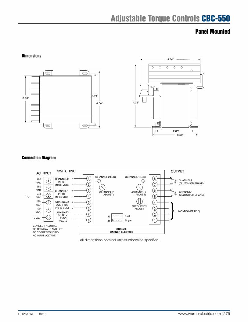
275P-1264-WE 10/18 www.warnerelectric.com
CBC-550WARNER ELECTRIC
AC INPUT
CHANNEL 1INPUT
(10-30 VDC)
CHANNEL 2INPUT
(10-30 VDC)
AUXILIARYSUPPLY12 VDC,250 mA
CHANNEL 2OVERRIDE(10-30 VDC)
1
2
3
4
5
6
480VAC380VAC240VAC220VAC120VAC
0 VAC
+
-
+
-
+
-
+
-
1
2
3
4
5
6
7
8
+
-
+
-8
7
6
5
4
3
2
1
OUTPUTSWITCHING
CONNECT NEUTRALTO TERMINAL 6 AND HOTTO CORRESPONDINGAC INPUT VOLTAGE.
CHANNEL 2(CLUTCH OR BRAKE)
CHANNEL 1(CLUTCH OR BRAKE)
N/C (DO NOT USE)
DualSingle
(CHANNEL 2 LED) (CHANNEL 1 LED)
J2J1
(CHANNEL 1ADJUST)
(CHANNEL 2ADJUST)
FREQUENCYADJUST
• • • •
• • • •
4.60"
2.85"3.50"
4.72"4.50"
4.08"3.90"
Dimensions
Connection Diagram
All dimensions nominal unless otherwise specified.
Adjustable Torque Controls CBC-550Panel Mounted

276 www.warnerelectric.com P-1264-WE 10/18
CLUTCHSWITCH
+12 VDC
HOLD LEVEL SET-UP SWITCH(Up: Normal, Down: Set-Up)
CLUTCH LED
BRAKE LED
SHORT CIRCUIT LED
OPEN:CLUTCHCLOSEDBRAKE
BRAKE
CLUTCH
120 VAC
SELECT
OUTPUTINHIBIT
COMMON
4
3
2
17
6
5
4
3
2
1
CLUTCHINITIALPULSE
CLUTCHRAMPTIME
CLUTCHHOLD
LEVELCLUTCHTORQUEADJUSTBRAKERAMPTIME
BRAKEHOLD
LEVELBRAKE
TORQUEADJUSTBRAKEINITIALPULSE
FUSE
FRONT VIEW
BACK VIEWTOP VIEW
4.25"(108)
5.00"(127)
6.50"(165)
5.00"(127)
5.00"(127)
0.31" TYP.(7.9)
0.15"R TYP.(3.8)
0.25"(6.4)
4.50"(114)
0.75"(19)
Initial PulseAdjustment
Ramp TimeAdjustment
Hold LevelAdjustment
TorqueAdjustment
Time
Cur
rent
Specifications
CBC-1825R
Part No. 1825-448-001
Input Voltage 120 VAC, 50/60 Hz, 100 VA maximum
Output Current Current driven PWM, compatible with 90 VDC clutch/brake (switch selectable current output)
Auxiliary Supply 12 VDC 250 mA
Circuit Protection Input Fused 1.5 Amp, 250 V fast-blo clutch and brake outputs are short circuit protected
Status Indicators Clutch and brake LEDs indicate output is energized Short circuit LED indicates a fault
Ambient Temperature 0° to 122°F (-18° to 50°C)
Switching Contact rating: 15 mA @ 15 V, open collector NPN 2mA maximum allowable leakage current and 2 V maximum saturation voltage
Set-up
Connection Diagram
Dimensions
CBC-1825R seriesThe CBC-1825R is designed to provide consistent and repeatable acceleration and deceleration when used with Warner Electric 90 VDC clutches and brakes. Current to each channel is introduced along an adjustable time ramp and monitored continuously. Adjustments include initial pull-in pulse, hold level, maximum torque, and ramp time. LEDs are provided on the circuit board to indicate power is applied to the clutch or brake unit.
Note: It is recommended that the auto-gap springs be removed from the clutch and brake for successful accel-decel application.
All dimensions nominal unless otherwise specified.
Adjustable Torque Controls CBC-1825RPanel Mounted

277P-1264-WE 10/18 www.warnerelectric.com
1
2
3
4
5
6
7
8
9
10
11
120 VAC50/60 Hz
SW
BK
CL
CR
CR, SW user furnished switchoptions for use with control. normally open relay contact normally open push button switch
NOTE:
CRSW
TYPICAL 3 WIRESWITCHING
CONFIGURATION
HOT
NEUTRAL
+
–
+
–
+
–
AUXILIARYSUPPLY
(+12V)
BRAKE INPUT(10-30VDC)
CLUTCH INPUT(10-30VDC)
5.00" (12.70)
3.25"(82.5)
4.65"(118.1)
.95" (24.1)
.50" (12.7)
.125" (3.2)RTYP.
.50" (12.7)
Specifications
CBC-700-90 CBC-700-24
Part No. 6042-448-003 6042-448-002
Input 120 VAC, 50/60 Hz 24-28 VAC, 50/60 Hz
Output Voltages Steady State 90 VDC 24 VDC Overexcitation 340 VDC 105 VDC
Output Current (Per channel .5 Amps 3.5 Amps alternately)
OEX Pulse Adjustable through logic board dip switches Duration (see service manual)
Inputs Two-optically isolated (10-30 VDC)
Ambient Temperature 0°F to 140°F (-18°C to +60°C) Range
Maximum Off State Leakage <2 mA (inputs)
Circuit Protection 1.6A Fast Act (5 x 20 mm) 5A Slo-Blo (5 x 20 mm)
Auxiliary Supply 12 VDC, 250 mA maximum
Enclosure (Optional)
DimensionsConnection Diagram
• Lift off hinge
• Quick-release latches
• Conforms to NEMA Type 13
• European Standard IEC 529, IP65
Part No. 6042-101-004
Size 8”H x 6”W x 4”D (203.2 x 152.4 x 101.6 mm)
CBC-700 seriesSimple, compact, high performance OEX control for either 90 or 24 VDC clutches and brakes. OEX spike duration and anti-overlap times delay are adjustable. Two optically isolated inputs.
• High performance• Switch selectable OEX duration• Force decay suppression with
adjustable anti-overlap time delay• Compact, flexible mounting• Models for 24 or 90 volt clutches
and brakes• Cycle rate limited by clutch/brake
All dimensions nominal unless otherwise specified.
Overexcitation Controls CBC-700General Purpose OEX Control

278 www.warnerelectric.com P-1264-WE 10/18
Specifications
CBC-750-6 CBC-750-24 CBC-750-90
Part No. 6041-448-001 6041-448-002 6041-448-003
Input Power 120/220/240 VAC, ±10%, 50/60 Hz, 350 VA (switch selectable)
Control Inputs Opto-isolated 10-30 VDC @ 10-35 mA nominal sinking or sourcing, or 24 VAC (50/60Hz) @ 22 mA nominal, or 120 VAC (50/60 Hz) @ 20 mA nominal
Clutch/brake Output Steady State Output Current controlled .910 to 4.34 A max. .227 to 1.175 A max. .060-.310 A max. Current Rise Time Dependent on clutch/brake size Current Fall Time Depending on clutch/brake size Overexcitation Voltage 75 VDC nom. 240 VDC nom. 450 VDC nom. Overexcitation Time Automatic adjustment by control feedback Anti-overlap Time Automatic adjustment by control feedback
Power Supply Output 12 VDC, ±0.6 VDC, 250 mA max.
Auxiliary Indicator Opto-isolated NPN transistors Outputs 24 VDC maximum, 20 mA max., reverse polarity protected
Circuit Protection Internal short circuit protection on each output channel.
Fusing AC Input Line 2 Amp, 250 V Slo-Blo OEX Supply 10 Amp, 32 V Slo-Blo 5 Amp, 250 V Slo-Blo 1 Amp, 250 V Slo-Blo
• High performance OEX control
• Constant current output capability
• Models for 6, 24, and 90 V clutches and brakes
• Outputs short circuit protected.
• AC/DC optically isolated inputs
• Transformer isolation Remote torque potentiometer capability
• Input/Output inhibit functions
• Switch selectable OEX function
• Automatic CH1/CH2 anit-overlap feature
• Heavy duty suppression circuits
• Selectable output current ranges
• Remote status indicators inputs and outputs
CBC-750 series Dual channel, current based OEX with switch ing logicWarner Electric’s CBC-750 series of Constant Current Overexcitation Clutch/Brake Controls are solid-state electronic controls designed to increase the cycle rate capabilities and accuracies of electromagnetic clutches and brakes. The controls accomplish this by sending a momentary high voltage overexcitation spike to the clutch and/or brake magnetic coil to build a high density magnetic flux field almost instantaneously. By using overexcitation, the response time is reduced as dramatically as performance is increased. For example, the current build up time of a 5 inch, 6 volt magnet is reduced from 84 milliseconds to 2 milliseconds.
The CBC-750 user selects either 120, 220 or 240 VAC operation at the time of installation. Models for 6 volt, 24 volt, or 90 volt clutches and brakes are available.
LED indicators on the faceplate of each control tell the user the status of input signals, output activation and any auxiliary inputs. A reset switch resets the output should a short be detected. Remote torque adjust potentiometer inputs are also provided. Appropriate current range for each size clutch or brake is selected by a dip switch. Constant current for each level is assured by the control’s design.
• Maintains torque at preset levels regardless of temperature variations
• Automatically controls OEX pulse duration for optimum response without overheating coils
• Automatically prevents clutch and brake “overlap”
• Configurable as an analog follower control through remote top input
• Integral switching logic through auxiliary, inhibit and override inputs
Shown with optional
cover, part number
6041-101-004
Overexcitation Controls CBC-750Rapid Acceleration/Deceleration

279P-1264-WE 10/18 www.warnerelectric.com
1
2
3
4
5
6
7
120/220/240 VAC50/60 Hz
CHANNEL 1(CLUTCH OR BRAKE)
CHANNEL 2(CLUTCH OR BRAKE)
CR
Minimum Connection Diagram using DC inputs.
1
2
3
4
5
6
7
TB1COMMONCONNECTIONS
TB2
10-30 VDC CONNECTION
1
2
3
4
5
6
7
8
TB5Q
1
2
3
4
5
6
7
TB6
Q, CR user furnished switchoptions for use with control. NPN transistor normally open relay contact
NOTE:
QCR
AUXILIARYSUPPLY12 VDCCHANNEL1OPTIONALREMOTETORQUEPOTENTIOMETERCHANNEL 2OPTIONALREMOTETORQUEPOTENTIOMETER
+-
SW8
SW6
SW10
SW3 SW11
SW5
SW2
SW4
SW7
SW5Channel 1 OEXenable ( ) / disable ( )
SW2Channel 1 local ( )or remote ( )torque adjust
SW4Channel 2 local ( )or remote ( )torque adjust
SW11Auxiliary input selectorChannel 1 ( )Channel 2 ( )
SW6Channel 2 OEXenable ( )disable ( )
SW10Channel 1 input invert ( ) ( )
SW3Level/pulse selector level ( )pulse ( )
SW8Channel 2 current range selector(settings in diagram below)
SW7Channel 1 current range selector(settings in diagram below)
All switches are in the down ( ) position from factory
Channel 1Torque Adjust(0-Full Voltage)
Channel 2Torque Adjust(0-Full Voltage)
5.69" (144.53)
14.01" (355.85)
13.00" (330.20)
11.50" (292.10)
7.50"(190.50)
9.56"(242.82)
9.77"(244.16)
4.78"(121.41)
10.75"(273.05)
3.09"(78.49)
1.12" (28.45) DIA.
1.25" (31.75)
2.69"(68.33)
.88" (22.35) DIA.CONDUIT ENTRANCE (3)
3.16"(80.26)
3.00"(76.20)
.218" (5.54) DIA.MTG. HOLES (4)
Dimensions
Connection Diagram
Setup SwitchesSW1: AC Voltage selection switch on terminal board inside control unit
Max. Current Output
(SW7 & SW8 settings)
Nominal Voltage 1 2 3 4 5
6 0.910 2.35 3.183 3.760 4.340
24 0.227 0.641 0.881 0.940 1.175
90 0.060 0.176 0.256 0.282 0.310
Seven optically isolated inputs accept 10-30V A.C./D.C. (TB2) or 120 VAC (TB3), configured through set-up switches
1. Channel 2 Input
2. Channel 2 Input Inhibit (disregards channel 2 input signal)
3. Auxiliary Input
4. Channel 1 Input
5. Channel 1 Input Inhibit (disregards channel 1 input signal)
6. Output Inhibit (deactivates both output channels)
7. Channel 2 Override (applies full voltage to channel 1 output)
All dimensions nominal unless otherwise specified.
Overexcitation Controls CBC-750Rapid Acceleration/Deceleration

280 www.warnerelectric.com P-1264-WE 10/18
CBC-1000 Position-loop control with error correction compensationWarner Electric’s CBC-1000 is a closed-loop positioning control with error compensation designed for industrial clutch/brake applications. The position loop is closed through encoder feedback which generates pulses proportional to load motion. The CBC-1000 uses this feedback to determine the optimum brake actuation point. The control can be programmed to operate in one of two distinct modes: absolute or incremental. The CBC-1000 includes eight solid state control outputs, a batch counter and a serial com mu ni ca tions interface.
The CBC-1000 system consists of four key elements: the CBC-1000, a clutch/brake, a clutch/brake control, and an encoder. Nearly any electric clutch/brake size and con fig u ra tion can be used. The clutch/brake control should have solid-state compatibility. Simple on-off, soft start/stop, and overexcitation controls may all be utilized based on the desired velocity profile.
Specifications
Part No. 6060-448-001
Input Power 100 to 130 VAC, 50/60 Hz, 20VA (200 to 260 VAC selectable)
Auxiliary Supply 12 VDC @ 175 mA Used for powering encoder, etc.
Main Counter Range 6 Decades Reset Input External and front panel Count Rate (20 kHz external input frequency)
Batch Counter Range 6 Decades Reset Through front panel only
Signal A and B Inputs Input Frequency D.C., 20 kHz quadrature max. Input High Level 3.25 VDC min. Input Low Level 1.75 VDC max.
Control Inputs Input Frequency D.C. to 20 Hz max. each input Input Type Single ended, current sinking Input Logic Both Edge and Level sensitive as defined by input use Input High Level 10 VDC min. to 20 VDC max. Input Low Level 0 VDC min. to 2 VDC max. Input Current 2.5 mA steady state
Display Decades 7 Decade, 0.6” red LED Decimal Point User programmable Range: xxx.xxx to xxxxxx
Program Security Program LOCK of lines 1 - 33
Control Outputs Type 8 Solid State 100 mA sink max., 24 VDC max.
Serial Interface Type RS-422A/485 compatible Baud Rate Selectable: 300, 600, 1200, 2400 Parity Selectable: None, Odd, Even Data ASCII
Diagnostics Nine Self-Test Diagnostics
Mechanical Enclosure Aluminum extrusion with molded VALOX bezel. Weight 2.5 lbs.
Environmental Operating Temp. 0° to +50°C (32° to 122°F) Storage Temp. -18° to 85°C (0° to 186°F) Ambient Humidity 90% and noncondensing
Accessories
Description Part Number
Encoder Cable (Accessory) 6060-101-001 Encoder Cable (Accessory) 7 Pin for marker 6060-101-002 100 PPR Encoder w/10’ cable 6060-101-010 250 PPR Encoder w/10’ cable 6060-101-025 600 PPR Encoder w/10’ cable 6060-101-060 600 PPR w/marker & 10’ cable 6060-101-061 1200 PPR Encoder w/10’ cable 6060-101-120 2500 PPR Encoder w/10’ cable 6060-101-250 5000 PPR Encoder w/10’ cable 6060-101-500
(PPR–Pulse Per Revolution)
Serial Interface Module
Performs the necessary voltage level conversions to interface the RS-422A/485 output of the CBC-1000 to RS-232C equipment.
Part Number: 6060-101-232
Closed Loop Position Control CBC-1000System Accuracy
OBSOLETE,No Replacement

281P-1264-WE 10/18 www.warnerelectric.com
OperationSuccessful operation will require knowledge of the following definitions and their relationships to the timing diagram.
Function Key Definitions
Count The actual move distance, in pulses or scaled into engineering units (inches, feet, rotations, degrees, etc.) displayed dynamically.
Move The desired move distance in pulses or scaled into engineering units. This is Present the value the operator enters to select a new move distance.
Early A distance prior to Move Preset at which the early warning output is activated. Warning Expressed as pulses or engineering units, this output can be used to accomplish
a soft brake (slow down), energize valves, etc.
Batch A cumulative batch counter that can be dynamically displayed to show the number of operations, cycles, etc. When this counter reaches the value programmed by the Batch Preset (key 7) the Batch Complete Output is activated. The batch counter can be manually or automatically reset.
Batch A programmable batch counteractivates the batch complete output when the Preset value programmed has been reached by the batch (key 6)
Braking The actual distance required to stop. This value is dynamically updated to Distance determine the brake actuation point. Factory default is 25 pulses or engineering
units which is only used for the first cycle after power-up. After the first cycle the CBC-1000 will tune to the particular brake being utilized. The amount of cycles needed for tuning depends on how far the true braking distance value is from the default of 25.
1COUNT
2MOV PST
3E.W.
6BATCH
7BCH PST
8BRK DIS
Timing Diagram
Inputs:(Active Low)
Outputs:(Momentary)(Edge Triggered)
Start
Stop
Velocity(Speed)
Time(Count)
BrakingDistance
Brake OnPoint
Early WarningPoint
StartPoint
Start
Early Warning
Brake On
Zero Speed
Zero Speed + Delay Time 1
Zero Speed + Delay Time 2
Auxiliary Start
Batch Complete 10
10
10
10 Delay Time 1
Delay Time 2
10
10
10
10
10
10
1. Select the proper clutch/brake • Determine torque and inertia
requirements
• Calculate heat dissipation for required cycle rate
• For best accuracy, mount clutch/brake directly on nip or drive shaft; avoid backlash
2. Select quadrature encoder • Select encoder PPR for desired
system resolution (i.e. inches/pulse, degrees/pulse, etc.)
• Determine input frequency; do not exceed 20,000 pulses/sec.
• Mount encoder directly to nip or drive shaft for best accuracy
3. Select clutch/brake power supply • Use CBC-700 overexcitation control
for best accuracy
• Use CBC-500/550 for soft starting and/or stopping
• Brake autogap may have to be removed for best accuracy
4. Plan system logic (switching requirements)
• Use absolute mode for indexing applications such as conveyors and turntables or cutoff ap pli ca tions where close registration is required
• Use incremental mode for cutoff applications
• Determine switching and relays required for machine operation
5. Select serial interface module if applicable.
Closed Loop Position Control CBC-1000CBC-1000 Application Procedure

282 www.warnerelectric.com P-1264-WE 10/18
3-wire Switching Option
Control’s switching terminal block
Jumper Switch Switch Channel Channel Mode 1 2 1 2
J1–Single Closed Open Latched On Off Open Closed Off Latched On
J2–Dual Closed Open Off Off Open Closed Latched On Latched On
2-wire Switching Option
Control’s switching terminal block
Jumper Mode Switch 1 Channel 1 Channel 2
J1–Single Open Off Powered Closed Powered Off
J2–Dual Open Powered Powered Closed Off Off
The CBC 400 and 500 series controls allow operation in either a single or dual mode. The mode of operation is de ter mined via the position of a jumper on the main control board.
The controls are shipped with the jumper in the J1 or single mode position. A variety of output logic can be ac com plished via the single/dual jumper position and whether the control is wired to one input switching device (2-wire mode) or two input switching devices (3-wire mode). The following diagrams show how each channel (output) of the control can be either al ter nate ly or si mul ta neous ly en er gized.
J2
J1
Dual
Jumper
Single
J1
DualSingle
CBC-400/450
CBC-500/550
Channel 2 Input Channel 1 Input
+ – + –
Switch 1(shown open)
Auxiliary 12 VDCSupply
+ –
1 2 3 4 7 8
Channel 2 Input Channel 1 Input
+ – + –
Switch 1(shown open)
Switch 2(shown open)
Auxiliary 12 VDCSupply
+ –
1 2 3 4 7 8
AppendixCBC-400/450/500/550 Single vs Dual Operation

283P-1264-WE 10/18 www.warnerelectric.com
1. What transformers can be used with con trols requiring 24-30 VAC input?
Part Manufacturer Number Pri ma ry Secondary
Abbott 6B 12-160 115 VAC 24V @ 6 amps
Quality 6-K-119VBR 115/230 VAC 24V @ 8 amps
Signal 24-6 115 VAC 24V @ 6 amps
Signal DP24-6 115/230 VAC 24V @ 6 amps
Triad F-260-U 115 VAC 24V @ 6 amps
2. When a single clutch or brake is used with a CBC-200 and no switch is used, a jumper wire is required across terminals 5 & 6 to get output at terminals 4 & 5.
3. What is the difference between a MCS-801 and a CBC-801-1 or between a MCS-103 and a MCS-103-1?
There is no performance difference between the MCS-103 and MCS-103-1. There is no per for mance difference between the MCS-801 and CBC-801-1. The CBC-801-1 is roughly 1/4” shorter than the MCS-801. The units wire and work exactly the same.
4. Which power supplies can be used with the SF 1525HT and SFC 1525HT coil?
The SF and SFC 1525 High Torque clutch coils require .794 amps of current to provide full rated torque. The following power supplies and controls will provide the needed power.
CBC-100 .8 amps CBC-450 1 amp CBC-150 .8 amps MCS-103-1 1.25 amps CBC-801 1.25 amps CBC-500 1 amp CBC-400 1 amp CBC-550 1 amp
5. Can I use a CBC-160 with a variable frequency drive and AC motor?
No. As the voltage to the drive is varied, the output to the electrically released brake would also vary. This would cause the brake to re-engage when it should be released.
6. Which power supplies offer a 12 VDC power source that could be used to power auxiliary switch inputs such as inductive or photoelectric sensors?
CBC-400, CBC-450, CBC-500, CBC-550, CBC-700, CBC-750
7. Is the CBC-1000 a stand-alone control?
No. The CBC-1000 provides closed loop feedback for a clutch/brake system. A common system will consist of four com po nents:
• a Warner Electric brake and clutch • a Warner Electric power supply • an Encoder • a CBC-1000 position control The application criteria will determine which clutch/brake and
which control will be appropriate selections.
8. Which of the controls would allow for the independent operation of two clutches or two brakes?
Four controls allow for completely independent operation of two clutches or brakes. That is, that a clutch and brake can both be on at once, both off at once, or one on and one off. These controls are:
CBC-801-1 and CBC-801-2, MCS-103-1, CBC-200, CBC-300
The CBC-400/450 and CBC-500/550 allow for operation of both channels on at once, both channels off at once or cycling between channel one and two. However, in the both-on/both-off mode, you cannot also do independent single channel operation.
9. Are there any controls that can be used to control the torque of a 90 volt clutch or brake via an analog signal input?
There are two options we offer, a special TCS-200 or a Bronco drive (B169 or B161s) with a signal follower card. These units can be configured to provide a variable torque output for a clutch or brake based on an analog input signal. Consult the factory for the best solution for your specific application needs.
10. Which controls can be used with electrically released brakes?
The CBC-160-1 and CBC-160-2 are designed specifically to use with the conduit box of EM and EUM electrically released brake designs. The CBC-160-1 and CBC-160-2 can also be used with ER and FB brake designs.
The MCS-103-1, CBC-200, CBC-300 and CBC-500/550 can all be used with ER, FB as well as UM-FBC, EM and EUM-FBB and EM and EUM-MBFB designs.
The MCS 805-1 and MCS 805-2 are for use only with the ER 1225 brakes. The ERS series brakes can be used with the CBC-100 or CBC-801 power supplies.
coil
jumper wire
4 5 6
Questions and Answers

284 www.warnerelectric.com P-1264-WE 10/18
Model Part Number Page
CBC-100-1 ...................................................................6003-448-101 .....................264CBC-100-2 ...................................................................6003-448-103 .....................264MCS-103-1 ...................................................................6010-448-002 .....................270CBC-150-1 ...................................................................6004-448-001 .....................264CBC-150-2 ...................................................................6004-448-002 .....................264CBC-160-1 ...................................................................6013-448-001 .....................265CBC-160-2 ...................................................................6013-448-002 .....................265MCS-153-1 ...................................................................6012-448-001 .....................271CBC-200 (Obsolete, replaced by CBC-300) ......................6011-448-002 .....................272CBC-300 ......................................................................6021-448-001 .....................272CBC-400-24 .................................................................6006-448-002 .....................268CBC-400-90 .................................................................6006-448-003 .....................268CBC-450-24 .................................................................6006-448-005 .....................269CBC-450-90 .................................................................6006-448-006 .....................269CBC-500-24 .................................................................6024-448-002 .....................273CBC-500-90 .................................................................6024-448-003 .....................273CBC-550-24 .................................................................6024-448-005 .....................274CBC-550-90 .................................................................6024-448-006 .....................274CBC-1825R ..................................................................1825-448-001 .....................276CBC-700-24 .................................................................6042-448-002 .....................277 CBC-700-90 .................................................................6042-448-003 .....................277CBC-700 Enclosure ......................................................6042-101-004 .....................277CBC-750-6 ...................................................................6041-448-001 .....................278CBC-750-24 .................................................................6041-448-002 .....................278CBC-750-90 .................................................................6041-448-003 .....................278CBC-801-1 ...................................................................6001-448-004 .....................266CBC-801-2 ...................................................................6001-448-006 .....................266Octal Socket, Foot Mount .............................................6001-101-001 .....................266Octal Socket, DIN Rail Mount .......................................6001-101-002 .....................266CBC-802-2 ...................................................................6002-448-001 .....................267CBC-1000 ....................................................................6060-448-001 .....................280Serial Interface Module ..................................................6060-101-232 .....................280Encoder Cable (Accessory) ...........................................6060-101-001 .....................280Encoder Cable (Accessory) 7 Pin for marker .................6060-101-002 .....................280Encoders: 100 PPR ......................................................6060-101-010 .....................280 250 PPR ......................................................6060-101-025 .....................280 600 PPR ......................................................6060-101-060 .....................280 600 PPR w/ marker .....................................6060-101-061 .....................280 1200 PPR ....................................................6060-101-120 .....................280 2500 PPR ....................................................6060-101-250 .....................280 5000 PPR ....................................................6060-101-500 .....................280Optional Enclosure: CBC-400, CBC-500, CBC-700 .....6042-101-004 .....................268Optional Enclosure CBC-450, CBC-550 .......................6006-101-007 .....................269
Ordering Information

www.altramotion.com
Altra Industrial Motion The Power Of Experience
Ameridrives
Bauer Gear Motor
Bibby Turboflex
Boston Gear
Delroyd Worm Gear
Formsprag Clutch
Guardian Couplings
Huco
Industrial Clutch
Inertia Dynamics
Kilian
Lamiflex Couplings
Marland Clutch
Matrix
Nuttall Gear
Stieber
Stromag
Svendborg Brakes
TB Wood’s
Twiflex
Warner Electric
Warner Linear
Wichita Clutch
Get Connected
The Altra Newsroom makes it quick and easy for you to get the news you need when you need it. From new literature releases to trade show schedules, the news is at your fi ngertips 24 hours a day.
www.altramotion.com/newsroom
Everything Altra
From the Altra homepage you can connect to all of our brands, and visit our
market portals to fi nd solutions for your specifi c needs.
www.altramotion.com
Literature Portal Conveniently download and request Altra's latest catalogs, brochures, service manuals and more on the Literature Portal. Find the
latest product information to meet your power transmission requirements by going to any Altra brand website and clicking on
the Literature tab.
www.altraliterature.com
Like us on Facebook and follow us on Twitter for up to the minute news you can use. Link with us on LinkedIn, follow us on Google+, and find us on YouTube to watch training videos and application movies.
Online Resources

Altra Industrial Motion
P-1264-WE 10/18www.warnerelectric.com
The Brands of Altra Industrial Motion
Couplings
Ameridriveswww.ameridrives.com
Bibby Turbo ex www.bibbyturbo ex.com
Guardian Couplingswww.guardiancouplings.com
Hucowww.huco.com
Lami ex Couplingswww.lami excouplings.com
Stromag www.stromag.com
TB Wood’swww.tbwoods.com
Geared Cam Limit Switches
Stromagwww.stromag.com
Electric Clutches & Brakes
Inertia Dynamicswww.idicb.com
Matrixwww.matrix-international.com
Stromagwww.stromag.com
Warner Electricwww.warnerelectric.com
Linear Products
Warner Linearwww.warnerlinear.com
Engineered Bearing Assemblies
Kilianwww.kilianbearings.com
Heavy Duty Clutches & Brakes
Industrial Clutchwww.indclutch.com
Twi exwww.twi ex.com
Stromagwww.stromag.com
Svendborg Brakeswww.svendborg-brakes.com
Wichita Clutchwww.wichitaclutch.com
Belted Drives
TB Wood’s www.tbwoods.com
Gearing
Bauer Gear Motorwww.bauergears.com
Boston Gearwww.bostongear.com
Delroyd Worm Gearwww.delroyd.com
Nuttall Gearwww.nuttallgear.com
Overrunning Clutches
Formsprag Clutchwww.formsprag.com
Marland Clutchwww.marland.com
Stieberwww.stieberclutch.com
Warner Electric Facilities
North America
USA31 Industrial Park RoadNew Hartford, CT 06057 - USA860-379-1252
Electromagnetic Clutches and Brakes
449 Gardner StreetSouth Beloit, IL 61080 - USA815-389-3771
4578 East Park 30 DriveColumbia City, IN 46725 - USA260-244-6183
Precision Electric Coils and Electromagnetic Clutches and Brakes
Customer Service1-800-825-6544
Application Support1-800-825-9050
Europe
France7, rue Champ eur, B.P. 20095St Barthelemy d’Anjou - France+33 (0)2 41 21 24 24
Electromagnetic Clutches and Brakes
Customer Service+33 (0)2 41 21 24 76
Application Support+33 (0) 2 41 21 24 24
Asia Pacifi c
Australia +61 2 9894 0133
China+86 21 5169-9255
Hong Kong +852 2615 9313
Singapore +65 6487 4464
Taiwan +886 2 2577 8156
Thailand +66 2322 5527
Neither the accuracy nor completeness of the information contained in this publication is guaranteed by the company and may be subject to change in its sole discretion. The operating and performance characteristics of these products may vary depending on the application, installation, operating conditions and environmental factors. The company’s terms and conditions of sale can be viewed at http://www.altramotion.com/terms-and-conditions/sales-terms-and-conditions. These terms and conditions apply to any person who may buy, acquire or use a product referred to herein, including any person who buys from a licensed distributor of these branded products.
©2018 by Warner Electric LLC. All rights reserved. All trademarks in this publication are the sole and exclusive property of Warner Electric LLC or one of its af liated companies.