AUXILIARY BRAKES FOR TRUCKS Research into ... - SWOV
59
AUXILIARY BRAKES FOR TRUCKS Research into the behaviour of a tractor-semi-trailer combination during emergency braking R-76-18 Voorburg, 1976 Institute for Road Safety Research SWOV, The Netherlands
-
Upload
khangminh22 -
Category
Documents
-
view
1 -
download
0
Transcript of AUXILIARY BRAKES FOR TRUCKS Research into ... - SWOV

AUXILIARY BRAKES FOR TRUCKS
Research into the behaviour of a tractor-semi-trailer combination
during emergency braking
R-76-18
Voorburg, 1976
Institute for Road Safety Research SWOV, The Netherlands

CONTENTS
Summary
I. Foreword
11. Introduction
Ill. Purpose of the research
IV. Present Legislation
V. Emergency braking
VI. Emergency braking performance
VII. Technical solution and practical
VIII. Practical part of the research
IX. Research results
X. Conclusions and recommendations
2
3 q
5
7 11
tests 13
16
22
3~

This report deals with an investigation carried out by a working
group of the Institute for Road Safety Research SWOV.
Purpose of the research was to get an insight in various secun
dary braking systems for goods vehicles. Practical test were
carried out with a tractor - semi trailer combination.
The performance of various split braking systems as well as spring
brake actuators are shown.
With nearly all of the secundary braking systems it is possible
to obtain sufficient deceleration to meet legal requirements for
the braking path. The critical point however is the lateral sta
bility_ The report concludes with recommendations for legal re
quirements concerning lateral stability both on dry and wet road
surfaces.
Conclusions:
- Lateral stability must be obtained on both a dry and a wet
road surface
- Tractors for semi-trailers should have a split braking system
- Service brakes for motor vehicles and trailers (semi-trailers)
should have a certain braking capacity in the case that somewhere
a failure occurs (emergency braking capacity)
Proposed solution:
- Emergency braking capacity of the service brake shall be at
least 50% of the normal required capacity

I. FOREWORD
During the GRF meeting in 1974, the Dutch delegation was asked
to make a proposal for the requirem~nts which motor vehicle
auxiliary brakes (emergency brakes) should meet.
In support of this proposal the Minister of Transport and Water
ways asked the Institute for Road Safety Research SWOV to under
take research into the functional requirements for auxiliary
brakes. This research was carried out thanks to the collaboration
of the Vehicle Research Laboratory of Delft University of Technolo
gy and Daf Trucks B.V., Eindhoven. The associated ad hoc working
party on Emergency Brakes consisted of A. Dijks and W.A.M. van
Blijswijk, of the Vehicle Research Laboratory of Delft University
of Technology; J. van Genugten of Daf Trucks B.V., Eindhoven;
G.J.M. Meekel of the Department of Road Transport RDW, The Hague,
and L.H.M. Schlosser of the Institute for Road·Safety Research
SWOV, Voorburg.
In making an initial inventory of the problems, serious gaps were
found in the legislation on auxiliary brakes, especially for
trailers and semi-trailers. Hence, in complying with the terms of
reference, the work was focused on arriving at functional
requirements for auxiliary brakes for all the categories of motor
vehicles falling within the scope of Regulation No. 13 and specif
ied further in Sections 5.2.2., 5.2.3. and 5.2.4., together with
the observations in Section 5.2.5. Two and three-wheeled vehicles
were therefore excluded.
Besides a theoretical approach to the problem, it was considered
advisable also to make practical tests for a number of specific
categories, mainly trucks. In the first instance, the vehicle
chosen was a tractor-semi-trailer combination, in the heaviest
category.

11. INTRODUCTION
Trucks are involved in accidents more often than private cars.
On Dutch national highly-ays the truck involvement quotient is
about 1.5 times higher than for private cars. On motorways the
figure is a little lower [1].
Trucks differ from private cars in movement characteristics,
dimensions and ergonomic features. Especially movement charac
teristics, longitudinal and lateral acceleration, are much more
unfavourable for trucks. As regards deceleration, this is caused
on the one hand by the lower braking and tracking force coef
ficients available with truck tyres, and on the other by the
generally lower braking efficiency of trucks owing to the great
er problems of braking force distribution. In accident research
it~ill be particularly difficult to isolate the influence of
each characteristic in contributing to the higer involvement
quotient.
Although data are scarce, it can nevetheless be argued that in
combatting traffic hazards the authorities should give prior
ity to improving trucks. With many of the normal trucks it is
not possible to perform a full emergency stop on a wet road
surface at high speed without instability. The generally more
severe consequences of accidents involving trucks also plays a
part in assessing priorities. In connection with the request
to the Dutch delegation, referred to in the Foreword, to work
out a proposal for the requirements to be met by auxiliary (emer
gency) brakes, the background must thus be sought mainly in the
finding that accidents which are contributed to directly or
indirectly by trucks having defective braking systems generally
have very serious consequences. It must be added that there are
no requirements at all for emergency brakes for trailers or
semi-trailers, while there are gaps in the case of tractor
vehicles. Emergency brakes for trucks therefore form the subject
of this study.

-6 ~
Ill. PURPOSE OF THE RESEARCH
Having regard to the terms of reference and especially the policy
aspects of the research, the ad hoc working party formulated the
following objectives:
1. Definition of emergency brakes;
2. Indicating possibilities of how emergency brakes can be ob
tained and testing the various systems in practice;
3. Comparison of the test results against systems already used
in practice;
4. Drawing up functional requirements which emergency brakes
must satisfy.
Starting from.these objectives, the following procedure was
chosen for the test aspects of the research:
1. Making a theoretical model with which the performance of the
various emergency braking systems can be predicted;
2. Practical tests with the several types of emergency brakes
with various external conditions such as road surface friction,
speed and truck-load conditions;
3. Evaluation of theoretical and practical tests so as to arrive
at functional requirements and proposals for policy measures.
Especially because of financial limitations, the work chosen in
the first instance concerned a tractor-semi-trailer combination
in the heaviest category. A combination of truck and truck and
trailer is contemplated at a later stage.
In addition to testing emergency braking systems for tractor
semi-trailer combinations, the operation of the normal service
brake was also thoroughly tested. In particular, it was examined
to what extent ALB's on the tractor's rear axle and the semi
trailer axles satisfactorily comply with the regulations in
75/524/EEC.

- 7 -
IV. PRESENT LEGISLATION
The requirements for brakes beside or instead of the national
requirements in various countries are combined in Regulation
no 13 from Geneva and in Regulation 71/320/EEC from Brussels.
Amending and extension of the requirements led in Brussels to
the supplementary Requirements 74/132/EEC and 75/524/EEC.
In order to obtain an amended Regulation no 13 with the same
contents as the latest Regulation of Brussels in GRF is stated to
wait untill the supplements of the Brussels'Regulations would be
ready. It is to be assumed that in short time Regulation no 13
will be changed similar to the Regulations of Brussels. The next
chapters must be read with this condition in mind.
The present requirements for motor vehicle braking systems in
the EEC are given in 71/320/EEC aad 75/524/EEC. In the former,
provisions regarding auxiliary brakes can be found in paras.
2.1.2.2., 2.2.1.2., 2.2.1.4. and 2.2.1.19. of Annex I and para.
21.2. of Annex 11.
Summing up the requirements, it is found that private cars,
trucks and buses have to have a service brake, an auxiliary
brake and a parking brake. If the service brake becomes defective,
the brakes of such vehicles must have a certain residual effect.
These residual effect requirements are usually lower than for
auxiliary brakes. If the auxiliary braking effect is obtained
from the residual effect of the service brake the require-
ments are the same. The residual effect need not
exist for tractors with semi-trailers if the transmission of the
semi-trailer service brake is independent of that of the tractor
vehicle.
Trailers of the 01 type need not have a service brake. Trailers
(also including semi-trailers) in categories 02' 03 and 04 must
have a service brake, however. Every trailer or semi-trailer re
quiring a service brake must also have a parking brake. No trailer

- 8 -
or semi-trailer needs to have an auxiliary brake. Nor, in the
event of the trailer's or semi-trailer's service brake failing
need there be any residual effect. This means, therefore, that
if a trailer's or semi-trailer's service brake fails, the vehicle
cannot be braked in any way at all. Conversely, there are regu
lations concerning braking of trailers or semi-trailers if the
tractor vehicle's service brake fails.
Para. 2.2.1.19. stipulates that the heaviest category of trailers
(03 and 04) must be brake controlled if the auxiliary braking
system of the tractor vehicle is operated. Furthermore, the
trailer must be braked with the remaining part of the service
brake if its transmission consists of two parts and one part fails.
Further, such trailers and semi-trailers must also be brakable
if there is a leakage or rupture in the pneumatic connection
between the tractor and the trailer or semi-trailer.
As regards braking force distribution, para. 2.2.1.8. stipulates
that the effect of the service brake must be rationally distrib
uted over the axles. What this means is elaborated in 75/524/EEC.
No requirements are made regarding auxiliary brakes or the resid
ual effect of the service brake as regards braking force distri
bution. But it is generally stipulated that in braking tests on
a dry road surface with reasonable friction none of the wheels
must lock.

v. EMERGENCY BRAKING
In the definition of auxiliary brakes it is stated that the
vehicle must be able to be stopped within a reasonable dis
tance if the service brake fails. In doing this, the driver must
be able to retain control of the steering mechanism with at
least one hand.
In view of the definition of an auxiliary brake this is obvious
ly intended for stopping the vehicle if a failure becomes
apparent. This does not necessarily mean that there must be an
emergency. This only happens if an effort has to be made to avoid
an accident if the service brake is not fully effective.
In view of the above, therefore, if the service brake fails
emergency braking can be regarded as: either the residual effect
of the service brake or the auxiliary brake. Under present condi
tions there is not always a guarantee that the shortest braking
path is obtained with emergency braking. This may be because
the system with the lowest deceleration is used or because time
is lost by changing over to another control, and on the assump
tion that the driver is aware or is informed of the defect in
the service brake.
Let us analyse the driver' s actions in an emergency_
Lost times
If the braking system is fully operative, the following times
can be defined:
reaction time t r
- this is the time elapsing from the moment the emergency is
observed until the moment the driver touches the brake pedal.
Lost time tv: this time consists of the reaction time plus half
of the swell time.

- 10 -
Values measured in tests show the following pattern W. t t r v
50 percent of tests 0.51 0.67 for private cars with
to hydraulic foot brakes
0.77
95 percent of tests 0.73 0.97
to
1.06
Other measurements give the following value [3J. The average
value of lost time t was 0.9 sec. In this case, 25 percent of v
the group investigated had a lost time of 1.2 sec., while in
some cases it was even more than 2 sec.
If the service brake becomes defective, a number of cases can be
distinguished. If the driver is aware of the failure he can be
assumed to stop his vehicle before an emergency arises.
If the failure becomes apparent at the moment of depressing the
brake pedal and the driver keeps the pedal pressed down the lost
time tv remains unchanged but the average deceleration is lowered
and the braking path lengthened.
It is quite conceivable, however, that the driver is taken by
surprise by the failure at the moment of depressing the brake
pedal, releases it and depresses it a second time, on the as
sumption that he will then have the full braking capacity avail
able. With a hydraulic braking system as well as with an air
pressure braking system the stimulus for the driver is the
deceleration. The reaction to press the brake pedal twice also
occurs with a hydraulic braking system if the distance the brake
pedal travels is insufficient to obtain maximum. braking pressure.
This situation gives an extra lost time t : waiting time re establishing that service brake does not work properly; taking
decision to try again followed by lost time 'ue to reapplying
brake pedal.
If the driver has a separately operated auxiliary brake and applies
this immediately he detects the failure then t is related to re

· - 11 -
the auxiliary brake and the time lost in operating it. The last
possibility is that the driver does not apply the auxiliary brake
until the brakes fail to function after he has pressed the brake
pedal for the second time. This results in:
Lost time auxiliary brake t = waiting time; finding that the vr service brake does not work; deciding to apply auxiliary brake
followed by lost time owing applying auxiliary brake.
No data are available regarding the driver's actions in an
emergency and the length of times t ani t • Since t is about re vr r half the total lost time, it can be estimated that for two
applications, or one application and once with the auxiliary brake
the total lost time will be about 1.5 to 2 times greater than
with the service brake. Fro two applications plus one application
of the auxiliary brake this estimate is about 2 to 2.5 times
that of the lost time with the normal service brake.
The consequence of this reasoning is that an emergency brake as
the remaining part, the residual effect of the service brake will
show the least lost time. If a separately operated auxiliary
brake is nevertheless to be admitted as an emergency brake, then
the average deceleration of the au~iliary brake will have to be
greater to meet the same requirement regarding braking path as
the residual effect of the service brake.
In order to obtain an idea of the extent of this higher deceler
ation, the following example has been worked out. If we take the
requirements for the auxiliary brake for trucks (categories
N1 , N2 and N3
) the maximum· braking path is S = 0.15V + 2 ~:5. Bearing in mind that this is a braking test, the driver's reac
tion time plays no part. The regulations in para. 2 of Annex 11
of 71/320 do not state for what time the average deceleration
should be calculated. Having regard to the build-up and swell
times, it can be assumed that this applies during the second
term of the above double term. If we take an extra reaction time
of 1 sec. for the emergency brakes, this gives the following
pattern:

- 12 -
v = 70 km/h v = 50 km/H 0 0
Stot = 95,7 m Stot = 51 m
seff d during m seff d during m
seff (m/s2
) seff
no lost time
extra lost
time of 1 sec.
v = initial 0
85.2 2.2
65.8 2.9
speed
Stot = total braking path
S eff = braking path when average
d = average deceleration m
43.5 2.2
29.6 3.3
deceleration occurs
v = 40 km/h 0
Stot = 33,8 m
seff d during m
seff seff
27.8 2.2
16.7 3.7
Lastly, it should be mentioned that if a higher deceleration is
required with a limited number of wheels, there is a danger of
one or more wheels locking, especially on a wet surface.
This may affect track stability. This is dealt with in the
following section.

- 13 -
VI. EMERGENCY BRAKING PERFORMANCE
In braking, there are three criteria for judging the braking
system: maximum braking path, minimum deceleration and stability.
If we take for emergency brakes the requirements for auxiliary
brakes, then it is stipulated that the auxiliary brake must
satisfy a type 0 test (para. 2.1.2.4. of Annex 11 of Regulation
71/320/EEC). This lays down the requirements for braking path
and deceleration. Para. 1.1.3.7. of Annex 11 stipulates that the
prescribed effect of the braking system must be obtained without
wheels locking, without the vehicle leaving its track and without
abnormal vibration. This must take place subject to the
provisions of Para. 1.1.3.4. that the road surface must have a good
friction coefficient.
For the service brake there are also regulations for lower
friction coefficients, but not for auxiliary brakes. This means
that an axle not locking on a rough surface may lock on a wet
surface, especially when the full braking capacity is used in an
emergency. In actual fact, therefore, besides the requirement of
braking path and deceleration, there must also be a stability
criterion for both rough and smooth surfaces.
In the case of the service brake this is solved by making regul
ations for the brake pressure on the wheels related to wheel
load. This also indicates the sequence of axle locking.
This solution is not always applicable to an emergency brake and
if only one axle is used in emergency braking then there is no
longer any question of braking force distribution or locking
sequence.
Based on practical conditions, a possible criterion might be to
stipulate a specific road width which the vehicle must not go
beyond during its entire braking path. The force then applied by
the driver to the steering wheel must not exceed a given value.
The advantage of such a requirement is that this is quite clear
and easy to establish in most cases. A jackknifing vehicle will
not be able to meet this requirement. Difficulties are likely when
the driver's skill plays a part in marginal situation. This may

be a source of misunderstanding especially during testing.
Moreover, the flatness of the road surface laterally is important
because practically all roads are banked to ensure good water
disposal. This flatness should be accurately specified for braking
tests.
A drawback to this criterion is that if it is satisfied vehicle
control is not guaranteed in certain cases, for instance if the
front wheels lock. There is then no longer any scope for evasive
action. Nevertheless, it must at all times be avoided that the
vehicle runs off its track uncontrolled or jackknifes.
In any event, international agreement will have to be reached. So
far, the most concrete proposal for a stability criterion is a
British one, as follows:
During a braking test the vehicle must remain for the entire
length of its braking path within a lane 12 feet wide or 1t time
the vehicle's width, whichever be less. During this, it is
permissible for the driver to take action with a moment on the
steering wheel not exceeding 30 Nm.
Testing
As stated above, it is practically impossible to evaluate an
emergency braking system merely with braking tests on a dry,
reasonably rough road surface. Track stability cannot always be
ascertained arithmetically either.
It is therefore advisable to extend emergency brake testing to
tests on a wet surface. These conditions can be achieved fairly
simply with a sprinkler installation. It is important that the
road surface is very well defined.
An interim solution might be to test various systems and, with
reference to this, forbid certain systems by means of regulations.
Another and better solution is to make tests on a roller testing
assembly.

.. I
VII. TECHNICAL SOLUTIONS AND PRACTICAL TESTS
A way of dispensing with tests on wet road surface is to make
the emergency brakes so that they meet the regulations for
service brakes with the exception of those regarding braking path
and deceleration. The most expensive solution is that of duplicat
ing the service brake transmission. A less expensive solution is
at all times to utilise half the braking capacity of the front
axle and half that of the rear axle. As regards the use of
diagonal circuit separation (one front wheel and one rear wheel)
doubts continue to exist regarding track stability. Utilising
half the braking capacity of both front wheels and that of one
rear wheel calls for special brakes on the front axle, i.e.
wedge-brakes by air pressure systems or dual circuit disc brakes.
With articulated vehicles reaction forces occur between the
towing vehicle and trailer or semi-trailer. These can influence
the stability. The extent of these reaction forces depends on the
way the braking power of the semi-trailer is realised. A semi
trailer with a tandem axle and two separate circuits can show big
differences if the tandem axle is not compensated for the weight
transference and one or the other circuit fails.
The Introduction stated that research was undertaken into the
emergency braking behaviour of a tractor and semi-trailer. This
to obtain a good insight in the above mentioned problems of
lateral stability and the influence of the reaction forces with
articulated vehicles. In combination with the theoretical approach
functional requirements have to be drawn up for emergency braking
systems. From this recommendations
be derived.
legal requirements have to
In view of the great variety of braking systems in tractors and
semi-trailers allowed on the roads (for instance the various
types of circuit separations and the single or double piping
systems), a choice was made from among these. The choice was
based on a combination provided by DAF con'sisting of a DAF
FT2800 tractor and a tandem axle semi-trailer (see Annex 1 and
16). The tractor had the standard dual circuit braking system

- 16 -j
and automatic load brake apportioner (ALR) on the rear axle.
The circuit separation is such that if one circuit fails either
the front axle or the rear axle remains braked. The semi-trailer's
brakes are operated via a double piping system. The semi-trailer
has a hand operated control with which the pressure to the brake
cylinders can be regulated depending on the truck's load. This
control has three positions: empty, semi-loaded, fully loaded.
The semi-trailer's tandem set has no compensator for the weight
transfernece occurring during braking.
For testing purposes, the tractor's braking system was modified;
by adjusting a number of valves a diagonal circuit separation
could be obtained with which only the left front wheel and the
right rear wheel could be operated. It was also possible, by
means of valves, to brake only the front or rear axle.
The semi-trailer's braking system could also be similarly adapted
(see Annex 2). All the brake cylinders were spring brake actuator
cylinders. They could be operated so that each axle could be
braked individually. Diagonal braking was also possible with them
(both with the tractor and the semi-trailer). Illustration 2
(Annex 16) shows two of the fifteen added valves.
Criteria
There were two criteria for evaluating the results:
1. The stability of the vehicle or combination.
2. The average deceleration or braking path.
As there are not (yet) any statutory requirements regarding
stability during braking, the working party drew up a number of
criteria itself for this research, both for solo tractors and
for combinations.
These criteria regard stability as inadequate:
a) If the solo tractor: (i) forms an angle of 20 0 or more compared
with the driving direction; (ii) shifts more than one metre to
left or right.
b) If the combination: (i) jackknifes so that the angle between
the tractor and the semi-trailer exceeds 100; (ii) shifts more
than one metre to left or right.

- 17 -
The driver did not correct the combination in order to obtain
a reproducable testprocedure. If it appeared during measurement
that instability was easy to correct, braking was evaluated as
stable.
Deceleration was adequate when the average deceleration was at
least 2,2 m/s 2 even in the case of higher initial speeds as men
tioned in par. 2 of Appendix 11 of 71/325/EEC.
The investigations assumed that in principle only one failure
could occur at a time. Emergency braking in this context means
any braking in which there is a defect in the braking system of
the tractor or the semi-trailer. Possible defects are a leaking
pipe or a defect in the ALR etc.

- 18 -
VIII. PRACTICAL PART OF THE RESEARCH
1. Measuring programme
A large number of measurements were made with the braking systems
described above. Each such braking system was measured at two
speeds (40 km/h and 80 km/h), and two road surfaces (d~y and
wet). There were also two conditions of loading: laden and unladen
The gross vehicle weight fully loaded was 325.000N.
The measurements can be subdivided into three main groups:
1. The residual effect of the service brake (i.e. the ordinary
foot brake) when a circuit fails;
2. The effect of the braking system when the hand-operated aux
iliary brake (spring brake actuator) is used on several axles;
3. The influence and effect of the ALR (on the tractor) and the
hand operated control valve (on the semi-trailer).
Each main group can again be split into three sub-groups:
1. The solo tractor;
2. The tractor with an unladen i semi-trailer;
3. The tractor with a laden semi-trailer.
A total of 200 measurements were made. For a schematic presenta
tion of the measurements see Annexes 3, 4 and 5.
2. Measuring site
The measurements were made on a section of National Highway E8
not yet open to traffic, near Enter, in Overijssel.
The measurement conditions there were practically ideal. Measure
ments were made in two directions on carriageways 12 metres wide
with a lateral incline of 1:50. The length of the section was
quite ample.
With the aid of a sprinkler installation one road section (150
metres long) was kept constantly wet so that for each adjusted
braking system measurements were made first dry and then wet.
The water for sprinkling was pumped from a brook. Illustration 1
(Annex 16) shows the sprinkler installation by the road quite
clearly and illustration 3 (Annex 17) shows how the road surface

- 19 -,
was wetted sufficiently over its entire width.
The measuring truck of the Vehic~ Research Laboratory of Delft
University of Technology measured the friction coefficients on
the measurement sections. This vehicle is a truck e~ipped with
measuring and recording equipment and a single-wheel trailer
fitted with the same tyre as the articulated vehicle (See Illus-
tration 8, annex 19). During the measurements the vertical
load on the measured tyre was 25,000N and the tyre pressure 6.25
bar. Measurements were made on both a dry and a wet road at speeds
of 90 to 10 km/hr.
The measuring wheel was braked at a constant speed, and~, the
maximum braking force coefficient before the wheel locked, and
~xb the braking force coefficient with the wheel locked, were
determined.
The measurements were repeated several times and the results are
given in the diagram (Annex 6). As this diagram shows, the sur
face was rather rough, so that comparatively high decelerations
were possible.
It is striking that at low speeds the braking capacity coefficient
with a locked wheel on a wet surface is higher than on a dry sur
face. This is probably due to temperature effects.
On a wet surface the tyre cools better than on a dry surface, be
cause with a locked wheel the rubber shows signs of combustion
in the area of contact. It must, however, be borne in mind that
the measurements were started at high speeds, and that at low
speeds, in the final measurements, the tyre had already heated
up considerably.
As in previous measurements, it was found that the tyre is more
inclined to lock when the brakes are applied hard, at one or more
fixed positions round its circumference.
3. Measured values
In each measurement the following factors were recorded:
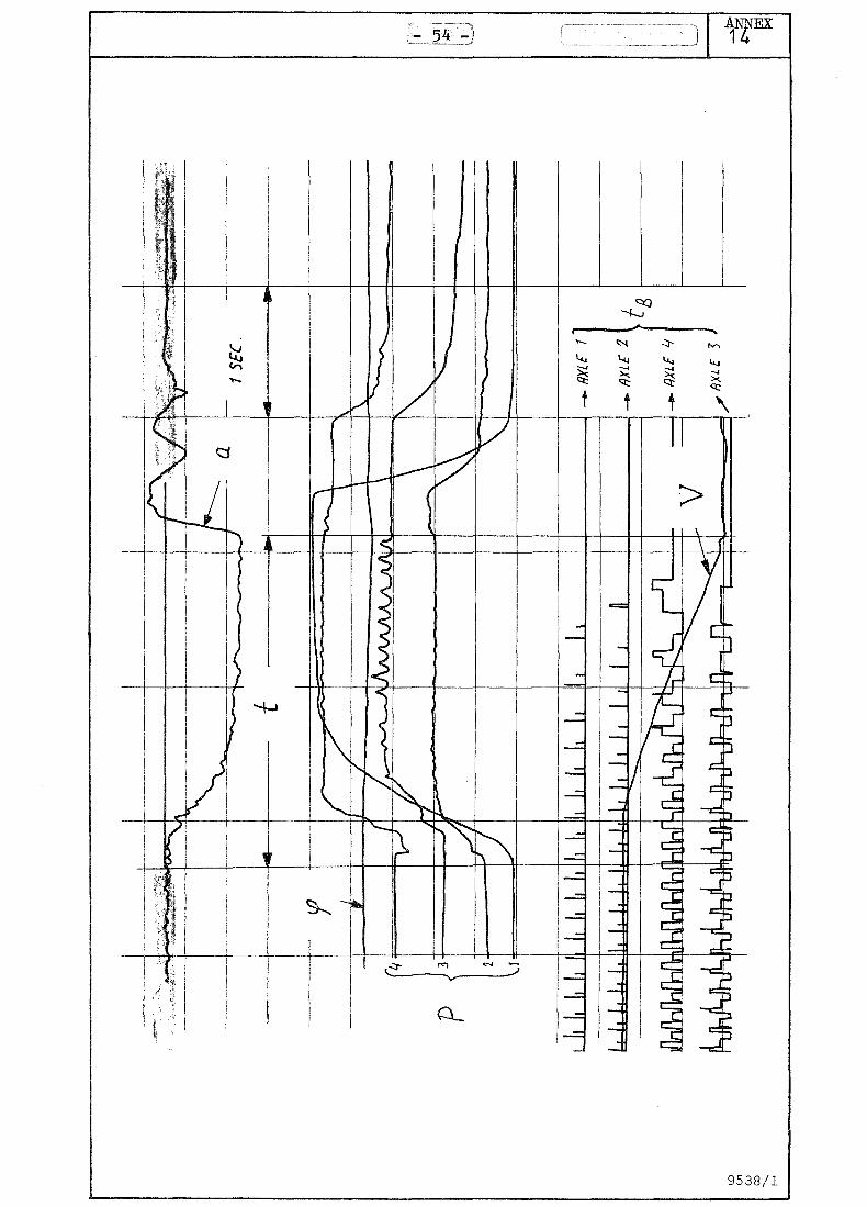
1. speed v 2. deceleration a
3. braking path s

- 20 -'
4. the angle ~ between the tractor and semi-trailer
5. the pressure p in the brake cylinders
6. the time tB after which a wheel locked
7. the duration t of the measurement
After each measurement the vehicle's position relative to the
driving direction was sketched. In a number of cases the temper
ature of the brake drums was measured.
4. Measuring equipment
4.1. The speed v was measured with a Peissler fifth wheel. Illus
tration 4 (Annex 17) shows how this wheel was fixed on the
semi-trailer. For solo measurements this wheel was placed behind
the tractor's right rear wheel. The vehicle's speed could be seen
directly in the cab from a meter belonging to the wheel. The speed
signal was noted on a UV recorder.
4.2. Deceleration during braking was measured with a (Donner) ac
celerometer. The recorder was located in a box on the tractor, as
shown in Illustration 5 (Annex 18). To avoid the semi-trailer
touching the box in a bend it was positioned at an angle. The
recorder signal was amplified and recorded.
4.3. After each measurement the braking path s could be seen from
the Peissler box. By fitting a switch to the brake pedal, the com
mencement of each braking was determined. The commencement of bra
king was marked on the paper strip.
4.4. The angle between the tractor and semi-trailer was measured
with a rotary potentiometer. This was made possible by fitting a
semi-circular disc near the connecting point on the semi-trailer,
with a steel wire over it. The potentiometer was fixed to the
tractor frame. A disc was also located on the potentiometer with
the wire wound round it several times (see Drawing). In this way
there was a fixed transmission of 1:10. The potentiometer was in
corporated in a bridge. Its signal was recorded.

connec
point of
semi-trailer
- 21 -
wire
tractor frame
~.5. The pressure in the brake cylinders was measured with quarz
pressure transducers (Kistler). Each transducer was compensated
for accelerations. One transducer was fitted per axle, as close
as possible to the brake cylinder. The charge amplifiers belonging
to these transducers were placed close to the transducers to avoid
the signal being weakened too much in the (special) transducer cable.
Illustrations 5 and 6 (Annex 18) show the boxes i~ which the
charge amplifiers were placed. These boxes were fully insulated
in order to preclude inaccuracies owing to temperature variations.
~.6. It was fairly simple to establish whether a wheel locked or
not. Reed relays were used for this; these are relays which close
under the influence of a magnetic flux. They were connected in
series-parallel with two resistances as shown below:
11 11
(

--22 -
With an opened relay the voltage drop across R2 is known. With
a closed relay it is zero. By fitting the relay on the (station
ary) axis of the semi-trailer and fixing a small magnet on the
(rotating) hub it was possible to ascertain from the voltage
across the relay whether the wheel was turning or not. In the
former case the voltage showed a step function and in the latter
a constant function.
On the tractor, the magnet was glued to the edge of the rim, and
the relay was placed in a plastic block on the brake-drum protec
ting plate.
In this way, each wheel had a relay. Illustration 6 (Annex 18)
shows how the relay wiring on the semi-trailer axles was fixed
to brackets. The signals from two relays (per axle) were noted
on one channel of the UV recorder. By suitably selecting Rl and
R2 it was possible to make the voltage drop across R2 for the
left side of the combination twice as great as for the right side.
After totalling two signals it thus remained possible to establish
which wheel was locking. The time tB after which this happened, as
from the commencement of braking, could be read from the paper
strip.
q.7. The measuring time was not directly recorded, but was easy
to ascertain because the commencement of the measurement was de
termined by marking and the end was at V = O.
4.8. The temperature of the brake drums was noted in order to
find out whether the drums were cooled sufficiently to start the
next test. Since it soon transpired that the time needed for con
verting the braking system was adequate for cooling the brakes,
the temperature was only measured in case of doubt.
4.9. As stated earlier, all the signals were noted on a UV recor
der. A Brush recorder was used with which 11 signals could be re
corded. Fer the twelfth signal, the marking, a separate galvanometer
was used.

- 23 -'
~.10. All the equipment could be fed from the tractor's 2~ volt
system by using converters. The equipment was placed on the bunks
in the cab. Annex 7 shows a block diagram of the equipment.
The driver was instructed to apply the brakes hard if possible.
In the first instance, it was assumed that the steering would not
be corrected (except for reasons of safety). Later, it was examined
in a number of measurements to what extent the steering could be
corrected. In order to avoid the combination jackknifing, a chain
was fixed to limit the jackknifing angle.

- 24: -
IX. RESEARCH RESULTS
1. Results of computations
A series of diagr~s shows the relationship between the required
friction coefficient k as between tyre and surfaee and axle load
on the one hand, and the deceleration factor (related to accelera
tion of specific gravity) on the other.
In all cases, the characteristics depict the artic in a number of
cases widely applying in practice.
The basis was the following data:
Axle load in N
tractor, front axle
tractor, rear axle
semi-trailer 1st axle
semi-trailer 2nd axle
laden
65,640
94:,750
79,760
79,760
unladen
50,200
35,335
24:,280
24:,280
The braking pressure to the semi-trailer speeds 0.7 bar ahead of
that on the tractor. When the truck is empty the braking pressure
to the tractor's rear axle is controlled by an automatic load brake
apportioner with a radial characteristic. On the semi-trailer, the
braking pressure can be contained by means of a hand operated con
trol of the quick-acting type.
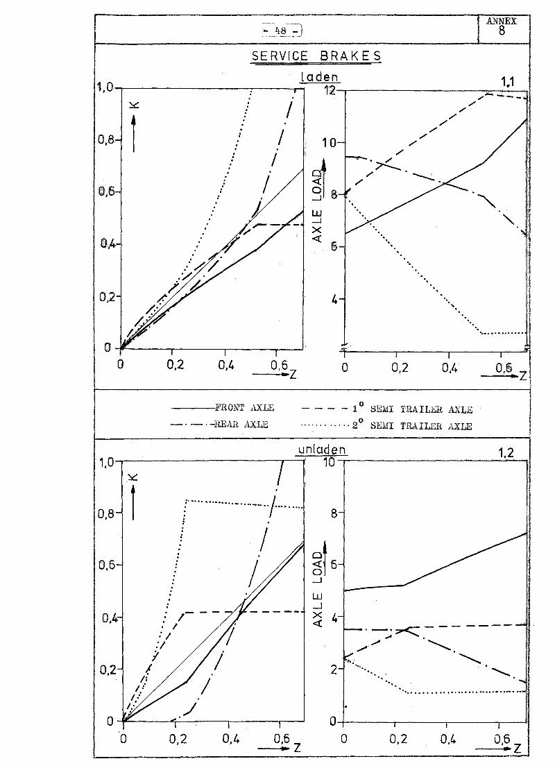
1.1.1. Service brake intact, laden (Annex 8).
Owing to the absence of weight compensation in the semi-trailer's
tandem set, the semi-trailer's second axle locks first.
1.1.2. Service brake intact, unladen (Annex 8).
Here, the effect is shown of the hand-operated control on the
semi-trailer. Until the point of switching, the braking force dis
tribution remains unchanged, and thus the braking capacities are
the same, whether laden or unladen, until the switching point.

- 25 -
The diagram shows that the switching point is at k = 0.8 for axle
No. q and at K = O.q for axle No. 3. The diagram is therefore
valid only if the maximum braking force coefficient is greater
than 0.8. In this case, axle No. q will not lock. If the maximum
braking capacity coefficient is less than 0.8, axle No. q will
lock quickly, and in addition the braking capacity will be lower
(Ab (;t-xm) • In order to obtain a given deceleration, therefore, axles Nos. 1
and 2 must brake more strongly than indicated in the diagram. On
a smooth surface Vxm R::: 0.35 and~ xb ~ 0.20) axles Nos. 3 and q
will allready lock before the .witching point is reached, and hence
the control will be ineffective. Axles Nos. 1 and 2 will then have
to supply the braking capacity for higher deceierations, when
axle No. 2 is still relieved by the semi-trailer pushing ahead.
Axle No. 2 will therefore lock quickly on a smooth surface, and
hence it makes no difference whether the hand-operated control
is positioned "fully loaded" or "empty".
1.2. Tractor fails, semi-trailer brakes normally (Annex 9). In or
der to obtain reasonable deceleration, there will have to be a high
friction coefficient.
There will be a great danger of the semi-trailer pulling off course.
1.3. Tractor fails, semi-trailer brakes normally (Annex 10). This
leads to a dangerous situation because the tractor's rear axle is
liable to lock quickly.
It makes little difference whether the vehicle is loaded or not.
E.E.C. regulations permit a simple single-circuit system for the
rear vehicle, as set forth in Section IV.
1.q.1. Tractor's front axle fails, laden (Annex 11).
In this situation reasonable deceleration is possible. Owing to
speeding towards the semi-trailer. the tractor's rear axle will be
the last to lock.
1.q.2. Tractor's front axle fails, unladen (Annex 11).
Owing to the semi-trailer's quick-acting regulator and the ALR with

- 26
a radial characteristic on the tractor's real axle, this case dif
fers little from 1.2.1. (tractor fails, uuladen).
1.5. Tractor's rear axle fails (Annex 12).
When the vehicle is empty, this situation will be much better than
if the front axle fails.
2. Measurement results
The result of each measurement was ascertainable from:
1. the observation sheet
2. the paper strip from the UV recorder.
The observation sheet not only showed precise data on temperature,
braking path etc., but also observations by the driver or his mate
regarding stability etc. See Annex 13. Where necessary, this infor
mation was incorporated in the results.
Besides the factors mentioned in section VIII.3, the following factors
were also determined:
1) The build-up time tA of the braking system (The time elapsing
between depressing the brake pedal and the moment at which pressure
begins to build up in the brake cylinder).
2) The time t75 in which the pressure in the brake cylinder reaches
75 per cent of the final pressure.
These two latter facts can be used only for comparison, because
the addition of valves and piping makes the circuit times in the
system differ from those under normal conditions.
Since the maximum deceleration only occurred for a very brief time
in a large number of measurements, an average deceleration a was gem defined:
in which Vo = speed at commencement of braking
t = duration of measurement
Annex 14 shows part of a measurement strip with the twelve signals.
Annex 15 shows a sheet with the result of several measurements worked
out.

\ - 27 -
The results will be given for main and sub groups as mentioned
in annexes 3, 4 and 5. For easy comparison the deceleration figures
are given as an average deceleration a for four measurements, gem that is at 40 and 80 km/hr both on dry and wet road surfaces.
When desirable differences are given, too.
3. Group 1
3.1. Solo tractor
A normally braked tractor remains stable and the average deceler
ation for the four measurements was ample at 4.6 m/s2.
If the front axle fails there are indications of very great in
stability if the rear axle locks, as on a wet surface. The average
deceleration was 2 m/s2.
Failure of the rear axle caused no problems. The front wheels lock
ed, which may affect vehicle control. The average deceleration was
3.75 m/s2.
All diagonal brakings were very unstable. Average deceleration 2
2.4 m/s •
It was impossible to correct diagonal brakings.
3.2. Tractor with unladen, semi-trailer
This combination normally causes no problems. Average deceleration
4.6 m/s2. Locking of axle 3 as calculated in par. IX.1 (necessary
friction more than 0.8; available friction 0.7) does not occur.
The braking force at the semi-trailer's axles probably was smaller
as calculated. Wear of the brakes results in a bigger stroke and
smaller braking forces.
Failure of a tractor axle causes no problems. A semi-trailer braked
normally at that moment apparently kept the combination stable.
A diagonally braked tractor causes an unstable combination pulling
strongly to the left. Jackknifing occurs if the steering is not
corrected.
Failure of one axle on the semi-trailer greatly relieves axle 2,
causing it to lock especially on a wet surface. The combination
will then jackknife.
- 28
A diagonal circuit on the semi-trailer again causes stability
problems. But the reason in this case is that the semi-trailer
is not adequately braked, so that axle 2 is relieved.
If only the tractor is braked, axle 2 locks and the combination
jackknifes. Braking the semi-trailer alone gives a stable combi-
nation, but a Iowa of 1.6 m/s2. gem
As expected, normal braking causes no problems relative to the
criteria. Even if a tractor axle failed (with a normally braked
semi-trailer), stability was still good ( similarly' to an empty
combination).
A diagonal circuit on the tractor did not cause the big stabili
ty problems of the empty combination. A slight correction in
steering met the stability criterion.
Failure of one semi-trailer axle had no serious effects on stabil
ity, similarly to a diagonal circuit.
Failure of the semi-trailer's or the tractor's brakes caused no
problems, apart from correcting the steering in the former case.
But the a seems rather low. gem
In nearly all the cases dealt with, the average deceleration
after a circuit failure was still adequate. For completeness, a
list is given below showing the a (in m/sec2 ) for four meas-gem urements:
Solo tractor: normal braking 4.6
failure of axle 1 2
failure of axle 2 3.75 braked diagonally 2.4
Combination: emEt~ full~ loaded
braked normally 4.6 4.1
failure axle 1 2.6 2.9

em!!t~ full~ loaded
failure axle 2 3.9 2.9
diagonal circuit 3.1 3.0
tractor
failure axle 3 3.8 3.1
failure axle 4: 4:.2 3.5
diagonal circuit 4:.0 3.2
semi-trailer
failure semi- 3.4: 2.3
trailer brakes
failure tractor 1.6 2.3
brakes
The biggest problems in emergency braking are in vehicle stabil
ity rather than in deceleration, though this is sometimes very
low.
It is striking in this connection that diagonal circuit s~para
tion has little to offer.
Furthermore, this research has again demonstrated the great
danger of locking wheels. Especially locking of the second axle
causes problems. It is striking that an inadequatly braked semi
trailer pushes forward, relieving the second axle. In such a case
an ALR on this axle does not hold the vehicle back enough and
wheel locking occurs.
In view of the foregoing, the difference in a if axle 3 or 4: gem fails is very striking. Owing to the weight transfer in the
tandem set, axle 3 makes a much bigger contribution to decelerat
ion than axle 4:.
4:. Main group 2
4:.1. Solo tractor
As regards stability, only the measurements in which the front
axle was braked were good. In the other three cases (see Annex 3)
axle 2 locked and the vehicle was very unstable.
The average deceleration for four measurements in the former

2 case was adequate at 3.q m/sec •
q.2. Tractor with unloaded semi-tractor
a) With intact semi-trailer and auxiliary brakes on tractor: The
results in this case are the same as for the solo tractor. Only
if the first axle is braked with the auxiliary brakes is stabil-2 ity good, with an a of 3.2 m/sec; gem
b) With intact tractor and auxiliary brakes on semi-trailer: If
axles 3 and q are braked, stability is good. Diagonal braking is
still reasonable, but braking only axle 3 or q causes stability
problems.
c) If all the axles of the combination are braked with spring
brake actuators, axle 2 will lock and severe instability effects
occur.
q.3. Tractor with loaded semi-trailer
a) With intact semi-trailer and auxiliary brakes on tractor:
Diagonal brakes on the tractor do not give good results. Braking
axle 1 or 2 or both goes well.
b) With intact tractor and auxiliary brakes on semi-trailer.
Except for an odd correction of steering, stability remained good
in these measurements.
c) If all the combination's axles are braked stability remains
good.
The avergae deceleration (m/sec2) for main group 2 were:
Solo tractor: Axles 1 and 2 braked 3.5
Oiily axle 1 braked 3.q
Only axle 2 braked 3.q.
Diagonal braking 2.5.

For the combination with:
Axles 1 and 2 (or 3 and q)
auxiliary brakes
Only axle 1 (or 3) brakes
Only axle 2 (or q) brakes
Diagonal braking
- 31 -
Intact semi-trailer Intact tractor
Empty Fully loaded Empty Fully
loaded
3.2
2.7 2.9
2.8
3.6 3.9 3.8
2.8
2.9
2.8
All axles with spring brake actuators applied: Empty q.l
Fully
loaded 2.9
The average deceleration are adequate, but in this main group as
well, stability is not as good as it ought to be. One reason is
that braking power per axle cannot be regulated, and for instance
axle 2 in the solo tractor or the empty combination is braked to
the maximum, causing locking and instability. Braking power can
be regulated for all axles at the same time with the auxiliary
brake.
Another reason for poor stability is the relieving of axle 2
through the semi-trailer pushing forward. Another thing disclosed
by the measurements was that the steering is difficult to correct
because the driver has to handle the steering wheel with one hand
and the auxiliary brake with the other.
5. Main group 3
5.1. Solo tractor ------------In this sub-group measurements were made with a tied-up ALR
control arm. It appears that this makes the pressure to the 2nd
axle too high and the wheels will then lock. Stability is very
poor especially if only axle 2 is braked.

- 32 -
a) Only ALR tied up: stability very poor owing to locking of
axle 2;
b) Only the brake regulator on the semi-trailer at tlfull tl• No
problems on a dry road. On a wet road axle 2 locks, followed by
instabili ty.
c) Both regulators at "full". The same result as in (a). The
combination was very unstable.
ALR on tractor at "full l1 : Jackknifing occurs through locking of
axle 2, thus failing to meet the stability criterion.
5.~. Conclusions -----------The average decelerations in this main group were:
Solo tractor with tied-up load brake apportioner:
Axle 1 and 2 braked ~.9
Only axle 2 braked 1.9
Combination:
Tied up ALR
Empty
4.0
Manual regulator valve at "Full" 5.2
Both regulator at "Full" 4.7
Loaded
4.1
If only the solo tractor's rear axle is braked to the full, the
deceleration is too low. This is due mainly to the wheels lock-
ing. In other cases the a is adequate. gem A defect in the ALR, sotthat it passes on the maximum pressure
during braking, has the consequence that axle 2 will lock re
gularly. The excessive pressure is not the only cause, because
locking is also encour~ged by the ALR no longer regulating dynam
ically.

- 33 -
An incorrectly adjusted regulator on the semi-trailer (i.e. at
"Full with an empty combination) causes the braked wheels to
lock; the semi-trailer provides too little braking power and
pushes forward so that axle 2 is relieved. Especially on a wet
road, the ALR will not hold the vehicle back enough and axle 2
will lock.

- 34 -
x. CONCLUSIONS AND RECOMMENDATIONS ..
In evaluating systems for emergency braking if the service brake
fails, the criteria were braking path, the appropriate average
deceleration and the track stability. In addition, attention was
paid to lost times and possibilities of correcting the steering.
If the service brake functions normally, an articulated vehicle
both loaded and unloaded proved to satisfy the criteria of
deceleration and stability, even if the brakes were fully applied.
This was found to be possible only if there was an automatic
load brake apportioner on the tractor's rear axle. If this is not
fitted" as is still the case with many of the present vehicles,
or if it fails, the artic is very unstable and will usually
jackknife if the brakes are fully applied.
With an intact service brake the solo tractor shows minor signs
of instability at the end of the braking path on a wet surface.
This is due to the limited possibility of regulating the load
related brakes. Without this facility, a solo tractor is very
unstable under all conditions.
If the service brake becomes defective, part of the braking
capacity may be retained because this brake has a residual
effect or because hand-operated auxiliary brakes are installed.
With nearly all applicable systems it was possible to reach the
minimum deceleration of 2.2 m/s 2 needed to satisfy the requirements
for the auxiliary brake's braking path. Exceptions were:
- circuit separation, with the tractor and semi-trailer each
forming a circuit.
if the tractor's brakes fail, very long braking paths occur.
- if the solo tractor is braked only on the rear axle.
The practical tests showed that the biggest problem in emergency
braking is the vehicleAs track stability rather than deceleration.
In braking with spring brake actuators, this happens because in

,- 35 -
this case braking capacity is independent of the vehicle's load.
With such actuators, braking capacity distribution is not regula
ted, and wheel-locking often occurs if the vehicle is unloaded.
The vehicle is unstable:
- if the tractor's rear wheels lock. The artic then usually
jackknifes or a solo tractor turns round its vertical axis.
- if the semi-trailer in an artic does not brake sufficiently.
The semi-trailer then pushes forward, taking the load off the
tractor's rear axle, and easily causes jackknifing.
- if diagonal circuit separation is applied to the tractor, i.e.
to the right front wheel and the left rear wheel or vice versa.
The vehicle then pulls off course, and cannot be corrected owing
to the big difference in braking capacity at the front and rear
axles, so that a strong turning moment occurs in the tractor.
If we examine the present requirements concerning brakes in
Regulations 71/320/EEC, 7~/132/EEC and 75/52~/EEC in the light of
these findings, serious gaps are found to exist:
- a vehicle combination as a whole need not undergo braking tests.
Each vehicle individually has to satisfy the criterion of
deceleration, since separate braking systems as between tractor
and semi-trailer are permitted by the present EEC requirements.
-track stability is guaranteed only if the semi-trailer continues
to brake sufficiently. According to the present requirements in
the above-mentioned directives, trailers and semi-trailers need
not be equipped with auxiliary brakes. Nor need the service brake
of the trailer or semi-trailer have any residual effect except if
the automatic load brake apportioner fails.
- track stability is the main criterion for the auxiliary brakes
and/or the residual effect of the service brake. No requirements
are given for track stability in case of emergency braking.
Instability occurs especially on wet road surfaces. Wheel-locking
during braking tests on other than dry surfaces are not provided
for in the present regulations.
- the hand-operated brake-pressure control of the quick-acting
type on a semi-trailer only has any purpose on a reasonably rough

- 36 -
surface. This control may also be of some use if there are low
braking capacities on the semi-trailer (owing to wear). On a
smooth surface the semi-trailer's wheels are already locked before
the control acts, and its value under these conditions is dubious.
Theoretical considerations and practical tests have shown that
the total time lost when using separate hand-operated auxiliary
brakes is greater than if the residual effect of the service brake
is used. Moreover, hand-operated auxiliary brakes have the draw
back that the driver has to take one hand from the steering wheel.
Experience shows that it is then difficult, if not impossible,
to correct the steering. Furthermore, it has not been proved that
using spring brake actuators as auxiliary brakes produces higher
decelerations than with the residual effect of the service brake,
while it is then that the greater loss of time has to be compen
sated for.
All the above findings are based, as far as practical tests are
concerned, on tests made under specific conditions.
Even when wet, the road surface still gave fairly good braking
force coefficients. The vehicle's behaviour on smoother surfaces
than those used for the tests may not be quite as good as regards
track stability.
Measurements were made only with one set of tyres of the same
make. The difference between different makes of tyres, however,
are not very great. A factor that had a somewhat adverse effect
on the measurements was brake wear. This changes braking capacity
distribution, and in particular makes it difficult to evaluate
the semi-trailer's hand-operated brake-pressure control. It is
therefore important, for such research, to adjust the brakes in
good time, automatically or otherwise.
80 km/h was chosen as the top speed, because many countries have
this limit for trucks. In practice, however, they often driver
much faster.
The load was varied between fully loaded and empty.
In practice, of course, there are many intermediate conditions,
- 37 -
often including uneven loading.
Notwithstanding the limited scope of the research outlined above,
a number of clear recommendations follow from these conclusions.
Recommendations
- The regulations should include a requirement regarding vehicle
lateral stability when using auxiliary brakes or the service brake's
residual effect.
Braking tests should be made on a wet surface with at least an
empty artic and a solo tractor. The roughness of the wet road
surface should be carefully defined.
- ~he regUlations should include a requirement that trailers and
semi-trailers should be equipped with auxiliary brakes or that
the service brake should have a certain residual effect in case
it fails.
- 'or both tractors and semi-trailers it is preferable, in case
of emergency braking, to have a service brake residual effect of,
say, 50% of the prescribed braking capacity.
- The use of systems in which half the braking capacity of each
axle is always available for emergency braking is preferable.
- For more detailed research it is advisable to make smaller-scale
tests than those described above, into the behaviour during
emergency braking of a 'combination of truck and trailer.

- 38 -J
REFERENCES
1. Traffic accidents and road surface skidding resistance.
Institute for Road Safety Research, SWOV, 1975.
2. Fink, W. Verzugsdauer beim Bremsen. ATZ 70 (1968) no. 9.
3. Johansson, G. and Rumar, K. Driver's brake reaction times.
The Department of Psychology, University of Uppsala, Sweden,
March" 1965.
- 39-
LIST OF APPENDICES
1. Measures and weights of the tractor and semi-trailer.
2. Outline of the added values of the tractor and semi-trailer.
3. Putline of circuit separation utilizing the residual effect of
the service brake: Main group 1.
4. Outline of braked wheels utilizing spring brake actuators:
Main group 2.
5. Outline of possible failures in the installed equipment for
brake force distribution: Main group 3.
6. Measured brake force coefficient at the measuring site.
7. Block diagram of the equipment.
8. Relationship between the required friction coefficient K and
axle load on the one hand, and the deceleration on the other for
the normal braking system.
9. Relationship between the required friction coefficient K and
axle load on the one hand, and the deceleration on the other when
the tractor's braking system fails.
10. Relationship between the required friction coefficient K and
axle load on the one hand, and the deceleration on the other when
the semi-trailer's braking system fails.
11. Relationship between the required friction coefficient K and
axle load on the one hand, and the deceleration on the other when
the tractor's front axle fails.
12. Relationship bwteen the required friction coefficient K and
axle load on the one hand, and the deceleration on the other when
the tractor's rear axle fails.

- 40'
13. Example of an observation sheet.
14. Example of a paper strip from the DV recorder.
15. Worked out measuring results.
16. Illustration 1 + 2.
17. Illustration 3 + 4.
18. Illustration 5 + 6.
19. Illustration 7 + 8.

t 15
10
~ x..j
1 ,
i ..
t J
I I
Yt ~
i: 2:: 0
~ ~i
1380
t t
t [;
1 tz
l. F
Z3
FZ
l F
Z2
So
lo tr
acto
r 4
8
23
,8
Un
lad
en
co
mb
inati
on
5
0,8
3
6,4
Lad
en
co
mb
inati
on
6
6,3
9
7,2
All
lo
ad
s in
kN
Tra
cto
r: ~1=1080
'Yl=
95
0
Sem
i-tr
ail
er
X2
Y2
Un
lad
en
5
71
0
10
00
Lad
en
4
80
0
17
30
FZ
3 T
ota
l l
-7
1,8
49
,5
13
6,7
16
2,6
3
26
,1
>l:
f->. :..-
~~
t:;j
:><J

« 0::
> 0::
- 42 ANNEX
2

SUBGROUP 1
~ 1 2
Normal braking
Failure of axle 1
Failure of axle 2
Diagonal braking
- 43 -
YAINGROUP 1
(Service brakes)
SUBGROUP 2 SUBGROUP 3
ANNEX 3
~"II Ol:) CJIwt nooo 00
1 2. :5 Lt 1
Normal braking
Failure of axle 1.
Failure of axle 2.
Diagonal braking tractor
Failure of axle 3.
Failure of axle 4.
Diagonal braking semi-trailor.
Only tractor braked
Only semi-trailor braked
2. 3 Lt

:LiA.INGROUP 2
(Spring brakes)
~
SUBGROUP 1 SUBGROUP 2
~ Cb" Du 1 2- 1 2 :5 'I
Axles 1+2 braked Service brake semi-tr.
Only axle 1 braked , Only axle 2 braked Tractorl
Diagonal braking Axles 1+2 spring br.
Only axle 1 brakes
Only axle 2 brakes
Diagonal braking
ANNEX 4
SUBGROUP 3
CJ-ill9, nooo 00
1 2 .J 'I
Service brake tractor
t Semi-trailor:
Axles 3+4 spring br.
Only axle 3 brakes
Only axle 4 brakes
Diagonal braking
Also in this maingroup:AII axles braked at the laden or unladen
combination

.uAINGROUP 3
t ~
SUBGROUP 1 SUBGROUP 2 SUBGROUP 3
~ ~"' Ou ~, oggJ 1 2 1 Z
J " 1 2 :J "
IF
With tied up ALa: All axles braked with: All axles braked with:
Axle 1+2 braked
Only axle 2 braked
Tied up ALR
Manual regulator at
'full'
Both regulators at
'full'
Tied up ALR
ied up ALa means:The control arm of the ALa s fixed in the
position 'full'
1/

TEST RESULTS ENTER
-----DRy
- - - --WET
TIRE: MICHELIN E 20 X
: 25500 N
PRES~URE: 6,25 BAR

BLOCK DIAGRAM OF THE
REED RELAY
LEFT 1~ 4X
l~ REED RELAY
RIGHT ,OMMATOR
PRESSURE CHARGE
TRANSDUCER AMPL.
ACCELERO-AMPL.
METER
ROTARY WHEAT-
POTENTIO-STONE
METER BRIDGE
SWITCH
FIFTH CONVER-
WHEEL
V 8
ANNEX 7
SIGNALS 1,2,3,4
SIGNALS 5,6,7,8
SIGN"H 9
~ ~
~ 0 r.:l ~
10 • > • :;:.
SIGNAL 11
12
1,0 ~
0,8 1 06-,
0,4
0,2
0 0
SERVICE BRAKES
: 0 0
0
/ 0
0
/ : 0 ,
0
0
/ • 0
0 0
0
0 / 0
0
; 0
: )
0,2 0,4 O,~Z
----,FRONT AXLE
_. - . -REAH. AXLE
laden 12
./ ,/
,/
10 ,/
,/
./
~e . '/Z
./ ./
W -.J X « . -6 -.
"
M -. ,
4 -. .. -
""'.'
0 0,2 0,4
- - - - 1 0 SEMI TRAILER
........... ·2 o
./ ./
. . -, ,
ANNEX 8
1.1 ,,,..,..-----
~ "-
. " ...... " ... "" .. "
0,0 Z ...
__ -------------------~~u~n~[a1doe~n~------------------1~.2~J 1.0 10
0,8 : .............. -.... _ .... / " ... " " ... "
o
: . .
0,6
. : /- - --: I 7' :/
:/
0,4
I . /' /
If / /: I:'
/.:
0,2
o 0,2 0,4
8
W -.J X 4 «
2 '. . '. -" .... "" " " .. " "" ...... """,, .......... " .. ..
0!4-----~----~----~--4
o 0,2 0.4

ANNEX --49:J 9
FAILURE TRACTOR
laden 2.1 1.0 , 12 . / ~
! I
f . I .
I . / ..-- ,
0,8- . 10-: ~.-/ . .
J 6-
I · · I · · / · 0.6- : II , . . d ! .....J , • . w , . I .....J I .
0.4- t >< ,
, / 6- '. . / « ... ! I \
\
:/ . ./
0,2- i 4- '.
/: . . \
1/ " ~:
f 0 T I I I I r ::r
0 0,2 0,4 0,6 0 0,2 0,4 06 ... z , "Z
FRON'r AXLE - - - --1 0
SEMI 'l'RAILER AXLE
- . _. -REAR AXLE ......... ·2 0 SEMI I.A TT .I<;R AXLE
unladen 2.2 1,0 10
~ .
! : . .
I
O,S -I s-I
I
~t 5-I
0,6- I I , i
I 0 I
I -' I
I I
W · I 0,4- · .-l 4-· / ! / >< ~'-'''''7 « ,. ! I ,.
"" /f ,. k ..... :'/ ... .... 0,2- /I 2- '. '0
/I .... " " . .
0 0 I I I I I I
0 0,2 0,4 O,~Z 0 0.2 0,4 O·~Z

ANNEX 10
FAI LURE SEMI TR.
laden 3.1 1, 11
~
r 9
L .,.~-
" Cl
" « . 0 " ...J
w5 ...J x «
0,2 3
O~----~----~----~--~ F I 0,2
I 0,4 o
1,0 ~
0,8 1
0,6
0,4
0,2
o
0,2 0,4 0,6 -2
---- FRONT AXLE
-'-' -REAR AXLE
o
- - - - -10
SEMI TRAlLEH. AXLE
......... 2 0 SEMI TRAILER AXLE
unladen 3.2
0,2
I /
0,4 O,6 .. Z .
10
8-
O~----~----~------r-~
o 0,2 0,4 O,~z

FAILURE FRONT AXLE
ANNEX 1 1
laden 41 -r--------~~.~--------~~~----------~_.==-~-~----~. 1,0 ,
0.8
0,6
0,4
o.
1
/ / . /
, ,
, , . .. . .
, ,
/ . .
I /
.' /1-..: /// . / //
,:/ /' :/ //
./ ./
10- ./
1 . '7----.
/ ~ . .-r/ o « o -15
.
'. w , -1 X
/ ' «
4- ". " /.-:
/.'f 16:' o 0.2 0,4 0,6
-----.. Z o
I 0,2
o - - - -1 SEMI
" " ......
I 0,4
AXLE --- FRONT AXLE
_. - . -REAR AXLE o
.... , ... ··2 SE.MI TRAILER AXLE
I 0,6 -z
unladen 4.2 1.0 -.------------=;:'""'"'-:;11f)0;;..::-r~-----------,
0,8
06 I
04 I
0,2
~
1 I
J' ........... {' , ,
! I , . '
/ I , ,
:: r--/L--: 1 : I :1 "
1 ;. ,:
/,'1
li I o ~_-JI!::..--r----:---"'------"!-.....j
o 0,2 0,4 0,6 "Z
8
,.. .----~ -----,.. ............ ,,'" . "-....
'. ". ............. , •....
04-----~----~-------"!--~ o 0,2 0,4 0,6 -z

ANNEX 12
FAI LURE REAR AX LE
laden 1.0~--------------------. 12,-----------~~_~--~5~j .
~
0,8- r
0,6
0.4
0,2
. .
. . · · ·
· / ". /
: " :/
· · ·
"
· · · · .
, "
10
o « o -'
I llJ -' X «
4
/ /
/ /
/ /
'-r--'-,~ /. ,
/ ..
, . , . . . . . ,
' . . . , "It'.._ ••
O~----~----_T----~--~
o 0,2 0,4
---FRONT AXLE
-. _. -REAR AXLE
o 0.2 0,4
- - - - _10
SEMI TRAILEH. AXLE o
···········2 SEMI AXLE
1.0 ~ __ ----__ ------------~u~n~l=atden=n 52 --, 1'0,--------------' -.1
0,8
0,6
0.4
0,2
o
· · · I • ,
· · · • · · , . . ,
: 1--: I ! I :/
,:/ 1
I 1/
!/
0,2 0,4 0,6 -""Z
8
'6 o « o -' llJ4 -1 .-'~--------x ,.'" -« ~// ~.
2 '-" " -', " "
'" " " ' .................... __ ...... _--
o 0,2 0,4 0,6 ----' ..... Z

TEST NUMBER: 3" '-I DATE: IS - r -t 5
UNLADEN LADEN DRY WET
I X I I I X I I BRAKING DISTANCE{m) DISTANCES(m)
SPEED{ km/h)
Q2J
2 . 3 D FRONT AXLE.l.ROAD SIDE
2. 0 0 REAR AXLE - ROAD SIDE
ANNEX 13
3.3 D 20
SDI-TRAILER AXLE - ROAD SIDE
TEMPERATURES °c
5 c9 FRONT AXLE
Lt 5 REAR AXLE
S 2 10
SEMI-TRAILER AXLE
'72. 20
SEMI-TRAILER AXLE
PO.SITION COMBINATION END OF TEST
REMARKS:
STABILITY: -
CORnECTION DRIVER :C'RSSA AI 0
I
)
<
~VI / I
-= ---= -
9538/1

SP
RIN
G
BR
AK
E /
SE
RV
ICE
B
RA
KE
IIIIIIII
IIII
c:::::
:::J
Illlll
llllll
IiiIII
IIIIII
I
SP
I
SE
SE
TE
ST
N
UM
BE
R
cf9
UN
TIL
97-
SP
: =
-,
--2
3 4
r~'l
AX
LE
1 A
XL
E
2 A
XL
E
3 A
XL
E
4 LO
CKIN
G
Nll.
. V
d
ry
un
lad
en
S
t II.
ge
lll
Il
p tA
tn
[Pm
u
tll.
t 1
5
Pm ..
x t
t15
P
t t 1
5
1L
11
\ 2
L
2R
31
.. 31
t 4
ft
4L
i0
i 0
wet
la
den
III
l1.lI
: II
IIlX
It
1I
l1Il
( I/
.
tf'9
'-10
D
L 2d
' '1.
2 2.
b 4'.
0 2
.0
a3
0.6
2,1
",3
0.
'1 ~/6
<--j
90
60
l>
l 6
'T
:$,3
it
a
2,0
0.
2-0
,6
2.0
c.!
O
.l(
2$
91
If
o
N
I. 2S
:5
3.d>
2.
.q
If. 0
2
,0
0.2
0.6
2.D
tJ,1
. a
lf
12.2.
92
!;S
AI
L '-1
&
6:2.
2.
.9
If.o
2.1
0,2
fJ.6
2.
1 o,
t o
J 2.
1 '13
'f
o
lJ
8 2
9
it.J
1.6
3.6
,..s-
0.3
AD
5:S
42
-(J
,b
9"1
60
()
0 9
0
1,4
2,,9
3.
1 5
',1j
as
0.1
l.)
0..3
~,6
95
1;0
N
8
21-
4.2
2,7-
3.6
5".S
aJ
11
,1 5':
1;
0.3
,.6
1.
0 1.6
'1
6 db
A
I 8
9'1
'1'"
2..4
1.
'1
S'.S
0
.3
tJ ... tP
S
S ~U
l) • .
,. 1.
3 2.
0
i"-
~>
U1§ t:;j l><l

1
2
ANNEX 16
9538/2

(- 57 -I
3
4
ANNEX 1 7
9538/3

5
6
9538/4

19
7
8
9538/5