Overload Protection Index Clutches - Caldic Techniek Belgium
33
Overload Protection Index Clutches CROSS+MORSE Power Transmission Solutions Types of Overload Protection 2 Crossgard Overload Clutches 13-14 Crossgard Type CG Clutch 15 Crossgard Type CG Couplings 16-17 Crossgard Type CGX Clutch 18 Crossgard Type CGX-C Couplings 19 Crossgard Type CGZ Clutch 20 Crossgard Type CGZ Couplings 21 Morse Torque Limiter Dimensions 4 Metric Torque Limiter Dimensions 5 Safegard Type CS Overload Clutches 22-23 Safegard Type CS Standard Series 24 Safegard Type CS Standard Couplings 25 Safegard Type CS Mini Series 26 Safegard Type CS Mini Couplings 27 Safegard Type CZ Overload Clutches 28-29 Safegard Type CZ Clutch Dimensions 30-31 Safegard Type CZ Coupling Dimensions 32-33 Sheargard Clutch 9-10 Sheargard Couplings 11 Sheargard Clutch Wedge Pin Ratings and Installation 12 Torque Limiter Platewheels 7 Torque Limiters 3 Torque Limiter Selection 6 Torque Limiter Couplings 8 Catalogue Selection INDEX Enquiry CD Contents
-
Upload
khangminh22 -
Category
Documents
-
view
1 -
download
0
Transcript of Overload Protection Index Clutches - Caldic Techniek Belgium

Overload Protection IndexClutches
CROSS+MORSE
Power Transmission Solutions
Power Transmission Solutions
Types of Overload Protection 2Crossgard Overload Clutches 13-14Crossgard Type CG Clutch 15Crossgard Type CG Couplings 16-17Crossgard Type CGX Clutch 18Crossgard Type CGX-C Couplings 19Crossgard Type CGZ Clutch 20Crossgard Type CGZ Couplings 21Morse Torque Limiter Dimensions 4Metric Torque Limiter Dimensions 5Safegard Type CS Overload Clutches 22-23Safegard Type CS Standard Series 24Safegard Type CS Standard Couplings 25Safegard Type CS Mini Series 26Safegard Type CS Mini Couplings 27 Safegard Type CZ Overload Clutches 28-29Safegard Type CZ Clutch Dimensions 30-31Safegard Type CZ Coupling Dimensions 32-33Sheargard Clutch 9-10Sheargard Couplings 11Sheargard Clutch Wedge Pin Ratings and Installation 12Torque Limiter Platewheels 7Torque Limiters 3Torque Limiter Selection 6Torque Limiter Couplings 8
Catalogue Selection INDEX
Enquiry
CD Contents

CROSS+MORSE
Power Transmission Solutions
CD Contents NEXTCatalogue Selection INDEX BACKINDEXOverload Protection Clutches :
Te
l +
44
1
21
3
60
0
15
5 F
ax
+
44
1
21
3
25
1
07
9 E
ma
il s
ale
s@
cr
os
sm
or
se
.c
om
DRIVE SYNCHRONISATION
DRIVE DISENGAGEMENT
RESETTING METHOD
BACKLASH
OVERLOAD INDICATOR
CAN PROVIDE SOFT START
SET TORQUE ACCURACY
SHAFT RANGE mm
MAX. TORQUE Nm
MAX SHAFT SPEED rpm
NO
NO
AUTO
NONE*
NONE
YES
15%
5-120
10000
3000
YES
YES
MANUAL
NONE
OPTIONAL
NO
10%
10-215
125000
1500
YES
1 REV
AUTO
MINIMAL
YES
NO
10%
8-70
1080
700
YES
1 REV
AUTO
NONE*
YES
NO
3%
7-70
785
1400
YES
YES
MANUAL
MINIMAL
YES
NO
10%
8-50
450
1800
NO
RATCHET
AUTO
MINIMAL
YES
NO
10%
7-65
1800
3300
YES
NO
AUTO
MINIMAL
YES
NO
10%
7-65
1800
4000
YES
1 REV
AUTO
MINIMAL
YES
NO
10%
7-65
1800
1000
YES
YES
MANUAL
MINIMAL
YES
NO
10%
7-65
1800
5000
NO
TEMP
AUTO
NONE*
YES
NO
5%
8-50
740
4000
YES
1 REV
AUTO
NONE*
YES
NO
5%
8-50
740
4000
CROSSGARD CGpp15-17
Cross+Morse Overload Clutches
All Cross+Morse protection devices are available as shaft mount units for mounting sprockets, pulleys or gears, or as couplings for shaft to shaft connection. The basic features of the units offered are as shown in the table below. For detailed design specification and selection of units refer to catalogue pages of the relevant series.
FRICTION TYPE CONSTANT DRIVE
MECHANICAL SHEAR PIN TYPE ZERO BACKLASHVERY HIGH TORQUES
LOW COSTROBUST DESIGN
ZERO BACKLASH
HIGH PRECISIONSYNCHRONISED DRIVE
COMPACT UNITS
HIGH SPEEDNON SYNCHRONISED
FAST RESET
CROSSGARD CGX PP18-19
SAFEGARD CZY PP28-33
CROSSGARD CGZPP20-21
SAFEGARD CSZPP22-25
SHEARGARDpp9-12
ELECTRICAL
CONSTANT TORQUEVERY LOW COSTROBUST DESIGN
TORQUE LIMITER pp3-8
SAFEGARD CZF pp28-33
SAFEGARD CSF pp22-27
HIGH SPEEDNON SYNCHRONISED
FAST RESET
BALL OR ROLLERDETENT
RELEASE TYPE
CONSTANT DRIVEHANDLE HIGH INERTIA
VERY HIGH SPEEDIMMEDIATE DRIVE
SAFEGARD CSLpp22-25
LOW BACKLASHSYNCHRONISED DRIVE
LOW COSTPOSITIVE RELEASE
SYNCHRONISED DRIVELOW COST
COMPACT UNITS
2
Overload Protection Devices
Development of manufacturing methods and production techniques has led to machinery and equipment beingmore automated, and systematically combined to provide the best material flow and production efficiency. In theseconditions any small accident which could damage either machinery or drive lines can result in extended downtimeof the total plant. Cross+Morse range of overload protection devices are designed to prevent damage of machineryor drive line in the event of an overload, so avoiding the need of costly repairs and minimising productiondowntime.
Several methods of overload protection are available, these being as classified below, all of which provide various levels ofprotection. Cross+Morse units are all of mechanical operation for minimum maintenance and simplicity of operation.
Classification of Overload Protection Types
OVERLOADPROTECTION
DEVICE
FEATURE TorqueLimiter Sheargard Crossgard
CGCrossgard
CGXCrossgard
CGZSafegard
CSFSafegard
CSLSafegard
CSYSafegard
CSZSafegard
CZFSafegard
CZY
*Within Torque Range
SAFEGARD CSYpp22-27
TOTAL DRIVEDISENGAGEMENT
FAST RESPONSEVERY HIGH SPEED
MANUAL RESET

CROSS+MORSE
Power Transmission Solutions
CD Contents NEXTCatalogue Selection INDEX BACKINDEXOverload Protection Clutches :
Te
l +
44
1
21
3
60
0
15
5 F
ax
+
44
1
21
3
25
1
07
9 E
ma
il s
ale
s@
cr
os
sm
or
se
.c
om
Cross+Morse Torque Limiters
3
Cross+Morse Torque Limiters are low cost protection devices that limit torquein a drive system by slipping when a preset value is exceeded, in order to:-
Prevent machine and drive damage.Eliminate costly machine downtime.
Correct Spring Selection and RatingsTorque Limiter capacities are directly proportional tothe spring force applied to the friction surfaces and itis a simple matter to increase capacity by increasingspring force - but not without a sacrifice. The higherthe unit load or pressure (psi) on the frictionsurfaces, the quicker the friction facings willdeteriorate as they slip against the pressure plates andcentre member. Morse ratings are realistic and areconsistent with optimum spring loads and facepressures that permit longer slip time, maintain re-engagement at pre-set torque, and providelong-lasting protection.The spring is designed so that its force varies little overa wide deflection range at the rated capacity of thetorque limiter. This assures load re-engagement nearthe pre-set torque level as the friction facing wears.It is characteristic of a disc spring that it is moreunstable and erratic in the lower end of its load vs.deflection curve; Morse therefore establishedminimum torque ratings consistent with springcharacteristics.
Morse Torque Limiters incorporate design features for long life and reliability.
Cross+Morse Torque Limiters offer you the following Benefits:
• Simple Design • Minimum Maintenance • Economical • Durable• Easy Adjustment • Corrosion Resistant • Compact • Low Cost• Wide Torque Range • Infinite Torque Adjustment Settings• Dependable
ConclusionThe incorporation of an inexpensive Cross+Morse Torque Limiter improves machine design, safeguards production, and minimises the downtime so ensuring increased productivity and profits.
The Torque Limiter is a protective device that limitstorque transmitted in a drive system by slipping whena preset value is exceeded as a result of shock load,overload or machine jam. It automatically re-engages,when the overload is removed, no setting beingrequired, Torque is transmitted by spring loadedfriction faces, the value being preset by adjustment ofthe spring force by simple setting of the adjustmentnuts and bolts. The Torque Limiter is suitable to usewith sprockets, gears, pulleys or a flange plate as thecentre member clamped between the friction facings.The Torque Limiter is not a new product withCross+Morse. In 1949 Morse introduced the first springloaded, friction type protective device which wasdeveloped to today’s line of products consisting of7 sizes, the models 200M to 700M being the mostpopular units. To further extend the capabilities of ourproducts a new metric series of clutches, consisting of 6sizes from M30 to M280 has been added, to cater forhigher torque applications, and areas where space islimited. As originator of the Torque Limiter, Morsegained vast experience in the design and application ofthese units as trouble free and long lasting protectivedevices. Many thousand units have been fitted toconveyors, mechanical handling equipment andagricultural machines.

CROSS+MORSE
Power Transmission Solutions
CD Contents NEXTCatalogue Selection INDEX BACKINDEXOverload Protection Clutches :
Te
l +
44
1
21
3
60
0
15
5 F
ax
+
44
1
21
3
25
1
07
9 E
ma
il s
ale
s@
cr
os
sm
or
se
.c
om
4
Standard Torque Limiters
Original Morse Series Torque LimitersDeveloped from the original Torque Limiters produced in 1949, these well proven units are based on Imperialdimensions. Imitated by many over the years these units provide the ideal low cost solution to overload protectionfor torques between 3 & 1500 Nm. For Torque Limiter selection refer to page 6.
*M1 Torque Limiters Fitted One Disc Spring. †Torque Limiter supplied standard without Bush, which is supplied with Platewheel.M2 Torque Limiters Fitted Two Disc Springs. If Bush required, specify on order which length (size) required.
For procedure to select Torque Limiters refer to page 6. (1) Sizes 13 & 20 Torque Limiters for replacement purposes onlyFor range of standard platewheels refer to page 7. Refer Metric sizes M200 - M280 for new applications.
Models 200M, 250M & 350M
Dimensions
Models 500M & 700M Models 13 & 20
*Model
Torquemin
Torquemax
Stockminplainbore
StockFinishbores
MaxBore
with StdKeyway
†Standard Bush Lengths (Ref.) SetScrew A
Nm Nm mm mm mm mm mm mm mm mm mm mm mm mm mm kg
B C(max)
D F G L MA/F
P Weight
200M1 3 13 19 (275, 365, 480, 551)9.5 22 M5 52 48 9 16 4.0 3.5 34.9 46 0.4
200M2 6 25 20 7.0, 9.5, 11.5, 13.4
250M1 7 34 19 (275, 365, 480, 551)9.5 22 M5 64 48 9 16 4.0 3.5 34.9 46 0.5
250M2 12 67 20 7.0, 9.5, 11.5, 13.4
350M1 20 100 20 (365, 480, 551, 628, 829)18 24 25 M6 89 62 16 19 4.0 3.5 42.9 60 1.1
350M2 34 200 25 9.5, 11.5, 13.4 16.0, 20.3
500M1 48 283 (480, 551, 628, 829)22 41 M8 127 76 16 22 6.5 3.5 63.5 - 92 3.0
500M2 88 566 11.5, 13.4, 16.0, 20.3
700M1 110 770 (520, 580, 667, 868, 966, 1187, 1375)24 64 M10 178 98 29 24 8.0 5.0 95.3 - 133 6.8
700M2 224 1540 13.2, 14.7, 16.9, 22.3, 24.6, 30.2, 34.9
13-8 (1) 678 1966 (375, 500, 562)38.1 82 - 330 146 22 36 9.5 4.8 114.3 - 279 38.6
13-16 (1) 1356 3120 9.5, 12.7, 14.3
20-5 (1) 2135 4270 (500, 625)50.8 124 - 508 184 24 46 12.5 4.8 165.1 - 413 115.0
20-10 (1) 4270 8540 12.7, 15.9
30353840
45485060
CROSS+MORSE
Power Transmission Solutions
CD Contents NEXTCatalogue Selection INDEX BACKINDEXOverload Protection Clutches :
Te
l +
44
1
21
3
60
0
15
5 F
ax
+
44
1
21
3
25
1
07
9 E
ma
il s
ale
s@
cr
os
sm
or
se
.c
om
5
Standard Torque Limiters
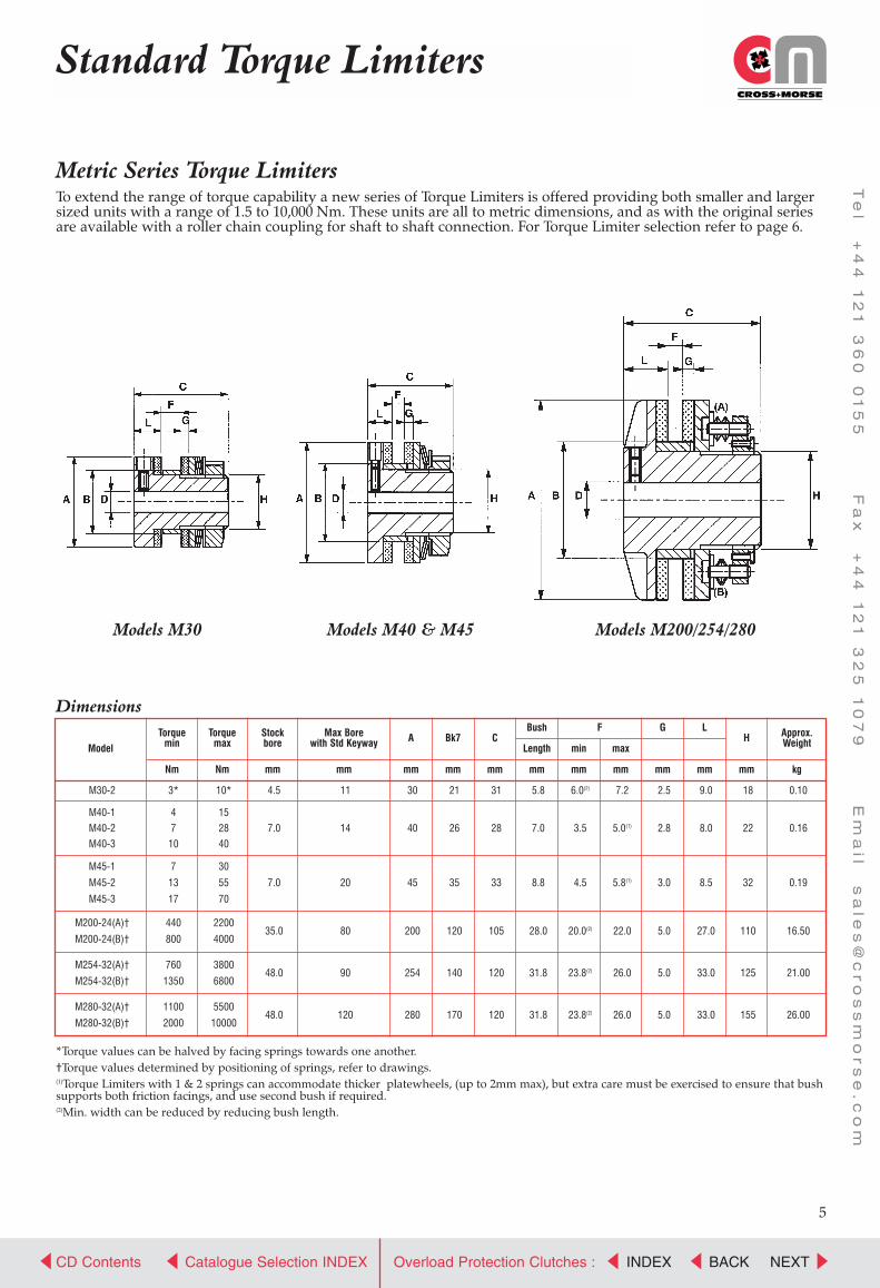
Metric Series Torque LimitersTo extend the range of torque capability a new series of Torque Limiters is offered providing both smaller and largersized units with a range of 1.5 to 10,000 Nm. These units are all to metric dimensions, and as with the original seriesare available with a roller chain coupling for shaft to shaft connection. For Torque Limiter selection refer to page 6.
*Torque values can be halved by facing springs towards one another.†Torque values determined by positioning of springs, refer to drawings.(1)Torque Limiters with 1 & 2 springs can accommodate thicker platewheels, (up to 2mm max), but extra care must be exercised to ensure that bushsupports both friction facings, and use second bush if required.(2)Min. width can be reduced by reducing bush length.
Models M30
Dimensions
Models M40 & M45 Models M200/254/280
Model
Torquemin
Torquemax
Stockbore
Max Borewith Std Keyway A
Nm Nm mm mm mm mm mm mm mm mm mm mm mm kg
Bk7 CFBush
Length min max
G LH Approx.
Weight
M30-2 3* 10* 4.5 11 30 21 31 5.8 6.0(2) 7.2 2.5 9.0 18 0.10
M40-1 4 15
M40-2 7 28 7.0 14 40 26 28 7.0 3.5 5.0(1) 2.8 8.0 22 0.16
M40-3 10 40
M45-1 7 30
M45-2 13 55 7.0 20 45 35 33 8.8 4.5 5.8(1) 3.0 8.5 32 0.19
M45-3 17 70
M200-24(A)† 440 2200
M200-24(B)† 800 4000
M254-32(A)† 760 3800
M254-32(B)† 1350 6800
M280-32(A)† 1100 5500
M280-32(B)† 2000 10000
35.0 80 200 120 105 28.0 20.0(2) 22.0 5.0 27.0 110 16.50
48.0 90 254 140 120 31.8 23.8(2) 26.0 5.0 33.0 125 21.00
48.0 120 280 170 120 31.8 23.8(2) 26.0 5.0 33.0 155 26.00

CROSS+MORSE
Power Transmission Solutions
CD Contents NEXTCatalogue Selection INDEX BACKINDEXOverload Protection Clutches :
Te
l +
44
1
21
3
60
0
15
5 F
ax
+
44
1
21
3
25
1
07
9 E
ma
il s
ale
s@
cr
os
sm
or
se
.c
om
At MinimumTorque
6
Torque Limiters Selection
Selection Procedure
(1)Platewheels require recess to fit Torque Limiter.(2)Platewheels for BS series chains requires recess to fit Torque Limiter.(3)Bushes require shortening to length indicated.(4)Two bushes required to total length indicated.For standard stock platewheels refer to page 7.
Dimensions
TorqueLimiterModel
Chain Size
ModelNo.
BoreDia.mm
SprocketMin.Teeth
BushLength
mm
SprocketMin.Teeth
BushLength
mm
SprocketMin.Teeth
BushLength
mm
SprocketMin.Teeth
BushLength
mm
SprocketMin.Teeth
BushLength
mm
SprocketMin.Teeth
BushLength
mm
SprocketMin.Teeth
BushLength
mm
SprocketMin.Teeth
BushLength
mm
SprocketMin.Teeth
BushLength
mm
3/8” 06B/35 1/2” 08B/40 5/8” 10B/50 3/4” 12B/60 11/4” 20B/100 11/2” 24B/120 13/4” 28B/1401” 16B/80
Maximum Operating RPM
50% PlusTorque Rating Over 5 min
kW Ratings according to max slip time
5 min 2 min 1 min 30 sec 10 sec
200M 1800 800 0.06 0.11 0.20 0.38 0.55 0.90250M 1450 430 0.08 0.16 0.30 0.56 0.80 1.30
350M 1050 280 0.19 0.37 0.70 1.30 1.85 3.00500M 750 250 0.47 0.93 1.70 3.25 4.65 7.50700M 530 200 1.02 2.04 3.80 7.15 10.20 16.30
M30 3000 310 0.01 0.02 0.04 0.07 0.10 0.16M40 2300 210 0.02 0.04 0.08 0.14 0.20 0.32M45 2000 140 0.03 0.05 0.10 0.18 0.25 0.40
M200 475 100 1.29 2.50 4.80 9.00 12.90 20.60M254 375 90 2.40 4.80 8.90 16.80 24.00 38.50M280 340 80 2.95 5.85 10.80 20.50 29.25 47.00
1. Determine if the Torque Limiter is to be mounted on input (driver) or output (driven) shaft. Mounting on input shaft isnormally lowest cost, and spreads load on Limiter body in overload slip, but if frequent slip occurs longer wear life of friction facings is obtained with the Torque Limiter on the output shaft.
2. Determine normal Drive Torque from input Power and Shaft Speed using formulae:-
Torque Nm = H.P. x 7124 Torque Nm = kW x 9550R.P.M. R.P.M.
3. Decide on required Slip Torque, normally between 1.2 and 1.5 times Drive Torque dependant on frequency of machinestop-start cycles.
4. Refer to pages 4 and 5, select size of Torque Limiter where Rated Torque slightly exceeds Slip Torque. Confirm SelectedTorque Limiter will accept drive shaft diameter.
5. Using capacity below, confirm selection of Torque Limiter. For machines under constant supervision or with motor overload sensors the 10 sec values should be used. For unmanned machines combination of torque and speedshould always be within power ratings over 5 min to avoid deterioration of components parts due to temperaturebuild-up. If necessary a larger Torque Limiter may have to be selected to provide sufficient heat dissipation.
6. Check Sprocket Tables below, to ensure that required size will fit selected Torque Limiter.
200M 41.3341.38 21 (365)
9.5 17 (480)11.5 14 (551)
13.4
250M 41.3341.38 25 (365)
9.5 20 (480)11.5 16 (551)
13.4
350M 49.2849.33 33 (365)
9.5 26 (480)11.5 21 (551)
13.4 18 (628)16.0 15 (829)
20.3
500M 73.1073.15 35 (480)
11.5 29 (551)13.4 25 (628)
16.0 19 (829)20.3
700M 104.88104.93 48 (520)
13.2 39 (580)14.7 33 (667)
16.9 25 (868)22.2 21 (966)
24.6 18 (1187)30.2 16 (1187)
30.2 15 (1375)34.9
13- 161.99162.05 44 (375)
9.5 36 (500)12.7 31 (562)
14.3 27 (562)14.3 24 (562)
14.3
20- 222.33222.40
M30 21.1021.05 14 4.5(3) 12 6.0
M40 26.1026.05 17 8.0 14 8.0
M45 35.1235.07
M200 120.18120.10
M254 140.20140.12
M280 170.20170.12
19 9.0 15 9.0
43 15.5(3) 36 17.0(3) 28 22.5(3) 23 25.0(3) 20 29.0 17 29.0(1) 15 29.0(1)
45 17.0(3) 35 22.5(3) 29 25.0(3) 24 31.8 21 31.8(2) 19 35.0(4)
50 17.0(3) 38 22.5(3) 31 25.0(3) 26 31.8 23 31.8(2) 21 35.0(4)
54 (500)12.7 46 (625)
15.9 40 (625)15.9 35 (625)
15.9
Note: If your drive requirements do not permit selection of a Standard Torque Limiter by the above procedurecontact Technical Department, Cross+Morse.
Minimum Sprocket Teeth and Bush Lengths for BS and ANSI Roller Chains
2” 32B/160

CROSS+MORSE
Power Transmission Solutions
CD Contents NEXTCatalogue Selection INDEX BACKINDEXOverload Protection Clutches :
Te
l +
44
1
21
3
60
0
15
5 F
ax
+
44
1
21
3
25
1
07
9 E
ma
il s
ale
s@
cr
os
sm
or
se
.c
om
7
Torque Limiters Platewheels
Morse recommend and offer as stockitems, specially machined platewheelsfor use with Torque Limiters. Both facesof Morse Torque Limiter Platewheelsare machined to 1.6µm surface finish.Uniform surfaces and parallel facesensure that Morse Torque Limiters willreliably maintain correct torque releaseand re-engagement. For the mosteconomical drive design, select aplatewheel from the increased range ofstandard stock platewheels.
Stock Machined Platewheels for BS Roller Chain
Torque Limiters are suitable for running in oil. As a general rule the torque capacity will be reduced to .25 of thestated torque when using SAE 30 oil. Torque Limiters to run in oil should have the friction facings soaked in oilbefore assembly.
FitsTorqueLimiterNumber
CatalogueNumber
ChainPitch
inches
Numberof
Teeth
OutsideDiameter
mm
Bore Dia.over
Bushingmm
Max.Width
mm
BushSize
BushLength
mm
Weight
kg
For accurate torque setting andapplications where slippage may befrequent, it is essential that a groundplate sprocket is used. Rated torquecapacity can only be obtained with dryfriction facings and a ground platesprocket which has been run-in for 500revolutions at 50% maximum torquerating for the single spring unit at aspeed not exceeding 120 r.p.m.
M30 M30G06B1-16 0.375 16 52.3 21.1 5.33 5.0 0.06M30G06B1-19 0.375 19 61.3 -0.05 5.33 5.0 0.09
M40 M40G06B1-19 0.375 19 61.3 26.1 5.33 7.0 0.09M40G06B1-22 0.375 22 71.0 -0.05 5.33 7.0 0.12
M45 M45G06B1-22 0.375 22 71.0 35.12 5.33 8.8 0.12M45G08B1-19 0.500 19 82.3 -0.05 7.24 8.8 0.18
200G06B1-21 0.375 21 67.8 41.38 5.33 365 9.5 0.11200M 200G06B1-23 0.375 23 73.5 -0.05 5.33 365 9.5 0.13
200G08B1-19 0.500 19 82.3 7.24 480 11.5 0.18
250G06B1-25 0.375 25 80.0 5.33 365 9.5 0.14250G06B1-38 0.375 38 119.4 5.33 365 9.5 0.36250G08B1-20 0.500 20 85.8 7.24 480 11.5 0.21250G08B1-21 0.500 21 90.4 7.24 480 11.5 0.23250G08B1-22 0.500 22 94.5 7.24 480 11.5 0.27250G08B1-23 0.500 23 98.5 7.24 480 11.5 0.32250G08B1-25 0.500 25 106.4 7.24 480 11.5 0.36
250M 250G08B1-30 0.500 30 127.5 41.38 7.24 480 11.5 0.54250G08B1-38 0.500 38 159.0 -0.05 7.24 480 11.5 0.91250G08B1-57 0.500 57 236.1 7.24 480 11.5 2.15250G10B1-19 0.625 19 104.1 9.02 551 13.4 0.41250G10B1-21 0.625 21 114.1 9.02 551 13.4 0.50250G10B1-23 0.625 23 124.2 9.02 551 13.4 0.64250G10B1-25 0.625 25 134.4 9.02 551 13.4 0.75250G10B1-38 0.625 38 199.6 9.02 551 13.4 1.78250G10B1-57 0.625 57 296.0 9.02 551 13.4 4.29
350G06B1-38 0.375 38 119.4 5.33 365 9.5 0.38350G08B1-27 0.500 27 114.5 7.24 480 11.5 0.40350G08B1-30 0.500 30 127.5 7.24 480 11.5 0.53350G08B1-38 0.500 38 159.0 7.24 480 11.5 0.91350G08B1-57 0.500 57 236.1 7.24 480 11.5 2.14350G10B1-21 0.625 21 114.1 9.02 551 13.4 0.47350G10B1-23 0.625 23 124.2 9.02 551 13.4 0.62350G10B1-24 0.625 24 129.3 9.02 551 13.4 0.68350G10B1-25 0.625 25 134.4 9.02 551 13.4 0.73
350M 350G10B1-38 0.625 38 199.6 49.33 9.02 551 13.4 1.73350G10B1-57 0.625 57 296.0 -0.05 9.02 551 13.4 4.27350G10B1-76 0.625 76 392.1 9.02 551 13.4 7.72350G12B1-19 0.750 19 125.2 10.97 628 16.0 0.73350G12B1-21 0.750 21 137.2 10.97 628 16.0 0.91350G12B1-23 0.750 23 150.2 10.97 628 16.0 1.15350G12B1-25 0.750 25 161.3 10.97 628 16.0 1.38350G12B1-38 0.750 38 239.8 10.97 628 16.0 3.04350G12B1-57 0.750 57 355.4 10.97 628 16.0 7.58350G12B1-76 0.750 76 469.9 10.97 628 16.0 13.65
500G08B1-38 0.500 38 159.0 7.24 480 11.5 0.82500G08B1-57 0.500 57 236.1 7.24 480 11.5 2.10500G08B1-76 0.500 76 312.4 7.24 480 11.5 3.70500G10B1-38 0.625 38 199.6 9.02 551 13.4 1.54500G10B1-57 0.625 57 296.0 9.02 551 13.4 4.24500G10B1-76 0.625 76 392.1 9.02 551 13.4 7.69500G12B1-25 0.750 25 161.3 10.97 628 16.0 1.13
500M 500G12B1-28 0.750 28 179.6 73.15 10.97 628 16.0 1.59500G12B1-38 0.750 38 239.8 -0.05 10.97 628 16.0 2.81500G12B1-57 0.750 57 355.4 10.97 628 16.0 7.52500G12B1-76 0.750 76 469.9 10.97 628 16.0 13.59500G16B1-19 1.000 19 166.6 16.08 829 20.3 2.31500G16B1-21 1.000 21 184.9 16.08 829 20.3 2.81500G16B1-23 1.000 23 200.7 16.08 829 20.3 3.20500G16B1-25 1.000 25 216.7 16.08 829 20.3 3.81500G16B1-38 1.000 38 320.5 16.08 829 20.3 7.42
700G10B1-39 0.625 39 205.0 9.02 580 14.7 1.54700G10B1-57 0.625 57 295.7 9.02 580 14.7 3.85700G10B1-76 0.625 76 392.1 9.02 580 14.7 7.65700G12B1-38 0.750 38 239.8 10.97 667 16.9 2.72
700M 700G12B1-57 0.750 57 355.4 104.93 10.97 667 16.9 7.47700G12B1-76 0.750 76 469.9 -0.05 10.97 667 16.9 13.55700G16B1-28 1.000 28 240.5 16.08 868 22.2 3.72700G16B1-38 1.000 38 320.5 16.08 868 22.2 7.39700G16B1-57 1.000 57 474.0 16.08 868 22.2 17.90700G20B1-21 1.250 21 230.9 18.57 966 24.6 3.76
M200 M200G16B1-30 1.000 30 254.0 120.18 16.08 28.0 4.20-0.08
M254 M254G24B1-24 1.500 24 306.8 140.2 24.10 31.8 9.30-0.08
M280 M280G24B1-30 1.500 30 379.5 170.2 24.10 31.8 14.50-0.08

CROSS+MORSE
Power Transmission Solutions
CD Contents NEXTCatalogue Selection INDEX BACKINDEXOverload Protection Clutches :
Te
l +
44
1
21
3
60
0
15
5 F
ax
+
44
1
21
3
25
1
07
9 E
ma
il s
ale
s@
cr
os
sm
or
se
.c
om
8
Torque Limiter Couplings
Torque Limiter combined with Roller Chain Flexible CouplingThe Torque Limiter Coupling combines overload protection with ability to connect in-line shafts. The unit consists of astandard Torque Limiter and platewheel connected to a special coupling sprocket by duplex Roller Chain. Available ineleven standard sizes, they are easy assembly units providing protection and reliability. For selection refer to page 6.
*Weights are for Torque Limiter and Coupling unbored.
Capacities and Dimensions
CatalogueNumber Max. Pall.
mmMax.Angle Min. Max. Limiter
mmCoupling
mmLimiter
mmCoupling
mm A B C D E F
SprocketSize
Dimensions mmMisalignment Torque Capacity Nm Minimum Plain Bore Maximum BoreWeight*
Kg
M30-2C 0.20 30’ 3 10 4.5 11 11 22 06B-16 55.0 57.1 37.0 22.5 31.0 1.5 0.5
M40-1C 4 15M40-2C 0.20 30’ 7 28 7 8 14 35 06B-22 55.0 75.2 55.0 25.0 28.0 2.0 0.8M40-3C 10 40
M45-1C 7 30M45-2C 0.20 30’ 13 55 7 8 20 40 06B-22 59.5 75.2 55.0 25.0 33.0 1.5 0.9M45-3C 17 70
200M-1C 0.25 30’ 3 13 11 14 22 42 08B-20 73.3 93.0 66.0 22.0 47.6 3.7 1.8200M-2C 6 25
250M-1C 0.25 30’ 7 34 11 11 22 50 08B-22 76.7 101.0 75.4 25.4 47.6 3.7 2.0250M-2C 12 67
350M-1C 0.31 30’ 20 100 18 18 25 70 10B-24 103.7 136.5 104.4 38.1 61.9 3.7 5.2350M-2C 34 200
500M-1C 0.38 30’ 48 283 22 22 41 95 12B-28 121.2 186.8 149.3 41.3 76.2 3.7 12.2500M-2C 88 566
700M-1C 0.51 30’ 110 770 24 24 64 135 16B-28 168.1 247.5 199.4 66.7 98.4 3.0 31.3700M-2C 224 1540
M200-24C 0.51 30’ 440 2200 35 35 80 100 16B-30 194.0 264.0 150.0 85.0 105.0 3.0 41.5800 4000
M254-32C 0.76 30’ 760 3800 48 51 90 150 24B-24 214.0 326.0 232.0 90.0 120.0 4.0 74.61350 6800
M280-32C 0.76 30’ 1100 5500 48 51 120 200 24B-30 214.0 398.0 302.0 90.0 120.0 4.0 98.22000 10000
Good Reasons to fit a Morse Torque Limiter on your Equipment.
DesignProtection for expensive components within the drive system or structural framework, gives longer machine life with increasedreliability in service, and reduction of expensive downtime.
MaintenanceMaintenance is reduced by the inherent protection offered by the torque limiter, which in itself is inexpensive, corrosion resistant,and extremely easy to maintain.
Product ImprovementMany existing machines can be fitted with a torque limiter, without modification to the design, by replacing a sprocket with atorque limiter fitted with a platewheel, or for in-line drives by replacing existing coupling with a torque limiter coupling.

CROSS+MORSE
Power Transmission Solutions
CD Contents NEXTCatalogue Selection INDEX BACKINDEXOverload Protection Clutches :
Te
l +
44
1
21
3
60
0
15
5 F
ax
+
44
1
21
3
25
1
07
9 E
ma
il s
ale
s@
cr
os
sm
or
se
.c
om
9
Sheargard Overload Clutches
The Cross Sheargard clutch complements the range ofTorque Limiters by providing machinery protection onapplications where accurate torque control and shaftsynchronisation are necessary; and when in the event of anoverload, total disengagement of driving and drivenmembers is required.
The design of the Sheargard Clutches provides for thetransmission of high torques (up to 125,000 Nm) with acompact, low inertia unit. Standard stock products enablesprompt delivery, at low cost of shearpin chain sprockets andflexible shaft couplings. The provision of an optional motormonitor plate enables disconnection of the power supplyand / or operation of alarm signals in the event of anoverload when used in conjunction with a limit switch orproximity switch.
The basic advantages of the well proven “Howdon” wedgeshearpin, have been combined with a clutch designed foreconomic production, with component parts sized to enablethe use of the existing range of torque limiter platewheeland chain flexible coupling to enable supply from stock ofcomplete drive assemblies. For higher speed applications arubber coupling is available.
In the diagram Hub “A” and Flange “B” have matchingtapered slots cut axially in their periphery, into which the“Howdon” wedge-shaped shearpins “C” are inserted andfirmly clamped by two self-locking screws. Torque is transmitted by the wedge which has a reduced diameterneck in mid-span “D”’ designed to shear when thepre-determined torque is exceeded, so allowing the sleeveto rotate freely on the hub.
The Cross Sheargard by virtue of its design offers a number of advantages overalternate overload protection systems
1. Simple DesignIn a Shearpin the full shear strength is directly available as a frictionless driving force. The use of up to three shearpins provideshigh torque capacity within a compact unit, keeping both inertias and costs to a minimum. Several ratings of pin for eachclutch size provides over 200 stock torque ratings. The Sheargard can be used with chain sprockets, gears, belt drives or shaftcouplings. In the event of an overload, the wedge shaped shearpins are easy to locate, and quickly replaced by removal of twoself-locking screws and broken halves of shearpin, and replacement with a new wedge pin.
2. Accurate Torque RatingsInaccuracy of torque setting in conventional shearpin couplings is caused by non-uniform shear necks, and poor fit of the pinwith its mating surfaces. The “Howdon Wedge” pins are precision turned to a constant form and can be expected to fracturewithin ±10% of catalogue rating. The wedge pins are rigidly located in the mating grooves so totally eliminating frettingfatigue failures, and ensuring zero backlash making it ideal for indexing and reversing drives. The clamping of the pin into thewedge angle ensures positive radial and axial location. The design also ensures load sharing is achieved when a number of pinsare used for higher torque drives, enabling different rated pins to be used in one clutch.
3. ReliabilityThe “Howdon Wedge” pins are naturally “fail-safe” under all conditions. They are not affected by changes in temperature orhumidity and are tolerant of most environment conditions. Sizes 350-900SG standard pins are manufactured from brass toavoid sparking in the event of overload, thus making them suitable in volatile atmospheres. The unconventional shape of thewedge pins prevents the fitment of alien pins ensuring safety and product liability requirements are met at all times. Theperipheral location of the wedge pins enables easy inspection, and clear colour coding of the pins ensures simple checking oftorque setting.
4. AvailabilityCross Sheargard Clutches and Couplings are carried in stock with minimum pilot bore. Units can be finished bored and keyedto customer’s specifications through a 48 hour rework service. A large stock of standard rated wedge pins, colour codedaccording to capacity ensures instant spares availability.
5. Low Cost ProtectionThe cost of Sheargard Clutches is kept low by volume production techniques, so providing the customer with a low costsynchronised, reliable overload protection device.

CROSS+MORSE
Power Transmission Solutions
CD Contents NEXTCatalogue Selection INDEX BACKINDEXOverload Protection Clutches :
Te
l +
44
1
21
3
60
0
15
5 F
ax
+
44
1
21
3
25
1
07
9 E
ma
il s
ale
s@
cr
os
sm
or
se
.c
om
10
Sheargard Overload Clutches
Standard Stock Sheargard Clutches are available in five sizes providing a torque range from 27 to13,700 Nm. Other units with torque ratings to 125,000 Nm are available to order, on short lead time.For further details contact Cross+Morse Sales Office.
*(1)For standard Torque Ratings see table page 12. *(2)The drive sprocket/pulley can overhang spigot.*(3)Dimensions E & F can be adjusted to suit sprocket widths. *(4)W37, W50, & W75 Brass Std, others steel.
Minimum Number of Teeth on Sprockets for Standard Roller Chains
Dimensions
ClutchSize
Bore Dia dWedge(4)*
Pins
Driveradius
R
Torque Rating(1)*
MinNm lb ft
MaxNm lb ft Min Max
250SG 2 x W25 26 27 20 336 248 10 25
350SG 3 x W37 34.5 33 24 1509 1113 19 28
500SG 3 x W37 47 45 33 2028 1496 24 45
700SG 3 x W50 66.5 251 185 5580 4115 28 65
900SG 3 x W75 92 788 581 13700 10105 45 100
1000SG 4 x W100 128 3468 2558 63920 47150 45 115
1200SG 4 x W100 147 3982 3937 73400 54140 50 150
1400SG 4 x W120 160 12240 9025 100000 73750 60 180
1600SG 4 x W120 200 15300 11285 125000 92200 60 215
ClutchSize
Clutch Size
Chain Pitch1/2”1/2” 5/8” 3/4” 1” 1 1/4” 1 1/2” 2”
Outside Dia.A
LengthThrough
BoreL
OverallLength
B1
OverallLength
B2
Spigot Dia.C
BoltPCD
D
BoltsP
SpigotLength
E(2)*
PositionBackFace
F
250SG 63 38.90 / 38.85 50 6 x M5 11.5 15.5
350SG 85 49.25 / 49.20 65 6 x M6 16 21
500SG 105 73.08 / 73.03 92 6 x M8 25 31
700SG 148 104.85 / 104.80 128 6 x M10 35 40
900SG 205 139.85 / 139.80 175 6 x M14 54 64
1000SG 280 164.85 / 164.80 220 8 x M16 75*(3) 91*(3)
1200SG 320 224.85 / 224.80 260 8 x M20 100*(3) 120*(3)
1400SG 350 254.85 / 254.80 300 8 x M24 125*(3) 150*(3)
1600SG 425 304.85 / 304.80 360 12 x M24 148*(3) 173*(3)
36
57
72
92
130
191
220
295
325
78
93
113
156
217
246
321
351
- 36
57
72
92
130
175
200
270
300
250SG 27 22 18
350SG 25 27 24 18
500SG 30 24 21 16 18
700SG 40 33 28 22 18 19
900SG 38 29 22 25 22
1000SG 35 29 28 26
1200SG 36 30 29
1400SG 40 34 25
1600SG 38 29
8mm900SG
-1600SG( ) On sizes 1000SG to 1600SG the
outer hub is retained by an end plate whichextends beyond bore length.

CROSS+MORSE
Power Transmission Solutions
CD Contents NEXTCatalogue Selection INDEX BACKINDEXOverload Protection Clutches :
Te
l +
44
1
21
3
60
0
15
5 F
ax
+
44
1
21
3
25
1
07
9 E
ma
il s
ale
s@
cr
os
sm
or
se
.c
om
350SGES 0.6 0.7° 33 300 19 28 45 115 48 57 9 114 72 85
500SGES 0.7 0.7° 45 1200 24 45 60 158 61 72 10 143 96 105
700SGES 0.9 0.8° 251 3000 28 65 75 202 75 92 16 183 120 148
900SGES 1.4 0.8° 788 12000 45 100 100 294 97 130 22 249 160 205
11
Sheargard Flexible Couplings
Sheargard Chain CouplingsThe standard Cross Sheargard unit combines with the Chain Coupling to provide stock overload couplings withminimum backlash and a high reliability. This construction provides a simple, reliable, easy to assemble flexible coupling capable of transmitting high loads and accommodating shaft misalignment with continuous overloadprotection. Motor monitor assemblies can also be used to switch off power in the event of an overload.
Sheargard ES & KE CouplingsFor high speed drives (over 500 rpm) low inertia rubber elastic couplings are offered to enable quiet operation withtorsional elasticity to damp vibration and absorb shock loads. The ES Couplings consists of two close grained castiron jaws with hard rubber drive elements interposed between them, retained by a reinforced thermoplastic cap. TheKE Coupling also has close grained cast iron jaws with a Pebax Polyester elastomeric gear ring interspaced to dampvibration and torsional loads. This series can be provided with taper-bore bushes on the coupling end. The KECoupling provides a lower cost solution.
Except as indicated all dimensions in mm*(1)Running Torque should not exceed 50% of this figure. *(3)Coupling half can be supplied for taper-bush fitted either from hub*(2)Coupling half manufactured with blind bore. end (type H) or from coupling end (type F).
*(4)Taper bore versions are shorter.
Chain Coupling
Chain Coupling Dimensions
KE & ES Couplings
CouplingRef.
Misalignment Torque Ratings Sheargard Bore Coupling Bore
Parallel Angular Min Nm Max Nm Min Max Min Max A B C D E F
350SG-C 0.311/2° 33 1509 19 28 18 57 106 137 104 38 57 11
500SG-C 0.381/2° 45 2028 24 45 22 70 119 187 149 41 72 5
700SG-C 0.511/2° 251 5580 28 65 24 102 162 248 199 67 92 3
900SG-C 0.751/2° 788 13700 45 100 51 150 216 326 232 83 130 3
1000SG-C 1.001/2° 3468 37500 45 115 60 200 286 462 320 106 175 5
KE Sheargard Coupling Dimensions
CouplingRef.
Misalignment Torque Ratings Sheargard Bore CouplingBore
Max *(2)
TaperBush
Size *(3)Parallel Angular Min Nm Max Nm*(1) Min Max
*(4) *(4)
A B C D E F
350SGKE13 0.4 1.0 33 725 19 28 55 1610 140 130 90 50 57 33
350SGKE15 0.4 1.0 33 1490 19 28 65 2012 151 150 104 58 57 36
500SGKE15 0.4 1.0 45 1490 24 45 65 2012 179 150 104 58 72 49
500SGKE18 0.4 1.0 45 2026 24 45 75 2517 185 180 120 68 72 45
700SGKE23 0.5 1.0 251 4800 28 65 95 3020 241 225 150 85 92 64
900SGKE28 0.5 1.0 788 7000 45 100 130 3525 305 275 206 106 130 69
ES Sheargard Coupling Dimensions
CouplingRef.
Misalignment Torque Ratings Sheargard Bore CouplingBore
Max *(2)Parallel Angular Min Nm Max Nm*(1) Min Max AB C DD E F

CROSS+MORSE
Power Transmission Solutions
CD Contents NEXTCatalogue Selection INDEX BACKINDEXOverload Protection Clutches :
Te
l +
44
1
21
3
60
0
15
5 F
ax
+
44
1
21
3
25
1
07
9 E
ma
il s
ale
s@
cr
os
sm
or
se
.c
om
12
Sheargard Torque Ratings
Selection of Wedges for Torque RatingFor each size of Sheargard clutch a selection of Standard wedge pins are available, which can be combined togetherto provide the desired torque setting. Standard Howdon wedges are coloured coded for identification. Sizes 350SG to900SG use brass pins as standard (steel optional), other clutches use steel as standard pin material.
Note:- Torque capacity of size 250SG controlled by unit size, and not wedge capacity. Sizes 1000SG and above are designed to accept up to fourwedges, size 250SG only has two wedge slots.
Torque Ratings - Nm
A representative selection of standard torque settingspossible with standard wedges is shown in the tablebelow, all torque ratings being accurate within ±10%.Additional torque settings can be provided withstandard or special wedge pins. To avoid unnecessarytripping of the clutch the design torque should be atleast 15% above max. starting torque of the drive. Tominimise downtime and costs, use selections with
minimum number of wedges, for simplicity ofmaintenance and stock control use selections withwedges one colour, as shown in the table. If torquesetting is critical, intermediate ratings can be obtained bymixing colours. For drives with shaft speed above 120rpm, or for improved protection of drive and machinery,use optional monitor plate with a limit switch orproximity sensor to switch off motor on overload.
Wedge Replacement following Overload:To return Sheargard to service after overload, first remove allbroken halves of wedges by removing their locking screws.Rotate hub on body until wedge grooves are in line (for driveswhere synchronisation is essential rotate until alignment markson body and hub flanges are in line). Ensure wedge grooves areclean. Fit new wedges of same colour identification as partsremoved and fix firmly into place by tightening locating screws.
Servicing Sheargard ClutchesSheargard units require minimal servicing. Routine checks thatwedge locating screws and monitor plate screws are securelylocked down is generally all that is required. If the clutch hassuffered a number of overloads, or at major maintenanceshutdowns disassembly of the clutch, cleaning with paraffin andlight greasing of bearing surfaces will ensure long service life.
Number of Wedges Used Clutch Size
Orange Orange/White Gold White White/
Yellow Yellow Yellow/Blue Blue Blue/
Green Green Green/Red Red Black 250SG 350SG 500SG 700SG 900SG 1000SG 1200SG 1400SG 1600SG
11
1
33 4546 6262 84
66 9027 86 116 251 788 3468 3982
92 124
99 135124 168125 167 341 1105 5160 5926
138 18682 165 221 446 1400 6942 7972 12240 1530054 172 232 502 1576 6936 7964
186 252199 267 652 1908 8718 10012250 334 682 2210 10320 11852
107 257 345 896 2285 9824 11282 17632 22040258 348 753 2364 10404 11946300 402 1119 2700 11607 13330
164 330 442 892 2800 13884 15944 24480 30600136 370 497 1368 3386 13875 15935 20240 25300
375 501 1023 3315 15480 17778
398 534 1304 3816 17436 20024447 600 1727 3974
168 503 676 1785 4562 15980 18352 24992 31240
1860 5293 16922 19434 31344 39180214 514 690 1792 4570 19648 22564 35264 44080
597 801 1956 5724 26154 30036
600 804 2238 5400 23214 26660272 740 994 2736 6772 27750 31870 40480 50600
27768 31888 48960 61200
771 1035 2688 6855 29472 33846 52896 66120894 1200 3454 7948900 1206 3357 8100 34821 39990
336 1006 1352 3570 9124 31960 36704 49984 624803720 10586 33844 38868 62688 78360
34872 40048
39296 45128 70528 881601110 1491 4104 10158 41625 47805 60720 759001341 1800 5181 11922
46428 533201509 2028 5355 13686 47940 55056 74976 93720
5580 50766 58302 94032 117540
55500 63740 80960 10120063920 73408 99968 124960
21
2
32
1
31
2
31
2
13
1
21
3
21
1
12
3
22
4
32
3
22
4
43
3
43
3
44

CROSS+MORSE
Power Transmission Solutions
CD Contents NEXTCatalogue Selection INDEX BACKINDEXOverload Protection Clutches :
Te
l +
44
1
21
3
60
0
15
5 F
ax
+
44
1
21
3
25
1
07
9 E
ma
il s
ale
s@
cr
os
sm
or
se
.c
om
13
The Crossgard series of overload protection clutches all use sprung loaded balls locked in detents to provide drive and overload control. The balls are random positioned in the clutch so drive can only beengaged in one relative angular position between driver and driven shafts, so ensuring fullsynchronisation of the drive at all times. In the event of an overload the balls are driven out of theirdetents to release the torque, and cause axial movement of the pressure plate which can be used toactuate a limit switch or proximity sensor to isolate the drive. All units are fitted with a torque indicatorto enable simple setting of the desired torque rating. There are three basic types of Crossgard Clutchesall of which are available as flexible shaft couplings, types CG, CGX and CGZ.
Crossgard Principles of OperationDuring normal operation torque is transmitted between hub and driving flange by a number of balls located in the flangeengaged in detents in the hub under load applied by disc springs. The balls are arranged in irregular angular positions to ensurere-engagement can only occur at one angular position between hub and flange. When an overload occurs the balls are driven outof their detents and then roll between the hub and pressure plate. The pressure plate moves axially a sensor plate which can beused to activate a proximity or limit switch. Torque is varied by adjusting the spring load on the pressure plate by tightening orloosening adjusting nuts.
Type CG Crossgard Clutch Pages 15-17
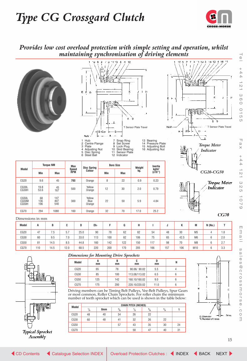
CG Crossgard Clutches are a low cost, simple designsuitable for general purpose applications. The clutchesprovide full overload protection of drives which requiresynchronisation to be maintained at all times. Followingoverload the clutches are automatically reset by slowrotation of input drive once the overload cause is cleared.Four sizes of clutch provide a torque range 10Nm to 1080Nm with operating speeds to 700rpm. Torque settings areaccurate to ±10% even after repeated tripping.Also can be supplied with roller chain or elastomericcoupling.
Use CG Clutch:• For general purpose applications.• Where drives are inaccessible.• For chain and low speed belt drives.• In wrapping and packaging machines.• On bakery and bottling machines.• For conveyors and on sliding door drives.
Crossgard Overload Couplings
Design FeaturesCrossgard clutches have been designed to provide the customer with a reliable, simple to operate clutch, all three typesincorporating the following design features.
Drive SynchronisationNon symmetrical arrangement of the drive balls and pockets allows only one angular position of engagement of drive,ensuring input and output are always synchronised.
Bi-directional driveThe clutches function equally in either direction of rotation, and are suitable for reversing drives.
Visual Torque MeterAll units have a scale on the adjusting nut to enable the set torque to be determined by reference to torque charts. Settingcan also be verified at any time by visual check.
Simple Torque setting and adjustmentRequired torque is set by turning the adjusting nut, and setting off torque scale.
Overload MonitoringAll units incorporate a sensor plate which moves axially when overload occurs to trigger a proximity or limit switch toisolate power to motor and activate failure indicators.
Stock availabilityAll standard Crossgard clutches are carried in stock with pilot bore. Units can be supplied with finished bore, keyseat andsetscrews, fitted with platewheels; or complete with flexible coupling on 72 hours lead time.
CROSS+MORSE
Power Transmission Solutions
CD Contents NEXTCatalogue Selection INDEX BACKINDEXOverload Protection Clutches :
Te
l +
44
1
21
3
60
0
15
5 F
ax
+
44
1
21
3
25
1
07
9 E
ma
il s
ale
s@
cr
os
sm
or
se
.c
om
14
Crossgard SelectionLike other overload devices,it is best to position the Crossgard nearest the driven equipment where the overload ismost likely to occur. Tripping torque should be at least 25% greater than the operating torque to compensate for motorstarting torque and intermittent, shock and reversing loads.
Selection Method1. Selecting the trip torque.
Trip torque should be set equal to the maximumamount of torque which can be applied based onsuch conditions as the strength of the machine andload. When it is not clear what the maximumamount of torque is, calculate the rated torque fromthe rated output and the rpm of the shaft ontowhich the Crossgard is to installed, and multiplythis figure by the service factor. The result may betaken as the trip torque.
Tripping Torque= Operating x SF
Torque Nm= Power kW x 9550RPM
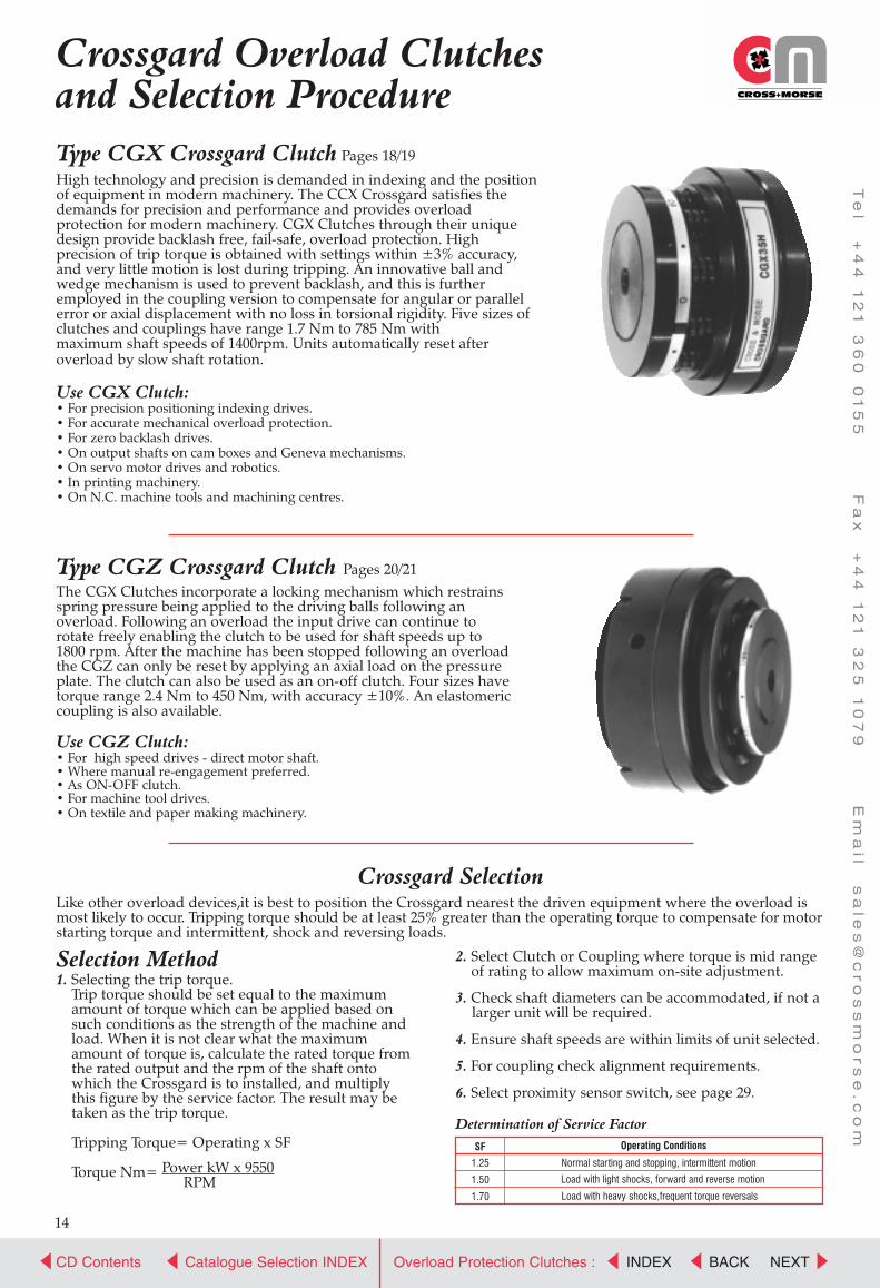
Type CGX Crossgard Clutch Pages 18/19
High technology and precision is demanded in indexing and the position of equipment in modern machinery. The CCX Crossgard satisfies the demands for precision and performance and provides overload protection for modern machinery. CGX Clutches through their unique design provide backlash free, fail-safe, overload protection. Highprecision of trip torque is obtained with settings within ±3% accuracy,and very little motion is lost during tripping. An innovative ball andwedge mechanism is used to prevent backlash, and this is furtheremployed in the coupling version to compensate for angular or parallelerror or axial displacement with no loss in torsional rigidity. Five sizes ofclutches and couplings have range 1.7 Nm to 785 Nm withmaximum shaft speeds of 1400rpm. Units automatically reset afteroverload by slow shaft rotation.
Use CGX Clutch: • For precision positioning indexing drives.• For accurate mechanical overload protection.• For zero backlash drives.• On output shafts on cam boxes and Geneva mechanisms.• On servo motor drives and robotics.• In printing machinery.• On N.C. machine tools and machining centres.
Type CGZ Crossgard Clutch Pages 20/21The CGX Clutches incorporate a locking mechanism which restrainsspring pressure being applied to the driving balls following anoverload. Following an overload the input drive can continue torotate freely enabling the clutch to be used for shaft speeds up to1800 rpm. After the machine has been stopped following an overloadthe CGZ can only be reset by applying an axial load on the pressureplate. The clutch can also be used as an on-off clutch. Four sizes havetorque range 2.4 Nm to 450 Nm, with accuracy ±10%. An elastomericcoupling is also available.
Use CGZ Clutch:• For high speed drives - direct motor shaft.• Where manual re-engagement preferred.• As ON-OFF clutch.• For machine tool drives.• On textile and paper making machinery.
2. Select Clutch or Coupling where torque is mid rangeof rating to allow maximum on-site adjustment.
3. Check shaft diameters can be accommodated, if not alarger unit will be required.
4. Ensure shaft speeds are within limits of unit selected.
5. For coupling check alignment requirements.
6. Select proximity sensor switch, see page 29.
Crossgard Overload Clutchesand Selection Procedure
Determination of Service Factor
SF Operating Conditions
1.25
1.50
1.70
Normal starting and stopping, intermittent motion
Load with light shocks, forward and reverse motion
Load with heavy shocks,frequent torque reversals
Catalogue Selection INDEX
Te
l +
44
1
21
3
60
0
15
5 F
ax
+
44
1
21
3
25
1
07
9 E
ma
il s
ale
s@
cr
os
sm
or
se
.c
om
CD Contents NEXTBACKINDEXOverload Protection Clutches :
15
CROSS+MORSE
Power Transmission Solutions
Driving members can be Timing Belt Pulleys, Vee-Belt Pulleys, Spur Gearsor most common, Roller Chain Sprockets. For roller chain the minimumnumber of teeth sprocket which can be used is shown in the table below:
40
48
48
60
90.06/ 90.02
113.08/113.02
160.10/160.02
220.10/220.02
Provides low cost overload protection with simple setting and operation, whilstmaintaining synchronisation of driving elements
Dimensions in mm
Dimensions for Mounting Drive Sprockets
Type CG Crossgard Clutch
T Sensor Plate Travel
1 Hub2 Centre Flange3 Plate4 Adjusting Nut5 Disc Spring6 Steel Ball
7 Snap Ring8 Set Screw9 Lock Plug
10 Skid Bearing11 Sensor Plate12 Indicator
13 Bearing14 Pressure Plate15 Adjusting Bolt16 Adjusting Nut
Torque Meter
Indicator
CG20-CG50
T Sensor Plate Travel
Torque NM
Min Max Model
Model A
Model Amm
Bmm
Cmm
Dmm N
B C D Eh7 F G H I J K M N (No.) T
MaxSpeedRPM
Disc SpringColour
Weightkg.
Inertiakgfm2
(x10_2)
Bore Size
CG20
CG70
9.6
294 1080 160 Orange 32 17.0 25.270
CG30LCG30H
CG20
CG30
CG50
CG70
47
60
81
110
CG20
CG30
CG50
CG70
ModelCHAIN PITCH (INCHES)
CG20
CG30
CG50
CG70
1/43/8
1/25/8
3/4 18mm
34
41
57
26
32
43
58
22
26
35
47
22
30
40
24
31
65
85
125
175
78
100
142
200
5.5
6.5
9.0
11.0
4
6
6
6
7.5
9.5
14.5
14.5
5.7
7.0
8.5
12.0
25.0
33.0
44.8
68.5
90
113
160
220
78
100
142
200
62
82
122
170
82
106
150
205
54
75
117
166
48
65
98
157
30
42.5
70
106
M5
M6
M8
M10
4
6
6
6
1.8
2.0
2.7
3.3
CG50LCG50MCG50H
YellowOrange
YellowBlue
Orange
19.853.6
68136196
300 22 50 5.9 4.84147407540
45167
45 700700
500 12 30 2.0 0.79
Orange 8 22 0.9 0.23
Min Max

CROSS+MORSE
Power Transmission Solutions
CD Contents NEXTCatalogue Selection INDEX BACKINDEXOverload Protection Clutches :
Te
l +
44
1
21
3
60
0
15
5 F
ax
+
44
1
21
3
25
1
07
9 E
ma
il s
ale
s@
cr
os
sm
or
se
.c
om
1616
Type CG CrossgardFlexible Couplings
Two basic types of couplings are being offered, Type ES Rubber Elastic Coupling, and Type CC RollerChain Coupling. Both combine the full overload protection capabilities of the CG Crossgard withfacility of shaft to shaft connection.
Dimensions in mm.
Model Setting TorqueNm
MaxSpeedRPM
Misalignment
Parallel Angular PilotBore
MaxBore
PilotBore
MaxBore
A B C D E F Weightkg
Inertiakg m2
x10-2
Clutch Coupling
Crossgard CG-CC CouplingsA standard roller chain sprocket is connected by a duplex roller chain to a platewheel mounted on the CG Clutch.This construction provides a simple, reliable, low cost means of transmitting drive with minimum backlash, andaccommodating reasonable shaft misalignment. Both Taper-bored and pilot bore sprockets are available.
CG-CC Crossgard Chain Coupling
CG20-CC
CG30L-CCCG30H-CC
CG50L-CCCG50M-CCCG50H-CC
CG70-CC
9.6 - 45
19.8 - 5453.6 - 167
68 - 147136 - 407196 - 540
294 -1080
700
500
300
160
0.25
0.31
0.38
0.51
8
12
22
32
20
30
50
70
16
20
20
25
53
60
63
80
81
99
123
174
118
147
199
265
70
85
95
120
30
35
40
50
47
60
81
110
3.5
4.0
2.0
14.5
2.6
4.8
12.3
29.2
0.91
3.79
11.5
65.0
1/2˚
1/2˚
1/2˚
1/2˚
Dimensions in mm.For further dimensions of Crossgard Clutch refer to page 15.
Model Setting TorqueNm
MaxSpeedRPM
Misalignment
Parallel Angular PilotBore
MaxBore Bush Max
Bore
A B C D E F Weightkg
Inertiakg m2
x10-2
Clutch Coupling
CG-CC Crossgard Taper Bored Chain Coupling
CG20-CCTB
CG30L-CCTBCG30H-CCTB
CG50L-CCTBCG50M-CCTBCG50H-CCTB
CG70-CCTB
9.6 - 45
19.8 - 5453.6 - 167
68 - 147136 - 407196 - 540
294 -1080
700
500
300
160
0.25
0.31
0.38
0.50
8
12
22
32
20
30
50
70
1610
2012
2517
3020
42
50
60
76
76
95
128
175
118
147
199
265
76
90
108
159
25
31
44
51
47
60
81
110
3.5
4.0
2.0
14.5
2.0
4.2
10.4
29.0
0.88
3.80
11.8
65.5
1/2˚
1/2˚
1/2˚
1/2˚

CROSS+MORSE
Power Transmission Solutions
CD Contents NEXTCatalogue Selection INDEX BACKINDEXOverload Protection Clutches :
Te
l +
44
1
21
3
60
0
15
5 F
ax
+
44
1
21
3
25
1
07
9 E
ma
il s
ale
s@
cr
os
sm
or
se
.c
om
17
Crossgard Overload Couplings
Crossgard CG-ES CouplingsThe ES Couplings consist of two close grained cast iron jaws with hard rubber drive elements interposed. It is a lowinertia coupling combining quiet operation with torsional elasticity to absorb shock loads and damp vibration.
Crossgard Couplings can be supplied with both clutch and coupling hub finish bored, keyseated, with setscrew to customers’requirements on 48-hour re-work service.
Installation of Crossgard CG ClutchesFor optimum performance of CG Clutches and couplings it is necessary to have a good fit(transition) between shafts and hubs.Drives should be via a parallel key with interference fit with ideally two set screws to maintain axial position on shaft.
The chain/belt drive should be accurately aligned to avoid axial loading of the clutch; and coupling assemblies should be carefullyaligned at installation to minimise operating loads.
All units should be installed with a limit switch or proximity switch to shut down the drive in the event of an overload, refer topage 29 for details standard units available.
Installation of Crossgard CouplingsPrior to installation it is necessary to separate the Crossgard and Coupling half by either removing the duplex chain, or for the ESCoupling removing the outer cover and the rubber element. Fit Crossgard and Coupling half to shafts, for ES Coupling ensurecover is fitted to hub prior to installation. Adjust distance between Crossgard and Coupling according to catalogue dimensions,and align shafts as accurately as possible. Refit duplex chain or rubber element and cover, ensure chain is free to move, and shaftsrotate freely.
For further dimensions of Crossgard Clutch refer to page 15.Dimensions in mm.
Model Setting TorqueNm
MaxSpeedRPM
Misalignment
Parallel Angular PilotBore
MaxBore
PilotBore
MaxBore
A B C D E F Weightkg
Inertiakg m2
x10-2
Clutch Coupling
CG-ES Crossgard Coupling
CG20-ES
CG30L-ESCG30H-ES
CG50L-ESCG50M-ESCG50H-ES
CG70-ES
9.6 - 45
19.8 - 5453.6 - 167
68 - 147136 - 407196 - 540
294 -1080
700
500
300
160
0.5
0.7
0.9
1.2
0.7˚
0.7˚
0.6˚
0.5˚
8
12
22
32
20
30
50
70
-
-
-
-
40
55
75
90
118
146
199
261
92
143
202
257
65
88
120
145
45
57
75
89
47
60
81
110
26
29
43
62
2.7
6.3
16.6
37.6
0.38
1.49
9.2
30.3

CROSS+MORSE
Power Transmission Solutions
CD Contents NEXTCatalogue Selection INDEX BACKINDEXOverload Protection Clutches :
Te
l +
44
1
21
3
60
0
15
5 F
ax
+
44
1
21
3
25
1
07
9 E
ma
il s
ale
s@
cr
os
sm
or
se
.c
om
18
Type CGX Crossgard Clutch
These clutches can be supplied with pilot bore, finish bore and keyseat, or fitted with clamping elements to clampdirectly to keyless shafts. The use of clamping elements ensures total elimination of backlash in the completeassembly within the operating torque range, but does require an increase to the overall length of clutch in order toaccommodate. Clutch and clamping element assemblies are supplied from stock to suit specific metric shaft sizes asindicated in the table, using clamping elements types ACE81 & RCK80.
For Selection of Crossgard CGX Clutches refer to page 14, always use with proximity sensor switch, refer to page 29
Provides complete overload protection of drives with accurate positioning and zero backlash.Suitable for gears, cams and index table drives.
1 Hub2 Driven Flange3 Plate4 Adjusting Nut5 Fixed Nut
6 Bearing7 Bearing8 Bearing9 Side Plate
10 Steel Ball
11 Coil Spring12 Set Screw13 Lock Plug
2-ø R Depth S
Min Torque PositionTravel when tripping
RotatedRevolutionScale
DegreeScale
TorqueScale
Dimensions in mm. *Weight and inertia values for clutches with max. bore.† Clamping elements protrude from end of clutch 17.5mm (CG X 10 & 20), 25.0mm (CGX 35 & 50), 31mm(CGX 70)
Model
Models A B C D F Gh7
HPCD I J
PCD M N O R SP Screws
No. Size
P Screws
No. Size
Setting TorqueRange
Nm
CGX10 L
CGX10 M
CGX10 H
CGX20 L
CGX20 M
CGX20 H
CGX35 L
CGX35 M
CGX35 H
CGX50 L
CGX50 M
CGX50 H
CGX70 L
CGX70 M
CGX70 H
CGX10
CGX20
CGX35
CGX50
CGX70
53
64
68
92
98
22
35
37.5
54.8
61
1.4
1.6
2.0
2.6
3.5
7.5
10
11
15
15
+0.3
+0.7
-0.5
+0.3
+1.0
62
86
107
148
185
54
74
88
130
164
42
60
70
105
135
34
50
60
-
-
56
70
88
123
148
56
73
91
129
153
61.8
86
107
148
185
4
6
6
6
6
M4x6
M5x8
M6x7
M8x13
M10x13
5
5
6
9
10
10
10
10
17
18
4
6
6
-
-
M4x7
M4x7
M5x8
-
-
5.5 - 15
11 - 30
6.5 - 24
13 - 35
26 - 68
23 - 68
44 - 100
89 - 200
46 - 120
92 - 200
180 - 400
130 - 370
270 - 520
400 - 785
1.7 - 6.5
MaxRunningSpeedRPM
Colour ofSpring xNumber
PilotBoremm
MaxBoremm
*Weightkg
Inertiakgfm2 (x10-2)
Shaft Clamping Element †Std. Bore Sizes (mm)
Yellow x 3
Red x 3
Red x 6
Yellow x 6
Red x 3
Red x 6
Red x 5
Green x 5
Green x 10
Red x 5
Green x 5
Green x 10
Red x 8
Green x 8
Green x 12
1400
1100
800
600
480
7
8.5
12
18
23
15
25
35
55
70
0.75
1.67
2.51
7.03
11.4
8, 9, 10, 11, 12
11, 12,14, 15, 16, 18, 19, 20
19, 20, 22, 24, 25, 28, 30
24, 25, 28, 30, 32, 35, 38, 40, 42
28, 30, 32, 35, 38, 40, 42, 45
48, 50, 55, 60
0.177
0.535
1.33
7.32
19.5

CROSS+MORSE
Power Transmission Solutions
CD Contents NEXTCatalogue Selection INDEX BACKINDEXOverload Protection Clutches :
Te
l +
44
1
21
3
60
0
15
5 F
ax
+
44
1
21
3
25
1
07
9 E
ma
il s
ale
s@
cr
os
sm
or
se
.c
om
19
Type CGX-CCrossgard Couplings
These couplings can be supplied with pilot bore, finish bore and keyseat and setscrews, or fitted with clamping elements to clamp directly to keyless shafts. The use of clamping elements eliminates all backlash in the drive linewithin the operating torque range, but does require an increase to the overall length of coupling in order to accommodate. Coupling and clamping element assembly are supplied to suit specific metric shaft sizes as indicated inthe table. Clutch and Coupling half can have different bush sizes.
Provides complete overload protection of drives with accurate positioning and zero backlash.For shaft to shaft connection.
1 Hub2 Centre Flange3 Plate4 Adjusting Nut5 Flange
6 Boss7 Bearing8 Side Plate9 Steel Ball
10 Coil Spring
11 Set Screw12 Lock Plug14 Hex-head Bolt15 Spring Washer
Dimensions in mm.
Models A B C
DMin.
PointedPosition
EPCD
FPCD G H I J M N O R S
PScrews xLength
QScrew xLength
CGX10-C
CGX20-C
CGX35-C
CGX50-C
CGX70-C
69
84
88
114
124
24
24
24
34
36
1.3
1.6
1.9
2.4
3.3
+0.3
+0.3
- 0.5
+0.9
+0.6
62
89
113
158
200
42
66
83
112
145
33
55
70
92
116
25
35
35
45
50
2
3
3
4
4
42
46
50
65
70
56
70
88
123
148
_
_
_
128
152
74
98
125
174
218
M4x18
M5x20
M6x25
M8x32
M10x22
M4x10
M5x12
M6x15
M8x20
M10x38
5
5
6
9
10
10
10
10
17
18
2-ø R Depth S
Min Torque PositionTravel when tripping
RotatedRevolution
Scale
DegreeScale
MaxBoremm
For Selection of Crossgard CGX-C Clutches refer to page 14, always use with proximity sensor switch, refer to page 29
*Weight and inertia values for couplings with max. bore.† Clamping elements protrude from end of clutch/coupling 17.5mm to 34.0mm dependant on size.
ModelSetting Torque
RangeNm
CGX10 LC
CGX10 MC
CGX10 HC
CGX20 LC
CGX20 MC
CGX20 HC
CGX35 LC
CGX35 MC
CGX35 HC
CGX50 LC
CGX50MC
CGX50HC
CGX70 LC
CGX70 MC
CGX70 HC
4.6 - 12.7
9.3 - 25.5
5.2 - 18.6
9.8 - 27.5
20.6 - 55
19 - 57
36 - 84
74 - 166
40 - 98
80 - 176
160 - 343
120 - 325
235 - 460
353 - 696
1.5 - 5.4
MaxRunningSpeedRPM
Colour ofSpring xNumber
PilotBoremm
MaxBoremm
PilotBoremm
Clutch Half Coupling Half*Weight
kgInertiakg m2
(x10-2
MaximumAngular
ErrorDeg.
MaximumParallel
ErrorDeg.
MaximumAxial
Movementmm
Shaft Clamping Element †Std. Bore Sizes (mm)
( ) Sizes fit Cplg half only
Yellow x 3
Red x 3
Red x 6
Yellow x 6
Red x 3
Red x 6
Red x 5
Green x 5
Green x 10
Red x 5
Green x 5
Green x 10
Red x 8
Green x 8
Green x 12
700
550
400
350
240
7
8.5
12
18
23
7
8.5
12
18
23
19
35
50
60
80
15
25
35
55
70
1.07
2.38
3.92
10.9
16.3
8, 9, 10, 11, 12
11, 12, 14, 15, 16,
18, 19, 20
(22, 24, 25, 28, 30)
15, 16, 18, 19, 20, 22,
24, 25, 28, 30
(32, 35, 38, 40, 42)
24, 25, 28, 30, 32,
35, 38, 40, 42
(45, 48, 50)
28, 30, 32, 35, 38,
40, 42, 45, 48, 50, 55, 60
(65)
0.222
0.924
2.65
13.34
35.7
0.6
0.6
0.6
0.6
0.6
0.1
0.1
0.1
0.1
0.1
±0.5
±0.5
±0.5
±0.5
±0.5º
Torque Scale

CROSS+MORSE
Power Transmission Solutions
CD Contents NEXTCatalogue Selection INDEX BACKINDEXOverload Protection Clutches :
Te
l +
44
1
21
3
60
0
15
5 F
ax
+
44
1
21
3
25
1
07
9 E
ma
il s
ale
s@
cr
os
sm
or
se
.c
om
20
Type CGZ Crossgard Clutch
Type CGZ clutches totally disengage on overload, and will not re-engage drive without external axial force being applied to thepressure plate when the clutch is correctly aligned. The clutch must be stationary when re-engaged, otherwise the clutch may bedamaged.The CGZ clutch can be used as a mechanical engage/disengage clutch, but whilst the clutch can be dis-engaged at full speed byapplying an axial force to the pressure plate, it can only be engaged whilst stationary. These clutches are designed for use onhorizontal shafts, but may be applied to vertical shaft applications providing the driven flange plate is uppermost.
For Selection of Crossgard CGZ Clutches refer to page 14.
Provides total disengagement in event of overload.Suitable for mounting gears, cams sprockets and timing belt pulleys
1 Hub2 Centre Flange3 Driven Flange Plate4 Plate
5 Ball Cage6 Adjustable Nut7 Bearing (Z Type)8 Steel Ball
9 Coil Spring10 Snap Ring11 Snap Ring12 Set Screw
13 Lock Plug14 Hex-Head Bolt15 Spring Washer16 Set Screw
Min Torque Position
Travel when tripping
2-ØV, Depth W
X
RotatedRevolutionScale
DegreeScale
TorqueScale
Dimensions in mm. *Weight and inertia values for clutches with max. bore.
Model
Model A B C ED F G H J KPCD
Lh7 N Q R S SIZEWVSize x
length
T Screw
No.
ITravelwhen
tripping
Setting TorqueRange
Nm
CGZ20 L
CGZ20 M
CGZ20 H
CGZ30 L
CGZ30 M
CGZ30 H
CGZ40 L
CGZ40 M
CGZ40 H
CGZ50 L
CGZ50 M
CGZ50 H
CGZ20
CGZ30
CGZ40
CGZ50
74
83.5
101
114.5
73
82
100
112
8
8
9
10
6
6
8
9
13.5
14.5
20
20.2
0.8
1.1
1.1
1.2
11
11.5
14
16
4.1
4.7
5.9
7
96
118
152
178
86
106
139
162
72
87
114
133
24.5
27.5
32.5
37
58
76
104
114
70
88
119
138
88
108
141
166
4
4
6
6
M5x10
M6x12
M6x12
M8x16
5
6
8
9
10
10
14
14
M5x10
M6x10
M8x10
M8x10
1
1.5
1
2.5
6 - 20
20 - 52
39 - 108
26 - 93
44 - 127
88 - 245
63 - 157
128 - 304
245 - 450
MaxRunningSpeedRPM
Colour ofSpring xNumber
PilotBoremm
*Weightkg
Inertiakgfm2 (x10-2)
Yellow x 3
Blue x 3
Blue x 6
Yellow x 4
Red x 4
Red x 8
Blue x 5
Red x 5
Red x 10
Red x 5
Red x 10
Green x 10
1800
1800
1800
1800
8
12
17
22
20
30
40
50
2.57
4.17
8.71
13.7
1.09
2.78
9.60
21.2
MaxBoremm
2.4 - 8.3
4.1 - 15.7
8.2 - 31.4

CROSS+MORSE
Power Transmission Solutions
CD Contents NEXTCatalogue Selection INDEX BACKINDEXOverload Protection Clutches :
Te
l +
44
1
21
3
60
0
15
5 F
ax
+
44
1
21
3
25
1
07
9 E
ma
il s
ale
s@
cr
os
sm
or
se
.c
om
21
Type CGZ CrossgardFlexible Couplings
For shaft to shaft connection the CGZ Couplings provides total disengagement in the event of overload. Suitable formounting on high speed shafts. The coupling consists of two close grain cast iron jaws with hard rubber driveelements interposed. A low inertia coupling which combines quiet operation with torsional elasticity to absorb shockloads and damp vibrations.
1 Coupling Hub2 Cover
3 Rubber Element4 Connecting Flange
For Selection of Crossgard CGZ Clutch Couplings refer to page 14.
*Weight and inertia values for couplings with max. bore.
Dimensions in mm
For detail dimensions of CGZ Clutch refer to page 20.*Couplings halves are stocked unbored and centred.
Stock Couplings can be reworked to customers’ bore and keyway requirements on short delivery lead time.
ModelSetting Torque
RangeNm
MaxRunningSpeed x
RPM
Colours ofSpring xNumber
CouplingModel Parallel mm Angular Axial mm
Weightkg
Inertiakgfm2 (x10-2)
Max Allowable Misalignment
CGZ20 L-ES
CGZ20 M-ES
CGZ20 H-ES
CGZ30 L-ES
CGZ30 M-ES
CGZ30 H-ES
CGZ40 L-ES
CGZ40 M-ES
CGZ40 H-ES
CGZ50 L-ES
CGZ50 M-ES
CGZ50 H-ES
4.1 - 15.7
8.2 - 31.4
6 - 20
20 - 52
39 - 108
26 - 93
44 - 127
88 - 245
63 - 157
128 - 304
245 - 450
2.4 - 8.3 Yellow x 3
Blue x 3
Blue x 6
Yellow x 4
Red x 4
Red x 8
Blue x 5
Red x 5
Red x 10
Red x 5
Red x 10
Green x 10
1800
1800
1800
1800
10SF
25SF
63SF
100SF
0.6
0.7
0.8
0.9
0.7˚
0.7˚
0.6˚
0.6˚
±1.0
±1.0
±1.2
±1.2
4.87
8.5
17.5
25.7
1.29
3.5
11.5
26.6
ModelCrossgard *Coupling
Pilot Bore Max Bore Max BoreA B C D E F G
CGZ20-ES
CGZ30-ES
CGZ40-ES
CGZ50-ES
8
12
17
22
20
30
40
50
45
55
70
75
142
167
202
229
73
82
100
112
48
57
67
75
21
28
35
42
96
118
152
178
114
143
181
202
72
88
110
120
CROSS+MORSE
Power Transmission Solutions
CD Contents NEXTCatalogue Selection INDEX BACKINDEXOverload Protection Clutches :
Te
l +
44
1
21
3
60
0
15
5 F
ax
+
44
1
21
3
25
1
07
9 E
ma
il s
ale
s@
cr
os
sm
or
se
.c
om
22
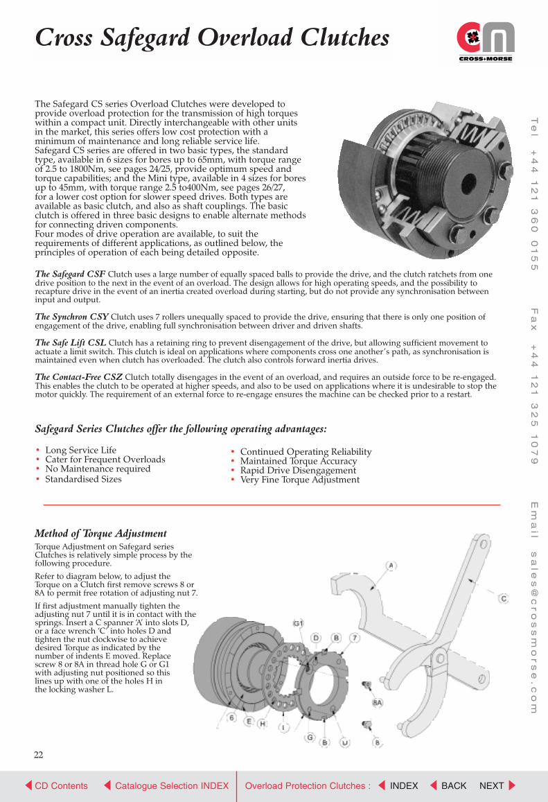
Cross Safegard Overload Clutches
The Safegard CS series Overload Clutches were developed to provide overload protection for the transmission of high torqueswithin a compact unit. Directly interchangeable with other unitsin the market, this series offers low cost protection with aminimum of maintenance and long reliable service life.Safegard CS series are offered in two basic types, the standardtype, available in 6 sizes for bores up to 65mm, with torque rangeof 2.5 to 1800Nm, see pages 24/25, provide optimum speed andtorque capabilities; and the Mini type, available in 4 sizes for boresup to 45mm, with torque range 2.5 to400Nm, see pages 26/27,for a lower cost option for slower speed drives. Both types areavailable as basic clutch, and also as shaft couplings. The basicclutch is offered in three basic designs to enable alternate methodsfor connecting driven components.Four modes of drive operation are available, to suit therequirements of different applications, as outlined below, theprinciples of operation of each being detailed opposite.
The Safegard CSF Clutch uses a large number of equally spaced balls to provide the drive, and the clutch ratchets from onedrive position to the next in the event of an overload. The design allows for high operating speeds, and the possibility to recapture drive in the event of an inertia created overload during starting, but do not provide any synchronisation betweeninput and output.
The Synchron CSY Clutch uses 7 rollers unequally spaced to provide the drive, ensuring that there is only one position of engagement of the drive, enabling full synchronisation between driver and driven shafts.
The Safe Lift CSL Clutch has a retaining ring to prevent disengagement of the drive, but allowing sufficient movement to actuate a limit switch. This clutch is ideal on applications where components cross one another’s path, as synchronisation ismaintained even when clutch has overloaded. The clutch also controls forward inertia drives.
The Contact-Free CSZ Clutch totally disengages in the event of an overload, and requires an outside force to be re-engaged.This enables the clutch to be operated at higher speeds, and also to be used on applications where it is undesirable to stop themotor quickly. The requirement of an external force to re-engage ensures the machine can be checked prior to a restart.
Safegard Series Clutches offer the following operating advantages:
• Long Service Life• Cater for Frequent Overloads• No Maintenance required• Standardised Sizes
• Continued Operating Reliability• Maintained Torque Accuracy• Rapid Drive Disengagement• Very Fine Torque Adjustment
Method of Torque AdjustmentTorque Adjustment on Safegard series Clutches is relatively simple process by the following procedure.
Refer to diagram below, to adjust the Torque on a Clutch first remove screws 8 or 8A to permit free rotation of adjusting nut 7.
If first adjustment manually tighten the adjusting nut 7 until it is in contact with the springs. Insert a C spanner ‘A’ into slots D,or a face wrench ‘C’ into holes D and tighten the nut clockwise to achieve desired Torque as indicated by the number of indents E moved. Replace screw 8 or 8A in thread hole G or G1 with adjusting nut positioned so this lines up with one of the holes H in the locking washer L.
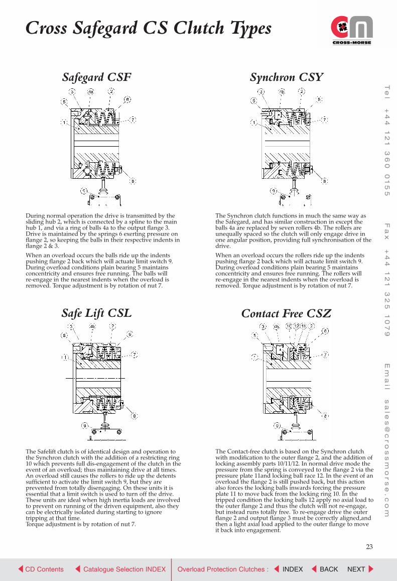
CROSS+MORSE
Power Transmission Solutions
CD Contents NEXTCatalogue Selection INDEX BACKINDEXOverload Protection Clutches :
Te
l +
44
1
21
3
60
0
15
5 F
ax
+
44
1
21
3
25
1
07
9 E
ma
il s
ale
s@
cr
os
sm
or
se
.c
om
23
Cross Safegard CS Clutch Types
During normal operation the drive is transmitted by thesliding hub 2, which is connected by a spline to the mainhub 1, and via a ring of balls 4a to the output flange 3.Drive is maintained by the springs 6 exerting pressure onflange 2, so keeping the balls in their respective indents inflange 2 & 3.
When an overload occurs the balls ride up the indentspushing flange 2 back which will actuate limit switch 9.During overload conditions plain bearing 5 maintains concentricity and ensures free running. The balls will re-engage in the nearest indents when the overload isremoved. Torque adjustment is by rotation of nut 7.
Safegard CSF
The Safelift clutch is of identical design and operation tothe Synchron clutch with the addition of a restricting ring10 which prevents full dis-engagement of the clutch in theevent of an overload; thus maintaining drive at all times.An overload still causes the rollers to ride up the detentssufficient to activate the limit switch 9, but they are prevented from totally disengaging. On these units it is essential that a limit switch is used to turn off the drive.These units are ideal when high inertia loads are involvedto prevent on running of the driven equipment, also theycan be electrically isolated during starting to ignore tripping at that time.Torque adjustment is by rotation of nut 7.
Safe Lift CSL
The Synchron clutch functions in much the same way asthe Safegard, and has similar construction in except theballs 4a are replaced by seven rollers 4b. The rollers areunequally spaced so the clutch will only engage drive inone angular position, providing full synchronisation of thedrive.
When an overload occurs the rollers ride up the indentspushing flange 2 back which will actuate limit switch 9.During overload conditions plain bearing 5 maintains concentricity and ensures free running. The rollers will re-engage in the nearest indents when the overload isremoved. Torque adjustment is by rotation of nut 7.
Synchron CSY
The Contact-free clutch is based on the Synchron clutchwith modification to the outer flange 2, and the addition oflocking assembly parts 10/11/12. In normal drive mode thepressure from the spring is conveyed to the flange 2 via thepressure plate 11and locking ball race 12. In the event of anoverload the flange 2 is still pushed back, but this actionalso forces the locking balls inwards forcing the pressureplate 11 to move back from the locking ring 10. In thetripped condition the locking balls 12 apply no axial load tothe outer flange 2 and thus the clutch will not re-engage,but instead runs totally free. To re-engage drive the outerflange 2 and output flange 3 must be correctly aligned,andthen a light axial load applied to the outer flange to moveit back into engagement.
Contact Free CSZ

CROSS+MORSE
Power Transmission Solutions
CD Contents NEXTCatalogue Selection INDEX BACKINDEXOverload Protection Clutches :
Te
l +
44
1
21
3
60
0
15
5 F
ax
+
44
1
21
3
25
1
07
9 E
ma
il s
ale
s@
cr
os
sm
or
se
.c
om
24
38 28 15 25.5 2 0.1
50 38 20 35.0 2 0.1
60 52 25 45.0 2 0.1
80 65 30 59.0 2 0.1
100 78 30 60.0 2 0.1
120 90 30 60.0 2 0.1
Cross Safegard Overload Clutches
CS Standard Series ClutchesThe standard series of clutches are available in 6 basic sizes offering three modes of operation, simple overload, synchronous overload, and safelift, and in 5 sizes of the totaldis-engagement design. All are available with three methods of supporting drive sprockets, pulleys, or gears, to provide flexibility in application design.Type A - allows simple connection of a driven gear with its own bearing support.Type B - has an integral needle roller bearing providing full support of driven gear.Type C - has extended inner race to mount larger pulleys with plain bearings.Up to Four torque ranges are available on each size of clutch, controlled by selection of theactuating spring set, providing a wide range of torque capacities to select from.Inertias are provided for each half of the clutch in dis-engaged condition, the hub inertiaincorporating all items that revolve free with the hub, and the flange inertia all those itemsthat stay with the flange connection.
For Limit Switch location and operation refer to page 29. Always use limit switch for long service life.
*For clutch Part No. for ordering refer to page 27.
A B C
CS Standard Series - Technical Capacities
Models*A, B & C
Torque Range according to Spring Selection
SNm
MNm
LNm
UNm
S/Mrpm
L/Urpm
minmm
maxmm
TypeA
TypeB
TypeC
TypeA
TypeB
TypeC
TypeA
TypeB
TypeC
Max. Speed Bore size Weight kg Hub Inertia kgcm2 Flange Inertia kgcm2
CS Standard Series DimensionsModels
CSF/CSYand
CSL/CSZ
Dimensions mm
AG7 B C D E F G H J K L L1 L2 N P R U V V1 Wh6 W1 X X1 Y Z
20 41.0 4.0 48 6xM5 6.5 55 50 9 3.0 7.5 38.5 51.5 66 35.0 3.1 6 21 8 27.5
25 60.0 4.0 70 6xM5 8.0 82 73 9 6.0 11.5 52.0 70.0 83 48.0 3.1 6 26 10 33.0
35 78.0 5.0 89 6xM6 10.0 100 91 9 6.0 12.0 61.0 78.0 100 56.0 3.6 8 36 12 39.0
45 90.5 5.0 105 6xM8 12.0 120 112 10 8.5 21.0 78.0 96.0 125 72.0 4.1 10 46 12 47.0
55 105.0 6.5 125 6xM10 15.0 146 140 9 11.0 27.0 100.0 124.5 153 93.5 4.1 12 56 16 52.5
65 120.5 6.5 155 6xM12 17.0 176 170 9 12.0 33.0 113.5 140.0 171 107.0 4.6 14 66 18 57.5
View from Driven Gear End of Clutches
CSF20CSY20CSL20
CSF25CSY25CSL25CSZ25
CSF35CSY35CSL35CSZ35
CSF45CSY45CSL45CSZ45
CSF55CSY55CSL55CSZ55
CSF65CSY65CSL65CSZ65
2.5-5.05-105-10
6-1212-2512-2512-25
12-2525-5025-5025-50
25-5050-10050-10050-100
50-100100-200100-200100-200
85-200170-400170-400170-400
5-1010-2010-20
12.2525-5025-5025-50
25-5050-10050-10050-100
50-100100-200100-200100-200
100-200200-400200-400200-400
170-500350-900350-900350-900
10-2020-4020-40
25-5550-10050-10050-100
50-120100-200100-200100-200
100-250200-400200-400200-400
200-500400-800400-800400-800
300-1000700-1800700-1800700-1800
20-40
55-100
120-200
250-400
500-800
700-1800
330010004000
2900950
39005000
2400800
33004000
2000650
28003500
1600550
23003000
1400400
18002300
1800500
3000
1450450
29005000
1200400
24004000
1000300
20003500
850250
16003000
700150
14002300
7
10
14
18
24
30
20
25
35
45
55
65
0.5
1.5
2.9
5.0
9.8
16.0
0.7
2.0
3.2
6.0
11.8
20.0
0.6
1.8
3.0
5.8
10.5
19.0
1.0
6.7
19.0
51.7
163.0
416.0
1.1
7.0
20.5
54.1
171.0
428.0
1.1
7.2
21.4
57.0
177.0
439.0
0.9
6.2
14.9
38.0
100.0
234.5
1.2
9.1
18.2
48.4
143.0
309.5
0.9
6.2
14.9
38.0
100.0
234.5

CROSS+MORSE
Power Transmission Solutions
CD Contents NEXTCatalogue Selection INDEX BACKINDEXOverload Protection Clutches :
Te
l +
44
1
21
3
60
0
15
5 F
ax
+
44
1
21
3
25
1
07
9 E
ma
il s
ale
s@
cr
os
sm
or
se
.c
om
MNm
25
Cross CS Overload ShaftCouplings
CS Standard Series CouplingsFor shaft to shaft connection CS Standard series clutches are available with an elastomeric coupling for all the sizesand modes of operation, simple overload, synchronous overload, or safe lift and total dis-engagement.The elastomeric Coupling permits up to 1/2 degree angular misalignment, with 0.3mm radial and a maximum of0.5mm axial. The rubber element absorbs peak shocks, providing greater accuracy in overload protection.Up to four torque ranges are available on each size of clutch, controlled by selection of the actuating spring set, providing a wide range of torque capacities to select from.Inertias are provided for each half of the clutch in dis-engaged condition, the hub inertia incorporating all items thatrevolve free with the hub, and the coupling inertia all those items that stay with the flexible coupling.
ModelsCSF/CSYand CSL
Dimensions
G H J K L L1 N R S T T1 T2 U W Y Z
CS Standard Series Couplings - Dimensions
For details on Limit Switch location and operation refer to page 29. Always use limit switch for long service life.
A-CC
*For clutch Part No. for ordering refer to page 27.
CS Standard Series Couplings - Technical Capacities
Models*Torque Range according to Spring Selection
SNm
LNm
UNm
S/Mrpm
L/Urpm min max max
Max. Speed Bore Size mmClutch M Cplg. M1
Weightkg
InertiaCplg. Side
kgcm2
InertiaHub Side
kgcm2
CSF20A-CCCSY20A-CCCSL20A-CC
CSF25A-CCCSY25A-CCCSL25A-CCCSZ25A-CC
CSF35A-CCCSY35A-CCCSL35A-CCCSZ35A-CC
CSF45A-CCCSY45A-CCCSL45A-CCCSZ45A-CC
CSF55A-CCCSY55A-CCCSL55A-CCCSZ55A-CC
CSF65A-CCCSY65A-CCCSL65A-CCCSZ65A-CC
2.5-5.05-105-10
6-1212-2512-2512-25
12-2525-5025-5025-50
25-5050-10050-10050-100
50-100100-200100-200100-200
85-200170-400170-400170-400
5-1010-2010-20
12-2525-5025-5025-50
25-5050-10050-10050-100
50-100100-200100-200100-200
100-200200-400200-400200-400
170-500350-900350-900350-900
10-2020-4020-40
25-5550-10050-10050-100
50-120100-200100-200100-200
100-250200-400200-400200-400
200-500400-800400-800400-800
300-1000700-1800700-1800700-1800
20-40
55-100
120-200
250-400
500-800
700-1800
330010004000
2900950
39005000
2400800
33004000
2000650
28003500
1600550
23003000
1400400
18002300
1800500
3000
1450450
29005000
1200400
24004000
1000300
20003500
850250
16003000
700150
14002300
7
10
14
18
24
30
20
25
35
45
55
65
30
50
50
60
60
70
1.2
5.0
6.4
10.6
15.0
27.0
1.0
6.7
19.0
51.7
163.0
416.0
6.1
71.8
81.0
148.5
279.0
734.0
20A-CC25A-CC35A-CC45A-CC55A-CC65A-CC
50.072.590.5
112.0140.0170.0
999
1099
3.06.06.08.5
11.012.0
7.511.512.020.027.033.0
38.552.061.078.0
100.0113.5
90.0138.0147.0176.0207.0242.5
35.048.056.072.093.5
107.0
5582
100120146176
67112112128148148
4679799090
107
3.03.54.04.05.55.5
78
10101313
335060707090
36487082
104129
222222
0.10.10.10.10.10.1

CROSS+MORSE
Power Transmission Solutions
CD Contents NEXTCatalogue Selection INDEX BACKINDEXOverload Protection Clutches :
Te
l +
44
1
21
3
60
0
15
5 F
ax
+
44
1
21
3
25
1
07
9 E
ma
il s
ale
s@
cr
os
sm
or
se
.c
om
26
Cross Safegard Overload Clutches
CS Mini Series ClutchesThe CS Mini series of clutches is available in 4 basic sizes with simple overload, and synchronous overload facilityThese lower cost units are offered with two methods to attach sprockets. gears, or pulleys.Type E - allows connection of driven gear with its own external bearing support.Type F - has extended inner race suitable to mount larger pulleys with a bronze or needle roller bearing.Four torque ranges are available on standard units, and three on the synchronous version, providing a wide range oftorque capacity to select from.The series is suitable for moderate speed applications with low radial forces and infrequent tripping. The design issuited to inline stop switch, or proximity switch.
E F
CS Mini Series - Technical Capacities
Models*E & F
Torque Range according to Spring Selection
SNm
MNm
LNm
UNm
S/Mrpm
L/Urpm
minmm
maxmm
Max. Speed Bore sizeWeight
kgInertiakgcm2
CS Mini Series Dimensions
Emergency Stop Switch Location and Operation - Switch CSS2The Stop Switch (available separately) should be used on all applications.
(1) Safegard Mini - (2) Synchron Mini
ModelsCSF &CSY
Dimensions mm
Ah8 Bh8 C D E E1 F G H K L L2 N P R V V1 Wh7 CH
20
25
35
45
36
46
64
78
55
70
90
115
46
59
80
100
6xM5
6xM5
6xM6
6xM6
11.5
16.5
16.5
22.0
4.5
5.5
6.5
8.0
5.5
7.0
7.0
8.0
21.7
23.2
29.0
34.5
53
74
88
114
38
54
70
86
50
57
65
81
83.5
94.0
108.0
127.0
3
4
4
5
2.8
3.5
4.0
4.0
80
100
120
150
47.5
59.0
85.5
98.5
40.5
48.0
53.0
60.0
30
35
50
65
7
8
10
10
ClutchSize
Z1
(1)mm
(2)mm
20
25
35
45
1.4
1.4
2.4
2.4
1.2
1.2
1.8
2.0
For Clutch Part No. for orderingrefer to page 27
CSF20
CSY20
CSF25
CSY25
CSF35
CSY35
CSF45
CSY45
2.5-5.0
5-10
6-12
12-25
12-25
25-50
25-50
50-100
5-10
10-20
12-25
25-50
25-50
50-100
50-100
100-200
10-20
20-40
25-55
50-100
50-120
100-200
100-250
200-400
20-40
55-100
120-200
250-400
800
700
800
700
800
700
800
650
800
500
700
450
600
400
500
300
7
10
14
18
20
25
35
45
0.5
1.5
2.5
5.0
2.7
7.6
25.0
81.0

CROSS+MORSE
Power Transmission Solutions
CD Contents NEXTCatalogue Selection INDEX BACKINDEXOverload Protection Clutches :
Te
l +
44
1
21
3
60
0
15
5 F
ax
+
44
1
21
3
25
1
07
9 E
ma
il s
ale
s@
cr
os
sm
or
se
.c
om
MNm
27
CS Mini Series Couplings
CS Mini Series CouplingsFor shaft to shaft connection CS Mini series clutches are available with an elastomeric coupling for all the sizes andmodes of operation, simple overload, synchronous overload.The elastomeric Coupling permits up to 1/2 degree of angular misalignment, with 0.3mm radial, and a maximum of0.5mm axial. The rubber element absorbs peak shocks, providing greater accuracy in overload protection.Up to four torque ranges are available on each size of clutch, controlled by selection of the actuating spring set,providing a wide range of torque capacities to select from.The series is suitable for moderate speed applications with low radial forces and infrequent tripping. The design issuited to inline stop switch, or proximity switch, see page 26.
Catalogue Part NumbersTo order Safegard series clutches it is essential to identify clutch type, size (refers to max bore capacity), connectionflange design, and spring ratings for correct torque, (see rating for each clutch).
Examples Clutch Reference is a Safegard (type CSF) size 35, design A with M rated springs (25-50 Nm).is a Synchron (type CSY) size 25, design E (Mini Series) with L ratedsprings (50-100 Nm).
Couplings are identified by suffix - CC, e.g. CSY 25E/L - CC is coupling version of above clutch. Clutchescome with pilot bores, but can be supplied finish bored if specified on order.
ModelsCSF/CSY
Dimensions
E F G K L N R S T T1 T2 U W
CS Mini Series Couplings - Dimensions
E-CC
*For clutch Part No. for ordering refer below
CS Mini Series Couplings - Technical Capacities
Models*Torque Range according to Spring Selection
SNm
LNm
UNm
S/Mrpm
L/Urpm min max max
Max. Speed Bore Size mmClutch M Cplg. M1
Weightkg
Inertia
kgcm2
CSF20E-CC
CSY20E-CC
CSF25E-CC
CSY25E-CC
CSF35E-CC
CSY35E-CC
CSF45E-CC
CSY45E-CC
2.5-5.0
5-10
6-12
12-25
12-25
25-50
25-50
50-10
5-10
10-20
12-25
25-50
25-50
50-100
50-100
100-200
10-20
20-40
25-55
50-100
50-120
100-200
100-250
200-400
20-40
55-100
120-200
250-400
800
700
800
700
800
700
800
650
800
500
700
450
600
400
500
300
7
10
14
18
20
25
35
45
30
35
50
60
1.2
2.5
5.2
10.0
8
21
91
205
20E-CC
25E-CC
35E-CC
45E-CC
11.5
16.5
16.5
22.0
5.5
7.0
7.0
8.0
53
74
88
114
21.7
23.2
29.0
34.5
84.5
98.0
132.0
155.0
50
57
65
81
80
100
120
150
67
82
112
128
46
53
79
90
2.8
3.5
4.0
4.0
7
8
10
10
37
48
66
81
38
54
70
86
CSF 35A/MCSY 25E/L

CROSS+MORSE
Power Transmission Solutions
CD Contents NEXTCatalogue Selection INDEX BACKINDEXOverload Protection Clutches :
Te
l +
44
1
21
3
60
0
15
5 F
ax
+
44
1
21
3
25
1
07
9 E
ma
il s
ale
s@
cr
os
sm
or
se
.c
om
ENGAGED
At Maximum Torque Setting At Minimum Torque Setting
DISENGAGED ENGAGED DISENGAGED
28
Series CZ Safegard Overload Clutch
Zero backlash Overload Clutches and Couplings, series CZ,available in 8 different basic types, and 5 basic sizes, for shaftdiameters from 8mm to 60mm; providing Overload Protectionfor Torque values from 5Nm to 740Nm.The CZ series Safegard overload clutches were developedto provide a totally backlash free transmission of power witha very responsive overload protection. These compact unitsare directly interchangeable with existing designs in the marketproviding a cost advantage with long reliable service life.Two basic modes of operation are available, the basic CZFSafegard ratchetting design with the driving balls equally spaced so that clutch can re-engage after a small angle of rotation, and the Synchron CZY design with the balls unequallyspaced so that clutch can only re-engage after a full revolutionso providing full synchronisation between driver and driven.Responsive overload reaction is obtained by the use of negativefunctioning Disc Springs to apply drive load. In the event of anoverload the spring load actually decreases, allowing fasterdis-engaging of the drive, and minimal pressure on the drivingsurface in the dis-engaged mode, reference diagrams below.
Method of OperationDuring normal operation the CZ Overload Clutch transmitsthe torque from the Hub (1) to the Flange (3) by a numberof hardened steel balls (4) located in pockets in the Hub,and forced into matching seats in the Flange by the DiscSpring (6) applying load to the Pressure Flange (2).In the event that the Driving Torque exceeds the pre-set value,the reaction forces on the Steel Balls exceeds the force appliedby the Pressure Flange, and the Balls start to ride-up out of theirseats in the Flange (3). This action reduces the spring load, soallowing the Balls to quickly come out of their seats, so releasingthe drive. The action of the Balls dis-engaging moves the PressureFlange to the right so activating the stop switch (9).Re-engagement is automatic once the torque level drops below thepre-set value. The Synchron design re-engages only at one angularposition to keep Hub and Flange accurately synchronised at all times.The Disc Springs work only in the negative area of their characteristicsso unscrewing the Adjusting Nut (7) increases the axial load of the Springs,so increasing dis-engaging torque. When desired Torque setting is achieved the Adjusting Nut is locked by the Bolt (8)being screwed into the locking Collar (10).

CROSS+MORSE
Power Transmission Solutions
CD Contents NEXTCatalogue Selection INDEX BACKINDEXOverload Protection Clutches :
Te
l +
44
1
21
3
60
0
15
5 F
ax
+
44
1
21
3
25
1
07
9 E
ma
il s
ale
s@
cr
os
sm
or
se
.c
om
29
Series CZ Safegard OverloadClutch
Overload Sensor SwitchesIt is strongly recommended that all installations should include a Limit Switch or Sensor to switch off the power inevent of an overload. The following are standard units available with mounting instructions.
a) Proximity Sensor Switchfor Radical mounting - CSS3
a) Proximity Sensor Switchfor Axial movement - CSS4
Clutch Engaged
Clutch Tripped
Wiring Connections for ProximitySensor - Models CSS3 & CSS4
Wiring for Limit SwitchModel CSS1
a) Mechanical Limit Switchfor contact actuation - CSS1
CZ Series Clutches and Couplings Torque AdjustmentReferring to drawing alongside Torque setting of CZ Clutches can be made using either a suitable size ‘C’ Spanner (A), or acorrect size Pin Wrench (C). First release Adjusting Nut (7)by removing the Locking Screw (8), then rotate the Nutclockwise until at end of stroke (do not apply excess force).Then rotate nut back anti-clockwise by one indent to reachthe neutral position, corresponding to minimum torque. Thencontinue to turn Adjusting Nut anti-clockwise for the numberof indents indicated on the label (F) on the outside of Clutchfor required Torque. Put Threadlock on Locking Screw, andreplace in one of the threaded holes (G) which aligns with a hole in the Locking Plate behind.
CSCLUTCH
Z mm
CFS CSY CSL CSZCZ
CLUTCHZ
mm
20
25
35
45
55
65
1.4
2.3
2.4
2.7
3.7
4.6
1.2
1.8
2.0
2.2
2.5
3.0
0.6
0.8
1.1
1.2
1.2
1.6
1.6
2.3
3.0
3.5
3.8
4.5
25 1.2
30 1.5
40 1.8
50 2.0
60 2.2
Clutch Engaged
Clutch Tripped
Sensor SwitchPosition
220-250VAC/15A24 VDC/6A
IP-54For other clutch types refer torespective dimension tables.
24VDC/6AIP-54
Outer Movement in Overload

CROSS+MORSE
Power Transmission Solutions
CD Contents NEXTCatalogue Selection INDEX BACKINDEXOverload Protection Clutches :
Te
l +
44
1
21
3
60
0
15
5 F
ax
+
44
1
21
3
25
1
07
9 E
ma
il s
ale
s@
cr
os
sm
or
se
.c
om
Series CZ Safegard OverloadClutches Standard Plain BoreUnits
Clutch Size
A B Ch5
D E E1 F G G1 H J K L L1 Mmin max
N P Rh6
T T1 Z CHA/F
2530405060
658095
110130
567185
100116
47627590
100
8x M48x M58x M68x M68x M8
579
1010
3343556773
7.58.0
10.512.012.0
811141618
6.58.8
11.513.014.0
789
1012
54.569.077.087.5
106.0
1214161721
4048596475
6580
100115130
810121622
2025354550
637788
100122
7085
100115135
3040455565
55567
2.82.83.54.04.0
1.21.51.82.02.2
778
1010
30
For Limit Switch location and operation refer to page 29. Always use limit switch for long service life.
*For clutch Part No. for ordering refer bottom of page
CZ Series types H & K - Dimensions
Clutch Part Numbers for OrderingTo correctly order CZ series clutches it is essential to identify the clutch operating mode, size, type, spring ratings(torque range), and for clutches and couplings using Clamping Elements for shaft connection, the shaft diameters.Operating Mode: CZ series clutches are available with two operating modes, ratchetting type CZF for applicationswhere synchronisation of input to output is not required, and single position type CZY for full synchronisation.Clutch Size: The clutch size generally indicates the max bore size, and is identified in the tables.Clutch Type: A letter from H to T indicates the clutch/coupling design, as shown in the respective drawings.For couplings type M and N it is required to indicate the coupling size also, e.g. for Coupling size 40-72 type Mthe reference is M72, for couplings P,R & T it is necessary to indicate rubber shore value ie.P92 is with rubber 92 shore.Spring Rating: following a / the letter S, M, or U indicates the Spring sizes selected, which controls the torque range. Bore Sizes: Except for pilot bored types H, K and M it is essential that the finish bore sizes of the Clutch/Couplingare provided to enable supply of the unit. Types H, K and M can be supplied with finish bores also if specified.
Examples
CZF40H/M is a Ratchetting size 40 clutch type ‘H’ with spring selection M.CZY50L/S-40 is a Synchronous size 50, type L, with spring set S, fitted with 40mm clamping bush.CSY40N89/U-35/40 is a Synchronous Coupling size 40, type N, with spring set U, with the clutch half
fitted with a 35mm clamping bush, and the coupling half with a 40mm clamping bush.CSY50M89/S-38/48 is a Synchronous Coupling size 50, type M, with spring set S, with the clutch half
bored and keyed for a 38mm shaft, and the coupling half bored and keyed for 48mm.
Standard Zero Backlash Clutches types H&KThese clutches are intended forkeyway connection to shafts wherepre-machined synchronisation isthe preferred design. Type H is usedto mount compact drive systems withminimal overhung load, the singledeep groove ball bearing providingfull radial support for the sprocket,pulley, or gear.Type K has an extended inner raceto support a second Bearing toallow fitment of wider transmissionelements, and where high radial loadsmay be encountered.
CZ Series types H & K - Technical Capacities
ModelsH&K
Clutch Size
25
30
40
50
60
5-14
9-27
19-60
35-110
80-185
10-28
18-54
38-125
80-220
160-370
20-60
38-115
70-255
160-440
320-740
4000
3000
2500
2000
1200
8
10
12
16
22
20
25
35*
45*
50
0.74
1.37
2.28
3.29
5.12
0.83
1.41
2.56
3.74
5.73
2.15
5.30
13.68
27.62
66.45
2.22
5.58
14.58
29.88
72.01
0.95
2.35
6.45
13.07
26.52
Torque Range according to Spring selection Max.Speed Bore Size ’M’ Weight kg Hub Inertia kgcm2 Flange
SNm
MNm
UNm
rpm minmm
maxmm
TypeH
TypeK
TypeH
TypeK
Inertiakg m2
*max bore achievable only with keyway according to DIN 6885 Sheet 3
Type H Type K
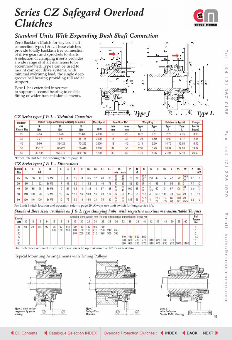
CROSS+MORSE
Power Transmission Solutions
CD Contents NEXTCatalogue Selection INDEX BACKINDEXOverload Protection Clutches :
Te
l +
44
1
21
3
60
0
15
5 F
ax
+
44
1
21
3
25
1
07
9 E
ma
il s
ale
s@
cr
os
sm
or
se
.c
om
Standard Units With Expanding Bush Shaft ConnectionZero Backlash Clutch for keyless shaftconnection types J & L. These clutches provide totally backlash free connectionof drive gears and sprockets to shafts.A selection of clamping inserts provides a wide range of shaft diameters to be accommodated. Type J can be used to mount compact drive systems, with minimal overhung load, the single deep groove ball bearing providing full radial support. Type L has extended inner race to support a second bearing to enable fitting of wider transmission elements.
31
Series CZ Safegard OverloadClutches
CZ Series types J & L - Dimensions
For Limit Switch location and operation refer to page 29. Always use limit switch for long service life.
*For clutch Part No. for ordering refer to page 30.
CZ Series types J & L - Technical Capacities
Standard Bore sizes available on J & L type clamping hubs, with respective maximum transmittable Torques
Shaft tolerance required for correct operation is h6 up to 40mm dia., h7 for over 40mm.
Typical Mounting Arrangements with Timing Pulleys
Type JPulley directMounted
Type Lwith Pulley onNeedle Roller Bearing
Type L with pulleysupported by plainbearing
25
30
40
50
60
5-14
9-27
19-60
35-110
80-185
10-28
18-54
38-125
80-220
160-370
20-60
38-115
70-255
160-440
320-740
4000
3000
2500
2000
1200
10
15
19
32
32
25
30
40
50
60
0.72
1.26
2.11
2.98
4.75
0.81
1.50
2.39
3.43
5.36
2.29
5.90
14.75
30.34
71.94
2.36
6.17
15.66
32.60
77.18
0.95
2.35
6.45
13.07
26.52
Torque Range according to Spring selection Max.Speed Bore Size ’M1’ Weight kg Hub Inertia kgcm2 Flange
rpm
Models* J & L
Clutch SizeS
NmM
NmU
Nmminmm
maxmm
TypeJ
TypeL
TypeJ
TypeL
Inertiakgcm2
43.54
V Size
A B Ch5
D E E1 F G G1 K1 L2 L3 M1
min maxP R
h6S T2 U U1 V1 W Z CH1
A/F
25
30
40
50
60
65
80
95
110
130
56
71
85
100
116
47
62
75
90
100
8x M4
8x M5
8x M6
8x M6
8x M8
5
7
9
10
10
33
43
55
67
73
7.5
8.0
10.5
12.0
12.0
8
11
14
16
18
6.5
8.8
11.5
13.0
14.0
12
12
14
16
21
40
46
57
63
75
65
78
98
114
130
101915
70
85
100
115
135
30
40
45
55
65
1.2
1.5
1.8
2
2.2
2.8
4
42
49
60
66.5
47
56
67
73
19323232
55
20 25 30
3040505060
40.54257576473.573.589
26.526314031292945.54 78.5
78
67
81
101
118134133
8586
72
88
108
124140141 10
10
7
10108
Clutch
Clutch Size
Available Bore sizes in mm (Figures indicate max. transmittable Torque Nm)
25 65 70 75 90 95 100 115 120 130 140 150 16030 120 130 150 160 180 190 210 220 240 26040 240 260 290 310 320 360 39040 440 480 520 55050 620 680 730 770 810 870 930 97060 620 680 730 770 810 870 930 970 1070 1160
10 11 12 14 15 16 18 19 20 22 24 25 28 30 32 35 38 40 42 45 48 50 55 60
BoltTorque
Nm
31010 5.91010
Type J Type L

CROSS+MORSE
Power Transmission Solutions
CD Contents NEXTCatalogue Selection INDEX BACKINDEXOverload Protection Clutches :
Te
l +
44
1
21
3
60
0
15
5 F
ax
+
44
1
21
3
25
1
07
9 E
ma
il s
ale
s@
cr
os
sm
or
se
.c
om
32
Standard CZ series Zero Backlash Overload Clutches combined with a Torsionally stiff. Steel Disc Coupling for ultimate shaft to shaft positional accuracy, with full overload protection. Available with keyed shaft connection, ortotally keyless with shaft clamping elements.
Series CZ Safegard OverloadCouplings
For clutch Part No. for ordering refer to page 30.*max bore achievable only with keyway according to DIN 6885 Sheet 3
CZ Series Couplings types M & N - Technical Capacities
CZ Series Couplings types M & N - Dimensions
Standard Bore sizes available on N type Clutch clamping hubs, with respective maximum transmittable Torques
Standard Bore sizes available on N type Coupling half clamping hubs, with respective maximum transmittable Torques
Shaft tolerances required for correct operation is h6 up to 40mm dia., h7 for over 40mm., for both Clutch and CouplingDisc Bolt Torque is for the bolts on the Flexible Disc Plate
ModelsM & N
CouplingSize
Torque RangeAccording to Spring Type
Speed Max.
rpm
Coupling Type M Bore SizesClutch Hub Coupling Hub
Coupling Type N Bore SizesClutch Hub Coupling Hub
Weight Hub Inertia Flange Inertia Max. MisalignmentCoupling
Angulardegrees
Axialmm
SNm
MNm
UNm
M minmm
M maxmm
M2 minmm
M2 maxmm
M1 minmm
M1 maxmm
M3 minmm
M3 maxmm
TypeMkg
TypeNkg
TypeM
kgcm2
TypeN
kgcm2
TypeM
kgcm2
TypeN
kgcm2
25-53
30-72
40-72
40-89
50-89
60-118
5-14
9-27
19-60
19-60
35-110
80-185
10-28
18-54
38-125
38-125
80-220
160-370
20-60
38-115
70-180
70-255
160-430
320-740
4000
3000
2500
2500
2000
1200
8
10
12
12
16
22
20
28
35*
35*
45*
50
6
10
10
14
14
15
25*
35
35
50*
50*
65
10
15
19
19
32
32
25
30
40
40
50
60
11
19
19
24
24
32
20
30
30
42
42
60
1.2
2.4
3.5
4.3
5.5
9.4
1.2
2.0
3.4
3.6
4.8
7.8
2.15
5.30
13.68
13.68
27.62
66.45
2.22
5.58
14.58
14.58
29.88
72.01
2.42
6.92
16.55
16.55
34.03
43.52
2.47
7.06
16.88
26.12
34.71
44.39
1
1
1
1
1
1
0.4
0.5
0.5
0.6
0.6
0.8
DimensionsModelsM & NSize
K K1 L L4 L5 L8 N P P1 P2 P3 S S1 T1 T2 T3 V W W1 X Y Y1 Z CH CH1 CH2MAX MAX MAX MAXMIN MIN
25-5330-7240-7240-8950-8960-118
121416161721
121214141621
404859596475
86.5113127143145173
95109128152153174
283443434754
63778888100122
7085
100100115135
65809797111131
5372728989118
324747626282
425757647489
425858727292
2.82.83.53.54.04.0
2.84.04.03.54.04.0
466666
475667677386
263140312929
263131454529
41.550.062.062.066.576.5
254040454555
253333454544
1.21.51.81.82.02.2
7788
1010
71010
81010
355555
ClutchSize
253040405060
10 11 12 14 15 16 18 19 20 22 24 25 28 30 32 35 38 40 42 45 48 50 55 60
65 70 75 90 95120
100130
115150
120160240
130180260
140190290
150210310
160220320
240360
260390
440620620
480680680
520730730
550770770
810810
870870
930930
970970 1070 1160
31010 5.91010
BoltTorque
Nm
Available Bore sizes in mm (Figures indicate max. transmittable Torque Nm)
ClutchSize
25-5330-7240-7240-8950-8960-118
11 12 14 15 16 18 19 20 22 24 25 28 30 32 35 38 40 42 45 48 50
80 87 102 108146
116155
130175
138210210
145220220
242242
265265529529
276276552552
309309618618
331331662662
706706730
772772798
839839866
883883912
926926958 1026 1094 1140
688
151533
DiscBolt Torque
Nm
Available Bore sizes in mm (Figures indicate max. transmittable Torque Nm)
51717171717
ElementBolt Torque
Nm
Type M Type N

CROSS+MORSE
Power Transmission Solutions
CD Contents
END
Catalogue Selection INDEX BACKINDEXOverload Protection Clutches :
Te
l +
44
1
21
3
60
0
15
5 F
ax
+
44
1
21
3
25
1
07
9 E
ma
il s
ale
s@
cr
os
sm
or
se
.c
om
Series CZ Safegard OverloadCouplingsStandard Keyless Connection Overload Clutches with Elastomeric Couplings
Couplings type T is identical to type P except coupling hub is not split, and hub suitable for standard reworkingCouplings are supplied standard with 92 Shore rubber inserts, but 98 shore can be supplied to order
CZ Series Couplings types P, R & T - Technical Capacities
For Clutch Part No. for ordering refer to page 30.*max bore achievable only with keyway according to DIN 6885 Sheet 3
CZ Series Couplings types P, R & T - Dimensions
Standard Bore sizes available on P, R & T type Clutch clamping hubs, with respective maximum transmittable Torques
Standard Bore sizes available on P type Coupling clamping hubs, with respective maximum transmittable Torques
Standard Bore sizes available on R type Coupling clamping hubs, with respective maximum transmittable Torques
Shaft tolerance required for correct operation is h6 up to 40mm dia., h7 for over 40mm.
ModelsP, R&TClutchSize
Torque RangeAccording to Spring Type
Speed Max.
rpm
Nominal TorqueFlexible Coupling
Coupling Hub Bore Sizes*
Cplg Types P & T Cplg Type R
Weight Hub Inertia
kgcm2
Max. Misalignment of CouplingAxial
mm
TypeP & T
kg
TypeRkg
25
30
40
50
60
5-14
9-27
19-60
35-110
80-185
10-28
18-54
38-125
80-220
160-370
20-60
38-115
70-255
160-440
320-740
35
95
190
265
310
60
160
325
450
525
4000
3000
2500
2000
1200
10
15
19
32
32
25
30
40
50
60
10
14
15
20
25
28
38
45
48
55
30
40
48
50
60
11
15
20
25
30
28
38
45
50
55
1.38
3.47
4.48
6.59
10.71
1.53
3.67
4.48
6.59
10.71
2.2
5.6
14.6
29.9
72.0
4.00
10.00
20.00
50.00
114.00
1.4
1.5
1.8
2.0
2.1
0.14
0.15
0.17
0.19
0.23
1
1
1
1
1
0.11
0.12
0.14
0.16
0.10 0.9
0.9
0.9
0.9
0.9
Clutch HubBore Sizes*
SNm
MNm
UNm
92 Sh.ANm
98 Sh.ANm
M1 minmm
M1 maxmm
M4 minmm
M4 (P)max mm
M5 minmm
M5 maxmm
M4 (T)max mm
Flange Inertia
kgcm2
92 Shore A 98 Shore ARadial
mmAng.deg.
Radialmm
Ang.deg.
DimensionsModelsP & RSize
AA AB AC H J K1 L6 L7 N P P5 P6 P7 P8 S T T1 T2 V W X2 Z CH CH1 CH3 CH4 MAXMAX MIN
2530405060
3035455056
---
2832
10.511.515.518.021.0
789
1012
54.569.077.087.5
106
1212141621
102120146159213
102120146159213
637788100122
7085
100115135
7085
100115135
55658095
105
---
8595
55658095
105
42.057.064.073.589.0
55567
2.82.83.54.04.0
2.84.04.04.04.0
4756677385
26.531.040.029.045.5
47.054.567.073.087.0
1.21.51.822.2
778
1010
710
8/101010
5668
10
44568
MAX MAX
ClutchSize
253040405060
10 11 12 14 15 16 18 19 20 22 24 25 28 30 32 35 38 40 42 45 48 50 55 60
65 70 75 90 95120
100130
115150
120160240
130180260
140190290
150210310
160220320
240360
260390
440620620
480680680
520730730
550770770
810810
870870
930930
970970 1070 1160
31010 5.9 1010
BoltTorque
Nm
Available Bore sizes in mm (Figures indicate max. transmittable Torque Nm)
BoltTorque
Nm
Available Bore sizes in mm (Figures indicate max. transmittable Torque Nm)ClutchSize
2530405060
10 11 14 15 16 19 20 24 25 28 30 32 35 38 40 42 45 48 50 55
34 35 3680
388192
398194
398598
418799
232
4391
104244
4592
105246393
4697
109255405
99112260413
102113266421
105118274434
109122283445
123288454
126294462
130301473
309486 494 514
10.5252569
120
BoltTorque
Nm
Available Bore sizes in mm (Figures indicate max. transmittable Torque Nm)ClutchSize
2530405060
11 14 15 16 19 20 24 25 28 30 32 35 38 40 42 45 48 50 55
48 67 74142
72154
90188
97189269
112237337
120250356399
143280398445
307436470775
310442506819
353501566955
389533581999
572630
1090
585647
1091
644728
1230836
1334858
1381 1540
66
103569
Type P (and T) Type R
33