Dynamic Frequency and Overload Management in ...
16
Received May 21, 2020, accepted June 15, 2020, date of publication June 22, 2020, date of current version July 3, 2020. Digital Object Identifier 10.1109/ACCESS.2020.3004185 Dynamic Frequency and Overload Management in Autonomous Coupled Microgrids for Self-Healing and Resiliency Improvement S. M. FERDOUS 1 , (Student Member, IEEE), G. M. SHAFIULLAH 1 , (Senior Member, IEEE), FARHAD SHAHNIA 1 , (Senior Member, IEEE), RAJVIKRAM MADURAI ELAVARASAN 2 , AND UMASHANKAR SUBRAMANIAM 3 , (Senior Member, IEEE) 1 Discipline of Engineering and Energy, Murdoch University, Perth, WA 6150, Australia 2 Department of Electrical and Electronics Engineering, Sri Venkateswara College of Engineering, Chennai 602117, India 3 Renewable Energy Laboratory, Faculty of Engineering, Prince Sultan University, Riyadh 11586, Saudi Arabia Corresponding authors: G. M. Shafiullah (gm.shafi[email protected]) and S. M. Ferdous ([email protected]) This work was supported by the Australian Government and Murdoch University through the Research Technical Program Scholarship. ABSTRACT Autonomous microgrids (MGs) are being installed in large remote areas to supply power where access to the utility grid is unavailable or infeasible. The power generation of such standalone MGs is largely dominated by renewable based energy sources where overloading or power deficiencies can be common due to the high intermittency and uncertainty in both load and power generation. Load-shedding is the most common mechanism to alleviate these problems to prevent system instability. To minimize load-shedding, most MGs are equipped with local battery energy storage (BES) systems to provide additional support. Furthermore, in the event of severe overloading or when BES capacity is insufficient to alleviate the overload, neighboring MGs can be provisionally coupled to provide mutual support to each other which is a more effective, economic and reliable approach. Such a coupling is preferred to be via power electronic converters to enhance the autonomy of the MGs. This paper proposes a two-stage, coordinated power sharing strategy among BESs and coupled MGs for overload management in autonomous MGs, through dynamic frequency control. Both local BES and the neighboring MGs can work in conjunction or individually to supply the required overload power demand. For this, BES’ state of charge should be above a minimum level and extra power generation capacity needs to be available in the neighboring MGs. A predefined framework with appropriate constraints and conditions, under which the power exchange will take place, are defined and formulated. The proposed mechanism is a decentralized approach, operating based on local frequency and state of charge measurements, and without any data communication amongst the MGs. The dynamic performance of such a network, is evaluated through extensive simulation studies in PSIM R and verifies that the proposed strategy can successfully alleviate the overloading situation in the MGs through proper frequency regulation. INDEX TERMS Battery energy storage, dynamic frequency control, interconnection converter, coupled microgrids, overload management. NOMENCLATURE BES Battery energy storage BFC Battery frequency controller BSC Battery storage converter DER Distributed energy resource ICC Interconnection converter The associate editor coordinating the review of this manuscript and approving it for publication was Amjad Anvari-Moghaddam . IFC Interconnection frequency controller LPF Low pass filter LQR Linear quadratic regulator MG Microgrid MGCC Microgrid central controller PCC Point of Common Coupling PI Proportional-integral 116796 This work is licensed under a Creative Commons Attribution 4.0 License. For more information, see https://creativecommons.org/licenses/by/4.0/ VOLUME 8, 2020
-
Upload
khangminh22 -
Category
Documents
-
view
1 -
download
0
Transcript of Dynamic Frequency and Overload Management in ...
Received May 21, 2020, accepted June 15, 2020, date of publication June 22, 2020, date of current version July 3, 2020.
Digital Object Identifier 10.1109/ACCESS.2020.3004185
Dynamic Frequency and Overload Managementin Autonomous Coupled Microgrids forSelf-Healing and Resiliency ImprovementS. M. FERDOUS1, (Student Member, IEEE), G. M. SHAFIULLAH 1, (Senior Member, IEEE),FARHAD SHAHNIA 1, (Senior Member, IEEE), RAJVIKRAM MADURAI ELAVARASAN 2,AND UMASHANKAR SUBRAMANIAM 3, (Senior Member, IEEE)1Discipline of Engineering and Energy, Murdoch University, Perth, WA 6150, Australia2Department of Electrical and Electronics Engineering, Sri Venkateswara College of Engineering, Chennai 602117, India3Renewable Energy Laboratory, Faculty of Engineering, Prince Sultan University, Riyadh 11586, Saudi Arabia
Corresponding authors: G. M. Shafiullah ([email protected]) and S. M. Ferdous ([email protected])
This work was supported by the Australian Government and Murdoch University through the Research Technical Program Scholarship.
ABSTRACT Autonomous microgrids (MGs) are being installed in large remote areas to supply power whereaccess to the utility grid is unavailable or infeasible. The power generation of such standaloneMGs is largelydominated by renewable based energy sources where overloading or power deficiencies can be common dueto the high intermittency and uncertainty in both load and power generation. Load-shedding is the mostcommon mechanism to alleviate these problems to prevent system instability. To minimize load-shedding,most MGs are equipped with local battery energy storage (BES) systems to provide additional support.Furthermore, in the event of severe overloading or when BES capacity is insufficient to alleviate the overload,neighboring MGs can be provisionally coupled to provide mutual support to each other which is a moreeffective, economic and reliable approach. Such a coupling is preferred to be via power electronic convertersto enhance the autonomy of the MGs. This paper proposes a two-stage, coordinated power sharing strategyamong BESs and coupled MGs for overload management in autonomous MGs, through dynamic frequencycontrol. Both local BES and the neighboring MGs can work in conjunction or individually to supply therequired overload power demand. For this, BES’ state of charge should be above a minimum level andextra power generation capacity needs to be available in the neighboring MGs. A predefined frameworkwith appropriate constraints and conditions, under which the power exchange will take place, are definedand formulated. The proposed mechanism is a decentralized approach, operating based on local frequencyand state of charge measurements, and without any data communication amongst the MGs. The dynamicperformance of such a network, is evaluated through extensive simulation studies in PSIM R© and verifiesthat the proposed strategy can successfully alleviate the overloading situation in the MGs through properfrequency regulation.
INDEX TERMS Battery energy storage, dynamic frequency control, interconnection converter, coupledmicrogrids, overload management.
NOMENCLATUREBES Battery energy storageBFC Battery frequency controllerBSC Battery storage converterDER Distributed energy resourceICC Interconnection converter
The associate editor coordinating the review of this manuscript and
approving it for publication was Amjad Anvari-Moghaddam .
IFC Interconnection frequency controllerLPF Low pass filterLQR Linear quadratic regulatorMG MicrogridMGCC Microgrid central controllerPCC Point of Common CouplingPI Proportional-integral
116796 This work is licensed under a Creative Commons Attribution 4.0 License. For more information, see https://creativecommons.org/licenses/by/4.0/ VOLUME 8, 2020

S. M. Ferdous et al.: Dynamic Frequency and Overload Management in Autonomous Coupled MGs
SoC State of ChargeVSC Voltage source converter
I. INTRODUCTIONMicrogrids are small-scale electrical power networks con-sisting of multiple distributed energy resources (DERs) andloads that can operate in a grid-connected or autonomousmode [1]. In large remote areas, where access to the utilitygrid is unavailable or infeasible (due to cost and economicconstraint), an autonomously operating MG is the optimumand feasible electrification solution [1]–[3]. Such MGs cansignificantly reduce the levelized cost of energy production;thus, network operators of remote areas prefer to operatetheir edge-of-the-grid or regional networks in the form ofautonomous MGs enabling a high penetration of renew-able sources [4]–[6]. Due to high intermittency and uncer-tainty associated with renewable-based DERs, overloadingor power deficiency as well as over-generation can be verycommon in autonomous MGs which will then lead to unac-ceptable voltage and frequency deviation from its acceptablelimits and system instability [7]. To address the issues of MGoverloading, numerous mechanism and operational solutionshave been suggested in the literature, out of which, load-shedding is the most common, easiest and simplest approach[8], [9]. On the other hand, risk-based planning can preventthe possibility of experiencing power shortage if intermit-tency and unavailability of the renewable sources are consid-ered. However, this will result in installing large-scale energystorage system and/or oversizing DERs [10], [11]. Despiteits cost, it is a common and viable practice to use floatingbattery energy storage (BES) units to support MGs [12], [13].Such BES units can play a vital role during peak demand,overloading or power deficiency as they can respond fasterthan diesel generators or micro-turbines as they are controlledthrough power electronics-based voltage source converters(VSCs) [14]. Nonetheless, using large BES units to addressoverload power demand is cost ineffective as overloading orpeak power demand are either intermittent or temporary [15],causing overdesign and oversizing of the both BES unit andits converter [16].
Temporarily coupling the neighboring MGs to each otherin order to exchange power in such conditions, and thus,retaining the frequency and voltage within the acceptablelimits and ensuring the system stability, has been proposedin [17] as new effective approach. Forming coupled MGsalso improves and enhances system reliability [18], [19].It is expected in future that; a remote locality will consistof several neighboring MGs in a close geographical area.Under such assumptions, the overloading or power deficiencymanagement strategy can be realized by properly couplingtwo or more of those MGs [20]–[23]. An extensive architec-tural analysis of different coupled MGs is shown in detailin [20] while [21]–[24] have discussed the concept of cou-pled MGs and its operation using different types of powerexchange links. A transformative architecture for coupling
MGs, is proposed in [25] for improving system performanceduring faults. Optimal control of a grid-connected MG toform coupled MGs is demonstrated in [26], [18]. Demandsharing through an interactive control of interconnected MGsis employed in [27] for wide range of system stability. Theissues of excess generation management strategy can also besolved by properly coupling two or more neighboring MGs[28]–[30]. The exchange of power among the MGs in aninterconnected system is discussed in [29]–[31]. Operation ofDERs within an interconnected MG is studies in [33], [34],while the interaction among the DERs are investigated in [35]and their stability limits.
The main drawback of the techniques of [21]–[24], [29] isthat the coupling of MGs will be established even for a minorpower deficiency or overloading. Moreover, the technique of[29] is only applicable for two MGs and is not scalable. Toaddress this problem, a new strategy is proposed in this paperwhich coordinates the required power sharing mechanismbetween a local BES unit and neighboring MG; such thatlight overloading can be mitigated by the BES unit whileinterconnection with neighboring MG is established duringsevere overloading. Furthermore, the proposed technique isscalable to any number of coupled MGs.
On the other hand, the physical interconnecting link of theMGs can be based on a conventional circuit breaker or aninterconnecting static switch [29]. However, each MG mayhave a different operator, and thus, their control structureand standards can be different from each other. Therefore, adirect physical connection reduces the autonomy of the MG.Hence, for such situations, proper isolation must be providedamong the MGs so that every MG can operate autonomouslywhile exchanging power with each other. Thus, a back-to-back power electronics-based converter is a good option insuch conditions [21]–[24], [31]. The proposed approach inthis paper, has been further updated to consider such preferredinterconnections among MGs, for which an appropriate pre-defined framework and protocol are essential.
This paper proposes a two-stage coordinated power sharingbetween BES and neighboring MGs through two differentself-healing agents, functioning in a decentralized (com-munication free) manner. This is realized by continuouslymonitoring the MG frequency and its BES unit’s SoC. Thisinformation is used to cooperatively activate or deactivatetwo developed self-healing agents, namely, battery frequencycontroller (BFC) for BES unit, and interconnection frequencycontroller (IFC) for the coupling of MGs. The proposedmechanism and control strategy are evaluated and validatedthrough detailed computer simulation studies using PSIM R©.
The key contributions of this paper to the research field canbe summarized as:• Proposing a coordinated power exchange strategy foroverloading management in autonomous MGs throughinternal and external support (via BES and neighbor-ing MG),
• Formulating the appropriate conditions and constraintsfor power exchange levels under a decentralized
VOLUME 8, 2020 116797
S. M. Ferdous et al.: Dynamic Frequency and Overload Management in Autonomous Coupled MGs
FIGURE 1. Schematic of interconnected autonomous MG networks.
approach (i.e., without any data communicationamongst the MGs),
• Dynamically modifying the amount of internal andexternal power exchange levels based on the BES units’SoC and the MGs’ loading condition
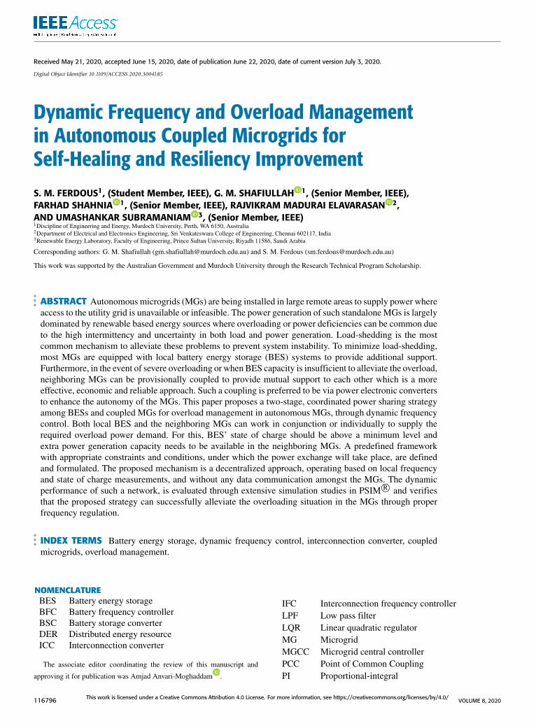
II. NETWORK UNDER CONSIDERATIONLet us consider a system of Fig. 1 whereN autonomousMGs,each consisting of multiple DERs, DGs, loads, one BES andone inter-connection converter (ICC). EachMG is monitored,supervised and controlled through its MG central controller,termed as MGCC. The DERs and BES are connected to theMG through VSCs. Different VSCs are controlled in differentoperating modes to regulate the power and frequency of eachMGs. The VSCs of DERs are assumed to be operating inthe P − f and Q − V droop control mode, where the volt-age and frequency at the output of each DER is determinedfrom [29], [33]
fMG = fmax − miPi (1a)
V = Vrated − niQi (1b)
where mi and ni are the droop coefficients of the ith DER ofthe MG, and can be obtained from
mi =fmax − fmin
Pmaxi
(2a)
ni =Vmax − Vmin
2Qmaxi
(2b)
where subscript max, min and rated represent the maximum,minimum and rated limits for frequency and voltage of theMGs while Pi and Qi are active and reactive powers injectedby eachDER to theMG.All DERswithin anMG are assumedto have the same 1f = fmax − fmin and 1V = Vmax − Vmin;Vrated is the rated voltage of the DER’s PCC (i.e., one perunit) when its reactive power exchange with the PCC is zero
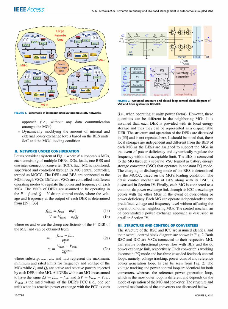
FIGURE 2. Assumed structure and closed-loop control block diagram ofVSC and filter system for BSC/ICC.
(i.e., when operating at unity power factor). However, thesequantities can be different in the neighboring MGs. It isassumed that, each DER is provided with its local energystorage and thus they can be represented as a dispatchableDER. The structure and operation of the DERs are discussedin [33] and is not repeated here. It should be noted that, theselocal storages are independent and different from the BES ofeach MG as the BESs are assigned to support the MGs inthe event of power deficiency and dynamically regulate thefrequency within the acceptable limit. The BES is connectedto the MG through a separate VSC termed as battery energystorage converter (BSC) that operates in constant PQ mode.The charging or discharging mode of the BES is determinedby the MGCC, based on the MG’s loading condition. Thedetail control mechanism of BES along with its BSC, isdiscussed in Section IV. Finally, each MG is connected to acommon dc power exchange link through its ICC to exchangepower with the other MGs in the event of overloading orpower deficiency. Each MG can operate independently at anypredefined voltage and frequency level without affecting theoperation of other neighboring MGs. The control mechanismof decentralized power exchange approach is discussed indetail in Section IV.
III. STRUCTURE AND CONTROL OF CONVERTERSThe structure of the BSC and ICC are assumed identical andtheir overall control block diagram are shown in Fig. 2. BothBSC and ICC are VSCs connected to their respective MG,that enable bi-directional power flow with BES and the dcpower exchange link, respectively. Each converter is workingin constant PQmode and has three cascaded feedback controlloops, namely, voltage tracking, power control and referencepower generation loop, as can be seen from Fig. 2. Thevoltage tracking and power control loop are identical for bothconverters, whereas, the reference power generation loop,which is the most outer loop, is different and depends on themode of operation of theMG and converter. The structure andcontrol mechanism of the converters are discussed below:
116798 VOLUME 8, 2020
S. M. Ferdous et al.: Dynamic Frequency and Overload Management in Autonomous Coupled MGs
A. CONVERTER STRUCTUREThe BSC and ICC structure is assumed to be a three-phase,three-leg VSC using IGBTs or MOSFETs, as schematicallyshown in Fig. 2. They are connected to the MG through anLCL filter to effectively filter out the undesired switchingharmonics. The dc side of the BSC is connected to the BESwhile a dc capacitor is installed on the dc link side of the ICCto interconnect it to the power exchange link. It is to be notedthat, any other three-phase VSC topology can also be used forBSC and ICC.
B. CONVERTER CONTROLBoth converters are operating in constant PQ mode irrespec-tive of the loading condition of the MG. Only the respectiveVSC’s output power reference varies depending on the MG’sloading condition and the outermost control loop which isactive during that time. The BSC is primarily controlled bythe MGCC through the BES controller block, operating asthe outermost loop. The BFC gets activated and operatesin conjunction with BES controller during an overloadingsituation. On the other, during normal operating condition,each ICC maintains the dc link voltage of the point at whichit is connected to the power exchange link. In the event ofoverloading and if the BES capacity is not enough to alleviatethe overloading situation; IFC gets activated to import therequired amount of power from the neighboring MG. Theeffective operation of both BSC and ICC are achieved throughcoordinated control among the three cascaded control loops,namely, linear quadratic regulator (LQR) based voltage track-ing and switching control, power control and dc link voltagecontrol. A brief description of these control loops is providedin Appendix-A.
IV. PROPOSED POWER EXCHANGE STRATEGYThe proposed power exchange strategy is a two-stage coor-dinated overload prevention mechanism for a group of cou-pled autonomous MGs. Let us consider each MG with thetwo introduced self-healing agents of BFC and IFC. All theneighboring MGs are interconnected to each other throughthe power exchange link and their ICCs while each MGhas its own BES, connected and controlled through its BSCand MGCC respectively. To facilitate the proposed powerexchange mechanism, the two self-healing agents continu-ously monitor the SoC of the BES and the frequency of theMG. The SoC is a measure of stored energy of BES, andhence, its capability to support the MG [36], [37]. On theother hand, the loading status of an individual MG can bedetermined by monitoring its frequency. As the demand ofan MG increases, its frequency decreases, and vice versa.Such characteristic is due to the droop control techniqueemployed for the DERs, as the grid-forming units of theMG and can be used as the indicator of power deficiencyor overloading in an MG. Hence, there is no need for anycommunication link or a central controller to regulate thepower flow. Furthermore, even in the presence of a central
controller, the proposed power exchange mechanism can beassigned as the backup system in the event of communicationfailure or during any contingency. For effective power sharingamong all the entities, a predefined framework needs to beintroduced to identify different system parameters and theirboundaries. Whether an entity (BSC/ICC) can participate inpower exchange or not, must be determined by the predefinedframework as their participation without proper coordinationand control may lead to system instability. In general, suchcoordination among the entities can be done by the self-healing agents, by monitoring the MG’s loading level andBES’s stored energy level through frequency and SoC mea-surements, respectively.
During normal operation, the MGCC decides the BES’soperation mode (i.e., charging/discharging) based on theMG’s power generation, loading level and its frequency, fMG.During overloading, if fMG falls beyond the minimum valueof fmin, then first the BFC would respond to alleviate theoverload situation and will work in conjunction with theBES controller. The BFC would determine the amount ofexcess power that needs to be provided by the BES to returnthe MG’s frequency back to fmin. The operation of BFC isdictated by the SoC of BES and the maximum power that canbe handled by the BSC, Pmax
BSC. In case of severe overloading,the BES may not be capable enough to alleviate the situationjust by itself due to the reasons such as- the BSC reachingthe maximum limit of its rated capacity and/or the SoC levelnot being large enough to provide the required power. Hence,the self-healing agent of IFC will then get activated to importpower from the neighboring MGs. The exchange of powerthrough interconnection can be achieved in two ways- first,a portion of the overload power demand is mitigated bythe BES and the rest is provided by the neighboring MGs;second, the total overload power demand is mitigated by thepower imported from the neighboring MGs assuming thatthey have excess power generation available. The overallblock diagram of the proposed power exchange mechanismis shown in Fig. 3.
A. BES CONTROLThe control mechanism of BES during charging and discharg-ing mode, is developed based on its SoC level, SoCbatt(t), andexcess available power of the MG, Pex(t), respectively. Bothparameters are instantaneous and vary with respect to time.Different methods of measuring SoCbatt(t) are discussed indetail in [36]. On the other hand, Pex(t) =
∑PDER(t) −∑
PL(t) where∑PDER(t) is the instantaneous total gener-
ated power of all DERs in MG and∑PL(t) is the MG’s
total instantaneous demand. Since the stored energy of aBES system reduces overtime during discharging mode, it isa more practical approach to set the BES discharge poweras a function of SoC instead of its ratings [15], [25], [37].Hence, a BES system with lower SoC level can be expectedto inject less power to prevent its fast discharging. Thus,the output reference power, Pdisbatt, of the BES unit duringdischarge mode, can vary proportionally to its SoC level in
VOLUME 8, 2020 116799

S. M. Ferdous et al.: Dynamic Frequency and Overload Management in Autonomous Coupled MGs
FIGURE 3. Overall block diagram of the proposed power exchange mechanism.
discrete steps (e.g., in steps of 5-10% as SoC level variesdynamically) [12], [37]. It may be noted that, the BES systemwill stop discharging if the SoC level drops to its minimumvalue of SoCmin. The BES cannot discharge further unless itis charged up to a value of SoCnom. Such a control mechanismcan be implemented using a hysteresis controller.
Similarly, the charging power of the BES unit can be variedproportionally to Pex in discrete steps of 5-10%. The higheris the surplus power available through excess generation ofDERs in theMG, the larger is the charging power for the BESunit, and vice versa. A graphical illustration of charging anddischarging power variation in discrete steps as a functionof MG’s surplus power and BES’ SoC level respectively isshown in Fig. 4. It is to be noted that, the BES charging anddischarging mode is selected based MG’s nominal frequencyof fnom. The charging mode is enabled when fMG > fnom asthis indicates availability of surplus power generation in MGwhereas the discharging mode is enabled when fMG < fnomas this condition characterizes the loading level where theMG needs support from the BES unit. The flowchart of Fig.5 shows the steps of operation of BES during its differentoperating modes while the schematic of the BES controlleris shown in Fig. 6.
A distinctive feature of the proposed method is that theBES is operating in grid-following mode (constant PQ con-trol) instead of the typical grid-forming mode (droop control)to provide the necessary support for the MG. Hence, it iscontrolled and monitored through the MGCC. This proposedmechanism offers better control and more flexibility in power
FIGURE 4. BES nominal operation scheme- (a) charging mode(b) discharging mode.
FIGURE 5. Different mode of operation of BES.
sharing via BES units. Also, the stability issues associatedwith droop control are eliminated; as in droop control tech-nique, it is important to select the proper droop coefficientsto ensure system stability [12], [37]. Most of the commer-cially available batteries are needed to be charged in constant
116800 VOLUME 8, 2020

S. M. Ferdous et al.: Dynamic Frequency and Overload Management in Autonomous Coupled MGs
FIGURE 6. Control of BES different operation modes.
FIGURE 7. Proposed overload management scheme and its differentmodes of operation.
current-constant voltage mode for optimum performance andlonger lifecycle, also known as healthy charging [38]. SuchCC-CV charging approach is not realizable in droop controltechnique. But with the proposed BES control mechanism,constant-voltage healthy charging mode can be easily imple-mented as shown in Fig. 6.
B. CONTROL OF BFC AND BSCThe BFC is the outermost control loop that gets activated andoperates in conjunction with the BES controller and regulatesthe output power of BSC during overload situation. To betterunderstand the operation of BFC and BSC, let us considerthe flowchart of Fig. 7. During nominal operating conditionof the MG, the BSC will receive the power reference fromBES controller and the charging/discharging mode will bedecided based on the developed logic. The BFC will onlyget activated during discharge mode when there is no surpluspower generation available in MG. Thus, the activation andoperation BFC is governed by fMG, SoCbatt and Pmax
BSC. Thefunctional block diagram of BFC is shown in Fig. 8. In theevent of overloading, if fMG drops below fmin, the BFC willget activated through the control signal ofQBSC after a certaintime delay of tBact, if the BES SoC level is greater than theminimum value of SOC ICC
min . If not, then BFC will not getactivated as the SoC level of BES unit is not enough to
FIGURE 8. Control mechanism of BSC for overload management.
alleviate the overload, and hence, power needs to be importedfrom neighboringMGs via the ICC. Similarly, when the over-loading period of theMG is over, the BFCwill get deactivatedand the proportional-integral (PI) controller is reset after acertain delay of tBdct. The input signal fed to the PI controlleris controlled through a multiplexer to ensure proper operationand to avoid drift in PI controller. A low pass filter (LPF)is added to introduce a certain delay to match the batteryresponse time. It is to be noted that, the delays are essentialto allow a reasonable time for the system transients to settledown. Without a proper delay, it is highly possible that theself-healing agents are activated even during transients whichwill result in redundant and unnecessary of power sharing.
Another mode of operation of BFC is possible when, theSoC level can only alleviate a portion of the total overload.Hence, the total overload power demand needs to be sharedby the BES systems of the overloadedMGand its neighboringMGs. This is realized by the BSC capacity evaluation blockof the BFC and dynamically varying the parameter, Pmax
BSC asa function of the SoC. The arrangement is shown in Fig. 8.PmaxBFC is the maximum reference power generated by the PI
controller of BFC and PBSC is the measured output powerof BSC. When PBSC reaches its maximum limit of Pmax
BSC,the input of PI controller should be set to zero. The resetcommand of PI controller should not be activated at thisinstant as the controller must retain the value at its output.The output power reference produced by the PI controller isthe portion of overload power demand that can be suppliedby the BES unit as per its SoC level. The rest of the overloadpower demand must be supplied by the neighboring MGs.
VOLUME 8, 2020 116801

S. M. Ferdous et al.: Dynamic Frequency and Overload Management in Autonomous Coupled MGs
Hence, an activation command for the ICC must be producedto initiate the power sharing through the power exchange link.
C. CONTROL OF IFC AND ICCThe second self-healing agent of the MG is IFC which isresponsible for importing power from the neighboring MGsthrough the power exchange link. The IFC is one of the out-ermost control loops for ICC. The activation of IFC dependson two specific conditions. First, when the SoC level of BESis less than SoC ICC
min , i.e., the SoC level is not large enoughto supply the required overload power demand. In this case,the entire overload power demand is supplied by the ICCfrom the neighboringMGs. Second, when the BSC reaches itsmaximum power limit while supplying overload demand asexplained in previous section. Hence, the rest of the overloadpower demand must be imported from the neighboring MGthrough the ICC. These two conditions are used to derive theactivation logic, QIFC, to activate the IFC which enables theICC to import required power for the overloaded MG. Thefunctional block diagram of the IFC is shown in Fig. 9. Thestructure and function of the controller is similar to BFC.During nominal operation of the MG or while a healthy MGsupporting a neighboring overloaded MG, the ICC shouldoperate in the dc link voltage control mode while the IFCmust remain deactivated. However, if the healthy MG thatwas supporting an overloaded MG, becomes overloaded too,the local BES system of the healthy MG and its BFC shouldget activated to alleviate the overload situation as long as theoverload power is less than Pmax
BSC of that particular MG. Ifthe overload power exceeds Pmax
BSC, then there is no alternativeother than to initiate load shedding. This is achieved by theactivation logic of QICC, as can be seen from Fig. 9. Alogic low value of QICC indicates that, the MG is alreadysupporting another neighboring overloaded MG and the ICCmust operate in the dc link voltage control mode, while IFCshould remain deactivated. The steps of operation of thecontrol approach in such case can be interpreted from theflowchart of Fig. 7. The sequence of control logic is necessaryto implement the developed decentralized control approach.Otherwise, the interconnection among the MGs will lead toinstability throughout the entire system.
V. PERFORMANCE EVALUATIONTo evaluate the dynamic performance of the proposed control,let us consider the system of Fig. 1 with two (for studycases A-E) and three MGs (for study case F) are connectedthrough a dc power exchange link, respectively. The perfor-mance of such a system has been evaluated through six studycases, as illustrated schematically in Fig. 10 and discussedseperately in this section. In these studies, the maximumcapacity of each MG is 70kW and the minimum acceptalefrequency limit is 49.8Hz while The nominal frequency is50Hz. The base power is assumed as 100 kVA while the basedc voltage in the power exchange link is assumed as 1kV.
In these study cases, to replicate non-ideal scenarios, allthe power electronic converters are represented by their
FIGURE 9. Control mechanism of ICC for overload management.
detailed switching model and the conventional close loopcontrol systems are carefully designed with necessary gainand phase margins, so that rated power exchange can takeplace within the network and their stability limits. Eachassumed MG also consists of two or more power electronicconverter based DERs, operating under droop control, andone power electronic converter interfaced BES. Furthermore,different operating and loading conditions of the MGs andtheir BES are considered such as – independent/joint oper-ation of the controllers, transition in controller actions andlight/moderate/heavy overloading. All the control actions arecarried out using local measurements only and without anydata communication among the controllers and converters.
A. LIGHT OVERLOADINGTo verify the ability of each MG operating independentlyand addressing the overloading problem, let us consider thenetwork of Fig. 10a and assume that both MGs are initiallyoperating at the steady-state condition and under the droopcontrol. In this particular study case, both MGs will be lightlyoverloaded and the situation can be alleviated by their respec-tive BES units. Hence, no external power support is required.The applied events in both MGs at different time instants areas follows while the simulation results of the MGs are shownin Fig. 11.
The BES unit of MG-1 and 2 are initially in discharg-ing mode and respectively providing a power of 0.1 and0.075 pu. At t = 0.7 s, MG-1 becomes overloaded by 15%(see Fig. 11a); hence, its frequency decreases to 49.7 Hz (seeFig. 11e). As the frequency has fallen beyond the acceptable
116802 VOLUME 8, 2020

S. M. Ferdous et al.: Dynamic Frequency and Overload Management in Autonomous Coupled MGs
FIGURE 10. Status of self-healing agents and converters in 6 differentcase studies.
limit of 49.8 Hz, MG-1’s BFC gets activated after a fixeddelay of 0.5 s. The controller determines the amount of over-load, POLBSC−1, to bring the frequency back to its acceptablelimit. The BES unit adjusts it reference power, PrefBSC−1, andstarts to inject the required power to alleviate the overloadsituation. At t = 2.5 s, the BES power level has decreasedfrom 0.1 to 0.075 pu, based on its SoC level, as decidedby the MGCC. Thus the BFC again adjusts the power levelthrough to maintain the frequency at 49.8 Hz. At t = 4 s, theoverloading of MG-1 is removed and its goes back to normaloperating condition. The BFC sets the reference overloadpower to zero and gets deactivated after a delay of 0.4 s.MG-1continues to receive 0.075 pu of power from BES as decidedby MGCC.
Now, let us consider the scenarios applied in case of MG-2. MG-2 was initially at the steady state condition while
FIGURE 11. Simulation results for light overloading.
MG-1 was undergoing the overloading scenarios. As theICC and the power exchange link provide complete isolationamong the MGs, any changes in MG-1 does not affect theoperation of MG-2, and thus ensures a complete autonomyin the operation of the MGs. At t = 1.5 s, 13% overloadis applied in MG-2, and thus frequency goes below 49.8 Hz
VOLUME 8, 2020 116803

S. M. Ferdous et al.: Dynamic Frequency and Overload Management in Autonomous Coupled MGs
(See Fig. 11c and 11e). The BFC ofMG-2 gets activated after0.5 s and starts to inject additional power of 0.055 pu to theMG-2 to retain the frequency back to 49.8 Hz. At t = 3 s, theoverload is reduced by 8%, and hence the new overload levelis 5%. Therefore, the BFC reduces the reference power to thenew value of 0.005 pu. At t= 5 s, the overload is completelyremoved and the BFC gets deactivated after 0.4 s as the MGreturns back to the normal operation.
B. MODERATE OVERLOADINGLet us assume, a scenario in which an MG is moderatelyoverloaded but the BES unit does not have enough energystorage to alleviate the overload. At that instant, if the neigh-boring MG has excess power available, it can supply therequired power to the overloaded MG through the powerexchange link. The schematic of the conidered network isshown in Fig. 10b while the simulation results are providedin Fig. 12. Let us assume a scenario in which MG-2 is over-loaded by 20% at t= 0.3 s, and hence its frequency dropsbelow 49.8 Hz. During this time, the BES of MG-2 is notin operation due to its low stored energy level, i.e., the SoCof BES unit is below SOC ICC
min . As a result, the BFC remainsinactive and the IFC gets activated by sensing the frequencydeviation and low level of SoC. First, the IFC will change themode of operation of ICC from dc link voltage control to con-stant PQ control mode. After a preset delay of 0.4 s, the IFCcalculates the amount of overload power needs to be importedfrom MG-1 to retain the frequency back to 49.8 Hz throughthe ICC of MG-2. It may be noted that ICC of MG-1 willcontinue to operate in maintaining the dc link voltage of thepower exchange link and operates in its nominal condition. Apower of 0.2 pu is required to alleviate the overload situationof MG-2 as can be seen from Fig. 12c, denoted as Pg2.The power supplied by MG-1 is slightly higher over 0.2 pubecause of the losses in the converter and tie-line as denotedbyPg1. At t= 1.3 s, an additional 15% load is added toMG-1.Due to addition of this load, while it was supporting MG-2 toalleviate its overloading, MG-1 also becomes overloaded by5%. The SoC level of BES in MG-1 is over nominal valueand was delivering a power of 0.1pu while it was overloaded.Hence, additional power needs to be supplied by the BESand thus the BFC of MG-1 is activated. It determines therequired overload power to be supplied is 0.05 pu and the totaloutput power of BSC of MG-1 is 0.15 pu, as can be seen fromFig. 12d. This scenario continues until t = 3.2 s at whichthe overloading of MG-2 is removed and MG-2’s frequencyincreases above the minimum limit. Therefore, MG-2 goesback to the normal operating condition. As MG-1 does notneed to support MG-2 anymore, the frequency of MG-1 alsoincreases above the minimum limit of 49.8 Hz at the sametime and MG-1 goes back to its nominal operating conditionas soon as MG-2’s overload is removed. MG-1 continues tooperate nominally with additional 15% added load until t =4.2 s, when the additional load is also removed from MG-1.The respective control signals for activating the self-healingagents are shown in Fig. 12f. It is to be noted that the IFC is
FIGURE 12. Simulation results for moderate overloading.
activated for MG-2 as it needed support through the powerexchange link while BFC was activated for MG-1 as it issupported by its local BES unit. It may also be noted here thatboth of the IFCs must not get activated at the same time in theevent overloading as there will be no convereter to regulatethe voltage of the power exchange link. This is realized bythe ICC detection loop (which is basically a window detectorcircuit) as shown in Fig. 9. The time delay in deactivation
116804 VOLUME 8, 2020

S. M. Ferdous et al.: Dynamic Frequency and Overload Management in Autonomous Coupled MGs
of IFC is greater than BFC as IFC must wait for a longerperiod to allow the dc link voltage to settle down and reachthe steady-state. When the IFC is deactivated, the control ofcorresponding ICC shifts from constant PQ control mode todc link voltage control mode.
C. CONTROLLER TRANSITIONLet us consider the network of Fig. 10c and assume a scenarioin which an MG is lightly overloaded and the situation canbe alleviated easily just by the BES unit itself. But if theoverloading continues for a long duration of time, the BES’sstored energy will be depleting rapidly. As a result, the SoClevel is also decreasing in proportion to its stored energy. Atsome point the BES will stop supporting the MG due to thelack of adequate stored energy. Therefore a transition in thecontrol action needs to take place, i.e., the IFC should takeover in the place of the BFC to alleviate the overload. Thistransition in control should be done smoothly and withoutcausing any stability issues. The simulation results of thiscase are provided in Fig. 13. Let us assumeMG-1 is operatingnominally with the BES supplying a power of 0.025 pu atan SoC level of 65%. At t = 0.2 s, the MG is overloadedby 6%. Thus, the BFC gets actiavated and starts to supplyan additional power of 0.06 pu to alleviate the overloading.Hence, the total power provided by the BES unit to the MGis 0.085 pu as can be seen in Fig. 13d. At t = 2.35 s, the SoCof BES in MG-1 goes below the minimum limit of SoC ICC
min ,which is assumed to be 55% in this study and hence theBFC gets deactivated as per the developed control logic. Atthis instant, the BES is providing only a power of 0.025pu,instead of required power of 0.085 pu. Hence,MG-1 becomesoverloaded again and the frequency falls below 49.8 Hz. Itis then sensed by the IFC and therefore, gets activated att = 2.5 s. The subsequent steps of operation of IFC areexactly the same as it was in the study case-B above. IFCenables the ICC to import a power of 0.06 pu from MG-2 toalleviate the overload. This is continued until t = 3.8 s atwhich the BES of MG-1 completely stops supplying powerto MG-1 as deciced by the MGCC based on its SoC level.Therefore, the IFC adjusts the required power demand toretain the frequency back to 49.8 Hz once again. The overloadof MG-1 is removed at t = 5.2 s and it goes back to itsnominal operation again. The IFC waits for a certain time forthe dc link voltage to settle and then switches back to the dclink voltage control mode.
D. HEAVY OVERLOADING-1To alleviate a heavy overloading situation, the total powermay be shared between the local BES and the neighboringMG. In the event of any overloading, it is expected that theMG should first try to alleviate the problem using local BES.If the stored energy of BES or the capacity of the BSC are notenough to address the overload problem, the MG should startimporting power through ICC. Both BSC and ICC shouldoperate simultaneously to supply the overload power demand.Now, let us consider the network of Fig. 10d. Let us assume a
FIGURE 13. Simulation results for controller transition.
scenario where both the MGs are operating in nominal condi-tion as can be seen in Fig. 14. The SoC level of both BESs areat maximum level. Hence both of them are supplying rateddischarge power of 0.1pu to their respective MGs. At t =0.2 s, 18% overload has occured in MG-2, and as a result, the
VOLUME 8, 2020 116805

S. M. Ferdous et al.: Dynamic Frequency and Overload Management in Autonomous Coupled MGs
frequency drops drastically below 49.8 Hz. This situation issensed by BFC and it gets activated at t = 0.5 s. At t = 0.7 s,the BFC starts to generate the reference power to alleviatethe overload situation as can be seen from Fig. 14c. Due toheavy overloading, the required power reference producedby the PI controller exceeds the maximum rated capacityof BSC, Pmax
BSC, which is assumed as 0.2 pu in this study.Hence, the PI controller should freeze (not reset) by settingits input to zero using the multiplexer circuit, as shown inFig. 8. Thus, the output of the PI controller will retain theevaluated value which is the maximum power that can bedelivered by the BES unit at that SoC level. This is realizedby comparing the instantaneous output power of BSC, PBSC,with Pmax
BSC. The parameter of PmaxBSC can be dynamically varied
and evaluated based on SoC level as discussed in section IV.Band illustrated in Fig. 8. In this particular study case, Pmax
BSCis set based on the BSC’s maximum capacity, as BES’s SoClevel is at its maximum level. In any other scenario, Pmax
BSCcan be evaluated dynamically based on the BES’ SoC level.This means that even though the BSC is capable to handlethe required overload power, the SoC level of the BES isinsufficient to produce it. Hence, Pmax
BSC needs to be updateddynamically based on its SoC level and such freezing mech-anism of PI controller is needed for this purpose. While bothBSC and BES reach their maximum power limit of 0.2 pu,the overloading of the MG is not alleviated, and hence, thefrequency still stays below 49.8Hz, as can be seen fromFig. 14b and 14c. This situation makes the IFC to get acti-vated at t = 1.1 s. The ICC of MG-2 changes its operationfrom the dc link voltage control mode to constant PQ modeand starts importing power from MG-1 at t = 1.5 s. Thus,the overload of the MG-2 is alleviated with both self-healingagents working simultaneously during which the BSC pro-vides a power of 0.1 pu while the ICC supplies a power of0.12 pu, as can be seen from Fig. 14d. Due to the rapid dis-charge rate of BES-2 (as it is operating at its maximumcapacity due to overload), at t = 3 s, the MGCC reduces thepower from 0.1 to 0.05 pu. Therefore, the IFC increases theICC’s power reference to maintain the frequency at 49.8 Hz.At t = 4.5 s, MG-1 becomes overloaded by 6%. The BFCof MG-1 gets activated and alleviates the overload situation.At t = 7.5 s, the overloading of MG-2 is removed, and asa result, both MGs are back to normal operation. It shouldbe noted that, all the four converters of bothMGs (i.e., 2 BSCsand 2 ICCs) were active and working in conjunction to allevi-ate the overload situation. The BFCs of bothMGs were activewhereas the IFC of only MG-2 was active (as both IFCs arenot allowed to get activated simultaneously). This is realizedby the activated control signals, as shown in Fig. 14h.
E. HEAVY OVERLOADING-2To investigate the efficacy and capability of alleviating over-loading situation in a decentralized manner, another heavyoverloading situation is considered. This study verifies thata lightly or moderately overloaded MG which is beingsupported by its BES can support its heavily overloaded
FIGURE 14. Simulation results for heavy overloading-1 example.
neighboring MG through interconnection. The proposeddecentralized topology will enable the MGs to exchangepower among themselves during overload situation as long asat least one IFC is inactive. In otherwords, as long as an MGexists that is capable of regulating the voltage of the power
116806 VOLUME 8, 2020

S. M. Ferdous et al.: Dynamic Frequency and Overload Management in Autonomous Coupled MGs
FIGURE 15. Simulation results for heavy overloading-2 example.
exchange link, the exchange of power among them can takeplace, even though that particular MGmay be overloaded andbeing supported by its BES unit. Consider the network ofFig. 10e for this study while Fig. 15 illustrates the simulationresults. Let us assume that at t = 0.5 s, MG-2 is overloadedby 5%. As a result the frequency has dropped below 49.8 Hz.
BES-2 was supplying a power of 0.1pu as decided by theMGCC, at the time of overloading. The drop in frequencylevel activates the BFC and it adjusts the active power ref-erence for BSC to supply the required overload power toMG-2. Thus, the frequency returns back to 49.8 Hz. Thesituation continues until t = 2.5 s at whichMG-1 becomesoverloaded by 14%. At the time of overloading, BES-1 wasdelivering a power of 0.05 pu to the MG. This activates theBFC’s associated controller. The SoC of BES-1 is less than70% at this time as can be seen from Fig. 15g, which setsthe maximum power that be supplied by BSC, Pmax
BSC, as0.15 pu. In this case, the value of Pmax
BSC is determined basedon the BES’ SoC value unlike the previous case, where it waschosen based on converter’s maximum rating. Due to heavyoverloading, the output of the PI controller of the BFC willreach its maximum limit of 0.15 pu within a short periodof time and freezes, as can be seen from Fig. 15d. As theoverloading problem is not alleviated, the IFC of MG-1 willget activated at t = 3.4 s. Hence, the mode of operation ofthe ICC of MG-1 changes from the dc link voltage controlto constant PQ mode. This is a scenario where both MGsare overloaded (MG-2 is lightly and MG-1 is heavily). Asthe ICC of MG-1 is changed to constant PQ mode, the ICCof MG-2 must remain in the dc-link voltage control modeto regulate the voltage of the power exchange link. It is tobe noted that, for a network where more than two MGs areinterconnected to share power, at least one MG is neededwhich is not heavily overloaded and can assign its ICC toregulate the dc-link voltage of the power exchange link. Once,the IFC of MG-1 is activated, it will produce the desiredreference to start importing power fromMG-2, as can be seenfrom Fig. 15e. As such, the frequency of MG-1 retains backto 49.8 Hz and the overloading is alleviated. At t = 5.5 s,the overloading in MG-2 is removed and it goes back to itsnormal operation mode. However, MG-2 keeps on supportingMG-1, as long as it remains overloaded. At t = 7.5 s, theoverloading in MG-1 is removed and it also moves back toits normal operation. The corresponding activation controlsignals for BFCs and IFC of both MGs are shown in Fig. 15h.
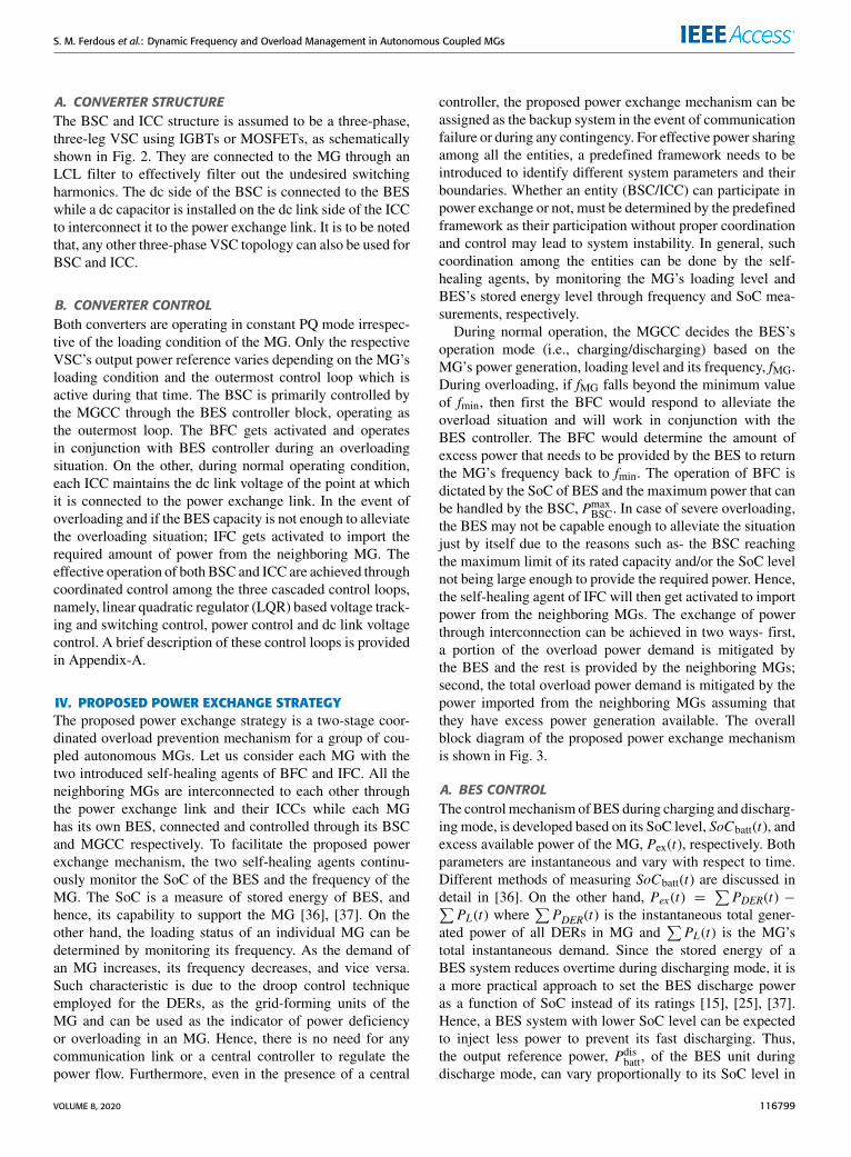
F. MULTIPLE MGsThis study case demonstrates the power sharing amongstmultiple MGs to alleviate the overloading situation. Let usconsider the network of Fig. 10f and assume a scenario inwhich three MGs are coupled through the power exchangelink. The results of this study are provided in Fig. 16. Let usassume that all the three MGs are operating in their nominalcondition. BES-1, 2 and 3 are supplying respectively a powerof 0.1, 0.05 and 0.1 pu to their respective MGs, as can beseen from Fig. 16c. At t = 0.3 s, MG-2 is overloaded by22%, and as a result, the frequency drops below 49.8 Hz. Thisactivates the controller of BFC-2 at t = 0.6 s. Based on theSoC level of BES-2, the maximum power that be supplied,PmaxBSC, is evaluated as 0.15 pu. As soon as the output power
of BSC-2 reaches 0.15 pu, the controller of BFC-2 freezes,as can be seen from Fig. 16c. As the frequency of MG-2 is
VOLUME 8, 2020 116807
S. M. Ferdous et al.: Dynamic Frequency and Overload Management in Autonomous Coupled MGs
FIGURE 16. Simulation results for multiple MGs.
still below 49.8 Hz, IFC-2 will get activated at t = 1.2 s,and hence, the mode of operation of ICC-2 changes fromthe dc link voltage control to constant PQ mode. At t =1.5 s, both MG-1and MG-3 start supplying power to MG-2to alleviate the overloading situation with a power ratio ofPg1:Pg3 = 2 : 1, as determined by their droop coefficients(see Appendix-A). It is expected that the power shared byMG-1 should be greater than MG-3 as the loading of MG-1is less than MG-3 (See Fig. 16a). The total overload powerdemand for MG-2 is 0.1245 pu where the supplied powerfrom MG-1 and MG-3 are respectively 0.091 and 0.0458 pu,as can be seen from Fig. 16d. To obtain the desired powersharing, the ratio of droop coefficients of MG-3 and MG-1are set as qMG−3 : qMG−1 = 2 : 1 based on the ratio of theirdroop coefficients. The excess power supplied by MG-1 andMG-3, in addition to overload power ofMG-2, is to overcome
the line and converter losses. At t = 4 s, the overloading ofMG-2 is removed and it goes back to its normal operation,and as such, bothMG-1 andMG-3 ceaseto supply power to it.The corresponding control activation signals for BFC-2 andIFC-2 are shown in Fig. 16f.
VI. CONCLUSIONA two-stage coordinated overloadmanagement technique hasbeen proposed for systems of coupled autonomous MGs viapower electronics-based converters. The proposal is based onusing two self-healing agents, operating cooperatively underthe predefined framework and constraints. With the proposedtechnique, any number of MGs can be coupled, and exchangepower based on the desired (set) ratios as far as at least oneMGhas sufficient power to supply the power deficiency in theother MGs. The proposal has been validated under variousloading conditions and SoC of BES. Through simulationstudies, it has been illustrated that the proposed strategy coor-dinates the power exchange between the overloaded MG andits neighboring MGs as well as its local BES satisfactorily.The key benefit of the proposal is that no data communicationis needed between the MGs and because of their couplingthrough power electronic converters, the MGs will maintaintheir autonomy evenwhen exchanging power with each other.
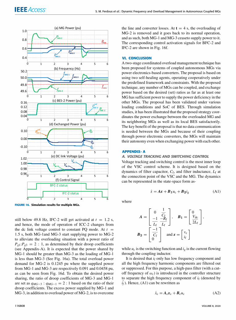
APPENDIX- AA. VOLTAGE TRACKING AND SWITCHING CONTROLVoltage tracking and switching control is the most inner loopof the VSC control scheme. It is designed based on thedynamics of filter capacitor, Cf, and filter inductance, Lf atthe connection point of the VSC and the MG. The dynamicscan be represented in the state-space form as-
x = Ax+ B1uc + B2ig (A1)
where
A =
01Cf
−1Lf
−RfLf
, B1 =
0Vdc2Lf
,B2 =
−1Cf0
and x =[vcif
]
while uc is the switching function and ig is the current flowingthrough the coupling inductor.
It is desired that if only has low frequency component andall the high frequency harmonic components are filtered outor suppressed. For this purpose, a high-pass filter (with a cut-off frequency of ωc) is introduced in the controller structureto separate the high frequency component of if (denoted byif ). Hence, (A1) can be rewritten as
xc = Acxc + Bcuc (A2)
116808 VOLUME 8, 2020

S. M. Ferdous et al.: Dynamic Frequency and Overload Management in Autonomous Coupled MGs
where
Ac =
0
1Cf
0
−1Lf
−RfLf
0
−1Lf
−RfLf
−ωc
,
Bc =
0
Vdc2LfVdc2Lf
and xc =
vcifif
.A suitable full state-feedback control law along with a refer-ence input (which is the filter capacitor voltage reference, vrefcin this case) can be introduced in the form of
uc = k1(vrefc − vc
)− k2if − k3 if = −Kxc + k1vrefc (A3)
where K =[k1 k2 k2
]is the state-feedback gain matrix in
which k1, k2 and k3 can be determined optimally by minimiz-ing a suitable cost function using linear quadratic regulator.Through this optimization process, a robust controller can bedesigned with a bandwidth large enough to accurately trackthe low frequency sinusoidal signal (i.e., 50 Hz) with almostzero steady-state error. Therefore, (A2) can be rewritten as
xc = Aclxc + Bclvrefc (A4)
where Acl = Ac − BcK and Bcl = k1Bc. This controlleroffers infinite gain and a minimum phase margin of 60
◦
, andhence, robustly stable. The control action can be realizedthrough a hysteresis function with a sufficiently small band(e.g., h = 10−4) [29], [33].
B. POWER CONTROLPower control is the first of two outer loops employed in cas-caded control structure and regulates the active and reactivepower flow through theVSC. This stage of control determinesthe correct reference voltage across Cf as can be seen fromFig. 2. The conventional direct-quadrature (dq) axis powercontrol approach can be then adopted for implanting thecontroller. The advantage of such type of controller is thatthe active and reactive power are completely decoupled andthus, can be controlled independently. Two PI controllerscan be used to produce the desired d and q axis referencevoltages, vrefd and vrefq . The dynamics of coupling inductance,Lg and resistance, Rg is considered while tuning the two PIcontrollers using pole-zero cancellation method [40]. The dand q axis reference voltages are then converted into three-phase ac reference voltage, vrefc_abc, for the filter capacitorusing the measured grid angle, θg, obtained through a phase-locked loop system. The transfer function of PI controller canbe given by
CPI(s) =Kc(sTc + 1)
sTc(A5)
where Tc = Lg/Rg; and Kc = 2π fBWLg. The parameter, fBWis the closed-loop bandwidth of the controller which needsto be at least 10 times smaller than the bandwidth of theinner voltage tracking control loop. Thus, it can be assumedas a unity gain block while tuning the PI controllers of thecurrent controller. The closed-loop transfer function of thecurrent/power controller is then given by
Gc(s) =irefdq
idq=
1sτ c + 1
=PrefPs
(A6)
where, τc = Lg/Kc is the time constant of the current con-troller, Ps is the active power output of the converter and Prefis the reference power. Note that, Pref is generated throughany one of the four different blocks of the outermost controlloop, depending on the operating mode of the converter, asshown in Fig. 2.
C. DC LINK VOLTAGE CONTROLThe dc link voltage controller is the outermost loop of thecontrol scheme. The dynamics of the dc link capacitor volt-age, Vdc,with respect to converter output power, Ps, can bedescribed as [40], [41]-
Gdc (s) =V 2dc
Ps=
(−2Cdc
)(sτ dc + 1)
s(A7)
where τdc = 2(Lf + Lg)Pso/3V 2d . The transfer function of
Gdc (s) is a linearized small signal model where Pso is thesteady state power output of the converter and Vd is the steadystate d-axis voltage at the PCC of MG. DC link referencevoltage can be obtained as -(
V refdc
)MG−i
= Vnom − qMG−iPMG−i (A8)
where q and P respectively denote the dc link droop coeffi-cient and the active power injected by the ICC and Vnom is thenominal voltage of the dc link (e.g., 1 pu). It is to be noted that,an active power absorption will be considered as negative.If (A8) is used to set the power desired sharing among thecoupled MGs, the ratio of the power injected by MG i and jwill be the reciprocal of the ratio of their droop coefficients,i.e.,
qMG−iPMG−i = qMG−jPMG−j (A9)
For the purpose of designing the dc link controller thatprovides the minimum gain and phase margin to obtain asatisfactory performance, a generic type-2 controller can bechosen and designed to regulate the dc link voltage. Thetransfer function of such type of controller can be written as
Cdc (s) =Kdc(s+ ωz)s(s+ ωp)
(A10)
The controller of Cdc (s) can be designed using the K -factormethod as described in [39]. Note that, the reference power ofPref in (A6) isPdc in this case as can be seen from Fig. 17. Theoverall open-loop dc link voltage system dynamics is given by
GOL (s) = Gc(s)Gdc (s) =(−2Cdc
)(sτ dc + 1)s(sτ c + 1)
(A11)
VOLUME 8, 2020 116809

S. M. Ferdous et al.: Dynamic Frequency and Overload Management in Autonomous Coupled MGs
TABLE 1. Technical data of the network under consideration.
FIGURE 17. Schematic of DC link voltage control system.
Hence, GOL (s) is the open-loop transfer function that isneeded to be considered for applying K -factor method asdiscussed in [42]. The design method is discussed in detailin [40]–[42] and is not repeated here.
APPENDIX-BThe technical data used in simulation for the system of cou-pled MGs are given in Table 1.
ACKNOWLEDGMENTThe PSIM R© software license and the technical support wasprovided by the Murdoch University. The authors acknowl-edge the support and expertise received from the RenewableEnergy Laboratory, Prince Sultan University, Saudi Arabia.
REFERENCES[1] R. H. Lasseter, ‘‘MicroGrids,’’ in Proc. IEEE Power Eng. Soc. Winter
Meeting, vol. 1, Jan. 2002, pp. 305–308.[2] H. Zou, S. Mao, Y. Wang, F. Zhang, X. Chen, and L. Cheng, ‘‘A survey
of energy management in interconnected multi-microgrids,’’ IEEE Access,vol. 7, pp. 72158–72169, 2019.
[3] Y. Yoldaş, A. Önen, S. M. Muyeen, A. V. Vasilakos, and İ. Alan, ‘‘Enhanc-ing smart grid with microgrids: Challenges and opportunities,’’ Renew.Sustain. Energy Rev., vol. 72, pp. 205–214, May 2017.
[4] L. Ali and F. Shahnia, ‘‘Determination of an economically-suitableand sustainable standalone power system for an off-grid town inWestern Australia,’’ Renew. Energy, vol. 106, pp. 243–254, Jun. 2017.
[5] S. A. Arefifar and Y. A.-R.-I. Mohamed, ‘‘DG mix, reactive sourcesand energy storage units for optimizing microgrid reliability and supplysecurity,’’ IEEE Trans. Smart Grid, vol. 5, no. 4, pp. 1835–1844, Jul. 2014.
[6] J. G. de Matos, F. S. F. e Silva, and L. A. de S. Ribeiro, ‘‘Power control inAC isolated microgrids with renewable energy sources and energy storagesystems,’’ IEEE Trans. Ind. Electron., vol. 62, no. 6, pp. 3490–3498,Jun. 2015.
[7] Z. Wang, B. Chen, J. Wang, M. M. Begovic, and C. Chen, ‘‘Coordinatedenergy management of networked microgrids in distribution systems,’’IEEE Trans. Smart Grid, vol. 6, no. 1, pp. 45–53, Jan. 2015.
[8] L. Sigrist, I. Egido, and L. Rouco, ‘‘Principles of a centralized UFLSscheme for small isolated power systems,’’ IEEE Trans. Power Syst.,vol. 28, no. 2, pp. 1610–1617, Dec. 2013.
[9] Y.-Y. Hong, M.-C. Hsiao, Y.-R. Chang, Y.-D. Lee, and H.-C. Huang,‘‘Multiscenario underfrequency load shedding in a microgrid consistingof intermittent renewables,’’ IEEE Trans. Power Del., vol. 28, no. 3,pp. 1610–1617, Jul. 2013.
[10] R. Paleta, A. Pina, and C. A. Santos Silva, ‘‘Polygeneration energycontainer: Designing and testing energy services for remote developingcommunities,’’ IEEE Trans. Sustain. Energy, vol. 5, no. 4, pp. 1348–1355,Oct. 2014.
[11] S. A. Arefifar, Y. A.-R.-I. Mohamed, and T. H. M. EL-Fouly, ‘‘Optimummicrogrid design for enhancing reliability and supply-security,’’ IEEETrans. Smart Grid, vol. 4, no. 3, pp. 1567–1575, Sep. 2013.
[12] T. Hosseinimehr, F. Shahnia, and A. Ghosh, ‘‘Power sharing control ofbatteries within autonomous microgrids based on their state of charge,’’in Proc. Australas. Universities Power Eng. Conf. (AUPEC), Wollongong,NSW, Australia, Sep. 2015, pp. 1–6.
[13] W. Pei, Z. Qi, W. Deng, and Z. Shen, ‘‘Operation of battery energy storagesystem using extensional information model based on IEC 61850 formicro-grids,’’ IET Gener., Transmiss. Distrib., vol. 10, no. 4, pp. 849–861,Mar. 2016.
[14] M. Goyal, A. Ghosh, and F. Shahnia, ‘‘Overload prevention in anautonomous microgrid using battery storage units,’’ in Proc. IEEE PESGen. Meeting|Conf. Exposit., Jul. 2014, pp. 1–5.
[15] M. F. Zia, E. Elbouchikhi, and M. Benbouzid, ‘‘Microgrids energy man-agement systems: A critical review on methods, solutions, and prospects,’’Appl. Energy, vol. 222, pp. 1033–1055, Jul. 2018.
[16] H. Dagdougui, A. Ouammi, and R. Sacile, ‘‘Optimal control of a networkof power microgrids using the Pontryagin’s minimum principle,’’ IEEETrans. Control Syst. Technol., vol. 22, no. 5, pp. 1942–1948, Sep. 2014.
[17] R. H. Lasseter, ‘‘Smart distribution: Coupled microgrids,’’ Proc. IEEE,vol. 99, no. 6, pp. 1074–1082, Jun. 2011.
[18] L. Che, X. Zhang, M. Shahidehpour, A. Alabdulwahab, and A. Abusorrah,‘‘Optimal interconnection planning of community microgrids withrenewable energy sources,’’ IEEE Trans. Smart Grid, vol. 8, no. 3,pp. 1054–1063, May 2017, doi: 10.1109/TSG.2015.2456834.
[19] F. Shahnia, S. Bourbour, and A. Ghosh, ‘‘Coupling neighboringmicrogrids for overload management based on dynamic multicriteriadecision-making,’’ IEEE Trans. Smart Grid, vol. 8, no. 2, pp. 969–983,Mar. 2017.
[20] E. Bullich-Massagué, F. Díaz-González, M. Aragüés-Peñalba,F. Girbau-Llistuella, P. Olivella-Rosell, and A. Sumper, ‘‘Microgridclustering architectures,’’ Appl. Energy, vol. 212, pp. 340–361, Feb. 2018.
[21] S. M. Ferdous, F. Shahnia, and G. Shafiullah, ‘‘Power sharing and controlstrategy for microgrid clusters,’’ in Proc. 9th Int. Conf. Power Energy Syst.(ICPES), Perth, WA, Australia, Dec. 2019, pp. 1–5.
[22] S. M. Ferdous, F. Shahnia, and G. Shafiullah, ‘‘Provisional energy trans-action management amongst neighboring microgrids through a DC powerexchange link,’’ in Proc. 9th Int. Conf. Power Energy Syst. (ICPES), Perth,WA, Australia, Dec. 2019, pp. 1–6.
[23] M. Goyal and A. Ghosh, ‘‘Microgrids interconnection to support mutu-ally during any contingency,’’ Sustain. Energy, Grids Netw., vol. 6,pp. 100–108, Jun. 2016.
[24] S. M. Ferdous, F. Shahnia, and G. Shafiullah, ‘‘Realizing a system ofcoupled microgrids using a single-phase AC power exchange link,’’ inProc. 9th Int. Conf. Power Energy Syst. (ICPES), Perth, WA, Australia,Dec. 2019, pp. 1–6.
[25] Z.Wang and J. Wang, ‘‘Self-healing resilient distribution systems based onsectionalization into microgrids,’’ IEEE Trans. Power Syst., vol. 30, no. 6,pp. 3139–3149, Nov. 2015.
[26] R. Minciardi and R. Sacile, ‘‘Optimal control in a cooperative network ofsmart power grids,’’ IEEE Syst. J., vol. 6, no. 1, pp. 126–133, Mar. 2012.
[27] Y. Zhang, L. Xie, and Q. Ding, ‘‘Interactive control ofcoupled microgrids for guaranteed system-wide small signalstability,’’ IEEE Trans. Smart Grid, vol. 7, no. 2, pp. 1088–1096,Mar. 2016.
[28] I. U. Nutkani, P. C. Loh, P. Wang, T. K. Jet, and F. Blaabjerg, ‘‘Inter-tied AC–AC microgrids with autonomous power import and export,’’ Int.J. Electr. Power Energy Syst., vol. 65, pp. 385–393, Feb. 2015.
116810 VOLUME 8, 2020

S. M. Ferdous et al.: Dynamic Frequency and Overload Management in Autonomous Coupled MGs
[29] E. Pashajavid, F. Shahnia, andA. Ghosh, ‘‘Provisional internal and externalpower exchange to support remote sustainable microgrids in the courseof power deficiency,’’ IET Gener., Transmiss. Distrib., vol. 11, no. 1,pp. 246–260, Jan. 2017.
[30] P. C. Loh, D. Li, Y. K. Chai, and F. Blaabjerg, ‘‘Autonomous operation ofhybridmicrogridwithAC andDC subgrids,’’ IEEE Trans. Power Electron.,vol. 28, no. 5, pp. 2214–2223, May 2013.
[31] B. John, A. Ghosh,M.Goyal, and F. Zare, ‘‘ADC power exchange highwaybased power flow management for interconnected microgrid clusters,’’IEEE Syst. J., vol. 13, no. 3, pp. 3347–3357, Sep. 2019.
[32] I. U. Nutkani, P. C. Loh, and F. Blaabjerg, ‘‘Distributed operation ofinterlinkedACmicrogrids with dynamic active and reactive power tuning,’’IEEE Trans. Ind. Appl., vol. 49, no. 5, pp. 2188–2196, Sep. 2013.
[33] F. Shahnia, A. Ghosh, S. Rajakaruna, and R. P. S. Chandrasena, ‘‘Primarycontrol level of parallel distributed energy resources converters in systemof multiple interconnected autonomous microgrids within self-healingnetworks,’’ IET Gener., Transmiss. Distrib., vol. 8, no. 2, pp. 203–222,Feb. 2014.
[34] M. Yazdanian and A. Mehrizi-Sani, ‘‘Distributed control techniques inmicrogrids,’’ IEEE Trans. Smart Grid, vol. 5, no. 6, pp. 2901–2909,Nov. 2014.
[35] F. Shahnia and A. Arefi, ‘‘Eigenanalysis-based small signal stability of thesystem of coupled sustainable microgrids,’’ Int. J. Electr. Power EnergySyst., vol. 91, pp. 42–60, Oct. 2017.
[36] W.-Y. Chang, ‘‘The state of charge estimating methods for battery:A review,’’ ISRN Appl. Math., vol. 2013, pp. 1–7, Jul. 2013.
[37] T. Hosseinimehr, A. Ghosh, and F. Shahnia, ‘‘Cooperative control ofbattery energy storage systems in microgrids,’’ Int. J. Electr. Power EnergySyst., vol. 87, pp. 109–120, May 2017.
[38] S. M. Ferdous, M. Asaduzzaman Shoeb, G. Shafiullah, and M. A. MoinOninda, ‘‘Parallel resonant converter for battery charging application,’’ inProc. 9th Int. Conf. Power Energy Syst. (ICPES), Dec. 2019, pp. 1–6.
[39] S. M. Ferdous, M. A. M. Oninda, G. Sarowar, K. K. Islam, andM. A. Hoque, ‘‘Non-isolated single stage PFC based LED driver with THDminimization using Cúk converter,’’ in Proc. 9th Int. Conf. Electr. Comput.Eng. (ICECE), Dec. 2016, pp. 471–474.
[40] A. Yazdani and R. Iravani, Voltage-Sourced Converters in Power Systems:Modeling, Control, and Applications. Hoboken, NJ, USA: Wiley, 2010.
[41] A. Yazdani and R. Iravani, ‘‘An accurate model for the DC-side voltagecontrol of the neutral point diode clamped converter,’’ IEEE Trans. PowerDel., vol. 21, no. 1, pp. 185–193, Jan. 2006.
[42] S. M. Ferdous, G. M. Shafiullah, M. A. M. Oninda, M. A. Shoeb, andT. Jamal, ‘‘Close loop compensation technique for high performanceMPPT using ripple correlation control,’’ in Proc. Australas. Univ. PowerEng. Conf. (AUPEC), Melbourne, VIC, Australia, Nov. 2017, pp. 1–6.
S. M. FERDOUS (Student Member, IEEE)received the bachelor’s and Master of Sciencedegrees in electrical and electronic engineeringfrom the Islamic University of Technology (IUT),Bangladesh, in 2009 and 2012, respectively, andthe Erasmus Mundus Joint master’s degree in sus-tainable transportation and electrical power system(STEPS) coordinated by the University of Notting-ham, U.K.; the University of Oviedo, Spain; theSapienza University of Rome, Italy; and Politec-
nico de Coimbra, Portugal, in 2015. He is currently pursuing the Ph.D. degreewith Murdoch University, Australia. He has an active teaching experience ofmore than six years andwasworking as anAssistant Professor with theGreenUniversity, Bangladesh. He has authored more than 45 refereed publishedbook chapters, journal articles, and conference papers. His research interestsinclude application of power electronics in microgrids, smart distributionnetworks, renewable power generation, and electric drives.
G. M. SHAFIULLAH (Senior Member, IEEE)received the Bachelor of Engineering degree inelectrical and electronics from the ChittagongUniversity of Engineering Technology (CUET),Bangladesh, and the Master of Engineering andPh.D. degrees from Central Queensland Univer-sity, Australia, in 2009 and 2013, respectively. Heis currently a Senior Lecturer in electrical engi-neering with Murdoch University. He is the authorof more than 120 refereed published book chap-
ters, journal articles, and conference papers. His research interests includepower systems, smart grid, renewable energy, and its enabling technologies.
FARHAD SHAHNIA (Senior Member, IEEE)received the Ph.D. degree in electrical engineeringfrom the Queensland University of Technology,Brisbane, Australia, in 2012.
He is currently an Associate Professor withMurdoch University, Perth, Australia. He has pub-lished over 100 articles in the area of applica-tion and control of power electronic converters indistribution systems and microgrids. He currentlyholds the position of the IEEE Western AustraliaSection Chair.
RAJVIKRAM MADURAI ELAVARASAN rece-ived the B.E. degree in electrical and electronicsengineering from Anna University, Chennai, andthe M.E. degree in power system engineering fromthe Thiagarajar College of Engineering, Madurai.He has worked as an Associate Technical Opera-tions with the IBM Global Technology ServicesDivision. He worked as an Assistant Professorwith the Department of Electrical and ElectronicsEngineering, Sri Venkateswara college of Engi-
neering, Sriperumbudur, India. His research interests include renewableenergy and smart grid, wind energy research, power system operation andcontrol, and artificial intelligence control techniques. He has publishedpapers in international journals, and international and national conferences.He was a Gold Medalist during his master’s degree.
UMASHANKAR SUBRAMANIAM (SeniorMember, IEEE) has over 15 years of teaching,research, and industrial research and developmentexperience. He was an Associate Professor andthe Head of VIT Vellore and a Senior Researchand Development and a Senior Application Engi-neer in the field of power electronics, renewableenergy, and electrical drives. He is currently anAssociate Professor with the Renewable EnergyLaboratory, College of Engineering, Prince Sultan
University, Saudi Arabia. He has published more than 250 research articlesin national and international journals and conferences. He has authored 12books/chapters and 12 technical articles on power electronics applicationsin renewable energy, and allied areas. He received the Danfoss InnovatorAward-Mentor, from 2014 to 2015 and 2017 to 2018, and the ResearchAwardfromVITUniversity, from 2013 to 2018. He also received the INAE SummerResearch Fellowship for the year 2014. He has taken charge as the Vice Chairof the IEEE Madras Section.
VOLUME 8, 2020 116811