Orthogonal Frequency Division Multiplexing
17
Page | P.E.S Institute of Technology Bengaluru-85 2014 ORTHOGONAL FREQUENCY DIVISION MULTIPLEXING Kishan P B Under-Graduate student in Dept. of Electronics and Communication Engineering PESIT, Bangalore – 560 085
Transcript of Orthogonal Frequency Division Multiplexing
Page | DEPT OF ECE P . E . S I n s t i t u t e o f T e c h n o l o g y
B e n g a l u r u - 8 5
2014
ORTHOGONAL
FREQUENCY DIVISION
MULTIPLEXING
Kishan P B
Under-Graduate student in
Dept. of Electronics and Communication Engineering
PESIT, Bangalore – 560 085
Page | i DEPT OF ECE
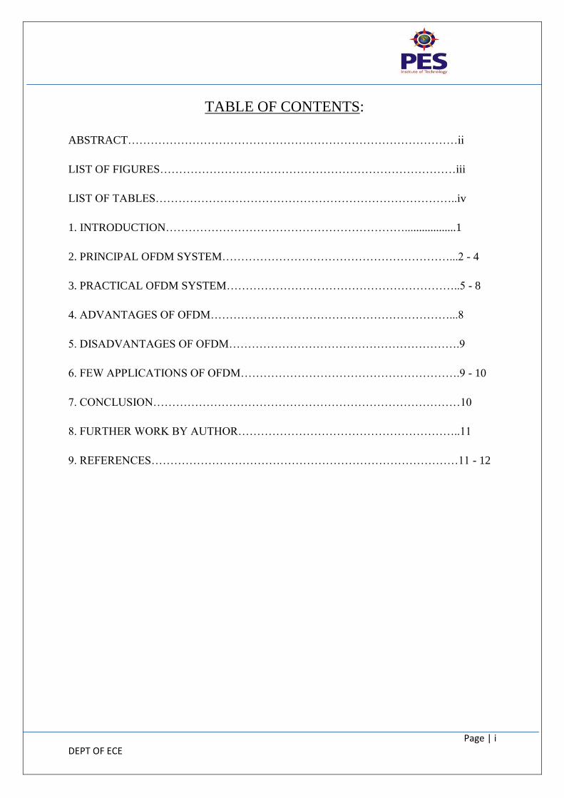
TABLE OF CONTENTS:
ABSTRACT……………………………………………………………………………ii
LIST OF FIGURES……………………………………………………………………iii
LIST OF TABLES……………………………………………………………………..iv
1. INTRODUCTION………………………………………………………..................1
2. PRINCIPAL OFDM SYSTEM……………………………………………………...2 - 4
3. PRACTICAL OFDM SYSTEM……………………………………………………..5 - 8
4. ADVANTAGES OF OFDM………………………………………………………...8
5. DISADVANTAGES OF OFDM…………………………………………………….9
6. FEW APPLICATIONS OF OFDM………………………………………………….9 - 10
7. CONCLUSION………………………………………………………………………10
8. FURTHER WORK BY AUTHOR…………………………………………………..11
9. REFERENCES………………………………………………………………………11 - 12
Page | ii DEPT OF ECE
ABSTRACT:
This report is an introduction to orthogonal frequency division multiplexing (OFDM). OFDM
is becoming the chosen modulation technique for wireless communications. OFDM can
provide large data rates with sufficient robustness to radio channel impairments. Many
research centers in the world have specialized teams working in the optimization of OFDM
for countless applications.
Page | iii DEPT OF ECE
LIST OF FIGURES:
Fig 2.1 Principal OFDM modulation block diagram 2
Fig 2.2 Serial to parallel conversion 3
Fig 2.3 Illustration of 3 subcarrier waveform 3
Fig 2.4 OFDM receiver 4
Fig 3.1 Practical OFDM Transmitter and Receiver system 5
Fig 3.2 Frequency response of raised-cosine filter with various roll-off factors 7
Page | iv DEPT OF ECE
LIST OF TABLES:
Table 1 Digital Audio Broadcasting (DAB) 9
Table 2 Wireless LANs 10
Page | 1 DEPT OF ECE
1. INTRODUCTION
Recently, a worldwide convergence has occurred for the use of Orthogonal Frequency
Division Multiplexing (OFDM) as an emerging technology for high data rates. In particular,
many wireless standards (Wi-Max, IEEE802.11a, LTE, DVB) have adopted the OFDM
technology as a mean to increase dramatically future wireless communications. OFDM is a
particular form of Multi-carrier transmission and is suited for frequency selective channels
and high data rates. This technique transforms a frequency-selective wide-band channel into a
group of non-selective narrowband channels, which makes it robust against large delay
spreads by preserving orthogonality in the frequency domain. Moreover, the ingenious
introduction of cyclic redundancy at the transmitter reduces the complexity to only FFT
processing and one tap scalar equalization at the receiver.
Page | 2 DEPT OF ECE
2. PRINCIPAL OFDM SYSTEM
I. Overview
Since the original OFDM model was proposed in the 1960s [1], the core structure of
OFDM has hardly changed. The key idea of OFDM is that a single user would make use of
all orthogonal subcarrier in divided frequency bands. Therefore, the data rate can be
increased significantly. Since the bandwidth is divided into several narrower subchannels,
each subchannel requires a longer symbol period. Therefore OFDM systems can overcome
the intersymbol interference (ISI) problem. As a consequence, the OFDM system can result
in lower bit error rates but higher data rates than conventional communication systems.
Nevertheless, OFDM technique has certain drawbacks [2], such as the increased system
complexity, which is associated with the generation of orthogonal subcarriers, and other new
problems, which might not occur in other modulation schemes. Such new problems include
the peak to average power ratio (PAPR) and inter-carrier interference (ICI).
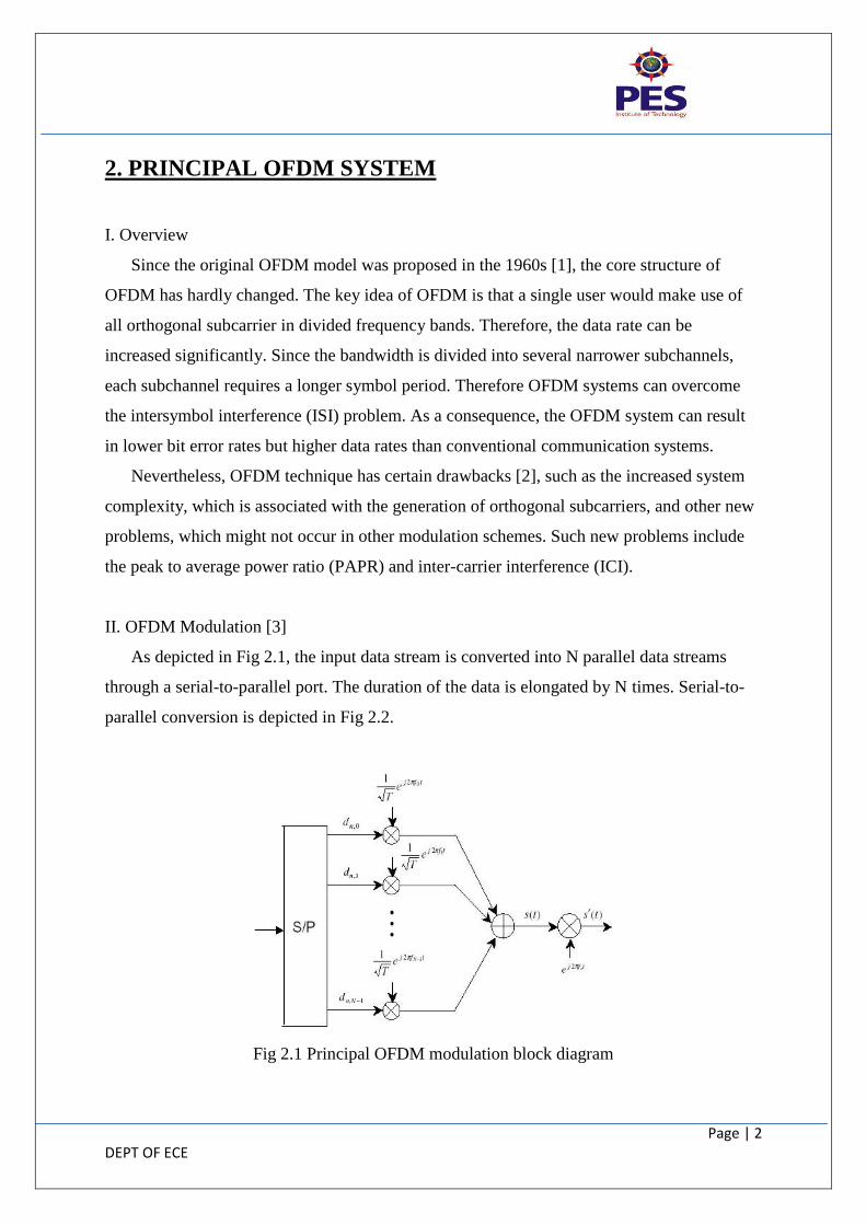
II. OFDM Modulation [3]
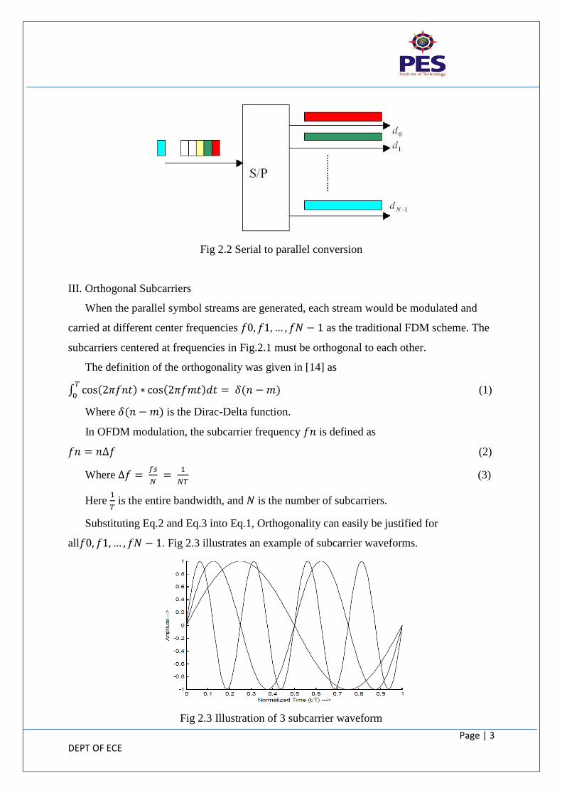
As depicted in Fig 2.1, the input data stream is converted into N parallel data streams
through a serial-to-parallel port. The duration of the data is elongated by N times. Serial-to-
parallel conversion is depicted in Fig 2.2.
Fig 2.1 Principal OFDM modulation block diagram
Page | 3 DEPT OF ECE
Fig 2.2 Serial to parallel conversion
III. Orthogonal Subcarriers
When the parallel symbol streams are generated, each stream would be modulated and
carried at different center frequencies as the traditional FDM scheme. The
subcarriers centered at frequencies in Fig.2.1 must be orthogonal to each other.
The definition of the orthogonality was given in [14] as
(1)
Where is the Dirac-Delta function.
In OFDM modulation, the subcarrier frequency is defined as
(2)
Where
(3)
Here
is the entire bandwidth, and is the number of subcarriers.
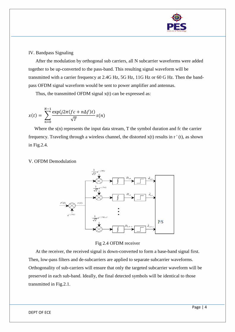
Substituting Eq.2 and Eq.3 into Eq.1, Orthogonality can easily be justified for
all . Fig 2.3 illustrates an example of subcarrier waveforms.
Fig 2.3 Illustration of 3 subcarrier waveform
Page | 4 DEPT OF ECE
IV. Bandpass Signaling
After the modulation by orthogonal sub carriers, all N subcarrier waveforms were added
together to be up-converted to the pass-band. This resulting signal waveform will be
transmitted with a carrier frequency at 2.4G Hz, 5G Hz, 11G Hz or 60 G Hz. Then the band-
pass OFDM signal waveform would be sent to power amplifier and antennas.
Thus, the transmitted OFDM signal x(t) can be expressed as:
Where the s(n) represents the input data stream, T the symbol duration and fc the carrier
frequency. Traveling through a wireless channel, the distorted x(t) results in r ' (t), as shown
in Fig.2.4.
V. OFDM Demodulation
Fig 2.4 OFDM receiver
At the receiver, the received signal is down-converted to form a base-band signal first.
Then, low-pass filters and de-subcarriers are applied to separate subcarrier waveforms.
Orthogonality of sub-carriers will ensure that only the targeted subcarrier waveform will be
preserved in each sub-band. Ideally, the final detected symbols will be identical to those
transmitted in Fig.2.1.
Page | 5 DEPT OF ECE
3. PRACTICAL OFDM SYSTEM
I. Overview
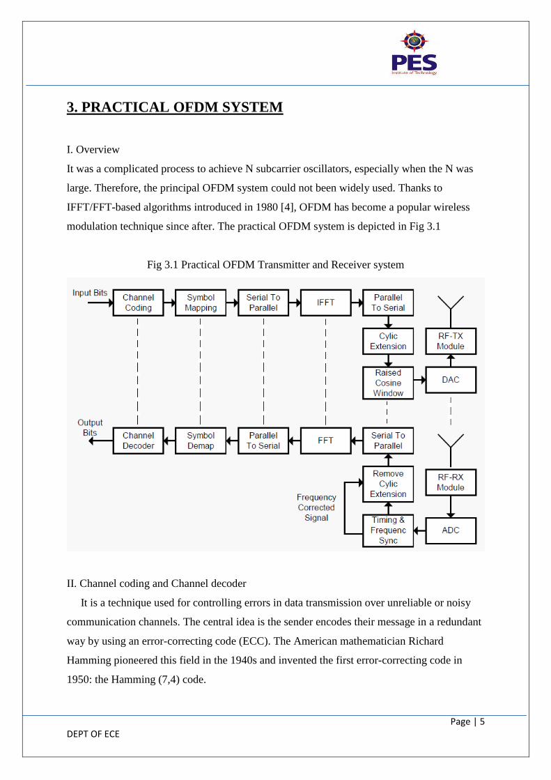
It was a complicated process to achieve N subcarrier oscillators, especially when the N was
large. Therefore, the principal OFDM system could not been widely used. Thanks to
IFFT/FFT-based algorithms introduced in 1980 [4], OFDM has become a popular wireless
modulation technique since after. The practical OFDM system is depicted in Fig 3.1
Fig 3.1 Practical OFDM Transmitter and Receiver system
II. Channel coding and Channel decoder
It is a technique used for controlling errors in data transmission over unreliable or noisy
communication channels. The central idea is the sender encodes their message in a redundant
way by using an error-correcting code (ECC). The American mathematician Richard
Hamming pioneered this field in the 1940s and invented the first error-correcting code in
1950: the Hamming (7,4) code.
Page | 6 DEPT OF ECE
Main two categories of Channel coding -
Block codes work on fixed-size blocks (packets) of bits or symbols of predetermined
size. Practical block codes can generally be decoded in polynomial time to their block
length.
Convolutional codes work on bit or symbol streams of arbitrary length. They are most
often decoded with the Viterbi algorithm, though other algorithms are sometimes
used. Viterbi decoding allows asymptotically optimal decoding efficiency with
increasing constraint length of the convolutional code, but at the expense of
exponentially increasing complexity. A convolutional code can be turned into a block
code, if desired, by "tail-biting".
III. Symbol Map and De-map
The process of mapping the information bits onto the signal constellation plays a fundamental
role in determining the properties of the modulation.
An OFDM signal consists of a sum of sub-carriers, each of which contains -
M-ary phase shift keyed (PSK) signal.
Quadrature amplitude modulated (QAM) signal.
IV. FFT and IFFT
An FFT computes the DFT and produces exactly the same result as evaluating the DFT
definition directly; the only difference is that an FFT is much faster.
Let x0, ...., xN-1 be complex numbers. The DFT is defined by the formula
Evaluating this definition directly requires O(N
2) operations.
The well-known radix-2 Cooley–Tukey algorithm for FFT and IFFT [5], for N a power of 2,
can compute the same result with only O( ) complex multiplications (again,
ignoring simplifications of multiplications by 1 and similar) and O( ) complex
additions.
Page | 7 DEPT OF ECE
V. Cyclic extension (prefix) and Remove cyclic extension (prefix).
It refers to the prefixing of a symbol with a repetition of the end. Although the receiver is
typically configured to discard the cyclic prefix samples, the cyclic prefix serves two
purposes [6].
As a guard interval, it eliminates the Inter-Symbol Interference (ISI) from the
previous symbol.
As a repetition of the end of the symbol, it allows the linear convolution of a
frequency-selective multipath channel to be modelled as circular convolution, which
in turn may be transformed to the frequency domain using a discrete Fourier
transform. This approach allows for simple frequency-domain processing, such as
channel estimation and equalization.
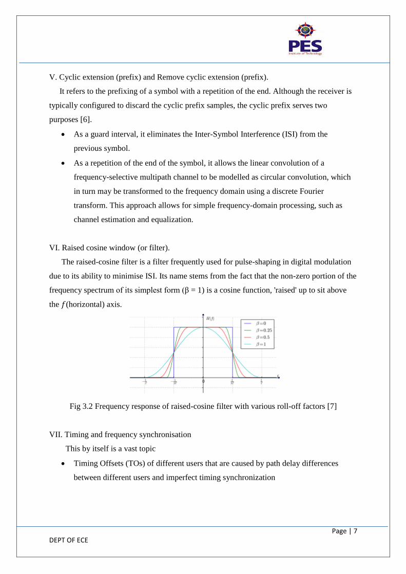
VI. Raised cosine window (or filter).
The raised-cosine filter is a filter frequently used for pulse-shaping in digital modulation
due to its ability to minimise ISI. Its name stems from the fact that the non-zero portion of the
frequency spectrum of its simplest form (β = 1) is a cosine function, 'raised' up to sit above
the (horizontal) axis.
Fig 3.2 Frequency response of raised-cosine filter with various roll-off factors [7]
VII. Timing and frequency synchronisation
This by itself is a vast topic
Timing Offsets (TOs) of different users that are caused by path delay differences
between different users and imperfect timing synchronization

Page | 8 DEPT OF ECE
Carrier Frequency Offsets (CFOs) of different users that are induced by Doppler
effects and/or poor oscillator alignments can destroy orthogonality among subcarriers
at the receiver and cause multiuser interference (MUI)
Main aim of this block in the receiver side is to synchronise the above two offsets [8].
VIII. ADC and DAC
Analog to Digital Converter – [9]
Digital to Analog Converter – [10]
IX. RF-RX and TX module
An RF module (radio frequency module) is a (usually) small electronic circuit used to
transmit and/or receive radio signals on one of a number of carrier frequencies. RF modules
are widely used in electronic design owing to the difficulty of designing radio circuitry. Good
electronic radio design is notoriously complex because of the sensitivity of radio circuits and
the accuracy of components and layouts required achieving operation on a specific frequency.
Design engineers will design a circuit for an application which requires radio communication
and then "drop in" a radio module rather than attempt a discrete design, saving time and
money on development.
4. ADVANTAGES OF OFDM [11]
Immunity to delay spread
1. Symbol duration >> channel delay spread
2. Guard interval
Resistance to frequency selective fading
Each subchannel is almost flat fading
Simple equalization
Each subchannel is almost flat fading, so it only needs a one-tap equalizer to
overcome channel effect.
Efficient bandwidth usage
The subchannel is kept orthogonality with overlap.
Page | 9 DEPT OF ECE
5. DISADVANTAGES OF OFDM [11]
The problem of synchronization
1. Symbol synchronization
Timing errors
Carrier phase noise
2. Frequency synchronization
Sampling frequency synchronization
Carrier frequency synchronization
Need FFT units at transmitter, receiver
The complexity of computations
6. FEW APPLICATIONS OF OFDM
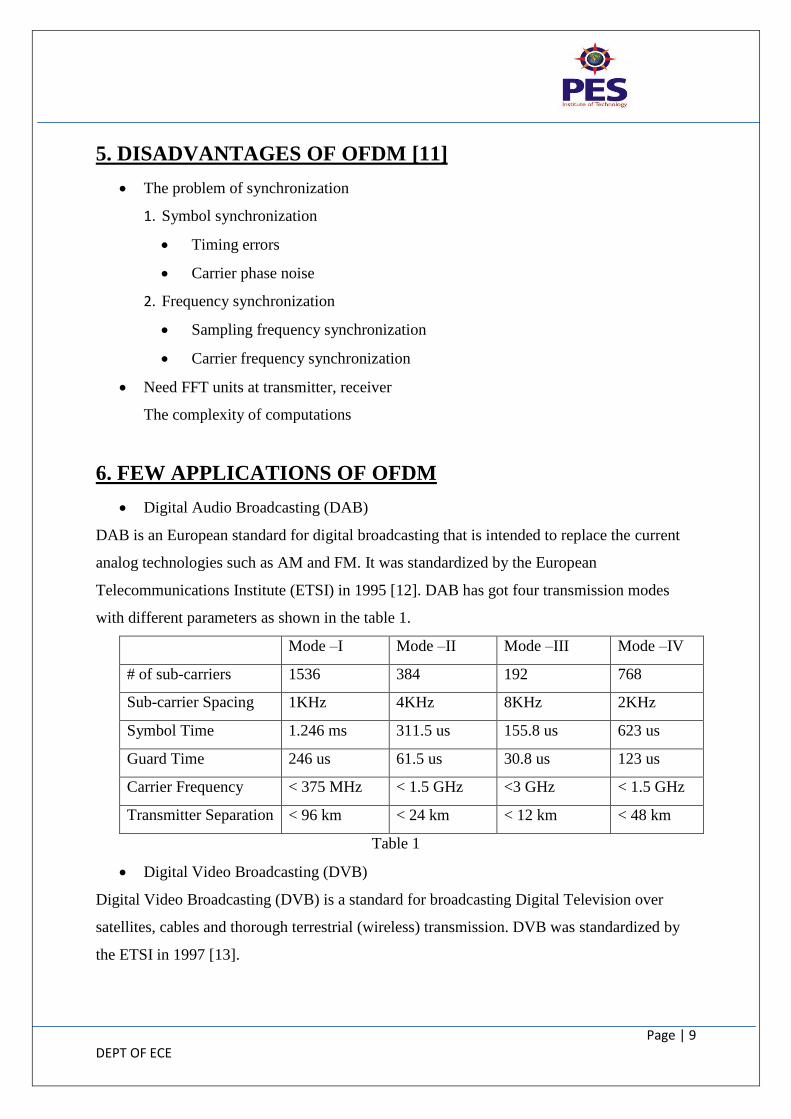
Digital Audio Broadcasting (DAB)
DAB is an European standard for digital broadcasting that is intended to replace the current
analog technologies such as AM and FM. It was standardized by the European
Telecommunications Institute (ETSI) in 1995 [12]. DAB has got four transmission modes
with different parameters as shown in the table 1.
Mode –I Mode –II Mode –III Mode –IV
# of sub-carriers 1536 384 192 768
Sub-carrier Spacing 1KHz 4KHz 8KHz 2KHz
Symbol Time 1.246 ms 311.5 us 155.8 us 623 us
Guard Time 246 us 61.5 us 30.8 us 123 us
Carrier Frequency < 375 MHz < 1.5 GHz <3 GHz < 1.5 GHz
Transmitter Separation < 96 km < 24 km < 12 km < 48 km
Table 1
Digital Video Broadcasting (DVB)
Digital Video Broadcasting (DVB) is a standard for broadcasting Digital Television over
satellites, cables and thorough terrestrial (wireless) transmission. DVB was standardized by
the ETSI in 1997 [13].
Page | 10 DEPT OF ECE
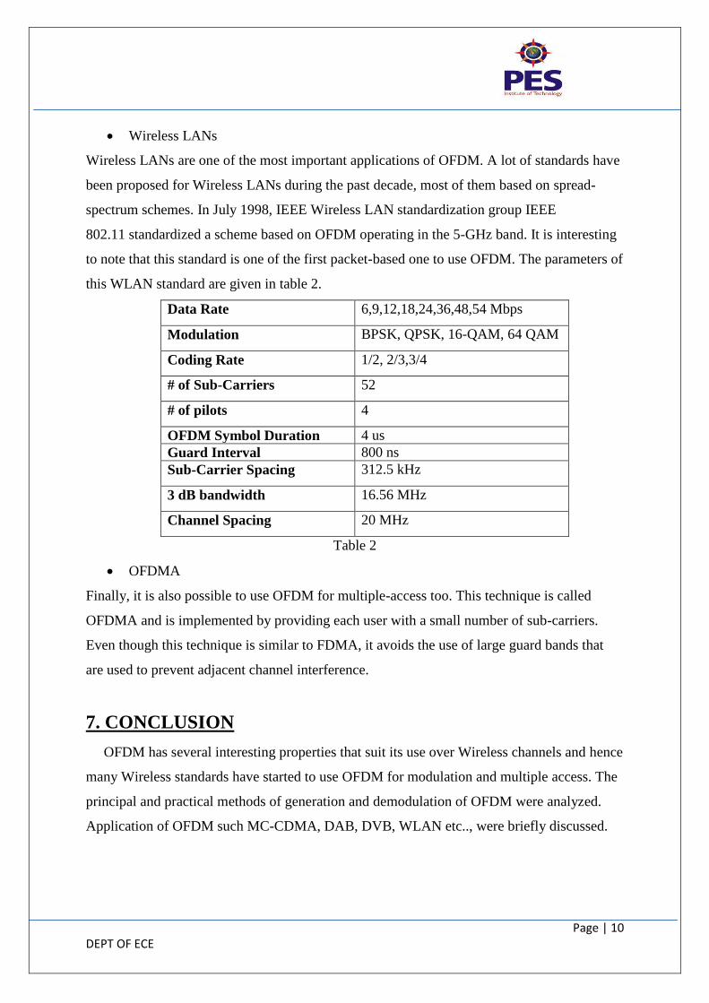
Wireless LANs
Wireless LANs are one of the most important applications of OFDM. A lot of standards have
been proposed for Wireless LANs during the past decade, most of them based on spread-
spectrum schemes. In July 1998, IEEE Wireless LAN standardization group IEEE
802.11 standardized a scheme based on OFDM operating in the 5-GHz band. It is interesting
to note that this standard is one of the first packet-based one to use OFDM. The parameters of
this WLAN standard are given in table 2.
Data Rate 6,9,12,18,24,36,48,54 Mbps
Modulation BPSK, QPSK, 16-QAM, 64 QAM
Coding Rate 1/2, 2/3,3/4
# of Sub-Carriers 52
# of pilots 4
OFDM Symbol Duration 4 us
Guard Interval 800 ns
Sub-Carrier Spacing 312.5 kHz
3 dB bandwidth 16.56 MHz
Channel Spacing 20 MHz
Table 2
OFDMA
Finally, it is also possible to use OFDM for multiple-access too. This technique is called
OFDMA and is implemented by providing each user with a small number of sub-carriers.
Even though this technique is similar to FDMA, it avoids the use of large guard bands that
are used to prevent adjacent channel interference.
7. CONCLUSION
OFDM has several interesting properties that suit its use over Wireless channels and hence
many Wireless standards have started to use OFDM for modulation and multiple access. The
principal and practical methods of generation and demodulation of OFDM were analyzed.
Application of OFDM such MC-CDMA, DAB, DVB, WLAN etc.., were briefly discussed.
Page | 11 DEPT OF ECE
8. FURTHER WORK BY THE AUTHOR
OFDM simulation in MATLAB.
Explanation of ADSL (Asymmetric digital subscriber line) which uses OFDM
concept.
9. REFERENCES
[1] R.W. Chang, “Synthesis of band- limited orthogonal signals for multichannel data
transmission” Bell Sys. Tech. Journal, vol. 45, Dec. 1966
[2] K. Thomas and H. Lajos, “Adaptive Multicarrier Modulation: A
Convenient Framework for Time-Frequency Processing in Wireless Communications”
IEEE processing of the IEEE, vol. 88, No.5, pp.611-640, May 2000
[3] Yao Xiao, “Orthogonal Frequency Division Multiplexing Modulation and Inter-carrier
Interference Cancellation”, M.S., Institute of Automation, May 2003
[4] Weinstein, S. and Ebert, P.; “Data Transmission by Frequency-Division Multiplexing
Using the Discrete Fourier Transform” IEEE Trans. on Commun. vol. 19 Issue: 5. Oct.1971
[5] John G. Proakis and Dimitris G. Manolakis, “Digital signal processing”, Pearson Prentice
Hall, 2007 - Technology & Engineering.
[6] M. D. Nisar, W. Utscick, H. Nottensteiner, and T. Hindelang, “Channel Estimation and
Equalization of OFDM Systems with Insufficient Cyclic Prefix,” in 65th IEEE Vehicular
Technology Conference, Apr 2007.
[7] Simon S. Haykin, “Digital communications”, Wiley, 08-Mar-1988 - Technology &
Engineering.
[8] K. Raghunath, Yogendra U. Itankar, A. Chockalingam, and Ranjan K. Mallik, “BER
Analysis of Uplink OFDMA in the Presence of Carrier Frequency and Timing Offsets on
Rician Fading Channels”, IEEE Trans. on Vehicular Technology, vol. 60, no. 9, pp. 4392-
4402, November 2011.
[9] http://en.wikipedia.org/wiki/Analog-to-digital_converter
[10] http://en.wikipedia.org/wiki/Digital-to-analog_converter
Page | 12 DEPT OF ECE
[11] L. Hanzo, W. Webb and T. Keller, “Single- and multi-carrier quadrature amplitude
modulation – Principles and applications for personal communications”, WLANs and
broadcasting, John Wiley & Sons, Ltd, 2000.
[12] ETSI, “Radio Broadcasting Systems: Digital Audio Broadcasting to Mobile, Portable
and Fixed Receivers”, European Telecommunication Standard, ETS 300-401, Feb.
1995.
[13] ETSI, “Digital Video Broadcasting: Framing Structure, Channel Coding and
Modulation for Digital Terrestrial Television”, European Telecommunication
Standard, EN 300-744, Aug 1997.