
Geometric requirements for photonic lanterns in space division multiplexing
10
Geometric requirements for photonic lanterns in space division multiplexing Nicolas K. Fontaine, 1,* Roland Ryf, 1 Joss Bland-Hawthorn, 2 and Sergio G. Leon-Saval 2 1 Bell Laboratories, Alcatel-Lucent, 791 Holmdel Rd., Holmdel, N.J., 07733, USA 2 Institute of Photonics and Optical Science (IPOS), School of Physics, The University of Sydney, Australia * [email protected] Abstract: We investigate the use of “photonic lanterns” as adiabatic mode converters for space-division multiplexing (SDM) systems to interface multiple single-mode fibers to a multi-mode fiber. In a SDM system, minimizing the coupling loss and mode-dependent loss best utilizes all spatial modes of the fiber which increases the capacity, the transmission distance, and minimizes the outage probability. We use modal analysis, the beam propagation method, and a transfer matrix technique to analyze the lanterns throughput along with its mode dependent loss and show that unitary coupling between single-mode fibers and a multi-mode fiber is only possible by optimizing the arrangements of the cores. Results include simulations for three, 12, 15, and 51 core lanterns to couple to six, 24, 30, and 102 spatial and polarization modes, respectively. © 2012 Optical Society of America OCIS codes: (060.2330) Fiber optics communications; (130.3120) Integrated optics devices References and links 1. A. Chraplyvy, “Plenary paper: The coming capacity crunch,” in “35th European Conference on Optical Commu- nication, 2009. ECOC ’09,” (IEEE, 2009), p. 1. 2. P. J. Winzer and G. J. Foschini, “MIMO capacities and outage probabilities in spatially multiplexed optical transport systems,” Opt. Express 19, 16680–16696 (2011). 3. R. Ryf, S. Randel, A. H. Gnauck, C. Bolle, A. Sierra, S. Mumtaz, M. Esmaeelpour, E. C. Burrows, R.-J. Essi- ambre, P. J. Winzer, D. W. Peckham, A. H. McCurdy, and R. Lingle, “Mode-division multiplexing over 96 km of few-mode fiber using coherent 6 × 6 MIMO processing,” J. Lightwave Technol. 30, 521–531 (2012). 4. R. E. Freund, C. A. Bunge, N. N. Ledentsov, D. Molin, and C. Caspar, “High-Speed transmission in multimode fibers,” J. Lightwave Technol. 28, 569–586 (2010). 5. J. Carpenter and T. D. Wilkinson, “Precise modal excitation in multimode fibre for control of modal dispersion and mode-group division multiplexing,” in “European Conference on Communications,” (Optical Society of America, 2011), OSA Technical Digest (CD), p. We.10.P1.62. 6. K. Ho and J. M. Kahn, “Statistics of group delays in multimode fiber with strong mode coupling,” J. Lightwave Technol. 29, 3119–3128 (2011). 7. R. Ryf, M. A. Mestre, A. Gnauck, S. Randel, C. Schmidt, R. Essiambre, P. Winzer, R. Delbue, P. Pupalaikis, A. Sureka, Y. Sun, X. Jiang, D. Peckham, A. H. McCurdy, and R. Lingle, “Low-Loss mode coupler for Mode- Multiplexed transmission in Few-Mode fiber,” in “OFC,” (2012), OSA Technical Digest, p. PDP5B.5. 8. S. Randel, R. Ryf, A. Sierra, P. J. Winzer, A. H. Gnauck, C. A. Bolle, R. Essiambre, D. W. Peckham, A. McCurdy, and R. Lingle, “6×56-Gb/s mode-division multiplexed transmission over 33-km few-mode fiber enabled by 6×6 MIMO equalization,” Opt. Express 19, 16697–16707 (2011). 9. H. B¨ ulow, H. Al-Hashimi, and B. Schmauss, “Coherent Multimode-Fiber MIMO transmission with spatial con- stellation modulation,” in “European Conference on Communications,” (Optical Society of America, 2011), OSA Technical Digest (CD), p. Tu.5.B.3. #173667 - $15.00 USD Received 1 Aug 2012; revised 30 Sep 2012; accepted 8 Nov 2012; published 16 Nov 2012 (C) 2012 OSA 19 November 2012 / Vol. 20, No. 24 / OPTICS EXPRESS 27123
Transcript of Geometric requirements for photonic lanterns in space division multiplexing

Geometric requirements for photoniclanterns in space division multiplexing
Nicolas K. Fontaine,1,∗ Roland Ryf,1 Joss Bland-Hawthorn,2 andSergio G. Leon-Saval2
1Bell Laboratories, Alcatel-Lucent, 791 Holmdel Rd.,Holmdel, N.J., 07733, USA
2Institute of Photonics and Optical Science (IPOS), School of Physics, The University ofSydney, Australia
Abstract: We investigate the use of “photonic lanterns” as adiabatic modeconverters for space-division multiplexing (SDM) systems to interfacemultiple single-mode fibers to a multi-mode fiber. In a SDM system,minimizing the coupling loss and mode-dependent loss best utilizes allspatial modes of the fiber which increases the capacity, the transmissiondistance, and minimizes the outage probability. We use modal analysis,the beam propagation method, and a transfer matrix technique to analyzethe lanterns throughput along with its mode dependent loss and show thatunitary coupling between single-mode fibers and a multi-mode fiber isonly possible by optimizing the arrangements of the cores. Results includesimulations for three, 12, 15, and 51 core lanterns to couple to six, 24, 30,and 102 spatial and polarization modes, respectively.
© 2012 Optical Society of America
OCIS codes: (060.2330) Fiber optics communications; (130.3120) Integrated optics devices
References and links1. A. Chraplyvy, “Plenary paper: The coming capacity crunch,” in “35th European Conference on Optical Commu-
nication, 2009. ECOC ’09,” (IEEE, 2009), p. 1.2. P. J. Winzer and G. J. Foschini, “MIMO capacities and outage probabilities in spatially multiplexed optical
transport systems,” Opt. Express19, 16680–16696 (2011).3. R. Ryf, S. Randel, A. H. Gnauck, C. Bolle, A. Sierra, S. Mumtaz, M. Esmaeelpour, E. C. Burrows, R.-J. Essi-
ambre, P. J. Winzer, D. W. Peckham, A. H. McCurdy, and R. Lingle, “Mode-division multiplexing over 96 km offew-mode fiber using coherent 6× 6 MIMO processing,” J. Lightwave Technol.30, 521–531 (2012).
4. R. E. Freund, C. A. Bunge, N. N. Ledentsov, D. Molin, and C. Caspar, “High-Speed transmission in multimodefibers,” J. Lightwave Technol.28, 569–586 (2010).
5. J. Carpenter and T. D. Wilkinson, “Precise modal excitation in multimode fibre for control of modal dispersionand mode-group division multiplexing,” in “European Conference on Communications,” (Optical Society ofAmerica, 2011), OSA Technical Digest (CD), p. We.10.P1.62.
6. K. Ho and J. M. Kahn, “Statistics of group delays in multimode fiber with strong mode coupling,” J. LightwaveTechnol.29, 3119–3128 (2011).
7. R. Ryf, M. A. Mestre, A. Gnauck, S. Randel, C. Schmidt, R. Essiambre, P. Winzer, R. Delbue, P. Pupalaikis,A. Sureka, Y. Sun, X. Jiang, D. Peckham, A. H. McCurdy, and R. Lingle, “Low-Loss mode coupler for Mode-Multiplexed transmission in Few-Mode fiber,” in “OFC,” (2012), OSA Technical Digest, p. PDP5B.5.
8. S. Randel, R. Ryf, A. Sierra, P. J. Winzer, A. H. Gnauck, C. A. Bolle, R. Essiambre, D. W. Peckham, A. McCurdy,and R. Lingle, “6×56-Gb/s mode-division multiplexed transmission over 33-km few-mode fiber enabled by 6×6MIMO equalization,” Opt. Express19, 16697–16707 (2011).
9. H. Bulow, H. Al-Hashimi, and B. Schmauss, “Coherent Multimode-Fiber MIMO transmission with spatial con-stellation modulation,” in “European Conference on Communications,” (Optical Society of America, 2011), OSATechnical Digest (CD), p. Tu.5.B.3.
#173667 - $15.00 USD Received 1 Aug 2012; revised 30 Sep 2012; accepted 8 Nov 2012; published 16 Nov 2012(C) 2012 OSA 19 November 2012 / Vol. 20, No. 24 / OPTICS EXPRESS 27123

10. C. R. Doerr, N. K. Fontaine, M. Hirano, T. Sasaki, L. Buhl, and P. Winzer, “Silicon photonic integrated circuitfor coupling to a ring-core multimode fiber for space-division multiplexing,” in “ECOC 2011, paper Th.13.A.3,”(2011).
11. N. K. Fontaine, C. R. Doerr, M. A. Mestre, R. R. Ryf, P. J. Winzer, L. L. Buhl, Y. Sun, X. Jiang, and R. LingleJr., “Space-division multiplexing and all-optical MIMO demultiplexing using a photonic integrated circuit,” in“OFC 2012, paper PDP5B.1,” (2012).
12. S. G. Leon-Saval, A. Argyros, and J. Bland-Hawthorn, “Photonic lanterns: a study of light propagation in multi-mode to single-mode converters,” Opt. Express18, 8430–8439 (2010).
13. R. R. Thomson, T. A. Birks, S. G. Leon-Saval, A. K. Kar, and J. Bland-Hawthorn, “Ultrafast laser inscription ofan integrated photonic lantern,” Opt. Express19, 5698–5705 (2011).
14. J. Bland-Hawthorn and P. Kern, “Astrophotonics: a new era for astronomical instruments,” Opt. Express17,1880–1884 (2009).
15. D. Noordegraaf, P. M. W. Skovgaard, M. D. Maack, J. Bland-Hawthorn, R. Haynes, and J. Lagsgaard, “Multi-mode to single-mode conversion in a 61 port photonic lantern,” Opt. Express18, 4673–4678 (2010).
16. T. A. Birks, B. J. Mangan, A. Dez, J. L. Cruz, and D. F. Murphy, “”Photonic lantern” spectral filters in multi-corefibre,” Opt. Express20, 13996–14008 (2012).
17. N. K. Fontaine, R. R. Ryf, S. G. Leon-Saval, and J. Bland-Hawthorn, “Evaluation of photonic lanterns for losslessmode-multiplexing,” in “ECOC 2012, paper Th.2.D.6,” (2012).
18. K. Okamoto,Fundamentals of Optical Waveguides,2nd ed. (Academic Press, 2005).19. R. Ryf, N. K. Fontaine, and R.-J. Essiambre, “Spot-based mode coupler for mode-multiplexed transmission in
few-mode fiber,” in “IEEE Summer Topicals 2012, paper TuC3.2 ,” (2012).20. H. Bulow, “Optical-mode demultiplexing by optical MIMO filtering of spatial samples,” IEEE Photon. Technol.
Lett. 24, 1045–1047 (2012).21. N. Jovanovic, I. Spaleniak, S. Gross, M. Ireland, J. S. Lawrence, C. Miese, A. Fuerbach, and M. J. Withford, “In-
tegrated photonic building blocks for next-generation astronomical instrumentation I: the multimode waveguide,”Opt. Express20, 17029–17043 (2012).
22. H. Bulow, H. Al-Hashimi, and B. Schmauss, “Stable coherent MIMO transport over few mode fiber enabled byan adiabatic mode splitter,” in “ECOC 2010, paper P4.4,” .
1. Introduction
In recent years, the capacity carried by a single fiber has been rapidly approaching its limits [1].Space-division multiplexing (SDM) can overcome this “capacity crunch” by using the spatialmodes of a multi-mode fiber (MMF), or the multiple cores in a multi-core fiber as an additionaland independent degree of freedom. Using multiple spatial modes can either increase the link’sspectral efficiency through additional channels occupying the same wavelength, or increasephoton-efficiency of the link through coding.
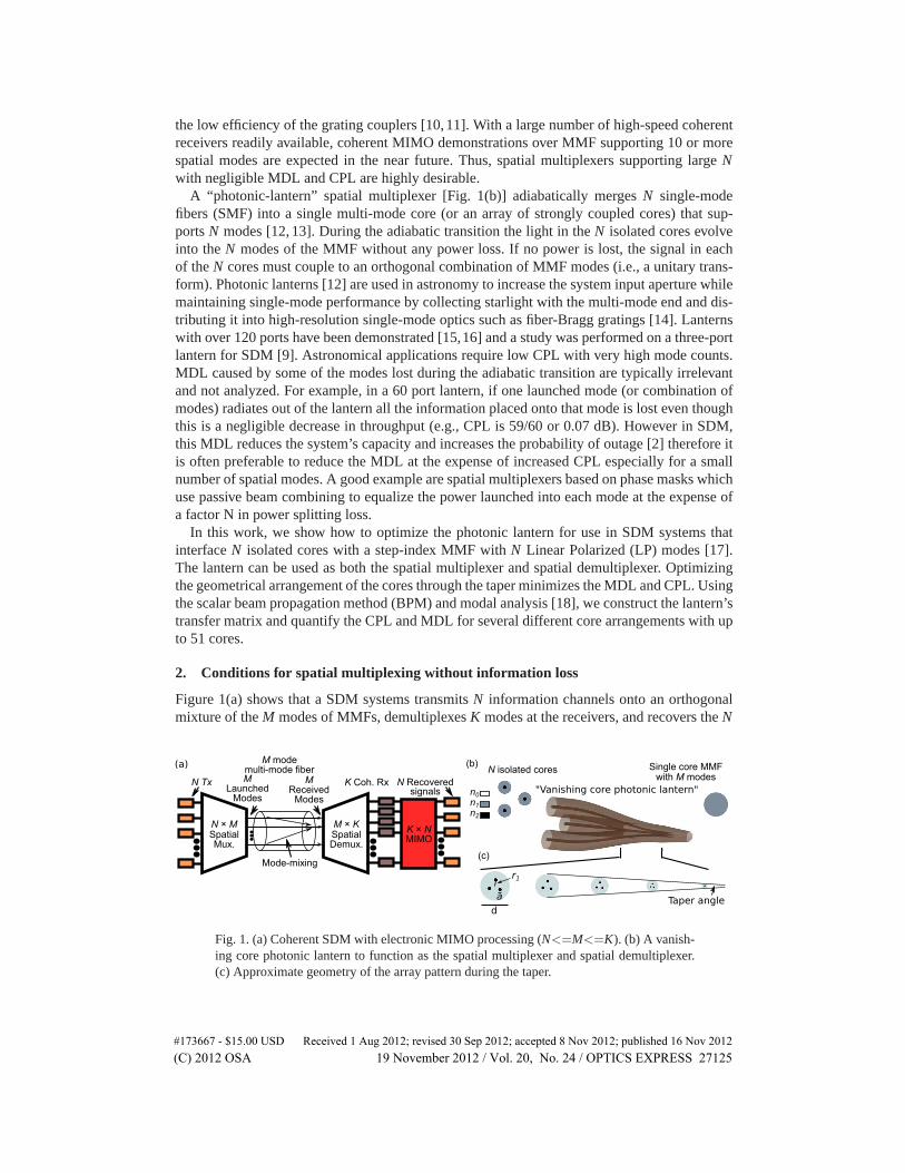
Figure 1(a) illustrates a multiple-input multiple-output (MIMO) based SDM system whereN independent information channels are launched onto an orthogonal combination ofM spa-tial modes. Such a system consists of a spatial multiplexer to couple to the fiber modes, amulti-mode fiber (MMF), a mode-demultiplexer, an array of coherent receivers (Coh. Rx), andelectrical MIMO processing. Maximal capacity in systems withN = M can occur only whenthe mode-dependent losses (MDL) are negligible [2]. There are a variety of spatial multiplex-ers with their respective strengths and weaknesses. Some spatial multiplexers directly excite thespatial modes (i.e., a mode-multiplexer) and others excite an orthogonal combination of modes.Directly exciting the MMF modes often requires large bulk-optic setups to produce the modeprofiles using phase masks or spatial-light modulators and beam-combiners to overlap the pro-files onto the MMF [3–5]. Due to passive beam-combining, the coupling losses (CPL) increaseproportionally toN. However, since mode scrambling is inevitable in MMFs [2, 3, 6–8], it isnot always necessary to excite individual MMF modes, especially for long-haul transmission.It could be beneficial to excite an orthogonal combination of modes such that all channels ex-perience similar modal dependencies. This is expected to reduce the outage probability [6,7,9].Additionally, electronic MIMO processing can faithfully recover the launched information pro-vided allK demultiplexed signals are coherently detected [7]. Photonic integrated circuits canshrink the coupler’s size, however these devices still suffer from relatively large losses due to
#173667 - $15.00 USD Received 1 Aug 2012; revised 30 Sep 2012; accepted 8 Nov 2012; published 16 Nov 2012(C) 2012 OSA 19 November 2012 / Vol. 20, No. 24 / OPTICS EXPRESS 27124
the low efficiency of the grating couplers [10,11]. With a large number of high-speed coherentreceivers readily available, coherent MIMO demonstrations over MMF supporting 10 or morespatial modes are expected in the near future. Thus, spatial multiplexers supporting largeNwith negligible MDL and CPL are highly desirable.
A “photonic-lantern” spatial multiplexer [Fig. 1(b)] adiabatically mergesN single-modefibers (SMF) into a single multi-mode core (or an array of strongly coupled cores) that sup-portsN modes [12, 13]. During the adiabatic transition the light in theN isolated cores evolveinto theN modes of the MMF without any power loss. If no power is lost, the signal in eachof theN cores must couple to an orthogonal combination of MMF modes (i.e., a unitary trans-form). Photonic lanterns [12] are used in astronomy to increase the system input aperture whilemaintaining single-mode performance by collecting starlight with the multi-mode end and dis-tributing it into high-resolution single-mode optics such as fiber-Bragg gratings [14]. Lanternswith over 120 ports have been demonstrated [15,16] and a study was performed on a three-portlantern for SDM [9]. Astronomical applications require low CPL with very high mode counts.MDL caused by some of the modes lost during the adiabatic transition are typically irrelevantand not analyzed. For example, in a 60 port lantern, if one launched mode (or combination ofmodes) radiates out of the lantern all the information placed onto that mode is lost even thoughthis is a negligible decrease in throughput (e.g., CPL is 59/60 or 0.07 dB). However in SDM,this MDL reduces the system’s capacity and increases the probability of outage [2] therefore itis often preferable to reduce the MDL at the expense of increased CPL especially for a smallnumber of spatial modes. A good example are spatial multiplexers based on phase masks whichuse passive beam combining to equalize the power launched into each mode at the expense ofa factor N in power splitting loss.
In this work, we show how to optimize the photonic lantern for use in SDM systems thatinterfaceN isolated cores with a step-index MMF withN Linear Polarized (LP) modes [17].The lantern can be used as both the spatial multiplexer and spatial demultiplexer. Optimizingthe geometrical arrangement of the cores through the taper minimizes the MDL and CPL. Usingthe scalar beam propagation method (BPM) and modal analysis [18], we construct the lantern’stransfer matrix and quantify the CPL and MDL for several different core arrangements with upto 51 cores.
2. Conditions for spatial multiplexing without information loss
Figure 1(a) shows that a SDM systems transmitsN information channels onto an orthogonalmixture of theM modes of MMFs, demultiplexesK modes at the receivers, and recovers theN
(a) (b) N isolated cores Single core MMF
with M modes
n0
n2
n1
N × MSpatialMux.
M × KSpatialDemux.
M mode multi-mode fiber
N Tx K Coh. Rx
K × NMIMO
N Recoveredsignals "Vanishing core photonic lantern"
M
Launched Modes
M
ReceivedModes
Mode-mixing(c)
d
r1
a Taper angle
Fig. 1. (a) Coherent SDM with electronic MIMO processing (N<=M<=K). (b) A vanish-ing core photonic lantern to function as the spatial multiplexer and spatial demultiplexer.(c) Approximate geometry of the array pattern during the taper.
#173667 - $15.00 USD Received 1 Aug 2012; revised 30 Sep 2012; accepted 8 Nov 2012; published 16 Nov 2012(C) 2012 OSA 19 November 2012 / Vol. 20, No. 24 / OPTICS EXPRESS 27125

LP01 LP11 LP31LP02LP21 LP12 LP41 LP03(a)
(b) Coupled core approximation
(c) 15 core approximation 'super-modes'
LP22
b
a
b
a
b
a
b
a
b
a
b
a
b
a
b
a
b
a
b
a
b
a
b
a
Step-index
multi-mode fiber
Incorrect
15 core approximation
of a step-index
multi-mode fiber
(d) 15 core incorrect approximation 'super-modes'
b
a
b
a
b
a
b
a
b
a
b
a
Correct
15 core approximation
of a step-index
multi-mode fiber
Mode not supported by15 mode MMF
LP01 LP11 LP31LP02LP21 LP12 LP41 LP03LP22
LP01 LP11 LP12LP02LP21 LP31 LP41 LP22
Fig. 2. (a) 15 lowest order step index fiber spatial modes. (b) Coupled waveguide arrayswhosesupermodes closely match the fiber modes. (c) 15 lowest order modes of near opti-mal 15 core arrangement. (d) 15 lowest order modes of an incorrect 15 core arrangement.
information channels with MIMO processing. According to the second law of thermodynamics(the brightness theorem), the number of orthogonal modes in a system cannot decrease. Ata minimum,N <= M <= K has to be fulfilled, otherwise there is possibility of informationloss [2]. Let us consider the simple example of coupling into and out of the fundamental modeof a two-mode MMF using single-mode fibers (N= 1, M = 2, K = 1). All the light couplesinto the MMF on the fundamental mode (N< M). However, during propagation there is thepotential for the information to scramble randomly between the fundamental and higher orderMMF modes. In the extreme case, the information transfers completely to the higher-ordermode and does not couple to the output. On average, the information has equal probability ofbeing on either mode and thus only half of the information is recovered. However, if both modesof the MMF are coupled out onto two SMFs (K=2) then the information is spread across twooutputs and not lost. Recovering the single-channel information requires additional receiversand MIMO processing. In a realistic network that incorporates amplifiers, routers, and cross-connects, it is important to unify the number of orthogonal modes and never let it increase (i.e.,N = M = K). For a complete analysis of information throughput and the outage probability ina MIMO system withN <= M andK <= M refer to [2].
3. Photonic lanterns for space division multiplexing
In this section we describe the lantern structure and optimal core arrangements for minimizingMDL and CPL.
#173667 - $15.00 USD Received 1 Aug 2012; revised 30 Sep 2012; accepted 8 Nov 2012; published 16 Nov 2012(C) 2012 OSA 19 November 2012 / Vol. 20, No. 24 / OPTICS EXPRESS 27126

Fig. 3. Comparison of two three-core lanterns using modal analysis. (a) Triangle arraywhich supports the same modes as the fiber, (b) linear array which supports the LP01,LP11a, and a TEM20 mode. Red lines indicate the three guided MMF modes, blue linesindicate higher-order cladding modes which are not guided in the MMF, and green linesindicate modes that are guided in the array but not in the MMF. NA1 = NA2 = 0.12.
3.1. Photonic lantern structure
The photonic lantern structure is illustrated in Fig. 1(c). The geometry consists of individualcores with indexn2 with diametera surrounded by a cladding with refractive indexn1. Thecores are then placed inside a glass capillary (i.e., second cladding) with diameterD whichhas a slightly lower indexn0. During the taper, the light is initially guided in the single modedcores. As the core diameter shrinks the light is then guided in the cladding material whichbecomes the new MMF core. In the following figures, the mode index is the effective refractiveindex of the guided mode. Each core is placed along a ring with number of cores defined asRn
wheren is the ring number (larger numbers further from center). For example, the three corelantern in Fig. 1(c) hasR1 = 3. The angle of the taper is defined with respect to the capillarydiameter vs. lateral position. Larger angles correspond to shorter tapers which become diabatic.We define NA1 as the numerical aperture between the core and the cladding material, andNA2 as the numerical aperture between the cladding and the capillary (using the step-indexapproximation).
3.2. Optimum core arrangements for a lantern interfacing to a step-index MMF
The starting point for low CPL and MDL lantern design is an uncoupled core geometry that bestapproximates the MMF modes or samples the modes [19, 20] [see Fig. 2(a)]. In the literature,photonic lantern core geometries consist of hexagonal lattices or square lattices with the numberof cores approximately equal to the number of final waveguide modes [12, 14, 21]. However,the arrangements which minimize MDL are unique for each waveguide geometry and have notbeen previously investigated.
Intuitively, when the cores are isolated or weakly coupled, their supermodes (or superposi-tion of supermodes) should resemble the final waveguide modes. The arrangement that bestapproximates the LPnm modes in a step-index MMF (nis the max azimuthal mode number, andm is the radial mode number) aremconcentric rings. The number of spots in each ring is 2p+1where p is the largestn for each radial-number,m. For example, Fig. 2(a) shows the 15 lowestorder LP modes. Each box represents the modes with identical cut-off frequency. Figure 2(b)
#173667 - $15.00 USD Received 1 Aug 2012; revised 30 Sep 2012; accepted 8 Nov 2012; published 16 Nov 2012(C) 2012 OSA 19 November 2012 / Vol. 20, No. 24 / OPTICS EXPRESS 27127

shows the core patterns that best approximate an MMF supporting 3, 6, 8, 10, 12, and 15 spatialmodes.Figure 2(c) shows the matching supermodes of the 15 core array which approximate aMMF supporting 15 spatial modes. In an adiabatic lantern, light launched in a particular super-mode mode will evolve into the corresponding MMF mode. Using these core geometries allowfor a photonic lantern couplers with negligible MDL and CPL.
In comparison, Fig. 2(d) shows the supermodes of a 15 core array with an incorrect corearrangement that consists of two rings with 9 and 6 cores. The supermode set does not includea LP03-like mode. Rather, it supports a mode that is unguided in a 15 mode MMF and anyenergy launched onto that supermode will radiate out of the lantern during the taper. Likewise,if the LP03 is launched from the MMF, it will be guided within the cladding rather than withinthe cores.
3.3. Fabrication
These lanterns can be fabricated in two different ways: by single mode fiber bundling of differ-ent cladding fibers to achieve the right fiber packing geometry [12], or through ultrafast pulsedlaser inscription in bulk glasses which gives unrestricted geometrical parameters as demon-strated in [13,21]. For lanterns with less than three rings we expect that the fiber packing methodshould produce lanterns with the lowest MDL and CPL since the lantern can be directly splicedto SMF and the MMF.
4. Simulations
In this section we compare different photonic lantern core geometries using modal analysis,BPM, and transfer matrices; those that can have 100% throughput (i.e., CPL = 0 dB and MDL= 0 dB) and those that have non zero MDL and CPL. For all simulations,n0=1.435,n1=1.44,n2=1.445 and NA1=NA2=0.12.
4.1. Quantification of coupling
In a coherent MIMO system the MDL sets the upper limit on capacity by reducing the numberof available modes and the CPL affects the maximum span length (e.g., 1 dB excess loss meansthe spans length is reduced by 5 km). We quantify the MDL and CPL of the lantern by analyzingits transfer matrix,H(ω), from each isolated core mode (or the supermodes of the coupledarray) to each MMF guided mode. Using the beam-propagation method (BPM), we constructthe transfer matrix from thei − th isolated core to the MMF by propagating a guided modefrom each isolated core (or core supermodes) to the lantern output [see Fig. 1],Li(x,y). Theoverlap ofLi(x,y) with each MMF modes,Fj(x,y), forms the coupling matrix with elementshi j =
∫Fj(x,y)L∗
i (x,y)dxdy. Likewise, the coupling matrix in the reverse direction (from theMMF to the isolated cores) could be computed by propagating from each MMF mode to eachsingle core, or by taking the conjugate transpose ofH(ω).
H(ω) can be calculated at each frequency and completely describes how the fiber modescouple to the isolated core modes. Singular value decomposition (SVD),H = UΣV∗, is usedto find the MDL and CPL whereΣ is a diagonal matrix containing the singular values,λ j , andU , V are unitary matrices of dimensionsN×N andM×M, respectively. The singular vectors,v j , the columns ofV, are always orthogonal and represent the required linear combination ofLi(x,y) that couple to an orthogonal combination of MMF modes (Fj ) with throughput ofλ 2
j .The field at the lantern output corresponding to eachλ j is A j(x,y) = ∑i LiVji . Using theA j ’s asa set of orthogonal channels, the the worst case MDL of the coupler is max(λ 2)/min(λ 2) andthe CPL isN/∑i λ 2. TheA j ’s corresponding toλ j = 0 span the null space ofH(ω) and willnot couple between the MMF and isolated cores.
#173667 - $15.00 USD Received 1 Aug 2012; revised 30 Sep 2012; accepted 8 Nov 2012; published 16 Nov 2012(C) 2012 OSA 19 November 2012 / Vol. 20, No. 24 / OPTICS EXPRESS 27128

Fig. 4. BPM simulations from for the three core lantern with 0.012 rad taper angle (a)theinput supermodes and the (b) input core modes to the outputs. (c,d) Intensity couplingmatrix from the inputs to the MMF modes. Simulation length is 10 mm, core diameter toouter diameter ratio is 1/8, the taper begins with a 70µm outer diameter and ends with a14 µm outer diameter.
Fig. 5. BPM simulations for the three core lantern with a 0.12 rad taper angle. (a) theinputsupermodes to the outputs. (b) Intensity coupling matrix from the inputs to the MMFmodes. Simulation length is 1 mm, core diameter to outer diameter ratio is 1/8, the taperbegins with a 70µm outer diameter and ends with a 14µm outer diameter.
4.2. Three core lantern examples
A three core lantern interfaces to a MMF supporting the LP01 and the double degenerate LP11
modes along with both polarizations. The obvious core arrangement consists of cores placed ina triangle pattern and is shown in Fig. 3(a). To highlight the importance of the core arrangement,Fig. 3(b) shows a lantern where the cores are placed along a line. The supermodes of the trianglelattice match the LP modes, and as the geometry shrinks those supermodes evolve into theMMF modes. The blue lines indicate the cladding modes of the lantern (i.e., those originallyguided outside the cores in the cladding) which stay well separated from the core modes (redlines). When the cores are spaced far apart, the propagation constants of the three supermodesapproach the same value indicating completely isolated cores. Also, the propagation constantsof the core modes remain well separated and do not cross, indicating that if the taper is adiabaticthen the light will evolve directly from the MMF modes into the supermodes. Note, althoughthis analysis uses the core supermodes, each isolated core mode is equal to a superposition ofthe supermodes. For example, the right most core mode is the superposition of the LP01 modeand the first LP11 mode. Finally, since no modes are lost, this lantern can have 100% throughputwithout MDL.
Figure 3(b) shows the same analysis for the linear pattern. The array supports the LP01 mode,only one of the LP11 modes, and a Hermite-Gaussian TEM20 mode. The TEM20 mode does not
#173667 - $15.00 USD Received 1 Aug 2012; revised 30 Sep 2012; accepted 8 Nov 2012; published 16 Nov 2012(C) 2012 OSA 19 November 2012 / Vol. 20, No. 24 / OPTICS EXPRESS 27129

exist in the MMF and the second LP11 mode is not guided by the linear array. Therefore, duringthe transition from the MMF to the isolated cores, the second LP11 mode is lost. Likewise,going the opposite direction from the isolated cores into the MMF any energy on TEM20 modeis lost. A third of the energy of each isolated core mode contains is on the TEM20 mode andthis lantern has throughput of 2/3 (CPL=1.76 dB) and infinite MDL.
Next, we perform a BPM simulation from the core supermodes into the MMF and from theisolated cores into the MMF and computeH(ω) for both cases. The taper angle is 0.012 radwhich results in an adiabatic transition. Figure 4(a,b) show the BPM results and Fig. 4(c,d)show the intensity of the coupling matrices. Through the transition, the radiation pattern lookslike the desired mode and evolves directly into individual MMF modes. Thus, the couplingmatrix is diagonal and since almost no power is lost during the transition and all input modesreach the output with equal power this lantern has 0 dB CPL and 0 dB MDL (rounded to within0.1 dB numerical error). Note, since the supermodes evolve directly into the MMF modes, thelantern can act as a 1-1 mode multiplexer by placing an appropriate optical mapping networkbefore the lantern input [22].
A more common scenario is to launch light into the isolated cores and the correspondingBPM simulation is shown in Fig. 4(b). Here, the input radiation pattern can be considered asuperposition of the supermodes and mode beating is expected as the supermode propagationconstants separate. During the taper, the light propagates back and forth between the cores andeventually evolves into a superposition of the three MMF modes. The coupling matrix is notdiagonal and scrambled, however it is free from CPL and MDL. The additional scrambling canreduce large modal dependencies during fiber transmission [6,7].
Figure 5 shows the supermode evolution in a diabatic (non adiabatic) transition. If the taperoccurs too fast, then light will couple to higher order cladding modes that are not guided inthe MMF and will possibly radiate outside the lantern. Figure 5(a) shows the BPM simulationillustrating that the light couples to the higher order cladding modes. Also, the spatial pattern atthe output of the lantern resembles the LP modes with some higher order radiative modes. Thecoupling matrix [Fig. 5(b)] is still diagonal, but the diagonal elements have less intensity andare nonuniform. Correspondingly, the CPL is 1.5 dB and the MDL is 0.5 dB.
4.3. Wavelength dependence
Since the lanterns use an adiabatic transition to obtain lossless coupling, they are expected tohave some wavelength dependence. Across a specified wavelength range, if theM isolated coresare single moded, and the MMF supportsM modes than the MDL and CPL can be 0 dB. Ratherthan affecting the MDL and CPL which reduce capacity, the wavelength dependence results ina unitary rotation of the coupling matrix. The longer the adiabatic taper, the faster the matrixrotates with wavelength. Across the telecommunications C-band, the three core lantern shouldhave negligable MDL or CPL since the MMF supports three modes and the isolated cores aresingle moded across the whole wavelength range.
4.4. Lossless twelve core lantern arrangements
Figure 6 shows modal and beam-propagation method (BPM) analyses of two 12 core arrange-ments on two rings that adiabatically taper into a 12 mode MMF: lantern A has an optimumpattern and lantern B has a incorrect square lattice. Lantern A has two rings with three andnine cores. Lantern B has four and eight cores on each ring approximates a rectangular grid.Figure 6(a) shows the propagation constants of the guided modes (supermodes) as the isolatedcores evolve into a single core. For lantern A, the 12 originally degenerate supermodes becomethe 12 MMF modes. Note that each core mode can be represented by a superposition of the 12degenerate supermodes. Throughout the taper, these supermodes remain well separated from
#173667 - $15.00 USD Received 1 Aug 2012; revised 30 Sep 2012; accepted 8 Nov 2012; published 16 Nov 2012(C) 2012 OSA 19 November 2012 / Vol. 20, No. 24 / OPTICS EXPRESS 27130

Fig. 6. Comparison of two 12 core lanterns. (a) Propagation constants vs. core separation.BPM simulation showing supermode radiating out of lantern B. (c) CPL and MDL calcu-lated using BPM assuming lantern is cut at different lengths.
the cladding modes which become cut-off (radiative). An adiabatic taper can ensure that thisspatial multiplexer will have zero MDL and CPL.
Contrarily in lantern B, one of the supermodes resembles the LP22 mode which is a radiationmode of the MMF. Additionally, one of the cladding modes (guided by the cladding rather thanthe cores) resembles the LP41b mode which is guided in the final 12-mode MMF. Figure 6(b)shows the evolution of theLP22 like supermode evolving into the radiativeLP22 MMF mode.Also, when coupling in the reverse direction (from the MMF into the SMFs) the originallyguided LP41b MMF mode evolves into a cladding mode of the waveguide array. Since onemode is lost, lantern B’s MDL is infinite and its best CPL is 0.37 dB (11/12).
Figure 6(c) shows the CPL and MDL for the two lanterns cut to different lengths assumingthat the fiber modes can be imaged (resized) onto the lantern output. For lantern A, as the cores
#173667 - $15.00 USD Received 1 Aug 2012; revised 30 Sep 2012; accepted 8 Nov 2012; published 16 Nov 2012(C) 2012 OSA 19 November 2012 / Vol. 20, No. 24 / OPTICS EXPRESS 27131

Fig. 7. Comparison of two 51 core lanterns. Propagation constants vs. cladding diameter.LanternC has correct core arrangements and cladding and supermodes do not mix. LanternD has an incorrect core arrangement and the one supermode mixes with one cladding mode.
merge, the MDL and CPL approaches zero. Also, the MDL and CPL fall below 0.5 dB at aneffective diameter of 37µm suggesting that the lantern is a good spatial multiplexer even if itdoes not fully merge into a single multi-mode core. Lantern B has infinite MDL because its LP22
like supermode evolves into a cut-off fiber mode. As the cores merge, the CPL asymptoticallyapproaches 0.37 dB (i.e., 11/12).
4.5. Core arrangements for large lanterns
Figure 7 shows modal analysis for a 51 core lantern tapering into a MMF supporting 51 spatialmodes (102 with polarization). Lantern C has the correct core arrangement as described above,and Lantern D has a slightly modified core arrangement where the 3rd and 4th ring from thecenter have an even number of cores. The modal analysis indicates that Lantern C can be loss-less since none of the core modes cross into the higher-order cladding modes during the taperand that Lantern D loses one mode during the transition. Considering all modes, lantern D hasa CPL of 0.086 dB and infinite MDL (one mode is lost). Therefore, these core arrangementsare also important for lanterns coupling to highly-multimode fibers. However, due to the largenumber of modes, the effects of an improper arrangement may go unnoticed.
5. Conclusions
We have shown through simulations that photonic lantern spatial multiplexers with the propercore arrangements can couple into and out of MMFs supporting a large number of spatial modes(51) and simultaneously achieve low MDL and low CPL. The lanterns with core arrangementswhose supermodes approximate the LP modes will only have negligible MDL and CPL. Other-wise, lanterns with incorrect core arrangement with supermodes that do not exist in the MMFwill lose at least one mode during the transition. Additionally, if the supermode patterns arelaunched, they will directly evolve into the corresponding MMF mode suggesting a techniqueto build a 1-1 mode multiplexer. Alternatively, launching the isolated core modes distributesthe information across the MMF modes possibly mitigating the effect of MDL occurring dur-ing transmission. These lanterns with optimal core arrangements will be important for largemode count SDM systems.
#173667 - $15.00 USD Received 1 Aug 2012; revised 30 Sep 2012; accepted 8 Nov 2012; published 16 Nov 2012(C) 2012 OSA 19 November 2012 / Vol. 20, No. 24 / OPTICS EXPRESS 27132