Morphology of Polymer/Clay Latex Particles Synthesized by Miniemulsion Polymerization: Modeling and...
13
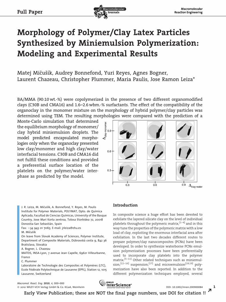
Morphology of Polymer/Clay Latex Particles Synthesized by Miniemulsion Polymerization: Modeling and Experimental Results Matej Mic ˇus ˇı ´k, Audrey Bonnefond, Yuri Reyes, Agnes Bogner, Laurent Chazeau, Christopher Plummer, Maria Paulis, Jose Ramon Leiza* Introduction In composite science a huge effort has been devoted to exfoliate the layered silicate clay on the level of individual platelets throughout the polymeric matrix, [1–4] and in this way tune the properties of the polymeric matrix with a low load of clay, exploiting the enormous interfacial area after exfoliation. In the last two decades different routes to prepare polymer/clay nanocomposites (PCNs) have been developed. In order to synthesize waterborne PCNs emul- sion polymerization processes have been preferentially used to incorporate clay platelets into the polymer matrix. [5–11] Other related techniques such as miniemul- sion, [12–16] suspension, [17] and microemulsion [18,19] poly- merization have also been reported. In addition to the different polymerization techniques employed, several Full Paper J. R. Leiza, M. Micˇusˇı ´k, A. Bonnefond, Y. Reyes, M. Paulis Institute for Polymer Materials, POLYMAT, Dpto. de Quı ´mica Aplicada, Facultad de Ciencias Quı ´micas, University of the Basque Country, Joxe Mari Korta zentroa, Tolosa Etorbidea 72, 20018 Donostia-San Sebastia ´n, Spain Fax: þ34 943 01 7065; E-mail: [email protected] M. Mic ˇusˇı ´k On leave from Slovak Academy of Sciences, Polymer Institute, Department of Composite Materials, Du ´bravska ´ cesta 9, 842 36 Bratislava, Slovakia A. Bogner, L. Chazeau MATEIS, INSA-Lyon, 7 avenue Jean Capelle, 69621 Villeurbanne, France C. Plummer Laboratoire de Technologie des Composites et Polyme `res (LTC), Ecole Fe ´de ´rale Polytechnique de Lausanne (EPFL), Station 12, 1015 Lausanne, Switzerland BA/MMA (90:10 wt.-%) were copolymerized in the presence of two different organomodified clays (C30B and CMA16) and 1.6–2.6 wbm.-% surfactants. The effect of the compatibility of the organoclay in the monomer mixture on the morphology of hybrid polymer/clay particles was determined using TEM. The resulting morphologies were compared with the prediction of a Monte-Carlo simulation that determined the equilibrium morphology of monomer/ clay hybrid miniemulsion droplets. The model predicted encapsulated morpho- logies only when the organoclay presented low clay/monomer and high clay/water interfacial tensions. C30B and CMA16 did not fulfill these conditions and provided a preferential surface location of the platelets on the polymer/water inter- phase as predicted by the model. Macromol. React. Eng. 2010, 4, 000–000 ß 2010 WILEY-VCH Verlag GmbH & Co. KGaA, Weinheim DOI: 10.1002/mren.200900084 1 Early View Publication; these are NOT the final page numbers, use DOI for citation !! R
Transcript of Morphology of Polymer/Clay Latex Particles Synthesized by Miniemulsion Polymerization: Modeling and...
Full Paper
Morphology of Polymer/Clay Latex ParticlesSynthesized by Miniemulsion Polymerization:Modeling and Experimental Results
Matej Micusık, Audrey Bonnefond, Yuri Reyes, Agnes Bogner,Laurent Chazeau, Christopher Plummer, Maria Paulis, Jose Ramon Leiza*
BA/MMA (90:10wt.-%) were copolymerized in the presence of two different organomodifiedclays (C30B and CMA16) and 1.6–2.6wbm.-% surfactants. The effect of the compatibility of theorganoclay in the monomer mixture on the morphology of hybrid polymer/clay particles wasdetermined using TEM. The resulting morphologies were compared with the prediction of aMonte-Carlo simulation that determinedthe equilibriummorphology ofmonomer/clay hybrid miniemulsion droplets. Themodel predicted encapsulated morpho-logies only when the organoclay presentedlow clay/monomer and high clay/waterinterfacial tensions. C30B and CMA16 didnot fulfill these conditions and provideda preferential surface location of theplatelets on the polymer/water inter-phase as predicted by the model.
J. R. Leiza, M. Micusık, A. Bonnefond, Y. Reyes, M. PaulisInstitute for Polymer Materials, POLYMAT, Dpto. de QuımicaAplicada, Facultad de Ciencias Quımicas, University of the BasqueCountry, Joxe Mari Korta zentroa, Tolosa Etorbidea 72, 20018Donostia-San Sebastian, SpainFax: þ34 943 01 7065; E-mail: [email protected]. MicusıkOn leave from Slovak Academy of Sciences, Polymer Institute,Department of Composite Materials, Dubravska cesta 9, 842 36Bratislava, SlovakiaA. Bogner, L. ChazeauMATEIS, INSA-Lyon, 7 avenue Jean Capelle, 69621 Villeurbanne,FranceC. PlummerLaboratoire de Technologie des Composites et Polymeres (LTC),Ecole Federale Polytechnique de Lausanne (EPFL), Station 12, 1015Lausanne, Switzerland
Macromol. React. Eng. 2010, 4, 000–000
� 2010 WILEY-VCH Verlag GmbH & Co. KGaA, Weinheim
Early View Publication; these are NOT the
Introduction
In composite science a huge effort has been devoted to
exfoliate the layered silicate clay on the level of individual
platelets throughout the polymeric matrix,[1–4] and in this
way tune the properties of the polymeric matrix with a low
load of clay, exploiting the enormous interfacial area after
exfoliation. In the last two decades different routes to
prepare polymer/clay nanocomposites (PCNs) have been
developed. In order to synthesize waterborne PCNs emul-
sion polymerization processes have been preferentially
used to incorporate clay platelets into the polymer
matrix.[5–11] Other related techniques such as miniemul-
sion,[12–16] suspension,[17] and microemulsion[18,19] poly-
merization have also been reported. In addition to the
different polymerization techniques employed, several
DOI: 10.1002/mren.200900084 1
final page numbers, use DOI for citation !! R
M. Micusık et al.
2
REa
types of clays, both synthetic (laponite, hectorite, gibbsite,
etc.), and natural (montmorillonite, hectorite, bentonite,
etc.) have been used with different degrees of modification,
if any. The goal in plenty of the works was just to exfoliate
the clay platelets in the polymer matrix. Other works, in
addition to the exfoliation of the platelets in the polymer
matrix, aimed at controlling the morphology of the hybrid
polymer/clay particles dispersed in water and tried to
achieve encapsulation of the clay platelets inside the
polymer particles.
Encapsulation of synthetic clay (laponite, gibbsite, and
saponite) has been recently reported.[20–23] Mellon[22] has
doubly modified laponite using a cationic surfactant to
hydrophobize the surface and a reactive silane to modify
the edges. The resulting hydrophobized clay was then
polymerized by miniemulsion polymerization of methyl
methacrylate (MMA)/ butyl acrylate (BA) at relatively low
solids content (SC, �20 wt.-%) to obtain encapsulated
laponite polymer particles. Tong and Deng[23] have also
shown clear evidence of the encapsulation of organosapo-
nite in polystyrene polymer particles synthesized by
miniemulsion polymerization. However, latexes with low
SC and large amounts of nonionic surfactants (9 weight
based on monomer(wbm).-%) were employed to obtain
stable latexes. More recently, Ali et al.[21] have encapsulated
gibbsite clay platelets by starved feed semibatch emulsion
polymerization by adsorbing at the positively charged
surface of the gibbsite platelets amphiphilic living rever-
sible addition/fragmentation chain transfer (RAFT) copo-
lymers of butyl acrylate (BA) and acrylic acid. The process
can be seen as a seeded semibatch polymerization where
the seed particles are the gibbsite platelets stabilized by
negatively charged living copolymers. The drawback of the
approach is that the stability provided by these copolymers
is weak and that the molecular weight of the polymer
synthesized is very low, due to the controlled nature of the
polymerization and hence the mechanical properties would
be strongly affected.
On the other hand, encapsulation of natural montmor-
illonite (MMT) clay in polymer particles by either emulsion
or miniemulsion polymerization has been elusive and in
most of the cases armored or surface location of the clay
platelets have been achieved.[16,24,25] However, Mirzataheri
et al.[26] claimed that MMT platelets were encapsulated
during the miniemulsion polymerization of styrene/butyl
acrylate (S/BA) in the presence of commercial organoclay
Cloisite 30B (C30B) using a mixture of anionic (sodium
dodecylsulfate) and nonionic (Span 80) surfactants. Boua-
nani et al.[27] claimed partial encapsulation of MMT
platelets in the miniemulsion polymerization of the
1,3,5-trimethyl-1,3,5-bis(3,3,3-trifluoropropyl)cyclotrisiloxane
monomer using a mixture of cationic and nonionic
surfactant and KOH as an initiator. In both cases the proofs
Macromol. React. Eng. 2010, 4, 000–000
� 2010 WILEY-VCH Verlag GmbH & Co. KGaA, Weinheim
rly View Publication; these are NOT the fina
of encapsulation were not sound. Transmission electron
microscopy (TEM) images were at low resolution and
platelet location was hardly recognized. A better example of
encapsulation of MMT was provided by Voorn et al.[28] The
authors modified the MMT platelet by the edges using a
reactive silane providing hydrophobicity and functionali-
zation to the clay. The modified clays were partially
encapsulated in polymer particles by polymerizing MMA
in starved feed surfactant free emulsion polymerization at
very low SC (<8 wt.-%). Although the authors showed clear
TEM evidence of the encapsulation in dumbbell-like
particles, the scanning electron microscopy (SEM) micro-
graph presented a large fraction of particles with no clay
at all.
In order to understand why did MMT clay platelets
preferentially locate at the surface of polymer particles, in
this work we have developed a simulation to predict the
morphology of hybrid monomer/clay miniemulsion
droplets with organoclays of different nature. In addition,
we have synthesized waterborne acrylic polymer/clay
adhesive nanocomposites by miniemulsion polymeriza-
tion using two organically modified clays with different
degrees of compatibility with the comonomer system used
(BA/MMA¼ 90:10). A commercial organomontmorillonite
(C30B) and in-house synthesized Cloisite MA16 (CMA16)
that was produced by cationic exchange of sodium cation in
Cloisite-Na with a cationic long alkyl chain acrylate
monomer were used. The morphologies of the hybrid latex
particles, the morphology of the nanocomposite polymer
films, the microstructure of the polymer and the adhesive
properties were analyzed and the results discussed in terms
of the thermodynamic equilibrium morphologies predicted
from the Monte-Carlo simulation.
Experimental Part
Materials
Commercial natural and organomodified clay, Cloisite-Na and
C30B [where methyl-bis-2-hydroxyethyltallow(�65% C18; �30%
C16; �5% C14)ammonium chloride was used as organomodifier]
were provided by Southern Clay Products Inc. (Texas, USA). Cloisite-
Na has a cationic exchange capacity of 92.6 mequiv. per 100 g clay
and its X-ray diffraction (XRD) analysis shows that the interlayer
space is 1.15 nm. MMA and BA (Quimidroga, Spain) were used as
monomers. As anionic surfactant Dowfax2A1 (Dow, USA) and as
nonionic surfactant Disponil AFX 4060 (Cognis, Germany), were
used. Stearyl acrylate (SA, Sigma-Aldrich) was used as a co-
stabilizer. Azoisobutyronitrile (AIBN), potassium persulfate (KPS),
and 4,4’ azobis(4-cyanopentanoic acid) (V501, Sigma-Aldrich,
Germany) were used as initiators. (2-Methacryloylethyl)hexade-
cyldimethylammonium bromide (MA16) was synthesized as
shown elsewhere.[16] All materials were used as received.
DOI: 10.1002/mren.200900084
l page numbers, use DOI for citation !!
Morphology of Polymer/Clay Latex Particles Synthesized by Miniemulsion . . .
Table 1. Formulation to prepare miniemulsions containing30wt.-% SC.
Component Amount Content
g wbm.-%
oil phase
BA 135 90
MMA 15 10
SA 4.5 3
organoclay 1.5–4.5 1–3
aqueous phase
anionic surfactant 1.5–3 1–2
nonionic surfactant 0–0.9 0–0.6
total surfactant 2.4–3.9 1.6–2.6
H2O 350 233.3
Miniemulsion Polymerization with Organically
Modified Clays
Preparation of Cloisite MA16 (CMA16) Organoclay
1.1 mequiv. of MA16 per gram of Cloisite-Na were used for cationic
exchange with Naþ. MA16 was dissolved in distilled water, and
then continuously added dropwise to the clay dispersion that was
being stirred at 25 8C. The cationic exchange was carried out at 25 8Cfor 6 h. Afterward, the CMA16 clay was filtrated and washed several
times with distilled water (until the conductivity of the filtrated
solution reached the conductivity of distilled H2O) in order to wash
off the possible adsorbed MA16, and then dried in a vacuum oven at
room temperature for 24 h.
Miniemulsion Polymerization
The miniemulsions were prepared using 500 mL agitated glass
reactors. A typical formulation employed in the polymerization is
displayed in Table 1. The oil phase was prepared by dissolving the
costabilizer SA and the organically modified clay in the monomers
(BA/MMA¼ 90:10 wt.-%). This mixture was stirred for 15 min at
1 000 rpm with a magnetic stirrer. The aqueous phase was prepared
by dissolving the emulsifier in water. As emulsifier anionic Dowfax
2A1 or the combination of nonionic Disponil AFX4060 and Dowfax
2A1 was used. Both phases (aqueous and oil phase) were brought
together and mixed for 15 min at 1 000 rpm. The dispersion was
sonicated using a Branson Sonifier 450 (operating at amplitude
�118mm and 80% duty cycle) for 15 min in an ice bath and under
magnetic stirring. The latexes, with SC of 30 wt.-% were synthesized
batchwise. The miniemulsion prepared as above was charged into
the jacketed reactor and the temperature rose to 70 8C. Water
soluble KPS, V501, or oil-soluble AIBN initiators were used.
Characterization Techniques
The organic content of organomodified clay was studied by
thermogravimetric analysis (TGA). To perform the TGA analysis the
Macromol. React. Eng. 2010, 4, 000–000
� 2010 WILEY-VCH Verlag GmbH & Co. KGaA, Weinheim
Early View Publication; these are NOT the
sample was heated from 0 to 800 8C with a heating rate of
10 8C �min�1 in the nitrogen atmosphere using a Thermogravi-
metric Analyzer model Q500 (TA Instruments).
The static contact angle (CA) measurements were performed on
pressed organoclay disks with distilled water, using a goniometer
OCA 20 (DataPhysics Instruments GmbH), in air under controlled
environment (23 8C and 55% humidity).
The dispersion state of organoclays in monomer mixture was
studied by absorption at l¼ 401 nm using UV-Vis spectrometer
Spectronic Genesys 5 (Milton Roy Comp.)
Polymer particle and monomer droplet size distributions were
measured by dynamic light scattering (DLS) using a Zetasizer Nano
Series (Malvern Instruments Ltd.). For this analysis, a fraction of the
latex (or miniemulsion) was diluted with deionized water
(saturated with monomers in the case of miniemulsion droplet
size measurement). The reported average particle size (droplet size)
values represent an average of two repeated measurements.
The stability of miniemulsions was studied by measuring the
backscattering light at 60 8C using a Turbiscan Lab expert device
(Formulaction SA).
The morphology of latex particles and films was studied by
means of a TEM. The latex samples were analyzed by negative
staining with Tecnai G2 20 Twin device at 200 kV (FEI Electron
Microscopes). Latexes were diluted up to 5 mL in deionized water to
predetermined concentration depending on particle size, and
stained with 0.5 mL of a 4 wt.-% aqueous solution of phospho-
tungstic acid. Samples were allowed to react during 7 d with the
stain. The dried films were cryosectioned with a Reichert-Jung
Ultracut E cryoultramicrotome at �70 8C with a Diatome 458diamond knife, and the observations were made with a Philips
CM10 TEM operated at 80 kV.
Wet-STEM experiment was performed in an environmental
scanning electron microscope (ESEM) FEG XL 30 (FEI Electron
Microscopes) operating at 30 kV in low-vacuum mode. The detector
usually used for backscattered electrons collection is placed just
below the sample, and in such a way that it collects scattered
electrons with both of the diodes, resulting in a kind of annular
dark-field mode. Schematically, it corresponds to brighter areas for
high atomic number elements and high thickness, i.e., an inverse
mass-thickness contrast. Wet-STEM is a recent imaging mode
developed in ESEM: operating with the STEM mode in ESEM enables
the observation of samples in water in its liquid state in
transmission imaging conditions. This new imaging mode is
described in details in ref.[29]
Wide-angle X-ray diffraction (WAXD) analyses were performed
on a D8 Advance (Bruker) (Cu Ka radiation with l¼0.154056 nm) at
room temperature. The range of the diffraction angles was 2u¼2–
128at a scanning rate of 0.018 � (5 s)�1. The (001) basal spacing of the
clay (d) was calculated using the Bragg equation.
The films used for the adhesive tests were made on a treated
poly(propylene) substrate.
The shear tests were done using a Binder oven (Sneep Industries),
at a temperature of 30 8C. The tack tests were carried out using the
rolling ball technique.[30] Each measurement was repeated eight
times for each latex.
The gel fractions of the samples were measured via conventional
Soxhlet extraction, using tetrahydrofuran (THF) as the solvent and
calculated as shown elsewhere.[31]
www.mre-journal.de 3
final page numbers, use DOI for citation !! R
M. Micusık et al.
4
REa
Results and Discussion
Predicting the Morphology of Hybrid Monomer/ClayMiniemulsion Droplets
As discussed in the introduction, there is already plenty of
experimental evidence showing that armored polymer
particles are preferentially achieved when organically
modified clays are used in in situ emulsion or miniemulsion
polymerization. Encapsulation of MMT platelets has shown
to be elusive no matter the type of hydrophobization or
modification of the clay employed.
The equilibrium morphology of clay platelets dispersed
in a polymer melt has been widely studied experimentally
and also by theoretical approaches. The model developed by
Lyatskaya and Balazs[32] has been employed to determine
the phase behavior of PCNs, under different conditions.
However, as far as the authors are aware there are no
reports addressing the equilibrium morphologies of mono-
mer (polymer)/clay hybrid droplets (particles).
The particle morphology depends on the interplay
between thermodynamic and kinetics. Thermodynamic
determines the particle morphology at equilibrium, accord-
ing to the minimum surface free energy. Kinetic factors
control whether the particle reaches the equilibrium
morphology or remains at a metastable (kinetically stable)
morphology. Since miniemulsion polymerization is the most
appropriate technique to incorporate hydrophobic species
into polymer particles[33] and organically modified clay
platelets are considered (hydrophobic in nature), the predic-
tion of the equilibrium morphology of monomer/organoclay
platelets miniemulsion droplets was considered in this work.
A standard canonical Monte-Carlo simulation was
carried out[34] to determine the morphology of hybrid
monomer/clay droplets. The simulation was carried in two-
dimensions for better visualization of the results and
because of computational efficiency. The three components
in the system were water (W), monomer (M), and clay (C).
The water and monomer phases were simulated by a
collection of individual disks of diameter sW¼ sM¼ 1, that
was considered as the simulation unit of length. The clay
platelets were modeled by a rigid chain of disks; each disk of
the clay chain had unitary diameter, which was also the
distance between the centers of two adjacent beads. The
rigidity of the chain was fixed, such that the angle formed
by three consecutive bonded beads was 1808. Since the clay
was modeled by a chain of 30 disks, the length/thickness
anisotropy of the clay was naturally taken into account in
the simulation.
The particle pair interaction between like components,
Uii(r), was given by
Macrom
� 2010
rly V
UiiðrÞ ¼1 if r � sii
0 if r > sii
�(1)
ol. React. Eng. 2010, 4, 000–000
WILEY-VCH Verlag GmbH & Co. KGaA, Weinheim
iew Publication; these are NOT the fina
where r is the interparticle distance. The cross particle-
particle pair interaction, Uij(r), was defined by
l pag
UijðrÞ ¼1 if r � sij
0 if r > sij
�; j„i (2)
where the subscript i and j stands for any of the
components. The cross interaction diameter, sij, was
calculated from
sij ¼ 0:5 si þ sj
� �1 þ Dij
� �(3)
where Dij> 0 is the nonadditive parameter. This simple
model potential was used due to computer efficiency and
mainly because it is the simplest model that is able to
show phase separation. Moreover, the larger Dij is, the
larger the interfacial tension (or repulsion) between the
component i and j is.[35] Therefore, one can obtain
the equilibrium location of the clay in miniemulsion
monomer droplets as a function of the clay hydrophobicity
and/or hydrophilicity. The Dmonomer/water ¼ 0.9 was main-
tained constant to reflect the insolubility of the monomer
in water.
The Monte-Carlo simulations were performed in the
canonical ensemble. The above-mentioned three-compo-
nent mixture was inserted in a circular simulation cell of
diameter D, with an impenetrable wall, such that the
interaction between a fluid disk and the wall is
Ui�wallðRÞ ¼1 if R � 0:5aD0 if R < 0:5aD
�(4)
where R is the distance of a disk (water, monomer, or clay)
and the center of the simulation cell. In order to mimic the
continuous aqueous phase, a¼ 1 if the disk i belongs to
water and a¼ 0.9 otherwise.
The composition of the cell was constant using 5 clay
platelets composed by 30 disks, and 1 050 monomer and
2 250 water disks. The simulation cell had a diameter
D¼ 100. The size of the clay platelets and that of the
monomer droplets mimic those obtained for an MMT type
clay platelet (100–150 nm) and monomer droplet sizes in
the range 200–250 nm typically found in previous experi-
mental procedure.[16]
The system was left to equilibrate for 106 configurations
with an acceptance ratio of 45%, according to the Metropolis
algorithm. It should be mentioned that the clay platelets
were allowed to undergo translational and rotational
movement. In around 2% of the movements, the disk
(water or monomer) was deleted from its position and it
was tried to be randomly inserted in the simulation cell in
order to speed up the equilibration of the system. Two-
dimensional profiles, ri(x,y) were collected in additional
0.5� 106 configurations using square elements of side
DOI: 10.1002/mren.200900084
e numbers, use DOI for citation !!
Morphology of Polymer/Clay Latex Particles Synthesized by Miniemulsion . . .
Table 2. Summary of d-spacing, organic content, and exchangeamount values for C30B and CMA16 organoclays.
Sample d-Spacing Organic
content
Exchange
amount
A wt.-% mequiv. � (g clay)�1
CMA16 17.8 22.2 0.75
C30B 18.5 24.7 0.92
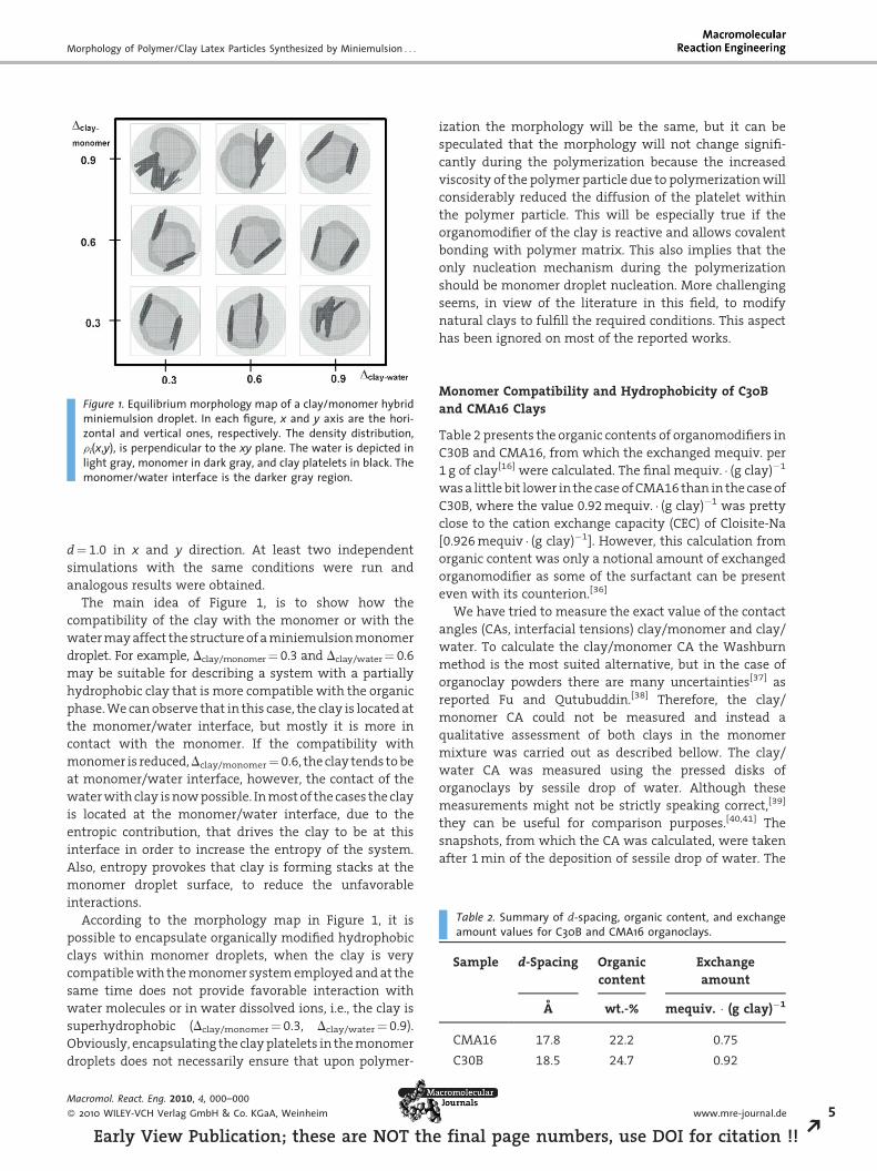
Figure 1. Equilibrium morphology map of a clay/monomer hybridminiemulsion droplet. In each figure, x and y axis are the hori-zontal and vertical ones, respectively. The density distribution,ri(x,y), is perpendicular to the xy plane. The water is depicted inlight gray, monomer in dark gray, and clay platelets in black. Themonomer/water interface is the darker gray region.
d¼ 1.0 in x and y direction. At least two independent
simulations with the same conditions were run and
analogous results were obtained.
The main idea of Figure 1, is to show how the
compatibility of the clay with the monomer or with the
water may affect the structure of a miniemulsion monomer
droplet. For example, Dclay/monomer¼ 0.3 and Dclay/water¼ 0.6
may be suitable for describing a system with a partially
hydrophobic clay that is more compatible with the organic
phase. We can observe that in this case, the clay is located at
the monomer/water interface, but mostly it is more in
contact with the monomer. If the compatibility with
monomer is reduced,Dclay/monomer ¼ 0.6, the clay tends to be
at monomer/water interface, however, the contact of the
water with clay is now possible. In most of the cases the clay
is located at the monomer/water interface, due to the
entropic contribution, that drives the clay to be at this
interface in order to increase the entropy of the system.
Also, entropy provokes that clay is forming stacks at the
monomer droplet surface, to reduce the unfavorable
interactions.
According to the morphology map in Figure 1, it is
possible to encapsulate organically modified hydrophobic
clays within monomer droplets, when the clay is very
compatible with the monomer system employed and at the
same time does not provide favorable interaction with
water molecules or in water dissolved ions, i.e., the clay is
superhydrophobic (Dclay/monomer¼ 0.3, Dclay/water ¼ 0.9).
Obviously, encapsulating the clay platelets in the monomer
droplets does not necessarily ensure that upon polymer-
Macromol. React. Eng. 2010, 4, 000–000
� 2010 WILEY-VCH Verlag GmbH & Co. KGaA, Weinheim
Early View Publication; these are NOT the
ization the morphology will be the same, but it can be
speculated that the morphology will not change signifi-
cantly during the polymerization because the increased
viscosity of the polymer particle due to polymerization will
considerably reduced the diffusion of the platelet within
the polymer particle. This will be especially true if the
organomodifier of the clay is reactive and allows covalent
bonding with polymer matrix. This also implies that the
only nucleation mechanism during the polymerization
should be monomer droplet nucleation. More challenging
seems, in view of the literature in this field, to modify
natural clays to fulfill the required conditions. This aspect
has been ignored on most of the reported works.
Monomer Compatibility and Hydrophobicity of C30Band CMA16 Clays
Table 2 presents the organic contents of organomodifiers in
C30B and CMA16, from which the exchanged mequiv. per
1 g of clay[16] were calculated. The final mequiv. � (g clay)�1
was a little bit lower in the case of CMA16 than in the case of
C30B, where the value 0.92 mequiv. � (g clay)�1 was pretty
close to the cation exchange capacity (CEC) of Cloisite-Na
[0.926 mequiv � (g clay)�1]. However, this calculation from
organic content was only a notional amount of exchanged
organomodifier as some of the surfactant can be present
even with its counterion.[36]
We have tried to measure the exact value of the contact
angles (CAs, interfacial tensions) clay/monomer and clay/
water. To calculate the clay/monomer CA the Washburn
method is the most suited alternative, but in the case of
organoclay powders there are many uncertainties[37] as
reported Fu and Qutubuddin.[38] Therefore, the clay/
monomer CA could not be measured and instead a
qualitative assessment of both clays in the monomer
mixture was carried out as described bellow. The clay/
water CA was measured using the pressed disks of
organoclays by sessile drop of water. Although these
measurements might not be strictly speaking correct,[39]
they can be useful for comparison purposes.[40,41] The
snapshots, from which the CA was calculated, were taken
after 1 min of the deposition of sessile drop of water. The
www.mre-journal.de 5
final page numbers, use DOI for citation !! R
M. Micusık et al.
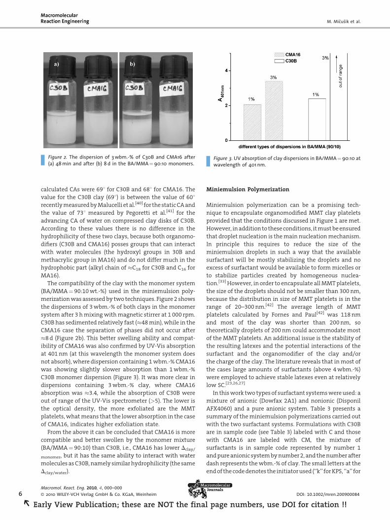
Figure 2. The dispersion of 3wbm.-% of C30B and CMA16 after(a) 48min and after (b) 8 d in the BA/MMA¼90:10 monomers.
Figure 3. UV absorption of clay dispersions in BA/MMA¼90:10 atwavelength of 401 nm.
6
REa
calculated CAs were 698 for C30B and 688 for CMA16. The
value for the C30B clay (698) is between the value of 608recently measured by Malucelli et al.[40] for the static CA and
the value of 738 measured by Pegoretti et al.[41] for the
advancing CA of water on compressed clay disks of C30B.
According to these values there is no difference in the
hydrophilicity of these two clays, because both organomo-
difiers (C30B and CMA16) posses groups that can interact
with water molecules (the hydroxyl groups in 30B and
methacrylic group in MA16) and do not differ much in the
hydrophobic part (alkyl chain of �C18 for C30B and C16 for
MA16).
The compatibility of the clay with the monomer system
(BA/MMA¼ 90:10 wt.-%) used in the miniemulsion poly-
merization was assessed by two techniques. Figure 2 shows
the dispersions of 3 wbm.-% of both clays in the monomer
system after 3 h mixing with magnetic stirrer at 1 000 rpm.
C30B has sedimented relatively fast (�48 min), while in the
CMA16 case the separation of phases did not occur after
�8 d (Figure 2b). This better swelling ability and compat-
ibility of CMA16 was also confirmed by UV-Vis absorption
at 401 nm (at this wavelength the monomer system does
not absorb), where dispersion containing 1 wbm.-% CMA16
was showing slightly slower absorption than 1 wbm.-%
C30B monomer dispersion (Figure 3). It was more clear in
dispersions containing 3 wbm.-% clay, where CMA16
absorption was �3.4, while the absorption of C30B were
out of range of the UV-Vis spectrometer (>5). The lower is
the optical density, the more exfoliated are the MMT
platelets, what means that the lower absorption in the case
of CMA16, indicates higher exfoliation state.
From the above it can be concluded that CMA16 is more
compatible and better swollen by the monomer mixture
(BA/MMA¼ 90:10) than C30B, i.e., CMA16 has lower Dclay/
monomer, but it has the same ability to interact with water
molecules as C30B, namely similar hydrophilicity (the same
Dclay/water).
Macromol. React. Eng. 2010, 4, 000–000
� 2010 WILEY-VCH Verlag GmbH & Co. KGaA, Weinheim
rly View Publication; these are NOT the fina
Miniemulsion Polymerization
Miniemulsion polymerization can be a promising tech-
nique to encapsulate organomodified MMT clay platelets
provided that the conditions discussed in Figure 1 are met.
However, in addition to these conditions, it must be ensured
that droplet nucleation is the main nucleation mechanism.
In principle this requires to reduce the size of the
miniemulsion droplets in such a way that the available
surfactant will be mostly stabilizing the droplets and no
excess of surfactant would be available to form micelles or
to stabilize particles created by homogeneous nuclea-
tion.[33] However, in order to encapsulate all MMT platelets,
the size of the droplets should not be smaller than 300 nm,
because the distribution in size of MMT platelets is in the
range of 20–300 nm.[42] The average length of MMT
platelets calculated by Fornes and Paul[42] was 118 nm
and most of the clay was shorter than 200 nm, so
theoretically droplets of 200 nm could accommodate most
of the MMT platelets. An additional issue is the stability of
the resulting latexes and the potential interactions of the
surfactant and the organomodifier of the clay and/or
the charge of the clay. The literature reveals that in most of
the cases large amounts of surfactants (above 4 wbm.-%)
were employed to achieve stable latexes even at relatively
low SC.[23,26,27]
In this work two types of surfactant systems were used: a
mixture of anionic (Dowfax 2A1) and nonionic (Disponil
AFX4060) and a pure anionic system. Table 3 presents a
summary of the miniemulsion polymerizations carried out
with the two surfactant systems. Formulations with C30B
are in sample code (see Table 3) labeled with C and those
with CMA16 are labeled with CM, the mixture of
surfactants is in sample code represented by number 1
and pure anionic system by number 2, and the number after
dash represents the wbm.-% of clay. The small letters at the
end of the code denotes the initiator used (‘‘k’’ for KPS, ‘‘a’’ for
DOI: 10.1002/mren.200900084
l page numbers, use DOI for citation !!
Morphology of Polymer/Clay Latex Particles Synthesized by Miniemulsion . . .
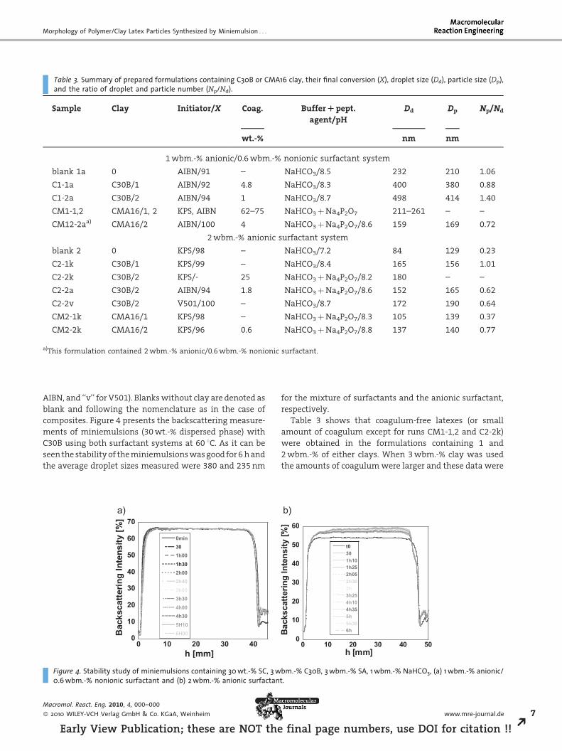
Table 3. Summary of prepared formulations containing C30B or CMA16 clay, their final conversion (X), droplet size (Dd), particle size (Dp),and the ratio of droplet and particle number (Np/Nd).
Sample Clay Initiator/X Coag. BufferRpept.
agent/pH
Dd Dp Np/Nd
wt.-% nm nm
1 wbm.-% anionic/0.6 wbm.-% nonionic surfactant system
blank 1a 0 AIBN/91 – NaHCO3/8.5 232 210 1.06
C1-1a C30B/1 AIBN/92 4.8 NaHCO3/8.3 400 380 0.88
C1-2a C30B/2 AIBN/94 1 NaHCO3/8.7 498 414 1.40
CM1-1,2 CMA16/1, 2 KPS, AIBN 62–75 NaHCO3 þNa4P2O7 211–261 – –
CM12-2aa) CMA16/2 AIBN/100 4 NaHCO3 þNa4P2O7/8.6 159 169 0.72
2 wbm.-% anionic surfactant system
blank 2 0 KPS/98 – NaHCO3/7.2 84 129 0.23
C2-1k C30B/1 KPS/99 – NaHCO3/8.4 165 156 1.01
C2-2k C30B/2 KPS/- 25 NaHCO3 þNa4P2O7/8.2 180 – –
C2-2a C30B/2 AIBN/94 1.8 NaHCO3 þNa4P2O7/8.6 152 165 0.62
C2-2v C30B/2 V501/100 – NaHCO3/8.7 172 190 0.64
CM2-1k CMA16/1 KPS/98 – NaHCO3 þNa4P2O7/8.3 105 139 0.37
CM2-2k CMA16/2 KPS/96 0.6 NaHCO3 þNa4P2O7/8.8 137 140 0.77
a)This formulation contained 2 wbm.-% anionic/0.6 wbm.-% nonionic surfactant.
AIBN, and ‘‘v’’ for V501). Blanks without clay are denoted as
blank and following the nomenclature as in the case of
composites. Figure 4 presents the backscattering measure-
ments of miniemulsions (30 wt.-% dispersed phase) with
C30B using both surfactant systems at 60 8C. As it can be
seen the stability of the miniemulsions was good for 6 h and
the average droplet sizes measured were 380 and 235 nm
0
10
20
30
40
50
60
70a)
0 10 20 30 40
0min301h001h302h002h403h003h304h004h305H106H00B
acks
catte
ring
Inte
nsity
[%]
h [mm]
Figure 4. Stability study of miniemulsions containing 30wt.-% SC, 3w0.6wbm.-% nonionic surfactant and (b) 2wbm.-% anionic surfactan
Macromol. React. Eng. 2010, 4, 000–000
� 2010 WILEY-VCH Verlag GmbH & Co. KGaA, Weinheim
Early View Publication; these are NOT the
for the mixture of surfactants and the anionic surfactant,
respectively.
Table 3 shows that coagulum-free latexes (or small
amount of coagulum except for runs CM1-1,2 and C2-2k)
were obtained in the formulations containing 1 and
2 wbm.-% of either clays. When 3 wbm.-% clay was used
the amounts of coagulum were larger and these data were
b)
0
10
20
30
40
50
60
0 10 20 30 40 50
t0301h101h252h052h303h3h254h104h355h5h306hB
acks
catte
ring
Inte
nsity
[%]
h [mm]
bm.-% C30B, 3wbm.-% SA, 1wbm.-% NaHCO3, (a) 1wbm.-% anionic/t.
www.mre-journal.de 7
final page numbers, use DOI for citation !! R
M. Micusık et al.
100 1000 100000
5
10
15
20
25Vo
lum
e [%
]
Size [nm]
C1-2a miniemulsionC1-2a final latexC2-2a miniemulsionC2-2a final latex
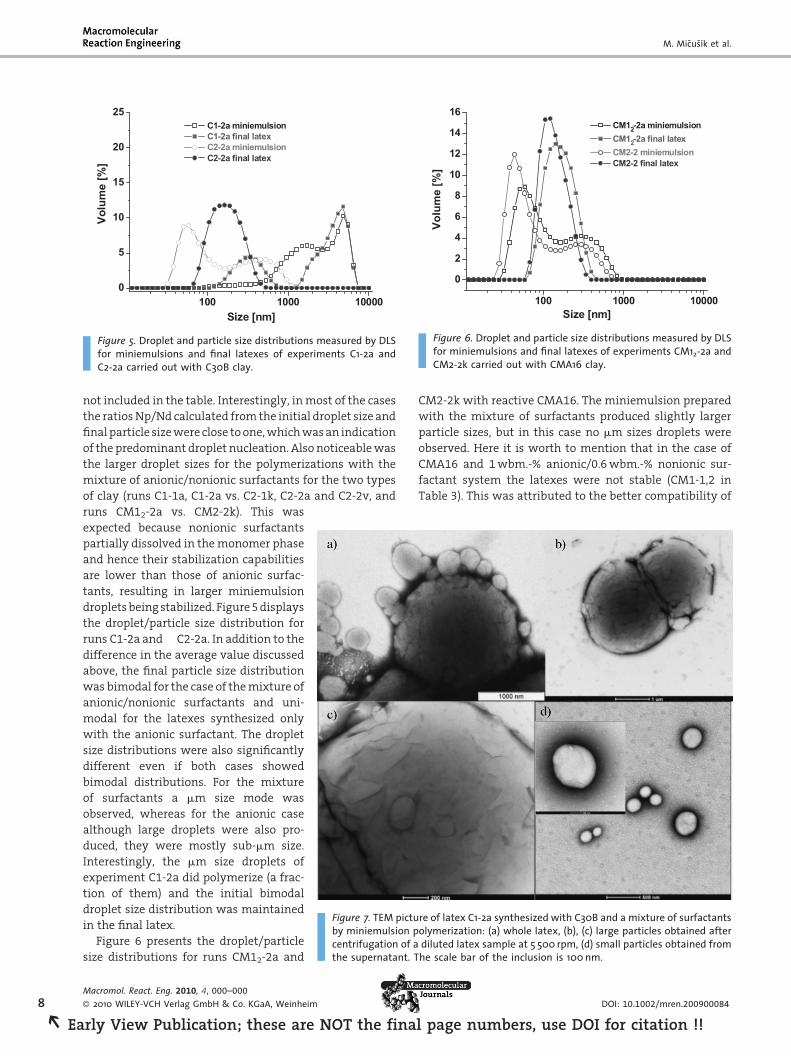
Figure 5. Droplet and particle size distributions measured by DLSfor miniemulsions and final latexes of experiments C1-2a andC2-2a carried out with C30B clay.
100 1000 10000
0
2
4
6
8
10
12
14
16
Volu
me
[%]
Size [nm]
CM12-2a miniemulsionCM12-2a final latexCM2-2 miniemulsionCM2-2 final latex
Figure 6. Droplet and particle size distributions measured by DLSfor miniemulsions and final latexes of experiments CM12-2a andCM2-2k carried out with CMA16 clay.
8
REa
not included in the table. Interestingly, in most of the cases
the ratios Np/Nd calculated from the initial droplet size and
final particle size were close to one, which was an indication
of the predominant droplet nucleation. Also noticeable was
the larger droplet sizes for the polymerizations with the
mixture of anionic/nonionic surfactants for the two types
of clay (runs C1-1a, C1-2a vs. C2-1k, C2-2a and C2-2v, and
Figure 7. TEM picture of latex C1-2a synthesized with C30B and a mixture of surfactantsby miniemulsion polymerization: (a) whole latex, (b), (c) large particles obtained aftercentrifugation of a diluted latex sample at 5 500 rpm, (d) small particles obtained fromthe supernatant. The scale bar of the inclusion is 100nm.
runs CM12-2a vs. CM2-2k). This was
expected because nonionic surfactants
partially dissolved in the monomer phase
and hence their stabilization capabilities
are lower than those of anionic surfac-
tants, resulting in larger miniemulsion
droplets being stabilized. Figure 5 displays
the droplet/particle size distribution for
runs C1-2a and C2-2a. In addition to the
difference in the average value discussed
above, the final particle size distribution
was bimodal for the case of the mixture of
anionic/nonionic surfactants and uni-
modal for the latexes synthesized only
with the anionic surfactant. The droplet
size distributions were also significantly
different even if both cases showed
bimodal distributions. For the mixture
of surfactants a mm size mode was
observed, whereas for the anionic case
although large droplets were also pro-
duced, they were mostly sub-mm size.
Interestingly, the mm size droplets of
experiment C1-2a did polymerize (a frac-
tion of them) and the initial bimodal
droplet size distribution was maintained
in the final latex.
Figure 6 presents the droplet/particle
size distributions for runs CM12-2a and
Macromol. React. Eng. 2010, 4, 000–000
� 2010 WILEY-VCH Verlag GmbH & Co. KGaA, Weinheim
rly View Publication; these are NOT the fina
CM2-2k with reactive CMA16. The miniemulsion prepared
with the mixture of surfactants produced slightly larger
particle sizes, but in this case no mm sizes droplets were
observed. Here it is worth to mention that in the case of
CMA16 and 1 wbm.-% anionic/0.6 wbm.-% nonionic sur-
factant system the latexes were not stable (CM1-1,2 in
Table 3). This was attributed to the better compatibility of
DOI: 10.1002/mren.200900084
l page numbers, use DOI for citation !!

Morphology of Polymer/Clay Latex Particles Synthesized by Miniemulsion . . .
CMA16 with the monomer mixture that facilitated break-
age and production of smaller droplets, which needed more
charge to stabilize the latex (note that stable latex was
achieved when the amount of anionic surfactant portion
was increased in CM12-2a).
Morphology of the Hybrid Latex Particles
Figure 7 presents a series of TEM images for latex C1-2a.
Figure 7a clearly confirms the bimodal nature of the latex
with particles above and below the mm size. Figure 7b–d
present TEM images of each population after ultracentri-
fugation of the latex to analyze both populations separately
(5 500 rpm for 30 min).
Figure 7b and c show plenty of C30B platelets in the large
particles. Whether the platelets are fully encapsulated,
protruding from the particle or at the surface is hard to say
from the images. Figure 7d shows that the population of
small particles was broad and the larger particles in this
population contained individualized platelets as it can be
seen in the inclusion in Figure 7d.
This latex was further analyzed by Wet-STEM to have
additional information about the location of the clay
Figure 8. Wet-STEM pictures of latex C1-2a.
Macromol. React. Eng. 2010, 4, 000–000
� 2010 WILEY-VCH Verlag GmbH & Co. KGaA, Weinheim
Early View Publication; these are NOT the
platelets in the wet state before film forming. Figure 8
displays two micrographs, which only captured large
particles. The micrographs show white areas at the junction
of the polymer particles and also within the particles as
veins that corresponded well with the shapes of platelets in
Figure 7b,c. One can speculate that these veins corre-
sponded to clay platelets encapsulated in the polymer
particles, but admittedly it is uncertain.
Figure 9 shows the TEM pictures for latex CM12-2a and
the presence of clay platelets at the surface of the particles
can be distinguished (Figure 9b). Also noticeable is the
presence of considerable number of snowman/dumbbell-
like particles (indicated by arrows). Voorn et al.[43] have
observed similar particles in a completely different process
using MMT clay modified with a reactive silane by the
edges. They explained that the dumbbell-like morphology
was a consequence of the polymerization starting in the
platelets and hence they claimed that in these particles
platelets were encapsulated. In our case it likely indicated
the reactivity of CMA16, but the presence of clay was not
clear at the particle-particle interphase. The structures
denoted by arrows in Figure 9b looks to be formed on the
platelet surface, what would confirm the CMA16 reactivity,
but no clear encapsulation was observed.
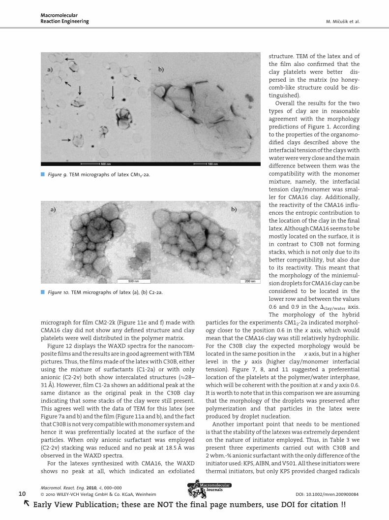
Figure 10a,b present the TEM micrographs for latex C2-2a
synthesized with only anionic surfactant and C30B. The
micrograph confirms the DLS information regarding the
size of the particles which was smaller and in the sub-mm
range. Unfortunately, not much can be said about the
location of the clay platelets in the polymer particles.
Morphology of the Films
Films were cast from the latex and cryo-sectioned speci-
mens observed by cryo-TEM. Films were also analyzed by
WAXD to explore the degree of exfoliation of the clay
platelets in the film. Figure 11 presents the TEM micro-
graphs of the thin films of latex C1-2a, C2-2v, and CM2-2k.
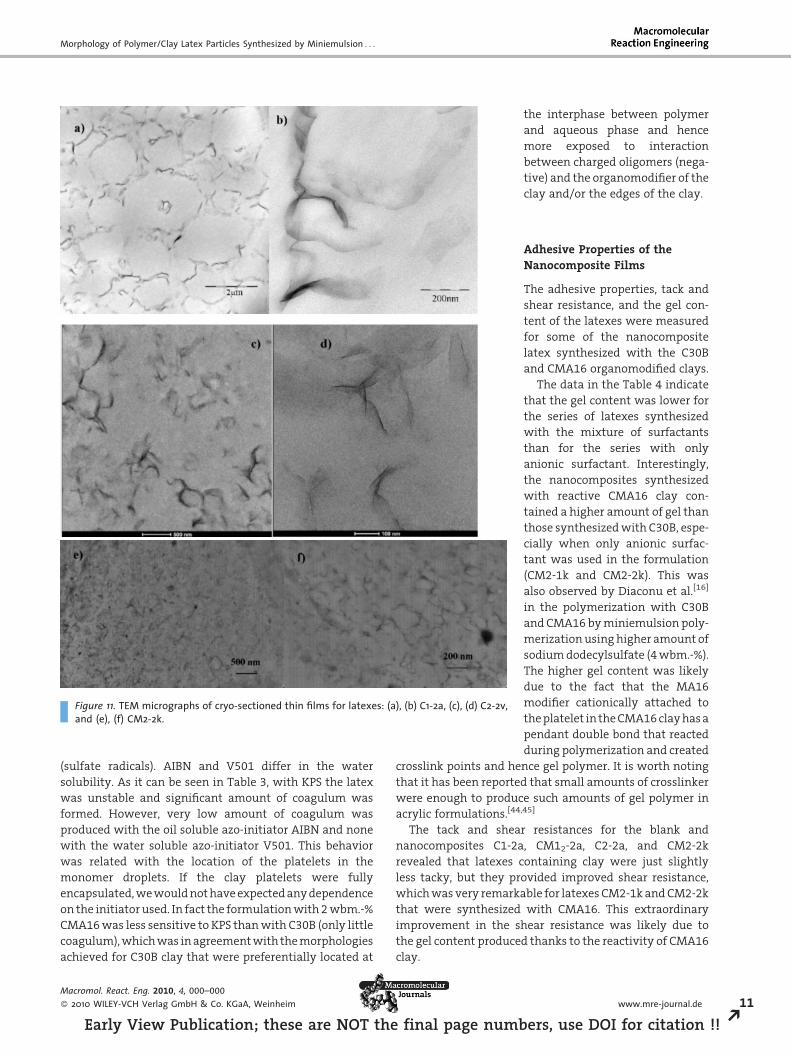
Film C1-2a (Figure 11a and b) shows a clear honeycomb
structure where the size of the original bimodal particles
was preserved. Clay stacks and individual platelets can be
recognized from the micrograph. This micrograph may shed
light about the uncertain location of the platelets (see TEM
and Wet-STEM micrographs in Figure 7 and 8). Although
clay platelets can migrate during film formation it is very
unlikely that they will migrate from the inner part of large
particles to the surface. Therefore, it can be concluded that
platelets were preferentially located close to the surface of
the particles. The micrograph for film C2-2v (Figure 11c
and d) did not show a clear honeycomb structure although
some sections looked like that. The clay platelets were
better dispersed because the size of the particles was
smaller and intercalated and exfoliated structures can be
observed (see larger magnification in Figure 11d). The
www.mre-journal.de 9
final page numbers, use DOI for citation !! R
M. Micusık et al.
Figure 9. TEM micrographs of latex CM12-2a.
Figure 10. TEM micrographs of latex (a), (b) C2-2a.
10
REa
micrograph for film CM2-2k (Figure 11e and f) made with
CMA16 clay did not show any defined structure and clay
platelets were well distributed in the polymer matrix.
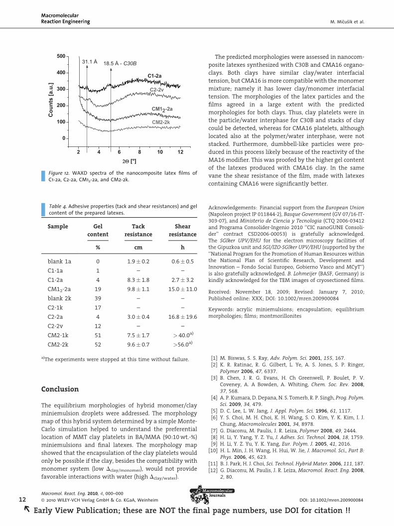
Figure 12 displays the WAXD spectra for the nanocom-
posite films and the results are in good agreement with TEM
pictures. Thus, the films made of the latex with C30B, either
using the mixture of surfactants (C1-2a) or with only
anionic (C2-2v) both show intercalated structures (�28–
31 A). However, film C1-2a shows an additional peak at the
same distance as the original peak in the C30B clay
indicating that some stacks of the clay were still present.
This agrees well with the data of TEM for this latex (see
Figure 7a and b) and the film (Figure 11a and b), and the fact
that C30B is not very compatible with monomer system and
hence it was preferentially located at the surface of the
particles. When only anionic surfactant was employed
(C2-2v) stacking was reduced and no peak at 18.5 A was
observed in the WAXD spectra.
For the latexes synthesized with CMA16, the WAXD
shows no peak at all, which indicated an exfoliated
Macromol. React. Eng. 2010, 4, 000–000
� 2010 WILEY-VCH Verlag GmbH & Co. KGaA, Weinheim
rly View Publication; these are NOT the final page numbers, u
structure. TEM of the latex and of
the film also confirmed that the
clay platelets were better dis-
persed in the matrix (no honey-
comb-like structure could be dis-
tinguished).
Overall the results for the two
types of clay are in reasonable
agreement with the morphology
predictions of Figure 1. According
to the properties of the organomo-
dified clays described above the
interfacial tension of the clays with
water were very close and the main
difference between them was the
compatibility with the monomer
mixture, namely, the interfacial
tension clay/monomer was smal-
ler for CMA16 clay. Additionally,
the reactivity of the CMA16 influ-
ences the entropic contribution to
the location of the clay in the final
latex. Although CMA16 seems to be
mostly located on the surface, it is
in contrast to C30B not forming
stacks, which is not only due to its
better compatibility, but also due
to its reactivity. This meant that
the morphology of the miniemul-
sion droplets for CMA16 clay can be
considered to be located in the
lower row and between the values
0.6 and 0.9 in the Dclay/water axis.
The morphology of the hybrid
particles for the experiments CM12-2a indicated morphol-
ogy closer to the position 0.6 in the x axis, which would
mean that the CMA16 clay was still relatively hydrophilic.
For the C30B clay the expected morphology would be
located in the same position in the x axis, but in a higher
level in the y axis (higher clay/monomer interfacial
tension). Figure 7, 8, and 11 suggested a preferential
location of the platelets at the polymer/water interphase,
which will be coherent with the position at x and y axis 0.6.
It is worth to note that in this comparison we are assuming
that the morphology of the droplets was preserved after
polymerization and that particles in the latex were
produced by droplet nucleation.
Another important point that needs to be mentioned
is that the stability of the latexes was extremely dependent
on the nature of initiator employed. Thus, in Table 3 we
present three experiments carried out with C30B and
2 wbm.-% anionic surfactant with the only difference of the
initiator used: KPS, AIBN, and V501. All these initiators were
thermal initiators, but only KPS provided charged radicals
DOI: 10.1002/mren.200900084
se DOI for citation !!
Morphology of Polymer/Clay Latex Particles Synthesized by Miniemulsion . . .
Figure 11. TEM micrographs of cryo-sectioned thin films for latexes: (a), (b) C1-2a, (c), (d) C2-2v,and (e), (f) CM2-2k.
(sulfate radicals). AIBN and V501 differ in the water
solubility. As it can be seen in Table 3, with KPS the latex
was unstable and significant amount of coagulum was
formed. However, very low amount of coagulum was
produced with the oil soluble azo-initiator AIBN and none
with the water soluble azo-initiator V501. This behavior
was related with the location of the platelets in the
monomer droplets. If the clay platelets were fully
encapsulated, we would not have expected any dependence
on the initiator used. In fact the formulation with 2 wbm.-%
CMA16 was less sensitive to KPS than with C30B (only little
coagulum), which was in agreement with the morphologies
achieved for C30B clay that were preferentially located at
Macromol. React. Eng. 2010, 4, 000–000
� 2010 WILEY-VCH Verlag GmbH & Co. KGaA, Weinheim
Early View Publication; these are NOT the final page numb
the interphase between polymer
and aqueous phase and hence
more exposed to interaction
between charged oligomers (nega-
tive) and the organomodifier of the
clay and/or the edges of the clay.
Adhesive Properties of theNanocomposite Films
The adhesive properties, tack and
shear resistance, and the gel con-
tent of the latexes were measured
for some of the nanocomposite
latex synthesized with the C30B
and CMA16 organomodified clays.
The data in the Table 4 indicate
that the gel content was lower for
the series of latexes synthesized
with the mixture of surfactants
than for the series with only
anionic surfactant. Interestingly,
the nanocomposites synthesized
with reactive CMA16 clay con-
tained a higher amount of gel than
those synthesized with C30B, espe-
cially when only anionic surfac-
tant was used in the formulation
(CM2-1k and CM2-2k). This was
also observed by Diaconu et al.[16]
in the polymerization with C30B
and CMA16 by miniemulsion poly-
merization using higher amount of
sodium dodecylsulfate (4 wbm.-%).
The higher gel content was likely
due to the fact that the MA16
modifier cationically attached to
the platelet in the CMA16 clay has a
pendant double bond that reacted
during polymerization and created
crosslink points and hence gel polymer. It is worth noting
that it has been reported that small amounts of crosslinker
were enough to produce such amounts of gel polymer in
acrylic formulations.[44,45]
The tack and shear resistances for the blank and
nanocomposites C1-2a, CM12-2a, C2-2a, and CM2-2k
revealed that latexes containing clay were just slightly
less tacky, but they provided improved shear resistance,
which was very remarkable for latexes CM2-1k and CM2-2k
that were synthesized with CMA16. This extraordinary
improvement in the shear resistance was likely due to
the gel content produced thanks to the reactivity of CMA16
clay.
www.mre-journal.de 11
ers, use DOI for citation !! R
M. Micusık et al.
2 4 6 8 10 12
0
100
200
300
400
500
CM2-2k
CM12-2a
C2-2v
31.1 Å
Cou
nts
[a.u
.]
[°]
18.5 Å - C30B
C1-2a
Figure 12. WAXD spectra of the nanocomposite latex films ofC1-2a, C2-2a, CM12-2a, and CM2-2k.
Table 4. Adhesive properties (tack and shear resistances) and gelcontent of the prepared latexes.
Sample Gel
content
Tack
resistance
Shear
resistance
% cm h
blank 1a 0 1.9� 0.2 0.6� 0.5
C1-1a 1 – –
C1-2a 4 8.3� 1.8 2.7� 3.2
CM12-2a 19 9.8� 1.1 15.0� 11.0
blank 2k 39 – –
C2-1k 17 – –
C2-2a 4 3.0� 0.4 16.8� 19.6
C2-2v 12 – –
CM2-1k 51 7.5� 1.7 > 40.0a)
CM2-2k 52 9.6� 0.7 >56.0a)
a)The experiments were stopped at this time without failure.
12
REa
Conclusion
The equilibrium morphologies of hybrid monomer/clay
miniemulsion droplets were addressed. The morphology
map of this hybrid system determined by a simple Monte-
Carlo simulation helped to understand the preferential
location of MMT clay platelets in BA/MMA (90:10 wt.-%)
miniemulsions and final latexes. The morphology map
showed that the encapsulation of the clay platelets would
only be possible if the clay, besides the compatibility with
monomer system (low Dclay/monomer), would not provide
favorable interactions with water (high Dclay/water).
Macromol. React. Eng. 2010, 4, 000–000
� 2010 WILEY-VCH Verlag GmbH & Co. KGaA, Weinheim
rly View Publication; these are NOT the fina
The predicted morphologies were assessed in nanocom-
posite latexes synthesized with C30B and CMA16 organo-
clays. Both clays have similar clay/water interfacial
tension, but CMA16 is more compatible with the monomer
mixture; namely it has lower clay/monomer interfacial
tension. The morphologies of the latex particles and the
films agreed in a large extent with the predicted
morphologies for both clays. Thus, clay platelets were in
the particle/water interphase for C30B and stacks of clay
could be detected, whereas for CMA16 platelets, although
located also at the polymer/water interphase, were not
stacked. Furthermore, dumbbell-like particles were pro-
duced in this process likely because of the reactivity of the
MA16 modifier. This was proofed by the higher gel content
of the latexes produced with CMA16 clay. In the same
vane the shear resistance of the film, made with latexes
containing CMA16 were significantly better.
Acknowledgements: Financial support from the European Union(Napoleon project IP 011844-2), Basque Government (GV 07/16-IT-303-07), and Ministerio de Ciencia y Tecnologia (CTQ 2006-03412and Programa Consolider-Ingenio 2010 ‘‘CIC nanoGUNE Consoli-der’’ contract CSD2006-00053) is gratefully acknowledged.The SGIker UPV/EHU for the electron microscopy facilities ofthe Gipuzkoa unit and SGI/IZO-SGIker UPV/EHU (supported by the‘‘National Program for the Promotion of Human Resources withinthe National Plan of Scientific Research, Development andInnovation – Fondo Social Europeo, Gobierno Vasco and MCyT’’)is also gratefully acknowledged. B. Lohmeijer (BASF, Germany) iskindly acknowledged for the TEM images of cryosectioned films.
Received: November 18, 2009; Revised: January 7, 2010;Published online: XXX; DOI: 10.1002/mren.200900084
Keywords: acrylic miniemulsions; encapsulation; equilibriummorphologies; films; montmorillonites
[1] M. Biswas, S. S. Ray, Adv. Polym. Sci. 2001, 155, 167.[2] K. R. Ratinac, R. G. Gilbert, L. Ye, A. S. Jones, S. P. Ringer,
Polymer 2006, 47, 6337.[3] B. Chen, J. R. G. Evans, H. Ch Greenwell, P. Boulet, P. V.
Coveney, A. A Bowden, A. Whiting, Chem. Soc. Rev. 2008,37, 568.
[4] A. P. Kumara, D. Depana, N. S. Tomerb, R. P. Singh, Prog. Polym.Sci. 2009, 34, 479.
[5] D. C. Lee, L. W. Jang, J. Appl. Polym. Sci. 1996, 61, 1117.[6] Y. S. Choi, M. H. Choi, K. H. Wang, S. O. Kim, Y. K. Kim, I. J.
Chung, Macromolecules 2001, 34, 8978.[7] G. Diaconu, M. Paulis, J. R. Leiza, Polymer 2008, 49, 2444.[8] H. Li, Y. Yang, Y. Z. Yu, J. Adhes. Sci. Technol. 2004, 18, 1759.[9] H. Li, Y. Z. Yu, Y. K. Yang, Eur. Polym. J. 2005, 41, 2016.
[10] H. L. Min, J. H. Wang, H. Hui, W. Jie, J. Macromol. Sci., Part B:Phys. 2006, 45, 623.
[11] B. J. Park, H. J. Choi, Sci. Technol. Hybrid Mater. 2006, 111, 187.[12] G. Diaconu, M. Paulis, J. R. Leiza, Macromol. React. Eng. 2008,
2, 80.
DOI: 10.1002/mren.200900084
l page numbers, use DOI for citation !!

Morphology of Polymer/Clay Latex Particles Synthesized by Miniemulsion . . .
[13] R. P. Moraes, A. M. Santos, P. C. Oliveira, F. C. T. Souza,M. do Amaral, T. S. Valera, N. R. Demarquette, Macromol.Symp. 2006, 245, 106.
[14] Q. Sun, Y. Deng, Z. L. Wang, Macromol. Mater. Eng. 2004, 289,288.
[15] A. Samakande, R. D. Sanderson, P. C. Hartmann, Polymer 2009,50, 42.
[16] G. Diaconu, M. Micusık, A. Bonnefond, M. Paulis, J. R. Leiza,Macromolecules 2009, 42, 3316.
[17] Y. Yang, L. Liu, J. Zhang, C. Li, H. Zhao, Langmuir 2007, 23, 2867.[18] D. Donescu, C. Radovici, C. Petcu, S. Serbam, M. C. Corobea,
M. Ghiurea, J. Dispersion Sci. Technol. 2008, 29, 340.[19] L. Fialova, I. Capek, R. Ianchis, M. C. Corobea, D. Donescu,
D. Berek, Polym. J. 2008, 40, 163.[20] E. Bourgeat-Lami, N. Negrete Herrera, J.-L. Putaux, A. Perro, S.
Reculusa, S. Ravaine, E. Duguet, Macromol. Symp. 2007, 248,213.
[21] S. I. Ali, J. P. A. Heuts, B. S. Hawkett, A. M. van Herk, Langmuir2009, 25, 10523.
[22] V. Mellon, ‘‘Synthesis and Characterization of WaterbornePolymer/Laponite Nanocomposite Latexes Through Minie-mulsion Polymerization’’, PhD thesis Universite ClaudeBernard Lyon I 2009, p. 169.
[23] Z. Tong, Y. Deng, Polymer 2007, 48, 4337.[24] N. Negrete-Herrera, J. L. Putaux, L. David, F. De Haas,
E. Bourgeat-Lami, Macromol. Rapid Commun. 2007, 28,1567.
[25] D. J. Voorn, W. Ming, A. M. van Herk, Macromolecules 2006,39, 2137.
[26] M. Mirzataheri, A. R. Mahdavian, M. Atai, Colloid Polym. Sci.2009, 287, 725.
[27] F. Bouanani, D. Bendedouch, P. Hemery, B. Bounaceur,Colloids Surf., A 2008, 317, 751.
Macromol. React. Eng. 2010, 4, 000–000
� 2010 WILEY-VCH Verlag GmbH & Co. KGaA, Weinheim
Early View Publication; these are NOT the
[28] D. J. Voorn, W. Ming, A. M. van Herk, Macromol. Symp. 2006,245-246, 584.
[29] A. Bogner, G. Thollet, D. Basset, P. H. Jouneau, C. Gauthier,Ultramicroscopy 2005, 104, 290.
[30] F. Alarcia, J. C. de la Cal, J. M. Asua, Macromol. Mater. Eng.2006, 291, 428.
[31] O. Elizalde, G. Arzamendi, J. R. Leiza, J. M. Asua, Ind. Eng. Chem.Res. 2004, 43, 7401. 7409.
[32] Y. Lyatskaya, A. Balazs, Macromolecules 1998, 31, 6676.[33] J. M. Asua, Prog. Polym. Sci. 2002, 27, 1283.[34] D. P. Landau, K. Binder, ‘‘AGuide toMonte-Carlo Simulation in
Statistical Physics’’, 2nd edition, Cambridge University Press,Cambridge 2005.
[35] Y. Duda, E. Vakarin, J. Alejandre, J. Colloid Interface Sci. 2003,258, 10.
[36] J. M. Cervantes-Uc, J. V. Cauich-Rodrıguez, H. Vazquez-Torres,L. F. Garfias-Mesıas, D. R. Paul, Thermochim. Acta 2007,457, 92.
[37] H. Czachor, Hydrol. Process. 2007, 21, 2239.[38] X. A. Fu, S. Qutubuddin, J. Colloid Interface Sci. 2005, 283,
373.[39] A. Rudawska, E. Jacniacka, Int. J. Adhes. Adhes. 2009, 29, 451.[40] G. Malucelli, S. Ronchetti, N. Lak, A. Priola, N. Tzankova
Dintcheva, F. P. La Mantia, Eur. Polym. J. 2007, 43, 328.[41] A. Pegoretti, A. Dorigato, M. Brugnara, A. Penati, Eur. Polym. J.
2008, 44, 1662.[42] T. D. Fornes, D. R. Paul, Polymer 2003, 44, 4993.[43] D. J. Voorn, W. Ming, A. M. van Herk, Macromolecules 2006,
39, 4654.[44] L. Bouvier-Fontes, R. Pirri, J. M. Asua, J. R. Leiza, Macromol-
ecules 2005, 38, 2722.[45] L. Bouvier-Fontes, R. Pirri, J. M. Asua, J. R. Leiza, Macromol-
ecules 2005, 38, 1164.
www.mre-journal.de 13
final page numbers, use DOI for citation !! R