Monovalent-ion-selective membranes for reverse electrodialysis
17
Monovalent-ion-selective membranes for reverse electrodialysis Enver Güler a,b , Willem van Baak c , Michel Saakes b , Kitty Nijmeijer a,n a Membrane Science & Technology, Mesa þ Institute for Nanotechnology, Faculty of Science and Technology, University of Twente, P.O. Box 217, 7500 AE Enschede, The Netherlands b Wetsus, Centre of Excellence for Sustainable Water Technology, P.O. Box 1113, 8900 CC Leeuwarden, The Netherlands c FUJIFILM Manufacturing Europe BV, Oudenstaart 1, P.O. Box 90156, 5000 LJ Tilburg, The Netherlands article info Article history: Received 6 October 2013 Received in revised form 17 December 2013 Accepted 22 December 2013 Available online 28 December 2013 Keywords: Reverse electrodialysis Monovalent-ion selectivity Membrane characterization Salinity gradient energy Antifouling abstract Reverse electrodialysis (RED) is a process that can be used to generate energy from salinity gradients. Since its application in practice requires the use of natural seawater and river water, the presence of multivalent ions is inevitable, but this currently limits RED performance. Membranes with selectivity for monovalent ions may overcome this limitation. Standard ion exchange membranes have low monovalent-ion selectivity. We used a relatively fast method to coat a standard commercial anion exchange membrane to improve its monovalent-ion selectivity. The coating layer was formed by copolymerization of 2-acryloylamido-2-methylpropanesulfonic acid (AMPS) as the active polymer and N,N-methylenebis(acrylamide) (MBA) as the crosslinker, using UV irradiation. The monovalent ion selectivity of the resulting membranes was comparable to that of commercial monovalent-selective membranes. Furthermore, the modified membranes with their negatively charged coating showed increased hydrophilicity and exhibited sufficient antifouling potential against organic foulants. When they were tested in an RED stack, their performance was found to depend especially on the proportion of the divalent ions (sulfate) in the river water stream. However, the use of the currently available monovalent selective membranes was not found to be very effective for obtaining higher gross power densities in RED. & 2013 Elsevier B.V. All rights reserved. 1. Introduction Global warming and the depletion of fossil fuel sources have resulted in a great deal of attention for energy from renewable sources [1]. Oceans and surface waters have the potential to contribute salinity gradient energy, thermal energy, and energy generated by waves and tidal forces [2]. Of these sustainable energy forms, particularly salinity gradient energy can be consid- ered significant with its theoretical power production potential of 2.4 TW, exceeding the current global electricity consumption [3,4]. One technology for extracting energy from salinity gradients is reverse electrodialysis (RED). In RED, selective ion transport is created via ion-selective membranes. These membranes allow the transport of either anions (i.e. in the case of anion exchange membranes) or cations (i.e. in the case of cation exchange membranes) resulting in a potential difference. The ionic transport is later counterbalanced by electron transport caused by redox reactions at the electrodes. The generated electric current can be utilized in an external electric device. As the ion exchange membranes are core elements in RED, their performance is vital for efficient energy generation. Besides ions like sodium and chloride, many other ions are naturally present in seawater and river water. The literature on ion exchange membranes indicates that the presence of multivalent ions has a lowering effect on stack voltage and thus on the power density [5,6]. Examples of multivalent ions are magnesium, calcium and sulfate. Multivalent ions –particularly magnesium and sulfate – increase the electrical resistance of the membranes and lower the power output [5]. Moreover, standard-grade ion exchange membranes usually have low selectivity towards such ions, e.g. cation exchange membranes were determined to have very low selectivity towards magnesium [5]. Multivalent ions tend to be transported against their concentration gradient, i.e. the so-called uphill transport [6], which is basically the ion exchange of monovalent ions from the seawater side (concentrate) with the multivalent ions from the river water side (diluate). The driving force for this transport against their activity gradient is the difference in electrochemical potential between the ions. Thus, for instance, in the case of anions, the ion exchange of sulfate ions from the diluate for chloride ions in the concentrate will be in a ratio of 1:2 to maintain electroneutrality. This transport of ions will continue until the electrochemical potential gradients of all ions in both solutions are equated. This will eventually decrease Contents lists available at ScienceDirect journal homepage: www.elsevier.com/locate/memsci Journal of Membrane Science 0376-7388/$ - see front matter & 2013 Elsevier B.V. All rights reserved. http://dx.doi.org/10.1016/j.memsci.2013.12.054 n Corresponding author. Tel.: þ31 53 489 4185; fax: þ31 53 489 4611. E-mail address: [email protected] (K. Nijmeijer). Journal of Membrane Science 455 (2014) 254–270
Transcript of Monovalent-ion-selective membranes for reverse electrodialysis
Monovalent-ion-selective membranes for reverse electrodialysis
Enver Güler a,b, Willem van Baak c, Michel Saakes b, Kitty Nijmeijer a,n
a Membrane Science & Technology, Mesaþ Institute for Nanotechnology, Faculty of Science and Technology, University of Twente, P.O. Box 217,7500 AE Enschede, The Netherlandsb Wetsus, Centre of Excellence for Sustainable Water Technology, P.O. Box 1113, 8900 CC Leeuwarden, The Netherlandsc FUJIFILM Manufacturing Europe BV, Oudenstaart 1, P.O. Box 90156, 5000 LJ Tilburg, The Netherlands
a r t i c l e i n f o
Article history:Received 6 October 2013Received in revised form17 December 2013Accepted 22 December 2013Available online 28 December 2013
Keywords:Reverse electrodialysisMonovalent-ion selectivityMembrane characterizationSalinity gradient energyAntifouling
a b s t r a c t
Reverse electrodialysis (RED) is a process that can be used to generate energy from salinity gradients.Since its application in practice requires the use of natural seawater and river water, the presence ofmultivalent ions is inevitable, but this currently limits RED performance. Membranes with selectivity formonovalent ions may overcome this limitation. Standard ion exchange membranes have lowmonovalent-ion selectivity. We used a relatively fast method to coat a standard commercial anionexchange membrane to improve its monovalent-ion selectivity. The coating layer was formed bycopolymerization of 2-acryloylamido-2-methylpropanesulfonic acid (AMPS) as the active polymer andN,N-methylenebis(acrylamide) (MBA) as the crosslinker, using UV irradiation. The monovalent ionselectivity of the resulting membranes was comparable to that of commercial monovalent-selectivemembranes. Furthermore, the modified membranes with their negatively charged coating showedincreased hydrophilicity and exhibited sufficient antifouling potential against organic foulants. Whenthey were tested in an RED stack, their performance was found to depend especially on the proportion ofthe divalent ions (sulfate) in the river water stream. However, the use of the currently availablemonovalent selective membranes was not found to be very effective for obtaining higher gross powerdensities in RED.
& 2013 Elsevier B.V. All rights reserved.
1. Introduction
Global warming and the depletion of fossil fuel sources haveresulted in a great deal of attention for energy from renewablesources [1]. Oceans and surface waters have the potential tocontribute salinity gradient energy, thermal energy, and energygenerated by waves and tidal forces [2]. Of these sustainableenergy forms, particularly salinity gradient energy can be consid-ered significant with its theoretical power production potential of2.4 TW, exceeding the current global electricity consumption [3,4].
One technology for extracting energy from salinity gradients isreverse electrodialysis (RED). In RED, selective ion transport iscreated via ion-selective membranes. These membranes allow thetransport of either anions (i.e. in the case of anion exchangemembranes) or cations (i.e. in the case of cation exchangemembranes) resulting in a potential difference. The ionic transportis later counterbalanced by electron transport caused by redoxreactions at the electrodes. The generated electric current can beutilized in an external electric device.
As the ion exchange membranes are core elements in RED,their performance is vital for efficient energy generation. Besidesions like sodium and chloride, many other ions are naturallypresent in seawater and river water. The literature on ion exchangemembranes indicates that the presence of multivalent ions has alowering effect on stack voltage and thus on the power density[5,6]. Examples of multivalent ions are magnesium, calciumand sulfate. Multivalent ions –particularly magnesium and sulfate– increase the electrical resistance of the membranes and lowerthe power output [5]. Moreover, standard-grade ion exchangemembranes usually have low selectivity towards such ions, e.g.cation exchange membranes were determined to have very lowselectivity towards magnesium [5]. Multivalent ions tend to betransported against their concentration gradient, i.e. the so-calleduphill transport [6], which is basically the ion exchange ofmonovalent ions from the seawater side (concentrate) with themultivalent ions from the river water side (diluate). The drivingforce for this transport against their activity gradient is thedifference in electrochemical potential between the ions. Thus,for instance, in the case of anions, the ion exchange of sulfate ionsfrom the diluate for chloride ions in the concentrate will be in aratio of 1:2 to maintain electroneutrality. This transport of ionswill continue until the electrochemical potential gradients of allions in both solutions are equated. This will eventually decrease
Contents lists available at ScienceDirect
journal homepage: www.elsevier.com/locate/memsci
Journal of Membrane Science
0376-7388/$ - see front matter & 2013 Elsevier B.V. All rights reserved.http://dx.doi.org/10.1016/j.memsci.2013.12.054
n Corresponding author. Tel.: þ31 53 489 4185; fax: þ31 53 489 4611.E-mail address: [email protected] (K. Nijmeijer).
Journal of Membrane Science 455 (2014) 254–270

the salinity gradient and thus the power density in RED [5].Therefore, one of the key electrochemical properties of themembranes that determine RED performance is the selectivityfor specific ions. In the RED process, such selectivity can beprovided by tailor-made ion exchange membranes.
Monovalent-ion-selective membranes have the capability toseparate monovalent ions from a solution, e.g. seawater and riverwater, containing both monovalent and multivalent ions. Suchrelative permselectivity can, for instance, be provided by a verythin layer on the surface of conventional membranes that allowsthe passage of only monovalent anions (e.g. chloride) whilerestricting the passage of divalent ions (e.g. sulfate) (Fig. 1). Sucha coating layer can, for instance, carry an opposite charge relativeto the membrane, as in Fig. 1. In addition to providing monovalent-ion selectivity, a membrane modification like this can simulta-neously be utilized to control biofouling which is a seriousproblem not only for RED [4] but also for conventional electro-dialysis [7,8].
Biofouling, especially for anion exchange membranes, is alsoconsidered to be one of the most important limitations for thepractical use of the RED process. Organic and colloidal foulingusually involves large negatively charged molecules resulting infouling specifically on standard anion exchange membranes,which are positively charged [4]. This results in an increase ofmembrane resistance and a decrease of apparent permselectivityduring RED operation with natural waters. Recently, Vermaas et al.investigated fouling in a RED stack using natural seawater andriver water, and proposed several strategies to reduce this foulingsuch as the use of profiled membranes (i.e. spacerless stacks) andswitching the current direction [4]. Several other authors studiedfouling in electrodialysis, especially for anion exchange mem-branes [9–14]. To prevent fouling, Grebenyuk et al. suggestedusing a coating layer with a surfactant containing a sulfonic acidfunctional group on the membrane surface, which is oppositelycharged relative to the membrane bulk material [10]. Combinedwith the idea of monovalent ion selectivity, this approach, the useof anion exchange membranes with an oppositely charged coatinglayer, will have benefits in a RED stack as well.
Another common problem in the application of RED is mem-brane poisoning. It occurs when electrolyte solutions having anegative charge, such as hexacyanoferrate compounds, penetrateinto the bulk of the anion exchange membranes, which arepositively charged, and results in decreased RED performance[15]. It can happen not only in the membranes adjacent to theelectrode compartments but also in the membranes inside the
stack if there is no proper sealing of the membrane cells (leakinggaskets). In addition to anti-fouling properties, a thin negativelycharged surface layer to make membranes monovalent-ion-selective also has the potential to prevent membrane poisoningto some extent (via electrostatic repulsion).
Various methodologies for the preparation of anion exchangemembranes with monovalent selectivity have already beenreported. Sieving of ions by the formation of a highly crosslinkedlayer was effective in changing the permselectivity betweenmonovalent and divalent ions [16,17]. The thickness of this layerwas optimized so as to obtain monovalent-ion selectivity withoutincreasing the electrical resistance. Later, Sata et al. carriedout a significant amount of work in this field, such as withcondensation-type aromatic amine polymers and formaldehydeon the membrane surface [18], impregnation of ethylene glycolsinto the membranes [19], and introduction of specific ion exchangegroups controlling the hydrophilicity of the base membrane[20–22]. Amara et al. [23,24] and Guesmi et al. [25] worked onthe physical adsorption of polyethylenimine (PEI) onto anionexchange membranes, and successfully achieved the separationof anions according to their hydration radii and their sizes. Deyet al. studied PEI functionalization on nanofiltration membranesand achieved a high rejection rate of divalent ions from saltsolutions, such as a solute rejection ratio of 1.25 for NaCl/Na2SO4
[26]. Layer-by-layer deposition, such as of alternating layers ofpoly-anions and poly-cations with wash steps in between, wasalso investigated with the aim to obtain a promising Cl�/SO4
2�
selectivity [27,28]. However, all these studies concerned methodsrequiring several steps, e.g. layer-by-layer deposition, or a greatdeal of time, e.g. immersion to achieve physical adsorption.Moreover, none of these studies targeted obtaining specific anti-fouling properties at the same time.
Previously, the formation of a negatively charged polyelectro-lyte layer on the surface of anion exchange membranes wasreported to increase permselectivity for monovalent ions [28].Recently, Mulyati et al. also found that monovalent-anion selec-tivity can be obtained by the electrostatic repulsion betweenmultivalent anions and a negative surface charge of the mem-brane, as this repulsion is greater than that between monovalentanions and a negative surface charge [8].
In the present paper, we report the development ofmonovalent-ion-selective membranes by coating commerciallyavailable standard grade anion exchange membranes for RED.Photo-polymerization (UV-curing) was performed to create ahighly negatively charged layer on the membrane surface by using
AEM
Cl-
SO42-
Na+ AEM
Cation exchange layers
Cl-
SO42-
Na+
Fig. 1. Mechanism of monovalent-ion selectivity by integration of a conventional ion exchange membrane (a) with cation exchange layers at both sides (b).
E. Güler et al. / Journal of Membrane Science 455 (2014) 254–270 255

polyanion 2-acryloylamido-2-methylpropanesulfonic acid (AMPS).Contrary to other membrane modification techniques described inthe aforementioned literature, we employed a relatively fastmethod, i.e. casting followed by UV-curing. We evaluated theRED performance of these modified membranes in the presence ofdivalent ions (i.e. sulfate) in terms of power density and theirantifouling potential against organic foulants and compared theresults to the performance of standard anion exchange mem-branes and commercially available anion exchange membraneswith monovalent ion selectivity.
2. Theory
2.1. Transport numbers
To evaluate the monovalent selectivity of membranes, bulktransport numbers of divalent (e.g. sulfate) and monovalent (e.g.chloride) ions in an aqueous salt solution can be determined.
The corresponding ion (A) flux through the membrane (JA) iscalculated from the concentration change in time ððdCA=dtÞÞ in adilute electrolyte solution:
JA ¼VðdCA=dtÞ
Að1Þ
V is the volume of the circulated solution (cm3) and A is themembrane area (cm2).
To evaluate monovalent-ion selectivity of the membranes, firstthe current (I) carried by a single ion (A) can be calculated from theconcentration change in time ððdCA=dtÞÞ in the dilute solution:
IA ¼ FVdCA
dtð2Þ
In this equation, F is the Faraday constant (96,485 C mol�1), V isthe volume of the circulated solution (cm3), C is concentration(mol cm�3) and t is the time (s). The transport number of a certainion tA is defined as the ratio of between the current carried by thision (IA) and the total current (I):
tA ¼IAI¼ FVðdCA=dtÞ
I¼ FVðdCA=dtÞ
iAð3Þ
In this equation, i is the current density (mA cm�2) and A is theeffective membrane area (cm2). Thus, to evaluate the relativepermselectivity of the membrane between A2 and A1 ions, thetransport number ratio can be determined such that:
PA2A1
¼ tA2=tA1
CA2=CA1
ð4Þ
here tA2 and tA1 denote the transport numbers of A2 and A1 ions,respectively; CA2
and CA1are the average concentrations of A2 and
A1 ions during electrodialysis in the dilute compartment, respec-tively [20]. In this particular work, A2 may denote sulfate ions andA1 may denote chloride ions.
2.2. Experimental and theoretical power density
The experimental gross power output can be calculated fromthe maximum of the product of voltage (E) and current (I). Thegross power density is then determined by dividing gross poweroutput by total membrane area (W m�2).
The theoretical gross power density can be calculated based onthe values of experimental open-circuit voltage (EOCV),which is thetotal stack potential with no current applied to the RED stack, andthe stack resistance as described earlier [29]. Neglecting the ohmicresistances of electrodes and its compartments, the stack resistance
(Rstack) can be defined as [30]:
Rstack ¼NA
RaemþRcemþdcκcþddκd
� �ð5Þ
In this equation, A is effective membrane area (m2), Raem is theanion exchange membrane resistance (Ωm2), Rcem is the cationexchange membrane resistance (Ωm2), dc is the thickness of theconcentrated saltwater compartment (m), dd is the thickness of thediluted saltwater compartment (m), κc is the conductivity in theconcentrated saltwater compartment (S m�1), and κd is the con-ductivity in the diluted saltwater compartment (S m�1). In thiswork, analytically measured conductivities of these compartmentswere used and replaced in Eq. (5) to find the stack resistance inorder to have more realistic values of these terms.
The maximum power output using Rstack and EOCV can subse-quently be expressed as:
Pmax ¼ ðEOCV Þ24Rstack
ð6Þ
Consequently, the power density (power output per unit mem-brane area, Pgross) can be calculated from Pmax:
Pgross ¼Pmax
2ANð7Þ
In this equation, Pgross is the maximum gross power density(W m�2), Pmax is maximum power output (W), A is effective areaof single membrane (m2) and N is number of membrane cells.
2.3. Current–voltage (I–V) relations and surface homogeneity
Amethod frequently used to characterize the transport propertiesof ion exchange membranes is to study a membrane system0scurrent–voltage (I–V) curves. Monitoring I–V curves yields insightsabout the surface properties of the ion exchange membranes, as theyare the performance-determining components of a RED system. Onthe other hand, ionic transport information above the limitingcurrent region in I–V curves might be of more interest for conven-tional electrodialysis (ED) applications than for RED since maximumpower generation takes place below the overlimiting region in REDwith seawater and river water concentrations. Fig. 2 shows a typicalcurrent–voltage curve for a monopolar ion exchange membrane.
The characteristic curve shows three regions. First, in the ohmicregion at lower current densities, ions are available in the diffusionboundary layer of the membrane to transport the current from onecompartment to another and there exists a linear relation betweenvoltage and current. Second, this region is followed by the plateauregion (i.e. limiting current region) in which the potential increases
Cur
rent
den
sity
Potential
Ohmic region
Limiting current region
Overlimiting region
ilim
∆V
Fig. 2. Schematic representation of typical current–voltage curve of ion exchangemembranes.
E. Güler et al. / Journal of Membrane Science 455 (2014) 254–270256

sharply due to the lack of ions. Due to concentration polarization,ions migrate faster through the membrane than from the bulksolution towards the membrane surface. Thus, the ion concentra-tion at the membrane surface decreases until it reaches zero. Thecurrent density that corresponds to this point is called the limitingcurrent density (ilim). Third, the current plateau is followed by theoverlimiting region where water splitting (i.e. production of Hþ andOH� to transport current) or electroconvection (i.e. mixing ofdiffusion layer resulting in irregular electric fields) occurs. Theplateau length and the onset of the overlimiting region can giveinformation about the conductive heterogeneity of membranesurfaces, and about modifications of the conductivity on membranesurfaces. The theory concerning electroconvection predicts a greaterplateau length for membranes with increased surface homogeneity[31]. Electroconvection can be defined as non-gravitational freeconvection in macroscopic domains of the electrolyte solution,caused by the interactions of a self-consisting electric field withthe corresponding space charge [31]. Rubinstein et al. elaboratedthis theory of flow vortices caused by the mixing of the diffusionlayer via surface heterogeneity [32]. According to this concept, theelimination or decrease of surface heterogeneity delays the earlieronset of electroconvection and causes greater plateau lengths in I–Vcurves. Thus, coating the membrane surface with a conductive thinlayer might hinder conductive heterogeneities (effect of funnel,Fig. 3b) and provide a more stable ionic flow from the electrolyte tothe membrane (Fig. 3a). Longer plateau lengths indicate a less activeelectroconvective effect, i.e. the smoother the membrane, the longerthe plateau.
Previous research also showed that coating the membranesurface with a conductive thin layer does increase conductivesurface homogeneity [31,32]. Rubinstein et al. used a polyvinylalcohol (PVA) coating layer (1–2 mm) on the membrane surface toeliminate the overlimiting conductance [34]. Similarly, Balsteret al. used a polyethylenimine (PEI) coating on commercial CMXmembranes and observed a noticeable broadening of the plateau(increased length) in the I–V curves [31]. Monitoring I–V curves
and determining the plateau length can provide information aboutthe level of homogeneity of the membrane surface [35–37].
2.4. Transition time for fouling determination
The antifouling potential of ion exchange membranes is animportant factor that co-determines RED performance. The mem-brane potential (ΔE, potential difference between both sides of themembrane) can be monitored in a single cell (not in a RED stack)over time to investigate fouling. Fouling results in increased arearesistance of the membrane, causing ΔE to increase in the singlecell in which fouling is investigated. First ΔE increases gradually,but it increases rapidly after fouling starts to occur. The timeelapsed until this rapid increase is called the transition time(Fig. 4). For membranes with relatively high antifouling properties,this transition time is relatively long.
3. Experimental
3.1. Materials
Table 1 lists selected properties of the membranes tested in thisstudy. Each membrane is homogenous with non-conductive reinfor-cement (either PP or PVC). The AMX and ACS membranes have apolymer matrix formed by copolymerization of styrene and divinyl-benzene. On the other hand, the commercial Fujifilm membrane (FujiA) is a standard-grade homogeneous anion exchange membranewithout any specific monovalent-ion selectivity or antifouling poten-tial. It has strongly basic anion exchange groups. We selected the Fuji Amembrane (Fujifilm Manufacturing Europe BV, The Netherlands) to bemodified to obtain improved monovalent-ion selectivity and antifoul-ing potential because of its electrochemical properties, as will bediscussed later.
solution
membrane
solution
membrane
Conducting region Non-conducting region
Fig. 3. Scheme of current line distribution close to (a) a homogeneous and(b) a heterogeneous membrane surface [31,33].
Mem
bran
e po
tent
ial (
∆E)
Time (t)
Transition time
Fig. 4. Typical graph of membrane potential (potential difference between bothsides of the membrane) versus time for the determination of transition time [38].
Table 1Characteristics of the anion exchange membranes used in this study [39–42].
Membrane Manufacturer Type Reinforcing Structure properties
Fuji A Fujifilm Standard grade PP –
AMX Tokuyama Standard grade PVC Styrene/DVBa
ASV (mono) Asahi Glass Monovalent-selective – –
ACS (mono) Tokuyama Monovalent-selective PVC Styrene/DVBFuji A-mono Tailor-made Monovalent-selective PP composite
a Divinylbenzene. Reinforcing materials: PP: polypropylene; PA: polyamide; PP: polypropylene; PVC: polyvinylchloride. All are homogeneous anion exchangemembranes.
E. Güler et al. / Journal of Membrane Science 455 (2014) 254–270 257

For the anionic coating layer, we used 2-acryloylamido-2-methylpropanesulfonic acid (AMPS, Sigma-Aldrich) as polyanion.We used N,N-methylenebis(acrylamide) (MBA, Sigma-Aldrich) asthe crosslinking agent to modify both sides of standard-grade FujiA membranes.
We used 2-hydroxy-2-methyl-1-phenyl-1-propane (Darocure1173, Ciba Specialty Chemicals) as free-radical photo-initiator, andLiOH monohydrate (Sigma-Aldrich) as pH neutralizer to controlthe high reactivity of AMPS at low pH values. Milli-Q water(Millipore) and isopropyl alcohol (IPA) (Sigma-Aldrich) were usedas solvent for the coating solution.
Neosepta AMX (Tokuyama) is a commercial standard-grademembrane without any specific monovalent-ion selectivity andantifouling properties. On the other hand, Neosepta ACS (Tokuyama)is a commercial monovalent-ion-selective anion exchange mem-brane prepared by deposition of a highly crosslinked layer on bothsides of the membrane surface [43]. Selemion ASV (Asahi Glass) isanother anion exchange membrane with specific monovalent-ionselectivity [42]. Although some of its chemical structure propertiesare undeclared, it is known from the literature that this membranehas a highly cross-linked layer similar to the ACS membrane [44].
Sodium chloride (99.5%, Acros Organics) and sodium sulfate(99%, Acros Organics) were used for membrane resistance mea-surements. We chose sodium dodecyl sulfate (SDS, Merck) as amodel organic foulant. For RED performance characterization,sodium chloride (technical grade, Boom BV, the Netherlands),
potassium hexacyanoferrate(II) (99%, Boom BV) and potassiumhexacyanoferrate(III) (99%, Boom BV) were used. All chemicalswere used without further purification.
3.2. Monovalent-ion-selective membranes
We prepared the monovalent-ion-selective membranes on thebasis of in-situ synthesis of a reactive polymeric layer on themembrane surface [45], preserving the bulk membrane structure.The modified membranes can be considered composite mem-branes with a functionalized surface. The coating layer containingsulfonic acid groups is formed by acrylamide (AMPS) monomercrosslinked by bis-acrylamide (MBA) via UV irradiation andfixed to the solid base membrane material without anychemical grafting. Fig. 5 shows the reaction scheme. The reactionis a photopolymerization reaction initiated by a free-radical-generating system via active double bonds; MBA functions as thecrosslinker that forms the polymer network (Fig. 5).
The coating solution was prepared by dissolving 5 wt% AMPS inMilli-Q water/IPA solution followed by addition of LiOH at smallamounts (1 wt%) at room temperature. Subsequently, crosslinkerMBA (2 wt%) was dissolved in the solution to which free-radicalphoto-initiator Darocure 1173 (0.5 wt%) was then added at 65 1C.After a clear solution was obtained, the mixtures were drawn intofilms by coating them onto air-dried Fuji A membranes with a12 mm wire-wound coating bar. The coated Fuji A membranes
Fig. 5. Reaction scheme of UV photopolymerization reaction of AMPS and MBA.
E. Güler et al. / Journal of Membrane Science 455 (2014) 254–270258

were then exposed to UV irradiation under a power output of240 W/cm. The UV generator was a bench top conveyor system(Heraeus Noblelight Fusion UV Inc., USA), in which UV wasemitted by a mercury H-bulb (240–280 nm) working at 100%intensity and a conveyor speed of 30 m/min (single pass) undernitrogen atmosphere. The distance between the UV lamp and themembrane was adjusted to 80 mm. The coated membrane wasdried at room temperature for 24 h and stored in 0.5 M NaCl untilfurther use.
In order to make a fair comparison with the commerciallyavailable monovalent-ion-selective membranes, e.g. the NeoseptaACS membrane, which has a highly cross-linked layer on bothsides [5,46], we coated our membranes on both sides as well. Wethen characterized all membranes and tested them in a RED stack.The coating on the side facing the river water compartmentprovides the greatest benefit as it prevents the back-transfer ofdivalent ions against their salinity gradient because of their lowchemical potential in this compartment [5]. The coating layer onthe river water side, where biofoulants are most densely present,also functions as antifouling in the stack. The coating that faces theseawater compartment helps control fouling as well to someextent, but fouling in the seawater compartment is less severethan in the river water compartment.
3.3. Characterization of surface properties
3.3.1. SEM-EDX analysisEnergy-dispersive X-ray spectrometry (EDX) mapping was
performed to determine the morphology and the element dis-tribution of carbon, sulfur, chloride and oxygen on the surface ofthe membranes. Sulfur mapping is useful as the sulfur originatesfrom the sulfonic acid groups in the coating. Surfaces and cross-sections of the vacuum-dried membranes were analyzed with aJEOL JSM-6330F SEM equipped with EDX detector (X-max, OxfordInstruments) operating at 10 kV.
3.3.2. XPS analysisAll tested membranes were also subjected to X-ray photo-
electron spectroscopy (XPS, Kratos Analytical AMICUS) to confirmthe integration of the coating layer and obtain an element analysisfor C, O, N, Cl, and S on the membrane surface. We also quantifiedthe atomic percentage of N from quaternary ammonium groups.Prior to the analysis, we immersed the membranes in a 3 M NaClsolution, then rinsed them three times with Milli-Q water. Themembranes were allowed to dry in a vacuum oven overnight at30 1C. The XPS analyses were performed with a surface sensitivityof 1–10 nm [47].
3.3.3. Water contact angleWater contact angle measurements (VCA Optima, AST Products
INC.) were carried out on the membrane surfaces to determine thehydrophilic properties of the original and modified membranes atroom temperature. Before the measurements, the membraneswere rinsed with Milli-Q water and air-dried overnight. Subse-quently, the membranes were further dried for 2 h in a vacuumoven at 30 1C. The static contact angle measurements wereperformed by placing 1 mL of deionized water onto the membranesurface by a computer-controlled syringe. After 5 s, the contactangle of the water drops was recorded. The measurements wererepeated five times for every membrane.
3.3.4. Surface roughnessTo characterize the surface topology of the membranes, optical
interferometry measurements were carried out (Wyko NT9100Optical Profiler, Veeco USA) on dry membrane samples. In view of
the semi-transparency of the membranes, we used black siliconrubber to make replicas of the surface texture of the dry mem-branes. We measured the depth of the replicas at five differentlocations. The average values of the surface roughness werecalculated as Ra (average mean deviation of the profile).
3.4. Electrochemical characterization
3.4.1. Current–voltage curves (I–V) and limiting current density(LCD)
Current–voltage experiments were carried out in a conven-tional six-compartment cell (Fig. 6). To evaluate the homogeneityof the membrane surface, chronopotentiometry was performedwith a direct current, a 0.1 M NaCl solution and a solution mixtureof 0.05 M NaCl/0.05 M Na2SO4. We used a 0.5 M Na2SO4 solution aselectrolyte. The solutions for each compartment were circulatedindividually at a flow rate of 300 mL/min, and the temperaturewas 2171 1C. The current was increased step by step (i.e. 0, 0.05,0.06,…, 0.35 A every 30 s) via a power supply (Delta Elektronika)and the voltage across the membrane under investigation wasmeasured between Haber–Luggin capillaries with a voltage meter.We plotted the current density versus the voltage over themembrane. The detailed description of the method to investigatelimiting current density (i.e. LCD, maximum attainable currentdensity of ions limited by concentration polarization and watersplitting) is described in detail elsewhere [48].
3.4.2. Transport numbersTo evaluate the monovalent-ion selectivity of the membranes,
bulk transport numbers for the divalent (i.e. sulfate) and monovalent(i.e. chloride) ions were determined. We measured the ionic fluxes ofsulfate and chloride through the membranes over time in the samesix-compartment cell (Fig. 6). A solution mixture of 0.05 M NaCl and0.05 M Na2SO4 was used as test solution in compartments 3 and 4.The applied direct current density was kept constant at 11.4 mA/cm2
(a total current of 150 mA) for each membrane. The solutions foreach compartment were circulated individually at a flow rate of300 mL/min, and the temperature was 2171 1C. Every 20 min, 5 mLof the solution was taken from the dilute (compartment 4) as well asfrom the concentrate compartment (compartment 3). Ion chromato-graphy (Dionex ICS-5000, Dionex Corp., CA, USA) was used tomeasure the Cl� and SO4
2� concentrations. The corresponding ion(A) flux through the membrane and the corresponding current in thedilute compartment (compartment 4 in Fig. 6) were calculated withEqs. (1) and (2), respectively. Once the bulk transport numbers were
Na+ Na+ Na+ Na+ Na+
SO42- SO4
2-
Na+
CEM CEM AEM CEM CEM
SO42-
Cl-
SO42-
Cl-SO4
2-SO42-
0.5M Na2SO4
0.5M Na2SO4
0.5M Na2SO4
0.5M Na2SO4
variedvaried
1 2 3 4 5 6
V
Fig. 6. Schematic diagram of six-compartment electrolytic cell (AEM¼anionexchange membrane, i.e. the membrane under investigation; CEM¼cation exchangemembrane).
E. Güler et al. / Journal of Membrane Science 455 (2014) 254–270 259
determined for sulfate and chloride, the relative permselectivity ofthe membranes (i.e. selectivity of sulfate over chloride) was deter-mined with the aid of Eq. (4).
3.5. Evaluation of antifouling potential
The antifouling potential of the modified membrane (FujiA-mono) and the original membrane (Fuji A) was investigatedagain using the six-compartment cell shown in Fig. 6. We used a0.1 M NaCl solution in the shielding compartments (compartments2 and 5). A mixture of 0.1 M NaCl as an electrolyte and 0.00060 Msodium dodecyl sulfate as a foulant was used in compartments3 and 4. The applied direct current density was constant at 10 mA/cm2, providing a total current of 31.4 mA. The solutions for eachcompartment were circulated individually at a flow rate of300 mL/min, and the temperature was 2571 1C.
Membrane potential, which is the potential difference betweenboth sides of the membrane, was measured over time to monitorfouling.
3.6. RED performance
3.6.1. RED setupThe performance of the investigated membranes was investi-
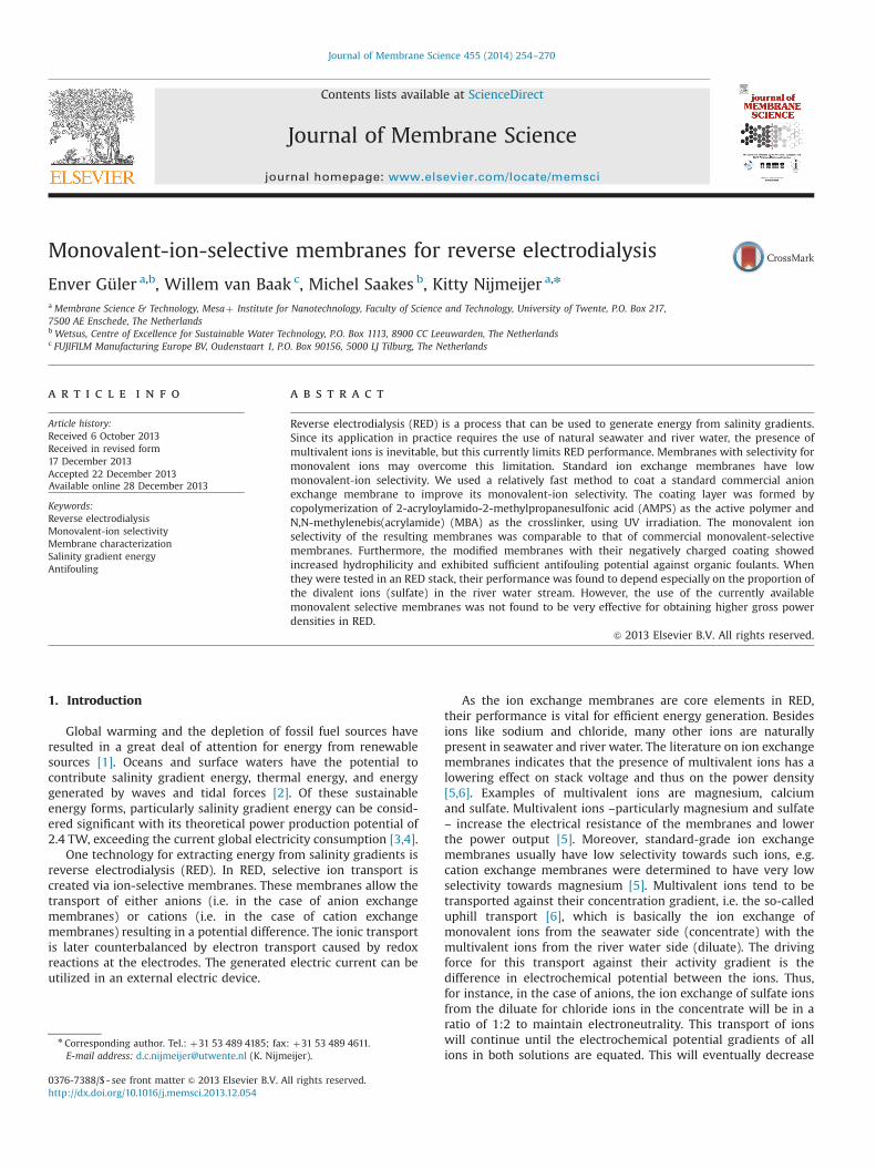
gated in a RED stack as previously described [29,49,50]. We used aPMMA stack (STT Products BV, The Netherlands) containing 2 Tielectrodes (mesh 1.0, 10 cm�10 cm) coated with Ir/Ru (MagnetoSpecial Anodes BV, The Netherlands); Fig. 7 gives a schematicrepresentation. This stack also contained silicone gaskets of200 mm (Specialty Silicone Fabricators, USA), and non-conductivespacers (Sefar, Nitex 03–300/51, Switzerland). We placed the stackin a thermostated oven kept at 25 1C (Fisher Scientific).
The feed solutions were artificial seawater (a mixture of 0.45 MNaCl and 0.05 M Na2SO4) and artificial river water (a mixture of0.003 M NaCl and 0.002 M Na2SO4 [5] and a mixture of 0.012 M
NaCl and 0.002 M Na2SO4), which we prepared with deminera-lized water. A conductivity meter (WTW, Germany) was used tomeasure the conductivity of the feed solutions. Peristaltic pumps(Masterflex, Cole Palmer) were used to circulate these feedsolutions through the RED stack. During measurements, theelectrolyte solution containing 0.05 M potassium hexacyanoferrate(II), 0.05 M potassium hexacyanoferrate (III) and 0.25 M NaCl werepumped through the electrode compartment at 300 mL/min.Temperature of these solutions was controlled at 2571 1C duringall experiments by means of a thermostated water bath (Colorathermostat WK16).
3.6.2. Experimental and theoretical power densityPower density measurements were carried out using a poten-
tiostat (Ivium Technologies, Eindhoven, The Netherlands) and achronopotentiometry method as described earlier [29]. We cor-rected the gross power output by subtracting the value of a blankrun using only one cation exchange membrane, only installed toprevent undesired effects in the RED stack such as membranepoisoning by hexacyanoferrate compounds in the electrolyte. Thetheoretical gross power density was calculated (as explained inSection 2.2) and compared to the experimental values.
4. Results and discussion
4.1. Membrane preparation
Table 2 shows selected properties of the membranes investi-gated in this study. The Fuji A membrane has a lower area resistance(0.93 Ω cm2) than the standard-grade AMX membrane and anacceptable permselectivity (89%). The hydrophilic properties of thismembrane (better wettability and adhesion properties, as discussedin more detailed later) allow proper surface modification. Therefore,
River water
Brackish water
Brackish water
Sea water
Electrode rinse solution
Cathode:reduction
Anode:oxidation
Na+
Na+Na+
Na+Na+
Na+Na+
Na +
Cl- Cl- Cl-
Cl-Cl-Cl-
C C C CAAA
e-e-
Fig. 7. Schematic representation of a RED system.
E. Güler et al. / Journal of Membrane Science 455 (2014) 254–270260

we selected the Fuji A membrane to be modified toward obtainingimproved monovalent-ion selectivity and antifouling potential.
After coating, the obtained Fuji A-mono membranes exhibited avery similar permselectivity and area resistance as the original FujiA membranes. Owing to the very low thickness of the conductivecoating (about 1.5 mm), the area resistance did not change sig-nificantly; permselectivity improved very slightly and was com-parable to that of the standard AMX membrane. By contrast,commercial monovalent-ion-selective membranes (ACS and ASV)have relatively high area resistances due to their highly cross-linked membrane surface structures [43,44]. High area resistancehas a detrimental effect on RED performance. Before further use,all membranes were washed with MilliQ water (unless otherwisestated). During the measurements, the membranes were easy tohandle and did not show any defects due to mechanical instability
after the measurements. As such we considered the mechanicaland chemical stability sufficient for the targeted application.
4.2. Characterization of membrane surface
4.2.1. SEM-EDX analysisFigs. 8 and 9 display the cross-section and surface morphology
of the native and coated Fuji A membrane, respectively, includingelement maps for carbon, sulfur, chloride and oxygen. Fig. 8a and cshows the original Fuji A membrane before coating. The non-uniform orientation of reinforcement is clearly visible in the cross-sections of the membrane. That adds conductive heterogeneity tothe membrane as the reinforcement is non-conductive. Fig. 8b andd depicts cross-section images of the Fuji A-mono membrane. Thecoating is hardly visible as it is thin and homogenous, and has avery similar non-porous dense structure as the original membranematerial.
Fig. 8c and d shows EDX mapping for sulfur, overlaid on a cross-section SEM image of (one side of) a native and coated Fuji Amembrane, respectively. Red dots indicate sulfur-containing areas.The red dots in the bulk of the original Fuji A membrane are due tonoise or trace amounts of sulfur (Fig. 8c). By contrast, the dots areintensely concentrated at the top of the cross-section of the Fuji A-mono membrane (Fig. 8d); this concentration represents thesulfonic acid functional groups in the coating layer. The coatingthickness was determined to be about 1.5 mm.
Fuji A membranes contain non-woven polypropylene materialas reinforcement. The non-conductive fibers of the reinforcementprotrude through the bulk membrane. As can be seen, the
Fig. 8. EDX sulfur mapping of cross-sections (magnification 2000� ): (a) original Fuji A membrane (b) coated Fuji A membrane (¼Fuji A-mono) (c) original Fuji A membranewith sulfur mapping (d) coated Fuji A membrane with sulfur mapping (red dots indicating sulfur-containing areas in membrane structure). EDX mapping was performed inonly part of the area visible in (c) because the fast-scanning mode was used. (For interpretation of the references to color in this figure legend, the reader is referred to theweb version of this article.)
Table 2Characteristics of the anion exchange membranes investigated in this study[39,41,42].
Membranea Thickness (mm) α (%) R (Ω cm2)
Fuji A 123 89.070.7 0.9370.10AMX 134 90.070.8 2.3570.05Fuji A-mono 124 91.070.8 1.1070.10ASV (mono) 110 96.070.4 3.0770.20ACS (mono) 121 94.070.4 4.3970.10
a All membranes investigated are homogenous membranes. ASV, ACS and FujiA-mono membranes have monovalent-ion selectivity; the other two are standardmembranes.
E. Güler et al. / Journal of Membrane Science 455 (2014) 254–270 261

distribution of sulfur is even in areas with active membrane material,but sulfur is absent in areas with reinforcement material. It meansthat coating was only successful on active membrane material, noton the non-conductive reinforcement. This is explained by the betterwettability and adhesion properties of the active membrane material.
We performed SEM-EDX mapping not only for S but also for C,Cl and O (Fig. 9) on the Fuji A-mono membrane surface. Fig. 9a is asurface image of a coated Fuji A membrane (Fuji A-mono). Clearlyvisible are the polypropylene fibers of the non-woven reinforce-ment, which protrude through the membrane, leading to a non-uniform surface morphology. The sulfur maps show that sulfur isnot homogeneously distributed over the membrane surface;uncoated areas are visible (Fig. 9b). These uncoated areas can beseen to correspond to locations in which fibers of the reinforce-ments protrude when Fig. 9b is overlaid on Fig. 9a, as shown inFig. 9c. As in Fig. 8, the red dots represent sulfur-containing areason the membrane surface.
The uncoated areas in Fig. 9c coincide with carbon-containingareas (blue) in Fig. 9d; the carbon represents the polypropylenematerial of the membrane reinforcement. The non-homogenousdistributions of Cl and O coincide with the distribution of S; Cl andO are also visible only on the active membrane material (Fig. 9eand f). Cl is a counter ion and is therefore only present at tracelevels at the surface, as the coating layer is covering the activemembrane material. Oxygen, on the other hand, is also present inthe coating (AMPS and MBA).
4.2.2. XPS analysisWe carried out XPS analysis to investigate the chemical
composition and verify the reaction on the membrane surface(up to a depth of 10 nm [47]). Table 3 shows the atomic percen-tages at the surface of all tested membranes. We determined
nitrogen related to the functional groups of the anion exchangemembranes (Nþ) (quaternary amine) separately from unchargednitrogen (N) such as nitrogen in secondary amine form. Thebinding energy for the charged Nþ group is higher than thebinding energy for a non-charged nitrogen functionality [51],leading to a difference of at least 3 eV in XPS spectra. By usingpeak curve fitting, we separated the regular N 1s peak and theNþpeak. We also determined atomic percentages of other rele-vant elements (C, O, Cl and S) (Table 3).
We found that the native Fuji A membrane has a higher surfacecharge (quaternary ammonium, Nþ) than the other commercialstandard-grade membranes (i.e. Neosepta AMX). That is favorablefor adherence of oppositely charged polyanions (electrostaticaffinity). On the other hand, the surface of the Fuji A membranesurface has a higher percentage of uncharged N than the standardAMX membrane. That might be because the Fuji A membranemight have some N containing components in addition to qua-ternary amines, whereas the AMX membrane lacks these species.
Fig. 9. EDX element mapping: (a) SEM image of Fuji A-mono membrane surface: (b) sulfur (S), (c) overlay of sulfur map on Fuji A-mono SEM image (red dots representingsulfur-containing areas), (d) carbon (C), (e) chloride (Cl) and (f) oxygen (O). The magnification of all the images is 150� . (For interpretation of the references to color in thisfigure legend, the reader is referred to the web version of this article.)
Table 3Element composition of membrane surface obtained from XPS analysis.
Membrane Element contents (%)
Nþa N 1sb Cl 2p S 2p C 1s O 1s C/O
Fuji A 2.2 5.3 1.6 0.38 70.8 20.0 3.5AMX 1.1 1.8 2.2 0.54 77.0 18.0 4.3Fuji A-mono o0.2 5.3 o0.08 1.75 65.1 27.9 2.3ACS (mono) 1.5 2.1 2.6 0.50 77.0 17.0 4.5ASV (mono) 0.8 1.7 1.8 0.47 75.0 21.1 3.6
a Nitrogen from quaternary ammonium groups.b Uncharged nitrogen.
E. Güler et al. / Journal of Membrane Science 455 (2014) 254–270262

In principle, the number of counter ions (e.g. chloride) isexpected to match to the number of functional groups (e.g.quaternary ammonium). Although the percentage quaternaryamine in the Fuji A membrane is two times higher than that ofthe AMX membrane, Cl as counter ion is slightly lower in the Fuji Amembrane than in the AMXmembrane. This might be related to therelatively more conductively heterogeneous character of the surfaceof the native Fuji A membrane. As expected, S is only present intrace amounts, since both membranes are standard-grade mem-branes without any coating. In addition, the ratio of C to O at themembrane surface is lower for the Fuji A membrane than for theAMX membrane. This may be related to the O content of theacrylamide (C3H5NO) species present in the Fuji A polymer matrix.
After modification of the Fuji A membrane, the atomic percen-tage of N in quaternary ammonium groups (Nþ) at the surfacewas much lower (as the coating contains no quaternary ammo-nium groups but sulfonic acid groups). Uncharged nitrogen did notexhibit a significant change since the coating contains secondaryamines from AMPS and MBA.
Obviously, these element data provide information related tothe effects and the successfulness of the coating process andconfirm the successful integration of the AMPS coating layer onthe active groups of the membrane material at the surface.
The surface ratio of C to O, which is approximately 3.5 for theunmodified Fuji A membrane, became 2.3 after coating. Thatmight indicate a decrease in the C amount (i.e. corresponding toa decreasing ratio of C to O) which is mostly related to the C in thepolypropylene filaments of the reinforcement structure. It couldindicate that a trace of coating is present in the areas where thereinforcement reaches the surface.
The percentage of carbon atoms differs between the FujiA-mono membrane and the other monovalent-selective mem-branes (ACS and ASV). The ratio of C to O of the Fuji A-monomembrane is lower than that of the commercial counterparts; thepolypropylene reinforcement represents a significant amount ofthe total carbon present on the surface because this non-wovenreinforcement material protrudes through the active membranematerial. For the ACS and ASV membranes, the carbon content isgenerally related to the polymeric membrane material, as thewoven support (which is the main reinforcement used in thesemembranes) is entirely covered by active membrane material. Theoxygen content of the Fuji A-mono membrane surface mainlyrepresents the oxygen included in acrylamide (C3H5NO) andsulfonic acid (–SO3) groups present in the polymer matrix of thecoating. That oxygen might cause the ratio of C to O to be smallerthan that of the ACS and ASV membranes. It is hard to identify theoxygen-containing compounds of the latter solely on the basis ofXPS measurements as insufficient information is available aboutthe composition of these membranes.
The Fuji A-mono membrane carried a lot less quaternary amine(Nþ) on the surface than the commercial monovalent-ion-selective ACS and ASV membranes as well as the uncoated Fuji Amembrane and the AMX membrane (Table 3). The percentage ofsecondary amine (N) is much lower for the ASV and ACS mem-branes (as well as the AMX membrane), which is explained by thechemistry of these membranes [42,43].
Because of the coating on the Fuji A-mono membrane, Cl ascounter ion is negligible on the membrane surface relative to theASV and ACS membranes. Regarding sulfur, the ASV and ACSmembranes have only trace amounts of sulfur, whereas the FujiA-mono membrane has more sulfur on the surface, which isattributable to the polyanion coating material. This confirms thatthe monovalent-ion selectivity of the ASV and ACS membranes isnot provided by a sulfur-containing polyanion coating but byanother technique such as coating with a thin layer that has ahigh crosslinking density [43].
4.2.3. Water contact angleWe carried out water contact angle measurements for all
membranes to determine their wettability (Table 4). In aqueousapplications, the more hydrophilic the membrane surface is, theless prone it is to fouling [8]. It is therefore important to ascertainwhether the hydrophilicity of the membranes is changed by ourmodification to determine its antifouling potential.
The contact angle of the standard Fuji A membrane is verysimilar to that of the standard Neosepta AMX membrane implyingthat these membranes have very similar hydrophilic properties(Table 4). After modification, the contact angle of the modifiedmembrane (Fuji A-mono) had decreased significantly (from �641to around �241; see Table 4); this is caused by the increase in thenumber of ionic groups by the addition of the negatively chargedcoating layer (sulfonic acid groups). Quaternary ammoniumgroups might also contribute to the total surface charge; however,this contribution can be estimated as very minor because there isonly a trace amount of quaternary amines on the modifiedmembrane surface as determined by XPS (Table 3). The stronglydecreased wetting angle confirms that, besides monovalent selec-tivity, the coating also added antifouling potential to the Fuji Amembranes. The wettability of the Fuji A-mono membranes is farbetter than that of the commercial counterparts (ACS and ASV),which are not produced specifically to aim at any antifoulingqualities.
4.2.4. Surface roughnessWe used optical interferometry techniques to investigate sur-
face roughness. A certain degree of surface roughness can haveadvantages in RED systems, as surface morphologies that promotemixing at the membrane–solution interface reduce the boundarylayer resistance, which usually leads to a higher power density[52,53]. However, this requires roughness being usually at muchhigher dimensional scales than those observed here. On the otherhand, surface roughness is also a component of hydrophilicity andtherefore plays a role in fouling. Specifically, colloidal fouling isusually more pronounced on rough membrane surfaces than onmembranes with a glossy surface [11,54].
Fig. 10 displays the average values of surface roughness (Ra,average mean deviation of the profile) as 3D images of themembrane surface morphology (i.e. hill-and-valley surface struc-ture) for the original Fuji A membrane, other commercial mem-branes and our coated membrane (Fuji A-mono). Red areas areareas with positive values, i.e. ‘hills’ and blue areas representnegative values, i.e. ‘valleys’.
It is clear from Fig. 10 that the standard Fuji A membrane has ahigher surface roughness (Ra¼5.8) than the standard AMX mem-brane (Ra¼3.1). The high surface roughness of the Fuji membraneis mainly related to the uneven distribution of the fibers of thenon-woven reinforcement (Fig. 9). A certain level of roughnessmight be advantageous for static adhesion of the coating layer;high roughness results in a larger contact area between coatingmaterial and membrane surface. The coating might preferentiallyaccumulate in the valleys of rougher surfaces, and have the effectof smoothing the surface.
Table 4Contact angle measurements.
Membrane Contact angle (deg.)
Fuji A 63.671.5AMX 62.874.7Fuji A-mono 23.573.9ASV (mono) 67.172.0ACS (mono) 57.175.7
E. Güler et al. / Journal of Membrane Science 455 (2014) 254–270 263

After the Fuji A membrane was coated, the roughness of theresulting Fuji A-mono membrane was indeed lower because of thesmoothing effect of the coating layer. This decrease of roughness ofaround 2 mm might be too small to lead to a recognizableadvantage when it comes to fouling prevention. However, this
smoothing effect of the coating affects the I–V curves as will bediscussed in Section 4.3.1.
The AMX membrane includes patterned spacers, creatingrelatively wide hills with a smoother surface (Fig. 10b). Further-more, the commercially available monovalent-ion-selective
Ra = 5.8 Ra = 3.1
Ra = 1.3 Ra = 3.7
Ra = 2.6
Fig. 10. Surface roughness for membranes: (a) Fuji A, (b) AMX, (c) Fuji A-mono (d) ASV and (e) ACS; dimensions of the investigated membrane: 1257�942 mm.
E. Güler et al. / Journal of Membrane Science 455 (2014) 254–270264
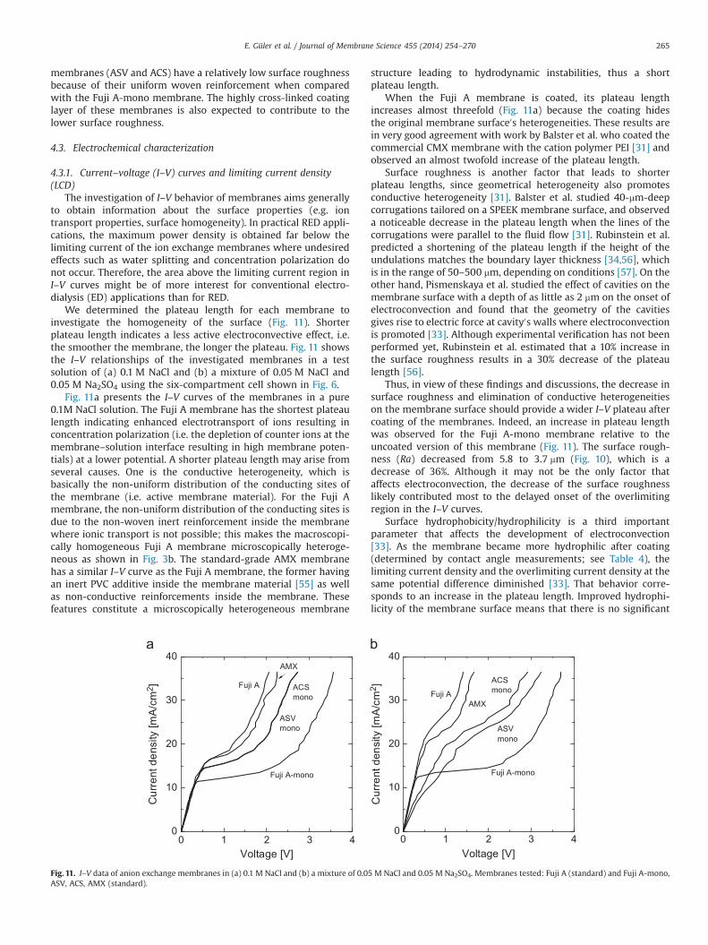
membranes (ASV and ACS) have a relatively low surface roughnessbecause of their uniform woven reinforcement when comparedwith the Fuji A-mono membrane. The highly cross-linked coatinglayer of these membranes is also expected to contribute to thelower surface roughness.
4.3. Electrochemical characterization
4.3.1. Current–voltage (I–V) curves and limiting current density(LCD)
The investigation of I–V behavior of membranes aims generallyto obtain information about the surface properties (e.g. iontransport properties, surface homogeneity). In practical RED appli-cations, the maximum power density is obtained far below thelimiting current of the ion exchange membranes where undesiredeffects such as water splitting and concentration polarization donot occur. Therefore, the area above the limiting current region inI–V curves might be of more interest for conventional electro-dialysis (ED) applications than for RED.
We determined the plateau length for each membrane toinvestigate the homogeneity of the surface (Fig. 11). Shorterplateau length indicates a less active electroconvective effect, i.e.the smoother the membrane, the longer the plateau. Fig. 11 showsthe I–V relationships of the investigated membranes in a testsolution of (a) 0.1 M NaCl and (b) a mixture of 0.05 M NaCl and0.05 M Na2SO4 using the six-compartment cell shown in Fig. 6.
Fig. 11a presents the I–V curves of the membranes in a pure0.1M NaCl solution. The Fuji A membrane has the shortest plateaulength indicating enhanced electrotransport of ions resulting inconcentration polarization (i.e. the depletion of counter ions at themembrane–solution interface resulting in high membrane poten-tials) at a lower potential. A shorter plateau length may arise fromseveral causes. One is the conductive heterogeneity, which isbasically the non-uniform distribution of the conducting sites ofthe membrane (i.e. active membrane material). For the Fuji Amembrane, the non-uniform distribution of the conducting sites isdue to the non-woven inert reinforcement inside the membranewhere ionic transport is not possible; this makes the macroscopi-cally homogeneous Fuji A membrane microscopically heteroge-neous as shown in Fig. 3b. The standard-grade AMX membranehas a similar I–V curve as the Fuji A membrane, the former havingan inert PVC additive inside the membrane material [55] as wellas non-conductive reinforcements inside the membrane. Thesefeatures constitute a microscopically heterogeneous membrane
structure leading to hydrodynamic instabilities, thus a shortplateau length.
When the Fuji A membrane is coated, its plateau lengthincreases almost threefold (Fig. 11a) because the coating hidesthe original membrane surface0s heterogeneities. These results arein very good agreement with work by Balster et al. who coated thecommercial CMX membrane with the cation polymer PEI [31] andobserved an almost twofold increase of the plateau length.
Surface roughness is another factor that leads to shorterplateau lengths, since geometrical heterogeneity also promotesconductive heterogeneity [31]. Balster et al. studied 40-mm-deepcorrugations tailored on a SPEEK membrane surface, and observeda noticeable decrease in the plateau length when the lines of thecorrugations were parallel to the fluid flow [31]. Rubinstein et al.predicted a shortening of the plateau length if the height of theundulations matches the boundary layer thickness [34,56], whichis in the range of 50–500 mm, depending on conditions [57]. On theother hand, Pismenskaya et al. studied the effect of cavities on themembrane surface with a depth of as little as 2 mm on the onset ofelectroconvection and found that the geometry of the cavitiesgives rise to electric force at cavity0s walls where electroconvectionis promoted [33]. Although experimental verification has not beenperformed yet, Rubinstein et al. estimated that a 10% increase inthe surface roughness results in a 30% decrease of the plateaulength [56].
Thus, in view of these findings and discussions, the decrease insurface roughness and elimination of conductive heterogeneitieson the membrane surface should provide a wider I–V plateau aftercoating of the membranes. Indeed, an increase in plateau lengthwas observed for the Fuji A-mono membrane relative to theuncoated version of this membrane (Fig. 11). The surface rough-ness (Ra) decreased from 5.8 to 3.7 mm (Fig. 10), which is adecrease of 36%. Although it may not be the only factor thataffects electroconvection, the decrease of the surface roughnesslikely contributed most to the delayed onset of the overlimitingregion in the I–V curves.
Surface hydrophobicity/hydrophilicity is a third importantparameter that affects the development of electroconvection[33]. As the membrane became more hydrophilic after coating(determined by contact angle measurements; see Table 4), thelimiting current density and the overlimiting current density at thesame potential difference diminished [33]. That behavior corre-sponds to an increase in the plateau length. Improved hydrophi-licity of the membrane surface means that there is no significant
0
10
20
30
40
ACSmono
ASVmono
Fuji A-mono
AMX
Cur
rent
den
sity
[mA
/cm
2 ]
Voltage [V]
Fuji A
0 1 2 3 4 0 1 2 3 40
10
20
30
40
ACSmono
ASVmono
AMX
Fuji A-mono
Cur
rent
den
sity
[mA
/cm
2 ]
Voltage [V]
Fuji A
Fig. 11. I–V data of anion exchange membranes in (a) 0.1 M NaCl and (b) a mixture of 0.05 M NaCl and 0.05 M Na2SO4. Membranes tested: Fuji A (standard) and Fuji A-mono,ASV, ACS, AMX (standard).
E. Güler et al. / Journal of Membrane Science 455 (2014) 254–270 265

repulsion of water molecules by the surface, resulting in a morestagnant water flow with fewer hydrodynamic instabilities [33]. Asexpected the plateau length became broader after the Fuji Amembrane was coated (Fig. 11a).
The I–V behavior of the commercial monovalent-ion-selectiveACS and ASV membranes overlapped when a pure NaCl solutionwas used as test solution (Fig. 11a). That indicates that the ionic-transport properties of these membranes are quite similar.
Fig. 11b shows the I–V behavior of the membranes in a solutioncontaining also divalent ions, i.e. sulfate. Relative to the plateaulengths for a pure NaCl solution, slightly broader plateaus wereobserved for all investigated membranes. This indicates lowertransport of sulfate from the diffusive boundary layer to the bulkmembrane matrix resulting in concentration polarization at higherpotentials. Also, because of slower depletion of the counter ionconcentration (Cl�), a higher potential was required to obtain azero counter ion concentration at the membrane–solutioninterface.
Table 5 shows the LCD data for the membranes tested in pure0.1 M NaCl and in a mixture of 0.05 M NaCl and 0.05 M Na2SO4.
As seen in Table 5, LCD values of standard grade membranes(Fuji A and Neosepta AMX) are similar in the NaCl solution andalso in the sulfate-containing solution (higher in the latter). Thecommercial monovalent-ion-selective membranes (ACS and ASV)also have similar LCD values in both types. All membranes havehigher LCD values for the sulfate-containing solution than for thepure NaCl solution (Table 5). This is due to the lower transport rateof sulfate in the membrane as LCD is an inverse function of thedifference between the counter ion transport numbers in themembrane and in the bulk solution [48].
Since LCD increases with increasing ionic transport inside themembrane, we expected the LCD to become lower after coating;this was indeed the case (Table 5). This difference was greaterwhen divalent sulfate ions were used in the solution (Table 5),with the Fuji A membrane having the highest and the Fuji A-monothe lowest value. When sulfate ions are used, the Fuji A-monomembrane has repulsive effects towards sulfate and ionic trans-port inside the membrane is mainly due to the monovalentchloride counter ions. On the other hand, with the standard FujiA membrane, the ionic transport rate is dependent on both sulfateand chloride; this is lower for sulfate ions due to the lowertransport properties compared with chloride.
4.3.2. Transport numbersAnother method to determine the monovalent selectivity of
membranes is to calculate bulk transport numbers of monovalentions (e.g. chloride) and divalent ions (e.g. sulfate) based on ionicfluxes (Eq. (1)). We determined the ionic fluxes of sulfate andchloride and calculated transport numbers (Eq. (3) and Table 6) foreach membrane under an applied direct current density heldconstant at 11.4 mA/cm2 (a total current of 150 mA) which isabout 80% of the limiting current density of the Fuji A membrane(Table 5). We then calculated the relative permselectivity (PSO4
Cl )
of the divalent ion (sulfate) to monovalent ion (chloride), using thetransport number data of Table 6. The lower the PSO4
Cl valuebecomes, the better the monovalent-ion selectivity of the con-sidered membrane is.
The Fuji A membrane is a standard membrane without anyspecific monovalent-ion selectivity. Although the chloride andsulfate fluxes of the Fuji A membrane are lower than that of thestandard-grade AMX membrane, it is clear that Fuji A membrane issimilar when the ratio of the ionic fluxes of sulfate and chloride isconsidered (Table 6).
The Fuji A-mono membrane has improved monovalent-ionselectivity with a relative permselectivity ðPSO4
Cl Þ of 0.755 which islower than that of the original uncoated Fuji A membrane, 0.841.It is also obvious from the flux values that the sulfate flux of theFuji A-mono membrane was reduced. The negatively chargedcoating on the membrane repels oppositely charged ions, i.e.sulfate and chloride. This electrostatic repulsion is greater fordivalent ions (though also depending on size), which provides aseparation due to electrical forces rather than a steric repulsionmechanism based on ion size [44] (such as accomplished by highlycrosslinked coatings). In other words, the charged layer affects thepermeability of divalent ions by rejecting them more intensivelythan monovalent ions.
The ACS membrane has the highest monovalent-ion selectivitywith the lowest relative permselectivity (PSO4
Cl ) value of 0.727. Thismembrane has also the lowest sulfate flux of 4.55�10�8 mol/(cm2 s). This might be due to the highly cross-linked surfacestructure as indicated by Saracco et al. that decreases the ion fluxof divalent ions [43]. The ASV membrane is another high-performance monovalent-ion-selective membrane available inthe market; although the chloride flux of this membrane is thelargest, its monovalent-ion selectivity is comparable to that of theACS membrane (Table 6). According to the literature, themonovalent-anion selectivity of the ASV membrane comes fromthe coating of a highly crosslinked resin on its surface similar tothe mechanism of monovalent-ion selectivity of the ACS mem-brane [44].
As a general trend, we observed that monovalent-ion selectiv-ity increases (i.e. PSO4
Cl value decreases) with increasing arearesistance (Tables 2 and 6). However, the ion flux values and thecorresponding transport numbers of sulfate do not decrease withincreasing area resistance. That could be related to membranecoatings with different degrees of crosslinking resulting in differ-ences in monovalent-ion selectivity. Moreover, only the Fuji A-mono membrane has a relatively high monovalent-ion selectivitywith a relatively low area resistance, 1.10 Ω cm2 (Table 2). Theconductive coating is so thin (1.5 mm) that it does not lead to anincrease in area resistance.
The Fuji A-mono membrane has an 8%-reduced sulfate flux(from 5.32 to 4.90�10�8 mol/(cm2 s)) provided by the coatinglayer. This corresponds to a decrease of the PSO4
Cl value of 10%. Whenthe relative permselectivities of the monovalent-ion-selective
Table 5Limiting current density (LCD) data of test membranes.
Membrane LCD (mA/cm2)
0.1M NaCl 0.05 M NaCl/0.05 M Na2SO4
Fuji A 13.7070.01 21.0870.53AMX 14.8170.00 19.9270.00Fuji A-mono 11.3670.01 12.7970.00ACS (mono) 13.9571.01 19.4970.49ASV (mono) 13.9571.01 19.7770.10
Table 6Bulk transport numbers for anion exchange membranes.
Membrane JCl(10�8 mol/(cm2 s))
JSO4
(10�8 mol/(cm2 s))tCl tSO4 PSO4
Cl
Fuji A 6.1570.01 5.3270.02 0.519 0.449 0.841AMX 6.5670.00 5.5870.00 0.553 0.471 0.832Fuji A-mono 6.3170.00 4.9070.00 0.533 0.413 0.755ASV (mono) 6.8870.00 5.1870.01 0.581 0.438 0.730ACS (mono) 6.2370.00 4.5570.00 0.526 0.384 0.727
J: ionic flux; t: bulk transport number; P: relative permselectivity (monovalent-ionselectivity).
E. Güler et al. / Journal of Membrane Science 455 (2014) 254–270266

membrane ACS and the standard AMX membrane are compared,the PSO4
Cl value exhibits a decrease of almost 13%. Thus, themonovalent-ion selectivity of the Fuji A-mono membrane can beconsidered in the same order as that of the commercially availableACS membrane, and as such a further increase in monovalentselectivity would probably be beneficial, but goes beyond the scopeof this research. The presented transport numbers may seem to below. However, transport numbers, and thus monovalent ion selec-tivity, are highly dependent on the characterization parametersused (e.g. current density, concentration of solutions, etc.) in theexperimental set up. For instance, the applied current density (80%of the limiting current density) is relatively high when the realoperating conditions are considered in typical RED systems, whichis typically about 20–40 A/m2. As all measurements are performedunder the same conditions, this however does allow a fair compar-ison of the different membranes.
4.4. Evaluation of antifouling potential
To evaluate the antifouling potential of the anion exchangemembranes after coating, we looked at the transition time, i.e. thetime elapsed before the onset of fouling, under constant directcurrent. Fig. 12 shows the membrane potential (i.e. potentialdifference between both sides of the membrane, ΔE) of theoriginal Fuji A membrane and the modified membrane (FujiA-mono) over time.
Fig. 12 shows that, as expected, the Fuji A-mono membrane hasa lower tendency for fouling because of its anionic coating andsubsequent electrostatic repulsion. The transition time for themodified membrane was found to be 90 min whereas it was50 min for the original unmodified Fuji A membrane.
Another indication of the fouling tendency of membranes is theslope of membrane potential versus time after the transition time[10]. Higher slopes indicate that fouling is more probable andsevere whereas it is less pronounced when the slope is relativelylow, i.e. the increase of membrane potential over time is slow. Theslope of membrane potential versus time curve (ΔE/t) also showsthat the modified membrane is less prone to fouling as it is lesssteep compared with the slope of the curve of the originalmembrane (Fig. 12). However, the difference between the foulingtendencies of the original and the modified membranes does notappear to be large. A possible reason for this behavior may beenhanced adhesion of the foulant to the membrane surface overtime because of a reduction in the repulsive effects of the coating
after fouling has started. Another reason for the small difference inthe fouling tendencies of the original and the modified membranemight be related to the critical micelle concentration CMC (i.e.solubility) of SDS in the solution. It is known from the literaturethat fouling takes place immediately in electrochemical processessuch as electrodialysis when the SDS concentration becomeshigher than the CMC because the formation of micelles in thesolution promotes fouling [14,38]. The CMC of the SDS solution isdependent the type and the concentration of electrolyte solutions.In addition, it is known that the CMC decreases with increasingconcentration of the electrolyte solution. We did not measure theCMC of the used solution in this work specifically, but theconcentration of SDS is expected to be in the range of the CMC,which is 3.6–8.3 mM for SDS in 0.03 M NaCl solution and purewater, respectively [58,59].
In addition to the charge of the membrane surface, also thehydrophilicity determines the antifouling potential of anionexchange membranes. As the contact angle of the Fuji A mem-branes had decreased significantly (from 63.61 to around 231) afterthe surface modification, the membrane hydrophilicity increasedresulting in improved antifouling potential (Table 4). This is also ingood agreement with the work performed by Mulyati et al. inwhich decrease of transition time was monitored as the contactangle of the used membranes increased [8]. It is clear that theanionic coating we applied to the Fuji A membranes indeedyielded a simultaneous improvement of antifouling potential andmonovalent-anion selectivity.
4.5. RED performance
We compared the RED performance of the coated (Fuji A-mono)anion exchange membranes having specific monovalent-ion selec-tivity with that of commercial membranes. Specifically, we looked atthe gross power densities of the monovalent-ion-selective NeoseptaACS and Fuji A-mono membranes and the values of their standardcounterparts, the Neosepta AMX and Fuji A membranes, respectively.Two tests were performed using artificial river water with differentmolar ratios of monovalent to divalent ion ([Cl�]/[SO4
2�]) of 1.5 and6, respectively and a seawater composition of 0.45 M NaCl and0.05 M Na2SO4. (Fig. 13). The Neosepta CMX membrane wasused as reference cation exchange membrane in the RED stack foreach test.
As can be seen in Fig. 13, the Fuji A and Fuji A-monomembranes performed better than the ACS and AMX membranes.The benefit of using Fuji A-mono membranes in RED is that thearea resistance did not increase significantly after coating Fuji Amembranes due to the low thickness of the conductive coatinglayer as already mentioned (Table 2). Besides, the permselectivityincreased very slightly from 89% to 91%. In conclusion, the use ofthese Fuji A membranes is advantageous in RED applications, andresults in the higher gross power densities. However, regardless ofthe monovalent selectivity, the electrical resistance of thesemembranes and that of the river water compartment appears tobe dominant and as such has a significant impact on the overallRED performance, i.e. gross power density. To decrease this andincrease the power output, at least the undesired effect of thedominating membrane resistance, thinner membranes could beconsidered to prepare monovalent-ion-selective membranes.In our previous work we have shown that the use of thinnermembranes increases the power output obtainable in REDsignificantly [29,50,60].
On the other hand, there is no significant difference between thegross power densities of the monovalent-ion-selective Fuji A-monomembrane and the standard Fuji A membrane. A similar trend is validfor the Neosepta membranes (ACS and AMX); the standard-gradeAMX membrane performed better than the monovalent-selective ACS
0 60 120 180 240 300 3600.12
0.13
0.14
0.15
0.16
0.17
0.18
0.19
0.20
Fuji A
Mem
bran
e po
tent
ial (
V)
Time (min)
Fuji A-mono
Fig. 12. Effect of surface coating on antifouling potential of Fuji A membrane.Membrane potential is the potential difference between both sides of membrane asa function of time. The feed solution contained 0.01 M NaCl and 0.00060 M sodiumdodecyl sulfate.
E. Güler et al. / Journal of Membrane Science 455 (2014) 254–270 267

membrane when a relatively low amount of sulfate was used in theartificial river water (Fig. 13b). In these specific conditions, usingmonovalent-ion-selective membranes clearly does not lead to bettergross power output, although the resistance to fouling has improved.
In Fig. 13a, the gross power density diminishes when the flowvelocity of the feed waters increases. However, this is not the casewhen the artificial river water has a high salt content (Fig. 13b).The situation in Fig. 13a can be attributed to the very lowconductivity of river water which is rapidly renewed such thatan increase of flow velocity creates additional resistance due to thereduced ion transport which is a consequence of low residencetime in the RED stack. In Fig. 13b, the conductivity of the riverwater is high enough so that the ionic transport is even promotedwhen the flow velocity is increased. In summary, besides the ioniccomposition (monovalent or divalent), the conductivity of riverwater is another important parameter that determines the powerdensity in this case.
The RED performance of the monovalent-selective ACS membranewas worse than that of the conventional AMX membrane; thisdifference was more pronounced when a relatively low concentrationof sulfate was used in the river water (Fig. 13b). This is a consequenceof the higher area resistance of ACS membranes (Table 2).
As it depends on many factors such as membrane resistance,apparent permselectivity and the ionic composition of the feedwater, the power density of a RED process is certainly not solelydetermined by monovalent/divalent selectivity of membranes. It istherefore useful to assess RED performance at open-circuit voltage(OCV), in zero-current condition. For that purpose, Eqs. 6 and 7 canbe used to calculate the gross power densities. Table 7 showsexperimental and OCV-based gross power densities at the highestfeed flow velocity (1.67 cm/s).
In Table 7, the RED performance of monovalent-ion-selectivemembranes is better than of the standard membranes whenlooking at OCV-based gross power density calculations (zero-current condition); this applies to both types of artificial riverwater. Although the values of the gross power density are not thatdistinctive from each other, using OCV values to calculate powerdensity indicates that the use of monovalent-selective membraneshas some benefits over using their standard counterparts. How-ever, under current-producing condition, these benefits showed tobe limited under the current conditions.
Although the presence of multivalent ions is known to have adeteriorating effect on the power density obtainable in RED [5,6], thecurrently available monovalent ion selective membranes and theones developed in this work, are not able to overcome this effect yet.The method we developed and presented is a very easy approach tointroduce monovalent ion selectivity on ion exchange membranes. Atthe same time, it serves to cope with fouling due to its anti-foulingpotential, a property that is essential especially in practical applica-tions where real seawater and river water is used. However, theobtained monovalent ion selectivity of the developed and availablemembranes is probably not sufficiently high yet, and higher valuesare required to obtain high power density in RED when using realfeed waters, which do contain multivalent ions. On the other hand,the theoretical potential of this RED system to obtain high powerdensities using OCV based calculations (Eqs. 6–7) is huge butdependent on the chosen process parameters such as membranepermselectivity, electrical resistance and cell length. Using a similarRED systemwith monovalent ionic feed solutions (seawater (0.510 MNaCl) and river water (0.017 M NaCl)), it is possible to obtain a netpower density of 15W/m2when the membrane resistance is reducedto 0.1 Ω cm2 at a 1 mm cell length [61]. Nevertheless, it is stillquestionable whether such a designwith small membrane resistanceand cell length can be obtained in practice.
5. Conclusions
This paper studied the preparation and characterization of amonovalent-ion-selective anion exchange membrane specificallydesigned for RED, using a relatively fast method that adds anegatively charged layer to the membrane surface by UV irradia-tion. The developed membrane combines antifouling tendencyand monovalent ion selectivity.
Table 7Gross power density based on experimental data and open-circuit voltage.
Membrane River water A 3 mMNaClþ2 mM Na2SO4
River water B 12 mMNaClþ2 mM Na2SO4
Experimental(W/m2)
OCV based(W/m2)
Experimental(W/m2)
OCV based(W/m2)
Fuji A 0.89 1.53 1.01 1.86AMX 0.78 1.41 0.90 1.67FujiA-mono
0.91 1.66 1.01 1.94
ACS 0.79 1.54 0.85 1.69
0.6
0.8
1.0
1.2
Gro
ss p
ower
den
sity
(W/m
2 )
Flow velocity (cm/s)
AMX
Fuji A-mono
ACS (mono)
Fuji A
3 mM NaCl + 2 mM Na2SO4
0.0 0.5 1.0 1.5 2.0 0.0 0.5 1.0 1.5 2.00.6
0.8
1.0
1.2
Gro
ss p
ower
den
sity
(W/m
2 )
Flow velocity (cm/s)
AMX
Fuji A-mono
ACS (mono)
Fuji A
12 mM NaCl + 2 mM Na2SO
4
Fig. 13. RED performance of monovalent-ion-selective anion exchange membranes using river water compositions of (a) 3 mM NaCl and 2 mM Na2SO4 and (b) 12 mM NaCland 2 mM Na2SO4. Seawater composition: 0.45 M NaCl and 0.05 M Na2SO4.
E. Güler et al. / Journal of Membrane Science 455 (2014) 254–270268

The negatively charged coating added antifouling properties tothe membrane. Particularly, the coated membrane surface exhib-ited improved hydrophilicity.
By coating a standard-grade commercial Fuji A membrane, weobtained a monovalent-ion selectivity comparable to that of thecommercially available monovalent-selective membranes Neo-septa ACS and Selemion ASV. However, the use of such membraneswas not found to be impressively effective for obtaining highergross power densities in RED, at least for the membranes having athickness of about 110 mm and higher. In this work, thinnermembranes were not tested but could eventually reveal a muchmore pronounced improvement in terms of power density. How-ever it has benefits in minimizing power density losses byrejecting adhering molecules or foulants.
Acknowledgments
This work was performed within the TTIW cooperation frame-work of Wetsus, centre of excellence for sustainable water technol-ogy (www.wetsus.nl). Wetsus is funded by the Dutch Ministry ofEconomic Affairs (IOP-TTI), the European Community (EuropeanFund for Regional Development and Seventh Framework Pro-gramme), Northern Netherlands Provinces (Peaks in the Delta), thecity of Leeuwarden and the Province of Fryslân. The authors wouldlike to thank Alliander, Eneco Energy, Fujifilm, Landustrie, MagnetoSpecial Anodes, A. Hak andMAST Carbon of the research theme “BlueEnergy” for productive conversations and financial support.
Nomenclature
A effective membrane area [cm2]CA concentration of the ion A [mol/cm3]dc thickness of dilute compartment [m]dd thickness of concentrate compartment [m]EOCV open-circuit voltage [V]F Faraday constant [96,485 C/mol]I total current carried in six-compartment cell [A]IA current carried by the ion A [A]JA ion flux of the ion A [mol/(cm2 s)]N number of membrane cells [dimensionless]PA2A1
relative permselectivity of the membrane betweenA2 and A1 [dimensionless]
Pgross gross power density [W/m2]Pmax maximum power output obtained [W]Raem anion exchange membrane resistance [Ωm2]Rcem cation exchange membrane resistance [Ω m2]Rstack ohmic stack resistance [Ω]V volume of circulated solution [cm3]
Greek symbols
κd conductivity of dilute compartment [S/m]κc conductivity of concentrate compartment [S/m]
References
[1] J.W. Post, H.V.M. Hamelers, C.J.N. Buisman, Energy recovery from controlledmixing salt and fresh water with a reverse electrodialysis system, Environ. Sci.Technol. 42 (2008) 5785–5790.
[2] J. Kim, S.J. Kim, D.-K. Kim, Energy harvesting from salinity gradient by reverseelectrodialysis with anodic alumina nanopores, Energy 51 (2013) 413–421.
[3] G.L. Wick, Power from salinity gradients, Energy 3 (1978) 95–100.[4] D.A. Vermaas, D. Kunteng, M. Saakes, K. Nijmeijer, Fouling in reverse electro-
dialysis under natural conditions, Water Res. 47 (2013) 1289–1298.[5] J.W. Post, H.V.M. Hamelers, C.J.N. Buisman, Influence of multivalent ions on
power production from mixing salt and fresh water with a reverse electro-dialysis system, J. Membr. Sci. 330 (2009) 65–72.
[6] D. Vermaas, J. Veerman, M. Saakes, K. Nijmeijer, Influence of multivalent ionson renewable energy generation in reverse electrodialysis, Energy Environ.Sci., http://dx.doi.org/10.1039/C3EE43501F, in press.
[7] H.-J. Lee, S.-H. Moon, S.-P. Tsai, Effects of pulsed electric fields on membranefouling in electrodialysis of NaCl solution containing humate, Sep. Purif.Technol. 27 (2002) 89–95.
[8] S. Mulyati, R. Takagi, A. Fujii, Y. Ohmukai, H. Matsuyama, Simultaneousimprovement of the monovalent anion selectivity and antifouling propertiesof an anion exchange membrane in an electrodialysis process, using polyelec-trolyte multilayer deposition, J. Membr. Sci. 431 (2013) 113–120.
[9] F. De Körösy, E. Zeigerson, Interaction of permselective membranes and theircounter-ions, Desalination 5 (1968) 185–199.
[10] V.D. Grebenyuk, R.D. Chebotareva, S. Peters, V. Linkov, Surface modification ofanion-exchange electrodialysis membranes to enhance anti-fouling character-istics, Desalination 115 (1998) 313–329.
[11] E. KorngoldF. de KörösyR. RahavM.F. Taboch, Fouling of anionselective mem-branes in electrodialysis, Desalination 8 (1970) 195–220.
[12] H.J. Lee, S.H. Moon, S.P. Tsai, Effects of pulsed electric fields on membranefouling in electrodialysis of NaC1 solution containing humate, Sep. Purif.Technol. 27 (2002) 89–95.
[13] V. Lindstrand, A.S. Jönsson, G. Sundström, Organic fouling of electro-dialysis membranes with and without applied voltage, Desalination 130(2000) 73–84.
[14] V. Lindstrand, G. Sundström, A.S. Jönsson, Fouling of electrodialysis mem-branes by organic substances, Desalination 128 (2000) 91–102.
[15] J. Veerman, M. Saakes, S.J. Metz, G.J. Harmsen, Reverse electrodialysis: evalua-tion of suitable electrode systems, J. Appl. Electrochem. 40 (2010) 1461–1474.
[16] T. Gunjima, Y. Sugaya, PreparationMethod of Anion Exchange Membranes HavingPermselectivity Between Anions, Japanese patent JP 48-34999, Japan, 1973.
[17] R. Yamane, Y. Mizutani, H. Motomura, R. Izuo, Preparation of SO42- nonperme-able anion-exchange membrane, J. Electrochem. Soc. Jpn. 32 (1964) 277–288.
[18] T. Sata, T. Yamaguchi, K. Matsusaki, Interaction between anionic polyelec-trolytes and anion exchange membranes and change in membrane properties,J. Membr. Sci. 100 (1995) 229–238.
[19] T. Sata, K. Mine, K. Matsusaki, Change in transport properties of anion-exchange membranes in the presence of ethylene glycols in electrodialysis, J.Colloid Interface Sci. 202 (1998) 348–358.
[20] T. Sata, Studies on anion exchange membranes having permselectivity forspecific anions in electrodialysis – Effect of hydrophilicity of anion exchangemembranes on permselectivity of anions, J. Membr. Sci. 167 (2000) 1–31.
[21] T. Sata, T. Yamaguchi, K. Matsusaki, Effect of hydrophobicity of ion exchangegroups of anion exchange membranes on permselectivity between twoanions, J. Phys. Chem. 99 (1995) 12875–12882.
[22] T. Sata, K. Mine, M. Higa, Change in permselectivity between sulfate andchloride ions through anion exchange membrane with hydrophilicity of themembrane, J. Membr. Sci. 141 (1998) 137–144.
[23] M. Amara, H. Kerdjoudj, Electro-adsorption of polyethyleneimine on the anionexchange membrane: application to the nitrate removal from loaded solu-tions, Anal. Chim. Acta 547 (2005) 50–52.
[24] M. Amara, H. Kerdjoudj, A modified anion-exchange membrane applied topurification of effluent containing different anions. Pre-treatment beforedesalination, Desalination 206 (2007) 205–209.
[25] F. Guesmi, C. Hannachi, B. Hamrouni, Selectivity of anion exchange membranemodified with polyethyleneimine, Ionics 18 (2012) 711–717.
[26] T.K. Dey, R.C. Bindal, S. Prabhakar, P.K. Tewari, Development, characterizationand performance evaluation of positively-charged thin film-composite nano-filtration membrane containing fixed quaternary ammonium moieties, Sep.Sci. Technol. 46 (2011) 933–943.
[27] S.U. Hong, R. Malaisamy, M.L. Bruening, Optimization of flux and selectivity inCl�/SO4
2� separations with multilayer polyelectrolyte membranes, J. Membr.Sci. 283 (2006) 366–372.
[28] K. Mihara, T. Misumi, H. Miyauchi, Y. Ishida, JP 48-34676, Anion-exchangemembranes with excellent permselectivity between anions with the samecharge, Japan, 1973.
[29] E. Guler, Y. Zhang, M. Saakes, K. Nijmeijer, Tailor-made anion-exchangemembranes for salinity gradient power generation using reverse electrodia-lysis, Chem. Sus. Chem. 5 (2012) 2262–2270.
[30] P. Długołecki, K. Nymeijer, S. Metz, M. Wessling, Current status of ionexchange membranes for power generation from salinity gradients, J. Membr.Sci. 319 (2008) 214–222.
[31] J. Balster, M.H. Yildirim, D.F. Stamatialis, R. Ibanez, R.G.H. Lammertink,V. Jordan, M. Wessling, Morphology and microtopology of cation-exchangepolymers and the origin of the overlimiting current, J. Phys. Chem. B 111(2007) 2152–2165.
[32] I. Rubinstein, B. Zaltzman, O. Kedem, Electric fields in and around ion-exchange membranes, J. Membr. Sci. 125 (1997) 17–21.
[33] N.D. Pismenskaya, V.V. Nikonenko, N.A. Melnik, K.A. Shevtsova, E.I. Belova,G. Pourcelly, D. Cot, L. Dammak, C. Larchet, Evolution with time of hydro-phobicity and microrelief of a cation-exchange membrane surface and itsimpact on overlimiting mass transfer, J. Phys. Chem. B 116 (2011) 2145–2161.
E. Güler et al. / Journal of Membrane Science 455 (2014) 254–270 269

[34] I. Rubinshtein, B. Zaltzman, J. Pretz, C. Linder, Experimental verification of theelectroosmotic mechanism of overlimiting conductance through a cationexchange electrodialysis membrane, Russian J. Electrochem. 38 (2002)853–863.
[35] G. Chamoulaud, D. Bélanger, Modification of ion-exchange membrane used forseparation of protons and metallic cations and characterization of themembrane by current–voltage curves, J. Colloid Interface Sci. 281 (2005)179–187.
[36] G. Pourcelly, Conductivity and selectivity of ion exchange membranes:structure-correlations, Desalination 147 (2002) 359–361.
[37] A. Elattar, A. Elmidaoui, N. Pismenskaia, C. Gavach, G. Pourcelly, Comparison oftransport properties of monovalent anions through anion-exchange mem-branes, J. Membr. Sci. 143 (1998) 249–261.
[38] S. Mulyati, R. Takagi, A. Fujii, Y. Ohmukai, T. Maruyama, H. Matsuyama,Improvement of the antifouling potential of an anion exchange membraneby surface modification with a polyelectrolyte for an electrodialysis process, J.Membr. Sci. 417–418 (2012) 137–143.
[39] www.fujifilmmembranes.com.[40] H. Antheunis, Curable Compositions and Membranes, WO2011073638, The
Netherlands, 2011.[41] www.tokuyama.co.jp.[42] www.agc.co.jp.[43] G. Saracco, M.C. Zanetti, Ion transport through monovalent-anion-
permselective membranes, Ind. Eng. Chem. Res. 33 (1994) 96–101.[44] H.-Y. Lu, C.-S. Lin, S.-C. Lee, M.-H. Ku, J.-P. Hsu, S. Tseng, S.-H. Lin, Preparation of
mineral source water from deep sea water: reduction of sulfate ion usingselemion ASV membrane, AIChE J. 57 (2011) 1033–1042.
[45] M. Ulbricht, Advanced functional polymer membranes, Polymer 47 (2006)2217–2262.
[46] G. Saracco, Transport properties of monovalent-ion-permselective mem-branes, Chem. Eng. Sci. 52 (1997) 3019–3031.
[47] ⟨http://surface.kratos.com⟩.[48] J.J. Krol, M. Wessling, H. Strathmann, Concentration polarization with mono-
polar ion exchange membranes: current–voltage curves and water dissocia-tion, J. Membr. Sci. 162 (1999) 145–154.
[49] P. Długołecki, A. Gambier, K. Nijmeijer, M. Wessling, Practical potential ofreverse electrodialysis as process for sustainable energy generation, Environ.Sci. Technol. 43 (2009) 6888–6894.
[50] E. Güler, R. Elizen, D.A. Vermaas, M. Saakes, K. Nijmeijer, Performance-determining membrane properties in reverse electrodialysis, J. Membr. Sci.446 (2013) 266–276.
[51] B.V. Crist, Handbook of Monochromatic XPS Data, XPS International LLC, 2005.[52] F. Parvizian, M. Rahimi, S.M. Hosseini, S.S. Madaeni, A.A. Alsairafi, The effect of
high frequency ultrasound on diffusion boundary layer resistance in ion-exchange membrane transport, Desalination 286 (2012) 155–165.
[53] P. Długołecki, B. Anet, S.J. Metz, K. Nijmeijer, M. Wessling, Transport limita-tions in ion exchange membranes at low salt concentrations, J. Membr. Sci.346 (2010) 163–171.
[54] V. Freger, J. Gilron, S. Belfer, TFC polyamide membranes modified by graftingof hydrophilic polymers: an FT-IR/AFM/TEM study, J. Membr. Sci. 209 (2002)283–292.
[55] W. Garcia-Vasquez, L. Dammak, C. Larchet, V. Nikonenko, N. Pismenskaya,D. Grande, Evolution of anion-exchange membrane properties in a full scaleelectrodialysis stack, J. Membr. Sci. 446 (2013) 255–265.
[56] I. Rubinstein, B. Zaltzman, Electro-osmotically induced convection at apermselective membrane, Phys. Rev. E – Statis. Phys., Plasmas, Fluids, RelatedInterdiscip. Top. 62 (2000) 2238–2251.
[57] X.T. Le, P. Viel, D.P. Tran, F. Grisotto, S. Palacin, Surface homogeneity of anionexchange membranes: a chronopotentiometric study in the overlimitingcurrent range, J. Phys. Chem. B 113 (2009) 5829–5836.
[58] C.-E. Lin, Determination of critical micelle concentration of surfactants bycapillary electrophoresis, J. Chromatogr. A 1037 (2004) 467–478.
[59] A. Cifuentes, J.L. Bernal, J.C. Diez-Masa, Determination of critical micelleconcentration values using capillary electrophoresis instrumentation, Anal.Chem. 69 (1997) 4271–4274.
[60] E. Brauns, Finite elements-based 2D theoretical analysis of the effect of IEXmembrane thickness and salt solution residence time on the ion transportwithin a salinity gradient power reverse electrodialysis half cell pair, Desali-nation Water Treat. 51 (2013) 6429–6443.
[61] D.A. Vermaas, E. Guler, M. Saakes, K. Nijmeijer, Theoretical power density fromsalinity gradients using reverse electrodialysis, Energy Proc. 20 (2012) 170–184.
E. Güler et al. / Journal of Membrane Science 455 (2014) 254–270270