Automotive Protocol Reverse Engineering & Car Internal ...
54
University of Piraeus Department of Digital Systems Postgraduate Programme “Digital Systems Security” Master’s Thesis Automotive Protocol Reverse Engineering & Car Internal Network Reconnaissance Michail Karamolegkos mte1814, [email protected] Supervisor: Dr. Christoforos Dadoyan, [email protected] Piraeus 2020-2021
-
Upload
khangminh22 -
Category
Documents
-
view
0 -
download
0
Transcript of Automotive Protocol Reverse Engineering & Car Internal ...
University of Piraeus
Department of Digital Systems
Postgraduate Programme “Digital Systems Security”
Master’s Thesis
Automotive Protocol Reverse Engineering & Car
Internal Network Reconnaissance
Michail Karamolegkos
mte1814, [email protected]
Supervisor: Dr. Christoforos Dadoyan, [email protected]
Piraeus 2020-2021


This thesis is dedicated to my family, for
their constant support and belief in me.

Table of Contents Table of Contents .................................................................................................................................................. 4
Table of figures ...................................................................................................................................................... 6
Abstract ..................................................................................................................................................................... 7
1 Introduction ................................................................................................................................................... 8
2 Systems and protocols............................................................................................................................. 10
2.1 CAN Bus ................................................................................................................................................ 10
2.1.1 Implementation ........................................................................................................................ 10
2.1.2 CAN Bus packet layout ........................................................................................................... 11
2.2 ISO-TP ................................................................................................................................................... 13
2.3 Unified Diagnostic Services (UDS) ............................................................................................. 13
2.3.1 UDS messages and communication flow ........................................................................ 14
2.4 Further Communication protocols ............................................................................................ 16
2.5 Car network architecture .............................................................................................................. 17
3 Protocol Reverse Engineering and Car Infrastructure reconnaissance ............................... 19
3.1 Protocol analysis ............................................................................................................................... 19
3.2 ECU Enumeration ............................................................................................................................. 25
3.3 Test Lab Setup.................................................................................................................................... 28
3.4 Software, developed for enumeration ...................................................................................... 32
3.4.1 Network configuration .......................................................................................................... 33
3.4.2 FEM IP address discovery .................................................................................................... 34
3.4.3 Enumerate Services for ECU ................................................................................................ 35
3.4.4 Enumerate valid Data Identifiers ...................................................................................... 38
4 Related Work .............................................................................................................................................. 40
5 Future Work ................................................................................................................................................ 41
6 References .................................................................................................................................................... 42
Appendix A – Enumerate ECUs ..................................................................................................................... 44
Appendix B – Connection utilities library ................................................................................................ 45
Appendix C – Enumerate Service 0x22 Data Identifiers ..................................................................... 49

Appendix D – Free Sender .............................................................................................................................. 50
Appendix E - UDS Error Codes ...................................................................................................................... 52

Table of figures Figure 1. Electronics cost as a percentage of total car cost .................................................................. 9
Figure 2. CAN bus differential signaling. ................................................................................................... 10
Figure 3. Typical CAN network topology .................................................................................................. 11
Figure 4. CAN-Frame in base format with electrical levels ............................................................... 12
Figure 5. UDS request packet layout........................................................................................................... 14
Figure 6. UDS response packet layout........................................................................................................ 15
Figure 7. UDS response of unsuccessful execution ............................................................................... 15
Figure 8. Example UDS message requesting the odometer reading .............................................. 15
Figure 9. Example UDS response of an unsuccessful execution ...................................................... 16
Figure 10. Official diagnostic head sold by BMW AG ........................................................................... 19
Figure 11. OBD-II to Ethernet cable used for connection to the car .............................................. 19
Figure 12. Wireshark packet containing odometer reading ............................................................. 20
Figure 13. Packet containing the requested value or function ......................................................... 21
Figure 14. Acknowledgement message from the car ........................................................................... 21
Figure 15. Response message ....................................................................................................................... 21
Figure 16. Message routing from Gateway ECU ..................................................................................... 23
Figure 17. Request towards Instrument Cluster ................................................................................... 24
Figure 18. Response from Instrument Cluster towards the diagnostic tool ............................... 24
Figure 19. Layout of the packet according to our analysis ................................................................ 25
Figure 20. Request (up) and Response (down) from manual TCP connection.......................... 26
Figure 21. Request (up) and Response(down) of packet containing random data ................. 26
Figure 22. Read Data by Identifier Request (up) to random address and Response (down)
................................................................................................................................................................................... 27
Figure 23. FEM ECU used in test bench ..................................................................................................... 29
Figure 24. OBD-II connector used for custom wiring .......................................................................... 30
Figure 25. Car hacking lab with FEM, Infotainment Unit and Instrument cluster .................... 31
Figure 26. FEM module .................................................................................................................................... 32
Figure 27. UDP broadcast message for vehicle discovery .................................................................. 34
Figure 28. UDP response providing vehicle information ................................................................... 34
Figure 29. Requesting a valid Service ID ................................................................................................... 36
Figure 30. Response indicating a Request Out of Range error ......................................................... 36
Figure 31. Request and Response of an unsupported Service ID .................................................... 36
Abstract
Automotive industry is undergoing a rapid evolution with road vehicles continuously
providing innovative technologies and services such as autonomous driving and
interconnection with other vehicles. These technological novelties are constantly increasing
the number of embedded electronics in vehicles. However, no equal growth is achieved in
the development of modern protocols that will provide essential security measures. Control
Area Network (CAN) bus and the underlying bus protocol used for the communication
among the different vehicle Electronic Control Units (ECU) on a vehicular CAN network, was
designed in an era of very limited security awareness; however, it still is the dominant
protocol used in road vehicles. The lack of security features on CAN bus has led to a notable
increase in attacks against road vehicles that usually lead to a total compromise. In the
present thesis we examine a diagnostic protocol using reverse engineering methodologies
and analyze how it works, as well as how it is used to perform various actions on a real car.
Furthermore, by utilizing our reverse engineering findings, we show how custom software
can be developed, that allows to trigger pre-programmed actions in the car and perform reconnaissance in the internal car network and the Electronic Control Units residing on it.

1 Introduction
The Automotive industry has traditionally been a rapidly evolving industry, with the
main motives behind the constant chase for innovative services and capabilities being the
consumer demand, as well as the competition from companies trying to dominate the field.
In the past decades, the technological advancements that were introduced with each new car
generation were more predictable, and first and foremost seemed a significantly smaller leap
in advancement compared to what the consumers experience nowadays. The greatest
change the Automotive industry, and anyone with activities related to it, are experiencing as
the years pass, are the fields the research and innovation are focused on. While in the past
all the effort for novelty was concentrated around the mechanical development and safety of
the vehicles, as well as the improvement of the construction and production processes;
during the last decade, the biggest share of human and financial efforts have concentrated
around the research and development of digital service, vehicle comfort and passenger
safety through technological advancements.
The technological means used for the implementation of the new features we come
across in modern road vehicles, have inevitably increased the number of the electronic
systems that are required to ensure their flawless operation. Modern vehicles use a
significantly increased number of Electronic Control Units (ECUs) than traditional vehicles
used to. An ECU can be considered as a microcontroller or a small computer, responsible for
the functionalities of a specific part or functionality of a car. The most common ECU is the
one used for the management of the internal combustion engine. Such an ECU is responsible
to control the ignition timing, the air-fuel mixture, and other parameters, vital for the proper
operation of the engine. Other common ECUs that are used in nearly every production
passenger vehicle of the last decades, are the engine, the braking/ABS and the airbag ECUs.
Each of these microcontrollers, alongside tens or thousands of sensors, that perform
measurements and feed with their data the ECUs, compose multiple intercommunication networks inside a car.
Nowadays, the proper operation of a conventional car is determined by more than a
dozen of Electronic Control Units. As more and more ECUs are added to vehicles, more
hardware and software is used and, as in every other field that gets digitized and more
electronic components get introduced, the attack surface is growing unavoidably. Additional
software introduces new security vulnerabilities and so does hardware that adds new
features to the vehicle such as new connectivity methods.
Despite the broad increase of embedded electronic systems used in cars and other
road vehicles, the security measures and security awareness adopted by the manufacturers,
and the security community, has not seen an equivalent increase. This is a key reason why

we see a constantly increasing number of attacks against vehicles and the whole Automotive
industry. An important factor for the lack of security research in the Automotive industry, is
the way electronic systems and Automotive protocols are implemented. Usually, there is no
public documentation or any information in general regarding each manufacturer’s
implementation of the protocols used in cars. Moreover, no information about the data that
are exchanged for communication among the different electronic modules is publicly
available. The purpose of this writing is to explain the architecture of the car electronic
systems, to demonstrate how proprietary protocols can be reverse engineered in order to
extract useful information, to show how a car hacking lab can be set-up, and finally to
influence security researchers and car enthusiasts to turn their efforts into the improvement of road vehicle security.
Figure 1. Electronics cost as a percentage of total car cost1
1 https://www.statista.com/statistics/277931/automotive-electronics-cost-as-a-share-of-total-car-cost-worldwide/
2 Systems and protocols
In this chapter, we will present different bus protocols used for the
intercommunication of the car ECUs. As described previously, the flawless operation of road
vehicles heavily depends on multiple Electronic Control Units as well as a substantial
number of sensors. All these components are interconnected in one or more buses and
communicate with each other to perform the various procedures they are designed for.
While sensors usually only produce electrical signals that are used as inputs by the ECUs, the
communication among the ECUs is much more complex and needs to be fault tolerant.
2.1 CAN Bus
The most commonly used standard for ECU intercommunication is ISO 11898-2
which covers the physical layer of Control Area Network (CAN) bus. CAN bus was developed
by Robert Bosch GmbH in 1983, was officially released in 1986 and its initial purpose was to multiplex electrical wiring.
2.1.1 Implementation
CAN runs on two wires: CAN high (CAN_H) and CAN low (CAN_L) and uses differential
signaling. By using differential signaling, when a signal should be transmitted, CAN raises the
voltage of the one line and reduces the voltage of the other line by an equal amount. This
way, two distinct states are created in the circuit, no or significant difference between the
lines’ voltage, allowing data transmission. Differential signaling is most usually met in
infrastructures that handle critical data in real-time, such as the industrial environments,
and must be fault and noise tolerant.
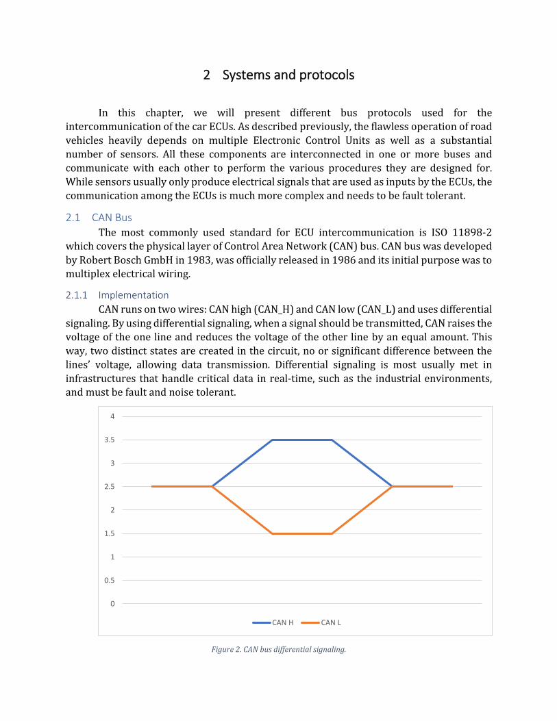
Figure 2. CAN bus differential signaling.
0
0.5
1
1.5
2
2.5
3
3.5
4
CAN H CAN L
The above figure shows how 1 bit of data can be transmitted in CAN bus by raising
the voltage in one line while at the same time dropping the voltage in the other and creating
a differential of 2V between them which is interpreted as a “low”. When the two lines have
the same voltage, their differential is 0V which is interpreted as a “high”. The differential
voltages are converted in representation of a data bits by the CAN controllers’ transceivers.
CAN controllers are the electronic devices that transmit and receive signals on the can bus,
such as an Electronic Control Unit. The sensors and ECUs that use the CAN bus incorporate a
transceiver that when triggered by the voltage change in one of the cables, identifies whether
the electric potential has been modified in the other line of the CAN bus as well. If not, the
packet that contains the invalid information is rejected as noise. The reason for 0 being
considered “high” is that CAN bus uses carrier sensor multiple access/collision avoidance
(CSMA/CA) and the lowest bit value has higher priority [1].
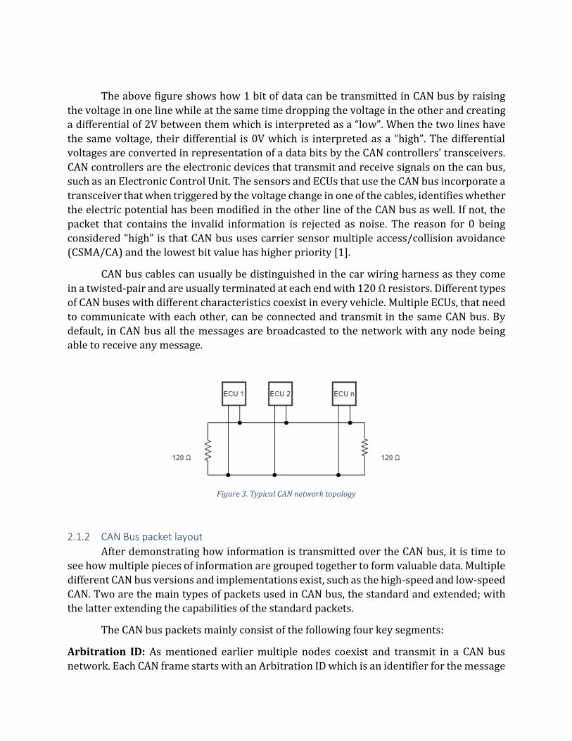
CAN bus cables can usually be distinguished in the car wiring harness as they come
in a twisted-pair and are usually terminated at each end with 120 Ω resistors. Different types
of CAN buses with different characteristics coexist in every vehicle. Multiple ECUs, that need
to communicate with each other, can be connected and transmit in the same CAN bus. By
default, in CAN bus all the messages are broadcasted to the network with any node being
able to receive any message.
Figure 3. Typical CAN network topology
2.1.2 CAN Bus packet layout
After demonstrating how information is transmitted over the CAN bus, it is time to
see how multiple pieces of information are grouped together to form valuable data. Multiple
different CAN bus versions and implementations exist, such as the high-speed and low-speed
CAN. Two are the main types of packets used in CAN bus, the standard and extended; with
the latter extending the capabilities of the standard packets.
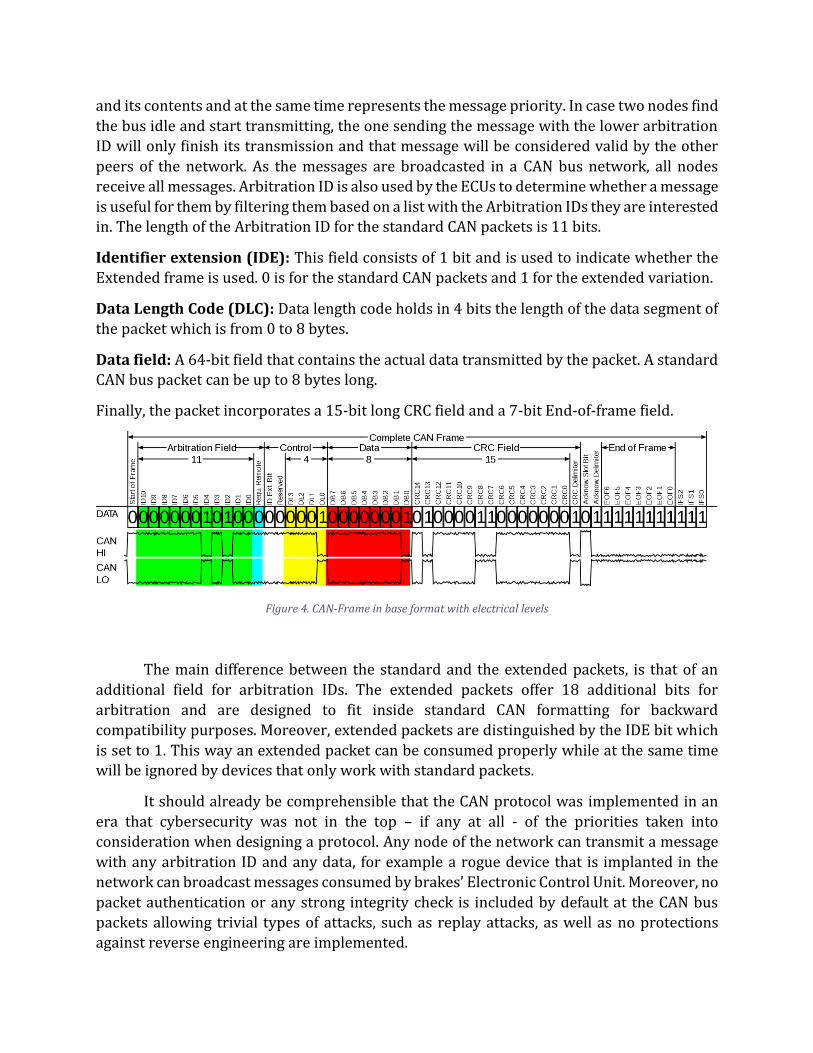
The CAN bus packets mainly consist of the following four key segments:
Arbitration ID: As mentioned earlier multiple nodes coexist and transmit in a CAN bus
network. Each CAN frame starts with an Arbitration ID which is an identifier for the message
and its contents and at the same time represents the message priority. In case two nodes find
the bus idle and start transmitting, the one sending the message with the lower arbitration
ID will only finish its transmission and that message will be considered valid by the other
peers of the network. As the messages are broadcasted in a CAN bus network, all nodes
receive all messages. Arbitration ID is also used by the ECUs to determine whether a message
is useful for them by filtering them based on a list with the Arbitration IDs they are interested in. The length of the Arbitration ID for the standard CAN packets is 11 bits.
Identifier extension (IDE): This field consists of 1 bit and is used to indicate whether the
Extended frame is used. 0 is for the standard CAN packets and 1 for the extended variation.
Data Length Code (DLC): Data length code holds in 4 bits the length of the data segment of
the packet which is from 0 to 8 bytes.
Data field: A 64-bit field that contains the actual data transmitted by the packet. A standard CAN bus packet can be up to 8 bytes long.
Finally, the packet incorporates a 15-bit long CRC field and a 7-bit End-of-frame field.
Figure 4. CAN-Frame in base format with electrical levels
The main difference between the standard and the extended packets, is that of an
additional field for arbitration IDs. The extended packets offer 18 additional bits for
arbitration and are designed to fit inside standard CAN formatting for backward
compatibility purposes. Moreover, extended packets are distinguished by the IDE bit which
is set to 1. This way an extended packet can be consumed properly while at the same time will be ignored by devices that only work with standard packets.
It should already be comprehensible that the CAN protocol was implemented in an
era that cybersecurity was not in the top – if any at all - of the priorities taken into
consideration when designing a protocol. Any node of the network can transmit a message
with any arbitration ID and any data, for example a rogue device that is implanted in the
network can broadcast messages consumed by brakes’ Electronic Control Unit. Moreover, no
packet authentication or any strong integrity check is included by default at the CAN bus
packets allowing trivial types of attacks, such as replay attacks, as well as no protections
against reverse engineering are implemented.
2.2 ISO-TP
ISO-TP (transport layer) is a transport protocol defined in the ISO 15765-2. As its
name implies, it is a standard designed for sending packets over the CAN bus and its purpose
is to increase the size of the transferred data. The ISO-TP messages can carry up to 4095
bytes of transmitted data per packet. In the OSI model, it covers Layer 3 (network layer) and
Layer 4 (transport layer).
The transmission of the much longer payload is achieved by chaining CAN packets
together. When a message that contains data that would not normally fit in one CAN packet
is being sent using the ISO-TP protocol, it is segmented and transmitted into multiple CAN
frames containing the segmented payload alongside metadata that allow the individual
frames to be properly reassembled into the original message the sender wanted to transmit.
Moreover, the ISO-TP protocol incorporates its own addressing scheme named
“Extended Addressing” while it is also able to operate with the Arbitration ID “Normal
Addressing” scheme, as described earlier. The “Extended Addressing” introduces source and
destination addresses to the transmitted messages, indicating which node the message was
composed for and which node is sending it. This protocol is most commonly used by
diagnostic devices of mechanics and manufacturers to transfer error codes and perform
complex diagnostic functions with Unified Diagnostic Services.
2.3 Unified Diagnostic Services (UDS)
Most modern cars come equipped with an OBD-II connector which can be considered
the diagnostic interface of the car and provides access to the vehicle internal network. The
purpose of the OBD-II connector is to allow external entities, such as diagnostic tools used
by mechanics during a troubleshooting session, to send and receive messages to the ECUs
residing in the different buses that exist in a vehicle. In the previous decades, when car
electronic systems were much more simple and provided significantly less functionality, the
traditional CAN bus packets were used for the diagnostic sessions. In the modern era where
nearly all car functions, from the window operation to the fuel injection and the door locks,
are electronically carried out, the need for more complex ways to communicate with a car arise.
Unified Diagnostic Services (UDS), specified by ISO 14229-1, was designed to fulfill
the aforementioned needs for more complex diagnostic and troubleshooting capabilities.
UDS is a very important communication protocol as nowadays it is used for all diagnostic
functionalities, such as simple error code reports or more complex procedure such as the
sensor initializations or even the ECU software flashing. As we will describe later proprietary
protocols are designed based on this protocol. Moving higher in the OSI model, UDS utilizes
the fifth and seventh layers.
2.3.1 UDS messages and communication flow
UDS operates over the standard CAN bus protocol in a client-server architecture,
where an external entity, such as a diagnostic tool, is considered the client and the ECUs the
servers. The client requests an ECU to perform an operation and the ECU will respond with
the result. Since UDS is an application layer protocol, it needs to be used over a data transport
protocol. Nowadays, ISO-TP over CAN bus is mostly used for UDS message transportation.
The main building blocks for UDS messages (both requests and responses) are
Service IDs, PIDs and data. The Service IDs define the type of functionality requested by the
client e.g. SID 0x22 is the “Read Data By Identifier” which is used to request data from the
car based on some predefined identifiers. Both the diagnostic tool and each ECU refer to the
same values with the same identifier; for example, when querying an instrument cluster, the
value 0x0A could be used to query the current reading of the odometer. The same value on
another ECU may or may not be mapped to a value. Next, the PIDs are like subfunction for
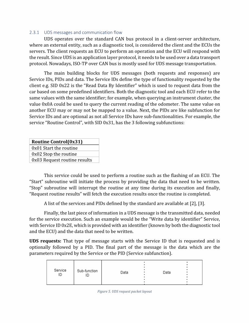
Service IDs and are optional as not all Service IDs have sub-functionalities. For example, the service “Routine Control”, with SID 0x31, has the 3 following subfunctions:
Routine Control(0x31)
0x01 Start the routine 0x02 Stop the routine 0x03 Request routine results
This service could be used to perform a routine such as the flashing of an ECU. The
“Start” subroutine will initiate the process by providing the data that need to be written.
“Stop” subroutine will interrupt the routine at any time during its execution and finally, “Request routine results” will fetch the execution results once the routine is completed.
A list of the services and PIDs defined by the standard are available at [2], [3].
Finally, the last piece of information in a UDS message is the transmitted data, needed
for the service execution. Such an example would be the “Write data by identifier” Service,
with Service ID 0x2E, which is provided with an identifier (known by both the diagnostic tool and the ECU) and the data that need to be written.
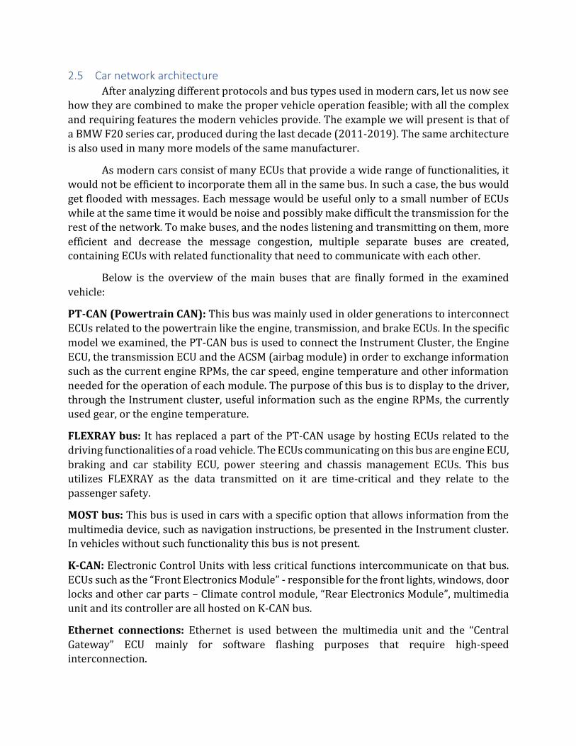
UDS requests: That type of message starts with the Service ID that is requested and is
optionally followed by a PID. The final part of the message is the data which are the parameters required by the Service or the PID (Service subfunction).
Figure 5. UDS request packet layout

UDS response: The response to a specific request message has an equivalent layout. In case
the requested function was executed successfully, the response will include the Service ID of
the requested Service increased by 0x40. For instance, in case of the “Request data by
identifier” service, with ID 0x22, the response of a successful execution will contain as
Service ID the value 0x62 followed by the Sub-function ID (PID) and the result in the data
field. In the case of an unsuccessful execution, the Service ID field will have the hexadecimal
value 7F followed by the Service ID and an error code describing the reason the function
failed.
Figure 6. UDS response packet layout
Figure 7. UDS response of unsuccessful execution
Below is an example of a request message alongside a response of an unsuccessful execution.
Figure 8. Example UDS message requesting the odometer reading

Figure 9. Example UDS response of an unsuccessful execution
The UDS protocol uses more types of messages for flow control and addressing
purposes in order for the communication to be orchestrated and encapsulated inside CAN
bus packets. The messages above describe how the useful data are transmitted between two
communicating nodes.
2.4 Further Communication protocols
More protocols with different characteristics are used in modern vehicles, for
different purposes. The most notable ones are the following:
• LIN (Local Interconnect Network) protocol: A simple and cheap to implement protocol
with a Master node that mainly does all the transmission and multiple slave nodes
listening and occasionally transmitting.
• MOST (Media Oriented Systems Transport) protocol: As implied by its name, it is a
protocol designed for multimedia devices that supports much higher speeds than CAN
protocols. Comes in different implementations with the fastest variation reaching bit rate
of 150Mbps.
• FlexRay Bus: FlexRay is an expensive, high-speed protocol that is used in buses with
nodes performing time-critical operations. Such implementations include buses with
ECUs related to driving operations such as the engine and the braking ECUs where the
integrity and timing of data transmission is critical for the passengers’ safety.
• Automotive Ethernet: As MOST and FlexRay usage is declining due to their high-cost
and high-complexity implementations, most modern road vehicles are moving to
Ethernet. Automotive Ethernet implementation is similar to what we find in computer
networks. It encapsulates CAN messages as UDP and can support features such as quality of service (QoS) and IPsec.
2.5 Car network architecture
After analyzing different protocols and bus types used in modern cars, let us now see
how they are combined to make the proper vehicle operation feasible; with all the complex
and requiring features the modern vehicles provide. The example we will present is that of
a BMW F20 series car, produced during the last decade (2011-2019). The same architecture
is also used in many more models of the same manufacturer.
As modern cars consist of many ECUs that provide a wide range of functionalities, it
would not be efficient to incorporate them all in the same bus. In such a case, the bus would
get flooded with messages. Each message would be useful only to a small number of ECUs
while at the same time it would be noise and possibly make difficult the transmission for the
rest of the network. To make buses, and the nodes listening and transmitting on them, more
efficient and decrease the message congestion, multiple separate buses are created, containing ECUs with related functionality that need to communicate with each other.
Below is the overview of the main buses that are finally formed in the examined
vehicle:
PT-CAN (Powertrain CAN): This bus was mainly used in older generations to interconnect
ECUs related to the powertrain like the engine, transmission, and brake ECUs. In the specific
model we examined, the PT-CAN bus is used to connect the Instrument Cluster, the Engine
ECU, the transmission ECU and the ACSM (airbag module) in order to exchange information
such as the current engine RPMs, the car speed, engine temperature and other information
needed for the operation of each module. The purpose of this bus is to display to the driver,
through the Instrument cluster, useful information such as the engine RPMs, the currently
used gear, or the engine temperature.
FLEXRAY bus: It has replaced a part of the PT-CAN usage by hosting ECUs related to the
driving functionalities of a road vehicle. The ECUs communicating on this bus are engine ECU,
braking and car stability ECU, power steering and chassis management ECUs. This bus
utilizes FLEXRAY as the data transmitted on it are time-critical and they relate to the
passenger safety.
MOST bus: This bus is used in cars with a specific option that allows information from the
multimedia device, such as navigation instructions, be presented in the Instrument cluster. In vehicles without such functionality this bus is not present.
K-CAN: Electronic Control Units with less critical functions intercommunicate on that bus.
ECUs such as the “Front Electronics Module” - responsible for the front lights, windows, door
locks and other car parts – Climate control module, “Rear Electronics Module”, multimedia
unit and its controller are all hosted on K-CAN bus.
Ethernet connections: Ethernet is used between the multimedia unit and the “Central
Gateway” ECU mainly for software flashing purposes that require high-speed interconnection.
As presented above, an ECU might be part of more than one buses in order to reduce
the overhead of the message transmission and distinguish the buses according to operational
field. Moreover, an Electronic Control Unit might under certain circumstances need to send
a message to a module of a different bus. For instance, when a light bulb of the taillights needs
replacement, a message should be sent to the Instrument Cluster to notify the driver.
However, the Instrument Cluster is not attached to any common bus with the “Rear
Electronics Module”, which is responsible for the taillights’ operation. For this purpose, an
ECU, under the name “Central Gateway”, with special purpose is used. This ECU is connected
to all car buses, receives and implements all protocols and is responsible to transfer
messages from one bus to another when the source and the destination nodes are not hosted on the same bus.
Furthermore, the “Central Gateway” ECU provides two interfaces, through the OBD-
II connector, for the connection of the car and its internal buses with external entities, such
as diagnostic tools. Proprietary protocols allow specific vehicle processes to be executed and
limited information to be accessed. Moreover, prevents the full access to data transmitted
internally in the car network. For this cause, the “Central Gateway” ECU acts as a “firewall”
that does not allow the internal messages to be transmitted to the “outer-world” through the
OBD connector as it used to happen in vehicles of older generations or as is the case with
other manufacturers. The “Central Gateway” ECU allows the communication for diagnostic
processes over a) an interface that uses CAN messages (D-CAN) and b) an Ethernet interface
where messages are exchanged using TCP. The second method will be used for our
experimentation.
3 Protocol Reverse Engineering and Car Infrastructure reconnaissance
In the present chapter we will show how the communication protocol used for
diagnostic purposes can be reverse engineered and identify how it works. Furthermore, we
will build a test bench – a home laboratory hosting car Electronic Control Units – where the
reverse engineering findings will be utilized to further explore the automotive ECUs and
their functionalities.
3.1 Protocol analysis
Our analysis was conducted in a BMW F20 series, a car produced from 2011 up to
2019 that incorporates many systems and technologies that are also used in next generation
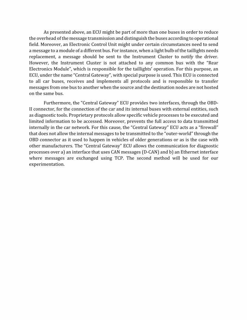
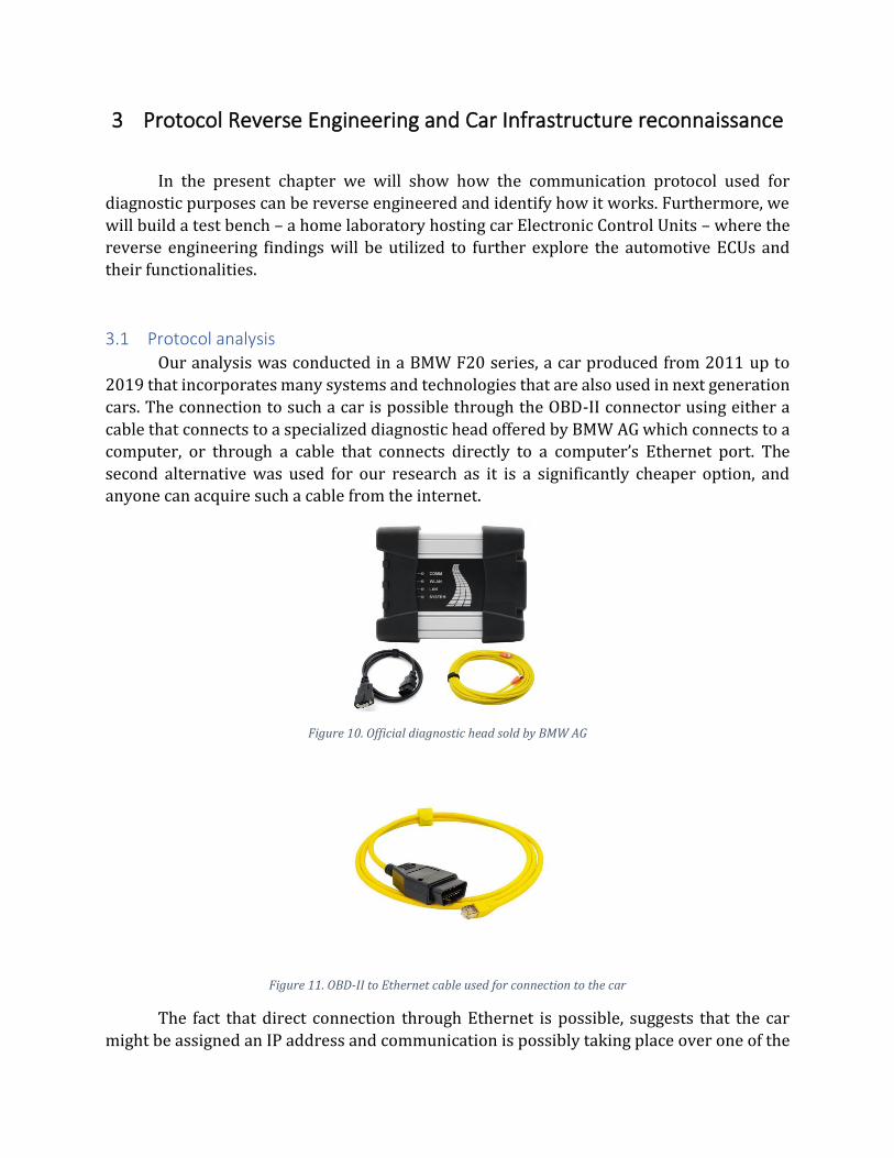
cars. The connection to such a car is possible through the OBD-II connector using either a
cable that connects to a specialized diagnostic head offered by BMW AG which connects to a
computer, or through a cable that connects directly to a computer’s Ethernet port. The
second alternative was used for our research as it is a significantly cheaper option, and anyone can acquire such a cable from the internet.
Figure 10. Official diagnostic head sold by BMW AG
Figure 11. OBD-II to Ethernet cable used for connection to the car
The fact that direct connection through Ethernet is possible, suggests that the car
might be assigned an IP address and communication is possibly taking place over one of the
known protocols used in computer networks. The first thing we did was to use a diagnostic
tool that utilizes the available connection and by using Wireshark, dump the traffic in the
connected Ethernet interface of the computer. Initially, it was attempted to use the
diagnostic tool to query for data that are human readable and would be easily identifiable in
the Wireshark sniffed traffic. The information we queried for, was the odometer reading.
After observing that the odometer value the diagnostic tool returned was the same as the
reading in the Instrument Cluster, and dumping the traffic in the interface used for the
connection with the car, an analysis took place and the following information were extracted.
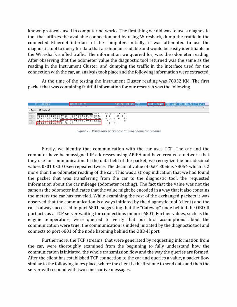
At the time of the testing the Instrument Cluster reading was 78052 KM. The first packet that was containing fruitful information for our research was the following.
Figure 12. Wireshark packet containing odometer reading
Firstly, we identify that communication with the car uses TCP. The car and the
computer have been assigned IP addresses using APIPA and have created a network that
they use for communication. In the data field of the packet, we recognize the hexadecimal
values 0x01 0x30 0xe6 repeated twice. The decimal value of 0x0130e6 is 78054 which is 2
more than the odometer reading of the car. This was a strong indication that we had found
the packet that was transferring from the car to the diagnostic tool, the requested
information about the car mileage (odometer reading). The fact that the value was not the
same as the odometer indicates that the value might be encoded in a way that it also contains
the meters the car has traveled. While examining the rest of the exchanged packets it was
observed that the communication is always initiated by the diagnostic tool (client) and the
car is always accessed in port 6801, suggesting that the “Gateway” node behind the OBD-II
port acts as a TCP server waiting for connections on port 6801. Further values, such as the
engine temperature, were queried to verify that our first assumptions about the
communication were true; the communication is indeed initiated by the diagnostic tool and
connects to port 6801 of the node listening behind the OBD-II port.
Furthermore, the TCP streams, that were generated by requesting information from
the car, were thoroughly examined from the beginning to fully understand how the
communication is initiated, the whole transmission flow and the way the queries are formed.
After the client has established TCP connection to the car and queries a value, a packet flow
similar to the following takes place, where the client is the first one to send data and then the server will respond with two consecutive messages.
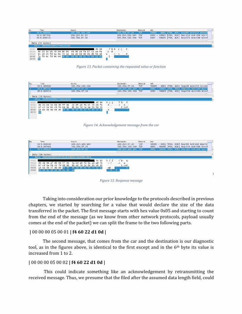
Figure 13. Packet containing the requested value or function
Figure 14. Acknowledgement message from the car
Figure 15. Response message
Taking into consideration our prior knowledge to the protocols described in previous
chapters, we started by searching for a value that would declare the size of the data
transferred in the packet. The first message starts with hex value 0x05 and starting to count
from the end of the message (as we know from other network protocols, payload usually
comes at the end of the packet) we can split the frame to the two following parts.
| 00 00 00 05 00 01 | f4 60 22 d1 0d |
The second message, that comes from the car and the destination is our diagnostic
tool, as in the figures above, is identical to the first except and in the 6th byte its value is increased from 1 to 2.
| 00 00 00 05 00 02 | f4 60 22 d1 0d |
This could indicate something like an acknowledgement by retransmitting the
received message. Thus, we presume that the filed after the assumed data length field, could

possibly host a value that indicates the type of the message, with value 0x1 indicating a
normal message, and value 0x2 indicating an acknowledgement message.
The third message, again coming from the car, starts with the hexadecimal value 0x0d (13 decimal) and splitting it in the 13th byte from the end we get the following.
| 00 00 00 0d | 00 01 | 60 f4 62 d1 0d 00 01 30 e6 00 01 30 e6 |
Another observation from that request-response pair, is that the first two bytes of
the third segment (bold) in the messages originating from the car, are the same with the first
two bytes of the first packet but in reverse order.
Analyzing further request and response pairs and by splitting the messages in
segments according to the value indicated by the first 4 bytes of each packet (e.g. 00 00 00
0d = 13 bytes length), the pattern where the first 2 bytes of the second segment appear both
in the request and the response but in reverse order, was consistent. Another observation
was that one of the two aforementioned repeating values was always 0xf4 while the other
value was constantly changing according to the ECU we were requesting data from. For
example, when a value from the instrument cluster was requested, the first byte pair was
always 0xf4 and 0x60 while when data related to the engine were requested, the pair was
0xf4 and 0x12.
It was these observations that suggested two things. First, the initial four bytes of the
messages were indeed indicating the payload length as we had assumed; and we could now
also assume that the first two bytes of the “payload field” were the addresses of the source
and destination nodes. The node with address 0xf4 should be us with the diagnostic tool,
sending messages to the Electronic Control Units. Therefore, the value 0xf4 existed in all
packets. The node with address 0x60 was the Instrument Cluster, as this was used when we
requested the odometer reading. The diagnostic tool knows what address each query must
be sent to and with what parameters. This way when it needs to request data from a specific
ECU, it will add the corresponding destination address. The “Gateway” module, that is
providing the Ethernet interface to OBD-II port, is the receiving node of the packets sent by
our computer and will examine the packet, identify in which bus resides the node with the
requested destination address and will forward the request by creating a new packet with
the protocol used on that bus. The response from the ECU will contain the address 0xf4 as
destination and the “Gateway” node will forward the response to the diagnostic tool using a
TCP packet. More specifically, the “Gateway” module in our case is the “Central Gateway”
ECU, as described in 2.5 above. The “Central Gateway” is sharing a common PCB with the “Front Electronics Module” ECU so it is called FEM_GW.
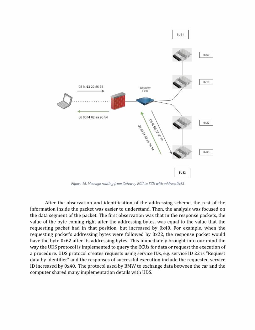
Figure 16. Message routing from Gateway ECU to ECU with address 0x63
After the observation and identification of the addressing scheme, the rest of the
information inside the packet was easier to understand. Then, the analysis was focused on
the data segment of the packet. The first observation was that in the response packets, the
value of the byte coming right after the addressing bytes, was equal to the value that the
requesting packet had in that position, but increased by 0x40. For example, when the
requesting packet’s addressing bytes were followed by 0x22, the response packet would
have the byte 0x62 after its addressing bytes. This immediately brought into our mind the
way the UDS protocol is implemented to query the ECUs for data or request the execution of
a procedure. UDS protocol creates requests using service IDs, e.g. service ID 22 is “Request
data by identifier” and the responses of successful execution include the requested service
ID increased by 0x40. The protocol used by BMW to exchange data between the car and the computer shared many implementation details with UDS.
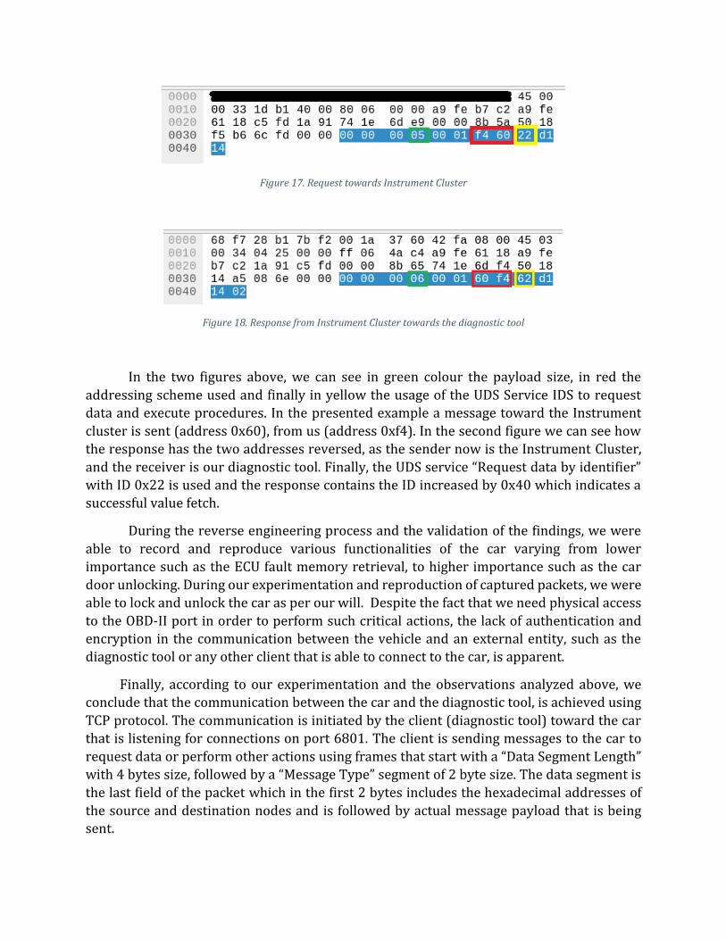
Figure 17. Request towards Instrument Cluster
Figure 18. Response from Instrument Cluster towards the diagnostic tool
In the two figures above, we can see in green colour the payload size, in red the
addressing scheme used and finally in yellow the usage of the UDS Service IDS to request
data and execute procedures. In the presented example a message toward the Instrument
cluster is sent (address 0x60), from us (address 0xf4). In the second figure we can see how
the response has the two addresses reversed, as the sender now is the Instrument Cluster,
and the receiver is our diagnostic tool. Finally, the UDS service “Request data by identifier”
with ID 0x22 is used and the response contains the ID increased by 0x40 which indicates a
successful value fetch.
During the reverse engineering process and the validation of the findings, we were
able to record and reproduce various functionalities of the car varying from lower
importance such as the ECU fault memory retrieval, to higher importance such as the car
door unlocking. During our experimentation and reproduction of captured packets, we were
able to lock and unlock the car as per our will. Despite the fact that we need physical access
to the OBD-II port in order to perform such critical actions, the lack of authentication and
encryption in the communication between the vehicle and an external entity, such as the
diagnostic tool or any other client that is able to connect to the car, is apparent.
Finally, according to our experimentation and the observations analyzed above, we
conclude that the communication between the car and the diagnostic tool, is achieved using
TCP protocol. The communication is initiated by the client (diagnostic tool) toward the car
that is listening for connections on port 6801. The client is sending messages to the car to
request data or perform other actions using frames that start with a “Data Segment Length”
with 4 bytes size, followed by a “Message Type” segment of 2 byte size. The data segment is
the last field of the packet which in the first 2 bytes includes the hexadecimal addresses of
the source and destination nodes and is followed by actual message payload that is being sent.

Figure 19. Layout of the packet according to our analysis
3.2 ECU Enumeration
After we identified the way the internal car network can be accessed and the
communication protocol seemed pretty simple, it was time to start creating our own
software to get deeper inside the internal car network. Our first objective was to
enumerate the different ECUs we can access from the “outer-world”. For that purpose, a
program was developed, that follows the communication protocol as described above and
brute forces all possible destination addresses. Our target was to observe the behavior of
the listening node in case of invalid destination addresses and finally discover the valid ones that correspond to internal ECUs.
Firstly, we create a Python script that replicates the TCP packet we analyzed earlier
and is used to query a value from an ECU. As service, we will use the “Request Data by
Identifier”, as we can safely assume that there are no risks imposed regarding the car’s
functionality.
import socket
HOST = “add IP address of ECU here”
PORT = 6801
sock = socket.socket(socket.AF_INET, socket.SOCK_STREAM)
sock.connect((HOST,PORT))
sock.send(b”\x00\x00\x00\x05\x00\x01\xf4\x60\x22\xd1\x0d”)
sock.recv(1024).hex()

We execute the code above while at the same time we dump the network traffic and
observe the outcome of our script as well as the captured data. We notice that the packets as
dumped by Wireshark are the same as in the network traffic generated by the diagnostic
tool.
Figure 20. Request (up) and Response (down) from manual TCP connection
Next, we modify the argument of “sock.send()” call by replacing values “\xd1” and
“\x0d” with two bytes that represent a Data Identifier that is unknown to the ECU, such as
0x0101. With this change we try to request something invalid so the target ECU will respond
with and error for “unknown requested data”. This way we will get the error that is returned
by an ECU when the “Read data by identifier” service is used with Data Identifier values that
do not exist. Later, when we request data from a random destination address, we will be able
to distinguish when we are targeting a non-existent node and when the target node exists,
but the requested identifier is not known to it. We send the new TCP packet and observe the response. The acknowledge messages have been omitted.
Figure 21. Request (up) and Response(down) of packet containing random data
After receiving the response of the requested packet with the “Read data by
identifier” service ID and two random hexadecimal values in the data field, we observe that
the response data start with the value 0x7f which indicates an unsuccessful execution.
Next, follows the value 0x22 which is the requested service ID, and finally the error code
0x31 which indicates the ROR (Request out of Range) error. The 0x7f value for
unsuccessful executions as well as the error code 0x31 are also found in UDS protocol. A full list of UDS error codes can be found in Appendix E.
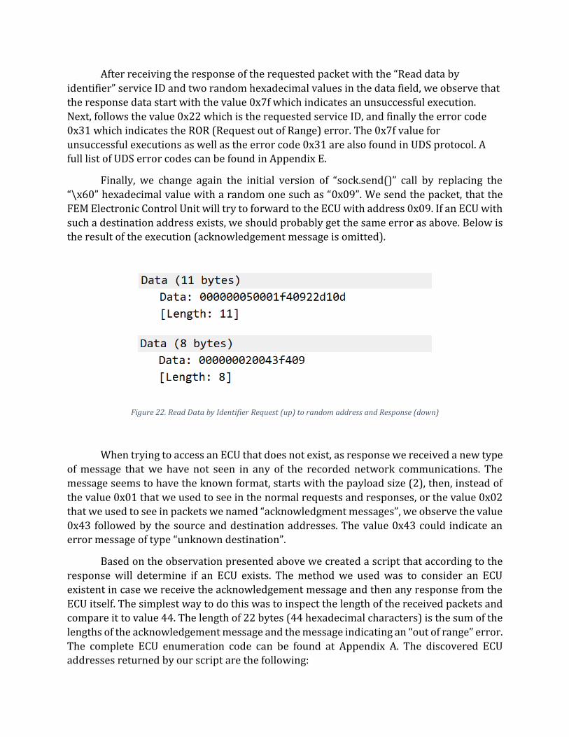
Finally, we change again the initial version of “sock.send()” call by replacing the
“\x60” hexadecimal value with a random one such as “0x09”. We send the packet, that the
FEM Electronic Control Unit will try to forward to the ECU with address 0x09. If an ECU with
such a destination address exists, we should probably get the same error as above. Below is
the result of the execution (acknowledgement message is omitted).
Figure 22. Read Data by Identifier Request (up) to random address and Response (down)
When trying to access an ECU that does not exist, as response we received a new type
of message that we have not seen in any of the recorded network communications. The
message seems to have the known format, starts with the payload size (2), then, instead of
the value 0x01 that we used to see in the normal requests and responses, or the value 0x02
that we used to see in packets we named “acknowledgment messages”, we observe the value
0x43 followed by the source and destination addresses. The value 0x43 could indicate an error message of type “unknown destination”.
Based on the observation presented above we created a script that according to the
response will determine if an ECU exists. The method we used was to consider an ECU
existent in case we receive the acknowledgement message and then any response from the
ECU itself. The simplest way to do this was to inspect the length of the received packets and
compare it to value 44. The length of 22 bytes (44 hexadecimal characters) is the sum of the
lengths of the acknowledgement message and the message indicating an “out of range” error.
The complete ECU enumeration code can be found at Appendix A. The discovered ECU addresses returned by our script are the following:

[+]Detected ECU at address: 01
[+]Detected ECU at address: 10
[+]Detected ECU at address: 1c
[+]Detected ECU at address: 29
[+]Detected ECU at address: 30
[+]Detected ECU at address: 40
[+]Detected ECU at address: 56
[+]Detected ECU at address: 60
[+]Detected ECU at address: 61
[+]Detected ECU at address: 63
3.3 Test Lab Setup
Until that point, the analysis and experiments were conducted on a real car. It is
generally recommended to not use a car for experimentation especially when fuzzing or
enumeration procedures are involved, as unwanted problems that require a significant
amount of money to be resolved might arise. As an example, to understand the criticality of
the situation, consider the case when a procedure that deploys all car airbags exists in the
airbag ECU and we accidentally trigger it during our service discovering routine. It would
therefore be very beneficial to build a testing lab – or test bench - where we can conduct our
research without being exposed to any type of danger. In this section we will describe how a
home lab with used ECUs can be built.
For the set-up of our car security research lab, we will first need a power supply. Car
electronics and car circuits usually operate in 12 Volts. That was as well the case with the
parts we used in our lab which operate in the range from 12 to 14 Volts. Any type of power
supply that supports the desirable voltage will be suitable, even the ones used in computers
(PSU).
Moreover, we will need an ECU of our choice, preferably second hand, that will be
used for our experiments. Used ECUs can be purchased for very low prices; apparently
depending on their type as ECUs with high demand will come in much higher prices. We also
prefer used ECUs as they most probably will be flashed with software, given that they were
removed from a functional car compared to new ones that usually come without any
software. A place with many available options is Ebay as there can anyone find a big variety
of used Electronic Control Units from many different manufacturers. Local shops with used
parts are also an alternative but, in that case, a prior research should be done regarding what
ECU we will choose to use and what price we should expect to be quoted. It is always useful
to get information regarding the car model the ECU was removed from as well as the year of
manufacturing.
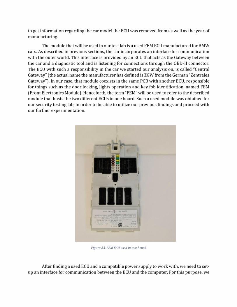
The module that will be used in our test lab is a used FEM ECU manufactured for BMW
cars. As described in previous sections, the car incorporates an interface for communication
with the outer world. This interface is provided by an ECU that acts as the Gateway between
the car and a diagnostic tool and is listening for connections through the OBD-II connector.
The ECU with such a responsibility in the car we started our analysis on, is called “Central
Gateway” (the actual name the manufacturer has defined is ZGW from the German “Zentrales
Gateway”). In our case, that module coexists in the same PCB with another ECU, responsible
for things such as the door locking, lights operation and key fob identification, named FEM
(Front Electronics Module). Henceforth, the term “FEM” will be used to refer to the described
module that hosts the two different ECUs in one board. Such a used module was obtained for
our security testing lab, in order to be able to utilize our previous findings and proceed with our further experimentation.
After finding a used ECU and a compatible power supply to work with, we need to set-
up an interface for communication between the ECU and the computer. For this purpose, we
Figure 23. FEM ECU used in test bench

will replicate the method used by the car manufacturer that was analyzed earlier. An OBD-II
plug will be connected to the FEM module so that it provides Ethernet connectivity. For this
step we will need a specialized OBD-II connector that provides cables for the connection of
each one of its pins. Such an OBD-II connector can be seen in the next figure.
Figure 24. OBD-II connector used for custom wiring
For the proper connection of the OBD-II plug with FEM, or for any other connection
between ECUs we want to perform, a lot of documentation and wiring diagram studying is
involved. This could be proved a very challenging procedure with many different obstacles.
First, manufacturers’ wiring documentations are usually hard to find. They are not publicly
available and can often be found only through leaked data. Moreover, such documentation
might not be accurate, not contain all the information needed or changes may exist between two vehicles of the same model and generation that were produced in different dates.
Once the correct document is found, we will need to identify the diagrams for the ECU
we own. In our case, all necessary documents and wiring diagrams could be found at newtis
website [4]. The first thing we searched for was the documentation of the FEM module. Many
useful information regarding the ECU, the way it works, and the functionalities it implements
were acquired from the documentation. Moving on to connection of the FEM with the OBD-
II connector, the wiring diagram, found on the same website, was thoroughly examined to
identify what pins of FEM were connected to what pins of OBD-II plug and in what order.
Once found, jumper cables and soldering were used for the connection with the OBD plug wires.
Finally, the power and ground pins of the module have to be identified and get
connected to the power supply. This information can as well be found in the wiring diagrams.
After all the described connections are successfully carried out, our test bench is ready for operation.
Further ECUs can be added to the testing lab; nevertheless, in the case of our example
build, the FEM module is enough for someone who wants to get started with ECU security
research and conduct a wide range of attacks and experiments. The FEM module provides
enough surface for experimentation with service enumeration, firmware dumping, custom
firmware flashing and CAN bus attacks as the specific ECU communicates with all other car

ECUs so it has access and transmits to all available buses of the vehicle. Below is presented
our test bench after the addition of two more Electronic Control Units.
Figure 25. Car hacking lab with FEM, Infotainment Unit and Instrument cluster
In the set-up presented in Figure 25, a FEM module can be seen interconnected with
two other ECUs and the OBD-II connector. The one ECU is the Instrument Cluster seen on the
right and the other is an Infotainment module that provides all the multimedia functionality.
The Instrument Cluster is connected to FEM on the “PT-CAN” bus, so when we searched the
wiring diagrams we tried to identify which pins in which socket of the FEM are connected to
that bus. The same procedure was followed for the Instrument Cluster, we tried to identify
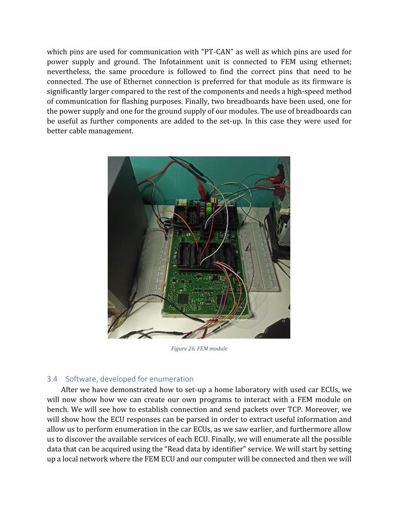
which pins are used for communication with “PT-CAN” as well as which pins are used for
power supply and ground. The Infotainment unit is connected to FEM using ethernet;
nevertheless, the same procedure is followed to find the correct pins that need to be
connected. The use of Ethernet connection is preferred for that module as its firmware is
significantly larger compared to the rest of the components and needs a high-speed method
of communication for flashing purposes. Finally, two breadboards have been used, one for
the power supply and one for the ground supply of our modules. The use of breadboards can
be useful as further components are added to the set-up. In this case they were used for better cable management.
Figure 26. FEM module
3.4 Software, developed for enumeration
After we have demonstrated how to set-up a home laboratory with used car ECUs, we
will now show how we can create our own programs to interact with a FEM module on
bench. We will see how to establish connection and send packets over TCP. Moreover, we
will show how the ECU responses can be parsed in order to extract useful information and
allow us to perform enumeration in the car ECUs, as we saw earlier, and furthermore allow
us to discover the available services of each ECU. Finally, we will enumerate all the possible
data that can be acquired using the “Read data by identifier” service. We will start by setting
up a local network where the FEM ECU and our computer will be connected and then we will
implement a method, similar to the one used by the diagnostic tools, that will automatically
detect and provide us with the IP address of the ECU. We will develop methods for
reoccurring functionalities in order to create a library that will be used to ease the
development process of further programs. The full code of the scripts presented in this section can be found in Appendixes A-D.
3.4.1 Network configuration
Firstly, we will create a network environment over where the two devices, ECU and
our computer, will be able to communicate. For the development purposes, we will be using
a Linux Debian system. All steps described below can also be carried out in any other
operating system such as Windows or macOS and are not restrictive to OSes using Linux. The
Debian system we will be using, will serve as the DHCP server of the network that will be
assigning IP addresses to the connected clients. For DHCP server we have used dnsmasq, a
lightweight program that provides DNS and DHCP services. To acquire it in operating
systems that use apt package manager, use the following command:
$apt-get install dnsmasq
Similar software can be used in other operating systems, such as the tftpd32 for systems
that use Windows. We need to set our DHCP server to operate in the Ethernet interface
where the OBD-II to Ethernet cable will be connected. The name of the interface can be
obtained in Linux systems using the command:
$ip a
To set-up dnqmasq we need to create a configuration file or edit its default configuration
file which can be found under /etc/dnsmasq.conf. Our configuration is straightforward; our
DHCP server will be listening for requests on interface “eth2” with IP address
“192.168.99.10”, will be assigning IP addresses in the pool 192.168.99.11-99 and the IPs will
be leased for 24 hours. The final form of the configuration file that will let dnsmasq operate with these parameters contains the two following lines:
dhcp-range=eth2,192.168.99.11,192.168.99.99,24h
listen-address=192.168.99.10
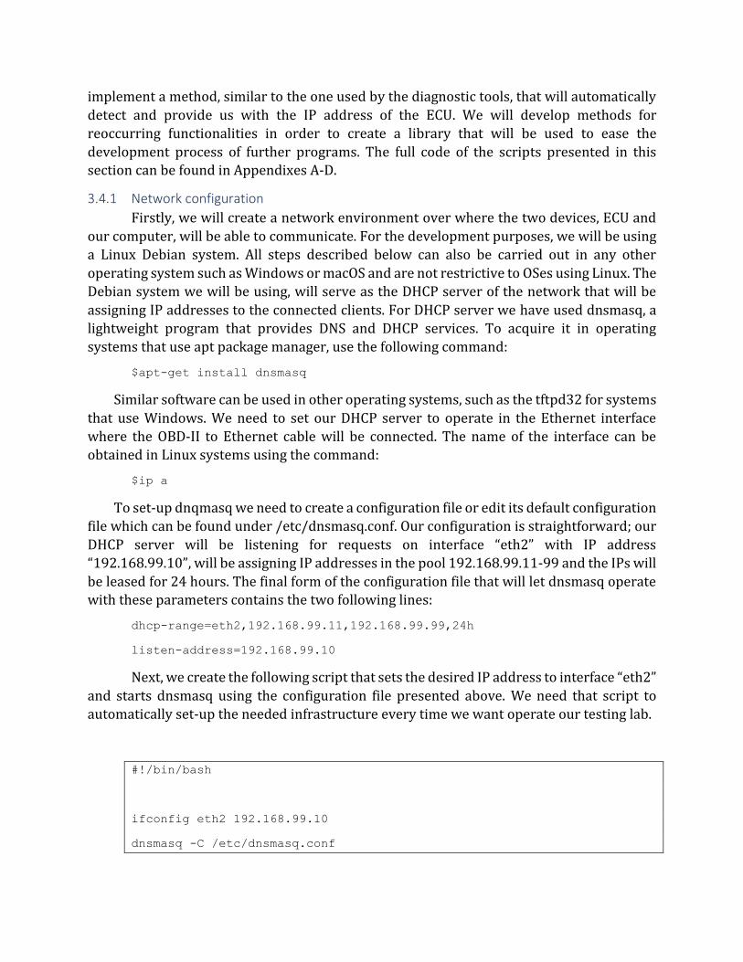
Next, we create the following script that sets the desired IP address to interface “eth2”
and starts dnsmasq using the configuration file presented above. We need that script to
automatically set-up the needed infrastructure every time we want operate our testing lab.
#!/bin/bash
ifconfig eth2 192.168.99.10
dnsmasq -C /etc/dnsmasq.conf
After setting up our network, we can put the FEM module in operation and check if it
it has been assigned an IP address. An easy way to do this, is by running the command:
$arp -a
An example output of the arp command is the following:
? (192.168.99.86) at <mac address> [ether] on eth2
Therefore, we can verify that the ECU is connected to our network and has been
assigned the IP address 192.168.99.86. The arp command is valid for Linux, macOS and
Windows operating systems. Other methods, such as the network scanning, can also be used
to determine if the module is properly connected to the network.
3.4.2 FEM IP address discovery
After having successfully connected the ECU to our network, we will develop a
method that automatically detects the IP the FEM modules is assigned each time, the same
way it is accomplished by the diagnostic tool. For this purpose, we will once again sniff the
traffic of the diagnostic tool and see if we can extract any information about how the
diagnostic tool acquires the FEM IP address. The sniffing procedure took place before the
diagnostic tool is connected to the car, in a stage when the user is prompted to select what
car (of the ones detected in the network) he wants to connect to. After examining the sniffed
traffic dump the following packets were identified to perform the IP discovery we are trying
to accomplish.
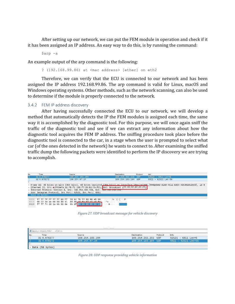
Figure 27. UDP broadcast message for vehicle discovery
Figure 28. UDP response providing vehicle information
The discovery procedure starts with the client (diagnostic tool) broadcasting a UDP
packet, containing the hexadecimal value 0x000000000011, to the whole network. The FEM
module that will receive the broadcasted message, responds from port 6811 with a UDP
packet containing information about the car. The received information include the vehicle VIN (Vehicle Identification Number) and FEM MAC address.
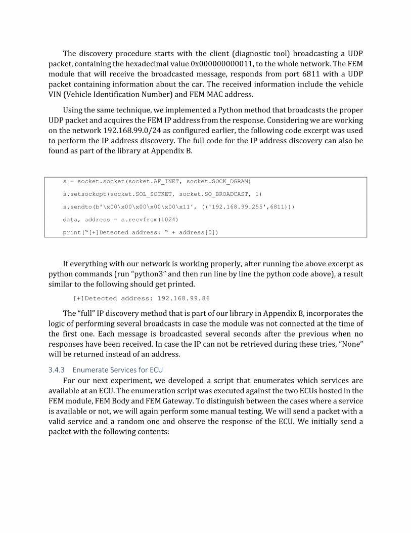
Using the same technique, we implemented a Python method that broadcasts the proper
UDP packet and acquires the FEM IP address from the response. Considering we are working
on the network 192.168.99.0/24 as configured earlier, the following code excerpt was used
to perform the IP address discovery. The full code for the IP address discovery can also be found as part of the library at Appendix B.
s = socket.socket(socket.AF_INET, socket.SOCK_DGRAM)
s.setsockopt(socket.SOL_SOCKET, socket.SO_BROADCAST, 1)
s.sendto(b'\x00\x00\x00\x00\x00\x11', (('192.168.99.255',6811)))
data, address = s.recvfrom(1024)
print(“[+]Detected address: “ + address[0])
If everything with our network is working properly, after running the above excerpt as
python commands (run “python3” and then run line by line the python code above), a result
similar to the following should get printed.
[+]Detected address: 192.168.99.86
The “full” IP discovery method that is part of our library in Appendix B, incorporates the
logic of performing several broadcasts in case the module was not connected at the time of
the first one. Each message is broadcasted several seconds after the previous when no
responses have been received. In case the IP can not be retrieved during these tries, “None” will be returned instead of an address.
3.4.3 Enumerate Services for ECU
For our next experiment, we developed a script that enumerates which services are
available at an ECU. The enumeration script was executed against the two ECUs hosted in the
FEM module, FEM Body and FEM Gateway. To distinguish between the cases where a service
is available or not, we will again perform some manual testing. We will send a packet with a
valid service and a random one and observe the response of the ECU. We initially send a
packet with the following contents:
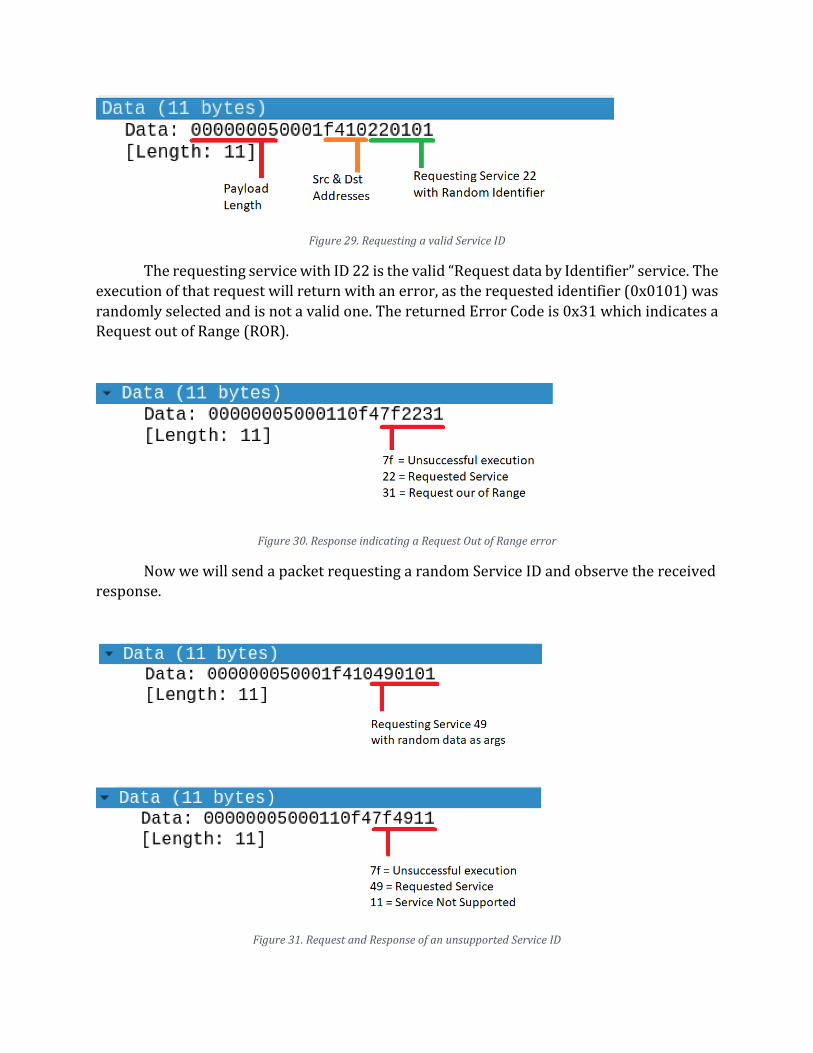
Figure 29. Requesting a valid Service ID
The requesting service with ID 22 is the valid “Request data by Identifier” service. The
execution of that request will return with an error, as the requested identifier (0x0101) was
randomly selected and is not a valid one. The returned Error Code is 0x31 which indicates a Request out of Range (ROR).
Figure 30. Response indicating a Request Out of Range error
Now we will send a packet requesting a random Service ID and observe the received response.
Figure 31. Request and Response of an unsupported Service ID
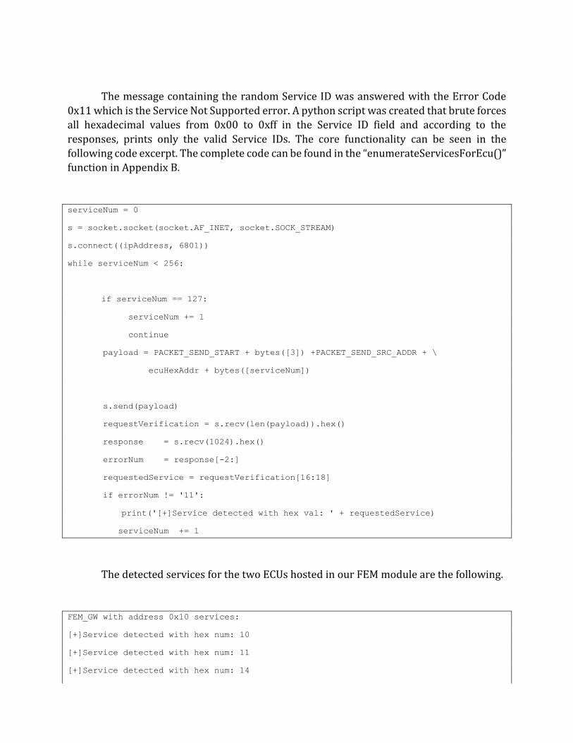
The message containing the random Service ID was answered with the Error Code
0x11 which is the Service Not Supported error. A python script was created that brute forces
all hexadecimal values from 0x00 to 0xff in the Service ID field and according to the
responses, prints only the valid Service IDs. The core functionality can be seen in the
following code excerpt. The complete code can be found in the “enumerateServicesForEcu()”
function in Appendix B.
serviceNum = 0
s = socket.socket(socket.AF_INET, socket.SOCK_STREAM)
s.connect((ipAddress, 6801))
while serviceNum < 256:
if serviceNum == 127:
serviceNum += 1
continue
payload = PACKET_SEND_START + bytes([3]) +PACKET_SEND_SRC_ADDR + \
ecuHexAddr + bytes([serviceNum])
s.send(payload)
requestVerification = s.recv(len(payload)).hex()
response = s.recv(1024).hex()
errorNum = response[-2:]
requestedService = requestVerification[16:18]
if errorNum != '11':
print('[+]Service detected with hex val: ' + requestedService)
serviceNum += 1
The detected services for the two ECUs hosted in our FEM module are the following.
FEM_GW with address 0x10 services:
[+]Service detected with hex num: 10
[+]Service detected with hex num: 11
[+]Service detected with hex num: 14

[+]Service detected with hex num: 19
[+]Service detected with hex num: 22
[+]Service detected with hex num: 27
[+]Service detected with hex num: 28
[+]Service detected with hex num: 2e
[+]Service detected with hex num: 31
[+]Service detected with hex num: 36
[+]Service detected with hex num: 37
[+]Service detected with hex num: 3e
[+]Service detected with hex num: 85
[+]Service detected with hex num: 86
[+]Service detected with hex num: bf
FEM_Body with address 0x40 services:
[+]Service detected with hex num: 10
[+]Service detected with hex num: 11
[+]Service detected with hex num: 14
[+]Service detected with hex num: 19
[+]Service detected with hex num: 22
[+]Service detected with hex num: 27
[+]Service detected with hex num: 28
[+]Service detected with hex num: 2e
[+]Service detected with hex num: 31
[+]Service detected with hex num: 3e
[+]Service detected with hex num: 85
[+]Service detected with hex num: 86
[+]Service detected with hex num: bf
3.4.4 Enumerate valid Data Identifiers
As our last experiment, we enumerated the available data identifiers of the “Read data
by identifier” service for each FEM ECU. This service gets a Data Identifier as argument and
the ECU that receives the request, will respond with the data that are correlated to that
identifier. Each ECU has different identifiers that are matched to different values. For
example, as we saw earlier, in the Instrument Cluster the identifier 0xd10d is matched to the
odometer reading. The same Data Identifier may not exist in another ECU. So, each ECU has
a matching of internal values to identifiers that are used by the diagnostic tool. These internal
values usually exist in the ECU memory or in more rare cases, they can be fetched from other
chips at runtime. So, each ECU has its own identifiers. Data Identifiers have 2-byte values which means their values are from 0 to 65535.
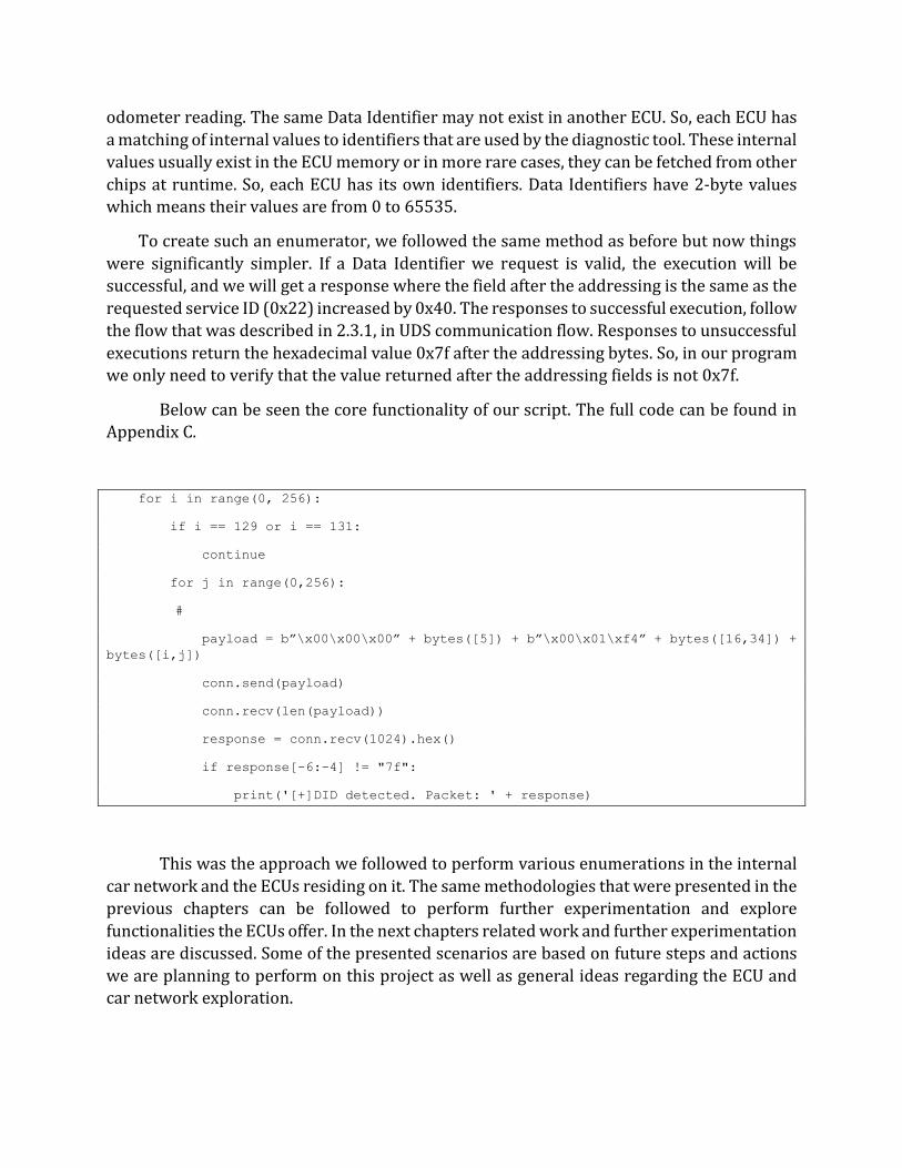
To create such an enumerator, we followed the same method as before but now things
were significantly simpler. If a Data Identifier we request is valid, the execution will be
successful, and we will get a response where the field after the addressing is the same as the
requested service ID (0x22) increased by 0x40. The responses to successful execution, follow
the flow that was described in 2.3.1, in UDS communication flow. Responses to unsuccessful
executions return the hexadecimal value 0x7f after the addressing bytes. So, in our program
we only need to verify that the value returned after the addressing fields is not 0x7f.
Below can be seen the core functionality of our script. The full code can be found in Appendix C.
for i in range(0, 256):
if i == 129 or i == 131:
continue
for j in range(0,256):
#
payload = b”\x00\x00\x00” + bytes([5]) + b”\x00\x01\xf4” + bytes([16,34]) +
bytes([i,j])
conn.send(payload)
conn.recv(len(payload))
response = conn.recv(1024).hex()
if response[-6:-4] != "7f":
print('[+]DID detected. Packet: ' + response)
This was the approach we followed to perform various enumerations in the internal
car network and the ECUs residing on it. The same methodologies that were presented in the
previous chapters can be followed to perform further experimentation and explore
functionalities the ECUs offer. In the next chapters related work and further experimentation
ideas are discussed. Some of the presented scenarios are based on future steps and actions
we are planning to perform on this project as well as general ideas regarding the ECU and car network exploration.
4 Related Work
The assessment and research of protocols used in Automotive industry is inevitably an
upcoming field. With the continuous growth of the car market and the constant integration
of more electronics in road vehicles, they have become a major target for cybercriminals [5].
After the first well known remote exploitation that resulted in the total compromise of a car
[6] was made public, an increasing number of incidents expose different vulnerabilities in the protocols and infrastructures [7] [8] used in road vehicles.
Many different approaches are used to solve different vulnerabilities of the protocols
used in Automotive industry [9]. Different authentication schemes [10] [11] for CAN bus
networks have been analyzed and proposed as well as encryption mechanisms [12], in an
attempt to solve fundamental security weaknesses. Moreover, vulnerability identification
techniques that are already used in software security, such as fuzzing, have been proposed
for use in CAN bus networks [13] or the Automotive field in general [14]. In other approaches
that try to mitigate the security vulnerabilities in CAN bus, Intrusion Detection Systems [15] and further cryptographic solutions have been analyzed.
To the author’s best knowledge, the reverse engineering of proprietary automotive
protocols as seen in the current work, is novel. Several CAN bus protocol reverse engineering
research has taken place [16] using either manual or automated methods [17]; however, the
analysis of a diagnostic protocol alongside the utilization of the findings to perform
enumeration in the car internal network constitutes a novelty. Such experimentation, with
higher layer protocols, can provide fruitful information about the operation of the road
vehicles’ internal networks as shown in the present work.
5 Future Work
As the presented work is a project-in-progress, in this section we will present some of
the next experimentation steps that will take place. Moreover, further ideas will be discussed
regarding scenarios that any interested researcher can dive into.
Planned steps:
• Dump and reverse engineer the FEM ECU firmware.
• Investigate the firmware for vulnerabilities.
• Explore privileged functionalities of the ECU that require Authentication and evaluate
the Authentication process.
• Reverse engineer the flashing procedure and flash custom firmware.
Further experimentation scenarios:
• Sniff and reverse engineer the communication of the ECU with the key fob.
• Reverse engineer the ECU pairing procedure with the key fob.
• Reverse engineer the key fob firmware.
• Discover how vehicle mileage is stored in FEM and investigate methods to modify the
stored value.
6 References
[1] J. A. Bruton, Securing CAN Bus Communication: An Analysis of Cryptographic Approaches, 2014.
[2] "Wikipedia UDS," [Online]. Available:
https://en.wikipedia.org/wiki/Unified_Diagnostic_Services#cite_note-1. [Accessed
30 January 2021].
[3] "Wikipedia OBD-II PIDs," [Online]. Available: https://en.wikipedia.org/wiki/OBD-II_PIDs. [Accessed 30 January 2021].
[4] "Newtis web site hosting many information about nearly all BMW cars," [Online].
Available: https://www.newtis.info/tisv2/a/en/. [Accessed 15 June 2020].
[5] K. Hyatt, "Automotive cyber hack security study upstream," [Online]. Available:
https://www.cnet.com/roadshow/news/2019-automotive-cyber-hack-security-study-upstream/. [Accessed 9 February 2021].
[6] M. C and V. C, "Remote exploitation of an unaltered passenger vehicle," 2015.
[Online]. Available:
https://d1wqtxts1xzle7.cloudfront.net/53311546/Remote_Car_Hacking.pdf?14960
34722=&response-content-
disposition=inline%3B+filename%3DRemote_Exploitation_of_an_Unaltered_Pass.pd
f&Expires=1612902240&Signature=KrV9d51QnwHkEXx2ATTvKzwSeFeFM~5~8sORSzFx8a2tbN1rc.
[7] S. Hartzell and C. Stubel, Automobile CAN Bus Network Security and Vulnerabilities, Seattle, Washington: University of Washington.
[8] M. Bozdal, M. Samie and I. Jennions, A Survey on CAN Bus Protocol: Attacks,
Challenges, and Potential Solutions, Bedford, 2018.
[9] O. Avatefipour and H. Malik, State-of-the-Art Survey on In-Vehicle Network
Communication “CAN-Bus” Security and Vulnerabilities, Michigan.
[10] S. Sharaf and H. Mostafa, A study of Authentication Encryption Algorithms (POET,
Deoxys, AEZ, MORUS, ACORN, AEGIS, AES-GCM) For Automotive Security, Sousse,
Tunisia, Tunisia, 2018.
[11] S. Bauer, M. Brunner and P. Schartner, Lightweight Authentication for Low-End Control Units with Hardware Based Individual Keys, Naples, Italy, Italy, 2019.
[12] S. Shreejith and S. A. Fahmy, Zero latency encryption with FPGAs for secure time-
triggered automotive networks, Shanghai, 2014.
[13] D. S. Fowler, J. Bryans, M. Cheah, P. Wooderson and S. A. Shaikh, A Method for
Constructing Automotive Cybersecurity Tests, a CAN Fuzz Testing Example, 2019.
[14] D. S. Fowler, J. Bryans, S. A. Shaikh and P. Wooderson, Fuzz Testing for Automotive Cyber-security, 2018.
[15] M. Gmiden, M. H. Gmiden and H. Trabelsi, An intrusion detection method for securing in-vehicle CAN bus, Sousse, 2016.
[16] M. Marchetti and D. Stabili, READ: Reverse Engineering of Automotive Data Frames,
2018.
[17] S. Kulandaivel, T. Goyal, A. K. Agrawal and V. Sekar, CANvas: Fast and Inexpensive
Automotive Network Mapping, Santa Clara, 2019.
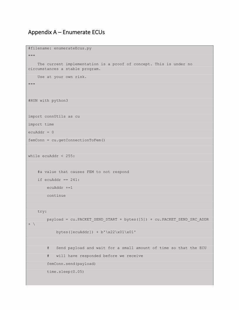
Appendix A – Enumerate ECUs
#filename: enumerateEcus.py
"""
The current implementation is a proof of concept. This is under no
circumstances a stable program.
Use at your own risk.
"""
#RUN with python3
import connUtils as cu
import time
ecuAddr = 0
femConn = cu.getConnectionToFem()
while ecuAddr < 255:
#a value that causes FEM to not respond
if ecuAddr == 241:
ecuAddr +=1
continue
try:
payload = cu.PACKET_SEND_START + bytes([5]) + cu.PACKET_SEND_SRC_ADDR
+ \
bytes([ecuAddr]) + b'\x22\x01\x01'
# Send payload and wait for a small amount of time so that the ECU
# will have responded before we receive
femConn.send(payload)
time.sleep(0.05)
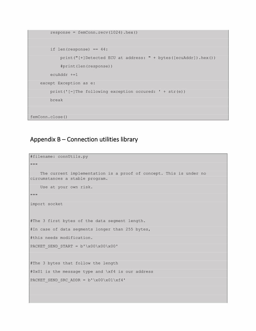
response = femConn.recv(1024).hex()
if len(response) == 44:
print("[+]Detected ECU at address: " + bytes([ecuAddr]).hex())
#print(len(response))
ecuAddr +=1
except Exception as e:
print('[-]The following exception occured: ' + str(e))
break
femConn.close()
Appendix B – Connection utilities library
#filename: connUtils.py
"""
The current implementation is a proof of concept. This is under no
circumstances a stable program.
Use at your own risk.
"""
import socket
#The 3 first bytes of the data segment length.
#In case of data segments longer than 255 bytes,
#this needs modification.
PACKET_SEND_START = b'\x00\x00\x00'
#The 3 bytes that follow the length
#0x01 is the message type and \xf4 is our address
PACKET_SEND_SRC_ADDR = b'\x00\x01\xf4'
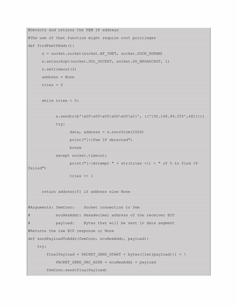
#Detects and returns the FEM IP address
#The use of that function might require root privileges
def findFemIPAddr():
s = socket.socket(socket.AF_INET, socket.SOCK_DGRAM)
s.setsockopt(socket.SOL_SOCKET, socket.SO_BROADCAST, 1)
s.settimeout(2)
address = None
tries = 0
while tries < 5:
s.sendto(b'\x00\x00\x00\x00\x00\x11', (('192.168.99.255',6811)))
try:
data, address = s.recvfrom(1024)
print("[+]Fem IP detected")
break
except socket.timeout:
print("[-]Attempt " + str(tries +1) + " of 5 to find IP
failed")
tries += 1
return address[0] if address else None
#Arguments: femConn: Socket connection to fem
# ecuHexAddr: Hexadecimal address of the receiver ECU
# payload: Bytes that will be sent in data segment
#Returns the raw ECU response or None
def sendPayloadToAddr(femConn, ecuHexAddr, payload):
try:
finalPayload = PACKET_SEND_START + bytes([len(payload)]) + \
PACKET_SEND_SRC_ADDR + ecuHexAddr + payload
femConn.send(finalPayload)
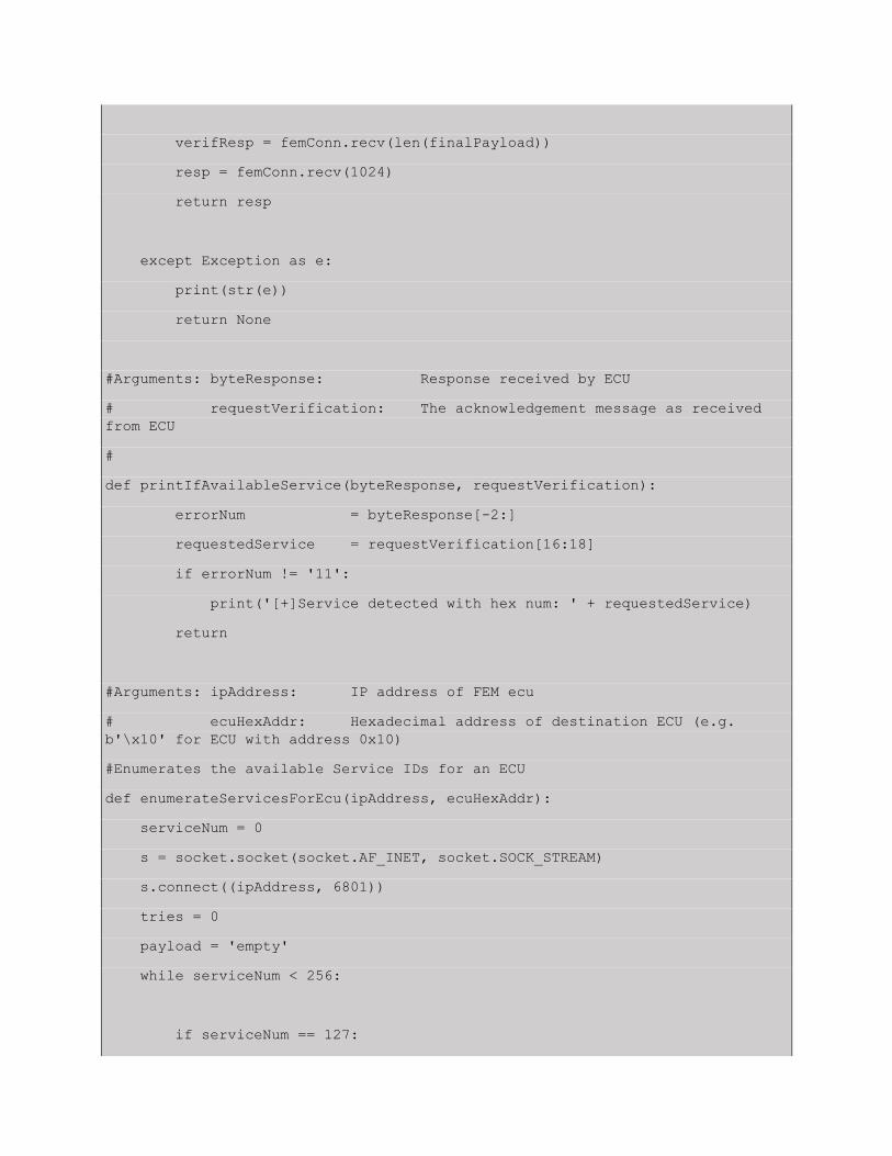
verifResp = femConn.recv(len(finalPayload))
resp = femConn.recv(1024)
return resp
except Exception as e:
print(str(e))
return None
#Arguments: byteResponse: Response received by ECU
# requestVerification: The acknowledgement message as received
from ECU
#
def printIfAvailableService(byteResponse, requestVerification):
errorNum = byteResponse[-2:]
requestedService = requestVerification[16:18]
if errorNum != '11':
print('[+]Service detected with hex num: ' + requestedService)
return
#Arguments: ipAddress: IP address of FEM ecu
# ecuHexAddr: Hexadecimal address of destination ECU (e.g.
b'\x10' for ECU with address 0x10)
#Enumerates the available Service IDs for an ECU
def enumerateServicesForEcu(ipAddress, ecuHexAddr):
serviceNum = 0
s = socket.socket(socket.AF_INET, socket.SOCK_STREAM)
s.connect((ipAddress, 6801))
tries = 0
payload = 'empty'
while serviceNum < 256:
if serviceNum == 127:

serviceNum += 1
continue
try:
payload = PACKET_SEND_START + bytes([3]) +PACKET_SEND_SRC_ADDR +
\
ecuHexAddr + bytes([serviceNum])
s.send(payload)
requestVerification = s.recv(len(payload)).hex()
response = s.recv(1024).hex()
printIfAvailableService(response, requestVerification)
serviceNum += 1
except Exception as e:
if tries < 5:
tries += 1
print('[-] Connection terminated for service: ' +
str(serviceNum))
print('\t[-]Exception: ' + str(e))
s = socket.socket(socket.AF_INET, socket.SOCK_STREAM)
s.connect((ipAddress, 6801))
continue
return
def getConnectionToFem(femAddr = None):
if femAddr == None:
femAddr = findFemIPAddr()

try:
s = socket.socket(socket.AF_INET, socket.SOCK_STREAM)
s.connect((femAddr, 6801))
return s
except Exception as e:
print(str(e))
return None
Appendix C – Enumerate Service 0x22 Data Identifiers
#filename: enumerateService22DIDs.py
"""
The current implementation is a proof of concept. This is under no
circumstances a stable program.
Use at your own risk.
"""
#RUN with python3
import socket
import connUtils as cu
import time
conn = cu.getConnectionToFem()
startTime = time.time()
for i in range(0, 256):
if i == 129 or i == 131:
continue
for j in range(0,25):
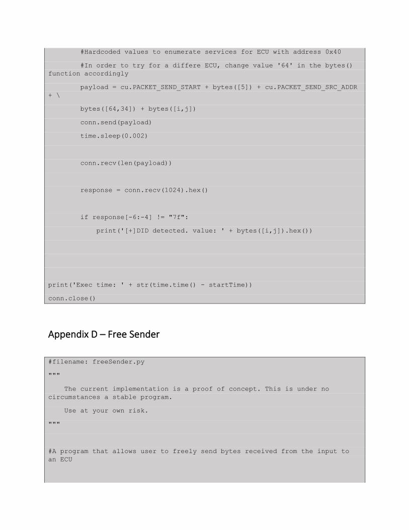
#Hardcoded values to enumerate services for ECU with address 0x40
#In order to try for a differe ECU, change value '64' in the bytes()
function accordingly
payload = cu.PACKET_SEND_START + bytes([5]) + cu.PACKET_SEND_SRC_ADDR
+ \
bytes([64,34]) + bytes([i,j])
conn.send(payload)
time.sleep(0.002)
conn.recv(len(payload))
response = conn.recv(1024).hex()
if response[-6:-4] != "7f":
print('[+]DID detected. value: ' + bytes([i,j]).hex())
print('Exec time: ' + str(time.time() - startTime))
conn.close()
Appendix D – Free Sender
#filename: freeSender.py
"""
The current implementation is a proof of concept. This is under no
circumstances a stable program.
Use at your own risk.
"""
#A program that allows user to freely send bytes received from the input to
an ECU
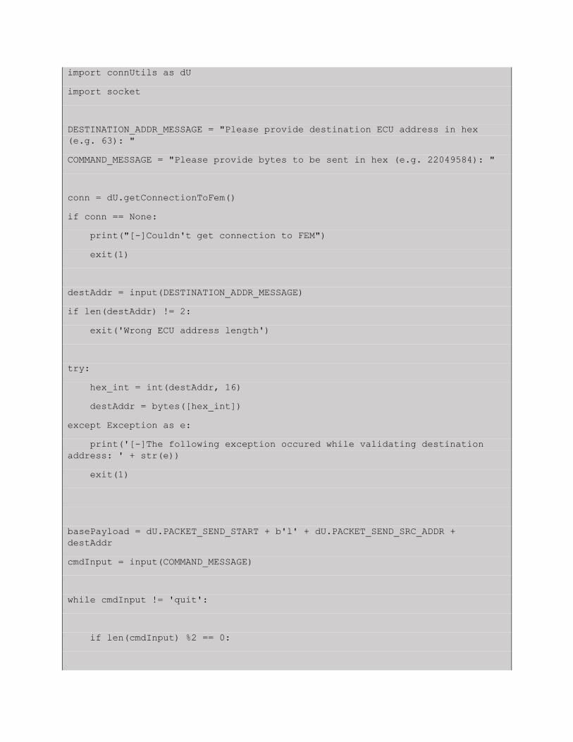
import connUtils as dU
import socket
DESTINATION_ADDR_MESSAGE = "Please provide destination ECU address in hex
(e.g. 63): "
COMMAND_MESSAGE = "Please provide bytes to be sent in hex (e.g. 22049584): "
conn = dU.getConnectionToFem()
if conn == None:
print("[-]Couldn't get connection to FEM")
exit(1)
destAddr = input(DESTINATION_ADDR_MESSAGE)
if len(destAddr) != 2:
exit('Wrong ECU address length')
try:
hex_int = int(destAddr, 16)
destAddr = bytes([hex_int])
except Exception as e:
print('[-]The following exception occured while validating destination
address: ' + str(e))
exit(1)
basePayload = dU.PACKET_SEND_START + b'l' + dU.PACKET_SEND_SRC_ADDR +
destAddr
cmdInput = input(COMMAND_MESSAGE)
while cmdInput != 'quit':
if len(cmdInput) %2 == 0:

inputTrimmed = cmdInput.strip()
totalLen = int(len(inputTrimmed)/2) + 2
payload = basePayload.replace(b'l', bytes([totalLen]))
payload += bytes.fromhex(inputTrimmed)
conn.send(payload)
ack = conn.recv(len(payload))
if len(ack) < len(payload):
exit('An error occured while parsing ECU response. Please make
sure the destination ECU exists')
resp = conn.recv(1024)
print("Service: " + inputTrimmed[0:2] + " data: " + inputTrimmed[2:]
+ " returned:")
print(resp.hex())
else:
print("Wrong CMD size")
cmdInput = input(COMMAND_MESSAGE)
Appendix E - UDS Error Codes
Error Code Description 0x00 Positive Response
0x01 – 0x0F ISO SAE Reserved
0x10 General Reject
0x11 Service Not Supported
0x12 Sub-function Not Supported
0x13 Incorrect Message Length Or Invalid Format
0x14 Response Too Long
0x15 – 0x20 ISO SAE Reserved
0x21 Busy Repeat Request
0x22 Conditions Not Correct
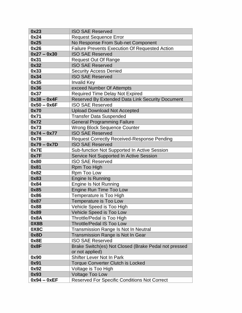
0x23 ISO SAE Reserved
0x24 Request Sequence Error
0x25 No Response From Sub-net Component
0x26 Failure Prevents Execution Of Requested Action
0x27 – 0x30 ISO SAE Reserved
0x31 Request Out Of Range
0x32 ISO SAE Reserved
0x33 Security Access Denied
0x34 ISO SAE Reserved
0x35 Invalid Key
0x36 exceed Number Of Attempts
0x37 Required Time Delay Not Expired
0x38 – 0x4F Reserved By Extended Data Link Security Document
0x50 – 0x6F ISO SAE Reserved
0x70 Upload Download Not Accepted
0x71 Transfer Data Suspended
0x72 General Programming Failure
0x73 Wrong Block Sequence Counter
0x74 – 0x77 ISO SAE Reserved
0x78 Request Correctly Received-Response Pending
0x79 – 0x7D ISO SAE Reserved
0x7E Sub-function Not Supported In Active Session
0x7F Service Not Supported In Active Session
0x80 ISO SAE Reserved
0x81 Rpm Too High
0x82 Rpm Too Low
0x83 Engine Is Running
0x84 Engine Is Not Running
0x85 Engine Run Time Too Low
0x86 Temperature is Too High
0x87 Temperature is Too Low
0x88 Vehicle Speed is Too High
0x89 Vehicle Speed is Too Low
0x8A Throttle/Pedal is Too High
0X8B Throttle/Pedal IS Too Low
0X8C Transmission Range Is Not In Neutral
0x8D Transmission Range is Not In Gear
0x8E ISO SAE Reserved
0x8F Brake Switch(es) Not Closed (Brake Pedal not pressed or not applied)
0x90 Shifter Lever Not In Park
0x91 Torque Converter Clutch is Locked
0x92 Voltage is Too High
0x93 Voltage Too Low
0x94 – 0xEF Reserved For Specific Conditions Not Correct

0xF0 – 0xFE Vehicle Manufacturer Specific Conditions Not Correct
0xFF ISO SAE Reserved