Dehydration of natural gas using membranes. Part I: Composite membranes
Upload
independentCategory
view
2download
0
Desalination xxx (2011) xxx–xxx
DES-10964; No of Pages 7
Contents lists available at SciVerse ScienceDirect
Desalination
j ourna l homepage: www.e lsev ie r.com/ locate /desa l
Stable ion-exchange membranes for water desalination by electrodialysis
Tina Chakrabarty, A. Michael Rajesh, Amaranadh Jasti, Amit K. Thakur, Ajay K. Singh, S. Prakash,Vaibhav Kulshrestha, Vinod K. Shahi⁎Electro-Membrane Processes Division, Central Salt and Marine Chemicals Research Institute, Council of Scientific and Industrial Research (CSIR), G. B. Marg, Bhavnagar-364002, India
⁎ Corresponding author. Tel.: +91 278 2569445; fax:E-mail addresses: [email protected], vinodshahi1@
0011-9164/$ – see front matter © 2011 Published by Edoi:10.1016/j.desal.2011.08.009
Please cite this article as: T. Chakrabarty,(2011), doi:10.1016/j.desal.2011.08.009
a b s t r a c t
a r t i c l e i n f oArticle history:Received 23 June 2011Received in revised form 8 August 2011Accepted 9 August 2011Available online xxxx
Keywords:ElectrodialysisStable membranesWater desalinationCation-exchange membraneAnion-exchange membrane
In this manuscript, we are using sulfonated poly (ethersulfone) (SPES) based cation-exchange membrane(CEM) and polyvinyl alcohol-4-vinylpyridine (4-VP) based cross-linked based anion-exchange membrane(AEM) for water desalination by electrodialysis (ED). These membranes were characterized for theirelectrochemical and physicochemical properties such as membrane conductivity, counter-ion transportnumber, ion-exchange capacity and water content. Prepared ion-exchange membranes (IEMs) showed goodstabilities under severe conditions such as high temperature and strong oxidizing conditions. ED experimentsin recirculation mode of operation were performed for water desalination. Energy consumption and currentefficiency values confirmed suitability of these IEMs for desalination of water by ED.
+91 278 2567562/2566970.yahoo.com (V.K. Shahi).
lsevier B.V.
et al., Stable ion-exchange membranes for w
© 2011 Published by Elsevier B.V.
1. Introduction
Rapid growth of chemical and biotechnology in diversified areasfuels the demand for the need of reliable green technologies for thedownstream processes, which include separation, purification andisolation of the molecules [1–4]. Electro-driven membrane separationprocesses involving ion-exchange membranes are not only part ofapplied electrochemistry but also belong to the field of separationtechniques such as electrodialysis, electro-electrodialysis and electro-deionization [5,6]. The most important industrial application of ED isthe production of drinking water from brackish water and seawater.ED is also used for the purification by demineralization of solutions ofwidely varying industrial fluids encountered in the food, chemical andpharmaceutical industries [7,8]. Thus, development of stable and costeffective ion-exchange membranes (cation- and anion-exchangemembrane) with good physicochemical and electrochemical proper-ties, water desalination is highly desired [1].
Styrene-divinylbenzene based ion-exchange membranes are wellreported in the literature for ED application [9,10]. Commercialmembranes from Tokuyama Soda Co. (Neosepta) and Asahi GlassCo., are copolymer of styrene and divinylbenzene, followed bysulfonation and amination in solution or bulk gives the cation andanion-exchange membranes, respectively. Sulfonation of the polymerwas achieved by chlorosulfonic acid or concentrated sulphuric acid indichloroethane using the silver sulfate as catalyst. The anion-exchangemembrane was prepared by chloromethylation of the polymerfollowed by the amination. Central Salt & Marine Chemicals Research
Institute, Bhavnagar, India, developed interpolymer type of IEMsbasedon poly (ethylene) and styrene-divinyl benzene copolymer [11,12].Numerous versatile industrial applications of these membranes wereinvestigated and thus commercialized because of their high chemicalstability, flexibility and high ionic conductivity [13–16]. Because ofpoly (ethylene), these membranes are thermally unstable. Undersevere condition (high temperature and strongly oxidizing condi-tions) stable IEMs are required for water desalination in a country likeIndia, which is unable to afford the huge cost of membrane developedby Dow, Neosepta, etc. Also, cost effectiveness, stabilities andselectivities are the serious problems with these types of membranes.
Sulfonated arylene main-chain polymers such as sulfonated poly(ether sulfone) (SPES), is considered an attractive material for CEMbecause of its low cost, easy and controlled sulphonation andprocessability [17]. In addition, during preparation of anion-exchangethese membrane, chloromethyl ether and solvents are used which arehazardous and not ecofriendly in nature. Efforts were also rendered todevelop cross-linked thermal, chemical and dimensional stable mem-brane in aqueous medium. Polyvinyl alcohol–silica composite mem-branes were prepared and anion-exchange groups were introduced bythe chemical grafting of 4-vinylpyridine (4-VP). Thesemembraneswerecharacterized by physicochemical and electrochemical studies, andemployed for water desalination by ED.
2. Experimental
2.1. Materials and membranes preparation
Polyvinyl alcohol (PVA; MW: 125,000), hydrochloric acid, sodiumhydroxide, sodium chloride, ammonium persulfate, and dimethyl
ater desalination by electrodialysis, Desalination
2 T. Chakrabarty et al. / Desalination xxx (2011) xxx–xxx
sulfate of AR grade were obtained from S.d-fine Chemicals, India.Tetraethylorthosilicate (TEOS), 4-vinylpyridine (4-VP), and divinyl-benzene were received from the Aldrich Chemicals and used withoutany further purification. Poly (ethersulfone) (3500) was receivedfrom Udel. Double distilled water was used in all experiments.
Sulfonation of PES was achieved by method reported earlier [18], inabsence of moisture contamination, to avoid inter and intra-molecularcross-linking. PES was sulfonated by slow addition of it dried powder inconc. sulfuric acid (10% w/v) at room temperature under constantstirring for 72 h. The moisture contamination was rigorously excludedto ensure acceptable reproducibility of sulfonation level. Presence ofmoisture contamination renders the formation of pyrosulfonateintermediate to inter and intra-molecular cross-linked sulfone. Aftersulfonation, polymerwas precipitatedwith at least afive-fold volume ofdeionizedwater and shredded if necessary to obtain a fine powder. Thiswas thenfilteredandwashedwithwater till last trace of acid. Sulfonatedpoly (ether sulfone) (SPES) was stored in wet condition to avoid cross-linking. For preparation of CEM, desired amount of SPES (5.0 g) weredissolved in DMSO (50 mL) with continuous stirring (24 h) to obtainhomogeneous solution for membrane preparation.
For preparation of AEM, 5 g of PVA was dissolved in 100 mL of hotdeionized water under constant stirring to obtain a homogeneoussolution. Then the required quantity of the 4-vinylpyridine (mono-mer), divinylbenzene (4% w/w) and ammonium persulfate (4% w/w)was added and at 70 °C the mixture was kept for 1 h to get the semi-interpenetrating polymer network. Further equivalent amount of thedimethyl sulphate with respect to 4-vinylpyridine was added toquaternize the pyridinium group. The mixture was stirred for 2 h atroom temperature to obtain a clear homogeneous solution. Then 2 mLof TEOS was added at room temperature and the mixture was keptunder stirred condition for 24 h to get a gel. The resulting gel was caston a clean glass plate with the desired thickness and dried at roomtemperature to obtain a film. Dried membranes were immersed in asolution containing formaldehyde (54.1 g), sodium sulfate (150.0 g),sulphuric acid (125.0 g) and water (470.0 g) for 2 h at 60 °C for effec-tive cross-linking.
Thin film of desired thickness (150 mm) was casted onto cleanedglass plate by obtained viscous solution and dried under IR lamp(24 h) followed by drying in vacuum oven (24 h) at 60 °C. Thesemembranes were conditioned in 0.10 M HCl solution and 0.10 MNaOH solutions alternately several times and then equilibrated withthe experimental solution before being subjected to physicochemicaland electrochemical studies.
2.2. Instrumentation
The FTIR spectra of different cation-exchange membranes wereobtained using spectrum GX series 49387, in which germaniumcrystal was used as internal refection element and angle of incidencewas 65 °C. For scanning electron microscopy (SEM), small pieces ofmembranes (0.5×0.5 cm2) were tilted on the SEM grid and weredried under IR lamp before gold coating. The gold sputter coatingswere carried out on the desired membrane samples at pressuresranging between 1 and 0.1 Pa. Sample was loaded in the machine,which was operated at 10−2–10−3 Pa with 300 V collector bias usinga Leo microscope.
2.3. Membrane stability
Thermal degradation and stability of the membranes wereinvestigated by thermo gravimetric analyzer (TGA) (Mettler ToledoTGA/SDTA851c with starc software) in nitrogen atmosphere at aheating rate of 10 °C/min from 50 to 600 °C.
To investigate the stability of these membranes in harsh oxidative,hot aqueous and acidic environment, long-term aging experimentswere carried out in respective mediums. The oxidative stability of
Please cite this article as: T. Chakrabarty, et al., Stable ion-exchange(2011), doi:10.1016/j.desal.2011.08.009
CEM and AEM membranes was evaluated in Fenton's reagent (3 mgL−1 ferrous sulphate solution in water with 5% H2O2) at 80 °C for 1 h.It served as an accelerated test to simulate the strong oxidative watersplitting conditions and membrane degradation by oxy active radicals[19]. For the hydrolytic stability test, small pieces of membranes wereboiled in water for 24 h at 120 °C in a pressurized closed vial. Theoxidative and hydrolytic stabilities were evaluated by loss in weight,ion-exchange capacity, conductivity and physical appearance of thetest samples [20]. Membrane stability was also assessed in HCl (1–8 M) for 6 hrs at room temperature and its swelling parameter wasrecorded. Chlorine stability tests were conducted by immersingmembranes in 5% NaOCl aqueous solution at 80 °C in terms ofpercentage in weight loss, IEC loss and conductivity loss [17].
2.4. Water content, IEC, counter-ion transport number, andmembrane conductivity
For the measurement of water content, the membrane samples(3×3 cm)were immersed in distilledwater for 24 h, their surfacewaswiped with filter paper and then wet membrane was weighed.Thickness of wet membrane was determined by means of a digitalmicrometer and membrane density for wet membrane was deter-mined by dividing the wet membrane weight by volume. Followingthis, wet membrane was dried at a fixed temperature of 60 °C toconstant weight. Thickness of drymembranewas also determined in asimilar manner and its density was estimated. Water content of themembranes was determined in terms of water concentration in themembrane phase [2].
Water content %ð Þ = Ww−Wd
Wd× 100 ð1Þ
IEC indicates the number of milli equivalent of exchangeablecharge in 1.0 g of the dry polymer matrix. The membranes werewashed with deionized water to remove last trace of acidity.Afterwards, it was equilibrated in 1.0 M NaCl solution (50 cm3) for24 h under random stirring at ambient temperature. Then, libratedH+ or OH− was estimated by acid–base titration using phenolphtha-lein as indicator. The IEC was calculated according to the equation [2]:
IECCEM =CHþ Vsol
Wdryð2Þ
IECAEM =COH− Vsol
Wdryð3Þ
where Wdry is the weight of the membrane sample under drycondition, CH+and COH−are concentrations of H+ and OH− ions,respectively.
Counter ions transport number in the membrane phase wasobtained by Hittorf method [21]. Experimental cell used for thedetermination of transport number was two asymmetric compart-ments separated by a circular piece of membrane (25 cm2) andelectrodes. The capacity of cathodic and anodic compartment was200 mL. The electrodes, obtained from Titanium Tantalum Products(TITAN, Chennai, India) were made of expanded TiO2 sheet coatedwith a triple precious metal oxide (titanium–ruthenium–platinum)(6.0 μm thickness) with 1.5 mm thickness. Distance between theelectrodes and effective membrane area was 0.11 cm and 25 cm2,respectively. Peristaltic pumps were used to feed NaCl solution(0.10 M) in a recirculationmode into the cathodic compartment whiledistilled water was fed into the anodic compartment with constantflow rate. In order to control, both the current density and voltage,digital multimeter was placed in series to apply the constant currentacross the electrodes. Experiments were carried out at constantcurrent density (8.0 mA cm−2) for 1 h. The samples were taken out
membranes for water desalination by electrodialysis, Desalination
3T. Chakrabarty et al. / Desalination xxx (2011) xxx–xxx
from the anodic and cathodic compartments to determine the changein Cl− concentration. The counter ion (Cl−) transport number wasdetermined by using the following equation [22]:
tm− =nFIt
C0V0−C−V−
� �ð4Þ
where n is the charge on Cl−, F is the Faraday constant, I is the appliedcurrent, t is the time (s). C0 and C− are the initial and final Cl−
concentration in the anodic compartment while, V0 and V− are theinitial and final volume of the anodic compartment. Similarly thecation (Na+) transport number was also determined by using thefollowing eq:
tmþ =nFIt
C0V0−CþV
þ� �ð5Þ
where n is the charge on Na+, C0 and C+ are the initial and finalconcentration of Na+ in the anodic compartment. The V0 and V+ arethe initial and final volume of cathodic compartment.
Membrane conductivity measurements were carried out inequilibration with NaCl using a potentiostat/galvanostat frequencyresponse analyzer (Auto Lab, Model PGSTAT 30). The membraneswere sandwiched between two in-house made stainless steel circularelectrodes (4.0 cm2). Direct current (DC) and sinusoidal alternatingcurrents (AC) were supplied to the respective electrodes for recordingthe frequency at a scanning rate of 1 μA/s within a frequency range of106 to 1 Hz. The spectrum of the blank short-circuited cell was alsocollected and this datawas subtracted (as a series circuit) from each ofthe recorded spectra of the membranes to eliminate cell and wiringresistances and inductances. The corrected spectra were viewed ascomplex impedance plots with the imaginary component of Z'' on they-axis and the real component of Z' on the x-axis (Z=Z'− iZ''); theionic resistance of each membrane was estimated to be theintersection of the x-axis with the extrapolation of the low frequencylinear component of each plot. The membrane resistances wereobtained from Nyquist plots. The cation and anion conductivity (κm)was calculated from eq:
κm S = cmð Þ = L cmð Þ= R Ωð Þ × A cm2ð Þ½ � ð6Þ
where L is the distance between the electrodes used to measure thepotential, R is the resistance of the membrane, and A is the surfacearea of the membrane.
2.5. Electrodialysis experiment
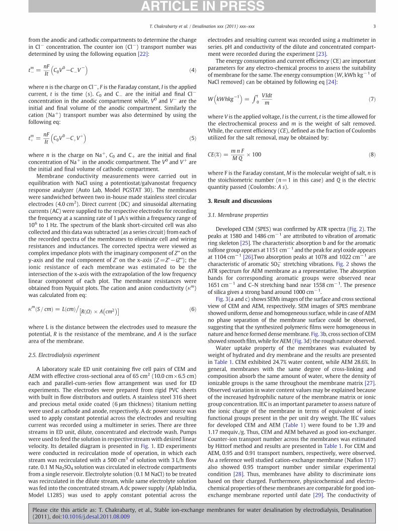
A laboratory scale ED unit containing five cell pairs of CEM andAEM with effective cross-sectional area of 65 cm2 (10.0 cm×6.5 cm)each and parallel-cum-series flow arrangement was used for EDexperiments. The electrodes were prepared from rigid PVC sheetswith built in flow distributors and outlets. A stainless steel 316 sheetand precious metal oxide coated (6 μm thickness) titanium nettingwere used as cathode and anode, respectively. A dc power source wasused to apply constant potential across the electrodes and resultingcurrent was recorded using a multimeter in series. There are threestreams in ED unit, dilute, concentrated and electrode wash. Pumpswere used to feed the solution in respective streamwith desired linearvelocity. Its detailed diagram is presented in Fig. 1. ED experimentswere conducted in recirculation mode of operation, in which eachstream was recirculated with a 500 cm3 of solution with 3 L/h flowrate. 0.1 M Na2SO4 solution was circulated in electrode compartmentsfrom a single reservoir. Electrolyte solution (0.1 M NaCl) to be treatedwas recirculated in the dilute stream, while same electrolyte solutionwas fed into the concentrated stream. A dc power supply (Aplab India,Model L1285) was used to apply constant potential across the
Please cite this article as: T. Chakrabarty, et al., Stable ion-exchange(2011), doi:10.1016/j.desal.2011.08.009
electrodes and resulting current was recorded using a multimeter inseries. pH and conductivity of the dilute and concentrated compart-ment were recorded during the experiment [23].
The energy consumption and current efficiency (CE) are importantparameters for any electro-chemical process to assess the suitabilityof membrane for the same. The energy consumption (W, kWh kg−1 ofNaCl removed) can be obtained by following eq [24]:
W kWhkg−1� �
= ∫ t
0
VIdtm
ð7Þ
where V is the applied voltage, I is the current, t is the time allowed forthe electrochemical process and m is the weight of salt removed.While, the current efficiency (CE), defined as the fraction of Coulombsutilized for the salt removal, may be obtained by:
CE %ð Þ = m n FM Q
× 100 ð8Þ
where F is the Faraday constant,M is the molecular weight of salt, n isthe stoichiometric number (n=1 in this case) and Q is the electricquantity passed (Coulombs: A s).
3. Result and discussions
3.1. Membrane properties
Developed CEM (SPES) was confirmed by ATR spectra (Fig. 2). Thepeaks at 1580 and 1486 cm−1 are attributed to vibration of aromaticring skeleton [25]. The characteristic absorption b and for the aromaticsulfone group appears at 1151 cm−1 and the peak for aryl oxide appearsat 1104 cm−1 [26].Two absorption peaks at 1078 and 1022 cm−1 arecharacteristic of aromatic SO3
− stretching vibrations. Fig. 2 shows theATR spectrum for AEM membrane as a representative. The absorptionbands for corresponding aromatic groups were observed near1651 cm−1 and C–N stretching band near 1558 cm−1. The presenceof silica gives a strong band around 1000 cm−1.
Fig. 3(a and c) shows SEMs images of the surface and cross sectionalview of CEM and AEM, respectively. SEM images of SPES membraneshoweduniform, dense and homogeneous surface, while in case of AEMno phase separation of the membrane surface could be observed,suggesting that the synthesized polymeric films were homogeneous innature and hence formed densemembrane. Fig. 3b, cross section of CEMshowedsmoothfilm,while forAEM(Fig. 3d) the roughnature observed.
Water uptake property of the membranes was evaluated byweight of hydrated and dry membrane and the results are presentedin Table 1. CEM exhibited 24.7% water content, while AEM 28.6%. Ingeneral, membranes with the same degree of cross-linking andcomposition absorb the same amount of water, where the density ofionizable groups is the same throughout the membrane matrix [27].Observed variation in water content values may be explained becauseof the increased hydrophilic nature of the membrane matrix or ionicgroup concentration. IEC is an important parameter to assess nature ofthe ionic charge of the membrane in terms of equivalent of ionicfunctional groups present in the per unit dry weight. The IEC valuesfor developed CEM and AEM (Table 1) were found to be 1.39 and1.17 mequiv./g. Thus, CEM and AEM behaved as good ion-exchanger.Counter-ion transport number across the membranes was estimatedby Hittorf method and results are presented in Table 1. For CEM andAEM, 0.95 and 0.91 transport numbers, respectively, were observed.As a reference well studied cation-exchange membrane (Nafion 117)also showed 0.95 transport number under similar experimentalcondition [28]. Thus, membranes have ability to discriminate ionsbased on their charged. Furthermore, physicochemical and electro-chemical properties of thesemembranes are comparable for good ion-exchange membrane reported until date [29]. The conductivity of
membranes for water desalination by electrodialysis, Desalination
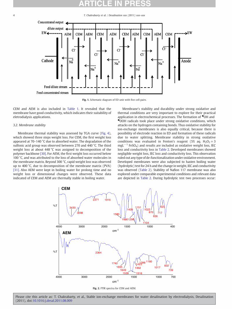
Fig. 1. Schematic diagram of ED unit with five cell pairs.
4 T. Chakrabarty et al. / Desalination xxx (2011) xxx–xxx
CEM and AEM is also included in Table 1. It revealed that themembrane have good conductivity, which indicates their suitability ofeletrodialysis applications.
3.2. Membrane stability
Membrane thermal stability was assessed by TGA curve (Fig. 4),which showed three steps weight loss. For CEM, the first weight lossappeared at 70–140 °C due to absorbed water. The degradation of thesulfonic acid group was observed between 270 and 440 °C. The thirdweight loss at about 448 °C was assigned to decomposition of thepolymer backbone [30]. For AEM, the first weight loss occurred below100 °C, and was attributed to the loss of absorbed water molecules inthe membrane matrix. Beyond 300 °C, rapid weight loss was observedup to 400 °C, due to decomposition of the membrane matrix (PVA)[31]. Also AEM were kept in boiling water for prolong time and noweight loss or dimensional changes were observed. These dataindicated of CEM and AEM are thermally stable in boiling water.
cm-
cm
4000 3000 2000
2364
17421
AEM
%T
CEM
%T
4000 3000 2000
3430
3098
2371 1916
158
Fig. 2. FTIR spectra fo
Please cite this article as: T. Chakrabarty, et al., Stable ion-exchange(2011), doi:10.1016/j.desal.2011.08.009
Membrane's stability and durability under strong oxidative andthermal conditions are very important to explore for their practicalapplication in electrochemical processes. The formation of ●OH and●OOH radicals took place under strong oxidative conditions, whichattacks on the hydrogen containing bonds. Thus oxidative stability forion-exchange membranes is also equally critical, because there ispossibility of electrode reaction in ED and formation of these radicalsdue to water splitting. Membrane stability in strong oxidativeconditions was evaluated in Fenton's reagent (5% aq. H2O2+3mgL−1 FeSO4) and results are included as oxidative weight loss, IECloss and conductivity loss in Table 2. Developed membranes showednegligible weight loss, IEC loss and conductivity loss. This observationruledout any typeof de-functionalizationunderoxidative environment.Developed membranes were also subjected to hasten boiling water(hydrolytic) test for 24 h and the change inweight, IEC and conductivitywas observed (Table 2). Stability of Nafion 117 membrane was alsoexplored under comparable experimental conditions and relevant dataare depicted in Table 2. During hydrolytic test two processes occur:
1
-1
1500 1000 700
6951649
1539 1516
146214231396 1180
1017832
739
1500 1000 4001104
0
1486
1409
1296
11511022
870
836717
625
r CEM and AEM.
membranes for water desalination by electrodialysis, Desalination

1µm 1µm
1µm 1µm
a b
c d
Fig. 3. CEM and AEM of; (a) and (c) surface image, (b) and (d) cross section, respectively.
100 200 300 400 500 600 7000
20
40
60
80
100
CEM
AEM
Wei
ght l
oss
(%)
Temp(oC)
Fig. 4. TGA curves of AEM and CEM.
5T. Chakrabarty et al. / Desalination xxx (2011) xxx–xxx
membrane swelling and its degradation. Membrane swelling takesplace because of hydrophilic domains and after swelling degradation ofthe matrix started. Degradation was more prominent for membraneswith low ionic domains. Thus, developed membrane showed lowweight, IEC and conductivity loss. Furthermore, developed membraneswere highly stable in 8.0 M HCl and NaOH for CEM and AEM,respectively and retained their properties with 2–6% swelling.
Chlorine tolerant nature of prepared CEM and AEMwas assessed interms of percentage in weight loss, IEC loss and conductivity loss.Chlorine is the most widely used oxidizing biocide in water treatmentbecause it is inexpensive and highly effective when present in waterat few mg L−1 levels. Disinfection of feed water to membranedesalination units is required to prevent biofilm growth on themembranes, which significantly degrades their performance. Thus,developedmembranes should be highly chlorine tolerant in nature fordesalination [32]. Resultant data are presented in Table 2. It is obviousthat CEM lost about 3–7% weight, IEC and conductivity after 24 htreatment of membranes, while for AEM lost about 6–10% weight, IECand conductivity. The membrane degradation occurred chemically asa result of oxy-chloride free radical attack on the polymer chain in thevicinity of hydrophilic domains. Moreover, chlorine tolerant naturefor both (CEM and AEM) was almost same and these membranesshowed their potential applications under chlorine environment.
3.3. Current–voltage (i–v) curves for prepared CEM and AEM
i–v curves of prepared CEM and AEMwere recorded in equilibrationwith 0.10 M NaCl solution (Fig. 5). These curves showed three typical
Table 1Physicochemical and electrochemical properties of CEM and AEM.
Properties CEM AEM Nafion 117
Thickness (μm) 160 150 195Water content (%) 24.7 28.6Ion-exchange capacity (mequiv./gof dry membrane)
1.39 1.173 0.90
Counter-ion transport number (tim) 0.95 0.91 0.98Specificmembrane conductivity (S cm−1) 2.12×10⁻² 2.02× 10⁻² 9.56 × 10⁻²
Please cite this article as: T. Chakrabarty, et al., Stable ion-exchange(2011), doi:10.1016/j.desal.2011.08.009
characteristic regions viz. Ohmic, non-Ohmic and plateau lengthregions. Limiting current density (Ilim) values for CEM and AEM werefound to be 1.28 and 1.02 mA cm−2, were estimated from i–v curves.Thus prepared CEM and AEM, showed excellent electro-transportproperties andmay be used for desalination. Furthermore, studies on i–v curves are quite useful for the prediction of suitability of ion-exchangemembrane for achieving desired separation.
3.4. Electrodialysis performance of developed membranes
ED experiments were performed to assess the suitability of thedeveloped ion-exchange membrane for water desalination. Experi-ments were performed at 1.5 V/cell pair (7.5 V) constant appliedvoltage by using 6000 mg L−1 NaCl solution as initial feed for DC,while Na2SO4 solution (0.10 M) through both electrode washcompartments, in recirculation mode of operation. The suitability ofdeveloped CEM and AEM for electro-membrane applications wereassessed in terms of estimating current efficiency and energyconsumption for the salt removal experimental condition. Variationsof current with time at constant applied voltage (7.5 V)were recordedduring ED experiment (Fig. 6). Initially current was high because ofhigh salt content of DC and CC. With the onset of experiment, ions(Na+ and Cl−) were migrated in opposite direction from DC to CC,which simultaneously reduced the resistance offered by CC. Depen-dence of solution conductivity for CC and DC streams during EDexperiments at 7.5 V applied voltage for different feed of both streams(6000 and 9000 mg L−1), has been presented in Fig. 7.
Flux for salt migration (J) from DC can be obtained by followingrelation, considering negligible mass (water) transport throughmembranes [29]:
J =Va
ACt−C0
Δtð9Þ
Table 2Oxidative, hydrolytic and chlorine stability in terms of loss in weight, ion-exchangecapacity (IEC), and membrane conductivity (κm) for developed CEM and AEM.
Stability test CEM AEM Nafion 117
Wloss IECloss κmloss Wloss IECloss κm
loss Wloss IECloss κmloss
Oxidativestability (%)
1.60 9.42 2.89 2.00 8.82 2.56 0.92 5.47 0.98
Hydrolyticstability (%)
10.45 11.59 4.89 8.61 10.44 4.56 5.67 7.61 2.13
Chlorinetolerance (%)
5.50 6.50 3.15 5.40 9.87 5.80 3.40 3.52 1.62
membranes for water desalination by electrodialysis, Desalination

0
2
4
6
8
0 1 2 3 4 5
Voltage(V)
Cur
rent
(mA
/cm
2 )
AEM
CEM
Fig. 5. Current–voltage (i–v) curves for CEM and AEM in equilibration with 0.1 M NaClsolution. Fig. 7. Variation of solution conductivity of CC and DC streams during ED experiments at
7.5 V applied voltage using feed solutions of 6000 and 9000 mg L−1.
6 T. Chakrabarty et al. / Desalination xxx (2011) xxx–xxx
where C0 and Ct are the initial and final concentration of NaCl in CC(mol m−3), Δt the time allowed for ED (s), Va the total volume of CCfeed (0.50×10⁻³ m3), and A is the effective membrane area(8.0×10⁻³ m2). Salt fluxes (at 1.5 V/cell pair constant appliedvoltage) are presented in Fig. 8 as a function of time for feed waterwith different salt content. Flux values decreased because ofprogressively lowered NaCl concentration in DC. This observationsuggested that rate of electro-transport of ions across membrane issuitable for achieving efficient desalination.
To evaluate the electrodialytic performance of developed AEMs,energy consumption and CE (%) data, obtained under similarexperimental conditions, are presented in Table 3. It was observedthat W decreased; while CE increased with the increase feed saltconcentration. We also observed that membrane perm selectivity,conductivity, and fixed charge concentration are the essential electro-chemical properties for an efficient AEM. These parameters (W & CE)are also depending on the operating conditions of an ED unit. Underoptimum operating conditions, for 6000 mgL−1 feed water, CE andWwere found to be 80.14% and 4.29 kWh kg−1 respectively. Thisshowed potential application of CEM and AEM for water desalinationby ED.
0
2
4
6
8
10
12
0 100 200
9000 mg L-1
6000 mg L-1
300
Cur
rent
den
sity
(mA
cm-2
)
Time (min)
Fig. 6. Variation of current density with time at 7.5 V applied voltage during EDexperiments using feed solutions of different TDS.
Please cite this article as: T. Chakrabarty, et al., Stable ion-exchange(2011), doi:10.1016/j.desal.2011.08.009
4. Conclusions
We prepared CEM by sulfonation of poly (ether sulfone), whileAEM was prepared by using PVA and 4-vinylpyridine in three steps:(i) sol–gel process, (ii) chemical cross-linking and (iii) quaternization.Developed CEM and AEM were characterized for their differentphysicochemical and electrochemical properties to evaluate theirapplicability in electrodialysis for water desalination. Membraneshigh water uptake, IEC, conductivity and counter-ion transportnumber, along with high stable nature. This offers new dimensionfor the preparation of ion-exchange membrane, in which membraneelectrochemical properties and stabilities were controlled by eitherdegree of sulphonation or formal cross-linking.
Current–voltage curve analysis revealed that prepared CEM andAEM showed excellent electro-transport properties and may be usedfor water desalination. Electrodialysis experiments also confirmedsuitability of these membranes for water desalination. In particular,recent advances in the development of ion-exchange membrane mayencourage the suitability of these membranes for different types ofelectro-membrane applications.
Fig. 8. Variation of flux with time during water desalination by ED at 1.5 V/cell pairconstant applied voltage (feed: 6000–12,000 mg L−1NaCl solution.
membranes for water desalination by electrodialysis, Desalination

Table 3Electrodialysis (ED) Performance for CEM and AEM at 1.50 V/cell pair applied potentialfor different feed of DC and CC.
Feed salt content (mg L−1) CE (%) Energy consumption(k Whkg−1 of NaCl removed)
6000 80.14 4.299000 82.73 3.9612000 89.67 3.19
7T. Chakrabarty et al. / Desalination xxx (2011) xxx–xxx
Acknowledgment
The authors are thankful to Dr. P.K. Ghosh, Director, CSMCRI,Bhavnagar for his encouragements and providing facilities. We alsoacknowledge the services of analytical science division, CSMCRI,Bhavnagar for instrumental support.
References
[1] R.K. Nagarale, G.S. Gohil, V.K. Shahi, Recent developments on ion-exchangemembranes and electro-membrane processes, Adv. Colloid Interface Sci. 119(2006) 97–130.
[2] M. Kumar, B.P. Tripathi, A. Saxena, V.K. Shahi, Electrochemical membrane reactor:Synthesis of quaternary ammonium hydroxide from its halide by in situ ionsubstitution, Electrochim. Acta 54 (2009) 1630–1637.
[3] M. Kumar, S. Singh, V.K. Shahi, Cross-linked Poly(vinyl alcohol)-Poly(acrylonitrile-co-2-dimethylamino ethylmethacrylate) based anion-exchange membranes in aqueousmedia, J. Phys. Chem. B 114 (2010) 198–206.
[4] Y. Ito, M. Inaba, D.J. Chung, Y. Imanishi, Control of water permeation by pH andionic strength through a porous membrane having poly(carboxylic acid) surface-grafted, Macromolecules 25 (1992) 7313–7316.
[5] H. Strathman, W.S.W. Ho, K.K. Sirkar, Membrane Handbook, Van NostrandReinhold, New York, 1992, pp. 219–262.
[6] E. Korngold, Electrodialysis" membranes and mass transfer, in: G. Belfort (Ed.),Synthetic Membrane Processes, Academic Press, New York, 1984, pp. 192–219.
[7] H. Strathmann, Electrodialysis, a mature technology with a multitude of newapplications, Desalination 264 (2010) 268–288.
[8] K. Sato, T. Sakairi, T. Yinemato, T. Tadaki, The desalination of amixed solution of anamino acid and an inorganic salt by means of electrodialysis with charge-mosaicmembranes, J. Membr. Sci. 100 (1995) 209–216.
[9] V.K. Shahi, S.K. Thampy, R. Rangarajan, Preparation and electrochemicalcharacterization of sulfonated interpolymer of polyethylene and styrene-divinylbenzene copolymer membranes, React. Funct. Polym. 46 (2000) 39–47.
[10] T. Sata, K. Kuzumoto, Y. Mizutani, Modification of anion exchange membraneswith polystyrenesulfonic, Acid Polym. J. 8 (1976) 225.
[11] K.P. Govindan, P.K. Narayanan, Indian Patent No. 124573, December, 1969[12] P.K. Narayanan, S.K. Adhikary, W.P. Harkare , K.P. Govindan, Indian Patent No.
160880, August, 1987[13] S.K. Adhikary, N.J. Dave, P.K. Narayanan, W.P. Harkare, B.S. Joshi, K.P. Govindan,
Studies on interpolymermembranes. Part III. Cation-exchange membranes, React.Polym. 1 (1983) 197–206.
Please cite this article as: T. Chakrabarty, et al., Stable ion-exchange(2011), doi:10.1016/j.desal.2011.08.009
[14] P.K. Narayanan, W.P. Harkare, S.K. Adhikary, N.J. Dave, D.K. Chouhan, K.P.Govindan, Performance of an electrodialysis desalination plant in rural area,Desalination 54 (1985) 145–150.
[15] V.K. Shahi, S.K. Thampy, A.K. Siddhanta, R. Rangarajan, Separation of sodiumsulfate and p-toluene sulfonic acid by electrodialysis, Sep. Sci. Technol. 37 (2002)3273–3289.
[16] V.K. Shahi, B.S. Makwana, S.K. Thampy, R. Rangarajan, A novel electrodialyzer forthe production of demineralized water by electrodialysis, Desalination 151(2002) 33–42.
[17] Q. Li, J.O. Jensen, R.F. Savinell, N.J. Bjerrum, High temperature proton exchangemembranes based on polybenzimidazoles for fuel cells, Prog. Polym. Sci. 34(2009) 449–477.
[18] S. Prakash, A.M. Rajesh, V.K. Shahi, Chlorine-tolerant poly electrolyte membranefor electrochemical dye degradation, Chem. Eng. J. 168 (2011) 108–114.
[19] B.P. Tripathi, V.K. Shahi, 3-[[(3-triethoxysilyl)propyl]amino]propane-1-sulfonicacid-poly(vinyl alcohol) cross-linked zwitterionic polymer electrolyte mem-branes for direct methanol fuel cell applications, ACS Appl. Mater. Interfaces 1(2009) 1002–1012.
[20] C.M. Tam, M. Dal-cin, M.D. Guiver, Polysulfone membranes. IV. Performanceevaluation of Radel A/PVP membranes, J. Membr. Sci. 78 (1993) 123–134.
[21] G.S. Gohil, R.K. Nagarale, V.K. Shahi, R. Rangarajan, Miceller enhanced electrodi-alysis: Influence of surfactants on the transport properties of ion-exchangemembranes, Sep. Purif. Technol. 47 (2005) 1–9.
[22] H.L. Wen, C.S. Song, Y.F. Tong, L. Chen, X.L. Liu, Synthesis and properties of poly(aryl ether sulfone ether ketone ketone) (PESEKK), J. Appl. Polym. Sci. 96 (2005)489–493.
[23] M. Ueda, H. Toyota, T. Ouchi, J. Sugiyama, K. Yonetake, T. Masuko, T. Teramoto,Synthesis and characterization of aromatic poly (ether sulfone)s containingpendant sodium sulfonate groups, J. Polym. Sci. Part A Polym. Chem. 31 (1993)853–858.
[24] B.T. Swinyard, D.S. Sagoo, J.A. Barrie, R. Ash, The transport and sorption of water inpolyethersulphone, polysulphone, and polyethersulphone/phenoxy blends, J.Appl. Polym. Sci. 41 (1990) 2479–2485.
[25] H.L. Wen, C.S. Song, Y.F. Tong, L. Chen, X.L. Liu, Synthesis and properties of poly(aryl ether sulfone ether ketone ketone) (PESEKK), J. Appl. Polym. Sci. 96 (2005)489–493.
[26] N.N. Krishnan, H.J. Kim, M. Prasanna, E. Cho, E.M. Shin, S.Y. Lee, I.H. Oh, S.A.Hongand, T.H. Lim, Synthesis and characterization of sulfonated poly (ethersulfone) copolymer membranes for fuel cell applications, J. Power Sources 158(2006) 1246–1250.
[27] H.B. Park, B.D. Freeman, Z.B. Zhang, M. Sankir, J.E. McGrath, Highly chlorine-tolerant polymers for desalination, Angew. Chem. 120 (2008) 6108–6113.
[28] B.P. Tripathi, T. Chakrabarty, V.K. Shahi, Highly charged and stable cross-linked 4,4(−bis(4-aminophenoxy)biphenyl-3,3(−disulfonic acid (BAPBDS)-sulfonatedpoly(ether sulfone) polymer electrolyte membranes impervious to methanol, J.Mater. Chem. 20 (2010) 8036–8044.
[29] T. Chakrabarty, M. Kumar, K.P. Rajesh, V.K. Shahi, T.S. Natarajan, Nano-fibroussulfonated poly(ether ether ketone) membrane for selective electro-transport ofions, Sep. Purif. Technol. 75 (2010) 174–182.
[30] K. Singh, V.K. Shahi, Electrochemical studies on nafion membrane, J. Membr. Sci.140 (1998) 51–56.
[31] M. Kumar, S. Singh, V.K. Shahi, cross-linked poly(vinyl alcohol)-poly(acrylonitrile-co-2-dimethylamino ethylmethacrylate) based anion-exchange membranes in aqueousmedia, J. Phys. Chem. B 114 (2010) 198–206.
[32] M.S. Kang, Y.J. Choi, I.J. Choi, T.H. Yoon, S.H. Moon, Electrochemical characteri-zation of sulfonated poly(arylene ether sulfone) (S-PES) cation-exchangemembranes J, Membr. Sci. 216 (2003) 39–53.
membranes for water desalination by electrodialysis, Desalination
Copyright © 2022 FDOKUMEN