Ionic composition and transport mechanisms in microbial desalination cells
8
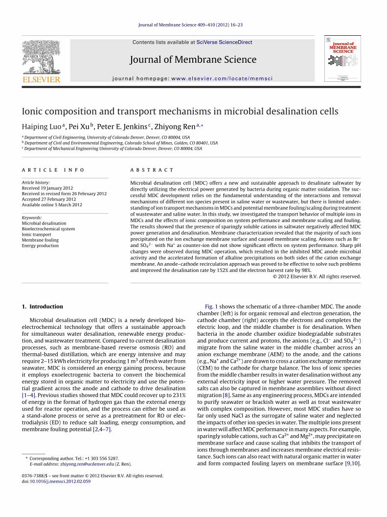
Journal of Membrane Science 409–410 (2012) 16–23 Contents lists available at SciVerse ScienceDirect Journal of Membrane Science j ourna l ho me pag e: www.elsevier.com/locate/memsci Ionic composition and transport mechanisms in microbial desalination cells Haiping Luo a , Pei Xu b , Peter E. Jenkins c , Zhiyong Ren a,∗ a Department of Civil Engineering, University of Colorado Denver, Denver, CO 80004, USA b Department of Civil and Environmental Engineering, Colorado School of Mines, Golden, CO 80401, USA c Department of Mechanical Engineering University of Colorado Denver, Denver, CO 80004, USA a r t i c l e i n f o Article history: Received 19 January 2012 Received in revised form 26 February 2012 Accepted 27 February 2012 Available online 5 March 2012 Keywords: Microbial desalination Bioelectrochemical system Ionic transport Membrane fouling Energy production a b s t r a c t Microbial desalination cell (MDC) offers a new and sustainable approach to desalinate saltwater by directly utilizing the electrical power generated by bacteria during organic matter oxidation. The suc- cessful MDC development relies on the fundamental understanding of the interactions and removal mechanisms of different ion species present in saline water or wastewater, but there is limited under- standing of ion transport mechanisms in MDCs and potential membrane fouling/scaling during treatment of wastewater and saline water. In this study, we investigated the transport behavior of multiple ions in MDCs and the effects of ionic composition on system performance and membrane scaling and fouling. The results showed that the presence of sparingly soluble cations in saltwater negatively affected MDC power generation and desalination. Membrane characterization revealed that the majority of such ions precipitated on the ion exchange membrane surface and caused membrane scaling. Anions such as Br − and SO 4 2− with Na + as counter-ion did not show significant effects on system performance. Sharp pH changes were observed during MDC operation, which resulted in the inhibited MDC anode microbial activity and the accelerated formation of alkaline precipitations on both sides of the cation exchange membrane. An anode–cathode recirculation approach was proved to be effective to solve such problems and improved the desalination rate by 152% and the electron harvest rate by 98%. © 2012 Elsevier B.V. All rights reserved. 1. Introduction Microbial desalination cell (MDC) is a newly developed bio- electrochemical technology that offers a sustainable approach for simultaneous water desalination, renewable energy produc- tion, and wastewater treatment. Compared to current desalination processes, such as membrane-based reverse osmosis (RO) and thermal-based distillation, which are energy intensive and may require 2–15 kWh electricity for producing 1 m 3 of fresh water from seawater, MDC is considered an energy gaining process, because it employs exoelectrogenic bacteria to convert the biochemical energy stored in organic matter to electricity and use the poten- tial gradient across the anode and cathode to drive desalination [1–4]. Previous studies showed that MDC could recover up to 231% of energy in the format of hydrogen gas than the external energy used for reactor operation, and the process can either be used as a stand-alone process or serve as a pretreatment for RO or elec- trodialysis (ED) to reduce salt loading, energy consumption, and membrane fouling potential [2,4–7]. ∗ Corresponding author. Tel.: +1 303 556 5287. E-mail address: [email protected] (Z. Ren). Fig. 1 shows the schematic of a three-chamber MDC. The anode chamber (left) is for organic removal and electron generation, the cathode chamber (right) accepts the electrons and completes the electric loop, and the middle chamber is for desalination. When bacteria in the anode chamber oxidize biodegradable substrates and produce current and protons, the anions (e.g., Cl − and SO 4 2− ) migrate from the saline water in the middle chamber across an anion exchange membrane (AEM) to the anode, and the cations (e.g., Na + and Ca 2+ ) are drawn to cross a cation exchange membrane (CEM) to the cathode for charge balance. The loss of ionic species from the middle chamber results in water desalination without any external electricity input or higher water pressure. The removed salts can also be captured in membrane assemblies without direct migration [8]. Same as any engineering process, MDCs are intended to purify seawater or brackish water as well as treat wastewater with complex composition. However, most MDC studies have so far only used NaCl as the surrogate of saline water and neglected the impacts of other ion species in water. The multiple ions present in water will affect MDC performance in many aspects. For example, sparingly soluble cations, such as Ca 2+ and Mg 2+ , may precipitate on membrane surface and cause scaling that inhibits the transport of ions through membranes and increases membrane electrical resis- tance. Such ions can also react with natural organic matter in water and form compacted fouling layers on membrane surface [9,10]. 0376-7388/$ – see front matter © 2012 Elsevier B.V. All rights reserved. doi:10.1016/j.memsci.2012.02.059
Transcript of Ionic composition and transport mechanisms in microbial desalination cells
I
Ha
b
c
a
ARRAA
KMBIME
1
eftptrsiet[ouatm
0d
Journal of Membrane Science 409– 410 (2012) 16– 23
Contents lists available at SciVerse ScienceDirect
Journal of Membrane Science
j ourna l ho me pag e: www.elsev ier .com/ locate /memsci
onic composition and transport mechanisms in microbial desalination cells
aiping Luoa, Pei Xub, Peter E. Jenkinsc, Zhiyong Rena,∗
Department of Civil Engineering, University of Colorado Denver, Denver, CO 80004, USADepartment of Civil and Environmental Engineering, Colorado School of Mines, Golden, CO 80401, USADepartment of Mechanical Engineering University of Colorado Denver, Denver, CO 80004, USA
r t i c l e i n f o
rticle history:eceived 19 January 2012eceived in revised form 26 February 2012ccepted 27 February 2012vailable online 5 March 2012
eywords:icrobial desalination
ioelectrochemical systemonic transport
a b s t r a c t
Microbial desalination cell (MDC) offers a new and sustainable approach to desalinate saltwater bydirectly utilizing the electrical power generated by bacteria during organic matter oxidation. The suc-cessful MDC development relies on the fundamental understanding of the interactions and removalmechanisms of different ion species present in saline water or wastewater, but there is limited under-standing of ion transport mechanisms in MDCs and potential membrane fouling/scaling during treatmentof wastewater and saline water. In this study, we investigated the transport behavior of multiple ions inMDCs and the effects of ionic composition on system performance and membrane scaling and fouling.The results showed that the presence of sparingly soluble cations in saltwater negatively affected MDCpower generation and desalination. Membrane characterization revealed that the majority of such ions
−
embrane foulingnergy productionprecipitated on the ion exchange membrane surface and caused membrane scaling. Anions such as Brand SO4
2− with Na+ as counter-ion did not show significant effects on system performance. Sharp pHchanges were observed during MDC operation, which resulted in the inhibited MDC anode microbialactivity and the accelerated formation of alkaline precipitations on both sides of the cation exchangemembrane. An anode–cathode recirculation approach was proved to be effective to solve such problemsand improved the desalination rate by 152% and the electron harvest rate by 98%.
© 2012 Elsevier B.V. All rights reserved.
. Introduction
Microbial desalination cell (MDC) is a newly developed bio-lectrochemical technology that offers a sustainable approachor simultaneous water desalination, renewable energy produc-ion, and wastewater treatment. Compared to current desalinationrocesses, such as membrane-based reverse osmosis (RO) andhermal-based distillation, which are energy intensive and mayequire 2–15 kWh electricity for producing 1 m3 of fresh water fromeawater, MDC is considered an energy gaining process, becauset employs exoelectrogenic bacteria to convert the biochemicalnergy stored in organic matter to electricity and use the poten-ial gradient across the anode and cathode to drive desalination1–4]. Previous studies showed that MDC could recover up to 231%f energy in the format of hydrogen gas than the external energysed for reactor operation, and the process can either be used as
stand-alone process or serve as a pretreatment for RO or elec-
rodialysis (ED) to reduce salt loading, energy consumption, andembrane fouling potential [2,4–7].
∗ Corresponding author. Tel.: +1 303 556 5287.E-mail address: [email protected] (Z. Ren).
376-7388/$ – see front matter © 2012 Elsevier B.V. All rights reserved.oi:10.1016/j.memsci.2012.02.059
Fig. 1 shows the schematic of a three-chamber MDC. The anodechamber (left) is for organic removal and electron generation, thecathode chamber (right) accepts the electrons and completes theelectric loop, and the middle chamber is for desalination. Whenbacteria in the anode chamber oxidize biodegradable substratesand produce current and protons, the anions (e.g., Cl− and SO4
2−)migrate from the saline water in the middle chamber across ananion exchange membrane (AEM) to the anode, and the cations(e.g., Na+ and Ca2+) are drawn to cross a cation exchange membrane(CEM) to the cathode for charge balance. The loss of ionic speciesfrom the middle chamber results in water desalination without anyexternal electricity input or higher water pressure. The removedsalts can also be captured in membrane assemblies without directmigration [8]. Same as any engineering process, MDCs are intendedto purify seawater or brackish water as well as treat wastewaterwith complex composition. However, most MDC studies have sofar only used NaCl as the surrogate of saline water and neglectedthe impacts of other ion species in water. The multiple ions presentin water will affect MDC performance in many aspects. For example,sparingly soluble cations, such as Ca2+ and Mg2+, may precipitate on
membrane surface and cause scaling that inhibits the transport ofions through membranes and increases membrane electrical resis-tance. Such ions can also react with natural organic matter in waterand form compacted fouling layers on membrane surface [9,10].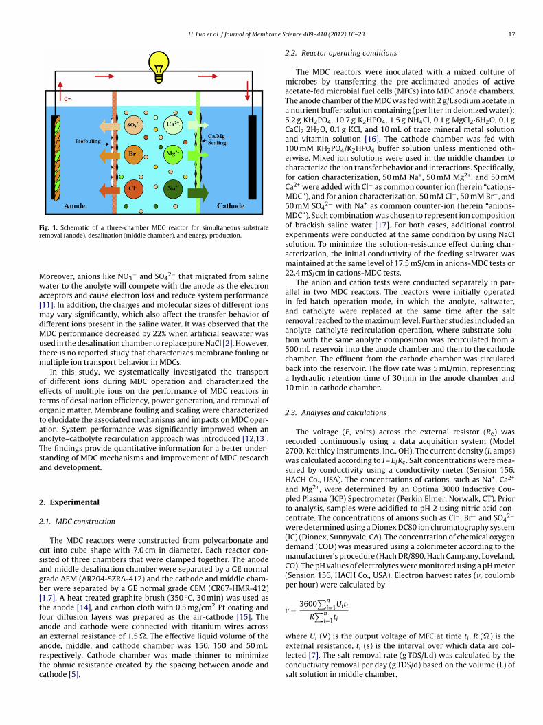
H. Luo et al. / Journal of Membrane S
Fig. 1. Schematic of a three-chamber MDC reactor for simultaneous substrater
Mwa[mdMutm
oetotaaTsa
2
2
csagb[tfaaartc
emoval (anode), desalination (middle chamber), and energy production.
oreover, anions like NO3− and SO4
2− that migrated from salineater to the anolyte will compete with the anode as the electron
cceptors and cause electron loss and reduce system performance11]. In addition, the charges and molecular sizes of different ions
ay vary significantly, which also affect the transfer behavior ofifferent ions present in the saline water. It was observed that theDC performance decreased by 22% when artificial seawater was
sed in the desalination chamber to replace pure NaCl [2]. However,here is no reported study that characterizes membrane fouling or
ultiple ion transport behavior in MDCs.In this study, we systematically investigated the transport
f different ions during MDC operation and characterized theffects of multiple ions on the performance of MDC reactors inerms of desalination efficiency, power generation, and removal ofrganic matter. Membrane fouling and scaling were characterizedo elucidate the associated mechanisms and impacts on MDC oper-tion. System performance was significantly improved when annolyte–catholyte recirculation approach was introduced [12,13].he findings provide quantitative information for a better under-tanding of MDC mechanisms and improvement of MDC researchnd development.
. Experimental
.1. MDC construction
The MDC reactors were constructed from polycarbonate andut into cube shape with 7.0 cm in diameter. Each reactor con-isted of three chambers that were clamped together. The anodend middle desalination chamber were separated by a GE normalrade AEM (AR204-SZRA-412) and the cathode and middle cham-er were separated by a GE normal grade CEM (CR67-HMR-412)1,7]. A heat treated graphite brush (350 ◦C, 30 min) was used ashe anode [14], and carbon cloth with 0.5 mg/cm2 Pt coating andour diffusion layers was prepared as the air-cathode [15]. The
node and cathode were connected with titanium wires acrossn external resistance of 1.5 �. The effective liquid volume of thenode, middle, and cathode chamber was 150, 150 and 50 mL,espectively. Cathode chamber was made thinner to minimizehe ohmic resistance created by the spacing between anode andathode [5].cience 409– 410 (2012) 16– 23 17
2.2. Reactor operating conditions
The MDC reactors were inoculated with a mixed culture ofmicrobes by transferring the pre-acclimated anodes of activeacetate-fed microbial fuel cells (MFCs) into MDC anode chambers.The anode chamber of the MDC was fed with 2 g/L sodium acetate ina nutrient buffer solution containing (per liter in deionized water):5.2 g KH2PO4, 10.7 g K2HPO4, 1.5 g NH4Cl, 0.1 g MgCl2·6H2O, 0.1 gCaCl2·2H2O, 0.1 g KCl, and 10 mL of trace mineral metal solutionand vitamin solution [16]. The cathode chamber was fed with100 mM KH2PO4/K2HPO4 buffer solution unless mentioned oth-erwise. Mixed ion solutions were used in the middle chamber tocharacterize the ion transfer behavior and interactions. Specifically,for cation characterization, 50 mM Na+, 50 mM Mg2+, and 50 mMCa2+ were added with Cl− as common counter ion (herein “cations-MDC”), and for anion characterization, 50 mM Cl−, 50 mM Br−, and50 mM SO4
2− with Na+ as common counter-ion (herein “anions-MDC”). Such combination was chosen to represent ion compositionof brackish saline water [17]. For both cases, additional controlexperiments were conducted at the same condition by using NaClsolution. To minimize the solution-resistance effect during char-acterization, the initial conductivity of the feeding saltwater wasmaintained at the same level of 17.5 mS/cm in anions-MDC tests or22.4 mS/cm in cations-MDC tests.
The anion and cation tests were conducted separately in par-allel in two MDC reactors. The reactors were initially operatedin fed-batch operation mode, in which the anolyte, saltwater,and catholyte were replaced at the same time after the saltremoval reached to the maximum level. Further studies included ananolyte–catholyte recirculation operation, where substrate solu-tion with the same anolyte composition was recirculated from a500 mL reservoir into the anode chamber and then to the cathodechamber. The effluent from the cathode chamber was circulatedback into the reservoir. The flow rate was 5 mL/min, representinga hydraulic retention time of 30 min in the anode chamber and10 min in cathode chamber.
2.3. Analyses and calculations
The voltage (E, volts) across the external resistor (Re) wasrecorded continuously using a data acquisition system (Model2700, Keithley Instruments, Inc., OH). The current density (I, amps)was calculated according to I = E/Re. Salt concentrations were mea-sured by conductivity using a conductivity meter (Sension 156,HACH Co., USA). The concentrations of cations, such as Na+, Ca2+
and Mg2+, were determined by an Optima 3000 Inductive Cou-pled Plasma (ICP) Spectrometer (Perkin Elmer, Norwalk, CT). Priorto analysis, samples were acidified to pH 2 using nitric acid con-centrate. The concentrations of anions such as Cl−, Br− and SO4
2−
were determined using a Dionex DC80 ion chromatography system(IC) (Dionex, Sunnyvale, CA). The concentration of chemical oxygendemand (COD) was measured using a colorimeter according to themanufacturer’s procedure (Hach DR/890, Hach Campany, Loveland,CO). The pH values of electrolytes were monitored using a pH meter(Sension 156, HACH Co., USA). Electron harvest rates (v, coulombper hour) were calculated by
v = 3600∑n
i=1Uiti
R∑n
i=1ti
where Ui (V) is the output voltage of MFC at time ti, R (�) is the
external resistance, ti (s) is the interval over which data are col-lected [7]. The salt removal rate (g TDS/L d) was calculated by theconductivity removal per day (g TDS/d) based on the volume (L) ofsalt solution in middle chamber.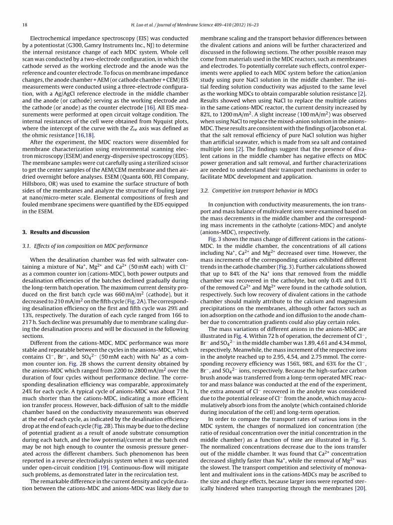
1 rane S
btscrcmtatsiwt
mtTtdHsafi
3
3
tadtddi12is
scmtds2micadodmarus
t
8 H. Luo et al. / Journal of Memb
Electrochemical impedance spectroscopy (EIS) was conductedy a potentiostat (G300, Gamry Instruments Inc., NJ) to determinehe internal resistance change of each MDC system. Whole cellcan was conducted by a two-electrode configuration, in which theathode served as the working electrode and the anode was theeference and counter electrode. To focus on membrane impedancehanges, the anode chamber + AEM (or cathode chamber + CEM) EISeasurements were conducted using a three-electrode configura-
ion, with a Ag/AgCl reference electrode in the middle chambernd the anode (or cathode) serving as the working electrode andhe cathode (or anode) as the counter electrode [16]. All EIS mea-urements were performed at open circuit voltage condition. Thenternal resistances of the cell were obtained from Nyquist plots,
here the intercept of the curve with the Zre axis was defined ashe ohmic resistance [16,18].
After the experiment, the MDC reactors were dissembled forembrane characterization using environmental scanning elec-
ron microscopy (ESEM) and energy-dispersive spectroscopy (EDS).he membrane samples were cut carefully using a sterilized scissoro get the center samples of the AEM/CEM membrane and then air-ried overnight before analyses. ESEM (Quanta 600, FEI Company,illsboro, OR) was used to examine the surface structure of both
ides of the membranes and analyze the structure of fouling layert nano/micro-meter scale. Elemental compositions of fresh andouled membrane specimens were quantified by the EDS equippedn the ESEM.
. Results and discussion
.1. Effects of ion composition on MDC performance
When the desalination chamber was fed with saltwater con-aining a mixture of Na+, Mg2+ and Ca2+ (50 mM each) with Cl−
s a common counter ion (cations-MDC), both power outputs andesalination efficiencies of the batches declined gradually duringhe long-term batch operation. The maximum current density pro-uced on the first batch cycle was 660 mA/m2 (cathode), but itecreased to 210 mA/m2 on the fifth cycle (Fig. 2A). The correspond-
ng desalination efficiency on the first and fifth cycle was 29% and3%, respectively. The duration of each cycle ranged from 166 to17 h. Such decline was presumably due to membrane scaling dur-
ng the desalination process and will be discussed in the followingections.
Different from the cations-MDC, MDC performance was moretable and repeatable between the cycles in the anions-MDC, whichontains Cl−, Br−, and SO4
2− (50 mM each) with Na+ as a com-on counter ion. Fig. 2B shows the current density obtained by
he anions-MDC which ranged from 2200 to 2800 mA/m2 over theuration of four cycles without performance decline. The corre-ponding desalination efficiency was comparable, approximately4% for each cycle. A typical cycle of anions-MDC was about 71 h,uch shorter than the cations-MDC, indicating a more efficient
on transfer process. However, back-diffusion of salt to the middlehamber based on the conductivity measurements was observedt the end of each cycle, as indicated by the desalination efficiencyrop at the end of each cycle (Fig. 2B). This may be due to the declinef potential gradient as a result of anode substrate consumptionuring each batch, and the low potential/current at the batch enday be not high enough to counter the osmosis pressure gener-
ted across the different chambers. Such phenomenon has beeneported in a reverse electrodialysis system when it was operated
nder open-circuit condition [19]. Continuous-flow will mitigateuch problems, as demonstrated later in the recirculation test.The remarkable difference in the current density and cycle dura-ion between the cations-MDC and anions-MDC was likely due to
cience 409– 410 (2012) 16– 23
membrane scaling and the transport behavior differences betweenthe divalent cations and anions will be further characterized anddiscussed in the following sections. The other possible reason maycome from materials used in the MDC reactors, such as membranesand electrodes. To potentially correlate such effects, control exper-iments were applied to each MDC system before the cation/anionstudy using pure NaCl solution in the middle chamber. The ini-tial feeding solution conductivity was adjusted to the same levelas the working MDCs to obtain comparable solution resistance [2].Results showed when using NaCl to replace the multiple cationsin the same cations-MDC reactor, the current density increased by82%, to 1200 mA/m2. A slight increase (100 mA/m2) was observedwhen using NaCl to replace the mixed-anion solution in the anions-MDC. These results are consistent with the findings of Jacobson et al.that the salt removal efficiency of pure NaCl solution was higherthan artificial seawater, which is made from sea salt and containedmultiple ions [2]. The findings suggest that the presence of diva-lent cations in the middle chamber has negative effects on MDCpower generation and salt removal, and further characterizationsare needed to understand their transport mechanisms in order tofacilitate MDC development and application.
3.2. Competitive ion transport behavior in MDCs
In conjunction with conductivity measurements, the ion trans-port and mass balance of multivalent ions were examined based onthe mass decrements in the middle chamber and the correspond-ing mass increments in the catholyte (cations-MDC) and anolyte(anions-MDC), respectively.
Fig. 3 shows the mass change of different cations in the cations-MDC. In the middle chamber, the concentrations of all cationsincluding Na+, Ca2+ and Mg2+ decreased over time. However, themass increments of the corresponding cations exhibited differenttrends in the cathode chamber (Fig. 3). Further calculations showedthat up to 84% of the Na+ ions that removed from the middlechamber was recovered in the catholyte, but only 0.4% and 0.1%of the removed Ca2+ and Mg2+ were found in the cathode solution,respectively. Such low recovery of divalent cations in the cathodechamber should mainly attribute to the calcium and magnesiumprecipitations on the membranes, although other factors such asion adsorption on the cathode and ion diffusion to the anode cham-ber due to concentration gradients could also play certain roles.
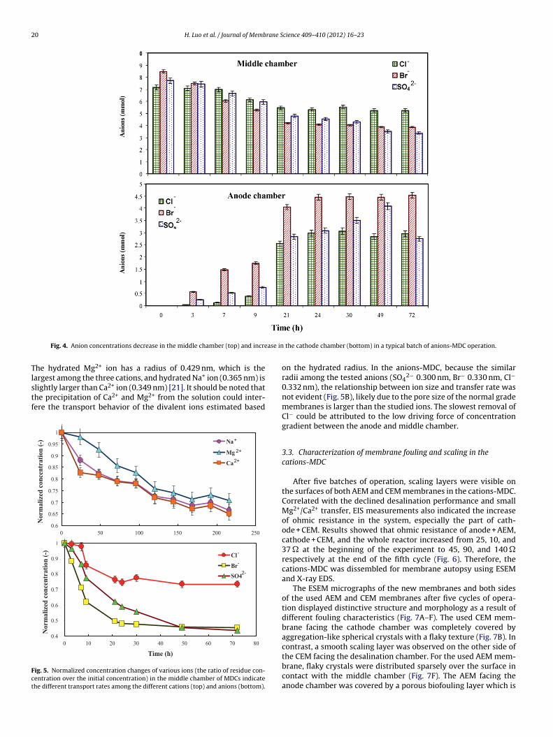
The mass variations of different anions in the anions-MDC areillustrated in Fig. 4. Within 72 h of operation, the decrement of Cl−,Br− and SO4
2− in the middle chamber was 1.89, 4.61 and 4.34 mmol,respectively. Meanwhile, the mass increment of the respective ionsin the anolyte reached up to 2.95, 4.54, and 2.75 mmol. The corre-sponding recovery efficiency was 156%, 98%, and 63% for the Cl−,Br−, and SO4
2− ions, respectively. Because the high-surface carbonbrush anode was transferred from a long-term operated MFC reac-tor and mass balance was conducted at the end of the experiment,the extra amount of Cl− recovered in the anolyte was considereddue to the potential release of Cl− from the anode, which may accu-mulatively absorb ions from the anolyte (which contained chlorideduring inoculation of the cell) and long-term operation.
In order to compare the transport rates of various ions in theMDC system, the changes of normalized ion concentration (theratio of residual concentration over the initial concentration in themiddle chamber) as a function of time are illustrated in Fig. 5.The normalized concentrations decrease due to the ions transferout of the middle chamber. It was found that Ca2+ concentrationdecreased slightly faster than Na+, while the removal of Mg2+ was
the slowest. The transport competition and selectivity of monova-lent and multivalent ions in the cations-MDCs may be ascribed tothe size and charge effects, because larger ions were reported ster-ically hindered when transporting through the membranes [20].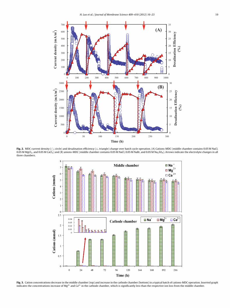
H. Luo et al. / Journal of Membrane Science 409– 410 (2012) 16– 23 19
0
100
200
300
400
500
600
700
0 100 200 300 400 500 600 700 800 900 1000
Cu
rre
nt
den
sity
(m
A/m
2)
0
5
10
15
20
25
30
35
Desa
lin
ati
on
Eff
icie
ncy
(%)
(A)
0
500
1000
1500
2000
2500
3000
0 50 100 150 200 250 300
Time (h)
Cu
rren
t d
ensi
ty (
mA
/m2)
0
5
10
15
20
25
30
Des
ali
na
tio
n E
ffic
ien
cy
(%)
(B)
Fig. 2. MDC current density (©, circle) and desalination efficiency (�, triangle) change over batch cycle operation. (A) Cations-MDC (middle chamber contains 0.05 M NaCl,0.05 M MgCl2, and 0.05 M CaCl2) and (B) anions-MDC (middle chamber contains 0.05 M NaCl, 0.05 M NaBr, and 0.05 M Na2SO4). Arrows indicate the electrolyte changes in allthree chambers.
Fig. 3. Cation concentrations decrease in the middle chamber (top) and increase in the cathode chamber (bottom) in a typical batch of cations-MDC operation. Inserted graphindicates the concentrations increase of Mg2+ and Ca2+ in the cathode chamber, which is significantly less than the respective ion loss from the middle chamber.
20 H. Luo et al. / Journal of Membrane Science 409– 410 (2012) 16– 23
ase in
Tlstf
Fct
Fig. 4. Anion concentrations decrease in the middle chamber (top) and incre
he hydrated Mg2+ ion has a radius of 0.429 nm, which is the+
argest among the three cations, and hydrated Na ion (0.365 nm) islightly larger than Ca2+ ion (0.349 nm) [21]. It should be noted thathe precipitation of Ca2+ and Mg2+ from the solution could inter-ere the transport behavior of the divalent ions estimated based
0.4
0.5
0.6
0.7
0.8
0.9
1
0 10 20 30 40 50 60 70 80
Time (h)
No
rma
lize
d c
on
cen
tra
tio
n (
-) Cl
Br
SO4
-
-
2-
0.6
0.65
0.7
0.75
0.8
0.85
0.9
0.95
1
0 50 100 150 200 250
No
rma
lize
d c
on
cen
tra
tio
n (
-) Na
Mg
Ca
2+
2+
+
ig. 5. Normalized concentration changes of various ions (the ratio of residue con-entration over the initial concentration) in the middle chamber of MDCs indicatehe different transport rates among the different cations (top) and anions (bottom).
the cathode chamber (bottom) in a typical batch of anions-MDC operation.
on the hydrated radius. In the anions-MDC, because the similarradii among the tested anions (SO4
2− 0.300 nm, Br− 0.330 nm, Cl−
0.332 nm), the relationship between ion size and transfer rate wasnot evident (Fig. 5B), likely due to the pore size of the normal grademembranes is larger than the studied ions. The slowest removal ofCl− could be attributed to the low driving force of concentrationgradient between the anode and middle chamber.
3.3. Characterization of membrane fouling and scaling in thecations-MDC
After five batches of operation, scaling layers were visible onthe surfaces of both AEM and CEM membranes in the cations-MDC.Correlated with the declined desalination performance and smallMg2+/Ca2+ transfer, EIS measurements also indicated the increaseof ohmic resistance in the system, especially the part of cath-ode + CEM. Results showed that ohmic resistance of anode + AEM,cathode + CEM, and the whole reactor increased from 25, 10, and37 � at the beginning of the experiment to 45, 90, and 140 �respectively at the end of the fifth cycle (Fig. 6). Therefore, thecations-MDC was dissembled for membrane autopsy using ESEMand X-ray EDS.
The ESEM micrographs of the new membranes and both sidesof the used AEM and CEM membranes after five cycles of opera-tion displayed distinctive structure and morphology as a result ofdifferent fouling characteristics (Fig. 7A–F). The used CEM mem-brane facing the cathode chamber was completely covered byaggregation-like spherical crystals with a flaky texture (Fig. 7B). Incontrast, a smooth scaling layer was observed on the other side of
the CEM facing the desalination chamber. For the used AEM mem-brane, flaky crystals were distributed sparsely over the surface incontact with the middle chamber (Fig. 7F). The AEM facing theanode chamber was covered by a porous biofouling layer which is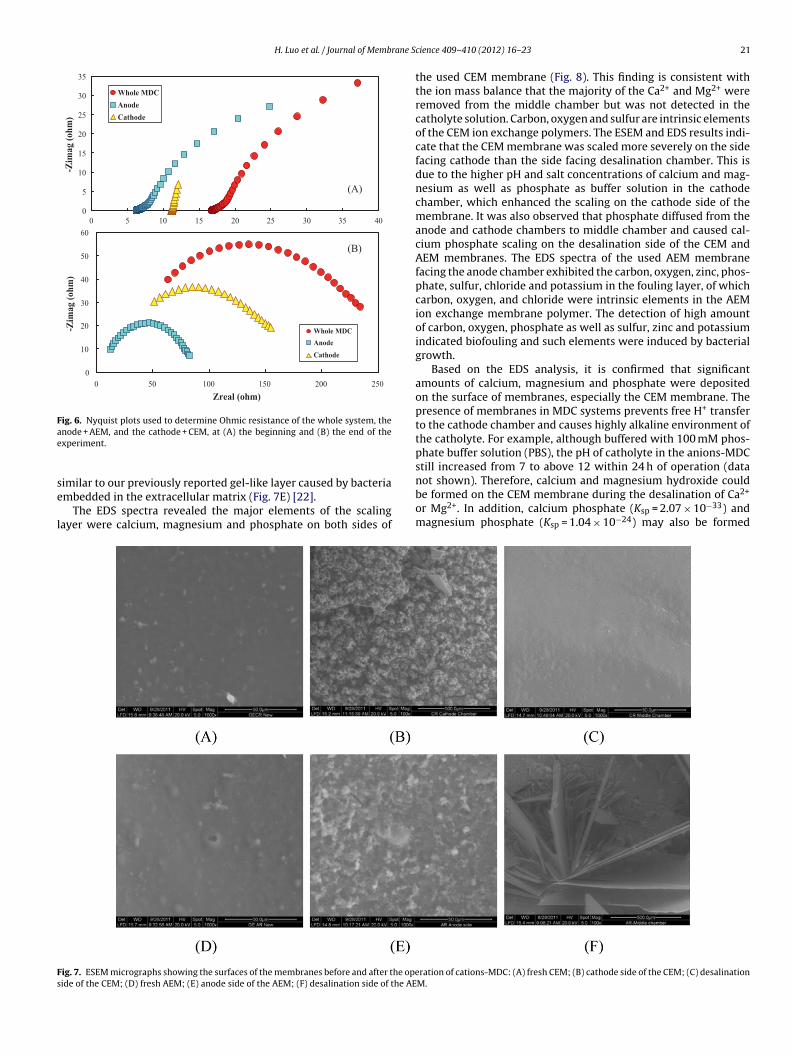
H. Luo et al. / Journal of Membrane S
0
5
10
15
20
25
30
35
0 5 10 15 20 25 30 35 40
-Zim
ag (
oh
m)
Whole MD C
Anode
Cathod e
0
10
20
30
40
50
60
0 50 100 150 200 250
Zreal (ohm )
-Zim
ag (
oh
m)
Whole MDC
Anode
Cathode
(A)
(B)
Fig. 6. Nyquist plots used to determine Ohmic resistance of the whole system, theae
se
l
not shown). Therefore, calcium and magnesium hydroxide could
Fs
node + AEM, and the cathode + CEM, at (A) the beginning and (B) the end of thexperiment.
imilar to our previously reported gel-like layer caused by bacteria
mbedded in the extracellular matrix (Fig. 7E) [22].The EDS spectra revealed the major elements of the scalingayer were calcium, magnesium and phosphate on both sides of
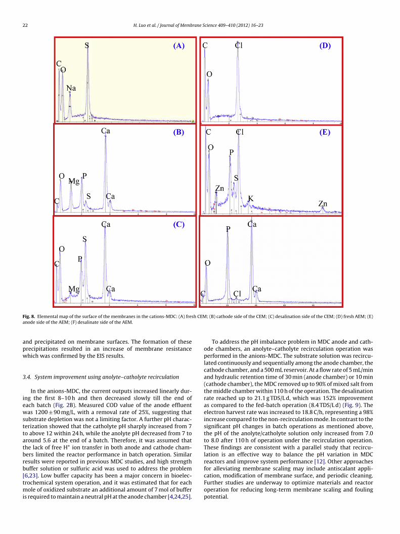
ig. 7. ESEM micrographs showing the surfaces of the membranes before and after the opeide of the CEM; (D) fresh AEM; (E) anode side of the AEM; (F) desalination side of the AE
cience 409– 410 (2012) 16– 23 21
the used CEM membrane (Fig. 8). This finding is consistent withthe ion mass balance that the majority of the Ca2+ and Mg2+ wereremoved from the middle chamber but was not detected in thecatholyte solution. Carbon, oxygen and sulfur are intrinsic elementsof the CEM ion exchange polymers. The ESEM and EDS results indi-cate that the CEM membrane was scaled more severely on the sidefacing cathode than the side facing desalination chamber. This isdue to the higher pH and salt concentrations of calcium and mag-nesium as well as phosphate as buffer solution in the cathodechamber, which enhanced the scaling on the cathode side of themembrane. It was also observed that phosphate diffused from theanode and cathode chambers to middle chamber and caused cal-cium phosphate scaling on the desalination side of the CEM andAEM membranes. The EDS spectra of the used AEM membranefacing the anode chamber exhibited the carbon, oxygen, zinc, phos-phate, sulfur, chloride and potassium in the fouling layer, of whichcarbon, oxygen, and chloride were intrinsic elements in the AEMion exchange membrane polymer. The detection of high amountof carbon, oxygen, phosphate as well as sulfur, zinc and potassiumindicated biofouling and such elements were induced by bacterialgrowth.
Based on the EDS analysis, it is confirmed that significantamounts of calcium, magnesium and phosphate were depositedon the surface of membranes, especially the CEM membrane. Thepresence of membranes in MDC systems prevents free H+ transferto the cathode chamber and causes highly alkaline environment ofthe catholyte. For example, although buffered with 100 mM phos-phate buffer solution (PBS), the pH of catholyte in the anions-MDCstill increased from 7 to above 12 within 24 h of operation (data
be formed on the CEM membrane during the desalination of Ca2+
or Mg2+. In addition, calcium phosphate (Ksp = 2.07 × 10⁻³³) andmagnesium phosphate (Ksp = 1.04 × 10⁻²⁴) may also be formed
ration of cations-MDC: (A) fresh CEM; (B) cathode side of the CEM; (C) desalinationM.
22 H. Luo et al. / Journal of Membrane Science 409– 410 (2012) 16– 23
F h CEMa
apw
3
iewsttatbrb[tmi
ig. 8. Elemental map of the surface of the membranes in the cations-MDC: (A) fresnode side of the AEM; (F) desalinate side of the AEM.
nd precipitated on membrane surfaces. The formation of theserecipitations resulted in an increase of membrane resistancehich was confirmed by the EIS results.
.4. System improvement using anolyte–catholyte recirculation
In the anions-MDC, the current outputs increased linearly dur-ng the first 8–10 h and then decreased slowly till the end ofach batch (Fig. 2B). Measured COD value of the anode effluentas 1200 ± 90 mg/L, with a removal rate of 25%, suggesting that
ubstrate depletion was not a limiting factor. A further pH charac-erization showed that the catholyte pH sharply increased from 7o above 12 within 24 h, while the anolyte pH decreased from 7 toround 5.6 at the end of a batch. Therefore, it was assumed thathe lack of free H+ ion transfer in both anode and cathode cham-ers limited the reactor performance in batch operation. Similaresults were reported in previous MDC studies, and high strengthuffer solution or sulfuric acid was used to address the problem
6,23]. Low buffer capacity has been a major concern in bioelec-rochemical system operation, and it was estimated that for eachole of oxidized substrate an additional amount of 7 mol of buffers required to maintain a neutral pH at the anode chamber [4,24,25].
; (B) cathode side of the CEM; (C) desalination side of the CEM; (D) fresh AEM; (E)
To address the pH imbalance problem in MDC anode and cath-ode chambers, an anolyte–catholyte recirculation operation wasperformed in the anions-MDC. The substrate solution was recircu-lated continuously and sequentially among the anode chamber, thecathode chamber, and a 500 mL reservoir. At a flow rate of 5 mL/minand hydraulic retention time of 30 min (anode chamber) or 10 min(cathode chamber), the MDC removed up to 90% of mixed salt fromthe middle chamber within 110 h of the operation. The desalinationrate reached up to 21.1 g TDS/L d, which was 152% improvementas compared to the fed-batch operation (8.4 TDS/L d) (Fig. 9). Theelectron harvest rate was increased to 18.8 C/h, representing a 98%increase compared to the non-recirculation mode. In contrast to thesignificant pH changes in batch operations as mentioned above,the pH of the anolyte/catholyte solution only increased from 7.0to 8.0 after 110 h of operation under the recirculation operation.These findings are consistent with a parallel study that recircu-lation is an effective way to balance the pH variation in MDCreactors and improve system performance [12]. Other approachesfor alleviating membrane scaling may include antiscalant appli-
cation, modification of membrane surface, and periodic cleaning.Further studies are underway to optimize materials and reactoroperation for reducing long-term membrane scaling and foulingpotential.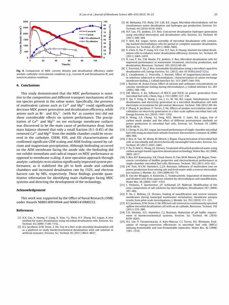
H. Luo et al. / Journal of Membrane S
Fan
4
tiodasiwmrecconoafchts
A
u
R
[
[
[
[
[
[
[
[
[
[
[
[
[
[
[
8259–8263.
ig. 9. Comparison of MDC current density and desalination efficiency undernolyte–catholyte recirculation condition (e.g., Current-R and Desalination-R) andonrecirculation condition.
. Conclusions
This study demonstrated that the MDC performance is sensi-ive to the composition and different transport mechanisms of theon species present in the saline water. Specifically, the presencef multivalent cations such as Ca2+ and Mg2+ could significantlyecrease MDC power generation and desalination efficiency, whilenions such as Br− and SO4
2− (with Na+ as counter ion) did nothow considerable effects on system performance. The precip-tation of Ca2+ and Mg2+ on ion exchange membrane surfaces
as discovered to be the main cause of performance drop. Ionicass balance showed that only a small fraction (0.1–0.4%) of the
emoved Ca2+ and Mg2+ from the middle chamber could be recov-red in the catholyte. ESEM, EDS, and EIS characterizations allonfirmed significant CEM scaling and AEM fouling caused by cal-ium and magnesium precipitation. Although biofouling occurredn the AEM membrane facing the anode side, the biofouling didot exhibit immediate and radical impact on MDC performance aspposed to membrane scaling. A new operation approach throughnolyte–catholyte recirculation significantly improved system per-ormance, as it stabilized the pH in both anode and cathodehambers and increased desalination rate by 152%, and electronarvest rate by 98%, respectively. These findings provide quan-itative information for identifying main challenges facing MDCystems and directing the development of the technology.
cknowledgement
This work was supported by the Office of Naval Research (ONR)nder Awards N000140910944 and N0001410M0232.
eferences
[1] X.X. Cao, X. Huang, P. Liang, K. Xiao, Y.J. Zhou, X.Y. Zhang, B.E. Logan, A new
method for water desalination using microbial desalination cells, Environ. Sci.Technol. 43 (2009) 7148–7152.[2] K.S. Jacobson, D.M. Drew, Z. He, Use of a liter-scale microbial desalination cellas a platform to study bioelectrochemical desalination with salt solution orartificial seawater, Environ. Sci. Technol. 45 (2011) 4652–4657.
[
cience 409– 410 (2012) 16– 23 23
[3] M. Mehanna, P.D. Kiely, D.F. Call, B.E. Logan, Microbial electrodialysis cell forsimultaneous water desalination and hydrogen gas production, Environ. Sci.Technol. 44 (2010) 9578–9583.
[4] H.P. Luo, P.E. Jenkins, Z.Y. Ren, Concurrent desalination hydrogen generationusing microbial electrolysis and desalination cells, Environ. Sci. Technol. 45(2011) 340–344.
[5] Y. Kim, B.E. Logan, Series assembly of microbial desalination cells contain-ing stacked electrodialysis cells for partial or complete seawater desalination,Environ. Sci. Technol. 45 (2011) 5840–5845.
[6] X. Chen, X. Xia, P. Liang, X.X. Cao, H.T. Sun, X. Huang, Stacked microbial desali-nation cells to enhance water desalination efficiency, Environ. Sci. Technol. 45(2011) 2465–2470.
[7] H. Luo, P. Xu, T.M. Roane, P.E. Jenkins, Z. Ren, Microbial desalination cells forimproved performance in wastewater treatment, electricity production, anddesalination, Bioresour. Technol. 105 (2012) 60–66.
[8] C. Forrestal, P. Xu, Z. Ren, Sustainable desalination using a microbial capacitivedesalination cell, Energy Environ. Sci. (2012), doi:10.1039/c2ee21121a.
[9] C. Casademont, G. Pourcelly, L. Bazinet, Effect of magnesium/calcium ratioin solutions subjected to electrodialysis: characterization of cation-exchangemembrane fouling, J. Colloid Interface Sci. 315 (2007) 544–554.
10] L. Bazinet, M. Araya-Farias, Effect of calcium and carbonate concentrations oncationic membrane fouling during electrodialysis, J. Colloid Interface Sci. 281(2005) 188–196.
11] J.M. Morris, S. Jin, Influence of NO(3) and SO(4) on power generation frommicrobial fuel cells, Chem. Eng. J. 153 (2009) 127–130.
12] Y. Qu, Y. Feng, X. Wang, J. Liu, J. Lv, W. He, B.E. Logan, Simultaneous waterdesalination and electricity generation in a microbial desalination cell withelectrolyte recirculation for pH control, Bioresour. Technol. 106 (2012) 89–94.
13] F. Zhang, K. Jacobson, P. Torres, Z. He, Effects of anolyte recirculation rates andcatholytes on electricity generation in a liter-scale upflow microbial fuel cell,Energy Environ. Sci. (2010) 1347–1352.
14] X. Wang, S.A. Cheng, Y.J. Feng, M.D. Merrill, T. Saito, B.E. Logan, Use ofcarbon mesh anodes and the effect of different pretreatment methods onpower production in microbial fuel cells, Environ. Sci. Technol. 43 (2009)6870–6874.
15] S. Cheng, H. Liu, B.E. Logan, Increased performance of single-chamber microbialfuel cells using an improved cathode structure, Electrochem. Commun. 8 (2006)489–494.
16] Z. Ren, H. Yan, W. Wang, M. Mench, J. Regan, Characterization of microbial fuelcells at microbially and electrochemically meaningful timescales, Environ. Sci.Technol. 45 (2011) 2435–2441.
17] P. Xu, D. Heil, G. Wang, J.E. Drewes, Treatment of brackish produced water usingcarbon aerogel-based capacitive deionization technology, Water Res. 42 (2008)2605–2617.
18] Z. Ren, R.P. Ramasamy, S.R. Cloud-Owen, H. Yan, M.M. Mench, J.M. Regan, Time-course correlation of biofilm properties and electrochemical performance insingle-chamber microbial fuel cells, Bioresour. Technol. 102 (2011) 416–421.
19] J.W. Post, H.V.M. Hamelers, C.J.N. Buisman, Influence of multivalent ions onpower production from mixing salt and fresh water with a reverse electrodial-ysis system, J. Membr. Sci. 330 (2009) 65–72.
20] B. Van der Bruggen, A. Koninckx, C. Vandecasteele, Separation of monovalentand divalent ions from aqueous solution by electrodialysis and nanofiltration,Water Res. 38 (2004) 1347–1353.
21] L. Firdaous, F. Quemeneur, J.P. Schlumpf, J.P. Maleriat, Modification of theionic composition of salt solutions by electrodialysis, Desalination 167 (2004)397–402.
22] P. Xu, C. Bellona, J.E. Drewes, Fouling of nanofiltration and reverse osmosismembranes during municipal wastewater reclamation: membrane autopsyresults from pilot-scale investigations, J. Membr. Sci. 353 (2010) 111–121.
23] K.S. Jacobson, D.M. Drew, Z. He, Efficient salt removal in a continuously operatedupflow microbial desalination cell with an air cathode, Bioresour. Technol. 102(2011) 376–380.
24] T.H. Sleutels, H.V. Hamelers, C.J. Buisman, Reduction of pH buffer require-ment in bioelectrochemical systems, Environ. Sci. Technol. 44 (2010)
25] H.S. Lee, P. Parameswaran, A. Kato-Marcus, C.I. Torres, B.E. Rittmann, Eval-uation of energy-conversion efficiencies in microbial fuel cells (MFCs)utilizing fermentable and non-fermentable substrates, Water Res. 42 (2008)1501–1510.