Modelling of grain boundary resistance in thin films of lanthanum manganites
8
Lithuanian Journal of Physics, Vol. 46, No. 2, pp. 191–198 (2006) MODELLING OF GRAIN BOUNDARY RESISTANCE IN THIN FILMS OF LANTHANUM MANGANITES V. Petrauskas and E.E. Tornau Semiconductor Physics Institute, A. Goštauto 11, LT-01108 Vilnius, Lithuania E-mail: et@pfi.lt Received 12 December 2005 We present two phenomenological models to calculate the grain boundary resistance in polycrystalline and two-phase lanthanum manganites. Using the first model we demonstrate that it is not the total magnetization, but rather the difference in magnetization of neighboring magnetic grains that plays the most important role in temperature dependences of resistance and magnetoresistance of doped polycrystalline lanthanum manganites with grain boundaries. Our calculations show that, in order to obtain the maximum in temperature dependence of resistance at Tm, grain boundary layers have to be, at least, weakly ferromagnetic. Increase of the ferromagneticity of these layers leads to decrease of resistance, increase of Tm, and decrease of the difference between Tm and Curie temperature TC. Increase in the number of grain boundaries also leads to increase of resistance, but does not affect the value of Tm. The second model is devoted to relation of resistivity and magnetization in two-phase thin films of lanthanum manganites. Every plane is asumed to be a mixture of two ferromagnetic phases with different magnetizations and concentrations. Thin film, represented as the system of such planes, is reduced to a circuit of resistances connected in parallel. The grain boundary resistivity is expressed as the difference in magnetization of phases. For such a system we have found that the peak of resistivity Tm decreases and shifts towards higher values of temperature with increase of film thickness, the result which qualitatively agrees with experimental data. Keywords: colossal magnetoresistance, thin lanthanum manganite films, ferromagnetism PACS: 72.25.Mk, 73.40.Gk, 75.47.Lx 1. Introduction Doped lanthanum manganites exhibiting colossal magnetoresistance (MR) effect are studied very inten- sively in recent years due to a great number of vari- ous practical applications which this property can pro- vide. Thin films of these compounds of rather different quality are needed for the applications. For example, single crystals or epitaxial thin films of popular lan- thanum manganite La 1-x Sr x MnO 3 exhibit the highest magnetoresistance only close to the resistivity maxi- mum (around 200–250 K), while the polycrystalline samples show high values of the magnetoresistance in a long interval of temperatures including room temper- ature. Temperature dependence of resistance R(T ) might be at least one of possible indicators of the sample qual- ity. It is well known that in doped manganites, such as e. g. La 1-x Ca x MnO 3 (LCMO) with doping x around 0.2–0.4, R(T ) exhibits maximum at metal–insulator transition temperature T m , which for the single crystals coincide with (or is rather close to) ferromagnetic to paramagnetic phase transition (Curie) temperature T C . Polycrystalline samples of poor quality and very thin films have a lot of similar properties [1]. High values of resistance, high field hysteresis, low values of temper- ature T m , notable difference T C - T m , and high values of MR down to low temperature are observed for both of them, evidencing much higher degree of system’s disorder in comparison with single crystals or epitaxial films. This disorder is related to imperfections of fab- rication of polycrystalline samples and substrate strain fields, occurring due to mismatch of substrate and man- ganite lattice constants, for very thin films. In compar- ison with very thin films, thicker films (especially the epitaxial ones) possess the electric and magnetic prop- erties much more resembling those of the single crys- tals. Epitaxial films are characterized by higher values of T m and much lower values of resistivity at T m . Their MR is maximum near T m (which for this case is rather close to T C ), but very low at low temperature [2]. Broad maximum of resistivity (low T m ) below T C in polycrystalline and thin films systems is sometimes explained by bad connectivity, grain size effects, or in- c Lithuanian Physical Society, 2006 c Lithuanian Academy of Sciences, 2006 ISSN 1648-8504
Transcript of Modelling of grain boundary resistance in thin films of lanthanum manganites

Lithuanian Journal of Physics, Vol. 46, No. 2, pp. 191–198 (2006)
MODELLING OF GRAIN BOUNDARY RESISTANCE IN THIN FILMSOF LANTHANUM MANGANITES
V. Petrauskas and E.E. TornauSemiconductor Physics Institute, A. Goštauto 11, LT-01108 Vilnius, Lithuania
E-mail: [email protected]
Received 12 December 2005
We present two phenomenological models to calculate the grain boundary resistance in polycrystalline and two-phaselanthanum manganites. Using the first model we demonstrate that it is not the total magnetization, but rather the differencein magnetization of neighboring magnetic grains that plays the most important role in temperature dependences of resistanceand magnetoresistance of doped polycrystalline lanthanum manganites with grain boundaries. Our calculations show that, inorder to obtain the maximum in temperature dependence of resistance at Tm, grain boundary layers have to be, at least, weaklyferromagnetic. Increase of the ferromagneticity of these layers leads to decrease of resistance, increase of Tm, and decreaseof the difference between Tm and Curie temperature TC. Increase in the number of grain boundaries also leads to increaseof resistance, but does not affect the value of Tm. The second model is devoted to relation of resistivity and magnetizationin two-phase thin films of lanthanum manganites. Every plane is asumed to be a mixture of two ferromagnetic phases withdifferent magnetizations and concentrations. Thin film, represented as the system of such planes, is reduced to a circuit ofresistances connected in parallel. The grain boundary resistivity is expressed as the difference in magnetization of phases. Forsuch a system we have found that the peak of resistivity Tm decreases and shifts towards higher values of temperature withincrease of film thickness, the result which qualitatively agrees with experimental data.
Keywords: colossal magnetoresistance, thin lanthanum manganite films, ferromagnetism
PACS: 72.25.Mk, 73.40.Gk, 75.47.Lx
1. Introduction
Doped lanthanum manganites exhibiting colossalmagnetoresistance (MR) effect are studied very inten-sively in recent years due to a great number of vari-ous practical applications which this property can pro-vide. Thin films of these compounds of rather differentquality are needed for the applications. For example,single crystals or epitaxial thin films of popular lan-thanum manganite La1−xSrxMnO3 exhibit the highestmagnetoresistance only close to the resistivity maxi-mum (around 200–250 K), while the polycrystallinesamples show high values of the magnetoresistance ina long interval of temperatures including room temper-ature.
Temperature dependence of resistance R(T ) mightbe at least one of possible indicators of the sample qual-ity. It is well known that in doped manganites, such ase. g. La1−xCaxMnO3 (LCMO) with doping x around0.2–0.4, R(T ) exhibits maximum at metal–insulatortransition temperature Tm, which for the single crystalscoincide with (or is rather close to) ferromagnetic to
paramagnetic phase transition (Curie) temperature TC.Polycrystalline samples of poor quality and very thinfilms have a lot of similar properties [1]. High values ofresistance, high field hysteresis, low values of temper-ature Tm, notable difference TC − Tm, and high valuesof MR down to low temperature are observed for bothof them, evidencing much higher degree of system’sdisorder in comparison with single crystals or epitaxialfilms. This disorder is related to imperfections of fab-rication of polycrystalline samples and substrate strainfields, occurring due to mismatch of substrate and man-ganite lattice constants, for very thin films. In compar-ison with very thin films, thicker films (especially theepitaxial ones) possess the electric and magnetic prop-erties much more resembling those of the single crys-tals. Epitaxial films are characterized by higher valuesof Tm and much lower values of resistivity at Tm. TheirMR is maximum near Tm (which for this case is ratherclose to TC), but very low at low temperature [2].
Broad maximum of resistivity (low Tm) below TC
in polycrystalline and thin films systems is sometimesexplained by bad connectivity, grain size effects, or in-
c© Lithuanian Physical Society, 2006c© Lithuanian Academy of Sciences, 2006 ISSN 1648-8504

192 V. Petrauskas and E.E. Tornau / Lithuanian J. Phys. 46, 191–198 (2006)
crease of grain boundaries and correspondingly barriersfor carriers tunnelling between ferromagnetic (FM) andparamagnetic (PM) grains. In Ref. [2] it was demon-strated that conduction is achieved through less resis-tive channels connected in parallel and is dominated byconnectivity between grains, but not grain size effects.On the contrary, the analysis [3] of La0.67Sr0.33MnO3
grains with sizes between 20 nm and 10 µm haveshown that the so-called high field MR progressivelyrises when reducing the grain size and the reason ofthis effect is the existence of non-collinear magneticsurface layer on the surface of the smallest grains. InRef. [4] it was shown that the peak at Tm might bedue to intrinsic resistance (high quality single crystalsor epitaxial films, low values of resistance, high val-ues of Tm) as well as extrinsic resistance (samples withgrain boundaries, high values of resistances, low val-ues of Tm). The competition between two magnetore-sistances, observed in phase separated lanthanum man-ganites – intrinsic colossal MR and extrinsic tunnellingMR – was also analysed in Ref. [5] by the tunnellingpercolation model by mapping it to random resistor net-work model, and qualitative explanation of magneto-transport in terms of grain size, grain boundaries, andintergranular connectivity, was obtained.
Here we present two simple models explaining thebehaviour of temperature dependences of resistanceand magnetoresistance in doped manganites systemswith grain boundaries (GB). First model could be ap-plied to polycrystalline bulk compounds of poor qual-ity (i. e. with considerable number of GB), the secondone – to thin manganite films. Both models could beapplied to such compounds in which the total resistanceis actually determined by GB (tunnelling or intergrain)resistance, and intrinsic intragrain resistance is muchless than the GB resistance. In defining the tunnellingresistance between two grains, we exploit some ideasof Gross et al. [4]. For the first model we artificiallyintroduce additional PM planes in otherwise FM film,thus simulating the occurrence of the GB layers. Thuswe obtain the difference in neighbouring grains mag-netization which is the key parameter of our model.
2. Models for grain boundary resistance
One of possible scenarios of the carrier transport indoped lanthanum manganites with GB considers thetunnelling of carriers through the GB. Very nice illus-tration of this effect is proposed by Gross et al. [4].There are two peaks in temperature dependence of re-sistance obtained with their samples: low temperature
peak of higher resistance is associated with artificiallyfabricated GB, and lower resistance peak with higherTm is characteristic to intrinsic MR properties of theepitaxial thin film.
The explanation of this effect given in Ref. [4] mightbe summarized as follows. The system consists of FMgrains separated by PM GB layers. Above TC to theFM phase the work functions ΦPM of two neighbour-ing islands are more or less equal, because they are bothPM. Below TC the separation into FM grains and PMGB layers takes place, and work function of the FMgrain increases with respect to that of the neighbouringPM grain, ∆Φ = ΦFM − ΦPM. To keep the system’sFermi level intact, this leads to the band bending in thePM GB and, consequently, to occurrence of a chargedepleted zone there. Using support of some ideas of[6] and their own experiments, Gross et al. demon-strate [4] that ∆Φ is proportional to a magnetizationsquared. However, and it should be emphasized here,the magnetization in their work has not the meaning oftotal magnetization as in the works of Furukawa [6] andViret et al. [7]. To be precise, ∆Φ =
∑
i ∆M2i , where
∆Mi = Mi+1 − Mi is the difference in magnetiza-tion between ith and (i + 1)th grain. The difference inwork function occurs if “ferromagneticity” (e. g. TC)of neighbouring grains is different, especially if one isFM and another PM.
The size of depleted zone at the GB has been shown[4] to be t ∼ ∆Φ1/2. On the other hand, using WKBapproximation the tunnelling resistance through rect-angular barrier of height ∆Φ and thickness t has beenestimated [8] as R = 4π2
~t exp(2kt)/(ke2), wherek = (2m∆Φ/~
2)1/2, e and m are elementary chargeand effective mass of a carrier. Consequently, one ob-tains R ∼ exp(∆Φ), and resistance crucially dependson a difference in magnetization at the GB.
It should be noted that here we assume that extrinsicGB resistance is much larger than the intrinsic resis-tance inside the FM grains. For not perfect samples theGB resistance possibly plays a crucial role and definesif not the form then at least the magnitude and locationof resistance maxima Tm.
2.1. Model 1: Polycrystalline system
Here we simulate the magnetization of a polycrys-talline sample with a simple cubic lattice (z = 6) andartificially introduce GB. The interaction of the meanfield and the external field H with the mean magnetic

V. Petrauskas and E.E. Tornau / Lithuanian J. Phys. 46, 191–198 (2006) 193
Fig. 1. Schematic representation of N magnetic planes as a one-dimensional system of N resistances connected in series. Herethe planes 1 and N are intentionally shown shaded to emphasizethat they create GB and therefore their FM properties (describedby interaction constant J1) are different from those of other planes
which are described by constant J .
moment Mi = gµB〈si〉 in ith plane can be describedby the following equation:
〈si〉 = sB
{
s[J(4〈si〉 + 〈si+1〉 + 〈si−1〉) + gµBH]
kBT
}
,
(1)where s is the spin moment, 〈si〉 is its thermally av-eraged value in ith plane, J is the exchange constantof interactions between spins. Here B{. . .} is the Bril-louin function, kB and g are Boltzmann and Lande fac-tors, µB is Bohr magneton, and T is the temperature.In the following we assume s = s(Mn3+) = 2. Thesolution for magnetization in the ith plane is related tothe magnetizations in the neighbouring planes. Thus,to obtain total magnetization of the system of thicknessd = Na, we have to solve the system of equations (1)for N planes, where a = ai − ai±1 is the lattice pa-rameter. At H = 0 the system undergoes FM phase
transition at kBTC = s(s+1)zJ/3 = 12J [9]. The tun-nelling current is assumed to flow perpendicular to thefilm planes. Thus if we assume each plane to be a sep-arate resistance we end up with a one-dimensional sys-tem of N resistances connected in series (see Fig. 1).
Now we start to artificially introduce PM planes inFM thin film, imitating the occurrence of the GB layers,and calculate the difference in magnetization of neigh-bouring planes ∆M = (
∑
i ∆M2i )/N . This is the
key parameter characterizing our tunnelling resistancefunction which we define as RGB = R0 exp(c∆M).Here R0 is the resistance part which does not dependon GB (comprising resistance in the grains and pola-ronic activated resistance dominating at T > TC) and cis constant. Here we are seeking for just qualitative de-scription and therefore for simplicity take R0 = c = 1and define RGB as “GB resistance” (or RGB-) function.This function starts to deviate from unity below TC.
Insertion of purely PM planes (J = J1 = 0 withinthese planes and for interaction with the spins in bothneighbouring planes) leads to saturation of RGB atlow temperatures. However, if the introduced planesdemonstrate at least weak FM behaviour (say, J1 =0.1 J), the R-function has the peak at Tm, and this peakmoves to higher values of temperature towards TC withincrease of J1 as shown in Fig. 2(a). Moreover, theGB resistance considerably decreases with decrease ofTC − Tm. Thus, to obtain the peak of resistance, theGB layer has to be, at least, weakly FM, and the bestquality samples (low resistance and Tm close to TC) arethose which have J1 → J or correspondingly TC of in-serted layer → TC, i. e. epitaxial films without GB.According to this model, the polycrystalline samples
(a) (b)Fig. 2. Temperature dependence of RGB (a) for concentration of inserted planes cGB = 0.2 and different values of J1 and (b) for J1 = 0.1
and different number of inserted planes. Inset: temperature dependence of total magnetization for J1 = 0.1 and different cGB.
194 V. Petrauskas and E.E. Tornau / Lithuanian J. Phys. 46, 191–198 (2006)
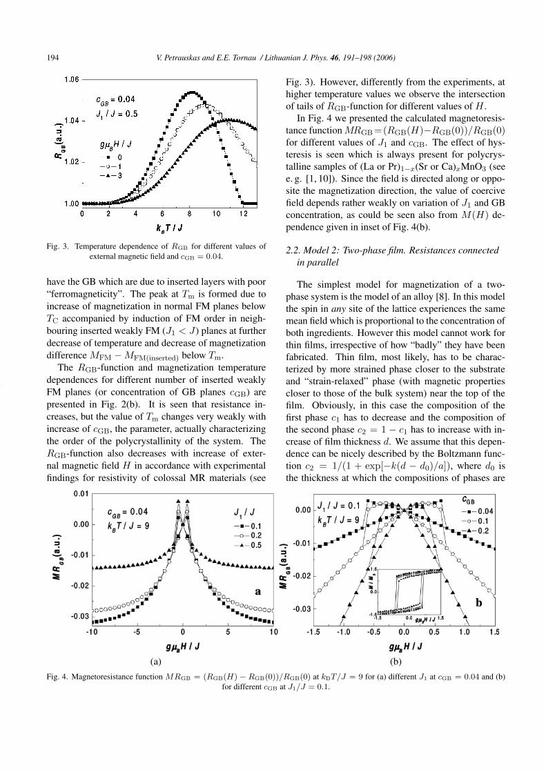
Fig. 3. Temperature dependence of RGB for different values ofexternal magnetic field and cGB = 0.04.
have the GB which are due to inserted layers with poor“ferromagneticity”. The peak at Tm is formed due toincrease of magnetization in normal FM planes belowTC accompanied by induction of FM order in neigh-bouring inserted weakly FM (J1 < J) planes at furtherdecrease of temperature and decrease of magnetizationdifference MFM − MFM(inserted) below Tm.
The RGB-function and magnetization temperaturedependences for different number of inserted weaklyFM planes (or concentration of GB planes cGB) arepresented in Fig. 2(b). It is seen that resistance in-creases, but the value of Tm changes very weakly withincrease of cGB, the parameter, actually characterizingthe order of the polycrystallinity of the system. TheRGB-function also decreases with increase of exter-nal magnetic field H in accordance with experimentalfindings for resistivity of colossal MR materials (see
Fig. 3). However, differently from the experiments, athigher temperature values we observe the intersectionof tails of RGB-function for different values of H .
In Fig. 4 we presented the calculated magnetoresis-tance function MRGB =(RGB(H)−RGB(0))/RGB(0)for different values of J1 and cGB. The effect of hys-teresis is seen which is always present for polycrys-talline samples of (La or Pr)1−x(Sr or Ca)xMnO3 (seee. g. [1, 10]). Since the field is directed along or oppo-site the magnetization direction, the value of coercivefield depends rather weakly on variation of J1 and GBconcentration, as could be seen also from M(H) de-pendence given in inset of Fig. 4(b).
2.2. Model 2: Two-phase film. Resistances connectedin parallel
The simplest model for magnetization of a two-phase system is the model of an alloy [8]. In this modelthe spin in any site of the lattice experiences the samemean field which is proportional to the concentration ofboth ingredients. However this model cannot work forthin films, irrespective of how “badly” they have beenfabricated. Thin film, most likely, has to be charac-terized by more strained phase closer to the substrateand “strain-relaxed” phase (with magnetic propertiescloser to those of the bulk system) near the top of thefilm. Obviously, in this case the composition of thefirst phase c1 has to decrease and the composition ofthe second phase c2 = 1 − c1 has to increase with in-crease of film thickness d. We assume that this depen-dence can be nicely described by the Boltzmann func-tion c2 = 1/(1 + exp[−k(d − d0)/a]), where d0 isthe thickness at which the compositions of phases are
(a) (b)Fig. 4. Magnetoresistance function MRGB = (RGB(H) − RGB(0))/RGB(0) at kBT/J = 9 for (a) different J1 at cGB = 0.04 and (b)
for different cGB at J1/J = 0.1.
V. Petrauskas and E.E. Tornau / Lithuanian J. Phys. 46, 191–198 (2006) 195
equal (c1(d0) = c2(d0) = 0.5) and k is the param-eter, in some way, characterizing the fabrication (orphase separation) conditions: high values of k corre-spond to abruptly separated phases, while low valuesindicate high degree of mixing in the system. Herea = ai − ai±1 is the lattice parameter and i is theplane index. In such a system for simple cubic lat-tice the interaction of the mean fields and the exter-nal magnetic field H with the mean magnetic momentsM1i = gµB〈s1i〉 and M2i = gµB〈s2i〉 of both phasesin ith plane can be described by the following equa-tions:
〈s1i〉= s1B{
s1[J11c1(4〈s1i〉 + 〈s1 i+1〉 + 〈s1 i−1〉)
+ J12c2(4〈s2i〉 + 〈s2 i+1〉 + 〈s2 i−1〉)
+ gµBH]/kBT}
,
〈s2i〉= s2B{
s2[J21c1(4〈s1i〉 + 〈s1 i+1〉 + 〈s1 i−1〉)
+ J22c2(4〈s2i〉 + 〈s2 i+1〉 + 〈s2 i−1〉)
+ gµBH]/(kBT )}
, (2)
where s1 and s2 are spin moments of both phases(s1 = s2 = s(Mn3+) = 2) , 〈s1i〉 and 〈s2i〉 are theirthermally averaged values in ith plane, J11, J22, andJ12 = J21 are the exchange constants of interactionsbetween spins of the first phase, between spins of thesecond phase, and between spins of the first and sec-ond phase, respectively. The solution for magnetiza-tion in the ith plane of components M1i and M2i andplane magnetization Mi = M1i + M2i is related tothe magnetizations in the neighbouring planes. Thus,to obtain total magnetization of the film of thicknessd = Na = d0 − (a/k) ln[(1 − c2)/c2], we have tosolve the system of equations (2) for N planes.
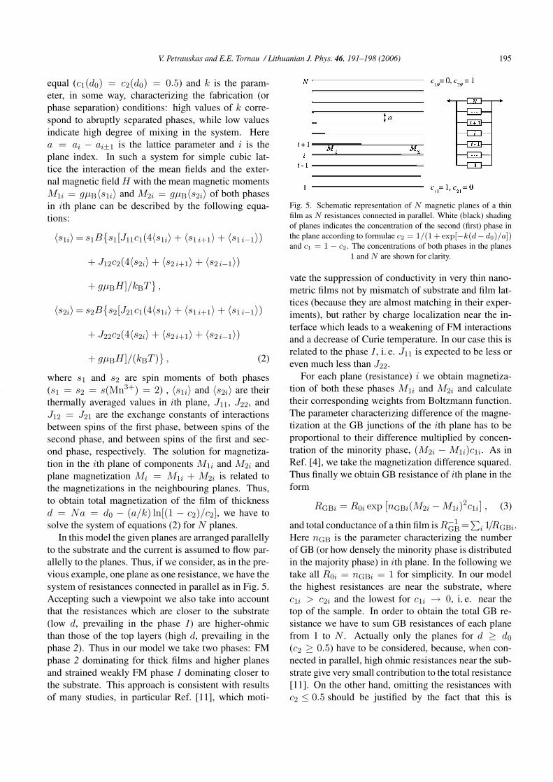
In this model the given planes are arranged parallellyto the substrate and the current is assumed to flow par-allelly to the planes. Thus, if we consider, as in the pre-vious example, one plane as one resistance, we have thesystem of resistances connected in parallel as in Fig. 5.Accepting such a viewpoint we also take into accountthat the resistances which are closer to the substrate(low d, prevailing in the phase 1) are higher-ohmicthan those of the top layers (high d, prevailing in thephase 2). Thus in our model we take two phases: FMphase 2 dominating for thick films and higher planesand strained weakly FM phase 1 dominating closer tothe substrate. This approach is consistent with resultsof many studies, in particular Ref. [11], which moti-
Fig. 5. Schematic representation of N magnetic planes of a thinfilm as N resistances connected in parallel. White (black) shadingof planes indicates the concentration of the second (first) phase inthe plane according to formulae c2 = 1/(1+ exp[−k(d− d0)/a])and c1 = 1 − c2. The concentrations of both phases in the planes
1 and N are shown for clarity.
vate the suppression of conductivity in very thin nano-metric films not by mismatch of substrate and film lat-tices (because they are almost matching in their exper-iments), but rather by charge localization near the in-terface which leads to a weakening of FM interactionsand a decrease of Curie temperature. In our case this isrelated to the phase 1, i. e. J11 is expected to be less oreven much less than J22.
For each plane (resistance) i we obtain magnetiza-tion of both these phases M1i and M2i and calculatetheir corresponding weights from Boltzmann function.The parameter characterizing difference of the magne-tization at the GB junctions of the ith plane has to beproportional to their difference multiplied by concen-tration of the minority phase, (M2i − M1i)c1i. As inRef. [4], we take the magnetization difference squared.Thus finally we obtain GB resistance of ith plane in theform
RGBi = R0i exp[
nGBi(M2i − M1i)2c1i
]
, (3)
and total conductance of a thin film is R−1GB =
∑
i 1/RGBi.Here nGB is the parameter characterizing the numberof GB (or how densely the minority phase is distributedin the majority phase) in ith plane. In the following wetake all R0i = nGBi = 1 for simplicity. In our modelthe highest resistances are near the substrate, wherec1i > c2i and the lowest for c1i → 0, i. e. near thetop of the sample. In order to obtain the total GB re-sistance we have to sum GB resistances of each planefrom 1 to N . Actually only the planes for d ≥ d0
(c2 ≥ 0.5) have to be considered, because, when con-nected in parallel, high ohmic resistances near the sub-strate give very small contribution to the total resistance[11]. On the other hand, omitting the resistances withc2 ≤ 0.5 should be justified by the fact that this is

196 V. Petrauskas and E.E. Tornau / Lithuanian J. Phys. 46, 191–198 (2006)
Fig. 6. Temperature dependence of RGB and magnetization (inset)for different values of J11 = J12.
exactly the threshold of the percolation of the phase 2in phase 1 on square lattice. It is noteworthy that wecan obtain the maximum of RGB(T ) function summingover all planes also, but the omission of high ohmic re-sistances leads to variation of Tm with d in larger limitsin accordance with experimental results.
Temperature dependences of GB resistivity are dem-onstrated in Fig. 6 for d = 100a and different values ofJ11 = J12. The Boltzmann function parameters ared0 = 15a and k = 0.01, i. e. the prevailing of thephase 1 is only in 15 planes nearest to the substrate, butthe saturation of phase 2 with distance is rather slow(c2i ∼ 1 is for N = d/a > 500). The peak movestowards higher values of temperature with increase offerromagneticity of minority phase as in the previousmodel. Temperature dependences of magnetization (in-set) also show induction of magnetization of phase 2 inphase 1 below TC, which is especially pronounced forthe sample with low J1 = J11/J22 = J12/J22.
The most interesting effect, resistivity dependenceon sample thickness is found in most experiments onthin films of lanthanum manganites (see e. g. [11, 12]).Our model can also describe this effect as shown inFig. 7. For J1 = 0.05, the ratio t = Tm(d =16a) / Tm(d = 400a) = 0.62. Here Tm at d = 400amight be taken as Tm of a bulk compound. This ratioslightly increases with increase of J1, e. g. t = 0.69for J1 = 0.2 and t = 0.77 for J1 = 0.5 (seeFig. 8). For epitaxial two-phase La0.83Sr0.17MnO3
samples with thickness ranging from 4 to 140 nm theratio t = Tm(d = 4 nm) / Tm(d = 140 nm) is alsoaround 0.7 [12]. In our model this ratio also slightlydepends on the parameters of the Boltzmann function.For abrupt separation of phases and fast saturation of
Fig. 7. Temperature dependence of RGB for different values of filmthickness.
Fig. 8. Temperature of RGB maximum as a function of film thick-ness at different values of J11 = J12.
phase 2 (much larger k) the thickness effect in t is quiteweak (t ≥ 0.9).
3. Conclusions
We present two models to calculate the resistancein polycrystalline and thin films of lanthanum mangan-ites. Studying the tunnelling through the artificially in-troduced grain boundaries resistance RGB, we use therelation between resistance and difference in magneti-zation of local grains and grain boundary layers. Usingthe one-dimensional model, which could be applied forpolycrystalline lanthanum manganite, we have shownthat grain boundary layers have to be at least weaklyferromagnetic in order to obtain the peak of resistanceat Tm in its temperature dependence. With increase offerromagneticity (Curie temperature) of grain bound-ary layer the peak at Tm decreases and moves towardshigher values of temperature. The increase of concen-

V. Petrauskas and E.E. Tornau / Lithuanian J. Phys. 46, 191–198 (2006) 197
tration of grain boundary layers also leads to reductionof the peak, but almost does not change the Tm value.We obtain the hysteresis in magnetic field dependencesof magnetoresistance when the field is parallel to mag-netization.
Good qualitative agreement for decrease and shift ofTm with increase of film thickness is obtained for thesecond model devoted to calculation of resistivity ofthin films consisting of two phases. We assume thateach plane of the film corresponds to one resistance.Then total resistivity for current flowing parallel to theplanes is calculated as for resistances connected in par-allel. The resistance for each plane is obtained in termsof plane magnetization which we obtain by calculatingthe magnetization of both phases and their correspond-ing weights.
Acknowledgements
We thank Lithuanian State Science and StudiesFoundation (project Nr. T-19 / 05-01) and EC projectPRAMA for financial support. Discussions withS. Balevicius, N. Žurauskiene, and S. Lapinskas aregratefully acknowledged.
References
[1] M.G. Blamire, B.-S. Teo, J.H. Durrell, N.D. Mathur,Z.H. Barber, J.L. McManus Driscoll, L.F. Cohen, andJ.E. Evetts, Strain-induced time-dependent magneticdisorder in ultra-thin La0.7Sr0.3MnO3, J. Magn. Magn.Mater. 191, 359–367 (1999).
[2] A. de Andres, M. Garcia-Hernandez, and J.L. Mar-tinez, Conduction channels and magnetoresistance inpolycrystalline manganites, Phys. Rev. B 60, 7328–7334 (1999).
[3] L. Balcells, J. Fontcuberta, B. Martinez, andX. Obradors, High-field magnetoresistance at inter-
faces in manganese perovskites, Phys. Rev. B 58,R14697–R146700 (1998).
[4] R. Gross, L. Alff, B. Buechner, B.H. Freitag, C. Hoe-fener, J. Klein, Y. Lu, W. Mader, J.B. Philipp,M.S.R. Rao, P. Reutler, S. Ritter, S. Thienhaus, S. Uh-lenbruck, and B. Wiedenhorst, Physics of grain bound-aries in the colossal magnetoresistance manganites,J. Magn. Magn. Mater. 211, 150–159 (2000).
[5] S. Ju, K.W. Yu, and Z.Y. Li, Spatially inhomogeneoustransport in phase separated polycrystalline mangan-ites, Phys. Rev B 71, 224401-1–8 (2005).
[6] N. Furukawa, Anomalous shift of chemical potentialin the double-exchange systems, J. Phys. Soc. Jpn. 66,2523–2524 (1997).
[7] M. Viret, L. Ranno, and J.M.D. Coey, Magnetic local-ization in mixed-valence manganites, Phys. Rev. B 55,8067–8070 (1997).
[8] J.G. Simmons, Generalized formula for the electrictunnel effect between similar electrodes separated bya thin insulating film, J. Appl. Phys. 34, 1793–1803(1963).
[9] M. Mansipuram, The Physical Principles of Magneto-Optical Recording (Cambridge University Press,1995).
[10] H.S. Wang, Q. Li, K. Liu, and C.L. Chien,Low field magnetoresistance anisotropy in ultrathinPr0.67Sr0.33MnO3 films grown on different substrates,Appl. Phys. Lett. 74, 2112–2114 (1999).
[11] G. Herrantz, M. Berkowski, E. Jedrika, M. Wojcik,F. Sanchez, M. Bibes, and J. Fontcuberta, Charge lo-calization in nanometric La2/3Ca1/3MnO3 thin filmsgrown on nearly matching substrates, J. Appl. Phys.93, 8065–8067 (2003).
[12] S. Balevicius, P. Cimmperman, V. Petrauskas,V. Stankevic, E.E. Tornau, N. Žurauskiene,A. Abrutis, V. Plaušinaitiene, M. Sawicki, T. Di-etl, and M. Aleszkiewicz, Two-phase structure ofultra-thin La–Sr–MnO films, accepted for publicationin Thin Solid Films.

198 V. Petrauskas and E.E. Tornau / Lithuanian J. Phys. 46, 191–198 (2006)
TARPGRANULINES VARŽOS MODELIAVIMAS PLONUOSE LANTANO MANGANITUSLUOKSNIUOSE
V. Petrauskas, E.E. Tornau
Puslaidininkiu fizikos institutas, Vilnius, Lietuva
SantraukaFeromagnetines medžiagos, lantano manganitai, pasižymi va-
dinamaja milžiniška (colossal) magnetovarža. Pateikti du mode-liai, skirti skaiciuoti varžai R tarp feromagnetiniu granuliu lantanomanganituose. Taikoma fenomenologine formule, siejanti varža,apskaiciuota kruvininkui tuneliuojant per staciakampi barjera, irsistemos imagnetejima. Granuliu imagnetejimas skaiciuojamas vi-dutinio lauko metodu.
Pirmasis modelis yra nuosekliai sujungtu feromagnetiniu plokš-tumu (granuliu) sistema, imituojanti polikristalini lantano manga-nita. Keiciant magnetines plokštumas nemagnetinemis ar silpnaimagnetinemis, fiksuojama, kaip pasikeis visos sistemos varža irmagnetovarža. Nustatyta, kad (a) ne imagnetejimas, o imagne-tejimo skirtumas tarp kaimyniniu granuliu yra esminis faktorius,varžos priklausomybeje nuo temperaturos R(T ) lemiantis varžossmaile; (b) R(T ) smaile gaunama tik tada, kai medžiaga tarp fe-romagnetiniu granuliu taip pat yra bent silpnas (t. y., žemos Kiuritemperaturos) feromagnetikas; (c) granuliu skaiciaus didejimas
mažina varža, bet nekeicia varžos maksimumo Tm padeties tem-peraturos skaleje.
Antrasis modelis skirtas plonu polikristaliniu ir epitaksiniu lan-tano manganitu sluoksniu varžai skaiciuoti. Tai yra dvieju faziusu skirtingomis feromagnetinemis savybemis modelis, nes tokiesluoksniai visada turi labiau „itemptas“ plokštumas arciau padeklo(daug fazes 1, jos koncentracija c1 À c2) ir tolimesnes plokštumas,kuriu savybes yra artimesnes trimates medžiagos savybems (daugfazes 2, c2 À c1). Kiekviena plokštuma yra abieju feromagneti-niu faziu su skirtingais faziu svoriais ir skirtingais imagnetejimaismišinys. Jeigu kiekviena plokštuma butu isivaizduojama kaip var-ža, o varža skaiciuojama kaip faziu imagnetejimu skirtumas, kaippirmame modelyje, butu gaunama lygiagreciai sujungtu varžu sis-tema, iš esmes tinkama plonu lantano manganitu savitajai varžai irmagnetovaržai modeliuoti. Tokiai sistemai buvo parinkti paramet-rai ir gautas geras sutapimas su eksperimentiniais duomenimis, t. y.,nustatyta, kad, storejant sluoksniui, varžos smaile mažeja ir R(T )priklausomybeje pasislenka link aukštesniu temperaturos verciu.